Biological/Natural Systems - TN.gov
469
Biological/Natural Systems 4-Day Course #1207 Fleming Training Center
-
Upload
khangminh22 -
Category
Documents
-
view
0 -
download
0
Transcript of Biological/Natural Systems - TN.gov

Biological/Natural Systems
4-Day Course #1207
Fleming Training Center


Course # 1207 March 15-18, 2022
Tuesday, March 15:
8:30 Overview of Wastewater Treatment
9:45 Wastewater Microbiology
11:00 Lunch
12:30 Ponds and Lagoons
1:45 Packed Bed Filters
Wednesday, March 16:
8:30 Septic Tanks
9:45 Disinfection
11:00 Lunch
12:30 Effluent Discharge
1:30 Laboratory
2:30 NPDES & 40CFR 136 Excerpt
Thursday, March 17:
8:30 Safety
9:30 Cross Connection Control
11:30 Lunch
12:30 Pumps
1:30 Basic Math Review
Friday, March 18:
8:30 Wastewater Math
11:00 Course Wrap-Up and Final Exam
Fleming Training Center
2022 Blanton Dr.
Murfreesboro, TN 37129
Biological/Natural Systems
Fleming Training Center
S T A T E O F T E N N E S S E E
Instructor: Sarah Snyder Phone: 615-898-6506 Email: [email protected] Fax: 615-898-8064
1

2

Biological/Natural Systems
Section 1 Introduction to Wastewater/Overview page 5
Section 2 Introduction to Microbiology page 19
Section 3 Septic Tanks page 27
Section 4 Ponds and Lagoons page 51
Section 5 Packed Bed Filters page 73
Section 6 Disinfection page 85
Section 7 Effluent Discharge page 99
Section 8 Laboratory page 115
Section 9 NPDES Permit Excerpt page 143
Section 10 40 CFR 136 Excerpt page 177
Section 11 Safety page 223
Section 12 Cross Connection Control page 243
Section 13 Pumps page 263
Section 14
Section 15
Math
TN Regs
page 285
page 337
3

4

Section 1
Introduction to Wastewater
5

Why do we treat waste?
TDEC ‐ Fleming Training Center 1
Protection of public health and receivingstreams is main job
Today’s technology is capable of treatingwastewater so that receiving streams arereasonably unaffected
TDEC ‐ Fleming Training Center 2
To protect public health by:
◦ Removing solids
◦ Stabilizing organic matter
◦ Removing pathogenic organisms
TDEC ‐ Fleming Training Center 3
Water is made up oftwo hydrogen atomsand one oxygenatom
“Pure” water ismanufactured in labs
Even rain anddistilled watercontain othersubstances calledimpuritiesH2O
TDEC ‐ Fleming Training Center 4
Organic waste◦ Contains carbon
Inorganic waste◦ Salts◦ Metals◦ Gravel◦ Sand
Both may come from domestic or industrialwaste
TDEC ‐ Fleming Training Center 5
If wastewater does notreceive adequatetreatment, solids maybuild up in thereceiving stream assludge in the bottomor scum floating to thesurface◦ Sludge and scum are
unsightly and maycontain organic material that consumes oxygen or be an odor problem
TDEC ‐ Fleming Training Center 6
Section 1 TDEC Fleming Training Center
Introduction to Wastewater Treatment6

Most living creatures (including fish)need oxygen to survive◦ Most fish can survive with at least 5 mg/L DO
When organic wastes are discharged to areceiving stream bacteria begin to feed on it,these bacteria need oxygen for this process◦ As more organic waste is added to the receiving
stream, the bacteria reproduce◦ As the bacteria reproduce, they use up more
oxygen◦ This can potentially cause a fish kill and odors
TDEC ‐ Fleming Training Center 7
Organic waste discharged to receiving stream.
Aerobic microorganisms use up oxygen to metabolize organic waste.
Biological activity creates oxygen deficit in stream.
Aquatic organisms requiring oxygen to survive
die off or migrate.
In the absence of oxygen, anaerobic microorganisms dominate.
Anaerobic activity causes putrification and odors
TDEC - Fleming Training Center 8
Initial efforts came from preventing diseaseoutbreaks◦ Most bacteria in wastewater are not harmful to
humans◦ Humans who have a disease caused by bacteria or
viruses can discharge some of these pathogens ◦ Many serious outbreaks of communicable diseases
have been traced back to contamination of drinking water or food from domestic wastewater
Good personal hygiene is your best defenseagainst infections and disease
TDEC ‐ Fleming Training Center 9
Bacteria◦ Cholera◦ Dysentery◦ Shigella◦ Salmonella◦ Typhoid
Viruses◦ Polio◦ Hepatitis (Jaundice)
Protozoa◦ Giardia◦ Cryptosporidiosis
The LifeStraw is a portable water purification tool that purifies water from potential
pathogens like typhoid, cholera, dysentery and diarrhea.
TDEC ‐ Fleming Training Center 10
National Pollutant Discharge EliminationSystem◦ Required by the Federal Water Pollution Act
Amendments of 1972 to help keep the nation’swater suitable for swimming and for fish and otherwildlife◦ Regulates discharges to surface waters
TDEC ‐ Fleming Training Center 11
Any condition caused by human activity thatadversely affects the quality of stream, lake,ocean, or groundwater.
TDEC ‐ Fleming Training Center 12
TDEC Fleming Training Center Section 1
Introduction to Wastewater Treatment 7

Unpolluted water has a wide diversity of aquatic organisms and contains enough dissolved oxygen.
Polluted water inhibits the growth of aquatic organisms.
TDEC ‐ Fleming Training Center 13
An organic compound is a substance that contains carbon.◦ Cyanide◦ Cyanates◦ Carbon dioxide and its relatives are exceptions to
that rule and are considered inorganic
TDEC ‐ Fleming Training Center 14
Organic material consumes oxygen in water.◦ Bacteria will “feed” on organic matter and most
need oxygen to be able to do this.◦ We want these bacteria to “feed” on the organic
matter and use it up in the plant and not in our receiving water.
High concentrations of organic material can cause taste and odor problems in recreational and drinking water.
Some material may be hazardous.
TDEC ‐ Fleming Training Center 15
Dissolved oxygen is oxygen that has been incorporated into water.
Many aquatic animals require it for their survival.
TDEC ‐ Fleming Training Center 16
Problems associated with excess nutrients:◦ Cause an increase in productivity of aquatic plants,
leading to depleted DO levels◦ May cause odor problems◦ Extra vegetation near surface may inhibit light
penetration of light into water Macronutrients:◦ Nitrogen (many WWTPs test for ammonia)◦ Phosphorus◦ Iron
TDEC ‐ Fleming Training Center 17
Serve many important purposes including degrading waste materials
Some may be dangerous to human health and must be removed from water (pathogens)
TDEC ‐ Fleming Training Center 18
Section 1 TDEC Fleming Training Center
Introduction to Wastewater Treatment8

Parameter Influent Concentration Effluent Goal**BOD5 200 mg/L < 30 mg/LTSS 200 mg/L < 30 mg/LTDS 800 mg/L < 1000 mg/L
Settleable Solids 10 mL/L < 0.1 ml/LpH 6 – 9 6 – 9
Fecal Coliform Too Numerous to Count < 500 cfu/100 mL
TNK (Ammonia + Organic Nitrogen) 30 mg/L < 10 mg/L Total
NitrogenNitrate-Nitrite < 1.0 mg/L Phosphorous 2.0 mg/L < 1.0 mg/L
Fats, Oils and Grease Varies None visible
** Depends on NPDES permitTDEC ‐ Fleming Training Center 19
Constant minimum slope is required to provide a velocity of at least 2 fps to avoid solids depositing
Manholes should be placed every 300-500 feet apart to provide access for inspections and cleaning
Min size is 4”
TDEC - Fleming Training Center 20
Manholes must be installed:◦ At the ends of any line 8” in diameter or larger line◦ Changes in grade, size of pipe or alignment◦ At intersections◦ And not greater than 400 ft. on a 15” diameter and
smaller sewers or 500 ft. on 18-30” sewers Horizontal Separation – sewers should be laid
with at least 10 feet of horizontal clearance from any existing or proposed water line
Vertical Separation – when sewers must cross a water line, they should be laid 18” below the bottom of the water line
TDEC ‐ Fleming Training Center 21
Hydrogen sulfide is made in the collection system and can:◦ Make waste more difficult to treat◦ Damage concrete structures◦ Cause odor problems
Biological activity in long, flat sewer lines will likely cause:◦ Hydrogen sulfide production◦ Oxygen deficiency in sewers, manholes or wetwells◦ Metal and concrete corrosion
Chlorine can be used in the collection system or at the plant headworks to oxidize hydrogen sulfide
TDEC ‐ Fleming Training Center 22
When excavating sewers 5 feet or more, cave-in protection is required◦ Contouring◦ Drag shields◦ Shoring◦ Sloping
If the ditch is 4 feet or deeper, ladders are required every 25 feet in the ditch
The most practical and best protection
TDEC ‐ Fleming Training Center 23
When entering a confined space, such as a manhole, you will need to have and use:◦ An approved man hoist◦ Forced air ventilator◦ Gas detector that checks for Oxygen Hydrogen sulfide Explosive
TDEC ‐ Fleming Training Center 24
TDEC Fleming Training Center Section 1
Introduction to Wastewater Treatment 9

Sanitary◦ Waste carried in from homes and commercial
businesses in the city plus some industrial waste Storm◦ Storm runoff from streets, land and building roofs◦ Normally discharged to a watercourse without
treatment Combined◦ Combination of sanitary and storm◦ Sanitary portions may become overloaded during
storms
TDEC ‐ Fleming Training Center 25
Com
bine
d S
yste
m
Sep
arat
e S
yste
m
TDEC - Fleming Training Center 26
PreliminaryTreatment
PrimaryTreatment
Tertiary Treat. (Advanced)
Disinfection
Sedimentation and Flotation
SecondaryTreatment
Biological Treatment Sedimentation
Chemical Phosphorous Removal
Biological Nutrient Removal
Multimedia Filtration
Screening Grit Removal Preaeration Flow Metering and Sampling
SolidsTreatment
Digestion Dewatering Disposal
Ultraviolet IrradiationChlorine GasSodium HypochloriteCalcium Hypochlorite
TDEC - Fleming Training Center 27
PreliminaryTreatment
PrimaryTreatment
Tertiary Treat. (Advanced)
Disinfection
SecondaryTreatment
Screening Grit Removal Preaeration Flow Metering and Sampling
SolidsTreatment
TDEC - Fleming Training Center 28
Muffin Monster(grinder)
Mechanical barscreen with debris
• Failure to keep a bar screen clean can result in a shockload•Removes roots, rags, cans, etc
Aerated grit chamber• 1 ft/sec flow through grit
chamber• Used to remove grit –heavy, mainly inorganic solids (sand, egg shells,
gravel, seeds, etc.)•Aeration also freshens wastewater and helps
remove floatables
TDEC - Fleming Training Center 29
According to TN regulations concerning NPDES permits, flow measuring devices must be calibrated and maintained to ensure a ± 10% of true flow
Flow is determined by the depth of the water
TDEC ‐ Fleming Training Center 30
Section 1 TDEC Fleming Training Center
Introduction to Wastewater Treatment10

PreliminaryTreatment
PrimaryTreatment
Tertiary Treat. (Advanced)
Disinfection
Sedimentation and Flotation
SecondaryTreatment
SolidsTreatment
TDEC - Fleming Training Center 31
Scum removal
Rectangular clarifier
Cross section of circular clarifier
Velocity drops to < 1 fps Separates settleable and
floatable solids Detention time ~ 1.5-2.0 hrs Raw water is gray
TDEC - Fleming Training Center 32
PreliminaryTreatment
PrimaryTreatment
Tertiary Treat. (Advanced)
Disinfection
SecondaryTreatment
Biological Treatment Sedimentation
SolidsTreatment
TDEC - Fleming Training Center 33
To remove the suspended solids & the dissolved organic load from the WW by using microbial populations.
The microorganisms are responsible for:◦ Degradation of the organic matter ◦ They can be classified into Aerobic (require oxygen for their metabolism) Anaerobic (grow in absence of oxygen) Facultative (proliferate either with or without oxygen)
TDEC ‐ Fleming Training Center 34
If the microorganisms are SUSPENDED in the WW during biological operation◦ Example: lagoons or mechanical wastewater plants Recycling of settled biomass is required for a
mechanical type plant While the microorganisms that are ATTACHED
to a surface over which they grow◦ Example: sand bed filter, some wetlands, trickling
filter or RBC (rotating biological contactor)◦ Biomass attached to media (rock, plastic, etc.) ◦ Recycling of settled biomass is not required.
TDEC ‐ Fleming Training Center 35 TDEC - Fleming Training Center 36
TDEC Fleming Training Center Section 1
Introduction to Wastewater Treatment 11

Secondary clarifier
Trickling Filter
TDEC - Fleming Training Center 37
Wastewater
Oxygen (natural or forced draft)
Organic/ nutrient
filter media
Biomass : viscous, jelly-like substance containing bacteria
Biomass = “zoogleal mass” or “Biofilm”Filter media = rock, slag, coal, bricks, redwood blocks or molded plastic
TDEC ‐ Fleming Training Center 38
Simplicity Lower maintenance Lower power/electrical costs Less production excess biological solids Resistance to shock loads
TDEC ‐ Fleming Training Center 39 TDEC ‐ Fleming Training Center 40
TF consists of:◦ A rotating arm that
sprays wastewater over a filter medium. Filter medium: rocks,
plastic, or other material. ◦ The water is collected
at the bottom of the filter for further treatment◦ Not really a filter, it
does not work like sand or filter paper
TDEC ‐ Fleming Training Center 41
Wastewater
Packing media
Underdrain
Treats domestic and biodegradable industrial wastes
Rotating steel shaft with HDPE disc media (drum)
Air or mechanically driven
Drum rotates through WW for food then through air for oxygen
TDEC ‐ Fleming Training Center 42
Section 1 TDEC Fleming Training Center
Introduction to Wastewater Treatment12

TDEC - Fleming Training Center 43
Oxidation Ditch
Fine Bubble Diffusers Mechanical Aeration
SBR – Sequencing Batch Reactor
TDEC - Fleming Training Center 44
PreliminaryTreatment
PrimaryTreatment
Tertiary Treat. (Advanced)
Disinfection
SecondaryTreatment
Chemical Phosphorous Removal
Biological Nutrient Removal
Multimedia Filtration
SolidsTreatment
TDEC - Fleming Training Center 45 TDEC - Fleming Training Center 46
TDEC - Fleming Training Center 47
Anoxic or anaerobic zone added toaerobic activated sludge to
denitrify to achieve low total N.
Anoxic Zone
TDEC - Fleming Training Center 48
TDEC Fleming Training Center Section 1
Introduction to Wastewater Treatment 13

TDEC - Fleming Training Center 49
PreliminaryTreatment
PrimaryTreatment
Tertiary Treat. (Advanced)
Disinfection
SecondaryTreatment
SolidsTreatment
Ultraviolet IrradiationChlorine GasSodium HypochloriteCalcium Hypochlorite
TDEC - Fleming Training Center 50
Purpose is to kill pathogenic organisms still in wastewater.
Typically wastewater must contain 200 cfu/100mL for Fecal coliforms or 126 cfu/100mL for E. coli to be considered “disinfected”
TDEC ‐ Fleming Training Center 51
Bleach
Tablet Hypochlorination
System
Chlorine Contact Chamber
Ton Chlorine Cylinders
UV system TDEC - Fleming Training Center 52
PrimaryTreatment
SecondaryTreatment
SolidsTreatment
Digestion Dewatering Disposal
TDEC - Fleming Training Center 53
Trucking Solids
Gravity Filter Bed
Anaerobic Digester
Gravity Thickener
Belt Press
TDEC - Fleming Training Center 54
Section 1 TDEC Fleming Training Center
Introduction to Wastewater Treatment14

Most wastewater is discharged to a receiving stream, river, lake or ocean.
Some is reclaimed or reused on golf courses, cemeteries, parks, etc.
TDEC ‐ Fleming Training Center 55 TDEC ‐ Fleming Training Center 56
TDEC Fleming Training Center Section 1
Introduction to Wastewater Treatment 15

Wastewater Treatment Overview Vocabulary ______1. Aerobic Bacteria ______2. Anaerobic Bacteria ______3. Biochemical Oxygen Demand
(BOD) ______4. Biochemical Oxygen Demand
(BOD) Test ______5. Combined Sewer ______6. Detention Time ______7. Disinfection ______8. Effluent ______9. Grit ______10. Headworks ______11. Infiltration ______12. Inflow ______13. Inorganic Waste
______14. Organic Waste ______15. Pathogenic Organisms ______16. pH ______17. Primary Treatment ______18. Receiving Water ______19. Sanitary Sewer ______20. Secondary Treatment ______21. Septic ______22. Sludge ______23. Stabilize ______24. Storm Sewer ______25. Supernatant ______26. Weir ______27. Wet Well
A. A stream, river, lake, ocean or other surface or groundwaters into which treated or
untreated wastewater is discharged. B. The process designed to kill most microorganisms in wastewater, including essentially all
pathogenic (disease‐causing) bacteria. C. The facilities where wastewater enters a wastewater treatment plant. This may consist of
bar screen, comminutors, and a wet well and pumps. D. An expression of the intensity of the basic or acidic condition of a liquid. The range is from
0 to 14 where 0 is most acidic, 14 most basic and 7 neutral. Natural waters usually range between 6.5 and 8.5.
E. To convert to a form that resist change. Bacteria that convert the material to gases and other relatively inert substances stabilize organic material. Stabilized organic material generally will not give off obnoxious odors.
F. The seepage of groundwater into a sewer system, including service connections. Seepage frequently occurs through defective or cracked pipes, pipe joints, connections or manhole walls.
G. Bacteria that will live and reproduce only in an environment containing oxygen that is available for their respiration, namely atmospheric oxygen or oxygen dissolved in water.
H. Water discharged into a sewer system and service connections from sources other than regular connections.
I. A wastewater treatment process used to convert dissolved or suspended materials into a form more readily separated from the water being treated. Usually the process follows primary treatment by sedimentation. The process commonly is a type of biological treatment process followed by secondary clarifiers that allow the solids to settle out from the water being treated.
J. A pipe or conduit (sewer) intended to carry wastewater or waterborne wastes from homes, businesses and industries to the POTW (Publicly Owned Treatment Works).
Section 1 TDEC Fleming Training Center
Introduction to Wastewater Treatment16

K. The heavy material present in wastewater, such as sand, coffee grounds, gravel, cinders and eggshells.
L. The rate at which organisms use the oxygen in water or wastewater while stabilizing decomposable organic matter under aerobic conditions. These measurements are used as a measurement of the organic strength of wastes in water.
M. A sewer designed to carry both sanitary wastewaters and storm‐ or surface‐water runoff. N. The settleable solids separated from liquids during processing. O. Chemical substances of mineral origin. P. A separate pipe, conduit or open channel (sewer) that carries runoff from storms, surface
drainage and street wash, but does not include domestic and industrial wastes. Q. Bacteria that live and reproduce in an environment containing no “free” or dissolved
oxygen. These bacteria obtain their oxygen supply by breaking down chemical compounds that contain oxygen, such as sulfate (SO4
2‐). R. Liquid removed from settled sludge. S. Bacteria, viruses or protozoa that can cause disease (typhoid, cholera, dysentery) in a host. T. (1) A wall or plate placed in an open channel and used to measure the flow. The depth of
the flow over the weir can be used to calculate the flow rate, or a chart or conversion table may be used. (2) A wall or obstruction used to control flow (from settling tanks and clarifiers) to assure a uniform flow rate and avoid short‐circuiting.
U. A condition produced by anaerobic bacteria. If sever, the wastewater produces hydrogen sulfide, turns black, gives off foul odors, contains little or no dissolved oxygen and creates a high oxygen demand.
V. The time required to fill a tank at a given flow or the theoretical time required for a given flow of wastewater to pass through a tank.
W. Waste material that comes mainly from animal or plant sources. Bacteria and other small organisms generally can consume these.
X. A compartment or tank in which wastewater is collected. The suction pipe of a pump may be connected to the wet well or a submersible pump may be located in the wet well.
Y. A procedure that measures the rate of oxygen use under controlled conditions of time and
temperature. Standard test conditions include dark incubation at 20 C for a specified time (usually five days).
Z. Wastewater or other liquid – raw (untreated), partially or completely treated – flowing from a reservoir, basin, treatment process or treatment plant.
AA. A wastewater treatment process that takes place in a rectangular or circular tank and allows those substances in wastewater that readily settle or float to be separated from the water being treated.
TDEC Fleming Training Center Section 1
Introduction to Wastewater Treatment 17

Answers to Vocabulary 1. G 2. Q 3. L 4. Y 5. M 6. V 7. B 8. Z 9. K
10. C 11. F 12. H 13. O 14. W 15. S 16. D 17. AA 18. A
19. J 20. I 21. U 22. N 23. E 24. P 25. R 26. T 27. X
Section 1 TDEC Fleming Training Center
Introduction to Wastewater Treatment18

Section 2
Introduction to Microbiology
19

Introduction to Microbiology
Biological Natural Systems
1TDEC - Fleming Training Center
What are Microbes?
• Bacteria• Protozoa• Viruses• Algae• Metazoa- worms, rotifers• Fungi
2Cyanobacteria
Crawling ciliate on activated sludge floc
TDEC - Fleming Training Center
Why are they important?
• Can cause disease– Most immediate
importance
• Role in environment– Major decomposers in
nature– Essential in a balanced
ecosystem
3
Giardia
E. coli
TDEC - Fleming Training Center
Why are they important?
• Role in treatment systems– Removed in water treatment– Key role in wastewater treatment– Major role in problems & solutions to solid waste
4TDEC - Fleming Training CenterRhizobium bacteria
Actinomycetes
What key role do they play?
• In lagoons:– Bacteria
• Tiny one-celled organisms• Work horse for treatment
– Algae• Use the carbon dioxide the bacteria produce to make
oxygen with the help of sunlight
– Vascular Plants• Duckweed
5TDEC - Fleming Training Center
Bacillus sp.
Viruses and Bacteria• Viruses
– Genetic material +protein coat
– Reproduce only byinfecting cells of otherorganisms
– Pathogenic
• Bacteria– Most important– “Workhorses” of WWT
6TDEC - Fleming Training Center
Norovirus
Hepatitis B
Section 2 TDEC Fleming Training Center
Microbiology20

Bacteria Found in Wastewater
7TDEC - Fleming Training Center 8
Size Range of Microorganisms
Bacteria
0.5 – 5.0 m
Amoeba
30 – 500 m
Ciliate
10 – 300 m
Flagellate
10 – 200 m
Human Hairsized 70-100 µm or 0.003-0.004 inch,
(0.001 in = 25 µm)
TDEC - Fleming Training Center
9
Bacteria• Binary fission is the process by which one
mature cell divides into two new cells.• Bacteria Reproducing
TDEC - Fleming Training Center
Types of BacteriaHeterotrophic and autotrophic bacteria differ in the source of nutrition they require.
• Heterotrophic:– CBOD removers– Denitrifiers– Organic food
• Ex: BOD
• Autotrophic– Nitrifiers– Inorganic food
• Ammonia
– Algae– Higher plants
TDEC - Fleming Training Center 10
Heterotrophic
• Need organic carbon as their food source.– Humans– Protozoa– Most wastewater bacteria
• Almost all animals are heterotrophs, as are most microorganisms (the major exceptions being microscopic algae and blue-green bacteria).
11TDEC - Fleming Training Center
Heterotrophic• Oxygen requirements:
– Aerobes require free DO to function– Anoxic use nitrate (NO3
-) and nitrite (NO2-), no
free DO– Anaerobes thrive in the absence of free DO, use
sulfate (SO4-) or carbon dioxide (CO2)
– Facultative bacteria prefer free DO but can function in its absence
12TDEC - Fleming Training Center
TDEC Fleming Training Center Section 2
Microbiology 21

Bacteria “Eating”
13TDEC - Fleming Training Center
Food
• Two types of “food”– Dissolved
• Example: sugar in oatmeal– “Chunky”
• Example: oats in oatmeal
• Our body uses both “foods”• We eat and our stomach and gut breaks the “chunky food”
down into smaller dissolved food that our cells in our bodies can use.
• If you had to stay in the hospital and could not eat, they would “feed” you dissolved food in the form of sucrose, a sugar water.
14TDEC - Fleming Training Center
Aerobic Degradation• Organics + O2 + nutrients + bugs
CO2 + H20 + new bugs + stable matter
1515
Oxygen
Carbon Dioxide
Water
Nitrogen, Phosphorus
& Iron
BOD or
“food”
Will not have an oxygen demand on
receiving stream
TDEC - Fleming Training Center
Autotrophic
• Use carbon dioxide (inorganic) as a carbon source– Autotrophic organisms take inorganic substances into
their bodies and transform them into organic nourishment.
– Autotrophic bacteria make their own food, either by photosynthesis (which uses sunlight, carbon dioxide and water to make food) or by chemosynthesis (which uses carbon dioxide, water and chemicals like ammonia to make food - these bacteria are called nitrogen fixers and include the bacteria found living in legume roots and in ocean vents).
16TDEC - Fleming Training Center
Algae
• Algae– Photosynthetic - Use energy from sun, carbon dioxide
and nutrients to make more cells, water and oxygen – Eutrophication can cause algal blooms in receiving
streams• Defined as overfertilization of lakes with nutrients and the
changes that occur as a result
– Key in operation of wastewater ponds: produce oxygen needed by bacteria
– Types: Green, Blue-green, Diatoms, Euglenoids
17TDEC - Fleming Training Center
Green Algae
• These are the most desirable algae• Bloom in Spring when predator numbers are
low and water temperature is greater than 60F
18TDEC - Fleming Training Center
Section 2 TDEC Fleming Training Center
Microbiology22

Blue – Green Algae
• Also called Cyanobacteria• Undesirable mats on lagoon surface• Some produce odors and toxic byproducts• Favored in poor growth conditions
– Low light– High temperatures– Low nutrient conditions
19TDEC - Fleming Training Center
Diatoms
• Brown• Predominate in winter when temperatures are
less than 60F
20TDEC - Fleming Training Center
Protozoa• Single-celled animals that also reproduce by binary
fission• Have complex digestive systems that ingest organic
matter which they use as an energy and carbon source• Graze on bacteria that won’t settle to the bottom of
the lagoon• Form cysts• Beneficial in wastewater treatment• Examples: Amoeba, Ciliates, Flagellates
21TDEC - Fleming Training Center
Amoeba
22
Amoeba eating
• Eats by bumping into food and engulfing particles
• Competes with bacteria
TDEC - Fleming Training Center
Ciliate
23
• Free swimmers:– Usually move around
using hair-like cilia to find food
– Large numbers found in lagoons
– Graze on amoebas, flagellates and smaller free swimmers
Paramecium eatingTDEC - Fleming Training Center
Ciliate
24
• Stalked ciliates:– Cilia rotates to create a
vortex to draw food into the mouth opening
Stalked Ciliates
TDEC - Fleming Training Center
TDEC Fleming Training Center Section 2
Microbiology 23

Ciliate
• Suctorian– Cilia have developed into
hollow tentacles– Capture prey by sticking
tentacle in it and then they suck out the cell content
25TDEC - Fleming Training Center
Flagellate
• They propel themselves around using a whip-like tail called a flagella
• Compete with amoeba and bacteria for food
26TDEC - Fleming Training Center
Metazoa
• Multi-cellular animals
• Slow growing• Usually larger than
protozoa and much larger than bacteria
• Examples:–Rotifer–Water Bear–Nematodes–Water Mite
–Ostracods
27TDEC - Fleming Training Center
Rotifer
• Feed on bacteria and small protozoa
• Lagoons – consume large amount of algae– Continuous cropping– Keeps algae population
in good condition
• Grinds up food and absorbs nutrients
28
Rotifer
TDEC - Fleming Training Center
Water Bear
• Not common in lagoons• Feeds on body fluids of
protozoans, rotifers and nematodes
• Sensitive to ammonia
29
Water Bear
TDEC - Fleming Training Center
Worms• Multicellular organisms• Diseases (tapeworms,
roundworms)• Beneficial in trickling
filters (increase air penetration in biofilm and help in sloughing)
• Sensitive to ammonia
Trickling filter
Ascaris and egg
30TDEC - Fleming Training Center
Section 2 TDEC Fleming Training Center
Microbiology24

Other Metazoas
Ostracod
• Seedshrimp– Common in lagoons
Copepod
• Crustacean
31TDEC - Fleming Training Center
Other Metazoas
Cadoceran
• Water flea
Hydracarina
• Water mite
32TDEC - Fleming Training Center
Fungi
• Fungi– Soil organisms– Degrade dead organic
matter (saprophytic)
33TDEC - Fleming Training Center
Any Questions?
TDEC - Fleming Training Center 34
TDEC Fleming Training Center Section 2
Microbiology 25

26

Section 3
Septic Tanks
27

Septic Tanks
TDEC - Fleming Training Center 1
What’s Wrong with this Technology?
TDEC - Fleming Training Center 2
Wastes and Water
If water is notavailable◦ Then wastewater is
not generated
◦ The original low-flushtoilet
TDEC - Fleming Training Center 3
Wastewater Defined
Used water and water-carried solids thatflow to a treatment plant
Stormwater, surface water, andgroundwater infiltration may be included◦ Water that has “stuff” in it Suspended Dissolved Floating Settleable
TDEC - Fleming Training Center 4
What Color is it?
Black Water◦ Toilets
◦ Kitchensink/dishwasher
Grey Water◦ Shower/bath
◦ Laundry
◦ NOT septic tankeffluent
Clear Water◦ Stormwater
◦ Sump pump
◦ Condensate
Yellow Water◦ Well, you know
TDEC - Fleming Training Center 5
Onsite Wastewater Treatment
Usually consists of 2 major parts:◦ A septic tank Provides primary treatment
◦ A soil adsorption system Usually a leach field
Many communities, State parks andschools use individual septic tanks, but theclarified effluent is further treated by asand filter, wetland or mound system
TDEC - Fleming Training Center 6
Section 3 TDEC Fleming Training Center
Septic Tanks28

Subsurface Sewage Disposal Systems (SSDS) Components
TDEC - Fleming Training Center 7
ABSORPTION FIELD MEDIA
AND SUBSTITUTES
• Crushed Rock Media (ConventionalSystems)
• Chambers• Large Diameter Gravelless Pipe (LDGP)• Expanded Polystyrene (EPS)
Crushed Rock Media
TDEC - Fleming Training Center 9
Chambers
TDEC - Fleming Training Center 10
Large Diameter Gravelless Pipe
TDEC - Fleming Training Center 11
Expanded Polystyrene
TDEC - Fleming Training Center 12
TDEC Fleming Training Center Section 3
Septic Tanks 29

Pump to Gravity
Source
Septic Tank with effluent screen
Drainfield
Soil
PumpTank
TDEC - Fleming Training Center 13
ALTERNATIVE METHODS OF SUBSURFACE SEWAGE DISPOSAL
• Low Pressure Pipe System (LPP)• Mound System• Waste Stabilization Lagoon• Subsurface Drip Disposal System (SDD)• Advanced Treatment System (ATS)
TDEC - Fleming Training Center 14
Low Pressure Pipe
TDEC - Fleming Training Center 15
Mound System
Provides soil-based treatment before water enters the subsurface –provides a solution for some sites with shallow soils
TDEC - Fleming Training Center 16
Finishing a Mound System
TDEC - Fleming Training Center 18
Section 3 TDEC Fleming Training Center
Septic Tanks30

Lagoon
Residential lagoons are permitted◦ Five acre homesite
◦ Fencing◦ Not a common
solution
◦ Minimum 5ft. of heavy clay
TDEC - Fleming Training Center 19
Subsurface Drip Disposal (SDD) System Utilizes pressurized
drip irrigation line for the uniform application of treated ww throughout the disposal field
TDEC - Fleming Training Center 21
In 2009 effluent treatment devices/systems (ATU/ATS) and subsurface drip disposal (SDD) systems were added to the list of approved alternative systems.Advanced Treatment System (ATS)
Secondary treatment device that is used to improve the quality of septic tank effluent for residential wastewater flows
Septic Tanks• Septic tank - essential for small scale
wastewater management option• Single or multi-chambered watertight vault• Model of simplicity, energy-free gravitational
settling device• Provides relatively quiescent conditions, allows
suspended solids to settle and floatables to rise to surface
• Provides space for very complex physical, chemical and biological processes
• Accomplishes approximately 50% of ultimate treatment
TDEC - Fleming Training Center 23
Septic Tanks A typical septic tank may be a single-
compartment tank or divided into two compartments◦ The first compartment commonly is as large as the
second compartment and acts as the primary clarifier where the majority of grease, oils and retained and digested solids are removed◦ This first compartment also performs the function of
the anaerobic digester where bacteria in the tank break down or reduce some of the heavy solids (sludge) that have accumulated on the bottom
TN Regs 0400-48-01-.09(1)o Tanks installed after 1991 shall be of two
compartment design
TDEC - Fleming Training Center 24
TDEC Fleming Training Center Section 3
Septic Tanks 31

Small System Primary Treatment
RISERS
INLET TEE
OUTLET TEE W/ EFFLUENT SCREEN
LIDS
SLUDGE
CLEAR LAYER
SCUM
TDEC - Fleming Training Center 25
Septic Tanks
The first compartment is separated from the second by an interior baffle or wall◦ The baffle permits the wastewater from the
clear water (supernatant) space between the sludge and scum layers to flow from the first compartment to the second compartment without carrying solids over from the first compartment This second compartment acts like a secondary
clarifier
TDEC - Fleming Training Center 26
Typical Cross Section
Risers to gradeOutlet tee
with effluent screenInlet tee
TDEC - Fleming Training Center 27
Liquid-Solid Separation
Primary Treatment◦ Septic tanks
◦ Hydraulic function Should have two or
three design-flow days of volume
Regulations provide specific volumes
Provides a damping effect on the inflow rate
TDEC - Fleming Training Center
Materials Of Construction• Reinforced concrete
• Most common• Fiber glass• Polyethylene• Steel (not used in TN)
• Require a coating of other corrosion resistance treatment and cathodic protection in corrosive soils to prevent rusting and possible leakage.
• Must be structurally sound and watertight• Hydrostatic• Vacuum
TDEC - Fleming Training Center 29
Watertightness – Why is it important? Leakage into septic tank may hydraulically
overload it and reduce detention time◦ Areas with high groundwater table
Settleable and floatable solids, grease, oils may be flushed out of tank and into disposal system◦ Plug the soil or shorten the useful life of treatment
and disposal system
Prevent leaking out of septic tank into groundwater◦ Leaking could drop water level so that scum is
released
TDEC - Fleming Training Center 30
Section 3 TDEC Fleming Training Center
Septic Tanks32

Tank Materials
Fiberglass
Polyethylene
Concrete
In Tennessee:Fiberglass and polyethylene tank must come from approved manufacturers
Must be watertight and structurally sound
TDEC - Fleming Training Center 31
Concrete Tank Delivery
TDEC - Fleming Training Center 32
Typical Ribbed FiberglassSeptic Tanks
TDEC - Fleming Training Center 33
Section view of single compartment tank, 1,500 gallon.
• Equipped with at least one manhole at each end to provide
access to the tank for maintenance.
Typical Ribbed FiberglassSeptic Tanks (continued)
TDEC - Fleming Training Center 34
Two compartment tank with distinctly separate chambers.
• 1st compartment acts as a primary clarifier where the majority
of grease, oils and retained solids are removed.
Sizing Directly related to number of bedrooms in
residence Common septic tank volumes◦ One or two bedrooms: 750 gal.◦ Three bedrooms: 900 gal.◦ Four bedrooms: 1,000 gal.◦ Add 250 gal. for each additional bedroom
Commercial size tanks◦ Based upon expected daily flow from commercial,
institutional, and recreational facilities.◦ Min tanks size is 750 gal. for flows less than 500 gal.◦ Flows of 500-1500 gal. 1.5 x Q (daily flow in gal)◦ Flows over 1500gal V=1175 gal + .75Q
TDEC - Fleming Training Center 35
Wastewater Sources
Residential◦ single family homes
◦ apartments
◦ subdivisions
Commercial◦ restaurants
◦ fuel stations
◦ bakeries
◦ schools and day care
These are the most common wastewater sources outside of sewage service areas◦ onsite (or near site)
wastewater renovation is the most efficient and economical means of managing the source water
TDEC - Fleming Training Center 36
TDEC Fleming Training Center Section 3
Septic Tanks 33

Facility Unit Flow Range, gal/unit/day
Flow Typical gal/unit/day
Airport Passenger 2-4 3
Apartment House Person 40-80 50
Automobile Service Station
Vehicle Served
8-15 12
Employee 9-15 13
BarCustomer 1-5 3
Employee 10-16 13
Boarding House Person 25-60 40
Department StoreToilet Room 400-600 500
Employee 8-15 10
HotelGuest 40-60 50
Employee 8-13 10
Industrial Building (sanitary waste only)
Employee 7-16 13TDEC - Fleming Training Center 37
Processes Within Septic Tank
Very complex physical, chemical and biological system
Sedimentation and floatation Storage
TDEC - Fleming Training Center 38
Sewage from house
Inspection access
Clean out access Inspection
access
To pump chamber
Scum
Liquid sewage
Sludge
Basic Assumptions
50% reduction in oxygen demand◦ Because organic solids remain in tank◦ Creates an accumulation in the tank That is either very slow to degrade Or will not degrade
Tremendous reduction in suspended solids Minimal biotransformation◦ Anaerobic environment
TDEC - Fleming Training Center 39
Sedimentation Theory Four types of sedimentation phenomena◦ Type 1: discrete particle
◦ Type 2: flocculant
◦ Type 3: hindered
◦ Type 4: compression
TDEC - Fleming Training Center 40
Types Of Settling Phenomena
TDEC - Fleming Training Center 41
Compartmentation
Conflicting findings whether it is beneficial (BOD and TSS)
University of Washington found single chamber tank best
University of Maine found two chamber tank best
Need for further research
TDEC - Fleming Training Center 42
Section 3 TDEC Fleming Training Center
Septic Tanks34

Biological Decomposition
Two types of biological decomposition◦ Aerobic decomposition in presence of
oxygen, rapid, releases great deal of energy. Not likely in septic tank.
◦ Anaerobic decomposition without the presence of oxygen
TDEC - Fleming Training Center 43
Two Stages In Anaerobic Decomposition
TDEC - Fleming Training Center 44
Single Compartments
TDEC - Fleming Training Center 45
Typical Gravity Septic Tank Typical Dosing Septic Tank
Two Compartments
TDEC - Fleming Training Center 46
Typical Gravity Septic Tank Typical Dosing Septic Tank
Reduction Of Organic Matter
Generates H2S gas, which is odorous◦ Gases vented through house vent, risers or
soil absorption system
Performance
TDEC - Fleming Training Center 47
Parameter AverageRaw
Sewage Influent
AverageSeptic Tank
Effluent
% Removal
BOD, mg/L 308 122 60
TSS, mg/L 316 72 77
Grease, mg/L 102 21 79
Solids Accumulation
Need to estimate the rate of septage (sludge + scum) accumulation◦ Scum layer = 12-14 inches thick◦ Sludge blanket = 24 inches deep
Determines pump out intervals Empirical relationships show (sludge +
scum) accumulation in gal/capita/year
TDEC - Fleming Training Center 48
TDEC Fleming Training Center Section 3
Septic Tanks 35

Checking SolidsSludge Judge
Used mainly at municipal wastewater treatment plants
The dip-stick does not have a ball but a ball valve that takes a truer core of the septic tank and it is less prone to clogging. ◦ It is important to get the
measurement on the first try because the action of putting the instrument down disturbs the solids.
TDEC - Fleming Training Center 49
Need for Pumping Pump when◦ scum clear space is <3” or◦ sludge clear space is <9”
TDEC - Fleming Training Center 50
Rate of Septage Accumulation
TDEC - Fleming Training Center 51
Rates of septage (sludge/scum) accumulation (95 percent level of confidence) from bounds 1995
Garbage Disposals
• Makes little difference in sludge accumulation (2% increase)
• Increases scum 34%
TDEC - Fleming Training Center 52
Accumulation rates for systems with garbage disposals and those without. From Bounds, 1995
Circular Tanks
TDEC - Fleming Training Center 53
Figure a. Circular TankCenter Feed
Elevation View
Figure b. Circular Tank
Peripheral Feed Elevation view
Four Zones Of Settling
TDEC - Fleming Training Center 54
Four zones of settling in large tanks
Zones of settling in a septic tank
Section 3 TDEC Fleming Training Center
Septic Tanks36

Inlets And Outlets
Inlet – sanitary tee or baffle minimizes short circuiting and dissipates kinetic energy.
Outlet – sanitary tee or baffle minimizes carryover of solids.
Effluent filters and screens are final chance to trap solids.
Gas deflection baffles deflect gases away from outlet
TDEC - Fleming Training Center 55
Risers to grade Outlet teewith effluent
screen
Inlet tee
TDEC - Fleming Training Center 56
Goal is Near Zero Velocity in Tank for Optimum Solids Removal The goal within a septic tank is to create conditions
that will result in maximum solids removal.◦ This takes near zero flow velocity, long flow path through
the tank, and a long residence time for the water within the tank.
Desirable length:width ratios for tanks are in the 3:1 range, though many are less – 2:1 or 2.5:1◦ Maximize distance between inlet and outlet
Shallow tanks (for a given volume) reduce the overflow rate so the residence time increases in the tank. ◦ The shallow tank also reduces the settling distance so
solids capture is soon so resuspension is less likely. Inlet to outlet drop ~ 2”
TDECn - Fleming Training Center
Outlet Filter Devices
TDEC - Fleming Training Center 58
FROM ZABEL INDUSTRIES INC.
FROM ORENCO
Outlet Filter Devices (Continued)
TDEC - Fleming Training Center 59
Gas deflection baffles
TDEC - Fleming Training Center 60
TDEC Fleming Training Center Section 3
Septic Tanks 37

Effluent Screens
Not required in Tennessee, but they are recommended.Riser must be installed for maintenance.
TDEC - Fleming Training Center 61
Access
Risers, manholes for cleaning, maintenance and septage pumping
Inspection ports
TDEC - Fleming Training Center 62
Adding an After-Market Riser to a Septic tank
TDEC - Fleming Training Center 63
Anti-Floatation Collars
Prevents tank from floating in high groundwater
TDEC - Fleming Training Center 64
Without pre-cast anti-flotation collars, ground anchors are required
Oil and Grease
Organic compounds, oil, liquid and grease solids very troublesome in septic tanks
Restaurants and other such facilities must have a grease interceptor
Grease will plug leach fields
TDEC - Fleming Training Center 65
Double-Compartment Grease Trap
TDEC - Fleming Training Center 66
From US EPA Design Manual 1980
Section 3 TDEC Fleming Training Center
Septic Tanks38

Trace Organics
May gain entrance from household activities
Paint thinners, grease removers, rug shampoo liquids, etc.
Chemicals in solution that are non-biodegradable
Little or no removal in septic tank
TDEC - Fleming Training Center 67
Septage
Highly variable odoriferous material in septic tank
Solids content 3-10%
TDEC - Fleming Training Center 68
Septage Management
Land application◦ Spread by hauler truck or farm equipment◦ Injected below the surface◦ Subsurface incorporation
◦ pH raised to at least 12
TDEC - Fleming Training Center 69
Septage Management
Disposal at conventional wastewater treatment plant◦ Upstream manhole◦ Treatment
headworks◦ Special sludge
handling process◦ Septage handling and
treatment plant
TDEC - Fleming Training Center 70
Speaking of Additives
Additives are not recommended nor have they been shown to have any beneficial effect on the system
Just say No!◦ Some may be harmful
◦ Research has shown little effect for sludge reduction
◦ May not be cost effective
TDEC - Fleming Training Center 71
Septic Tank Additives Advertised to remedy most known problems in
septic tanks and drain fields Types of additives◦ Inorganic compounds◦ Organic solvents◦ Biological
Over 1,000 additives on the market, yet no known authoritative testing has been done by manufacturers
Not recommended
TDEC - Fleming Training Center 72
TDEC Fleming Training Center Section 3
Septic Tanks 39

Construction Considerations
Location Bedding and backfill
TDEC - Fleming Training Center 73
System Maintenance
Know where all components of your system are located◦ Clean-out locations◦ Septic tank◦ Soil absorption area and reserve area◦ Cross overs
TDEC - Fleming Training Center 74
Misconception
Septic system maintenance is not required◦ Out of sight
◦ Out of mind
◦ Could be a very costly misconception
Low Maintenance◦ But not “no
maintenance”
TDEC - Fleming Training Center 75
Operation and Maintenance
Inspected every 2-3 years Sludge and scum accumulations indicate
need for pumping Non-decomposable (inorganic) material
should be kept out of the tank
TDEC - Fleming Training Center 76
When Should I Pump the Septic Tank?
Varies according to use and size of tank
Rough estimate: every 3 to 5 years
How many teenagers are in the house?
TDEC - Fleming Training Center 77
If You Have an Effluent Screen…
It must be serviced Clogged effluent screen
could back water up into house
Must have access riser above screen for easy maintenance
TDEC - Fleming Training Center 78
Section 3 TDEC Fleming Training Center
Septic Tanks40

Effluent Screen Cleaning Wash off directly into
the septic tank Should be done at the
inlet end of the tank to prevent solids bypass
Bypass protection on some models
Rubber gloves should be used in this operation –and anytime one is handling sewage related objects.
Use a backflow preventer
TDEC - Fleming Training Center 79
After Pumping…
You must refill the tank with water to prevent the tank from floating◦ It is embarrassing◦ It is expensive to fix if it cracks
TDEC - Fleming Training Center 80
After Pumping….
Do I need to add something to re-start the tank◦ No!!
◦ Bacteria will naturally colonize the tank
◦ No roadkill is needed to inoculate the tank
TDEC - Fleming Training Center 81
Regulations State and local health departments promulgate
and enforce laws◦ Early codes relied on soil percolation test◦ Regulations became standardized in spite of differing
climate and soil conditions◦ Led to prescriptive designs◦ By late 1970s there was a gradual increase in sizes of
septic tank and drain fields◦ Present emphasis, increased focus on system
performance, pollutant transport fate and environmental impacts
TDEC - Fleming Training Center 82
Regulations
Regulations ◦ Tennessee has a state-wide program◦ 0400-48-01 Regulations to Govern
Subsurface Sewage Disposal Systems TDEC staff located in most counties They approve the site before system is covered
◦ Several cities/counties have a local program Local program must be equally or more stringent
than State program
TDEC - Fleming Training Center 83
Summary Septic tank complex physical, chemical and
biological reactor Energy free, cost efficient Absolute necessity for small scale wastewater
treatment system Generally can expect◦ 40-60% BOD removal◦ 40-80% SS removal◦ 96-98% settleable solids removal
TDEC - Fleming Training Center 84
TDEC Fleming Training Center Section 3
Septic Tanks 41

Always Pay the Backhoe Operator
TDEC - Fleming Training Center 85
Section 3 TDEC Fleming Training Center
Septic Tanks42

Single Compartment Septic Tank
Top View
Side View
Access Port: 18” Diameter
minimum
Access Riser
Outlet Inlet
Riser and Lid
8” PVC inspection port with cap
Sanitary Tee(s)
18” Typical (12”) min 48.5”
Typical
Slope to drain away from lid
32” Typical
Effluent Filter
TDEC Fleming Training Center Section 3
Septic Tanks 43

Two Compartment Septic Tank
Top View
Side View
Access Port: 18” Diameter
minimum
Access Riser
Outlet Inlet
Riser and Lid8” PVC inspection port with cap
Sanitary Tee(s)
18” Typical (12”) min 48.5”
Typical
Slope to drain away from lid
32” Typical
32” Typical
Effluent Filter
Section 3 TDEC Fleming Training Center
Septic Tanks44

United States Office of Water Environmental Protection (4606) July 2001 Agency
EPA 816-F-01-021
Source Water Protection Practices Bulletin Managing Septic Systems to Prevent Contamination of Drinking Water Septic systems (also known as onsite wastewater disposal systems) are used to treat and dispose of sanitary waste. When properly sited, designed, constructed, and operated, they pose a relatively minor threat to drinking water sources. On the other hand, improperly used or operated septic systems can be a significant source of ground water contamination that can lead to waterborne disease outbreaks and other adverse health effects.
This fact sheet discusses ways to prevent septic systems from contaminating sources of drinking water. Septic systems that receive non-sanitary wastes (e.g., industrial process wastewater) are considered industrial injection wells, and are not the primary focus of this fact sheet. Other fact sheets in this series address prevention measures for contamination sources such as fertilizers, pesticides, animal feeding operations, and vehicle washing.
SOURCES OF SEPTIC SYSTEM EFFLUENT
About 25 percent of U.S. households rely on septic systems to treat and dispose of sanitary waste that includes wastewater from kitchens, clothes washing machines, and bathrooms. Septic systems are primarily located in rural areas not served by sanitary sewers.
A typical household septic system consists of a septic tank, a distribution box, and a drain field. The septic tank is a rectangular or cylindrical container made of concrete, fiberglass, or polyethylene. Wastewater flows into the tank, where it is held for a period of time to allow suspended solids to separate out. The heavier solids collect in the bottom of the tank and are partially decomposed by microbial activity. Grease, oil, and fat, along with some digested solids, float to the surface to form a scum layer. (Note: Some septic tanks have a second compartment for additional effluent clarification.)
The partially clarified wastewater that remains between the layers of scum and sludge flows to the distribution box, which distributes it evenly through the
drain field. The drain field is a network of perforated pipes laid in gravel-filled trenches or beds. Wastewater flows out of the pipes, through the gravel, and into the surrounding soil. As the wastewater effluent percolates down through the soil, chemical and biological processes remove some of the contaminants before they reach ground water.
TDEC Fleming Training Center Section 3
Septic Tanks 45

Large capacity septic systems are essentially larger versions (with larger capacities and flow rates) of single family residential septic systems, but they may have more than one septic tank or drain field for additional treatment capacity. In some cases, an effluent filter may be added at the outlet of the large capacity septic tank to achieve further removal of solids. Many large systems rely on pumps rather than gravity to provide an even flow distribution into the drain field.
WHY IS IT IMPORTANT TO MANAGE SEPTIC SYSTEMS NEAR THE SOURCES OF YOUR DRINKING WATER?
Septic systems are a significant source of ground water contamination leading to waterborne disease outbreaks and other adverse health effects. The bacteria, protozoa, and viruses found in sanitary wastewater can cause numerous diseases, including gastrointestinal illness, cholera, hepatitis A, and typhoid.
Nitrogen, primarily from urine, feces, food waste, and cleaning compounds, is present in sanitary wastewater. Consumption of nitrates can cause methemoglobinemia (blue baby syndrome) in infants, which reduces the ability of the blood to carry oxygen. If left untreated, methemoglobinemia can be fatal for affected infants. Due to this health risk, a drinking water maximum contaminant level (MCL) of 10 milligrams per liter (mg/l) or parts per million (ppm) has been set for nitrate measured as nitrogen. Even properly functioning conventional septic systems, however, may not remove enough nitrogen to attain this standard in their effluent.
AVAILABLE PREVENTION MEASURES TO ADDRESS SEPTIC SYSTEMS
Septic systems can contribute to source water contamination for various reasons, including improper siting, poor design, faulty construction, and incorrect operation and maintenance. Most States and localities regulate siting, design, and construction of septic systems and only regulate operation and maintenance for large capacity septic systems. Some of the more widely used prevention measures are described below. Your local health department should be able to advise you on specific requirements for your community.
Please keep in mind that individual prevention measures may or may not be adequate to prevent contamination of source waters. Most likely, individual measures should be combined in an overall prevention approach that considers the nature of the potential source of contamination, the purpose, cost, operational, and maintenance requirements of the measures, the vulnerability of the source water, the public’s acceptance of the measures, and the community’s desired degree of risk reduction
Siting
Most jurisdictions have adopted, for septic systems, minimum horizontal setback distances from features such as buildings and drinking water wells and minimum vertical setback distances from impermeable soil layers and the water table. Septic systems should be located a safe distance from drinking water sources to avoid potential contamination. Areas with high water tables and shallow impermeable layers should be avoided because there is insufficient unsaturated soil thickness to ensure sufficient treatment. Soil permeability must be adequate to ensure proper treatment of septic system effluent. If permeability is too low, the drain field may not be able to handle wastewater flows, and surface ponding (thus contributing to the contamination of surface water through runoff) or plumbing back-ups may result. If permeability is too high, the effluent may reach ground water before it is adequately treated. As a result, alternative systems may be necessary in karst areas. Well-drained loamy soils are generally the most desirable for proper septic system operation. In making siting decisions, local health officials should also evaluate whether soils and receiving waters can absorb the combined effluent loadings from all of the septic systems in the area.
Section 3 TDEC Fleming Training Center
Septic Tanks46

Design and Construction
Septic tanks and drain fields should be of adequate size to handle anticipated wastewater flows. In addition, soil characteristics and topography should be taken into account in designing the drain field. Generally speaking, the lower the soil permeability, the larger the drain field required for adequate treatment. Drain fields should be located in relatively flat areas to ensure uniform effluent flow.
Effluent containing excessive amounts of grease, fats, and oils may clog the septic tank or drain field and lead to premature failure. The installation of grease interceptors is recommended for restaurants and other facilities with similar wastewater characteristics.
Septic drain field Construction should be performed by a licensed septic system
installer to ensure compliance with applicable regulations. The infiltration capacity of the soil may be reduced if the soil is overly compacted. Care should be taken not to drive heavy vehicles over the drain field area during construction or afterward. Construction equipment should operate from upslope of the drain field area. Construction should not be performed when the soil is wet, or excessive soil smearing and soil compaction may result.
Operation and Maintenance
Proper operation and maintenance of septic systems is perhaps the most crucial prevention measure to preventing contamination. Inadequate septic system operation and maintenance can lead to failure even when systems are designed and constructed according to regulation. Homeowners associations and tenant associations can play an important role in educating their members about their septic systems. In commercial establishments such as strip malls, management companies can serve a similar role. Septic system owners should continuously monitor the drain field area for signs of failure, including odors, surfacing sewage, and lush vegetation. The septic tank should be inspected annually to ensure that the internal structures are in good working order and to monitor the scum level.
Many septic systems fail due to hydraulic overloading that leads to surface ponding. Reducing wastewater volumes through water conservation is important to extend the life of the drain field. Conservation measures include using water-saving devices, repairing leaky plumbing fixtures, taking shorter showers, and washing only full loads of dishes and laundry. Wastewater from basement sump pumps and water softeners should not be discharged into the septic system to minimize hydraulic load. In addition, surface runoff from driveways, roofs, and patios should be directed away from the drain field.
If an excessive amount of sludge is allowed to collect in the bottom of the septic tank, wastewater will not spend a sufficient time in the tank before flowing into the drain field. The increased concentration of solids entering the drain field can reduce soil permeability and cause the drain field to fail. Septic tanks should be pumped out every two to five years, depending on the tank size, wastewater volume, and types of solids entering the system. Garbage disposals increase the volume of solids entering the septic tank, requiring them to be pumped more often.
TDEC Fleming Training Center Section 3
Septic Tanks 47

pharmaceuticals, and pesticides can interfere with the proper operation of the septic system and cause ground water contamination. Homeowners should take advantage of local hazardous waste collection
Household chemicals such as solvents, drain cleaners, oils, paint,
programs to dispose of these wastes whenever
possible. napkins, and cigarettes do not easily decompose, and contribute to the build-up of solids in the tank.
Grease, cooking fats, coffee grounds, sanitary
The use of additives containing yeast, bacteria, enzymes, and solvents has not been proven to improve the performance of septic systems, and may interfere with their normal operation. Bacterial “starters” are not necessary because a wide range of bacteria are normally present in sewage entering the tank. Additives containing solvents or petrochemicals can cause ground water contamination.
Vehicles and heavy equipment should be kept off the drain field area to prevent soil compaction and damage to pipes. Trees should not be planted over the drain field because the roots can enter the perforated piping and lead to back-ups. Last, any type of construction over the drain field should be avoided. Impervious cover can reduce soil evaporation from the drain field, reducing its capacity to handle wastewater.
FOR ADDITIONAL INFORMATION
For information on septic system regulations in your community, contact your state or local health department. The information sources below contain information on measures to prevent septic system failures. All of the documents listed are available free of charge on the Internet.
Numerous documents on septic systems are available for download from U.S. Department of Agriculture Cooperative State Research, Education, and Extension Service State Partners. Links to the various State Partners can be found at http://www.reeusda.gov/1700/statepartners/usa.htm. Several examples of these documents are presented below:
Bicki, T.J. and D.G. Peterson. “Septic Systems: Operation and Maintenance of On-siteSewage Disposal Systems.” Land and Water: Conserving Natural Resources inIllinois, Number 15, Cooperative Extension Service, University of Illinois at Urbana-Champaign. Retrieved February 26, 2001 from the World Wide Web: http://web.aces.uiuc.edu/vista/pdf_pubs/SEPTIC.PDF.
Hiller, Joe and Andrea Lewis. (October 1994). Septic System Failure: What To Do. University of Wyoming Cooperative Extension Service. B-1007. Retrieved February27, 2001 from the World Wide Web: http://www.uwyo.edu/ag/ces/PUBS/Wy1007.pdf.
Hiller, Joe and Andrea Lewis. (October 1994). Septic System Maintenance. University of Wyoming Cooperative Extension Service. B-1008. Retrieved February26, 2001 from the World Wide Web: http://www.uwyo.edu/ag/ces/PUBS/Wy1008.pdf.
Porter, E., R. Rynk, K. Babin, and B.N. Burnell. Care and Maintenance of YourHome Septic System. University of Idaho College of Agriculture, CooperativeExtension System. CIS 1027. Retrieved February 27, 2001 from the World Wide Web: http://info.ag.uidaho.edu/Resources/PDFs/CIS1027.pdf.
Section 3 TDEC Fleming Training Center
Septic Tanks48

Powell, G. Morgan. (March 1996). Get to Know Your Septic System. Kansas
Cooperative Extension Service, Kansas State University. MF-2179. Retrieved February 26, 2001 from the World Wide Web: http://www.oznet.ksu.edu/library/H20QL2/MF883.PDF.
Powell, G. Morgan. (July 1992). Septic Tank – Soil Adsorption System. Kansas Cooperative Extension Service, Kansas State University. MF-944. Retrieved February 27, 2001 from the World Wide Web: http://www.oznet.ksu.edu/library/H20QL2/MF944.PDF.
Powell, G. Morgan, Barbara L. Dallemand, Judith M. Willingham. (August 1998). Septic Tank Maintenance: A Key to Longer Septic System Life. Kansas Cooperative Extension Service, Kansas State University. MF-947. Retrieved February 28, 2001 from the World Wide Web: http://www.oznet.ksu.edu/library/H20QL2/MF947.PDF.
Powell, G. Morgan, Barbara L. Dallemand, Judith M. Willingham. (December 1998). Why Do Septic Systems Fail? Kansas Cooperative Extension Service, Kansas State University. MF-946. Retrieved February 27, 2001 from the World Wide Web: http://www.oznet.ksu.edu/library/H20QL2/MF946.PDF.
Runyan, R. Craig, Septic Tank Maintenance. Cooperative Extension Service, College of Agriculture and Home Economics, New Mexico State University, Guide M-113.
Washington State University Cooperative Extension and U.S. Department of Agriculture. (Reprinted January 1998). Properly Managing Your Septic Tank System. EB1671. Retrieved February 26, 2001 from the World Wide Web: http://cru.cahe.wsu.edu/CEPublications/eb1671/eb1671.html.
The National Small Flows Clearinghouse has developed a series of brochures on septic systems. They can be found at http://www.estd.wvu.edu/nsfc/NSFC_septic_news.html.
North Carolina State University Water Quality Group. Septic Systems. Retrieved February 27, 2001 from the World Wide Web: http://h2osparc.wq.ncsu.edu/estuary/rec/septic.html.
Septic Information Website: Inspecting, Designing, & Maintaining Residential Septic Systems. Retrieved February 28, 2001 from the World Wide Web: http://www.inspect-ny.com/septbook.htm.
Stormwater Manager’s Resource Center. Non-Stormwater Fact Sheet: Septic Systems. Retrieved February 26, 2001 from the World Wide Web: http://www.stormwatercenter.net/Assorted%20Fact%20Sheets/Tool7-Non_Stormwater/SepticS ystems.htm.
U.S. Environmental Protection Agency. (September 1999). The Class V Underground Injection Control Study, Volume 5: Large Capacity Septic Systems. Retrieved February 27, 2001 from the World Wide Web: http://www.epa.gov/safewater/uic/classv/volume5.pdf.
U.S. Environmental Protection Agency. Decentralized Onsite Management for Treatment of Domestic Wastes. Retrieved May 1, 2001 from the World Wide Web: http://www.epa.gov/seahome/decent.html.
U.S. Environmental Protection Agency. Principles and Design of Onsite Waste Disposal with Septic Systems. Retrieved May 1, 2001 from the World Wide Web: http://www.epa.gov/seahome/onsite.html.
TDEC Fleming Training Center Section 3
Septic Tanks 49

50

Section 4
Ponds and Lagoons
51

Wastewater Ponds & Lagoons
TDEC - Fleming Training Center1
Advantages of Ponds
• Economical to operate
• Capable of handling high flows
• Adaptable to changing loads
• Accumulate sludge at a rate of 0.2 lbs per lbof BOD (much lower than conventionalfacilities where the accumulation rate is 0.5lbs to 1.0 lbs of solids per lb of BODremoved.)
TDEC - Fleming Training Center2
Advantages of Ponds
• Have an increasedpotential design life
• Serve as wildlife habitat
• Consume little energy
• Adaptable to landapplication
• Does not require highly trainedpersonnel
TDEC - Fleming Training Center3
Disadvantages of Ponds
• May produce odors
• Require large land areas
• Are effected by climactic conditions
• May have high suspended solids levels ineffluent (algae – green water)
• Might contaminate groundwater
TDEC - Fleming Training Center4
Types of Bacteria in Lagoons
• Aerobic bacteria
– Need D.O. to live and grow
• Anaerobic bacteria
– Live only where there is no D.O.
• Facultative bacteria
– Can live with or without D.O.
TDEC - Fleming Training Center5
Aerobic Degradation• Organics + O2 + nutrients + bugs
CO2 + H20 + new bugs + stable matter
Oxygen
Carbon Dioxide
Water
Nitrogen, Phosphorus
& Iron
BOD or
“food”
Will not have an oxygen demand on
receiving stream
TDEC - Fleming Training Center6
Section 4 TDEC Fleming Training Center
Ponds/Lagoons52

Anaerobic Decomposition
• Organics + nutrients + bugs
CH4 + CO2 + NH4 + H2S + other productsMethane Carbon
DioxideAmmonia Hydrogen
Sulfide
BODor
“Food”
Nitrogen and
Phosphorus
TDEC - Fleming Training Center7
Lagoon Treatment Process
• Physical
• Chemical
• Biological
• Indirect
TDEC - Fleming Training Center8
Lagoon Treatment Process
Physical
• Solids settling
• Volatilization of:– Carbon dioxide
– Methane
– Nitrogen gas
– Reduced sulfur compounds
Chemical
• Precipitation in sludge layer
TDEC - Fleming Training Center9
Biological
• Bacterial oxidation of carbon compounds
• Bacterial release of ammonia from organic nitrogen compounds– Then the bacteria oxidize ammonia to nitrate
– Finally bacteria can reduce nitrate to nitrogen gas
• Liberation of phosphorous and metals from their organic compounds and further removal
TDEC - Fleming Training Center10
Indirect
• Photosynthesis by algae removes carbon dioxide
– Leads to an increase in pH values, which causes:
• Precipitation of phosphorous and metals
• Volatilization and loss of ammonia
TDEC - Fleming Training Center11
Photosynthesis vs. Respiration
CO2 + H20 O2 + CH2O carbohydrate
Photosynthesis
Respiration
Algae produce oxygen during periods of sunlight and consume oxygen during the night
TDEC - Fleming Training Center12
TDEC Fleming Training Center Section 4
Ponds/Lagoons 53

What Happens to BOD?
• Aerobic respiration
– 50% used by bugs as food, releasing carbon as CO2
• Anaerobic respiration
– Some released as methane
• New biomass reproduction
• Sludge accumulation
– 0.2 lbs sludge produced per lb of BOD removed
TDEC - Fleming Training Center13
Why Remove Ammonia?
• Toxic to aquatic organisms
• Has an oxygen demand for receiving waters
• Converts to nitrate, which promotes algaegrowth in receiving stream
TDEC - Fleming Training Center14
What Happens to Ammonia?
• Stripped to atmosphere
– Volatilization
– Especially in complete mix aerated lagoons
– Major removal pathway
• Microorganism uptake
– 10‐25% removed by algae and microorganisms, but given back as they die and decompose
• Converted to nitrogen gas
TDEC - Fleming Training Center15
Nitrification Reaction
NH4 + O2 NO2‐ + H+ + H2O + New Bugs
NO2‐ + O2 NO3
‐ + New Bugs
Nitrosomonas
Nitrobacter
Nitrite Oxygen Nitrate
Ammonia Oxygen Nitrite Acid Water
TDEC - Fleming Training Center16
Denitrification Reaction
NO3 + Food CO2‐ + H2O + N2 + OH‐ + New Bugs
17
Nitrate Carbon Water Nitrogen Alkalinity Dioxide Gas
TDEC - Fleming Training Center17
What Happens to Phosphorous?
• Some uptake by algae and bacteria
• Some chemical precipitation, when calciumor magnesium is present
– As pH increases to greater than 8.5,phosphorous removal rate increases
TDEC - Fleming Training Center18
Section 4 TDEC Fleming Training Center
Ponds/Lagoons54

Types of Lagoons
• Aerobic
• Anaerobic
• Facultative
• Aerated
Types of Bacteria in Stabilization Lagoons
Aerobic Anaerobic Facultative
TDEC - Fleming Training Center19
Aerobic Pond
• Shallow: 3‐4 ft deep
• D.O. throughout water column
• Flat terrain with much sunshine
• D.O. due to photosynthesis
TDEC - Fleming Training Center20
Aerobic Pond
Typically use higher depth in summer andlower depth in winter
Use higher depth to accommodate I/I
Detention time > 40 days is desirable
Detention time can be adjusted by varyingwater depth
TDEC - Fleming Training Center21
Decomposition in Aerobic Layers of a Pond
22
Wind Action
• Wind creates surface mixing
• Mixing can remove oxygen from the waterwhen the lagoon is supersaturated withoxygen
• Mixing can add oxygen when the lagoon isless than saturated
• Dikes and levees should be kept free oftrees, bushes, etc., which could block wind
TDEC - Fleming Training Center23
Temperature
• Temperature is important to a lagoon’sperformance for 2 reasons:– Water will hold more oxygen at a cold temperature than at a warmer temperature
– Biological activity decreases with a reduction in temperature
• A 10‐degree drop in temperature can reducebacterial activity by 50%
• The most desirable conditions for soluble BODremoval are warm temperatures with amplesunlight and a moderate breeze
TDEC - Fleming Training Center24
TDEC Fleming Training Center Section 4
Ponds/Lagoons 55

Sunlight
• Sunlight is vital to efficient lagoon operation• Without it, algal photosynthesis would notoccur and the oxygen content would drop
• The depth of sunlight penetration determinesthe extent to which the lagoon contentsparticipate in oxygen production
• The density of algae affects sunlightpenetration
• With good algae growth, sunlight penetrationand oxygen production will be limited to theupper 2 to 3 feet
TDEC - Fleming Training Center25
Nutrients
• In addition to organic matter and oxygen,bacteria need a sufficient supply ofnutrients to grow and multiply
• Nitrogen in the form of ammonia (NH4+)and phosphorus in the form of phosphate(PO4‐) are the main nutrients needed
• Domestic wastewater normally hassufficient quantities of each
TDEC - Fleming Training Center26
pH
• The pH of a lagoon indicates whether its contents are acidic or alkaline
• An alkaline environment produces the best results.• The pH normally varies throughout the day
depending on algal activity• The pH is usually higher during the day because
algae are consuming more carbon dioxide (photosynthesis) than they are producing(respiration)
• The pH is typically lower at night because CO2 is being produced (respiration) but not consumed by algae
TDEC - Fleming Training Center27
Dissolved Oxygen
• DO is vital for aerobic bacteria and preferredby facultative bacteria
• Some DO is produced by natural reaerationand much is produced by algal activity
• In warm months, DO levels during the day willoften exceed saturation
• It is good practice to monitor DO levels inlagoons to determine normal ranges and tonotice any drastic changes which may indicatepotential problems
TDEC - Fleming Training Center28
Flow
• Regular flow monitoring is needed because:
– It is required for NPDES permit compliance
– Accurate flow data are needed to calculate BODloadings
– Records compiled from regular flow monitoringwill serve as a basis for evaluating the amount of I/I which occurs
– Effluent quality and performance can be relatedto flow if accurate flow records are kept
TDEC - Fleming Training Center29
Anaerobic Pond
• No dissolved oxygen
• Treatment due to fermentation of sludge onbottom
• Highly efficient removal organic wastes
• Typically 8‐16 ft deep
TDEC - Fleming Training Center30
Section 4 TDEC Fleming Training Center
Ponds/Lagoons56

Anaerobic Lagoons
• Typically used to pretreat high strength wastewater.
• Typically 15 ‐ 20 feet deep to minimize heat losses and reduce land requirements
• Can produce odors and explosive gases (methane)
• Liners are recommended for top, bottom, and sides. A top cover is needed to retain/minimize heat losses.
TDEC - Fleming Training Center31
Anaerobic Lagoons
Ref: EPA, 1980, Innovative and Alternative Technology Assessment Manual
TDEC - Fleming Training Center32
Facultative Lagoon
• Most common
• Upper portion aerobic due to algae
• Sludge layer anaerobic
• Depth: 4‐8 ft
• DT: 5‐30 day+
TDEC - Fleming Training Center33
Organic Wastes Organic Acids & Alcohols
CO2 + NH3 + H2S + CH4
O2
Bacteria
CO2
Algae
Facultative Lagoon Process
Anaerobic
Facultative
Aerobic
Wind (wind action promotes mixing and re‐aeration)
O2
New Cells
New Cells
O2 (during daylight hours)
Re‐aeration of
wastewaterDead Cells
Dead Cells
H2S + 2O2 H2SO4
H2S (If oxygen is not present in upper layer)
TDEC - Fleming Training Center34
Facultative Lagoons
• Oxygen requirements satisfied by surface‐to‐air transfer and photosynthesis reactions.
• Residence times of 20 ‐ 180 days. 30 days are common in the south.
TDEC - Fleming Training Center35
Facultative Lagoons
• BOD5 loading rates: ~ 30 lb. BOD5/acre/day overall
• BOD5 loading ~ 50 lb. BOD5/acre/day in the first cell.
• Typically use at least 2 cells and sometimes 3 cells.
• May require a liner to protect groundwater if seepage rate is greater than ¼ inch/day
TDEC - Fleming Training Center36
TDEC Fleming Training Center Section 4
Ponds/Lagoons 57

Aerated LagoonsAerated compared to Facultative
• Shorter detention times
• Heavier loadings
Detention Times
• Aerated Lagoons: 3‐10 d
• Facultative Lagoons:• 5‐30 days (typical)
• 180 days (in cold climates)
TDEC - Fleming Training Center37
Mechanically Aerated Ponds
Stationary or floating aerators
Allows for higher organic
loading or shorter detention time in lagoon
TDEC - Fleming Training Center38
Dissolved Oxygen
• DO is necessary for bacterial stabilization of organic matter
• The purpose of the aeration equipment is to supply the needed oxygen
• In most cases, operators should have the capability to control aerator “run‐time” so that they can provide the amount of oxygen needed
• Many aerators are automatically controlled by timing devices
TDEC - Fleming Training Center39
Methods of Controlling DO
• Minimum DO – Generally, at least 2 mg/L of DO should be maintained in the aerobic zone (Take DO readings at various locations and at various depths)
• BOD Removal – Generally, it is good practice to supply 1.5 times as much oxygen as the desired BOD5 removal (see next slide for typical aerator performance)
TDEC - Fleming Training Center40
Aerated Lagoons: Partial vs. Complete Mix
• Less land; constructed deeper
• Uniform D.O or partial mix
• Not dependent for DO by sun/photosynthesis
• More maintenance required
• Greater energy costs to supply oxygen to bacteria
• Easily affected by temp.
• Require sedimentation unit after lagoon (complete mix)
TDEC - Fleming Training Center41
Partial Mixed Aerated Lagoons (PMALs)
• Hydraulic residence time of 5‐20 days
• Depth of 6‐16 feet
• Will typically have an aerobic zone near the surface and a facultative zone in the bottom
• Sludge will accumulate in the facultative zone (bottom) and undergo anoxic/anaerobic treatment.
• Aerators provide both oxygen and mixing. Aerators do not completely mix the contents of the basin
• Organic loading: 10‐150 lb BOD5/(ac‐day)
TDEC - Fleming Training Center42
Section 4 TDEC Fleming Training Center
Ponds/Lagoons58

Partial Mixed Aerated Lagoons
• The effluent may contain high concentrations of algae. A mg/L of suspended algae may contribute up to 0.5 mg/L of BOD5.
• Aeration requirements for mixing will typically be 4‐10 hp/MG of volume. – Aeration/mixing requirements will vary from state to state.
• Several PMALs may be used in series and a polishing cell may be provided at the end of the partially mixed aerated cells.
• May require a liner to protect groundwater if seepage rate is greater than ¼ inch/day
TDEC - Fleming Training Center43
Complete Mixed Aerated Lagoons (CMALs)
• Hydraulic residence time of 1‐6 days
• Depth of 8‐16 feet
• Will be completely aerobic (oxygen throughout)
• Aerators provide both oxygen and mixing. Aerators do not completely mix the contents of the basin but keep most solids in suspension.
• The mixing within the lagoon prevents algae from being exposed to sunlight for extended periods of time, which minimizes algae growth.
• Organic loading: 50‐300 lb BOD5/(ac‐day)
TDEC - Fleming Training Center44
Complete Mixed Aerated Lagoons
• The effluent should not contain high concentrations of algae. Thus, algae biomass should contribute little to effluent BOD.
• Aeration requirements for mixing will typically be 20‐30 hp/MG of volume. – Aeration/mixing requirements will vary from state to state.
• A PMAL or a polishing cell is usually provided after the completely mixed aerated cell to allow settling of biological solids.
• May require a liner to protect groundwater if seepage rate is greater than ¼ inch/day
TDEC - Fleming Training Center45
Diffused Aeration Lagoons
Less mixing; more efficientoxygen transfer
TDEC - Fleming Training Center46
Temperature
• Temperature is important to an aerated lagoon’s performance for 2 reasons:
– Water will hold more oxygen at a cold temperature than at a warmer temperature
– Biological activity decreases with a reduction in temperature
• A 10‐degree drop in temperature can reduce bacterial activity by 50%
TDEC - Fleming Training Center47
Nutrients
• In addition to organic matter and oxygen, bacteria need a sufficient supply of nutrients to grow and multiply
• Nitrogen in the form of ammonia (NH4+) and phosphorus in the form of phosphate (PO4‐) are the main nutrients needed
• Domestic wastewater normally has sufficient quantities of each
TDEC - Fleming Training Center48
TDEC Fleming Training Center Section 4
Ponds/Lagoons 59

Flow
• Regular flow monitoring is needed because:
– It is required for NPDES permit compliance
– Accurate flow data are needed to calculate BOD loadings
– Records compiled from regular flow monitoring will serve as a basis for evaluating the amount of I/I which occurs
– Effluent quality and performance can be related to flow if accurate flow records are kept
TDEC - Fleming Training Center49
Typical Lagoon DesignParameter Aerobic Facultative Anaerobic Aerated
Size, ac <10, multiples
2‐10 multiples
0.5‐2.0 2‐10, multiples
Operation Series or Parallel
Series or Parallel
Series Series or Parallel
Detention Time, days 10‐40 5‐30* 20‐50 3‐10
Depth, ft 3‐4 4‐8 8‐16 6‐20
pH 6.5‐10.5 6.5‐8.5 6.5‐7.2 6.5‐8.0
Temperature Range, C
0‐30 0‐50 6‐50 0‐30
Optimum Temperature, C
20 20 30 20
BOD5 Loading, lb/ac/d
54‐110 45‐160 180‐450 ___
BOD5 Removal, % 80‐95 80‐95 50‐85 80‐95
*180 days in cold climates TDEC - Fleming Training Center50
Pond Structures: Inlet
• Force main vs. gravity
• Single vs. multiple inlets
• Below surface best: prevents freezing
TDEC - Fleming Training Center51
Above: telescoping tube.
Left: flash boards
Pond Structures: Outlet
• Just below surface with scum baffle to minimize transfer of algae
TDEC - Fleming Training Center52
•Synthetic liner•Packed clay liner•Berm or levee:grass and/or rip rap
TDEC - Fleming Training Center53
Factors Effecting Pond Operation
• Physical:
– Surface area
– Depth
– Hydraulic load
– Type of aeration
– Temperature
– Flow variations
TDEC - Fleming Training Center54
Section 4 TDEC Fleming Training Center
Ponds/Lagoons60

Factors Effecting Pond Operation
• Biochemical:
– Organic loading rate
– pH
– Dissolved oxygen
– Alkalinity
• Microbiological: bacteria, algae, etc.
TDEC - Fleming Training Center55
Causes of High Effluent BOD and TSS
TDEC - Fleming Training Center56
Lagoons in Series
Advantages
• Few algae and bacteria in final effluent
• Reduces short circuiting
Disadvantages
• First lagoon in series experiences heavy load and can become anaerobic
Series Parallel
TDEC - Fleming Training Center57
Lagoons in Parallel
Advantages
• Can take heavier loads without becoming anaerobic
• One lagoon can be closed for cleaning and maintenance
• Prevents organic overload in winter
Disadvantages
• May not produce as good an effluent as series arrangement
Primary
Primary
Secondary
TDEC - Fleming Training Center58
Factors Operators Influent
• Number of cells in series
• Continuous versus intermittent discharge
• Parallel versus series
• Recirculation
• Short‐circuiting prevention
• Aerator operation
• Monitor organic loading
• Monitor sludge accumulation
TDEC - Fleming Training Center59
Microorganisms in Wastewater Treatment Lagoons
• Single Celled:
– Bacteria: treat wastewater
– Algae
– Protozoa:• Flagellates
• Free Swimming Ciliates
• Stalked Ciliates
• Multi Celled:
– Metazoa:• Rotifers
• Crustaceans
TDEC - Fleming Training Center60
TDEC Fleming Training Center Section 4
Ponds/Lagoons 61

Protozoa
• Flagellates
– Consume organic matter
– Compete with bacteria
• Ciliates
– Consume bacteria and algae in wastewater
TDEC - Fleming Training Center61
Metazoa
• Rotifers
– Filter organic waste & bacteria
– Indicate effective biological treatment
• Crustaceans feed on algae.
TDEC - Fleming Training Center62
Monitoring Performance• D.O. and pH: diurnal variation at
several points in each cell and at several depths – Highest values in p.m.
• Seasonal flow variation• Sludge production • Actual detention time vs. design• Spring overturn:
– Bottom water becomes warmer & rises up
– Surface is colder (more dense) than bottom and pond “flips”
Flow
SeasonsWinter Spring Summer Fall
TDEC - Fleming Training Center63
Overturn/Turnover
• Mixing of all layers in a reservoir when the water temperatures become similar from top to bottom
• May occur in Spring and/or Fall
• Spring: surface water warms to similar temp as bottom
• Fall: surface water cools to similar temp as bottom
• Wind plays a roleTDEC - Fleming Training Center
64
Overturn/Turnover
• Thermocline = The middle, transitional layer of a reservoir that shows rapid temperature change
• Separates the warm surface waters from the cold, denser waters at the bottom
Epilimnion, Thermocline, Hypolimnion
TDEC - Fleming Training Center65
Daily Operation & Maintenance
Control of scum & mats of blue-green
bacteria
Block sunlight; reduce green algae activity;
odors; avian botulism
Agitation with water jets & rakes manually
Weeds Mosquito breeding ground; scum
accumulation; hinders circulation
Pull out young plants; maintain min. 3 ft depth;
riprap; raise & lower water level
Insects Nuisance; disease Mosquito larvicide; surface aeration;
addition Gambusia(mosquito fish)
Muskrats, groundhogs, turtles
Destroy berm walls by burrowing
Trap out; shoot; lower water level to expose
den
TDEC - Fleming Training Center66
Section 4 TDEC Fleming Training Center
Ponds/Lagoons62

Daily O & M
TDEC - Fleming Training Center67
Causes of Poor Quality Effluent
• Aeration equipment failure
• Organic overload
• High total suspended solids (green algae)
• Toxic influent
• Loss of volume
• Short circuiting
TDEC - Fleming Training Center68
Low D.O. in Lagoon
• Low algae growth
• Excess scum
• Aeration problems
• Organic overload
• Short circuiting
TDEC - Fleming Training Center69
Odors in Lagoons
• Causes: overloading; poor housekeeping
• Treatment methods:
– Add aeration
– Feed sodium nitrate as oxygen source
– Housekeeping‐manual scum and algae removal
– Masking agents
TDEC - Fleming Training Center70
Lagoon Safety
• Never work around a lagoon alone
• Never perform maintenance from a boat
• Never take a boat onto the lagoon alone
TDEC - Fleming Training Center71
Lagoon Safety
TDEC - Fleming Training Center72
TDEC Fleming Training Center Section 4
Ponds/Lagoons 63

Lagoon EffluentPolishing withDuckweed
• Duckweed covers surface ofpolishing pond
• Prevents sunlight penetration, killing green algae
TDEC - Fleming Training Center73
Polishing Pond
• Design Criteria:
• Organic Loading:
– 20‐25 lbs BOD/ac/day
• Hydraulic Loading:
– 2350‐2990 gpd/ac
• Water Depth
– 5‐6.5 ft
• Secondary Effluent Quality:
• BOD– < 30 ppm
• SS– < 30 ppm
• Total Nitrogen– < 15 ppm
• Total Phosphorous– < 6 ppm
TDEC - Fleming Training Center74
Any Questions?
TDEC - Fleming Training Center75
Section 4 TDEC Fleming Training Center
Ponds/Lagoons64

Wastewater Lagoons Vocabulary
______1. Acidity ______2. Acre‐foot ______3. Aerated Pond ______4. Aerobic ______5. Aerobic Stabilization ______6. Algae ______7. Algaecide ______8. Anaerobic Decomposition ______9. Aquatic Vegetation ______10. Bacteria ______11. Bioflocculation ______12. Chemical Oxygen Demand ______13. Coliform Group ______14. Composite (Proportional)
Sample ______15. DO ______16. Diurnal ______17. Facultative Bacteria ______18. Facultative Pond ______19. Fixed Sample ______20. Fungi ______21. Grab Sample ______22. Hydraulic Loading ______23. Influent ______24. Inorganic Matter ______25. Milli
______26. Milligrams per Liter ______27. Molecular Oxygen ______28. Organic Loading ______29. Oxygen Available ______30. Oxygen Depletion ______31. Parallel Operation ______32. Percolation ______33. Photosynthesis ______34. Population Equivalent ______35. Riprap ______36. Series Operation ______37. Settleable Solids ______38. Short‐circuiting ______39. Sludge Banks ______40. Splash Pad ______41. Stabilization ______42. Stabilized Waste ______43. Standard Methods ______44. Stop Log ______45. Super Saturation ______46. Suspended Solids ______47. Tertiary Treatment ______48. Total Solids ______49. Toxic ______50. Toxicity ______51. Volatile Solids
A. The quantity of solids in water that represent a loss in weight upon ignition at 550CB. A volume term referring to that amount of liquid, 1 acre in area, 1 foot deepC. A collection of individual samples obtained at regular intervals, usually everyone or two hours
during a 24‐hour time span. Each individual sample is combined with the others in proportion tothe flow when the sample is combined with the others in proportion to the flow when the samplewas collected. The resulting mixture forms a representative sample and is analyzed to determinethe average conditions during the sampling period.
D. A measure of the oxygen‐consuming capacity of inorganic matter present in wastewater. It isexpressed as the amount of oxygen consumed from a chemical oxidant in mg/L during a specifictest. Results are not necessarily related to the biochemical oxygen demand because the chemicaloxidant may react with substances that bacteria do not stabilize.
E. Having a daily cycle.F. A group of microscopic organisms lacking chlorophyll and use organic nutrients as a food source.G. When wastewater being treated flows through one treatment unit and then flows through
another similar treatment unit.
TDEC Fleming Training Center Section 4
Ponds/Lagoons 65

H. The movement or flow of water through soil or rocks. I. Those bacteria that can adapt to aerobic or anaerobic conditions. Can utilize dissolved or
combined oxygen (oxygen bound in a compound by a chemical action.) J. The number of pounds of BOD added to treatment unit per day. K. Those solids that will settle out when a sample of sewage is allowed to stand quietly for a one‐
hour period in an Imhoff cone. L. That liquid entering a process unit or operation. M. When wastewater being treated is split and a portion flows to one treatment unit while the
remainder flows to another similar treatment unit. N. The breakdown of complex organic matter by bacteria in the absence of dissolved oxygen. O. Broken stones, boulders or other materials placed compactly or irregularly on levees or dikes for
the protection of earth surfaces against the erosive action of water. P. A group of bacteria that inhabit the intestinal tract of man, warm blooded animals and may be
found in plants, soil, air and the aquatic environment. Q. A log or board in an outlet box or device used to control the water levels in ponds. R. A single sample not necessarily taken at a set time or flow. An instantaneous sample. S. A process in which chlorophyll‐containing plants produce complex organic (living) materials from
carbon dioxide, water and inorganic salts, with sunlight as the source of energy. Oxygen is produced in this process as a waste product.
T. The volume of flow per day per unit area. U. A condition that may exist in wastes and will inhibit or destroy the growth or function of certain
organisms. V. An expression used to indicate 1/1000 of a standard unit of weight, length or capacity (metric
system). milliliter (mL) 1/1000 liter (L) milligram (mg) 1/1000 gram (g) millimeter (mm) 1/1000 meter (m)
W. The most common type of pond in current use. The upper portion (supernatant) is aerobic, while the bottom layer is anaerobic. Algae supply most of the oxygen to the supernatant.
X. The situation in which water holds more oxygen at a specified temperature than normally required for saturation.
Y. Methods of analysis prescribed by joint action of the American Public Health Association (APHA), American Water Works Association (AWWA) and Water Pollution Control Federation (WPCF).
Z. The oxygen molecule, O2, which is not combined with another element to form a compound. Also called free oxygen.
AA. The process of reducing a material using a biological and chemical means to a form that does not readily decompose.
BB. Microscopic plants that contain chlorophyll and float or are suspended and live in water. They also may be attached to structures, rocks or other similar substances.
CC. That vegetation that will grow in or near water. DD. Poisonous. EE. A waste that has been treated or decomposed to the extent that, if discharged or released, its rate
and state of decomposition would be such that the waste would not cause a nuisance or odors. FF. Dissolved molecular oxygen usually expressed in mg/L, ppm or percent saturation.
Section 4 TDEC Fleming Training Center
Ponds/Lagoons66

GG. A unit of concentration on weight/volume basis. Equivalent to ppm when speaking of water or wastewater.
HH. The hydraulic conditions in a tank, chamber or basin where time of passage is less than that of the normal flow through period.
II. A wastewater treatment pond in which mechanical or diffused‐air aeration is used to supplement the oxygen supply.
JJ. The loss of oxygen from water or wastewater due to biological, chemical or physical action. KK. Any substance or chemical applied to kill or control algal growths. LL. Simple or complex organisms without chlorophyll. The simpler forms are one‐celled; higher forms
have branched filaments and complicated life cycles. Examples are molds, yeast and mushrooms. MM. A condition characterized by the presence of free dissolved oxygen in the aquatic environment. NN. A means of expressing the strength of organic material in wastewater. In a domestic wastewater
system, microorganisms use up about 0.2 pounds of oxygen per day for each person using the system (as measured by the standard BOD test).
OO. Refers to the solids contained in dissolved and suspended form in water. Determined on weighing
after drying at 103C. PP. The concentration of insoluble materials suspended or dispersed in waste or used water.
Generally expressed in mg/L on a dry weight basis. Usually determined by filtration methods. QQ. A structure made of concrete or other durable material to protect bare soil fro, erosion by
splashing or falling water. RR. Chemical substances of mineral origin. SS. The clumping together of fine dispersed organic particles by the action of bacteria and algae. This
results in faster and more complete settling of the organic solids in wastewater. TT. The accumulation of solids including silt, mineral, organic and cell mass material that is produced
in an aquatic system. UU. Any process of water renovation that upgrades treated wastewater to meet specific reused
requirements. May include general cleanup of water or removal of the specific parts of wastes insufficiently removed by conventional treatment processes. Typical processes include chemical treatment and pressure filtration. Also called Advanced Waste Treatment.
VV. That part of the oxygen available for aerobic stabilization of organic matter. Includes dissolved oxygen and that available in nitrites or nitrates, peroxides, ozone and certain other forms of oxygen.
WW. The stabilization of organic matter through metabolism into more complex matter by bacteria in the presence of dissolved oxygen.
XX. A sample that has chemicals added that prevent the water quality indicators of interest in the sample from changing before final measurements are performed later in the lab.
YY. The capacity of water or wastewater to neutralize bases. It is a measure of how much base can be added to a liquid without causing a great change in pH.
TDEC Fleming Training Center Section 4
Ponds/Lagoons 67

Wastewater Lagoons Review Questions
1. A pond that has dissolved oxygen distributed throughout the pond.
a. Aerobic b. Anaerobic c. Facultative
2. A pond that contains no dissolved oxygen near the bottom and does contain dissolved oxygen near
the surface. a. Aerobic b. Anaerobic c. Facultative
3. A pond that contains no dissolved oxygen.
a. Aerobic b. Anaerobic c. Facultative
4. Algae produce ____________________ from the water molecule through photosynthesis.
a. Oxygen b. Carbon Dioxide c. Methane d. all of the above e. none of the above
5. Pond efficiency is affected by biological factors, which one is not a biological factor?
a. The type of bacteria present b. The type and quantity of algae c. The activity of the organisms present d. Nutrient Deficiencies e. The temperature
6. A pond is not functioning properly when _____________________________.
a. it creates a visual or odor nuisance b. it has a high BOD or suspended solids in its effluent c. it has a high coliform bacteria concentration in its effluent d. all of the above e. none of the above
Section 4 TDEC Fleming Training Center
Ponds/Lagoons68

7. A definite ____________ color in a pond indicates a flourishing algae population and is a good sign. a. green b. black c. gray d. all of the above e. none of the above
8. Most odors in ponds are caused by overloading and poor housekeeping.
a. True b. False
9. The outlet of a pond should be submerged to prevent the discharge of floating materials.
a. True b. False
10. The inlet of a pond should be submerged to distribute the heat of the influent as much as possible
and to minimize the occurrence of floating materials. a. True b. False
11. When the pH and dissolved oxygen drop dangerously low, the loading should be:
a. increased. b. left unchanged. c. decreased or stopped. d. all of the above e. none of the above
12. Ponds should be started in winter to take advantage of the increased efficiency associated with low
temperatures. a. True b. False
13. Weeds are objectionable around a pond because ______________________.
a. they provide a place for the breeding of insects b. they allow for scum accumulation c. they hinder pond circulation d. all of the above e. none of the above
14. An operator can use _________________ to break up accumulation of scum.
a. rakes b. jets of water c. outboard motors d. all of the above
TDEC Fleming Training Center Section 4
Ponds/Lagoons 69

e. none of the above
15. A drop in pH and dissolved oxygen may be caused by ________________. a. overloading b. lack of circulation c. wave action d. A & B e. A & C
16. Odors in ponds can be reduced by ___________________________.
a. recirculation from aerobic units b. the use of floating aerators. c. chlorination d. all of the above e. none of the above
17. Suspended vegetation in a pond can be controlled by all of the following methods except
____________________. a. mowing regularly during the growing season b. keeping a few ducks in the pond c. mechanical harvesting d. skimming with rakes or boards e. keeping the pond exposed to a clean sweep of the wind
18. Herbicides can be used to control emergent weeds, suspended vegetation, and dike vegetation, but
only as a last resort. a. True b. False
19. Emergent weeds can be controlled by lowering the water level, cutting or burning the weeds, and
raising the water level. a. True b. False
20. Emergent weeds can be controlled by keeping the water more than _______ feet deep.
a. 1.5 b. 2.0 c. 3.0 d. all of the above
21. Excessive BOD loadings can occur when
a. influent loads exceed design capacity due to population increases b. due to industrial growth c. industrial dumps or spills
Section 4 TDEC Fleming Training Center
Ponds/Lagoons70

d. all of the above e. none of the above
22. Large amounts of brown or black scum on the surface of a pond is an indication that the pond is
overloaded. a. True b. False
Answers to Vocabulary 1. YY 2. B 3. II 4. MM 5. WW 6. BB 7. KK 8. N 9. CC 10. F 11. SS 12. D 13. P 14. C 15. FF 16. E 17. I
18. W 19. XX 20. LL 21. R 22. T 23. L 24. RR 25. V 26. GG 27. Z 28. J 29. VV 30. JJ 31. M 32. H 33. S 34. NN
35. O 36. G 37. K 38. HH 39. TT 40. QQ 41. AA 42. EE 43. Y 44. Q 45. X 46. PP 47. UU 48. OO 49. DD 50. U 51. A
Answers to Review Questions: 1. A 2. C 3. B 4. A 5. E 6. D 7. A 8. A 9. A 10. A 11. C 12. B
13. D 14. D 15. D 16. D 17. A 18. A 19. A 20. C 21. D 22. A
TDEC Fleming Training Center Section 4
Ponds/Lagoons 71

Section 4 TDEC Fleming Training Center
Ponds/Lagoons72

Section 5
Packed Bed Filters
73

Packed Bed Filters
1 TDEC - Fleming Training Center
Packed Bed Filters Introduction Secondary treatment units
Follow primary treatment in a septic tank
Fixed film treatment systems Biomass grows on media
A passive aerobic system
Examples: open sand filter, RSF, open cell foam, textile, peat moss.
2 TDEC - Fleming Training Center
PBF Treatment Process Wastewater applied in small doses
Percolates over media in thin film
Organisms on media contact wastewater Can’t let them dry out
Air maintained in media pores
Oxygen transferred into the thin film and to organisms
Aeration may be active or passive
3 TDEC - Fleming Training Center
Fixed Film Treatment
4
Liquid Wastes
OrganicsAir
End Products
BOD, SS and NutrientsExcess Cell Mass Sloughs Off
Pathogens
Biological Mass
Media
TDEC - Fleming Training Center
Theory of Operation Organisms are “fixed” on media surface
WW is “micro-dosed” to the filter
WW is treated as it moves over media surfaces in contact with organisms
5 TDEC - Fleming Training Center
Modes of Treatment Filtration and trapping of organic matter and pathogens
Adsorption of pathogens, ammonium and some phosphorus
Biological decomposition of organic matter
Biochemical transformations
6 TDEC - Fleming Training Center
Section 5 TDEC Fleming Training Center
Packed Bed Filters74

Typical Concentrations of Effluent from Septic Tanks and PBFs
BOD, mg/L
TSS, mg/L
Nitrate – N,
mg/L
Ammonia – N, mg/L
DO, mg/L
Fecal Coliform,cfu/100
mLSepticTank
130 –250
30 –130
0 – 2 25 – 60 Less than 2
105 – 107
PBF 5 – 25 5 – 30 15 – 30 0 – 4 3 – 5 102 – 104
7 TDEC - Fleming Training Center
Packed Bed Filter Effluentvs. Septic Tank Effluent Low oxygen demand (BOD) 90% removed
Low in total and volatile solids 90% removed
Will not form a significant biomat in soils
Low in pathogens 99% removed
Significant reduction total nitrogen – 40-80% removed
8 TDEC - Fleming Training Center
Two Major Categories of PBF Single Pass: through once Intermittent filters
Recirculating: part passes through more than once Recirculating filters
9 TDEC - Fleming Training Center
Media Types Natural and mineral media Sand and gravel Expanded shale Cinders Limestone Activated carbon Peat or peat fiber
10 TDEC - Fleming Training Center
Manufactured Media Types Textile fabric
Open cell foam cubes
Hard plastic
Crushed recycled glass
Chipped recycled tires
Processed slag
11 TDEC - Fleming Training Center
Sand and Gravel Filters Designed and constructed to operate in either single pass or
recirculating mode
Media must meet specific specifications
Must (generally) be processed to provide the right gradation Sometimes crushed Screened for proper gradation Washed
Must be handled carefully after processing to maintain the specification and remain free of fines
12 TDEC - Fleming Training Center
TDEC Fleming Training Center Section 5
Packed Bed Filters 75

Biological Processes Biofilm forms on sand grains
Oxygen around the film promotes aerobic activity
Many microorganism species present at all times
Most in the upper 12 inches
Insufficient food limits organisms in lower layers
Most BOD removal occurs in the top few inches SS and CBOD removed in top ~6 inches Nitrifying organisms thrive deeper in the surface layer
Organic matter consumed by microbes in the biofilm
13 TDEC - Fleming Training Center
Important Biological Design Parameters Choice of media Surface area Void space
Provision for aeration Active Passive
Small doses of wastewater applied uniformly Keeps flow in the biofilm – i.e. unsaturated flow Provides residence time in thin films on surfaces Prevents displacing air from voids
14 TDEC - Fleming Training Center
More on Biological Processes Nitrogen removal is a biological process
Nitrifying bacteria convert ammonium-N (NH4)and organic-N to nitrate-N (NO3)
Most conversion to NO3 occurs in the top 12 inches
In small pores and lower in the filter, oxygen concentrations are reduced and biological Denitrification is thought to occur in smaller saturated pores
Nitrogen gas (N2) is released to the air
15 TDEC - Fleming Training Center
Oxygen Requirements of a PBF Based on the BOD5 and Nitrogen load applied
BOD5 load applied is determined by flow and concentration of applied effluent lbs BOD5/day = (BOD5, mg/L)(Q, MGD)(8.34)
lbs TKN/day = (TKN, mg/L)(Q, MGD)(8.34)
lbs O2/day = (1.2)(BOD5, lbs/day) + (4.6)(TKN, lbs/day)
16 TDEC - Fleming Training Center
Single Pass Systems Any of the media options may be used in either single pass or
recirculating mode
Natural/Mineral media are more likely to be used in single pass mode
Manufactured media are usually used in recirculating mode
17 TDEC - Fleming Training Center
Single Pass Sand Filters Several designs are in use Free access (open) Buried single pass Pressure dosed single pass
18 TDEC - Fleming Training Center
Section 5 TDEC Fleming Training Center
Packed Bed Filters76

Free Access Sand Filters Oldest form for individual sites
Used for community wastewater treatment since late 1800’s in Massachusetts
May be large – several acres in size
Depth ranged from 3 to 8 feet
19 TDEC - Fleming Training Center
Free Access (Open) Sand Filters Wastewater is pump or siphon dosed to the filter, discharged
at a single point
Gravity flow over the surface of the filter
Require frequent maintenance of the surface to break up or remove accumulated solids
20 TDEC - Fleming Training Center
Two Cell Open or Free Access Sand
Filter
Plan View
Cross Section
21 TDEC - Fleming Training Center
Buried, Gravity Fed Single Pass Sand Filters Distribution is through 4-inch diameter pipe with large (1/2”
+) perforations
Septic tank effluent flows by gravity to the filter at whatever rate it flows from the tank
Poor distribution limits the life
Effluent quality is better than might be expected, similar to pressure dosed single pass systems
22 TDEC - Fleming Training Center
Buried Gravity Flow Single Pass Sand Filter
Plan View
Cross Section
23 TDEC - Fleming Training Center
Pressure Dosed Single Pass Sand Filters (SPSF) The preferred system – uniform application
Pump control can include a timer so that effluent can be “micro-dosed” to the sand filter uniformly over time as well as space
Provides the ultimate in slow, unsaturated flow Assures film flow Long residence time for biological reactions Air remains in pores for oxygen diffusion into the moisture
films on surfaces – to microbes
24 TDEC - Fleming Training Center
TDEC Fleming Training Center Section 5
Packed Bed Filters 77

Single Pass Pressure Dosed Sand FilterWith Pump Basin – Cross Section
25 TDEC - Fleming Training Center
SPSF Sand System Design Surface area loading = 1–1.25 gpd/ft2 (design Q)
Media depth 24 inches
Maximum soil cover 8–12 inches
Texture of soil cover: sand or loamy sand
Bottom layer: 6–8 inches of pea gravel around drain
Maximum flow distance to 4” slotted drain: 15 ft
26 TDEC - Fleming Training Center
SPSF Cut-Away Illustration
27 TDEC - Fleming Training Center
SPSF Showing Valve Boxes Over Cleanouts
28 TDEC - Fleming Training Center
Hydraulic and Organic Loading -- SPSF Typical design hydraulic loading is 1–1.2 gpd/ft2
For cold climates, keep hydraulic load < 1.0 gpd
Dose volume < 0.5 gal/orifice/dose
Typical doses per day: 18–24
29 TDEC - Fleming Training Center
Maintenance For SPSF Good maintenance is key
Maintenance minimum annually
First visit MUST be within the first few weeks of use To catch construction damage or errors To be sure controls are set correctly for the use pattern To check for leaks, including leaky tanks To advise owner/resident on SPSF use To be sure landscaping does not add depth, compact or cause
other damage
30 TDEC - Fleming Training Center
Section 5 TDEC Fleming Training Center
Packed Bed Filters78

Maintenance Routine for the SPSF The septic tank(s) should be inspected periodically (not every
visit) and pumped as needed Flush pressure pipe network Check pressure at end of laterals: compare with previous Check sand filter for ponding (in monitoring tubes) Check pump controls for proper operation Read pump run-time meter and event counter Check pump voltage (off and while pumping) and amp draw
while pumping Pull and observe the final effluent in a clear sample bottle
checking for clarity and odor.
31 TDEC - Fleming Training Center
Drainfield Check as Part of Maintenance Visit Check for wetness around the drainfield
Note vegetation patterns
Note ponding level in observation tubes
Observe surface flow patterns Be sure surface runoff is directed away from drainfield and SPSF Roof water/downspout drainage away from system
32 TDEC - Fleming Training Center
Recirculating Systems Recirculation is used in many wastewater treatment
processes, usually to retain organism populations
Recirculating sand filter concept was introduced by Hines and Favreau in the 1970’s.
Involve mixing a portion of the filtered effluent with incoming septic tank effluent
This blended effluent can be applied to filter media at higher loading rates
33 TDEC - Fleming Training Center
Recirculating Packed Bed Filter Schematic
34 TDEC - Fleming Training Center
Achieving Recirculation Drainage from the filter is directed through a flow divider One part is sent to final dispersal 3 – 5 parts, more or less, are returned to the recirc. tank for
another pass through the filter
The pump control timer is set to deliver the desired total quantity of flow to the filter daily Qf = Qi (Rr +1)
35 TDEC - Fleming Training Center
Simple Float Valve Illustration
36
Valve is mounted in the recirc. tank on the filter drain return line
When the valve is closed, all the flow is sent to final dispersal
When the valve is open, all the flow drops into the tank
By setting the timer for the correct total daily flow to the filter, the system provides the proper recirculation ratio.
TDEC - Fleming Training Center
TDEC Fleming Training Center Section 5
Packed Bed Filters 79

Adapted from Orenco Systems, Inc.Note, this may not be the best drawing
Typical RSF Cross Section
37 TDEC - Fleming Training Center
Benefits of Recirculation Diluted effluent is applied to the filter Can apply effluent a greater forward flow loading rate Less odor
Smaller filter for a given flow
Can withstand somewhat higher strength incoming wastewater
Can cope with flow variations, including peak flows
Provides a means for making adjustments for variations in flow and strength through varying recirculation ratios
38 TDEC - Fleming Training Center
Typical RSF Media Fine gravel media with
effective size of 2.5 – 3 mm
Note lack of fines on the media
This is a good material for an RSF for domestic effluent
39 TDEC - Fleming Training Center
Recirculation Tank Design Size: volume equal to daily design flow
Configuration: Septic tank effluent and return flow from filter enter at same
end of the tank to mix Pump(s) to filter are at opposite end of tank Provide long flow path to pump end Pumps mounted up off tank floor Preferably in a vault with effluent screen ahead of pump intake
Intake to pump system at mid-depth of tank
40 TDEC - Fleming Training Center
RSF -- Recirculation Tank Illustration
41 TDEC - Fleming Training Center
Multiple Cell Community RSF Makes Maintenance Easier
42 TDEC - Fleming Training Center
Section 5 TDEC Fleming Training Center
Packed Bed Filters80

Laterals End with Constant Flow Out
43 TDEC - Fleming Training Center
Sand Filter Frame Ready for Media
44 TDEC - Fleming Training Center
Sand Filter Drain Network
45 TDEC - Fleming Training Center
RSF Effluent Quality
46 TDEC - Fleming Training Center
RSF Maintenance Tasks Check observation sumps in S.F. for ponding
Flush distribution system lines
Check pressure to determine orifice clogging
Clean orifices as needed
Make sure drain(s) are not submerged and can “breath” air into filter
47 TDEC - Fleming Training Center
RSF Maintenance Tasks Check pump controls for proper operation and adjustment
Check pump voltage – off and while pumping
Check pump amp draw while pumping
Check Soil Absorption System observations sumps
Check sludge and scum in septic tank(s) & pump tank
48 TDEC - Fleming Training Center
TDEC Fleming Training Center Section 5
Packed Bed Filters 81

PBF Controls Control systems for pumps and dosing are critical to proper
operation
Uniform distribution and small, frequent doses are required for best treatment
Timer control for pumps is preferred
For single pass systems, timers can be turned on and off by floats
49 TDEC - Fleming Training Center
Pump in a recirc. tank with floats to control the timer, alarms, and a second pump
50 TDEC - Fleming Training Center
Float Type Controls Floats may contain mechanical or mercury switches
Should be mounted on a separate bracket or float “tree” Separate from pump discharge pipe Removable as a unit for float position adjustment Allow pump removal without disturbing floats
Floats must be positioned so as not to become inhibited by chords, other floats, or piping
51 TDEC - Fleming Training Center
Pump Selection Pumps used are usually submersible
High head turbine pumps – a converted well pump Effluent pumps – higher flow, low head
Turbine pumps are desirable for feeding distribution systems with small holes (typical 1/8”) Steep curve assists in providing self cleaning Head increases rapidly as flow is reduced
If effluent pumps are used, in-line screens can be added to help protect against orifice clogging
Both types of pumps, if selected for effluent applications, will provide long service life
Liquid levels should be designed to keep pumps submerged.
52 TDEC - Fleming Training Center
Peat Filters
53
Peat is excellent media for PBFs
Forms: fiber, moss, pellets or prefabricated peat bales
Modular, ready to set in place and connect up
Peat is carefully chosen and often processed
TDEC - Fleming Training Center
Peat Filters (cont.) Typically used in single pass mode
Peat houses a wide variety of microflora from bacteria to nematodes
Peat deteriorates over time and must be replaced
Good, long term performance
Effluent quality similar to sand filters, but much less space required: about 1/6 as much
54 TDEC - Fleming Training Center
Section 5 TDEC Fleming Training Center
Packed Bed Filters82

Open Cell Foam Filters Developed for use in Ontario as the “Waterloo Biofilter”
Polyurethane foam (2” cubes)
Wastewater sprayed over the top of media
Long retention time in the filter provides good treatment
Sometimes requires forced air
55 TDEC - Fleming Training Center
Waterloo® Open Cell Foam Filters Foam cubes have large
surface area and large void volume percentage.
Foam is not decomposed by organisms in wastewater.
Media 36 to 102” deep.
Doses/day: 80 to 140.
56 TDEC - Fleming Training Center
SCAT® Open Cell Foam Filter Hydraulic load: 11 to 16 gpd/ft2
Helical spray nozzle @ 5 to 8 psi
Void space: 30%
Dose Volume: 1.2 to 1.5 gal/ft2
57 TDEC - Fleming Training Center
AdvanTex® Textile Filter
58
Most has geosynthetic or geotextile fabric
Vertical sections of fabric are 2 ft long hung side by side
Wastewater applied in small, uniform doses several times per hour
Hydraulic load: 25 to 35 gpd/ft2 (very high due
to increased surface area) South Blount Utility has these and the effluent then
goes to a drip fieldTDEC - Fleming Training Center
AdvanTex® Textile Filter
59
Operated in recirculatingmode
Aerobic conditions maintained due to large volume of pore space (90%)
BOD and TSS removed efficiently
Ammonia is nitrified Denitrification for
nitrogen removal possible
TDEC - Fleming Training Center
Conclusion Media Filters are capable of providing reliable, long term
service and excellent effluent quality if they are: Properly sited Properly designed Properly used by the owner/occupant Properly maintained on a regular basis
The greatest challenge to be addressed before widespread adoption of technologies like PBF’s can be commonplace is the development and public acceptance of management organizations and fee structures to assure that the systems are properly maintained on a regular basis.
TDEC - Fleming Training Center60
TDEC Fleming Training Center Section 5
Packed Bed Filters 83

Any Questions?
TDEC - Fleming Training Center61
Section 5 TDEC Fleming Training Center
Packed Bed Filters84

Section 6
Disinfection
85

Wastewater Disinfection and Chlorination
TDEC - Fleming Training Center 1
Disinfection
• The MAIN purpose of disinfection is to destroypathogenic microorganisms and thus preventspread of disease
• Pathogenic = disease‐causing
• Ultimate measure of effectiveness isbacteriological result
TDEC - Fleming Training Center 2
Removal of Pathogenic Microorganisms
• Wastewater treatment removes some of thepathogenic microorganisms through theseprocesses:
– Physical removal through sedimentation and filtration
– Natural die‐off in an unfavorable environment
– Destruction by chemicals introduced for treatment purposes
TDEC - Fleming Training Center 3
Disinfection vs. Sterilization
• Disinfection is the destruction of allpathogenic microorganisms– Chlorination of wastewater is considered adequate when the
• fecal coliform count has been reduced to 200 cfu*/100 mL or less
• E. coli count has been reduced to 126 cfu/100 mL or less
• Sterilization is the destruction of ALLmicroorganisms
TDEC - Fleming Training Center 4
*cfu = colony forming unit
Pathogenic OrganismsDiseases that are spread through water (waterborne diseases):
◦ Bacterial
Cholera
Typhoid
Salmonellosis
Shigellosis, a bacillarydysentery
Gastroenteritis from enteropathogenic Escherichia coli
◦ Protozoa
Amoebic Dysentery
Giardiasis
Cryptosporidiosis
◦ Viral
Polio
Hepatitis A
Viral gastroenteritis
TDEC - Fleming Training Center 5
Disinfection
• The main objective of disinfection is toprevent the spread of disease by protecting:
– Public water supplies
– Receiving waters used for recreational purposes
• Protect water where human contact is likely
– Fisheries and shellfish growing areas
– Irrigation and agricultural waters
TDEC - Fleming Training Center 6
Section 6 TDEC Fleming Training Center
Disinfection86

Chlorine Chemicals
Elemental chlorine◦ Yellow‐green gas or amber liquid◦ 100% chlorine
Sodium hypochlorite – Bleach◦ Clear, pale yellow liquid◦ 5‐15% chlorine
Calcium hypochlorite – HTH◦ White, pale yellow granules or tablets◦ 65% chlorine
Chlorine dioxide◦ Green‐yellow gas generated on‐site
TDEC - Fleming Training Center 7
Chemical formulas
• Elemental chlorine (Free chlorine)
– Cl2
• Hypochlorite (OCl‐)
– Sodium hypochlorite ‐ Bleach
• NaOCl
– Calcium hypochlorite – HTH
• Ca(OCl)2
• Chlorine dioxide
– ClO2TDEC - Fleming Training Center 8
Chlorine
• Reacts with:
– Hydrogen sulfide (H2S)
– Iron
– Manganese
– Nitrite
– Phenols
– Ammonia
– And lastly used for disinfection
TDEC - Fleming Training Center 9
Chlorine Demand
Chemistry of Chlorination
• Each form of chlorine (Cl2, OCl‐, ClO2) has a
similar reaction with water and forms:
Hypochlorous Acid or Hypochlorite
• Adding any form of chlorine to wastewaterresults in hydrolysis
Hydrolysis = a chemical reaction in which a compound is converted into another compound by taking up water
TDEC - Fleming Training Center 10
Chemistry of Chlorination
• Oxidizing agent = any substance (ex: oxygen[O2] or chlorine [Cl2]) that will readily add(take on) electrons
– When O2 or Cl2 is added to water, organic substances are oxidized
• Reducing agent = any substance (ex: basemetal such as iron or the sulfide ion [S2‐]) thatwill readily donate (give up) electrons
TDEC - Fleming Training Center 11
Chemistry of Chlorination
Cl2 + H2O HOCl + HCl
hypochlorous acid hydrochloric acid
• Hypochlorous acid – Most effective disinfectant
– Prevalent at pH less than 7
Dissociates at higher pH:
HOCl H+ + OClhypochlorite ion
– Hypochlorite ion is only 1% as effective as hypochlorous acid.
TDEC - Fleming Training Center 12
TDEC Fleming Training Center Section 6
Disinfection 87

Chemistry of Hypochlorination
NaOCl + H2O HOCl + NaOH
hypochlorous acid
• Sodium hypochlorite will slightly raise the pH because of the sodium hydroxide (NaOH)
• Calcium hypochlorite does the same
TDEC - Fleming Training Center 13
Ca(OCl)2 + 2H2O Ca(OH)2 + 2HOCl
Chlorine Dioxide (ClO2): Chemistry
• Made onsite and very unstable
2NaClO2 + Cl2 2NaCl + 2ClO2Sodium Chlorine Sodium ChlorineChlorite Chloride Dioxide
• 2ClO2 + H2O ClO3‐ + ClO2
‐ + 2H+
Chlorine Water Chlorate Chlorite Hydrogen
dioxide Ion Ion Ion
TDEC - Fleming Training Center 14
Chlorine DoseChlorine Dose = Chlorine Demand + Chlorine Residual
Chlorine Residual = Combined Chlorine forms + Free Chlorine
• Free chlorine residual = the residual formed after the chlorine demand has been met
• Combined chlorine residual = residual chlorine produced by the reaction of chlorine with substances in the water (it can be combined with ammonia, organic nitrogen, or both)
– Chloramines and Chlororganics
– It is still available to oxidize organic matter and kill bacteria, but not as effective as free residual
TDEC - Fleming Training Center 15
Breakpoint Chlorination Curve
TDEC - Fleming Training Center 16
Factors Influencing Disinfection
Injection point and method of mixing Design or shape of contact chamber Contact time◦ Most contact chambers are designed to give 30 min contact time
Effectiveness of upstream processes◦ The lower the SS, the better the disinfection
Temperature Dose and type of chemical pH Numbers and types of microorganisms
TDEC - Fleming Training Center 17
Chlorine Demand
• Chlorine demand can be caused by environmental factors such as:
– Temperature
– pH
– Alkalinity
– Suspended solids
– Biochemical and chemical oxygen demand
– Ammonia nitrogen compounds
TDEC - Fleming Training Center 18
Section 6 TDEC Fleming Training Center
Disinfection88

Typical Layout ‐ Contact Basin
• Design Criteria (10.2.2.4‐5):o 30:1 length to width
o The total length of the channel created by the baffles should be 30 times the distance between the baffles
o 15 min. contact time at peak hourly flowo 30 min. contact time at max monthly avg. flow
TDEC - Fleming Training Center 19
Relative Effectiveness
vs. pH vs. Temperature
TDEC - Fleming Training Center 20
When the temperature increases the disinfection action of
chlorine increases.
The lower the ph (<7), the disinfection action increases because hypochlorous acid is
formed from chlorine and has 40 to 80 times greater disinfection
potential.
Relative Effectiveness
vs. Dosage vs. Contact Time
TDEC - Fleming Training Center 21
Types of Feed Control
Manual Control Start Stop Control
TDEC - Fleming Training Center 22
Types of Feed Control
Step Rate Control Timed Program Control
TDEC - Fleming Training Center 23
Flow Proportional Control
TDEC - Fleming Training Center 24
TDEC Fleming Training Center Section 6
Disinfection 89

Chlorine Hazards• Chlorine gas is:
– 2.5 times heavier than air
– Extremely toxic
– Corrosive in moist atmospheres
• Exhaust fans should be located at floor level in the chlorine room.
• Self‐contained air (SCBA) required– Should be on‐site, located
outside of Cl2 room TDEC - Fleming Training Center 25
Chlorine Leaks
To locate chlorine leaks you should use a commercial ammonia water (containing 28‐30% ammonia as NH3 which is the same as 58% ammonium hydroxide, NH4OH, or commercial 26º Baumé)◦ The ammonia water can be put in a polyethylene squeeze bottle
about half full and squeeze the ammonia vapors around potential Cl2 leak.
◦ When ammonia vapor comes in contact with chlorine, a white cloud of ammonia chloride is formed.
◦ A ammonia soaked rag wrapped around a stick will also do. ◦ Household ammonia is not strong enough.
Never put water on a chlorine leak because the mixture of water and chlorine will increase the rate of corrosion at the leak.
TDEC - Fleming Training Center 26
Chlorine Leaks
• To shut down a gas chlorination system for maintenance:
– Turn off the chlorine gas supply
– Wait for the rotameter ball to drop to 0 lbs
– Turn off the injector water supply to insure that all gas has been expelled
TDEC - Fleming Training Center 27
Physiological Response to Chlorine Gas
Effect
Parts of Chlorine Gas per Million Parts of Air by
Volume (ppm)
Slight symptoms after several hours’ exposure 1*
Detectable odor 0.08 – 0.4
60‐min inhalation without serious effects 4
Noxiousness 5
Throat irritation 15
Coughing 30
Dangerous from ½ ‐ 1 hour 40
Death after a few deep breaths 1,000
*OSHA regs specify that exposure to chlorine shall at NO time exceed 1 ppm.TDEC - Fleming Training Center 28
Chlorine• Chlorine is available in:
– 150 lb cylinders
– 1 ton containers
– Up to 90 ton railroad cars
• These containers under normal conditions of temperature and pressure contain chlorine as a liquid and a gas form.
– If you take chlorine from the bottom of the container, it will be liquid
– If you take chlorine from the top of the container, it will be gas
– Liquid chlorine expands in volume by 460 times as a gas at atmospheric pressure
TDEC - Fleming Training Center 29
Chlorine Cylinder (100 or 150 lb.)
• The fusible plug melts at 158‐165°F to prevent build‐up of excessive pressure and possible rupture
• Move cylinders with properly balanced hand truck with clamp supports that fasten at least 2/3 of the way up the cylinder
• Cylinders must be kept away from direct heat
• It is not advisable to draw more than 40 lbs of chlorine in a 24‐hr period because of the danger of freezing and slowing down the chlorine flow
TDEC - Fleming Training Center 30
Section 6 TDEC Fleming Training Center
Disinfection90

Ton Container
TDEC - Fleming Training Center 31
Ton Container
Ton tanks weigh ~ 3,700 poundsMost ton tanks have 6‐8 fusible plugs that are designed to melt at the same temperature range as the safety plug in the cylinder valve
Ton tanks should be stored and used on their sides, above the floor or ground on steel or concrete supports
Ton tanks should be placed on trunnions The upper valve will discharge chlorine gas and he lower valve will discharge liquid chlorine
The max withdrawal rate for a ton container is 400 lbs/day.
TDEC - Fleming Training Center 32
Chlorine Repair Kits
TDEC - Fleming Training Center 33
Kit A
Kit B
Chlorination Equipment
• Vacuum fed (safer)
• Used to establish a feed rate in pounds per day
• Components include:– Differential regulating valve
– V‐Notch orifice with plug positioner
– Rotameter
Evaporator
Installed where large amounts of chlorine are fed
An evaporator is a hot water heater surrounding a steel tank and the liquid chlorine is evaporated to gas at 110‐120°F
TDEC - Fleming Training Center 34
Chlorinator
Dechlorination
• Dechlorination is the physical or chemical removal of all traces of residual chlorine remaining after the disinfection process and prior to the discharge of the effluent to the receiving waters
• Removal methods:
– Aeration
– Sunlight
– Long detention time
– Chemicals TDEC - Fleming Training Center 35
Chemicals Used for Dechlorination
• Sulfur dioxide
– SO2
–One‐to‐one basis
–Most popular
• Sodium sulfite
–Na2SO3
• Sodium bisulfate
–NaHSO3
• Sodium metabisulfite
–Na2S2O5
• Sodium Thiosulfate
–Na2S2O3
TDEC - Fleming Training Center 36
TDEC Fleming Training Center Section 6
Disinfection 91

Sulfur Dioxide (SO2)
• Colorless gas with a characteristic pungent odor
• Not flammable or explosive
• Not corrosive unless in a moist environment (can form sulfuric acid)
• Detecting for sulfur dioxide leaks is done the same way for chlorine by using ammonia vapor dispenser or ammonia soaked rags.
TDEC - Fleming Training Center 37
SO2 Application Point
• The typical application point is just before discharge into receiving stream
• This allows for maximum time for disinfection to take place
TDEC - Fleming Training Center 38
SO2 Chemical Reaction• Reacts almost instantaneously
• Conversion of all active positive chlorine ions to the nonactive negative chloride ions
• Organic materials present may require extra SO2
• Excess SO2 dosage should be avoided because it will lead to:
1. reduction in DO
2. drop in pH
3. increase in BOD/CODTDEC - Fleming Training Center 39
Physiological Response to Sulfur Dioxide
Effect Concentration
Lowest concentration detectable by odor 3‐5 ppm
Lowest concentration immediately irritating to throat 8‐12 ppm
Lowest concentration immediately irritating to eyes 20 ppm
Lowest concentration causing coughing 20 ppm
Maximum allowable concentration for 8‐hr exposure 10 ppm
Maximum allowable concentration for 1‐hr exposure 50‐100 ppm
Tolerable (briefly) 150 ppm
Immediately dangerous concentration 400‐500 ppm
OSHA 8‐hour TWA (Time Weighted Average) is 2 ppm and the 15‐minute STEL (Short Term Exposure Limit) is 5 ppm
TDEC - Fleming Training Center 40
Ultraviolet Radiation
Ultraviolet radiation is commonly referred to as ultraviolet light or UV
• With growing concern with safety of chlorine handling and the possible health effects of chlorination by‐products, UV is gaining popularity
• UV disinfection may become a practical alternative to chlorine disinfection at STP
TDEC - Fleming Training Center 41
Ultraviolet Radiation A UV system transfers electromagnetic energy from a mercury arc lamp to an organism’s genetic material. When UV radiation penetrates the cell wall of an organism, it destroys the cell’s ability to reproduce
UV radiation, generated by an electrical discharge through mercury vapor, penetrates the genetic material of microorganisms and retards their ability to reproduce.
TDEC - Fleming Training Center 42
Section 6 TDEC Fleming Training Center
Disinfection92

Ultraviolet Radiation
• The effectiveness of a UV system depends on: Characteristics of the WW
Intensity of the UV radiation Amount of time the microorganisms are exposed to the radiation
Reactor configuration
For any one treatment plant, the disinfection success is directly related to the concentration of colloidal and particulate constituents in the WW
TDEC - Fleming Training Center 43
UV – System Components
• Mercury arc lamps
• Reactor
• Ballast
• Source of UV can either be low‐pressure or medium pressure mercury arc lamp with low or high intensities.
TDEC - Fleming Training Center 44
UV – System Components
• The optimum wavelength to effectively inactivate microorganisms is in the range of 250‐270 nm.
• The intensity of the radiation emitted from the lamp dissipates as the distance from the lamp increases.
• Low‐pressure lamps emit essentially monochromatic light at a wavelength of 253.7 nm.
• Standard lengths of the low‐pressure lamps are 0.75 and 1.5 meters with diameters of 1.5‐2.0 cm.
• The ideal lamp wall temperature is between 95‐122º
TDEC - Fleming Training Center 45
Low Pressure UV Lamps
• Lamp assemblies mounted in a rack(s) that are immersed in flowing water
• Can be enclosed in a vessel or in an open channel
– Enclosed in vessels in pressure systems
• Placed either horizontal and parallel to flow or vertical and perpendicular to flow
• Number of lamps determines water depth in channel
TDEC - Fleming Training Center 46
UV – System Components
• Medium‐pressure lamps are generally used for large facilities
• They have approximately 15‐20 times the germicidal UV intensity of low‐pressure lamps
• The medium‐pressure lamp disinfect faster and has greater penetration capability because of its higher intensity.
• However, these lamps operate at higher temperatures with higher energy consumption
TDEC - Fleming Training Center 47
UV Operation
• Lamp output declines as they age– Operators must monitor output and replace bulbs that no longer meet design standards
• Turbidity and flow must be monitored– Suspended particles can shield microorganisms from the UV light
– Flows should be somewhat turbulent to ensure complete exposure of all organisms to the bulbs
• UV light does NOT leave a residual like chlorine– Bacteriological tests must be run frequently to ensure adequate disinfection is taking place
– Microorganisms that were not killed may be able to heal themselves
TDEC - Fleming Training Center 48
TDEC Fleming Training Center Section 6
Disinfection 93

Typical UV Lamp Configurations
Closed vessel lamp arrangements are more typically found in drinking water plants
Wastewater plants normally have UV bulbs placed in an open channel either horizontal or perpendicular to flow
TDEC - Fleming Training Center 49
Safety with UV Systems
• The light from a UV lamp can cause serious burns to your eyes and skin
• Always take precautions to protect your eyes and skin
• NEVER look into the uncovered sections of the UV chamber without protective glasses
• UV lamps contain mercury vapor, which is a hazardous substance that can be released if the lamp is broken
TDEC - Fleming Training Center 50
Maintenance• Quartz sleeves
– Cleaning frequency depends on water quality and treatment chemicals
– Dip modules in nitric acid or phosphoric acid for 5 minutes to remove scale
– Cleaned by removing modules from channel or by in‐channel cleaning
– In‐channel cleaning requires back‐up channel and greater volume of cleaning solution
• Precautions should be taken to protect concrete walls of channel from being damaged by acid
TDEC - Fleming Training Center 51
Maintenance• UV lamps
– Service life ranges from 7,500 – 20,000 hours
– Depends on
• Level of suspended solids
• Frequency of on/off cycles
• Operating temperature of lamp electrodes
– Lamp output drops 30‐40% in first 7,500 hours
– Lamp electrode failure is most common cause of lamp failure
– Do not throw used lamps in garbage can
• Must be disposed properly due to mercury contentTDEC - Fleming Training Center 52
UV ‐ Advantages
• Effective at inactivating most viruses, spores and cysts• Physical process rather than a chemical disinfectant
– Eliminates the need to generate, handle, transport or store toxic/hazardous or corrosive chemicals
• No residual effect that can be harmful to humans or aquatic life
• User‐friendly for operators• Shorter contact time when compared with other
disinfectants – Approximately 20‐30 seconds with low‐pressure lamps
• Requires less space than other methods
TDEC - Fleming Training Center 53
UV ‐ Disadvantages• Low dose may not effectively inactivate some viruses, spores
or cysts
• Organisms can sometimes repair and reverse the destructive effects of UV through a “repair mechanism” known as photo reactivation, or in the absence of light known as “dark repair”
• Preventive maintenance program is necessary to control fouling of tubes
• Turbidity and TSS in the WW can render UV disinfection ineffective
– UV disinfection with low‐pressure lamps is not as effective for secondary effluent with TSS levels above 30 mg/L
• Not as cost‐effective as chlorination, bust costs are competitive when chlorination and dechlorination is used and fire codes are met TDEC - Fleming Training Center 54
Section 6 TDEC Fleming Training Center
Disinfection94

Process of Ozone Disinfection
TDEC - Fleming Training Center 55
Effects of Ozone on Bacteria
Ozone disinfection steps:1 – Computer animation of a bacterial cell2 – Close-up of an ozone molecule on the bacterial cell wall3 – Ozone penetrates the cell wall and causes corrosion4 – Close-up of the effect of ozone on the cell wall5 – Bacterial cell after it has come in contact with a number of ozone molecules6 – Cell destruction (lysis)
TDEC - Fleming Training Center 56
Ozone
• Produced when oxygen (O2) molecules are exposed to an energy source and converted to the unstable gas, ozone (O3)
• Most WW plants generate ozone by imposing a high voltage alternating current (6‐20 kilovolts) across a dielectric discharge gap that contains an oxygen‐bearing gas.
• Ozone is generated on‐site because it is unstable and decomposes to elemental oxygen in a short amount of time after generation.
TDEC - Fleming Training Center 57
O2 + Energy O + OO + O2 O3
Ozone
• Extremely dry air or pure oxygen is exposed to a controlled, uniform high‐voltage discharge at a high or low frequency.
• The dew point of the feed gas must be ‐60ºC (‐76ºF) or lower
• The gas stream generated from air will contain about 0.5‐3.0% ozone by weight– Pure oxygen will form approximately 2‐4 times that concentration
TDEC - Fleming Training Center 58
Ozone
• After generation, ozone is fed into a down‐flow contact chamber containing the wastewater
• The main purpose of the contactor is to transfer ozone from the gas bubble into the bulk liquid while providing sufficient contact time for disinfection
• Because it is consumed quickly, it must be contacted uniformly in a near plug flow contactor
• Residual ozone measured by the iodometricmethod
• Dissolved ozone measured by Indigo test
TDEC - Fleming Training Center 59
Ozone
• Effectiveness depends on:
– Susceptibility of the target organisms
– Contact time
– Concentration of ozone
• The key process control guidelines are dose, mixing, and contact time
TDEC - Fleming Training Center 60
TDEC Fleming Training Center Section 6
Disinfection 95

Equipment• Ozone Generator
• Consists of a pair of electrodes separated by a gas space and a layer of glass insulation
• Air passes through the empty space
• Electrical discharge occurs across the gas space and ozone is formed
TDEC - Fleming Training Center 61
Oxygen from air + Electrical voltage Ionized oxygen + HeatO2 + electricity 2(O)
Ionized oxygen + Non‐ionized oxygen Ozone2(O) + 2(O2) 2 (O3)
Maintenance
• Inspect electrical equipment and pressure vessels monthly
• Conduct a yearly preventive maintenance program
– Should be done by a factory representative or an operator trained by the manufacturer
• Lubricate moving parts according to manufacturer’s recommendations
TDEC - Fleming Training Center 62
Safety
• Ozone is a toxic gas and is a hazard to plants and animals
• When ozone breaks down in the atmosphere, the resulting pollutants can be very harmful
• Ozone contactors must have a system to collect ozone off‐gas.
– Ozone generating installations must include a thermal or catalytic ozone destroyer
TDEC - Fleming Training Center 63
Ozone ‐ Advantages
• More effective than chlorine in destroying viruses and bacteria
• Short contact time (10‐30 min)• No harmful residues left in water• No re‐growth of microorganisms
– Except for those protected by particulates in water
• Generated on‐site– Fewer safety problems associated with shipping and handling
• Elevates DO levels in effluent– Can eliminate needs for post aeration– Can raise DO levels in receiving stream
TDEC - Fleming Training Center 64
Ozone ‐ Disadvantages
• Low dose may not effectively inactivate some viruses, spores and cysts
• More complex technology– Requiring more complex equipment and efficient contacting
systems
• Very reactive and corrosive– Requiring corrosive‐resistant materials such as stainless steel
• Not economical for WW with high levels of solids, BOD, COD or total organic carbon (TOC)
• Extremely irritating and possibly toxic to humans at concentrations of 1 ppm or greater in air
• Cost can be high in capital and power intensiveness
TDEC - Fleming Training Center 65
Any Questions?
TDEC - Fleming Training Center 66
Section 6 TDEC Fleming Training Center
Disinfection96

Chlorination – Review Questions
1. Water is the universal ____________________.
2. The destruction of all pathogenic microorganisms is called ________________________, which is
not to be confused with ______________________________, in which all microorganisms
(pathogenic and nonpathogenic) are destroyed.
3. What is meant by “breakpoint chlorination?”
4. How do you determine the Chlorine Dose?
5. Explain why each of these factors that influence disinfection are important:
a. pH
b. Temperature
c. Microorganisms
d. Turbidity
e. Reducing agents
6. When chlorine is added to water, it breaks down into what two products? Which of these products
is a more effective disinfectant?
TDEC Fleming Training Center Section 6
Disinfection 97

7. Why are contact time and residual chlorine levels considered critical factors in the disinfection
process?
8. Which of the following is not an approved method for chlorine analysis?
a. Amperometric titration
b. DPD Colorimetric
c. DPD Color Comparator
d. DPD Titrimetric
e. Ion Specific Electrode
9. When analyzing Total Chlorine using the Hach procedure (method 8167), you can read the sample
immediately (within 1 minute) of adding the DPD pillow. True or False
10. A water sample is tested and found to have a chlorine demand of 1.7 mg/L. If the desired chlorine
residual is 0.9 mg/L, what is the desired chlorine dose (in mg/L)?
11. The chlorine dosage for water is 2.7 mg/L. If the chlorine residual after a 30 minute contact time is
found to be 0.7 mg/L, what is the chlorine demand (in mg/L)?
12. What should the chlorinator setting be (in pounds per day) to treat a flow of 2.35 MGD if the
chlorine demand is 3.2 mg/L and a chlorine residual of 0.9 mg/L is desired?
Section 6 TDEC Fleming Training Center
Disinfection98

Section 7
Effluent Discharge
99

EFFLUENT DISPOSAL
Biological Natural Systems1
TDEC -Fleming Training Center
EFFLUENT DISPOSAL
2
• Dilution• Lakes
• Rivers
• Streams
• Wastewater Reclamation• Land application
• Underground disposal
TDEC -Fleming Training Center
DISPOSAL BY DILUTION
• Treatment required prior to discharge:
• Stabilize waste
• Protect public health
• Meet discharge requirements
• Site specific
• Most common method of effluentdisposal
3
TDEC -Fleming Training Center
DISPOSAL BY DILUTION
• Diffusers
• Cascading outfalls
• Increase D.O.
• Remove chlorine
• Remove sulfur dioxide
• Surface discharge
4
TDEC -Fleming Training Center
LAND TREATMENT OF WASTEWATER
EFFLUENT5
TDEC -Fleming Training Center
LAND TREATMENT SYSTEMS
• When high‐quality effluent or even zero‐discharge is required, land treatmentoffers a means of reclamation or ultimatedisposal
6
TDEC -Fleming Training Center
Section 7 TDEC Fleming Training Center
Effluent Discharge100

LAND TREATMENT SYSTEMS
• Simulate natural pathways of treatment
• Use soil, plants, and bacteria to treat andreclaim wastewater
• Treatment is provided by natural processesas effluent moves through soil and plants
• Some of wastewater is lost by evaporationand transpiration
• Remainder returns to hydrologic cyclethrough surface runoff or percolation togroundwater 7
TDEC -Fleming Training Center
HYDROLOGIC CYCLE
8
TDEC -Fleming Training Center
LAND APPLICATION SYSTEM
• Treatment prior to application
• Transmission to the land treatment site
• Storage
• Distribution over the site
• Runoff recovery system
• Crop systems
9
TDEC -Fleming Training Center
SITE CONSIDERATIONS
• Control of ponding problems
• Percolation
• Crop selection
• Drainage tiles
• Install PVC laterals below ground
• Potential odor release with spray systems
• Routine inspection of equipment
• Plan “B” in case system fails
10
TDEC -Fleming Training Center
WASTEWATER RECLAMATION: LAND APPLICATION
11
• Irrigation mostcommon:
• Ridge and furrow
• Sprinklers
• Surface/drip systems
• Overland flowWastewater Treatment Plant & Poplar Tree Reuse System;
Woodburn, Oregon
TDEC -Fleming Training Center
IRRIGATION
12
• Method depends on crop grown• Silage / hay• Parks / golf courses• Horticulture / timber / turf grass
• Water & nutrients enhance plant growth for beneficial use.
• Water removed by:• Surface evaporation & plant transpiration
• Deep percolation to subsoil
TDEC -Fleming Training Center
TDEC Fleming Training Center Section 7
Effluent Discharge 101

IRRIGATION
13
• Irrigation application of wastewater over relatively flat area, usually by spray (sprinklers) or surface spreading
• Water and nutrients are absorbed by plants and soil
• In soil, organic matter is oxidized by bacteria
TDEC -Fleming Training Center
IRRIGATION
• Most common land treatment in US• Spray: fixed or moving• Surface spreading: controlled flooding orridge & furrow
• Climate affects efficiency• If ground freezes, subsurface seepage is greatlyreduced.
• Therefore storage of treated wastewater may benecessary
• Ex: lawns, parks, golf courses, pastures,forests, fodder crops (corn, alfalfa), fibercrops, cemeteries 14
TDEC -Fleming Training Center
IRRIGATION
• Irrigation also can serve as an alternative onsite disposal method for lots deemed unsuitable for conventional septic tank/soil absorption systems.
• Because irrigation systems are designed to deliver wastewater slowly at rates beneficial tovegetation, and because the wastewater is applied either to the ground surface or at shallow depths, irrigation may be permitted on certain sites with high bedrock, high groundwater, or slowly permeable soils.
• Irrigation systems also can be designed to accommodate sites with complex terrains. 15
TDEC -Fleming Training Center
PRE‐TREATMENT
• After wastewater receives primary andsometimes secondary treatment additionaltreatment maybe required prior to irrigationto reduce the amount of suspended solidsand organisms in the wastewater.• Both can pose a threat to public health and clog systems.
• Microorganisms, such as bacteria, can collect or multiply and create slime that clogs systems.
• Pretreatment also minimizes odors in wastewater, so there is less potential for creating a public nuisance and attracting animals that can spread diseases. 16
TDEC -Fleming Training Center
PRE‐TREATMENT
• Different degrees of pretreatment are required for the wastewater depending on how it will be used and the intended method of irrigation. • Standards are more rigorous for surface irrigation methods,
such as spray irrigation, and when irrigating food or feed crops or land intended for public use.
• Biological pretreatment to remove organic matter from the wastewater is followed by filtration, to remove small particlesfrom the wastewater, and disinfection.
• Subsurface drip irrigation systems also employ filters mainly to protect against system clogging.
• Additional treatment may be necessary to protect the receiving environment and may include secondary treatment plus disinfection.
• This adds to the cost of building, operating, and maintaining systems, which should be considered when determining whether irrigation is a practical wastewater disposal option. 17
TDEC -Fleming Training Center
IRRIGATION ‐ SPRAY SYSTEMS
• Fixed• Buried or on surface
• Cultivated crops or woodlands
• Moving ‐ center pivot
• Minimum slope 2 – 3%• Promotes lateral drainage and reduces ponding
• Maximum slope in TN:• Row crops 8%
• Forage crops 15%
• Forests 30 % 18
TDEC -Fleming Training Center
Section 7 TDEC Fleming Training Center
Effluent Discharge102

IRRIGATION ‐ SPRAY SYSTEMS
19
Fixed Spray Irrigation on Risers
Center Pivot – Moving Spray Irrigation
TDEC -Fleming Training Center
IRRIGATION – RIDGE & FURROW
• Wastewater flows through furrowsbetween rows of crop
• Wastewater slowly percolates into soil
• Wastewater receives partial treatmentbefore it is absorbed by plants
20
TDEC -Fleming Training Center
IRRIGATION – RIDGE AND FURROW21
TDEC -Flemin
g Training Cent
er
Source: fao.org
Source: colostate.edu
IRRIGATION – RIDGE & FURROW
22Gated pipe applying flow to furrows
Irrigation ditch in foreground supplying water to furrows
TDEC -Fleming Training Center
IRRIGATION – REMOVAL EFFICIENCIES
Parameter % RemovalBOD 98
COD 80
Suspended Solids 98
Nitrogen 85Phosphorus 95
Metals 95
Microorganisms 98
23
TDEC -Fleming Training Center
IRRIGATION – REMOVAL EFFICIENCIES
• Under normal circumstances:• Water and nitrogen are absorbed by crops• Phosphorus and metals are adsorbed by soil particles• Bacteria is removed by filtration• Viruses are removed by adsorption
• Nitrogen cycle• Secondary effluent contains ammonia, nitrate and organic nitrogen
• Ammonia and organic nitrogen are retained in soil by adsorption and ion exchange, then oxidized to nitrate
• Major removal mechanisms are ammonia volatilization, crop uptake and denitrification
24
TDEC -Fleming Training Center
TDEC Fleming Training Center Section 7
Effluent Discharge 103

OVERLAND FLOW
• Spray or surface application
• 2‐8% slope• Slow surface flow treats wastewater
• Water removed by evaporation & percolation
• Runoff collection• 6‐12 hours/day, 5‐7 days/week 25
TDEC -Fleming Training Center
OVERLAND FLOW
26
TDEC -Fleming Training Center
OVERLAND FLOW
• Wastewater is applied intermittently at top of terrace
• Runoff collected at bottom (for further treatment)
• Treatment occurs through direct contact with soil
27
TDEC -Fleming Training Center
OVERLAND FLOW
• Low pressure sprays
• <20 psi
• Low energy costs
• Good wastewater distribution
• Nozzles subject to plugging
• Surface distribution
• Generate minimal aerosols
• Higher energy costs
• Hard to maintain uniform distribution 28
TDEC -Fleming Training Center
DISTRIBUTION METHODS
Methods Advantages Limitations
General Low energy costsMinimize aerosols and wind driftSmall Buffer zones
Difficult to achieve uniform distributionModerate erosion potential
Gated Pipe Same as General, plus:Easy to cleanEasiest to balance hydraulically
Same as General, plus:Potential for freezing and settling
Slotted or Perforated Pipe
Same as General Same as Gated Pipe, plus:Small openings clogMost difficult to balance hydraulically
Bubbling Orifices
Same as General, plus:Not subject to freezing/settlingOnly the orifice must be leveled
Same as General, plus:Difficult to clean when clogged
Low-pressure Sprays
Better distribution than surface methodsLess aerosols than sprinklerLow energy costs
Nozzles subject to cloggingMore aerosols and wind drift than surface methods
Sprinklers Most uniform distribution High energy costsAerosol and wind drift potentialLarge buffer zones
29TDEC - Fleming Training Center
SUITABLE GRASSES
Common Name
Perennial or
Annual
Rooting Characteristics
Method of Establishment
Growing Height
(cm)
Reed canary Perennial sod seed 120-210
Tall fescue Perennial bunch seed 90-120
Rye grass Annual sod seed 60-90
Redtop Perennial sod seed 60-90
KY bluegrass Perennial sod seed 30-75
Orchard grass Perennial bunch seed 15-60
Common Bermuda
Perennial sod seed 30-45
Coastal Bermuda
Perennial sod sprig 30-60
Dallis grass Perennial bunch seed 60-120
Bahia Perennial sod seed 60-12030
Cool
Sea
son
Gras
sW
arm
Sea
son
TDEC - Fleming Training Center
Section 7 TDEC Fleming Training Center
Effluent Discharge104

SUITABLE GRASSES
• Well established plant cover is essential for efficient performance of overland flow
• Primary purpose of plants is to facilitate treatment of wastewater
• Planting a mixture of different grasses usually gives best results
• Ryegrass used as a nurse crop; grows quickly until other grasses are established
31
TDEC -Fleming Training Center
SUITABLE GRASSES
• Cool Season Grass – plant from Spring through early Summer or early Fall to late Fall
• Warm Season Grass – generally should be planted from late Spring through early Fall
• Planting time affected by expected rainfall, location, climate, grass variety, etc
• Amount of seed required to establish cover depends on:• Expected germination• Type of grass• Water availability• Time available for crop development
32
TDEC -Fleming Training Center
OVERLAND FLOW – REMOVAL EFFICIENCIES
Parameter % RemovalBOD 92
Suspended Solids 92
Nitrogen 70-90
Phosphorus 40-80
Metals 50
33
• Treatment by oxidation and filtration• SS removed by filtration through vegetative cover• BOD oxidized by microorganisms in soil and on vegetative debris
• Nitrogen removal by denitrification and plant uptake
TDEC -Fleming Training Center
SUBSURFACE DRIP DISPOSAL (SDD)
• With drip systems, treated wastewater is applied to soil slowly and uniformly from a network of narrow tubing (0.5‐to 0.75‐ inch diameter), usually plastic or polyethylene, placed either on the ground surface or below ground at shallow depths of 6 to 12 inches in the plant root zone.
• The wastewater is pumped through the tubes under pressure, but drips out slowly from a series of evenly‐spaced openings.
• The openings may be simple holes or, as is the case in most subsurface systems, they may be fitted with turbulent flow or pressure‐compensating emitter devices.
• These emitter designs are proprietary and vary depending on the manufacturer of the system.
34
TDEC -Fleming Training Center
SUBSURFACE DRIP DISPOSAL (SDD)
• Since subsurface drip systems release wastewater below ground, directly to plant roots, they irrigate more efficiently and have advantages over surface irrigation
• Soil surface tends to stay dry, which means less evaporation and there is little chance for the water to come in contact with plant foliage, animals or humans
35
TDEC -Fleming Training Center
SUBSURFACE CLOGGING
• Drip system emitter clogging was more of a problem in the past than it is today.
• Root intrusion into the drip tubing and internal clogging from the buildup of sediment, suspended solids, algae, and bacterial slime have been diminished greatly by better pretreatment, filtration, disinfection, and new tubing and emitter designs.
• Most systems allow weekly or biweekly forward flushing of the tubes to scouring velocity to remove slime and sediment buildup.
36
TDEC -Fleming Training Center
TDEC Fleming Training Center Section 7
Effluent Discharge 105

SUBSURFACE CLOGGING
• US EPA approves the use of trifluralin to prevent root intrusion into the emitters
• One manufacturer has incorporated a chemical barrier into the tubing material
37
TDEC -Fleming Training Center
FURROW VS. SUBSURFACE
38
Less weed growth with subsurface drip irrigation
TDEC -Fleming Training Center
LEACH FIELDS
• Effluent from the septic tank flows by gravity or is pumped to a leach field for disposal.
• The wastewater effluent is absorbed by soil particles and moves both horizontally and vertically through the soil pores.
• The dissolved organic material in the effluent is removed by bacteria which live in the top ten feet of the soil.
39
TDEC -Fleming Training Center
LEACH FIELDS
• As the effluent moves through the soil, the temperature and chemical characteristics of the wastewater change and create an unfavorable habitat for most bacteria and viruses. • Therefore, as the septic tank effluent moves through the soil, organic material and microorganisms are removed.
• The wastewater generally percolates downward through soil and eventually enters a groundwater aquifer.
• A portion of the wastewater moves upwards by capillary action and is removed at the ground surface by evaporation and transpiration of plants.
40
TDEC -Fleming Training Center
LEACH FIELD DESIGN
• A leach field consists of a series of four‐inch diameter perforated distribution pipelines placed in two‐to‐three foot wide trenches.
• The perforated pipe is placed on top of gravel which is also used to backfill around the pipe.
• The gravel promotes drainage and reduces root growth near the pipeline.
41
TDEC -Fleming Training Center
LEACH FIELD DESIGN
• Untreated building paper or straw is placed over the gravel to prevent fine soil particles from migrating into the gravel.
• The building paper or straw does not reduce the evapotranspiration of the wastewater.
• A minimum topsoil cover is placed over the gravel to protect the leach field, prevent contact with the wastewater and reduce infiltration from rain and snow.
42
TDEC -Fleming Training Center
Section 7 TDEC Fleming Training Center
Effluent Discharge106

RAPID INFILTRATION
• Primary objective is to recharge the groundwater
• Wastewater is applied to spreading basins or seepage basins and allowed to percolate through the soil
• No plants are used or desired43
TDEC -Fleming Training Center
RAPID INFILTRATION
• Top– Picture of a seepage basin in Nevada
• Bottom ‐ Large volumes of reclaimed water, which have undergone advanced secondary treatment, are reused through land‐based applications in a 40‐square‐mile area near Orlando, Florida.
44
RAPID INFILTRATION
• Effluent is discharged into a basin with a porous liner
• No plants needed or desired
• Primary objective is groundwater recharge
• Not approved in Tennessee• Due to Karst topography – cracks in limestone provide direct route of infiltration to groundwater and therefore no treatment achieved and groundwater may become contaminated 45
TDEC -Fleming Training Center
LAND TREATMENT LIMITATIONS
• Sealing soil surface due to high SS in final effluent• More common in clay soils• Disk or plow field to break
mats of solids• Apply water intermittently
and allow surface mat to dry and crack
• Build up salts in soil• Salts are toxic to plants• Leach out the salts by
applying fresh water• Rip up the soil 4 – 5 ft deep
to encourage percolation
TDEC -Fleming Training Center
46
LAND TREATMENT LIMITATIONS
• Excessive nitrate ions reach groundwater• Rain can soak soil so that no treatment is achieved
• Do not apply nitrate in excess of crop’s nitrogen uptake ability
• Excessive nitrate in groundwater can lead to methylmoglobenemia (blue baby syndrome)• Too much nitrate consumed by child leads to nitrate in stomach and intestines where nitrogen is absorbed into bloodstream and it bonds to red blood cells preventing them from carrying oxygen.
• Baby becomes oxygen deprived, turns blue and suffocates
47
TDEC -Fleming Training Center
MONITORING REQUIREMENTS
Area Test FrequencyEffluent and groundwater or seepage
BODFecal coliformTotal coliformFlowNitrogenPhosphorusSuspended solidspHTotal dissolved solids (TDS)BoronChloride
Two times per weekWeeklyWeeklyContinuousWeeklyWeeklyTwo times per weekDailyMonthlyMonthlyMonthly
Vegetation - - - variable depending on crop - - -
Soils ConductivitypHCation Exchange Capacity (CEC)
Two times per monthTwo times per monthTwo times per month
48TDEC - Fleming Training Center
TDEC Fleming Training Center Section 7
Effluent Discharge 107

WATER QUALITY INDICATORS
• Plant effluent analyzed prior to discharge:
• In‐stream: pH, D.O., temperature
• In laboratory: BOD, COD, suspended solids, fecal coliforms, E. coli, N, P
• Disposal by dilution may require analysis of receiving stream upstream & downstream
49
TDEC -Fleming Training Center
ANY QUESTIONS?
50
TDEC
‐Fle
ming Train
ing C
enter
Section 7 TDEC Fleming Training Center
Effluent Discharge108

(Click Here to Return to Bookmarks Page) TFS-71
Onsite Wastewater Treatment SystemsTechnology Fact Sheet 12
Land Treatment Systems
Description
Land (surface) treatment systems (figures 1 and 2) are permitted in some states, but are not widely used because of theirlarge land area requirements exacerbated by code-required setbacks. For example, a spray irrigation system requires aboutfour times the area of an individual home lagoon. When these systems are used, large buffer areas and fencing may berequired to ensure minimal human exposure. Also, given the nature of these systems, all requirements include disinfectionand significant pretreatment before application. In wet and cold areas, an additional basin for storage or a larger dosing
Figure 2. Conceptual schematic of rapid infiltration system
Figure 1. Conceptual schematic of spray irrigation system
TDEC Fleming Training Center Section 7
Effluent Discharge 109

TFS-72
tank is necessary to eliminate possible runoff from the application area. The most used variation of these systems is thespray irrigation system (figure 3).
Spray irrigation systems distribute wastewater evenly on a vegetated plot for final treatment and discharge. Spray irriga-tion can be useful in areas where conventional onsite wastewater systems are unsuitable due to low soil permeability,shallow water depth table or impermeable layer, or complex site topography. Spray irrigation is not often used for residen-tial onsite systems because of its large areal demands, the need to discontinue spraying during extended periods of coldweather, and the high potential for human contact with the wastewater during spraying. Spray irrigation systems areamong the most land-intensive disposal systems. Drifting aerosols from spray heads can be a nuisance and must be moni-tored for impact on nearby land use and potential human contact. Buffer zones for residential systems must often be aslarge as, or even larger than, the spray field itself to minimize problems.
In a spray irrigation system, pretreatment of the wastewater is normally provided by a septic tank (primary clarifier) andaerobic unit, as well as a sand (media) filter and disinfection unit. Some states do not require the aerobic unit if the filter isused. The pretreated wastewater in spray irrigation systems is applied at low rates to grassy or wooded areas. Vegetationand soil microorganisms metabolize most nutrients and organic compounds in the wastewater during percolation throughthe first several inches of soil. The cleaned water is then absorbed by deep-rooted vegetation, or it passes through the soilto the ground water.
Rapid infiltration (RI) is a soil-based treatment method in which pretreated (clarified) wastewater is applied intermittentlyto a shallow earthen basin with exposed soil surfaces. It is only used where permeable soils, which generally can accept aconventional OWTS, are available. Because loading rates are high, most wastewater infiltrates the subsoil with minimallosses to evaporation. Treatment occurs within the soil before the wastewater reaches the ground water. The RI alternativeis rarely used for onsite wastewater management. It is more widely used as a small-community wastewater treatmentsystem in the United States and around the world.
The third and last type of land surface treatment is the overland flow (OF) process. In this system, pretreated wastewater isspread along a contour at the top of a gently sloping site that has minimum permeability. The wastewater then flows downthe slope and is treated by microorganisms attached to vegetation as it travels by sheet flow over very impermeable soilsuntil it is collected at the bottom of the slope for discharge. This system (figure 4) requires land areas similar to the spray
Figure 3. Typical residential spray irrigation systems
1. House sewer; 2. Septic tank (two required); 3. Aerobic unit; 4. Dosing tank; 5. Sand filter; 6. Cl2 disinfection (or UV); 7. Tank and pump (plus storage); 8. Pipingsystem; 9. Sprinklers; 10. Application site
Source: Adapted from McIntyre et al., 1994.
Section 7 TDEC Fleming Training Center
Effluent Discharge110

TFS-73
irrigation system. However, surface water discharge requirements (e.g., disinfection) from the OF system must still bemet. Overland flow, like rapid infiltration, is rarely used for onsite wastewater management.
Typical applications
Spray irrigation (SI) is normally considered at site locations that do not permit a conventional SWIS because of relativeimpermeability and shallow depths caused by restrictive conditions (e.g., ground water or impermeable bedrock orfragipan). SI is normally the final step in the treatment sequence as the effluent is reintroduced to the environment. Moststates require advanced treatment and disinfection prior to SI treatment.
Design assumptions
After pretreatment, which at a minimum should be a typical ISF effluent followed by disinfection, the treated wastewateris conveyed to a holding tank with a pump and controls that deliver it to the sprinkler system. The sprinklers spread thewastewater over a predetermined area at specific times. In wet climates or frozen soil conditions, an additional holding(storage) basin or larger dosing tank is required to prevent irrigation during periods when the wastewater would not beaccepted by the soil for treatment and intended environmental incorporation. Regulations for buffer requirements fromTexas, Virginia, and Pennsylvania are incorporated into table 1. Typically, the features listed below and their peripheralbuffer zones are fenced to prevent exposure.
Application rates vary. Texas determines design rates based on evaporation, Virginia bases rates on soil texture, andPennsylvania uses a combination of soil depth and slope. From a performance code approach, the application rate shouldbe based on protecting the receiving surface/ground waters. It should be based on wastewater characteristics, criticalconstituent required concentrations (at a monitoring locationwhere a specific quality standard must be met), and thecharacteristics of the site (i.e., features that will mitigatewastewater contaminants in order to meet the constituentconcentration at the point of use).
In practical terms, all three states require the same pretreat-ment sequence, which yields SI influent of approximately 5, 5,25, and 4 mg/L of CBOD, TSS, TN, and TP, respectively, inaddition to a fecal coliform (FC) level of about 10 cfu/100 mL(if the disinfection step is working properly). Passage through1 foot of unsaturated soil should for a few years remove mostCBOD, TSS, TP, and FC; therefore, nitrogen will be the
Figure 4. Overland flow system schematic
Table 1. Buffer requirements to various features
Source: North Carolina DEHNR, 1996.
TDEC Fleming Training Center Section 7
Effluent Discharge 111

TFS-74
constituent of most concern. During the growing season, removal should be feasible by crop uptake and, to a lesser degree,ammonia volatilization.
Therefore, the hydraulic and nitrogen loading rates for a specific site are the primary design parameter. Also, these systemsare rarely considered for permeable soils. The design approach described below is for this set of circumstances.
Spray irrigation systems are designed to treat wastewater and evenly distribute the effluent on a vegetated lot for finaltreatment. The application rate is determined by two major factors: hydraulic loading and nutrient loading (usually nitrogenis the limiting factor). The application rate is designed to meet the capacity of the soil to accept the effluent hydraulicallyand subsequently allow it to drain through the soil. The application rate can be varied according to the permeability of thesoil. In Pennsylvania and Virginia, this method results in application rates of 0.6 to 2.5 cm/week. Lower rates can greatlyimprove nitrogen removal. The treated wastewater is spread over the required application area through a sprinkler or dripirrigation system.
Sprinklers are generally low-angle (7 to 13 degrees), large-drop-size nozzles designed to minimize aerosols. Applicationareas must be vegetated (with crops not intended for human consumption) and have slopes that preclude runoff tostreams. The type of vegetation determines the nitrogen loading capacity of the site, but the hydraulic capacity depends onclimate and soil characteristics. Additional nitrogen losses may occur through denitrification (only about 25 percent due tothe low BOD:N ratio) and ammonia volatilization (about 10 percent if soil pH is high; less to none if it is acidic).
Spray irrigation of wastewater effluent must be timed to coincide with plant uptake and nutrient use. Temperature factorsin some areas of the country may preclude the use of spray irrigation during certain times of the year. The wastewatermay need to be stored in holding tanks during the coldest period of the year, because plant growth is limited and thenitrogen in effluent discharged during this time will be mineralized and unavailable for plant uptake.
Some SI systems irrigate only one or two days per week so that the soil can drain and aerate between applications. Othersspray twice during the night or in the early morning to minimize inconvenience to the homeowner and to minimize thepotential for human contact.
The width of the required buffer zone depends on the slope of the site, the average wind direction and velocity, the type ofvegetation, and the types of nearby land uses. For wastewater produced by a single-family home, the minimum recom-mended SI plot area, including buffer zones, is commonly about 2 acres (0.81 hectares) in Pennsylvania and Virginia.
Performance
Studies that sample both the soil below the spray field and its runoff show that spray irrigation systems work as well asother methods of managing wastewater. Spray irrigation systems are designed for no degradation; therefore, hydraulic andnutrient loading rates are based on the type of vegetation used and the hydraulic properties of the soils. If the vegetationcannot assimilate the amount of nitrogen applied, for example, then nitrogen removal to reduce the nitrogen content of theeffluent prior to spray irrigation may be required. The overall efficiency of a spray irrigation system in removing pollutantswill be a function of the pollutant removal efficiencies of the entire treatment process and plant uptake.
There have been few documented cases of health problems due to the spray irrigation, but use of proper buffer zones iscrucial. One benefit of spray irrigation is savings on potable water because the wastewater is used for irrigation.
Management needs
Construction factors include site preparation and installation of runoff controls, irrigation piping, return systems, andstorage facilities. Since sustained wastewater infiltration is an important component of successful system operation, it iscritical that construction activity be limited on the application site. Where stormwater runoff can be significant, measuresmust be taken to prevent excessive erosion, including terracing of steep slopes, contour plowing, no-till farming, establish-ment of grass border strips, and installation of sediment control basins. Earthworking operations should be conducted in
Section 7 TDEC Fleming Training Center
Effluent Discharge112

TFS-75
such a way as to minimize soil compaction. Soil moisture should generally be low during these operations. High-flotationtires are recommended for all construction vehicles.
The soil profile must also be managed to maintain infiltration rates by avoiding soil compaction and maintaining soilchemical balance. Compaction and surface sealing (caused by harvesting equipment and development of fine layers frommultiple wastewater applications) can reduce soil infiltration and increase runoff.
Local regulatory agencies may require ground water monitoring to evaluate system performance. Soil fertility and chemicalbalance should be evaluated periodically to determine if soil amendments are necessary. Trace elements may also beanalyzed to monitor possibly toxic accumulations.
Residuals produced by slow-rate land application systems are limited to harvested crops and crop residues that are not forhuman consumption. Agricultural crop applications require the most intensive management, while forest applicationrequires the least management. Management tasks may include soil tillage, planting and harvesting of crops, nutrientcontrol, pH adjustment, and sodium and salinity control. No special equipment, other than the appropriate agriculturalequipment, is required. Typical pump, controls, and basin requirements prevail for the dosing system.
Virginia’s O/M requirements for onsite spray irrigation systems (not including pretreatment unit processes) include thefollowing:
• Monthly. Walk over spray area and examine for
– Ponding of effluent
– Bad odors
– Damage to spray heads
– Surfacing liquids
– Vegetation problems
– Surface soil collapse
• Quarterly. Conducted by a qualified, semi-skilled operator
– Proper spray sequence
– Proper pump function
– Proper liquid levels
• Biannually
– Erosion
– Storage unit capacity
• Annually. Effluent sampling by a certified laboratory
– Test water supplied to spray irrigation area for pH, total Kjeldahl nitrogen, fecal coliform bacteria, chlorine, TSS,and BOD
– Reports of analyses are to be submitted by the laboratory to the local/district health department within 10 days ofthe completion of the analyses.
A management contract with an approved operator or operations firm is also required.
TDEC Fleming Training Center Section 7
Effluent Discharge 113

TFS-76 (Click Here to Return to Bookmarks Page)
Risk management issuesNo crops grown on the SI application area should be consumed by humans. Buffer zones should minimize aerosol expo-sure. Spray irrigation systems with sufficient storage capacity are essentially unaffected by major flow variations. A waterbalance should be conducted to determine the need under the climate conditions, soils, and application rates and patterns ofeach rate. Similarly, toxic shock loadings should be largely dissipated in the preceding pretreatment steps, but phytotoxiccompounds may still be a concern at the application site. Spray irrigation cannot function during saturated or frozenconditions, and the pretreated influent must be stored until proper vegetative uptake (usually nitrogen) conditions return.Power outages will affect the upstream pretreatment processes rather than the SI system, even though the system musthave power to function.
However, by the time the wastewater effluent is discharged by the sprinklers, the water should be sufficiently treated so asnot to pose health risks. There have been no documented cases of health problems due to the spray irrigation of properlytreated wastewater. However, drifting aerosols from the spray heads should be monitored for impact on nearby land uses.A benefit of spray irrigation is the use of effluent, instead of potable tap water, to water the landscape.
CostsConstruction costs of SI systems are very high if the generally required pretreatment is included, especially if both anaerobic unit and a sand filter treating septic tank effluent are included. Such a system could easily cost $20,000 or more.
O/M costs for the SI system alone primarily include labor (15 to 20 hours per year), power (for pumps and other pretreat-ment needs) and materials (e.g., chlorine, if chosen). O/M costs are estimated at more than $500 per year, given the entiretreatment train suggested by figure 3. If the aerobic treatment unit is not required ahead of the sand filter, and a UVdisinfection unit is used, this cost may reduce to $300 to $400 annually.
ReferencesCrites, R., and G. Tchobanoglous. 1996. Small and Decentralized Wastewater Management Systems. WCB/McGraw-Hill,
San Francisco, CA.
Emery, H.C. 1999. Onsite Spray Irrigation: A Tale of Three Cities. Pumper.
McIntyre, C., C. D’Amico, and J.H. Willenbrock. 1994. Residential Wastewater Treatment and Disposal: On-Site SprayIrrigation Systems. In Proceedings of the Seventh Onsite Wastewater Treatment Symposium. American Society ofAgricultural Engineers, St. Joseph, MI.
Monnett, G.T., R.B. Reneau, Jr., and C. Hagedorn. 1991. Evaluation of Onsite Spray Irrigation for Disposal on MarginalSoils. In Proceedings of the 6th Onsite Wastewater Treatment Symposium. American Society of Agricultural Engineers,St. Joseph, MI.
North Carolina, DEHNR. 1996. On-site Wastewater Management Guidance Manual. Division of Environmental Health.Raleigh, NC.
Rubin, A.R. 1992. Slow-Rate Spray Irrigation and Drip Disposal Systems for Treatment and Renovation of DomesticWastewater from Individual Homes. In Proceedings of the Seventh Northwest Onsite Wastewater Treatment ShortCourse. University of Washington, Seattle.
Shuval, H.I., A. Adin, B. Fattal, E. Raisitz, and P. Yekutiel. 1986. Wastewater Irrigation in Developing Countries. WorldBank technical paper no. 51. World Bank, Washington, DC.
U.S. Environmental Protection Agency (USEPA). 1992. Manual: Wastewater Treatment/Disposal for Small Communities.EPA/625/R-92/005. U.S. Environmental Protection Agency, Office of Research and Development, Cincinnati, OH.
U.S. Environmental Protection Agency (USEPA). 1981. Process Design Manual for Land Treatment of MunicipalWastewater. EPA 625/1-81-013. U.S. Environmental Protection Agency, Office of Research and Development,Cincinnati, OH.
Section 7 TDEC Fleming Training Center
Effluent Discharge114

Section 8
Introduction to Wastewater Laboratory,
Standard Methods, SOPs, & QA/QC
115

INTRODUCTION TO A WASTEWATER LABORATORYBiological Natural Systems
NPDES Permit1.1 NUMERICANDNARRATIVEEFFLUENTLIMITATIONS
•Refer to 40 CFR 136 for approved methods
• Latest revision went into effect on September 27, 2017
•Standard Methods for the Examination of Water andWastewater.
• The 23rd edition is the latest
edition ‐ But there is often a lag time
Tools for Success• 40 CFR 136:
• Table IA - List of Approved Biological Methods• Table IB – List of Approved Inorganic Test Procedures• Table II – Required Containers, Preservation Techniques,
and Holding Times
Tools for Success
• 40 CFR 136.7 Quality Assurance and Quality Control (MUR -method update rule)
Tools for Success
• 40CFR136.6 (Flexibility to Modify Methods)
• Hach ® EPA compliant methods (http://www.hach.com/epa)
• Confirm method of analysis (WW or DW)
• equivalent, acceptable or approved (EPA compliant)
• Fleming Training Center website• Standard Methods for Water and Wastewater Analyses (consensus body approved methods)
• State of TN, Design Criteria for Sewage Works (Technical/Engineering Documents)
Tools for Success
Section 8 TDEC Fleming Training Center
Laboratory116

• Standard Operating Procedures• Yearly review/signature• Update• training
• Review of log books• Instrument calibration (daily)• Temperature• Maintenance• Sampler• Standard preparation• Calibration
• Lab instruments - yearly maintenance check (or morefrequently)
• including thermometers and weights• Flow measurement devices – yearly maintenance check
Tools for Success Why Sample?
1. Meet compliance requirements
2. Process control
3. Ensure public safety and protect theenvironment
Sampling Plan
• There are many questions to consider before actually collecting a sample
• The answer to these questions will help you put togethera sampling plan
1. Why is the sample being collected?
2. What tests need to be run on the sample?
3. Where is the sample going to be collected from?
4. How is the sample going to be collected?
5. When does the sample need to be collected/analyzed?
6. Who is going to analyze the sample?
Reliable sampling data are obtained by collecting samples:• At the right location
• In the correct manner
• At the right time
Automated Samplers Manual Sampling Device
Automatic Sampling Device• Timesaver• Composite: set to collect
specific volumes over a periodof time
• Refrigerated and thoroughlymixed
• Clean intake line regularly toprevent growth of bacteria oralgae
Preventative SamplerMaintenance
• Pump tubing replacement
• Suction line replacement
• Container replacement
• Diagnostic routines
• Volume calibration
• Desiccant replacement
TDEC Fleming Training Center Section 8
Laboratory 117

Samplers• Sampling devices may include weighted buckets, beakers,
or other containers attached to a rod or chain.
Can you clean it?!
Samplers – Approved or Not?
Considerations
• Collection
• Volume
• Storage and preservation
• Sample points
• Sampling frequency
• Include Sampling Plan in SOP
40 CFR 136 Table II
NPDES permit
Sample Types
• The two types of samples typically taken for an activatedsludge process are:• Grab
• Composite
Grab Samples• Single volume of water
• Representative of water quality at exact timeand place of sampling
• Grab samples are used to test for unstableparameters that could change if the samplewere allowed to stand for any length of time◦ DO
◦ pH
◦ Chlorine residual
◦ Temperature
◦ E. coli and/or fecal coliform
Composite Sample• Representative of average water quality of location over a
period of time
• Series of grab samples mixed together
• Determines average concentration
• Not suitable for all tests
• Types of composite samples:
1. Fixed volume or timecomposite
2. Flow proportioned
Section 8 TDEC Fleming Training Center
Laboratory118

Flow VariationsExample of Flow-Proportioned Sample Collection
Time Flow Sample Volume
10:00 am 18 MGD 180 mL
10:00 pm 12 MGD 120 mL
Composite Sample
• Composite sampling is used when:
• This is required by the permit
• Plant removal efficiencies are calculated
• Average data are needed to make processadjustments
• Refrigerated and thoroughly mixed
• BOD, total N, settleable solids
• NEVER use composite sample for bacterialanalysis
Sampling Guidelines• Representative• Proper container• Do not contaminate the lid• Preservative/ dechlorinating agent
• If bottle already has preservative or dechlorinator in it,don’t over fill or rinse out
If you have questions regarding volume,container or holding times, check 40 CFR136 Table II or contact the lab if you havean outside lab do your analysis
Sampling Guidelines
Hold by base
Turn into current
Avoid air bubbles
Label containers with:
1. Sample Location
2. Date and Time of collection
3. Name of collector
4. Any other pertinent information
Sample Labeling
Location:
Date / Time:
Sampled by:
Comments: grab samplepH < 2 with H2SO4 and stored at 4°C
BS (Bob Smith)
9/22/2018 @ 8:15 AM
196 E. Main Street, Springfield, TN
TDEC Fleming Training Center Section 8
Laboratory 119

Chain of Custody• Written record to trace possession and handling of samples from collection to reporting• In case of legal litigation
• Used when sending out samples to contract lab
• Should identify who handled sample from collection to transport to storage to analysis to destruction• Including dates, times, initials, addresses, etc.
Sample Volume
• Depends on test procedure
• Headspace for mixing
• Preservative
• QA/QC comparisons
Sampling Point Selection
• Flow well mixed
• Exclude large particles (>1/4 inch)
• Exclude floating matter
• Readily accessible & in safe area
Subsurface Sampling
• Grasp container at base
• Plunge bottle mouth down into water
• To avoid introducing any floating material
• Position mouth of bottle into current and away from hand
• Tip bottle slightly upward to allow air to exit so bottle can fill
Homemade Depth Sampler
• Collection from basins, tanks, lakes, reservoirs
• Pre-marked steel cable• Pre-measured/marked
rope• non-smearing
ink/paint• A jerk on the cord will
remove the stopper and allow the bottle to fill
Process Monitoring and Control Tests
• DO
• BOD5 or cBOD5
• COD
• Solids
• Microscopic Examination
• Temp
• Depth of sludge
• pH
• Nitrogen• Ammonia
• Nitrate
• Nitrite
• Total Kjeldalh (TKN)
• Phosphorus
• Chlorine
• Alkalinity
• Coliforms• E.coli
Section 8 TDEC Fleming Training Center
Laboratory120

Dissolved Oxygen (DO)• Measurement of the amount of oxygen dissolved in a unit volume of water
• Two options for testing DO• DO probe and meter
• Winkler method
• Hold Time = 15 minutes!
• BOD and nitrification are both aerobic processes
The amount of oxygen that given volume of water can hold is a function of:
1. Barometric pressure (the pressure the atmospheric oxygen is exerting at the air-water interface)
2. Water temperature
3. Amount of other substances dissolved in the water• Salinity
Dissolved Oxygen
• Temperature:
• Greater temperature Less DO
• Lower temperature More DO
Dissolved Oxygen Dissolved Oxygen
• Organic material (in the presence of oxygen and bacteria)• Organic material will require oxygen to decompose.
• More organic material requires more DO, and will tend to deplete water of DO.
• Oxygen Demand• The amount of oxygen required to oxidize a material.
• Biochemical oxygen demand, or BOD is the amount of oxygen used during the breakdown of organic material.
• BOD is considered an indirect measure of the organic content of a sample.
• Dissolved oxygen measured by Winkler method (titration) or using a meter and electrode.
• BOD5 (or CBOD5)• The Biological Oxygen Demand lasts 5 days
Biochemical Oxygen Demand• Measure initial D.O.
• Incubate sample for 5 days
• Measure final D.O.
• The BOD5 is the amount of D.O. used up over the 5-day period.
BOD5 Procedure
Incubated at 20 ± 1º C for 5 days in the dark
TDEC Fleming Training Center Section 8
Laboratory 121

• The ultimate BOD is the total amount of dissolved oxygen it would take to completely breakdown all the organic material in a sample over an infinite amount of time.
• BOD consumed + BOD remaining = ultimate BOD
Ultimate BOD Biochemical Oxygen Demand
• The total BOD includes both carbonaceous BOD and nitrogenous components.
• If your permit requires CBOD only, you must add nitrification inhibitor• This prevents the oxidation of nitrogen compounds
• In the US and Canada, the BOD of domestic wastewater typically ranges from 100 to 250 mg/L.
• Industrial wastewater can have much higher levels of BOD.
Biochemical Oxygen Demand
• Requirements for valid BOD results:1. Blank depletion must be 0.2 mg/L DO
• Preferably <0.1 mg/L DO
2. Initial DO must be 9.0 mg/L
3. Samples must deplete at least 2.0 mg/L DO
4. Samples must have at least 1.0 mg/L DO remaining at the end of the incubation period
Biochemical Oxygen Demand
• Typically a composite sample
• Not useful for process control
• Need minimum of 3 dilutions and run a duplicate every 20th sample• Influent and effluent are considered separate samples, so if you run BOD 5/week, that would be considered as 20 samples within that week.
• BODt = BOD at t days (mg/L)• DOi = Initial DO (mg/L)• DOf = Final DO (mg/L)• Vs = Volume of sample (mL)• Vb = Volume of BOD bottle (mL) = 300 mL• P = Percent sample, decimal
BOD BOD Calculation
• Initial DO = 8.2 mg/L
• Final DO = 4.5 mg/L
• Sample Volume = 6 mL
• BOD5, mg/L = D1 – D2
P
• Where P = % sample• 6/300 = 0.02
• BOD5, mg/L = 8.2 – 4.5 0.02
= 185 mg/L
Section 8 TDEC Fleming Training Center
Laboratory122

BOD Calculation
• Use the following data to determine the BOD for this sample• Initial DO = 8.1 mg/L
• Final DO = 4.0 mg/L
• Sample Volume = 12 mL
BOD Calculation
• P = 12/300 = 0.04
• BOD5, mg/L = 8.1 – 4.00.04
= 102.5 mg/L
• COD is the equivalent amount of oxygen needed to break down organic matter using strong oxidizing agents.
• Sometimes measured to use as quick (2-4 hrs) process control test.• Faster than BOD
• Usually higher than BOD, but ratio varies• Because it measures the oxidation of both
organic and inorganic substances
• Can be used to approximate BOD
Chemical Oxygen Demand (COD) Solids• Cause many problems:
• Fill storage areas, clog ditches and channels.• Settled solids often create
anaerobic zones on the bottom of natural streams due to depletion of all the oxygen
• Interfere with mechanical systems.
• Associated with taste/color/clarity problems in drinking water.
• Total solids• the matter left behind after
drying a sample of water at 103-105ºC.
• Dissolved solids
• Suspended solids• Settleable
• Nonsettleable• Colloidal
• Organic and inorganic solids
• Floatable solids
Solids
Dissolved Solids
Colloidal Solids
SettleableSolids
Suspended Solids
Total Solids
150 mg/L
70 mg/L
500 mg/L
220 mg/L
720 mg/L
• Total suspended solids (TSS) are the part of the sample that may be caught with a 1.5 µm filter.
• Total dissolved solids (TDS) are the part of the sample that will pass through the filter.
Solids (TSS and TDS)
TDEC Fleming Training Center Section 8
Laboratory 123

Suspended Solids (TSS)• Amount of material suspended in sample
• Suspended solids are a combination of settleable solids and those that will remain in suspension
• The SS test measures the amount of solids in suspension that can be removed by filtration
• The sample is filtered through a pre-weighed filter paper and dried in an oven at 103-105ºC
Suspended Solids (TSS)
103 – 105 degrees C
Solids• Total volatile solids is the portion of the sample lost after the sample has been heated to 550ºC. It is an approximation of the organic material present.
• Total fixed solids is the portion that still remains after heating. It is an approximation of the mineral matter present.
• These categories may be further groups:• Volatile dissolved solids (VDS)
• Volatile suspended solids (VSS)
• Fixed dissolved solids (FDS)
• Fixed suspended solids (FSS)
Solids
• The mass of solids per known volume of water is:
• S = Solids concentration (mg/L)
• Mt = Mass of solids and container (mg)
• Mc = Mass of container (mg)
• Vol = volume of liquid sample (L)
Solids Microscopic Examination• Microscopic examinations should be performed
immediately after sample collection
• Can provide valuable information if performed routinely• Biological characteristics and health of system
• Warning signs (Ex: toxicity)
Section 8 TDEC Fleming Training Center
Laboratory124

Temperature• Microorganisms will respond to temperature changes
• Metabolic rate will be slower in colder temperatures
Thermometers
• Periodically check thermometer’s bias against a reference thermometer certified by NIST• At least annually
• Record of certification
• NIST = National Institute of Standards and Technology• Formerly NSB (National Bureau of Standards)
• Can use a metal case to protect from breaking in the field
• Temps in lab should be taken daily
Thermometers
• After calibration, mark the necessary calibration correction factor on each device so that only calibrated/corrected temperature values are recorded.
pH• Power of hydrogen
• Measurement of the hydrogen ion concentration
• pH = -log [H+]
• Each decrease in pH unit equals a 10x increase in acid
• Scale runs from 0 to 14, with 7 being neutral
• Probe measures millivolts, then converts into pH units• Temperature affects millivolts generated, therefore you need
a Automatic Temperature Compensator (ATC)
• If the pH of the mixed liquor varies too far from neutral (pH = 7.0), microorganisms may become inhibited or may start to die. • Discharge limit 6 – 9
pH
• Calibrate daily with fresh buffers• Use at least two buffers
• Store probe in slightly acidic solution
• Replace probes yearly
0 1 2 3 4 5 6 7 8 9 10 11 12 13 14
TDEC Fleming Training Center Section 8
Laboratory 125

Nutrients
• A balanced nutrient ration is essential for microorganism health • Function at maximum efficiency
• Most important nutrients are 1. Carbon
2. Nitrogen
3. Phosphorus
Carbon
• Principal component of the organic substances found in wastewater
• Biodegraded by microorganisms in activated sludge• Anaerobic conditions
• Anoxic conditions (denitrification)
• Aeration basin (nitrification)
• Use carbon to build cell structures and generate energy
Nitrogen Group - N
• In water and wastewater the forms of nitrogen that are of greatest interest are:• Nitrate
• Nitrite
• Ammonia
• Organic Nitrogen
Inorganic Nitrogen Total Nitrogen
TKN
Nitrogen
• The influent wastewater contains:• Organic N
• Ammonium N (NH4-)
• Organic N converted to NH4- by bacteria in
activated sludge• NH4
- Nitrite Nitrate
• The Nitrogen compounds not degraded are converted in anoxic zone• Nitrate Nitrogen gas
Phosphorus Group - P
• 3 Main types of phosphorus in water
1. Orthophosphate• “reactive phosphorus”
2. Condensed phosphate• (Ex: Polyphosphates)
3. Organic phosphate• Organically bound
All of these together form Total P
Phosphorus Group - P
• Elemental phosphorus never occurs by itself in water, always as some kind of compound• Dissolved or particulate
• Phosphorus occurs in natural water and wastewater almost solely as phosphates• Inorganic form (ortho and poly)
• Organic (organically bound)
• During biological WW treatment, polyphosphates and organically bound phosphorus are converted to orthophosphate
Section 8 TDEC Fleming Training Center
Laboratory126

Phosphorus
• Types of Phosphorus Analyses include:• Orthophosphate
• Acid Hydrolyzable Phosphate/Condensed Phosphate
• Total Phosphorous/Organic Phosphate
• Only Orthophosphate can be measured directly
• Other forms must be converted to this
Chlorine Residual
• Two most common tests:• Amperometric titration
• Less interferences such as color and/or turbidity
• DPD ( N,N-diethyl-p-phenylenediamine )
• Analysis should be performed ASAP
• Exposure to sunlight or agitation of the sample will cause a reduction in the chlorine residual
Chlorine Residual
• Approved Methods:• Amperometric titration
• Ioodmetric titration – starch endpoint
• Back titration
• DPD - FAS
• Spectrophotometric, DPD
• Electrode
• NOTE: DPD color comparator is NOT an approved method
Chlorine Residual
• DPD colorimetric method most commonly used• Match color of sample to a
standard• Swirl sample for 20 seconds to
mix• Wait three minutes (Hach
method)• Place it into colorimeter and take
reading
• Alkalinity is the capacity of water to absorb hydrogen ions without significant pH change.
• Bicarbonates, carbonates, and hydroxides are the three chemical forms that contribute to alkalinity.
Alkalinity Coliform Bacteria
• Most probable number (MPN) of coliform bacteria are estimated to indicate the presence of bacteria originating from the intestines of warm-blooded animals
• Coliform bacteria are generally considered harmless• But their presence may
indicate the presence of pathogenic organisms
TDEC Fleming Training Center Section 8
Laboratory 127

• The number of colonies that form are proportional to how many microbial organisms are present in a sample.
• NPDES permits now require additional testing for E. coli.
Testing for Microbial Organisms
Colilert media and sample
bottle (top) and results
after incubation in QuantiTrays.
Sampling
• Clean, sterilized borosilicate glass or plastic bottles or sterile plastic bags.
• Leave ample air space for mixing.
• Collect samples representative of wastewater tested.
• Use aseptic techniques; avoid sample contamination.
• Test samples as soon as possible.
• Fecal coliforms are used as an indicator organism.
• The sample material is placed in a nutrient bath (mFC broth) and incubated at 44.5±0.2°C for 24 hrs.
Testing for Microbial Organisms
Dry air incubator and UV sterilizer for filter funnel.
Membrane Filtration
M-ColiBlue24® Membrane Filtration Method, Hach Company, www.Hach.com
Membrane Filtration
M-ColiBlue24® Membrane Filtration Method, Hach Company, www.Hach.com
Membrane Filtration Equipment
• Water bath or air incubator operating at appropriate temperature
• Vacuum pump
• UV sterilizer or boiling water bath
• 10-15 X dissecting microscope; should have fluorescent illuminator
• Alcohol burner
Section 8 TDEC Fleming Training Center
Laboratory128

Membrane Filtration Supplies and Glassware• Sterile graduated cylinder
• Sterile pipets• Sterile MF filtration flask• Sterile dilution water• Sterile sample vessels• Samples containing chlorine must be treated with 3% sodium thiosulfate solution
• mFC Broth
FECAL COLIFORMMembrane filtration (SM9222 D-1997)
Fecal Coliform• A 100 mL volume of sample is filtered through a 47-mm
membrane filter using standard techniques. • Filter is transferred to a 50-mm petri plate containing an
absorbent pad saturated with mFC Broth.• Invert filter and incubate at 44.5±0.2°C for 24 ± 2 hrs.• Fecal coliform density reported as number of colonies per
100 mL of sample.• Fecal coliforms appear blue.• Colonies = colony forming unit = cfu
• NPDES permit limit: monthly average of 200 cfu/100 mL; daily maximum of 1000 cfu/100 mL.
• Interferences• None, but excess particulates may cause colonies to grow together
on a crowded filter or slow the sample filtration process.
Fecal Coliform
• Maximum hold time is 8 hrs at < 10°C
• Ideal sample volume yields 20-60 colonies
• Samples <20 mL, add 10 mL sterile dilution water to filter funnel before applying vacuum.
• Sanitize funnel between samples.
• Visually determine colony counts on membrane filters.
• Verify using 10-15 X binocular wide-field microscope.
ESCHERICHIA COLI (E.COLI)m-ColiBlue24® with Membrane Filtration
E. coli m-ColiBlue24®
• Incubation at 35 ± 0.5°C for 24 ± 2 hrs.
• E. coli density reported as number of colonies per 100 mL of sample.
• E. coli appear blue
• NPDES permit limit: monthly average of 126 cfu/100 mL
• Samples and equipment known or suspected to have viable E. coli attached or contained must be sterilized prior to disposal.
TDEC Fleming Training Center Section 8
Laboratory 129

E. coli m-ColiBlue24®
• Maximum hold time is 8 hrs at < 10°C
• Ideal sample volume yields 20-80 colonies
• Run a minimum of 3 dilutions
• Samples <20 mL, add 10 mL sterile dilution water to filter funnel before applying vacuum.
• Sanitize funnel between samples.
• Visually determine colony counts on membrane filters.
• Verify using 10-15 X binocular wide-field microscope.
ESCHERICHIA COLI (E.COLI)Colilert
Colilert® & Colilert-18®
MPN (Most Probable Number) Method
• Add substrate to a 100 mL sample
• If making dilutions, use sterile DI water, not sterile buffered water.
Colilert® & Colilert-18®
• Shake sample vigorously. Wait for bubbles to dissipate.
• Pour into QuantiTray.
Colilert® & Colilert-18®
• Seal sample in Quanti-Tray
• Incubate at 35±0.5°C for 18 hrs (Colilert-18) OR 24 hrs (Colilert)
Colilert® & Colilert-18®
• Examine tray for appropriate color change
• Yellow is an indicator of total coliforms
Left: The 97 well QuantiTray 2000 will count up to 2419 cfu without dilution. Right: The 51 well QuantiTray will count up to 200 cfu without dilution.
Section 8 TDEC Fleming Training Center
Laboratory130

Colilert® & Colilert-18®
• Examine positive total coliform for fluorescence using a UV light in a dark environment
• Fluorescence is a positive indicator for E. coli
• Calculate MPN value according to the table provided with the QuantiTray
All Bacteriological Checks
• Temperatures are documented twice daily at least 4 hours apart, when samples are being incubated
• Thermometers are certified at least annually against NIST thermometers
• Reagents for storage requirements and expiration dates
• E. coli colonies identified correctly
• Calculations are correct
• Holding Times are met• Sample collection
• Analysis start
• End times
Geometric Mean
• You have run your E. coli samples for the month and need to figure your geometric mean.
• Your results are as follows:• 60 cfu
• 100 cfu
• 0 cfu
• 0 cfu
Geometric Mean• Geometric Mean – (X1)(X2)(X3)…(Xn)1/n
• Step 1: 1/n 1 divided the number of test results. For our example above, there are four test results.
• 1 ÷ 4 = 0.25 (write this number down, you will use it in Step 3)
• Step 2: Multiply all of the test results together and punch the = button on the calculator. Remember to count 0 as a 1.
• 60 x 100 x 1 x 1 = 6000 (Do Not clear out your calculator)
• Step 3: Punch the yx button and then type in the number from Step 1, then punch =.
• 6000 yx 0.25 = 8.8011
Geometric Mean• Geometric Mean – (X1)(X2)(X3)…(Xn)1/n
• Step 1: 1/n 1 divided the number of test results. For our example above, there are four test results.
• 1 ÷ 4 = 0.25 (write this number down, you will use it in Step 3)
• Step 2: Multiply all of the test results together and punch the = button on the calculator. Remember to count 0 as a 1.
• 60 x 100 x 1 x 1 = 6000 (Do Not clear out your calculator)
• Step 3: Punch the button, then type in the number from Step 1, & then punch =.
• 6000 ^0.25 = 8.8011
Geometric Mean
• Now, try one on your own:
• 20, 20, 210, 350
• Geometric Mean = 73.6
TDEC Fleming Training Center Section 8
Laboratory 131

Geometric Mean
• ¼ = 0.25
• (20)(20)(210)(350) = 29,400,000
• (29,400,000)0.25 = 73.6
• Generally listed under one heading called FOG (fats, oils and greases) as it is often not important to know the exact make-up of this group of components.
• Collect samples in wide-mouth, glass jars
• Cool to <6°C, preserve with HCL or H2SO4 to pH <2
• Max hold time = 28 days
Oil and Grease
TDEC ‐ Fleming Training Center
Water Quality Indicators• Receiving water measurements = tests used to
determine the effect of discharge on the receiving waters and on the beneficial uses (water supply, recreation, fishery) of the receiving waters after effluent has mixed with receiving waters
• To measure impact:
• Take a measurement upstream (not affected) and downstream (affected) and compare the two results
• “Oxygen profile” (Dissolved oxygen) to get a good measure of the effect of the effluent
• Measure the DO at several different cross sections downstream from discharge to find out where the lowest DO level occurs
Water Quality Indicators• To determine impact, the following questions must be
answered:
1. What are the characteristics upstream?
• Temperature
• Dissolved oxygen (DO)
2. What are the characteristics downstream?
3. If upstream and downstream are different, does the discharge cause the difference?
4. Are the downstream characteristics in violation of established standards or objectives
5. If downstream is in violation, did the discharge cause it?
Water Quality Indicators• If results do not look correct, do not reject outright. Investigate
and attempt to identify the reasons for the result.
• Sampling errors, testing errors, recording errors
• Sudden drop in DO downstream (without a similar drop upstream) indicates that the plant’s BOD removal efficiency has decreased
• Sudden drop in DO could be caused by increase in temperature due to an industrial or stormwater discharge
• Sudden changes in effluent may be due to:
1. Process failure
2. Sudden increase in flow quantity
3. Change in influent characteristics such as industrial waste discharges into the system
Water Quality Indicators – DO profile
Source: Operation of Wastewater Treatment Plants, Vol II, seventh ed., p.250-251
Section 8 TDEC Fleming Training Center
Laboratory132

Water Quality Indicators
• Plant effluent analyzed prior to discharge:
• In-stream: pH, D.O., temperature
• In laboratory: BOD, COD, suspended solids,fecal coliforms, E. coli, N, P
• Disposal by dilution may require analysis ofreceiving stream upstream & downstream• WET testing (Whole Effluent Toxicity)
Whole Effluent Toxicity (WET) Testing• Whole Effluent Toxicity (WET) test refers to the combined
toxic effect to aquatic organisms from all pollutants contained in a wastewater effluent
• Also known as Biomonitoring• Looks at the effluent as a single component
• WET tests measure wastewater's effects on specific test organisms' ability to survive, grow and reproduce
• Acute toxicity
• Short term, lethal effects
• “End of pipe” conditions
• Chronic toxicity• Long term, sub-lethal
effects• Mixed water conditions• More sensitive test
Whole Effluent Toxicity (WET) Testing• NPDES permit limits found in Sections 3.4, 3.5
• Methods for compliance with NPDES permits in 40 CFR 136.3
• Test organisms:
• Water flea (Ceriodaphnia dubia)
• Invertebrate crustacean
• Fathead Minnow (Pimephales promelas)
• Vertebrate fish
Any Questions?
TDEC Fleming Training Center Section 8
Laboratory 133

BNS Class
1880’s movement for “securing the adoption of more uniform and efficient methods of water analysis”
Drinking water only until 1925 1933 joint publication Standard Methods of the Examination of Water and Sewage
Methods believed to be best available Recommendations of specialists, ratified by large number of analysts and other experts
Truly consensus standards Offers valid and recognized basis for control and evaluation
• Standard Methods for the Examination of Water and Wastewater
The purpose of the CFR is to present the official and complete text of agency regulations in one organized publication and to provide a comprehensive and convenient reference for all those who may need to know the text of general and permanent Federal regulations
• The CFR is divided into 50 titles representingbroad areas subject to Federal regulation• Each title divided into chapters• Each chapter divided into parts• Each part divided into sections
• Wastewater: 40 CFR 136• Drinking Water: 40 CFR 141
• Sometimes CFR supersedes Standard Methods
Section 8 TDEC Fleming Training Center
Laboratory134

CFR will list approved methods for testing Includes:
Standard Methods
EPA methods
Hachmethods
Always check to make sure you are using an approved method!
All procedures must be documented in some type of SOP
It can be very simple but must provide the information necessary for someone who is not familiar with the test to perform it Step by step instructions on how and where to collect the samples and then how to run the test
9
Describes the analytical method Sufficient detail that someone unfamiliar with the method could perform it and get satisfactory results
Can include pictures (Ex: where samples are collected)
It must include the QC Acceptance Criteria, the definition of a “Batch” and the minimum frequency of QC checks
Should include : Title of reference Method # Summary Definitions
Interferences
Safety considerations Equipment and supplies Preservation and storage requirements
QC information
Etc…
Annually: Review/Update
▪ Make any necessary adjustments▪ Changes to facility?▪ Changes to staff?
Document new Revision Training
▪ Have all analysts review/read▪ Have analysts sign off that they have done refresher▪ Documentation
TDEC Fleming Training Center Section 8
Laboratory 135

Common documents in an SOP:
Copy of method from manufacturer on how tocalibrate instrument, run samples, etc. QA/QC information from TDEC Step‐by‐step instruction for you plant on the 12Steps that apply to that test Where you grab your samples
What are some key points that are missing from this SOP?
Review of log books • Instrument calibration(daily)
• Temperature• Maintenance• Sampler• Standard preparation• Calibration
Lab instruments ‐ yearly maintenance check (or more frequently)
▪ including thermometers andweights
Flow measurement devices – yearly maintenance check
QA/QC that has been done
• Maintain a complete and accurate list of exact locations of all sampling sites
• Maintain a complete and accurate list of all test procedures used• Record method numbers on bench sheets
• Write in pen• Initial your entries• Use a notebook that has numbered pages
Where the analyst records the test results Even though data is transferred to the DMR, bench sheets are still an official record
At a minimum, it should include:1. Date
2. Time
3. Analyst’s initials4. Name of test/Method #5. Sample results6. Lot #s
Section 8 TDEC Fleming Training Center
Laboratory136

A. …follow equivalent EPA procedures
B. Refer to QA/QC in consensus organization compendium. (Follow Standard Methods)
C. Follow the 12 Steps where applicable.
The 13th step requires an SOP (standard operating procedures)
1. DOC – demonstration of capability2. MDL –method detection level3. LRB/MB – method blank4. LFB – laboratory fortified blank (standard)5. LFM/LFMD – laboratory fortified matrix/duplicate (spike)6. Internal standards, surrogate standards or tracer – only applies to organic
analysis and radiochemistry7. Calibration‐ initial and continuing8. Control charts or other trend analysis9. Corrective action – root cause analysis10. QC acceptance criteria11. Definition of a batch (preparation and analytical)12. Minimum frequency for conducting all QC elements13. Unwritten 13th Step – SOP – Standard Operating Procedures need to be
written and followed for all lab sampling and analysesNot all of these items apply to all tests, there are many exceptions!
Total Residual Chlorine pH TSS Settleable Solids Aluminum
Does your plant have a NPDES permit?
How do you interpret your Permit language or the Rule?Can you defend that interpretation, will a judge or jury support you?What do Regulators say and what is written?
• Is it clear?• Don’t be afraid to askWhy?
• Don’t be afraid to ask for directives in writing
Most Labs are doing lots of QA/QC stuff –especially contract labs
Write down what you do….SOP Summarize QC Data Table Form Average, Max, Min.
Control Charts
[Photo credit: Patient Care Technician]
DOC once for each analyst Standard Methods 1020.B.1
• As a minimum, include a reagent blank and at least 4 LFBs at a concentration between 10 times the MDL and the midpoint of a calibration curve.
• Something to keep along with these records is a signedform (documentation) that analyst has read and understands all appropriate SOPs and Methods.
How often?• Once for each analyst▪ Recommended yearly for backup analyst who does not perform tests frequently
• Each analyst should have a file kept on their training within and for the lab.
• DW: chlorine, pH, TSS• WW: Ammonia, BOD/CBOD,Chlorine, pH, DO, Total phosphorus, TSS
TDEC Fleming Training Center Section 8
Laboratory 137

Estimation of the detection limit for variety of physical and chemical methods
EPA defines as: “the minimum measured concentration of a substance that can be reported with 99% confidence that the measured concentration is distinguishable from method blank results”
What tests does this apply to?
DW: ChlorineWW: Ammonia, Chlorine, and Total Phosphorus
How often?• Annually – but at leastevery 13 months
Ongoing data collection and MDL validation is now required quarterly
It is a calculation that statistically gives the lowest concentration that a lab/facility can “see,” or detect an analyte
Not practical for many analyses As detector sensitivity improves, the background contamination of the lab, consumable supplies, and equipment can be more important in determining the detection limit than the sensitivity of the instrument
Initial MDL
Process at least 7 spiked samples and 7 method blank samples
▪ As a starting point for selecting the concentration to use when determining the MDL, use an estimate of five times the estimated true detection level
▪ Ideally, use pooled data from several analysts
Must be prepared in at least 3 batches on 3 separate dates and analyzed on 3 separate dates▪ Preparation and analysis can be on the same day
Initial MDL continued… If multiple instruments will be assigned the same MDL, sample analyses must be distributed acrossall the instruments
▪ Minimum of 2 spiked and 2 blank samples per instrument, analyzed on different dates
Compute MDLs – value based on spiked samples
Compute MDLb – value based on blank samples
▪ Use the MDL calculator on the FTC website
Whichever is greater is your MDL
Ongoing Data Collection: MDLs: Value calculated from the spiked samples
▪ Minimum of 2 spiked samples on each instrument
▪ Minimum of 8 per year (2 per quarter)
MDLb: value calculated from the method blanks▪ No additional samples required – just use the routine method blanks
TDEC - Fleming Training Center
Samples used to calculate MDL should be performed throughout the year, not on a single date Samples analyzed every quarter, but calculation performed only once a year
Lab has the option to pool data from multiple instruments to calculate one MDL that represents multiple instruments
Section 8 TDEC Fleming Training Center
Laboratory138

Annual Verification: At least once every 13 months you need to re‐calculate your MDLs and MDLb
▪ Ideally, use all method blank results from the last 24months for the MDLb calculation
▪ There is an option to use less data included in the rule
The verified MDL is the higher of the two numbers (either the MDLs or the MDLb)
Your existing MDL may be left unchanged ifspecific criteria are met▪ See 40 CFR 136 Appendix B
Where do I find the MDL Calculator?
1. Go to Fleming Training Center’s website▪ https://www.tn.gov/environment/program‐areas/wr‐water‐
resources/fleming‐training‐center.html
2. On left side, click on “Course Books and Reference Material”
3. In the drop‐down menu, click on “Waste WaterInformation”
4. Click on “Method Update Rule – Method Detection Limit Math 2018”
Some things to remember…
Record values in multiple places so you don’t losethem
You need to “save as” for each parameter
Save a copy of the calculator before you changethe I3 cell date (every 13 months)
You need an electronic or a hardcopy on file▪ Play it safe – have both
Also known as Method Blank Standard Methods 1020.B.5 A reagent blank (method blank) consists of reagent water and all reagents that normally are in contact with a sample during the entire analytical procedure (distillation, incubation, etc.)
DW: Chlorine, TSS WW: Ammonia, BOD/cBOD, Chlorine, Total Phosphorus and TSS
How often? Depends on method QA/QC
Standard Methods 1020.B.6• A laboratory‐fortified blank is a reagent water sample to which a known concentration of theanalyte of interest has been added
• Sample batch = 5% basis = 1 every 20 samples
▪At least once a month
• Use an added concentration of at least 10 times the MDL, or less than or equal to the midpoint ofthe calibration curve
For samples that need to be analyzed on a 5% basis or once for every 20 samples follow these criteria:• If a permit stated that 3 analyses per week, we wouldallow for a LFB to be analyzed at least once per month.
• If a permit stated 5 analyses per week, we wouldsuggest twice a month.
• Once per month would be the minimum requirement
DW: Chlorine, TSSWW: Ammonia, BOD/cBOD, Chlorine, Total Phosphorus, TSS
TDEC Fleming Training Center Section 8
Laboratory 139

Also known as a Spike and Spike dupStandard Methods 1020.B.7
• A laboratory matrix (LFM) is an additional portion of a sample to which a known amount of the analyte of interestis added before sample preparation
• The LFM is used to evaluate analyte recovery in a sample
• Sample batch = 5% basis = 1 every 20 samples
▪At least once a month
• Add a concentration less than or equal to the midpoint of the calibration curve
• Preferably the same concentration as the LFB (laboratory fortified blank)
• Also called a Matrix Spike/Matrix Spike Duplicate(MS/MSD)
• Shows if there are interferences in the effluent matrix
• WW: Ammonia and Total Phosphorus
• How often?For samples that need to be analyzed on a 5% basis or oncefor every 20 samples follow these criteria:
• If a permit stated that 3 analyses per week, we would allow for a LFB to beanalyzed at least once per month.
• If a permit stated 5 analyses per week, we would suggest twice a month.
• Once per month would be the minimum requirement.
• Not a part of the 12 Steps of QA, an addition from the Stateof TN
• Why is this important?
• Precision refers to the closeness of two or more measurements to each other
• Standard Methods 1020.B.8• As a minimum, include one duplicate sample with each sample set or on a 5% basis
• Standard Methods 1020.B.12• Calculate the RPD (relative percent difference)• Equal to or less than 20% RPD
• DW: Chlorine, pH, TSS, and Settleable Solids• WW: BOD/CBOD, chlorine, pH, DO, TSS and Settleable Solids
• How often?For samples that need to be analyzed on a 5% basis or once for every 20 samples follow these criteria: (10% would be once every 10 samples for TSS)
• If a permit stated that 3 analyses per week, we would allowfor a LFB to be analyzed at least once per month.
• If a permit stated 5 analyses per week, we would suggesttwice a month.
• Once per month would be the minimum requirement.
• ICV
• Standard Methods 1020.B.11.b• Perform Initial Calibration using at least 3 concentrations of standards for linear curve
• Calibrate meter (DO, pH) or verify scale, colorimeter/spectrophotometer, and thermometer
• CCV• Standard Methods 1020.B.11.c• Analysts periodically use a calibration standard to confirm that the instrument performance has not changed significantly since initial calibration.
• Verify calibration by analyzing one standard at aconcentration near or at the mid‐point of the calibration range.
• Verify the calibration (especially if preset by manufacturer) at beginning of day, after every 10readings and at the end of the batch
• Daily
Section 8 TDEC Fleming Training Center
Laboratory140

Accuracy Control Charts Standard Methods 1020 B.13.a
• The accuracy chart for QC samples(e.g., reagent blanks, LFBs, calibration check standards and LFMs) is constructed from the average and standard deviation of measurements.
• The accuracy chart includes upper and lower warning levels (WL) and upper and lower control levels (CL).
• Common practice is to use ±2s and ±3s limits for the WL and CL, respectively, where s represents standard deviation.
• Precision Control Charts• Standard Methods 1020 B.13.b
• The precision chart also isconstructed on the average and standard deviation of a specified number of measurements (e.g., %RSD [relative standard deviation] or RPD) for a replicate or duplicate analyses of the analyte of interest.
(2014 Update) Create and maintain control charts if you have 20‐30 data points within 90 days• If you do not meet the above criteria, follow QCAcceptance Criteria below.• Blanks < MDL
• LFB ± 15%
• ICV/CCV ± 10%
• LFM/LFMD ± 20%
• RPD < 20%• Reporting limit = MDL
• Standard Methods 1020 B.15• QC data that are outside the acceptance limits or exhibit atrend are evidence of unacceptable error in the analytical process.
• Take corrective action promptly to determine and eliminate the source of error.
• Do not report data until thecause of the problem is identified and either corrected or qualified (see Table 1020:II)
• The corrective action plan needs to be in your SOP for each method on what to do if your QCtests fail or are out of range
• If you have a “boo boo”, writedown how you fixed it
• Any issues should be recorded anda sentence on how it can be prevented, if possible, in the future
• Common problems and their corrections should be covered inyour Standard Operating Procedures (SOP)
• If you see things frequently, you can give them qualifiers that arenoted in your SOP
• Ex: B = blanks failed, R = rainevent
Have in SOP for each method the acceptance ranges for standards, duplicates, spikes, etc. and make sure they match the method requirements.
If not mentioned in method, these are the accepted criteria for QC:
Blank < reporting limit
LFB ± 15%
MS/MSD ± 20%
ICV/CCV ± 10%
RPD ± 20%
Each “Batch” could be daily, every 10 samples or every 20 samples
Check method If you sample only once a month, need to run QC each time
QC Frequency is usually lumped in with the definition of a “batch” and should be in the SOP of some kind
TDEC Fleming Training Center Section 8
Laboratory 141

142

Section 9
NPDES Excerpt
143

No. «PERMIT_NUMBER»
Authorization to discharge under the National Pollutant Discharge Elimination System (NPDES)
Issued By
STATE OF TENNESSEE DEPARTMENT OF ENVIRONMENT AND CONSERVATION
DIVISION OF WATER RESOURCES William R. Snodgrass - Tennessee Tower
312 Rosa L. Parks Avenue, 11th Floor Nashville, Tennessee 37243-1102
Under authority of the Tennessee Water Quality Control Act of 1977 (T.C.A. 69-3-101 et seq.) and the delegation of authority from the United States Environmental Protection Agency under the Federal Water Pollution Control Act, as amended by the Clean Water Act of 1977 (33 U.S.C. 1251, et seq.)
Discharger: «Permittee_Name» «Project_Name»
is authorized to discharge: «EFFLUENT_DESCRIPTION»
from a facility located: in «Site_City», «County» County, Tennessee
to receiving waters named: «RECEIVING_STREAM»
in accordance with effluent limitations, monitoring requirements and other conditions set forth herein.
This permit shall become effective on:
This permit shall expire on:
Issuance date:
for Jennifer Dodd Director
CN-0759 RDA 2366
Section 9 TDEC Fleming Training Center
NPDES Excerpt144

TABLE OF CONTENTS
____________________________________________________________________________ Page
1.0. EFFLUENT LIMITATIONS AND MONITORING REQUIREMENTS .................................................. 1
1.1. NUMERIC AND NARRATIVE EFFLUENT LIMITATIONS.................................................................................... 1 1.2. MONITORING PROCEDURES ......................................................................................................................... 3
1.2.1. Representative Sampling ..................................................................................................................... 3 1.2.2. Sampling Frequency ............................................................................................................................ 4 1.2.3. Test Procedures ................................................................................................................................... 4 1.2.4. Recording of Results ............................................................................................................................ 5 1.2.5. Records Retention ................................................................................................................................ 5
1.3. REPORTING ................................................................................................................................................... 5 1.3.1. Monitoring Results .............................................................................................................................. 5 1.3.2. Additional Monitoring by Permittee .................................................................................................... 6 1.3.3. Falsifying Results and/or Reports ........................................................................................................ 6 1.3.4. Monthly Report of Operation .............................................................................................................. 7 1.3.5. Bypass, Release and Overflow Reporting ............................................................................................ 7 1.3.6. Reporting Less Than Detection; Reporting Significant Figures ............................................................ 7
1.4. COMPLIANCE WITH SECTION 208 ................................................................................................................. 8 1.5. REOPENER CLAUSE ....................................................................................................................................... 8 1.6. SCHEDULE OF COMPLIANCE ......................................................................................................................... 8
2.0. GENERAL PERMIT REQUIREMENTS ................................................................................................ 9
2.1. GENERAL PROVISIONS .................................................................................................................................. 9 2.1.1. Duty to Reapply ................................................................................................................................... 9 2.1.2. Right of Entry ....................................................................................................................................... 9 2.1.3. Availability of Reports.......................................................................................................................... 9 2.1.4. Proper Operation and Maintenance .................................................................................................... 9 2.1.5. Treatment Facility Failure (Industrial Sources) .................................................................................. 10 2.1.6. Property Rights .................................................................................................................................. 10 2.1.7. Severability ........................................................................................................................................ 10 2.1.8. Other Information ............................................................................................................................. 10
2.2. CHANGES AFFECTING THE PERMIT ............................................................................................................. 10 2.2.1. Planned Changes ............................................................................................................................... 10 2.2.2. Permit Modification, Revocation, or Termination ............................................................................. 11 2.2.3. Change of Ownership ........................................................................................................................ 11 2.2.4. Change of Mailing Address ................................................................................................................ 12
2.3. NONCOMPLIANCE ...................................................................................................................................... 12 2.3.1. Effect of Noncompliance.................................................................................................................... 12 2.3.2. Reporting of Noncompliance ............................................................................................................. 12 2.3.3. Overflow ............................................................................................................................................ 13 2.3.4. Upset ................................................................................................................................................. 14 2.3.5. Adverse Impact .................................................................................................................................. 14 2.3.6. Bypass ................................................................................................................................................ 15 2.3.7. Washout ............................................................................................................................................ 15
2.4. LIABILITIES .................................................................................................................................................. 16 2.4.1. Civil and Criminal Liability ................................................................................................................. 16
TDEC Fleming Training Center Section 9
NPDES Excerpt 145

2.4.2. Liability Under State Law ................................................................................................................... 16
3.0. PERMIT SPECIFIC REQUIREMENTS ............................................................................................... 17
3.1. CERTIFIED OPERATOR ................................................................................................................................. 17 3.2. POTW PRETREATMENT PROGRAM GENERAL PROVISIONS ........................................................................ 17 3.3. BIOSOLIDS MANAGEMENT PRACTICES .......................................................................................................... 24 3.4. BIOMONITORING REQUIREMENTS, CHRONIC ............................................................................................ 25 3.5. BIOMONITORING REQUIREMENTS, ACUTE .................................................................................................. 28 3.6. PLACEMENT OF SIGNS ................................................................................................................................ 32 3.7. ANTIDEGRADATION ................................................................................................................................... 32 3.8. PUMP/LIFT STATION INSPECTION .............................................................................................................. 33 3.9. BIOLOGICAL MONITORING ......................................................................................................................... 33
4.0. DEFINITIONS AND ACRONYMS ....................................................................................................... 36
4.1. DEFINITIONS ............................................................................................................................................... 36 4.2. ACRONYMNS AND ABBREVIATIONS ........................................................................................................... 40
RATIONALE ............................................................................................................................................................ 1
1. FACILITY INFORMATION ................................................................................................................................... 1 2. RECEIVING STREAM INFORMATION ................................................................................................................. 1 3. CURRENT PERMIT STATUS ................................................................................................................................ 1 4. NEW PERMIT LIMITATIONS AND COMPLIANCE SCHEDULE SUMMARY ............................................................ 2 5. PREVIOUS PERMIT DISCHARGE MONITORING REPORT REVIEW ....................................................................... 2 6. PROPOSED EFFLUENT LIMITS AND RATIONALE ................................................................................................ 4
6.1. CBOD5, Dissolved Oxygen, and Percent Removals Requirements ............................................................ 6 6.2. NH3-N toxicity .......................................................................................................................................... 8 6.3. Chlorination ............................................................................................................................................. 9 6.4. Total Nitrogen and Total Phosphorus monitoring/reporting ................................................................. 10 6.5. E. coli Requirements ............................................................................................................................... 11 6.6. Biomonitoring ........................................................................................................................................ 11 6.7. Metals and Toxics .................................................................................................................................. 15 6.8. Volatile Organic, Acid-Extractable, and Base-Neutral Compounds ....................................................... 16 6.9. Overflow (sanitary sewer and dry-weather), release and bypass reporting .......................................... 17
7. OTHER PERMIT REQUIREMENTS AND CONDITIONS ....................................................................................... 18 7.1. Certified Wastewater Treatment Operator ........................................................................................... 18 7.2. Collection System Certified Operator ..................................................................................................... 18 7.3. Pretreatment Program ........................................................................................................................... 18 7.4. Biosolids MANAGEMENT PRACTICES ..................................................................................................... 20 7.5. Permit Term ........................................................................................................................................... 20 7.6. ELECTRONIC REPORTING ....................................................................................................................... 20
8. ANTIDEGRADATION STATEMENT/WATER QUALITY STATUS .......................................................................... 21
APPENDIX 1 ......................................................................................................................................................... 23
APPENDIX 2 ......................................................................................................................................................... 24
APPENDIX 3 ......................................................................................................................................................... 25
APPENDIX 4 ......................................................................................................................................................... 32
«Staff_Initials» «PERMIT_NUMBER».DOC
Section 9 TDEC Fleming Training Center
NPDES Excerpt146

1.0. EFFLUENT LIMITATIONS AND MONITORING REQUIREMENTS ____________________________________________________________________________
1.1. NUMERIC AND NARRATIVE EFFLUENT LIMITATIONS
The City of «Site_City» is authorized to discharge «EFFLUENT_DESCRIPTION» to the «RECEIVING_STREAM». Discharge 001 consists of municipal wastewater from a treatment facility with a design capacity of «Flow_Rate» MGD. Discharge 001 shall be limited and monitored by the permittee as specified below:
Notes: The permittee shall achieve % removal of CBOD5 and TSS on a monthly average basis. The permittee shall
report all instances of releases, overflows and/or bypasses. See Part 2.3.3.a for the definition of overflow and Part 1.3.5.1 for reporting requirements. Unless elsewhere specified, summer months are May through October; winter months are November through April. See Part 1.2.3 for test procedures. See Part 3.4 for biomonitoring test and reporting requirements. See next page for percent removal calculations. Total residual chlorine (TRC) monitoring shall be applicable when chlorine, bromine, or any other oxidants are added. The acceptable methods for analysis of TRC are any methods specified in Title 40 CFR, Part 136 as amended. The method detection level (MDL) for TRC shall not exceed 0.05 mg/l unless the permittee demonstrates that its MDL is higher. The permittee shall retain the documentation that justifies the higher MDL and have it available for review upon request. In cases where the permit limit is less that the MDL, the reporting of TRC at less than the MDL shall be interpreted to constitute compliance with the permit. Monitoring and reporting requirements for both total nitrogen (TN) and total phosphorus (TP) begin the effective date of the permit. The annual rolling load (lb/year) is calculated and reported monthly using the data from the current month and previous 11 months. Each annual load is the grand total of the average pounds per day for 12 months multiplied by 365 days. Each daily load is calculated by multiplying the day’s sample concentration (mg/l) by the effluent flow rate (MGD) for the day of the sample was collected by 8.34.
𝐿𝐿𝐿𝐿𝐿𝐿𝐿𝐿 = � 𝐸𝐸𝐸𝐸𝐸𝐸𝐸𝐸𝐸𝐸𝐸𝐸𝐸𝐸𝐸𝐸 𝐶𝐶𝐿𝐿𝐸𝐸𝐶𝐶𝐸𝐸𝐸𝐸𝐸𝐸𝐶𝐶𝐿𝐿𝐸𝐸𝐶𝐶𝐿𝐿𝐸𝐸
� 𝑥𝑥 �𝐸𝐸𝐸𝐸𝐸𝐸𝐸𝐸𝐸𝐸𝐸𝐸𝐸𝐸𝐸𝐸 𝐸𝐸𝐸𝐸𝐿𝐿𝑓𝑓 𝐸𝐸𝐿𝐿𝐶𝐶 𝐸𝐸ℎ𝐸𝐸 𝐿𝐿𝐿𝐿𝑑𝑑 𝐸𝐸ℎ𝐸𝐸𝐿𝐿𝐿𝐿𝑑𝑑 𝐸𝐸ℎ𝐸𝐸 𝑠𝑠𝐿𝐿𝑠𝑠𝑠𝑠𝐸𝐸𝐸𝐸 𝑓𝑓𝐿𝐿𝑠𝑠 𝐶𝐶𝐿𝐿𝐸𝐸𝐸𝐸𝐸𝐸𝐶𝐶𝐸𝐸𝐸𝐸𝐿𝐿 � 𝑥𝑥 (8.34)
The average pound per day is the mathematical average where the sum of all the calculated loads during the current month and previous 11 months is divided by the number of calculated loads. Each load is calculated using the day’s sample concentration (mg/l) and the effluent flow rate for the day the sample was collected.
TDEC Fleming Training Center Section 9
NPDES Excerpt 147

𝐴𝐴𝐴𝐴𝐸𝐸𝐶𝐶𝐿𝐿𝐴𝐴𝐸𝐸 𝑃𝑃𝐿𝐿𝐸𝐸𝐸𝐸𝐿𝐿𝑠𝑠 𝑠𝑠𝐸𝐸𝐶𝐶 𝐷𝐷𝐿𝐿𝑑𝑑 =
⎝
⎜⎜⎛
𝑆𝑆𝐸𝐸𝑠𝑠 𝐿𝐿𝐸𝐸 𝐴𝐴𝐸𝐸𝐸𝐸 𝐿𝐿𝐿𝐿𝐿𝐿𝐿𝐿𝑠𝑠 𝐶𝐶𝐸𝐸 𝐸𝐸𝑙𝑙𝑠𝑠𝐿𝐿𝐿𝐿𝑑𝑑 𝐷𝐷𝐸𝐸𝐶𝐶𝐶𝐶𝐸𝐸𝐴𝐴 𝐸𝐸ℎ𝐸𝐸
𝐶𝐶𝐸𝐸𝐶𝐶𝐶𝐶𝐸𝐸𝐸𝐸𝐸𝐸 𝑀𝑀𝐿𝐿𝐸𝐸𝐸𝐸ℎ 𝐿𝐿𝐸𝐸𝐿𝐿 𝐸𝐸ℎ𝐸𝐸 𝑃𝑃𝐶𝐶𝐸𝐸𝐴𝐴𝐶𝐶𝐿𝐿𝐸𝐸𝑠𝑠 11 𝑀𝑀𝐿𝐿𝐸𝐸𝐸𝐸ℎ𝑠𝑠𝑇𝑇𝐿𝐿𝐸𝐸𝐿𝐿𝐸𝐸 𝑁𝑁𝐸𝐸𝑠𝑠𝑙𝑙𝐸𝐸𝐶𝐶 𝐿𝐿𝐸𝐸 𝐿𝐿𝐿𝐿𝐿𝐿𝐿𝐿𝑠𝑠 𝐶𝐶𝐿𝐿𝐸𝐸𝐶𝐶𝐸𝐸𝐸𝐸𝐿𝐿𝐸𝐸𝐸𝐸𝐿𝐿 𝐷𝐷𝐸𝐸𝐶𝐶𝐶𝐶𝐸𝐸𝐴𝐴𝐸𝐸ℎ𝐸𝐸 𝐶𝐶𝐸𝐸𝐶𝐶𝐶𝐶𝐸𝐸𝐸𝐸𝐸𝐸 𝑀𝑀𝐿𝐿𝐸𝐸𝐸𝐸ℎ 𝐿𝐿𝐸𝐸𝐿𝐿 𝑃𝑃𝐶𝐶𝐸𝐸𝐴𝐴𝐶𝐶𝐿𝐿𝐸𝐸𝑠𝑠 11 𝑀𝑀𝐿𝐿𝐸𝐸𝐸𝐸ℎ𝑠𝑠
⎠
⎟⎟⎞
The annual rolling load for the current month is calculated by multiplying the average of all sample loads for the current month and the previous 11 months by 365.
𝐴𝐴𝐸𝐸𝐸𝐸𝐸𝐸𝐿𝐿𝐸𝐸 𝑅𝑅𝐿𝐿𝐸𝐸𝐸𝐸𝐶𝐶𝐸𝐸𝐴𝐴 𝐿𝐿𝐿𝐿𝐿𝐿𝐿𝐿
= �𝑆𝑆𝐸𝐸𝑠𝑠 𝐿𝐿𝐸𝐸 𝐴𝐴𝐸𝐸𝐸𝐸 𝐿𝐿𝐿𝐿𝐿𝐿𝐿𝐿𝑠𝑠 𝐶𝐶𝐸𝐸 𝐸𝐸𝑙𝑙𝑠𝑠𝐿𝐿𝐿𝐿𝑑𝑑 𝐷𝐷𝐸𝐸𝐶𝐶𝐶𝐶𝐸𝐸𝐴𝐴 𝐸𝐸ℎ𝐸𝐸 𝐶𝐶𝐸𝐸𝐶𝐶𝐶𝐶𝐸𝐸𝐸𝐸𝐸𝐸 𝑀𝑀𝐿𝐿𝐸𝐸𝐸𝐸ℎ 𝐿𝐿𝐸𝐸𝐿𝐿 𝑃𝑃𝐶𝐶𝐸𝐸𝐴𝐴𝐶𝐶𝐿𝐿𝐸𝐸𝑠𝑠 11 𝑀𝑀𝐿𝐿𝐸𝐸𝐸𝐸ℎ𝑠𝑠
𝑇𝑇𝐿𝐿𝐸𝐸𝐿𝐿𝐸𝐸 𝑁𝑁𝐸𝐸𝑠𝑠𝑙𝑙𝐸𝐸𝐶𝐶 𝐿𝐿𝐸𝐸 𝐿𝐿𝐿𝐿𝐿𝐿𝐿𝐿𝑠𝑠 𝐶𝐶𝐿𝐿𝐸𝐸𝐶𝐶𝐸𝐸𝐸𝐸𝐿𝐿𝐸𝐸𝐸𝐸𝐿𝐿 𝐷𝐷𝐸𝐸𝐶𝐶𝐶𝐶𝐸𝐸𝐴𝐴 𝐸𝐸ℎ𝐸𝐸 𝐶𝐶𝐸𝐸𝐶𝐶𝐶𝐶𝐸𝐸𝐸𝐸𝐸𝐸 𝑀𝑀𝐿𝐿𝐸𝐸𝐸𝐸ℎ 𝐿𝐿𝐸𝐸𝐿𝐿 𝑃𝑃𝐶𝐶𝐸𝐸𝐴𝐴𝐶𝐶𝐿𝐿𝐸𝐸𝑠𝑠 11 𝑀𝑀𝐿𝐿𝐸𝐸𝐸𝐸ℎ𝑠𝑠�𝑥𝑥 (365)
(Copy and paste Narrative Conditions for this Permit from the ICIS Limit Sets in WL here. Include all narrative conditions with a due date that require tracking by DWR during the permit term. This includes dates that are a function of the final permit effective date.)
The wastewater discharge must be disinfected to the extent that viable coliform organisms are effectively eliminated. The concentration of the E. coli group after disinfection shall not exceed 126 cfu per 100 ml as the geometric mean calculated on the actual number of samples collected and tested for E. coli within the required reporting period. The permittee may collect more samples than specified as the monitoring frequency. Samples may not be collected at intervals of less than 12 hours. For the purpose of determining the geometric mean, individual samples having an E. coli group concentration of less than one (1) per 100 ml shall be considered as having a concentration of one (1) per 100 ml. In addition, the concentration of the E. coli group in any individual sample shall not exceed a specified maximum amount. A maximum daily limit of 487 colonies per 100 ml applies to lakes and exceptional Tennessee waters. A maximum daily limit of 941 colonies per 100 ml applies to all other recreational waters. There shall be no distinctly visible floating scum, oil or other matter contained in the wastewater discharge. The wastewater discharge must not cause an objectionable color contrast in the receiving stream. The wastewater discharge shall not contain pollutants in quantities that will be hazardous or otherwise detrimental to humans, livestock, wildlife, plant life, or fish and aquatic life in the receiving stream. Sludge or any other material removed by any treatment works must be disposed of in a manner that prevents its entrance into or pollution of any surface or subsurface waters. Additionally, the disposal of such sludge or other material must be in compliance with the Tennessee Solid Waste Disposal Act, TCA 68-31-101 et seq. and the Tennessee Hazardous Waste Management Act, TCA 68-46-101 et seq.
Section 9 TDEC Fleming Training Center
NPDES Excerpt148

Nothing in this permit authorizes take for the purposes of a facility’s compliance with the Endangered Species Act. (40 C.F.R. 125.98(b)(1)). For the purpose of evaluating compliance with the permit limits established herein, where certain limits are below the State of Tennessee published required detection levels (RDLs) for any given effluent characteristics, the results of analyses below the RDL shall be reported as Below Detection Level (BDL), unless in specific cases other detection limits are demonstrated to be the best achievable because of the particular nature of the wastewater being analyzed. For CBOD5 and TSS, the treatment facility shall demonstrate a minimum of % removal efficiency on a monthly average basis. This is calculated by determining an average of all daily influent concentrations and comparing this to an average of all daily effluent concentrations. The formula for this calculation is as follows:
1 - average of daily effluent concentration x 100% = % removal average of daily influent concentration
The treatment facility will also demonstrate % minimum removal of the CBOD5 and TSS based upon each daily composite sample. The formula for this calculation is as follows:
1 - daily effluent concentration x 100% = % removal daily influent concentration
1.2. MONITORING PROCEDURES
1.2.1. Representative Sampling
Samples and measurements taken in compliance with the monitoring requirements specified herein shall be representative of the volume and nature of the monitored discharge, and shall be taken after treatment and prior to mixing with uncontaminated storm water runoff or the receiving stream. Appropriate flow measurement devices and methods consistent with accepted scientific practices shall be selected and used to insure the accuracy and reliability of measurements of the volume of monitored discharges. The devices shall be installed, calibrated and maintained to insure that the accuracy of the measurements is consistent with accepted capability of that type of device. Devices selected shall be capable of measuring flows with a maximum deviation of less than plus or minus 10% from the true discharge rates throughout the range of expected discharge volumes.
Samples and measurements taken in compliance with the monitoring requirements specified above shall be representative of the volume and nature of the monitored discharge, and shall be taken at the following location(s): Influent samples must be collected prior to mixing with any other wastewater being returned to the head of the plant, such as sludge return. Those systems with more than one influent line must collect samples from each and proportion the results by the flow from each line.
TDEC Fleming Training Center Section 9
NPDES Excerpt 149

Effluent samples must be representative of the wastewater being discharged and collected prior to mixing with any other discharge or the receiving stream. This can be a different point for different parameters, but must be after all treatment for that parameter or all expected change:
a. The chlorine residual must be measured after the chlorine contact chamber and
any dechlorination. It may be to the advantage of the permittee to measure at the end of any long outfall lines.
b. Samples for E. coli can be collected at any point between disinfection and the
actual discharge. c. The dissolved oxygen can drop in the outfall line; therefore, D.O. measurements
are required at the discharge end of outfall lines greater than one mile long. Systems with outfall lines less than one mile may measure dissolved oxygen as the wastewater leaves the treatment facility. For systems with dechlorination, dissolved oxygen must be measured after this step and as close to the end of the outfall line as possible.
d. Total suspended solids and settleable solids can be collected at any point after
the final clarifier. e. Biomonitoring tests (if required) shall be conducted on final effluent.
1.2.2. Sampling Frequency
Where the permit requires sampling and monitoring of a particular effluent characteristic(s) at a frequency of less than once per day or daily, the permittee is precluded from marking the “No Discharge” block on the Discharge Monitoring Report if there has been any discharge from that particular outfall during the period which coincides with the required monitoring frequency; i.e. if the required monitoring frequency is once per month or 1/month, the monitoring period is one month, and if the discharge occurs during only one day in that period then the permittee must sample on that day and report the results of analyses accordingly.
1.2.3. Test Procedures
a. Test procedures for the analysis of pollutants shall conform to regulations published pursuant to Section 304 (h) of the Clean Water Act (the "Act"), as amended, under which such procedures may be required.
b. Unless otherwise noted in the permit, all pollutant parameters shall be
determined according to methods prescribed in Title 40, CFR, Part 136, as amended, promulgated pursuant to Section 304 (h) of the Act.
c. Composite samples must be proportioned by flow at time of sampling. Aliquots
may be collected manually or automatically. The sample aliquots must be maintained at ≤ 6 degrees Celsius during the compositing period.
Section 9 TDEC Fleming Training Center
NPDES Excerpt150

d. In instances where permit limits established through implementation of applicable
water criteria are below analytical capabilities, compliance with those limits will be determined using the detection limits described in the TN Rules, Chapter 0400-40-03-.05(8).
e. All sampling for total mercury at the municipal wastewater plant (application,
pretreatment, etc.) shall use Methods 1631, 245.7 or any additional method in 40 CFR 136 with a maximum detection limit of 5 ng/L.
1.2.4. Recording of Results
For each measurement or sample taken pursuant to the requirements of this permit, the permittee shall record the following information:
a. The exact place, date and time of sampling or measurements; b. The exact person(s) collecting samples or measurements; c. The dates and times the analyses were performed; d. The person(s) or laboratory who performed the analyses; e. The analytical techniques or methods used, and;
f. The results of all required analyses.
1.2.5. Records Retention
All records and information resulting from the monitoring activities required by this permit including all records of analyses performed and calibration and maintenance of instrumentation shall be retained for a minimum of three (3) years, or longer, if requested by the Division of Water Resources.
1.3. REPORTING
1.3.1. Monitoring Results
Monitoring results shall be recorded monthly and submitted monthly using NetDMR. Submittals shall be no later than 15 days after the completion of the reporting period. If NetDMR is not functioning, a completed DMR with an original signature shall be submitted to the following address:
STATE OF TENNESSEE DEPARTMENT OF ENVIRONMENT AND CONSERVATION
DIVISION OF WATER RESOURCES COMPLIANCE & ENFORCEMENT SECTION William R. Snodgrass - Tennessee Tower
312 Rosa L. Parks Avenue, 11th Floor
TDEC Fleming Training Center Section 9
NPDES Excerpt 151

Nashville, Tennessee 37243-1102 If NetDMR is not functioning, a copy of the completed and signed DMR shall be mailed to the «EFO_Name» Environmental Field Office (EFO) at the following address:
STATE OF TENNESSEE DEPARTMENT OF ENVIRONMENT AND CONSERVATION
DIVISION OF WATER RESOURCES «Efo_Full_Name» «Efo_Address»
«Efo_City», Tennessee «Efo_Zip» In addition, any communication regarding compliance with the conditions of this permit must be sent to the two offices listed above. The first DMR is due on the 15th of the month following permit effectiveness. DMRs and any other information or report must be signed and certified by a responsible corporate officer as defined in 40 CFR 122.22, a general partner or proprietor, or a principal municipal executive officer or ranking elected official, or his duly authorized representative. Such authorization must be submitted in writing and must explain the duties and responsibilities of the authorized representative. For purposes of determining compliance with this permit, data provided to the division electronically is legally equivalent to data submitted on signed and certified DMR forms.
1.3.2. Additional Monitoring by Permittee
If the permittee monitors any pollutant more frequently than required at the location(s) designated, using approved analytical methods as specified herein, the results of such monitoring shall be included in the calculation and reporting of the values required in the DMR form. Such increased frequency shall also be indicated on the form.
1.3.3. Falsifying Results and/or Reports
Knowingly making any false statement on any report required by this permit or falsifying any result may result in the imposition of criminal penalties as provided for in Section 309 of the Federal Water Pollution Control Act, as amended, and in Section 69-3-115 of the Tennessee Water Quality Control Act.
Section 9 TDEC Fleming Training Center
NPDES Excerpt152

1.3.4. Monthly Report of Operation
Monthly operational reports shall be submitted on standard forms to the appropriate Division of Water Resources Environmental Field Office in Jackson, Nashville, Chattanooga, Columbia, Cookeville, Memphis, Johnson City, or Knoxville. Reports shall be submitted by the 15th day of the month following data collection.
1.3.5. Bypass, Release and Overflow Reporting 1.3.5.1. Report Requirements
A summary report of known instances of sanitary sewer overflows, releases, and bypasses shall accompany the Discharge Monitoring Report (DMR). The report must contain the date(s), estimated duration in hours, estimated quantity of wastewater in gallons, and if applicable, the receiving stream for each instance of sanitary sewer overflow, release, or bypass. For each sanitary sewer overflow and release, the report shall identify (using the permittee’s naming conventions) the next downstream pump station. For each sanitary sewer overflow, the report shall also identify whether it was a dry weather overflow. The report must also detail activities undertaken during the reporting period to correct the reported sanitary sewer overflows and releases. On the DMR, the permittee must separately report: the total number of sanitary sewer overflows for the reporting month and the cumulative total for the previous 12 months; the total number of dry-weather overflows for the reporting month and the cumulative total for the previous 12 months; the total number of releases for the reporting month; and the total number of bypasses for the reporting month. On the DMR, sanitary sewer overflows are coded “SSO, Dry Weather and SSO, Wet Weather” and releases are coded “Release [Sewer], Dry Weather and Release [Sewer], Wet Weather.” Estimated total monthly volume for each type of event will be reported as gallons per month. Each release due to improper operation or maintenance shall be reported as such. Each discrete location of a sanitary sewer overflow or a release shall be reported as a separate value.
1.3.5.2. Anticipated Bypass Notification
If, because of unavoidable maintenance or construction, the permittee has need to create an in-plant bypass which would cause an effluent violation, the permittee must notify the division as soon as possible, but in any case, no later than 10 days prior to the date of the bypass.
1.3.6. Reporting Less Than Detection; Reporting Significant Figures
A permit limit may be less than the accepted detection level. If the samples are below the detection level, then report “BDL” or “NODI =B” on the DMRs. The permittee must use the correct detection levels in all analytical testing required in the permit. The required detection levels are listed in the Rules of the Department of
TDEC Fleming Training Center Section 9
NPDES Excerpt 153

Environment and Conservation, Division of Water Resources, Chapter 0400-40-03-.05(8). For example, if the limit is 0.02 mg/l with a detection level of 0.05 mg/l and detection is shown; 0.05 mg/l must be reported. In contrast, if nothing is detected reporting “BDL” or “NODI =B” is acceptable. Reported results are to correspond to the number of significant figures (decimal places) set forth in the permit conditions. The permittee shall round values, if allowed by the method of sample analysis, using a uniform rounding convention adopted by the permittee.
1.4. COMPLIANCE WITH SECTION 208
The limits and conditions in this permit shall require compliance with an area-wide waste treatment plan (208 Water Quality Management Plan) where such approved plan is applicable.
1.5. REOPENER CLAUSE
This permit shall be modified, or alternatively revoked and reissued, to comply with any applicable effluent standard or limitation issued or approved under Sections 301(b)(2)(C) and (D), 307(a)(2) and 405(d)(2)(D) of the Clean Water Act, as amended, if the effluent standard, limitation or sludge disposal requirement so issued or approved: a. Contains different conditions or is otherwise more stringent than any condition in
the permit; or b. Controls any pollutant or disposal method not addressed in the permit. The permit as modified or reissued under this paragraph shall also contain any other requirements of the Act then applicable.
1.6. SCHEDULE OF COMPLIANCE
Full compliance and operational levels shall be attained from the effective date of this permit.
Section 9 TDEC Fleming Training Center
NPDES Excerpt154

2.0. GENERAL PERMIT REQUIREMENTS ____________________________________________________________________________
2.1. GENERAL PROVISIONS
2.1.1. Duty to Reapply
Permittee is not authorized to discharge after the expiration date of this permit. In order to receive authorization to discharge beyond the expiration date, the permittee shall submit such information and forms as are required to the Director of the Division of Water Resources (the "director") no later than 180 days prior to the expiration date. Such forms shall be properly signed and certified.
2.1.2. Right of Entry
The permittee shall allow the director, the Regional Administrator of the U.S. Environmental Protection Agency, or their authorized representatives, upon the presentation of credentials:
a. To enter upon the permittee's premises where an effluent source is located or
where records are required to be kept under the terms and conditions of this permit, and at reasonable times to copy these records;
b. Inspect at reasonable times any facilities, equipment (including monitoring and
control equipment), practices, or operations regulated or required under this permit; and
c. Sample or monitor at reasonable times, for the purposes of assuring permit compliance
or as otherwise authorized by the Director.
2.1.3. Availability of Reports
Except for data determined to be confidential under Section 308 of the Federal Water Pollution Control Act, as amended, all reports prepared in accordance with the terms of this permit shall be available for public inspection at the offices of the Division of Water Resources. As required by the Federal Act, effluent data shall not be considered confidential.
2.1.4. Proper Operation and Maintenance
a. The permittee shall at all times properly operate and maintain all facilities and systems (and related appurtenances) for collection and treatment which are installed or used by the permittee to achieve compliance with the terms and conditions of this permit. Proper operation and maintenance also includes adequate laboratory and process controls and appropriate quality assurance procedures. This provision requires the operation of backup or auxiliary facilities or similar systems, which are installed by a permittee only when the operation is
TDEC Fleming Training Center Section 9
NPDES Excerpt 155

necessary to achieve compliance with the conditions of the permit. Backup continuous pH and flow monitoring equipment are not required.
b. Dilution water shall not be added to comply with effluent requirements to achieve
BCT, BPT, BAT and or other technology based effluent limitations such as those in Tennessee Rule 0400-40-05-.09.
2.1.5. Treatment Facility Failure (Industrial Sources)
The permittee, in order to maintain compliance with this permit, shall control production, all discharges, or both, upon reduction, loss, or failure of the treatment facility, until the facility is restored or an alternative method of treatment is provided. This requirement applies in such situations as the reduction, loss, or failure of the primary source of power.
2.1.6. Property Rights
The issuance of this permit does not convey any property rights in either real or personal property, or any exclusive privileges, nor does it authorize any injury to private property or any invasion of personal rights, nor any infringement of federal, state, or local laws or regulations.
2.1.7. Severability
The provisions of this permit are severable. If any provision of this permit due to any circumstance, is held invalid, then the application of such provision to other circumstances and to the remainder of this permit shall not be affected thereby.
2.1.8. Other Information
If the permittee becomes aware of failure to submit any relevant facts in a permit application, or of submission of incorrect information in a permit application or in any report to the director, then the permittee shall promptly submit such facts or information.
2.2. CHANGES AFFECTING THE PERMIT
2.2.1. Planned Changes
The permittee shall give notice to the director as soon as possible of any planned physical alterations or additions to the permitted facility. Notice is required only when:
a. The alteration or addition to a permitted facility may meet one of the criteria for
determining whether a facility is a new source in 40 CFR 122.29(b); or b. The alteration or addition could significantly change the nature or increase the
quantity of pollutants discharged. This notification applies to pollutants, which are
Section 9 TDEC Fleming Training Center
NPDES Excerpt156

subject neither to effluent limitations in the permit, nor to notification requirements under 40 CFR 122.42(a)(1).
c. The alteration or addition results in a significant change in the permittee’s sludge
use or disposal practices.
2.2.2. Permit Modification, Revocation, or Termination
a. This permit may be modified, revoked and reissued, or terminated for cause as described in 40 CFR 122.62 and 122.64, Federal Register, Volume 49, No. 188 (Wednesday, September 26, 1984), as amended.
b. The permittee shall furnish to the director, within a reasonable time, any
information which the director may request to determine whether cause exists for modifying, revoking and reissuing, or terminating this permit, or to determine compliance with this permit. The permittee shall also furnish to the director, upon request, copies of records required to be kept by this permit.
c. If any applicable effluent standard or prohibition (including any schedule of
compliance specified in such effluent standard or prohibition) is established for any toxic pollutant under Section 307(a) of the Federal Water Pollution Control Act, as amended, the director shall modify or revoke and reissue the permit to conform to the prohibition or to the effluent standard, providing that the effluent standard is more stringent than the limitation in the permit on the toxic pollutant. The permittee shall comply with these effluent standards or prohibitions within the time provided in the regulations that establish these standards or prohibitions, even if the permit has not yet been modified or revoked and reissued to incorporate the requirement.
d. The filing of a request by the permittee for a modification, revocation, reissuance,
termination, or notification of planned changes or anticipated noncompliance does not halt any permit condition.
2.2.3. Change of Ownership
This permit may be transferred to another party (provided there are neither modifications to the facility or its operations, nor any other changes which might affect the permit limits and conditions contained in the permit) by the permittee if:
a. The permittee notifies the director of the proposed transfer at least 30 days in
advance of the proposed transfer date; b. The notice includes a written agreement between the existing and new
permittees containing a specified date for transfer of permit responsibility, coverage, and liability between them; and
TDEC Fleming Training Center Section 9
NPDES Excerpt 157

c. The director, within 30 days, does not notify the current permittee and the new permittee of his intent to modify, revoke or reissue, or terminate the permit and to require that a new application be filed rather than agreeing to the transfer of the permit.
Pursuant to the requirements of 40 CFR 122.61, concerning transfer of ownership, the permittee must provide the following information to the division in their formal notice of intent to transfer ownership: 1) the NPDES permit number of the subject permit; 2) the effective date of the proposed transfer; 3) the name and address of the transferor; 4) the name and address of the transferee; 5) the names of the responsible parties for both the transferor and transferee; 6) a statement that the transferee assumes responsibility for the subject NPDES permit; 7) a statement that the transferor relinquishes responsibility for the subject NPDES permit; 8) the signatures of the responsible parties for both the transferor and transferee pursuant to the requirements of 40 CFR 122.22(a), “Signatories to permit applications”; and, 9) a statement regarding any proposed modifications to the facility, its operations, or any other changes which might affect the permit limits and conditions contained in the permit.
2.2.4. Change of Mailing Address
The permittee shall promptly provide to the director written notice of any change of mailing address. In the absence of such notice the original address of the permittee will be assumed to be correct.
2.3. NONCOMPLIANCE
2.3.1. Effect of Noncompliance
The permittee shall comply with all conditions of this permit. Any permit noncompliance constitutes a violation of applicable state and federal laws and is grounds for enforcement action, permit termination, permit modification, or denial of permit reissuance.
2.3.2. Reporting of Noncompliance
a. 24-Hour Reporting
In the case of any noncompliance which could cause a threat to public drinking supplies, or any other discharge which could constitute a threat to human health or the environment, the required notice of non-compliance shall be provided to the Division of Water Resources in the appropriate Environmental Field Office within 24-hours from the time the permittee becomes aware of the circumstances. (The Environmental Field Office should be contacted for names and phone numbers of environmental response team). A written submission must be provided within five days of the time the permittee becomes aware of the circumstances unless the director on a case-by-case
Section 9 TDEC Fleming Training Center
NPDES Excerpt158

basis waives this requirement. The permittee shall provide the director with the following information:
i. A description of the discharge and cause of noncompliance;
ii. The period of noncompliance, including exact dates and times or, if not
corrected, the anticipated time the noncompliance is expected to continue; and
iii. The steps being taken to reduce, eliminate, and prevent recurrence of the
noncomplying discharge.
b. Scheduled Reporting
For instances of noncompliance which do not cause a threat to public drinking supplies, or any other discharge which could constitute a threat to human health or the environment,, the permittee shall report the noncompliance on the Discharge Monitoring Report. The report shall contain all information concerning the steps taken, or planned, to reduce, eliminate, and prevent recurrence of the violation and the anticipated time the violation is expected to continue.
2.3.3. Overflow
a. Sanitary sewer overflows, including dry-weather overflows, are prohibited. b. The permittee shall operate the collection system so as to avoid sanitary sewer
overflows and releases due to improper operation or maintenance. A “release” may be due to improper operation or maintenance of the collection system or may be due to other cause(s). Releases caused by improper operation or maintenance of the permittee’s collection and transmission system are prohibited.
c. The permittee shall take all reasonable steps to minimize any adverse impact
associated with overflows and releases. d. No new or additional flows shall be added upstream of any point in the collection
or transmission system that experiences greater than 5 sanitary sewer overflows and/or releases per year1 or would otherwise overload any portion of the system. Unless there is specific enforcement action to the contrary, the permittee is relieved of this requirement after: 1) an authorized representative of the Commissioner of the Department of Environment and Conservation has approved an engineering report and construction plans and specifications prepared in accordance with accepted engineering practices for correction of the problem; 2) the correction work is underway; and 3) the cumulative, peak-design, flows potentially added from new connections and line extensions upstream of any chronic overflow or release point are less than or proportional to the amount
1 This includes dry weather overflows, wet weather overflows, dry weather releases and wet weather releases.
TDEC Fleming Training Center Section 9
NPDES Excerpt 159

of inflow and infiltration removal documented upstream of that point. The inflow and infiltration reduction must be measured by the permittee using practices that are customary in the environmental engineering field and reported in an attachment to a Monthly Operating Report submitted to the local TDEC Environmental Field Office. The data measurement period shall be sufficient to account for seasonal rainfall patterns and seasonal groundwater table elevations.
e. In the event that chronic sanitary sewer overflows or releases have occurred
from a single point in the collection system for reasons that may not warrant the self-imposed moratorium of the actions identified in this paragraph, the permittee may request a meeting with the Division of Water Resources EFO staff to petition for a waiver based on mitigating evidence.
2.3.4. Upset
a. "Upset" means an exceptional incident in which there is unintentional and temporary noncompliance with technology-based effluent limitations because of factors beyond the reasonable control of the permittee. An upset does not include noncompliance to the extent caused by operational error, improperly designed treatment facilities, inadequate treatment facilities, lack of preventive maintenance, or careless or improper operation.
b. An upset shall constitute an affirmative defense to an action brought for
noncompliance with such technology-based permit effluent limitations if the permittee demonstrates, through properly signed, contemporaneous operating logs, or other relevant evidence that:
i. An upset occurred and that the permittee can identify the cause(s) of the
upset; ii. The permitted facility was at the time being operated in a prudent and
workman-like manner and in compliance with proper operation and maintenance procedures;
iii. The permittee submitted information required under "Reporting of
Noncompliance" within 24-hours of becoming aware of the upset (if this information is provided orally, a written submission must be provided within five days); and
iv. The permittee complied with any remedial measures required under "Adverse
Impact." 2.3.5. Adverse Impact
The permittee shall take all reasonable steps to minimize any adverse impact to the waters of Tennessee resulting from noncompliance with this permit, including such accelerated or additional monitoring as necessary to determine the nature and impact of the noncomplying discharge. It shall not be a defense for the permittee in
Section 9 TDEC Fleming Training Center
NPDES Excerpt160

an enforcement action that it would have been necessary to halt or reduce the permitted activity in order to maintain compliance with the conditions of this permit.
2.3.6. Bypass
a. "Bypass" is the intentional diversion of waste streams from any portion of a treatment facility. "Severe property damage" means substantial physical damage to property, damage to the treatment facilities which would cause them to become inoperable, or substantial and permanent loss of natural resources which can reasonably be expected to occur in the absence of a bypass. Severe property damage does not mean economic loss caused by delays in production.
b. Bypasses are prohibited unless all of the following 3 conditions are met:
i. The bypass is unavoidable to prevent loss of life, personal injury, or severe
property damage; ii. There are no feasible alternatives to bypass, such as the construction and
use of auxiliary treatment facilities, retention of untreated wastes, or maintenance during normal periods of equipment downtime. This condition is not satisfied if adequate back-up equipment should have been installed in the exercise of reasonable engineering judgment to prevent a bypass, which occurred during normal periods of equipment downtime or preventative maintenance;
iii. The permittee submits notice of an unanticipated bypass to the Division of
Water Resources in the appropriate Environmental Field Office within 24 hours of becoming aware of the bypass (if this information is provided orally, a written submission must be provided within five days). When the need for the bypass is foreseeable, prior notification shall be submitted to the director, if possible, at least 10 days before the date of the bypass.
c. Bypasses not exceeding permit limitations are allowed only if the bypass is
necessary for essential maintenance to assure efficient operation. All other bypasses are prohibited. Allowable bypasses not exceeding limitations are not subject to the reporting requirements of 2.3.6.b.iii, above.
2.3.7. Washout
a. For domestic wastewater plants only, a "washout" shall be defined as loss of Mixed Liquor Suspended Solids (MLSS) of 30.00% or more. This refers to the MLSS in the aeration basin(s) only. This does not include MLSS decrease due to solids wasting to the sludge disposal system. A washout can be caused by improper operation or from peak flows due to infiltration and inflow.
b. A washout is prohibited. If a washout occurs the permittee must report the
incident to the Division of Water Resources in the appropriate Environmental Field Office within 24 hours by telephone. A written submission must be provided within five days. The washout must be noted on the discharge monitoring report. Each day of a washout is a separate violation.
TDEC Fleming Training Center Section 9
NPDES Excerpt 161

2.4. LIABILITIES
2.4.1. Civil and Criminal Liability
Except as provided in permit conditions for "Bypassing," “Overflow,” and "Upset," nothing in this permit shall be construed to relieve the permittee from civil or criminal penalties for noncompliance. Notwithstanding this permit, the permittee shall remain liable for any damages sustained by the State of Tennessee, including but not limited to fish kills and losses of aquatic life and/or wildlife, as a result of the discharge of wastewater to any surface or subsurface waters. Additionally, notwithstanding this Permit, it shall be the responsibility of the permittee to conduct its wastewater treatment and/or discharge activities in a manner such that public or private nuisances or health hazards will not be created.
2.4.2. Liability Under State Law
Nothing in this permit shall be construed to preclude the institution of any legal action or relieve the permittee from any responsibilities, liabilities, or penalties established pursuant to any applicable state law or the Federal Water Pollution Control Act, as amended.
Section 9 TDEC Fleming Training Center
NPDES Excerpt162

Division of Solid Waste Management Office Location Zip Code Phone No.
Chattanooga 1301 Riverfront Parkway, Suite 206 37402 (423) 634-5745 Jackson 1625 Hollywood Drive 38305 (731) 512-1300 Cookeville 1221 South Willow Avenue 38506 (931) 520-6688 Columbia 1421 Hampshire Pike 38401 (931) 380-3371 Johnson City 2305 Silverdale Road 37601 (423) 854-5400 Knoxville 3711 Middlebrook Pike 37921 (865) 594-6035 Memphis 8383 Wolf Lake Drive, Bartlett 38133 (901) 371-3000 Nashville 711 R.S. Gass Boulevard 37216 (615) 687-7000
Keep this paragraph if sludge disposal is to a municipal solid waste landfill: The current method of sludge disposal is to a municipal solid waste landfill (or co - composting facility). This method of disposal is controlled by the rules of the Tennessee Division of Solid Waste Management (DSWM) and Federal Regulations at 40 CFR 258. If the permittee anticipates changing its disposal practices to either land application or surface disposal, the Division of Water Resources shall be notified prior to the change. A copy of the results of pollutant analyses required by the Tennessee Division of Solid Waste Management (DSWM) and / or 40 CFR 258 shall be submitted to the Division of Water Resources.
3.4. BIOMONITORING REQUIREMENTS, CHRONIC
The permittee shall conduct a 3-Brood Ceriodaphnia dubia Survival and Reproduction Test and a 7-Day Fathead Minnow (Pimephales promelas) Larval Survival and Growth Test on samples of final effluent from Outfall 001. The measured endpoint for toxicity will be the inhibition concentration causing 25% reduction in survival, reproduction and growth (IC25) of the test organisms. The IC25 shall be determined based on a 25% reduction as compared to the controls, and as derived from linear interpolation. The average reproduction and growth responses will be determined based on the number of Ceriodaphnia dubia or Pimephales promelas larvae used to initiate the test.
If the permit limit is 100%, use this table:
Test shall be conducted and its results reported based on appropriate replicates of a total of five serial dilutions and a control, using the percent effluent dilutions as presented in the following table:
Serial Dilutions for Whole Effluent Toxicity (WET) Testing
Permit Limit (PL)
0.50 X PL 0.25 X PL 0.125 X PL 0.0625 X PL Control
% effluent 100 50 25 12.5 6.25 0
If the permit limit is at or above 90%, use this table:
(enter the permit limit in the appropriate field, highlight the entire row, press F9)
TDEC Fleming Training Center Section 9
NPDES Excerpt 163

Test shall be conducted and its results reported based on appropriate replicates of a total of five serial dilutions and a control, using the percent effluent dilutions as presented in the following table:
Serial Dilutions for Whole Effluent Toxicity (WET) Testing
100% Effluent
Permit Limit (PL)
0.50 X PL 0.25 X PL 0.125 X PL Control
% effluent 100 xx 0.0 0.0 0.0 0
If the permit limit is above 25%, but below 90%, use this table:
(enter the permit limit in the appropriate field, highlight the entire row, press F9)
Test shall be conducted and its results reported based on appropriate replicates of a total of five serial dilutions and a control, using the percent effluent dilutions as presented in the following table:
Serial Dilutions for Whole Effluent Toxicity (WET) Testing
100% Effluent
(100+PL)/2 Permit Limit (PL)
0.50 X PL 0.25 X PL Control
% effluent 100 50 xx 0.0 0.0 0
If the permit limit is at or below 25%, use this table:
(enter the permit limit in the appropriate field, highlight the entire row, press F9)
Test shall be conducted and its results reported based on appropriate replicates of a total of five serial dilutions and a control, using the percent effluent dilutions as presented in the following table:
Serial Dilutions for Whole Effluent Toxicity (WET) Testing
4 X PL 2 X PL Permit Limit (PL)
0.50 X PL 0.25 X PL Control
% effluent 0 0 xx 0.0 0.0 0
The dilution/control water used will be moderately hard water as described in Short-Term Methods for Estimating the Chronic Toxicity of Effluents and Receiving Water to Freshwater Organisms, EPA-821-R-02-013 (or the most current edition). A chronic standard reference toxicant quality assurance test shall be conducted with each species used in the toxicity tests and the results submitted with the discharge monitoring report. Additionally, the analysis of this multi-concentration test shall include review of the concentration-response relationship to ensure that calculated test results are interpreted appropriately.
Section 9 TDEC Fleming Training Center
NPDES Excerpt164

Toxicity will be demonstrated if the IC25 is less than or equal to the permit limit indicated for each outfall in the above table(s). All tests will be conducted using a minimum of three 24-hour flow-proportionate composite samples of final effluent collected on days 1, 3 and 5. If, in any control more than 20% of the test organisms die in 7 days, the test (control and effluent) is considered invalid and the test shall be repeated within two (2) weeks. Furthermore, if the results do not meet the acceptability criteria in Short-Term Methods for Estimating the Chronic Toxicity of Effluents and Receiving Water to Freshwater Organisms, EPA-821-R-02-013 (or the most current edition), or if the required concentration-response review fails to yield a valid relationship per guidance contained in Method Guidance and Recommendations for Whole Effluent Toxicity (WET) Testing, EPA-821-B-00-004 (or the most current edition), that test shall be repeated. Any test initiated but terminated before completion must also be reported along with a complete explanation for the termination.
CHOOSE 1 OF THE 2 PARAGRAPHS BELOW. USE PARAGRAPH (1) WHEN DILUTION RATIO IS GREATER THAN 500 TO 1:
(1) The toxicity tests specified herein shall be conducted yearly (1/yr) for Outfall 001 and begin no later than 90 days from the effective date of this permit. Monitoring frequency will be 1/quarter when a non-categorical Significant Industrial User (SIU) or a Categorical Industrial User (CIU) discharges to the treatment works.
(2) The toxicity tests specified herein shall be conducted quarterly (1/Quarter) for Outfall 001 and begin no later than 90 days from the effective date of this permit.
In the event of a test failure, the permittee must start a follow-up test within 2 weeks and submit results from a follow-up test within 30 days from obtaining initial WET testing results. The follow-up test must be conducted using the same serial dilutions as presented in the corresponding table(s) above. The follow-up test will not negate an initial failed test. In addition, the failure of a follow-up test will constitute a separate permit violation. In the event of 2 consecutive test failures or 3 test failures within a 12-month period for the same outfall, the permittee must initiate a Toxicity Identification Evaluation/Toxicity Reduction Evaluation (TIE/TRE) study within 30 days and so notify the division by letter. This notification shall include a schedule of activities for the initial investigation of that outfall. During the term of the TIE/TRE study, the frequency of biomonitoring shall be once every three months. Additionally, the permittee shall submit progress reports once every three months throughout the term of the TIE/TRE study. The toxicity must be reduced to allowable limits for that outfall within 2 years of initiation of the TIE/TRE study. Subsequent to the results obtained from the TIE/TRE studies, the permittee may request an extension of the TIE/TRE study period if necessary to conduct further analyses. The final determination of any extension period will be made at the discretion of the division. The TIE/TRE study may be terminated at any time upon the completion and submission of 2 consecutive tests (for the same outfall) demonstrating compliance. Following the completion of TIE/TRE study, the frequency of monitoring will return to
TDEC Fleming Training Center Section 9
NPDES Excerpt 165

a regular schedule, as defined previously in this section as well in Part I of the permit. During the course of the TIE/TRE study, the permittee will continue to conduct toxicity testing of the outfall being investigated at the frequency of once every three months but will not be required to perform follow-up tests for that outfall during the period of TIE/TRE study. Test procedures, quality assurance practices, determinations of effluent survival/reproduction and survival/growth values, and report formats will be made in accordance with Short-Term Methods for Estimating the Chronic Toxicity of Effluents and Receiving Water to Freshwater Organisms, EPA-821-R-02-013, or the most current edition. Results of all tests, reference toxicant information, copies of raw data sheets, statistical analysis and chemical analyses shall be compiled in a report. The report will be written in accordance with Short-Term Methods for Estimating the Chronic Toxicity of Effluents and Receiving Water to Freshwater Organisms, EPA-821-R-02-013, or the most current edition. Two copies of biomonitoring reports (including follow-up reports) shall be submitted to the division. One copy of the report shall be submitted along with the discharge monitoring report (DMR). The second copy shall be submitted to the local Division of Water Resources office address (see table below):
Division of Water Resources
Office Location Zip Code Phone No.
Chattanooga 1301 Riverfront Pkwy., Suite 206 37402 (423) 634-5745 Jackson 1625 Hollywood Drive 38305 (731) 512-1300 Cookeville 1221 South Willow Avenue 38506 (931) 520-6688 Columbia 1421 Hampshire Pike 38401 (931) 380-3371 Johnson City 2305 Silverdale Road 37601 (423) 854-5400 Knoxville 3711 Middlebrook Pike 37921 (865) 594-6035 Memphis 8383 Wolf Lake Drive, Bartlett 38133 (901) 371-3000 Nashville 711 R.S. Gass Boulevard 37216 (615) 687-7000
3.5. BIOMONITORING REQUIREMENTS, ACUTE
The permittee shall conduct a 48-hour static acute toxicity test on two test species on samples of final effluent from Outfall 001. The test species to be used are Water Fleas (Ceriodaphnia dubia) and Fathead Minnows (Pimephales promelas).
The measured endpoint for toxicity will be the concentration causing 50% lethality (LC50) of the test organisms. The LC50 shall be determined based on a 50% lethality as compared to the controls, and as derived from linear interpolation.
If the permit limit is 100%, use this table:
Test shall be conducted and its results reported based on appropriate replicates of a total of five serial dilutions and a control, using the percent effluent dilutions as presented in the following table:
Section 9 TDEC Fleming Training Center
NPDES Excerpt166

Serial Dilutions for Whole Effluent Toxicity (WET) Testing
Permit Limit (PL)
0.50 X PL 0.25 X PL 0.125 X PL 0.0625 X PL Control
% effluent 100 50 25 12.5 6.25 0
If the permit limit is at or above 90%, use this table:
(enter the permit limit in the appropriate field, highlight the entire row, press F9)
Test shall be conducted and its results reported based on appropriate replicates of a total of five serial dilutions and a control, using the percent effluent dilutions as presented in the following table:
Serial Dilutions for Whole Effluent Toxicity (WET) Testing
100% Effluent
Permit Limit (PL)
0.50 X PL 0.25 X PL 0.125 X PL Control
% effluent 100 xx 0.0 0.0 0.0 0
If the permit limit is above 25%, but below 90%, use this table:
(enter the permit limit in the appropriate field, highlight the entire row, press F9)
Test shall be conducted and its results reported based on appropriate replicates of a total of five serial dilutions and a control, using the percent effluent dilutions as presented in the following table:
Serial Dilutions for Whole Effluent Toxicity (WET) Testing
100% Effluent
(100+PL)/2 Permit Limit (PL)
0.50 X PL 0.25 X PL Control
% effluent 100 50 xx 0.0 0.0 0
If the permit limit is at or below 25%, use this table:
(enter the permit limit in the appropriate field, highlight the entire row, press F9)
Test shall be conducted and its results reported based on appropriate replicates of a total of five serial dilutions and a control, using the percent effluent dilutions as presented in the following table:
TDEC Fleming Training Center Section 9
NPDES Excerpt 167

Serial Dilutions for Whole Effluent Toxicity (WET) Testing
4 X PL 2 X PL Permit Limit (PL)
0.50 X PL 0.25 X PL Control
% effluent 0 0 xx 0.0 0.0 0
The dilution/control water used will be moderately hard water as described in Methods for Measuring the Acute Toxicity of Effluents to Freshwater and Marine Organisms, EPA-821-R-02-012 (or the most current edition). An acute standard reference toxicant quality assurance test shall be conducted with each species used in the toxicity tests and the results submitted with the discharge monitoring report. Additionally, the analysis of this multi-concentration test shall include review of the concentration-response relationship to ensure that calculated test results are interpreted appropriately.
Toxicity will be demonstrated if the LC50 is less than or equal to the permit limit indicated for each outfall in the above table(s).
All tests will be conducted using four separate grab samples of final effluent, to be used in four separate tests, and shall be collected at evenly spaced (6-hour) intervals over a 24-hour period. If in any control, more than 10% of the test organisms die in 48 hours, the test (control and effluent) is considered invalid and the test shall be repeated within two (2) weeks. Furthermore, if the results do not meet the acceptability criteria in Methods for Measuring the Acute Toxicity of Effluents to Freshwater and Marine Organisms, EPA-821-R-02-012 (or the most current edition), if the required concentration-response review fails to yield a valid relationship per guidance contained in Method Guidance and Recommendations for Whole Effluent Toxicity (WET) Testing, EPA-821-B-00-004 (or the most current edition), that test shall be repeated. Any test initiated but terminated before completion must also be reported along with a complete explanation for the termination.
The toxicity tests specified herein shall be conducted quarterly (1/Quarter) for Outfall 001 and begin no later than 90 days from the effective date of this permit.
In the event of a test failure, the permittee must start a follow-up test within 2 weeks and submit results from a follow-up test within 30 days from obtaining initial WET testing results. The follow-up test must be conducted using the same serial dilutions as presented in the corresponding table(s) above. The follow-up test will not negate an initial failed test. In addition, the failure of a follow-up test will constitute a separate permit violation.
In the event of 2 consecutive test failures or 3 test failures within a 12-month period for the same outfall, the permittee must initiate a Toxicity Identification Evaluation/Toxicity Reduction Evaluation (TIE/TRE) study within 30 days and so notify the division by letter. This notification shall include a schedule of activities for the initial investigation of that outfall. During the term of the TIE/TRE study, the frequency of biomonitoring shall be once every three months. Additionally, the permittee shall submit progress reports once every three months throughout the term of the TIE/TRE study. The toxicity must be reduced to allowable limits for that outfall within 2 years of initiation of the TIE/TRE study. Subsequent to the results obtained
Section 9 TDEC Fleming Training Center
NPDES Excerpt168

from the TIE/TRE studies, the permittee may request an extension of the TIE/TRE study period if necessary to conduct further analyses. The final determination of any extension period will be made at the discretion of the division.
The TIE/TRE study may be terminated at any time upon the completion and submission of 2 consecutive tests (for the same outfall) demonstrating compliance. Following the completion of TIE/TRE study, the frequency of monitoring will return to a regular schedule, as defined previously in this section as well in Part I of the permit. During the course of the TIE/TRE study, the permittee will continue to conduct toxicity testing of the outfall being investigated at the frequency of once every three months but will not be required to perform follow-up tests for that outfall during the period of TIE/TRE study.
Test procedures, quality assurance practices and determination of effluent lethality values will be made in accordance with Methods for Measuring the Acute Toxicity of Effluents to Freshwater and Marine Organisms, EPA-821-R-02-012, or the most current edition.
Results of all tests, reference toxicant information, copies of raw data sheets, statistical analysis and chemical analysis shall be compiled in a report. The report shall be written in accordance with Methods for Measuring the Acute Toxicity of Effluents to Freshwater and Marine Organisms, EPA-821-R-02-012, or the most current edition.
Two copies of biomonitoring reports (including follow-up reports) shall be submitted to the division. One copy of the report shall be submitted along with the discharge monitoring report (DMR). The second copy shall be submitted to the local Division of Water Resources office address (see table below):
Division of Water Resources
Office Location Zip Code Phone No.
Chattanooga 1301 Riverfront Pkwy., Suite 206 37402 (423) 634-5745 Jackson 1625 Hollywood Drive 38305 (731) 512-1300 Cookeville 1221 South Willow Avenue 38506 (931) 520-6688 Columbia 1421 Hampshire Pike 38401 (931) 380-3371 Johnson City 2305 Silverdale Road 37601 (423) 854-5400 Knoxville 3711 Middlebrook Pike 37921 (865) 594-6035 Memphis 8383 Wolf Lake Drive, Bartlett 38133 (901) 371-3000 Nashville 711 R.S. Gass Boulevard 37216 (615) 687-7000
TDEC Fleming Training Center Section 9
NPDES Excerpt 169

4.0. DEFINITIONS AND ACRONYMS ____________________________________________________________________________
4.1. DEFINITIONS
“Biosolids” are treated sewage sludge that have contaminant concentrations less than or equal to the contaminant concentrations listed in Table 1 of subparagraph (3)(b) of Rule 0400-40-15-.02, meet any one of the ten vector attraction reduction options listed in part (4)(b)1, 2, 3, 4, 5, 6, 7, 8, 9, or 10 of Rule 0400-40-15-.04, and meet either one of the six pathogen reduction alternatives for Class A listed in part (3)(a)3, 4, 5, 6, 7, or 8, or one of the three pathogen reduction alternatives for Class B listed in part (3)(b)2, 3, or 4 of Rule 0400- 40-15-.04. A "bypass" is defined as the intentional diversion of waste streams from any portion of a treatment facility. A “calendar day” is defined as the 24-hour period from midnight to midnight or any other 24-hour period that reasonably approximates the midnight to midnight time period. A "composite sample" is a combination of not less than 8 influent or effluent portions, of at least 100 ml, collected over a 24-hour period. Under certain circumstances a lesser time period may be allowed, but in no case, less than 8 hours. The "daily maximum concentration" is a limitation on the average concentration in units of mass per volume (e.g. milligrams per liter), of the discharge during any calendar day. When a proportional-to-flow composite sampling device is used, the daily concentration is the concentration of that 24-hour composite; when other sampling means are used, the daily concentration is the arithmetic mean of the concentrations of equal volume samples collected during any calendar day or sampling period. “Discharge” or “discharge of a pollutant” refers to the addition of pollutants to waters from a source. A “dry weather overflow” is a type of sanitary sewer overflow and is defined as one day or any portion of a day in which unpermitted discharge of wastewater from the collection or treatment system other than through the permitted outfall occurs and is not directly related to a rainfall event. Discharges from more than one point within a 24-hour period shall be counted as separate overflows. “Degradation” means the alteration of the properties of waters by the addition of pollutants, withdrawal of water, or removal of habitat, except those alterations of a short duration, withdrawal of water, or removal of habitat, except those alterations of a short duration.
Section 9 TDEC Fleming Training Center
NPDES Excerpt170

“De Minimis” - Degradation of a small magnitude, as provided in this paragraph. (a) Discharges and withdrawals
1. Subject to the limitation in part 3 of this subparagraph, a single discharge other than those from new domestic wastewater sources will be considered de minimis if it uses less than five percent of the available assimilative capacity for the substance being discharged. 2. Subject to the limitation in part 3 of this subparagraph, a single water withdrawal will be considered de minimis if it removes less than five percent of the 7Q10 flow of the stream. 3. If more than one activity described in part 1 or 2 of this subparagraph has been authorized in a segment and the total of the authorized and proposed impacts uses no more than 10% of the assimilative capacity, or 7Q10 low flow, they are presumed to be de minimis. Where the total of the authorized and proposed impacts uses 10% of the assimilative capacity, or 7Q10 low flow, additional degradation may only be treated as de minimis if the Division finds on a scientific basis that the additional degradation has an insignificant effect on the resource.
(b) Habitat alterations authorized by an Aquatic Resource Alteration Permit (ARAP) are de minimis if the Division finds that the impacts, individually and cumulatively are offset by impact minimization and/or in-system mitigation, provided however, in ONRWs the mitigation must occur within the ONRW.
An “ecoregion” is a relatively homogeneous area defined by similarity of climate, landform, soil, potential natural vegetation, hydrology, or other ecologically relevant variables. The "geometric mean" of any set of values is the nth root of the product of the individual values where “n” is equal to the number of individual values. The geometric mean is equivalent to the antilog of the arithmetic mean of the logarithms of the individual values. For the purposes of calculating the geometric mean, values of zero (0) shall be considered to be one (1). A "grab sample" is a single influent or effluent sample collected at a particular time. The "instantaneous maximum concentration" is a limitation on the concentration, in milligrams per liter, of any pollutant contained in the wastewater discharge determined from a grab sample taken from the discharge at any point in time. The "instantaneous minimum concentration" is the minimum allowable concentration, in milligrams per liter, of a pollutant parameter contained in the wastewater discharge determined from a grab sample taken from the discharge at any point in time.
TDEC Fleming Training Center Section 9
NPDES Excerpt 171
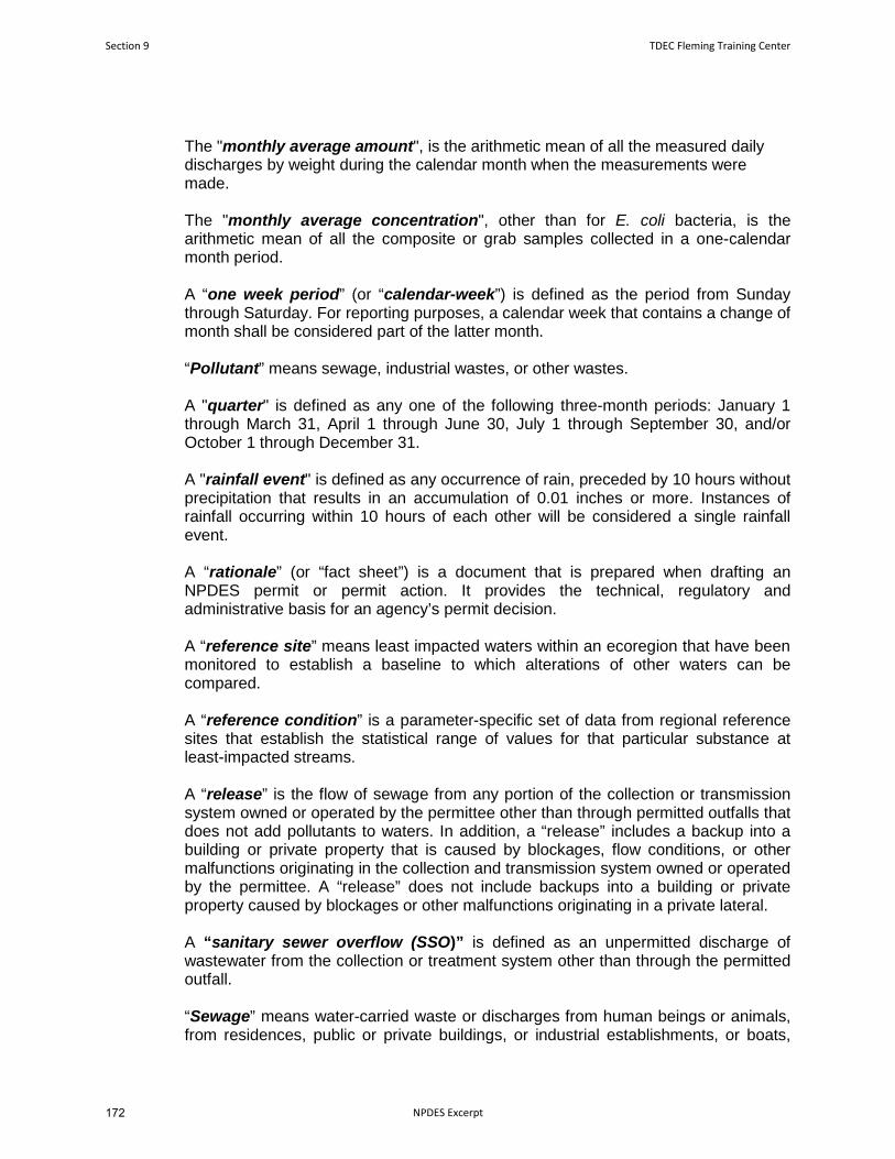
The "monthly average amount", is the arithmetic mean of all the measured daily discharges by weight during the calendar month when the measurements were made. The "monthly average concentration", other than for E. coli bacteria, is the arithmetic mean of all the composite or grab samples collected in a one-calendar month period. A “one week period” (or “calendar-week”) is defined as the period from Sunday through Saturday. For reporting purposes, a calendar week that contains a change of month shall be considered part of the latter month. “Pollutant” means sewage, industrial wastes, or other wastes. A "quarter" is defined as any one of the following three-month periods: January 1 through March 31, April 1 through June 30, July 1 through September 30, and/or October 1 through December 31. A "rainfall event" is defined as any occurrence of rain, preceded by 10 hours without precipitation that results in an accumulation of 0.01 inches or more. Instances of rainfall occurring within 10 hours of each other will be considered a single rainfall event. A “rationale” (or “fact sheet”) is a document that is prepared when drafting an NPDES permit or permit action. It provides the technical, regulatory and administrative basis for an agency’s permit decision. A “reference site” means least impacted waters within an ecoregion that have been monitored to establish a baseline to which alterations of other waters can be compared. A “reference condition” is a parameter-specific set of data from regional reference sites that establish the statistical range of values for that particular substance at least-impacted streams. A “release” is the flow of sewage from any portion of the collection or transmission system owned or operated by the permittee other than through permitted outfalls that does not add pollutants to waters. In addition, a “release” includes a backup into a building or private property that is caused by blockages, flow conditions, or other malfunctions originating in the collection and transmission system owned or operated by the permittee. A “release” does not include backups into a building or private property caused by blockages or other malfunctions originating in a private lateral. A “sanitary sewer overflow (SSO)” is defined as an unpermitted discharge of wastewater from the collection or treatment system other than through the permitted outfall. “Sewage” means water-carried waste or discharges from human beings or animals, from residences, public or private buildings, or industrial establishments, or boats,
Section 9 TDEC Fleming Training Center
NPDES Excerpt172

together with such other wastes and ground, surface, storm, or other water as may be present. “Severe property damage” when used to consider the allowance of a bypass or SSO means substantial physical damage to property, damage to the treatment facilities which causes them to become inoperable, or substantial and permanent loss of natural resources which can reasonably be expected to occur in the absence of a bypass or SSO. Severe property damage does not mean economic loss caused by delays in production. “Sewerage system” means the conduits, sewers, and all devices and appurtenances by means of which sewage and other waste is collected, pumped, treated, or disposed. “Sludge” or “sewage sludge” is solid, semi-solid, or liquid residue generated during the treatment of domestic sewage in a treatment works. Sewage sludge includes, but is not limited to, domestic septage; scum or solids removed in primary, secondary, or advanced wastewater treatment processes; and a material derived from sewage sludge. Sewage sludge does not include ash generated during the firing of sewage sludge in a sewage sludge incinerator or grit and screenings generated during preliminary treatment of domestic sewage in a treatment works. A “subecoregion” is a smaller, more homogenous area that has been delineated within an ecoregion. “Upset” means an exceptional incident in which there is unintentional and temporary noncompliance with technology-based effluent limitations because of factors beyond the reasonable control of the permittee. An upset does not include noncompliance to the extent caused by operational error, improperly designed treatment facilities, inadequate treatment facilities, lack of preventive maintenance, or careless or improper operation. The term, “washout” is applicable to activated sludge plants and is defined as loss of mixed liquor suspended solids (MLSS) of 30.00% or more from the aeration basin(s). “Waters” means any and all water, public or private, on or beneath the surface of the ground, which are contained within, flow through, or border upon Tennessee or any portion thereof except those bodies of water confined to and retained within the limits of private property in single ownership which do not combine or effect a junction with natural surface or underground waters. The "weekly average amount", shall be determined by the summation of all the measured daily discharges by weight divided by the number of days during the calendar week when the measurements were made. The "weekly average concentration", is the arithmetic mean of all the composite samples collected in a one-week period. The permittee must report the highest weekly average in the one-month period.
TDEC Fleming Training Center Section 9
NPDES Excerpt 173

4.2. ACRONYMNS AND ABBREVIATIONS
1Q10 – 1-day minimum, 10-year recurrence interval
30Q5 – 30-day minimum, 5-year recurrence interval
7Q10 – 7-day minimum, 10-year recurrence interval
BAT – best available technology economically achievable
BCT – best conventional pollutant control technology
BDL – below detection level
BOD5 – five day biochemical oxygen demand
BPT – best practicable control technology currently available
CBOD5 – five day carbonaceous biochemical oxygen demand
CEI – compliance evaluation inspection
CFR – code of federal regulations
CFS – cubic feet per second
CFU – colony forming units
CIU – categorical industrial user
CSO – combined sewer overflow
DMR – discharge monitoring report
D.O. – dissolved oxygen
E. coli – Escherichia coli
EFO – environmental field office
LB(lb) - pound
IC25 – inhibition concentration causing 25% reduction in survival, reproduction and growth of the test organisms
IU – industrial user
IWS – industrial waste survey
LC50 – acute test causing 50% lethality
MDL – method detection level
MGD – million gallons per day
MG/L(mg/l) – milligrams per liter
ML – minimum level of quantification
ml – milliliter
MLSS – mixed liquor suspended solids
Section 9 TDEC Fleming Training Center
NPDES Excerpt174

MOR – monthly operating report
NODI – no discharge
NPDES – national pollutant discharge elimination system
PL – permit limit
POTW – publicly owned treatment works
RDL – required detection limit
SAR – semi-annual [pretreatment program] report
SIU – significant industrial user
SSO – sanitary sewer overflow
STP – sewage treatment plant
TCA – Tennessee code annotated
TDEC – Tennessee Department of Environment and Conservation
TIE/TRE – toxicity identification evaluation/toxicity reduction evaluation
TMDL – total maximum daily load
TRC – total residual chlorine
TSS – total suspended solids
WQBEL – water quality based effluent limit
TDEC Fleming Training Center Section 9
NPDES Excerpt 175

176

Section 10
40 CFR 136 Excerpt
177

2/1/22, 4:03 PM eCFR :: 40 CFR 136.3 -- Identification of test procedures.
https://www.ecfr.gov/current/title-40/chapter-I/subchapter-D/part-136/section-136.3 1/91
Displaying title 40, up to date as of 1/27/2022. Title 40 was last amended 1/27/2022.
Enhanced Display enabled
Title 40 - Protection of Environment
Chapter I - Environmental Protection Agency
Subchapter D - Water Programs
Part 136 - Guidelines Establishing Test Procedures for the Analysis of Pollutants
§ 136.3 Identi�ication of test procedures.
Table IA - List of Approved Biological Methods for Wastewater and Sewage Sludge
Bacteria
1. Coliform (fecal),number per 100 mL ornumber per gram dryweight
Most ProbableNumber (MPN), 5tube, 3 dilution, or
p.132,1680,
1681
9221 E-2014
Membrane �lter(MF) , single step
p. 124 9222 D-2015
B-0050-85
2. Coliform (fecal),number per 100 mL
MPN, 5 tube, 3dilution, or
p. 132 9221 E-2014; 9221F-2014
Multipletube/multiple well,or
Colilert-18®.
MF , single step p. 124 9222 D-2015
3. Coliform (total),number per 100 mL
MPN, 5 tube, 3dilution, or
p. 114 9221 B-2014
MF , single stepor two step
p. 108 9222 B-2015
B-0025-85
(a) Parameters or pollutants, for which methods are approved, are listed together with test procedure descriptions and references in TablesIA, IB, IC, ID, IE, IF, IG, and IH of this section. The methods listed in Tables IA, IB, IC, ID, IE, IF, IG, and IH are incorporated by reference, seeparagraph (b) of this section, with the exception of EPA Methods 200.7, 601-613, 624.1, 625.1, 1613, 1624, and 1625. The full texts ofMethods 601-613, 624.1, 625.1, 1613, 1624, and 1625 are printed in appendix A of this part, and the full text of Method 200.7 is printed inappendix C of this part. The full text for determining the method detection limit when using the test procedures is given in appendix B ofthis part. In the event of a con�ict between the reporting requirements of 40 CFR parts 122 and 125 and any reporting requirementsassociated with the methods listed in these tables, the provisions of 40 CFR parts 122 and 125 are controlling and will determine apermittee's reporting requirements. The full texts of the referenced test procedures are incorporated by reference into Tables IA, IB, IC, ID,IE, IF, IG, and IH. The date after the method number indicates the latest editorial change of the method. The discharge parameter valuesfor which reports are required must be determined by one of the standard analytical test procedures incorporated by reference anddescribed in Tables IA, IB, IC, ID, IE, IF, IG, and IH or by any alternate test procedure which has been approved by the Administrator underthe provisions of paragraph (d) of this section and §§ 136.4 and 136.5. Under certain circumstances (paragraph (c) of this section, §136.5(a) through (d) or 40 CFR 401.13,) other additional or alternate test procedures may be used.
3
11
15
11 20
2 5 3 29
4
3
33
13
18 28
2 5 5
3 29
3
2 5
3 30
4
Parameter and units Method1 EPAStandardmethods
AOAC,ASTM,USGS
Other
178
BG44022
Typewritten Text
Note: This is not the complete 40 CFR 136. This packet only contains certain segment and is intended for educational purposes only.
BG44022
Typewritten Text
BG44022
Typewritten Text
BG44022
Typewritten Text
BG44022
Typewritten Text
BG44022
Typewritten Text
BG44022
Typewritten Text

2/1/22, 4:03 PM eCFR :: 40 CFR 136.3 -- Identification of test procedures.
https://www.ecfr.gov/current/title-40/chapter-I/subchapter-D/part-136/section-136.3 2/91
MF , withenrichment
p. 111 9222 B-2015
4. E. coli, number per100 mL
MPN multipletube, or
9221B2014/9221F-2014
multipletube/multiple well,or
9223 B-2016
991.15 Colilert® Colilert-18®
MF , twostep, or
9222 B-2015/9222I-2015
Single step 1603 m-ColiBlue24®.
5. Fecal streptococci,number per 100 mL
MPN, 5 tube, 3dilution, or
p. 139 9230 B-2013
MF , or p. 136 9230 C-2013
B-0055-85
Plate count p. 143
6. Enterococci, numberper 100 mL
MPN, 5 tube, 3dilution, or
p. 139 9230 B-2013
MPN , multipletube/multiple well,or
9230 D-2013
D6503-99
Enterolert®.
MF singlestep or
1600 9230 C-2013
Plate count p. 143
7. Salmonella, numberper gram dry weight
MPN multiple tube 1682
Aquatic Toxicity
8. Toxicity, acute, freshwater organisms, LC ,percent e�uent
Water �ea,Cladoceran,Ceriodaphnia dubiaacute
2002.0
Water �eas,Cladocerans,Daphnia pulex andDaphnia magnaacute
2021.0
2 5
3 30
6 8 16
12 14
33
13 10
13 18
13
17 18
2 5 6 7 8
31
21
19
3
2
3 32
4
3
3
6 8
9
13
23
2 5 6 7 8 24
32
3
11
22
5025
25
Parameter and units Method1 EPAStandardmethods
AOAC,ASTM,USGS
Other
179

2/1/22, 4:03 PM eCFR :: 40 CFR 136.3 -- Identification of test procedures.
https://www.ecfr.gov/current/title-40/chapter-I/subchapter-D/part-136/section-136.3 3/91
Fish, Fatheadminnow,Pimephalespromelas, andBanner�n shiner,Cyprinella leedsi,acute
2000.0
Fish, Rainbow trout,Oncorhynchusmykiss, and brooktrout, Salvelinusfontinalis, acute
2019.0
9. Toxicity, acute,estuarine and marineorganisms of theAtlantic Ocean andGulf of Mexico, LC ,percent e�uent
Mysid, Mysidopsisbahia, acute
2007.0.
Fish, Sheepsheadminnow,Cyprinodonvariegatus, acute
2004.0
Fish, Silverside,Menidia beryllina,Menidia menidia,and Menidiapeninsulae, acute.
2006.0.
10. Toxicity, chronic,fresh water organisms,NOEC or IC , percente�uent
Fish, Fatheadminnow,Pimephalespromelas, larvalsurvival and growth
1000.0
Fish, Fatheadminnow,Pimephalespromelas, embryo-larval survival andteratogenicity
1001.0
Water �ea,Cladoceran,Ceriodaphnia dubia,survival andreproduction
1002.0
Green alga,Selenastrumcapricornutum,growth
1003.0
25
25
50
25
25
25
25
26
26
26
26
Parameter and units Method1 EPAStandardmethods
AOAC,ASTM,USGS
Other
180

2/1/22, 4:03 PM eCFR :: 40 CFR 136.3 -- Identification of test procedures.
https://www.ecfr.gov/current/title-40/chapter-I/subchapter-D/part-136/section-136.3 4/91
11. Toxicity, chronic,estuarine and marineorganisms of theAtlantic Ocean andGulf of Mexico, NOECor IC , percente�uent
Fish, Sheepsheadminnow,Cyprinodonvariegatus, larvalsurvival and growth
1004.0.
Fish, Sheepsheadminnow,Cyprinodonvariegatus, embryo-larval survival andteratogenicity
1005.0
Fish, Inlandsilverside, Menidiaberyllina, larvalsurvival and growth
1006.0
Mysid, Mysidopsisbahia, survival,growth, andfecundity
1007.0
Sea urchin, Arbaciapunctulata,fertilization
1008.0
Table IA notes:
The method must be speci�ed when results are reported.
A 0.45-µm membrane �lter (MF) or other pore size certi�ed by the manufacturer to fully retain organisms to becultivated and to be free of extractables which could interfere with their growth.
Microbiological Methods for Monitoring the Environment, Water and Wastes, EPA/600/8-78/017. 1978. U.S.EPA.
U.S. Geological Survey Techniques of Water-Resource Investigations, Book 5, Laboratory Analysis, Chapter A4,Methods for Collection and Analysis of Aquatic Biological and Microbiological Samples. 1989. USGS.
Because the MF technique usually yields low and variable recovery from chlorinated wastewaters, the MostProbable Number method will be required to resolve any controversies.
Tests must be conducted to provide organism enumeration (density). Select the appropriate con�guration oftubes/�ltrations and dilutions/volumes to account for the quality, character, consistency, and anticipatedorganism density of the water sample.
When the MF method has been used previously to test waters with high turbidity, large numbers of noncoliformbacteria, or samples that may contain organisms stressed by chlorine, a parallel test should be conducted with amultiple-tube technique to demonstrate applicability and comparability of results.
To assess the comparability of results obtained with individual methods, it is suggested that side-by-side testsbe conducted across seasons of the year with the water samples routinely tested in accordance with the mostcurrent Standard Methods for the Examination of Water and Wastewater or EPA alternate test procedure (ATP)guidelines.
25
27
27
27
27
27
1
2
3
4
5
6
7
8
Parameter and units Method1 EPAStandardmethods
AOAC,ASTM,USGS
Other
181

2/1/22, 4:03 PM eCFR :: 40 CFR 136.3 -- Identification of test procedures.
https://www.ecfr.gov/current/title-40/chapter-I/subchapter-D/part-136/section-136.3 5/91
Annual Book of ASTM Standards-Water and Environmental Technology, Section 11.02. 2000, 1999, 1996. ASTMInternational.
O�cial Methods of Analysis of AOAC International. 16th Edition, 4th Revision, 1998. AOAC International.
Recommended for enumeration of target organism in sewage sludge.
The multiple-tube fermentation test is used in 9221B.2-2014. Lactose broth may be used in lieu of lauryltryptose broth (LTB), if at least 25 parallel tests are conducted between this broth and LTB using the watersamples normally tested, and this comparison demonstrates that the false-positive rate and false-negative ratefor total coliform using lactose broth is less than 10 percent. No requirement exists to run the completed phaseon 10 percent of all total coliform-positive tubes on a seasonal basis.
These tests are collectively known as de�ned enzyme substrate tests.
After prior enrichment in a presumptive medium for total coliform using 9221B.2-2014, all presumptive tubesor bottles showing any amount of gas, growth or acidity within 48 h ± 3 h of incubation shall be submitted to9221F-2014. Commercially available EC-MUG media or EC media supplemented in the laboratory with 50 µg/mLof MUG may be used.
Method 1680: Fecal Coliforms in Sewage Sludge (Biosolids) by Multiple-Tube Fermentation Using Lauryl-Tryptose Broth (LTB) and EC Medium, EPA-821-R-14-009. September 2014. U.S. EPA.
Samples shall be enumerated by the multiple-tube or multiple-well procedure. Using multiple-tube procedures,employ an appropriate tube and dilution con�guration of the sample as needed and report the Most ProbableNumber (MPN). Samples tested with Colilert® may be enumerated with the multiple-well procedures, Quanti-Tray® or Quanti-Tray®/2000 and the MPN calculated from the table provided by the manufacturer.
Colilert-18® is an optimized formulation of the Colilert® for the determination of total coliforms and E. colithat provides results within 18 h of incubation at 35 °C rather than the 24 h required for the Colilert® test and isrecommended for marine water samples.
Descriptions of the Colilert®, Colilert-18®, Quanti-Tray®, and Quanti-Tray®/2000 may be obtained from IDEXXLaboratories, Inc.
A description of the mColiBlue24® test is available from Hach Company.
Method 1681: Fecal Coliforms in Sewage Sludge (Biosolids) by Multiple-Tube Fermentation Using A-1Medium, EPA-821-R-06-013. July 2006. U.S. EPA.
Method 1603: Escherichia coli (E. coli) in Water by Membrane Filtration Using Modi�ed Membrane-Thermotolerant Escherichia coli Agar (modi�ed mTEC), EPA-821-R-14-010. September 2014. U.S. EPA.
Method 1682: Salmonella in Sewage Sludge (Biosolids) by Modi�ed Semisolid Rappaport-Vassiliadis (MSRV)Medium, EPA-821-R-14-012. September 2014. U.S. EPA.
A description of the Enterolert® test may be obtained from IDEXX Laboratories Inc.
Method 1600: Enterococci in Water by Membrane Filtration Using Membrane-Enterococcus Indoxyl-β-D-Glucoside Agar (mEI), EPA-821-R-14-011. September 2014. U.S. EPA.
Methods for Measuring the Acute Toxicity of E�uents and Receiving Waters to Freshwater and MarineOrganisms, EPA-821-R-02-012. Fifth Edition, October 2002. U.S. EPA; and U.S. EPA Whole E�uent ToxicityMethods Errata Sheet, EPA 821-R-02-012-ES. December 2016.
Short-term Methods for Estimating the Chronic Toxicity of E�uents and Receiving Waters to FreshwaterOrganisms, EPA-821-R-02-013. Fourth Edition, October 2002. U.S. EPA; and U.S. EPA Whole E�uent ToxicityMethods Errata Sheet, EPA 821-R-02-012-ES. December 2016.
Short-term Methods for Estimating the Chronic Toxicity of E�uents and Receiving Waters to Marine andEstuarine Organisms, EPA-821-R-02-014. Third Edition, October 2002. U.S. EPA; and U.S. EPA Whole E�uentToxicity Methods Errata Sheet, EPA 821-R-02-012-ES. December 2016.
To use Colilert-18® to assay for fecal coliforms, the incubation temperature is 44.5 ± 0.2 °C, and a water bathincubator is used.
9
10
11
12
13
14
15
16
17
18
19
20
21
22
23
24
25
26
27
28
182

2/1/22, 4:03 PM eCFR :: 40 CFR 136.3 -- Identification of test procedures.
https://www.ecfr.gov/current/title-40/chapter-I/subchapter-D/part-136/section-136.3 6/91
On a monthly basis, at least ten blue colonies from positive samples must be veri�ed using Lauryl TryptoseBroth and EC broth, followed by count adjustment based on these results; and representative non-blue coloniesshould be veri�ed using Lauryl Tryptose Broth. Where possible, veri�cations should be done from randomizedsample sources.
On a monthly basis, at least ten sheen colonies from positive samples must be veri�ed using lauryl tryptosebroth and brilliant green lactose bile broth, followed by count adjustment based on these results; andrepresentative non-sheen colonies should be veri�ed using lauryl tryptose broth. Where possible, veri�cationsshould be done from randomized sample sources.
Subject coliform positive samples determined by 9222 B-2015 or other membrane �lter procedure to 9222 I-2015 using NA-MUG media.
Veri�cation of colonies by incubation of BHI agar at 10 ± 0.5 °C for 48 ± 3 h is optional. As per the Errata to the23rd Edition of Standard Methods for the Examination of Water and Wastewater “Growth on a BHI agar plateincubated at 10 ± 0.5 °C for 48 ± 3 h is further veri�cation that the colony belongs to the genus Enterococcus.”
9221 F.2-2014 allows for simultaneous detection of E. coli and thermotolerant fecal coliforms by addinginverted vials to EC-MUG; the inverted vials collect gas produced by thermotolerant fecal coliforms.
Table IB - List of Approved Inorganic Test Procedures
29
30
31
32
33
1. Acidity, asCaCO , mg/L
Electrometric endpointor phenolphthaleinendpoint
2310 B-2011
D1067-16
I-1020-85.
2. Alkalinity, asCaCO , mg/L
Electrometric orColorimetric titration topH 4.5, Manual
2320 B-2011
D1067-16
973.43, I-1030-85.
Automatic 310.2(Rev.1974)
I-2030-85.
3. Aluminum -Total, mg/L
Digestion, followed byany of the following:
AA direct aspiration 3111 D-2011 or3111 E-2011
I-3051-85.
AA furnace 3113 B-2010.
STGFAA 200.9,Rev. 2.2(1994)/
ICP/AES 200.5,Rev 4.2(2003);200.7,Rev. 4.4(1994)
3120 B-2011
D1976-12
I-4471-97.
ICP/MS 200.8,Rev. 5.4(1994)
3125 B-2011
D5673-16
993.14, I-4472-97.
3
2
3
3
2
1
2
4
4
36 2
36
68
50
3
81
Parameter Methodology58 EPA52 Standardmethods84 ASTM USGS/AOAC/Other
183

2/1/22, 4:03 PM eCFR :: 40 CFR 136.3 -- Identification of test procedures.
https://www.ecfr.gov/current/title-40/chapter-I/subchapter-D/part-136/section-136.3 7/91
Direct Current Plasma(DCP)
D4190-15
See footnote.
Colorimetric(Eriochrome cyanine R)
3500-Al B-2011.
4. Ammonia(as N), mg/L
Manual distillation orgas diffusion (pH > 11),followed by any of thefollowing:
350.1,Rev. 2.0(1993)
4500-NHB-2011
973.49.
Nesslerization D1426-15 (A)
973.49, I-3520-85.
Titration 4500-NHC-2011.
Electrode 4500-NHD-2011 orE-2011
D1426-15 (B).
Manual phenate,salicylate, or othersubstituted phenols inBerthelot reaction-based methods
4500-NHF-2011
See footnote.
Automated phenate,salicylate, or othersubstituted phenols inBerthelot reaction-based methods
350.1,Rev. 2.0(1993)
4500-NHG-20114500-NHH-2011
I-4523-85, I-2522-90.
Automated electrode See footnote.
Ion Chromatography D6919-17.
Automated gasdiffusion, followed byconductivity cellanalysis
TimberlineAmmonia-001.
Automated gasdiffusion followed by�uorescence detectoranalysis
FIAlab100.
5. Antimony -Total, mg/L
Digestion, followed byany of the following:
AA direct aspiration 3111 B-2011.
AA furnace 3113 B-2010.
36
34
63
3
3
2
3
3
360
303
3
2
80
7
74
82
4
4
36
Parameter Methodology58 EPA52 Standardmethods84 ASTM USGS/AOAC/Other
184

2/1/22, 4:03 PM eCFR :: 40 CFR 136.3 -- Identification of test procedures.
https://www.ecfr.gov/current/title-40/chapter-I/subchapter-D/part-136/section-136.3 8/91
STGFAA 200.9,Rev. 2.2(1994).
ICP/AES 200.5,Rev 4.2(2003);200.7,Rev. 4.4(1994)
3120 B-2011
D1976-12.
ICP/MS 200.8,Rev. 5.4(1994)
3125 B-2011
D5673-16
993.14, I-4472-97.
6. Arsenic-Total, mg/L
Digestion, followed byany of the following:
206.5(Issued1978) .
AA gaseous hydride 3114 B-2011 or3114 C-2011
D2972-15 (B)
I-3062-85.
AA furnace 3113 B-2010
D2972-15 (C)
I-4063-98.
STGFAA 200.9,Rev. 2.2(1994).
ICP/AES 200.5,Rev 4.2(2003);200.7,Rev. 4.4(1994)
3120 B-2011
D1976-12.
ICP/MS 200.8,Rev. 5.4(1994)
3125 B-2011
D5673-16
993.14, I-4020-05.
Colorimetric (SDDC) 3500-As B-2011
D2972-15 (A)
I-3060-85.
7. Barium-Total, mg/L
Digestion, followed byany of the following:
AA direct aspiration 3111 D-2011
I-3084-85.
AA furnace 3113 B-2010
D4382-18.
36
68
3
81
4
4
1
2
49
36
68
3
70
2
4
4
36 2
Parameter Methodology58 EPA52 Standardmethods84 ASTM USGS/AOAC/Other
STGFAA 200.9,Rev. 2.2(1994).
ICP/AES 200.5,Rev 4.2(2003);200.7,Rev. 4.4(1994)
3120 B-2011
D1976-12.
ICP/MS 200.8,Rev. 5.4(1994)
3125 B-2011
D5673-16
993.14, I-4472-97.
6. Arsenic-Total, mg/L
Digestion, followed byany of the following:
206.5(Issued1978) .
AA gaseous hydride 3114 B-2011 or3114 C-2011
D2972-15 (B)
I-3062-85.
AA furnace 3113 B-2010
D2972-15 (C)
I-4063-98.
STGFAA 200.9,Rev. 2.2(1994).
ICP/AES 200.5,Rev 4.2(2003);200.7,Rev. 4.4(1994)
3120 B-2011
D1976-12.
ICP/MS 200.8,Rev. 5.4(1994)
3125 B-2011
D5673-16
993.14, I-4020-05.
Colorimetric (SDDC) 3500-As B-2011
D2972-15 (A)
I-3060-85.
7. Barium-Total, mg/L
Digestion, followed byany of the following:
AA direct aspiration 3111 D-2011
I-3084-85.
AA furnace 3113 B-2010
D4382-18.
36
68
3
81
4
4
1
2
49
36
68
3
70
2
4
4
36 2
Parameter Methodology58 EPA52 Standardmethods84 ASTM USGS/AOAC/Other
185

2/1/22, 4:03 PM eCFR :: 40 CFR 136.3 -- Identification of test procedures.
https://www.ecfr.gov/current/title-40/chapter-I/subchapter-D/part-136/section-136.3 9/91
ICP/AES 200.5,Rev 4.2(2003);200.7,Rev. 4.4(1994)
3120 B-2011
I-4471-97.
ICP/MS 200.8,Rev. 5.4(1994)
3125 B-2011
D5673-16
993.14, I-4472-97.
DCP See footnote.
8. Beryllium -Total, mg/L
Digestion, followed byany of the following:
AA direct aspiration 3111 D-2011 or3111 E-2011
D3645-15 (A)
I-3095-85.
AA furnace 3113 B-2010
D3645-15 (B).
STGFAA 200.9,Rev. 2.2(1994).
ICP/AES 200.5,Rev 4.2(2003);200.7,Rev. 4.4(1994)
3120 B-2011
D1976-12
I-4471-97.
ICP/MS 200.8,Rev. 5.4(1994)
3125 B-2011
D5673-16
993.14, I-4472-97.
DCP D4190-15
See footnote.
Colorimetric(aluminon)
Seefootnote. .
9. Biochemicaloxygendemand(BOD ), mg/L
Dissolved OxygenDepletion
5210 B-2016
973.44, p. 17, I-1578-78, Seefootnote.
10. Boron -Total, mg/L
Colorimetric(curcumin)
4500-B B-2011
I-3112-85.
36
68
50
3
81
36 34
4
4
2
68
50
3
81
34
61
5
85
3 9
8
10, 63
37
2
Parameter Methodology58 EPA52 Standardmethods84 ASTM USGS/AOAC/Other
ICP/AES 200.5,Rev 4.2(2003);200.7,Rev. 4.4(1994)
3120 B-2011
I-4471-97.
ICP/MS 200.8,Rev. 5.4(1994)
3125 B-2011
D5673-16
993.14, I-4472-97.
DCP See footnote.
8. Beryllium -Total, mg/L
Digestion, followed byany of the following:
AA direct aspiration 3111 D-2011 or3111 E-2011
D3645-15 (A)
I-3095-85.
AA furnace 3113 B-2010
D3645-15 (B).
STGFAA 200.9,Rev. 2.2(1994).
ICP/AES 200.5,Rev 4.2(2003);200.7,Rev. 4.4(1994)
3120 B-2011
D1976-12
I-4471-97.
ICP/MS 200.8,Rev. 5.4(1994)
3125 B-2011
D5673-16
993.14, I-4472-97.
DCP D4190-15
See footnote.
Colorimetric(aluminon)
Seefootnote. .
9. Biochemicaloxygendemand(BOD ), mg/L
Dissolved OxygenDepletion
5210 B-2016
973.44, p. 17, I-1578-78, Seefootnote.
10. Boron -Total, mg/L
Colorimetric(curcumin)
4500-B B-2011
I-3112-85.
36
68
50
3
81
36 34
4
4
2
68
50
3
81
34
61
5
85
3 9
8
10, 63
37
2
Parameter Methodology58 EPA52 Standardmethods84 ASTM USGS/AOAC/Other
186

2/1/22, 4:03 PM eCFR :: 40 CFR 136.3 -- Identification of test procedures.
https://www.ecfr.gov/current/title-40/chapter-I/subchapter-D/part-136/section-136.3 10/91
ICP/AES 200.5,Rev 4.2(2003);200.7,Rev. 4.4(1994)
3120 B-2011
D1976-12
I-4471-97.
ICP/MS 200.8,Rev. 5.4(1994)
3125 B-2011
D5673-16
993.14.
DCP D4190-15
S7ee footnote.
11. Bromide,mg/L
Electrode D1246-16
I-1125-85.
Ion Chromatography 300.0,Rev 2.1(1993)and300.1,Rev 1.0(1997)
4110 B-2011, C-2011, D-2011
D4327-17
993.30, I-2057-85.
CIE/UV 4140 B-2011
D6508-15
D6508, Rev. 2.
12. Cadmium -Total, mg/L
Digestion, followed byany of the following:
AA direct aspiration 3111 B-2011 or3111 C-2011
D3557-17 (Aor B)
974.27, p. 37, I-3135-85 or I-3136-85.
AA furnace 3113 B-2010
D3557-17 (D)
I-4138-89.
STGFAA 200.9,Rev. 2.2(1994).
ICP/AES 200.5,Rev 4.2(2003);200.7,Rev. 4.4(1994)
3120 B-2011
D1976-12
I-1472-85 or I-4471-97.
ICP/MS 200.8,Rev. 5.4(1994)
3125 B-2011
D5673-16
993.14, I-4472-97.
DCP D4190-15
See footnote.
68
50
3
34
2
3
79
54
4
4
36 3 9
2
2
51
36
68
2
50
3
81
36 34
Parameter Methodology58 EPA52 Standardmethods84 ASTM USGS/AOAC/Other
ICP/AES 200.5,Rev 4.2(2003);200.7,Rev. 4.4(1994)
3120 B-2011
D1976-12
I-4471-97.
ICP/MS 200.8,Rev. 5.4(1994)
3125 B-2011
D5673-16
993.14.
DCP D4190-15
S7ee footnote.
11. Bromide,mg/L
Electrode D1246-16
I-1125-85.
Ion Chromatography 300.0,Rev 2.1(1993)and300.1,Rev 1.0(1997)
4110 B-2011, C-2011, D-2011
D4327-17
993.30, I-2057-85.
CIE/UV 4140 B-2011
D6508-15
D6508, Rev. 2.
12. Cadmium -Total, mg/L
Digestion, followed byany of the following:
AA direct aspiration 3111 B-2011 or3111 C-2011
D3557-17 (Aor B)
974.27, p. 37, I-3135-85 or I-3136-85.
AA furnace 3113 B-2010
D3557-17 (D)
I-4138-89.
STGFAA 200.9,Rev. 2.2(1994).
ICP/AES 200.5,Rev 4.2(2003);200.7,Rev. 4.4(1994)
3120 B-2011
D1976-12
I-1472-85 or I-4471-97.
ICP/MS 200.8,Rev. 5.4(1994)
3125 B-2011
D5673-16
993.14, I-4472-97.
DCP D4190-15
See footnote.
68
50
3
34
2
3
79
54
4
4
36 3 9
2
2
51
36
68
2
50
3
81
36 34
Parameter Methodology58 EPA52 Standardmethods84 ASTM USGS/AOAC/Other
187

2/1/22, 4:03 PM eCFR :: 40 CFR 136.3 -- Identification of test procedures.
https://www.ecfr.gov/current/title-40/chapter-I/subchapter-D/part-136/section-136.3 11/91
Voltammetry D3557-17 (C).
Colorimetric(Dithizone)
3500-Cd-D-1990.
13. Calcium -Total, mg/L
Digestion, followed byany of the following:
AA direct aspiration 3111 B-2011
D511-14 (B)
I-3152-85.
ICP/AES 200.5,Rev 4.2(2003);200.7,Rev. 4.4(1994)
3120 B-2011
I-4471-97.
ICP/MS 200.8,Rev. 5.4(1994)
3125 B-2011
D5673-16
993.14.
DCP See footnote.
Titrimetric (EDTA) 3500-Ca B-2011
D511-14 (A).
Ion Chromatography D6919-17.
14.Carbonaceousbiochemicaloxygendemand(CBOD ),mg/L
Dissolved OxygenDepletion withnitri�cation inhibitor
5210 B-2016
See footnote.
15. Chemicaloxygendemand (COD),mg/L
Titrimetric 410.3(Rev.1978)
5220 B-2011 or C-2011
D1252-06(12)(A)
973.46, p. 17, I-3560-85.
Spectrophotometric,manual or automatic
410.4,Rev. 2.0(1993)
5220 D-2011
D1252-06(12)(B)
See footnotes., I-3561-85.
16. Chloride,mg/L
Titrimetric: (silvernitrate)
4500-Cl B-2011
D512-12 (B)
I-1183-85.
(Mercuric nitrate) 4500-Cl C-2011
D512-12 (A)
973.51, I-1184-85.
Colorimetric: manual I-1187-85.
Automated(ferricyanide)
4500-Cl E-2011
I-2187-85.
11
4
4
2
68
50
3
34
512
85
35 63
1
3 9
2
13 14
83 2
- 2
- 3
2
2
- 2
Parameter Methodology58 EPA52 Standardmethods84 ASTM USGS/AOAC/Other
188

2/1/22, 4:03 PM eCFR :: 40 CFR 136.3 -- Identification of test procedures.
https://www.ecfr.gov/current/title-40/chapter-I/subchapter-D/part-136/section-136.3 12/91
PotentiometricTitration
4500-Cl D-2011.
Ion Selective Electrode D512-12 (C).
Ion Chromatography 300.0,Rev 2.1(1993)and300.1,Rev 1.0(1997)
4110 B-2011 or4110 C-2011
D4327-17
993.30, I-2057-90.
CIE/UV 4140 B-2011
D6508-15
D6508, Rev. 2.
17. Chlorine-Total residual,mg/L
Amperometric direct 4500-Cl D-2011
D1253-14.
Amperometric direct(low level)
4500-Cl E-2011.
Iodometric direct 4500-Cl B-2011.
Back titration etherend-point
4500-Cl C-2011.
DPD-FAS 4500-Cl F-2011.
Spectrophotometric,DPD
4500-Cl G-2011.
Electrode See footnote.
17A. Chlorine-Free Available,mg/L
Amperometric direct 4500-Cl D-2011
D1253-14.
Amperometric direct(low level)
4500-Cl E-2011.
DPD-FAS 4500-Cl F-2011.
Spectrophotometric,DPD
4500-Cl G-2011.
18. ChromiumVI dissolved,mg/L
0.45-micron �ltrationfollowed by any of thefollowing:
AA chelation-extraction 3111 C-2011
I-1232-85.
-
3
51
54
15
16
2
Parameter Methodology58 EPA52 Standardmethods84 ASTM USGS/AOAC/Other
189

2/1/22, 4:03 PM eCFR :: 40 CFR 136.3 -- Identification of test procedures.
https://www.ecfr.gov/current/title-40/chapter-I/subchapter-D/part-136/section-136.3 13/91
Ion Chromatography 218.6,Rev. 3.3(1994)
3500-Cr C-2011
D5257-17
993.23.
Colorimetric (diphenyl-carbazide)
3500-Cr B-2011
D1687-17 (A)
I-1230-85.
19. Chromium -Total, mg/L
Digestion, followed byany of the following:
AA direct aspiration 3111 B-2011
D1687-17 (B)
974.27, I-3236-85.
AA chelation-extraction 3111 C-2011.
AA furnace 3113 B-2010
D1687-17 (C)
I-3233-93.
STGFAA 200.9,Rev. 2.2(1994).
ICP/AES 200.5,Rev 4.2(2003),200.7,Rev. 4.4(1994)
3120 B-2011
D1976-12.
ICP/MS 200.8,Rev. 5.4(1994)
3125 B-2011
D5673-16
993.14, I-4020-05 I-4472-97.
DCP D4190-15
See footnote.
Colorimetric (diphenyl-carbazide)
3500-Cr B-2011.
20. Cobalt -Total, mg/L
Digestion, followed byany of the following:
AA direct aspiration 3111 B-2011 or3111 C-2011
D3558-15 (Aor B)
p. 37, I-3239-85.
AA furnace 3113 B-2010
D3558-15 (C)
I-4243-89.
STGFAA 200.9,Rev. 2.2(1994).
ICP/AES 200.7,Rev. 4.4(1994)
3120 B-2011
D1976-12
I-4471-97.
3
2
4
4
36 3
2
46
36
68
3
70 81
36 34
4
4
9 2
51
50
Parameter Methodology58 EPA52 Standardmethods84 ASTM USGS/AOAC/Other
190

2/1/22, 4:03 PM eCFR :: 40 CFR 136.3 -- Identification of test procedures.
https://www.ecfr.gov/current/title-40/chapter-I/subchapter-D/part-136/section-136.3 14/91
ICP/MS 200.8,Rev. 5.4(1994)
3125 B-2011
D5673-16
993.14, I-4020-05 I-4472-97.
DCP D4190-15
See footnote.
21. Color,platinumcobalt units ordominantwavelength,hue, luminancepurity
Colorimetric (ADMI) 2120 F-2011 .
Platinum cobalt visualcomparison
2120 B-2011
I-1250-85.
Spectrophotometric See footnote
22. Copper -Total, mg/L
Digestion, followed byany of the following:
AA direct aspiration 3111 B-2011 or3111 C-2011
D1688-17 (Aor B)
974.27, p. 37, I-3270-85 or I-3271-85.
AA furnace 3113 B-2010
D1688-17 (C)
I-4274-89.
STGFAA 200.9,Rev. 2.2(1994).
ICP/AES 200.5,Rev 4.2(2003);200.7,Rev. 4.4(1994)
3120 B-2011
D1976-12
I-4471-97.
ICP/MS 200.8,Rev. 5.4(1994)
3125 B-2011
D5673-16
993.14, I-4020-05, , I-4472-97.
DCP D4190-15
See footnote.
Colorimetric(Neocuproine)
3500-Cu B-2011.
Colorimetric(Bathocuproine)
3500-Cu C-2011
See footnote.
23. Cyanide -Total, mg/L
Automated UVdigestion/distillationand Colorimetry
Kelada-01.
3
70 81
34
78
2
18
4
4
36 3 9
2
2
51
36
68
50
3
70 81
36 34
19
55
Parameter Methodology58 EPA52 Standardmethods84 ASTM USGS/AOAC/Other
ICP/MS 200.8,Rev. 5.4(1994)
3125 B-2011
D5673-16
993.14, I-4020-05 I-4472-97.
DCP D4190-15
See footnote.
21. Color,platinumcobalt units ordominantwavelength,hue, luminancepurity
Colorimetric (ADMI) 2120 F-2011 .
Platinum cobalt visualcomparison
2120 B-2011
I-1250-85.
Spectrophotometric See footnote
22. Copper -Total, mg/L
Digestion, followed byany of the following:
AA direct aspiration 3111 B-2011 or3111 C-2011
D1688-17 (Aor B)
974.27, p. 37, I-3270-85 or I-3271-85.
AA furnace 3113 B-2010
D1688-17 (C)
I-4274-89.
STGFAA 200.9,Rev. 2.2(1994).
ICP/AES 200.5,Rev 4.2(2003);200.7,Rev. 4.4(1994)
3120 B-2011
D1976-12
I-4471-97.
ICP/MS 200.8,Rev. 5.4(1994)
3125 B-2011
D5673-16
993.14, I-4020-05, , I-4472-97.
DCP D4190-15
See footnote.
Colorimetric(Neocuproine)
3500-Cu B-2011.
Colorimetric(Bathocuproine)
3500-Cu C-2011
See footnote.
23. Cyanide -Total, mg/L
Automated UVdigestion/distillationand Colorimetry
Kelada-01.
3
70 81
34
78
2
18
4
4
36 3 9
2
2
51
36
68
50
3
70 81
36 34
19
55
Parameter Methodology58 EPA52 Standardmethods84 ASTM USGS/AOAC/Other
191

2/1/22, 4:03 PM eCFR :: 40 CFR 136.3 -- Identification of test procedures.
https://www.ecfr.gov/current/title-40/chapter-I/subchapter-D/part-136/section-136.3 15/91
Segmented FlowInjection, In-LineUltraviolet Digestion,followed by gasdiffusion amperometry
D7511-12(17).
Manual distillation withMgCl , followed by anyof the following:
335.4,Rev. 1.0(1993)
4500-CNB-2016 andC-2016
D2036-09(15)(A),D7284-13(17)
10-204-00-1-X.
Flow Injection, gasdiffusion amperometry
D2036-09(15)(A)D7284-13(17).
Titrimetric 4500-CND-2016
D2036-09(15)(A)
p. 22.
Spectrophotometric,manual
4500-CNE-2016
D2036-09(15)(A)
I-3300-85.
Semi-Automated 335.4,Rev. 1.0(1993)
4500-CNN-2016
10-204-00-1-X, I-4302-85.
Ion Chromatography D2036-09(15)(A).
Ion Selective Electrode 4500-CN F-2016
D2036-09(15)(A).
24. Cyanide-Available, mg/L
Cyanide Amenable toChlorination (CATC);Manual distillation withMgCl , followed byTitrimetric orSpectrophotometric
4500-CNG-2016
D2036-09(15)(B).
Flow injection andligand exchange,followed by gasdiffusionamperometry
D6888-16
OIA-1677-09.
Automated Distillationand Colorimetry (no UVdigestion)
Kelada-01.
257
- 56
- 9
- 2
20
57
- 56
2
-
2
-
59
44
55
Parameter Methodology58 EPA52 Standardmethods84 ASTM USGS/AOAC/Other
192

2/1/22, 4:03 PM eCFR :: 40 CFR 136.3 -- Identification of test procedures.
https://www.ecfr.gov/current/title-40/chapter-I/subchapter-D/part-136/section-136.3 16/91
24.A Cyanide-Free, mg/L
Flow Injection,followed by gasdiffusion amperometry
D7237-15 (A)
OIA-1677-09.
Manual micro-diffusionand colorimetry
D4282-15.
25. Fluoride -Total, mg/L
Manual distillation,followed by any of thefollowing:
4500-F B-2011
D1179-16 (A).
Electrode, manual 4500-F C-2011
D1179-16 (B).
Electrode, automated I-4327-85.
Colorimetric, (SPADNS) 4500-F D-2011.
Automatedcomplexone
4500-F E-2011.
Ion Chromatography 300.0,Rev 2.1(1993)and300.1,Rev 1.0(1997)
4110 B-2011 or C-2011
D4327-17
993.30.
CIE/UV 4140 B-2011
D6508-15
D6508, Rev. 2.
26. Gold -Total, mg/L
Digestion, followed byany of the following:
AA direct aspiration 3111 B-2011.
AA furnace 231.2(Issued1978)
3113 B-2010.
ICP/MS 200.8,Rev. 5.4(1994)
3125 B-2011
D5673-16
993.14.
DCP See footnote.
27. Hardness -Total, asCaCO , mg/L
Automatedcolorimetric
130.1(Issued1971) .
Titrimetric (EDTA) 2340 C-2011
D1126-17
973.52B , I-1338-85.
44
6 -
-
2
-
-
3
54
4
4
1
3
34
31
3
2
Parameter Methodology58 EPA52 Standardmethods84 ASTM USGS/AOAC/Other
193

2/1/22, 4:03 PM eCFR :: 40 CFR 136.3 -- Identification of test procedures.
https://www.ecfr.gov/current/title-40/chapter-I/subchapter-D/part-136/section-136.3 17/91
Ca plus Mg as theircarbonates, by anyapproved method forCa and Mg (SeeParameters 13 and 33),provided that the sumof the lowest point ofquantitation for Ca andMg is below theNPDES permitrequirement forHardness
2340 B-2011.
28. Hydrogenion (pH), pHunits
Electrometricmeasurement
4500-H B-2011
D1293-99 (Aor B)
973.41, I-1586-85.
Automated electrode 150.2(Dec.1982)
See footnote, I-2587-85.
29. Iridium -Total, mg/L
Digestion, followed byany of the following:
AA direct aspiration 3111 B-2011.
AA furnace 235.2(Issued1978) .
ICP/MS 3125 B-2011.
30. Iron -Total, mg/L
Digestion, followed byany of the following:
AA direct aspiration 3111 B-2011 or3111 C-2011
D1068-15 (A)
974.27, I-3381-85.
AA furnace 3113 B-2010
D1068-15 (B).
STGFAA 200.9,Rev. 2.2(1994)
ICP/AES 200.5,Rev. 4.2(2003);200.7,Rev. 4.4(1994)
3120 B-2011
D1976-12
I-4471-97.
+ 3
2
1
21
2
4
4
1
4
4
36 3
2
36
68
50
Parameter Methodology58 EPA52 Standardmethods84 ASTM USGS/AOAC/Other
194

2/1/22, 4:03 PM eCFR :: 40 CFR 136.3 -- Identification of test procedures.
https://www.ecfr.gov/current/title-40/chapter-I/subchapter-D/part-136/section-136.3 18/91
ICP/MS 200.8,Rev. 5.4(1994)
3125 B-2011
D5673-16
993.14.
DCP D4190-15
See footnote.
Colorimetric(Phenanthroline)
3500-Fe B-2011
D1068-15 (C)
See footnote.
31. KjeldahlNitrogen -Total, (as N),mg/L
Manual digestionand distillation or gasdiffusion, followed byany of the following:
4500-NB-2011 orC-2011 and4500-NHB-2011
D3590-17 (A)
I-4515-91.
Titration 4500-NHC-2011
973.48.
Nesslerization D1426-15 (A).
Electrode 4500-NHD-2011 orE-2011
D1426-15 (B).
Semi-automatedphenate
350.1,Rev. 2.0(1993)
4500-NHG-20114500-NHH-2011
Manual phenate,salicylate, or othersubstituted phenols inBerthelot reactionbased methods
4500-NHF-2011
See footnote.
Automated gasdiffusion, followed byconductivity cellanalysis
TimberlineAmmonia-001.
Automated gasdiffusion followed by�uorescence detectoranalysis
FIAlab 100.
Automated Methods for TKN that do not require manual distillation
Automated phenate,salicylate, or othersubstituted phenols inBerthelot reactionbased methodscolorimetric (autodigestion anddistillation)
351.1(Rev.1978)
I-4551-78.
3
36 34
22
5
20org
3
45
33
3
3
3
360
74
82
1
8
Parameter Methodology58 EPA52 Standardmethods84 ASTM USGS/AOAC/Other
195

2/1/22, 4:03 PM eCFR :: 40 CFR 136.3 -- Identification of test procedures.
https://www.ecfr.gov/current/title-40/chapter-I/subchapter-D/part-136/section-136.3 19/91
Semi-automated blockdigestor colorimetric(distillation notrequired)
351.2,Rev. 2.0(1993)
4500-ND-2011
D3590-17 (B)
I-4515-91
Block digester,followed by Autodistillation andTitration
See footnote.
Block digester,followed by Autodistillation andNesslerization
See footnote.
Block Digester,followed by Flowinjection gas diffusion(distillation notrequired)
See footnote.
Digestion withperoxdisulfate,followed bySpectrophotometric(2,6-dimethyl phenol)
Hach 10242.
Digestion withpersulfate, followed byColorimetric
NCASI TNTPW10900.
32. Lead -Total, mg/L
Digestion, followed byany of the following:
AA direct aspiration 3111 B-2011 or3111 C-2011
D3559-15 (Aor B)
974.27, I-3399-85.
AA furnace 3113 B-2010
D3559-15 (D)
I-4403-89.
STGFAA 200.9,Rev. 2.2(1994).
ICP/AES 200.5,Rev. 4.2(2003);200.7,Rev. 4.4(1994)
3120 B-2011
D1976-12
I-4471-97.
ICP/MS 200.8,Rev. 5.4(1994)
3125 B-2011
D5673-16
993.14, I-4472-97.
org45
39
40
41
76
77
4
4
36 3
2
51
36
68
50
3
81
Parameter Methodology58 EPA52 Standardmethods84 ASTM USGS/AOAC/Other
196

2/1/22, 4:03 PM eCFR :: 40 CFR 136.3 -- Identification of test procedures.
https://www.ecfr.gov/current/title-40/chapter-I/subchapter-D/part-136/section-136.3 20/91
DCP D4190-15
See footnote.
Voltammetry D3559-15 (C).
Colorimetric(Dithizone)
3500-Pb B-2011.
33.Magnesium -Total, mg/L
Digestion, followed byany of the following:
AA direct aspiration 3111 B-2011
D511-14 (B)
974.27, I-3447-85.
ICP/AES 200.5,Rev. 4.2(2003) ;200.7,Rev. 4.4(1994)
3120 B-2011
D1976-12
I-4471-97.
ICP/MS 200.8,Rev. 5.4(1994)
3125 B-2011
D5673-16
993.14.
DCP See footnote.
Ion Chromatography D6919-17.
34. Manganese- Total, mg/L
Digestion, followed byany of the following:
AA direct aspiration 3111 B-2011
D858-17 (Aor B)
974.27, I-3454-85.
AA furnace 3113 B-2010
D858-17 (C).
STGFAA 200.9,Rev. 2.2(1994)
ICP/AES 200.5,Rev. 4.2(2003);200.7,Rev. 4.4(1994)
3120 B-2011
D1976-12
I-4471-97.
ICP/MS 200.8,Rev. 5.4(1994)
3125 B-2011
D5673-16
993.14, I-4472-97.
36 34
11
4
4
3
2
68
50
3
34
4
4
36 3
2
36
68
50
3
81
Parameter Methodology58 EPA52 Standardmethods84 ASTM USGS/AOAC/Other
197

2/1/22, 4:03 PM eCFR :: 40 CFR 136.3 -- Identification of test procedures.
https://www.ecfr.gov/current/title-40/chapter-I/subchapter-D/part-136/section-136.3 21/91
DCP D4190-15
See footnote.
Colorimetric(Persulfate)
3500-Mn B-2011
920.203.
Colorimetric(Periodate)
See footnote.
35. Mercury -Total, mg/L
Cold vapor, Manual 245.1,Rev. 3.0(1994)
3112 B-2011
D3223-17
977.22, I-3462-85.
Cold vapor, Automated 245.2(Issued1974) .
Cold vapor atomic�uorescencespectrometry (CVAFS)
245.7Rev. 2.0(2005)
I-4464-01.
Purge and Trap CVAFS 1631E .
36.Molybdenum -Total, mg/L
Digestion, followed byany of the following:
AA direct aspiration 3111 D-2011
I-3490-85.
AA furnace 3113 -2010 I-3492-96.
ICP/AES 200.7,Rev. 4.4(1994)
3120 B-2011
D1976-12
I-4471-97.
ICP/MS 200.8,Rev. 5.4(1994)
3125 B-2011
D5673-16
993.14, I-4472-97.
DCP See footnote.
37. Nickel -Total, mg/L
Digestion, followed byany of the following:
AA direct aspiration 3111 B-2011 or3111 C-2011
D1886-14 (Aor B)
I-3499-85
AA furnace 3113 B-2010
D1886-14 (C)
I-4503-89.
STGFAA 200.9,Rev. 2.2(1994)
36 34
3
23
3
2
1
17
71
43
4
4
2
47
50
3
81
34
4
4
36 2
51
Parameter Methodology58 EPA52 Standardmethods84 ASTM USGS/AOAC/Other
198

2/1/22, 4:03 PM eCFR :: 40 CFR 136.3 -- Identification of test procedures.
https://www.ecfr.gov/current/title-40/chapter-I/subchapter-D/part-136/section-136.3 22/91
ICP/AES 200.5,Rev. 4.2(2003);200.7,Rev. 4.4(1994)
3120 B-2011
D1976-12
I-4471-97.
ICP/MS 200.8,Rev. 5.4(1994)
3125 B-2011
D5673-16
993.14, I-4020-05 I-4472-97.
DCP D4190-15
See footnote.
38. Nitrate (asN), mg/L
Ion Chromatography 300.0,Rev. 2.1(1993)and300.1,Rev. 1.0(1997)
4110 B-2011 or C-2011
D4327-17
993.30.
CIE/UV 4140 B-2011
D6508-15 D6508,Rev.2.
Ion Selective Electrode 4500-NOD-2016.
Colorimetric (Brucinesulfate)
352.1(Issued1971)
973.50, 419D , p.28.
Spectrophotometric(2,6-dimethylphenol)
Hach 10206
Nitrate-nitrite N minusNitrite N (Seeparameters 39 and 40)
39. Nitrate-nitrite (as N),mg/L
Cadmium reduction,Manual
4500-NOE-2016
D3867-16 (B).
Cadmium reduction,Automated
353.2,Rev. 2.0(1993)
4500-NOF-20164500-NOI-2016
D3867-16 (A)
I-2545-90.
Automated hydrazine 4500-NOH-2016.
Reduction/Colorimetric See footnote.
36
68
50
3
70 81
36 34
3
54
3-
1
3 17
9
75
3-
3-
3-
51
3-
62
Parameter Methodology58 EPA52 Standardmethods84 ASTM USGS/AOAC/Other
199

2/1/22, 4:03 PM eCFR :: 40 CFR 136.3 -- Identification of test procedures.
https://www.ecfr.gov/current/title-40/chapter-I/subchapter-D/part-136/section-136.3 23/91
Ion Chromatography 300.0,Rev. 2.1(1993)and300.1,Rev. 1.0(1997)
4110 B-2011 or C-2011
D4327-17
993.30.
CIE/UV 4140 B-2011
D6508-15
D6508, Rev. 2.
Enzymatic reduction,followed by automatedcolorimetricdetermination
D7781-14
I-2547-11. I-2548-11. N07-0003.
Enzymatic reduction,followed by manualcolorimetricdetermination
4500-NOJ-2018.
Spectrophotometric(2,6-dimethylphenol)
Hach 10206.
40. Nitrite (asN), mg/L
Spectrophotometric:Manual
4500-NO -B-2011
See footnote.
Automated(Diazotization)
I-4540-85, Seefootnote. I-2540-90.
Automated (*bypasscadmium reduction)
353.2,Rev. 2.0(1993)
4500-NOF-20164500-NOI-2016
D3867-16 (A)
I-4545-85.
Manual (*bypasscadmium or enzymaticreduction)
4500-NOE-2016,4500-NOJ-2018
D3867-16 (B).
Ion Chromatography 300.0,Rev. 2.1(1993)and300.1,Rev. 1.0(1997)
4110 B-2011 or C-2011
D4327-17
993.30.
CIE/UV 4140 B-2011
D6508-15
D6508, Rev. 2.
Automated (*bypassEnzymatic reduction)
D7781-14
I-2547-11 I-2548-11 N07-0003.
3
54
72
72
73
3-
75
225
2
62
80
3-
3-
2
3-
3-
3
54
72
72 73
Parameter Methodology58 EPA52 Standardmethods84 ASTM USGS/AOAC/Other
Ion Chromatography 300.0,Rev. 2.1(1993)and300.1,Rev. 1.0(1997)
4110 B-2011 or C-2011
D4327-17
993.30.
CIE/UV 4140 B-2011
D6508-15
D6508, Rev. 2.
Enzymatic reduction,followed by automatedcolorimetricdetermination
D7781-14
I-2547-11. I-2548-11. N07-0003.
Enzymatic reduction,followed by manualcolorimetricdetermination
4500-NOJ-2018.
Spectrophotometric(2,6-dimethylphenol)
Hach 10206.
40. Nitrite (asN), mg/L
Spectrophotometric:Manual
4500-NO -B-2011
See footnote.
Automated(Diazotization)
I-4540-85, Seefootnote. I-2540-90.
Automated (*bypasscadmium reduction)
353.2,Rev. 2.0(1993)
4500-NOF-20164500-NOI-2016
D3867-16 (A)
I-4545-85.
Manual (*bypasscadmium or enzymaticreduction)
4500-NOE-2016,4500-NOJ-2018
D3867-16 (B).
Ion Chromatography 300.0,Rev. 2.1(1993)and300.1,Rev. 1.0(1997)
4110 B-2011 or C-2011
D4327-17
993.30.
CIE/UV 4140 B-2011
D6508-15
D6508, Rev. 2.
Automated (*bypassEnzymatic reduction)
D7781-14
I-2547-11 I-2548-11 N07-0003.
3
54
72
72
73
3-
75
225
2
62
80
3-
3-
2
3-
3-
3
54
72
72 73
Parameter Methodology58 EPA52 Standardmethods84 ASTM USGS/AOAC/Other
200

2/1/22, 4:03 PM eCFR :: 40 CFR 136.3 -- Identification of test procedures.
https://www.ecfr.gov/current/title-40/chapter-I/subchapter-D/part-136/section-136.3 24/91
41. Oil andgrease - Totalrecoverable,mg/L
Hexane extractablematerial (HEM): n-Hexane extraction andgravimetry
1664Rev. A;1664Rev. B
5520 B-2011 .
Silica gel treated HEM(SGT-HEM): Silica geltreatment andgravimetry
1664Rev. A;1664Rev. B
5520 B-2011 and5520 F-2011 .
42. Organiccarbon - Total(TOC), mg/L
Combustion 5310 B-2014
D7573-09(17)
973.47, p. 14.
Heated persulfate orUV persulfate oxidation
5310 C-2014 5310D-2011
D4839-03(17)
973.47, p. 14.
43. Organicnitrogen (as N),mg/L
Total Kjeldahl N(Parameter 31) minusammonia N (Parameter4)
44. Ortho-phosphate (asP), mg/L
Ascorbic acid method:
Automated 365.1,Rev. 2.0(1993)
4500-P F-2011 or G-2011
973.56, I-4601-85, I-2601-90.
Manual, single-reagent 4500-P E-2011
D515-88 (A)
973.55.
Manual, two-reagent 365.3(Issued1978) .
Ion Chromatography 300.0,Rev. 2.1(1993)and300.1,Rev. 1.0(1997)
4110 B-2011 or C-2011
D4327-17
993.30.
CIE/UV 4140 B-2011
D6508-15
D6508, Rev. 2.
45. Osmium -Total, mg/L
Digestion, followed byany of the following:
AA direct aspiration 3111 D-2011.
42
38
42
38
38
3 24
3, 24
3
2 80
3
1
3
54
4
4
Parameter Methodology58 EPA52 Standardmethods84 ASTM USGS/AOAC/Other
201

2/1/22, 4:03 PM eCFR :: 40 CFR 136.3 -- Identification of test procedures.
https://www.ecfr.gov/current/title-40/chapter-I/subchapter-D/part-136/section-136.3 25/91
AA furnace 252.2(Issued1978) .
46. Oxygen,dissolved,mg/L
Winkler (Azidemodi�cation)
4500-O (B-F)-2016
D888-12 (A)
973.45B, I-1575-78.
Electrode 4500-O G-2016
D888-12 (B)
I-1576-78.
Luminescence-BasedSensor
4500-O H-2016
D888-12 (C)
See footnote.See footnote.
47. Palladium -Total, mg/L
Digestion, followed byany of the following:
AA direct aspiration 3111 B-2011.
AA furnace 253.2(Issued1978) .
ICP/MS 3125 B-2011.
DCP See footnote.
48. Phenols,mg/L
Manual distillation,followed by any of thefollowing:
420.1(Rev.1978)
5530 B-2010
D1783-01(12).
Colorimetric (4AAP)manual
420.1(Rev.1978)
5530 D-2010
D1783-01(12)(A orB).
Automatedcolorimetric (4AAP)
420.4Rev. 1.0(1993)
49.Phosphorus(elemental),mg/L
Gas-liquidchromatography
See footnote.
50.Phosphorus -Total, mg/L
Digestion, followedby any of the following:
4500-P B(5)-2011
973.55.
Manual 365.3(Issued1978)
4500-P E-2011
D515-88 (A).
Automated ascorbicacid reduction
365.1Rev. 2.0(1993)
4500-P (F-H)-2011
973.56, I-4600-85.
1
3
8
8
63
64
4
4
1
34
26
1
1
27
28
20 3
1
3
2
Parameter Methodology58 EPA52 Standardmethods84 ASTM USGS/AOAC/Other
202
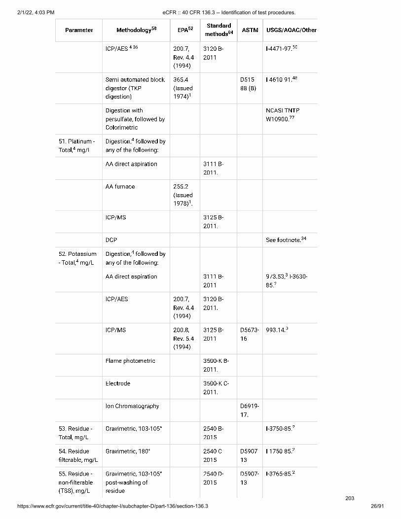
2/1/22, 4:03 PM eCFR :: 40 CFR 136.3 -- Identification of test procedures.
https://www.ecfr.gov/current/title-40/chapter-I/subchapter-D/part-136/section-136.3 26/91
ICP/AES 200.7,Rev. 4.4(1994)
3120 B-2011
I-4471-97.
Semi-automated blockdigestor (TKPdigestion)
365.4(Issued1974)
D515-88 (B)
I-4610-91.
Digestion withpersulfate, followed byColorimetric
NCASI TNTPW10900.
51. Platinum -Total, mg/L
Digestion, followed byany of the following:
AA direct aspiration 3111 B-2011.
AA furnace 255.2(Issued1978) .
ICP/MS 3125 B-2011.
DCP See footnote.
52. Potassium- Total, mg/L
Digestion, followed byany of the following:
AA direct aspiration 3111 B-2011
973.53, I-3630-85.
ICP/AES 200.7,Rev. 4.4(1994)
3120 B-2011.
ICP/MS 200.8,Rev. 5.4(1994)
3125 B-2011
D5673-16
993.14.
Flame photometric 3500-K B-2011.
Electrode 3500-K C-2011.
Ion Chromatography D6919-17.
53. Residue -Total, mg/L
Gravimetric, 103-105° 2540 B-2015
I-3750-85.
54. Residue -�lterable, mg/L
Gravimetric, 180° 2540 C-2015
D5907-13
I-1750-85.
55. Residue -non-�lterable(TSS), mg/L
Gravimetric, 103-105°post-washing ofresidue
2540 D-2015
D5907-13
I-3765-85.
4 36 50
1
48
77
4
4
1
34
4
4
3
2
3
2
2
2
Parameter Methodology58 EPA52 Standardmethods84 ASTM USGS/AOAC/Other
ICP/AES 200.7,Rev. 4.4(1994)
3120 B-2011
I-4471-97.
Semi-automated blockdigestor (TKPdigestion)
365.4(Issued1974)
D515-88 (B)
I-4610-91.
Digestion withpersulfate, followed byColorimetric
NCASI TNTPW10900.
51. Platinum -Total, mg/L
Digestion, followed byany of the following:
AA direct aspiration 3111 B-2011.
AA furnace 255.2(Issued1978) .
ICP/MS 3125 B-2011.
DCP See footnote.
52. Potassium- Total, mg/L
Digestion, followed byany of the following:
AA direct aspiration 3111 B-2011
973.53, I-3630-85.
ICP/AES 200.7,Rev. 4.4(1994)
3120 B-2011.
ICP/MS 200.8,Rev. 5.4(1994)
3125 B-2011
D5673-16
993.14.
Flame photometric 3500-K B-2011.
Electrode 3500-K C-2011.
Ion Chromatography D6919-17.
53. Residue -Total, mg/L
Gravimetric, 103-105° 2540 B-2015
I-3750-85.
54. Residue -�lterable, mg/L
Gravimetric, 180° 2540 C-2015
D5907-13
I-1750-85.
55. Residue -non-�lterable(TSS), mg/L
Gravimetric, 103-105°post-washing ofresidue
2540 D-2015
D5907-13
I-3765-85.
4 36 50
1
48
77
4
4
1
34
4
4
3
2
3
2
2
2
Parameter Methodology58 EPA52 Standardmethods84 ASTM USGS/AOAC/Other
203

2/1/22, 4:03 PM eCFR :: 40 CFR 136.3 -- Identification of test procedures.
https://www.ecfr.gov/current/title-40/chapter-I/subchapter-D/part-136/section-136.3 27/91
56. Residue -settleable, ml/L
Volumetric (Imhoffcone), or gravimetric
2540 F-2015.
57. Residue -Volatile, mg/L
Gravimetric, 550° 160.4(Issued1971)
2540 E-2015
I-3753-85.
58. Rhodium -Total, mg/L
Digestion, followed byany of the following:
AA direct aspiration, or 3111 B-2011.
AA furnace 265.2(Issued1978) .
ICP/MS 3125 B-2011.
59. Ruthenium- Total, mg/L
Digestion, followed byany of the following:
AA direct aspiration, or 3111 B-2011.
AA furnace 267.2 .
ICP/MS 3125 B-2011.
60. Selenium -Total, mg/L
Digestion, followed byany of the following:
AA furnace 3113 B-2010
D3859-15 (B)
I-4668-98.
STGFAA 200.9,Rev. 2.2(1994).
ICP/AES 200.5,Rev 4.2(2003);200.7,Rev. 4.4(1994)
3120 B-2011
D1976-12.
ICP/MS 200.8,Rev. 5.4(1994)
3125 B-2011
D5673-16
993.14, I-4020-05 I-4472-97.
AA gaseous hydride 3114 B-2011, or3114 C-2011
D3859-15 (A)
I-3667-85.
1
2
4
4
1
4
4
1
4
4
49
36
68
3
70 81
2
Parameter Methodology58 EPA52 Standardmethods84 ASTM USGS/AOAC/Other
204

2/1/22, 4:03 PM eCFR :: 40 CFR 136.3 -- Identification of test procedures.
https://www.ecfr.gov/current/title-40/chapter-I/subchapter-D/part-136/section-136.3 28/91
61. Silica -Dissolved,mg/L
0.45-micron �ltrationfollowed by any of thefollowing:
Colorimetric, Manual 4500-SiOC-2011
D859-16
I-1700-85.
Automated(Molybdosilicate)
4500-SiOE-2011 orF-2011
I-2700-85.
ICP/AES 200.5,Rev. 4.2(2003) ;200.7,Rev. 4.4(1994)
3120 B-2011
I-4471-97.
ICP/MS 200.8,Rev. 5.4(1994)
3125 B-2011
D5673-16
993.14.
62. Silver -Total, mg/L
Digestion, followedby any of the following:
AA direct aspiration 3111 B-2011 or3111 C-2011
974.27, p. 37, I-3720-85.
AA furnace 3113 B-2010
I-4724-89.
STGFAA 200.9,Rev. 2.2(1994).
ICP/AES 200.5,Rev. 4.2(2003);200.7,Rev. 4.4(1994)
3120 B-2011
D1976-12
I-4471-97.
ICP/MS 200.8,Rev. 5.4(1994)
3125 B-2011
D5673-16
993.14, I-4472-97.
DCP See footnote.
63. Sodium -Total, mg/L
Digestion, followed byany of the following:
AA direct aspiration 3111 B-2011
973.54, I-3735-85.
37
22
22
68
50
3
4 31
4 29
3 9
2
51
68
50
3
81
34
4
4
3
2
Parameter Methodology58 EPA52 Standardmethods84 ASTM USGS/AOAC/Other
205

2/1/22, 4:03 PM eCFR :: 40 CFR 136.3 -- Identification of test procedures.
https://www.ecfr.gov/current/title-40/chapter-I/subchapter-D/part-136/section-136.3 29/91
ICP/AES 200.5,Rev. 4.2(2003);200.7,Rev. 4.4(1994)
3120 B-2011
I-4471-97.
ICP/MS 200.8,Rev. 5.4(1994)
3125 B-2011
D5673-16
993.14.
DCP See footnote.
Flame photometric 3500-Na B-2011.
Ion Chromatography D6919-17.
64. Speci�cconductance,micromhos/cmat 25 °C
Wheatstone bridge 120.1(Rev.1982)
2510 B-2011
D1125-95(99)(A)
973.40, I-2781-85.
65. Sulfate (asSO ), mg/L
Automatedcolorimetric
375.2,Rev. 2.0(1993)
4500-SOF-2011 orG-2011
Gravimetric 4500-SOC-2011 orD-2011
925.54.
Turbidimetric 4500-SOE-2011
D516-16.
Ion Chromatography 300.0,Rev. 2.1(1993)and300.1,Rev. 1.0(1997)
4110 B-2011 or C-2011
D4327-17
993.30 , I-4020-05
CIE/UV 4140 B-2011
D6508-15
D6508, Rev. 2.
66. Sul�de (asS), mg/L
Sample Pretreatment 4500-S B,C-2011.
Titrimetric (iodine) 4500-S F-2011
I-3840-85.
Colorimetric(methylene blue)
4500-S D-2011.
Ion Selective Electrode 4500-S G-2011
D4658-15.
68
50
3
34
1
3
2
4
42-
42- 3
42-
370
54
2-
2- 2
2-
2-
Parameter Methodology58 EPA52 Standardmethods84 ASTM USGS/AOAC/Other
206

2/1/22, 4:03 PM eCFR :: 40 CFR 136.3 -- Identification of test procedures.
https://www.ecfr.gov/current/title-40/chapter-I/subchapter-D/part-136/section-136.3 30/91
67. Sul�te (asSO ), mg/L
Titrimetric (iodine-iodate)
4500-SOB-2011.
68.Surfactants,mg/L
Colorimetric(methylene blue)
5540 C-2011
D2330-02.
69.Temperature,°C
Thermometric 2550 B-2010
See footnote.
70. Thallium-Total, mg/L
Digestion, followed byany of the following:
AA direct aspiration 3111 B-2011.
AA furnace 279.2(Issued1978)
3113 B-2010.
STGFAA 200.9,Rev. 2.2(1994).
ICP/AES 200.7,Rev. 4.4(1994)
3120 B-2011
D1976-12.
ICP/MS 200.8,Rev. 5.4(1994)
3125 B-2011
D5673-16
993.14, I-4471-97 I-4472-97.
71. Tin-Total,mg/L
Digestion, followed byany of the following:
AA direct aspiration 3111 B-2011
I-3850-78.
AA furnace 3113 B-2010.
STGFAA 200.9,Rev. 2.2(1994).
ICP/AES 200.5,Rev. 4.2(2003) ;200.7,Rev. 4.4(1994).
ICP/MS 200.8,Rev. 5.4(1994)
3125 B-2011
D5673-16
993.14.
3
32-
32
4
4
1
3
50 81
4 4
8
68
3
Parameter Methodology58 EPA52 Standardmethods84 ASTM USGS/AOAC/Other
207

2/1/22, 4:03 PM eCFR :: 40 CFR 136.3 -- Identification of test procedures.
https://www.ecfr.gov/current/title-40/chapter-I/subchapter-D/part-136/section-136.3 31/91
72. Titanium-Total, mg/L
Digestion, followed byany of the following:
AA direct aspiration 3111 D-2011.
AA furnace 283.2(Issued1978) .
ICP/AES 200.7,Rev. 4.4(1994).
ICP/MS 200.8,Rev. 5.4(1994)
3125 B-2011
D5673-16
993.14.
DCP See footnote.
73. Turbidity,NTU
Nephelometric 180.1,Rev. 2.0(1993)
2130 B-2011
D1889-00
I-3860-85 See footnote. See footnote. See footnote.
74. Vanadium-Total, mg/L
Digestion, followed byany of the following:
AA direct aspiration 3111 D-2011.
AA furnace 3113 B-2010
D3373-17.
ICP/AES 200.5,Rev. 4.2(2003);200.7,Rev. 4.4(1994)
3120 B-2011
D1976-12
I-4471-97
ICP/MS 200.8,Rev. 5.4(1994)
3125 B-2011
D5673-16
993.14, I-4020-05.
DCP D4190-15
See footnote.
Colorimetric (GallicAcid)
3500-V B-2011.
75. Zinc-Total,mg/L
Digestion, followed byany of the following:
AA direct aspiration 3111 B-2011 or3111 C-2011
D1691-17 (Aor B)
974.27, p. 37, I-3900-85.
4
4
1
3
34
53
2
65
66
67
4
4
68
50
3
70
34
4 4
36 3 9
2
Parameter Methodology58 EPA52 Standardmethods84 ASTM USGS/AOAC/Other
208

2/1/22, 4:03 PM eCFR :: 40 CFR 136.3 -- Identification of test procedures.
https://www.ecfr.gov/current/title-40/chapter-I/subchapter-D/part-136/section-136.3 32/91
Table IB Notes:
Methods for Chemical Analysis of Water and Wastes, EPA-600/4-79-020. Revised March 1983 and 1979, whereapplicable. U.S. EPA.
Methods for Analysis of Inorganic Substances in Water and Fluvial Sediments, Techniques of Water-ResourceInvestigations of the U.S. Geological Survey, Book 5, Chapter A1., unless otherwise stated. 1989. USGS.
O�cial Methods of Analysis of the Association of O�cial Analytical Chemists, Methods Manual, SixteenthEdition, 4th Revision, 1998. AOAC International.
For the determination of total metals (which are equivalent to total recoverable metals) the sample is not�ltered before processing. A digestion procedure is required to solubilize analytes in suspended material and tobreak down organic-metal complexes (to convert the analyte to a detectable form for colorimetric analysis). Fornon-platform graphite furnace atomic absorption determinations, a digestion using nitric acid (as speci�ed inSection 4.1.3 of Methods for Chemical Analysis of Water and Wastes) is required prior to analysis. Theprocedure used should subject the sample to gentle acid re�uxing, and at no time should the sample be taken todryness. For direct aspiration �ame atomic absorption (FLAA) determinations, a combination acid (nitric andhydrochloric acids) digestion is preferred, prior to analysis. The approved total recoverable digestion is describedas Method 200.2 in Supplement I of “Methods for the Determination of Metals in Environmental Samples”EPA/600R-94/111, May, 1994, and is reproduced in EPA Methods 200.7, 200.8, and 200.9 from the sameSupplement. However, when using the gaseous hydride technique or for the determination of certain elementssuch as antimony, arsenic, selenium, silver, and tin by non-EPA graphite furnace atomic absorption methods,mercury by cold vapor atomic absorption, the noble metals and titanium by FLAA, a speci�c or modi�ed sampledigestion procedure may be required, and, in all cases the referenced method write-up should be consulted forspeci�c instruction and/or cautions. For analyses using inductively coupled plasma-atomic emissionspectrometry (ICP-AES), the direct current plasma (DCP) technique or EPA spectrochemical techniques(platform furnace AA, ICP-AES, and ICP-MS), use EPA Method 200.2 or an approved alternate procedure (e.g.,CEM microwave digestion, which may be used with certain analytes as indicated in Table IB); the totalrecoverable digestion procedures in EPA Methods 200.7, 200.8, and 200.9 may be used for those respectivemethods. Regardless of the digestion procedure, the results of the analysis after digestion procedure arereported as “total” metals.
Copper sulfate or other catalysts that have been found suitable may be used in place of mercuric sulfate.
AA furnace 289.2(Issued1978) .
ICP/AES 200.5,Rev. 4.2(2003);200.7,Rev. 4.4(1994)
3120 B-2011
D1976-12
I-4471-97.
ICP/MS 200.8,Rev. 5.4(1994)
3125 B-2011
D5673-16
993.14, I-4020-05 I-4472-97.
DCP D4190-15
See footnote.
Colorimetric (Zincon) 3500 Zn B-2011
See footnote.
76. Acid MineDrainage
1627 .
1
36
68
50
3
70 81
36 34
33
69
Parameter Methodology58 EPA52 Standardmethods84 ASTM USGS/AOAC/Other
1
2
3
4
5
209

2/1/22, 4:03 PM eCFR :: 40 CFR 136.3 -- Identification of test procedures.
https://www.ecfr.gov/current/title-40/chapter-I/subchapter-D/part-136/section-136.3 33/91
Manual distillation is not required if comparability data on representative e�uent samples are on �le to showthat this preliminary distillation step is not necessary; however, manual distillation will be required to resolve anycontroversies. In general, the analytical method should be consulted regarding the need for distillation. If themethod is not clear, the laboratory may compare a minimum of 9 different sample matrices to evaluate the needfor distillation. For each matrix, a matrix spike and matrix spike duplicate are analyzed both with and without thedistillation step (for a total of 36 samples, assuming 9 matrices). If results are comparable, the laboratory maydispense with the distillation step for future analysis. Comparable is de�ned as < 20% RPD for all testedmatrices). Alternatively, the two populations of spike recovery percentages may be compared using a recognizedstatistical test.
Industrial Method Number 379-75 WE Ammonia, Automated Electrode Method, Technicon Auto Analyzer II.February 19, 1976. Bran & Luebbe Analyzing Technologies Inc.
The approved method is that cited in Methods for Determination of Inorganic Substances in Water and FluvialSediments, Techniques of Water-Resources Investigations of the U.S. Geological Survey, Book 5, Chapter A1.1979. USGS.
American National Standard on Photographic Processing E�uents. April 2, 1975. American National StandardsInstitute.
In-Situ Method 1003-8-2009, Biochemical Oxygen Demand (BOD) Measurement by Optical Probe. 2009. In-SituIncorporated.
The use of normal and differential pulse voltage ramps to increase sensitivity and resolution is acceptable.
Carbonaceous biochemical oxygen demand (CBOD ) must not be confused with the traditional BOD testmethod which measures “total 5-day BOD.” The addition of the nitri�cation inhibitor is not a procedural option butmust be included to report the CBOD parameter. A discharger whose permit requires reporting the traditionalBOD may not use a nitri�cation inhibitor in the procedure for reporting the results. Only when a discharger'spermit speci�cally states CBOD is required can the permittee report data using a nitri�cation inhibitor.
OIC Chemical Oxygen Demand Method. 1978. Oceanography International Corporation.
Method 8000, Chemical Oxygen Demand, Hach Handbook of Water Analysis, 1979. Hach Company.
The back-titration method will be used to resolve controversy.
Orion Research Instruction Manual, Residual Chlorine Electrode Model 97-70. 1977. Orion ResearchIncorporated. The calibration graph for the Orion residual chlorine method must be derived using a reagent blankand three standard solutions, containing 0.2, 1.0, and 5.0 mL 0.00281 N potassium iodate/100 mL solution,respectively.
Method 245.7, Mercury in Water by Cold Vapor Atomic Fluorescence Spectrometry, EPA-821-R-05-001.Revision 2.0, February 2005. US EPA.
National Council of the Paper Industry for Air and Stream Improvement (NCASI) Technical Bulletin 253 (1971)and Technical Bulletin 803, May 2000.
Method 8506, Bicinchoninate Method for Copper, Hach Handbook of Water Analysis. 1979. Hach Company.
When using a method with block digestion, this treatment is not required.
Industrial Method Number 378-75WA, Hydrogen ion (pH) Automated Electrode Method, Bran & Luebbe(Technicon) Autoanalyzer II. October 1976. Bran & Luebbe Analyzing Technologies.
Method 8008, 1,10-Phenanthroline Method using FerroVer Iron Reagent for Water. 1980. Hach Company.
Method 8034, Periodate Oxidation Method for Manganese, Hach Handbook of Wastewater Analysis. 1979.Hach Company.
Methods for Analysis of Organic Substances in Water and Fluvial Sediments, Techniques of Water-ResourcesInvestigations of the U.S. Geological Survey, Book 5, Chapter A3, (1972 Revised 1987). 1987. USGS.
Method 8507, Nitrogen, Nitrite-Low Range, Diazotization Method for Water and Wastewater. 1979. HachCompany.
Just prior to distillation, adjust the sulfuric-acid-preserved sample to pH 4 with 1 + 9 NaOH.
6
7
8
9
10
11
125 5
5
5
5
13
14
15
16
17
18
19
20
21
22
23
24
25
26
210

2/1/22, 4:03 PM eCFR :: 40 CFR 136.3 -- Identification of test procedures.
https://www.ecfr.gov/current/title-40/chapter-I/subchapter-D/part-136/section-136.3 34/91
The colorimetric reaction must be conducted at a pH of 10.0 ± 0.2.
Addison, R.F., and R.G. Ackman. 1970. Direct Determination of Elemental Phosphorus by Gas-LiquidChromatography, Journal of Chromatography, 47(3):421-426.
Approved methods for the analysis of silver in industrial wastewaters at concentrations of 1 mg/L and aboveare inadequate where silver exists as an inorganic halide. Silver halides such as the bromide and chloride arerelatively insoluble in reagents such as nitric acid but are readily soluble in an aqueous buffer of sodiumthiosulfate and sodium hydroxide to pH of 12. Therefore, for levels of silver above 1 mg/L, 20 mL of sampleshould be diluted to 100 mL by adding 40 mL each of 2 M Na S O and NaOH. Standards should be prepared inthe same manner. For levels of silver below 1 mg/L the approved method is satisfactory.
The use of EDTA decreases method sensitivity. Analysts may omit EDTA or replace with another suitablecomplexing reagent provided that all method-speci�ed quality control acceptance criteria are met.
For samples known or suspected to contain high levels of silver (e.g., in excess of 4 mg/L), cyanogen iodideshould be used to keep the silver in solution for analysis. Prepare a cyanogen iodide solution by adding 4.0 mL ofconcentrated NH OH, 6.5 g of KCN, and 5.0 mL of a 1.0 N solution of I to 50 mL of reagent water in a volumetric�ask and dilute to 100.0 mL. After digestion of the sample, adjust the pH of the digestate to >7 to prevent theformation of HCN under acidic conditions. Add 1 mL of the cyanogen iodide solution to the sample digestateand adjust the volume to 100 mL with reagent water (NOT acid). If cyanogen iodide is added to sampledigestates, then silver standards must be prepared that contain cyanogen iodide as well. Prepare workingstandards by diluting a small volume of a silver stock solution with water and adjusting the pH>7 with NH OH.Add 1 mL of the cyanogen iodide solution and let stand 1 hour. Transfer to a 100-mL volumetric �ask and diluteto volume with water.
“Water Temperature-In�uential Factors, Field Measurement and Data Presentation,” Techniques of Water-Resources Investigations of the U.S. Geological Survey, Book 1, Chapter D1. 1975. USGS.
Method 8009, Zincon Method for Zinc, Hach Handbook of Water Analysis, 1979. Hach Company.
Method AES0029, Direct Current Plasma (DCP) Optical Emission Spectrometric Method for Trace ElementalAnalysis of Water and Wastes. 1986-Revised 1991. Thermo Jarrell Ash Corporation.
In-Situ Method 1004-8-2009, Carbonaceous Biochemical Oxygen Demand (CBOD) Measurement by OpticalProbe. 2009. In-Situ Incorporated.
Microwave-assisted digestion may be employed for this metal, when analyzed by this methodology. ClosedVessel Microwave Digestion of Wastewater Samples for Determination of Metals. April 16, 1992. CEMCorporation
When determining boron and silica, only plastic, PTFE, or quartz laboratory ware may be used from start untilcompletion of analysis.
Only use n-hexane (n-Hexane - 85% minimum purity, 99.0% min. saturated C6 isomers, residue less than 1mg/L) extraction solvent when determining Oil and Grease parameters - Hexane Extractable Material (HEM), orSilica Gel Treated HEM (analogous to EPA Methods 1664 Rev. A and 1664 Rev. B). Use of other extractionsolvents is prohibited.
Method PAI-DK01, Nitrogen, Total Kjeldahl, Block Digestion, Steam Distillation, Titrimetric Detection. RevisedDecember 22, 1994. OI Analytical.
Method PAI-DK02, Nitrogen, Total Kjeldahl, Block Digestion, Steam Distillation, Colorimetric Detection. RevisedDecember 22, 1994. OI Analytical.
Method PAI-DK03, Nitrogen, Total Kjeldahl, Block Digestion, Automated FIA Gas Diffusion. Revised December22, 1994. OI Analytical.
Method 1664 Rev. B is the revised version of EPA Method 1664 Rev. A. U.S. EPA. February 1999, Revision A.Method 1664, n-Hexane Extractable Material (HEM; Oil and Grease) and Silica Gel Treated n-Hexane ExtractableMaterial (SGT-HEM; Non-polar Material) by Extraction and Gravimetry. EPA-821-R-98-002. U.S. EPA. February2010, Revision B. Method 1664, n-Hexane Extractable Material (HEM; Oil and Grease) and Silica Gel Treated n-Hexane Extractable Material (SGT-HEM; Non-polar Material) by Extraction and Gravimetry. EPA-821-R-10-001.
Method 1631, Revision E, Mercury in Water by Oxidation, Purge and Trap, and Cold Vapor Atomic FluorescenceSpectrometry, EPA-821-R-02-019. Revision E. August 2002, U.S. EPA. The application of clean techniquesdescribed in EPA's Method 1669: Sampling Ambient Water for Trace Metals at EPA Water Quality Criteria Levels,EPA-821-R-96-011, are recommended to preclude contamination at low-level, trace metal determinations.
27
28
29
2 2 3
30
31
4 2
4
32
33
34
35
36
37
38
39
40
41
42
43
211

2/1/22, 4:03 PM eCFR :: 40 CFR 136.3 -- Identification of test procedures.
https://www.ecfr.gov/current/title-40/chapter-I/subchapter-D/part-136/section-136.3 35/91
Method OIA-1677-09, Available Cyanide by Ligand Exchange and Flow Injection Analysis (FIA). 2010. OIAnalytical.
Open File Report 00-170, Methods of Analysis by the U.S. Geological Survey National Water Quality Laboratory- Determination of Ammonium Plus Organic Nitrogen by a Kjeldahl Digestion Method and an AutomatedPhotometric Finish that Includes Digest Cleanup by Gas Diffusion. 2000. USGS.
Open File Report 93-449, Methods of Analysis by the U.S. Geological Survey National Water Quality Laboratory- Determination of Chromium in Water by Graphite Furnace Atomic Absorption Spectrophotometry. 1993. USGS.
Open File Report 97-198, Methods of Analysis by the U.S. Geological Survey National Water Quality Laboratory- Determination of Molybdenum by Graphite Furnace Atomic Absorption Spectrophotometry. 1997. USGS.
Open File Report 92-146, Methods of Analysis by the U.S. Geological Survey National Water Quality Laboratory- Determination of Total Phosphorus by Kjeldahl Digestion Method and an Automated Colorimetric Finish ThatIncludes Dialysis. 1992. USGS.
Open File Report 98-639, Methods of Analysis by the U.S. Geological Survey National Water Quality Laboratory- Determination of Arsenic and Selenium in Water and Sediment by Graphite Furnace-Atomic AbsorptionSpectrometry. 1999. USGS.
Open File Report 98-165, Methods of Analysis by the U.S. Geological Survey National Water Quality Laboratory- Determination of Elements in Whole-water Digests Using Inductively Coupled Plasma-Optical EmissionSpectrometry and Inductively Coupled Plasma-Mass Spectrometry. 1998. USGS.
Open File Report 93-125, Methods of Analysis by the U.S. Geological Survey National Water Quality Laboratory- Determination of Inorganic and Organic Constituents in Water and Fluvial Sediments. 1993. USGS.
Unless otherwise indicated, all EPA methods, excluding EPA Method 300.1, are published in U.S. EPA. May1994. Methods for the Determination of Metals in Environmental Samples, Supplement I, EPA/600/R-94/111; orU.S. EPA. August 1993. Methods for the Determination of Inorganic Substances in Environmental Samples,EPA/600/R-93/100. EPA Method 300.1 is U.S. EPA. Revision 1.0, 1997, including errata cover sheet April 27,1999. Determination of Inorganic Ions in Drinking Water by Ion Chromatography.
Styrene divinyl benzene beads (e.g., AMCO-AEPA-1 or equivalent) and stabilized formazin (e.g., HachStablCal or equivalent) are acceptable substitutes for formazin.
Method D6508-15, Test Method for Determination of Dissolved Inorganic Anions in Aqueous Matrices UsingCapillary Ion Electrophoresis and Chromate Electrolyte. 2015. ASTM
Kelada-01, Kelada Automated Test Methods for Total Cyanide, Acid Dissociable Cyanide, and Thiocyanate,EPA 821-B-01-009, Revision 1.2, August 2001. U.S. EPA. Note: A 450-W UV lamp may be used in this methodinstead of the 550-W lamp speci�ed if it provides performance within the quality control (QC) acceptance criteriaof the method in a given instrument. Similarly, modi�ed �ow cell con�gurations and �ow conditions may be usedin the method, provided that the QC acceptance criteria are met.
QuikChem Method 10-204-00-1-X, Digestion and Distillation of Total Cyanide in Drinking and Wastewatersusing MICRO DIST and Determination of Cyanide by Flow Injection Analysis. Revision 2.2, March 2005. LachatInstruments.
When using sul�de removal test procedures described in EPA Method 335.4-1, reconstitute particulate that is�ltered with the sample prior to distillation.
Unless otherwise stated, if the language of this table speci�es a sample digestion and/or distillation “followedby” analysis with a method, approved digestion and/or distillation are required prior to analysis.
Samples analyzed for available cyanide using OI Analytical method OIA-1677-09 or ASTM method D6888-16that contain particulate matter may be �ltered only after the ligand exchange reagents have been added to thesamples, because the ligand exchange process converts complexes containing available cyanide to free cyanide,which is not removed by �ltration. Analysts are further cautioned to limit the time between the addition of theligand exchange reagents and sample �ltration to no more than 30 minutes to preclude settling of materials insamples.
Analysts should be aware that pH optima and chromophore absorption maxima might differ when phenol isreplaced by a substituted phenol as the color reagent in Berthelot Reaction (“phenol-hypochlorite reaction”)colorimetric ammonium determination methods. For example, when phenol is used as the color reagent, pH
44
45
46
47
48
49
50
51
52
53
TM
54
55
56
57
58
59
60
212

2/1/22, 4:03 PM eCFR :: 40 CFR 136.3 -- Identification of test procedures.
https://www.ecfr.gov/current/title-40/chapter-I/subchapter-D/part-136/section-136.3 36/91
optimum and wavelength of maximum absorbance are about 11.5 and 635 nm, respectively - see, Patton, C.J.and S.R. Crouch. March 1977. Anal. Chem. 49:464-469. These reaction parameters increase to pH > 12.6 and 665nm when salicylate is used as the color reagent - see, Krom, M.D. April 1980. The Analyst 105:305-316.
If atomic absorption or ICP instrumentation is not available, the aluminon colorimetric method detailed in the19th Edition of Standard Methods for the Examination of Water and Wastewater may be used. This method haspoorer precision and bias than the methods of choice.
Easy (1-Reagent) Nitrate Method, Revision November 12, 2011. Craig Chinchilla.
Hach Method 10360, Luminescence Measurement of Dissolved Oxygen in Water and Wastewater and for Usein the Determination of BOD and CBOD . Revision 1.2, October 2011. Hach Company. This method may be usedto measure dissolved oxygen when performing the methods approved in Table IB for measurement ofbiochemical oxygen demand (BOD) and carbonaceous biochemical oxygen demand (CBOD).
In-Situ Method 1002-8-2009, Dissolved Oxygen (DO) Measurement by Optical Probe. 2009. In-SituIncorporated.
Mitchell Method M5331, Determination of Turbidity by Nephelometry. Revision 1.0, July 31, 2008. LeckMitchell.
Mitchell Method M5271, Determination of Turbidity by Nephelometry. Revision 1.0, July 31, 2008. LeckMitchell.
Orion Method AQ4500, Determination of Turbidity by Nephelometry. Revision 5, March 12, 2009. ThermoScienti�c.
EPA Method 200.5, Determination of Trace Elements in Drinking Water by Axially Viewed Inductively CoupledPlasma-Atomic Emission Spectrometry, EPA/600/R-06/115. Revision 4.2, October 2003. U.S. EPA.
Method 1627, Kinetic Test Method for the Prediction of Mine Drainage Quality, EPA-821-R-09-002. December2011. U.S. EPA.
Techniques and Methods Book 5-B1, Determination of Elements in Natural-Water, Biota, Sediment and SoilSamples Using Collision/Reaction Cell Inductively Coupled Plasma-Mass Spectrometry, Chapter 1, Section B,Methods of the National Water Quality Laboratory, Book 5, Laboratory Analysis, 2006. USGS.
Water-Resources Investigations Report 01-4132, Methods of Analysis by the U.S. Geological Survey NationalWater Quality Laboratory - Determination of Organic Plus Inorganic Mercury in Filtered and Un�ltered NaturalWater with Cold Vapor-Atomic Fluorescence Spectrometry, 2001. USGS.
USGS Techniques and Methods 5-B8, Chapter 8, Section B, Methods of the National Water Quality LaboratoryBook 5, Laboratory Analysis, 2011 USGS.
NECi Method N07-0003, “Nitrate Reductase Nitrate-Nitrogen Analysis,” Revision 9.0, March 2014, The NitrateElimination Co., Inc.
Timberline Instruments, LLC Method Ammonia-001, “Determination of Inorganic Ammonia by ContinuousFlow Gas Diffusion and Conductivity Cell Analysis,” June 2011, Timberline Instruments, LLC.
Hach Company Method 10206, “Spectrophotometric Measurement of Nitrate in Water and Wastewater,”Revision 2.1, January 2013, Hach Company.
Hach Company Method 10242, “Simpli�ed Spectrophotometric Measurement of Total Kjeldahl Nitrogen inWater and Wastewater,” Revision 1.1, January 2013, Hach Company.
National Council for Air and Stream Improvement (NCASI) Method TNTP-W10900, “Total (Kjeldahl) Nitrogenand Total Phosphorus in Pulp and Paper Biologically Treated E�uent by Alkaline Persulfate Digestion,” June2011, National Council for Air and Stream Improvement, Inc.
The pH adjusted sample is to be adjusted to 7.6 for NPDES reporting purposes.
I-2057-85 U.S. Geological Survey Techniques of Water-Resources Investigations, Book 5, Chap. A11989,Methods for Determination of Inorganic Substances in Water and Fluvial Sediments, 1989.
61
62
63
5 5
64
65
66
67
68
69
70
71
72
73
74
75
76
77
78
79
213

2/1/22, 4:03 PM eCFR :: 40 CFR 136.3 -- Identification of test procedures.
https://www.ecfr.gov/current/title-40/chapter-I/subchapter-D/part-136/section-136.3 37/91
Methods I-2522-90, I-2540-90, and I-2601-90 U.S. Geological Survey Open-File Report 93-125, Methods ofAnalysis by the U.S. Geological Survey National Water Quality Laboratory-Determination of Inorganic and OrganicConstituents in Water and Fluvial Sediments, 1993.
Method I-1472-97, U.S. Geological Survey Open-File Report 98-165, Methods of Analysis by the U.S. GeologicalSurvey National Water Quality Laboratory-Determination of Inorganic and Organic Constituents in Water andFluvial Sediments, 1998.
FIAlab Instruments, Inc. Method FIAlab 100, “Determination of Inorganic Ammonia by Continuous Flow GasDiffusion and Fluorescence Detector Analysis”, April 4, 2018, FIAlab Instruments, Inc.
MACHEREY-NAGEL GmbH and Co. Method 036/038 NANOCOLOR® COD LR/HR, “SpectrophotometricMeasurement of Chemical Oxygen Demand in Water and Wastewater”, Revision 1.5, May 2018, MACHEREY-NAGEL GmbH and Co. KG.
Please refer to the following applicable Quality Control Sections: Part 2000 Methods, Physical and AggregateProperties 2020 (2017); Part 3000 Methods, Metals, 3020 (2017); Part 4000 Methods, Inorganic NonmetallicConstituents, 4020 (2014); Part 5000 Methods, and Aggregate Organic Constituents, 5020 (2017). These QualityControl Standards are available for download at www.standardmethods.org at no charge.
Each laboratory may establish its own control limits by performing at least 25 glucose-glutamic acid (GGA)checks over several weeks or months and calculating the mean and standard deviation. The laboratory may thenuse the mean ± 3 standard deviations as the control limit for future GGA checks. However, GGA acceptancecriteria can be no wider than 198 ± 30.5 mg/L for BOD . GGA acceptance criteria for CBOD must be either 198 ±30.5 mg/L, or the lab may develop control charts under the following conditions:
• Dissolved oxygen uptake from the seed contribution is between 0.6-1.0 mg/L.
• Control charts are performed on at least 25 GGA checks with three standard deviations from the derived mean.
• The RSD must not exceed 7.5%.
• Any single GGA value cannot be less than 150 mg/L or higher than 250 mg/L.
Table IC - List of Approved Test Procedures for Non-Pesticide Organic Compounds
1. Acenaphthene GC 610
GC/MS 625.1,1625B
6410 B-2000
Seefootnote ,p. 27.
HPLC 610 6440 B-2005
D4657-92 (98)
2. Acenaphthylene GC 610
GC/MS 625.1,1625B
6410 B-2000
Seefootnote ,p. 27.
HPLC 610 6440 B-2005
D4657-92 (98)
3. Acrolein GC 603
GC/MS 624.1,1624B
4. Acrylonitrile GC 603
80
81
82
83
84
85
5
9
9
4
Parameter1 Method EPA27 Standardmethods ASTM Other
214

2/1/22, 4:04 PM eCFR :: 40 CFR 136.3 -- Identification of test procedures.
https://www.ecfr.gov/current/title-40/chapter-I/subchapter-D/part-136/section-136.3 84/91
Table II - Required Containers, Preservation Techniques, and Holding Times
Table IA - Bacterial Tests
1-4. Coliform, total, fecal, and E. coli PA, G Cool, <10 °C, 0.008%Na S O
8 hours.
5. Fecal streptococci PA, G Cool, <10 °C, 0.008%Na S O
8 hours.
6. Enterococci PA, G Cool, <10 °C, 0.008%Na S O
8 hours.
7. Salmonella PA, G Cool, <10 °C, 0.008%Na S O
8 hours.
Table IA - Aquatic Toxicity Tests
8-11. Toxicity, acute and chronic P, FP, G Cool, ≤6 °C 36 hours.
Table IB - Inorganic Tests
1. Acidity P, FP, G Cool, ≤6 °C 14 days.
2. Alkalinity P, FP, G Cool, ≤6 °C 14 days.
(xx) Water-Resources Investigation Report 01-4098, Methods of Analysis by the U.S. Geological Survey National Water QualityLaboratory - Determination of Moderate-Use Pesticides and Selected Degradates in Water by C-18 Solid-Phase Extraction andGas Chromatography/Mass Spectrometry. 2001. Table ID, Note 13.
(xxi) Water-Resources Investigations Report 01-4132, Methods of Analysis by the U.S. Geological Survey National Water QualityLaboratory - Determination of Organic Plus Inorganic Mercury in Filtered and Un�ltered Natural Water With Cold Vapor-AtomicFluorescence Spectrometry. 2001. Table IB, Note 71.
(xxii) Water-Resources Investigation Report 01-4134, Methods of Analysis by the U.S. Geological Survey National Water QualityLaboratory - Determination of Pesticides in Water by Graphitized Carbon-Based Solid-Phase Extraction and High-PerformanceLiquid Chromatography/Mass Spectrometry. 2001. Table ID, Note 12.
(xxiii) Water Temperature - In�uential Factors, Field Measurement and Data Presentation, Techniques of Water-ResourcesInvestigations of the U.S. Geological Survey, Book 1, Chapter D1. 1975. Table IB, Note 32.
(39) Waters Corporation, 34 Maple Street, Milford MA 01757, Telephone: 508-482-2131, Fax: 508-482-3625.
(i) Method D6508, Test Method for Determination of Dissolved Inorganic Anions in Aqueous Matrices Using Capillary IonElectrophoresis and Chromate Electrolyte. Revision 2, December 2000. Table IB, Note 54.
(ii) [Reserved]
(c) Under certain circumstances, the Director may establish limitations on the discharge of a parameter for which there is no test procedurein this part or in 40 CFR parts 405 through 499. In these instances the test procedure shall be speci�ed by the Director.
(d) Under certain circumstances, the Administrator may approve additional alternate test procedures for nationwide use, uponrecommendation by the Alternate Test Procedure Program Coordinator, Washington, DC.
(e) Sample preservation procedures, container materials, and maximum allowable holding times for parameters are cited in Tables IA, IB, IC,ID, IE, IF, IG, and IH are prescribed in Table II. Information in the table takes precedence over information in speci�c methods orelsewhere. Any person may apply for a change from the prescribed preservation techniques, container materials, and maximum holdingtimes applicable to samples taken from a speci�c discharge. Applications for such limited use changes may be made by letters to theRegional Alternative Test Procedure (ATP) Program Coordinator or the permitting authority in the Region in which the discharge willoccur. Su�cient data should be provided to assure such changes in sample preservation, containers or holding times do not adverselyaffect the integrity of the sample. The Regional ATP Coordinator or permitting authority will review the application and then notify theapplicant and the appropriate State agency of approval or rejection of the use of the alternate test procedure. A decision to approve ordeny any request on deviations from the prescribed Table II requirements will be made within 90 days of receipt of the application by theRegional Administrator. An analyst may not modify any sample preservation and/or holding time requirements of an approved methodunless the requirements of this section are met.
2 2 35
22 23
2 2 35
22
2 2 35
22
2 2 35
22
16
18
18
Parameter number/nameContainer
1 Preservation 2 3 Maximumholding time 4
215

2/1/22, 4:04 PM eCFR :: 40 CFR 136.3 -- Identification of test procedures.
https://www.ecfr.gov/current/title-40/chapter-I/subchapter-D/part-136/section-136.3 85/91
4. Ammonia P, FP, G Cool, ≤6 °C , H SOto pH <2
28 days.
9. Biochemical oxygen demand P, FP, G Cool, ≤6 °C 48 hours.
10. Boron P, FP, orQuartz
HNO to pH <2 6 months.
11. Bromide P, FP, G None required 28 days.
14. Biochemical oxygen demand, carbonaceous P, FP G Cool, ≤6 °C 48 hours.
15. Chemical oxygen demand P, FP, G Cool, ≤6 °C , H SOto pH <2
28 days.
16. Chloride P, FP, G None required 28 days.
17. Chlorine, total residual P, G None required Analyze within15 minutes.
21. Color P, FP, G Cool, ≤6 °C 48 hours.
23-24. Cyanide, total or available (or CATC) andfree
P, FP, G Cool, ≤6 °C , NaOHto pH >10 , reducingagent if oxidizerpresent
14 days.
25. Fluoride P None required 28 days.
27. Hardness P, FP, G HNO or H SO to pH<2
6 months.
28. Hydrogen ion (pH) P, FP, G None required Analyze within15 minutes.
31, 43. Kjeldahl and organic N P, FP, G Cool, ≤6 °C , H SOto pH <2
28 days.
Table IB - Metals
18. Chromium VI P, FP, G Cool, ≤6 °C , pH =9.3-9.7
28 days.
35. Mercury (CVAA) P, FP, G HNO to pH <2 28 days.
35. Mercury (CVAFS) FP, G; andFP-linedcap
5 mL/L 12N HCl or 5mL/L BrCl
90 days.
3, 5-8, 12, 13, 19, 20, 22, 26, 29, 30, 32-34, 36, 37,45, 47, 51, 52, 58-60, 62, 63, 70-72, 74, 75. Metals,except boron, chromium VI, and mercury
P, FP, G HNO to pH <2, or atleast 24 hours prior toanalysis
6 months.
38. Nitrate P, FP, G Cool, ≤6 °C 48 hours.
39. Nitrate-nitrite P, FP, G Cool, ≤6 °C , H SOto pH <2
28 days.
40. Nitrite P, FP, G Cool, ≤6 °C 48 hours.
182 4
18
3
18
182 4
18
18
5 6
3 2 4
182 4
7
18
20
3
17
17
17
3
19
18
182 4
18
Parameter number/nameContainer
1 Preservation 2 3 Maximumholding time 4
216

2/1/22, 4:04 PM eCFR :: 40 CFR 136.3 -- Identification of test procedures.
https://www.ecfr.gov/current/title-40/chapter-I/subchapter-D/part-136/section-136.3 86/91
41. Oil and grease G Cool to ≤6 °C , HClor H SO to pH <2
28 days.
42. Organic Carbon P, FP, G Cool to ≤6 °C , HCl,H SO , or H PO topH <2
28 days.
44. Orthophosphate P, FP, G Cool, to ≤6 °C Filter within 15minutes;Analyze within48 hours.
46. Oxygen, Dissolved Probe G, Bottleand top
None required Analyze within15 minutes.
47. Winkler G, Bottleand top
Fix on site and storein dark
8 hours.
48. Phenols G Cool, ≤6 °C , H SOto pH <2
28 days.
49. Phosphorus (elemental) G Cool, ≤6 °C 48 hours.
50. Phosphorus, total P, FP, G Cool, ≤6 °C , H SOto pH <2
28 days.
53. Residue, total P, FP, G Cool, ≤6 °C 7 days.
54. Residue, Filterable (TDS) P, FP, G Cool, ≤6 °C 7 days.
55. Residue, Non�lterable (TSS) P, FP, G Cool, ≤6 °C 7 days.
56. Residue, Settleable P, FP, G Cool, ≤6 °C 48 hours.
57. Residue, Volatile P, FP, G Cool, ≤6 °C 7 days.
61. Silica P orQuartz
Cool, ≤6 °C 28 days.
64. Speci�c conductance P, FP, G Cool, ≤6 °C 28 days.
65. Sulfate P, FP, G Cool, ≤6 °C 28 days.
66. Sul�de P, FP, G Cool, ≤6 °C , addzinc acetate plussodium hydroxide topH >9
7 days.
67. Sul�te P, FP, G None required Analyze within15 minutes.
68. Surfactants P, FP, G Cool, ≤6 °C 48 hours.
69. Temperature P, FP, G None required Analyze within15 minutes.
73. Turbidity P, FP, G Cool, ≤6 °C 48 hours.
Table IC - Organic Tests
18
2 4
18
2 4 3 4
18 24
182 4
18
182 4
18
18
18
18
18
18
18
18
18
18
18
8
Parameter number/nameContainer
1 Preservation 2 3 Maximumholding time 4
217

2/1/22, 4:04 PM eCFR :: 40 CFR 136.3 -- Identification of test procedures.
https://www.ecfr.gov/current/title-40/chapter-I/subchapter-D/part-136/section-136.3 87/91
13, 18-20, 22, 24, 25, 27, 28, 34-37, 39-43, 45-47,56, 76, 104, 105, 108-111, 113. PurgeableHalocarbons
G, FP-linedseptum
Cool, ≤6 °C , 0.008%Na S O , HCl to pH2
14 days.
26. 2-Chloroethylvinyl ether G, FP-linedseptum
Cool, ≤6 °C , 0.008%Na S O
14 days.
6, 57, 106. Purgeable aromatic hydrocarbons G, FP-linedseptum
Cool, ≤6 °C , 0.008%Na S O , HCl to pH2
14 days.
3, 4. Acrolein and acrylonitrile G, FP-linedseptum
Cool, ≤6 °C , 0.008%Na S O , pH to 4-5
14 days.
23, 30, 44, 49, 53, 77, 80, 81, 98, 100, 112. Phenols G, FP-lined cap
Cool, ≤6 °C , 0.008%Na S O
7 days untilextraction, 40days afterextraction.
7, 38. Benzidines G, FP-lined cap
Cool, ≤6 °C , 0.008%Na S O
7 days untilextraction.
14, 17, 48, 50-52. Phthalate esters G, FP-lined cap
Cool, ≤6 °C 7 days untilextraction, 40days afterextraction.
82-84. Nitrosamines G, FP-lined cap
Cool, ≤6 °C , store indark, 0.008% Na S O
7 days untilextraction, 40days afterextraction.
88-94. PCBs G, FP-lined cap
Cool, ≤6 °C 1 year untilextraction, 1year afterextraction.
54, 55, 75, 79. Nitroaromatics and isophorone G, FP-lined cap
Cool, ≤6 °C , store indark, 0.008% Na S O
7 days untilextraction, 40days afterextraction.
1, 2, 5, 8-12, 32, 33, 58, 59, 74, 78, 99, 101.Polynuclear aromatic hydrocarbons
G, FP-lined cap
Cool, ≤6 °C , store indark, 0.008% Na S O
7 days untilextraction, 40days afterextraction.
15, 16, 21, 31, 87. Haloethers G, FP-lined cap
Cool, ≤6 °C , 0.008%Na S O
7 days untilextraction, 40days afterextraction.
18
2 2 35
9
9
18
2 2 35
18
2 2 35
9
9
18
2 2 310
10
11
18
2 2 3
11 12 18
2 2 35 13
11 18
11 14 18
2 2 35
11 18
11 18
2 2 35
11
18
2 2 35
11 18
2 2 35
Parameter number/nameContainer
1 Preservation 2 3 Maximumholding time 4
218

2/1/22, 4:04 PM eCFR :: 40 CFR 136.3 -- Identification of test procedures.
https://www.ecfr.gov/current/title-40/chapter-I/subchapter-D/part-136/section-136.3 88/91
29, 35-37, 63-65, 73, 107. Chlorinatedhydrocarbons
G, FP-lined cap
Cool, ≤6 °C 7 days untilextraction, 40days afterextraction.
60-62, 66-72, 85, 86, 95-97, 102, 103. CDDs/CDFs G See footnote 11 See footnote11.
Aqueous Samples: Field and LabPreservation
G Cool, ≤6 °C , 0.008%Na S O , pH <9
1 year.
Solids and Mixed-Phase Samples: FieldPreservation
G Cool, ≤6 °C 7 days.
Tissue Samples: Field Preservation G Cool, ≤6 °C 24 hours.
Solids, Mixed-Phase, and Tissue Samples:Lab Preservation
G Freeze, ≤−10 °C 1 year.
114-118. Alkylated phenols G Cool, <6 °C, H SO topH <2
28 days untilextraction, 40days afterextraction.
119. Adsorbable Organic Halides (AOX) G Cool, <6 °C, 0.008%Na S O , HNO to pH<2
Hold at least 3days, but notmore than 6months.
120. Chlorinated Phenolics G, FP-lined cap
Cool, <6 °C, 0.008%Na S O , H SO to pH<2
30 days untilacetylation, 30days afteracetylation.
Table ID - Pesticides Tests
1-70. Pesticides G, FP-lined cap
Cool, ≤6 °C , pH 5-9 7 days untilextraction, 40days afterextraction.
Table IE - Radiological Tests
1-5. Alpha, beta, and radium P, FP, G HNO to pH <2 6 months.
Table IH - Bacterial Tests
1, 2. Coliform, total, fecal PA, G Cool, <10 °C, 0.008%Na S O
8 hours.
3.E. coli PA, G Cool, <10 °C, 0.008%Na S O
8 hours.
4. Fecal streptococci PA, G Cool, <10 °C, 0.008%Na S O
8 hours.
5. Enterococci PA, G Cool, <10 °C, 0.008%Na S O
8 hours.
11
18
11
18
2 2 35
18
18
2 4
2 2 3 3
2 2 3 2 4
11 18
15
3
2 2 35
22
2 2 35
22
2 2 35
22
2 2 35
22
Parameter number/nameContainer
1 Preservation 2 3 Maximumholding time 4
219

2/1/22, 4:04 PM eCFR :: 40 CFR 136.3 -- Identification of test procedures.
https://www.ecfr.gov/current/title-40/chapter-I/subchapter-D/part-136/section-136.3 89/91
Table IH - Protozoan Tests
6. Cryptosporidium LDPE;�eld�ltration
1-10 °C 96 hours.
7. Giardia LDPE;�eld�ltration
1-10 °C 96 hours.
”P” is for polyethylene; “FP” is �uoropolymer (polytetra�uoroethylene [PTFE]; Te�on®), or other �uoropolymer, unlessstated otherwise in this Table II; “G” is glass; “PA” is any plastic that is made of a sterilizable material (polypropylene orother autoclavable plastic); “LDPE” is low density polyethylene.
Except where noted in this Table II and the method for the parameter, preserve each grab sample within 15 minutes ofcollection. For a composite sample collected with an automated sample (e.g., using a 24-hour composite sample; see 40CFR 122.21(g)(7)(i) or 40 CFR part 403, appendix E), refrigerate the sample at ≤6 °C during collection unless speci�edotherwise in this Table II or in the method(s). For a composite sample to be split into separate aliquots for preservationand/or analysis, maintain the sample at ≤6 °C, unless speci�ed otherwise in this Table II or in the method(s), untilcollection, splitting, and preservation is completed. Add the preservative to the sample container prior to sample collectionwhen the preservative will not compromise the integrity of a grab sample, a composite sample, or aliquot split from acomposite sample within 15 minutes of collection. If a composite measurement is required but a composite sample wouldcompromise sample integrity, individual grab samples must be collected at prescribed time intervals (e.g., 4 samples overthe course of a day, at 6-hour intervals). Grab samples must be analyzed separately and the concentrations averaged.Alternatively, grab samples may be collected in the �eld and composited in the laboratory if the compositing procedureproduces results equivalent to results produced by arithmetic averaging of results of analysis of individual grab samples.For examples of laboratory compositing procedures, see EPA Method 1664 Rev. A (oil and grease) and the procedures at40 CFR 141.24(f)(14)(iv) and (v) (volatile organics).
When any sample is to be shipped by common carrier or sent via the U.S. Postal Service, it must comply with theDepartment of Transportation Hazardous Materials Regulations (49 CFR part 172). The person offering such material fortransportation is responsible for ensuring such compliance. For the preservation requirement of Table II, the O�ce ofHazardous Materials, Materials Transportation Bureau, Department of Transportation has determined that the HazardousMaterials Regulations do not apply to the following materials: Hydrochloric acid (HCl) in water solutions at concentrationsof 0.04% by weight or less (pH about 1.96 or greater; Nitric acid (HNO ) in water solutions at concentrations of 0.15% byweight or less (pH about 1.62 or greater); Sulfuric acid (H SO ) in water solutions at concentrations of 0.35% by weight orless (pH about 1.15 or greater); and Sodium hydroxide (NaOH) in water solutions at concentrations of 0.080% by weight orless (pH about 12.30 or less).
Samples should be analyzed as soon as possible after collection. The times listed are the maximum times that samplesmay be held before the start of analysis and still be considered valid. Samples may be held for longer periods only if thepermittee or monitoring laboratory have data on �le to show that, for the speci�c types of samples under study, theanalytes are stable for the longer time, and has received a variance from the Regional ATP Coordinator under § 136.3(e).For a grab sample, the holding time begins at the time of collection. For a composite sample collected with an automatedsampler (e.g., using a 24-hour composite sampler; see 40 CFR 122.21(g)(7)(i) or 40 CFR part 403, appendix E), the holdingtime begins at the time of the end of collection of the composite sample. For a set of grab samples composited in the �eldor laboratory, the holding time begins at the time of collection of the last grab sample in the set. Some samples may not bestable for the maximum time period given in the table. A permittee or monitoring laboratory is obligated to hold the samplefor a shorter time if it knows that a shorter time is necessary to maintain sample stability. See § 136.3(e) for details. Thedate and time of collection of an individual grab sample is the date and time at which the sample is collected. For a set ofgrab samples to be composited, and that are all collected on the same calendar date, the date of collection is the date onwhich the samples are collected. For a set of grab samples to be composited, and that are collected across two calendardates, the date of collection is the dates of the two days; e.g., November 14-15. For a composite sample collectedautomatically on a given date, the date of collection is the date on which the sample is collected. For a composite samplecollected automatically, and that is collected across two calendar dates, the date of collection is the dates of the two days;e.g., November 14-15. For static-renewal toxicity tests, each grab or composite sample may also be used to prepare testsolutions for renewal at 24 h, 48 h, and/or 72 h after �rst use, if stored at 0-6 °C, with minimum head space.
ASTM D7365-09a speci�es treatment options for samples containing oxidants (e.g., chlorine) for cyanide analyses. Also,Section 9060A of Standard Methods for the Examination of Water and Wastewater (23rd edition) addresses dechlorinationprocedures for microbiological analyses.
21
21
1
2
3
3
2 4
4
5
Parameter number/nameContainer
1 Preservation 2 3 Maximumholding time 4
220

2/1/22, 4:04 PM eCFR :: 40 CFR 136.3 -- Identification of test procedures.
https://www.ecfr.gov/current/title-40/chapter-I/subchapter-D/part-136/section-136.3 90/91
Sampling, preservation and mitigating interferences in water samples for analysis of cyanide are described in ASTMD7365-09a (15). There may be interferences that are not mitigated by the analytical test methods or D7365-09a (15). Anytechnique for removal or suppression of interference may be employed, provided the laboratory demonstrates that it moreaccurately measures cyanide through quality control measures described in the analytical test method. Any removal orsuppression technique not described in D7365-09a (15) or the analytical test method must be documented along withsupporting data.
For dissolved metals, �lter grab samples within 15 minutes of collection and before adding preservatives. For acomposite sample collected with an automated sampler (e.g., using a 24-hour composite sampler; see 40 CFR 122.21(g)(7)(i) or 40 CFR part 403, appendix E), �lter the sample within 15 minutes after completion of collection and before addingpreservatives. If it is known or suspected that dissolved sample integrity will be compromised during collection of acomposite sample collected automatically over time (e.g., by interchange of a metal between dissolved and suspendedforms), collect and �lter grab samples to be composited (footnote 2) in place of a composite sample collectedautomatically.
Guidance applies to samples to be analyzed by GC, LC, or GC/MS for speci�c compounds.
If the sample is not adjusted to pH 2, then the sample must be analyzed within seven days of sampling.
The pH adjustment is not required if acrolein will not be measured. Samples for acrolein receiving no pH adjustmentmust be analyzed within 3 days of sampling.
When the extractable analytes of concern fall within a single chemical category, the speci�ed preservative andmaximum holding times should be observed for optimum safeguard of sample integrity (i.e., use all necessarypreservatives and hold for the shortest time listed). When the analytes of concern fall within two or more chemicalcategories, the sample may be preserved by cooling to ≤6 °C, reducing residual chlorine with 0.008% sodium thiosulfate,storing in the dark, and adjusting the pH to 6-9; samples preserved in this manner may be held for seven days beforeextraction and for forty days after extraction. Exceptions to this optional preservation and holding time procedure arenoted in footnote 5 (regarding the requirement for thiosulfate reduction), and footnotes 12, 13 (regarding the analysis ofbenzidine).
If 1,2-diphenylhydrazine is likely to be present, adjust the pH of the sample to 4.0 ± 0.2 to prevent rearrangement tobenzidine.
Extracts may be stored up to 30 days at <0 °C.
For the analysis of diphenylnitrosamine, add 0.008% Na S O and adjust pH to 7-10 with NaOH within 24 hours ofsampling.
The pH adjustment may be performed upon receipt at the laboratory and may be omitted if the samples are extractedwithin 72 hours of collection. For the analysis of aldrin, add 0.008% Na S O .
Place su�cient ice with the samples in the shipping container to ensure that ice is still present when the samples arriveat the laboratory. However, even if ice is present when the samples arrive, immediately measure the temperature of thesamples and con�rm that the preservation temperature maximum has not been exceeded. In the isolated cases where itcan be documented that this holding temperature cannot be met, the permittee can be given the option of on-site testingor can request a variance. The request for a variance should include supportive data which show that the toxicity of thee�uent samples is not reduced because of the increased holding temperature. Aqueous samples must not be frozen.Hand-delivered samples used on the day of collection do not need to be cooled to 0 to 6 °C prior to test initiation.
Samples collected for the determination of trace level mercury (<100 ng/L) using EPA Method 1631 must be collected intightly-capped �uoropolymer or glass bottles and preserved with BrCl or HCl solution within 48 hours of sample collection.The time to preservation may be extended to 28 days if a sample is oxidized in the sample bottle. A sample collected fordissolved trace level mercury should be �ltered in the laboratory within 24 hours of the time of collection. However, ifcircumstances preclude overnight shipment, the sample should be �ltered in a designated clean area in the �eld inaccordance with procedures given in Method 1669. If sample integrity will not be maintained by shipment to and �ltrationin the laboratory, the sample must be �ltered in a designated clean area in the �eld within the time period necessary tomaintain sample integrity. A sample that has been collected for determination of total or dissolved trace level mercurymust be analyzed within 90 days of sample collection.
Aqueous samples must be preserved at ≤6 °C, and should not be frozen unless data demonstrating that sample freezingdoes not adversely impact sample integrity is maintained on �le and accepted as valid by the regulatory authority. Also, forpurposes of NPDES monitoring, the speci�cation of “≤ °C” is used in place of the “4 °C” and “<4 °C” sample temperaturerequirements listed in some methods. It is not necessary to measure the sample temperature to three signi�cant �gures(1/100th of 1 degree); rather, three signi�cant �gures are speci�ed so that rounding down to 6 °C may not be used to meetthe ≤6 °C requirement. The preservation temperature does not apply to samples that are analyzed immediately (less than15 minutes).
6
7
8
9
10
11
12
13
142 2 3
15
2 2 3
16
17
18
221

2/1/22, 4:04 PM eCFR :: 40 CFR 136.3 -- Identification of test procedures.
https://www.ecfr.gov/current/title-40/chapter-I/subchapter-D/part-136/section-136.3 91/91
An aqueous sample may be collected and shipped without acid preservation. However, acid must be added at least 24hours before analysis to dissolve any metals that adsorb to the container walls. If the sample must be analyzed within 24hours of collection, add the acid immediately (see footnote 2). Soil and sediment samples do not need to be preservedwith acid. The allowances in this footnote supersede the preservation and holding time requirements in the approvedmetals methods.
To achieve the 28-day holding time, use the ammonium sulfate buffer solution speci�ed in EPA Method 218.6. Theallowance in this footnote supersedes preservation and holding time requirements in the approved hexavalent chromiummethods, unless this supersession would compromise the measurement, in which case requirements in the method mustbe followed.
Holding time is calculated from time of sample collection to elution for samples shipped to the laboratory in bulk andcalculated from the time of sample �ltration to elution for samples �ltered in the �eld.
Sample analysis should begin as soon as possible after receipt; sample incubation must be started no later than 8 hoursfrom time of collection.
For fecal coliform samples for sewage sludge (biosolids) only, the holding time is extended to 24 hours for the followingsample types using either EPA Method 1680 (LTB-EC) or 1681 (A-1): Class A composted, Class B aerobically digested, andClass B anaerobically digested.
The immediate �ltration requirement in orthophosphate measurement is to assess the dissolved or bio-available form oforthophosphorus (i.e., that which passes through a 0.45-micron �lter), hence the requirement to �lter the sampleimmediately upon collection (i.e., within 15 minutes of collection).
[38 FR 28758, Oct. 16, 1973]
19
20
21
22
23
24
Editorial Note: For FEDERAL REGISTER citations affecting § 136.3, see the List of CFR Sections Affected, which appears in the Finding Aids
section of the printed volume and at www.govinfo.gov.
EDITORIAL NOTE
222

Section 11
Safety
223

Safety
Biological Natural Systems
TDEC - Fleming Training Center 1
Safety
An accident is caused by either an unsafeact or an unsafe environment.
Personal cleanliness is the best means ofprotection against infection
TDEC - Fleming Training Center 2
General Duty Clause
FEDERAL ‐ 29 CFR 1903.1
Worker Right to Know: EMPLOYERS MUST: Furnish a place of employment free of recognized hazards that are causing or are likely to cause death or serious physical harm to employees. Employers must comply with occupational safety and health standards promulgated under the Williams‐Steiger Occupational Safety and Health Act of 1970.
TDEC - Fleming Training Center 3
Before Leaving the Yard Work assignments
Equipment needs
Equipment inspection
Vehicle inspection When backing up a truck, one person should always be at the
rear of the truck in view of the driver
Mirrors and windows
Lights and horn
Brakes
Tires
Trailer hitch/safety chain
TDEC - Fleming Training Center 4
Traffic Safety
TDEC - Fleming Training Center 5
Traffic Control Zones
Advanced warning area
Transition area
Buffer space
Work area
Termination area
TDEC - Fleming Training Center 6
Section 11 TDEC Fleming Training Center
Safety224

Traffic Control Zones
TDEC - Fleming Training Center 7
Advanced warningarea length:Urban areas- 1 blockRoadways- 1500 ftFreeways- ½ to 1 mile
Advance Warning Area tells traffic what to expect
ahead
Transition Area moves traffic out of the normal path
Buffer Space (longitudinal) provides protection for traffic and workers
Activity Area is where the work takes place
Work Space is set aside for workers, equipment and material storage
Termination Area lets traffic resume normal
driving
Buffer Space (lateral)
Traffic Space allows traffic to pass through the
activity area
100’ Downstream Taper
Manhole Hazards
Atmospheric
Physical injury
Infection and disease
Insects and biting animals
Toxic exposure
Drowning
TDEC - Fleming Training Center 8
Onsite/Decentralized Systems
TDEC - Fleming Training Center 9
EPA Guidelines for Management of Onsite/Decentralized WW Systems
Onsite systems are often significant contributors of pathogens and nutrients
U.S. Bureau of Census indicated at least 10% have stopped working
70% failure rate in some communities
Failing systems are the 3rd most common source of groundwater contamination
TDEC - Fleming Training Center 10
OSHA Guidelines for safely entering and cleaning sewage tanks
Atmospheric hazards
Oxygen deficiency, flammable or toxic gases
Gases detectable only by properly calibrated instruments
Biological hazards
Pathogens – bacteria, viruses, protozoa, parasitic worms, fungi
Hepatitis, typhoid fever, dystentery, cholera
Inhaling or ingesting contaminated mists may result in serious illness
TDEC - Fleming Training Center 11
OSHA Guidelines for safely entering and cleaning sewage tanks
Physical hazards
Slips, trips, falls due to slippery and sloping surfaces
Limited access and egress
Corroded ladder rungs
Risk of punctures and cuts from sharp edges
Mechanical hazards
Energized equipment, rotating machinery, waste stream leaks
Chemical hazards
Ammonium compounds, formaldehyde, chlorine products, odor control and sewage‐biodegrading enzymes, pharmaceutical drugs, hormones, and heavy metals
TDEC - Fleming Training Center 12
TDEC Fleming Training Center Section 11
Safety 225

Confined Space
TDEC - Fleming Training Center 13
Confined Space Conditions
Large enough and so configured that an employee can bodily enter and perform assigned work
Limited or restricted means of entry or exit
Not designed for continuous employee occupancy
TDEC - Fleming Training Center 14
Confined Space Examples
Storage tanks
Manholes
Hoppers
Vaults
Septic tanks
Inside filters
Basins
Sewers
TDEC - Fleming Training Center 15
Equipment Needed for Confined Spaces Safety harness with lifeline, tripod and winch
Electrochemical sensors
Ventilation blower with hose
Should have a capacity of no less than 750‐850 cfm
TDEC - Fleming Training Center 16
Equipment Needed for Confined Spaces PPE
Ladder
Rope
Breathing Apparatus
TDEC - Fleming Training Center 17
Permit Required Confined Space
Contains or has potential to contain hazardous atmosphere
Contains material with potential to engulf an entrant
Entrant could be trapped or asphyxiated
Positions required for entrance into a permit required confined space Supervisor
Attendant – at least one person much be outside a permit required space
Entrant
TDEC - Fleming Training Center 18
Section 11 TDEC Fleming Training Center
Safety226

Atmospheric Hazards
Need to have atmosphere monitored!!!
Explosive or flammable gas or vapor These can develop in the collection system or sewer plant due to legal, illegal or accidental sources
Toxic or suffocating gases Comes from natural breakdown of organic matter in wastewater or toxic discharges
Depletion or elimination of breathable oxygen Oxygen deficient atmosphere
Minimum oxygen level is 19.5%
TDEC - Fleming Training Center 19
Hydrogen Sulfide – H2S
Detected by the smell of rotten eggs Loss of ability to detect short exposures
Olfactory fatigue Not noticeable at high concentrations Poisonous, colorless, flammable, explosive and corrosive Exposures to .07% to 0.1% will cause acute poisoning and
paralyze the respiratory center of the body At the above levels, death and/or rapid loss of
consciousness occur S.G. = 1.19 Alarm set point = 10 ppm (0.001%)
TDEC - Fleming Training Center 20
Hydrogen Sulfide – H2S% PPM Hazard
46 460,000 Upper Explosive Limit (UEL)
4.3 43,000 Lower Explosive (LEL)
0.1 1,000 DEAD
0.07 700 Rapid loss of consciousness
0.01 100 IDLH
0.005 50 Eye tissue damage
0.002 20 Eye, nose irritant
0.001 10 Alarm set point
TDEC - Fleming Training Center 21
Hydrogen Sulfide – H2S
TDEC - Fleming Training Center 22
Methane Gas – CH4
Product of anaerobic waste decomposition Leaks in natural gas pipelines
Odorless unless natural gas supplied through pipeline, has mercaptansadded, but soil can strip the odor
Explosive at a concentration of 5% or 50,000 ppm Spaces may contain concentrations above the Lower Explosive
Limits (LEL) and still have oxygen above the 19.5% allowable Colorless, odorless, tasteless Does not decrease oxygen content Acts as an asphyxiant Coal miners used canaries as early alarms; if bird died, it was time
to get out S.G.= 0.55 Alarm set point is 10% LEL = 5000 ppm
TDEC - Fleming Training Center 23
Methane Gas – CH4
TDEC - Fleming Training Center 24
% PPM Hazard
85 850,000 Amount in natural gas
65 650,000 Amount in digester gas
15 150,000 Upper Explosive Limit (UEL)
5 50,000 Lower Explosive Limit (LEL)
0.5 5,000 Alarm set point (10% of LEL)
TDEC Fleming Training Center Section 11
Safety 227

Carbon Monoxide ‐ CO Decreases amount oxygen present
Hazardous because it readily binds with hemoglobin in blood, starving the person’s body of oxygen
ALWAYS VENTILATE 0.15% (1500 ppm) DEAD Will cause headaches at .02% in two hour period Maximum amount that can be tolerated is 0.04% in 60
minute period Colorless, odorless, tasteless, flammable and poisonous Manufactured fuel gas S. G. = 0.97 Alarm set point at 35 ppm
TDEC - Fleming Training Center 25
Carbon Monoxide ‐ CO
TDEC - Fleming Training Center 26
% PPM Hazard
74 740,000 Upper Explosive Limit (UEL)
12.5 125,000 Lower Explosive (LEL)
0.2 2,000 Unconscious in 30 minutes
0.15 1,500 IDLH
0.05 500 Sever headache
0.02 200 Headache after 2‐3 hours
0.0035 35 8‐hour exposure limit
0.0035 35 Alarm set point
Carbon Monoxide ‐ CO
Carbon Monoxide poisoning Canaries used to CO detection
TDEC - Fleming Training Center 27
Oxygen – O2
ALWAYS ventilate – normal air contains ~ 21% Oxygen deficient atmosphere if less than 19.5% Oxygen enriched at greater than 23.5%
Speeds combustion Could be from pure oxygen being used to oxidize hydrogen
sulfide
Leave area if oxygen concentrations approach 22% Early warning signs that an operator is not getting
enough oxygen: Shortness of breath Chest heaving Change from usual responses
TDEC - Fleming Training Center 28
Oxygen – O2
TDEC - Fleming Training Center 29
% PPM Hazard
23.5 235,000 Accelerates combustion
20.9 209,000 Oxygen content of normal air
19.5 195,000 Minimum permissible level
8 8,000 DEAD in 6 minutes
6 6,000 Coma in 40 seconds, then DEAD
Oxygen – O2
When O2 levels drop below 16%, a person experiences
Rapid fatigue
Inability to think clearly
Poor coordination
Difficulty breathing
Ringing in the ears
Also, a false sense of well‐being may develop
TDEC - Fleming Training Center 30
Section 11 TDEC Fleming Training Center
Safety228

Oxygen – O2
In a confined space, the amount of oxygen in the atmosphere may be reduced by several factors
Oxygen consumption
During combustion of flammable substances
Welding, heating, cutting or even rust formation
Oxygen displacement
Carbon dioxide can displace oxygen
Bacterial action
TDEC - Fleming Training Center 31
Atmospheric Alarm Units
Continuously sample the atmosphere Test atmospheres from manhole areas
prior to removing the cover if pick holes available
Remove manhole covers with non sparking tools
1. Test for oxygen first2. Combustible gases second (methane
at 5000 ppm) Atmospheric alarms with a catalytic
element are used to test for explosiveconditions.
3. Test for toxic gases third
TDEC - Fleming Training Center 32
Atmospheric Alarm Units
Alarms set to read:
Flammable gasses exceeding 10% of the LEL
H2S exceeds 10 ppm and/or
O2 percentage drops below 19.5%
CO alarm set point is 35 ppm
Calibrate unit before using
Most desirable units: simultaneously sample, analyze and alarm all three atmospheric conditions
TDEC - Fleming Training Center 33
Atmospheric Alarm Units
Some physical and environmental conditions that could affect the accuracy of gas detection instruments include:
Caustic gases
Temperature
Dirty air
Humidity
Air velocity
Vibration
TDEC - Fleming Training Center 34
Safety Procedures if Explosive Atmosphere Discovered
Immediately notify supervisor
Do not remove manhole cover
Turn off running engines in area
Route vehicles around area
Inspect up and downstream of manhole
Route traffic off the street
Notify waste and or pretreatment facility
Cautiously ventilate
NO SMOKING IN AREA
TDEC - Fleming Training Center 35
Ventilation
• Blowers need to be placed upwind of manhole and at least 10 feet from opening
• Gas driven engine –exhaust must be downwind of manhole
• Air intake should be 2‐5 feet above ground service
TDEC - Fleming Training Center 36
TDEC Fleming Training Center Section 11
Safety 229

Infectious Disease Hazards
• Many diseases may be transmitted by wastewater: hepatitis A, cholera, bacterial dysentery, polio, typhoid, amoebic dysentery
• Ingestion (splashes); inhalation (aerosols); contact (cuts or burns)
• Wash hands frequently
• Avoid touching face
• Never eat, drink or smoke without first washing hands
TDEC - Fleming Training Center 37Best method of protection is person cleanliness!
Lockout / Tagout
TDEC - Fleming Training Center 38
LOTO General Requirements
Written program
Utilize tagout system if energy isolating device not capable of being locked out
Lockout/tagout hardware provided
Devices used only for intended purposes
Tagout shall warn DO NOT START, DO NOT ENERGIZE, DO NOT OPERATE
Only trained employees shall perform lockout/tagout
TDEC - Fleming Training Center 39
Requirements for Lockout of Equipment
Before beginning work on any pump, the first thing to be done is to lock it out. The person doing the work should have the key
Notify employees
Employees notified after completion of work and equipment re‐energized
TDEC - Fleming Training Center 40
Recommend Steps for Lockout/Tagout
Notify employees that device locked and tagged out
Turn off machine normally
De‐activate energy
Use appropriate lockout/tagout equipment
Release any stored energy
Try to start machine by normal means
TDEC - Fleming Training Center 41
Lockout/Tagout
TDEC - Fleming Training Center 42
Section 11 TDEC Fleming Training Center
Safety230

Steps for Restoring Equipment
Check area for equipment or tools
Notify all employees in the area
Verify controls are in neutral
Remove lockout/tagout devices and re‐energize device
Notify employees maintenance and/or repairs are complete and equipment is operationally
TDEC - Fleming Training Center 43
Training Requirements
Employer shall train all employees
All new employees trained
Recognition of applicable hazardous energy
Purpose of program
Procedures
Consequences
ANNUAL REQUIREMENT
TDEC - Fleming Training Center 44
Inspections
Conduct periodic inspection at least annually
Shall include review between the inspector and each authorized employee
Recommendation: Frequent walk through of work areas and observation of Maintenance and Operation area
TDEC - Fleming Training Center 45
Required Record Keeping
Written Lockout/Tagout Program
Training: Annual and New Employees
Inspections: Annual including new equipment, inspection of devices, and procedures
TDEC - Fleming Training Center 46
Most Cited Industry Standards By TOSHA
No written Hazard Communication Program
Inadequate Hazard Communication Training
PPE Hazard Assessment not Done
No Energy Control Program ‐ Lockout/Tagout
No MSDS on Site
No one Trained in First Aid
No Emergency Action Plan
Metal Parts of Cord and Plug Equipment Not Grounded
Unlabeled Containers of Hazardous ChemicalsTDEC - Fleming Training Center 47 TDEC - Fleming Training Center 48
TDEC Fleming Training Center Section 11
Safety 231

TDEC - Fleming Training Center 49 TDEC - Fleming Training Center 50
TDEC - Fleming Training Center 51 TDEC - Fleming Training Center 52
Electrical Safety
TDEC - Fleming Training Center 53
OSHA Says
Any electrical installations shall be done by a professionally trained electrician.
Any employee who is in a work area where there is a danger of electric shock shall be trained.
Employees working on electrical machinery shall be trained in lockout/tagout procedures
TDEC - Fleming Training Center 54
Section 11 TDEC Fleming Training Center
Safety232

Fire Protection
TDEC - Fleming Training Center 55
Fire Protection Equipment
Fire extinguishers shall be located where they are readily accessible.
Shall be fully charged and operable at all times.
Charged after each use.
All fire fighting equipment is to be inspected at least annually.
Portable fire extinguishers inspected at least monthly and records kept.
Hydrostatic testing on each extinguisher every five years.
Fire detection systems tested monthly if batter operated.
TDEC - Fleming Training Center 56
Types of Fire Extinguishers
Class A Used on combustible materials such as wood, paper or trash
Can be water based.
Class B Used in areas where there is a presence of a flammable or combustible liquid
Shall not be water based
Example is dry chemical extinguisher
An existing system can be used but not refilled.
TDEC - Fleming Training Center 57
Types of Fire Extinguishers
Class C
Use for areas electrical
Best is carbon dioxide extinguisher.
Using water to extinguish a class C fire risks electrical shock
Class D
Used in areas with combustible metal hazards
Dry powder type
Use no other type for this fire.
TDEC - Fleming Training Center 58
Types of Fire Extinguishers
Class Material Method
A Wood, paper Water
B Flammable liquids (oil, grease, paint)
Carbon dioxide, foam, dry chemical or
HalonC Live electricity Carbon dioxide, dry
chemical, HalonD Metals Carbon dioxide
TDEC - Fleming Training Center 59
Types of Fire Extinguishers
Combination ABC are most common
Have the types of extinguishers available depending upon analyses performed in each area
TDEC - Fleming Training Center 60
TDEC Fleming Training Center Section 11
Safety 233

Fire Extinguishers
To operate a fire extinguisher, remember the word PASS
Pull the pin. Hold the extinguisher with the nozzle pointing away from you
Aim low. Point the extinguisher at the base of the fire.
Squeeze the lever slowly and evenly.
Sweep the nozzle from side‐to‐side.
TDEC - Fleming Training Center 61
Fire Extinguishers
TDEC - Fleming Training Center 62
Combo Extinguisher
Chemical Safety
TDEC - Fleming Training Center 63
Personal Protective Equipment
Gloves
Coveralls / Overalls
Face Shield / Goggles
Respirator / SCBA
Boots
Ear Plugs / Muffs
TDEC - Fleming Training Center 64
Safety Data Sheets Also called SDS
Previously called MSDS
Lists: Common and chemical name Manufacturer info Hazardous ingredients Health hazard data Physical data Fire and explosive data Spill or leak procedures PPE Special precautions
TDEC - Fleming Training Center 65
MSDS to SDS
What is the difference between a MSDS and the new SDS?
SDSs are in use globally
The Safety Data Sheets (formerly MSDSs) will now have a specified 16‐section format
TDEC - Fleming Training Center 66
Section 11 TDEC Fleming Training Center
Safety234

Minimum Info for SDS Product identification Hazard Identification Composition/info on
ingredients First‐aid measures Fire‐fighting measures Accidental release
measures Handling and storage Exposure controls
Physical/chemical properties
Stability & reactivity Toxicological information Ecological information* Disposal considerations* Transport information* Regulatory information* Other information
(including date of SDS orlast revision)*
TDEC - Fleming Training Center 67
* Non mandatory
MSDS to SDS
In addition, chemical manufacturers and importers will be required to provide a label that includes a harmonized signal word, pictogram, and hazard statement for each hazard class and category
The use of pictograms will enable workers, employers, and chemical users worldwide to understand the most basic chemical information without language barriers
TDEC - Fleming Training Center 68
OSHA Pictograms
TDEC - Fleming Training Center 69
Flammables Oxidizers Explosives Acute toxicity Corrosives
Gases under pressure
Carcinogens Environmental toxicity
Irritant
NFPA
National Fire Protection Association
Chemical hazard label
Color coded
Numerical system Health
Flammability
Reactivity
Special precautions
Labels are required on all chemicals in the lab
TDEC - Fleming Training Center 70
RTK Labels
“Right to Know”
In 1983, OSHA institutedHazard Communication Standard 1910‐1200, a rule that gives employees the right to know the hazards of chemicals to which they may be exposed in the workplace.
TDEC - Fleming Training Center 71
Degrees of Hazard
Each of the colored areas has a number in it regarding the degree of hazard
4 extreme
3 serious
2 moderate
1 slight
0 minimal
TDEC - Fleming Training Center 72
TDEC Fleming Training Center Section 11
Safety 235

Chemical Label
TDEC - Fleming Training Center 73
Terms
Lower Explosive Level (LEL) – minimum concentration of flammable gas or vapor in air that supports combustion
Upper Explosive Limit (UEL) – maximum concentration of flammable gas or vapor in air that will support combustion
Teratogen – causes structural abnormality following fetal exposure during pregnancy
Mutagen – capable of altering a cell’s genetic makeup
TDEC - Fleming Training Center 74
Trenching
TDEC - Fleming Training Center 75
Trenching Basics
Provide stairways, ladders, ramps or other safe means of access in all trenches 4 feet or deeper
These devices must be located within 25 feet of all workers
Ladders used in trenches shall protrude at least 3 feet above the trench edge
Minimum diameter of rungs on a fixed steel ladder is ¾‐inch
Minimum clear length of rungs on a fixed steel ladder is 16 inches
TDEC - Fleming Training Center 76
Trenching Basics
Trenches 5 feet deep or greater require a protective system, which can be shielding, shoring or sloping A registered engineer must approve all shielding and shoring
Trenches 20 feet deep or greater require that the protective system be designed by a registered professional engineer
Keep excavated soil (spoils) and other materials at least 2 feet from trench edges.
The support or shield system must extend at least 18 inches above the top of the vertical side.
TDEC - Fleming Training Center 77
Any Questions?
TDEC - Fleming Training Center 78
Section 11 TDEC Fleming Training Center
Safety236

Name of Gas and Chemical Formula
Spec. Gravity
Explosive Range
Common Properties Physiological Effects Most Common Source
in Sewers Method of Testing Lower Limit
Upper Limit
Oxygen, O2 1.11 Not flammable
Colorless, odorless, tasteless, non-poisonous
gas. Supports combustion
Normal air contains 20.93% of O2. If it becomes less than 19.5%, do not enter space without respiratory
protection.
Oxygen depletion from poor ventilation and
absorption or chemical consumption of available
O2. Oxygen deficiency
indicator.
Carbon Monoxide,
CO 0.97 12.5 74.2
Colorless, odorless, nonirritating, tasteless, flammable, explosive
Hemoglobin of blood has strong affinity for gas
causing oxygen starvation. 0.2-0.25% causes
unconsciousness in 30 minutes. Manufactured fuel gas. CO ampoules.
Methane, CH4 0.55 5.0 15.0
Colorless, tasteless, odorless, non-poisonous,
flammable, explosive
Acts mechanically to deprive tissues of oxygen. Does not support life. A
simple asphyxiant.
Natural gas, marsh gas, manufactured fuel gas, gas found in sewers.
1. Combustible gasindicator.
2. Oxygen deficiencyindicator.
Hydrogen Sulfide,
H2S 1.19 4.3 46.0
Rotten egg odor in small concentrations, but sense of smell rapidly impaired. Odor not evident at high
concentrations. Colorless, flammable, explosive,
poisonous
Death in a few minutes at 0.2%. Paralyzes
respiratory center.
Petroleum fumes, from blasting, gas found in
sewers.
1. Hydrogen sulfideanalyzer
2. Hydrogen sulfideampoules.
Carbon Dioxide,
CO2 1.53 Not flammable
Colorless, odorless, nonflammable. Not generally present in
dangerous amounts unless there is already a
deficiency of oxygen
10% can’t be tolerated for more than a few minutes.
Acts on nerves of respiration.
Issues from carbonaceous strata. Gas
found in sewers. Oxygen deficiency
indicator.
Chlorine, Cl2 2.5
Not flammable Not explosive
Greenish yellow gas or amber color liquid under
pressure. Highly irritating and penetrating odor.
Highly corrosive in presence of moisture.
Respiratory irritant, irritating to eyes and
mucous membranes. 30 ppm causes coughing. 40-60 ppm dangerous in 30
minutes. 1,000 ppm apt to be fatal in a few breaths.
Leaking pipe connections. Overdosage.
Chlorine detector. Odor. Strong ammonia on swab
gives off white fumes.
Sulfur Dioxide,
SO2 2.3 Not flammable Not explosive
Colorless compressed liquefied gas with a highly
pungent odor. Highly corrosive in presence of
moisture.
Respiratory irritant, irritating to eyes, skin and mucous membranes. Only
slightly less toxic than chlorine.
Leaking pipe and connections.
Sulfur dioxide detector. Odor. Strong ammonia on
swab gives off white fumes.
TDEC Fleming Training Center Section 11
Safety 237

Sewer Safety Vocabulary
______1. Aerobic ______2. Ambient ______3. Anaerobic ______4. Competent Person ______5. Confined Space ______6. Confined Space, Non‐Permit ______7. Confined Space, Permit‐
Required (Permit Space) ______8. Decibel ______9. Engulfment
______10. Fit Test ______11. IDLH ______12. Mercaptans ______13. Olfactory Fatigue ______14. Oxygen Deficiency ______15. Oxygen Enrichment ______16. Septic ______17. Sewer Gas ______18. Spoil
A. A condition where atmospheric or dissolved molecular oxygen is not present in the aquatic(water) environment.
B. A unit for expressing the relative intensity of sounds on a scale from zero for the averageleast perceptible sound to about 130 for the average level where sound causes pain tohumans. Abbreviated dB.
C. A space which is large enough and so configured that an employee can bodily enter andperform assigned work; has limited or restricted means for entry or exit and it not designedfor continuous employee occupancy.
D. Compounds containing sulfur that have an extremely offensive skunk‐like odor; alsosometimes described as smelling like garlic or onions.
E. The use of a procedure to qualitatively or quantitatively evaluate the fit of a respirator onan individual.
F. An atmosphere containing oxygen at a concentration of less than 19.5% by volume.G. A condition where atmospheric or dissolved molecular oxygen is present in the aquatic
(water) environment.H. A condition produced by anaerobic bacteria. If severe, the wastewater produces hydrogen
sulfide, turns black, gives off foul odors, contains little or no dissolved oxygen and thewastewater has a high oxygen demand.
I. Immediately Dangerous to Life or Health. The atmospheric concentration of any toxic,corrosive or asphyxiant substance that poses an immediate threat to life or would causeirreversible or delayed adverse health effects or would interfere with an individual’s abilityto escape from a dangerous atmosphere.
J. Gas in collection lines (sewers) that result from the decomposition of organic matter in thewastewater. When testing for gases found in sewers, test for lack of oxygen and also forexplosive and toxic gases.
K. A person capable of identifying existing and predictable hazards in the surroundings, orworking conditions that are unsanitary, hazardous or dangerous to employees, and whohas authorization to take prompt corrective measures to eliminate the hazards.
L. Excavated material such as soil from the trench of a sewer.
Section 11 TDEC Fleming Training Center
Safety238

M. The surrounding and effective capture of a person by a liquid or finely divided (flowable)solid substance that can be aspirated to cause death by filling or plugging the respiratorysystem or that can exert enough force on the body to cause death by strangulation,constriction or crushing.
N. A condition where a person’s nose, after exposure to certain odors, is no longer able todetect the odor.
O. A confined space that does not contain or, with respect to atmospheric hazards, have thepotential to contain any hazard capable of causing death or serious physical harm.
P. An atmosphere containing oxygen at a concentration of more than 23.5% by volume.Q. Surrounding. Ambient or surrounding atmosphere.R. A confined space that has one or more of the following characteristics: contains or has the
potential to contain a hazardous atmosphere; contains a material that has the potential forengulfing an entrant; has an internal configuration such that an entrant could be trappedor asphyxiated by inwardly converging walls or by a floor that slopes downward and tapersto a smaller cross section; or contains any other recognized serious safety of health hazard.
Safety Questions
1. How can traffic be warned of your presence in the street?
2. What is the purpose of the advance warning area?
3. List six types of traffic control devices.
4. How can explosive or flammable atmosphere develop in a collection system?
5. What types of hazardous atmospheres should an atmospheric test unit be able to detect inconfined spaces?
TDEC Fleming Training Center Section 11
Safety 239

6. If operators are scheduled to work in a manhole, when should the atmosphere in themanhole be tested?
7. When a blower is used to ventilate a manhole, where should the blower be located?
8. List the safety equipment recommended for use when operators are required to enter aconfined space.
9. What are some early signs that an operator working in a manhole or other confined spaceis not getting enough oxygen?
10. How can collection system operators be protected from injury by the accidental dischargeof stored energy?
11. How can collection system operators protect their hearing from loud noises?
12. How would you extinguish a fire?
Answers to Vocabulary and Questions
Vocabulary: 1. G2. Q3. A4. K5. O6. C
7. R8. B9. M10. E11. I12. D
13. N14. F15. P16. H17. J18. L
Section 11 TDEC Fleming Training Center
Safety240

Questions: 1. Traffic can be warned of your presence in a street by signs, flags or flashers and vehicles
with rotating flashing lights. Vehicle‐mounted traffic guides are also helpful. Flaggers can be used to alert drivers and to direct traffic around a work site.
2. The purpose of the advance warning area is to give drivers enough time to see what is happening ahead and adjust their driving patterns.
3. Types of traffic control devices include: signs, barricades, traffic cones, drums, vertical panels, lighting devices, advance warning arrow boards, flashing vehicle lights, high level warning devices and portable changeable message signs. Flaggers may also be used to control traffic.
4. Explosive or flammable atmospheres can develop at any time in the collection system. Flammable gases or vapors may enter a sewer or manhole from a variety of legal, illegal or accidental sources.
5. An atmospheric test unit should be able to detect flammable and explosive gases, toxic gases and oxygen deficiency.
6. If operators are scheduled to work in a manhole, the atmosphere in the manhole should be tested before anyone enters it, preferably before the cover is even removed, and atmospheric testing should continue for the entire time anyone is working in the manhole.
7. The blower used to ventilate a manhole should be located in an area upwind of the manhole and at least 10 feet from the manhole opening. If the blower has a gas‐driven engine, the exhaust must be downwind from the manhole. The air intake to the blower should be 2‐5 feet above the ground surface, depending on conditions (higher for dusty conditions).
8. SCBA (self‐contained breathing apparatus); safety harness with lifeline, tripod and winch; portable atmospheric alarm unit; ventilation blower with hose; manhole enclosure (if entering a manhole); ladder or tripod with winch; ropes and buckets; hard hats; protective clothing; cones and barricades; firs‐aid kit; soap, water, paper towels and a trash bag
9. The early warning signs that an operator is not getting enough oxygen include: labored breathing (shortness of breath), chest heaving and change from usual responses
10. Operators can be protected from injury due to the accidental discharge of stored energy by following prescribed lockout/ tagout procedures.
11. Collection system operators can protect their hearing from loud noises by use of approved earplugs, earmuffs and/or person protective equipment.
12. To extinguish a fire, first identify the material burning (class or category) and then use the appropriate method to put out the fire.
TDEC Fleming Training Center Section 11
Safety 241

242

Section 12
Cross Connection Control
243

Cross-Connection Control
TDEC, Fleming Training Center
Outline
• Case studies of backflow incidents
• Basics of Cross-Connection Control
• Hydraulics
• Definitions
• Backflow Preventers
• Applications
TDEC, Fleming Training Center
Backflow Case Study
TDEC, Fleming Training Center
Human Blood in the Water System
Blood observed in drinking fountains at a funeral home
Hydraulic aspirator used to drain body fluids during embalming
Contamination caused by low water pressure while aspirator was in use
Backflow Case Study
TDEC, Fleming Training Center
Kool-Aid Laced with ChlordaneExterminator submerged garden hoses in small buckets while mixing insecticide at the same time a water meter was being installed nearby
During a new water meter installation chlordane was backsiphoned into water lines and became mixed with Kool-Aid
A dozen children and three adults became sick
Backflow Case Study
TDEC, Fleming Training Center
Propane Gas in the Water MainsGas company initiated repairs on 30,000 gallon liquid propane tank by flushing with fire hydrant
Vapor pressure of propane residual in the tank exceeded water main pressure
Hundreds evacuated, two homes caught fire, water supply contaminated
Backflow Case Study
TDEC, Fleming Training Center
EPA StudyEPA compiled backflow incident data from 1970 to 2001 and found:
459 incidents resulted in
12,093 illnesses
Backflow incidents can result in property damage, personal injury, and even death
Section 12 TDEC Fleming Training Center
Cross Connection244

Authority
TDEC, Fleming Training Center
• Federal
• Federal Safe Drinking Water Act
• State
• Tennessee Safe Drinking Water Act
• Statute
• Regulation
• Local
• Ordinance (City) or Policy (Utility)
• Plumbing Code
• Cross Connection Control Plan
Hydraulics and Pressure
• Water can flow through a pipe in either direction
• The direction of flow will depend on the forces(pressures) acting on the water
• Water pressure naturally tends to equalize
• Therefore, water flows down a gradient fromhigh pressure regions to low pressure regions
TDEC, Fleming Training Center
Head Pressure
• 27 3/4” of watergenerates a pressureof one pound persquare inch (psi)
• The pressure on thebottom of thecontainer isgenerated by theweight of the waterabove it
27 3/4”
1 psi
TDEC, Fleming Training Center
27 ¾” = 2.31 Feet of Head
Normal Flow
50 psi 45 psi
TDEC, Fleming Training Center
No Flow
48 psi50 psi
TDEC, Fleming Training Center
Normal Flow
100 psi 85 psi
TDEC, Fleming Training Center
TDEC Fleming Training Center Section 12
Cross Connection 245

Reverse Flow - Backflow
0 psi 85 psi
TDEC, Fleming Training Center
Backflow
• The undesirable reversal of flow of water orother substances into the potable waterdistribution supply
TDEC, Fleming Training Center
• Occurs due to:• Backpressure
• Backsiphonage
Backpressure
• Pressure in downstream piping greater thansupply pressure
Normal Direction of Flow
TDEC, Fleming Training Center
Backpressure
TDEC, Fleming Training Center
Backsiphonage
• Sub-atmospheric pressure in the watersystem
Normal Direction of Flow
TDEC, Fleming Training Center
Backsiphonage
• As backsiphonage occurs air will be drawnup into the water pipes
TDEC, Fleming Training Center
What is drawn into the water pipes if backsiphonage
occurs?
Section 12 TDEC Fleming Training Center
Cross Connection246

Backsiphonage
• Whatever is in the barrel…TDEC, Fleming Training Center
What is drawn into the water pipes if backsiphonage
occurs?
Backsiphonage
TDEC, Fleming Training Center
Aspirator Effect
Backsiphonage may occur at this point
TDEC, Fleming Training Center
• As water flows through a pipe, the pressure against the walls of the pipe decreases as the speed of the water increases
• If a second pipe is attached there could be a low pressure area created at the point of connection which could siphon water from the attached pipe into the flowing pipe - Backsiphonage
Cross-Connection
• An actual or potential connection between apotable water supply and any non-potablesubstance or source
• Cross-connection types:• Direct
• Indirect
TDEC, Fleming Training Center
Direct Cross-Connection
• A direct cross-connection is subject tobackpressure or backsiphonage
TDEC, Fleming Training Center
Indirect Cross-Connection
• An indirect cross-connection is subject tobacksiphonage only
Submerged Inlet
TDEC, Fleming Training Center
TDEC Fleming Training Center Section 12
Cross Connection 247

Submerged InletSubmerged Inlet Low InletLow Inlet
Indirect Cross Connection Low Inlet
Direct Cross Connection?
? ?
Degree of Hazard
• Non-Health Hazard• Low hazard
• Will not cause illnessor death
• Pollutant
• Health Hazard• High hazard
• Causes illness ordeath
• Contaminant
TDEC, Fleming Training Center
The Backflow Incident
For backflow to occur three conditions must be met:1. There must be a cross-connection. A passage
must exist between the potable water system and another source.
2. A hazard must exist in this other source towhich the potable water is connected.
3. The hydraulic condition of eitherbacksiphonage or backpressure must occur.
TDEC, Fleming Training Center
Five Means of Preventing Backflow
• Air Gap Separation (AG)
• Reduced Pressure Principle Assembly(RPZ/RPBP/RP)
• Double Check Valve Assembly (DCVA)
• Pressure Vacuum Breaker (PVB)/Spill-Resistant Vacuum Breaker
• Atmospheric Vacuum Breaker (AVB)
TDEC, Fleming Training Center
Air Gap
TDEC, Fleming Training Center
• An air gap is the vertical separation between thewater supply line outlet and the overflow rim ofthe non-pressurized receiving fixture or tank
Air Gap
Section 12 TDEC Fleming Training Center
Cross Connection248

Air Gap
TDEC, Fleming Training Center
2 X ID,not <1 inch
• An air gap is the BESTmethod of protectionagainst backflow
• Approved air gapseparation must have avertical unobstructeddistance of at least twicethe internal diameter ofthe outlet pipe, but neverless than 1 inch
Air Gap Separation Limitations
• The air gap is the best method of backflowprevention, but it is easily defeated throughmodifications or being bypassed
• The air gap separation causes a loss ofpressure in the system
TDEC, Fleming Training Center
• Sanitary control is lost -cannot be installed in anenvironment containingairborne contamination
Approved Air Gap Separation
Backflow Protection Against:
• Backsiphonage
• Backpressure
• Contaminant (health hazard)
• Pollutant (non-health hazard)
TDEC, Fleming Training Center
Reduced Pressure Principle Assembly
Normal FlowTDEC, Fleming Training Center
Reduced Pressure Principle Assembly
TDEC, Fleming Training Center
• The reduced pressure principle backflowprevention assembly (RP) consists of twoindependently operating check valves togetherwith a hydraulically operating, mechanicallyindependent, pressure differential relief valvelocated between the check valves, all locatedbetween two resilient seated shutoff valves andfour properly located test cocks.
• BEST device to protect against
backflow
RP
TDEC, Fleming Training Center
TDEC Fleming Training Center Section 12
Cross Connection 249

RP
TDEC, Fleming Training Center
• The two check valves loaded in the closedposition mechanically keep the water flowing inone direction through the assembly
• The relief valve assembly is designed to maintaina lower pressure in the zone between the twochecks than in the supply side of the unit whichhydraulically keeps the water flowing in onedirection through the assembly• Water always flows from high pressure to low
pressure
RP
Backflow Protection Against:
• Backsiphonage
• Backpressure
• Contaminant (health hazard)
• Pollutant (non-health hazard)
TDEC, Fleming Training Center
Double Check Valve Assembly (DC)
Normal Flow
TDEC, Fleming Training Center
Double Check Valve Assembly (DC)
TDEC, Fleming Training Center
• The double check valve backflow preventionassembly (DC) consists of two independentlyoperating check valves installed between two tightlyclosing resilient seated shutoff valves and fitted withfour properly located test cocks
• Similar to the RP, but has norelief port so it cannot maintaina lower pressure in the zonebetween the checks and nowhere for the water to go during abackflow incident or failure
Double Check Valve Assembly (DC)
Second check fouled during backpressure
TDEC, Fleming Training Center
• Since the water in a DC cannot leave the systemduring a backflow event or assembly failure then it is a higher risk and therefore cannot be used in a highhazard (contaminant) application
• If one check fails the other will continue to protect,but given enough time the second check will fail and backflow will occur
Double Check Valve Assembly (DC)
Backflow Protection Against:
• Backsiphonage
• Backpressure
• Pollutant only
TDEC, Fleming Training Center
Section 12 TDEC Fleming Training Center
Cross Connection250

Proper Installation for DC and RP
TDEC, Fleming Training Center
• Lowest part of the relief valve should be a minimum of 12 inches above either: the ground, the top of the opening of the enclosure wall, or the maximum flood level• Whichever is highest, in order to prevent any part
of the assembly from becoming submerged
• Maximum 60” above grade to the center line of assembly, if higher then safe permanent access must be provided for testing and servicing
* Tennessee Cross-Connection Control Manual and Design Criteria for Cross-Connection Control Plans,Ordinances, and Policies (2008) – Appendix B
Proper Installation for DC and RP
TDEC, Fleming Training Center
• Assemblies should be installed in accordance with manufacturer’s installations otherwise it voids the approval for the assembly
• Protected from vandalism and weather (if needed)
• RP requires adequate drainage –cannot be installed in a pit or meter box
• Must be accessible for testing and repair
Pressure Vacuum Breaker (PVB)
TDEC, Fleming Training Center
Pressure Vacuum Breaker (PVB)
TDEC, Fleming Training Center
No
rma
l F
low
• The pressure vacuum breaker or spill resistant vacuum breaker consists of an independently operating check valve loaded in the closed position and an independently operating air inlet valve loaded in the open position and located on the discharge side of the check valve, with tightly closing shutoff valves on each side of the check valves, and properly located test cocks for valve testing
Pressure Vacuum Breaker (PVB)
TDEC, Fleming Training Center
No
rma
l F
low
• Incoming water pressure will compress the spring on the check and flow into the body
• As pressure builds up in the body it will compress the spring on the air valve and close it allowing water to travel downstream
PVB Backsiphonage Condition
TDEC, Fleming Training Center
• In a backsiphonage condition there is a loss of supply pressure and the check valve is forced closed
• If the body loses pressure the air inlet valve is forced open allowing air into the body of the pressure vacuum breaker and breaking any siphon
• Only to be used to protect against backsiphonage
TDEC Fleming Training Center Section 12
Cross Connection 251

Installation of PVB
• PVB is not designed to protect against backpressure and cannot have any source of backpressure (including head pressure) downstream of the device
12”
TDEC, Fleming Training Center
• Needs to be installed 12 inches above the highest point downstream
Pressure Vacuum Breaker
12”
Aspirator
Chemicals
To Irrigation
TDEC, Fleming Training Center
• Acceptable installation not subject to backpressure
Not acceptable in TN – all irrigation systems must be protected by an RP
Pressure Vacuum Breaker
• Improper installation subject to backpressure
To Irrigation
TDEC, Fleming Training Center
Pump creating higher pressure than supply
pressure = Backpressure
Pressure Vacuum Breaker
Backflow Protection Against:
• Backsiphonage Only
• Contaminant (health hazard)
• Pollutant (non-health hazard)
• Elevation - at least 12” above downstream piping
TDEC, Fleming Training Center
Atmospheric Vacuum Breaker (AVB)
TDEC, Fleming Training Center
Atmospheric Vacuum Breaker (AVB)
TDEC, Fleming Training Center
Nor
mal
Flo
w
• The atmospheric vacuum breaker is a device designed to prevent backsiphonage. It consists of a body, a single moving float that acts as a check valve when there is no flow and as a air-inlet valve when flow is present, and an air-inlet opening covered by a cap
Section 12 TDEC Fleming Training Center
Cross Connection252

Atmospheric Vacuum Breaker (AVB)
• During a backsiphonagecondition the float drops by gravity due to the loss of incoming pressure which automatically opens the air inlet, introducing air into the system to break any siphon that has formed
TDEC, Fleming Training Center
Loss of supply pressure
• AVB is not designed to protect against backpressure and cannot have any source of backpressure (including head pressure) downstream of the device
Installation of AVB
6”
TDEC, Fleming Training Center
• Needs to be installed 6 inches above the highest point downstream
Atmospheric Vacuum Breaker
6”
Aspirator
Chemicals
To Irrigation
TDEC, Fleming Training Center
• Acceptable installation not subject to backpressure
Not acceptable in TN – all irrigation systems must be protected by an RP
Atmospheric Vacuum Breaker
• Improper installation: downstream shutoff valves
Separate irrigation zones
TDEC, Fleming Training Center
• Shutoff valves downstream of an AVB can cause a continuous use situation
• The float of an AVB subjected to continuous use could begin to adhere to the air inlet and allow backflow
Atmospheric Vacuum Breaker
Backflow Protection Against:
• Backsiphonage Only
• Contaminant (health hazard)
• Pollutant (non-health hazard)
• Elevation - at least 6”
• Non-Continuous Use
TDEC, Fleming Training Center
Indirect DirectBacksiphonage Only Backpressure
and Backsiphonage
Continuous Use Non-Continuous Use
Health Hazard
Air Gap Air Gap Air Gap
RP RP RP
PVB PVB
AVB
Non –Health Hazard
Air Gap Air Gap Air Gap
RP RP RP
DC DC DC
PVB PVB
AVB
TDEC, Fleming Training Center
TDEC Fleming Training Center Section 12
Cross Connection 253

Testing of Assemblies
• Assemblies must be tested when installed, after repair, and at least annually
• Assembly testing must be conducted by certified personnel
TDEC, Fleming Training Center
• TDEC issues a certification for all assembly testers
• Backflow tester certification courses are offered through the Fleming Training Center
The ultimate goal of cross connection control is to protect the
public drinking water supply
Cross Connection Control
Section 12 TDEC Fleming Training Center
Cross Connection254

Cross Connection Vocabulary Words Absolute Pressure – The total pressure; gauge pressure plus atmospheric pressure. Absolute pressure is generally measured in pounds per square inch (psi). Air Gap – A physical separation between the free flowing discharge end of a potable water supply line and an open or non‐pressurized receiving vessel. An air gap acts as a physical, unobstructed separation between the water distribution system and the wastewater collections system. An “approved air gap” must be twice the internal diameter of the supply pipe measured vertically above the overflow rim of the receiving vessel, but never less than 1 inch.
The air gap is the most effective method for preventing backflow. Air Inlet – The opening in the body of a device (usually a vacuum breaker) which will allow free atmosphere into the liquid passageway of the device body, which will prevent downstream siphoning. (backsiphonage) ‐ Approved Backflow Prevention Assembly – An assembly that has been evaluated/tested and approved according to the authority having jurisdiction for use within the water system. Aspirator Effect – The hydraulic effect of suction created by an aspirator or restricted area of flow. At this restricted area of flow the pressure drops to sub‐atmospheric, creating suction. The effect can be increased with the use of a Venturi apparatus. Atmospheric Pressure – The pressure exerted by the weight of the atmosphere (14.7 psi at sea level). As the elevation above sea increases, the atmospheric pressure decreases. Atmospheric Vacuum Breaker (AVB) – A non‐testable backflow device consisting of a body, a checking member (float), and an atmospheric opening. An AVB protects against backsiphonage only, not backpressure. Auxiliary Water Supply – Any water supply on or available to the premises other than water supplied by the public water purveyor. These waters may be polluted or contaminated and constitute an unacceptable water source over which the water purveyor does not have sanitary control. Backflow – The undesirable reversal of flow of contaminated water, other liquids or gases into the distribution system of a potable water supply. Backflow Prevention Device (Backflow Preventer) – Any device, method or construction used to prevent the backward flow of liquids into a potable water supply. Backpressure (Superior Pressure) – The hydraulic condition of increased pressure in a system above the supply pressure which results in backflow into the potable water supply. Backsiphonage – The hydraulic condition resulting in backflow due to a reduction in system pressure, which causes a sub‐atmospheric pressure (vacuum) to exist in the water system. Bypass – Any arrangement of pipes, plumbing or hoses designed to divert the flow around an installed backflow device or assembly through which the flow normally passes. Check Valve – A mechanical device designed to allow flow in one direction only.
TDEC Fleming Training Center Section 12
Cross Connection 255

Containment – A water purveyor’s backflow prevention policy of installing a backflow prevention device commensurate with the degree of hazard after the termination of the distribution system (water meter) and prior to any branches in the system. Contaminant – Any substance introduced into the public water system that will cause illness or death. (high hazard) Continuous Pressure – A condition in which upstream pressure is applied for more than 12 hours in a 24‐hour period to a device or assembly. Continuous pressure can cause mechanical parts within a device to freeze. Cross Connection – Any physical arrangement whereby a public water system is connected, directly or indirectly, with any other water supply system, sewer, drain, conduit, pool, storage reservoir, plumbing fixture or other device which contains or may contain contaminated water, sewage, or other waste or liquid of unknown or unsafe quality which may be capable of contaminating the public water supply as a result of backflow. Cross Connection Control – The use of assemblies, methods and procedures to prevent contamination of a potable water supply through cross connections. Degree of Hazard – The danger posed by a particular substance or set of circumstances. Generally, a low degree of hazard (pollutant) is one that does not affect health, but may be aesthetically objectionable. A high degree of hazard (contaminant) is one that could cause serious illness or death. Differential Pressure – The relative difference in pressure between two pressure sources. Direct Cross‐Connection – A continuous, enclosed interconnection to allow the flow of fluid from ones system to the other. A direct cross connection is subject to both backsiphonage and backpressure. Distribution System – A system of conduits (pipes, laterals, fixtures) by which a potable water supply is distributed to consumers. Double Check Detector Assembly – A specially designed assembly composed of line size approved double check valve assembly, with a bypass containing a water meter and approved double check valve assembly specifically designed for such application. The meter shall register accurately for very low rates of flow up to 2 gallons per minute and shall show a registration for all rates of flow. This assembly shall only be used to protect against non‐health hazards and is designed primarily for uses on fire sprinkler systems. Double Check Valve Assembly – A backflow prevention assembly consisting of two independently acting internally loaded check valves, four properly located test cocks, and two shutoff valves. Used to protect against non‐health hazards (pollutants) only. Dual Check – An untestable backflow prevention device consisting of two independently operating check valves, without any test cocks or shut‐off valves. Failed – The status of a backflow prevention assembly determined by a performance evaluation based on the failure to meet all minimums set forth by the approved testing procedure.
Section 12 TDEC Fleming Training Center
Cross Connection256

Feed Water – Water that is added to a commercial or industrial system and subsequently used by the system, such as water that is fed to a boiler to produce steam. Flood‐Level Rim – The top edge of a receptor from which water overflows. Gauge Pressure – Pounds per square inch (psi) that are registered on a test gauge. Gauge pressure measures only the amount of pressure above (or below) atmospheric pressure. Indirect Cross‐Connection – A potential cross connection where the interconnection is not continuously enclosed and is subject to backsiphonage only. Isolation – A water purveyor’s backflow prevention policy of installing a backflow prevention device commensurate with the degree of hazard at each fixture or appliance outlet. Liability – Legally responsible for or being obligated by law for the protection of the potable water supply. Negative Pressure – Pressure that is less than atmospheric; negative pressure in a pipe can induce a partial vacuum that can siphon nonpotable liquids into the potable distribution system. Nonpotable – Any liquid that is not considered safe for human consumption. Parallel Installation (Dual Installation) – The installation of two or more backflow prevention assemblies of the same type having a common inlet, outlet, and direction of flow. Passed – The status of a backflow prevention assembly determined by a performance evaluation in which the assembly meets all minimums set forth by the approved testing procedure. Pathogen – A disease producing organism, such as a virus, bacterium, or other microorganism. Associated with high hazard (contaminant) conditions. Performance Evaluation – An evaluation of an approved backflow prevention assembly using the latest approved testing procedures in determining the status of the assembly. Plumbing – Any arrangement of pipes, fittings, fixtures or other devices for the purpose of moving liquids from one point to another, generally within a single structure. Poison – A substance that can kill, injure or impair a living organism. Pollutant – A substance that would constitute a non‐health hazard and would be aesthetically objectionable if introduced into the potable water system. Potable – Water (or other liquids) that are safe for human consumption. Pressure – The weight (of air, water, etc.) exerted on a surface, generally expressed as pounds per square inch (psi). Pressure Vacuum Breaker (PVB) – A backflow prevention assembly consisting of one or two independently operating spring loaded check valves and an independently operating spring loaded air inlet valve located on the
TDEC Fleming Training Center Section 12
Cross Connection 257

discharge side of the check valve(s), with properly located test cocks, and tightly closing shutoff valves on each side of the check valves. A PVB is testable and protects against backsiphonage only, not backpressure. Reduced Pressure Principle Assembly (RP) – A backflow prevention assembly consisting of two independently operating spring‐loaded check valves together with a hydraulically operating, mechanically independent, pressure differential relief valve located between the check valves and below the first check valve. These units shall be located between two tightly closing shutoff valves with four properly located test cocks.
The RP is the best device for preventing backflow.
Reduced Pressure Principle Detector Assembly – A specially designed assembly composed of a line size approved reduced pressure principle backflow prevention assembly with a bypass containing a water meter and an approved reduced pressure principle backflow prevention assembly specifically designed for such application. The meter shall register accurately for very low flow rates of flows up to 2 gallons per minute and shall show registration of all flow rates. This assembly shall only be used to protect against non‐health and health hazards and is designed primarily for uses on fire sprinkler systems. Refusal of Service (Shutoff Policy) – A formal policy adopted by a governing board to enable a utility to refuse or discontinue service where a known hazard exists and corrective measures are not undertaken. Regulating Agency – Any local, state or federal authority given the power to issue rules or regulations having the force of law for the purpose of providing uniformity in details and procedures. Relief Valve – A device designed to release air from a pipeline, or introduce air into a line if the internal pressure drops below atmospheric pressure. Submerged Inlet – The discharge of a piping system that is located below the flood level rim of a tank or vessel. This can result in an indirect cross connection with a potable drinking water supply. Test Cock – An appurtenance on a device or valve used for testing the device. Venturi – A specifically designed hydraulic structure designed to increase the velocity and thus decrease the pressure of a fluid through a constricted region creating suction. Venturi Effect – A hydraulic principle that states that as the flow path is restricted, a fluid will exhibit a greater velocity and a reduced system pressure through the restriction. The Venturi effect can induce a vacuum in a distribution system. Waterborne Disease – Any disease that is capable of being transmitted through water. Examples include typhoid, cholera, giardiasis. Water Purveyor – An organization that is engaged in producing and/or distributing potable water for domestic use.
Section 12 TDEC Fleming Training Center
Cross Connection258

Cross‐Connections Examples and Potential Hazards
Connected System Sewage pumps Boilers Cooling towers Flush valve toilets Garden hose (sil cocks) Auxiliary water supply Aspirators Dishwashers Car wash Photographic developers Commercial food processors Sinks Chlorinators Solar energy systems Sterilizers Sprinkler systems Water systems Swimming pools Plating vats Laboratory glassware or washing equipment Pump primers Baptismal founts Access hole flush Agricultural pesticide mixing tanks Irrigation systems Watering troughs Autopsy tables
Hazard Level High High High High Low to high Low to high High Moderate Moderate to high Moderate to high Low to moderate High High Low to high High High Low to high Moderate High High Moderate to high Moderate High High Low to high Moderate High
TDEC Fleming Training Center Section 12
Cross Connection 259

Cross Connection Vocabulary
1. In plumbing, the unobstructed vertical distance through the free atmosphere between the lowest opening
from any pipe or outlet supplying water to a tank, plumbing fixture or other container, and the overflow rim
of that container is known as a(n) ___________________________.
2. An ___________________________________________ is a mechanical device consisting of a float check
valve and an air‐inlet port designed to prevent backsiphonage.
3. An _______________________________ is any water source or system, other than potable water supply,
that may be available in the building or premises.
4. The hydraulic condition of __________________________ , caused by a difference in pressures, occurs
when non‐potable water or other fluids flow into a potable water system.
5. A backflow condition in which a pump, elevated tank, boiler or other means results in a pressure greater
than the supply pressure is called ________________________________.
6. ______________________ is a backflow condition in which the pressure in the distribution system is less
than atmospheric pressure.
7. A __________________________ is a valve designed to open in the direction of normal flow and close with
the reversal of flow.
8. A physical arrangement that connects the potable water supply with any other non‐potable water supply is
known as a ____________________________________.
9. _________________________ is water that is added to a commercial or industrial system and subsequently
used by the system, such as water that is fed to a boiler to produce steam.
10. A _________________________ is a substance that would constitute a non‐health hazard and would be
aesthetically objectionable if introduced into the potable water system.
11. The top edge of an open receptacle over which water will flow is called the ____________________.
12. A _______________________________ is a device designed to prevent backsiphonage, consisting of one or
two independently operating spring‐loaded check valves and an independently operating spring –loaded air‐
inlet valve.
13. A mechanical device consisting of two independently operating, spring‐loaded check valves with a reduced
pressure zone with relief valve between the check valves is a ________________________.
14. A ______________________ is the term used to describe an organization that is engaged in producing
and/or distributing potable water for domestic use.
15. The test kit gauge measures the __________________________ on the backflow prevention assemblies.
Word Bank
Differential pressure
Pollutant
Air Gap
Feed Water
Water Purveyor
Overflow Rim
Atmospheric Vacuum Breaker
Cross Connection
Reduced Pressure Principle Assembly
Pressure Vacuum Breaker
Auxiliary Supply
Check Valve
Backflow
Backsiphonage
Backpressure
Section 12 TDEC Fleming Training Center
Cross Connection260

Cross‐Connections Review Questions
1. Define a cross‐connection.
2. Explain what is meant by backsiphonage and backpressure.
3. List four situations that can cause negative pressure in a potable water supply.
4. List six waterborne diseases that are known to have occurred as a result of cross‐connections.
TDEC Fleming Training Center Section 12
Cross Connection 261

5. What is the most reliable backflow‐prevention method?
6. Is a single check valve position protection against backflow? Why or why not?
7. How often should a reduced‐pressure‐zone backflow preventer be tested?
8. In what position should an atmospheric vacuum breaker be installed relative to a shutoff valve? Why?
9. How does a vacuum breaker prevent backsiphonage?
10. List seven elements that are essential to implement and operate a cross‐connection control program successfully?
Section 12 TDEC Fleming Training Center
Cross Connection262

Section 13
Pumps and Equipment
Maintenance
263

PUMPSCalifornia State University: Sacramento
Necessity Of Pumps
• Pumps are required when gravity cannotsupply water with sufficient pressure to allparts of the distribution system
• Pumps account for the largest energy costfor a water supply operation
Types of Pumps
• Velocity Pumps
• Positive-Displacement Pumps
Types of Pumps
• Positive-Displacement Pumps• Metering pumps
• sometimes used to feed chemicals
• Piston pump
• Screw pump
• Velocity Pumps• Vertical turbine
• Centrifugal
Positive-Displacement Pumps
• Chemical feed pumps• Delivers a constantvolume with eachstroke
• Less efficient thancentrifugal pumps
• Cannot operateagainst a closeddischarge valve
• Types: piston,diaphragm, gear, orscrew pump
Positive-Displacement Pumps
• Reciprocating (piston) pump - piston movesback and forth in cylinder, liquid enters andleaves through check valves
Section 13 TDEC Fleming Training Center
Pumps264

Positive-Displacement Pumps
• Rotary pump - Uselobes or gears to moveliquid through pump
Positive Displacement Pumps
• Peristaltic Pump• Fluid to be pumped flowsthrough flexible tube insidea pump casing
• Rotor inside turns andcompresses the tube
• Rotor forces fluid throughtube
Screw Pumps
• Aka progressive cavity pumps• Screw pumps are used to liftwastewater to a higherelevation
• This pump consists of a screwoperating at a constant speedwithin a housing or trough
• The screw has a pitch and is setat a specific angle
• When revolving, it carrieswastewater up the trough to adischarge point
Incline screw pumps handle large solids without plugging
Velocity Pumps
• Spinning impeller or propeller accelerateswater to high velocity in pump casing (orvolute)
• High velocity, low pressure water isconverted to low velocity, high pressurewater
Volute Diffuser
Velocity Pump Design Characteristics
• Axial - flow designs• Propeller shaped impeller adds head by liftingaction on vanes
• Water moves parallel to pump instead of beingthrown outward
• High volume, but limited head
• Not self-priming
Velocity Pump Design Characteristics
• Radial flow designs• Water comes in through
center (eye) of impeller
• Water thrown outwardfrom impeller to diffusersthat convert velocity topressure
• The discharge isperpendicular to thepump shaft
TDEC Fleming Training Center Section 13
Pumps 265

Velocity Pump Design Characteristics
• Mixed - flow designs• Has features of axial and radial flow
• Works well for water with solids
Centrifugal Pump
• Basically a very simple device: an impellerrotating in a casing
• The impeller is supported on a shaft, whichin turn, is supported by bearings
• Liquid coming in at the center (eye) of theimpeller is picked up by the vanes and bythe rotation of the impeller and then isthrown out by centrifugal force into thedischarge
Centrifugal Pumps
• Volute-casing type most commonly used inwater utilities
• Impeller rotates in casing - radial flow
• Single or multi-stage
• By varying size, shape, and width ofimpeller, a wide range of flows andpressures can be achieved
Advantages of Centrifugal Pumps
• Wide range of capacities• Uniform flow at a constant speed and head• Low cost• Ability to be adapted to various types of drivers• Moderate to high efficiency• No need for internal lubrication
Disadvantages of Centrifugal Pumps
• Efficiency is limited to very narrow ranges of flowand head
• Flow capacity greatly depends on dischargepressure
• Generally no self-priming ability• Can run backwards if check valve fails and sticksopen
• Potential impeller damage if pumping abrasivewater
Let’s Build a Centrifugal Pump
• First we need a device to spin liquid at highspeeds – an impeller• As the impeller spins, liquid between the bladesis impelled outward by centrifugal force
• As liquid in the impeller moves outward, it willsuck more liquid behind it through this eye
#1: If there is any danger that foreign material may be sucked into the pump, clogging or wearing of the impeller unduly, provide the intake end of the suction piping with a suitable screen
Section 13 TDEC Fleming Training Center
Pumps266

Impeller
• Bronze or stainless steel
• Closed; some single-suction have semi-open; open designs
• Inspect regularly
• As the impeller wears on a pump, the pump efficiency will decrease
Let’s Build a Centrifugal Pump
• Now we need a shaft to support and turn the impeller• It must maintain the impeller in precisely the right place
• But that ruggedness does not protect the shaft from the corrosive or abrasive effects of the liquid pumped, so we must protect it with sleeves slid on from either end
#2: Never pump a liquid for which the pump was not designed
Shaft and Sleeves
• Shaft • Connects impeller to pump; steel or stainless steel
• Should be repaired/replaced if grooves or scores appear on the shaft
• Shaft Sleeves• Protect shaft from wear from packing rings• Generally they are bronze, but various other alloys, ceramics, glass or even rubber-coating are sometimes required.
Let’s Build a Centrifugal Pump
• We mount the shaft on sleeve, ball or roller bearings• If bearings supporting the turning shaft and impeller are allowed to wear excessively and lower the turning units within a pump’s closely fitted mechanism, the life and efficiency of that pump will be seriously threatened.
#3: Keep the right amount of the right lubricant in bearings at all times.
Bearings
• Anti-friction devices for supporting and guiding pump and motor shafts
• Get noisy as they wear out• If pump bearings are over lubricated, the bearings will overheat and can be damaged or fail• Tiny indentations high on the shoulder of a bearing or
race is called brinelling• When greasing a bearing on an electric motor, the relief
plug should be removed and replaced after the motor has run for a few minutes. This prevents you from damaging the seals of the bearing.
• Types: ball, roller, sleeve
Let’s Build a Centrifugal Pump
• To connect with the motor, we add a coupling flange• Our pump is driven by a separate motor, and we attach a flange to one end of the shaft through which bolts will connect with the motor flange
• If shafts are met at an angle, every rotation throws tremendous extra load on bearings of both pump and the motor
#4: See that pump and motor flanges are parallel and vertical and that they stay that way.
TDEC Fleming Training Center Section 13
Pumps 267

Couplings
• Connect pump and motor shafts
• Lubricated require greasing at 6 month intervals
• Dry has rubber or elastomeric membrane
• Calipers and thickness gauges can be used to check alignment on flexible couplings
Misalignment of Pump & Motor
• Excessive bearing loading• Shaft bending• Premature bearing failure• Shaft damage• Checking alignment should be a regular procedure in pump maintenance.• Foundations can settle unevenly• Piping can change pump position• Bolts can loosen• Misalignment is a major cause of pump and coupling wear.
Common Pump & Motor Connections
• Direct coupling
• Angle drive
• Belt or chain
• Flexible coupling
• Close-coupled
Let’s Build a Centrifugal Pump
• Now we need a “straw” through which liquid can be sucked• The horizontal pipe slopes upward toward the pump so that air pockets won’t be drawn into the pump and cause loss of suction
#5: Any down-sloping toward the pump in suction piping should be corrected
Let’s Build a Centrifugal Pump
• We contain and direct the spinning liquid with a casing• Designed to minimize
friction loss as water is thrown outward from impeller
• Usually made of cast iron, spiral shape
#6: See that piping puts absolutely no strain on the pump casing.
Mechanical Details of Centrifugal Pumps
• Casing
• Housing surrounding the impeller; also called the volute
• Designed to minimize friction loss as water is thrown outward from impeller
• Usually made of cast iron, spiral shape
Section 13 TDEC Fleming Training Center
Pumps268

Let’s Build a Centrifugal Pump
• Now our pump is almost complete, but it would leak like a sieve• As water is drawn into the spinning impeller, centrifugal force causes it to flow outward, building up high pressure at the outside of the pump (which will force water out) and creating low pressure at the center of the pump (which will draw water in)• Water tends to be drawn back from pressure to
suction through the space between the impeller and casing – this needs to be plugged
Let’s Build a Centrifugal Pump
• So we add wear rings to plug internal liquid leakage• Wear rings fill the gaps without having to move the parts of the pump closer together
#7: Never allow a pump to run dry. Water is a lubricant between the rings and impeller.
Wear Rings
• Restrict flow between impeller discharge and suction
• Leakage reduces pump efficiency
• Installed to protect the impeller and pump casing from excessive wear
• Provides a replaceable wearing surface
• Inspect regularly
#8: Examine wearing rings at regular intervals. When seriously worn, their replacement with greatly improve pump efficiency.
Let’s Build a Centrifugal Pump
• To keep air from being drawn in, we use stuffing boxes• We have two good reasons for wanting to keep air out of our pump• We want to pump water, not air
• Air leakage is apt to cause our pump to lose suction
• Each stuffing box we use consists of a casing, rings of packing and a gland at the outside end• A mechanical seal may be used instead
Stuffing Box#9 – Packing should be replace periodically. Forcing in a ring or two of new packing instead of replacing worn packing is bad practice. It is apt to dislodge the seal cage.
#10 - Never tighten a gland more than necessary as excessive pressure will wear shaft sleeves unduly.
#11 – If shaft sleeves are badly scored, replace them immediately.
Let’s Build a Centrifugal Pump
• To make packing more airtight, we add water seal piping• In the center of each stuffing box is a “seal cage”
• This liquid acts both to block out air intake and to lubricate the packing
• To control liquid flow, draw up the packing gland just tight enough to allow approximately one drop/second flow from the box
#12 – If the liquid being pumped contains grit, a separate source of sealing liquid should be obtained.
TDEC Fleming Training Center Section 13
Pumps 269

Lantern Rings
• Perforated ring placed in stuffing box
• A spacer ring in the packing gland that forms seal around shaft, helps keep air from entering the pump and lubricates packing
Packing Rings
• Asbestos or metal ring lubricated with Teflon or graphite
• Provides a seal where the shaft passes through the pump casing in order to keep air form being drawn or sucked into the pump and/or the water being pumped from coming out
Packing Rings
• If new packing leaks, stop the motor and repack the pump
• Pumps need new packing when the gland or follower is pulled all the way down
• The packing around the shaft should be tightened slowly, over a period of several hours to just enough to allow an occasional drop of liquid (20-60 drops per minute is desired)• Leakage acts as a lubricant
• Stagger joints 180º if only 2 rings are in stuffing box, space at 120º for 3 rings or 90º if 4 rings or more are in set
Packing Rings
• If packing is not maintained properly, the following troubles can arise:• Loss of suction due to air being allowed to enter pump
• Shaft or shaft sleeve damage
• Water or wastewater contaminating bearings
• Flooding of pump station
• Rust corrosion and unsightliness of pump and area
Mechanical Seals• Located in stuffing box• Prevents water from leaking along shaft; keeps air out of pump
• Should not leak• Consists of a rotating ring and stationary element• The operating temperature on a mechanical seal should never exceed 160⁰F (71⁰C)
• Mechanical seals are always flushed in some manner to lubricate the seal faces and minimize wear• The flushing water pressure in a water‐lubricated wastewater pump should be 3‐5 psi higher than the pump discharge pressure.
Mechanical Seals
• Required instead of packing rings for suction head greater than 60 psi
• Prevents water from leaking along shaft, keeps air out of pump• Should not leak any water
Section 13 TDEC Fleming Training Center
Pumps270

Packing vs. Mechanical Seals
• If a pump has packing, water should drip slowly
• If it has a mechanical seal, no leakage should occur
Packing Rings vs. Mechanical Seal
• Advantages• Less expensive, short
term
• Can accommodate some looseness
• Disadvantages• Increased wear on shaft
or shaft sleeve
• Increased labor required for adjustment and replacement
Mechanical Seal vs. Packing Rings
• Advantages• Last 3-4 years, which can
be a savings in labor• Usually there is no
damage to shaft sleeve• Continual adjusting,
cleaning or repacking is not required
• Possibility of flooding lift station because a pump has thrown its packing is eliminated; however mechanical seals can fail and lift stations can be flooded
• Disadvantages• High initial cost• Great skill and care
needed to replace• When they fail, the pump
must be shut down• Pump must be
dismantled to repair
Pump Discharge
Bearings
Shaft
Stuffing Box CasingOr
Volute
Impeller
Packing Gland
Shaft
Impeller
Stuffing Box
Lantern Ring
Packing
Wear Ring(missing)
Stuffing Box
Packing Gland
Centrifugal Pump Operation
• Pump Starting -• Impeller must be submerged for a pump to start
• Should never be run empty, except momentarily, because parts lubricated by water would be damaged
• Foot valve helps hold prime
• Discharge valve should open slowly to control water hammer
• In small pumps, a check valve closes immediately when pump stops to prevent flow reversal
• In large pumps, discharge valve may close before pump stops
TDEC Fleming Training Center Section 13
Pumps 271

Centrifugal Pump Operation
• Pump shut down for extended period of time -• Close the valve in the suction line
• Close the valve in the discharge line
• Drain the pump casing
Flow Control
• Flow usually controlled by starting and stopping pumps
• Throttling flow should be avoided - wastes energy
• Variable speed drives or motor are best way to vary flow• Variable speed pumping equipment can be adjusted to match the inflow rate
Monitoring Operational Variables
• Pump and motor should be tested and complete test results recorded as a baseline for the measurement of performance within the first 30 days of operation
Monitoring Operational Variables
• Suction and Discharge Heads• Pressure gauges
• Bearing and Motor Temperature• Temp indicators can shut down pump if temp gets too high
• Check temp of motor by feel
Monitoring Operational Variables
• Vibration• Detectors can sense malfunctions causing excess vibration
• Operators can learn to distinguish between normal and abnormal sounds
Monitoring Operational Variables
• Likely causes of vibration• Bad bearings or bearing failure
• Imbalance of rotating elements, damage to impeller
• Misalignment from shifts in underlying foundation
• Improper motor to pump alignment
Section 13 TDEC Fleming Training Center
Pumps272

Monitoring Operational Variables
• Speed• Cavitation can occur at
low and high speeds
• Creation of vapor bubbles due to partial vacuum created by incomplete filling of the pump
Monitoring Operational Variables
Cavitation is a noise coming from a centrifugal pump that sounds like marbles trapped in the volute
A condition where small bubbles of vapor form and explode against the impeller, causing a pinging sound
Best method to prevent it from occurring is to reduce the suction lift
Inspection and Maintenance
• Inspection and maintenance prolongs life of pumps• Checking operating temperature of bearings• Checking packing glands• Operating two or more pumps of the same size
alternatively to equalize wear• Check parallel and angular alignment of the coupling on
the pump and motor• A feeler gauge, dial indicator calipers are tools that can be used
to check proper alignment
• Necessary for warranty• Keep records of all maintenance on each pump• Keep log of operating hours
Inspection: Impellers
• Wear on impeller and volute
• Cavitation marks
• Chips, broken tips, corrosion, unusual wear
• Tightness on shaft
• Clearances
• Tears or bubbles (if rubber coated)
Pump Won’t Start?
• Incorrect power supply
• No power supply
• Incorrectly connected
• Fuse out, loose or open connection
• Rotating parts of motor jammed mechanically
• Internal circuitry open
Pump Safety
• Machinery should always be turned off and locked out/tagged out before any work is performed on it
• Make sure all moving parts are free to move and all guards in place before restarting
• Machinery creating excessive noise shall be equipped with mufflers.
TDEC Fleming Training Center Section 13
Pumps 273

Pump Safety: Wet Wells
• Confined spaces
• Corrosion of ladder rungs
• Explosive atmospheres
• Hydrogen sulfide accumulation
• Slippery surfaces
Any Questions?
Section 13 TDEC Fleming Training Center
Pumps274

Pumps, Motors, and Equipment Maintenance Vocabulary
1. A _______________________ is a safety device in an electric circuit that automatically shuts off the circuit
when it becomes overloaded. The device can be manually reset.
2. _____________________ describes the tiny indentations (dents) that occur high on the shoulder of the
bearing race or bearing. A type of bearing failure.
3. A ___________________ is a protective device having a strip or wire of fusible metal that, when placed in a
circuit, will melt and break the electric circuit if heated too much. High temperatures will develop in the fuse
when a current flows through the fuse in excess of that which the circuit will carry safely.
4. The formation and collapse of a gas pocket or bubble on the blade of an impeller or the gate of a valve is
known as _____________________. The collapse of this gas pocket or bubble drives water into the impeller
or gate with a terrific force that can cause pitting on the impeller or gate surface. This is accompanied by
loud noises that sound like someone is pounding on the impeller or gate with a hammer.
5. ____________________ is the electrical pressure available to cause a flow of current (amperage) when an
electric circuit is closed.
6. The frequent starting and stopping of an electric motor is called _____________________.
7. The term________________ describes the movement or flow of electricity.
8. A _______________________ is an instrument used for checking the insulation resistance on motors,
feeders, bus bar systems, grounds, and branch circuit wiring.
9. _______________________ is the strength of an electric current measured in amperes. The amount of
electric current flow, similar to the flow of water in gallons per minute.
10. _____________________ is that property of a conductor or wire that opposes the passage of a current, thus
causing electrical energy to be transformed into heat.
11. A ______________________ is the complete path of an electric current, including the generating apparatus
or other source; or a specific segment or section of the complete path.
12. A _______________________ is an anti‐friction device that is used to support and guide a pump and motor
shaft.
13. The__________________________ is a check valve placed in the bottom of the suction pipe of a pump,
which opens to allow water to enter the suction pipe, but closes to prevent water from passing out of it at
the bottom end. It keeps the prime.
14. The rotating set of vanes that force water through the pump are known as the ____________________.
15. The ___________________________ is a perforated ring placed around the pump shaft in the stuffing box.
Water from the pump discharge is piped to this ring. The water forms a liquid seal around the shaft and
lubricates the packing.
16. A _____________________ seal is placed on the pump shaft to prevent water from leaking from thepump
along the shaft; the seal also prevents air from entering the pump.
17. Rings of graphite‐impregnated cotton, flax, or synthetic materials that are used to control leakage along a
valve stem or a pump shaft are called _________________________.
18. A ______________________________ pump delivers a precise volume of liquid with each stroke of the
piston or rotation of the shaft.
TDEC Fleming Training Center Section 13
Pumps 275

19. A _________________________ pump consists of an impeller on a rotating shaft enclosed by a casing
having suction and discharge connections. The spinning impeller throws water outward at a high velocity,
and the casing shape concerts this velocity into pressure.
20. The expanding section of a pump casing which converts velocity head to pressure head is the
________________.
21. The term _____________________________ describes the potentially damaging slam that occurs ina pipe
when a sudden change in water velocity (usually the result of too‐rapidly starting a pump or operating a
valve) creates a great increase in water pressure.
22. _______________ rings are made of brass or bronze and placed on the impeller and/or casing of a
centrifugal pump to control the amount of water that is allowed to leak from the discharge to the suction
side of the pump.
Word Bank
Amperage
Brinelling
Bearing
Cavitation
Centrifugal
Circuit
Circuit Breaker
Current
Foot Valve
Fuse
Impeller
Jogging
Lantern Ring
Mechanical
Megger
Packing
Positive Displacement
Resistance
Voltage
Volute
Water Hammer
Wear
Section 13 TDEC Fleming Training Center
Pumps276

Pumps and Motors Review Questions 1. Leakage of water around the packing on a centrifugal pump is important because it acts as
a (n): a. Adhesive b. Lubricant c. Absorbent d. Backflow preventer
2. What is the purpose of wear rings in a pump?
a. Hold the shaft in place b. Hold the impeller in place c. Control amount of water leaking from discharge to suction side d. Prevent oil from getting into the casing of the pump
3. Which of the following does a lantern ring accomplish?
a. Lubricates the packing b. Helps keep air from entering the pump c. Both (a.) and (b.)
4. Closed, open, and semi‐open are types of what pump part?
a. Impeller b. Shaft sleeve c. Casing d. Coupling
5. When tightening the packing on a centrifugal pump, which of the following applies?
a. Tighten hand tight, never use a wrench b. Tighten to 20 foot pounds of pressure c. Tighten slowly, over a period of several hours d. Tighten until no leakage can be seen from the shaft
6. Excessive vibrations in a pump can be caused by:
a. Bearing failure b. Damage to the impeller c. Misalignment of the pump shaft and motor d. All of the above
7. What component can be installed on a pump to hold the prime?
a. Toe valve b. Foot valve c. Prime valve d. Casing valve
TDEC Fleming Training Center Section 13
Pumps 277

8. The operating temperature of a mechanical seal should not exceed:
a. 60C b. 150F c. 160F d. 71C e. c and d
9. What is the term for the condition where small bubbles of vapor form and explode against
the impeller, causing a pinging sound? a. Corrosion b. Cavitation c. Aeration d. Combustion
10. The first thing that should be done before any work is begun on a pump or electrical motor
is: a. Notify the state b. Put on safety goggles c. Lock out the power source and tag it d. Have a competent person to supervise the work
11. Under what operating condition do electric motors pull the most current?
a. At start up b. At full operating speed c. At shut down d. When locked out
12. As the impeller on a pump becomes worn, the pump efficiency will:
a. Decrease b. Increase c. Stay the same
13. How do the two basic parts of a velocity pump operate? 14. What are two designs used to change high velocity to high pressure in a pump?
Section 13 TDEC Fleming Training Center
Pumps278

15. In what type of pump are centrifugal force and the lifting action of the impeller vanes combined to develop the total dynamic head?
16. Identify one unique safety advantage that velocity pumps have over positive‐displacement
pumps. 17. What is the multistage centrifugal pump? What effects does the design have on discharge
pressure and flow volume? 18. What are two types of vertical turbine pump, as distinguished by pump and motor
arrangement, which are commonly used to pump ground water from wells? 19. What type of vertical turbine pump is commonly used as an inline booster pump? 20. What is the most common used of positive‐displacement pumps in water plants today? 21. What is the purpose of the foot valve on a centrifugal pump?
TDEC Fleming Training Center Section 13
Pumps 279

22. How is the casing of a double‐suction pump disassembled? 23. What is the function of wear rings in centrifugal pumps of the closed‐impeller design?
What is the function of the lantern rings? 24. Describe the two common types of seals used to control leakage between the pump shaft
and the casing. 25. What feature distinguishes a close‐coupled pump and motor? 26. What is the value of listening to a pump or laying a hand on the unit as it operates? 27. When do most electric motors take the most current? 28. What are three major ways of reducing power costs where electric motors are used?
Section 13 TDEC Fleming Training Center
Pumps280

29. What effect could over lubrication of motor bearings have? 30. Why should emery cloth not be used around electrical machines? 31. What are the most likely causes of vibration in an existing pump installation? 32. What can happen when a fuse blows on a single leg of a three‐phase circuit? 33. What is the first rule of safety when repairing electrical devices?
TDEC Fleming Training Center Section 13
Pumps 281

Equipment Maintenance Review Questions 1. What are some of the uses of a voltage tester? 2. How often should motors and wirings be megged? 3. An ohmmeter is used to check the ohms of resistance in what control circuit components? 4. What are the two types of protective/safety devices found in main electrical panels or control
units? 5. What is the most common pump driver used in lift stations? 6. Why should inexperienced, unqualified, or unauthorized persons and even qualified and
authorized persons be extremely careful around electrical panels, circuits, wiring, and equipment? 7. Under what conditions would you recommend the installation of a screw pump? 8. What is the purpose of packing?
Section 13 TDEC Fleming Training Center
Pumps282

9. What is the purpose of the lantern ring? 10. How often should impellers be inspected for wear? 11. What is the purpose of wear rings? 12. What causes cavitation? 13. How often should the suction filter of a compressor be cleaned? 14. How often should the condensate from the air receiver be drained? 15. What is the purpose of lubrication? 16. What precautions must be taken before oiling or greasing equipment?
TDEC Fleming Training Center Section 13
Pumps 283

17. If an ammeter reads higher than expected, the high current could produce a. “Freezing” of motor windings b. Irregular meter readings c. Lower than expected output horsepower d. Overheating and damage equipment
18. The greatest cause of electric motor failures is
a. Bearing failures b. Contaminants c. Overload (thermal) d. Single phasing
19. Flexible shafting is used where the pump and driver are
a. Coupled with belts b. Difficult to keep properly aligned c. Located relatively far apart d. Required to be coupled with universal joints
20. Never operate a compressor without the suction filter because dirt and foreign materials will
cause a. Deterioration of lubricants b. Effluent contamination c. Excessive water d. Plugging of the rotors, pistons or blades
Section 13 TDEC Fleming Training Center
Pumps284

Section 14
Math
285

For Water and Wastewater Plant
Operators
by Joanne Kirkpatrick Price
Disregarding all numbers, what type of
problem is it?
What diagram, if any, is associated with
the concept identified?
What information is required to solve the
problem and how is it expressed in the
problem?
What is the final answer?
Does the answer make sense?
Solve for X (4)(1.5)(𝑥) = 1100
• X must be by itself on one side of equal sign
4 and 1.5 must be moved away from X
𝑥 = 1100
(4)(1.5)
𝑥 = 183.3
How was this accomplished?
To understand how we move the
numbers, we will need to consider more
closely the math concepts associated
with moving the terms.
An equation is a mathematical statement
in which the terms or calculation on one
side equals the terms or calculation on
the other side.
To preserve this equality, anything done
to one side of the equation must be done
to the other side as well.
3𝑥 = 14
Since X is multiplied by 3, you can get rid
of the 3 by using the opposite process:
division.
286

To preserve the equation, you must divide the other side of the equation as well.
3𝑥
3=
14
3
𝑥 =14
3
Since both sides of the equation are divided by the same number, the value of the equation remains unchanged.
730 =𝑥
3847
730 =𝑥
3847 ×
3847
1
3847
1× 730 =
𝑥
3847×
3847
1
3847 × 730 = 𝑥
2,808,310 = 𝑥
What you do to one
side of the
equation, must be
done to the other
side.
0.5=(165)(3)(8.34)
x
0.5 = 4128.3
𝑥
0.5 =4128.3
𝑥×
𝑥
1
𝑥
1× 0.5 =
4128.3
𝑥×
𝑥
1
𝑥 0.5 = 4128.3
𝑥 (0.5)
0.5=
4128.3
0.5
𝑥 =4128.3
0.5
𝑥 = 8256.6
What you do to one
side of the
equation, must be
done to the other
side.
Simplify Follow same procedure as solving for X
Then take the square root
𝑥2 = 15,625
𝑥2 = 15,625
𝑥 = 125
(0.785)(𝑥2) = 2826
(0.785)(𝑥2)
0.785=
2826
0.785
𝑥2 =2826
0.785
𝑥2 = 3600
𝑥2 = 3600
𝑥 = 60
287

Converting Decimals and Fractions To convert a fraction to a decimal
Simply divide the numerator by the denominator 1
2= 1 ÷ 2 = 0.5
10
13= 10 ÷ 13 = 0.7692
Percents and Decimals To convert from a decimal to a percent
Simply move the decimal point two places to the right
0.46 46.0%
To convert from a percent to a decimal
Simply move the decimal two points to the left
79.5% 0.795
Remember:
You CANNOT have a percent in an equation!!
Writing Equations Key words
Of means “multiply”
Is means “equal to”
Calculate 25% of 595,000
25% × 595,000
0.25 × 595,000
148,750
Example 5 448 is what percent of 560?
448 = 𝑥% × 560
448
560=
𝑥% × 560
560
0.80 = 𝑥%
80% = 𝑥
288

Solving for the Unknown
Basics – finding x 1. 8.1 = (3)(x)(1.5) 2. (0.785)(0.33)(0.33)(x) = 0.49 3. 233 = 44
x
4. 940 = x (0.785)(90)(90)
5. x = (165)(3)(8.34) 0.5
6. 56.5 = 3800 (x)(8.34)
7. 114 = (230)(1.15)(8.34) (0.785)(70)(70)(x)
8. 2 = x 180
9. 46 = (105)(x)(8.34) (0.785)(100)(100)(4)
10. 2.4 = (0.785)(5)(5)(4)(7.48) x
289

11. 19,747 = (20)(12)(x)(7.48) 12. (15)(12)(1.25)(7.48) = 337
x
13. x = 213 (4.5)(8.34)
14. x = 2.4 246
15. 6 = (x)(0.18)(8.34) (65)(1.3)(8.34)
16. (3000)(3.6)(8.34) = 23.4 (0.785)(x)
17. 109 = x (0.785)(80)(80)
18. (x)(3.7)(8.34) = 3620 19. 2.5 = 1,270,000 x 20. 0.59 = (170)(2.42)(8.34)
(1980)(x)(8.34)
290

Finding x2
21. (0.785)(D2) = 5024 22. (x2)(10)(7.48) = 10,771.2 23. 51 = 64,000
(0.785)(D2)
24. (0.785)(D2) = 0.54 25. 2.1 = (0.785)(D2)(15)(7.48)
(0.785)(80)(80)
291

Percent Practice Problems
Convert the following fractions to decimals:
1. ¾
2. ⅝
3. ¼
4. ½
Convert the following percents to decimals:
5. 35%
6. 99%
7. 0.5%
8. 30.6%
Convert the following decimals to percents:
9. 0.65
10. 0.125
11. 1.0
12. 0.05
Calculate the following:
13. 15% of 125
14. 22% of 450
15. 473 is what % of 2365?
16. 1.3 is what % of 6.5?
292

Answers for Solving for the Unknown
Basics – Finding x
1. 1.8
2. 5.7
3. 5.3
4. 5,976,990
5. 8256.6
6. 8.1
7. 0.005
8. 360
9. 1649
10. 244.7
11. 11
12. 5
13. 7994
14. 590.4
15. 2817
16. 4903
17. 547,616
18. 117
19. 508,000
20. 0.35
Finding x2
21. 80
22. 12
23. 40
24. 0.83
25. 10.9
Percent Practice Problems
1. 0.75
2. 0.625
3. 0.25
4. 0.5
5. 0.35
6. 0.99
7. 0.005
8. 0.306
9. 65%
10. 12.5%
11. 100%
12. 5%
13. 18.75
14. 99
15. 20%
16. 20%
293

DIMENSIONAL ANALYSIS
MATHEMATICS MANUAL FOR WATER AND WASTEWATER TREATMENT PLANT OPERATORS
BY FRANK R. SPELLMAN
DIMENSIONAL ANALYSIS
• Used to check if a problem is set up correctly
• Work with the units of measure, not the numbers
• Step 1:
• Express fraction in a vertical format
𝑔𝑎𝑙 𝑓𝑡3 to 𝑔𝑎𝑙
𝑓𝑡3
• Step 2:
• Be able to divide a fraction
𝑙𝑏
𝑑𝑎𝑦𝑚𝑖𝑛
𝑑𝑎𝑦
becomes𝑙𝑏
𝑑𝑎𝑦×
𝑑𝑎𝑦
𝑚𝑖𝑛
DIMENSIONAL ANALYSIS
• Step 3:
• Know how to divide terms in the numerator and denominator
• Like terms can cancel each other out
• For every term that is canceled in the numerator, a similar term mustbe canceled in the denominator
𝑙𝑏
𝑑𝑎𝑦×𝑑𝑎𝑦
𝑚𝑖𝑛=
𝑙𝑏
𝑚𝑖𝑛
• Units with exponents should be written in expanded form
𝑓𝑡3 = (𝑓𝑡)(𝑓𝑡)(𝑓𝑡)
EXAMPLE 1
• Convert 1800 ft3 into gallons.
• We need the conversion factor that connects the two units
1 cubic foot of water = 7.48 gal
• This is a ratio, so it can be written two different ways
1 𝑓𝑡3
7.48 𝑔𝑎𝑙 OR
7.48 𝑔𝑎𝑙
1 𝑓𝑡3
• We want to use the version that allows us to cancel out units
EXAMPLE 1
1800 𝑓𝑡3
1
1 𝑓𝑡3
7.48 𝑔𝑎𝑙=
1800 𝑓𝑡6
7.48 𝑔𝑎𝑙
• Will anything cancel out?
NO
• Let’s try the other version
1800 𝑓𝑡3
1
7.48 𝑔𝑎𝑙
1 𝑓𝑡3=
1800 7.48
1 1
• Will anything cancel out?
YES
13,464 𝑔𝑎𝑙
1 𝑓𝑡3
7.48 𝑔𝑎𝑙 OR
7.48 𝑔𝑎𝑙
1 𝑓𝑡3
Metric System & Temperature For Water and Wastewater
Plant Operators
by Joanne Kirkpatrick Price
294

Metric Units
Primary Unit
mega . . . . kilo hecto deka no deci centi milli . . . . micro
(M) (k) (h) (da) prefix (d) (c) (m) (µ)
1,000,000 1,000 100 10 1 1/10 1/100 1/1,000 1/1,000,000
meter – linear measurement liter – volume measurement gram – weight measurement
King Henry Died By Drinking Chocolate Milk
Metric Units
Kilo Hecto Deca Basic
Unit Deci Centi Milli
King Henry Died By Drinking Chocolate M ilk
1000X
larger
100X
larger
10X
larger
Meter
Liter
Gram
1 unit
10X smaller 100X smaller 1000X
smaller
MULTIPLY numbers by 10 if you are getting smaller
DIVIDE number by 10 if you are getting bigger
Problem 1 Convert 2500 milliliters to liters
Converting milliliters to liters requires a move of three place values to the left
Therefore, move the decimal point 3 places to the
left
2 5 0 0. = 2.5 Liters
Primary Unit
mega . . . . kilo hecto deka no deci centi milli . . . . micro
(M) (k) (h) (da) prefix (d) (c) (m) (µ)
1,000,000 1,000 100 10 1 1/10 1/100 1/1,000 1/1,000,000
meter – linear measurement liter – volume measurement gram – weight measurement
3 2 1
Problem 2 Convert 0.75 km into cm
From kilometers to centimeters there is a move of 5
value places to the right
0. 7 5 = 75,000 cm
Primary Unit
mega . . . . kilo hecto deka no deci centi milli . . . . micro
(M) (k) (h) (da) prefix (d) (c) (m) (µ)
1,000,000 1,000 100 10 1 1/10 1/100 1/1,000 1/1,000,000
meter – linear measurement liter – volume measurement gram – weight measurement
1 2 3 4 5
295

General Conversions
1. 325 ft3 = gal
2. 2512 kg = lb
3. 2.5 miles = ft
4. 1500 hp = kW
5. 2.2 ac-ft = gal
6. 2100 ft2 = ac
7. 92.6 ft3 = lb
8. 17,260 ft3 = MG
9. 0.6% = mg/L
10. 30 gal = ft3
11. A screening pit must have a capacity of 400 ft3. How many lbs is this?
12. A reservoir contains 50 ac-ft of water. How many gallons of water does it contain?
296

13. 3.6 cfs = gpm
14. 1820 gpm = gpd
15. 45 gps = cfs
16. 8.6 MGD= gpm
17. 2.92 MGD = lb/min
18. 385 cfm = gpd
19. 1,662 gpm = lb/day
20. 3.77 cfs = MGD
21. The flow through a pipeline is 8.4 cfs. What is the flow in gpd?
22. A treatment plant receives a flow of 6.31 MGD. What is the flow in cfm?
297

Basic Conversions Extra Problems
1. How many seconds are in a minute?
2. How many minutes are in an hour?
3. How many hours in a day?
4. How many minutes in a day?
5. How many inches in a foot?
6. How many feet in a mile?
7. How many feet in a meter?
8. How many meters in a mile?
9. How much does one gallon of water weigh?
10. How much does one cubic foot of water weigh?
298

11. Express a flow of 5 cfs in terms of gpm. 12. What is 38 gps expressed as gpd? 13. What is 0.7 cfs expressed as gpd? 14. What is 9164 gpm expressed as cfs? 15. What is 1.2 cfs expressed as MGD? 16. Convert 65 gpm into lbs/day. 17. Convert 345 lbs/day into gpm. 18. Convert 0.9 MGD to cfm.
299

19. Convert 1.2 MGD to ft3/hour.
20. Convert a flow of 4,270,000 gpd to cfm.
21. What is 5.6 MGD expressed as cfs?
22. Express 423,690 cfd as gpm.
23. Convert 2730 gpm to gpd.
24. Convert 1440 gpm to MGD.
25. Convert 45 gps to ft3/day.
300

Volume and Flow Conversions 1. 2,431 gal 2. 5,533 lb 3. 13,200 ft 4. 1,119 kW 5. 717,200 gal 6. 0.05 ac 7. 5,778.24 lb 8. 0.13 MG 9. 6,000 mg/L 10. 4.01 ft3 11. 24,960 lb 12. 16,300,000 gal 13. 1,615.68 gal/min 14. 2,620,800 gal/day 15. 6.02 ft3/sec 16. 5,968.4 gpm 17. 16,911.67 lb/min 18. 4,146,912 gal/day 19. 19,959,955.2 lb/day 20. 2.43 MGD 21. 5,428,684.8 gal/day 22. 585.82 ft3/min
Basic Conversions Extra Problems 1. 60 sec 2. 60 min 3. 24 hr 4. 1440 min 5. 12 in 6. 5280 ft 7. 3.28 ft 8. 1610 m 9. 8.34 lbs 10. 62.4 lbs 11. 2244 gpm 12. 3,283,200 gpd 13. 452,390 gpd 14. 20.42 cfs 15. 0.78 MGD 16. 780,624 lbs/day 17. 0.03 gpm 18. 83.56 ft3/min 19. 6684.49 ft3/hr 20. 396.43 ft3/min 21. 8.67 cfs 22. 2200.83 gpm 23. 3,931,200 gpd 24. 2.07 MGD 25. 519,786.10 ft3/day
301

CIRCUMFERENCE AND AREA
Suggested Strategy to Solving Word Problems • Disregarding all numbers, what type of problem is it?• What diagram, if any, is associated with the concept
identified?• What information is required to solve the problem and
how is it expressed in the problem?• What is the final answer?• Does the answer make sense?
Parts of a Circle
D
• Diameter is distance across the center of circle• Radius is distance from circle’s center to the edge
• Circumference is the distance around a circle or a circularobject
Circumference & Perimeter • Circumference of a Circle
𝐶𝑖𝑟𝑐𝑢𝑚𝑓𝑒𝑟𝑒𝑛𝑐𝑒 = (3.14)(𝐷𝑖𝑎𝑚𝑒𝑡𝑒𝑟)
• Find the circumference in inches of a 6 inch diameter
pipe. 𝐶𝑖𝑟𝑐𝑢𝑚𝑓𝑒𝑟𝑒𝑛𝑐𝑒 = 3.14 𝑑𝑖𝑎𝑚𝑒𝑡𝑒𝑟
𝐶 = (3.14)(6 𝑖𝑛𝑐ℎ𝑒𝑠)
𝐶 = 18.85 𝑖𝑛𝑐ℎ𝑒𝑠
Example 1
Area • Area is the measurement of the amount of space on the
surface of an object• Two dimensional measurement• Measured in: in2, ft2, acres, etc.
Area • Area of Circle
𝐴𝑟𝑒𝑎 = (0.785) (𝐷𝑖𝑎𝑚𝑒𝑡𝑒𝑟)2
𝐴 = (0.785)(𝐷)2
A circle takes up 78.5% of a circle.
302

Example 2 • Find the area of the cross section of a pipe in ft2 that has
a diameter of 2 feet. 𝐴𝑟𝑒𝑎 = (0.785)(𝐷)2
𝐴 = (0.785)(2𝑓𝑡)(2𝑓𝑡)
𝐴 = 3.14 𝑓𝑡2
2 ft
Area • Area of Rectangle
𝐴𝑟𝑒𝑎 = 𝑙𝑒𝑛𝑔𝑡ℎ 𝑤𝑖𝑑𝑡ℎ
𝐴 = (𝐿)(𝑊)
Example 2 • Find the area in ft2 of a rectangular basin that is 20 feet
long and 17 feet wide. 𝐴 = (𝐿)(𝑊)
𝐴 = 20𝑓𝑡 17𝑓𝑡
𝐴 = 340𝑓𝑡2 20 ft
17 ft
Area • Area of Right Triangle
𝐴𝑟𝑒𝑎 =(𝑏𝑎𝑠𝑒)(ℎ𝑒𝑖𝑔ℎ𝑡)
2
𝐴 =𝑏 (ℎ)
2
23 ft
16 ft
• Determine the area in ft2 of a right triangle where the base is 23 feet long with a height of 16 feet.
𝐴 =𝑏 (ℎ)
2
𝐴 =23𝑓𝑡 (16𝑓𝑡)
2
𝐴 =368𝑓𝑡2
2
𝐴 = 184𝑓𝑡2
Example 3 Area • Area of Cylinder (total exterior surface area)
𝐴𝑟𝑒𝑎 = 𝑠𝑢𝑟𝑓𝑎𝑐𝑒 𝑎𝑟𝑒𝑎 𝑜𝑓 𝑒𝑛𝑑 #1+ 𝑠𝑢𝑟𝑓𝑎𝑐𝑒 𝑎𝑟𝑒𝑎 𝑜𝑓 𝑒𝑛𝑑 #2+ [ 3.14 𝐷𝑖𝑎𝑚𝑒𝑡𝑒𝑟 ℎ𝑒𝑖𝑔ℎ𝑡 ]
𝐴 = 𝐴1 + 𝐴2 + [ 3.14 𝐷 ℎ ]
303

• Find the total surface area in ft2 of a pipeline that is 2 ft in diameter and 20 feet long.
𝐴 = 𝐴1 + 𝐴2 + [ 3.14 𝐷 ℎ ]
𝐴1 = (0.785)(𝐷)2
𝐴1 = (0.785)(2𝑓𝑡)(2𝑓𝑡)
𝐴1 = 3.14𝑓𝑡2
𝐴 = 3.14𝑓𝑡2 + 3.14𝑓𝑡2 + 3.14 2𝑓𝑡 20𝑓𝑡
𝐴 = 3.14𝑓𝑡2 + 3.14𝑓𝑡2 + 125.6𝑓𝑡2
𝐴 = 131.88 𝑓𝑡2
Example 4
𝐴1 = 𝐴2
Area • Area of Cone (lateral area)
𝐴𝑟𝑒𝑎 = (3.14)(𝑟𝑎𝑑𝑖𝑢𝑠) 𝑟𝑎𝑑𝑖𝑢𝑠2 + ℎ𝑒𝑖𝑔ℎ𝑡2
𝐴 = (3.14)(𝑟) 𝑟2 + ℎ2
• Find the lateral area (in ft2) of a cone that is 3 feet tall and has a radius of 1.5 feet.
𝐴 = 3.14 𝑟 𝑟2 + ℎ2
𝐴 = (3.14)(1.5𝑓𝑡) (1.5𝑓𝑡)(1.5𝑓𝑡) + (3𝑓𝑡)(3𝑓𝑡)
𝐴 = (3.14)(1.5𝑓𝑡) 2.25𝑓𝑡2 + 9𝑓𝑡2
𝐴 = 3.14 1.5𝑓𝑡 11.25𝑓𝑡2
𝐴 = (3.14)(1.5𝑓𝑡)(3.3541𝑓𝑡)
𝐴 = 15.79𝑓𝑡2
Example 5 Area • Area of Cone (total surface area)
𝐴𝑟𝑒𝑎 = (3.14)(𝑟𝑎𝑑𝑖𝑢𝑠)(𝑟𝑎𝑑𝑖𝑢𝑠 + 𝑟𝑎𝑑𝑖𝑢𝑠2 + ℎ𝑒𝑖𝑔ℎ𝑡2 )
𝐴 = (3.14)(𝑟)(𝑟 + 𝑟2 + ℎ2 )
Example 6 • Find the total surface area in ft2 of a cone that is 4.5 feet deep
with a diameter of 6 feet.
𝐴 = (3.14)(𝑟)(𝑟 + 𝑟2 + ℎ2 )
𝐴 = (3.14)(3𝑓𝑡)(3𝑓𝑡 + (3𝑓𝑡)(3𝑓𝑡) + (4.5𝑓𝑡)(4.5𝑓𝑡) )
𝐴 = (3.14)(3𝑓𝑡)(3𝑓𝑡 + 9𝑓𝑡2 + 20.25𝑓𝑡2 )
𝐴 = (3.14)(3𝑓𝑡)(3𝑓𝑡 + 29.25𝑓𝑡2 )
𝐴 = 3.14 3𝑓𝑡 3𝑓𝑡 + 5.4083𝑓𝑡
𝐴 = 3.14 3𝑓𝑡 8.4083𝑓𝑡
𝐴 = 79.21𝑓𝑡2
𝑟𝑎𝑑𝑖𝑢𝑠 = 1
2𝐷
𝑟 =1
26𝑓𝑡
𝑟 = 3 𝑓𝑡
Volume
304

Volume
Volume is the capacity of a unit or how much it will hold
Measured in
cubic units (ft3, m3, yd3) or
liquid volume units (gallons, liters, million gallons)
The answer will come out in cubic units
You must then convert it to liquid volume units
Volume of a Cylinder
𝑉𝑜𝑙𝑢𝑚𝑒 = 0.785 𝐷𝑖𝑎𝑚𝑒𝑡𝑒𝑟2 ℎ𝑒𝑖𝑔ℎ𝑡
𝑉𝑜𝑙 = 0.785 𝐷2 ℎ
Example 1
Determine the volume in ft3 for a tank that is 20 feet tall
with a diameter of 7.5 ft.
𝑉𝑜𝑙 = (0.785) 𝐷 2(ℎ)
𝑉𝑜𝑙 = 0.785 7.5𝑓𝑡 7.5𝑓𝑡 20𝑓𝑡
𝑉𝑜𝑙 = 883.13 𝑓𝑡3
Volume of a Cone
𝑉𝑜𝑙𝑢𝑚𝑒 = 13 0.785 𝐷𝑖𝑎𝑚𝑒𝑡𝑒𝑟2 ℎ𝑒𝑖𝑔ℎ𝑡
𝑉𝑜𝑙 = 13 0.785 𝐷2 ℎ
Example 2
Determine the volume in gallons of a conical tank that is 8
feet wide and 15 feet tall.
𝑉𝑜𝑙 = 13 0.785 𝐷2 ℎ
𝑉𝑜𝑙 = (1 3 )(0.785)(8𝑓𝑡)(8𝑓𝑡)(15𝑓𝑡)
𝑉𝑜𝑙 = 0.3333 (753.6 𝑓𝑡3)
𝑉𝑜𝑙 = 251.1749 𝑓𝑡3
𝑉𝑜𝑙, 𝑔𝑎𝑙 = (251.1749 𝑓𝑡3)(7.48 𝑔𝑎𝑙
𝑓𝑡3 )
𝑉𝑜𝑙, 𝑔𝑎𝑙 = 1878.78 𝑔𝑎𝑙𝑙𝑜𝑛𝑠
Volume of a Rectangle
𝑉𝑜𝑙𝑢𝑚𝑒 = 𝑙𝑒𝑛𝑔𝑡ℎ 𝑤𝑖𝑑𝑡ℎ ℎ𝑒𝑖𝑔ℎ𝑡
𝑉𝑜𝑙 = 𝑙 (𝑤)(ℎ)
305

Example 3
Determine the volume in m3 for a tank that measures 30
meters by 15 meters by 25 meters.
𝑉𝑜𝑙 = 𝑙 (𝑤)(ℎ)
𝑉𝑜𝑙 = 30𝑚 15𝑚 25𝑚
𝑉𝑜𝑙 = 11,250 𝑚3
306

Basic Math for Water and Wastewater CIRCUMFERENCE, AREA, AND VOLUME
Circumference 1.
2.
3.
4.
5. A chemical holding tank has a diameter of 24 feet. What is the circumference of the tank in feet?
6. An influent pipe inlet opening has a diameter of 4 feet. What is the circumference of the inlet opening in inches?
7. What is the length (in feet) around the top of a circular clarifier that has a diameter of 32 feet?
3in
5in
2ft
36in
307

Area 1. A basin has a length of 45 feet and a width of 12 feet. Calculate the area in ft2.
2. If the diameter of a circle is 10 inches, what is the cross-sectional area in square
feet? 3. Calculate the surface area (in ft2) of the top of basin which is 90 feet long, 25 feet
wide, and 10 feet deep. 4. Calculate the area (in ft2) for a 2 ft diameter main that has just been laid.
5. What is the area of the rectangle that is 3 feet by 9 feet? 6. Calculate the area (in ft2) for an 18” main that has just been laid.
308

Volume 1. Calculate the volume (in ft3) for a tank that measures 10 feet by 10 feet by 10 feet. 2. Calculate the volume (in gallons) for a basin that measures 22 feet by 11 feet by 5
feet. 3. Calculate the volume of water in a tank (in gallons), which measures 12 feet long, 6
feet wide, 5 feet deep, and contains 8 inches of water. 4. Calculate the volume (in ft3) of a cone shaped chemical hopper with a diameter of
12 feet and a depth of 18 feet. 5. A new water main needs to be disinfected. The main is 30” in diameter and has a
length of 0.25 miles. How many gallons of water will it hold?
309

6. A 3 million gallon water tank needs to be disinfected. The method you will use requires you to calculate 5% of the tank volume. How many gallons will this be?
DON’T THINK TOO HARD ON THIS ONE…
7. If you double the size of a pipe, does it double the volume that can be carried? For example, if you have 1000 feet of 12 inch line and you replace it with a 24 inch line, does your volume double?
ANSWERS: Circumference Area Volume 1. 18.85 in 1. 540 ft2 1. 1000 ft3 2. 31.42 in 2. 0.55 ft2 2. 9050.8 gal 3. 6.28 ft 3. 2250 ft2 3. 359.04 gal 4. 113.10 in 4. 3.14 ft2 4. 678.58 ft3 5. 75.40 ft 5. 27 ft2 5. 48442.35 gal 6. 150.80 in 6. 1.77 ft2 6. 150,000 gal 7. 100.53 ft 7. 446671.14 gal 8. No, it quadruples it (4X)
310

Velocity & Flow
Velocity • The speed at which something is moving
• Measured in
o𝑓𝑡
𝑚𝑖𝑛 𝑓𝑡
𝑠𝑒𝑐 𝑚𝑖𝑙𝑒𝑠ℎ𝑟 etc
𝑉𝑒𝑙𝑜𝑐𝑖𝑡𝑦 =𝑑𝑖𝑠𝑡𝑎𝑛𝑐𝑒
𝑡𝑖𝑚𝑒
Example 1 • Blue dye is placed in a sewer line at a manhole. Three (3)
minutes later, the dye appears in a manhole 125 feet down stream. What is the velocity of the flow in ft/min?
𝑉𝑒𝑙𝑜𝑐𝑖𝑡𝑦 =𝑑𝑖𝑠𝑡𝑎𝑛𝑐𝑒
𝑡𝑖𝑚𝑒
𝑉𝑒𝑙 =125 𝑓𝑡
3 𝑚𝑖𝑛
𝑉𝑒𝑙 = 41.67 𝑓𝑡
𝑚𝑖𝑛
Flow • The volume of water that flows over a period of
time
• Measured in
o𝑓𝑡3
𝑠𝑒𝑐 𝑓𝑡3
𝑚𝑖𝑛 𝑔𝑎𝑙 𝑑𝑎𝑦 𝑀𝐺𝐷
𝐹𝑙𝑜𝑤 = 𝐴𝑟𝑒𝑎 𝑉𝑒𝑙𝑜𝑐𝑖𝑡𝑦
𝑄 = 𝐴𝑉
Example 2 • Water is flowing at velocity 3 ft/sec through a
channel that is 2 feet wide and 1.5 feet deep. What is the flow in cubic feet per second?
𝑄 = 𝐴𝑉
𝑄 = 𝑙 𝑤 𝑣𝑒𝑙𝑜𝑐𝑖𝑡𝑦
𝑄 = 2𝑓𝑡 1.5𝑓𝑡 3 𝑓𝑡
𝑠𝑒𝑐
𝑄 = 9 𝑓𝑡3
𝑠𝑒𝑐
Example 3 • Determine the flow in ft3/sec through a 6 inch pipe
that is flowing full at a velocity of 4.5 ft/sec.
𝑄 = 𝐴𝑉
𝑄 = (0.785)(𝐷2) (𝑣𝑒𝑙)
𝑄 = 0.785 0.5 𝑓𝑡 0.5 𝑓𝑡 4.5 𝑓𝑡
𝑠𝑒𝑐
𝑄 = 0.88 𝑓𝑡3
𝑠𝑒𝑐
𝐷 = 6 𝑖𝑛 1 𝑓𝑡12 𝑖𝑛
𝐷 = 0.5 𝑓𝑡
311

Basic Math for Water and Wastewater Flow and Velocity
Velocity 1. A cork is placed in a channel and travels 370 feet in 2 minutes. What is the velocity of the
wastewater in the channel, ft/min? 2. A float travels 300 feet in a channel in 2 minutes and 14 seconds. What is the velocity in the
channel, ft/sec? 3. The distance between manhole #1 and manhole #2 is 105 feet. A fishing bobber is dropped
into manhole #1 and enters manhole #2 in 30 seconds. What is the velocity of the wastewater in the sewer in ft/min?
Distance Traveled, ft
Float
Velocity = Distance Traveled, ft Duration of Test, min = ft/min
312

width, ft
Flow in a channel 4. A channel 48 inches wide has water flowing to a depth of 1.5 feet. If the velocity of the
water is 2.8 ft/sec, what is the flow in the channel in cu ft/sec? 5. A channel 3 feet wide has water flowing to a depth of 2.5 feet. If the velocity through the
channel is 120 feet/min, what is the flow rate in cu ft/min? in MGD? 6. A channel is 3 feet wide and has water flowing at a velocity of 1.5 ft/sec. If the flow
through the channel is 8.1 ft3/sec, what is the depth of the water in the channel in feet?
depth, ft
Velocity, ft/time
Q = ( A ) ( V ) ft3/time (ft)(ft) (ft/time)
313

Flow through a full pipe 7. The flow through a 2 ft diameter pipeline is moving at a velocity of 3.2 ft/sec. What is the
flow rate in cu ft/sec? 8. The flow through a 6 inch diameter pipeline is moving at a velocity of 3 ft/sec. What is the
flow rate in ft3/sec? 9. The flow through a pipe is 0.7 ft3/sec. If the velocity of the flow is 3.6 ft/sec, and the pipe is
flowing full, what is the diameter of the pipe in inches? 10. An 8 inch diameter pipeline has water flowing at a velocity of 3.4 ft/sec. What is the flow
rate in gpm?
Velocity, ft/time Diameter, ft
Q = ( A ) ( V ) ft3/time ft2 (ft/time) Q = (0.785) ( D )2 ( vel ) ft3/time (ft)(ft) (ft/time)
314

Basic Math for Water and Wastewater FLOW RATE
Q = AV 1. A channel is 3 feet wide with water flowing to a depth of 2 feet. If the velocity in the
channel is found to be 1.8 fps, what is the cubic feet per second flow rate in the channel?
2. A 12-inch diameter pipe is flowing full. What is the cubic feet per minute flow rate in
the pipe if the velocity is 110 feet/min? 3. A water main with a diameter of 18 inches is determined to have a velocity of 182 feet
per minute. What is the flow rate in gpm? 4. A 24-inch main has a velocity of 212 feet/min. What is the gpd flow rate for the pipe? 5. What would be the gpd flow rate for a 6” line flowing at 2 feet/second?
315

6. A 36” water main has just been installed. According to the Design Criteria for the State of Tennessee, the minimum flushing velocity is 2 ft/sec. If the main is flushed at 2.5 ft/second, how many gallons/minute should be flushed from the hydrant?
7. A 36” water main has just been installed. If the main is flows at 2 ft/second, how
many MGD will the pipe deliver? 8. A certain pipe has a diameter of 18 inches. If the pipe is flowing full, and the water is
known to flow a distance of 830 yards in 5 minutes, what is the MGD flow rate for the pipe?
9. A float is placed in a channel. It takes 2.5 minutes to travel 300 feet. What is the
velocity in feet per minute in the channel? (Assume that float is traveling at the average velocity of the water.)
316

10. A cork placed in a channel travels 30 feet in 20 seconds. What is the velocity of the cork in feet per second?
11. A channel is 4 feet wide with water flowing to a depth of 2.3 feet. If a float placed in
the channel takes 3 minutes to travel a distance of 500 feet, what is the cubic-feet-per-minute flow rate in the channel?
12. The average velocity in a full-flowing pipe is measured and known to be 2.9 fps. The
pipe is a 24” main. Assuming that the pipe flows 18 hours per day and that the month in question contains 31 days, what is the total flow for the pipe in MG for that month?
13. The flow entering the leg of a tee connection is 9 cfs. If the flow through one branch
of the tee is 5 cfs, what is the flow through the other branch? 5 cfs 9 cfs x cfs
317

ANSWERS: 1. 10.8 ft3/sec 2. 86.35 ft3/min 3. 2,404.50 gpm 4. 7,170,172.42 gpd 5. 253,661.76 gpd 6. 7,926.93 gpm 7. 9.13 MGD
8. 9.47 MGD 9. 120 ft/min 10. 1.5 ft/sec 11. 1,533.33 ft3/min 12. 136.83 MG 13. 4 ft3/sec
318

Lagoon Math
BOD Loading 1. Calculate the BOD loading (lbs/day) on a pond if the influent flow is 390,000
gal/day with a BOD of 245 mg/L. 2. The BOD concentration of the wastewater entering a pond is 158 mg/L. If the flow
to the pond is 220,000 gal/day, how many lbs/day BOD enter the pond? 3. The flow to a waste treatment pond is 175 gal/min. If the BOD concentration of
the water is 221 mg/L, how many pounds of BOD are applied to the pond daily? 4. The BOD concentration of the influent wastewater to a waste treatment pond is 190
mg/L. If the flow to the pond is 125 gpm, how many pounds of BOD are applied to the pond daily?
319

Organic Loading Rate 5. A 7.5-acre pond receives a flow of 200,000 gal/day. If the influent flow has a BOD
content of 190 mg/L, what is the organic loading rate in lbs/day/ac on the pond? 6. A pond has an average width of 400 feet and an average length of 710 feet. The
flow to the pond is 157,000 gal/day with a BOD content of 147 mg/L. What is the organic loading rate in lbs/day/ac on the pond?
7. The flow to a pond is 70,000 gpd with a BOD content of 124 mg/L. The pond has
an average width of 220 feet and an average length of 382 feet. What is the organic loading rate in lbs/day/ac on the pond?
320

BOD Removal Efficiency 8. The BOD entering a waste treatment pond is 207 mg/L. If the BOD in the pond
effluent is 39 mg/L, what is the BOD removal efficiency of the pond? 9. The influent of a waste treatment pond has a BOD content of 262 mg/L. If the
BOD content of the pond effluent is 130 mg/L, what is the BOD removal efficiency of the pond?
10. The BOD entering a waste treatment pond is 280 mg/L. If the BOD in the pond
effluent is 45 mg/L, what is the BOD removal efficiency of the pond? 11. The BOD entering a waste treatment pond is 140 mg/L. If the BOD in the pond
effluent is 56 mg/L, what is the BOD removal efficiency of the pond? Hydraulic Loading Rate 12. A 20-acre pond receives a flow of 3.3 acre-feet/day. What is the hydraulic loading
rate on the pond in in./day? 13. A 15-acre pond receives a flow of 5 acre-feet/day. What is the hydraulic loading
rate on the pond in in./day?
321

Population Loading 14. A 4-acre wastewater pond serves a population of 1320 people. What is the
population loading on the pond? 15. A wastewater pond serves a population of 5460 people. If the pond covers 18.5
acres, what is the population loading on the pond? Detention Time
16. A waste treatment pond has a total volume of 17 ac-ft. If the flow to the pond is 0.42 ac-ft/day, what is the detention time of the pond (days)?
17. A waste treatment pond is operated at a depth of 6 feet. The average width of the
pond is 440 feet and the average length is 680 feet. If the flow to the pond is 0.3 MGD, what is the detention time in days?
18. The average width of the pond is 240 feet and the average length is 390 feet. A
waste treatment pond is operated at a depth of 5 feet. If the flow to the pond is 70,000 gal/day, what is the detention time, in days?
322

19. A waste treatment pond has an average length of 680 ft., an average width of 420 ft., and a water depth of 4 ft. If the flow to the pond is 0.47 ac-ft/day, what is the detention time for the pond in days?
ANSWERS: 1. 796.9 lbs/day 2. 289.9 lbs/day 3. 464.5 lbs/day 4. 285.2 lbs/day 5. 42.3 lbs/day/acre 6. 29.5 lbs/day/acre 7. 37.5 lbs/day/acre 8. 81% 9. 50% 10. 84%
11. 60% 12. 2 in/day 13. 4 in/day 14. 330 15. 295 16. 40 days 17. 45 days 18. 50 days 19. 56 days
323

Applied Math for BNS Chemical Dosage
To convert between mg/L concentrations and % concentrations, use the
conversion of 1% = 10,000 mg/L mg/L is “parts per million” concentration or ppm
Chemical Feed Rate (Full Strength), lbs/day 1. Determine the chlorinator setting (lbs/day) needed to treat a flow of 4.4 MGD with
a chlorine dose of 3.2 mg/L. 2. The desired dosage for chlorine is 1.1 mg/L. If the flow to be treated is 1,660,000
gpd, how many lbs/day of chlorine is required? 3. Determine the chlorinator setting (lbs/day) needed to treat a flow of 1.2 MGD with
a chlorine dose of 1.7 mg/L.
324

4. To control hydrogen sulfide (H2S) and odors in an 8-inch sewer, the chlorine dose must be 10 mg/L when the flow is 0.37 MGD. Determine the chlorine feed rate in lbs/day.
5. A wastewater flow of 3.8 cfs requires a chlorine dose of 15 mg/L. What is the
desired chlorine feed rate in lbs/day? 6. A company contends a new product effectively controls roots in sewer pipes at a
concentration of 150 mg/L if the contact time is 60 minutes. How many pounds of chemical are required, assuming perfect mixing, if 450 feet of 6-inch sewer were to be treated?
Chemical Feed Rate (Less than Full Strength), lbs/day
7. A total chlorine dose of 10.8 mg/L is required to treat a particular wastewater. If
the flow is 2.77 MGD and the calcium hypochlorite has 65% available chlorine, calculate the lbs/day of hypochlorite required.
325

8. The desired dose of a polymer is 4 mg/L. The polymer literature provided indicates the compound is 60% active polymer. If a flow of 4.2 MGD is to be treated, how many lbs/day of polymer compound must be fed?
9. The effluent from a wastewater lagoon requires a chlorine dose of 18 mg/L. If the
average daily flow is 1,095,000 gpd and sodium hypochlorite (15% available chlorine) is to be used to disinfect the wastewater, how many lbs/day of hypochlorite are required?
10. Your town has been receiving complaints about odors in your sewer system. To
correct the problem, you have decided to feed calcium hypochlorite (65% available chlorine). The recommended dose is 15 mg/L chlorine. If your flow is 75 gpm, how much calcium hypochlorite is required, lbs/day?
11. If sodium hypochlorite (15% available chlorine) is used instead in #10, how many
gallons must be fed daily? (Assume 1 gallon of solution weighs 8.34 lbs.)
326

12. To inactivate and control slime in the collection system, 40% sodium hydroxide (NaOH) can be fed at about 8,000 mg/L over one hour. If the NaOH solution is used to treat a section of 12-inch sewer 800 ft long, calculate the volume in gallons of NaOH solution required. (Assume 1 gallon solution weighs 8.34 lbs)
Chlorine Dose, Demand and Residual, mg/L 13. A secondary wastewater effluent is tested and found to have a chlorine demand of
4.8 mg/L. If the desired chlorine residual is 0.9 mg/L, what is the desired chlorine dose, mg/L?
14. The chlorine dose for a secondary effluent is 8.4 mg/L. If the chlorine residual after
a 30 minute contact time is found to be 0.8 mg/L, what is the chlorine demand, mg/L?
15. What should the chlorinator setting be (lbs/day) to treat a flow of 3.9 MGD if the
chlorine demand is 8 mg/L and a chlorine residual of 1.5 mg/L is desired?
327

16. A secondary effluent is tested and found to have a chlorine demand of 4.9 mg/L. If the desired residual is 0.8 mg/L, what is the desired chlorine dose (mg/L)?
17. The chlorine dosage for a secondary effluent is 8.8 mg/L. If the chlorine residual
after 30 minutes of contact time is found to be 0.9 mg/L, what is the chlorine demand in mg/L?
18. The chlorine demand of a secondary effluent is 7.9 mg/L. If the chlorine residual of
0.6 mg/L is desired, what is the desired chlorine dosage in mg/L? Chemical Dosage, mg/L 19. The chlorinator is set to feed 31.5 lbs of chlorine per 24 hours for a plant flow of
1.6 MGD. Calculate the chlorine residual for a chlorine demand of 1.85 mg/L.
328

20. A wastewater plant has a flow of 2,570 gpm. If the chlorinator is feeding 93 pounds per day, what is the dose in mg/L?
21. What should the chlorinator setting be in lbs/day to treat a flow of 4.0 MGD if the
chlorinator demand is 9 mg/L and a chlorine residual of 1.7 mg/L is desired? Hypochlorination 22. How many pounds of HTH (65% available chlorine) will it take to make a 2%
solution when dissolved in enough water to make 15 gallons of hypochlorite? 23. How many pounds of 65% HTH are used to make 1 gallon of 3% solution? 24. How many pounds of 65% available HTH is needed to make 5 gallons of 18%
solution?
329

Use the following information for problems 25 – 28: At 8:00 a.m. on Monday morning a chlorine cylinder weighs 83 pounds. At 8:00 a.m. on Tuesday morning the same cylinder weighs 69 pounds.
25. What is the chlorinator feed rate in pounds per day?
26. Estimate the chlorine dose in mg/L for the chlorinator. The flow totalizer reads12,982,083 gallons at 8:00AM on Monday morning and 13,528,924 at 8:00AM onTuesday morning. (Note: This totalizer does not zero out each morning.)
27. If the setting on the chlorinator does not change, how many pounds of chlorine willbe left in the cylinder on Friday morning at 8:00 a.m.?
28. How many 150-lb chlorine cylinders will this water plant need in a month (with 30days) if the chlorinator setting remains the same?
330

Use the following information for problems 29 – 31: At 8:00 a.m. on Friday morning a chlorine cylinder weighs 298 pounds. That afternoon at 4:00 p.m. the same cylinder weighs 216 pounds. 29. What is the chlorinator feed rate in pounds per day? 30. How many pounds of chlorine will be in the cylinder at 8:00 a.m. on Saturday
morning if the feed rate does not change? 31. What is the minimum number of ton cylinders the operator will need in a month
with 31 days (at this feed rate)?
Answers: 1. 117 lbs/day 2. 15.2 lbs/day 3. 17.0 lbs/day 4. 30.9 lbs/day 5. 307 lbs/day 6. 0.83 lbs 7. 384 lbs/day 8. 234 lbs/day 9. 1096 lbs/day 10. 20.8 lbs/day 11. 10.8 gpd 12. 93.9 gpd 13. 5.7 mg/L 14. 7.6 mg/L 15. 309 lbs/day 16. 5.7 mg/L
17. 7.9 mg/L 18. 8.5 mg/L 19. 0.51 mg/L 20. 3.0 mg/L 21. 357 lbs/day 22. 3.8 lbs 23. 0.4 lbs 24. 11.5 lbs 25. 14 lbs/day 26. 3.1 mg/L 27. 27 lbs 28. 3 cylinders 29. 246 lbs/day 30. 52 lbs 31. 4 cylinders
331

Applied Math for Wastewater Treatment Laboratory
Bacteriological, fecal coliform and E. coli 1. Calculate the geometric mean for the following fecal coliform test results: 60, 100,
0, 0, 40, 20, 20, 45, 55, 60, 20, 20 2. Calculate the geometric mean for the following fecal coliform test results: 0, 0, 50,
50, 25, 100, 100, 50, 75, 50 Solutions 3. How many mL of 0.7 N NaOH is needed to get 750 mL of 0.05 N NaOH? 4. How many mL of 0.5 N NaOH react with 800 mL of 0.1 N HCl? Biochemical Oxygen Demand, BOD
Blanks must not deplete more than 0.2 mg/L DO The sample must deplete at least 2.0 mg/L DO, if it does not, the dilution is too
weak and report as inadequate depletion After 5 days of incubation at 20ºC ± 1.0ºC, the sample must have at least 1.0
mg/L DO, if less than, the sample was too strong
332

5. Given the following information, determine the BOD of the wastewater:
Sample Volume = 5 mLBOD Bottle Volume = 300 mLInitial DO of Diluted Sample = 6 mg/LFinal DO of Diluted Sample = 3.5 mg/L
6. Given the following information, determine the BOD of the wastewater:
Sample Volume = 10 mLBOD Bottle Volume = 300 mLInitial DO of Diluted Sample = 8.3mg/LFinal DO of Diluted Sample = 4.2 mg/L
7. Given the following primary effluent BOD test results, calculate the 7-day average:
April 10 – 190 mg/L April 11 – 198 mg/L April 12 – 205 mg/L April 13 – 202 mg/L
April 14 – 210 mg/L April 15 – 201 mg/L April 16 – 197 mg/L
Alkalinity
8. Calculate the total alkalinity in mg/L as CaCO3 for a sample of raw wastewater thatrequired 24 mL of 0.02N H2SO4 to titrate 100 mL sample from pH 7.2 to 4.5.
333

9. Calculate the total alkalinity in mg/L as CaCO3 for a sample of raw wastewater that required 10.1 mL of 0.02N H2SO4 to titrate 100 mL sample from pH 7.5 to 4.5.
Temperature 10. The influent to a treatment plant has a temperature of 72ºF. What is the
temperature expressed in degrees Celsius? 11. Convert 56º F to degrees Celsius. 12. The effluent of a treatment plant is 22ºC. What is this temperature expressed in
degrees F? Answers: 1. 21 2. 26 3. 53.6 mL 4. 160 mL 5. 150 mg/L 6. 123 mg/L 7. 200 mg/L
8. 240 mg/L 9. 101 mg/L 10. 22.2ºC 11. 13.3ºC 12. 71.6ºF
334
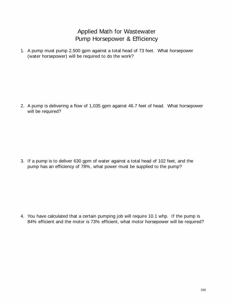
Applied Math for Wastewater Pump Horsepower & Efficiency
1. A pump must pump 2,500 gpm against a total head of 73 feet. What horsepower(water horsepower) will be required to do the work?
2. A pump is delivering a flow of 1,035 gpm against 46.7 feet of head. What horsepowerwill be required?
3. If a pump is to deliver 630 gpm of water against a total head of 102 feet, and thepump has an efficiency of 78%, what power must be supplied to the pump?
4. You have calculated that a certain pumping job will require 10.1 whp. If the pump is84% efficient and the motor is 73% efficient, what motor horsepower will be required?
335

5. What is the overall efficiency if an electric power equivalent to 36 hp is supplied to themotor and 16.3 hp of work is accomplished?
6. A pump is discharging 1,250 gpm against a head of 71 feet. The wire-to-waterefficiency is 82%. If the cost of power is $0.028/kW hr, what is the cost of the powerconsumed during a week in which the pump runs 126 hours?
7. A wet well is 12 feet long and 10 feet wide. The influent valve to the wet well isclosed. If a pump lowers the water level 2.6 feet during a 5-minute pumping test, whatis the gpm pumping rate?
ANSWERS
1. 46 hp2. 12.2 hp3. 20.8 hp4. 16.5 hp5. 45.3%
6. $71.937. 467 gpm
336

Section 15
TN Regs - Excerpts from the
Design Criteria for Sewage Works
337

January 2016 2-1 Design Criteria Ch. 2
CHAPTER 2
Sewers and Wastewater Pumping Stations
2.1 General Requirements for Collection Systems
2.1.1 Construction Approval
2.1.2 Ownership
2.1.3 Design
2.1.4 Overflows
2.1.5 Calculations
2.2 Design Considerations
2.2.1 Design Period
2.2.2 Basis of Design
2.2.3 Design Factors
2.3 Design and Construction Details
2.3.1 Gravity sewers
2.3.2 Materials
2.3.3 Pipe Bedding
2.3.4 Joints
2.3.5 Leakage Testing
2.3.6 Visual Inspection
2.3.7 Low Pressure Systems
2.3.8 Manholes
2.4 Special Details
2.4.1 Protection of Water Supplies
2.4.2 Backflow Preventers
2.4.3 Sewers in Relation to Streams
2.4.4 I inverted Siphons
2.5 General Requirements for Wastewater Pumping stations
2.5.1 Location and Flood Protection
2.5.2 Pumping Rate and Number of Units
2.5.3 Grit and Clogging Protection
2.5.4 Pumping Units
2.5.5 Flow Measurement
2.5.6 Alarm System
2.5.7 Overflows and/or Bypasses
338

January 2016 2-2 Design Criteria Ch. 2
2.6 Special Details
2.6.1 General
2.6.2 Wet Well - Dry Well Stations
2.6.3 Suction Lift Stations
2.6.4 Submersible Pumps
2.6.5 Grinder and Effluent Pumps
2.7 Operability and Reliability
2.7.1 Objective
2.7.2 Backup Units
2.7.3 Power Outages
2.7.4 Emergency Power Supply (for Treatment Plants as well as Pumping stations)
2.7.5 Storage
2.8 Force Mains
2.8.1 Size
2.8.2 Velocity
2.8.3 Air Release Valve
2.8.4 Termination
2.8.5 Materials of Construction
2.8.6 Pressure Tests
2.8.7 Anchorage
2.8.8 Friction Losses
2.8.9 Water Hammer
2.8.10 Isolation and Valving
APPENDIX
Appendix 2-A: Design Basis for Wastewater Flow and Loadings
339

January 2016 2-3 Design Criteria Ch. 2
2.1 General Requirements for Collection Systems
2.1.1 Construction Approval
In general, construction of new sewer systems or extensions of existing systems must ensure
that the downstream conveyance system and the receiving wastewater treatment plant are
either:
a. Capable of adequately conveying or processing the added hydraulic and organic load, or
b. Capable of providing adequate conveyance or treatment facilities on a time schedule
acceptable to the Division
2.1.2 Ownership
Sewer systems including pumping stations integral to gravity sewer and low-pressure sewer
designs require ownership by a responsible party, such as a public entity, for operation and
maintenance.
2.1.3 Design
The design and construction of new sewer systems must achieve total containment of sanitary
wastes and exclusion of infiltration and inflow (I/I). This includes installing pipe with
watertight joints, watertight connections to manholes, and watertight connections to service
laterals or service lateral stubs and trench design that minimizes the potential for migration of
water along the trench. However, the new sewer system and appurtenances must be able to
convey the wastewater load, including existing I/I, from upstream areas as appropriate.
2.1.4 Overflows
The Division of Water Resources (Division) will not permit overflows in separate sanitary
sewers or new overflows in existing combined sewers. The Division will not permit overflows
in new interceptor sewers intercepting existing combined sewers. An alarm system to signal
existing overflow conditions and procedures for reporting overflows may be required.
2.1.5 Calculations
The Division requires the submittal of all computations and other data used for design of the
sewer system.
2.2 Design Considerations
2.2.1 Design Period
2.2.1.1 Collection sewers (Laterals and Submains)
The Division requires collection sewers for the ultimate development of the tributary areas.
340

January 2016 2-4 Design Criteria Ch. 2
2.2.1.2 Main, Trunk, and Interceptor Sewers
The Division requires certain design factors for trunk sewers:
a. Possible solids deposition, odor, and pipe corrosion that might occur at initial flows
b. Population and economic growth projections and the accuracy of the projections
c. Comparative costs of staged construction alternatives
d. Effect of sewer sizing on land use and development
2.2.2 Basis of Design
The Division’s design requirements for new sewer systems are on the basis of per capita flows
or alternative methods.
2.2.2.1 Per Capita Flow
The Division requires the use of Appendix 2-A. Substitutions or additions to the
information presented in this table are acceptable if better or more accurate data is
available.
The Division requires the following:
a. Lateral and Submains: Minimum peak design flow should be not less than 400 percent
of the average design flow.
''Lateral'' - a sewer that has no other common sewers discharging into it.
"Submain” is defined as a sewer that receives flow from one or more lateral sewers.
b. Main, Trunk, and Interceptor sewers: Minimum peak design flow should be not less 250
percent of the average design flow.
"Main” or "trunk" is defined as a sewer that receives flow from one or more submains.
"Interceptor" - a sewer that receives flow from a number of main or trunk sewers, force
mains, etc.
2.2.2.2 Alternative Methods
The Division allows alternative methods other than on the basis of per capita flow rates.
Alternative methods may include the use of peaking factors of the contributing area,
allowances for future commercial and industrial areas, separation of infiltration and
inflow from the normal sanitary flow (for new sewers serving existing upstream
sewers), and modification of per capita flow rates (based on specific data). There
should be no allowance for infiltration or inflow into newly constructed or proposed
sewers.
341

January 2016 2-5 Design Criteria Ch. 2
2.2.3 Design Factors
The Division requires consideration of the following factors:
a. Peak wastewater flows from residential, commercial, institutional, and industrial sources
b. Potential for groundwater infiltration from existing upstream sewers
c. Topography and depth of excavation
d. Treatment plant location
e. Soils conditions
f. Pumping requirements
g. Maintenance, including manpower and budget
h. Existing sewers
i. Existing and future surface improvements
j. Controlling service connection elevations
k. Proximity to surface streams, including minimizing the potential for draining or diversion
of stream water into the pipe trench
l. Watertight and exclude groundwater and surface water.
2.3 Design and Construction Details
2.3.1 Gravity Sewers
The Division requires gravity sewers to be approximately one-half full when conveying the
anticipated peak daily dry weather flow and does not surcharge when conveying the anticipated
peak wet weather flow.
2.3.1.1 Minimum Size
The minimum size of new public sewers should be 8 inches (nominal) in diameter.
2.3.1.2 Depth
Generally, sewers should not be less than 2 ½ feet deep but should be sufficiently deep
to prevent freezing and physical damage.
2.3.1.3 Roughness Coefficient
The Division requires that a roughness coefficient “n” value of 0.013 be used in
Manning’s formula for the design of all sewer facilities unless a roughness coefficient
specific to the given pipe material is available. The roughness coefficient selected must
consider the long-term condition of the sewer. However, the Division requires an “n”
value equal to or greater than 0.011.
2.3.1.4 Slope
342

January 2016 2-6 Design Criteria Ch. 2
Sewers must be self-cleansing and capable of transporting most solids to the desired
point, usually a treatment facility. Two methods are approved for design in the State of
Tennessee: 1) Tractive Force and 2) Traditional (Ten-State Standards). For reasons of
economical design and long-term maintenance, the Division prefers the Tractive Force
Method.
Tractive Force Method:
ASCE and WEF (WEF Manual of Practice No. FD-5 Gravity Sanitary Sewer Design and
Construction, 2007, Section 5.6) now advocates a transition to the tractive force approach for
self-cleansing design. “Tractive Force (TF) design is a major improvement over traditional
methods to achieve self-cleansing in gravity sewers. This approach results in a self-cleansing
pipe slope value (Smin) for the design minimum flow rate (Qmin) in each sewer reach. Qmin is the
predicted largest 1-hour flow rate in the reach during the lowest flow week over the sewer
design life. Past design practices seldom included accurate estimation of Qmin values, but good
estimates of Qmin are crucial for TF design. The engineer should show in the engineering report
the calculations for Qmin for new sewer pipe projects. As compared to traditional minimum
slopes, Smin slopes via the TF method are flatter for sewers carrying typical to larger Qmin
values and steeper for sewers carrying smaller Qmin values.” ( Merritt, LaVere B., Tractive
Force Design for Sanitary Sewer Self-Cleansing, ASCE, May 2009)
Once a good estimate has been developed for Qmin, then Table 2-1 (WEF, 2007, Table 5.5, page
148) for calculating minimum slopes for a typical condition in sewers is provided to assist
designers with applying TF principles.
Table 2-1 Tractive Force Equations for Minimum Slope
Sewer Size When n is Variable*
(inches) value of Smin =
(Q in cfs)
8 0.000848 Qmin -0.5707
10 0.000887 Qmin -0.5721
12 0.000921 Qmin -0.5731
15 0.000966 Qmin -0.5744
18 0.001004 Qmin -0.5754
21 0.001038 Qmin -0.5761
24 0.001069 Qmin -0.5768
27 0.001097 Qmin -0.5774
30 0.001123 Qmin -0.5778
36 0.001169 Qmin -0.5787
42 0.001212 Qmin -0.5812
3Based on Darcy-Weisbach
343

January 2016 2-7 Design Criteria Ch. 2
Traditional Method:
The Traditional Method for conventional gravity sewers requires mean velocities, when
flowing full, of not less than 2.0 feet per second. Table 2-2 provides minimum slopes when
using the traditional method; however, slopes greater than these are desirable.
Table 2-2 Minimum Slope from Traditional Method
Sewer Size Minimum Slope*
(inches) (feet per 100 feet)
8 0.40
10 0.28
12 0.22
15 0.15
18 0.12
21 0.10
24 0.08
27 0.067
30 0.058
36 0.05 **
42 0.042***
* Great Lakes Upper Mississippi River Board, 1997.
** Recommended steeper – to give velocity of 2.1 ft/sec (WEF, 2007)
*** Recommended steeper – to give velocity of 2.3 ft/sec (WEF, 2007)
Under special condition, the using the Traditional Method, the Division may allow slopes
slightly less than those required for the 2.0 feet-per-second velocity when flowing full may be
permitted. Such decreased slopes will only be considered where the depth of flow will be 0.3 of
the diameter or greater for design average flow. Whenever such decreased slopes are proposed,
the design engineer should furnish with his report his computations of the depths of flow in
such pipes at minimum, average, and daily or hourly rates of flow. The maintaining wastewater
agency must recognize and accept in writing the problems of additional maintenance caused by
decreased slopes.
Uniform slope between manholes is required.
A minimum of 5 feet of horizontal separation between gas mains is required.
Anchors are required for sewers on 20 percent slope or greater. Secure anchors will have a
minimum two-foot thick tightly compacted clay collar or equal. Suggested minimum anchorage
spacing is as follows:
a. Not over 36 feet center to center on grades 20 percent and up to 35 percent.
b. Not over 24 feet center to center on grades 35 percent and up to 50 percent.
c. Not over 16 feet center to center on grades 50 percent and over.
344

January 2016 2-8 Design Criteria Ch. 2
2.3.1.5 Alignment
Straight alignment between manholes is required for gravity sewers. However, curved
sewers may be approved where circumstances warrant but only in large (i.e., 24" and
larger) diameter segments.
2.3.1.6 Increasing Size
When a smaller sewer joins a larger one, the Division requires the alignment to
maintain the same energy gradient. An approximate method for securing these results is
to match the crowns of the sewers entering/ exiting the manhole or junction structure.
2.3.1.7 High-Velocity Protection
Where velocities greater than 15 feet per second are expected, the Division requires
protective measures against internal erosion or displacement by shock.
2.3.2 Materials
The Division will consider any generally accepted material for sewers. The material selected
should be adapted to local conditions such as character of industrial wastes, possibility of
septicity, soil characteristics, abrasion and similar problems. The Division requires careful
consider of pipes and compression joint materials subjected to corrosive or solvent wastes.
Chemical/stress failure and stability in the presence of common household chemicals such as
cooking oils, detergents and drain cleaners are factors.
The specifications should stipulate need to keep clean the pipe interior, sealing surfaces, fittings
and other accessories. Pipe bundles should be stored on flat surfaces with uniform support. The
protection of stored pipe is required. Pipe with prolonged exposure (six months or more) to
sunlight requires a suitable covering (canvas or other opaque material). The Division requires
care be given to gaskets. Ensure that gasket not be exposed to oil, grease, ozone (produced by
electric motors), excessive heat and direct sunlight. Consult with the manufacturers for specific
storage and handling recommendations.
2.3.2.1 Rigid Pipe
Rigid pipe includes, but is not be limited to, concrete pipe. Any rigid pipe should have a
minimum crushing strength of 2000 pounds per lineal foot. All pipes should meet the
appropriate ASTM and/or ANSI specifications.
2.3.2.2 Semi-rigid Pipe
Semi-rigid pipe includes, but is not be limited to, ductile iron. All pipes should meet the
appropriate ASTM and/or ANSI specifications.
2.3.2.3 Flexible Pipe
345

January 2016 2-9 Design Criteria Ch. 2
Flexible pipe includes, but is not be limited to, ABS solid wall pipe, polyvinyl chloride
pipe (PVC), polyethylene pipe (PE), fiberglass composite pipe, reinforced plastic
mortar pipe (RPM) and reinforced thermosetting resin pipe (RTR). PVC pipe should
have a minimum Standard Dimension Ratio (SDR) of 35. The Division requires that all
other flexible pipe have the same calculated minimum deflection under identical
conditions as the SDR 35 PVC pipe.
To calculate the flexible pipe deflection under earth loading use the formula presented
in the ASCE/WPCF publication, Design and Construction of Sanitary and Storm
Sewers.
All pipes should meet appropriate ASTM and/or ANSI specifications. ASTM D-3033
and D-3034 PVC pipes differ in wall thickness and have non-interchangeable fittings.
2.3.3 Pipe Bedding and Backfilling
The Division requires that all sewers designs provide protection from damage from
superimposed loads. The width and depth of the trench require allowances be made for loads
on the sewer. Backfill material up to three feet above the top of the pipe should not exceed 6
inches in diameter at its greater dimension.
The Division requires ductile iron pipe in roadways where cover is less than 4 feet. In such
cases, a minimum cover of six inches is required.
The Division requires ductile iron pipe or relocation when the top of the sewer is less than 18
inches below the bottom of a culvert or conduit.
2.3.3.1 Rigid Pipe
Bedding Classes A, B, or C as described in ASTM C-12 or WPCF MOP No. 9 (ASCE
MOP No. 37) should be used for all rigid pipe, provided the proper strength pipe is used
with the specified bedding to support the anticipated load. The Division requires the
use of ASTM-C-12 (placement of bedding and backfill).
2.3.3.2 Semi-Rigid Pipe
The Division requires the use of Bedding Classes I, II, III, or IV (ML and CL only) as
described in ASTM D-2321 for all semi-rigid pipe provided with the specified bedding
to support the anticipated load.
The Division requires ASTM-A-746 be used to install ductile iron pipe.
2.3.3.3 Flexible Pipe
346

January 2016 2-10 Design Criteria Ch. 2
The Division requires the use of Bedding Classes I, II, or III as described in ASTM D-
2321 for all flexible pipe. The Division requires the proper strength pipe with the
specified bedding to support the anticipated load.
The Division requires ASTM-D-2321 for bedding, haunching, initial backfill, and
backfill.
The Division requires Class I bedding material for bedding, haunching, and initial
backfill as described in 2.3.3.4. (polyethylene pipe).
2.3.3.4 Alternate Bedding Option
The Division will allow all sewers bedded and backfilled with a minimum of 12 inches
of Class I material over the top and below the invert of the pipe--an alternative to sub-
sections 2.3.3.1, 2.3.3.2 and 2.3.3.3.
2.3.3.5 Deflection Testing
The Division requires deflection testing of all flexible pipes. The Division requires
backfill testing after it has been in place at least 24 hours.
No pipe should exceed a deflection of 5%.
The test should be run with a rigid ball or an engineer approved 9-arm mandrel having a
diameter equal to 95% of the inside diameter of the pipe. The test requires manually
pulling the test device through the line.
2.3.4 Joints
The Division requires the specification to include the method of making joints and the materials
used. The Division requires that sewer joints eliminate infiltration and prevent the entrance of
roots.
Elastomeric gaskets, other types of pre-molded (factory made) joints, and ABS solvent-cement
welded joints are required. The Division requires the use of ASTM-F2620 for butt fusion
joining technique with polyethylene pipe. The Division requires the removal of internal beads
for butt fusion joints on pipelines with slopes less than one percent. Cement mortar joints are
not acceptable. Field solvent welds for PVC and PE pipe and fittings are not acceptable.
2.3.5 Leakage Testing
The Division requires the use of ASTM-C-828 for low-pressure air testing for all pipes. The
time required for the pressure to drop from the stabilized 3.5 psig to 2.5 psig should be greater
than or equal to the minimum calculated test time (the Division requires that air loss rate be
part of the test criteria).
The testing method should take into consideration the range in groundwater elevations
projected and the situation during the test. The height of the groundwater should be measured
from the top of the invert (one foot of H20 = 0.433 psi).
347

January 2016 2-11 Design Criteria Ch. 2
Table 2-3 provides the minimum test times and allowable air loss values for various pipe size
per 100 ft.
Table 2-3 Leakage Test Parameters
Pipe Size
(inches)
Time, T
(sec/100 ft)
Allowable Air Loss, Q
(ft3/min)
6 42 2.0
8 72 2.0
10 90 2.5
12 108 3.0
15 126 4.0
18 144 5.0
21 180 5.5
24 216 6.0
27 252 6.5
30 288 7.0
2.3.6 Visual Inspection
The Division requires that new sewers be video inspected to confirm proper installation and to
provide a visual record of the condition of the newly constructed sewer for future reference.
2.3.7 Low Pressure Systems
2.3.7.1 Application
The Division requires the consideration of low-pressure systems for situations in which
gravity sewers are extremely costly or impractical, such as rock or high groundwater
table.
2.3.7.2 Grinder Pumps
The Division requires all the collection and transport of raw wastewater from individual
buildings/dwellings to the pressure system by appropriately sized grinder pumps.
Grinder pumps do not require a septic tank.
All pumps should have operating curves that do not allow backflow under maximum
head conditions.
Pumps should be watertight and located above the seasonal groundwater table were
possible where possible.
2.3.7.3 Septic Tank Effluent Pump (STEP) system
348

January 2016 2-12 Design Criteria Ch. 2
All STEP installations require careful attention to the following design details and
construction techniques:
a. All STEPs preceded by a watertight septic tank. Retrofitting a STEP to an existing
septic tank will require a visual inspection of the tank.
Replacement of all defective septic tanks.
b. STEPs retrofitted to an existing septic tank and drain field must provide a positive
means of preventing groundwater from backing up through the drain field to the
STEP.
c. The STEP should be located as close as possible to the septic tank.
d. Electrical power supplied through the main circuit box. Electricity furnished to a
separate circuit box installed on the exterior wall of the building, near the STEP.
2.3.7.4 Hydraulic
Hydraulic calculations are of extreme importance. Head losses within the low-pressure
system will change with each pump activation.
2.3.7.5 Minimum Velocity
The recommended minimum operating velocity in a pressure system should be 2 feet
per second (fps).
2.3.7.6 Flushing
There should be a means of cleaning the system, particularly to clear any settleable
solids or grease accumulation.
2.3.7.7 Pressure Testing
There should be means for isolating and pressurizing sections of the system to detect
and locate leaks.
2.3.7.8 Alarms
There should be an external visual warning system to indicate the malfunction of the
pump. The high-level (in storage tank) warning system should be a dual audio / visual
system.
2.3.7.9 Cleanouts
The Division requires cleanouts at a maximum of 400-foot intervals.
2.3.7.10 Ventilation
Ventilation of the pumping station should be provided via house vents where allowable
or through a separate system.
2.3.8 Manholes
349

January 2016 2-13 Design Criteria Ch. 2
2.3.8.1 Location
The Division requires manholes at the end of each 8-inch diameter sewer or greater.
The Division will waive this requirement if a stub-out is installed (assumes line will be
extended in near future).
The Division requires manholes at all changes in grade, size, or alignment; at all
intersections; and at distances not greater than 400 feet for sewers 15 inches or less.
The Division requires manholes at 500 feet for sewer 18 inches to 30 inches. The
Division may allow greater spacing in larger sewers and in those carrying a settled
effluent.
2.3.8.2 Drop Connection
The Division requires a drop connection for a sewer entering a manhole at an elevation
of 24 inches or more above the manhole invert. Where the difference in elevation
between the incoming sewer and the manhole invert is less than 24 inches, a filleted
invert will prevent solids deposition.
2.3.8.3 Diameter
The minimum diameter of manholes should be 48 inches; larger diameters are
preferable. The minimum clear opening in the manhole frame shall meet current OSHA
standards.
2.3.8.4 Flow Channels
Flow channels in manholes should be of such shape and slope to provide smooth
transition between inlet and outlet sewers and to minimize turbulence. Channeling
height should be to the crowns of the sewers. Benches should be sloped from the
manhole wall toward the channel to prevent accumulation of solids.
2.3.8.5 Water tightness
The Division requires watertight manhole covers wherever the manhole tops may be
flooded. Manholes of brick or segmented block are not appropriate materials for
manhole construction where groundwater conditions are unfavorable. In pre-cast
concrete manholes, the Division requires plastic gaskets, pre-molded rubber gaskets or
flexible, plastic gaskets.
2.3.8.6 Connections
The Division requires special attention be paid to the connection between the manhole
wall and the sewer pipe in order to minimize long-term infiltration into the system. The
Division requires flexible joints for line connections directly to the manholes, or to short
stubs integral with the manholes. Flexible joints are joints that permit the manholes to
settle without destroying the watertight integrity of the line connections.
2.3.8.7 Ventilation
350

January 2016 2-14 Design Criteria Ch. 2
The Division requires consideration of ventilation of gravity sewer systems where
continuous watertight sections are greater than 1,000 feet in length. Vent height and
construction must consider flood conditions.
2.3.8.8 Frames, Covers, and Steps
Frames, covers, and steps, if utilized, should be of suitable material and designed to
accommodate prevailing site conditions and to provide for a safe installation.
Materials used for manhole steps should be highly corrosion-resistant. The Division
requires aluminum or plastic with reinforcing bar.
2.3.8.9 Vacuum Testing
New manholes should be vacuum tested after construction to verify they will not be
new sources of infiltration or inflow. The Division requires the test to include the
manhole frame. The Division considers the test acceptable if the vacuum remains at 10
inches of mercury or drops to no less than 9 inches of mercury within one minute. The
Division may allow alternative testing methods--if demonstrated to be equal of better
than vacuum testing.
2.4 Special Details
2.4.1 Protection of Water Supplies
2.4.1.1 Water Supply Interconnections
There shall be no physical connection between a public or private potable water supply
system and a sewer or appurtenance thereto.
2.4.1.2 Relation to Water Mains
Horizontal Separation: Whenever possible, the Division requires at least 10 feet
horizontal separation of the sewer from any existing or proposed water main. Should
local conditions prevent a lateral separation of 10 feet, the Division may allow the
sewer closer than 10 feet to a water main if in a separate trench and if the elevation of
the top (crown) of the sewer is at least 18 inches below the bottom (invert) of the water
main.
Vertical Separation: Whenever sewers must cross under water mains, the Division
requires the sewer at such elevation that the top of the sewer is at least 18 inches below
the bottom of the water main. The Division will consider other alternatives if the sewer
evaluation cannot be varied.
When it is impossible to obtain proper horizontal and vertical separation as stipulated
above, the sewer should be designed and constructed equal to the water main pipe and
should be pressure-tested to assure water-tightness (see drinking water criteria) or the
joints of the sewer pipe should be encased in concrete to inhibit infiltration/exfiltration.
Details of the encasement should be clear and extend the necessary distance to achieve
design goals. The designer should consider the temperature differential between the
351

January 2016 2-15 Design Criteria Ch. 2
pipe and the surrounding materials in their determination if reinforcement is necessary.
Such arrangements are discouraged.
The Division requires the designer’s evaluation, calculations, and conclusions in the
project record and provided to all interested parties upon request.
2.4.2 Backflow Preventers
State approved reduced pressure backflow prevention devices are required on all potable water
mains serving the wastewater treatment plant or pumping station. The Division can provide a list
of approved backflow preventers.
2.4.3 Sewers in Relation to Streams
2.4.3.1 Site Characterizations for Sewers in Proximity to Streams
For new sewers or existing sewers replaced in the same trench that cross or have an
alignment within 50 feet of the bank of a surface stream, upon notification of the
potential route of the proposed sewer, the Division will perform a site characterization
to determine the potential for stream capture. (See Section 1.2.4.1 of Chapter 1) If the
Division determines there is potential for stream capture, a site-specific Aquatic
Resource Alteration Permit (ARAP) is required, and obtaining this permit will require
the design engineer to provide a plan to prevent stream capture. This may require
additional study of the characteristics of the stream, including soil classification data,
rock depth (if present), recommendations for controlling seepage, cut and fill
recommendations, a trench dewatering plan, and other site specific data.
2.4.3.2 Location of Sewers in Streams
Open trench sewers located along streams should be located outside of the streambed
and sufficiently removed there from to minimize disturbance or root damage to
streamside trees and vegetation.
Sewer outfalls, headwalls, manholes, gate boxes or other structures should be located so
they do not interfere with the free discharge of flood flows of the stream.
The Division requires open trench sewer crossings of streams to cross the stream as
nearly perpendicular to the stream flow as possible and be free from change in grade.
2.4.3.3 Construction
Sewers entering or crossing streams should be ductile iron pipe from manhole to
manhole, wrapped in plastic and encased in high strength flowable fill. (Note: This
provision is subject to a case-by-case review. In this case, the Division requires an
impermeable barrier that might be flowable fill, concrete, liners, casing pipe or a
combination. The best practice may be different depending upon stream flow, local
soils, topography and geology).
352

January 2016 2-16 Design Criteria Ch. 2
The sewer should be free of alignment or grade changes. The Division requires sewer
systems designs to minimize the number of stream crossings. The Division requires the
stream returned as nearly as possible to its original condition upon completion of
construction. The Division requires the stream banks to be seeded or other erosion
prevention methods employed to prevent erosion. Stream banks should be sodded, if
necessary, to prevent erosion. The consulting engineer should specify the method or
methods in the construction of the sewers in or near the stream to control siltation.
With regard to prohibitions on the contractor, the Division requires that the
specifications contain the following clauses:
unnecessarily disturbing or uprooting trees and vegetation along the stream
bank and in the vicinity of the stream,
dumping of soil and debris into streams and/or on banks of streams,
changing course of the stream without encroachment permit,
leaving cofferdams in streams,
leaving temporary stream crossings for equipment,
operating equipment in the stream, or
pumping silt-laden water into the stream.
The Division requires provisions in the specifications to:
retard the rate of runoff from the construction site,
control disposal of runoff,
liberal use of silt fencing to trap sediment resulting from construction in
temporary or permanent silt-holding basins,
pump discharges resulting from dewatering operations;
deposit out of the flood plain area all material and debris removed from the
streambed.
Specifications should require that cleanup, grading, seeding, planting or restoration of
the work area should be carried out as early as practical as the construction proceeds.
The Division requires the specifications mandate a trench-dewatering plan for new
sewer alignments that cross a stream or are within 50 feet of the bank of the stream
defined in Section 1.2.4.1.
2.4.3.4 Special Construction Requirements
The Division requires the employment of special design requirements to prevent stream
drainage from sinking at the crossing and following along the sewer pipe bedding. The
Division requires an in trench impounding structure of compacted clay or concrete
check dams. The Division will consider other proposals.
2.4.3.5 Aerial Crossings
The Division may allow sewers that lay on piers across ravines or streams if no other
practical alternative exists or, in the design engineer’s judgment, other methods will not
be as reliable.
353

January 2016 2-17 Design Criteria Ch. 2
The Division requires support for all joints. All supports designs must prevent frost
heave, overturning or settlement. The Division requires precautions against freezing,
such as insulation or increased slope and expansion joints between aboveground and
belowground sewers. The Division requires deigns to consider the impact of
floodwaters and debris. The design should consider maintenance of an adequate
waterway for the 100-year flood flows. The design engineer should analyze the impact
of the proposed aerial crossing(s) on flooding, including hydraulic modeling, such as
Hydrologic Engineering Center-River Analysis System (HEC-RAS) modeling, as
necessary.
2.4.3.6 Permits
It is the owner’s responsibility to obtain all necessary permits along streams or rivers;
i.e., Corps of Engineers, TVA, or the Natural Resources Section of the Division of
Water Resources.
2.4.4 Inverted Siphons
Under normal conditions, the Division will not allow inverted siphons. However, if they are,
the Division requires that the following:
Minimum of two barrels,
Minimum pipe size of six inches--provided with necessary appurtenances for convenient
flushing and maintenance,
Manholes with adequate clearances for rodding,
Sufficient head and pipe sizes to secure velocities of at least 3.0 feet per second for
average flows,
Inlet and outlet details arranged so that the normal flow is diverted to one barrel, and so
that either barrel may be cut out of service for cleaning,
Design engineer furnishes hydraulic calculations with the plans,
Proper access maintained.
2.5 General Requirements for Wastewater Pumping Stations
2.5.1 Location and Flood Protection
The Division requires wastewater pumping stations located as far as practicable from present or
proposed built-up residential areas, with an all-weather road and noise control, odor control,
and station architectural design taken into consideration. Sites for stations should be of
sufficient size for future expansion or addition, if applicable. The Division requires security for
the pumping station and controls.
The Division requires protection from the 100-year flood for the station's operational
components.
354

January 2016 2-18 Design Criteria Ch. 2
Where the wet well is at a depth greater than the water table elevation, special provisions
should be made to ensure watertight construction of the wet well. The Division requires
connections to the pumping station at an elevation higher than the maximum water table
elevation, where possible.
2.5.2 Pumping Rate and Number of Units
At least two pump units should be provided, each capable of handling the expected maximum
flow. The Division requires the submittal of pump head and system head curves.
For three or more units the Division requires a design to fit actual flow conditions and must be
of such capacity that, with any one unit out of services, the remaining units will have capacity
to handle the maximum wastewater flow.
A station expected to operate at a flow rate less than one-half the average design flow for an
extended period may create septic conditions due to long holding times in the wet well. The
design should consider the need for additional measures to prevent the formation of odors.
The design should the use of variable-speed or multiple staged pumps, particularly when the
pumping station delivers flow directly to a treatment plant. The design allows delivery of the
wastewater at approximately the same rate as received at the pumping station.
2.5.3 Grit and Clogging Protection
Where it may be necessary to pump wastewater prior to grit removal, the design of the wet well
should receive special attention, and the design of the discharge piping should be to prevent grit
settling in pump discharge lines of pumps not operating.
Design of the pumping station should consider the protection of the pump from damage caused
by grit and debris, where warranted. To accomplish this--maintain minimum pump operational
speeds, through the installation of bar screens with a grinder or comminutor, or similar devices.
For the larger or deeper stations, duplicate protection units, each sized at full capacity, are
preferred.
2.5.4 Pumping Units
2.5.4.1 Pump Openings
The Division requires pumps be capable of passing a 3-inch compressible solid. The
Division requires pump suction and discharge openings to be at least 4 inches in
diameter unless it is a pump with chopping or grinding capabilities.
2.5.4.2 Priming
The Division requires the placement of pumps so that under normal operating
conditions they will operate under a positive suction head (except for suction lift
pumps).
355

January 2016 2-19 Design Criteria Ch. 2
2.5.4.3 Intake
Each pump should have an individual intake. Wet well design should be such as to
avoid turbulence near the intake.
2.5.4.4 Controls
The location of controls should ensure that the flows entering the wet well to not affect
them, by the suction of the pumps, or by proximity to wet well walls. Controls must be
able to activate additional pumps if the water in the wet well continues to rise. Controls
can be float switches, air-operated pneumatic, radar, ultrasonic or capacitance probe
types. Provisions should be made to automatically alternate the pumps in use. Pumping
stations with motors and/or controls below grade should be equipped with a secure
external disconnect switch. The Division requires consideration of an “intrinsically
safe” power source if float switches are used.
The Division requires consideration of redundant controls and/or remote monitoring to
assist in preventing overflows.
2.5.5 Flow Measurement
At pumping stations with flow capacity greater than 0.5 million gallons per day (mgd), the
Division recommends providing suitable devices for measuring flow.
2.5.6 Alarm System
The Division recommends an alarm system for all pumping stations such as, telemetry alarm to
24-hour monitoring stations or telephone alarms to duty personnel (when reliability
classification or property damage warrants it). The Division requires an audiovisual device at
the station for external observation when telemetry is not used.
The Division requires alarms for high wet well and power failure, as a minimum, for all
pumping stations. For larger stations, the Division requires alarms signalizing pump and other
component failures or malfunctions.
The Division requires a backup power supply, such as a battery pack with an automatic
switchover feature, for the alarm system, such that a failure of the primary power source will
not disable the alarm system. The alarm system must be tested and verified that it is in good
working order.
2.5.7 Overflows and/or Bypasses
Pumping stations should be designed and built without any type of overflow or bypass
structure.
2.6 Special Details
2.6.1 General
356

January 2016 2-20 Design Criteria Ch. 2
2.6.1.1 Materials
Materials must not contain hydrogen sulfide and other corrosive gases, greases, oils,
and other constituents frequently present in wastewater. The Division recommends the
use of concrete additives or protective coatings to prevent deterioration caused by
corrosive gases.
2.6.1.2 Electrical Equipment
Electrical systems and components (e.g., motors, lights, cables, conduits, switchboxes,
and control circuits) in enclosed or partially enclosed spaces where flammable mixtures
occasionally may be present (including raw wastewater wet wells) should comply with
the National Electrical Code requirements for Class I Division 1 locations.
2.6.1.3 Water Supply
There should be no physical connection between any potable water supply and a
wastewater pumping station that under any conditions might cause contamination of the
potable water supply. A potable water supply must comply with conditions stipulated
in section 2.4.2.
2.6.1.4 Lighting
Adequate lighting is required for the entire pumping station.
2.6.1.5 Pump and Motor Removal
The Division requires the removal of pumps, motors, and other equipment, without
interruption of system service.
2.6.1.6 Safety
The Division requires suitable and safe means of access to equipment requiring
inspection or maintenance and that stairways and ladders satisfy all OSHA
requirements.
2.6.1.7 Valves and Piping
The Division requires suitable shutoff valves on suction and discharge lines of each
pump for normal pump isolation and a check valve on each discharge line between the
shutoff valve and the pump. Pump suction and discharge piping should not be less than
4 inches in diameter except where design of special equipment allows. The velocity in
the suction line should not exceed 6 feet per second and, in the discharge piping, 8 feet
per second. A separate shutoff valve is desirable on the common line leaving the
pumping station.
357

January 2016 2-21 Design Criteria Ch. 2
2.6.1.8 Ventilation
The Division requires ventilation for all pumping stations during all periods when the
station is manned. Portable ventilation equipment is acceptable for small pumping
stations. Mechanical ventilation is required if screens or mechanical equipment, which
might require periodic maintenance and inspection, are located in the wet well. In pits
over 15 feet deep, multiple inlets and outlets are desirable. The Division requires that
dampers not be used on exhaust or fresh air ducts, and fine screens or other obstructions
in air ducts should be avoided to prevent clogging.
2.6.2 Wet Well - Dry Well Stations
2.6.2.1 Separation
The Division requires complete separation of wet and dry wells, including their
superstructures.
The Division recommends dividing the wet well into two sections, properly
interconnected, to facilitate repairs and cleaning where continuity of pumping station
operation is necessary.
2.6.2.2 Wet Well Size and Design
Provide an evaluation of the effective capacity of the wet well based on pumping
requirements and reliability classifications.
Wet well design should consider approaches for minimizing solids deposition.
2.6.2.3 Dry Well Dewatering
The Division requires a separate sump pump in the dry wells to remove leakage or
drainage with the discharge above the high water level of the wet well. The Division
will not approve water ejectors connected to a potable water supply. All floor and
walkway surfaces should have an adequate slope to a point of drainage.
2.6.3 Suction Lift Stations
2.6.3.1 Priming
Conventional suction-lift pumps should be of the self-priming type, as demonstrated by
a reliable record of satisfactory operation. The maximum recommended lift for a
suction lift pumping station is 15 feet, using pumps of 200 gallons per minute (gpm)
capacity or less.
358

January 2016 2-22 Design Criteria Ch. 2
2.6.3.2 Capacity
The capacity of suction lift pumping stations should be limited by the net positive
suction head and specific speed requirements, as stated on the manufacturer’s pump
curve, for the most severe operating conditions.
2.6.3.3 Air Relief
a. Air Relief Lines
An air relief line on the pump discharge piping is required for all suction lift
pumps. This line should be located at the maximum elevation between the pump
discharge flange and the discharge check valve to ensure the maximum bleed-off of
entrapped air. The air relief line should terminate in the wet well or suitable sump
and be open to the atmosphere.
b. Air Relief Valves
The Division requires air relief valves in air relief lines on pumps not discharging to
gravity sewer collection systems. The air relief valve should be located as close as
practical to the discharge side of the pump.
2.6.3.4 Pump Location
For standard designs, suction lift pumps are mounted on the wet well but not within the
wet well.
2.6.3.5 Access to Wet Well
Access to the wet well should not be through the dry well, and the dry well should have
a gastight seal when mounted directly above the wet well.
2.6.4 Submersible Pumps
2.6.4.1 Pump Removal
Submersible pumps should be readily removable and replaceable without dewatering
the wet well or requiring personnel to enter the wet well.
The Division recommends a hoist or crane system for removing the pumps from the wet
well either through a permanent installation at the site or a mobile system that could be
utilized at multiple sites.
2.6.4.2 Controls
The control panel should be located outside the wet well and suitably protected from
weather, humidity, vandalism, and gases migrating from the wet well.
359

January 2016 2-23 Design Criteria Ch. 2
2.6.4.3 Valves
The Division recommends all control valves on the discharge line for each pump in a
convenient location outside the wet well in separate pits and protected from weather and
vandalism.
2.6.4.4 Submergence
Positive provision, such as backup controls, is required to assure submergence of the
pumping units.
2.6.5 Grinder and Effluent Pumps
The requirements for grinder pumps are included in Section 2.3.6.
2.7 Operability and Reliability
2.7.1 Objective
The objective of reliability is to prevent the discharge of raw or partially treated wastewater to
any waters and to protect public health by preventing backup of wastewater and subsequent
discharge to basements, streets, and other public and private property.
2.7.2 Backup Units
A minimum of two pumps or pneumatic ejectors are required in each station in accordance with
section 2.5.2.
2.7.3 Power Outages
An emergency power source or auxiliary power is required for all pumping stations larger than
1 MGD to ensure continuous operability unless experience has shown the frequency and
duration of outages to be low and the pumping station and/or sewers provide storage sufficient
for expected interruptions in power service.
2.7.4 Emergency Power Supply (for Treatment Plants as well as Pumping stations)
2.7.4.1 General
The Division requires provision of an emergency power supply for pumping stations
(and treatment plants) to at least two independent public utility sources, or by provision
of portable or in-place internal combustion engine equipment that will generate
electrical or mechanical energy, or by the provision of portable pumping equipment.
Emergency power must be provided for all stations which are 1 MGD or larger, or as
determined by the reliability classification.
360

January 2016 2-24 Design Criteria Ch. 2
Emergency power should be provided that, alone or combined with storage, will prevent
overflows from occurring during any power outage that is equal to the maximum outage
in the immediate area during the last 10 years. If available data were less than 10 years,
an evaluation of a similar area served by the power utility for 10 years would be
appropriate.
2.7.4.2 In -Place Equipment
The utilization of in-place internal combustion equipment requires the following
guidelines:
a. Placement: bolted in place. Facilities for unit removal for purposes of major
repair or routine maintenance.
b. Controls: automatic and manual startup and cut-in.
c. Size: adequate to provide power for lighting and ventilation systems and
such further systems that affect capability and safety as well as the pumps.
d. Engine Location: located above grade, with suitable and adequate
ventilation of exhaust gases.
e. Underground Fuel Storage Tank: design and construction must conform to
the applicable requirements of Federal Regulations 40 CFR 280 and 281.
Contact the Tennessee Division of Superfund, Underground Storage Tank
Program, for guidance.
2.7.4.3 Portable Equipment
The utilization of portable equipment requires the following guidelines:
Pumping units have connections to operate between the wet well and the discharge side
of station and the station provided with permanent fixtures that will facilitate rapid and
easy connection of lines.
2.7.5 Storage
The Division requires wet well and tributary main capacity above the high-level alarm
sufficient to hold the peak flow expected during the maximum power outage duration during
the last 10 years.
2.8 Force Mains
2.8.1 Size
Minimum size force mains required to be not less than 4 inches in diameter, except for grinder
pumps or septic tank effluent applications
361

January 2016 2-25 Design Criteria Ch. 2
2.8.2 Velocity
At pumping capacity, a minimum self-scouring velocity of 3 feet per second (fps) should be
maintained unless flushing facilities are provided. Velocity should not exceed 8 fps.
2.8.3 Air/Vacuum Relief Valve
An air relief valve is required at the necessary high points in the force main to relieve air
locking. Vacuum relief values may be necessary to relieve negative pressures on force mains to
protect against pipe collapse.
2.8.4 Termination
The force main should enter the receiving manhole with its centerline horizontal and with an
invert elevation that will ensure a smooth flow transition to the gravity flow section; but in no
case should the force main enter the gravity sewer system at a point more than 1 foot above the
flow line of the receiving manhole. The design should minimize turbulence at the point of
discharge.
The Division requires the use of inert materials or protective coatings for the receiving manhole
to prevent deterioration because of hydrogen sulfide or other chemicals where such chemicals
are present or suspected to be present because of industrial discharges or long force mains.
2.8.5 Materials of Construction
The pipe material should be adapted to local conditions, such as character of industrial wastes,
soil characteristics, exceptionally heavy external loadings, internal erosion, corrosion, and
similar problems.
Installation specification should contain appropriate requirements based on the criteria,
standards, and requirements established by the industry in its technical publications.
Requirements should be set forth in the specifications for the pipe and methods of bedding and
backfilling thereof so as not to damage the pipe or its joints, impede cleaning operations, not
create excessive side fill pressures or ovality of the pipe, nor seriously impair flow capacity.
The Division requires that the design of all pipes prevent damage from superimposed loads.
Proper design allowance for loads on the pipe because of the width and depth of trench is
required.
2.8.6 Pressure Tests
The Division requires testing, before backfilling, of all force mains at a minimum pressure of at
least 50 percent above the design operating pressure for at least 30 minutes. Leakage should
not exceed the amount given by the following formula:
362

January 2016 2-26 Design Criteria Ch. 2
L = ND (P).5
/7,400
Where L is allowable leakage in gallons per hour
N is the number of pipe joints
D is the pipe diameter in inches
P is the test pressure in psi
2.8.7 Anchorage
The Division requires sufficient anchorage of force mains within the pumping station and
throughout the line length to include, thrust blocks, restrained joints, and/or tie rods.
2.8.8 Friction Losses
The Division requires the use of a C factor that will take into consideration the conditions of
the force main at its design usage. For example, a grease-coated pipe after several years will
not have the same C factor as a new pipe.
2.8.9 Water Hammer
The force main design should investigate the potential for the existence of water hammer.
2.8.10 Isolation and Valving
The Division recommends the installation of isolation valves at strategic locations along the
force main to facilitate maintenance of the system.
363

January 2016 2-27 Design Criteria Ch. 2
APPENDIX 2-A
Design Basis for Wastewater Flow and Loadings
Table 2-A.1. Typical Wastewater Flow Rates from Commercial Sources
(Source: Crites and Tchobanoglous, 1998)
Table 2-A.2. Typical Wastewater Flow Rates from Institutional Sources
(Source: Crites and Tchobanoglous, 1998)
364

January 2016 2-28 Design Criteria Ch. 2
Table 2-A.3. Typical Wastewater Flow Rates from Commercial Sources
(Source: Crites and Tchobanoglous, 1998)
365

January 2016 4-1 Design Criteria Ch. 4
CHAPTER 4
Preliminary and Pretreatment Facilities
4.1 Screening and Grinding
4.1.1 General
4.1.2 Location
4.1.3 Bar Screens
4.1.4 Fine Screens
4.1.5 Communition
4.1.6 Operability
4.1.7 Disposal
4.2 Grit Removal
4.2.1 General
4.2.2 Location
4.2.3 Design
4.2.4 Disposal
4.2.5 Operability
4.3 Pre-aeration
4.4 Flow Equalization
4.4.1 General
4.4.2 Location
4.4.3 Design and Operability
4.5 Swirls and Helical Bends
366

January 2016 4-2 Design Criteria Ch. 4
PRELIMINARY AND PRETREATMENT FACILITIES
4.1 Screening and Grinding
4.1.1 General
Some type of screening and/or grinding device shall be provided at all mechanical
wastewater plants. The effective removal of grit, rocks, debris, excessive oil or grease
and the screening of solids shall be accomplished prior to any activated sludge process.
Any grinding which does not dispose of the shredded material outside of the wastewater
stream must be evaluated with regard to the influent characteristics (rags, combined
sewers) of the waste prior to any activated sludge process.
4.1.2 Location
4.1.2.1 Indoors
Screening devices installed in a building where other equipment or offices are
located shall be accessible only through an outside entrance. Adequate lighting,
ventilation and access for maintenance or removal of equipment and screenings
shall be provided.
4.1.2.2 Outdoors
The removal point for screenings should be as practical as possible for the plant
personnel, preferably at ground level. Ladder access is not acceptable unless
hoisting facilities for screenings are provided. Separate hoisting is not required
for bar screens in manual bypass channels.
4.1.2.3 Deep Pit Installations
Stairway access, adequate lighting and ventilation with a convenient and adequate
means for screenings removal shall be provided.
4.1.3 Bar Screens
4.1.3.1 Manually Cleaned
Clear openings between bars shall be from 1 to 2 inches. Slope of the bars shall be
30 to 60 degrees from the vertical. Bar size shall be from 1/4 to 5/8 inches with 1
to 3 inches of depth, depending on the length and material to maintain integrity.
A perforated drain plate shall be installed at the top of the bar screen for
temporary storage and drainage.
367

January 2016 4-3 Design Criteria Ch. 4
4.1.3.2 Mechanically Cleaned
Mechanically cleaned bar screens are recommended for all plants greater than 1
MGD. Both front cleaned or back cleaned models may be acceptable. Clear
openings no less than 5/8 inch are acceptable. Protection from freezing
conditions should be considered.
Other than the rakes, no moving parts shall be below the water line.
4.1.3.3 Velocities
Approach velocities no less than 1.25 fps nor a velocity greater than 3.0 fps
through the bar screen is desired.
4.1.4 Fine Screens
4.1.4.1 General
Fine screens shall be preceeded by a trash rack or coarse bar screen.
Comminution shall not be used ahead of fine screens. A minimum of two fine
screens shall be provided, each capable of independent operation at peak design
flow. The design engineer must fully evaluate a proposal where fine screens are
to be used in lieu of primary sedimentation. Fine screens shall not be considered
equivalent to primary sedimentation or grit removal, but will be reviewed on a
case-by-case basis. Oil and grease removal must be considered.
4.1.4.2 Design
The operation should be designed to not splash operating personnel with
wastewater or screenings. Fine screens will generally increase the dissolved
oxygen content of the influent which may be beneficial in certain circumstances.
The screens must be enclosed or otherwise protected from cold weather freezing
conditions. Disposal of screenings must be addressed. To be landfilled,
screenings must be dried to approximately 20% solids. Odors may be a problem
in sensitive locations.
4.1.5 Comminution
4.1.5.1 General
In-line comminution may not be acceptable prior to an activated sludge process
for facilities with a history of problems with rags. Out-of-stream comminution or
disintegration is acceptable for activated sludge processes; however, screenings
should not return to the wastewater stream.
368

January 2016 4-4 Design Criteria Ch. 4
4.1.5.2 Design
A coarse bar screen with an automatic bypass shall precede comminution for all
mechanical plants. Gravel traps shall precede comminution which is not preceded
by grit removal. Clear openings of 1/4 inch are prefered in the comminution
device. An automatic unit bypass or other means of protection shall be provided
to protect the comminutor motor from flooding. The design shall incorporate a
method for removing the equipment from service and for repairs or sharpening of
the teeth.
4.1.6 Operability
All screening devices shall have the capability of isolation from the wastewater
stream. Sufficient wash water shall be available for cleanup of the area. All
mechanical screening devices shall be provided with a manually cleaned bar
screen bypass. Multiple bar screens should be considered for plants with rag
problems instead of comminutors.
Adequate space must be provided for access to each screening or comminution
device. This is critical in elevated, indoor or deep pit installations.
4.1.7 Disposal
All screenings shall be disposed of in an approved manner. Suitable containers
shall be provided for holding the screenings. Run-off control must be provided
around the containers, where applicable. If fine screens are proposed,
consideration must be given to the wastewater overflow if the screens clog or
blind. Overflows must be contained and bypassed around the screens by dikes or
other means.
4.2 Grit Removal
4.2.1 General
Grit removal is recommended for all mechanical wastewater plants and is
required in duplicate for plants receiving wastewater from combined sewers.
Systems with a history of substantial grit accumulations may be required to
provide for grit removal. Where a system is designed without grit removal
facilities, the design shall allow for future installation by providing adequate head
and area. Grit washing may be required.
369

January 2016 4-5 Design Criteria Ch. 4
4.2.2 Location
Wherever circumstances permit, grit removal shall be located prior to pumps and
comminution when so equiped. Bar screens shall be prior to grit removal.
Adequate lighting, ventilation and access for maintenance and removal of grit
shall be provided. Stairway access is required if the chamber is above or below
ground level. Adequate and convenient means of grit removal shall be provided.
4.2.3 Design
4.2.3.1 Channel Type
A controlled velocity of one foot per second is recommended. Control by either
sutro or proportional weir should be used. If a Parshall flume is used for control,
the grit chamber must be designed to approach a parabolic cross-section. The
length of the channel depends on the size of grit to be removed. The design
engineer shall provide this information. Inlet and outlet turbulence must be
minimized.
4.2.3.2 Square Type
Square-type basins or similar arrangements should be sized for an overflow rate
of 46,300 (WPCF) gallons per day per square foot at the peak flow based on
65-mesh grit at a specific gravity of 2.65. Other overflow rates may be used when
the design incorporates particle travel distance and detention. Inlet and outlet
turbulence must be minimized.
4.2.3.3 Aerated Type
Aerated grit chambers shall be designed on the basis of detention and/or particle
travel distance. Detention time of 2-5 minutes at peak flow is acceptable. Control
of the air shall be provided for flexibility. Skimming equipment must be provided
in the aerated grit chamber if the outlet is below the water surface.
4.2.3.4 Other Types
Cyclone or swirl-type grit removal processes may be acceptable. The design
engineer will be expected to provide a complete treatment analysis for approval.
4.2.4 Disposal
Temporary storage containers shall be provided to hold the grit. Run-off control
shall be provided. Attention should be given to operations which may splash
waste or grit on operating personnel. Grit washing is required before removal to
drying beds. If not washed, the grit shall be disposed of in an approved landfill.
370

January 2016 4-6 Design Criteria Ch. 4
4.2.5 Operability
Adjustable control valves shall be included in each diffuser air line to control
mixing and particle segregation. Variable speed arrangements should be provided
in cyclone or mechanical type systems. Provisions shall be made for isolation and
dewatering each unit or units.
4.3 Pre-Aeration
Pre-aeration is desirable in certain instances, such as to reduce septicity.
Pre-aeration may be required where pressure or small diameter collection systems
are used. Long detention times in pump stations or collection lines should also be
considered. Units shall be designed so that removal from service will not
interfere with normal plant operations.
4.4 Flow Equalization
4.4.1 General
Equalization may be used to minimize random or cyclic peaking of organic or
hydraulic loadings when the total flow is ultimately processed through the plant.
Either in-line or side-line equalization is acceptable. Equalization may be required
where peak flows are greater than 2 times the average design flow.
4.4.2 Location
Tanks are generally located after screening and grit removal. Care should be
taken in design to minimize solids deposition if located upstream of primary
clarifiers. Equalization downstream of primary clarifiers should be investigated,
as primary clarifier performance is less sensitive to flow peaking when compared
to other processes. Other locations will be evaluated on a case-by-case basis.
4.4.3 Design and Operability
Generally, aeration will be required. Minimum requirements are to maintain 1.0
mg/l of dissolved oxygen. Odor consideration must be addressed when a plant is
located in a sensitive area or large equalization basins are used. Large tanks must
be divided into compartments to allow for operational flexibility, repair and
cleaning. Each compartment shall be capable of dewatering and access. In plant
upgrades, existing units which are otherwise to be abandoned may be used for
equalization, where possible. Sizing the tankage and compartments will depend
on the intended use; i.e., when equalization is for periodic high organic loadings,
peak flow events, toxics, etc. A complete analysis shall accompany all
engineering report (or plan) submission.
371

January 2016 4-7 Design Criteria Ch. 4
The tank must be capable of being drained and isolated. Controlling the flow rate
from the equalization tank to the plant is desirable.
4.5 Swirls and Helical Bends
These units are not to be used in lieu of primary clarification unless special design
considerations are used. They are primarily designed for 'coarse' floating and
settleable solids removal and will be considered only on a case-by-case basis for
in-plant processes. They will, however, be approved for replacing regulators in
combined sewer systems, as an interim measure until separation of the sanitary
and storm flows is completed. Treatability studies will be required as part of the
design. A separate NPDES permit will be required for each of these units that
will discharge to a surface water.
372

January 2016 9-1 Design Criteria Ch. 9
CHAPTER 9
Ponds and Aerated Lagoons 9.1 General 9.1.1 Applicability 9.1.2 Supplement to Engineering Report 9.1.3 Effluent Requirements 9.2 Design Loadings 9.2.1 Stabilization Ponds 9.2.2 Aerated Lagoons 9.3 Special Details 9.3.1 General 9.3.2 Stabilization Ponds 9.3.3 Aerated Lagoons 9.4 Pond Construction Details 9.4.1 Liners 9.4.2 Pond Construction 9.4.3 Prefilling 9.4.4 Utilities and Structures Within Dike Sections 9.5 Hydrograph Controlled Release (HCR) Lagoons 9.6 Polishing Lagoons 9.7 Operability 9.8 Upgrading Existing Systems
373

January 2016 9-2 Design Criteria Ch. 9
PONDS AND AERATED LAGOONS
9.1 General
This chapter describes the requirements for the following biological treatment
processes:
a. Stabilization ponds
b. Aerated lagoons
Additionally, this chapter describes the requirements for use of hydraulic control
release lagoons for effluent disposal.
A guide to provisions for lagoon design is the EPA publication Design
Manual - Municipal Wastewater Stabilization Ponds, EPA-625/1-83-015.
9.1.1 Applicability
In general, ponds and aerated lagoons are most applicable to small and/or rural
communities where land is available at low cost and minimum secondary
treatment requirements are acceptable. Advantages include potentially lower
capital costs, simple operation, and low O&M costs.
9.1.2 Supplement to Engineering Report
The engineering report shall contain pertinent information on location, geology,
soil conditions, area for expansion, and any other factors that will affect the
feasibility and acceptability of the proposed treatment system.
The following information should be submitted in addition to that required in the
Chapter 1 section titled "Engineering Report and Preliminary Plans":
a. The location and direction of all residences, commercial development, and
water supplies within 1/2 mile of the proposed pond
b. Results of the geotechnical investigation performed at the site
c. Data demonstrating anticipated seepage rates of the proposed pond bottom at
the maximum water surface elevation
d. A description, including maps showing elevations and contours, of the site
and adjacent area suitable for expansion
e. The ability to disinfect the discharge is required.
374

January 2016 9-3 Design Criteria Ch. 9
9.1.3 Effluent Requirements
See Chapter 1, Section 1.1.
9.2 Design Loadings
9.2.1 Stabilization Ponds
Stabilization ponds are facultative and are not artificially mixed or aerated.
Mixing and aeration are provided by natural processes. Oxygen is supplied
mainly by algae.
Design loading shall not exceed 30 pounds BOD per acre per day on a total pond
area basis and 50 pounds BOD per acre per day to any single pond (from
Middlebrooks).
9.2.2 Aerated Lagoons
An aerated lagoon may be a complete-mix lagoon or a partial-mix aerated lagoon.
Complete-mix lagoons provide enough aeration or mixing to maintain solids in
suspension. Power levels are normally between 20 and 40 horsepower per million
gallons. The partial-mix aerated lagoon is designed to permit accumulation of
settleable solids on the lagoon bottom, where they decompose anaerobically. The
power level is normally 4 to 10 horsepower per million gallons of volume.
BOD removal efficiencies normally vary from 80 to 90 percent, depending on
detention time and provisions for suspended solids removal.
The aerated lagoon system design for minimum detention time may be estimated
by using the following formula; however, for the development of final
parameters, it is recommended that actual experimental data be developed.
Se = 1
So 1 + 2.3K1t
where:
t = detention time, days
K1= reaction coefficient, complete system per day, base 10
For complete treatment of normal domestic sewage, the K1 value will be assumed to be:
K1 = 1.087 @20oC for complete mix
K1 = 0.12 @20oC for partial mix
Se = effluent BOD5, mg/l
So = influent BOD5, mg/l
375

January 2016 9-4 Design Criteria Ch. 9
The reaction rate coefficient for domestic sewage that includes significant
quantities of industrial wastes, other wastes, and partially treated sewage should
be determined experimentally for various conditions that might be encountered in
the aerated ponds. Conversion of the reaction rate coefficient to temperatures
other than 20 degrees C should be according to the following formula:
K1 = K20 1.036(T-20) (T = temperature in degrees C)
The minimum equilibrium temperature of the lagoon should be used for design of
the aerated lagoon. The minimum equilibrium temperature should be estimated
by using heat balance equations, which should include factors for influent
wastewater temperature, ambient air temperature, lagoon surface area, and heat
transfer effects of aeration, wind, and humidity. The minimum 30-day average
ambient air temperature obtained from climatological data should be used for
design.
Additional storage volume shall be considered for sludge storage and partial mix
in aerated lagoons.
Sludge processing and disposal should be considered.
9.3 Special Details
9.3.1 General
9.3.1.1 Location
a. Distance from Habitation
A pond site should be located as far as practicable from habitation or
any area that may be built up within a reasonable future period, taking
into consideration site specifics such as topography, prevailing winds,
and forests. Buffer zones between the lagoon and residences or similar
land use should be at least 300 feet to residential property lines, and
1000 feet to existing residence structures.
b. Prevailing Winds
If practical, ponds should be located so that local prevailing winds will
be in the direction of uninhabited areas. Preference should be given to
sites that will permit an unobstructed wind sweep across the length of
the ponds in the direction of the local prevailing winds.
376

January 2016 9-5 Design Criteria Ch. 9
c. Surface Runoff
Location of ponds in watersheds receiving significant amounts of
runoff water is discouraged unless adequate provisions are made to
divert storm water around the ponds and protect pond
embankments from erosion.
d. Water Table
The effect of the ground water location on pond performance and
construction must be considered.
e. Ground Water Protection
Ground Water Protection's main emphasis should be on site
selection and liner construction, utilizing mainly compacted clay.
Proximity of ponds to water supplies and other facilities subject to
contamination and location in areas of porous soils and fissured
rock formations should be critically evaluated to avoid creation of
health hazards or other undesirable conditions. The possibility of
chemical pollution may merit appropriate consideration. Test
wells to monitor potential ground water pollution may be required
and should be designed with proper consideration to water
movement through the soil as appropriate.
An approved system of ground water monitoring wells or
lysimeters may be required around the perimeter of the pond site to
facilitate ground water monitoring. The use of wells and/or
lysimeters will be determined on a case-by-case basis depending
on proximity of water supply and maximum ground water levels.
This determination will be at the site approval phase (see Section
1.1).
A routine ground water sampling program shall be initiated prior to
and during the pond operation, if required.
f. Floodwaters
Pond sites shall not be constructed in areas subject to 25-year
flooding, or the ponds and other facilities shall be protected by
dikes from the 25-year flood.
377

January 2016 9-6 Design Criteria Ch. 9
9.3.1.2 Pond Shape
The shape of all cells should be such that there are no narrow or
elongated portions. Round, square, or rectangular ponds should
have a length to width ratio near 1:1 for complete mix ponds.
Rectangular ponds with a length not exceeding three times the
width are considered most desirable for complete mix aerated
lagoons. However, stabilization ponds should be rectangular with a
length exceeding three times the width, or be baffled to ensure full
utilization of the basin. No islands, peninsulas, or coves are
permitted. Dikes should be rounded at corners to minimize
accumulations of floating materials. Common dike construction
should be considered whenever possible to minimize the length of
exterior dikes.
9.3.1.3 Recirculation
Recirculation of lagoon effluent may be considered. Recirculation
systems should be designed for 0.5 to 2.0 times the average
influent wastewater flow and include flow measurement and
control.
9.3.1.4 Flow Measurement
The design shall include provisions to measure, total, and record
the wastewater flows.
9.3.1.5 Level Gauges
Pond level gauges should be located on outfall structures or be
attached to stationary structures for each pond.
9.3.1.6 Pond Dewatering
All ponds shall have emergency drawdown piping to allow
complete draining for maintenance.
Sufficient pumps and appurtenances should be available to
facilitate draining of individual ponds in cases where multiple
pond systems are constructed at the same elevation or for use if
recirculation is desired.
9.3.1.7 Control Building
A control building for laboratory and maintenance equipment
should be provided.
378

January 2016 9-7 Design Criteria Ch. 9
9.3.1.8 General Site Requirements
The pond area shall be enclosed with an adequate fence to keep out
livestock and discourage trespassing, and be located so that travel
along the top of the dike by maintenance vehicles is not obstructed.
A vehicle access gate of width sufficient to accommodate mowing
equipment and maintenance vehicles should be provided. All
access gates shall be provided with locks. Cyclone-type fences, 5
to 6 feet high with 3 strands of barbed wire, are desirable, with
appropriate warning signs required.
9.3.1.9 Provision for Sludge Accumulation
Influent solids, bacteria, and algae that settle out in the lagoons
will not completely decompose and a sludge blanket will form.
This can be a problem if the design does not include provisions for
removal and disposal of accumulated sludge, particularly in the
cases of anaerobic stabilization ponds and aerated lagoons. The
design should include an estimate of the rate of sludge
accumulation, frequency of sludge removal, methods of sludge
removal, and ultimate sludge handling and disposal. Abandoning
and capping of the lagoon is an acceptable solution (Re: The
Division of Solid Waste Management guidelines for abandonment
of a lagoon). However, the design life shall be stated in the report.
9.3.2 Stabilization Ponds
9.3.2.1 Depth
The primary (first in a series) pond depth should not exceed 6 feet.
Greater depths will be considered for polishing ponds and the last ponds in
a series of 4 or more.
9.3.2.2 Influent Structures and Pipelines
a. Manholes
A manhole should be installed at the terminus of the interceptor
line or the force main and should be located as close to the dike as
topography permits; its invert should be at least 6 inches above the
maximum operating level of the pond to provide sufficient
hydraulic head without surcharging the manhole.
379

January 2016 9-8 Design Criteria Ch. 9
b. Influent Pipelines
The influent pipeline can be placed at zero grade. The use of an
exposed dike to carry the influent pipeline to the discharge points
is prohibited, as such a structure will impede circulation.
c. Inlets
Influent and effluent piping should be located to minimize
short-circuiting and stagnation within the pond and maximize use
of the entire pond area.
Multiple inlet discharge points shall be used for primary cells
larger than 10 acres.
All gravity lines should discharge horizontally onto discharge
aprons. Force mains should discharge vertically up and shall be
submerged at least 2 feet when operating at the 3-foot depth.
d. Discharge Apron
Provision should be made to prevent erosion at the point of
discharge to the pond.
9.3.2.3 Interconnecting Piping and Outlet Structures
Interconnecting piping for pond installations shall be valved or provided
with other arrangements to regulate flow between structures and permit
variable depth control.
The outlet structure can be placed on the horizontal pond floor adjacent to
the inner toe of the dike embankment. A permanent walkway from the top
of the dike to the top of the outlet structure is required for access.
The outlet structure should consist of a well or box equipped with
multiple-valved pond drawoff lines. An adjustable drawoff device is also
acceptable. The outlet structure should be designed so that the liquid level
of the pond can be varied from a 3.0- 5.0 foot depth in increments of 0.5
foot or less. Withdrawal points shall be spaced so that effluent can be
withdrawn from depths of 0.75 foot to 2.0 feet below pond water surface,
irrespective of the pond depth.
The lowest drawoff lines should be 12 inches off the bottom to control
eroding velocities and avoid pickup of bottom deposits. The overflow
from the pond shall be taken near but below the water surface. A two-foot
deep baffle may be helpful to keep algae from the effluent. The structure
should also have provisions for draining the pond.
380

January 2016 9-9 Design Criteria Ch. 9
A locking device should be provided to prevent unauthorized access to
level control facilities. An unvalved overflow placed 6 inches above the
maximum water level shall be provided.
Outlets should be located nearest the prevailing winds to allow floating
solids to be blown away from effluent weirs.
The pond overflow pipes shall be sized for the peak design flow to prevent
overtopping of the dikes.
9.3.2.4 Minimum and Maximum Pond Size
No pond should be constructed with less than 1/2 acre or more than 40
acres of surface area.
9.3.2.5 Number of Ponds
A minimum of three ponds, and preferably four ponds, in series should be
provided (or baffling provided for a single cell lagoon design
configuration) to insure good hydraulic design. The objective in the
design is to eliminate short circuiting.
9.3.2.6 Parallel/Series Operation
Designs, other than single ponds with baffling, should provide for
operation of ponds in parallel or series. Hydraulic design should allow for
equal distribution of flows to all ponds in either mode of operation.
9.3.3 Aerated Lagoons
9.3.3.1 Depth
Depth should be based on the type of aeration equipment used, heat loss
considerations, and cost, but should be no less than 7 feet. In choosing a
depth, aerator erosion protection and allowances for ice cover and solids
accumulation should be considered.
9.3.3.2 Influent Structures and Pipelines
The same requirements apply as described for facultative systems, except
that the discharge locations should be coordinated with the aeration
equipment design.
381

January 2016 9-10 Design Criteria Ch. 9
9.3.3.3 Interconnecting Piping and Outlet Structures
a. Interconnecting Piping
The same requirements apply as described for facultative systems.
b. Outlet Structure
The same requirements apply as described for facultative systems, except
for variable depth requirements and arrangement of the outlet to withdraw
effluent from a point at or near the surface. The outlet shall be preceded
by an underflow baffle.
9.3.3.4 Number of Ponds
Not less than three basins should be used to provide the detention time and
volume required. The basins should be arranged for both parallel and
series operation. A settling pond with a hydraulic detention time of 2 days
at average design flow must follow the aerated cells, or an equivalent of
the final aerated cell must be free of turbulence to allow settling of
suspended solids.
9.3.3.5 Aeration Equipment
A minimum of two mechanical aerators or blowers shall be used to
provide the horsepower required. At least three anchor points should be
provided for each aerator. Access to aerators should be provided for
routine maintenance which does not affect mixing in the lagoon. Timers
will be required.
9.4 Pond Construction Details
9.4.1 Liners
9.4.1.1 Requirement for Lining
The seepage rate through the lagoon bottom and dikes shall not be greater
than a water surface drop of 1/4 inch per day. (Note: The seepage rate of
1/4 inch per day is 7.3 x 10⁻⁶ cm/sec coefficient of permeability seepage
rate under pond conditions.) If the native soil cannot be compacted or
modified to meet this requirement, a pond liner system will be required.
If a lagoon is proposed to be upgraded, it must be shown that it currently
meets the 1/4-inch per day seepage rate before approval will be given.
382

January 2016 9-11 Design Criteria Ch. 9
9.4.1.2 General
Pond liner systems that should be evaluated and considered include (1)
earth liners, including native soil or local soils mixed with commercially
prepared bentonite or comparable chemical sealing compound, and (2)
synthetic membrane liners.
The liner should not be subject to deterioration in the presence of the
wastewater. The geotechnical recommendations should be carefully
considered during pond liner design.
Consideration should also be given to construct test wells when required
by the Department in any future regulations, or when industrial waste is
involved.
9.4.1.3 Soil Liners
The thickness and the permeability of the soil liners shall be sufficient to
limit the leakage to the maximum allowable rate of 1/4 inch per day. The
evaluation of earth for use as a soil liner should include laboratory
permeability tests of the material and laboratory compaction tests. The
analysis should take into consideration the expected permeability of the
soil when compacted in the field. All of the soil liner material shall have
essentially the same properties.
The analysis of an earth liner should also include evaluation of the earth
liner material with regard to filter design criteria. This is required so that
the fine-grained liner material does not infiltrate into a coarser subgrade
material and thus reduce the effective thickness of the liner.
If the ponds are going to remain empty for any period of time,
consideration should be given to the possible effects on the soil liners from
freezing and thawing during cold weather or cracking from hot, dry
weather. Freezing and thawing will generally loosen the soil for some
depth. This depth is dependent on the depth of frost penetration.
The compaction requirements for the liner should produce a density equal
to or greater than the density at which the permeability tests were made.
The minimum liner thickness should be 12 inches, to ensure proper mixing
of bentonite with the native soil. The soil should be placed in lifts no
more than 6 inches in compacted thickness. The moisture content at
which the soil is placed should be at or slightly above the optimum
moisture content.
Construction and placement of the soil liner should be inspected by a
qualified inspector. The inspector should keep records on the uniformity
of the earth liner material, moisture contents, and the densities obtained.
Bentonite and other similar liners should be considered as a form of earth
liner. Their seepage characteristics should be analyzed as previously
383

January 2016 9-12 Design Criteria Ch. 9
mentioned, and laboratory testing should be performed using the mixture
of the native or local soil and bentonite or similar compound.
In general, the requirements for bentonite or similar compounds should
include the following: (1) The bentonite or similar compound should be
high swelling and free flowing and have a particle size distribution
favorable for uniform application and minimizing of wind drift; (2) the
application rate should be least 125 percent of the minimum rate found to
be adequate in laboratory tests; (3) application rates recommended by a
supplier should be confirmed by an independent laboratory; and (4) the
mixtures of soil and bentonite or similar compound should be compacted
at a water content greater than the optimum moisture content.
9.4.1.4 Synthetic Membrane Liners
Requirements for the thickness of synthetic liners may vary due to the
liner material, but it is generally recommended that the liner thickness be
no less than 20 mils; that is, 0.020 inch. There may be special conditions
when reinforced membranes should be considered. These are usually
considered where extra tensile strength is required. The membrane liner
material should be compatible with the wastewater in the ponds such that
no damage results to the liner. PVC liners should not be used where they
will be exposed directly to sunlight. The preparation of the subgrade for a
membrane liner is important. The subgrade should be graded and
compacted so that there are no holes or exposed angular rocks or pieces of
wood or debris. If the subgrade is very gravelly and contains angular rocks
that could possibly damage the liner, a minimum bedding of 3 inches of
sand should be provided directly beneath the liner. The liner should be
covered with 12 inches of soil. This includes the side slope as well. No
equipment should be allowed to operate directly on the liner.
Consideration should be given to specifying that the manufacturer's
representative be on the job supervising the installation during all aspects
of the liner placement. An inspector should be on the job to monitor and
inspect the installation.
Leakage must not exceed 1/4-inch per day.
9.4.1.5 Other Liners
Other liners that have been successfully used are soil cement, gunite, and
asphalt concrete.
The performance of these liners is highly dependent on the experience and
skill of the designer. Close review of the design of these types of liners is
recommended.
384

January 2016 9-13 Design Criteria Ch. 9
9.4.2 Pond Construction
9.4.2.1 General
Ponds are often constructed of either a built-up dike or embankment
section constructed on the existing grade, or they are constructed using a
cut and fill technique. Dikes and embankments shall be designed using
the generally accepted procedures for the design of small earth dams. The
design should attempt to make use of locally available materials for the
construction of dikes. Consideration should also be given to slope stability
and seepage through and beneath the embankment and along pipes.
9.4.2.2 Top Width
The minimum recommended dike top width should be 12 feet on tangents
and 15 feet on curves to permit access of maintenance vehicles. The
minimum inside radius of curves of the corners of the pond should be 35
feet.
9.4.2.3 Side Slopes
Normally, inside slopes of either dikes or cut sections should not be
steeper than 3 horizontal to 1 vertical. Outer slopes should not be steeper
than 2 horizontal to 1 vertical. However, in many instances, the types of
material used, maintenance considerations, and seepage conditions can
indicate that other slopes should be used.
9.4.2.4 Freeboard
There should be sufficient freeboard to prevent overtopping of the dike
from wave action and strong winds. A minimum of one foot is required.
9.4.2.5 Erosion Control
Erosion control should be considered for the inside slopes of the dike to
prevent the formation of wavecut beaches in the dike slope. In the event
that earth liners or membrane liners with earth cover are used,
consideration should be given to erosion protection directly beneath
aeration units. If the currents are strong enough, considering the type of
material used for the earth cover, erosion pads may be necessary beneath
the aeration units. Erosion control should also be considered wherever
influent pipes empty into the pond.
If a grass cover for the outer slopes is desired, they should be fertilized
and seeded to establish a good growth of vegetative cover. This
vegetative cover will help control erosion from runoff. Consideration
should also be given to protection of the outer slopes in the event that
flooding occurs. The erosion protection should be able to withstand the
currents from a flood.
385

January 2016 9-14 Design Criteria Ch. 9
9.4.3 Prefilling
The need to prefill ponds in order to determine the leakage rate shall be
determined by the Department and incorporated into the plans and specifications.
The strongest consideration for prefilling ponds will be given to ponds with earth
liners. Ponds in areas where the surrounding homes are on wells will also be
given strong consideration for prefilling.
9.4.4 Utilities and Structures Within Dike Sections
Pipes that extend through an embankment should be bedded up to the springline
with concrete. Backfill should be with relatively impermeable material. No
granular bedding material should be used. Cutoff collars should be used as
required. No gravel or granular base should be used under or around any
structures placed in the embankment within the pond. Embankments should be
constructed at least 2 feet above the top of the pipe before excavating the pipe
trench.
9.5 Hydrograph Controlled Release (HCR) Lagoons
All lagoons requirements apply to HCR lagoons with the following additional
concerns:
HCR lagoons control the discharge of treated wastewater in accordance with the
stream's assimilative capacity. Detention times vary widely and must be
determined on a case-by-case basis.
HCR sites require much receiving stream flow pattern characterization. For this
purpose, EPA Region IV has developed a computer design program. The
Division of Water Pollution Control can assist in sizing the HCR basin using this
program. HCR sites may be more economical if the design is combined with
summertime land application. Their design is more economical if summer/winter
or monthly standards are available.
The design and construction of the in-stream flow measurement equipment are
critical components of an HCR system. The United States Geological Survey
(USGS) should be contacted during the design phase. The USGS also has
considerable construction experience concerning in-stream monitoring stations,
although construction need not necessarily be done or supervised by the USGS.
386

January 2016 9-15 Design Criteria Ch. 9
9.6 Polishing Lagoons
Polishing lagoons following activated sludge are not permissible in Tennessee due
to the one-cell algae interference.
9.7 Operability
Once a pond is designed, little operation should be required. However, to avoid
NPDES permit violations, pond flexibility is needed. Operation flexibility is best
facilitated by the addition of piping and valves to each pond which allows
isolation of its volume during an algal bloom.
9.8 Upgrading Existing Systems
There are approximately sixty existing lagoons in Tennessee which were built
utilizing standards and criteria from the 1960 period. Most are single- or
double-cell units which need upgrading. Many are required to meet tertiary
standards. The upgrade case should, in general, utilize the guidance in this
chapter or proven configurations. It is noted, however, that there are many lagoon
combinations available, such as complete-mix pond, partial-mix pond,
stabilization pond, HCR pond and marsh-pond (wetlands)concepts. The
combination of these alternatives should be based upon the effluent permit design
standards as well as site economics.
387

January 2016 10-1 Design Criteria Ch. 10
CHAPTER 10
Disinfection
10.1 General
10.1.1 Requirement for Disinfection
10.1.2 Methods of Disinfection
10.1.3 Dechlorination
10.2 Chlorination
10.2.1 General
10.2.2 Design Considerations
10.2.3 Design Details
10.2.4 Safety
10.3 Alternate Methods
10.3.1 Ozonation
10.3.2 Ultraviolet Disinfection
388

January 2016 10-2 Design Criteria Ch. 10
DISINFECTION
10.1 General
10.1.1 Requirement for Disinfection
Proper disinfection of treated wastewater before disposal is required for all plants
(with the exception of some land application systems) to protect the public health.
Disinfection as a minimum shall:
a. Protect public water supplies
b. Protect fisheries and shellfish waters
c. Protect irrigation and agricultural waters
d. Protect water where human contact is likely
10.1.2 Methods of Disinfection
10.1.2.1 Chlorination
Chlorination using dry chlorine (see definition in following section) is
the most commonly applied method of disinfection and should be used
unless other factors, including chlorine availability, costs, or
environmental concerns, justify an alternative method.
10.1.2.2 Ozonation
Ozonation may be considered as an alternative to chlorination for the
reasons described above. Ozonation is considered as Developmental
Technology, and should only be considered for very large installations.
10.1.2.3 Other
Other potential methods of disinfection, such as by ultraviolet light, are
available and their application will be considered on a case-by-case
basis.
10.1.3 Dechlorination
Capability to add dechlorination should be considered in all new treatment plants.
Dechlorination of chlorinated effluents shall be provided when permit conditions
dictate the need.
389

January 2016 10-3 Design Criteria Ch. 10
10.2 Chlorination
10.2.1 General
10.2.1.1 Forms of Chlorine
a. Dry Chlorine
Dry chlorine is defined as elemental chlorine existing in the liquid or
gaseous phase, containing less than 150 mg/l water. Unless otherwise
stated, the word "chlorine" wherever used in this section refers to dry
chlorine.
b. Sodium Hypochlorite
Sodium hypochlorite may be used as an alternative to chlorine whenever
dry chlorine availability, cost, or public safety justifies its use. The
requirements for sodium hypochlorite generation and feeding will be
determined on a case-by-case basis.
c. Other
Other chlorine compounds such as chlorine dioxide or bromine chloride
may be used as alternatives to chlorine whenever cost or environmental
concerns justify their use. The acceptability of other chlorine compounds
will be determined on a case-by-case basis.
10.2.1.2 Chlorine Feed Equipment
Solution-feed vacuum-type chlorinators are generally preferred for large
installations. The use of hypochlorite feeders of the positive
displacement type may be considered. Dry chlorine tablet type feeders
may also be considered for small flows, into large streams.
Liquid chlorine evaporators should be considered where more than four
1-ton containers will be connected to a supply manifold.
10.2.1.3 Chlorine Supply
a. Cylinders
Cylinders should be considered where the average daily chlorine use is
150 pounds or less. Cylinders are available in 100-pound or 150-pound
sizes.
390

January 2016 10-4 Design Criteria Ch. 10
b. Containers
The use of 1-ton containers should be considered where the average
daily chlorine consumption is over 150 pounds.
c. Large-Volume Shipments
At large installations, consideration should be given to the use of truck
or railroad tank cars, or possibly barge tank loads, generally
accompanied by gas evaporators.
10.2.1.4 Chlorine Gas Withdrawal Rates
The maximum withdrawal rate for 100- and 150- pound cylinders should
be limited to 40 pounds per day per cylinder.
When gas is withdrawn from 2,000-pound containers, the withdrawal
rate should be limited to 400 pounds per day per container.
10.2.2 Design Considerations
10.2.2.1 General
Chlorination system designs should consider the following design
factors:
Flow
Contact time
Concentration and type of chlorine residual
Mixing
pH
Suspended solids
Industrial wastes
Temperature
Concentration of organisms
Ammonia concentration
391

January 2016 10-5 Design Criteria Ch. 10
10.2.2.2 Capacity
Required chlorinator capacities will vary, depending on the use and
point of application of the chlorine. Chlorine dosage should be
established for each individual situation, with those variables affecting
the chlorine reaction taken into consideration. For normal wastewater,
the following dosing capacity may be used as a guideline.
Dosage Capacity*
Type of Treatment (mg/l)
Prechlorination for
Odor Control 20-25
Activated Sludge Return 5-10
Trickling Filter Plant
Effluent (non-nitrified) 3-15
Activated Sludge Plant
Effluent (non-nitrified) 2-8
Tertiary Filtration 1-6
Effluent
Nitrified Effluent 2-6
Stabilization Pond
Effluent Up to 35
* Based on Average Design Flow.
The design should provide adequate flexibility in the chlorination
equipment and control system to allow controlled chlorination at
minimum and peak flows over the entire life of the treatment plant.
Special consideration should be given to the chlorination requirements
during the first years of operation to ensure the chlorination system is
readily operable at less than design flows without overchlorination.
Chlorination equipment should operate between 25% and 75% of total
operating range, to allow for adjusting flexibility at design average flow.
392

January 2016 10-6 Design Criteria Ch. 10
10.2.2.3 Mixing
The mixing of chlorine and wastewater can be accomplished by
hydraulic or mechanical mixing.
Hydraulic mixing is preferred in smaller plants over mechanical mixing
and should be done according to the following criteria.
a. Pipe Flow:
A Reynolds Number of greater than or equal to 1.9 X 10⁴ is required.
Pipes up to 30 inches in diameter: chlorine injected into center of pipe.
Pipes greater than 30 inches in diameter: chlorine injected with a
grid-type diffuser.
Chlorine applied at least 10 pipe diameters upstream from inlet to
contact tank.
b. Open channel flow:
A hydraulic jump with a minimum Froude Number of 4.5 is necessary to
provide adequate hydraulic mixing. Point of chlorine injection must be
variable because jump location will change with changes in flow.
When mechanical mixing must be used, the following criteria apply:
Use where Reynolds Number for pipe flow is less than 1.9 X 10⁴ or for
open channel flow without a hydraulic jump.
A mixer-reactor unit is necessary that provides 6 to 18 seconds contact.
Inject chlorine just upstream from mixer.
Mixer speed a minimum of 50 revolutions per minute (rpm).
Jet Chlorinators may be used in a separate chamber from the contact
chamber.
The contact chamber shall conform to Section 10.2.2.4 with an average
design flow minimum detention time reduced to 15 minutes and a peak
detention time of 7.5 minutes.
393

January 2016 10-7 Design Criteria Ch. 10
10.2.2.4 Contact Period
Contact chambers shall be sized to provide a minimum of 30 minutes
detention at average design flow and 15 minutes detention at daily peak
design flow, whichever is greater. Contact chambers should be designed
so detention times are less than 2 hours for initial flows.
10.2.2.5 Contact Chambers
The contact chambers should be baffled to minimize short-circuiting
and backmixing of the chlorinated wastewater to such an extent that plug
flow is approached. It is recommended that baffles be constructed
parallel to the longitudinal axis of the chamber with a minimum
length-to-width ratio of 30:1 (the total length of the channel created by
the baffles should be 30 times the distance between the baffles).
Shallow unidirectional contact chambers should also have cross-baffles
to reduce short-circuiting caused by wind currents.
Provision shall be made for removal of floating and settleable solids
from chlorine contact tanks or basins without discharging inadequately
disinfected effluent. To accomplish continuous disinfection, the
chlorine contact tank should be designed with duplicate compartments to
permit draining and cleaning of individual compartments. A sump or
drain within each compartment, with the drainage flowing to a raw
sewage inlet, shall be provided for dewatering, sludge accumulation, and
maintenance. Unit drains shall not discharge into the outfall pipeline.
Baffles shall be provided to prevent the discharge of floating material.
A readily accessible sampling point shall be provided at the outlet end of
the contact chamber.
In some instances, the effluent line may be used as chlorine contact
chambers provided that the conditions set forth above are met.
10.2.2.6 Dechlorination
a. Sulfur Dioxide
Sulfur dioxide can be purchased, handled, and applied to wastewater in
the same way as chlorine. Sulfur dioxide gas forms sulfurous acid, a
strong reducing agent, when combined with water. When mixed with
free and combined chlorine residuals, sulfurous acid will neutralize these
active chlorine compounds to the nontoxic chloride ion.
Sulfur dioxide dosage required for dechlorination is 1 mg/l of SO2 for 1
mg/l of chlorine residual expressed as Cl2. Reaction time is essentially
394

January 2016 10-8 Design Criteria Ch. 10
instantaneous. Detention time requirements are based on the time
necessary to assure complete mixing of the sulfur dioxide.
b. Other Methods
For very small treatment systems, detention ponds should be considered
for dechlorination.
Design rationale and calculations shall be submitted upon request to
justify the basis of design for all major components of other
dechlorination processes.
10.2.2.7 Sampling, Instrumentation, and Control
For treatment facility designs of 0.5 mgd and greater, continuously
modulated dosage control systems should be used. The control system
should adjust the chlorine dosage rate to accommodate fluctuations in
effluent chlorine demand and residual caused by changes in waste flow
and waste characteristics with a maximum lag time of five minutes.
These facilities should also utilize continuous chlorine residual
monitoring.
Flow proportional control is preferred over manual control for smaller
facilities and may be required on a case-by-case basis. The design shall
shut off the chlorination for small systems where the flow is zero, such
as late at night.
In all cases where dechlorination is required, a compound loop control
system or equivalent should be provided.
All sample lines should be designed so that they can be easily purged of
slimes and other debris and drain or be protected from freezing.
Alarms and monitoring equipment that adequately alert the operators in
the event of deficiencies, malfunctions, or hazardous situations related to
chlorine supply metering equipment, leaks, and residuals may be
required on a case-by-case basis.
Design of instrumentation and control equipment should allow operation
at initial and design flows.
395

January 2016 10-9 Design Criteria Ch. 10
10.2.2.8 Residual Chlorine Testing
Equipment should be provided for measuring chlorine residual.
There are five EPA accepted methods for analysis of total residual
chlorine and they are:
1) Ion Selective Electrode,
2) Amperometric End Point Titration Method,
3) Iodometric Titration Methods I & II,
4) DPD Colormetric Method and,
5) DPD Ferrous Titrimetric Method.
Where the discharge occurs in critical areas, the installation of facilities
for continuous automatic chlorine residual analysis and recording
systems may be required.
10.2.3 Design Details
10.2.3.1 Housing
a. General
An enclosed structure shall be provided for the chlorination equipment.
Chlorine cylinder or container storage area shall be shaded from direct
sunlight.
Chlorination systems should be protected from fire hazards, and water
should be available for cooling cylinders or containers in case of fire.
Any building which will house chlorine equipment or containers should
be designed and constructed to protect all elements of the chlorine
system from fire hazards. If flammable materials are stored or processed
in the same building with chlorination equipment (other than that
utilizing hypochlorite solutions), a firewall should be erected to separate
the two areas.
If gas chlorination equipment and chlorine cylinders or containers are to
be in a building used for other purposes, a gastight partition shall
separate this room from any other portion of the building. Doors to this
room shall open only to the outside of the building and shall be equipped
with panic hardware. Such rooms should be at or above ground level
and should permit easy access to all equipment.
396

January 2016 10-10 Design Criteria Ch. 10
A reinforced glass, gastight window shall be installed in an exterior door
or interior wall of the chlorinator room to permit the chlorinator to be
viewed without entering the room.
Adequate room must be provided for easy access to all equipment for
maintenance and repair. The minimum acceptable clearance around and
in back of equipment is 2 feet, except for units designed for wall or
cylinder mounting.
b. Heat
Chlorinator rooms should have a means of heating and controlling the
room air temperature above a minimum of 55° F. A temperature of 65°
F is recommended.
The room housing chlorine cylinders or containers in use should be
maintained at a temperature less than the chlorinator room, but in no
case less than 55° F unless evaporators are used and liquid chlorine is
withdrawn.
All rooms containing chlorine should also be protected from excess heat.
The room containing ozone generation units shall be maintained above
35oF at all times.
c. Ventilation
All chlorine feed rooms and rooms where chlorine is stored should be
force-ventilated, providing one air change per minute, except "package"
buildings with less than 16 square feet of floor space, where an entire
side opens as a door and sufficient cross-ventilation is provided by a
window. For ozonation systems, continuous ventilation to provide at
least 6 complete air changes per hour should be installed. The entrance
to the air exhaust duct from the room should be near the floor and the
point of discharge should be so located as not to contaminate the air inlet
to any building or inhabited areas. The air inlet should be located to
provide cross-ventilation by air at a temperature that will not adversely
affect the chlorination equipment.
Chlorinators and some accessories require individual vents to a safe
outside area. The vent should terminate not more than 25 feet above the
chlorinator or accessory and have a slight downward slope from the
highest point. The outside end of the vent should bend down to preclude
water entering the vent and be covered with a screen to exclude insects.
397

January 2016 10-11 Design Criteria Ch. 10
d. Electrical
Electrical controls for lights and the ventilation system should operate
automatically when the entrance doors are opened. Manually controlled
override switches should be located adjacent to and outside of all
entrance doors, with an indicator light at each entrance. Electrical
controls should be excluded, insofar as possible, from rooms containing
chlorine cylinders, chlorine piping, or chlorination equipment.
e. Dechlorination equipment (SO2) shall not be placed in the same room
as the Cl2 equipment. SO2 equipment is to be located such that the
safety requirements of handling Cl2 are not violated in any form or
manner.
10.2.3.2 Piping and Connections
a. Dry Chlorine
Piping systems should be as simple as possible, with a minimum number
of joints; piping should be well supported, adequately sloped to allow
drainage, protected from mechanical damage, and protected against
temperature extremes.
The piping system to handle gas under pressure should be constructed of
Schedule 80 black seamless steel pipe with 2,000-pound forged steel
fittings. Unions should be ammonia type with lead gaskets. All valves
should be Chlorine Institute-approved. Gauges should be equipped with
a silver protector diaphragm.
Piping can be assembled by either welded or threaded connections. All
threaded pipe must be cleaned with solvent, preferably trichlorethylene,
and dried with nitrogen gas or dry air. Teflon tape should be used for
thread lubricant in lieu of pipe dope.
b. Injector Vacuum Line
The injector vacuum line between the chlorinator and the injector should
be Schedule 80 PVC or fiber cast pipe approved for moist chlorine use.
c. Chlorine Solution
The chlorine solution lines can be Schedule 40 or 80 PVC, rubber-lined
steel, saran-lined steel, or fiber cast pipe approved for moist chlorine
use. Valves should be PVC, PVC-lined, or rubber- lined.
398

January 2016 10-12 Design Criteria Ch. 10
10.2.3.3 Water Supply
An ample supply of water shall be available for operating the
chlorinator. Where a booster pump is required, duplicate equipment
shall be provided, and, when necessary, standby power as well. When
connection is made from domestic water supplies, equipment for
backflow prevention shall be provided. Where treated effluent is used, a
wye strainer shall be required. Pressure gauges should be provided on
chlorinator water supply lines.
10.2.3.4 Standby Equipment and Spare Parts
Standby chlorination capabilities should be provided which will ensure
adequate disinfection with any unit out of operation for maintenance or
repairs. An adequate inventory of parts subject to wear and breakage
should be maintained at all times.
10.2.3.5 Scales
Scales shall be provided at all plants using chlorine gas. At large plants,
scales of the indicating and recording type are recommended. Scales
shall be provided for each cylinder or container in service; one scale is
adequate for a group of cylinders or containers connected to a common
manifold. Scales should be constructed of or coated with
corrosion-resistant material. Scales shall be recommended for day tanks
when using HTH.
10.2.3.6 Handling Equipment
Handling equipment should be provided as follows for 100- and
150-pound cylinders:
A hand truck specifically designed for cylinders
A method of securing cylinders to prevent them from falling over
Handling equipment should be provided as follows for 2,000-pound
containers:
Two-ton-capacity hoist
Cylinder lifting bar
399

January 2016 10-13 Design Criteria Ch. 10
Monorail or hoist with sufficient lifting height to pass one cylinder over
another cylinder trunnions to allow rotating the cylinders for proper
connection.
10.2.3.7 Container Space
Sufficient space should be provided in the supply area for at least one
spare cylinder or container for each one in service.
10.2.3.8 Automatic Switchover of Cylinders and Containers
Automatic switchover of chlorine cylinders and containers at facilities
having less than continuous operator attendance is desirable and will be
required on a case-by-case basis.
10.2.4 Safety
10.2.4.1 Leak Detection and Controls
A bottle of 56% ammonium hydroxide solution shall be available for
detecting chlorine leaks.
All installations utilizing 2,000-pound containers and having less than
continuous operator attendance shall have suitable continuous chlorine
leak detectors. Continuous chlorine leak detectors would be desirable at
all installations. Whenever chlorine leak detectors are installed, they
should be connected to a centrally located alarm system and shall
automatically start exhaust fans.
10.2.4.2 Breathing Apparatus
At least one gas mask in good operating condition and of a type
approved by the National Institute for Occupational Safety and Health
(NIOSH) as suitable for high concentrations of chlorine gas shall be
available at all installations where chlorine gas is handled and shall be
stored outside of any room where chlorine is used or stored. Instructions
for using, testing, and replacing mask parts, including canisters, shall be
posted. At large installations, where 1-ton containers are used,
self- contained air breathing apparatus of the positive pressure type shall
be provided.
400

January 2016 10-14 Design Criteria Ch. 10
10.2.4.3 Container Repair Kits
All installations utilizing 1-ton containers should have Chlorine Institute
Emergency Container Kits. Other installations using cylinders should
have access to kits stored at a central location.
10.2.4.4 Piping Color Codes
It is desirable to color code all piping related to chlorine systems.
10.3 Alternate Methods
10.3.1 Ozonation
10.3.1.1 Application
Ozonation may be substituted for chlorination whenever chlorine
availability, cost, or environmental benefits justify its
application.
Ozone is generated on-site from either air or high-purity oxygen.
Ozonation should be considered if high-purity oxygen is
available at the plant for other processes.
10.3.1.2 Design Basis
The design requirements for ozonation systems should be based
on pilot testing or similar full-scale installations.
As a minimum, the following design factors should be
considered:
a. Ozone dosage
b. Dispersion and mixing of ozone in wastewater
c. Contactor design
All design criteria shall be submitted upon request to justify the
basis of design of the ozonation system. The detailed design
requirements will be determined on a case-by-case basis.
401

January 2016 10-15 Design Criteria Ch. 10
10.3.2 Ultraviolet Disinfection
10.3.2.1 Application
UV disinfection may be substituted for chlorination, particularly
whenever chlorine availability, cost, or environmental benefits
justify its application. For tertiary treatment plants where
dechlorination is required or chlorine toxicity is suspected, UV
disinfection is a viable alternative.
10.3.2.2 Design Basis
In the design of UV disinfection units there are three basic areas
that should be considered:
a. Reactor hydraulics
b. Factors affecting transmission of UV light to the
microorganisms
c. Properties of the wastewater being disinfected.
UV disinfection is considered as Developmental Technology and
all design criteria shall be submitted upon request to justify the
basis of the UV disinfection system. The detailed design
requirements will be determined on a case-by-case basis.
402

January 2016 13-1 Design Criteria Ch. 13
CHAPTER 13
Plant Flow Measurement and Sampling
13.1 Purpose
13.2 Flow Measurement
13.2.1 General Considerations
13.2.2 Parshall Flumes
13.2.3 Sharp Crested Weirs
13.2.4 Venturi and Modified Flow Tube Meters
13.2.5 Other Flow Metering Devices
13.2.6 Hydrograph Controlled Release (HCR) Systems
13.3 Sampling
13.3.1 Automatic Sampling Equipment
13.3.2 Manual Sampling
13.3.3 Long Outfall Lines
13.3.4 Sampling Schedules
403

January 2016 13-2 Design Criteria Ch. 13
PLANT FLOW MEASUREMENT AND SAMPLING
13.1 Purpose
Complete and accurate flow measuring and sampling are essential in the proper
treatment of wastewater. Compliance with discharge limits requires proper flow
measurement and sampling. They provide the operator with the information to
optimize process control and operational costs, as well as providing an accurate
data base of flows and process performance which can be used to analyze changes
in operational strategy or assist future plant design.
13.2 Flow Measurement
13.2.1 General Considerations
13.2.1.1 Facilities for measuring the volume of sewage flows should be provided
at all treatment works.
13.2.1.2 Plants with a capacity equal to or less than 100,000 gallons per day
(gpd) shall be equipped, as a minimum, with a primary metering device
such as: a Parshall flume having a separate float well and staff gauge, a
weir box having plate and staff gauge, or other approved devices.
Continuous recording devices may be required where circumstances
warrant.
13.2.1.3 Plants having a capacity of greater than 100,000 gpd shall be provided
with indicating, recording, and totalizing equipment using strip or
circular charts and with flow charts for periods of 1 or 7 days. The chart
size shall be sufficient to accurately record and depict the flow
measured.
13.2.1.4 Flows passed through the plant and flows bypassed shall be measured in
a manner which will allow them to be distinguished and separately
reported.
13.2.1.5 Measuring equipment shall be provided which is accurate under all
expected flow conditions (minimum initial flow and maximum design
peak flow). The accuracy of the total flow monitoring system (primary
device, transmitter, and indicator) must be acceptable. The effect of
such factors as ambient temperature, power source voltage, electronic
interference, and humidity should be considered. Surges must be
eliminated to provide accurate measurement.
Two primary devices and flow charts may be required in some cases.
404

January 2016 13-3 Design Criteria Ch. 13
13.2.1.6 Metering devices within a sewage works shall be located so that recycle
flow streams do not inadvertently affect the flow measurement. In some
cases, measurement of the total flow (influent plus recycle) may be
desirable.
13.2.1.7 All clarifiers must be provided with a means for accurate flow
measurement of sludge wasting and sludge return lines so that solids
handling can be controlled. Sludge digesters, thickeners, and holding
tanks should be provided with some way to determine the volume of
sludge added or removed. This can be accomplished by a sidewall
depth scale or graduation in batch operations.
13.2.1.8 Flow meter and indicator selection should be justified considering
factors such as probable flow range, acceptable headloss, required
accuracy, and fouling ability of the water to be measured. For more
detailed information the consultant is encouraged to read the EPA
Design Information Report "Flow Measurement Instrumentation";
Journal WPCF, Volume 58, Number 10, pp. 1005-1009. This report
offers many installation details and considerations for different types of
flow monitoring equipment.
13.2.1.9 Flow splitter boxes shall be constructed so that they are reliable, easily
controllable, and accessible for maintenance purposes.
13.2.1.10 Where influent and effluent flow-proportional composite sampling is
required, separate influent and effluent flow measuring equipment is
required.
13.2.1.11 Consideration should be given to providing some types of flow meters
with bypass piping and valving for cleaning and maintenance purposes.
13.2.2 Parshall Flumes
Parshall Flumes are ideal for measuring flows of raw sewage and primary
effluents because clogging problems are usually minimal.
The properly sized flume should be selected for the flow range to be encountered.
All Parshall Flumes must be designed to the specified dimensions of an
acceptable reference.
The following requirements must be met when designing a Parshall Flume.
13.2.2.1 Flow should be evenly distributed across the width of the channel.
13.2.2.2 The crest must have a smooth, definite edge. If a liner is used, all screws
and bolts should be countersunk.
405

January 2016 13-4 Design Criteria Ch. 13
13.2.2.3 Longitudinal and lateral axes of the crest floor must be level.
13.2.2.4 The location of the head measuring points (stilling well) must be
two-thirds the length of the converging sidewall upstream from the crest.
Sonar-type devices are only acceptable when foaming or turbulance is
not a problem.
13.2.2.5 The pressure tap to the stilling well must be at right angles to the wall of
the converging section.
13.2.2.6 The invert (i.e., inside bottom) of the pressure tap must be at the same
elevation as the crest.
13.2.2.7 The tap should be flush with the flume side wall and have square, sharp
corners free from burrs or other projections.
13.2.2.8 The tap pipe should be 2 inches in size and be horizontal or slope
downward to the stilling well.
13.2.2.9 Free-flow conditions shall be maintained under all flow rates to be
encountered by providing low enough elevations downstream of the
flume. No constrictions (i.e., sharp bends or decrease in pipe size)
should be placed after the flume as this might cause submergence under
high flow conditions.
13.2.2.10 The volume of the stilling well should be determined by the conditions
of flow. For flows that vary rapidly, the volume should be small so that
the instrument float can respond quickly to the changes in rate. For
relatively steady flows, a large-volume stilling well is acceptable.
Consideration should be given to protecting the stilling well from
freezing.
13.2.2.11 Drain and shut-off valves shall be provided to empty and clean the
stilling well.
13.2.2.12 Means shall be provided for accurately maintaining a level in the
stilling well at the same elevation as the crest in the flume, to permit
adjusting the instrument to zero flow conditions.
13.2.2.13 The flume must be located where a uniform channel width is
maintained ahead of the flume for a distance equal to or greater than
fifteen (15) channel widths.
The approach channel must be straight and the approaching flow must
not be turbulent, surging, or unbalanced. Flow -lines should be
essentially parallel to the centerline of the flume.
406

January 2016 13-5 Design Criteria Ch. 13
13.2.3 Sharp Crested Weirs
The following criteria are for V-notch weirs, rectangular weirs with and without
end contractions, and Cipolletti weirs. The following details must be met when
designing a sharp crested weir:
13.2.3.1 The weir must be installed so that it is perpendicular to the axis of flow.
The upstream face of the bulkhead must be smooth.
13.2.3.2 The thickness of the weir crest should be less than 0.1 inch or the
downstream edge of the crest must be relieved by chamfering at a 45°
angle so that the horizontal (unchamfered) thickness of the weir is less
than 0.1 inch.
13.2.3.3 The sides of rectangular contracted weirs must be truly vertical. Angles
of V-notch weirs must be cut precisely. All corners must be machined or
filed perpendicular to the upstream face so that the weir will be free of
burrs or scratches.
13.2.3.4 The distance from the weir crest to the bottom of the approach channel
must be greater than twice the maximum weir head and is never to be
less than one foot.
13.2.3.5 The distance from the sides of the weir to the side of the approach
channel must be greater than twice the maximum weir head and is never
to be less than one foot (except for rectangular weirs without end
contractions.
13.2.3.6 The nappe (overflow sheet) must touch only the upstream edges of the
weir crest or notch. If properly designed, air should circulate freely
under and on both sides of the nappe. For suppressed rectangular weirs
(i.e., no contractions), the enclosed space under the nappe must be
adequately ventilated to maintain accurate head and discharge
relationships.
13.2.3.7 The measurement of head on the weir must be taken at a point at least
four (4) times the maximum head on the crest upstream from the weir.
13.2.3.8 The cross - sectional area of the approach channel must be at least eight
(8) times that of the nappe at the crest for a distance upstream of 15-20
times the maximum head on the crest in order to minimize the approach
velocity.
The approach channel must be straight and uniform upstream of the weir
for the same distance, with the exception of weirs with end contractions
where a uniform cross section is not needed.
407

January 2016 13-6 Design Criteria Ch. 13
13.2.3.9 The head on the weir must have at least three (3) inches of free fall at the
maximum downstream water surface to ensure free fall and aeration of
the nappe.
13.2.3.10 All of the flow must pass over the weir and no leakage at the weir plate
edges or bottom is permissable.
13.2.3.11 The weir plate is to be constructed of a material equal to or more
resistant than 304 Stainless Steel.
13.2.4 Venturi and Modified Flow Tube Meters
The following requirements should be observed for application of venturi meters:
13.2.4.1 The range of flows, hydraulic gradient, and space available for
installation must be suitable for a venturi meter and are very important
in selecting the mode of transmission to the indicator, recorder, or
totalizer.
13.2.4.2 Venturi meters shall not be used where the range of flows is too great or
where the liquid may not be under a positive head at all times.
13.2.4.3 Cleanouts or handholes are desirable, particularly on units handling raw
sewage or sludge.
13.2.4.4 Units used to measure air delivered by positive - displacement blowers
should be located as far as possible from the blowers, or means should
be provided to dampen blower pulsations.
13.2.4.5 The velocity and direction of the flow in the pipe ahead of the meter can
have a detrimental effect on accuracy. There should be no bends or other
fittings for 6 pipe diameters upstream of the venturi meter, unless treated
effluent is being measured when straightening vanes are provided.
13.2.4.6 Other design guidelines as provided by manufacturers of venturi meters
should also be considered.
13.2.5 Other Flow Metering Devices
Flow meters, such as propeller meters, magnetic flow meters, orifice meters, pitot
tubes, and other devices, should only be used in applications in accordance with
the manufacturer's recommendations and design guidelines.
408

January 2016 13-7 Design Criteria Ch. 13
13.2.6 Hydrograph Controlled Release (HCR) Systems
For plants utilizing HCR systems, accurate stream flow measurements are
required. Detailed plans must be submitted outlining the construction of the
primary stream flow measuring device and the associated instrumentation. The
following factors should be emphasized in the design.
13.2.6.1 Accuracy over the flow range required for effluent discharge limiting
purposes.
13.2.6.2 Operational factors such as cleaning and maintenance requirements.
13.2.6.3 Cost
The use of sharp crested weirs as described in Section 13.2.3 will not be
allowed due to the installation requirements such as approach channel
details and upstream pool depth and since entrapment and accumulation
of silt and debris may cause the device to measure inaccurately. Parshall
Flumes may be used due to their self-cleaning ability but field
calibration will be required. Self-cleaning V-notch weirs are
recommended due to their accuracy in low flow ranges. The weir can be
made self-cleaning by sloping both sides of the weir away from the
crest. The top portion of the crest shall be covered with angle-iron to
prevent its breakdown. The angle of the V-notch should be determined
by the stream characteristics; however, a smaller angle will increase
accuracy in the low flow range. The primary device shall be built with
sufficient depth into the stream bed to prevent undercutting and
sufficient height to cover the required flow range.
It is recommended that the wastewater system director, engineer, or
other city official contact the U.S. Geological Survey (USGS), Water
Resources Division, in Nashville, Tennessee, for assistance with the
design and installation of the flow measuring device. They offer a
program which shares much of the costs for designing and maintaining
the device. After visiting the site, they can assist with the design of a
self-cleaning weir for the stream. They provide the consultant with a
field design that shows the proper location and installation of the weir.
From this field design, the consultant must provide detailed plans to the
State.
The wastewater system is responsible for constructing the weir at their
own cost. The flow measuring station is installed, maintained, and
calibrated by USGS personnel so that accurate results are insured.
The primary device will record continuous flow of the stream and can be
designed to send a feedback signal to the WWTP for other purposes
such as controlling plant discharge rates.
409

January 2016 13-8 Design Criteria Ch. 13
This program benefits both the local wastewater system, the State of
Tennessee, and the USGS, as it adds to stream flow data bases archived
for public use. Cost sharing allows the flow measuring station to be
built and operated at a lower cost for all parties concerned.
13.3 Sampling
13.3.1 Automatic Sampling Equipment
The following general guidelines should be adhered to in the use of automatic
samplers:
13.3.1.1 Automatic samplers shall be used where composite sampling is
necessary.
13.3.1.2 The sampling device shall be located near the source being sampled, to
prevent sample degradation in the line.
13.3.1.3 Long sampling transmission lines should be avoided.
13.3.1.4 If sampling transmission lines are used, they shall be large enough to
prevent plugging, yet have velocities sufficient to prevent
sedimentation. Provisions shall be included to make sample lines
cleanable. Minimum velocities in sample lines shall be 3 feet per
second under all operating conditions.
13.3.1.5 Samples shall be refrigerated unless the samples will not be effected by
biological degradation.
13.3.1.6 Sampler inlet lines shall be located where the flow stream is well mixed
and representative of the total flow.
13.3.1.7 Influent automatic samplers should draw a sample downstream of bar
screens or comminutors. They should be located before any return
sludge lines or scum lines.
13.3.1.8 Effluent sampling should draw a sample immediately upstream of the
chlorination point. This will eliminate the need to dechlorinate and then
re-seed the sample.
13.3.2 Manual Sampling
Because grab samples are manually obtained, safe access to sampling sites should
be considered in the design of treatment facilities.
410

January 2016 13-9 Design Criteria Ch. 13
13.3.3 Long Outfall Lines
Many wastewater systems are constructing long outfall lines to take advantage of
secondary or equivalent permit limits.
Due to possible changes in effluent quality between the treatment facility and the
outfall, a remote sampling station will be required at or near the confluence of the
outfall line and the receiving stream on all outfall lines greater than one mile in
length.
Dissolved oxygen, fecal coliform, and chlorine residual may have to be measured
at the remote sampling station for permit compliance purposes.
13.3.4 Sampling Schedules
Samples must be taken and analyzed for two purposes: permit compliance and
process control. Any time a new permit is issued, a sampling schedule for permit
compliance will be determined by the Division of Water Pollution Control. An
additional sampling program needs to be set up for process control purposes. This
would include all testing required for completing the monthly operational report,
as well as any other tests that might aid the operation of the plant. This schedule
can be determined by the Division of Water Pollution Control, Wastewater
Treatment Section or the appropriate field office once final plans are approved.
The designer shall provide safe access points to collect representative influent and
effluent samples of all treatment units and to collect samples of all sludge
transmission lines. This makes it possible to determine the efficiency of each
treatment process. Additional information about methods of analyses can be
obtained from the Federal Register 40 CFR Part 136. Information about sampling
locations and techniques can be obtained from the EPA Aerobic Biological
Wastewater Treatment Facilities Process Control Manual and EPA's NPDES
Compliance Inspection Manual.
411

January 2016 16-1 Design Criteria Ch. 16
CHAPTER 16
Design Guidelines for Wastewater Treatment Systems
Using Spray Irrigation
16.1 General
16.1.1 General
16.1.2 Applicability
16.1.3 Location
16.1.4 Topography
16.1.5 Soils
16.2 Soil Investigations
16.2.1 General
16.2.2 Soil Soil Mapping
16.2.3 Soil Definitions
16.3 Preapplication Treatment Requirements
16.3.1 General
16.3.2 BOD and TSS Reduction, and Disinfection
16.3.3 Treatment and Storage Ponds
16.4 Inorganic Constituents of Treated Wastewater
16.5 Protection of Irrigation Equipment
16.6 Determination of Design Application Rates
16.6.1 General
16.6.2 Design Values
16.7 Determination of Design Wastewater Loading
16.7.1 General
16.8 Nitrogen Loading and Crop Selection and Management
16.8.1 General
16.8.2 Nitrogen Loading
16.8.3 Organic/BOD Loading
16.8.4 Cover Crop Selection and Management
412

January 2016 16-2 Design Criteria Ch. 16
16.9 Land Area Requirements
16.9.1 General
16.9.2 Field Area Requirements
16.9.3 Buffer Zone Requirements
16.10 Storage Requirements
16.10.1 General
16.10.2 Estimation of Storage Requirements Using Water Balance Calculations
16.11 Distribution System
16.11.1 General
16.11.2 Surface Spreading
16.11.3 Sprinkler Spreading
16.12 Spray Irrigation of Wastewater from Gray Water Facilities
16.12.1 General
16.12.2 Site Location
16.12.3 Design Flow
16.12.4 Pretreatment
16.12.5 Field Requirements
16.12.6 Application Equipment
16.12.7 Operation of System
16.13 Plan of Operation and Management
16.13.1 Introduction
16.13.2 Management and Staffing
16.13.3 Facility Operation and Management
16.13.4 Monitoring Program
16.13.5 Records and Reports
413

January 2016 16-3 Design Criteria Ch. 16
SPRAY IRRIGATION
LAND TREATMENT SYSTEMS
16.1 General
16.1.1 General
This chapter provides guidelines and criteria for the design of surface spray irrigation
land treatment systems.
The wastewater loading rate is limited by the maximum amount of a particular
wastewater constituent that can be applied to a specific site. For wastewater from
municipalities, the limiting design factor is usually either the hydraulic capacity of the
soil or the nitrogen content of the wastewater. For industrial wastewater, the limiting
design factor may be the hydraulic capacity of the soil, nitrogen or any other wastewater
constituent such as metals, organics, etc.
16.1.2 Applicability
Spray irrigation wastewater treatment systems must be designed and operated so that
there is no direct discharge to surface waters. Treatment consists of evaporation directly
to the atmosphere, by transpiration to the atmosphere via vegetation uptake and by
percolation to groundwater. A State of Tennessee Operation Permit (SOP) is required for
operation of spray irrigation land treatment systems.
16.1.3 Location
The spray irrigation treatment site should be relatively isolated, easily accessible and not
susceptible to flooding. The site can be developed on agricultural land and/or forests or
can include parks, golf courses, etc. Site location shall take into account dwellings,
roads, streams, etc. A site evaluation by the Division of Water Pollution will be required
before review of the Engineering Report and/or application for an SOP.
16.1.4 Topography
Maximum grades for wastewater spray fields should be limited to 8% for row crops, 15%
for forage crops and 30% for forests. The greater the slope the greater potential for
lateral subsurface drainage, ponding and extended saturation of the soil. Depressions,
sink holes, etc., are to be avoided.
16.1.5 Soils
The infiltrative capacity of soil is a critical factor to be considered when designing any
type of spray irrigation system. If the profile of a particular soil considered for spray
irrigation extended to a significant depth without a restrictive horizon (most limiting
layer), the ability to load that soil per unit area would be relatively high.
414

January 2016 16-4 Design Criteria Ch. 16
On the other extreme, if a soil being considered for spray irrigation has a shallow
restrictive horizon, the ability to load that soil would be lower relative to the deeper soil.
Depth to restrictive horizon, soil permeability and slope of the restrictive horizon are
factors that control the amount and rate at which ground water can exit an area. If the
amount of treated effluent applied to an area, in combination with rainfall over the area
and groundwater moving into the area, exceed the soil profile’s ability to transmit the
water away from the application area, surface runoff of wastewater effluent will likely
occur.
Evaluation of a soil area’s suitability for spray irrigation should take into consideration
limiting aspects of the soil profile. Sites with shallow restrictive horizons overlain by
low permeability soils represent one of the more limited scenarios for spray irrigation and
the application rate and/or application area should be suitably modified.
Also critical when designing systems in soils with shallow restrictive horizons are the
presence and location of hydrologic boundaries such as drainage ways and waterways.
These hydrologic boundaries provide an outlet for ground water discharge. Not only is it
critical to identify these features in consideration of appropriate setbacks/buffers, it is
also critical to factor in their role in the overall hydrologic cycle of the landscape.
Horizons along which lateral flow would be expected include, but are not necessarily
limited to: bedrock, fragipans, and zones with high clay percentage overlain by more
permeable soil.
Spray irrigation design submittals should take into consideration all factors influencing
the infiltrative capacity of the soil and the ability of the soil and site to transport ground
water away from the application area. Spray pattern designs must properly utilize the site
soil and topography. It should be noted that the use of historical information from
existing systems installed and operated in similar soils, with documented loading rates,
landscape positions and design conditions similar to the proposed system may be
applicable. Therefore, soils that have been highly compacted and/or disturbed, such as
old road beds, foundations, etc., must be excluded when evaluating suitable areas for
surface spray irrigation systems.
16.2 Soil Investigations
16.2.1 General
Preliminary soil investigations should be done to identify areas best suited for surface
spray irrigation. The proposed surface spray area must be mapped at sufficient accuracy
to identify each soils series (or lowest possible level of soil classification) present and the
boundary location between series. Once those areas are identified, the more detailed
procedures outlined below will be employed.
It is required that all soil investigations be performed by a soil scientist currently on the
Ground Water Protection list of approved soil scientists/soil consultants.
For spray irrigation wastewater treatment systems, moderately permeable and well-
drained soils are desirable. However, the use of any soil is acceptable if it meets the
following four (4) criteria:
415

January 2016 16-5 Design Criteria Ch. 16
1. The applied effluent loading rate does not exceed the applicable hydraulic loading
rate in Table 16-1. The applicable hydraulic loading rate is determined by a
detailed site evaluation in which the site is mapped utilizing soil borings and pits
to determine the physical properties of soil horizons and soil map units.
2. The applied effluent maximum loading rate does not exceed 10% of the minimum
NRCS saturated vertical hydraulic conductivity (KSAT) for the soil series or 0.25
GPD/SF whichever is least. Note: this may have to be lowered based upon the
results of the nutrient loading rate calculation per Equation 16-1.
3. The soil does not have a restrictive horizon within its top twenty (20) inches.
4. The soil is well drained, or capable of being drained.
It is desirable to have a minimum depth of twenty (20) inches of undisturbed soil
above a restrictive horizon (eg., rock, fragipan, high water table, etc.)
416

January 2016 16-6 Design Criteria Ch. 16
TABLE 16-1
Hydraulic Loading Rates (GPD/SF) – For Spray Irrigation Systems
(Reference: EPA/R-00/08, February 2002, “Onsite Wastewater Treatment Systems Manual”)
TEXTURE
STRUCTURE
HYDRAULIC
LOADING
RATE*
SHAPE GRADE
GPD / SF GPD / SF
BOD ≤ 150
mg/L BOD ≤ 30 mg/L
Coarse Sand, NA NA 0.80 NA
Loamy Coarse Sand
Sand NA NA NA
Loamy Sand,
Single Grain Structureless 0.40
1.00
Fine Sand,
Loamy Fine Sand,
Very Fine Sand,
Loamy Very Fine
Sand
Coarse Sandy Loam,
Sandy Loam
Massive Structureless 0.20 0.60
Platy Weak 0.20 0.50
Moderate, Strong
Blocky, Weak 0.20 0.70
Granular Moderate, Strong 0.40 1.00
Loam
Massive Structureless 0.20 0.50
Platy Weak, Moderate,
Strong
Angular, Blocky Weak 0.40 0.60
Granular,
Subangular Moderate, Strong
0.60 0.80
Silt Loam
Massive Structureless 0.20
Platy Weak, Moderate,
Strong
Angular, Blocky, Weak 0.40 0.60
Granular,
Subangular Moderate, Strong
0.60 0.80
Sandy Clay Loam, Massive Structureless
417

January 2016 16-7 Design Criteria Ch. 16
Clay Loam,
Silty Clay Loam Platy
Weak, Moderate,
Strong
Angular, Blocky Weak 0.30
Granular,
Subangular Moderate, Strong
0.60
Sandy Clay
Clay,
Silty Clay
Massive Structureless
Platy Weak, Moderate,
Strong
Angular, Blocky Weak
Granular,
Subangular Moderate, Strong
0.20 0.30
* Maximum allowable is 0.25 GPD/SF; however all hydraulic
loading rates may be adjusted based upon special site specific
evaluations approved by TDEC.
These soils are considered unacceptable for spray irrigation.
418

January 2016 16-8 Design Criteria Ch. 16
16.2.2 Soil Mapping
The mapping procedure will usually begin with the property/land being generally
evaluated to delineate or separate areas with suitable characteristics. This procedure will
save time and money since some areas will be too shallow, too wet, too steep, etc.
Adequate ground control is mandatory for all sites. The ground control is necessary to
reproduce the map if needed. All located coordinates (soil map boundaries and pit
locations) must be shown on the final Water Pollution Control (WPC) Soil Map.
Soil data collection shall be based upon one, or combination of the following:
1. Grid staking at intervals sufficient to allow the soils scientist to attest to the
accuracy of the map for the intended purpose;
2. Mapping of pits and critical auger locations using dual frequency survey grade
Global Positioning System (GPS) units.
3. Other controls adequate to map the location of pits, physical features, and
separations.
4. Grid stakes and GPS data points must be locatable to within two (2) feet of
distance shown.
5. The ground control has to correlate to the exterior boundaries of the property so as
to show the location of the soils areas within the bounds of the project and must
be certified by a Registered Land Surveyor per TCA 62-18-102(3).
The soil scientists are responsible for conducting a sufficient number of borings that, in
their professional opinion, will allow them to certify the soils series (or lowest possible
level of soil classification) present, identify boundaries between series, and describe each
soil horizon as to color, depth to restrictive horizon, and depth to rock. Any
redoximorphic features observed are to be described. This delineation should be based
upon the texture and structure of the soils to a depth of forty-eight (48) inches or
restrictive horizon whichever is shallower.
After the mapped soils area is established and marked, soil borings to a minimum depth
of forty-eight (48) inches or restrictive horizon, whichever is shallowest, shall be taken at
sufficient intervals to identify and map the boundaries of the soils series (or lowest
possible level of soil classification) present on the site. The exact number and location of
borings will be determined by the soils scientist in consultation with the design engineer.
Sufficient borings should be made to identify any dissimilar soils accounting for more
than 10 percent of the total proposed surface spray irrigation area.
The soil scientist shall excavate an adequate number of pits to determine the typical
profiles and soils characteristics that are expected for all soils mapped. It is
recommended that a minimum of two (2) pits per acre in polygons of qualifying soils be
excavated; however, the actual number and location of pits will be left to the best
professional judgment of the soil scientist. If less than two (2) pits per acre are utilized,
the soil scientist must include the rationale in notes on the WPC Soil Map.
419

January 2016 16-9 Design Criteria Ch. 16
The pit description must be entered onto a pedon sheet and submitted with the soils map
and engineering report. The “Soil Description” should include all of the information
contained on form NRCS-Soils-232G (5-86), U.S. Department of Agriculture, Natural
Resources Conservation Service (as shown in Chapter 17, Appendix D).
In their description of the pit profiles, the soil scientists must describe the soil’s structure,
texture, color, and any redoximorphic features present. They should also describe root
depth and presence of macropores, etc. The series name or lowest possible level of soil
classification will be recorded. The depth to hard rock using an auger or a tile probe must
be specified if the depth is less than forty-eight (48) inches and estimated if greater than
forty-eight (48) inches. The auger borings and soil backhoe pits should be located,
numbered and shown on the WPC Soil Map. The soil scientist will be required to
prepare and sign a detailed certification statement for each site evaluated as follows:
Water Pollution Control Soil Map Completed by:
Signature Date
John/Jane Doe, Soils Consultant
The following statement should appear on the map:
“I, (Soils Consultant’s Name) affirm that this Water Pollution Control Soil Map has
been prepared in accordance with accepted standards of soil science practice and the
standards and methodologies established in the NRCS Soil Survey Manual and USDA
Soil Taxonomy. No other warranties are made or implied.”
Soil profile information and pit excavation, as described in these design criteria, are
additional requirements deemed necessary to properly assess an area’s suitability for
surface spray irrigation.
420

January 2016 16-10 Design Criteria Ch. 16
16.2.3 Soil Definitions
Soil Horizons (layers): Soil is made up of distinct horizontal layers; these layers are
called horizons and display vertical zones. They range from rich, organic upper layers
(humus and topsoil) to underlying rocky layers (subsoil, regolith and bedrock).
Soil horizons develop due to the nature of soil formation. Soil is the product of the
weathering of parent material (i.e. bedrock), accompanied by the addition of organic
matter. The method for naming the soil horizons is quite simple as the Figure 16.1
shows. In the simplest naming system, soils horizons are designated O (organic), A
(topsoil), B (mineral soil), C (weathered parent material), and R is the unweathered rock
(bedrock) layer that is beneath all the other layers. The horizons of most importance to
plant growth and forest health are the O and A horizons. The litter layer found covering
the soil is also of interest because it provides most of the organic matter found in the O
and A horizons.
421

January 2016 16-11 Design Criteria Ch. 16
FIGURE 16.1
The Litter Layer is the topmost layer on the forest floor. It consists of leaves,
needles and other non-decomposed material on the forest floor. While this is not
considered part of the soil, it is interesting to measure the depth of the litter layer
when sampling the soil. The depth of the litter layer can vary greatly even within
a particular site. Because of this, several measurements are required to attempt to
characterize litter layer depth. The litter layer can be considered part of the
overall soils depth.
The O-Horizon primarily consists of decomposed organic matter and has a dark
rich color, increased porosity, and increased aggregate structure (larger soil
“clumps”). The depth of the O horizon is measured from the surface of the soil
(after the litter layer has been cleared away) to the point where the darker organic
color changes to a slightly lighter colored soil that contains increased mineral
particles in addition to organic matter.
422

January 2016 16-12 Design Criteria Ch. 16
The transition from the O to the A horizon can also be recognized by a significant
increase in the mineral soil particles. In many urban soils, the O horizon may
very thin if it exists at all. The O horizon can also be considered part of the
overall soils depth.
The A-Horizon is the mineral “topsoil” and consists of highly weathered parent
material (rocks), which is somewhat lighter in color than the O horizon due to a
decrease in organic matter. The particles in the A horizon are more granular and
“crumb-like”. Seeds germinate and plant roots grow in this layer. It is made up
of humus (decomposed organic matter) mixed with mineral particles. The depth
of the A horizon is measured from the region of color changes from the dark O
horizon to the transition to the B horizon. The transition to the B horizon can be
identified by increased clay content (see below) and the absence of organic
material: no root hairs, small pieces of needle, etc.
The most thorough soil study involves analysis on separate O and A horizon
samples. This requires separating and storing O and A horizon samples. It also
involves completing the entire soil analysis on both the O and A samples. If this
is not possible, the O and A samples can be combined (or composited) and the
analysis can be completed on the O and A sample together.
The B-Horizon is also called the subsoil - this layer is beneath the A horizon and
above the C horizon. It contains clay and mineral deposits (like iron, aluminum
oxides, and calcium carbonate) that it receives when soil solution containing
dissolved minerals drips from the soil above.
The B horizon is identified by increased clay content which makes the soil hold
together when moist. A simple test for clay content is to moisten a small handful
of soil and attempt to smear a small portion up the forefinger. Soils high in clay
will hold together and form a “ribbon”, soils with more sand and silt will be
granular and fall apart. It is lighter in color and often may be reddish due to the
iron content.
The C Horizon (layer beneath the B Horizon) consists of porous rock (broken-up
bedrock, bedrock with holes). It is also called regolith or saprolyte which means
"rotten rock." Plant roots do not penetrate into this layer; very little organic
material is found in this layer.
The R-Horizon is the unweathered rock (bedrock) layer that is beneath all the
other layers. For the purposes of drip dispersal designs, the R horizon is
considered an impermeable layer.
Water Pollution Control (WPC) Soils Map. A first order survey as defined in
the Soil Survey Manual, United States Department of Agriculture, October 1993.
These surveys are made for various land use that requires detailed soils
information.
423

January 2016 16-13 Design Criteria Ch. 16
Map scale should be one (1) inch equals one hundred (100) feet or a scale that
will allow the map to fill a 24” x 36” plan sheet. These maps should have
adequate cartographic detail to satisfy the requirements of project. The WPC
Soils Map is essentially a special map that shows a very high degree of soil and
landscape detail. Baseline mapping standards for these WPC Soil Maps prepared
in support of surface spray irrigation should be a first order survey in accordance
with the current edition of the Soil Survey Manual, United States Department of
Agricultural, October 1993. Soil profile information and pit excavation, as
described in these design criteria are additional requirements deemed necessary to
properly assess an area’s suitability for surface spray irrigation. These maps
should be clearly marked or labeled as “Water Pollution Control Soil Map”.
Soil map unit. A unique collection of areas that have common soil
characteristics and/or miscellaneous physical and chemical features.
Soil scientist. A person having the experience and education necessary to
measure soil properties and classify soils per Soil Taxonomy, synonymous with
the term “soil consultant”.
Soil series. A group of soils having similar properties; the lowest level of soil
classification.
Most limiting horizon. A horizon in the soil (bedrock or fragipan) that either
provides the greatest impediment to or completely stops, the downward
movement of liquids through the soil.
16.3 Preapplication Treatment Requirements
16.3.1 General
Wastewater spray irrigation systems have a demonstrated ability to treat high strength
organic wastes to low levels. However, such systems require a high degree of
management with particular attention paid to organic loading rates and aeration of the
soil profile between wastewater applications.
The Division of Water Pollution requires that all domestic and municipal wastewaters
receive biological treatment prior to irrigation.
This is necessary to:
a. Protect the health of persons contacting the irrigated wastewater.
b. Reduce the potential for odors in storage and irrigation.
Some industrial wastewaters may be suitable for direct land treatment by irrigation under
intensive management schemes. The Division of Water Pollution Control will evaluate
such systems on a case-by-case basis.
424

January 2016 16-14 Design Criteria Ch. 16
16.3.2 BOD and TSS Reduction, and Disinfection
Preapplication treatment standards for domestic and municipal wastewaters prior to
storage and/or irrigation are as follows:
a. Sites Closed to Public Access
All wastewater must be treated to a level afforded by lagoons which are designed in
accordance with Chapter 9.
Disinfection is generally not required for restricted and fenced access land treatment
sites. The Division of Water Pollution Control may, however, require disinfection
when deemed necessary.
b. Sites Open to Public Access
Sites open to public access include golf courses, cemeteries, green areas, parks, and
other public or private land where public use occurs or is expected to occur.
Wastewater that is spray irrigated on public access sites must not exceed a 5-day
Biochemical Oxygen Demand and Total Suspended Solids of 30 mg/L, as a monthly
average. Disinfection to reduce E. coli bacteria to 23 colonies/100 mL is required.
The preapplication treatment standards for wastewater that is to be applied to public
access areas will be reviewed by the Division of Water Pollution Control on a
case-by-case basis. More stringent preapplication treatment standards may be
required as the Division of Water Pollution Control deems necessary. The Division
of Water Pollution Control recommends that the engineer give preference to
pretreatment systems that will provide the greatest degree of reliability.
425

January 2016 16-15 Design Criteria Ch. 16
16.3.3 Treatment and Storage Ponds
The storage pond and irrigation pump station must be hydraulically separate from the
treatment cells (i.e., pumping must not affect hydraulic detention time in these cells).
The Division of Water Pollution Control recommends the use of Chapter 9 of the Design
Criteria for Sewage Works, as well as the United States Environmental Protection
Agency's October 1983 Design Manual: Municipal Wastewater Stabilization Ponds as a
reference for design of preapplication treatment ponds.
16.4 Inorganic Constituents of Treated Wastewater
Inorganic constituents of effluent from preapplication treatment should be compared with
Table 16-2 to insure compatibility with land treatment site soils and cover crops.
426

January 2016 16-16 Design Criteria Ch. 16
Table 16-2
Recommended Values for Inorganic Constituents in Wastewater Surfaced Applied to Land
Potential Problem
and Constituent No Problem
Increasing
Problem
Severe
Problem
pH (Standard Units) 6.5 – 8.4 <5.0 or >9.0
Permeability
Electrical Conductivity (mho/cm) >0.50 <0.50 <2.0
Sodium Adsorption Ratio (a) <5.0 5.0 – 9.0 >9.0
Salinity
Electrical Conductivity (mho/cm) <0.75 0.75 – 3.0 >3.0
Anions:
Bicarbonate (meq/L) <1.5 1.5 – 8.5 >8.5
(mg/L as CaCO3) <150 150 – 850 >850
Chloride (meq/L) <3.0 3.0 – 10 >10
(mg/L) <100 100 – 300 >300
Fluoride (mg/L) <1.8
Cations:
Ammonia (mg/L as N) <5.0 5.0 – 30 >30
Sodium (meq/L) <3.0 3.0 – 9.0 >9.0
(mg/L) <70 70 or greater
Trace Metals (mg/L)
Aluminum <10
Arsenic <0.2
Beryllium <0.2
Boron <0.5 0.5 – 2.0 >2.0
Cadmium <0.02
Chromium <0.2
Cobalt <0.1
Copper <0.4
Iron <10
Lead <10
Lithium <2.5
Manganese <0.4
Molybdenum <0.02
Nickel <0.4
Selenium <0.04
Zinc <4.0
(a) Sodium Adsorption Ratio (SAR) = Na+1
SQR ( Ca+2
+ Mg+2
) / 2
Where, Na+1, Ca+2, and Mg+2 in wastewater are expressed in milliequivalents per liter(meq/L).
SQR represents “Square Root of”
427

January 2016 16-17 Design Criteria Ch. 16
16.5 Protection of Irrigation Equipment
Prior to pumping to the spray field distribution system, the wastewater must be screened
to remove fibers, coarse solids, oil and grease which might clog distribution pipes or
spray nozzles. As a minimum, screens with a nominal diameter smaller than the smallest
flow opening in the distribution system should be provided. Screening to remove solids
greater than one-half (½) the diameter of the smallest sprinkler nozzle is recommended
by some sprinkler manufacturers. The planned method for disposal of the screenings
must be provided.
Pressurized, clean water for backwashing screens should be provided. This backwash
may be manual or automated. Backwashed screenings should be captured and removed
for disposal. These screenings should not be returned to the storage pond(s) or
preapplication treatment system.
16.6 Determination of Design Application Rates
16.6.1 General
One of the key steps in the design of a spray irrigation system is to develop a "design
application rate" in gallons per day per square foot (GPD/SF). This value is derived from
either the hydraulic (water) loading rate (Lwh) based upon the most restrictive of (1) the
NRCS hydraulic conductivity data and the texture and structure (per Table 16-1), or (2)
the nutrient (nitrogen) loading rate (Lwn) calculations to determine design wastewater
loading(s) and, thus, spray irrigation field area requirements.
16.6.2 Design Values
The most limiting horizon, of each soil series shall be identified. Any surface condition
which limits the vertical or lateral drainage of the soil profile shall also be identified.
Examples of such conditions are shallow bedrock, a high water table, aquitards, and
extremely anisotropic soil permeability. Design considerations relative to the soils per
Section 16.1.5 must be used.
Sites with seasonal high groundwater less than twenty-four (24) inches deep may require
drainage improvements before they can be utilized for spray irrigation land treatment.
The design hydraulic conductivity at such sites is a function of the design of the drainage
system.
428

January 2016 16-18 Design Criteria Ch. 16
16.7 Determination of Design Wastewater Loading
16.7.1 General
The design wastewater loading is a function of:
a. Precipitation.
b. Evapotranspiration.
c. Design hydraulic conductivity rate.
d. Nitrogen loading limitations.
e. Other constituent (i.e., organic/BOD) loading limitations.
f. Groundwater and drainage conditions.
g. Average and peak design wastewater flows.
h. Soil denitrification rates
i. Rate of nitrogen uptake in site vegetation
Therefore, developing the design wastewater loading is an interative process. The Lwh
value is determined by a detailed site evaluation and will be dependent upon the soil
characteristics as shown in Table 16-1 and pictorially represented in Figure 16.2. This
loading is then compared to the Lwn loading limitations (reference Section 16.8). If the
initial Lwh value exceeds the Lwn value, the design wastewater loading resulting from
the nitrogen reduction evaluation described in Section 16.8 becomes the design loading
rate.
FIGURE 16.2
429

January 2016 16-19 Design Criteria Ch. 16
16.8 Nitrogen Loading and Crop Selection and Management
16.8.1 General
Nitrate concentration in percolate from wastewater spray irrigation systems will be
limited via a State Operation Permit (SOP) to not exceed 10 mg/L nitrate-nitrogen at the
site property line. Percolate nitrate concentration is a function of nitrogen loading, cover
crop, and management of vegetation and hydraulic loading. The design wastewater
loading determined from using the criteria stipulated in 16.1.5 for hydraulic loading rates
must be checked against nitrogen loading limitations.
16.8.2 Nitrogen Loading
In some instances, the amount of wastewater that can be applied to a site may be limited
by the amount of nitrogen in the wastewater. A particular site may be limited by the
nitrogen content of the wastewater during certain months of the year and limited by the
infiltration rate during the remainder of the year.
16.8.3 Organic / BOD Loading
When wastewater is high strength (above 150 mg/L BOD), the organic loading rate
should be limited as follows based upon the soil:
10,000 pounds of BOD per acre per year for Clays.
15, 000 pounds of BOD per acre per year for Loams.
20,000 pounds of BOD per acre per year for Sandy.
(Reference: Dr. Robert Rubin, NC State University, who cited work by Phillips and Carlile)
430

January 2016 16-20 Design Criteria Ch. 16
Equation 16-1 is used to calculate, on a monthly basis, the allowable hydraulic loading
rate based on nitrogen limits:
(Equation 16-1)
Lwn = Cp (Pr - PET) + U(4.413)
(1 - f)(Cn) - Cp
Where:
Lwn = allowable monthly hydraulic loading rate based on nitrogen limits, inches/month
Cp = nitrogen concentration in the percolating wastewater, mg/L.
This will usually be 10mg/L Nitrate-Nitrogen
Pr = Five-year return monthly precipitation, inches/month
PET = potential evapotranspiration, inches/month
U = nitrogen uptake by cover, lbs/acre/year pounds/acre/year
(value should not exceed 100 lbs/acre/year)
Cn = Nitrate-Nitrogen concentration in applied wastewater, mg/L
(after losses in preapplication treatment)
F = fraction of applied nitrogen removed by denitrification and volatilization.
The values of Lwh and Lwn are compared for each month.
The lesser of the two values will be used to determine the amount of acreage needed.
NOTES:
A “Cn” value of less than 23 mg/L will become a permit condition.
The allowable vegetative uptake “U” of nitrogen on the drip area will be limited to
an uptake rate of 100 pounds per acre per year unless trees are the vegetation.
The “f” values for denitrification have been estimated based upon data supplied by
the University of Tennessee and Oak Ridge National Laboratory. Denitrification
rates (f) ranging from 25% in January and February to 35% in July and August are
very conservative, but are defendable based upon the literature. Denitrification rates
are assumed to vary linearly with the temperature and the actual rates are likely to be
higher than the default values shown in Table 16-1.
Conversion Factor - 4.413 mg-acre-inch/liter-lb. The equation and factor are from
the TDHE Design Criteria for Sewage Works (April 1989).
431

January 2016 16-21 Design Criteria Ch. 16
The factor comes from assuming that one pound of contaminant of concern is
diluted within a volume of water equal to one acre-inch. For Example calculation
see Chapter 17, Appendix 17-A. For the derivation of this factor see Chapter 17,
Appendix 17-C.
432

January 2016 16-22 Design Criteria Ch. 16
Table 16-2 shows the default values for Lwn calculations. Other values may be used provided
adequate rationale and documentation is presented to, and approved by the Division of Water
Pollution Control.
TABLE 16-2
MONTH
Pr(1)
Inches / Month
PET(2)
Inches / Month
N
Uptake(3)
Percent / Month
f
Denitrification(4)
Percent / Month
JAN 7.62 0.10 1% 25%
FEB 6.72 0.27 2% 25%
MAR 8.85 0.97 4% 27%
APR 6.59 2.30 8% 29%
MAY 6.13 3.59 12% 31%
JUN 5.52 4.90 15% 33%
JUL 6.85 5.44 17% 35%
AUG 4.73 5.00 15% 35%
SEP 5.54 3.79 12% 34%
OCT 4.47 1.98 8% 32%
NOV 6.11 0.82 4% 29%
DEC 7.55 0.27 2% 26%
(1) Based upon Table A-3 – 5-year return monthly precipitation
(2) Based upon Table A-2 – Potential Evapotranspiration
(3) Based upon Table A-5 – Monthly Nitrogen Uptake by Vegetation
(4) Applied Nitrogen Fraction Removed by Denitrification / Volatilization
Note: Appendix 16-B shows Equation 16-1, using the default values.
433

January 2016 16-23 Design Criteria Ch. 16
16.8.4 Cover Crop Selection and Management
Row crops may be irrigated with wastewater via spray irrigation only when not intended
for direct human consumption. Livestock must not be allowed on wet fields so that
severe soil compaction and reduced soil infiltration rates can be avoided. Further, wet
grazing conditions can also lead to animal hoof diseases. Pasture rotation should be
practiced so that wastewater spray application can be commenced immediately after
livestock have been removed. In general, a pasture area should not be grazed longer than
7 days. Typical regrowth periods between grazings range from 14 to 35 days.
Depending on the period of regrowth provided, one to three spray applications can be
made during the regrowth period. At least 3 to 4 days drying time following an
application should be allowed before livestock are returned to the pasture. Unmanaged,
volunteer vegetation (i.e., weeds) is not an acceptable spray irrigation field cover.
Disturbed areas in forest systems must be initially grassed and replanted for succession to
forest.
Spray irrigation field cover crops require management and periodic harvesting to
maintain optimum growth conditions assumed in design. Forage crops should be
harvested and removed several times annually. Pine forest systems should be harvested
at 20 to 25 year intervals. Hardwood forest systems should be harvested at 40 to 60
years. It is recommended that whole tree harvesting be considered to maximize nutrient
removal. However, wastewater spray irrigation loadings following the harvesting of
forest systems must be reduced until the hydraulic capacity of the site is restored. Spray
field area to allow for harvesting and the regeneration cycle should be considered by the
design engineer.
While high in nitrogen and phosphorus, domestic and municipal wastewaters are usually
deficient in potassium and trace elements needed for vigorous agronomic cover crop
growth. High growth rate forage crops such as Alfalfa and Coastal Bermuda will require
supplemental nutrient addition to maintain nitrogen uptake rates assumed in design.
Industrial wastewaters considered for irrigation should be carefully evaluated for their
plant nutrient value.
16.9 Land Area Requirements
16.9.1 General
The land area to which wastewater is spray irrigated is termed a "field". The total land
requirement includes not only the field area, but also land for any preapplication
treatment facilities, storage reservoir(s), buffer zone, administration/maintenance
structures and access roads. Field and buffer zone requirements are addressed in this
Section. Land area for storage reservoirs is discussed in Section 16.10. All other land
requirements will be dictated by standard engineering practices and will not be addressed
in this document.
434

January 2016 16-24 Design Criteria Ch. 16
16.9.2 Field Area Requirements
The area required for the field is determined by using the following equation:
A = (Qy + V)C
Lwd (Eq. 16-2)
Where:
A = Field area, acres
Qy = Flow, MG per year
V = Net loss or gain in stored wastewater due to precipitation,
evaporation and/or seepage at the storage reservoir, gallons per day
Lwd = Design hydraulic loading rate, in/year
C = 1,000,000 gal x ft3 x 12 in x acre = 36.83
MG 7.48 gal ft 43,560 ft2
The first calculation of the field area must be made without considering the net gain or
loss from the storage reservoir. After the storage reservoir area has been calculated, the
value of V can be completed. The final field area is then recalculated to account for V.
The Appendix includes the use of Equation 16-2.
16.9.3 Buffer Zone Requirements
The objectives of buffer zones around land treatment sites are to control public access,
improve project aesthetics and, in case of spray irrigation, to minimize the transport of
aerosols. Since development of off-site property adjacent to the treatment site may be
uncontrolable, the buffer zone must be the primary means of separating the field area
from off-site property. Table 16-3 gives minimum widths of buffer zones for varying site
conditions:
435

January 2016 16-25 Design Criteria Ch. 16
Table 16-3
On-Site Buffer Zone Requirements
SURFACE
SPREAD
SPRINKLER SYSTEMS
(Edge of Impact Zone)
Open Fields Forested
Site Boundaries 100 Feet 300 Feet 150 Feet
On-Site streams,
ponds and roads 50 Feet 150 Feet 75 Feet
16.10 Storage Requirements
16.10.1 General
The design of a wastewater spray irrigation land application system must take into
account that wastewater application will be neither continuous nor constant. Provisions
must be made for containing wastewater when conditions exist such that either
wastewater cannot be applied or when the volume of wastewater to be applied exceeds
the maximum application rate. The minimum storage requirement should be sixty (60)
days at design flow unless engineering rationale can be presented and approved by the
Division of Water Pollution Control that justifies less storage capacity.
The storage requirement may be determined and/or evlauted by either of two methods.
The first method involves the use of water balance calculations and is illustrated in
Appendix A. The second method involves the use of a computer program that was
developed based upon an extensive NOAA study of climatic variations throughout the
United States. The program entitled EPA-2 would probably be the most appropriate of
the three programs available. For information on the use of the computer program,
contact the National Climatic Center of NOAA at (704) 259-0448.
436

January 2016 16-26 Design Criteria Ch. 16
16.10.2 Estimation of Storage Requirements Using Water Balance Calculations
The actual wastewater that is available is compared to the actual amount that can be
applied. Any excess wastewater must be stored. The actual wastewater volume must be
converted to units of depth for that comparison. Equation 16-3 will be used:
Wp = Qm x C ( Eq. 16-3)
Ap
Where:
Wp = depth of wastewater, in inches
Qm = volume of wastewater for each month of the year, in million gallons
C = 1,000,000 gd x ft3 x acre x 12 in = 36.83
MG 7.48 gal 43,560 ft2 ft
Ap = field area, in acres
The months in which storage is required are cumulated to determine the maximum
amount of total storage needed. The use of the method is illustrated in Appendix A.
The maximum storage amount in inches, over the field area, is converted to a volume, in
cubic feet. A suitable depth is chosen and a storage basin surface area is calculated.
This storage basin will be affected by three factors: precipitation, evaporation and
seepage. These three factors are determined and the result is V, which is then introduced
back into equation 16-2. A new, final field area is calculated and a corresponding new
storage volume is determined.
In Tennessee, the maximum seepage is 1/4 inch per day. This amount can be used unless
the storage basin will be constructed so that a lesser seepage rate will result. In some
cases, where an impervious liner will be constructed, the seepage rate will be zero.
16.11 Distribution System
16.11.1 General
The design of the distribution system is a critical aspect of the land application. The field
area and the storage volume were derived with the assumption that wastewater would be
evenly distributed. For high strength wastes or wastes with high suspended/settleable
solids, sprinkler applications are preformed. Sprinklers will distribute these wastes more
evenly over the treatment area whereas surface application may result in accumulation of
solids and odors near the application point.
437

January 2016 16-27 Design Criteria Ch. 16
16.11.2 Surface Spreading
With surface spreading, wastewater is applied to the ground surface, usually by
perforated pipe or by an irrigation-type ditch, and flows uniformly over the field by
gravity. The uniform flow is critically dependent upon a constant slope of the field, both
horizontal and perpendicular to the direction of flow. Several other factors are of
importance:
a. Uniform distribution cannot be achieved on highly permeable soils. The
wastewater will tend to percolate into the soil that is nearest to the point of
application.
b. A relatively large amount of wastewater must be applied each time so that
wastewater will reach all portions of the field.
The dosing must account for the fact that the field area nearest the point of
application will be wetted for a longer period of time and, thus, will percolate
more wastewater.
c. Erosion and/or runoff may be a problem. Since a surface discharge will not be
allowed to occur, a return system may be necessary.
16.11.3 Sprinkler Spreading
Sprinkler systems can be classified into one of three general categories:
(1) solid set, (2) portable and (3) continuously moving.
The following factors should be considered during design:
a. The hydraulic conditions within the distribution system must be given a thorough
review. Head losses through pipes, bends, nozzles, etc., must be balanced so that
the wastewater is uniformly applied to the field.
b. Design must consider the effects of cold weather. Nozzles, risers, supply pipes,
etc., must be designed to prevent wastewater from freezing in the various parts.
c. Wind can distort the spray pattern. Also, aerosols may be carried off the field
area. A properly designed buffer zone should alleviate most of the aerosol
problems. Also, the O&M manual can include a provision which would prevent
spraying when the wind velocity is high enough to carry wastewater off the field
area.
d. Crop selection is important. The higher humidity level may lead to an increase in
crop disease.
e. Higher slopes can be used than in surface spreading. Also, slopes do not need to
be constant. Further, the type of crop is nearly unlimited. Forests can be irrigated
438

January 2016 16-28 Design Criteria Ch. 16
with solid set sprinklers. Forage crops can be irrigated with any of the three basic
types of systems.
f. The system layout must take into consideration the method that will be used for
harvesting the crop.
16.12 Spray Irrigation of Wastewater from Gray Water Facilities
16.12.1 General
This Section provides criteria for facilities that produce a "gray water" wastewater.
These facilities include coin-operated laundries, car washes and swimming pool
backwash filters.
Wastewater disposal requirements are not as complex as are those for domestic
wastewater. An engineering report which provides information on the design of the
facilities must be submitted to the Division of Water Pollution Control.
16.12.2 Site Location
16.12.2.1 The Division of Water Pollution Control must inspect and approve the
proposed site prior to any construction being undertaken.
16.12.2.2 The site must be chosen such that the operation of the system will not affect
surrounding property owners. No surface runoff or stream discharge will be allowed.
16.12.3 Design Flow
Since these are service enterprises, the amount of wastewater that is generated is directly
related to the desire of people to use the facilities. Thus, an estimate of the number of
potential users (and frequency) is extremely important.
Various factors must be taken into consideration:
a. A rural setting would tend to have a shorter daily usage period than would an
urban location.
b. An area that is predominately single-family houses would tend to have a lesser
usage rate for laundries and car washes than would an area with apartment
complexes.
c. The amount of water that washing machines use will vary among
manufacturers and models. The Division recommends the use of water-saving
machines.
439

January 2016 16-29 Design Criteria Ch. 16
The design engineer should use 250 gpd/washer for laundries and 700 gpd/bay for car
washes unless more reliable data is available.
16.12.4 Pretreatment
16.12.4.1 General
Facilities that produce gray water have different pretreatment requirements,
designed not only to the type of facility but also to the specific establishment.
16.12.4.2 Laundries
a. All laundry wastewater (does not include sanitary wastes) shall pass
through a series of lint screens.
A series will consist of five screens, starting with a screen with 1-inch
mesh and ending with a screen that is basically equivalent to a window
screen.
b. Since some detergents produce a wastewater with a pH in the range of
11.0 to 11.5, some type of pH adjustment may be necessary. This may
occur as a retrofit if the vegetation in the spray plots is being stressed
by the high pH.
c. Disinfection will generally not be required unless the operation of the
facilities will result in a potential hazard to the public. The need for
disinfection will be determined by the Division of Water Pollution
Control on a case-by-case basis.
16.12.4.3 Car Washes
a. All car wash wastewater shall pass through a grit removal unit. The
flow-through velocity shall be less than 0.5 feet per second. The grit
removal unit shall be constructed to facilitate the removal of grit.
b. The use of detergents with a neutral (or nearly neutral) pH is
recommended. The use of high-pH detergents may require
neutralization if the vegetation is being stressed by the high pH.
16.12.4.4 Swimming Pools
a. A holding tank/pond shall be provided to receive the backwash water
from the swimming pool filters. The solids shall be allowed to settle
to the bottom before the supernatant is removed for disposition on the
spray plots.
440

January 2016 16-30 Design Criteria Ch. 16
b. Dechlorination may be required if the vegetation on the plots is being
stressed by the chlorine in the water.
c. If the entire pool volume is to be emptied, by using the spray plots, the
rate shall be controlled so as to not exceed the application rate that is
specified in Section 16.7.
16.12.5 Field Requirements
16.12.5.1 The maximum wastewater that can be sprayed on a site is based either on the
nitrogen content of the wastewater or an amount equal to 10% of the infiltration rate of
the most restrictive layer of soil which shall be determined by the design engineer with
input from a qualified soil scientist.
16.12.5.2 The application of wastewater shall alternate between at least two separate
plots. Each plot shall not receive wastewater for more than three consecutive days and
must have at least three days rest between applications. Reserve land area of equivalent
capacity must be available for all gray water systems.
16.12.5.3 Ground slopes shall not exceed 30%. Extra precautions must be taken on
steep slopes (15-30%) to prevent runoff and erosion.
16.12.5.4 The field shall be covered with a good lawn or pasture grass unless an
existing forested area is chosen. The ground cover should be a sturdy perennial that will
resist erosion and washout. Forested areas should be chosen so that installation of
sprinkler equipment will not damage the root systems of the trees and will not produce
runoff due to the usual lack of grass in forested areas.
16.12.6 Application Equipment
16.12.6.1 Sprinklers shall be of a type and number such that the wastewater will be
evenly distributed over the entirety of a plot. Information on sprinklers shall
be included in the engineering report. In forest plots, sprinklers shall be on
risers which shall be tall enough to allow the wastewater to be sprayed above
the undergrowth. Sprinklers shall be of the type that are not susceptible to
clogging.
16.12.6.2 All piping (excluding risers) shall be buried to a depth that will prevent
freezing in the lines. An exception to this burial requirement can be made in
the case where piping will be laid in forested areas. Burial in this case may
be difficult, expensive and may kill some trees. All risers shall be designed
such that wastewater will drain from them when wastewater is not being
pumped. This can be accomplished by either draining all lines back into the
pump sump or by placing a gravel drain pit at the base of each riser. Each
riser would necessarily be equipped with a weep hole. Particular attention
441

January 2016 16-31 Design Criteria Ch. 16
must be given during the design so that the entire subsurface piping does not
drain into these pits.
16.12.6.3 The engineering report must contain hydraulic calculations that show that
each nozzle distributes an equivalent amount of wastewater. Differences in
elevation and decreasing pipe sizes will be factors which need to be
addressed.
16.12.6.4 The piping must be of a type that will withstand a pressure equal to or greater
than 1-1/2 times the highest pressure point in the system. The risers should
be of a type of material such that they can remain erect without support. The
pipe joints should comply with the appropriate ASTM requirements.
Adequate thrust blocks shall be installed as necessary.
16.12.6.5 A sump shall be provided into which the wastewater will flow for pumping to
the spray plots. The pump can be either a submersible type, located in the
sump, or a dry-well type, located immediately adjacent to the sump in a
dry-well. The pump shall be capable of pumping the maximum flow that can
be expected to enter the sump in any 10-minute period. The pump shall be
operated by some type of float mechanism. The float mechanism shall
activate the pump when the water level reaches 2/3 of the depth of the sump
and should de-activate the pump before the water level drops to the point to
where air can enter the intake.
If the distribution system is designed to drain back into the sump, the sump
shall be enlarged to account for that volume.
If desired, the sump for laundries can also contain the lint screens. The
screens shall, in any case, be constructed so that they cannot be bypassed.
They shall be built so that they can be easily cleaned. A container shall be
provided for disposal of the lint which is removed from the screens.
16.12.6.6 The pipe from the facility to the sump shall be large enough to handle the peak
instantaneous flow that could be realistically generated by the facility. Flow
quantities, head loss calculations, etc., shall be included in the engineering
report.
16.12.7 Operation of System
16.12.7.1 The operator shall insure that wastewater is applied to alternate plots on a
regular basis.
16.12.7.2 Monthly operating reports shall be submitted to the appropriate field office of
the Division of Water Pollution Control. The parameters to be reported shall
be delineated by field office personnel but should include, as a minimum,
dates of spray plot alternation.
442

January 2016 16-32 Design Criteria Ch. 16
16.12.7.3 The owner of the system shall apply for and receive an operating permit from
the Division of Water Pollution Control prior to initiation of operation of the
system.
16.12.7.4 The system operator shall inspect and maintain the pump and sprinklers in
accordance with manufacturer's recommendations. An operations manual
shall be located at the facility for ready reference.
16.12.7.5 The operator shall inspect the wastewater facilities on a regular basis. The
inspection shall include the spray plots to determine whether or not runoff
and/or erosion are or have occurred, the spray patterns of the sprinklers, the
physical condition of the system (looking for damage due to adverse pH
conditions, etc.)
16.12.7.6 The spray plots shall be mowed on a regular basis to enhance
evapotranspiration. Grass height shall not exceed 6-inches.
16.12.7.7 The lint screen at laundries shall be cleaned on a schedule that is frequent
enough to prevent upstream problems due to head loss through the screens.
Disposition of the lint shall be in accordance with applicable requirements.
16.12.7.8 The grit traps at car washes shall be cleaned at a frequency that is sufficient to
keep the trap in its designed operating condition.
16.12.7.9 If the car wash is equipped with an automatic wax cycle, the operator shall be
especially attentive to the possibility of wax build-up on the sump, pump and
all downstream piping.
16.12.7.10 The operator shall insure that the car wash facility is not used as a sanitary
dumping station for motor homes or for washing trucks/trailers that are used
for hauling livestock. If necessary, the facility shall be posted with signs
which clearly indicate this prohibition.
16.12.7.11 The sludge holding tank/pond at a swimming pool facility shall be cleaned at
a frequency that is sufficient to prevent solids from being carried over into
the pump sump. Cleaning shall be performed in a manner that will minimize
re-suspending the solids and allowing them to enter the pump sump.
16.13 Plan of Operation and Management
A Plan of Operation and Management (POM) is required before an Operation Permit
(SOP) can be issued. The Plan is written by the owner or the owner's engineer during
construction of the slow rate land treatment system. Once accepted by the Division, the
Plan becomes the operating and monitoring manual for the facility and is incorporated
by reference into the Permit.
443

January 2016 16-33 Design Criteria Ch. 16
This manual must be kept at the facility site and must be available for inspection by
personnel from the Tennessee Department of Health and Environment.
This POM should include, but not be limited to, the following information:
16.13.1 Introduction
a. System Description:
1. A narrative description and process design summary for the land treatment
facility including the design wastewater flow, design wastewater
characteristics, preapplication treatment system and spray fields.
2. A map of the land treatment facility showing the preapplication treatment
system, storage pond(s), spray fields, buffer zones, roads, streams, drainage
system discharges, monitoring wells, etc.
3. A map of force mains and pump stations tributary to the land treatment
facility. Indicate their size and capacity.
4. A schematic and plan of the preapplication treatment sytem and storage
pond(s) identifying all pumps, valves and process control points.
5. A schematic and plan of the irrigation distribution system identifying all
pumps, valves, gauges, sprinklers, etc.
b. Discuss the design life of the facility and factors that may shorten its useful life.
Include procedures or precautions which will compensate for these limitations.
c. A copy of facility's State Operation Permit.
16.13.2 Management and Staffing
a. Discuss management's responsibilities and duties.
b. Discuss staffing requirements and duties:
1. Describe the various job titles, number of positions, qualifications, experience,
training, etc.
2. Define the work hours, duties and responsibilities of each staff member.
444

January 2016 16-34 Design Criteria Ch. 16
16.13.3 Facility Operation and Management
a. Preapplication Treatment System:
1. Describe how the sytem is to be operated.
2. Discuss process control.
3. Discuss maintenance schedules and procedures
b. Irrigation System Management:
1. Wastewater Application.
Discuss how the following will be monitored and controlled.
Include rate and loading limits:
(a) Wastewater loading rate (inches/week)
(b) Wastewater application rate (inches/hour)
(c) Spray field application cycles
(d) Organic, nitrogen and phosphorus loadings (lbs/acre per month, etc)
2. Discuss how the system is to be operated and maintained.
(a) Storage pond(s)
(b) Irrigation pump station(s)
(c) Spray field force main(s) and laterals
3. Discuss start-up and shut-down procedures.
4. Discuss system maintenance.
(a) Equipment inspection schedules
(b) Equipment maintenance schedules
5. Discuss operating procedures for adverse conditions.
(a) Wet weather
445

January 2016 16-35 Design Criteria Ch. 16
(b) Freezing weather
(c) Saturated Soil
(d) Excessive winds
(e) Electrical and mechanical malfunctions
6. Provide troubleshooting procedures for common or expected problems.
7. Discuss the operation and maintenance of back-up, stand-by and support
equipment.
c. Vegetation Management:
1. Discuss how the selected cover crop is to be established, monitored and
maintained.
2. Discuss cover crop cultivation procedures, harvesting schedules and uses.
3. Discuss buffer zone vegetative cover and its maintenance.
d. Drainage System (if applicable):
1. Discuss operation and maintenance of surface drainage and runoff control
structures.
2. Discuss operation and maintenance of subsurface drainage systems.
16.13.4 Monitoring Program
a. Discuss sampling procedures, frequency, location and parameters for:
1. Preapplication treatment system.
2. Irrigation System:
(a) Storage pond(s)
(b) Groundwater monitoring wells
(c) Drainage system discharges (if applicable)
(d) Surface water (if applicable)
446

January 2016 16-36 Design Criteria Ch. 16
b. Discuss soil sampling and testing:
c. Discuss ambient conditions monitoring:
1. Rainfall
2. Wind speed
3. Soil moisture
d. Discuss the interpretation of monitoring results and facility operation:
1. Preapplication treatment system.
2. Spray fields.
3. Soils.
16.13.5 Records and Reports
a. Discuss maintenance records:
1. Preventive.
2. Corrective.
b. Monitoring reports and/or records should include:
1. Preapplication treatment system and storage pond(s).
(a) Influent flow
(b) Influent and effluent wastewater characteristics
2. Irrigation System.
(a) Wastewater volume applied to spray fields.
(b) Spray field scheduling.
(c) Loading rates.
3. Groundwater Depth.
4. Drainage system discharge parameters (if applicable).
447

January 2016 16-37 Design Criteria Ch. 16
5. Surface water parameters (if applicable).
6. Soils data.
7. Rainfall and climatic data.
448

February 2016 17-1 Design Criteria Ch. 17
CHAPTER 17
Design Guidelines for Wastewater Dispersal
Using Drip Irrigation
17.1 General
17.1.1 General
17.1.2 Applicability
17.1.3 Slopes and Buffers
17.1.4 Soils
17.1.5 Line Spacing
17.1.6 Line Depth
17.2 Soil Investigations
17.2.1 General
17.2.2 Soil Mapping
17.2.3 Definitions
17.2.4 Special Soil/Geologic Considerations
17.3 Determination of Design Percolation Rates
17.3.1 General
17.3.2 Design Values
17.4 Determination of Design Wastewater Loading
17.4.1 General
17.5 Nitrogen Loading and Crop Selection and Management
17.5.1 General
17.5.2 Nitrogen Loading
17.6 Plan of Operation and Management
17.6.1 Introduction
17.6.2 Management and Staffing
17.6.3 Facility Operation and Management
17.6.4 Monitoring Program
17.6.5 Records and Reports
Appendix 17-A Hydraulic Values and Conversion Factors
Appendix 17-B Example using Equation 17-2 (Nitrogen Loading Rate, Lwn)
Appendix 17-C Derivation of Conversion Factor for Equation 17-2
449

February 2016 17-2 Design Criteria Ch. 17
DRIP DISPERSAL TREATMENT
17.1 General
17.1.1 General
This chapter provides guidelines and criteria for the design of drip dispersal systems for
domestic wastewater effluent treated to a level of secondary treatment. It is not
applicable to spray irrigation, overland flow or rapid infiltration. The design engineer
should use best professional judgment (BPJ) to produce a system that will be robust and
sustainable for many years.
17.1.2 Applicability
Drip dispersal systems are designed and operated to allow the soil to provide final
treatment of the wastewater prior to its introduction to groundwater. Dispersal and
treatment occurs via physical, chemical and biological processes within the soil and
through evapotranspiration and nutrient uptake by plant matter.
The ultimate goal is to create a treatment and dispersal system that will return the treated
water to the environment while protecting ground water and surface waters from
excessive pollution. Water does not disappear in the soil column, it evaporates into the
atmosphere, is used by plants and/or organisms, or moves through the soils to ground
water or into water courses. There are many factors to be considered when designing
drip dispersal systems, such as the quality of treated effluent being applied, depth of soils,
and retention time in the soils before water returns to either ground water or surface
water. The development of these guidelines utilized general assumptions, best
professional judgment (BPJ) and empirical data.
The infiltrative capacity of soil is a critical factor to be considered when designing any
type of subsurface sewage disposal system. However, equal consideration should be
given to other factors that control the overall lateral movement of groundwater within the
soil profile.
If the profile of a particular soil considered for drip dispersal extended to a significant
depth without a restrictive horizon (most limiting layer), the ability to load that soil per
unit area would be relatively high. On the other extreme, if a soil being considered for
drip dispersal had a shallow restrictive horizon, the ability to load that soil would be
lower relative to the deeper soil. Depth to restrictive horizon, soil permeability and slope
of the restrictive horizon are factors that control the amount and rate at which ground
water can exit an area. If the amount of treated effluent applied to an area, in
combination with rainfall over the area and groundwater moving into the area, exceed the
soil profile’s ability to transmit the water away from the application area, mounding and
runoff will occur.
Evaluation of a soil area’s suitability for drip dispersal should take into consideration
limiting aspects of the soil profile. Level sites with shallow restrictive horizons overlain
by low permeability soils represent one of the more limited scenarios for drip dispersal
and the application rate and/or application area should be suitably modified.
Also critical when designing systems in soils with shallow restrictive horizons are the
presence and location of hydrologic boundaries such as drainage ways and waterways.
450

February 2016 17-3 Design Criteria Ch. 17
These hydrologic boundaries provide an outlet for ground water discharge. Not only is it
critical to identify these features in consideration of appropriate setbacks/buffers, it is
also critical to factor in their role in the overall hydrologic cycle of the landscape.
Horizons along which lateral flow would be expected include, but are not necessarily
limited to: bedrock, fragipans, and zones with high clay percentage overlain by more
permeable soil.
Drip dispersal design submittals should take into consideration all factors
influencing the infiltrative capacity of the soil and the ability of the soil and site to
transport ground water away from the application area. It should be noted that the
use of historical information from existing systems installed and operated in similar
soils, with documented loading rates, landscape positions and design conditions
similar to the proposed system may be applicable. Therefore, soils that have been
highly compacted and/or disturbed, such as old road beds, foundations, etc., must be
excluded when evaluating suitable areas for drip dispersal systems.
17.1.3 Slopes and Buffers
Slopes - Slopes up to and including 50% slope with suitable soils may be considered for
drip dispersal. Depending upon the overall shape of the slope (concave, convex or linear
on the planar and profile view) the design engineer may have to make adjustments in the
aspect ratio of the drip lines on the slope, the loading rate, or both to ensure that all
applied effluent will move down gradient and/or into the underlying formations without
surfacing. It is important to note that when the proposed drip field area slopes are greater
than 30%, the design engineer may need to a obtain a geologic investigation conducted
by a geologist or geotechnical engineer evaluating the slip potential of the slope under
operating conditions. When slopes increase above 10 percent, wastewater flow down the
slope (parallel to the slope) may control the hydraulic design of the system.
For land application areas with slopes between 10 percent and 50 percent and with a
restrictive horizon less than 48 inches, the design engineer should calculate the
percentage saturation of the soil column at the narrowest portion of the cross-sectional
area of the dispersal area perpendicular to the direction of flow. This landscape loading
rate analysis will determine the saturation depth at design load and flow of the most
restrictive cross-section in the down gradient flow path within and beyond the drip field.
The aspect of ratio of the drip field should be adjusted or the loading rate reduced as
necessary to ensure that surfacing does not occur.
Buffers - Treatment and dispersal system components should be located so as to protect
potable water supplies and distribution systems and surface waters. The design engineer
is responsible to identify setbacks on construction drawings. Setbacks from water bodies,
water courses, and sink holes will be a function of local subsurface geology and quality
of the applied effluent. It is important to note that varying site conditions may require
different distances of separation. The distances may increase or decrease as soil
conditions so warrant as determined by a qualified professional (engineer, soil scientist,
geologist, etc.).
If site buffers are different from Table 17-1, then the design engineer must provide
rationale used for the recommended site buffers which must be approved by the
Tennessee Department of Environment and Conservation.
451

February 2016 17-4 Design Criteria Ch. 17
TABLE 17-1
17.1.4 Soils
In general, moderately permeable and well-drained soils are desirable. However, the use
of any soil is acceptable if it meets the following four (4) criteria:
1. The applied effluent loading rate does not exceed the applicable hydraulic loading
rate in Table 17-2. The applicable hydraulic loading rate is determined by a
detailed site evaluation in which the site is mapped utilizing soil borings and pits
to determine the physical properties of soil horizons and soil map units.
2. The applied effluent maximum loading rate does not exceed 10% of the minimum
NRCS saturated vertical hydraulic conductivity (KSAT) for the soil series or 0.25
GPD/SF whichever is least. Note: this may have to be lowered based upon the
results of the nutrient loading rate calculation per Section 17.5.2.
3. The soil does not have a restrictive horizon within its top twenty (20) inches.
4. The soil is well drained, or capable of being drained.
Buffer Distance
Site Feature Septic Tank and /or
Dosing Chamber
(Feet)
Dispersal
Field
(Feet)
Wells and Springs
Dwellings and Buildings
Property Lines
Underground Utilities
Septic Tank
Gullies, Ravines,
Blue Line Streams, Drains
Drainways, Cutbanks,
and Sinkholes
Closed Depressions
Soil Improvement Practice
*To be determined by the design engineer and approved by the Division of Water Pollution Control.
50
5
10
10
NA
25
25
* *
25
50
10
10
10
5
25
452

February 2016 17-5 Design Criteria Ch. 17
TABLE 17-2
Hydraulic Loading Rates (GPD/SF) – For Drip Dispersal Systems
TEXTURE
STRUCTURE
HYDRAULIC
LOADING
RATE*
SHAPE GRADE GPD / SF
BOD ≤ 30 mg/L Coarse Sand,
NA NA NA Loamy Coarse Sand
Sand NA NA NA
Loamy Sand,
Single Grain Structure less 1.00
Fine Sand,
Loamy Fine Sand,
Very Fine Sand,
Loamy Very Fine Sand
Coarse Sandy Loam,
Sandy Loam
Massive Structure less 0.60
Platy Weak 0.50
Moderate, Strong
Blocky, Weak 0.70
Granular Moderate, Strong 1.00
Loam
Massive Structure less 0.50
Platy Weak, Moderate, Strong
Angular, Blocky Weak 0.60
Granular, Sub angular Moderate, Strong 0.80
Silt Loam
Massive Structure less 0.20
Platy Weak, Moderate, Strong
Angular, Blocky, Weak 0.60
Granular, Sub angular Moderate, Strong 0.80
Sandy Clay Loam,
Clay Loam,
Silty Clay Loam
Massive Structure less
Platy Weak, Moderate, Strong
Angular, Blocky Weak 0.30
Granular, Sub angular Moderate, Strong 0.60
Sandy Clay
Clay,
Silty Clay
Massive Structure less
Platy Weak, Moderate, Strong
Angular, Blocky Weak
Granular, Sub angular Moderate, Strong 0.30
*Maximum allowable hydraulic loading rate is 0.25 GPD/SF;
however, all hydraulic loading rates may be adjusted based upon
special site specific evaluations approved by TDEC.
These soils are considered unacceptable for drip dispersal.
Reference: EPA/R-00/08, February 2002, “Onsite Wastewater Treatment Systems Manual”
453

February 2016 17-6 Design Criteria Ch. 17
It is desirable to have a minimum depth of twenty (20) inches of undisturbed soil above a
restrictive horizon which may need to be increased as slope increases. This is necessary
to provide adequate installation depth and buffer below the drip line. (For example, see
Figure 17.1).
FIGURE 17.1
Even if a soil meets the depth requirements it may not be suitable due to the texture
and/or structure. If a soil shows signs of wetness within a depth of 20 inches of the soil
surface, it will most likely require a soil improvement practice such as an interceptor or
drawdown drain. The location and size of the drains and buffers must be factored into
the total area required for the drip dispersal system.
17.1.5 Line Spacing
In an attempt to achieve even distribution of the wastewater and maximum utilization of
the soil, it is recommended that the emitter line spacing and emitter spacing be at 2-foot
spacing. Depending upon site conditions (soil type, slope and reserve area) the
Department of Environment and Conservation may allow spacing to increase to ensure
that each emitter supplies a minimum wetted area of not more than ten (10) square feet
(i.e., 5-foot line spacing with 2-foot emitter spacing or 10-foot line spacing with 1-foot
emitter spacing).
17.1.6 Line Depth
Drip dispersal lines should be placed at depths of six (6) to ten (10) inches below the
surface. The drip lines should be laid level and should run with the contour.
454

February 2016 17-7 Design Criteria Ch. 17
17.2 Soil Investigations
17.2.1 General
Preliminary soil investigations should be done to identify areas best suited for subsurface
wastewater drip dispersal. The proposed drip dispersal area must be mapped at sufficient
accuracy to identify each soils series (or lowest possible level of soil classification)
present and the boundary location between series. Once those areas are identified, the
more detailed procedures outlined below will be employed. It is required that all soil
investigations be performed by a soil scientist currently on the Ground Water Protection
list of approved soil scientists/soil consultants.
17.2.2 Soil Mapping
The mapping procedure will usually begin with the property/land being generally
evaluated to delineate or separate areas with suitable characteristics. This procedure will
save time and money since some areas will be too shallow, too wet, too steep, etc.
Adequate ground control is mandatory for all sites. The ground control is necessary to
reproduce the map if needed. All located coordinates (soil map boundaries and pit
locations) must be shown on the final Water Pollution Control (WPC) Soils Map.
Soil data collection shall be based upon one, or combination of the following:
1. Grid staking at intervals sufficient to allow the soils scientist to attest to the
accuracy of the map for the intended purpose;
2. Mapping of pits and critical auger locations using dual frequency survey grade
Global Positioning System (GPS) units.
3. Other controls adequate to map the location of pits, physical features, and
separations.
4. Grid stakes and GPS data points must be locatable to within two (2) feet of
distance shown.
5. The ground control has to correlate to the exterior boundaries of the property so as
to show the location of the soils areas within the bounds of the project and must
be certified by a Registered Land Surveyor per TCA 62-18-102(3).
The soil scientists are responsible for conducting a sufficient number of borings that, in
their professional opinion, will allow them to certify the soils series (or lowest possible
level of soil classification) present, identify boundaries between series, and describe each
soil horizon as to color, depth to restrictive horizon, and depth to rock. Any
redoximorphic features observed are to be described. This delineation should be based
upon the texture and structure of the soils to a depth of forty-eight (48) inches or
restrictive horizon whichever is shallower.
After the mapped soils area is established and marked, soil borings to a minimum depth
of forty-eight (48) inches or restrictive horizon, whichever is shallowest, shall be taken at
sufficient intervals to identify and map the boundaries of the soils series (or lowest
possible level of soil classification) present on the site. The exact number and location of
borings will be determined by the soils scientist in consultation with the design engineer.
Sufficient borings should be made to identify any dissimilar soils accounting for more
than 10 percent of the total proposed drip dispersal area.
455

February 2016 17-8 Design Criteria Ch. 17
The soil scientist shall excavate an adequate number of pits to determine the typical
profiles and soils characteristics that are expected for all soils mapped. It is recommended
that a minimum of two (2) pits per acre in polygons of qualifying soils be excavated;
however, the actual number and location of pits will be left to the best professional
judgment of the soil scientist. If less than two (2) pits per acre are utilized, the soil
scientist must include the rationale in notes on the WPC Soil Map. The pit description
must be entered onto a pedon sheet and submitted with the soils map and engineering
report. The “Soil Description” should include all of the information contained on form
NRCS-Soils-232G (5-86), U.S. Department of Agriculture, Natural Resources
Conservation Service (as shown in Appendix D).
In their description of the pit profiles, the soil scientists must describe the soil’s structure,
texture, color, and any redoximorphic features present. They should also describe root
depth and presence of macropores, etc. The series name or lowest possible level of soil
classification will be recorded. The depth to hard rock using an auger or a tile probe must
be specified if the depth is less than forty-eight (48) inches and estimated if greater than
forty-eight (48) inches. The auger borings and soil backhoe pits should be located,
numbered and shown on the WPC Soils Map. The soil scientist will be required to
prepare and sign a detailed certification statement for each site evaluated as follows:
Water Pollution Control Soils Map Completed by:
Signature Date
John/Jane Doe, Soils Consultant
The following statement should appear on the map:
“I, (Soils Consultant’s Name) affirm that this Water Pollution Control Soils Map has
been prepared in accordance with accepted standards of soil science practice and the
standards and methodologies established in the NRCS Soil Survey Manual and USDA
Soil Taxonomy. No other warranties are made or implied.”
Soil profile information and pit excavation, as described in these design criteria, are
additional requirements deemed necessary to properly assess an area’s suitability for drip
dispersal.
17.2.3 Definitions:
Soil Horizons (layers): Soil is made up of distinct horizontal layers; these layers are
called horizons and display vertical zones. They range from rich, organic upper layers
(humus and topsoil) to underlying rocky layers (subsoil, regolith and bedrock).
Soil horizons develop due to the nature of soil formation. Soil is the product of the
weathering of parent material (i.e. bedrock), accompanied by the addition of organic
matter. The method for naming the soil horizons is quite simple as the Figure 17.2
shows.
456

February 2016 17-9 Design Criteria Ch. 17
In the simplest naming system, soils horizons are designated O (organic), A (topsoil), B
(mineral soil), C (weathered parent material), and R is the un-weathered rock (bedrock)
layer that is beneath all the other layers. The horizons of most importance to plant
growth and forest health are the O and A horizons. The litter layer found covering the
soil is also of interest because it provides most of the organic matter found in the O and A
horizons.
457

February 2016 17-10 Design Criteria Ch. 17
FIGURE 17.2
The Litter Layer is the topmost layer on the forest floor. It consists of leaves, needles
and other non-decomposed material on the forest floor. While this is not considered part
of the soil, it is interesting to measure the depth of the litter layer when sampling the soil.
The depth of the litter layer can vary greatly even within a particular site. Because of
this, several measurements are required to attempt to characterize litter layer depth. The
litter layer can be considered part of the overall soils depth.
The O-Horizon primarily consists of decomposed organic matter and has a dark rich
color, increased porosity, and increased aggregate structure (larger soil “clumps”). The
depth of the O horizon is measured from the surface of the soil (after the litter layer has
been cleared away) to the point where the darker organic color changes to a slightly
lighter colored soil that contains increased mineral particles in addition to organic matter.
The transition from the O to the A horizon can also be recognized by a significant
increase in the mineral soil particles. In many urban soils, the O horizon may very thin if
it exists at all. The O horizon can also be considered part of the overall soils depth.
458

February 2016 17-11 Design Criteria Ch. 17
The A-Horizon is the mineral “topsoil” and consists of highly weathered parent
material (rocks), which is somewhat lighter in color than the O horizon due to a decrease
in organic matter. The particles in the A horizon are more granular and “crumb-like”.
Seeds germinate and plant roots grow in this layer. It is made up of humus (decomposed
organic matter) mixed with mineral particles. The depth of the A horizon is measured
from the region of color changes from the dark O horizon to the transition to the B
horizon. The transition to the B horizon can be identified by increased clay content (see
below) and the absence of organic material: no root hairs, small pieces of needle, etc.
The most thorough soil study involves analysis on separate O and A horizon samples.
This requires separating and storing O and A horizon samples. It also involves
completing the entire soil analysis on both the O and A samples. If this is not possible,
the O and A samples can be combined (or composited) and the analysis can be completed
on the O and A sample together.
The B-Horizon is also called the subsoil - this layer is beneath the A horizon and above
the C horizon. It contains clay and mineral deposits (like iron, aluminum oxides, and
calcium carbonate) that it receives when soil solution containing dissolved minerals drips
from the soil above.
The B horizon is identified by increased clay content that makes the soil hold together
when moist. A simple test for clay content is to moisten a small handful of soil and
attempt to smear a small portion up the forefinger. Soils high in clay will hold together
and form a “ribbon”, soils with more sand and silt will be granular and fall apart. It is
lighter in color and often may be reddish due to the iron content.
The C Horizon (layer beneath the B Horizon) consists of porous rock (broken-up
bedrock, bedrock with holes). It is also called regolith or saprolyte which means "rotten
rock." Plant roots do not penetrate into this layer; very little organic material is found in
this layer.
The R-Horizon is the un-weathered rock (bedrock) layer that is beneath all the other
layers. For the purposes of drip dispersal designs, the R horizon is considered an
impermeable layer.
Water Pollution Control (WPC) Soils Map. A first order survey as defined in the Soil
Survey Manual, United States Department of Agriculture, October 1993. These surveys
are made for various land use that requires detailed soils information. Map scale should
be one (1) inch equals one hundred (100) feet or a scale that will allow the map to fill a
24” x 36” plan sheet. These maps should have adequate cartographic detail to satisfy the
requirements of project. The WPC Soils Map is essentially a special map that shows a
very high degree of soil and landscape detail. Baseline mapping standards for these WPC
Soils Maps prepared in support of drip dispersal should be a first order survey in
accordance with the current edition of the Soil Survey Manual, United States Department
of Agricultural; October 1993. Soil profile information and pit excavation, as described
in these design criteria are additional requirements deemed necessary to properly assess
an area’s suitability for drip dispersal. These maps should be clearly marked or labeled as
“Water Pollution Control Soils Map”.
459

February 2016 17-12 Design Criteria Ch. 17
Soil map unit. A unique collection of areas that have common soil characteristics and/or
miscellaneous physical and chemical features.
Soil scientist. A person having the experience and education necessary to measure soil
properties and classify soils per Soil Taxonomy, synonymous with the term “soil
consultant”.
Soil series. A group of soils that have similar properties; the lowest level of soil
classification.
Most limiting horizon. A horizon in the soil (bedrock or fragipan) that either provides
the greatest impediment to or completely stops the downward movement of liquids
through the soil.
17.2.4 Special Soil/Geologic Considerations
For sites with slopes between 30% and 50%, TDEC may request, a special investigation
(performed by a qualified professional, such as a geologist, geo-tech engineer,
engineering geologist, etc.) to be conducted to evaluate those sites. To adequately
complete these determinations the following information should be provided.
Strike and dip angle of underlying bedrock
Depth to either hard rock and partly weathered rock
Type of rock (limestone, shale, etc.)
Soil particle-size class designation to a depth of six (6) feet or to hard rock
whichever is less
Slippage potential of slope
Certification statement signed by a qualified professional that addresses all of
the above characteristics.
For sites with slopes between 30% and 50%, in addition to meeting all other soil
suitability requirements, the site should also meet the following requirements:
Have a vertical depth of at least twenty (20) inches of soil above the rock
layer.
Not have a predominant particle size class of fragmental or sandy-skeletal.
17.3 Determination of Design Application Rates
17.3.1 General
One of the key steps in the design of a drip dispersal system is to develop a "design
application rate" in gallons per day per square foot (GPD/SF). This value is derived from
either the hydraulic (water) loading rate (Lwh) based upon the most restrictive of (1) the
NRCS hydraulic conductivity data and the texture and structure (per Table 17-2), or (2)
the nutrient (nitrogen) loading rate (Lwn) calculations to determine design wastewater
loading(s) and, thus, drip field area requirements.
460

February 2016 17-13 Design Criteria Ch. 17
17.3.2 Design Values
The most limiting horizon, of each soil series (or lowest possible level of soil
classification) shall be identified. Any surface condition that limits the vertical or lateral
drainage of the soil profile shall also be identified. Examples of such conditions are
shallow bedrock, a high water table, aquitards, and extremely anisotropic soil
permeability. Design considerations relative to the soils per Section 17.1.4 must be used.
Sites with seasonal high groundwater less than twenty-four (24) inches deep may require
drainage improvements before they can be utilized for slow rate land treatment. The
design hydraulic conductivity at such sites is a function of the design of the drainage
system.
17.4 Determination of Design Wastewater Loading
17.4.1 General
The design wastewater loading is a function of:
a. Precipitation.
b. Evapotranspiration.
c. Design hydraulic conductivity rate.
d. Nitrogen loading limitations.
e. Other constituent loading limitations.
f. Groundwater and drainage conditions.
g. Average and peak design wastewater flows.
h. Soil denitrification rates
i. Rate of nitrogen uptake in site vegetation
Therefore, developing the design wastewater loading is an iterative process. The Lwh
value is determined by a detailed site evaluation and will be dependent upon the soil
characteristics as shown in Table 17-2 and pictorially represented in Figure 17.3. This
loading is then compared to the Lwn loading limitations (reference Section 17.5). If the
initial Lwh value exceeds the Lwn value, the design wastewater loading resulting from
the nitrogen reduction evaluation described in Section 17.5 becomes the design loading
rate.
461

February 2016 17-14 Design Criteria Ch. 17
FIGURE 17.3
17.5 Nitrogen Loading and Crop Selection and Management
17.5.1 General
Nitrate concentration in percolate from wastewater irrigation systems will be limited via a
State Operation Permit (SOP) to not exceed 10 mg/L nitrate-nitrogen at the site property
line. Percolate nitrate concentration is a function of nitrogen loading, cover crop, and
management of vegetation and hydraulic loading. The design wastewater loading
determined from using the criteria stipulated in 17.1.4 for hydraulic conductivity must be
checked against nitrogen loading limitations.
17.5.2 Nitrogen Loading
In some instances, the amount of wastewater that can be applied to a site may be limited
by the amount of nitrogen in the wastewater. A particular site may be limited by the
nitrogen content of the wastewater during certain months of the year and limited by the
infiltration rate during the remainder of the year.
462

February 2016 17-15 Design Criteria Ch. 17
Equation 17-2 is used to calculate, on a monthly basis, the allowable hydraulic loading rate based
on nitrogen limits:
Lwn = Cp (Pr - PET) + N(4.413)
(1 - f)(Cn) - Cp (Equation 17-2)
Where:
Lwn = allowable monthly hydraulic loading rate based on nitrogen limits, inches/month
Cp = nitrogen concentration in the percolating wastewater, mg/L.
This will usually be 10mg/L Nitrate-Nitrogen
Pr = Five-year return monthly precipitation, inches/month
PET = potential evapotranspiration, inches/month
U = nitrogen uptake by cover, lbs./acre/year
N = nitrogen uptake by cover, lbs./acre/month
Cn = Nitrate-Nitrogen concentration in applied wastewater, mg/L
(after losses in pre-application treatment)
f = fraction of applied nitrogen removed by denitrification and volatilization.
The values of Lwh and Lwn are compared for each month.
The lesser of the two values will be used to determine the amount of acreage needed.
NOTES:
A “Cn” value of less than 23 mg/L will become a permit condition.
The allowable (default value) vegetative uptake “U” of nitrogen on the drip area will
be an uptake rate of 100 pounds per acre per year unless trees or other vegetation are
acceptable to, and permitted by WPC.
The “f” values for denitrification have been estimated based upon data supplied by
the University of Tennessee and Oak Ridge National Laboratory. Denitrification
rates (f) ranging from 25% in January and February to 35% in July and August are
very conservative, but are defendable based upon the literature. Denitrification rates
are assumed to vary linearly with the temperature and the actual rates are likely to be
higher than the default values shown in Table 17-2.
Conversion Factor - 4.413mg-acre-inch/liter-lb. The equation and factor are from the
TDHE Design Criteria for Sewage Works (April 1989). The factor comes from
assuming that one pound of contaminant of concern is diluted within a volume of
water equal to one acre-inch. For the derivation of this factor see Appendix 17-C.
463

February 2016 17-16 Design Criteria Ch. 17
Table 17-3 shows the default values for Lwn calculations. Other values may be used provided
adequate rationale and documentation is presented to, and approved by the Department of
Environment and Conservation.
TABLE 17-3
MONTH
Pr(1)
Inches / Month
PET(2)
Inches / Month
N
Uptake(3)
Percent / Month
f
Denitrification(4)
Percent / Month
JAN 7.62 0.10 1% 25%
FEB 6.72 0.27 2% 25%
MAR 8.85 0.97 4% 27%
APR 6.59 2.30 8% 29%
MAY 6.13 3.59 12% 31%
JUN 5.52 4.90 15% 33%
JUL 6.85 5.44 17% 35%
AUG 4.73 5.00 15% 35%
SEP 5.54 3.79 12% 34%
OCT 4.47 1.98 8% 32%
NOV 6.11 0.82 4% 29%
DEC 7.55 0.27 2% 26%
(1) Based upon Table A-3 of Chapter 16 – 5-year return monthly precipitation
(2) Based upon Table A-2 of Chapter 16 – Potential Evapotranspiration
(3) Based upon Table A-5 of Chapter 16 – Monthly Nitrogen Uptake by Vegetation
(4) Applied Nitrogen Fraction Removed by Denitrification / Volatilization
Note: Appendix 17-B shows Equation 17-2, using the default values.
464

February 2016 17-17 Design Criteria Ch. 17
17.6 Plan of Operation and Management
Each decentralized wastewater treatment system utilizing drip effluent dispersal should
be covered by a Plan of Operation and Management (POM). For public utility systems, a
General POM applicable to all of the utility’s facilities and covering the items discussed
below will suffice. The POM is written by the owner or the owner's engineer and once
accepted by the Division of Water Pollution Control, the POM becomes the operating and
monitoring manual for the facility. This manual should be kept on file by the facility
owner and should be available for inspection by personnel from the Tennessee
Department of Environment and Conservation.
This Plan should include, but not be limited to, the following information unless
previously submitted via the permit application process:
17.6.1 Introduction
a. System Description:
1. A narrative description and process design summary for the land treatment
facility including the design wastewater flow, design wastewater characteristics,
pre-application treatment system and drip fields.
2. A map of the land treatment facility showing the pre-application treatment
system, drip fields, buffer zones, roads, streams, drainage system discharges,
monitoring wells, etc.
3. A map of the collection system including gravity lines, force mains and pump
stations tributary to the land treatment facility. Indicate their size and capacity.
4. A schematic and plan of the pre-application treatment system identifying all
pumps, valves and process control points.
5. A schematic and plan of the irrigation distribution system identifying all
pumps, valves, gauges, etc.
b. Discuss the design life of the facility and factors that may shorten its useful life.
Include procedures or precautions that will compensate for these limitations.
17.6.2 Management and Staffing
a. Discuss management's responsibilities and duties.
b. Discuss staffing requirements and duties:
1. Describe the various job titles, number of positions, qualifications, experience,
training, etc.
2. Define the work hours, duties and responsibilities of each staff member.
3. Describe the location of operational and maintenance personnel relative to the
location of the treatment system.
17.6.3 Facility Operation and Management
a. Pre-application Treatment System:
465

February 2016 17-18 Design Criteria Ch. 17
1. Describe how the system is to be operated.
2. Discuss process control.
3. Discuss maintenance schedules and procedures.
4. Discuss the use of telemetry
b. Drip Dispersal System Management:
1. Wastewater Application. Discuss how the following will be monitored and
controlled. Include rate and loading limits.
(a) Wastewater loading rate
(gallons per day per square foot or inches/week)
(b) Drip dispersal field application cycles
2. Discuss how the system is to be operated and maintained.
(a) Storage pond(s), where utilized.
(b) Irrigation pump station(s)
(c) Drip dispersal field force main(s) and laterals
3. Discuss start-up and shut-down procedures.
4. Discuss system maintenance.
(a) Equipment inspection schedules
(b) Equipment maintenance schedules
5. Discuss operating procedures for adverse conditions.
(a) Electrical and mechanical malfunctions
6. Provide troubleshooting procedures for common or expected problems.
7. Discuss the operation and maintenance of back-up, stand-by and support
equipment.
c. Drainage System (if applicable):
1. Discuss operation and maintenance of surface drainage and run off control
structures.
2. Discuss operation and maintenance of subsurface drainage systems.
17.6.4 Monitoring Program
a. Discuss sampling procedures, frequency, location and parameters for:
1. Pre-application treatment system.
2. Drip Dispersal System:
(a) Storage pond(s), where utilized
(b) Groundwater monitoring wells
(c) Drainage system discharges (if applicable)
(d) Surface water (if applicable)
466

February 2016 17-19 Design Criteria Ch. 17
b. Discuss soil sampling and testing:
c. Discuss ambient conditions monitoring:
1. Rainfall
2. Soil moisture
d. Discuss the interpretation of monitoring results and facility operation:
1. Pre-application treatment system.
2. Drip dispersal fields.
3. Soils.
17.6.5 Records and Reports
a. Discuss maintenance records:
1. Preventive.
2. Corrective.
b. Monitoring reports and/or records should include:
1. Pre-application treatment system and storage pond(s).
(a) Influent flow
(b) Influent and effluent wastewater characteristics
2. Drip Dispersal System.
(a) Wastewater volume applied to drip dispersal fields.
(b) Loading rates.
3. Groundwater Depth.
4. Drainage system discharge parameters (if applicable).
5. Soils data.
6. Rainfall and climatic data.
467