Warship 2011 - Naval Submarines and UUVs.pdf
634
RINA INTERNATIONAL CONFERENCE Warship 2011: Naval Submarines and UUVS 29 – 30 June 2011 © 2011: The Royal Institution of Naval Architects The Institution is not, as a body, responsible for the opinions expressed by the individual authors or speakers THE ROYAL INSTITUTION OF NAVAL ARCHITECTS 10 Upper Belgrave Street London SW1X 8BQ Telephone: 020 7235 4622 Fax: 020 7259 5912 ISBN No: 1-905040-86-5
-
Upload
khangminh22 -
Category
Documents
-
view
1 -
download
0
Transcript of Warship 2011 - Naval Submarines and UUVs.pdf

RINA
INTERNATIONAL CONFERENCE
Warship 2011:
Naval Submarines and UUVS
29 – 30 June 2011
© 2011: The Royal Institution of Naval Architects
The Institution is not, as a body, responsible for the opinions expressed by the individual authors or speakers
THE ROYAL INSTITUTION OF NAVAL ARCHITECTS 10 Upper Belgrave Street London SW1X 8BQ
Telephone: 020 7235 4622
Fax: 020 7259 5912
ISBN No: 1-905040-86-5

Babcock International Group Plcwww.babcock.co.uk SH1100227014
DEVELOPMENT OF AN INTEGRATED SUBMARINE ESCAPE SYSTEM
DEVELOPMENT OF AN INTEGRATED SUBMARINE ESCAPE SYSTEM
THE ROYAL INSTITUTION OF NAVAL ARCHITECTSWARSHIP 2011: NAVAL SUBMARINES & UUVS29 – 30 June 2011,Bath,UK
T. Peacock and R. Manion

Babcock International Group Plcwww.babcock.co.uk
Introduction
• Tower Escape System Review
• Tower Geometry and Ergonomics
• Flood
• Pressurisation
• Draining
• Testing, Acceptance and Support
• Summary

Babcock International Group Plcwww.babcock.co.uk
Submarine Escape
• Last resort in the event of the Submarine becoming disabled (DISSUB)
• Rescue is preferred option in most instances
• Rescue may not be timely, or even possible in some situations

Babcock International Group Plcwww.babcock.co.uk
Escape Requirements
• Operational Requirements
– Operate safely and successfully at all depths down to submarine collapse depth or the limits of human capability
– Reduce the risk of harm to escapees to ALARP
– Consume air efficiently to ensure there is adequate supply for all escape scenarios
– Provide a reliable and consistent outcome
• Acquisition Requirements
– Ensure a de-risked and confident acquisition programme
– Minimise disruption to the submarine programme during installation
– Provide a simple service solution with assured system availability

Babcock International Group Plcwww.babcock.co.uk
Typical Tower Escape Process

Babcock International Group Plcwww.babcock.co.uk
Typical Tower Escape Equipment
• Lower Hatch
• Vent Valve
• Flood Valve
• Stole Charging Valve
• Outer Hatch
• Escape Suit
Babcock International Group Plcwww.babcock.co.uk
Issues
• Lack of Control
• Depth Limited Escape
• Shallow Water Capability
• Inefficient Use of Air
• System Reliability
• System Ownership
• Unproven System Performance

Babcock International Group Plcwww.babcock.co.uk
Equipment Layout
• Moving equipment from the inside of the tower to the outside
• Possible snagging issue removed
• Improves the ability to control the volume within the tower
• Simplifies maintenance
• Protects the equipment from the potentially harsh conditions within the tower

Babcock International Group Plcwww.babcock.co.uk
Tower Geometry & Capacity
• Spatial analysis to identify volume requirement per escapee
• Sufficient height to allow escapee to stand fully upright
• Volume of tower minimised to limit so that work required to compress the air bubble is reduced
700 litres per escapee
750 litres per escapee
620 litres per escapee

Babcock International Group Plcwww.babcock.co.uk
Flood
• Currently takes a substantial period of time, especially at shallow depths
• ‘Unvented’ escape an option
• Flood rate currently uncontrolled and dictated by the pressurisation requirement
• A Depth Compensated Flood Control Valve would vary the flood orifice with depth, allowing a constant flood time across all depths
0
100
200
300
400
500
600
0 20 40 60 80 100 120 140
time (s)
Depth
(m
)
Fixed Orifice DCFCV Depth Compensated Pressurisation Valve
K)PP(2
AQ chdepth

Babcock International Group Plcwww.babcock.co.uk
Pressurisation
• Optimum pressurisation rate is to double pressure every 4 seconds.
• System model generated from first principles
• Validated against in service tower data
• Used to analyse the performance of a typical system and proposed options
4t
ch 2P
SystemModel

Babcock International Group Plcwww.babcock.co.uk
Typical System Performance
0
2
4
6
8
10
12
14
0 5 10 15 20 25 30 35
time (s)
Tim
e to d
ouble
(s)
20 60 120 180 240 360 500Depth (m)
• Depths < 180m pressurisation rate is slower than optimal
• At 180m pressurisation rate briefly achieves 4 second doubling time but does not exceed it
• Depths > 180m pressurisation rate exceeds the 4 second doubling limit

Babcock International Group Plcwww.babcock.co.uk
Depth Compensation
• Identify the orifice size that minimises the pressure doubling time without exceeding the 4 second limit at each depth
• Produced concepts for implementing this using either
– Manual adjustment
– Automatically actuated
0%
50%
100%
150%
200%
250%
300%
350%
400%
450%
0 100 200 300 400 500 600
Depth (m)
Valv
e S
ize R
ela
tive T
o fix
ed
Orific
e A
t 180m
implementing this using either
0 100 200 300 400 500 600
Depth (m)

Babcock International Group Plcwww.babcock.co.uk
Depth Compensation
0
2
4
6
8
10
12
14
0 5 10 15 20 25 30 35
time (s)
Tim
e to d
ouble
(s)
20 60 120 180 240 360 500Depth (m)
• Improved pressurisation rates at all depths (except at 180m)
• At depths < 180m pressurisation time is reduced
• At depths >180 m pressurisation rate does not exceed 4 second doubling time limit
• At all depths pressurisation rate falls between a doubling time of 4 and 9 seconds

Babcock International Group Plcwww.babcock.co.uk
Pressurisation Efficiency
• Difference between the achieved rate and the limit of doubling every 4 seconds
• Improvements over fixed orifice at depths < 180m
• Exceeds 85% across operational range
0%
10%
20%
30%
40%
50%
60%
70%
80%
90%
100%
0 100 200 300 400 500 600
Depth (m)
Effic
iency %
Fixed Orifice Depth Compensated Pressure Compensated

Babcock International Group Plcwww.babcock.co.uk
Pressure Compensation
0 x
5 x
10 x
15 x
20 x
25 x
30 x
0 5 10 15 20 25
tim e (s )
Valv
e S
ize r
ela
tive t
o F
ixed
Orifice a
t 180m
20 60 120 180 240 360 500

Babcock International Group Plcwww.babcock.co.uk
Air Consumption
• Modelling shows that current air supply is significantly more than needed for breathing and suit inflation purposes
• At low pressures (early in phase or shallow depths) the majority of the pressurisation is due to extra air
• Potential savings in air supply
0%
50%
100%
150%
200%
250%
0 100 200 300 400 500 600
Depth
Air u
sage r
ealti
ve to fix
ed o
rific
e
at 180m
Fixed orifice Depth Compensated Pressure Compensated

Babcock International Group Plcwww.babcock.co.uk
Escape Cycle
• When possible improvements in the flood and pressurisation phases are combined both time and air savings are significant
• Cycle times for the fixed orifice decrease with depth but are not viable beyond 180m
• Air and cycle time savings are greatest at the shallow depths
• Additional cycle time saving possible during the drainage phase
0
100
200
300
400
500
600
0 50 100 150 200
Cycle Time (s)
Depth
(m
)
Fixed Orifice Depth Compensated
Pressure Compensated

Babcock International Group Plcwww.babcock.co.uk
Draining
• Lower Hatch
– Access
– Last man operation
– Dead weight operability
– Drainage
• Concepts Considered
– Removable Shield
– Upward Opening Hinged Hatch
– Internal Arcing Hatch
– Downward Opening Hinged Hatch
– Vertical Axis Rotating Hatch
– Horizontal Sliding Hatch

Babcock International Group Plcwww.babcock.co.uk
Performance Vs. Cost Trade-off
• Ability to facilitate rapid drainage
• Simplified last man operation
• Similar scoring allow platform integration to be deciding factor
0%
10%
20%
30%
40%
50%
60%
70%
80%
90%
100%
0%20%40%60%80%100%
Cost
Perf
orm
ance
Upward Opening Hinged Hatch Downward Opening Hinged HatchHorizontal Sliding Hatch Internal Arcing HatchVertical Axis Rotating Hatch Removable Shield

Babcock International Group Plcwww.babcock.co.uk
Test Acceptance & Support
• Continued development will be based around an Integrated Test, Evaluation and Acceptance Plan
• Physical testing aligned with system modelling
• Incremental progress development through the TRL scale
• Whole system testing down to 600m

Babcock International Group Plcwww.babcock.co.uk
Development Route
20 0 20 40 60 800
5 105
1 106
1.5 106
2 106
f18 tt( )
f12 tt( )
f9 tt( )
f6 tt( )
f4 tt( )
tt
TR
L
Time

Babcock International Group Plcwww.babcock.co.uk
System Approach
• Development of whole system allows components to work in harmony
• Modular architecture for ease of manufacture, testing, installation and maintenance
• Ownership and responsibility for whole system enables CFA, with assured performance
• Regulated and reduced through-life costs

Babcock International Group Plcwww.babcock.co.uk
Summary
• System Requirements
• Issues
• Tower Geometry and Ergonomics
• System Modelling
– Flood
– Pressurisation
• Drainage Concepts
• Development, Acceptance and Support Philosophy

Impacts of the maintenance on a Submarine basic design
Marie NICOD, Naval Submarine Architect, DCNS, France
Warship 2011: Naval Submarines and UUVs, 29 – 30 June, 2011, Bath, UK

2 | RINA Warship 2011 | Impacts of the maintenance on a submarine basic design
CONTENTS
1. Introduction
2. Methodology
3. Typical approach
4. Conclusion

3 | RINA Warship 2011 | Impacts of the maintenance on a submarine basic design
Introduction

4 | RINA Warship 2011 | Impacts of the maintenance on a submarine basic design
Introduction
Warship rhythm of maintenance impacts
submarine's availability
fleet availability
life cycle cost
must be defined early
Rhythm of maintenance linked with
submarine’s features
technologies
Aim of the study : Performances /Costs optimization
quickly
easily
basic design stage

5 | RINA Warship 2011 | Impacts of the maintenance on a submarine basic design
Methodology

6 | RINA Warship 2011 | Impacts of the maintenance on a submarine basic design
Methodology DEFINITIONS
Maintenance concept
Ship Availability
Minimal fleet availability
IMA (Intermediate Maintenance Availability)
SRA (Selected Restrictive Availability)
ROH (Regular Overhaul)

7 | RINA Warship 2011 | Impacts of the maintenance on a submarine basic design
Methodology GROUND RULES
Basic Equation
Life cycle Cost = f (Submarine features,
Technologies,
Rhythm of Maintenance,
Ship shelf life)
C = f (S, T, M, L)
C optimization : best (S, T, M, L) combination
S, T, M and L are under constraints (submarine’s performances)
Step 1 : Reference
Step 2: Realistic combinations
Step 3 : Value analysis

8 | RINA Warship 2011 | Impacts of the maintenance on a submarine basic design
Typical Approach

9 | RINA Warship 2011 | Impacts of the maintenance on a submarine basic design
Step1- The S, T, M, L reference DEFINITION OF THE REFERENCE
Initialization : Cref = f(Sref , Tref , Mref , Lref )
Reference submarine Tref and Sref
Basic configuration
First basic design
Existing ship
Reference rhythm of maintenance Mref
Experience feedback and type of submarine
Reference ship shelf life Lref
Coherent with the design
Estimation of Cref

10 | RINA Warship 2011 | Impacts of the maintenance on a submarine basic design
Step1- The S, T, M, L reference DEFINITION OF THE REFERENCE
Example
Sref- SSK- Surface Displacement 1600 t
Mref
- ROH : 52 weeks every 7 years - IMA : 3 weeks every 16 weeks
Tref : in line with Mref
Lref : 35 years and 40 years
Cref : 100 %

11 | RINA Warship 2011 | Impacts of the maintenance on a submarine basic design
Only major elements are studied
Process
Applied also to potential alternative technologies
Step1- The S, T, M, L reference SCOPE OF THE STUDY
Experience feedback
Civil, military, conception Regulations
Maintenance plans
Maintenance tasks
Stakes on the submarine’s design
Costs
Technologies Materials, Spare partsManpower

12 | RINA Warship 2011 | Impacts of the maintenance on a submarine basic design
Step1- The S, T, M, L reference SCOPE OF THE STUDY
Example
Major elements of the reference Submarine
Potential alternative : Batteries : Lithium technology
ELEMENT DEADLINE MAINTENANCE TASKSPressure hull 8 years max
15 yearsExaminationDirect vent
Batteries 8 years Spare partsPressure bottles 40 months
10 yearsInspectionRemoting, trials, refitting

13 | RINA Warship 2011 | Impacts of the maintenance on a submarine basic design
Step2- Realistic (S, T, M, L) combinations ELABORATING THEORETICAL RHYTHMS OF MAINTENANCE (M)
Several rhythms of maintenance
Theoretical and simple
Definition of the ROH periodicities
Definition of the IMA periodicities
Definition of the ROH and IMA durations
Several submarine shelf lives
Estimations
Cost of maintaining
Technical availability

14 | RINA Warship 2011 | Impacts of the maintenance on a submarine basic design
Step2- Realistic (S, T, M, L) combinations ELABORATING THEORETICAL RHYTHMS OF MAINTENANCE (M)
Example
Mref M1t M2t
35 years 40 years 35 years 40 years 35 years 40 years
ROH duration 52 weeks 52 weeks 52 weeks
ROH periodicity 7 years 10 years 12 years
IMA duration 3 weeks 3 weeks 3 weeks
IMA periodicity 16 weeks 16 weeks 16 weeks
Number of ROH 5 5 3 4 2 3
Number of IMA 95 111 103 116 105 118

15 | RINA Warship 2011 | Impacts of the maintenance on a submarine basic design
Step2- Realistic (S, T, M, L) combinations ELABORATING THEORETICAL RHYTHMS OF MAINTENANCE (M)
Example
Cost of maintaining / Patrol (%) vs ROH Periodicity (years)
THEORETICAL RHYTHMS
50
60
70
80
90
100
110
6 7 8 9 10 11 12 13
35 years
40 years

16 | RINA Warship 2011 | Impacts of the maintenance on a submarine basic design
Step2- Realistic (S, T, M, L) combinations MAINTENANCE CONCEPTS
Aim: coherent (S, T, M) sets Maintenance concepts
The process must be repeated for every major element and every rhythm of maintenance
Major reference element
Theoretical rhythm of
maintenance
TEST
Maintenance tasks
No modification
-Creation of SRAs
-Adjustments in the ROHs cycle
-Change of technology
-Adaptation of some features
NO
YES

17 | RINA Warship 2011 | Impacts of the maintenance on a submarine basic design
Step2- Realistic (S, T, M, L) combinations MAINTENANCE CONCEPTS
Example
Maintenance concept 1 (10 year ROH cycle)
Maintenance concept 2 (12 year ROH cycle)
SRA cycle : 16 weeks, between two ROHs
ELEMENT M1 = Mref + IMPACTS S1 = Sref + IMPACTS T1 = Tref + IMPACTSPressure hull / Ease of access /
Batteries / / Lithium batteries
Pressure bottles ROH periodicity: 9.5 years / /
ELEMENT M2 = Mref + IMPACTS S2 = Sref + IMPACTS T2 = Tref + IMPACTS
Pressure hull Taking advantage of the SRA / /
Batteries Taking advantage of the SRA (A) / Lithium batteries (B)
Pressure bottles SRA must be added / /

18 | RINA Warship 2011 | Impacts of the maintenance on a submarine basic design
Step2- Realistic (S, T, M, L) combinations MAINTENANCE CONCEPTS
Example
Cost of maintaining / Patrol (%) vs ROH Periodicity (years)
NEW RHYTHMS
50
60
70
80
90
100
110
6 7 8 9 10 11 12 13
35 years - new
40 years - new
35 years - theoretical
40 years - theoretical

19 | RINA Warship 2011 | Impacts of the maintenance on a submarine basic design
Step2- Realistic (S, T, M, L) combinations VALIDATION OF THE MAINTENANCE CONCEPTS
Direct impacts on the submarine Final impacts on the submarine : Basic design
Parametric basic design model One model per maintenance concept (First model : the reference submarine)
Discrete parametric conception laws on major elements …… resulting in modifying the submarine main features

20 | RINA Warship 2011 | Impacts of the maintenance on a submarine basic design
Step2- Realistic (S, T, M, L) combinations VALIDATION OF THE MAINTENANCE CONCEPTS
Example : Architectural feature modification
Ease of access around the pressure bottles
Volume (platform plant system) = C*SurfDisp + (A*Crew + B) A, B, C constants
C value is modified
DIRECT additional volume : 2.2% Surface Displacement
Example : Change of technology
New battery technology : Lithium instead of Lead
Volume = Capacity * VU- VU : constant, m3/ MWh, depending on the technology
Weight = Capacity * MU + f(Surface Disp)- MU : constant, t / MWh, depending on the technology- f : function of Surface displacement only, on basic approach
DIRECT volume reduction : 2.8 % Surface Displacement
DIRECT weight reduction : 4.8 % Weight estimate

21 | RINA Warship 2011 | Impacts of the maintenance on a submarine basic design
Step2- Realistic (S, T, M, L) combinations VALIDATION OF THE MAINTENANCE CONCEPTS
Example : Basic design made for 2nd Maintenance Concept(12 year ROH cycle)
The arrangement must be studied again, particularly with regard to - The evolution of the lead ballast position - The pressure bottle- The critical paths
- For instance : simple or double hull?
y

22 | RINA Warship 2011 | Impacts of the maintenance on a submarine basic design
Step3 – Value Analysis PERFORMANCE INDEX
Criteria and families
Operational needs
- Ship availability
- Fleet availability
- Living and employment conditions of the crew
Submarine Features, Technologies and Performance
- Proven technologies or not
- Impacts on the submarine’s features
- Impacts on the submarine’s performances
Rhythm of maintenance
- Occupancy and availability of the harbour(s) and the dry-dock(s)
- Last cycle
- Complexity of maintenance tasks
Notation scale for each criterion
The criteria and their families are balanced

23 | RINA Warship 2011 | Impacts of the maintenance on a submarine basic design
Step3 – Value Analysis PERFORMANCE INDEX
Example
0
5
10
15
20
25
30
35
40
45
50
55
60
65
70
Operational needs Submarine features,
technologies and
performances
Rhythm of maintenance
Criteria families
Performance index
70
75
80
85
90
95
100
105
110
Total Performance Index
12 y
ea
rR
OH
cycle
(double
hu
ll) -
35
years
12 y
ea
rR
OH
cycle
(double
hu
ll) -
40
years
9.5
year
RO
H c
ycle
-40 y
ears
Refe
rence
–35 y
ea
rs
Refe
rence
–40 y
ea
rs
9.5
year
RO
H c
ycle
–35 y
ears
12 y
ea
rR
OH
cycle
(sin
gle
hu
ll) -
35
years
12 y
ea
rR
OH
cycle
(sin
gle
hu
ll) –
40 y
ears
12 y
ea
rR
OH
cycle
(double
hu
ll) -
35
years
12 y
ea
rR
OH
cycle
(double
hu
ll) -
40
years
9.5
year
RO
H c
ycle
-40 y
ears
Refe
rence
–35 y
ea
rs
Refe
rence
–40 y
ea
rs
9.5
year
RO
H c
ycle
–35 y
ears
12 y
ea
rR
OH
cycle
(sin
gle
hu
ll) -
35
years
12 y
ea
rR
OH
cycle
(sin
gle
hu
ll) –
40 y
ears
12 y
ea
rR
OH
cycle
(double
hu
ll) -
35
years
12 y
ea
rR
OH
cycle
(double
hu
ll) -
40
years

24 | RINA Warship 2011 | Impacts of the maintenance on a submarine basic design
Step3 – Value Analysis COSTS
Cost balanced by the risks
( cost of providing
+
cost of maintaining )
X risk coefficient
The costs here are a decision-making aid.

25 | RINA Warship 2011 | Impacts of the maintenance on a submarine basic design
Step3 – Value Analysis CHOICE
Example
75
80
85
90
95
100
105
110
88 93 98 103Costs
Performance Index
Reference
35 years
Concept 1
40 years
Concept 2
40 years - DH
Concept 2
35 years - SH
Concept 2
35 years - DH
Reference
40 years
Concept 2
40 years - SH
Concept 1
35 years

26 | RINA Warship 2011 | Impacts of the maintenance on a submarine basic design
Conclusion

27 | RINA Warship 2011 | Impacts of the maintenance on a submarine basic design
Conclusion
Since the earliest design stages To deal with the life cycle cost To optimize the set of linked parameters
The process can be applied to every type of submarine It is part of the design process at DCNS
Decision-maki


Warship 2011: Naval Submarines and UUVs, 29 – 30 June, 2011, Bath, UK
© 2011: The Royal Institution of Naval Architects
CONTENTS
A Vision for an MXV and UXV Enabled Future Host Submarine (SSH)
S D Binns, T Gibbs & R Eddy, BMT Defence Services, UK
Towards an Automated Active UUV Dock on a Slowly Moving Submarine
G.D. Watt and M.R. MacKenzie, Defence Research and Development Canada – Atlantic (DRDC), Canada J.A. Carretero and R. Dubay,, University of New Brunswick (UNB), Canada
Underwater Gliders – Force Multipliers For Naval Roles
A Ray, SN Singh and V Seshadri, Indian Institute of Technology Delhi, India
A Submarine Concept Design – The Submarine as an UXV Mothership
R G Pawling and D J Andrews, University College London, UK
Hydrodynamic Design Implications for a Submarine Operating Near the Surface
M R Renilson, and D Ranmuthugala, Australian Maritime College, University of Tasmania, Australia E Dawson, and B Anderson, Defence Science and Technology Organisation, Australia S Van Steel, Aker Solutions, AustraliaS Wilson-Haffenden, Incat Crowther, Australia
Evaluating the Manoeuvring Performance of an X-Plane Submarine
P Crossland, P Marchant and N Thompson, QinetiQ Ltd, UK
Submarine Manoeuvring: Correlating Simulation with Model Tests and Full Scale Trials
N Kimber, QinetiQ Ltd, UK
Full Authority Submarine Control Concept Development
R Mansfield and D Venn, Stirling Dynamics Ltd, UK
Recovery of Surfaced Disabled Submarines
A Watt, Submarine Support Management Group (BMT Defence Services), UK E Ofosu-Apeasah, Ministry of Defence Salvage & Marine Operations Project Team, UK
Development of an Integrated Submarine Escape System
T Peacock and R Manion, Babcock, UK
US Submarine Concept Design Tool
A J Mackenna, S A Patten, and R K Van Eseltine, Naval Surface Warfare Center – Carderock Division, USA

Warship 2011: Naval Submarines and UUVs, 29 – 30 June, 2011, Bath, UK
© 2011: The Royal Institution of Naval Architects
Overview of a Methodology for the Early Phases in Systems Design of Future Submarines
M Nordin, Swedish Defence Research Institute and Chalmers University of Technology, Sweden
US Technical Authority in Submarine Design and Engineering
W V Richter and M A Martz, Naval Sea Systems Command, USA
Submarine Propulsor Technical Developments, Opportunities and Challenges
S Banks, Rolls-Royce plc, UK
Construction Materials for Small Submersibles
P Delaforce and P Vinton, Rolls-Royce plc, UK
Dynamic Behaviour of Ring Stiffened Cylindrical Structure Subjected to Underwater Explosion
YeonOk Shin and Young S. Shin, Korea Advanced Institute of Science and Technology, South Korea
Acoustic Characterisation of Anechoic or Decoupling Coatings Taking Into Account the Supporting Hull
C Audoly, DCNS, Le Mourillon, 83076 Toulon Cedex, France
Impacts of the Maintenance on a Submarine Basic Design
M Nicod, DCNS, France
Incorporating Through Life Support Requirements into Submarine Design
S Smith, Babcock International Group, UK
Alternative Propulsion for Nuclear Submarines
A Zubair, Karachi ShipYard, Pakistan

Warship 2011: Naval Submarines and UUVs, 29 – 30 June, 2011, Bath, UK
© 2011: The Royal Institution of Naval Architects
A VISION FOR AN MXV AND UXV ENABLED FUTURE HOST SUBMARINE (SSH)
Simon D Binns, Tom Gibbs & Ross Eddy, BMT Defence Services, UK
SUMMARY
Navies continue to require a covert and rapidly deployable underwater capability. This requirement demands a performance advantage, reduction of risks to operators and the platform itself whilst ensuring that value for money is achieved. Manned (MXVs) and Unmanned Off-board Vehicles (UXVs) are a means to help meet this need. However, to date the initial development of these vehicles has commonly taken place independent of the parent platform. As a result there are challenges in successfully operating these vehicles from existing submarines. This paper aims to explore the potential mix of underwater parent platform and off-board vehicle options available to meet future underwater capability requirements. It investigates the consequences and potential benefits of considering the interface of submarines with off-board vehicles at an early stage, and seeks to initiate a dialogue between submarine designers, submarine operators and vehicle developers.
To meet these aims, future underwater capability requirements are identified and potential future roles for MXVs and UXVs are explored. A series of candidate parent submarine options are considered and the concept of a designated host delivery platform or SS Host (SSH) is proposed. Existing MXV and UXV configurations are briefly reviewed and future configurations are speculated on. The accommodation of future large and highly capable Unmanned Underwater Vehicles is identified as a significant challenge. The results of capability studies assessing performance characteristics such as speed, range and endurance required to meet operational goals are presented in order to understand this challenge. The implications of these performance characteristics for MXV and UXV size and interface requirements are identified allowing the impact on parent submarine options to be assessed.
A series of SSH configuration options are proposed based on this analysis. These options are compared in terms of compatibility with MXV and UXV interface requirements, cost, complexity and overall capacity to meet the capability need identified. The paper concludes by proposing novel, putative and balanced SSH designs. Detailed features are discussed and specific design drivers and technology development needs for submarine designers, MXV developers and UXV developers are identified
ABBREVIATIONS
ASuW Anti-Surface Warfare ASW Anti Submarine Warfare DDH Dry Deck Hangar ISR Intelligence, Surveillance &
Reconnaissance IFEP Integrated Full Electric Propulsion MBT Main Ballast Tank MCM Mine Countermeasures MXV Manned Off-Board Vehicle NRE Non-Recurring Expenditure RIB Rigid-hulled Inflatable Boat ROO Radius Of Operation ROV Remotely Operated Vehicle SDV Swimmer Delivery Vehicle SF Special Forces SSE Submerged Signal Ejector SSH Ship Submersible Host SSHN Ship Submersible Host Nuclear SSK Ship Submersible Conventional SSN Ship Submersible Nuclear TLC Through Life Costs UAV Unmanned Air Vehicle UPC Unit Production Cost UUV Unmanned Underwater Vehicle UXV Unmanned Off-Board Vehicle VLS Vertical Launch System WSC Weapon Stowage Compartment
1. INTRODUCTION
1.1 THE CURRENT & FUTURE UNDERWATER CAPABILITY NEED
Current and future underwater capability requirements are developed to support a nation’s security and defence policies. Western nation’s policies typically include the requirement for operations to counter terrorism, direct intervention against hostile states, conflict prevention and defending interests.
In the case of nations with global interests, these operations can be expeditionary in nature with emphasis on versatility, joint operations with naval, land and air powers [ 1 ] (including those of other nations), and mobility in response to regional needs and escalatory crises. Therefore potential future operational environments include homeland waters, ‘East of Suez’, the Pacific Rim, South Atlantic and the Arctic. These expeditionary operations may be conducted in the littoral or deep water environments, against undeveloped and emerging highly developed threats.
1.2 FUTURE PLATFORM ROLES
Candidate roles to be undertaken by future underwater assets are therefore wide and varied and can include any

Warship 2011: Naval Submarines and UUVs, 29 – 30 June, 2011, Bath, UK
© 2011: The Royal Institution of Naval Architects
that takes advantage of their inherent stealth and independence:
Sea denial (Anti-Submarine Warfare (ASW) and Anti-Surface Ship Warfare (ASuW); Intelligence, Surveillance and Reconnaissance (ISR); Land strike; Force/Task group protection; Special Forces (SF) operations; Mine-Counter Measures (MCM); Anti-piracy, anti-smuggling and coastguard duties.
1.3 WIDER REQUIREMENTS
The current political and economical climate means that there is intense pressure to ensure that defence assets represent value for money. This in turn places pressure on costs; Non-Recurring Expenditure (NRE) for design development, Unit Production Costs (UPC) and Through Life Costs (TLC) that dominate the overall cost of ownership. In the West, as submarine fleet numbers shrink with economic pressures, there remains a desire to do more with less. This requires platforms to be more available for operations as opposed to being tied up alongside in maintenance periods.
There is the need for incremental safety enhancements in new submarine classes and preservation of survivability levels as threat levels increase. In addition, the number of platforms available continues to reduce and the acceptability of the loss a major platform continues to reduce.
1.4 MANNED & UNMANNED OFF-BOARD VEHICLES
Manned (MXVs) and Unmanned Off-board Vehicles (UXVs) already in military operation and unmanned technology development being driven by commercial pressures in the Offshore Industry offer a means to help meet some of the requirements that have been identified. These systems provide the opportunity to distance operators and high value host platforms from threats, extend the host platform’s sphere of operations and therefore help maintain the performance advantage. In addition, MXVs and UXVs could be operated in certain scenarios without the support of a high value parent platform therefore satisfying the aspiration to do more with less.
To date the initial development of these vehicles has commonly taken place independent of the parent submarine. In addition, existing platforms have not been designed to deploy high capability off-board systems. As a result there have been challenges in successfully operating these vehicles from existing submarines.
This paper investigates the potential mix of parent platform and off-board vehicle options available to meet future underwater capability requirements. Further it discusses the consequences and potential benefits of considering the interface of submarines with off-board vehicles, and seeks to initiate dialogue between submarine designers, submarine operators and vehicle developers.
2. CANDIDATE MANNED & UNMANNED OFF-BOARD SYSTEMS
There is a large range of potential off-board systems that could be used to support and enhance the current and future underwater capability requirements identified. A brief overview of these systems and their potential application follows.
2.1 TRADITIONAL SUBMARINE OFF-BOARD SYSTEMS
Traditional submarine weapons include heavyweight torpedoes, anti-ship and land attack missiles. The current trend is for these systems to be discharged from 21” tubes and stowed internally. The 21” torpedo tube has been the de facto standard for the last 100 years in UK submarines [2].
Current defence systems are decoys and torpedo countermeasures, including soft and hard kill effectors [3]. These systems can be either launched from internal Submerged Signal Ejectors (SSEs) or larger external casing stowage arrangements.
2.2 UNMANNED AIR VEHICLES (UAVs)
UAVs are now extensively used in the land domain to provide over the horizon near–real-time imagery intelligence to meet reconnaissance, surveillance, and target acquisition mission requirements.
A UAV will significantly increase a submarine’s sphere of influence and potentially support a variety of missions such as tactical and intelligence reconnaissance and surveillance, SF operations support, land strike support, and battle damage assessment. The disadvantage is that the presence of an above water system, be it the vehicle itself or a mast to control it, is a risk to the covert posture of the submarine.
A series of UAV launch systems are being considered for micro to small UAVs. These systems generally consist of a collapsible fixed wing UAV, a pressure proof storage canister, discharge arrangements and treat the vehicle as disposable.

Warship 2011: Naval Submarines and UUVs, 29 – 30 June, 2011, Bath, UK
© 2011: The Royal Institution of Naval Architects
Figure 1 - VOLANS Mini-UAV Launch System [4]
Large high capability UAVs are difficult to operate from a submerged submarine due to the challenge of recovering them. They do not complement covert operations if a parent submarine has to surface for recovery or raise a mast for intermittent command and control. As a result their integration has not been considered in detail as part of this study or been allowed to drive parent platform interface requirements.
2.3 UNMANNED SURFACED VEHICLES (USVs)
USVs are able to provide persistent Mine Counter-Measures (MCM), patrol and interdiction, ISR and ASW and are increasing in prominence in surface ship operations. Similar to UAVs, they could compromise a submarine’s covert posture. This risk could be reduced by the incorporation of air breathing semi-submersible configurations. This will also provide increased endurance for a given vehicle displacement compared to an air independent UUV. An example of an existing air breathing semi-submersible USV is shown in Figure 2.
Figure 2 – Lockheed Martin Semi-Submersible Remote Minehunting System [5]
2.4 MANNED OFF-BOARD VEHICLES (MXVs)
Swimmer Delivery Vehicles (SDVs) increase the reach of SF teams from the parent platform covertly. Existing SDVs range in size and capability, they include personnel vehicles that will fit in a 21” tube, the Mk 8 Mod 1 [ 6 ] and the now cancelled Advanced SEAL Delivery System (ASDS).
The ASDS was intended to be a ‘dry’ vehicle with an improved environment for passengers during transit in order to preserve their physical condition for operations once at their destination. The ASDS has suffered from
cost escalation and technical challenges [7] indicating that in the near term the simplest and lowest cost solution remains a ‘wet’ vehicle which is either resistant to deep diving depths or transported in a pressure resistant vessel.
Other candidate manned off-board vehicles include inflatables and outboards that can be stowed in the external casing. The deployment of jet-skis or modified Rigid-hulled Inflatable Boats (RIBs) may offer higher transit speeds, range and sea state capability. Although they would present a more cumbersome object to handle compared to existing more easily collapsible inflatables.
2.5 ROVs & UUVs
By definition ROVs are tethered to a parent platform, an umbilical providing direct command and control to the vehicle and the facility for immediate feedback, high data rates and power. UUVs operate fully submerged and without a tether, and therefore have the potential to complement submarines in terms of independence and stealth.
The offshore industry currently leads the development of UUVs and ROVs with a large number of vehicles currently in operation world-wide conducting roles such as hydrographical survey. Candidate roles for ROVs and UUV are:
Covert MCM; Covert hydrographical survey; Equipment, UXV and MXV retrieval; Shallow water ISR; Mobile communication network nodes; Deploying communications network nodes; Deploying sensor network nodes; Barrier and area search ASW and ASuW; Parent platform replenishment; UXV and MXV replenishment; Submarine track and trail.
UUVs are already operated from naval surface ships [8] and used in roles such as MCM and hydrographical survey. The most demanding and perhaps ambitious candidate application is submarine track and trail where the vehicle would be required to detect, classify and track a submerged enemy submarine. This would provide valuable information such as signatures, wake, speed and typical operating areas and patterns.
The envisioned MXV and UXV concepts of employment that have been described are illustrated in Figure 3.

Warship 2011: Naval Submarines and UUVs, 29 – 30 June, 2011, Bath, UK
© 2011: The Royal Institution of Naval Architects
Figure 3 - UXV & MXV Concepts of Employment
3. UUV PERFORMANCE REQUIREMENTS
UUVs are envisaged to be the primary candidate off-board system to meet the underwater capability requirements that have been identified. It is necessary to characterise the likely missions that these vehicles will undertake in order to elicit characteristics such as number of vehicles, search and transit speeds, range and payload fit needed to achieve confidence of mission success. When these sensitivities are understood it is possible to develop parent platform requirements.
3.1 ASSUMED UUV MISSION PROFILES
Understanding the performance requirements of UUVs can be likened to the analysis that is typically undertaken to define the high level performance requirements of SSKs. Similarly, the missions that UUVs may undertake are assumed to consist of two major phases; transit to and from an operational area, and patrol of an operational area. The total number of vehicles required to ensure availability in the operational area can then be calculated based on these requirements.
3.2 PATROL EFFECTIVENESS SENSITIVITIES
Many of the candidate UUV roles can be simplified to vignettes such as area and barrier search. Basic MCM and ASW can be simplified in this way, and the probability of single and multiple vehicles detecting a stationary or moving target can be calculated for a specified search area or line. The MCM vignette is relatively simple as the probability of success is a function of area coverage rate, dependent on vehicle number, vehicle speed and sensor detection range.
In barrier and area search scenarios such as ASW and ASuW a target is transiting through the area. Figure 4 and Figure 5 show that detection range and number of vehicles have greatest impact on the probability of success as opposed to search speed.
@4 Kts@ 6 Kts
@ 8 Kts
0
10
20
30
40
50
60
70
80
90
0 1 2 3 4 5 6 7
%Success
Number of UUV's
Figure 4 – Number of UUVs versus Probability of Success for Varying Search Speed
@250m
@325m
@500m
0
20
40
60
80
100
120
0 1 2 3 4 5 6 7
%Success
Number of UUV's
Figure 5 – Number of UUVs versus Probability of Success for Varying Detection Range
These results suggest the potential benefit of stationary sensor networks where the vehicles become simple nodes and their design can be greatly simplified and costs reduced. This approach suits choke points and known transit routes, however once the network has been laid it cannot be relocated and the endurance of nodes will be limited. In addition, roles remain for UUVs to deploy the nodes, replace them and trail an enemy contact once it has been detected.
3.3 TRANSIT, RANGE & AVAILABILITY SENSITIVITIES
In the assumed example UUV mission profile, the following factors will drive the total number of UUVs required to ensure availability in the operational area:
Radius Of Operation (ROO) from the parent platform; Transit speed; Patrol duration; Payload replenishment requirements; Maintenance and re-charge/fuel requirements; Reliability and redundancy.

Warship 2011: Naval Submarines and UUVs, 29 – 30 June, 2011, Bath, UK
© 2011: The Royal Institution of Naval Architects
The ROO will be driven by what is deemed to provide acceptable stand-off in terms of survivability and acceptability of detection for the parent platform, but will be limited by communications capabilities. Maintenance requirements including re-charging or refuelling will also reduce the time that that vehicles are available to undertake useful operations. The impact of transit range on required vehicle numbers is shown in Figure 6, and the impact of vehicle endurance in Figure 7. The corresponding impact on vehicle displacement of varying ROO and transit speeds are illustrated in Figure 8.
2 Vehicleson Station
3 Vehicleson Station
4 Vehicleson Station
1 Vehicleon Station
0
2
4
6
8
10
12
0 50 100 150 200 250
TotalU
UVNum
bers
Transit Distance (Nm)
p
Figure 6 – Transit Distance versus Total Vehicle Numbers Required, for Varying Numbers on Station
1 Veh cleon Stat on
2 Veh cles on Stat on
3 Veh cles on Stat on
4 Veh cles on Stat on
0
2
4
6
8
10
12
14
16
18
0 20 40 60 80 100 120 140
TotalU
UVNum
bers
Endurance on Station (Hrs)
Figure 7 – Vehicle Endurance versus Total Vehicle Numbers Required, for Varying Numbers on Station
Submarine track and trail requirements are more difficult to bound. Trail endurance will be limited by the energy remaining at the start of a trail and the target vessel transit speed. Given likely submarine transit speeds, UUV stealth could be sacrificed to increase endurance via the adoption of semi-submersible air-breathing configurations.
4. UUV CONCEPTS
The above analysis provides an overview of the key mobility and operational requirements that will drive UUV characteristics. A discussion of the potential impact of these requirements on UUV design follows.
4.1 GENERAL DESIGN
Existing vehicles range significantly in terms of size, configuration, capability and autonomy. The broad functions of UUVs are similar to full size submarines and include similar challenges.
External forms include simple torpedo shaped bodies, oblate shapes, multi-hulls, podded propulsion and glider configurations. Internally, vehicles can feature conventional pressure hulls familiar to a submarine designer or be free-flooding with pressure resistant components and syntactic foams to correct any hydrostatic imbalance.
4.2 ENERGY STORAGE
Energy storage and maximisation of submerged endurance is a key consideration in the design of UUVs. The choice of energy storage medium will be influenced by the required discharge rate, the level of stealth required and the density of the plant and associated support equipment.
The general benefit of batteries is that they can be scaled to suit any demand including micro and small UUV applications. Lithium battery technologies have a high energy density and are growing in prominence in many applications including SSKs [ 9 ]. Figure 8 shows the sensitivity of UUV displacement to ROO for varying speeds, constant payload capacity and battery fit.
4 Kts
5 Kts
6 Kts
0
5
10
15
20
25
30
0 15 30 45 60 75
Veh
icelDisplacem
ent(te)
Transit Range (Nm)
Figure 8 - ROO versus Vehicle Displacement (Lithium Polymer Battery)
Air independent liquid chemical fuelled alternatives include fuel cells, closed cycle systems and Stirling engines. Chemical fuels offer the benefit of higher energy density. However these technologies are generally difficult to scale to a minimum size due to associated ancillary system requirements. Therefore these technologies become more attractive for medium to large vehicles. Additionally, battery charging is a potentially time consuming evolution. Liquid fuels such as liquid oxygen and hydrocarbons can be pumped directly into off-board vehicles and will contribute to increased UUV availability.

Warship 2011: Naval Submarines and UUVs, 29 – 30 June, 2011, Bath, UK
© 2011: The Royal Institution of Naval Architects
4.3 SENSORS
Synthetic aperture sonar offers significant improvements in resolution compared to conventional side-scan sonars and is valuable for MCM and hydrographical survey. Whilst novel sonar array and signal processing technologies should deliver significant reductions in array size and weight for an equivalent detection performance, it is likely to remain a dominant constraint for a future AsuW and ASW dedicated capability. Although the vehicle constraints on hull mounted array size may be overcome to a degree by the adoption of systems such as towed arrays [10].
4.4 COMMUNICATION & AUTONOMY
The requirement for robust and covert high data rate underwater communications is the focus of much research and development because it is viewed as a key enabling technology for the exploitation of a UUV delivered capability. Systems in development include underwater communication networks and gateway buoys. These systems are becoming a realistic means to control a series of UXV assets covertly [ 11 ]. Alternatively existing satellite communications remains an option where it is not possible to deploy a network and it is deemed acceptable to risk a covert posture.
Simple survey roles do not present major autonomy challenges. Avoiding detection and minimising signatures does and these challenges will increase as the complexity of roles increases. The area continues to be a major research area for all UUVs, whether military, commercial, or academic in origin [12], and ambitious candidate roles will draw heavily this research.
4.5 GENERIC UUV PAYLOAD FITS
Table 1 presents three generic UUV categories and payload fits to be used to inform parent platform requirement assumptions for this study.
Medium Large Very Large
Configuration Body of Revolution Total number of vehicles required (3 on station & 50nm ROO)
9 7 5
Diameter (m) 0.533 1.25 2 Length (m) 7 8.5 10 Displacement (kg) ~ 1,000 ~ 5,800 ~ 15,750 Transit Speed (kts) 4 4 4 Sprint Speed (kts) 6 8 10 Range at Transit Speed (Nm) 115-145 250-350 350-550 Endurance after 50Nm Transit (Hrs) <15 30-55 70-100+ Payload Volume (m3) 0.1 1.15 2+
Table 1 – Generic UUV Categories & Payload Fits (Lithium Polymer Battery Fit)
5. MXV & UXV INTERFACE REQUIREMENTS
5.1 UXV & MXV SOLUTION SPACE
Whilst a generic set of UUV fit options have been defined to inform this study, the range of off-board systems that a future platform could be required to operate is large and likely to vary during the parent platform’s life as technologies evolve and new roles are required. This presents significant challenges when attempting to define interface requirements particularly if the parent platform has an operational life of approximately thirty years and the operational life of a generation of off-board vehicles is less then ten years.
5.2 PLATFORM SYSTEM REQUIREMENTS
MXVs and UXVs also require different system interfaces during each management stage in their operational lifecycle. A functional decomposition of the operational lifecycle (Figure 9) can be used to elicit high level parent platform interface requirements.
ManageUnderwater
Vehicle
Manage OnboardUnderwater Vehicle
Manage OffboardUnderwater Vehicle
Recover Stow MaintainLaunchDeployed
Figure 9 - Generic UXV Operational Lifecycle

Warship 2011: Naval Submarines and UUVs, 29 – 30 June, 2011, Bath, UK
© 2011: The Royal Institution of Naval Architects
5.3 MAINTENANCE REQUIREMENTS
There is potentially a high degree of commonality in the maintenance requirements of MXVs and UXVs. Figure 10 illustrates that MXVs introduce the most onerous system demands, particularly when accommodated in a Dry Deck Hangar (DDH), due to the need for numerous air systems to provide a safe, breathable atmosphere for divers and operators.
Host
Chemical Systems
Communications Systems
Electrical Services
Control and Indication Systems
Mechan cal Systems
Operating and Maintenance Equipment
Structural
Water Serv ces
Air Systems
Vehicle 1
Manned
Large
High TRL
Stowed in Shelter
(e.g. SDV)
Air Supply Systems
Air Return Systems
Liquid Fuels
Liquid Oxygen
Voice Communications
Data Communications
Low Voltage
Medium Voltage
Control & Indication
Flood Alarms
Atmospheric Monitoring
Fire Detection
CCTV
Capture/Deploy Devices
Arrestor Mechanisms
Hydraulics
Access
Stowage
Operators (Host)
Operators (Vehicle)
Maintenance Equipment
Test/Calibration
Spares
Flood and Drain
Fire Fighting
Ballast and Hover
Structure
Figure 10 - MXV Platform System Interface Requirements
The adoption of fuel cells, liquid oxygen and hydrocarbons in either MXVs or UXVs will introduce further demands and will necessitate the provision of safe storage and access arrangements for fuels. These issues will become increasingly challenging if these fuels are introduced to internal compartments with munitions, explosives and ordnance.
5.4 STOWAGE REQUIREMENTS
A key decision is whether to stow vehicles internally or externally. External stowage will subject systems permanently to sea water, deep diving pressures, shock and unless suitably faired into the hullform, they will contribute to resistance and hydrodynamic noise. In addition they will not be accessible for organic repair, maintenance or re-roling. The benefit of external stowage is a reduction of cost and complexity due to reduction of major pressure hull penetrations, simplification of trim and compensation systems, handling arrangements and an overall reduction of comparatively expensive pressure hull volume.
In the near term it is envisaged there is greater need for flexibility as there will be less capacity to influence candidate off-board system design and development, and off-board systems may not be sufficiently developed to be located externally without facilities for regular access and maintenance.
5.5 LAUNCH & RECOVERY REQUIREMENTS
Vehicle launch and recovery is now generally accepted as the key challenge in deploying off-board systems. Putative launch and recovery high level requirements are:
Low manning/automation; Simplicity/low cost; Reliability; Flexibility; Minimum burden on host platform operations, i.e. ability to launch and recover without stopping the host platform.
Numerous mechanisms are being proposed for the automated capture of UUVs and include docking arms [13] and large targets that a vehicle can drive itself into [14]. Factors that will have a bearing on the overall ease of the recovery evolution include; the orientation of the parent platform to the off-board system, nearby submarine appendages, hydrodynamic conditions for capture and return to stowage position and the speed of the parent platform.
The submerged near stationary capture and automated handling to a stowage position of Medium sized UUVs has been demonstrated [15] although the programme is now discontinued, indicating that whilst launch and recovery is feasible it is not simple.
6. SHIP SUBMERSIBLE HOST (SSH) CONCEPTS
The range of high level delivery options available to support expeditionary operations include:
Airdrop and Surface Ship Recovery; Surface Ship; Surfaced Optimised Diesel Electric Submarine; Submerged Optimised Diesel Electric Submarine; Nuclear Powered Submarine.
The assumed need for covert deployment quickly excludes airdrop and surface ship concepts, with the submarine remaining the preferred delivery platform. As the covert operation of systems such as UUVs increases, it is envisaged that future submarines will act as more of a Host platform, or SSH, whose primary role is only to deliver these off-board systems into theatre to perform the required roles.

Warship 2011: Naval Submarines and UUVs, 29 – 30 June, 2011, Bath, UK
© 2011: The Royal Institution of Naval Architects
The requirement for independent, covert and rapid global deployment generally prescribes the adoption of nuclear propulsion. This study has explored a series of ‘SSHN’ concepts for the near term as off-board systems become available for retrofit to existing platforms, and longer term options where there is greater opportunity for UXV, MXV and SSHN design to influence each other. The principal particulars of a 5,700te baseline SSN used to explore a range of strategies are given in Appendix A.
Figure 11 - Baseline SSN
6.1 NEAR TERM CONCEPTS
The near term strategies for operating UXVs and MXVs from existing designs and in service submarines that have been explored are illustrated in Figure 12.
Figure 12 - Near Term MXV & UUV Deployment Concepts
6.1(a) Torpedo Tube Interface
The use of existing 21” horizontal forward facing weapon handling and discharge arrangements to accommodate Medium sized UUVs provides clear advantages in terms of minimising modification and disruption to existing systems and arrangements. In addition the weapon stowage compartment provides a convenient location for the stowage and maintenance of vehicles. However vehicle diameter and length is constrained, recovery remains challenging and will likely necessitate the host submarine to stop in the water and provision of a hover system to assist with this. Capture mechanisms such as robotic arms or ROVs will be required for recovery. Recovery issues may be overcome by disposable systems, however this will likely limit their cost and capability.
The introduction of an oversized forward facing tube has been proposed for the Swedish A26 design [16]. The large tube constrains vehicle dimensions to a lesser degree, can accommodate Large UUVs and act as a large diver lock in/lock out chamber. It does not resolve the recovery challenges and could introduce others as part of a retrofit, such as trim and compensation capacity and disruption to systems forward.
6.1(b) Wet & Dry Deck Hangars
A DDH (Figure 13) can accommodate Large vehicles and allows access whilst at sea. However the level of access is limited by the hangar volume’s impact on transverse stability, trim and compensation requirements and a variety of platform systems. Wet or dry external hangars impact submerged hydrodynamics and the resulting increase in submerged resistance, reduction in maximum speeds and or endurance can be significant. The appendage can also have an impact on acoustic signature. This noise penalty may be acceptable as part of a temporary fit, however in the longer term with increasingly high capability threats this may not be the case.
Figure 13 - Dry Deck Hangar Design
6.1(c) Vertical Launch Systems
Large diameter external Vertical Launch System (VLS) tubes are to be adopted in the Virginia Class Block 3 [17]. The external vertical tube provides a dry stowage environment, protection from deep diving depth pressures and can be faired into the submarine form. The arrangement suits the launch of missile systems, however off-board systems such as UUVs and SDVs generally prefer to be horizontal and a vehicle will not be accessible for maintenance and vehicle re-roling. Handling systems will be required to capture a UUV, rotate it to a vertical orientation and recover it to the tube. As part of a design change or modification there are potential severe conflicts with existing systems forward such as the bow array, forward hydroplane actuation, Main Ballast Tank (MBT), mooring and towing arrangements and high pressure air stowage. Additionally, the bridge fin may be an obstacle during vehicle launch and recovery.
VLS tubes located internal to the pressure hull present the same challenges for large vehicle recovery as those located externally. Location internally can provide the opportunity for access to vehicles when stowed. This

Warship 2011: Naval Submarines and UUVs, 29 – 30 June, 2011, Bath, UK
© 2011: The Royal Institution of Naval Architects
arrangement could conceivably be retrofitted to an existing vessel as part of a hull plug. However, the number of tubes added will be limited by available margins in terms of weight, reserve of buoyancy, trim and compensation, manoeuvring and control, hotel loads and platform systems.
6.1(d) Interface Scalability
Figure 14 shows the sensitivity of UPC to varying number of Large vehicles for the different interfaces. The introduction of an oversized tube allows the existing Weapon Stowage Compartment (WSC) to accommodate up to four Large vehicles at the expense of 21” reloads. The other options are fitted in addition to the existing weapon handling arrangements and result in a significant cost penalty particularly as the number of vehicles increases.
Above four vehicles the disruption to the basis SSN becomes significant and there is a step change due to the introduction of a four deck arrangement. The penalty for the DDH systems are particularly high as numbers increase due to top-weight, increased ballast requirements and resulting increase in displacement.
1
1 05
1.1
1 15
1.2
1 25
0 1 2 3 4
RELAT
IVEUPC
NUMBER OF 'LARGE' UUVs
BASELINESSN
INTERNAL STOWAGE
DDH
EXTERNALVLS
INTERNAL VLS
Figure 14- Number of Large UUVs versus Relative SSHN UPC
6.2 MEDIUM TERM CONCEPTS
The near term concepts discussed show that it is difficult to accommodate multiple Large vehicles within the constraints of an existing design. Particular challenges are simplification of recovery, providing flexibility to accommodate a range of vehicles without major modification and access to internal dry maintenance and re-roling spaces. A series of concepts have been developed to explore these challenges whilst incrementally reducing the constraints imposed by existing arrangements.
6.2(a) Amidships Interface Concepts
The introduction of an interface amidships continues to minimise disruption to systems and equipments forward and aft. The challenge is to provide a route for vehicles to an internal maintenance space or versatile garage whilst not compromising the hydrodynamic performance of the outer form. This can be achieved by the
introduction of secondary structure freeflood spaces in the middle of the submarine with access to an internal garage space forward via a 1.5m diameter lock in lock out chamber sized to accommodate Large UUVs.
Figure 15 - Amidships SSHN Interface Concept
With single hull submarines it is necessary to split the pressure hull and provide access fore and aft for the crew. The most weight efficient solution is to use a combination of cones and toroidal transition sections, however these can increase fabrication costs. An alternative, if a weight penalty can be accommodated is to use sandwich bulkheads. The size of the weight penalty is dependent on pressure hull diameter and deep diving depth. The assumed basis propulsion arrangements and requirements limit the extent to which pressure hull diameter can be reduced. Therefore this kind of arrangement will likely justify the introduction of weight reduction strategies such as high strength steels and composite structures if the pressure hull volume and production costs are to be minimised.
For recovery, it is envisaged that vehicles will approach the amidships interface from astern and be captured outside of the boundary layer. On capture, the vehicle will be brought into the external secondary structure, then into the internal garage maintenance space. An internal versatile garage provides a dry and controlled environment for facilities for:
Stowage of non-deep diving resistant systems and support equipments; Repair or periodic maintenance of off-board systems; Recharge/refuel; Programming and data download; Wash down.
Warship 2011: Naval Submarines and UUVs, 29 – 30 June, 2011, Bath, UK
© 2011: The Royal Institution of Naval Architects
The garage can also serve forward facing standard 21” weapon handling and discharge systems, retained for self defence and to allow the parent submarine to continue to conduct roles not possible by UUVs. A large diameter Logistic Escape Trunk (LET) is adopted to aid embarkation and removal of vehicles, associated support equipment and weapons through life.
The secondary structure amidships provides a convenient volume for the permanent outboard stowage of vehicles as they become available in the longer term. In addition it can accommodate other systems such as UAV VLS cartridges or ROVs to be used for equipment retrieval and off-board vehicle rescue and recovery.
The ability to conduct minimum maintenance such as recharge or refuel, data download and mission programming without bringing the vehicle inboard will increase UUV availability. Therefore there is the potential for external capture and maintenance sites (Figure 15) that can serve vehicles rapidly and allow them to return to their mission and minimise the impact on host submarine operations.
The amidships interface allows Large vehicles to be brought inboard more easily and provides internal stowage space for four Large vehicles as well as a significant amount external stowage space within the outer form. The disadvantage, as Appendix A shows, is a significant increase in platform displacement and UPC over the baseline SSN due to additional structure, complexity, and the retention of multiple off-board system interfaces.
6.2(b) Aft Interface Concepts
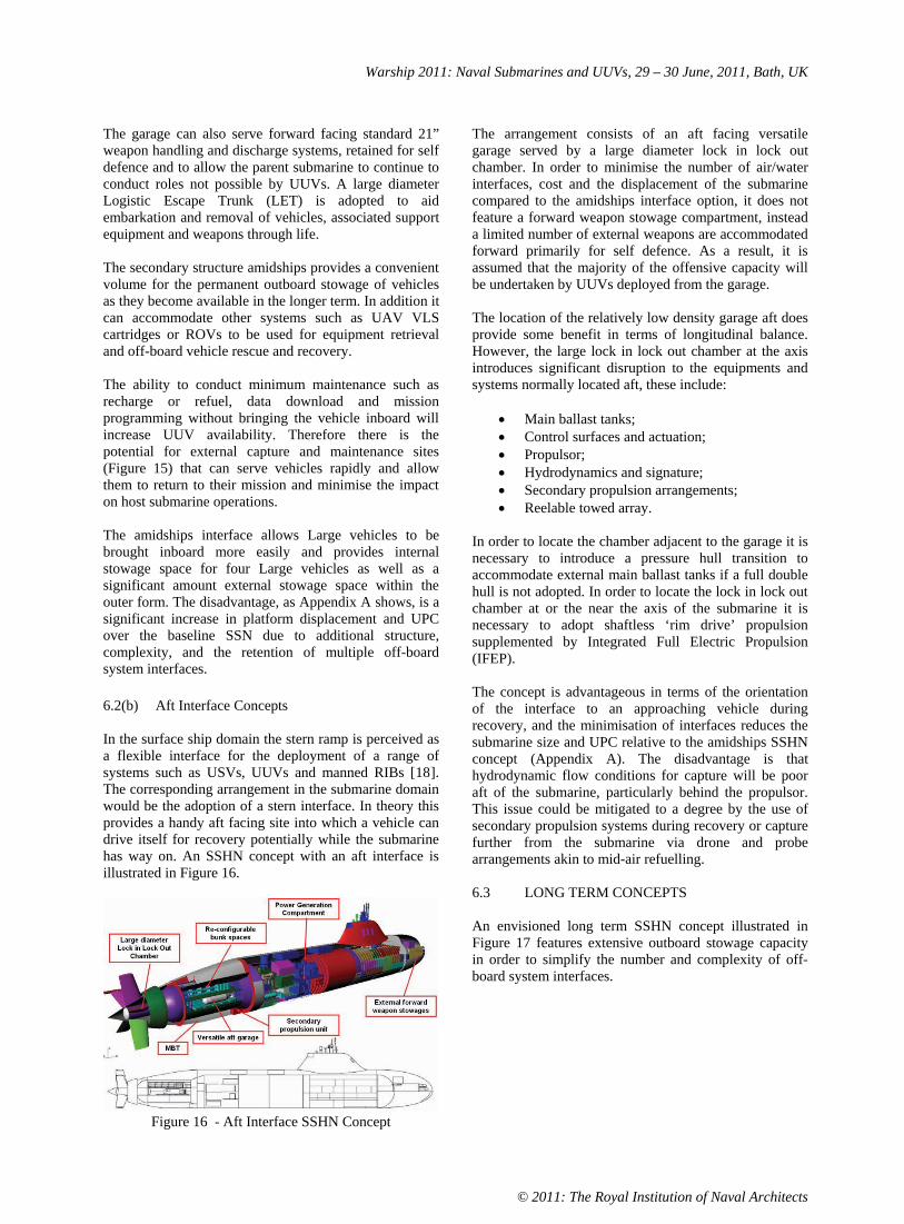
In the surface ship domain the stern ramp is perceived as a flexible interface for the deployment of a range of systems such as USVs, UUVs and manned RIBs [18]. The corresponding arrangement in the submarine domain would be the adoption of a stern interface. In theory this provides a handy aft facing site into which a vehicle can drive itself for recovery potentially while the submarine has way on. An SSHN concept with an aft interface is illustrated in Figure 16.
Figure 16 - Aft Interface SSHN Concept
The arrangement consists of an aft facing versatile garage served by a large diameter lock in lock out chamber. In order to minimise the number of air/water interfaces, cost and the displacement of the submarine compared to the amidships interface option, it does not feature a forward weapon stowage compartment, instead a limited number of external weapons are accommodated forward primarily for self defence. As a result, it is assumed that the majority of the offensive capacity will be undertaken by UUVs deployed from the garage.
The location of the relatively low density garage aft does provide some benefit in terms of longitudinal balance. However, the large lock in lock out chamber at the axis introduces significant disruption to the equipments and systems normally located aft, these include:
Main ballast tanks; Control surfaces and actuation; Propulsor; Hydrodynamics and signature; Secondary propulsion arrangements; Reelable towed array.
In order to locate the chamber adjacent to the garage it is necessary to introduce a pressure hull transition to accommodate external main ballast tanks if a full double hull is not adopted. In order to locate the lock in lock out chamber at or the near the axis of the submarine it is necessary to adopt shaftless ‘rim drive’ propulsion supplemented by Integrated Full Electric Propulsion (IFEP).
The concept is advantageous in terms of the orientation of the interface to an approaching vehicle during recovery, and the minimisation of interfaces reduces the submarine size and UPC relative to the amidships SSHN concept (Appendix A). The disadvantage is that hydrodynamic flow conditions for capture will be poor aft of the submarine, particularly behind the propulsor. This issue could be mitigated to a degree by the use of secondary propulsion systems during recovery or capture further from the submarine via drone and probe arrangements akin to mid-air refuelling.
6.3 LONG TERM CONCEPTS
An envisioned long term SSHN concept illustrated in Figure 17 features extensive outboard stowage capacity in order to simplify the number and complexity of off-board system interfaces.

Warship 2011: Naval Submarines and UUVs, 29 – 30 June, 2011, Bath, UK
© 2011: The Royal Institution of Naval Architects
Figure 17 - Long Term SSHN Concept
The UXV and MXV interfaces are located forward in order to take advantage of improved hydrodynamic conditions for launch and recovery. This location also minimises the disruption to basic submarine functions such as propulsion, manoeuvring and control, and wider characteristics such as signature performance.
The proposed interface is reconfigurable and modular, with standard interfaces for power, services, command and control and physical connection. Module dimensions and fits assessed are shown in Table 2.
UXV/MXV Module Type Option A BNumber of Bays Provided 8 6
Length (m) 10 12Width (m) 1.75 2.5 Height (m) 1.75 2.5 Maximum Size Vehicle ‘Large’ ‘Very Large’
Table 2 – SSH Module Characteristics
These flexible arrangements allow the platform to receive the Very Large vehicle fit and the other envisaged off-board systems during its operational life. The modules can also include launch, recovery and handling arrangements for individual system requirements. SSH module configurations are illustrated in Figure 18. Envisaged module payloads include:
UUV & handling system; SDV (wet & dry) & handling system; Torpedo self defence package; Countermeasures discharge system; SDV & handling system; Land strike package; UAV & handling system; RIB and handling system.
The SSHN concept presented in Figure 17 can accommodate six type B modules. A potential load-out includes five Very Large UUVs allowing three vehicles
to be maintained on station with a ROO of 50nm. The remaining bay is used for Host self defence weapons and countermeasures.
Modularity in UUVs is not a new concept [14]. However, the emergence of a reconfigurable standard ‘worker’ vehicle by specification or as part of a de-facto standard, would reduce the number of vehicles needed to conduct a range of roles. The envisioned vehicle (Figure 18) would consist of a standard body, command and control systems, propulsion fit and payload space. Payload package options would then include:
ASW; ASuW; MCM;ISR;Swimmer delivery; Gateway/network buoy deployment; Extended endurance; Hydrographical survey; Oceanographic survey.
Figure 18 – SSH Modules and UUV Mission Packages
The long term exposure of complex systems to the seawater environment will pose challenges in terms of marine growth/fouling and corrosion particularly in tropical climates. These issues may be overcome to a degree by material selection, encapsulation and removal and or replacement for limited maintenance between patrols.
The SSHN arrangement is configured to allow modules to be lowered into the bays from the dockside and off-board vehicles to interface with the SSHN from above

Warship 2011: Naval Submarines and UUVs, 29 – 30 June, 2011, Bath, UK
© 2011: The Royal Institution of Naval Architects
and below. Bringing MXVs within the main external form in order to minimise signature penalties presents pressure hull structural design challenges due to longitudinal balance considerations and the need to provide an interface for access to wet and dry MXVs. The arrangement shown in Figure 17 takes advantage of the pressure hull modular arrangements proposed by Leadmon [19]. The resulting internal awkward spaces are to be used for temporary austere accommodation for embarked forces and tankage.
The aspiration to decouple submarine functions from the interface and overall strength requirements necessitates additional secondary structure and double hull arrangements. This drives weight, but can be offset to a degree by the introduction of high strength steels, composite secondary structures and re-arrangement to minimise ballast requirements.
The adoption of modularity, extensive external stowage arrangements and common interfaces for all underwater off-board systems facilitates a reduction of displacement and UPC compared to a platform with the facilities to undertake all required roles at the same time (Appendix A).
6.4 VERY LONG TERM CONCEPTS
As communications and autonomy challenges are overcome and ‘worker’ UUV ROO increase it is conceivable that the SSH becomes virtually an unmanned submarine with adequate communications, autonomy and range to be deployable by alternative low cost delivery systems such as air-drop or surface ship.
7. CONCLUSIONS
UXVs and MXVs are a potential means to distance operators from threats and extend a parent platform’s sphere of influence. Key UXV and MXV enabling technologies and developmental areas for demanding future roles identified are:
Underwater communications; UUV autonomy; UUV power and propulsion; External stowage; Off-board vehicle manoeuvring and control behaviour in proximity to parent platforms; Off-board vehicle capture and release; Rules of engagement.
It is challenging to retrofit envisioned UXV and MXV fits to existing designs. Particular constraints include existing 21” weapon handling and discharge systems, the aspiration for simple automated recovery and provision of facilities to maintain vehicles in a dry and accessible environment. Even with limited evolutionary change from baseline SSN arrangements, it remains challenging
to bring multiple large UUVs and MXVs inboard satisfactorily without adding complexity and cost.
The longer term concepts explored have shown that there is potential to address some of these issues through the adoption of modularity and significant external reconfigurable spaces. However there remain challenges for off-board system designers such as facilitating satisfactory prolonged external stowage of vehicles. For the Naval Architect, there are challenges in the following classical areas:
Concept design; Weight, buoyancy and hydrostatic balance management; Arrangement; Watertight integrity; Structural design; Hydrodynamics, hullform design and signatures; Manoeuvring & control.
As a result, the extensive operation of UXVs and MXVs from a parent submarine has the potential provoke departures from current SSN arrangements that have changed little in the last 50 years and warrant assignment of the SSH designation.
If UXVs and MXVs are to play a significant role in future operations, there is a need for good dialogue between end-users, submarine designers and off-board system designers in defining the requirement and identifying candidate technologies. They also need to work in concert such that there is an appropriate balance between the host platform, interfaces and off-board systems characteristics.
8. ACKNOWLEDGEMENTS
The authors would like to thank Jay Hart and Will Hassett at BMT Defence Services for invaluable combat systems engineering and structural design support at BMT Defence Services.
9. REFERENCES
[1] G BLACKBURN, ‘A Maritime Strategy without a Navy – A Review of the Government’s Strategic Thought and Practice Since 1998’. University of Hull,January 2007
[2] CDR. F. LIPSCOMBE, ‘The British Submarine’, Conway Maritime Press, Greenwich. ISBN 85177 086 X
[3] H MANSECK, ‘Torpedo Defence Systems Survey’, Naval Forces, International Forum for Maritime Power, No 3/2010, ISSN 0722-8880

Warship 2011: Naval Submarines and UUVs, 29 – 30 June, 2011, Bath, UK
© 2011: The Royal Institution of Naval Architects
[4] B KRUGER, ‘Innovative Hoistable Masts for Existing and Future Tasks of Submarines’, Naval Forces, International Forum for Maritime Power, Issue 2007, ISSN 722-8880
[5] LOCKHEED MARTIN, AN/WLD-1 Remote Minehunting System (RMS), Product Brochure
[6] “Jane’s Fighting ships 2010-2011”. ISBN-978 0 7106 2920 3
[7] Global Security.org, Advanced SEAL Delivery System (ASDS), http://www.globalsecurity.org/military/systems/ship/asdshtm
[8] Jane’s Navy International, ‘RN surveys REMUS Progress’ October 2006
[9] A BUCHEN, ‘Integration of Lithium –Ion Batteries’ Naval Forces, International Forum for Maritime Power,Issue 2007, ISSN 722-8880
[10] T FISH, ‘Data Mules: the Sub-Hunting Autonomous Workhorse’, Jane’s Navy International June 2010
[11] M S STEWART & J PAVLOS, ‘A Means to Networked Persistent Undersea Surveillance’, Submarine Technology Symposium 2006
[12] ‘The Navy Unmanned Undersea Vehicle (UUV) Master Plan April 20, 2000
[13] G D WATT, ‘ Unmanned Underwater Vehicle Docking with a Submarine Proceeding at Low Speed’, 6th
NRC-IOT Workshop on Underwater Vehicle Technology 21-22 October 2010, St John’s, Newfoundland
[14] T HARDY & G BARLOW, ‘Unmanned Underwater Vehicle (UUV) Deployment and Retrieval Considerations for Submarines’, INEC 2008, Hamburg,Germany
[15] Marine Technology Reporter, ‘First Submerged UUV Recovery by a Submarine’ 26/11/07. http://www.seadiscovery.com/mt/
[16] PER-OLA HEDIN, ‘A26 - The Next Generation Submarine for the Swedish Navy’, Naval Forces, International Forum for Maritime Power, Issue 2007, ISSN 722-8880
[17] RDML (sel.) David C. Johnson, Mr. George M. Drakeley, and Mr. George M. Smith, ‘Engineering the Solution: VIRGINIA Class Submarine Cost Reduction’
[18] C. BROADBENT & S. BINNS, ‘A Vision for a UXV Enabled Versatile Surface Combatant’. RINAFuture Warship 06 London.
[19] J T LEADMON ET AL, ‘Submarine Payload Modularity for an Uncertain Future’, Warship 2002: Naval Submarines 7 London, UK

Warship 2011: Naval Submarines and UUVs, 29 – 30 June, 2011, Bath, UK
© 2011: The Royal Institution of Naval Architects
10. AUTHORS BIOGRAPHIES
Mr Simon D Binns is currently a Senior Naval Architect at BMT Defence Services in Bath. Recently he has been the Naval Architecture lead for submarine concept design options in support of a major UK submarine programme.
He is also heavily involved in submarine related R&D activities at BMT and led the design of the BMT Vidar-36 SSK. Before joining BMT Simon was a Senior Naval Architect at the UK MoD Defence Science and Technology Laboratory (DSTL) where he led warship and high speed craft concept and feasibility studies. This included research activities investigating the deployment of unmanned vehicles from current and future combatants. His qualifications include an M.Sc and B.Eng. (Hons) from the University of Southampton where he also undertook a number of submarine related studies.
Mr Tom Gibbs is a Naval Architect at BMT Defence Services in Bath. His qualifications include an M.Eng. (Hons) degree from University College London. He has been involved in submarine concept studies for the UK MoD. He has also been involved in the computational simulation of various aspects of submarine operations.
In addition to submarine concept design, particular areas of R&D interest include the design of unmanned underwater vehicles and the computational simulation of operational scenarios.
Mr Ross Eddy is a Senior Mechanical Engineer with experience in the Marine, Aerospace and Software Engineering disciplines. He has an MEng (Hons) in Aerospace Engineering from the University of Bath. He has worked on a wide range of projects and has gained significant experience in multi-discipline and system integration roles, often in teaming arrangements such as three years spent in the Submarine Support Management Group. Ross has led the Naval Engineering aspects for a number of pre-concept submarine and surface ship design activities. He has been involved in and responsible for a number of Technology Management tasks on behalf of the UK MoD in the last 5 years. He has worked alongside a number of rainbow teaming arrangements dedicated to emergent future naval projects, many of which have included the integration of UXVs and MXVs on naval vessels.
DISCLAIMER
The opinions expressed in this paper are those of the authors and not those of BMT Defence Services or other companies, the UK MoD or any of its agencies.

APPENDIX A
CONCEPT CONFIGURATION
SSN BASELINE OVERSIZED TT DDH EXTERNAL VLS INTERNAL VLS AMIDSHIP INTERFACE
AFT INTERFACE FWD EXTERNAL
CONFIGURATION SH SH SH SH SH SH Partial DH Saddle SURFACED DISPLACEMENT (te) 5,700 5,700 6,800 6,300 6,600 6,900 5,600 6,400
FORM DISPLACEMENT (te) 7,800 7,800 9,200 9,100 9,200 10,600 8,100 10,500 SUB’ DISPLACEMENT (te) 6,300 6,300 7,500 7,100 7,300 7,700 6,200 7,300 LENGTH OVERALL (m) 96 96 103 103 108 107 95 112STABILITY BALLAST % LOA 20 20 23 -6 25 25 8 -4 ROB (ALL MBT BLOWN) % 11.0 11.0 10.0 12.6 10.0 11.5 11.6 14.0 DDD (% reference depth) 100 100 100 100 100 90 100 95 PH MATERIAL HY80/NQ1 HY80/NQ1 HY80/NQ1 HY80/NQ1 HY80/NQ1 HY100/NQ2 HY100/NQ2 HY100/NQ2
SECODARY STRUCTURES B-GradeEquivalent
B-GradeEquivalent
B-GradeEquivalent
B-GradeEquivalent
B-GradeEquivalent
B-GradeEquivalent +Composite
B-Grade Equivalent +Composite
B-GradeEquivalent +Composite
MAXIMIM SUBMERGED SPEED (% reference speed) 100 100 100 100 100 100 100 85
PRIMARY MOVER Mechanical & Propulsor
Mechanical & Propulsor
Mechanical & Propulsor
Mechanical & Propulsor
Mechanical & Propulsor
Mechanical & Propulsor IFEP & Rim IFEP & 4 x Pods
SECONDARY 1 x SPU 1 x SPU 1 x SPU 1 x SPU 1 x SPU 2 x SPU 2 x SPU 1 x Tunnel TORPEDO TUBES 4 2 & 1 x Oversized 4 4 4 4 N/A N/AOTHER INTERFACES 2 x DDH 2 x ext VLS 4 x int VLS 1 x Large LILO 1 x Large LILO 2 x transfer towers
INTERNAL STOWAGE 22 x 21" Reloads 4 x Large UXV/MXV 22 x 21" Reloads 22 x 21" Reloads 22 x 21" Reloads 4 x Large
UXV/MXV 4 x Large UXV/MXV N/A
OTHER STOWAGES 2 x DDH 2 x ext VLS 4 x int VLS 6 x ext Large UXV/MXV 6 x ext 21" stowages
6 x V Large Modules
4 x ext Large UXV/MXV
6 x small VLS 6 x small VLS 6 x small VLS SSE 2 2 2 2 2 2 MAST FIT Standard Standard Standard Standard Standard Standard 6 x module bays 6 x module bays SONAR FIT Silver Silver Silver Silver Silver Silver Bronze Bronze COMMUNICATIONS FIT Bronze Bronze Bronze Bronze Bronze Bronze Silver Silver COUNTERMEASURES Silver Silver Silver Silver Silver Bronze Bronze Bronze

Warship 2011: Naval Submarines and UUVs, 29 – 30 June 2011, Bath, UK
TOWARDS AN AUTOMATED ACTIVE UUV DOCK ON A SLOWLY MOVING
SUBMARINE
G.D. Watt, Defence Research and Development Canada – Atlantic (DRDC), Canada
J.A. Carretero and R. Dubay, Dept. of Mechanical Engineering, University of New Brunswick (UNB), Canada
M.R. MacKenzie, DRDC Atlantic, Canada
SUMMARY
DRDC has initiated a project to develop an automated method for recovering UUVs to a submarine underwayat low speed in the presence of environmental disturbance. Torpedo tubes are not used, there are no inherentUUV size or shape restrictions, and docking infrastructure on the UUV is minimized. This paper reviews currentUUV docking methodology and concludes that improved maneuverability and position sensing are required. Anactive dock (a quasi-independent third body) is proposed for augmenting the limited maneuverability of thesubmarine and UUV, and some docking concepts are presented. Optical and/or electromagnetic sensors aresuggested for improving position sensing accuracy for final docking.
1. INTRODUCTION
Unmanned vehicles are effective autonomous intelli-gent agents that increase battlefield awareness withlittle risk to personnel and major platforms. Innaval warfare, unmanned underwater vehicles (UUVs)potentially provide covert intelligence, surveillance,reconnaissance, minehunting, mapping, communica-tion, and payload delivery capabilities [1]. However,they operate in an inhospitable environment with lim-ited communication and positional information. Thismakes them expensive unmanned vehicles and ex-plains why their development has lagged that of un-manned aerial vehicles [2]. Nevertheless, the tech-nology is evolving and many NATO navies now haveplans for incorporating UUVs as integral componentsof their future naval platforms. UUV/major platformintegration amplifies the capabilities of each. Operat-ing from submarines, for example, UUVs have muchgreater covert range and endurance while submarinesreceive enhanced awareness and functionality whichreduce risk for the submarine and its crew.
Platform integration requires a reliable UUV launchand recovery capability. However, recovery is prob-lematic, a bottleneck delaying effective integration.Recovery is especially difficult for submarines. Ac-cordingly, DRDC has initiated a project to addressthe issue. This paper describes our first steps.
Ideally, docking a UUV on a submarine should beautonomous, reliable, fast, and have minimal opera-tional limitations. This focuses attention on a worstcase scenario in which recovery takes place in littoralwaters in high sea states, a difficult problem that de-fines the parameter space for our UUV docking ob-jectives. Solving this problem precludes a tentativeapproach.
2. CURRENT DOCKING METHODS
2.1 STATIONARY DOCKS
Oceanographers are interested in ‘autonomous oceansampling networks’ in which small UUVs (1 to 2 mlong) continuously patrol and sample ocean proper-ties, periodically returning to a stationary dock todownload data and recharge their batteries. They usedocks that are either fixed or tethered to the oceanfloor. Three types of docking capture methods aredescribed: funnels [3,4,5,6,7] which minimize dockinghardware on the UUV, a V latch on the nose of theUUV that engages a vertical cable on the dock [8],and an aircraft carrier landing arrangement in whichthe UUV drops a hook that must catch a transverseguide on a flat dock [9]. Ultrashort baseline acoustic[4,5,8,9], electromagnetic [6], and optical [3,7] posi-tion sensing methods are used, always with the UUVhoming towards a passive dock displaying a source.
2.1(a) Sensing
Of the three sensing methods employed, acoustic hom-ing is the most conventional, has by far the longestrange (several hundred meters or more), is omnidirec-tional, and is readily implemented with commercial-off-the-shelf components. However, it has low ac-curacy and slow update rates for final docking. Inthe above references, acoustic homing provided about±0.5 m accuracy [4] for final docking.
Feezor et al [6] discuss the many advantages of electro-magnetic homing. Their source on the dock was three64 cm diameter coils requiring 15 W of power each.Their 2.2 m long UUV used three orthogonal 9 cm di-ameter receiver coils and was able to detect and homein on the dock from 25 to 30 m away with ±0.2 m ac-curacy. The system provides fast update rates and
c© 2011 Defence Research and Development Canada

Warship 2011: Naval Submarines and UUVs, 29 – 30 June 2011, Bath, UK
the UUV knows both its distance and orientation rel-ative to the dock; indeed, it just follows the magneticfield lines right to the dock. They claim the systemis not significantly effected by fouling, bubbles, float-ing organic matter, the surface, the sea floor, or steelvessels not directly in the homing path.
Of the two optical homing methods, Cowen et al [3]
use the simplest approach. They use a light bulb for asource at the apex of a funnel and ‘terminal guidance’control. This simple method uses a four quadrantphotodetector on the UUV which determines the lensquadrant in which the light intensity is greatest. TheUUV then adjusts its orientation to keep the light in-tensity equal in each quadrant, which keeps the UUVpointing at the light source. Docking was successfulif the light source was acquired in time for the UUVto adjust its approach. Acquisition ranges of 10 to15 m in turbid harbor water and up to 30 m in clearwater were obtained. They achieved positional ac-curacies of ±0.01 m. Park et al [7] used five lightsources around the rim of their funnel and a mod-ern charge-coupled device camera, allowing the UUVto estimate distance and orientation from the dock.Although their tests took place in clear tank waterwithout current or wave disturbance, they had lesssuccess docking than did Cowen et al, reflecting themore complicated approaches they were attempting.
In general, acoustic homing provides the best longrange sensing and will need to be part of any UUVdocking solution that begins with separation distancesexceeding about 50 m. For final docking, opticaltracking provides the best accuracy (at the expenseof range) with excellent update rates for following un-steady trajectories. Electromagnetic sensing overlapsthe previous two methods and provides an alternativewhen, for example, thermoclines or turbidity are anissue (Baiden et al [10] examine the effect of turbidityon underwater optical communication).
2.1(b) Capture
Funnels were the most common capture mechanismfor the stationary docks reviewed here, with openingsthat were approximately a meter in diameter (fourUUV hull diameters [5]). This requires less exter-nal hardware on each vehicle than the other methods,which is efficient. However, funnels work only if theUUV is adequately aligned with the funnel axis onentry. Otherwise, the UUV just bounces off the sideof the funnel. Park et al [7] put a lot of effort intoattitude control. Feezor et al [6] noted that dockingfailed when the UUV was more than 30 degrees off thedock axis when the source was acquired. Cowen et al[3] attributed their failures to acquiring the sourcelate enough that the tail fins of their Odyssey IIBdid not allow the vehicle to turn rapidly enough; if
it could have turned more sharply, perhaps misalign-ment would have been a problem anyway.
Fixed funnels are problematic in the presence of cross-flow caused by wave disturbance, tidal currents ifthe dock is fixed, or platform motion if the dock ison a vessel. In their ocean tests, Cowen et al [3]
aligned their funnel axis with the current and thenhand launched the UUV up-current towards the dockfrom about 40 m away, so the UUV did not have todeal with a crossflow or do path planning. It is possi-ble to have a moored funnel automatically align withthe current in a realistic scenario, but then the dockmust communicate its alignment to the UUV in someway. The funnels used in the other experiments werefixed in the ocean, in convenient bays or harbors, ex-cept for Park et al [7] where the experiments tookplace in a quiescent maneuvering basin.
The moored vertical cable used by Singh et al [8]
was apparently successful but requires a horizontalV catching device and latch on the nose of the UUV.The dimensions of this device are not given but wouldneed to be as large as the positional error in the ultra-short baseline acoustic homing system they use. In-terestingly, they propose a next generation device inwhich a side arm/latch extends out from the side ofthe UUV to catch the cable as the UUV slides by.Although this could be retractable, one would be re-quired for each UUV using the dock. The big advan-tage to this system is its inherent omni-directionalityand insensitivity to vertical positioning error whiledocking. Crossflow is still a problem but, after sev-eral failed passes at the cable, a UUV should be ableto figure out which direction a current, at least, iscoming from and adjust its approach accordingly.
The ‘aircraft carrier landing’ method described by Ka-wasaki et al [9] not only requires specialized hardwareon the UUV but also involves dangling a hook, whichcan catch on anything.
2.1(c) Success Rates
Docking success is not always reported clearly sincethese are research trials in which new equipment andtechniques are often being tried for the first time.
The Woods Hole Oceanographic Institution studiesconscientiously reported success and failure. After ini-tial trials and adopting various performance improve-ments using a REMUS 100 UUV, acoustic homing,and a 1 m diameter funnel, Stokey et al [4] achievedabout a 62% success rate per docking attempt, or an88% success rate per mission, where each mission isdefined as five docking attempts. Allen et al [5], whoused an updated version of this system, including aslightly smaller rectangular funnel, report a decreased
c© 2011 Defence Research and Development Canada

Warship 2011: Naval Submarines and UUVs, 29 – 30 June 2011, Bath, UK
mission success rate of 60%. The tests by Stokey et aland Allen et al each spanned several days in differentlocations.
Feezor et al [6] used a 2.2 m long SeaGrant OdysseyIIB UUV, electromagnetic homing, and a 1 m diam-eter funnel to dock successfully for five out of eightdocking attempts. This was done in one location overa two week period. The UUV speed varied from 1.5to 2 m/s and docking took place in the presence ofprevailing cross currents as large as 0.3 m/s. Dockingfailed when the UUV was misaligned with the dockaxis by more than 30 degrees when the source wasfirst acquired.
Cowen et al [3] used a 2.2 m long SeaGrant OdysseyIIB UUV, optical terminal guidance, and a funnel ofundisclosed size in a simplified scenario to achieve suc-cessful docking providing the optical source was ac-quired soon enough.
Park et al [7] used a 1.2 m long UUV, a 1 m diame-ter funnel, and optical vision guidance in a quiescentmaneuvering basin. They provide a frank discussionof the issues they faced but give no final feel for theirsuccess rate.
These success rates are not high enough to justifyroutinely risking the million dollar UUVs naval ves-sels would employ. Success rates close to 100% arerequired, and they are required in more challengingenvironments than the above tests experienced.
One wonders how much more successful the trials us-ing funnels would have been had the docks had theability to keep the funnel axes pointing at the oncom-ing UUV. This would require additional complexityand infrastructure, but on the dock rather than onevery UUV that is deployed.
2.2 DOCKING WITH NAVAL PLATFORMS
Naval capabilities are not discussed as freely in theopen literature as the oceanographic research de-scribed above. Seizer [11] notes that there are cur-rently no autonomous systems for surface ship launchand recovery of UUVs. The same is likely true forsubmarines. The Director of Innovation in the USOffice of Naval Research recently identified:
• sea state,
• operational tempo,
• autonomy,
• motion prediction, and
• UUV maneuvering and control authority
as challenging objectives for UUV recovery by Navalvessels [12].
Surface ships currently recover UUVs, when the seastate allows it, using ramps, slings, and/or cranes withman-in-the-loop control to anticipate and correct forlarge relative motion between the UUV and dockingapparatus. We are aware of three proprietary sys-tems that attempt to recover UUVs as autonomouslyas possible to surface ships. These are under devel-opment and/or are unproven. They use a reasonablymaneuverable surface ship to close with the UUV anddeploy a towed body over the stern. Seizer [11] de-scribes the Advanced Technology & Research Corpo-ration’s method in some detail. Using tow bodies witha submarine is risky, but possible if the tow is short.
Man-in-the-loop submarine UUV recovery methodsare available or under development [13,14]. They de-ploy a remotely operated vehicle (ROV) from one tor-pedo tube which attaches to and maneuvers the UUVinto a second tube. This takes two torpedo tubes outof action and restricts the UUV to 21 inches in di-ameter in current submarines, which restricts UUVendurance. The Saab system [13] requires both theUUV and submarine to sit on the bottom during dock-ing, so it is neither a deep water capability nor onethat would be reliable amongst the fjords of Canada’swest coast. The US Naval Underwater Warfare Cen-ter (Newport) system [14] is similar but is intendedfor use in deep water while the vehicles are underwayor hovering. A secondary benefit of these systems isthat a deployable ROV provides the submarine withmany other capabilities.
The US is pursuing other UUV docking options forsubmarines. The ‘long-term mine reconnaissance sys-tem’ (LMRS) is a torpedo tube launch and recov-ery UUV requiring, again, the use of two torpedotubes. UUV recovery involves a telescoping roboticarm extending from one tube, docking with the UUV,and then inserting the UUV back into a second tube.Homing and docking with this system was success-fully demonstrated in January 2006 [15]. However,the project has been discontinued, perhaps becauseof cost and the limited endurance provided by thetorpedo tube sized UUVs. Schuette [12] discussesthe ‘universal launch & recovery module’ (ULRM)which is intended to deploy UUVs from large diame-ter SSGN or Virginia class SSN missile tubes, whichwill allow for UUVs with greater endurance. An ini-tial demonstration is scheduled for 2012. No mentionis made of how docking will take place.
The ROV docking solution may be the best currentsolution for submarines if it can be made functionalwhile the submarine is underway, especially sinceit allows for far-field docking which avoids the flownonuniformities, wakes, and vortices close to the sub-marine hull [16]. However, it lacks automation andwill have difficulty with environmental disturbance.
c© 2011 Defence Research and Development Canada

Warship 2011: Naval Submarines and UUVs, 29 – 30 June 2011, Bath, UK
3. DOCKING OBJECTIVES
Henceforth, the discussion is for a UUV docking witha submarine. The submarine must maintain headwayto maintain control. The docking solution should pro-vide for:
• deep water operations,
• littoral operations with minimal sea state limita-tions,
• automation for reliability and temporal efficiency,
• low risk to the submarine propeller or appendagesshould something break or let go during docking,
• low risk of UUV/submarine collision in the pres-ence of environmental disturbance,
• a flexible choice of UUV size and shape to maxi-mize endurance and functionality,
• minimal docking infrastructure on the UUV to sim-plify use of commercial-off-the-shelf vehicles.
Docking has three sequential phases: 1) making phys-ical contact between the UUV and dock, 2) capture,and 3) parking. Our focus is on the difficult making-contact phase. To ensure capture will readily follow,we are collaborating with Rolls-Royce Naval MarineCanada who are experienced in UUV capture. Weenvision parking solutions that are external to thepressure hull but enclosed either within the deck oradditional ‘blister’ fairings such as those proposed byBMT’s Hardy [17].
4. MAKING-CONTACT SCENARIO
4.1 STAGE 1: UUV HOMING
Submarines lack the maneuverability necessary tosafely, reliably, and efficiently close with and positionthemselves for recovering a passive UUV. Therefore,the UUV must home in on the submarine.
After rendezvousing with the UUV, the submarinemaintains straight and level flight at 2 to 3 knotsand deploys a dock off to the side, away from localdisturbance near the hull and the nonuniform flowat the ends of the boat. This location is accessibleby the UUV, minimizes danger to the tailplanes andpropeller, and can be shifted laterally away from andtowards the hull to adjust the trade-off between func-tionality and the risk of collision as these become bet-ter understood over time. It is also a good compro-mise location in littoral conditions, keeping dockingbelow free surface disturbance and above ocean floorhazards.
The dock displays an omnidirectional acoustic tran-sponder for the UUV to home in on and receive com-mands from. Homing will be most successful using
acoustic sensing because it has the range necessaryto initiate docking from hundreds of meters away ormore. This provides needed flexibility for path plan-ning and recovering after failed docking attempts.
The UUV is responsible for stage 1 path planning,although simple commands and limited information(eg, submarine course) can be passed to the UUV viathe transponder or by conventional acoustic modem.Path planning is a research area by itself [18,19,20]
and is not considered further here.
As the stationary docking trials showed, final dockingis unlikely to have a high success rate using simplehoming because of course and depth keeping error, po-sition sensing error, and environmental disturbance.The problem changes somewhat when the dock ismoving steadily forward with the submarine. It ismade easier by the fact that the UUV and dock canbe brought together gradually, possibly allowing con-tact to be timed. However, the problem is aggravatedby the uncontrolled roll and added course and depthkeeping error of the submarine, with the latter exceed-ing that of the UUV. In addition, in the presence ofenvironmental disturbance, especially in littoral con-ditions, the size difference between the UUV and sub-marine will result in unsteady relative motion betweenthem. This will occur with six degrees-of-freedom(DOF), three translational and three rotational, withas many different time constants. Even if this motioncould be anticipated, neither the submarine nor theUUV have the control to overcome it. A secondaryaccurate position measurement together with optimalUUV speed adjustment might correct for steady mis-alignment and transverse offset, but unsteady mis-alignment and offset are problematic because correc-tions require time and distance to take effect.
4.2 STAGE 2: ACTIVE DOCKING
Solving the final docking problem requires additionaltechnology and infrastructure. Two additional capa-bilities are required:
• Relative position measurements that are more ac-curate, and available at faster update rates, thancan be provided by acoustic sensing.
• Transverse maneuverability with the reach andspeed to overcome the desired level of relative mo-tion.
To the extent possible, this added complexity shouldbe kept on the dock. Continuing with the dockingscenario of §4.1, we now assume the dock has a cameraand the UUV can display strategically located lightemitting diodes (LEDs). We also assume the dockcan maneuver in, at least, a transverse plane with therequired reach and speed.
c© 2011 Defence Research and Development Canada

Warship 2011: Naval Submarines and UUVs, 29 – 30 June 2011, Bath, UK
Once the UUV is running roughly parallel with thesubmarine, aft of but within about 10 m of the docklongitudinally, it activates its LEDs and continues toclose with the dock. When the UUV is within thetransverse reach of the dock and the dock has a sta-ble lock on the UUV (via camera and LEDs), the docktakes command. It signals the UUV to deactivate mis-alignment and transverse position control, and thencontinuously adjusts the UUV forward speed to grad-ually overtake the dock. The dock measures UUVposition, velocity, and acceleration in six DOF andadjusts itself transversely to stay centered in front ofthe oncoming UUV until contact is made or, perhaps,to meet the UUV at a point in space and time whencontact can be made with minimal contact force. Thisstrategy decouples longitudinal from transverse con-trol, relieving the UUV of a task for which it is notwell suited.
The LEDs on the UUV are small and optionally pro-vide the UUV with high bandwidth communicationto the dock/submarine. Having the light source onthe UUV, rather than illuminating the UUV from thedock, improves tracking accuracy [21] and eliminatesbackscatter, a major source of underwater optical in-terference [22] that substantially reduces range. It ispossible to overcome backscatter [23] and to track ob-jects visually in real time using a previously definedgeometrical model of the object [24], technologies thatcould eliminate the need for lights on the UUV.
The oceanography trials showed that increased po-sitional accuracy and update rates are available us-ing either optical or electromagnetic sensing. Bothmay be used for added robustness in an initial de-sign. With an electromagnetic source on the UUV,the dock would have back-up, longer range (than op-tical) position sensing that would be immune to tur-bidity. Having multiple redundant position measure-ments, whether they are separate systems or addi-tional sensors in the same system, brings up the is-sue of real time data fusion. This is not consideredhere but we note that this classic sensing problem issuccessfully addressed by roboticists using probabilitytheory and Bayesian filters [25,26].
5. EVALUATION ENVIRONMENT
Our project is investigating all of the above subjectareas. Many position sensing, docking, and controlsolutions are possible, the best of which need to beevaluated in realistic and extreme conditions. Doingso at-sea, or even in a towing tank, is time consuming,expensive, and limiting in both the number of scenar-ios and the level of extreme condition that can besafely tested. Therefore, computer simulation, cou-pled with strategic prototype development and test-ing, will be used for initial evaluation.
The computer simulation will model the submarine,UUV, and active dock maneuvering in the presence ofeach other with six DOF. Hydrodynamic interactions,control systems, position sensing, and environmentaldisturbance all need to be modelled. A special mod-ule will be built into the simulation to facilitate over-all control strategy development, perhaps the biggestchallenge for the project. This strategy must interpretsensory feedback (that has inherent error) to controlseveral hardware components (that have inherent lim-itations). The multivariable control architecture mayhave to be adaptive to account for a nonlinear dy-namic response in several system outputs. To obtainaccurate system simulation models that realisticallyaccount for errors and limitations, dock and positionsensing prototypes will be built and tested.
The initial objective of evaluation is not to fix on oneparticular design or strategy but to show that twostage docking will work, perhaps in different ways,and to assess how well it works in different scenar-ios. A virtual test environment will be very valuablefor this and, eventually, for choosing a final design,training, and future developments.
6. TOWARDS AN ACTIVE DOCK DESIGN
In this section, we begin examining the details of dockdesign and present some preliminary concepts. Dur-ing the 2010/2011 academic year, DRDC sponsored adock design competition for final year Mechanical En-gineering students at UNB, with the authors of thispaper as advisors. The ideas presented here reflectthose of the students [27,28] merged with our ownand other team members (see Acknowledgments).
In §6.1, we estimate the magnitude and nature of therelative motion that might occur between the UUVand dock. In §6.2, we show how the vertical compo-nent of this motion can be matched by a self-actuatingwing-dock that extracts energy from the forward mo-tion imposed by the submarine. Building on theseresults, in §6.3 we present some concept designs forself and fully actuated docks.
6.1 RELATIVE MOTION EXTREMES
Gross assumptions are used to obtain conservative es-timates of the extremes in the relative motion betweenthe UUV and dock. First, the extremes are assumedto occur when docking at 10 m depth in water 20 mdeep in a moderate to high sea state. The dock isassumed stationary while the UUV moves as would aparticle of water, so the extremes are just the motionof a particle of water at 10 m depth in this situa-tion. Unimodal linearized wave theory [29] togetherwith wave period statistics [30,31] are used to estimateparticle motion.
c© 2011 Defence Research and Development Canada

Warship 2011: Naval Submarines and UUVs, 29 – 30 June 2011, Bath, UK
−4 −3 −2 −1 0 1 2
Horizontal Displacement(m)
−2
−1
0
1
2V
erti
calD
ispla
cem
ent
(m) wave height H = 5 m
ocean depth d = 20 m
H = 5 md = ∞
H = 2.5 md = 20 m
H = 2.5 md = ∞
Figure 1: Fluid particle paths at a depth of 10 mfor unimodal, peak-to-peak, surface wave heights of2.5 m (right) and 5 m (left) in water 20 m deep (top)and infinitely deep (bottom). The solid lines delimitregions that result from a range of possible wave peri-ods for each wave height (Table 1). The dashed linesuse the mean periods 9.75 s (for H = 2 .5 m) and12.5 s (for H = 5 m).
Figure 1 shows the fluid particle displacements thatoccur at 10 m depth for Sea State 5 and 6 unimodalwaves in shallow and deep water. The wave periodsspan a 95% confidence interval for the given waveheights in the North Atlantic. Although these pe-riods may not be appropriate for very shallow water,they suffice for the current estimates. In deep wa-ter, fluid particle paths are all circular for these idealwaves, with amplitudes that decrease exponentiallywith distance below the surface. In shallow water,particle paths become elliptical with the vertical mo-tion decreasing and horizontal motion increasing for agiven wave height, but amplitudes still decrease withincreasing distance below the surface.
Table 1 shows the fluid particle kinematics for shal-low water waves. While these are guidelines for thekinematics an active dock should strive for, severalpoints are worth noting. First, in these situationsthe submarine and UUV likely would be heading intothe waves at about 1 m/s, which would moderate thelongitudinal closing velocity extremes. Secondly, thedock does need to replicate the motion of the UUV,just intercept it at some point in its trajectory wherebenign contact can be made. Of course, real wavesare multi-modal with varying heights. This makesthe motion irregular as well as unsteady so that pre-dicting contact will be difficult.
6.2 SELF-ACTUATING VERTICAL MOTION
With relative motion between the UUV and subma-rine having a potential amplitude of several meters,docking must take place at some distance from thesubmarine to minimize the chance of collision. Oneway to do this is with a long streamlined arm; ie, a
wave height: H (m) 2.5 5
wave period: T (s) 7 – 15 10 – 16
horz. ampl.: x (m) 0.63 – 1.93 2.31 – 4.16
vert. ampl.: z (m) 0.44 – 0.59 1.10 – 1.20
x ampl. (m/s) 0.57 – 0.81 1.45 – 1.63
z ampl. (m/s) 0.40 – 0.25 0.69 – 0.47
x ampl. (m/s2) 0.51 – 0.34 0.91 – 0.64
z ampl. (m/s2) 0.36 – 0.10 0.43 – 0.18
Table 1: Fluid particle horizontal and vertical dis-placement, velocity, and acceleration amplitudes forunimodal wave heights of 2.5 and 5 m at a depth of10 m in water 20 m deep (top half of Figure 1).
wing. A wing is interesting because it can use the for-ward motion to generate lift to move itself verticallythrough the docking envelope. The plausibility of thisapproach is examined here.
Consider the two-dimensional symmetrical wing inFigure 2 (see Table 2 for nomenclature). It has aconstant forward speed U = 1 m/s. Its time varyingpitch angle θ generates lift which moves the wing atvertical velocity V . The lift results from the angle ofattack α , the angle the wing chord line makes withthe wing net velocity W . The wing lift is perpendic-ular to W and the drag acts in a direction oppositeto W . The one dimensional equation of vertical mo-tion for the wing is:
total mass
unit span× dV
dt=
vertical force
unit span(1)
where the total mass is the wing plus added mass:
total mass
unit span= ρμτc2 +
πρc2
4
(τ2 sin2 θ + cos2 θ
). (2)
The wing is assumed neutrally buoyant with cross sec-tional area (volume per unit span) μτc2. The addedmass is estimated by treating the wing as an ellipsewhich has zero off-diagonal terms in its added massmatrix. Notice that the added mass is much largerthan the mass at small pitch angles and much smallerat large pitch angles.
The RHS of the equation of motion is:
vertical force
unit span= L
U
W− D
V
W
=1
2ρW 2c
(C�
U
W− Cd
V
W
) (3)
Linearized airfoil theory approximates the steadystate lift well when α � 1 and the airfoil is unstalled:
C� = 2πα (4)
c© 2011 Defence Research and Development Canada

Warship 2011: Naval Submarines and UUVs, 29 – 30 June 2011, Bath, UK
c
L
DU
V W
α
θ
Figure 2: NACA 0020 2D wing dynamics.
c chord lengthD, Cd drag, dimensionless drag per unit spanL, C� lift, dimensionless lift per unit span
t timeU,V, W forward, vertical, net velocity
α angle of attackθ pitch angleμ 0.685, shape factorρ fluid densityτ 0.2, thickness to chord ratio
Table 2: Wing-dock analysis nomenclature.
where:
α = θ − tan−1V
U. (5)
The drag is small and could be neglected if that fa-cilitated linearization. However, the pitch angle ispotentially large and appears nonlinearly in (2), sothere is nothing to be gained by neglecting drag. It isapproximated as:
Cd ≈ Cd0
(1 + C2
�
), Cd0 ≈ 0.01. (6)
The final equation for vertical motion is:
dV
dt=
2√
U2 + V 2[2παU − Cd0
(1 + 4π2α2
)V
]c[4μτ + π
(τ2 sin2 θ + cos2 θ
)](7)
in which (5) is used to eliminate either α or θ, as re-quired. This first order ordinary differential equationcan be solved numerically when θ(t) is given. How-ever, our interest is in the reverse problem. We solvefor the θ(t) profiles necessary to produce the verti-cal velocities V (t) characteristic of the fluid particlemotions presented in §6.1, to see if the pitch anglesand associated angles of attack required to track theseparticles are plausible.
In (7), let:
V = V0 sin2πt
T(8)
where V0 (the amplitude of z ) and T are taken fromTable 1 for 5 m waves. Numerical solutions to (7) forθ and α are shown in Figure 3.
0 4 8 12 16
t (s)
−40
−20
0
20
40
θ(d
egre
es)
3a) Pitch angle
KeyV0 T c
m/s s m0.69 10 10.69 10 0.50.47 16 10.47 16 2
0 4 8 12 16
t (s)
−8
−6
−4
−2
0
2
4
6
8
α(d
egre
es)
3b) Angle of attack.
Figure 3: Wing pitch angles and angles of attack pro-viding the wing motion necessary to match fluid par-ticle vertical motion 10 m below 5 m high unimodalsurface waves in water 20 m deep.
Figure 3a shows that the pitch angles necessary togenerate the required vertical motion are plausible.Figure 3b shows that the associated angles of attackare well within the unstalled and linear range, as (4)assumes.
Figure 3 also shows that the required pitch angles areinsensitive to the size of the wing, but that halving thesize also halves the incidence required to achieve thedesired motion. Since θ is insensitive to c in (7), andCd0 is small, then α ∝ c. Therefore, the lift providingV is L ∝ cC� ∝ cα ∝ c2. This is significant since thestrength of the downwash in the wake trailing fromthe wing is proportional to the lift and may adverselyimpact a UUV docking with the wing. Thus, the wingshould be kept as small as possible and doing so im-
c© 2011 Defence Research and Development Canada

Warship 2011: Naval Submarines and UUVs, 29 – 30 June 2011, Bath, UK
Figure 4: Manually flown aircraft refueling boom.(Lockheed-Martin Tactical Aircraft Systems photo.)
proves its performance. The lag effect discussed inthe next paragraph reinforces this conclusion.
A limitation in this analysis is the assumption thatwing lift varies quasi-steadily. Lift does not changeinstantaneously with α as (4) assumes, but developsgradually with a time constant that is approximatelyc/U , the time it takes for the flow to convect over thewing. This will introduce a time lag proportional towing chord length into the Figure 3 responses. Mod-elling this lag will require a more sophisticated anal-ysis than presented here. Nevertheless, the predictedθ and α magnitudes are moderate; there is room toaccommodate higher magnitudes if required.
6.3 DOCK CONCEPT DESIGNS
The UUV docking requirement is similar to the aerialrefueling requirement for aircraft.* Two aerial re-fueling solutions are available: a passive drogue de-ployed by the tanker that the receiving aircraft insertsa probe into, and a faster method using the refuel-ing boom shown in Figure 4. Both methods requiresteady conditions, good visibility, and manual control.The refueling boom method requires manual controlof the boom in addition to the receiving aircraft. Thecontrol fins on the boom are sized for fine steady-statecontrol rather than dynamic response. The boom pi-lot has the best view, looking aft from the back of thetanker; he controls final docking and refueling andadvises the aircraft pilot of the prescribed dockingenvelope.
UUV docking with a submarine cannot rely on ei-ther visibility or steady state conditions. Automa-tion is likely the best way to assess position sensinginformation from several sources and generate a con-trolled dynamic response that locates and orients adocking mechanism in space and time. What followsare concepts for solving the making-contact part ofthe problem without worrying too much about orien-tation, capturing or parking the UUV, or housing thedock. Funnels are deliberately ignored; they can beused later to compensate for any inability to achievecontact. We assume the submarine is moving ahead
* en.wikipedia.org/wiki/Aerial refueling
Figure 5: Dock/submarine relative proportions.
in straight and level flight at 1 m/s and that dockingtakes place 4 to 8 m from the side of the hull. Figure 5shows the size of a wing-dock with an 8 m span rela-tive to a 70 m long submarine with an 8 m diameterhull.
Two types of dock are proposed. The first type usesforward speed to partially self-actuate, as shown inFigure 6. These wing-docks adjust their pitch tomove circumferentially around a hinge joint on thehull, covering a large swath in a transverse plane. Ra-dial control is provided in Figure 6a with a telescop-ing smaller section which, optionally, would allow thedock to contact the UUV from the side. In Figure 6b,extensive radial coverage is provided by a spanwisetraveler which is the contact point. Both these dockswould require a mechanism (not shown) to retract thewings, which could provide some axial adjustment aswell.
In Figure 6c, the wing is at the end of a long arm andadjusted radially by a telescoping brace which alsoserves to retract the wing against the hull. The cy-lindrical arm and brace are misaligned with the flowby at most 30 degrees, which reduces drag and elim-inates unsteady vortex shedding. Alternative designs(not shown) might use a fixed length brace, with thebase of either or both the brace and arm moving alongthe hull, or with the brace/arm junction moving upand down the arm.
Fully powered docks are shown in Figure 7. Figure 7ashows a two stage dock, beginning with a conventionaltwo-link robotic arm for gross, low speed position ad-justment throughout a 3D docking envelope, not justa transverse plane. It uses self-aligning fairings to re-duce drag. It is shown rotating about a vertical baseattached to the side of the submarine, but could ro-tate horizontally about a horizontal base sitting onthe deck. Attached to the end of the arm is the sec-ond stage of the dock, a parallel manipulator (PM)that provides fast, precise, local control. PMs areconventional well proven robotic tools in air but theirperformance in water needs to be evaluated. Lebans
c© 2011 Defence Research and Development Canada
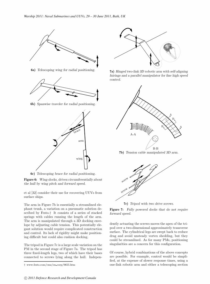
Warship 2011: Naval Submarines and UUVs, 29 – 30 June 2011, Bath, UK
6a) Telescoping wing for radial positioning.
6b) Spanwise traveler for radial positioning.
brace
arm
wing
6c) Telescoping brace for radial positioning.
Figure 6: Wing-docks, driven circumferentially aboutthe hull by wing pitch and forward speed.
et al [32] consider their use for recovering UUVs fromsurface ships.
The arm in Figure 7b is essentially a streamlined ele-phant trunk, a variation on a pneumatic solution de-scribed by Festo.† It consists of a series of stackedsprings with cables running the length of the arm.The arm is manipulated through a 3D docking enve-lope by adjusting cable tension. This potentially ele-gant solution would require complicated constructionand control. Its lack of rigidity might make position-ing difficult but could also cushion docking.
The tripod in Figure 7c is a large scale variation on thePM in the second stage of Figure 7a. The tripod hasthree fixed-length legs, two of which have their basesconnected to screws lying along the hull. Indepen-
† www.festo.com/cms/en corp/9655.htm
7a) Hinged two-link 3D robotic arm with self-aligningfairings and a parallel manipulator for fine high speedcontrol.
A
AB
B
B-B
A-A
7b) Tension cable manipulated 3D arm.
screw
screw
7c) Tripod with two drive screws.
Figure 7: Fully powered docks that do not requireforward speed.
dently actuating the screws moves the apex of the tri-pod over a two-dimensional approximately transversesurface. The cylindrical legs are swept back to reducedrag and avoid unsteady vortex shedding, but theycould be streamlined. As for many PMs, positioningsingularities are a concern for this configuration.
Of course, hybrid combinations of the above conceptsare possible. For example, control would be simpli-fied, at the expense of slower response times, using aone-link robotic arm and either a telescoping section
c© 2011 Defence Research and Development Canada

Warship 2011: Naval Submarines and UUVs, 29 – 30 June 2011, Bath, UK
or traveler, features from Figures 7a and 6a,b. All ofthe above concepts need to be evaluated for their im-mersed response times, controllability, hydrodynamiccharacteristics, retractability, robustness, and abilityto facilitate UUV capture and parking. When re-tracted, the dock must be housed within either thedeck or an added blister fairing, presumably adjacentto the UUVs.
7. CONCLUDING REMARKS
A study of current UUV docking methods shows thatconventional acoustic homing by the UUV needs to beaugmented with more accurate position sensing andbetter maneuverability for final docking. To recoverUUVs to a submerged slowly moving submarine inthe presence of environmental disturbance, an activedock is proposed as a way to provide these added ca-pabilities while minimizing added infrastructure onthe UUV. The dock would be deployed off to the sideof the submarine and be capable of sensing the UUVposition and moving the docking point to interceptthe UUV anywhere from 4 to 8 meters from the hull.For final docking, the UUV does nothing more thanslowly close with the dock while displaying LEDs tofacilitate dock tracking.
Several docking concepts and position sensing con-figurations are being considered. Following detailedanalysis and modelling, prototypes will be built andtested. A computer simulation of the docking process,complete with environmental disturbance and systemerror and limitation models, is being developed. Itwill be used to evaluate hardware and sensor perfor-mance and, importantly, to develop a realistic overallcontrol strategy.
8. ACKNOWLEDGMENTS
This project is funded by the DRDC Technology In-vestment Fund. This paper has benefitted from ad-vice from a large project team and other interested in-dividuals from DRDC Atlantic, DRDC Suffield, UNB,Rolls-Royce Naval Marine Canada (formerly ODIMBrooke Ocean), the Canadian Forces, and the Insti-tute for Ocean Technology and Memorial Universityin St. John’s Newfoundland.
9. REFERENCES
1. United States Navy, ‘The Navy Unmanned Un-dersea Vehicle (UUV) Master Plan,’ November 2004,www.navy.mil/navydata/technology/uuvmp.pdf.
2. R. Scott, ‘Clearing the Way: UUVs Evolve toMeet Front-Line MCM Requirements,’ IHS Jane’s De-fense & Security Intelligence & Analysis, February2008.
3. S. Cowen, S. Breist, J. Dombrowski, ‘Underwa-ter Docking of Autonomous Undersea Vehicles UsingOptical Terminal Guidance,’ P Oceans 97, vol 2, pp1143-1147, Halifax, October 1997.
4. R. Stokey, B. Allen, T. Austin, R. Goldsborough,N. Forrester, M. Purcell, C. von Alt, ‘Enabling Tech-nologies for REMUS Docking: An Integral Compo-nent of an Autonomous Ocean-Sampling Network,’IEEE J Oceanic Engineering, vol 26, no 4, October2001.
5. B. Allen, T. Austin, N. Forrester, R. Golds-borough, A. Kukulya, G. Packard, M. Purcell, R.Stokey, ‘Autonomous Docking Demonstrations withEnhanced Remus Technology,’ P Oceans 2006, pp 1-6, September 2006.
6. M.D. Feezor, F.Y. Sorrell, P.R. Blankinship, J.G.Bellingham, ‘Autonomous Underwater Vehicle Hom-ing/Docking via Electromagnetic Guidance,’ IEEE JOceanic Engineering, vol 26, no 4, October 2001.
7. J.-T. Park, B.-H.Jun, P.-M.-Lee, J. Oh, ‘Experi-ments on Vision Guided Docking of an AutonomousUnderwater Vehicle Using One Camera,’ Ocean En-gineering, 36 (2009), pp 48-61, January 2009.
8. H. Singh, J.G. Bellingham, F. Hover, S. Lerner,B.A. Morgan, K. Von der Heydt, D. Yoerger, ‘Dockingfor an Autonomous Ocean Sampling Network,’ IEEEJ Oceanic Engineering, vol 26, no 4, October 2001.
9. T. Kawasaki, T. Noguchi, T. Fukasawa, M. Baino,‘Development of AUV ”Marine Bird” with Underwa-ter Docking and Recharging System,’ 3rd Int Work-shop on Scientific Use of Submarine Cables and Re-lated Technologies 2003, pp 166-170, June 2003.
10. G. Baiden, Y. Bissiri, A. Masoti, ‘Paving the Wayfor a Future Underwater Omni-Directional WirelessOptical Communication System,’ Ocean Engineering36, pp 633-640, 2009.
11. M. Seizier, ‘An Unmanned Underwater VehicleLaunch, Recovery, and Onboard Handling and Servic-ing System (LROHSS) for use with Unmanned Sur-face Vehicles,’ American Society of Naval EngineersLaunch and Recovery Symposium 2010, PowerPointpresentation, December 2010.‡
12. L. Schuette, ‘Innovation Opportunities in Launch& Recovery,’ American Society of Naval EngineersLaunch and Recovery Symposium 2010, Keynote Ad-dress, PowerPoint presentation, December 2010.‡
‡ www.navalengineers.org/publications/symposiaproceedings/Pages/LaunchandRecovery2010.aspx
c© 2011 Defence Research and Development Canada

Warship 2011: Naval Submarines and UUVs, 29 – 30 June 2011, Bath, UK
13. J. Siesjo, ‘SUBROV, a Versatile Submarine ROVSystem, or Getting a GRIP on AUVs,’ www.rov-online.com/?p=100.
14. R. Bashour, M. Ansay, D. French, ‘NUWC’s Mid-Sized Autonomous Reconfigurable Vehicle (MARV):Sub Surface Ship Launch & Recovery of a UUV Ef-forts,’ American Society of Naval Engineers Launchand Recovery Symposium 2010, PowerPoint presen-tation, December 2010.‡
15. ‘AN/BLQ-11 (LMRS),’ Jane’s Underwater War-fare Systems, October 2010.
16. R. Fedor, ‘Simulation of a Launch and Recoveryof an UUV to an Submarine,’ Masters Thesis in NavalArchitecture, Royal Institute of Technology (Sweden),October 2009.
17. T. Hardy, ‘Unmanned Underwater Vehicle (UUV)Deployment and Retrieval Considerations for Subma-rines,’ Int Naval Engineering Conference, April 2008.
18. G.J.S. Rae, S.M. Smith, ‘A Fuzzy Rule BasedDocking Procedure for Autonomous Underwater Ve-hicles,’ P Oceans 92, pp 539-546, October 1992.
19. C.S. Tan, R. Sutton, S. Ahmad, J. Chudley, ‘Au-tonomous Underwater Vehicle Retrieval ManoeuvreUsing Artificial Intelligent Strategy,’ P GCUV’ 2003,IFAC, Newport, UK, pp 143-148, 2003.
20. P. Jantapremjit, P. A. Wilson, ‘Guidance-ControlBased Path Following for Homing and Docking usingan Autonomous Underwater Vehicle,’ P Oceans 2008– MTS/IEEE Kobe Techno-Ocean, April 2008.
21. J. Giesbrecht, ‘Development of a Vision-BasedRobotic Follower Vehicle,’ DRDC Suffield TechnicalReport 2009-26, February 2009.
22. J.S. Jaffe, K.D. Moore, J. McLean, M.R. Strand,‘Underwater Optical Imaging: Status and Prospects,’Oceanography, vol 14, no 3, 2001.
23. G.R. Fournier, D. Bonnier, J.L Forand, P.W.Pace, ‘Range-Gated Underwater Laser Imaging Sys-tem,’ Optical Engineering 32(09), pp.2185-2190, Sep-tember 1993.
24. S. Ruel, T. Luu, M. Anctil, S. Gagnon, ‘TargetLocalization from 3D data for On-Orbit AutonomousRendezvous & Docking,’ IEEE Aerospace Conference,2008.
25. S. Thrun, W. Burgard, D. Fox, ‘ProbabilisticRobotics,’ MIT Press, 2005.
26. M. Birsan, ‘Recursive Bayesian Method for Mag-netic Dipole Tracking with a Tensor Gradiometer,’IEEE Transactions on Magnetics, vol 47, no 2, Feb-ruary 2011.
27. T. Aske, M. Barton, T. MacKay, ‘Docking of Un-manned Underwater Vehicles With Submarines,’ Se-nior Report, Dept Mech Eng, U New Brunswick, April2009.
28. J. Cote, C. Gillis, K. Hilton, ‘Docking Autono-mous Underwater Vehicles (UUV) on Submarines,’Senior Report, Dept Mech Eng, U New Brunswick,April 2009.
29. T. Sarpkaya, M. Isaacson, ‘Mechanics of WaveForces on Offshore Structures,’ Van Nostrand Rein-hold Company, 1981.
30. J. Colwell, DRDC private communication, 2010.
31. S.L. Bales, W.T. Lee, J.M. Voelker, ‘StandardizedWave and Wind Environments for NATO OperationalAreas,’ DTNSRDC/SPD-0919-01, July 1981.
32. G. Lebans, K. Wilkie, R. Dubay, D. Crabtree, T.Edmonds, ‘Telerobotic Shipboard Handling System,’P Oceans 97, vol 2, pp 1237-1241, October 1997.
10. AUTHORS BIOGRAPHY
George Watt, PhD has been a Defence Scientist withDefence Research and Development Canada – At-lantic in Halifax, Nova Scotia for 26 years. He special-izes in submarine/UUV hydrodynamics, maneuveringsimulation, and analytical, experimental, and compu-tational fluid mechanics.
Juan Carretero, PhD is an Associate Professor in Me-chanical Engineering at the University of New Bruns-wick, Fredericton, New Brunswick. He has 15 yearsexperience in robotics, computer simulation of me-chanical systems, and design optimization.
Rickey Dubay, PhD is a Professor in Mechanical En-gineering at UNB. He has worked in advanced processcontrol for 20 years, specializing in the developmentand application of advanced control methodologies fornonlinear systems.
Mel MacKenzie, BEng has worked at DRDC Atlanticfor 24 years designing, building, and testing mechani-cal systems. He has extensive at-sea field experience.
c© 2011 Defence Research and Development Canada

Warship 2011: Naval Submarines and UUVs, 29 – 30 June, 2011, Bath, UK
© 2011: The Royal Institution of Naval Architects
UNDERWATER GLIDERS – FORCE MULTIPLIERS FOR NAVAL ROLES
Amit Ray, SN Singh and V Seshadri, Indian Institute of Technology Delhi, India
SUMMARY
Underwater Gliders are a class of AUVs that are characterized by small size, long endurance, low speed and low cost. Buoyancy-driven Gliders follow a saw-tooth pattern across the ocean depths, periodically transmitting the data collected by on-board sensors. Although developed for oceanographic studies, the potential applications for these vehicles are only limited by imagination. This paper surveys the technological development of Underwater Gliders and describes their possible applications for a spectrum of naval roles.
NOMENCLATURE
ASW Anti-Submarine Warfare AUV Autonomous Underwater Vehicle ISR Intelligence, Surveillance &
Reconnaissance L/D Lift-to-Drag ratio MCM Mine Counter Measures ONR Office of Naval Research, US Navy UAV Unmanned Aerial VehicleUSV Unmanned Surface Vehicle UUV Unmanned Undersea Vehicle
1. INTRODUCTION
In the present worldwide scenario of growing emphasis on littoral warfare, asymmetric threats, and shrinking numbers of naval platforms, it is imperative to recognize the tactical possibilities offered by unmanned vehicles. Underwater Gliders are a class of AUVs (Autonomous Underwater Vehicles) that are characterized by small size, long endurance, low speed and low cost. Buoyancy-driven Gliders are designed to follow a saw-tooth pattern across the ocean depths, periodically transmitting the data collected by on-board sensors. These were developed for oceanographic studies, with initial development in mid-1990s.
In contrast to propeller-driven AUVs, Undersea Gliders use buoyancy change and wings to produce forward motion. They display long endurance (over six months, or over 3,000 km) by operating at slow speed (<0.5 m/s ) and using minimal electrical power (typically less than 1 W on average) for the vehicle’s control systems and sensor payload. They use two-way satellite communications from the sea surface to send their data ashore and receive new mission commands [1].
Underwater Gliders have the potential to contribute to many routine yet vital naval functions including reconnaissance, surveillance, mine hunting and harbour patrolling. Deployment of such vehicles in significant numbers, at limited costs, would act as force multipliers for a wide range of naval scenarios. Working in tandem with manned submarines or surface ships, such long-endurance vehicles could even serve as vital sensors for
barrier operations and for Anti-Submarine Warfare (ASW).
The paper describes the state-of-the-art in worldwide technological development of Underwater Gliders, particularly hydrodynamics and control, and describes various naval applications, present and future, for these versatile craft.
2. TECHNOLOGICAL DEVELOPMENTS
2.1 CONCEPT
The vision of small, low cost, long endurance and networked autonomous ‘Gliders’ is attributed to the oceanographer Henry Stommel of Woods Hole Oceanographic Institute (WHOI) and Douglas C. Webb [2]. The apparent simplicity of the concept makes it extremely attractive. A heavier-than-water vehicle (encapsulating requisite instrumentation and controls) will dive without propulsion. Due to its small size (length about 2 metres), the pressure-resistant enclosure (for internal electronics and controls) within its outer form can be made strong enough to withstand hydrostatic pressure of the order of 1000 metres. During its dive, the vehicle covers a distance forward, depending upon the lift generated due to its hydrodynamic form (body and wings) and its angle of attack. The trim angle of the vehicle as well as its buoyancy is controlled by internal mechanisms, using autonomous controllers programmed as a function of depth.
At the requisite depth, the buoyancy ‘engine’ is used to make the vehicle lighter (usually by operating a hydraulic pump, enlarging an inflatable chamber within the outer envelope of the vehicle). The vehicle then glides upwards, till the ocean surface, or till a pre-designated depth. Thus, the underwater glider describes a saw-tooth trajectory across the ocean depths (Figure 1). During each glide, its on-board sensors record data, typically on salinity, temperature and density of sea water. Periodically the vehicle surfaces, raises its satellite antenna and transmits its recorded data via satellite to a shore monitoring station, during which it can also receive information, as well as update its position. The primary vehicle navigation system uses an on-board GPS receiver

Warship 2011: Naval Submarines and UUVs, 29 – 30 June, 2011, Bath, UK
© 2011: The Royal Institution of Naval Architects
coupled with an attitude sensor, depth sensor, and altimeter to provide dead-reckoned navigation.
Figure 1. Method of Travel of an Underwater Glider [3]
2.2 ‘LEGACY’ GLIDERS
Today’s three most widely used designs of operational, commercially available, gliders are products of the Autonomous Ocean Sampling Network program of the Office of Naval Research (ONR), US Navy. These are termed here as ‘legacy’ gliders and their main characteristics are summarized in Table 1. The Slocum Electric Glider (Figure 2) developed by Teledyne Webb Research [4]; the Seaglider (Figure 3), developed by the University of Washington [5]; and the Spray (Figure 4), developed by Scripps Institute of Oceanography (SIO) and Woods Hole Oceanographic Institution(WHOI) [6]. Approximately 160 commercially available gliders of these three types were in operation in 2009 [8].
Figure 2. A Slocum glider on the surface [23]
The low-power propulsion system of underwater gliders enables deployments over distances greater than 1500 km, with durations longer than thirty days and diving depths of minimum 200 m. This characteristic
distinguishes them distinct from other AUVs, which require constant energy from batteries for propulsion, thus resulting in an endurance of a day or two at most. Thus, the glider is an ideal autonomous remote sensing platform. The glider can transfer data and receive new missions, through Iridium communication link. It can carry physical, optical and acoustic sensor packages to measure various ocean environmental parameters. [9]
Figure 3. University of Washington’s Seaglider in its handling cradle [23]
Figure 4. Spray schematics [3]
Table 1 Characteristics of Legacy Gliders [7]
Property Slocum Electric
Seaglider Spray
Weight 52 kg 52 kg 51 kg Length 1.5 m 1.8 m 2.0 m Max. Depth 200/ 1000 m 1000 m 1500 m Avg. Speed 0.35 m/s 0.25 m/s 0.30 m/s Max. Range 1500 km 4600 km 4700 km Endurance 20 days 6 months Developed by Webb
ResearchUniv. of Washington
SIO & WHOI
Produced by Teledyne iRobot Bluefin Robotics

Warship 2011: Naval Submarines and UUVs, 29 – 30 June, 2011, Bath, UK
© 2011: The Royal Institution of Naval Architects
The low cost, long endurance and ease of handling of these Gliders offered significant advantages over typical oceanographic profilers, particularly since a mother ship is not required for expensive cruises to deploy/ recover them. Gliders are relatively inexpensive: about $100,000 each, as compared to $30,000 a day for a data-gathering mission using a ship [10, 11]. From another perspective, gliders can collect several multi-variable oceanographic profiles (e.g. temperature, salinity, velocity, oxygen, fluorescence, optical backscatter, etc.) for the cost of a single expendable bathythermograph (XBT) probe [9].
All three ‘legacy’ gliders are typically launched either directly from a small boat, or by a sling using a shipboard winch or crane. They can be recovered either directly into a small boat, or by bridle (or lasso) using a crane or winch from the deck of a larger vessel.
In addition, gliders are extremely stealthy. They are quiet, with very low self-noise, small acoustic cross section and leave a practically invisible wake. They are scalable in design (from small to large). They also offer energy recovery capability: from ocean temperature gradients, from ocean currents, from waves (surface gravity & internal).
2.3 SCIENTIFIC DEPLOYMENTS
Glider missions so far have mainly focused on data-collection for biophysical and physical oceanography, contributing to studies on ecosystem dynamics, red tides, ocean circulation and climate-related research [1].
In the 15-odd years since the first glider first went to sea, the ‘legacy’ gliders have been used extensively across world oceans to provide online data on oceanographic parameters. They have been used to measure ocean currents, salinity and temperature. They are also being used to monitor pollution levels, plankton blooms and, monitor marine animals. They have been used in the Atlantic, Pacific and Indian oceans, and even for polar ice missions, in Arctic as well as Antarctic seas. They have been used in coordinated surveys for oceanographic applications. Their applications include surveys near oil rigs, marine biology studies. Gliders were used to monitor the quality of water in the Gulf of Mexico after the oil spillage in summer of 2010 [12].
Oceanographic departments in universities worldwide are increasingly using gliders for scientific research. For example, gliders of Rutgers University (New Jersey, USA) have logged 40,000 undersea miles on 166 missions [10]. There are currently 4 gliders deployed in Antarctica, which are used to gather and transmit data about penguin habitat to researchers in Rutgers University, 25,000 miles away, via satellite connections [13]. In the past five years, a fleet of 32 gliders operated by Oregon State University (OSU)’s College of Oceanic and Atmospheric Sciences has covered more than 43,000 kilometers in the Pacific Ocean. In those five years, the
gliders have recorded more than 156,000 oceanic profiles, almost 40 times that provided by six decades of shipboard studies [14].
Gliders have crossed the Atlantic and operated in hurricanes. As examples of maximal deployment endurance, one Seaglider mission covered 3,200 km in six months, while another covered 3,750 km in seven months [1]. A Slocum Glider completed a 5,700 km voyage over 160 days by in 2008. Implementation of different mission planning algorithms to gather spatio-temporally variable data in a given region has been demonstrated at sea on several occasions [15].
2.4 ‘FLYING WING’ GLIDERS
The first Underwater Glider purely for defence application was the ‘X-Ray’ or ‘Liberdade Flying Wing’ (Figure 5), developed by the Scripps Institution of Oceanography and the University of Washington [16]. Unlike the body-wing combination used for the initial ‘legacy’ Gliders, the ‘X-Ray’ consists of a ‘blended wing body’. This shape was motivated by the purpose of functioning as a passive sonar array, with hydrophones arranged on the leading edges of the wings, as well as to maximise the horizontal distance covered in each glide. Thus, the X-Ray has been designed for an anti-submarine warfare role. The glider can surface to transmit data to a satellite, or stay submerged to send acoustic communications.
The X-Ray has a 6.1 m wing span and is 20 times larger by volume than the legacy gliders (weight: 850 kg). Its lift-to-drag ratio is 17/1 at a horizontal speed of about 1.8 m/s. The payload includes a low-power, 32-element hydrophone array placed along the leading edge of the wing (for large physical aperture at frequencies above 1 kHz), and a 4-component vector sensor [17]. Its endurance at nominal load is 200 hours, while endurance on hotel load is about 6 months [18]. It can be programmed to monitor large areas of the ocean (maximum ranges exceeding 1000 km with on-board energy supplies). The glider is very quiet, making it hard to detect using passive acoustic sensing.
Figure 5. X-Ray glider during at-sea testing [16]

Warship 2011: Naval Submarines and UUVs, 29 – 30 June, 2011, Bath, UK
© 2011: The Royal Institution of Naval Architects
Trials of the X-Ray were carried out over 2006-2008. Initial sea trials were conducted in March 2004 to validate hydrodynamic design, in which glide trajectory at a prescribed net buoyancy was observed to confirm that the wing was flying as designed. Subsequent phases of trials were for integrating the sensors and proving endurance and range. During trials in August 2007, the glider was deployed using the glider launch and recovery system [19, 20, 21].
Based upon the experience developed over three years of at-sea testing, the XRay has been followed by the ‘Z-Ray’ (Figure 6), an even larger version of the ‘flying wing’ type of Glider [22]. Sea trials were planned in Dec 2010/ Jan 2011. The Z-Ray has been designed and built by the Marine Physical Laboratory of Scripps Institution of Oceanography (MPL/SIO) and Applied Physics Laboratory of University of Washington (APL/UW). The outer shroud is made of plastic and is mounted to a titanium inner strength structure. The glider has a maximum design depth of 300 m and weighs about 680 kg in air. [23].
Figure 6. Photograph of Z-Ray, without its 3-ft antenna mast or wing tips [23]
Some of the design changes made in the Z-Ray as compared to the X-Ray were as follows [22]:-
A new airfoil was chosen for the outer shape, specifically designed to operate in conjunction with camber-changing trailing-edge flaps. The wing has a larger aspect ratio and a swept-back angle of 30 deg, moving the center of pressure aft. ZRay should achieve lift-to-drag ratios exceeding 35-to-1, over twice that of the XRay.
The outer shroud is designed to be made of ABS plastic mounted to an inner strength cage made of titanium. The XRay used “monocoque” construction of fiberglass and carbon-fiber composite materials for reinforcement, which has superior strength-to-weight ratio, but is difficult and expensive to modify.
The pressure housings containing the glider flight electronics with an oil-filled housing have a shape conformal to the interior space (instead of spherical shape).
Small water jets are incorporated for fine attitude control at or near neutral buoyancy, particularly important for orienting the leading-edge hydrophone array aperture in specific directions.
To increase the passive sensing capability, mountings for four large sensors (e.g., low frequency acoustic vector sensors or very wideband (200+ kHz) hydrophones), are incorporated one each at each wingtip and in the tail, in addition to the one in the nose (for X-Ray). (Figure 7)
Figure 7. CAD/CAM drawing of Z-Ray, showing the locations of passive acoustic sensor systems in the glider. [23]
2.5 FUTURE CONCEPTS
In the footsteps of the ‘legacy’ gliders, several other designs have been developed. These are listed in Table 2.
To further reduce dependence on stored electrical energy, concepts for harnessing thermal, solar and wave energy are being developed [24].
The concept of ‘hybrid’ gliders refers to a provision of AUV-type thruster in a glider, enabling it to follow a horizontal trajectory when necessary. Examples are the AUV-Glider, SeaExplorer and AutoSub LongRanger. The thruster will also enable the glider to overcome strong ocean currents and maintain its course. It will also be able to use greater speed when on thrusters [7].
The maturity as well as the potential of glider technology can be gauged by the more than sixty papers presented in the 5th EGO Workshop and Glider School (European/Everyone's Gliding Observatories) on experiences related to glider technology and its multidisciplinary applications, held from 14-18 March 2011 at Gran Canaria, Spain [25]. Sensors are now being

Warship 2011: Naval Submarines and UUVs, 29 – 30 June, 2011, Bath, UK
© 2011: The Royal Institution of Naval Architects
custom-produced for use on gliders. Technologies are being developed for coordinating operations of multiple gliders of different types, managing collaborative data-collection and operations.
Table 2 Summary of Other Futuristic Gliders
Name Main Features Developer Webb Thermal Glider
Buoyancy change by using temperature variation with ocean depth; extremely long endurance
Webb Research/Teledyne
DeepSeaglider
Greater depth than Seaglider
iRobot
SeaExplorer Hybrid. Uses acoustic fix for navigation.
ACSA
Autosub LongRanger
Hybrid.
Bionik Manta
Biomimetic form. Endurance 24 hours.
Evo Logics
USM Glider Prototype University Sains Malaysia
ALBAC Sea trials in 1992; one glide cycle
University of Tokyo
AUV-Glider Hybrid. 6000 m depth. 2 knots speed.
Florida Inst. of Tech.
WaveGlider Solar & wave- powered. Surface float tethered to sub-surface glider.
Liquid Robotics
Sterne Hybrid Glider
Hybrid. 3.5 kn on thruster, 2.5 kn gliding. 4.5 m long.
Ecole NSD’I, Brest, France
3. HYDRODYNAMICS & CONTROL
3.1 DESIGN DRIVERS
The first steps in designing a glider include determining the mission requirements, sizing the main components, and choosing the initial vehicle geometry. Mission requirements include range, endurance, speed and payload. These will determine the glider’s power requirements. Power is frequently the most significant limiting factor in glider performance, so special attention to the power budget is required in all design phases. A specific design limit on the glider volume is a major design parameter that limits the internal volume available for batteries, actuators, payload and other internal components. The tradeoff between volume and range is a function of glide path, speed, glider volume, and battery size. In general, results presented in [26] and [27] suggest that larger gliders, with greater volume available for ballast and batteries, are capable of higher speeds and longer ranges. Since they also require fewer deployments and therefore less ship time, larger gliders may have some cost advantages.
3.2 HYDRODYNAMIC DESIGN
Studies on manoeuvring and control of Underwater Gliders are crucial to characterize their trajectory as well as to develop efficient algorithms for control, particularly in view of their very long endurance. Glider dynamic model and various aspects of dynamics and control have been discussed by Graver [26, 28]. Determination of hydrodynamic parameters for different shapes of underwater gliders, using data obtained from computational studies (inviscid panel method) as well as a semi-empirical approach have been undertaken by Geisbert [29] (Figure 8). Methods have been developed for analyzing stability for nonlinear glider dynamics [30, 31]. Glider control systems have been described by Bachmayer [32]. System identification of hydrodynamic parameters from sea trial data has also been reported [26, 30].
Figure 8. Distribution of pressure coefficient on X-Ray Glider computed by inviscid panel CFD software USAERO/OMNI3D [29]
A glider’s shape determines its hydrodynamic properties, particularly lift and drag. Body shape and wing geometry are therefore critical to glider performance. It is desirable to minimize drag, while providing an adequate lift/drag ratio, determined by the desired range of glide path angles. Typical vertical-to-horizontal glide ratios are 1:4 for legacy gliders. In designs where the body will be at a low or zero angle of attack during flight, relatively simple streamlined bodies of rotation with optimal fineness ratios (length to width) may give the lowest drag shape for a given volume. This is because at the low Reynolds number regime in which legacy gliders operate (order 105 by body length, 104 by wing chord), skin friction drag is significant. These aspects have been discussed by Graver [26].
In the turbulent flow regime, wing design should maximize aspect ratio to reduce drag. Very high aspect ratios may be used in gliders because the wing loads are much smaller than in aircraft. However, at low Reynolds numbers, increasing wing aspect ratio and reducing wing chord may actually increase the drag on the wing by reducing the Reynolds regime of flow on the wing [26].

Warship 2011: Naval Submarines and UUVs, 29 – 30 June, 2011, Bath, UK
© 2011: The Royal Institution of Naval Architects
A glider design for maximum horizontal speed should minimize drag at a glide angle near 35 degrees. The equilibrium lift/drag (L/D) ratio is fixed by the desired glide path angle. The fastest glide angle (around 35 ),requires a lift/drag ratio of only 1.4. Therefore, when designing a glider for maximum speed it is considered more important to minimize drag than to maximize lift. [26]
Flying the glider to deeper depths is found to be intrinsically more energy-efficient. A certain minimum ratio of net buoyancy volume to total vehicle volume is found (about 0.4%), beyond which, bigger gliders achieve better transport economy. This improvement is accompanied by higher speed capability. Maximum along-course speed in still water is always obtained at a 35 glide angle, regardless of vehicle shape or other hydrodynamic properties [27].
Winged bodies of revolution with maximum buoyancy engine capacity are the optimal combination for maximum speed. For a given maximum buoyancy engine capacity, flying wings of equivalent vehicle volume are slower then winged bodies of revolution, but have superior range and transport economy and require fewer dive cycles (and less near surface exposure time) for a given distance traveled [27].
Figure 9. Glide polar (spider plot) of legacy glider. Polar contours appear as concentric solid curves for loaded mass B = 5 to 60 g. Dashed radial lines are contours of constant angle of attack, . [27]
The glide polar (Figure 9) can be used to represent all information defining the performance of a glider. There is a different glide polar for each possible value of loaded mass, M, and selected polars are shown for values of M ranging from 5 to 160 grams, designated by the solid
concentric lines. The maximum L/D is found at the points where the line projected from the origin meets the points of tangency with the various polar lines (near bottom of the diagram). The glide speed at which maximum L/D occurs is given by these points of tangency because they represent the locus of points having the greatest horizontal velocity (u) for the smallest vertical velocity (w). The vector sum of these (u,w) pairs from the tangent points is often referred to as speed-to-fly or best L/D speed [27].
3.3 MOTION CONTROL
Steering is provided by an internal weight shift, for both the Spray and Seaglider. The resulting roll angle is used to create change in heading. The Slocum, optimised for littoral environments, requires a more aggressive turn radius and thus utilizes a tail fin rudder. The overall stability of the vehicles needs to be carefully set up with regards to the vertical separation between the centre of buoyancy and the centre of gravity (typically 4 to 6 mm). This sensitivity to pitch allows the vehicles to adjust trim (pitch) angle by moving a mass (a portion of the batteries), fore and aft to achieve the desired dive/climb angle [1].
Motion control thus reduces to varying the parameters (buoyancy and center of mass) that affect the state of steady motion. These parameters are conventionally controlled through feedback, in response to measured errors in the state of motion, but one may also incorporate a feed-forward component to speed convergence and improve performance [33]. For an underwater glider traveling at a constant speed and maximum flight efficiency (i.e., maximum lift-to-drag ratio), minimum time paths are minimum energy paths, which can be followed using specific motion control systems [33, 34]. Closed-loop guidance, such as a line-of-sight strategy, is required because only approximate solutions for steady turning motion are available and because model and environmental uncertainty is inevitable [35].
3.4 COMPARISON OF ALTERNATIVE FORMS
Given an initial design using a conventional glider layout, trade-off studies may optimize the glider hydrodynamics, sizing, speed and other design parameters. Optimisation studies for Glider shape and size were reported [27]. One of the major conclusions is that a larger Glider would be more efficient (6-7 metres wingspan), as compared to the initial Gliders (which had about 2 metres wingspan). The ‘Flying Wing’ Gliders are accordingly designed with a greater lift-to-drag ratio and also a greater size. The recommendations of this study can be observed to have been implemented in the progression from the X-Ray to Z-Ray designs.
In comparison of a conventional and a blended wing design, for the same useful internal volume, it emerged

Warship 2011: Naval Submarines and UUVs, 29 – 30 June, 2011, Bath, UK
© 2011: The Royal Institution of Naval Architects
that the flying wing design has higher profile (zero lift) drag than the equivalent conventional glider design, due to its larger wetted surface area. The flying wing design has much higher maximum lift/drag ratio than the conventional design. The flying wing design has lower drag at higher lift/drag ratios and shallower glide path angles than the conventional design. This means that a flying wing gliding with a shallow glide path angle would be faster than a conventional glider with equivalent ballast capacity gliding at the same glide path angle. This suggests that flying wing and conventional glider designs are suited to different applications [26].
Therefore, operational glide path and speed requirements will probably drive the choice between a conventional glider layout and a flying wing design. Flying wings and blended wing-body designs should be considered when design requirements call for shallow glide path angles. One problem in the design of flying wing gliders is the internal arrangement of glider components and the construction of a pressurized section within the flying wing, particularly for housing batteries.
Some alternate hydrodynamic designs may be considered. A conventional glider design incorporating cambered airfoils and moving flaps and hydrodynamic surfaces could offer improved performance. Asymmetrical gliding and wing designs may also be considered. Other possible modifications include the use of movable flaps and surfaces on the wings or all-moving wings.
Studies have also been reported for design of a glider with independently controllable main wings, which is likely to have better motion capability as compared with conventional underwater gliders with fixed main wings. [36].
4. NAVAL APPLICATIONS
4.1 BACKGROUND
For naval forces, the threat environment has moved from the “blue water” to “brown water,” or littoral regions, with attention being drawn to “asymmetric threat” and terrorist actions. With this change in emphasis, new capabilities will be required of naval forces in the areas of maritime intelligence, surveillance, and reconnaissance (ISR); oceanographic bathymetric surveys; battlespace preparation; battlespace awareness; mine warfare; antisubmarine warfare (ASW); special operations and strike support; surface warfare (including interdiction); littoral ASW with emphasis on diesel submarines; and base and port security. These missions, in turn, require focus on integrated, persistent ISR; command, control, and communications (C3); and distributed, real-time knowledge. The increasing needs arising from the new threats may be alleviated, to a growing extent, by networking sensors and
communications to the greatest possible advantage, and by using unmanned surface vehicles (USVs) and unmanned undersea vehicles (UUVs) as nodes in sensor and communications networks [37].
In the present scenario of shrinking defence allocations and increasing asymmetric threats, there is therefore a need for a paradigm shift in focus from manned to unmanned assets. While manned assets will remain essential for majority of naval roles, unmanned vehicles can reduce their workload and improve their coverage, thus acting as force multipliers.
Initial developments of Underwater Gliders (in 1990s) at WHOI, SIO and University of Washington were all sponsored by the Office of Naval Research of the US Navy. The US Navy’s UUV Master Plan identifies the utility of UUVs for maritime reconnaissance (passive electromagnetic/electro-optical (EM/EO) localization, and indications and warning), undersea search and survey, communication and navigational aids, and submarine track and trail [37].
4.2 POTENTIAL ROLES OF GLIDERS
4.2 (a) Intelligence, Surveillance and Reconnaissance
The task of Intelligence-gathering, Surveillance and Reconnaissance (ISR) is one of the primary responsibilities of any naval force. In peace time, this occupies a significant proportion of naval assets. Even with the present-day coverage of satellites, this aspect of naval operations remains a challenge. Submarines are a very useful asset for this important function. The number of platforms available and duration of such surveillance becomes a limitation, resulting in gaps in monitoring. Underwater Gliders could potentially perform this role by periodically taking a peek on surface, raising an unobtrusive antenna that is a fraction of the size of a periscope. Gliders could be programmed to remain stationary with antenna hoisted, periodically transmitting data captured (optical or electronic), and correcting for drift in position by taking a plunge to head towards a new location. A pack of Gliders could thus monitor a harbour or choke point on continuous basis.
4.2 (b) Anti-Submarine Warfare
Anti-Submarine Warfare (ASW) remains one of the major challenges in naval technology, with submarines usually staying a step ahead of detection techniques in the race. Locating a submarine in an area is generally more difficult than detecting the passage of a submarine past a choke point (such as exit from harbour). The US has a sophisticated worldwide network of underwater hydrophones forming the SOSUS array, providing continuous acoustic data from a series of strategically located arrays. Underwater Gliders could be valuable for such an application for two basic reasons: low self-noise and low cost. Gliders could be used to patrol not only

Warship 2011: Naval Submarines and UUVs, 29 – 30 June, 2011, Bath, UK
© 2011: The Royal Institution of Naval Architects
specified choke points such as straits or harbour exits, but also undertake methodical search patterns in wider areas of interest. Being virtually undetectable itself, it could enable a continuous, unobtrusive watch to be maintained to detect and localize the presence of any submarine. The information could be passed to shore monitoring stations for deployment of conventional ASW assets (such as Maritime Reconnaisance aircraft) to pursue the contact further, in a hostile scenario. The X-Ray glider’s primary function is to track quiet diesel–electric submarines operating in shallow-water. It can be programmed to monitor large areas of the ocean. The glider is very quiet, making it hard to detect using passive acoustic sensing [19]. Gliders could multiply manifold the capability of sonobuoys and magnebuoys and transform the very nature of ASW.
4.2 (c) Mine Countermeasure
AUVs inducted into navies so far have been primarily for mine-hunting / minesweeping. The very nature of this activity suggests obvious advantages in using an unmanned platform. Therefore, AUVs such as HUGIN and REMUS have been widely inducted to locate mines in a designated area. However, the endurance of such AUVs that are propelled using batteries is of the order of 24 hours, which is a fraction of the endurance of Underwater Gliders. A glider could potentially be deployed for minesweeping designated channels on a
continuous basis for, say, 6 months at a time. Several glider-borne optical package suites have been demonstrated to aid in MCM by determining the visibility in littoral areas in advance of deployed assets [4].
4.2 (d) Harbour Patrolling
Analogous to their application for intelligence-gathering in enemy harbours, Gliders could be valuable for policing applications in a defensive role. When periodically surfacing and raising its transmitter, a Glider could also capture visual images of the surface scenario. The advantage of a Glider compared to an Unmanned Surface Vehicle (USV) would again be its endurance, since it is dependent upon buoyancy change for its forward motion in the designated direction. Moreover, by being visible on surface only sporadically, it offers lower probability of detection than a USV.
4.2 (e) Military Oceanography
Military oceanography can be conducted from shore establishments, piloting the gliders remotely instead of sending a big submarine (in the case of covert operations) to undertake temperature and salinity profiles in the ocean. This is the most direct extension of the proven scientific functions for which gliders are presently being used worldwide today.
Table 3 Mapping of potential naval role descriptions to future types of underwater gliders
Role Description for Specific Glider Type Role Categories Depth-Unlimited Depth-limited Virtual Station-
keepingLevel flight
hybrids1. ISR
(a) Surveillance Long-range Coastal - -(b) Perimeter Patrol In deep water Coastal round-trip
patrol - -
(c) Recci Rapid environ-mental assess-ment
Target recci; Virtual periscope
- -
2. ASW (a) Detection/ Neutralisation
Re-configurable vertical arrays
Patrolling sonobuoys; neutralization
Re-configurable arrays; Magnebuoys
ASW Patrol
(b) Training Submarine simulator
- - Target simulator
3. MCM - Dumb minehunting & neutralization
- Mobile MCM,Pattern search
4. Harbour Patrolling (a) Perimeter defence In deep-water Coastal defence &
barriers - -
(b) Sentry - Coastal Trip-wire sentry for choke points
-
5. Military Oceanography Oceanic environment characterization
Littoral acoustic profiling
Fixed-point profiling
Seafloor mapping
6. Payload Delivery Long-range clandestine delivery
Delivery of ordnance (mines, charges, etc.) in hostile littorals
Mother vehicle for delivery of AUVs to search/ Patrol areas; Assistance for terminal homing of long-range torpedoes.

Warship 2011: Naval Submarines and UUVs, 29 – 30 June, 2011, Bath, UK
© 2011: The Royal Institution of Naval Architects
4.2 (f) Payload Delivery
Gliders are scalable, and as mentioned earlier, larger gliders offer certain advantages in transport efficiency. Such large gliders could potentially undertake delivery of ordnance as well as static sensors, in situations where delivery time is not required in a matter of hours or days.
4.2 (g) Correlation of Roles to Glider Types
Depending upon the chosen role, glider design may be oriented towards that particular function. A study [27] for the US Navy categorises potential classes of gliders as follows:-
Depth-unlimited: Similar to ‘legacy’ gliders, with deep zigzags. Depth-limited: Flat glide slopes and higher cruise speeds compared to ‘legacy’ gliders; similar to ‘Flying Wing’ design. Virtual station-keeping: Hovering/ anchoring/ bottoming capability, with adequate thrust to counter ocean currents. Payload Delivery: Combination of deep-water and depth-limited operational capabilities. Level Flight Hybrids: Glider provided with alternative thruster, offering level flight capability when necessary.
Based on the above categorization of types of gliders, their specific potential naval roles have been are summarized in Table 3.
4.3 TRIALS UNDERTAKEN
Legacy gliders have participated in various US Naval exercises (e.g. RIMPAC-04, TASWEX-04). The first launch of an underwater glider from a submarine was in November 2006. A Slocum Glider was launched with the aid of Navy divers from the Dry Deck Shelter onboard USS Buffalo (Los Angeles class SSN). The Glider gathered and transmitted information for five days in an area off the Southwest coast of Oahu, Hawaii. For retrieval, it was envisaged that the Glider would be located via GPS and divers would retrieve it and bring it aboard [38].
In January 2011, an exercise was conducted by the Office of Naval Research (ONR) of the US Navy at the Southern California Anti-Submarine Warfare Range (SOAR) to analyze the performance of near-real-time passive acoustic detection, classification, and localization systems integrated onto a set of autonomous platforms, including buoyancy-driven underwater gliders (Z-Ray, Seaglider, Slocum glider), autonomous surface platforms, and profiling floats, to monitor marine mammal calling activity [23]. This programme dates back to 2007, when ONR started the Passive Acoustic Autonomous Monitoring (PAAM) of Marine Mammals program to develop near-real-time monitoring systems on autonomous underwater vehicles.
NATO tested three Gliders in the Mediterranean Sea in February 2011 as part of the alliance’s largest annual anti-submarine warfare exercise “Proud Manta 11”. In 2009, a glider of the same type had completed a trans-Atlantic crossing that lasted 221 days. The gliders were at sea for three weeks during the exercise, traveling up to 300 miles, collecting data on water salinity and temperature and relaying it to the shore [39].
4.4 FUTURE PROGRAMMES
In Oct 2010, iRobot Corporation received two contracts from the US Naval Oceanographic Office for delivery of Seagliders and to refurbish, upgrade and support the Navy’s existing fleet of Seaglider systems [40]
Figure 10. PLUSNet concept of operations [41]
The US Navy’s Persistent Littoral Undersea Surveillance Network (PLUSNet) demonstrates multi-sensor and multi-vehicle anti-submarine warfare (ASW) by means of an underwater acoustic communications network [41]. This ONR-funded multi-institution effort is part of a larger research and development framework which aims to provide autonomous detection and tracking of quiet submarines in support of the Navy Sea Power 21 concept. The PLUSNet concept is an Unmanned Systems Approach to Distributed Sensor ASW Surveillance. The network is aimed to be environmentally and tactically adaptive, employing a cable-free sensor network,

Warship 2011: Naval Submarines and UUVs, 29 – 30 June, 2011, Bath, UK
© 2011: The Royal Institution of Naval Architects
comprising of: Fixed sensor nodes, Mobile sensor nodes, Autonomous processing and Nested communication structure. Gliders are intended to function as mobile sensor nodes in this concept, with tasks to assess environment, detect and redeploy (adapt), acting in coordination as sensor "wolf packs” against intruding submarines. The PLUSNet concept would serve as clandestine undersea surveillance for submarines in far-forward and/or contested waters of order 103-104 square nautical miles, shallow and deep water, operating for months. In the environmental assessment role, gliders could be used for acoustic assessment, such as for bathymetry, Sound Velocity Profiling, detection ranges. This data could be used to finalize network cluster topology and fixed/mobile mix of sensors [42]. Sensor deployment of fixed and mobile sensor nodes could be by launching from submarine, ship or USV, in order to deploy for optimum surveillance coverage. Target initial detection would be communicated to network. The mobile asset "wolfpack" would then respond to detection to achieve weapon firing criteria. Persistent surveillance could be ensured through power saving sensing technology and intelligent AUV behaviors. The concept is illustrated in Figure 10.
5. TECHNOLOGICAL CHALLENGES
Energy storage, navigation, communication, sensing, and control are probably the most significant technology needs for AUVs in general [37]. Most of these issues are offered a solution by the glider concept. However, to remain clandestine, both navigation and communication functions must work undersea with minimal exposure at the surface, for which gliders need to breach the surface. However, using GPS and Satcom at the surface may continue to remain the most reliable navigation and communications link, particularly in shallow water.
Certain practical problems are faced by gliders due to their long endurance and range. Problems include the build up of barnacles on long flights, which create drag. At the surface, ships, kelp and curious fisherman also pose risks. Gliders may be lost due to trawling activities.
From hydrodynamic considerations, the gliders are limited in their ability to maintain depth and cannot perform level flight (for which ‘hybrid’ concepts are being introduced). Due to their low speed, they are limited in ability to penetrate strong currents. Although their glide efficiency increases with increasing size, this imposes limitations on diving depth due to greater structural strength required from larger pressure-proof enclosures.
Larger Gliders of the ‘Flying Wing’ configuration (with 6 m or greater wingspan) might be effective in the open sea, but their size could hinder them in shallow waters and make them more difficult to deploy than the original Gliders.
Although gliders are extremely quiet in general, they do generate some noise during their dive, particularly due to action of hydraulic piston for changing buoyancy while diving [43].
An important consideration is the relative density differences of the stratified water column and the temperature and pressure effects on the volume of the hull. Buoyancy drive force is on the order of 0.5 to 0.9 L displacement for a 52 L vehicle. Such buoyancy change capacity of 0.5% is significantly less than the density difference between fresh and salt water, thus the glider is unable to compensate for the full range of density gradients that may occur, making an exact ballasting procedure necessary. Gliders are also limited in their electrical power capacity for additional sensors. [44]
6. CONCLUSIONS
Glider technologies have significantly matured and proliferated over the past decade in academic institutions associated with oceanography across the world. Experience with special-purpose UAV systems during recent conflicts have demonstrated that, once employed in operations, the value of Unmanned Vehicles becomes immediately evident, ideas for new operational concepts are spawned, a constituency is formed, and strong advocacy begins to build [37]. An AUV Market Survey Report [45] forecasts that 1,144 AUVs will be required worldwide over the next decade, resulting in a total market value of $2.3 billion over the forecast period – just under half ($1.1billion) of which will come from military sector expenditure.
Underwater Gliders are already capable of flights measured in weeks and hundreds of miles. The next generation of gliders promise huge gains in efficiency, range and speed, for which the driving force will be hydrodynamics as much as electronics. The Liberdade class of flying wing underwater gliders (ZRay) as well as the Wave glider are capable of carrying large and high-data-rate payloads, have sufficient physical size to provide large array aperture at low and mid frequencies [46]. Many new concepts continue to emerge. The ability to be both mobile and bottom-resting is being offered in a vehicle of lenticular or ellipsoidal shape, having low drag in the horizontal bottom current, and ability to resist trawls and dredges [47]. Other studies have explored the potential benefits of morphing the wing shape during flight, to extend mission range/duration and improve agility [48]. The technologies of thermal and solar-powered Gliders also hold out promise for even lower energy consumption, and such self-sustaining gliders could potentially undertake missions spanning five years and thousands of miles. A seawater pressure energy conversion system that utilizes seawater pressure to generate electricity may offer potential design improvements [49]. Other future concepts include a Booster/Glider combination (glider with boosters/

Warship 2011: Naval Submarines and UUVs, 29 – 30 June, 2011, Bath, UK
© 2011: The Royal Institution of Naval Architects
payloads that could be jettisoned), or a Glider with conformal sensors [41].
A study on glider technologies [27] recommended the following thrust areas for technology improvement:-
Vehicle shapes optimized for well posed mission requirements. Optimized wing technologies for bi-directional angle of attack flight. Control systems: implementation of speed to fly or avoidance/evasion strategies. Buoyancy engines: energy recovery during descent. Pressure compensated battery technology.
Wernli [50] had pointed out that “for the cost of launching one space satellite, hundreds of AUVs could be launched into the oceans on limited duration missions today. The future can realize vast undersea networks of AUVs. Ocean networks of “innerspace satellites” can exist that will provide the data necessary to explore the oceans properly, predict the weather, provide a defense capability when required…”. This is true for Underwater Gliders in particular. Their potential is limited only by imagination. It is prudent to monitor scientific and commercial developments in this field and take maximum advantage from these developments for meeting the needs of every Navy. A synthesis of tactical vision, with technological awareness and capability, is necessary to harness the potential benefits offered by these versatile vehicles, for a wide range of offensive and defensive naval applications.
7. ACKNOWLEDGEMENTS
This study was undertaken as part of a project supported by the Naval Research Board (NRB) of the Defence Research & Development Organisation (DRDO), India, which is gratefully acknowledged by the authors. The opinions expressed here are those of the individual authors.
8. REFERENCES
1. GRIFFITHS, G., JONES, C. P., FERGUSON, J., BOSE, N., ‘Undersea Gliders’, Journal of Ocean Technology, 2007.
2. STOMMEL, H., ‘The Slocum Mission’, Oceanography, Apr 1989.
3. ‘Spray’, http://spray.ucsd.edu/, Accessed 15 Apr 11.
4. JONES, C. and WEBB, D., ‘Slocum Gliders, Advancing Oceanography’, Proceedings of the 15th
International Symposium on Unmanned Untethered Submersible Technology Conference (UUST’07),Durham, NH, USA, Aug 2007.
5. ERIKSEN, C.C., OSSE, T.J., LIGHT, R.D., WEN, T. and LEHMAN, T.W., ‘Seaglider: A long-range Autonomous Underwater Vehicle for Oceanographic Research’, IEEE Journal of Oceanic Engineering, 26, 2001.
6. SHERMAN, J., DAVIS, R.E., OWENS, W.B. and VALDES, J., ‘The Autonomous Underwater Glider Spray’, IEEE Journal of Oceanic Engineering, 26, 2001.
7. WOOD, S., ‘Autonomous Underwater Gliders’, in: INZARTSEV A.V. (ed.) Underwater Vehicles, InTech, 2009.
8. WOLK, F., LUECK, R.G., ST. LAURENT, L., ‘Turbulence Measurements from a Glider’, 13th Workshop on Physical Processes in Natural Waters,Palermo, Italy, Sep 2009.
9. DAVIS, R.E., ERIKSEN, C.C. and JONES, C.P., ‘Autonomous Buoyancy-Driven Underwater Gliders’ in: GRIFFITHS, G. (ed.), Technology and Applications of Autonomous Underwater Vehicles, Taylor and Francis, London, 2003.
10. DINGES, T., ‘Unmanned Submarines Glide Across The Ocean, Putting Rutgers At Leading Edge Of Exploration’, http://www nj.com/news/index.ssf/2009/ 08/unmanned submarines glide acro html, Aug 2009.
11. GUIZZO, E., ‘Defense Contractors Snap Up Submersible Robot Gliders’, IEEE Spectrum, 45(9 (INT)), Sep 2008.
12. BOURNE, J.K., ‘Robots of the Gulf Spill: Fishlike Subs, Smart Torpedoes, National Geographic Daily News, Oct 2010.
13. BETTELEY, P., ‘Remus and Gliders — Penguin Feeding Habitat Investigations in Antarctica, Studying Belgica at the Bottom of the World’, http://frozenfly.edublogs.org/2011/01/28/remus-and-gliders-penguin-feeding-habitat-investigations-in-antarctica/ , Jan 2011.
14. FLOYD, M., ‘Run Silent, Run Deep’, Oregon State University,http://www.oregonstate.edu/terra/2011/02/run-silent-run-deep/, Feb 2011.
15. SMITH, R.N. et al, ‘Persistent Ocean Monitoring with Underwater Gliders: Adapting Sampling Resolution’, Journal of Field Robotics, 2011.
16. ‘X Ray Flying Wing Glider’, Applied Physics Laboratory, University of Washington, http://www.apl.washington.edu/projects/xray/summary html, Accessed 15 Apr 2011.
17. D’SPAIN, G.L., JENKINS, S.A, ZIMMERMAN, R., LUBY, J.C. and THODE, A.M., ‘Underwater Acoustic

Warship 2011: Naval Submarines and UUVs, 29 – 30 June, 2011, Bath, UK
© 2011: The Royal Institution of Naval Architects
Measurements with the Liberdade/X-Ray Flying Wing Glider’, J. Acoust. Soc. Am., Volume 117(4), Apr 2005.
18. ‘Liberdade XRay configuration’, AUVAC (Autonomous Undersea Vehicle Applications Center), http://archive.auvac.org/resources/browse/configuration/detail.php?configuration id=64, Accessed 8 May 11.
19. SNOW, D., ‘Underwater Travel Takes Wing’, Wired News, http://www.wired.com/science/discoveries/news/ 2004/03/62435, Mar 2004.
20. ‘Liberdade XRAY Advanced Underwater Glider’, Office of Naval Research, http://www.onr navy mil/en/ Media-Center/Fact-Sheets/Liberdade-XRAY-Advanced-Underwater-Glider.aspx, Accessed 8 May 11.
21. ‘XRAY GLIDER: At Sea Tests Cruise Plan Aug 2007- R. G. Sproul’, http://shipsked.ucsd.edu/Schedules/ 2007/rgs 2007/d'spain/cp.pdf , Accessed 8 May 11.
22. D’SPAIN, G.L., ‘Final Report: Flying Wing Autonomous Underwater Glider for Basic Research in Ocean Acoustics, Signal/Array Processing, Underwater Autonomous Vehicle Technology, Oceanography, Geophysics, and Marine Biological Studies’, ONR Report No. ADA496168, Mar 09.
23. WEISE, M. et al, ‘Passive Autonomous Acoustic Monitoring of Marine Mammals: SOAR Range Validation Test: Autonomous Buoyancy-Driven Gliders, Autonomous Surface Vehicles, and Autonomous Profiling Floats, 3-9 Jan 2011’, http://shipsked.ucsd.edu/Schedules/2010/2010-SP-dspain02/ONR PAAM RangeValidationTest DraftTestPlan.8Dec10.pdf, Accessed 8 May 11.
24. WEBB, D.C., SIMONETTI, P.J. and JONES, C.P., ‘Slocum, An Underwater Glider Propelled By Environmental Energy’, IEEE Journal of Oceanic Engineering, Vol. 26(4), 2001.
25. 5th EGO Workshop and Glider School, http://www.ego2011.eu/, Accessed 8 May 11.
26. GRAVER, J.G., ‘Underwater Gliders: Dynamics, Control and Design’, Ph.D. Dissertation, Department Of Mechanical and Aerospace Engineering, Princeton University, May 2005.
27. JENKINS, S. A., HUMPHREYS, D. E., SHERMAN, J., OSSE ,J., JONES, C., LEONARD, N. E., BACHMAYER, R., GRAVER, J., ‘Underwater Glider System Study’, Technical Report, Office of Naval Research, 2003.
28. GRAVER, J. G., BACHMAYER, R., and LEONARD, N. E., ‘ONR Underwater Glider Systems Study- Glider Design Notes Part 2’, Technical Report to
ONR Committee for Underwater Glider Systems Study, Princeton University, Apr 2003.
29. GEISBERT, J.S., ‘Hydrodynamic Modeling for Autonomous Underwater Vehicles Using Computational and Semi-Empirical Methods’, M.S. Thesis, Virginia Polytechnic Institute and State University, May 2007.
30. GRAVER, J.G. and LEONARD, N., ‘Underwater Glider Dynamics and Control’, Proceedings 12th International Symposium on Unmanned Untethered Submersible Technology, Durham, NH, USA, 2001.
31. BHATTA, P., ‘Nonlinear Stability and Control of Gliding Vehicles’, Ph.D. Dissertation, Department of Mechanical and Aerospace Engineering, Princeton University, Sep 2006.
32. BACHMAYER, R., GRAVER, J. G., and LEONARD, N. E., ‘Glider Controllers – Current Design and Future Prospects’, Technical Report to ONR Committee for Underwater Glider Systems Study, Princeton University, Apr 2003.
33. MAHMOUDIAN, N., ‘Efficient Motion Planning and Control for Underwater Gliders’, Ph.D. Thesis in Aerospace Engineering, Virginia Polytechnic Institute and State University, 2009.
34. MAHMOUDIAN, N., GEISBERT, J. and WOOLSEY, C., ‘Dynamics & Control Of Underwater Gliders: Steady Motions’, Virginia Center for Autonomous Systems, Virginia Polytechnic Institute & State University, Technical Report No. VaCAS-2007-01, June 2007.
35. MAHMOUDIAN, N. and WOOLSEY, C., ‘Underwater Glider Motion Control’, 47th IEEE Conference on Decision and Control, Cancun, Mexico, Dec 2008.
36. MASAKAZU, A. et al, ‘Feasibility Study of an Underwater Glider with Independently Controllable Main Wings- Development of an Experimental Underwater Glider’, Journal of the Japan Society of Naval Architects and Ocean Engineers, Vol. 4, 2006.
37. Autonomous Vehicles in Support of Naval Operations, National Research Council, National Academies Press, 2005.
38. RUSH, D., ‘Submarine Makes First Launch of an Underwater Glider’, Undersea Warfare, Vol. 7 (6), http://www navy mil/navydata/cno/n87/usw/issue 29/glider html , 2006.
39. ROBSON, S., ‘Unmanned Subs take on Undersea Warfare’, http://www.stripes.com/news/unmanned-subs-making-waves-in-undersea-warfare-1.133668, Feb 2011.

Warship 2011: Naval Submarines and UUVs, 29 – 30 June, 2011, Bath, UK
© 2011: The Royal Institution of Naval Architects
40. ‘iRobot gets Seaglider contracts from the Navy’, Boston Globe, http://www.boston.com/business/ticker/ 2010/10/ irobot gets sea html, Oct 2010.
41. MARTIN, D.L., ‘Autonomous Platforms in Persistent Littoral Undersea Surveillance: Scientific and Systems Engineering Challenges’, Applied Physics Laboratory, University of Washington, http://www.nps.edu/ Academics/Institutes/Meyer/docs/SI4000/Seminar topics
10/NPS SYSENG MARTIN.ppt, Oct 2005.
42. GRUND, M. FREITAG, L. PREISIG, J. and BALL, K., ‘The PLUSNet Underwater Communications System: Acoustic Telemetry for Undersea Surveillance’, OCEANS 2006 Conference, Boston, Sep 2006.
43. MOORE, K.A., ‘Evaluation Of An Autonomous Underwater Vehicle For Acoustic Surveys, Investigation of 3D Propagation Effects At The New Jersey Shelf Break Front and Acoustic Backscatter In Controlled Water Wave Fields’, M.S. Thesis, University Of Rhode Island, 2007.
44. BISHOP, C., YOUNG, B.D., BACHMAYER, R., Autonomous Underwater Glider Research at Memorial University, The Journal of Ocean Technology, May 2009.
45. ‘The World AUV Market Report 2010-2019’, Douglas-Westwood, Dec 2009.
46. HILDEBRAND, J.A., D'SPAIN, G.L., ROCH, M.A., PORTER, M.B., ‘Glider-based Passive Acoustic Monitoring Techniques in the Southern California Region’, Scripps Institution Of Oceanography Report, Sep 2009.
47. NIEWIADOMSKA, K., JONES, C., WEBB, D., ‘Design Of A Mobile And Bottom-Resting Autonomous Underwater Gliding Vehicle’, Proceedings of the Unmanned Underwater Submersibles Technology Conference, Lee New Hampshire, 2003.
48. TURNOCK, S.R., KEANE, A.J., BRESSLOFF, N.W., NICHOLLS-LEE, R.F. and BOYD, S.W., ‘Morphing of ‘flying’ shapes for autonomous underwater and aerial vehicles’, NATO RTO Modelling & Simulation Conference, Lisbon, Portugal, 2009.
49. WANG,F., GU, L., CHEN, Y., ‘An Energy Conversion System Based On Deep-Sea Pressure’, Ocean Engineering 35, 2008.
50. WERNLI, R.L., ‘AUVs- The Maturity of the Technology’, Space and Naval Warfare Systems Center, San Diego, May 2000.
9. AUTHORS’ BIOGRAPHY
Commander Amit Ray is a Naval Architect in the Indian Navy (since 1998), presently posted at Integrated Headquarters of MoD (Navy) at New Delhi. He has been involved in dockyard, staff, design and instructional assignments pertaining to submarine repairs, submarine sea trials, submarine design, and teaching graduate students at IIT Delhi. He is the recipient of the Director’s Gold Medal after M.Tech. (Ocean Engineering & Naval Architecture) from IIT Kharagpur, and Medal of Distinction from the Royal Institution of Naval Architects. He has a Ph.D. in submarine hydrodynamics from IIT Delhi.
Prof. SN Singh is a Professor in the Department of Applied Mechanics at the Indian Institute of Technology Delhi, India. He is an Aeronautical engineer and has over 20 years of teaching and R&D experience at IIT. His areas of expertise are fluid mechanics, CFD, flow instrumentation and allied fields.
Prof. V Seshadri is a Chair Professor in the Department of Applied Mechanics at the Indian Institute of Technology Delhi, India, with over 30 years of teaching and R&D experience. His areas of specialisation include pipeline engineering, CFD, development and calibration of fluid devices, and Biofluid mechanics.

Warship 2011: Naval Submarines and UUVs, 29 – 30 June, 2011, Bath, UK
© 2011: The Royal Institution of Naval Architects
A SUBMARINE CONCEPT DESIGN – THE SUBMARINE AS AN UXV MOTHERSHIP
R G Pawling and D J Andrews, Design Research Centre, Department of Mechanical Engineering, University College London, UK
SUMMARY
The shift in post Cold War naval strategy from open-ocean Anti-Submarine Warfare (ASW) to littoral operations has signalled the need for adoption of new systems and possibly new configurations to best utilise the submarine’s virtues. The most significant of the new systems is possibly the Unmanned Underwater Vehicle (UUV), which allows the submarine to influence events in the littoral while lessening direct threats to it. To deploy UUVs for the wider range of submarine operations, particularly in the open ocean, will require larger more capable UUVs, impacting the design of the manned host submarine. The current paper presents the concept design of a “UXV Submarine Mothership”, deploying such unmanned vehicles. The design utilises an advanced version of the graphically based approach to computer aided design of submarines using the UCL Design Building Block approach.
1. INTRODUCTION
A paper by the second author and others on SUBCON, entitled “A New Approach to Submarine Concept Design” [1], was presented to the 1996 Warship Conference “Submarines 5”. It was explained in that paper that the production of the SUBCON tool several years before for the Director of Future Projects (Naval) in the UK Ministry of Defence (MoD) arose from the need for DFP(N) to explore an unusually wide range of material possibilities to meet future RN submarine requirements. At that time it was seen to be necessary to undertake whole submarine concept studies to interface with both Operational Analysis investigations into future submarine capabilities and to inform investment considerations an the related naval underwater battlespace related research programme.
It had become rapidly apparent that the MoD’s existing ad hoc and essentially evolutionary based methods for undertaking initial submarine design studies would not be adequate for the wide range of design studies likely to be needed to be produced as part of what subsequently became the Future Attack Submarine or FASM Integrated Project Team. The need to explore in a much more extensive manner than previous Cold War focused submarines programmes, both nuclear (SSN/SSBN) and conventional (SSK) vessels, coincided with significant developments in computer aided ship design (CASD) tool sets. The 1996 paper thus largely described the graphically based SUBCON CASD tool produced for DFP(N) by BMT Icons (later Kockums Computer Systems (UK) and now part of AVEVA [2]). This classified MoD tool set is not the CASD tool used by the UCL DRC for the current study but could be said to be a precursor of the QinetiQ GRC Early Stage Submarine Design (ESSD) version of the GRC PARAMARINE CASD suite, containing the SURFCON graphics module – itself based on the second author’s Design Building Block approach to preliminary ship design [3, 4]. This approach to submarine design is summarised by Figure 1, which is reproduced from Reference 1.
Figure 1: The Logic of the SUBCON Submarine Concept Design approach [1]
In describing the motivation behind the 1996 SUBCON tool, the Submarine 5 Conference paper pointed out that there were two main reasons why the tool with a Design Building Block capability needed to be produced for the nascent FASM concept studies:
a) The requirement for a new class of RN submarines beyond the last “Cold War” originated submarines, the then designated SSNOZ Class (now the ASTUTE SSNs) was likely to be considerably different from the concept of a post- World War II “Anti-Soviet Nuclear Submarine” role. It would need a greater multi-role set of capabilities, such as Special Forces (SF) deployment, communications hub and Mine Counter Measures (MCM) and other predominantly littoral warfare focused roles;
b)There were already several major technology thrusts (such as Air Independent Propulsion (AIP), Autonomous Underwater Vehicles (AUVs) and new materials) likely to lead to the need to explore radically novel submarine configurations, which the then evolutionary based submarine design concept tool were unlikely to be able to satisfactorily address.
These two main reasons could then be seen to come together in the concept of a submarine primarily

Warship 2011: Naval Submarines and UUVs, 29 – 30 June, 2011, Bath, UK
© 2011: The Royal Institution of Naval Architects
configured around the requirement to act as a AUV (or even better UXV – unmanned underwater (U), above water (A) and autonomous air (AA) vehicle or “X” vehicle) “mothership”. And it is this concept which has been recently investigated by the UCL DRC using the licensed ESSD version of PARAMARINE-SURFCON toolset.
This paper describes a design study conducted by the UCL DRC for a UUV mothership submarine. The study had several broad aims:
To demonstrate the use of the Design Building Block approach (DBBa) in submarine design To evaluate the use of the PARAMARINE implementation of the DBBa in submarine design To evaluate the use of previously developed procedures for using the DBBa in submarine design To develop a concept design examining the effects of future UXVs on submarine configuration, systems and operations
2. THE DESIGN BUILDING BLOCK APPROACH
The UCL Design Research Centre (DRC) has expounded and developed a configurationally-centred approach to preliminary ship and submarine design, which adopts a flexible configurational model of the vessel combined with naval architectural numerical analysis tools to ensure technical balance, while enabling innovative exploration during the formative design evolution. This is designated the Design Building Block approach [4]. As noted in Section 1, the first implementation of the approach was for submarines and Figure 2 taken from reference 1 illustrates the multi-mission submarine developed as a demonstration of the SUBCON system.
Figure 2: Screen shot of the Multi-mission Submarine designed in 1995 using the SUBCON design tool [1]
The DRC has instigated an alliance with Graphics Research Corporation Limited (GRC) to incorporate the Design Building Block approach through the SURFCON facility being incorporated within GRC’s PARAMARINE Preliminary Ship Design System [5]. PARAMARINE is an object-based naval architectural design package utilising the commercial ParaSolid
modeller as its core [6]. A screenshot of the system in use is shown in Figure 3. This screenshot shows the interactive graphical display of the design configuration (the “graphical pane” on the right, with a hierarchical navigation pane on the left and examples of numerical data and analysis (a surfaced stability calculation in this case)).
Figure 3: Screenshot of PARAMARINE showing interactive numerical, tabular and graphical information in the Design Building Block objects
PARAMARINE-SURFCON is not just a graphical layout tool, it also contains objects for the assessment of the performance of the design across a range of ship and submarine design capabilities, including resistance and propulsion, stability, manoeuvring and radar cross section signatures, in order that each design study is both numerically balanced and achieves the desired levels of ship performance. The interactive graphical interface enhances the use of these numerical analysis tools by placing the results in the context of the current ship configuration – for example, the results of a stability curve (GZ) calculation can be visualised to directly investigate the effect of geometric shape on the GZ curve.
Thus the Design Building Block approach to the early stages of ship design seeks to encourage a more holistic approach to the development of the ship design solution. Instead of a set of numerical steps or a mechanistic approach, where each aspect of the performance of the design is examined separately and sequentially, with any limited graphics being an outcome of the numeric balance, the integrated nature of the SURFCON implementation in PARMARINE allows the physical aspects of the design to be continuously appreciated by the designer from the commencement of the design.
3. UNMANNED VEHICLES (UXVs)
Unmanned vehicles have been developed for a range of roles and operational environments. The four environments most relevant to naval missions are surface, air, ground and underwater. The first stage of the

Warship 2011: Naval Submarines and UUVs, 29 – 30 June, 2011, Bath, UK
© 2011: The Royal Institution of Naval Architects
DRC design study involved an outline survey of all these areas considering their potential application to submarines. The main technical areas considered were; deployment and recovery, command and control and energy storage and supply. It should be noted that the main focus in this survey was on fully reusable vehicles.
3.1 SURFACE VEHICLES (USVs)
USVs have seen extensive development in recent years, with application aimed at surface ships. The concept of operations for the US Navy’s Littoral Combat Ship is built around extensive use of USVs, largely based on a manned RiB configuration [7]. Smaller vehicles, again based on manned craft such as jetskis and speedboats have been developed [8]. The USN is currently pursuing a large semi-submerged USV for overt ASW missions [9]. A similar concept is employed in the Remote Minehunting System (RMS) [10].
Considering operations from a submarine, USVs largely use air breathing propulsion, which would require tanks for diesel fuel (and the attendant compensation system) for refuelling. A combination of shallow draught and operations in the turbulent surface zone could render acoustic datalinks for USVs impractical, limiting command and control options to line of sight and satellite radio links. These could be provided by a towed communications buoy or an expendable radio communication buoy [11].
The main issue in the integration of (reusable) USVs into submarines is seen to be their deployment and recovery. A conventionally configured surface vessel will have a significant reserve of buoyancy, which must be eliminated to allow tacit (submerged) recovery. A possible approach would be to employ semi-submersible USVs where most of the vessel is submerged with a deployable mast for above water sensors, weapons and air supply. Such a variable geometry vessel could then be handled as an Unmanned Underwater Vehicle for deployment and recovery.
3.2 AIR VEHICLES (UAVs)
An outline of the historical development of UAVs, current usage and designs was provided in the authors’ paper to Warships 2009 [12]. That paper highlighted a Lockheed Martin proposal for a strike UAV to be launched and recovered from a converted Trident missile tube [13]. This study is worth noting in that it indicates the level of complexity involved in the submerged recovery of a UAV. The difficulties in operating aircraft from submarines have been covered by other authors [14] and it was decided not to address this in the current study.
3.3 GROUND VEHICLES (UGVs)
Unmanned Ground Vehicles are worth consideration as they may be a vital part of the combat system for future UUVs. Small UGVs, some employing innovative multi-limbed configurations, are being developed for reconnaissance of the shallow water “surf zone” [15]. These small – sometimes disposable – UGVs would be deployed in large numbers from larger UUVs.
3.4 UNDERWATER VEHICLES (UUVs)
In the field of Unmanned Underwater Vehicles it is important to note a major distinction between tethered Remotely Operated Vehicles (ROVs) and Autonomous Underwater Vehicles (AUVs). ROVs have long been used in the offshore hydrocarbon industry for inspection and maintenance and scientific and naval fields for exploration and recovery operations and minehunting [10], [16], [17]. They are under constant control and monitoring from a surface mothership, which supplies power via a tether cable. AUVs, however are not physically connected to the mothership and rely on intermittent – or at least, low data rate – communication.
The main user of AUVs to date has probably been the oceanographic community, using low powered AUVs to gather information about the ocean environment [17]. More recent developments have seen civilian and purpose built naval AUVs applied to minehunting and ASW [18]. Significantly, UUVs are now under development for deployment and control from submarines. Although initial configurations have been limited to the 21 inch (533mm) diameter of existing torpedo tubes, development efforts in the US are looking towards larger vehicles and even non body of revolution hulls, typified by the “Manta” concept shown in Figure 4 [19], [20].
A broad survey of concepts for deployment and recovery of UUVs was provided by Hardy and Barlow [21]. It should be noted that the interface technologies used will be closely related to the propulsion and energy storage technologies used by the AUV, in addition to the resulting demands on the mothership. A small battery powered vehicle, for example, may be recovered via a torpedo tube for recharging [22] while a larger one could enter a floodable hangar [23]. Internal stowage of the vehicles means they can be easily maintained on board. This can also facilitiate the application of modular concepts for energy storage and even combat systems [23]. The main disadvantage is the need for large floodable interfaces [23] with personnel required to perform maintenance and module changes. For larger AUVs, or those powered by potentially hazardous materials, internal carriage may not be an option.

Warship 2011: Naval Submarines and UUVs, 29 – 30 June, 2011, Bath, UK
© 2011: The Royal Institution of Naval Architects
Figure 4: Manta test vehicle and future concept illustration [19,] [20].
Davies & Moore [24] provide a useful overview of technologies currently available (with an emphasis on fuel cells) to meet the US Navy’s requirements for UUV power systems. This is a particularly challenging problem due both to the need for air independent operation and the requirement for the vehicles to be neutrally buoyant. Although lithium technology batteries give significant improvements in stored energy per weight and volume they remain too heavy and currently the advantage is seen to lie with fuel cell technology [25], [26]. This is based on a fuel cell stack in which hydrogen and oxygen react to produce water, heat and electricity and a wide range of technologies, commercial and developmental products exist. The specific issue highlighted by Davies & Moore [24] and Nowak [27] is how to store the reactants. Gaseous storage is volumetrically inefficient and will not meet the density constraints for UXVs and submarines.
There are, however, a wide range of options including liquid and chemical storage. An example of the latter is the lithium hydride storage system used in the German Type 212 submarines [28]. But less sophisticated examples include ammonia and, of course, diesel itself. These storage options each introduce additional design problems; oxygen storage methods represent a fire risk, hydrogen storage methods may introduce new materials into the closed environment of the submarine, and can require complex systems to “recharge” the depleted hydrogen storage [24]. Regardless of the hydrogen storage method used, oxygen storage remains an issue, [24], [29], given the safety hazard represented by storage methods such as Liquid Oxygen. Given the wide range of options, most of which are either commercially available
or near-term developmental items, it is seems inevitable that one, or possibly more, will be adopted if UUVs are to increase their performance, particularly for long range open ocean operations.
AUVs suffer from difficulties in the area of command and control. Deployment of towed buoys from the AUV will increase resistance and limit tactical options, whilst the prosecution of targets requires positive control. Some success has been had in the field of acoustic modems, however Reference 30 describes successful experiments with tacit operations at range of 10-20km. The low data rate of acoustic communications would require a high level of pre-processing on the AUV.
4. UUV DESIGNS IN THE UCL DRC STUDY
4.1 ADVANCED CONCEPTS
Following the technology survey, the Design Building Block approach was used to develop an indicative UUV design for application to a submarine design study. The requirements were deliberately kept vague; an ASW AUV capable of carrying a “useful” combat system at 10 knots for 40 to 50 hours, using current or near term technologies, with a configuration that would allow it to be used to represent future developments. Initial investigations examined the possibility of carrying heavyweight (21 inch) torpedoes, including unconventional configurations. Figures 5 and 6 illustrate some of these initial concepts.
Figure 5: Initial UUV concepts featuring non body-of-revolution outer hull and heavyweight torpedoes
Figure 6: Alternative concept trading weapons capability for endurance with conventional lithium-ion batteries

Warship 2011: Naval Submarines and UUVs, 29 – 30 June, 2011, Bath, UK
© 2011: The Royal Institution of Naval Architects
Ultimately these configurations were rejected for this study due to the increased resistance (and risk) of the non body of revolution outer hull having to contain the energy storage systems (in the pressure hull) and heavy weapons. It was concluded that this configuration would become desirable in some circumstances:
Developments in energy storage densities which would then offset the increased resistance; Integration of unusual weapons and sensors such as large flat surfaces for conformal arrays; Development of conformal concepts to allow UUVs to fire whilst attached to the mothership (as in the USNs Manta concept), however this would depend on the particular operational requirement.
4.2 THE SELECTED CONCEPT
For the purposes of the UCL study, a more conventional reduced capability UUV was developed. This is shown in Figures 7 and 8 and an outline of the principal particulars is given in Table 1. The UUV concept employed uses external stowage due to its large diameter. This imposes greater requirements for reliability on the UUV but allows a larger and more capable vehicle. The UUV was developed with battery and fuel cell power systems as a comparison of the technologies.
Figure 7: battery version
Figure 8: fuel cell version
External Hull
Length 14.9m Diameter 2m Displacement 26.2te Power @ 10 knots 27kw Hotel Load 13kw Endurance @ 10 knots
Battery 40 hours Fuel Cell 50 hours
Table 1: Summary of data for indicative UUV design
This UUV utilises compressed gas storage of hydrogen and oxygen gases, feeding a cell stack based on the Siemens BZM 34 [31]. The gases are stored at pressure
between 300 and 350 bar using commercially available bottles. This is a conservative technological assumption but, being based on existing technologies, provided weight and space estimates for the UUV and enabled its support equipment to be defined.
4.3 UUV SUPPORT EQUIPMENT
Of equal importance to the design of the UUV itself is the design of its support equipment. Two main choices were foreseen:
Storage versus generation, with bulk storage of hydrogen and oxygen gases or constant generation via electrolysis with a small stored reserve for refuelling; Internal versus external stowage, either incorporating the hydrogen / oxygen plant inside the main manned pressure hull or in a separate but accessible pressure hull.
Given the low density of gas storage and the safety consequences of such a large amount of stored energy, the decision was taken to use a small reserve (enough for a single UUV refuelling) and constant generation. For similar safety concerns, the hydrogen / oxygen plant was designed to fit in a small pressure hull to be carried in the upper casing and sail. This would also subsequently allow the plant to be exchanged for a more advanced system appropriate to one of the energy storage systems described in Reference 24. The indicated UUV support space is shown in Figure 9. Table 2 contains key numerical parameters for the support space.
Figure 9: UUV support space showing electrolyser and compressor units (green) with gas storage tanks in module ends (yellow)
Length 17.6m Diameter 3m Stiffening Internal Weight 91te Buoyancy 146te
Table 2: UUV support space design data
The main problem with constant generation of fuel gases is that of noise. Solid state electrolysers designed for the production of gases are now commercially available [32], [33] but they still require pumping for feedwater and,most significantly, for compression of the resultant gases. Although solid state compression of hydrogen to very high pressure is now under development at laboratory

Warship 2011: Naval Submarines and UUVs, 29 – 30 June, 2011, Bath, UK
© 2011: The Royal Institution of Naval Architects
scale [34], this is not applicable to oxygen, so weight and space was allowed for rafted enclosed compressors. It is also envisioned that the UUV support module would have a rafted floor structure and elastomeric outer coating. However, it is accepted that this represents a risk, even if very low noise linear compressors (such as those used in space applications) are used.
The overall concept for refuelling operations is that the UUV would land on the casing aft of the support module and connect to transfer lines. At a minimum the following would be required:
Data;Power (for running the UUV whilst docked); Pure water offload; Hydrogen refuelling; Oxygen refuelling.
Consideration was given to refuelling the UUVs in dispersed stowages, but this was deemed impractical due to the long lengths of high quality oxygen and hydrogen piping required.
Additional systems required to support the UUVs included a control room, as part of the submarine’s Control Room complex, and acoustic modems for communications. The stowage concepts are discussed in Section 5.
4.4 UUV CONCEPT OF OPERATIONS
A broad, highly indicative concept of operations was developed to support the UCL study. This is shown diagrammatically in Figure 10. It should be noted that this was not a highly detailed concept, such as Vandenberg [35] but would be compatible with modern networked approaches to ASW [36].
Figure 10: UUV Concept of Operations
This concept has the mothership submarine carrying out an ASW patrol, operating at the centre of a fleet of deployed UUVs. Those deployed at long range will perform search operations, acting as a “tripwire” and potentially employing their dispersed formation to improve passive sonar performance. Those at closer range will act as communications relays and defensive units, capable of engaging both enemy submarines and incoming ASW weapons. All UUVs in this concept are capable of acting as communcations relays and all have a passive sonar fit. The weapons outfit may be a mix of offensive and defensive weapons, allowing flexibility in the deployment and “posture” of the mothership and its UUV action group.
5. MOTHERSHIP DESIGNS IN THE UCL DRC STUDY
5.1 COMMON REQUIREMENTS
To study the effects of integrating the indicative UUV into a submarine design, a set of common requirements was developed such that they could be met by all variant designs. These are indicative requirements and include both performance and certain aspects of design style, such as allowances for accommodation spaces. Table 3 summarises the common requirements to all variants.
Performance
Maximum Speed 25 knots Deep Diving Depth 450m Stores Endurance 90 days Complement 72Outfit
Torpedoes 6 HWT in external tubes Decoys 4 external launcher groups
Sonars Passive bow, flank and stern Active bow
Communications
Towed buoy Buoyant wire antenna 2 x comms mast Underwater telephone
Masts and Periscopes
1 x electro-optical search 1 x electro-optical attack 1x radar mast
UUVs 6 with external stowage UUV Loading Crane loading (surfaced) Design Style
Propulsion Single PWR Geared steam turbines & pumpjetDiesel and battery back-up
Accommodation Improved cf. current submarines Combat Sys. Spaces Area similar to surface ships
Table 3: Mothership Design Requirements

Warship 2011: Naval Submarines and UUVs, 29 – 30 June, 2011, Bath, UK
© 2011: The Royal Institution of Naval Architects
5.2 MOTHERSHIP CORE DESIGN
As one of the aims of the DRC study was to assess the use of the Design Building Block approach and the UCL database for the design of innovative submarines, a core mothership design was developed to meet the design requirements without the UUVs. This was a numerically balanced design, assessed for area and volume demands, weight and buoyancy balance, trim and stability (submerged and surfaced) and powering. Hull structures were not designed for this study, instead a structural density was adopted, based on past UCL designs with similar hull topologies and deep diving depths.
The core design is shown in Figure 11 and some key numerical characteristics are given in Table 4. This was a relatively conventional design with the reactor compartment amidships, with propulsion machinery aft and combat systems and accommodation forward. However, there were some differences from conventional Western SSN design practice:
Double hull with externally stiffened pressure hull, which enabled subsequent integration of UUVs; Large reserve of buoyancy made possible by the double hull, the main cost impact being additional air tanks; Split auxiliary systems with diesel generators and auxiliary machinery spaces forward of the reactor compartment. The consequences of this were:- 1. Improved trim, as the lack of a large weapons
stowage compartment made the pressure hull stern-heavy;
2. Permitted a surfaced submarine with flooding in one compartment to run more vital systems than would be possible with only an emergency generator available;
3. Reduced distributed systems runs; 4. Unfortunately longer rounds for the marine
engineers, including additional transits through the reactor tunnel becomes necessary.
Figure 11: Mothership core design (with port side outer hull hidden)
Overall Dimensions
Length 86.6m Beam 11.5m Form Displacement 8065te Buoyancy Displacement 4470te Reserve of Buoyancy 23% Solid Ballast 4.7% Structural Weight Fraction 46% Pressure Hull
Length 65.8m Diameter 9.4m Bulkheads 2General Data
Power for 25 knots 13.8MW Submerged BG 0.47m
Table 4: Mothership core design characteristics
Figure 12 shows the four Functional Groups used in the Design Building Block Approach; FLOAT, MOVE, FIGHT and INFSTRUCTURE. This figure illustrates the extent to which the modern accommodation standards drive the design.
The development of this core design demonstrated that the approach and toolset could be applied to submarine design and also allowed the definition of a more detailed process for submarine design. It should be noted that the design of the UUVs, support system and core motherhsip took approximately one month, including obtaining appropriate design data, while each of the design variants took 2-3 days to complete. The core design also highlighted several issues that needed to be addressed in the subsequent variant designs.

Warship 2011: Naval Submarines and UUVs, 29 – 30 June, 2011, Bath, UK
© 2011: The Royal Institution of Naval Architects
FLOAT MOVE
FIGHT INFRASTRUCTURE Figure 12: Functional Groups in the mothership core design
5.2 (a) Layout Guidance
Examination of partial general arrangement drawings of British [37], US [38], [39], Russian [38], [40], [41] and French [42] nuclear submarines indicated that there is, in fact, a much wider range of layout solutions for submarines than the case for most surface ships, which are usually highly constrained by a few choices [43]. Although the second author has experience in the design of RN submarines, it was found in this study that previously adopted solutions were hard to compare with alternatives, without clear insights on the fundamental underlying requirements - which could differ significantly between designs.
5.2 (b) Design Data
The documentation used in the UCL Submarine Design Exercise [44], [45] contains details on some aspects of a notional 1500te SSK plus information relevant to a 5000te SSN. However, this information is very variable. For example distributed systems, such as an SSK air purification system, are described at the detailed equipment level, but little information is available on the weight and, more importantly, the centroid of such distributed systems. Contrary to this, the SSN propulsion plant is described in very high level terms (overall weight and space) but without sufficient information on the components, making the estimation of VCG and LCG very difficult.
5.2 (c) Model Complexity
It was found that some elements of the design model could be relatively simply described in comparison to the surface ship case. Thus the body of revolution external structure and pressure hull were simple to define
compared with a surface ship hullform. The external air bottles for main ballast tank blow, however, added significant complexity as many Boolean operations were required to subtract their volume from that of the ballast tanks to ensure correct sizing of the latter.
5.2 (d) Performance Estimation
The estimates for resistance and propulsion used in this design study have a high degree of uncertainty. PARAMARINE contains an implementation of the method described by Reference 46 but results gained by applying this method to published data on existing submarines varied in their accuracy. Even if this method is completely accurate there is still uncertainty regarding the resistance of fins and fairings. For the purposes of this “order of magnitude” level study the existing methods were accepted.
5.3 OPTIONS SURVEY
Using the mothership core design as a basis, several layout options for the six UUVs were investigated. These included horizontal and angled stowage and the use of revolving stowage systems [47], [48]. These are illustrated in Figure 13. For each option the resulting overall size of the submarine was estimated by a very crude scaling of outer hull, allowing an estimate of the skin frictional resistance. This, along with the type of stowage, overall dimensions and type of pressure hull (simple cylinder or more complex shapes) were entered into a weighted matrix to identify two (later three) options for further investigation, Designs V3, V5 and V2b. In all the designs, the UUV support module was to be located in the aft section of the fin, with refuelling points immediately astern.

Warship 2011: Naval Submarines and UUVs, 29 – 30 June, 2011, Bath, UK
© 2011: The Royal Institution of Naval Architects
V1 V1a V2
V2a & b V3 V4
V5
V1: Angled stowages either side of a narrowed pressure hull section V1a: Angled stowages in a free flood space forward V2: Horizontal stowages with an internal handling system in a free flood spaceV2a & b: Horizontal stowages with a handling system wrapped around a narrowed pressure hull section V3: Horizontal stowages in fairings on the upper casing V4: Angled stowages in a free flood space amidships V5: Horizontal stowages over a narrowed pressure hull section forward
Figure 13: Summary of the UUV stowage options considered
5.4 DESIGN V3
Several variants were produced exploring different ways of stowing and deploying UUVs and three of these are outlined in this section of the paper. Thus Design V3 stowed the UUVs in the upper casing. The double hull
spacing was found to be insufficient to completely enclose the UUVs, so two fairings were added. Of the designs this one has the most conventional pressure hull – a right circular cylinder with torispherical dome ends. Figure 14 gives an overview of the design and the key numerical characteristics are provided in Table 5.
Figure 14: Overview of Design V3

Warship 2011: Naval Submarines and UUVs, 29 – 30 June, 2011, Bath, UK
© 2011: The Royal Institution of Naval Architects
Overall Dimensions
Length 88.1m Beam 11.55m Form Displacement 8680te Buoyancy Displacement 4924te (end of life)Reserve of Buoyancy 24% Solid Ballast 7.3% Structural Weight Fraction 44% Pressure Hull
Length 67.9m Diameter 9.45m General Data
Power for 25 knots 15MW Submerged BG 0.71m
Table 5: Summary of Design V3 characteristics
Of the three designs investigated, Design V3 is the most compact, with the UUVs stored parallel to the main hull. The disadvantage of this arrangement is that the resulting length to beam ratio of the outer hull is low and this, combined with the additional surface area of the fairings, increased the powering requirement. The main difficulty in this design was to achieve an acceptable surfaced stability, as on the surface the neutrally buoyant UUVs act as topweight. This led to the UUVs having to be placed just above the surfaced waterline with solid ballast in the keel.
Figure 15 shows an end-view of the submarine illustrating the size of the UUV stowage fairings. The shaping of these fairings would be cruicial to prevent an increase in noise due to turbulent inflow into the propulsor.
Figure 15: Bow view of Design V3 showing UUV stowages in upper casing
5.5 DESIGN V5
Design V5 stowed the UUVs over the forward pressure hull in a large mission bay with individual hatches for the UUVs. This required three main changes to the core design: a lengthened pressure hull; the placement of the fin further aft; and, most significantly, a more complex pressure hull geometry. Figure 16 shows an overview of the design, while Table 6 gives the outline characteristics.
Figure 16: Overview of Design V5

Warship 2011: Naval Submarines and UUVs, 29 – 30 June, 2011, Bath, UK
© 2011: The Royal Institution of Naval Architects
Overall Dimensions
Length 97.14m Beam 11.55m Form Displacement 9380te Buoyancy Displacement 4895te (end of life)Reserve of Buoyancy 30% Solid Ballast 5.2% Structural Weight Fraction 46% Pressure Hull
Length 78m (total) Diameter 9.45m (aft) Diameter 7.45m (fwd) General Data
Power for 25 knots 14.7MW Submerged BG 0.408m
Table 6: Summary of Design V5 characteristics
Figure 17: V5 Design V5 highlighting pressure hull and UUV stowage
Figure 17 highlights the stepped pressure hull and UUV stowage arrangement adopted for this design. This introduced two main issues. Firstly, the pressure hull topology to be employed and secondly, surfaced stability.
Two options were considered for the change in pressure hull diameter; an asymmetric cone and a flat double bulkhead. The latter was found to be more volumetrically efficient and its use was noted on none-UK designed nuclear submarines, but not for as large a change in diameter as that proposed for Design V5 (>20%). Strain compatability, flatness requirements and behaviour under shock loading were all considered to be risks associated with this arrangement. Asymmetric cones were widely used for the ends of conventional submarines with ship-shaped outer hulls, but Burcher and Rydill [46] noted their unsuitability for deeper diving submarines. In Design V5 weight and space allowances were included for additional structure but further investigation was beyond the scope of this study.
The issue of surfaced stability was within the purview of this design study, while also providing an example of the advantage of the Design Building Block approach.
Figure 18 illustrates the surfaced submarine, showing the waterline, UUV position and ballast tanks. The high location of the UUVs and low position of the pressure hull in Design V5 led to very poor stability on the surface, resulting in this design being only marginally stable. This was primarily due to the VCB being substantially lowered by the pressure hull’s asymmetric configuration.
Figure 18: Design V5 surfaced condition showing UUVs and ballast tanks

Warship 2011: Naval Submarines and UUVs, 29 – 30 June, 2011, Bath, UK
© 2011: The Royal Institution of Naval Architects
The flexible spatial model used in the Design Building Block approach enabled a rapid assessment of alternatives and the solution of a combination of solid ballast and subdivided saddle tanks to raise the VCB, was adopted. Given that these features have not been incorporated in UK submarines since the OBERON Class in the 1960s [49] a type-ship design approach based on modern submarines could not have supported this solution.
5.6 DESIGN V2b
Design V2b was the final configuration developed and is a variant on the “Magnum” [45] rotary stowage and handling system concept. This sub-variant arose from considerations of the stability issues in Design V5 when it was realised that the handling system need only be used to load the UUVs when alongside and not to deploy them. This removed the primary concern with Design V2, namely the potential for a failure in the handling system which could then disable the submarine’s entire UUV system, while at sea. Figure 19 shows an overview of the design with Table 7 giving the outline characteristics.
Figure 19: Overview of Design V2b
Overall Dimensions
Length 97.2m Beam 11.5m Form Displacement 9195te Buoyancy Displacement 4794te (end of life)Reserve of Buoyancy 25% Solid Ballast 7.1% Structural Weight Fraction 45% Pressure Hull
Length 78.9m (total) Diameter 9.4m (aft) Diameter 6.8m (fwd) General Data
Power for 25 knots 14.5MW Submerged BG 0.69m
Table 7: Summary of Design V2b characteristics
As with Design V5, the increased length to beam ratio of Design V2b reduced the resistance compared with Design V3. The pressure hull could be a simpler body of revolution form composed of symmetric cones and cylinders. In this configuration the UUVs would be loaded through a top hatch and rotated to their stowage position with the submarine alongside. During operations, the UUVs would be launched and recovered using individual hatches, reducing reliance on a single system. However, the forward stowage location of the
UUVs in Design V5 and Design V2b resulted in the fin being further aft, which introduced three potential problems:
The UUV support space ended up above the reactor compartment limiting access, however modern long life reactor cores plus the modular concept for the UUV support space should mitigate this concern; The impact of the wake from the fin on the propulsor would be increased; The space available for UUV docking aft would be reduced, which would be an issue to be addressed in more detail, due to the kinematics of operating large UUVs in close proximity to the fin, control surfaces and propulsor, which would represent a potential operational and safety risk.
6. DISCUSSION AND CONCLUSIONS
This paper has presented the results of a short study conducted by the UCL Design Research Centre into the design of a submarine UXV mothership. The aims of this study centred around two main issues: firstly, to apply the Design Building Block approach to the design of a modern, innovative submarine, while evaluating the consequential methodological and procedural aspects; and, secondly, to examine the technical issues of a submarine UXV mothership. The study is considered to be a successful first exercise while demonstrating significant areas requiring future investigation.

Warship 2011: Naval Submarines and UUVs, 29 – 30 June, 2011, Bath, UK
© 2011: The Royal Institution of Naval Architects
6.1 THE APPLICATION OF THE DESIGN METHOD
The Design Building Block approach encompasses three aspects: the design philosophy and overall approach; the implementation in a software toolset; and the detailed procedure to use that toolset. This set of design studies successfully demonstrated the application of the method and toolset to the design of a large UUV, its support spaces and three possible options for a mothership. The process used was based on previous UCL work in this area and the detailed design logs, produced during this investigation, will be used to develop the process further.
The main design process issues identified centred on information and assessment. More work is required to develop a robust database to allow estimation of submarine systems weights, spaces and centres of gravity. This applies both to distributed systems and large machinery items. A programme is in hand to improve the latter by making use of unclassified information and, while it is accepted that this may not capture certain military design features, it will be an improvement over the current database.
This study also indicated that developing guidance and assessment models for submarine internal layout is an area requiring future work. This is particularly significant in adopting new technologies, such as unmanned vehicles, if they are to be fully exploited. Thus the design drivers and decisions behind previous decisions adopted in submarine design may no longer be applicable, which would limit the usefulness of a completely evolutionary approach. The counterpoint, of course, is the potential for increased risk in revolutionary designs. This too could be more readily addressed, if the underlying reasons for adopting past configurations were able to be made explicit by the submarine design community.
6.2 THE SUBMARINE AS A UXV MOTHERSHIP
A literature survey by the DRC team of recent developments in unmanned vehicles identified UUVs as being the most amenable to application to submarines. In addition and crucially to this study, it is the UXV type with the most design data available. Given the successful application of the Design Building Block approach to the design of notional UUV, a similar investigation of submarine deployed USVs could be the next step. Any development of a UAV mothership submarine design would clearly be dependent on the identification of a suitable UAV.
The submarine design variants developed in the investigation indicate that a mothership can be configured to carry a useful number of large UUVs, without necessarily driving it to very large sizes. However, it was also clear that compromises have to be made and that the submarine distributed support systems
must also be considered when integrating UUVs into the submarine. A question currently unanswered is to what degree a submarine can become a mothership for a full spectrum of UXVs. This is due to this investigation having focussed on a specific role, that of ASW in open ocean environments rather than, say, more multi-role operations in the littoral.
7. REFERENCES
1. Andrews, D. J, Cudmore, A. C, Humble, P & Wilson, D, ‘SUBCON - A New Approach to Submarine Concept Design’, International Conference Warship 96: Naval Submarines 5, RINA, London, June 1996.
2. www.aveva.com checked 2011-06-02
3. Andrews, D J, (1986), ‘An Integrated Approach to Ship Synthesis’, Trans. RINA, Vol.128, London: RINA.
4. Andrews, D. J. & Dicks, C. A., ‘The Building Block Design Methodology Applied to Advanced Naval Ship Design.’ Proceedings of IMDC 97, Newcastle, June 1997.
5. Andrews, D J and Pawling, R. ‘SURFCON – A 21st Century Ship Design Tool.’ Proceedings of IMDC 03,Athens May 2003.
6. Bole, M. & Forrest, C., ‘Early Stage Integrated Parametric Ship Design’, Proceedings of 12th ICCAS 2005, Busan, Korea, August 2005.
7. Ricci, V, (2003), ‘Unmanned Surface Vehicle (USV) for Assured Access and Force Protection’, JLOTS / Logistics From the Sea Symposium, Vicksburg, MS.
8. Rafael product brochure for ‘Protector’ USV: http://www.rafael.co.il/marketing/SIP_STORAGE/FILEF/3/633.pdf checked 2011-06-02
9. Scott, R, (2011), ‘DARPA’s Unmanned ASW Sloop Concept Casts Lines’, Jane’s Navy International, Jan / Feb 2011.
10. Hollosi, C, (2010), ‘Jane’s Unmanned Maritime Vehicles and Systems’, Issue Four, Jane’s Information Group.
11. Ultra Electronics ECB http://www.ultra-os.com/underwater.php checked 2011-06-02
12. Pawling, R & Andrews, D. J. (2009), ‘The Ship Design Challenge of Naval Unmanned Aerial Vehicles’, International Conference Warship 2009: Air power at sea, RINA, London, June 2009.
13. Ruszkowski, R A, ‘Submarine-Launched and Recovered Multi- Purpose UAV (MPUAV) Concept and

Warship 2011: Naval Submarines and UUVs, 29 – 30 June, 2011, Bath, UK
© 2011: The Royal Institution of Naval Architects
Project Overview’, Lockheed Martin Aeronautics Company, 5 October, 2005.
14. Treadwell, T. C, (1999), ‘Strike from Beneath the Sea: A History of Aircraft-carrying Submarines’, Tempus Publishing Ltd.
15. UUVMP Team, ‘The Navy Unmannned Undersea Vehicle (UUV) Master Plan’, November 9th 2004.
16. Talipsky, R, (2004), ‘Open Architecture, Dual Commercial/Military Use of Large Displacement Unmanned Undersea Vehicles’, NDIA, October 2004, Arlington VA.
17. Mazumdar, M, (2011), ‘Reading the signs Across Ocean and Atmosphere’, Jane’s Navy International, June 2011.
18. Hollosi, C, (2011), ‘NATO Deploys Gliders for ASW Exercise’, Jane’s International Defence Review, March 2011.
19. Carrerio, L. G & Burke, A. A, (2006), ‘Unmanned Underwater Vehicles’, 7th Annual SECA Workshop and Peer Review.
20. Manta: Autonomous Surveillance and Attack Platform, ONR Program Code 333, May 2009.
21. Hardy, T & Barlow, G, (2008), ‘Unmanned Underwater Vehicle (UUV) Deployment and Retrieval Considerations for Submarines’, INEC 2008, Hamburg, Germany.
22. White, D, (2007), ‘Navy Unmanned Maritime Vehicle Systems’, Mine Warfare Technology Review Conference, 10th May, 2007.
23. LCDR J, Rucker, LCDR P, Small, (2005), ‘Advanced Covert Collection & Employment Submarine System (ACCESS)’, Student design project, MIT.
24. Davies, K. L & Moore, R. M, (2006), ‘UUV FCEPS Technology Assessment and Design Process’, Hawaii Natural Energy Institute (HNEI), University of Hawaii at Manoa.
25. Shaw, K & Brown, N, (2002), ‘Unmanned Vehicles Enter the Underwater Battlespace’, Jane’s Navy International, December 2002.
26. Deitz, D, (2011), ‘Large UUV Technologies’, Large Displacement Unmanned Undersea Vehicle Innovative Naval Prototype Industry Day, March 10th, 2011.
27. Nowak, R. J, (2011), ‘UUV Power and Energy System Overview’, Unmanned Undersea Vehicle (UUV) Energy ONR Industry Day, Annapolis MD, February 2011.
28. Sattler, G & Pommer, H, (1996), ‘Storage of Reactants for PEM FC Systems Aboard Submarines, International Conference Warship 96: Naval Submarines 5, RINA, London, June 1996.
29. NATO, RTO-TR-AVT-103 - Fuel Cells for Land, Sea and Air Vehicles, May 2006, http://www.rta.nato.int/pubs/rdp.asp?RDP=RTO-TR-AVT-103
30. van Walreea, P, Ludwigb, T, Solbergc, C, Sangfeltd, E, Lainee, A, Bertolottof, G, & Ishøyg, A, (2009),’UUV Covert Acoustic Communications’, Underwater Acoustic Measurements conference, Nafplion, Greece, June 2009.
31. Hammerschmidt, A. E, (2006), ‘Fuel Cell Propulsion of Submarines’, Advanced Naval Propulsion Symposium 2006, October 30-31, Arlington, VA, USA.
32. Deschampsa, A, Etievanta, C, Fateevb, V, Grigorievb, S, Kalinnikovb, A, Milletc, P, Porembskyb, V, Puyencheta, C, (2006),‘Development of Advanced PEM Water Electrolysers’, WHEC 16, 13-16 June 2006 – Lyon France.
33. Fell, H, J, (2009), ‘On-Site Hydrogen Production by Water Electrolysis –Status and Trends’, Nordic Hydrogen Conference 2009, Oslo.
34. Lipp, L, (2008), ‘Development of Highly Efficient Solid State Electrochemical Hydrogen Compressor (EHC)’ June 11, 2008, progress report for US DoE, http://www.hydrogen.energy.gov/
35. Vandenberg, T. D, (2010), ‘Manning and Maintainability of a Submarine Unmanned Undersea Vehicle (UUV) Program: A Systems Engineering Case Study’, Master’s Thesis, NPS Monterey, CA, September 2010.
36. Scott, R, (2011), ‘Networked Concepts Look to Square the ASW Circle’, Jane’s International Defence Review, January 2011.
37. Unpublished MoD paper, 1983.
38. Polmar, N & Moore, K. J, (2004), ‘Cold War Submarines’, Potomac Books, Inc, Washington DC.
39. Friedman, N (1994), ‘US Submarines Since 1945’, US Naval Institute, Annapolis, MD.
40. Pavlov, A. S, (1997), ‘Warships of the USSR and Russia 1945-1995’, Chatham Publishing, London.
41. ‘Deep Storm / The Encyclopedia of Russian Underwater Fleet’, http://deepstorm ru/ checked 2011-06-02.

Warship 2011: Naval Submarines and UUVs, 29 – 30 June, 2011, Bath, UK
© 2011: The Royal Institution of Naval Architects
42. Service Historique de la Défense: http://www.servicehistorique.sga.defense.gouv.fr/ checked 2011-06-02.
43. Brown, D, K, (1987), "The Architecture of Frigates", Proc. Warship 1987: Int. Symp. On ASW, London: RINA.
44. ‘Submarine Design Procedure’, September 27, 2010, Department of Mechanical Engineering, UCL.
45. ‘Submarine Data Book’, September 27, 2010, Department of Mechanical Engineering, UCL.
46. Burcher, R & Rydill, L, (1994), ‘Concepts in Submarine Design’, Cambridge University Press.
47. Meir, W. M, ‘Project Magnum’, International Conference Warship 96: Naval Submarines 5, RINA, London, June 1996.
48. Hewish, M, (2002), ‘Submarines to Cast off Their Shackles, Take on New Roles’, Jane’s International Defence Review, March 2002.
49. Brown, D. K & Moore, G, (2003), ‘Rebuilding the Royal Navy’, Chatham Publishing, London.
8. AUTHORS BIOGRAPHY
Richard Pawling completed the MEng in Naval Architecture and Marine Engineering at University College London in 2001 and recently completed a PhD thesis on the application of the Design Building Block approach to innovative ship design. Richard has continued his research both in the DRC and via a secondment in industry and has been awarded both the Samuel Baxter and W H C Nicholas prizes by RINA for papers reporting his research.
David Andrews was given a new Chair in Engineering Design at University College London in September 2000, following his early retirement from the UK Ministry of Defence where in his last senior post, he was Director of Frigates and Mine Countermeasures. His early career in the Royal Corps of Naval Constructors included in-service and new construction submarine sections, including Head of the VANGUARD Structures and Hydrodynamics Section. He was subsequently Head of Preliminary Design in the Future Projects (Naval) Directorate, where he was responsible for the initial studies on the Royal Navy’s new Aircraft Carrier, Future Attack Submarine and Future Surface Combatant and was the authority on unconventional hull forms. Appointed to the MoD Grade 5 post of Professor of Naval Architecture at UCL he was responsible for training and education of MoD post graduate naval architects and directing the Submarine Design Course. At UCL as Professor of Engineering Design he has set up a new Design Research Centre in the Department of
Mechanical Engineering, which is focusing on computer aided preliminary design, trimaran research, Ship combat system integration and design methodology for complex systems. He is a Fellow of RINA, a Vice President and Member of Council & Executive Committee. In 2000 he was elected a Fellow of the Royal Academy of Engineering.

Warship 2011: Naval Submarines and UUVs, 29 – 30 June, 2011, Bath, UK
© 2011: The Royal Institution of Naval Architects
HYDRODYNAMIC DESIGN IMPLICATIONS FOR A SUBMARINE OPERATING NEAR THE SURFACE
M R Renilson, and D Ranmuthugala, Australian Maritime College, University of Tasmania, Australia E Dawson, and B Anderson, Defence Science and Technology Organisation, Australia S Van Steel, Aker Solutions, AustraliaS Wilson-Haffenden, Incat Crowther, Australia
SUMMARY Conventional submarines (SSKs) are regularly required to operate near the surface to run diesel engines to recharge batteries, for surveillance, and for deployment and recovery of special forces. When operating close to the surface, submarines generate waves which cause added resistance, resulting in a reduction in speed and/or an increase in power required. This can have an adverse effect on the submarine’s range and endurance, which may need to be taken into account when assessing the operability of a proposed SSK design.
Studies are being conducted by the Australian Defence Science & Technology Organisation (DSTO) in conjunction with the Australian Maritime College (AMC) to identify and quantify the effects of submarine depth and speed on the increase in straight line resistance caused by operating close to the surface. In the study to date, two model configurations: a bare hull with and without the sail; were tested over a range of depths and speeds. The results show increased resistance for both configurations at shallow depths when compared to the deep water value.
1. INTRODUCTION
A deeply submerged submarine does not generate detectable surface waves, and hence does not suffer from wavemaking resistance. However, when it is travelling close to the surface the pressure disturbance around the boat does cause waves to be formed on the water surface, and the consequent wavemaking resistance results in an increase in the total resistance.
Conventional submarines (SSKs) are regularly required to operate near the surface to run diesel engines to recharge batteries, for surveillance and for deployment and recovery of special forces. The impact of the near surface operation on its range and speed need careful consideration. Hence, an understanding of the flow behaviour, and resulting increase in resistance, due to these operations is necessary.
In addition, it is well known that when submarines operate close to the surface they experience surface suction, which can cause control difficulties in the vertical plane.
In order to better understand these issues the Australian Defence Science and Technology Organisation (DSTO) is conducting experimental and numerical studies in conjunction with the Australian Maritime College (AMC).
2. BACKGROUND
2.1 SSK DESIGN CONSIDERATIONS
For the purpose of this study a full scale SSK with a length of 80m was used as being representative of a large SSK. A non-dimensional ratio of length to diameter (L/D) of 8.6 was chosen, as it also corresponded to the geometry of the axisymmetric SUBOFF submarine hull form developed by the Defence Advanced Research Projects Agency (DARPA) - Model 5470 described in Groves et al [1]. As can be seen from figure 1, this corresponds to the principal dimensions (Length and L/D ratio) for a typical large SSK.
2.2 SCALE MODEL EXPERIMENTS
To enable the results to be compared with those from other research projects, much of the work has been based on the axisymmetric SUBOFF submarine geometry, as mentioned in section 2.1. This is an internationally accepted benchmark model and serves as a reliable source of publically available experimental and CFD data. A detailed description of the SUBOFF geometry is presented by Groves et al [1].

Warship 2011: Naval Submarines and UUVs, 29 – 30 June, 2011, Bath, UK
© 2011: The Royal Institution of Naval Architects
Figure 1: L/D as a function of L for existing vessels
A model with the principal particulars, given in table 1, was used for this work. The model was held at various fixed distances below the water surface as given in table 2. It was sting mounted from the rear as shown in figures 2 and 3 to reduce the effect of interference between the supporting mechanism and the water surface. Tests were conducted at the range of speeds given in table 3. Note that Froude scaling was used to convert from model to full scale.
Table 1: Principal particulars of model HullLength (m) 1.436 Diameter (m) 0.181 Wetted area (m2) 0.753 Sail Chord (m) 0.131 Span (m) 0.079 Wetted area (m2) 0.026
Table 2: Test depths Non-
Dimensional Depth (H*)
Model CL Depth
(m)
Fullscale CL
Depth(m)
1.1 0.200 10.23 1.3 0.235 12.09 2.2 0.400 20.46 3.3 0.600 30.69 4.4 0.800 40.92 5.5 1.000 51.15
Table 3: Speeds used in test program Modelscale(m/s)
Full scale (knots)
Froudenumber (based
onL = 80m)
0.5 7.08 0.133 1.0 13.61 0.266 1.5 20.69 0.400 2.0 27.77 0.533 2.6 35.94 0.693
Further details of the model test program are given by the authors in Dawson et al [2].

Warship 2011: Naval Submarines and UUVs, 29 – 30 June, 2011, Bath, UK
© 2011: The Royal Institution of Naval Architects
Figure 2: Experimental set up
Figure 3: Schematic of experimental set up
3 RESULTS FROM MODEL TESTS
The non-dimensionalised total resistance is plotted as a function of Froude number for the bare hull and the appended hull in figures 4 and 5 respectively. The figures show well-defined peaks for non-dimensional depths of H* = 1.1 and 1.3.
Photographs of the wave patterns for the appended hull at a selection of Froude numbers for the H* = 1.1 condition are given in figure 6. As can be seen, at low Froude numbers the waves are small, with a low wavelength. At higher Froude numbers the magnitude of the waves is increased, and the wavelengths are longer.
4 EFFECT OF NEAR SURFACE OPERATION
4.1 GENERAL
The individual non-dimensional results in figures 5 and 6 were averaged for each depth, and then scaled, using Froude Scaling with no form factor, to correspond to an 80m long submarine, such as may be representative of a larger SSK.
The resulting effective power requirement at two depths corresponding to the very shallow depth (H* = 1.1), and the deep depth are presented in figures 7 and 8. As can be seen, the presence of the water surface, and consequent wavemaking resistance, increases the power requirement significantly, particularly at around 16½ knots.
4.2 EFFECT OF SAIL
The ratio of the effective power required when close to surface to that required when deeply submerged is presented in figure 9 as a function of speed for both the bare hull and for the hull with the sail. It is assumed that the reason that the sail appears to reduce the disadvantage of the presence of the free surface at some speeds, and increase it at others, is because it has a different Froude number compared to the hull. Hence the interaction between the sail wave system and the hull wave system can be constructive, or destructive, depending on the speed of the boat. This is probably particularly relevant for the lower speeds where the Froude number on the hull is relatively low, while that on the sail will be relatively high.
It is expected that a sail with increased volume would result in greater differences in effective power required as this would result in greater volume immediately below the free surface. As sails with increased volumes may be required for other reasons it is suggested that this be the subject of further work in the future. In addition, it may be possible to ‘tune’ the length of the sail for a given operational speed and this should also be investigated.
4.3 EFFECT OF L/D RATIO
The required effective power for the bare hull in both the deep and shallow configurations was estimated from the resistance determined at a speed corresponding to 10 knots full scale using a RANS CFD approach described in Fell [3] and Wilson-Haffenden [4]. The estimated ratio of power required when shallow to power required when running deeply submerged is plotted as a function of L/D in figure 10.

Warship 2011: Naval Submarines and UUVs, 29 – 30 June, 2011, Bath, UK
© 2011: The Royal Institution of Naval Architects
Figure 4: Total resistance coefficient as a function of Froude number (bare hull)
Figure 5: Total resistance coefficient as a function of Froude number (appended hull)

Warship 2011: Naval Submarines and UUVs, 29 – 30 June, 2011, Bath, UK
© 2011: The Royal Institution of Naval Architects
Figure 6: Total resistance coefficient and wave pattern as a function of Froude number (appended hull)
Figure 7: Effective power required for bare hull

Warship 2011: Naval Submarines and UUVs, 29 – 30 June, 2011, Bath, UK
© 2011: The Royal Institution of Naval Architects
Figure 8: Effective power required for hull with sail
Figure 9: Ratio of effective power required when close to surface to that required when deeply submerged

Warship 2011: Naval Submarines and UUVs, 29 – 30 June, 2011, Bath, UK
© 2011: The Royal Institution of Naval Architects
Figure 10: Ratio of power required at 10 knots as a function of L/D ratio
As can be seen, the required increase in power for 10 knots is smaller for the vessel with a larger L/D. This may be due to a lower form drag for the larger L/D, or because the vessel with the larger L/D is actually travelling at a lower Froude number for the same speed. This phenomenon will be the subject of further investigation.
4.4 EFFECT ON OPERATIONS
For the boat with the sail, the approximate effective power required at a range of speeds is given in table 4 for both the shallow and deep scenarios.
Table 4: Approximate effective power Speed(knots)
Effective power when
shallow (kW)
Effective power when deep(kW)
Percentage increase in required effective power
Additional effective power
required when
shallow (kW)
5 40 30 30% 10 7 100 70 40% 30
10 290 190 50% 100 12 530 320 65% 210 15 2,250 890 150% 1,360
In order to consider the effect that this will have on the operation of an SSK, a fictional operation of 75 days is assumed, where the boat spends 30% of its time snorting at 10 knots. Assuming a total propulsion efficiency of 70%, this results in an increase in energy requirement of approximately 77MW/hours compared to that calculated neglecting wavemaking resistance. Assuming a conservative fuel consumption of 200g/kW hour this gives a total additional mass of fuel required of about 15 tonnes, which is a significant proportion of the fuel carried by a submarine of this size.
5. CONCLUDING REMARKS
When a submarine is operating close to the surface it will generate waves, which will result in wavemaking drag. The wavemaking drag is a function of Froude number, and hence exhibits the familiar humps and hollows in the speed curve.
Depending on Froude number, the percentage increase in drag on a submarine travelling close to the surface, compared to one operating deeply, can be significant. The presence of a sail will influence the additional drag on a submarine close to the surface, and it is anticipated that sails with greater volume will result in increased wavemaking drag. The Froude number of the sail will be different to the hull Froude number and this may result in interference which could be constructive, or destructive. Further work is required to better understand how to optimise this for a submarine travelling close to the surface.
As expected, increasing the L/D ratio appears to reduce the effect of the free surface on the power required when operating close to the surface.

Warship 2011: Naval Submarines and UUVs, 29 – 30 June, 2011, Bath, UK
© 2011: The Royal Institution of Naval Architects
6. REFERENCES
1. GROVES, N.C., HUANG, T.T., AND CHANG, M.S., ‘Geometric Characteristics of DARPA SUBOFF Models (DTRC Model Nos 5470 and 5471)’ David Taylor Research Centre, Bethesda, Maryland, USA, 1989.
2. DAWSON, E., ANDERSON, B., VAN STEEL, S, RENILSON, M., AND RANMUTHUGALA, D., ‘An experimental investigation into the effects of near-surface operation on the wave-making resistance of SSK type submarines’, Maritime Systems and Technology Conference, November 2010, Rome, 2010.
3. FELL, B.J., ‘Structured Mesh Optimisation and CFD Simulation of the Fully Appended DARPA Suboff Model’, Final Year Thesis – Bachelor of Engineering, Australian Maritime College, University of Tasmania, 2009.
4. WILSON-HAFFENDEN, S., ‘An Investigation into the Wave Making Resistance of a Submarine Travelling Below the Free Surface’, Final Year Thesis – Bachelor of Engineering, Australian Maritime College, University of Tasmania, 2009.
7. AUTHORS BIOGRAPHY
Martin Renilson is Technical Manager for Renilson Marine Consulting Pty Ltd, and holds a part time Chair in Hydrodynamics at the Australian Maritime College. He established the Ship Hydrodynamics Centre at the Australian Maritime College in the mid 1980s, was Director of the Australian Maritime Engineering Cooperative Research Centre, and then Head of Department of Naval Architecture and Ocean Engineering. He also spent six years as Technical Manager for Hydrodynamics at DERA/QinetiQ in the UK before returning to Tasmania in 2007.
Dev Ranmuthugala is Head of Maritime Engineering, at the Australian Maritime College, having previously worked in piping system design and marine engineering. He has a PhD in Engineering from the University of Tasmania and a Masters Degree in Marine Engineering from University of Newcastle (UK). Dev’s current research includes experimental and computational fluid dynamics to investigate the hydrodynamic characteristics of underwater vehicles as well as maritime engineering education. He has also worked on towed underwater vehicle systems and stability of surfaced submarines.
Edward Dawson is a Research Scientist with the Australian Defence Science and Technology Organisation. After graduating from the University of Tasmania with a Bachelor of Engineering (Naval Architecture) Edward worked in the Australian
commercial and defence maritime industry as a consulting engineer. During this time he designed, planned and managed research programs in the areas of fluid mechanics and hydrodynamics.
In 2010 Edward commenced a Masters degree with the University of Tasmania and is investigating the effects of near surface operation of conventional submarines on their manoeuvring performance in the vertical plane. In his current position, Edward is principally involved in the surface platform hydrodynamics research and technology domain.
Brendon Anderson is the Head of the Hydrodynamics Group within the Maritime Platforms Division of DSTO. He is responsible for the development of and project lead for activities supporting the Royal Australian Navy in the science and technology capability area of submarine platform performance.
Sean Van Steel graduated with a Bachelor of Engineering (Naval Architecture) from the University of Tasmania in 2010. During his final year as an undergraduate, Sean successfully completed a research project investigating the effects of submarine and free-surface interaction on wave making resistance and vertical force using both experimental and numerical methods. Sean is now working as a Naval Architect in the offshore energy sector.
Sam Wilson-Haffenden graduated from the Australian Maritime College with a Bachelor of Engineering (Naval Architecture). After graduating Sam worked as a consulting engineer in the defence industry for a short time before moving to his current role as a Naval Architect for Incat Crowther.

Warship 2011: Naval Submarines and UUVs, 29 – 30 June, 2011, Bath, UK
© 2011: The Royal Institution of Naval Architects
EVALUATING THE MANOEUVRING PERFORMANCE OF AN X-PLANE SUBMARINE
P Crossland, P Marchant and N Thompson, QinetiQ Ltd, UK
SUMMARY
To ensure that submarines are safe to operate there is a need to quantify the manoeuvring performance of a particular geometry throughout the design process. This may mean, initially, demonstrating that the submarine has sufficient dynamic stability and control authority but, in due course, will lead to a full understanding of the agility of the submarine and the ability of the submarine to recover from emergency scenarios, such as hydroplane jams or flooding incidents. Ultimately, advice to submarine operators on Safe Operating Envelopes for the platforms is required. In the UK, current submarine capabilities are heavily targeted towards providing support to a submarine fleet with traditional cruciform stern arrangements. However, it is thought that performance improvements may be achieved with the use of X-plane arrangements. However, before such concepts can be considered as design options for any future UK submarine, the capability to understand the performance of such designs must be developed and validated. This paper describes the principal elements of a four year research programme undertaken by QinetiQ Ltd to develop the numerical and experimental capability to assess the performance of an X-plane submarine design, ranging from techniques that can be used at concept design stage, through to the provision of Safe Operating Envelopes as guidance. The paper brings together an extensive experimental programme of captive and free running model tests and compares with simulation techniques.
NOMENCLATURE
6CB 6 Component Balance Tail cone angle (deg) b, s, r Hydroplane angle: bow, stern, rudder
(rads) lp, ls, up, us Hydroplane angle: lower port, lower
stbd, upper port, upper stbd (rads) , , Angles of roll, pitch, heading (rads) Cross flow velocity = (v 2+w 2)½ (m/s) Density of water (kg m-3)
COTS Commercial Off The Shelf CFD Computational Fluid Dynamics Cr Hydroplane chord at root (m) Ct Hydroplane chord at tip (m) DVL Doppler Velocity Log EOP Emergency Operating Procedure g Acceleration due to gravity (m/s2)GH Horizontal stability index (-) GRP Glass Reinforced Plastic GV Vertical stability index (-) K , M , N Non dimensional hydrodynamic moments: roll, pitch yaw (-) m Non dimensional mass (-) MLD Manoeuvring Limitation Diagram p, q, r Angular velocity components: roll, pitch, yaw (rads/s) Raft Hull radius at aft position (m) Rfwd Hull radius at fwd position (m) RN Royal Navy S Hydroplane span (m) SOE Safe Operating Envelope SME Safe Manoeuvring Envelope SRM Submarine Research Model t Hydroplane thickness (m) u, v, w Velocity components: surge, sway, heave (m/s) Xstock Hydroplane stock longitudinal position (m)
X , Y , Z Non dimensional hydrodynamic forces: surge, sway, heave (-) xB, yB, zB Co-ordinates of centre of buoyancy with respect to the fixed axes (m) xG, yG, zG Co-ordinates of centre of gravity with respect to the fixed axes (m)
1. INTRODUCTION
The submarine hydrodynamic capability at QinetiQ Haslar is heavily targeted towards providing support to the current Royal Navy (RN) submarine fleet with traditional cruciform stern arrangements. However, it is thought that improvements in Safe Operating Envelopes (SOE) can be achieved with the use of novel stern arrangements, such as X-planes. The arrangement is such that there is effectively redundancy in the lifting surfaces which, in the event of a single stern plane jam, can easily correct for the forces generated.
However, before such X-plane concepts can be considered as design options for potential future UK submarines, the capability to understand the performance of such configurations during the design stage must be developed and validated beforehand. A validated method of predicting the performance of a manoeuvring submarine will provide the ability to advise designers, owners and operators of future submarines concerning the merits of alternative stern configurations; and reduce risk during the design and procurement of submarines with X-plane stern arrangements.
As part of a four year programme of work, a validated means to enable the investigation of the relative merits of a range of aft appendage configurations including X-plane stern arrangements was developed.
X-planes are considered as a progression towards automation; X-planes offer the ability (and probably the

Warship 2011: Naval Submarines and UUVs, 29 – 30 June, 2011, Bath, UK
© 2011: The Royal Institution of Naval Architects
necessity) for one person to operate the planes to control depth and course together, in contrast to some existing RN submarines with separate controls. Operationally, the advantages of X-planes are that they provide greater safety, if an X-plane submarine was to experience a single plane jam then the remaining three planes would be able to not just counteract the effects but also enable the submarine to remain operational. The greater availability of lift due to the four planes allows a reduction in the surface area of the planes or, provides hydroplanes with a better aspect ratio. A higher aspect ratio means that the plane can produce more lift per unit angle than a plane with the same surface area and lower aspect ratio. Furthermore, the higher aspect ratio (which means that the chord length is lower relative to the span value for the lift curve slope) implies that, at higher angles of attack, any potential interference effects would be smaller than planes with a higher chord.
The disadvantages, however, are that when sizing the X-planes to provide a desired vertical stability this sets the horizontal stability to a greater extent. This trait can be offset to some extent by having an X-plane design with the planes not set at a 90 degree angle to each other, but at an angle that creates a greater component of lift in the vertical plane than the horizontal plane.
2. X-PLANE DESIGN
The aim of the design study was to develop an X-plane stern arrangement for an existing design of submarine to allow subsequent testing in the Ship Tank and Rotating Arm at QinetiQ Haslar. So, due to the requirement to make early design decisions to enable a complete experimental programme to be undertaken in the desired timescales, it was recognised that the X-plane design would not be optimal for that particular hull form but would represent an arrangement that is suitable for generating validation data.
The “design space” is represented in Figure 1. In addition to the above time constraints, there were also design constraints; principally that any X-plane stern should easily interface with the existing physical model and had to be configurable to be able to cost-effectively implement the design on to the Submarine Research Model (SRM).
Xstock
S
Ct
Cr
RfwdRaft
Xstock
S
Ct
Cr
RfwdRaft
(a) Stern configuration
Ct
Cr
Stock position
Ct/4
Cr/4
t
Ct
Cr
Stock position
Ct/4
Cr/4
t
(b) Appendage design
Figure 1: Design variables for an X-plane
In summary the following design constraints were applied.
X-plane had to fit to the existing captive model. All four hydroplanes should be the same. Must be able to interface with existing propulsor. Cone section must allow interface with existing SRM X-plane section. Stock position must correspond to existing SRM X-plane location.
These design constraints effectively:
Fixed the forward radius of the cone section (to interface with the existing model). Fixed the aft radius of the cone section (to interface with the existing propulsor). Fixed the cone angle to ensure configurable with the SRM. Fixed the stock location to ensure configurable with the SRM. Fixed the X configuration to be orthogonal.
So, the only flexibility remaining was in the detailed design of the hydroplane itself. In fact, the span is effectively fixed since it should be contained in a box defined by the maximum beam of the hull, as shown in Figure 2.
Figure 2: Box defining span limits
S

Warship 2011: Naval Submarines and UUVs, 29 – 30 June, 2011, Bath, UK
© 2011: The Royal Institution of Naval Architects
Once the span had been fixed the decision was made to maintain the same aspect ratio of the upper rudder of an existing submarine; this, in effect, fixed the root and tip chords. Thus, the X-plane appendage represented a geosim of the upper rudder of the existing submarine; geosim because the span had to be reduced to be accommodated in the defining box and the chord length reduced to maintain the same aspect ratio. The result was that each X-plane appendage represented, approximately, a 20% reduction in the surface area when compared with the upper rudder. However, because there are four of them, this represented around a 33% increase in lifting surface compared with the original upper and lower rudder combined. It was decided to design an all moving plane with a NACA0018 section shape, similar to that for the existing upper rudder.
3. CONCEPT DESIGN TOOLS
3.1 COEFFICIENT BASED TECHNIQUES
The essence of most submarine manoeuvring codes is that, for each time step, the state variables associated with the rigid body are equated to the external hydrodynamic forces and moments X, Y, Z, K, M and N. Based on the submarine's mass properties, the forces and moments are converted to accelerations, which are integrated to provide velocities and displacements. The mathematical approach to determining the quasi steady state forces and moments on a manoeuvring submarine are described by Gertler and Hagen [1]. For example the equation for pitch moment is given as:
waveM+
sinBzBGzgmcoscosBxBGxgm
qqqq
M+prrpM+2rrrM2pppMqqM
sqsqu
MqqM
rvvrM+pvvpMquqMwwM
ww
Mwwu
M+wwM
ssuuM+bbuuM+2vvwMwuwMuuMM
For an X-plane configuration the terms involving s are more complex since there are individual contributions from each appendage. Hence, the X-plane arrangement and use of independently actuated planes leads to a separate set of hydroplane coefficients being derived for each individual control surface (Xi), as shown in Table 1.
Cruciform X-plane Rudder Sternplane Xuu r r' Xuu s s' Xuu X Xi'
Yuu r' - Yuu Xi'
- Zuu s' Zuu Xi'
Kuu r' - Kuu Xi'
- Muu s' Muu Xi'
Nuu r' - Nuu Xi'
Table 1: Comparison of cruciform and X-plane appendage coefficients
Current methods of determining this coefficient set include physical captive model tests, numerical methods or a combination of both. In each case the model, or geometry, is constrained at a fixed angle of attack with or without the control surfaces at a fixed angle of attack; the resultant forces and moments are then measured or predicted.
The functionality of an ideal concept design tool for submarine manoeuvring would be to be able to accept any shape of hull-form and combination of appendages. It is unlikely that a single tool could accurately cover, in its entirety, this desired functionality. However, it is expected that a concept design tool should be capable of covering current and feasible future developments of submarine configuration, such as off axis mounted fore planes and X-plane stern arrangements. The aim was to develop the methodology or functionality of a concept design tool that utilises the best components/practices from the three design tools mentioned above. This is not just in the context of X-plane configurations but in the context of a range of concept design issues.
The geometry based concept design tools currently used at QinetiQ Haslar are:
DRIVS SUBSIM SCAMCFX
3.2 DRIVS
DRIVS is used to assess the performance of a concept submarine design through its stability and control indices. The approach implemented in DRIVS assumes that the derivative contributions from the constituent parts of the submarine can be calculated independently and summed. The constituent parts of the submarine are considered to be the hull, bridge fin, hydroplanes and propulsor. Interference effects between various parts that can be considered include:
• Bridge fin vortex effect on hull • Bridge fin vortex effect on upper rudder • Bow plane vortices effect on hull • Bow plane vortices effect on stern planes
Much of the above interference effects are based upon empirically derived data. These data were derived from experiments on traditional submarine shapes with
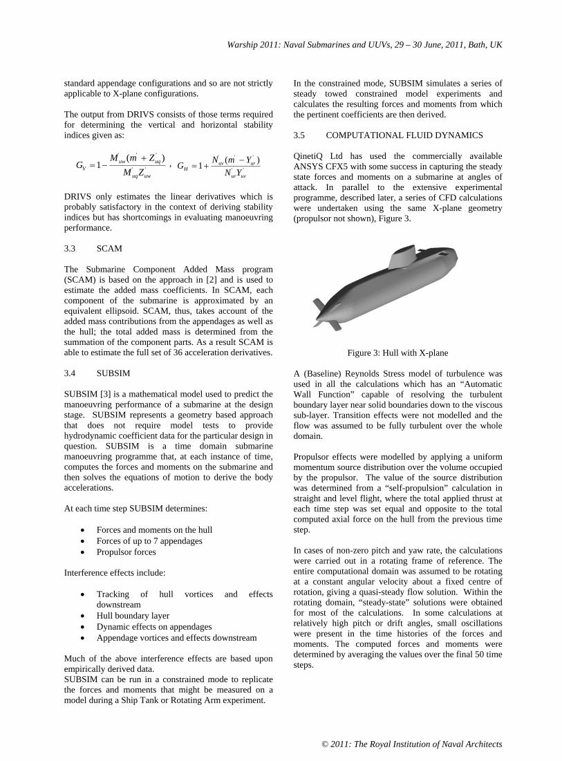
Warship 2011: Naval Submarines and UUVs, 29 – 30 June, 2011, Bath, UK
© 2011: The Royal Institution of Naval Architects
standard appendage configurations and so are not strictly applicable to X-plane configurations.
The output from DRIVS consists of those terms required for determining the vertical and horizontal stability indices given as:
''
''' )(1
uwuq
uquwV ZM
ZmMG ,
''
''' )(1uvur
uruvH YN
YmNG
DRIVS only estimates the linear derivatives which is probably satisfactory in the context of deriving stability indices but has shortcomings in evaluating manoeuvring performance.
3.3 SCAM
The Submarine Component Added Mass program (SCAM) is based on the approach in [2] and is used to estimate the added mass coefficients. In SCAM, each component of the submarine is approximated by an equivalent ellipsoid. SCAM, thus, takes account of the added mass contributions from the appendages as well as the hull; the total added mass is determined from the summation of the component parts. As a result SCAM is able to estimate the full set of 36 acceleration derivatives.
3.4 SUBSIM
SUBSIM [3] is a mathematical model used to predict the manoeuvring performance of a submarine at the design stage. SUBSIM represents a geometry based approach that does not require model tests to provide hydrodynamic coefficient data for the particular design in question. SUBSIM is a time domain submarine manoeuvring programme that, at each instance of time, computes the forces and moments on the submarine and then solves the equations of motion to derive the body accelerations.
At each time step SUBSIM determines:
Forces and moments on the hull Forces of up to 7 appendages Propulsor forces
Interference effects include:
Tracking of hull vortices and effects downstream Hull boundary layer Dynamic effects on appendages Appendage vortices and effects downstream
Much of the above interference effects are based upon empirically derived data. SUBSIM can be run in a constrained mode to replicate the forces and moments that might be measured on a model during a Ship Tank or Rotating Arm experiment.
In the constrained mode, SUBSIM simulates a series of steady towed constrained model experiments and calculates the resulting forces and moments from which the pertinent coefficients are then derived.
3.5 COMPUTATIONAL FLUID DYNAMICS
QinetiQ Ltd has used the commercially available ANSYS CFX5 with some success in capturing the steady state forces and moments on a submarine at angles of attack. In parallel to the extensive experimental programme, described later, a series of CFD calculations were undertaken using the same X-plane geometry (propulsor not shown), Figure 3.
Figure 3: Hull with X-plane
A (Baseline) Reynolds Stress model of turbulence was used in all the calculations which has an “Automatic Wall Function” capable of resolving the turbulent boundary layer near solid boundaries down to the viscous sub-layer. Transition effects were not modelled and the flow was assumed to be fully turbulent over the whole domain.
Propulsor effects were modelled by applying a uniform momentum source distribution over the volume occupied by the propulsor. The value of the source distribution was determined from a “self-propulsion” calculation in straight and level flight, where the total applied thrust at each time step was set equal and opposite to the total computed axial force on the hull from the previous time step.
In cases of non-zero pitch and yaw rate, the calculations were carried out in a rotating frame of reference. The entire computational domain was assumed to be rotating at a constant angular velocity about a fixed centre of rotation, giving a quasi-steady flow solution. Within the rotating domain, “steady-state” solutions were obtained for most of the calculations. In some calculations at relatively high pitch or drift angles, small oscillations were present in the time histories of the forces and moments. The computed forces and moments were determined by averaging the values over the final 50 time steps.
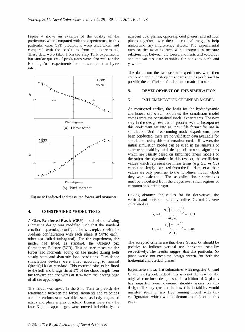
Warship 2011: Naval Submarines and UUVs, 29 – 30 June, 2011, Bath, UK
© 2011: The Royal Institution of Naval Architects
Figure 4 shows an example of the quality of the predictions when compared with the experiments. In this particular case, CFD predictions were undertaken and compared with the conditions from the experiments. These data were taken from the Ship Tank experiments but similar quality of predictions were observed for the Rotating Arm experiments for non-zero pitch and yaw rate .
15
0
15
-20 -10 0 10 20
Z'
Pitch (degrees)
Expts
CFD
(a) Heave force
-2 0
0 0
2 5
-20 -10 0 10 20
M'
Pitch (degrees)
ExptsCFD
(b) Pitch moment
Figure 4: Predicted and measured forces and moments
4. CONSTRAINED MODEL TESTS
A Glass Reinforced Plastic (GRP) model of the existing submarine design was modified such that the standard cruciform appendage configuration was replaced with the X-plane configuration with each plane at 90° to each other (so called orthogonal). For the experiment, the model had fitted, as standard, the QinetiQ Six Component Balance (6CB). This balance measured the forces and moments acting on the model during both steady state and dynamic load conditions. Turbulence stimulation devices were fitted according to normal QinetiQ Haslar standard. This required pins to be fitted to the hull and bridge fin at 5% of the chord length from the forward end and wires at 10% from the leading edge of all the appendages.
The model was towed in the Ship Tank to provide the relationship between the forces, moments and velocities and the various state variables such as body angles of attack and plane angles of attack. During these runs the four X-plane appendages were moved individually, as
adjacent dual planes, opposing dual planes, and all four planes together, over their operational range to help understand any interference effects. The experimental runs on the Rotating Arm were designed to measure relationships between the forces, moments and velocities and the various state variables for non-zero pitch and yaw rate.
The data from the two sets of experiments were then combined and a least-squares regression as performed to provide the coefficients for the mathematical model.
5. DEVELOPMENT OF THE SIMULATION
5.1 IMPLEMENTATION OF LINEAR MODEL
As mentioned earlier, the basis for the hydrodynamic coefficient set which populates the simulation model comes from the constrained model experiments. The next step in the design evaluation process was to incorporate this coefficient set into an input file format for use in simulation. Until free-running model experiments have been conducted, there are no validation data available for simulations using this mathematical model. However, the initial simulation model can be used in the analysis of submarine stability and design of control algorithms which are usually based on simplified linear models of the submarine dynamics. In this respect, the coefficient values which represent the linear terms (e.g. Zuw or Yur)cannot be simply extracted from the full data set as their values are only pertinent to the non-linear fit for which they were calculated. The so called linear derivatives must be calculated from the slopes over small regions of variation about the origin.
Having obtained the values for the derivatives, the vertical and horizontal stability indices Gv and Gh were calculated as:
11.01wq
qu
v
ZM
ZmMG
04.01vr
rv
h
YN
YmNG
The accepted criteria are that these Gv and Gh should be positive to indicate vertical and horizontal stability respectively. The results suggest that this particular X-plane would not meet the design criteria for both the horizontal and vertical planes.
Experience shows that submarines with negative Gv and Gh are not typical. Indeed, this was not the case for the original cruciform design; so, the addition of X-planes has imparted some dynamic stability issues on this design. The key question is how this instability would manifest itself in any free running model with this configuration which will be demonstrated later in this paper.

Warship 2011: Naval Submarines and UUVs, 29 – 30 June, 2011, Bath, UK
© 2011: The Royal Institution of Naval Architects
5.2 AUTOPILOT DESIGN
All the controllers are designed from the linearised models using the derivative values to define the dynamics. The course and depth controllers are treated separately, with the demands summed at the output to the control surfaces themselves.
Furthermore, course control was divided into two modes, course-keeping and course-changing. The controllers themselves take the form of a high order state-space system; embedded in the autopilot is a procedure for switching between, for heading control, the course-keeping and course-changing controllers and for depth control, the depth-keeping and depth-changing controllers which used the following rules:
Course control if the heading error exceeds 10° switch to course-changing mode when the heading error falls below 1° revert to course-keeping mode
Depth control if the depth error exceeds 2m (Full scale equivalent) switch to depth-changing mode when the depth error falls below 1m (Full scale equivalent) revert to depth-keeping mode
For each aspect of control, both controllers are required to be run in parallel, such that when switching from one to the other the incoming controller is prepared with the correct demand output.
5.3 AUTOPILOT IMPLEMENTATION
A framework has been developed which allows a co-simulation between the COTS software SIMULINK® and the QinetiQ in-house submarine manoeuvring code, SUBHOV, in which data are transferred between the two codes during run-time. While running, a graphic display window provides a visualisation of the X-plane control surfaces. An example is given in Figure 5.
Figure 5: X-plane visualisation
In order to implement this controller in a free-manoeuvring model, the autopilot was re-written in the graphical programming language LabVIEW© to enable the autopilot to run under a real-time operating system at a fixed iteration rate.
A conventional cruciform dive command, which would just be applied to the stern planes, is now applied to all four X-plane control surfaces, as shown in Figure 6(a). (The view is from aft looking forward.) Similarly, when a conventional cruciform initiates a turn, this would just be applied to the rudder, which for the X-plane would be applied to all the control surfaces as shown in Figure 6(b).
(a) Acting as a stern plane
(b) Acting as a rudder
(c) Combination of depth and heading control
Figure 6: Cruciform to X-plane transformation
When simultaneous depth and heading demands are made, the demanded control surfaces are simply summed. Figure 6(c) shows an example of a combined 10° dive on the planes and a 10° starboard rudder. The upper starboard and lower port control surfaces sum to 20° deflections, while the upper port and lower starboard demands cancel out. For an X-plane configuration, a positive deflection for any control surface is a clockwise rotation about the shaft when looking away from the hull. This gives rise to the following equations:
us = + s - r , ls = + s + r , lp = - s + r , up = - s - r
During the development of the coefficient set and implementation in simulation, it was found that the lower pair of X-plane control surfaces were slightly more effective than the upper pair, despite being geometrically identical. This is reflected in the pertinent coefficients, where the lower pair values are around 8% greater than the upper pair values. This is possibly due to the presence of the bridge fin creating vortices that are transported downstream and impact on the upper pair of control surfaces.
6. FREE RUNNING MODEL TESTS
Once the autopilot had been developed using a real time operating system the free running model tests could then

Warship 2011: Naval Submarines and UUVs, 29 – 30 June, 2011, Bath, UK
© 2011: The Royal Institution of Naval Architects
be undertaken. This section presents details of these experiments conducted in both the Ocean Basin and at a deep water reservoir.
There were several aims to these free-running model experiments:
to replicate the manoeuvres conducted using the equivalent cruciform model to explore high-speed manoeuvres to investigate the alternative control options offered by an X-plane arrangement to explore hydroplane jam responses and investigate recovery strategies to conduct manoeuvres suitable for System Identification, leading to improvements in the mathematical model predictions
The QinetiQ SRM is capable of all the above, but is chiefly used for exploring the extremes of the manoeuvring envelope [4]. The SRM was configured as a geosim of the model used in the constrained experiments, Figure 7. A standard set of instrumentation was fitted, comprising of a Ring Laser Gyro (RLG), Doppler Velocity Log (DVL) and pressure depth transducers, to undertake an extensive set of tests.
Figure 7: Profile view of SRM clad as an X-plane
The experiments fall into two distinct parts: manoeuvres in the Ocean Basin and manoeuvres at the reservoir. In general, the Ocean Basin manoeuvres were limited to the slow and moderate speed runs and some limited depth changes. Some jam manoeuvres to rise were also conducted. The bulk of the programme was conducted at the reservoir where the available space allowed for the higher speed manoeuvres to be conducted as well as those which required larger depth changes.
In the Ocean Basin, the model is operated under driver control. The driver operated control desk functionality is limited, in part, by the bandwidth available for through-water communication. The driver has control of rudder and motor rpm, and through push-buttons can switch the autopilot on or off, or initiate certain manoeuvres such as turns, depth changes, zig-zag manoeuvres or hydroplane jams. The model is launched from a fixed cradle at one end of the tank and is driven up to speed, depth and heading and into the manoeuvring area. On completion of each manoeuvre, the model is brought to the surface,
captured by the divers and returned to the cradle for data off-load.
When operating at the reservoir there is no driver-communication system available. The model is effectively autonomous whereby all manoeuvres are pre-programmed, with events happening according to a fixed time sequence. The increased test area available at the reservoir allowed for several manoeuvres to be conducted in a single launch, provided the model is allowed time to recover onto speed, depth and heading between each evolution. For this reason, all runs were created in simulation first, the results of which also allow for planning of the approximate surfacing location.
By way of an example, turning circles form a standard set of manoeuvres which involve a set of parameters measurable from a turning circle manoeuvre. These include:
Advance - defined as the distance travelled in the direction of the original heading between the helm-over order and the point of achieving a heading change of 90°.
Transfer - defined as the distance travelled at right angles to the original track between the helm-over order and the point of achieving a heading change of 90°.
Tactical diameter - defined as the distance travelled at right angles to the original track between the helm-over order and the point of achieving a heading change of 180°.
Drift angle is the angle between the submarine’s heading and the direction of travel. In this case it has been calculated from the DVL data as drift angle = tan -1(v/u) once a steady state condition has been achieved.
Figure 8: Tactical diameter for a range speeds
Figure 8 shows how the tactical diameter varies with rudder angle for a range of speeds tested. These turning circles were conducted using all four control surfaces as rudders, with additive depth control applied as required. Because of the requirement for depth control, some of

Warship 2011: Naval Submarines and UUVs, 29 – 30 June, 2011, Bath, UK
© 2011: The Royal Institution of Naval Architects
the 30° rudder turns did not quite achieve this angle. The data show a consistent variation in the tactical diameter with rudder angle and are largely independent of speed. There is a distinct “flattening off” at the higher rudder angles with no improvement in diameter at 30° rudder over 25° rudder, possibly as a result of the planes stalling.
As described earlier, the stability indices suggested that this X-plane design would be directionally unstable, so how did this manifest itself in the free running model tests? During the completion of a turn, where a pull-out manoeuvre is initiated, the yaw rate would persist; an example of a persistent yaw rate is given in Figure 9 which shows a pull-out at a speed equivalent to 8 knots. Following a 10° rudder turn, the rudders are returned to midships. The yaw rate does decay, but settles on a non-zero value, i.e. the submarine keeps turning.
Figure 9: Example of yaw instability
Further experiments demonstrated that whilst in the vertical plane there was some transient instability, the design can be controlled by the planes without incurring excessive plane activity.
A series of tests included the application of a single hydroplane jam following a steady period of straight and level running. All other control surfaces remained under autopilot authority, and the initial response was to “do nothing”, i.e. allow the autopilot to simply carry on with the current ordered depth and heading.
An example of an 8 knot jam to rise is shown in Figure 11. Generally, for modest jam angles of say 10° and 20°, any pitch, depth and yaw excursions were minimal. However, for the higher 30° jam to rise on the upper port plane, shown in Figure 10, the excursions were more considerable, and yaw became uncontrolled. The initial response of the course keeping and depth keeping controllers is to control yaw and pitch equally; however, both failed in this scenario. When the heading error reached 10°, the autopilo t switched to the course-changing controller which had no integral action. As such the demands of the heading control then become swamped by the depth control so the submarine is no longer controlled in yaw. As a result the control of depth and pitch are regained at the expense of increasing the yaw rate.
Figure 10: Single plane jam at 8 knots
As mentioned earlier a simulation framework was created which allowed all of the manoeuvres to be replicated with a single command. In order to simulate the free-running model as best as possible, there are several initialisation tasks required.
The simulated rpm must provide the correct speed The acceleration, deceleration and braking characteristics must agree. The balance angles and compressibility must be established to correctly account for loss of buoyancy during depth changes
All the standard and jam manoeuvres have been replicated in simulation but only a single representative example is given here. Figure 11 shows the comparison between simulation and experiment of a single plane jam to dive at a speed equivalent to 18 knots.
The simulations of the excursions following a single hydroplane jam are reasonably well predicted. For the higher plane jams in Figure 12, the simulations are a little optimistic. In this example, for the first 5 seconds of the jam the first few degrees of the pitch and yaw excursions are well modelled. From 5 seconds onwards, the model continued its excursions rapidly, whereas the simulation starts to hold a steady state. This could possibly be due to a lack of modelling of the stall characteristics of the control surfaces, although this would apply equally to the jammed surface as well as to the recovery surfaces. However, the characteristics are likely to be different since some hydroplanes will be in the wake of the

Warship 2011: Naval Submarines and UUVs, 29 – 30 June, 2011, Bath, UK
© 2011: The Royal Institution of Naval Architects
submarine and some will not. The mathematical model does not currently include this detail.
Figure 11: Simulation of single plane jam with turning
In general, single hydroplane jams at moderate angles were comfortably dealt with by the autopilot without any further action, with depth and heading successfully maintained. However, single hydroplane jams at the maximum deflection were not successfully controlled by the “do nothing” strategy. An alternative strategy of slowing down and allowing heading changes meant that depth and pitch were better maintained. However, depth was not always fully recovered (i.e. zero depth rate) so further options should be considered.
Although the simulations show good agreement in many areas, there are a number of points for further investigation. Depth and pitch response prediction in a turn have been improved for controlled turns, but still require investigation in free turns and hydroplane jam scenarios. The poor roll predictions during turns also require investigation.
7. PRELIMINARY SAFE OPERATING ENVELOPES
In order to provide operator guidance in a form suitable for use in RN Submarines, the recovery methodology associated with jam incidents for an X-plane configuration must be determined. The final step in this process is to understand how this work culminates in providing operator guidance. Safe Operating Envelopes (SOE) are provided to all RN Submarines to increase the likelihood, that should a submarine suffer a flood or a hydroplane jam, it would be able to recover safely. The SOE diagram provides details of safe combinations of speeds and depths at which the submarine can operate, should an incident occur.
The format of the SOE and the contents of the submarine’s Emergency Operating Procedures (EOP) are intrinsically linked to one another, as one defines the other. However, there are also design issues that impact on the form of the SOE. For example, if a particular design feature, such as an X-plane, impacts on the EOP as a result of a jam or flood then this will impact on the SOE. Thus, it is important to understand what form the SOE would take for an X-plane arrangement. The derivation of the coefficient set, its verification in simulation and the development of the autopilot meant that the form of the SOE could be investigated through simulation. The manoeuvring simulation tools were then used to investigate the most appropriate recovery strategies for a Royal Navy submarine design with an X-plane configuration.
It is important to ensure consistency between the design philosophy that results in the submarines control surfaces arrangement, the content of the Emergency Operating Procedures and the format of the Safe Operating Envelope. Two formats for the SOE were considered, plane limited and pitch limited.
Plane limited Manoeuvring Limitation Diagram (MLD) [4]: This format is used for linked cruciform stern plane submarines where the jam of both stern planes causes large depth excursions. Pitch limited Safe Manoeuvring Envelope (SME) [5]: This format is used for independently actuated stern planes where a single jammed stern plane causes a small depth excursion.
Assessing the X-plane jam recovery trajectories led to the conclusion that whilst depth excursions were mainly minimal, pitch angles could be large. This suggested that the most appropriate format would be the pitch limited SOE. In order to define a pitch limited SOE for the X-plane configuration an appropriate EOP methodology had to be chosen. The following possible EOP options have been considered in response to a single plane jam incident:
Order the diagonally opposite stern plane to an equal angle, bow planes to rise/dive and full astern until 5 knots, followed by revolutions for 5 knots, or directly order the stop speed. Order the three remaining stern planes to full rise/dive and then take ‘appropriate’ actions. Switch the autopilot on at the detection of the jam. Remain in autopilot as the jam occurs.

Warship 2011: Naval Submarines and UUVs, 29 – 30 June, 2011, Bath, UK
© 2011: The Royal Institution of Naval Architects
Figure 12: Proposed format for X-plane operator guidance and indicative data
An example of a typical SOE for an X-plane is shown in Figure 12. The results indicated that deriving suitable operator guidance for an X-plane submarine is likely to result in the need to adopt a different approach to the recovery methodology that is currently applied for RN cruciform submarines. This differing approach is likely to require more automation of the recovery methodology than is currently applied, in order to control the increased effectiveness of the stern planes. Therefore, the autopilot is likely to be more involved in the recovery process than previously, and may even require additional functionality in order to specifically address the response required for a plane jam.
8. CONCLUSIONS
This paper has described the principal elements of a four year research programme undertaken by QinetiQ Ltd to develop the numerical and experimental capability to assess the performance of an X-plane submarine design. The paper has brought together the development of a design toolset and an extensive experimental programme of captive and free running model tests to provide the capability to evaluate novel stern plane configurations and provide safe operator guidance.
9. ACKNOWLEDGEMENTS
The authors acknowledge the UK MoD for supporting this research programme and acknowledge the efforts of the Hydrodynamics Team for their support in undertaking the work described here.
10. REFERENCES
[1] GERTLER, M., and HAGEN, G.R., ‘Standard equations of motion for submarine simulation’ Naval Ship Research and Development Centre, Report No. 2510, USA, 1967.
[2] WATT, G.D., ‘Estimates for the Added Mass of a Multi-Component, Deeply Submerged Vehicle’, RINA WARSHIP Conventional Naval Submarines, UK, 1988.
[3] LLOYD, A.R.J.M., ‘Progress towards a rational method of predicting submarine manoeuvres’, RINA WARSHIP Naval Submarines, UK, 1983.
[4] HAYNES, D., BAYLISS, J., and HARDON, P., ‘Use of the Submarine Research Model to explore the manoeuvring envelope’, WARSHIP Naval Submarines 7,UK, 2002.
[5] PURVIS, S., and PHILIP, N., ‘Astute class movement control – an integrated approach’ RINA WARSHIP Naval Submarines 8, UK, 2005.
11. AUTHORS BIOGRAPHY
Paul Crossland leads the Submarine and Propulsors Team at QinetiQ Haslar. He is responsible for the submarine hydrodynamics programme at QinetiQ Haslar, developing experimental and computational techniques for assessing the performance of submarines, including understanding the behaviour of submarines close to the surface. He is currently chair of 26th ITTC seakeeping committee developing standards for hydrodynamic testing.
Philip Marchant works in the Submarine and Propulsors Team at QinetiQ Haslar. He has worked at Haslar for 9 years, is a member of RINA and has an MSc from University of Southampton and a BEng (Hons) from Southampton Institute of Higher Education.
Neil Thompson works in the Submarine and Propulsors Team at QinetiQ Haslar. He has worked at Haslar for 5 years, is a Graduate member of IMechE and has an MEng from the University of Southampton.

Warship 2011: Naval Submarines and UUVs, 29 – 30 June, 2011, Bath, UK
© 2011: The Royal Institution of Naval Architects
SUBMARINE MANOEUVRING: CORRELATING SIMULATION WITH MODEL TESTS AND FULL SCALE TRIALS
Nick Kimber, QinetiQ Ltd, UK
SUMMARY
As part of ongoing safety assurance programmes, work undertaken by QinetiQ, on behalf of the Ministry of Defence, is continually seeking to improve the mathematical modelling of manoeuvring submarines. Most of the validation evidence for trajectory simulation comes from free-running model experiments, but these simulations are generally used for predicting performance and responses to emergency manoeuvres at full scale. Occasionally an opportunity is granted to conduct sea trials on a full scale platform and this provides vital information for correlation with simulation and model scale data. Details of recent major trials are presented, including the types of manoeuvres conducted and the reasons for their inclusion in the programme. In addition, QinetiQ's Submarine Research Model has been used to replicate a subset of the full-scale manoeuvres as faithfully as possible, based on actual trial conduct. Some comparisons between model and full-scale results are presented, and the issues faced when conducting these types of trial and model experiment are discussed.
NOMENCLATURE
AUTEC Atlantic Undersea Test and Evaluation Centre EM Electro Magnetic SOE Safe Operating Envelope SQEP Suitably Qualified and Experienced Personnel SRM Submarine Research Model TAS Trim Advisory System UV Ultra Violet
1. INTRODUCTION
Under the Maritime Strategic Capability Agreement, the Ministry of Defence has a long-term programme of work with QinetiQ to retain capability in the areas of submarine hydromechanics, maritime life support, and submarine structures and survivability. The objective of this work is to aid the MOD in its assurance that submarines are safe, affordable and effective.
One aspect of this assurance is in the issuing of Operator Guidance to submarine crews in the form of standard and emergency procedures, and in the understanding of safe operating envelopes. Predictions of manoeuvring performance come chiefly from mathematical modelling and simulation codes, which are created and developed over time through a combination of constrained model testing, free-running model testing, and full-scale trials.
This paper gives an overview of the process of validation of manoeuvring simulation, with details of the types of manoeuvring trials conducted and their subsequent correlation with model experiments and simulation.
2. MATHEMATICAL MODELLING
Numerical computer simulations play an important part in the understanding of a submarine’s manoeuvring and control performance. Whether assessing basic handling characteristics or running “what if?” scenarios, desktop
computer simulations are an everyday tool. Furthermore, the Submarine Control Trainers based at Faslane and Devonport are driven by mathematical models which need to give a realistic response to the operators’ inputs.
Given that both operational training and the limits placed on the operational envelope rely on the output of computer simulation, it is vital that the underlying mathematical model is afforded an appropriate level of validation.
2.1 CONSTRAINED MODEL EXPERIMENTS
At a concept or early design stage, there are theoretical and empirical tools which can give an indication of a submarine’s basic stability and control parameters. As a design matures it is usual to conduct a set of towing experiments on a constrained model and from these, a more detailed mathematical model can be developed.
All UK Royal Navy submarines have been tested in the tanks at QinetiQ Haslar. Straight-line towing is performed in the 270m Ship Tank, and circular motion towing takes place on the 30m Rotating Arm, situated within the Ocean Basin.
These experiments generate a database of forces and moments acting on the submarine, as functions of the particular attitude to the flow and the deflections of the control surfaces. These relationships are usually expressed by non-linear equations of motion [1] such that the forces and moments can be recreated. In a time-domain simulation, these instantaneous forces and moments are used to derive the accelerations, which are then integrated numerically to provide updates to the velocity and position vectors.
At this stage, the mathematical model can be used for initial six degree-of-freedom simulations but it still requires validation.
Warship 2011: Naval Submarines and UUVs, 29 – 30 June, 2011, Bath, UK
© 2011: The Royal Institution of Naval Architects
2.2 FREE-RUNNING MODEL EXPERIMENTS
A free-running submarine model provides the initial validation for the mathematical model, as well as providing direct measurement of some handling characteristics such as turning circle diameters. Simulations of the free-running manoeuvres can be conducted, and any consistent discrepancies can be addressed [2].
All UK RN submarines since DREADNOUGHT have had free-running models constructed and tested in the 60m × 120m Ocean Basin at Haslar. The most recent new model was of the ASTUTE Class, and these free-running experiments were conducted in 2005, some five years ahead of her first sea trials.
Prior to the full-scale launch, the free-running model experiments provide the best evidence that the submarine will behave as expected. Once the submarine is at sea and becomes operational, then there is an interest in confirming the expected handling characteristics, and in gathering data to validate the mathematical manoeuvring models.
3. FULL-SCALE TRIALS
3.1 HISTORY
QinetiQ and its predecessor organisations have been involved in submarine manoeuvring trials for over 50 years. Table 1 lists submarine trials conducted during that period. These are limited to those dealing with manoeuvring aspects; there are of course many other aspects of a submarine's operations which undergo trials.
The description column in Table 1 is a little generic; Contractor Sea Trials, First of Class and general manoeuvring trials will incorporate a range of standard manoeuvres such as propulsion performance, turning circles and autopilot depth changing. Periscope depth keeping trials are self-explanatory while emergency recovery trials will typically investigate the response to, and recovery from, an after hydroplane jam.
For many of these trials, and certainly the more recent ones, QinetiQ maintains an electronic database of the manoeuvres. The range of parameters recorded during each trial varies but will typically include:
speed roll, pitch, heading depth angular rates accelerations control surface angles rpm range track data (if available)
The method of recording these parameters is detailed in the next section.
3.2 INSTRUMENTATION
Measurement techniques have evolved over the years. Early records were made to tape or UV paper and had to be post-processed and digitised back in the office. Since 1993 it has been standard practice to capture calibrated data directly to a laptop or PC.
The source of each measurement varies, and the intention is always to be as non-interfering with Ship Systems as possible. Motion data is typically taken from a Ship's System synchro repeater unit and converted to an analogue voltage. Some devices, such as the EM-log, may have spare serial outputs which duplicate the measurement signal. Control surface deflections are typically measured by fitting independent transducers to the rams, while shaft rpm is measured using an independent tachometer.
All these analogue signals require calibration. For the Ship Systems, there are procedures to inject dummy measurements, while the independent transducers require the actual motion of the control surfaces, which is easily enough done when alongside. Calibration of shaft rpm, however, has to be done at sea.
The sources of these measurements are distributed throughout the length of the submarine and all have to be brought to one location for synchronised recording. Fortunately, RN submarines are fitted with a network of cables specifically for use during trials which solves the problem of passing signals through watertight bulkheads. Each signal only requires a local cable run to the nearest junction box and from there internal wiring can route the signals to a convenient central location.
A full instrumentation rig, including cable runs and calibration, can take a team of three people around three to four days to install. Recent trials have made use of existing data highways to extract digital data from Ship Systems (e.g. over a MIL-STD-1553 network). This can save a lot of rigging effort, but the data buses do not always carry all the required information.
For some trials, it is possible to gather data using manual records alone, for example, propulsion trials. If records are only required of rpm and speed, these values can usually be noted by hand from local displays at a rate sufficient for analysis (from a manoeuvring point of view).

Warship 2011: Naval Submarines and UUVs, 29 – 30 June, 2011, Bath, UK
© 2011: The Royal Institution of Naval Architects
Year Boat Description Digital data
available 1958 HMS PORPOISE Dynamic stability and turning trials 1963 HMS DREADNOUGHT First of Class trials 1964 HMS PORPOISE Manoeuvring trials 1965 HMS DREADNOUGHT Speed trial 1967 HMS VALIANT First of Class trials 1968 HMS RESOLUTION Manoeuvring trials at AUTEC 1970 HMS WARSPITE Emergency recovery 1970 HMS OTTER Acceleration and deceleration 1970/1 HMS CHURCHILL Contractor sea trials 1971 HMS REPULSE Emergency recovery and stability 1972 HMS SWIFTSURE Contractor sea trials 1973 HMS SWIFTSURE First of Class trials 1974 HMS SOVEREIGN Contractor sea trials 1974 HMS SWIFTSURE Manoeuvring trials at AUTEC 1974 HMS CONQUEROR Manoeuvring trials at AUTEC 1976 HMS SOVEREIGN First of Class trials 1976 HMS SUPERB Contractor sea trials 1976 HMS OCELOT Periscope depth keeping 1978 HMS SWIFTSURE Frequency response trial 1981 HMS SOVEREIGN Periscope depth keeping 1982 HMS VALIANT Emergency recovery 1983/4 HMS TRAFALGAR First of Class trials 1985 HMS SPARTAN Periscope depth keeping 1985 HMS TURBULENT First of Class trials 1986 HMS TURBULENT Periscope depth keeping 1989 HMS UPHOLDER Contractor sea trials 1992/3 HMS VANGUARD Contractor sea trials 1993 HMS SUPERB Depth keeping trials 1993 HMS UPHOLDER First of Class trials 1994 HMS VANGUARD Depth keeping / frequency response 1994 HMS VANGUARD First of Class trials 1995 HMS TRIUMPH Emergency recovery 1995 HMS TRIUMPH Trim and compensation 1996 HMS SCEPTRE Depth keeping 2000 HMS TRIUMPH Manoeuvring trials 2001 HMS TRIUMPH Peak motion measurement 2002 HMS TORBAY Post-refit manoeuvring trials 2003 HMS TRENCHANT Post-refit manoeuvring trials 2004 HMS SPARTAN Depth keeping 2005 HMS TRENCHANT Manoeuvring / emergency recovery 2006 HMS TALENT Post-refit manoeuvring trials 2006 HMS TRAFALGAR Propulsion trial *
2008 HMS VIGILANT Manoeuvring / emergency recovery 2010 HMS TALENT Propulsion trial *
2010 HMS TRIUMPH Post-refit trials *
2010 HMS VICTORIOUS Manoeuvring trials * manual records only
Table 1: Submarine manoeuvring trials over the past 50 years

Warship 2011: Naval Submarines and UUVs, 29 – 30 June, 2011, Bath, UK
© 2011: The Royal Institution of Naval Architects
3.3 TYPES OF MANOEUVRES
A typical manoeuvring trial will consist of two phases – the first to establish some basic characteristics, and the second to conduct the more "exciting" manoeuvres. The types of runs are described in the following sections.
3.3 (a) Preparation/Calibration
Initial checks will consist of simple acceleration, deceleration and braking runs in order to determine propulsion performance, as it relates to manoeuvring.
One very important aspect of the analysis of manoeuvring trials is the understanding of the submarine's trim condition prior to any manoeuvre [3]. To assist with this, a real-time Trim Advisory System (TAS) is used during trials to indicate the submarine's condition. The algorithm underlying this observes the control surface angles employed to hold pitch and depth. The lift from the control surfaces is assumed to be known from the constrained model experiments, and hence any unexpected lift required to maintain pitch or depth can be attributed to a trim or compensation error. Calibrating such a system at sea is achieved by making known trim and compensation changes and correlating these with the resulting changes in the control surface angles. Another test conducted is to maintain a fixed trim condition and accelerate the submarine. If the TAS output does not remain constant then a simple correction can be made which essentially accounts for the lift and moment due to the hull itself.
All submarines are compressible to some extent and lose buoyancy with increasing depth. Over time, the crew will learn how much compensation is required to maintain neutral buoyancy following routine depth changes. For a first-of-class submarine, initial estimates are made theoretically, and these are validated at sea by conducting slow speed trimming exercises over a range of depths.
All the above preparation runs are essential if there is an intention to use the data to validate the mathematical model and simulation codes. Trim condition and compressibility effects must be taken into account when simulating the subsequent manoeuvres.
3.3 (b) Open-loop Manoeuvring
A number of standard open-loop manoeuvres are typically conducted as part of Contractor Sea Trials or First of Class trials.
Turning circles are the most basic type of manoeuvre, and these may be augmented with pull-outs (i.e. return rudder to mid-ships) to measure horizontal stability.
Zig-zags are also a standard manoeuvre and for submarines can be conducted in both the horizontal and vertical planes.
Free-turns are turning circles with no depth control. These are often conducted to establish a submarine’s natural response in the vertical plane at different speeds.
Pulse manoeuvres, particularly in the vertical plane, are conducted to demonstrate a control surface’s ability to generate a pitch moment.
Frequency response manoeuvres, where the pitch or heading is made to follow a sinusoidal track, are basic system identification tools used to measure the response between a control surface and the subsequent motion.
All these simple open-loop manoeuvres provide useful data against which specific parts of the mathematical model can be validated.
3.3 (c) Pseudo Emergency Manoeuvres
Several of the trial descriptions in Table 1 include the term ‘emergency recovery’. These refer to manoeuvres where the after hydroplanes are deliberately forced to ‘jam’ at a fixed angle, and then the response options to such a scenario are explored. They are described in more detail in [4].
These runs form an important part of crew training, and an equally important part in the validation of the mathematical model. The operational limits placed upon a submarine’s manoeuvring envelope (in terms of speed and depth) are generated as a result of computer simulation predictions of ‘worst-case’ scenarios. Clearly, these limits are never tested at sea but it is necessary to establish that the computer models are not over-optimistic in assessing a submarine’s chances of recovery.
Full-scale mathematical model validation trials have to be performed well within the existing safe limits of operation. The only option for truly exploring the boundaries is to return to a free-running model. First, though, it is necessary to establish the correlation between the full-scale submarine, the physical model and the simulation. One example is described in section 4.
3.4 DEVELOPMENT OF ‘BEST PRACTICE’
Over the years, a great deal of experience has been gained in planning, conducting and analysing trials. Much of the process is covered in [3] but essentially, once Trials Orders are written, they are subject to scrutiny by a multi-disciplinary board of Suitably Qualified and Experienced Personnel (SQEP). The impact of each planned manoeuvre is assessed and precautionary measures are suggested. If considered necessary, some manoeuvres are practiced in a Submarine Control Trainer (or simulator) to establish the best procedure. The objective is to generate a set of Trials Orders which are clear to follow, provide all the necessary guidance, and deliver the objectives of the

Warship 2011: Naval Submarines and UUVs, 29 – 30 June, 2011, Bath, UK
© 2011: The Royal Institution of Naval Architects
trial. The remainder of this section contains a few lessons learned.
One of the greatest issues faced during analysis is having a good understanding of the initial conditions prior to each manoeuvre. This problem is nothing new – the report [5] on the 1958 trial listed at the top of Table 1 states:
"considerably more attention must be given in future to the state of the ship at the beginning of the manoeuvre"
This remains a challenge which is faced today. There is always pressure in the Control Room to "crack on" through a trials programme and this can often mean that one manoeuvre is begun before the submarine has sufficiently recovered from the previous one. The solution is to state explicitly in the Trials Orders that a specific period of time must elapse between the submarine being declared ready for a manoeuvre and the actual execution.
Real-time time-history displays in the Control Room are a strongly recommended means of communicating the required initial conditions to the crew. During propulsion trials, for example, a five-minute scrolling display of speed will indicate when steady conditions have truly been reached, i.e. the display will show a flat line. Alternatively, the TAS output can be used to show when a steady trim condition has been achieved. If such observations are made at the time of conduct, it will save a lot of difficulty during subsequent analysis.
The Trials Orders should always plan to conduct repeat runs. This is in recognition that initial conditions will never be exactly the same twice, despite best intentions. A mathematical model will always give the same output for a given input but the real-life response is likely to vary due to external disturbances. Repeats should be conducted at different times, possibly with different on-watch operators.
For the pseudo-emergency recovery manoeuvres, a particular tool has been developed to aid the repetition process – the stick limiter device. Not all the jams are required to use the maximum deflection, indeed it is part of the safety case that the manoeuvres only increase in small steps from a known response. In order to provide a limited deflection jam, a temporary stop device is fitted which allows the helmsman to rest the control stick against an adjustable lug (Figure 1). This also prevents ‘wandering’ of the control surface during the jam. When full authority control is required, the lug can be flipped out of the way. An advantage of this system is that repeat runs can ensure that the control stick is placed at the exact same deflection each time.
Alongside all the data gathered by computer, equal importance must be given to manual records. There is a great deal which goes on in a submarine’s Control Room
and Manoeuvring Room which cannot be captured electronically. This can range from trimming operations to changes of on-watch personnel, and must include all decisions taken as to why things happened the way they did.
Figure 1: Control surface limiter device
An example of the need to conduct repeat runs is given in Figure 2. This was an emergency recovery manoeuvre, with the after hydroplanes ‘jammed’ at 6° to rise. The response was to apply astern rpm in order to reduce the pitch and depth excursions. This manoeuvre was conducted three times over a two-day period.
From the perspective of the actions taken in the Control Room, the procedure followed was identical. However, the resulting pitch and depth trajectories were not. One of the runs (solid line) shows some undesirable control surface activity prior to the manoeuvre, and also the astern rpm being applied in a different way. The other two lines (dashed and dotted) show agreement in the inputs, but not in the outputs. The cause of this may be simply due to different trim conditions (the runs were conducted 48 hours apart) or perhaps a chaotic hydrodynamic effect due to the astern propulsion.
4. FREE RUNNING MODEL EXPERIMENTS
Following one of the recent major manoeuvring trials, a number of the emergency recovery manoeuvres were recreated using the QinetiQ Submarine Research Model, which had been configured to represent the particular submarine as closely as possible.

Warship 2011: Naval Submarines and UUVs, 29 – 30 June, 2011, Bath, UK
© 2011: The Royal Institution of Naval Architects
-20 0 20 40 60 80 100 120
1
rel.
spee
d
-20 0 20 40 60 80 100 120
dept
h (m
)
-20 0 20 40 60 80 100 12005
10
pitc
h (°
)
-20 0 20 40 60 80 100 120-10
0
10
s (°
)
-20 0 20 40 60 80 100 120astern
0
ahead
Time (s)
rpm
Figure 2: Time-histories from three ‘identical’ full-scale runs
Details of the SRM were presented in [4]. Since that time a significant overhaul programme has increased the model’s capability and operability through the addition of new measurement and control technology.
For each particular manoeuvre, the model was programmed to follow the same sequence of control inputs and event timings as were measured on the full-scale trial. Each model manoeuvre was then repeated several times.
For a given after hydroplane jam, several response options were considered. Initially, a purely astern rpm action was applied. Subsequently, the addition of rudder angle was explored, including the asymmetry of port and starboard responses. Most runs employed a 35° hard over rudder, with the aim of reducing the submarine’s speed as rapidly as possible. However, the act of turning can have consequences on the pitch angle (known as cross-coupling [2]) and so some runs were conducted with a 15° rudder deflection. Figure 3 captures the run plan for the middle of the three approach speeds investigated.
The central column of Figure 3 (where the rudder is 0°) represents the purely vertical plane runs, consisting of the indicated hydroplane jam angle and the application of astern rpm. The cells either side represent runs where the indicated rudder angle was also applied as part of the recovery procedure. The central row, where a sternplane jam of 0° is indicated, represents runs which investigated the application of rudder and astern rpm only. These were conducted in order to isolate their effects from those of the sternplanes.
At the particular speed represented in Figure 3, the hydroplane jam angles were limited to ±10° for the full-scale trial. The more benign manoeuvres were not repeated at model scale, but the more extreme manoeuvres were, in order to establish the correlation between the two scales. The free-running model was then used to extend the envelope of manoeuvres. In addition to increasing the range of jam angles explored, a whole series of runs were conducted at a higher speed than the three investigated at full scale.
(port) rudder (stbd)35° 15° 3° 0° -3° -15° -35°
(rise) -25°-20°-16°-10°-6°-4°0°4°6°10°16°20°
(dive) 25°
Trial data onlyTrial and model dataModel data only
ster
npla
ne ja
m a
ngle
Figure 3: Schematic of trial and model run plan
Figure 4 plots the time-history measurements of a few of the motion data channels, suitably scaled to compare the full-scale and model-experiment results. This particular manoeuvre, a 6° after hydroplane jam to rise, was conducted three times at full-scale and six times at model scale.
-20 0 20 40 60 80 100 120 140 160
1
spee
dap
proa
ch s
peed
-20 0 20 40 60 80 100 120 140 160
dept
h (m
)
-20 0 20 40 60 80 100 120 140 160
0
10
20
pitc
h (°
)
Time (s)
Full-scale trialsModel experiments
Figure 4: Example comparison of full-scale and model scale motions

Warship 2011: Naval Submarines and UUVs, 29 – 30 June, 2011, Bath, UK
© 2011: The Royal Institution of Naval Architects
Despite the more controlled conditions exerted over the model experiments, there is still a range of trajectory responses, particularly noticeable in the pitch records. This again is thought to be due to the chaotic nature of the flow over the aft end caused by the astern rpm.
From a safe manoeuvring point of view, the characteristics of interest are the peak pitch angle and the depth excursion, as these will determine whether the submarine’s response remains within safe limits. Figure 5 plots the pitch and depth excursions from the trial and model experiment against each other.
mod
el d
epth
exc
ursi
on
trial depth excursion
SAFE
SAFE
UNSAFE
UNSAFE
y=xlow speedmedium speedhigh speed
mod
el p
itch
excu
rsio
n
trial pitch excursion
SAFE
SAFE
UNSAFE
UNSAFE y=xlow speedmedium speed
high speed
Figure 5: Correlation of model and full-scale pitch and depth excursions
The excursions correlate reasonably well. The variations within a single run can be observed, for instance, in the upper right corner of the depth comparison plot – there is one value of the trial depth excursion plotted against five results from the repeated model tests.
In the lower left region of the pitch comparison plot, most data points lie above the y=x line. This indicates that the model pitch excursions under-predict the full-scale results. It would therefore be an unsafe procedure to rely solely upon the model-scale results to generate a Safe Operating Envelope (SOE). Of course, this is not the case and, as stated in section 2, it is the simulation codes which are used to generate the SOE.
5. SIMULATION CORRELATION
A similar correlation exercise is carried out for simulations of the emergency recovery manoeuvres. These simulations can be conducted against both the model experiments and the full-scale trials. The mathematical models used at each scale are almost identical; there are obviously changes to the physical characteristics (length, mass, inertia), and to the time-scale. In addition, it is necessary to make some small changes to the propulsion model to maintain the correct relationship between rpm and speed at each scale.
Figure 6 plots the comparisons of simulation results with those from the 121 model-scale emergency recovery manoeuvres. Here, nearly all of the predictions over-estimate the model experiment response. These regions are indicated as SAFE, because the real-life response (albeit at model scale) is not as extreme as that predicted. This means that if operator guidance were issued based on these simulation results, the limitations would be conservative.
model depth excursion
sim
dep
th e
xcur
sion
SAFE
SAFE
UNSAFE
UNSAFE y=x
low speedmedium speedhigh speed
higher speed
model pitch excursion
sim
pitc
h ex
curs
ion
SAFE
SAFE
UNSAFE
UNSAFEy=xlow speed
medium speedhigh speedhigher speed
Figure 6: Correlation of simulation and model pitch and depth excursions
However, given that the free-running model tends to under-predict the full-scale response, and the simulation at model-scale tends to over-predict, it is necessary to complete the set and plot simulation against full-scale. These results are presented in Figure 7.

Warship 2011: Naval Submarines and UUVs, 29 – 30 June, 2011, Bath, UK
© 2011: The Royal Institution of Naval Architects
Of the three sets of comparisons (Figures 5, 6 and 7), it is perhaps this final set which shows the best correlation, and this is borne out by the mathematics of the least-squares fits, as indicated in Table 2.
depth pitch model v full-scale 0.92 0.92 simulation v model 1.20 1.21 simulation v full-scale 1.06 1.05
Table 2: Correlation slopes of excursion comparisons
sim
dep
th e
xcur
sion
trial depth excursion
SAFE
SAFE
UNSAFE
UNSAFEy=x
low speedmedium speedhigh speed
sim
pitc
h ex
curs
ion
trial pitch excursion
SAFE
SAFE
UNSAFE
UNSAFE
y=x
low speedmedium speed
high speed
Figure 7: Correlation of simulation and full-scale pitch and depth excursions
6. CONCLUSIONS
It is always the intention to maintain the mathematical model such that it gives the best representation of full-scale behaviour. Much of our knowledge, however, comes from model-scale experiments backed up occasionally by full-scale trials. It is necessary to reconcile the differences between the physical measurements at both scales, and the simulations of these manoeuvres.
Explanations are always readily available to account for differences between results. For full-scale trials the environmental conditions and external disturbances are often unknown. It is difficult to assess the trim conditions, and harder to maintain a fixed one for any
length of time. A free-running model may be an exact geosim of its full-scale counterpart but inertial characteristics are difficult to replicate and there are hydrodynamic scaling issues to take into account.
Therefore, full-scale data is a valuable resource and it is vital to make the best use of trials opportunities as they arise. Good planning is essential, including thorough reviews of the Trials Orders by experienced personnel, and by those who will be, or are familiar with, managing the actual conduct the trials.
A good procedure has been developed over the years and the historical data available in the QinetiQ Haslar archive allows for reviews of which types of manoeuvres work well, how long they take to conduct, and what could be done better on future trials.
All trials need to include preparatory runs to help eliminate any unknowns which can hamper subsequent analysis, and the conduct of each individual manoeuvre must ensure that the initial conditions are steady and well understood. This will allow a more reliable simulation to be performed, leading to a better understanding of the correlation between the real world and the mathematical model.
7. ACKNOWLEDGEMENTS
Much of the recent work described in this paper has been carried out with the support of the Sea Systems Group, and the In Service Submarines project team, Ministry of Defence, Abbey Wood. These colleagues have contributed to the planning of the trials, providing the liaison with the Royal Navy staff, and have acted as Trials Offers for the conduct at sea. The support from CINCFLEET in making platforms available is also acknowledged.
It is evident from the wealth of historical reports that the co-operation of the submarine Command teams and crews has been instrumental in the success of each trial. This has been the experience too in recent years, with Commanding Officers taking a keen interest in the outcomes of the trials and ensuring that the crew learns as much as possible about submarine handling characteristics. On occasion, additional manoeuvres have been granted beyond the scope of the Trials Orders to make the most of the platform’s availability and the training opportunity. Also acknowledged is the support of the Submarine Simulator staff at Faslane and Devonport who have allowed Trials Orders to be practiced and practical issues to be resolved.

Warship 2011: Naval Submarines and UUVs, 29 – 30 June, 2011, Bath, UK
© 2011: The Royal Institution of Naval Architects
8. REFERENCES
1. GERTLER, M. & HAGEN, G., ‘Standard Equations of Motion for Submarine Simulation’, Report 2510, Naval Ship Research and Development Centre, Washington, D.C, 1967.
2. KIMBER, N. & CROSSLAND, P., ‘Advances in Experimental Techniques for Understanding the Manoeuvring Performance of Submarines’, RINA Warship 2008: Naval Submarines 9, Glasgow, UK, June 2008.
3. BAYLISS, J., KIMBER, N., MARCHANT, P., BRYARS, J., ‘Submarine Trials and Experimentation – Dealing with Real-life Data’, RINA Warship 2005: Naval Submarines 8, London, UK, June 2005.
4. HAYNES, D., BAYLISS, J., HARDON, P., ‘Use of the Submarine Research Model to Explore the Manoeuvring Envelope’, RINA Warship 2002: Naval Submarines 7, London, UK, June 2002.
5. TUPPER, E.C., ‘HM Submarine PORPOISE – Dynamic Stability Trials’, Unpublished Report No. 33/59, AEW, Haslar, July 1959.
9. AUTHORS BIOGRAPHY
Nick Kimber is a Senior Scientist and the technical lead for submarine control within the Hydrodynamics Team at QinetiQ, Haslar. He has been involved in all aspects of submarine model testing and full-scale sea trials, with an interest in experimental techniques. His main area of work has been the analysis of captive and free-manoeuvring model experiments, the mathematical modelling of submarine motions and the research and development of algorithms for submarine control. He plays a key role in the planning and analysis of model-scale experiments and full-scale submarine manoeuvring sea trials. Current areas of interest include the validation of manoeuvring simulations with model experiments and full-scale trials data. He is a member of the Hydro Testing Alliance, an EU Network of Excellence, with an interest in free-running model technologies.

Warship 2011: Naval Submarines and UUVs, 29 – 30 June, 2011, Bath, UK
© 2011: The Royal Institution of Naval Architects
FULL AUTHORITY SUBMARINE CONTROL CONCEPT DEVELOPMENT
R Mansfield and D Venn, Stirling Dynamics Ltd, UK
SUMMARY
Full Authority Submarine Control (FASC) is a new concept for steering and diving systems, and combines Stirling’s proven Active Control Technology from the fly-by-wire aircraft industry with extensive experience in producing submarine autopilot and hover control software. This results in an integrated method of control which encompasses all steering and diving control requirements for the entire speed range of the submarine. FASC is a single unit comprising an active force-feedback side-stick and software algorithms which optimally control the trim and compensation system, hover system and hydroplanes appropriately across the entire speed range. The technology is currently being evaluated in a real-time demonstrator which has enabled functionality assessment, evaluation of performance and direct comparison with existing systems. This paper explains the FASC concept and reports on the findings of the recent work undertaken on the development of automatic out if trim compensation control.
NOMENCLATURE
AP Autopilot FASC Full Authority Submarine Control HMI Human Machine Interface OTC Out of Trim Compensator PID Proportional, Integral, Differential SME Safety Maneouvring Envelope TRL Technology Readiness Level
1. INTRODUCTION
Stirling’s research into new concepts for submarine platform control has been prompted by a number of factors. Technology ‘push’ factors and industry ‘pull’ factors have now created an environment where the concept can successfully develop to become a viable production solution.
Firstly, it was recognised that accepted issues with conventional methods of steering and diving control could be solved through the deployment of a new concept. Technology and design methodologies, many developed in the aerospace domain, are now sufficiently mature to support this development.
Secondly, future submarine will be required to operate in an increasing number of different roles and these roles may change through the life of the submarine. The current focus on littoral operations requires accurate platform control to be achieved in a more challenging environment. Stirling’s customers are now placing requirements for more manoeuvres and operations to be performed under automatic control, with performance criteria becoming more exacting and wide ranging. Performance requirements are being extended in the areas of setpoint following, disturbance rejection, and minimisation of control effort.
In parallel there are now additional pressures on product development from end users and customers, a desire to reduce development costs and through life costs translate into requirements to minimise integration effort, training
and maintenance costs. All these requirements have been combined to drive the system design approach for FASC.
2. OVERVIEW OF CONVENTIONAL STEERING AND DIVING CONTROL
Conventionally, steering and diving functions are performed by a combination of separate automatic controllers and manual operations to control the hydroplanes, ballast and hover systems. A simplified system is shown in Figure 1 which shows that functions that often run in concert do not necessarily communicate. In addition, interfaces are duplicated both on the input and output of some of the functions.
Depth control requires many of the functions shown in Figure 1 to be operated simultaneously which, if the functions have been designed independently, can mean that the boat’s manoeuvring is compromised during complex evolutions.
Figure 1: Conventional Depth Control Options
DataBus
Depth & Plant Information Hover Controller
Depth, Pitch & Plant Information Depth Autopilot
Heading & Plant Information Heading Autopilo
Plant Information
Trim & Compensat on
Depth, P tch & Heading Manual Control
Depth, Pitch & Plant Information
Out of Trim Estima or
Valve D ve
pos t on
Valve D ve Valve D ve
pos t on
Valve D ve
Valve D ve E ect onicsValve D ve E ect onicsValve D ve E ect onicsValve D ve E ect onics
Valve D ve E ect onics
pos t on
veloc ty
Valve D ve E ect onicsValve D ve E ect onics
pos t on
veloc ty
Valve D ve E ect onics
Fwd Hydroplanes
Aft Hydroplanes
Rudder
Hover System
MAT AB ULINK D l p t En ironment
MAT AB ULINK D l p t En ironment
Display
Trim, Bilge & Ba last
DataBus
DataBus
Depth & Plant Information Hover Controller
Depth, Pitch & Plant Information Depth Autopilot
Heading & Plant Information Heading Autopilo
Plant Information
Trim & Compensat on
Depth, P tch & Heading Manual Control
Depth, Pitch & Plant Information
Out of Trim Estima or
Valve D ve
pos t on
Valve D ve Valve D ve
pos t on
Valve D ve
Valve D ve E ect onicsValve D ve E ect onicsValve D ve E ect onicsValve D ve E ect onics
Valve D ve E ect onics
pos t on
veloc ty
Valve D ve E ect onicsValve D ve E ect onics
pos t on
veloc ty
Valve D ve E ect onics
Fwd Hydroplanes
Aft Hydroplanes
Rudder
Hover System
MAT AB ULINK D l p t En ironment
MAT AB ULINK D l p t En ironment
Display
Trim, Bilge & Ba last
DataBus

Warship 2011: Naval Submarines and UUVs, 29 – 30 June, 2011, Bath, UK
© 2011: The Royal Institution of Naval Architects
Stirling have identified the following key disadvantages with conventional systems:
Each control element is a separate unit carried out under separate contracts. Hence, the cost of the entire system is increased and the design process incurs large management and integration cost overheads. The conventional system requires at least two operators to carry out manoeuvring (at least one for hydroplane operation and one for trim and compensation). This is an unnecessary luxury given the confined and sometimes crowded conditions in a submarine’s control room. Control of future small platforms would be unfeasible using this current approach. Each control element is designed to meet a set of autonomous requirements. Therefore, when the systems are integrated, performance is compromised because the controllers are not necessarily optimised to work together. Conventional autopilot systems require man-in-the-loop intervention to adjust the trim and compensation during depth changes. Thus, the autopilot performance is compromised, and in the worst case safety is compromised, if the trim and compensation is mismanaged.
In conclusion, it is evident that the system shown in Figure 1 can be simplified and therefore optimised to provide a more efficient and controllable steering and diving system.
3. THE FULL AUTHORITY SUBMARINE CONTROL CONCEPT.
The overall concept of FASC is to simplify control of the submarine by tying together all aspect of the hover, trim, ballasting, and steering & diving control systems. Controlling all the aforementioned systems through a single interface allows for more optimised control of the submarine, while at the same time reducing the control complexity for the operator through the use of software control algorithms and tactile Human Machine Interface (HMI) technology.
The single control unit replaces all the separate steering and diving control functions; this unit controls both hydrodynamic and hydrostatic force actuators via a data bus. The control can therefore be optimised for performance across the entire speed and depth range. FASC utilises Stirling’s active control stick and a touch screen to enable operator inputs for both manual and automatic control.
FASC operates in a similar manner to Fly-by-Wire Flight Control Systems on aircraft. Thus, it acts as an interface between manual inputs and the control surfaces. A change in perception is therefore required regarding the distinction between the traditional Manual and
Automatic modes. When operating with FASC active, using the stick to order, for example, a depth change, the operator no-longer orders the angle of the fwd and aft hydroplanes. With FASC, a movement of the control stick indicates a desired pitch angle or ordered depth rate when at slow speed. The plane angles are then calculated within the FASC algorithms to obtain the desired attitude. The trim of the boat is actively controlled through the manoeuvre to provide a consistent response.
The basic schematic for the FASC interface is shown in Figure 2.
Va ve D ve Ele t on cs
pos t on
ve oci y
Va ve D ve Ele t on csVa ve D ve Ele t on cs
pos t on
ve oci y
Va ve D ve Ele t on cs
Rudder
Valve D ve E ect on cs
pos t on
ve oci y
Valve D ve E ect on csValve D ve E ect on cs
pos t on
ve oci y
Valve D ve E ect on cs
Va ve D ive E ect oni s
pos t on
veloc y
Va ve D ive E ect oni sVa ve D ive E ect oni s
pos t on
veloc y
Va ve D ive E ect oni s
Fwd Hydroplanes
Data Bus
Full Authority Submarine Controller
Hover Valve Bilge Pump Trim Pump Trim Pump Ballast Pump
Display Display
Aft Fore
Figure 2: FASC Schematic
There are four essential components to the FASC concept:
Stirling’s active stick technology. Integration of autopilot, hover control and automatic ballast algorithms. Integration of the safety manoeuvring envelope into FASC operation. System design for portability.
These features are discussed further in the following subsections
3.1 ACTIVE STICK FUNCTIONALITY
Active control technology is a key element within the FASC concept. The control stick used within FASC houses its own industrial single board computer, which runs a control algorithm at 1kHz in order to provide a smooth active feel with the effect of a mass spring damper. This technology is proven in use in both military and civil simulators and aircraft. Strain gauges in the unit detect the force being applied by the operator in each axis, motors in each axis then backdrive against the operator input to provide the required feel, including hard stops and axis lock features.
The current FASC control stick implementation has been met through iteration following a number of operator trials. The depth control axis while operating in FASC mode (Figure 3) has a series of soft-stops and detents

Warship 2011: Naval Submarines and UUVs, 29 – 30 June, 2011, Bath, UK
© 2011: The Royal Institution of Naval Architects
programmed to indicate to the operator standard depth changes (for example, SLOW, NORMAL, FAST or 5°, 10°, 15°). However, selection of all angles between these stops is also possible. In this example, ordering a slow descent will send an order for 5° pitch-down to FASC. The algorithms within FASC handle the flare-in and ensure that the submarine achieves and maintains the desired pitch. When approaching the desired depth, the operator gradually moves the stick to its central position, once in this central position, the current depth is captured as the ordered depth.
Hard Stop
Depth Hold
SLOWNORMAL
FAST
RiseDive
Figure 3: Active Stick Pitch Axis Demands
If the operator is at periscope depth, there is no requirement to attempt to counteract the sea state with the stick because this is carried out in FASC. Hence, to manually keep depth in a sea state, the stick is left at its central position. This borrows from ‘carefree’ control theories in the aerospace domain.
Superimposed onto the detents is a hard-stop beyond which the operator cannot move the stick. This hard stop is linked in real-time to limits imposed for safety or operational reasons, for instance by a Noise Reduction Mode or limits permitted by the SME. This gives the operator a tactile method for identifying the operating envelope. These hard stops can back-drive the control stick to prevent the boat from moving outside the safety manoeuvring envelope.
The heading control axis has a series of soft-stops and detents programmed to indicate to the operator steering rudder deflections (i.e. 10°, 20°, 30°) with hard-stops linked to the rudder limits (which may be speed-scheduled to limit depth excursions during a turn).
In addition to the detents and soft-stops the stick has the ability to modify a number of feel characteristics in real-time which can be configured during operator trials:
Force – deflection characteristic. Detent and breakout characteristics. Hard stops. Dynamic and static friction. Stick shaker for warnings and alarms notifications. Axis locking and active trimming of neutral position through grip switches.
3.2 INTEGRATED SAFETY MANOEUVRING ENVELOPE
Recommended limitations to the boat operation (speed, hydroplane plane angles) are historically presented in the form of a Safety Manoeuvring Envelope (SME) or Manoeuvring Limitation Diagram. These diagrams display a great amount of information which must be cross-referenced to key boat parameters and adhered to by the helmsman. An example SME is presented in Figure 4.
Figure 4: Example Safety Manoeuvring Envelope
Stirling have integrated the safety manoeuvring envelope for the boat within the FASC concept, the FASC algorithms will ensure that the SME is adhered to, and provide visual and tactile feedback to the operator when limits are being approached and applied. This will enable the implementation of ‘carefree’ handling. Stirling envisage that the system will incorporate the following key features:
Operator pitch and depth demands can be automatically limited to the SME, tactile feedback can be provided immediately to the operator through inceptor hard stops or soft stops. As operator demands are interpreted by the algorithms, plane demands can be automatically adjusted to comply with SME limits.
In the future the estimated trim state of the boat could be used to optimise the SME in real-time, therefore enhancing the SME to the current state of the boat (as opposed to an assumed state from the conventional SME charts).

Warship 2011: Naval Submarines and UUVs, 29 – 30 June, 2011, Bath, UK
© 2011: The Royal Institution of Naval Architects
3.3 FASC ALGORITHM DEVELOPMENT
FASC control encompasses a number of automatic control strategies. Heading, depth and pitch setpoints are ordered through the HMI (Setpoint Mode), or through movement of the active inceptor (Inceptor Mode). Inceptor inputs always take precedence.
All orders are interpreted by 3 control algorithms, incorporating a traditional steering and diving control algorithm, a hover control algorithm for depth control at low speed, and a new automatic trim and compensation control algorithm which works in concert with the steering and diving control algorithm. A central mode logic function ensures that the correct combination of hydroplane, trim and compensation and hover demands is ordered through the speed range. The FASC control algorithm elements are presented in Figure 5.
Figure 5: FASC Algorithm Components.
Given the performance requirements that are being placed on the latest generation of autopilots, it is physically impossible to design an autopilot algorithm which is fully optimised for performance when neutrally buoyant, and at the same time provides robustness against trim changes of the boat. For this reason the introduction of an automatic out of trim compensation algorithm is becoming ever more imperative.
The aim of the out of trim compensation (OTC) algorithm is to automatically compensate for trim and compensation changes due to sea-water density changes, boat compressibility or internal routines. This will Reduce levels of uncertainty and perceived unpredictability by the operator by ensuring a neutral trim state is maintained during evolutions.
Automatic control of trim and ballast will follow a strict set of rules to ensure that pumps and valves are not constantly moving. This will ensure that the submarine’s stealth capabilities are not compromised and that the trim and ballast system life is not reduced further than for a manually controlled system.
In order to maintain accurate depth control during low speed depth keeping and depth changing operations FASC also contains a hover control algorithm, currently this is configured to use a dedicated hover system to change and control the trim status of the boat through continuous flow demands. The specific arrangement of the hover system being controlled will eventually determine the control philosophy, but it is intended that FASC will control continuous hover flow rates in order to achieve the necessary performance.
The integrated approach used by FASC means the transitions and combinations between hydroplane control, automatic trim and compensation, and low speed hover is a seamless process, with the controller internally determining how to most effectively meet operator demands. This eliminates the potential for control algorithm conflict during the transition phase.
Due to the automatic handover between control algorithms and control effectors, operator actions and workload are reduced. This is illustrated Figure 6 and Figure 7, which describe a typical sequence of operations as speed is reduced to enter hover control, both under typical control systems found on the current generation of boats, and under FASC control.
Figure 6: Conventional Speed Reduction.

Warship 2011: Naval Submarines and UUVs, 29 – 30 June, 2011, Bath, UK
© 2011: The Royal Institution of Naval Architects
Figure 7: Speed Reduction with FASC
3.4 FASC PORTABILITY FEATURES
There are numerous FASC configurations envisaged by Stirling. Figure 8 presents an overview of the options identified.
Data Bus
Master FASC(Control Room)
Hover Valve Ballast Pump Trim PumpBilge PumpTrim Pump
Va ve D i e
E ect on cs
osi i n
ve oc ty
Va ve D i e
E ect on cs
Va ve D i e
E ect on cs
osi i n
ve oc ty
Va ve D i e
E ect on cs
Rudder
Va ve D ive
El ct onics
po i ion
ve oci y
Va ve D ive
El ct onics
Va ve D ive
El ct onics
po i ion
ve oci y
Va ve D ive
El ct onics
Aft Hydroplanes
V lve D ve
E ect o cs
pos t on
ve oc ty
V lve D ve
E ect o cs
V lve D ve
E ect o cs
pos t on
ve oc ty
V lve D ve
E ect o cs
Fwd Hydroplanes
DisplayDisplay
Auxiliary FASC
(Bridge Fin)
Auxi iary FASC
(Manoeuvring) Secondary FASC
(UUV Controller)
Alongside TrainingFac lity
UUVCommunications
Data Bus
Master FASC(Control Room)
Hover Valve Ballast Pump Trim PumpTrim PumpBilge PumpBilge PumpTrim PumpTrim Pump
Va ve D i e
E ect on cs
osi i n
ve oc ty
Va ve D i e
E ect on cs
Va ve D i e
E ect on cs
osi i n
ve oc ty
Va ve D i e
E ect on cs
Rudder
Va ve D i e
E ect on cs
osi i n
ve oc ty
Va ve D i e
E ect on cs
Va ve D i e
E ect on cs
osi i n
ve oc ty
Va ve D i e
E ect on cs
Rudder
Va ve D ive
El ct onics
po i ion
ve oci y
Va ve D ive
El ct onics
Va ve D ive
El ct onics
po i ion
ve oci y
Va ve D ive
El ct onics
Aft Hydroplanes
Va ve D ive
El ct onics
po i ion
ve oci y
Va ve D ive
El ct onics
Va ve D ive
El ct onics
po i ion
ve oci y
Va ve D ive
El ct onics
Aft Hydroplanes
V lve D ve
E ect o cs
pos t on
ve oc ty
V lve D ve
E ect o cs
V lve D ve
E ect o cs
pos t on
ve oc ty
V lve D ve
E ect o cs
Fwd Hydroplanes
V lve D ve
E ect o cs
pos t on
ve oc ty
V lve D ve
E ect o cs
V lve D ve
E ect o cs
pos t on
ve oc ty
V lve D ve
E ect o cs
Fwd Hydroplanes
DisplayDisplayDisplayDisplay
Auxiliary FASC
(Bridge Fin)
Auxi iary FASC
(Manoeuvring) Secondary FASC
(UUV Controller)
Alongside TrainingFac lity
UUVCommunications
Figure 8: FASC Portability Options
The Master FASC referred to in Figure 8 is located in the Control Room, and is the default point from which FASC is operated. Additional active controllers could be connected into the data bus at any point on the submarine. Via the same data bus, the system can talk seamlessly with the steering and diving control plant. The data bus does not necessarily have to be the ship’s primary system. The following options are currently apparent:
When surfaced, the submarine can be controlled using a portable unit in the bridge. The system could be used to transmit control data to a UUV by plugging it into the UUV transmitter’s data bus. When alongside, the actual submarine system can be connected to shore-based simulators to provide alongside training facilities.
Full platform control will be available from manoeuvring if the control room is unavailable, for example during fire or flood scenarios.
FASC’s portability also provides the following benefits:
It is easy to implement redundancy in control through the use of multiple FASC units and data buses, this increases the system reliability. Maintenance is made simpler as due to their compact size, complete FASC units can be carried as lowest replaceable units in on-board spares. The ability to hot swap FASC units will improve system availability.
4. STATUS OF FASC DEVELOPMENT
4.1 TRL LEVELS
The development of FASC as an integrated unit is currently at the initial demonstrator stage. The aim of the development program for FASC is to raise the technology to TRL 5/6 in readiness for the next generation of submarines.
FASC has been developed using the building blocks contained within Stirling Dynamics’ portfolio of submarine control algorithms. The technology readiness level of the elements used by Stirling Dynamics which are feeding into the FASC solution is summarised thus:
4.1(a) Automatic Out of Trim Compensation
Current TRL 3. Advisory ballast control algorithms have been developed and incorporated into two deployed systems which have both undergone successful sea trials. No automated system has been developed, but the techniques matured during the advisory ballast system development are directly applicable to an automated control application.
4.1(b) Automatic Course and Depth Control
Current TRL 9. Stirling autopilots, which feature automatic control of depth, pitch and heading, are now in service on several classes of boat. The latest generation of algorithms are currently undergoing first of class sea trials on a number of platforms.
4.1(c) Low Speed Hover Control
Current TRL 7/8. Stirling’s hover control algorithm, which provides continuous control of compensation at low speeds, is currently undergoing first of class sea trials.
4.1(d) Active Control Stick
Current TRL 8/9. Stirling Dynamics’ active control technology has been developed over the past ten years

Warship 2011: Naval Submarines and UUVs, 29 – 30 June, 2011, Bath, UK
© 2011: The Royal Institution of Naval Architects
and is now used as standard in aerospace by companies such as NASA Langley and Lockheed Martin. Active control sticks have not yet been deployed in a submarine environment.
4.1(e) FASC
Current TRL 3. Recent system development has focussed on implementing a demonstrator, complete with an active controller, autopilot with rate control functions, user interface, and a full non-linear boat model. This has enabled initial functionality assessment by end users, the results of which are feeding into further development.
Given the maturity of Stirling’s existing autopilot and hover control algorithms, recent control development has focussed on automatic out of trim compensation algorithms that work in concert with the algorithm governing hydroplane demands. The findings of this work are presented in the next section.
Further development work will be targeted in the following areas:
development of warnings, alarms and failure handling functionality. systems engineering for open architecture. full integration of all systems into FASC.
5. DEVELOPMENT OF AN AUTOMATIC TRIM COMPENSATION ALGORITHM
Stirling have developed an automatic trim compensation algorithm using a simulation which has been developed using Simulink software. The elements of this simulation are identified in Figure 9.
Figure 9: Development Simulation Environment.
The boat model contains actuator dynamics, propulsor dynamics and the main boat dynamics. This consists of a set of six degree of freedom equations of motion which allow the rigid body dynamic motion of the boat to be modelled. The force/moment in each degree of freedom is derived from the current boat states, hydroplane positions, and propulsor speed using a set of hydrodynamic coefficients. These differential equations are solved in the time domain using numerical integration techniques. The control algorithms also run in this simulation environment as separate modules. Through a repeatable automated process, these algorithms can be autocoded into C++ code and then incorporated into the real time FASC demonstrator.
For developing FASC algorithms a generic hydrodynamic coefficient set is currently being used, this represents a diesel-electric submarine, approximately 2500 tonnes, with an x – plane configuration. The autopilot algorithm is configured to control utilising all x-plane surfaces, and plane orders are automatically reconfigured when either single or double x-plane surface jams are detected. The trim and compensation plant is modelled and can nominally produce maximum pump and flood rates of 40 litres/s.
Sea state, swell, and density disturbances can be created within the simulation environment. The sea state is defined by either the Pierson-Moskowitz, Bretschneider or Joint North Sea Wave Project (JONSWAP) wave energy spectra and is specified using the significant wave height and peak period. Density disturbances can be generated both as vertical density gradients and as density fronts, which are typically seen when operating in a littoral environment due to the salinity variations present.
These disturbances on the platform have been used to develop the OTC algorithm. Figure 10 is a schematic of the current algorithm configuration.
1
Compensation
Flow
Demand
Boat Data
AP Mode
Allow Q
Transient Maneouvre
Detection Logic
C Err QDem
PID Control
0
Neutral Trim
State Demand
Flow Demand
Limits
FCV Chatter
Prevention 0
Depth
Pitch
Plane Angles
C Est
Augmented Kalman
Filter
2
Boat Data
1
AP Mode
Figure 10: OTC Algorithm Configuration.

Warship 2011: Naval Submarines and UUVs, 29 – 30 June, 2011, Bath, UK
© 2011: The Royal Institution of Naval Architects
The algorithm utilises boat sensor data and information on the autopilot operational mode to generate a compensation flow demand. The setpoint for the algorithm is always a neutral trim state demand. The first stage of the algorithm generates an estimate of the current trim state of the boat and compares this with the neutral trim demand. The estimate of the trim state is generated utilising an augmented Kalman filter and associated pre-filtering of sensor inputs. The Kalman filter states are estimated using the known control inputs to the system, the key sensor measurements, and a system dynamics model which accounts for changes in boat speed. State estimation filters of this type have previously been successfully deployed for out of trim estimation displays.
The trim state error is then translated into a compensation flow demand using a classical PID control algorithm. The flow demand output is then shaped to ensure flows are not demanded which can cause both excessive plant wear and undesirable effects such as water hammer and cavitation.
Because of the limitations of the linear dynamics model used to predict the trim state, the estimated trim state becomes less accurate when rapid pitch transients are achieved, this typically occurs at the beginning and end of depth changes. To avoid erroneous compensation flow demands being generated, a state machine has been created which implements logic to ensure that out of trim compensation demands are suspended during transient manoeuvres where rapid pitch transients occur.
Algorithm development and testing has focussed on achieving performance increases in three areas. These areas have been targeted as a result of direct experience of systems operating in service:
Operation in high sea state and swell conditions at periscope depth. Depth changes which generate an out of trim condition, due to a combination of vertical density gradients and boat compressibility effects. Depth keeping situations where a change of trim occurs, this could be due to traversing a density front or stores release.
5.1 OTC TESTING RESULTS
5.1(a) Sea State Performance
Figure 11 illustrates the depth control achieved in a sea state 5 with a 12s swell applied, both using OTC in concert with the autopilot, and using the autopilot alone. The simulation has been run for an elapsed time of half an hour. The lowest subplot shows the delta change in compensation tank volume about the initial tank level.
Figure 11: OTC performance in sea state & swell
In this situation the application of the out of trim compensator improves depth and pitch control significantly.
The application of the sea state produces first order forces on the boat which reflect the energy spectra of the sea state. Depending on the sea state applied the peak period is in the region of 8 to 10 seconds. In addition, longer period second order suction forces are seen due to the periodic reinforcement of the different sea state frequency elements, and there is also a mean suction force on the boat when at periscope depth. The first order sea state forces applied are too short in period for the OTC to counteract, hence the controller has been tuned to counteract the longer period second order and steady state out of trim forces.
5.1(b) Disturbance Rejection in Depth Keeping
To illustrate the benefits of using OTC when depth keeping, Figure 12 illustrates the depth control achieved when the boat traverses through two successive density fronts. Each density front is a change of 2kg/m3, applied over a distance of 200m.

Warship 2011: Naval Submarines and UUVs, 29 – 30 June, 2011, Bath, UK
© 2011: The Royal Institution of Naval Architects
Figure 12: OTC performance through density fronts.
The first front is reached at approximately 100s, the second at approximately 500s. In pure AP control, the first density front is traversed successfully, with the transient and steady state disturbance counteracted by hydroplane deflections. When the second front is reached, there is insufficient remaining control authority on the bowplane to counteract the transient and depth is lost. With OTC active, the majority of the transient disturbance is still countered by hydroplane motion, but the steady state force is compensated for by OTC. This allows the hydroplanes to return to their neutral position and restores their control authority, allowing future control actions to either perform manoeuvres or to counter disturbances effectively.
5.1(c) Depth Change Performance.
Figure 13 illustrates the depth control achieved during a depth change from 50m to 110m in heave mode at 4kts. A vertical density gradient has been applied which results in the boat becoming light as it descends.
Figure 13: OTC performance in heave depth change
Under AP control only, the bowplane is saturated at its position limit, so no further control authority is available to perform the depth change and maintain zero pitch. As the boat gets deeper its descent rate slows. Stirling have experienced this situation in trials in areas of high density variation. This produces a perception of inconsistency and unpredictability in AP performance, both in terms of depth change time and also depth overshoot when achieving the new ordered value.
With OTC engaged, the boat is maintained in a neutrally buoyant state as she descends, providing a constant rate of descent, and more consistent overshoot and settling characteristics on the new depth. Quiescent periods of flow are due to the transient manoeuvre detection logic inhibiting the demand.
OTC has also been employed successfully during depth changes performed at a set pitch angle. Figures 14 and 15 show results for a long 200m depth change, performed at a pitch demand of 10 degrees, at a speed of 6kts.
In Figure 15 a density gradient has been applied which results in the boat becoming light, whilst in figure 16 the reverse has been applied, resulting in the boat becoming

Warship 2011: Naval Submarines and UUVs, 29 – 30 June, 2011, Bath, UK
© 2011: The Royal Institution of Naval Architects
equally heavy. In only AP control, performance is markedly different for the two depth changes, both in terms of time and depth overshoot. With OTC engaged, the performance becomes consistent, and compares to that achieved in a neutral buoyancy situation.
Figure 14: OTC performance in pitch mode depth change
Figure 15: OTC Performance in pitch mode depth change
6. SUMMARY OF OTC DEVELOPMENT
Stirling have successfully developed an OTC algorithm which maintains a neutral trim state, this algorithm has been successfully tested in a representative simulation environment. Through the testing undertaken to date the following conclusions have been drawn:
OTC is most effective in sea state 4 to sea state 6, below sea state 4 no significant performance benefits have been achieved. OTC significantly improves depth keeping performance when periodic swell elements are present. 12s and 18s swells have been simulated. OTC successfully eliminates steady trim disturbances, restoring hydroplane control authority. OTC can successfully operate during depth changes, resulting in manoeuvres which are more consistent. OTC provides most improvement at speeds below 8kts.
7. CONCLUSIONS
The varied future roles that submarines will be required to operate in will result in more challenging platform control requirements across the entire speed range. Due to pressures on space and operator workload, there will be pressure for the boat to spend more time in ‘automatic’ control than is the normal practice on the current generation of boats in operation.
Stirling have identified a control concept which simplifies control of the boat by tying together all aspects of hover, trim and compensation and hydroplane control. This allows for more optimised control of the submarine. With the successful development of the OTC algorithm, the benefits of this control concept have now been proven in a representative simulation environment.
Packaging the control concept into active stick technology has created a portable solution with a simplified and intuitive operator interface. This has created a solution which is flexible, scaleable, and provides benefits in availability, reliability and maintainability.

Warship 2011: Naval Submarines and UUVs, 29 – 30 June, 2011, Bath, UK
© 2011: The Royal Institution of Naval Architects
8. AUTHORS BIOGRAPHY
Ross Mansfield holds the current position of Business Manager for the Marine Group at Stirling Dynamics. His previous experience includes development of autopilot and hover control solutions for both nuclear and diesel-electric submarines. Ross is experienced in all aspects of system design, from requirements definition through to supporting sea acceptance trials. Ross joined Stirling after completing his Masters in Aerospace Engineering, subsequently developing control solutions for gas turbine, aircraft and helicopter applications before moving to the Marine Group.
Darran Venn holds the current position of Principal Engineer at Stirling Dynamics, he is a specialist in control algorithm development, vehicle dynamics and simulation and modelling. Darran joined Stirling after completing his PhD, in which he investigated vehicle dynamics using Bifurcation and Continuation methods. Subsequently Darran has technically led several projects from inception through to customer acceptance, developing control solutions in both aerospace and su0bmarine domains.

Warship 2011: Naval Submarines and UUVs, 29 – 30 June, 2011, Bath, UK
© 2011: The Royal Institution of Naval Architects
RECOVERY OF SURFACED DISABLED SUBMARINES
A Watt, Submarine Support Management Group (BMT Defence Services), UK E Ofosu-Apeasah, Ministry of Defence Salvage & Marine Operations Project Team, UK
SUMMARY
One of the requirements for a dived submarine is the ability to recover from a significant incident such as a fire or collision. In these circumstances, the recovery from the incident may require the submarine to surface and depending on the severity may lead to the submarine becoming disabled on the surface. In such instances, the submarines’ crew will need to stabilise the situation before additional external support is available.
The surfaced disabled submarine cannot be considered safe until it is successfully recovered to a safe haven which initially depends on the equipment onboard. However, a number of recovery methods such as, snagging the anchor or rudder, can provide additional options to support the recovery. The behaviour of the submarine under these alternative recovery methods is not fully understood and is being investigated via computer and tank modelling in parallel with full scale trials.
1. INTRODUCTION
1.1 SALVAGE & MARINE OPERATIONS PROJECT TEAM (S&MO)
The UK Ministry of Defence (MoD UK) S&MO is part of the Defence Equipment and Support organisation with a complement of about 60 civilians, led by the Chief Salvage & Mooring Officer.
The primary role of S&MO is to provide tri-service marine salvage, ocean and coastal towing, heavy lift and fleet operational mooring capability worldwide. S&MO is a first responder organisation, with the ability to provide personnel and equipment within defined readiness parameters to a maritime incident, with the first elements being ready to deploy within 6 hours of the initiating event.
S&MO operational personnel are sponsored reserves who are required to hold and maintain both their commercial industry qualifications and military training capabilities in various disciplines, such as marine engineering, seamanship, naval architecture, salvage, mooring and diving in readiness for their deployment. This offers flexibility in the deployment of S&MO personnel in support of maritime incidents ranging from peacetime evolutions working with contractors’ right through to hostile military theatres working directly alongside military personnel.
1.2 SUBMARINE SUPPORT MANAGEMENT GROUP (SSMG)
The SSMG is an industry team with Babcock as prime contractor, supported by the BMT Group and SEA, collectively providing design and engineering technical services to the in-service Royal Navy submarine flotilla.
The Submarine Engineering Support Contract (SESC), which the SSMG services, is a 10 year contract that runs
until April 2019 between the MoD UK In-Service Submarines Project Team and Babcock.
The SESC evolved out of the MoD’s Transforming Submarine Support Initiative to provide design and engineering technical services. The contract is designed to create an integrated joint team to produce the shared MoD UK In-Service Submarines Project Team and MoD UK Combat Systems Group outputs necessary to deliver submarine availability.
The SESC applies partnering principles to deliver a more sustainable support enterprise, flexible to adapt to changing priorities while able to provide surety of submarine availability and meet the increasing demands for safety assurance.
2. AIM AND SCOPE
Submarines are specifically designed and built with multi-redundancy systems to enable them to operate and navigate safely both on the surface and under water. Consequently in the event of loss of all electrical and propulsive power when dived, the submarine will still be able to return to the surface by blowing water out of its main ballast tanks using high pressure air banks.
However, if a large quantity of sea water floods into the pressure hull after a catastrophic incident or failure of a sea water system that cannot be isolated, a point will be reached when no action taken by the submarine crew can compensate for the increased weight of flood water and the submarine will sink to the sea bed.
In this instance, provided the submarine is in rescue capable waters, the recovery of the submarine crew will be undertaken by a submarine rescue system. However, this scenario is outside the scope of this paper, which aims to discuss both existing and other innovative methods that may be employed to successfully recover a surfaced disabled submarine to a safe haven.

Warship 2011: Naval Submarines and UUVs, 29 – 30 June, 2011, Bath, UK
© 2011: The Royal Institution of Naval Architects
2.1 SUBMARINE INCIDENTS
Although infrequent, some of the possible incidents that could lead to a submarine becoming disabled on the surface are:
Fire;Collision and grounding; Fishing net entanglement; Mechanical or material defect; Sabotage; Radiological; Enemy action, etc.
2.2 SUBMARINE INCIDENT LOCATIONS
The world’s oceans cover over 70% of the earth’s surface, with about 77% of this being in relatively deepwater, over 3000 metres. The likely location of a submarine incident will be dictated by the type of submarine and its operating area and therefore may occur in one of the following areas:
Littoral and/or coastal waters with or without host nation support; Open oceans with easy access to offshore support vessels; Remote open oceans with poor access to offshore support vessels; Unfriendly hostile areas without host nation support; and Antarctic and Arctic regions.
The subsequent stabilising and recovery options for each of the above areas are discussed later.
2.3 CHALLENGES AND CONSIDERATIONS
Some of the challenges and considerations that may have to be overcome in responding to a submarine incident in any of the above areas are:
Weather and geography of the area; State of tide and daylight; Speed and timeliness of response; Personnel and vessel safety; Technical;Environmental, radiological and pollution; Political and diplomatic aspects; Availability of commercial resources; Logistical Support; Media management and communications; and Force protection.
3. INITIAL STABILISING ACTIONS
The actions necessary to stabilise the initial situation will be dependant on a number of factors such as; the prevailing sea state, weather and environmental conditions, type and nature of the incident and the extent of disablement, for example, loss of propulsion and manoeuvring capability.
3.1 ACTIONS BY SUBMARINE CREW
The initial response to the incident by the submarine crew will be dictated by their training and experience, the submarine design and equipment onboard. Initial responses to an incident may include:
Notification of the submarine Operating Authority of the incident; Damage control and fire fighting techniques; Communication with nearby naval or commercial vessels for support; Deployment of a parachute type sea anchor to orientate the bow of the submarine into head seas or wind to reduce roll and rate of drift; Anchoring the submarine; Beaching the submarine in sheltered waters.
3.2 FLOODING AND LOSS OF BUOYANCY
If the submarine has lost or is losing buoyancy through flooding there could be a number ways to alleviate the situation. Submarine crew are trained and exercised in damage control techniques on their vessels and carry damage control equipment onboard such as wooden planks, wooden wedges and hammers which would be used to combat the ingress of sea water.
When the exact location of the damage is known and it is found to be just below the waterline, the submarine can be ballasted or heeled such that the damaged area remains above the surface to limit sea water ingress. Eductors or pumps can then be used to remove the sea water from the damaged compartment. For minor damage to the main ballast tanks the low pressure blower can be used to maintain a positive differential air pressure and keep sea water out.
3.3 ASSISTANCE FROM NEARBY VESSELS
If the submarine is accompanied by a support ship and other surface assets then it may be possible to provide immediate assistance to the submarine. The support ship and the other surface assets could, if required, provide:
A berthing capability and tailored assistance; First aid salvage patching capability from outside the submarine; External electrical power supply; Communications; Fire fighting; Low and high pressure air through the high and low salvage valves.
3.4 ASSISTANCE FROM EXTERNAL AND SPECIALIST TEAMS
In MoD UK it is common practice for specialist personnel, equipment and vessels to be mobilised to support a marine incident anywhere in the world, therefore a disabled surfaced submarine recovery would be responded to similarly.

Warship 2011: Naval Submarines and UUVs, 29 – 30 June, 2011, Bath, UK
© 2011: The Royal Institution of Naval Architects
4. SURFACE STABILISING AND RECOVERY OPTIONS
The first option available to the submarine crew is the provision of specialist advice and/or first aid assistance to enable repairs to be undertaken on site so that the submarine can transit to a safe haven under its own power.
The main other stabilising and recovery options under the likely incident locations are discussed below.
4.1 LITTORAL, COASTAL OR SHALLOW WATER AREAS
4.1 (a) Allow The Submarine To Drift
The submarine could be allowed to drift off or along the coast provided that there was no risk of collision or grounding and danger to surface navigation such as fishing nets, wrecks, mined areas etc.
4.1 (b) Use Of A Parachute Sea Anchor
The natural tendency for most surface ships is to turn approximately beam on to the sea and/or wind when disabled or “not under command”. This orientation will often cause extremely uncomfortable roll motions even in lower sea states.
Sea anchors have been used over many years, principally by yachts, fishing and pleasure boats for holding their bow or head into the wind, or to improve their directional stability downwind in adverse conditions.
A commercial variant has been adapted by S&MO with assistance from Para Anchors Ltd, Australia for use with larger vessels and is designed to produce drag and hold the bow or stern of the vessel into the wind or sea, thereby reducing roll and pitch motions and improving crew comfort onboard.
The S&MO parachute sea anchor is designed to be secured to a strong point at the bow of the submarine, either via the mooring bollards, fin harness or rip out tow pendant and deployed over the side. The force generated by the parachute sea anchor during the modelling has been shown to be enough to deploy the rip out tow, thereby enabling responding tugs to recover both the parachute sea anchor and rip out tow line and commence the tow without the need to get too close to the submarine in potentially high sea states. The fin harness and rip-out tow recovery methods are explained in Section 5.
Figure 1 – Photograph of a parachute sea anchor on test with a submarine model
Towing tank and open water trials undertaken by S&MO and QinetiQ have shown that a parachute sea anchor which has been designed to suit the size and displacement of the submarine can change its heading, drift rate and reduce pitch and roll motions. The trials have also indicated that it is possible to change the behaviour and characteristics of the parachute sea anchor depending on the type of material used, shape, size and amount of load impacted on it. A full-scale test of the parachute sea anchor with an operational submarine is planned to be held later this year.
Sea Direction
Buoy
Retrieval Line
ParachuteSea Anchor
Bridle & StropAssembly
Steelite
Figure 2 – Schematic of the use of a parachute sea anchor
4.1 (c) Anchoring The Submarine
The submarine could anchor in suitable water-depths to hold her position and undertake repairs. However, it has been known for submarines to go to sea with their anchor secured in place with a Blake Slip to prevent noise generation from the rattling of the anchor or chain cable against the hawse pipe. However, the fitting of the Blake slip means that the anchor cannot be deployed without first having to put personnel on the casing to release it.
It is considered that for future submarines, the anchoring arrangements should be modified to prevent the potential noise issues and also allow the anchor to be released from inside the submarine.
In the interim period, it is necessary to ensure that submarines do not go to sea with their Blake Slip’s

Warship 2011: Naval Submarines and UUVs, 29 – 30 June, 2011, Bath, UK
© 2011: The Royal Institution of Naval Architects
engaged or that they can be released quickly if the anchor is required.
4.1 (d) Mooring Alongside A Support Ship
The submarine could moor alongside a support ship for assistance. The support ship could then anchor, moor or maintain position by Dynamic Positioning if fitted. The motion monitoring capability of the support ship as well as the design of new intelligent fenders that are capable of transmitting motion data, audible warning alarms and lights indicating the stresses being experienced to the support ship to enable appropriate action to be taken, needs to be reviewed.
4.1 (e) Rigging The Fin Harness
The use of the fin harness is explained in Paragraph 5.6. If carried, the submarine crew could rig it in readiness for a tow.
4.1 (f) Beaching The Submarine
Should the submarine continue to lose buoyancy and there is a risk that it could sink, then beaching it in shallow sheltered water on a soft sea bed could be considered. For a nuclear submarine the maintenance of the sea water supply for reactor cooling would need to be addressed.
4.1 (g) Towing To A Place Of Safety
The submarine could be towed to a place of safety. See Section 5 for a description of submarine towing methods.
4.2 DEEP WATER AREAS
For the purposes of this paper, deep water is taken as depths exceeding 100m as it is considered that beyond this depth, the submarine is unlikely to be able to use its designed and fitted anchor system. While some of the recovery options in littoral and shallow waters can also be utilised in deep water, only those that are specific to deep water away from the coast are listed below.
4.2 (a) Anchoring
The Deep Water Mooring System (DWMS) has been developed by S&MO for mooring a disabled or damaged submarine of up to 18000 tonnes displacement in depths of up to 3000m in all types of seabed in sea state 8 conditions for a maximum of 30 days.
4.2 (b) Heavy Lift / Floating Dry Dock
If the disabled submarine cannot be repaired in situ to allow it to transit to a safe haven under its own power, then an emergency tow or use of a heavy lift vessel or floating dry dock for recovery could be considered.
5. RECOVERY METHODS
When a submarine is disabled on the surface it is not considered safe until it has been recovered to a safe haven. If the submarine cannot be repaired in situ then the main recovery method is via emergency towing.
5.1 EMERGENCY TOW OF SUBMARINES
All operational MoD UK Submarines have a built in emergency towing system referred to as the “Rip-Out Tow.” Other alternative emergency towing methods developed by S&MO are also available depending on the nature of the incident, prevailing sea state conditions and risk of exposure of personnel on the casing in adverse environmental conditions.
5.2 RIP OUT TOW
The MoD UK Rip-Out tow system comprises: Rip out pendant; Main tow line; Tow slip.
The rip-out pendant is a high modulus polyethylene (HMPE) rope which is stowed in a channel that runs from the bow along the casing and up to the top of the starboard side of the fin. The pendant allows the submarine crew to secure a messenger line, passed from a tug, to the pendant eye without leaving the relative safety of the navigation position at the top of the fin.
The tug pulls on the messenger and “Rip’s-Out” the pendant in order to deploy the main tow line. The main tow line is a 100 metre HMPE rope stored in a recess under the submarine casing near the bow.
The tow slip connects the main tow line to the submarine structure and allows the main tow line to be disconnected or slipped by the submarine in an emergency. It is operated via a mechanical linkage that is manually actuated from within the submarine.
5.3 ANCHOR SNAG
The anchor snag method has been developed to enable the submarine to be towed via the anchor chain cable.
The submarine will initially deploy its anchor to a predetermined depth beneath the keel. A weighted wire, which sinks to a predetermined safe depth beneath the submarine, is paid out between two tugs. The tugs approach the stern of the submarine from the port and starboard sides of the submarine. As the tugs move ahead of the submarine the weighted wire snags the deployed anchor chain.
At a safe distance ahead of the submarine, typically 100 metres, the 2 tugs meet and pass the ends of the weighted wire to one tug. The tug holding the 2 eyes of the

Warship 2011: Naval Submarines and UUVs, 29 – 30 June, 2011, Bath, UK
© 2011: The Royal Institution of Naval Architects
weighted wire then connects them to its main towing hawser using a suitable shackle. Figure 3 shows a schematic of the complete anchor snag towing arrangement.
For longer tows, a more robust arrangement may be required. Using a tug with an open stern in suitable sea conditions the submarine anchor can be recovered onto the deck of the tug. The main tow line of the tug can then be secured directly to the anchor chain to provide a more secure connection.
Figure 3 – Schematic of a tow using the Anchor Snag methodology
5.4 RUDDER SNAG
If the towing methods normally available to tow the submarine from the bow are inaccessible then other options need to be considered. The rudder snag towing method has been developed to provide an alternative stern towing method.
Two tugs (lead and support) manoeuvre such that one is to port and the other to starboard of the submarine, both aft of the bridge fin. The tug to leeward of the submarine fires a rocket line type device to pass a line to the windward tug over the aft casing between the upper rudder and the fin. The line is attached to a messenger line which in turn is attached to the Rudder Snag System, see Figure 4, with which the tow will be undertaken.
Figure 4 – Schematic of the Rudder Snag system
The windward tug hauls in the line and messenger line to recover and secure the Rudder Snag System such that the chain is approximately central on the casing.
The tugs then move aft towards the stern of the submarine and meet approximately 100m aft of the submarine to enable the ends of the wire to be joined on the lead tug. The lead tug then secures the ends of the wire to its main towing hawser to start the tow. A schematic of the rudder snag methodology can be seen in Figure 5.
Figure 5 – Schematic of a tow using the Rudder Snag methodology
A disadvantage of this method is that the tow is likely to cause damage to the upper rudder which would require rectification before the submarine could return to sea.
5.5 USE OF MOORING BOLLARDS / HINGED CLEATS
If the casing can be accessed then it may be possible to utilise the mooring bollards or hinged cleats by rigging either a wire or protected soft rope pendants into a bridle arrangement for towing. However the sea conditions would need to be benign to safely allow personnel on the casing to raise the mooring bollards/hinged cleats.
5.6 FIN HARNESS
The fin harness was originally intended to be used to hold and prevent a disabled submarine from running ashore in an emergency. However, as demonstrated during the HMCS CHICOUTIMI incident, it can be adapted for towing a disabled submarine. The fin harness system should only be used where the fin has been proved to be able to withstand the loads associated with its use.
Figure 6 – Schematic of a tow using the Fin Harness methodology without assistance from the submarine crew
The fin harness can be deployed either by the submarine crew or deployed by 2 tugs lassoing the fin without the assistance of the submarine crew.
Wire Chain (7m) Wire

Warship 2011: Naval Submarines and UUVs, 29 – 30 June, 2011, Bath, UK
© 2011: The Royal Institution of Naval Architects
Figure 7 – Photograph of the Fin Harness rigged by the submarine crew
5.7 HEAVY LIFT / FLOATING DRY DOCK
Although technically feasible, the use of a heavy lift vessel or floating dry dock for the recovery of a disabled submarine could only be contemplated if the safety and technical issues relating to such an occurrence have been addressed beforehand, such as:
Means of provision and circulation of cooling water for the submarine if it is nuclear powered; Design of both conventional and special keel blocks to facilitate docking of the submarine; Receptacle tanks and containers for contaminated water waste, etc; Electrical and other power requirements.
The floating dry-dock if not self propelled would also have to be towed into theatre. However it may have an additional capability to enable some minor repairs to be undertaken during transit.
6. SUBMARINE BEHAVIOUR DURING RECOVERY
Submarines tend to behave differently from surface ships when on the surface owing to their small windage area. The natural orientation of each submarine when disabled or stopped and making no way through the water is slightly different and can only be ascertained through model tank, full scale trials or through observations during operations.
6.1 MODEL TANK AND OPEN WATER TRIALS
Model towing tank and open water trials [1] have been undertaken for all classes of Royal Navy submarines. The results of these trials indicate that the behaviour of a submarine is dependent on the following factors:
Hull shape; whether it is pear shaped, parallel or cylindrical; Trim;Direction of tow (ahead or astern);
Position or location of the tow point from the extremities of the submarine; The sea state and prevailing seas to the towed course;Availability and use of steering; The characteristics, length and catenaries of the tow line.
Figure 8 – Photograph of an open water tow trial on a Resolution Class submarine model with drogues at the stern to keep it on the towed course
6.2 FULL SCALE TRIALS
Four full-scale submarine towing trials have taken place since 2003 in support of the continuing submarine towing capability development. Two of the trials took place on submarines immediately prior to their decommissioning. The third trial used a barge to simulate a submarine to prove the anchor snagging concept before demonstrating it on a submarine, which was successfully carried out during the fourth trial.
The behaviour of the submarines during the full scale trials was found to be consistent with the model trials. The high level results of both the model and full scale trials indicate the following:
Submarines tend to tow and behave better when being towed via the bow, particularly when it has a stern trim of more than 1m and the tow-point at the bow is located within 0.10L from the forward extremity (where L is the overall length of the submarine).
At slow towing speeds below 3 knots and short tow cable lengths (short stay and scope) the submarines tend to be directionally unstable with a tendency to slowly “fish tail” behind the towing vessel.

Warship 2011: Naval Submarines and UUVs, 29 – 30 June, 2011, Bath, UK
© 2011: The Royal Institution of Naval Architects
At higher towing speeds, 3 knots and above, with a tow cable length of between 2L and 3L the submarines tend to reach an equilibrium position with the heading veering from 20-30 degrees to port or starboard of the heading of the towing vessel.
The anchor snag towing methodology has been demonstrated in benign environmental conditions. The ease of snagging the anchor is dependent on the equipment fit, sea state and seamanship experience of the towing vessel crew. The towing characteristics exhibited by the submarine when towed via the anchor are marginally better than those outlined for slow towing speeds.
The rudder snag towing method has been demonstrated in benign conditions. The towing characteristics exhibited by the submarine were similar to those outlined for slow towing speeds. Further refinement of the method is required before it can be formally confirmed as a credible contingent towing method.
The provision of steering on the submarine if available or the use of drogues when being towed has been found to reduce the veering angles from port to starboard.
Figure 9 – Photograph of the drogues during tests with a submarine model
The minimum tow speed in suitable weather conditions should not be less than 5 knots and the tow cable length should be within 3L to 4L. Unless in heavy seas, a tow cable length of more than 4L does not appear to be beneficial.
Owing to their low hull resistance, submarines do not tend to slow down as rapidly as the towing vessel, therefore caution needs to be exercised when slowing down or shortening the tow to ensure that the submarine does not overtake or collide with the towing vessel.
A trim of more than 1m by the stern when towing from the bow and a trim of 2 to 3 metres by the bow when towing from the stern is required in order to improve the behaviour of the tow and reduce the tow loads.
Optimum tow points of 0L to 0.15L from the forward or aft extremities of the submarine are necessary for both a stable tow and reduced tow loads. Use of a bridle connecting point is marginally better than the use of a single line.
6.3 HEAVY LIFT / FLOATING DRY DOCK RECOVERY
The behaviour of the submarine if recovered by a heavy lift vessel or floating dry dock is dependent on the sea conditions encountered during the voyage, the degree of flexing, pitching, rolling, the transverse and horizontal accelerations, the design of the keel and side blocks and the sea fastening arrangements that have been utilised in the design of the transport.
7. RESEARCH AND COLLABORATION WITH INDUSTRY AND CLASSIFICATION SOCIETIES
It is considered that there is a need to explore research and collaboration with Industry and Classification Societies in the development and optimisation of the following submarine recovery concepts:
The development of a low density compound that can be injected into a compartment or space to displace flood water out of damaged tanks or compartments;
During the model and full scale trials, it was apparent that the behaviour of the submarine could be effected by varying the characteristics of some of the equipment in use. For example, during the parachute sea anchor and drogue trials, it was found that the shape, material composition and weight of the drogues and parachute sea anchors affected their performance so further investigation is required to identify the optimum shape, material and weight of these systems;
Modification of the anchor release mechanisms to enable the anchor to be deployed from inside the submarine in an emergency;
Adaptation of the parachute sea anchor and drogues for use by disabled large vessels, such as tankers, in order to slow down their rate of drift and prevent them from running aground and polluting the shore. If tests for large surface vessels are successful, then the parachute sea anchor could eventually be considered as

Warship 2011: Naval Submarines and UUVs, 29 – 30 June, 2011, Bath, UK
© 2011: The Royal Institution of Naval Architects
additional emergency response equipment for use by disabled vessels carrying hazardous and dangerous cargoes. Could this system possibly allow the classification societies and IMO to permit the carriage of a single anchor on ships fitted with the parachute sea anchor;
Develop a list of requirements for heavy lifting a disabled nuclear submarine to identify if the next generation of heavy lift and/or self-propelled floating dry dock vessels can be designed to incorporate these requirements;
The design requirements for most heavy lift load-on/load-out operations in offshore waters are limited by 10m/sec wind speed, wave-height of 0.5m and current of less than 0.5m/sec which would be difficult to meet in open sea conditions. Could the design of new intelligent fender systems with heave compensation characteristics that can be installed as blocks on the deck of the heavy lift or floating dry dock vessel be used to facilitate the loading of a disabled submarine at sea in significant wave-height of 2m be feasible.
8. RECOMMENDATIONS
8.1 DESIGN CONSIDERATIONS
The International Maritime Organisation’s (IMO) - Maritime Safety Committee Circular No 1255 dated 27 May 2008 requires that ships subject to Safety of Life at Sea (SOLAS) regulation II-1/3-4 (Emergency Towing Arrangement Procedures) have the ability to be towed from the bow and stern in emergency situations. IMO requirements do not apply to warships unless MoD UK chooses to comply with best practice. It is considered that submarines readiness for towing and surface recovery will be enhanced by compliance with this requirement.
In order to minimise the need to deploy personnel on the submarine’s casing when initiating a tow, at least two sets of mooring bollards (forward and aft) should be designed such that they can be raised from inside the pressure hull for tow snagging purposes.
To allow the submarine to be towed via the anchor snag methodology the structure of the submarine in way of the hawse pipe and main ballast tanks needs to be suitably strengthened to prevent damage and/or chafing upon contact with the anchor chain cable.
To facilitate the use of the anchor snagging method, the design and/or modification of the key anchoring components and arrangements on submarines need to be reviewed so that it is possible to release the anchor remotely from inside the submarine.
The anchoring system and components should be designed to also be capable of withstanding the loads associated with the towing the submarine.
Investigate the feasibility of submarines carrying a parachute sea anchor and fin harness for emergency use.
Consider, developing a means of replenishing diesel fuel oil to a submarine at sea to allow long transits on diesel engines in the event of the nuclear plant needing to be shut down.
Consider, developing a means of berthing a submarine alongside a support ship at sea in non-benign conditions.
Consider, the development of various systems and/or equipment that will facilitate the docking of the submarine easily on the deck of a heavy lift ship. The provision of flat keels, flooding bonnets, power connections, etc. will expedite and enhance this capability.
Consider, in conjunction with industry, the development of intelligent docking and fender systems and new ways of towing and recovery of damaged ships at sea and in ice regions.
Consider consultation with Owners and Industry regarding, the design and build of new generation heavy lift vessels that are not only capable of loading in 2m significant seas but can also and provide power and other support services required by both nuclear and diesel powered submarines.
8.2 TRAINING AND EDUCATION
Operational MoD UK submarines do not routinely deploy their rip out tow for training purposes and the opportunity to practice with the system, currently only occurs during full scale towing trials. A tailored package of rip out tow training for submarine crew is required.
A specific training package involving the recently developed and trialled methods of towing and recovering disabled submarines needs to be developed for ship staff, salvage/emergency response officers and tug masters. This will enable personnel directly involved in such incidents to deliver a timely and effective response and allow the lessons learnt from previous incidents to be shared.
Submarines tend to behave differently from surface ships when being towed, therefore tug masters need to be briefed on these anticipated behaviour. The recommended tow speed depending on the prevailing sea state conditions and risks associated with approaching too close to the submarine need to be addressed.
Submarine incidents are thankfully rare consequently there are few opportunities to utilise the recovery

Warship 2011: Naval Submarines and UUVs, 29 – 30 June, 2011, Bath, UK
© 2011: The Royal Institution of Naval Architects
methods. Therefore, the lessons learnt from previous incidents and trials need to be shared with the wider submarine community.
9. CONCLUSIONS
Model and full scale towing trials have supported the development of knowledge and understanding of a range of submarine recovery methods. These provide flexibility in being able to provide a tailored response to a submarine disabled on the surface.
The work in the areas described in this paper and others continues aiming to enhance current disabled surfaced submarine recovery methods to ensure that there are numerous proven options to provide an optimised response to a range of different situations.
Collaboration with industry, academia and classification societies on the new areas of research discussed in this paper would be beneficial and improve general safety on submarines.
The training of submarine crews and salvage officers will enhance their preparedness when responding to an incident. The provision of data and knowledge of the behaviour of submarines to tug masters prior to a tow will enhance safety during the tow.
The existing lines of communication and interface between S&MO, industry and owners should continue as it will give MoD UK advance notification of the built-in capabilities and features that are available on new build heavy lift vessels. This will enable MoD UK to ‘plug and play’ into these installed systems to expedite the potentially recovery of a damaged and disabled submarine thereby preventing marine and/or environmental pollution in the future.
The on-going review of the design of future submarines including their surface recovery is considered essential and should continue. The review and possible modifications to existing operational submarines should be assessed on a case by case basis by their Owners and Operators.
10. DISCLAIMER
The views and opinions expressed by the authors are theirs alone, and do not necessarily reflect the views, opinions, or strategies of MoD UK, BMT Defence Services or Babcock.
11. ACKNOWLEDGEMENTS
The authors would like to acknowledge the In–Service Submarines Structures Design Authority, Superintendant Upkeep Submarines and S&MO for their funding of the towing research projects and QinetiQ for carrying out the towing research projects on behalf of S&MO.
12. REFERENCES
1. ANDERSON, J., WATTS, S., HILLS, N., OFOSU-APEASAH, E., ‘Submarine Towing Trials’, Warship 2005: Naval submarines 8, London, UK.
MoD UK SSN & SSBN Towing and Fleet Trial Reports - Unpublished
S&MO Russian Submarine Towing Reports – Unpublished.
S&MO Drogues & Parachute Sea Anchor Towing Reports – Unpublished
13. AUTHORS BIOGRAPHY
Angus Watt, MEng CEng MRINA, is a Senior Naval Architect employed by BMT Defence Services however, since January 2007, he has been seconded to the Submarine Support Management Group (SSMG) a Babcock led team. He is currently the special projects team leader in the design services group where he is responsible for work in the areas of Submarine Escape, Rescue, Abandonment and Survival (SMERAS) and specialist diving systems. The SSMG has supported the S&MO and the in-service submarines structures design authority on submarine towing developments and trials since 2003. When previously a member of the constructive team, Angus was the lead on providing support for the HMS TRAFALGAR tow trial and an anchor snagging trial.
Captain Emmanuel Ofosu-Apeasah, Master Mariner, BA (Hons), is a Salvage and Mooring Master and Staff Officer Special Projects in the S&MO. A Master Mariner with 10 years command experience during his 21 years career in the Merchant Navy, he joined the MoD in 1991 and has been regularly involved in numerous salvage, towing, heavy lift and mooring operations, such as salvage of HMS NOTTINGHAM, MT SEA EMPRESS, tow and heavy lift of HMCS CHICOUTIMI and HMS ENDURANCE. He has undertaken numerous model towing tank, open water and full scale Fleet trials for all classes of Royal Navy surface vessels and submarines and has developed specialist towing and mooring systems and equipment for their use. He has also undertaken research and development in new methods of improving safety on both Royal Navy and commercial disabled and damaged vessels and has been working with both academia and manufacturers in developing the S&MO parachute sea anchor, drogue, anchor snagging and deep water mooring systems. Emmanuel also developed the fin harness system which was utilised successfully in the tow of HMCS CHICOUTIMI after her fire incident in 2004.

Warship 2011: Naval Submarines and UUVs, 29 – 30 June, 2011, Bath, UK
© 2011: The Royal Institution of Naval Architects
DEVELOPMENT OF AN INTEGRATED SUBMARINE ESCAPE SYSTEM
T Peacock and R Manion, Babcock, UK
SUMMARY
Submarines have evolved significantly in both size and role since the escape method currently used by many navies was first developed. An ideal escape system would operate successfully at the shallowest of depths and continue beyond the limits of human capability, so that the system itself is not the limiting factor for establishing viable escape. Furthermore, the escape tower flood and pressurisation rate would be controlled to minimise the risk of injury, reduce evolution time and decrease air consumption at all depths. This paper outlines the requirements of a modern submarine escape system and describes the work that Babcock is undertaking to develop an efficient, safe, reliable, low maintenance system that can be retro-fitted.
NOMENCLATURE
A Orifice Area (m2)ALARP As Low As Reasonably Practicable BIBS Built In Breathing System CFA Contracting For Availability COTS Commercial Off The Shelf DISSUB Distressed Submarine DCS De-Compression Sickness ELSS Emergency Life Support Supply HIS Hood Inflation System HP Air High Pressure Air K Loss coefficient MOTS Military Off The Shelf OEM Original Equipment Manufacturer Pch Escape Tower Air Pressure (N m-2)PDepth Sea Pressure at a given depth (N m-2)Q Volume flow rate (m3 s-1) Density of water (kg m-3)
TRL Technology Readiness Levels t Time (seconds)
1. INTRODUCTION
Submarine operators have a responsibility to provide a means of evacuation in the event of a DISSUB situation. Rescue may not timely, or even possible in some situations – for example very shallow water or high seas states. It is therefore vital that an effective means of escape is incorporated into the submarine.
Many navies use a ‘tower’ escape method. Essentially this involves entering a chamber, flooding it with water until the pressure of the trapped air is equal to the outside sea pressure, opening a hatch and floating to the surface.
Submarines have evolved significantly in both size and role since this method of escape was first developed. However, the system arrangement and equipment has remained largely unchanged from one class of submarine to the next and hence now struggles to meet the demands placed upon it.
This paper describes the key requirements and principles of the tower escape method, and reviews a typical tower
system, as shown in Figure 1. It goes on to discuss the development work undertaken to design a new system that addresses the existing inadequacies.
Figure 1: Typical Tower Schematic
2. TOWER ESCAPE SYSTEM REVIEW
2.1 REQUIREMENTS
The key stakeholder requirements for an escape system can be summarised as follows.
The system must:
Operate safely and successfully at all depths down to submarine collapse depth or the limits of human capability Reduce the risk of harm to escapees to ALARP Consume air efficiently to ensure there is adequate supply for all escape scenarios Provide a reliable and consistent outcome Ensure a de-risked and confident acquisition programme

Warship 2011: Naval Submarines and UUVs, 29 – 30 June, 2011, Bath, UK
© 2011: The Royal Institution of Naval Architects
Minimise disruption to the submarine programme during installation Provide a simple service solution with assured system availability
2.1 (a) Operate Safely at all Submarine Depths
The escape system should operate successfully at the shallowest of depths and continue beyond the limits of human capability and submarine collapse depth. It is essential that an inoperable system does prevent an otherwise viable escape.
Rescue vehicles can find it difficult to operate at shallow depths, due to low hydrostatic pressures, so escape may be the only means of evacuation from a DISSUB.
2.1 (b) Reduce the Risk of Harm to ALARP
The risk of injury and illness to an escapee should be reduced to As Low As Reasonably Practicable. Submarine escape is an inherently hazardous exercise, but steps must be undertaken to reduce the probability of occurrence.
Causes of injury include physical knocks whilst accessing/exiting the escape tower, prolonged exposure to pressure (resulting in DCS) and over-rapid pressurisation (resulting in barotraumas).
It is therefore vital that the escape process happens in a controlled manner, minimising the time exposed to elevated pressure whilst not pressurising the tower so quickly as to cause barotrauma.
The safe limit for pressurisation is that the pressure within the escape tower should never double in less than four seconds [1].
In fact, this pressurisation profile, which equates to:
4
t
ch 2P (1)
can be taken as the optimum pressurisation rate.
Doubling the pressure in less than four seconds leads to unacceptable risk of barotrauma. Any slower and the escape process is unnecessarily slow, subjecting the escapee to elevated pressure for longer than required and increasing the consumption of air from the dedicated supply .
2.1 (c) Consume Air Efficiently
Once inside the tower, the escapee is connected to breathable quality air supplied via dedicated HP Air bottles.
It is fundamental that there should be sufficient supply to cover the air demand in any escape scenario. There is generally limited space available for the HP Air bottles, so using the air in an efficient manner is preferable to installing additional bottles.
2.1 (d) Prove Reliable and Consistent
To confidently predict air consumption and pressurisation rates, the system hardware must operate in a repeatable manner. Valves and mechanisms should perform reliably and consistently. The system must continue to operate after a shock event and with all main power supplies unavailable.
2.1 (e) De-Risk Acquisition
The acquisition of new equipment is simpler and cheaper if there is confidence that the equipment will work as intended. The use of COTS and MOTS components, coupled with an incremental test and acceptance plan de-risks the development and acquisition process. The entire escape system should be at Technology Readiness Level (TRL) 6 before it is installed on the submarine [2]. This involves demonstrating the system at whole-system level in a representative environment.
2.1 (f) Minimise Impact on Submarine
Installation and through life maintenance of the escape system should have minimal impact on the platform, to ease scheduling and reduce cost. A fully tested modular system would simplify the system integration.
2.1 (g) Assure System Availability
There is a clear benefit to submarine operators having a support provider taking responsibility for assuring the availability of the system. Approaches such as ‘Contracting for Availability’ incentivise increased availability and reduced through life maintenance costs. Such contracts are impractical in piecemeal systems where there is no clear design authority.
2.2 PRINCIPLES OF OPERATION
Towers can be sized to accommodate one, two or more persons. Regardless of size the basic principles of tower escape are the same, as shown diagrammatically in Figure 2.
.

Warship 2011: Naval Submarines and UUVs, 29 – 30 June, 2011, Bath, UK
© 2011: The Royal Institution of Naval Architects
Figure 2: Typical Tower Escape Sequence
In its simplest form, the process requires completing the following actions in the shortest possible safe time:
Enter tower Pressurise to depth pressure EscapeDrain tower
2.2 (a) Enter Tower
Factors that affect the ease, speed and safety of entry include the size of the access hatch, the height of the tower above the deck and the hatch operating and sealing arrangement. Hatches that sit on the inside face of the tower are more difficult to open if there is a deadweight inside the tower, for example an Emergency Life Support Supply (ELSS) posted pod, and require more internal tower volume to manoeuvre the hatch. However, they are simpler to seal as the tower pressure forces the hatch closed.
Once within the tower the hatch must be secured. As with all elements of escape process, the ‘last man’ must be able to do this unassisted. The escapee then inserts a ‘stole’, an integral part of the escape suit, into an air supply regulator valve, and is ready to receive air.
Initially the air is only needed for breathing purposes. However, during the escape cycle the air serves four purposes:
To provide air for the escapee to breathe To inflate the hood of the escape suit against the ever increasing tower pressure To inflate the escapee life jacket To contribute to the pressurisation of the tower
2.2 (b) Pressurisation
Once in the sea, the escapee will be subject to hydrostatic pressure equivalent to approximately 1 bar for every 10m
of depth. The escapee can not be instantaneously subjected to this pressure; instead he must be brought up to this pressure in a controlled manner. The optimum rate of pressurisation is to double the pressure of the air trapped within the tower every four seconds.
It is not necessary to pressurise the entire tower volume. ‘Vented’ escapes introduce a flood phase prior to the pressurisation phase. A vent valve initially allows the air to escape into the submarine as the water level rises. At a prescribed water level, the vent closes and pressurisation commences on a smaller volume of air. This can result in lower tower temperatures and, depending on how pressurisation is achieved, reduced air consumption. For escape towers situated in engine rooms there is a benefit in the tower temperature not exceeding the auto-ignition temperature of diesel and lubricant oils.
The flooding phase is distinct from the pressurisation phase and has different control requirements. Flooding does not cause physiological stress to the escapee and so should happen as quickly as possible, within sensible limits.
‘Unvented’ escape systems eliminate the flood phase entirely and therefore reduce the escape evolution time, but at the expense of elevated temperatures. Unvented escape can be considered as equivalent to having the vent at the very bottom of the tower. At the other extreme, the vent could be at the top of the tower leaving a tiny bubble of air to pressurise. However, it is difficult to control the pressurisation rate of very small air volumes as they are more sensitive to changes in air and water supply. The position of the vent could lie anywhere between these two extremes.
With the vent shut, pressurisation begins. The air can be pressurised either by flooding the tower with water, thus reducing the volume of the air bubble, or by adding extra air, thus increasing the mass of air. As air is a limited resource but sea water is plentiful, there is a clear

Warship 2011: Naval Submarines and UUVs, 29 – 30 June, 2011, Bath, UK
© 2011: The Royal Institution of Naval Architects
preference to use water. In practise, pressurisation results from a combination of both air and water as it is necessary for air supplied for breathing and hood inflation to vent out into the tower. It is therefore important that the air and water supply are regulated to act in harmony. However, typically at low pressures (for example, at shallow depths or early in the pressurisation phase) it is the addition of air that is the dominant pressurisation method. This is an inefficient use of air.
2.2 (c) Escape
The top hatch is sprung loaded and opens when the net pressure load acting upon it approaches zero, due to the equalising pressure. Once the escapee exits the tower the outer hatch is then closed, via a mechanical linkage from within the submarine. To minimise ‘bottom time’ (time at maximum pressure) it is important that the hatch opens quickly and that a clear, unobstructed path is presented to the escapee. In the case of a multi-person tower it is imperative that the order of escape is understood, to prevent bottlenecking or unnecessary delays.
2.2 (d) Drain Tower
With the escapee now ascending to the surface the upper hatch is shut and the tower drained of water as rapidly as possible. If the system is a vented system the vent valve should be opened to prevent a vacuum forming in the tower, which would increase the drain time.
Lower hatches that seal against the inner surface of the tower can be difficult to raise against the head of water and hence require the water to be drained through a drain valve, with the hatch shut. An outward opening hatch can be opened with the tower filled with water, allowing faster drain times, but care must be taken when releasing a tower’s worth of water into the occupied escape compartment.
2.3 ISSUES
A typical tower escape system suffers from a number of issues.
2.3 (a) Lack of Control
Many tower escape systems have very limited control over the water ingress rate, which affects both the flood and pressurisation phases. Water enters through a fixed diameter orifice and flow rate is then simply a function of submarine depth.
2.3 (b) Depth Limited Escape
At one specific depth, usually co-incident with the continental shelf, this results in a pressurisation rate that approximates the optimum doubling every four seconds rate. At any deeper depth the rate of pressurisation is too fast and so the system can not operate safely. This
means the system fails to operate before the limits of human capability are reached and whilst the submarine structure is still sound.
2.3 (c) Shallow Water Capability
At depths shallower than the critical depth, the tower floods and pressurises unnecessarily slowly. This prolongs the escapees time under pressure, thereby increasing the risk of DCS. Air consumption is also increased. It is believed that some classes of submarine have insufficient air to supply all escapees in extreme scenarios.
2.3 (d) System Reliability
Submarines have evolved significantly in both size and role since tower escape was first introduced. Many system components have remained relatively unaltered in this time and now operate outside the parameters they were originally designed for. As a result, some components have frequent and costly maintenance programmes and perform inconsistently.
2.3 (e) System Ownership
Typical escape systems comprise of hardware supplied by a number of OEMs, with no single system owner to take overall responsibility. This can lead to delays in identifying the cause of issues and resolving them.
2.3 (f) Unproven System Performance
Escape systems are not generally demonstrated at the whole-system level prior to installation on the submarine. Frequently they are only been proven to TRL 5 (laboratory testing at component and sub-system level) before undergoing acceptance tests on the submarine, TRL 8. There is therefore an undesirable leap of faith involved in commissioning the system, with associated risk.
3. SYSTEM DEVELOPMENT
To improve system performance and meet the key stakeholder requirements outlined in Section 2.1, a new tower escape system is being developed. This development has considered the functional and non-functional requirements of the system in its entirety, and a fundamental review of the system arrangement has been conducted.
Some of the main areas of the development programme are described below:
3.1 TOWER GEOMETRY & ERGONOMICS
3.1 (a) Equipment Layout

Warship 2011: Naval Submarines and UUVs, 29 – 30 June, 2011, Bath, UK
© 2011: The Royal Institution of Naval Architects
On a typical tower, the majority of the escape equipment is mounted within the tower itself. Due to the confined nature of the tower, it is difficult to both inspect and maintain the equipment. Internal mounting also means that the equipment needs to be capable of withstanding the pressures applied during tower evolutions and the potentially corrosive environment present if the tower isn’t kept sufficiently moisture free.
The alternative to this configuration is to mount the equipment on the outside of the tower, wherever possible. This also removes many of the potential snagging points that could hamper an escapee or tear the escape suit. An additional benefit is that the diameter of the tower, and hence floodable volume, can be reduced without compromising the usable space within the tower. This reduces flood times.
3.1 (b) Tower Geometry
A tower should be tall enough to allow escapees to stand upright with legs and back straight. A hunched position puts strain on the lungs, making breathing more difficult, especially as tower pressure increases. A tower that enables an upright posture therefore reduces the risk of harm.
Tower volume, and hence diameter, should be minimised to reduce flood up times and air consumption. A tower cylinder with varying diameter can reduce tower volume while still enabling adequate hatch sizes and space for equipment. Water bags or syntactic foam can be used to fill void spaces within the tower, if required.
Figure 3, shows an example of a reduced volume tower with full standing room and a clear, unobstructed trunk through the tower.
Figure 3: Profiled Tower Design
3.1 (c) Tower Capacity
The majority of escape towers on small submarines are configured for a single escapee, while larger submarines sometimes utilise towers that are designed for two escapees per cycle. To allow both escapees to stand within the tower, the diameter and consequently the volume of the ‘two man’ tower is larger than that of the ‘single man’ tower. Typical ‘two man’ towers have an unnecessarily large diameter that could, and should, be much reduced.
A spatial analysis of a reduced diameter ‘two man’ tower shows that it still does not provide a particularly efficient use of space, as shown in Figure 4. This results in the floodable volume per escapee being increased, which in turn extends the escape cycle time and exacerbates the pressurisation affects associated with the vent phase.
Figure 4: Tower Volume Required Per Escapee
By marginally increasing the diameter of the ‘two man’ tower, it would be possible to allow a third escapee to be accommodated. This results in a much higher packing density and would allow three men to escape in an almost identical time to two men. This would therefore provide a significant reduction in the crew’s overall escape time, approximately a 30% saving.
The third escapee would be at ‘bottom pressure’ for a longer period than in a two man tower. However, a conservative assumption of a four second escape time per person would increase the risk of DCS by just 0.7% at 180m for the third person [1]. This is considered acceptable, especially when combined with the reduced overall escape time.

Warship 2011: Naval Submarines and UUVs, 29 – 30 June, 2011, Bath, UK
© 2011: The Royal Institution of Naval Architects
3.2 FLOOD
The flood phase would ideally be completed as quickly as sensibly possible. The flood rate can be assumed to be determined by the flood orifice size and the depth pressure as prescribed by
K
)PP(2AQ chdepth (2)
The flood time will therefore increase as the depth pressure decreases - unless the orifice area is able to compensate. A typical tower utilises the same fixed orifice for both the flood and pressurisation phases, the size of which is determined in order to control the pressurisation rate at a depth of 180m. Therefore, at shallow depths the flood time is prolonged while at greater depths flooding will occur rapidly as shown in Figure 5.
Figure 5: Variation of Flood Time With Depth
The flood rates that occur at shallow depths mean that this phase represents a large proportion of the escape cycle time, during which the crew will be consuming valuable HP air resource. Any time reduction in this phase would result in a significant reduction in overall air consumption.
To achieve a reduction, a dedicated Depth Compensating Flood Control Valve can be used to ensure that the flood time is consistent across the entire depth range. Such a valve could, in principle, be manually or automatically operated with the flood time only being limited by the maximum allowable pipe dimensions. A mechanically operated automatic system is considered to offer the best combination of ease of use, reliability and safety, as it requires no human intervention or external power source.
Provided the Depth Compensating Flood Control Valve is capable of opening to approximately 3 times the size of the typical orifice then the flood time could be configured so that it is equivalent to that currently only achieved at 180m across the depth range. This would result in a significant reduction in flood time over the
current 0-180m operational range, with even greater savings becoming achievable if the maximum orifice sixe were to be increased further.
Alternatively, the depth compensated pressure control valve (as described in section 3.3) could provide the flood functionality. As shown in Figure 5 this would result in an even greater saving in flood time at shallow depths but would not achieve the same performance beyond 180m.
3.3 PRESSURISATION
3.3 (a) Typical Tower Performance
To investigate the factors affecting a tower’s pressurisation characteristics a mathematical model was developed from first principles. The model was then validated against test data obtained from an in-service escape tower. The correlation between the results showed that the model provided an excellent description of the towers performance across its operational envelope.
Using the model it was possible to demonstrate that the pressurisation rate of a typical escape tower will vary both throughout the pressurisation cycle and across different operational depths as shown in Figure 6.
0
2
4
6
8
10
12
14
0 5 10 15 20 25 30 35
time (s)
Tim
e to d
ouble
(s)
20 60 120 180 240 360 500Depth (m)
Figure 6: Variation of Pressure Doubling Time With Depth For A Typical Fixed Orifice System
Figure 6 shows that the pressure doubling time at depths less than 180m is greater than the 4 second limit. This would cause the escapee to spend unnecessary time at pressure and the escape cycle time will also be increased. Conversely, at depths greater than 180 the doubling time is less the 4 second limit and would consequently unacceptably increase the risk of barotrauma. It is therefore apparent that the only depth at which a typical system achieves satisfactory performance is at 180m where upon the time to double tracks roughly along but not below the 4 second limit. This result correlates with the principle that the typical system has been optimised of escape at this depth.

Warship 2011: Naval Submarines and UUVs, 29 – 30 June, 2011, Bath, UK
© 2011: The Royal Institution of Naval Architects
3.3 (b) Pressure Compensation
As an ideal system would achieve the 4 second pressure doubling time across the depth range and throughout the pressurisation cycle, the pressurisation control valve would need to take into account both the pressure within the tower and the depth pressure. Babcock currently provides this type of profile controlled valve as part of its submarine weapon launch system to the Royal Navy’s ASTUTE Class, the Royal Canadian Navy’s VICTORIA Class and the Royal Australian Navy COLLINS Class. Preliminary investigations have shown that it would be eminently possible to modify this proven equipment to achieve the required functionality. However, achieving this complex control within the current system necessitates the use of some boat services such as electrical power. As this cannot be assumed to be available on the DISSUB, unless a dedicated backup system was implemented, efforts are ongoing to establish whether the same performance can be achieved using purely passive mechanical means.
3.3 (c) Depth Compensation
Based on the analysis of the typical tower configuration, it was possible to deduce that for a given depth an optimal pressurisation orifice size could be identified. Although only able to account for the changes in depth pressure this system would be capable of mimicking the typical system’s 180m performance across the entire depth range. Figure 7 shows how the orifice size would need to vary with depth relative to the 180m orifice size.
0%
50%
100%
150%
200%
250%
300%
350%
400%
450%
0 100 200 300 400 500 600
Depth (m)
Valv
e S
ize R
ela
tive T
o fix
ed
Orific
e A
t 180m
Figure 7: How The Optimal Orifice Size Varies With Depth
Utilising these orifice parameters within the model resulted in the pressure doubling time graphs shown in Figure 8. This showed that across the entire depth range the doubling times all approach the 4 second limit but crucially do not cross it.
0
2
4
6
8
10
12
14
0 5 10 15 20 25 30 35
time (s)
Tim
e to d
ouble
(s)
20 60 120 180 240 360 500Depth (m)
Figure 8: Variation of Pressure Doubling Time With Depth For A Depth Compensated System
As the performance of the pressure compensated system achieves a doubling time of 4 seconds across the entire pressurisation cycle, the smaller the depth compensated system’s fluctuations the closer its performance is to that of its ideal counterpart. By calculating the difference between typical and depth compensated system relative to the pressure compensated system their relative performance was quantified as shown in Figure 9.
0%
10%
20%
30%
40%
50%
60%
70%
80%
90%
100%
0 100 200 300 400 500 600
Depth (m)
Effic
iency %
Fixed Orifice Depth Compensated Pressure Compensated
Figure 9: Variation of Pressurisation Efficiency With Depth
This shows that the performance of the depth compensated valve is significantly better than the fixed orifice at depths below 180m. Although performance reduces as the depth increases, it remains in excess of 85% efficient. This is in stark contrast to the typical system which becomes unviable at depths deeper than 180m due to the excessive pressurisation rate.

Warship 2011: Naval Submarines and UUVs, 29 – 30 June, 2011, Bath, UK
© 2011: The Royal Institution of Naval Architects
3.3 (d) Pressurisation Time and Air Consumption
While the correlation of the doubling time to the 4 second limit is a good indicator of a systems overall performance, it does not describe how it will impact the rest of the escape system. To assess this, the pressurisation cycle time relative to the acceptance tolerances within AS301 [3] was examined. However, AS301 merely ensures consistent performance from one tower to another rather than specifying the optimal performance.
Both the depth and pressure compensating system show significant time savings relative to the typical system over the current operational range while equalisation time steadily increases with depth beyond this point.
As air consumption is a concern, particularly for the retrofit market, the resulting air usage for the depth compensating system needs to be less than or equal to that of the typical system for it to be a viable upgrade. Although the equations governing the supply of air to the escapee were kept constant across the typical, depth compensating and pressure compensating configurations, the air consumption still varies significantly as illustrated by Figure 10.
0%
50%
100%
150%
200%
250%
0 100 200 300 400 500 600
Depth
Air u
sage r
ealti
ve to fix
ed o
rific
e
at 180m
Fixed orifice Depth Compensated Pressure Compensated
Figure 10: Variation of Air Consumption With Depth
This shows that the depth compensating system consumes less air than the fixed orifice at all depths below 180m while at depths greater than 180m it appears to increase almost linearly. As with the pressurisation curves, it is not practical to compare the results with the fixed orifice at depths greater than 180m because its pressurisation rate means that the fixed orifice configuration becomes unsafe.
The proximity of the depth compensating system to the ideal pressure compensating system demonstrates that only a small amount of air can be saved by opting for the ideal pressure compensating system.
Calculating the air consumption profiles has shown that the current air settings appear to provide significantly more air than would be strictly necessary to maintain the volume of the escapee’s hood. It also shows that the air is
contributing to both the temperature regulation within the hood and pressurisation of the tower.
Investigations are ongoing to establish why the excess air is being supplied so that if possible, the air supply rate can be reduced. With less air being supplied, preliminary analysis has shown that the pressurisation valve’s orifice properties have to change not only in scale but also in profile. The impact of this change, along with the possibility of incorporating features of the passive pressure compensating system into the depth compensating system are currently being considered in order to achieve better air performance .
3.3 (e) Escape Cycle
To assess the impact upon the entire escape cycle the flood and pressurisation phases must be examined together. The resulting air consumption relative to the typical system at 180m and cycle times for each of the configurations at a selection of depths are shown in Figure 11.
Fixed Orifice
DepthCompensated
PressureCompensated
Depth
(m)
CycleTime
(s)
AirUsage
CycleTime
(s)
AirUsage
CycleTime
(s)
AirUsage
20 144 170% 39 48% 11 16% 60 96 126% 44 60% 17 28%
120 74 109% 54 80% 25 45% 180 63 100% 63 100% 31 61% 240 N/A N/A 71 119% 35 74% 360 N/A N/A 84 153% 46 104% 500 N/A N/A 96 190% 54 133%
Figure 11: Variation of Cycle Time and Air usage With
Depth
This shows that both the depth and pressure compensated systems make significant savings in both parameters even though this does not take into account the further savings that would be possible if the following were implemented:
Reduced HIS air supply rate Optimised tower geometry Rapid tower drainage
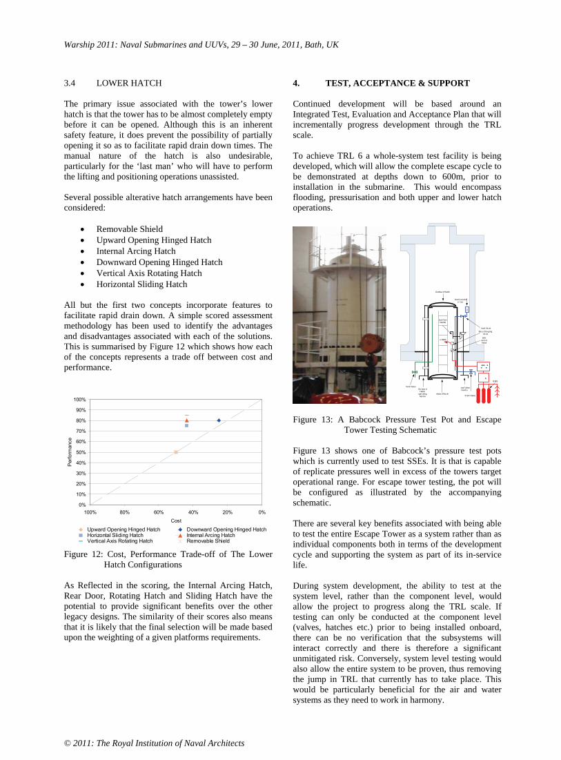
Warship 2011: Naval Submarines and UUVs, 29 – 30 June, 2011, Bath, UK
© 2011: The Royal Institution of Naval Architects
3.4 LOWER HATCH
The primary issue associated with the tower’s lower hatch is that the tower has to be almost completely empty before it can be opened. Although this is an inherent safety feature, it does prevent the possibility of partially opening it so as to facilitate rapid drain down times. The manual nature of the hatch is also undesirable, particularly for the ‘last man’ who will have to perform the lifting and positioning operations unassisted.
Several possible alterative hatch arrangements have been considered:
Removable Shield Upward Opening Hinged Hatch Internal Arcing Hatch Downward Opening Hinged Hatch Vertical Axis Rotating Hatch Horizontal Sliding Hatch
All but the first two concepts incorporate features to facilitate rapid drain down. A simple scored assessment methodology has been used to identify the advantages and disadvantages associated with each of the solutions. This is summarised by Figure 12 which shows how each of the concepts represents a trade off between cost and performance.
0%
10%
20%
30%
40%
50%
60%
70%
80%
90%
100%
0%20%40%60%80%100%
Cost
Perf
orm
ance
Upward Opening Hinged Hatch Downward Opening Hinged HatchHorizontal Sliding Hatch Internal Arcing HatchVertical Axis Rotating Hatch Removable Shield
Figure 12: Cost, Performance Trade-off of The Lower Hatch Configurations
As Reflected in the scoring, the Internal Arcing Hatch, Rear Door, Rotating Hatch and Sliding Hatch have the potential to provide significant benefits over the other legacy designs. The similarity of their scores also means that it is likely that the final selection will be made based upon the weighting of a given platforms requirements.
4. TEST, ACCEPTANCE & SUPPORT
Continued development will be based around an Integrated Test, Evaluation and Acceptance Plan that will incrementally progress development through the TRL scale.
To achieve TRL 6 a whole-system test facility is being developed, which will allow the complete escape cycle to be demonstrated at depths down to 600m, prior to installation in the submarine. This would encompass flooding, pressurisation and both upper and lower hatch operations.
k
Outboa d Hatch
nboa d Ha ch
ood Valve hand e
lood Va v handle
lood Va ve
Vent ValveOu boa d
Hatch ope ating
hand e
o SEIE HIS
cont ol Valve
ess e e e
Sto e Cha ging Va ve
D ain Valve
B BS
lood in et and o i ice
Figure 13: A Babcock Pressure Test Pot and Escape
Tower Testing Schematic
Figure 13 shows one of Babcock’s pressure test pots which is currently used to test SSEs. It is that is capable of replicate pressures well in excess of the towers target operational range. For escape tower testing, the pot will be configured as illustrated by the accompanying schematic.
There are several key benefits associated with being able to test the entire Escape Tower as a system rather than as individual components both in terms of the development cycle and supporting the system as part of its in-service life.
During system development, the ability to test at the system level, rather than the component level, would allow the project to progress along the TRL scale. If testing can only be conducted at the component level (valves, hatches etc.) prior to being installed onboard, there can be no verification that the subsystems will interact correctly and there is therefore a significant unmitigated risk. Conversely, system level testing would also allow the entire system to be proven, thus removing the jump in TRL that currently has to take place. This would be particularly beneficial for the air and water systems as they need to work in harmony.

Warship 2011: Naval Submarines and UUVs, 29 – 30 June, 2011, Bath, UK
© 2011: The Royal Institution of Naval Architects
Once in service, the ability to test a complete Escape Tower system would expedite and simplify the process through which upgrades and design modifications could be implemented without the need to align the programme with a specific platform’s maintenance period or necessitating prolonged Sea Acceptance Trials.
Combing the additional confidence obtained through testing and verification with the ability to take ownership of the entire system would not only provide performance benefits but would facilitate a Contracting For Availability (CFA) approach. This would in turn enable through life costs to be regulated and reduced.
5. CONCLUSIONS
Typically, submarine tower escape systems are not configured to operate across the full range of depths a submarine may experience. Often they are optimised to one specific depth, which can make escape from other depths unviable.
Flood and pressurisation control valves have been investigated and shown to offer an improved performance at all depths. Physiologically acceptable pressurisation rates are achievable at all depths, air consumption is significantly reduced and system reliability and availability are improved.
Improvements in the tower geometry and layout can further decrease air consumption, speed up the escape process, ease maintenance and reduce the risk of injury.
A variety of lower hatch designs have been considered, with the aim of minimising tower size, aiding access, increasing survivability and ensuring water tight integrity.
A de-risked development, testing and acquisition plan is described, which allows the system to be fully demonstrated prior to installation on the submarine and provides through-life availability benefits.
Future escape can be limited by the extent of human capability rather than the escape system itself.
6. ACKNOWLEDGEMENTS
The authors would like to thank Neil Hopkins at Sonistics for his continual support in our escape system developments, and the team at the Submarine Escape Training Tower (SETT) for sharing their expert opinion.
7. REFERENCES
1. Williams, C., ‘A Review of The Acceptable Environment of Pressure Profiles For Submarine Tower Escape’, SEE Sub – committee, 2007
2. Policy, information and guidance on the Technology Management aspects of UK MOD Defence Acquisition, version 1.0.2, 2009
3. Acceptance Schedule No 301, Escape Tower Acceptance Schedule – Swiftsure & Trafalgar Class Submarines, 2008
8. AUTHORS’ BIOGRAPHIES
Toby Peacock holds the current position of Senior Naval Architect at Babcock. He is responsible for the development of future systems and equipment. Since 2006 he has worked on the development of a variety of submarine products including mission payload systems, towed communication systems and escape systems. Prior to this he worked in submarine support, providing assistance to in-service submarines. He graduated with a First Class honours degree in Marine Technology from Newcastle University in 1999.
Richard Manion holds the current position of Engineer at Babcock. He is responsible for the development of the Submarine Escape Tower and the associated Test Facility. After graduating with a Masters degree in Mechanical Engineering from the University of Bristol in 2007 he has worked on a variety of submarine projects including the delivery of weapon handling and launch system for the Royal Navy’s Astute Class, the Canadian Navy’s Victoria Class and the Spanish Navy’s S-80 Class. Since 2010 he has worked on the development of naval systems including the handling and integration modular mission systems and escape systems.

Warship 2011: Naval Submarines and UUVs, 29 – 30 June, 2011, Bath, UK
© 2011: The Royal Institution of Naval Architects
US SUBMARINE CONCEPT DESIGN TOOL
A J Mackenna, S A Patten, and R K Van Eseltine, Naval Surface Warfare Center – Carderock Division, USA
SUMMARY
When Naval Sea Systems Command (NAVSEA) is faced with the challenge of a new submarine concept design, it has until recently taken the traditional approach of developing a few point designs using a physical and digital library of historical submarine design data and a variety of commercial and in-house design tools. Navy leadership has a need to make informed requirements decisions early on in a submarine acquisition program. To service this need, a tool was required that would allow a design team to analyze more of the submarine design space within the limited time and budget constraints of early stage design. This use case guided the requirements for a new submarine concept design tool that is capable of creating multiple ship concepts with greater speed and accuracy than traditional methods. NAVSEA commissioned Naval Surface Warfare Center Carderock Division to develop Advanced Ship and Submarine Evaluation Tool (ASSET) for Submarines. In addition to cost and schedule efficiency, ASSET-Submarine provides technical ac-countability by having vetted the engineering design processes through US Navy Technical Warrant Holders. This paper recounts the development of ASSET-Submarine.
1. INTRODUCTION
Early stage submarine design encompasses a broad spec-trum of design activities. A design activity can last as little as a man-day or as long as several man-years. Early stage study results are used to define cost and effective-ness relationships and to make educated decisions for technical and programmatic matters. If more studies are performed at the early stages of a submarine design, re-sulting in more comprehensive exploration of the design space, this will lead to better design and requirements decisions. In order to reduce the amount of time each study takes, ASSET-Submarine was developed to rapidly create a submarine concept design.
2. OVERVIEW OF EARLY STAGE SUBMARINE DESIGN
Submarine design combines the design expertise of sev-eral engineering disciplines. The scope of the studies range from Rough Order of Magnitude (ROM) concept studies to detailed design for production; the former re-quiring as little as a man-day and the latter involving a large team working for years. The focus of this paper will be the lower end to intermediate level of the concept de-sign spectrum, encompassing ROM and feasibility studies.
ROM studies provide estimates of a notional submarine’s rough arrangements drawings, characteristics, and per-formance attributes, such as displacement, length, draft and speed.
Feasibility studies provide sufficiently detailed informa-tion that enables:
Analyses of system performance Identification of technical risks Accurate tradeoff studies Cost estimates Definition of additional ship characteristics for use in operational effectiveness analyses
Submarine concept and feasibility studies may be per-formed to provide:
Support of submarine acquisition programs Whole ship concept studies Tradeoff studies Support Research and Development (R&D) and Science and Technology (S&T) Community, in-cluding technology assessment New concept exploratory studies Support of Office of Naval Intelligence (ONI) Reference studies for evaluating contractor per-formed submarine design Assessment of third party submarine concepts
Traditional methods of conducting early stage submarine concept designs reference a physical and digital library of historical submarine design data and a variety of commercial and in-house design tools. The majority of designs use legacy data as a starting point; the weight and displacement balance calculations are performed by the concept naval architects by adjusting weight and dis-placement data from past ships or concept designs. Computer Aided Design (CAD), including three-dimensional modeling of the hull or two-dimensional arrangements drawings, is used for design and reporting. The entire process is comprised of separate design disci-plines that are manually iterated by the concept naval architect based on the given requirements. Figure 1 shows a flowchart of the submarine design disciplines.

Warship 2011: Naval Submarines and UUVs, 29 – 30 June, 2011, Bath, UK
© 2011: The Royal Institution of Naval Architects
Figure 1: Flowchart of the Submarine Design Disciplines
3. REQUIREMENTS
3.1 RAPID CONCEPT GENERATION
Early stage concept design process consists of many de-sign disciplines that are brought together in an iterative approach to synthesize the design. This method is condu-cive to a computer based tool that integrates the design disciplines to assist the designer. Using the traditional method of concept design, small iterative changes incur a large amount of rework and calculation. The time needed to respond to queries for concept design solutions would be reduced significantly with a software solution to con-cept design. The US Navy has a direct need to generate rapid submarine concept designs to support acquisition decisions.
3.2 DESIGN KNOWLEDGE RETENTION
The frequency of early stage submarine concept design is difficult to predict; therefore, it is difficult to maintain an experienced concept naval architect workforce. This in-stability introduces difficulties with knowledge retention and transference of knowledge to new naval architects. A design tool with integrated design rules could help to alleviate these concerns. Documenting the design rules used in the tool is essential to keeping future concept naval architects trained in not only the use of the soft-ware, but in the principles behind submarine concept design.
3.3 DESIGN SPACE EXPLORATION
The traditional method of doing submarine concept de-signs consists of performing a point design and performing subsequent iterations on that point design. The time required to do iterations is shorter than per-forming a single point design from scratch, but it still can be a labor intensive effort to design only a couple of points in the design space. A design tool with the ability to quickly perform iterations allows the designer to rap-idly explore a multivariable design space.
3.4 COST SAVINGS
The use of a design tool for submarine concept design can produce cost savings by significantly reducing the amount of time to perform a study and increasing the quantity and quality of output for a given cost. More of the design space can be explored because the point de-signs are performed faster and cheaper. Proper ship sizing during the concept stage is critical to a successful acquisition program. The capability to rapidly produce concepts can identify sizing issues and design flaws ear-lier in a submarine design. This has the potential to save programs significant costs, as flaws in the submarine design become more and more costly to fix the longer they go undiscovered.

Warship 2011: Naval Submarines and UUVs, 29 – 30 June, 2011, Bath, UK
© 2011: The Royal Institution of Naval Architects
3.5 US NAVY VALIDATION
An important requirement for a submarine concept de-sign tool is that the implemented design process be validated by the US Navy. Software that hides the design approach within the code does not agree with the strict technical authority culture of the US submarine design force. The US Navy puts a large portion of design work out on contract; therefore, the necessity to validate work delivered on contract requires transparent design proc-esses.
4. DEVELOPMENT HISTORY
Attempts to create an early stage submarine design tool began as early as 1985. At various points in time proprie-tary, university, and government development efforts have been tried.
A recurring issue with past submarine design tool devel-opment efforts is that the naval architects that are capable of creating the design algorithms do not have the com-puter science background necessary to make a good software product. Likewise, computer scientists lack the design knowledge to effectively write a meaningful sub-marine design tool.
In an effort to reduce cost, focus on the development of capability instead of infrastructure, and the need for the tool to also be a design repository, the decision was made that the Navy would develop its own submarine design tool based on Navy requirements and needs. The Navy team is comprised of both naval architects and computer scientists who work together to produce the software.
5. APPLICATION DEVELOPMENT
Development of ASSET-Submarine focused on achiev-ing the following three overarching requirements.
Validate the analysis modules by replicating re-cent US attack submarine designs within the tool. Support design variation studies on recent attack submarines. Develop new attack submarine concepts.
The development of ASSET-Submarine was divided into two phases. The first phase was a theory development phase which produced a set of documents that delineated the mathematical equations and calculation processes required for a submarine design. The theory documents were then combined into an overall design calculation process. The second phase was the software development phase, which implemented the theory.
6. THEORY DEVELOPMENT
Theory documents were developed for each engineering discipline that is included in the computational capabili-ties of the tool. Subject matter experts were used to develop and review the theory. At the conclusion of the theory development, the theory documents were re-viewed and approved by the NAVSEA submarine design community. An overarching requirements document was developed that detailed how the different design disci-plines would be integrated into a single tool that is capable of generating a balanced submarine design.
In the requirements for the first release of ASSET-Submarine, the weight estimation and displacement cal-culation capability were given the highest priority above all other design capabilities. Submarine concept design is centered on balancing weights and displacements. The balance of the ship vertically and longitudinally is the key to determining basic feasibility of a submarine con-cept.
6.1 MODEL FIDELITY
Compared to surface ship concept design, the weights and displacements are worked at a much higher level of fidelity. The required modeling fidelity required the im-plementation of a 5-digit level Ship Work Breakdown Structure (SWBS), which contains 375 separate weight categories. These weights are scaled from the USS VIRGINIA (SSN 774) parent weights, but use a paramet-ric equation to scale the weight based on the weight driver(s) for each category. Being parametric algorithms, the weights of a concept submarine will scale with the changes in dimensions and requirements. These weights can be calculated at almost any point in the submarine design process; even if most of the geometry is left unde-fined; the only requirement is the concept submarine must have an outer hull and pressure hull defined.
Since US submarines have ballast tanks located forward and aft of the pressure hull, displacement items in those areas have a significant effect on the longitudinal balance of the ship. Therefore, the prominent displacement items are individually represented and accounted for in the model. Many displacement items are dependent on ship geometry; for example, torpedo tubes require large re-cesses in the main ballast tank volume, yet; the recess geometry is dependent on the outer hull, pressure hull, and main ballast tank geometry. A tool that assists with the difficult main ballast tank geometry calculations is valuable to a concept naval architect, whose time can be better spent analyzing the resultant concepts.
Warship 2011: Naval Submarines and UUVs, 29 – 30 June, 2011, Bath, UK
© 2011: The Royal Institution of Naval Architects
6.2 METHODOLOGY
Designing a concept submarine before requirements are known is difficult. Designing a concept submarine is cumbersome after a high level of design definition is complete. A flexible methodology is needed so the user is able to quickly develop a new design from scratch. The decision was made to establish a baseline design, or par-ent ship, as a starting point for the designer; the first baseline developed is the VIRGINIA. When the user starts the tool for the first time, the VIRGINIA is loaded as the default. The user is required to activate these de-faults during the design definition process. Since a detailed baseline lies under the concept model, the de-signer can quickly sketch out a submarine design and perform detailed calculations on that design.
6.3 DESIGN PROCESS
Given an initial baseline, the requirements for the subma-rine, such as mission duration, crew size, etc., can be adjusted. Once modified requirements are established, a rough sizing of the outer hull, pressure hull, and main ballast tanks is performed. After the hull is sized, hull appendages, such as sail, rudder, stern planes, and bow planes, bow sonar, and hull mounted sonar can be de-fined. At this point, sizing and placement of all of the major tanks that reside inside of the pressure hull, such as trim tanks and auxiliary tanks are determined. The hull geometry has the flexibility to be resized at any time dur-ing the design process. An equilibrium polygon is calculated to assist the designer with the tank sizing and arrangement process; this ensures the tanks have suffi-cient volume to trim the boat in a variety of submerged conditions.
The solid ballast solution is calculated accounting for stability, trim, and weight-displacement balance. The solid ballast value is permitted to go negative if needed to satisfy the balance criteria; however, the program identifies the design as infeasible with negative solid ballast. Performance analyses (e.g. speed-power calcula-tions) are then performed on the balanced design.
7. SOFTWARE DEVELOPMENT
Upon completion of the theory development phase of the project, the theory documents and design process pro-duced were provided to the software development team for implementation.
7.1 USING EXISTING INFRASTRUCTURE
Prior to the commencement of development of the sub-marine portion of ASSET (ASSET-Submarine), the US Navy had designated ASSET and the Leading Edge Ar-chitecture for Prototyping Systems (LEAPS) as its standard early stage concept development platform for surface ships. Future analysis tool development by the US Navy will be done with LEAPS integration. ASSET-
Submarine was built upon this existing platform. Each component of the platform is described in general, and any significant differences are noted in an individual subsection.
7.1 (a) Advanced Ship and Submarine Evaluation Tool (ASSET)
ASSET is the US Navy’s early stage concept develop-ment tool for surface ships. The surface ship portion of ASSET is referred to as ASSET-Ship. ASSET-Ship is made up of discipline specific modules (i.e. hull geome-try, gross arrangement, hull structural design, resistance, propulsion, power plant sizing, weight estimation, and area/volume sufficiency analysis).
ASSET-Ship performs synthesis utilizing the discipline specific modules in a design spiral approach with multi-ple iterations until it converges into a feasible ship design. The modules in ASSET-Ship are tightly inte-grated so that the synthesis process is stable and converges on a solution.
7.1 (b) Leading Edge Architecture for Prototyping Sys-tems (LEAPS)
The LEAPS software enables an engineering analysis team to evaluate a product’s design and verify its capa-bilities against customer requirements. The LEAPS architecture is an effective tool for supporting concep-tual, preliminary, and late stage ship design and analysis integration. Due to the complexity and diversity of naval ship design and analysis tools, the LEAPS architecture takes a “meta model” approach to product model devel-opment. This approach is capable of analyzing ships, aircraft, tanks, and any other complex system of systems. LEAPS provides the ability to create design repositories through the use of its Persistent Database (PDB) capabil-ity.
The US Navy has several analysis programs that inter-face with LEAPS. One of which that is of particular interest is the Ship Hydrostatics Calculation Program (SHCP) which was used as the base of the hydrostatics analysis used in ASSET-Submarine.
7.1 (c) Lessons Learned From ASSET–Ship
Prior to the commencement of development, a design review was performed on ASSET–Ship. ASSET-Ship is designed with an integrated ship design process built into the application. This process is applied to user require-ments, and an ASSET-Ship model goes through its iterative process adjusting the design parameters of the ship to arrive at a feasible ship design. ASSET-Ship un-derstands how to change the ship to ensure feasibility, and can make those changes in a way that is computa-tionally stable during the synthesis process. Some of the larger issues with this approach are:
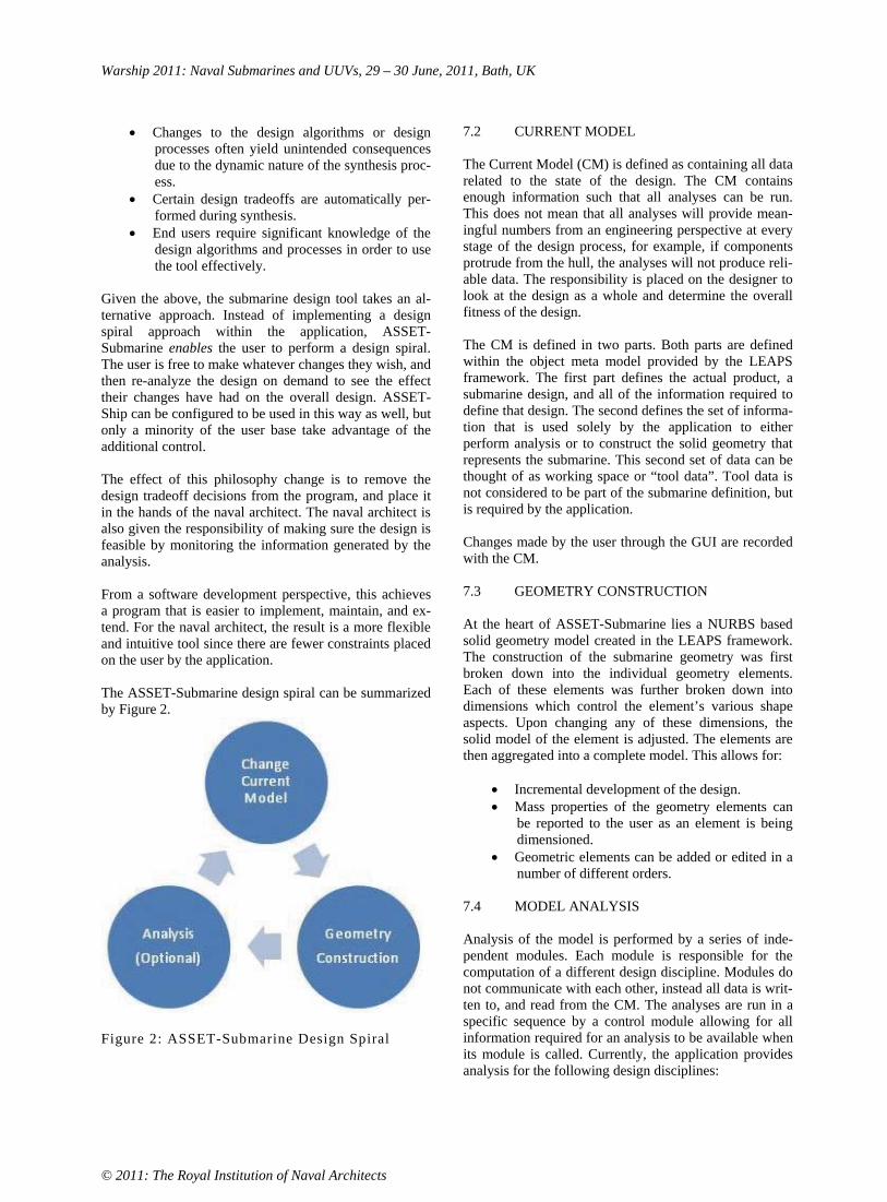
Warship 2011: Naval Submarines and UUVs, 29 – 30 June, 2011, Bath, UK
© 2011: The Royal Institution of Naval Architects
Changes to the design algorithms or design processes often yield unintended consequences due to the dynamic nature of the synthesis proc-ess.Certain design tradeoffs are automatically per-formed during synthesis. End users require significant knowledge of the design algorithms and processes in order to use the tool effectively.
Given the above, the submarine design tool takes an al-ternative approach. Instead of implementing a design spiral approach within the application, ASSET-Submarine enables the user to perform a design spiral. The user is free to make whatever changes they wish, and then re-analyze the design on demand to see the effect their changes have had on the overall design. ASSET-Ship can be configured to be used in this way as well, but only a minority of the user base take advantage of the additional control.
The effect of this philosophy change is to remove the design tradeoff decisions from the program, and place it in the hands of the naval architect. The naval architect is also given the responsibility of making sure the design is feasible by monitoring the information generated by the analysis.
From a software development perspective, this achieves a program that is easier to implement, maintain, and ex-tend. For the naval architect, the result is a more flexible and intuitive tool since there are fewer constraints placed on the user by the application.
The ASSET-Submarine design spiral can be summarized by Figure 2.
Figure 2: ASSET-Submarine Design Spiral
7.2 CURRENT MODEL
The Current Model (CM) is defined as containing all data related to the state of the design. The CM contains enough information such that all analyses can be run. This does not mean that all analyses will provide mean-ingful numbers from an engineering perspective at every stage of the design process, for example, if components protrude from the hull, the analyses will not produce reli-able data. The responsibility is placed on the designer to look at the design as a whole and determine the overall fitness of the design.
The CM is defined in two parts. Both parts are defined within the object meta model provided by the LEAPS framework. The first part defines the actual product, a submarine design, and all of the information required to define that design. The second defines the set of informa-tion that is used solely by the application to either perform analysis or to construct the solid geometry that represents the submarine. This second set of data can be thought of as working space or “tool data”. Tool data is not considered to be part of the submarine definition, but is required by the application.
Changes made by the user through the GUI are recorded with the CM.
7.3 GEOMETRY CONSTRUCTION
At the heart of ASSET-Submarine lies a NURBS based solid geometry model created in the LEAPS framework. The construction of the submarine geometry was first broken down into the individual geometry elements. Each of these elements was further broken down into dimensions which control the element’s various shape aspects. Upon changing any of these dimensions, the solid model of the element is adjusted. The elements are then aggregated into a complete model. This allows for:
Incremental development of the design. Mass properties of the geometry elements can be reported to the user as an element is being dimensioned. Geometric elements can be added or edited in a number of different orders.
7.4 MODEL ANALYSIS
Analysis of the model is performed by a series of inde-pendent modules. Each module is responsible for the computation of a different design discipline. Modules do not communicate with each other, instead all data is writ-ten to, and read from the CM. The analyses are run in a specific sequence by a control module allowing for all information required for an analysis to be available when its module is called. Currently, the application provides analysis for the following design disciplines:

Warship 2011: Naval Submarines and UUVs, 29 – 30 June, 2011, Bath, UK
© 2011: The Royal Institution of Naval Architects
Weight Displacement ResistanceHydrostatics Balance
Model analysis can be computationally intensive and is performed upon request of the user.
8. FUTURE WORK
At the time of this paper, two formal releases of ASSET-Submarine have been issued, version 1.0 and version 1.1. In future years, work for ASSET-Submarine includes the following major features:
Support for other than US attack submarines Submarine space arrangement capability Alternative hull designs Additional control surface and pressure hull end-cap geometry definitions Cost estimation Manpower estimation Interfacing with external analyses software (sig-natures, maneuvering)
9. CONCLUSIONS
Multiple drivers indicate the need for a design tool capa-ble of allowing a naval architect to both develop new submarine design concepts and provide analysis on pro-posed changes to existing submarine designs. ASSET-Submarine is a start towards an integrated approach to the development and analysis of both early stage concept designs, and in-class design variations. The current ver-sion of the application is capable of reducing the time, and therefore the cost, needed to perform a number of design modification evaluations from man-days to man-hours. Future versions of the tool will further expand the realm of problems to which the tool can be applied.
10. ACKNOWLEDGEMENTS
The authors would like to thank Mark Arvidson and Robert Stortstrom for their technical contributions to this paper.
11. AUTHORS’ BIOGRAPHIES
Adrian Mackenna is a Naval Architect at the Naval Surface Warfare Center – Carderock Division (NSWCCD) located in Bethesda, Maryland, United States. At NSWCCD, Adrian leads the Implementation Team of the Ship Design Tool Development Branch. Adrian’s team is responsible for requirements and theory development as well as user support and training for ship design software development. The Ship Design Tool Development Branch is responsible for the development and maintenance of ASSET-Ship, ASSET-Submarine,
the LEAPS database, and the LEAPS suite of early stage design and analysis tools.
Scott Patten is a Naval Architect at the Naval Surface Warfare Center – Carderock Division (NSWCCD) lo-cated in Bethesda, Maryland, United States. Scott works as the submarine design tool liaison between the Ad-vanced Submarine Concepts group at Naval Sea Systems Command (NAVSEA) and the Ship Design Tool Devel-opment Branch at NSWCCD. He is also an end-user of ASSET-Submarine in his role as a submarine concept naval architect for NAVSEA.
R. Keawe Van Eseltine is a Computer Scientist at the Naval Surface Warfare Center – Carderock Division (NSWCCD) located in Bethesda, Maryland, United States. At NSWCCD, Keawe works for the Ship Design Tool Development Branch - Development Team. The Development Team is responsible for the creation and maintenance of LEAPS, ASSET and their related tools. He is currently the lead developer for ASSET-Submarine, and is also involved in projects using LEAPS that are in development by industry and academia such as Intelligent Ship Arrangements (ISA) and the Hullform Transformation Tool (HULTRAN).

Warship 2011: Naval Submarines and UUVs, 29 – 30 June, 2011, Bath, UK
© 2011: The Royal Institution of Naval Architects
OVERVIEW OF A METHODOLOGY FOR THE EARLY PHASES IN SYSTEMS DESIGN OF FUTURE SUBMARINES
M Nordin, Swedish Defence Research Institute and Chalmers University of Technology, Sweden
SUMMARY
This paper discusses a set of simulation based design (SBD) methods and tools for Naval Integrated Complex Systems (NICS), such as submarines. The prerequisites for the design of NICS are based on systems theory and are especially useful in the early phases of the design were a structured, creative and traceable methodology is needed. The methodology can be used from the very first step in the design process to meet the needs and requirements of the customer and stakeholders. The use of the methodology will give a balanced and cost-effective result in the form of a preliminary design specification for a submarine. The focal point of the methodology is its application in early phases aiming for earlier knowledge-growth than with classical design methodology. A higher level of knowledge with higher precision can be reached and as a result better cost and performance predictions with fewer iteration cycles. The work has resulted in a knowledge based parametric and concept exploration model for submarine design including a model for economical calculation of cost. A physical simulation model with an event and Monte Carlo based operations analysis tool is supporting a systems analysis tool for evaluation of a complete submarine system. The methodology introduces the use of a generic design object to stimulate an operations analysis simulation and from there extract tactically derived functions and function requirements.
1. INTRODUCTION TO SHIP DESIGN
Classical naval ship design procedures for surface ships and submarines have largely been the same for most of the 20th century. Based upon requirements, submarine projects were calculated and redrawn until the necessary balances for the submarine were achieved. New ideas were implemented in stages and to move forward in the development process, the design was "frozen" at different stages with the purpose to reduce the uncertainties. Unfortunately this had the side effect that creativity and alternative routes were limited early in the project. With long development times this too often resulted in systems that were obsolete already at the time of delivery [1].
The purpose of the ship design process is to develop a valid design description of a feasible ship, at a level sufficient for its production, where its properties correspond to an expected behaviour in one or more specified operating conditions. A design description, i.e. concept, contains information about size, arrangement and performance of the ship, its systems and components. Performance specification is a way to express how and to what degree the specified functions are addressed. The relevant performance is dependent on what roles and tasks the ship shall solve [2].
This paper deals with the design of Naval Integrated Complex Systems (NICS) exemplified by military submarines [1, 3]. The definition of design does not only mean the technical systems design, but it also includes the cost calculation and the performance and system effect predictions [1, 3, 4]. This approach stresses three properties: Naval because these systems are usually produced in a few units and usually without a prior prototype. This places high demands on the design process from the very start. Integrated, because multiple functions are aggregated to fewer systems in a smaller space. Complex, because the total system must solve a
variety of functions and tasks, often in the same mission, were functions and their functional requirements with direct methods cannot be found with the use of conventional direct methods.
To achieve a design solution, design offices used to follow a gradual procedure described with the iterative design spiral with increasing accuracy in the concept as it converged to the centre of the spiral [5]. The cost aspect of a ship project was later introduced in the spiral after the technical design [6]. These classical means of design and analysis, provided that the options really existed, took weeks to months of complex and expensive calculations even with ready-made empirical "spreadsheets" and similar tools. Each treated option was still based on known solutions because the search for new knowledge through the development of new solutions would be too costly and time-consuming.
However, the design spiral did not solve the problem of describing the situation at a given time or the problems of low and sometimes incorrect knowledge growth during the early stages. These problems initiated new attempts to describe and develop the design process.
The number of combinations of various system solutions has since been multiplied. The different design problems that earlier could seem relatively simple are today more multifaceted and complex. This complex multifunctional nature of a design problem means that a direct solution is not possible and prevents a direct design approach for the development of a design description to such a level of detail that it can be used as the basis for the product specification of a submarine. The need for a methodology that manages naval integrated and complex systems is therefore necessary.

Warship 2011: Naval Submarines and UUVs, 29 – 30 June, 2011, Bath, UK
© 2011: The Royal Institution of Naval Architects
Design projects have by nature their greatest uncertainty in the beginning, but this is also where the affectability is highest. To improve precision, speed, knowledge growth and the qualitative and quantitative information in the new diversity of explored options a new tool is needed for design. Based on the methodology, a designer can exploit, develop, process and analyse in a systematic way already known knowledge and new alternative approaches. It would also need the ability to manage the large amount of existing information in a representative way at different levels of abstraction in such a way that experienced submarine designers can recognize it and take advantage of the representation.
Analysis of previous submarine projects has shown that mistakes in the early stages where made because of inadequate handling of the primary balances (volume and weight balance, power and energy balance), which gave a bad estimation of submarine size. Deficiencies have sometimes been caused by incorrect direction and the absence of early decisions on the ultimate goal but also a lack of knowledge on the basis of estimates and predictions in the early stages. Changes and corrections in size, general arrangement and system structure caused by deficiencies in the primary balances will be very costly if they are to be corrected late in the project. In the worst case this will terminate a project.
The concept contains all the information necessary to describe the complete submarine system and its performance on a comprehensive system level. The first outline of a concept is called a play-card and holds only the basic information of the design description. The play-card will later mature to a full concept. The physical structure of the systems includes installations, equipment and components which provide the technical performance that is related to the tasks and missions that the functions of the submarine system shall be able to perform. At the same time performance of certain installations designed for specific functions will affect performance of other functions. Therefore in reality, the different systems will be developed in parallel and not in sequence. A more developed design methodology which used the parallel approach was introduced with the development of concurrent engineering for ship design [7].
Figure 1: Desirable and classical knowledge growth in relation to influence on the design, committed cost and cost outcomes [1].
The degree of influence in the different acquisition phases during a nominal submarine project based on cost committed and outcome clearly shows the importance of activity in the early phases, as illustrated in figure 1. The desire is of course that the affectability can be kept open as long as possible and that the proportion of committed cost can be kept down for as long as possible while ensuring that a high level of knowledge-based growth can be accomplished.
It is vital for a successful design that early predictions of size and the fundamental balances of a submarine design object are correct from the very start, as has been shown by several studies [1, 2, 4, 8]. This is also one of the main drivers for a coherent methodology.
The aim is therefore to develop a coherent model based on the theory of technical systems [9], with the influence of technical, financial and operational factors,
with which we can develop projects, with emphasis on the early phases allowing for a higher level of early knowledge growth without having a negative impact on creativity that will not restrict systems designers too early, which methodology threaten to base the design on older systems solutions.
2. SUBMARINE OPERATIONS
Today more than 90% of international trade is transported on ships through the major waterways, or in military terms Sea-lines of Communications (SLOC), between the major populations centres of which 70% are located along the coast line. According to Mahan [10] naval power is crucial to secure these waterways and shipping lanes. Also, Corbett [11] and Gray & Barnett [12] support this principle.

Warship 2011: Naval Submarines and UUVs, 29 – 30 June, 2011, Bath, UK
© 2011: The Royal Institution of Naval Architects
In more modern times, not only ships use the sea. Energy supply and data communications are dependent on cables laid on the ocean floor. The major part of all electronically based financial transactions goes through these data lines along the Seabed [13]. The concept of Sea Lines of Communications (SLOC) has therefore received more attention from a safety point of view. According to Padfield [14, 15, 16] the development and prosperity of the West have been and are dependent on the safety of this SLOC, i.e. they are a matter of strategic concern.
2.1 OPERATIONAL USE OF SUBMARINE SYSTEMS
The covert operation, beneath the ocean surface may qualify as the submarines most characteristic feature, along with the ability to act in a surprising and asymmetric way. These capabilities were the original drivers for the creation and development of submarines. The ability to operate covertly against the shipping lane focal points, choke points, harbours and bases including the capability to penetrate harbours and base areas was developed from the very beginning. From these early tasks the submarines developed the ability to operate anywhere in the ocean against the sea lines of communications and points of interest during peace time as well as in war.
The capability of naval forces to direct action and effect in different arenas can be described using the basic operational capabilities; command, intelligence, effect, mobility, protection and endurance. From a classical naval perspective, these operational capabilities are divided into military operations, support operations and humanitarian operations:
Sea Control o Securing Command o Exercising Command o Disputing Command or Sea Denial
Maritime Peace Support Operations o Peace Keeping Operations o Peace Enforcement Operations o Peacemaking Operations o Peace Building Operations
Operations other than war o Humanitarian Support Operations o Civil-Military Cooperation Operations
The basis for all operational planning is the manoeuvre philosophy. In the multidimensional combat space, this means, to discover the opponents critical weaknesses and subjecting them to a rapid and effective intervention, directly or indirectly. Precision operation in this respect is the core and extended driver of military technological development.
The logic behind the manoeuvre philosophy is based on the main principle that one should never confront an
enemy frontally. The tactic is to find an alternative path or position for reaching the goal from a more asymmetrical perspective. Exposed weaknesses in the opponent structure are explored and are thereafter used progressively to achieve a system breakdown of the opponent. This makes the manoeuvre philosophy a more cost-efficient alternative to attrition warfare. The ultimate aim is to decrease the opponent’s desire for continued warfare. Submarines have the ability to stay covert for a sustainable time and by asymmetric behaviour early, forwardly and with surprise carry out actions against an opponent with great effect. These actions may be direct or indirect and can be targeted directly against the opponent’s vital points from were the opponents Centre of gravity can be reached or threatened.
2.2 TACTICAL MISSION TYPES FOR SUBMARINES
Conventional submarines are fulfilling roles and solve different tasks during various tactical missions. One operation can include several mission types. An example of a representative number of tactical mission types is presented below.
Table 1: Tactical mission types. Tactical mission types NATO Abbr.Surveillance & reconnaissance mission SRIntelligence & Surveillance mission ISSpecial Operations Warfare SOWUnderwater Information Warfare UIW Underwater Work UWMine Counter Warfare MCW Mine Warfare MWAnti Submarine Warfare ASWAnti Surface Warfare ASuWAnti Ground Warfare AGrW
The tactical mission types above put different requirements on the submarine as a platform and especially on its combat systems (e.g. weapons, sensor and command systems etc). It is therefore important that any evaluation of the submarine operations must be able to single out the capabilities and effects for the different mission types, if one is to find the best solution in the design space.
The effectiveness of the evaluation is dependent on the ability to trace the connection between tactical results, technical performance and cost from the systems function of the submarine. There are however different technical solutions for different submarine systems. These differences are linked to the choice of technical design for each submarine system and depend on a combination of the following:
Submarine platform performance, such as underwater speed, endurance, signature etc. The submarine information handling; surveillance, communications, command and control systems.

Warship 2011: Naval Submarines and UUVs, 29 – 30 June, 2011, Bath, UK
© 2011: The Royal Institution of Naval Architects
Submarine combat systems; weapons, ROV, UUV and divers etc.
A description of submarine operations must thus be capable of modelling the various tactical mission types and at the same time allow different combinations of the technical performance of various submarines and associated combat procedures. A tactical model must also be able to manage what a decision-making process and information model look like and how it commands and controls the general tactical decisions as well as different decisions on combat procedures.
3. THE SUBMARINE AS A TECHNICAL SYSTEM AND ITS GENERIC DESIGN PROCESS
Design is a broad interdisciplinary process. When design methods are to be developed within a given domain, in this case, submarine systems, operational knowledge and its technical dependencies in the domain are key factors.
3.1 SUBMARINE SYSTEM FUNCTION STRUCTURE
A functional structure was initially developed during the development of Swedish submarine projects A11 Sjöormen and A14 Näcken. This functional structure has since then been refined and aggregated to a system function structure for submarines [1].
Table 2: The submarine system functions structure. Submarine system functions structure System functions Functional description of the
aggregated system functions 1. Hull To exclude water, sustain the pressure
of depth, to carry the system and the payload and reduce the water resistance of the hull form
2. Crew To man the boat and host a crew 3. Protection To operate covertly, detect weapons,
counter manoeuvre, deploy counter measure and to sustain damage
4. Safety To secure the survival and rescue of the crew
5. Energy To generate, transform, store and distribute energy
6. Propulsion To propel 7. Manoeuvring To manoeuvre 8. Navigation To navigate 9. Communication To communicate 10. Surveillance To survey acoustically, optically,
electrically, magnetically etc. 11. Command &
control To command and control
12. Engagement To engage directly or indirectly
3.2 GENERIC DESCRIPTION OF THE SUBMARINE DESIGN PROCESS
This process was developed during the submarine project Ub2000 on the basis of experience gained from the earlier Swedish design process that was used in the
submarine projects A11, A14, A17 and until the end of the preliminary design phase of project A19S.
The design process begins with the customers needs. The design process of submarines is based on a set of task descriptions from the customer of what the submarine system is required to do. The customer and its users will express this in a mission statement containing one or more mission profiles depending on the number of types of tasks and mission types that must be resolved, see Tactical mission types in 2.2.
The mission statement and its mission profiles form the basis for the identification of the functions and operational requirements for the submarine system. The mission specific features are identified from the planned mission profiles and from the results of tactical simulation in an operations analysis. Then the different functional requirements can be derived by analyzing the results. The different sets of requirements for various missions from the mission profiles are sorted, aggregated and reduced to one system function requirement matrix. Thus, the process has gone from the customers and stakeholders need domain to the function domain.
In the function domain, the work with an early level of abstraction based on performance also contains parametric studies to search for feasible play-cards and determine the boundaries of the design room to be explored in functional terms. When the functional requirements are identified and play-cards have been generated and evaluated, the submarine systems design is initiated. This means that functions will be allocated to systems so that:
each function is served by at least one system or several functions can be served by one system or one function can be served by several systems.
Allocation of functions to the system results in a system structure matrix. This can be unique for each concept as it is the result of design work in the transition from the function domain to the system domain. When the allocation of functions to systems is finished, the complete set of systems has addressed all functional requirements.
The submarine is now defined in the system domain. This is a product definition of the submarine, which provides the basis for further development to the building specification.
3.3 SIZING AND BALANCING OF THE SUBMARINE DESIGN OBJECT
The size prediction of the submarine is initially done in the function domain based on the functional requirements.

Warship 2011: Naval Submarines and UUVs, 29 – 30 June, 2011, Bath, UK
© 2011: The Royal Institution of Naval Architects
Balancing the submarine is done in both the function and systems domain where all the design elements in a submarine such as hull sections, tanks and installations with their components can be designed and assigned to a design object. Several balances govern the design of a submarine;
Weight-volume balance. The displacement of submarine volume is equal to or larger than the required functional volume alternatively the systems and component volume. The sum of all weights including different mission specific payloads and water densities is equal to the current tonnage (displacement) so that the submarine neither sinks nor surfaces and that the momentum balance is met in both surfaced and submerged conditions within the rules of static and dynamic stability. Energy-power balance. The sum of all the energies and power outputs of various kinds in the submarine meets the operational requirements. Signature balance. To set up a signature profile that does not exceed the requirements on detection for the different signature fields. Cost Balance. Predicted cost is within budget. System Effect Balance. The evaluated concept performance meets the requirements for the different mission types.
4. A COHERENT METHODOLOGY FOR SUBMARINE DESIGN IN THE EARLY PHASES
The requirement for the development of a coherent design methodology for NICS was to base it on the Swedish procurement process and an adaptation of the Systems Engineering standard ISO/IEC 15288.
To be able to step seamlessly from design descriptions at higher levels of abstraction in the function domain into more detailed descriptions in the system and installation domains the performance calculations for the design object must be valid and equivalent, regardless of domain and domain transitions.
Figure 2: Schematic picture of domain transitions during the design process.
This successive work across domain boundaries makes traceable, structured and creative exploration of the design space possible. A schematic picture of domain transitions in the design process is sketched in figure 2 above. It is not a straightforward process to optimize the design object. It is a complex iterative process. This process is illustrated by figure 3 below.
Figure 3: Flowchart of the submarine design process.
This process will be run through for each domain. If any of the steps; technical design, cost prediction or effect calculation is not conclusive under the conditions that apply to the given set of needs, the process returns to previous steps until a balance is reached.
The coherent methodology is based on the five methods sketched in the submarine design process in figure 3. These methods have been developed to models within the combined toolbox for Submarine analysis and design (SubAn). These models are:
A model for the functional analysis of needs to requirements. Implemented in toolbox SubFunk. A model for the technical system design. Implemented in toolboxes SubParm and SubDes. A model of systems cost prediction. Implemented in toolbox SubCost. A model for operations analysis and system effect calculations. Implemented in toolbox SubOA.A model for systems analysis and evaluation. Implemented in toolbox SubSA.
Through the use of the principle of controlled convergence, the design space is explored in the early phases of design.
Generally the process moves from the design space to the design room and converges to a design area/point as illustrated by figure 4. Every member of the team is always immediately aware of what space he is working in with his colleagues by referring to this graph.

Warship 2011: Naval Submarines and UUVs, 29 – 30 June, 2011, Bath, UK
© 2011: The Royal Institution of Naval Architects
Figure 4: From the design space via the design room to the design area/point.
This iterative approach of refining the design objects through gradual expansion and reduction has been developed to explore the design space, in search of the actual design area/point in the design room and balance and optimize the design object in that area/point.
4.1 A MODEL FOR IDENTIFICATION OF NEEDS AND DEDUCTION OF FUNCTIONS REQUIREMENTS
It was identified early in the development process that not only the customer, the user and the stakeholder but also the design team must know the rationale behind the stated needs. Therefore the development is dependent on a more general level of knowledge, from the strategic appreciation down to the mission statements, e.g. the different mission profiles based on the mission statements defined by What, Where and How;
WHAT: What roles and tasks in the different mission types shall the system perform? See also table 1. WHERE: Where shall the system operate, in which environment? HOW: How shall the tasks be solved? (Expressed in mission profiles).
The answers are organized in a matrix of needs. Based on the matrix of needs, a planned mission profile (1) is developed. This can be divided into phases (2) with planned general activities (PGA) (3) and further subdivided in to planned activities (PA) (4), as illustrated above in figure 5.
Figure 5: Decomposition of a planned operation profile via phases to planned general activities and activities. .From this planned mission profile a functional flow diagram is developed for the entire system. This diagram provides a structure that is populated with functional requirements from the mission profiles. But it is only when the design object executes its mission profile and confronts its surrounding environment (scenario) that the event based tactical requirements can be identified and deduced from the results from an event-driven and Monte Carlo based operations analysis simulation.
As a result from the events, new event-based tactical decisions are executed, which generate a set of tactical general activities (TGA) and tactical activities (TA), which in turn provides tactical functions (TF) with additional functional requirements. As a result we can now compile both the planned and the event-based functions and their requirements.
We then obtain the functional structure of the overall design object and the requirement matrix for this mission profile. Sensitivity analysis can ensure that both the functional structure and their functional requirements are valid for the current conditions. By systematically using this procedure for all mission types and profiles, geographical regions of interest, it was concluded that the operational-tactical-functional requirement space is identified.

Warship 2011: Naval Submarines and UUVs, 29 – 30 June, 2011, Bath, UK
© 2011: The Royal Institution of Naval Architects
4.2 A MODEL FOR TECHNICAL DESIGN
The early phases of the technical system design starts in the function domain during the study phase and continues in the system domain during the conceptual design phase. The workflow from system function requirements via parametric studies to concept studies is illustrated in figure 6 below. This figure shows the association between parametric and concept studies and the iterative process for both the parameter studies and conceptual studies.
Figure 6: Flow chart of the study and conceptual design phases.
The identified functions will now be placed into a consistent representation of the submarine. To manage the incremental raise of detailed content in the representations, from play-cards to the concepts, a scale of abstraction is used. This is illustrated below in figure 7. In the functional domain three levels of abstraction are used.
Figure 7: Different levels of abstraction in the parametric and conceptual studies.In the first “point-like” abstraction level the available reference volume (VR) shall be greater than the required functional volume (VF). At the same time, the buoyancy (B) shall be equal to the mass (G) to secure balance. In the second “tube like” abstraction the same requirements shall be fulfilled. An additional requirement of momentum balance is added (M=0). The third “submarine like” abstraction level is done in a similar way. In the parametric model, the model itself does a
first balancing. Results are exported to the concept exploration model which is the next step. In the conceptual design phase, the operator designs the concepts.
For the conceptual design, the degree of abstraction is more a question of the number of components. Figure 7 above indicates the level of detail by the number of components that the different models contain. The number of components is also a measure of time needed to generate a concept.
4.2(a) The Parametric Model
The parametric model with its functional dependencies is used to quickly generate play-cards for the design object from system function requirements. The parametric model searches iteratively for minimum weight and volume for play-cards that satisfies power-energy, mass-volume and momentum balances. The multiple purposes of the parametric model are:
To act as a stimulator in the functional analysis in combination with the operations analysis model. To set up the design space so that the design room can be determined in a way that the size of the design objects size can be identified, see steps A and B below in figure 8 regarding technical systems design. To vary the essential parameters in parametric and sensitivity analysis to gain a deeper understanding of the design objects placement in the design room. Play-cards constitute the starting point for concept studies.
4.2(b) The Concept Exploration Model
In the concept exploration model, unlike the parameter model, the designer is given the freedom to design the concept in any desired way. An integrated calculation engine that keeps track of all the data in the concept supports this design freedom, and as a result, the designer should be allowed to concentrate on balancing and optimizing. The system scripts manage the knowledge database in the concept model. A system script contains historical as well as system specific information for a given system including different options for design. The multiple purposes of the conceptual design model are:
Within the identified design room balance and optimize concepts as shown in B and C below in figure 8. To freely explore and generate alternative concepts in the design room. To be able to reverse engineer existing submarines.

Warship 2011: Naval Submarines and UUVs, 29 – 30 June, 2011, Bath, UK
© 2011: The Royal Institution of Naval Architects
Figure 8: Technical systems design with the parametric and concept exploration models.
4.3 A MODEL FOR SYSTEMS COST PREDICTIONS
The cost prediction is an essential part of the design process. The cost prediction model is not fully described in this paper, but it is based on normal procedures. However, a few features of the cost prediction method need to be communicated to understand the full picture of cost predictions in the early phases of design. It was concluded that it is especially important in the beginning of a new project in the function and the systems domain. Even before a new submarine project is started, there is a need to have an appreciation of what a future acquisition may cost. To support this, statistics from previous projects is used.
4.3(a) Cost Predictions In The Function Domain
An initial concept (play-card) contains function data. These script-based data can be retrieved from a database containing historic statistics of the different functions performance, cost, weight and volume. When a play-card is generated, the result is a design description and a predicted cost in functional terms. A new project will normally also develop new functions and features. By using the play-cards in the function domain, these added costs can be described and predicted.
4.3(b) Cost Predictions In The Systems Domain
A developed concept contains system data. These systems data are retrieved from a script based database containing historical as well as up to date statistics of the various systems performance, cost, weight and shape. When a concept is created, in addition to a design description, the cost is calculated and assigned to the system groups containing engineering hours, workshop hours and purchased materials and supplies. The function and system cost table can then be modified for the number of units to be acquired. The cost of alternative developments can be calculated and predicted by use of different index and time periods/years for the various systems groups. In this way the complete life cycle cost can be calculated and compiled for a complete submarine project.
4.4 A MODEL FOR SYSTEMS EFFECT PREDICTION
One essential part of systems design is the model for measurement and calculation of the systems effect or the Overall Measure of Effectiveness, OMoE. This is done
by using a physical simulation and event driven Monte Carlo operations analysis model. In this model we can study a submarine’s capacity to implement the planned missions in an environment that interacts with the submarine under a set of rules. The submarine's performance and system effect are measured and calculated. The results are compared and evaluated against the results for other play-cards. The model consists of the following parts:
A database of actors with their platforms, operation systems, sensor system, tactics and weapons, as well as decision-making rules.A scenario editor for own mission and scenario generation. A simulation programme for operations research. Results and database management of the system effect analysis. System effect measurement and calculation including a report generator. A test system.
With an editor, a scenario can be designed for a given geographical area of operation. This area includes an environmental description which will interact with the different sensor systems involved. The scenario editor is also used to generate the different mission profiles for the submarine. One run through the mission profile is called an elementary turn or just turn.
F1
A BC
E DC
Figure 9: Principal sketch of a mission profile for SR missions with the phases sequence A-B-C-F1-C-D-E.
A mission profile for a Surveillance & Reconnaissance mission, SR-mission (F1), is illustrated in figure 9. The submarine starts its mission in a base (Phase type A) and sail out to the open sea (Phase type B). From there the submarine transits to the operational area (area of interest) (Phase type C). In the operations area the submarine begins the SR mission (Phase type F1, see figure 10) for the duration of T hours (T0 to T1). After that, the submarine leaves for base and the sequences of phases are reversed until the submarine reaches its base (Phase type E).
During simulation, the submarine is going through the planned mission profile until there is a disturbance detected by the submarines sensors. The artificial commanding officer then, based on tactical rules, makes a tactical decision on how to act.

Warship 2011: Naval Submarines and UUVs, 29 – 30 June, 2011, Bath, UK
© 2011: The Royal Institution of Naval Architects
This will be an ongoing process until there are no more disturbances, the submarine has been sunk or that the submarine has to go back to base. During simulation, the model measures and collects data for later calculation of OMoE for the actual mission. Depending on complexity, a simulation can contain between 100 to 5000 turns until the OMoE has converged to a stabilized value.
Figure 10: An example of a SR mission phase F1 including a submarine and one target of interest
During the simulation, data elements (DE) from the initiation of the simulation, together with the measured data elements (ME), are stored in a database. After the complete simulation the data are used for calculation of OMoE. The result can vary between zero and one, see figure 11 below.
System effect for mission type F1
0
0,1
0,2
0,3
0,4
0,5
0,6
0,7
0,8
0,9
1
Mis
sion
1
Mis
sion
2
Mis
sion
3
Mis
sion
4
Mis
sion
5
Mis
sion
6
Mis
sion
7
Mis
sion
8
Mis
sion
9
Mis
sion
10
Figure 11: Systems effect results for a submarine based on ten different SR-missions in different environments.
Submarines in operation in real situations counter a unique mix of circumstances which will form new appreciations of missions. The OA model must therefore be able to handle upcoming surprises from the submarines adversaries in peacetime operations as well as war situations in a tactically correct way. It was therefore concluded that it is important that the tactical rules reflect these real situations and that the used set of rules is audited by experienced officers. Having done that, it was later shown that the model behaved according to the current appreciation of tactics.
4.5 A MODEL FOR SYSTEMS ANALYSIS, EVALUATION, SELECTION AND DECISION
In support of the selection process used, a methodology based on developed play-cards or concepts can compile and present cost data and system performance data for various analytical scenarios. There is traceability of both system cost and system effect back to the technical system description from the results of the simulations in the operations analysis model. The model for presentation and analysis allows various combinations of results to be compared. Priorities between the various types of missions can be viewed and criteria can be adjusted.
Figure 12 below illustrates one example of a cost-effect chart used in the evaluation and selection for NICS. The design room is bounded by two lines: the first marks the maximum price for the acquisition and the second sets the minimum accepted system effect, normally a specified reference system or stated requirements. The lighter area represents the allowed design room.
Figure 12: Principle figure of the actual design room with the different concept families placed in the chart.
The results from different concept families with varying cost and system effect are marked in the chart. From the previously given priorities for mission types, priorities can be varied so that different positions for the play-cards and concepts can be identified and evaluated. A major aspect is the opportunity for direct feedback to the design process in the hunt for the best design point in the design room.
5. VALIDATION OF THE METHODOLOGY AND TOOLBOX SUBAN
Validation has taken place through the various participating groups from academia, industry, and naval authorities. They have tested and validated the methodology and its implementation in the toolbox
Own SubTransiting
Phase C
Transiting
Phase C
SR mission
Phase, F1
Target
T0 T1
Area of interest

Warship 2011: Naval Submarines and UUVs, 29 – 30 June, 2011, Bath, UK
© 2011: The Royal Institution of Naval Architects
SubAn. The first approach to a coherent methodology and its models were tested in the academic environment where changes and amendments were implemented. The methodology was validated by reverse engineering of six Swedish submarines projects (type A11, A14, A17 A14S, A17S and A19S). During the reverse engineering process new knowledge about the submarines emerged.
The testing was carried out by the Swedish Defence Material Administration (FMV) development team. Industry and FMV design teams have subsequently validated the methodology and its models during concept and preliminary design work, including control of progress of two recent submarine projects, namely the half time upgrade (HTU) of submarine type A19S Gotland and the development of the A26 project.
The design groups have successfully completed their tasks, to test and validate that the new design methodology in relation to the previous methodology provides:
A coherent methodology that provides a gradual and traceable knowledge growth from needs to a complete system definition. An approach that gives steeper knowledge growth with higher precision, earlier in the process. A methodology that produces higher knowledge content without blocking the creativity. A methodology that is not only describing but also learning and exploring.
In summary, it has been shown that a design team who use the new methodology incorporated in the toolbox can develop:
Play-cards within the hour Concepts within a working day Reference models within 1-5 working days Product models within 10 to 30 working days.
Submarine concepts, developed with the new coherent methodology, including a representative design description from the technical design, economic calculation and systems effect, can be evaluated against a set of alternatively developed concepts in relation to the stated specific needs and deduced requirements.
6. CONCLUSIONS
The developed coherent methodology for Naval Integrated Complex Systems with its models, methods and tools offers an opportunity for faster submarine systems development with more accurate results in the early design phases compared to previously used methodologies.
The coherent methodology quickly identifies the best design room in the vast design space for the identified set of requirements by using parametric design models in the function domain based on the stated needs. The design space can then be further investigated with the help of concept exploration, thus the best design point is determined using the previously identified requirements.
The models and methods for technical systems design, cost calculation, and system effect prediction and evaluation was integrated into a computation and analysis environment. This made work more efficient in the early phases of the development of the design object.
It was shown during the validation process that the coherent methodology uses less time, compared to the older methodologies, for generation and evaluation of play-cards and concepts, thus it favours knowledge growth before committed cost takes over and influences decision making adversely.
7. ACKNOWLEDGEMENT
I would like to extend my gratitude to the development team of the toolbox SubAN and to professor (emeritus) Anders Ulfvarson for their constant support.
8. REFERENCES
1. NORDIN, M., ‘A systems theoretical methodology for Naval Integrated Complex Systems’, Chalmers University of Technology, 2009.
2. VAN DER NAT, C., ‘A knowledge-based Concept Exploration Model for Submarine Design’, DelftUniversity, 1999.
3. NORDIN, M., ‘A system analysis tool for submarine design used during the study and predesign phases’, International Conference on Submarine Systems,1990.
4. KORMILITSIN, Y.N. & KHALIZEV, O.A., ‘Theory of submarine design’, Saint-Petersburg State Maritime Technical University, 2000.
5. EVANS, J.H., ‘Basic design concepts’, Naval Engineers Journal, 1959.
6. BUXTON, I.L., ‘Engineering economics applied to ship design’, The Naval Architect, 1972.
7. MISTREE, F., SMITH, W.F., BRAS, B.A. & ALLEN, J.K., ‘Decision-Based Design: A Contemporary Paradigm for ship Design’, SNAME, 1990.

Warship 2011: Naval Submarines and UUVs, 29 – 30 June, 2011, Bath, UK
© 2011: The Royal Institution of Naval Architects
8. BURCHER, R. & RYDILL, L., ‘Concepts in submarine design’, University College London, Cambridge Press, 1994.
9. HUBKA, V. & EDER, W. E., ‘Theory of Technical Systems. A Total Concept Theory for Engineering Design’, Springer-Verlag, 1988.
10. MAHAN, A. T., ‘The influence of sea power upon history’, Sampson Low, Marston & Co., Ltd, 1890.
11. CORBETT, J. S., ‘Some principles of maritime strategy’, Longmans, Green and Co., 1911.
12. GRAY, C. S., ‘Sea power and strategy’, Tri-service press, 1989.
13. LACROIX, F. W., BUTTON, R. W., JOHNSON, S. E. & WISE, J. R., ‘A concept of operations for a new deep-diving submarine’, RAND Corporation,2001.
14. PADFIELD, P., ‘Maritime supremacy and the opening of the western mind. Naval campaigns that shaped the modern world 1588-1782’, John Murrey,1999
15. PADFIELD, P., ‘Maritime power and the struggle for freedom. Naval campaigns that shaped the modern world 1788-1851’, The overlook press,2005.
16. PADFIELD, P., ‘Maritime dominion and the triumph of the free world. Naval campaigns that shaped the modern world 1852-2001’, John Murrey,2009.
9. AUTHORS BIOGRAPHY
Mats Nordin holds the position as Deputy Research Director in The Department of Underwater Technology. Swedish Defence Research Agency (FOI). He has previously been Head of submarine department and Director of underwater systems at the Swedish Defence Material Administration (FMV).

Warship 2011: Naval Submarines and UUVs, 29 – 30 June, 2011, Bath, UK
© 2011: The Royal Institution of Naval Architects
US TECHNICAL AUTHORITY IN SUBMARINE DESIGN AND ENGINEERING
W V Richter and M A Martz, Naval Sea Systems Command, USA
SUMMARY
This paper describes the evolution of Technical Authority in the US Navy, and it’s relevance to submarine design, construction, maintenance, and modernization. Originating with policy set by the US Secretary of the Navy, Technical Authority structure and practice has evolved over the last fifteen years to ensure authority, responsibilities, and accountabilities to establish, monitor, and approve technical standards, tools, and processes.
The Naval Systems Engineering Directorate (NSED), within the Naval Sea Systems Command (NAVSEA), is responsible for providing the (non-nuclear) engineering and scientific expertise, knowledge, and authority necessary to design, build, maintain, repair, modernize, certify, and dispose of the Navy's ships, submarines, and associated warfare systems. The Technical Authority chain of command includes formally designated Deputy Warranting Officers, Technical Warrant Holders, and supporting pyramids of Engineering Managers and Lead Engineers.
NOMENCLATURE
ASN (RD&A) Assistant Secretary of the Navy for Research, Development and Acquisition
CHENG Chief Engineer CNO Chief of Naval Operations COMNAVSEA Commander, NAVSEA CSE Chief Systems Engineer DEP CHENG Deputy Chief Engineer DoN Department of the Navy DWO Deputy Warranting Officer EA Engineering Agent EFR Engineering Field Representative EM Engineering Manager MCSC Marine Corps Systems Command NAVFAC Naval Facilities Engineering Command NAVSEA Naval Sea Systems Command NAVSUP Naval Supply Systems Command NSED Naval Systems Engineering Directorate NSWC Naval Surface Warfare Center NSY Naval Shipyard NUWC Naval Undersea Warfare Center PEO Program Executive Office PM Program Manager RMC Regional Maintenance Center SDM Ship Design Manager SECNAV Secretary of the Navy SPAWAR Space and Naval Warfare Systems
Command SUBSAFE Submarine Safety SUPSHIP Supervisors of Shipbuilding SYSCOM Systems Command TA Technical Authority TDM Technical Domain Manager TWH Technical Warrant Holder
1. INTRODUCTION
Naval Sea Systems Command (NAVSEA) is the largest of the Department of the Navy’s six systems commands. It is responsible for developing, delivering and maintaining ships and systems on time and on cost for
the US Navy. NAVSEA is also responsible for establishing and enforcing technical authority in combat system design and operation. To support this, more than 50,000 civilian and military personnel work at 33 activities in 16 states. Approximately 18,000 of the 50,000 people are scientists or engineers. These scientists and engineers use their technical expertise to set standards and design systems that operate safely, reliably, and meet Fleet needs. NAVSEA has several different business units, which include Program Executive Offices, Naval Shipyards, Supervisors of Shipbuilding, Regional Maintenance Centers, Warfare Centers, and other Field Activities. Program Executive Offices (PEOs) report directly to the Assistant Secretary of the Navy for Research, Development and Acquisition (ASN (RD&A)) for all acquisition matters. PEOs also report to the Chief of Naval Operations (CNO) through the NAVSEA Commander (COMNAVSEA) for in-service support matters.
The four Naval Shipyards (Portsmouth, Norfolk, Puget Sound, and Pearl Harbor) are owned by the fleet and operated by NAVSEA. In order to execute shipbuilding contracts, NAVSEA’s four Supervisors of Shipbuilding (SUPSHIPs) act as Administrative Contract Offices and oversee cost, schedule and quality for our industry partners’ new construction shipbuilding and assigned in-service work. The four SUPSHIPs are located in Bath, Maine; Groton, Connecticut; Gulf Coast, Mississippi; and Newport News, Virginia. NAVSEA also has six Regional Maintenance Centers (RMCs) that provide ship repair, industrial, engineering and technical support services. The Naval Surface Warfare Center (NSWC) and the Naval Undersea Warfare Center (NUWC) are technical institutions dedicated to sustaining warfighting readiness.
1.1 NAVSEA HEADQUARTERS
At NAVSEA Headquarters, in Washington, DC, Team Submarine is a diverse partnership unifying several submarine-related commands and activities into a single
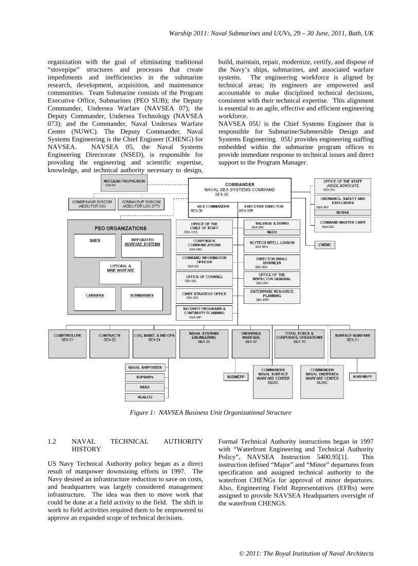
Warship 2011: Naval Submarines and UUVs, 29 – 30 June, 2011, Bath, UK
© 2011: The Royal Institution of Naval Architects
organization with the goal of eliminating traditional “stovepipe” structures and processes that create impediments and inefficiencies in the submarine research, development, acquisition, and maintenance communities. Team Submarine consists of the Program Executive Office, Submarines (PEO SUB); the Deputy Commander, Undersea Warfare (NAVSEA 07); the Deputy Commander, Undersea Technology (NAVSEA 073); and the Commander, Naval Undersea Warfare Center (NUWC). The Deputy Commander, Naval Systems Engineering is the Chief Engineer (CHENG) for NAVSEA. NAVSEA 05, the Naval Systems Engineering Directorate (NSED), is responsible for providing the engineering and scientific expertise, knowledge, and technical authority necessary to design,
build, maintain, repair, modernize, certify, and dispose of the Navy’s ships, submarines, and associated warfare systems. The engineering workforce is aligned by technical areas; its engineers are empowered and accountable to make disciplined technical decisions, consistent with their technical expertise. This alignment is essential to an agile, effective and efficient engineering workforce. NAVSEA 05U is the Chief Systems Engineer that is responsible for Submarine/Submersible Design and Systems Engineering. 05U provides engineering staffing embedded within the submarine program offices to provide immediate response to technical issues and direct support to the Program Manager.
Figure 1: NAVSEA Business Unit Organizational Structure
1.2 NAVAL TECHNICAL AUTHORITY HISTORY
US Navy Technical Authority policy began as a direct result of manpower downsizing efforts in 1997. The Navy desired an infrastructure reduction to save on costs, and headquarters was largely considered management infrastructure. The idea was then to move work that could be done at a field activity to the field. The shift in work to field activities required them to be empowered to approve an expanded scope of technical decisions.
Formal Technical Authority instructions began in 1997 with “Waterfront Engineering and Technical Authority Policy”, NAVSEA Instruction 5400.95[1]. This instruction defined “Major” and “Minor” departures from specification and assigned technical authority to the waterfront CHENGs for approval of minor departures. Also, Engineering Field Representatives (EFRs) were assigned to provide NAVSEA Headquarters oversight of the waterfront CHENGS.

Warship 2011: Naval Submarines and UUVs, 29 – 30 June, 2011, Bath, UK
© 2011: The Royal Institution of Naval Architects
“Engineering Agent Selection, Assignment, Responsibility, Tasking and Appraisal”, NAVSEA Instruction 5400.57B, was modified in 1999 to update engineering agent policy and expand the scope to codify Technical Authority Agents at Warfare Centers. Also in 1999, NAVSEA Instruction 5400.61B was issued. It established policy for interaction between Program Managers (PMs), Ship Design Managers (SDMs) and Headquarter technical codes.
In 2003, NAVSEA Instruction 5400.97 [2] was issued that designated NAVSEA’s Engineering and Technical Authority Policy. It established a common approach with consistent terminology for independent technical authority and described the inter-relationship among systems engineering, technical authority, programmatic authority, technical processes, certification authority, and certificate holders. In 2005 the Space and Naval Warfare Systems Command (SPAWAR) and the Naval Air Systems Command (NAVAIR), adopted 5400.97. In 2007, this instruction was also adopted by the Naval Supply systems Command (NAVSUP) and the Naval Facilities Engineering Command (NAVFAC). A similar policy was adopted by the Marine Corps Systems Command (MCSC). These six Naval SYSCOMs have subsequently issued joint policies for Risk Management (NAVSEA Instruction 5000.8) and Systems Engineering (NAVSEA Instruction 5000.9) to better define the roles and collaboration between technical and program authorities throughout the Department of the Navy (DoN).
In October of 2010, the most recent change to NAVSEANOTE 5400 [3] aligned Deputy CHENGs (DEP CHENGs) to assist the NAVSEA CHENG in alignment, development and sustainment of technical authority within their assigned areas. In the submarine community, the DEP CHENG is the Commander of the Naval Undersea Warfare Center NUWC).
2. TECHNICAL AUTHORITY ROLES AND RESPONSIBILITIES
Technical Authorities have been set up to make technically sound, timely engineering decisions that efficiently support Program Office cost and scheduling constraints. The independence of technical authority is an essential aspect of the engineering community because it provides constructive collaboration with programmatic authorities on technical work. It also implements checks and balances necessary to ensure our facilities and products support the war fighter and meet the changing needs of the Navy.
The Technical Authority chain of command consists of the Secretary of the Navy (SECNAV), COMNAVSEA, NAVSEA CHENG, Deputy Warranting Officers, and Technical Warrant Holders. Engineering Managers / Agents, Lead Engineers, and a network of engineers, scientists, mathematicians and technicians support the Technical Authority chain of command.
Figure 2: Technical Authority Pyramid
2.1 COMMANDER, NAVAL SEA SYSTEMS COMMAND (COMNAVSEA)
SECNAV designates COMNAVSEA as the Technical Authority (TA) and directs the PEOs and Program Managers (PMs) to work with NAVSEA to ensure that TA processes are an integral part of their program execution and that acquisition issues pertaining to supportability of their systems are coordinated and addressed throughout the entire life cycle.
COMNAVSEA establishes and maintains organizational alignment, designates Deputy Warranting Officers (DWOs), is the final arbitrator of disagreements between the technical and programmatic authorities, and partners with other SYSCOM Commanders to ensure alignment and collaboration.
2.2 NAVSEA CHIEF ENGINEER (CHENG)
CHENG has delegated authority to perform responsibilities on behalf of COMNAVSEA, including alignment, execution and oversight of technical authority [3]. CHENG is responsible for establishing common policies for TA, technical standards, analysis, systems engineering, certification, reliability and safety. CHENG also designates the Technical Warrant Holders. The CHENG is the final decision authority for Technical Warrant Holder responsibilities. CHENG is the final arbitrator of disagreements between Deputy Warranting Officers.
2.3 DEPUTY WARRANTING OFFICERS (DWOs)
Deputy Warranting Officers are designated in NAVSEA INST 5400.97C [2] and modified in NAVSEA NOTE 5400 [3]. DWOs provide leadership and are accountable for all engineering and technical decision making in their respective technical domains. They include Chief Systems Engineers and Technical Domain Managers. DWOs endorse warranted technical area definitions and TWH nominations. They implement technical authority policies and oversea execution of technical authority by TWHs.

Warship 2011: Naval Submarines and UUVs, 29 – 30 June, 2011, Bath, UK
© 2011: The Royal Institution of Naval Architects
2.3 (a) Chief Systems Engineer (Cse)
The Chief Systems Engineer is a DWO responsible for implementation of systems engineering practices and processes in support of NAVSEA-affiliated Program Executive Offices, SEA 07, and Deputy Commander for Surface Warfare (NAVSEA 21). The CSE for Submarines (CSE SUBS) is the Director for Submarine/Submersible Design and Systems Engineering (SEA 05U) and is aligned to PEO SUBS and SEA 07.
The CSEs coordinate technical authority support from the Technical Domain Managers. CSEs also provide input and review of technical standards and updates to ensure PEO understanding and ability to implement in their programs.
2.3 (b) Technical Domain Managers (Tdms)
Technical Domain Managers are DWOs responsible for broad engineering disciplines. As an example, the TDM for Warfare Systems Engineering – Undersea is the Division Technical Director of Naval Undersea Warfare Center – Newport Division. This technical domain includes the sensors, weapons, and combat control systems for undersea warfare.
TDMs also define technical authority science and technology needs, and they provide independent technical authority support for systems engineering technical reviews.
2.4 TECHNICAL WARRANT HOLDERS (TWHs)
Qualified individuals are formally warranted as independent technical authorities. These Technical Warrant Holders (TWHs) are entrusted and empowered to provide leadership and make technically sound engineering decisions within their warranted technical areas. TWH responsibilities are defined to include [3]:
Setting Technical Standards Technical Area Expertise Ensuring Safe and Reliable Operations Ensuring Effective and Efficient Systems Engineering Judgment in Making Unbiased Technical DecisionsStewardship of Engineering and Technical Capabilities Accountability and Technical Integrity
They are experts in their warranted technical areas and lead technical efforts throughout the Navy, independent of organizational boundaries.
2.5 ENGINEERING MANAGER / AGENT
Engineering Managers (EMs) and Engineering Agents (EAs) are part of the support network of engineers,
scientists, mathematicians, and technicians directly supporting the ability of TWHs to execute their responsibilities of their warrants. In general, the EM is a single, accountable manager for an EA. Engineering Agents are defined as an organization defined by a Memorandum of Agreement (MOA) or other assigning document [4]. EAs provide technical services to TWHs, PMs, and the Fleet. They apply their expertise to such services as analysis, development of technical alternatives, end-to-end and total system performance assessment, consultation, investigation, research, development, test and evaluation, risk assessment and mitigation, planning, design and certification of systems or equipment, construction, production or integration, and in-service support. These include In-service Engineering Agents (ISEAs), Design Yards, Planning Yards, Planning Activities, and Life Cycle Manager roles. EAs sustain NAVSEA technical core equities in their respective technical areas.
3. TECHNICAL AUTHORITY EXAMPLES
Prior to the implementation of formal Technical Authority policy beginning in 1997, Technical Authority was practiced, but not at a consistent level. Technical rigor was stronger in the SUBSAFE Program and weapons safety certification than it was in many other parts of NAVSEA. The 1997 policy empowered waterfront Chief Engineers and held them accountable to apply more rigor in their processes. This concept was expanded throughout NAVSEA in 2003 by the implementation of NAVSEA Instruction 5400.97, the NAVSEA Engineering and Technical Authority Policy [3], and later throughout DoN.
3.1 NEAR LOSS OF USS DOLPHIN (AGSS-555), 2002
On 21 May 2002, USS DOLPHIN (AGSS-555) suffered a flooding casualty that nearly resulted in the loss of the ship. USS DOLPHIN was conducting training exercises about 100 miles off the San Diego coastline when a torpedo shield door gasket failed, and water began to flood the ship. Due to high winds and 10- to 11-foot swells in the ocean, approximately 70-to-85 tons of seawater entered the ship, an amount dangerously close to its reserve buoyancy. [5]
A Naval Sea Systems Command Flag Board was convened to identify the technical chain of events that led to the USS DOLPHIN casualty. This Board was chartered to identify technical accountability, process shortfalls and corrective action to prevent reoccurrence on this and other US Navy assets.
The Board found that the root cause of the near loss of the USS DOLPHIN was the loss of configuration control and a culmination of technical, process, and cultural issues. It was purely from the actions of the crew and good fortune that the USS DOLPHIN is not on the bottom with 43 lives lost. This casualty resulted from the

Warship 2011: Naval Submarines and UUVs, 29 – 30 June, 2011, Bath, UK
© 2011: The Royal Institution of Naval Architects
technical and management communities’ failure to exercise due diligence and the culmination of technical, process, and cultural issues that had developed over the years since the ship was designed and commissioned in the 1960s. What happened was a gradual but significant shift away from good procedures and compliance.
3.2 LOSS OF COLUMBIA, 2003
The parallel between USS DOLPHIN and Space Shuttle COLUMBIA is striking. In 1998, COLUMBIA completed a mission that encountered so many issues that a review board was convened. The gradual erosion of engineering rigor in the shuttle program appalled that board. They made specific recommendations for operational, technical, and cultural issues.
The Shuttle Independent Assessment Team made 120 specific recommendations. The study director was “disappointed that more of our recommendations could not be implemented.” In 2003, the COLUMBIA Accident Investigation Board Chairman called the 1999 recommendations “eerily prescient” given the February 1, 2003 loss [6].
“One of the most difficult COLUMBIA Accident Investigation Board organizational recommendations is that we develop an independent technical authority to assure excellence.” – Sean O’Keefe, NASA Administrator [6].
3.3 SUBSAFE CERTIFICATION AUTHORITY
The US Navy’s Submarine Safety (SUBSAFE) Program is a prime example of a program that requires stringent Technical Authority. SUBSAFE is firmly rooted in the technical specifications and technical documents upon which our submarines are designed, constructed, and maintained.
SUBSAFE certification is a disciplined course of action that brings structure to new submarine construction and maintenance programs. This leads to formal authorization for unrestricted operations at sea. Prior to sea trials, a comprehensive SUBSAFE certification audit is performed which certifies that the design, installed material, fabrication processes used, and testing were properly accomplished. Once this initial certification for unrestricted operations at sea is received, it is maintained throughout its service life where SUBSAFE rules are applied to maintenance performed [7].
4. CONCLUSION
This paper described the evolution of Technical Authority in the US Navy, and it’s relevance to submarine design, construction, maintenance, and modernization. The Technical Authority structure and practice has evolved over the last fifteen years to ensure authority, responsibilities, and accountabilities to establish, monitor, and approve technical standards, tools, and processes. The Technical Authority chain of
command includes formally designated Deputy Warranting Officers, Technical Warrant Holders, and supporting pyramids of Engineering Managers and Lead Engineers.
5. ACKNOWLEDGEMENTS
NAVSEA: David Cartwright, Stuart Mennitt, Brandon Ellingson, Scott Patten, Scott Daley, Robert Stortstrom, Mark Arvidson, Jamie Atkinson, Tracey Dreiss, Chris Paquette NUWC: John Babb
6. REFERENCES
1. VADM McCOY, K.M., ‘Waterfront Engineering and Technical Authority Policy’, NAVSEA INSTRUCTION 5400.95E, 8 April 2010.
2. VADM SULLIVAN, P.E., ‘Virtual SYSCOM Engineering and Technical Authority Policy’, NAVSEA INST 5400.97C, 27 November 2006.
3. VADM McCOY, K.M., ‘NAVSEA Technical Authorities’, NAVSEA NOTICE 5400, 7 October 2010.
4. VADM BALISLE, P.M., ‘Engineering Agent Selection, Assignment, Responsibility, Tasking and Appraisal’, NAVSEA INSTRUCTION 5400.57D, 3 February 2003
5. Hoehne, T. ‘Navy Recognizes USS Dolphin’s Modest Hero’, Navy.mil Story Number: NNS030115-08,15 JANUARY 2003
6. COLUMBIA Accident Investigation Review Board, ‘COLUMBIA Accident Investigation Board Report’, 26 AUGUST 2003.
7. IWANOWICZ, S.E., MCBRIDE, M.S., LILLY, C.A., ‘The United States Navy’s Submarine Safety (SUBSAFE) Program’, RINA Warship 2005: Naval Submarines 8, London, UK, 2005.
7. AUTHORS BIOGRAPHY
Wayne Richter is the Chief Systems Engineer of NAVSEA 05U, the Submarine/Submersible Design and Systems Engineering Group.
Matthew Martz is a Naval Architect in the Advanced Submarine Concepts Division, NAVSEA 05U6. He is responsible for the design of submarine advanced concepts.
Author's Note: This paper represents the views and opinions of the authors and does not necessarily represent those of the U.S. Navy.

Warship 2011: Naval Submarines and UUVs, 29 – 30 June, 2011, Bath, UK
© 2011: The Royal Institution of Naval Architects
SUBMARINE PROPULSOR TECHNICAL DEVELOPMENTS, OPPORTUNITIES AND CHALLENGES
S Banks, Rolls-Royce plc, UK
SUMMARY
Pump jet propulsors for UK naval nuclear submarines are designed to meet a variety of arduous service conditions. Improvements in design and technology will be required to satisfy even more demanding requirements for future propulsors. This paper discusses the improvements made so far and the challenges faced for future development. Some promising avenues of research that offer to provide enhancements in performance or affordability are also discussed.
NOMENCLATURE
b Beam breadth (m) E Young’s modulus (N m-2)f Natural frequency (Hz) I Second moment of area (m4)k Beam stiffness (N m-1)l Beam length (m) M Beam mass (kg) P Applied force (N) t Beam thickness (m)
Material density (kg m-3) Beam deflection (m) y Yield stress (N m-2)
1. INTRODUCTION
The propulsors for UK naval nuclear submarines have evolved to meet ever more demanding requirements over a period of nearly 50 years since HMS Dreadnought was commissioned in 1963. The special operational requirements, particularly for those submarines carrying the UKs nuclear deterrent, require their propulsors to remain quiet in operation so that the vessel can remain undetected when carrying out critical missions. With increasing demands for submarine capability and lifetime, there has also been a drive to reduce the weight of the propulsor and to make the component parts last longer. As a result, the propulsor design has developed through time into a niche pump jet design that utilises novel materials and advanced manufacturing technology to meet these demands.
Rolls-Royce has been involved in the UK nuclear submarine programme since the outset in 1958 and is responsible for the design and manufacture of the nuclear reactor and parts of the Nuclear Steam Raising Plant (NSRP). Additional to its nuclear propulsion activities, Rolls-Royce provides marine propulsion systems to over 200 navies world-wide. Recent growth and acquisitions mean that Rolls-Royce’s marine portfolio now covers both commercial and naval marine sectors, supplying marine gas turbines, diesel engines, propellers, water jets, stabilisers, podded propulsion systems and deck machinery.
The UK Ministry of Defence awarded the prime contract for the new ASTUTE class [Figure 1] of nuclear powered
submarines to BAE SYSTEMS Electronics Ltd in 1996. As part of their contract submission in 2000, BAE SYSTEMS carried out a competitive tendering exercise involving UK and US companies for the design and manufacture of the pump jet propulsor. The subsequent contract was awarded to Rolls-Royce in April 2001. Since 2001, Rolls-Royce has delivered three complete pump jet propulsors and is now contracted to deliver the propulsors for Astute Boat 4 and 5.
This paper discusses recent developments in UK propulsor technology and identifies the key opportunities and challenges associated with designs for future UK naval nuclear submarine platforms.
Figure 1: Astute Submarine at BAE Systems Shipyard Barrow-in-Furness (2009)
2. PUMP JET PROPULSORS
2.1 HISTORY
The pump jet propulsor was designed and developed initially by the UK Ministry of Defence for HMS CHURCHILL class submarines in the late 1960s. Variations of the original design have been fitted to all new build UK SSNs (the SWIFTSURE and TRAFALGAR classes) and SSBNs (VANGUARD class).
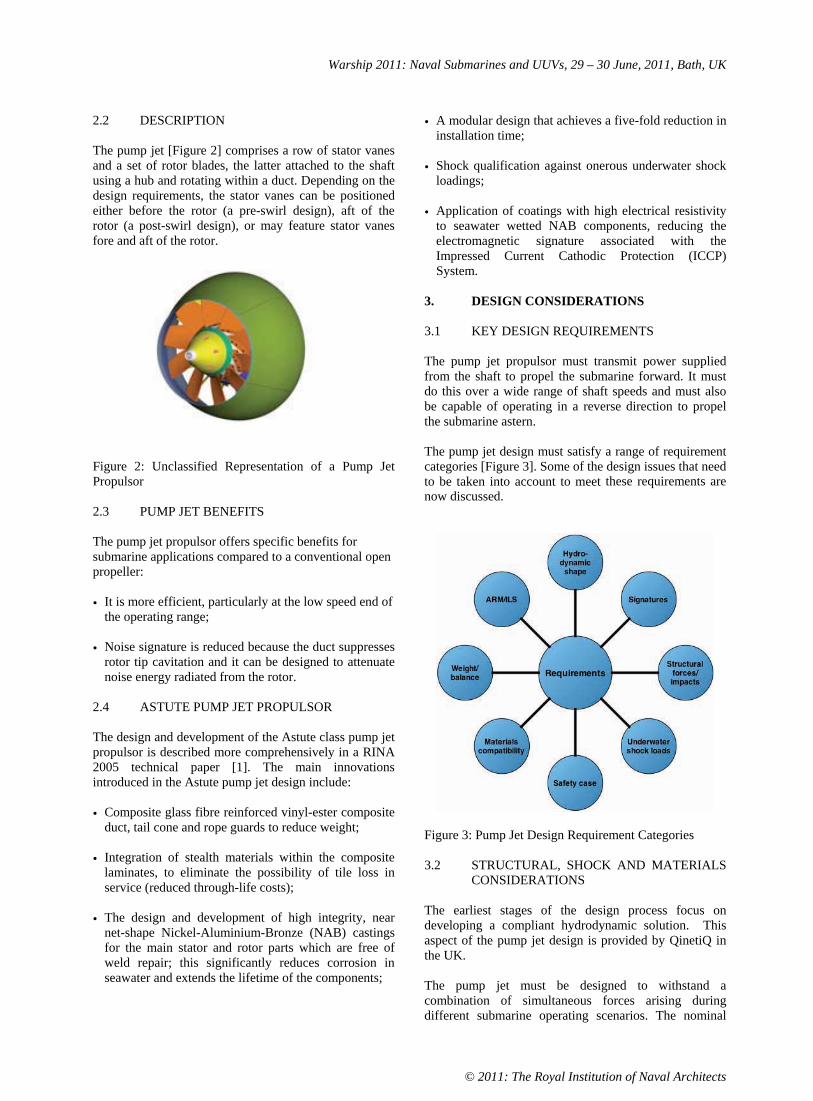
Warship 2011: Naval Submarines and UUVs, 29 – 30 June, 2011, Bath, UK
© 2011: The Royal Institution of Naval Architects
2.2 DESCRIPTION
The pump jet [Figure 2] comprises a row of stator vanes and a set of rotor blades, the latter attached to the shaft using a hub and rotating within a duct. Depending on the design requirements, the stator vanes can be positioned either before the rotor (a pre-swirl design), aft of the rotor (a post-swirl design), or may feature stator vanes fore and aft of the rotor.
Figure 2: Unclassified Representation of a Pump Jet Propulsor
2.3 PUMP JET BENEFITS
The pump jet propulsor offers specific benefits for submarine applications compared to a conventional open propeller:
• It is more efficient, particularly at the low speed end of the operating range;
• Noise signature is reduced because the duct suppresses rotor tip cavitation and it can be designed to attenuate noise energy radiated from the rotor.
2.4 ASTUTE PUMP JET PROPULSOR
The design and development of the Astute class pump jet propulsor is described more comprehensively in a RINA 2005 technical paper [1]. The main innovations introduced in the Astute pump jet design include:
• Composite glass fibre reinforced vinyl-ester composite duct, tail cone and rope guards to reduce weight;
• Integration of stealth materials within the composite laminates, to eliminate the possibility of tile loss in service (reduced through-life costs);
• The design and development of high integrity, near net-shape Nickel-Aluminium-Bronze (NAB) castings for the main stator and rotor parts which are free of weld repair; this significantly reduces corrosion in seawater and extends the lifetime of the components;
• A modular design that achieves a five-fold reduction in installation time;
• Shock qualification against onerous underwater shock loadings;
• Application of coatings with high electrical resistivity to seawater wetted NAB components, reducing the electromagnetic signature associated with the Impressed Current Cathodic Protection (ICCP) System.
3. DESIGN CONSIDERATIONS
3.1 KEY DESIGN REQUIREMENTS
The pump jet propulsor must transmit power supplied from the shaft to propel the submarine forward. It must do this over a wide range of shaft speeds and must also be capable of operating in a reverse direction to propel the submarine astern.
The pump jet design must satisfy a range of requirement categories [Figure 3]. Some of the design issues that need to be taken into account to meet these requirements are now discussed.
Figure 3: Pump Jet Design Requirement Categories
3.2 STRUCTURAL, SHOCK AND MATERIALS CONSIDERATIONS
The earliest stages of the design process focus on developing a compliant hydrodynamic solution. This aspect of the pump jet design is provided by QinetiQ in the UK.
The pump jet must be designed to withstand a combination of simultaneous forces arising during different submarine operating scenarios. The nominal

Warship 2011: Naval Submarines and UUVs, 29 – 30 June, 2011, Bath, UK
© 2011: The Royal Institution of Naval Architects
design loads are predicted by analysis and, where possible, validated from measurements taken from previous designs or from scale model tests. Safety factors are applied to these nominal loads for design purposes to account for uncertainty. The pump jet structural design must ensure that stresses do not exceed specified limits for each material. In setting the allowable stresses, it is important to recognise that materials can degrade through cyclic loading in the seawater environment. Therefore, end-of-life material conditions are used in the design assessment. This is particularly important in the case of composites, which will absorb seawater through hydrolysis until a saturation condition is reached. Appropriate design allowable stresses/strains may be determined from a materials test program using small standard test specimens.
NAB properties are established by testing coupons taken from representative demonstrator castings. Here, it is important to recognise the effects of casting section thickness on the material properties. Generally, lower static properties are attained from thicker wall sections within a casting as a result of the lower cooling rates during metal solidification (which promotes larger grain size). If NAB components are likely to experience cavitation or high rates of erosion, then appropriate allowances should be made in the design to account for material loss.
The pump jet design must ensure that the deflections of the duct do not result in contact with the rotor and that adequate clearances are maintained for efficient operation and low noise signature. For some load cases, the requirement to ensure adequate stiffness may be more design limiting that stress, for example under shock and submarine whipping conditions.
3.3 SIGNATURE CONSIDERATIONS
Methods of prediction of far field radiated noise, electromagnetic and target echo strength performance are discussed in the RINA 2005 technical paper [1].
Figure 4: Pump Jet Propulsor Signature Types
3.3 (a) Radiated Noise
The submarine must be capable of quiet operation to remain undetected by enemy sonar. Above a particular submarine speed, the propulsor is the most significant source of submarine radiated noise, so it is important to be able to operate effectively below this threshold speed.
This requirement is addressed foremost in the design by:
• Minimising the occurrence and severity of fluctuating hydrodynamic forces acting on the pump jet, for example by addressing features that can lead to a non-uniform flow field around the stern of the submarine.
• Designing the structure to prevent or mitigate forced excitations caused by the unavoidable unsteady forces (for example, as a result of interaction between rotor blades and the wakes of upstream stator vanes).
Composite components exhibit lower natural frequencies than metal parts of identical geometry. When immersed in seawater, the frequencies will shift to lower values due to the additional entrained mass of water which is displaced by the blade when vibrating. The percentage shift for the composite component will be significantly greater than for the geometrically equivalent metal part. This is because the entrained water mass represents a greater proportion of the effective blade plus water mass for the lower density material.
This behaviour increases the amount of effort that the designer may have to expend to ensure adequate stiffness and to avoid resonances in the pump jet duct/stator structure. Options for tuning the modal frequencies may also need to be traded against hydrodynamic shape requirements.
3.3 (b) Electromagnetic Signature
An electrical signature may be generated by the galvanic reactions occurring when dissimilar metals are placed in seawater, and by any corrosion protection system installed to prevent such reactions. Previous UK naval nuclear submarine pump jets have suffered from the effects of corrosion, with significant impact on platform availability and through-life maintenance costs. The corrosion of the propulsor and its associated electromagnetic signature therefore has to be considered at submarine system level to ensure a good understanding of the potential problems.
The prediction of electromagnetic signature for the Astute pump jet takes into account the potential loss of coatings in areas that might be subjected to cavitating flow conditions under extreme operating conditions.
3.3 (c) Target Echo Strength
Target echo strength refers to the amount of sonar energy which is reflected back from the propulsor and is therefore capable of being detected by the enemy. Multiple reflections from the edges of blades and energy transmission through semi-transparent components (e.g. the composite duct) can result in complex acoustic scattering. It is therefore important that these effects are analysed at an early stage in the design to ensure that the

Warship 2011: Naval Submarines and UUVs, 29 – 30 June, 2011, Bath, UK
© 2011: The Royal Institution of Naval Architects
shape, materials of construction and minor design details can be traded to yield an acceptable signature.
3.4 WEIGHT CONSIDERATIONS
To achieve a neutral state of buoyancy, the submarine displacement needs to be sufficient for the weight of the submarine and its payload. Once weight budgets have been set against a particular displacement, further increases in payload and equipment mass are highly undesirable. If such weight increases require extra hull displacement, then the increase in submarine drag may demand more propulsive power, which itself implies an increase in mass of the propulsion plant. The process is therefore a circular one, leading potentially to an ever bigger, heavier and more expensive submarine.
Reducing the mass of the components at the aft end of the submarine also requires less lead ballast to maintain longitudinal balance of the submarine [2]. A given propulsor mass reduction can therefore require the equivalent amount less in ballast. Weight reduction is, therefore, an important goal of the designer and it may be prudent to consider all reasonable measures to deliver weight savings beyond the targets specified in the initial requirements.
3.5 MANUFACTURING CONSIDERATIONS
3.5 (a) NAB Castings
Static and centrifugal NAB castings for the Astute pump jet propulsor have been produced for Rolls-Royce by Meighs foundry in Stoke-on-Trent, meeting the requirements of demanding UK naval acceptance standards [3, 4]. A key factor in this success is the early liaison between the designer and the foundry to minimise the likelihood of recurrent manufacturing concessions and scrapped parts (e.g. due to casting defects).
If NAB castings are to last for the lifetime of the submarine, then weld repairs must be eliminated and it is here that casting design is of vital importance. Computer modelling can be used to predict the flow and solidification of the melt, thus complementing traditional casting design guides and providing early confidence in the soundness of castings. Once assurance is established, demonstrator castings can be produced using rapid prototype techniques as a precursor to committing more significant funds to pattern production.
NAB castings should be designed to near net-shape to eliminate the need for excessive machining to final size. This reduces the risk of uncovering shrinkage porosity, which tends to concentrate towards the centre of the casting as a result of metal contraction towards the cooler surfaces of the mould. Reduced machining also helps to reduce manufacturing costs.
3.5 (b) Composite Mouldings
The Astute pump jet propulsor parts are produced using a resin infusion technique by Marshall Slingsby Aviation in Kirkbymoorside, North Yorkshire. Single-sided moulds are used and the smooth, accurate moulded surfaces of each part form the wetted surfaces of the pump jet.
The profile and surface finish of the non-moulded surfaces is less critical. It is important, however, to consider in the design the potential effects of tolerance build-up when such non-moulded surfaces form part of a larger assembly.
The design of composite structures should recognise that typical resins used in construction will be prone to shrinkage during the polymer curing process. This sometimes requires moulds to be offset from the nominal desired shape, so that the requisite hydrodynamic tolerances are satisfied in the final part. It is important to obtain comprehensive data at each stage of the manufacturing process to fully understand and subsequently to counteract the potential effects of shrinkage of large composite structures.
4. FUTURE REQUIREMENTS
4.1 AFFORDABILITY
The UK submarines enterprise as a whole is under pressure to become more affordable in future, whilst facing the challenges of more demanding performance requirements and diminished capability for UK supply of some key parts of the propulsion plant. These factors are particularly relevant for future pump jet propulsors. The diminished foundry capability in the UK has already led to the procurement of some large NAB castings for Astute Boat 4 and 5 pump jets from overseas.
Submarine onboard space will be at an even greater premium in future, especially if early constraints are placed on displacement to control platform costs. Measures that help to reduce onboard space demand, e.g. for ballast, will therefore become increasingly important. If solutions are available that go beyond the targets set in equipment weight budgets, then some flexibility may be provided for increasing payload and capability in the future.
4.2 STEALTH AND SIGNATURE IMPROVEMENTS
Submarine survivability faces ever increasing challenges from enemy sonar detection. It is likely that future submarine pump jet propulsor designs will need to make significant reductions in noise to match improvements in on-board machinery noise signature. Otherwise, the submarine speed at which the propulsor becomes the

Warship 2011: Naval Submarines and UUVs, 29 – 30 June, 2011, Bath, UK
© 2011: The Royal Institution of Naval Architects
most dominant noise source will reduce, limiting the effectiveness of operations.
5. OPPORTUNITIES AND CHALLENGES
5.1 ‘MORE COMPOSITE’ PUMP JET DUCT
For reasons discussed earlier, the pump jet propulsor weight has a direct impact on cost. Propulsor weight reduction can therefore help to improve affordability, provided that the benefits are recognised at an early stage in the submarine design. A more stringent propulsor weight budget can only be fixed, however, if confidence in the technology needed to deliver the weight improvement is available. Rolls-Royce, sponsored by UK MoD, is therefore developing the manufacturing technology for production of Composite Stator Vanes (CSVs) for future submarine pump jet propulsors. Initial CSV development has been focussed on a typical ASTUTE stator vane geometry using a glass-fibre epoxy resin laminate system.
CSVs also offer affordability improvements since the parts can be produced to accurate tolerances by resin transfer moulding and, unlike their metallic counterparts, they require no further machining to attain the necessary tolerances and surface finish. There is also a broader, competitive UK supply chain for these parts than for the high integrity NAB castings that they would replace.
The structural design justification for introduction of CSVs into Astute class comprises a combination of elements, including stress analysis, validated by full-scale component testing. The component tests include:
• Start-of-life ultimate strength tests;
• Fatigue tests;
• Impact tests;
• Underwater shock tests;
• End-of-life residual strength tests (post fatigue, impact or shock).
A number of non-destructive examination (NDE) techniques, including laser shearography [Figure 5], are used before and after component testing to search for evidence of failure. The laser shearography technique can be applied to non-uniform surfaces, such as those of CSVs, to indicate changes in sub-surface condition of the material. Destructive microanalysis in Rolls-Royce laboratories of material taken from pre and post-tested CSVs also assists in the investigation of laminate failure mechanisms. Observations made at this stage of development are being used to help to improve the laminate design for the final application.
Figure 5: Laser Shearography Fringe Patterns for a CSV (Laser Optical Engineering Ltd, Loughborough)
The development project has culminated in successful underwater shock testing of full-size CSVs by Weidlinger Associates [Figure 6] and the results will be used for future validation of improved numerical shock models.
Figure 6: Underwater Shock Testing of Prototype CSV (Weidlinger Associates Ltd)
The development programme has also demonstrated the feasibility of embedding robust optical fibre strain sensors [Figure 7] within the CSV laminate, for potential use in condition monitoring, or for design validation.
Figure 7: CSV Flat Panel with Optical Fibre Strain Sensors (Insensys)

Warship 2011: Naval Submarines and UUVs, 29 – 30 June, 2011, Bath, UK
© 2011: The Royal Institution of Naval Architects
Basing the CSV design on the existing geometry of the Astute pump jet propulsor NAB stator vane, however, introduces some challenges. For example, if a straightforward material substitution is implemented, where all NAB stator vanes are replaced by CSVs, the global stiffness of the duct/stator system is reduced significantly. This might impair the hydrodynamic efficiency when compared to that of the established metal design and may also introduce hydrodynamic noise sources. The reduction in modal frequencies of the duct/stator may also have an impact on the radiated noise signature if new resonances are introduced. Increased deflections during shock/whipping loading might also reduce margins against shock.
To illustrate these issues, simple design comparisons can be made between equivalent beams in different materials. Consider the load/deflection equation for a tip loaded rectangular section cantilever beam:
Deflection: = P / k
Stiffness: k = (3.E.I) / l3
Second moment of area: I = (b. t3) / 12
From which: = (4.P. l3) / (E. b. t3)
Two transversely loaded rectangular beams of identical length and breadth and with the same tip applied force will therefore have the same deflection if:
E1 t13 = E2. t2
3
Assuming the NAB modulus is about six times that of a typical glass fibre vinyl-ester composite (approximately 120 GPa compared to 20 GPa respectively), then a composite beam would need to be about 1.8 times thicker than the equivalent NAB beam to give the same deflection under load.
Using a similar approach, we can estimate the necessary beam thickness in each material needed to maintain the same natural frequency in air.
Considering the expression for the fundamental natural frequency of a simple mass-spring system:
Natural frequency: f = (1/2. ).(k/M)½
Mass of beam: M = b.t.l.
From which: f = (1/4. ).((E/ ).(t/L)2)½
For the same natural frequency:
t1 x (E1/ 1) ½ = t2 x (E2/ 2) ½
Assuming the same values for Young's modulus as used in the previous calculation, and typical density values of
7,600 kg/m3 and 2,200 kg/m3 for NAB and composite, the composite beam would need to be about 1.3 times thicker than the NAB beam to give the same natural frequency. Similar calculations can be made to estimate the relative frequency shifts of the different materials when submerged in water (to allow for the entrained mass effect).
These types of calculation can provide a useful insight at the earliest stages of design to assess the characteristics of components made from different materials and to assist the material selection decision. They also illustrate that it is potentially misleading just to focus on the weight saving benefits of composites without considering other performance impacts. Problems can be avoided if the use of composites is recognised from the onset of the hydrodynamic design, since it is then that geometric and structural changes can be most easily accommodated and trade-offs made. Again, the full involvement of the manufacturer in the design process is important to ensure cost effective manufacture and to avoid exotherm problems that can affect thicker section composite parts during thermosetting of the resin.
The stark contrasts highlighted by these calculations suggest that there may be some benefit from attained by alternating the metallic NAB and composite vanes in a pump jet propulsor duct/stator. Work completed by Rolls-Royce as part of the CSV development indicates that this may provide a lower risk route to technology insertion on current platforms, where hydrodynamic shape is fixed. It also allows greater scope for optimisation of hydrodynamic, signature and weight characteristics in future applications. The projected future weight saving benefits from CSV introduction for a future attack submarine are shown in Figure 5. The projections assume that just over 50% of the NAB stator vanes can be substituted by CSVs.
Figure 8: Masses of TRAFALGAR, ASTUTE and projected future attack submarine pump jet propulsor ducts
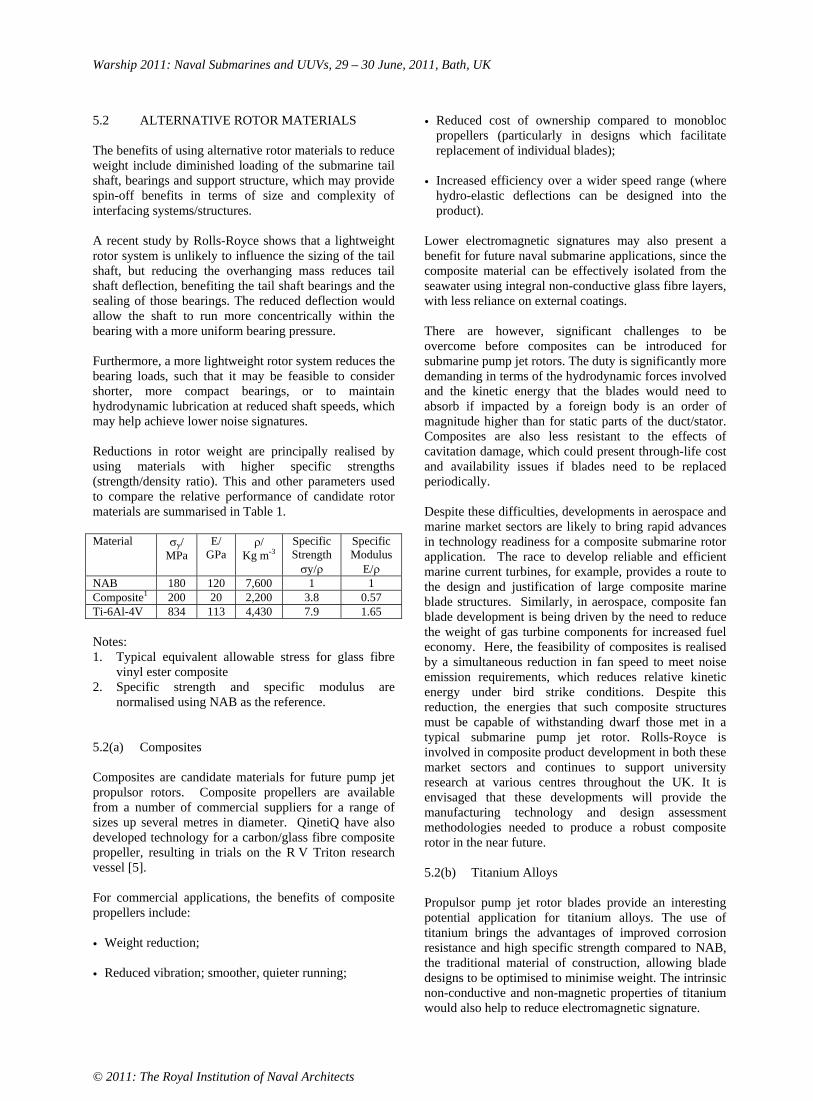
Warship 2011: Naval Submarines and UUVs, 29 – 30 June, 2011, Bath, UK
© 2011: The Royal Institution of Naval Architects
5.2 ALTERNATIVE ROTOR MATERIALS
The benefits of using alternative rotor materials to reduce weight include diminished loading of the submarine tail shaft, bearings and support structure, which may provide spin-off benefits in terms of size and complexity of interfacing systems/structures.
A recent study by Rolls-Royce shows that a lightweight rotor system is unlikely to influence the sizing of the tail shaft, but reducing the overhanging mass reduces tail shaft deflection, benefiting the tail shaft bearings and the sealing of those bearings. The reduced deflection would allow the shaft to run more concentrically within the bearing with a more uniform bearing pressure.
Furthermore, a more lightweight rotor system reduces the bearing loads, such that it may be feasible to consider shorter, more compact bearings, or to maintain hydrodynamic lubrication at reduced shaft speeds, which may help achieve lower noise signatures.
Reductions in rotor weight are principally realised by using materials with higher specific strengths (strength/density ratio). This and other parameters used to compare the relative performance of candidate rotor materials are summarised in Table 1.
Material y/MPa
E/GPa
/Kg m-3
Specific Strength
y/
Specific Modulus
E/NAB 180 120 7,600 1 1 Composite1 200 20 2,200 3.8 0.57 Ti-6Al-4V 834 113 4,430 7.9 1.65
Notes:1. Typical equivalent allowable stress for glass fibre
vinyl ester composite 2. Specific strength and specific modulus are
normalised using NAB as the reference.
5.2(a) Composites
Composites are candidate materials for future pump jet propulsor rotors. Composite propellers are available from a number of commercial suppliers for a range of sizes up several metres in diameter. QinetiQ have also developed technology for a carbon/glass fibre composite propeller, resulting in trials on the R V Triton research vessel [5].
For commercial applications, the benefits of composite propellers include:
• Weight reduction;
• Reduced vibration; smoother, quieter running;
• Reduced cost of ownership compared to monobloc propellers (particularly in designs which facilitate replacement of individual blades);
• Increased efficiency over a wider speed range (where hydro-elastic deflections can be designed into the product).
Lower electromagnetic signatures may also present a benefit for future naval submarine applications, since the composite material can be effectively isolated from the seawater using integral non-conductive glass fibre layers, with less reliance on external coatings.
There are however, significant challenges to be overcome before composites can be introduced for submarine pump jet rotors. The duty is significantly more demanding in terms of the hydrodynamic forces involved and the kinetic energy that the blades would need to absorb if impacted by a foreign body is an order of magnitude higher than for static parts of the duct/stator. Composites are also less resistant to the effects of cavitation damage, which could present through-life cost and availability issues if blades need to be replaced periodically.
Despite these difficulties, developments in aerospace and marine market sectors are likely to bring rapid advances in technology readiness for a composite submarine rotor application. The race to develop reliable and efficient marine current turbines, for example, provides a route to the design and justification of large composite marine blade structures. Similarly, in aerospace, composite fan blade development is being driven by the need to reduce the weight of gas turbine components for increased fuel economy. Here, the feasibility of composites is realised by a simultaneous reduction in fan speed to meet noise emission requirements, which reduces relative kinetic energy under bird strike conditions. Despite this reduction, the energies that such composite structures must be capable of withstanding dwarf those met in a typical submarine pump jet rotor. Rolls-Royce is involved in composite product development in both these market sectors and continues to support university research at various centres throughout the UK. It is envisaged that these developments will provide the manufacturing technology and design assessment methodologies needed to produce a robust composite rotor in the near future.
5.2(b) Titanium Alloys
Propulsor pump jet rotor blades provide an interesting potential application for titanium alloys. The use of titanium brings the advantages of improved corrosion resistance and high specific strength compared to NAB, the traditional material of construction, allowing blade designs to be optimised to minimise weight. The intrinsic non-conductive and non-magnetic properties of titanium would also help to reduce electromagnetic signature.

Warship 2011: Naval Submarines and UUVs, 29 – 30 June, 2011, Bath, UK
© 2011: The Royal Institution of Naval Architects
The major barrier to use of titanium is the high cost of material and its processing. Low cost methods for manufacturing titanium parts using powder metallurgy offer some promise and are currently under development in Rolls-Royce. Initial work is based on recovery of Ti-6Al-4V titanium off-cuts from aerospace part manufacture.
Ti-6Al-4V exhibits a much higher specific strength (nearly eight times higher than NAB), indicating a significant potential weight saving if blades are designed to take full benefit of the enhanced strength. The modulus of titanium is also comparable to that of NAB, so increased deflection under hydrodynamic load should not be of significant concern.
Studies by Rolls-Royce into the potential weight benefits of using titanium alloy for pump jet rotor blade parts suggest that about 75% of the potential weight reduction would be attributable directly to the lower density of the material compared to that of NAB, with the remaining 25% attainable from blade geometry optimisation to take account of the material strength increase.
A strength based design approach may, however, be under-conservative since the material is significantly less ductile than NAB and other failure modes, including fatigue and fracture, may present more onerous limits. When other failure modes are taken into account, it is possible that the weight of the rotor blades could be reduced by up to 50%.
These predictions assume a solid rotor blade construction. It is possible, however, to produce hollow (free-flood) titanium blade structures by the Superplastic Forming and Diffusion Bonding (SPF/DB) manufacturing technique used to produce aerospace fan blades. This may give additional scope for trade-off between hydrodynamic shape and weight than a solid blade design.
Other barriers to introduction of titanium include isolation of the material from other less noble materials in the shaft line to prevent galvanic corrosion of the latter in seawater. An integrated approach to ensure compatibility of all materials in the system would be necessary to avoid introducing significant corrosion problems.
6. RIM-DRIVE TECHNOLOGY
Rim-drive motors, a type of electrical machine based on permanent magnet technology, offer the potential to simplify the pump jet propulsor design. In a pump jet design, the stator winding could be integrated within the duct and surface mounted permanent magnets attached to the rotor tips.
The benefits of rim-drive include:
• Reduced complexity due to lower part count (no mechanical transmission components are required);
• Higher power density, which results in a smaller and more compact system compared to a conventional design;
• The propulsion motor becomes an integral part of the unit, and so reduces on-board space demands; the only additional parts required on-board are the cables to connect to the motor control supply cabinet;
• Greater hydrodynamic efficiency due to a smaller central hub and elimination of the shaft;
• Higher system efficiency, as the power is delivered directly where it is required, resulting in no shaft-line or gearbox losses;
• Lower noise and vibration due to elimination shaft-line and gearing;
• Prolonged rotor life due to reduced cavitation;
• The use of water lubricated bearings eliminates the need for shaft seals and oil filled gear housings.
Rim-drive technology is now approaching maturity in Rolls-Royce for a range of commercial marine applications including tunnel thrusters, deck winches, podded propulsion units and azimuthing devices for marine current turbines [Figure 6].
Figure 9: 500 kW demonstrator tidal generating system operating at European Marine Energy Centre in Orkney since September 2010 (Rolls-Royce Tidal Generation Ltd)

Warship 2011: Naval Submarines and UUVs, 29 – 30 June, 2011, Bath, UK
© 2011: The Royal Institution of Naval Architects
The additional challenges faced by rim-drive for a submarine propulsor application include:
• Catering for the performance effects of motor water-gap variation (e.g. caused by submarine manoeuvring loads acting on the duct);
• Justifying the materials and component parts for the lifetime of the submarine (bearings, stator winding insulation, motor canning materials);
• Meeting ARM targets;
• Dealing with the electromagnetic signature generated by the stator coils and magnets;
• Devising an installation sequence which accommodates the small motor water gaps.
7. CONCLUSIONS
This paper emphasises the multi-disciplinary nature of the submarine pump jet propulsor design process. Timely input is required from many stakeholders including hydrodynamic, structural, materials, signatures, and manufacturing experts. These various aspects need to be considered concurrently at the earliest stages of design, so that trade-offs can be made, providing a solution that achieves the best balance between cost and performance. This concurrent approach also serves to avoid the pitfalls of unduly constraining any specific aspect of performance at a later stage in the design cycle.
Various opportunities for improvement in technology are identified for future pump jet propulsor designs.
8. ACKNOWLEDGEMENTS
The support of the UK Ministry of Defence is gratefully acknowledged along with that provided by the following organisations, each of which has been involved in development of pump jet propulsor technology:
• BAE Systems Surface Ship • BAE Systems Electronics Ltd • Frazer-Nash Consultancy • Meighs Limited • Marshall Slingsby Aviation Limited • Materials Engineering Research Laboratory (MERL) • Weidlinger Associates • Insensys Ltd • QinetiQ Haslar
9. REFERENCES
1. BANKS, S., VINTON, P. AND WEST, M., ‘ASTUTE Propulsor Technical Innovation Summary’, RINA Submarines 8 Conference Paper, July 2005.
2. BURCHER, R. AND RYDILL, L., ‘Concepts in Submarine Design’, Cambridge Ocean Technology Series 2, 1998.
3. Defence Standard 02-747 Part 1. Requirements for NAB Castings and Ingots. NAB Naval Alloy Centrifugally Cast.
4. Defence Standard 02-747 Part 4. Requirements for NAB Castings and Ingots. NAB Naval Alloy Sand Castings with Welding Restricted to the Non-Wetted Surface.
5. KANE, C. E., Smith, J.R., ‘Composite Blades in Marine Propulsors’. Advanced Marine Materials: Technology and Applications, London UK, 2003.
10. AUTHOR’S BIOGRAPHY
Simon Banks is a graduate of Loughborough University of Technology and joined Rolls-Royce in 1988. He has been responsible for delivery of various design projects for naval and commercial markets, including aerospace and submarine applications. Simon is a design specialist working in the Nuclear Propulsion Systems department at Rolls-Royce Submarines in Derby. He has been fully involved in the design, verification and support to manufacture of ASTUTE Class propulsors since 2000 and continues to promote development of propulsion technology for future submarines.

Warship 2011: Naval Submarines and UUVs, 29 – 30 June, 2011, Bath, UK
© 2011: The Royal Institution of Naval Architects
CONSTRUCTION MATERIALS FOR SMALL SUBMERSIBLES
P Delaforce and P Vinton, Rolls-Royce plc, UK
SUMMARY
The use of composite materials offers the potential benefit of weight reduction and the associated increase in range, endurance, and payload. The classification societies have been reluctant to classify composite pressure hulls for manned submersibles, so where classification society approval is required traditional submarine metals are mandated. The classification societies rules in addition to the existing design standards and codes for industrial composite pressure vessels could provide the foundation for composite pressure hull standards. This paper discusses a number of proposals for the construction standards of composite hulls for small submersibles.
1. INTRODUCTION
Fibre reinforced composites materials have been adopted in many industries, from automotive to aerospace, in the pursuit of component weight reduction, utilising their high strength to density ratios. For small submersibles weight saving in the form of the minimisation of the hull weight to displacement ratio is crucial to increasing their range, endurance, and payload. A significant weight reduction of the submersible offers the potential to reduce the size of the launch and recovery systems. Many parts of the exostructure, such as hydrodynamic fairings and floodable structures are already manufactured out of composite materials. The largest single component which offers the greatest opportunity of weight reduction from the utilisation of composite materials is the pressure hull.
There has been significant interest over the years in the design and production of prototype submersibles with a composite pressure hull [1-2]. However, the classification societies have been reluctant to classify composite pressure hulls for manned submersibles so, where classification society approval is required construction has reverted to known submarine steels or certain aluminium or titanium alloys [3-6].
Small submersible designs could be developed to utilising Acrylic plastic for windows and viewports, using a single domed viewport which makes up large proportion of the pressure hull. However, there is a limit by which Acrylic viewports can be used before a fibre-reinforced composite pressure hull is required for further weight reduction.
The purpose of this paper is to review the existing design rules and codes mandated by the classification societies for manned submersibles and present a set of proposals for classification society approval. Using existing design rules and safety factors used for submarine and composite pressure vessel construction.
2. CURRENT RULES AND STANDARDS
The foremost shipping classification societies mandate the use of pressure vessel steels, Aluminium and Titanium alloys for the construction of the pressure hull, and permit the use of Acrylic plastic for windows and viewports [3-6].
In the United States, the American Bureau of Shipping (ABS) Rules for Building and Classing Underwater Vehicles [3] incorporates both the Boiler and Pressure Vessel Code (BPVC) for construction [7], and the Safety Standards for Pressure Vessels for Human Occupancy [6]. Both of these standards are produced by the American Society of Mechanical Engineers (ASME).
One section of the ASME Boiler and Pressure Vessel code covers the design and construction of fibre-reinforced plastic pressure vessels, Section X [8]. This design code for composite pressure vessels is the obvious starting point for developing composite pressure hull design code and acceptance criteria.
Examination of Section X reveals that two different design methodologies are permitted, design qualification through the destructive test of a prototype (Class I, composite vessels) and the use of mandatory design rules and acceptance testing by non-destructive examination (Class II, composite vessels). Class II vessels permit a relatively low maximum internal and external pressures are, were the maximum external pressure must not exceed 100 kPa (1 bar). This is due to the relative limited experience and data available for composite vessels to produce a robust design using a design by rule approach.
Design qualification through destructive testing of a prototype provides a strong base to demonstrate sufficient safety factors for pressure vessels subjected to large internal and external pressures. For Class I vessels the maximum external pressure is limited by the manufacturing method. Table 1 summaries the maximum pressure for the allowed manufacturing method for Class I vessels and the qualification test and production test acceptance requirements.

Warship 2011: Naval Submarines and UUVs, 29 – 30 June, 2011, Bath, UK
© 2011: The Royal Institution of Naval Architects
Table 1 Requirements for Class I Composite Pressure Vessels, from ASME BPVC, Section X
Parameter Requirement Code Ref
Internal or External Dependent on fabrication method.
1 MPa (10 bar) For bag-moulded, centrifugally cast and contact-moulded vessels.
10 MPa (100 bar) For filament-wound vessels, or one-sixth of the bursting pressure.
Design Pressure
20 MPa (200 bar) For filament-wound vessels with polar boss openings or one-fifth of the bursting pressure.
RD-111, RD-120
a) Prototype subjected to 100,000 cycles of pressure ranging for max external and internal design pressure.
b) Prototype shall withstand an external pressure of twice max external design pressure without buckling.
RD-311, RT-223.2 Internal and
External Pressure Service
c) Prototype shall withstand a hydrostatic pressure of at least six times the max internal design pressure.
RD-160
Vessel will be designed for a min internal pressure of 100 kPa in addition to external design pressure.
a) Prototype shall withstand an external pressure of twice max external design pressure without buckling.
b) Prototype subjected to 100,000 cycles of pressure ranging from max external to the internal design pressure of 100 kPa. (1 bar)
RD-312, RT-223.3
Qualification Test Requirements
External Pressure Service Only
c) Prototype shall withstand a hydrostatic pressure of at least six times the internal design pressure of 100 kPa. (1 bar)
RD-160
Thickness check To be within 10% of ½ (R×t), where R = radius of the shell, t = nominal specified thickness. RT-420
Vessel Weight To be within 95% of the weight specified in the qualification test report from the prototype. RT-430
Barcol Hardness Test
Within the range specified by qualification test report. RT-440
1.1 times the internal or external design pressure for vessel without welded metal components.
Production Test Requirements
Hydrostatic Leakage Test 1.3 times the internal or external design pressure
for vessel with welded metal components.
RT-450

Warship 2011: Naval Submarines and UUVs, 29 – 30 June, 2011, Bath, UK
© 2011: The Royal Institution of Naval Architects
Table 2 Comparison of the Qualification and Acceptance Requirement from the Standards and Codes
ASME Boiler & Pressure Vessel Code, Section X
ASME Safety Standards Pressure Vessels for Human Occupancy
ABS Rules Underwater Vehicles Systems and Hyperbaric Facilities
ExternalPressure
2 times max external design pressure without buckling. (RD-312 & RT-223.3)
Acrylic window: Shall not exceed 1380 bar (138 MPa) (Section 2, para 3-1.2)
Acrylic window: Shall not exceed 1380 bar (138 MPa) (Section 7, para 19.13)
Internal Pressure
6 times the internal design pressure. (RD-160)
- - Qualification
Fatigue
Prototype subjected to 100,000 cycles of pressure ranging from max external to the internal without leakage.(RD-312 & RT-223.3)
Acrylic window: 10,000 cycles pressure cycles or 40,000 hrs, respectively.(Section 2, para )
Acrylic window: 10,000 cycles pressure cycles or 40,000 hrs, respectively.(Section 7, para 7)
Hydrostatically proof tested to 1.1 times the internal or external design pressure for vessels without welded metal components. (RT-450)
All external pressure hulls hydrostatically tested to 1.25 of the design pressure. (Section 1, para 1-7.13.6)
All external pressure hulls hydrostatically tested to 1.25 the design depth for two cycles.(Section 3, para 3.1)
Hydrostatically proof tested to 1.3 times the internal or external design pressure for vessels with welded metal components. (RT-450)
Strain gauges are to be applied at hard spots, discontinuities, high stress regions etc. (Section 1, para 1-7.13.6)
Triaxial strain gauges are to be fitted in way of hard spots and discontinuities during proof test. (Section 3, para 3.3)
Pressure Testing
- -
- Acrylic window: Shall not exceed 1.5 times the design pressure or 138 Mpa, whichever is the lesser value. (Section 7, para 19.13)
Acceptance
TestDive - -
Final test dive to design depth. (Section 3, para 3.3)

Warship 2011: Naval Submarines and UUVs, 29 – 30 June, 2011, Bath, UK
© 2011: The Royal Institution of Naval Architects
Section X of the ASME BPVC only makes a distinction between filament-wound vessels and groups all the other manufacturing methods together. Differences in composite lay-ups between woven rovings, multi-axial fabric and unidirectional fabrics are not recognised, although their use would allow lighter and more cost effective lay-ups.
In reality Section X of the ASME BPVC only makes a distinction between filament-wound vessels and groups of all the other manufacturing methods together, in terms of the maximum allowable design pressures. Furthermore, there is a distinct difference in the forms of fibre reinforcement permitted for bag-moulded, centrifugal-casted and contact-moulded manufacturing processes. Both the bag-moulded and centrifugal-casted processes are only permitted to use random short fibres. In contrast the contact-moulded process is permitted to use either random short length fibres or roving or biaxial fabric.
Differences in composite lay-ups between woven rovings, multi-axial fabric and unidirectional fabrics are not recognised out side of a hand lay-up manufacturing process, although their use would allow lighter and more cost effective lay-ups.
As illustrated in Table 1, the design qualification requirements contains inherently large safety factors, with the requirement to demonstrate the vessel design can withstand an external pressure of at least twice the design pressure without buckling.
Table 2 compares the qualification and acceptance requirement mandated for composite pressure vessels in Section X of the ASME BPVC, and the pressure hulls and Acrylic windows in the ASME Safety Standards for Pressure Vessels for Human Occupancy, and ASB rules for under water vehicles.
As it can be seen from Table 2 there are several similarities between the requirements for composite pressure vessel and submersible pressure hull classification rules. All three standards stipulate an external hydrostatic proof test acceptance requirement. The ABS rules and ASME Safety Standards for Pressure Vessels for Human Occupancy for all external pressure hulls mandate an external hydrostatic test of 1.25 times the design pressure. This is higher than the external hydrostatic proof test of 1.1 times the design pressure for a composite pressure vessel design using Section X of the ASME BPVC. The ASB rules specify that the hydrostatic proof test is conducted over two cycles, while other standards specify it should be performed once.
The ASB Rules and ASME Safety Standards for Pressure Vessels for Human Occupancy do not prescribe any specific acceptance requirements, except for the proof testing of the pressure hull. Both standards refer to the
acceptance requirement stated in ASME BPVC, Section VIII, and expect compliance.
Section X of the ASME BPVC supplies a number of additional acceptance requirements, demonstrating that the production of composite vessels have equivalent mechanical properties to the prototype vessels used for qualification. These tests are to measure the wall thickness, vessel weight and Barcol hardness of the vessel. It would be sensible to use the same acceptance tests for composite pressure hulls.
Section X composite pressure vessels are primarily intended for industrial application, with many operating cycles and long design lives, as is evident by the requirement to demonstrate a fatigue resistance of 100,000 cycles over the full design pressure range [7]. A requirement to demonstrate a fatigue resistance for such a large number of cycles, which is many times larger then the number of dives a small submersibles would be subjected to in its life, inducing unnecessary cost to the prototype qualification test.
The fatigue requirements placed on the Acrylic windows and viewports from both the ABS rules and ASME Safety Standards for Pressure Vessels for Human Occupancy specifies a limit of 10,000 cycles or 40,000 hours [3,6]. Since the small submersibles under consideration in this paper are most likely to be fitted with Acrylic viewports and hatches, their mandated fatigue life will limit the operational life of the vessel unless these elements are replaced.
ASME BPVC from Section VIII, Division 2 (alternative rules) stipulates that for experimental fatigue analysis the minimum factor applied to the number of design cycles is 2.6 [7]. It would be appropriate to utilise this factor in determining the number of test cycles to apply to the qualification fatigue test, demonstrating its fatigue resistance.
3. PROPOSED COMPOSITE PRESSURE HULL STANDARDS
3.1 QUALIFICATION REQUIREMENTS
The examination of the relative design codes for composite pressure vessels and submersible construction rules has highlighted a set of requirements that can be used to develop a composite pressure hull standard.
A reasonable starting point for the use of composite pressure hulls is for them to be designed to the Class I standard that is specified in Section X of the ASME BPVC, which limits an external design pressure of 1 MPa (100 m depth). This allows the greatest flexibility in the manufacturing route with the various lay-up configurations available, and offers the greatest potential cost saving, while minimising the weight of the pressure hull. The greatest potential cost and performance

Warship 2011: Naval Submarines and UUVs, 29 – 30 June, 2011, Bath, UK
© 2011: The Royal Institution of Naval Architects
improvements are likely to be achieved with the use of multi-axial fabric or unidirectional fabrics with a bag-moulded process. However, these are presently not permitted under Section X of the ASME BPVC.
The prototype qualification tests proposed are as follows:
• External hydrostatic pressure testing to twice the external design pressure without buckling;
• Internal hydrostatic pressure testing to six times the internal design pressure without leaking or bursting;
• Hydrostatic fatigue testing to the maximum design pressure of 2.6 times the design cycles without leaking.
3.2 ACCEPTANCE REQUIREMENTS
Acceptance requirements for a composite pressure hull is derived predominately from Section X of the ASME BPVC and is as follows:
• To be within 95% of the weight specified for the prototype vessel in the qualification test report;
• To be within 10% of the ½ (R•t), where R is the radius of the shell and t is the nominal specified thickness of the prototype vessel;
• The Barcol hardness is within the range measured from the prototype vessel specified in the qualification test report;
• Hydrostatic pressure test to 1.25 maximum design pressure for two cycles;
• Final test dive to the maximum design depth.
4. CONCLUSIONS
Examination of submersible construction standards and rules from the classification societies, in addition to the existing design standards and codes for industrial composite pressure vessels has revealed that they can be used as a foundation for standards on the construction of a manned submersible composite pressure hulls.
5. REFERENCES
1. SMITH, C.S., ‘Design of Submersible Pressure Hulls in Composite Materials’, Marine Structures, Vol. 4, pp 141-182, 1991.
2. GRAHAM, D., ‘Composite Pressure Hulls for Deep Ocean Submersibles’, Composite Structures, Vol. 32, pp 331-343, 1995.
3. ABS Rules for Building and Classing Underwater Vehicles, Systems and Hyperbaric Facilities. American Bureau of Shipping, Houston, TX, USA, 2010.
4. Rules for Classification and Construction, I - Ship Technology, Part 5 – Underwater Technology, Chapter 2 - Manned Submersibles. Germanischer Lloyd Aktiengesllschaft, Hamburg, Germany, 2009.
5. Rules for Classification and Construction, III – Naval Ship Technology, Part 2 – Sub-Surface Ships, Chapter 1 – Submarines. Germanischer Lloyd Aktiengesllschaft, Hamburg, Germany, 2008.
6. ASME PVHO-1-2007, Safety Standards for Pressure Vessels for Human Occupancy. The American Society of Mechanical Engineers, New York, NY, USA, 2007.
7. ASME Boiler and Pressure Vessel Code, Section VIII, Alternative Rules for Construction of Pressure Vessels. The American Society of Mechanical Engineers, New York, NY, USA, 2010.
8. ASME Boiler and Pressure Vessel Code, Section X - Fibre-Reinforced Plastic Pressure Vessels. The American Society of Mechanical Engineers, New York, NY, USA, 2010,
6. AUTHORS BIOGRAPHY
Philip Delaforce holds the positing of Design Engineer working in the Nuclear Propulsion Systems department at Rolls-Royce Submarines in Derby. He is involved in the design and support to manufacture of ASTUTE Class propulsion equipment. Philip is a graduate of the University of Surry and joined Rolls-Royce in 2005. He has previously been responsible for delivery of various design projects for commercial aerospace and energy applications.
Peter Vinton holds the positing of Chief Design Engineer working in the Nuclear Propulsion Systems department at Rolls-Royce Submarines in Derby. He is responsible for ensuring appropriate safety and engineering governance is applied to all designs within the department. His previous experience includes being responsible for all technical aspects of the ASTUTE Propulsor project from the outset. Peter joined Rolls-Royce in 1993 having previously served in the Royal Navy for 13 years as a submarine Marine Engineer Officer. He has been responsible for a number of submarine design and support projects.

Warship 2011: Naval Submarines and UUVs, 29 – 30 June, 2011, Bath, UK
© 2011: The Royal Institution of Naval Architects
DYNAMIC BEHAVIOUR OF RING STIFFENED CYLINDRICAL STRUCTURE SUBJECTED TO UNDERWATER EXPLOSION
YeonOk Shin and Young S. Shin, Korea Advanced Institute of Science and Technology, South Korea
SUMMARY
The dynamic stability of ring-stiffened cylindrical hull structure to underwater explosion is investigated using a finite element approach. Arbitrary Lagrangian Eulerian (ALE) method in LS-DYNA has been employed to conduct analysis. One of detrimental collapse instability in tripping is identified in ring stiffened cylindrical structure. Tripping can be defined as a lateral-bending-torsional-buckling behavior of ring stiffener. The stiffener tripping-form of collapse is a sudden and drastic reduction in load-carrying ability resulting total failure. Progressive tripping phenomenon is observed to identify triggering instability resulting total collapse. The sensitivity analysis is conducted to investigate instability region for stiffener tripping. The stability region is proposed in terms of ring-stiffener sizing with respect to hull structure configuration.
NOMENCLATURE
Density of water (kg m-3)P Pressure (N m-2)t Time (sec)
Time constant A Bubble radius D Depth of water T Bubble period g Acceleration of gravity
1. INTRODUCTION
Underwater explosion are very important and complex problem for naval surface ships or submarines. The dynamic responses of submerged structure impinged by underwater explosion have received attention since the 1950s. To endure the shock pressure, the submerged structure form is the ring stiffened cylinder. The significant parameter affecting the damage response of submerged structure is the tripping of stiffener because the tripping of stiffener leads to collapse the structure. In this study the instability region for stiffener tripping is investigated throughout the sensitivity study. The type of the submerged structure investigated is the rectangular ring stiffened cylindrical shell with hemispherical end caps [1]. This model was simulated to study the dynamic behaviour of structure instead of the physical testing since the physical testing of submerged structure subjected to underwater explosion is enormous cost and limited by environmental concern. The response of structure is calculated by Arbitrary Lagrangian-Eulerian method (ALE). ALE is used to the fluid-structure interaction. This study uses LS-DYNA for analysing structure subjected to underwater explosion. LS-DYNA is a general purpose non-linear finite element code for analysing the large deformation static and dynamic response of structures including structures coupled to fluids. The main solution methodology is based on explicit time integration [2].
2. THEORETICAL BACKGROUND
2.1 TRIPPING
Stiffener tripping or lateral-bending-torsional buckling occurs when the stiffeners rotate about the line of attachment to the plating [3]. Tripping remains an important failure mode since once the tripping occurs for a stiffener, the stiffened plate is left with no effective stiffening and global failure of the entire stiffened plate can follow [4]. Figure 1(b) shows the tripping.
(a)
(b) Figure 1. (a) Overall buckling (b) Stiffener tripping
2.2 SHOCK LOADING
The energy of underwater explosion releases the high shockwave pressure and highly compressed gas bubble in the surrounding water. The shock formula presented here are quite accurate at distance between 10 and 100 radius of explosive. The following is the empirically determined equation of pressure history;
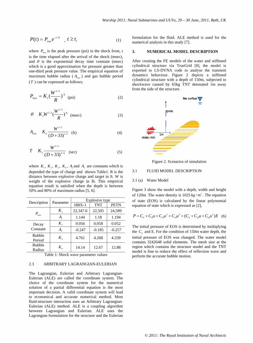
Warship 2011: Naval Submarines and UUVs, 29 – 30 June, 2011, Bath, UK
© 2011: The Royal Institution of Naval Architects
/max)( tePtP , 1tt (1)
where maxP is the peak pressure (psi) in the shock front, t is the time elapsed after the arrival of the shock (msec), and is the exponential decay time constant (msec) which is a good approximation for pressure greater than one-third peak pressure value. The empirical equation of maximum bubble radius ( maxA ) and gas bubble period (T ) can be expressed as follows;
1)(3/1
1maxA
R
WKP (psi) (2)
2)(3/1
3/12
A
R
WWK (msec) (3)
3/1
3/1
6 )33(D
WKAmas (ft) (4)
6/5
3/1
5 )33(D
WKT (sec) (5)
where ,1K ,2K ,5K ,6K 1A and 2A are constants which is depended the type of charge and shown Table1. R is the distance between explosive charge and target in ft. W is weight of the explosive charge in lb. This empirical equation result is satisfied when the depth is between 50% and 80% of maximum radius [5, 6].
Explosive type Description Parameter HBX-1 TNT PETN 1K 22,347.6 22,505 24,589
maxP1A 1.144 1.18 1.194 2K 0.056 0.058 0.052 Decay
Constant 2A -0.247 -0.185 -0.257
Bubble Period 5K 4.761 4.268 4.339 Bubble Radius 6K 14.14 12.67 12.88
Table 1: Shock wave parameter values
2.3 ARBITRARY LAGRANGIAN-EULERIAN
The Lagrangian, Eulerian and Arbitrary Lagrangian-Eulerian (ALE) are called the coordinate system. The choice of the coordinate system for the numerical solution of a partial differential equation is the most important decision. A valid coordinate system will lead to economical and accurate numerical method. Most fluid-structure interaction uses an Arbitrary Lagrangian-Eulerian (ALE) method. ALE is a coupling algorithm between Lagrangian and Eulerian. ALE uses the Lagrangian formulation for the structure and the Eulerian
formulation for the fluid. ALE method is used for the numerical analysis in this study [7].
3. NUMERICAL MODEL DESCRIPTION
After creating the FE models of the water and stiffened cylindrical structure via TrueGrid [8], the model is exported to LS-DYNA code to analyse the transient dynamics behaviour. Figure 2 depicts a stiffened cylindrical structure with a depth of 150m, subjected to shockwave caused by 65kg TNT detonated 1m away from the side of the structure.
Figure 2. Scenarios of simulation
3.1 FLUID MODEL DESCRIPTION
3.1 (a) Water Model
Figure 3 show the model with a depth, width and height of 120m. The water density is 1025 3/ mkg . The equation of state (EOS) is calculated by the linear polynomial equation of state which is expressed as [2],
ECCCCCCCP )( 2654
33
2210 (6)
The initial pressure of EOS is determined by multiplying the 4C and E. For the condition of 150m water depth, the initial pressure of EOS was changed. The water model contains 3242648 solid elements. The mesh size at the region which contains the structure model and the TNT model is fine to reduce the effect of reflection wave and perform the accurate bubble motion.
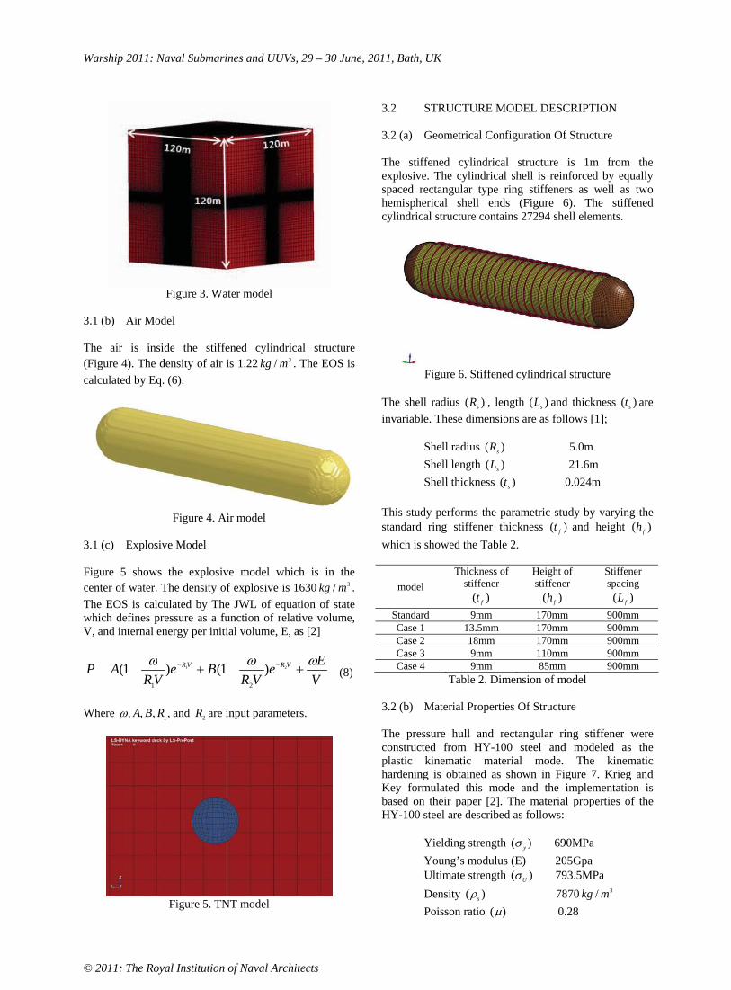
Warship 2011: Naval Submarines and UUVs, 29 – 30 June, 2011, Bath, UK
© 2011: The Royal Institution of Naval Architects
Figure 3. Water model
3.1 (b) Air Model
The air is inside the stiffened cylindrical structure (Figure 4). The density of air is 1.22 3/ mkg . The EOS is calculated by Eq. (6).
Figure 4. Air model
3.1 (c) Explosive Model
Figure 5 shows the explosive model which is in the center of water. The density of explosive is 1630 3/ mkg .The EOS is calculated by The JWL of equation of state which defines pressure as a function of relative volume, V, and internal energy per initial volume, E, as [2]
V
Ee
VRBe
VRAP VRVR 21 )1()1(
21 (8)
Where ,,,, 1RBA and 2R are input parameters.
Figure 5. TNT model
3.2 STRUCTURE MODEL DESCRIPTION
3.2 (a) Geometrical Configuration Of Structure
The stiffened cylindrical structure is 1m from the explosive. The cylindrical shell is reinforced by equally spaced rectangular type ring stiffeners as well as two hemispherical shell ends (Figure 6). The stiffened cylindrical structure contains 27294 shell elements.
Figure 6. Stiffened cylindrical structure
The shell radius )( sR , length )( sL and thickness )( st areinvariable. These dimensions are as follows [1];
Shell radius )( sR 5.0m Shell length )( sL 21.6m Shell thickness )( st 0.024m
This study performs the parametric study by varying the standard ring stiffener thickness )( ft and height )( fh
which is showed the Table 2.
modelThickness of
stiffener )( ft
Height of stiffener
)( fh
Stiffener spacing
)( fL
Standard 9mm 170mm 900mm Case 1 13.5mm 170mm 900mm Case 2 18mm 170mm 900mm Case 3 9mm 110mm 900mm Case 4 9mm 85mm 900mm
Table 2. Dimension of model
3.2 (b) Material Properties Of Structure
The pressure hull and rectangular ring stiffener were constructed from HY-100 steel and modeled as the plastic kinematic material mode. The kinematic hardening is obtained as shown in Figure 7. Krieg and Key formulated this mode and the implementation is based on their paper [2]. The material properties of the HY-100 steel are described as follows:
Yielding strength )( y 690MPa Young’s modulus (E) 205Gpa Ultimate strength )( U 793.5MPa Density )( s 7870 3/ mkg
Poisson ratio )( 0.28

Warship 2011: Naval Submarines and UUVs, 29 – 30 June, 2011, Bath, UK
© 2011: The Royal Institution of Naval Architects
Figure 7. Elastic-plastic behaviour with kinematic hardening.
3.3 LOADING CONDITION
3.3 (a) Hydrostatic Loading Condition
The following formula is the hydrostatic pressure
gDhP f)( (8)
In the above equation, f is the mass density of water, g denotes acceleration of gravity 9.81 2/ sm and D indicates the depth of water 150m. The hydrostatic pressure is 1.51Mpa.
3.3 (b) Shock Loading Condition
For this study, the shock pressure was determined from Eqs. (1) ~ (2). The shock loading are given as follows;
TNT weight: W = 18.3kg Standoff distance: R = 1m Time to analyse: t = 0 ~ 0.8s Peak pressure: masP 269 Mpa Decay constant: 278.0 ms
4. NUMERICAL ANALYSIS
The numerical analysis is performed to compare the dynamic response of the different stiffened cylindrical structures at the same shock loading condition. The total simulation time is 0.8s but the explosive charge explodes at 0.2s since the hydrostatic pressure has been stabilized for 0.2sec. The time step is 5100.1 sec. The time step is acceptable for the mesh size of this model. To compare the deformation of rectangular stiffeners and cylinders, the effective plastic strain is measured at the particular elements of model which are influenced by the shockwave pressure and the bubble effect (Figure 8). The effective plastic strain (EPS) is monotonically increasing scalar value which is calculated incrementally as a function of the plastic component of the rate of deformation tensor [9]. EPS formulation is follows;
,......),( Pij
tij
ty
t ef (9)
ij
t
y
t
P
ij
fdde (10)
ttPPPtt dedee
0 32
(11)
where y
t f is yield function, P
ijde is plastic strain increment , d is a scalar to be determined and Ptt e iseffective plastic strain.
Figure 8. Measure point of structure
4.1 STANDARD MODEL
Figure 9 shows the motion of standard model subjected to the underwater explosion. The stiffener of tripping is presented at Figure 9(e)
(a) T=0.2s
(b) T=0.35s
St-22049 St-22289

Warship 2011: Naval Submarines and UUVs, 29 – 30 June, 2011, Bath, UK
© 2011: The Royal Institution of Naval Architects
(c) T=0.47s
(d) T=0.8s
(e) Expansion of midsection structure at T=0.45s Figure 9. Motion of standard model
4.2 CHANGE OF THE STIFFENER THICKNESS
Figure 10 illustrates a sequence of case4 during the analysis process. These parametric studies are performed by varying the thickness of the stiffener web, with the web height kept constant. In compared to Figure 9 and Figure 10, the motion of cylinder is different between the standard case and case3.The stiffener of tripping is shown at Figure 10(e)
(a) T=0.2s
(b) T=0.35s
(c) T=0.47s
(d) T=0.8s
(e) Expansion of midsection structure at T=0.45s Figure 10. Motion of case 2
The EPS values of standard, case1, and case2 are displayed at Figure 11. And Figure 12 show the midsection of cylinder to compare the degree of deformation. Although Figure 11 implies that increasing the stiffener thickness does not effect to decrease the generation of stiffener tripping, Figure 12 indicates that case2 was more effective than case1 to decrease the deformation of cylinder. In other worlds, the tripping is not decrease by increasing the thickness of stiffener but the deformation of structure is decrease.
(a) St-22049

Warship 2011: Naval Submarines and UUVs, 29 – 30 June, 2011, Bath, UK
© 2011: The Royal Institution of Naval Architects
(b) St-22289 [A: standard model, B: case1, C: case2]
Figure 11. EPS value of stiffener
(a) Standard (b) Case 1
(c) Case 2 Figure 11. Midsection of cylinder at 0.5s
4.3 CHANGE OF THE STIFFENER HEIGHT
This simulation is performed by varying the height of stiffener, with thickness of stiffener kept constant. The motion of case3 subjected to underwater explosion is similar with the motion of standard. Otherwise a sequence of case4 is similar to case2 during the simulation process. The stiffener tripping of case 4 is presented at Figure 12. The responses of standard, case3, and case4 are compared at Figure 13 which shows the influence of height of the stiffener web on the tripping behaviour of the stiffener. That indicates that the tripping phenomena decrease as the height of stiffener web decrease.
Figure 12. Expansion of midsection structure at T=0.47s
(a) St-22049
(b) St-22289 [A: standard model, B: case3, C: case4]
Figure 13. EPS value of stiffener
Also, Figure 13 shows that the tripping of stiffener decrease as the degree of structure deformation decrease. Figure 14 shows the midsection of structure of case3 and case4.

Warship 2011: Naval Submarines and UUVs, 29 – 30 June, 2011, Bath, UK
© 2011: The Royal Institution of Naval Architects
(a) Case 3 (b) Case 4
Figure 14. Midsection of cylinder at 0.5sec
5. CONCLUSIONS
The study has been investigated the dynamic behaviour of ring stiffened cylindrical structure subjected to underwater explosion. To identify the instability region for stiffener tripping, sensitivity analysis was performed by the modelling and simulation. The response of structure was calculated by Arbitrary Lagrangian-Eulerian (ALE) method. Two type of parametric study was performed. One of parametric studies was carried out by varying the thickness of the stiffener web, with the web height kept constant. The other is performed by varying the height of stiffener, with the thickness of stiffener kept constant. As a result of simulation, the tripping is not decrease by increasing the thickness of stiffener but the deformation of structure is decreased. As stiffener height reduces, the tripping of stiffener and deformation of structure are decreased. Also compared to the Figure 12 and Figure 15, the low stiffener is more effective than the thick stiffener to reduce the deformation of structure.
6. ACKNOWLEDGEMENT
This research was supported by WCU (World Class University) program through the National Research Foundation of Korea funded by the Ministry of Education, Science and Technology (R31-2008-000-10045-0)
7. REFERENCES
1. P. RADHA AND K. RAJAGOPABN, ‘Random Polar Sampling Technique for Reliability Analysis of submarine pressure hull’, Journal of Naval Architecture and Marine Engineering, 2004.
2. R.D. KRIEG AND S.W. KEY, ‘Implementation of a time independent plasticity theory into structural computer programs’, Constitutive equations in viscoplasticity: Computational and engineering aspects; Proceedings of the Winter Annual Meeting, 1976.
3. H.L. BUDWEG AND Y.S. SHIN, ‘Experimental Studies on the Tripping Behavior of Narrow T-Stiffened Flat Plates Subjected to Hydrostatic Pressure and
Underwater Shock’, The 58th Shock and Vibration Symposium, 1, 61-95, 1987.
4. I.A. SHEIKH, G.Y. GRONDIN AND A.E. ELWI, ‘Stiffened steel plates under uniaxial compression’, J.constr. Steel res., 58, 1061-1080, 2002.
5. R.H. COLE, ‘Underwater Explosions’, Princeton University Press, 1948.
6. Y.S. SHIN, ‘Overview of Underwater Shock and DDAM’, 80th shock & vibration symposium, 2009.
7. M. SOULI AND D.J. BENSON, ‘Arbitrary Lagrangian-Eulerian and Fluid-Structure Interaction’, ISTE Ltd and JOHN Wiley & Sons, Inc., 2010.
8. XYZ Scientific Applications, Inc., ‘TrueGrid User’s Manual, Volume 1 (Version 2.3.0)’, April 2006.
9. KLAUS-JURGEN BATHE, ‘Finite Element Procedures’, Prentice Hall, Pearson Education, Inc.,2006.
8. AUTHORS BIOGRAPHY
YeonOk Shin holds the current position of graduate student at Ocean Systems Engineering (OSE), Korea Advanced Institute of Science and Technology (KAIST), Daejeon, South Korea.
Young S. Shin is a WCU visiting professor at Ocean Systems Engineering (OSE), Korea Advanced Institute of Science and Technology (KAIST): He is a Fellow of ASME (American Society of Mechanical Engineers), and also distinguish emeritus professor of Naval Postgraduate school, Monterey, California, USA.

Warship 2011: Naval Submarines and UUVs, 29 – 30 June, 2011, Bath, UK
© 2011: The Royal Institution of Naval Architects
ACOUSTIC CHARACTERISATION OF ANECHOIC OR DECOUPLING COATINGS TAKING INTO ACCOUNT THE SUPPORTING HULL
C Audoly, DCNS, Le Mourillon, 83076 Toulon Cedex, France
SUMMARY
External anechoic and decoupling coatings are used on submarine to reduce acoustic target strength and radiated noise, respectively. Acoustic performance of such coatings is generally assessed by measuring the reflection and coefficients of test panels in a water tank, along frequency and at different static pressures if required. However, these measurements can’t give easily an estimate of the actual efficiency of the coating integrated on the hull, more particularly at low frequencies. As an example, it is clear that the reflection coefficient of a given anechoic coating will not be the same in free field, glued on a thick pressure hull, or glued on a thinner non-resistant structure. After a brief presentation of the type of materials of interest and the parameters to be considered by the naval architect for integration on a submarine, the paper will present a method to evaluate the acoustic efficiency of coatings, taking into account the supporting hull. Some examples are given.
NOMENCLATURE
c Sound speed in water (m s-1)f Frequency (Hz) hS Thickness of supporting structure (m) i Complex number defined by i2=-1kS Wavenumber in supporting plate (rd m-1)
Density of water (kg m-3)S Density of water (kg m-3)
Circular frequency (rd s-1)CA Anechoism coefficient CM Decoupling coefficients R Reflection coefficient T Transmission coefficient
Coefficients R, T, CA, CM, are dimensionless. In the case of sinusoidal signals, they are complex-valued, and are generally represented by the level in decibel and the phase in degrees (or rd). For exemple, Transmission coefficient level is defined as 20 log10 T .
1. INTRODUCTION
Acoustic discretion and stealth are key requirements for warships, mainly submarines, in order to reduce the risk of detection by adverse passive and active sonar systems, respectively. More details about the context can be found for example in ref. [1]. Acoustic discretion is characterized by a spectrum of noise radiated in water, generated by three main components which are machinery noise (noise and vibration produced by internal equipment, transmitted into water through the hull), noise radiated by flow interacting with external structures, and propeller flow-induced noise. At low speeds of the vessel, machinery noise is generally dominant. A possible solution to reduce significantly that noise component consists in surrounding the most radiating parts of the hull by a layer of compliant material, in the form of a decoupling coating. Acoustically speaking, the role of a decoupling
coating is to reduce the radiation factor, or radiation efficiency of the hull. As far as acoustic stealth is concerned, the main quantity to minimize is the acoustic target strength, defined as the ratio between the acoustic intensity scattered by the structure of the submarine submitted to an incident wave and the acoustic intensity of that incoming wave. Target strength depends mainly on size, shape, acoustic reflectivity of external surface, and direction of incoming wave. Additionally, some acoustic echoes may appear due to reflection from structures or equipment integrated between the external structures and the pressure hull. A solution to reduce target strength is to integrate anechoic coatings on the outer hull. In order to optimize submarine design regarding acoustic discretion and stealth, it is necessary to assess the efficiency of the coatings, not only the intrinsic properties of the material, but integrated on the hull. The purpose of this paper is to present a method able to determine these performances, based on a post-processing of standard acoustic measurements of test panels in a water tank.
2. ACOUSTIC CHARACTERIZATION OF COATINGS
2.1 INTEGRATION OF ACOUSTIC COATINGS ON A SUBMARINE
Different parts of a submarine hull can be covered by acoustic coatings (figure 1) :
- decoupling coatings will be placed mainly on the aft sections, where most of the noisy equipment is installed ;
- anechoic coatings can be placed in different locations, depending on the general architecture and the target strength level requirement:
o rigid pressure hull (broad side); o bridge fin; o bridge casing; o aft and bow frameworks.

Warship 2011: Naval Submarines and UUVs, 29 – 30 June, 2011, Bath, UK
© 2011: The Royal Institution of Naval Architects
It should be noted that the coatings are not necessarily integrated on external pressure hulls, and can be located on outer non-resistant structures with water on both sides.
Figure 1 : Submarine shape with acoustic coatings
Some acoustic coatings can be multifunctional, i.e. presenting both decoupling and anechoic efficiency. On a technology point of view, they are more complex, using for example several layers of specific materials.
2.2 CASE OF COATINGS ON A RIGID PRESSURE HULL
Two coefficients are relevant to characterize the acoustic efficiency on a pressure hull (figure 2) :
- decoupling coefficient; - anechoism coefiicient.
Decoupling coefficient characterizes reduction of radiation of efficient of a rigid hull with coating with respect to the same hull with same prescribed vibratory level, without coating. Anechoism coefficient is defined as the acoustic reflection coefficient of the coating with a rigid backing (i.e. zero displacement at the interface).
Figure 2 : Anechoism and decoupling coefficients of an acoustic coating on a rigid hull
2.3 CASE OF COATINGS ON NON-RESISTANT EXTERNAL STRUCTURES
In that case, more relevant physical quantities are acoustic reflection and transmission coefficients of the coating integrated on the structure, as shown on figure 3. It is important to note that these coefficients don’t depend only on the intrinsic acoustic properties of the coating, but also on those of the supporting structure
(type of material, thickness). The material is often steel or GRP (Glass Reinforces Plastic).
Figure 3 : Reflection and transmission coefficients of an acoustic coating integrated on a supporting structure
3. EVALUATION OF ACOUSTIC EFFICIENCY OF COATINGS - CLASSICAL METHODS
Evaluation of acoustic efficiency of coatings is not an easy task, and requires special equipment. Two of these are presented below: test structure and water tank measurements.
3.1 USE OF A TEST STRUCTURE
This method is primarily used to evaluate decoupling efficiency, as shown on figure 4.
Figure 4 : Use of a test structure
The structure is designed to be as representative as possible of a scale one stiff structure. For practical reasons (operation constraints, cost), it can take the form of a floating platform. It is mechanically excited by a shaker, for example, or by acoustic sources in air. The portion of hull in contact with water should be entirely covered with the acoustic coating to be tested, otherwise a very compliant layer should be installed laterally. The measurement is done in two steps: without sample (then the structure radiates freely), then with sample. The difference in radiated level gives an estimate of the decoupling efficiency.

Warship 2011: Naval Submarines and UUVs, 29 – 30 June, 2011, Bath, UK
© 2011: The Royal Institution of Naval Architects
Such an equipment could be used also to evaluate anechoism coefficient, by problems will arise with boundary conditions (in particular the reflections on water surface).
3.2 TEST PANEL WATER TANK ACOUSTIC MEASUREMENT
A test panel of the coating to test, of size approximately one meter square, is placed in a water tank (figure 5). Acoustic waves are generated in water using a transducer, located a few meters from the panel, generally in the form of sinusoidal signals with a time window. Hydrophones are placed on both sides of the test panels, in near field, to measure the pressure.
Figure 5 : Test panel measurement in a water tank
A reference measurement without panel, then a measurement with test panel, are done. Comparison allows to determine reflection and transmission coefficients (both amplitude and phase) along frequency, by varying the frequency of the emitted signal. Some equipment and techniques are presented for example in ref. [2].
3.3 LIMITATIONS
Method presented at § 3.1 is limited to the evaluation of decoupling efficiency of a coating on a rigid structure. It requires a large special structure, and requires a rather large quantity of material to test, then it is expensive to build, operate, and maintain. It should be reserved to final qualification of operational coatings. Method presented at § 3.2 allows to determine the acoustic performance of the material in free field, i.e. with water on both sides, but not the decoupling and anechoism coefficients as defined previously. The influence of different supporting layers, as defines in § 2.3, can be determined, but with the expense of additional samples and measurement campaigns.
4. EVALUATION OF ACOUSTIC EFFICIENCY OF COATINGS - GLOBAL METHOD
4.1 PRINCIPLE
The principle of the “global characterization method” is based on the fact that: - a test panel is fully characterized by a 2x2 transfer matrix relating the acoustic pressures and displacements on both sides of the panel, which is a classical approach (see for example ref. [3]), - the coefficients of the matrix, at a given frequency, car expressed directly from the reflection and transmission coefficient of the panel in free field, with two successive experiments (incident wave from the right and from the left).This approach has been presented previously in references [4] and [5]. Then, classical measurement of a test panel in a water tank, as presented in § 3.2, can give additional information, using adequate post-processing of the data.
4.2 TRANSFER MATRIX
If subscript 1 denotes the case of incident wave on side 1 of the panel, and subscript the case of incident wave on side 2, we have:
1
1
2
2 .u
pM
u
pC , with
''CM ,
2
212121.2
1T
RRRRTT ,
2
212121.2
1T
RRRRTTci ,
2
212121.2
1.'T
RRRRTT
c
i ,
2
212121.2
1'T
RRRRTT .
4.3 DERIVATION OF ANECHOISM AND DECOUPLING COEFFICIENTS
Derivation of anechoism and decoupling coefficients leads to remarkably simple expressions:
2
211 1
.'''
R
TTR
ci
ciCA
1
11'
'.'R
T
ciCM
These formulae can be even more simplified in the case of a symmetric panel [4].

Warship 2011: Naval Submarines and UUVs, 29 – 30 June, 2011, Bath, UK
© 2011: The Royal Institution of Naval Architects
4.4 SIMULATION OF THE EFFECT OF A SUPPORTING LAYER
When the coating is integrated on an external structure, as shown on figure 3, it is possible to simulate the acoustical effect with respect to the coating alone. By modelling the supporting structure as a homogeneous layer, we introduce its transfer function MS. The transfer function of the coating integrated on the structure MTOTis obtained by the product of the matrices:
TOTTOT
TOTTOTCSTOT MMM
''. , with:
SSSS
SS
SSSSSS
SS
SSS hk
c
hkhkchk
M cos)sin(sin.cos
''.
Reflection and transmission coefficients of the coating on the supporting structure are given by:
TOTTOT
TOTTOT
TOTTOT
TOTTOT
TOT
cc
i
cc
i
R
'.'
'.' ,
TOTTOT
TOTTOT
TOTTOTTOTTOTTOT
cc
i
T
'.'
''.2 .
5. EXAMPLES
Two examples are presented below, one is a single layer anechoic coating, the second a bi-layer coating, the second layer being more compliant in order to achieve both anechoic and decoupling efficiency. Results have been obtained through numerical simulation, although the same method could be applied without restriction on experimental results.
5.1 SINGLE LAYER ANECHOIC PANEL
Figure 6 compares the reflection coefficient of the panel with water on both sides (as measured in a water tank), the anechoism coefficient (rigid backing), and the reflection coefficient when the coating is placed on a steel support and a GRP support, respectively.
Figure 6 : Reflectivity of anechoic coating
Figure 7 gives similar data with the transmission coefficients in the different cases and with the decoupling coefficient.
Figure 7 : Transmissibility of anechoic coating
At first sight, this coating presents a low reflection coefficient in a wide frequency band, even at low frequencies. In fact, at low frequencies, most of the energy is transmitted, as shown on figure 7, with the risk of being reflected by internal structures. When the coating is put on a rigid backing, the reflectivity is characterized by the anechoism coefficient, which is much higher (close to 0 dB, which means close to 1 in amplitude). We observe also that when the coating is integrated on a steel plate (corresponding to the case of aft or bow frameworks), reflection coefficient is close to anechoism coefficient at high frequencies, and transmission coefficient is lower than in free field.
5.2 BI-FUNCTION PANEL
In a similar way as for the first example, figures 8 and 9 give the reflectivity and transmissibility of the coating in the different cases.
Figure 8 : Reflectivity of bi-function coating

Warship 2011: Naval Submarines and UUVs, 29 – 30 June, 2011, Bath, UK
© 2011: The Royal Institution of Naval Architects
Figure 9 : Transmissibility of bi-function coating
Results confirm that this kind of coating exhibits both anechoic and decoupling behaviour, if frequency is high enough. We observe also that reflectivity is nearly independent from the nature of the backing, except at very low frequencies. This is due to the inner layer of the coating which behaves like a soft reflector.
6. CONCLUSIONS
A method has been presented to assess the efficiency of an acoustic coating when integrated on different external structures of submarines (pressure hull, frameworks, other non-resistant structures…). That information is useful during design phases, in order to optimize acoustic radiated noise and target strength of the vessel. The methods, which uses transfer matrices, consists in a specific post-processing of numerical or experimental data obtained from standard test panel acoustic measurements in a water tank.
7. REFERENCES
1. URICK, R.J., ‘Principles of Underwater Sound – 3rd
edition’, McGraw-Hill, 1983.
2. HUMPHREY, V.F., ROBINSON, S.P., SMITH, J.D., MARTIN, M.J., BEAMISS, G.A., HAYMAN, G., CARROLL, N.L., ‘Acoustic characterization of panel materials under simulated ocean condition using a parametric array source’, J. Acoust. Soc. Am Vol. 124,2008.
3. BRUNEAU & M., POTEL, C. ‘Materials and Acoustics Handbook’, ISTE, Wiley, 2009.
4. AUDOLY, C. ‘Global Characterization of Acoustic Panels at Normal Incidence for Underwater Applications’, Acustica Vol. 76, 1992.
5. AUDOLY, C., & GIANGRECO, C. ‘Global Characterization of Multilayer Panels for Underwater Applications’, J. Wave Material Interactions Vols.5&6,1991.
8. AUTHORS BIOGRAPHY
Christian Audoly graduated as engineer from Ecole Nationale Supérieure de l’Aé ronautique et de l’Espace, and got a PhD in underwater acoustics. Since the 80’s, he has worked at DCNS as a scientist and technical manager in acoustic detection, platform signature management, and simulations. He is presently expert in submarine vulnerability studies.

Warship 2011: Naval Submarines and UUVs, 29 – 30 June, 2011, Bath, UK
© 2011: The Royal Institution of Naval Architects
IMPACTS OF THE MAINTENANCE ON A SUBMARINE BASIC DESIGN
M Nicod, DCNS, France
SUMMARY
This paper aims at assessing how the rhythm of maintenance is linked with the submarine basic design and its life cycle cost. The outlined method enables the architect either to choose an optimized rhythm for a new ship design, or identify the strategies about architecture and technology to be implemented in order to fit with a required rhythm. The ratio Performances / Costs is at the heart of the subject. The central theme is the definition and the costing of several so called Maintenance Concepts. In this study, a maintenance concept is a rhythm of maintenance along with all the technical features requested on the submarine design to achieve it. The best choice will be an optimized combination of the submarine’s features, the technologies, the main parameters of the rhythm of maintenance and the ship shelf life.
NOMENCLATURE
IMA Intermediate Maintenance Availability SRA Selected Restrictive Availability ROH Regular OverHaul C Submarine life cycle cost S Submarine’s features T Submarine’s technologies M Submarine’s rhythm of maintenance L Ship shelf life
1. INTRODUCTION
The rhythm of maintenance of a war submarine must be defined since the earliest design phases. Indeed, the rhythm of maintenance impacts not only the ship’s availability but also the ship’s life cycle cost and the fleet minimum availability required to ensure the operational missions. Besides, the rhythm of maintenance is also linked with the choice of technologies and architectural features, in order to reach properly the target ship performances.
This paper provides a methodology and an illustrated typical approach to optimize the submarine’s performances (including maintenance) all along with its life cycle cost. This kind of study can be used quickly and easily during the conceptual and/or basic design stages.
2. METHODOLOGY
2.1 DEFINITIONS
This section defines the major specific terms that are used in this paper.
In this study, a maintenance concept is a rhythm of maintenance along with all the architectural features and all the technologies requested on the submarine to achieve it.
A submarine is available when ready to sail with full capabilities. This notion includes a time limit depending on the submarine’s type and which is most of the time about 48 hours. The submarine’s technical availability represents the number of days it is available in its life.
The minimal fleet availability is the number of submarines requested simultaneously to ensure the main mission.
IMA (intermediate maintenance availability) are periodic harbour maintenances, during which the submarine is available within a time limit.
SRA (selected restrictive availability) are dry-dock or harbour periods of maintenance during which the submarine is unavailable. These periods are planned to realize longer maintenance tasks than during an IMA.
ROH (regular overhaul) are long dry-dock periods of maintenance during which the submarine is unavailable.
2.2 GROUND RULES
The methodology relies on a basic equation. The submarine’s life cycle cost is a function of four parameters: the submarine’s features, the submarine’s technologies, the rhythm of maintenance and the shelf life. This can be written as: C = f (S, T, M, L).Note that the life cycle cost here only includes the costs of providing and of maintaining. Whereas this equation seems very simple, it represents a whole complex model of the performances and the costs of the submarine.
The optimization of the life cycle cost C is obtained by the best realistic (S, T, M, L) combination. Realistic means that the chosen architectures and technologies will

Warship 2011: Naval Submarines and UUVs, 29 – 30 June, 2011, Bath, UK
© 2011: The Royal Institution of Naval Architects
lead together to a valid submarine design and that the rhythm of maintenance is coherent with them. S, T, M and L are under many constraints, because they are linked with the whole range of the submarine’s performances.
The process can be broken down into 3 steps: Step 1 : definition of the reference (S, T, M, L)set and of the reference C;Step 2 : determination of some realistic (S, T, M,L) combination, and their associated cost; Step 3 : value analysis on the realistic (S, T, M,L) combinations.
3. TYPICAL APPROACH
3.1 THE REFERENCE
3.1 (a) Defining The Reference
The equation C = f (S, T, M, L) must be initialized: Cref = f (Sref, Tref, Mref, Lref).
A reference submarine provides Sref and Tref. This reference submarine can be an existing one, a first basic design, or at least a basic configuration of the main features and technologies.
The reference rhythm of maintenance Mref is basically defined using the experience feedback and taking into account the type of submarine. It must be coherent with the ship’s features and technologies and also with the industrial organisation of the yard.
The reference ship shelf life Lref is chosen according to the submarine’s design and particularly the pressure hull. However, in an early stage, several ship shelf lives can be studied, if they are close enough not to alter the design.
The reference costs Cref is either already known (for instance it is the case of an existing ship) or estimated with some prediction laws using the feedback experience and the Sref, Tref, Mref, Lref parameters.
3.1 (b) Defining The Scope Of The Study
Among the architectural features and the technologies, only the major elements shall be studied; that is to say those having great impacts on the submarine performances, the frequency and the duration of the main maintenance periods, the costs of maintaining and of providing.
Some potential alternative technologies might be studied. They can be chosen because of their advantages considering the maintenance aspects, or because they can be used instead of some almost out of date technologies.
First, we must determine all the elements that are mentioned in submarines usual maintenance plans and in the civil, military, conception regulations or standards. Then, we must keep only the elements for which one of the following items is true:
the maintenance tasks are long and/or complex; the costs of maintaining are expensive (materials, spare parts, manpower for instance); it is a great stake on the submarine’s design (dimensions, safety, … for instance); it makes a quite important part of the submarine’s cost of providing.
The experience feedback is also of great help during this process and particularly for the first steps.
In the end we must focus on no more than 10 to 20 major elements.
3.2 REALISTIC COMBINATIONS
3.2 (a) Elaborating Theoretical Rhythms Of Maintenance
Several rhythms of maintenance are built, which seem to be able to reduce the cost of maintaining.
Theses rhythms must be theoretical and simple. For example, they don’t include any SRA. The periodicities of the ROH must be different for each rhythm and far-enough to evaluate the gaps. The chosen periodicities can also match to some technological and/or regulatory deadlines. The IMA cycle can be equivalent to one IMA after each patrol. The durations of the ROH and the IMA are elaborated using the experience feedback. They also take into account the industrial organisation of the yard and the technological innovations with which the feedback doesn’t deal yet.
Several ship shelf lives per rhythm are chosen which are coherent to the customer’s needs.
The cost of maintaining is estimated for each rhythm of maintenance. It mostly varies according to the number of ROH and of IMA during the submarine ship shelf life. The ship’s technical availability is calculated for each rhythm of maintenance. As the rhythms are theoretical at this stage, the availability naturally increases while the cost decreases. The fleet availability might also be estimated, just to give an idea. To be exact in fact, the rhythms would need to be precisely adjusted, which is quite unnecessary at this stage.
3.2 (b) Maintenance Concepts
The equation C = f (S, T, M, L) may have only a few solutions which are the coherent (S, T, M, L) sets.

Warship 2011: Naval Submarines and UUVs, 29 – 30 June, 2011, Bath, UK
© 2011: The Royal Institution of Naval Architects
A coherent set is a maintenance concept.
At first, the coherence of the set is defined without the L parameter. Considering a conceptual/basic design, this parameter takes importance only at the end of the process during the value analysis. Then, the coherent (S, T, M)sets and L might be adapted to be consistent.
To elaborate the maintenance concept, we must analyse each major element with each rhythm of maintenance. If the maintenance tasks (duration, dead lines) can be done without any difficulty in the maintenance periods then nothing should change. Otherwise, we must choose a solution among:
making adjustments in the ROH cycle to fit with some major elements deadlines; creating a SRA cycle coherent with the main problematic tasks of maintenance; changing of technology to improve the plan of maintenance of the major elements; adapting some of the submarine features, so that the maintenance is easier and can be done in less time.
Finally, the maintenance concepts are made up of: the former theoretical rhythms of maintenance, which can have been adapted: they are called “new rhythms” in this paper; the reference technologies and the evolutions that have been necessary; the reference ship with all the architectural modifications the maintenance compels.
3.2 (c) Validation Of The Maintenance Concepts
For each maintenance concept, the modified features and technologies must be validated. It involves two steps. First, the direct impacts on the submarine are estimated. Then a basic design including all the chosen features and technologies together is elaborated and checked with the architect’s usual criteria. This step is required to estimate the final impacts.
The validation can be done using a parametrical basic design model. Such a model provides the main volumes, the critical paths, a weight estimate and some basic stability results. The first model represents the reference submarine. The models corresponding to the maintenance concepts are made from it. The parametrical model enables the architect to choose some features and technologies and then to estimate the impacts on the submarine. It is build with several discrete parametric conception laws on the major elements. The combination of these laws results in modifying the submarine main features (the displacements for instance) and could lead to change some of the architectural choices.
3.3 VALUE ANALYSIS
3.3 (a) Performance Index
The performance index is elaborated thanks to several criteria gathered in families. Each criteria and each family is balanced. We must define a notation scale for each criterion. A basic one is proposed here:
6 is most of the time equivalent to the reference; 3 is worse than the reference but still remains acceptable;1 is worse than the reference and can prove to be crippling; 9 is (far) better than the reference but can also be some kind of over quality.
The weight factors for the criteria and their families represent the context and the priorities, for instance:
Are the maintenance concepts challenged with the designer’s or the user’s point of view? Are there any major constraints on the shipyards? What are the main constraints on the whole submarine architecture and on the choice of the technologies?
3.3 (b) Costs
The life cycle cost is defined here as the cost of providing plus the cost of maintaining. The cost of providing is the reference cost of providing modulated by the impacts on the submarine’s features and on the technologies. The cost of maintaining is estimated with the number of maintenance periods, their length. The estimated per day costs for each type of maintenance period, if they are already known, may be useful.
The life cycle cost should be balanced by a risk coefficient. This coefficient takes into account, for instance, the margin of errors on the results of the submarine basic design or the uncertainty about how the industrial organisation would fit with the rhythm of maintenance.
We must although keep in mind that in this kind of study the cost values are estimated with quite an important margin of error. They must be analysed with relative values in relation to a reference. They are a decision-making aid.
3.3 (c) Choice
Once the index of performance and the costs are calculated, the ratio Performance /Cost is established for each maintenance concept, in order to help the architect making his choice. Usually, a graph showing the performance index vs the costs for each maintenance concept is interesting.

Warship 2011: Naval Submarines and UUVs, 29 – 30 June, 2011, Bath, UK
© 2011: The Royal Institution of Naval Architects
The reference value is the ratio performance / cost of the reference concept of maintenance. All the values must be compared to this one. A line passing through the reference point and which has a slope equal to the reference value is usually drawn on the graph to help comparisons.
4. EXAMPLE
The typical approach that is developed in this paper has already been validated on several submarine basic designs.
It is illustrated here with a very simplified example, owing to confidentiality, and also to allow an easier comprehension of the subject and the results.
4.1 THE REFERENCE
4.1 (a) Defining The Reference
The reference submarine is an SSK. Its surface displacement is 1600 t and its submerged displacement is 1800 t.
The reference rhythm of maintenance is made up of: A ROH cycle : 52 weeks long every 7 years; An IMA cycle : 3 weeks long every 16 weeks (the submarine is available within 3 days).
The reference technologies are chosen to be in line with the reference rhythm of maintenance.
The reference ship shelf life is 35 year. The case corresponding to 40 years is also studied.
All the costs will be estimated in comparison with the reference cost. The reference cost is 100%.
4.1 (b) Defining The Scope Of The Study
The list of the major elements is voluntarily short in this example, to enable a better comprehension and clearer conclusions.
The first major element is obviously the pressure hull. Due to corrosion, and according to [1], an examination of the hull must be done every 8 years and the hull should be direct vent every 15 years, or every 10 years for the inner hull when in a corrosive environment.
The lead batteries have a limited shelf life. The battery elements are renewed at least every 8 years.
The pressure bottles (mostly air pressure bottles) are inspected on board every 40 months. They must be removed, tested and refitted every 10 years, according to [2].
The lithium battery technology is a potential alternative to the lead batteries. The lead batteries can indeed prove to be obsolete in a few years. Besides, the lithium batteries have better performances than the lead batteries, and they live longer.
In a real study, we would have to focus obviously on some more major elements, such as, for instance, the elastomeric parts or the seawater systems.
4.2 REALISTIC COMBINATIONS
4.2 (a) Elaborating Theoretical Rhythms Of Maintenance
Two ship shelf lives values are tested: 35 years and 40 years. Note that the ship configuration just after tests and trials and the building strategy implemented could slightly modify those values later.
Two theoretical rhythms of maintenance (plus the reference) are built:
First rhythm of maintenance : M1t:o The ROH cycle is 52 weeks every 10
years;o The IMA cycle is the same as for Mref.
Second rhythm of maintenance : M2t :o The ROH cycle is 52 weeks every 12
years;o The IMA cycle is the same as for Mref.
The number of ROH and of IMA per theoretical rhythm (including the reference) appears on the table below:
Number of ROH
Number of IMA
Mref – 35 years 5 95 Mref – 40 years 5 111 M1t – 35 years 3 103 M1t – 40 years 4 116 M2t – 35 years 2 105 M2t – 40 years 3 118
The graphs hereafter show the evolution of the ship’s technical availability and of the estimated cost of maintaining.
Availability (%) vs ROH Periodicity (years)
THEORETICAL RHYTHMS
85
86
87
88
89
90
91
92
93
94
95
6 7 8 9 10 11 12 13
35 years
40 years

Warship 2011: Naval Submarines and UUVs, 29 – 30 June, 2011, Bath, UK
© 2011: The Royal Institution of Naval Architects
Costs of Maintaining (%) vs ROH Periodicity (years)
THEORETICAL RHYTHMS
50
60
70
80
90
100
110
6 7 8 9 10 11 12 13
35 years
40 years
Figure 1: Costs of maintaining and Availability vs. ROH Periodicity (theoretical rhythms)
A very relevant indicator is the cost of maintaining per patrol ratio. Its evolution is shown hereafter.
Cost of maintaining / Patrol (%) vs ROH Periodicity (years)
THEORETICAL RHYTHMS
50
60
70
80
90
100
110
6 7 8 9 10 11 12 13
35 years
40 years
Figure 2: Cost of maintaining per patrol vs. ROH periodicity (theoretical rhythms)
4.2 (b) Maintenance Concepts
The reference maintenance concept is the reference submarine plus the reference rhythm of maintenance. The reference ship shelf life is 35 years and the case with 40 years is also studied.
The first maintenance concept is the (S1, T1, M1) set plus the two ship shelf lives that are studied in this example. The set is elaborated from the reference submarine and the first theoretical rhythm of maintenance with some adjustments:
The examination of the pressure hull every 8 years cannot be dry-dock done. So the reference submarine will be modified to provide a better ease of access from the inside. We can achieve this purpose by adding some volume and / or optimizing the arrangement. Besides, the control methods might be changed; The lead batteries shelf life is too short compared to the periodicity of the ROH. We would rather use a lithium battery technology to comply with the ROH deadlines;
The periodicity of the ROH is a little bit too long to enable the requalification of the pressure bottles on time. The easiest solution consists in slightly adjusting the ROH cycle with a 9.5 year periodicity, instead of 10 years.
The second maintenance concept is the (S2, T2, M2) set plus the two ship shelf lives that are studied in this example. The set is elaborated from the reference submarine and the second theoretical rhythm of maintenance with some adjustments:
The periodicity of the ROH is far too long compared to the requalification deadline of the pressure bottles. We decide then to add a SRA cycle during which the requalification tasks can be done properly. The SRA cycle must allow the pressure hull examination ; The lead batteries shelf life is too short compared to the periodicity of the ROH. The lithium battery technology shall be used instead. But the lead batteries also can be replaced during the SRA. We choose the first solution in this example.
Considering the time of requalifications and the number of bottles, the time to control the hull and the time to make some other controls, the SRA are about 16 weeks long. There is a SRA between two ROH.
The graphs below show how the ship availability and the costs of maintaining are modified, considering the new rhythms M1 and M2.
Availability (%) vs ROH Periodicity (years)
NEW RHYTHMS
85,00
86,00
87,00
88,00
89,00
90,00
91,00
92,00
93,00
94,00
95,00
6 7 8 9 10 11 12 13
35 years - new
40 years-new
35 years - theoretical
40 years - theoretical
Costs of Maintaining (%) vs ROH Periodicity (years)
NEW RHYTHMS
50
60
70
80
90
100
110
6 7 8 9 10 11 12 13
35 years - new
40 years - new
35 years - theoretical
40 years - theoretical
Figure 3: Costs of maintaining and Availability vs. ROH periodicity (adjusted rhythms)

Warship 2011: Naval Submarines and UUVs, 29 – 30 June, 2011, Bath, UK
© 2011: The Royal Institution of Naval Architects
Cost of maintaining / Patrol (%) vs ROH Periodicity (years)
NEW RHYTHMS
50
60
70
80
90
100
110
6 7 8 9 10 11 12 13
35 years - new
40 years - new
35 years - theoretical
40 years - theoretical
Figure 4: Cost of maintaining per patrol vs. ROH frequency (adjusted rhythms)
The second rhythm of maintenance (12 year ROH cycle) appeared to be very interesting when analysing the theoretical rhythm. But, actually, the search for coherence between the submarine’s features, technologies and rhythm of maintenance involves some modifications that have a bad effect on the cost of maintaining per patrol ratio.
4.2 (c) Validation Of The Maintenance Concepts
Direct impacts
In the two maintenance concepts studied here, the battery technology is modified: we use lithium instead of lead. The usual laws to describe the volume and the weight of the batteries are: Volumebatteries = Capacity . VU Weightbatteries = Capacity . MU + f(surface displacement) VU is a constant in m3.MWh-1 which depends on the battery technology. MU is a constant in t.MWh-1 which depends on the battery technology. F is a function which depends only on the surface displacement on basic approach. We work on two parameters, VU and MU, to represent the impact of the technological evolution. In this example, the direct volume reduction is about 2.8% of the surface displacement. The direct weight reduction is about 4.8% of the weight estimate. These volume decreases are limited to the batteries.
In the second maintenance concept, the pressure bottles are removed, tested and refitted during a 16 week SRA. The available time for all these tasks can prove to be short compared to a ROH. Thus more volume is necessary around the bottles to increase the ease of access and so reduce the time of removal and refitting. The usual law to describe the volume of the platform plant systems is: VolumePPS = K1.Surface displacement + (K2.Crew + K3) K1, K2 and K3 are three constants. We use 3 parameters to define how this volume will increase: the number of pressure bottles, the pressure
bottle length and diameter and the volume that must be added around the bottles. The K1 coefficient evolution modelizes the volume augmentation. In this example, the direct additional volume due to the requalification of the pressure bottles during a SRA is about 2.2% of the surface displacement. This additional volume calculated is limited to the platform plant system.
Final impact – basic design
The example here only deals with a basic design made for the second maintenance concept (12 year ROH cycle).The basic design takes into account the evolutions of weight and volume provided by the laws above. More volume is dedicated to platform plant system for the pressure bottle maintenance. Less volume and less weight are dedicated to the batteries. The weight of the batteries decreases faster than their volume. The volume evolutions of the batteries and of the platform plant system compensate for each other. Taken as a whole, the volume will be quite the same, and the weight will decrease. If the batteries are located in the bottom of the submarine, the lead ballast vertical position will also decrease. The pressure bottles can be placed outside or inside the pressure hull. Outside could reduce the direct volume increase due to maintenance, but it may lead to a rather important increase of the shape displacement. If the batteries are a critical path (in length and/ or in diameter), the pressure bottles should rather be located outside in order to optimize the pressure hull volume. In this case, a double hull architecture (partial or total double hull) would be suitable for the pressure bottles maintenance. But we must be careful because the double hull can prove to be too complex to maintain and can increase the shape displacement, and, so, the power plant. To conclude, many architectural choices are linked with the maintenance concept. Besides, the submarine arrangement must be studied again, particularly with regard to the lead ballast position. Finally a complete basic design is necessary to show all the indirect impacts of the maintenance concept on the submarine.
4.3 VALUE ANALYSIS
4.3 (a) Performance Index
The criteria and their families are defined:
Operational needs: o Ship’s availability; o Fleet availability; o Living and employment conditions of
the crew. Submarine’s features, technologies and performances:
o Proven technologies or not; o Impacts on the submarine’s features;

Warship 2011: Naval Submarines and UUVs, 29 – 30 June, 2011, Bath, UK
© 2011: The Royal Institution of Naval Architects
o Impacts on the submarine’s main performances;
Rhythm of maintenance: o Occupancy and availability of the
harbour(s) and the dry-dock(s); o Last cycle; o Complexity of the maintenance tasks.
The graph below shows the performance index of each concept of maintenance, per criteria family and globally. Each criterion and each family are balanced.
Note that the performance index of the different families cannot be compared on the chart because they don’t have the same weight.
Performance index
(by families and total)
0
5
10
15
20
25
30
35
40
45
50
55
60
65
70
75
80
85
90
95
100
105
110
Operational needs Submarine features,
technologies and
performances
Rhythm of
maintenance
Total Performance
Index
Reference - 35 years
Reference - 40 years
Concept 1 - 35 years
Concept 1 - 40 years
Concept 2 - 35 years - single hull
Concept 2 - 40 years - single hull
Concept 2 - 35 years - double hull
Concept 2 - 40 years - double hull
Figure 5: performance index, by families and total, of each maintenance concept
The main explanations of these results concerning the operational needs are:
The first and the second maintenance concepts increase the submarine availability more or less in the same proportions; The SRA penalizes the employments conditions of the crew ; A longer ship shelf life not necessary increases the availability because most of the times it involves more ROH ;
The results are not linked with the architectural choices.
The main explanations of these results concerning the submarine’s features technologies and performances are:
The lithium technology for the batteries is less mature than the lead technology ;
An easier access to the pressure bottles increases the submarine’s main features, with sizeable impacts in the double hull case; The second maintenance concept with a single hull might show difficulties to reach the stability criterias (decrease of the lead ballast vertical position), whereas the double hull allows a keel.
The results depend on the architectural and technological choices but are directly linked with neither the ship shelf life nor the rhythm of maintenance
The main explanations of these results concerning the Rhythm of maintenance are:
The SRA cycle deeply disrupts the occupation plan of the harbour and/or the dry-dock; The last cycle is more or less well used depending on the rhythm of maintenance and of the ship shelf life ; The maintaining tasks are difficult for the pressure hull
o In the first concept because the examination must be done from the inside with adapted control methods ;
o In the second concept, double hull case.
4.3 (b) Costs
The costs of maintaining are analysed on section 4.2 (b).
The costs of providing are elaborated from the reference cost corrected with a coefficient. For each concept of maintenance the coefficient can be different. It represents the estimated impacts on the costs due to all the technological and architectural modifications on the submarine.
4.3 (c) Choice
The graph below is a typical performance vs. costs representation.
75
80
85
90
95
100
105
110
88 93 98 103Costs
Performance Index
Reference
35 years
Concept 1
40 years
Concept 2
40 years - DH
Concept 2
35 years - SH
Concept 2
35 years - DH
Reference
40 years
Concept 2
40 years - SH
Concept 1
35 years
Figure 6: Performance vs. costs for each maintenance concept

Warship 2011: Naval Submarines and UUVs, 29 – 30 June, 2011, Bath, UK
© 2011: The Royal Institution of Naval Architects
The concept 2 with single hull well illustrates that the maintenance concept and the ship shelf life cannot be chosen separately. The reciprocal assertion is also true.
Choosing a rhythm of maintenance including a 12 year ROH cycle (concept 2) would lead to a whole submarine architecture optimization. The impacts on the cost and on the performances can be major ones.
In this example, the first maintenance concept (9.5 year ROH cycle) with a 35 year ship shelf life would be chosen, for 4 reasons:
Its cost is far better than the reference cost; At the same time its performance index is higher than the reference; As a matter of fact its value is more important than the reference; Moreover, its performance is well balanced between the criteria families.
5. CONCLUSIONS
This approach provides the architect with a decision-making aid. It helps him to deal with the submarine’s life cycle cost since the earliest design stages.
The costs, the rhythm of maintenance, the architecture and the technologies are linked together. The ship shelf life is an important parameter which shall not be neglected when elaborating the rhythm of maintenance. The result of the study is not instinctive, most of the times.
The value analysis is a powerful tool to optimize the major parameters set including all their constraints. The choice of the criteria and their weight factor is crucial in this process.
If two maintenance concepts seem relevant, the optimal one can be some kind of a mix of them, and will be determined with a sensitivity study.
This approach can be applied to every type of submarine. It is now part of the design process at DCNS.
6. REFERENCES
1. ‘Etudes, construction, entretien, contrôle et réparation des structures des sous-marins classiques’, DCNS restricted standard.
2. ‘Arrêté ministériel relatif à l’exploitation des équipements sous pression’, French Official Journal,15th March 2000
7. AUTHORS BIOGRAPHY
Marie Nicod holds the current position of Naval Architect at DCNS. She works on submarine pilot studies. With the whole warship architect, she is responsible for the ship’s performances and the global coherence of the submarine. She drives the team in charge of the submarine’s systems studies except for the combat and weapons systems. She takes care of the basic design major balances.

Warship 2011: Naval Submarines and UUVs, 29 – 30 June, 2011, Bath, UK
© 2011: The Royal Institution of Naval Architects
INCORPORATING THROUGH LIFE SUPPORT REQUIREMENTS INTO SUBMARINE DESIGN
S Smith, Babcock International Group, UK
SUMMARY
The UK’s programme to design a successor to the Vanguard class of SSBN deterrent submarines is well underway, with approval to proceed with the Design Phase achieved. This high-profile programme contains some novel changes to the UK’s traditional approach to submarine procurement, essential if our submarine enterprise is to respond to the financial and performance challenges that it faces.
A collaborative approach has been adopted which combines the complementary capabilities and capacities of the UK Ministry of Defence as Intelligent Customer, BAE SYSTEMS as the submarine designer and manufacturer, Rolls-Royce as the designer and manufacturer of the nuclear propulsion plant, and Babcock as the through-life support partner. The Main Gate decision on whether to move from Design to Production will take place in 2016.
Babcock’s role, before the design even leaves the drawing board, is to support the design teams in ensuring that a balanced approach to design decisions is taken where there is potential conflict between, for example, ease of production versus ease of maintenance, or production cost versus through-life costs. In parallel, a robust, low-risk support solution for the class is being developed, that minimises through life costs and assures a smooth transition into service.
This early engagement of the through-life support provider is an essential component in ensuring the success of the any submarine procurement programme, with the benefits to be proven on the Successor programme.
NOMENCLATURE
ARM Availability, Reliability & Maintainability CASD Continuous At Sea Deterrent CMC Common Missile Compartment CWE Collaborative Working Environment DFS Design for Support IKM Information & Knowledge Management IMS Integrated Master Schedule IPMT Integrated Programme Management Team LFE Learning from Experience MoD Ministry of Defence (United Kingdom) MSTA Major System Technical Authority MUOC Maintenance, Upkeep and Operating Cycle NSRP Nuclear Steam Raising Plant SEPP Submarine Enterprise Performance Programme SSBN Ship Submersible Ballistic Nuclear SSMG Submarine Support Management Group SSN Ship Submersible Nuclear TLC Through-life Cost TLS Through-life Support WBSI Whole Boat Support Integrator WBTA Whole Boat Technical Authority
1. INTRODUCTION
In December 2006, the United Kingdom’s Government re-affirmed its intention to retain a minimum nuclear deterrence capability [1].
With the current class of deterrent submarines rapidly approaching the end of their design life, a programme to replace the submarine platforms with which the
Continuous At Sea Deterrent (CASD) is fielded was required.
Against a challenging economic backdrop, the principal submarine stakeholders: the Ministry of Defence, BAE SYSTEMS, Rolls-Royce and Babcock, have engaged in a collaborative effort to design and, if approved, build a new class of deterrent submarines that capitalises on the respective strengths of these participants to deliver an effective solution that actively manages the programme’s risks while delivering value for money.
Babcock, as the primary provider of in-service support to the UK’s in-service submarines was uniquely positioned to ensure that through-life engineering and cost implications will be considered at all stages of the maturing design. This is a marked change to previous submarine projects, where an ‘over the fence’ approach between procurement and support has existed.
Having just progressed through Initial Gate approvals, the project is entering its Design Phase, which will see the team’s effort focused on maturing the single conceptual design in readiness for Main Gate approval in 2016 and subsequent commencement of the Production Phase.
This paper outlines the rationale for involving Babcock as the in-service support partner’s at such an early stage, and the contribution being made to the Successor programme.

Warship 2011: Naval Submarines and UUVs, 29 – 30 June, 2011, Bath, UK
© 2011: The Royal Institution of Naval Architects
2. THE SUBMARINE ENTERPRISE
2.1 SUBMARINE ENTERPRISE PERFORMANCE PROGRAMME (SEPP)
Since the end of the Cold War, the justification for many of the UK’s military capabilities has been challenged, and the submarine flotilla is no different. On one hand, we have seen a reduction in the number of platforms available to the Royal Navy but, at the same time, we have seen increasingly capable submarines engaged in a wider variety of roles.
Recognising this, the UK’s Ministry of Defence engaged its three principal industrial partners: BAE SYSTEMS as the submarine designer and builder, Rolls-Royce as the nuclear plant designer and builder, and Babcock as the through-life support provider jointly embarked on SEPP with the remit to drive ‘Cost Out, Availability Up and Sustainability In’ across the UK’s submarine programmes. The intention being to demonstrate that the submarines are an effective and affordable military capability for the country. The Successor programme is the ultimate test of the success of these efforts, and its performance will be a reflection on the submarine enterprise as a whole.
2.2 BABCOCK’S INTERESTS
As a result of a number of acquisitions, Babcock had positioned itself as the main provider of in-service support to the UK’s submarine flotilla, managing the operational Naval Bases in Plymouth and Clyde, as well as owning the deep maintenance facilities.
Under its Terms of Business Agreement with the Ministry of Defence, which committed Babcock to delivering £500M cost savings, it also undertook to move its business model towards an output based structure where profit is aligned to its Customer’s own outputs, i.e. a Continuous At Sea Deterrent and availability of high-readiness attack/patrol submarines. It therefore has a profound interest in ensuring that the resultant Successor platform will deliver the required availability to support CASD for a minimal through-life cost. While this perspective places Babcock in potential tension with the traditional procurement focuses of delivery timescale and unit price, the early engagement of the support partner in the design of Successor offers opportunities to explore compromises or, at least, to ensure that design decisions are being made fully appraised of the implications.
3. THE SUCCESSOR PROGRAMME
Under the MoD’s direction, each of the industrial participants has assumed a defined role within Successor, with a remit to support each other in terms of capacity and/or capability for the benefit of the programme.
The MoD’s role is critical to the success of the programme, and a strong Client team has been formed with Engineering System Owners appointed for each of the major systems. Acting as the Intelligent Customer for Industry’s provider functions, these key individuals hold design, programme and financial responsibility.
BAE SYSTEMS, as the Whole Boat Technical Authority (WBTA) during the Design and Build phases, is responsible for ensuring a safe, efficient design at the whole boat level, integrating the contribution of the Major System Technical Authorities (Platform, Nuclear Steam Raising Plant (NSRP), Combat Systems, etc).
Rolls Royce, as the Major System Technical Authority (MSTA) for the NSRP, is responsible for ensuring a safe, efficient design of the new Pressurised Water Reactor (PWR3) propulsion plant.
Babcock, as the Whole Boat Support Integrator (WBSI), is responsible for designing the support solution and supporting the design process in ensuring supportability and Through Life Cost (TLC) considerations are addressed.
Finally, seizing the opportunity to share costs with the United States’ Ohio Replacement Programme, the UK and US Governments have agreed to procure a Common Missile Compartment (CMC) for both programmes. Electric Boat in the US is the lead designer for the CMC, closely interfacing with BAE SYSTEMS and Babcock for design and support perspectives respectively.
3.1 INTEGRATED PROGRAMME MANAGEMENT TEAM (IPMT)
Reporting to the MoD’s Team Leader, an Integrated Programme Management Team (IPMT) has been formed, constituted of the senior technical and project management representatives from all four UK parties and led by BAE SYSTEMS, to drive delivery against an Integrated Master Schedule (IMS). The IMS represents a first in integrating the shipbuilder’s logic, the nuclear programme, the CMC programme and support contribution into a single, manageable programme with dependencies and issues clearly visible to the team.
3.2 ENABLING THE COLLABORATION
The Ministry of Defence and each of the industrial participants have their own Corporate IT networks upon which the toolsets needed to design Successor sit. Given the multi-organisation and multi-site nature of the collaboration, access to a single, secure repository of information and documentation is essential for effective programme delivery.
Babcock is providing its security accredited Data Centre and Restricted and Secret Collaborative Working Environments (CWE's) as a central Information and

Warship 2011: Naval Submarines and UUVs, 29 – 30 June, 2011, Bath, UK
© 2011: The Royal Institution of Naval Architects
Knowledge Management (IKM) repository to enable collaboration and sharing between MoD and the industry partners. This builds on the SEPP principles in driving down costs and realising greater business benefits by re-utilising existing capabilities already successfully deployed across the Submarine Enterprise.
The CWE capability is further enhanced with the provision of centrally hosted, best of breed virtual desktops for users working outside of the main Design offices. This has enabled complex infrastructure and security accreditation issues to be addressed, and avoided software incompatibility issues between MoD and industry partners’ systems and toolsets.
4. SUPPORTING THE DESIGN
In its WBSI role, Babcock works closely with the WBTA (BAE SYSTEMS) and the MSTAs (e.g. Rolls-Royce) in ensuring that a balanced approach to design is adopted.
4.1 DESIGN FOR SUPPORT PROCESS
The Design for Support (DFS) process employed on Successor provides an auditable method of demonstrating to stakeholders that supportability has been given appropriate consideration during the Design.
The contribution made by Babcock to Supportability is primarily through a close working relationship with the platform and secondary propulsion design teams, who are responsible to the WBTA.
A small team of support specialists, with extensive submarine operating and maintenance expertise, are co-located with the design teams to enable them to contribute effectively to the many meetings, workshops and Decision Panels held to review the evolving design.
Embedded support specialists at Rolls-Royce, BAE SYSTEMS’ combat systems team and Electric Boat’s New London Office contribute to DFS activities with other team members to provide support input and to ensure a consistent approach to support aspects.
The DFS process provides a focus on ‘through-life support’ aspects of the design, to ensure engineers and designers consider system/equipment supportability at a time in the submarine design lifecycle when changes can be accommodated with minimal cost and/or disruption. Figure 1 illustrates the high level process.
Impactees Evaluation ValidatorEvaluation Owner Decider
Concept design
Review design & produce support
intent
Produce DFS assessment
matrix
Review DFS matrix
Conduct trade-off process
Total support coherency review
Approved DFS definition
Figure 1: DFS Top Level swimlane process diagram The DFS process has been developed to be applicable to a broad spectrum of stakeholders and will ensure appropriate consideration is given to the following areas:
Access – The ability to access the system/equipment to carry out planned and unplanned support activities; Community – The people required to provide physical, technical, management and logistical support in-service; Facilities – The facilities required to deliver the proposed support solution; Equipment – The equipment required onboard, at base port, at other support facilities, by the original equipment manufacturer or elsewhere to deliver the proposed support solution; Materials – The materials required to sustain the systems or equipment for the platform life; Learning from Experience (LFE) – Identification of maintenance, waterfront and in-service problems and design improvements, based on experience from other submarine classes. Data – The data required to define and manage the configuration of all aspects of the through-life support solution.
Additional processes have been developed to ensure that lessons learnt from the operational fleet of SSBN and SSN submarines can be reviewed by the Engineers and Designers working on the design of the Successor.
The outputs from the DFS process are documented and subject to configuration management to provide an auditable record of the analysis, assessment, decisions and trade-offs made during the Design phase of the programme. All formal outputs, including the LFE database, are available to all participants through the CWE.

Warship 2011: Naval Submarines and UUVs, 29 – 30 June, 2011, Bath, UK
© 2011: The Royal Institution of Naval Architects
4.2 AVAILABILITY, RELIABILITY & MAINTAINABILITY (ARM) TARGETS
ARM is a key characteristic in the Successor development programme, with a Whole Boat ARM requirement specified in the User Requirement Document (URD). Ensuring first that the requirements have been fully understood, the process of decomposition of the requirement then begins. To maintain CASD, there must be a boat at sea at all times and a standby boat available to go to sea at short notice. The ARM requirement for the boat at sea is specified in terms of ‘Mission Availability’. This is the probability of the boat at sea to successfully complete its mission objectives. Failure is defined as that which would cause the mission to abort.
The whole boat is divided into five major systems. They are platform, secondary propulsion, NSRP, CMC and combat systems. Targets are assigned for each of the major systems. Given equal weighting to each of the major systems, the whole boat ‘Mission Availability’ is decomposed as follows.
If ‘A’ is the whole boat mission availability and Ai is the mission availability for system i, i = 1 to 5, Ai is calculated simply as follows.
Ai = (A)1/5
Example: If A = 0.90, Ai = (0.90)1/5 = 0.979
If equal weighting is not appropriate, the method can be suitably extended to allow for different weighting.
The major system target derived as above is further decomposed similarly. For example within platform, there are about 30 or so sub systems (air, hydraulics, buoyancy, etc). Assuming equal weighting again, subsystem targets are derived similarly. Using the same example as above, platform subsystem target for each is (0.979)1/30 = 0.9993. The requirements are thus set top down from the whole boat requirement.
Before the targets are firmly set, a bottom up assessment of the current design is also undertaken to ensure the targets are realistic and achievable. This is done by developing Reliability Block Diagrams from the functional descriptions given in the design documents and using a suitable method, for example, the Markov or the fault tree technique to derive subsystem availability figures. The bottom up assessment process, in addition to providing assurance that the requirements are realistic and achievable, also helps to influence design in setting optimum levels of redundancy, cross connections etc that are required. The data for bottom up assessment primarily comes from similar equipment data maintained by the Submarine Support Management Group (SSMG), generated from operational feedback. The bottom up assessment will continue throughout the design phase.
The lessons learnt captured from the LFE process is also fed back into the design. These are timely activities that are being carried out to influence the Successor design which will ensure the required levels of availability are achieved when the platforms are in service.
4.3 PLATFORM AVAILABILITY MODELLING
The fundamental user requirement of the Successor programme is to deliver a class of submarines that can maintain the UK’s CASD. Naturally, individual and collective design decisions that are taken at this stage have the potential to significantly impact the probability of the platform’s ability to achieve this.
Other factors that affect the confidence with which CASD can be assured included the boat’s Maintenance, Upkeep and Operating Cycle (MUOC). Rather than the MUOC being a function of the end design, the approach on Successor is to design a MUOC that maximises the probability and flexibility of CASD delivery, and to influence the design to sit within this.
The derivation of the planned MUOC considers resource loading at the various maintenance venues in order to reduce the costs associated with peak and trough demand, and seeks to build in resilience to strategic shock events, such as defects that result in an urgent return off of patrol or that prevent sailing.
The support team has developed a software tool which can model the probability of sustaining CASD based on a given design and support arrangement. This is particularly useful in informing design Decision Panels on the respective merits of two design options.
4.4 DECISION PANELS
In order to sentence significant design decisions, Decision Panels are convened to consider the respective merits of the various options.
At all of these Design Panels, the through-life considerations are presented by Babcock as WBSI, and include impact on maintenance burden, risk to CASD, supply chain stability, obsolescence and through-life cost.
Inevitably, there are situations where the best through-life solution is not necessarily the best for production – either from a technical or cost perspective. Fortunately, in the majority of cases, solutions that are acceptable to both build and support interests are found. However, where the benefits of a particular design on the build are considered to outweigh the impact on through-life, then Babcock begins a process of actively mitigating the TLS impact of that decision.

Warship 2011: Naval Submarines and UUVs, 29 – 30 June, 2011, Bath, UK
© 2011: The Royal Institution of Naval Architects
5. DESIGNING THE SUPPORT
As the Whole Boat Support Integrator, Babcock has the following primary responsibilities during Successor’s design and build phases, which are the early preparations for the Company’s responsibilities when the platforms enter service.
5.1 SUPPORTABILITY ENGINEERING
One of the key requirements of the Successor design is to reduce the maintenance burden. In order to achieve this we have adopted a Supportability Engineering approach with the emphasis on influencing the design via the application of the DFS process. The bridge between system design and designing the system’s support is a highly complex network of independent system’s engineering relationships. A key role of the supportability engineer is to act as integrator of the parts of this network and, through the use of tools and technology, orchestrate the integration process to achieve a supportable design.
Figure 2 illustrates the Supportability Engineering Network and identifies the tools and methods involved. This is not applied to all equipments and is tailored against the criticality of the system/equipment in maintaining CASD and the trade off between design and supportability. The supportability analysis will be scoped to the objectives and level of design and will provide the analysis needed to analyse, define and verify the supportability objectives for the system and assessing the associated risks.
Figure 2: Supportability engineering network
Key supportability criteria that are being considered include:
The physical and operational maintenance environment; Assessment of the design characteristics, its complexities, and the obstacles and enablers to effective supportability;
Impact of the proposed maintenance defined against the determined MUOC and other factors affecting operational capability; As part of the trade-off analysis assessment as to the affordability of the system through life; Manpower and personnel requirements in both manning and skill levels including the use of contractor support; Use of LFE and pull through of performance and supportability histories from previous submarine classes where appropriate; Assessment of maintainability technology with regard to the application of condition based maintenance and the use of embedded diagnostics, prognostics and similar maintenance enablers; Equipment standardisation including support and test equipment; Development of TLC estimates.
In adopting this integrated design and supportability discipline, we will create a framework to design-in enhanced system reliability, maintainability and supportability and in so doing achieve the desired reductions in the logistics baseline and associated through-life cost.
5.2 MANAGING THE MATURITY OF THE SUPPORT SOLUTION
Given that the Successor programme presents a complex management challenge with a large number of participants working concurrently, a formal structure for the definition and assessment of product maturity was required. This arrangement provides a broad framework against which the various platform, system and support teams can independently develop cost effective task scheduling, retaining the best features and quality of their respective Corporate processes, whilst synchronising delivery at key points in the programme.
The development and integration of design maturity management activity has been driven by the WBTA, and Babcock, as the WBSI, has taken the lead role in the definition of the support maturity framework.
The resulting arrangement is specific to the needs of the Successor project but it has been developed with a thorough understanding of the drivers, dependencies and obstacles that support programmes have historically experienced. This knowledge has been used to link metrics covering Methods, Logistic Data, Configuration and Performance with a series of conditional definitions that identify the required level of maturity at every formal review point across the programme.
The resultant framework is coherent with the design maturity approach and, critically, the definitions do not limit the options for the processes, technology or tools that can be used in the development of programme outputs; nor do they commit the programme to

Warship 2011: Naval Submarines and UUVs, 29 – 30 June, 2011, Bath, UK
© 2011: The Royal Institution of Naval Architects
proprietary delivery solutions with the inevitable obsolescence issues that will result in a programme of this duration.
5.3 PLATFORM AND INFRASTRUCTURE INTERFACE
In order to minimise investment costs, it is highly desirable to accommodate the evolving Successor design within the existing facility constraints wherever possible. Those assets that directly interface with the submarine and might affect Successor’s design have been identified and include the approaches and channels to the sites, the berths, wharfs, docks, services and facilities.
In order to allow some freedom of movement in the development of the concept design, the identification of practical maximum platform dimensions (length, breadth, draught, air draught and weight distribution) were determined based on the most constraining aspect of the existing support facilities such as shiplifts and berths. This indicative ‘concept’ was designated ‘MAX’. A submarine of these proportions is not necessarily reflective of any design option but represents a ‘worst case’ scenario with respect to infrastructure impact. Providing the emerging design stays within the MAX dimensions, a reasonable degree of confidence can be taken that the new platform will be able to be accommodated within existing infrastructure without major design change.
The life of Successor will exceed the design life of a number of existing facilities, and so a review is underway to determine the feasibility of life extension of these facilities from both a technical and value-for-money perspective.
The impact to the infrastructure relating to the actual support activities undertaken, as well as the emerging dimensions of the submarine is assessed with consideration given to:
Shore side service requirements Maintenance / support activities Support activity enablers Ship movements
Noting the intent to create a platform design that is more self-sufficient than previous submarines, the Safety Case development programme and the platform design, including the nuclear propulsion plant, must take cognisance of the need to conduct deep intrusive maintenance and overhaul of critical system components.
So far a number of impacts of the design have been identified that will require to be addressed as the programme matures; the impacts vary but each facility is affected in some way. This needs close management and a dedicated team has been embedded with the Design
Teams to manage and prosecute successful resolution of interface impacts as they arise.
5.4 SUPPORT INFORMATION
Information is a key enabler for the conduct of Successor’s design and build phases, information is generated by all project disciplines and its efficient use, storage and control is important to Babcock’s role as the WBSI as information generated during these phases will underpin both the design and subsequent delivery of the in-service support system. The range of this information is illustrated at Figure 3.
Figure 3 – Successor Support Information Interfaces
Babcock’s Through Life Support (TLS) team is responsible for the management of support information - information, in whatever form, that is required to inform project stakeholders as to the specific support requirements that the Successor capability must accommodate, satisfy or provide.
Babcock’s approach to support information recognises the cost and timescale challenges that must be met long before any in-service submarine support provision is required. The active integration of supportability engineers into the design phase activities ensures that the specific information that is needed to support the submarines throughout their life is defined early.
Platform and MSTAs must have access to the specific and detailed support related user and system support requirements from as early as practicably possible during the design phase. This ensures that the Babcock’s DFS focus can exert valuable influence during design evolution to ensure that successor’s design is supportable and affordable at an acceptable unit price.
The project has looked at ‘lessons learnt’ from previous maritime projects which show that detailed, accurate and relevant information is expensive to produce, store and

Warship 2011: Naval Submarines and UUVs, 29 – 30 June, 2011, Bath, UK
© 2011: The Royal Institution of Naval Architects
control, and that it is essential that only that which is actually required by the project is produced.
Information generated too early in the design is likely to require expensive re-work so it is equally important that design maturity is considered and information is produced only as and when it is needed by the project.
Supportability engineering undertakes various analysis of the design as it evolves such as Failure Modes and Effects Analyses (FMEA), these analyses generate information needed by supportability engineers, but the same information is also needed by safety engineers and environmental Engineers. Babcock’s approach is to ensure that only one functional FMEA is undertaken during the design phase such that it produces the information required by all engineering disciplines.
Valuable information generated by the shipbuilder during build, test and commissioning is often lost to the support stakeholder community driving in unnecessary cost, delay and unavailability as information is recovered or re-generated. It is extremely important that all information is created once and used by all to prevent unnecessary cost.
Following transition from Concept to the Design phase, the generation of support information and data through design evolution will continue to an ever increasing level of maturity and under increasing rigorously applied levels of configuration control.
Support information will be stored in the Successor Whole Boat Support Data Repository which comprises a number of support and ARM toolsets that, where possible, will be integrated and controlled in a similar manner to the information and data generated or stored within them.
This approach will enable collaboration between all major stakeholders of the Successor programme, providing a controlled flow of information to the right place at the right time.
Successor build, test and commissioning presents a significant opportunity for the integration of information systems between the shipbuilder and the support integrator as vital test, performance and maintenance data is collected, analysed and reported to confirm platform, system and equipment performance. Performance, cost and timescale risks will be significantly reduced if the same information tools are used then as will be used in-service.
Whatever the solution, IKM must ensure the integrity of information is maintained as the programme moves from phase to phase and as systems are upgraded or replaced over the thirty year plus submarine lifetime.
6. CONCLUSION
The UK’s submarine enterprise is facing a hugely challenging period, where it must demonstrate that submarines remain an effective and affordable capability. With its profile, the Successor programme is centre stage in both the political and public’s spotlight.
In order to rise to the challenges it faces, the MoD has established a collaborative team from the submarine enterprise to deliver Successor, using the complementary skills of its principal players. This team is working to an integrated programme, and collectively responding to challenges and opportunities as they emerge.
A strong Customer organisation has been formed with clear responsibility for technical, programme and cost management on a system-by-system basis.
Ensuring that informed through-life supportability, platform availability and cost considerations are addressed at this early stage of the programme will greatly assist in ensuring that the Successor programme will deliver a class of deterrent submarines that can continue to effectively and efficiently sustain the nation’s Continuous At-Sea Deterrent.
7. ACKNOWLEDGEMENTS
The author wishes to acknowledge and thank the following individuals and their teams, who have assisted in the development of this paper, and who continue to contribute to the support input on the Successor programme: Simon Baker, Bangalore Basker, Rod Benson, Dave Cottle, Steve Foster, Tony Fry and Rod MacKay,
8. REFERENCES
1. ‘The Future of the United Kingdom’s Nuclear Deterrent’, Her Majesty’s Stationary Office CM6994,2006.
9. AUTHORS BIOGRAPHY
Steve Smith holds the current position of Successor Programme Director at Babcock, where he is responsible for the Company’s support input into the programme. Steve sits alongside MoD, BAE and Rolls-Royce Programme Directors to form the Integrated Programme Management Team’s leadership team. Prior to this, Steve managed the SSMG, providing engineering advice and support to the MoD’s In-Service Submarines team.

Warship 2011: Naval Submarines and UUVs, 29 – 30 June, 2011, Bath, UK
© 2011: The Royal Institution of Naval Architects
ALTERNATIVE PROPULSION FOR NUCLEAR SUBMARINES
Asim Zubair, Karachi ShipYard, Pakistan
SUMMARY
This paper describes the alternative propulsion for a nuclear submarine which can be used in case of a reactor scram in tactical scenarios where it is undesirable to use diesel engines as they rely on atmosphere and requires the submarine to snorkel. Three Siemens BZM 120 PEM fuel cells and 85 tones of Li-Ion batteries are used, sufficient to power 5200 tone of model submarine used in this paper. The combination of Li-Ion batteries and fuel cell can provide submerged endurance of 13 days to 5200 tone submarine with the addition of a 5.8m long plug.
NOMENCLATURE
AIP Air Independent Propulsion CCD Closed Cycle Diesel PEM Polymer Electrolyte Membrane HAMZA Name of Model Submarine UCL University College London LAB Lead Acid Battery LAIS Lithium Aluminium Iron Sulphide
1. INTRODUCTION
Nuclear reactors are designed and built with high degrees of reliability and redundancy across all operating parameters. Ultimately if the reactor scrams due to an unforeseen problem, modern SSN’s use diesel engines and lead acid batteries as the back up to maintain reactor integrity and safety. Running traditional diesels, however is reliant upon access to the atmosphere which may be tactically undesirable or impossible (i.e. under ice), while the lead acid batteries with their poor power density can provide power only for few hours. The need is therefore felt to find some safe and reliable means of propulsion which can be used in case of reactor scram without compromising stealth which is one of submarines fundamental characteristics which makes the submarine such a formidable platform.
The interest in use of AIP system for increasing the submerged endurance of diesel electric submarine is increasing among nations which are unwilling to pay the high costs involved in the use of nuclear reactor for submarine power requirements. Others are interested to use it as an alternative to the nuclear reactor in case the reactor scrams. Several AIP schemes are developed and in use to provide diesel electric submarines with slow speed endurance to as much as three weeks or a month. There are different approaches to air independent propulsion systems; these can be divided in to two categories:
a. Those which convert chemical energy in to heat, then in to mechanical energy and then, in to electrical energy via an alternator rectifier (thermal engines). b. Those which convert the chemical energy directly in to electrical energy; they use fuel cells.
The thermal engines developed for use in submarines include closed cycle diesel engine CCD, Stirling engine and closed cycle gas turbine. CCD systems have been developed by a number of firms in Germany, Britain, the Netherlands, and a few other countries. However, except for a 300-horsepower demonstration system refitted onto the German Navy's EX-U 1 in 1993, no modern CCD systems have entered naval service. The CCD operates just as noisily and produces just as much heat as a regular diesel-electric engine. This makes it just as detectable by sonar and infrared means as an unmodified SSK. The CCD also ejects exhaust gases, which may be detectable by chemical means. The STIRLING cycle engine forms the basis of the first AIP system to enter naval service in recent times. The Swedish builders, KOCKUMS Naval Systems, tested a prototype plant at sea in 1989, and today, three Swedish Gotland-class boats are each fitted with two adjunct, 75 kilowatt STIRLING-cycle propulsion units that burn liquid oxygen and diesel fuel to generate electricity for either propulsion or charging batteries within a conventional diesel-electric plant. The resulting underwater endurance of the 1,500-ton boats is reported to be up to 14 days at five knots, but significant burst speeds are possible when the batteries are topped up [8]. The problem Stirling engine presents is the large plant size and low overall efficiency. The only steam turbine AIP under active investigation is the French MESMA system (Module d'Energie Sous-Marin Autonome). MESMA Provides higher output powers than other AIP systems, as the system internal pressure is high it does not require a compressor to expel the exhaust gases. The operating temperatures of 700 degrees Celsius increase the submarine's infrared signature. Ethanol used in MESMA plant as fuel is not typically used as a maritime fuel. MESMA equipped navies cannot rely on allies for refueling, are limited in interoperability, and thus their submarines' range is restricted. The basis for the excellent suitability of fuel cells is found in their functional principle: Conversion of the energy in the fuel into electricity takes place silently, without combustion, by way of a direct electrochemical conversion. Hydrogen and oxygen react by means of a catalyst at a low temperature of about 80°C to produce only electricity and water. For use in submarines PEM fuel cells were chosen, which operate at temperatures of 80°C. The advantages are obvious: low operating temperature (low signature), highly efficient energy conversion using hydrogen and oxygen, favorable

Warship 2011: Naval Submarines and UUVs, 29 – 30 June, 2011, Bath, UK
© 2011: The Royal Institution of Naval Architects
switch-on/switch-off, dynamic behavior, no exhausts and no limits in power or diving depth. A fuel cell module of 120KW is in use on 214 class submarines [14]. The paper focuses on the study of improved batteries to replace the lead acid batteries of current nuclear submarines and, installation of an AIP plug on nuclear submarines which can be used in case of a reactor scram. A model submarine named ‘HAMZA’ is designed and used to analyze the effects of different propulsion options available for a nuclear submarine in case of reactor scram. The important characteristics of ‘HAMZA’ are given in Table 1.
Displacement 5200 tone Length 9.8 m Beam 9.8 m Draught 9.5 m Maximum speed Nuclear AIP
30 knots 6 knots
Speed (patrol) 4 knots Table 1: Model Submarine ‘HAMZA’ Data
The power required to propel ‘HAMZA’ at different speeds was calculated by using the powering spread sheet compiled by the Naval Architecture and Marine Engineering Department at UCL. The assumptions of prismatic coefficient equal to 0.8, ‘propeller diameter/pressure hull diameter’ equal to 0.6, propeller efficiency 0.65 and relative rotative efficiency equal to 1.02 were made. Power speed curve for ‘HAMZA’ at slow speed of up to 10 knots is shown in Figure 1.
Figure 1: Power Speed Curve for ‘HAMZA’ at full speed 2. BATTERIES
Different batteries are available to be used as a mean of storing energy. Lead acid batteries, nickel cadmium batteries, high temperature ZEBRA and LAIS batteries, and low temperature lithium ion batteries are studied as different options for ‘HAMZA’. The lead acid battery cells store electrical energy in the form of chemical energy, releasing this stored energy in to an electrical circuit as the battery discharges. Lead acid batteries are
in use in both conventional and nuclear submarines. LABs require constant maintenance to give the operator maximum confidence that the battery will be available on demand. LABs are unreliable and known failure modes and short circuits can lead to the battery self discharging, sudden death, or cell requiring replacement, and that the single cell failure can degrade the overall performance of the battery [3]. The low power density and high weight has lead to the search of some alternative battery to be used in future submarines. Nickel cadmium batteries are well developed but are not big enough for submarine power requirements. Up till now no nickel cadmium battery has been installed in a full size submarine. Compared to a LAB of same power nickel cadmium batteries are much smaller and lighter. ZEBRA (Zero emission battery research activity) battery is high temperature battery which is under research to be used as a submarine main battery. ZEBRA is a system that allows the battery to be charged and retains 100% charge regardless of whether the battery is maintained at a temperature or is left to cool down. The ZEBRA battery is still under development and more work is needed on this battery before it can be used as a submarine main battery. The work requires proving the battery that it can spend much of its time in the standby mode and when required can immediately switch over to provide power at suitable level. Lithium aluminium iron sulphide LAIS is the most promising of several high temperature batteries under development. LAIS is energy efficient and requires 15% less fuel than LABs for the same charge stored. Fitting LAIS to subs will extend their underwater patrol by 2 and sprint by 3. The lead acid batteries aboard Upholder class submarines provide 10MW hours of electric energy. If replaced by ZEBRA batteries they will provide energy of 16MW hours, while a LAIS installation of same size will provide a capacity of 22MW hours. Lithium-ion batteries can be formed into a wide variety of shapes and sizes so as to efficiently fill available space in the submarines they power. Li-ion batteries are lighter than other submarine batteries. A key advantage of using Li-ion chemistry is the high open circuit voltage that can be obtained in comparison to aqueous batteries The assumed values of energy density for different batteries based on the data available from references [1-4] are given in Table 2.
Battery Type Weight (Wh/kg)
Volume (KWh/ m3)
Lead Acid 35 70 Ni/Cadmium 50 100 ZEBRA 90 160 LAIS 200 200 Lithium Ion 140 300 Table 2: Energy Density for Different Batteries
From Figure 1 the shaft power required for ‘HAMZA’ at an average speed of 6 knots is 110KW. Taking in to consideration the power lost in propeller and

Warship 2011: Naval Submarines and UUVs, 29 – 30 June, 2011, Bath, UK
© 2011: The Royal Institution of Naval Architects
transmission system from engines to shaft it is assumed that an installed power of 150KW would be required. The hotel load and the reactor safety load for ‘HAMZA’ is assumed as 200KW giving a total load requirement of 350KW at patrol speed of 6 knots. It is assumed that the submarine carries a single conventional Lead acid battery of 85 tone with a total of 126 cells each capable of delivering 9000 Ampere hour at 6 hour discharge rate. As the cells in the Lead acid battery can give a maximum voltage of 2.2V so the total energy available from this battery is 2.45MWh. This available power can support the submarine at 6 knots for 6.12 hours. For a sprint speed of 30 knots 12.24MW of power is required, the lead acid battery can provide this power for only 12 minutes.
The energy available after replacing the 85 tone Lead acid batteries on ‘HAMZA’ with other batteries of same weight and their effect on submerged endurance is given in Table 3.
Battery type Energy from 85 tone battery (MWh)
Volume required for 85 tone battery (m3)
Endurance of ‘HAMZA’ at 6 knots (hours)
Lead acid 2.98 42.5 6 Ni/Cadmium 4.25 42.5 12.1 ZEBRA 7.65 47.8 21.8 LAIS 17.0 85.1 48.6 Lithium ion 11.9 39.7 34.0 Table 3: Available Energy from 85 tone of Battery
From Table 3 it can be seen that the high temperature LAIS battery gives a maximum submerged endurance of 48 hours at 6 knots speed but requires a volume of 85 m3.On the other hand a lithium ion battery of same weight gives a submerged endurance of 34 hours and requires a volume of 39 m3. Based on the advantages of lithium ion battery it is decided to replace the lead acid batteries of ‘HAMZA’ with low temperature lithium ion batteries. A lithium ion battery has a power density of 140Wh/Kg, so if a lithium ion battery of the same weight as previously installed lead acid battery is used 11.91MWh of power will be available. This is sufficient to power ‘HAMZA’ for 34 hours at 6 knots, and for 58 minute at 30 knots. High risks are involved in use of lithium ion batteries on board submarines which can be reduced by the use of advanced technology in battery design and following good safety standards. DCNS has completed integration studies with a Li-Ion module on board the Scorpion and addressed issues such as qualification and onboard safety. “Li-Ion technology is now ready to be used as the main batteries on submarines” says SAFT [6].
3. AIP SYSTEMS
It is very important to understand what an AIP system can do before using it for any operation. An AIP system can be used to charge the batteries at a trickle charge
level, say at 200 KW for as long as the AIP fuel and oxygen storage can provide the energy. For example the main Lead acid batteries used in ‘HAMZA’ can provide 2.45MWh of stored energy. If an AIP system is installed on ‘HAMZA’ which can provide 250KWh of charging rate for 15 days, the additional submerged endurance will then be 90MWh which will be sufficient to propel ‘HAMZA’ at 6 knots for 10 days. AIP systems can propel the submarine at low speed but cannot do so at top speed or at any intermediate speed. This can be understood by explaining the case of ‘HAMZA’. The power required to propel ‘HAMZA’ at 30 knots is 12.24MW, the Lead acid battery can propel ‘HAMZA’ for 12 minute at top speed, in this time the assumed AIP system of 250KWh will be able to provide only 50KW of energy.
AIP system studied and compared for use on ‘HAMZA’ are:
a. Diesel engine (closed cycle). b. Stirling engine. c. Gas turbine (closed cycle MESMA) d. Fuel cell
4. WEIGHT AND VOLUME COMPARISON
The weight and volume required for the above AIP systems is studied by using the model submarine ‘HAMZA’. Table 4 shows the weight and volume required for each AIP system if fitted on ‘HAMZA’.
Name Total Weight (tone)
Volume (m3) Density
Stirling Engine 368 242 1.52 Metal Hydride Fuel cell 436 225 1.96 MESMA 347 236 1.47 300 kW CCD 291 214 1.36
Table 4: Weight and Volume Required for AIP Systems
The heat engines are not retained because of the noise and heat signatures. MESMA has the highest oxidant consumption rate as compared to other AIP systems and is less efficient than fuel cells. Fuel cells are much stealthier than heat engines. It is kept in mind that the chosen fuel storage system must be volumetrically efficient owing to the restricted space available within a submarine. Based on these advantages it is decided that ‘HAMZA’ will be fitted with fuel cells.
Among different fuel cells the PEM fuel cells are considered to be the best option for ‘HAMZA’. Three Siemens BZM 120 Protons Exchange Membrane fuel cells of 120KW each, provides 360KW of power. Sufficient hydrogen in metal hydrides and liquid oxygen is carried to provide 11 days fuel cell operation at an average speed of 6 knots. The fuel cell system can either

Warship 2011: Naval Submarines and UUVs, 29 – 30 June, 2011, Bath, UK
© 2011: The Royal Institution of Naval Architects
be distributed along the hull or can be fitted in a plug of 5.8m long. It is assumed that a plug of 5.8m will be fitted in ‘HAMZA’. A rough elevation view of ‘HAMZA’ with fuel cell plant fitted is shown in Figure 2.
Figure 2: HAMZA fitted with fuel cells
5. REACTANTS STORAGE
The main reactants in fuel cell are hydrogen and oxygen which can be stored in different forms. Hydrogen can be stored in pure form in metal hydrides cylinders or it can be obtained from hydrogen based fuels. Oxygen is best stored in liquefied form in cryogenic tanks. The method for storage of hydrogen and oxygen onboard ‘HAMZA’ is explained below:
5.1 OXYGEN
In ‘HAMZA’ the oxygen required for the fuel cell operation is stored in liquid form in cryogenic tanks. The oxygen required for ‘HAMZA’, for 11 days operation on fuel cell is:
Total AIP power required 99.98MWh Specific oxygen consumption 0.40 Kg/KWh Weight of required oxygen 43.9 tones
The oxygen required for the crew of ‘HAMZA’ for 90 day operation (includes 11 days AIP operation) at sea is presented below:
Crew 110 Oxygen required per man hour 26.6 gram/mh Total hours 2160 hours Weight of oxygen required 6.33 tones Total oxygen required 50.23 tones
The approach adopted for ‘HAMZA’ is to store liquid oxygen in two bottles located inboard. In this way the bottles can be monitored and contained in the event of mishap. The criticality of the supply of oxygen, suitably heated and fed to the AIP is such that the pipe work is kept to a short length by storing the bottles in the AIP plug. The dimensions of the tank used for oxygen storage is shown in Figure 3.
Figure 3. Liquid Oxygen Storage Tank
5.2 HYDROGEN STORAGE
Figure 4: Tank for Hydrogen Storage Dimensions: ½ m diameter x 6 m length
The pure hydrogen required for the fuel cells on ‘HAMZA’ is stored in metal hydride canisters. This method of storing hydrogen gives a higher volumetric density than liquid or especially high pressure gas storage and is conceivably the safest method of hydrogen storage. The metal hydride storage cylinders are completely maintenance free, so they are accommodated in the outer hull of the submarine. The hydrogen required for the fuel cell operation on ‘HAMZA’ for 11 days is:
Total AIP power required 99.98MWh Specific Hydrogen consumption 0.06 Kg/KWh Total hydrogen required 6.4 tones
The metal hydride cylinders chosen for storing hydrogen on ‘HAMZA’ are same as used by HDW for type 212 submarines. This type of storage imposes a severe weight plenty and requires 100 kg of metal for each 2 kg of hydrogen stored. The number of bottles required for hydrogen storage on ‘HAMZA’ is:
Weight of each metal hydride tank 4.4 tones Hydrogen in each tank 0.08 tones Total hydrogen bottles required 80
Figure 5: ‘HAMZA’ Fitted with Hydrogen Cylinders
6. COMPARISON OF DIFFERENT DESIGN OPTIONS
The possible design options for the nuclear submarine in case of the reactor scram are: Option 1: Replace the existing batteries with improved (Lithium Ion) batteries. Option 2: Hybrid nuclear/fuel cell system with Lead acid batteries Option 3: Replace the diesel generators with the Lithium Ion batteries Option 4: Hybrid nuclear/fuel cell system with improved Lithium Ion batteries

Warship 2011: Naval Submarines and UUVs, 29 – 30 June, 2011, Bath, UK
© 2011: The Royal Institution of Naval Architects
6.1 OPTION 1
The weight and volume of lead acid batteries on ‘HAMZA’ is 85 tones and 42.8 m3 respectively. The effects of replacing the lead acid batteries with lithium ion batteries of same size are shown in Table 5, which shows that the submerged endurance of ‘HAMZA’ will increase up to 31 hours after replacing the lead acid batteries with lithium ion batteries.
Battery Type Lead acid
Lithium Ion
Power required for ‘HAMZA’ at 6 knots (KW) 350 350 Volume (m3) 42.8 42.8 Energy/m3 (KWh/m3) 60 250
Energy available from 42.8 m3
of batteries (MWh) 2.56 10.7 Energy/weight (Wh/Kg) 30 100 Total weight (tonne) 85.6 107
Submerged endurance (hours) 6 30.5 Table 5: Effects of Replacing LAB with Lithium Ion Battery
6.2 OPTION 2
The volume and weight required for the PEM fuel cell system on ‘HAMZA’ for a submerged endurance of 11 days at 6 knots is:
Volume of AIP plug required 222 m3
Weight of AIP plug required 436 tones
The fuel cell system of this size will provide 99MWh of power to ‘HAMZA’ for 11 days at 6 knots.
6.3 OPTION 3
It is assumed that the diesel engine installed on ‘HAMZA’ has dimensions of 8.17.14 m3 giving a total volume of 24.48 m3 for two diesel engines. The volume of fuel stored on ‘HMAZA’ for diesel engines is assumed as 10.35 m3. Thus the total volume required for diesel engine operation is 34.8 m3. If this volume is used for storing lithium ion batteries it will have the following effects:
Space available after removing diesel engines- 34.8 m3
Energy obtained from lithium ion batteries - 8.7MWh Submerged endurance at 6 knots - 24 hours
If diesel engines are replaced by lithium ion batteries it will increase the submerged endurance of submarine by 24 hours.
6.4 OPTION 4
The combination of option 1 and option 2 will result in a hybrid nuclear/fuel cell plant submarine with advanced Lithium Ion batteries. The combined effect of fuel cell plant and Lithium Ion batteries is;
Energy available from Lithium Ion batteries - 10.7MWh Energy available from fuel cell plant - 99MWh Total available energy - 109.7MWh Submerged endurance - 13 days Additional volume required for AIP- 226 m3
This shows that combination of fuel cell and lithium ion batteries increased the endurance of ‘HAMZA’ up to 13 days at 6 knots which is a good solution.
7. REPLACING FUEL CELL WITH LITHIUM ION BATTERY
A further study is made in terms of using the volume required for the fuel cell, for lithium ion batteries. The results are:
Available volume after removing fuel cell - 226 m3
Energy available from lithium ion batteries - 56.5MWh Submerged endurance - 7 days
This shows that if the volume required for the fuel cells is used for lithium ion batteries it will provide a submerged endurance of 7 days which is less than 11 days obtained by the use of fuel cells.
8. REPLACING DIESEL ENGINE WITH FUEL CELL
Based on the diesel engine data used in submarines it is assumed that the diesel engine on ‘HAMZA’ can provide a snorkel range of 5,000nm which can be used by the submarine to return home in case of a reactor scram. If the diesel engines are replaced with fuel cell plant it can only provide a range (limited by fuel and oxygen carried) of 1600nm which is far less than that provided by the diesel engines. Therefore removing the diesel engine and using fuel cell as secondary power is not a good solution.
9. CONCLUSION
The combination of fuel cells with lithium ion batteries for use in case of a reactor scram could be revolutionary with the possibility of improvements in submarine safety. A comparative analysis between different design options is shown in Table 6.

Warship 2011: Naval Submarines and UUVs, 29 – 30 June, 2011, Bath, UK
© 2011: The Royal Institution of Naval Architects
AIP System Submerged Endurance
Lead acid batteries 6 hours Lithium ion batteries 30 hours LAB + Fuel cell 11 days Lithium ion + Fuel cell 13 days
Table 6: Endurance of ‘HAMZA’ at 6 knots
The effects of Li-Ion battery and fuel cell on submarine cost are not addressed in this paper due to lack of data available. It is recommended that a cost based analysis should be done for different AIP systems explained in this paper to get a more realistic and affordable system.
10. REFERENCES
1. DAVID MILLER (1991), Submarines of the world, zenith press, ISBN-10: 0517586665
2. D WILLIAMSON, N BENSTEAD. “ZEBRA battery- the solution to submarine energy storage”. Warship 2005, naval submarines 8, London, UK, 2005.
3. STAN ZIMMERMAN. “Submarine technology for 21st century”: Trafford Publishing. Chapters 2, 3, 4 ISBN: 978-1-55212-330-0., 2000
4. ROY BURCHER AND LOUIS RYDILL. “Concepts in submarine design” Ist Ed. Cambridge University Press. ISBN-10: 052155926X., 1995
5. JOHN BUCKINGHAM, CHRISTOPHER HODGE, TIMOTHY HARDY. “Submarine power and propulsion application of technology to deliver customer benefit”. UDT Europe, Glasgow, UK 2008.
6. “Lithium ion batteries store up long potential”, Warship technology pp 36-38, January 2009.
7. GRANT B. THOMTON, LCDR, USN. “A design tool for the evaluation of atmosphere independent propulsion in submarines”. thesis B.S Marine Engineering, Massachusetts institute of technology, May 1994.
8. BRAD ROSS. “Status of the Emerging Technology of Stirling Machines”, aerospace and electronic system magazine IEEE, VOL 10, PP 34-39, JUNE 1995
9. HERBERT NILSSON. “Air independent power system for autonomous submarines”, OCEAN 85 conference, pp 12-14, November 1985.
10. KERROS P, INIZAN C, GROUSSET D. “MESMA AIP system for submarines”. Oceans Engineering for Today's Technology and Tomorrow's Preservation, IEEE, vol 3, pp 457-466, 13-16 September 1994.
11. GERALD BOISRAYON. “The nuclear coastal submarine-An alternative to exotic propulsion system”. Paris, France.
12. PETER HAUSCHILDT, ALBERT HAMMERSCHMIDT. “PEM Fuel Cell Systems – An attractive energy source for submarines”. Monch Publishing Group, Bonn, Germany, edition No. 5, , pp. 30-33, October 2003.
13. DR J B LAKEMAN, DR D J BROWNING. “TheRole of Fuel Cells in the Supply of Silent Power for Operations in Littoral Waters”, Qinetiq ltd, Gosport, UK,April 2004.
14. PRAVEEN KALA, MIKE HICKS. “Proposal for fuel cell and other clean-fuel powered ferries for pearl harbour”, 30th NDIA Environmental and Energy Symposium & Exhibit, 8 April 2004.
15. DAVE PEDERSEN, DIRK LUNDGREN, RYAN BRITSCHGI. “Fuel Cell Integration to a DC Power System”, Acoustic Research Detachment (ARD) Naval Surface Warfare Center Carderock Division (NSWCCD),May 2008.
16. LIEUTIENT COMMANDER M.H.B.LUNN. “Fuel cells”, J. Nav.Eng.39 (2).2000.
17. V.W.ADAMS . “Possible fuel cell application for ships and submarines”, Journal of power sources 29:1-21-2, 181-192, Elsevier Sequoia, 1990.
18. V W ADAMS. “Marine applications of fuel cells”. 1990 fuel cell seminar, phoenix, Arizona, November 1990.
19. G SATTLER. “Storage of reactants for PEM FC systems aboard submarines”. International symposium naval submarines 5, London UK, June 1996.
11. AUTHORS BIOGRAPHY
ASIM ZUBAIR holds the current position of deputy Manager at Karachi Ship Yard. He is responsible for the construction of small boats and yachts.

Warship 2011: Naval Submarines and UUVs, 29 – 30 June, 2011, Bath, UK
© 2011: Royal Institution of Naval Architects
AUTHORS’ CONTACT DETAILS
S Binns BMT Defence Services, UK [email protected]
G Watt Defence Research & Development Canada [email protected]
A Ray Indian Navy, India [email protected]
R G Pawling University College London, UK [email protected]
M Renilson University of Tasmania, Australia [email protected]
P Crossland QinetiQ Ltd, UK [email protected]
N Kimber QinetiQ, Ltd, UK [email protected]
P Mansfield Stirling Dynamics Ltd, UK [email protected]
A Watt BMT Defence Services, UK [email protected]
T Peacock Babcock, UK [email protected]
S Patten Naval Sea Systems Command, USA [email protected]
M Nordin Swedish Defence Research Agency, Sweden [email protected]
M Martz Naval Sea Systems Command, USA [email protected]
S Banks RollsRoyce, UK [email protected]
J Hensler Mandy BMT Fleet Technology Ltd, Canada [email protected]
P Vinton RollsRoyce, UK [email protected]
YeonOk Shin KAIST, S. Korea [email protected]
C Audoly DCNS, France [email protected]
M Nicod DCNS, France [email protected]
S Smith Babcock, UK [email protected]
A Zubair Karachi Shipyard, Pakistan [email protected]

A Submarine Concept Design – the Submarine as an UxV Mothership
R G Pawling
D J Andrews
Design Research Centre, UCL
Presentation Outline
• The Design Building Block approach
– Background and history
• UxVs for submarines
• The indicative DRC UUV
• UUV Mothership options
• Conclusions:
– The Application of the Design Method
– The Submarine as UxV Mothership

The Design Building Block Approach

SURFCON Development
DBBaConcept
81, 84, 88, 97
D Andrews(UCL)
SUBCONImplementation
1995
BMT IconsFor UK MoD
SURFCONDemonstration
1998
C Dicks(UCL)
PARAMARINEImplementation
2001
GRC
SURFCONApplication
2007
R Pawling(UCL)
DfPApplication
2010
D Burger(UCL)
SimulationApplication
2011
L Casarosa(UCL)
SelectionConcept
2010
T McDonald(UCL)

SUBCON Interface

Multi-Mission Submarine (1995)

Implementation in PARAMARINE

Implementation in PARAMARINE

Implementation in PARAMARINE

Implementation in PARAMARINE

Implementation in PARAMARINE

Implementation in PARAMARINE

Implementation in PARAMARINE

Implementation in PARAMARINE

The Design Building Block
Hierarchical View Graphical View

Example Characteristics
Tankage
Weight from solid
Weight
Space (volume or area)
Buoyant declaration
Personnel demand or supply
Variable
Node (for connections)
Text tag
User defined characteristic
Service demand or supply

DRC Studies

Aims of This Study
• Demonstrate the DBBa in submarine design
• Evaluate the PARAMARINE DBBa in submarine design
• Evaluate procedures for using the DBBa in submarine design
• Examine the effects of future UxVs on submarine design

UxVs for Submarines
UnmannedSurfaceVehicles
Configuration
RiB
Jetski
Semi-sub
Energy Air BreathingDiesel
C & C SATCOM
Deployment & Recovery
ExcessBuoyancy
Configuration

UxVs for Submarines
UnmannedAir
Vehicles
Configuration
Rotary
Fixed Wing
EnergyAir Breathing
AVCAT
C & C
SATCOM
Deployment & Recovery
ExcessBuoyancy
Configuration
Sensitive to Environment

UxVs for Submarines
UnmannedUnderwater
Vehicles
Configuration
Body of Revolution
Blended body
EnergyOxygen
C & C AcousticModem
Deployment & Recovery Internal or
External
Precise Control
Hydrogen

The Indicative DRC UUV
Length 14.9m
Diameter 2m
Displacement 26.2te
Performance @ 10 knotsPower 40kw
Endurance 50 hours

UUV and Support Space Internals

Example UUV Concept of Operations

Mothership Core Design

UUV Stowage Options Survey
V1
V2
V4
V1a
V3
V5
V2 a,b

Design V3
Length 88.1m
Beam 11.55m
Form Displacement 8680te
Buoyancy Displacement 4924te (end of life)
Reserve of Buoyancy 24%
Solid Ballast 7.3%
Structural Weight Fraction 44%
Pressure Hull Length 67.9m
Pressure Hull Diameter 9.45m
Power for 25 knots 15MW

Design V5
Length 97.14m
Beam 11.55m
Form Displacement 9380te
Buoyancy Displacement 4895te (end of life)
Reserve of Buoyancy 30%
Solid Ballast 5.2%
Structural Weight Fraction 46%
Pressure Hull Length 78m (total)
Pressure Hull Diameter 9.45m (aft) 7.45m (fwd)
Power for 25 knots 14.7MW

Design V5 Surfaced Condition

Design V2b
Length 97.2m
Beam 11.5m
Form Displacement 9195te
Buoyancy Displacement 4794te (end of life)
Reserve of Buoyancy 25%
Solid Ballast 7.1%
Structural Weight Fraction 45%
Pressure Hull Length 78.9m (total)
Pressure Hull Diameter 9.4m (aft), 6.8m (fwd)
Power for 25 knots 14.5MW

Conclusions:The Application of the Design Method
• Three aspects to the method
– Design philosophy and overall approach
– Implementation in a software toolset
– Detailed procedure to use that toolset
• These studies successfully demonstrated all three

Conclusions:The Application of the Design Method
• Three aspects to the method
– Design philosophy and overall approach
• Unconventional configurations
– Implementation in a software toolset
• Unconventional configurations
• Database development required
– Detailed procedure to use that toolset
• To be further developed
• Database development required
• These studies successfully demonstrated all three

Conclusions:The Submarine as UxV Mothership
• UUVs most amenable to application in S/M
– Data is available i.e. are a near term technology
• Investigation of S/M deployed USVs the next step
– Also near term technology
• Investigation of a UAV mothership dependent on the identification of a suitable UAV
– Recovery methods a major issue

Conclusions:The Submarine as UxV Mothership
• Designs developed indicate
– A S/M can carry a useful number of large UUVs
– Without requiring a large mothership
– Compromises in design have to be made
– UUV support systems must be considered
• A question unanswered
– To what degree a submarine can become a mothership for a full spectrum of UxVs


©D
CN
S 2
010
all
rig
hts
reserv
ed
/ t
od
os
los d
ere
ch
os
reserv
ad
os
/ to
us d
roit
s r
és
erv
és
Acoustic characterisation of anechoic or decoupling coatings taking into account the supporting hull
Christian Audoly, DCNS Ingénierie, Toulon, France
Warship 2011: Naval Submarines and UUVs, 29 – 30 June, 2011, Bath, UK

©D
CN
S 2
010
all
rig
hts
reserv
ed
/ t
od
os
los d
ere
ch
os
reserv
ad
os
/ to
us d
roit
s r
és
erv
és
2 | RINA Warship 2011 – C. Audoly
Contents
Introduction :
Acoustic stealth of submarines
Role of hull acoustic coatings
Evaluation of acoustic performance of coatings – classical methods
Water tank measurements
Direct evaluation of decoupling efficiency
Global characterization method
Principle
Evaluation of decoupling and anechoic coefficients
Simulation of arbitrary backings using transfer matrices
Examples
Summary

©D
CN
S 2
3 | RINA Warship 2011 – C. Audoly
Introduction
Acoustic characterisation of anechoic or decoupling coatings taking into account the supporting hull

©D
CN
S 20
10
all r
ight
s re
serv
ed /
todo
slo
s de
rech
osre
serv
ados
/ tou
s dr
oits
rése
rvés
4 | RINA Warship 2011 – C. Audoly
Radiated noise in water Stealth / passive sonar systems
Reduction of radiated noise in a wide frequency band reduces the risk for the submarine to be detected by an adverse passive sonar systemsAt low speeds the main radiated noise component is due to machinery noise and vibration transmitted to the hull
MachineryMachinery
FlowFlow
PropellerPropeller

©D
CN
S 2
010
all
rig
hts
reserv
ed
/ t
od
os
los d
ere
ch
os
reserv
ad
os
/ to
us d
roit
s r
és
erv
és
5 | RINA Warship 2011 – C. Audoly
Radiated noise in water Stealth / active sonar systems
Reduction of acoustic target strength reduces the risk for the submarine to be detected by an adverse active sonar systems
Target strength is related to :
Geometry
Acoustic reflectivity of surfaces
Internal echoes (depending of frequency)

©D
CN
S 2
010
all
rig
hts
reserv
ed
/ t
od
os
los d
ere
ch
os
reserv
ad
os
/ to
us d
roit
s r
és
erv
és
6 | RINA Warship 2011 – C. Audoly
Acoustic hull coatings provide solutions to reduce radiated noise and/or target strength
DECOUPLING ANECHOIC
Technology : viscoelastic slabs including micro or macro-voids
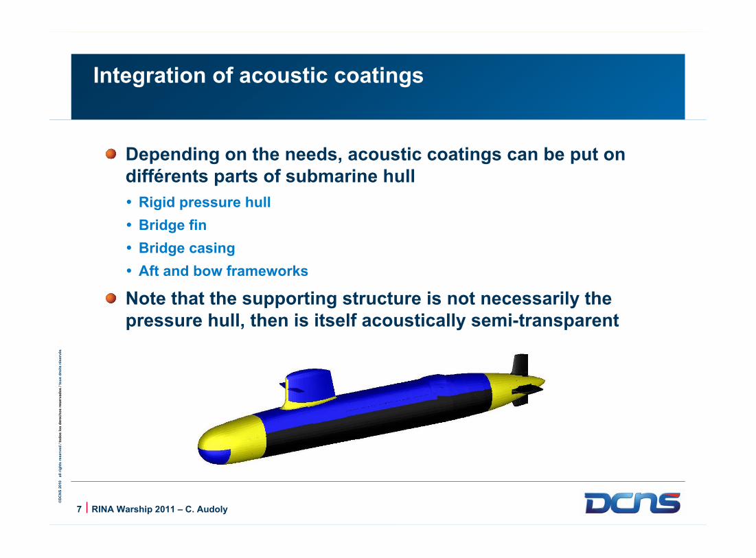
©D
CN
S 2
010
all
rig
hts
reserv
ed
/ t
od
os
los d
ere
ch
os
reserv
ad
os
/ to
us d
roit
s r
és
erv
és
7 | RINA Warship 2011 – C. Audoly
Integration of acoustic coatings
Depending on the needs, acoustic coatings can be put on différents parts of submarine hull
Rigid pressure hull
Bridge fin
Bridge casing
Aft and bow frameworks
Note that the supporting structure is not necessarily the pressure hull, then is itself acoustically semi-transparent
©D
CN
S 2
8 | RINA Warship 2011 – C. Audoly
Evaluation of acoustic performance of coatings – classical methods
Acoustic characterisation of anechoic or decoupling coatings taking into account the supporting hull

©D
CN
S 2
010
all
rig
hts
reserv
ed
/ t
od
os
los d
ere
ch
os
reserv
ad
os
/ to
us d
roit
s r
és
erv
és
9 | RINA Warship 2011 – C. Audoly
Evaluation of decoupling coefficient using a vibrating structure
A structure, partially or totally immersed in water is excited by a shaker or an acoustic source
Comparison of acoustic power radiated by the structure with/without coating gives an estimate of decoupling efficiency

©D
CN
S 2
010
all
rig
hts
reserv
ed
/ t
od
os
los d
ere
ch
os
reserv
ad
os
/ to
us d
roit
s r
és
erv
és
10 | RINA Warship 2011 – C. Audoly
Acoustic measurement of a test panel in a water tank
A transducer generates pulses in water
Hydrophones are placed near the test panel
Comparison of received signals with/without panels allow to determine coefficients R and T along frequency

©D
CN
S 2
010
all
rig
hts
reserv
ed
/ t
od
os
los d
ere
ch
os
reserv
ad
os
/ to
us d
roit
s r
és
erv
és
11 | RINA Warship 2011 – C. Audoly
Drawbacks of classical methods
Evaluation of decoupling coefficient using a vibrating structure requires specific equipment and a large sample. It is not cost effective.
No method available to evaluate anechoic efficiency on a rigid hull
Acoustic measurement of a test panel in a water tank :
Gives primarily coefficients R and T in free field (water on both sides, without backing)
Influence of a backing or supporting structure car be determined, but there are some limitations, and a new measurement must be done for each additional backing to be tested

©D
CN
S 2
12 | RINA Warship 2011 – C. Audoly
Global characterization method
Acoustic characterisation of anechoic or decoupling coatings taking into account the supporting hull

©D
CN
S 2
010
all
rig
hts
reserv
ed
/ t
od
os
los d
ere
ch
os
reserv
ad
os
/ to
us d
roit
s r
és
erv
és
13 | RINA Warship 2011 – C. Audoly
The needs
Determine anechoic efficiency on a rigid backing
Determine decoupling efficiency with prescribed vibration
Determine R and T of a non-resistant structure with acoustic coating

©D
CN
S 2
010
all
rig
hts
reserv
ed
/ t
od
os
los d
ere
ch
os
reserv
ad
os
/ to
us d
roit
s r
és
erv
és
14 | RINA Warship 2011 – C. Audoly
Method Transfer matrix of the coating
Two classical measurements of R and T (modulus and phase) along frequency are done in a water tank, with wave incident successively on both sides of the test panel in free field
A transfer matrix [MC ] is derived, relating acoustic pressure and displacement on the two sides of the panel
''
CM
1
1
2
2 .up
Mup
C
2
212121.2
1T
RRRRTT
2
212121.2
1T
RRRRTTci
2
212121.2
1.'T
RRRRTTci
2
212121.2
1'T
RRRRTT

©D
CN
S 2
010
all
rig
hts
reserv
ed
/ t
od
os
los d
ere
ch
os
reserv
ad
os
/ to
us d
roit
s r
és
erv
és
15 | RINA Warship 2011 – C. Audoly
Method Derivation of anechoism and decoupling coefficients
Anechoism coefficient :
Decoupling coefficient :
2
211 1
.'''
RTTR
ciciCA
1
11'
'.'.R
Tci
CM

©D
CN
S 2
010
all
rig
hts
reserv
ed
/ t
od
os
los d
ere
ch
os
reserv
ad
os
/ to
us d
roit
s r
és
erv
és
16 | RINA Warship 2011 – C. Audoly
Method Coefficients R and T with a supporting solid layer
Given the density, sound speed and thickness of solid layer, we define its transfer matrix :
Total transfer matrix of the coated solid layer is :
Reflection and transmission coefficients are derived :
TOTTOT
TOTTOTCSTOT MMM
''.
TOTTOT
TOTTOT
TOTTOTTOTTOTTOT
cc
iT
'.'
''.2
TOTTOT
TOTTOT
TOTTOT
TOTTOT
TOT
cc
i
cc
iR
'.'
'.'
SSSS
SS
SSSSSS
SS
SSS hk
chk
hkchkM cos)sin(
sin.cos
''

©D
CN
S 2
010
all
rig
hts
reserv
ed
/ t
od
os
los d
ere
ch
os
reserv
ad
os
/ to
us d
roit
s r
és
erv
és
17 | RINA Warship 2011 – C. Audoly
Example 1 : Anechoic coating R, CA, Influence of steel and GRP layers
-30
-20
-10
0
Frequency
Le
ve
l (d
B) R Free-field
Anechoism coef.
R Steel support
R GRP support

©D
CN
S 2
010
all
rig
hts
reserv
ed
/ t
od
os
los d
ere
ch
os
reserv
ad
os
/ to
us d
roit
s r
és
erv
és
18 | RINA Warship 2011 – C. Audoly
Example 1 : Anechoic coating T, CM, Influence of steel and GRP layers
-20
-15
-10
-5
0
Frequency
Le
ve
l (d
B) T Free-field
Decoupling coef.
T Steel support
T GRP support

©D
CN
S 2
010
all
rig
hts
reserv
ed
/ t
od
os
los d
ere
ch
os
reserv
ad
os
/ to
us d
roit
s r
és
erv
és
19 | RINA Warship 2011 – C. Audoly
Example 2 : Bi-layer coating R, CA, Influence of steel and GRP layers
-20
-15
-10
-5
0
Frequency
Le
ve
l (d
B) R Free-field
Anechoism coef.
R Steel support
R GRP support

©D
CN
S 2
010
all
rig
hts
reserv
ed
/ t
od
os
los d
ere
ch
os
reserv
ad
os
/ to
us d
roit
s r
és
erv
és
20 | RINA Warship 2011 – C. Audoly
Example 2 : Bi-layer coating T, CM, Influence of steel and GRP layers
-30
-20
-10
0
Frequency
Le
ve
l (d
B) T Free-field
Decoupling coef.
T Steel support
T GRP support

©D
CN
S 2
21 | RINA Warship 2011 – C. Audoly
Summary
Acoustic characterisation of anechoic or decoupling coatings taking into account the supporting hull

©D
CN
S 2
010
all
rig
hts
reserv
ed
/ t
od
os
los d
ere
ch
os
reserv
ad
os
/ to
us d
roit
s r
és
erv
és
22 | RINA Warship 2011 – C. Audoly
Summary
A method has been developped to determine acoustic performance of acoustic coatings to be integrated on ship or submarine hulls
Anechoic efficiency (rigid backing)
Decoupling efficiency (rigid hull, air backed)
Reflection and transmission of a non-resistant structure with coating
Basically, it uses standard water tank acoustic test panel measurements with numerical post-processing
It is of practical use to optimise acoustic discretion and acoustic stealth of ships or submarines


Construction Materials for Small Submersibles
Presented by Peter Vinton and Philip Delaforce
© 2011 Rolls-Royce Group plc The information in this document is the property of Rolls-Royce Group plc and may not be copied or communicated to a third party, or used for any purpose other than that for which it is supplied without the express written consent of Rolls-Royce Group plc.
This information is given in good faith based upon the latest information available to Rolls-Royce Group plc, no warranty or representation is given concerning such information, which must not be taken as establishing any contractual or other commitment binding upon Rolls-Royce Group plc or any of its subsidiary or associated companies.

2
Contents:
1. Introduction
2. Codes and Standards for Submersibles and Composite Pressure Vessels
3. ASME Boiler and Pressure Code, Section X
4. Comparison Between Codes and Classification Rules
5. Proposed Composite Pressure Hull Standards
6. Aspects for Development of Codes and Standards
7. Summary

3
Introduction
Design Drivers for Small Submersibles
– Minimisation of the hull weight to displacement ratio
for small submersibles is crucial to increasing:
• Range
• Endurance
• Payload
– A significant weight reduction offers the potential to reduce the size of the launch and recovery systems,
– Composite materials offer weight reduction through utilising their high strength to density ratios,
– Many parts of the exostructure, such as hydrodynamic fairings and floodable structures are already manufactured out of composite materials,
– The pressure hull offers the greatest opportunity for weight reduction from the use of composite materials.
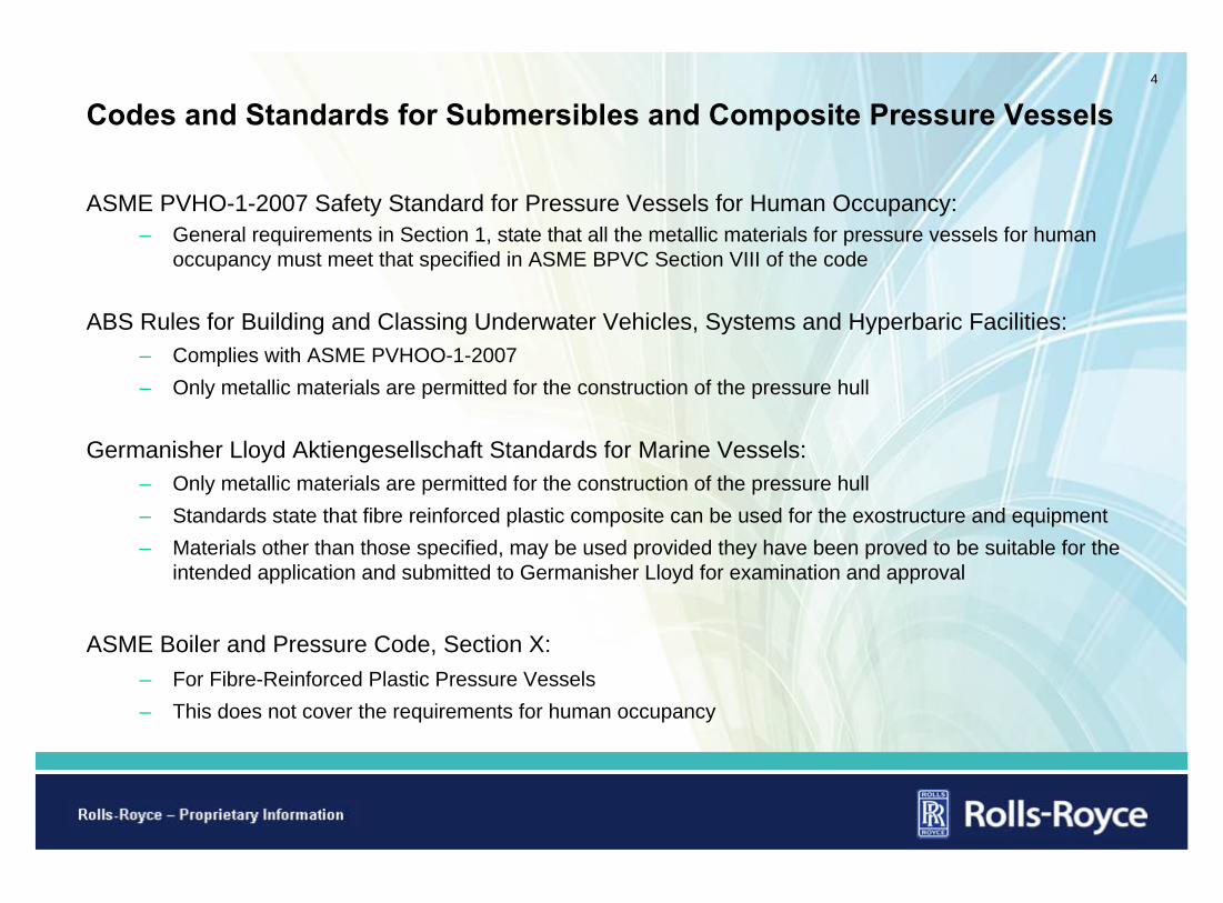
4
Codes and Standards for Submersibles and Composite Pressure Vessels
ASME PVHO-1-2007 Safety Standard for Pressure Vessels for Human Occupancy:
– General requirements in Section 1, state that all the metallic materials for pressure vessels for human occupancy must meet that specified in ASME BPVC Section VIII of the code
ABS Rules for Building and Classing Underwater Vehicles, Systems and Hyperbaric Facilities:
– Complies with ASME PVHOO-1-2007
– Only metallic materials are permitted for the construction of the pressure hull
Germanisher Lloyd Aktiengesellschaft Standards for Marine Vessels:
– Only metallic materials are permitted for the construction of the pressure hull
– Standards state that fibre reinforced plastic composite can be used for the exostructure and equipment
– Materials other than those specified, may be used provided they have been proved to be suitable for the intended application and submitted to Germanisher Lloyd for examination and approval
ASME Boiler and Pressure Code, Section X:
– For Fibre-Reinforced Plastic Pressure Vessels
– This does not cover the requirements for human occupancy

5
ASME Boiler and Pressure Code, Section X Part1
Code Allow Two Different Design Methodologies– Class I designs – qualification of a vessel design is through the destructive test of a prototype. The
maximum design pressure is determined by the composite manufacturing method:
• 1 MPa (10 bar) for bag-moulded, centrifugally cast and contact-moulded vessels,
• 10 MPa (100 bar) for filament-wound vessels,
• 20 MPa (200 bar) for filament-wound vessels with polar boss openings
– Class II design – mandatory design rules and acceptance testing by non-destructive methods.
• Class II vessels are limited to an external pressure of 100 kPa (1 bar)
• Low maximum internal and external pressures are allowed, due to relative limited experience and data available
– Material permitted under the code for both Classes:
• Carbon, graphite, glass and aramid fibres are permitted
• Epoxy, polyester/vinyl ester, phenolic and furan resins permitted
Differences in Composite Lay-ups
– Does not recognise the difference between woven rovings, multi-axial fabric and unidirectional fabrics
• Contact-moulded process is permitted to use random short length fibres or roving / biaxial fabric
• Bag-moulded and centrifugal-casted are only permitted to use random short fibres

6
ASME Boiler and Pressure Code, Section X, Part 2
Class I – Prototype Qualification Test Requirements
– 100,000 cycles of pressure ranging for maximum external and internal design pressure without leaking,
– An external pressure of twice maximum external design pressure without buckling,
– A hydrostatic pressure of at least six times the maximum internal design pressure, where the minimum internal design pressure is 100 kPa. (1 bar)
– Destructive qualification tests demonstrate large robust safety factors to bursting of the vessel.
– Section X composite pressure vessels are primarily intended for industrial application, with many operating cycles and long design lives.
– A requirement to demonstrate a fatigue resistance for such a large number of cycles, way beyond what a submersible would realistically experience, would be unnecessary and costly.
Class I – Production Test Requirements
– Vessel wall thickness – within 10% of qualified prototype,
– Vessel weight – within 95% of the weight measure from the qualified prototype,
– Barcol hardness test – within the range measured from the of the qualified prototype,
– Hydrostatic leakage test - 1.3 times the internal or external design pressure,

7
Comparison Between Codes and Classification Rules – Qualification
Fatigue Testing
– For pressure vessels for human occupancy and the ABS rules, the acrylic windows have a lower number of cycles for the fatigue test then stipulated in the ASME BPVC Section X.
– A fatigue design for 10,000 cycles is much closer to the number of dives a small submersible would be subjected to in its operating life.
– Acrylic viewports will limit the operational life of the vessel unless these elements are replaced.
ASME Boiler & Pressure Vessel Code, Section X
ASME Safety Standards Pressure Vessels for Human Occupancy
ABS Rules Underwater Vehicles Systems and Hyperbaric Facilities
Qualification
ExternalPressure
2 times max external design pressure without buckling.
Acrylic window:Shall not exceed 1380 bar (138 MPa)
Acrylic window:Shall not exceed 1380 bar (138 MPa)
Internal Pressure
6 times the internal design pressure.
- -
Fatigue
100,000 cycles of pressure ranging from max external to the internal without leakage.
Acrylic window:10,000 cycles pressure cycles or 40,000 hrs, respectively.
Acrylic window:10,000 cycles pressure cycles or 40,000 hrs, respectively.

8
Comparison Between Codes and Classification Rules – Acceptance
ASME Boiler & Pressure Vessel Code, Section X
ASME Safety Standards Pressure Vessels for Human Occupancy
ABS Rules Underwater Vehicles Systems and Hyperbaric Facilities
Acceptance
PressureTesting
To 1.3 times the internal or external design pressure for vessels with welded metal components.
To 1.25 of the design pressure.To 1.25 the design depth for two cycles.
-Strain gauges are to be applied.
Triaxial strain gauges are to be fitted.
- -Acrylic window: Shall not exceed 1.5 times the design pressure or 138 MPa.
Dive Test - - Final test dive to design depth.
Production Acceptance Testing
– All three standards stipulate a hydrostatic proof test acceptance requirement, from 1.25 to 1.3 times of the design pressures.
– ASB Rules and ASME Safety Standards for Pressure Vessels for Human Occupancy rely on the ASME BPVC, Section VIII acceptance requirements.
– ASME BPVC Section X, stipulates additional acceptance requirements to demonstrate that the production of composite vessels attain equivalent mechanical properties to the qualified prototype.

9
Proposed Composite Pressure Hull Standards – Qualification Part 1
ASME BPVC Section X, offers a starting point– Designed to Class I (qualification through the destructive test of a prototype),
– Internal design pressure is 100 kPa (1 bar):
• Hydrostatic test 6 times the internal design pressure,
– Limit the external design pressure to 1 MPa (100 m depth):
• Allows the greatest flexibility in the manufacturing route / various lay-up configurations available,
• Offers the greatest potential cost saving, while minimising the weight of the pressure hull,
• Hydrostatic test to 2 times maximum external design pressure.
Fatigue Requirements– ASME BPVC Section X, mandates a 100,000 cycles fatigue test,
– Acrylic viewports are designed for a fatigue life of 10,000 cycles,
– ASME BPVC from Section VIII, Division 2 (alternative rules) for experimental fatigue analysis, applies a factor of 2.6 to the design fatigue life for the qualification test.
Propose Fatigue Qualification Test– Fatigue test to 10,000 cycles, the same as for the acrylic viewports,
– Fatigue test as a minimum to 2.6 times the design fatigue life.

10
Proposed Composite Pressure Hull Standards – Acceptance
ASME BPVC Section X, offers a starting point– Vessel wall thickness – within 10% of qualified prototype,
– Vessel weight – within 95% of the weight measure from the qualified prototype,
– Barcol hardness test – within the range measured from the of the qualified prototype.
ABS Rules– Hydrostatic leakage test - 1.25 times the external and internal design pressure,
– Strain gauges fitted to the pressure hull during hydrostatic test, to demonstrate no evidence of buckling,
– Final test dive to design depth.

11
Aspects for Development of Codes and Standards
Determination of Bucking Onset– Standard method to determine whether the onset of buckling has occurred on a curved or cylindrical
surface,
– Strain gauged the internal side of the vessel with an array of gauges to record the strains,
– An array of strain gauges will highlight periodic patterns in the circumferential strains to failure, allowing the buckling mode to be estimated.
Utilising NDE for Acceptance Testing– The Aerospace and Automotive industries routinely use NDE techniques on composite component,
– Opportunities to utilise these techniques and acceptance standards from those industries.
Effect of Different Lay-up Configuration– ASME BPVC Section X only differentiates between filament-wounding and groups all the other lay-up
configuration together,
– Overlapping fabric joints are not such as issue for preventing buckling compared to bursting,
– Does not consider the use of braided lay-up of combinations of different lay-ups configurations,
– Other lay-up types offering lighter and more cost effective solutions.

12
Summary
Industrial composite pressure vessels codes and standards, such as the ASME BPVC Section X, could provide the foundation for composite pressure hull standards.
Industrial composite pressure vessels codes contain large inherent safety factors which are demonstrated through the prototype qualification testing requirements.
However industrial vessels are primarily intended to experience a large number of operating cycles and have long design lives, hence their fatigue qualification requirements are unreasonably large for small submersible pressure hulls.
Fatigue qualification test to either:– 10,000 cycles, as mandated for acrylic viewports, – A minimum of 2.6 times the design fatigue life.
Industrial composite pressure vessels codes acceptance test requirements could provide the foundation to demonstrate equivalent mechanical properties to the qualified prototype.
Industrial composite pressure vessels codes only differentiates between filament-wounding and groups all the other lay-up configuration together.

13
Proposed Standards for Classification Societies
Qualification Through the Destructive Testing of a Prototype
– Fatigue testing to maximum external and internal design pressure for 2.6 times the fatigue design life,
– Hydrostatic test to 6 times the internal design pressure,
– Hydrostatic test to 2 times maximum external design pressure
– Vessel wall thickness measure from qualifying prototype,
– Barcol hardness of the qualifying prototype along its length,
– Vessel weight of the qualifying prototype.
Production Acceptance Tests
– Vessel wall thickness – within 10% of qualified prototype,
– Vessel weight – within 95% of the weight measure from the qualified prototype,
– Barcol hardness test – within the range measured from the of the qualified prototype,
– Hydrostatic leakage test - 1.25 times the external and internal design pressure,
– Final test dive to design depth.


3

4

5


JWL
Variable A B R1 R2 OMEG E0 VO
Type 3.3712e+11 3.231e+9 4.15 0.95 0.3 7.0e+9 1
16

Whole Model
17

Cylinder Shell
Shell inner diameter(Ds) 5.0 m
Shell model length(Ls) 21.6 m
Shell model thickness(ts) 0.024 m
Ls
Dsts
18


Yielding strength(σy) 690 MPa
Young’s modulus(E) 205 GPa
Ultimate strength(σU) 793.5 MPa
Density(ρs) 7,870 kg/m3
Poisson ration(μ) 0.28
20

21
Next Page

© Copyright QinetiQ Limited 2011
Evaluating the Manoeuvring Performance of an X-plane Submarine
Paul Crossland, Phil Marchant and Neil ThompsonRINA Warship 2011: Naval Submarines and UUVs
29th – 30th June 2011, Bath

© Copyright QinetiQ Limited 2011
Xview
H1 Depth Autopi ot
h (m )
ordh (m )
speed (m/s)
hydroplane dem ands (rad)
Control DistributionOpt ons
Conventional dem andsX-plane dem ands
Advanced Autopilot
depth
pitch (deg)
ord depth
dem
Contents slide
01 Background
02 X-plane design
03 Modelling submarine manoeuvring
04 Captive model experiments
05 Development of computational toolset
06 Autopilot development
07 Free-running model experiments
08 Safe Operating Envelope
09 Conclusions

© Copyright QinetiQ Limited 2011
3
01 Background – QinetiQ and the MSCA
The Maritime Strategic Capability Agreement (MSCA) is a 15 year contract signed between QinetiQ and UK MoD in 2008 to provide key submarine capabilities.
Part of the contract covers the MoD’s requirements for Submarine Manoeuvring and control advice, support and research:
•Provide advice and guidance for future acquisition and in-service support
•Maintain the ability to predict and model (both physically and computationally) the hydrodynamic aspects and manoeuvring performance of submarines
•Maintain the above capabilities to ensure that they remain at the forefront of technical competence.

© Copyright QinetiQ Limited 2011
4
01 Background – Submarine Manoeuvring and Control
The major Manoeuvring and Control concerns for submarines are if flooding incidents occur at slow speeds, or a hydroplane jam incident occurs at high speeds.
flooding incident
hydroplane jam incident
Sea surface
Maximum Excursion Depth
slow speed
high speed

© Copyright QinetiQ Limited 2011
5
Safe Operating Envelope (SOE)• The UK MoD set safety and operational
constraints for the RN submarine fleet.
• Graphical means of depicting combinations of submarine speed and depth.
• Guidance from the provision of Safe Operating Envelopes (SOE) is generated using submarine simulation tools.
• Compiled from several thousand computer simulated runs.
• RN submarine fleet consist of traditional cruciform arrangements – safety guidance specific to stern plane arrangement.
01 Background – the need for guidance
No operational restrictions
imposed
Operational restrictions
imposed
Risk of exceeding pitch limit

© Copyright QinetiQ Limited 2011
01 Background – Program aim
Aim: To develop a validated capability that will enable the investigation of the relative merits of a range of aft appendage configurations including X-planes.
• Develop an experimental X-plane design
• Undertake a series of experiments to evaluate performance of this design
• Develop a complimentary computational capability

© Copyright QinetiQ Limited 2011
DESIGN CONSTRAINTS
•X-plane had to fit to the existing captive model.
•All four hydroplanes had to be the same.
•Must be able to interface with existing propulsor.
•Cone section must allow interface with existing SRM X-plane section.
•Stock position must correspond to existing SRM X-plane location.
IMPACT OF CONSTRAINTS
•Fixed the forward radius of the cone section
(to interface with the existing model).•Fixed the aft radius of the cone section (to interface with the existing propulsor).•Fixed the cone angle to ensure configurable with the SRM.•Fixed the stock location to ensure configurable with the SRM.•Fixed the X configuration to be orthogonal.
02 X-plane design

© Copyright QinetiQ Limited 2011
• SPAN
− limited by box enclosing the hull
• Chord
− Set root and tip chord to maintain same aspect ratio of upper rudder of current model
• Each X-plane is a geosim of the upper rudder of the current model which results in a reduction of about 22% in surface area.
• Total increase of about 30% in effective surface area compared to existing model
• Modified a constrained model and free running model
βXstock
S
Ct
Cr
RfwdRaftβ
Xstock
S
Ct
Cr
RfwdRaft
02 X-plane design

© Copyright QinetiQ Limited 2011
Constrained model
02 X-plane design

© Copyright QinetiQ Limited 2011
02 X-plane design
Free running model - Submarine research model (SRM)
• 4.5m pressure hull
• clad with hull form
• measurement package
− Ring Laser Gyro
− Doppler Velocity Log
− two pressure transducers
• independent actuation ofall control surfaces
• can run autonomously or receivecommands via underwater radio

© Copyright QinetiQ Limited 2011
02 X-plane design

© Copyright QinetiQ Limited 2011
12
No simulation System based simulation CFD based simulation
Free running models
Trajectories
Derivation of manoeuvring performance parameters
System identification
Mathematical model
Hydrodynamics derivatives and coefficients
Stability and control indices
UnsteadyQuasi- steady
Euler based methods
Navier Stokes based methods
Captive model tests
Equations of motion
Full-scale trials
Model experiments
Hydrodynamic database
03 Modelling submarine manoeuvring

© Copyright QinetiQ Limited 2011
13
• Ship Tank
− 270m × 12m × 5.5m
− wave-makers
• Ocean Basin
− 120m × 60m × 5.5m
− 30m Rotating Arm
− waves to SS6 (scaled)
03 Modelling submarine manoeuvring

© Copyright QinetiQ Limited 2011
14
[ ]
( ) Θ−+′+
′+′+
′+′+
′+′+′+
′+′+′+′=−−
cosBmgQZρ
)WQWνZδSQUZ(ρ
)UQZWZ(ρ
)WνZWUZWνZ(ρ
)δSUZδBUZUWZUZ(ρQzUQWm
Q
WQWνδSQU
UQW
WνWUWν
δSUδBUUWUUG
&l
l
&l
l
l&
&
&
421
321
321
221
2222212
22
Θ−−′+′+
′+′+
′+′+
′+′+′+
′+′+′+′=++
s in)Bzzmg()QQMQM(ρ
)δSQUMQνM(ρ
)UQMWM(ρ
)WνMWUMWνM(ρ
)δSUMδBUMUWMUM(ρ)WQU(mzQI
BGQQQ
δSQUQν
UQW
WνWUWν
δSUδBUUWUUGy
&l
l
&l
l
l&&
&
&
521
421
421
321
222321
22
Mathematical model (vertical plane)
03 Modelling submarine manoeuvring

© Copyright QinetiQ Limited 2011
15
Cruciform
→
X-plane Rudder Sternplane Xuuδrδr' Xuuδsδs' XuuδXδXi' Yuuδr' - YuuδXi'
- Zuuδs' ZuuδXi' Kuuδr' - KuuδXi'
- Muuδs' MuuδXi' Nuuδr' - NuuδXi'
Comparison of cruciform and X-plane appendage coefficients
Model corrections for X-planes
03 Modelling submarine manoeuvring

© Copyright QinetiQ Limited 2011
Interference tests
+ =
03 Modelling submarine manoeuvring

© Copyright QinetiQ Limited 2011
17
• Tow model at 3.048 m/s
• Static and dynamic PMM
• To derive the translational coefficients
• Model
− Inverted for vertical plane
− Onside for horizontal plane
• Vary pitch or yaw angle to create a cross flow velocity
• Run plan of approximately 1000 runs
04 Captive model experiments - Ship Tank

© Copyright QinetiQ Limited 2011
18
• Incident model speed is 3.048 m/s
• To derive the rotational coefficients
• Model
− Inverted for vertical plane
− Onside for horizontal plane
• Vary pitch or yaw rate.
• Change radius of rotation and rotational velocity
• Run plan of approx. 1500 runs
• Combined datasets from the Ship Tank and Rotating Arm, derive full coefficient set from regression analysis
04 Captive model experiments – Rotating Arm

© Copyright QinetiQ Limited 2011
Low fidelity
l t
E d alised thods
Lifting panelmethods
Vortex methods
Increase in empiricism
c i i
c RANS CFD
Low fidelity
id lit
LES CFDIdealised methods
Vortex methods
Increase in empiricism
Incre i com i
c RANS CFD
Low fidelity
High fidelity
LES CFDIdealised methods
Lifting panelmethods
Vortex methods
Increase in empiricism
Increase in complexity
Direct NS Solvers
RANS CFD
Low fidelity
High fidelity
LES CFDIdealised methods
Vortex methods
Increase in empiricism
Increase in complexity
Direct NS Solvers
RANS CFD
Aim: To develop a capability for predicting a preliminary manoeuvring coefficient set for a concept submarine.
• Looking at CFD and lower fidelity alternatives
• DRIVS – produces the stability indices
• SCAM – Added mass terms
• SUBSIM geometry based technique using semi-empirical methods
• Use combination of SCAM and SUBSIM to determine preliminary coefficient set
05 Development of computational toolset

© Copyright QinetiQ Limited 2011
20
• ANSYS CFX
• Grid sizes of 10.9 million cells for a half-geometry, 21.8 million cells for a full geometry.
• Use baseline Reynolds Stress Model resolving down to the viscous sub-layer
• Propulsor modelled as a momentum source
05 Development of computational toolset - CFD
-20 -10 0 10 20
Z'
Pitch (degrees)
Expts
CFD
-20 -10 0 10 20
M'
Pitch (degrees)
Expts
CFD

© Copyright QinetiQ Limited 2011
21
Stability analysis
11.01 −=′′
′+′′
−=wq
qu
v
ZM
ZmMG
04.01 −=′′
′−′′
+=vr
rv
h
YN
YmNG
06 Autopilot development

© Copyright QinetiQ Limited 2011
22
Coeff CruciformX-plane
upper pairX-plane
lower pairX-plane
combined
Zδs′ 1 0.91 0.98 1.89
Mδs′ 1 0.92 0.98 1.90
Yδr ′ 1 0.67 0.71 1.38
Nδr ′ 1 0.69 0.76 1.45
Relative control power
06 Autopilot development

© Copyright QinetiQ Limited 2011
23
Vertical plane
• two modes: depth-keeping and depth-changing
− depth-keeping maintains set depth at zero pitch
− depth-changing orders a pitch angle proportional to depth error (up to pitch limit)
− depth-rate is then a function of the pitch angle
• switching between modes based on depth-error
Horizontal plane
• same two modes: course-keeping and course-changing
− course-keeping will maintain heading (but not track)
− course-changing applies rudder proportional to heading error (up to rudder limit)
• switching based on heading error
06 Autopilot development

© Copyright QinetiQ Limited 2011
24
Controllers effectively working in the traditional cruciform manner
• separate vertical and horizontal control
• simple summation applied to transform to X-plane control
δupper stbd = + δs – δr
δlower stbd = + δs + δr
δlower port = – δs + δr
δupper port = – δs – δr
06 Autopilot development

© Copyright QinetiQ Limited 2011
25
Programme aims
• Replicate previous free-running experiments
− Ocean Basin
− explore high-speed manoeuvres
• Investigate control issues
− different control authority strategies
• Explore hydroplane jam effects and recovery strategies
• Conduct manoeuvres suitable for SI analysis
− improve the mathematical model predictions
07 Free-running model experiments
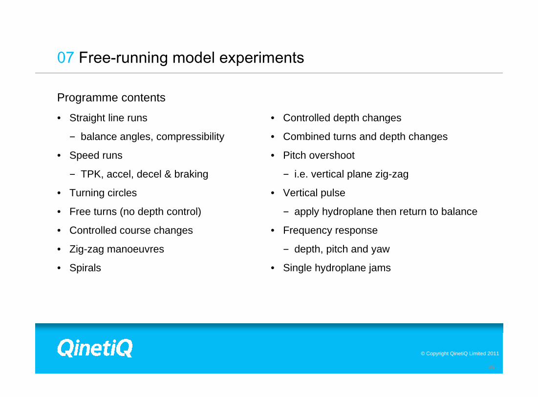
© Copyright QinetiQ Limited 2011
26
Programme contents
• Straight line runs
− balance angles, compressibility
• Speed runs
− TPK, accel, decel & braking
• Turning circles
• Free turns (no depth control)
• Controlled course changes
• Zig-zag manoeuvres
• Spirals
• Controlled depth changes
• Combined turns and depth changes
• Pitch overshoot
− i.e. vertical plane zig-zag
• Vertical pulse
− apply hydroplane then return to balance
• Frequency response
− depth, pitch and yaw
• Single hydroplane jams
07 Free-running model experiments
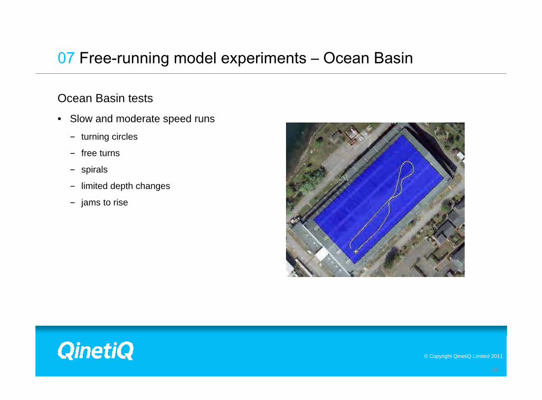
© Copyright QinetiQ Limited 2011
27
Ocean Basin tests
• Slow and moderate speed runs
− turning circles
− free turns
− spirals
− limited depth changes
− jams to rise
07 Free-running model experiments – Ocean Basin

© Copyright QinetiQ Limited 2011
28
Deep water reservoir tests
• High speed and deeper diving runs
-300 -200 -100 0 100 200 300
-100
-50
0
50
100
150
200
250
300
350
07 Free-running model experiments – Reservoir

© Copyright QinetiQ Limited 2011
29
• Operating at the deep water reservoir
− Model launched from pontoon
− Undertakes 4-5 different runs autonomously
− Model recovered by RIB
Distance (m)
Dis
tanc
e (m
)
-400 -200 0 200 400 600
-300
-200
-100
0
100
200
300
400
500
600
700
simulation
experiment
07 Free-running model experiments – Reservoir

© Copyright QinetiQ Limited 2011
30
Comparison between experiments and simulation • Single stern plane jam
• Time histories don’t match exactly but agreement is very good
07 Free-running model experiments – validation

© Copyright QinetiQ Limited 2011
• Experiments in the Ocean Basin and the Ship Tank
− calm water, regular and irregular waves
− equivalent to sea states 3, 4 and 5
− head, following and oblique waves
• Some evidence of vertical plane instability possibly due to planes rate limiting
• Some evidence of horizontal induced instability as a result of excessive plane action
• Autopilot design is key
Model track in Ocean Basin
Ship Tank
07 Free-running model experiments – additional tests

© Copyright QinetiQ Limited 2011
• Obtained dataset of surface performance of X-plane configuration
• Using the Qualisys® system in the Ocean Basin
• Tests indicate this X-plane configuration is horizontally stable
• Some further development of model autopilot for surface free running experiments required
07 Free-running model experiments – additional tests

© Copyright QinetiQ Limited 2011
33
Creating an SOE requires the derived mathematical model to be used, in order to:
• Process a range of scenarios with varying:
− Initial depths and speeds
− Jam angle (both to rise and to dive)
− Initial pitch angle
• For each of these trajectories, it must be examined and determined whether it has safely recovered, or not.
• The critical speed for each scenario can then be determined.
• The critical speeds can then be plotted in an SOE format.
08 Safe Operating Envelope (SOE)

© Copyright QinetiQ Limited 2011
34
08 Safe Operating Envelope (SOE)
Jam Scenarios - Pass

© Copyright QinetiQ Limited 2011
35
08 Safe Operating Envelope (SOE)
Jam Scenarios - Fail

© Copyright QinetiQ Limited 2011
08 Safe Operating Envelope (SOE)
• The SOE, the submarine’s Emergency Operating Procedures (EOP) and the submarine’s design are intrinsically linked together.
• Designing a submarine with X-planes changes the existing EOP methodology, and that impacts the SOE.
• To create an SOE for an X-plane submarine, a suitable EOP must first be derived. A number of potential EOP options were considered
− Order the diagonally opposite stern plane to an equal angle, with use of bow planes and astern RPM
− Order the three remaining stern planes to full rise/dive and then take ‘appropriate’ actions
− Use of autopilot

© Copyright QinetiQ Limited 2011
08 Safe Operating Envelope (SOE)
• In addition, two formats were considered, either Plane limited (MLD) or Pitch limited (SME).
• Plane limited SOE guidance is usually provided when more significant limitations are applied and relates to multiple hydroplane jam angles at a single initial pitch angle. Multiple guidance envelopes are then provided for different initial pitch angles.
• Pitch limited SOE guidance is usually provided when less significant limitations are applied and relates to a single hydroplane jam angle at multiple initial pitch angles.
MLD
SM
E

© Copyright QinetiQ Limited 2011
08 Safe Operating Envelope (SOE)
• The selected EOP methodology for the X-plane SOE was to order the diagonally opposite stern plane to an equal angle, with use of bow planes and astern RPM
• The selected plot format was the SME.

© Copyright QinetiQ Limited 2011
09 Conclusions
• Developed a X-plane design for subsequent testing
• Particular X-plane design was not optimised, but can generate:
− Yaw rates rapidly �
− Pitch rates rapidly �
• Design is theoretically unstable, but is not uncontrollable
− Control surface activity not excessive
• Autopilot performance was good for deep water manoeuvres
− Further tuning would be required for PD and surfaced operations
• “Surprise” at increased effectiveness of lower planes
− Maximum jam angle response strategy still not resolved
• Initial considerations for an SOE
• Developed a complimentary computational toolset

Hydrodynamic design implications for a submarine operating near the surface
Martin Renilson and Dev Ranmuthugala (AMC)Ed Dawson and Brendon Anderson (DSTO)Sean Van Steel and Sam Wilson-Haffenden (Ex AMC)

Contents
Contents
1.Aim2.Introduction3.Experimental set up4.Effect of depth5.Effect of sail6.Effect of L/D ratio7.Effect on operations8.Concluding remarks

Aim
Aims
To identify and quantify effect of operating close to the surface:
1.Resistance and powering
2.Manoeuvring in the vertical plane
3.Manoeuvring in the horizontal plane
Only first aim considered at this stage

Introduction
Full scale SSK:
Length 80mL/D = 8.6
SUBOFF

Experimental set up
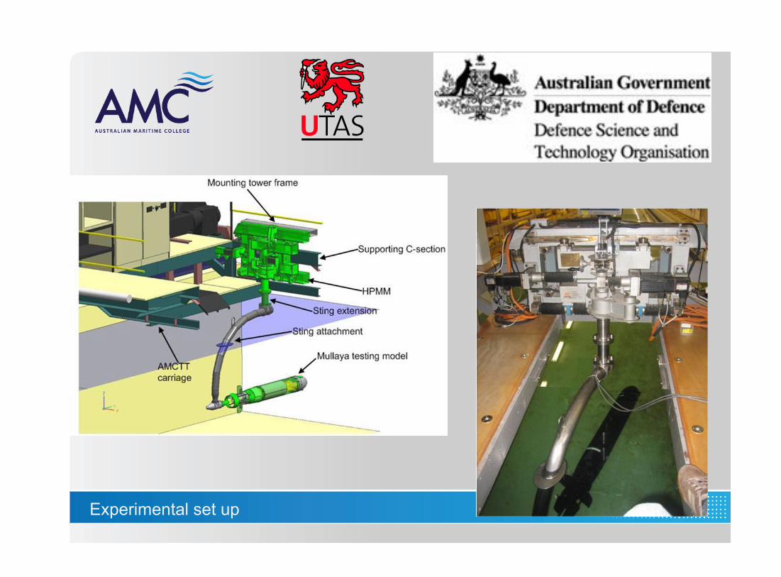
Experimental set up

Depths tested
Non-
Dimensional Depth (H*)
Model CL Depth (m)
Full scale CL
Depth (m)
1.1 0.200 10.23 1.3 0.235 12.09 2.2 0.400 20.46 3.3 0.600 30.69 4.4 0.800 40.92 5.5 1.000 51.15

Results with sail
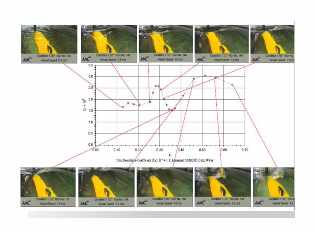

Results
Full scale speed = 7 knots
Frhull = 0.13Frsail = 0.44

Results
Full scale speed = 12 knots
Frhull = 0.21Frsail = 0.71

Results
Full scale speed = 15 knots
Frhull = 0.27Frsail = 0.88

Results
Full scale speed = 17 knots
Frhull = 0.32Frsail = 1.06


Effect of sail
Effect of sail
Will depend on Froude numberFroude number for sail is different to that for hullInteraction between wave systems (sail/hull)
Will depend on volumeIncreased volume likely to increase wavemaking drag

Effect of L/D ratio
Effect of L/D ratio
Comparison of deep and shallow using RANS CFD
Constant speed of 10 knots
Diameter remained constant – length changed
No sail
Ratio of power in shallow condition to power when deep


Effect of L/D ratio
Effect of L/D ratio
Required increase in power at 10 knots is smaller for larger L/D
Less form drag for higher L/D
May be due to lower Froude number for same speed

Effect on operations
Speed (knots)
Effective power when
shallow (kW)
Effective power when deep (kW)
Percentage increase in required effective power
Additional effective power
required when
shallow (kW)
5 40 30 30% 107 100 70 40% 30
10 290 190 50% 100 12 530 320 65% 210 15 2,250 890 150% 1,360

Effect on operations
Fictional SSK operation:
Patrol length 75 daysTime snorting 30% (at 10 knots)Propulsion efficiency 70%
Resulting increase in energy required = 77MW/hoursAdditional mass of fuel = 15 tonnes

Concluding remarks
Concluding remarks
1.When submarine is operating close to the surface it will generate waves and hence additional drag
2.Sail will complicate issues:a.Froude number of sail is different to hullb.increased volume – more wavemaking drag
3.Increased L/D ratio appears to reduce the effect of free surface

www.babcock.co.uk 1

www.babcock.co.uk 2
Incorporating Through Life Support Requirements into Submarine Design
Incorporating Through Life Support Requirements into Submarine Design
Simon Baker for Steve Smith
NOT PROTECTIVELY MARKED

www.babcock.co.uk 3
Incorporating Through Life Support Requirements into Submarine Design
• UK programme to design a successor to Vanguard Class SSBN
• Approval to proceed to Design Phase achieved
• Collaborative approach adopted:
– MoD – customer
– BAE SYSTEMS – designer & builder
– Rolls Royce – designer & builder of nuclear propulsion plant
– Babcock – through life support
• Two key roles for Through Life Support:
– Support the design
– Design the support
NOT PROTECTIVELY MARKED

www.babcock.co.uk 4
Supportability in design – Background
• Historically, naval acquisition programmes have focused upon UPC, capability and procurement delivery
• Supportability has been a late and/or incomplete work stream not fully integrated with the design programme
• Constrained by near term financial pressures, unbalanced organisation and immature customer requirements.
• Resulting in:-
– ILS being seen as expensive and ineffective – a view formed across many major naval procurement projects.
– sub-optimal in-service support solutions
• New approach for SSBN replacement submarine ‘Successor’ ado
NOT PROTECTIVELY MARKED

www.babcock.co.uk
Supportability in design – Background
• Support Team fully engaged from the earliest days of pre- concept as a Tier 1 supplier within the collaborative MoD/Industry team
– The largest single contributor to reducing support costs, whilst increasing availability and readiness, is the delivery of a submarine that is designed to be supported
– The interface between support & design teams was identified as a key weaknesses in previous programmes
– The early design decisions determine the supportability of a platform
• UK MoD recognised the need for change
• In response, Babcock developed a structured, tailored TLS programme to address historic failings
– Support the design– Design the support
NOT PROTECTIVELY MARKED

www.babcock.co.uk 6
Supporting the Design
• To positively impact the developing design to deliver through-life benefit
• Activities include:
– Co-location of support experts with the design team
– Advice/influence from a maintenance perspective
– Implementation of formal processes that include:
– Learning From Experience
– Design For Support process
– Decision Panel process
• Decisions that affect TLS are taken with ‘eyes wide open’
NOT PROTECTIVELY MARKED

www.babcock.co.uk 7
Supporting the Design - Design for Support Process
• To demonstrate to stakeholders that supportability
given appropriate consideration through design
• Small team of support specialists working directly with
designers
• Assessment matrix:
– Accessibility
– Support needs
– Facilities
– LFE
• Contribution to decision panels
• Embedded to ensure consistent approach
NOT PROTECTIVELY MARKED

www.babcock.co.uk 8
Supporting the Design - AR&M Targets
• Whole Boat requirement specified in URD
• Requirement decomposed into 5 major systems
• Mission availability targets assigned
• Bottom up assessment to ensure realistic & achievable:
– RBDs from available design information
– Derive subsystem availability figures
• Design influence:
– Optimise redundancy
– Systems cross connections
• Data taken from similar in service equipment and generated from operational feed back including LFE
NOT PROTECTIVELY MARKED

www.babcock.co.uk 9
Supporting the Design – Platform Availability Modelling
• Maintenance Upkeep & Operating Cycle up front:
– Not a function of end design
– Maximise the probability of achieving CASD
– Strategic shock resilience
– Resource loading – peaks & troughs
– Influence design
• Software modelling – predict probability of sustaining CASD
• Decision panels
– Sentence significant design decisions
– TLS impact
– Pragmatic compromise
NOT PROTECTIVELY MARKED

www.babcock.co.uk 10
Designing the Support
• To design and deliver a Successor submarine support solution which will drive significant cost savings and reduction in maintenance burden through-life
• Activities include :-
– Development of tailored ILS and ARM programmes - support solution maturity
– Maintenance regime and ability to achieve MUOC
– Development of a clear trade off policy supported by valid cost models, informed by current class performance
NOT PROTECTIVELY MARKED

www.babcock.co.uk 11
Designing the Support – Supportabilty Engineering
• Key requirement to reduce maintenance burden
• Supportabilty criteria
– Physical & operational environment
– Impact against MUOC
– Through life cost
• Tailor process
• Recognise design maturity
• Trade off – robust decision support tools
• Supplier engagement– Avoid rework:
– Engage suppliers early
– Only ask for what is actually needed
– Risk based approach – understand capability for LSA activities
NOT PROTECTIVELY MARKED
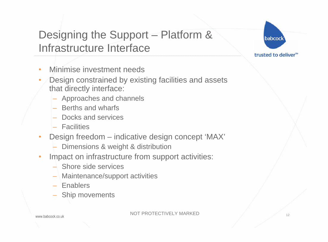
www.babcock.co.uk 12
Designing the Support – Platform & Infrastructure Interface
• Minimise investment needs
• Design constrained by existing facilities and assets that directly interface:
– Approaches and channels
– Berths and wharfs
– Docks and services
– Facilities
• Design freedom – indicative design concept ‘MAX’
– Dimensions & weight & distribution
• Impact on infrastructure from support activities:
– Shore side services
– Maintenance/support activities
– Enablers
– Ship movements
NOT PROTECTIVELY MARKED

www.babcock.co.uk 13
Designing the Support – Support Information
NOT PROTECTIVELY MARKED

www.babcock.co.uk 14
Conclusions
• TLS early is the best chance to influence design and lever TLC benefits
• Trade off through design is appropriate and inevitable; – the right balance must be sought and driven by the client
• Co-location and support influence ‘by osmosis’ works
• Development of Support performance baselines during concept is vital along with the ability to monitor the design against maintenance reduction targets
• Although UPC dominates – don’t lose sight of availability
• The foundation has been laid for Successor to be the most supportable submarine platform ever delivered by the UK
NOT PROTECTIVELY MARKED
Overview of a methodology for the early phases in systems design of future submarines
Mats Nordin
Swedish Defence Research Agency

Contents- Introduction- Submarine design process- Technical design- Operations analysis- Systems analysis- Conclusions

First Swedish submarine 1883 One of the very first steam driven submarines…

…and more than 100 years later……to the modern Swedish Stirling AIP submarines

The Swedish design philosophy today
Corner stones in Swedish design practice
• Design to cost – not design to requirements
• Based on needs – requirements is part of the design process
• Performance based design – not template based
• Systems design – balance and “optimization”
• Systems building – not component building
• Major disciplines
• Systems integration
• Air independent systems
• Signature and stealth
• Structural design static / dynamic (shock etc.)

Some examples of mission and tasks for modern
submarines (SSK/SSG)
• ISR / SIGINT / ELINT…
• Special operations
• Underwater work / interaction
• Mine warfare / mine counter warfare
• Anti submarine warfare
• Anti surface warfare
• Anti ground warfare
• Submarine based search / rescue
• Missions other than war
• …

Thesubmarinedesignprocess

A system engineering approach for Naval Integrated Complex System, NICS
Systems analysis
Technical design
Cost prediction
Operationsanalysis
Systems engineering approach
IPT of operators, designers, scientists, etc
Communication and integrated project teams
Close cooperation between customer and contractor
Naval => Few ships/boats, no prototype
Integrated => Many functions served by on or more systems and vice versa including redundancy
Complex => Systems are designed tointeract and perform in a vastnumber of missions and situations

Level of system specific knowledge
Aim forSystem Specific
Knowledge

A seamless methodology for Naval Integrated Complex System, NICS

The search for the optimum design for Naval Integrated Complex System, NICS
Par e r Co ce uW Whe e How

The principle of controlled convergence

NeedsRequirements
EconomyCost
TechnicalDescription
SystemsEffect
SystemsAnalysis
I II III IV V
Submarine design process

Needs from the customer Why – What – Where - How
Mission based:
- Needs - Requirements - Design
Participants etc:
- Government
- MoD
- Armed Forces J staff
- Naval staff
- Submarine Sqn.
- Designers
- Engineers
- Scientists
- …
Customer & stakeholders
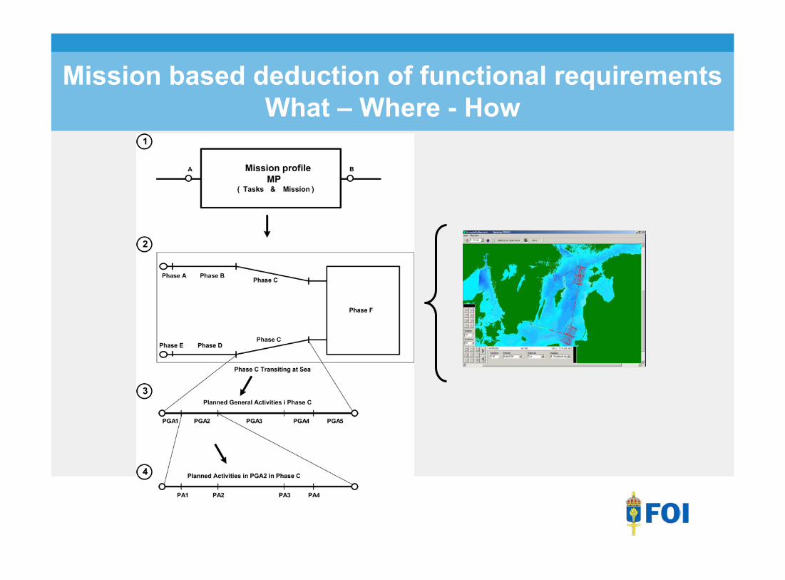
Mission based deduction of functional requirements What – Where - How

From the mission profiles What– Where- How
Technicaldesign

Levels of abstraction

Technical systems design and cost parametric and conceptual design

Operationsanalysis

Operations analysis – The mission profile
Planed mission profile
Including:
- Speed
- Course
- Time
- Depth
- Signature regime
- Machinery regime
- Mission orders
- Tactics etc.

Operations analysis – The Scenario
Environment – The Scenario
Including:
- Different actors routes e.g. speed etc.
- Naval ships, Merchants etc.
- Environmental factors: - Ambient noise etc. - Sea state - Sound profile - Magnetic field - Conductivity
- Rules of engagement

Operations analysis – The encounter
Simulation of a mission in one scenario
Operations analysis based on a physical description of the design object e.g. a submarine:
- How good is our submarine
- Measuring of MoE and OMoE
- Different tactical missions
- Different scenarios
- Different environments
Functional analysis:
- Deduction of event based functions and their requirements

Systemsanalysis

Lowest effect, Emin
Cost
Effect
E1
E5
E3
K1K3 K4
dEdK
Conceptfamily 5
Conceptfamily 1
Conceptfamily 4
E4
K5
Eopt
Kopt
Conceptfamily 2
Conceptfamily 3
Systems effect vs. cost
Systems analysis
Evaluation based on a physical description of the design object e.g. a submarine:
-Cost and effect based evaluation for all the different combinations of interest
-A set of rules for guidance during evaluation and as a support for decision
-It is not a automated process but a structured approach for analysis

Conclusions I
• A effect and mission based approach starts with needs
• Requirements is part of a design process
• A integrated design and analysis methodology for submarine design includes:
• Technical design
• Cost prediction and calculation
• Operations analysis
• Systems analysis
• Knowledge data bases both in the functional and systems domain – a vital part of the process
• Integrated project team – customer and contractor

Conclusions II
•A coherent methodology that provides a gradual and traceable knowledge growth from needs to a complete system definition.
•An approach that gives steeper knowledge growth with higher precision, earlier in the process.
•A methodology that produces higher knowledge content without blocking the creativity.
•A methodology that is not only describing but also learning and exploring.

Conclusions III
In summary, it has been shown that a design teams who use the new methodology incorporated in the toolbox can develop:
•Play-cards within the hour
•Concepts within a working day
•Reference models within 1-5 working days
•Product models within 10 to 30 working days.

QUESTIONS ?

SubAn Toolbox for submarine design and analysis
• SubAn: Main program for submarine design and analysis
• SubFunc: Functional analysis
• SubFunc Needs and requirements tools for functional analysis in the functions domain
• SubDes: Design program for submarines
• SubParm Parametric submarine design program in the functions domain
• SubParmDB Functional script database for submarine parametric design
• SubDesDB Systems script database for submarine conceptual design
• SubHull Hull and appendage design program
• SubStrength Pressure hull design program
• SubPred Speed-power prediction
• SubPow Predicting of powering and energy balance and endurance
• SubEn Predicting of the hotel/auxiliary load
• SubHydro Predicting static and dynamic stability
• SubCoff Predicting hydrodynamic coefficients
• SubMan Predicting maneuver an sea keeping
• SubRec Predicting emergency maneuvers
• SubSig Predicting submarine signatures (A/M/E)
• SubCost: Cost prediction and analysis program
• SubCost I Predicting of relative cost n the functions domain
• SubCost II Predicting of relative and absolute cost in the systems domain
• SubOA: Operations analysis program
• SubOaDB Database for play-cards and concepts
• SubOaScen Scenario and mission editing program
• SubOaSim Simulation program
• SubOaEff Systems effect MoE/OMoE
• SubOaRes Result and data handling for post analysis of OMoE/MoE
• SubOaLt Test system
• SubSA: System analysis and “optimization” tools
• SubSA System analysis program (SubCost and SubOA)

Warship 2011: Naval Submarines & UUVs
Recovery of Surfaced Disabled Submarines
Angus Watt Submarine Support Management Group
Emmanuel Ofosu-Apeasah MoD UK S&MO
29th June 2011

Introduction
• Outline of S&MO and SSMG
• Aim & Scope of presentation
• Overview
• Incidents & Locations
• Stabilising Options
• Recovery Methods
• Behaviour During Recovery (Video)
• Trial Results
• Research & Collaboration
• Recommendations
• Conclusions
29th June 2011 Warship 2011: Naval Submarines & UUVs 2

Outline of S&MO
• S&MO is part of the Defence Equipment and Support organisation within UK MoD
• Primary role is to provide tri-service marine salvage, ocean and coastal towing, heavy lift and fleet operational mooring capability worldwide
• First responder organisation, with first elements being ready to deploy within 6 hours of the initiating event
29th June 2011 Warship 2011: Naval Submarines & UUVs 3

Outline of SSMG
• The Submarine Support Management Group is an industry team with Babcock as prime contractor, supported by BMT Group and SEA
• Integrated joint team to produce the shared MoD UK In-Service Submarines Project Team and MoD UK Combat Systems Group outputs necessary to deliver submarine availability
• Collectively provides design and engineering technical services to the in-service Royal Navy submarine flotilla
29th June 2011 Warship 2011: Naval Submarines & UUVs 4

Aim & Scope of Presentation
Aim
To present existing and other innovative methods employed in the stabilisation and recovery of a surfaced disabled submarine to a safe haven and promote subsequent discussion
Scope
Excludes the escape and rescue of the submarine crew or the salvage of a bottomed disabled submarine
Disclaimer
The views and opinions expressed in this presentation by the authors do not necessarily reflect the views opinions or strategies of MoD UK, BMT Defence Services or Babcock
29th June 2011 Warship 2011: Naval Submarines & UUVs 5

Overview
• In the event of loss of power, watertight integrity or manoeuvring a dived SM should be able to recover to the surface
• On reaching the surface the SM may not be out of danger:
– Continued flooding
– External hazards e.g. collision or grounding
– Surface seakeeping
• Disabled surfaced submarine is not considered “safe” until successful recovery to a safe haven e.g. Port
29th June 2011 Warship 2011: Naval Submarines & UUVs 6

Incidents & Locations
• Incidents that could lead to a submarine becoming disabled on the surface include:
– Fire, Collision and grounding
– Mechanical or material defect etc.
• Submarine incident locations:
– Littoral & coastal waters with or without host nation support
– Open oceans with easy access to offshore support ships
– Remote open oceans with poor access to offshore support ships
– Unfriendly hostile areas without host nation support
– Antarctic and arctic regions
29th June 2011 Warship 2011: Naval Submarines & UUVs 7

Stabilising Options
• Command priorities: Secure, Stabilise, Improve
• Specialist advice or first aid assistance to carry out repairs & transit under own power
• If not possible then:
– Use a parachute sea anchor
– Rig fin harness
– Moor alongside a support ship
– Anchor (inc. Deep Water Mooring System)
• If the SM cannot be repaired in situ to allow a transit to a safe haven under own power:
– Emergency Tow or Heavy Lift / Floating Dock
29th June 2011 Warship 2011: Naval Submarines & UUVs 8
Anchor (inc. Deep Water Mooring System)
If the SM cannot be repaired in situ to allow a

Recovery Methods
Rip Out Tow
•Bow tow
•Built-in UK submarine emergency towing method:
– Rip out pendant
– Main tow line
– Tow slip
29th June 2011 Warship 2011: Naval Submarines & UUVs 9

Recovery Methods
Anchor Snag
•Bow tow
•Anchor chain cable
•Tow via catenary in anchor chain
•Blake slip/stopper removed
29th June 2011 Warship 2011: Naval Submarines & UUVs 10

Recovery Methods
Rudder Snag
•Stern tow
•Chain cable & fibre/wire ropes
29th June 2011 Warship 2011: Naval Submarines & UUVs 11

Recovery Methods
Use of Mooring Bollards / Hinged Cleats
•Bow or stern tow
•Ensure adequate equipment strength
29th June 2011 Warship 2011: Naval Submarines & UUVs 12

Recovery Methods
Fin Harness
•Ahead tow
•Webbing belt & Steelite
•Intended to hold & prevent a disabled submarine from running ashore in an emergency
29th June 2011 Warship 2011: Naval Submarines & UUVs 13

Recovery Methods
Heavy lift / Floating Dry Dock
•Should recovery via emergency tow not be possible
29th June 2011 Warship 2011: Naval Submarines & UUVs 14

Behaviour During Recovery
• The video with cover:
– SM model being towed from the bow
– SM model being towed from the bridge fin
– SM model being towed from the rudder
– SM model being towed from the bow using drogues
– SM model with parachute sea anchor deployed
– Full Scale SM rip out and fin harness tow
29th June 2011 Warship 2011: Naval Submarines & UUVs 15

Model Tank & Open Water Trials
• Towing trials undertaken for all classes of RN SM, results show that their behaviour is dependant on:
– Trim
– Direction of tow (ahead or astern)
– Position & location of tow point
– Sea state
– Availability of steering
– Tow line length and catenaries
29th June 2011 Warship 2011: Naval Submarines & UUVs 16

Full Scale Trial Results
Improved Behaviour & Reduced Tow Loads
•Stern trim >1m when towing from the bow
•Stern trim >1m and the bow tow point is located within 0.10L from the forward extremity
•Tow points within 0.15L from the forward or aft extremities
•Bow trim of 2m to 3m when towing from the stern
29th June 2011 Warship 2011: Naval Submarines & UUVs 17

Full Scale Trial Results
General Towing Experience
•Speeds <3 knots and short tow cable lengths the submarines tend to be directionally unstable
•Speeds >3 knots, with a tow cable length of between 2L and 3L the SM’s tend to reach an equilibrium position with the heading veering from 20-30 degrees to port or starboard of the towing vessel
•Steering on the submarine, or the use of drogues during the tow found to reduce the veering angles
29th June 2011 Warship 2011: Naval Submarines & UUVs 18

Full Scale Trial Results
Anchor Snag
•Demonstrated in benign environmental conditions
•Ease of snagging the anchor dependent on the equipment fit, sea state and seamanship experience
•Towing characteristics marginally better than those outlined for slow towing speeds
Rudder Snag
•Demonstrated in benign environmental conditions
•Towing characteristics similar to those outlined for slow towing speeds however further refinement required
29th June 2011 Warship 2011: Naval Submarines & UUVs 19

Full Scale Trial Results
Other Considerations
•Minimum tow speed in suitable weather conditions should be >5 knots and tow cable lengths of 3L to 4L, unless in heavy seas
•Tow cable length of >4L does not appear to be beneficial
•Caution when slowing down or shortening the tow to ensure that the submarine does not overtake or collide with towing vessel
•Use of a bridle connecting point is marginally better than the use of a single line
29th June 2011 Warship 2011: Naval Submarines & UUVs 20

Research & Collaboration
• Development and optimisation of SM recovery concepts:
– Develop a low density compound to displace flood water
– Enable the anchor to be released from inside the submarine (Blake Slip)
– Optimise the shape, material and weight of the Parachute Sea Anchor and Drogues
– Develop a list of requirements for heavy lifting a disabled submarine
– Adaptation of the parachute sea anchor and drogues for use by disabled large commercial vessels
– Develop capability to undertake load-on/load-out operations in greater than 0.5m wave height
29th June 2011 Warship 2011: Naval Submarines & UUVs 21

Recommendations
Design
•Bow and stern tow capability iaw IMO Requirements
•SM’s to carry a parachute sea anchor and fin harness
•Ensure the anchoring equipment is also suitable for towing
•Mooring bollards raised from within PH
•Develop the capability to RAS diesel fuel at sea and the ability to moor alongside a support ship.
•Consultation on design of new generation heavy lift vessels
Training & Education
• Develop a towing training course for SM crew
• Brief tug masters on towed SM behaviour
• Publish lessons learnt from SM tow trials
29th June 2011 Warship 2011: Naval Submarines & UUVs 22

Conclusions
• Model and full scale trials have supported the development of knowledge and understanding of recovery methods
• Model and full scale trials should continue to consolidate existing and develop new recovery methods
• Collaboration beneficial to improve options development
• Training of SM crew and tug masters to enhance preparedness
• Trial results provide input into the requirements for existing & future submarines
29th June 2011 Warship 2011: Naval Submarines & UUVs 23

Any Questions?
29th June 2011 Warship 2011: Naval Submarines & UUVs 24

Full Aut ority Submarine Control:Full Authority Submarine Control:
Conc t DevelopmentConcept Development
S rlingStirling DynamicsDynamics
Presentation by: aRoss Mansfield
Date:Date: 29/06/201129/06/2011
Presented At:Presented At: Warship 2011Warship 2011

IntroductionIntroduction
•• Ov view of Conventional Steering & Diving Con lOverview of Conventional Steering & Diving Control
•• F Authority Submarine ControlFull Authority Submarine Control
• Elements of the systemElements of the system
• Why hasnWhy hasn’’t this been done before?t this been done before?
• Status of current elements Status of current elements –– TRLsTRLs
• Automatic out of trim compensation developmenAutomatic out of trim compensation development
•• C clusionsConclusions
•• Qu tions Questions
© 2011 Stirling Dynamics2

Overview of Conventional Steering & Diving ControlOverview of Conventional Steering & Diving Control
© 2011 Stirling Dynamics3
Valve Drive
Electronics
o
v
position
velocity
Valve Drive
Electronicso
v
Valve Drive
Electronics
o
v
position
velocity
Valve Drive
Electronicso
v
Rudder
Valve Drive
Electronics
o
v
position
velocity
Valve Drive
Electronicso
v
Valve Drive
Electronics
o
v
position
velocity
Valve Drive
Electronicso
v
Aft Hydroplanes
Valve Drive
Electronics
o
v
position
velocity
Valve Drive
Electronicso
v
Valve Drive
Electronics
o
v
position
velocity
Valve Drive
Electronicso
v
Fwd Hydroplanes
PMSDataBus
Hover Plant
DisplayTrim & Comp System
Hover Controller
Depth Autopilot
Heading Autopilot
Manual Control
Trim & Compensation
Out of Trim Estimation
Depth, Pitch, Plant Info
Depth, Pitch, Speed
Heading, Speed
Depth, Pitch, Speed
Display
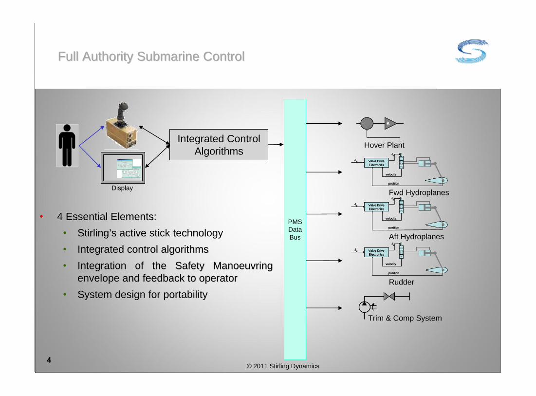
Full Authority Submarine ControlFull Authority Submarine Control
© 2011 Stirling Dynamics4
Valve Drive
Electronics
o
v
position
velocity
Valve Drive
Electronicso
v
Valve Drive
Electronics
o
v
position
velocity
Valve Drive
Electronicso
v
Rudder
Valve Drive
Electronics
o
v
position
velocity
Valve Drive
Electronicso
v
Valve Drive
Electronics
o
v
position
velocity
Valve Drive
Electronicso
v
Aft Hydroplanes
Valve Drive
Electronics
o
v
position
velocity
Valve Drive
Electronicso
v
Valve Drive
Electronics
o
v
position
velocity
Valve Drive
Electronicso
v
Fwd Hydroplanes
PMSDataBus
Hover Plant
Display
Trim & Comp System
Integrated Control Algorithms
•• 4 Esse al Elements:4 Essential Elements:
•• tStirling’’s act ve i t c nol s active stick technology
•• Inte ted control algorithmsIntegrated control algorithms
•• Integ on of the Safety Manoeuvring Integration of the Safety Manoeuvring
envel and feedback to operatorenvelope and feedback to operator
•• yst i for port l tSystem design for portability

Full Authority Submarine Control: Operator ControlFull Authority Submarine Control: Operator Control
© 2011 Stirling Dynamics5
Integrated Control Algorithms
• The active stick provides real-time configurable force feedback, detents, soft stops, hard stops
Hard Stop
Depth Hold
SLOWNORMAL
FAST
RiseDive
Stick Control Software
InputProcessing:Stick takes
Priority
Display
SME Limits
SME Limits
Ordered PitchOrdered Depth
Rate
Depth Setpoint
DemandBackdrive
FASC Software

• Current ship control actions to achieve low speed hover
Full Authority Submarine ControlFull Authority Submarine Control
© 2011 Stirling Dynamics6
Order trim
rpm
Order con
stant
depth and he
ading
Manually trim
to
OTE advice
Order zero rpm
Initialise Hover
System
Engage Hover
System
Disen
gage
Autop
ilot
Speed
time
Manual H
ydroplane
Control
Hover ControlAP Control

Speed
time
Order zero rpm
Order con
stant
depth and he
ading
Full Authority Submarine Control
Full Authority Submarine ControlFull Authority Submarine Control
© 2011 Stirling Dynamics7
• Operator actions and workload are reduced
• Depth control is seamless across the speed range.
• The integrated control algorithm uses the most appropriate combination of control effectors.
• The potential for control algorithm and/or operator action conflict during transition phases is eliminated

Full Authority Submarine Control: PortabilityFull Authority Submarine Control: Portability
© 2011 Stirling Dynamics
8
Data Bus
Master FASC(Control Room)
Hover Valve Ballast Pump Trim PumpBilge PumpTrim Pump
Valve Drive
Electronics
o
v
position
velocity
Valve Drive
Electronicso
v
Valve Drive
Electronics
o
v
position
velocity
Valve Drive
Electronicso
v
Rudder
Valve Drive
Electronics
o
v
position
Valve Drive
Electronicso
v
Valve Drive
Electronics
o
v
position
Valve Drive
Electronicso
v
Aft Hydroplanes
Valve Dr ve
Electron cs
o
v
position
velocity
Valve Dr ve
Electron cso
v
Valve Dr ve
Electron cs
o
v
position
velocity
Valve Dr ve
Electron cso
v
Fwd Hydroplanes
Auxiliary FASC(Bridge Fin)
Auxiliary FASC(Manoeuvring) Secondary FASC
(UUV Controller)
Alongside TrainingFacility
UUVCommunications
•• Redundancy control is Redundancy in control is
provided t gh multiple provided through multiple
FASC unFASC units
• om le AS its Complete FASC units
can be ried as can be carried as LRUsLRUs
in on bo rd spares.in on board spares.
•• Hot s pping FASC units Hot swapping FASC units
ovid vai abi i yprovides availability
DisplayDisplay

Full Authority Submarine Control: Why Now?Full Authority Submarine Control: Why Now?
© 2011 Stirling Dynamics9
Te oTechnology
P oc eProcesses
Stan dsStandards
iftSwiftsure:ch i Mechanical AP
T af arTrafalgar:Me a ca Mechanical AP
Upholder:Upholder:Software APSoftware AP
Vanguard:Vanguard:Software APSoftware AP
Astute:Astute:IPMS:IPMS:AP
HoverHover
Manual T CompManual Trim & Comp
Successor:Successor:??
1973 19831983 19901990 19931993 20092009
19841984
A 0:A320:F rst p du i n First production
digital FBW digital FBW
syst msystem
20062006
JS :JSF:F rst d n First production
active stickactive stick
19701970
ConcordConcorde:First anal First analogue
FBW st mFBW system
NASA F8:NASA F8:First xpe men a First experimental
digital FBW digital FBW
systemsystem
21972
Test Active stick / FCS Test
ro rammprogrammes:
NASA AHNASA AH--64 HACT64 HACT
ASA UHNASA UH- 0 RASC60 RASCAL
QQ VAAC HarrierQQ VAAC Harrier
1990s-2000s

Full Authority Submarine Control: Development StatusFull Authority Submarine Control: Development Status
© 2011 Stirling Dynamics10
Technology TRL
Active Stick 8/9
Course & Depth Autopilot
8/9
Hover Controller 7/8
Automatic out of trim compensation
3
FASC 2/3
Stirling Dynamics has developed algorithms and software used on Astute, U214, U209, U212A, Dolphin class boats.
Developed over the past ten years and now used as standard by companies such as NASA Langley, Boeing and Lockheed Martin. Now being supplied for the JSF simulator program in the USA.
Stirling’s hover control algorithm has recently undergone successful first of class sea trials.
Core functionality implemented in real time demonstrator developed using prototyping hardware and software.
Core algorithm developed and demonstrated in representative simulation environment.

Full Authority Submarine Control: OTC DevelopmentFull Authority Submarine Control: OTC Development
© 2011 Stirling Dynamics11
ShaftSpeed
Auto Flow Demands
ExternalExcitation
Trim andComp. Plant
Autopilot Algorithm
Out of Trim Compensation Algorithm
Density
Sea State
Propulsion Dynamics
Actuator Dynamics
Sensors
Mass Matrix
Added Mass Terms
Hydrodynamic Body and
Control Surface Forces
Hydrostatic Forces
States
++
++
x÷
Boatstates
Boat Dynamics
Auto ControlDemand
s
Boat Model
Auto Plane Demands
Plane Angles
Ballast Mass & cg changes
Forces/moments
Speed Demand
Out of Trim Estimation KF
PID Control
Transient Manoeuvre detection
Control demand shaping
Flow demand
In trim demand
- +
Plant Control Limits
OperatorOrders
OTC Algorithm

Full Authority Submarine Control: OTC DevelopmentFull Authority Submarine Control: OTC Development
• Depth Changing:
• OTC can successfully trim the boat during depth changes, resulting in more consistent manoeuvres.
• Depth Keeping
• OTC is most Effective in sea state 4 to sea state 6, assisting hydroplane control
• OTC significantly improves depth keeping performance when periodic swell are present, 12s and 18s swells have been simulated.
• OTC successfully eliminates steady disturbances, restoring hydroplane control authority
12

Full Authority Submarine Control: SummaryFull Authority Submarine Control: Summary
© 2011 Stirling Dynamics13
• Change from ‘blue water’ to more wide ranging roles is producing more challenging platform control requirements.
• Combined with additional pressures on space and operator workload, this is driving the requirement for the boat to spend more time in ‘automatic’ control.
• Platform control solutions need to be flexible and upgradeable to accommodate changing roles during the service life of the submarine.
• FASC delivers integrated depth, pitch and course control control, providing a simplified intuitive operator interface, and a flexible, scaleable system
• Features and technology proven in the aerospace domain have been incorporated into FASC.
• With the successful development of OTC, the complete control algorithm structure in FASC has been developed, taking FASC to TRL 3.
• Stirling are currently investigating the route to achieve TRL6/7

S rling Stirling DynamicsDynamics
Full Authority Submarine Control: QuestionsFull Authority Submarine Control: Questions

© 2011 Stirling Dynamics15
Head Office 26 Regent Street Clifton Bristol, BS8 4HG United Kingdom Tel +44 (0)117 9152 500
Filton Office Brabazon Office Park Golf Course Lane Filton Bristol, BS34 7PZ United Kingdom Tel +44 (0)117 9152 500
Farnborough Office Terminal Building Blackbushe Airport Camberley Surrey, GU17 9LQ United Kingdom Tel +44 (0)117 9152 500
Stirling Dynamics Inc Crowne Pointe Corporate Center Suite 205 4030 Lake Washington Blvd NE Kirkland, WA 98033-7870 USA Tel +1 425 827 5222

1
Submarine manoeuvring: correlating simulation with model tests and full-scale trials
Nick Kimber, QinetiQ, Haslar, UK
A presentation to: RINA Warship 2011
Naval Submarines and UUVs
29th June 2011

2
Contents
1 Introduction
2 Full-scale trials
3 Types of manoeuvres
4 Development of best practice
5 Free-running model experiments
6 Comparisons
7 Conclusions

3
1 Introduction
As part of the Maritime Strategic Capability Agreement (MSCA) the UK Ministry of Defence requires support for its ongoing safety assurance programmes
• one aspect is the issuing of Operator Guidance
• manoeuvring predictions come from mathematical models
• these must be developed, maintained, updatedand validated throughout the life of a submarine
• much of the validation comes from model experiments
− backed up by full-scale trials when possible
• the mathematical model also “drives” the platformsimulators used for crew training at the Faslaneand Devonport bases
PERISCOPE DEPTH
speed
depth
25°
18°
12°
6°
AVOID
AVOID
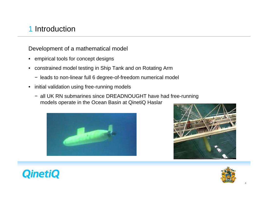
4
1 Introduction
Development of a mathematical model
• empirical tools for concept designs
• constrained model testing in Ship Tank and on Rotating Arm
− leads to non-linear full 6 degree-of-freedom numerical model
• initial validation using free-running models
− all UK RN submarines since DREADNOUGHT have had free-running models operate in the Ocean Basin at QinetiQ Haslar

2Full-scale trials
5

2 Full-scale trials
6
QinetiQ has been involved in submarine manoeuvring trials for over 50 years
Year Boat Description
1958 HMS PORPOISE Dynamic stability and turning trials
1963 HMS DREADNOUGHT First of Class trials
1964 HMS PORPOISE Manoeuvring trials
1965 HMS DREADNOUGHT Speed trial
1967 HMS VALIANT First of Class trials
1968 HMS RESOLUTION Manoeuvring trials at AUTEC
1970 HMS WARSPITE Emergency recovery
1970 HMS OTTER Acceleration and deceleration
1970/1 HMS CHURCHILL Contractor sea trials
1971 HMS REPULSE Emergency recovery and stability
1972 HMS SWIFTSURE Contractor sea trials
1973 HMS SWIFTSURE First of Class trials
1974 HMS SOVEREIGN Contractor sea trials
1974 HMS SWIFTSURE Manoeuvring trials at AUTEC
1974 HMS CONQUEROR Manoeuvring trials at AUTEC
Year Boat Description
1976 HMS SOVEREIGN First of Class trials
1976 HMS SUPERB Contractor sea trials
1976 HMS OCELOT Periscope depth keeping
1978 HMS SWIFTSURE Frequency response trial
1981 HMS SOVEREIGN Periscope depth keeping
1982 HMS VALIANT Emergency recovery
1983/4 HMS TRAFALGAR First of Class trials
1985 HMS SPARTAN Periscope depth keeping
1985 HMS TURBULENT First of Class trials
1986 HMS TURBULENT Periscope depth keeping
1989 HMS UPHOLDER Contractor sea trials
1992/3 HMS VANGUARD Contractor sea trials
1993 HMS SUPERB Depth keeping trials
1993 HMS UPHOLDER First of Class trials
1994 HMS VANGUARD Depth keeping

2 Full-scale trials
7
Year Boat Description
1994 HMS VANGUARD First of Class trials
1995 HMS TRIUMPH Emergency recovery
1995 HMS TRIUMPH Trim and compensation
1996 HMS SCEPTRE Depth keeping
2000 HMS TRIUMPH Manoeuvring trials
2001 HMS TRIUMPH Peak motion measurement
2002 HMS TORBAY Post-refit manoeuvring trials
2003 HMS TRENCHANT Post-refit manoeuvring trials
2004 HMS SPARTAN Depth keeping
2005 HMS TRENCHANT Manoeuvring / emergency recovery
2006 HMS TALENT Post-refit manoeuvring trials
2006 HMS TRAFALGAR Propulsion trial
2008 HMS VIGILANT Manoeuvring / emergency recovery
2010 HMS TALENT Propulsion trial
2010 HMS TRIUMPH Post-refit trials
2010 HMS VICTORIOUS Manoeuvring trials
Generic descriptions
• Contractor Sea Trial
• First of Class trials
• Post-refit
• Manoeuvring
• Propulsion
• Periscope Depth
• Emergency recovery

2 Full-scale trials
8
Instrumentation
• speed
• roll, pitch, heading
• depth
• angular rates
• accelerations
• control surface angles
• rpm
• range track data (if available)
• manual records

3Types of manoeuvres
9

3 Types of manoeuvres
10
• Preparation / calibration
− propulsion runs: acceleration,deceleration and braking
adju
sted
log
spee
d (k
ts)
TPK
adjusted log speed
TPK
0 20 40 60 80 100 120
Sp
ee
d
Time (s)
trial data
simulation

3 Types of manoeuvres
11
• Preparation / calibration
− propulsion runs: acceleration,deceleration and braking
− trim assessment
12.5 13 13.5 14 14.5
-0.8
-0.4
0
0.4
0.8
x 10
Time of Day (hours)
Balla
st
err
or
(litre
s)
TAS estimate
O tank
9 9.2 9.4 9.6 9.8 10 10.2 10.4 10.6-6000
-4000
-2000
0
2000
4000
Time of Day (hours)
Trim
err
or
(litre
s)
TAS estimate
tank dip reading

3 Types of manoeuvres
12
• Preparation / calibration
− propulsion runs: acceleration,deceleration and braking
− trim assessment
− compressibility estimation
Loss of buoyancy (tonnes)
Dep
th (m
)
Dips
Totalisers
Calculated

3 Types of manoeuvres
13
• Open-loop manoeuvring
− turning circles / pull-outs
− free turns
− zig-zags
− pitch overshoots
− single hydroplane pulse manoeuvres
− frequency response
• Closed-loop manoeuvring
− autopilot performance
− periscope depthkeeping
-18 -16 -14 -12 -10 -8 -6 -4 -2 0 278
80
82
84
86
88
90
92
94
96

3 Types of manoeuvres
14
• Pseudo emergency manoeuvres
− hydroplane jams
− various responsestrategies
Fixed plate
Stop
Stop
Limiter
Order Transmission Box

4Development of best practice
15

4 Development of best practice
16
Preparation and planning
• much experience has been gained in the writing of trials orders
• all trial aspects are considered by a Hazard Review board of SQEP
• some manoeuvres are practiced in the simulators
• build up manoeuvres in stages
Trial execution
• initial conditions
− write waiting periods in the trial orders
− provide a time-history display
− do repeat runs
• write everything down
"considerably more attention must be given in future to the state of the ship at the beginning of the manoeuvre"
– EC Tupper, 1958 report

4 Development of best practice
17
Repeat runs
-20 0 20 40 60 80 100 120
1
rel. s
peed
-20 0 20 40 60 80 100 120
depth
(m
)
-20 0 20 40 60 80 100 120
0
5
10
pitch (
°)
-20 0 20 40 60 80 100 120-10
0
10
s (
°)
-20 0 20 40 60 80 100 120astern
0
ahead
Time (s)
rpm

5Free-running model experiments
18

5 Free-running model experiments
19
Use of the Submarine Research Model
• can be programmed to run autonomouslyin a deep-water facility
− follows timed sequence of eventsbased on full-scale conduct
• aim to replicate the more extremefull-scale runs
− then extend the rangeof manoeuvres
• prior to these run all the same propulsion, trim condition and compressibility tests
(port) rudder (stbd)35° 15° 3° 0° -3° -15° -35°
(rise) -25°-20°-16°-10°-6°-4°0°4°6°10°16°20°
(dive) 25°
Trial data onlyTrial and model dataModel data only
ster
npla
ne ja
m a
ngle

5 Free-running model experiments
20
Use of the Submarine Research Model
• also conducted several repeat runsof each manoeuvre
Assessing correlation
• points of interest are
− peak depth excursion
− peak pitch excursion
• these are the parameters which determine the safe operating boundaries
-20 0 20 40 60 80 100 120 140 160
1
spe
ed
ap
proa
ch s
peed
-20 0 20 40 60 80 100 120 140 160
dept
h (m
)-20 0 20 40 60 80 100 120 140 160
0
10
20
pitc
h (°
)Time (s)
Full-scale trialsModel experiments

6 Comparisons
21
Comparing model-scale with full-scale
depth pitch
mo
de
l d
ep
th e
xc
urs
ion
trial depth excursion
SAFE
SAFE
UNSAFE
UNSAFE
y=x
low speed
medium speed
high speed
mo
de
l p
itc
h e
xc
urs
ion
trial pitch excursion
SAFE
SAFE
UNSAFE
UNSAFE y=x
low speed
medium speed
high speed

6 Comparisons
22
Comparing simulation with model-scale
depth pitch
model depth excursion
sim
de
pth
ex
cu
rsio
n
SAFE
SAFE
UNSAFE
UNSAFE y=x
low speed
medium speed
high speed
higher speed
model pitch excursion
sim
pit
ch
ex
cu
rsio
n
SAFE
SAFE
UNSAFE
UNSAFEy=x
low speed
medium speed
high speed
higher speed

6 Comparisons
23
Comparing simulation with full-scale
depth pitch
sim
de
pth
ex
cu
rsio
n
trial depth excursion
SAFE
SAFE
UNSAFE
UNSAFEy=x
low speed
medium speed
high speed
sim
pit
ch
ex
cu
rsio
n
trial pitch excursion
SAFE
SAFE
UNSAFE
UNSAFE
y=x
low speed
medium speed
high speed

7 Conclusions
24
The aim is to maintain the mathematical model at the best possible fidelity
• validation comes principally from model experiments
• occasionally supported by full-scale trials
• any differences between results at the two scales must be reconciled
Full-scale data is a valuable resource
• good planning essential
− refer to existing database of manoeuvres
• conduct good preparatory runs to assess the boat condition
• allow time for steady initial conditions, and put this in the trial orders
• conduct repeats
− simulation will only give one answer

25
Any questions?

UNCLASSIFIED
Submarine Propulsor Technical DevelopmentsOpportunities and Challenges
Simon Banks - Design Specialist, Rolls-Royce plc
Copyright Rolls-Royce plc 2011
© 2011 Rolls-Royce Group plc The information in this document is the property of Rolls-Royce Group plc and may not be copied or communicated to a third party, or used for any purpose other than that for which it is supplied without the express written consent of Rolls-Royce Group plc.
This information is given in good faith based upon the latest information available to Rolls-Royce Group plc, no warranty or representation is given concerning such information, which must not be taken as establishing any contractual or other commitment binding upon Rolls-Royce Group plc or any of its subsidiary or associated companies.
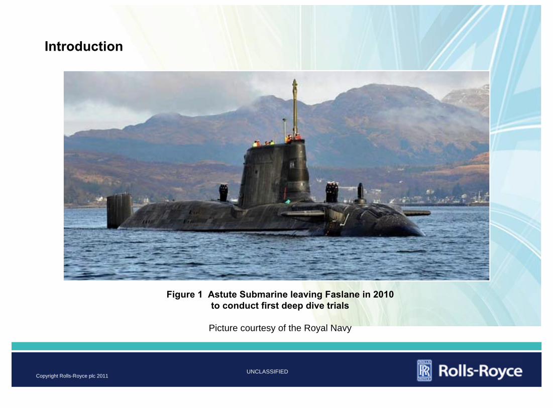
UNCLASSIFIED
Introduction
Figure 1 Astute Submarine leaving Faslane in 2010 to conduct first deep dive trials
Picture courtesy of the Royal Navy
Copyright Rolls-Royce plc 2011

UNCLASSIFIED
• Pump jet propulsors originally designed and developed by UK MoD for HMS Churchill in late 1960s.
• Variations fitted to all new build UK SSNs and SSBNs.
• Rolls-Royce involved in propulsor design and manufacture since 2000 (Astute Class).
History
Figure 2 Astute Submarine at BAES Shipyard, Barrow-in-Furness during launch in 2009
Picture: Murdo MacLeod
Copyright Rolls-Royce plc 2011

UNCLASSIFIED
• Features:
• Duct and stator vanes;
• Rotor blades, attached to shaft via a hub;
• Tail cone;
• Rope guards.
• Benefits* for naval nuclear submarine application:
• Higher efficiency;
• Reduced noise.
• Disadvantages*:
• Heavy, more costly
• A complex design
• Poorer astern performance
Pump Jet Description and Benefits
Figure 3 Unclassified Representation of a Pump Jet Propulsor
* Compared to an open propeller
Copyright Rolls-Royce plc 2011

UNCLASSIFIED
• Composite GFRP duct, tail cone and rope guards to reduce weight.
• Integration of stealth materials into composite laminates to eliminate tile loss.
• Application of high integrity, weld-free Nickel Aluminium Bronze castings to Def Stan 02-747 Part 4, for reduced corrosion and longer service life.
•Modular design for reduced installation/removal time.
• Shock qualification against onerous underwater shock criteria using modern assessment techniques.
Astute Class Propulsor - Important Achievements
Figure 4 NAB Stator Demonstrator Casting
Copyright Rolls-Royce plc 2011

UNCLASSIFIED
•Propulsor fundamental requirements:
• To convert power supplied from the shaft into propulsive power (to propel the submarine forwards and astern over a wide range of shaft speeds)
• To satisfy a range of performance and safety requirements
Design Requirements
Figure 5 Pump Jet Design Requirement Areas
Copyright Rolls-Royce plc 2011

UNCLASSIFIED
• Reduced costs:
• Unit production costs
• Through-life costs
• Reduced signature (particularly radiated noise)
• Reduced weight
Future Design Drivers
Figure 6 T-Class Submarine Berthed at Devonport
Copyright Rolls-Royce plc 2011

UNCLASSIFIED
• More widespread use of multi-functional composite materials for propulsor duct and stators.
• Development of lighter weight rotors.
• Shaft-independent propulsion.
Opportunities
Figure 7 Composite Stator Vane Flat Panel Test Piece containing Optical Fibre Strain Sensor
System
Copyright Rolls-Royce plc 2011

UNCLASSIFIED
“More Composite” Pump Jet Duct - Pros & Cons
Copyright Rolls-Royce plc 2011

UNCLASSIFIED
Alternative Rotor Materials - Benefits
Figure 8 Rolls-Royce NAB Propeller for UK Royal Navy Aircraft Carrier “Queen Elizabeth”
• Nickel-Aluminium-Bronze is well established and proven for marine propeller applications and submarine propulsor rotors.
• Provides a good combination of properties.
• However, development of lighter weight rotors could offer new benefits associated with reduced shaft and bearing loading.
• Realisation will need alternative rotor materials.
Copyright Rolls-Royce plc 2011

UNCLASSIFIED
Alternative Rotor Materials - Specific Property Comparisons
Copyright Rolls-Royce plc 2011

UNCLASSIFIED
Alternative Rotor Materials - Titanium
Copyright Rolls-Royce plc 2011

UNCLASSIFIED
Alternative Rotor Materials - Composites
Copyright Rolls-Royce plc 2011

UNCLASSIFIED
Composite Developments in Non-Naval Markets
• Non-naval market sectors will bring rapid advances in composites technology
• Examples:
• Marine current turbines
• Gas turbine composite fan blades
Figure 9 500 kW Demonstrator Tidal Energy System Operating at European Marine Energy
Centre in Orkney
Picture courtesy Tidal Generation Limited
Copyright Rolls-Royce plc 2011

UNCLASSIFIED
Shaft Independent Propulsion
• Benefits:
• Reduced complexity
• Higher power density
• Increased efficiency
• Reduced on-board space demands
• Lower noise and vibration
• Challenges:
• Water gap control under propulsor load
• Material longevity in marine environment
• Electromagnetic signature
• Design for assembly and installation (small water gaps)
Copyright Rolls-Royce plc 2011

UNCLASSIFIED
Conclusions
• Submarine pump jet design process is multi-disciplinary.
• Timely input from many stakeholders is needed to achieve the most optimal solution.
• Various opportunities for improvement exist
Copyright Rolls-Royce plc 2011

UNCLASSIFIED
Acknowledgements
• The support of the UK Ministry of Defence is gratefully acknowledged along with that provided by the following organisations, each of which has been involved in development of pump jet propulsor technology:
• BAE Systems Surface Ship
• BAE Systems Electronics Ltd
• Frazer-Nash Consultancy
• Meighs Limited
• Marshall Slingsby Aviation Limited
• Materials Engineering Research Laboratory (MERL)
• Weidlinger Associates
• Insensys Ltd
• QinetiQ Haslar
Copyright Rolls-Royce plc 2011

Defence R&D Canada – Atlantic
G.D. Watt, DRDC Atlantic
J.A. Carretero, R. DubayUniversity of New Brunswick
M.R. MacKenzie, DRDC Atlantic
Towards an Automated Active UUV Dock on a Slowly Moving Submarine
Royal Institution of Naval ArchitectsWarship 2011: Naval Submarines and UUVsBath, 29 – 30 June 2011

1
Deployable Unmanned Underwater Vehicles
• Expand the operational envelopes of UUVs and their hosts• Provide major naval platforms with
– Mine counter measures– Intelligence, surveillance, and reconnaissance– Communications– Oceanographic sensing
• Acquire from their host (covert when host is a submarine)– extended range– front line support
But recovering UUVs is difficult, especially for submarines

2
Oceanographers Recover Using Stationary Docks• Woods Hole, Remus docking
– dock fixed to ocean floor– Ultra-short baseline acoustic
position sensing:• range to several hundred meters• only ±0.5 m positioning accuracy
– 60% success rate per attempt, 90% for five attempts
• Naval Command, Control and Ocean Surveillance Center– Optical terminal guidance
• short range: down to 7 m in murky harbour water• good position accuracy: ±0.01 m
– Success docking • by launching upstream towards funnel• providing target acquired soon enough

3
Current Recovery Methods for Submarines
• Saab Underwater Systems– Sub and UUV sit on bottom– Two torpedo tubes required– Operator controlled
• Naval Undersea Warfare Center Division, Newport– Tail grab while underway– Two torpedo tubes required– Acoustic, optical sensing– Operator controlled
• ONR’s Universal Launch & Recovery Module– Larger, greater endurance UUVs– Under development; recovery method unclear

4
Recovery Requirements
• Deep water operations• Littoral operations with minimal sea state limitations• Automation for reliability and temporal efficiency• Low risk to propeller/appendages in case of breakage• Low risk of collision in presence of environmental disturbance• Flexible choice of UUV size/shape for endurance/functionality• Minimal docking infrastructure on UUV

5
Recovering a UUV with a Submarine
Three Phases• Making Contact
– Following UUV/submarine rendezvous, the UUV and dock must make physical contact
• Capture• ParkingProject focus is on making contact, the difficult part of the problem
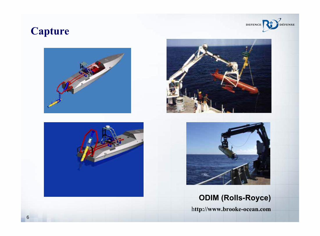
6
Capture
ODIM (Rolls-Royce)
http://www.brooke-ocean.com

7
Parking see Hardy, INEC 2008 BMT Defence Services
• Deck mounted enclosure
• Blister fairing on the side– allows covert deployment

8
Making-Contact Challenges
• After the UUV has completed its mission and rendezvoused with the submarine,– Submarine maintains straight and level flight at 2 – 3 knots.– Submarine dock displays an acoustic transponder and the UUV
homes in on it.• The docking that follows must allow for:
– inaccuracy in position sensing,– inaccuracy in heading and depth keeping ability,– uncontrolled vehicle motions (eg, roll),– different UUV and submarine responses to environmental
disturbance.– limited UUV and submarine maneuverability
• especially transverse to their path

9
Solutions
Where?
• Dock off to the side, midway along submarine hull– keeps UUV in relatively uniform flow– minimizes risk of collision– readily accessible by UUV– good compromise for docking in littoral waters
How?
• Two-stage position sensing– UUV: acoustic sensing provides range– Dock: optical/electromagnetic sensing for accurate, fast updates
• Two-stage maneuvering– UUV: initial path planning, homing– Dock: rapid transverse positioning for final docking

10
Active Dock
• Accurate position sensing, fast update rates– dock camera locates light emitting diodes (LEDs) on UUV
• Rapid transverse maneuverability– decouples transverse (fast) from axial (slow) offset corrections
• Takes command– Controls final docking– Issues simple commands to UUV (slow down, speed up, try again)
Relieves the UUV of many docking tasks, minimizing dockinginfrastructure on every UUV that is deployed

11
Making-Contact Scenario: Stage 1
UUV Homing
• UUV uses conventional acoustic sensing to home in on dock– One-way acoustic communications, dock to UUV, as required– Good range for establishing a viable approach– UUV does path planning
• UUV closes to within the transverse reach but remains somewhat aft of the dock
• UUV activates strategically located LEDs on its nose and appendages
• Dock locks onto LEDs and takes command Stage 2

12
Making-Contact Scenario: Stage 2
Final Docking
• Dock has acquired UUV optically/electromagnetically– Commands UUV to deactivate transverse control
• UUV enters 1D mode– Modulates UUV forward speed as it overtakes the dock.
• Dock continually corrects for transverse offset– keeps itself centered on the approaching UUV, or– monitors UUV, anticipates time and location for benign contact
• Dock requires– Good reach– Rapid transverse response– Fast, accurate position sensing multiple sensors, data fusion– Good control strategy

13
Evaluation Environment
Control strategy development Computer simulation
• Hydrodynamic/mechanical models of submarine, UUV, dock – three bodies, hydrodynamic interference
• Position sensing model– error, range, turbidity limitations
• Control systems– error and limitations
• Environmental disturbance– sea state effects at depth, internal waves, random motions
• Interface for control strategy developmentInexpensive, timely, model extreme scenarios with zero-risk

14
Way Ahead
3 Year Project• DRDC (Atlantic/Suffield)
– Leading– Position sensor design/prototype construction/testing– Errors and limitations simulation– Bayesian filters (data fusion) simulation– hydrodynamic modelling simulation
• University of New Brunswick (UNB)– Dock design/prototype construction/testing– Errors and limitations simulation
• Dynamic Systems Analysis (dsa-ltd.ca): simulation construction• Institute for Ocean Technology (NRC-IOT): control strategy• Rolls-Royce Naval Marine: consulting

15
Preliminary Dock Design• Establish docking envelope
– Location: off to side, midway along length– Size: what is relative motion between UUV and dock?
• Relative Motion Extremes– Fluid particle motion at 10 m depth under unimodal waves– Wave height = 2.5, 5 m– Ocean depth = 20 m, – Wave period = 7 – 16 s
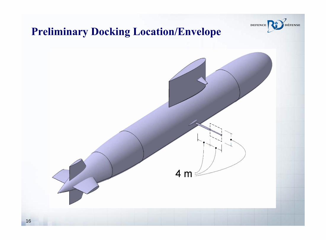
16
Preliminary Docking Location/Envelope

17
Dock Concept Designs
Wing Docks• Circumferential positioning Forward speed and pitch actuated• Radial positioning using:
Telescoping brace
Telescoping wing
Spanwise traveler

Defence R&D Canada – Atlantic

UNDERWATER GLIDERSUNDERWATER GLIDERS
FORCE MULTIPLIERS FOR NAVAL ROLESFORCE MULTIPLIERS FOR NAVAL ROLES
Commander AMIT RAYCommander AMIT RAY, PhD, PhDIndian Navy / IIT DelhiIndian Navy / IIT Delhi
W rs ip 201 : av l ub ar e an Warship 2011: Naval Submarines and UU sUUVs

AIMAIM
Review worldwide development of Review worldwide development of Unmanned Underwater Gliders and Unmanned Underwater Gliders and discuss potential naval applicationsdiscuss potential naval applications

SCOPESCOPE Introduction to Underwater GlidersIntroduction to Underwater Gliders Technological DevelopmentsTechnological Developments Hydrodynamics & ControlHydrodynamics & Control Naval ApplicationsNaval Applications Technological ChallengesTechnological Challenges

INTRODUCTIONINTRODUCTION
BackgroundBackground Defence EnvironmentDefence Environment
•• Growing emphasis on littoral warfareGrowing emphasis on littoral warfare•• Asymmetric threatsAsymmetric threats•• Shrinking numbers of naval platformsShrinking numbers of naval platforms
Imperative to recognize the tactical Imperative to recognize the tactical possibilities offered by possibilities offered by unmanned vehiclesunmanned vehicles
Autonomous Underwater Vehicles (Autonomous Underwater Vehicles (AUVsAUVs): ): Typically have low endurance (~24 hrs) Typically have low endurance (~24 hrs)

Underwater GlidersUnderwater Gliders ConceptConcept: : AUVsAUVs that use small changes in that use small changes in
buoyancy to travel upward/ downward, moving buoyancy to travel upward/ downward, moving forward in a vertical sawforward in a vertical saw--tooth pattern at low tooth pattern at low speed, with very low power consumption.speed, with very low power consumption.
5 km (7 hours)
200 – 1000 metres

FeaturesFeatures
Small, lightSmall, light--weight underwater weight underwater vehicles, developed for oceanographic vehicles, developed for oceanographic measurements measurements
Payload: variety of sensors (typically Payload: variety of sensors (typically CTD)CTD)
Buoyancy driven Buoyancy driven
Low speed (~0.5 knot horizontal Low speed (~0.5 knot horizontal speed)speed)

FeaturesFeatures
Long endurance (months; 1000s km) Long endurance (months; 1000s km)
BatteryBattery--powered powered
Communication via Iridium on Communication via Iridium on surface surface
Extremely quietExtremely quiet
Cost = a few days of shipCost = a few days of ship--timetime

TECHNOLOGICALTECHNOLOGICALDEVELOPMENTSDEVELOPMENTS
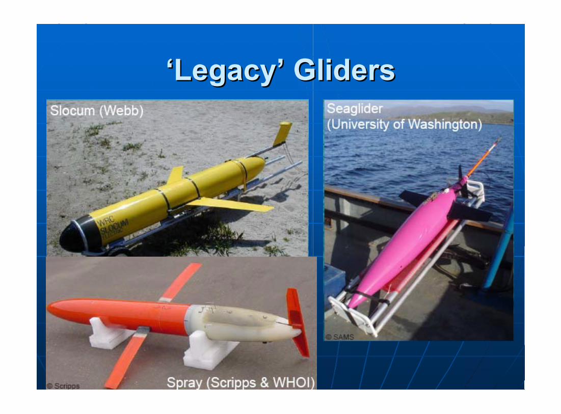
‘‘LegacyLegacy’’ GlidersGliders

SeagliderSeaglider SlocumSlocum SpraySpray
Length (m)Length (m) 1.81.8 1.51.5 2.02.0
Diameter (cm)Diameter (cm) 3030 2121 2020
Weight (kg)Weight (kg) 5252 5252 5252
Max. Depth (m)Max. Depth (m) 10001000 200 or 1000200 or 1000 15001500
Range (km)Range (km) 46004600 15001500 47004700
Endurance (days)Endurance (days) 180180 2020

Operating PrinciplesOperating Principles Moves vertically through water by changing Moves vertically through water by changing
buoyancy; buoyancy; No propellerNo propeller
Lift generatedLift generated due to hydrodynamic shape and due to hydrodynamic shape and pitch angle: moves forward as it dives/ surfacespitch angle: moves forward as it dives/ surfaces
Pitch angle controlPitch angle control by moveable internal weights by moveable internal weights
SteeringSteering by:by:•• Controlling roll (internal moving weights)Controlling roll (internal moving weights)•• RudderRudder
NavigationNavigation by:by:•• GPS on surface; DR underwaterGPS on surface; DR underwater•• CompassCompass•• Depth gauge (Altimeter)Depth gauge (Altimeter)

SchematicsSchematics-- ‘‘SpraySpray’’

Glider Hydraulic Buoyancy Glider Hydraulic Buoyancy EngineEngine

Operating CycleOperating Cycle On surfaceOn surface: GPS fix: GPS fix
DiveDive phase: phase: Buoyancy reduced, Buoyancy reduced, batteries forward; batteries forward; Record dataRecord data
ClimbClimb phase: phase: Buoyancy increased, Buoyancy increased, batteries aft ; batteries aft ; Record dataRecord data
On surfaceOn surface: Data : Data transmission; GPS transmission; GPS fixfix

CommunicationsCommunications By Iridium networkBy Iridium network On surface:On surface:
Glider sends data from its last diveGlider sends data from its last dive Pilot can rePilot can re--direct & send commands to direct & send commands to
Glider via text filesGlider via text files

OperationsOperations
About About 160160 commercially commercially available gliders of these available gliders of these three types were in three types were in operation in 2009operation in 2009
Mainly used to provide Mainly used to provide online dataonline data for biophysical for biophysical and physical and physical oceanographyoceanography so farso far
CostCost: about $50: about $50--70,00070,000•• Against $30,000 Against $30,000 per dayper day for for
an oceanographic dataan oceanographic data-- gathering shipgathering ship

OperationsOperations Coordinated missions over Coordinated missions over
months tracked from different months tracked from different continentscontinents
Easy to deploy and recoverEasy to deploy and recover
Glider fleets of universities Glider fleets of universities have logged more that have logged more that 80,00080,000 undersea milesundersea miles over past 5 over past 5 yearsyears
A Slocum Glider completed a A Slocum Glider completed a 5,700 km5,700 km voyage over 160 voyage over 160 days in 2008.days in 2008.
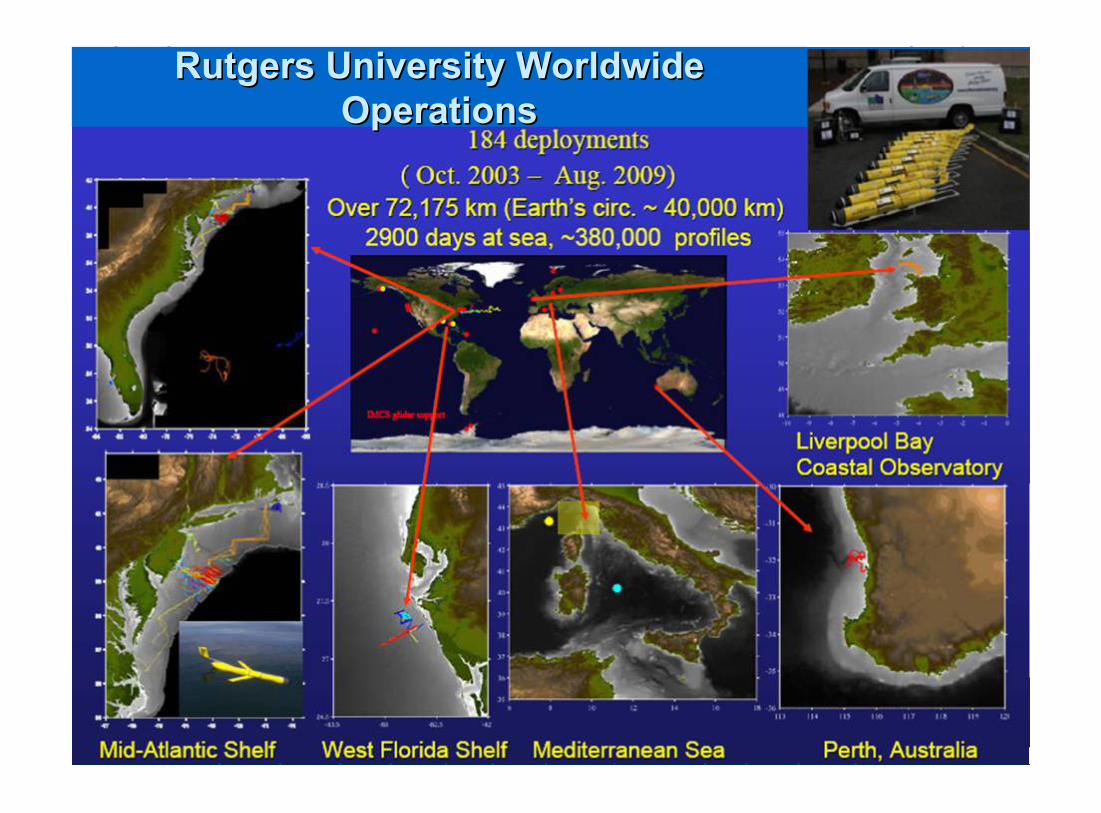
Rutgers University Worldwide Rutgers University Worldwide OperationsOperations

Deployments in AntarcticaDeployments in Antarctica

Coordinated SurveysCoordinated Surveys Snapshot of Glider locationsSnapshot of Glider locations-- Autonomous Ocean Sampling Autonomous Ocean Sampling
NetworkNetwork--II Monterey Bay 2003II Monterey Bay 2003

Sample Salinity plotSample Salinity plot

Sample monthSample month--long record of temperature & long record of temperature &
salinity as function of depthsalinity as function of depth

Sample Current PlotSample Current Plot

‘‘Flying WingFlying Wing’’ GlidersGliders
‘‘XX--RayRay’’ or or ‘‘LiberdadeLiberdade Flying Flying WingWing’’
‘‘ZZ--RayRay’’
Greater liftGreater lift
Hydrophones on leading edges of wingsHydrophones on leading edges of wings

XX--RayRay Passive sonar array for ASW applicationPassive sonar array for ASW application
Data Data TxTx by satellite; acoustic communication by satellite; acoustic communication submergedsubmerged
6.1 m wingspan6.1 m wingspan
Weight 850 kgWeight 850 kg
Range 1200Range 1200--1500 km1500 km
Speed 1Speed 1--3 knots3 knots
Endurance ~6 monthsEndurance ~6 months
Trials over 2006Trials over 2006--0808

ZZ--RayRay Sea trials in Dec 2010/ Jan Sea trials in Dec 2010/ Jan
20112011
Outer shroud of Outer shroud of monocoquemonocoque construction (fiberglass and construction (fiberglass and carboncarbon--fiber composites)fiber composites)
Titanium inner structureTitanium inner structure
Maximum depth 300 mMaximum depth 300 m
Weight about 680 kgWeight about 680 kg
Small water jets for fine Small water jets for fine attitude controlattitude control

ZZ--RayRay

TimelinesTimelines
19891989-- Vision of Gliders (Henry Vision of Gliders (Henry StommelStommel) ) 19921992-- ALBAC glider tested in JapanALBAC glider tested in Japan 20012001-- ‘‘LegacyLegacy’’ GlidersGliders in productionin production in US in US
(Slocum, (Slocum, SeagliderSeaglider, Spray), Spray) 20042004-- First US Naval exercisesFirst US Naval exercises 20052005-- Operational Gliders in US NavyOperational Gliders in US Navy 20062006-- First First ‘‘Flying WingFlying Wing’’ Glider (XGlider (X--Ray)Ray) 20082008-- ‘‘WavegliderWaveglider’’ tested at seatested at sea 20102010-- ‘‘ZZ--RayRay’’ tested at seatested at sea

Institutions InvolvedInstitutions Involved Design & DevelopmentDesign & Development
•• Webb ResearchWebb Research•• University of WashingtonUniversity of Washington•• Scripps Institute of Scripps Institute of
Oceano r hOceanography•• W ds le Oceanographi Woods Hole Oceanographic
InstituteInstitute•• Florida Institute of Florida Institute of
TechnologyTechnology•• EcoleEcole NSDNSD’’II•• University of SouthamptonUniversity of Southampton•• University of Tokyo University of Tokyo •• Osaka UniversityOsaka University
•• Office of Naval Research, Office of Naval Research, US NavyUS Navy
Production/ DesignProduction/ Design•• TeledyneTeledyne•• iRobotiRobot•• BluefinBluefin RoboticsRobotics•• ACSAACSA•• EvoEvo LogicsLogics•• Liquid RoboticsLiquid Robotics
Scientific ApplicationsScientific Applications•• Rutgers UniversityRutgers University•• Memorial UniversityMemorial University•• National Oceanography National Oceanography
CenterCenter•• Univ. of East AngliaUniv. of East Anglia•• Univ. of Western Univ. of Western
AustraliaAustralia

Future ConceptsFuture Concepts Thermal, solar and waveThermal, solar and wave––powered gliders: powered gliders:
•• Even lower energy consumptionEven lower energy consumption•• Miss ons spanning five years and thousands of Missions spanning five years and thousands of
miles miles
‘‘HybridHybrid’’ glidersgliders•• Provision of AUVProvision of AUV--type thruster in a glidertype thruster in a glider•• Enables horizontal trajectory when necessaryEnables horizontal trajectory when necessary•• AUVAUV--Glider, Glider, SeaExplorerSeaExplorer, , AutoSubAutoSub--LongRangerLongRanger

Future ConceptsFuture Concepts Booster/GliderBooster/Glider combination, withcombination, with
payloads that could be jettisonedpayloads that could be jettisoned
Seawater pressureSeawater pressure energy conversion energy conversion system to generate electricitysystem to generate electricity
BiomimeticBiomimetic formform

HYDRODYNAMICS & HYDRODYNAMICS & CONTROLCONTROL

Design DriversDesign Drivers Limited internal Limited internal volumevolume
MinimiseMinimise power consumptionpower consumption: : maximisemaximise endurance and rangeendurance and range
TradeoffTradeoff is a function of:is a function of:•• Glide pathGlide path•• SpeedSpeed•• Glider volumeGlider volume•• Battery sizeBattery size
Larger Larger gliders: Higher speeds & longer gliders: Higher speeds & longer rangesranges
Hydrodynamic DesignHydrodynamic Design
AimAim: : CharacteriseCharacterise trajectory & trajectory & develop efficient control algorithmsdevelop efficient control algorithms
Aspects of researchAspects of research::•• Refinement of shapeRefinement of shape•• Nonlinear stability analysisNonlinear stability analysis•• Control systemsControl systems•• System identification of parametersSystem identification of parameters

Hydrodynamic DesignHydrodynamic Design
Body shape & wing geometry Body shape & wing geometry optimisationoptimisation•• MinimiseMinimise dragdrag•• Lift/Drag ratioLift/Drag ratio•• VerticalVertical--toto--horizontal glide ratioshorizontal glide ratios
At low At low ReRe, form of legacy gliders gives low , form of legacy gliders gives low drag for given volumedrag for given volume
For max. horizontal speed, minimal drag For max. horizontal speed, minimal drag at glide angle near 35 deg, which requires at glide angle near 35 deg, which requires L/D of 1.4L/D of 1.4

Hydrodynamic DesignHydrodynamic Design
Flying the glider to deeper depths is Flying the glider to deeper depths is intrinsically more energyintrinsically more energy--efficientefficient
Bigger gliders achieve better Bigger gliders achieve better transport economy, with higher transport economy, with higher speed capabilityspeed capability

Motion ControlMotion Control Steering by:Steering by:
•• Internal weight shift used for change in Internal weight shift used for change in roll angle, thus changing headingroll angle, thus changing heading
•• Tail fin rudderTail fin rudder
Overall stability carefully adjusted: Overall stability carefully adjusted: affects sensitivity for pitch angleaffects sensitivity for pitch angle
ClosedClosed--loop guidance for change in loop guidance for change in buoyancy, pitch and roll.buoyancy, pitch and roll.
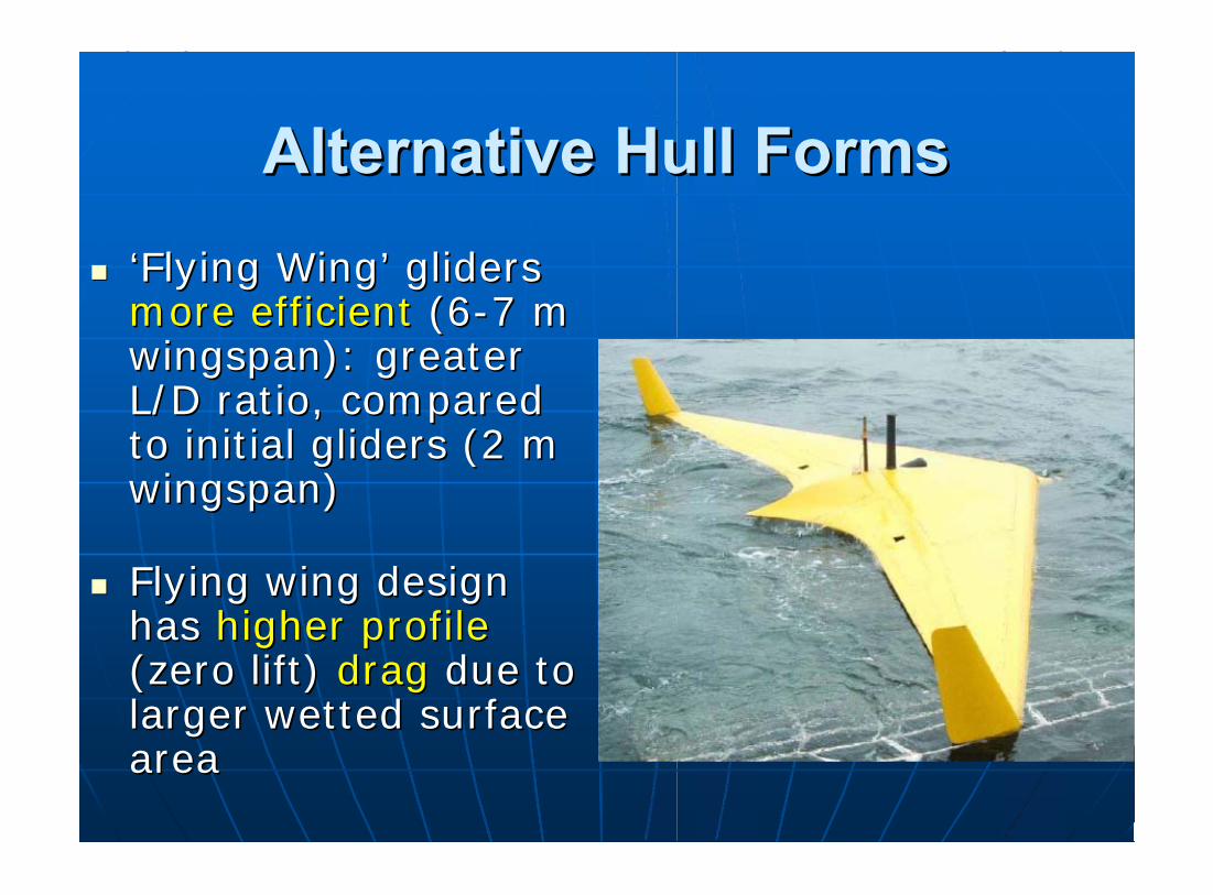
Alternative Hull FormsAlternative Hull Forms ‘‘Flying WingFlying Wing’’ gliders gliders
more efficientmore efficient (6(6--7 m 7 m wingspan): greater wingspan): greater L/D ratio, compared L/D ratio, compared to initial gliders (2 m to initial gliders (2 m wingspan)wingspan)
Flying wing design Flying wing design has has higher profilehigher profile (zero lift) (zero lift) dragdrag due to due to larger wetted surface larger wetted surface areaarea

Alternative Hull FormsAlternative Hull Forms Flying wing design has Flying wing design has lower drag at higher lower drag at higher
L/D ratiosL/D ratios and and shallower glide pathshallower glide path angles angles than legacy gliders than legacy gliders
Flying wings and blended wingFlying wings and blended wing--body body designs are better when design designs are better when design requirements call for requirements call for shallow glide pathshallow glide path anglesangles
Internal arrangementInternal arrangement of flying wing glider of flying wing glider components is problematiccomponents is problematic

Future Hydrodynamic Future Hydrodynamic ConceptsConcepts
Conventional glider Conventional glider design with cambered design with cambered airfoils and moving airfoils and moving flaps; flaps; morphing shapesmorphing shapes
Asymmetrical gliding Asymmetrical gliding and wing designsand wing designs
Independently Independently controllablecontrollable main wingsmain wings

Future Hydrodynamic Future Hydrodynamic ConceptsConcepts
Greater sizeGreater size•• Large and highLarge and high--datadata--rate rate
payloadspayloads•• Sufficient physical size to provide Sufficient physical size to provide
large acoustic array aperture at large acoustic array aperture at low and mid frequencieslow and mid frequencies
LenticularLenticular or ellipsoidal shape: or ellipsoidal shape: •• Low drag in the horizontal bottom Low drag in the horizontal bottom
currentcurrent•• Ability to resist trawls and Ability to resist trawls and
dredgesdredges

NAVALNAVALAPPLICATIONSAPPLICATIONS

Changing RolesChanging Roles Emphasis on Emphasis on littorallittoral warfarewarfare
Asymmetric Asymmetric threatsthreats
Capability enhancementCapability enhancement for:for:•• Persistent Intelligence, Surveillance & Persistent Intelligence, Surveillance &
Reconnaissance (ISR)Reconnaissance (ISR)•• Oceanographic bathymetric surveysOceanographic bathymetric surveys•• BattlespaceBattlespace awareness & preparationawareness & preparation•• Mine warfareMine warfare•• Base & port securityBase & port security

Shift to Unmanned PlatformsShift to Unmanned Platforms New threats can be met by New threats can be met by
networking sensors and networking sensors and communicationscommunications
Unmanned vehicles can be used as Unmanned vehicles can be used as nodes innodes in sensor & communicationsensor & communication networknetwork
UXVsUXVs can reduce workload of manned can reduce workload of manned platforms and improve coverage: platforms and improve coverage: force multipliersforce multipliers

Potential Glider RolesPotential Glider Roles ISRISR
•• Filling gaps in coverage by deployment in Filling gaps in coverage by deployment in numbersnumbers
•• UnobtrusiveUnobtrusive
•• Continuous monitoring of choke points and Continuous monitoring of choke points and harboursharbours: one or many: one or many
•• Data recording & transmission in realData recording & transmission in real--timetime
•• ‘‘Virtual periscopeVirtual periscope’’/ Upward/ Upward--looking traffic looking traffic surveillancesurveillance


Potential Glider RolesPotential Glider Roles ASWASW
•• Low selfLow self--noise and low costnoise and low cost
•• Hydrophone arrays on XHydrophone arrays on X--Ray & ZRay & Z--RayRay
•• ‘‘SentrySentry’’ at choke points at choke points
•• Methodical search pattern in an areaMethodical search pattern in an area
•• ReRe--configurable vertical/ horizontal arraysconfigurable vertical/ horizontal arrays
•• Transmit data to conventional ASW assetsTransmit data to conventional ASW assets
•• Multiply manifold the capability of Multiply manifold the capability of sonobuoyssonobuoys & & magnebuoysmagnebuoys
•• Training usesTraining uses

Potential Glider RolesPotential Glider Roles Mine CountermeasureMine Countermeasure
•• AUVsAUVs presently employed have endurance of presently employed have endurance of about 24 hours onlyabout 24 hours only
•• Glider could sweep a channel for 6 months at a Glider could sweep a channel for 6 months at a timetime
•• GliderGlider--borne optical suites demonstrated in borne optical suites demonstrated in littoral waterslittoral waters
•• Dumb Dumb minehuntingminehunting & & neutralisationneutralisation
•• Pattern searchPattern search

Potential Glider RolesPotential Glider Roles
HarbourHarbour PatrollingPatrolling•• Defensive role: perimeter defence or Defensive role: perimeter defence or
‘‘sentrysentry’’
•• Periodical visual recording & Periodical visual recording & transmissiontransmission
•• Greater endurance and stealth Greater endurance and stealth compared to USV or conventional AUVcompared to USV or conventional AUV

Potential Glider RolesPotential Glider Roles Military OceanographyMilitary Oceanography
•• Remote data collection (temperature & salinity Remote data collection (temperature & salinity profiles)profiles)
•• Littoral acoustic profilingLittoral acoustic profiling
•• FixedFixed--point profilingpoint profiling
•• SeaSea--floor mappingfloor mapping
•• Cheaper than submarines or even Cheaper than submarines or even XBTsXBTs
•• Most direct extension of proven scientific Most direct extension of proven scientific functions of Glidersfunctions of Gliders

Potential Glider RolesPotential Glider Roles Payload DeliveryPayload Delivery
•• LongLong--range clandestine delivery in hostile range clandestine delivery in hostile littoralslittorals
•• Delivery of ordnance (mines, charges, etc.)Delivery of ordnance (mines, charges, etc.)
•• Delivery of static sensorsDelivery of static sensors
•• Assistance for terminal homing of longAssistance for terminal homing of long--range range torpedoestorpedoes
•• Mother vehicle for delivery of Mother vehicle for delivery of SDVsSDVs
•• Delivery of Delivery of AUVsAUVs to search/ patrol areasto search/ patrol areas
•• Delivery time in hours/ daysDelivery time in hours/ days

Glider Types based on RolesGlider Types based on Roles DepthDepth--unlimitedunlimited: Similar to : Similar to ‘‘legacylegacy’’ gliders, with gliders, with
deep zigzags.deep zigzags.
DepthDepth--limitedlimited: Flat glide slopes and higher cruise : Flat glide slopes and higher cruise speeds; similar to speeds; similar to ‘‘Flying WingFlying Wing’’ design.design.
Virtual stationVirtual station--keepingkeeping: Hovering/ anchoring/ : Hovering/ anchoring/ bottoming capability, with adequate thrust to bottoming capability, with adequate thrust to counter ocean currents.counter ocean currents.
Payload DeliveryPayload Delivery: Combination of deep: Combination of deep--water and water and depthdepth--limited operational capabilities.limited operational capabilities.
Level Flight HybridsLevel Flight Hybrids: Alternative thruster offers : Alternative thruster offers level flight capability when necessary.level flight capability when necessary.

Potential Sensor SuitesPotential Sensor Suites
Passive/ Active acoustic sensorsPassive/ Active acoustic sensors Magnetic GradiometerMagnetic Gradiometer RF communicationRF communication AboveAbove--water cameras (water cameras (colourcolour; IR); IR) Inertial navigationInertial navigation CTD sensorsCTD sensors Acoustic modemAcoustic modem

Naval Trials UndertakenNaval Trials Undertaken US Navy exercisesUS Navy exercises: RIMPAC: RIMPAC--04, TASWEX04, TASWEX--0404
November 2006:November 2006: First launchFirst launch of an underwater glider of an underwater glider from a from a submarinesubmarine
Passive Acoustic Autonomous Monitoring (Passive Acoustic Autonomous Monitoring (PAAMPAAM) of ) of Marine Mammals programMarine Mammals program since 2007 since 2007
January 2011January 2011: ONR exercise at the Southern California : ONR exercise at the Southern California ASW Range (SOAR)ASW Range (SOAR) including including ZZ--Ray, Ray, SeagliderSeaglider, Slocum , Slocum gliderglider
February 2011February 2011:: NATO tested three Gliders in the NATO tested three Gliders in the Mediterranean Sea in ASW exercise Mediterranean Sea in ASW exercise ‘‘Proud Manta 11Proud Manta 11’’

FutureFutureProgrammesProgrammes
US NavyUS Navy’’s s Persistent Littoral Persistent Littoral Undersea Undersea Surveillance Surveillance Network (Network (PLUSNetPLUSNet))
•• Clandestine Clandestine undersea undersea surveillance for surveillance for submarinessubmarines
•• Comprises fixed Comprises fixed and mobile sensor and mobile sensor nodes, autonomous nodes, autonomous processing and processing and nested nested communicationscommunications

PLUSNetPLUSNet conceptconcept
Cover 10Cover 1033--101044
square nautical square nautical miles, operating for miles, operating for monthsmonths
Sensor deployment Sensor deployment from submarine, from submarine, ship or USV, for ship or USV, for optimum optimum surveillance surveillance coveragecoverage
Target initial Target initial detection detection communicated to communicated to networknetwork

PLUSNetPLUSNet conceptconcept
Gliders: mobile Gliders: mobile sensor nodes to sensor nodes to assess environment, assess environment, detect and redeploy detect and redeploy (adapt), acting in (adapt), acting in coordination as coordination as sensor "wolf packssensor "wolf packs””
Mobile asset Mobile asset ""wolfpackwolfpack" would " would respond to respond to detection to achieve detection to achieve weapon firing weapon firing criteriacriteria

TECHNOLOGICALTECHNOLOGICALCHALLENGESCHALLENGES

Technology LimitationsTechnology Limitations Navigation/ communication using Navigation/ communication using GPS and GPS and
SatcomSatcom at the surfaceat the surface limits stealthlimits stealth
Limited Limited ability to maintain depthability to maintain depth; cannot perform ; cannot perform level flight (Hence level flight (Hence ‘‘hybridhybrid’’ concepts)concepts)
Limited ability against Limited ability against strong currentsstrong currents
Slight Slight Noise Noise signature during dive (operation of signature during dive (operation of hydraulic piston)hydraulic piston)
Limited Limited power capacitypower capacity for additional sensorsfor additional sensors
ControllabilityControllability difficult with increasing sizedifficult with increasing size

Operational LimitationsOperational Limitations Increase inIncrease in dragdrag and degradation of sensors/ and degradation of sensors/
controls due to biocontrols due to bio--fouling over monthsfouling over months
Risks due to Risks due to trawlingtrawling activitiesactivities
Risks due to Risks due to fish bitesfish bites
Large sizeLarge size (6m or more wingspan) hinders (6m or more wingspan) hinders shallowshallow--water operationswater operations
Limitations due to variation in sea Limitations due to variation in sea water densitywater density
Viability of 2Viability of 2--way data/ way data/ communicationcommunication linklink

Thrust Areas for Technology Thrust Areas for Technology ImprovementImprovement
Vehicle shapesVehicle shapes optimized for well posed optimized for well posed mission requirements. mission requirements.
OptimizedOptimized wingwing technologies for bitechnologies for bi-- directional angle of attack flight.directional angle of attack flight.
Control systemsControl systems: implementation of speed : implementation of speed to fly or avoidance/evasion strategies.to fly or avoidance/evasion strategies.
Buoyancy enginesBuoyancy engines: energy recovery : energy recovery during descent. during descent.
Pressure compensated Pressure compensated batterybattery technology.technology.

CONCLUSIONSCONCLUSIONS

Underwater Gliders have Underwater Gliders have proven utilityproven utility in in oceanography and are capable of flights oceanography and are capable of flights measured in measured in weeks and hundreds of milesweeks and hundreds of miles
Next generationNext generation of gliders: greater of gliders: greater payload, efficiency, range and speedpayload, efficiency, range and speed•• Driving force will be hydrodynamics as much Driving force will be hydrodynamics as much
as electronicsas electronics
Ocean networksOcean networks of of ““innerspaceinnerspace satellitessatellites”” are feasible in future: depths no longer are feasible in future: depths no longer opaqueopaque

Gliders are versatile platforms with Gliders are versatile platforms with wide range of wide range of offensive and defensiveoffensive and defensive naval applicationsnaval applications
Need to Need to monitormonitor and apply scientific and apply scientific and commercial developmentsand commercial developments
Need tactical Need tactical visionvision, along with , along with technological technological awarenessawareness and and capabilitycapability, to harness potential , to harness potential benefits benefits

Thank YouThank You

UNCLASSIFIED
UNCLASSIFIED
1
US Navy Technical Authority Overview
Dave Cartwright and Matt MartzNAVSEA 05
Naval Systems Engineering Directorate
DISTRIBUTION STATEMENT A. Approved for public release; distribution is unlimited.

UNCLASSIFIED
UNCLASSIFIED
2
Bottom Line Up Front NAVSEA NOTICE 5400
A statutory requirement to exercise Technical Authority, vested in the Secretary of the Navy.
For ships, SECNAV delegates that authority to COMNAVSEA.
This can’t be delegated to private industry.
NAVSEA executes Technical Authority over BOTH in-service ships and ships under design and new construction.
COMNAVSEA signed NAVSEA NOTE 5400 on 7 Oct 2010: (1) to formalize linking Technical Authority and Competency Alignment policies, roles and responsibilities in the Research and Systems Engineering (R&SE) competency; and (2) to update NAVSEA Technical Authority.
Define responsibilities of the Deputy Chief Engineers (DEP CHENGs) and the CHENG Deputy (CHENG DEP).
Realign Deputy Warranting Officer (DWO; CSE and TDM) Technical Domains.
Establish the NAVSEA Engineering Leadership Council (ELC).
Establish the R&SE Competency Domain Managers (CDMs).

UNCLASSIFIED
UNCLASSIFIED
3
Technical Authority (TA) Defined
SECNAVINST 5400.15C Defines Technical Authority:
“TA is the authority, responsibility, and accountability to establish, monitor and approve technical standards, tools, and processes in conformance with applicable Department of Defense (DoD) and DON policy, requirements, architectures, and standards.”
And specifies who has TA:
“The SYSCOM Commanders* are responsible for … serving as the technical authority and operational safety and assurance certification authorities for their assigned areas of responsibility.”
And specifies who Sets Requirements:
“CNO… and CMC… are responsible for determining requirements and establishing the relative priority of those requirements …and for Operational Test and Evaluation”
And specifies who has Program Authority:
“ASN(RD&A) shall lead the acquisition management structure and process [and] … wield close programmatic oversight …”
*SYSCOMS specified: NAVSEA, NAVAIR, SPAWAR, MARCOR
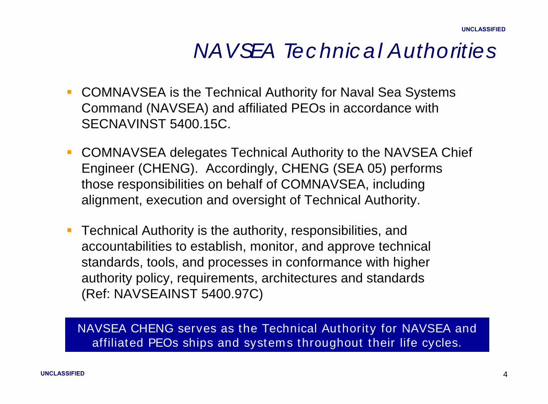
UNCLASSIFIED
UNCLASSIFIED
4
NAVSEA Technical Authorities
COMNAVSEA is the Technical Authority for Naval Sea Systems Command (NAVSEA) and affiliated PEOs in accordance with SECNAVINST 5400.15C.
COMNAVSEA delegates Technical Authority to the NAVSEA Chief Engineer (CHENG). Accordingly, CHENG (SEA 05) performs those responsibilities on behalf of COMNAVSEA, including alignment, execution and oversight of Technical Authority.
Technical Authority is the authority, responsibilities, and accountabilities to establish, monitor, and approve technical standards, tools, and processes in conformance with higher authority policy, requirements, architectures and standards (Ref: NAVSEAINST 5400.97C)
NAVSEA CHENG serves as the Technical Authority for NAVSEA and affiliated PEOs ships and systems throughout their life cycles.

UNCLASSIFIED
UNCLASSIFIED
5
What is Technical Authority?
Responsibilities of Technical Authority:
Setting Technical Standards
Technical Area Expertise
Assuring Safe and Reliable Operations
Ensuring Effective and Efficient Systems Engineering
Judgment in Making Unbiased Technical Decisions
Stewardship of Engineering and Technical Capabilities
Accountability and Technical Integrity
“The exercise of Technical Authority is a discipline that establishes and assures adherence to technical standards
and policy…..a range of technically acceptable options with risk and value assessments….”

UNCLASSIFIED
UNCLASSIFIED
6
What Kinds of Technical Authority Warrant Holders do we have?
Technical Area Experts• Propulsion, Missiles, Shock, etc.
Chief System Engineers• Submarine Warfare, DDG 51/CG 47 Class, etc
Cost Engineering Managers• Aircraft Carriers, Submarines, etc.
Ship Design Managers• In-Service, New Construction and Future Concepts
Waterfront Chief Engineers• Naval Shipyards, SUPSHIPs, Regional Maintenance Centers

UNCLASSIFIED
UNCLASSIFIED
7
NAVSEA Organization

UNCLASSIFIED
UNCLASSIFIED
88
Technical Authority Pyramid

UNCLASSIFIED
UNCLASSIFIED
9
15 DWO Technical Domains & 207 TWH Technical Areas
Ships 41
Subs 20
Carriers 10
IWS 16
LMW 8
SEA 00VW 0
SEA 05M 5
SEA 05W 24
SEA 05N 18
SEA 05P 29
SEA 05Z 17
SEA 00C 4
SEA 04R 4
COMNSWC 4
SEA 05C 7
Technical Areas (95)
Technical Areas (112)
Chief Systems Engineers (5)• Aircraft Carriers: SES (SEA 05V)• Surface Ships: SES (SEA 05D)• Submarines: SES (SEA 05U)• Integrated Warfare Systems: SES (SEA 05H)• Littoral& Mine Warfare: CAPT (SEA 05L)
Technical Domain Managers (10)• Cost Engineering: SES (SEA 05C)• Explosive Ordnance Engineering: RDML (COMNSWC)• Weapons System, Ordinance & Explosive Safety & Security:
SES (SEA 00VW)• Industrial Engineering: SES (SEA 04R)• Marine Engineering: SES (SEA 05Z)• Ocean Engineering: CAPT (SEA 00C)• Ship Integrity & Performance Engineering: SES (SEA05P)• Warfare Systems Engineering, Surface: SES (NSWCDD / SEA 05W)• Warfare Systems Engineering, Undersea :
SES (NUWCNPT / SEA 05N)
•Warfare Systems Engineering, L&MW: SES (NSWCPC / SEA 05M)

UNCLASSIFIED
UNCLASSIFIED
10
Technical Authority Must be Independent of Program Authority
Fleet Need
Warfighting Requirement
National Mission Need
Program Authority
(cost, schedule, product)
Technical Authority
(safety, standards)
Navy Operational Need
Balance of Authority / Strength of Collaboration

UNCLASSIFIED
UNCLASSIFIED
11
“TWH” Definition
Technical Warrant Holders (TWHs) shall be
• HQ or Field Activity Government employees or military personnel
• May be double-hatted, but not employees of programmatic organizations
• Authorized and responsible to access directly the DWO and WO
• Experts in their warranted technical areas
TWHs have the following responsibilities
• Setting technical standards
• Technical area expertise
• Ensuring safe and reliable operations
• Ensuring Effective and efficient systems engineering
• Judgment in making unbiased technical decisions
• Stewardship of engineering and technical capabilities
• Accountability and technical integrity
Definition derived from NAVSEAINST 5400.97E of 27 Nov 2006

UNCLASSIFIED
UNCLASSIFIED
12
Ship Design Manager (SDM): warranted as the TWH responsible and accountable to both the technical and programmatic chains of command, for making design and integration decisions for those platforms, manage the systems engineering efforts for assigned platforms.
• Program Manager (PM) is the point of entry for correspondence coming to HQ on assigned programs. The SDM leads the technical effort in supporting the PM’s written response
• SDM physically embedded within the Program Office to coordinate the technical efforts with technical warrants
• SDM has 2 bosses - works for the PM as well as the CHENG.
Ship Design Manager (SDM)

UNCLASSIFIED
UNCLASSIFIED
13
Ship Design Managerfor VIRGINIA Class Submarines
DEPCHENG for Surface Warfare & Explosive Ordnance -- COMNSWC
DEPCHENG for Undersea Warfare -- COMNUWC
NAVSEA NOTE 5400, Technical Authority, of 7 Oct 2010 establish:
IWS
LMW
SUBS
CV
SHIPS
IWS
LMW
SUBS
CV
SHIPSIN
DU
STR
IAL
ENG
CHIEF ENGINEER (CHENG)DEP CHENGS & ENG LEADERSHIP COUNCIL
CAPABILITY & CERTIFICATIONC
OST
EN
G
MA
RIN
E EN
G
CUSTOMER DEMAND
OUTPUT TO CUSTOMERS
IPTs
OC
EAN
EN
G
SHIP
INT
& P
ERF
ENG
WSE
-LM
W
EXPL
OSI
VE O
RD
EN
G
Chief Systems Eng (CSE) Technical Domain Manager (TDM) CUSTOMERS
TEC
H P
OLI
CY
& S
TD
ONR, etcCTO
IPT
LE
AD
ER
SH
IP
CE
RTIF
IED
P
RO
DU
CTS
TH
AT
ME
ET
R
EQ
UIR
EM
EN
TS
WSE
- SU
RFA
CE
WSE
-UN
DER
SEA
WSO
E SS
(*)
(*) WSOE SS – Weapons System, Ordinance & Explosive Safety & Security

UNCLASSIFIED
UNCLASSIFIED
14
Improved Technology on the VIRGINIA Class (PMS 450)
Reconfigurable Torpedo Room
Special Operations Forces (SOF) Control Station
Light Weight Wide Aperture Array (LWAA) Panels
Logistic Escape Trunk (LET)
Dry Deck Shelter (DDS)
DDS Capable Logistic Plug Trunk (LPT)
LockoutTrunk(LOT)
WeaponsShipping Hatch
Universal Modular Masts (UMM)
SailArray
SonarSphere
High Frequency Chin Array
12 Vertical Launch System (VLS) Canisters
14

UNCLASSIFIED
UNCLASSIFIED
15
VIRGINIA Class Status
USS VIRGINIA(SSN 774)
USS TEXAS(SSN 775)
USS HAWAII(SSN 776)
Completed 1st PACDeployment Feb 2011
USS NORTH CAROLINA (SSN 777)
USS NEW HAMPSHIRE (SSN 778)
USS NEW MEXICO(SSN 779)
MINNESOTA(SSN 783)
MISSISSIPPI(SSN 782)
CALIFORNIA(SSN 781)
USS MISSOURI(SSN 780)
SSN 786
CPR derived (based on dollars) percent complete data as of Dec 2010.
Completed 1st FullDeployment Apr 2010
Completed 1st PACDeployment Aug 2010 ICEX 2011 Mar2011
88% CompleteLaunched - Nov 10
Delivery - Jul 11
80% CompleteKeel Laying‐ Jun 10
Completes PSAJun 11
Started PSAJan 11
Arrived PAC Fleet Nov 2010
43% Complete 25% Complete
NORTH DAKOTA(SSN 784)
JOHN WARNER(SSN 785)
SSN 791SSN 790SSN 789SSN 788SSN 787
Construction Start ‐ 2 Mar 11
Construction Start ‐ 2 Sep 11
63% CompleteKeel Laying‐May 11

UNCLASSIFIED
UNCLASSIFIED
16
Modular Assembly and Construction
Modular Construction Provides Inherent Flexibility to Adapt Changing Missions

UNCLASSIFIED
UNCLASSIFIED
17
Module 8-9
M
B-5
-2A
Build Plan Improvements
Key Accomplishments• Transportation infrastructure improved • Modular outfitting increased • Work realigned to achieve greater level
of single shipyard learning• Hull coating accomplished in module
assembly phase• Design modified to support component
installs in module assembly phase
Changes to the Manufacturing Assembly Plan (MAP) Facilitate a Four Module Concept

UNCLASSIFIED
UNCLASSIFIED
18
Technical Authority from the Program Office Perspective
Pros:• Single point of contact for technical issues• Accountability for decisions• Disagreements between TWHs require DWO/CHENG intervention
Cons:• Single point of contact for technical issues
Tech Warrant Holders may not focus on cost and schedule impacts
Tend to be risk adverse
Competing priorities with other Programs
Technical Authority Proven Effective in Submarine Acquisition Process

UNCLASSIFIED
UNCLASSIFIED
19
What happens when Technical Authority is not Independent of Program Authority
“One of the most difficult COLUMBIA Accident Investigation Board organizational recommendations is that we develop an independenttechnical authority to assure excellence.”
Sean O’Keefe, NASA Administrator
Loss of COLUMBIA 2003
Near Loss of DOLPHIN 2002

UNCLASSIFIED
UNCLASSIFIED
2020
Technical Authority Gone Bad

1
US Submarine Concept Design Tool
Adrian J. Mackenna, Scott A. Patten, and R. Keawe Van EseltineNaval Surface Warfare Center – Carderock Division, USA

2
Introduction
• Early stage submarine design encompasses a broad spectrum of design
Low Required
Effort
High Required
Effort

3
The Need for a Design Tool
• Rapid Concept Generation• Design Space Exploration• Cost Savings• US Navy Validation• Design Knowledge Retention

4
Development History
• Attempts at developing a tool occurred as early as 1985– Proprietary, university, and government
• Recurring issue – Naval Architects ≠ Software Developers
• US Navy decided in 2009 to develop its own tool with a team of both naval architects and computer scientists

5
Submarine Design Disciplines
Structures
Geometry
Appendage
Propulsor
Space
Ship Balance
Machinery
Weight
Resistance
Displacement
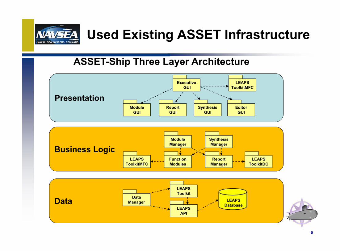
6
Used Existing ASSET Infrastructure
Presentation
Business Logic
Data
ASSET-Ship Three Layer Architecture
LEAPSToolkitMFC
ExecutiveGUI
EditorGUI
SynthesisGUI
ReportGUI
ModuleGUI
LEAPSToolkitMFC
FunctionModules
ModuleManager
ReportManager
SynthesisManager
LEAPSToolkitDC
LEAPSAPI
LEAPSToolkit
DataManager LEAPS
Database

7
Used Existing LEAPS Infrastructure
Intelligent Object OrientedSuperset of All ApplicationRequirements
GeometryPropertiesSystemsComponentsPerformanceBehaviors…
Requirements
GeometryTopologyPropertiesMaterialsSystemsComponents…
DesignRequirements
Design RequirementsPlus…
ScenariosPerformanceBehaviorAttributes…
Smart Product Model Analysis / M&S

8
Product Meta Model

9
Design Process

10
Geometry Construction
Outer Hull
Structures
Pressure Hull
Torpedo Room
Syntactic Fill Tanks

11
User Interface - Workflow
The geometry is defined by editing the dimensions in the diagram.

12
User Interface - Workflow

13
User Interface - Workflow

14
Product

15
Conclusion
• Cost• Validation and Verification• Training for Junior Naval Architects

16
Questions?