WAH' PEDAL UNIT - World Radio History
68
r i I i r . i I rw Vol. 23 No. 11 JUNE 1970 'WAH -WAH' PEDAL UNIT With the aid of this unit the brilliance of electronic guitar reproduction is enhanced by a continuously variable frequency response controlled by the guitar player's foot FEATURED IN THIS ISSUE SIMPLE ELECTRONIC DOORBELL CYBERNETIC CYNTHIA emus/ Motoring Offer 3/6 www.americanradiohistory.com
-
Upload
khangminh22 -
Category
Documents
-
view
2 -
download
0
Transcript of WAH' PEDAL UNIT - World Radio History

r
i
I
i
r .
i I
rw
Vol. 23 No. 11 JUNE 1970
'WAH -WAH' PEDAL UNIT With the aid of this unit the brilliance of electronic guitar reproduction is enhanced by a continuously variable frequency response controlled by the guitar player's foot
FEATURED
IN THIS ISSUE
SIMPLE ELECTRONIC DOORBELL
CYBERNETIC CYNTHIA
emus/ Motoring
Offer
3/6
www.americanradiohistory.com

0 AC107 14/6 13F115 51- NKTI29 6;- 0084 5 - 2N386 12/- 2N3416 7/6 25320 96
ACI16 5/- 8F152 13/6 NKTI41 7 0C123 71- 2N385A / 2N3436 175 6_
25321 6- AC127 5/6 BF154 9/- NKTI42 6 - O C139 51- 2N388A I5'- 2N3525 11/9 25323 10 -
rrs ACI27Z 9/6 BF159 I5I- NKT143 5'6 0 C140 7;- 2N404 4 6 2N3528 19 - 25701 g 6
3,-J ÁC128 4/6 91- NKTIA4 8'- O C170 5,- 2N410 el- 2N3606 5 6 25701 Ilb u AC176 SI- BF167 5/- NKT161 6- OC171 6/- 2N458A 25 - 2N3607 . 4!6 25720 25-
Ill- BF173 6/- NKT162 6 - OC200 6!3 2N51 IA 49 6 2N3702 l'3 25732 8/6
u.r AC188 I11- BF178 10!6 NKT163 5 6 OC201 96 2N513A 2N3703 3.- 251002 10;-
O ACY17 SI- BF179 126 NK7164 5.6 OC202 I8:- 112 6 2N3704 3 3
ACYIB 316 BFI80 6'- NKT165 6- 0C203 7-6 2N599 10 - 2N7705 3- DIODES $ q ACYI9 415 BF181 6;6 NKT211 6:- OC204 8- 2N601 25 - 2N3706 I RECTIFIERS IJqI ACY20 3/7 BF184 7 - NKT2I2 6 - 0C205 91- 2N657 20 - 2N3707 3:- AA119 1
1:i ACY2I 41- BFI8S 8 NKT213 4- OC206 1016 2N696 4- 2N3708 2:'- AAY I 1 1- ACY22 119 BF194 3:6 NKT2I4 4- OC207 7!6 2N697 4- 2N3709 3- AAZ12 6i- ACY40 31- BF195 3l- NKT2I5 4- OC309 12;- 2N698 6- 2N3710 )'- AAZ13 16
¡n. ACY4I 4/4 BF200 10.6 NKT216 10 _ OCP71 19!6 2N706 2 6 2N37Ì I 3'- BA100 6/- AJ ACY44 8/- BFXI3 S - NKT217 13 - ORPI2 9:'6 2N706A 2 6 2N3819 8!- BAI IO 6 -
kg/n AD140 111- BFX29 8 - NKT21B 5 7 ORP60 .8'- 2N708 4- 2N3B20 18 9 BAI I I 6;- ÁD149 1116 BFX44 B - NKT2I9 6 - ORP6I B - 2N71I 7 6 2N3B26 6'- BAI12 IB'-
A:. ADI61 61- BFXB4 7 6 NKT221 5 6 ORP63 9.- 2N71IA 7 6 2N3854 516 BAI IS
rn. AD162 6l- BFX85 9 - NKT222 4 P346A 5;- 2N715 7 6 2N3854A S!6 BA130 ADT140 1216 BFX86 6'6 NKT223 3.6 RAS310AF 2N7Ì6 7 6 2N3855 5 BAY31
EIr* AFI02 1216 BFXBB S - NKT224 46 6 - 2N743 4 6 2N7B55A 6!- BAY38 L ÁF106 7!6 BFYIB 5 - NKT225 3:6 RASSOBAF 2N744 6 - 2N3856 61- BY100
4 AFI I4 5- BFYSO 4 6 NKT226 10- IS'- 2N753 5 6 2N3B56A 61- BY125 AFI 15 5'- BFY51 39 NKT227 5:6 SIM 19'- 2N914 46 2N3858 5/- BY127 4!- AFI 16 5 - BFY52 46 NKT228 6;- SIM
11 2N9Ì8 7 6 2N3BSBA 61- BY234 2!3
AFI17 5- BFY53 61 1_ NKT261 43 ST140 3- 2N929 56 2N3859 5!6 BYXIO AFI IB 126 Bf'N57 b- NKT262 43 5T141 5- 2N930 7'6 2N3B59A 6/7 BVX36/
IAFI21 6- BFW58 5:6 NKT264 4'7 5T2 99 2N1090 66 2N3B60 6!- 150 2:6 AF124 46 BFW59 5'- NKT271 4'- T1407 98 2N1091 66 2N3866 15/- BVX36' AF126 36 BFW60 4 6 NKT272 4- TIP31A 196 2N1131 6 2N3877 9!- 300 1!10
AF127 7 6 BSX19 76 NKT273 4'- TIP32A 22 6 2NI132 8 2N3877A 9/6 BYX36' AF179 7.6 BSX20 3i4 NKT274 4- T 1534 17 6 2N1302 4- 2N3900 106 600 7 9
kgÁF178 9 6 BSX21 7i6 NKT275 5 - 71544 1 9 2N1303 4- 2N3900A BYY2I 25
IAF179 11,6 BSX76 4:- NKT276 3 6 T1545 3 7 2N1304 5:- l l!6 BYY23 26 3
AFI80 Ilió BSX77 6!- NKT279A 2 6 T1S46 3 3 2NI305 5:- 2N3903 7;- BYY25 31 9
AFIBI 8/6 BSX76 6 NKT281 5- TIS47 3 3 2N1306 5 - 2N3904 7'- BYY142 7 9
AFIB6W 91- BSY27 4 NKT301 16 - T1548 3 3 2341307 5.- 2N3905 7 6 BYZIO 9
AFI86G 9:- B5Y29 Si: - N KT302 11 - T IS49 7 6 2N1308 7 - 2N3906 7:6 BVZ12 6- AF239 7 6 BSY32 5/- NK7303 10 - T IS50 56 2N1309 7- 2N4037 IS'- BYZ17 5
AFY19 21.6 BSY36 5!- NKT304 9 6 TIS51 4'- 2N1496 34 - 2N4058 46 CG6E 4-
AFZI I 8- BSY37 5;- NKT)51 8- TI552 4;- 2N1507 4 8 2N4059 5- CG61 16 ASY26 5- BSY38 4'- NKT352 7 6 T IM 6'6 2N 1613 5 6 2N4060 5;- CG62 2 6
ASY27 6 - BSY95A )-6 NKT401 17 6 TI560 6/6 2N1671Á 2N4061 4;- CG63 2 - ASY28 5.- BS'N41 8i6 NKT402 24 - TI561 7 - 29 6 2N4062 4 6 CG64 2 6 ASY29 6:- BSW70 5'6 NKT403 IS - TSW30C IB.- 2N1711 6 6 2N4284 3- EA403 3'6
IJASZ21 7;6 BTX39/600 NKT404 12 6 U23AAA 51- 2341893 IO - 2N4285 3'- EC401 AUY10 30:- 120- NKT40S IS- V205 20:- 2N2147 I7 - 2N12B6 3,'- EC402 48
B2M Il/6 BTX40'600 N KT406 IS - V405A 9'3 2N2152 27 6 2N4267 l'- E0387 3 6 B3M I51- 120 - NKT45I 12 6 XAI02 6:- 2N214B 12 6 2N4288 71-
GEX45i I 443
BC107 2/9 BTY87; 150R NKT452 12.6 XA702 15'- 2N2160 14 9 2N42B9 3 - G13M 4
O BCI08 2/9 31 - NKT453 10- X0113 5 - 2N2243 26- 2N4290 3:- 0A5 3 g BC109 2/9 C106F1 9- NKT6I3F 5 2N2368 5- 2N4291 3;- OÁ10 6
F BC1I3 5/- CIII I8'- NKT674F 5'- ZT22 19;- 2N2369 5- 3- 0A47 6
BC115 616 CII IE 12 - NKT675 5'- ZT86 17;6 2N2369A 56 2N4871 6!9 0A70 6 I BCI16 8/- 6100 9.- NKT676 5- ZT2270 '6 2342432 67 - 2345027 106 OÁ73 6
ÌBC118 5'- C426 8) NKT677F 5;- 40250 6 2N2484 e- 2N5028 11/6 OA79 6
BC125 11'- UM 9/8 NK7703 8/- 40309 9 6 2N2613 7 6 2N5029 916 OASI 6
BC126 II- D13T1 101- NKT713 716 40710 IJ:- 2N2614 4- 2N5070 H6 OABS 6
BC134 5- GET102 6!- NKT773 _5/- 4031I 106 2N2646 IO- 2N5172 ],1- OA90 6
r3 BC135 6 - GETIO] 4 6 NKT10339 40312. I) 6 2N27Ì I 6- 2345174 IO !6 OASI 6 l:A BC136 g- GETI I) 1- 616 40114 106 2342712 6- 2345175 IO ï6 0A95 6
BC137 8 6 GETI 14 4/- NKT10419 40315 10 6 2N27I3 5 6 2N5176 9 - 0A200 2- BC138 12 - GET120 6/6 6/_ 40316 13'- 2N2904 H;6 2N5232 5 6 0A202 2-
b BC140 lI'7 GET8B0 91- NKT10429 40317 I1 - 2N2904A 81- 2NSN9 Ui6 5019 7d qqq BC147 2 9 0E7887 41- I I'- 40319 I5'- 2N2905 l0/- 2N5249A TD716 I1 -
BC148 3 3 GETB89 6/- N KTI0519 40320 10 6 2N2905A 8/- 13 6 N34A 4 - BCI49 3 - 0E7890 616 6 6 40323 106 2N2923 4/- 2N5305 76 N60 4-
IBCI54 12- GET896 4/6 NKT16229 40324 12 6 2N2924 4/- 2N5306 8'- N64 4- BCI67 3 GETB97 4/6 II'- 40326 I06 2N2925 3/6 2N5309 12 6 N82A 96
LIBC168 3 9 GET898 61- NKT20329 40329 7:6 2N2926 2N5354 5 6 N87A 4 6 EMI GEX 45!I 3/- 11 - 40344 8 - Green 2/- 2N5355 5 6 N191 5:-
r_ BC 182L 3'- MATI00 S/- 0 C20 196 40347 9.6 2N2926 2N5356 106 N914 1'9
(u..lBC183L 2 6 MATIOI 516 O C22 8 - 40348 14:6 Yellow 2/- 3N84 26 - 344001 l'-
BCIB4 3 - MATI20 5/- 0C23 8- 40360 II 6 2N2926 3N128 186 N4005 4,- 8C212L 3 9 MAT121 5!6 0 C24 8 40361 II:- Orange 2,!- 3N140 19 6 N4007 5'- BCY10 10 - M3400 21 6 0C25 7 6 40362 14 - 2N2926 3N141 21 6 N4148 I 9
rn BCYI2 12 M1420 12.6 0C26 6 40770 86 Brown 1!- 3NI42 166 5113 416 I.ZA^ BCY30 5'- M1421 22.6 0C28 12 - 40406 16:- 2N3011 1216 3N143 196 544 I!9
6:I BCY3I 5 6 M1430 20 6 OC35 9- 40408 14:- 2N3036 39 - 3N152 14 - 5130 21- IBCY32 10.- M1440 19 6 OC36 12b 40467 166 2N3053 5'- 25001 10 - 5131 116 BCY33 4'- M14B0 20 6 OC41 4 6 40468A 1616 2N3054 12 6 25002 12 6 5132 ll- ri BCY34 5:- MJ481 27- OC42 46 40602 9 9 2N3055 I5- 28003 126 5920 1!4
IJ BCY38 6'- MÌ490 22 6 OC43 46 2G30Ì 7:6 2343133 6 - 25004 IS - AA 270 l'9 Fri BCY40 10;- MÌ491 29 6 OC44 3 - 20302 3i- 2N3I35 6 - 25005 15 - RAS310AF
IBCY42 4 - MPF102 8 6 OC4 7- 22306 B;6 2N3116 6- 25006 I5.- BCY43 4 - MPFIOI 7 6 OC70 26 20339A S!- 2N3235 28 6 25012 15:-
r BCY54 7 6 MPF104 716 0071 7- 20371 3/- 2N3234 27 6 25012A 11!6 BCY70 4 6 MPF105 8- 0072 4 6 203716 3 - 2N339IA 6- 2S017
F'1 BCY71 8'- MPS3638 6 6 0075 4;6 20374 5'- 2N3392 5 - 25018 IBCY72 4'- NKT0013 9 6 0076 2;6 20378 7- 2N3393 5- 25019 BCY87 86 9 NKTI21 I I - 0077 5/6 20381 5- 2N3394 4 9 25104
EaBCZI I 7 6 NKTI22 8 - ()CBI 4/6 2N109 I I - 2N3402 5 6 25301 BD119 15;- NKTI23 6 - 008 ID 31- 2N174 16 - 2N3403 5.6 25302 rl BD121 I8'- NKTI25, 56 0082 5/- 234217 716 2N3404 7:6 25303
1r..^1 BO123 21 6 NKTI27 5 6 OC82D )I- 2N,370 15!- 2N3414 5;6 25304
LZA 130124 I1'- NKT128 5:6 0083 416 2N384 17:- 2N3415 6;- 25306
1.6
2: 6
1716 1916 12!6 8/6 716
I0/- I1 /6 151-
Tail End Offer
PBC108 Texas
Plastic BCI08
11/09 each
ear
LOWEST I,C. PRICES YET! - ICIO
PA230
PA234
PA237
PA246
SL403A
TAA263
TAD 100
TAA293 TAA310 TAA320
SL702C 3N84 261- Silicon controlled switch Data sheets available on request -I /- per copy
PLEASE NOTE: Only new -full specification int._
grated circuits, no below -specification types.
FAIRCHILD MICRO -LOGIC
5916 Sinclair IC amp 20 /- IC Preamplifier 20/- I watt audio amp.
32/6 2 watt audio amp.
52/6 5 watt audio amp.
49/6 3 watt Plessey amp.
15 /- Mullard linear amp.
45/- IC receiver 20/- Mullard gen. purp. amp.
30/- Record /Playback preamp.
13 /- MOS LF amplifier 29/6 Plessey linear amplifier
I -6 ul 900 9/9 9/- uÌ914 9/9 9/- 8/- ul 923 12/6 11/9 II /- Prices for 100+ and 1000+ on application.
5 page data and circuits article -2/6 Plastic spreaders -I/6 each
7-11 12+ 8/-
Prices quoted are current at time of going to press and '(nay be subject to variation without notice. Semiconductors offered in this advertisement bear the relevant manufacturers' original markings and are subject too r full replacement guarantee if not to published specifi-
a:i °ns. We do not offer "re- marked" makers' rejects or similar.
t of specification devices. Please enclose a stamped self- addressed envelope with any query. Quantity prices on application: many more types in stock
and expected daily. If you buy in bulk we can save you money! Export enquiries particularly welcome, cable address: Lestroco Brentwood. Terms of :BusinessI Retail orders -cash with order please; Trade -please furnish references if credit account required. Postage: I/- per order inland: 4/- Europe; 12/- Commonwealth.
ADDRESS YOUR ORDERS TO L.S.T. LTD., 7 COPTFOLD ROAD, BRENTWOOD, ESSEX
ULTRASONIC TRANSDUCERS Operate at 40kc1s. Can be used for remote cncr0l systems
without c
cables or electronic links. Type 1404 trans-ducers
and transmit
FREEo W.th each paw our complete
e ve ree o.tcu .
PRICE 65.15.0 Pair
(Sold only .n pairs)
ZENER DIODES 400tnW 10% GLASS CASE
TEXAS Mfr. 52016 S2019 52041 52047 52456 52062 52568 51075 52082. 51100 51110 52120 51160 s211p 51270 52700
PRICES
3.6 volt 79 volt l von
47 volt 5.6 volt 8.2 volt 64 volt 7.5 volt SI volt 10 volt II volt 12 volt 16 volt IS volt 27 volt 70 olt
I-24 I /64 25-99 1/9
IRC20 816 Int. Rectifier thyristor
200 piv. 1.2 amp. (similar Cß1)
Ì00 25 -1.719 71-
BY1 27 41- Mullard Plastic
HV rectifier 800 piv. I amp. (similar BY100,
25i31[c.)
31o0131_
INFRA -RED DEVICES
56CAY 2916 arsenide
emitter
MGA100 351 - Gallium arsenide
emitter
31 F2 2816 Infra -red detector
diode
2N3819 81- Texas FET
25 619 100i 519
2N4871 619 Motorola smijunction 25+519100+419
2N3055 151 115 watt silicon power
transistor 25 +131_100 ±11I -
219 BC107 & 9
BC108 25+Y13100+21_
2N2926 21-
NPN P. ,,. ter transistor
25 n 118100 ; 116
AD16112 101 - Siemens /Telefu nken
NPN /PNP output pair 25 91_ 100 + 81_
CR1 -401C 10/- 400 PN I amp SCR.
CR1 -051C 7/6 50 PIV I amp SCR.
www.americanradiohistory.com

So6hCroydRoad, AMATRONIX LTD. South Croydon, Surrey, CR2 ODE
NEW & PERFECT TRANSISTORS AD161-2I2/- HK041 2/6 2N3704 AF239 10/- HK101 2/- 2N3707 135000G 11/3 HK601 2/6 2N3794 BD121 18/- 1544 1/4 2N3983 BC107 3/- 0A90 1/3 2N4058 13C168 2/3 SF115 3/- 2N4284 8C169 2/6 71407 6/6 2N4289 BF167 5/3 TIS6OM 4/8 2N4291 BF178 9/- TIS61M 4/II 258187 8F225 5/- 2N706 2/7 258405 BFYS1 4/6 2N2926G 2/6 25D72 GET693 1/3 2N3702 3/- 40468A
3/6 3/6 3/- 6/6 4/- 3/- 3/- 3/- 2/- 5/- 5/- 7/6
RECTIFIERS: 800piv, 500mA Si, 15557, 3/ -; 50piv, I00mA,
1 / -. Submin. Selenium Bridge. 30Vrms, 150mA dc, 3/6; Contact- cooled Sel. Bridge. 30Vrms, 700mA dc, 6/-, Silicon Bridge, 80Vrms, lAdc, 10 /-. All new and perfect.
NEW !
"IDENTICAL RESONATORS ": new Brush Clevite Transfilters for do-it - yourself ceramic i.f. filters. Four of these plus seven fixed capacitors give razor -sharp selectivity to superhets with 455kHz i.f. Kit of 4 resonators and all capacitors, plus notes on use, 35/ -. Single resonators, 10 /- each, 4 for 30/- "R.C." MILLIVOLTMETER (Jan., p. 342). Our AX10 Printed Circuit accom- modates the main part of the circuit (not TRI ). With layout drawing and hints, 15 / -.
COMPONENT KITS
AMPLIFIER PACKAGES, Reliable and efficient, and still far cheaper than i.c.'s!
AX2 9V, up to 300mW 12/6 AX3 9V, up to 800mW in 8 ohms 22/6 AX4 24V, 5W, 8 ohms, 3W,15 ohms 30/- AXS 12 -15V, 3W, 3 -5 ohms. NEW! 35/-
'GEN' GALORE !
Regular customers know that we supply really practical data sheets with our mains transformers, component kits, ceramic resonators, f.e.ts, i.cs, etc. All part of the normal Amatronix service.
BUILD A MINI MAINS PACK
i
9V Components
ac as shown, mA and hints 17/6.
Mini Mains Transformers 30x30x37 mm MT7 7 -0 -7V 120mA 13/6 MT9 9-0-9V 80mA 12/6 MT12 12 -0 -12V 50mA 13/6
MAIL ORDER ONLY. PROMPT SERVICE. Orders over 10 /- UK post paid. Discounts, Orders over E3, 10%; over L10, 15 %.
CAPACITORS Polystyrene: I60V, small, low -loss, tol. 1 F
or 2 }%. New prices: 10- 1500pF, 1 /-; 2200- 22,000pF, 1/6. In stock: 10, 12, IS, 18, 22, 27, 33, 39, 47. 56, 68, 82, 100, 120, 150, 180, 220, 270, 330, 390, 560, 680, 820. 1000, 1500, 2200, 3300. 4700, 6800, 8200, 10.000, 15,000, 22,000pF, Miniature Metallised Polyester .01 uf, 8d; IuF, 10d; .22uF, 1/- 250V wkg.
Tuning: 300pF max. Jacksons Dilemin sub - min single tuner, 10 / -.
RESISTORS Carbon Film, }W, miniature, low noise. 10, 12. 15, 18, 22, 27, 33, 39, 47, 56, 68, 820 and so on to 10M. Toi. ± 5% to 1M, 10% above 1M. All 4d. each. Carbon Skeleton Presets. Submin., vertical. linear, 100mW. 50, 150, 5000 and so on to I.5M. Egen Type 467, 1/6 each. Volume Control, 10K log. with d.p. switch and long aluminium spindle with flat. Standard size, Egen. 5/6 each. R. F. CHOKES. Repanco: CHI, 2.SmH, 2/6; CH2. 5mH, 3/ -; C143, 7.5mH, 3/ -; CH4. 10mH, 3/ -; CH5, 1.5mH, 2/6. All small, ferrite -cored. FERRITE RODS: 4in. or 4 }in. x fin., wound for MW (300pF), 5/ -; unwound. 2/ -; oval, unwound, 2 x # x }in., with data, 2/6. TRANSFORMERS, MINI. A.F.: Eagle LT700, 12005E c.t. to 313, 200mW, 5 / -; Repanco TT47 driver for single ended push - pull, 4.5 to (1) + (I ), 6/-, TELESCOPIC AERIAL: 7 #in. opening to 47in., 9/, BATTERY HOLDER BH2 for two 1.5V p.m cells, with snap connector, 2/6. EARPIECES, all 3.5mm plugged, crystal, 4/9; magnetic, 80. 2/6.
THE MODERN BOOK CO NEW EDITION
COLOUR TELEVISION with particular reference to the PAL system
50/- G. N. Patchett
The Radio Amateur's Handbook by A.R.R.L. 1970 edition. 48s.
The Practical Aerial Handbook by Gordon J. King. 54s.
Postage 4/6
Postage 1/6
1970 World Radio -TV Handbook. 42s. Postage 1/-
20 Solid State Projects for the Home by R. M. Marston. 18s. Postage 1/- Beginner's Guide to Transistors by J. A. Reddihough. 15s. Postage 1 /- Transistor Electronic Organs for the Amateur by Alan Douglas. 20s. Postage 1/-
The Hi -Fi and Tape Recorder Handbook by Gordon J. King. 40s. Postage 2/6
Postage 1/6
All -In -One Gramophone Book by Vivian Capel. 15s.
Servicing with the Oscilloscope by Gordon J. King. 28s.
Postage 9d.
Postage 1 /-
Transistor Audio and Radio Circuits by Mullard. 30s. Postage 1/-
Electronic Games and Toys You Can Build by Len Buckwalter. 24s. Postage 1 /- TV Fault Finding 405/625 Lines by J. R. Davies. 8s. 6d. Postage 6d.
Radio Communication Handbook by Radio Society Great Britain. 63s. Postage 4/6 Rapid Servicing of Transistor Equipment by Gordon J. King. 30s. Postage 1/6
We have the Finest Selection of English and American Radio Books in the Country
19 -21 PRAED STREET (Dept RC) LONDON W2 Telephone PADdington 4185
IiJNL 1970 649
www.americanradiohistory.com

A NEW BOOK
LOW COST
PROPORTIONAL Over 160 pages. Size 84 x Si in.
The theory and practice of simple pro- portional control systems for models, plus:
Over a dozen special circuits.
Theoretical diagrams.
Component lists.
Full -size and twice -size practical diagrams.
Full -size and twice -size Printed Circuit designs.
Clear description of operation of each.
Practical application gen.
Build yourself - Transmitter
Receiver
Pulsers
Coders
De- coders
Switchers
Plus a wealth of ancillary electro -mechanical items
A really practical book on the updating of single
channel control systems to proportional, from the
simple rudder -only, to full dual proportional, plus
engine control.
ALL THIS GEN FOR ONLY
21/- Plus 1/- post and packing
Order now from
RADIO MODELLER, 64 Wellington Road, Hampton Hill, Middx.
And be first in the queue for expected late -June delivery.
650
BI -PAK =LOW COST IC'S BI -PAK Semiconductors now offer you the largest and most popular range of I.C.'s avail- able at these Exclusive Low Prices. T.T.L. Digital SN 74N Series fully coded, brand new to manufacturers specifications. Dual In -Line plastic 14 & 16 pin packages.
BI-PAK ORDER NO. BP 00 = SN 7400N
BP 01 = SN 7401N
BP 04 = SN 7404N BP 10=SN7410N
BP 20 = SN 7420N
BP 30 = SN 7430N
BP 40 = SN 7440N
BP 41 = SN 7441AN
BP 42 = SN 7442N
BP 51 = SN 7450N
BP 53 = SN 7453N
BP 60 = SN 7460N
BP 70 = SN 7470N
BP 72 = SN 7472N
BP 73 = SN 7473N
BP 74 = SN 7474N BP 75 = SN 7475N BP 76 = SN 7476N
BP 83 = SN 7483N BP 90 = SN 7490N BP 92 = SN 7492N
BP 93 = SN 7493N
BP 94 = SN 7494N
BP 95 = SN 7495N
BP 96 = SN 7496N
DESCRIPTION PRICE AND QTY. PRICES 1 -24 25 -99 I00up
NAND Quad 2 -Input GATE 6/6 5/6 4/6 Quad 2 -Input NAND GATE - OPEN COL- LECTOR 6/6 5/6 HEX INVERTER 6/6 5/6
Triple 3 -Input NAND GATE 6/6 5/6 Dual 4 -Input NAND GATE 6/6 5/6 Single 8 -Input NAND GATE 6/6 5/6 Dual 4 -Input BUFFER GATE 6/6 5/6 BCD to decimal decoder and N.I.T. Driver 22/6 20/- BCD to decimal decode (TTI. O /P) 22/6 20/- Dual 2 -Input AND /OR/ NOT GATE expandable 6/6 5/6 4/6 Single 8 -Input AND/ OR /NOT GATE - ex- pandable 6/6 5/6 Dual 4 -Input - expand- able 6/6 5/6 Single JK Flip -Flop - edge triggered 9/- 8/- Single Master Slave JK Flip -Flop 9/- 8/- Dual Master Slave JK Flip -Flop 10 /- 9/- Dual D Flip -Flop 10 /- 9/- Quad Bistable Latch 11 /- 10 /- Dual Master Slave Flip - Flop with preset and clear 11 /- 10 /- Four Bit Binary Adder 26/- 22/6 BCD Decade Counter 22/6 20/- Divide by 12 4 Bit Binary Counter 22/6 20/- Divide by 16 4 Bit
Counter 22/6 20/- Dual Entry 4 Bit Shift Register 22/6 20/- 4 Bit Up -Down Shift Register 22/6 20/- 5 Bit Shift Register 24/- 21/-
46 4/6
4/6
4/6
4/6
4/6
17/6
17/6
4/6
4/6
7/- 7/- 8/6 8/6 9/6
9/6 20/- 17/6
17/6
17/6
17/6
17 /a 18/6
Brand new. Full to manufacturers specification. BP 709 OPERATIONAL AMPLIFIER
Dual -in -line 14 pin package. = SN 72709 and similar to M IC 709 & ZLD 709C. PRICE EACH 1 -24 25 -99 100 up
10/6 9/- 8/- This is a high performance operational Amplifier with high im- pedance differential inputs and low impedance output.
INTEGRATED CIRCUITS Manufacturers "Fall outs" - out of spec devices including functional units and part functional but classed as out of spec from the manufacturers very rigid specifications. Ideal for learning about I.C.'s and experimental work. on testing some will be found perfect. PAK NO. PAK NO. UIC 00 = 5 x 7400N . . 10 /- UIC 50 = 5 x 7450 . . . 10 /- UIC 01 = 5 x 7401N . . 10 /- UIC 53 = 5 x 7453 . . . 10 /- UIC 10 = 5 x 7410N . . 10 /- UIC 72 = 5 x 7472 . . . 10 /- UIC 20 = 5 x 7420N . . 10 /- UIC 74 = 5 x 7474 . . . 10 /- UIC 30 = 5 x 7430N . . 10 /- UIC 75 = 5 x 7475 . . . 10 /- UIC 40 = 5 x 7440N . . 10 /- UIC 90 = 5 x 7490. . 10 /- UIC 41 = 5 x 7441AN . 10 /- UIC XI = 20 x As'd 74's 30/- Packs cannot be split but 20 assorted pieces (our mix) is avail- able as Pak UIC Xl. Every Pak carries our Bi -Pak Satisfaction or money back Guarantee.
Motorola Digital I.C.'s MDTL Dual In -line Package Price Type MC 844P Expandable dual 4 -input Nand Power Gate 10 /- each Type MC 845P Clocked Flip -Flop 15 /- each
Full Data supplied with Units.
Data is available for the SN 74N Series of Integrated Circuits in booklet form. Price 2/6.
Please send all orders direct to our Warehouse and despatch department, postal address:
BI -PAK Semiconductors, P.O. BOX 6, WARE, HERTS. Postage and packing add 1/, Overseas add extra for Airmail.
Minimum order 10 / -. Cash with order please.
THE RADIO CONSTRUCTOR
www.americanradiohistory.com
VALUE ALL THE WAY QUALITY- TESTED PAKS
6 Matched Trans. 0C44/45/81/81D . 10 /- 20 Re ct AF Trans. PNP 10 /- 16 White Spot RF Trans. PNP 10/- 5 Silicon Recta. 3 A 100 -400 PIV 10 /- 2 0 A Silicon Recta. 100 PIV 10/- 2 OCI 140 Trans. NPN Switching 10/-
1 12 A SCR 100 PIV 3 Sil. Trans. 2S303 PNP 10,- 3 200 Mc /s Sil. Trans. NPN BSY26/27 10 /- 3 Zener Diodes I W 33V 5% Tol 10 /- 4 High Current Trans. 0C42 Eqvt. 10 /- 2 Power Transistors I 0C26 1 0C35 10 /- 5 Silicon Recta., 400 PIV 250mA 10 /- 4 0075 Transistors I Power Trans. 0C20 I00V 10/-
10 0A202 Sil. Diodes Sub -min. 10 /- 2 Low Noise Trans. NPN 2N929/30 10/
I Sil. Trans. NPN VCB 100 ZT86 I0 /- B OA81 Diodes lo /- 4 0072 Transistors 10/- 4 0077 Transistors 4 Sil. Recta. 400 PIV 500mA IO %- 5 5 GET884 Trans. Eqvt. 0C44 10/- 5 GETB83 Trans. Eqvt. 0C45 10 /- 2 2N708 Sil. Trans. 300Mc /s NPN 10 /- 3 GT3I LF Low Noise Germ Trans 10 /- 6 IN914 Sil. Diodes 75 PIV 75mA 10 /- 8 0A95 Germ. Diodes Sub -min. IN69 10 /- 3 NPN Germ. Trans. NKT773 Eqvt 10/- 2 0C22 Power Trans. Germ. 10/- 2 0C25 Power Trans. Germ 10/- 4 AC128 Trans. PNP High Gain 10 /- 4 AC127/128 Comp. pair PNP /NPN 10 /- 3 2N1307 NPN Switching Trans 10 /- 7 CG62H Germ. Diodes Eqvt. 0A71 10 /- 3 AF 16 Type Trans. 10 /-
12 Assorted Germ. Diodes Marked 10 /- 4 ACI26 Germ. PNP Trans 10/- 4 Silcon Rect. 100 PIV 750mA 10 - 3 AFI 17 Trans. 10 /- 7 OC81 Type Trans 10 /- 3OC171 Trans 10 /- 5 2N2926 Sil. Epoxy
007 Type Trans Trans lOOf_
2 25701 Sil. Trans. Texas.... 10 /- 2 10 A 600 PIV Sil. Recto. IS45R 10 /- 3 6C108 Sil. NPN High Gain Trans. 10 /- 12N910 NPN Sil. Trans. VCB 100 10 /- 2 1000 PIV Sil. Rect. 1.5 A R53310 AF 10/- 3 BSY95A Sil. Trans. NPN 200Mc /s. 10 /- 3 0C200 Sil. Trans. 10 /- 2 GET880 Low Noise Germ. Trans 10 /-
1 AFI39 PNP High Freq. Trans 10 /- 3 NPN Trans. I ST141 & 2 STI40 10/- 4 Madt's 2 MATI00 & 2 MATI20 10 /- 3 Madt's 2 MATI01 & I MATI21 10/- 4 0C44 Germ. Trans. AF 10 /- 3 AC127 NPN Germ. Trans. 10 /- 12N3906 Sil. PNP Trans. Motorola 10 /- 2 Sil. Power Rents. BYZI3 15/-
I Sil. Power Trans. NPN 100Mc/s 7K201A 15/-
2 2N 1 132 PNP Eoitaxial Planar Sil 10/- 3 2N697 Epitaxial Planar Trans. Sil 15/- 4 Germ. Power Trans. Eqvt. OC16 15/- I Unijunction Trans. 2N2646 15 /- 2 Sil. Trans. 200Mcls 60Vcb íT83/84 15/-
20 NKT Trans. AF. RF. VHF. Coded -,- Eqvt. Lira IO/-
2 2N2712 Sil. Epoxy Planar HFE225 15/- 8 BY100 Type Sil. Recto 20/-
25 Sil. and Germ. Trans. Mixed, all marked, New 30/-
SEMICONDUCTORS FOR "P.E." 50 }SO AMP.
EACH TYPE EACH 4/6 1N914 II-
12/9 0A200 I/- 3/- BFY51 3/6 3,6 BYZ 13 4/6 3/9 40632 14/- 8/- 22V I WZener 3/6
TYPE 2N1613 2N3055 2N3703 2N3704 2N3707 2N3819
GIRO No. 388 -7006
500, Chesham House,
150 Regent St. LONDON,
W.I.
KING OF THE PAKS Unequalled Value and Quality
SUPER PAKS NEW BI-PAK
SEMICONDUCTORS Satisfaction GUARANTEED in Every Pak, or money back.
Pak No. UI 120 Glass Sub -min. General Purpose Germanium Diodes 10/- U2 60 Mixed Germanium Transistors AF /RF 10/- U3 75 Germanium Gold Bonded Diodes sim. OAS, 0A47 10/- U4 40 Germanium Transistors like OCBI, AC128 10 /- US 60 200mA Sub -min. Sil. Diodes 10/- U6 30 Silicon Planar Transistors NPN sim. BSY95A, 2N706 10 /- U7 16 Silicon Rectifiers Top -Hat 750mA up to 1,000V 10 /- U8 50 Sil. Planar Diodes 250mA OA/200/202 10/- U9 20 Mixed Volts I watt Zener Diodes 10 /- UI I 30 PNP Silicon Planar Transistors TO -5 sim. 2N1132 10 /- U13 30 PNP -NPN Sil. Transistors 0C200 & 25104 10 /- U 14 150 Mixed Silicon and Germanium Diodes 10 /- U15 25 NPN Silicon Planar Transistors TO -5 aim. 2N697 lo /- U 16 10 3 -Amp Silicon Rectifiers Stud Type up to 1000 PIV 10/- U17 30 Germanium PNP AF Transistors TO-5 like ACY 17 -22 10 /- U 18 8 6 -Amp Silicon Rectifiers BYZ 13 Type up to 600 PIV 10/- U19 25 Silicon NPN Transistors like BC108 10/- U20 12 1.5 -amp Silicon Rectifiers Top -Hat up to 1,000 PIV 10 /- U21 30 A.F. Germanium alloy Transistors 2G300 Series & 007 I0/- U23 30 Madt's like MAT Series PNP Transistors I0 /- U24 20 Germanium 1 -amp Rectifiers GJM up to 300 PIV 10 /- U25 25 300 Mc /a NPN Silicon Transistors 2N708, BSY27 í0 /- U26 30 Fast Switching Silicon Diodes like IN914 Micro -min I0/- U28 Experimenters' Assortment of Integrated Circuits, un-
tested. Gates, Flip-Flops, Registers, etc., 8 Assorted Pieces 20/- U29 10 I amp SCR's TO -5 can up to 600 PIV CRS I /25.600 20/- U3I 20 Sil. Planar NPN trans. low noise Amp 2N3707 I0/- U32 25 Zener diodes 400mW 007 case mixed Volts, 3 -18 10 /- U33 15 Plastic case 1 amp Silicon Rectifiers IN4000 series 10/- U34 30 Sil. PNP alloy trans. TO -5 BCY26, 25302/4 10/- U35 25 Sil. Planar trans. PNP TO -18 2N2906 10 /- U36 25 Sil. Planar NPN trans. TO -5 BFY50/51 /52 I0/- U37 30 Sil. alloy trans. SO -2 PNP, 0C200 25322 10 /- U38 20 Fast Switching Sil. trans. NPN 400Mc /s 2N301 I ,í0 /- U39 30 RF Germ. PNP trans. 2N 1303/5 TO -5 10 /- U40 10 Dual trans. 6 lead TO -5 2N2060 10 /- U41 25 RF Germ. trans. TO -1 0C45 NKT72 l0 /- U42 10 VHF Germ. PNP trans. TO -1 NKT667 AFI 17 10 /- Code Nos. mentioned above are given as a guide to the type of device in the Pak. The devices themselves are normally unmarked.
NEW LOW PRICE TESTED S.C.R.'S
PI V 50
100 200 400 600 800
IA 3A 7A I6A (TO -5 (TO -66 (TO-48 (TO -48 case) case) case) case) each each each each MV
416 5/- 9/6 10/6 25 5/- 6/6 10 /6 12/6 50 7/- 7/6 11 /6 15/- 100 8/6 9/6 13/6 18/6 200
10/6 11 /6 15/6 25/- 400 12/6 14/- 181- 30/- 600
30A
each 20/- 23/- 28/- 32/- 35!- 80/-
2 Amp POTTED BRIDGE RECTIFIERS 200V. 10 / -, 600V. 15/ -, 800V. 20/-
TRANSISTOR EQUIVALENT & SPECIFICATION BOOK
(German publication). A complete cross reference and equivalent book for Euro- pean, American and Japanese Transistors. Exclusive to BI -PAK. 15/- each
SIL. RECTS. TESTED PIV 750mA 3A /OA 30A
50 If- 2/9 4/3 9/6 100 1/3 3/3 4/6 15/- 200 1/9 4/ 4/9 20/- 300 2/3 4/6 6/6 22/- 400 2/6 5/6 7/6 25/- 500 3/- 6/- 8/6 30/- 600 313 6/9 9/- 37/- 800 3/6 7/6 II /- 40/-
1000 5/- 9/3 12/6 50/- 1200 6/6 II/6 15/-
TRIACS VBOM 2A 6A IOA
(TO -I) (TO -66) (T0-48) 100 14/- IS /- 22/6 200 17/6 20 /- 28,6 400 20/- 24/- 35/-
VBOM _ Blocking volt- age in either direction. LUCAS 35A SILICON
RECTIFIERS Branded. 400 PIV. Special Price stud type, flying lead, 22/6 each.
PRINTED CIRCUITS EX- COMPUTER
Packed with semiconductors and components, 10 boards give a guaranteed 30 trans. ana 30 diodes. Our price I O boards 10/ -. Plus 2/- P. & P.
PLEASE NOTE. To avoid any further Increased Postal Charges to our Customers and enable us to keep our "By Return Postal service" which is second to none, we have re- organized and streamlined our Despatch Order Department and we now request you to send all your orders to- gether with your remittance, direct to our Warehouse and Despatch Department, postal address: BI -PAK SEMICON- DUCTORS, Despatch Dept., P.O. BOX 6,W ARE, HERTS. Postage and packing still I I- per order. Minimum order 10 / -.
UNIJUNCTION ÚT46. Eqvt. 2N2646, Eqvt. TIS43. BEN3000
5/6 EACH 25 -99 5/- 100 UP 4/-
NPN SILICON PLANAR BCI07/8/9, 2;. each; 50 -99, I /I0; 100 up. 1/8 each; 1,000 off, 1/6 each. Fully tested and coded TO -18 case.
SILICON HIGH VOLTAGE RECTIFIERS
10 -Amp 3 -K.V. (3000 P.I.V.) Stud Type with Flying Leads 16/- each
ADI6I ADI62 NPN PNP
MATCHED COMPLE- MENTARY PAIRS OF GERM. POWER TRANSISTORS. For mains driven out- put stages of Amplifiers and Radio receives. OUR LOWEST PRICE OF 12/6 PER PAIR.
HIGH POWER SILI- CON PLANAR TRAN- SISTORS. TO -3. Ferranti ZT1487 NPN VCB60 Ic6AfT. IM /c. VCE 40 Ptot. 75W VEB8 hFE 15-45
Price IS/ -each
2N3055 115 W. SIL POWER NPN OUR PRICE 12/6 each
FULL RANGE OF ZENER DIODES
VOLT. RANGE 2 -16V 400mW (DO -7 Cue) 2/6
I -5W (Top -Hat) .. 3/6 IOW (SO -10 Stud) .. 5/- All fully tested 5% toi. and marked. State volt- age required.
BRAND NEW TEXAS GERM. TRANSISTORS Coded and Guarant'd Pak EQVT.
OC7I TI T2 8 2G374 OC75 T3 8 2G3744A 008 D T4 82G38IA 0081 15 8 203821 OC82 T6 8 2G344A OC44 77 8 2G345A OC45 T8 8 2G378 OC78 T9 8 2G399A 2N 1302 TIO 8 20417 AF117
All 10 /- each pack
2N2060 NPN SIL. DUAL TRANS. CODE D1699 TEXAS. OUR PRICE 5/- each.
120 VCB NIXIE DRIVER TRANSIS- TOR Sim. BSX21 & C407. 2N1893 FULLY TESTED AND CODED ND120. 1 -24 3/6 each. TO -5 NPN 25 up3/ -each
Sil, trans. suitable for P.E. Organ. Metal TO -18 Eqvt. ZTX300 I /- each. Any Qty.
FREE One 10/- Packof your own choice free with orders valued £4 or over.
NPN DIFFUSED SILI- CON PHOTO -DUO- DIODE TYPE 15701 (2N2175) for Tape Readout, high switch.
g d measurement indicators, 50V 250mW. OUR PRICE 10/- EACH, 50 OR OVER 8/6. EACH. FULL DETAILS.
FET'S 2N 3819 10/- 2N 3820 25/- MPF105 8/-
LOW COST F.E.T.s Fully Tested, Guaran- teed Peramecers equit. to 2N3819, MPF IO2, 2N5459. 1 -24 7/6 each; 25 -99 613 each; 100 up 5/6 each. Coded FE19. Full data sent. TO -72
CADMIUM CELLS ORPI2 8/6
ORP60, ORP6I 8/ -each
PHOTO TRANS. OCP71 Type., 8/6
INTEGRATED CIRCUITS
BI -PA IC MONOLITHIC
AMPLIFIERS (TO -S 8 lead)
BP709C, Operational am- plifier, 15/- each.
BP70I C, Operational am- plifier (with Zener output), 12/6 each.
BP702C, Operational am- plifier (with direct output), 12/6 each.
BP501,Wide band ampli- fier, 18/- each.
BP521, Logarithmic wide band amp., 14/- each.
BP201 /C, General pur- pose amplifier (TO-5 8
ad), (voltage or cur- rent amp.), 12/6 each.
I.C. Operational Ampli- fier with Zener output. Type 701 C. Ideal for P.E. Projects. 8 Lead TO-5 case. Full data. Our price 12/6 each 5 off 11 /- each. Large Qty. Prices quoted for.
AMPLIFIER For use in
'P.E.' projects
Identical encapsulation and pin configuration to the following SL402 -3, ICIO and IC403. Each circuit incorporates a pre -amp and class A.B. Power amp stage capable of delivering up to 3 watts RMS. Fully tested and guaranteed. Supplied complete with circuit details and data. CODED BP.I010. OUR LOWEST PRICE 30/- each. 10 up 251- each.
OTHER MONOLITHIC
DEVICES DI 3D I Silicon Unilateral
switch 10 /- each. A Silicon Planar, mono- lithic integral circuit hav- ing thyristor electrical characteristics, but with an anode gate and a built- in "Zener" diode be- tween gate and cathode. Full data and application circuits available on re- quest. FAIRCHILD (U.S.A.) RTUL MICROLOGIC
INTEGRATED CIRCUITS
Epoxy case T8 -5 lead temp. range 15 °C. to 55 °C. UL900, Buffer, 9/9 each. UL914, Dual two -input
gate, 9/9 each. UL923 J- -flip-flop, 13/6
each. Complete data and cir- cuits for the Fairchild I.C.'s available in booklet form priced I/6.
MULLARD I.C. AMPLIFIERS
TA A243, Operational amplifier, 70/- each.
TA A263, Linear AF amplifier, 18/6 each.
TA A293, General pur- pose amplifier, 21/- each.
CA3020 RCA (U.S.A.) LINEAR
INTEGRATED CIRCUITS
Audio Power Amplifier, 30/- each. MONOLITHIC
DIGITAL CIRCUITS (IO lead TO -5)
BP305A, 6 -Input AND gate, 9/6 each.
BP3I4A, 7 -Input NOR gate, 9/6 each.
BP3I5A, Dual 3 -Input NOR gate, 9/6 each.
8P316A, Dual 2 -Input NOR (expand- able), 9/6 eachexpand-
BP320A, J -K- Binry ele- ment, 11/6 each.
BP332A, Dual 3 -Input OR gate, 9/6 each.
KING or THE PARS BI-PAK GUARANI SAIISNICTION OR MONEY BACK JUNE 1970
651
www.americanradiohistory.com

Nan A FAST EASY WAY TO LEARN BASIC RADIO AND ELECTRONICS
Build as you learn with the exciting new TECHNATRON Outfit! No mathematics. No soldering -but you learn the practical way.
Now you can learn basic Radio and Electronics at home -the fast, modern way. You can give yourself the essential technical `know -how' sooner than you would have thought possible - read circuits, assemble standard components, experiment, build ... and enjoy every moment of it. B.I.E.T's Simplified Study Method and the remarkable new TECHNATRON Self - Build Outfit take the mystery out of the subject-make learn- ing easy and interesting.
Even if you don't know the first thing about Radio now, you'll build your own Radio set within a month or so!
and what's more, A 14- year -old could under - YOU'LL UNDERSTAND stand and benefit from this EXACTLY WHAT YOU Course -but it teaches the ARE DOING. The Tech- real thing. Bite -size lessons - natron Outfit contains every -. wonderfully clear and easy to thing you need, from tools to understand, practical projects transistors ... even a versatile from a burglar -alarm to a Multimeter which we teach sophisticated Radio set .. .
you how to use. You need here's your chance to master only a little of your spare basic Radio and Electronics, time, the cost is surprisingly even if you think you're a low and the fee may be paid `non- technical' type. And, if by convenient monthly instal- you want to carry on to more ments. You can use the advanced work, B.I.E.T. has equipment again and again- a fine range of Courses up to and it remains your own A.M.I.E.R.E. and City and property. Guilds standards. You LEARN -but it's as Send now for free 164 -page book.
Like to know more about this fascinating as a hobby, intriguing new way to learn
Radio and Electronics? Fill in the coupon and post it today. We'll send you full details and a 164 -page book -- ̀ENGINEERING OP- PORTUNITIES'- -Free and without any obligation.
Among many other interest- ing experiments, the Radio set you build -and it's a good one -is really a bonus; this is first and last a teaching Course: But the training is as rewarding and interesting as any hobby. It could be the springboard for a career in Radio and Electronics or provide a great new, spare - time interest.
BRITISH INSTITUTE OF
ENGINEERING TECHNOLOGY Dept. 370B, Aldermaston Court,
Aldermaston, Berkshire.
' To: D I.E.T,, Dept. 370B ALDERMASTON COURT, ' ALDERMASTON, BERKS.
I would like to know more about your Practical Radio & Electronics Course. Please send me full details and FREE 164 -page book
name
address
POST TN/,S COUPON
NOW
652
es
1
I
age I .- ®-- =MIIME- v - -- -J
BOUND VOLUME No. 22
of
"The Radio Constructor"
FOR YOUR LIBRARY
Comprising 800 pages plus index
AUGUST 1968 to JULY 1969
PRICE 351- Postage 4'6
Special discount of 10/- for regular readers
Just cut the heading from each month's contents page, including title and month of issue, and this will be sufficient evidence of readership to qualify for the discount.
Thus regular readers will still retain their copies for workbench use, while having a splendid bound volume containing issues in mint condition.
PRICE 25/- Postage 4/6
We regret all earlier volumes now completely sold out.
Available only from: -
Data Publications Ltd, 57 Maida Vale London W9
THE RADIO CONSTRUCTOR
www.americanradiohistory.com

Listen to the world with Eddystone When you own an Eddystone communications receiver, you have the broadcasting world at your finger tips - wherever you happen to be-on land or at sea. The reputation these sets have attained is proof of their esrcRcree and reliability and at Imhofs, there is a special Eddystone departn.uu. where you can see, hear and compare all models listed here. Same day despatch to any part of the world: free delivery in the U.K.; plus after sales service for which Imhofs and Eddystone are world famous. EDDYSTONE EB35 Mark II broadcast receiver AM /FM transistorised. A high performance all -band receiver, can also be used as a 'Hi-Fi' tuner. Powered by 6 SP2 torch cells, or, with Type 924 power supply unit, front AC mains. £88.12.3d. Also stereo model. £97.10.9d. EDDYSTONE 940 (13 valve) communications receiver. A connoisseur's instrument combining `Professional' appearance with performance: has a world -wide reputation, two RF stages ensure high- sensitivity. £159.0.04. EDDYSTONE ECIO transistorised communications receiver. An en- thusiast's receiver at a modest price. Embodies features usually only found in much more expensive designs. Powered by 6 SP2 torch cells or Type 924 power unit (AC). £62.10.0d. EDDYSTONE ECIO Mark II ' ransistorised communications receiver. A de -luxe version of this famous design now incorporating `S' meter and limited fine tuner. £74.10.0d. EDDYSTONE EA12 'Ham Band' receiver. Built to professional stan- dards but specifically for the amateur enthusiast. High sensitivity for all reception modes CW, MCW, AM and SSB. FSK adaptor available as ancillary £205.0.Od. There is an Eddystone Communications receiver for any frequency between IOkHz and 870 MHz full details from Imhofs or your local Eddystone agent.
. : ) ._ t°
IMHOFS MAIN EDDYSTONE DISTRIBUTORS
Dept: RCI6 112 -116 New Oxford Street, London, WC1 Tel: 01- 636 7878
R:i6D
THE WILSIC Mk II REVERBERATION UNIT KIT
A new, all silicon version of our self -contained, 6 transistor, reverberation chamber to which microphones, instruments, tuners or tape recorders may be connected for added dimen- sional effect. The output is suitable for most amplifiers and the unit is especially suitable for use with electronic organs. A ready-built and transducer assembly is used. (58/11 if bought separately). Complete easy -to -build kit, with constructional notes and circuits: L7.10.0. Pre -drilled and printed case 34/- extra. All parts available separately. Send 1/- for circuit and con- struction details.
THE IMPROVED WILSIC SIGNAL INJECTOR. Now all- silicon circuit
, for extra high frequency harmonics. Light and compact, measuring only 3d" x (excluding probe). Price ready for use, including battery 32/6 post free.
THE WILSIC WAH -WAH PEDAL KIT
SELECTIVE AMPLIFIER MODULE. The basis of the Wah -Wah pedal. Kit contains all the components to build a 2- transistor circuit module, also the sockets, control, etc., required for the constructor to assemble his own design. 35/-. Assembled and tested module 42/6. FOOT VOLUME CONTROL PEDAL. Foot pedal unit in very strong fawn plastic. Fitted with output lead and plug for con- nection to guitar amplifier. May be used for volume control or converted to Wah -Wah by adding the module. Pedal unit only £5.12.6. Complete kit for Wah -Wah pedal L7.0.0. All post free. Send 1/6 for our catalogue of components, testmeters, musical electronics and more details of the above items.
Callers welcome.
WILSIC ELECTRONICS LIMITED 6 COPLEY ROAD, DONCASTER, YORKSHIRE
JUNE 1970
Never Built a Kit Before? Why not prove how easy it is the HEATHKIT way. Build one of these beginner kits.
,. .'. r'r.=
Stereo Record Player Exciting sound; budget price. Kit: K /SRP -1.
£27 -6 -0 Carr. 5/-
Deluxe Car Radio Heathkit value; power- ful output. Kit: K /CR -1 (less speakers).
£12 -12 -0 Carr. 5/-
`Severn' AM /FM Radio Beautiful looks; luxury sound. Kit: K /Severn.
£18 -18 -0 Carr 5/-
L
Low cost; accurate. Kit: K /GD -69.
Carr. paid
Economy SW Receiver World -wide reception, 1
to 30 MHz plus 550- 1620 kHz. Kit: K /GR -64.
£24 -16 -0 Carr. 9/-
VVM 7AC, 7DC, 7ohm ranges. Kit: K /IM -18U £16 -14 -0 Carr. 5/-
Portable VVM
For hobbyists - house- holders. Kit: K /IM -17.
£14 -8 -0 Carr. 6/-
II
D.I.Y. Speaker Set As SSU -1 (less cabinet). Kit: K /SCM -1. £6 -10 -0.
Carr. 5/-
Many more kits in the FREE Catalogue Please rush me a copy of your FREE Catalogue Name
Address
53/6 Post Code
A Schlumberger Company
DAYSTROM LTD. Dept. 53/6 Gloucester GL2 6EE
653
www.americanradiohistory.com

IF YOU'RE BUYING A HOUSE
Mortgage Protection is the best Policy for you
If you're buying your house with the help of
a Building Society or a private loan, a "York-
shire" Mortgage Protection Policy will take
care of your outstanding payment in the event
of your premature death. And, if you wish, you
can arrange a Protection "Plus" Policy, which
gives you a substantial cash return at the end
of the mortgage term. It costs so little yet
means so much to your dependants. Leave
them a home not a mortgage!
Please send for further details, without any
obligation, of course.
THE YORKSHIRE INSURANCE COMPANY LIMITED
Becket House, 36 -37 Old Jewry, LONDON, E.C.2.
Itpays to be protected bya General Accident company
Please send me further particulars of the Mortgage Protection Policy
Name
Address
5304
654 THE RADIO CONSTRUCTOR
www.americanradiohistory.com

BIPRE-PAK FULLY TESTED AND MARKED
AC107 3- AC126 2%6 OC1710 4%- AC127 3/6 0C200 3/6 ACI28 2/6 0C201 7/- ACI76 5/- 2G301 2/6 ACY17 3/- 2G303 2/6 AFI14 4/- 2N711 10/- AFI15 3/6 2N1302-3 4/- AFI16 3/6 2N1304-5 5/- AFI17 3/6 2N1306-7 6/- AF186 10/- 2N1308-9 8/- AF139 10/- 2N3819 9/. AF239 12/6 Power BFY50 4/- Transistors BSY25 7/6 0C20 10/- 8SY26 3/- 0C23 10/- BSY27 3/- 0C25 8/- BSY28 3/- 0C26 5/- BSY29 3/- 0C28 7/6 BSY95A 3/- 0C35 5/- 0C41 2/6 0C36 7/6 0C44 2/6 AD149 10/- 0C45 2/6 AUYlO 30/- 0071 2/6 2N3055 15/- 0072 2/6 2S034 10/- 0073 3/6 Diodes 0081 2/6 AAY42 2/- OC8ID 2/6 0A95 2/- 0083 4/- 0A79 1/9 0C139 2/6 0A81 1/9 OC140 3/6 IN914 1/6
FREE ! Packs of your own choice
up to the value of 10 /- with orders over 14.
ANOTHER SCOOP FOR BI- PRE -PAK JUST RELEASED FROM STOCK, A.E.I. INTEGRATED CIRCUITS
These are brand new genuine surplus stocks. marked and guaranteed to full makers speci
fication and not remarked rejects. NE808A Single 8 I/P Nand Gate TTL 7/- NE816A Dual 4 I/P Nand Gate TTL 7/- NE825A D.C. Clocked J -K Flip -Flop TTL 17/6 NE840A Dual 4 I/P Exclusive OR Gate TTL 7/- NE855A Dual 4 Power Gate TTL 7/- NE870A Triple 3 I/P Nand TTL 7/ NE880A Quad 2 Nand TTL 7/- SP616A Dual 4 Nand Gate DTL 7/- SP63IA Quad 2 I/P Gate Expander DTL 7/- SP670A Triple 3 Nand Gate DTL 7/- SP806A Dual I/P Expander TTL 7/ SP808A Single 8 I/P Nand Gate TTL 7/- 5P8I6A Dual 4 /IP Nand Gate TTL 7/- SP825A D.C. Clocked J -K Flip -Flop TTL 17/6 SP840A Dual 4 I/P Exclusive OR Gate TTL 7/- SP855A Dual 4 Power Gate TTL 7/- SP870A Triple 3 I/P Nand TTL 7/- SP880A Quad 2 I/P Nand TTL 7/- NE500K Video Amplifier 40/- NE50IK Video Amplifier 40 MHz 40/- NE806J Dual 4 I/P Expander TTL 7/- NE808J Single 8 I/P Nand Gate TTL 7/- NE816J Dual I/P Nand Gate TTL 7/- NE825J D.C. Clocked J -K Flip -Flop TTL 17/6 NE840J Dual 4 I/P Exclusive OR Gate TTL 7/- NE855J Dual 4 Power Driver TTL 7/- NE880J Quad 2 I/P Nand TTL 7/- ST620A J -K Flip -Flop DTL 17/6 ST659A Dual 4 Buffer /Driver DTL 7/-
Suffix: A =DIP 14 lead K =10 lead TO.5 J1 =Flat Pack
NEW TESTED & GUARANTEED PAKS 82 4 Photo - Cells, Sun Batteries. 10 /_
.3 to .5V, .5 to 2mA. B77 2 ADI6I -AD162 NPN /PNP 10/-
Trans. Comp. output. Pair B81 10 Reed Switches. Mixed types 10 /_
large and small. B89 2 5SP5 Light Sensitive Cells. 10 /- Light res. 4002. Dark 1m2. 891 $ NKT163/164 PNP Germ, to
-5. Equiv. to 0C44. 0C45. 10/- B92 4 74,1'2,1356., il Trans. AO6 =B5X 20, 10 /_
9 500 MHz, 360 mW. B93 5 GETI 13 Trans. equivalent to 10 /_ ACYI7 -2I PNP Germ. 896 5 2N3136 PNP Sil. Trans. TO- 10/- 18. HFE100 -300. IC.600mA.
200 MHz.
898 10 XBI12 & XBIO2 equiv. to 10/- AC126, AC156. OC81 /2. OC71/2, NKT271, etc.
899200 Capacitors, Electrolytics, 10 /- Paper, Silver Mica, etc. Postage on this pak 2/6.
H4 250 Mixed Resistors. 10 /- Post & packing 2/.. H7 40 Wirewound resistors. Mixed 10/.
values. Postage 1/6.
H8 4 BY127 Sil. Recs. 1000 Ply. 10/_ I amp. Plastic.
LOOK! TRANSISTORS ONLY 6d. EACH TYPE A
PNP SILICON ALLOY TO -5 CAN
Spec:- hFE 15 -100. ICER at VCE =20V I mA Max. These are of the 25300 range which is a direct equivalent to the OC200- 205 range.
TYPE B PNP SILICON PLASTIC
ENCAPSULATION Spec:- hFE 10.200 ICER at VCE =10V I mA Max. These are of the 2N3702 -3 and 2N4059 -62 range.
TYPE D NPN SILICON PLANAR
PLASTIC PACKAGE Spec:- VCB 10v VCE 10v Ptot 500 mW hFE 50 min. Audio Preamplifier Tran- sistor, similar to BC 113/4/5.
Return of the unbeatable P.1 Pak.
Now greater value than ever Full of short lead semiconductors and electronic components, approx. 170. We guarantee at least 30 really high quality factory marked Transistors PNP and NPN. and a host of diodes and rectifiers. Mounted on printed circuit panels. Identification chart supplie% to give some information on the transistors.
P.1 PLEASE ASK FOR PAK P.1 ONLY 10 /- 2/- P & P on this Pak.
SPECIAL OFFER
Germ anium Bridge
Rectifiers GEX 541 Fl
Single phase amp 74v
Three Phase 18 a
Ideal 1onÁSlleyAKERS OosT power
FRpCt10 ONL M12I6 EACH
POST & PACKING 216
NEW UNMARKED UNTESTED PAKS
B78 12 Integrated Circuits, Data & 'I C1 /_ Circuits of types, supplied with orders.
880 ó Dual Trans. Matched O/P 10 /- pairs NPN, Sil. ;n TO -5 can. B82 10 OC4S, 00810 & 0081 10 /_
Trans. Mullard glass type.
883 200 Trans. Makers rejects. NPN/ PNP. Sil. & Germ. 10 /-
MAKE A REV. COUNTER for your Car. The 'TACHO BLOCK'. This encapsulated block will turn any 0 -1mA meter into a perfectly linear and accurate rev. counter for 20/- each any car.
884 100 Silicon Doides DO -7 glass 10 - equiv. to 0A200. OA202. / 866 150 High quality Germ. Diodes. 10 /- Min. glass type. 866 50 Sil. Diodes sub. min. IN914 10 /- & IN916 types. B87 100Germ. PNP Trans. equiv. tom/.
0C44, OC4S, 0081, etc. 888 50 Sil. Trans. NPN. PNP. 10 /- equivalent to 00200/I,
2N706A, BSY95A, etc. B60 10 7 Watt Zener Diodes.
10 Mixed voltages. /- 115 16 1 Amp. Plastic Diodes. 50- 10/- 1000 Volts. H6 40 250mW. Zener Diodes 10 /_ DO -7 min. Glass Type.
FREE CATALOGUE AND LISTS for: - ZENER DIODES
TRANSISTORS, RECTIFIERS FULL PRE -PAK LISTS
& SUBSTITUTION CHART
MINIMUM ORDER 10 / -. CASH WITH ORDER PLEASE. Add 1 /- post and packing per order. OVERSEAS ADD EXTRA FOR AIRMAIL.
P.O. RELAYS 8 FOR Various Contacts and Coil Resistances. No individual selection. Post & Packing 5/- 20 /-
FREE! A WRITTEN GUARANTEE WITH ALL OUR TESTED SEMICONDUCTORS
DEPT. C, 22-224 BINPRE-MUC LTD TELEPHONEZ SOU H LIFF-ON-SEA; ESSEX
END (0702) 46344
II'KI' 14'70 655
www.americanradiohistory.com

HOME RADIO (Components) LTD., Dept. RC, 234 -240 London Road, Mitcham CR4 3HD. Telephone : 01-648 8422
A PURCHASE A HOME RADIO CATALOGUE,
using the Coupon below. Please enclose a
cheque or postal order for 12/6 (8/6 plus
4/- packing & postage). Your catalogue will
be sent by return of post.
CHOOSE YOUR COMPONENTS. In the
Home Radio Catalogue over 8,000 com-
ponents are listed and more than 1,500
illustrated. A comprehensive index helps
you to locate your requirements easily.
JOIN OUR CREDIT ACCOUNT SERVICE.
Full details are enclosed with every cata-
logue.
The price of 12/6 applies only to catalogues pur- chased by cus- tomers residing in the U.K.
656
E
ORDER YOUR COMPONENTS. Having joined our Credit Account Service, you may
order either by phone or post. If you phone out of office hours, a recording machine takes your message.
GET STARTED ON THAT PROJECT! Whether it's constructing or servicing work, the fact that you can obtain the right components easily, without having to chase from shop to shop, will put you in the right frame of mind to make a better job of it.
Whether or not you want to use the Credit Account
Service mentioned above, you certainly need the
Home Radio Components Catalogue, if you construct or repair radio, television and electronic gadgets. By
the way, the catalogue contains six vouchers, each
worth a shilling when used as instructed, and with
the catalogue we supply a 30 -page Price Supplement and a Bookmark giving electronic abbreviations.
Post the Coupon today, with cheque or P.O. for 12/6.
Please write your Name and Address in block capitals
Name
Address
HOME RADIO (Components) LTD., Dept RC,
234 -240 London Road, Mitcham, Surrey CR4 3HD
THE RADIO CONSTRUCTOR
www.americanradiohistory.com

THE Rad flitru cto r Incorporating THE RADIO AMATEUR JUNE 1970
VoI. 23 No. 11
Published Monthly (1st of Month) First Published 1947
Editorial and Advertising Offices 57 MAIDA VALE LONDON W9
Telephone 01 -286 6141
Telegrams Databux, London
© Data Publications Ltd., 1970. Contents may only be reproduced after obtaining prior permission from the Editor. Short abstracts or references are allowable provided acknowledgement of source is given.
Annual Subscription 48s. (U.S.A. and Canada $6) including postage. Remit- tances should be made payable to "Data Publications Ltd. ". Overseas readers please pay by cheque or International Money Order.
Queries. We regret that we are unable to answer queries other than those arising from articles appearing in this magazine nor can we advise on modifi- cations to equipment described. Queries should be submitted in writing and accompanied by a stamped addressed envelope for reply.
Correspondence should be addressed to the Editor, Advertising Manager, Sub- scription Manager or the Publishers as appropriate.
Opinions expressed by contributors are not necessarily those of the Editor or proprietors.
Production.- Letterpress.
CONTENTS
SPRITE LITES 658 MIDSUMMER NIGHT'S DREAM 661 SIMPLE VOLTAGE MONITOR 662
(Suggested Circuit No. 235) NEWS AND COMMENT 666 SIMPLE ELECTRONIC DOORBELL 668 CAN ANYONE HELP ? 669 FOR THE SWL - STARTING ON THE
BROADCAST BANDS 670 NOW HEAR THESE 671 CYBERNETIC CYNTHIA (Part 1) 672 CURRENT SCHEDULES 677 TRADE REVIEW 678 INSTANT PROTOTYPE PRINTED CIRCUITS 678 TRADE REVIEW 679 `WAH -WAH' PEDAL UNIT 680 COIL WINDER FOR THE HOME
CONSTRUCTOR 687 CURRENT TRENDS 690 UNDERSTANDING TAPE RECORDING
(Part 2) 691 RECENT PUBLICATIONS 695 IN YOUR WORKSHOP 696 RADIO CONSTRUCTOR MOTORING OFFER 702 RADIO TOPICS 704 LATE NEWS 705 EDDYSTONE RECEIVERS FOR
METEOROLOGICAL WORK 705 LAST LOOK ROUND 705 RADIO CONSTRUCTOR'S DATA SHEET
No. 39 (Abbreviations - M to Z) iii
Published in Great Britain by the Proprietors and Publishers, Data Publications Ltd, 57 Maida Vale, London, W.9. The Radio Constructor is printed by Kent Paper Company Ltd, London and Ashford, Kent.
JULY ISSUE WILL BE PUBLISHED ON JULY 1st
www.americanradiohistory.com

SPRITE LITES by
H. T. KITCHEN
The two fluorescent lighting assemblies des- cribed here give mains -type lighting from a
12 volt battery, thus providing an ideal form of illumination for campers and for boat and caravan enthusiasts. The efficiency of the fluorescent tubes, together with low losses in the voltage step -up circuit, results in a
high light level being obtained at a very economical battery current drain
THE TWO LIGHTS ABOUT TO BE DESCRIBED WERE designed to provide a modest, and a high, level of illumination in situations where mains volt-
ages are not available. They will, therefore, be of particular interest to boating and caravanning enthu- siasts, who will find the need for a 12 volt accumu- lator no great hardship as far as transport is concerned. Members of the camping fraternity possessing some form of motorised transport could, in addition, be included in this category.
The lights could also prove most useful to those unfortunates compelled by force of circumstance to undertake car maintenance or repair 'on the village ,common' or in a garage where, again, mains voltages are not available. In this latter instance, and speaking from personal experience, the writer has found that the soft, virtually shadowless, light obtained from the fluorescent tubes employed is greatly preferable to the `hard' light produced by a normal incandescent light bulb.
The inverter unit, together with 8 watt and 13 watt fluorescent tubes
658
1'wó main precautions have to be observed when using the lights. First, great care is needed to guard against mechanical shock which could fracture the tube. Second, since the case of the transistor em- ployed, being common with its collector, is `live', it must not be allowed to contact any metalwork which is connected to either side of the supply battery. If necessary, a guard of perforated metal can be easily fabricated to prevent any such short -circuits.
TWO VERSIONS
Two versions of the lights were constructed, one using an 8 watt fluorescent tube, and the other a 13 watt tube. The light output from the 8 watt tube is, clearly, not as high as the light output from the 13 watt tube, but as the consequent current con- sumption is less it has its compensations. The con- version from one tube to the other is inexpensive and quite simple, requiring only an additional piece of metalwork and the changing of the bias resistor for the transistor.
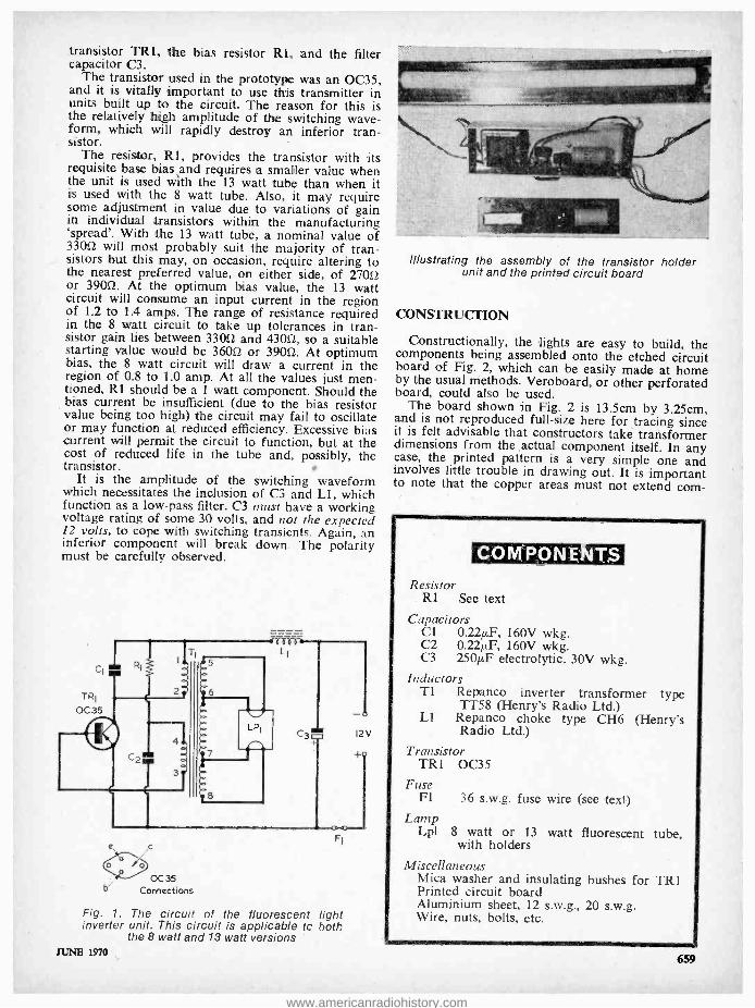
The heart of both versions of the lights is a very simple but highly efficient direct voltage to alternating voltage inverter, this having the circuit shown in Fig. 1. It comprises a power transistor TRI, the oscillator /step -up transformer TI, two capacitors Cl C2, and a resistor Rl. C3 and Ll are not part of the basic inverter circuit and their function will there- fore be described later.
The circuit oscillates by virtue of the inductive coupling existing between the collector and base of TRI by way of the windings of Tl. Cl and C2 cause the transformer to resonate at some 12kHz, this being a frequency high enough to be out of audible range; it is certainly never obtrusive or objectionable, at least to people with normal hearing.
The secondaries of Tl provide two outputs, one to feed the filaments at each end of the tube, and one to provide the requisite h.t. for the tube. The 13 watt tube provides a light output of 730 lumens, or 56 lumens per watt. This is a commendably high degree of efficiency and provides an adequate level of illumination in any moderately sized boat, caravan or tent. In a larger area, or where a higher level of illumination is required, two or more lights can be used, the modest current consumption making the use of multiple lights a viable proposition.
The switching waveform, though at the low funda- mental frequency of 12kHz, is of a sufficiently high amplitude for its harmonics to cause interference with nearby radio receivers. The position can be further aggravated by the supply leads between the lamp unit and the accumulator acting as a trans- mitting aerial.
In order to prevent the radiation of these har- monics an r.f. filter is required, and this is the func- tion performed by C3 and Ll. The lights will, of course, work quite well without these filter com- ponents, but their inclusion is most strongly advo- cated - unless one wants to be pilloried as an anti- social villain!
COMPONENTS
The circuit, as a complete entity, needs no further comment. Three individual components do, however, require a little additional explanation. These are the
THE RADIO CONSTRUCTOR
www.americanradiohistory.com
transistor TRI, the bias resistor R1, and the filter capacitor C3.
The transistor used in the prototype was an 0C35, and it is vitally important to use this transmitter in units built up to the circuit. The reason for this is the relatively high amplitude of the switching wave- form, which will rapidly destroy an inferior tran- sistor. -
The resistor, R1, provides the transistor with its requisite base bias and requires a smaller value when the unit is used with the 13 watt tube than when it is used with the 8 watt tube. Also, it may require some adjustment in value due to variations of gain in individual transistors within the manufacturing `spread'. With the 13 watt tube, a nominal value of 33052 will most probably suit the majority of tran- sistors but this may, on occasion, require altering to the nearest preferred value, on either side, of 27012 or 39052. At the optimum bias value, the 13 watt circuit will consume an input current in the region of 1.2 to IA amps. The range of resistance required in the 8 watt circuit to take up tolerances in tran- sistor gain lies between 33012 and 43012, so a suitable starting value would be 36052 or 39012. At optimum bias, the 8 watt circuit will draw a current in the region of 0.8 to 1.0 amp. At all the values just men- tioned, RI should be a 1 watt component. Should the bias current be insufficient (due to the bias resistor value being too high) the circuit may fail to oscillate or may function at reduced efficiency. Excessive bias current will permit the circuit to function, but at the cost of reduced life in the tube and, possibly, the transistor.
It is the amplitude of the switching waveform which necessitates the inclusion of C3 and Ll, which function as a low -pass filter. C3 must have a working voltage rating of some 30 volts, and not the expected 12 volts, to cope with switching transients. Again, an inferior component will break down. The polarity must be carefully observed.
ÓC35 Connections
Fig. 1. The circuit of the fluorescent light inverter unit. This circuit is applicable tc both
the 8 watt and 13 watt versions
F1
JUNE 1970
Illustrating the assembly of the transistor holder unit and the printed circuit board
CONSTRUCTION
Constructionally, the lights are easy to build, the components being assembled onto the etched circuit board of Fig. 2, which can be easily made at home by the usual methods. Veroboard, or other perforated board, could also be used.
The board shown in Fig. 2 is 13.5cm by 3.25cm, and is not reproduced full -size here for tracing since it is felt advisable that constructors take transformer dimensions from the actual component itself. In any case, the printed pattern is a very simple one and involves little trouble in drawing out. It is important to note that the copper areas must not extend corn-
COM PON ENTS
Resistor Rl See text
Capacitors Cl 0.24F, 160V wkg. C2 0.22µF, 160V wkg. C3 250µF electrolytic, 30V wkg.
Inductors TI Repanco inverter transformer type
1T58 (Henry's Radio Ltd.) Ll Repanco choke type CH6 (Henry's
Radio Ltd.)
Transistor TR1 0C35
Fuse Fl 36 s.w.g. fuse wire (see text)
Lamp Lpl 8 watt or 13 watt fluorescent
with holders
Miscellaneous Mica washer and insulating bushes for TRI Printed circuit board Aluminium sheet, 12 s.w.g., 20 s.w.g. Wire, nuts, bolts, etc.
tube.
659
www.americanradiohistory.com

i2V
Two 6BA clear fixing holes Two holes for Ti clamps
To filament
1 4 7 8
Ne ////!// ,/// 1////!1 '
:'1 %/ íri3? Y
'/ RI / ̀
V , /,I 3
0 I i.i Iiiii /i _ g. . /` /. ikt
Fuse wire Two leadout holes for TRI
base and emitter leads
13 5 cm
Fig. 2 The simple printed circuit layout required is illustrated here. The copper side of the board is towards the reader
To filament
3 25cm
L
pletely to the board edge at any point because these edges are close to the metalwork in which the board is mounted. The two fixing holes indicated as `1' and `2' have spacing which corresponds to the mounting hole spacing of the 0C35 transistor itself. Also, their
3 holes each side for self - tapping screws
2cm
4
7 cm 7cm
4 holes for OC 35
1.25cm
4cm
2 25 cm
3.5 cm
4cm
Transistor holder (material I6swg aluminium)
27.5 cm 275cm
3 holes each side for self- tapping screws
660
2 holes to suit lampholder
Tube carrier (13w)
(material 2Oswg aluminium)
Fig. 3. Dimensions of the transistor holder and tube carrier. The transistor holder sides and ends are bent up to form a box in which the
printed circuit board assembly is housed
positions should correspond to the transistor mount- ing holes in the metalwork, which will be discussed shortly. The connection to the collector of the tran- sistor is taken directly at mounting hole `2'. The emitter and base leads of the transistor pass through two holes in the printed circuit board, as indicated, being connected to the adjacent copper sections by short lengths of bare tinned copper wire.
A short length of 36 s.w.g. tinned copper wire, which can most easily be obtained as a single strand from a length of commonly used 23 x .0076 wire, is
employed for fusing purposes, being soldered directly onto the circuit board as shown. This provides a measure of protection for the circuit. Three pairs of flying leads, two pairs for the tube and one pair (preferably red and black) for the positive and nega- tive battery connections, should be soldered to the board and cut to the required lengths.
The metalwork, shown in Fig. 3, is fairly simple, the only difference between the 8 watt and 13 watt versions being in the length of the tube carriers, this being 31.5cm finished length for the 8 watt tube as against 55cm for the 13 watt tube.
The transistor holder also acts as a heat sink and, if an alternative form of construction is used, the transistor must have an equivalent area of metal to conduct heat away from it. The method of attaching the transistor holder to the tube carrier, by means of small self- tapping screws, is the same in both versions.
The transistor is mounted onto the holder using a mica washer and insulating bushes, so that the transistor case is insulated from the holder. A smear of silicone grease on both sides of the mica washer is beneficial. The nuts and bolts must be tightened firmly but not excessively, or fracture of the mica washer and /or distortion of the transistor case will result.
The etched circuit board is secured to the side of the transistor holder by means of the same 6BA bolts, which mount the transistor spacers being used to hold the board away from the inside surface of . the holder, and so obviating the possibility of short- circuits. The circuit board must be fairly accurately aligned with the transistor on the side of the holder, so that its base and emitter leads pass through the
THE RADIO CONSTRUCTOR
www.americanradiohistory.com

Connections to emitter Printed circuit board and base
To
filaments
Copper side of Insulating printed circuit bush
board
Erds and sides bent up
Spacer Transistor Mica washer holder
(a)
Transistor holder
Tube carrier Self-tapping screws
(b) Fig. 4(a). Detail illustrating the manner in which the transistor, transistor holder and printed circuit board are assembled. The transistor case is insulated from the transistor
holder (b). How the transistor holder and tube carrier
are assembled together
appropriate holes drilled in the circuit board. Further details showing construction and assembly are given in Figs. 4(a) and (b).
After completion, and prior to being assembled into the holder, the circuit should be checked for satisfactory operation and the value of Rl changed, if required. TRl must be mounted on its holder during these checks. The battery voltage and current should be monitored.
As a final point it is advisable to keep the leads to the battery no longer than is necessary, and to keep them twisted. Remember, also, that the unit will be damaged if the battery is connected with incorrect polarity.
JUNE 1970
Midsummer Night's Dream All of us dream at times I suppose, at least they
cost nothing and that is something these days! Some of us have dreams which reoccur from time to time and these are allegedly derived from certain fixations of the mind - at any rate that is the theory. From this, I gather that the premier fixation of my dark and tortuous mind is the ownership of a shack lavishly complete with expensive equipment. Pleasant whilst it lasts, such ethereal bliss probably represents a holiday of the mind and, like all vacations, can be relied upon to have the same mundane termination -a return to the workaday world of harsh reality!
With half of the bedclothes and one foot on the floor of the boudoir, realisation dawns upon the still sluggish mind that the shack equipment consists in reality of a motley collection of surplus, second- hand and hastily home -built units. The latter, all exhibiting a birds nest -like appearance, are fondly imagined to be producing the best attainable results. Alas and alack, lacking here is the stuff my dreams are made of!
Whether the dreams occur during midsummer or midwinter makes little difference - seasonal variations apparently do not alter the mind fixation - it is just that the foot gets colder during the latter period.
Of course, we all have day- dreams during our waking hours, some would term them flights of fancy but either appellation would, I imagine, suffice. In these day- dreams we invariably cast ourselves in the role of the unflinching, honest, forthright and in- credibly courageous tall -in- the -saddle hero -a knight in shining armour in fact. One look into a mirror however produces a similar result as awakening from that dream - upon reflection we perceive ourselves as we really are and .end up with no magnificent equipment - still less any shining armour!
Countless dreams ago now, an Army acquaintance I shall call Will, simply because it is his name and it does match the title, confided that he regularly dreamed of setting up a W/T station only to discover he was minus a sectional aerial mast resulting in the transmitter being off the air - a military crime of enormous magnitude. He must have been beset with dark doubts and fears about his future as an un- wanted and unpaid lancejack! Like all of us in the W/T Section he was supposed to have checked the issued gear prior to leaving the QM store. Being detained over breakfast - he was a well -known `twicer' - time was short and his issue presumed com- plete. As it turned out later, he found himself without the aerial sections.
On the Hampshire moors that sunny midsummer, Will had to find a way to overcome the lamentable oversight. With characteristic aplomb he surreptiously crept to a nearby hedge along which the PBI had strung a landline, snipped out a length, slung one end over a nearby branch and connected the other end to his transmitter. Returning to the severed PBI land - line, he gave a few jerks to take up some slack and quickly completed the circuit. Dreams it seems do come true sometimes.
Will, later confiding to me his PBI landline `borrow- ing' escapade, met with the obvious response - yes, you've guessed it - "where there's a Will there's a way !" C.W.
661
www.americanradiohistory.com
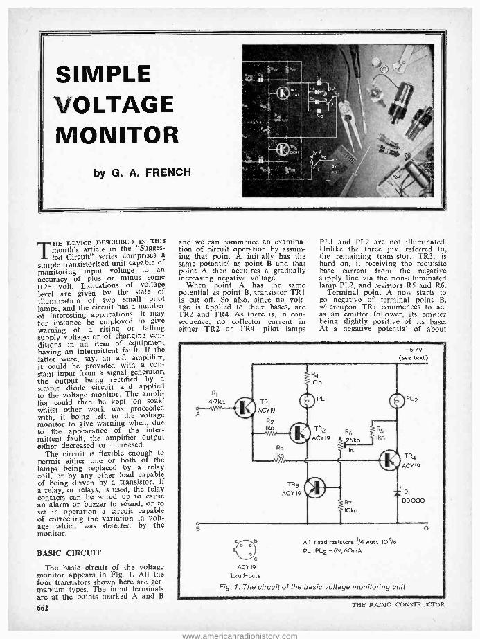
HE DEVICE DESCRIBED IN THIS THE article in the "Sugges-
ted Circuit" series comprises a simple transistorised unit capable of monitoring input voltage to an accuracy of plus or minus some 0.25 volt. Indications of voltage level are given by the state of illumination of two small pilot lamps, and the circuit has a number of interesting applications. It may for instance be employed to give warning of a rising or falling supply voltage or of changing con- ditions in an item of equipment having an intermittent fault. If the latter were, say, an a.f. amplifier, it could be provided with a con- stant input from a signal generator, the output being rectified by a simple diode circuit and applied to the voltage monitor. The ampli- fier could then be kept on soak' whilst other work was proceeded with, it being left to the voltage monitor to give warning when, due to the appearance of the inter- mittent fault, the amplifier output either decreased or increased.
The circuit is flexible enough to permit either one or both of the lamps being replaced by a relay coil, or by any other load capable of being driven by a transistor. If a relay, or relays, is used, the relay contacts can be wired up to cause an alarm or buzzer to sound, or to set in operation a circuit capable of correcting the variation in volt - age which was detected by the monitor.
BASIC CIRCUIT
The basic circuit of the voltage monitor appears in Fig. 1. All the four transistors shown here are ger- manium types. The input terminals are at the points marked A and B
662
and we can commence an examina- tion of circuit operation by assum- ing that point A initially has the same potential as point B and that point A then acquires a gradually increasing negative voltage.
When point A has the same potential as point B, transistor TR1 is cut off. So also, since no volt- age is applied to their bases, are TR2 and TR4. As there is, in con- sequence, no collector current in either TR2 or TR4, pilot lamps
PL1 and PL2 are not illuminated. Unlike the three just referred to, the remaining transistor, TR3, is hard on, it receiving the requisite base current from the negative supply line via the non -illuminated lamp PL2, and resistors R5 and R6.
Terminal point A now starts to go negative of terminal point B, whereupon TRI commences to act as an emitter follower, its emitter being slightly positive of its base. At a negative potential of about
-67V (see text)
TR4
ACY 19
+ DI
DD000
C
ACY 19
Lead -outs
All fixed resistors 1/4 watt IO °lo
PLl,PL2 - 6V, 6OmA
Fig. 1. The circuit of the basic voltage monitoring unit
THE RADIO CONSTRUCTOR
www.americanradiohistory.com

0.4 volts at point A, the emitter voltage of TRI is such that base current commences to flow in TR2. The figure of 0.4 volts represents the sum of the base- emitter voltage drop in TRI, the base- emitter volt- age drop in TR2 and the collector - emitter voltage drop in the hard -on TR3. As point A continues to go negative, base current in TR2 in- creases, causing a continually in- creasing collector current in this transistor and the illumination of pilot lamp PLI. The process con- tinues until PLI is lit with maxi- mum brightness.
No base current has, up to now, flown in TR4, this being due to the fact that silicon diode Dl, in TR4 emitter circuit, does not per- mit forward current to pass until a forward voltage of about 0.6 to 0.7 appears across it. Thus, of the two pilot lamps only PLI is illuminated.
If point A is taken still further negative again, it will be found that, at about 1 volt, base current commences to flow in TR4. This figure of 1 volt is made up of the sum of the base -emitter voltage drop in TR1 (slightly increased now due to the TR1 emitter current flow- ing to TR2 base), the base -emitter voltage drop in TR4 and the for- ward voltage drop across DI. As point A goes still further negative, base current in TR4 increases, causing pilot lamp PL2 to light up and the voltage at the collector of TR4 to fall. This falling voltage results in decreasing base current in TR3 until, when PL2 is lit at full brilliance, TR3 cuts off. As
no current is now available for TR2 emitter, pilot lamp PL1 becomes extinguished. An increasing nega- tive excursion at point A has no further effect on the circuit, apart from causing an increasing base current in TR4, which is already hard on.
Summing up the operation of the circuit we may see that, if point A initially has the same potential as point B, neither of the pilot lamps lights up. As point A is gradually made more and more negative with respect to point B, pilot lamp PLI becomes illuminated and then, at a higher negative voltage, pilot lamp PL2. Illumination in PL2 causes pilot lamp PLI to extinguish.
PILOT LAMP ILLUMINATION
Figs. 2(a) and (b) illustrate the action of the circuit in terms of actual pilot lamp illumination. These curves were drawn by visual examination of pilot lamp brilliance against input voltage at terminal point A, as observed with the prototype circuit. As is to be ex- pected, the lamps commence to glow (and therefore cause the curves to rise above zero brilliance level) for input voltages slightly higher than the 0.4 and 1 volt figures just mentioned, this being due to the fact that a significant collector current has to flow before the filaments achieve a radiating temperature. Fig. 2(a) shows the results obtained when R6 of Fig. 1
is adjusted to insert 20k12 into circuit, and it will be seen that
Max. brilliance
Lamp brilliance
R6= 20kn PL2
Max. brilliance
Lamp brilliance
-0-5 -
R6= 5kn
PLI
-1.5 -2 --25
Applied voltage (volts)
(a)
-0.5 -1 -15 -2 -2.5
Applied voltage (volts)
(b) Fig. 2(a). The performance provided by the prototype circuit with
R6 adjusted to insert 20kí2 (b). The monitor is capable of offering a different mode of operation
when R6 is adjusted to insert 5k12
JUNE 1970
AUDIO
AMPLIFIERS
16 Transistor & Valve Designs for the Home Constructor
Amplifiers for Tuner Units, Record Players,
Tape Recorders, Public Address, etc., etc.
Includes contributions by such well -known authors as A. S. Carpenter, A. Kinloch, E. Govier, G. A. French, F. G. Rayer, P. F. Bretherick, K. Jones, D. Aldous, R. Murray -Shelley, C. Swires, G. A. Stevens and V. E. Holley.
Edited by J. R. Davies
124 pages
PRICE 10s. 6d. Postage 8d.
To: DATA PUBLICATIONS Ltd., 57 Maida Vale London W9
Please supply copy(ies) of "Audio Amplifiers ", Data Book No. 18. I enclose cheque/ crossed postal order for
Name
Address
RC BLOCK LETTERS PLEASE
663
www.americanradiohistory.com
çç» 111 -4" u
iv nlq .4 - l ..
_. -
- -- - i SUPERB LARGE SCALE
MULTIMETER AT A PRICE YOU CAN AFFORD
* 20,0000 /volt * Mirror Scale
* Overload Protection * Free Batteries
D.C. VOLTS: 0.6, 3, 12, 30, 120, 300 A.C. VOLTS: 3, 30, 120, 600 D.C. AMPS: 50µA, 600µA, 60mA,
600mA. RESISTANCE - 10k, IOOk, lmep, lOmegs
( half scale 600. 6000, 60000, 600kÁ 1
DECIBELS: -20 to +46 db. SIZE: 6" x 4(" x 2("
MONEY BACK IF NOT SATISFIED
ONLY £6.5.0 /Plp P.
IVORYET LTD. 31 Albert Road Hendon, London, N.W.4
The
RADIO CONSTRUCTOR
ANNUAL SUBSCRIPTIONS to this magazine may be obtained
through your newsagent
or direct from the publishers
ONLY 481- per year, post free
Please send remittance with name and address and commencing issue required to :
DATA PUBLICATIONS LTD
57 Maida Vale London W9
664
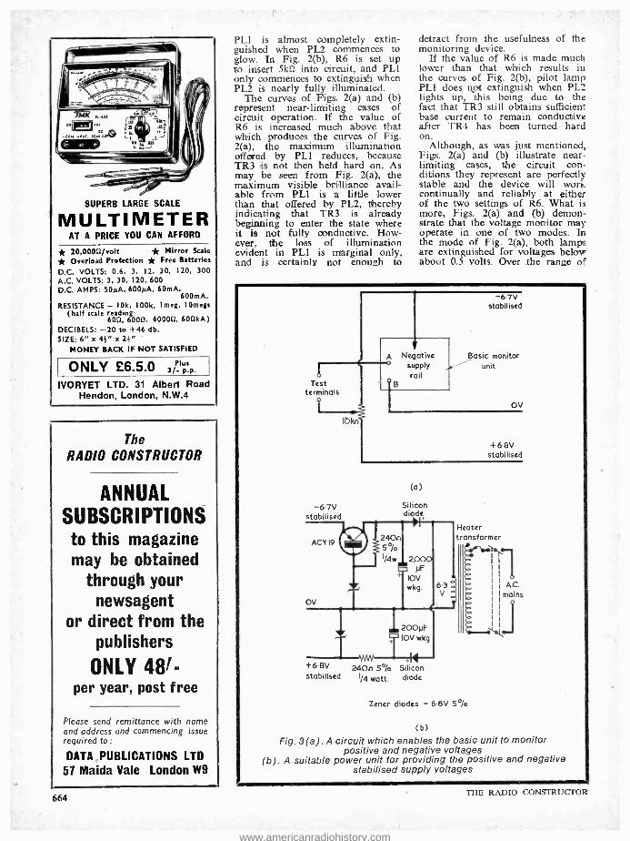
PLI is almost completely extin- guished when PL2 commences to glow. In Fig. 2(b), R6 is set up to insert 5kti into circuit, and PLI only commences to extinguish when PL2 is nearly fully illuminated.
The curves of Figs. 2(a) and (b) represent near -limiting cases of circuit operation. If the value of R6 is increased much above that which produces the curves of Fig. 2(a), the maximum illumination offered by PLI reduces, because TR3 is not then held hard on. As may be seen from Fig. 2(a), the maximum visible brilliance avail- able from PL1 is a little lower than that offered by PL2, thereby indicating that TR3 is already beginning to enter the state where it is not fully conductive. How- ever, the loss of illumination evident in PL1 is marginal only, and is certainly not enough to
detract from the usefulness of the monitoring device.
If the value of R6 is made much lower than that which results in the curves of Fig. 2(b), pilot lamp PL1 does not extinguish when PL2 lights up, this being due to the fact that TR3 still obtains sufficient base current to remain conductive after TR4 has been turned hard on.
Although, as was just mentioned, Figs. 2(a) and (b) illustrate near - limiting cases, the circuit con- ditions they represent are perfectly stable and the device will work continually and reliably at either of the two settings of R6. What is more, Figs. 2(a) and (b) demon- strate that the voltage monitor may operate in one of two modes. In the mode of Fig. 2(a), both lamps are extinguished for voltages below about 0.5 volts. Over the range of
Test terminals
-67V stabilised
1okn
A Negative supply rail
-67v stabilised
Basic monitor unit
oV
+68V stabilised
(a)
Silicon diode
Heater transformer
e'T
A.C.
mains OV
+6.8V 24On 5°/o Silicon stabilised 1/4 watt, diode
Zener diodes - 6.6V 5 °/o
(b)
Fig. 3(a). A circuit which enables the basic unit to monitor positive and negative voltages
(b). A suitable power unit for providing the positive and negative stabilised supply voltages
THE RADIO CONSTRUCTOR
www.americanradiohistory.com

about 0.6 to 1.2 volts only PLI is noticeably illuminated and, for voltages above about 1.2 volts, only PL2 is noticeably illuminated. The existence of a 'central' monitored voltage (plus or minus some 0.3 volts) can then be indicated by illumination in PLI. If the moni- tored voltage goes positive of the `central' voltage both lamps ex- tinguish whilst, if it goes negative, only PL2 becomes illuminated.
In the mode shown in Fig. 2(b), the `central' monitored voltage may correspond to the range (between about 1.25 and 1.7 volts) where both lamps are noticeably illumina- ted. If the voltage goes positive of this range, first PL2 extinguishes, followed later by PLI. If the volt- age goes negative of the range, PLI extinguishes. Working in the Fig. 2(b) mode confers the advantage that the voltage can be monitored within closer limits than occurs with the Fig. 2(a) mode. COMPONENTS AND CIRCUIT VALUES
In Fig. 1 the two pilot lamps are M.E.S. types rated at 6 volts and 60mA. (These are available from Home Radio under Cat. No. PL7). Lamps - drawing currents larger than 60mA must not be used, as they may cause the tran- sistors to suffer excessive dissipa- tion.
Transistors type ACY19 were employed in the prototype and offer a good choice so far as the characterstics required here are concerned. It should be mentioned that the ACY19 has a maximum reverse base -emitter voltage rating of 12 volts only, whereupon care should be taken to ensure that this voltage is not accidentally exceeded when coupling terminal point A to the voltage which is. to be moni- tored. The base of the ACY19 is, incidentally, internally connected to the transistor metal case.
It might be considered that a silicon transistor would be prefer- able in the TRI position, since it would offer lower leakage currents.
However, the base current drawn by TRI in the prototype was less than 20µA over the input voltages shown in Figs. 2(a) and (b), where- upon it can be assumed that the germanium transistor specified rep- resents a reasonable practical choice.
The function of Rl is to limit current flow between terminal points A and B when the monitor power supply is turned o$. Without R1 in circuit, terminal point B would then be coupled to terminal point A via D1, the emitter -base diode of TR4, R3 and the emitter - base diode of TRI. For most input voltages likely to be encountered, R1 should limit the current which may then flow to, at worst, a milli - amp or two.
Resistors R2 and R3 are also limiting resistors, and have the secondary function of preventing possible interaction between the base circuits of TR2 and TR4. D1 can be any silicon diode, such as the Lucas DD000 specified, which is capable of passing a forward current of 60mA.
R5 is another limiting resistor, and it prevents excessive base current in TR3 if R6 should be accidentally set to insert too low a resistance. There is a possibility that R6 may not offer sufficient control if the particular ACY19 employed in the TR3 position has an unusually high gain. In this in- stance it will be found that R6 cannot insert enough resistance to enable the condition of Fig. 2(a) to be achieved. If this occurs, the value of R6 should be increased to, say, 50kí2.
R4 is inserted in the supply to PLI to produce approximately the same voltage drop (when PLI is fully illuminated) as is given by D1 in the PL2 circuit.
The supply voltage is specified at the rather unusual figure of 6.7 volts. This is a nominal figure which ensures approximately correct lamp operation, and represents the supply voltage which should be aimed for when employing a stabilised mains
power unit. Battery operation is not very attractive because current con- sumption, at around 60mA for either bulb, is rather high. In prac- tice, the circuit works perfectly reliably for supply voltages be- tween 7 and 5 volts. Differing supply voltages naturally vary the light level offered by the pilot lamps, but they do not greatly affect the test voltages at point A, relative to point B, which cause lamp illumination or extinction. The latter are mainly governed by the forward voltage drops in the base - emitter junctions of the transistors concerned, and in Dl. VOLTAGE APPLICATION
Several different methods of applying the voltage to be moni- tored to terminal points A and B are feasible, the most flexible approach being illustrated in Fig. 3(a). Here, the basic monitor unit has its own 6.7 volt stabilised supply, a second 6.8 volt supply providing a stabilised voltage that is positive of terminal B. The circuit is capable of monitoring voltages on the upper test terminal of up to 4.5 volts positive and 7.5 volts negative by suitable adjustment of the 10kí2 potentiometer. The cir- cuit to be monitored is connected to the test terminals, after which the 10k2 potentiometer is adjusted to the position which causes pilot lamp PLI to be illuminated (for Fig. 2(a) mode working) or PLi and PL2 to be illuminated (for Fig. 2(b) mode working). Any varia- tion in voltage at the test terminals is then indicated by change in lamp illumination, as already discussed.
Individual experimenters will have their own ideas for producing the stabilised voltages required by the arrangement shown in Fig. 3(a). A practical example of a suitable circuit is given in Fig. 3(b), this employing a 6.3 volt mains heater transformer. Both the zener diodes shown in Fig. 3(b) are small 6.8 volt types with a tolerance of 5% and a dissipation rating in excess of 50mW.
SATELLITE NAVIGATION SYSTEM S. G. Brown Ltd., Watford, Herts., a subsidiary of
Hawker Siddeley Dynamics, has obtained inter- national selling and distribution rights for Magnavox satellite receiver systems. These enable the position of ships, aircraft or land vehicles anywhere in the world to be accurately fixed using data from the U.S. Navy's navigation satellite system.
This equipment is invaluable for accurate ship- board navigation, oceanography and geophysical exploration. The Magnavox system can be interfaced with other navigational equipment to the users' requirements.
S. G. Brown Ltd., who signed the agreement with the Magnavox Company of Fort Wayne, U.S.A., in February, offer a sales and service organisation to support this equipment in most parts of the world. JUNE 1970
BI -PAK LOW COST IC's A complete range of Digital T.T.L. Integrated
Circuits has now been launched by Bi -Pak Semi- conductors to cover the popular 74N service of logic units. These will be available in the dual -in -line plastic package at approximately half the normal distribu- tion price. The range includes gates, flip -flops and complex units such as divide by 16 four bit binary counters, shift regulators and decimal decoders plus nixie tube drivers.
Bi -Pak hope to publish in the near future enough circuitry for building computers, calculators, etc., using the Integrated Circuits mentioned. Bi -Pak say their aim is to further reduce the cost for amateur electronics.
Full details and prices are available from:- Bi -Pak Semiconductors, P.O. Box 6, Ware, Herts.
665
www.americanradiohistory.com

NEWS AND .
VARIABLE AND FIXED SENSITIVITY D.C.
MICROVOLTMETER
The new Comark D.C. Micro - voltmeter Type 1221 has a maxi- mum sensitivity of 30 microvolts f.s.d. and gives a resolution of 0, 3µV per division on a 120mm scale. It has 12 fixed calibration ranges from 100µV f.s.d. to 30V f.s.d., ac- curate to ± 2% of f.s.d. A con- tinuously variable sensitivity con- trol, which does not affect the cali- bration of the fixed ranges, increases the sensitivity to a maximum of x3 on all ranges, permitting direct read- out in engineering units. The meter may be switched to centre zero or left zero.
A d.c. output, proportional to meter reading, of 1V for f.s.d. at 2mA is provided, permitting the in- strument to be used as an inexpen- sive pre- amplifier for digital volt- meters or chart recorders.
Input resistance is 1,00011111 per volt on the 100µV to 300mV ranges and a constant 1011112 on the 1V to 30V ranges. The input offset current can be adjusted to less than 1 milli - microamp and the amplifier zero drift is less than 3µV per °C. Input overload protection is provided on all ranges, permitting inputs up to 15V to be applied without damage on the 100µV to 300mV ranges and up to 200V on the remaining ranges.
The 1221 is powered by readily available dry cells and is produced in three styles: portable, laboratory and panel mounting. 666
SURGE INDICATOR Until recently it has been ex-
tremely difficult to obtain economi- cal indication of the magnitudes of transients.
In instances where electrical or electronic engineers require an in- dication of the magnitude of a transient, it is not essential to use exacting equipment such as storage oscilloscopes to enable him to take the necessary evasive action.
It is now possible to read the amplitude of a transient directly by use of the Surge Indicator recently introduced by Erskine Laboratories Ltd.
It markets in the U.K. at £25, carriage paid, at which price it should prove of particular interest to designers, manufacturers and other users of semi conductor and relay switching equipment.
The manufacturers claim that their Surge Indicator can save its cost in a millionth of a second, as in that time, transients can cause ir- revocable damage, to electrical or
electronic equipment incorporating semi conductor triacs, thyristors, transistors and diodes. Alternatively, equipment such as computor assem- blies can give spurious output data.
With the Erskine Surge Indicator, it is possible to determine the source of the transient and take corrective action accordingly. For example, by using the indicator it is possible to determine, experimentally, the most effective suppression network, across a relay coil, bearing in mind the "trade off" against operating and re- lease times.
Erskine Laboratories, having been established for more than 30 years, is one of the pioneers in the de- velopment of electronic equipment
'including Oscilloscopes, Wave Guides and Miniature Tape Re- corders.
PRESSURE ON SPACE We apologise to those readers
whose requests have not yet appeared in our feature Can Anyone Help? Their requests have not been overlooked but have taken their place in the queue.
The reason for the pressure on space is due to our policy of giving more and more information and value for money. The number of items in the Contents Lists nowa- days exceed 20 items per issue. There can be few magazines with so much text for such a modest cover price.
CONSTERNATION IN THE HOME
'There has often been specula- tion about which of a loving wife's announcements produces most con- sternation in her partner's breast; high among the contenders are the well -known but slightly hackneyed "I gave your wardrobe a good clear - out today" and "I've pulled out all the weeds from that new flower - bed" '. - From a husband speaking in BBC Woman's Hour.
To which we would add "I tidied up your shack today ".
01 ELMA ROTARY STUD SWITCH
The Elma sub -miniature rotary stud switch now features an im- proved case in glass filled polycar- bonate as shown below. This tough material is unaffected by most com- mon solvents and is more easily marked with numbers to aid wiring.
The switches are now available with special tags for direct em- placement in printed circuit boards, and may be supplied with screwdriver slots instead of shafts.
As a further service, a range of different torque settings is available. The standard torque is 200 gm /cm, but 400 and 600 gm /cm can be sup- plied to order.
The Elmer 01 switch uses a high quality ceramic wafer and gold plated stud contacts. Contact resis- stance is better than 5 milliohms.
THE RADIO CONSTRUCTOR
www.americanradiohistory.com
. . COMMENT AMATEUR RADIO LINKS
"SHUT -IN" OPERATORS In an age when satellites make communications
swifter and more extensive than ever before, it can be surprising to discover that some people are still cut off from their fellow men by physical handicaps. For the deaf and the blind there are hearing aids, Braille printing and similar devices to help overcome disabilities. Yet other ailments can shut in the victim from the world - unless he is determined not to be left out, and some physically sound friends respond to that determination.
We have from time to time referred to the work of the Radio Amateur Invalid Bedfast Club in help-
. ing the physically handicapped people in this country who have, or develop, an interest in Amateur Radio.
We now give some news of a similar organisation in the U.S.A. In San Ysidro, a city in California close to the Mexican border, two young men, victims of a crippling disease, became amateur radio opera- tors. The identical twin brothers, Henry and Jack Johnson, are only able to talk, move their eyeballs and control a capillary nerve in one arm. But now, thanks to the efforts of a group of dedicated radio amateurs, they are able to talk to the four corners of the earth.
As a result, there is now a radio network linking handicapped operators around the world. The organ- isation, called International Handicappers' Net (IHN), grew out of a conversation with the disabled twins and a Lieutenant Commander Ray E. Meyers, a retired Navy communications officer.
It was the Johnson brothers who suggested start- ing a radio network of handicapped amateurs along with the possibility of listing the members so that others might immediately recognise fellow members.
Because the physical handicaps include a wide range of crippling conditions, the unhandicapped members have resorted to a variety of systems of instrûction in addition to creating ingenious devices to meet individual difficulties in handling trans- mission and reception of messages.
Voice- controlled relays permitting an armless operator to send intelligible code, radio controls which can be turned on and off by the flick of an eyelid, a device to enable a bedridden operator to manage his controls by air pressure blown through a flexible hose, are examples.
If you would like to help the somewhat similar organisation in the U.K., details can be obtained from the Honorary Secretary of the Radio Amateur Invalid Bedfast Club, Mrs. Frances Woolley, 331 Wigan Lane, Wigan, Lancs. TUNE 1970
VERO STRIP
Vero Electronics Ltd., of Chandler's Ford, Hamp- shire, have recently introduced a new type of ter- minal board which has been designed as a simple and inexpensive mounting strip for discrete com- ponents. These can be mounted across the width of the board or alternatively along its length to effect cross- connection.
The mechanical and electrical specifications of the materials used enable the board to withstand a maxi- mum working voltage of 2KV, whilst still maintain- ing an insulation resistance of one hundred thousand megohms between adjacent copper pads. These fea- tures make the board suitable for all applications where a conventional tagstrip or group board might be used.
The dimensions of the Vero strip are such that they can be mounted in standard die -cast boxes.
A number of terminal pins are also available which can be used in conjunction with the Vero strip where such additional facilities are required.
"All l can get on this set tonight is interference" I-
667
www.americanradiohistory.com

SIMPLE ELECTRONIC DOORBELL
by
H. WILLIAMS
The extremely simple audio oscillator described here offers a tone which varies with supply voltage. Components are not at all critical and the device can be employed as a `doorbell' or for any other application requiring an electronic `buzzer'
THE SIMPLE PROJECT DESCRIBED in this article was designed to take the place of a rather
unpleasant- sounding doorbell that finally packed up. The circuit was built up entirely from available components which most construc- tors will already have in the junk box. One facility incorporated in the design was that the note emitted from a call at the back door was different from that produced by a call at the front, thus saving wasted journeys which had occurred on several occasions with the previous bell.
Apart from the use described here for the circuit there must be many others, for it is simply an electronic `buzzer' whose pitch can be varied with the applied supply voltage.
THE CIRCUIT
The circuit of the `doorbell', shown in Fig. 1, could hardly be simpler. Also, as will be seen shortly, the components required could hardly be less critical.
When a voltage, either 6 volts or 9 volts, depending upon which button is pushed, is applied to the circuit, Cl 'rapidly charges up through R1 and Tl primáry. When a certain charge in CI is reached, TR1 switches on. This transistor is essentially in the collector -base circuit of TR2 which is in conse- quence also turned on. TR2 starts to discharge Cl, thereby turning off TRI which, in turn, switches off TR2. Cl starts to charge again, thus starting the cycle once more. 668
From this description it will be seen just how non -critical the com- ponents are. A wide combination of resistors and capacitors may be used and will produce the same note, this being dependent upon the time constant of the network rather than on the individual values. As shown in Fig. 1, the author's circuit
R1
15Okn
employed a 150k12 resistor for R1 and a 0.05µF capacitor for Cl.
The transistors themselves are equally non -critical as long as one is n.p.n. and the other p.n.p. When actually switched on, TR2 passes a relatively high current, but many transistors will handle currents way above their rated ones for short periods, such as the time that a doorbell is actually rung. Construc- tors who are prepared to risk the possibility of breakdown could use a small transistor for TR2. If an 0081, on the other hand, is em- ployed, the bell can be rung perma- nently with no danger of over- heating, even without a heat -sink for the transistor. TR1 may be a 2N2926, or similar.
Any speaker impedance between 312 and 8052 can be used and in fact Ti is not strictly necessary. The loudspeaker, even with as low an impedance as 352, can be connected directly between the collector of TR2 and the negative rail. How- ever, the omission of the t!ans- former will result in the battery being exhausted far quicker. The note emitted depends partly upon the collector load of TR2 and if Tl is left out, R1 will have to be increased to something like 680kS2. Ti may he any transistor output transformer having a ratio of the order of 4.5 : 1.
The pitch of the note depends on the applied voltage, and the author employed a 9 -volt grid -bias battery as this can be readily tapped at 6 volts. If difficulty is experienced in obtaining a grid -bias battery, a
TRI - 2N2926,etc. TR2 - OC 81, etc.
ecb (000l
TR2
dot
Remote door bell - pushes
\_._ 5I
9V
-----0 0-- -- 6V 52
2N2926 OC61
Lead -outs Lead -outs
Fig. 1. The circuit of the electronic 'doorbell' THE RADIO CONSTRUCTOR
www.americanradiohistory.com
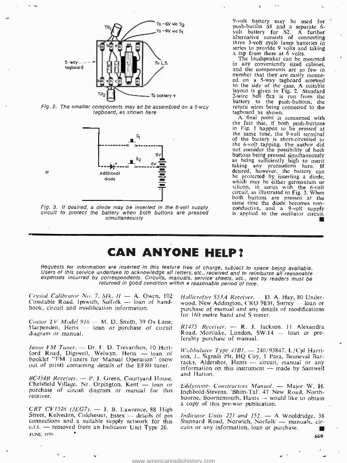
5-way- tagboard
TR1 To -6V via S2
To -9V via Si
To LS.
TR2 To battery +
Fig. 2. The smaller components may all be assembled on a 5 -way tagboard, as shown here
s
0 O.
Additional diode
Fig. 3. If desired, a diode may be inserted in the 6 -volt supply circuit to protect the battery when both buttons are pressed
simultaneously
9 -volt battery may be used for push -button S1 and a separate 6- volt battery for S2. A further alternative consists of connecting three 3 -volt cycle lamp batteries in series to provide 9 volts and taking a tap from these at 6 volts.
The loudspeaker can be mounted in any conveniently sized cabinet, and the components are so few in number that they are easily mount- ed on a 5 -way tagboard screwed to the side of the case. A suitable layout is given in Fig. 2. Standard 2 -wire bell flex is run from the battery to the push- buttons, the return wires being connected to the tagboard as shown.
A final point is concerned with the fact that, if both push- buttons in Fig. 1 happen to be pressed at the same time, the 9 -volt terminal of the battery is short -circuited to the 6 -volt tapping. The author did not consider the possibility of both buttons being pressed simultaneously as being sufficiently high to merit taking any precautions here. If desired, however, the battery can be protected by inserting a diode, which may be either germanium or silicon, in series with the 6 -volt circuit, as illustrated in Fig. 3. When both buttons are pressed at the same time the diode becomes non - conductive, and a 9 -volt supply is applied to the oscillator circuit.
CAN ANYONE HELP ?
Requests for information are inserted in this feature free of charge, subject to space being available. Users of this service undertake to acknowledge all letters, etc., received and to reimburse all reasonable expenses incurred by correspondents. Circuits, manuals, service sheets, etc., lent by readers must be
returned in good condition within a reasonable period of time.
Crystal Calibrator No. 7, Mk. I1 - A. Owen, 102 Constable Road, Ipswich, Suffolk - loan of hand- book, circuit and modification information.
Cossor TV Model 916 - M. D. Smith, 39 Ox Lane, Harpenden, Herts - loan or purchase of circuit diagram or manual.
Jason FM Tuner. - Dr. F. D. Trevarthen, 10 Hert- ford Road, Digswell, Welwyn, Herts - loan of booklet "FM Tuners for Manual Operation" (now out of print) containing details of the EF80 tuner.
BC454B Receiver. - P. J. Green, Courtyard House, Chelsfield Village, Nr. Orpington, Kent - loan or purchase of circuit diagram or manual for this receiver.
CRT CV1526 (3EG7). - J. B. Lawrence, 88 High Street, Kelvedon, Colchester, Essex - details of pin connections and a suitable supply network for this c.r.t. - removed from an Indicator Unit Type 26. JUNE 1970
Hallicrafter S53A Receiver. - D. A. Hay, 80 Under- wood, New Addington, CRO 9EH, Surrey - loan or purchase of manual and any details of modifications for 160 metre band and S meter.
R1475 Receiver. - R. J. Jackson, 11 Alexandra Road, Mortlake, London, SW.14 - loan or pre- ferably purchase of manual.
Wobbulator Type 41B1. - 240/93847. L /Cpl Harri- son, J., Signals Plt, HQ Coy, 1 Para, Bruneval Bar- racks, Aldershot, Hants - circuit, manual or any information on this instrument - made by Samwell and Hutton.
Eddystone- Constructors Manual. - Major W. H. Inchbold- Stevens, Bhim -Tal', 47 New Road, North - bourne, Bournemouth, Hants - would like to obtain a copy of this pre -war publication.
Indicator Units 221 and 152. -A Wooldridge, 38 Stannard Road, Norwich, Norfolk - manuals, cir- cuits or any information, loan or purchase.
669
www.americanradiohistory.com

FOR ME SW'...
STARTING ON THE BROADCAST
BANDS There are, perhaps, some short wave listeners who
would like a change from amateur band listening and many beginner short wave listeners who wish to take up broadcast band listening but who are all loth to do so because of the apparent complexity of it all. The many broadcast bands, constantly changing broadcast schedules, periodic frequency alterations and, probably the most difficult problem of all, spot frequency readings and station identifica- tions all tend to make life difficult for the broadcast band listener.
Although broadcast band listening is a much more difficult proposition and represents a much greater challenge than amateur band listening, it is perfectly possible to make a start providing one is equipped with a 1MHz crystal oscillator. It is assumed, of course, that the beginner is equipped with a com- munications receiver and a simple aerial and earth system. The receiver bandset dial must exhibit reason- ably correct frequency readings.
For the beginner short wave listener, a simple aerial array is all that is required when making a start on surveying the various broadcast bands, com- plex switchable systems of several aerials being erected later as one progresses with the hobby and, naturally, becomes ambitious to receive various parts of the world with the 'maximum possible efficiency.
In the first instance, a long wire `Inverted -L' type of aerial, erected as high as possible and with as much length as is practicable at the particular loca- tion, would prove adequate. The length of wire should be positioned in such a manner that it is as clear of such earthed objects as trees, metal pipes and gutterings as possible. Those having small gardens need not despair - it is not absolutely essen- tial to erect a very long length of wire - one of 33ft., including the down -lead, will suffice. To gain addi- tional length, those would-be broadcast band listeners suffering from restricted space for aerial erection purposes may care to site the wire around the con- fines of the garden. In this manner, the aerial would form three sides of a square or rectangle when viewed in plan form. Alternatively, a similar arrange- ment would be that of running the wire, at the far end, parallel with the pole to within 3 or 4 feet of the ground - suitably spaced from the pole by means of a wooden strut and an insulator at the lower end. 670
RAC30 PRAi-tFL
A QSL card received from Radio Prague, Czechoslovakia, for a report on the English programme radiated at 1900GMT on 7345kHz
At the house end of the aerial wire, a similar arrange- ment could be made. The point to remember is that no angles in the wire should be less than 90 °. In other words, avoid sharp bends when erecting an aerial wire.
The earth lead from the receiver should be kept short and be secured at the other end to a copper pipe driven into moist soil as deep as possible.
The 1MHz crystal oscillator unit represents the minimum requirement for obtaining band -edge fre- quency marker points. If one is to eventually become a dyed -in -the -wool broadcast band operator, recourse must be had either to a 100kHz crystal oscillator with the additional facility of a 10kHz multivibrator or a BC221 frequency meter. Frequency charts for each broadcast band can be drawn up with the aid of crystal standards, spot frequencies being plotted against bandspread dial readings once the bandset dial has been correctly set at the band -edge indicated by the 1MHz crystal oscillator.
WHERE TO START
Where to make a start is, of course, a matter of opinion but it is suggested that the beginner could not do better than commence activities on the 16 metre band (17700 to 17900kHz). The band -edge crystal oscillator (1MHz) will provide a marker point
THE RADIO CONSTRUCTOR
www.americanradiohistory.com
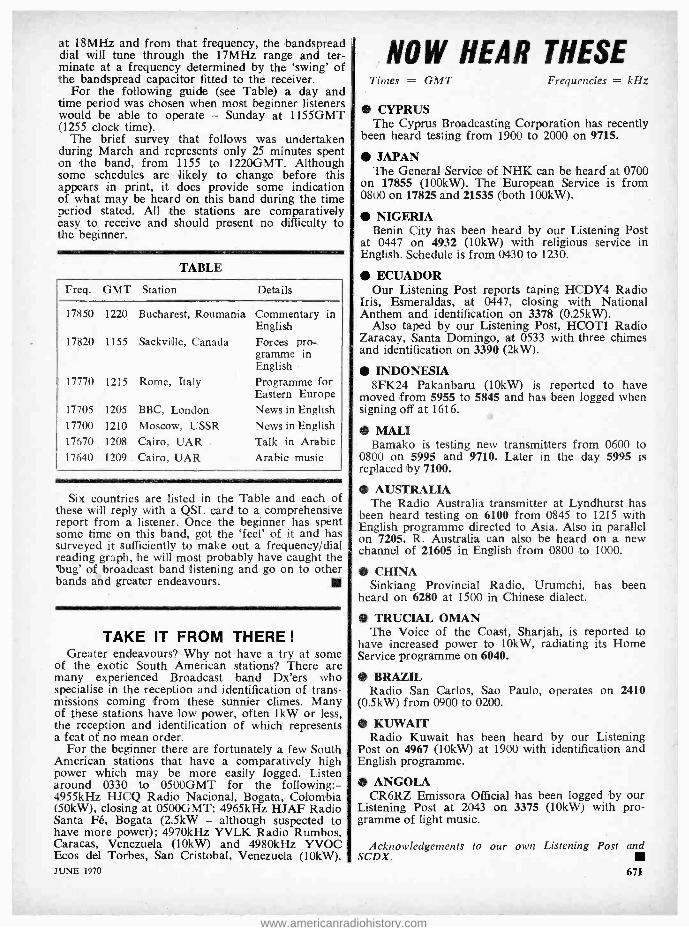
at 18MHz and from that frequency, the ,bandspread dial will tune through the 17MHz range and ter- minate at a frequency determined by the `swing' of the bandspread capacitor fitted to the receiver.
For the following guide (see Table) a day and time period was chosen when most beginner listeners would be able to operate - Sunday at 1155GMT (1255 clock time).
The brief survey that follows was undertaken during March and represents only 25 minutes spent on the band, from 1155 to 1220GMT. Although some schedules are likely to change before this appears in print, it does provide some indication of what may be heard on this band during the time period stated. All the stations are comparatively easy to receive and should present no difficulty to the beginner.
TABLE
Freq. GMT Station Details
17850 1220 Bucharest, Roumania Commentary in English
17820 1155 Sackville, Canada Forces pro.. gramme in English
17770 1215 Rome, Italy Programme for Eastern Europe
17705 1205 BBC, London News in English 17700 1210 Moscow, USSR News in English 17670. 1208 Cairo, UAR Talk in Arabic 17640 1209 Cairo, UAR Arabic music
Six countries are listed in the Table and each of these will reply with a QSL card to a comprehensive report from a listener. Once the beginner has spent some time on this band, got the `feel' of it and has surveyed it sufficiently to make out a frequency /dial reading graph, he will most probably have caught the 'bug' of broadcast band listening and go on to other bands and greater endeavours.
TAKE IT FROM THERE !
Greater endeavours? Why not have a try at some of the exotic South American stations? There are many experienced Broadcast band Dx'ers who specialise in the reception and identification of trans- missions coming from these sunnier climes. Many of these stations have low power, often 1kW or less, the reception and identification of which represents a feat of no mean order.
For the beginner there are fortunately a few South American stations that have a comparatively high power which may be more easily logged. Listen around 0330 to 0500GMT for the following: - 4955kHz HJCQ Radio Nacional, Bogata, Colombia (50kW), closing at 0500GMT; 4965kHz HJAF Radio Santa Fé, Bogata (2.5kW - although suspected to have more power); 4970kHz YVLK Radio Rumbos, Caracas, Venezuela (10kW) and 4980kHz YVOC Ecos del Torbes, San Cristobal, Venezuela (10kW). JUNE 1970
NOW HEAR THESE Times = GMT Frequencies = kHz
CYPRUS The Cyprus Broadcasting Corporation has recently
been heard testing from 1900 to 2000 on 9715.
JAPAN The General Service of NHK can be heard at 0700
on 17855 (100kW). The European Service is from 0800 on 17825 and 21535 (both 100kW).
NIGERIA Benin City has been heard by our Listening Post
at 0447 on 4932 (10kW) with religious service in English. Schedule is from 0430 to 1230.
ECUADOR Our Listening Post reports taping HCDY4 Radio
Iris, Esmeraldas, at 0447, closing with National Anthem and identification on 3378 (0.25kW).
Also taped by our Listening Post, HCOT1 Radio Zaracay, Santa Domingo, at 0533 with three chimes and identification on 3390 (2kW).
INDONESIA 8FK24 Pakanbaru (10kW) is reported to have
moved from 5955 to 5845 and has been logged when signing off at 1616.
MALI Bamako is testing new transmitters from 0600 to
0800 on 5995 and 9710. Later in the day 5995 is replaced by 7100.
AUSTRALIA The Radio Australia transmitter at Lyndhurst has
been heard testing on 6100 from 0845 to 1215 with English programme directed to Asia. Also in parallel on 7205. R. Australia can also be heard on a new channel of 21605 in English from 0800 to 1000.
CHINA Sinkiang Provincial Radio, Urumchi, has been
heard on 6280 at 1500 in Chinese dialect.
TRUCIAL OMAN The Voice of the Coast, Sharjah, is reported to
have increased power to 10kW, radiating its Home Service programme on 6040.
BRAZIL Radio San Carlos, Sao Paulo, operates on 2410
(0.5kW) from 0900 to 0200.
KUWAIT Radio Kuwait has been heard by our Listening
Post on 4967 (10kW) at 1900 with identification and English programme.
ANGOLA CR6RZ Emissora Official has been logged by our
Listening Post at 2043 on 3375 (10kW) with pro- gramme of light music.
Acknowledgements to our own Listening Post and
671
SCDX.
www.americanradiohistory.com
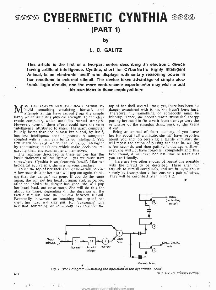
--TTT CYBERNETIC CYNTHIA £ <^T (PART 1)
by
L. C. GALITZ
This article is the first of a two -part series describing an electronic device having artificial intelligence. Cynthia, short for CYberNeTic Highly Intelligent Animal, is an electronic `snail' who displays rudimentary reasoning power in her reactions to external stimuli. The device takes advantage of simple elec- tronic logic circuits, and the more venturesome experimenter may wish to add
his own ideas to those employed here
MAN HAS ALWAYS HAD AN INBORN DESIRE TO build something emulating himself, and attempts at this have ranged from the simple
lever, which amplifies physical strength, to the elec- tronic computer, which amplifies mental strength. However, none of these efforts could have the term `intelligence' attributed to thçm. The giant computer is only faster than the human brain and, by itself, has less intelligence than a peanut. A computer coupled with a man can be called intelligent. Yet, few machines exist which can be called intelligent by themselves; machines which make decisions re- garding their environment and themselves.
The machine described in these articles has the basic rudiments of intelligence - yet we must start somewhere. Cynthia is an electronic `snail'. Like her biological equivalents, she is a nervous creature.
Touch the top of her shell and her head will pop in. A few seconds later her head will pop out again, think- ing that the `danger' has gone. If you do the same again, she will put her head in again and, as before, after she thinks the danger has gone, she will pop her head back out once more. She will do this for about six times, depending on the duration of the tactile stimulus, and the interval between stimuli. Eventually, however, on touching the top of her shell, her head will stay put. Her `reasoning' tells her that something or somebody has touched the
672
Touch stimulus
top of her shell several times; yet, there has been no danger associated with it, i.e. she hasn't been hurt. Therefore, the something or somebody must be friendly. Hence, she needn't waste `muscular' energy putting her head in (to save it from damage were the originator of the stimulus dangerous), so she keeps it out.
Being an animal of short memory, if you leave her for about half a minute, she will have forgotten about you and, on receiving a tactile stimulus, she will repeat the action of putting her head in, waiting a few seconds, and then putting it out again. How- ever, she will not have forgotten completely and, this time round, it will take her less time to learn that you are friendly.
There are two other modes of operations possible with the circuit to be described. These alter her attitude to stimuli completely, and are brought about simply by transposing either one, or a pair of wires. They will be described later in Part 2.
Summer Schmitt Inverter trigger
Monostables
Relay (controlling
motor)
ii.Motor control
unit
Fig. 1. Block diagram illustrating the operation of the cybernetic 'snail' THE RADIO CONSTRUCTOR
www.americanradiohistory.com

BLOCK DIAGRAM
It will be seen from Fig. 1 that when a touch stimulus is applied to the input of the circuit, and assuming there is a 1 on the lower input of the And gate, then there will be a 1 output from this gate. This will trigger Monostables 1 and 2 via their dif- ferentiating capacitors. When Monostable 2 reverts to its stable condition it will trigger Monostable 3.
The output of Monostable 1 passes to a motor con- trol unit, which arranges to put the snail's head in. The head is driven in this direction for approximately one second. Meanwhile, Monostable 2 has gone quasistable for about three or four seconds. When it reverts to its normal state, it triggers Monostable 3 which couples to the relay driver transistor. The Monostable has a quasistable period of about two seconds. This two second pulse drives the relay, which reverses the polarity of the motor supply and drives the motor. Thus, Cynthia puts her head back out again. Summing up the role of the Monostable circuitry; on receiving an output 1 pulse from the And gate, Cynthia puts her head in, pauses for approximately three seconds, and then puts her head out again.
At the beginning, we assumed that there was a 1 on the lower input of the And gate. Let us next see what in fact happens in the circuitry before this And gate.
On receiving a tactile stimulus, a pulse is fed to the summer or integrator. This is rather a fancy name for a capacitor in series with a resistor! As each pulse appears, the capacitor charges up a little. While there is no pulse it slowly discharges. When pulses arrive in quick succession (once every ten seconds for instance) the capacitor has little time to discharge much, and the voltage across it increases gradually until it reaches a certain critical level. Fig. 2 shows the voltage across the integrating capacitor plotted against time, along with the pulses from the tactile sensor (which is, actually, a microswitch).
The output of the summer goes to a Schmitt Trigger, which gives an output 1 only when the volt- age on the input exceeds a certain critical level. Thus, when the capacitor charges up sufficiently, the output
4
v
Threshold voltage
5-
Summer output
o-
o- o
Microswitch output
Time
Fig. 2. Waveforms given around the micro - switch and summer circuits
JUNE 1970
RADIO CONSTRUCTOR
JULY ISSUE
4 -BAND SUPERHET This communications -type
design offers reception over two short wave ranges, medium and long waves and incorporates a b.f.o. stage and an i.f. gain control. The complications of oscillator and aerial tuned circuit wiring are eradicated by the use of a ready -wired 4 -band coilpack.
The circuit exhibits the following line-up: - ECH81 frequency changer, 6BÁ6 i.f., 0A81 de- tector, 12ÁT7 a.f. amplifier /b.f.o., 6AM5 output and BY100 rectifier.
n MINIATURE STABILISED POWER UNIT
This will deliver 1.5 to 9 volts d.c. at currents up to 50mA and incorporates an overload pro- tection circuit which enables the maximum out- put current to be limited from 5 to 50mA. A simple manual voltage limiter is also included.
`DISCOVERY' S.W. RECEIVER This design was featured in our March issue
and proved to be a popular design for beginner constructors. In Further Notes, simple modifica- tions are described which result in the addition of bandspread and headphone reception.
NUS * OTHER PROJECTS &
FEATURES * DATA SHEET No.40
ON SALE 1st JULY
673
www.americanradiohistory.com

RADIO CONTROL FOR MODELS
More than 200
RADIO
CONIROL Fogy
MODELS
SHIPS, BOATS and AIRCRAFT
By F. C. J U D D
With sections on servo-
mechanisms by
RAYMOND F. STOCK
illustrations -- circuits,
working diagrams, photographs & tables.
Each page is packed with information.
192 Pages
I .5 S Postage 9d.
This book is basically an amalgamation of "Radio Control for Model Ships, Boats and Aircraft" and "Radio Control Mechanisms ". Additional material has been added on Multi- Channel Operation; Tran- sistorised Radio Control Receivers -Simple and Three -Channel; A Compact Efficiency Aerial; Deac Battery Information; Licence Conditions, etc.
- -- - - - ---- - ..- - To Data Publication Ltd., 57 Maida Vale, London, W.9
Please supply copy(ies) of your publica-
tion "RADIO CONTROL FOR MODELS" DATA BOOK No. 16.
I enclose cheque /crossed postal order for
NAME
ADDRESS
BLOCK LETTERS PLEASE
674
of the Schmitt Trigger becomes 1. This is taken through an imaginary inverter (why it's imaginary will be explained later) to the input of the And gate.
Summing up the operation of the circuit before the And gate: normally there is an output 1 from the 'inverter', so tactile input pulses will trigger the monostables. However, after several pulses in quick succession, the output of the Schmitt Trigger be- comes 1, making the lower input of the And gate O.
Thus, no tactile input pulses get through to the monostable circuitry. After a while, the integrating capacitor discharges below the threshold voltage, and the Schmitt Trigger output becomes 0 again, and pulses can once more get through to the monostables. As there is still an appreciable charge on the inte- grating capacitor, it will take less time for the Schmitt Trigger to fire again if tactile stimuli are reapplied to the circuit.
It would be thought that the Schmitt Trigger would switch off almost immediately after the voltage across the integrating capacitor fell below the threshold voltage. There has been incorporated, however, a certain 'backlash' in the Schmitt Trigger's operation by having unequal collector resistors. In other words, the threshold voltage required to fire the Trigger is higher than the threshold voltage required to bring the Trigger back to its normal mode of operation. This is analogous to the operation of the common or garden neon tube. Fig. 3 shows details of the Schmitt Trigger operation.
THE CIRCUIT
The full circuit is shown in Fig. 4. Comparison of this with the block diagram given in Fig. 1 shows that the circuit is almost a direct translation of the block diagram, using only standard building blocks, namely: And gate; Schmitt Trigger; monostable, relay driver. The only unusual parts of the circuit are the summer, and the output connection from the Schmitt Trigger.
S2 is the tactile input -a microswitch which feeds pulses through diode DI to the summing capacitor Cl. The voltage on TR1 base represents the output of the summer, and, as TRl operates in the common collector mode, the voltage on TR1 emitter is virtually identical with that on TRl base. R1 is part of the And gate formed by D2, D3 and R11, and is necessary to tie down the voltage on the anode of D2 to something like 6 volts when no pulse from the microswitch is coming through. Were it not for R1,
Output volts
(collector TR3)
II /2V
Input volts
( Base TR2)
Time -i- Fig. 3. Operating conditions at the Schmitt Trigger
THE RADIO CONSTRUCTOR
www.americanradiohistory.com

R3 NNW
R11
RIO
TR
B
TR4 TR5
C3
1I
RLA3
BY1
4SV
-!-F-
TR7
16
RLAI
RL A2
+MI C7
RLA 3
Fig. 4. Complete circuit diagram for the cybernetic model
D4
Resistors (All fixed values i watt 10 %)
R1 2.2k52 R2 6.8k12 R3 39k12 R4 See text R5 10k12 potentiometer, preset
variable R6 6.8kS2 R7 22kí2 R8 39052 R9 10k52 RIO 3.9kc2 R11 3.9k12 R12 2.7k52 R13 See text R14 22kí2 R15 2.7k12 R16 15052 R17 2.7k52 R18 See text R19 22kc2 R20 2.7kí2 R21 2.7kS2 R22 See text R23 22k52 R24 2.7k12
Semiconductors (See text for further details on semiconductors)
TR1 to TR6 Any p.n.p. transistor, e.g. 0071 or surplus Power p.n.p. transistor, e.g. 0C26 to TR11 Any p.n.p. transistor, e.g.
or 0071 or surplus TR12 Any p.n.p. transistor
energising relay D1 to D4 Any diode, e.g. 0A81 or surplus
TR7 TR8
Capacitors Cl 500µF electrolytic, 10V wkg. C2 0.1µF polyester, 125V wkg. C3 0.1µF polyester, 125V wkg. C4 100µF electrolytic, 10V wkg. C5 400µF electrolytic, 10V wkg. C6 400µF electrolytic, 10V wkg. C7 0.1µF polyester, 125V wkg.
C o M P o N E N T S
capable of
Switches S1(a) (b) d.p.s.t. toggle S2 Microswitch with operating lever
Motor M1
Relay RLA
Small 4.5 volt motor (see text)
G.P.O. Type 3000 relay, 10052 coil, 2 changeover contacts, 1 make con- tact (see text)
Batteries BY1 4.5 volt battery, e.g. Ever Ready 1289
or 126, or equivalent BY2 9 volt battery, e.g. Ever Ready PP7
or PP9, or equivalent
Miscellaneous Tag board, turret -tag board, or tagstrips (see
text) Knob (if R5 is variable resistor) Pulley Elastic band Plywood, Perspex, brackets, etc., as required
JUNE 1970 675
www.americanradiohistory.com

the And gate would not work. Because of Rl, D1 is necessary to prevent the charge leaking away from Cl. R3 is required to cut down the voltage fed to the And gate, seeing that only the minutest pulse is re- quired from this gate to trigger the monostables.
The output of TR1 is fed to the Schmitt Trigger via R5. This variable resistor sets the threshold at which the Schmitt Trigger fires, and hence the num- ber of stimuli needed before the threshold voltage is reached. The normal output of a Schmitt Trigger is taken from the second collector, i.e. TR3. How- ever, seeing that the inverted function of the Schmitt Trigger is required, instead of adding another tran- sistor stage to invert the output, it is simpler to take the output from the first collector, whose output is the opposite to that of the second collector. This output acts as the lower input of the And gate.
The output of this And gate triggers Monostables 1 and 2. The output of Monostable 1 (TR4 and TR5) passes to TR6, again in the common collector mode, which drives the power transistor TR7. This in turn drives the motor in one direction via the normally closed contacts of relay RLA.
TR8 and TR9 form Monostable 2, along with asso- ciated components, and TRIO and TR11 form Mono - stable 3. The output of Monostable 3 passes to TR12, the relay driver. Diode D4 is wired across the relay coil in the usual manner to prevent transient voltages damaging TR12. Operation of relay RLA closes con- tacts RLA3, causing the base of TR7 to go negative and switching this transistor on. Simultaneously, contacts RLA1 and RLA2 change over, reversing the motor. Thus the motor is driven in the opposite direction for a short time.
It will be noticed that two separate power supplies are used - one for the electronics and other for the motor. The reason for this is that, if the motor and electronics were powered from the same source, motor transients would trigger the monostables via the power supply line. The author had enough trouble with one monostable triggering all the others even though the other two had no inputs! Trouble of this nature may be experienced with the mono - stable circuitry and, depending on how serious it is, the following cures may prevent monostables trigger- ing spuriously.
1. Put a large value electrolytic capacitor (e.g. 1,000µF 15V wkg.) across the supply rails.
2. Strap resistors across the first base -emitter junc- tion of the offending monostable (i.e. TR4, TR8 or
Cynthia, being a curious animal, normally has her head projecting out of her shell
676
When Cynthia's shell is touched she initially pops her head in for safety. After continued stimuli, however, she uses her reasoning power to assess the magnitude of the
possible danger
TRIO). The value of the resistance could be about 47k0.
3. Failing all this, the only other alternative lies in decoupling the monostable from the power supply line, as in Fig. 5. This would have to be done to each offending monostable separately.
COMPONENTS
The resistors and capacitors are standard, and are as specified in the Components List. The values of R4, R13, R18 and R22 are found experimentally, and the process involved is discussed in Part 2. R5 may be a preset or variable potentiometer fitted with a knob. Once it has been set up it does not need any further adjustment unless a change in Cynthia's reac- tions is required. The hardware needed, listed under `Miscellaneous', is also described in Part 2.
The semiconductors used in the prototype were of the unmarked untested variety which can be pur- chased from several firms advertising in this maga- zine. Apart from TR7 and TR12, all the transistors may be small p.n.p. germanium or silicon types. The 0071, etc., will be suitable. TR7 should be a p.n.p. power transistor, such as the 0C26, whilst TR12 should be any p.n.p. type capable of passing the relay coil energising current. The transistors may be either germanium or silicon. However, where two transistors are used in conjunction with one another, as in the Schmitt Trigger and the monostables, they should both be of the same variety.
The diodes may similarly be either germanium or silicon. It would, perhaps, be preferable to use all germanium or all silicon diodes in the circuit, with D2 and D3, in particular, both being of the same type.
The relay employed by the author was a surplus G.P.O. Type 3000 having a 1000 coil. Any similar component capable of energising reliably at a little less than 9 volts will be satisfactory. It requires two changeover contact sets and one make contact set.
The motor can be of almost any variety operating on 4.5 volts, and does not have to be very powerful.
THE RADIO CONSTRUCTOR
www.americanradiohistory.com

Decoupling capacitor e.g.25ONF
IOV wkg.
MONOSTABLE
Fig. 5. If necessary, power supply decoupling may be added to individual monostable stages,
as shown here
A wide selection is available from Ripmax Ltd., 80 Highgate Road, Kentish Town, London, N.W.5. A particularly suitable type is the Ripmax EM405 motor, which is intended for operation on 1.5 to 6 volts. This can be obtained at all good model shops.
Batteries are specified in the Components List, but it may be found more convenient to use a stabilised mains unit. Indeed, it may be worth constructing one of these units if work is to be carried out with cybernetic projects one can use up a lot of PP9's testing relay - driven circuits! The author has built up a unit specifically for the testing of the electronic modules, this being the supply described in 'In Your Workshop' in the December 1967 issue of The Radio Constructor.
(To be continued)
VACATION SCHOOL RF ELECTRICAL MEASUREMENT PRACTICE
An IEE vacation school on radio frequency elec- trical measurement practice is to be held at the University of Kent, Canterbury, from the 6th to 18th September 1970.
The aim of the school is to review the latest prac- tices in the field, and will mainly be of interest to senior workers in, and supervisors of, measurements laboratories.
A minimum of mathematical treatment is planned, and the emphasis of the school will be on practical aspects of the subject. Some thirty lectures will be given during the vacation school, and these will be supplemented by group discussion periods.
Further details and registration will be available in due course from the Secretary, LS(SE), IEE, Savoy Place, London WC2R OBL. JUNE 1970
CURRENT SCHEDULES Times = GMT Frequencies kHz
* WINDWARD ISLANDS The Windward Islands Broadcasting Service
schedule is as follows: To Eastern Caribbean from 1545 to 1800 on 9550, from 1545 to 2245 on 5015 and from 2155 to 0215 on 4280. To Jamaica from 1545 to 1800, from 1845 to 2245 on 15105 and from 2315 to 0215 on 11970. To the British Isles from 1945 to 2130 on 21690. * TOGO REPUBLIC
Radio Lomé schedule as follows:- From 0530 to 0900, 1200 to 1400 and from 1630 to 2300 on 6155 (4kW). From 0530 to 0800, 1730 to 2300 on 5047 (100kW). From 0800 to 0900, 1200 to 1400 and from 1630 to 1730 on 7265 (100kW). On Saturdays, schedule is extended from 1400 to 1630 and on Sun- days from 0530 to 2300 continuous. * MALAGASY REPUBLIC
Tananarive broadcasts an Overseas Service from 1330 to 1430 on 17730 (100kW). * KUWAIT
Radio Kuwait is now on 21685 (50kW) from 1300 to 1910. A parallel transmission can also be heard on 21590 (10 /250kW) from 0900 to 1700 and from 1800 to 1910. From 1700 to 1800 this transmitter moves to 21605. R. Kuwait also signs on in English on 15405 at 1600 and closes at 1900. * CONGO BRAZZAVILLE
Radio Brazzaville relays the ORTF English pro- gramme Paris Calling daily from 2015 to 2100 on 15190 (50kW). Broadcasts in French from Brazza- ville. may be heard till 2100 on 3232 (1.5kW), 4800 (4kW) and on 7105 (4kW). Other channels in parallel are: 5970 (4kW), 9730 (15kW) and 11725 (50kW). * NEW ZEALAND
ZL5 Wellington on 17770 (7.5kW) relays the Home Service from 2000 to 0545 with ZL21 15110 (7.5kW) in parallel directed to the Pacific Islands from 2000 to 2230. Relays the BBC news at 2000. Broadcasts to the Pacific from 0600 to 0845 from ZL7 are now on 6080 (7.5kW) and ZL2 on 9540 (7.5kW). To Australia from 0900 to 1145 on 9520 ZL7 and 11775 ZL3 (both 7.5kW). Wellington can also be heard after midnight over ZL4 on 15280 (7.5kW). * POLAND
The Polish Pathfinders station at Warsaw is now on 6950 (5kW) with programmes in Polish on week- days from 1100 to 1700 and on Sundays from 0900 to 1700. Test transmissions in English and French after 1700. * UNITED ARAB REPUBLIC
As a result of the recent test transmissions from Cairo in the 31 metre band, the European Service is now on 9655 with the English programme at 2145. * SWEDEN
Changes effective until September are as follows: To South Asia in English, Swedish and French from 1400 to 1530 on 17840; to Middle East in English and Swedish from 1600 to 1700 on 15240; to Far East in Russian and English from 2015 to 2115 on 11705 and to Western North America in French, English and Swedish from 0300 to 0430 on 11705.
Acknowledgements to our own Listening Post and SCDX.
677
www.americanradiohistory.com

TRADE REVIEW .. .
DIGITAL CLOCK DISPLAY MECHANISM
Recently Introduced to the U.K. market, the ITT Digital Clock Display Mechanism is a synchronous - motor- driven digital time indicator. It incorporates an alarm setting which, operating a change -over microswitch, permits any desired warning device to be energised at the appropriate time.
The time indication is for a twelve -hour clock, divided into minute intervals. The alarm graduation is for 24 hours at 10- minute intervals.
The figures are white on black ground, 7.6 mm in height. The standard model operates off 240v. 50 Hz; other a.c. ratings are available. Approximate dimensions are: width 82 mm; height 38 mm; depth 75 mm.
INSTANT PROTOTYPE PRINTED
CIRCUITS
In only a few minutes and by a simple additive process, inexpensive `printed circuitry' can now be produced without the tiresome need for master lay- outs, costly photo -negatives and time consuming etch- ing treatments.
Cirkitrite Limited, a London based company, have achieved this break -through by developing a process by which electrically conductive patterns can be pro- duced by direct application of a special pen to selected areas. This could revolutionise the production of prototypes for experimental purposes.
The principle of the Cirkitrite process is simple: a chemical contained in the Cirkitrite pen is applied directly to specially prepared materials which are subsequently immersed in a metal reducing solution. Since the chemical provides a catalyctic surface to the selected areas only, the chemical reduction of metal is confined to those areas - even when the whole material is immersed in the reducing solution. Thus an electrically conductive pattern can be drawn directly on to the substrate without the necessity for etching or otherwise removing conductive material from areas where it is not required. It could be termed a process of selective deposition.
A Cirkitrite kit set has been specially produced to demonstrate the principle and at the same time pro- vide sufficient chemicals and materials to produce
NEW RADIO TRANSMISSION AERIAL
A newly designed multi -band radio transmitting - receiving aerial is being marketed throughout the world by J -Beam Engineering Limited, of Northamp- ton. The new aerial. developed from conception to production by J -Beam Engineering, and known as the Triple Three, is constructed almost entirely from specially fabricated aluminium welded tube supplied by Alcoa Britain -a subsidiary of Aluminium Corn- pany of America.
Each Triple Three consists of an 18 -feet aluminium boom with three 36 -feet aluminium element rods. It is designed to provide amateur radio operators with a three 'band beam with performance on each band equal to that of a single -band beam.
Welded aluminium tube is used for the aerial in preference to other materials because of its extreme lightness - for all its size, the Triple Three weighs only 55 lbs. - its rigidity and its natural resistance to corrosion under constant exposure to the weather. Special fabricating is performed by Alcoa Britain to tailor the welded tube to Triple Three specifications. This includes tapering, swaging (narrowing of the tube diameter in steps to enable sections to be joined by fitting one inside the end of another and adjust- ing telescopically) and internal de- finning, which pro- vides a smooth interior for each element tube. 678
A new process developed by Cirkitrite Ltd., enables prototype printed circuits to be pro- duced in minutes without costly photo -nega- tives and time consuming etching treatments. Using the Cirkitrite kit set, simply draw the desired pattern on to specially prepared plastic panels and develop by immersing in a
chemical solution THE RADIO CONSTRUCTOR
www.americanradiohistory.com

sample products for experimentation. The kit is supplied in a vacuum formed tray which incorpor- ates a suitable depression for mixing chemicals and
processing materials. It will quickly be realised that the process has wide applications if used in conjunc- tion with electro- plating or by employing other tech- niques well known to the printed circuit industry.
The principles of the operation are as follows: The non- conducting materials (in the kit sets being SRBP and ABS plastic panels) have been specially prepared to accept the chemical contained in the Cirkitrite pen. Finger marking of the surface beforehand should be carefully avoided. When this chemical is applied by drawing the pattern required, the panel is immersed in a metal reducing solution. In the case of Copperite this solution consists of three components mixed to- gether at time of use. This solution deposits true metallic copper only on the areas traced by the pen. The whole operation can be completed in a few minutes.
The panel is now processed, having received a highly conductive pattern of copper in the order of 0.5 micron thickness capable of carrying an electrical current. Due to its thickness the current carrying capacity is limited, but is capable of accepting electro- plating current densities in the order of 0.5 amp /dm2. The thickness, and therefore the current carrying capacity, can be increased by electroplating or further electroless deposition.
The initial deposit, when thoroughly rinsed and dried, has a limited life due to oxidation from the atmosphere but if further treated or electroplated it can be preserved indefinitely.
It is based upon principles used in present day 'through -hole plating' techniques and apart from its practical value in the electronic field it can also be used for the production of electrical patterns, name- plates, signs, etc., to produce attractive designs such as Nickelrite, Silverite and Goldrite. As their names indicate, these are finishes in nickel, silver and gold produced by further electroless chemical deposition.
SOME APPLICATIONS
Cirkitrite has an immediate application for the pro- duction of prototype printed circuits which can be quickly and cheaply produced for experimental pur- poses. In some instances the application of the initial Copperite deposit may be adequate and, as previously mentioned, can quickly produce circuits comparable to those manufactured by other more expensive and complicated systems. The deposit produced by the reduction process, though very thin (6 -20 x 10 -6), en- able it to be used for some direct electronic appli- cations.
The process can also be used to modify existing printed circuits or produce selective through -hole con- nections. Since it can be applied directly by hand (using the Cirkitrite pen) the process can also pro- duce patterns on irregular surfaces and is not con- fined to flat panels.
Wider applications are, however, possible. Among these are included Copperite, Nickelrite, Silverite and Goldrite solutions for the electroless deposition of the finishes described. Additional solutions are also avail- able for preserving finishes and details of these are Available on request from Cirkitrite Limited, c/o Haven Green, Ealing, London, W.5.
JUNE 1970
TRADE REVIEW .. . LOGIC MODULES
Geatronix Ltd. have introduced a complete range of transistor /resistor logic modules with solderless inter -connections. This range is compatible with their existing Norkit system (solder type connections) and is known as Mark II Norkit. Nand, And, Nor and Or gates are available together with bistable units and lamp and relay drivers.
The simple assembly system provides for mounting up to 18 modules in a group and consists mainly of three busbars which pass through eyelets in the
printed circuit board. These busbars serve the dual purpose of holding the assembly rigid and distribut- ing the supplies to each module.
Logic interconnections are made with patching leads having a discrete connector at each end which push into slots in the printed circuit board. Re- arrangement of the logic circuit is rapidly achieved by removal and reconnection of the patching leads as desired.
The Mark II Norkit system is believed to provide the most economic and rapid method of assembling prototype logic systems. The complete assembly can be used as a simulator for logic problems or as a permanent solid state controller in a specific appli- cation.
Further details can be obtained from Geatronix Ltd., 28 Redstock Road, Southend -on -Sea, Essex.
TAPE CASSETTE CASE Adding further to their range of Bib accessories,
the Bib Division of Multicore Solders Ltd., of Hemel Hempstead, Herts. (winners of the Queen's Award to Industry) announce the introduction of their Bib 'Five' Tape Cassette Case, reference Size N.
This handy case holds five compact cassettes per- manently in their containers, which is the ideal number that can be held easily with one hand, and is a convenient size for keeping in the car, besides for storing cassettes in the home. The container, made from strong p.v.c., has a clear hinged top, through which the cassette titles can be easily seen.
679
www.americanradiohistory.com

THE WAH -WAH PEDAL UNIT DESCRIBED IN THIS article has been designed to enhance the brilliance of electric guitar reproduction by providing a
continuously variable frequency response which may be controlled by the guitar player's foot. The result is the well-known `wah -wah' effect which nowadays backs up the performance of so many leading pro- fessional groups.
CIRCUITS AND COMPONENTS
The circuit of the Wah -Wah Pedal Unit appears in Fig. 1, and it will be seen that this includes two transistors type 2N4061 connected in a frequency selective network. This network enables a high degree of amplification to be achieved over a narrow band of frequencies, the latter being selected by potentiometer R7. This potentiometer is mechanically coupled to the pedal, and its setting may in con- sequence be varied by the instrumentalist's foot. A wide range of pleasing and unusual effects are, there- fore, directly under the control of the guitar player.
The guitar is coupled into the Pedal Unit by fitting its plug into jack JKl. The process of inserting the jack plug causes the earthy contact of JK1 to com- plete the battery supply circuit, whereupon the unit becomes switched on. There is no separate on -off switch. The output is applied to the subsequent amplifier by way of a flexible screened lead fitted with a jack plug.
The complete circuit is powered by a PP3 battery which is contained within the pedal unit. Current consumption is of the order of 1.2mA only, with the result that the battery can be expected to have a considerably long life.
With the exception of R7, all transistors, capacitors and resistors are assembled on a piece of Veroboard with 0.15in. hole matrix. This, in company with a 6 -way tagstrip and the battery securing clip is mounted on the metal base plate of the basic pedal assembly. The latter has the same construction as a volume pedal control unit, the pedal coupling to an internal potentiometer by way of a rack and pinion. All the specialised parts required for the Wah -Wah Pedal Unit, including the basic pedal assembly and the input jack, are available from Wilsic Electronics Ltd., 6 Copley Road, Doncaster, Yorks. Also available from this company is a complete kit of parts for making up the unit.
680
qV'Ali WAH'
R. J. C
Professional both in appearance and i
described here can be quickly and ea: at low cost. It is completely self -cor required being provided by an input
terminating in a jack
VEROBOARD ASSEMBLY
Construction begins with the wiring up of com- ponents on the Veroboard, following the layout given In Fig. 2. (In the Wilsic Electronics kit the Veroboard is provided with the copper strips already cut and the mounting holes drilled. Correct orientation of the board may then be judged from the positions of the two mounting holes, one being further from its adjacent edge than the other).
CS
TRI
2N4061 JKI RI C1
Input
ebc 000
2N4061 Lead -outs
Fig. 1. The complete circuit diagram for automatically when a ja
THE RADIO CONSTRUCTOR
www.americanradiohistory.com

PEI /AL UNIT
BORN
performance, the Wah -Wah pedal unit assembled by the home -constructor
ined, the only external connections :k for the guitar, and an output lead lug for the amplifier
When wiring up the Veroboard, each soldered joint should be made quickly, using only a small amount of solder. Take care to ensure that solder is kept away from adjacent copper strips, where it could cause short -circuits. The transistors should not be overheated when they are being soldered into posi- tion or when nearby components are being mounted. A number of the components are mounted vertically, as in Fig. 3. The polarity of electrolytic capacitors is indicated by a plus or minus sign, as applicable,
Wah -Wah Pedal Unit. This switches on plug is inserted in JK1
JUNE 1970
Caver Feature
COM PON ENTS Resistors (All fixed values If watt 5%)
R1 220kí R2 100kí2 R3 100kf2 R4 10kí2 R5 10kc R6 470kí2
*R7 10k12 potentiometer, linear R8 4.7kí2 R9 10kí R10 100kí2
* Part of pedal assembly.
Capacitors (All capacitors miniature types. Electrolytic capacitor voltage ratings are minimum figures -- higher ratings may be used if desired.)
Cl 16µF electrolytic, 10V wkg. C2 0.001µF C3 0.01µF C4 0.01µF C5 16µF electrolytic, 10V wkg. C6 0.001µF C7 16µF electrolytic, 10V wkg.
Transistors TR1 2N4061 TR2 2N4061
Socket JK 1 Input jack, with make contact
(Wilsic Electronics Ltd.)
Battery B1 9 -volt battery type PP3 (Ever Ready)
Miscellaneous Pedal assembly (Wilsic Electronics Ltd.) Veroboard, 0.15in. matrix (see Fig. 2) Battery clip ( Wilsic Electronics Ltd.) 6 -way tagstrip (see Fig. 5(a) ) Flexible screened cable Jack plug Battery connector Plastic insulating sheet, 18 x 3 1in. (Wilsic
Electronics Ltd.) 2 half- grommets Nuts, bolts, wire, etc.
681
www.americanradiohistory.com

7
6
5
4
3
2
Breaks in strips
0 0 0 o / o 0 0 0 o 0 0 0 0 0 0
o ( 0 ) o o o o 0
o o o o 0 0 0 0( o) o o
o) o o o ( 14, o
0 0 0 0 0 o o ( 0 ) o o
o o o o o o 0 0 0
o o 0 0 0 0 0 ( o o o o o
Mounting hole
A B C
1 o
2
5
i
D E F GH J K L
Jumper Mounting hole
Chassis connection M N O P O / (red)
RI
Sleeving
7 0 / 0
Output Negative battery lead (orange) (black)
Control lead (red /white)
Fig. 2. The copper and component sides of the Veroboard panel
alongside the appropriate lead. The wiring instruc- tions which follow refer to coloured connecting leads, these including a red /white lead. Alternative colours may be used here provided, of course, that the correct connections are made.
The first set of instructions, given in Steps 1 to 23 inclusive, applies to the soldering of components to the Veroboard. It is assumed that the copper strips have already been cut and the mounting holes drilled, as in Fig. 2.
1. Connect R10 (100kû; brown, black, yellow) be- tween holes A2 and A6.
2. Connect R4 (10k2; brown, black, orange) be- tween holes B1 and B5.
3. Connect C7 (16µF) between holes D6 and D7. The capacitor is upright, taking up the position shown in Fig. 2, and its negative leads connects to hole D7.
4. Connect up TR2 as follows: base to F3, collector to F5, emitter to F6.
5. Connect R8 (4.7k0; yellow, violet, red) between holes G2 and G6.
6. Connect C6 (may be marked 0.001µF or 1,000pF) between holes H2 and H6.
7. Connect R6 (470k12; yellow, violet, yellow) up- right between holes I4 and I6.
682
8. Connect R5 (10k0; brown, black, orange) up- right between holes Il and I3.
9. Connect up TR1 as follows: base to J4, collector to J3, emitter to J2.
10. Connect R9 (10k0; brown, black, orange) up- right between holes J6 and J7.
11. Connect C2 (may be marked 0.001µF or 1,000pF) upright between holes K2 and K4.
12. Connect R3 (100kû; brown, black, yellow) upright between holes L2 and L4.
13. Connect R2 (100kû; brown, black, yellow) upright between holes M2 and M3.
14. Connect C3 (0.01µF) between holes M4 and M5. 15. Connect C4 (0.01µF) between holes N5 and N6. 16. Connect Cl (16µF) upright between holes N3
and N4, with negative lead to N4. 17. Connect C5 (16µF) upright between holes J1 and
Ll, with positive lead to L1. 18. Fitting sleeving over its length, connect a length
of tinned copper wire (a scrap resistor lead will serve) between holes 01 and 06.
19. Connect a 2I-in. length of red flexible p.v.c. covered wire to hole Q2. This will later provide the chassis connection.
20. Connect the black battery connector lead to hole C5.
THE RADIO CONSTRUCTOR
www.americanradiohistory.com

The pedal depressed, taking the slider of the internal potentiometer fully to the end of its track
1 +
Veroboard
Fig. 3. Vertically positioned components should be mounted neatly, as indi- cated by this example showing one of the electro-
lytic capacitors
Potentiometer
Potentiometer
(a)
Pedal rack
Pedal rack
For Veroboard
/ / / a`
(b)
Fig. 4(a). The pedal poten- tiometer should have the orientation shown here for correct wah -wah operation (b). If the potentiometer
3 3` 18
r 1.85°
0.8.
3` 385` tags project in the direction
illustrated here, the bush mounting nut should be loosened and the potentio- meter rotated to the correct
position
1125%7
D
For battery clip For tagstrip 32"
Existing corner holes 6 holes 6BA clearance
Fig. 5. Drilling details for the pedal base plate. The feet are on the underside, away from the reader
JUNE 1970 683
www.americanradiohistory.com

Veroboard
Tagstrip
Battery clip
Oo 0
RI
Veroboard
(o)
6BA bolt,washer and nut
Plastic sheet
'
o`
o
Half of rubber grommet
Steel base
(b) Fig. 6(a). The positions taken up by the Veroboard, 6 -way tagstrip and battery securing clip.
Correct orientation for the Veroboard is indicated by the position of R1 (b). Detail illustrating how the Veroboard is secured to the pedal base plate
21. Fitting sleeving over its lead-out connect one end of R1 (220k0; red, red, yellow) to hole Q3, as shown in Fig. 2. The other end of this resistor is connected later.
22. Connect a 3in. length of orange flexible p.v.c. covered wire to hole B6. This will later provide the output connection.
23. Connect a 21in. length of red /white flexible p.v.c. covered wire to hole Q5. This is the 'con- trol lead', and connects later to the slider of R7.
26.
WIRING THE COMPLETE UNIT 27.
The fitting of components to the Veroboard is now complete. All connections should be carefully checked, paying particular attention to ensuring that there are no short circuits between copper strips. The next process consists of fitting the Veroboard and other components to the basic pedal assembly 28. and of wiring these up. 24. Remove the metal base plate of the pedal. This
plate is secured by four small screws at its corners.
25. Unsolder the existing connections at the pedal potentiometer. Next check the position of the potentiometer tags. If these project, generally, in the direction of the jack socket, as shown in Fig. 4(a), the potentiometer is mounted in the correct position for Wah -Wah operation. If the tags project directly upwards, as in Fig. 4(b), the potentiometer bush locking nut should be
684
29.
loosened and the potentiometer rotated, with the pedal fully closed, to the position shown in Fig. 4(a). This adjustment is necessary because, for best Wah -Wah effect, the potentiometer should insert zero resistance into circuit when the pedal is closed. Using a suitable pair of pliers, remove the exist- ing jack socket. This process is eased if the pedal is opened to its fullest extent. Drill or file out the socket hole to Trin. diameter. Fit socket JK1 to this hole with its tags pointing towards the potentiometer. Place the base plate of the pedal feet -down on a solid surface, then mark off and centre -punch the 6 holes shown in Fig. 5. Drill these holes 6BA clearance. It is important to ensure that the holes are accurately positioned, or the Wah - Wah components may interfere with existing pedal parts. Following Figs. 6(a) and (b), fit the battery securing clip, 6 -way tagstrip and Veroboard. The battery clip is mounted with short 6BA screws, and the tagstrip and Veroboard with longer 6BA screws. To prevent short -circuits to the base plate, the Veroboard underside is spaced off by half a rubber grommet at each screw; also, a sheet of plastic is fitted between the grommets and the baseplate surface. See Fig. 6(b). Turn next to Fig. 7, which shows the final wiring steps. Here, the tags on the tagstrip are num- bered 1 to 6 for identification in the wiring in- structions. Similarly, the three tags of JK1 are
THE RADIO CONSTRUCTOR
www.americanradiohistory.com

The Veroboard, 6 -way tagstrip and battery take up the positions shown here. This illustration should be consulted in conjunction with Fig. 7
Red
To battery connector Screened input lead
1 Potentiometer
Screened output lead
Socket JKl I Tinned copper chassis wire Clamp
JKl tags
Fig. 7. Final wiring details. The tags of JK1, shown in the inset, point towards the reader
JUNE 1970 685
www.americanradiohistory.com

numbered 7, 8 and 9, as indicated in the inset. The jack is shown in this inset with its tags pointing towards the reader. In the wiring steps which follow, soldering at individual connec- tions should only be carried out when expressly stated.
30. Connect the free end of the red /white lead fitted in Step 23 to tag 1 of the tagstrip. Connect a 6-1-in. length of similarly coloured wire to this same tag, and solder both connections.
31. Connect the free end of the 6Zin. length of wire, just fitted, to the slider (central tag) of the pedal potentiometer. Solder at this tag.
32. Covering with sleeving and shortening as neces- sary, connect the free end of R1 (fitted in Step 21) to tag 2 of the tagstrip. Connect the centre wire of a 6in. length of screened cable to this same tag. Solder both connections.
33. Connect the braiding of the 6in. length of screened cable to tag 3 (earthed) of the tagstrip. Connect the free end of the red lead from the Veroboard (fitted in Step 19) to tag 3 of the tagstrip.
34. Take up the flexible screened cable already fitted to the pedal and connect its braiding to tag 3 of the tagstrip. This screened cable is now the out- put lead. Solder all three connections at tag 3
of the tagstrip. Secure the ouput lead by means of the plastic cable clamp at the centre of the pedal underside such that about 5in. of cable appears between the clamp and the tagstrip.
35. Connect the centre wire of the output lead to tag 4 of the tagstrip. Connect the free end of the orange lead from the Veroboard (fitted in Step 22) to this same tag. Solder both connections at tag 4.
36. Connect the red positive lead from the battery connector to tag 5 of the tagstrip. Connect a
lin. length of red p.v.c. covered flexible wire to, this same tag. Solder both connections at tag 5 of the tagstrip. (There are no connections to tag 6 of the tagstrip.)
37. Connect the free end of the lin. red lead, just fitted, to tag 7 of the input jack.JKl. Solder at. tag 7.
38. Connect the centre wire at the free end of the- 6in. screened cable (fitted in Steps 32 and 33) to tag 8 of input jack JK1. Solder at tag 8.
39. Connect the braiding at the free end of the 6in. screened cable to tag 9 of input jack JK1. To this same tag connect one end of a 6in. length of bare tinned copper wire. Solder both connec- tions at tag 9.
40. Pass the free end of the bare tinned copper wire through the potentiometer tag nearest the metal plate securing the pedal mechanical com- ponents. The wire should run directly between the jack tag and the potentiometer tag without being taut. Solder at the potentiometer tag.
41. Continue the bare tinned copper wire on to the metal case of the potentiometer, soldering it to this case. Snip off any excess wire.
42. Insert the battery in its clip as shown in the accompanying photograph, and fit its connector.
43. Positioning the interconnecting leads so that they will not foul any pedal parts, refit the base plate to the pedal assembly and secure in position with the four small screws at the corners.
Wiring -up is complete. There is no necessity to fit an output jack to the screened output lead as this will already be provided.
The Wah -Wah Pedal Unit is now ready for use. As has already been mentioned, it is automatically switched on by the insertion of the jack plug from the guitar. The output of the Pedal Unit then plugs into the main guitar amplifier.
FEEDING THE COMPUTER CORRECTLY
How do you make sure a computer has been fed with the right facts? We all know what happens when human errors creep in: gas -bills where the date has been included in the amount to pay. This is a very real problem. Normally, one girl at a keyboard types the information to go in, and then another girl, often at a second machine, types it again. Then the two typings are compared so that errors are found and corrected.
Now an inventor has come up with an idea which saves the second girl and the second machine. The same girl types the same figures twice. Will she make the same mistakes twice? Not with this appara- tus, according to a BBC report by Richard Oliver. He explained that the operator does not see the whole original document from which she takes the figures. Instead, on this equipment, called Soval, she sees and types only the parts of the document she is concerned with. Bundles of fine glass fibres, spaced at one end to cover those parts, are brought together at the other end, so that the figures are all arranged in a compact pattern. When she has typed this, the bundles of fibres are automatically changed for a second set, arranged differently, so that the figures appear in a different order. The machine then sorts out the jumbled set and compares it with the original set. 686
EDUCATIONAL TV FOR CANADA Canada's first high -power u.h.f. television trans-
mitter will be installed in Toronto jointly by CBC and Marconi this year. The contract, worth $200,000, was awarded to the Marconi Broadcasting Division through the agency of the Canadian Marconi Com- pany, against severe American competition.
The 55kW Marconi transmitter will be owned and operated by the Canadian Broadcasting Corporation, and leased to the Ontario Department of Education. The Department will use the transmitter for the country's first full -time educational television channel.
Ontario is the second largest of the Canadian provinces, and has the biggest population. The new educational programme will be aimed at schools, universities and the general public in the area around Toronto, the provincial capital, which houses one- third of Ontario's 72 million population. Initially the new station, with an effective radiated power of 423kW, will reach about 625,000 viewers who have sets equipped to receive u.h.f. signals, but this new outlet will have a potential audience of more than 21- million viewers around Toronto, on both sides of Lake Ontario.
The Marconi B7318 55kW transmitter is designed to give the optimum performance in both colour and black and white. It incorporates a Marconi solid state drive together with sound and vision amplifiers which use high -gain 5 -cavity klystrons.
THE RADIO CONSTRUCTOR
www.americanradiohistory.com

COIL WINDER FOR THE
HOME CONSTRUCTOR by
R. P. NEAVE
This simple coil winder may be readily made up by the
metal- working enthusiast. The author was able to braze and weld some of the component parts together, but con-
structors who do not have access to the necessary equip- ment should still have no difficulty in devising alternative
methods of assembly
ANY KEEN HOME CONSTRUCTOR OF radio and electronic apparatus will at some point find that a
coil or coils of non -standard variety is required. Since most amateur de- signed and home constructed pro- jects require a certain amount of cut and try it is usually impossible and almost always disproportionally expensive either to have special coils wound professionally or to buy the 'nearest' standard item avail- able and carry out 'pruning' opera - tions. Since both these methods are long- winded the simple solution is `to wind your own'.
A large assortment of coil for- mers is already available in the component catalogues of firms catering for the home constructor, so the remaining items required are, first, suitable wire and, second, some means of winding a coil without permanent deformation of wrists and fingers.
The winder described here was designed and made by the writer, using easily obtainable materials. The dimensions of the various component parts are in no way critical and are open to variation to suit individual preference or the availability of materials. The dimen- sions given are those of the model constructed by the writer.
COMPLETE ASSEMBLY
The complete winder assembly, with parts named, is shown in Fig. 1.
At the top is the spindle, this being fitted with a winding handle and passing through the spindle bush. Secured to the spindle are a winding head and friction disc, together with a threaded extension rod of fin. diameter. The latter is terminated with a washer of 3in. diameter and a wing nut. The coil JUNE 1970
former is secured between the washer and the winding head, the whole extension assembly being capable of accepting formers whose
Friction disc
Winding head
Extension
inside diameter lies in the range of }in. to 2in. The winder may, therefore, accommodate all the commoner sizes of coil likely to
Spindle Winding
handle
/Spindlt bush
3 °washer
Wing nut
Brake assembly , Brake bolt
Small washer
asa immoral**
Si
Stock
2'washer
Spool holder
Compression spring
Clamp
Clamp bolt
Fig. 1. The complete coil winder, with principal parts named
687
www.americanradiohistory.com

be required by the average con- structor.
The edge of the friction disc runs between two nylon discs, which constitute the brake assembly. These can be tightened up on the friction disc by means of a wing nut. Braking can be adjusted to give any required tension, and the friction disc can be completely locked if it is desired to rest during winding operations.
Below the brake assembly is the spool holder. This takes the spool of winding wire, which appears be- tween a compression spring and a 2in. washer secured by a wing nut.
All these parts are assembled on the vertical stock. At the bottom of this stock is a clamp which is intended for bench mounting. If desired, the bench -mounting clamp can be omitted, the lower end of the stock being held, instead, in a vice. Constructors having a suitable vice available .may prefer to save construction time by using this alternative method holding the stock in position.
In the detailed assembly instruc- tions which are next given, the List of Materials should be consulted, when necessary, in addition to the diagrams.
STOCK AND WINDING HEAD
Fig. 2 illustrates the stock and spindle bush. The stock consists of a length of mild bright steel having the dimensions shown. The three tapped holes below the spindle bush are referred to later. At the top is the spindle bush, this being brazed into a fin. hole in the stock. The bush comprises a 21in. length of round mild steel with an outside diameter of kin.;
This view illustrates the winder edge -on, and should be consulted
in conjunction with Fig. f
688
Bush protrudes
I /8` only
Spindle bush brazed
Into Whole in stock
Fig. 2. Side and front views of the stock and spindle bush
I /2'nut.Whit. welded to
F.M.S.
Setscrew Handle
1 /2'x l/4' 1 /2`RMS.
Fig. 3. The winding handle assembly
rx 118"FM.S.
5`long
and it has a fin. hole drilled through its centre, as shown.
The spindle passes through the bush and is made of a 4 by fin. mild steel bolt with the head re- moved. Screwed firmly on to it at the outside end is the winding handle assembly, which is illus- trated in Fig. 3. This includes a Sin. length of flat mild steel to the dimensions given, the handle proper being turned from a 2in. length
of fin. round mild steel, being secured by a f by ;in. set screw. At the centre of the Sin. length of flat mild steel is welded a fin. Whitworth nut to take the spindle.
The winding head and friction disc assembly is illustrated in Fig. 4. The head was turned from a piece of tin. round mild steel with a stepped profile to accom- modate the inside dimensions of a number of different sized formers. There is no reason, however, why the head should not have a straight taper of 45° or so, should this be preferred. The widest diameter of the head is drilled and tapped fin. to take the winding spindle. To this end is also secured the fric- tion disc which consists of a circular disc of 12 s.w.g. mild steel with a fin. clearance hole in its centre. The disc is secured to the head by three countersunk machine screws.
The narrower end of the head is drilled and tapped fin. Whit- worth to take the extension, over which the former of the coil to be wound is fitted. The extension consists of a 4in. length of fin. threaded rod. As may be seen from Fig. 1 and the photographs, the coil former is held in place by a wing nut and washer at the end remote from the head. The washer has a diameter of 3in., and a fin. hole at its centre.
BRAKE ASSEMBLY AND SPOOL HOLDER
The friction brake is made by clamping two discs of nylon of about I fin. diameter and Ain. thickness together, on either side of the friction disc edge, as shown in Fig. 5. They are held together by a fin. bolt passing through the uppermost tapped hole in the stock (see Fig. 1). The outer end of the bolt has a wing nut secured to it with the aid of a lock nut. The degree of braking required can then be controlled by adjusting this wing nut.
In the centre tapped hole of the stock is fitted the spool holder. This simply consists of a 4in. length of fin. threaded rod, locked against the stock on the inside by a lock nut. As may be seen from Fig. 1 and the photographs, the spool is held at one end by a com- pression spring bearing on a small washer, and at the other end by a large 2in. washer and a wing nut. The small washer may be f or fain. I.D. as required. The large washer has a diameter of 2in. and a fain. centre hole.
It should be noted that the com- pression spring is only intended to control winding tension for fine wires. With heavy wires, winding tension is controlled by band.
THE RADIO CONSTRUCTOR
www.americanradiohistory.com

5 "dia
Friction disc
Hole tapped I /4" Whit.
Hole tapped
Vin centre of head
2`cia
2"
3c /sk machine screws securing disc spaced
at 120°
l/2 "clearance hole in disc
Stepped head 3/8 "smallest dia.
to 2" in 13 increments of radius of 1/16"
Fig. 4. Front and side views of the head and friction disc assembly
Friction disc
I 1/2 x 5 /16"nyIon"
discs (2)
C /sk.1 /4 "x 2" setscrew
Wing nut
Tapped 1/4 hole in stock
Outer disc cut away on inner face to a
depth just less ..than thickness of friction disc and just short of full diameter of disc
Fig. 5. How the brake discs are assembled in relation to the friction disc
CLAMP ASSEMBLY
The clamp assembly appears in Fig. 6 and is made from one 4in. and one 5in. length of angle steel having the dimensions indicated.
The upper jaw is shown in Fig. 6(a) and is secured to the stock by a ;in. Whitworth bolt. This passes through the bottom tapped hole in the stock, a nut being added on the inside for additional strength. In Fig. 6(a) the 4in. length of angle is on the side of the stock away from the reader. Welded to the jaw is a stiffener brace which bears against the edge of the stock. This consists of a 3in.length of lin. by }in. flat mild steel. Note the lin. B.S.F. hole for the clamp adjusting screw.
The lower jaw slides up and down the stock and is illustrated in Fig. 6(b) where, once again, the angle is on the side of the stock away from the reader. Welded to the angle are two lin. lengths of lin. by Bin. flat mild steel; and welded in turn to these is a 31in. by lin. flat strip. This construction allows the lower jaw to pass up and down the stock, as required. Fig. 6(c) gives a view from the bottom end of the stock..
The clamp bolt is shown in Fig. 7. This consists of a lin. B.S.F. screw, to the head of which is welded a lin. length of fin. round mild steel to act as an extension piece. The end of this extension is slotted to take a washer, which functions as a 'turn key'.
Stiffener brace
Angle
Bolt hole drilled to clear I/4 "Whit Holé tapped 3 /B"B.SE
to line up with clear- ance hole in lower.
jaw
Stock
(a)
(b)
I x 3 /8spacers welded to angle
31/4 "x I "x 1/8 "flat strip welded to spacers
Angle Stock 3/B"clearance hole
(c)
Fig. 6(a). The upper jaw of the clamp
(b). The lower jaw. This is free to slide up and down the stock (c). The lower jaw, as seen from the bottom end of the
stock
3 /13"B.SF. HTS. set screw
_-- Washer
I "x I /2 "R.M.S. extension welded to head and slotted to take washer as 'turn key'
Fig. 7. How the clamp bolt is made up
JUNE 1970 689
www.americanradiohistory.com

COMPLETION
When the winder has been com- pleted, it may be given a suitable finish, as required. Suggested finishes are given in the List of Materials.
LIST OF MATERIALS
1. Stock 13in. by 11 by Bin. mild bright
steel. 2. Spindle
4m. by 2in. mild steel bolt (head removed).
3. Spindle Bush ;in. round mild steel 2+in.
long, 2in. hole through centre. 4. Friction Disc
12 s.w.g. mild steel, 5in. diameter.
Three 2in. by Bin. c/s machine screws.
5. Winding Head 2in, by 2in. round mild steel.
6. Extension 4in. by ;in. threaded rod. One washer, 3in. diameter, Bin.
hole. One wing nut, ;in.
7. Clamp 9in. by Iain. by l; by ;in.
angle steel. 5in. by lin. by tin. flat mild
steel. 3;in. by lin. by Bin. flat mild
steel. One mild steel hex. bolt lin.
by lin. One hex. nut ;in.
8. Clamp Bolt 2in. by Bin. H.T.S. set screw. lin. by Bin. round mild steel. Washer kin. or lin hole by
3/32in. thick. 9. Spool Holder
4in. by ;in. threaded rod. One ;in. wing nut. One lin. hex. nut. 12ín. by Tsin. compression
spring (18 s.w.g.) One washer, 2in. diameter by
Tsin. hole. One washer, ;in. or *in. hole.
10. Brake Assembly Two nylon discs, 12ín. diameter
by Tsin. thick. 11. Brake Bolt
One 2in. by kin. c/s machine screw.
One wing nut, ;in. One hex. nut, lin.
12. Winding Handle One 2in. Whit. hex. nut. 5in. by lin. by Bin. flat mild
steel. 2in. by 2in. round mild steel. One 2in. by ;in. set screw.
13. Miscellaneous Aluminium primer paint. Aerosol or crackle type paint
for finishing.
690
CURRENT
TREADS
D.C. MOTOR SPEED CONTROLLERS
Sapphire Research and Elec- tronics Limited have introduced a range of low cost thyristor speed controllers. Available for d.c. shunt or compound motors up to 3 h.p. the motor speed control is achieved
by armature voltage regulation using a full wave thyristor bridge rectifier. In the `standard' and `accurate' units, control is obtained by armature voltage feedback, com- paring the voltage across the motor with a speed reference signal ob- tained from a potentiometer. In the `accurate' controller a high degree of stability is achieved at low cost by stabilising the field current. Where a very high order of accuracy is required, the feedback signal is obtained from a Sapphire tachometer incorporated in the unit.
All the controllers have a `soft start' and armature current limit protection. This gives slow accelera- tion from standstill to the set run- ning speed, and also protects the motor against overload. The motor may be switched by switching the mains supply. The controllers are also protected against a failure in the field circuit.
Sapphire Research and Elec- tronics Ltd., Sapphire Works, Fern- dale, Glam., are also prepared to consider special requirements.
NEW BIB TAPE BOX LABELS
The Bib Division of Multicore Solders Ltd. (winners of the Queen's Award to Industry), of Hemel Hampstead, Harts, announce the introduction of a new line Bib Tape Box Labels, to their range of audio aids and accessories.
At the end of last year Tape Reel Labels, reference Size T/1 and Tape Cassette and Container Labels, reference Size T/3 were introduced into the range, which proved very popular with tape recorder en- thusiasts. Now this new pack of Tape Box Labels, reference Size T/2
will act as a further aid to identify recordings within the tape box or container. These labels are supplied in packs of 20, and presented printed in a form which makes them easy to complete, to identify titles, composers, artists, reel num- ber, date and type of tape. Supplied on backing paper in sheet form, so that details may be written or typed before the label is removed from the sheet. These title labels are suitable for 5" or 7" tape containers, and are applied along the edge.
Packed in a plastic bag with attractive header card each pack of 20 has a recommended retail price of 2s. Od. Available from leading audio dealers.
METRIX INSTRUMENTS
ITT Components Group Europe has been appointed sole agent in the British Isles for the range of instru- ments manufactured by ITT Metrix of France.
The range of instruments marketed by ITT Metrix embraces multi - meters (including a new digital model about which further details will be available shortly), electronic voltmeters, oscilloscopes panel meters and generators (including test pattern generators and a PAL colour bar generator). Instruments for testing electronic components are also available, including an inte- grated circuit tester
Further details of the ITT Metrix range of instruments can be ob- tained from: ITT Components Group Europe, Trading Services, Edinburgh Way, Harlow, Essex. Telephone: 02796 26811, extn. 738; telex: 81146.
THE RADIO CONSTRUCTOR
www.americanradiohistory.com

IN LAST MONTH'S ISSUE WE discussed the process of record- ing a signal on to the magnetic
tape of a tape recorder. We saw that, assuming there are no losses in the recording system at the higher frequencies, the primary require- ment of the recording amplifier is that it should offer a 'flat' frequency response at all frequencies to be re- corded, the output of the amplifier being expressed in terms of the signal current it causes to flow in the record head. When high fre- quency losses are taken into account, however, this flat response has to be modified by applying a treble boost at the higher frequencies in the range of frequencies to be re- corded, the boost being added mainly to compensate for self - demagnetisation in the tape and, to a lesser extent, to overcome high frequency losses in the record head. We saw also that, as recording fre- quency increases, the lengths of the 'magnets' created in the tape reduce until they approach the width of the record head gap itself, where- upon there is a limit to the highest frequency that can usefully be re- corded. Finally it was noted that, with normal record heads, this fre- quency is considerably higher than that at which tape self- demagnetisa- tion starts to become significant, and that it' is the latter which is mainly catered for by the treble boost.
PLAYBACK
To reproduce the previously re- corded signal, the tape is drawn past a playback head at the same speed as was employed during recording. The playback head has the same basic construction as the record head, having a rear gap and a very narrow front gap together with a coil made up of windings on the two halves of its core. In low cost domestic recorders a single head is, in fact, used for both the record and playback functions.
If the signal recorded on the tape is a simple sine wave (as was the
by W. G. Morley
This second article in our series on tape recording examines the process of playback and discusses the amplifier response curves that are required if the overall frequency response from recording through to playback is to be maintained 'flat'
one we applied to the tape in last month's article) we can assume that we have created in the tape a series of imaginary bar 'magnets', as shown in the upper section of Fig. 1(a). The arrow inside each magnet in this diagram indicates the direction of magnetic field (assumed by con- vention to flow from South to North inside a magnet) and the length of each magnet corresponds to a half - cycle of the sine wave signal. Un- like conventional bar magnets, the
magnets in the tape have maximum field strength at their centres, with zero field strength at their extremi- ties.
We can reproduce the magnetic field strength along the tape in the form of a graph, as in the lower section of Fig. 1(a). This graph has the same appearance as an electrical sine wave. Zero magnetic force corresponds to the points where one magnet changes over to the next and, also, to the points
A typical example of a modern high performance tape recorder. The model illustrated here is the Grundig TK144 complete with
microphone JUNE 1970 691
www.americanradiohistory.com

Magnets
/pe r
Direction of tape travel
(a)
Time
Magnetic field strength
Playback head voltage
(b)
Fig. 1(a). Magnetic field strength along a tape, on which has been recorded a sine wave, may
be presented in graphical form (b). When the tape is drawn past the playback head, a voltage is induced in its coil, as shown here. Peaks on opposite sides of the zero line
have opposite polarity
where the direction of field changes over. The peaks in the graph indi- cate maximum magnetic force, and the points in between trace out the change in magnetic field strength between a peak of one polarity and the, succeeding peak of opposite polarity.
As the tape is drawn past the gap of the playback head, the magnets in the tape cause lines of magnetic force to appear in its core, these corresponding in ampli- tude and direction to the changing field strength, in the tape and, in consequence, to the situation de- picted by the graph in the lower section of Fig. 1(a). As a result, a voltage is induced in the play- back head coil. Now, in accordance with simple generator theory, the amplitude of the induced voltage varies according to the rate of change of magnetic field strength and its polarity corresponds to the direction in which the magnetic field is changing.
Fig. 1(b) illustrates the voltage induced in the coil of the playback head. At the peaks in the curve which depicts magnetic field strength there is, for an instant, no change in strength, whereupon no voltage is induced in the coil. Immediately 692
after each peak there commences a change of magnetic strength, the rate of change increasing to a maximum as the curve passes through the zero line. The con- sequence is that the voltage in- duced in the coil is at maximum when the curve representing mag-
netic field strength is at zero and is itself at zero when the curve representing magnetic field strength is at maximum. Thus, we have in- duced in the coil an alternating voltage which, by inspection, has the same frequency as the sine wave current which originally created the magnets in the tape. As may be seen, the voltage is effectively shifted in phase by 90° from the magnetisation due to the original recording signal current.
If the original sine wave current applied to the record head had (whilst maintaining the same fre- quency) varied in amplitude, the strength of the magnetic fields in the magnets created in the tape would have likewise varied, and there would then be a correspond- ing variation in the rate of change of magnetic field strength from one magnet to the next as the tape is drawn past the playback head. This would cause a similar varia- tion in the amplitude of the volt- age induced in the playback head coil. In consequence, the voltage at the playback head not only has the same frequency as the original sine wave current but also exhibits corresponding variations in ampli- tude. It may be shown further that, assuming no distortion is introduced in the recording and playback pro- cesses, the voltage induced in the playback head coil is, like the original recording current, a sine wave.
PLAYBACK RESPONSE
When discussing, just now, the fact that the amplitude of the lay - back head voltage corresponds to the amplitude of the recording head current, the proviso was made that the recording signal is maintained at the same frequency when its amplitude changes. The reason for
32-
26-
24-
20- Relative output 16-
(dB) 12-
8
4
o 100 30o I.000 3,OOO Io,000
Frequency (HZ)
Fig. 2. Illustrating the voltage output from a
playback head if a tape magnetised at uniform level at all frequencies is drawn past it
THE RADIO CONSTRUCTOR
www.americanradiohistory.com

32-
28-
24-
20- Relative -
output 16.
(dB) 12-
8-
4-
o 30 100 300 1000 3000 10,000
Frequency (HZ)
Output current
32-
28-
(a)
24- Relative current 20-
Relative 33/4 i.p.s.
output
(dB)
16-
12-
71/2 i.p.s. 8-
4- fg 15 i.p.s.
O 30 160 360 I,OÓo 31300 Io,000
Frequency (Hz)
(b) Fig. 3(a). Bass boost in the playback amplifier, as illustrated here, compensates for the play-
back head response shown in Fig. 2 (b). Recorders having more than one tape speed normally offer a different playback
amplifier response for each speed
Frequency
(d)
Slope = -6OB per octave
Frequency
(b)
Fig. 4. In an `ideal' tape recorder system the record amplifier would have the straight line response curve shown in (a) and the play- back amplifier the linear falling response shown in (b) over all the frequencies to be handled. It is the falling -off in efficiency at the higher frequencies which, in practice, necessi- tate that these response curves be modified to
those illustrated earlier
introducing this condition is that the playback head offers a response which varies considerably with fre- quency.
Let us assume that the tape drawn past the playback head has had recorded on it, over one sec- tion, a sine wave having a fre- quency of say 100Hz, this being followed by a second section on which has been recorded a sine wave of 200Hz at the same ampli- tude. It is obvious that the 200Hz section of tape will cause the rate of change of magnetic field strength in the core of the playback head to be twice that given by the 100Hz section of tape. Since the voltage induced in the coil of the play- back head varies according to the rate of change of magnetic field strength, the voltage amplitude at the playback head resulting from the 200Hz signal will be twice that resulting from the 100Hz signal. JUNE 1970
This is an inherent and unavoid- able feature of playback head func- tioning and may be summed up by stating that when (assuming no losses) a tape magnetised at uni- form level at all frequencies is drawn past it, the voltage output offered by the playback head doubles when frequency doubles. A typical playback head response is illustrated in the curve shown in Fig. 2 where, over the range of 75 to 2,000Hz, playback voltage out- put increases by 6dB per octave. This last statement should nat con- fuse the beginner: '6dB' corresponds to a voltage ratio of 2 to 1 (actually, L995 to 1) and an `octave' is the interval between two frequencies having the ratio of 2 to 1. Above 2,000Hz the increase in output amplitude with increase in fre- quency tends to reduce, this being the result of losses due to gap width, losses in the head, and
I
similar factors. At around 4,000Hz the losses become greater than the inherent 6dB per octave rise, and the response commences to fall.
The response curve of Fig. 2 is representative of what may be ex- pected at a tape speed of 7 }in. per second. If the tape is run at a lower speed, say 3fin. per second, losses due to playback head gap width become evident earlier, and the 6dB rise per octave commences to reduce at a lower recorded fre- quency. Conversely, for a tape speed of 1 5in. per second the in- crease of 6dB per octave continues up to a higher frequency than occurs at 7 #in. per second.
It is necessary to correct the fre- quency response offered by the play- back head and this is achieved by a filter circuit or circuits in the playback amplifier which apply a bass boost, as illustrated in Fig. 3(a). The curve in Fig. 3(a) corn-
693
www.americanradiohistory.com
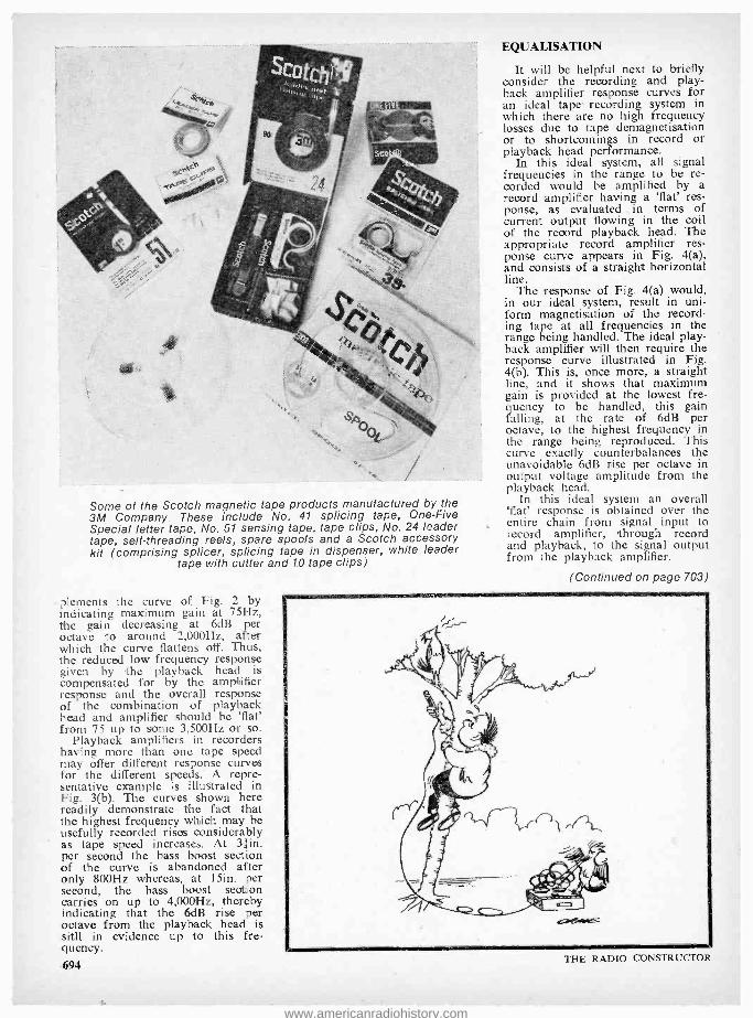
Some of the Scotch magnetic tape products manufactured by the 3M Company These include No. 41 splicing tape, One -Five Special letter tape, No. 51 sensing tape, tape clips, No. 24 leader tape, self- threading reels, spare spools and a Scotch accessory kit (comprising splicer, splicing tape in dispenser, white leader
tape with cutter and 1.0 tape clips)
,elements the curve of Fig. 2 by indicating maximum gain at 75Hz, the gain decreasing at 6dB per octave to around 2,000Hz, after which the curve flattens off. Thus, the reduced low frequency response given by the playback head is compensated for by the amplifier response and the overall response of the combination of playback head and amplifier should be 'flat' from 75 up to some 3,500Hz or so.
Playback amplifiers in recorders having more than one tape speed may offer different response curves for the different speeds. A repre- sentative example is illustrated in Fig. 3(b). The curves shown here readily demonstrate the fact that the highest frequency which may be usefully recorded rises considerably as tape speed increases. At 31in. per second the bass boost section of the curve is abandoned after only 800Hz whereas, at 15in. per second, the bass boost section carries on up to 4,000Hz, thereby indicating that the 6dB rise per octave from the playback head is still in evidence up to this fre- quency.
694
EQUALISATION
It will be helpful next to briefly consider the recording and play- back amplifier response curves for an ideal tape recording system in which there are no high frequency losses due to tape demagnetisation or to shortcomings in record or playback head performance.
In this ideal system, all signal frequencies in the range to be re- corded would be amplified by a record amplifier having a 'flat' res- ponse, as evaluated in terms of current output flowing in the coil of the record playback head. The appropriate record amplifier res- ponse curve appears in Fig. 4(a), and consists of a straight horizontal line.
The response of Fig. 4(a) would, in our ideal system, result in uni- form magnetisation of the record- ing tape at all frequencies in the range being handled. The ideal play- back amplifier will then require the response curve illustrated in Fig. 4(b). This is, once more, a straight line, and it shows that maximum gain is provided at the lowest fre- quency to be handled, this gain falling, at the rate of 6dB per octave, to the highest frequency in the range being reproduced. This curve exactly counterbalances the unavoidable 6dB rise per octave in output voltage amplitude from the playback head.
In this ideal system an overall 'flat' response is obtained over the entire chain from signal input to record amplifier, through record and playback, to the signal output from the playback amplifier.
(Continued on page 703)
THE RADIO CONSTRUCTOR
www.americanradiohistory.com

RECENT PUBLICATIONS 11-1-1
QUESTIONS AND ANSWERS ON TRANSISTORS, Third Edition. By Clement Brown. 96 pages, 41 x 61in. Published by Butterworth & Co. (Publishers) Ltd. Price 10s.
This pocket hard -cover book appears in the Newnes- Butterworth 'Questions and Answers' series, and it is irteresting to note that the author has also written several of the other titles, these being 'Questions and Answers on Electronics', 'Questions and Answers on Computers' and 'Questions and Answers on Audio'.
The 'question and answer' approach is generally acknowledged as representing an efficient and attractive method of presenting technical information, since it enables the text to be broken up into small individual sections, each devoted to a particular aspect of the overall subject. The technique is very successfully exploited in the book under review, in which descriptions of quite complex functions are presented with economy and clarity. The subject matter covers a wide spectrum in the field of semiconductors, ranging from diodes to integrated circuits, and there are a large number of clear diagrams. Obviously, each item dealt with cannot be discussed in depth, but then that is not the purpose of the present book.
'Questions and Answers on Transistors' will be particularly useful as an introductory reference book for the beginner who is just starting to interest himself in transistors and allied semiconductor devices.
TELEVISION ENGINEERING, PRINCIPLES AND PRACTICE, VOLUME THREE, Second Edition. By S. W. Amos, B.Sc., C. Eng., M.I.E.E., D. C. Birkinshaw, M.B.E., M.A., C.Eng., F.I.E.E. and K. H. Green, C.Eng., M.I.E.R.E. 268 pages, 5/ x 81in. Published by Iliffe Books Ltd. Price 70s.
There are four volumes in the textbook 'Television Engineering'. Volume One deals with television funda- mentals, camera tubes, television optics and electron optics; Volume Two deals with video frequency amplification; and Volume Four deals with general circuit techniques. Volume Three, under review, deals with waveform gener- ation and is now in its second edition, having been extensively revised to include information on circuits based on transistors and to bring the subject matter otherwise up to date. All four volumes of 'Television Engineering' are written by senior members of the B.B.C. Engineering Division.
Volume Three describes the generation and application of the different waveforms encountered in television work. The treatment is largely descriptive in nature and employs a minimum of mathematics. The first part of the volume examines the waveforms used in television equipment and their application in a camera channel, after which Parts 2 to 5 inclusive deal respectively with sine waves, rectangular waves, sawtooth waves and parabolic waves. Part 6 provides three short appendices which cover aspects of valve input impedance and exponential curves, and the book ends with a good cross -referenced index.
A work with an authorship such as the present volume has can be expected to be authoritative and this is, indeed, the case. A particularly valuable feature is that circuits and functions are described at a level which can be appreciated and understood by anyone having an interest in television engineering, whether this be from the design, maintenance or, even, hobbyist viewpoint. The text is backed by more than 150 diagrams, these depicting circuits or waveforms as applicable.
LUMINESCENT SCREENS, PHOTOMETRY AND COLORIMETRY. By J. Kamler, M.Sc. 204 pages, 61 x 8in. Published by Iliffe Books, Ltd. Price 60s.
This book was first published in Poland, and the present revised edition is an English translation edited by D. G. C. Jones, B.Sc., Ph.d. The purpose of the author is to bring together in a unified way the different experi- mental concepts which have evolved for evaluating the performance of luminescent screens and, as such, is of particular interest in the sphere of colour television. The book commences with a description of the luminous properties of phosphors and luminescent screens, together with testing methods, then continues to radiation measurement, the spectrophotometry of phosphors, colour measurements, phosphor afterglow measurements and measurements of the electro- optical parameters of luminescent screens.
Under these general headings there is a very considerable wealth of information and the text is full of prac- tical facts discussed with an admirable conciseness. Mathematics are used, wherever necessary, to elucidate prrocesses and properties.
The field covered is of a specialised nature and the book will be of greatest worth to the professional engineer or to the student whose work is concerned, in general, with luminescence and phosphorescence and, in particular, .
with the measurement of the properties of phosphors employed in colour television cathode ray tubes. JUNE 1970 695
www.americanradiohistory.com

n =:é
wórk shop, 44 O YOU," ASKED SMITHY
D suddenly, "feel like knock- ing up a little experimental
circuit for me ?" The Serviceman drained his dis-
graceful tin mug of tea then placed it on his bench with a gesture of finality. There was at least half - an -hour of lunch break outstand- ing, and both he and Dick had finished their mid -day meals.
"If you like," said Dick oblig- ingly. "What's the circuit for ?"
"It's for a reaction timer," replied Smithy. "It can be used for measur- ing the reaction time of people to different stimuli."
"That sounds interesting," com- mented Dick. "Is there any special reason for making up the circuit ?"
"I want to use it to check out, in practice, some fresh ideas I've been having recently concerning constant current devices," explained Smithy. "You remember that we played around with devices of this nature a few months ago. "*
CONSTANT CURRENT DEVICE
"I do, indeed," said Dick promptly. "We had a transistor operating as a constant current de- vice, and we put it in the com- mon cathode circuit of two á.f. valves. Amongst other things, it enabled us to build a push -pull output stage where the output valves did their own phase -splitting."
"That's right," agreed Smithy, pulling his note -pad towards him and beckoning his assistant over. "Before telling you about my pre- sent ideas, which are for a com- pletely different application, I think
See "In Your Workshop" in October and November 1969 issues.
696
This month Smithy the Serviceman returns to the subject of
constant current devices, paying particular attention to their applications in conjunction with capacitance. After a theoreti- cal discussion on a sawtooth generator having an exception- ally linear waveform, he turns to a practical project, and he
and Dick construct and set up a simple but highly effective reaction timer
it would be helpful for both of us if I were to just briefly recap on the basic manner in which a tran- sistor functions as a constant current device. This might help us to get our thoughts orientated in the right direction. To get a con- stant current from a transistor, you operate it in grounded base. The collector current resulting from any given emitter current is then virtu- ally constant over all the collector voltages within the ratings of the transistor."
Smithy scribbled out a sketch of a grounded base transistor and its odllector voltage -collector current characteristics. (Figs. la) and (b)).
"In the set -up we used last time," Dick reminded him, "we didn't in- corporate a separate supply for the emitter current."
"True enough," agreed Smithy. "What we did was to tie the base to a fixed potential by connecting it to a zener diode or to a forward - biased silicon diode. (Figs. 2(a) and (b) ). With the zener diode the con- stant current transistor can be either a germanium or silicon type, but with the forward- biased silicon diode the transistor must be ger- manium because the stabilised volt- age across the diode has to be greater than the base - emitter voltage drop in the transistor. With these arrangements, we altered emitter current by varying the resistance in the emitter circuit. This set -up is very useful because it makes the constant current device capable of aperating from a single positive and a single negative supply rail. An important requirement of the current in the zener diode, or in the forward- biased silicon diode, and its series supply resistor, is that it should be comfortably in excess of the base current required by the transistor, this base current being equal to the desired collector current divided by the current gain of the transistor. And, to finalise on what we discussed previously, the current flowing in the emitter circuit is equal to the desired collector current plus the base current."
"I remember all that," replied Dick a little impatiently. "I'm a little puzzled, though, as to where a constant current generator comes in so far as a reaction timer is concerned."
"It comes in," said Smithy, "be- cause what I'm interested in at the moment is the behaviour of a con- stant current device when it's used in conjunction with capacitance. I'm shortly going to show you that a circuit including a constant current device and a capacitor offers one of the simplest and most linear rising or falling voltage waveform generators that you can possibly get. Before I do that, though, just take a quick look at this sketch of a simple RC circuit coupled to a battery and switch. (Fig. 3(a) ). If the capacitor in this circuit is initially discharged when the switch is closed, what sort of rising voltage characteristic do you get across the capacitor ?"
Collector load
Collector current
(a)
Collector voltage
(b)
Fig. 1 (a). Collector supply and emitter bias polarities for a
p.n.p. transistor in the ground- ed base mode. These are reversed for an n.p.n. transistor
(b). A typical family of collector voltage -collector current charac- teristic curves for grounded base operation, these being applicable to three different emitter currents
THE RADIO CONSTRUCTOR
www.americanradiohistory.com

Col lector load
Zeser diode
Col lector load
(a)
Silicon diode
(b)
Fig. 2(a). The grounded base transistor may be employed as a constant current device oper- ating from standard supply rails by holding the base volt- age stable with the aid of a
zener diode (b). With germanium transistors,
the base voltage may alternatively be held stable by a forward
biased silicon diode
"You get a rising voltage," re- plied Dick, picking up Smithy's pen and adding a further sketch to the top sheet of the note -pad, "which follows an exponential curve with time." (Fig. 3(b) ).
"Right," said Smithy briskly, as he retrieved his pen. "Now, let's replace that resistor with a con- stant current device. (Fig. 4(a) ). With a resistor, the charging current flowing into the capacitor reduces all the time because the voltage across the resistor, and hence the current which flows through it, be- comes smaller as the capacitor charges up. This effect is what pro- duces the exponential charging curve. With a constant current de- vice, though, there is a completely different state of affairs. The device allows only the constant current to flow into the capacitor, this being maintained regardless of the voltage across the capacitor. In conse- quence, the rate of change of volt- age across the capacitor remains unaltered all the time it is charging up and the final outcome is that the voltage across the capacitor in- creases in completely linear fashion. Instead of the exponential curve JUNE 1970
given with the series resistor, you get a perfectly straight line!" (Fig. 4(b) ).
"Gosh," said Dick, gazing at Smithy's diagram. "That's some- thing I hadn't thought of before."
"It is rather impressive, isn't it ?" said Smithy. "One possible appli- cation which immediately suggests itself after seeing that characteristic is the use of a constant current device in a sawtooth generator."
Smithy tore the top sheet off his note -pad and scribbled out a circuit on the sheet underneath. (Fig. 5).
"This is an example of what I mean," he went on. "What I've shown here is a multivibrator which couples to an output transistor, TR3. The mark and space ratio of the multivibrator is such that TWA is cut off during most of the cycle, and is hard on for the remainder. The sawtooth appears across capa- citor C3. When TR3 is hard on this capacitor is short -circuited and discharges to nearly zero voltage. When TR3 cut off, however, the capacitor is allowed to charge via the constant current transistor, TR4, whereupon the circuit produces a completely linear rising voltage. Output amplitude is controlled by a variable resistor in the emitter circuit of the constant current transistor. If the constant current is varied by altering the value of the emitter resistance, the amplitude of the output voltage waveform will similarly vary."
"That," pronounced Dick, "is rather a neat circuit."
"It could certainly form a useful circuit for experimenters," respon- ded Smithy. "However, I don't want to spend any more time on it for the present, and I'd prefer to get back to constant current devices and capacitors in general. By the way, I said just now that the constant current device can pro- vide a linear falling voltage wave- form as well as a linear rising volt- age waveform. The falling voltage is given if the constant current device is connected across a charged capacitor such that it allows a constant discharge current to flow."
"Fair enough," remarked Dick. "Incidentally, how do you work out the time constant given by the combination of capacitor and con- stant current device ?"
"There isn't one!" chuckled Smithy. "With a constant current device and a capacitor you simply have a straightforward and con- stant change in voltage. If the change is an increase, this carries on until the voltage across the capacitor is very close to the applied supply voltage. After that it stops, of course, because the constant current device doesn't have enough voltage' across it to allow the constant current to flow."
"Well," persisted Dick, "if you don't have a time constant, how
do you work out the change in voltage with respect to time ?"
"You refer to it in terms of volts change per second," explained Smithy. `The rate of change of
volts per second in equal to - C'
where I is the current in amps and C is capacitance in farads. Or you can have current in microamps and capacitance in microfarads if you find this easier for calculations."
"Blimey," said Dick. "That's a dead simple formula, isn't it ?"
"It is," agreed Smithy. "To take an example of its use, let's say that we have a constant current of 5mA charging a capacitor of 100µF. 5mA is equal to 5,000µA, so the expression, using microamps and
5,000 microfarads, gives us -. The
100 voltage across the capacitor rises, therefore, at 50 volts per second."
"I see," said Dick musingly. "Is there anything else in the general line I should know concerning con- stant current devices in conjunction with capacitance before we get started on this reaction timer of yours ?"
REACTION TIMER
"I don't think so," said Smithy, reaching for his note -pad once more. "So we can now get weaving on the timer without further delay.
1
E volts
E
volts
Voltage across
capacitor
(a)
Time -o- (b)
Fig. 3(a). An RC circuit in which the capacitor charges to battery
voltage via a resistor (b). The voltage across the capacitor follows the familiar exponential charging curve
after the switch is closed 697
www.americanradiohistory.com

Four Local Suppléer LONDON
Established 1910
H. L. SMITH & CO. LTD.
Comprehensive stocks of components by
all leading makers.
287 -9 EDGWARE ROAD LONDON W.2
Tel 01 -723 5891
THE
MODERN BOOK CO.
Largest selection of English &
American radio and technical books in the country.
19 -21 PRAED STREET, LONDON, W.2
Tel: PADdington 4185/2926
TAKE THE SLOG OUT OF SOLDERING
With this lightweight miniature solder iron fitted with high efficiency nickel plated bit. & powerful 15 watt element ANTEX model CN240 voltsnn Special low price. ACT NOW L.7
TRANSISTORS ACY22 1/9 0C45 1/9 ZTX300 1/9 BC 108 1/9 0071 1/9 2N706 1/9 BFY51 1/9 0C200 1/9 2N2926 1/9 BFY52 1/9 0C202 1/9 2N3708 1/9 All the above types are available at 16 for C1. Brand New. Individually tested.
MONEY BACK GUARANTEE p &p I/- J. M. KING (W), 17 Buckridge, Portpool Lane. London, E.C.1
HAMPSHIRE
BOURNEMOUTH LARGEST HI -FI AND RADIO COMPONENT ._
STORE IN THE SOUTH
FORRESTERS NATIONAL RADIO SUPPLIES LTD. 70-72 Holdenhurst Road
Bournemouth Telephone 25232
698
I'll start off by sketching out a simplified circuit, because this will make it easier to explain some of the points of operation,"
The Serviceman quickly sketched out the diagram. (Fig. 6).
"Here we are," he remarked. "Basically, the whole timer project is extremely simple. The supply is provided by a 12 volt battery and this couples, via a constant current device and a push- button whose contacts open when it is pressed, to a 1,000µF capacitor. For the sake of illustration we will say, for the time being, that the constant current device passes IOmA. One section of a double -pole switch connects across the capacitor, whilst the other section couples to a stimulus circuit."
"Stimulus circuit?" "A circuit which gives visual or
aural warning of the start of a timing period," explained Smithy. "It could consist of a bulb and battery in series or an a.f. oscillator feeding a loudspeaker, or any similar sort of thing. Connected across the capacitor is a very high impedance voltmeter having an f.s.d. of 10 volts. And that, so far as this simplified diagram is con- cerned, is the lot!"
"Just that?" "Just that," repeated Smithy.
"I'll next ask you to tell me the rate of change of voltage across the capacitor, bearing in mind that the constant current is 10mA and that the value of the capacitor is 1,000µF."
"Let's see now," said Dick musingly. "I'll put the IOmA into microamps first, which gives me a current of 10,000µA. So the for -
10,000 mula becomes . The rate of
1,000 change of voltage is 10 volts per second, then."
"An excellent bit of calculation," approved Smithy, "and perfectly correct, too. Let's next assume that I'm going to check your reaction time to a visual stimulus. I'll con- nect a battery and bulb to the stimulus arm of the double -pole switch, and set this switch to the position where the bulb is not lit and the 1,000µF capacitor is short- circuited. I'll then ask you to push the press -button as soon as you observe the bulb lighting up."
"This is getting really intriguing," remarked Dick. "Go on, Smithy!"
"At some unexpected moment," continued Smithy, "I am, unseen by you, going to throw that double - pale switch. This will immediately light up the bulb and take the short -circuit off the 1,00014F cap- acitor, whereupon the voltage across the capacitor will start rising at the rate of 10 volts per second. As soon as you observe the bulb light up you push the
press -button. This will stop the capacitor charging and the voltage across it at that instant will then be indicated by the voltmeter. Since the voltage rise is a linear 10 volts per second, the voltmeter will indicate the fraction of a second which has elapsed between my throwing the switch and you pressing the button. If it reads 4 volts, then the time that has elapsed will be 0.4 seconds. Got it ?"
PRACTICAL CIRCUIT
"I'll say I have," responded Dick eagerly. "I can see that we could have quite a bit of fun with this gadget. How about the practical circuit ?"
"Give me a couple of minutes," replied Smithy, "and I'll get that sorted out for you as well."
Smithy concentrated, then pro - ceded to draw out the full circuit diagram of the reaction timer. After some minutes had elapsed,
leaned back and, with a proud gesture, indicated the fruits of his labours. (Fig. 7).
"Here it is," he pronounced, "the practical circuit of my reaction timer. The constant current device is the germanium transistor, TR2, and the base of this transistor is held at a fixed potential by means of the forward biased silicon diode, D2. There'll be a steady voltage of about 0.6 across this diode, which is well in excess of the 0.2 volt that appears across the base-emitter junction of TR2."
Constant current device
Voltage across
capacitor
(a)
Time
(b)
Fig. 4(a). A circuit in which the capacitor charges via a
constant current device (b). The voltage across the capacitor rises in linear manner
THE RADIO CONSTRUCTOR
www.americanradiohistory.com

"Fair enough," commented Dick, gazing searchingly at the circuit. "Incidentally, what's the 2252 re- sistor for ?"
"Do you mean R2 ?" "I do." "It's function," replied Smithy,
"is to ensure that you don't put a dead short- circuit across the cap- acitor when switch Si is set to Position 1. The 2252 resistor limits the discharge current to a value which won't harm the electrolytic."
"Hang on a minute," said Dick suspiciously. "The switching is dif- ferent from what you put in your simplified circuit. In the simplified diagram the switch shorting out the electrolytic was part of a double - pole component. In the present circuit you've combined the two switches in the single -pole com- ponent you've marked as SI."
"The reason for doing that," said Smithy, "is that, in the practical
emitter follower, which means that the voltage on its emitter is equal to the voltage on its base minus the base- emitter voltage drop. Since R1 has a value of 10k52, the meter will give an f.s.d. reading when there's 10 volts on TR2 emitter. The fact that M1 is calibrated from zero to 1 provides an incidental advantage here, since the calibra- tion then corresponds directly to time in seconds."
"There seems to be a snag here," said Dick suddenly. "Now, let's make quite certain I've got my facts right. The general idea is that, after putting SI to Position 2, you stop the capacitor charging by pushing press- button S2, isn't it?"
"That's correct." "Whereupon the milliammeter
will indicate the voltage that was acquired by the capacitor as you press the button ?"
"True," agreed Smithy. "The
Zener diode
Amplitude control
TR2 TR3 NC
Ti i
Sawtooth output
Fig. 5. Smithy's suggestion for a sawtooth generator offering a very linear waveform. (This circuit, which has not been checked
in practice, provides an interesting experimental project)
version of the circuit, it's necessary to use a switch which is very quiet and quick in operation. It's got to be quiet, of course, because the chap who's having his reaction time checked will otherwise respond to the aural stimulus given by the click as it changes over. An ideal component for S1 is a change- over microswitch, which is ' both quick and quiet in operation. How- ever, changeover microswitches are usually available in single -pole only, which explains why I've combined the capacitor and stimulus circuits in the manner I've shown in the circuit."
"I see," commented Dick thought- fully. "Now, where's the 0 -10 volt voltmeter ?"
"That's provided by TRI, RI and the 0 -1mA meter, Ml," replied Smithy. "TR1 functions as an JUNE 1970
needle of the milliammeter swings over from zero to f.s.d. in 1 second, which is far' too quick to allow readings to be evaluated directly. When you press the button you `freeze' the meter needle at the read- ing it held at the instant of press- ing the button."
"But," protested Dick, "that's where the snag comes in. So far as I can see, the meter needle won't `freeze'. All that will happen is that the 1,000µF capacitor will discharge because of the base current drawn by TRI and because of its own leakage resistance. The meter needle will just slowly drop back to zero."
"There will be a gradual dis- charge from the electrolytic," ad- mitted Smithy. "But the meter needle should still remain steady at the reading it had when you pressed the button for quite a con-
'Your Local Supplier KENT
EMSAC BASIC ANTENNA SYSTEMS CN1 2 metre converter, 170/- P &P 4/6. CN3 4 metre converter, 170/- P& P
4/6. PS1 Mains power supply for above. 70/- P &P 4/6. CN2 2 metre converter + PSU in case, 277/- P &P 6/6. CN4 4 metre converter + PSU in case, 277/- P &P 6/6. TU2 Tuning unit for matching any antenna to receiver. 1.8-30M Hz. 90/- P&P 4/6. KM1 Morse practice oscillator /keying monitor, 160/- P &P 4/6. PRI 2 metre mosfet pre -amp. over 20db. gain. 95/- P &P 4/6.
ELECTRONIC & MECHANICAL SUB -ASSEMBLY CO. LTD.
Highfield House, West Kingsdown, Kent Tel: West Kingsdown 2344
SURREY
Portable Transistor Amplifier Many uses - Intercoms. Baby Alarms. Guitar Practice, Telephone or Record Player Amplifier. ONE WATT OUTPUT. Wooden cabinet 12x9x4 ". Rexine covered two -tone grey. Four transistors, 7x4" speaker. Volume control. Jack socket. Uses PP9 battery. Brand new - full makers' guarantee.
Worth double our price
79/6 Post Free
Full List 1/- Radio Component Specialists 337 Whitehorse Road, West Croydon, Surrey. Phone 01- 684 -1665
SUSSEX
E. JEFFRIES For your new television set,
tape recorder, transistor radio, and hi -fi equipment.
PHILIPS, ULTRA, INVICTA, DANSETTE, MASTERADIO, PERDIO,
MARCONI, PHILCO, FIDELITY
6A Albert Parade, Victoria Drive,
EASTBOURNE SUSSEX
EIRE
PEATS for PARTS ELECTRONIC COMPONENTS
RADIO & TELEVISION
For the convenience of IRISH enthusiasts we supply: The Radio Constructor, Data Books and Panel -Signs Transfers Also a postal service
Wm. B. PEAT & Co. Ltd. 28 PARNELL STREET
DUBLIN 1
699
www.americanradiohistory.com
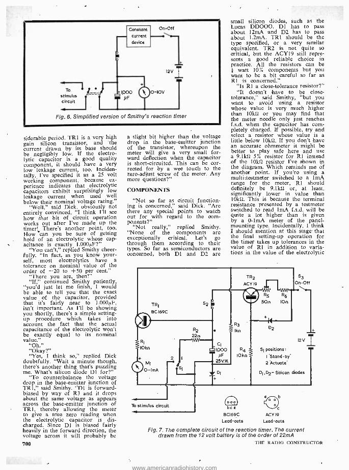
To
stimulus - circuit
Fig. 6. Simplified version of Smithy's reaction timer
siderable period. TRI is a very high gain silicon transistor, and the current drawn by its base should be negligibly low. If the electro- lytic capacitor is a good quality component, it should have a very low leakage current, too. Inciden- tally, I've specified it as a 25 volt working component, because ex- perience indicates that electrolytic capacitors exhibit surprisingly low leakage current when used well below their nominal voltage rating."
"Well," said Dick, obviously not entirely convinced, "I think I'll see how that bit of circuit operation works out after I've made up the timer! There's another point, too. How can you be sure of getting hold of an electrolytic whose cap- acitance is exactly 1,000µF ?"
"You can't," replied Smithy cheer- fully. "In fact, as you know your- self, most electrolytics have a tolerance on nominal value of the order of -20 to +50 per cent."
"There you are, then!" "If," continued Smithy patiently,
"you'd just let me finish, I would be able to tell you that the exact value of the capacitor, provided that it's fairly near to 1,000µF, isn't important. As I'll be showing you shortly, there's a simple setting - up procedure which takes into account the fact that the actual capacitance of the electrolytic won't be exactly equal to its nominal value."
"Oh." "Okay ?" "Yes, I think so," replied Dick
doubtfully. "Wait a minute though, there's another thing that's puzzling me. What's silicon diode D1 for ?"
"To counterbalance the voltage drop in the base -emitter junction of TRI," said Smithy. "D1 is forward - biased by way of R3 and it drops about the same voltage as appears across the base -emitter junction of TRI, thereby allowing the meter to give a true zero reading when the electrolytic capacitor is dis- charged. Since Dl is biased fairly heavily in the forward direction, the voltage across it will probably be
700
a slight bit higher than the voltage drop in the base -emitter junction of the transistor, whereupon the meter will give a very small for- ward deflection when the capacitor is short -circuited. This can be cor- rected for by a wee touch to the zero -adjust screw of the meter. Any more questions ?"
COMPONENTS
"Not so far as circuit function- ing is concerned," said Dick. "Are there any special points to watch out for with regard to the com- ponents?"
"Not really," replied Smithy. "None of the components are exceptionally critical. Let's go through them according to their types. So far as semiconductors are concerned, both Dl and D2 are
small silicon diodes, such as the Lucas DD000. Dl has to pass about 12mA and D2 has to pass about 1.2mA. TRI should be the type specified, or a very similar equivalent. TR2 is not quite so critical, but the ACY19 still repre- sents a good reliable choice in practice. All the resistors can be } watt 10% components but you want to be a bit careful so far as Rl is concerned."
"Is 121 a close -tolerance resistor ?" "It doesn't have to be close -
tolerance," said Smithy, "but you want to avoid using a resistor whose value is very much higher than 10kí2 or you may find that the meter needle only just reaches f.s.d. when the capacitor has com- pletely charged. If possible, try and select a resistor whose value is a little below 10ktl. If you don't have an accurate ohmmeter it might be better to play safe here and use a 9.1kí2 5% resistor for Rl instead of the l0k12 resistor I've shown In the diagram. Which reminds me of another point. If you're using a multi-testmeter switched to a lmA range for the meter, Rl should definitely be 9.1161 or, at least, significantly lower in value than 10k11. This is because the terminal resistance presented by a testmeter switched to read lmA f.s.d. will be quite a lot higher than is given by a 0-1mA meter of the panel - mounting type. Incidentally, I think I should mention at this stage that the final setting -up operation for the timer takes up tolerances in the value of Rl in addition to varia- tions in the value of the electrolytic
TR2
ACY 19
To stimulus circuit
R3
Ikn
S3
On-Off
MAN' R5 R6
500 IOn
R4
IOkn
000 bce
BCI69C
Lead -outs
Si positions:
'Stand-by. 2 Actuate'
Di,D2- Silicon diodes
-c ACY 19
Lead -outs
Fig. 7. The complete circuit of the reaction timer. The current drawn from the 12 volt battery is of the order of 22mA
THE RADIO CONSTRUCTOR
www.americanradiohistory.com

Circuit broken '.X here
Testmeter
Negative supply rail
(a)
Temporary 500n potentiometer
s2
i Testmeter
Negative supply rail
(b)
Fig. 8(a). The circuit is initially checked by setting up R5 so that TR2 passes a constant current of 10mA
(b). To take up circuit tolerances, full -scale meter traversal is checked at a constant current of 1mA
capacitor." "Ah," said Dick. "That capacitor
is pretty well the only component you haven't mentioned."
"Then I'll do so right now," responded Smithy: "The electrolytic capacitor must be a reliable new component of good manufacture. The whole success of the circuit depends on the goodness of this component."
Satisfied with Smithy's answer, Dick rose, picked up the circuit diagram, and walked purposefully towards his bench.
"I'll start by knocking up this circuit right now," he announced. "I should be able to wire it up quite quickly on a small piece of tagboard hitched onto a bit of ali to hold the switches and press - button."
"Okey- doke," said Smithy equ- ably. "So far as construction is concerned, the connection to the JUNE 1970
slider of the 502 pot in the emitter circuit of TR2 should be of a tem- porary nature only. This is because it has to be unmade to allow an extra component to be inserted during setting -up. Oh yes, and the same applies to the lead from the collector of TR2. Leave the wire from this collector completely un- connected at switch S2 during wiring up."
The clatter of tools and soldering - iron from Dick's bench soon indi- cated that constructional work was in process. In a surprisingly short time, Dick announced that he had completed the assembly of the circuit. Smithy walked over to in- spect his assistant's handiwork.
"Very good," he commented approvingly. "We'll initially check the circuit out by setting up the constant current transistor to give us IOmA. To do this we connect a testmeter switched to read 50 or
100mA between the collector of TR2 and the negative supply line, then set up R5 for lOmA."
Smithy made the required con- nection (Fig. 8(a) ), then adjusted R5 to insert maximum resistance. He switched on cautiously by means of S3, ensuring that he could switch off again quickly if, due to a fault condition, the meter indi- cated excess current. However, the meter needle did nothing other than rise sedately to slightly less than 5mA. Smithy adjusted R5 for a reading of lOmA, then switched off again at S3.
"This," he remarked, "is just a try-out. Now, temporarily connect the collector of TR2 to S2."
Dick made the connection, after which Smithy set Si to Position 1
and closed S3 again. The 0-1mA meter in the timer circuit gave a very small forward indication. Smithy returned the needle exactly to zero by means of the meter zero - adjust screw. He then set 51 to Position 2. The meter needle moved fairly rapidly to the right, stopping at its f.s.d. end -stop. Smithy put SI to Position 1, where- upon the meter needle returned to zero again. Smithy set SI to Posi- tion 2 once more, pressing S2 quickly afterwards and holding it. down. The meter needle held steady for a few moments at about 0.4, then gradually began to fall slowly to the left.
"I told you that would happen," remarked Dick accusingly. "The electrolytic starts discharging as soon as you press the button."
"Tush," reproved Smithy. "Tush! These are early days yet, mate."
Smithy put the circuit through its paces about a dozen further times, stopping the meter needle at various points on the scale. Gradu- ally, the tendency for the meter needle to fall after S2 had been
2.5V bulb 1." 3V
On-Off
Fig. 9. A suitable stimulus circuit, wired up to Si. This uses a separ- ate battery and the on -off switch shown here could be ganged, if desired, with S3 in Fig. 7. The value of the resistor shown as 1011 may need adjustment to suit
some bulbs
701
www.americanradiohistory.com

pressed disappeared, and it even- tually remained completely steady at all settings whilst S2 was pressed.
"That's more like it," remarked Smithy, pleased. "I don't know how long that 1,000µF electrolytic cap- acitor has been in store, but it is now beginning to get properly 'formed' due to its use in this circuit. I'll run the timer another ten times or so to make certain that the capacitor is reliably 'formed', after which we'll get the circuit properly set up."
SETTING -UP
After the further runs, Smithy declared himself satisfied with the condition of the electrolytic cap- acitor.
"Right," he remarked. "The next job is to set up the circuit so that it accommodates the actual capaci- tance of the electrolytic. As I said a few minutes ago, this process will also take up tolerances in R1 as well. Now, the speed at which the meter needle is moving at present is far too fast for us to check visually and so we shall next slow it down by reducing the constant
current to ImA. Will you therefore, Dick, once more remove the con- nection from TR2 collector to S2 and, also, insert a 50051 pot in series with R6 and RS?" (Fig. 8(b) ).
Dick found a suitable potentio- meter and carried out Smithy's bid- ding.
"Good," said the Serviceman, "we'll next set up for a constant current of lmA."
Smithy connected the testmeter between TR2 collector and the negative supply rail and, after switching on, adjusted the tem- porary 50012 potentiometer for a reading of exactly ImA. He next removed the testmeter and asked Dick to remake the connection at S2. Smithy then switched on and cycled the unit once more. This time, the movement of the meter needle was very much slower.
"I suppose," said Dick, watching the meter needle with fascinated eyes, "that the length of the period is now of the order of 10 seconds."
"It is," confirmed Smithy. "What we have to do next is to measure the period which exists between the instant of operating Si and . the instant at which the needle passes
the f.s.d. point on the meter scale." - Carefully looking at the second
sweep hand of his watch, Smithy checked the time needed for the meter needle to fully traverse its scale. He repeated this operation several times, then diverted his gaze away from his watch.
"As near as dammit," he an- nounced, "the period is 13 seconds each time. This means that, for a full scale traversal in one second, we'll need a constant current of 13mA."
13mA? How d'you make that out ?"
"The present rate of change of voltage across the capacitor," ex- plained Smithy, "corresponds to a full scale traversal of the meter needle in 13 seconds. We want to increase the rate of change of volt- age so that full needle movement occurs in one second. The rate of change of voltage must therefore be increased 13 times, which necessi- tates a similar increase in the con- stant current charging the capacitor. At present it's lmA, and so we must multiply it up to 13mA."
"I see now," said Dick brightly. "Of course it has to be multiplied 13 times!"
RADIO CONSTRUCTOR SPECIAL EXCLUSIVE OFFER
MASERATI AIR HORNS DUAL HORNS
Ideal for Motorway or Continental driving. Will fit under the bonnet of any car. Available in 6, 12 or 24 volts. This unit incorporates a new extra powerful compressor, which is only available with Maserati Air Horns. Extra tough red plastic trumpets, both 6 }in. long, base diameter of each 3in. Com- pressor height 41in., diameter 2Iin. Total weight, including box, 4', -lbs. Complete with relay, tubing, securing nuts and bolts and fixing instructions. List Price 5 gns.
OUR PRICE 69/6 plus p. & p. 6/ -.
TRIPLE HORNS Three alternating notes in fast sequence. Can also be sounded together by operating the dash switch. A very pleasant musical warning attract- ing immediate attention. Extremely compact, will fit on all cars. Available in 6 and 12 volts
°may OUR PRICE 135/- plus p & p 6/ -. I
I I
' To Data Publications Ltd. 57 Maida Vale, London, W.9
I Please supply:
These famous air horns are proving a popular fitting on small and medium sized boats.
COVERED BY A SEVEN -DAY MONEY BACK GUARANTEE I
1
Dual Horns Triple Horns (State voltage required)
I enclose cheque /crossed postal order for Name Address
Block Letters Please
702 THE RADIO CONSTRUCTOR
www.americanradiohistory.com

"That's the idea," commended Smithy. "If it had happened that, with the lma constant current, full scale traversal had occurred in, say, eight seconds, then the final con- stant current we'd require would be 8mA. The great advantage of setting -up the timer circuit in this manner is the fact that only three easy measurements are re- quired, two being of current and one of time. Anyway, we're on the last lap now. So, remove the tem- porary 50052 pot, connect R6 pro- perly to the slider of R5, and once more disconnect the connection at S2 from TR2 collector."
After Dick had carried out these instructions Smithy connected the testmeter to the circuit in the same manner as for the original 10mA constant current adjustment. This time, however, he adjusted R5 for exactly 13mA. He then switched off at S3, took up Dick's soldering iron and, with an air of finality, per- manently connected the lead from TR2 collector to the tag at S2.
"Setting -up," he announced, "is complete. From now on, that meter will give a linear indication of elapsed time, with f.s.d. correspond- ing to exactly one second. All we've got left to do now is to add a bulb and battery for the stimulus cir- cuit."
"I've been thinking about the bulb and battery," said Dick. "Isn't there a possibility that there'll be a very slight delay before the bulb lights up to full brilliance after it has been switched on ?"
"That could happen, I suppose," replied Smithy. "However, any pos- sible delay in bulb illumination can be reduced to a minimum by keep- ing the filament just glowing when it's switched off by means of a' resistor across the switch. The bulb
should then achieve full brilliance almost immediately after switch Si is operated." (Fig. 9).
"I wonder," commented Dick pensively, "what value of resistance will be required."
"That," replied Smithy, "is a matter for experiment. Incidentally, I should use an ordinary torch bulb rather than, say, a radio pilot lamp, as the latter types tend to have somewhat sluggish filaments."
FINAL TRY -OUT
Dick very quickly had the bulb circuit wired up, and he found that the value of resistance required to keep the bulb just glowing was 1052. When this resistor was short- circuited the bulb attained full brilliance, so far as could be per- ceived, virtually instantaneously.
"Good," said Smithy. "Let's now take a measurement of your reac- tion time."
After Smithy had switched on the reaction timer at S3, Dick posi- tioned himself alongside it with his finger on the press- button, and con- centrated on the just -glowing bulb. Smithy's hand, out of Dick's sight, hovered over switch Si, which was now in Position 1. Suddenly the bulb glowed brightly. Taken slightly unawares, Dick jammed his finger down on the button.
"Don't take% your finger off," warned Smithy, "or the meter needle will carry on to f.s.d."
They both looked at the meter. It indicated 0.6 seconds.
"Blimey, you're slow," com- mented Smithy. "Most people have reaction times of about a third of a second."
"Lets have another go, Smithy," pleaded Dick. "I wasn't quite pre- pared then."
"As you like." After several further attempts
Dick became more practised, and he found himself continually scoring a reaction time of approxi- mately 0.3 seconds. Then he and Smithy changed positions. Much to Dick's chagrin, the Serviceman scored 0.28 at the very first attempt and continued with a steady 0.25 seconds on each further occasion.
"You must," grumbled Dick, "have a whole length of your ner- vous system shorted out some- where. Nevertheless, this is a jolly useful gadget., It's just the sort of thing that's required to convince boozey car- drivers who think that their reactions are speeded up after a few drinks how misguided they are."
"It is, indeed," agreed Smithy. "And the circuit, with slight modi- fications including, perhaps, a change in the constant current to accommodate different timing periods, also has quite a lot of potential applications in production and experimental engineering."
Smithy glanced at the Workshop clock, and started.
"Blow me," he gasped, "we've wasted nearly an hour of working time playing around with this gadget. I'm now going to have a timing reaction myself, and this consists of announcing an immediate return to work!"
Whereupon the Serviceman, com- pletely deaf to the protests of his assistant, picked up the reaction timer and deposited it out of sight in the cupboard under his bench; after which he devoted himself to the hardest task so far, that of chivvying the reluctant Dick back to a proper consideration of his function as a supposedly full -time radio and TV service engineer.
UNDERSTANDING TAPE RECORDING (Continued from page 694)
In practice, such an ideal state of affairs cannot be achieved, the main failing being the losses at high frequencies due to tape demagnetisa- tion, and to losses at the record and playback heads. The ideal curve of Fig. 4(a) has, in conse- quence, to be modified by the in- troduction of treble boost to over- come these- losses. And the ideal curve of Fig. 4(b) has to be modi- fied by causing its falling section to cease at or around the fre- quency where high frequency play- back losses begin to become sig- nificant. It will be noted that the practical response curves we have seen up to now more closely approach those for ideal' conditions as tape speed increases. JUNE 1970
The procedure of applying treble boost to the record amplifier, and bass boost to the playback amplifier is described as equalisation. This is a blanket term which covers any electronic process whose aim is that of reducing distortion (in the present instance frequency distortion, i.e. unequal amplification of all fre- quencies) with the aid of suitable filters.
NEXT MONTH
In next month's issue we shall turn our attention to the bias signal which is applied to the record head during recording.
CHINESE EARTH SATELLITE
Our Listening Post reports taping the Chinese satellite signals from 2010 to 2022GMT on 28th of April. The signals were first heard, barely audible, on a measured frequency of 20009kHz at 2008GMT and rapidly gained in strength to peak at S9 with rapid flutter QSB to S7. The signal strength was best at 2017, rapidly declining till 2025, by which time signals had faded out into the noise level.
The transmission consisted of a single tone oscillator rendering of the tune "The East is Red" con- tinuously repeated.
703
www.americanradiohistory.com

radio lopies By Recorder
OME SKILLS, ONCE ACQUIRED, are never forgotten.
Particularly high amongst these is the ability to send and receive morse code. I appreciate that some would -be amateurs these days depre- cate the necessity for learning morse and, whilst I do not want to be drawn into that controversy, I do feel that a working knowledge of the code can be a definite asset to anyone who is seriously interested in short wave Dx reception. Also, skill with morse can be acquired fairly easily, particularly if one is a member of a local club where morse instruction sessions are held from time to time.
STUMBLING BLOCK
I would suggest that the main stumbling block encountered by those who start to learn the code from scratch is the tendency to concentrate excessively on character recognition. This point applies par- ticularly to the reading of morse, where the actual recognition of the morse characters should be rele- gated, as it were, to the back of the mind. To quote a parallel- in- stance, there are plenty of people who can type at surprisingly high speeds simply with the first finger of both hands. They have never been trained to type but have, due to the requirements of business or correspondence, tapped out docu- ments and letters on a typewriter over the years as and when re- quired. Initially, these self -taught typists would have had to look at the keyboard all the time to select the keys required. After a period, however, they found that the process 704
The D.C. Multimeter type TM9BP, currently manufactured by Levell Electronics, Ltd.
of typing had become automatic, whereupon they became capable of rattling off page after page with hardly a glance at the keys at all. Learning the morse code should follow the same lines. At first the individual characters have to be recognised, just as occurs in the first stages of one -finger typing, after which the learner gradually changes to automatic recognition of the characters, and finally writes down the morse message just as though it had been dictated to him in normal language. The great secret of learning morse is to relax and let the natural ability of the brain to respond to new stimuli take over. It is surprising how soon a good reading speed can be obtained by proceeding in this manner. Another point to bear in mind is that if, during the reception of a morse message, the odd character is missed, just forget it. Trying to remember what the character was whilst further characters are being received only gets the mind flustered.
Most of my own morse- bashing experience occurred in the Services where I was expected, as a sideline, to be able to take over from full - time operators. It was then that I discovered the uncanny ability of c.w. signals to break through quite fantastically high interference. The ear itself acts a a `filter' here and tends to ascribe a particular charac- teristic to the required signal that enables it to be isolated from those around it. Also, one can quite often identify the sender of a morse code signal after having become used to his `fist'. Morse characters with exact length and spacing are excellent to receive, but some operators tend to
acquire an individual rhythm which pervades all the messages they send. Their transmissions, whilst not exactly the copy -book morse that would be sent by a machine, devi- ate only slightly from the mathe- matical ideal and can be a veritable pleasure to copy.
After which, all I can now do is to offer the best of wishes to those who are currently engaged in learn- ing the dah -de- dah -dit, dah -dah- dah, dah- dit -dit, dit !
D.C. MULTIMETER
The accompanying photograph illustrates the latest d.c. multimeter, type TM9BP, available from Levell Electronics, Ltd.
This instrument contains a high gain chopper stabilised d.c. ampli- fier, with entirely solid -state cir- cuitry, which is powered by a PP9 battery having a life of 1,000 hours. When used as a microvoltmeter, it offers ranges from 3µV f.s.d. to 1kV f.s.d., with the high input resistance of 1M12 per µV up to 10mV, greater than 10,000M2 from 30mV to 1V and l00M12 above 1V. An alterna- tive application is as a pico- ammeter, whereupon ranges from 3pA f.s.d. to lA f.s.d. are available. The multimeter may also be em- ployed as a null detector, with a maximum sensitivity of 1.5-0- 1.5µV; as an ohmmeter, with linear ranges from 312 f.s.d. to 1,000M12 f.s.d.; or as a d.c. amplifier, with a maxi- mum gain of 333,300 and a maxi- mum output of 1V into lk12.
The type TM9BP multimeter is available, at £93, from Levell Elec- tronics Ltd., Park Road, High Barnet, Hertfordshire.
THE RADIO CONSTRUCTOR
www.americanradiohistory.com

LATE NEWS * AMATEUR BANDS
ICELAND Amateur transmissions from this country are not
usually plentiful but in recent weeks things have livened up with three stations becoming very active on 14MHz s.s.b. Listen for TF2WKF, TF2WKI and TF2WKP.
NICARAGUA Normally prefixed YN, some stations may be
heard using the HT prefix. HT1FR was heard to give his QTH as POB744 Managua.
NETHERLANDS ANTILLES Several stations are currently active from Curacao,
one notable s.s.b. signal being that of PJ1CL, heard giving his QTH as POB738.
BOTSWANA A2CAH has been heard on 14MHz s.s.b. giving
his QTH as POB17, Gaberones. JORDAN
Active to date is JY1, heard on 14MHz s.s.b. around 1700 to 1830 GMT. JY1 is the callsign of King Hussein, POB 1055, Amman.
IRAN Those readers who need this country should listen
for EP2FB and EP2TW, both currently active on 14MHz s.s.b.
TOP BAND For those who can read the `dots and dashes'
much Dx fare has been around of late in the c.w. portion of the band. In addition to many OK1's we have heard OK2BIT, OK3CHL, OL5ANG, OL6AMQ and OL8ANL.
EDDYSTONE RECEIVERS FOR
METEOROLOGICAL WORK
The British Meteorological Office has ordered 22 general purpose v.h.f. receivers, Type 990R, from Eddystone Radio. They are largely intended for use with radiosonde equipment, to receive information on meteorological conditions in the upper atmosphere from radiosonde balloons and rockets.
The Eddystone 990R receiver was first introduced at the end of 1967, as a replacement for the highly suc- cessful 770R equipment. It provides a completely solid -state equipment with a unique free- tuning range from 27MHz to 240 MHz.
The receivers will be used for radiosondé work at meteorological stations in the United Kingdom and overseas. They will receive informa- tion on temperature, pressure and humidity transmitted from both the conventional balloon- carried type of radiosonde, and a free -falling type which is ejected from a rocket. This latter type is useable at more than 200,000 feet and transmits f.m. sig- nals. JUNE 1970
* BROADCAST BANDS MEXICO
XERMX Radio Mexico has changed frequency from 9535 to 9745. Also on 6055 and 11720 in parallel. Sign off is at 0500.
TAHITI Radio Tahiti, Papeete, has been heard signing on
at 0230GMT instead of the usual 0300 on 11835 immediately after R.Sweden signs off on the channel.
YUGOSLAVIA Radio Belgrade now radiates a short wave listener
programme in English on the first Tuesday of each month from 1830 to 1900 on 6100, 7200 and 9620. Reports are requested.
SUDAN Radio Omdurman now uses the following chan-
nels: 4994, 6150 (20kW); 7200 (120kW), 9505 (50kW) and 11835 (120kW), with 15170 (50kW) as a stand- by frequency.
ISRAEL Kol Yisrael may be heard with an English pro-
gramme from 2045 to 2130 on 9009 and 9625. A 20kW transmitter is in parallel on 9725.
ALBANIA Radio Tirana can be heard with an English pro-
gramme at 2015GMT on 7065 (50/240kW). INDIA
All India Radio, Delhi, can be logged with an English programme at 2015 on 7215 (10 /100kW).
Acknowledgements to our own Listening Post and SCDX.
LAST LeN nK ROUND INTERESTED IN SAVING ?
If your meters don't centre -zero and you want to build a bridge circuit how the Dickens do you overcome the problem? Buy a new meter?
Hoard your hard -earned lolly and miserly scrimp together the simple rectifier circuit in Unusual Null Indicator to be featured next month.
Scrooge would have carolled over this one!
SAVING FOR INTEREST ?
If you want to measure the vital statistics of Millivolt, you'll have to meter in our next issue! Solid -State A.C. Millivoltmeter offers a wide frequency coverage, sensitivities from 10mV f.s.d. to 100V f.s.d. in five switched ranges with a relatively small number of components.
Another interesting design and money saver. Milli was always the former but hardly ever the latter!
SAVING GRACE ?
Never mind about Milli - what about Cybernetic Cynthia on page 672 of this issue? Beauty is only skin deep, or so we are led to believe. Although snail -like Cynthia displays few charms and won't come out of her shell, she at least has the saving grace of intelligence - albeit artificial - but then, often as not, so has beauty!
705
www.americanradiohistory.com

ANNOUNCING . .
N EVN NAND/PAN
IDEAL FOR WORKSHOP USE
WORDING (Sets 3 and 4) COMPLETELY REVISED. Over 1,000 words. Height of Letters %2in. FREQUENCY LISTS (Sets 5 and 6). Now in kHz and MHz.
Supplied to Universities, Technical Colleges, Government Establishments, Research Lab- oratories and Industry.
Easy to fix Permanent and durable Stapled in booklet form Designed to hang above workbench Pocket for loose cuttings Professional finish
* Set 3 Wording -WHITE
* Set 4 Wording -BLACK
* Set 5 DIALS -clear background
* Set 6 DIALS -black background
PANEL SIGNS Permanent Paint Transfers
RADIO CONSTRUCTOR
The Perfect Transfer for
the Home Constructor Each Set contains Six Sheets
5f- per set (postage 4d.)
To Data Publications Ltd. 57 Maida Vale, London, W 9
Please supply:
Set 3 Set 4 Set 5 Set 6
I enclose cheque /crossed postal order for........ Name
Address
R.C. BLOCK LETTERS PLEASE
706 THE RADIO CONSTRUCTOR
www.americanradiohistory.com
SMALL ADVERTISEMENTS Rate: 9d. per word Minimum charge 12/-
Box No. 2/- extra.
Advertisements must be prepaid and all copy must be received by the 4th of the month for insertion in the following month's issue. The Publishers cannot be held liable in any way for printing errors or omissions, nor can they accept responsibility for the bona fides of advertisers. (Replies to Box Numbers should be addressed to: Box No. -, The Radio Constructor, 57 Maida Vale, London, W.9.)
BUILD IT in a DEWBOX robust quality plastic cabinet 2in. x 2 #ins. x any length. S.A.E. for details. D.E.W. Ltd.; 254 Ringwood Road, Ferndown, Dorset. Write now right now.
SERVICE SHEETS. Radio, Television, Transistors, Tape Recorders, Record Players. Catalogue 2/6d. S.A.E. please. Hamilton Radio, 54 London Road, Bexhill, Sussex.
TO CLEAR. Back numbers of "The National Geo- graphical Magazine", from January 1959. 3/6d. each post paid. Box No. G110.
NEW CATALOGUE NO. 18, containing credit vouchers value 10 / -, now available. Manufacturers new and surplus electronic and mechanical components, price 4/6d. post free. Arthur Sallis Radio Control Ltd., 28 Gardner Street, Brighton, Sussex.
500 MW TRANSISTOR AMPLIFIER KIT, ideal for record players, intercoms, baby alarms, etc. 3 tran- sistor 9V. All parts tested before dispatch. Complete kit with circuit, 10 /6d. p.p. 6d. Tested transistors 8/- per dozen, 1/- each, p.p. 6d. Sim. 2N697, 2N706, 0C44, 0071, OC81, AC128, BFY50/1/2. A Manley, 111 Mayow Road, Sydenham, London, S.E.26.
BOOKS TO CLEAR: "The Upper Atmosphere ", Massey & Boyd, 50/ -. "KEOEEIT ", story of the Aurora Borealis 20/ -. "Teach Yourself Russian ", 5/ -. "Principles of Modern Book -keeping ", 5/ -. "Outlook ", elementary weather forecasting, 7/6d. "Health Physics ", principles of radiation protection, Rees 50/ -. All plus postage. Box No. G111.
FOR SALE: Transistorised grid dip oscillators (also act as wavemeters), 2 to 30 Mc /s. £10. GW3YQM, 4 Green Park, Pentlepoir, Saundersfoot, Pernbs. S. Wales. Telephone: Saundersfoot 3351.
JOIN THE INTERNATIONAL S.W. LEAGUE. Free services to members including Q.S.L. Bureau, Ama- teur and Broadcast Translation, Technical and Identifi- cation Dept. -both Broadcast and Fixed Stations, DX Certificates, contests and activities for the SWL and transmitting members. Monthly magazine, Monitor, containing articles of general interest to Broadcast and Amateur SWLs, Transmitter Section and League affairs, etc. League supplies such as badges, headed notepaper and envelopes, QSL cards, etc., are available at reasonable cost. Send for League particulars. Mem- bership including monthly magazine, etc., 35s. per annum. Secretary ISWL, 1 Grove Road, Lydney, Glos., GL15 5JE.
MUSICAL MIRACLES. Send s.a.e. for details of Drum Sound Modules, versatile bass -pedal accompaniment unit, self- contained with unique effects. Kits for Waa- waa pedals, 49/ -. Also bargain components, reed switches, etc. D.E.W. Ltd., 254 Ringwood Road, Fern - down, Dorset.
ARE YOU A MOTORING ENTHUSIAST? The Seven Fifty Motor Club caters for all types of motor sport - racing, rallies, hill climbs, etc. Monthly Bulletin free to members. For full details write to: The General Secretary, Colin Peck, "Dancer's End ", St. Winifred's Road, Biggin Hill, Kent.
(Continued on page 709) JUNE 1970
BENTLEY ACOUSTIC CORPORATION LTD. 38 Chalcot Road, Chalk Farm, The Old Pollee Station LONDON, N.W.I. Gloucester Road
01 - 722 9090 LITTLEHAMPTON, Susses
Please forward all mail orders to Littlehampton PHONE 6743
5Z4G 71- ECC85 516 PC88 10/3 U26 1119 ACI57 5!- BY126 3/- 6AQ5 516 ECC86 8/- PC95 8/3 U191 12/6 ADI40 716 BY127 3/6 6AT6 4/- ECC88 7/- PC97 8/6 U301 111- AD149 81- BYZIO S!- 6C4 51- ECC189 9/6 PC900 7/6 U404 7/6 ADI62 9/- BYZI I St- 6/30L2 2/- ECF80 6/6 PCC84 6/3 U801 19/6 AFI06 10!- BYZ12 5/- 6BR7 5/9 ECF82 6/6 PCC85 6/6 UABC806/6 AFII4 4/- BYZ13 51- 6BW7 3/- ECF86 9/- PCC88 9/9 UBC81 7/- AFI IS 4/3 0A70 31- 6F23 4/3 ECH42 12/9 PCC89 9/6 UBFBO 5/9 AFI17 4/6 0A79 1/9 6F28 4/- ECH81 5/9 PCCI89 10/6 UBF139 619 AFI19 31- OA81 1/9 6L6GT 7/9 ECH83 BI- PCFBO 6/6 UC92 5/6 AFI2 I 6/- 0A90 2/6 9D7 516 ECH84 7/6 PCF82 6/3 UCC84 BI- AFI26 5/- 0A91 1/9 10F18 7/- ECL80 7/- PCF84 81- UCC8S 7/3 AF139 131- 0A95 119 30C15 3/- ECL82 6/6 PCF86 12/9 UCF80 8/3 AFIBO 9/6 0A200 II- 30C17 6!- ECL83 9/- PCF200 13/3 UCH2I 9l- AFI86 I I I- 0A202 2/- 30C18 4/- ECL86 8/- PCF801 71- UCH42 12/- AFt39 7/6 0C22 5/- 30E5 6.'- EF22 12/6 CF807 9/- UCHBI 6/6 BA102 9/- OC23 5/- 30FLI 3/9 EF4I 10/- PCH200 1213 UCL82 7/- BAI15 2/8 0C24 5/- 30FL14 4/6 EF80 4/6 PCL82 7/3 UCLB3 IO/- BAI 16 5/- 0C25 S/- 30115 3/9 EF85 5/3 PCL83 10% UF41 IO/- BA129 2/6 OC28 9!- 30L17 5/6 EF86 6/3 PCL84 7/6 UFBO 6/9 BAI30 2!- 0C35 7/6 30P4 2/- EF89 5/- PCLB5 9/- UFOS 6/9 BCI07 4/- 0C36 7/6 30P4MR 7/6 EF9I 3/3 CL86 8/6 UF86 91- BCIOB 3/6 0C38 8/6 30P12 3/9 EFI83 6/- PEN45DD 15/- UF89 619 BCII3 5/- OC44 2l- 30P19 2/- EF184 6/- FL200 11/9 UL4I 10/6 BC118 4/6 0C45 21- 30PLI 3/9 EH90 7/6 PL36 9/6 UL84 6/6 BCY10 5/- 0C46 3/- 30PL13 5/6 EL33 12/- PL81 9/6 UM80 6/6 BCYI2 5/- OC70 2/3 30PL14 5/- EL34 10/6 PL82 6/6 UY4I 7/6 BCY33 5/- OC71 2/- DY87 5/9 EL4I Fll- PL83 6/6 UY85 5/9 BCY34 4/6 OC72 2/- E88CC 2/- EL84 4/9 P1.84 6/6 2N404 6/- BCY38 5/- 0074 2/6 EABC80 6l6 EL95 5/3 PL500 13/- 2N1756 101- BCY39 4/6 0075 2/- EAF42 O/- EM80 7/6 PL504 13/6 2N2297 4/6 BCZI 13/6 OC78 3/- EB34 3/- EM8I 7/6 PI509 28/9 2N2369 4/3 801 19 9/- OC78D 3l- EB91 2/3 EM84 6/6 PY33 10/- 2N2613 7/9 BFY50 4/- OCBI 2/- EBC41 9/6 EBC81 6/6
EMS 1- EM87 17!6
Y81 53 PY82 5Ì3
2N3053 66 2N3703 3j9
BEM 4/- BFY52 4/6 OC82D 2%3
EBF80 6/9 EY51 7/6 PY83 5/9 2N3709 4!- 8E159 5/- 0083 2/- EBF83 8/- EY87 6/6 PY88 6/9 2N3988 IO!- BFI63 4/- 0084 3/- EBF89 613 EZ4f) 7/6 PY800 7/6 25323 10/- 89173 7/6 0C123 4/6 EC92 6/6 EZ80 4/6 PY801 6/9 AA119 3/- BFI80 6/- 0C169 3/6 ECC8I 3/9 EZ8I 4/9 QQV03/1024/- ACI 13 5/- BYI00 3/6 0CI72 4/- ECCB2 4/6 HVR2 10/6 R19 7/6 AC127 2/6 BYI01 3/- 0C200 4/4 ECC83 4/6 KTW6212'6 U19 34/6 ACI54 5!- BY105 3/6 OC202 4t6 ECC84 6/3 PC86 10/3 U25 13/- AC156 4/- BYI 14 3/6 OC203 4/6
Terms of business: Cash wi h order only. No C.O.D. Post/Packing 6d per item. Orders over [5 post free. All orders despatched same day as received by first class mail. Complete catalogue including transistor section and components with terms of business 1/-. Any parcel insured against damage in transit for 6d. extra. Business hours 9 a.m.-5.30 p.m. Saturdays 9 a.m.-1 p.m.
Littlehampton closed Sats.
IN EST. 189(
TECHNICAL TRAINING IN RADIO, TELEVISION AND ELECTRONIC ENGINEERING
First class opportunities in Radio and Electronics await the ICS trained man. Let ICS train YOU for a well -paid post in this expanding field. ICS courses offer the keen, ambitious man the oppor- tunity to acquire, quickly and easily, the specialized training so essential to success. Diploma courses in Radio TV Engineering and Servicing, Electronics, Computers, etc. Expert coaching for:
C. & G. TELECOMMUNICATION TECHNICIANS CERTS. C. & G. ELECTRONIC SERVICING R.T.E.B. RADIO AND TV SERVICING CERTIFICATE RADIO AMATEURS EXAMINATION
* P.M.G. CERTIFICATES IN RADIO TELEGRAPHY
Examination Students Coached until Successful. NEW SELF -BUILD RADIO COURSES Build your own 5 -valve receiver, transistor portable, signal generator, multi -test meter and professional -type valve voltmeter -all under expert guidance. POST THIS COUPON TODAY and find out how ICS can help YOU in your career. Full details of ICS courses in Radio, Television and Electronics will be sent to you by return mail. MEMBER OF ASSOC. OF BRITISH CORRESPONDENCE COLLEGES.
INTERNATIONAL CORRESPONDENCE SCHOOLS Dept. 248, Intertext House, Stewarts Road, London, S.W.B.
NAME Block Capitals Please
ADDRESS _.._._._..._..____._...._...
707
www.americanradiohistory.com

F R EE TO AMBOU S THE LATEST EDITIOITIN OF ENOINEFRINO
ENGINEERS OPPORTUNIT16
Have you sent for your copy 2
ENGINEERING OPPORTUNITIES is a highly informative 164 page guide to the best paid engineering posts. It tells you how you can quickly prepare at home for a recognised engineering qualification and outlines a wonderful range of modern Home Study Courses in all branches of Engineering. This unique book also gives full details of the Practical Radio & Electronic Courses administered by our Specialist Electronics Training Division - explains the benefits of our Appointments Dept. and shows you how to qualify for five years promotion in one year. "Satisfaction or refund of fee" terms Whatever your age or experience you cannot afford to miss reading this famous book. Send for your copy of "ENGINEERING OPPORTUNITIES" today - FREE.
Practical Equipment including Tools The specialist Electronics Division of B.I.E.T. NOW offers you a real laboratory training at home with practical equipment. Basic Practice and Theoretical Courses for beginners in Radio, T.V., Electronics, etc. Ask for details. Which is your pet subject 2
A.M.I.E.R.E. City & Guilds Radio Amateur's Exam. R.T.E.B. Certificate P.M.G. Certificate Practical Radio Radio & Television Servicing Practical Electronics Electronics Engineering Automation The B.I.E.T. is the leading institute of its kind in the world.
Please send Free Books and Full Information
British Institute of Engineering Technology
NAME
ADDRESS
Subject of interest Age
ALDERMASTON COURT, Dept 480D, Aldermaston, Berks
INTERNATIONAL
SHORT
WAVE
LEAGUE
Membership 35s. Od. per annum (U.S.A. $5.00) including 12 monthly issues of Monitor - the League journal. Including free use of all Services, QSL Bureau, etc.
THE LARGEST S.W.L. ORGANISATION
IN THE WORLD
For full details write to: The Secretary,
I.S.W.L., 60 WHITE STREET, DERBY
708
DENCO (CLACTON) LIMITED 355 -7 -9 OLD ROAD, CLACTON -ON -SEA, ESSEX
Our components are chosen by Technical Authors and Constructors throughout the World for their performance and reliability, every coil being inspected twice plus a final test and near spot -on alignment as a final check.
Our General Catalogue showing full product range DTB4 Transistor & Valve circuitry for D.P. Coils DTB9 Valve Type Coil Pack Application circuitry MD.1 Decoder Circuitry for Stereo Reception
2s. 6d. 2s. 6d. 2s. 6d. 4s. Od.
All post paid, but please enclose S.A.E. with all other requests in the interests of retaining lowest possible prices to actual consumers.
II IL RADIO CONSTRUCTOR
www.americanradiohistory.com

SMALL ADVERTISEMENTS (Continued from page 707)
MAGAZINES TO CLEAR: CQ 1947 -November, 1955 - April, 1957- February to June, 1959 -July to December, complete, 1964 -March missing, 1965- complete, 1 /6d. per copy. QST, 1948 October, 1961 October to Decem- ber, 1962 September, 2/- per copy. RSGB Bulletin, 1956 -May, September, October, 1957- August, Septem- ber, 1958- February, July to December, 1959- 60-com- plete, 1961 -August, September missing, 1962- February to May, 1/- per copy. 73, 1963 -July, August, Septem- ber to November, 1967- January, October, 1968 January, February, April & November, 1 /6d. per copy. Wireless World, 1947- December, 1958- September, 1960- January, April, June, September to December, 1964- January, December, 1965- January to June, 2/- per copy. Box No. G114.
WANTED: Glass paper weights. Details to Box No. G117.
WORLD DX CLUB covers all aspects of SWLing on Amateur and Broadcast Bands through its monthly bulletin "Contact ". Membership costs 25s. a year. En- quiries to Secretary, WDXC, 17 Taunton Road, Bridg- water, Somerset.
WANTED: Ilford Elmo 8TL -6 or 4 standard 8 cine camera, with 100ft. magazine. Box No. G121.
"FLAME FROM THE AIR ". A revolutionary cigarette lighter that has no wick, flints or moving parts; uses no petrol, gas or batteries; cannot be blown out. Awarded gold medal Luxembourg International Trades Fair. 39/6d. plus 2/6d. p.p. from: JW Exports (Dept. M01), 44 Earls Court Road, Kensington, London, W.8.
FREE GIFT when you request our . quality stamps, supplied on approval. Generous discounts. Details from: Watson's Philatelic Service, 6 Beech Avenue, Brentwood, Essex. -
BOOKS TO CLEAR: At 1 /6d each post paid:- Pelican books - Man, Microbe & Malady, Cine- Biology, Science News Nos. 11, 30, 33, 35 and 51. "Queet, Evolution of a Scientist ", "Discovery ". Puffin Book. "Aquarium Management ", "Chemistry", "Industrial Electronic Apparatus ", "Electronics Made Easy ". All at 2/6d. each post paid:- "Mid- century Journey ", Man & The Universe" Lodge, "Men of Science & their Discoveries ", "1001 Mechanical Facts ", Marshall, "Workshop Hints & Tips ", Model Engineer Hand- book. All at 5/- each post paid:- "On Scottish Hills, Humble, "Model Engineering Practice ", Camm, "Dis- ease & Its Conquest, Hollis, "Ski -ing for Beginners ", "Footsteps in Civilisation ", "Hotels -Admin. & Accounts ", "Principles of Executorship Accounts ". All at 7/6d. post paid:- "Radio & Electronic Hobbies" Judd, "The M.E. Lathe Manual" Westbury, "Engines for Small Craft" Barnard, "Thyratrons ", Philips, "Sound & Cine for Beginners ", "Maritime Meteor- ology", Earl, "Cloud Types for Observers" Met. Office, "Science Today & Tomorrow" 2nd Series, "Science Survey No. 3 ", Life & Sunday Times World Library: S.E. Asia, Scandinavia, Brazil, Japan, Israel, Britain, Italy, Russia, Mexico, France, India, Germany, Greece, Tropical Africa. Life Science Library: Man & Space, Planets, Energy. "The Story of Atomic Energy" Soddy, "The Colour of Canada ", "Frontier to Space" Burgess, "Earth Satellite" Moore, "Man The Adven- turer", "Man on the Moon ", "Practical Yacht Racing ". Box No. G I25.
FOR SALE: PROJECTION Television receiver Decca, large screen (oft. x 3 ft.) for sale in perfect working order. Fine polished walnut cabinet. £50. Box No. G126.
(Continued on page 711) JUNE 1970
CALLBOOK Published quarterly: March, June, Sept. & Dec. Known the world over as the CALLBOOK, this compre- hensive reference lists about 300,000 licensed radio amateurs in the United States Directory and 160,000 or more in the rest of the world (contained in the " DX Section "). The CALLBOOK also includes much incidental DX information. Every amateur operator and SWL needs the latest CALLBOOK to get the most out of Amateur Radio.
DX Listings 45/6 US Listings 69/6 The two together, covering the World, £5/10/0
Post free
WORLD RADIO /TV HANDBOOK 1970 The World's only complete reference guide to Inter- national Radio & Television Broadcasting Stations. It includes : Frequencies, time schedules, announce- ments, personnel, slogans, interval signals and much more.
Lists all International short -wave stations, including frequencies for each country, foreign broadcasts, long and medium wave stations (AM broadcast Band), TV stations and domestic programmes.
43/6 Post tree
Available from
SHORT WAVE MAGAZINE Publications Department, 55 Victoria Street, London, S.W.1 01 -222 5341
(Counter Service, 9.30 -5.15, Mon. to Fri.) (Nearest Station: St. James's Park)
(GIRO A/C No. 547 6151)
FERGUSON RADIO CORPORATION LTD.
1R
S6116 Urgently required within a colour television receiver Production Department.Applicants should hold a City and Guilds Intermediate or Final Certificate in Radio and Television Servicing or alternatively have had considerable practical experience. Excellent working conditions and rates of pay.
Please app/y, completing details below: to: -
Personnel Manager Ts /Rs Ferguson Radio Corporation Ltd., Great Cambridge Road, Enfield, Middx. 01 -363 5353 Ext. 2320
NAME
ADDRESS
TEL. NO
QUALIFICATIONS
709
www.americanradiohistory.com

RADIO OPERATORS There will be a number of vacancies in the
Composite Signals Organisation for ex- perienced Radio Operators in 1971 and in subsequent years.
Specialist training courses lasting approxi- mately nine months, according to the trainee's progress, are held at intervals. Applications are now invited for the course starting in January 1971.
During training a salary will be paid on the following scale: -
Age 21 £848 per annum 22 906 Pf
23 943 fl 24 981 25 and over 1,023
Free accommodation will be provided at the Training School.
After successful completion of the course, operators will be paid on the Grade 1 scale:-
Age 21 £1,023 per annum 22 1,087 23 1,150 24 1,214 25 (highest 1,288.
age point) then by six annual increases to a maximum of £1,749 per annum.
Excellent conditions and good prospects of promotion. Opportunities for service abroad.
Applicants must normally be under 35 years of age at start of training course and must have at least two years' operating ex- perience. Preference given to those who also have GCE or PMG qualifications.
Interviews will be arranged throughout 1970.
Application forms and further particulars from:-
99.
OP
Recruitment Officer (R.O.63) Government Communications
Headquarters, Oakley, Priors Road, CHELTENHAM, Glos., GL52 5AJ. Tel: Cheltenham 21491. Ext. 2270.
710
Electronic Test Engineers
Pye Telecommunications of Cambridge has immediate vacancies for Production Test Engineers. The work entails checking to an exacting specification VHF /UHF and SSB radio telephone equipment before customer delivery ; applicants must therefore have experience of fault finding and testing electronic equipment, preferably communication' equipment. Formal qualifications, while desirable, are not as important as practical proficiency. Armed Service experience of such work would be perfectly acceptable. Pye Telecom is the world's largest exporter of radio telephone equipment and is engaged in a major expansion programme designed to double present turnover during the next 5 years. There are therefore excellent opportunities for promotion within the Company. Pye also encourages its staff to take higher technical and professional qualifications. These are genuine career opportunities in an expansionist company so write, or telephone, for an application form without delay. Interviews can be arranged anywhere in the country at locations to suit the majority of applicants. Mrs A. E. Darkin, Pye Telecommunications Ltd., Cambridge Works, Haig Road, Cambridge. Telephone: Cambridge 51351
4 Pye Telecommunications Ltd Tp
THE RADIO CONSTRUCTOR
www.americanradiohistory.com

SMALL ADVERTISEMENTS (Continued from page 709)
TO CLEAR: Metal rectifier, Radiospares REC22, 15/ -. Push -pull interstage trans. Repanco TT4, 5/ -. Pair Mullard 0C36 transistors, 15/ -. Heat sink to match, 5/ -. 50 assorted resistors, 10 / -. 50 assorted capacitors, 15/ -. Tanoy hand mic., 10 / -. Eddystone 2 }in. coil farmers, 7/6d. Mains transformers: 350- 0 -350V 250mA, 5V 2A +2, 6.3V 2A, 2V 1A, 15/ -. 250- 0 -250V 100mA, 4V 6.3V 2A, 10 / -. 0 -140V tapped out, 250V a.c. tapped in, 10 / -. Box No. G123.
FOR SALE: Sinclair Z30 amplifiers, 78/ -. Stereo Sixty, 178 / -. Eagle A.M. Tuner AMT35, 79/ -. P. & J. minia- ture mains transformers 9 -0-9V 80mA, 12 -0 -12V 50mA, 10 / -. Further details: Box No. G124.
FOR SALE: Transistors mixed (untested), 50 for 12/6d. p.p. 1 /6d. Brand new guaranteed transistors 16 for 19/6d. Mixed components, hundreds of resistors and capacitors, 19/6d. Write for list: Edmund Clark Elec- tronics, 377 St. Johns Street, London, E.C.1.
"MEDIUM WAVE NEWS" Monthly during Dx season. -Details from: K. Brownless, 7 The Avenue, Clifton, York.
INNOVATION IN DX CLUBS ANNOUNCED! Formed in October, 1965, the Radio New York Worldwide Listeners Club now has 3,600 members in 86 countries! A unique club offering shortwave listeners monthly magazines containing listening tips and technical fea- tures, numbered wallet -sized membership cards and gold 8 }in. by llin. membership certificates. Multi- lingual report forms available for cost of postage. "We must be doing something right!" "Find out ... join now!" Send 7s. 2d. (crossed domestic money order) for one year's membership to: The Radio New York Worldwide Listeners Club, 485 Madison Avenue, New York 100022, U.S.A.
POSTAL ADVERTISING? This is the Holborn Service, Mailing lists, addressing, enclosing, wrappering, fac- simile letters, automatic typing, copy service, campaign planning, design and artwork, printing and stationery. Please ask for price list. -The Holborn Direct Mail Company, Capacity House, 2-6 Rothsay Street, Tower Bridge Road, London, S.E.1. Telephone: 01-407 -1495.
Electronics technician required for the con- struction and maintenance of an interesting range of electronic equipment used in the teaching and research laboratories of the De- partment of Zoology and Comparative Physiology. Salary according to age and ability on scale £743 - £1,047 p.a. plus London Weighting and possible £30 or £50 p.a. quali- fication award. Five day week. Four /five weeks annual leave. Pension Scheme. Letters only to Registrar (Z /T) Queen Mary College (Univer- sity of London) Mile End Road, E.1. stating full details of age, experience and present work.
RADAR SPOTTER Prevention is best - YOU know it
makes sense! Use our unique non -radiating legal radar receiver. Gives early warning of Radar Speed Traps up to 1
miles on motorways. Completely self contained (no wiring). Compact, clips on to sun visor. Weighs only 101 ozs.
BE SAFE. NOT SORRY -ORDER NOW. E13.5.0. C.O.D. 5/- extra. BELDING & BENNETT LTD, (Box 38) 45 Green Lane, Purley, Surrey. For full details Tel: 01 -660 2896 or send 8d. in stamps. Callers welcome by appointment.
JUNE 1970
If you can put a`Yes'in every box, you might just make a RADIO TECHNICIAN in Air Traffic Control
1
An all- consuming interest in telecommunications
At least one year's practical experience in telecommunications, preferably with 'ONC' or 'C and G' technical qualifications A highly developed sense of responsibility
Willingness to undergo a rigorous programme of training
Aged 19 or over
To the right man, the National Air Traffic Control Service offers the prospect of an interesting and steadily developing career as a Radio Technician in air traffic control.
The work involves the installation and maintenance of some of the very latest electronic equipment at civil airports, radar stations and other specialist establishments all over the country. Important today, the job will become increasingly vital as Britain's air traffic continues to grow. and prospects for promotion are excellent. Starting salary varies from £1044 (at 19) to £1373 (at 25 or over). Scale maximum £1590 (higher rates at Heathrow). The annual leave allowance is good, and there is a non -contributory pension for established staff.
If you feel you can meet the demands of this rather special job -and you have a strong determination to succeed -you are invited to complete the coupon below.
Send this coupon for full details and application form To: A J Edwards, C Eng, MIEE, The Adelphi, Room 705, John Adam Street, London WC2, marking your envelope "Recruitment ".
Name .........
Address ..
RCTIG I
Not applicable to residents outside the United Kingdom
ATCS National Air Traffic Control Service
41110s sow Imo IBfa' -- 711
www.americanradiohistory.com

CHASSIS and
CASES by
H. L. SMITH & CO. LTD. 287/9 Edgware Road
London W2 TEL: 01 -723 5891
CASES ALUMINIUM, SILVER HAMMERED FINISH
Type Size Price Type Size Price N 8x6x2 "* 18/- W I2x7x7" 37/6 N 6x6x3" 17/6 W I5x9x8" 48/6 Type N 4x4x2" 11 /- Y 8x6x6" 29/- W U 4x4x4" 11/- Y 12x7x7" 45/- U 5 }x4 1x4 }" 17/- Y 13x7x9" S0/6 U 8x6x6" 23/- Y 15x9x7" 53/6 U 9 0x7 }x3}" 24/- Z 17x10x9" 72/6 U I5x9x9" 49/- Z 19x10x81" 78/- W 8x6x6" 23/- *Height Type N has removable bottom, Type U re- movable bottom or back, Type W removable front, Type Y all screwed construction, Type Z removable back and front. Plus p. & p.
Type N
-Type Y
Type Y
Type U
BLANK CHASSIS SWG ALUMINIUM FOUR -SIDED 16
Size Price Base 6x4x2" 6/3 2/11 7x4x11" 6/- 3/2 7x5x2" 7/6 3/5 8x4x2" 7/- 3/4 8 }x5 }x2" 8/- 3/9
1x7x2" " 9/- 3/90 I2x4x2 " 10 /- 4/3
12x5x3' 12/- 4/9
Size Price Base 10x8x2 " 12/- 5/6 12x7x2 " 12/- S /11
13x8x2 " 1319 6/11 14x7x3' 14/6 6/6 14x10x2 " 16/- 8/7 15x10x2 " 16/6 9/1 17x10x3' 19/6 10 /1
TO FIT OUR CASES 7x51x14" 7/- 3/9 12x61x2" 10/9 5 /11
7x51x2" 7/9 3/9 14x8 x2" 13/6 7/11 11x6}}x11" 10 /- 5/6 151x 1x2 " 17/- 9/6 11x61x2 10/- 5/6 171x91x21" 18/6 10/6
Plus post & packing PANELS: Any size up to aft. at 6/- sq. ft. 16 s.w.g. (18 s.w.g. 5/3). Plus postage and packing.
YUKAW SO PROFESSIONAL THE SELF "SP1Ma YUKAN AEROSOL WAY
Get these air drying GREY f1AMMER
Noe OR BLACK WRINKLE (CRACKCE) f/nisAes
Talton Aerosol spraykit contains 16 on. Rne quality. durable easy natant spray. No stove baking required. Hammers available In trey, blue. sold. Henri. Modern Eggshell Black Wrinkle (Crackle) all at IS /1I at ow counter or. 16/11. orriage paid, per push -button elf -spray on. Also Durable.
only) 13(11
and water resistant Black Matt finish (12 or selfspray cans SPECIAL
/1
OFFER: Imo plus loptional transferable snap-on misses handle (valet 5/-) for le(Il,orrlage paid. Choice of 13 self -spray plain colours and primer (Motor tar quality) also available. Plear endow cheque or crossed P.O. for total among direct so:
DEPT: N/3 YU KAN, 307a, EDGWARE ROAD, LONDON, W.2. We apply many Government Departments, Municipal Authorities, Institutes and leading Industrial Organisations -We on supply you tom.
Open all day Saturday. Clued Thursday afterwous. J
Be well-
ipped [It Bí1RHIE You need not worry about the painful and lingering minor burns that occur from time to time in leisure pursuits if you keep BURNEZE close to hand. This unique new scientific aerosol cools and anaesthetizes. BURNEZE takes the heat out of a burn in just 8 seconds, then controls the blistering and pain that steal skill from nimble fingers. Be well- equipped - buy BURNEZE, from chemists.
® Potter & Clarke Ltd Croydon CR9 3LP
DATA BOOK SERIES DI15 TV FAULT FINDING
124 pages. Price 8/6, postage 8d.
DB6 THE RADIO AMATEUR OPERATOR'S HANDBOOK 64 pages. Price 6/ -, postage 6d.
DB 16 RADIO CONTROL FOR MODELS 192 pages. Price 15/ -, postage 1 / -.
1)817 UNDERSTANDING TELEVISION 512 pages. Price 37/6, postage 3/ -.
DI118 AUDIO AMPLIFIERS 128 pages. Price 10/6, postage 8d.
I enclose Postal Order /Cheque for in payment for ....._...._.. .._...._...._..._...._...._.._.
NAME
ADDRESS
(Please use Block Capitals for both name and address) Postal Orders should be crossed and made payable to Data Publications Ltd.
Overseas customers please pay by International Money Order All publications are obtainable from your local bookseller
Data Publications Ltd., 57 Maida Vale, London W.9
Please mention THE RADIO CONSTRUCTOR when writing to advertisers
712 THE RADIO CONSTRUCTOR
www.americanradiohistory.com

M
0
cc
L., Ú o q 3 U O O w 6. 3 28= ti O
°-' c r>,-.9... -0 Ti° > °>ó
ç y duiki . aoiti °c ó>c
>+ mím-,yQ'y >,yÿ . y 0.5.4.1.1.1 C C OO...'-.Er g w
NOCa, q ,,,., Cm0 ,.>U yyy EOp
á aaiai coi°°'0'> 4>33°:a° c ÿÑovw `., www 8
N ó m:?: 'c°wEáá°'3°w.°V° w=°g óác m. N C pq pç_ nNymTJ Eoó.ÿyyyyyyooN.Nmeom v
sa °' óm ayi.oa [.°..° á..[.[..G. ÿ ú ó ° .ñ'C éa ó.~
E oóó...myy T fy..
4 i. 4. 4. N N co N N N N N N N co, N ............. Z>>>>>>> 3 3 3 4. .,r m
2 .Z U C
i
d
k 01 .0
03 ~w 44 do-:w.d riF
o _.9. I- o
a ÿ o..-. 0
- m d ?
C > O LL N C y 6, O O id N y ,. w
1.1.1 °' *cd _ b "al [
óói b a[ C Ó jy /y
°' n ó ó Ñ a o W oo ;r:o .a Cy U y
ó .. °o Q 3o O a ieG y -'a
CO E o >. ° " á o d ó 0ó ó ó i á, Qm o .°c
cr +si
4 ó ao Eó N.ñv `jo.E Ecó C ÿ N II mm °' Noo°' >ia g0 o,,NaCG v
yy
w-- > b. 0.1-.,..o y y--. E o.-,0 y
C o y m y y o
fl.CLw .o p.+ cy.ó Ú tr -o a.tib.d Ñ p ß,'ñ acod >+w úo E E[y, E ó mEomm,>E $y 34 °;..,
N EEoy .óE,m3'cîy.cmo'.~.wE ó wya oyyw ,,..5
m m._.O m :: ow0 0o C a- N E) Cw Nx N N m+-'
W___.3 ".O. _^ y y m^i yG G y¡j 3A..-N aO+ ty N m-,=. Ú.-, m.NbT)
EEEEËEccóóááá,áoa'ñ,áááç,á.áoa'ááówd° N
w m H y C
0 E¡i,w E àócciciaaaadi,ci .c,EEEEEEEó v.4a > ci daGcUi«w+w w
www.americanradiohistory.com

HENRY'S IU LI EGLAND'S TL
1
N EQUIPMENT CENTRES
COMPLETE STEREO SYSTEM FOR £39 -10 -0 flenclec 0 -5 Stereo Ain ph0er Inputs for ce a , Carendee. Toner,AMF. err Output for
8 to IS ohm Speakers Silver. with black and wood finish British ruade Size 12!' x 3/" x 6j ". Hoed headphone socket Complete system comprises 5 -5 Amplifier, Garrard 3000
or Model 50 with 9TAHC dram Cartridge. pair EMI 10 watt Speakers. tw n Tweeters and
Crossover. with polished wood Cabinets 18" x 11" x 7". also Phnrh and Cover.
Complete Stereo System
( Recommended price (50 )
09.10.0 p 20/-
Amplifier only L13.19.6 p.p.7 /6
DHO25 Recommended Stereo - phones 45/-
BUILD THIS VHF FM TUNER 5 MULLARD TRANSISTORS. 300 kc /s BANDWIDTH PRINTED CIRCUIT. HIGH FIDELITY REPRODUC- TION MONO & STEREO A popular VHF /FM tuner for quality and reception of m and stereo. There
is no doubt about it- VHF /FM gives es the REAL sound
All parrs sold separately Ask for LEAFLET No 3.
PARTS TOTAL COST L6.19.6 p.p. 3/6
DECODER (FOR STEREO) (5.19.6
New printed circuit design wish full BUILD power output Fully tuneable on both
YOURSELF mw /Iw. bands. 7 Mullard transistors Hared 5" speaker. Room filling power. Easy to build. with terrific results Two- A colour leathercloth cabinet with selvered QUALITY front. All local and continental stations Complete deta led m
r
i d RADIO TOTAL COST L6.19.6 p.p.. 6/6 Ask for Leaflet No 1.
SINCLAIR EQUIPMENT
SPECIAL OFFER
Z30 75/. each STEREO 60 L8.10.0. PZ5 76/6. PZ6 L6.19.6.
ZSO L5.9.6. PER (5.19.6.
Two of Z30, STEREO 60. PZ5 (usually (23.100) IV
or with E76 Cr piece of POS E21
COMPLETE RANGE OF AMPLIFIERS AND PREAMPLIFIERS
IN STOCK ALL DETAILED IN CATALOGUE ABOVE
TEST EQUIPMENT FOR YOUR HOME
(i
,aî V' 431
AF /105 50k /v Multimeter (illustrated) Price L8.10.0 p p 3/6. Leather case 26
200H 20k /v Multimeter Price L3.17.6. pp 3/ -. Case 12/6
TE2OD RF Generator. Price L1S. pp
TE22D Matching Audio Generator. Price L17. p p 7/6
TE65 Valve Voltmeter Price L17.10.0. pp 3/6 (Illustrated).
FULL DETAILS AND COMPLETE FANGE IN CATAI,
HI -Fl equipment to suit EVIRYPOW
O FREE STOCK LIST NO. 16/17
ON REQUEST
CHOOSE FROM 100 COMPLETE STEREO SYSTEMS - COMPLETE RANGE OF INDIVIDUAL UNITS ALSO
IN STOCK. DEMONSTRATIONS ALL DAY.
LOW CASH AND CREDIT /HP PRICES (CREDIT TERMS FROM L30 PURCHASE
-CALLERS ONLY)
411,
HENRY'S
HENRY'S LATEST CATALOGUE NEW PRINT NOW 350 PAGES
COMPONENTS * EQUIPMENT * SPECIAL OFFERS
* TEST GEAR * MODULES
EVERYTHING FOR THE CONSTRUCTOR
Complete with 10/- value discount voue he -r
for use with purchases.
WHY NOT SEND AWAY TODAY!
PRICE 7/6 p.p. 2/-
25 WATT & 50 WATT RMS
SILICON AMPLIFIERS LOOK AT THE SPECIFICATIONS !
0.3 DISTORTION AT FULL POWER.
I ( B I I c/s to 40 kc /s AT FULL POWER.
RESPONSE IdB II c/s to 100 kc /s.
PA2S 10 Sihcon Transistors, Differential Input. 25 w tts RM to ohms, 700mV Input Sire only 5" x 3" x 2 ".4 -hole fixing. Supplied with Edg Conned or and Harness.
PASO 12 Transistor Version. 50 wart RMS into 3 to 4 ohms Se e 5" 3" x 4" MU442 Power Supply for one
t
or o PA25 or one PASO.
PA25 L7.10.0 PASO L9.10.0 MU442 L6
NO SOLDERING - !UST PLUG CONNECTORS !
YOU CAN SAVE 25'1 SP25 Mk. II L11.9.6. AP7S 416.19.6.
SL65B L14.19.6, SL72B L25. A70 Mk. II L11.19.6
Above with Sono[one 9TAHC diem.. add L2. With magnetic, add 70/ -. With Goldring G800, add L8.10.0.
Also fitted with 9TAHC Diamond Model 50
L8.10.0. 3000 LM L9.1S.0.
Plastic Covers: Standard 99/6 p p 4/6 Deluxe L8.10.0 or 5L728 type L8.10.0 p p 6/.
(None for A70 )
SPECIAL OFFER
WITH BRAND NEW (Post etc. GARRARD UNITS 7/6)
HENRY'S
STOCK
EVERY
TYPE OF
COMPONENT
YOU NEED
A
CATALOGUE
IS A
MUST
SCOOP! NEW ; TRACK BRITISH MADE 3 -SPEED TAPE DECKS MAINS OPERATED TAPE MACHINE. FITTED MARRIOTT XRPSI7 and XESII t TRACK HEADS PIANO KEY OPERA- TION. DESIGNED FOR THE HOME CON. STRUCTOR OPERATES WITH UP TO 7" SPOOLS VERTICALLY OR HORIZONTALLY SIZE 13" o 10" x 5/ ".
PRICE £13.19.6 p.p.7 /6
ELECTRONIC ORGANS MODERN ALL BRITISH TRANSIS-
TORISED DESIGNS AVAILABLE AS
KITS OR READY BUILT ** TEAK VENEERED CABINETS
FOR ALL MODELS
.1. 49 NOTE OR 61 NOTE SINGLE 7C MANUAL DESIGNS. ALSO TWO.
MANUAL 49 NOTE ** KITS AVAILABLE IN SECTIONS AS
REQUIRED
..L HP and CREDIT SALE FACILITIES
FREE 16 page organ brochure cove mg organs ro
kit form end ready buelt -w ire or phone to ORGAN DEPT. Ask for Peter Elvins.
liMad Order Dept Components, Organ Dept
303 EDGWARE ROAD, LONDON W.2. Telephone: 01 -723 1008 9
II OPEN NON -SAT 9am -6pm TFR3RS 9am-lpm
High Fidelity and Equipment Centre
309 EDGWARE ROAD, LONDON W2. Telephone: 01 -723 6963
www.americanradiohistory.com