PRINCIPLES OF RADIO
505
WorldRadioHistory
-
Upload
khangminh22 -
Category
Documents
-
view
0 -
download
0
Transcript of PRINCIPLES OF RADIO

PRINCIPLES OF RADIO
BY
KEITH HENNEY Editor, Electronics
Author, Electron Tubes in Industry Editor, Radie Engineering Handbook Member, Institute of Radio Engineers
SECOND EDITION
NEW YORK JOHN WILEY & SONS , INC. LONDON: CHAPMAN & HALL, LIMITED
1934
WorldRadioHistory
Ct WYRIGHT, 1929, 1934
BY
KEITH HENNEY
All Rights Reserved
This book or any part thereof must not be reproduced in any form without the written permission of the publisher.
Printed in U. S. A.
12/35 PRESS OF
BRAUNWORTH & CO.. INC.
BOOK MANUFACTURERS
BROOKLYN. NEW YORK
WorldRadioHistory
PRINCIPLES OF RADIO
WorldRadioHistory
Mr17. "7.elrerNp,,e- , .
PREFACE TO THE SECOND EDITION
IT has been five years since the first edition of this book was published. In this period several printings have been necessary, and in each printing numerous changes and additions were made to keep the text up to date. In the second edition these revisions became so great that the book was almost completely rewritten and a great quantity of new material added.
In the beginning the book was written for those who must study without a teacher as well as for those who attend schools where radio is taught. This attitude has been preserved. The new problems, like the older ones, are practical in nature; they deal with circuits and constants which a radio engineer encounters. The experiments, new and old, are designed to give the "feel" of the apparatus the research engineer or the experimenter uses.
The radio art still moves forward rapidly and unexpectedly. Circuits which were dead for years are resurrected and given new life (vide reflex). Entire new orders of tubes are invented, devel-oped and laid away almost before engineers become acquainted with their possibilities. Those new devices which promise to remain in the art are described as are other elements of modern receiver design which were but dimly visioned when the last printing was made but which are now in full glory. Television, seemingly nearer technical solution, has been described briefly; so has facsimile transmiésion. It is possible that both these methods of communication may come into wide application soon.
Radio engineering is still a great adventure. The technical and social possibilities are still very great. The student with vision and knowledge of the art still has tremendous opportunity.
THE Arnim% January, 1934
WorldRadioHistory
CONTENTS
CHAPTER PAGE
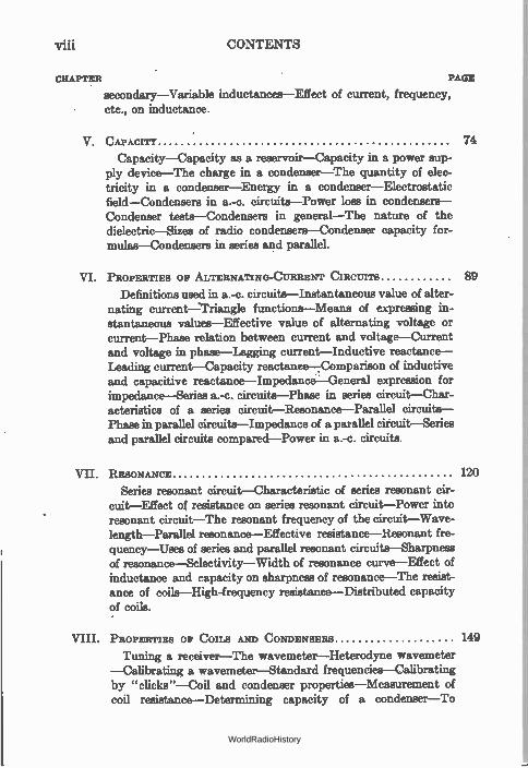
I. FUNDAMENTALS 1
The electron—Charged bodies—The laws of electrical charges —The atom—The ether—The electric current—Insulators and conductors—Conductivity—Resistance—The ohm—The effect of molecular motion on resistance—The effect of temperature on resistance—Temperature coefficient of resistance—The ampere— The volt—Engineer's shorthand—Mathematics in the study of radio—Curve plotting—Symbols.
II. Oakes LAW
Ohm's law—Ways of stating Ohm's law—Voltage drops— Graphs of Ohm's law—Series and parallel circuits—Character-istics of parallel circuits—More complicated circuits—Detection and measurement of current—Ammeters—Voltmeters—Sensi-tivity of meters—Ammeter-voltmeter method of measuring resist-ance—Voltmeter method of measuring resistance—Use of low resistance voltmeter and milliammeter in high resistance cir-cuits—Resistance measurement.
III. PRODUCTION OF CURRENT
Batteries—Electrolysis—Common dry cell—Storage cell— Internal resistance—Polarization—Celle in series—Cells in par-allel—Magnetism—Oersted's experiment—Faraday's discovery —The electric generator—Work done by alternating current— D.-c. generator—Internal resistance—Electrical power—Power lost in resistance—Efficiency.
IV. INDUCTANCE
Coupled circuits—Lenz's law—Inertia—Inductance—Self-inductance—Magnitude of inductance and induced voltage— The unit of inductance—Typical inductances—Coupling— Magnitude of mutual inductance—Measurement of inductance —The transformer—Power in transformer circuits—Transformer losses—The auto-transformer—Transformer with open-circuited
vii
20
38
57
WorldRadioHistory
viii CONTENTS
CHAPTER PAGE
secondary—Variable inductances—Effect of current, frequency, etc., on inductance.
V. CAPACITY 74
Capacity—Capacity as a reservoir—Capacity in a power sup-ply device—The charge in a condenser—The quantity of elec-tricity in a condenser—Energy in a condenser—Electrostatic field—Condensers in a.-c. circuits—Power loss in condensers— Condenser tests—Condensers in general—The nature of the dielectric—Sizes of radio condensers—Condenser capacity for-mulas—Condensers in series and parallel.
VI. PROPERTIES OF ALTERNATING-CURRENT CIRCUITS
Definitions used in a.-c. circuits—Instantaneous value of alter-nating current—Triangle functions—Means of expressing in-stantaneous values--Effective value of alternating voltage or current—Phase relation between current and voltage—Current and voltage in phase—Lagging current—Inductive reactance— TAwling current—Capacity rea,ctanee-7Comparison of inductive and capacitive reactance—ImpedanceGeneral expression for impedance—Series a.-c. circuits—Phase in series circuit—Char-acteristics of a series circuit—Resonance—Parallel circuits— Phase in parallel circuits—Impedance of a parallel circuit—Series and parallel circuits compared—Power in a.-c. circuits.
89
VII. RESONANCE 120
Series resonant circuit—Characteristic of series resonant cir-cuit—Effect of resistance on series resonant circuit—Power into resonant circuit—The resonant frequency of the circuit—Wave-length—Parallel resonance—Effective resistance—Resonant fre-quency—Uses of series and parallel resonant circuits—Sharpness of resonance—Selectivity—Width of resonance curve—Effect of inductance and capacity on sharpness of resonance—The resist-ance of coils—High-frequency resistance—Distributed capacity of coils.
VIII. PROPERTIES OF COILS AND CONDENSERS 149
Tuning a receiver—The wavemeter—Heterodyne wavemeter —Calibrating a wavemeter—Standard frequencies—Calibrating by "clicks"—Coil and condenser properties—Measurement of coil resistance—Determining capacity of a condenser—To
WorldRadioHistory
CONTENTS ix
CHAPTER PAGE
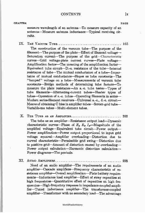
measure wavelength of an antenna—To measure capacity of an antenna—Measure antenna inductance—Typical receiving cir-cuits.
IX. THE VACUUM TUBE 165
The construction of the vacuum tube—The purpose of the filament—The purpose of the plate—Effect of filament voltage— Saturation current—The purpose of the grid—Characteristic curves—Grid voltage-plate current curves—Plate voltage— Amplification factor—The meaning of the amplification factor— Equivalent tube circuit—D.-c. resistance of the tube—Internal resistance of tube—The mutual conductance of a tube—Impor-tance of mutual conductance—Slopes as tube constants—The "lumped" voltage on a tube—Measurements of vacuum tube constants—Bridge methods of determining tube factors—To measure the plate resistance—An a.-c. tube tester—Types of tube filaments—Alternating-current tubes—Heater types of tubes—Operation of a.-c. tubes—Operating filaments in series— Modern series-filament receivers—Universal a.-c., d.-c. circuit— Means of obtaining C bias in amplifier tubes—Screen-grid tube— Variable-mu tubes—Multi-element tubes.
X. THE TUBE AS AN AMPLIFIER 202
The tube as an amplifier—Resistance output load—Dynamic characteristic curves—Phase of Eg El, 4—Magnitude of the amplified voltage—Equivalent tube circuit—Power output— Power amplification—Power output proportional to input grid voltage squared—Amplifier overloading—Distortion due to curved characteristic—Permissible grid swing—Distortion due to positive grid—Amount of distortion caused by overloading— Power output calculation—Harmonic distortion calculation— Power diagrams—The pentode.
XI. AUDIO AMPLIFIERS 228
Need of an audio amplifier—The requirements of an audio amplifier—Cascade amplifiers—Frequency characteristic of re-sistance amplifier—Overall amplification—Plate battery require-ments—Inductance load amplifier—Effect of stray capacities at high frequencies—Quantitative effect of capacities on high fre-quencies—High-frequency response in impedance-coupled ampli-fier—Tuned inductance amplifier—The transformer-coupled amplifier—Transformer with no secondary load—The advantage
WorldRadioHistory
X CONTENTS
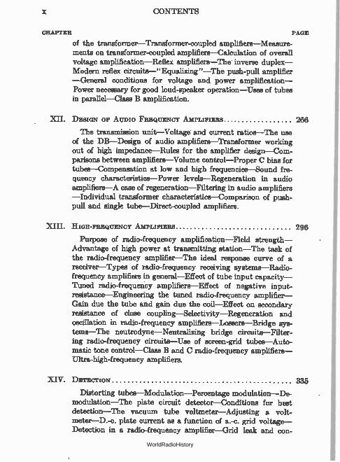
CHAPTER PAGE
of the transformer—Transformer-coupled amplifiers—Measure-ments on transformer-coupled amplifiers—Calculation of overall voltage amplification—Reflex amplifiers—The inverse duplex— Modern reflex circuits—" Equalizing "—The push-pull amplifier —General conditions for voltage and power amplification— Power necessary for good loud-speaker operation—Uses of tubes in parallel—Class B amplification.
XII. DESIGN OF AUDIO FREQUENCY AMPLIFIERS 266
The transmission unit—Voltage and current ratios—The use of the Dl3—Design of audio amplifiers—Transformer working out of high impedance—Rules for the amplifier design—Com-parisons between amplifiers—Volume control—Proper C bias for tubes—Compensation at low and high frequencies—Sound fre-quency characteristics—Power levels—Regeneration in audio amplifiers—A case of regeneration—Filtering in audio amplifiers —Individual transformer characteristics—Comparison of push-pull and single tube—Direct-coupled amplifiers.
XIII. HIGH-FREQUENCY AMPLIFIERS 296
Purpose of radio-frequency amplification—Field strength— Advantage of high power at transmitting station—The task of the radio-frequency amplifier—The ideal response curve of a receiver—Types of radio-frequency receiving systems—Radio-frequency amplifiers in general—Effect of tube input capacity— Tuned radio-frequency amplifiers—Effect of negative input-resistance—Engineering the tuned radio-frequency amplifier— Gain due the tube and gain due the coil—Effect on secondary resistance of close coupling—Selectivity--Regeneration and oscillation in radio-frequency amplifiers—Lossers—Bridge sys-tems—The neutrodyne—Neutralizing bridge circuits—Filter-ing radio-frequency circuits—Use of screen-grid tubes—Auto-matic tone control—Class B and C radio-frequency amplifiers— Ultra-high-frequency amplifiers.
XIV. DETECTION 335
Distorting tubes—Modulation—Percentage modulation—De-modulation—The plate circuit detector—Conditions for best detection—The vacuum tube voltmeter—Adjusting a volt-meter—D.-c. plate current as a function of a.-c. grid voltage— Detection in a radio-frequency amplifier—Grid leak and con-
WorldRadioHistory
CONTENTS Xi
CHAPTER PAGE
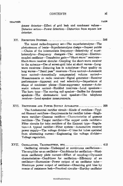
denser detector—Effect of grid leak and condenser values— Detector action—Power detection—Distortion from square law detector.
XV. RECEIVING SYSTEMS 356
The tuned radio-frequency set—The superheterodyne—The phenomenon of beats—Superheterodyne design—Repeat points —Choice of the intermediate frequency—Selectivity of super-heterodyne—Frequency changers—The autodyne—Electron-coupled oscillator—Translation gain—" Short-wave" receivers— Short-wave receiver circuits—Coupling the short-wave receiver to the antenna—Use of screen-grid tube at short waves—Long-wave receivers—Detuning loss in autodynes—Poor quality on long waves—"Band pass" receivers—Tone control—Automatic tone control—Acoustically compensated volume control— Measurements on radio receivers—Signal generator—Receiver performance—Apparent and real selectivity—Importance of shape of condenser plates—Noise-suppressor systems—Auto-matic volume control—Shielded receivers—Loud speakers— The horn type—The moving coil speaker—Baffles for dynamic speakers—The electrostatic loud speaker—The telephone receiver—Loud-speaker measurements.
XVI. RECTIFIERS AND POWER SUPPLY APPARATUS 390
The fundamental rectifier circuit—Kinds of rectifiers—Typi-cal filament rectifiers—Requirements for rectifier tubes—Single-wave rectifier—Gaseous rectifiers—Characteristics of gaseous rectifiers—The Tungar rectifier—The copper oxide rectifier— Filter circuits for tube rectifiers of the filament type—Regula-tion—A typical rectifier—Filter system—Automotive receiver power supply—The voltage divider—C bias for tubes operated from alternating current—Engineering the voltage divider— Voltage regulation.
XVII. OSCILLATORS, TRANSMITTERS, ETC. 415 Oscillating circuits—Undamped or continuous oscillations—
The amplifier as an oscillator—Conditions for oscillation—Maxi-mum oscillatory plate current—Effect of coupling—Dynamic characteristics—Conditions for oscillation—Efficiency of an oscillator—Harmonics—Power output of an oscillator tube— Maximum power output of oscillator—Obtaining grid bias by means of resistance leak—Practical circuits—Hartley oscillator
WorldRadioHistory
xii CONTENTS
CHAPTER PAGE
—Shunt-feeding oscillators—Other oscillating circuits—Adjust-ing the oscillator—Frequency stability—Master oscillator sys-tems—Crystal control apparatus—Frequency doublers—Self-rectified transmitters—Adjusting the plate load to the tube— Plate current when oscillator is connected to antenna—Keying a transmitter—Too close coupling to antenna—Methods of connecting oscillator to antenna—Feeding power through trans-mission line—Modulation—Amount of power required for modulation—Antenna current increase with modulation—Modu-lation at low power.
XVIII. ANTENNes, TRANSMISSION, grc 453
Radiation resistance—The radiation field—Calculation of the received current—Types of antennas—Directional antennas— Inductance and capacity of antennas—Natural wavelength of antenna—Loading an antenna—Decreasing the wavelength of an antenna—Short-wave transmission—Fading—Comparison of night and day reception—Static—Anti-static antenna systems— Elimination of man-made interference--Automobile antennas.
XIX. FACSIMILE AND TELEVISION TRANSMISSION 467
The problem of picture transmission—Picture elements— Frequency band required—Method of taking the picture apart— Scanning—Flying spot—Cathode-ray television—The icono-scope—Use of ultra-high frequencies.
INDEX 479
WorldRadioHistory
PRINCIPLES OF RADIO
CHAPTER I
FUNDAMENTALS
No one can learn a great deal about the theory and practice of radio who does not also know a few fundamental facts about electricity, for radio is but one aspect of a much broader field, electrical engineering. And since electricity is but a movement of the smallest known bit of matter and energy, the electron, it is necessary that a study of electricity must be preceded by a slight knowledge of the electron.
1. The electron.—The entire universe is made up of various combinations of about ninety substances known as elements. These elements are composed of but two things, negative electrical charges known as electrons, and positive charges known as protons. The electrons are all alike. The only difference between copper and aluminum lies in the difference in the number and position of their electrical charges.
2. Charged bodies.—The term charge is used in various ways. A body on which there is an equal amount of negative and positive electricity is said to be in equilibrium; but if the body has ait excess of either negative or positive electricity it is said to be charged. Sometimes the body itself is called a charge and of course may be referred to as a positive or a negative charge. If it has a great excess of either of the two kinds of electricity, it is said to be highly charged. In this condition it is in a state of very unstable equilibrium, and at the least chance some change will occur to bring the body into a state of greater equilibrium.
WorldRadioHistory
2 FUNDAMENTALS
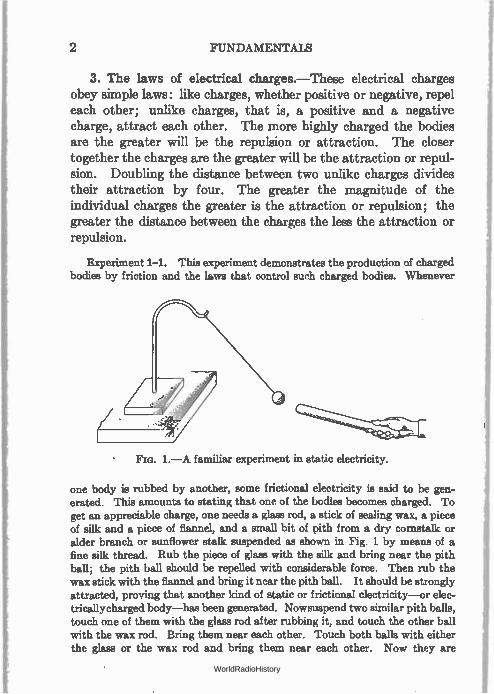
3. The laws of electrical charges.—These electrical charges obey simple laws: like charges, whether positive or negative, repel each other; unlike charges, that is, a positive and a negative charge, attract each other. The more highly charged the bodies are the greater will be the repulsion or attraction. The closer together the charges are the greater will be the attraction or repul-sion. Doubling the distance between two unlike charges divides their attraction by four. The greater the magnitude of the individual charges the greater is the attraction or repulsion; the greater the distance between the charges the less the attraction or repulsion.
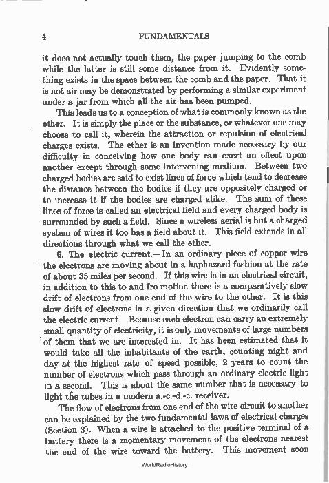
Experiment 1-1. This experiment demonstrates the production of charged bodies by friction and the laws that control such charged bodies. Whenever
Fia. 1.—A familiar experiment in static electricity.
one body is rubbed by another, some frictional electricity is said to be gen-erated. This amounts to stating that one of the bodies becomes charged. To get an appreciable charge, one needs a glass rod, a stick of sealing wax, a piece of silk and a piece of flannel, and a small bit of pith from a dry cornstalk or alder branch or sunflower stalk suspended as shown in Fig. 1 by means of a fine silk thread. Rub the piece of glass with the silk and bring near the pith ball; the pith ball should be repelled with considerable force. Then rub the wax stick with the flannel and bring it near the pith ball. It should be strongly attracted, proving that another kind of static or frictional electricity—or elec-tricallycharged body—has been generated. Nowsuspend two similar pith balls, touch one of them with the glass rod after rubbing it, and touch the other ball with the wax rod. Bring them near each other. Touch both balls with either the glass or the wax rod and bring them near each other. Now they are
WorldRadioHistory
THE ETHER 3
repelled. The bitter part of the experiment is almost the starting point of the world's history of electrical experiment.
4. The atom.—The simplest form in which an element can exist by itself is called the atom. A combination of two or more atoms is called a molecule. Ordinarily the atom or molecule is in electrical equilibrium with its surroundin. If, however, through some severe mechanical shock for examp, it should lose an elec-tron it would be charged and then woØ.ld follow th, laws cited above. It would then attract or get riØ of an electron at the first opportunity and become neutral aga.
It is the motion of electrons tha we know as the electric cur-rent. When there is a sufficient number of electrons, a billion billion per second, for instance, there is current enough to light an incandescent lamp or heat an electric iron.
The atoms and molecules in matter are in constant motion, carrying with them in their movements the electrons that con-stitute them; in the bumping of one atom against another, elec-trons are lost, gained, and interchanged.
Atoms of matter are inconceivably small. Everyone has seen many-colored oil films on the street. It is possible to obtain oil filins less than half a ten-millionth of an inch thick. The atoms composing these films cannot be thicker than this figure; the elec-trons are much smaller yet. We think the distances in the solar system of which the earth is part are beyond comprehension, the sun for example being about 90 million miles from the earth; but the dimensions of the electrons in their smallness are even more difficult to picture. The diameter of the electron is estimated to be about 1 foot divided by a hundred million million. Each of these electrons resembles its brother exactly, so that when an elec-tron is knocked out of an atom by a collision it is free to combine with any other body near by which may have a deficit of negative electricity, no matter what the body may be made of. The electron is the unit out of which everything is made.
5. The ether.—The fact that one charge can exert a force, either of attraction or repulsion, upon another implies that some-thing connects the two. For instance, a comb which has been rubbed on the coat sleeve will pick up bits of paper even though
WorldRadioHistory
4 FUNDAMENTALS
it does not actually touch them, the paper jumping to the comb while the latter is still some distance from it. Evidently some-thing exists in the space between the comb and the paper. That it is not air may be demonstrated by performing a similar experiment under a jar from which all the air has been pumped.
This leads us to a conception of what is commonly known as the ether. It is simply the place or the substance, or whatever one may choose to call it, wherein the attraction or repulsion of electrical charges exists. The ether is an invention made necessary by our difficulty in conceiving how one body can exert an effect upon another except through some intervening medium. Between two charged bodies are said to exist lines of force which tend to decrease the distance between the bodies if they are oppositely charged or to increase it if the bodies are charged alike. The sum of these lines of force is called an electrical field and every charged body is surrounded by such a field. Since a wireless aerial is but a charged system of wires it too has a field about it. This field extends in all directions through what we call the ether.
6. The electric current.—In an ordinary piece of copper wire the electrons are moving about in a haphazard fashion at the rate of about 35 miles per second. If this wire is in an electrical circuit, in addition to this to and fro motion there is a comparatively slow drift of electrons from one end of the wire to the other. It is this slow drift of electrons in a given direction that we ordinarily call the electric current. Because each electron can carry an extremely small quantity of electricity, it is only movements of large numbers of them that we are interested in. It has been estimated that it would take all the inhabitants of the earth, counting night and day at the highest rate of speed possible, 2 years to count the number of electrons which pass through an ordinary electric light la a second. This is about the same number that is necessary to light tfie tubes in a modern a.-c.-d.-c. receiver.
The flow of electrons from one end of the wire circuit to another can be explained by the two fundamental laws of electrical charges (Section 3). When a wire is attached to the positive terminal of a battery there is a momentary movement of the electrons nearest the end of the wire toward the battery. This movement soon
WorldRadioHistory
INSULATORS AND CONDUCTORS 5
ceases because the flow of electrons into the battery leaves a dearth of them at the other end of the wire which must be supplied. If both ends are attached to the battery a steady drift of electrons takes place out of the negative pole or terminal of the battery, through the wire, and to the battery again at the positive terminal.
Thus the actual motion of the electrons is from the negative toward the positive end of a circuit. This is in the opposite direc-tion from the rule established many years before the electron had been discovered, namely, that current flows from positive to nega-tive. In problems the student can assume either direction so long as he is consistent. We know that the electrons flow from negative to positive; electrical workers assume the current flows from posi-tive to negative. In this book we shall follow the latter rule, but the student should remember that the actual carriers of electricity move in the opposite direction.
7. Insulators and conductors.—It is a matter of common knowledge that the current does not flow through the non-metallic parts of a radio set, or through the insulating material around a broken conductor. How does it happen that some materials are such good " conductors," copper and silver for example, whereas others, such as glass or bakelite, appear not to conduct at all? Here again we are dealing with the building stones of all matter, the atom and the electron. Atoms of the so-called non-conductors maintain their hold on their individual electrons very tightly; few electrons escape. In the conductors, the electrons of the various atoms are freer to move about, and so to be interchanged among atoms. A conductor is a substance that quickly loses its charge when rubbed. A non-conductor retains its charge longer. A good conductor is a material whose electrons are freer to
move about than those of a poor conductor. Strictly speaking, there are no non-conductors. All materials will carry current to some degree. Glass, for example, which is generally considered a very good insulator, conducts electricity fairly well when it is in a molten state.
The best insulators—that is, the poorest conductors—are amber, rubber, sulphur, shellac, porcelain, quartz, silk, air. Dry
WorldRadioHistory
d = 1 copper, nickel, and iron-manganese, for example,
d = 1/2 have resistances many
6 FUNDAMENTALS
wood, paper, cotton and linen thread are semi-conductors. The best conductors are the metals, acids, moist earth, etc.
8. Conductivity.—All materials have a certain characteristic which we may call conductivity, which describes their ability to conduct an electric current. Among pure metals silver has a very high conductivity, copper is next, and near the bottom lies iron with about one-ninth the conductivity of copper. The con-ductance of a circuit is a term expressing its ability to pass an electric current. The greater the conductance, the greater the current.
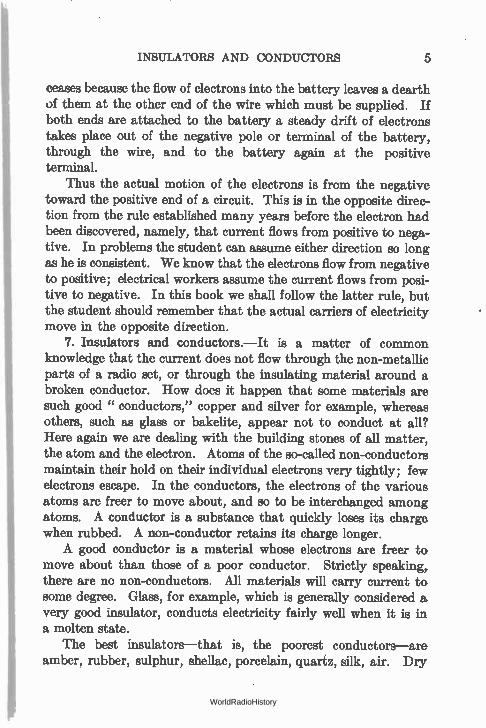
9. Resistance.—Those metals which have a high conductivity may be said to offer little resistance to the flow of electrons through
them. Thus, copper has a low resistance, while some combinations of
= 1 t R 1
L - 1
L = 2
R = 4 L = 1
(I= 1 R = 1/2 I times that of copper. A device added to a circuit to increase its resistance
L=
d = 2 is called a "resistor." The words resistance and resistor are used synon-•, •,
2 3 4
ymously in this text. Fia. 2.—Resistance depends upon the length The resistance of two
and size of a conductor. wires of the same material
and at the same temperature depends upon two things, the length of the wires and the area of their cross-section. Naturally, the longer the wire the fewer electrons can pass through it in a given time; similarly the smaller the diameter of a wire the greater the resist-ance, just as you can get more gallons of water per second from a 3-inch fire hose than from a 1-inch garden hose, although they may be attached to the same hydrant.
Similarly, a wire 2 feet long has twice the resistance of a wire 1 foot long but of the same diameter. Of two wires the same length the one having the smaller diameter will have the greater resistance. (See Fig. 2.) Area = 3.1416 X (radius)2.
R
L = 1
R = 2
WorldRadioHistory
THE OHM 7
The resistances of several metals compared to silver are as follows:
Silver 1.00 Platinum 7.20 Copper ' 1.11 German silver 14 . 20 Aluminum 1.87 Hard steel 13.5 Nickel 4.67 Mercury 63.1 Soft iron 6.00
Problem 1-1. How many times higher in resistance is mercury than silver? Than copper?
Problem 2-1. Two wires of the same length and diameter have resist-ances in the ratio of 5.4 to 1. If the lower resistance wire is copper, could you identify the other wire material from the above table?
Problem 3-1. Two wires, one of soft iron and the other of hard steel, are to have the same resistance. They have the same diameter. The hard steel wire is one foot long. What is the length of the soft iron wire?
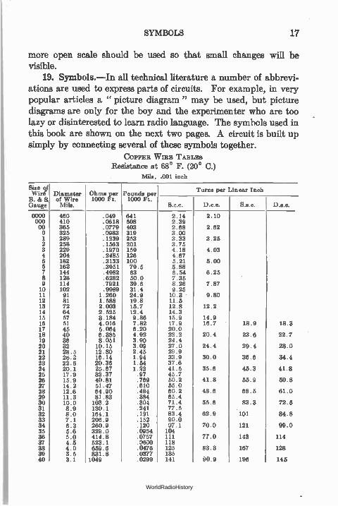
10. The ohm.—The unit of resistance is the ohm. It is the resistance of a column of mercury weighing 14.4521 grams, having a uniform cross-section and a height of 106.3 cm. at 0° Centigrade. A 9.35-foot length of No. 30 copper wire has a resistance of about one ohm. The table on page 17 gives sizes and resistance per thousand feet of copper wire. The resistance per foot may be obtained from such a table by dividing the resistance per thousand feet by one thousand.
Note that increasing the size of wire by three numbers, that is, from No. 20 to No. 23, doubles the resistance of the wire from 10.15 to 20.36 ohms; going from No. 30 to No. 27 lowers the resistance from 103.2 to 51.5 ohms per thousand feet.
Copper is used in electrical and radio circuits because of its high conductivity compared to other metals and its low cost com-pared to metals of higher conductivity. It is readily obtainable and easily worked.
Problem 4-1. What size of soft iron wire will have the same resistance as No. 32 copper?
Problem 6-1. What is the resistance of 1 foot of No. 20 copper? Of No. 24 hard steel?
Problem 6-1. What is the resistance of a column of mercury of the fol-lowing dimensions, weight 0.032 lb. (1 pound = 453.6 grams), length 41.7 inches (1 inch = 2.54 centimeters) at 0° C., the column having uniform cross-section?
WorldRadioHistory

8 FUNDAMENTALS
11. The effect of molecular motion on resistance.—Why do some substances have greater resistance than others? Let us again consider the electrons, atoms, and molecules which make up the wires carrying the currents. Not only are the electrons in motion, but the atoms and molecules themselves are in a sluggish motion, the violence of this motion depending upon the temperature of the wire and the material of which the wire is made.
And although molecules cannot traverse the electric circuit as the electrons can, in their to and fro motion they impede the progress of the electricity bearers by countless collisions with them. The greater this molecular motion, the greater the resistance to a progressive flow of electrons, and the greater the wire's electrical resistance.
12. The effect of temperature on resistance.—The resistance of all pure metals rises with increase in temperature. This is be-cause of the greater molecular agitation at higher temperatures, making it more difficult for the electrons to drift in their progressive motion around the circuit.
At absolute zero, 273 degrees below zero Centigrade, all molec-ular motion is supposed to stop, making the resistances of metals practically zero. At the lowest terhperature• reached it has been found that the resistance of a coil of wire is so low that current will flow for some time after the driving force is removed. Scientists have approached to within a fraction of a degree of absolute zero.
13. Temperature coefficient of resistance.—Conductors in which radio engineers are interested increase or decrease in resist-ance at a regular rate with respect to temperature. The change in resistance of a given wire may be computed from the following facts. The " temperature coefficient of resistance" is a term which gives the amount a resistance increases for each degree rise in temperature for each ohm at the original temperature. For example, if a copper wire with a temperature coefficient of 0.0042 has a resistance of 80 ohms at 0° C., this resistance will be increased by 80 X 0.0042 for each degree rise in temperature. At 50° C. the resistance increase would be 80 X 0.0042 X 50 or 16.8 ohms, and the resistance would now be 80 + 16.8 or 96.8 ohms. Manganin wire, composed of 84 per cent copper, 12 per cent manganese,
WorldRadioHistory
THE AMPERE 9
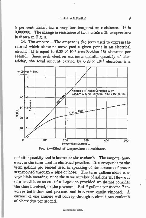
4 per cent nickel, has a very low temperature resistance. It is 0.000006. The change in resistance of two metals with temperature is shown in Fig. 3.
14. The ampere.—The ampere is the term used to express the rate at which electrons move past a given point in an electrical circuit. It is equal to 6.28 X 10¹⁸ (see Section 16) electrons per second. Since each electron carries a definite quantity of elec-tricity, the total amount carried by 6.28 X 10¹⁸ electrons is a
% Ch
40
30
vi 20
10
nge in Res. ‘..— 6
ç
Nickel- Ni; 28%
hromium Cu; 5%
Alloy Fe.kin Si, etc.
C.
NiChrome
o
Nichrome S.M .L.—
.. 67%
,e le
s .m.1.. pno
o 100 200 300 Temperature Degrees C.
FIG. 3.—Effect of temperature on resistance.
400 500
definite quantity and is known as the coulomb. The ampere, how-ever, is the term used in electrical practice. It corresponds to the term gallons per second used in speaking of the amount of water transported through a pipe or hose. The term gallons alone con-veys little meaning, since the same number of gallons will flow out of a small hose as out of a large one provided we do not consider the time involved, or the pressure. But " gallons per second " in-volves both time and pressure and is a term easily visioned. A current of one ampere will convey through a circuit one coulomb of electricity per second.
WorldRadioHistory
10 FUNDAMENTALS
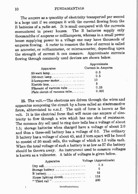
The ampere as a quantity of electricity transported per second is a large unit if we compare it with the current flowing from the B batteries of a radio set. It is small compared with the currents encountered in . power houses. The B batteries supply only thousandths of amperes or milliamperes, whereas in a small power house supplying power to a village one may have thousands of amperes flowing. A meter to measure the flow of current is called an ammeter, or milliammeter, or microammeter, depending upon the strength of current it can measure. Approximate currents flowing through commonly used devices are shown below.
Approximate Apparatus Current in Amperes
50-watt lamp 0.5 250-watt lamp 2.5 2-horsepower motor 10 Electric iron 5 Filament of vacuum tube 0.25 Plate circuit of vacuum tube 0.001
15. The volt.—The electrons are driven through the wires and apparatus composing the circuit by a force called an electromotive force, abbreviated to e.m.f. The unit of force is known as the volt. It is the electrical force that will cause one ampere of elec-tricity to flow through a wire which has one ohm of resistance. The common dry cell used to ring door bells has a voltage of about 1.5; storage batteries when charged have a voltage of about 2.0 and thus a three-cell battery has a voltage of 6.0. The ordinary B battery has a voltage of about 45, and if torn apart will be found to consist of 30 small cells, the voltage of which is 1.5 volts each. When the total voltage of such a battery is as low as 37 the battery should be thrown away. An instrument used to measure voltages is known as a voltmeter. A table of voltages is given below.
Apparatus Voltage (Approximate)
Dry cell 1.5 Storage battery 6 B battery 45 House lighting circuit 115 " Third rail " 500
WorldRadioHistory
ENGINEERS' SHORTHAND 11
16. Engineers' shorthand.—Engineers have a simple short-hand method of working with large numbers well illustrated by the figures 6.28 X 10¹⁸, which really means that 6.28 multiplied by a million million million electrons flowing past a given point per second constitute the electric current known as an ampere. We shall have occasion to use this system many times in the course of the book and students are encouraged to master it as soon as possible. The table below will be helpful.
1 = 10° = one
10 = 102 = ten
100 = 102 = hundred
1000 = 103 = thousand, etc.
1 = 100 = one
.1 = 10 -2 = = one-tenth
.01 = 10 -2 = = one-hundredth
.001 = 10 -2 - 10100 one-thousandth, etc.
The small number above the figure 10 is called the exponent. Numbers less than 1 have negative exponents. Thus three-thousandths may be expressed in these several ways:
3 3 .003 = 3 X 10-2 = — —
1000 102
When numbers are multiplied, their exponents are added; when the numbers are divided, the exponents are subtracted. Thus 100 multiplied by four-tenths may be done in shorthand as follows:
100 X .4 = 102 X 4 X 10 -2
= 4 X 10'
= 4 X 10
= 40
Similarly, let us divide 3000 by 150.
3000 ÷ 150 = (3 X 10²) ÷ (1.5 X 10²)
3 X 10' X 10 -2
= 1.5
= 2 X 10
= 20
WorldRadioHistory
12 FUNDAMENTALS
The rules are few and those are simple:
1. To multiply, add exponents. 2. To divide, subtract exponents. 3. When any number crosses the line, change the sign of the
exponent.
Example 1-1. Multiply 20,000 by 1200 and divide the result by 6000.
20,000 = 2 X 10'
1200 = 12 X 102
6000 = 6 X 10'
20,000 X 1200 2 X 104 X 12 X 102
6000 - 6 X 10'
2 X 12 X 104 X 108 X 10-8
6
= -getX 1o3
= 4000
Problem 7-1. How many electrons flow past a given point per second when the number of amperes is 6? 60? 600? 0.1? 0.003?
Problem 8-1. The sun is roughly 90 million miles from the earth. Express this in " shorthand."
Problem 9-1. At 100 miles per hour, how many months would it take to
reach the sun? Problem 10-1. If light travels at 300 million meters per second and if a
meter equals 3.3 feet, how long does it take the sun's rays to reach the earth? Problem 11-1. How many amperes of current flow when 31.4 X 10"
electrons per second flow past a point?
In connection with such shorthand methods the following table of prefixes commonly used will be important.
Prefix Abbreviation Meaning
micro p one millionth milli m one thousandth centi e one hundredth deci d one tenth deka dk ten hekto h one hundred kilo k one thousand mega M one million
WorldRadioHistory
CURVE PLOTTING 13
Thus a thousandth of an ampere is known as a milliampere, a million ohms is called a megohm, etc.; or, expressed in numbers, 1 milliampere = 10-3 or .001 ampere; 1 megohm = 1,000,000 ohms.
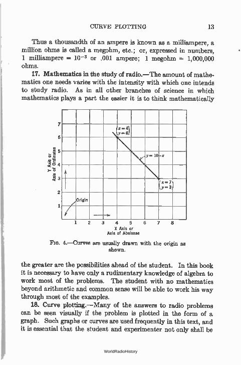
17. Mathematics in the study of radio.—The amount of mathe-matics one needs varies with the intensity with which one intends to study radio. As in all other branches of science in which mathematics plays a part the easier it is to think mathematically
7
6
2
Ix-41 4.-61
10 -x
x=, 7
Y= 3
Origin
1 2 3 4 5
X Axis or Axis of Absissae
6 7
Fro. 4.—Curves are usually drawn with the origin as shown.
the greater are the possibilities ahead of the student. In this book it is necessary to have only a rudimentary knowledge of algebra to work most of the problems. The student with no mathematics beyond arithmetic and common *sense will be able to work his way through most of the examples.
18. Curve plotting.—Many of the answers to radio problems can be seen visually if the problem is plotted in the form of a graph. Such graphs or curves are used frequently in this text, and it is essential that the student and experimenter not only shall be
WorldRadioHistory
14 FUNDAMENTALS
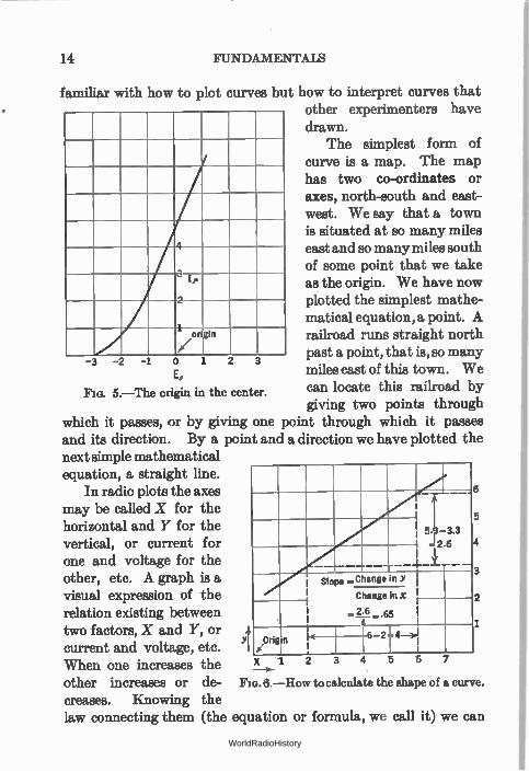
familiar with how to plot curves but how to interpret curves that other experimenters have drawn.
The simplest form of curve is a map. The map has two co-ordinates or axes, north-south and east-west. We say that a town is situated at so many miles east and so many miles south of some point that we take as the origin. We have now plotted the simplest mathe-matical equation, a point. A railroad runs straight north past a point, that is, so many miles east of this town. We can locate this railroad by giving two points through
which it passes, or by giving one point through which it passes and its direction. By a point and a direction we have plotted the next simple mathematical equation, a straight line.
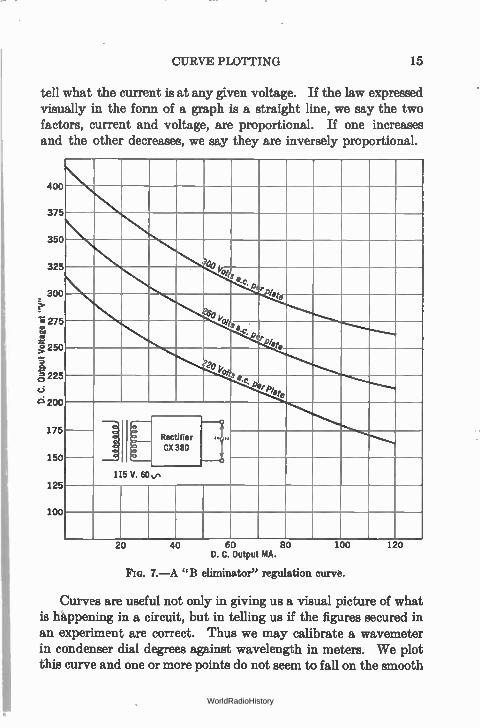
In radio plots the axes may be called X for the horizontal and Y for the vertical, or current for one and voltage for the other, etc. A graph is a visual expression of the relation existing between two factors, X and Y, or current and voltage, etc. When one increases the other increases or de-creases. Knowing the law connecting them (the
1 )7
ip
1 origin
E,
Fro. 5.—The origin in the center.
- 2 6
-1-
I slope _Change in Y
Change in x
-L.65
Orig r‘
6 2 4 —),I n . 1.
X -1 2 3
5
3
2
FIG. 6.—How to calculate the shape of a curve.
equation or formula, we call it) we can
WorldRadioHistory
CURVE PLOTTING 15
tell what the current is at any given voltage. If the law expressed visually in the form of a graph is a straight line, we say the two factors, current and voltage, are proportional. If one increases and the other decreases, we say they are inversely proportional.
400
375
350
325
300 ≥:•
1;5275
250
à 225
C)
12; 200
175
150
125
100
late
CX 380 .,
115 V. 60v,
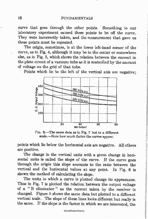
20 40 60 80 D. C. Output MA.
Flo. 7.— A "B eliminator" regulation curve.
100 120
Curves are useful not only in giving us a visual picture of what is happening in a circuit, but in telling us if the figures secured in an experiment are correct. Thus we may calibrate a wavemeter in condenser dial degrees against wavelength in meters. We plot this curve and one or more points do not seem to fall on the smooth
WorldRadioHistory
16 FUNDAMENTALS
curve that goes through the other points. Something in our laboratory experiment caused these points to be off the curve. They were incorrectly taken, and the measurement that gave us these points must be repeated.
The origin, sometimes, is at the lower left-hand corner of the curve, as in Fig. 4, although it may be in the center or somewhere else, as in Fig. 5, which shows the relation between the current in the plate circuit of a vacuum tube as it is controlled by the amount of voltage on the grid of that tube.
Points which lie to the left of the vertical axis are negative;
450 00
>7'• 300
0. cf. 200 d d
100
300 y • •s
260 Volts a.c.
220 V Its cc.
20 40 60 80 MA Output
8.—The same data as in Fig. 7 but to a different scale.—Note how much flatter the curves appear.
points which lie below the horizontal axis are negative. All others are positive.
The change in the vertical units with a given change in hori-zontal units is called the slope of the curve. If the curve goes through the origin this slope amounts to the ratio between the vertical and the horizontal values at any point. In Fig. 6 is shown the method of calculating the slope.
The units in which a curve is plotted change its appearance. Thus in Fig. 7 is plotted the relation between the output voltage of a " B eliminator" as the current taken by the receiver is changed. Figure 8 shows the same data but plotted to a different vertical scale. The slope of these lines looks different but really is the same. If the slope is the factor in which we are interested, the
WorldRadioHistory
SYMBOLS 17
more open scale should be used so that small changes will be visible.
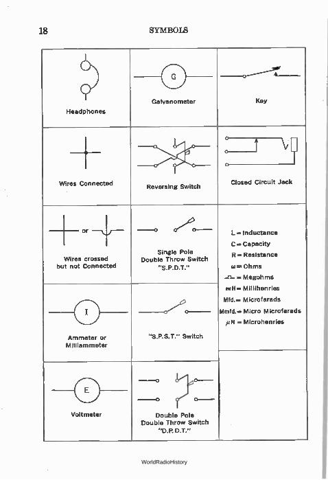
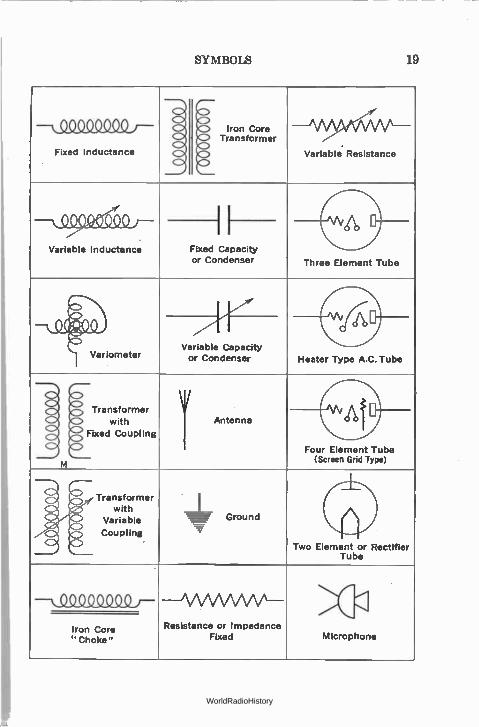
19. Symbols.-In all technical literature a number of abbrevi-ations are used to express parts of circuits. For example, in very popular articles a " picture diagram" may be used, but picture diagrams are only for the boy and the experimenter who are too lazy or disinterested to learn radio language. The symbols used in this book are shown on the next two pages. A circuit is built up simply by connecting several of these symbols together.
COPPER WIRE TABLES Resistance at 68° F. (20° C.)
Mils, .001 inch
Size qf Wire B.& a Gauge
Diameter of Wire Mils.
Ohms per 1000 Ft.
Pounds per 1000 Ft.
Turns per Linear Inch
S.c.c. D.c.c. S.a.e. Da.c.
0000 460 641 2.14 2.10 000 410
.049
.0618 508 2.39 00 365 403 2.68 2.62 0 1
325 289
.0779
.0983 319 253
3.00 3.33 3.25
2 258 .1239 .1563 201 3.75
3 229 .1970 159 4.18 4.03 4 204 .2485 126 4.67 5 182 100 5.21 5.00 6 162
.3133
.3951 79.5 5.88 7 144 83 6.54 8.25 8 128
.4982
.6282 50.0 7.35 • 9 114 39.6 8.26 7.87 10 102
.7921 31.4 9.25
11 91 .9989
1.260 24.9 10.3 • 9.80 12 81 1.588 19.8 11.5 13 72 2.003 15.7 12.8 12.2 14 64 2.525 12.4 14.3 15 57 3.184 9.86 15.9 14.9 18 51 4.016 7.82 17.9 16.7 18.9 18.3 17 45 5.064 6.20 20.0 18 40 6.385 4.92 22.2 20.4 23.6 22.7 19 38 8.051 3.90 24.4 20 32 10.15 3.09 27.0 24.4 29.4 28.0 21 28.5 12.80 2.45 29.9 22 28.; 16.14 1.94 33.9 30.0 38.8 34.4 23 22.6 20.36 1.54 37.6 24 20.1 25.67 1.22 41.5 35.6 45.3 41.8 25 17.9 32.37 .97 45.7 26 15.9 40.81 .769 50.2 41.8 55.9 50.8 27 14.2 51.47 .610 55.0 28 29
12.6 11.3
64.90 81.83
.484
.384 60.2 65.4
48.6 68.5 61.0
30 10.0 103.2 .301 71.4 55.6 83.3 72.5 31 8.9 130.1 .241 77.5 32 8.0 164.1 .191 83.4 62.9 101 84.8 33 7.1 206.9 .152 90.0 34 6.3 260.9 .120 97.1 70.0 121 99.0 35 5.6 329.0 .0954 104 36 37
5.0 4.5
414.8 523.1
.0757
.0600 111 118
7/.0 143 114
38 4.0 659.8 .0478 125 83.3 167 128 39 3.5 831.8 .0377 135 40 3.1 1049 .0299 141 90.9 196 145
WorldRadioHistory
Voltmeter
18 SYMBOLS
Galvanometer
Headphones
Key
+ Wires Connected Reversing Switch
o to
Closed Circuit Jack
+ or Wires crossed
but not Connected
_ 0
Single Pole Double Throw Switch
Ammeter or Milliammeter
Cr e)O--
"S.P.S.T." Switch
Inductance
C.-Capacity
R— Resistance
cu=Ohms
-cl-=Megohms
mH=Millihenries
Mfd.— Microfarads
limfd.= Micro Microfarads
p H =Microhenries
— 0
Double Pole Double Throw Switch
"D.P. D.T."
WorldRadioHistory
SYMBOLS 19
Fixed Inductance
Variable Inductance
IIron Core Transformer
Variable. Resistance
Fixed Capacity or Condenser Three Element Tube
Variometer Variable Capacity or Condenser Heater Type A.C. Tube
Transformer with
Fixed Coupling
Antenna
Four Element Tube (Screen Grid Type)
Transformer with
Variable
Coupling
Ground
Two Element or Rectifier Tube
-- Q_OQQ9Q_00)-Iron Core "Choke"
Resistance or or Impedance Fixed Microphone
WorldRadioHistory
CHAPTER II
OHM'S LAW
IN the previous chapter we stated that an electric current was a motion of electrons; that the force which caused the motion of the electrons was called an electromotive force (e.m.f.) or a potential difference (p.d.), that the resistance of a circuit opposes the flow of current, and that the unit of the current which actually flows per second is called the ampere. We have then a very simple law which enables the engineer to calculate
1. The current that will flow when the voltage and resistance are known.
2. The voltage necessary to force a certain amount of current through a known resistance.
3. The resistance that will restrict the current to a certain value under pressure of a certain e.m.f. expressed in volts.
20. Ohm's law.—The law which governs all simple and many complex electrical phenomena is known as Ohm's law. This law states that: Current in amperes equals e.m.f. in volts divided by resistance in ohms, or, as expressed in electrical abbreviations,
E (voltage) I (current) —
R (resistance)*
21. Ways of Stating Ohm's law.—There are three ways of stating this fundamental law. They are: •
(1) I = EIR (2) E= IXR (3) R = E/I
These three ways of stating the same law are determined from the first statement of Ohm's law by simple mathematical trans-formation, and make less difficult the solving of problems.
20 WorldRadioHistory
VOLTAGE DROP 21
22. Voltage drop.—The second way of stating Ohm's law is that whenever a current flows through a resistance, there is a differ-ence of potential at the two ends of that resistance. For every ampere of current that flows through an ohm of resistance, there is a volt lost. In other words it requires a volt to force an ampere through an ohm of resistance, and once that task is over, the volt is gone.
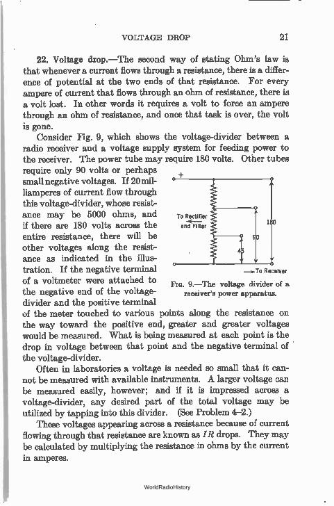
Consider Fig. 9, which shows the voltage-divider between a radio receiver and a voltage supply system for feeding power to the receiver. The power tube may require 180 volts. Other tubes require only 90 volts or perhaps small negative voltages. If 20 mil-liamperes of current flow through this voltage-divider, whose resist-ance may be 5000 ohms, and To Rectifier
—e,— if there are 180 volts across the and Filter 180
entire resistance, there will be other voltages along the resist-ance as indicated in the illus-tration. If the negative terminal of a voltmeter were attached to FIG. 9.—The voltage divider of a the negative end of the voltage- receiver's power apparatus.
divider and the positive terminal of the meter touched to various points along the resistance on the way toward the positive end, greater and greater voltages would be measured. What is being measured at each point is the drop in voltage between that point and the negative terminal of the voltage-divider.
Often in laboratories a voltage is needed so small that it can-not be measured with available instruments. A larger voltage can be measured easily, however; and if it is impressed across a voltage-divider, any desired part of the total voltage may be utilized by tapping into this divider. (See Problem 4-2.)
These voltages appearing across a resistance because of current flowing through that resistance are known as IR drops. They may be calculated by multiplying the resistance in ohms by the current in amperes.
+
—)-To Receiver
WorldRadioHistory
22 OHM'S LAW
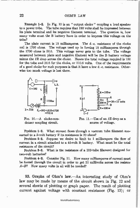
Example 1-2. In Fig. 10 is an " output choke" coupling a loud speaker to a power tube. The tube requires that 180 volts shall be impressed between its plate terminal and its negative filament terminal. The question is, how many volts must the B battery have in order to impress this voltage on the tube?
The plate current is 18 milliamperes. The d.-c. resistance of the choke coil is 1700 ohms. The voltage used up in forcing 18 milliamperes through the 1700 ohms is 30.6. This voltage never gets to the tube. The voltage measured between plate and negative filament will be the B battery voltage minus the IR drop across the choke. Hence the total voltage required is 180 for the tube and 30.6 for the choke, or 210.6 volts. One of the requirements of a good choke for such purposes is that it have a low d.-c. resistance. Other-wise too much voltage is lost there.
1=.018 E6=180+ 018x1700 =210.6
FIG. 10.—A choke-con-denser coupling circuit.
I=7
R —100w
A
E-20 x 10 volts B
R = 100 of
11.—Use of an IR drop as a source of voltage.
Problem 1-2. What current flows through a vacuum tube filament con-nected to a 5-volt battery if its resistance is 20 ohms?
Problem 2-2. Suppose we desire to limit to 1 milliampere the flow of current in a circuit attached to a 45-volt B battery. What must be the total resistance of the circuit?
Problem 8-2. What is the resistance of a 232-tube filament designed for two-volt batteries?
Problem 4-2. Consider Fig. 11. How many milliamperes of current must be forced through the circuit in order to get 20 millivolts across the resistor A-B? How many volts in all will be needed?
23. Graphs of Ohm's law.—An interesting study of Ohm's law may be made by means of the circuit shown in Fig. 12 and several sheets of plotting or graph paper. The result of plotting current against voltage with constant resistance (Fig. 13); or
WorldRadioHistory
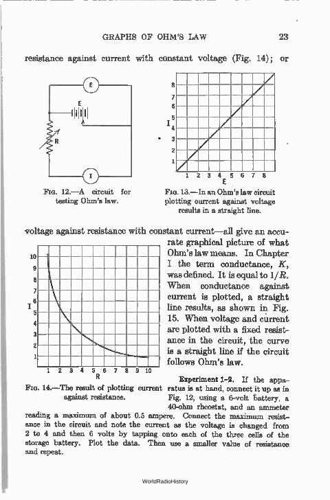
Fia. 12.—A circuit for testing Ohm's law.
GRAPHS OF OHM'S LAW 23
resistance against current with constant voltage (Fig. 14); or
8
7
6
5 I 4
• 3
2
1
1 2 3 4 5 6 7 8 E
13.—In an Ohm's law circuit plotting current against voltage
results in a straight line.
voltage against resistance with constant current—all give an accu-rate graphical picture of what Ohm's law means. In Chapter 10
9 I the term conductance, K, 8 was defined. It is equal to 1/R.
When conductance against 7
current is plotted, a straight 6 1 line results, as shown in Fig. 5 4 15. When voltage and current
are plotted with a fixed resist-ance in the circuit, the curve
2 is a straight line if the circuit follows Ohm's law.
1 2 3 4 5 6 7 8 9 10
Experiment 1-2. If the appa-14.—The result of plotting current ratus is at hand, connect it up 88 in
against resistance. Fig. 12, using a 6-volt battery, a 40-ohm rheostat, and an ammeter
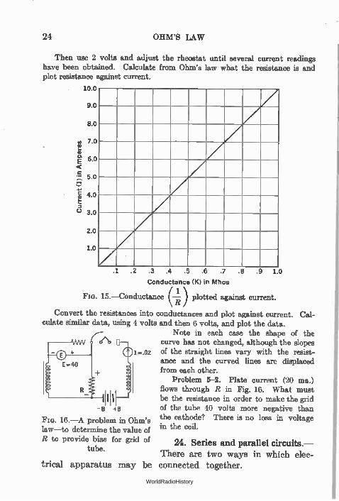
reading a maximum of about 0.5 ampere. Connect the maximum resist-ance in the circuit and note the current as the voltage is changed from 2 to 4 and then 6 volts by tapping onto each of the three cells of the storage battery. Plot the data. Then use a smaller value of resistance and repeat.
WorldRadioHistory
3.0
24 OHM'S LAW
Then use 2 volts and adjust the rheostat until several current readings have been obtained. Calculate from Ohm's law what the resistance is and plot resistance against current.
10.0
9.0
8.0
7.0 a)
2.0
1.0
.1 .2 .3 .4 .5 .6 .7 .8
Conductance (K) in Mhos
Fm. 15.—Conductance 1 ) plotted against current.
Convert the resistances into conductances and plot against current. Cal-culate similar data, using 4 volts and then 6 volts, and plot the data.
Note in each case the shape of the c(N) curve has not changed, although the slopes
1-.02 of the straight lines vary with the resist-ance and the curved lines are displaced from each other.
Problem 5-2. Plate current (20 ma.)
flows through R in Fig. 16. What must be the resistance in order to make the grid
- B +B of the tube 40 volts more negative than
FIG. 16.—A problem in Ohm's the cathode? There is no loss in voltage law—to determine the value of in the coil.
R to provide bias for grid of 24. Series and parallel circuits.— tube.
There are two ways in which elec-trical apparatus may be connected together.
.9 10
WorldRadioHistory
SERIES AND PARALLEL CIRCUITS 25
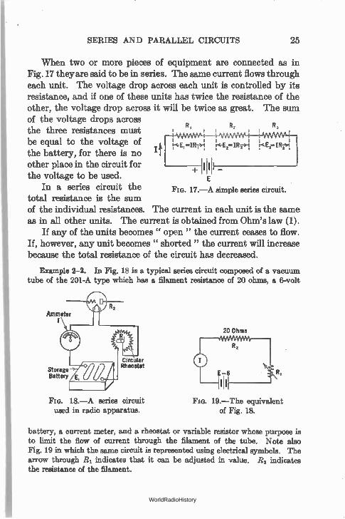
When two or more pieces of equipment are connected as in Fig. 17 they are said to be in series. The same current flows through each unit. The voltage drop across each unit is controlled by its resistance, and if one of these units has twice the resistance of the other, the voltage drop across it will be twice as great. The sum of the voltage drops across
R, R, the three resistances must be equal to the voltage of the battery, for there is no re‘Ei-aRT>1. E IR-31
other place in the circuit for 1!111 _ the voltage to be used. E
In a series circuit the total resistance is the sum of the individual resistances. The current in each unit is the same as in all other units. The current is obtained from Ohm's law (1).
If any of the units becomes " open " the current ceases to flow. If, however, any unit becomes " shorted " the current will increase because the total resistance of the circuit has decreased.
R,
Fie. 17.—A simple series circuit.
Example 2-2. In Fig. 18 is a typical series circuit composed of a vacuum tube of the 201-A type which has a filament resistance of 20 ohms, a 6-volt
Ammeter
Storage Battery
Circular Rheostat
Fm. 18.—A series circuit used in radio apparatus.
20 Ohms
Fm. 19.—The equivalent of Fig. 18.
battery, a current meter, and a rheostat or variable resistor whose purpose is to limit the flow of current through the filament of the tube. Note also Fig. 19 in which the same circuit is represented using electrical symbols. The arrow through R1 indicates that it can be adjusted in value. R2 indicates the resistance of the filament.
WorldRadioHistory
26 OHM'S LAW
The question is, what current will flow through the circuit as the resistance of R1 is varied? Suppose it is 4 ohms. We know the same current will flow through both the filament and the rheostat. The resistance, then, in the circuit is equal to 20 plus 4 or 24 ohms, and by Ohm's law we know that the current will be the voltage divided by the total resistance, or
E 6 6 - R1 ± R2 = 4 ± 20 _ 24 = 0.25 ampere.
There are two resistances in this circuit. Current flows through them. There must then be two voltage drops. Let us calculate what they are. By equation 2 we multiply the resistance by the current.
voltage drop = IR1 = .25 ampere X 4 ohms = 1 volt voltage drop = //i2 = .25 ampere X 20 ohms = 5 volts
In other words, of the six volts available at the terminals of the battery, five have been used up across the 20-ohm resistance and one volt has been used to drive 0.25 ampere through the 4-ohm resistance.
Problem 6-2. In a" universal" a.-c.-d.-c. set there are 4 tubes of the 6.3-volt series connected in series. What resistance must be put in series with them if they are to be put directly across a 115-volt line?
Problem 7-2. Suppose you were going to use five 6.3-volt tubes in a series filament circuit. How many volts will be necessary?
Problem 8-2. What would be the resistance of the above tubes in series? Problem 9-2. On a 32-volt farm system how many tubes of the
automotive type (236, etc.) can be run in series? Six of the Air-cell series (230, etc.) are to run be from this system. What series resistance is necessary?
Problem 10-2. How much resistance would be necessary if one 199-type tube is to be run from a 6-volt storage battery? Two tubes? Five tubes?
Problem 11-2. An incandescent lamp has a resistance, when hot, of about 55 ohms, and re-quires one ampere to light at full brilliancy. How many could be run in series on a 110-volt cir-cuit?
Problem 12-2. How many volts are required to force one milliampere through a circuit composed of a vacuum tube and a resistance, if the latter
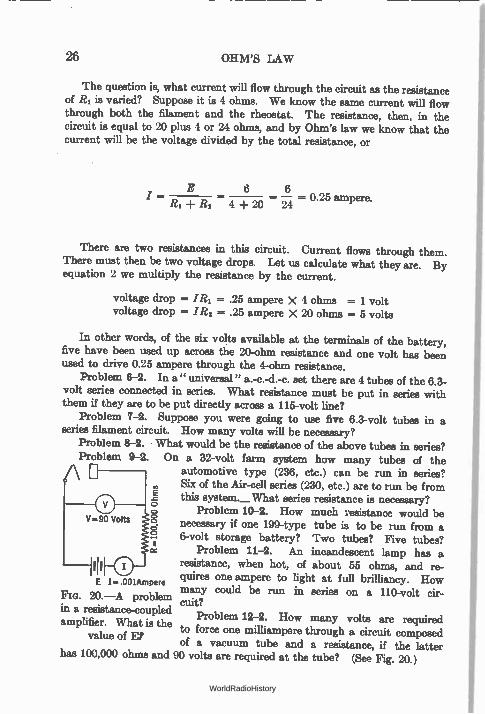
has 100,000 ohms and 90 volts are required at the tube? (See Fig. 20.)
E I...001Ampere FIG. 20.—A problem in a resistance-coupled amplifier. What is the
value of Er
WorldRadioHistory
CHARACTERISTICS OF PARALLEL CIRCUITS 27
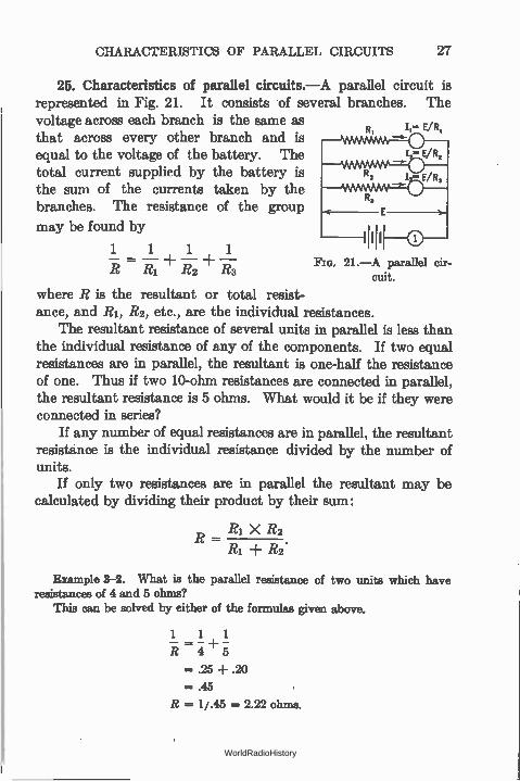
25. Characteristics of parallel circuits.—A parallel circuit is represented in Fig. 21. It consists of several branches. The voltage across each branch is the same as E/R, that across every other branch and is equal to the voltage of the battery. The total current supplied by the battery is the sum of the currents taken by the branches. The resistance of the group
may be found by 1111 1 1 1 1
where R is the resultant or total resist-ance, and RI, R2, etc., are the individual resistances.
The resultant resistance of several units in parallel is less than the individual resistance of any of the components. If two equal resistances are in parallel, the resultant is one-half the resistance of one. Thus if two 10-ohm resistances are connected in parallel, the resultant resistance is 5 ohms. What would it be if they were connected in series?
If any number of equal resistances are in parallel, the resultant resistance is the individual resistance divided by the number of units.
If only two resistances are in parallel the resultant may be calculated by dividing their product by their sum:
Ri X R2
± R2.
Fla. 21.—A parallel cir-cuit.
Example 3-2. What is the parallel resistance of two units which have resistances of 4 and 5 ohms?
This can be solved by either of the formulas given above.
1 1 1
= .25 -I- .20
=.45
R = 1/.45 = 2.22 ohms.
WorldRadioHistory
28 OHM'S LAW
Or, RI R RI X -
± R2
4 X 5
4 -I- 5
= —20 = 2.22 ohms. 9
Example 4-2. Suppose, as in Fig. 22, these two resistances in parallel are placed in series with a resistance of 1 ohm and across a battery of 6 volts. What current would flow out of the battery and through each resistance?
The total resistance is 2.22 ± 1 = 3.22 ohms. The current flowing, then, is 6 ÷ 3.22 = 1.86 amperes. This current through the combined resistance of
R, —4
FIG. 22.—Solve for the various
currents.
200 Ohms
800 Ohms 500 Ohms
FIG. 23.—What is the voltage drop
across the 800 ohms?
the 4- and 5-ohm units produces a voltage drop of I X R or 1.86 X 2.22 or 4.14 volts. This voltage across 4 ohms produces a current of 4.14 4- 4 or 1.035 amperes, and across 5 ohms produces a current of 0.827 ampere. These two currents added together are 1.862 amperes, which checks our calculation above.
Problem 13-2. A radio receiver has five tubes of the a.-c. heater type, each taking 1.75 amperes. What is their combined resistance, and how much current do they take from a 2.5-volt transformer secondary? If another load of the same voltage but half the current is added, what current is required?
Problem 14-2. A circuit has three branches of 4, 6, and 8 ohms. A cur-rent of 4 amperes flows through the 6-ohm branch. What current flows through the other branches?
Problem 15-2. Consider the circuit of Fig. 23. What is the voltage drop across the 800-ohm resistor?
WorldRadioHistory
DETECTION AND MEASUREMENT OF CURRENT 29
Experiment 2-2. Connect as in Fig. 22 several shunt resistances such as tubes, rheostats, fixed filament resistors, etc., in series with a battery and a rheostat. Measure the parallel resistance and individual resistances by read-ing the current through them separately and in parallel and the voltage of the
1 1 1 battery. Test the relation — = 1 — — R2 R R3
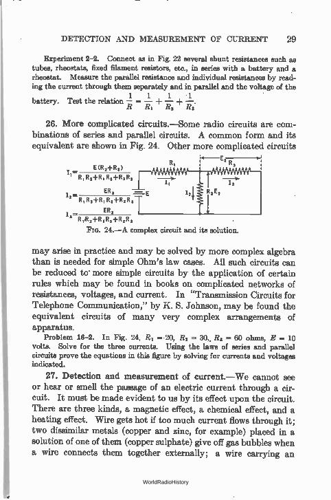
26. More complicated circuits.—Some radio circuits are com-binations of series and parallel circuits. A common form and its equivalent are shown in Fig. 24. Other more complicated circuits
E (12 21-R,)
R, R,-4-R,
ER, — I, —
R, R2-FR, Rs-FR, R
ER,
R Met-R I R,-FR2R3
Flo. 24.—A complex circuit and its solution.
may arise in practice and may be solved by more complex algebra than is needed for simple Ohm's law cases. All such circuits can be reduced to more simple circuits by the application of certain rules which may be found in books on complicated networks of resistances, voltages, and current. In "Transmission Circuits for Telephone Communication," by K. S. Johnson, may be found the equivalent circuits of many very complex arrangements of apparatus.
Problem 16-2. In Fig. 24, RI = 20, R3 = 30,, R3 = 60 ohms, E = 10 volts. Solve for the three currents. Using the laws of series and parallel circuits prove the equations in this figure by solving for currents and voltages indicated.
27. Detection and measurement of current.—We cannot see or hear or men the passage of an electric current through a cir-cuit. It must be made evident to us by its effect upon the circuit. There are three kinds, a magnetic effect, a chemical effect, and a heating effect. Wire gets hot if too much current flows through it; two dissimilar metals (copper and zinc, for example) placed in a solution of one of them (copper sulphate) give off gas bubbles when a wire connects them together externally; a wire carrying an
WorldRadioHistory
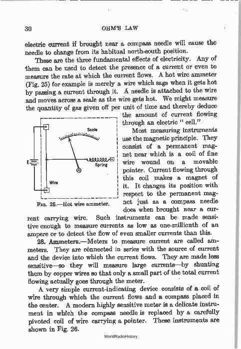
25.—Hot wire ammeter.
30 OHM'S LAW
electric current if brought near a compass needle will cause the needle to change from its habitual north-south position.
These are the three fundamental effects of electricity. Any of them can be used to detect the presence of a current or even to measure the rate at which the current flows. A hot wire ammeter (Fig. 25) for example is merely a wire which sags when it gets hot by passing a current through it. A needle is attached to the wire and moves across a scale as the wire gets hot. We might measure the quantity of gas given off per unit of time and thereby deduce
the amount of current flowing through an electric " cell."
Most measuring instruments use the magnetic principle. They consist of a permanent mag-net near which is a coil of fine wire wound on a movable pointer. Current flowing through this coil makes a magnet of it. It changes its position with respect to the permanent mag-net just as a compass needle does when brought near a cur-
rent carrying wire. Such instruments can be made sensi-tive enough to measure currents as low as one-millionth of an ampere or to detect the flow of even smaller currents than this.
28. Ammeters.—Meters to measure current are called am-meters. They are connected in series with the source of current and the device into which the current flows. They are made less sensitive—so they will measure large currents—by shunting them by copper wires so that only a small part of the total current flowing actually goes through the meter. A very simple current-indicating device consists of a coil of
wire through which the current flows and a compass placed in the center. A modern highly sensitive meter is a delicate instru-ment in which the compass needle is replaced by a carefully pivoted coil of wire carrying a pointer. These instruments are shown in Fig. 26.
WorldRadioHistory
VOLTMETERS
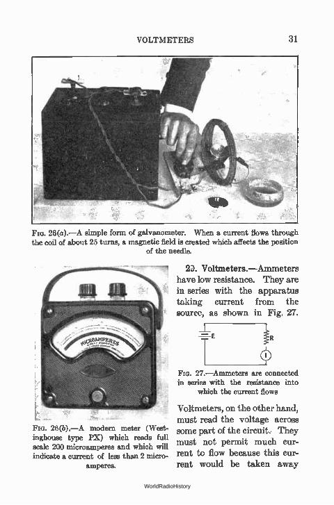
Fm. 26(a).—A simple form of galvanometer. When a current flows through the coil of about 25 turns, a magnetic field is created which affects the position
of the needle.
26(b).—A modern meter (West-inghouse type PX) which reads full scale 200 microamperes and which will indicate a current of less than 2 micro-
amperes.
2. Voltmeters.—Ammeters have low resistance. They are in series with the apparatus taking current from the source, as shown in Fig. 27.
iR 27.—Ammeters are connected
in series with the resistance into which the current flows
Voltmeters, on the other hand, must read the voltage across some part of the circuit.. They must not permit much cur-rent to flow because this cur-rent would be taken away
WorldRadioHistory
32 OHM'S LAW
from the circuit. They have a high resistance. They are really high resistance ammeters. Thus an ammeter, the Jewell 0-1 milli-ampere meter for example, can be made to read volts by putting it in series with a high resistance and across the circuit to be measured.
For example, 1 volt is required to give 1 milliampere of current through 1000 ohms. Thus if we have a 1 0 milliampere meter and we wish to measure a voltage of the order of 1 volt, we need only a resistance of 1000 ohms. Then the figures on the meter scale will read volts instead of milliamperes. Such a series resistance is called a multiplier. A Weston Model 301 meter reading 1.0 milliampere full scale
will measure a maximum current of 50 ma. if a resistance of 0.57 ohm is placed across it. If the resistance is reduced to 0.27 ohm, the meter will read 100 milliamperes when its needle points to 1.0 milliampere. Weston Models 280 and 301 voltmeters have a resistance of about 62 ohms per volt. Thus a meter reading a maximum of 100 volts has a resistance of 6200 ohms.
Problem 17-2. How much current is required for full scale deflection on a Weston Model 301, 50-volt voltmeter?
30. Sensitivity of meters.—A sensitive current-measuring meter is one which will measure very small currents but which has a low resistance. A sensitive voltmeter is one which will give a large needle deflection through a very high resistance. Voltmeters which are used to measure the voltage of high resistance devices such as plate supply units have high resistance in order that the
current taken from the device shall not R-10,0oo
MwseWive& t be great enough to lower appreciably E- 100 x the voltage of the device.
Example 5-2. Suppose we are to measure Fm. 28.—A low resistance the voltage across the circuit at the point X in voltmeter placed at X will not Fig. 28. The voltage at X depends upon the read the open circuit voltage, current taken by the meter. What is desired
is the " open-circuit " or " no-load" voltage across X, that is, the voltage existing there if no current is taken by the meter. If no current flows, there is no voltage drop in the resistance R and hence the voltage at i is the voltage of the battery, or 100 volts. Suppose, however, the
WorldRadioHistory
AMMETER-VOLTMETER METHOD 33
meter nas a resistance of 1000 ohms. The current flowing is given by Ohm's law
I = E/R
= 100 ÷ (10,00) + 1000)
- 0091 a mpere or 9.1 milliamperes. Iles) - - •
This current thrcugh the 10,000-ohm resistance R (which may be the internal resistance of the battery E (Section 49) causes a voltage drop across this resistance of I X R = .0091 X 10,000 = 91 volts. .
The voltage actually recorded on the meter, then, is the difference between the battery voltage and the drop acmss the resistance R, or
voltage at X = E - (I X R) = 100 - 91 = 9.0 volts.
If, however, the meter is a high-resistance meter, say 1000 ohms per volt, that is, 100,000 ohms for a meter designed to read 100 volts, the current taken from the battery would be
I = E/R = 0.00091 ampere
and the IR drop across the resistance R would be only
E = IR = (0.00091 X 10,000)
= 9.1 volts
and the voltage read at X would be 100 - 9.1 volts or 91.9 volts. In other words the high-resistance voltmeter gives a reading much nearer
the open-circuit or no-load voltage desired.
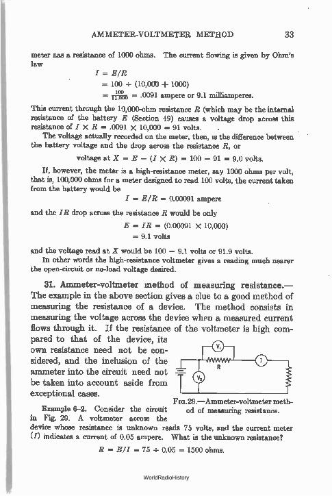
31. Ammeter-voltmeter method of measuring resistance.— The example in the above section gives a clue to a good method of measuring the resistance of a device. The method consists in measuring the voltage across the device when a measured current flows through it. If the resistance of the voltmeter is high com-pared to that of the device, its own resistance need not be con-sidered, and the inclusion of the
ammeter into the circuit need not be taken taken into account aside from
exceptional cases. Fia. 29.—Ammeter-voltmeter meth-
Example 6-2. Consider the circuit od of measuring resistance. in Fig. 29. A voltmeter across the device whose resistance is unknown reads 75 volts, and the current meter (I) indicates a current of 0.05 ampere. What is the unknown resistance?
I? = Ell = 75 ÷ 0.05 = 1500 ohms.
WorldRadioHistory
34 OHM'S LAW
32. Voltmeter method of measuring resistance.—If the resist-ance of a voltmeter is known, a resistance can be measured by its use and a battery. Weston Models 301 and 280 each have resistance of 62 ohms per volt, so that a 50-volt meter would have a resistance of 3100 ohms. Take two readings, one of the battery alone and one of the battery in series with the unknown resistance. Then the desired resistance may be found from
R 1)R. E
where Eb = Voltage of battery alone; E = Voltage across battery and resistance; = Resistance of meter.
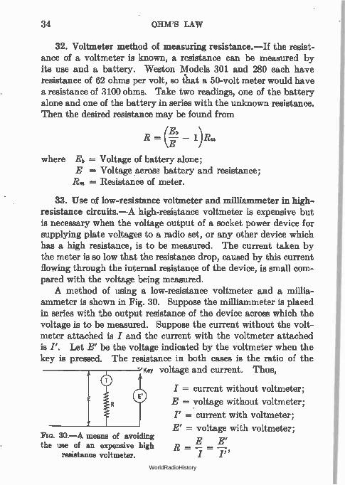
33. Use of low-resistance voltmeter and milliammeter in high-resistance circuits.—A high-resistance voltmeter is expensive but is necessary when the voltage output of a socket power device for supplying plate voltages to a radio set, or any other device which has a high resistance, is to be measured. The current taken by the meter is so low that the resistance drop, caused by this current flowing through the internal resistance of the device, is small com-pared with the voltage being measured. A method of using a low-resistance voltmeter and a millia-
ammeter is shown in Fig. 30. Suppose the milliammeter is placed in series with the output resistance of the device across which the voltage is to be measured. Suppose the current without the volt-meter attached is I and the current with the voltmeter attached is I'. Let E' be the voltage indicated by the voltmeter when the key is pressed. The resistance in both cases is the ratio of the
Key voltage and current. Thus,
I = current without voltmeter;
E = voltage without voltmeter;
I' =. current with voltmeter;
E' = voltage with voltmeter;
E E' R = —I"
Fig. 30.—A Means of avoiding the use of an expensive high
resistance voltmeter.
WorldRadioHistory
RESISTANCE MEASUREMENT 35
whence E = desired voltage
= E' X 7,
E' and
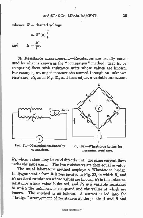
34. Resistance measurement.—Resistances are usually meas-ured by what is known as the " comparison " method, that is, by comparing them with resistance units whose values are known. For example, we might measure the current through an unknown resistance, RI, as in Fig. 31, and then adjust a variable resistance,
31.—Measuring resistance by comparison.
E
Fia. 32.—Wheatstone bridge for measuring resistance.
R2, whose values may be read directly until the same current flows under the same e.m.f. The two resistances are then equal in value.
The usual laboratory method employs a Wheatstone bridge. In diagrammatic form it is represented in Fig. 32, in which R1 and R2 are fixed resistances whose values are known, R3 is the unknown resistance whose value is desired, and R4 is a variable resistance to which the unknown is compared and the values of which are known. The method is as follows. A current is led into the " bridge " arrangement of resistances at the points A and B and
WorldRadioHistory
36 OHM'S LAW
a sensitive current indicating meter placed at the points X and Y. The values of RI, R2, and R4 are adjusted until the meter, g, shows that no current flows through it, that is, there is no differ-ence in voltage between the two points X and Y which would force current through the meter. In other words X and Y are at the same voltage.
The total current I divides at A and flows into the " arms " of the bridge forming the currents Ii through R1 and R2 and 12 through R3 and R4. If there is no potential difference between X and Y, the voltage drop along RI is equal to the voltage drop along R3.
Thus
Similarly
Dividing (1) by (2)
IiRI = I2R3
I1R2 = 12R4
R1 R3
ii2 = 714.
(1)
(2)
(3)
Suppose R1 and R2 are equal in value. Then equation (3) becomes
1 = R3/R4
or-R3 = R4,
and to find the value of the unknown resistance R3 we need only adjust R4 (whose values are known) until no current flows through the meter. Then the two resistances are equal. Suppose, how-ever, that the unknown resistance is much larger than any value we can obtain by adjusting R4. For example, let it be ten times as large. Then it is only necessary to make RI ten times as large as R2 when (3) becomes
RI/R2 = Ra/R4 = 10
R3 = 10 R4,
and it is only necessary to adjust R4 until no current flows through the meter and to multiply the resistance of this standard R4 by 13 to get the value of the unknown resistor Ra.
WorldRadioHistory
RESISTANCE MEASUREMENT 37
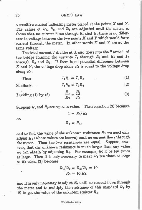
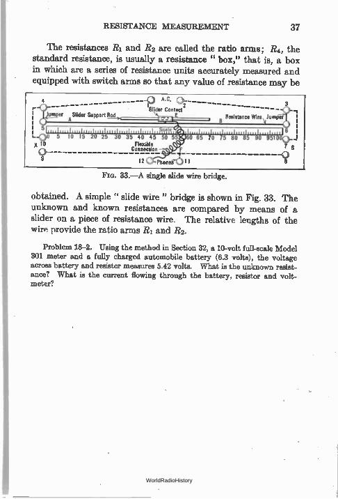
The resistances R1 and R2 are called the ratio arms; R4, the standard resistance, is usually a resistance " box," that is, a box in which are a series of resistance units accurately measured and equipped with switch arms so that any value of resistance may be
A.C.
'Slider Contact2 ----- - umper A Slider Support Rod Resistance Wire Jumper
\I ale
30 35 40 45 50 55 Flexible
Connection
124 phone-i'l;:¡11 1
Fla. 33.—A single slide wire bridge.
3
obtained. A simple " slide wire" bridge is shown in Fig. 33. The unknown and known resistances are compared by means of a slider on a piece of resistance wire. The relative lengths of the wirn provide the ratio arms R1 and R2.
Problem 18-2. Using the method in Section 32, a 10-volt full-scale Model
301 meter and a fully charged automobile battery (6.3 volts), the voltage
across battery and resistor measures 5.42 volts. What is the unknown resist-
ance? What is the current flowing through the battery, resistor and volt-
meter?
WorldRadioHistory
CHAPTER III
PRODUCTION OF CURRENT
ELECTRICAL energy does not exist in nature in a form useful to man. It must be transformed from some other form of energy. For example, the mechanical energy of a motor, or steam engine, may be transformed into electrical energy by means of a generator.
The commonest sources of current useful to radio workers are the battery and the generator. The battery is a device which converts chemical energy into electrical energy; the generator uses up mechanical energy with the same result.
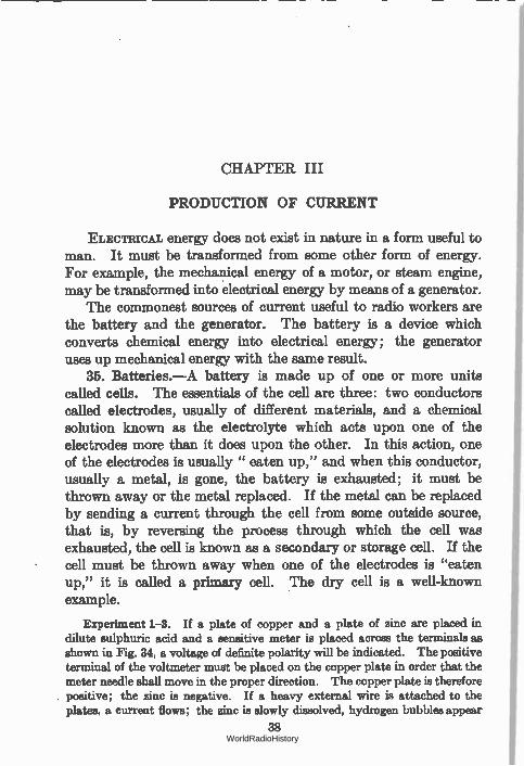
35. Batteries.—A battery is made up of one or more units called cells. The essentials of the cell are three: two conductors called electrodes, usually of different materials, and a chemical solution known as the electrolyte which acts upon one of the electrodes more than it does upon the other. In this action, one of the electrodes is usually " eaten up," and when this conductor, usually a metal, is gone, the battery is exhausted; it must be thrown away or the metal replaced. If the metal can be replaced by sending a current through the cell from some outside source, that is, by reversing the process through which the cell was exhausted, the cell is known as a secondary or storage cell. If the cell must be thrown away when one of the electrodes is "eaten up," it is called a primary cell. The dry cell is a well-known example.
Experiment 1-3. If a plate of copper and a plate of zinc are placed in dilute sulphuric acid and a sensitive meter is placed across the terminals as shown in Fig. 34, a voltage of definite polarity will be indicated. The positive terminal of the voltmeter must be placed on the copper plate in order that the meter needle shall move in the proper direction. The copper plate is therefore positive; the zinc is negative. If a heavy external wire is attached to the plates, a current flows; the zinc is slowly dissolved, hydrogen bubbles appear
38 WorldRadioHistory
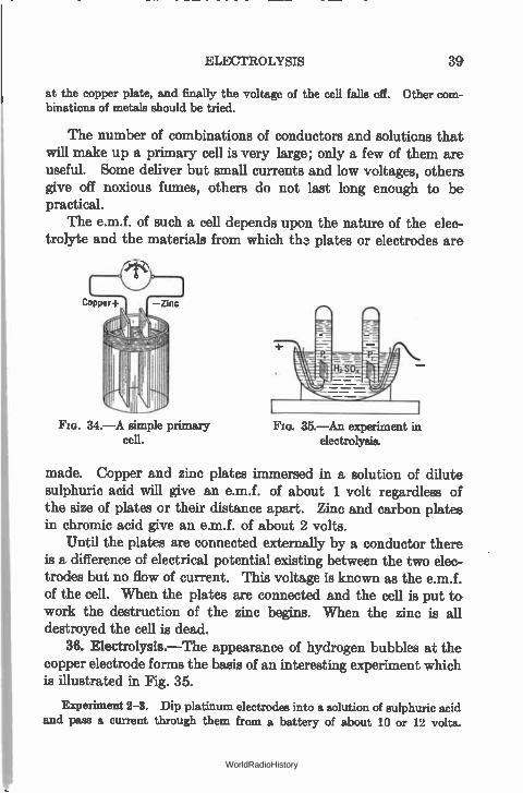
ELECTROLYSIS 3g
at the copper plate, and finally the voltage of the cell falls off. Other com-binations of metals should be tried.
The number of combinations of conductors and solutions that will make up a primary cell is very large; only a few of them are useful. Some deliver but small currents and low voltages, others give off noxious fumes, others do not last long enough to be practical.
The e.m.f. of such a cell depends upon the nature of the elec-trolyte and the materials from which th a plates or electrodes are
Copper+ —zinc
ri
Fia. 34.—A simple primary cell.
FIG. 35.—An experiment in electrolysis.
made. Copper and zinc plates immersed in a solution of dilute sulphuric acid will give an e.m.f. of about 1 volt regardless of the size of plates or their distance apart. Zinc and carbon plates in chromic acid give an e.m.f. of about 2 volts.
Until the plates are connected externally by a conductor there is a difference of electrical potential existing between the two elec-trodes but no flow of current. This voltage is known as the e.m.f. of the cell. When the plates are connected and the cell is put to work the destruction of the zinc begins. When the zinc is all destroyed the cell is dead.
36. Electrolysis.—The appearance of hydrogen bubbles at the copper electrode forms the basis of an interesting experiment which is illustrated in Fig. 35.
Experiment 2-3. Dip platinum electrodes into a solution of sulphuric acid and pass a current through them from a battery of about 10 or 12 volts.
WorldRadioHistory
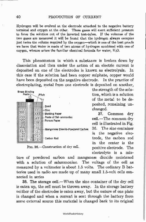
40 PRODUCTION OF CURRENT
Hydrogen will be evolved at the electrode attached to the negative battery terminal and oxygen at the other. These gases will exert sufficient pressure to force the solution out of the inverted test-tubes. If the volumes of the two gases are measured it will be found that the hydrogen always occupies just twice the volume required by the oxygen—which is one of the best proofs we have that water is made of two atoms of hydrogen combined with one of oxygen, whence arises the familiar chemical formula for water, H20.
This phenomenon in which a substance is broken down by dissociation and then under the action of an electric current is deposited on one of the electrodes is known as electrolysis. In this case if the solution had been copper sulphate, copper would have been deposited on the negative electrode. In the practice of electroplating, metal from one electrode is deposited on another,
the strength of the solu-Posts Pitch tion, which is a solution
of the metal to be de-IJMlL posited, remaining un-
Zinc changed. Blotting Paper 37. Common dry Paste of Sal- ammoniac cell.—The common dry Porous Paper
cell is illustrated in Fig. Manganese Dioxide-Powdered Carbon 36. The zinc container
is the negative elec-Carbon Rod trode, the carbon rod
in the center is the positive electrode. The electrolyte is a mix-
ture of powdered carbon and manganese dioxide moistened with a solution of salammoniac. The voltage of the cell as measured by a voltmeter is about 1.5 volts. The ordinary B bat-teries used in radio are made up of many small 1.5-volt cells con-nected in series
38. The storage cell.—When the zinc container of the dry cell is eaten up, the cell must be thrown away. In the storage battery neither of the electrodes is eaten away, but the nature of one plate is changed and when a current is sent through the battery from some external source this material is changed back to its original
Brass Binding
Fm. 36.—Construction of dry cell.
WorldRadioHistory
INTERNAL RESISTANCE 41
form, so that the cell is said to be " charged " and can be used again.
The storage cell has two electrodes, one of lead and one of lead peroxide immersed in a dilute solution of sulphuric acid. The usual storage battery is made up of three cells in series, producing a voltage of about 6 at the terminals. The positive terminal is usually marked, either with a red terminal, or a large cross, or in some other way. It is important to know the polarity of the bat-tery when charging it. The positive post of the battery should be connected to the positive post of the charging line.
Experiment 3-3. If two lead plates about 6 inches square are immersed in a dilute solution of sulphuric acid—say one part of acid to ten of water—and connected in series with a battery of 6 or 8 volts and an ammeter, a current will be seen to flow, and the color of the plate attached to the positive terminal of the battery begins to change and the evolution of hydrogen bubbles at the other plate will be observed. The current soon decreases. Now replace the external battery with an incandescent lamp or an electric bell and note that current flows out of the lead cell and through the light or the bell.
39. Internal resistance.—One might think that an unlimited current could be secured from a battery if it were short-circuited. Such is the case. A very low-resistance ammeter placed across a dry cell gives a definite reading—it is not unlimited. Something must be in the circuit which has a resistance greater than that of the ammeter or the connections. For example a new dry cell will deliver about 30 amperes through wires of very low resistance.
This something which restricts the current to a limited value is the internal resistance of the cell. This resistance depends upon the construction of the cell, its electrode and electrolyte material, the distance apart of the electrodes, the condition of the cell— whether new or old. The older the cell the smaller the area of electrode in contact with the electrolyte and the greater the resist-ance. The current delivered by a cell is
E I —
r R
when r = internal resistance of cell; R = external resistance of circuit.
WorldRadioHistory
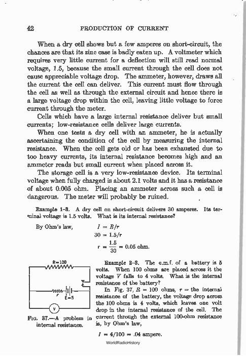
42 PRODUCTION OF CURRENT
When a dry cell shows but a few amperes on short-circuit, the chances are that its zinc case is badly eaten up. A voltmeter which requires very little current for a deflection will still read normal voltage, 1.5, because the small current through the cell does not cause appreciable voltage drop. The ammeter, however, draws all the current the cell can deliver. This current must flow through the cell as well as through the external circuit and hence there is a large voltage drop within the cell, leaving little voltage to force current through the meter.
Cells which have a large internal resistance deliver but small currents; low-resistance cells deliver large currents.
When one tests a dry cell with an ammeter, he is actually ascertaining the condition of the cell by measuring the internal resistance. When the cell gets old or has been exhausted due to too heavy currents, its internal resistance becomes high and an ammeter reads but small current when placed across it.
The storage cell is a very low-resistance device. Its terminal voltage when fully charged is about 2.1 volts and it has a resistance of about 0.005 ohm. Placing an ammeter across such a cell is dangerous. The meter will probably be ruined.
Example 1-3. A dry cell on short-circuit delivers 30 amperes. Its ter-tninal voltage is 1.5 volts. What is its internal resistance?
By Ohm's law,
FIG. 37.—A problem in internal resistance.
I = E/r
30 = 1.5/r
15 r = a° 5 ohm. iô =
Example 2-3. The e.m.f. of a battery is 5 volts. When 100 ohms are placed across it the voltage V falls to 4 volts. What is the internal resistance of the battery?
In Fig. 37, R = 100 ohms, r = the internal resistance of the battery, the voltage drop across the 100 ohms is 4 volts, which leaves one volt drop in the internal resistance of the cell. The current through the external 100-ohm resistance is, by Ohm's law,
1 = 4/100 = .04 ampere.
WorldRadioHistory
POLARIZATION 43
This current must also flow through the internal resistance of the battery and there it causes a voltage drop of one volt.
E =/Xr 1 = 0.04 x r r = 1/.04 = 25 ohms.
Note that the internal resistance of the cell is represented as being in series with the voltage and the external resistance. This is because the current must actually flow through the internal resistance of all such voltage generators, and hence the resistance of the device is represented in series with the remainder of the circuit. Care must be taken in such representations not to place the voltmeter in the wrong place. In Fig. 37 the voltmeter is actually placed across the battery and its internal resistance, which is connected directly to the 100-ohm resistance.
The voltage of the cell on open circuit is its e.m.f. Under load the voltage falls, and is now labeled as the p.d. (potential differ-ence). The e.m.f. of high-resistance cells can only be measured by high-resistance meters, those that take but little current from the cell. When the voltage of a cell or battery is mentioned its e.m.f. is assumed unless otherwise labeled.
40. Polarization.—In common with all other cells the zinc-copper sulphuric acid cell (Fig. 34) suffers from polarization. The hydrogen bubbles which surround the copper plate decrease its surface in contact with the active liquid. This increases the cell's resistance. In addition, a minute voltage is set up between the hydrogen and the copper. This voltage is opposite to the useful voltage and has the same effect upon the usefulness of the battery as an addition to the cell's internal resistance.
Various means are taken to overcome the bad effects of polari-zation. Chemicals may be placed in the cell to supply oxygen, which will combine with the hydrogen to form water; shaking the cell may remove the hydrogen bubbles and decrease the resist-ance of the cell. The manganese dioxide used in dry cell construc-tion is a depolarizer. But these are only temporary remedies. Sooner or later the internal resistance of the cell becomes so high that the cell is no longer useful. A dry cell which has had large currents taken from it becomes polarized. If it is allowed to
WorldRadioHistory
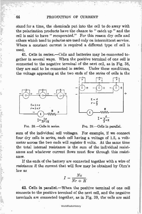
I— 3e 3r+R
38.—Cells in aeries.
44 PRODUCTION OF CURRENT
stand for a time, the chemicals put into the cell to do away with the polarization products have the chance to " catch up " and the cell is said to have " recuperated." For this reason dry cells and others which tend to polarize are used only on intermittent service. Where a constant current is required a different type of cell is used.
41. Cells in series.—Cells and batteries may be connected to-gether in several ways. When the positive terminal of one cell is connected to the negative terminal of the next cell, as in Fig. 38, they are said to be connected in series. Under these conditions, the voltage appearing at the two ends of the series of cells is the
r-r-, re-i e I r I r I
I. re i+R
39.—Cells in parallel.
sum of the individual cell voltages. For example, if we connect four dry cells in series, each cell having a voltage of 1.5, a volt-meter across the two ends will register 6 volts. At the same time the total internal resistance is the sum of the individual resist-ances and whatever current flows must flow through this resist-ance.
If the ends of the battery are connected together with a wire of resistance R the current that will flow may be obtained by Ohm's law as
Ne I —
Nr R.
42. Cells in parallel.—When the positive terminal of one cell connects to the positive terminal of the next cell, and the negative terminals are connected together, as in Fig. 39, the• cells are said
WorldRadioHistory
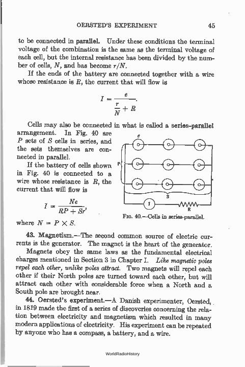
OERSTED'S EXPERIMENT 45
to be connected in parallel. Under these conditions the terminal voltage of the combination is the same as the terminal voltage of each cell, but the internal resistance has been divided by the num-ber of cells, N, and has become r/N.
If the ends of the battery are connected together with a wire whose resistance is R, the current that will flow is
e
N ± R
Cells may also be connected in what is called a series-parallel arrangement. In Fig. 40 are P sets of S cells in series, and the sets themselves are con-nected in parallel.
If the battery of cells shown in Fig. 40 is connected to a wire whose resistance is R, the current that will flow is
Ne I —
RP -I- Sr'
where N = P X S.
43. Magnetism.—The second common source of electric cur-rents is the generator. The magnet is the heart of the generator.
Magnets obey the same laws as the fundamental electrical charges mentioned in Section 3 in Chapter I. Like magnetic poles repel each other, unlike poles attract. Two magnets will repel each other if their North poles are turned toward each other, but will attract each other with considerable force when a North and a South pole are brought near.
44. Oersted's experiment.—A Danish experimenter, Oersted, in 1819 made the first of a series of discoveries concerning the rela-tion between electricity and magnetism which resulted in many modern applications of electricity. His experiment can be repeated by anyone who has a compass, a battery, and a wire.
FIG. 40.—Cells in series-parallel.
WorldRadioHistory
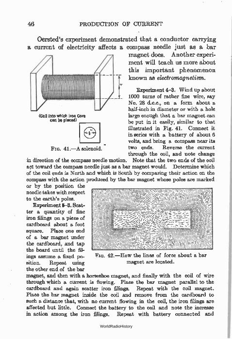
46 PRODUCTION OF CURRENT
Oersted's experiment demonstrated that a conductor carrying a current of electricity affects a compass needle just as a bar
magnet does. Another experi-ment will teach us more about this important phenomenon known as electromagnetism.
Experiment 4-3. Wind up about 1000 turns of rather fine wire, say No. 28 d.c.c., on a form about a half-inch in diameter or with a hole large enough that a bar magnet can be put in it easily, similar to that illustrated in Fig. 41. Connect it in series with a battery of about 6 volts, and bring a compass near its two ends. Reverse the current through the coil, and note change
in direction of the compass needle motion. Note that the two ends of the coil set toward the compass needle just as a bar magnet would. Determine which of the coil ends is North and which is South by comparing their action on the compass with the action produced by the bar magnet whose poles are marked or by the position the needle takes with respect to the earth's poles.
Experiment 5-3. Scat-ter a quantity of fine iron filings on a piece of cardboard about a foot square. Place one end of a bar magnet under the cardboard, and tap the board until the fil-ings assume a fixed po-sition. Repeat using the other end of the bar magnet, and then with a horseshoe magnet, and finally with the coil of wire through which a current is flowing. Place the bar magnet parallel to the cardboard and again scatter iron filings. Repeat with the coil magnet. Place the bar magnet inside the coil and remove from the cardboard to such a distance that, with no current flowing in the coil, the iron filings are affected but little. Connect the battery to the coil and note the increase in action among the iron filings. Repeat with battery connected and
(Coil into which Iron Core can be placed)
e FIG. 41.—A solenoid.
FIG. 42.—How the lines of force about a bar magnet are located.
WorldRadioHistory
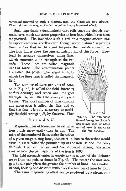
OERSTED'S EXPERIMENT 47
cardboard removed to such a distance that the filings are not affected. Then put the bar magnet inside the coil and note increased effect.
Such experiments demonstrate that coils carrying electric cur-rents have much the same properties as iron bars which have been magnetized. The fact that such a coil or a magnet affects iron filings or compass needles even though some distance separates them, shows that in the space between them exists some force. The iron filings show the general distribution of this force. They tend to arrange themselves along lines ,, which concentrate in strength at the two ends. These lines are called magnetic lines of force. The concentration points , are called the poles. The space through \ ' which the lines pass is called the magnetic field.
The number of lines per unit of area, as in Fig. 43, is called the field intensity or flux density; and when one line goes through 1 sq. cm. the field strength is one Gauss. The total number of lines through any given area is called the flux, and to find the flux it is only necessary to multi-ply the field strength, H, by the area. Thus
flux° =A X H.
Magnetic lines of force may be set up in iron much more easily than in air. The ratio of the number of lines, under the action of a given magnetizing force, that exist in iron to those that would exist in air is called the permeability of the iron. If one line flows through 1 sq. cm. of air and one thousand through the same area of iron the permeability of the iron is 1000. The field strength varies inversely as the square of the distance
away from the pole as shown in Fig. 43. The nearer the unit area gets to the pole piece the greater the number of lines. As a matter of fact, halving the distance multiplies the number of lines by four.
The same magnetizing effect can be produced by a strong cur-
Fm. 43.—The number of lines of force going through one square inch or other unit of area is known as
the flux density.
WorldRadioHistory
48 PRODUCTION OF CURRENT
rent acting through a few turns of wire as by a weak current through many turns of wire. If the product of turns and amperes, called the ampere turns, is the same in two cases the magnetizing effect will be the same.
It is because of the increased permeability, and of the con-sequent bacrease in flux density, that adding the iron core to the solenoid, or coil of wire in Experiment 5-3, is so effective. Soft irçn is most easily magnetized, but loses its magnetism with the same rapidity. Permanent magnets are made from steel.
45. Faraday's discovery.—The second important discovery on the way toward present-day electrical machinery was that of the celebrated English experimenter, Faraday. The experiment may be repeated by anyone who has a coil of wire, a bar magnet, and a sensitive current indicator such as the galvanometer used in Experiment 6-3.
Experiment 6-3. Construct a galvanometer like that in Fig. 26a and con-nect to the coil used in Experiment 4-3. Thrust a bar magnet into the coil quickly, and then remove it. Note the motions of the compass needle. Wind up another coil with about the same number of turns but of such a diameter that it can be placed around the first coil easily. Connect the second coil to a battery in series with a 30-ohm rheostat and place over the first coil and then remove with a quick motion. Note the compass needle variations.
In all of the above procedure, note the relation between the compass needle movements and the rapidity with which the various changes are carried out.
Such was Faraday's experiment. When the bar magnet, or the coil carrying a current, was motionless, there was no motion of the needle. When a bar was thrust into the coil the needle moved in one direction, and when the motion of the bar was reversed the needle reversed its motion too. There was no metallic connection between the two coils, or between the coil and the bar magnet— and yet changing the position of one with respect to the other, or changing the direction of magnitude or current through one coil produced some electrical effect in the other circuit.
The facts underlying Faraday's experiment are these: An elec-tric voltage was generated o'r induced in the coil when the bar magnet was thrust into it. A voltage of opposite polarity was generated when the magnet was removed. This voltage sent a
WorldRadioHistory
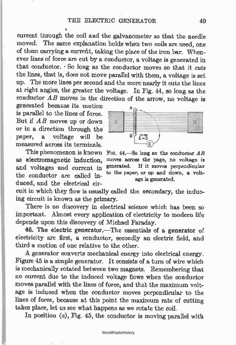
THE ELECTRIC GENERATOR 49
current through the coil and the galvanometer so that the needle moved. The same explanation holds when two coils are used, one of them carrying a current, taking the place of the iron bar. When-ever lines of force are cut by a conductor, a voltage is generated in that conductor. • So long as the conductor moves so that it cuts the lines, that is, does not move parallel with them, a voltage is set up. The more lines per second and the more nearly it cuts the lines at right angles, the greater the voltage. In Fig. 44, so long as the conductor AB moves in the direction of the arrow, no voltage is generated because its motion A
is parallel to the lines of force. But if AB moves up or down or in a direction through the paper, a voltage will be measured across its terminals.
This phenomenon is known Fia. 44.—So long as the conductor AB as electromagnetic induction, moves across the page, no voltage is and voltages and current in generated. If it moves perpendicular
to the paper, or up and down, a volt-the conductor are called in-age is generated.
duced, and the electrical cir-cuit in which they flow is usually called the secondary, the induc-ing circuit is known as the primary.
There is no discovery in electrical science which has been so important. Almost every application of electricity to modern life depends upon this discovery of Michael Faraday.
46. The electric generator.—The essentials of a generator of electricity are first, a conductor, secondly an electric field, and third a motion of one relative to the other. A generator converts mechanical energy into electrical energy.
Figure 45 is a simple generator. It consists of a turn of wire which is mechanically rotated between two magnets. Remembering that no current due to the induced voltage flows when the conductor moves parallel with the lines of force, and that the maximum volt-age is induced when the conductor moves perpendicular to the lines of force, because at this point the maximum rate of cutting takes place, let us see what happens as we rotate the coil.
In position (a), Fig. 45, the conductor is moving parallel with
WorldRadioHistory
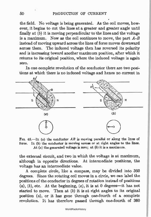
50 PRODUCTION OF CURRENT
the field. No voltage is being generated. As the coil moves, how-ever, it begins to cut the lines at a greater and greater angle until finally at (b) it is moving perpendicular to the lines and the voltage is a maximum. Now as the coil continues to move, the part A-B instead of moving upward across the lines of force moves downward across them. The induced voltage then has reversed its polarity and is increasing toward another maximum position, after which it returns to its original position, where the induced voltage is again zero.
In one complete revolution of the conductor there are two posi-tions at which there is no induced voltage and hence no current in
A/
(a) (6)
45.—In (a) the conductor AB is moving parallel or along the lines of force. In (b) the conductor is moving across or at right angles to the lines.
At (a) the generated voltage is zero; at (b) it is a maximum.
the external circuit, and two in which the voltage is at maximum, although in opposite directions. At intermediate positions, the voltage has an intermediate value. A complete circle, like a compass, may be divided into 360
degrees. Since the rotating coil moves in a circle, we can label the positions of the conductor in degrees of rotation instead of positions (a), (b), etc. At the beginning, (a), it is at 0 degrees—it has not started to move. Then at (b) it is at right angles to its original position (a), or it has gone through one-fourth of a complete revolution. It has therefore passed through one-fourth of 360
WorldRadioHistory
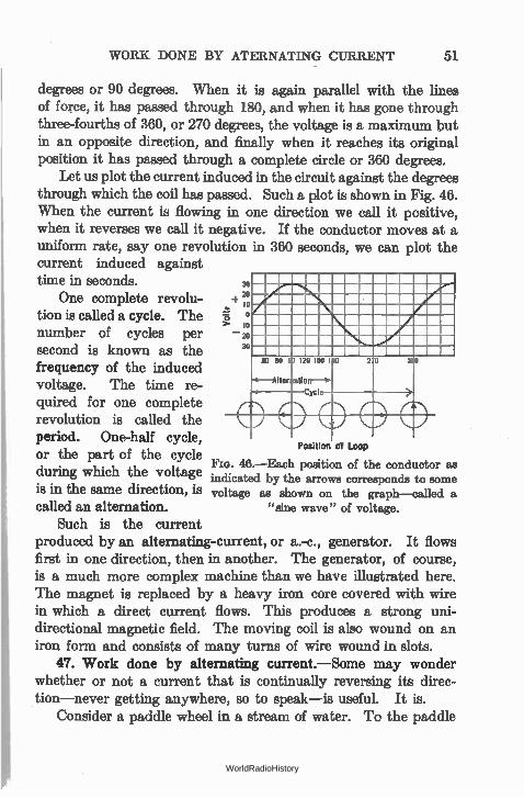
WORK DONE BY ATERNATING CURRENT 51
degrees or 90 degrees. When it is again parallel with the lines of force, it has passed through 180, and when it has gone through three-fourths of 360, or 270 degrees, the voltage is a maximum but in an opposite direction, and finally when it reaches its original position it has passed through a complete circle or 360 degrees.
Let us plot the current induced in the circuit against the degrees through which the coil has passed. Such a plot is shown in Fig. 46. When the current is flowing in one direction we call it positive, when it reverses we call it negative. If the conductor moves at a uniform rate, say one revolution in 360 seconds, we can plot the current induced against time in seconds.
One complete revolu-tion is called a cycle. The number of cycles per second is known as the frequency of the induced voltage. The time re-quired for one complete revolution is called the period. One-half cycle, or the part of the cycle
Fro. 46.—Each position of the conductor as during which the voltage indicated by the arrows corresponds to some is in the same direction, is voltage as shown on the graph—called a
called an alternation. "sine wave" of voltage.
Such is the current produced by an alternating-current, or a.-c., generator. It flows first in one direction, then in another. The generator, of course, is a much more complex machine than we have illustrated here. The magnet is replaced by a heavy iron core covered with wire in which a direct current flows. This produces a strong uni-directional magnetic field. The moving coil is also wound on an iron form and consists of many turns of wire wound in slots.
47. Work done by alternating current.—Some may wonder whether or not a current that is continually reversing its direc-tion—never getting anywhere, so to speak—is useful. It is.
Consider a paddle wheel in a stream of water. To the paddle
Position of Loop
WorldRadioHistory
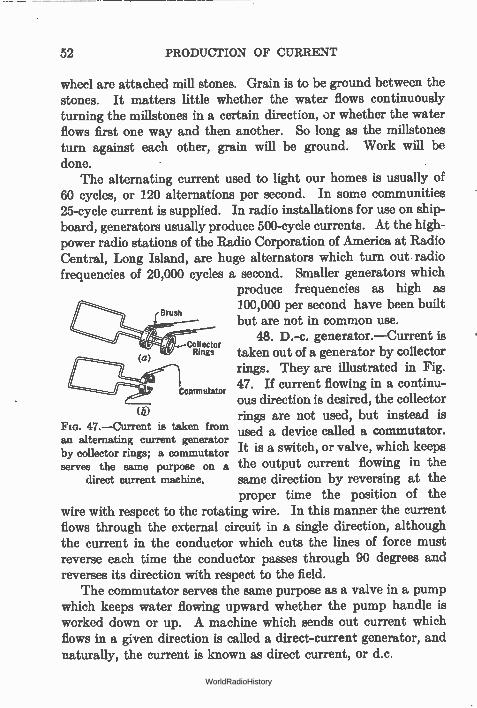
52 PRODUCTION OF CURRENT
wheel are attached mill stones. Grain is to be ground between the stones. It matters little whether the water flows continuously turning the millstones in a certain direction, or whether the water flows first one way and then another. So long as the millstones turn against each other, grain will be ground. Work will be done.
The alternating current used to light our homes is usually of 60 cycles, or 120 alternations per second. In some communities 25-cycle current is supplied. In radio installations for use on ship-board, generators usually produce 500-cycle currents. At the high-power radio stations of the Radio Corporation of America at Radio Central, Long Island, are huge alternators which turn out radio frequencies of 20,000 cycles a second. Smaller generators which
produce frequencies as high as 100,000 per second have been built
Brush but are not in common use.
48. D.-c. generator.—Current is Rings taken out of a generator by collector
rings. They are illustrated in Fig.
ennunntsior 47. If current flowing in a continu-ous direction is desired, the collector rings are not used, but instead is used a device called a commutator. It is a switch, or valve, which keeps the output current flowing in the same direction by reversing at the proper time the position of the
wire with respect to the rotating wire. In this manner the current flows through the external circuit in a single direction, although the current in the conductor which cuts the lines of force must reverse each time the conductor passes through 90 degrees and reverses its direction with respect to the field.
The commutator serves the same purpose as a valve in a pump which keeps water flowing upward whether the pump handle is worked down or up. A machine which sends out current which flows in a given direction is called a direct-current generator, and naturally, the current is known as direct current, or d.c.
(.12) 47.—Current is taken from
an alternating current generator by collector rings; a commutator serves the same purpose on a
direct current machine.
WorldRadioHistory
ELECTRICAL POWER 53
49. Internal resistance.—The generator too has an internal resistance so that the voltage measured at its terminals differs when different currents are taken from it. The voltage measured across the terminals on a meter requiring little current is called the open-circuit voltage. As the current taken from the generator increases, this voltage drops.
50. Electrical power.—Throughout the previous discussion we have spoken of electrical energy in a rather loose way. What do we mean by energy? What is power? What is their relation to work?
Energy is the ability to do work. A body may have one of two kinds of mechanical energy, either potential energy or kinetic energy. The former is due to the position of the body, the latter is due to its motion. A heavy ball on top a flag pole has potential energy because if it falls it can do work, useful or not. It may heat the ground where it falls, or it may be used to drive a post into the ground. A cannon ball speeding through the air has energy because it can do work, useful or otherwise, if it is stopped suddenly. The target may be heated thereby, converting the kinetic energy pos-sessed by the ball into heat energy. The amount of damage done gives the eye a certain measure by which to judge the energy originally possessed by the cannon ball. This energy was origi-nally possessed by the powder and was imparted to the ball when it exploded.
The power required to force a certain current of electricity through a wire at a voltage of E volts is the product of the voltage and the current. Thus
Power in watts equals current in amperes times volts,
or P = I X E.
A horsepower is 33,000 foot-pounds per minute. It is equal to 746 watts.
All expressions for power involve the factor of time. In other words, power is the rate of doing work. It requires more power to accomplish a certain amount of work in a short time than in a longer time. For example a ton of material raised a foot in the air represents 2000 foot-pounds of work. If it is accomplished by a
WorldRadioHistory
54 PRODUCTION OF CURRENT
crane in 1 second of time it represents an expenditure of 2000 X 60 or 120,000 foot-pounds per minute of power. Since one horse-power is equal to 33,000 foot-pounds per minute, the crane has a power of 120,000 ÷ 33,000 or about 3.65 horsepower.
Now if a man raises the ton of material one foot in the air in an hour's time by going up a very long and gradual incline, his power is 2000 ÷ 60 or 33.2 foot-pounds per minute, or roughly one-thousandth horsepower (0.001 hp.). The amount of work done in the two cases is the same—the ton of material has been raised one foot in the air. The rate of doing work has changed.
Example 3-3. A generator is rated at 5 kilowatts (5000 watts) output. How many amperes can it supply if its voltage is 110 and it has no appreciable resistance? How many horsepower is this?
Power equals E x I 5000 = 110 X I
I = 5000/110 = 45.6 amperes.
Horsepower equals 746 watts.
5000/746 = 6.7 horsepower.
51. Power lost in resistance.—According to the law called the Conservation of Energy, energy can neither be created nor de-stroyed. It comes from somewhere and goes somewhere. Simi-larly, all power, which is the rate at which energy is used, must be accounted for. The energy required to force current through a resistance must do some work. It cannot disappear. This work results in heating the resistance. Whenever current flows through a resistance, heat is generated and the greater the current the greater the heat. As a matter of fact the heat is proportional to the square of the current. If the wire is heated faster than the heat can be dissipated in heating the surrounding air, the wire melts. Energy has been supplied to the unit at too great a rate. A resistor used in a power supply device is rated at so-many
ohms and as capable of dissipating so-many watts. Thus a 1000-ohm, 20-watt resistor, means that the resistance of the unit is 1000 ohms, and that 20 watts of electrical power can be put into it with-out danger of burn-out. WorldRadioHistory
EXPRESSIONS FOR POWER 55
Problem 1-3. Electric power is bought at the rate of so-much per kilo-watt-hour. Suppose your rate is 10 cents per kilowatt-hour. How much does it cost to run a flat-iron on a 110-volt circuit if it consumes 6 amperes?
Problem 2-3. Assuming that 20 milliamperes direct current flow through the winding of a loud speaker which has a d.-c. resistance of 1000 ohms, what amount of heat in watts (PR) must be dissipated? What supplies this power? Suppose an output device is used which has a resistance of only 200 ohms. How much power is saved? Is there any other advantage of the latter arrange-ment you can see?
52. Expressions for power.—Just as there are three ways of stating Ohm's law, so there are three ways of stating the relation between power, volts, amperes, ohms. Thus:
(1) P= IXE (2) P = 12 X R (3) P = E 2 R
Example 4-3. A power supply device supplies 180 volts to a power tube of the 171 type which consumes 20 milliamperes. How much power is taken from the device? What is the resistance of the tube? • The power supplied is E X I = 180 X 0.02 = 3.6 watts. The resistance into which this power is fed is equal to P 12 = 3.6 ÷ .0004 = 9000 ohms or E2 ÷ P = 1802 ÷ 3.6 = 32,400 ÷ 3.6 = 9000 ohms.
The maximum current that can pass through one's body with-out serious results is 0.01 ampere. The resistance varies with one's health and the surface in contact, etc. If the finger tips of the two hands are dry, the resistance from one hand to the other is about 50,000 ohms, and thus by Ohm's law the maximum voltage that can be safely touched is 500.
Problem 3-3. Assuming that a man can touch with his dry finger tips a 500-volt street car conductor, and that the resistance of his body is 50,000 ohms, how much power is used up in heating the body?
Problem 4-3. A voltage of 110 is to be placed across a circuit whose resist-ance must be such that 220 watts can be delivered. What is the resistance of the circuit?
Problem 5-3. How much power is taken from a storage battery which supplies five automotive radio receiver tubes?
Problem 8-3. One milliampere of plate current flows through a 100,000-ohm resistor. How much power in heat must the resistor be capable of dissipating?
Problem 7-3. How much current can be sent through a 1000-ohm 20-watt resistor without danger of burning it up? What voltage is required?
Problem 8-3. In a plate voltage supply device the voltage-divider has a total resistance of 5000 ohms. The receiver requires a maximum current of 30 milliamper-q. What must be the wattage rating of the resistor?
WorldRadioHistory
56 PRODUCTION OF CURRENT
Problem 9-3. An automobile receiver of five 6.3-volt tubes consumes a plate current of 50 milliamperes at 180 volts. Assume that the car battery supplies this load; what power is required?
53. Efficiency.—Efficiency is a term that is loosely employed by nearly everybody. Anything which works is said to be effi-cient, and one's efficiency is often confused with his energy—his ability to do work whether the work is actually carried out or not. The term, however, has a very exact meaning when one uses it in speaking of mechanical or electrical systems of any kind. Energy is a relative term. It is a ratio showing how much useful work one gets out of a total amount of work done.
Let us consider a steam engine connected to a dynamo, a com-bination of machines for transforming mechanical energy into elec-trical energy. If the steam engine consumes one horsepower (746 watts) and delivers 500 watts of electrical energy, it is said to be more efficient than if it delivered only 250 watts. Let us consider two men, one of whom gets a lot of work done in a small amount of time and with an expenditure of little effort. The other gets the same amount of work done but with great effort, perhaps flurrying about from one thing to another instead of tackling his problem in a straightforward manner. The first man is more efficient. Re wastes less time and energy.
Efficiency, then, is the ratio between useful work or energy or effect got out of a machine to the total energy or power or effort put into it. It is expressed in percentage. A machine that is 100 per cent efficient has no losses; there is no friction in its bear-ings, or, if it is an electrical device, no resistance in its wires. There are no such machines in use to-day. Efficiency is the ratio of useful power one gets out of a device to the power put into it.
useful output useful output Efficiency —
input output plus losses
Problem 10-3. In the above problem a motor generator or vibrator system supplies the plate voltage. If its efficiency is 40 per cent what power and current are taken from the battery?
Problem 11-3. Seventy-five per cent of the ampere-hours put into a battery are returned by it on discharge. How many hours must a 100-ampere-hour battery be charged at a one-ampere rate?
WorldRadioHistory
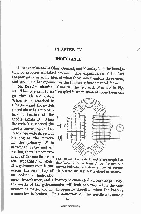
CHAPTER IV
INDUCTANCE
l'H.E experiments of Ohm, Oersted, and Faraday laid the founda-tion of modern electrical science. The experiments of the last chapter gave us some idea of what these investigators discovered, and gave us a background for the following fundamental facts.
54. Coupled circuits.—Consider the two coils P and S in Fig. 48. They are said to be " coupled " when lines of force from one go through the other. When P is attached to a battery and the switch closed there is a momen-tary indication of the needle across S. When the switch is opened the needle moves again but in the opposite direction. So long as the current in the primary P is steady in value and di-rection, there is no move-ment of the needle across the secondary or coils. If a galvanometer is put across the secondary of an ordinary high-ratio audio transformer, and a battery is connected across the primary, the needle of the galvanometer will kick one way when the con-nection is made, and in the opposite direction when the battery connection is broken. This deflection of the needle indicates a
57
„— ..---------1-2-z--
//"...--..-------...:::. ///.--- ---_:.--- -.;•••
\‘‘\‘‘u
gl \%‘‘‘ \\ •
‘‘ \\;:. ••,./
48.—If the coils P and S are coupled so that lines of force from P go through S, a current indicator will show a flow of current in S when the key in P is closed or opened.
WorldRadioHistory
58 INDUCTANCE
momentary flow of current in the secondary coil; this current flows only when the primary current is changing, i.e., starting or stopping, not when the primary current is fixed in value or direction.
55. Lenz's law.—There are two fundamental facts about this phenomenon of coupled circuits. The first is that when lines of force couple two coils together, and some change in these lines takes place, perhaps due to a change in the current in the circuit that is producing the lines, a voltage is " induced " in the second circuit. The second fundamental fact is known as Lenz's law: this induced voltage is in such a direction that it opposes the change in current that produced it.
Thus when the battery is attached to P, lines of force thread their way across the turns of wire in S. This movement of the lines of force through S induces a voltage across this coil and a current flows in the coil and the apparatus connected to it. This current in the second coil is in such a direction that its field, that is, its lines of force threading through the primary, induces a counter voltage in the primary opposite in direction to the battery voltage across it.
When the battery voltage is broken, the lines of force from the primary current collapse back on the coil, and, in crossing the secondary turns in an opposite direction to that taken when the current in the primary is increasing, induce a voltage in the secondary in such a direction that it tends to keep the primary current flowing.
The result is that it takes a longer time to build up the primary current to its final value at " make " and a longer time for the current to fall to zero at " break."
This phenomenon of induced current is of most fundamental importance. It is the basis of all our modern electrical machinery. Our motors, our dynamos, our radio signals all are the result of our ability to produce changes in one circuit by doing something to another although the two circuits have no metallic connection whatever.
The fact that current takes longer to reach its final value in a circuit in which there is a coil of wire indicates that something
WorldRadioHistory
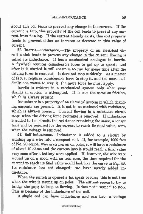
SELF-INDUCTANCE 59
about this coil tends to prevent any change in the current. If the current is zero, this property of the coil tends to prevent any cur-rent from flowing. If the current already exists, this coil property tends to prevent either an increase or decrease in this value of current.
56. Inertia—inductance.—The property of an electrical cir-cuit which tends to prevent any change in the current flowing is called its inductance. It has a mechanical analogue in inertia. A flywheel requires considerable force to get up to speed; and after it is started it will continue to run for some time after the driving force is removed. It does not stop suddenly. As a matter of fact it requires considerable force to stop it, and the more sud-denly one wants to stop it, the more force he must apply.
Inertia is evident in a mechanical system only when some change in motion is attempted. It is not the same as friction, which is always present.
Inductance is a property of an electrical system in which chang-ing currents are present. It is not to be confused with resistance, which is always present. Current flowing in a resistance circuit stops when the driving force (voltage) is removed. If inductance is added to the circuit, the resistance remaining the same, a longer time will be required for the current to reach its final value, zero, when the voltage is removed.
57. Self-inductance.—Inductance is added to a circuit by winding up a wire into a compact coil. If, for example, 1000 feet of No. 20 copper wire is strung up on poles, it will have a resistance of about 10 ohms and the current into it would reach a final value very soon after a battery were applied. If, however, the wire were wound up on a spool with an iron core, the time required for the current to reach its final value would look like the curve in Fig. 49. Its resistance has not changed; we have merely added in-ductance.
When the switch is opened a fat spark occurs; this is not true when the wire is strung up on poles. The current seems to try to bridge the gap; to keep on flowing. It does not " want" to stop. This is because of the inductance of the coil. A single coil can have inductance and can have a voltage
WorldRadioHistory
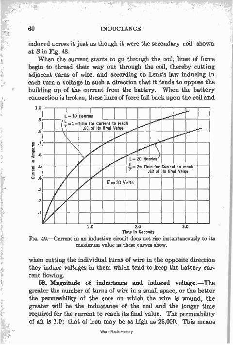
60 INDUCTANCE
induced across it just as though it were the secondary coil shown at S in Fig. 48.
When the current starts to go through the coil, lines of force begin to thread their way out through the coil, thereby cutting adjacent turns of wire, and according to Lenz's law inducing in each turn a voltage in such a direction that it tends to oppose the building up of the current from the battery. When the battery connection is broken, these lines of force fall back upon the coil and
1.0
.9
.8
111 -7
.e 1É -5
I I I L..10 Henries
--1-r ..1=Time for Current to reach .63 of its final Value
L = 20 Henries L Time for Current to reach
.63 of its final Value
E=10 Volts
10 20 Time in Seconds
FIG. 49.—Current in an inductive circuit does not rise instantaneously to its maximum value as these curves show.
3.0
when cutting the individual turns of wire in the opposite direction they induce voltages in them which tend to keep the battery cur-rent flowing.
58. Magnitude of inductance and induced voltage.—The greater the number of turns of wire in a small space, or the better the permeability of the core on which the wire is wound, the greater will be the inductance of the coil and the longer time required for the current to reach its final value. The permeability of air is 1.0; that of iron may be as high as 25,000. This means
WorldRadioHistory
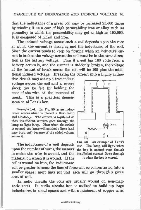
MAGNITUDE OF INDUCTANCE AND INDUCED VOLTAGE 61
that the inductance of a given coil may be increased 25,000 times by winding it on a core of high permeability iron or alloy such as permalloy in which the permeability may get as high as 100,000. It is composed of nickel and iron.
The induced voltage across such a coil depends upon the rate at which the current is changing and the inductance of the coil. Since the current tends to keep on flowing when an inductive cir-cuit is broken the voltage across the coil must be in the same direc-tion as the battery voltage. Thus if a coil has 100 volts from a battery across it, and the current is suddenly broken, the voltage at the instant of break across the coil will be 100 plus the addi-tional induced voltage. Breaking the current into a highly induc-tive circuit may set up a tremendous voltage across the coil and a severe shock can be felt by holding the ends of the wire at the moment of break. This is a practical demon-stration of Lenz's law.
Example 1-4. In Fig. 50 is an induc-tance across which is placed a flash lamp and a battery. The current is regulated so that insufficient current goes through the lamp to light it up. Now when the switch is opened the lamp will suddenly light (and may burn out) because of the added voltage across it.
The inductance of a coil depends upon the number of turns, the manner in which the wire is wound, and the material on which it is wound. If the coil is wound on iron, the inductance will be greater because the lines of force will be concentrated into a smaller space; more lines per unit area will go through a given area of coil.
In radio circuits the coils are usually wound on non-mag-netic cores. In audio circuits iron is utilized to build up large inductances in small spaces and with a minimum of copper wire.
Fm. 50.—An example of Lenz's law. The lamp will light when the key is opened even though insufficient current flows through
it when the key is closed.
WorldRadioHistory
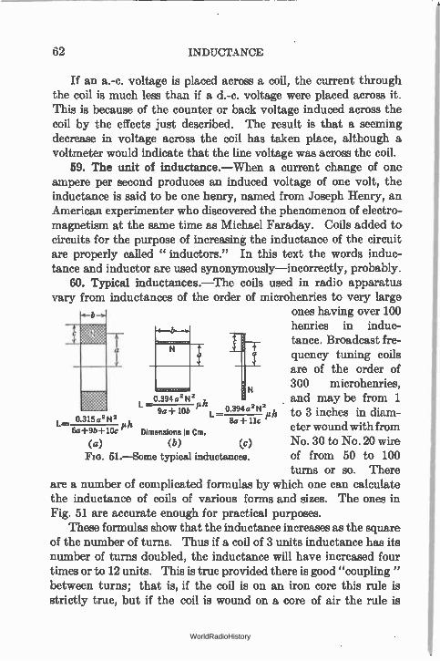
62 INDUCTANCE
If an a.-c. voltage is placed across a coil, the current through the coil is much less than if a d.-c. voltage were placed across it. This is because of the counter or back voltage induced across the coil by the effects just described. The result is that a seeming decrease in voltage across the coil has taken place, although a voltmeter would indicate that the line voltage was across the coil.
59. The unit of inductance.—When a current change of one ampere per second produces an induced voltage of one volt, the inductance is said to be one henry, named from Joseph Henry, an American experimenter who discovered the phenomenon of electro-magnetism at the same time as Michael Faraday. Coils added to circuits for the purpose of increasing the inductance of the circuit are properly called " inductors." In this text the words induc-tance and inductor are used synonymously—incorrectly, probably.
60. Typical inductances.—The coils used in radio apparatus vary from inductances of the order of microhenries to very large
ones having over 100 henries in induc-tance. Broadcast fre-quency
N are of the order of 300 mi crohenries,
tuning coils
L -0.394a° N2 p 9a + 10b L _ 0 394 a2N2 and may be from 1 h to 3 inches in cliam-
o 315a2 N2 Ph 8a + 11c 6a+9b+10e Dimensions in cm. eter wound with from
(a) (b) (c) No. 30 to No. 20 wire 51.--Some typical inductances. of from 50 to 100
turns or so. There are a number of complicated formulas by which one can calculate the inductance of coils of various forms and sizes. The ones in Fig. 51 are accurate enough for practical purposes.
These formulas show that the inductance increases as the square of the number of turns. Thus if a coil of 3 units inductance has its number of turns doubled, the inductance will have increased four times or to 12 units. This is true provided there is good "coupling" between turns; that is, if the coil is on an iron core this rule is strictly true, but if the coil is wound on a core of air the rule is
WorldRadioHistory
MAGNITUDE OF MUTUAL INDUCTANCE 63
only approximately true. It becomes more nearly a fact the closer together the turns of wire.
Problem 1-4. A coil like that in Fig. 51a is called a multilayer coil. Such a coil is wound to have 1000 turns, in a slot 1 inch square. The distance from the center of the coil to the center of the winding (a in Fig. 51) is 2 inches. What is the inductance of the coil in microhenries? Remember that the dimensions given in Fig. 51 are in centimeters and that one inch equals 2.54 cm.
Problem 2-4. A coil like that in Fig. 51b is called a solenoid. It is the type of coil most often used in radio circuits. Calculate the inductance of such a coil composed of 60 turns of wire in a space of 3 inches, the diameter of the coil form being 3 inches. Coils used in modern broadcast receivers are wound on cores about one inch or lesa in diameter.
61. Coupling.—The closer together the two coils, P and S, Fig. 48, the greater the number of the lines of force due to the primary current that links with the turns of the secondary, and the better the " coupling " is said to be. The better the permeability of the medium in which the lines go, the better the coupling.
The voltage across the secondary of such a two-coil circuit as that shown in Fig. 48 depends upon the sizes of both coils, their proximity, the permeability of the medium, and the rate at which he primary current changes. All of the factors except the rate of change of the primary current are grouped together and called the mutual inductance of the circuit. -
The secondary voltage, then, is equal to
M X rate of change of primary current,
where M is the mutual inductance and is rated in henries.
62. Magnitude of mutual inductance.—Formulas in Fig. 51 show that the inductance of a coil depends upon the square of the number of turns. Doubling the turns increases the inductance four times. Consider two coils built alike and having the same inductance. If they are connected together the total inductance will be equal to that of a single coil of double the turns. In other words the total inductance of two coils connected " series aiding" will be four times the inductance of a single coil. If the connections to one coil are reversed, the total inductance will be zero because
WorldRadioHistory
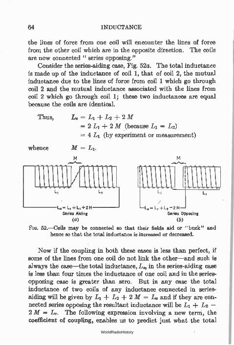
64 INDUCTANCE
the lines of force from one coil will encounter the lines of force from the other coil which are in the opposite direction. The coils are now connected " series opposing."
Consider the series-aiding case, Fig. 52a. The total inductance is made up of the inductance of coil 1, that of coil 2, the mutual inductance due to the lines of force from coil 1 which go through coil 2 and the mutual inductance associated with the lines from coil 2 which go through coil 1; these two inductances are equal because the coils are identical.
Thus, Lo = L1 + L2 ± 2 M
= 2 L1 -I- 2 M (because L1 = L2)
= 4 L1 (by experiment or measurement)
whence M = LI.
L. L, +1_2+2M
Series Aiding
(a)
L. L, +L2 —2 M Series Opposing
(b)
FIG. 52.—Coils may be connected so that their fields aid or "buck" and hence so that the total inductance is increased or decreased.
Now if the coupling in both these cases is less than perfect, if some of the lines from one coil do not link the other—and such is always the case—the total inductance, Lo, in the series-aiding case is less than four times the inductance of one coil and in the series-opposing case is greater than zero. But in any case the total inductance of two coils of any inductance connected in series-aiding will be given by L1 + L2 + 2 M = La and if they are con-nected series opposing the resultant inductance will be L1 L2 — 2 M = Lo. The following expression involving a new term, the coefficient of coupling, enables us to predict just what the total
WorldRadioHistory
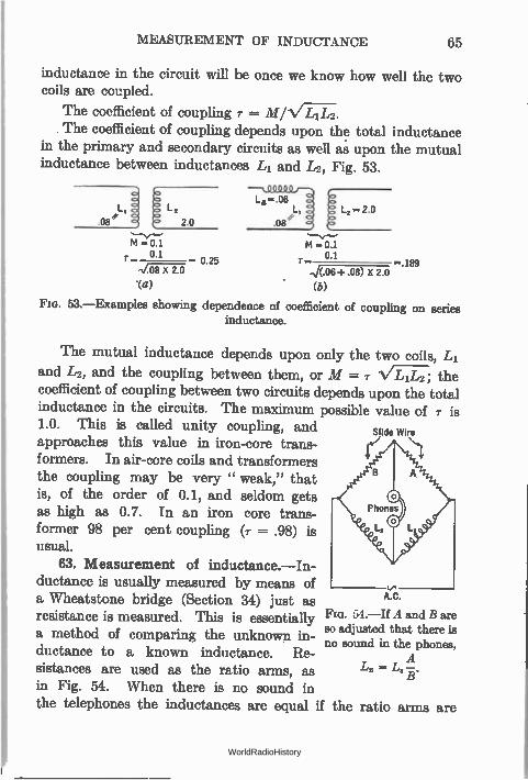
MEASUREMENT OF INDUCTANCE 65
M = 0.1 0 1 • 0.25
/.7C.5----( 2.0
.(a)
inductance in the circuit will be once we know how well the two coils are coupled.
The coefficient of coupling T = M/1/Z-ITZI The coefficient of coupling depends upon the total inductance
in the primary and secondary circuits as well as upon the mutual inductance between inductances L1 and L2, Fig. 53.
M = OA 0.1
.../(.06+ _08) X 2.0
(b)
189
FIG. 53.—Examples showing dependence of coefficient of coupling on series inductance.
The mutual inductance depends upon only the two coils, L1
and Li2, and the coupling between them, or M = 7" 1/7Li-r2; the coefficient of coupling between two circuits depends upon the total inductance in the circuits. The maximum possible value of 1.0. This is called unity coupling, and approaches this value in iron-core trans-formers. In air-core coils and transformers the coupling may be very " weak," that is, of the order of 0.1, and seldom gets as high as 0.7. In an iron core trans-former 98 per cent coupling (r = .98) is usual.
63. Measurement of inductance.—In-ductance is usually measured by means of a Wheatstone bridge (Section 34) just as resistance is measured. This is essentially a method of comparing the unknown in-ductance to a known inductance. Re-sistances are used as the ratio arms, as in Fig. 54. When there is no sound in the telephones the inductances are equal if the
Slide Wire
tJ
An.
Fm. 54.—If A and B are so adjusted that there is no sound in the phones,
ris
A =
ratio arms are
WorldRadioHistory
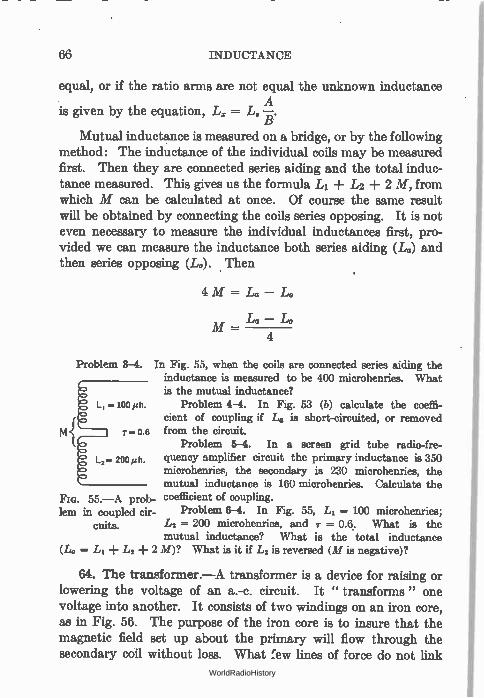
66 INDUCTANCE
equal, or if the ratio arms are not equal the unknown inductance A
is given by the equation, L. = L.—B.
Mutual inductance is measured on a bridge, or by the following method: The inductance of the individual coils may be measured first. Then they are connected series aiding and the total induc-tance measured. This gives us the formula L1 ± L2 -I- 2 M, from which M can be calculated at once. Of course the same result will be obtained by connecting the coils series opposing. It is not even necessary to measure the individual inductances first, pro-vided we can measure the inductance both series aiding (La) and then series opposing (L.). Then
4 M = L0 —
M — 4
L. — L.
Problem 3-4. In Fig. 55, when the coils are connected series aiding the inductance is measured to be 400 microhenries. What is the mutual inductance?
L, = 100 ,,h Problem 4-4. In Fig. 53 (b) calculate the coeffi-cient of coupling if L. is short-circuited, or removed from the circuit.
Problem 5-4. In a screen grid tube radio-fre-L2= 200 h. quency amplifier circuit the primary inductance is 350
microhenries, the secondary is 230 microhenries, the mutual inductance is 160 microhenries. Calculate the
Fie. 55.—A prob- coefficient of coupling. lem in coupled cir- Problem 6-4. In Fig. 55, L1 = 100 microhenries;
cuita. L2 = 200 microhenries, and T = 0.6. What is the mutual inductance? What is the total inductance
(L. = L1 + LI + 2 M)? What is it if L2 is reversed (M is negative)?
64. The transformer.—A transformer is a device for raising or lowering the voltage of an a.-c. circuit. It " transforms" one voltage into another. It consists of two windings on an iron core, as in Fig. 56. The purpose of the iron core is to insure that the magnetic field set up about the primary will flow through the secondary coil without loss. What few lines of force do not link
WorldRadioHistory
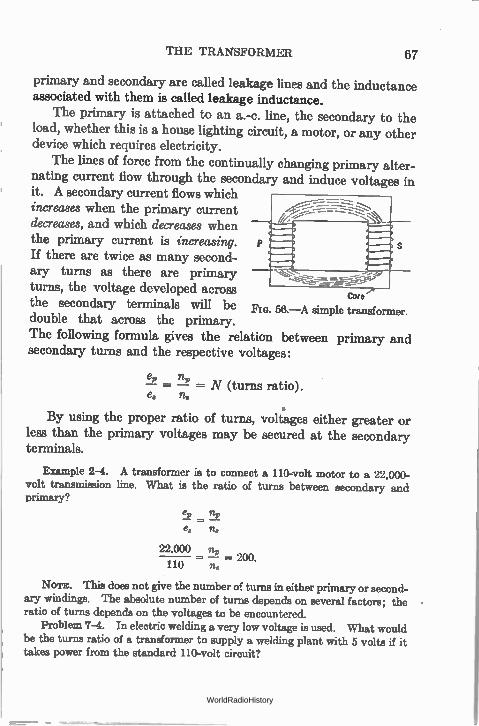
THE TRANSFORMER 67
primary and secondary are called leakage lines and the inductance associated with them is called leakage inductance.
The primary is attached to an a.-c. line, the secondary to the load, whether this is a house lighting circuit, a motor, or any other device which requires electricity.
The lines of force from the continually changing primary alter-nating current flow through the secondary and induce voltages in it. A secondary current flows which increases when the primary current decreases, and which decreases when the primary current is increasing. If there are twice as many second-ary turns as there are primary turns, the voltage developed across
Core the secondary terminals will be double that across the primary. The following formula gives the relation between primary and secondary turns and the respective voltages:
FIG. 56.—A simple transformer.
= N (turns ratio). e, n„
By using the proper ratio of turns, voltages either greater or less than the primary voltages may be secured at the secondary terminals.
Example 2-4. A transformer is to connect a 110-volt motor to a 22,000-volt transmission line. What is the ratio of turns between secondary and primary?
e2 _ n,,e„ - na
22,000 no - - 200.
110 no
NOTE. This does not give the number of turns in either primary or second-ary windings. The absolute number of turns depends on several factors; the ratio of turns depends on the voltages to be encountered.
Problem 7-4. In electric welding a very low voltage is used. What would be the turns ratio of a transformer to supply a welding plant with 5 volts if it takes power from the standard 110-volt circuit?
-V--
WorldRadioHistory
68 INDUCTANCE
Problem 8-4. In Problem 13-2 what are the turns ratio and minimum primary current? If the transformer is 90 per cent efficient what power does it take from the line?
Problem 9-4. A primary consists of 200 turns of wire and is connected to a 110-volt circuit. The secondary feeds a rectifier circuit requiring 550 volts. How many turns will be on the secondary winding?
65. Power in transformer circuits.—Since the transformer does not add any electricity to the circuit but merely changes or trans-forms from one voltage to another the electricity that already exists, the total amount of energy in the circuit must remain the same. If it were possible to construct a perfect transformer there would be no loss in power when it is transformed from one voltage to another. Since power is the product of volts times amperes, an increase in voltage by means of a transformer must result in a decrease in current, and vice versa. On the secondary side of a transformer there cannot be more power than in the primary and if the transformer is one of high efficiency, the power will be only slightly less than on the primary side. The product of amperes times volts remains the same.
Thus the primary power is
E,I, and the secondary power is
Eau.
(1)
(2)
and since there is no loss or gain in power
E,I, = E.I. (3)
I„ when — — = N (turns ratio),
la E,
which shows that the secondary voltage increases as N increases; the secondary current decreases when N increases.
66. Transformer losses.—Transformers are not perfect. There is some resistance in both primary and secondary coils. The cur-rent going through these resistances produces heat, which repre-sents a certain amount of power lost. All of the lines of force coming out of the primary coil do not go through the secondary
WorldRadioHistory
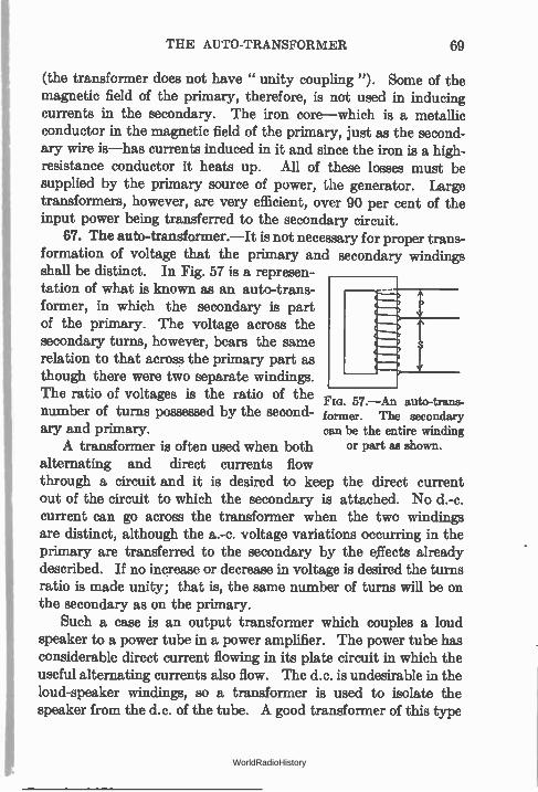
THE AUTO-TRANSFORMER 69
(the transformer does not have " unity coupling "). Some of the magnetic field of the primary, therefore, is not used in inducing currents in the secondary. The iron core—which is a metallic conductor in the magnetic field of the primary, just as the second-ary wire is—has currents induced in it and since the iron is a high-resistance conductor it heats up. All of these losses must be supplied by the primary source of power, the generator. Large transformers, however, are very efficient, over 90 per cent of the input power being transferred to the secondary circuit.
67. The auto-transformer.—It is not necessary for proper trans-formation of voltage that the primary and secondary windings shall be distinct. In Fig. 57 is a represen-tation of what is known as an auto-trans-former, in which the secondary is part of the primary. The voltage across the secondary turns, however, bears the same relation to that across the primary part as though there were two separate windings. The ratio of voltages is the ratio of the
57.—An auto-trans-number of turns possessed by the second- former. The secondary ary and primary. can be the entire winding
A transformer is often used when both or part as shown.
alternating and direct currents flow through a circuit and it is desired to keep the direct current out of the circuit to which the secondary is attached. No d.-c. current can go across the transformer when the two windings are distinct, although the a.-c. voltage variations occurring in the primary are transferred to the secondary by the effects already described. If no increase or decrease in voltage is desired the turns ratio is made unity; that is, the same number of turns will be on the secondary as on the primary.
Such a case is an output transformer which couples a loud speaker to a power tube in a power amplifier. The power tube has considerable direct current flowing in its plate circuit in which the useful alternating currents also flow. The d.c. is undesirable in the loud-speaker windings, so a transformer is used to isolate the speaker from the d.c. of the tube. A good transformer of this type
WorldRadioHistory
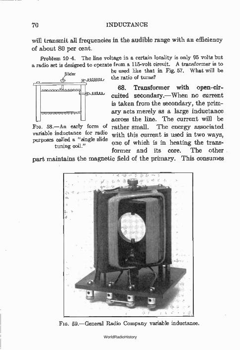
will transmit all frequencies in the audible range with an efficiency of about 80 per cent.
Problem 10-4. The line voltage in a certain locality is only 95 volts but a radio set is designed to operate from a 115-volt circuit. A transformer is to
be used like that in Fig. 57. What will be the ratio of turns?
68. Transformer with open-cir-cuited secondary.—When no current is taken from the secondary, the prim-ary acts merely as a large inductance across the line. The current will be
Flo. 58.—An early form of rather small. The energy associated variable inductance for radio with this current is used in two ways, purposes called a "single slide
one of which i tuning coil s in heating the trans-." former and its core. The other
part maintains the magnetic field of the primary. This consumes
70 INDUCTANCE
Slider
F G. 59.—General Radio Company variable inductance.
WorldRadioHistory
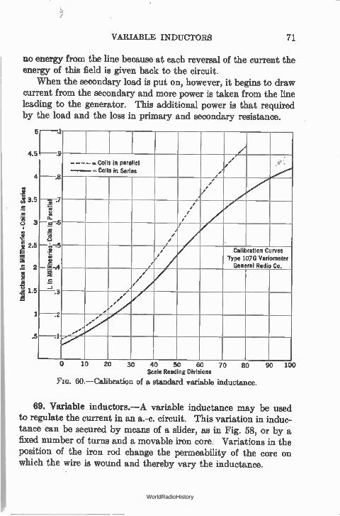
VARIABLE INDUCTORS 71
no energy from the line because at each reversal of the current the energy of this field is given back to the circuit.
When the secondary load is put on, however, it begins to draw current from the secondary and more power is taken from the line leading to the generator. This additional power is that required by the load and the loss in primary and secondary resistance.
4.5
4
3.5 .c
a c.) 3
f, 2.5
2 8
1.5 e
.5
'P i In
1
IL i
n Millihenries- Coils
in P
arallel
4.•
to
---- - — cons in Parallel Coils in Series •
/ •
/. ' '
• /
• • / -,
/ / /
• / /
•
ff / /
/
/ Calibration Curves
Type 107G Variometer General Radio Co.
e
/ / /
/
. J
r .
... ,
ett e
.2
„
7
.1
10 20 30 40 50 60 70 80 Scale Reading Divisions
FIG. 60.— Calibration of a standard variable inductance.
90 100
69. Variable inductors.—A variable inductance may be used to regulate the current in an a.-c. circuit. This variation in induc-tance can be secured by means of a slider, as in Fig. 58, or by a fixed number of turns and a movable iron core. Variations in the position of the iron rod change the permeability of the core on which the wire is wound and thereby vary the inductance.
WorldRadioHistory
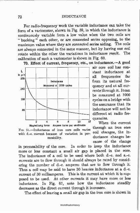
72 INDUCTANCE
For radio-frequency work the variable inductance can take the form of a variometer, shown in Fig. 59, in which the inductance is continuously variable from a low value when the two coils are " bucking " each other, or are connected series opposing, to the maximum value where they are connected series aiding. The coils are always connected in the same manner, but by having one coil rotate within the other the variations in inductance result. The calibration of such a variometer is shown in Fig. 60.
70. Effect of current, frequency, etc., on inductance.—A good air core coil has con-stant inductance at
In 3 all frequencies far
from its natural fre-
2 quency and at all cur-
rents through it. It can be measured at 1000
1 cycles on a bridge with the assurance that its inductance will not be different at radio fre-quencies.
2 4 6 8 10 12 When the current Magnetizing force Ampere turns per centimeter
. through an iron core 61.—Inductance of iron core coils varies ,
with d.-c. current because of variation in per- coil changes, the in-meability. ductance changes be-
cause of the change in permeability of the core. In order to keep the inductance more or less constant a small air gap is placed in the core. The inductance of a coil to be used where both d.-c. and a.-c. currents are to flow through it should always be rated by consid-ering the number of d.-c. amperes that are to flow through it. Thus a coil may be said to have 30 henries inductance at a d.-c. current of 30 milliamperes. This is the current at which it is sup-posed to be used. At other currents it may have more or less inductance. In Fig. 61, note how the inductance steadily decreases as the direct current through it increases.
The effect of leaving a small air gap in the iron core is shown in
t h
20
Measured
Inductance
a 1000 cy les
40
60
80
WorldRadioHistory
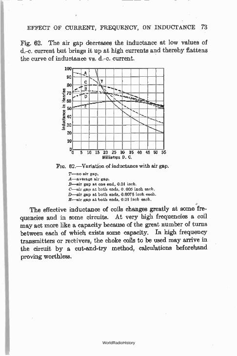
EFFECT OF CURRENT, FREQUENCY, ON INDUCTANCE 73
Fig. 62. The air gap decreases the inductance at low values of d.-c. current but brings it up at high currents and thereby flattens the curve of inductance vs. d.-c. current.
10
9
8
7
5
Fo 4
e 3
— 2
1
, - — ......e , ,... I
8 ......... ..0"... l'-- --- -
s
D • ---• ‘.
, ..., e"
., ..«.e. -4:i.
..........
1 ,......
1
...._ ....,......
I
I
i 0 5 10 15 20 25 30 35
Milliamps D. C. 40 45 50 55
FIG. 62.—Variation of inductance with air gap.
T—no air gap. A—average air gap. B—air gap at one end, 0.01 inch. C—air gap at both ends, 0.005 inch each. D—air gap at both ends, 0.0075 inch each. E—air gap at both ends, 0.01 inch each.
The effective inductance of coils changes greatly at some fre-quencies and in some circuits. At very high frequencies a coil may act more like a capacity because of the great number of turns between each of which exists some capacity. In high frequency transmitters or recèivers, the choke coils to be used may arrive in the circuit by a cut-and-try method, calculations beforehand proving worthless.
WorldRadioHistory
CHAPTER V
CAPACITY
THERE are two essential electrical quantities in every radio cir-cuit. These are inductance and capacity. They are represented in the circuit by the coils and the condensers. Upon their relative sizes depends the wavelength or frequency to which the receiver or transmitter is tuned. Resistance is always present too, but the effort of all radio engineers is to reduce the resistance and to over-come the losses in power due to its presence, just as mechanical engineers deplore the share of power wasted in mechanical friction.
71. Capacity.—Inductance has been likened to inertia. In an alternating-current circuit, it tends to prevent changes in the cur-rent flowing. Inductance is a property of a circuit ; so is capacity. It is not something one can see, or feel, or hear; one cannot see, or feel, or hear electricity. We are only aware of it by the work it does. Inductance in concentrated form is possessed by coils. Whenever a coil has an alternating current flowing through it, the inductance is one of its important qualities. Capacity in concen-trated form exists in condensers formed by conductors which are insulated from each other. Electricity can be stored in a con-denser. This capacity tends to prevent any change in the elec-trical pressure or voltage which exists between these objects.
72. Capacity as a reservoir.—In an electrical circuit, a con-denser serves the same purpose that the familiar standpipe or water tower serves in the water supply system of a city. The water tower maintains a constant water pressure regardless of the number of small drains from it, and regardless of the fact that the pumps filling the tower put water into it in spurts, not in a steady stream as comes from one's garden hose.
74 WorldRadioHistory
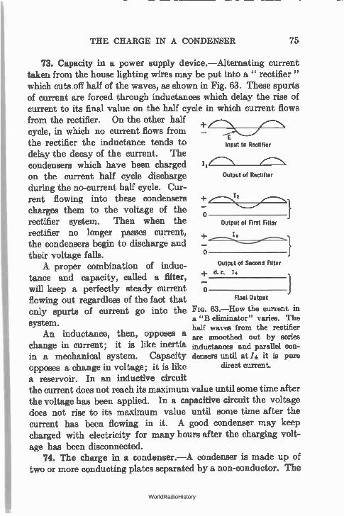
THE CHARGE IN A CONDENSER 75
73. Capacity in a power supply device.—Alternating current taken from the house lighting wires may be put into a " rectifier " which cuts off half of the waves, as shown in Fig. 63. These spurts of current are forced through inductances which delay the rise of current to its final value on the half cycle in which current flows from the rectifier. On the other half cycle, in which no current flows from the rectifier the inductance tends to delay the decay of the current. The condensers which have been charged on the current half cycle discharge during the no-current half cycle. Cur-rent flowing into these condensers charges them to the voltage of the rectifier system. Then when the rectifier no longer passes current, the condensers begin to discharge and their voltage falls. A proper combination of induc-
tance and capacity, called a filter, will keep a perfectly steady current flowing out regardless of the fact that only spurts of current go into the system.
An inductance, then, opposes a change in current; it is like inertia in a mechanical system. Capacity opposes a change in voltage; it is like a reservoir. In an inductive circuit the current does not reach its maximum value until some time after the voltage has been applied. In a capacitive circuit the voltage does not rise to its maximum value until some time after the current has been flowing in it. A good condenser may keep charged with electricity for many hours after the charging volt-age has been disconnected.
74. The charge in a condenser.—A condenser is made up of two or more conducting plates separated by a non-conductor. The
E Input to Rectifier
/ Output of Rectifier
o Output of First Filter
+ I,
o Output of Second Filter
▪ d. C. 14
O Final Output
FIG. 63.—How the current in a "B eliminator" varies. The half waves from the rectifier are smoothed out by series inductances and parallel con-densers until at /4 it is pure
direct current.
WorldRadioHistory
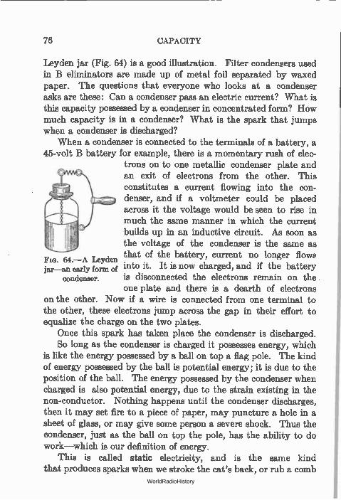
76 CAPACITY
Leyden jar (Fig. 64) is a good illustration. Filter condensers used in B eliminators are made up of metal foil separated by waxed paper. The questions that everyone who looks at a condenser asks are these: Can a condenser pass an electric current? What is this capacity possessed by a condenser in concentrated form? How much capacity is in a condenser? What is the spark that jumps when a condenser is discharged?
When a condenser is connected to the terminals of a battery, a 45-volt B battery for example, there is a momentary rush of elec-
trons on to one metallic condenser plate and an exit of electrons from the other. This constitutes a current flowing into the con-denser, and if a voltmeter could be placed across it the voltage would be seen to rise in much the same manner in which the current builds up in an inductive circuit. As soon as the voltage of the condenser is the same as that of the battery, current no longer flow into it. It is now charged, and if the battery is disconnected the electrons remain on the one plate and there is a dearth of electrons
on the other. Now if a wire is connected from one terminal to the other, these electrons jump across the gap in their effort to equalize the charge on the two plates.
Once this spark has taken place the condenser is discharged. So long as the condenser is charged it possesses energy, which
is like the energy possessed by a ball on top a flag pole. The kind of energy possessed by the ball is potential energy; it is due to the position of the ball. The energy possessed by the condenser when charged is also potential energy, due to the strain existing in the non-conductor. Nothing happens until the condenser discharges, then it may set fire to a piece of paper, may puncture a hole in a sheet of glass, or may give some person a severe shock. Thus the condenser, just as the ball on top the pole, has the ability to do work—which is our definition of energy.
This is called static electricity, and is the same kind that produces sparks when we stroke the cat's back, or rub a comb
Fla. 64.—A Leyden jar—an early form of
condenser.
WorldRadioHistory
QUANTITY OF ELECTRICITY IN A CONDENSER 77
on a coat sleeve, or the kind of electricity that jumps from one cloud to another on a hot summer day.
75. The quantity of electricity in a condenser.—The quantity of electricity that rushes into a condenser when it is connected to a battery is a perfectly definite quantity and can be calculated or measured. This quantity, Q, rated in coulombs, depends upon two factors only, the capacity of the condenser and the charging voltage. The capacity of the condenser depends only upon the physical make-up of the condenser, that is, (1) the size of the con-ducting plates, (2) the nature of the non-conductor called the dielectric, and (3) the distance apart of the plates. The quantity Q is proportional to both these factors, and may be expressed as
Q (coulombs) = C (capacity) X E (voltage).
The unit of capacity is the farad, named from Michael Faraday, and is the capacity of the condenser whose voltage is raised 1 volt when 1 coulomb of electricity is added to it; or vice versa, the capacity of the condenser to which 1 coulomb of electricity can be added by an externally applied voltage of 1 volt. This is a very large unit and in practice engineers have to deal with mil-lionths of farads, or microfarads. A smaller unit yet, micro-micro-farad, is used in some radio circuits. This is equal to 10-12 farads. Another unit is the centimeter of capacity. It is equal to 1.1124 micro-microfarads.
We write the above expression as
Q (coulombs) C (farads) -
E (volts)
This expression shows that the capacity of a condenser is the ratio between the quantity of electricity in it and the voltage across it.
The third way of stating the relation between capacity, quan-tity, and voltage, defines the voltage:
Q (quantity) E (voltage) - •
C (capacity).
WorldRadioHistory
78 CAPACITY
A discharged condenser, of course, has no electricity, Q, in it and hence no voltage across it. When it is connected to a battery, a voltage is built up across the two plates, the value of this voltage being given at any instant by the ratio between the quantity, Q, and the capacity, C, of the condenser. The greater the quantity of electricity stored on the conducting plates, the greater the voltage. When the battery is removed the quantity of electricity remains and, of course, a voltage, E, exists between the two plates.
76. Time of charge.—Since an ampere is a rate of flow of cur-rent, that is, 1 coulomb per second, one can calculate the rate at which current flows into a condenser provided the quantity, Q, and the time, t, are known. The amperes before the condenser is attached to the battery are zero, at the completion of the charging process the amperes are zero. The average rate, then, is what one secures from the equation,
I =t.
Example 1-5. A condenser of 15 microfarads is attached to a 220-volt circuit. What quantity of electricity flows into it? If it requires 1/200 second to charge it, what is the average current?
Q=CxE = 15 X 10 -6 X 220
= 3300 X 10 -4
=-- .0033 coulomb.
I--t
.0033
.005
= .66 ampere.
This is also the average rate of discharge if the time of complete discharge
is 1/200 second. Problem 1-5. What is the capacity of a condenser that holds .0024
coulombs when attached to 220 volts? Problem 2-5. In a radio circuit is a .0005-mfd. (500 mmfd.) condenser
across a 500-volt source. What quantity of electricity will flow into it? Problem 3-5. What voltage will be necessary to put 0.012 coulomb into
the condenser of Problem 1?
WorldRadioHistory
ENERGY IN A CONDENSER 79
Problem 4-6. The average charging current in Problem 1 is 2 amperes. How long will it take to charge the condenser?
Problem 5-5. Suppose the average voltage across a condenser when it is being discharged is one-half the voltage when fully charged. Connect a 10-ohm resistance across the condenser of Problem 1. What average current flows? What is the average power used to heat the wire?
Problem 6-5. How long would it take to discharge the condenser in Problem 5? If the resistance is doubled, what power is used up in heat and how long will it take to discharge the condenser?
77. Energy in a condenser.—The amount of energy that can be stored in a condenser in the form of static electricity can be com-puted from the formula:
energy = C E2.
This represents the work done in charging the condenser, and naturally represents the energy released if the condenser is dis-charged.
Similarly, the energy in the lines of force about a coil through which an a.-c. current flows is equal to L 12.
The unit of energy or work is the joule. It is the amount of work required to force one coulomb of electricity through a one ohm resistance. Thus if a 1-mfd. condenser is charged to a voltage of 500, the energy is
X 1 X 10-6 X 500 2 = .125 joule.
Since power is the rate of doing work, we can find the power required to charge such a condenser in one second of time by dividing the above expression by one second. Thus
1 C E2 Power in watts -
2 t
and if we attach the condenser to a secondary of a 500-volt trans-former which charges the condenser 120 times a second (60-cycle current) the power will be = C E2 X 120 provided the condenser is permitted to discharge each time it is charged. Thus the smaller the time, the greater the power required to charge the condenser.
WorldRadioHistory
80 CAPACITY
A general expression for such a problem is
Power = CE2N,
if N is the times per second the condenser is charged and dis-charged.
Example 2-5. A condenser in a transmitting station has a capacity of .001 mfd. and is charged with a 20,000-volt source. What energy goes into the condenser and what power is required to charge it 120 times a second (60-cycle source)?
Energy or work, W = 4 CE2
= 4 X .001 X 10 -2 X 20,0002
= 0.2 joule.
Power, P W XN
= 4CE2N
-= 0.2 X 120
= 24 watts..
Problem 7-5. If the generator in the example above were a 500-cycle generator, what would be the power taken from it?
Problem 8-5. How much power is required to charge a 1-mfd. condenser to a voltage of 220, 120 times a second?
Problem 9-5. A transmitting antenna has a capacity of .0005 tnfd. It is desired to transmit 1 kw. of power. To what voltage must the antenna be charged from a 500-cycle source?
Problem 10-5. Suppose an antenna is to be supplied with 500 watts of power and that between the charging mechanism and the antenna exists an efficiency of 30 per cent. The condenser, which discharges into the antenna, has a capacity of 0.012 mfd., and the generator which charges the condenser is a 500-cycle machine. A transformer is used to step up the voltage 110 from the generator to the value required by the condenser. What is the secondary voltage of the transformer and what is the turns ratio between secondary and primary? NOTE: Remember that a 500-cycle generator charges a condenser 1000 times a second.
78. Electrostatic and electromagnetic fields.—The energy exist-ing in an inductive circuit is said to exist in the electromagnetic field surrounding the inductance. This field is made up of lines of force and can be explored with a compass, or by sprinkling iron filings on paper as in Fig. 42.
The energy in a condenser is said to exist in the electrostatic field. This is the locality in which the electrical strain exists, that
WorldRadioHistory
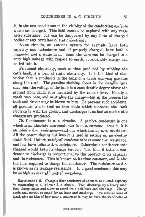
CONDENSERS IN A.-C. CIRCUITS 81
in, in the non-conductors in the vicinity of the conducting surfaces which are charged. This field cannot be explored with any mag-netic substance, but can be discovered by any form of charged bodies or any container of static electricity.
Some circuits, an antenna system fo- example, have both capacity and inductance and, if properly charged, have both a magnetic and a static field. Since the wire can be charged to a, very high voltage with respect to earth, considerably energy can be fed into it.
Frictional electricity, such as that produced by rubbing the cat's back, is a form of static electricity. It is this kind of elec-tricity that is produced in the tank of a truck carrying gasoline along the road. The gasoline sloshing about in the metallic tank may iaise the voltage of the tank to a considerable degree above the ground from which it is insulated by the rubber tires. Finally a spark may pass, and neutralize the charge—but in the process the tank and driver may be blown to bits. To prevent such accidents, all gasoline trucks trail an iron chain which connects the tank electrically with the ground and discharges it as fast as such static charges are produced. s
79. Condensers in a.-c. circuits.—A perfect condenser is one which is an absolute non-conductor to d.-c. currents—that is, it is an infinite d.-c. resistance—and one which has no a.-c. resistance. All the power that is put into it is used in setting up an electro-static field. Unfortunately all condensers have some a.-c. resistance, and few have infinite d.-c. resistance. Otherwise a condenser once charged would keep its charge forever. The time it takes a con-denser to discharge is proportional to the product of its capacity and its resistance. This is known as its time constant, and is also the time required to charge the condenser. The resistance to d.c. is known as its leakage resistance. In a good condenser this may be as high as several hundred megohms.
Experiment 1-5. Charge a filter condenser of about 2- to 10-mid, capacity by connecting to a 110-volt d.-c. circuit. Then discharge by a heavy wire; then charge again and allow to stand for a half-hour and discharge. Charge again and permit to stand for an hour and discharge. The relative sizes of spark give an idea of how poor a condenser it may be from the standpoint of
WorldRadioHistory
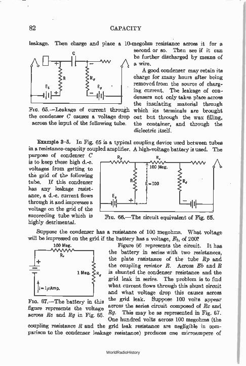
82 CAPACITY
leakage. Then charge and place a 10-megohm resistance across it for a second or so. Then see if it can be further discharged by means of a wire. A good condenser may retain its
charge for many hours after being removed from the source of charg-ing current. The leakage of con-densers not only takes place across the insulating material through
65.—Leakage of current through which its terminals are brought the condenser C causes a voltage drop out but through the wax filling, across the input of the following tube. the container, and through the
dielectric itself.
Example 3-5. In Fig. 65 is a typical coupling device used between tubes in a resistance-capacity coupled amplifier. A high-voltage battery is used. The purpose of condenser C Rp R,
is to keep these high d.-c. voltages from getting to 100 Meg.
the grid of the following tube. If this condenser E..100 has any leakage resist-ance, a d.-c. current flows E,
through it and impresses a voltage on the grid of the succeeding tube which is Fm. 66.—The circuit equivalent of Fig. 65 highly detrimental.
Suppose the condenser has a resistance of 100 megohms. What voltage will be impressed on the grid if the battery has a voltage, Eb, of 2007
100 Meg. Figure 66 represents the circuit. It has R the battery in series with two resistances, .
the plate resistance of the tube Rp and the coupling resistor R. Across Rb and R
«MO
1.ffl• 1 Meg. Rp is shunted the condenser resistance and the grid leak in series. The problem is to find what current flows through this shunt circuit and what voltage drop this causes across
FIG. 67.—The battery in this the grid leak. Suppose 100 volts appear figure represents the voltage across the series circuit composed of Rc and across Rc and Rg in Fig Rg. This may be as represented in Fig. 67. . 65.
One hundred volts across 100 megohms (the coupling resistance I? and the grid leak resistance are negligible in com-parison to the condenser leakage resistance) produces one microampere of
11.411Ame.
WorldRadioHistory
CONDENSERS IN GENERAL 83
current. This one microampere flowing through the grid leak of one megohm produces a voltage of 1 volt. This voltage is of a polarity that is opposite to the C bias and therefore decreases its value. In addition a certain amount of noise may be developed by the d.-c. current flowing through this condenser and grid leak. This noise is directly impressed on the input to the amplifier tube and may assume large values when amplified by succeeding stages. Condensers used in resistance amplifiers must have a high resistance.
80. Power loss in condensers.—A pure inductance takes no power from an a.-c. line once the magnetic field is established. If, however, the coil has resistance, power is wasted in heating it. Similarly, a perfect condenser, that is, one having no resistance, wastes no power. If the condenser has resistance—and all have— power is wasted in heat when it is connected to a source of current, whether a d.-c. or an a.-c. source. This power in watts is the cur-rent squared times the resistance.
81. Condenser tests.—If a voltmeter, a battery, and a con-denser are connected in series a momentary deflection will be noted if the condenser is good. If the condenser is leaky, a constant deflection will be noted. If the condenser is fairly large, one or two microfarads, and no deflection is noted, the condenser is probably open. If the full battery voltage is read by the meter, the con-denser is shorted.
If a condenser that has been determined to be not shorted is placed across a battery and then a pair of phones is placed across the condenser, a click will indicate that the condenser is good. The click is the discharge of the condenser through the phones.
82. Condensers in general.—A condenser, then, is any object with two or more conducting plates separated by a non-conductor called the dielectric. A cloud filled with moisture is a good con-ductor. So is the earth. The cloud may be a mile or so above the earth and subjected to all sorts of electrical differences of potential. It may become charged with respect to the earth. When this charge becomes great enough to jump the gap, a spark passes, and the condenser is discharged. This is known to us as lightning. Small discharges between parts of a cloud or between two clouds may cause only small sparks and are made known to us by " static."
The earth is considered as being at zero potential. All ob-jects not connected to earth have a higher voltage than the earth.
WorldRadioHistory
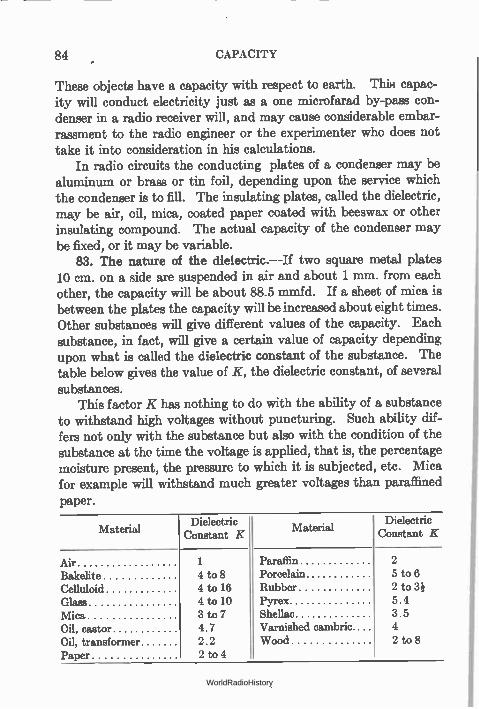
84 CAPACITY
These objects have a capacity with respect to earth. This capac-ity will conduct electricity just as a one microfarad by-pass con-denser in a radio receiver will, and may cause considerable embar-rassment to the radio engineer or the experimenter who does not take it into consideration in his calculations.
In radio circuits the conducting plates of a condenser may be aluminum or brass or tin foil, depending upon the service which the condenser is to fill. The insulating plates, called the dielectric, may be air, oil, mica, coated paper coated with beeswax or other insulating compound. The actual capacity of the condenser may be fixed, or it may be variable.
83. The nature of the dielectric.--If two square metal plates 10 cm. on a side are suspended in air and about 1 mm. from each other, the capacity will be about 88.5 mmfd. If a sheet of mica is between the plates the capacity will be increased about eight times. Other substances will give different values of the capacity. Each substance, in fact, will give a certain value of capacity depending upon what is called the dielectric constant of the substance. The table below gives the value of K, the dielectric constant, of several substances.
This factor K has nothing to do with the ability of a substance to withstand high voltages without puncturing. Such ability dif-fers not only with the substance but also with the condition of the substance at the time the voltage is applied, that is, the percentage moisture present, the pressure to which it is subjected, etc. Mica for example will withstand much greater voltages than paraffined paper.
Material Dielectric
Constant K
Air Bakelite Celluloid Glass Mica Oil, castor Oil, transformer Paper
1 4 to 8 4 to 16 4 to 10 3 to 7 4.7 2.2 2 t,o 4
Material Dielectric
Constant K
Paraffin Porcelain Rubber Pyrex Shellac Varnished cambric Wood
2 5 to 6 2 to 3¡ 5.4 3.5 4 2 to 8
WorldRadioHistory
CONDENSER CAPACITY FORMULAS 85
84. Sizes of radio condensers.—The farad is a very large unit. In radio work the capacities used vary from a few million millionths of a farad to several millionths of farads. A millionth of a farad is known as a microfarad, and a millionth of this value is called a micro-microfarad. These are related as shown below.
One farad equals one million mfd, and one million million mmfd
One mfd. equals one millionth farad and one million mmfd. One mmfd. equals one million millionth farad, and one mil-
lionth mid.
Sometimes the centimeter is used as a unit of capacity. It is equal to 1.1124 micro-mi crofarads.
85. Condenser capacity formulas.—Formulas have been worked out by which it is possible to compute the capacity of condensers of various forms. For example the capacity of two flat conducting plates separated by a non-conductor may be computed from the formula :
885 XAXK C —
1010 X d
where C = capacity in microfarads; A = area of the metallic plate in square centimeters; K = dielectric constant of the non-conductor; d = thickness of dielectric in centimeters.
Or
C = 0.0885 KA d
where C = capacity in micro-microfarads; d = thickness in centimeters; A = area in square centimeters; K = dielectric constant.
Formulas for other types of condensers may be found in the Bureau of Standards Bulletin 74, Radio Instruments and Measure-ments, page 235.
WorldRadioHistory
86 CAPACITY
In receiving sets the tuning condensers are variable. The important function of separating one station from another is per-formed by changing the capacity of the condenser, which is called tuning the circuit. The tuning condensers have air as the dielec-tric and plates of various metals, usually brass or aluminum. The capacities range from 25 mmfd. to 100 mmfd. in a short-wave (high-frequency) receiver to 500 mmfd. for broadcast frequency receivers. Receivers for the long waves used in transoceanic com-munications are much larger. The above values of capacity may be written as .0001 and .0005 mfd. It is probably easier to express small capacities in micro-microfarads rather than in one of the larger units. Whenever an easy path for an alternating current is needed a fixed condenser is used. It is called a by-pass condenser.
Example 4-5. How many plates 16 X 20 cm. in area and separated by paraffined paper (K = 2.1) .005 cm. thick are required for a condenser of 24 mfd.?
885 AK C
1010d
885 x 16 X 20 X 2.1
101° X .005
= 0.0119 mfd. capacity per plate.
24 Number of plates 119 2200.
.0
Problem 11-5. Express in micro-microfarads: 0100 farad, 1 mfd., 0.00025 mfd. Express in farads: 500 mmfd., 0.01 mfd., -116- mfd. Express in micro-farads: 1 farad, 500 mmfd., 0.01 mmfd.
Problem 12-5. What is the capacity of two square plates suspended in air 0.1 mm. apart, if the plates are 10 cm. on a side?
Problem 13-5. A variable tuning condenser has a capacity of 0.001 when air is used as dielectric. Suppose the container is filled with castor oil. What is the capacity now?
Problem 14-5. Lead foil plates are separated by mica 0.1 mm. thick having a dielectric constant of 6. What is the capacity of a condenser made up of 200 pairs of such plates?
Problem 15-5. How many joules of enemy can be stored in such a con-denser as in Problem 14 when 100 volts are impressed across it? How much power will it take to charge it to this voltage 120 times a second?
WorldRadioHistory
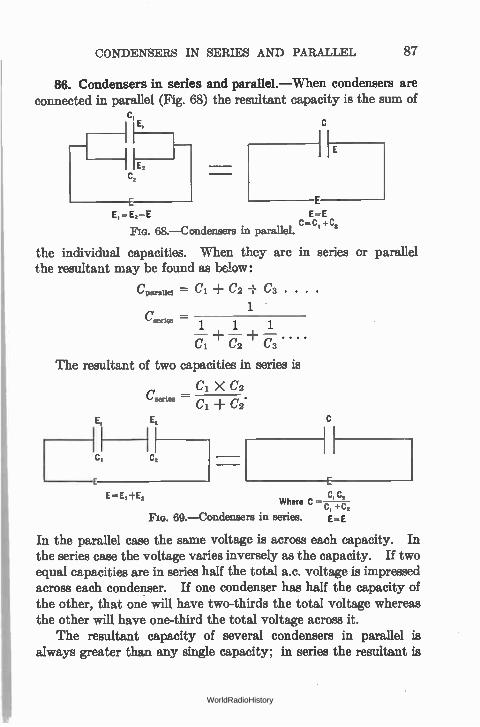
CONDENSERS IN SERIES AND PARALLEL 87
86. Condensers in series and parallel.—When condensers are connected in parallel (Fig. 68) the resultant capacity is the sum of
Ci c,
I Et E
E E,-E2-E
+C 68.—Condensers in parallel.
the individual capacities. When they are in series or parallel the resultant may be found as below:
Cparallel
Geerles
= Cl ± C2 C3 . . .
1
1 1 1
fi —+ — +—.... a
The resultant of two capacities in series is
Cl X C2
Cl C2.
C, C, Where C C +c,
Fia. 69.—Condensers in series. E= E
In the parallel case the same voltage is across each capacity. In the series case the voltage varies inversely as the capacity. If two equal capacities are in series half the total a.c. voltage is impressed across each condenser. If one condenser has half the capacity of the other, that one will have two-thirds the total voltage whereas the other will have one-third the total voltage across it.
The resultant capacity of several condensers in parallel is always greater than any single capacity; in series the resultant is
WorldRadioHistory
88 CAPACITY
less than the capacity of the smallest of the group. In series the voltage across each condenser varies inversely as its capacity and is always less than the total voltage across the combination. When a condenser is placed in an a.-c. circuit whose voltage is more than the condenser can tolerate, it is only necessary to use two or more condensers in series so that the voltage across individual members of the group is below the danger limit, and so that the total capacity in the circuit is the value desired.
When condensers are used across d.-c. circuits, as in filter circuits, the d.-c. resistance of the condenser becomes of impor-tance. If two condensers in series across a certain d.-c. voltage have equal capacities but different d.-c. resistances, the voltage drop across the two condensers will differ. The voltage across one of them may be sufficient to destroy it.
Example 5-5. In a radio circuit a .0005-mfd. variable condenser is avail-able but the circuit calls for a .00035-mfd. condenser. What fixed condenser may be used to reduce the maximum capacity in the circuit to the proper value? How shall it be connected?
Solution. Since the total capacity is to be reduced, the fixed condenser must be connected in series with the variable condenser. The total capacity is given as 0.00035 mfd. This is equal, from the above equation, to
C X C2 .00035 — I CI
.0005 X C2
.0005 -F C2
whence C2 = .001166 or 1166 mmfd.
Problem 16-5. Whenever the capacity of a tuning circuit is quadrupled, the inductance remaining constant, the wavelength is doubled and the fre-quency is halved. A broadcast receiver tunea to 600 meters (500 kc.) with a 500-mmfd. condenser. What maximum capacity must be put in parallel with this condenser in order to receive 800-meter (375-kc.) radio compass signals and ship-to-shore traffic on 2,200 meters? Ans. 390 mmfd., 6250 mmfd.
WorldRadioHistory
CHAPTER VI
PROPERTIES OF ALTERNATING-CURRENT CIRCUITS
THE two kinds of current in common use are: direct currents (d.c.) which have a more or less constant value and which flow in the same direction all the time; and alternating currents (a.c.) in which not only is the magnitude constantly changing but the direction also.
87. Definitions used in a.-c. circuits.—When the voltage (or current) has started from zero, risen to its maximum value in one direction, decreased to zero and risen to maximum value in the opposite direction and finally come back to its starting value and point, zero, it is said to have completed a cycle. Ordinary house-lighting current which has a frequency of 60 cycles per second goes through this cyclic change in magnitude and direction 60 times a second. The frequency is the number of times a second a cycle is completed. An alternation is half a cycle; that is, when the voltage has gone from zero to zero through one maximum it is said to have completed one alternation. In 60-cycle circuits there are 120 alter-nations per second. In a.-c. circuits we must consider the element of time; in d.-c. circuits time does not enter; the magnitude of the current is constant.
Alternating currents exist of nearly all ranges of frequencies. Sixty cycles is the common power frequency; tones generated by audio-frequency oscillators for testing purposes may go from almost zero frequency to as high as the human ear can hear, that is, about 13,000 cycles per second depending upon the person. Electric waves of frequences as low as 15,000 cycles exist. They are gen-erated in the long wave high-power radio stations carrying on transoceanic communication. From that value radio frequencies
89
WorldRadioHistory
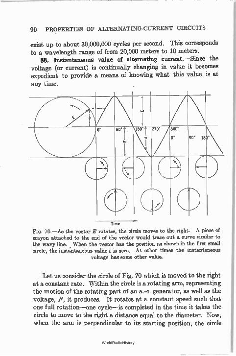
90 PROPERTIES OF ALTERNATING-CURRENT CIRCUITS
exist up to about 30,000,000 cycles per second. This corresponds to a wavelength range of from 20,000 meters to 10 meters.
88. Instantaneous value of alternating current.—Since the voltage (or current) is continually changing in value it becomes expedient to provide a means of knowing what this value is at any time.
0 90 180 2 70 ° 360
0° 90° 180°
ED
0 ,--CP
Time
FIG. 70.—As the vector E rotates, the circle moves to the right. A piece of crayon attached to the end of the vector would trace out a curve similar to the wavy line. When the vector has the position as shown in the first small circle, the instantaneous value e is zero. At other times the instantaneous
voltage has some other value.
Let us consider the circle of Fig. 70 which is moved to the right at a constant rate. Within the circle is a rotating arm, representing the motion of the rotating part of an a.-c. generator, as well as the voltage, E, it produces. It rotates at a constant speed such that one full rotation—one cycle—is completed in the time it takes the circle to move to the right a distance equal to the diameter. Now, when the arm is perpendicular to its starting position, the circle
WorldRadioHistory
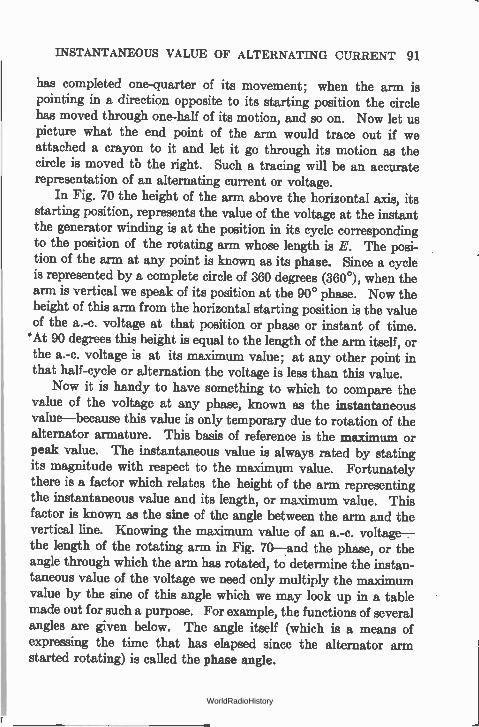
INSTANTANEOUS VALUE OF ALTERNATING CURRENT 91
has completed one-quarter of its movement; when the arm is pointing in a direction opposite to its starting position the circle has moved through one-half of its motion, and so on. Now let us picture what the end point of the arm would trace out if we attached a crayon to it and let it go through its motion as the circle is moved tb the right. Such a tracing will be an accurate representation of an alternating current or voltage.
In Fig. 70 the height of the arm above the horizontal axis, its starting position, represents the value of the voltage at the instant the generator winding is at the position in its cycle corresponding to the position of the rotating arm whose length is E. The posi-tion of the arm at any point is known as its phase. Since a cycle is represented by a complete circle of 360 degrees (3600), when the arm is vertical we speak of its position at the 90° phase. Now the height of this arm from the horizontal starting position is the value of the a.-c. voltage at that position or phase or instant of time. 'At 90 degrees this height is equal to the length of the arm itself, or the a.-c. voltage is at its maximum value; at any other point in that half-cycle or alternation the voltage is less than this value.
Now it is handy to have something to which to compare the value of the voltage at any phase, known as the instantaneous value—because this value is only temporary due to rotation of the alternator armature. This basis of reference is the maximum or peak value. The instantaneous value is always rated by stating its magnitude with respect to the maximum value. Fortunately there is a factor which relates the height of the arm representing the instantaneous value and its length, or maximum value. This factor is known as the sine of the angle between the arm and the vertical line. Knowing the maximum value of an a.-c. voltage— the length of the rotating arm in Fig. 70—and the phase, or the angle through which the arm has rotated, to determine the instan-taneous value of the voltage we need only multiply the maximum value by the sine of this angle which we may look up in a table made out for such a purpose. For example, the functions of several angles are given below. The angle itself (which is a means of expressing the time that has elapsed since the alternator arm started rotating) is called the phase angle.
WorldRadioHistory
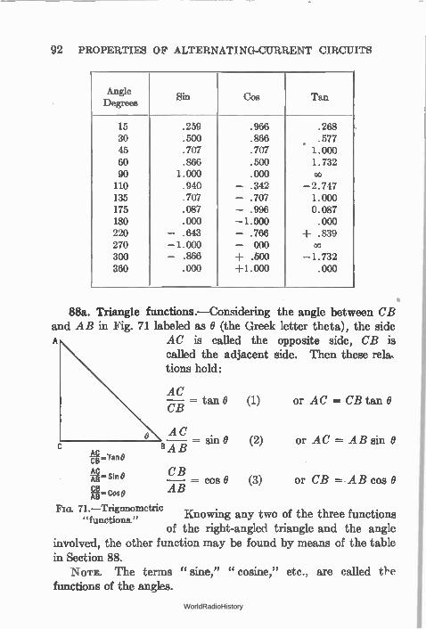
92 PROPERTIES OF ALTERNATING-CURRENT CIRCUITS
Angle Degrees
Sin Cos Tan
15 .259 .966 .268 30 .500 .866 .577 45 .707 .707 . 1.000 60 .866 .500 1.732 90 1.000 .000 oo 110 .940 - .342 -2.747 135 .707 - .707 1.000 175 .087 - .996 0.087 180 .000 -1.000 .000 220 - .643 - .766 +.839 270 -1.000 - 000 co 300 - .866 ± .500 -1.732 360 .000 +1.000 .000
88a. Triangle functions.-Considering the angle between CB and AB in Fig. 71 labeled as 0 (the Greek letter theta), the side
AC is called the opposite side, CB is called the adjacent side. Then these re'a. tions hold:
AC cB =Tan
AC -AB= Sin
CB -AB= Cone
AC = tan 0 (1) or AC = CB tan 0
AC
BAB
CB
AB
sin 0 (2) or AC = AB sin 0
= cos O (3) or CB = AB cos 0
Fra. 71.-Trigonometric "functions." Knowing any two of the three functions
of the right-angled triangle and the angle involved, the other function may be found by means of the table in Section 88. NOTE. The terms "sine," "cosine," etc., are called the
functions of the angles.
WorldRadioHistory
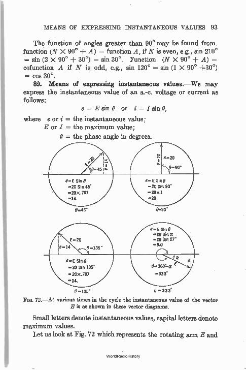
MEANS OF EXPRESSING INSTANTANEOUS VALUES 93
The function of angles greater than 90° may be found from. function (N X 90° + A) = function A, if N is even, e.g., sin 210° = sin (2 X 90° + 30°) = sin 30°. Function (N X 90° A) = cofunction A if N is odd, e.g., sin 120° = sin (1 X 90° +30°) = cos 30°.
89. Means of expressing instantaneous values.—We may express the instantaneous value of an a.-c. voltage or current as follows:
e = E sin 0 or i = / sin 0,
where e or i = the instantaneous value; E or I = the maximum value;
O = the phase angle in degrees.
e— E Sin 0 —20 Sin 90° —20x1 —20
0=45'
.---e-.E Sin 0 —20 Sin« =20 Sin 27' —9.0
e—E Sin O
—20 Sin 135'
—20x.707
-.14.
0-135 ° — 33 3°
72.—At various times in the cycle the instantaneous value of the vector E is as shown in these vector diagrams.
Small letters denote instantaneous values, capital letters denote maximum values.
Let us look at Fig. 72 which represents the rotating arm E and
WorldRadioHistory
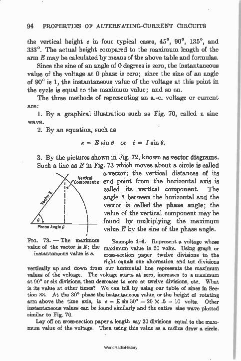
Phase Angle O
94 PROPERTIES OF ALTERNATING-CURRENT CIRCUITS
the vertical height e in four typical cases, 45°, 90°, 135°, and 333°. The actual height compared to the maximum length of the arm E may be calculated by means of the above table and formulas.
Since the sine of an angle of 0 degrees is zero, the instantaneous value of the voltage at 0 phase is zero; since the sine of an angle of 90° is 1, the instantaneous value of the voltage at this point in the cycle is equal to the maximum value; and so on.
The three methods of representing an a.-c. voltage or current are:
1. By a graphical illustration such as Fig. 70, called a sine wave.
2. By an equation, such as
e = E sin O or i = I sin O.
3. By the pictures shown in Fig. 72, known as vector diagrams. Such a line as E in Fig. 73 which moves about a circle is called
a vector; the vertical distances of its ComponeVerticalnt e end point from the horizontal axis is
called its vertical component. The angle O between the horizontal and the vector is called the phase angle; the value of the vertical component may be found by multiplying the maximum value E by the sine of the phase angle.
FIG. 73. — The maximum value of the vector is E; the
instantaneous value is e.
Example 1-6. Represent a voltage whose maximum value is 20 volts. Using graph or cross-section paper twelve divisions to the right equals one alternation and ten divisions
vertically up and down from our horizontal line represents the maximum values of the voltage. The voltage starts at zero, increases to a maximum at 90° or six divisions, then decreases to zero at twelve divisions, etc. What is its value at other times? We can tell by using our table of sines in Sec-tion 88. At the 30° phase the instantaneous value, or the height of rotating arm above the time axis, is e = E sin 30° = 20 X .5 = 10 volts. Other instantaneous values can be found similarly and the entire sine wave plotted similar to Fig. 70.
Lay off on cross-section paper a length say 20 divisions equal to the maxi-mum value of the voltage. Then using this value as a radius draw a circle.
WorldRadioHistory
EFFECTIVE VALUE 95
Then the instantaneous value at any time in the cycle can be found by measur-ing the vertical distance of this point on the circle to the horizontal axis. Thus at the 30° phase the vertical distance is 10 because sin 30° = .5 This illustrated the vector diagram. A voltage of maximum value 20 may be represented mathematically as
e = 20 sin O
Problem 1-6. The maximum value of an alternating voltage is 110. What is its value at the following phases: 300? 60°? 110°? 180°7 270°? 300°? 360°?
Problem 2-6. The instantaneous value of an alternating voltage is 250 volts at 35°. What is its maximum value? What is its value at 135°7
Problem 3-6. The instantaneous value of an alternating voltage is 400 volts at 75°. Plot to some convenient scale its sine wave.
Note. In all this discussion voltages or currents can be spoken of with the same laws in mind. Thus the form of a sine wave of current looks exactly like the sine wave of voltage with the same maximum value. The vector diagram looks the same because it is only necessary to label the rotating arm I instead of E and the mathematical formula reads i = I sin O instead of e = E sin O. The answers to the above problems will be the same numerically whether we speak of voltage or current.
A word should be said, too, about the terminology frequently used in speaking of the voltages and currents in an a.-c. circuit. Engineers use the expression " a.-c. voltage" or " a.-c. current" for simplicity, not stopping to think that such an expression really is an abbreviation for " an alternating-current voltage" or for " alternating-current current." Although one would not say the latter, one often uses the abbreviation. In many radio circuits there are both a.-c. and d.-c. branches and in some or all of them both direct and alternating currents and voltages exist. It is simpler to speak of an " a.-c. voltage" than of an alternating e.m.f. and in the interest of simplicity this terminology has been employed here whenever it is useful.
90. Effective value of alternating voltage or current.—Since the voltage (or current) in an a.-c. system is rapidly changing direc-tion, and since the needle and mechanism of an ordinary d.-c. measuring instrument require appreciable time for a deflection, they cannot follow the rapid changes of voltage or current and would only wobble about the zero point of the meter even if they could fol-
WorldRadioHistory
96 PROPERTIES OF ALTERNATING-CURRENT CIRCUITS
low the fluctuations. We can, however, compare direct and alternating currents by noting their respective heating effects. An alternating current is said to be equal in value to a direct cur-rent of so-many amperes when it produces the same heating effect. This is known as the effective value of the alternating current and is equal to the maximum values multiplied by .707 or
divided by
Thus = .707 I = Jett* = 1.41
where /eff. = effective value of an alternating current; I = maximum value.
The effective value is also known as the root mean square or r.m.s. value for the following reasons. The heating effect of a direct current is proportional to the square of the current. Then if we take the instantaneous values of the current over a cycle of alternating current, square them, get an average of these values, extract the square root of this value, it will be equal to the direct-current value that will produce an identical heating effect. The value of current secured in this manner is .707 times the maximum value. Since it is the " square root of the average or mean squares" of several current values, it is abbreviated to the " root mean square " or r.m.s. An r.m.s. voltage is one that will produce a current whose heating effect is the same as a given direct current as discussed above.
= Eeff. =- .707 E = E.
and
E 'er(
= = E X VI .707 eff*
Voltage or current is considered as effective unless otherwise indicated or stated.
Example 2-6. What is the effective value of an alternating voltage whose maximum value is 100 volts?
E .707 .707 X 100 = 70.7 volts
Problem 4-6. The effective value of an alternating current is 12 amperes. What is the maximum value?
WorldRadioHistory
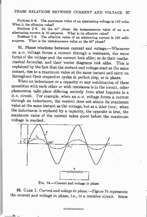
PHASE RELATIONS BETWEEN CURRENT AND VOLTAGE 97
Problem 5-6. The maximum value of an alternating voltage is 110 volts. What it the effective value?
Problem 0-6. At the 45° phase the instantaneous value of an a.-c. alternating current is 10 amperes. What is its effective value?
Problem 7-6. The effective value of an alternating current is 100 milli-amperes. What is the instantaneous value at the 60° phase?
91. Phase relations between current and voltage.—Whenever an a.-c. voltage forces a current through a resistance, the wave forms of the voltage and the current look alike; so do their mathe-matical formulas, and their vector diagrams look alike. This is explained by the fact that the current and voltage start at the same instant, rise to a maximum value at the same instant and carry on throughout their respective cycles in perfect step, or in phase.
When an inductance or a capacity or any combination of these quantities with each other or with resistance is in the circuit, other phenomena take place differing entirely from what happens in a d.-c. circuit. For example, when an a.-c. voltage forces a current through an inductance, the current does not attain its maximum value at the same instant as the voltage, but at a later time; when the inductance is replaced by a capacity, the opposite is true, the maximum value of the current takes place before the maximum voltage is reached.
74.—Current and and voltage in phase.
92. CASE I. Current and voltage in phase.—Figure 74 represents the current and voltage in phase, i.e., in a resistive circuit. Since
WorldRadioHistory
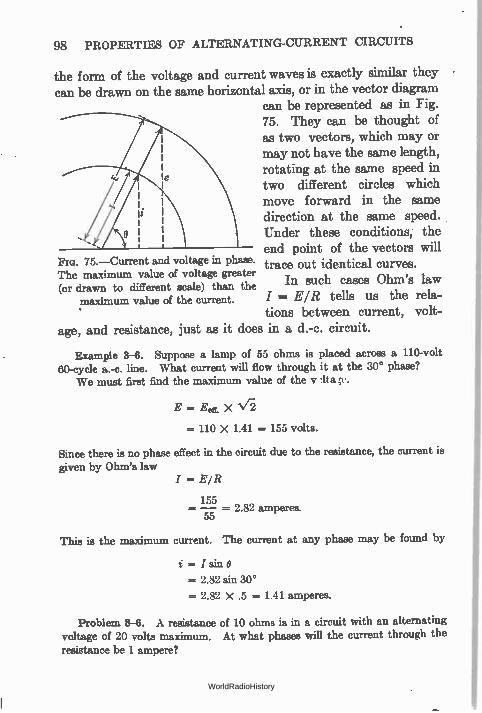
98 PROPERTIES OF ALTERNATING-CURRENT CIRCUITS
the form of the voltage and current waves is exactly similar they can be drawn on the same horizontal axis, or in the vector diagram
can be represented as in Fig. 75. They can be thought of as two vectors, which may or may not have the same length, rotating at the same speed in two different circles which move forward in the same direction at the same speed. Under these conditions, the end point of the vectors will
75.—Current and voltage in phase. trace out identical curves. The maximum value of voltage greater (or drawn to different scale) than the In such cases Ohm's law
maximum value of the current. / = E/R tells us the rela-tions between current, volt-
age, and resistance, just as it does in a d.-c. circuit.
Example 3-6. Suppose a lamp of 55 ohms is placed across a 110-volt 60-cycle a.-c. line. What current will flow through it at the 30° phase?
We must first find the maximum value of the y
E -= Eel!. X
= 110 X 1.41 = 155 volts.
Since there is no phase effect in the circuit due to the resistance, the current is given by Ohm's law
/ = E/ R
155 = 2.82 amperes.
--- 55
This is the maximum current. The current at any phase may be found by
i= /sine
= 2.82 sin 30°
=- 2.82 X .5 = 1.41 amperes.
Problem 8-6. A resistance of 10 ohms is in a circuit with an alternating voltage of 20 volts maximum. At what phases will the current through the resistance be 1 ampere?
WorldRadioHistory
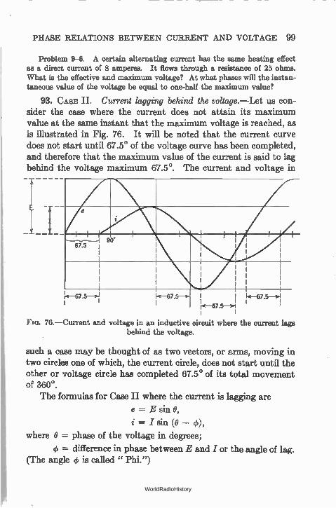
PHASE RELATIONS BETWEEN CURRENT AND VOLTAGE 99
Problem 9-6. A certain alternating current has the same heating effect as a direct current of 8 amperes. It flows through a resistance of 25 ohms. What is the effective and maximum voltage? At what phases will the instan-taneous value of the voltage be equal to one-half the maximum value?
93. CASE II. Current lagging behind the voltage.—Let us con-sider the case where the current does not attain its maximum value at the same instant that the maximum voltage is reached, as is illustrated in Fig. 76. It will be noted that the current curve does not start until 67.5° of the voltage curve has been completed, and therefore that the maximum value of the current is said to lag behind the voltage maximum 67.5°. The current and voltage in
ro-67.5—>1
76.—Current and voltage in an inductive circuit where the current lags behind the voltage.
such a case may be thought of as two vectors, or arms, moving in two circles one of which, the current circle, does not start until the other or voltage circle has completed 67.5° of its total movement of 360°.
The formulas for Case II where the current is lagging are
e = E sin 0,
i = I sin (e — 4)),
where 0 = phase of the voltage in degrees;
= difference in phase between E and / or the angle of lag. (The angle 4, is called " Phi.")
WorldRadioHistory
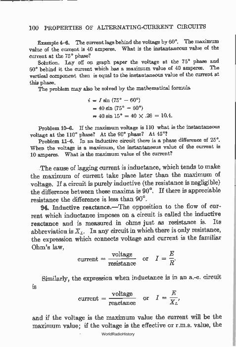
100 PROPERTIES OF ALTERNATING-CURRENT CIRCUITS
Example 4-6. The current lags behind the voltage by 60°. The maximum value of the current is 40 amperes. What is the instantaneous value of the current at the 75° phase?
Solution. Lay off on graph paper the voltage at the 75° phase and 60° behind it the current which has a maximum value of 40 amperes. The vertical component then is equal to the instantaneous value of the current at
this phase. The problem may also be solved by the mathematical formula
= / sin (75° — 60°)
= 40 sin (75° — 60°)
.= 40 sin 15° = 40 X .26 = 10.4.
Problem 10-6. If the maximum voltage is 110 what is the instantaneous voltage at the 110° phase? At the 90° phase? At 45°?
Problem 11-6. In an inductive circuit there is a phase difference of 25°. When the voltage is a maximum, the instantaneous value of the current is 10 amperes. What is the maximum value of the current?
The cause of lagging current is inductance, which tends to make the maximum of current take place later than the maximum of voltage. If a circuit is purely inductive (the resistance is negligible) the difference between these maxima, is 90°. If there is appreciable resistance the difference is less than 90°.
94. Inductive reactance.—The opposition to the flow of cur-rent which inductance imposes on a circuit is called the inductive reactance and is measured in ohms just as resistance is. Its abbreviation is XL. In any circuit in which there is only resistance, the expression which connects voltage and current is the familiar Ohm's law,
voltage E current =- , or I = —
resistance
Similarly, the expression when inductance is in an a.-c. circuit is
voltage E current — or I = —
reactance XL'
and if the voltage is the maximum value the current will be the maximum value; if the voltage is the effective or r.m.s. value, the
WorldRadioHistory
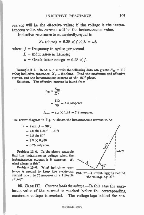
INDUCTIVE REACTANCE 101
current will be the effective value; if the voltage is the instan-taneous value the current will be the instantaneous value.
Inductive reactance is numerically , equal to
XL (ohms) = 6.28 X f X L= wL
where f = frequency in cycles per second;
L = inductance in henries;
w = Greek letter omega = 6.28 X f.
Example 5-6. In an a.-c. circuit the following data are given: Eer = 110 volts; inductive reactance, XL = 20 ohms. Find the maximum and effective current and the instantaneous current at the 150° phase.
Solution. The effective current is found from
Eeff 'eft
XL
110 , — = 0.0 amperes. 20
Ieff X 1.41 = 7.8 amperes.
The vector diagram in Fig. 77 shows the instantaneous current to be
/ sin (0 - 90°)
= 7.8 sin (150° - 90°)
= 7.8 sin 60°
= 7.8 X 0.866
= 6.75 amperes. ,‘•
Problem 12-6. In the above example find the instantaneous voltage when the instantaneous current is 6 amperes. At what phase is this?
60° Problem 13-6. What inductive reac-
tance is needed to keep the maximum current down to 75 amperes in a 110-volt circuit?
Fm. 77.—Current lagging behind the voltage by 90°.
95. CASE III. Current leads the voltage.—In this case the max-imum value of the current is reached before the corresponding maximum voltage is reached. The voltage lags behind the cur-
WorldRadioHistory
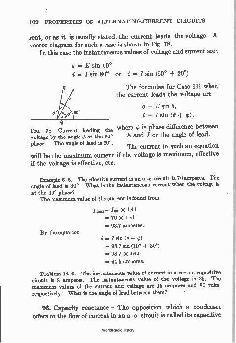
102 PROPERTIES OF ALTERNATING-CURRENT CIRCUITS
rent, or as it is usually stated, the current leads the voltage. A vector diagram for such a case is shown in Fig. 78.
In this case the instantaneous values of voltage and current are
e = E sin 60° i = I sin 80° or i = I sin (60° + 20°)
The formulas for Case III when the current leads the voltage are
e = E sin 0,
i = I sin (0 -I- 0), o
Flo. 78.—Current leading the where 4) is phase difference between voltage by the angle 4 at the 60° E and I or the angle of lead. phase. The angle of lead is 20°. The current in such an equation will be the maximum current if the voltage is maximum, effective
if the voltage is effective, etc.
o'
Example 6-6. The effective current in an a.-c. circuit is 70 amperes. The angle of lead is 30°. What is the instantaneous current'when the voltage is at the 10° phase?
The maximum value of the current is found from
/max= /ea X 1.41
--- 70 X 1.41
= 98.7 amperes. By the equation
= / sin (0 -I- 0)
= 98.7 sin (10° -I- 30°)
= 98.7 X .643
= 64.5 amperes.
Problem 14-6. The instantaneous value of current in a certain capacitive circuit is 8 amperes. The instantaneous value of the voltage is 25. The maximum values of the current and voltage are 15 amperes and 80 volts respectively. What is the angle of lead between them? •
96. Capacity reactance.—The opposition which a condenser offers to the flow of current in an a.-c. circuit is called its capacitive
WorldRadioHistory
CAPACITY REACTANCE 103
reactance and is measured in ohms just as resistance and inductive reactance are. The equation
voltage E current — or I = —
capacitive reactance
is similar in form to Ohm's law and the equation for current in an inductive circuit.
Capacitive reactance is equal numerically to
1 1 X(ohms) —
6.28 Xf X C
where f = frequency in cycles per second;
C = capacity in farads;
= Greek letter omega = 6.28 X f.
Current leads the voltage in a capacitive circuit because capac-ity tends to prevent any changes in voltage and so the maximum of current in a purely capacity circuit takes place 90° ahead of the maximum of voltage. If there is a appreciable resistance in the circuit the difference is less than 90°; thus resistance tends to bring the current and voltage in phase.
Example 7-13.—If a condenser which has a capacity reactance of 5 ohms, is in an a.-c. circuit the instantaneous value of the voltage at the 20° phase is 48 volts. What is the maximum current through the condenser? What is the instantaneous current through it at the 20° phase?
Solution. e = E sin 20°
48 = E X .342
E = 140 volts
I = Xa
140 = 5 = 28 amperes
i = I sin (20° + 90°)
i = 28 sin 110°
= 28 cos 20°
= 28 X .940
= 26.32 amperes.
WorldRadioHistory
104 PROPERTIES OF ALTERNATING-CURRENT CIRCUITS
Problem 15-6.—If a condenser in an a.-c. circuit whose voltage is 110 passes a current of 3 amperes what is the reactance of the condenser in ohms?
Problem 16-6.—Condensers are usually rated at the maximum voltage at which they can be operated with safety. What should be the rating of a con-denser to be used in a 220-volt a.-e. circuit?
Problem 17-6.—An a.-c. circuit has a voltage of 115, and a current of 4.5 amperes is flowing. It has a condenser in it. What is the reactance of this condenser? What is the instantaneous value of the current when the voltage
is 80 volts? At what phase is this?
97. Comparison of inductive and capacitive reactances.—Coils and condensers have opposite effects upon an alternating current. The reactance of an inductance increases with increase of frequency; a condenser has less reactance as the frequency increases. A coil which will pass considerable current at 60 cycles may
pass practically none at one million cycles. Where it is desired to pass a low-frequency current and to prevent the passage of a high-frequency current, an inductance in series with the circuit may be used. Note that the coil—called a choke coil—is in series with the circuit, where a by-pass condenser would be across the circuit. If even greater discrimination against a high-frequency current is desired, a combination of condenser and choke is used. The choke is in series, the condenser is shunted across the circuit.
Example 8-6.—Assume an a.-c. circuit composed of an inductance of one millihenry. What current will flow if E is 100 volts and the frequency ie 600 cycles?
XL = 6.28 Xf X L
= 6.28 X 1 X 10 -8 X 600
= 3.8 ohms
E 100 = 26 es. I = = 3 amperes.
XL
When it is desired to exclude current of a given frequency from a circuit, a shunt capacity is placed across the circuit. High frequencies will go through this by-pass condenser whereas the lower frequencies will not be so shunted and will go on through the rest of the circuit. A frequent use is where an R.F. choke passes direct current but prevents the flow of alternating current whereas a condenser passes a.c. but stops d.c. A large condenser is placed across batteries so that a.-c. currents will have an easy path around them.
WorldRadioHistory
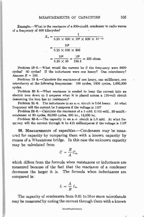
MEASUREMENTS OF CAPACITIES 105
Example.—What is the reactance of a 500-mmfd. condenser to radio waves of a frequency of 600 kilocycles?
Xc - 6.28 X 600 X 1W X 500 X 10 -12
1
10°
6.28X600X 500
106 los — 530 ohms.
6.28 X 30 188.4
Problem 18-6.—What would the current be if the frequency were 6000 cycles? 60 cycles? If the inductance were one henry? One microhenry? Assume E = 100.
Problem 19-6.—Calculate the reactance of one henry, one millihenry, one microhenry at the following frequencies: 100 cycles, 1000 cycles, 1,000,000 cycles.
Problem 20-6.—What reactance is needed to keep the current into an electric iron down to 5 amperes when it is placed across a 110-volt circuit (assuming the iron has no resistance)?
Problem 21-6. The inductance in an a.-c. circuit is 0.04 henry. At what frequency will the current be 3 amperes if the voltage is 110?
Problem 22-6.—Calculate the reactance of a 1-mfd. 0.001-mfd., 50-mmfd.-condenser at 60 cycles, 60,000 cycles, 600 kc., 15,000 kc.
Problem 23-6.—The capacity in an a.-c. circuit is 1.0 mfd. At what fre-qu2ncy will the current through it be 415 milliamperes if the voltage is no?
98. Measurements of capacities.—Condensers may be meas-ured for capacity by comparing them with a known capacity by
means of a Wheatstone bridge. In this case the unknown capacity
may be calculated from
C = — A
which differs from the formula when resistances or inductance are
measured because of the fact that the reactance of a condenser
decreases the larger it is. The formula when inductances are
compared is:
The capacity of condensers from 0.01 to 10 or more microfarads
may be measured by noting the current through them with a known
WorldRadioHistory
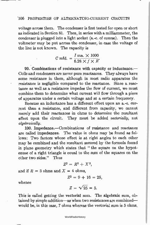
.106 PROPERTIES OF ALTERNATING-CURRENT CIRCUITS
voltage across them. The condenser is first tested for open or short as indicated in Section 81. Then, in series with a milliammeter, the condenser is plugged into a light socket (a.-c. of course). Then the voltmeter may be put across the condenser, in case the voltage of the line is not known. The capacity is
/ ma. X 1000 C mfd. —
6.28 X f X E.
99. Combinations of resistance with capacity or inductance.— Coils and condensers are never pure reactances. They always have some resistance in them, although in most radio apparatus the resistance is negligible compared to the reactance. Since a reac-tance as well as a resistance impedes the flow of current, we must combine them to determine what current will flow through a piece of apparatus under a certain voltage and at a certain frequency.
Because an inductance has a different effect upon an a.-c. cur-rent than a resistance, and different from capacity, we cannot merely add their reactances in ohms to determine the resultant effect upon the circuit. They must be added vectorially, not algebraically.
100. Impedance.—Combinations of resistance and reactance are called impedances. The value in ohms may be found as fol-lows: Two factors whose effect is at right angles to each other may be combined and the resultant secured by the formula found in plane geometry which states that " the square on the hypot-enuse of a right triangle is eaua1 to the sum of the squares on the other two sides." Thus
z2 = R2 ± x2,
and if R = 3 ohms and X = 4 ohms,
Z2 = 9 ± 16 = 25, whence
Z = = 5.
This is called getting the vectorial sum. The algebraic sum, ob-tained by simple addition—as when two resistances are combined— would be, in this case, 7 ohms whereas the vectorial sum is 5 ohms,
WorldRadioHistory
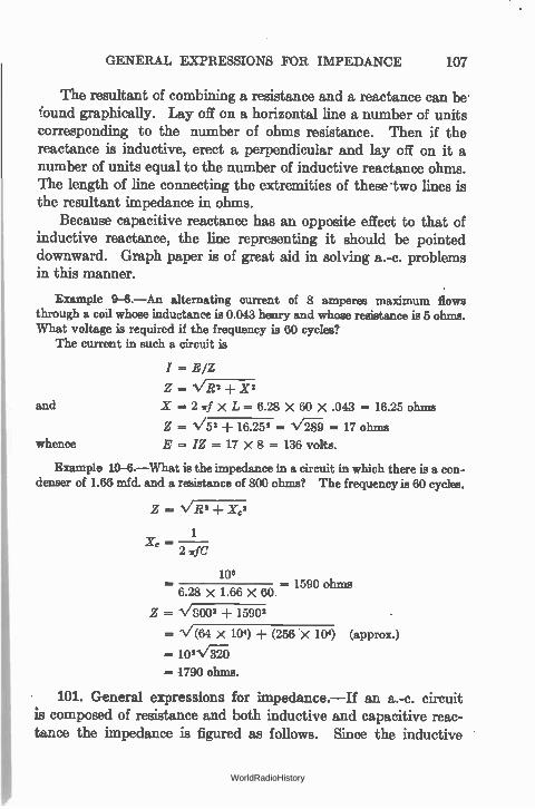
GENERAL EXPRESSIONS FOR IMPEDANCE 107
The resultant of combining a resistance and a reactance can be• found graphically. Lay off on a horizontal line a number of units corresponding to the number of ohms resistance. Then if the reactance is inductive, erect a perpendicular and lay off on it a number of units equal to the number of inductive reactance ohms. The length of line connecting the extremities of these two lines is the resultant impedance in ohms.
Because capacitive reactance has an opposite effect to that of inductive reactance, the line representing it should be pointed downward. Graph paper is of great aid in solving a.-c. problems in this manner.
Example 9-6.—An alternating current of 8 amperes maximum flows through a coil whose inductance is 0.043 henry and whose resistance is 5 ohms. What voltage is required if the frequency is 60 cycles?
The current in such a circuit is
and
whence
I = E/Z
Z = N/Ti 27-1- .2(2
X = 2 7rf X L = 6.28 X 60 X .043 = 16.25 ohms
Z = 1/52 ± 16.252 = = 17 ohms
E = IZ = 17 X 8 = 136 volts.
Example 10-6.—What is the impedance in a circuit in which there is a con-denser of 1.66 mfd. and a resistance of 800 ohms? The frequency is 60 cycles.
Z = R2 ± Xc2
1 X - 2
102 = 1590 ohms
6.28 X 1.66 X 60
Z V8002 -F 15902
= 1/(64 X 104) -I- (256 X 10') (approx.)
102\/.") ,--- 1790 ohms.
101. General expressions for impedance.—If an a.-c. circuit is composed of resistance and both inductive and capacitive reac-tance the impedance is figured as follows. Since the inductive
WorldRadioHistory
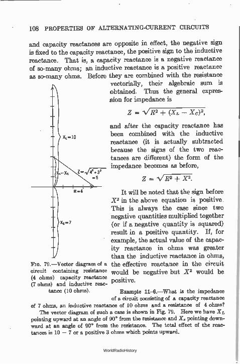
108 PROPERTIES OF ALTERNATING-CURRENT CIRCUITS
and capacity reactances are opposite in effect, the negative sign is fixed to the capacity reactance, the positive sign to the inductive reactance. That is, a capacity reactance is a negative reactance of so-many ohms; an inductive reactance is a positive reactance as so-many ohms. Before they are combined with the resistance
vectorially, their algebraic sum is obtained. Thus the general expres-sion for impedance is
Z = VR2 -1- (XL — XL,)2,
FIG. 79.—Vector diagram of a circuit containing resistance (4 ohms) capacity reactance (7 ohms) and inductive reac-
tance (10 ohms).
of a circuit consisting of a capacity reactance of 7 ohms, an inductive reactance of 10 ohms and a resistance of 4 ohms?
The vector diagram of such a ease is shown in Fig. 79. Here we have XL pointing upward at an angle of 90° from the resistance and /Cc pointing down-ward at an angle of 90° from the resistance. The total effect of the reac-tances is 10 - 7 or a positive 3 ohms which points upward.
and after the capacity reactance has been combined with the inductive reactance (it is actually subtracted because the signs of the two reac-tances are different) the form of the impedance becomes as before,
Z = 1/R2 -I- X2.
It will be noted that the sign before X2 in the above equation is positive This is always the case since two negative quantities multiplied together (or if a negative quantity is squared) result in a positive quantity. If, for example, the actual value of the capac-ity reactance in ohms was greater than the inductive reactance in ohms, the effective reactance in the circuit would be negative but X2 would be positive.
Example 11-6.—What is the impedance
WorldRadioHistory
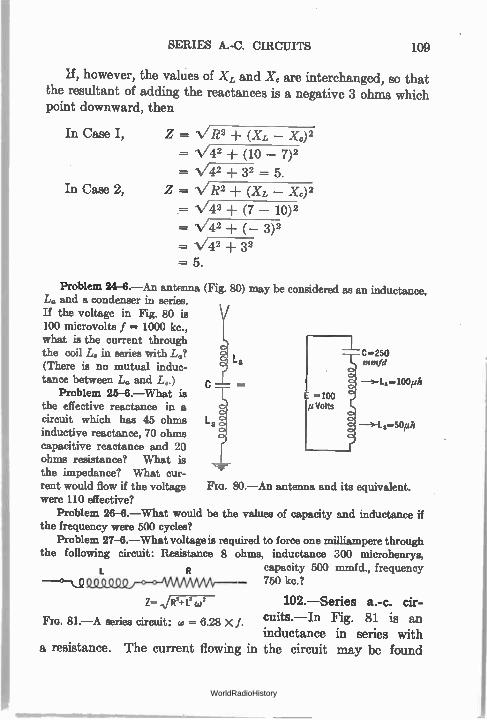
SERIES A.-C. CIRCUITS 109
If, however, the values of X, and X. are interchanged, so that the resultant of adding the reactances is a negative 3 ohms which point downward, then
In Case I, Z = VR2 + (XL — Xe)2 = V42 (10 — 7)2 -V42 + 32 5.
In Case 2, Z = VR2 -I- (XL — X.)2 = 1/42 -I- (7 — 10)2 = 44/42 (_ 3)2 N/42 + 32 = 5.
Problem 24-6.—An antenna (Fig. 80) may be considered as an inductance, L. and a condenser in series. If the voltage in Fig. 80 is 100 microvolts f = 1000 kc., what is the current through the coil La in series with L.? c =250
ntmfd (There is no mutual induc-tance between La and L..) c La =100,ah
Problem 25-6.—What is the effective reactance in a circuit which has 45 ohms L3=-50/th inductive reactance, 70 ohms capacitive reactance and 20 ohms resistance? What is the impedance? What cur-rent would flow if the voltage FIG. 80.—An antenna and its equivalent. were 110 effective?
Problem 26-6.—What would be the values of capacity and inductance if the frequency were 500 cycles?
Problem 27-6.—What voltage is required to force one milliampere through the following circuit: Resistance 8 ohms, inductance 300 microhenrys,
capacity 500 mmfd., frequency
Q_C) 000 o o AMAAMAr-- 750 kc.?
Z- /R2+L2 W2 102.—Series a.-c. cir-
Fla. 81.—A series circuit: co = 6.28 XI. cuits.—In Fig. 81 is an inductance in series with
a resistance. The current flowing in the circuit may be found
loo Volts
WorldRadioHistory
110 PROPERTIES OF ALTERNATING-CURRENT CIRCUITS
by dividing the voltage across the circuit by the impedance of the circuit. That is: I = E/Z, in which
z = VE2 + x2,
which is quite different in numerical value from R + X. For example, if R = 3 and X = 4, the vector sum Z = 5 where as the arithmetical sum = 7.
As in a d.-c. circuit, the voltage across an impedance, a reac-tance, or a resistance is equal to that impedance, reactance or resistance in ohms times the current in amperes.
Voltage across a resistance
Voltage across an inductance
Voltage across a capacity
Voltage across L and C
ER =IXR
EL = I X XL
Ec = I X Xc
EL+ c= I (XL — Xc)
The voltage across two resistances or reactances is the algebraic sum of the individual voltages, remembering that a capacity reac-tance has a negative sign and that the voltage across it is negative with respect to that across an inductance. The voltage across two impedances, however, must be determined by adding the individual voltages vectorially. This is because the impedance is a vector sum of a resistance and reactance.
Let us take a typical example. The current in the circuit of Fig. 81 is
E
- v,R2 + X2
or E I VR2 + X2
E2 = 12 (R2 + X2)
or E2 = /2R2 -F /2X2
= ER2 -I- E12
whence E = v ER2+ E12
Therefore the resultant voltage across a resistance and a reactance is the vector sum of the individual voltages.
WorldRadioHistory
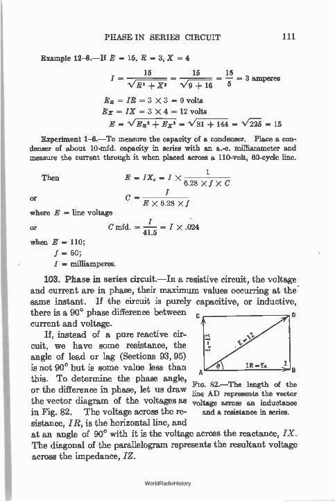
PHASE IN SERIES CIRCUIT 111
Example 12-6.—If E = 15, R = 3, X = 4
15 15 15 --- 3 I - VR2 -1- X2 "%/ --k 16 5 amPerea
ER = IR = 3 X 3 = 9 volts Ex =IX = 3 X 4 = 12 volts
E VER2 Ex2 =1/8-1-1- 14 V =15
Experiment 1-6.—To measure the capacity of a condenser. Place a con-denser of about 10-mfd. capacity in series with an a.-c. milliammeter and measure the current through it when placed across a 110-volt, 60-cycle line.
Then
or
where E = line voltage
or
E = IX c = I X 6.28XfXC
1
c - E X 6.28 X f
C mfd. = — / X .024 41.5
when E = 110;
f — 60; I = milliamperes.
103. Phase in series circuit.—In a resistive circuit, the voltage and current are in phase, their maximum values occurring at the. same instant. If the circuit is purely capacitive, or inductive, there is a 90° phase difference between D current and voltage.
If, instead of a pure reactive cir-cuit, we have some resistance, the angle of lead or lag (Sections 93, 95) is not 90° but is some value less than
A this. To determine the phase angle,
Fm. 82.—The length of the or the difference in phase, let us draw line AD represents the vector the vector diagram of the voltages as voltage across an inductance in Fig. 82. The voltage across the re- and a resistance in series.
sistance, IR, is the horizontal line, and at an angle of 90° with it is the voltage across the reactance, /X. The diagonal of the parallelogram represents the resultant voltage across the impedance, /Z.
WorldRadioHistory
112 PROPERTIES OF ALTERNATING-CURRENT CIRCUITS
Because a resistance in an a.-c. circuit produces no phase difference between the current and voltage the current through and the voltage across a resistance are said to be in phase. Their directions may be represented along the same line, that is, along the horizontal line representing the voltage across the resistance IR. The direction of the diagonal represents the direction of the voltage across the entire circuit. Since, then, the direction of the IR line represents the direction of the current, /, and the direction of the /Z line represents the direction of the voltage, E, the angle between these lines represents the angular difference in phase between the voltage and current. The angle 0 then is equal to the angle of phase difference between the voltage across the combina-tion and the current through it. Thus, in Fig. 82 BD ÷ AB is the tangent of the angle 0, or
BD 71—B. = tan 0,
and since BD = AC = IX (or the voltage across X) and AB = IR (or the voltage across R),
Ex IX X t ER = IR = an O.
Knowing the reactance and the resistance in ohms the tangent of the angle may be determined, and the angle itself looked up in a table. When the tangent of an angle is known but not the angle,
the expression is written O = tan-1 —X and is read " O (theta) the
the angle whose tangent is X over R." The effect of a resistance in series with a reactance is to decrease
the angle of phase difference between the current and the voltage or to bring them more nearly in phase. In a pure reactance circuit, the angle is 90'; when resistance is added this angle decreases. In a pure resistance circuit, there is no angle, the current and volt-age are in phase; they reach their maximum values at the same instant.
WorldRadioHistory
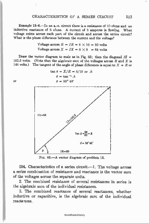
CHARACTERISTICS OF A SERIES CIRCUIT 113
Example 13-6.—In an a.-c. circuit there is a resistance of 10 ohms and an inductive reactance of 8 ohms. A current of 8 amperes is flowing. What voltage exists across each part of the circuit and across the entire circuit? What is the phase difference between the current and the voltage?
Voltage across R = IR = 8 X 10 = 80 volts
Voltage across X = IX = 8 X 8 = 64 volts
Draw the vector diagram to scale as in Fig. 83; then the diagonal /Z = 102.5 volts. (Note that the algebraic sum of the voltages across R and X is 144 volts.) The tangent of the angle of phase difference is equal to X ÷ R or
tan O = X/R = 8/10 or .8
O = tan -1 .8
or 0 = 38* 40'
FIG. 83.—A vector diagram of problem 13.
104. Characteristics of a series circuit.-1. The voltage across a series combination of resistance and reactance is the vector sum of the voltages across the separate units.
2. The combined resistance of several resistances in series is the algebraic sum of the individual resistances.
3. The combined reactance of several reactances, whether inductive or capacitive, is the algebraic sum of the individual reacts nces.
WorldRadioHistory
114 PROPERTIES OF ALTERNATING-CURRENT CIRCUITS
4. The impedance, or combined effect of a resistance and reac-tance, is ihe vector sum of their individual values.
5. The combined impedance of several separate impedances is the vector sum of the individual impedances.
Example.—Suppose we combine two resistances, reactances, etc., of 3 and 4 ohms respectively. The table below shows the resultant values.
Combination Sum Resultant
1. R = 3; X = 4 "Vi-k 16 --- Z 5 2. R = 3; R = 4 3 -F 4 = R 7
3. XL = 4; Xa -- 3 4 - 3 = X 1
3. XL = 3; Xc = 4 3 - 4 = X -1
3. XL = 3; XL = 4 4 + 3 = X 7
3. Xe = 3; .ic = 4 -4-3 = X -7
4. R = 3; X = 4 "N AI77-1- 16 = Z 5
(1) R = 3, XL = 4 Xe = 3 V9 ± (4 -- 3) 2 = Z 3.16
(2) R = 3, XL = 3 Xe = 4 V9 + (3 - 4) 2 = 2 3.16
(3) R -- 3, XL = 3 Xe = 3 V9 -F (3 - 3) 2 = Z 3
Note in (1) and (2) above that the resultant is the same although the conditions are different. This is due to the fact that a negative number when squared, or multiplied by itself, becomes a positive number. In other words, a negative reactance and a resistance always produce a positive impedance.
105. Resonance.—In (3) above, a very important phenomenon is illustrated. When the capacity reactance of a series circuit equals the inductive reactance, their respective effects cancel out and the resultant impedance is the resistance in ohms alone. To a circuit possessing inductive reactance one can add a certain amount of capacity and thereby reduce the impedance of the circuit (at some particular frequency) to the value of the ohmic resistance. This is the phenomenon underlying all tuning in radio circuits; it is known as resonance.
Problem 28-6.—Two resistances, one of 8 ohms and the other of 24 ohms, are in a 60-cycle 110-volt circuit. What current flows? What is the current if the frequency is increased to 500 cycles?
I WorldRadioHistory
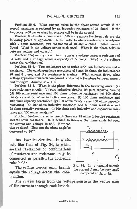
PARALLEL CIRCUITS 115
Problem 29-6.—What current exists in the above-named circuit if the second resistance is replaced by an inductive reactance of 24 ohms? If the frequency is 60 cycles what inductance will be in the circuit?
Problem 30-6.—In a circuit with 550 volts across the terminals are the following pieces of apparatus: A coil with 15 ohms reactance, a condenser with 7 ohms reactance, two resistances of 10 and 5 ohms. What current flows? What is the voltage across each part? What is the phase relation between voltage and current?
Problem 31-6.—In an a.-c. circuit appear a voltage across a resistance of 34 volts and a voltage across a capacity of 66 volts. What is the voltage across the combination?
Problem 32-8.—Two condensers are in series with two inductances and a resistance. The condensers have reactances of 8 and 10 ohms, the inductances 20 and 6 ohms, and the resistance is 4 ohms. What current flows, what voltage appears across each component and what is the phase between current and voltage? Assume E = 110.
Problem 33-6.—What is the phase difference in the following cases: (a) pure resistance circuit; (b) pure inductive circuit; (c) pure capacity circuit; (d) 100 ohms resistance and 100 ohms inductive reactance; (e) 100 ohms resistance and 50 ohms inductive reactance; (f) 100 ohms resistance and 100 ohms capacity reactance; (g) 100 ohms resistance and 50 ohms capacity reactance; (h) 100 ohms inductive reactance and 50 ohms resistance and 25 ohms capacity reactance; (i) 100 ohms each inductive and capacitive reac-tance and 100 ohms resistance?
Problem 84-6.—In a series circuit there are 45 ohms inductive reactance and 20 ohms resistance. It is desired to increase the phase angle between the current and voltage to 85°. How can this be done? How can the phase angle be decreased to 30°7
106. Parallel circuits.—In a cir-cuit like that of Fig. 84, in which several reactances or combinations of reactance and resistance may be connected in parallel, the following rules hold:
The voltage across each branch equals the voltage across the com-bination.
The current taken from the voltage source is the vector of the currents through each branch.
=t 84.—In a parallel 'circuit
the current I may be very small compared to IL or
Bum
WorldRadioHistory
'116 PROPERTIES OF ALTERNATING-CURRENT CIRCUITS
The impedance offered to the flow of current by the combina-tion is the voltage divided by the total current.
Thus in Fig. 84 the current through the entire combination may be found as follows, assuming E = 120; Xc = 8; X.r, = 5; R = 3:
E 120 /c «= X—c = —8 = 15 amperes through the condenser
E 120 R = = = 40 amperes through the resistance
E 120 = = -5- = 24 amperes through the inductance
I = I R2 ± (IL - I c)2 = 1/1.€81 = 41 amperes
120 Z = —41 = 2.92 ohms.
107. Phase in parallel circuit.—The phase angle between the current and the voltage in a parallel circuit may be obtained from the expression
IL - /c tan O -
IR
or O = tan -1 (IL - IC
\ IR
108. Impedance of parallel circuit.—Since the impedance is the ratio between the voltage across the circuit and the current through it, in order to find the impedance of several branches in parallel we must know the voltage and the current. Often we would like to know the impedance without knowing either the voltage or the current. The procedure then is to assume a voltage, to find the currents that would flow, divide the voltage by the current and get therefrom the impedance, or
WorldRadioHistory
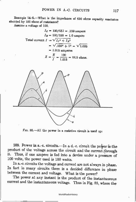
POWER IN A.-C. CIRCUITS 117
Example 14-6.—What is the impedance of 630 ohms capacity reactance shunted by 100 ohms of resistance?
Assume a voltage of 100.
/c = 100/633 = .159 ampere
/R = 100/100 = 1.0 ampere
Total current / = V/c2 /R2
= V.1592 -I- 12 =
= 1.015 amperes
E 100 — 98.5 ohms.
/ 1.015
85.—All the power in a resistive circuit is used up.
109. Power in a.-c. circuits.—In a d.-c. circuit the poker is the product of the voltage across the circuit and the current through it. Thus, if one ampere is fed into a device under a pressure of 100 volts, the power used is 100 watts.
In a.-c. circuits the voltage and current are not always in phase. In fact in many circuits there is a decided difference in phase between the current and voltage. What is the power?
The power at any instant is the product of the instantaneous current and the instantaneous voltage. Thus in Fig. 85, where the
WorldRadioHistory
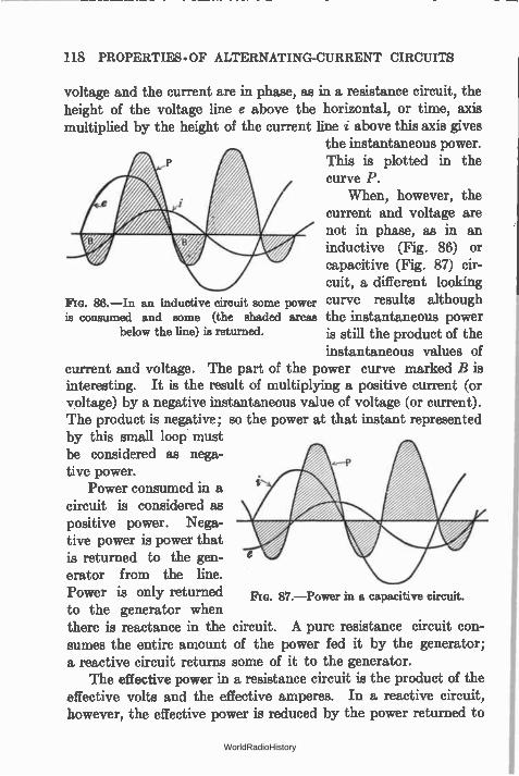
118 PROPERTIES - OF ALTERNATING-CURRENT CIRCUITS
voltage and the current are in phase, as in a resistance circuit, the height of the voltage line e above the horizontal, or time, axis multiplied by the height of the current line i above this axis gives
the instantaneous power. This is plotted in the curve P.
When, however, the current and voltage are not in phase, as in an inductive (Fig. 86) or capacitive (Fig. 87) cir-cuit, a different looking
843.—In an inductive circuit some power curve results although is consumed and some (the shaded areas the instantaneous power
below the line) is returned, is still the product of the
instantaneous values of current and voltage. The part of the power curve marked B is interesting. It is the result of multiplying a positive current (or voltage) by a negative instantaneous value of voltage (or current). The product is negative; so the power at that instant represented by this small loop must be considered as nega-tive power.
Power consumed in a circuit is considered as positive power. Nega-tive power is power that is returned to the gen-erator from the line. Power is only returned to the generator when there is reactance in the circuit. A pure resistance circuit con-sumes the entire amount of the power fed it by the generator; a reactive circuit returns some of it to the generator.
The effective power in a resistance circuit is the product of the effective volts and the effective amperes. In a reactive circuit, however, the effective power is reduced by the power returned to
87.—Power in a capacitive circuit.
WorldRadioHistory
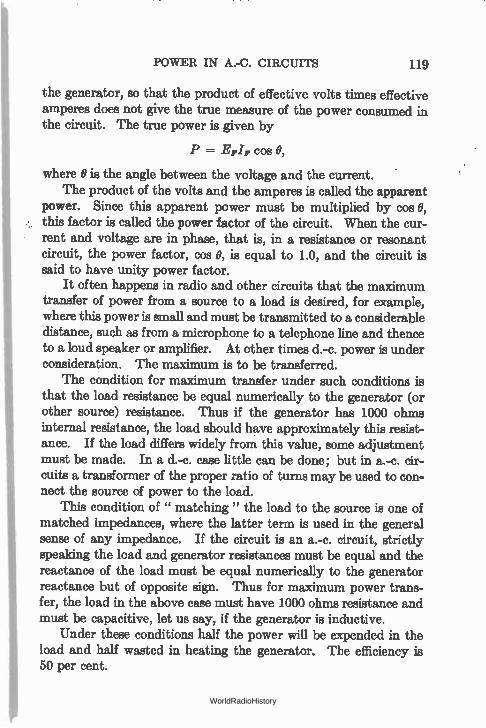
POWER IN A.-C. CIRCUITS 119
the generator, so that the product of effective volts times effective amperes does not give the true measure of the power consumed in the circuit. The true power is given by
P = EFIF cos 0,
where 0 is the angle between the voltage and the current. The product of the volts and the amperes is called the apparent
power. Since this apparent power must be multiplied by cos 0, this factor is called the power factor of the circuit. When the cur-rent and voltage are in phase, that is, in a resistance or resonant circuit, the power factor, cos 0, is equal to 1.0, and the circuit is said to have unity power factor.
It often happens in radio and other circuits that the maximum transfer of power from a source to a load is desired, for example, where this power is small and must be transmitted to a considerable distance, such as from a microphone to a telephone line and thence to a loud speaker or amplifier. At other times d.-c. power is under consideration. The maximum is to be transferred.
The condition for maximum transfer under such conditions is that the load resistance be equal numerically to the generator (or other source) resistance. Thus if the generator has 1000 ohms internal resistance, the load should have approximately this resist-ance. If the load differs widely from this value, some adjustment must be made. In a d.-c. case little can be done; but in a.-c. cir-cuits a transformer of the proper ratio of turns may be used to con-nect the source of power to the load.
This condition of " matching " the load to the source is one of matched impedances, where the latter term is used in the general sense of any impedance. If the circuit is an a.-c. circuit, strictly speaking the load and generator resistances must be equal and the reactance of the load must be equal numerically to the generator reactance but of opposite sign. Thus for maximum power trans-fer, the load in the above case must have 1000 ohms resistance and must be capacitive, let us say, if the generator is inductive.
Under these conditions half the power will be expended in the load and half wasted in heating the generator. The efficiency is 50 per cent.
e WorldRadioHistory
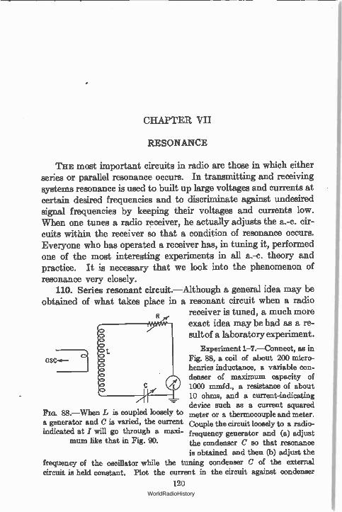
CHAPTER VII
RESONANCE
THE most important circuits in radio are those in which either series or parallel resonance occurs. In transmitting and receiving systems resonance is used to built up large voltages and currents at certain desired frequencies and to discriminate against undesired signal frequencies by keeping their voltages and currents low. When one tunes a radio receiver, he actually adjusts the a.-c. cir-cuits within the receiver so that a condition of resonance occurs. Everyone who has operated a receiver has, in tuning it, performed one of the most interesting experiments in all a.-c. theory and practice. It is necessary that we look into the phenomenon of resonance very closely.
110. Series resonant circuit.—Although a general idea may be obtained of what takes place in a resonant circuit when a radio
receiver is tuned, a much more
OSC-«-7 --1
Fm. 88.—When L is coupled loosely to a generator and C is varied, the current indicated at I will go through a maxi-
mum like that in Fig. 90.
exact idea may be had as a re-sult of a laboratory experiment.
Experiment 1-7.—Connect, as in Fig. 88, a coil of about 200 micro-henries inductance, a variable con-denser of maximum capacity of 1000 mmfd., a resistance of about 10 ohms, and a current-indicating device such as a current squared meter or a thermocouple and meter. Couple the circuit loosely to a radio-frequency generator and (a) adjust the condenser C so that resonance is obtained and then (b) adjust the
frequency of the oscillator while the tuning condenser C of the external circuit is held constant. Plot the current in the circuit against condenser
120 WorldRadioHistory
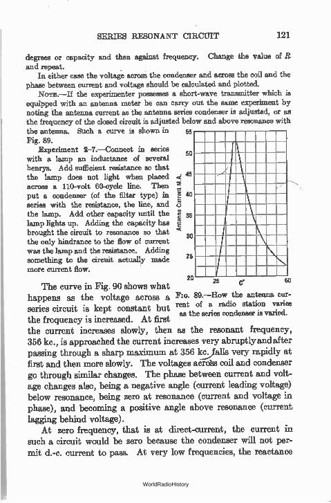
SERIES RESONANT CIRCUIT 121
degrees or capacity and then against frequency. Change the value of R and repeat.
In either case the voltage across the condenser and across the coil and the phase between current and voltage should be calculated and plotted.
Nom.—If the experimenter possesses a short-wave transmitter which is equipped with an antenna meter he can carry out the same experiment by noting the antenna current as the antenna series condenser is adjusted, or as the frequency of the closed circuit is adjusted below and above resonance with the antenna. Such a curve is shown in 55
Fig. 89. Experiment 2-7.—Connect in series
with a lamp an inductance of several henrys. Add sufficient resistance so that the lamp does not light when placed across a 110-volt 60-cycle line. Then put a condenser (of the filter type) in series with the resistance, the line, and the lamp. Add other capacity until the lamp lights up. Adding the capacity has brought the circuit to resonance so that the only hindrance to the flow of current was the lamp and the resistance. Adding something to the circuit actually made more current flow.
The curve in Fig. 90 shows what happens as the voltage across a series circuit is kept constant but the frequency is increased. At first the current increases slowly, then as the resonant frequency, 356 kc., is approached the current increases very abruptly and after passing through a sharp maximum at 356 kç.../falls very rapidly at first and then more slowly. The voltages acroSs coil and condenser go through similar changes. The phase between current and volt-age changes also, being a negative angle (current leading voltage) below resonance, being zero at resonance (current and voltage in phase), and becoming a positive angle above resonance (current lagging behind voltage).
At zero frequency, that is at direct-current, the current in such a circuit would be zero because the condenser will not per-mit d.-c. current to pass. At very low frequencies, the reactance
Ante
nna Current M.A.
50
45
40
35
30
25
20 60 25 C.
89.—How the antenna cur-rent of a radio station varies as the series condenser is varied.
WorldRadioHistory
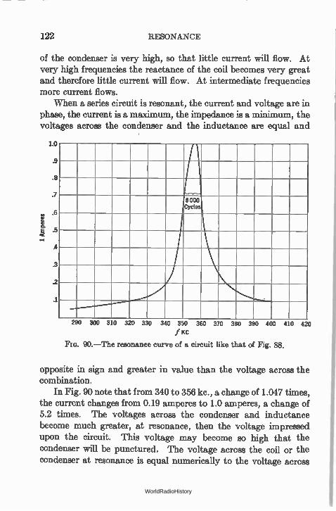
122 RESONANCE
of the condenser is very high, so that little current will flow. At very high frequencies the reactance of the coil becomes very great and therefore little current will flow. At intermediate frequencies more current flows.
When a series circuit is resonant, the current and voltage are in phase, the current is a maximum, the impedance is a minimum, the voltages across the condenser and the inductance are equal and
1.0
.9
.8
.7
., .6 E a E .5 <
A
.3
.2
.1
290 300 310 320 330 340 350 360 370 380 390 400 410 420
f 'cc
Fla. 90.—The resonance curve of a circuit like that of Fig. 88.
opposite in sign and greater in value than the voltage across the combination.
In Fig. 90 note that from 340 to 356 kc., a change of 1.047 times, the current changes from 0.19 amperes to 1.0 amperes, a change of 5.2 times. The voltages across the condenser and inductance become much greater, at resonance, then the voltage impressed upon the circuit. This voltage may become so high that the condenser will be punctured. The voltage across the coil or the condenser at resonance is equal numerically to the voltage across
WorldRadioHistory
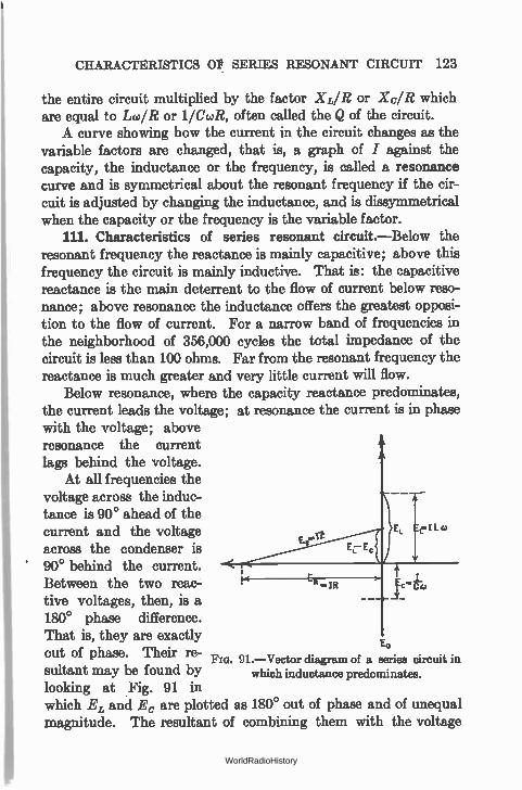
CHARACTERISTICS OP SERIES RESONANT CIRCUIT 123
the entire circuit multiplied by the factor XL/R or Xc/R which are equal to Im/R or 11CcaR, often called the Q of the circuit. A curve showing how the current in the circuit changes as the
variable factors are changed, that is, a graph of I against the capacity, the inductance or the frequency, is called a resonance curve and is symmetrical about the resonant frequency if the cir-cuit is adjusted by changing the inductance, and is dissymmetrical when the capacity or the frequency is the variable factor.
111. Characteristics of series resonant circuit.—Below the resonant frequency the reactance is mainly capacitive; above this frequency the circuit is mainly inductive. That is: the capacitive reactance is the main deterrent to the flow of current below reso-nance; above resonance the inductance offers the greatest opposi-tion to the flow of current. For a narrow band of frequencies in the neighborhood of 356,000 cycles the total impedance of the circuit is less than 100 ohms. Far from the resonant frequency the reactance is much greater and very little current will flow.
Below resonance, where the capacity reactance predominates, the current leads the voltage; at resonance the current is in phase with the voltage; above resonance the current lags behind the voltage.
At all frequencies the voltage across the induc-tance is 90° ahead of the current and the voltage EL LW
across the condenser is 90° behind the current. Between the two reac-tive voltages, then, is a 180° phase difference. That is, they are exactly Ec,
out of phase. Their re- Flu. 91.—Vector diagram of a series circuit in sultant may be found by which inductance predominates. looking at Fig. 91 in which E, and E, are plotted as 180° out of phase and of unequal magnitude. The resultant of combining them with the voltage
R IR
WorldRadioHistory
124 RESONANCE
across the resistance must be the voltage across the entire series circuit, which is the vector sum. Thus,
E = ER2 ± (EL — Ec)2
At any frequency but that of resonance, one of the two reactive voltages is greater than the other. At resonance, however, the two voltages are equal in magnitude and opposite in phase so that the resultant of combining the reactive voltages is zero. When added vectorially to the IR drop in the circuit, the resultant is the voltage which is impressed by the external source.
The vector sum of the reactive and resistive voltages is equal to the impressed voltage.
Example 1-7.—What are the voltages and phase relations in the circuit of Fig. 88 at a frequency of 370 kc.7
I = .274 ampere
Xc =- 430 ohms
XL = 466 ohms
R = 10 ohms
ER = I X R = .274 X 10 = 2.74 volts
= I X Xc = .274 X 430 = 118 volts
EL = / X XL = .274 X 466 = 128 volts
••/.742 -I- 1282 = 128 volts (approx.)
128 itut-Er. = tan -2— = tan' 46.6 = 88.46°
2.74
ER+c = -V2.742 ± 1182 = 118 volts (approx.)
118 OR+c = tan'- tan-' 43 = - 88.38°
EL+C = EL - Ec = 9.6 volts = Ex
E = IVR2 ± X' = ER' + Ex' = V2.742 + 9.6'
= 10 volts
een+hfc = tan_i % = tan_i XL - Xc 466 - 430 o
R 10 - °.° = 74° 30'
WorldRadioHistory
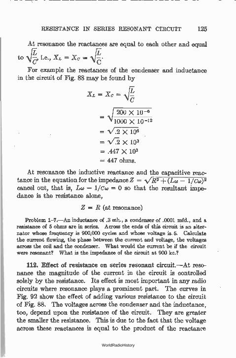
RESISTANCE IN SERIES RESONANT CIRCUIT 125
At resonance the reactances are equal to each other and equal
to \jL , i.e., XL = Xc = é •
For example the reactances of the condenser and inductance in the circuit of Fig. 88 may be found by
=
..\1 200 X 10 -6
1000 X 10 -12
= 17.2 X 106
= 1/ X 103
= .447 X 103
= 447 ohms.
At resonance the inductive reactance and the capacitive reac-tance in the equation for the impedance Z = Vit2 -I- (Lw — 1/Cw)2 cancel out, that is, Lw — 1/Cw = 0 so that the resultant impe-dance is the resistance alone,
Z = R (at resonance)
Problem 1-7.—An inductance of .3 mh., a condenser of .0001 mfd., and a resistance of 5 ohms are in series. Across the ends of this circuit is an alter-nator whose frequency is 900,000 cycles and whose voltage is 5. Calculate the current flowing, the phase between the current and voltage, the voltages across the coil and the condenser. What would the current be if the circuit were resonant? What is the impedance of the circuit at 900 kc.?
112. Effect of resistance on series resonant circuit.—At reso-nance the magnitude of the current in the circuit is controlled solely by the resistance. Its effect is most important in any radio circuits where resonance plays a prominent part. The curves in Fig. 92 show the effect of adding various resistance to the circuit of Fig. 88. The voltages across the condenser and the inductance, too, depend upon the resistance of the circuit. They are greater the smaller the resistance. This is due to the fact that the voltage across these reactances is equal to the product of the reactance
WorldRadioHistory
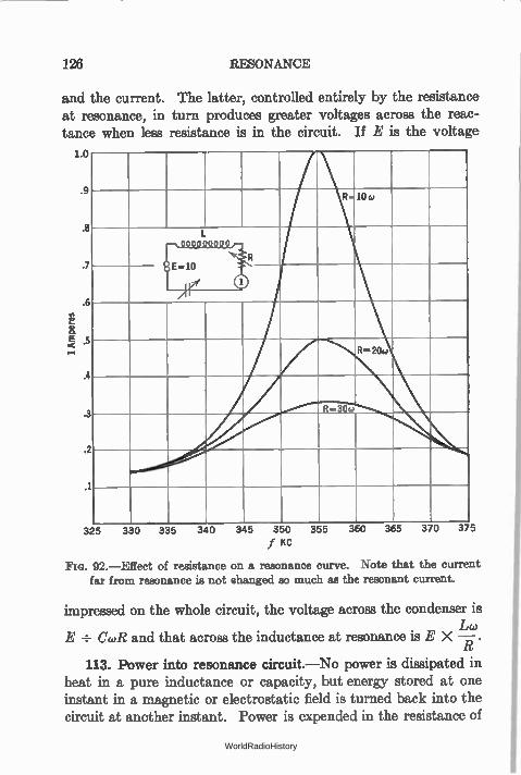
126 RESONANCE
and the current. The latter, controlled entirely by the resistance at resonance, in turn produces greater voltages across the reac-tance when less resistance is in the circuit. If E is the voltage
1.f
1 R 10&)
1
r
;
i
I
R=206.)
R-30w 3
11111141/4. 2
1
325 330 335 340 345 350 355 360 365 370 375
f KC
Flo. 92.—Effect of resistance on a resonance curve. Note that the current far from resonance is not shanged so much as the resonant current.
impressed on the whole circuit, the voltage across the condenser is Lco
E ÷ CA? and that across the inductance at resonance is E X —R .
113. Power into resonance circuit.—No power is dissipated in heat in a pure inductance or capacity, but energy stored at one instant in a magnetic or electrostatic field is turned back into the circuit at another instant. Power is expended in the resistance of
WorldRadioHistory
RESONANT FREQUENCY OF THE CIRCUIT 127
a circuit, but since at high values of resistance the current is small, the power in the circuit will be small. This power is equal, as usual, to
P = 12 X R
where R is the resistance of the circuit. In case of Fig. 88, where the resistance is 10 ohms and the current at resonance 1 ampere, the power is 10 watts. Since at resonance there is no reactance effec-tive in the circuit the power fed into it by the generator is the product of the current times the voltage, or 10 X 1 or 10 watts.
In other words, all the energy taken from the generator is used up in heating the resistance. None is necessary to maintain the magnetic and electrostatic fields of the coil and the condenser. The energy in these fields is transferred from one to the other, the sum at any one instant being equal to the sum at any other instant so long as the energy dissipated in the resistance is supplied from the outside.
Problem 2-7. What power is taken from the generator in Problem 1-7?
In actual circuits the resistance is not isolated as in our dem-onstration problems. All coils have resistance; so do all con-densers, although the resistance of modern variable capacities is quite small. These resistances take power from the generator and reduce the maximum height of the resonance curve.
114. The resonant frequency of the circuit.—The condition for series resonance — that the reactances of the circuit add up to zero—is fulfilled when
XL = Xc
or XL, — Xe =
1 or caL — Co, = i
1 or wL
WC
1 or
— LC
WorldRadioHistory
128 RESONANCE
and since 6.28 X f = co,
1
f - 6.28 17re
and since 6.28 is equal to the mathematical expression 2 Ir we arrive at the familiar expression for the resonant frequency of a circuit as
1
f - 271--V71'
in which f = the frequency in cycles; L = the inductance in henrys; C = the capacity in farads; ir = the Greek letter " Pi " and is equal to 3.1416 . . . .
Example 2-7. To what frequency will a circuit tune which has an induc-tance of 0.25 henry and capacity of 0.001 mfd.?
Let us write the above formula as
fi _
fl — 39.5 X .25 X.001 X 10-9
1 1 4 e LC - 39.5 LC
1
109 _
39.5 X.25 '
109 = —
9.87
f = -‘,7.01 X ViTM
= 10.1 x 10³ cycles
= 10.1 kc.
Such an expression for the resonant frequency of a circuit shows that the frequency depends upon the product of L and C, and not upon either of them alone. If L is doubled, C can be halved and the natural frequency of the circuit will not be changed.
WorldRadioHistory
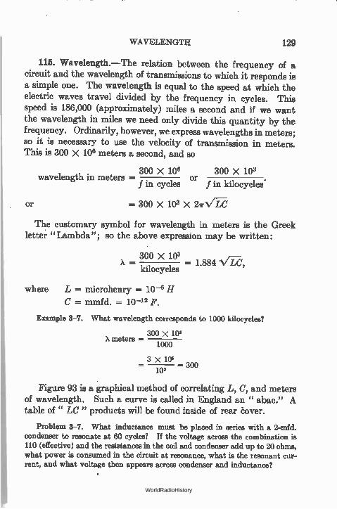
WAVELENGTH 129
115. Wavelength.—The relation between the frequency of a circuit and the wavelength of transmissions to which it responds is a simple one. The wavelength is equal to the speed at which the electric waves travel divided by the frequency in cycles. This speed is 186,000 (approximately) miles a second and if we want the wavelength in miles we need only divide this quantity by the frequency. Ordinarily, however, we express wavelengths in meters; so it is necessary to use the velocity of transmission in meters. This is 300 X 106 meters a second, and so
300 X 106 300 X 103 wavelength in meters - or
f in cycles • f in kilocycles
or = 300 X 103 X 271-1/LC
The customary symbol for wavelength in meters is the Greek letter "Lambda"; so the above expression may be written:
300 X 103 X - - 1.884 ••// 1,
kilocycles
where L = microhenry = 10 -6 H
C = mmfd. = 10 -12 F.
Example 3-7. What wavelength corresponds to 1000 kilocycles?
300 x 103 X meters —
1000
3 X 10⁶ _ 10 — 300
3
Figure 93 is a graphical method of correlating L, C, and meters of wavelength. Such a curve is called in England an " abac." A table of" LC" products will be found inside of rear Cover.
Problem 3-7. What inductance must be placed in series with a 2-mfd. condenser to resonate at 60 cycles? If the voltage across the combination is 110 (effective) and the resistances in the coil and condenser add up to 20 ohms, what power is consumed in the circuit at resonance, what is the resonant cur-rent, and what voltage then appears across condenser and inductance?
WorldRadioHistory
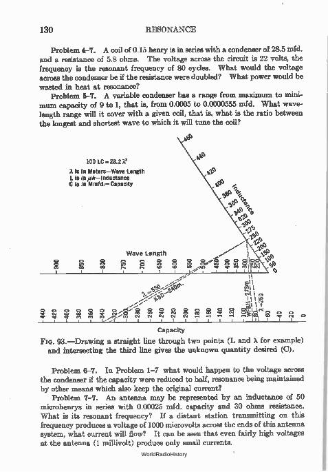
130 RESONANCE
Problem 4-7. A coil of 0.15 henry is in series with a condenser of 28.5 mfd. and a resistance of 5.8 ohms. The voltage across the circuit is 22 volts, the frequency is the resonant frequency of 80 cycles. What would the voltage across the condenser be if the resistance were doubled? What power would be
wasted in heat at resonance? Problem 5-7. A variable condenser has a range from maximum to mini-
mum capacity of 9 to 1, that is, from 0.0005 to 0.0000555 mfd. What wave-length range will it cover with a given coil, that is, what is the ratio between the longest and shortest wave to which it will time the coil?
100 LC-28.2A'
A is in Meters-Wave Length L is in/A—Inductance C is in Mmfd.— Capacity
Wave Length 0 0 „
'FP , e % ,43 94, e93,
O , 8.-e, 8 Wye,. v'ttli .n .en .e
î 0 0 0 CY 0 00 en
0.40-.,e îrí c!i 0 O 0
ea a. 00 csi . I I I
8 0.4
Capacity
FIG. 93.—Drawing a straight line through two points (L and X for example) and intersecting the third line gives the unknown quantity desired (C).
Problem 6-7. In Problem 1-7 what would happen to the voltage across the condenser if the capacity were reduced to half, resonance being maintained by other means which also keep the original current?
Problem 7-7. An antenna may be represented by an inductance of 50 microhenrys in series with 0.00025 mfd. capacity and 30 ohms resistance. What is its resonant frequency? If a distant station transmitting on this frequency produces a voltage of 1000 microvolts across the ends of this antenna system, what current will flow? It can be seen that even fairly high voltages at the antenna (1 millivolt) produce only small currents.
WorldRadioHistory
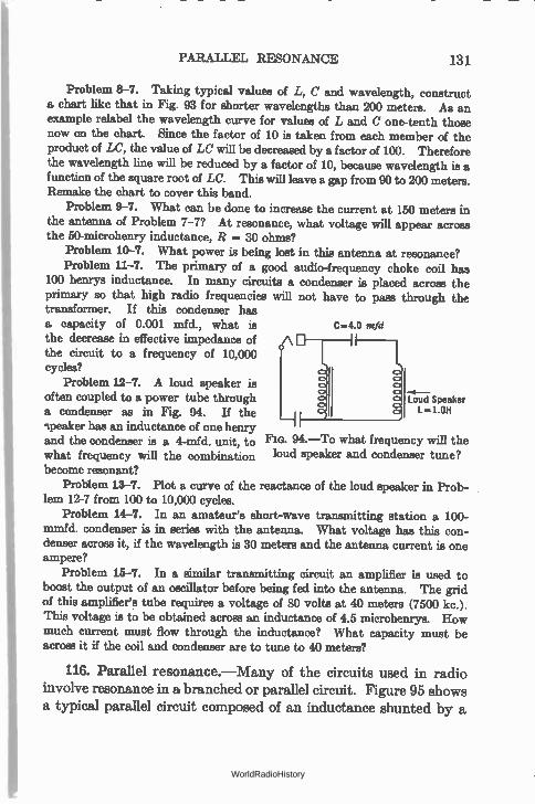
PARALLEL RESONANCE 131
Problem 8-7. Taking typical values of L, C and wavelength, construct a chart like that in Fig. 93 for shorter wavelengths than 200 meters. As an example relabel the wavelength curve for values of L and C one-tenth those now on the chart. Since the factor of 10 is taken from each member of the product of LC, the value of LC will be decreased by a factor of 100. Therefore the wavelength line will be reduced by a factor of 10, because wavelength is a function of the square root of W. This will leave a gap from 90 to 200 meters. Remake the chart to cover this band.
Problem 9-7. What can be done to increase the current at 150 meters in the antenna of Problem 7-7? At resonance, what voltage will appear across the 50-microhenry inductance, R = 30 ohms?
Problem 10-7. What power is being lost in this antenna at resonance? Problem 11-7. The primary of a good audio-frequency choke coil has
100 henrys inductance. In many circuits a condenser is placed across the primary so that high radio frequencies will not have to pass through the transformer. If this condenser has a capacity of 0.001 mfd., what is the decrease in effective impedance of A the circuit to a frequency of 10,000 cycles?
Problem 12-7. A loud speaker is often coupled to a power tube through Loud Speaker
L-1.0H
C4.0 mid
a condenser as in Fig. 94. If the 9peaker has an inductance of one henry and the condenser is a 4-mfd. unit, to Fm. 94.—To what frequency will the what frequency will the combination loud speaker and condenser tune? become resonant?
Problem 13-7. Plot a curve of the reactance of the loud speaker in Prob-lem 12-7 from 100 to 10,000 cycles.
Problem 14-7. In an amateur's short-wave transmitting station a 100-mmfd. condenser is in series with the antenna. What voltage has this con-denser across it, if the wavelength is 30 meters and the antenna current is one ampere?
Problem 15-7. In a similar transmitting circuit an amplifier is used to boost the output of an oscillator before being fed into the antenna. The grid of this amplifier's tnbe requires a voltage of 80 volts at 40 meters (7500 kc.). This voltage is to be obtained across an inductance of 4.5 microhenrys. How much current must flow through the inductance? What capacity must be across it if the coil and condenser are to tune to 40 meters?
116. Parallel resonance.—Many of the circuits used in radio involve resonance in a branched or parallel circuit. Figure 95 shows a typical parallel circuit composed of an inductance shunted by a
WorldRadioHistory
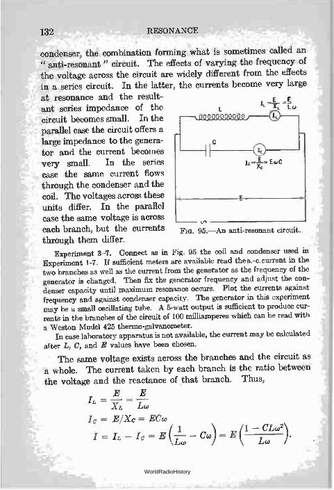
132 RESONANCE
condenser, the combination forming what is sometimes called an " anti-resonant " circuit. The effects of varying the frequency of the voltage across the circuit are widely different from the effects in a series circuit. In the latter, the currents become very large at resonance and the result- E
ant series impedance of the IL Lc>
circuit becomes small. In the parallel case the circuit offers a large impedance to the genera-tor and the current becomes very small. In the series E lc =—Xc EG' C
case the same current flows through the condenser and the coil. The voltages across these E
units differ. In the parallel case the same voltage is across each branch, but the currents Fio. 95.—An anti-resonant circuit. through them differ.
Experiment 3-7. Connect as in Fig. 95 the coil and condenser used in Experiment 1-7. If sufficient meters are available read the a.-c.current in the two branches as well as the current from the generator as the frequency of the generator is changed. Then fix the generator frequency and adjust the con-denser capacity until maximum resonance occurs. Plot the currents against frequency and against condenser capacity. The generator in this experiment may be a small oscillating tube. A 5-watt output is sufficient to produce cur-rents in the branches of the circuit of 100 milliamperes which can be read with
a Weston Model 425 thermo-galvanometer. In case laboratory apparatus is not available, the current may be calculated
after L, C, and E values have been chosen.
The same voltage exists across the branches and the circuit as a whole. The current taken by each branch is the ratio between the voltage and the reactance of that branch. Thus,
E E IL = —x.z =
Ic = EIXc = M I6; 1 1 — CLco2
I = — Ic = E(--Lw — Cco) E Le) ).
WorldRadioHistory
PARALLEL RESONANCE 133
As the frequency is increased, more and more current is taken by the capacity branch, less and less by the inductance branch. In the series case the voltages across coil and condenser are out of phase; their algebraic sum at any frequency combined vectorially with the II? drop is the voltage across the combination. In the parallel case the currents are out of phase; at any frequency their algebraic sum combined vectorially with the shunt resistance cur-rent (if any) give the current taken from the generator. In the simple case where the resistance is neglected, the algebraic sum of the currents gives the generator current. Since these two cur-rents are out of phase (the capacity current has a negative sign), adding them algebraically actually means subtracting Ic from IL.
At resonance the currents taken by the two branches are equal and if there is no resistance in the circuit the current taken from the generator is zero, because it is the difference of the two branch currents which is read in the generator circuit ammeter.
The impedance of the circuit as a whole, that is, the impedance into which the generator must feed current, is the ratio between the voltage and current as usual:
Z = E/I.
Therefore, if no current flows, the circuit has infinite impedance. Actually there is always some resistance in the circuit. This may be in an additional shunt path, or it may exist in one or both of the other branches. Actually, then, the generator current does not fall to zero but passes through a minimum value. In most radio cir-cuits by far the greater part of the resistance which is in the circuit resides in the coil since the resistance of the average well con-structed condenser used at radio frequencies is very small. In such a circuit in which there is resistance in series with the induc-tance the power absorbed by the parallel circuit is given by the following expression, where E is the voltage across the circuit
RE2 W —
2(R24)
The current taken by the circuit is not exactly in phase with the generator voltage and so minimum-current resonance differs slightly from zero-reactance resonance.
WorldRadioHistory
134 RESONANCE
ER — R2 ± co2L2
and the impedance presented to the generator is
E R2 ± w2L2
R •
117. Effective resistance.—If, as is usual, the resistance of the coil is small compared to its reactance, the condition for resonance
is
and the minimum current from the generator becomes
ER I r w2L2'
and since the impedance of the circuit is equal to the ratio between the voltage across it and the current through it, it becomes
co2L2
= CR.
Since at resonance the current into the circuit from the generator is in phase with the voltage, E, across the circuit, the expression above is not a true impedance but is more nearly a resistance. It may be called the " effective resistance " of the circuit.
118. Resonant frequency.—In this manner we arrive at the frequency to which a low resistance circuit becomes resonant:
WorldRadioHistory
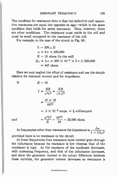
RESONANT FREQUENCY 135
The condition for resonance then is that the inductive and capaci-tive reactances are equal but opposite in sign—which is the same condition that holds for series resonance. Here, however, there are other conditions. The resistance must reside in the coil and must be small compared to the reactance of the coil.
For example, in the case of the circuit in Fig. 95:
L = 200 itH
w = 2r X 356,000
R = 10 ohms (in the coil)
= Lw = 200 X 10 -6 X 2 ir X 356,000
= 447 ohms.
Here we may neglect the effect of resistance and use the simple relation for resonant current and for impedance.
If E = 10
ER ER I = —
w2L2 (XL) 2
10 X 10 4472
and
= .5 X 10 -3 amps. = milliampere
w2L2 4472 = — — — = 20,000 ohms.
R 10
At frequencies other than resonance the impedance is Lw 1 — CLc.)2
provided there is no resistance in the circuit. At lower frequencies than resonance most current goes through
the inductance because its reactance is low whereas that of the condenser is high. As the reactance of the condenser decreases, with increasing frequency, and that of the inductance increases, and since the generator current is the actual difference between these currents, the generator current decreases as resonance is
WorldRadioHistory
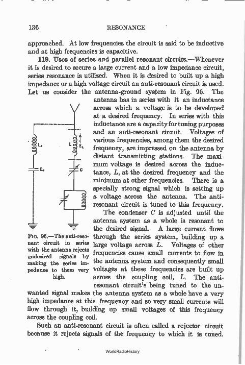
136 RESONANCE
approached. At low frequencies the circuit is said to be inductive and at high frequencies is capacitive.
119. Uses of series and parallel resonant circuits.—Whenever it is desired to secure a large current and a low impedance circuit, series resonance is utilized. When it is desired to built up a high impedance or a high voltage circuit an anti-resonant circuit is used. Let us consider the antenna-ground system in Fig. 96. The
antenna has in series with it an inductance across which a voltage is to be developed at a desired frequency. In series with this inductance are a capacity for tuning purposes and an anti-resonant circuit. Voltages of various frequencies, among them the desired
L frequency, are impressed on the antenna by distant transmitting stations. The maxi-mum voltage is desired across the induc-tance, L, at the desired frequency and the minimum at other frequencies. There is a specially strong signal which is setting up a voltage across the antenna. The anti-resonant circuit is tuned to this frequency.
The condenser C is adjusted until the antenna system as a whole is resonant to the desired signal. A large current flows
96.—The anti-rezo- through the series system, building up a nant circuit in series large voltage across L. Voltages of other with the antenna rejects frequencies cause small currents to flow in undesired signals by making the series im- the antenna. system and consequently small pedance to them very voltages at these frequencies are built up
high. across the coupling coil, L. The anti-resonant circuit's being tuned to the un-
wanted signal makes the antenna system as a whole have a very high impedance at this frequency and so very small currents will flow through it, building up small voltages of this frequency across the coupling coil.
Such an anti-resonant circuit is often called a rejector circuit because it rejects signals of the frequency to which it is tuned.
WorldRadioHistory
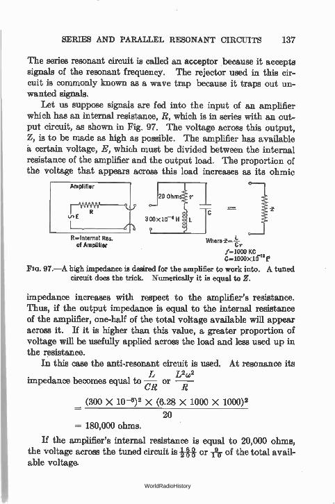
SERIES AND PARALLEL RESONANT CIRCUITS 137
The series resonant circuit is called an acceptor because it accepts signals of the resonant frequency. The rejector used in this cir-cuit is commonly known as a wave trap because it traps out un-wanted signals.
Let us suppose signals are fed into the input of an amplifier which has an internal resistance, R, which is in series with an out-put circuit, as shown in Fig. 97. The voltage across this output, Z, is to be made as high as possible. The amplifier has available à certain voltage, E, which must be divided between the internal resistance of the amplifier and the output load. The proportion of the voltage that appears across this load increases as its ohmic
R —Internal Res. of Amplifier
Where î--Cr
f-1000 KC C-1000X 10-12 le
FIG. 97.—A high impedance is desired for the amplifier to work into. A tuned circuit does the trick. Numerically it is equal to Z.
impedance increases with respect to the amplifier's resistance. Thus, if the output impedance is equal to the internal resistance of the amplifier, one-half of the total voltage available will appear across it. If it is higher than this value, a greater proportion of voltage will be usefully applied across the load and less used up in the resistance.
In this case the anti-resonant circuit is used. At resonance its L2(02
impedance becomes equal to —CR or
(300 X 10 -8)2 X (6.28 X 1000 X 1000)2
20 180,000 ohms.
If the amplifier's internal resistance is equal to 20,000 ohms, the voltage across the tuned circuit is g g or -Ay of the total avail-able voltage.
WorldRadioHistory
138 RESONANCE
Problem 16-7. A screen-grid tube gives the greatest voltage amplification when worked into a very high impedance. A condenser of 1500 mmfd. is available. Calculating the size of the inductance required to tune to 1000 meters and assuming it has a resistance of 30 ohms, what is the impedance
(L2ws— 1 that can be presented to the tube by shunting the coil and condenser? r Problem 17-7. A wave trap is to be put into an antenna and tuned to a
station whose frequency is 750 kc. What will be a convenient size of con-denser and coil to use? They are to be shunted across each other and the combination put in series with the antenna. If the coil has a resistance of 10 ohms and the condenser a resistance of 1.0 ohm at this frequency, what impedance will the trap offer to the offending signal?
Problem 18-7. In Problem 17-7, neglecting phase differences between the trap and the rest of the antenna, if the total impedance of the antenna to the offending signal is double that of the trap alone so that one-half of the total antenna voltage is across the trap, what current will flow through the condenser if the total 750-kc. voltage across the system is 10 microvolts?
120. Sharpness of resonance.—The effect of resistance is to reduce the maximum current flowing in a series resonant circuit, and to make less pronounced the minimum of current flowing into a parallel resonant circuit from an external source.
Since the maximum current is desired in a series circuit, and the maximum impedance in a parallel case, the inclusion of resistance in either is deleterious.
Let us consider the antenna illustrated in Fig. 96. Suppose its inductance, L, is 200 microhenrys and C at resonance (356 kc.) is 1000 mmfd. For the moment we shall neglect the presence of the wave trap. Assume a voltage of 10 volts. What is the effect on the resonance curve of this antenna system if it has a resistance of 10 ohms or of 40 ohms? The current at resonance in the 10-ohm case is 1 ampere whereas at 370 kc. the current is .274 ampere, a ratio of 3.65. In this 40-ohm case, the resonant current would be only 0.25 ampere—one-fourth of its value with the lower resistance—and the current at 370 kc., i.e., 14 kc. off resonance, would be .188 ampere. This is a current ratio between the resonant and the off-resonant current of only 1.33.
In other words, if the antenna had impressed on it from equally distant and equally powerful radio stations two voltages, one of 356 kc.—the desired frequency,—and one of 370 kc.—the unwanted
WorldRadioHistory
SHARPNESS OF RESONANCE 139
frequency,— 3.65 times as much current flows at the desired fre-quency as the unwanted. In the 40-ohm antenna, however, not only is the desired current cut to one-quarter of its other value but the ratio of wanted to unwanted current has been decreased to 1.33. The low-resistance antenna is said to be more " selective" and its " selectivity " is decreased when resistance is added to it.
121. Selectivity.—The selectivity of a circuit is a measure of its ability to distinguish between wanted and unwanted signals. The steepness of the resonance curve is a direct measure of this selectivity.
Let us consider the parallel or anti-resonant circuit. At its resonant frequency it keeps currents of undesired frequency from flowing through the antenna because of its high impedance at those currents. This impedance, L2co2/r, increases as the resist-ance of the circuit decreases, so it behooves the designer to use low-resistance coils and condensers when building a trap or rejector circuit.
Since a circuit may be tuned to resonance by varying any one of three variable factors, the inductance, capacity, or frequency, we may express the sharpness of resonance in any one of three ways. It may be the fractional change in current for a given frac-tional change in either L or C. Naturally the sharper the resonance curve and the greater its height, the greater will be the current change for a small number of degrees of change in the tuning con-denser. The ciercuit will tune " sharply "; it is called a sharp circuit. In practice the condenser is used as the tuning variable. If, then, the current at resonance Ir and the tuning capacity C,. are noted and then changed to give some other value of current, the sharpness of resonance may be found by substituting values in the following expression,
\i1r2 - 1 2
1 2
ST« — Cr C
By some mathematical juggling of this cumbersome expression (see Bulletin 74, Bureau of Standards, page 36) a much simpler
WorldRadioHistory
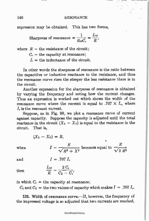
140 RESONANCE
expression may be obtained. This has two forms,
1 Sharpness of resonance —
RcoC, R
where R = the resistance of the circuit;
Cr = the capacity at resonance;
L = the inductance of the circuit.
In other words the sharpness of resonance is the ratio between the capacitive or inductive reactance to the resistance, and thus the resonance curve rises the steeper the less resistance there is in the circuit.
Another expression for the sharpness of resonance is obtained by varying the frequency and noting how the current changes. Thus an expression is worked out which shows the width of the resonance curve where the current is equal to .707 X Ir, where I, is the resonant current.
Suppose, as in Fig. 98, we plot a resonance curve of current against capacity. Suppose the capacity is adjusted until the total reactance in the circuit (XL — Xc) is equal to the resistance in the circuit. That is,
— Xc) = R,
when
and
then
E E I — becomes equal to
1/R2 ± X2 N/-272
I = .707 ir
Lw 2 Cr
R C2 -
in which Cr = the capacity at resonance;
Ci and C2 = the two values of capacity which makes I = .707 I,.
122. Width of resonance curve.—If, however, the frequency of the impressed voltage is so adjusted that two currents are reached,
WorldRadioHistory
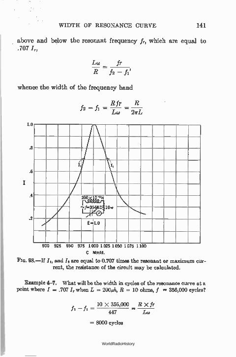
WIDTH OF RESONANCE CURVE 141
above and below the resonant frequency fr, which are equal to .107 I„
Lw fr
R f2 — fl'
whence the width of the frequency band
R fr R /2 — fi = — =
Lw27rL
1.0
.8
il
.6
.4
.2 E1.0
900 925 950 975 1 000 I 025 1 050 1 075 1 100
C Med.
98.—If /2, and /2 are equal to 0.707 times the resonant or maximum cur-rent, the resistance of the circuit may be calculated.
Example 4-7. What will be the width in cycles of the resonance curve at a point where I = .707 Ir when L = 200A, R = 10 ohms, f = 356,000 cycles?
10 x 356,000 R X fr fi —
447 /Ad
= 8000 cycles
WorldRadioHistory
142 RESONANCE
and if L20 2 C,.
- c, - c,
C2 - Ci 2C X R
Lcu
2000 X 10 = . 447
= 44.7 mmfd.
= change in capacity required to change the current from / = .707 Ir below resonance, to / = .707 /2 above resonance, or from /2 to /2 in Fig. 98.
Problem 19-7. In Fig. 98, suppose the resistance is 20 ohms instead of 10. Calculate the width of the band at the point where the current is 0.7 of its maximum value, and the change in capacity required to produce this change in current.
Problem 20-7. A certain coil-condenser combination has a resistance of 16 ohms at 400 meters. The inductance is 170 microhenrys. What is the width of band passed at the point where the current is equal to 0.7 of its maximum value? What is the " sharpness of resonance" of this circuit? Note that this expression is the ratio between either reactance and the resistance.
Problem 21-7. A circuit is to pass only 0.707 of its maximum current at a point 2.0 kc. off resonance, which occurs at 500 kc. The condenser to be used has a capacity of 0.0006 add. Calculate the maximum resistance the
circuit can have. Problem 22-7. Suppose that increasing the size of an inductance by a
factor of 2.0 increases the resistance in a circuit by a factor of 1.5. The circuit is to tune to the same wavelength. What has happened to the sharpness of resonance, or, what amounts to the same thing, to the selectivity of the
circuit? Problem 23-7. If the expression Loilr of a coil remains constant over a
fairly wide band of frequencies, does the selectivity of a tuned circuit differ at
different frequencies? Does the width of band passed differ at 1500 kc. from what it is at 500 kc.?
The selectivity of a radio receiver can be illustrated by Fig. 188 which shows the relative gain of a stage of a radio fre-quency amplifier when the signal is so-and-so-many kilocycles away from the frequency to which the receiver is tuned. Note the sharpness of the curve at 550 kc. and the poor selectivity at high frequencies.
WorldRadioHistory
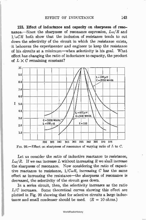
EFFECT OF INDUCTANCE 143
123. Effect of inductance and capacity on sharpness of reso-nance.—Since the sharpness of resonance expression, Lw/R and 11coCR both show that the inclusion of resistance tends to cut down the selectivity of the circuit in which the resistance exists, it behooves the experimenter and engineer to keep the resistance of his circuits at a minimum—when selectivity is his goal. What effect has changing the ratio of inductance to capacity, the product of L X C remaining constant?
10.
9.0
8.0
7.0
6.0
I 5.0
4.0
3.0
2.0
1.0
L.400itH C-2000 Mnfd.
L..400/4H C.•500 Mmfd.
C..1000 Mmfd. I_..200 H E.100
330 335 340 345 350 355 360 365 370 375
99.—Effect on cheapness of resonance of varying ratio of L to C.
Let us consider the ratio of inductive reactance to resistance, Lw/R. If we can increase L without increasing R we shall increase the sharpness of resonance. Now considering the ratio of capaci-tive reactance to resistance, 11CcoR, increasing C has the same effect as increasing the resistance—the sharpness of resonance is decreased, the selectivity of the circuit goes down.
In a series circuit, then, the selectivity increases as the ratio L/C increases. Some theoretical curves showing this effect are plotted in Fig. 99 showing that for selective circuits a large induc-tance and small condenser should be used. (R = 10 ohms.)
WorldRadioHistory
144 RESONANCE
The ratio of L to C occurs in many formulas dealing with the resonant circuit. For example, consider a long line with uni-formly distributed capacity and inductance. The impedance of
this line will be NÍ./ ohms. As another example, in a parallel circuit made up of capacity in one branch and inductance in the other with resistances in both branches, it can be shown that the circuit as a whole acts as a pure resistance having no reactance provided the two resistances are equal to each other and equal to the square root of the ratio of L to C. Thus when
Rc = RL =
X = 0 and r= Rc=RL
where r is the effective resistance.
124. The resistance of coils.—The curves in Fig. 99 were plotted on the assumption that the resistance of the coil did not increase as the inductance was changed. Unfortunately this can-not be carried out in practice unless very large and unwieldy coils are made. This means, simply, that a coil has a resistance to a.c. different from that which it has to d.c. For example, a very good coil used at broadcast frequency may have a resistance as low as 10 ohms at some medium broadcast frequency. But so little wire is used in making this coil that the d.-c. resistance will be perhaps a fraction of an ohm. Even straight wires have different a.-c. and d.-c. resistances.
Straight wires, however, have the least difference in resistance between high frequency and direct current. In laboratory work where small accurately known resistances are desired to be used at high frequencies, short lengths of high-resistance wire are employed. For example, manganin or one of the other high-resistance alloys may be cut into the proper lengths, soldered to copper lead wires and used as standards of resistance where a decade box could not be utilized at all.
Even with such wires it is often difficult to separate the react-ance and resistance effects; if the lead-in wires are close together and of large size appreciable capacity reactance may be added,
WorldRadioHistory
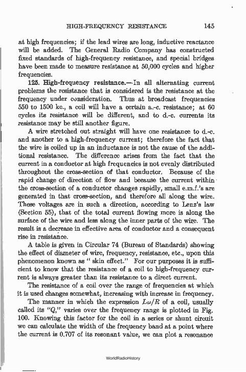
HIGH-FREQUENCY RESISTANCE 145
at high frequencies; if the lead wires are long, inductive reactance will be added. The General Radio Company has constructed fixed standards of high-frequency resistance, and special bridges have been made to measure resistance at 50,000 cycles and higher frequencies.
125. High-frequency resistance.—In all alternating current problems the resistance that is considered is the resistance at the frequency under consideration. Thus at broadcast frequencies 550 to 1500 kc., a coil will have a certain a.-c. resistance; at 60 cycles its resistance will be different, and to d.-c. currents its resistance may be still another figure. A wire stretched out straight will have one resistance to d.-c.
and another to a high-frequency current; therefore the fact that the wire is coiled up in an inductance is not the cause of the addi-tional resistance. The difference arises from the fact that the current in a conductor at high frequencies is not evenly distributed throughout the cross-section of that conductor. Because of the rapid change of direction of flow and because the current within the cross-section of a conductor changes rapidly, small e.m.f.'s are generated in that cross-section, and therefore all along the wire. These voltages are in such a direction, according to Lenz's law (Section 55), that of the total current flowing more is along the surface of the wire and less along the inner parts of the wire. The result is a decrease in effective area of conductor and a consequent rise in resistance. A table is given in Circular 74 (Bureau of Standards) showing
the effect of diameter of wire, frequency, resistance, etc., upon this phenomenon known as " skin effect." For our purposes it is suffi-cient to know that the resistance of a coil to high-frequency cur-rent is always greater than its resistance to a direct current.
The resistance of a coil over the range of frequencies at which it is used changes somewhat, increasing with increase in frequency.
The manner in which the expression Lco/R of a coil, usually called its "Q," varies over the frequency range is plotted in Fig. 100. Knowing this factor for the coil in a series or shunt circuit we can calculate the width of the frequency band at a point where the current is 0.707 of its resonant value, we can plot a resonance
WorldRadioHistory
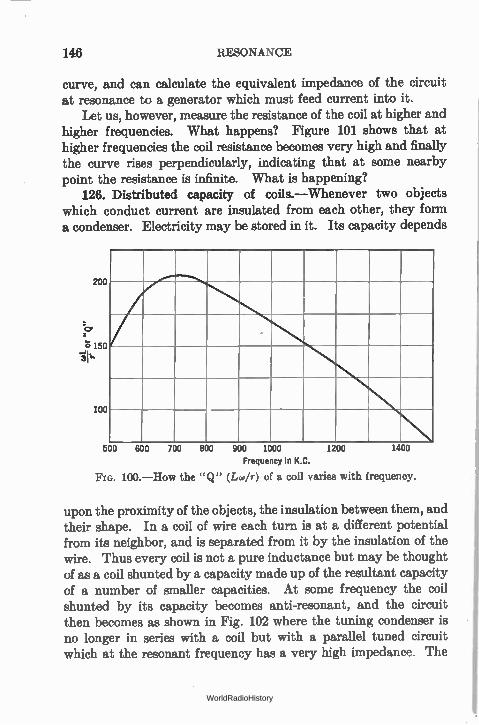
146 RESONANCE
curve, and can calculate the equivalent impedance of the circuit at resonance to a generator which must feed current into it.
Let us, however, measure the resistance of the coil at higher and higher frequencies. What happens? Figure 101 shows that at higher frequencies the coil resistance becomes very high and finally the curve rises perpendicularly, indicating that at some nearby point the resistance is infinite. What is happening?
126. Distributed capacity of coils.—Whenever two objects which conduct current are insulated from each other, they form a condenser. Electricity may be stored in it. Its capacity depends
200
-c,, 's 150 -à'l•
100
500 600 700 800 900 1000
Frequency in K.C.
FIG. 100.—How the "Q" (Lco/r) of a coil varies with frequency.
1200 1400
upon the proximity of the objects, the insulation between them, and their shape. In a coil of wire each turn is at a different potential from its neighbor, and is separated from it by the insulation of the wire. Thus every coil is not a pure inductance but may be thought of as a coil shunted by a capacity made up of the resultant capacity of a number of smaller capacities. At some frequency the coil shunted by its capacity becomes anti-resonant, and the circuit then becomes as shown in Fig. 102 where the tuning condenser is no longer in series with a coil but with a parallel tuned circuit which at the resonant frequency has a very high impedance. The
WorldRadioHistory
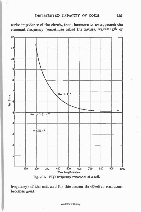
DISTRIBUTED CAPACITY OF COILS 147
series impedance of the circuit, then, increases as we approach the resonant frequency (sometimes called the natural wavelength or
12
11
10
9
8
7
° 6
5
4
3
2
1
Res. to A C.
Res. to D. C.
1252/M
100 200 300 400 500 600
Wave Length Meters
Fig. I01.— High-frequency resistance of a coil.
700 800 900 1000
frequency) of the coil, and for this reason its effective resistance becomes great.
WorldRadioHistory
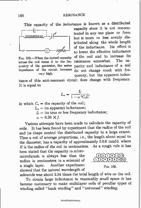
148 RESONANCE
This capacity of the inductance is known as a distributed capacity since it is not concen-trated in any one place or form but is more or less evenly dis-tributed along the whole length of the inductance. Its effect is to lower the effective inductance
102.—When the dotted capacity of the coil and to increase its across the coil tunee it to the fre- resistance somewhat. The ca-queney of the generator, the series pacity and inductance of a coil impedance of the circuit becomes do not change much with fre-
very high. quency, but the apparent induc-tance of this anti-resonant circuit does change with frequency. It is equal to
L. — 1 — co 2C.L'
in which C. = the capacity of the coil; = its apparent inductance;
L = its true or low frequency inductance; w = 6.28 X f.
Various attempts have been made to calculate the capacity of coils. It has been found by experiment that the radius of the coil and its shape control the distributed capacity to a large extent. Thus a coil of average proportions, i.e., the length about equal to the diameter, has a capacity of approximately 0.6R mmfd. where R is the radius of the coil in centimeters. As a rough rule it has been stated that the capacity in micro-microfarads is always less than the radius in centimeters in a solenoid of a single layer. Another experiment showed that the natural wavelength of solenoids was about 2.54 times the total length of wire on the coil.
To obtain large inductance in reasonably small space it has become customary to make multilayer coils of peculiar types of winding called "bank winding" and "universal" winding.
Fla. 103.
WorldRadioHistory
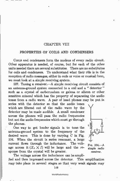
CHAPTER VIII
PROPERTIES OF COILS AND CONDENSERS
Cons and condensers form the nucleus of every radio circuit. Other apparatus is needed, of course, but for each of the other units needed there are several substitutes. There are no substitutes for coils and condensers. To understand what their rôle is in the reception of radio messages, either in code or voice or musical form, we must look at a simple receiving system.
127. Tuning a receiver.—A simple receiving circuit consists of an antenna-ground system connected to a coil and a " detector " such as a crystal of carborundum or galena or silicon or other sensitive mineral which has the property of separating the audio tones from a radio wave. A pair of head phones may be put in series with the detector so that the audio tones which are filtered out of the radio wave by the detector may be made audible. A small condenser across the phones will pass the radio frequencies but not the audio frequencies which must go through the phones.
One way to get louder signals is to tune the antenna-ground system to the frequency of the desired wave. This is done by varying C in Fig. 104. When the circuit is series resonant, a large current flows through the inductance. The volt- no. 104.—A age across it (XL X /) will be large and the re- simple radio
spouse from the crystal will be greater. receiver.
The voltage across the inductance can be ampli-fied and then impressed across the detector. This amplification may take place in several stages so that very weak signals may
149
WorldRadioHistory
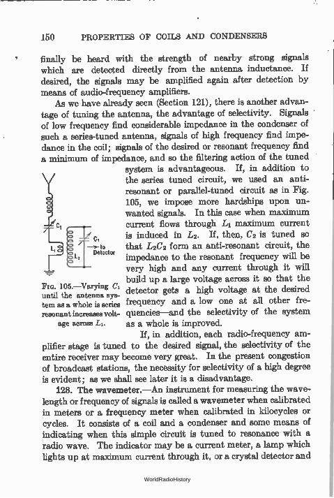
150 PROPERTIES OF COILS AND CONDENSERS
finally be heard with the strength of nearby strong signals which are detected directly from the antenna inductance. If desired, the signals may be amplified again after detection by means of audio-frequency amplifiers.
As we have already seen (Section 121), there is another advan-tage of tuning the antenna, the advantage of selectivity. Signals of low frequency find considerable impedance in the condenser of such a series-tuned antenna, signals of high frequency find impe-dance in the coil; signals of the desired or resonant frequency find a minimum of impedance, and so the filtering action of the tuned
system is advantageous. If, in addition to the series tuned circuit, we used an anti-resonant or parallel-tuned circuit as in Fig. 105, we impose more hardships upon un-wanted signals. In this case when maximum current flows through L1 maximum current
c, is induced in L2. If, then, C2 is tuned so to that L2C2 form an anti-resonant circuit, the
Detector impedance to the resonant frequency will be very high and any current through it will build up a large voltage across it so that the
FIG. 105.—Varying until the antenna aye-
detector gets a high voltage at the desired
tern as a whole is series frequency and a low one at all other fre-resonant increases volt- quencies—and the selectivity of the system
age across LI. as a whole is improved. If, in addition, each radio-frequency am-
plifier stage is tuned to the desired signal, the selectivity of the entire receiver may become very great. In the present congestion of broadcast stations, the necessity for selectivity of a high degree is evident; as we shall see later it is a disadvantage.
128. The wavemeter.—An instrument for measuring the wave-length or frequency of signals is called a wavemeter when calibrated in meters or a frequency meter when calibrated in kilocycles or cycles. It consists of a coil and a condenser and some means of indicating when this simple circuit is tuned to resonance with a radio wave. The indicator may be a current meter, a lamp which lights up at maximum current through it, or a crystal detector and
WorldRadioHistory
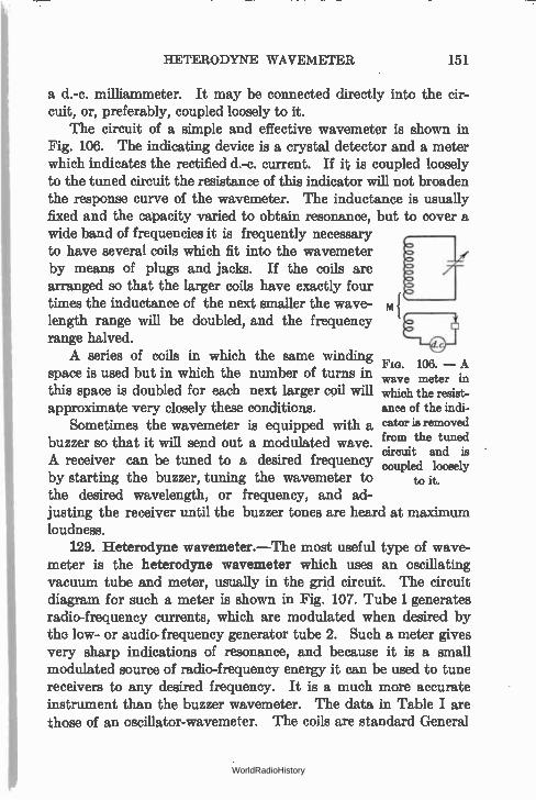
HETERODYNE WAVEMETER 151
a d.-c. milliammeter. It may be connected directly into the cir-cuit, or, preferably, coupled loosely to it.
The circuit of a simple and effective wavemeter is shown in Fig. 106. The indicating device is a crystal detector and a meter which indicates the rectified d.-c. current. If it is coupled loosely to the tuned circuit the resistance of this indicator will not broaden the response curve of the wavemeter. The inductance is usually fixed and the capacity varied to obtain resonance, but to cover a wide band of frequencies it is frequently necessary to have several coils which fit into the wavemeter by means of plugs and jacks. If the coils are arranged so that the larger coils have exactly four
- times the inductance of the next smaller the wave- m length range will be doubled, and the frequency range halved. A series of coils in which the same winding
space is used but in which the number of turns in this space is doubled for each next larger coil will approximate very closely these conditions.
Sometimes the wavemeter is equipped with a buzzer so that it will send out a modulated wave. A receiver can be tuned to a desired frequency by starting the buzzer, tuning the wavemeter to the desired wavelength, or frequency, and ad-justing the receiver until the buzzer tones are heard at maximum loudness.
129. Heterodyne wavemeter.—The most useful type of wave-meter is the heterodyne wavemeter which uses an oscillating vacuum tube and meter, usually in the grid circuit. The circuit diagram for such a meter is shown in Fig. 107. Tube 1 generates radio-frequency currents, which are modulated when desired by the low- or audio- frequency generator tube 2. Such a meter gives very sharp indications of resonance, and because it is a small modulated source of radio-frequency energy it can be used to tune receivers to any desired frequency. It is a much more accurate instrument than the buzzer wavemeter. The data in Table I are those of an oscillator-wavemeter. The coils are standard General
Fia. 106. — A wave meter in which the resist-ance of the indi-cator is removed from the tuned circuit and is coupled loosely
to it.
WorldRadioHistory
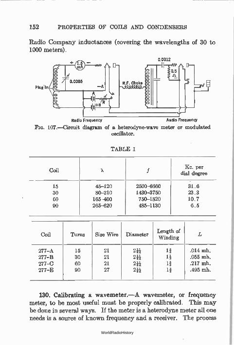
152 PROPERTIES OF COILS AND CONDENSERS
Radio Company inductances (covering the wavelengths of 30 to 1000 meters).
0.0005
Plug in —A
Radio Frequency
0.0012
)--"H g
R.F. Choke ,—,..euODOQ.0)-‘%'
e
0.5
-
0—
Audio Frequency
FIG. 107.—Circuit diagram of a heterodyne-wave meter or modulated oscillator.
TABLE I
Coil X f Kc. per
dial degree
15 45-120 2500-6660 31.6 30 80-210 1430-3750 23.3 60 165-400 750-1820 10.7 90 265-620 485-1130 6.5
Coil Turns Size Wire Diameter Length of . .
Wmdmg L
277-A 15 21 244 14 .014 mh. 277-B 30 21 244 14 .055 mh. 277-C 60 21 24+ 14 .217 mh. 277-E 90 27 2ii 14 .495 mh.
130. Calibrating a wavemeter.—A wavemeter, or frequency meter, to be most useful must be properly calibrated. This may be done in several ways. If the meter is a heterodyne meter all one needs is a source of known frequency and a receiver. The process
WorldRadioHistory
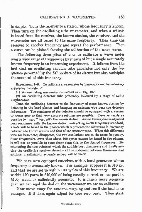
CALIBRATING A WAVEMETER 153
is simple. Tune the receiver to a station whose frequency is known. Then turn on the oscillating tube wavemeter, and when a whistle is heard from the receiver, the known station, the receiver, and the wavemeter are all tuned to the same frequency. Then tune the receiver to another frequency and repeat the performance. Then a curve can be plotted showing the calibration of the wave meter.
The following description of how to calibrate a wave meter over a wide range of frequencies by means of but a single accurately known frequency is an interesting experiment. It follows from the fact that an oscillating vacuum tube generates not only the fre-quency governed by the LC product of its circuit but also multiples (harmonics) of this frequency.
Experiment 1-8. To calibrate a wavemeter by harmonics.—The necessary apparatus consists of:
(1) An oscillating wavemeter connected as in Fig. 107. (2) An oscillating detector tube preferably followed by a stage of audio
amplification. Tune the oscillating detector to the frequency of some known station by
listening in the head phones and bringing an antenna wire near the detector inductance. The condenser of the detector should be equipped with a vernier or worm gear so that very accurate settings are possible. Tune as nearly as possible to" zero " beat with the known station. As the tuning dial is adjusted near resonance with the known station, now acting as our frequency standard, a note will be heard in the phones which represents the difference in frequency between the known station and that of the detector tube. When this difference tone (or beat note) disappears, the two oscillations are at the same frequency. Since frequencies lower than about 100 cycles cannot be heard in the phones, it will not be possible to tune closer than this to the desired frequency. By estimating the two points at which the audible beat disappears and finally set-ting the oscillating receiver detector at the mid-point between these two dial settings, a sufficiently accurate setting will be made.
We have now equipped outselves with a local generator whose frequency is accurately known. Fôr example, suppose it is 610 kc. and that we are set to within 100 cycles of this frequency. We are within 100 parts in 610,000 of being exactly correct or one part in 6100, which is sufficiently accurate. It is much more accurate than we can read the dial on the wavemeter we are to calibrate.
Now move away the antenna coupling and see if the beat note changes. If it does, again adjust for true zero beat. Then start
WorldRadioHistory
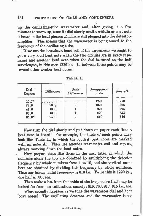
154 PROPERTIES OF COILS AND CONDENSERS
up the oscillating-tube wavemeter and, after giving it a few minutes to warm up, tune its dial slowly until a whistle or beat note •is heard in the head phones which are still plugged into the detector-amplifier. This means that the wavemeter is being tuned to the frequency of the oscillating tube.
If we use the broadcast band coil of the wavemeter we ought to get a very loud beat note when the two circuits are in exact reso-nance and another loud note when the dial is tuned to the half wavelength, in this case 1220 kc. In between these points may be several other weaker beat notes.
TABLE II
Dial Degrees
Difference Units
Difference f—apprœd-
nude f—exact
10.2* 1220 1220
34.0 23.8 2 1020 1016
47.0 13.0 1 920 915
60.0 13.0 1 820 813
85.0* 25.0 2 610 610
Now turn the dial slowly and put down on paper each time a beat note is heard. For example, the table of such points may look like Table II, in which the loudest beat notes are marked with an asterisk. Then use another wavemeter coil and repeat, always marking down the loud notes.
Now prepare data like those in the next table, in which the numbers along the top are obtained by multiplying the detector frequency by whole numbers from 1 to 10, and the vertical num-bers are obtained by dividing this frequency by whole numbers. Thus our fundamental frequency is 610 kc. Twice this is 1220 kc., one half is 305, etc.
Then make a list from this table of the frequencies that may be looked for from our calibration, namely: 610, 763, 813, 915 kc., etc.
What actually happens as we tune the wavemeter dial and hear beat notes? The oscillating detector and the wavemeter tubes
WorldRadioHistory
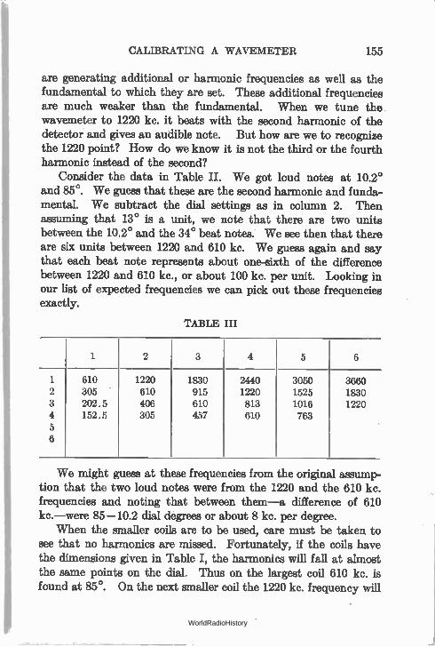
CALIBRATING A WAVEMETER 155
are generating additional or harmonic frequencies as well as the fundamental to which they are set. These additional frequencies are much weaker than the fundamental. When we tune the wavemeter to 1220 kc. it beats with the second harmonic of the detector and gives an audible note. But how are we to recognize the 1220 point? How do we know it is not the third or the fourth harmonic instead of the second?
Consider the data in Table II. We got loud notes at 10.2° and 85°. We guess that these are the second harmonic and funda-mental. We subtract the dial settings as in column 2. Then assuming that 13° is a unit, we note that there are two units between the 10.2° and the 34° beat notes. We see then that there are six units between 1220 and 610 kc. We guess again and say that each beat note represents about one-sixth of the difference between 1220 and 610 kc., or about 100 kc. per unit. Looking in our list of expected frequencies we can pick out these frequencies exactly.
TABLE III
1 2 3 4 5 6
1 610 1220 1830 2440 3050 3660 2 305 610 915 1220 1525 1830 3 202.5 406 610 813 1016 1220 4 152.5 305 457 610 763 5 6
We might guess at these frequencies from the original assump-tion that the two loud notes were from the 1220 and the 610 kc. frequencies and noting that between them—a difference of 610 kc.—were 85-10.2 dial degrees or about 8 kc. per degree.
When the smaller coils are to be used, care must be taken to see that no harmonics are missed. Fortunately, if the coils have the dimensions even in Table I, the harmonics will fall at almost the seine points on the dial. Thus on the largest coil 610 kc. is found at 85°. On the next smaller coil the 1220 kc. frequency will
WorldRadioHistory
156 PROPERTIES OF COILS AND CONDENSERS
be found within a degree or two of 85°. And so on until the entire set of coils is calibrated.
131. Standard Frequencies.—In this country standard fre-quency signals are sent out from the Bureau of Standards at stated intervals and can be heard at distances up to 1000 miles from Washington, D. C. In addition there are many long-wave and intermediate-wave stations whose frequencies are kept within very close limits and which are " on the air" 24 hours of the day. The broadcasting stations themselves form good standards of frequency —especially the better known stations—covering the band from 550 to 1500 kc., and above this are many short-wave stations whose signals may be heard the world over.
132. Calibrating by " clicks."—A method of calibration that is often used is the click method. When a tuned circuit is brought near the inductance of the heterodyne wavemeter, a sharp dip of the grid current needle will be noted as the two circuits are reso-nated to each other. If the same tuned circuit is brought near the inductance of an oscillating detector tube, a sharp click will be heard when the circuits are tuned to the same frequency provided one listens in the plate circuit of this tube or behind a stage of audio-amplification. This click is produced by a sharp change in grid current and a corresponding change in plate current.
Experiment 2-8. Calibration by eliells.—This method requires an oscil-lating detector, a standard meter and the unknown meter to be calibrated.
Couple the standard meter to the inductance of the detector, and turn the dial until a sharp click is heard in the phones indicating that the circuits are tuned alike. If the two inductances are closely coupled two clicks will be heard, one when the tube stops oscillating and one when its starts again. These two points may be several degrees apart. Loosen the coupling, and note that the two clicks approach each other. Keep on loosening it until a degree of coupling is reached when only a single resonance click is noticed. Note the dial setting of the standard meter. Now remove it from the tuned circuit and bring near the latter the wavemeeer to be calibrated. Turn its condenser dial until a click is heard as before. Now the meter has the same frequency, or wavelength, as the standard. Other points for a calibration curve may be noted in the same manner.
This method really constitutes setting a generator or miniature transmitter (the oscillating detector) to a given frequency by means of the standard meter and then tuning the uncalibrated meter to resonance with this generator.
WorldRadioHistory
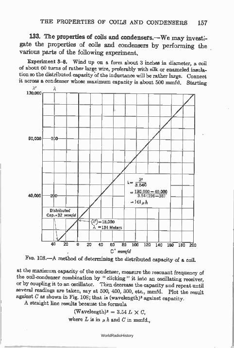
THE PROPERTIES OF COILS AND CONDENSERS 157
133. The properties of coils and condensers.—We may investi-gate the properties of coils and condensers by performing the various parts of the following experiment.
Experiment 3-8. Wind up on a form about 3 inches in diameter, a coil of about 60 turns of rather large wire, preferably with silk or enameled insula-tion so the distributed capacity of the inductance will be rather large. Connect it across a condenser whose maximum capacity is about 500 mmfd. Starting
liu.uuu
90,000
40,000
—3 0
L...
.. 130,000
2?
—40,000
3.54C
200 3.54(196-38) .. 61µh
Distributed Cap..32 mmfd
000 a ...134 Meters
0 20 40 60 80 100 120 140 160 180 200
C. mmfd
Fie. 108.—A method of determining the distributed capacity of a coil.
at the maximum capacity of the condenser, measure the resonant frequency of the coil-condenser combination by " clicking " it into an oscillating receiver, or by coupling it to an oscillator. Then decrease the capacity and repeat until several readings are taken, say at 500, 400, 300, etc., mmfd. Plot the result against C as shown in Fig. 108; that is (wavelength)2 against capacity. A straight line results because the formula
(Wavelength)2 = 3.54 L X C,
where L is in µ h and C in mmfd.,
WorldRadioHistory
158 PROPERTIES OF COILS AND CONDENSERS
is the equation of a straight line and states that the wavelength squared is proportional to the capacity in the circuit. The slope of the line divided by 3.54 is the inductance of the coil, that is,
1 Xs L
3.54 C •
It will be noticed that the straight line crosses the wavelength squared axis at some distance above the zero point. This gives us the natural wave-length squared of the coil itself and therefore the resonant wavelength to which the coil with no additional capacity will tune. The point where the line crosses the capacity axis gives us the distributed capacity of the coil. This value multiplied by the inductance as obtained above gives the LC product which when fitted into the proper formula gives the natural wavelength of the coil.
Thus, in one experiment we can determine not only the frequency or wave-length to which a coil-condenser combination will tune, but we can determine the coil's inductance, its distributed capacity, and its natural wavelength.
As a check on these data: (a) calculate the inductance from the formulas given in Fig. 51. (b) If a heterodyne wavemeter is available and calibrated to short wavelengths, detach the condenser from the coil and click the latter into it, and thereby determine the natural wavelength of the coil.
134. Measurement of coil resistance.—The effect of resistance upon the sharpness of resonance and the selectivity of the circuit has been mentioned (Section 112). The resonance curve gives us one method of measuring the resistance in a given circuit, provided we know the inductance of the coil—which can be calculated from the formula in Fig. 51.
Experiment 4-8. To determine the resistance of a coil.—Couple a series circuit composed of a coil, condenser, and indicating meter to a generator of about 5-watts output. Adjust the frequency of the generator through reso-nance with the series circuit. If the generator has a constant output over this frequency range the accuracy with which the coil resistance is determined will be greater. Pick out the two frequencies above and below resonance where the current in the circuit is .707 of its value at resonance and calculate the width of frequency band at this point and the resistance of the circuit, from the equation
R — Lw (f2 — f i)
fr •
Subtract from this value the resistance of the current meter. For example a model 425 Weston thermo-galvanometer will read currents of 115 milliamperes and has a radio-frequency resistance
WorldRadioHistory
MEASUREMENT OF COIL RESISTANCE 159
of 4.5 ohms. The value of resistance remaining is the resistance of coil, leads, and condenser. Most of this resistance resides in the coil.
Experiment 5-8. To determine resistance of a circuit.—Another method of determining the resistance of a coil is as follows. It necessitates the use of a decade resistance box or series of accurately known resistances of negligible inductance and capacity and a variable condenser.
Small lengths of high-resistance wire (manganin) are to be preferred for frequencies higher than 1000 kc. Their d.-c. and high-frequency resistance is practically the same.
Connect the apparatus in series and couple to an oscillator. With the resistance box short-circuited (R = 0), tune the circuit to reso-
nance. Then add enough resistance to the circuit to halve the current, retuning to resonance, if necessary. Then since we have halved the current, Ohm's law tells us that we have doubled the resistance. In other words the added resistance is equal to the resistance already existing in the circuit. Again subtract the resistance of the current-indicating meter. What remains is the resistance of coils, condensers and leads.
Repeat at several different frequencies and calculate the " sharpness of resonance" Lw/R, and plot against frequency and wavelength.
If only one or two resistance units are available, say 5 or 10 ohms and not a continuously variable standard of resistance like a decade box, the resistance of the circuit above may be determined by noting the current at resonance, and the current when some resistance has been added, retuning to resonance after adding the resistance if necessary. Then the current, according to Ohm's law, is
E Ii = —
R1
where /1 =
/2 =
R1 =
R2 =
whence
E 12 —
± R2'
current at resonance and no added resistance;
current at resonance and R2 added;
resistance of circuit;
added resistance; R212
Ii — — 12.
-r
WorldRadioHistory
160 PROPERTIES OF COILS AND CONDENSERS
If a current-indicating meter is used whose deflections are proportional to the current squared, an example is a thermo-galvanometer or a hot-wire meter, it is only necessary in this experiment to add sufficient resistance to quarter the deflection of the instrument. This is equivalent to halving the current, and the added resistance is equal to the resistance already in the circuit.
The lower the resistance of the current-indicating device, the greater will be the accuracy with which such measurements may be carried out. For example, if the indicator has a resistance of 4.5 ohms and the circuit a resistance of 5 ohms, great accuracy cannot be attained, but if the circuit resistance is double or treble that of the indicator, much greater accuracy results. In any case the meter resistance must be subtracted from the measured resistance to get the resistance due the circuit alone.
135. Condenser capacity.—We will now investigate by means of an experiment the capacity of a condenser.
Experiment 6-8. To determine the capacity of a condenser.—Connect a variable condenser whose calibration is known across a coil and click into an oscillating receiver or into a heterodyne wavemeter; attach the unknown condenser across the variable condenser and retune the latter to resonance with the wavemeter. The difference in readings of the calibrated condenser is the capacity of the unknown condenser. For example, suppose resonance is obtained by the variable condenser alone when set at 4(1) mmfd. Connect-ing the second condenser across the variable forces us to reduce the capacity of the latter to 340 mmfd. The difference 400 - 340 = 60 mmfd. is the capacity of the unknown. Such a method enables the experimenter to dis-regard the capacity of the coil itself or of the leads since these are connected across the variable at all times and do not change when the unknown is attached to the circuit.
136. Antenna wavelength.—We will proceed to determine the wavelength of an antenna by means of the following experiment.
Experiment 7-8. To measure the natural wavelength of an antenna.— Connect in series with the antenna an inductance which can be adjusted in even steps, say a coil of 20 turns with taps at each turn. Measure the fre-quency to which the antenna tunes with the entire coil in the circuit by coupling the coil to a heterodyne wavemeter. Then reduce the inductance by one turn, and repeat. Repeat until accurate readings are no longer possible. Plot wavelength, or frequency, against added turns of wire. Where the line crosses
WorldRadioHistory
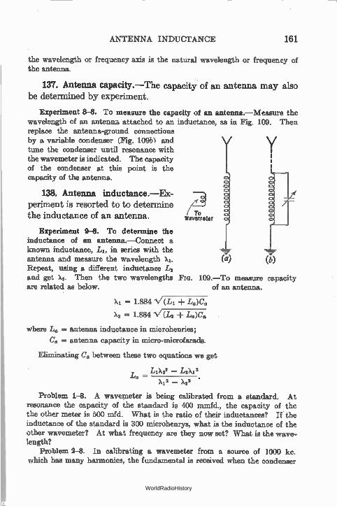
ANTENNA INDUCTANCE 161
the wavelength or frequency axis is the natural wavelength or frequency of the antenna.
137. Antenna capacity.—The capacity of an antenna may also be determined by experiment.
Experiment 8-8. To measure the capacity of an antenna.—Measure the wavelength of an antenna attached to an inductance, as in Fig. 109. Then replace the antenna-ground connections by a variable condenser (Fig. 10961 and tune the condenser until resonance with the wavemeter is indicated. The capacity of the condenser at this point is the capacity of the antenna.
138. Antenna inductance.—Ex-periment is resorted to to determine the inductance of an antenna.
Experiment 9-8. To determine the inductance of an antenna.—Connect a known inductance, LI, in series with the antenna and measure the wavelength X1. Repeat, using a different inductance L2 and get X. Then the two wavelengths FIG. 199.—To measure capacity are related as below.
( fro wavemeter
).1 = 1.884 V(LI La)C.
X2 -= 1.884 V(L2 La)Co
(a)
of an antenna.
where L. = antenna inductance in microhenries;
C„ = antenna capacity in micro-microfarads.
Eliminating Cc, between these two equations we get
L LIX22 — L2X22 a
x22 _ x22
Problem 1-8. A wavemeter is being calibrated from a standard. At resonance the capacity of the standard is 400 mmfd., the capacity of the the other meter is 500 mfd. What is the ratio of their inductances? If the inductance of the standard is 300 microhenrys, what is the inductance of the other wavemeter? At what frequency are they now set? What is the wave-length?
Problem 2-8. In calibrating a wavemeter from a source of 1000 kc. which has many harmonics, the fundamental is received when the condenser
WorldRadioHistory
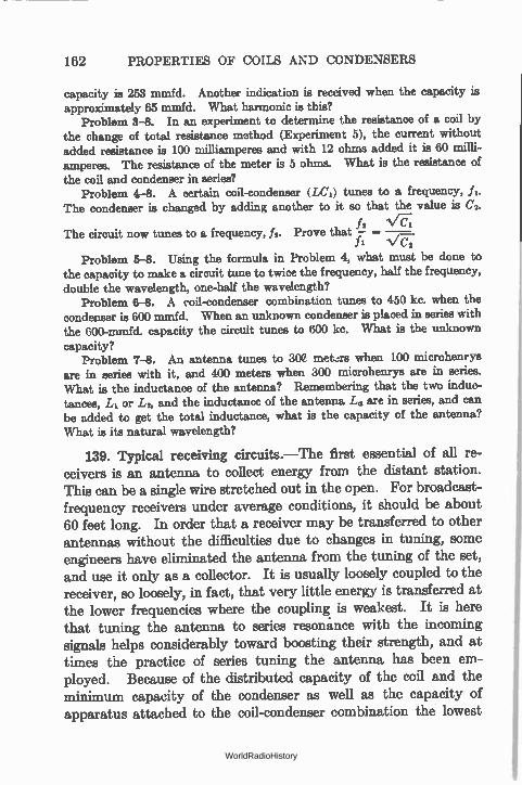
162 PROPERTIES OF COILS AND CONDENSERS
capacity is 253 mmfd. Another indication is received when the capacity is approximately 65 mmfd. What harmonic is this?
Problem 3-8. In an experiment to determine the resistance of a coil by the change of total resistance method (Experiment 5), the current without added resistance is 100 milliamperes and with 12 ohms added it is 60 milli-amperes. The resistance of the meter is 5 ohms. What is the resistance of the coil and condenser in series?
Problem 4-8. A certain coil-condenser (LCI) tunes to a frequency, f i. The condenser is changed by adding another to it so that the value is C2.
h NrC71 The circuit now tunes to a frequency, f,. Prove that — = -V-F;
Problem 5-8. Using the formula in Problem 4, what must be done to the capacity to make a circuit tune to twice the frequency, half the frequency, double the wavelength, one-half the wavelength?
Problem 6-8. A coil-condenser combination tunes to 450 kc. when the condenser is 600 mmfd. When an unknown condenser is placed in series with the 600-mmfd. capacity the circuit tunes to 600 kc. What is the unknown capacity?
Problem 7-8. An antenna tunes to 30C met.ers when 100 microhenrys are in series with it, and 400 meters when 300 microhenrys are in series. What is the inductance of the antenna? Remembering that the two induc-tances, L1 or L:, and the inductance of the antenna L. are in series, and can be added to get the total inductance, what is the capacity of the antenna?
What is its natural wavelength?
139. Typical receiving circuits.—The first essential of all re-ceivers is an antenna to collect energy from the distant station. This can be a single wire stretched out in the open. For broadcast-frequency receivers under average conditions, it should be about 60 feet long. In order that a receiver may be transferred to other antennas without the difficulties due to changes in tuning, some engineers have eliminated the antenna, from the tuning of the set, and use it only as a collector. It is usually loosely coupled to the receiver, so loosely, in fact, that very little energy is transferred at the lower frequencies where the coupling is weakest. It is here that tuning the antenna to series resonance with the incoming signals helps considerably toward boosting their strength, and at times the practice of series tuning the antenna has been em-ployed. Because of the distributed capacity of the coil and the minimum capacity of the condenser as well as the capacity of apparatus attached to the coil-condenser combination the lowest
WorldRadioHistory
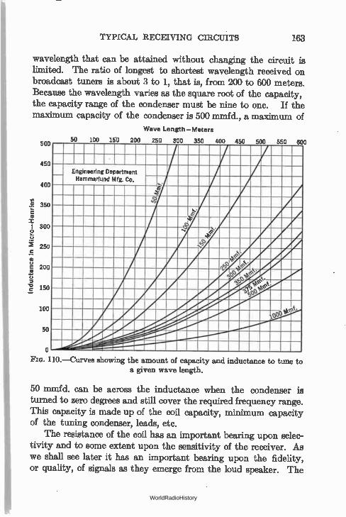
TYPICAL RECEIVING CIRCUITS 163
wavelength that can be attained without changing the circuit is
limited. The ratio of longest to shortest wavelength received on
broadcast tuners is about 3 to 1, that is, from 200 to 600 meters. Because the wavelength varies as the square root of the capacity,
the capacity range of the condenser must be nine to one. If the
maximum capacity of the condenser is 500 mmfd., a maximum of
Wave Length—Meters
Indu
ctan
ce i
n Micro—Henries
500
450
400
350
300
250
200
150
100
50
i uu Lou ZUU ZbU 300 350 400 450 500 550 60
_ Engineering Department Hammarlund Mfg. Co.
/ _e. .".. • „
.22r
._
re 44.14.1.11
., 4 fflill.
AM
.. e (e.
ot •
tre ee,‘,401
SItte. ,b
1Me •
0
FIG. 110.—Curves showing the amount of capacity and inductance to tune to a given wave length.
50 mmfd. can be across the inductance when the condenser is
turned to zero degrees and still cover the required frequency range.
This capacity is made up of the coil capacity, minimum capacity
of the tuning condenser, leads, etc.
The resistance of the coil has an important bearing upon selec-
tivity and to some extent upon the sensitivity of the receiver. As
we shall see later it has an important bearing upon the fidelity,
or quality, of signals as they emerge from the loud speaker. The
WorldRadioHistory
164 PROPERTIES OF COILS AND toaNDENSERS
resistance of modern variable condensers may be neglected. The resistance introduced into coils and accessory circuits by large nearby metallic masses may be considerable, and therefore coils, if shielded, must be kept at a respectable distance from the metallic shielding material.
Modern receivers usually possess from one to four stages of amplification at radio frequencies (or intermediate frequencies) and from one to three stages of audio-frequency amplification.
Inductance in Micro—Henries
10
100
200
300
400
500
111.—Curves showing the approximate inductance of a coil as a function of length of winding and turns per inch for a coil 2% inches in diameter.
Turns per Inch
20 90 ao 50 so
Hammarlund Mfg Co.
1"lo lg
In general the more radio stages the more selective and sensitive the set will be, but the number of tubes is no criterion as to the set's ability to get weak distant stations through strong local interference. A well engineered receiver of four tubes may be much better than a poorly designed receiver of eight tubes. The difference lies not in the number of tubes but in the design and subsequent engineering.
WorldRadioHistory
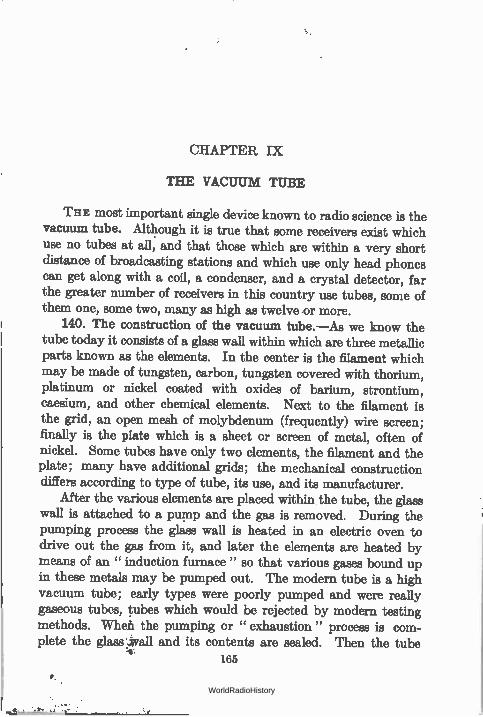
CHAPTER IX
THE VACUUM TUBE
THE most important single device known to radio science is the vacuum tube. Although it is true that some receivers exist which use no tubes at all, and that those which are within a very short distance of broadcasting stations and which use only head phones can get along with a coil, a condenser, and a crystal detector, far the greater number of receivers in this country use tubes, some of them one, some two, many as high as twelve .or more.
140. The construction of the vacuum tube.—As we know the tube today it consists of a glass wall within which are three metallic parts known as the elements. In the center is the filament which may be made of tungsten, carbon, tungsten covered with thorium, platinum or nickel coated with oxides of barium, strontium, caesium, and other chemical elements. Next to the filament is the grid, an open mesh of molybdenum (frequently) wire screen; finally is the plate which is a sheet or screen of metal, often of nickel. Some tubes have only two elements, the filament and the plate; many have additional grids; the mechanical construction differs according to type of tube, its use, and its manufacturer.
After the various elements are placed within the tube, the glass wall is attached to a pump and the gas is removed. During the pumping process the glass wall is heated in an electric oven to drive out the gas from it, and later the elements are heated by means of an " induction furnace" so that various gases bound up in these metals may be pumped out. The modern tube is a high vacuum tube; early types were poorly pumped and were really gaseous tubes, tubes which would be rejected by modern testing methods. Whefi the pumping or " exhaustion " process is com-plete the glass wall and its contents are sealed. Then the tube
165
WorldRadioHistory
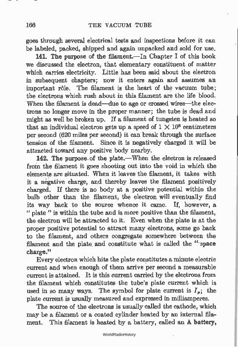
166 THE VACUUM TUBE
goes through several electrical tests and inspections before it can be labeled, packed, shipped and again unpacked and sold for use.
141. The purpose of the filament.—In Chapter I of this book we discussed the electron, that elementary constituent of matter which carries electricity. Little has been said about the electron in subsequent chapters; now it enters again and assumes an important rôle. The filament is the heart of the vacuum tube; the electrons which rush about in this filament are the life blood. When the filament is dead—due to age or crossed wires—the elec-trons no longer move in the proper manner; the tube is dead and might as well be broken up. If a filament of tungsten is heated so that an individual electron gets up a speed of 1 X 10⁸ centimeters per second (620 miles per second) it can break through the surface tension of the filament. Since it is negatively charged it will be attracted toward any positive body nearby.
142. The purpose of the plate.—When the electron is released from the filament it goes shooting out into the void in which the elements are situated. When it leaves the filament, it takes with it a negative charge, and thereby leaves the filament positively charged. If there is no body at a positive potential within the bulb other than the filament, the electron will eventually find its way back to the source whence it came. If, however, a " plate " is within the tube and is more positive than the filament, the electron will be attracted to it. Even when the plate is at the proper positive potential to attract many electrons, some go back to the filament, and others congregate somewhere between the filament and the plate and constitute what is called the " space charge."
Every electron which hits the plate constitutes a minute electric current and when enough of them arrive per second a measurable current is attained. It is this current carried by the electrons from the filament which constitutes the tube's plate current which is used in so many ways. The symbol for plate current is ./,,; the plate current is usually measured and expressed in milliamperes.
The source of the electrons is usually called the cathode, which may be a filament or a coated cylinder heated by an internal fila-ment. This filament is heated by a battery, called an A battery,
WorldRadioHistory
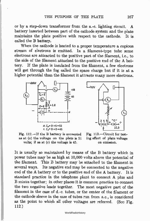
THE PURPOSE OF THE PLATE 167
or by a step-down transformer from the a.-c. lighting circuit. A battery inserted between part of the cathode system and the plate maintains the plate positive with respect to the cathode. It is called the B battery.
When the cathode is heated to a proper temperature a copious stream of electrons is emitted. In a filament-type tube some electrons are attracted to the positive part of the filament, i.e., to the side of the filament attached to the positive end of the A bat-tery. If the plate is insulated from the filament, a few electrons will get through the fog called the space charge but if it is at a higher potential than the filament it attracts many more electrons.
45
a. Ep- B +6 -51 C. E,8 +O-45
Fig. 112.—If the B battery is connected as at (a) the voltage on the plate is 51
volts; if as at (c) the voltage is 45.
Fig. 113.—Circuit for test-ing effect of plate voltage
on emission.
It is usually so maintained by means of the B battery which in power tubes may be as high at 10,000 volts above the potential of the filament. This B battery may be attached to the filament in several ways. Its negative end may be connected to the negative end of the A battery or to the positive end of the A battery. It is standard practice in the telephone plant to connect A plus and B minus together; in other places it is common practice to connect the two negative leads together. The most negative part of the filament in the case of d.-c. tubes, or the center of the filament or the cathode sleeve in the case of tubes run from a.c., is considered as the point to which all other voltages are referred. (See Fig. 112.)
WorldRadioHistory
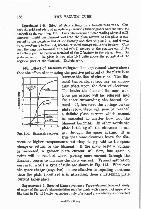
168 THE VACUUM TUBE
Experiment 1-9. Effect of plate voltage on a two-element tube.—Con-nect the grid and plate of an ordinary receiving tube together and connect into a circuit as shown in Fig. 113. Use a plate-current meter reading about 5 amperes. Light the filament and read the plate current as the plate is con-nected to the negative end of the battery and then to plus 2, 4, and 6 volts by connecting it to the first, second, or third storage cell in the battery. Con-nect the negative terminal of a 4.5-volt C battery to the positive end of the A battery and the positive terminal of the C battery to the plate. Read the plate current. The plate is now plus 10.5 volts above the potential of the negative part of the filament. Explain why.
143. Effect of filament voltage.—The experiment above shows that the effect of increasing the positive potential of the plate is to 7 increase the flow of electrons. The fila-
6 ment temperature, too, has an impor-
CX 301-A tant effect upon the flow of electrons. E.1-0 E -90 5 The hotter the filament the more elec-
If tili'Kampen»
4 trons per second will be released into the space surrounding the heated ele-
3 67 ment. If, however, the voltage on the 2 plate is low, there will soon be reached
a definite plate current which cannot 1 , -45
be exceeded no matter how hot the o filament becomes. In other words the
3 4 5 6 • EF plate is taking all the electrons it can
Fig. 114.—Saturation curves. get through the space charge. It is true that more electrons leave the fila-
ment at higher temperatures but they simply add to the space charge or return to the filament. If the plate battery voltage is increased, a greater plate current will flow, but again a point will be reached where passing more current through the filament ceases to increase the plate current. Typical saturation curves for a 201 A type of tube are shown in Fig. 114. Whenever the space charge (negative) is more effective in repelling electrons than the plate (positive) is in attracting them a flattening plate current takes place.
Experiment 2-9. Effect of filament voltage: Three-element tube.—A study •of many of the tube's characteristics may be made with a set-up of apparatus like that in Fig. 115 which consists simply of a board upon which are connected
WorldRadioHistory
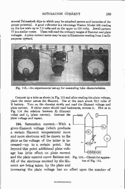
SATURATION dURRENT 169'
several Fahnestock clips to which may be attached meters and batteries of the proper potential. A good voltmeter is a two-range Weston Model 506 reading on the low scale up to 7.5 volts and on the upper to 150 volts. Jewell pattern 77 is a similar meter. These will read the ordinary ranges of filament and plate voltages. A plate current meter may be any milliammeter reading from 5 milli-amperes upward.
Fig. 115.—An experimental set-up for measuring tube characteristics.
Connect up a tube as EthoWn in Fig. 116 and after reading the plate voltage, place the meter across the filament. Use at the start about 22.5 volts of B battery. Turn on the rheostat slowly and read the filament voltage and plate current. If either meter should read backwards, reverse it. Plot as in. Fig. 114 the relation between Ef (filament volts) and 4, (plate current). Increase the plate voltage and repeat.
144. Saturation current—With a given filament voltage (which produces a certain filament temperature) more and more electrons will be drawn to the plate as the voltage of the latter is in-creased—up to a certain point. But beyond this point additional plate volt-age has little effect on plate current 11111111111111i and the plate current curve flattens out. Fig. 116.—Circuit for appara-
All of the electrons emitted by the fila-ment are being taken by the plate and increasing the plate voltage has no effect upon the number of
tua of Fig. 115.
WorldRadioHistory
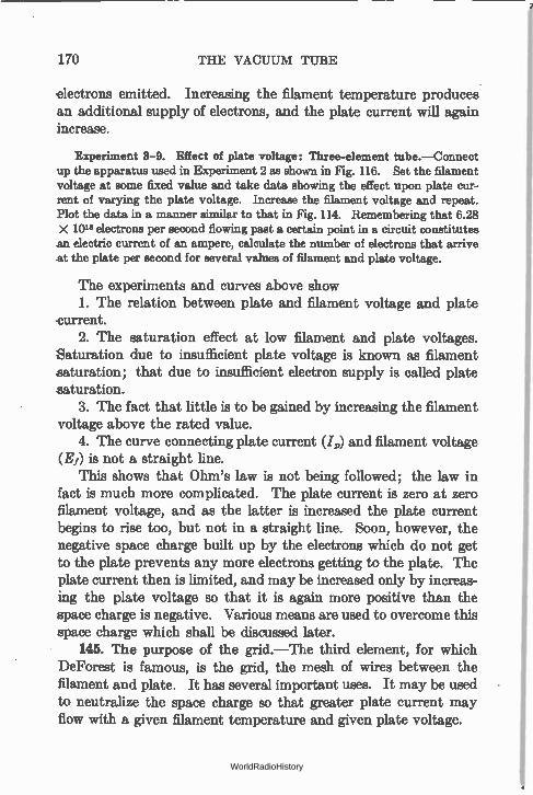
170 THE VACUUM TUBE
electrons emitted. Increasing the filament temperature produces an additional supply of electrons, and the plate current will again increase.
Experiment 3-9. Effect of plate voltage: Three-element tube.—Connect up the apparatus used in Experiment 2 as shown in Fig. 116. Set the filament voltage at some fixed value and take data showing the effect upon plate cur-rent of varying the plate voltage. Increase the filament voltage and repeat. Plot the data in a manner similar to that in Fig. 114. Remembering that 6.28 X 10¹⁸ electrons per second flowing past a certain point in a circuit constitutes an electric current of an ampere, calculate the number of electrons that arrive at the plate per second for several values of filament and plate voltage.
The experiments and curves above show 1. The relation between plate and filament voltage and plate
current. 2. The saturation effect at low filament and plate voltages.
Saturation due to insufficient plate voltage is known as filament saturation; that due to insufficient electron supply is called plate saturation.
3. The fact that little is to be gained by increasing the filament voltage above the rated value.
4. The curve connecting plate current (/„) and filament voltage (Ef) is not a straight line.
This shows that Ohm's law is not being followed; the law in fact is much more complicated. The plate current is zero at zero filament voltage, and as the latter is increased the plate current begins to rise too, but not in a straight line. Soon, however, the negative space charge built up by the electrons which do not get to the plate prevents any more electrons getting to the plate. The plate current then is limited, and may be increased only by increas-ing the plate voltage so that it is again more positive than the space charge is negative. Various means are used to overcome this space charge which shall be discussed later.
145. The purpose of the grid.—The third element, for which DeForest is famous, is the grid, the mesh of wires between the filament and plate. It has several important uses. It may be used to neutralize the space charge so that greater plate current may flow with a given filament temperature and given plate voltage.
WorldRadioHistory
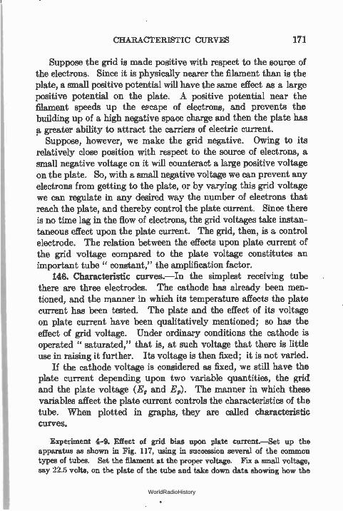
CHARACTERISTIC CURVES 171
Suppose the grid is made positive with respect to the source of the electrons. Since it is physically nearer the filament than is the plate, a small positive potential will have the same effect as a large positive potential on the plate. A positive potential near the filament speeds up the escape of electrons, and prevents the building up of a high negative space charge and then the plate has et greater ability to attract the carriers of electric current.
Suppose, however, we make the grid negative. Owing to its relatively close position with respect to the source of electrons, a small negative voltage on it will counteract a large positive voltage on the plate. So, with a small negative voltage we can prevent any electrons from getting to the plate, or by varying this grid voltage we can regulate in any desired way the number of electrons that reach the plate, and thereby control the plate current. Since there is no time lag in the flow of electrons, the grid voltages take instan-taneous effect upon the plate current. The grid, then, is a control electrode. The relation between the effects upon plate current of the grid voltage compared to the plate voltage constitutes an important tube " constant," the amplification factor.
146. Characteristic curves.—In the simplest receiving tube there are three electrodes. The cathode has already been men-tioned, and the manner in which its temperature affects the plate current has been tested. The plate and the effect of its voltage on plate current have been qualitatively mentioned; so has the effect of grid voltage. Under ordinary conditions the cathode is operated " saturated," that is, at such voltage that there is little use in raising it further. Its voltage is then fixed; it is not varied.
If the cathode voltage is considered as fixed, we still have the plate current depending upon two variable quantities, the grid and the plate voltage (E. and Er). The manner in which these variables affect the plate current controls the characteristics of the tube. When plotted in graphs, they are called characteristic curves.
Experiment 4-9. Effect of grid bias upon plate current —Set up the apparatus as shown in Fig. 117, using in succession several of the common types of tubes. Set the filament at the proper voltage. Fix a small voltage, say 22.5 volts, on the plate of the tube and take down data showing how the
WorldRadioHistory
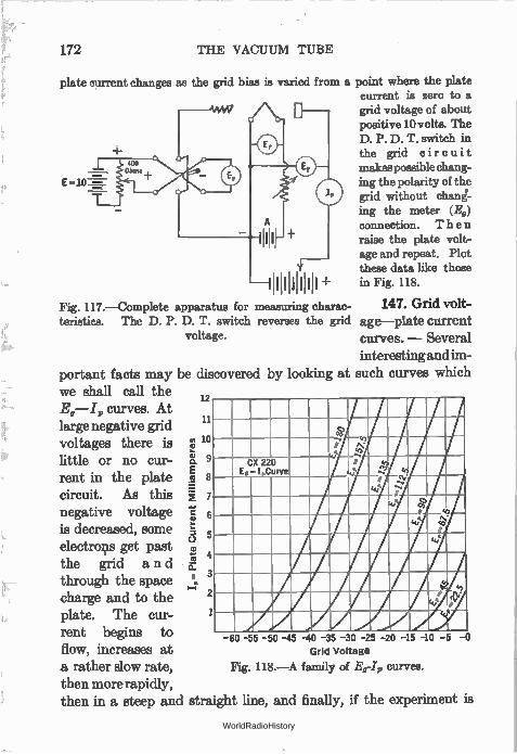
172 THE VACUUM TUBE
plate current changes as the grid bias is varied from a point where the plate current is zero to a grid voltage of about positive 10 volts. The D. P. D. T. switch in the grid circuit makes possible chang-
E = mg the polarity of the grid without chant-ing the meter (E0) connection. Then raise the plate volt-age and repeat. Plot these data like those
11111111iiii+ in Fig. 118.
Fig. 117.—Complete apparatus for measuring charac- 147. Grid volt-teristics. The D. P. D. T. switch reverses the grid age—plate current
voltage. curves. — Several interesting and im-
portant facts may be discovered by looking at such curves which we shall call the
12 curves. At
large negative grid voltages there is io little or no cur- 9
rent in the plate 8
circuit. As this 7
negative voltage É, 6 is decreased, some .; 5
C.) electrons get past
•,;3' 4 the grid and Er.
P through the space . charge and to the plate. The cur-rent begins to flow, increases at a rather slow rate, then more rapidly, then in a steep and straight line, and finally, if the experiment is
.... N'
CX 220 E -I Curve
r .
co co r
ce
co t,.. Ae 21 ge
cce`
-60 -55 -50 -45 -40 -35 -30 -25 -20 -15 -10 -5 -0 Grid Voltage
Fig. 118.—A family of E0-I9 curves.
WorldRadioHistory
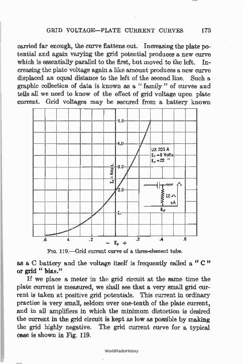
GRID VOLTAGE—PLATE CURRENT CURVES 173
carried far enough, the curve flattens out. Increasing the plate po-tential and again varying the grid potential produces a new curve which is essentially parallel to the first, but moved to the left. In-creasing the plate voltage again a like amount produces a new curve displaced an equal distance to the left of the second line. Such a graphic collection of data is known as a " family " of curves and tells all we need to know of the effect of grid voltage upon plate current. Grid voltages may be secured from a battery known
5.0
4.0
UX 201-A E, =5 Volts E„ -22 "
2.0
1.
.6 4 .2 .2 — E,
Pm. 119.— Grid current curve of a three-element tube.
.4 .6
as a C battery and the voltage itself is frequently called a " C " or grid " bias."
If we place a meter in the grid circuit at the same time the plate current is measured, we shall see that a very small grid cur-rent is taken at positive grid potentials. This current in ordinary practice is very small, seldom over one-tenth of the plate current, and in all amplifiers in which the minimum distortion is desired the current in the grid circuit is kept as low as possible by making the grid highly negative. The grid current curve for a typical case is shown in Fig. 119.
WorldRadioHistory
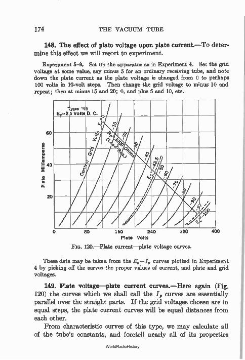
174 THE VACUUM TUBE
148. The effect of plate voltage upon plate current.—To deter-mine this effect we will resort to experiment.
Experiment 5-9. Set up the apparatus as in Experiment 4. Set the grid voltage at some value, say minus 5 for an ordinary receiving tube, and note down the plate current as the plate voltage is changed from 0 to perhaps 100 volts in 10-volt steps. Then change the grid voltage to minus 10 and repeat; then at minus 15 and 20; 0, and plus 5 and 10, etc.
60
20
4ype Et=2
I '45
5 Volts D. C. , e , e 1'0
r< 3.›.
o .3, .
ei o ,, do / 0 0 /
0 0 / /
, 1 / / 00_
> / /
80 160 240 Plate Volts
Fra. 120.— Plate current— plate voltage curves.
320 400
These data may be taken from the Eg —1,, curves plotted in Experiment 4 by picking off the curves the proper values of current, and plate and grid voltages.
149. Plate voltage—plate current curves.—Here again (Fig. 120) the curves which we shall call the /„ curves are essentially parallel over the straight parts. If the grid voltages chosen are in equal steps, the plate current curves will be equal distances from each other.
From characteristic curves of this type, we may calculate all of the tube's constants, and foretell nearly all of its properties
WorldRadioHistory
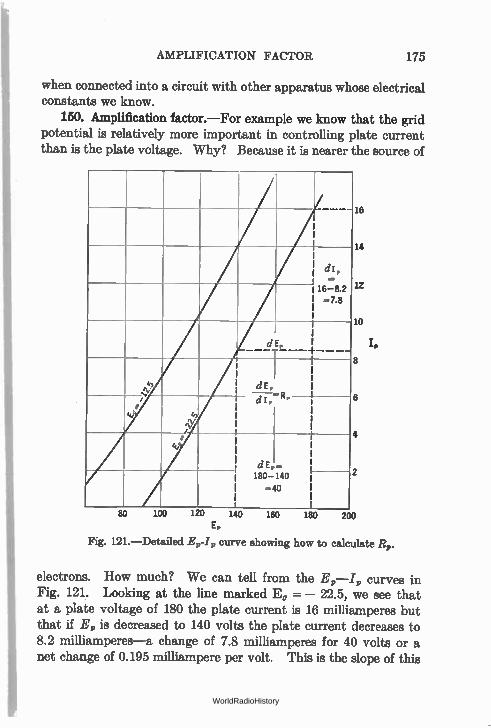
AMPLIFICATION FACTOR 175
when connected into a circuit with other apparatus whose electrical constants we know.
150. Amplification factor.—For example we know that the grid potential is relatively more important in controlling plate current than is the plate voltage. Why? Because it is nearer the source of
/dl, =
16-8.2 =7.8
dE,
4, ev N
dE,
• 3/4 3/4
.‘" 1., /
i—Ip=R°
• 3/4
dE, 180-140
-40
100 140 160 180
18
14
1Z
10
8
6
200 E,
Fig. 121.—Detailed Ee l, curve showing how to calculate Rp.
electrons. How much? We can tell from the E„—I, curves in Fig. 121. Looking at the line marked E, = — 22.5, we see that at a plate voltage of 180 the plate current is 16 milliamperes but that if E, is decreased to 140 volts the plate current decreases to 8.2 milliamperes—a change of 7.8 milliamperes for 40 volts or a net change of 0.195 milliampere per volt. This is the slope of this
WorldRadioHistory
176 THE VACUUM TUBE
particular line and, as we shall see later, it gives us another impor-tant tube constant without further calculation.
Now looking at the two curves marked E, = — 12.5 and E, = —22.5 at the points where they cross the 140-volt E„ line, we see that at this value of plate voltage the plate current is respec-tively 14.0 and 8.2 milliamperes at these two values of grid voltage. This means that changing the grid voltage by 10 volts causes a change of 5.8 milliamperes in the plate current, a net change of 0.58 milliampere per volt. Dividing the change per volt caused by E, variations, by the change per volt produced by E„ variations gives us the relative ability of the grid and plate potentials to influence the plate current. Thus,
Ability of grid voltage to control plate current
Ability of plate voltage to control plate current
0.58 ma./volt — 3.0.
0.195 ma./volt
This ratio is defined as the amplification factor of the tube. It. is the ratio between the plate voltage change required to produce a certain plate current change and the grid voltage change required to produce the same change in plate current. The Greek letter mu, ;4 is the symbol used in the literature for the amplification factor of a tube. Thus
plate voltage change to produce a given plate current change — gridvoltage change to produce the same plate current change'
The amplification factor for a given tube does, not vary much under the conditions under which the tube is ordinarily used. It is controlled largely by its mechanical construction, and the nearness of the grid to the filament. A grid composed of many wires close to the filament produces a high amplification factor; a tube with a wide mesh and not so close to the filament produces a tube with a low amplification factor.
The student should note that the amplification factor is not the ratio between plate and grid voltages, but is the ratio between
WorldRadioHistory
EQUIVALENT TUBE CIRCUIT 177
changes in these voltages. It may be expressed in more mathe-matical language as
dE„ = — to produce a given dI,,
dE,
where the prefix " d " signifies " a change in" (a differential). The amplification factor may be obtained from the E,-I,,
curves in Fig. 121 in a manner similar to that outlined above. It is also equal to the change in I„ produced by, say 20 volts change in E, divided by the change in I„ produced by 20 volts change in E„. Thus in Fig. 120 changing E, from —40 to —20 (with E„ -= 160) produces a variation of 32 milliamperes while along the =— 40 line a change of E, from 200 to 220 volts produces...a
variation of approximately 11 ma. Then
32 = — = 3 (approx.)
11 which is about right for a 45.
151. The meaning of the amplification factor.—If the ampli-fication factor of a tube is 3, for example, adding 30 volts to the plate will increase the plate current a certain amount. Adding only 10 volts (positive) to the grid will produce the same plate current change or adding 10 volts negative to the grid will bring the plate current back to its value before the plate voltage had been increased. In other words any voltage placed on the grid of such a tube has the same effect as a voltage in the plate circuit multiplied—or amplified—by the g of the tube. A voltage E, on the grid becomes equal to 12E, when it gets to the plate circuit.
152. Equivalent tube circuit.—Since a change in plate voltage may be replaced by a smaller change in grid voltage multiplied by the µ of the tube, we may replace the entire tube by a fictitious generator whose voltage is µE, and whose internal resistance is equal to the resistance of the tube. In fact in all problems the tube is so considered, and is indicated symbolically as in Fig. 122.
Problem 1-9. With a 20-volt bias the plate current of a tube under a given value of E, is 55 ma., and when the bias is increased to 30 volts the plate current is reduced to 28 ma. If, however, at this value of grid bias ( —30)
WorldRadioHistory
178 THE VACUUM TUBE
the plate voltage is increased from 180 to 210 volts the plate current comes back to its original value, 55 ma. What is the amplification factor of the tube?
Problem 2-9. The amplification of a tube is 8 and when the grid is — 3 volts the plate current is 3 ma. If the bias is reduced to zero the current in-creases to 8 ma. Both of these current values were read when the plate voltage was 90 volts. How much would the plate voltage have to be reduced (at zero grid bias) to bring back the current to its 3 ma. value?
Problem 3-9. Changing the plate voltage of a power tube from 100 to 300 volts changes the plate current from 10 to 55 ma. If the bias is zero at the latter figure what must be done to it to reduce the .current to its former value if the amplification factor is 7.8?
R, I—MAW/OA-1
Fig. 122.—The tube and its equivalent circuit; a voltage AEG in series with R„ and the load.
153. D.-c. resistance of a tube.—Since a certain plate current flows under the pressure of a certain plate voltage, the ratio
E, R =
in which E„ = the d.-c. voltage on the plate; = the d.-c. current in the plate circuit,
gives the d.-c. resistance of the space between the filament and the plate. The power used up by the electronic current may be found by multiplying the plate voltage by the plate current, or
P = I,E, or —42 or Ip2R.
This power is the rate at which the kinetic energy possessed by the moving electrons is given up to the plate. When the electron leaves the filament it is attracted toward the plate, increasing in
WorldRadioHistory
INTERNAL RESISTANCE OF THE TUBE 179
speed as it gets closer and closer to the positive potential which is the attracting force. When the electron hits the plate its kinetic energy due to its motion is given up. In a transmitting tube the number of electrons that arrive per second may be so high that the plate becomes red- or white-hot.
154. Internal resistance of the tube.—This d.-c. resistance is not what is popularly known as the " impedance " of the tube, or more properly called its " plate resistance" or " differential or internal resistance." The latter is the ratio between a change in plate voltage and the change in plate current produced by this change in plate voltage. It is the resistance offered to the flow of a.-c. currents in the plate circuit and is not the same resistance as is offered to the flow of d.-c. current from the battery. Then
change in plate voltage dE, R, — or
change in plate current dl
For example changing the plate voltage from 180 to 140 volts (Fig. 121) produced a plate current change of 78 milliamperes (0.0078 ampere)
dE, 180 — 140 40 R,, 7 — 5200 ohms (approx.).
di, .016 — .0082 — .0078
Problem 4-9. Make a table showing the d.-c. resistance of various tubes in general use at the conditions they ordinarily work, that is, a 232 tube at E, = 135 volts and Eg = 3, a 45 with Eg = 180 and Eg = — 33. Use values of plate current in the tube chart. Compare the d.-c. resistance with the a.-c. resistance.
Problem 5-9. The plate current of a tube is 4.5 ma. when E,, = 90 volts, and is equal to 0.9 ma. when Ep = 40 volts. What is the plate resistance?
Problem 6-9. The plate resistance of a tube is 12,000 ohms. At Ep = 140, I, = 14.5 ma. What is I,, when E, = 100 volts?
Problem 7-9. Calculate the d.-c. resistance of the tube under the two conditions of E, and I,, in Problem 6, and the power used in heating the plate.
The internal resistance changes with plate and grid voltages and so the conditions of both must be considered when the resist-ance is. mentioned. Thus the UX 171 has an. internal resistance of 2000 ohms when the plate voltage is 180 volts, and the grid
, WorldRadioHistory
180 THE VACUUM TUBE
voltage is 40.5 volts negative. Its internal resistance differs if either E„ or E, is varied.
The student should note that R„ is not the ratio between a plate voltage and a plate current but is a ratio between changes in both plate current and plate voltage. Thus a 201-A tube at a plate voltage of 90 has a plate current of 2.5 ma. The ratio 90 0025 - 36,000 ohms is the d.-c. resistance; R,, is equal to about . 13,000 ohms under these conditions.
155. Mutual conductance of a tube.—There is one more impor-tant tube constant, the mutual conductance. This is the factor which tells us how much plate current change is caused by a given grid voltage change. Thus
G change in plate current dl, m -
change in grid voltage dE,
Thus if a change of one grid volt produces a change of plate current of 1 milliampere, the mutual conductance
- 1 Urn 1 X 10⁻³- 1 X 10 -3 mho or 1000 micromhos.
The mutual conductance is defined, too, by the ratio between the amplification factor and the plate resistance. Thus
dI Gm = = — because µ = and R = dE dE
dE„ dE, dI,
dE„
dE,
R„ = dE, dEg.
dl„
Problem 8-9. A tube has a plate current of 7.75 ma. at zero grid bias and 3.8 ma. at E, = —4. What is the mutual conductance?
Problem 9-9. The mutual conductance of a tube is 800 micromhos. What change in plate current is produced by a 1 volt change on the grid?
Problem 10-9. The mutual conductance of a tube is 775 micromhos. The plate current at Ea = —6 is 2 ma. What is the plate current at Eg = —2?
Therefore
WorldRadioHistory
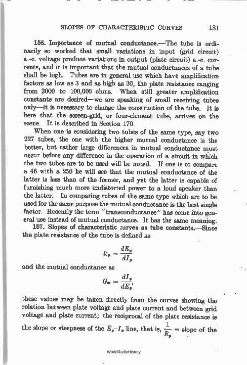
SLOPES OF CHARACTERISTIC CURVES 181
156. Importance of mutual conductance.—The tube is ordi-narily so worked that small variations in input (grid circuit) a.-c. voltage produce variations in output (plate circuit) a.-c. cur-rents, and it is important that the mutual conductances of a tube shall be high. Tubes are in general use which have amplification factors as low as 3 and as high as 30, the plate resistance ranging from 2000 to 100,000 ohms. When still greater amplification constants are desired—we are speaking of small receiving tubes only—it is necessary to change the construction of the tube. It is here that the screen-grid, or four-element tube, arrives on the scene. It is described in Section 170.
When one is considering two tubes of the same type, say two 227 tubes, the one with the higher mutual conductance is the better, but rather large differences in mutual conductance must occur before any difference in the operation of a circuit in which the two tubes are to be used will be noted. If one is to compare a 46 with a 250 he will see that the mutual conductance of the latter is less than of the former, and yet the latter is capable of furnishing much more undistorted power to a loud speaker than the latter. In comparing tubes of the same type which are to be used for the same purpose the mutual conductance is the best single factor. Recently the term "transconductance" has come into gen-eral use instead of mutual conductance. It has the same meaning.
157. Slopes of characteristic =ryes as tube constants.—Since the plate resistance of the tube is defined as
dE R = P
P dI,
and the mutual conductance as
dl G. =
these values may be taken directly from the curves showing the relation between plate voltage and plate current and between grid voltage and plate current; the reciprocal of the plate resistance is
1 the slope or steepness of the Er-17, line, that is, —R, = slope of the
WorldRadioHistory
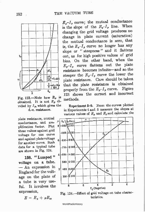
182 THE VACUUM TUBE
tp
-A-
Fig. 123.—Note how R9 is obtained. It is not E9 di-vided by I, which gives the
d.-c. resistance.
plate resistance, mutual conductance, and am-plification factor. Plot 8
these values against grid voltage for one curve and against plate voltage for another curve. Such data for a typical tube are shown in Fig. 124.
158. " Lumped " voltage on a tube. — An expression in England for the volt-age on the plate of a tube is very use-ful. It involves the expression,
E = E, liEg,
11
6
E9-I, curve; the mutual conductance is the slope of the E5-I, line. When changing the grid voltage produces no change in plate current (saturation) the mutual conductance is zero, that is, the 4—I, curve no longer has any slope or " steepness" and it flattens out, as for high positive values of grid bias. On the other hand, when the
curve flattens out the plate resistance becomes infinite—and so the steeper the E9-I, curve the lower the plate resistance. Care should be taken that the plate resistance is obtained properly from the E9-I, curve. Figure 123 shows the correct and incorrect methods.
Experiment 5-9. From the curves plotted in Experiments 4 and 5 measure the slopes at various values of E„ and 4, and calculate the
GM 9Ohm
-1-000
900
-8
-70
-60
500
! 400
30
2 00
du
0
800
6 000
Gu
400
12 000
00
000
riP
- -
2
6 Eg (Negative)
Fig. 124.—Effect of grid voltage on tube charac-teristics.
WorldRadioHistory
"LUMPED" VOLTAGE ON A TUBE . 183
where E -= the effective or " lumped " voltage on the plate; E„ = the plate voltage due to the B battery; E, = the voltage on the grid, due a C bias;
1.1 = the amplification factor of the tube.
For example we know that adding a negative C bias to a tube's grid reduces the plate current. The same value of plate current may be attained without the C bias by reducing the plate voltage. Then for every value of plate current there is a combination of grid bias and plate voltage that will produce it, the actual values being given by the above expression.
If, then, we plot the single curve showing the plate current at various plate voltages but with the grid at zero bias, we can easily calculate what the plate current will be under some other condi-tion of B and C voltage. Thus with zero bias and 90 volts on the plate, the plate current may be 10 ma. That is,
E = 90 + il X 0 = 90
Now suppose p = 8 and E, = —3
E = 90 ± 8 X ( — 3) = 90 — 24 = 66.
To get I„, it is only necessary to look at our E,—I, curve for E, --. 0 and find what j, is when E, = 66. This is the value of current desired, and is one point on the new curve E, = —3. Then assume some other value of E„ and find the new I„ and place a mark on «the graph paper for this point which is the second for the E, = — 3 curve. Other points may be obtained for other values of E„ and E„ and thus any number of curves may be drawn which will be parallel to the first or E, = 0 curve.
Problem 11-9. The p of a tube is 3; what is the lumped or effective plate voltage when E, = 180 and E, = — 40?
Problem 12-9. The plate voltage E„ on a tube is 120 but the plate cur-rent corresponds to a plate voltage of 40 at zero grid bias. If the value of E, is 10, what is the p of the tube? Do you see a simple way of measuring the amplification factor of a tube by this method?
Problem 13-9. If the plate current of a tube is 2 ma. when E, = 90 and Ea = —4.5 and p = 8, at what value of E, will it be equal to 2 ma. when Eg = 0?
WorldRadioHistory
184 THE VACUUM TUBE
159. Measurements of vacuum tube constants.—The various factors which define all of a tube's characteristics—s, R„, and Gm— are known as the tube constants. It is very important that means be handy for measuring these constants at various values of plate and grid voltage so that a full knowledge of a tube's character-istics may be had.
Such calculations may be made by means of the characteristic curves. This is slow work, however, and the experimenter or radio service man has no time for such processes. A simpler method will be described.
(a) To measure the plate resistance of a tube.
This is the ratio between the change in plate voltage and the change in plate current: dE„/d/p. Set the grid bias at the value desired, for example — 6 for a 237, and choose the plate voltage at which the tube will operate in practice at this bias. Then set the voltage at values somewhat higher and then somewhat lower than this median value, measure the plate currents, set down the data below in which the currents and voltages will be values secured by testing a 237.
100 — 80 20 R„ = dEp/d1„ = = — 7700 ohms.
.0033 — .0007 .0026
This means that at a grid bias of E, = — 6, the average plate resistance between the values of E„ = 80 and 100 volts is 7700 ohms.
It will be somewhat difficult to measure tubes of high resist-ance, screen grid tubes, by this method because the plate current curves are almost flat over the working range of plate voltages.
(b) To measure the mutual conductance.
This is the ratio between plate current change dl„ and the grid voltage change dE„ that produced it. Set the plate voltage at the value at which the tube will operate, for example: 90 volts. If the bias under operating conditions is to be 6 volts (a 237) set the grid at minus 7 and then minus 5 and read the plate cur-
WorldRadioHistory
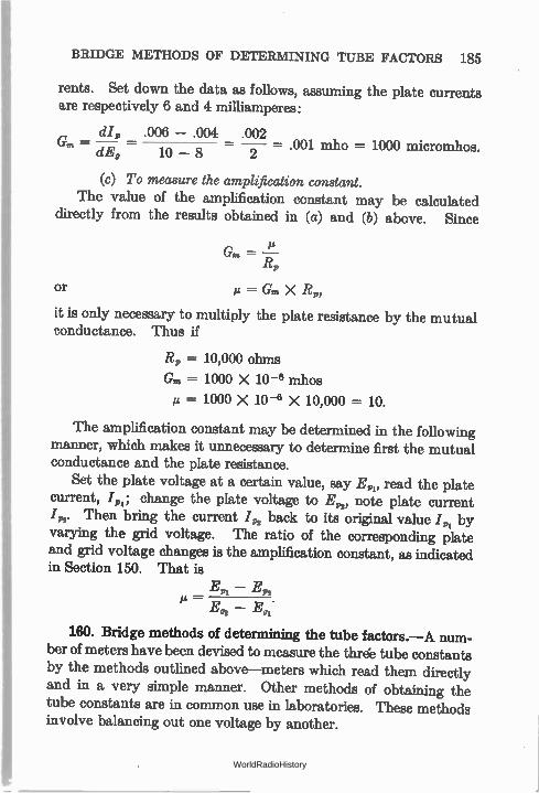
BRIDGE METHODS OF DETERMINING TUBE FACTORS 185
rents. Set down the data as follows, assuming the plate currents are respectively 6 and 4 milliamperes:
dl„ .006 - .004 .002 00 Gp. - - - - .1 mho = 1000 micromhos.
dEp
(c) To measure the amplification constant. The value of the amplification constant may be calculated
directly from the results obtained in (a) and (b) above. Since
Gm = I Rp
or et = Gm X Rp,
it is only necessary to multiply the plate resistance by the mutual conductance. Thus if
Rp = 10,000 ohms
Gm = 1000 X 10 -6 mhos
µ = 1000 X 10 -6 X 10,000 = 10.
The amplification constant may be determined in the following manner, which makes it unnecessary to determine first the mutual conductance and the plate resistance.
Set the plate voltage at a certain value, say E,,, read the plate current, I„i; change the plate voltage to E„,, note plate current 42. Then bring the current /7,2 back to its original value 1.„i by varying the grid voltage. The ratio of the corresponding plate and grid voltage changes is the amplification constant, as indicated in Section 150. That is
Ein - .E7,2 M-
E 02 - E g:
160. Bridge methods of determining the tube factors.—A num-ber of meters have been devised to measure the thre'e tube constants by the methods outlined above—meters which read them directly and in a very simple manner. Other methods of obtaining the tube constants are in common use in laboratories. These methods involve balancing out one voltage by another.
WorldRadioHistory
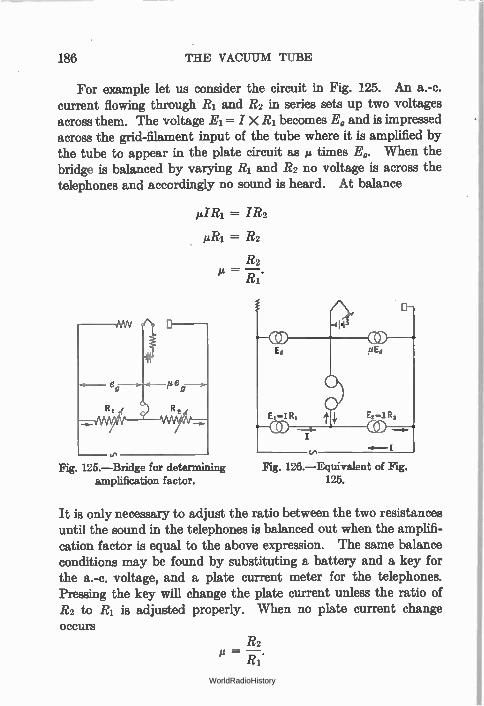
186 THE VACUUM TUBE
For example let us consider the circuit in Fig. 125. An a.-c. current flowing through R1 and R2 in series sets up two voltages across them. The voltage Ei = I X R1 becomes E, and is impressed across the grid-filament input of the tube where it is amplified by the tube to appear in the plate circuit as kg times E,. When the bridge is balanced by varying R1 and R2 no voltage is across the telephones and accordingly no sound is heard. At balance
MIR' = IR2
iiiii = R2
R2
14 = —. Ri
<___ e g— o
R 1 R,
-0.- —I-
te
Fig. 125.—Bridge for determining amplification factor.
Fig. 126.—Equivalent of Fig. 125.
It is only necessary to adjust the ratio between the two resistances until the sound in the telephones is balanced out when the amplifi-cation factor is equal to the above expression. The same balance conditions may be found by substituting a battery and a key for the a.-c. voltage, and a plate current meter for the telephones. Pressing the key will change the plate current unless the ratio of R2 to R1 is adjusted properly. When no plate current change Occurs
R2
Ri
WorldRadioHistory
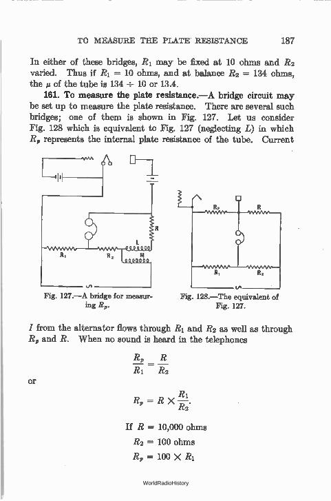
Fig. 127.—A bridge for measur-ing R,.
TO MEASURE THE PLATE RESISTANCE 187
In either of these bridges, R1 may be fixed at 10 ohms and R2 varied. Thus if R1 = 10 ohms, and at balance R2 = 134 ohms, the IA of the tube is 134 ÷ 10 or 13.4.
161. To measure the plate resistance.—A bridge circuit may be set up to measure the plate resistance. There are several such bridges; one of them is shown in Fig. 127. Let us consider Fig. 128 which is equivalent to Fig. 127 (neglecting L) in which R, represents the internal plate resistance of the tube. Current
o Fig. 128.—The equivalent of
Fig. 127.
I from the alternator flows through R1 and R2 as well as through R, and R. When no sound is heard in the telephones
R, R
R1 R2 or
R R, = R X i —
R2.
If R = 10,000 ohms
R2 = 100 ohms
R, = 100 X R1
WorldRadioHistory
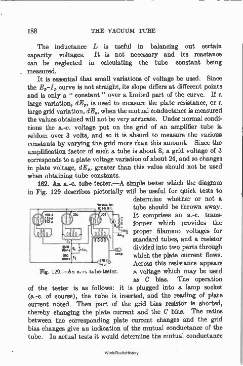
188 THE VACUUM TUBE
The inductance L is useful in balancing out certain capacity voltages. It is not necessary and its reactance can be neglected in calculating the tube constant being measured.
It is essential that small variations of voltage be used. Since the E„-I„ curve is not straight, its slope differs at different points and is only a constant" over a limited part of the curve. If a large variation, dE,, is used to measure the plate resistance, or a large grid variation, dE,, when the mutual conductance is measured the values obtained will not be very accurate. Under normal condi-tions the a.-c. voltage put on the grid of an amplifier tube is seldom over 3 volts, and so it is absurd to measure the various constants by varying the grid more than this amount. Since the amplification factor of such a tube is about 8, a grid voltage of 3 corresponds to a plate voltage variation of about 24, and so changes in plate voltage, dE,, greater than this value should not be used when obtaining tube constants.
162. An a.-c. tube tester.—A simple tester which the diagram in Fig. 129 describes pictorially will be useful for quick tests to
determine whether or not a Wtston 101. 3015 1111, tube should be thrown away.
It comprises an a.-c. trans-former which provides the proper filament voltages for standard tubes, and a resistor divided into two parts through which the plate current flows. Across this resistance appears A. voltage which may be used as C bias. The operation
of the tester is as follows: it is plugged into a lamp socket (a.-c. of course), the tube is inserted, and the reading of plate current noted. Then part of the grid bias resistor is shorted, thereby changing the plate current and the C bias. The ratios between the corresponding plate current changes and the grid bias changes give an indication of the mutual conductance of the tube. In actual tests it would determine the mutual conductance
Fig. 129.—An a.-c. tube-tester.
WorldRadioHistory

TYPES OF TUBE FILAMENTS 189
of several types of tubes within 80 per cent or better of the value as measured upon an accurate bridge.
Suppose for example that the plate current is 0.001 ampere when the bias resistor is 4000 ohms and 0.003 ampere (3 milli-amperes) when the bias resistance is reduced to 500 ohms. We set the data down as
dI .003 - .001 .002 .002 Gm - P -
dE„ .001 X 4000 - .003 X 500 4.0 - 1.5 2.5
= .0008
= 800 micromhos.
163. Types of tube filaments.—The filament of the vacuum tube has undergone many mutations since the invention of the tube. What is desired, of course, is a copious emitter of electrons, that is, one which gives off many electrons at a low filament temperature and with expenditure of little current from the heating battery. Tubes which burn with a dull glow—Western Electric tubes, the WI) 12, the 112-A; the 30, 45, 47 and the rectifier tubes such as the UX 280, have filaments which burn at a com-paratively low temperature. They are very efficient because they are coated with rare elements which emit many electrons even though the temperature is not high.
Another type of filament is the thoriated tungsten filament. It is made of tungsten which is impregnated with atomic thorium. When the filament is heated the thorium gives off the electrons, and as the supply on the surface of the wire is exhausted a new supply comes from the interior of the filament. If, due to an acci-dental overload of filament voltage, the tube seems not to have the required plate current, it is probable that the balance between the rate at which the surface electrons are used up and the rate at which they come from the interior of the filament has been upset. The tube may then be reactivated, as explained in the following section.
The thoriated filament is very efficient, requiring much less power from the filament battery than any other kind of filament for a given amount of power output. The filament in the 199 type
WorldRadioHistory
190 THE VACUUM TUBE
of tube is finer than the human hair, and requires only 60 milli-amperes to give sufficient emission—which should be compared with the 201 type of tube used in the early days of radio. It required 1 ampere at 5 volts to heat it sufficiently to give off a rather meager supply of electrons.
164. Reactivating thoriated filaments.—The older types of tube usually evidence the end of their useful life by burning out. The thoriated filament, on the other hand, has a practically con-stant output until the thorium is exhausted and then the output of the tube falls off rapidly although the filament still lights and looks perfectly normal. The test for such cases is to connect grid and plate together, apply a certain voltage to these common ele-ments and the filament, read the current, and if it falls below a certain value " reactivate."
Machines for reactivating thoriated filaments are on the market and diagrams of connections for such devices and directions may be secured from tube manufacturers. Modern types of cathodes cannot be successfully reactivated.
165. Alternating-current tubes.—Tubes which can be heated by a.c. are almost universally used (heater-type) because of the greater simplicity of operation. A transformer attached to an a.-c. circuit is much less cumbersome than a storage battery which must be periodically charged. There are several easons why we cannot run the ordinary type of tube from a.c. When ordinary battery-operated tubes are lighted by a.c. an objectionable hum results. Suppose we lighted the filament from a.c. The voltage along the filament is continually changing, part of the time one side is positive with respect to the other, and part of the time it is negative. There is a continual heating and cooling going on which cannot help but transmit some of its variations to the plate
circuit. If a centertapped resistor is placed across the filament and the
plate and grid circuits are attached to the center of the filament as in Fig. 176, the hum emanating from the plate circuit is less, but the filament is too light and has too little thermal inertia to with-stand the continual heating and cooling without transferring some of its variations to the plate circuit. The hum is still too great.
WorldRadioHistory
HEATER TYPES OF TUBES 191
Suppose, however, we have a very heavy filament with a low voltage across it. It has a high thermal inertia and it is possible to get a good balance between the electromagnetic and electro-static fields at the value of plate current desired by introducing the grid and plate circuits to the center of the filament by means of a centertapped transformer winding, or a resistor. Such is the 226 type of tube. This uses a very rugged oxide-coated filament which consumes 1.05 amperes at a voltage of 1.5. The voltage drop across the tube is low, its thermal inertia is high, it has a very low hum output. It can be used as a radio-frequency amplifier and to some extent as an audio-frequency amplifier.
166. Heater types of tubes.—The separate heater type of tube has a metal cylinder which surrounds a filament heated by alter-nating current. The cylinder is heated by conduction and convec-tion from the filament proper from which it is electrically insulated. The thermal inertia of the cylinder and the insulating material is so great that fluctuations in a.-c. voltage of the filament do not affect the plate current.
The hum appearing in the plate circuit of such tubes, when operated from alternating current, is much less than in the 226 type. In addition to the decrease in hum there are other advan-tages to the heater type of tube. As a matter of fact, so great are the advantages of this type that it has practically displaced the filament type in home radio receivers.
The cathode, which is the coated cylinder and from which electrons flow, has no connection with the filament inside it which may be heated from a.c. or d.c.
Often the heater is biased either positive or negative with respect to the cathode. The idea is to still further prevent any flow of hum or noise from the a.-c. line into the cathode and thence into the amplification system.
The heater-type of tube is sturdier; therefore less subject to microphonic noises; in less danger of damage from shocks, etc. It has the disadvantage that appreciable time is required to get the cathode hot enough to emit electrons.
167. Operating filaments in series.—Under ordinary circum-stances vacuum tubes are operated with their filaments in parallel,
WorldRadioHistory
Ant.
Grd.
Bus
113 — 500 " lo 04 — 300,000 " I.
R is — 300,000 R9 —100.000 " II
R 7 —200,000 " ii s R g —250,000 " lil 8 — 2700 "
1 R7 = Volume Control 08= Tone Control
2
RESISTANCE VALUES 350 Ohms 10 2000 Ohms
02 — 2000 " Rii— 6000 " R12— WOO R23-100,000 R14 -300.000 R18 -300,000 R 16 — 50,000
Cl
Line
Switch on Tone Control
i rII-4 to" Ce C2 20130
epº:ol so) -És-ri t 0990_, —80 Spk. Field
970 w CONDENSER VALUES
992,
56 53
Cuw.
C7— 8 Mfd, Electro. C2— 16 Mfd. Electro. C 8— 20 Mid. Electro.
To Cg— .05 Mid. All C6— .006 "
JFila. C — .05 " C7— .01 " Ce— .01 " Cg— .1 " Cir .25 "
C11 —.05 Mid. C12—.25 "
C14 —.01 " C18—.0015" C10—.05 " C17 —.0005 " C18—.0005 " C18 -20 Mid, Electra. C20 —.25 Mid. Cou —.07 "
Fm. 130.—Circuit diagram of 1933 superheterodyne. The first tube (58) is an r.-f. amplifier, the second (56) is an oscillator, the next two 58's are first detector, or mixer tube, and i.-f. amplifier, and the following tubes act as second
detector and a.v.c. tube (55), first and final stage a.-f. amplifiers. The 53 is a complete Class B amplifier.
WorldRadioHistory
OPERATING FILAMENTS IN SERIES 193
so that the total current taken is the sum of the filament currents of the individual tubes. It is possible, however, to operate the tubes with their filaments in series, and under some circumstances this is preferable to the other arrangement.
It is more difficult to rectify and filter large currents at low voltages than small currents at high voltages. If, however, it is possible to get a well rectified and filtered source of current at say 250 ma. we can operate a radio receiver with ordinary tubes from the a.-c. circuit by connecting the filaments in series.
o B +13
+90
1 2 3 R.F. R.F. Det
T+5 -2.5 — + —2.5 —
lOw 10W 5
45 4 A.F.
/\ [IF
( )
—10
5 0 A.F /.s. /\ 3—°
22.5
20
15
K— —5 10
27.5
30
-30 +30
Fig. 131.—A series filament circuit in which the voltage drop across a tube's filament is used as another tube's grid bias, etc.
Let us consider the circuit of Fig. 131 in which the filaments are wired in series. In this case the same current flows through each tube and the total voltage required is the sum of the voltage drops across the tubes and the 10-ohm resistor. To operate a receiver using five 5-volt tubes requires a source of current that will produce 250 ma. at a voltage of 5 X 5 or 25 volts plus whatever additional C bias voltages may be necessary. The current enters one end of the filament series and exits at the other. As we go along the receiver there is a series of voltage drops, each filament as it gets
WorldRadioHistory
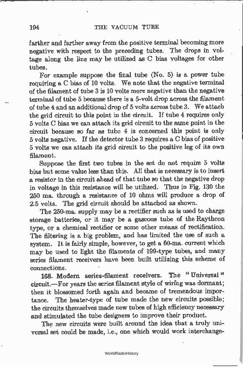
194 THE VACUUM TUBE
farther and farther away from the positive terminal becoming more negative with respect to the preceding tubes. The drops in vol-tage along the line may be utilized as C bias voltages for other tubes.
For example suppose the final tube (No. 5) is a power tube requiring a C bias of 10 volts. We note that the negative terminal of the filament of tube 3 is 10 volts more negative than the negative terminal of tube 5 because there is a 5-volt drop across the filament of tube 4 and an additional drop of 5 volts across tube 3. We attach the grid circuit to this point in the circuit. If tube 4 requires only 5 volts C bias we can attach its grid circuit to the same point in the circuit because so far as tube 4 is concerned this point is only 5 volts negative. If the detector tube 3 requires a C bias of positive 5 volts we can attach its grid circuit to the positive leg of its own filament.
Suppose the first two tubes in the set do not require 5 volts bias but some value less than this. All that is necessary is to insert a resistor in the circuit ahead of that tube so that the negative drop in voltage in this resistance will be utilized. Thus in Fig. 130 the 250 ma. through a resistance of 10 ohms will produce a drop of 2.5 volts. The grid circuit should be attached as shown.
The 250-ma. supply may be a rectifier such as is used to charge storage batteries, or it may be a gaseous tube of the Raytheon type, or a chemical rectifier or some other means of rectification. The filtering is a big problem, and has limited the use of such a system. It is fairly simple, however, to get a 60-ma. current which may be used to light the filaments of 199-type tubes, and many series filament receivers have been built utilizing this scheme of connections.
168. Modern series-filament receivers. The "Universal" circuit.—For years the series filament style of wiring was dormant; then it blossomed forth again and became of tremendous impor-tance. The heater-type of tube made the new circuits possible; the circuits themselves made new tubes of high efficiency necessary and stimulated the tube designers to improve their product.
The new circuits were built around the idea that a truly uni-versal set could be made, i.e., one which would work interchange-
WorldRadioHistory
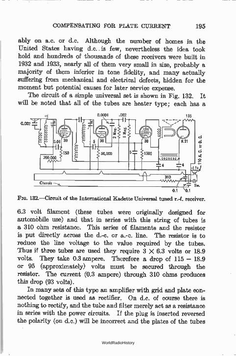
COMPENSATING FOR PLATE CURRENT 195
ably on a.c. or d.c. Although the number of homes in the United States having d.c.. is few, nevertheless the idea took hold and hundreds of thousands of these receivers were built in 1932 and 1933, nearly all of them very small in size, probably a majority of them inferior in tone fidelity, and many actually suffering from mechanical and electrical defects, hidden for the moment but potential causes for later service expense.
The circuit of a simple universal set is shown in Fig. 132. It will be noted that all of the tubes are heater type; each has a
0.0001 .002 135
O A. C
. or D
. C.
0.1 0.1
FIG. 132.—Circuit of the International Kadette Universal tuned r.-f. receiver.
6.3 volt filament (these tubes were originally designed for automóbile use) and that in series with this string of tubes is a 310 ohm resistance. This series of filaments and the resistor is put directly across the d.-c. or a.-c. line. The resistor is to reduce the line voltage to the value required by the tubes. Thus if three tubes are used they require 3 X 6.3 volts or 18.9 volts. They take 0.3 ampere. Therefore a drop of 115 — 18.9 or 95 (approximately) volts must be secured through the resistor. The current (0.3 ampere) through 310 ohms produces this drop (93 volts).
In many sets of this type an amplifier with grid and plate con-nected together is used as rectifier. On d.c. of course there is nothing to rectify, and the tube and filter merely act as a resistance in series with the power circuits. If the plug is inserted reversed the polarity (on d.c.) will be incorrect and the plates of the tubes
WorldRadioHistory
196 THE VACUUM TUBE
will be negative with respect to the source of electrons. Therefore the set will not " play." It is only necessary to reverse the plug. On a.c. it makes no difference, except that the set may hum less if the plug has a certain polarity.
169. Means of obtaining C bias in amplifier tubes.—In all amplifiers of the present time it is desirable to maintain the grids of the tubes at a negative potential with respect to the filament. Such biasing keeps the plate current low, and if properly done will situate the operating point on such a part of the characteristic that minimum distortion due to overloading and curvature results.
Fig. 133.—Obtaining grid bias by means of filament-current flowing through a
resistance.
-0
L.S.
Grid Return Lead
Fm. 134.—Obtaining grid bias by means of plate current flowing through a resist-
ance.
Bias voltages may be obtained from a C battery. The voltage drop across a resistance in the tube's own filament may be used as bias, as is shown in Fig. 133. Remembering that all voltages in the circuit are reckoned either from the negative side of the fila-ment or from the center of the filament (or the cathode in the case of heater tubes) we see that the grid of this tube is negative by the amount of the voltage drop in the resistance. Attaching the grid " return " to this point gives it a 1.0-volt bias. Another method involves using a resistance through which flows the plate current of the tube (or several tubes). Thus in Fig. 134, which represents the conventional power stage for the radio receiver, the 2000-ohm resistor is connected to the center tap of the filament transformer. The plate current flows through this resistor, pro-
WorldRadioHistory
SCREEN-GRID TUBE 197
ducing a voltage drop there, and since the end toward the B battery is more negative than the end toward the filament, the grid return lead of that tube may be connected to the same point as the nega-tive B lead. The grid is then biased negatively by the voltage drop in this resistor. If the plate current is 20 ma. the grid bias will be equal to .020 X 2000 = 40 volts. If because of an increase in plate voltage from any cause the plate current increases to 25 ma. the grid bias increases to 50 volts—and such a biasing scheme pro-vides some protection for the tube. When the plate voltage changes, the grid bias changes too and tends to keep the plate cur-rent within prescribed limits.
170. Screen-grid tube.—In many uses, notably as radio-fre-quency amplifiers, the capacities which exist within the tube are detrimental. There are three such capacities, the grid to filament, grid to plate, and filament to plate. Because of the grid-plate capacity a path exists between the input (grid circuit) and the output (plate circuit) of the tube so that variations in the output may affect the input. Because of the amplification factor of the tube these variations may be amplified and repeated back into the plate circuit and the performance repeated until the normal func-tioning of the tube is seriously impaired. It would be an advantage if the grid-plate capacity of tubes could be eliminated or reduced.
Because of the space charge—the cloud of negative electrons between the filament and the plate—the current that can flow in the plate circuit is limited, and if this space charge could be eliminated, or at least reduced, the grid voltage would have a much greater controlling effect on the plate current.
Both of these beneficial effects may be secured by the addition of more grids. For example in the screen-grid tube the grid-plate capacity has been reduced from an average value of 6.0 mmfd. to about 0.02 mmfd. and an amplification factor of several hundred is not difficult to attain.
The screen-grid tube consists of the usual elements and an additional grid. The second grid is maintained at a positive poten-tial with respect to the heater or filament. The second or screen grid is maintained at zero potential so far as signal frequencies are concerned and thereby screens the grid from the plate circuit signal variations.
WorldRadioHistory
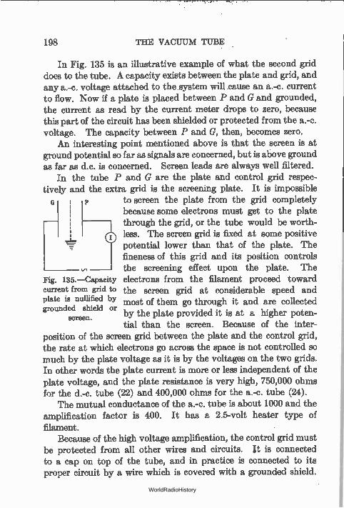
198 THE VACUUM TUBE
In Fig. 135 is an illustrative example of what the second grid does to the tube. A capacity exists between the plate and grid, and any a.-c. voltage attached to the system will cause an a.-c. current to flow. Now if a plate is placed between P and G and grounded, the current as read by the current meter drops to zero, because this part of the circuit has been shielded or protected from the a.-c. voltage. The capacity between P and G, then, becomes zero.
An interesting point mentioned above is that the screen is at ground potential so far as signals are concerned, but is above ground as far as d.c. is concerned. Screen leads are always well filtered.
In the tube P and G are the plate and control grid respec-tively and the extra grid is the screening plate. It is impossible c p to screen the plate from the grid completely
because some electrons must get to the plate through the grid, or the tube would be worth-less. The screen grid is fixed at some positive potential lower than that of the plate. The fineness of this grid and its position controls the screening effect upon the plate. The
Fig. 135.—Capacity electrons from the filament proceed toward current from grid to the screen grid at considerable speed and plate is nullified by most of them go through it and are collected grounded shield or
by the plate providedscreen. it is at a higher poten-tial than the screen. Because of the inter-
position of the screen grid between the plate and the control grid, the rate at which electrons go across the space is not controlled so much by the plate voltage as it is by the voltages on the two grids. In other words the plate current is more or less independent of the plate voltage, and the plate resistance is very high, 750,000 ohms for the d.-c. tube (22) and 400,000 ohms for the a.-c. tube (24).
The mutual conductance of the a.-c. tube is about 1000 and the amplification factor is 400. It has a 2.5-volt heater type of filament.
Because of the high voltage amplification, the control grid must be protected from all other wires and circuits. it is connected to a cap on top of the tube, and in practice is connected to its proper circuit by a wire which is covered with a grounded shield.
WorldRadioHistory
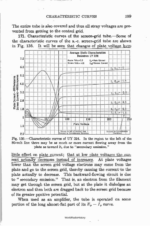
CHARACTERISTIC CURVES 199
The entire tube is also covered and thus all stray voltages are pre-vented from getting to the control grid.
171. Characteristic curves of the screen-grid tube.—Some of the characteristic curves of the a.-c. screen-grid tube are shown in Fig. 136. It will be seen that changes of plate voltage have
7.0
6.0
on 5.0
2.0 (f) -'
1.0
o
LO
2.0
Average Static Characteristics Radiotron UY 224
Heater Votts.2.5 lai-Plate Current Screen Volts +75 IceScreen Current
°
r \f ---------
I
7L 31-
Ee •
\j/
4.5
IT-Ezir. 6.0— 1.-Ej,— 1.6—
50 100 150 200 25
\ Plate Voltage
vile Va Sub
ues to left of eci o Considerable
vertical I Va
ne lotion
Su ject I
to on Varlition
Fig. 136 —Characteristic curves of UY 224. In the region to the left of the 80-volt line there may be as much or more current flowing away from the
plate as toward it, due to "secondary emission."
little effect on plate t; that at low plate voltages the cur-rent actually decreases instead of increases. At plate voltages rower than the screen grid voltage electrons may come from the plate and go to the screen grid, thereby causing the current to the plate actually to decrease. This backward-flowing circuit is due to " secondary emission." That is, an electron from the filament may get through the screen grid, but at the plate it dislodges an electron and then both are dragged back to the screen grid because of its greater positive potential.
When used as an amplifier, the tube is operated on some portion of the long almost-flat part of its Ei, — I„ curve.
WorldRadioHistory
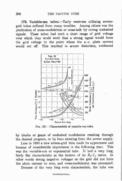
200 THE VACUUM TUBE
172. Variable-mu tubes.—Early receivers utilizing screen-grid tubes suffered from many troubles. Among others was the production of cross-modulation or cross-talk by strong undesired signals. These tubes had such a short range of grid voltage over which they could work that a strong signal would force the grid voltage to the point where the a.-c. plate current would cut off. This resulted in severe distortion, evidenced
I 2.5
e 2.0
1.s
g 1.0
cr 5
. ' 1 Type 39
E1=6.3 Volts - Screen Volts=90
200
I: r.. i
too <.1 _
g s
e l
OM o
—50 Control —20 G, d —10 Volts
$
„et° o
—20 —15 —10 —5 Control Grid Volts
o
1600
1400
1200
1000 c_•›“-
800 .77, .11 •I-' `4 ‘E,
600 1' E «C
400
200
Fro. 137.—Characteristic of variable-mu tube.
by blurbs or gasps of undesired modulation crashing through the desired program, or by hum entering from the power supply.
Late in 1930 a new screen-grid tube made its appearance and became of considerable importance in the following year. This was the variable-mu or exponential tube. It had a very long, fairly flat characteristic at the bottom of its E0-I, curve. In other words strong negative voltages on the grid did not force the plate current to zero, and cross-modulation was prevented.
Because of the very long even characteristic, the tube was
WorldRadioHistory
MISTREATMENT OF TUBES 201
nicely adapted for automatic volume control, for radio and inter-mediate amplifiers, and for recording signal strength, or loud speaker output or other measurements where large ranges of cur-rent or voltage, etc., were to be measured. These tubes have come to be described as super-control tubes.
173. Multi-element tubes.—After the successful use of the power pentode in many receivers, the principle of the suppressor grid was applied to r.-f. amplifier tubes of the screen-grid type. In this kind of tube as shown in Fig. 136 there is a large portion of the characteristic which is not useful because of secondary emission.
By the use of another grid placed near the plate and connected internally to the cathode secondary electrons are driven back to the plate and prevented from flowing from plate to screen grid. Therefore the dip in the characteristic at values of plate voltage below the screen voltage is prevented.
Experiments were made to determine the value of a suppressœ grid in screen grid tubes for r.-f. amplification with the result that tubes of the 39 and similar types were produced. These are super-control (variable-mu) screen grids with a suppressor grid. In other words they are variable-mu pentodes and do not have the secondary emission characteristic.
Another multi-element tube was the Wunderlich detector, which led to the introduction of the 55 and similar tubes. In this tube there is a triode, or pentode, of any desired characteristic and also a diode, or two diodes. The triode, or pentode, may perform its usual function of a.-f. or r.-f. amplification (usually the former) while the diode acts as a detector. This diode is merely a small plate which collects electrons from the same cathode which supplies the electrons for the triode.
One diode may act as detector, the resulting a.-f. voltage being fed to the grid of the triode portion of the tube and, after amplifica-tion, to the final audio amplifier. The tube is useful in cases where a diode will not produce sufficient voltage to drive a power amplifier without the use of an intermediate stage. One diode may rectify the incoming wave and the resulting direct current may be made to flow through a resistance in such a direction that the negative end may be applied to the grids of previous tubes as an automatic volume control voltage.
WorldRadioHistory
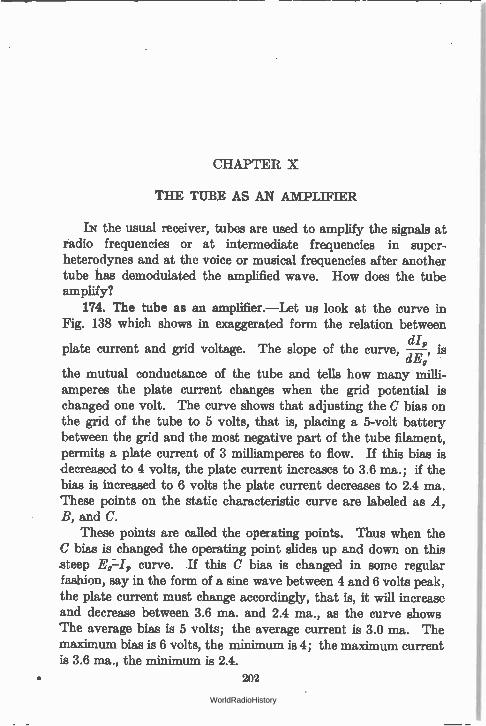
CHAPTER X
THE TUBE AS AN AMPLIFIER
IN the usual receiver, tubes are used to amplify the signals at raclio frequencies or at intermediate frequencies in super-heterodynes and at the voice or musical frequencies after another tube has demodulated the amplified wave. How does the tube amplify?
174. The tube as an amplifier.—Let us look at the curve in Fig. 138 which shows in exaggerated form the relation between
plate current and grid voltage. The slope of the curve, —dI„, is dE,
the mutual conductance of the tube and tells how many milli-amperes the plate current changes when the grid potential is changed one volt. The curve shows that adjusting the C bias on the grid of the tube to 5 volts, that is, placing a 5-volt battery between the grid and the most negative part of the tube filament, permits a plate current of 3 milliamperes to flow. If this bias is decreased to 4 volts, the plate current increases to 3.6 ma.; if the bias is increased to 6 volts the plate current decreases to 2.4 ma. These points on the static characteristic curve are labeled as A, B, and C.
These points are called the operating points. Thus when the C bias is changed the operating point slides up and down on this steep Er-I, curve. If this C bias is changed in some regular fashion, say in the form of a sine wave between 4 and 6 volts peak, the plate current must change accordingly, that is, it will increase and decrease between 3.6 ma. and 2.4 ma., as the curve shows The average bias is 5 volts; the average current is 3.0 ma. The maximum bias is 6 volts, the minimum is 4; the maximum current is 3.6 ma., the minimum is 2.4.
202
WorldRadioHistory
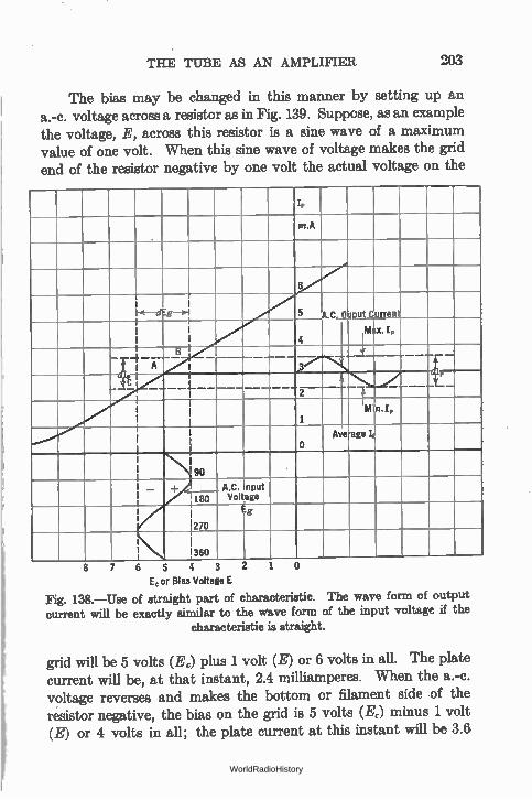
THE TUBE AS AN AMPLIFIER 203
The bias may be changed in this manner by setting up an a.-c. voltage across a resistor as in Fig. 139. Suppose, as an example the voltage, E, across this resistor is a sine wave of a maximum value of one volt. When this sine wave of voltage makes the grid end of the resistor negative by one volt the actual voltage on the
I,
• m.A
1-E--dEg—s1 A put Current
..7,,V 7'd
4 M x. I,
B so
A ,.3' 4{,-----,
E • A
— 1' 2
I Min.I,
0 Ave age I
90
I — I 1
' 180 Voltage
1 1
270
Eg
_()
1 360 _ 8 7 6 5 o
Ec or Bias Voltage E
Fig. 138.—Use of straight part of characteristic. The wave form of output current will be exactly similar to the wave form of the input voltage if the
characteristic is straight.
grid will be 5 volts (L) plus 1 volt (E) or 6 volts in all. The plate current will be, at that instant, 2.4 milliamperes. When the a.-c. voltage reverses and makes the bottom or filament side of the resistor negative, the bias on the grid is 5 volts (E,) minus 1 volt (E) or 4 volts in all; the plate current at this instant will be 3.6
WorldRadioHistory
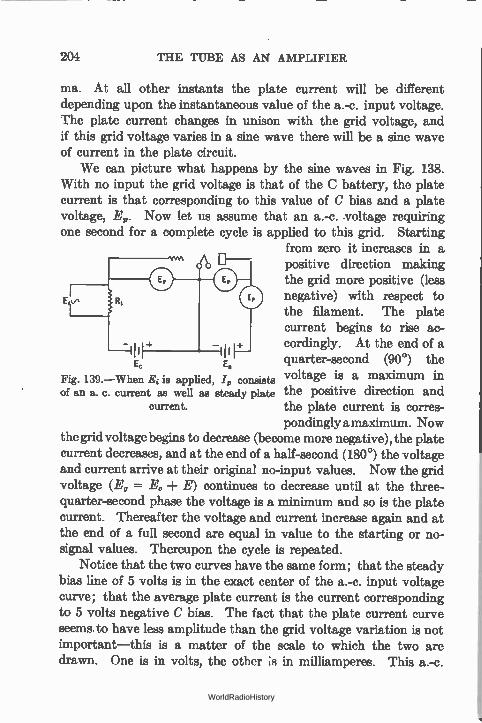
204 THE TUBE AS AN AMPLIFIER
ma. At all other instants the plate current will be different depending upon the instantaneous value of the a.-c. input voltage. The plate current changes in unison with the grid voltage, and if this grid voltage varies in a sine wave there will be a sine wave of current in the plate circuit.
We can picture what happens by the sine waves in Fig. 138. With no input the grid voltage is that of the C battery, the plate current is that corresponding to this value of C bias and a plate voltage, E. Now let us assume that an a.-c. voltage requiring one second for a complete cycle is applied to this grid. Starting
from zero it increases in a A D- positive direction making
the grid more positive (less negative) with respect to the filament. The plate current begins to rise ac-cordingly. At the end of a quarter-second (90°) the voltage is a maximum in the positive direction and the plate current is corres-pondingly a maximum. Now
the grid voltage begins to decrease (become more negative), the plate current decreases, and at the end of a half-second (180°) the voltage and current arrive at their original no-input values. Now the grid voltage (E, = Ec -f- E) continues to decrease until at the three-quarter-second phase the voltage is a minimum and so is the plate current. Thereafter the voltage and current increase again and at the end of a full second are equal in value to the starting or no-signal values. Thereupon the cycle is repeated.
Notice that the two curves have the saine form; that the steady bias line of 5 volts is in the exact center of the a.-c. input voltage curve; that the average plate current is the current corresponding to 5 volts negative C bias. The fact that the plate current curve seems to have less amplitude than the grid voltage variation is not important—this is a matter of the scale to which the two are drawn. One is in volts, the other ;s in milliamperes. This a.-c.
Ec E.
Fig. 139.—When Ei is applied, /„ consists of an a. c. current as well as steady plate
current.
WorldRadioHistory
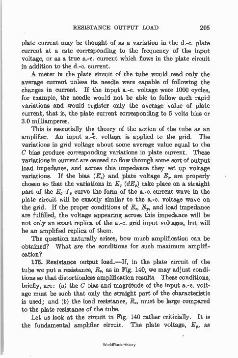
RESISTANCE OUTPUT LOAD 205
plate current may be thought of as a variation in the d.-c. plate current at a rate corresponding to the frequency of the input voltage, or as a true a.-c. current which flows in the plate circuit in addition to the d.-c. current. A meter in the plate circuit of the tube would read only the
average current unless its needle were capable of following the changes in current. If the input a.-c. voltage were 1000 cycles, for example, the needle would not be able to follow such rapid variations and would register only the average value of plate current, that is, the plate current corresponding to 5 volts bias or 3.0 milliamperes.
This is essentially the theory of the action of the tube as an amplifier. An input a.e. voltage is applied to the grid. The variations in grid voltage about some average value equal to the C bias produce corresponding variations in plate current. These variations in current are caused to flow through some sort of output load impedance, and across this impedance they set up voltage variations. If the bias (E,) and plate voltage E, are properly chosen so that the variations in E, (dE„) take place on a straight part of the E9-I, curve the form of the a.-c. current wave in the plate circuit will be exactly similar to the a.-c. voltage wave on the grid. If the proper conditions of E„ E,, and load impedance are fulfilled, the voltage appearing across this impedance will be not only an exact replica of the a.-c. grid input voltages, but will be an amplified replica of them.
The question naturally arises, how much amplification can be obtained? What are the conditions for such maximum amplifi-cation?
175. Resistance output load.—If, in the plate circuit of the tube we put a resistance, R0, as in Fig. 140, we may adjust condi-tions so that distortionless amplification results. These conditions, briefly, are: (a) the C bias and magnitude of the input a.-c. volt-age must be such that only the straight part of the characteristic is used; and (b) the load resistance, R„ must be large compared to the plate resistance of the tube.
Let us look at the circuit in Fig. 140 rather criticially. It is the fundamental amplifier circuit. The plate voltage, E,, as
WorldRadioHistory
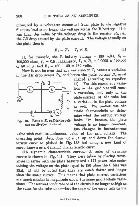
206 THE TUBE AS AN AMPLIFIER
measured by a voltmeter connected from plate to the negative filament lead is no longer the voltage across the B battery. It is less than this value by the voltage drop in the resistor R., i.e., the IR drop caused by the plate current. The voltage actually on the plate then is
E, = Eb X Ro (1)
If, for example, the B battery voltage = 180 volts, Ro =-100,000 ohms, I, = 0.5 milliampere, I, X Ro = 0.0005 X 100,000 or 50 volts, and E, = 180 — 50 = 130 volts.
Now it can be seen that any variation in I, causes a variation in the IR drop across R., and hence the plate voltage E, must
change according to equation (1). For this reason any varia-
tip tion in the grid bias will cause a variation, not only in the
V, Et I plate current of the tube but r o 20 R0 E0 a variation in the plate voltage
as well. We cannot use the bill static characteristic to deter-"
E, Es mine what the output voltage Fig. 140.—Ratio of E0 to Ei is the volt- looks like, because the plate
age amplication of circuit. voltage is no longer constant, but changes in instantaneous
value with each instantaneous value of the grid voltage. The operating point, then, does not slide up and down the charac-teristic curve as plotted in Fig. 138 but along a new kind of curve known as a dynamic characteristic curve.
176. Dynamic characteristic curves.—A series of dynamic curves is shown in Fig. 141. They were taken by placing resist-ances in series with the plate battery and a 171 power tube main-taining the voltage on the plate equal to 180 when the C bias was 38.5. It will be noted that they are much flatter and longer than the static curves. This means that plate current variations are much smaller in magnitude under the same grid voltage varia-tions. The mutual conductance of the circuit is no longer as high as the value for the tube alone—but the slope of the curve tells us the
WorldRadioHistory
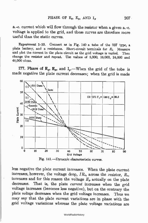
PHASE OF 4, Ft,, AND I,, 207
a.-c. current which will flow through the resistor when a given a.-c. voltage is applied to the grid, and these curves are therefore more useful than the static curves.
Experiment 1-10. Connect as in Fig. 140 a tube of the 237 type, a plate battery, and a resistance. Short-circuit terminals for E. Measure and plot the current in the plate circuit as the grid voltage is varied. Then change the resistor and repeat. Use values of 8,000, 18,000, 24,000 and 48,000 ohms.
177. Phase of Ep, Ep, and I,,.—When the grid of the tube is made negative the plate current decreases; when the grid is made
so
50
40
c3 30
20
10
o
:00 ohms\\ ‘ Static \
\'• (2)
2000 Oh
.\
s • \
\ \ CX-371 Ep.. 180 Ep= 38.5
'. -0ynan1ic
',./.0, 0 °he\ .......
\ \ `..\.: \
8000 Ohms'. ''....
' s .\
\. *
s... ",..., •....
..s..,
. - --s, --S--
0 10 20 30 40 50 Grid Voltage
Fig. 141.—Dynamic characteristic curves.
60 70 so 90
less negative the plate current increases. When the plate current increases, *however, the voltage drop, IRo, across the resistor, Ro, increases and for this reason the voltage E„ actually on the plate decreases. That is, the plate current increases when the grid voltage increases (becomes less negative), but on the contrary the plate voltage decreases when the grid voltage increases. Thus we may say that the plate current variations are in phase with the grid voltage variations whereas the plate voltage variations are
WorldRadioHistory
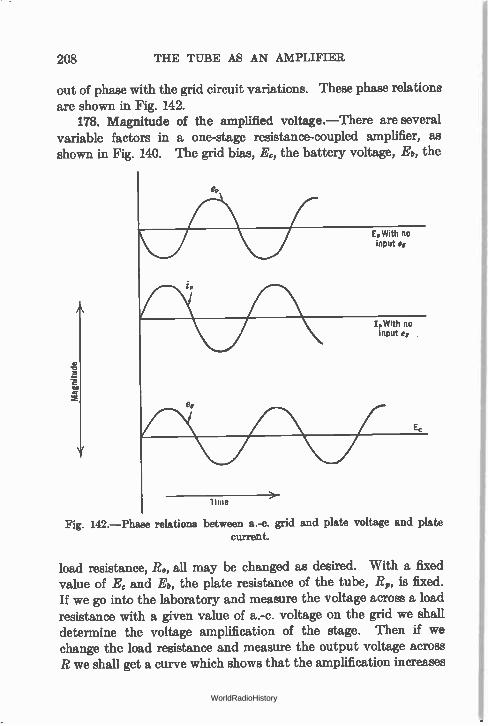
208 THE TUBE AS AN AMPLIFIER
out of phase with the grid circuit variations. These phase relations are shown in Fig. 142.
178. Magnitude of the amplified voltage.—There are several variable factors in a one-stage resistance-coupled amplifier, as shown in Fig. 140. The grid bias, Ec, the battery voltage, Eb, the
E, With no input e,
I, With no input e0
Ec
lime
Fig. 142.—Phase relations between a.-c. grid and plate voltage and plate current.
load resistance, Ro, all may be changed as desired. With a fixed value of Ec and Eb, the plate resistance of the tube, R,, is fixed. If we go into the laboratory and measure the voltage across a load resistance with a given value of a.-c. voltage on the grid we shall determine the voltage amplification of the stage. Then if we change the load resistance and measure the output voltage across R we shall get a curve which shows that the amplification increases
WorldRadioHistory
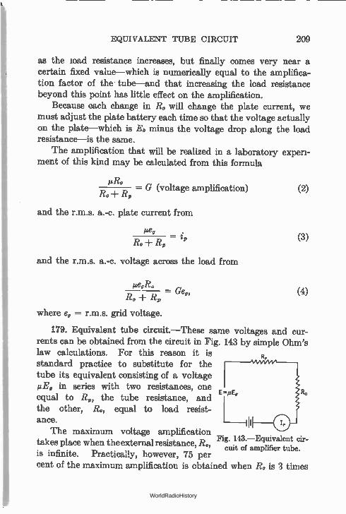
EQUIVALENT TUBE CIRCUIT 209
as the load resistance increases, but finally comes very near a certain fixed value—which is numerically equal to the amplifica-tion factor of the tube—and that increasing the load resistance beyond this point has little effect on the amplification.
Because each change in Ro will change the plate current, we must adjust the plate battery each time so that the voltage actually on the plate—which is Eb minus the voltage drop along the load resistance—is the same.
The amplification that will be realized in a laboratory experi-ment of this kind may be calculated from this formula
edio — G (voltage amplification) (2)
Ro+ R,
and the r.m.s. a.-c. plate current from
and the r.m.s. a.-c. voltage across the load from
pe„Ro
Ro Geo,
R,
(3)
(4)
where e, = r.m.s. grid voltage.
179. Equivalent tube circuit.—These same voltages and cur-rents can be obtained from the circuit in Fig. 143 by simple Ohm's law calculations. For this reason it is R,
standard practice to substitute for the tube its equivalent consisting of a voltage µE9 in series with two resistances, one
E=./2E, equal to R„, the tube resistance, and the other, Ro, equal to load resist-ance.
The maximum voltage amplification takes place when the external resistance, Ro,
cuit of amplifier tube. is infinite. Practically, however, 75 per cent of the maximum amplification is obtained when Ro is 3 times
Fig. 143.—Equivalent eir-
WorldRadioHistory
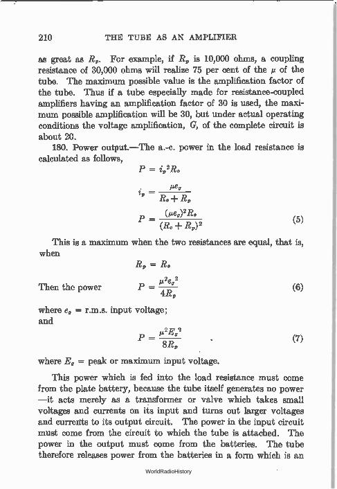
210 THE TUBE AS AN AMPLIFIER
as great as R„. For example, if R,, is 10,000 ohms, a coupling resistance of 30,000 ohms will realize 75 per cent of the » of the tube. The maximum possible value is the amplification factor of the tube. Thus if a tube especially made for resistance-coupled amplifiers having an amplification factor of 30 is used, the maxi-mum possible amplification will be 30, but under actual operating conditions the voltage amplification, G, of the complete circuit is about 20.
180. Power output —The a.-c. power in the load resistance is calculated as follows,
P = ii,2Ro
ea i =
(ge„)2R0 P —
(R,,-1- R„) 2 (5)
This is a maximum when the two resistances are equal, that is, when
Then the power
R, = Ro
1.,2e0 2
P — 4R„
where e, = r.m.s. input voltage; and
1., 2Eg 2
P = 8R„
(6)
(7)
where E, = peak or maximum input voltage.
This power which is fed into the load resistance must come from the plate battery, because the tube itself generates no power —it acts merely as a transformer or valve which takes small voltages and currents on its input and turns out larger voltages and currents to its output circuit. The power in the input circuit must come from the circuit to which the tube is attached. The power in the output must come from the batteries. The tube therefore releases power from the batteries in a form which is an
WorldRadioHistory
POWER AMPLIFICATION 211
exact replica of the power utilized in the input circuit to which the tube is attached.
181. Power amplification.—Ordinarily the grid of a tube is biased so highly negatively that practically no current flows in the grid circuit. The tube input circuit itself then draws little or no power. If, however, the a.-c. voltages are fed into the tube through a resistance, some power is expended in this input resistance. If the values of resistance and current are known the power may be calculated. The power amplification will be the output power divided by the input power. The fact that a tube is a power multiplier distinguishes it from a transformer which is merely a power transmitter, taking power at one current and voltage and passing it on at another current and voltage. The transmitted power is never more than or even equal to the input power. It is always less; unlike a tube, the transformer cannot amplify power or release it from local batteries. The power output is propor-tional to the square of the voltage on the grid. Thus doubling the input a.-c. voltage quadruples the output a.-c. power.
Example 1-10. Four milliamperes of current at 1000 cycles are fed through a 10,000-ohm resistance in series with the grid of a tube and its C battery. In the output is a 2000-ohm resistor. The amplification factor of the tube is 3, its internal plate resistance is 2000 ohms. What is the power output, what is the voltage across the output, what is the voltage and power amplifica-tion, and what power is lost on the internal resistance of the tube?
Let the input voltage Ei = /i1?; = .004 X 10,000 = 40 volts r.m.s.
voltage amplification G = PR°
3 X 2000 - 4000 — 1.5 times.
The output voltage Eo = Ei X G= 40 X 1.5 = 60 volts r.m.s.
Power output P. ei2Ei2
4R,
9 X 402 — 1.80 watts
- 4 X 2000
WorldRadioHistory
212 THE TUBE AS AN AMPLIFIER
Power input P. Ii2R; = (.004) 2 X 10,000
= 16 X 10-8 X 10,000
= .16 watt
Power amplification = Po/Pi = 1.8/.16 = 11.25 times.
Since I, (a.c.) flows through both Ro and R, and since R„ = Ro a.-c. power
lost in R, = power lost in Ro = 1.8 watts. Total power taken from batteries = 3.6 watts.
useful power 1.8 Efficiency = - - 50 per cent.
total power 3.6
Problem 1-10. Assume a 201-A tube with a load resistance of 12,000 ohms and an a.-c. grid voltage of 3 volts (peak). The µ of the tube is 8, its R, is 12,000 ohms. What is the maximum value of the a.-c. plate current? (Use formula 3.) What is the r.m.s. value? What a.-c. power is developed in the load resistance? What voltage appears there?
Problem 2-10. What is the voltage amplification in the above circuit? (Use formula 2.) How much would it be increased if the load resistance were increased to 36,000 ohms? How much would this change the power output?
Problem 3-10. The plate resistance of a certain " high p." tube is 60,000 ohms and its amplification factor is 20. What plate resistor value in ohms must be used to realize a voltage amplification of 15?
Problem 4-10. A 112-type tube has an internal plate resistance of 5000 ohms, its amplification factor is 8; it is worked into a load of 5000 ohms. Plot the output power in the load resistance as the input a.-c. voltage is increased from 1 to 8 volts (peak). (Use formula 7.)
Problem 5-10. What is the voltage amplication in Problem 4. Problem 6-10. The power output of a tube when worked into a load
whose resistance is equal to the tube resistance (when the input grid voltages
are maximum volts) may be written as X E,2. If we divide this expres-8 R,
sion by Et,' we shall have a figure which gives us the power output in watts per (volt input) 2. Make a table of such values for all the tubes used at the present time, getting the tube data from the tube chart.
Problem 7-10. The normal e bias for a 112-type tube is 9 volts. What is the largest r.m.s. voltage that may be applied to its grid before the grid gaes
positive?
182. Amplifier overloading.—The conditions for undistortea amplification are: (a) the C bias and magnitude of the a.-c. input voltage must be such that only the straight part of the tube's
WorldRadioHistory
AMPLIFIER OVERLOADING 213
characteristic is used, and (b) the load resistance must be large with respect to the internal resistance of the tube, R,. Let us examine these conditions. Suppose first that the C bias is too great, as in Fig. 144, so that the operating point goes into a curved part of the characteristic. The wave of plate current is no longer similar to that of the grid voltage, and its average value is no longer equal
I,,
A.C. Plate Current
‘ Plate Current due to overloading
Increase in Plate Current
i \ Normal D.C. Plate Current
E,
Input A.C. Voltage
Fig. 144.—Effect of using curved part of characteristic. Note dissimilarity between output and input.
to the zero a.-c. input condition as is true when the bias is such that input voltages carry the grid operating point only over a straight part of the curve. The negative parts of the a.-c. waves are partly cut off. Distortion results because the negative and positive halves of the cycle are not amplified alike. A meter in the plate circuit would show an increase in current when signals were put on the grid—an infallible sign of overloading distortion. If the C bias is great enough and input signals are strong enough
WorldRadioHistory
214 THE TUBE AS AN AMPLIFIER
the grid may be forced so far negative that the plate current may be reduced to zero on the negative halves of the wave. This would produce even worse distortion.
Overloading, then, is a technical name for operating a tube under a wrong C bias, or with too strong input signals.
If the C bias is too small, input signals force the grid positive at times and distortion again occurs for a reason explained in Section 185. In this case the plate current as read by a d.-c. meter would decrease when the input voltages are applied to the
grid. Suppose, however, the tube is biased properly, say at the
center of the region between the lower bend of the Ed-I, curve and the point which corresponds to zero grid voltage. Distortion does not occur unless too great a.-c. voltages are put on the grid— voltages sufficient to drivc the operating point down on the curve, or up on the positive part of the curve.
There are two possible remedies for such kinds of distortion. One (a) is to reduce the input voltage until the operating point moves over only a straight portion of the curve; another (b) is to increase the B and C voltages until a longer straight portion is available. As shown in Fig. 118, increasing the plate voltage moves the Es-Ii, curve to the left and increases its straight part. The C bias would be increased accordingly.
If the tube is properly biased, the input a.-c. voltage must be such that its peak value does not exceed the value of the C bias voltage. Thus if a tube has a bias of 40.5 volts, the input value of the a.-c. voltage must not exceed this value, and thus its r.m.s. value must be not over 40.5 ÷ 1.4, or about 28.5 volts. A voltage input greater than this will force the grid positive with consequent distortion. As seen in Section 186, the peak voltage input must be even less than this value to prevent the operating point going down into this curved region.
183. Distortion due to curved characteristic.—When a load is in the plate circuit of a tube its characteristic becomes flatter and its straight part longer, but at the lower part of the curve there is still a bend and throughout the E0-I„ graph there is considerable curvature unless the load resistance is high. Large input voltages,
WorldRadioHistory
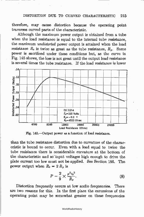
DISTORTION DUE TO CURVED CHARACTERISTIC 215,
therefore, may cause distortion because the operating point traverses curved parts of the characteristic.
Although the maximum power output is obtained from a tube when the load resistance is equal to the internal tube resistance, the maximum undistorted power output is attained when the load resistance 14, is twice as great as the tube resistance, R9. Some power is sacrificed under these conditions but, as the curve in Fig. 145 shows, the loss is not great until the output load resistance is several times the tube resistance. If the load resistance is lower
.14
„, .12
re
lo a.
cj .08
1.06
.04
.02
24000
CX 112-A Et-135 VOILS
Riffl4500 Ohms
4000 8000 12000 16000 20000 Load Resistance (Ohms)
Fig. 145.—Output power as a function of load resistance.
than the tube resistance distortion due to curvature of the charac-eristic is bound to occur. Even with a load equal to twice the tube resistance there is considerable curvature at the bottom of the characteristic and so input voltages high enough to drive the plate current too low must not be applied. See Section 186. The power output when Ro = 2 R, is
2 m2e,2
9 R,
Distortion frequently occurs at low audio frequencies. There are two reasons for this. In the first place the excursions of the operating point may be somewhat greater on these frequencies,
(8)
WorldRadioHistory
216 THE TUBE AS AN AMPLIFIER
because of the greater power in them than in high tones. In the second place, the loud speaker may have a resistance which varies with frequency, becoming low at low frequencies, probably lower than the tube resistance. Thus distortion due to curvature as well as loading distortion may occur on low notes.
The solution is to use a power tube which will easily handle the greatest input grid voltages that will be encountered, and secondly, to use a power tube with a low internal resistance so that the load resistance will, at the lowest frequency, be larger than the tube resistance.
184. Permissible grid swing.—The expression " grid swing" is often used, especially in England, to indicate the extent to which the voltage of the grid varies under the incoming signals. To state that the grid swing on a certain tube is 10 volts means that the voltage of the grid varies between 5 above and 5 below some fixed value, a total swing of 10 volts. In this country we should say the maximum input voltage was 5. Under these conditions the C bias should be 5 volts at least, preferably more. The maximum permissible grid swing is the range of voltage on the grid which will not cause distortion either because of the grid going positive or because of the operating point traversing the lower bend. Whether one says the grid swing that may be applied to a 171 power tube is 80 volts or whether he says that the peak voltage that may be applied is 40 volts is immaterial. They mean the same thing. The grid swing cannot be determined by looking at the static characteristic curve. It can be determined from the dynamic curve or as indicated in Section 186.
185. Distortion due to positive grid.—Why does distortion occur when the grid of an amplifier tube is permitted to swing positive on loud signals? If we plot the plate current against grid voltage, as the C bias in Fig. 139 is changed, we find that, when the grid goes positive, the plate current curve no longer is straight; it slumps off and soon becomes almost horizontal. Distortion will occur at the instant the input voltage takes the operating
point up on the upper bend. The reason for this bend is as follows. When the grid becomes
positive with respect to the negative side of the filament, it begins
WorldRadioHistory
AMOUNT OF DISTORTION CAUSED BY OVERLOADING 217
to attract electrons to it and these electrons constitute a flow of current. Current flows in the grid circuit, and must go through the input resistance R. There is, then, an IR drop in the grid circuit, so that the voltage actually on the grid (E0) is not the applied grid voltage E but this value minus the drop in the input resistance—just as the plate voltage is not the voltage of the B battery but this voltage minus the drop in the output load resist-ance. The greater the input voltage the more the grid goes positive, the greater the voltage drop in this resistance and the bias voltage that is actually on the grid because of rectification.
The grid must never be permitted to go positive in ordinary circuits. Some circuits have been developed in which the grid is not only permitted to go positive but is forced to do so with a consequent greater power output. Such circuits (Class B) have not come into general use.
186. Amount of distortion caused by overloading.—What is the result of operating amplifier tubes over a curved part of the characteristic? The result is an output wave form quite different from the input wave. Distortion is taking place whenever the magnified output voltage is not exactly, in all respects, like the input voltage. When the d.-c. plate current of an amplifier tube changes under the action of an input a.-c. grid voltage, distortion is taking place; the form of the wave in the output circuit does not look like the form of the input wave. This output wave may be very complex.
When a tube distorts, it adds certain frequencies to the output circuit which were not present in the input. All of these frequencies added together at any instant produce a wave form which looks unlike the original wave form.
How can we tell the amount of distortion to be expected with given tube and circuit constants? It is not difficult to determine what percentage of distortion will occur. Here is another place where the characteristic curves come in handy; this time the Eel, curves are used.
Let us look at Fig. 146 which gives the characteristic of a Cunningham CX-371 type of tube. The vertical 180-volt line is the working line for this tube. The intersection of this line
WorldRadioHistory
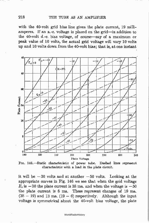
218 THE TUBE AS AN AMPLIFIER
with the 40-volt grid bias line gives the plate current, 19 milli-amperes. If an a.-c. voltage is placed on the grid—in addition to the 40-volt d.-c. bias voltage, of course—say of a maximum or peak value of 10 volts, the actual grid voltage will vary 10 volts up and 10 volts down from the 40-volt bias; that is, at one instant
as
40
16
8
o 100 120 110 160 180
Plate Voltage
Fia. 146.—Static characteristic of power tube. Dashed lines represent characteristic with a load in the plate circuit.
E, -0 c='' - ° -1 -30
....-...."_
...-
X- 37 .....-
./
60
0
...--tia
...--•
...--
...--- 0 ....-
..-0 60
....-' ...--
--le --- .....-d
.....5 .---___.
-- e ..... ---Alilli
70
.._-__ pi ..---
--
200 220 240
it will be —30 volts and at another —50 volts. Looking at the appropriate curves in Fig. 146 we see that when the grid voltage EG is —30 the plate current is 38 ma. and when the voltage is —50 the plate current is 6 ma. These represent changes of 19 ma. (38 — 19) and 13 ma. (19 — 6) respectively. Although the input voltage is symmetrical about the 40-volt bias voltage, the plate
WorldRadioHistory
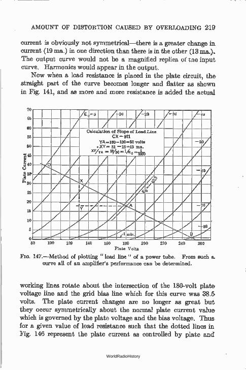
AMOUNT OF DISTORTION CAUSED BY OVERLOADING 219
current is obviously not symmetrical—there is a greater change in current (19 ma.) in one direction than there is in the other (13 ma.). The output curve would not be a magnified replica of tne input curve. Harmonics would appear in the output.
Now when a load resistance is placed in the plate circuit, the straight part of the curve becomes longer and flatter as shown in Fig. 141, and as more and more resistance is added the actual
70 66 60 55 50 .1. 45 1140 e 36' .g a. 30 25 20 15 10 5 O 80 100 120 140 150 180 200
Plate Volts
Fia. 147.—Method of plotting " load line" of a power tube. From such a. curve all of an amplifier's performance can be determined.
E «40 U —o A 10 AO / 7—
J
/
Calculation of Slope of Load Line CX — 871 YA=180 -130...50 volts
• XV= 31 —18=13 ma. XY/yA = 1340 = 14 o n ion
-50
x ,,4. ,,,e liri •
A A -80
oc.../"." B _......
(1 ,u n •n. _....• 220 240 260
working lines rotate about the intersection of the 180-volt plate voltage line and the grid bias line which for this curve was 38.5, volts. The plate current changes are no longer as great but they occur symmetrically about the normal plate current value which is governed by the plate voltage and the bias voltage. Thus for a given value of load resistance such that the dotted lines in Fig. 146 represent the plate current as controlled by plate and
WorldRadioHistory
220 THE TUBE AS AN AMPLIFIER
grid voltages, the same input voltage 10 (peak) causes the plate current to increase from 19 to 24 ma. in one direction and to decrease from 19 to 14 ma. in the other—a symmetrical varia-tion.
It is a simpler process to determine the plate current variations with a given plate load resistance by the method of plotting the " load line." To do this a family of E„-I, curves is necessary as in Fig. 147. The load line gives the plate current at any given set of Ec and E„ values and with a given resistance load. It is determined as follows: it must pass through the intersection of the E, = 180 and Ec = — 40.5 lines, or A in the figure, because these are the recommended values for this tube, a CX-371. Through this point A draw a line parallel with the plate voltage axis. Make it any convenient length. Theh at the end of this line erect a perpendicular line of such length that YX/A Y= 1000/R. where R. is the plate load resistance, in this case 3900 ohms. Through X draw a line through A and extend to the Ec = line and the I, = 0 line as in the Figure.
The reasons for this bit of apparent sleight-of-hand are as follows. The slope of this load line must be the reciprocal of the load resistance, i.e., if the load resistance, Ro, is 3900 ohms, the slope of this line must be 1/3900 ohms. The slope of the line will be equal to the vertical side of a triangle divided by the horizontal side of this triangle which has for the third side either the load line, or a shorter line parallel to the load line.
Thus, slope of load line:
vertical 1 /(amps.) I X 1000 ma. _ _
horizontal R. E (volts) E volts
The value of plate current corresponding to any set of E„ and Ec values with this particular load resistance may be found from this line. Thus with Ec = 0 and E„ = 92 volts, I, = 39 ma., with Ec = — 60 and E, = 218, 4 = 9 ma. Thus if the bias voltage is 40.5 and the peak voltage applied to the grid is 10, the actual grid voltage varies from 40.5 — 10 or 30.5 to 40.5 10 or 50.5 and the corresponding plate currents will be 24 and 13 approximately, or approximately 5.5 ma. up and down from the 18.5 ma. value.
WorldRadioHistory
HARMONIC DISTORTION CALCULATION 221
Now the grid must not go positive, and the plate current must not become so low on strong signals that the curved part of the characteristic is used. Thus 1.0 ma. is about the lowest the plate current should go, or the value when Ec = —80. From —40.5 to —80 is 39.5 volts which is the peak a.c. that should be put on the grid. This input will cause the plate current to vary between 39 ma. and 1 ma.
187. Power output calculation.—The power output may be calculated from the above data by means of the following formula:
P = 1/8 (E max. — E min.) X (I„ max. — I„ min.)
= 1/8 (250 — 92) X (.039 — .001)
= .75 watt = 750 milliwatts of output power.
188. Harmonic distortion calculation.—The amount of distor-tion present in sueh an amplifier working under such conditions may be found from the following equation in which Io = 18.5 ma. which is equal to the plate current when 180 volts are on the plate and the C bias is 40.5 volts.
(/„ max. ± I„ min.) — 10 Distortion —
(4 max. — /, min.)
(.039 ± .001) — .0185
.039 — .001
.02 - - .0185 — . .038 039
= 3.9 per cent.
This distortion is the amount of second harmonic current in the output. Thus if the input a.-c. grid voltage has a frequency of 1000 cycles and if the output current is 10 milliamperes (fun-damental) there will be in the plate circuit 3.9 per cent of this current or about 0.4 milliampere in the form of a 2000-cycle wave.
It has been determined that a 5 per cent distortion is not objec-tionable to the ear—but this involves a matter of opinion and other factors. If and when better loud speakers are available it is possible that the average car will detect leas distortion than this.
WorldRadioHistory
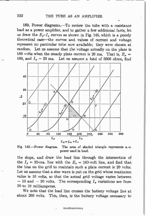
222 THE TUBE AS AN AMPLIFIER
• 189. Power diagrams.—To review the tube with a resistance
load as a power amplifier, and to gather a few additional facts, let us draw the E,—I„ curves as shown in Fig. 148, which is a purely theoretical case—the curves and values of current and voltage represent no particular tube now available; they were chosen at random. Let us assume that the voltage actually on the plate is 160 volts when the steady plate current is 20 ma. That is, E„ --160, and I, = 20 ma. Let us assume a load of 5000 ohms, find
40
30
20
16
'
G -o e/,
e
A
C
, e /
ti) / e
47 /
i B
F
0
H
D E
0 40 CO 120 160 200 240, 280
ER EB ER +Ep
Fig. 148.—Power diagram. The area of shaded triangle represents a.-c. power used in load.
the slope, and draw the load line through the intersection of the I, = 20-ma, line with the E„ = 160-volt line, and find that the bias on the grid to maintain such a plate current is 20 volts. Let us assume that a sine wave is put on the grid whose maximum value is 10 volts, so that the actual grid voltage varies between — 10 and — 30 volts. The corresponding I, variations are from 30 to 10 milliamperes.
We note that the load line crosses the battery voltage line at about 260 volts. This, then, is the battery voltage necessary to
320 360
WorldRadioHistory
POWER DIAGRAMS 223
insure that the plate of the tube gets its 160 volts. In other words there is a drop of 100 volts (5000 X .02) in the resistance of the load, R. Under normal conditions of no a.-c. input to the grid, the voltage across the tube is 160 volts, across the load is 100 volts, and the plate current is 20 ma.
Now the d.-c. power lost in the load is the product of the volt-age across the resistance R and the current through it; and the power lost on the plate of the tube is the product of the voltage across the tube and the current flowing. Thus,
Power lost in load = ER X I„ = DE X CD
Power lost in tube = E, X I„ = OD X CD
and the total power supplied by the battery must be the sum of these powers, that is
Power from battery = EB X I, = OE X CD
Now the area of the rectangle CDEF = DE X CD = power in load, and the area of the rectangle ODCG = OD X CD = power lost in tube, and the area of the rectangle OEFG = OE X CD = total power from battery.
When an a.-c. input is applied to the tube so that the grid is operated about its mean or average value of — 20 volts, the maximum a.-c. current through the load is given by the line HC and the maximum a.-c. voltage across the load is given by the line HB. Let us call these values of current and voltage
eR = maximum a.-c. voltage across load = HB
i„ = maximum a.-c. current through load = HC
Since a.-c. power in a resistance circuit is the product of the r.m.s. current and the voltage, to obtain the a.-c. power in the load we must first get the r.m.s. values of the above values and then multiply them
eR r.m.s. 1
eR max. X V 2
1 i,„ r.m.s. = i„ max. X
V 2
WorldRadioHistory
224 THE TUBE AS AN AMPLIFIER
whence a.-c. power in load = eRi, (r.m.s.)
1 1 = eR X ip X X
V 2 V2
eR X i,
2
HB X HC — area of triangle HCB.
2
This power is dissipated in the load resistance in addition to the d.-c. power lost there due the voltage drop across it and the current through it. Since the average current drawn from the battery has not changed, the power taken from the battery has not changed—and yet the load has an additional amount of power used up in it. Where does this power come from? Clearly it must come from the power used up on the plate of the tube. When an a.-c. voltage is placed on the grid, then a.-c. power is developed in the load, less power is wasted on the tube plaie, and the tube will actually run cooler when it is delivering power to the load than when standing idle, that is, with no a.-c. input grid voltage.
Let us see what these values of power are. We can take them directly from the graph in Fig. 148.
d.-c. power lost in load (no a.-c. grid voltage)
= DE X CD = (260 — 160) X (20 ma.)
= 100 X .02 = 2 watts
d.-c. power lost in tube (no a.-c. grid voltage)
• =OD X CD = (160) X (20 ma.)
= 160 X .02 = 3.2 watts
d.-c. power taken from battery
= OE X CD = 260 X .02 = 5.2 watts
max. a.-c. voltage across a load (a.-c. grid voltage = 10)
=FIB = 210 — 160 = 50 volts
WorldRadioHistory
POWER DIAGRAMS 225
max. a.-c. current through load (a.-c. grid voltage = 10)
= HC = 10 ma. = .01 ampere
a.-c. power in load (a.-c. grid voltage = 10)
X HB X HC = .5 X 50 X .01 = .25 watt
= 250 milliwatts, which is subtracted from d.-c. power in tube.
In Section 180 the formula for the power output of a tube was stated to be
power output - (R, R)2
e2e92R
and in order to check the above calculations we must find the tube constants from the curves in Fig. 148. The plate resistance of the tube is simply the reciprocal of the slope of the E,-I, line, and noting that a change of 160 - 100 volts on the E0 = - 10 line produces a change in plate current of from 42 to 25 ma. we calculate
160 - 100 60 RP - .042 - .025 - = 3500 ohms,
.017
and from the two curves, E, = - 10 and E, = - 20 we ascertain that a change of 10 volts on the grid produces a change in plate current of from 42 to 20 ma. when the plate voltage is 160, we calculate
whence
.042 - .020 Gm - - 2200 micromhos
10
j.t = R, X G. = 3500 X 2200 X 10-6
= 7.7 whence power output
(7.7 X 7.07)2 X 5000
(5000 + 3500)2
= .206 watt = 206 milliwatts.
WorldRadioHistory
225 THE TUBE AS AN AMPLIFIER
This value agrees closely enough with our data secured from the characteristic curves in Fig. 148.
Thus from a collection of the 4,-4 curves of any tube we may obtain all the necessary data upon which to build an amplifier and calculate its power output, the losses in the various tubes, the percentage distortion, etc.
190. The pentode.—A triple-grid tube which has come into wide use as an a.-f. amplifier is the pentode. It is a screen-grid tube with an additional grid between the plate and the screen grid and permanently connected, within the tube, to the cathode. Its
purpose is explained as follows. In the screen-grid tube, as shown in Fig. 136, at values of plate
voltage less than the screen voltage the space or electron current tends to go backwards and makes a portion of the characteristic useless for amplification. The question naturally arises, why make the plate less positive than the screen grid? The reason is that when an a.-c. voltage is put on the grid of the tube, this voltage is multiplied by the mu of the tube and reappears in the plate circuit as an a.-c. voltage. This is superimposed upon the steady or d.-c. voltage, at some moments adding to this voltage and increasing the plate current and at other moments decreasing the effective voltage on the plate. If we put sufficient voltage on the grid the instantaneous plate voltage may fall to a low value, lower than the screen voltage, with the result that electrons will flow from the plate to screen and the amplifier breaks into oscillation or causes some other sign of distress.
The suppressor grid, which is at zero potential because it is connected to the cathode, acts as a wall over which the electrons emitted from the plate cannot hurdle. They are suppressed or thrown back to the plate. The bad part of the characteristic is ironed out, and greater voltages may be impressed on the grid.
The tube is a high-resistance, high-mu tube. It has much greater sensitivity than a triode designed for power output. Thus a 47 will deliver about 3 watts at a signal voltage of approximately 15 while a 45 will deliver but 1.6 watts with a signal voltage of approximately 35 volts.
WorldRadioHistory
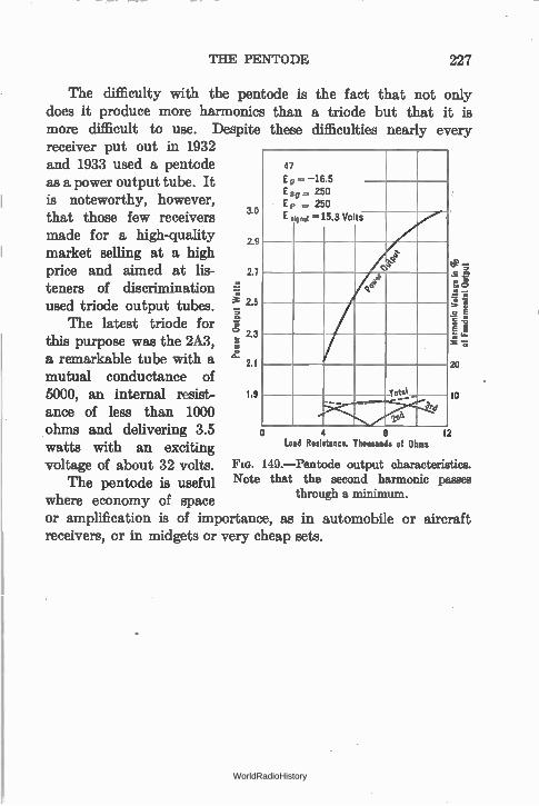
THE PENTODE 227
The difficulty with the pentode is the fact that not only does it produce more harmonics than a triode but that it is more difficult to use. Despite these difficulties nearly every receiver put out in 1932 and 1933 used a pentode as a power output tube. It is noteworthy, however, that those few receivers 3.0 made for a high-quality 2.9 market selling at a high price and aimed at lis- 2.7
teners of discrimination tr• e used triode output tubes. 2.5
The latest triode for e, Z3
this purpose was the 2A3, a remarkable tube with a 2.1
mutual conductance of 5000, an internal resist- 1.9
anos of less than 1000 ohms and delivering 3.5 watts with an exciting voltage of about 32 volts. Fia. 149.—Pentode output characteristics.
The pentode is useful Note that the second harmonic passes
where economy of space through a minimum.
or amplification is of importance, as in automobile or aircraft receivers, or in midgets or very cheap sets.
47
E g E8g Ep E
= —16.5 = 250 = 250 ign .i =15.3 VOItS
ce e 41
1 e
-rote_
4 e Load Resistance, Thousands of Ohms
10
12
WorldRadioHistory
CHAPTER XI
AUDIO AMPLIFIERS
SO FAR we have not spoken of the frequency or band of fre-quencies at which the vacuum tube and its associated apparatus will amplify. The theory up to the present point deals with amplifiers in general. It is necessary now to consider the types of amplifiers, and their differences.
191. Need of an audio amplifier.—All radio receivers in use at the present time have an audio amplifier of more or less ampli-fication. The principles of such amplifiers underlie the whole phenomenon of amplification.
Let us think of the broadcasting studio in which originate the signals which we must amplify. A microphone stands in front of a musician or a speaker. It has two electrodes which for the sake of our discussion may be made of carbon. Between them is a little box of carbon granules. One of he electrodes has a metal diaphragm attached to it which is so located that the air vibrations we call sound impinge on it. When sound is directed into the microphone it moves the diaphragm which in turn moves one of the electrodes which squeezes the carbon granules and thereby changes their electrical resistance. The steady battery current which normally flows through the microphone from one carbon electrode through the carbon granules to the other electrode is changed in accordance to the frequencies of the music or speech directed into it.
This steady current of the microphone is said to be " modu-lated " or changed in accordance with the voice frequencies; and after the steady current is filtered out, the changes are built up in strength by amplifiers which will transmit the range of frequencies
228 WorldRadioHistory
NEED OF AN AUDIO AMPLIFIER 229
that will be encountered in practice. Here then is the first need for amplifiers. They must make up the loss resulting from trans-ferring the energy in the moving air particles we call sound into the energy of the changing electric current. This loss in energy that must be made up is considerable.
The frequencies normally transmitted over telephone lines range from 250 to about 2500 cycles. These are complex audio-frequency a.-c. currents. Most of the energy of the voice occurs in the frequencies below 1000 cycles, most of the intelligibility above that frequency; therefore if a filter is put in the telephone line which admits only frequencies below 1000 cycles we would hear a sound but it would be unintelligible. On the other hand, if the filter cut out all the low tones and transmitted only those above 1000 cycles, we could understand what the speaker was say-ing, but the sound would not carry, it would be weak.
For best intelligibility and carrying power—naturalness, we say—all the frequencies from about 120 to 2500 are necessary for transmission of speech.
Music, however, is more complex and for realism and natural-ness a much greater frequency range must be transmitted, not only by the microphone. but also by the amplifiers, the radio broadcast-ing station, the ether, the receiver, the amplifier, and finally the loud speaker in one's home. Music requires the transmission of all frequencies between 100 and 5000 cycles per second, and many critics desire that a still greater range shall be transmitted. At the present time, in the United States, the best broadcasting stations and connecting circuits transmit from below 100 to above 5000 cycles per second. After a certain amount of amplification these tones are mixed with a radio-frequency wave which is emitted from the antenna of the transmitting station. Just as the microphone current is said to be modulated, so is the radio-frequency wave of the station said to be modulated by these amplified audio-frequency tones. The program then becomes inaudible and remains so until some demodulating device separates the program from the carrier.
In spite of the fact that considerable power is used at the broad-casting station, there is an enormous loss in signal strength as we
WorldRadioHistory
230 AUDIO AMPLIFIERS
go away from the transmitter. These radio-frequency waves modu-lated at audio frequencies are greatly reduced in strength owing to absorption and dissipation in the medium through which they travel. It is now our duty to make up the transmission losses, to amplify them again, to demodulate or separate the audio- and radio-frequency currents, and then to forget all about the radio circuit from then on.
An audio amplifier, then, has nothing to do with radio at all, and can be used to amplify any voice or music frequency-modu-lated electric currents that are placed upon its input. Its job is to build up the strength of a minute electric current to the point where the audio modulations on this current are of equal or greater strength than they were originally.
From the moment the sound in the studio enters the micro-phone, it ceases to exist as sound, and becomes an electric current. The amount of voltage amplification necessary depends of course upon the ultimate strength of the desired signal and the strength of the signal which is to be raised to this level. The maximum amplification that has been attained is of the order of 10 1200 which is used in some tests on telephone cable. No sound is emitted again until some translating device is used, a device that will have electric currents in its input and sound or air waves in its output. Then, and only then, is sound emitted. Nowhere along the line from microphone to loud speaker can the signal be heard, unless some translating device is " plugged in." After demodula-tion the currents of audible frequency are amplified as much as desired by an audio amplifier.
The voice-frequency currents that can be amplified by an audio amplifier may come from a phonograph " pick-up," a telephone transmitter mouthpiece, or the plate circuit of a detector tube in a radio receiver. The radio link is, then, only an incidental and extremely inefficient part of the whole system—better results could be secured by eliminating the radio link completely and using telephone or power lines between the receiver and the transmitter. The advantage of radio is the ability to " broadcast " in all direc-tions, and to eliminate the need of a metallic circuit between the person broadcasting and the person listening.
WorldRadioHistory
THE REQUIREMENTS OF AN AUDIO AMPLIFIER 231
Let us forget all about the radio part of our receiver, tempora-rily, and consider only the audio-frequency amplifier.
192. The requirements of an audio amplifier.—An amplifier to accept, transmit, and amplify audio-frequency tones has several requirements which have taxed the ingenuity of many engineers:
(1) The amplifier must transmit all the tones required, in their proper proportion. It must have no frequency distortion.
(2) The amplifier must amplify all frequencies properly whether the input voltage is high or low. It must have no volume dis-tortion.
(3) It must have an overall amplification which added to the radio-frequency amplification will make up for the enormeus loss of power between the input to the microphone and the output from the loud speaker.
Let us consider, for the moment, only the amount of amplifica-tion necessary. This value of overall amplification varies, of course, with the input signals possible, and the output power required. For home reception an output of one watt of electrical power into a loud speaker of average efficiency—perhaps 5 per cent—is sufficient, although many people get along with much less than this value, and some require much greater power outputs.
If the amplifier works out of the conventional " grid leak and condenser" detector tube, the maximum voltage available without distortion due to detector overloading is about 0.3 volt. If the loud speaker has a resistance of 4000 ohms and if we fix the output power at 0.7 watt there must be the following amplification:
Wo = power into load = 700 milliwatts
R,, = resistance of load = 4000 ohms
EL = voltage across load E. = VW. X R. = 53 volts r.m.s. E = total a.-c. voltage in
plate circuit of last tube = 53 X 3/2 = 79 volts
= input voltage to amplifier = 0.3 volt r.m.s.
G = voltage amplification = 79/0.3 = 260 times
It is better that the amplifier shall have considerably more gain than this figure so that the detector may be worked at a safe dis-
WorldRadioHistory
232 AUDIO AMPLIFIERS
tance below its overloading point—to have a good factor of safety —and that weak signals from distant stations can " load up" the amplifier and its speaker.
In many modern receivers certain modifications have been made so that the detector output is sufficiently high that a loud speaker can be operated on but one stage of audio amplification. In others two or more stages are necessary to get the desired output of power.
Let us say, then, that the minimum gain for our amplifier is 300 times. How can we secure this amplification? There are several ways and we have already discussed the various types of amplifier arrangements. It is only necessary so to design each stage or to add a sufficient number of stages that the overall voltage amplification will be sufficient. The next problem is to see if the required frequency characteristic can be secured to prevent dis-tortion due to over emphasis or discrimination at some frequencies.
Example 1-11. An amplifier has a voltage gain, up to the grid of the last tube, of 200. The last tube has a ei of 8 and a plate resistance of 5000 ohms. It works into an impedance of 10,000 ohms. The input to the amplifier is 0.1 volt r.m.s. Calculate the power into the resistance, the voltage across it and the ratio between this voltage and the input voltage to get the overall voltage amplification.
The a.-c. voltage on grid of last tube = 4 X G = 0.1 X 200 = 20 volts. The a.-c. voltage in plate circuit of last tube = 20 X 8 = 160 volts. The a.-c. voltage across 10,000-ohm load = 2/3 X 160 = 106 volts. Power into load = E2/R = 1062/10,000 = 1.2 watts. Voltage amplification = E0/E = 106/0.1 = 1060 times. Problem 1-11. What voltage gain must an amplifier have to deliver 1.5
watts to a 4000-ohm load in the plate circuit of a tube whose plate resistance is 2000 ohms if the input voltage to the amplifier is 0.3 volt r.m.s.?
Problem 2-11. The load of an amplifier is a 2000-ohm resistor. The plate resistance of the last tube is 2000 ohms and its µ is 3. The gain in volt-age up to the grid of this last tube is 100. What input voltage is required to deliver 50 milliwatts of power?
Problem 3-11. Prove that if the load resistance is double the tube resist-ance, the voltage across the load is two-thirds of the total a.-c. voltage in the plate circuit of the tube and the voltage amplification is equal to the amplifica-up to the grid of the tube times the IA of the tube times 2/3.
Problem 4-11. If the load resistance is twice the tube resistance and the a.-c. voltage across the load is 100 volts, what must be the total a.-c, voltage in the plate circuit? If the la of the ttibe is 8, what must be the grid a.-c.
WorldRadioHistory
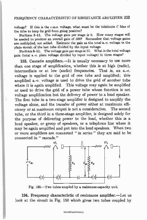
Fig. 150.—Two tubes coupled by a resistance-capacity unit.
FREQUENCY CHARACTERISTIC OF RESISTANCE AMPLIFIER 233
voltage? If this is the r.m.s. voltage, what must be the minimum C bias of the tube to keep its grid from going positive?
Problem 5-11. The voltage gain per stage is 8. How many stages will be needed to produce an overall gain of 500? Remember that voltage gains are multiplied, not added. Estimate the gain as the total a.-c. voltage in the plate circuit of the last tube divided by the input voltage.
Problem 6-11. The voltage gain per stage is 10. What is the total voltage gain (total a.-c. plate voltage divided by input voltage) in three stages?
193. Cascade amplifiers.—It is usually necessary to use more than one stage of amplification, whether this is at high (radio), intermediate or at low (audio) frequencies. That is, an a.-c. voltage is applied to the grid of one tube and amplified; this amplified a.-c. voltage is used to drive the grid of another tube where it is again amplified. This voltage may again be amplified or used to drive the grid of a power tube whose function is not voltage amplification but the delivery of power to a loud speaker. The first tube in a two-stage amplifier is designed to amplify the voltage alone, and the transfer of power either at maximum effi-ciency or at maximum output is not a consideration. The second tube, or the third in a three-stage amplifier, is designed solely for the purpose of delivering power to the load, whether this is a loud speaker, or group of speakers, or a telephone line where it may be again amplified and put into the loud speakers. When two or more amplifiers are connected " in series" they are said to be connected in " cascade."
VT c VT,
NW
194. Frequency characteristic of resistance amplifier.—Let us look at the circuit in Fig. 150 which gives two tubes coupled by
WorldRadioHistory
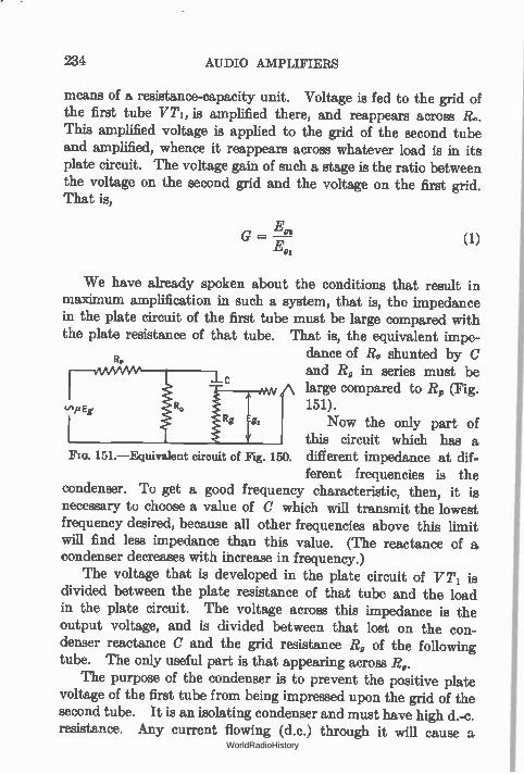
234 AUDIO AMPLIFIERS
means of a resistance-capacity unit. Voltage is fed to the grid of the first tube VT1, is amplified there, and reappears across R. This amplified voltage is applied to the grid of the second tube and amplified, whence it reappears across whatever load is in its plate circuit. The voltage gain of such a stage is the ratio between the voltage on the second grid and the voltage on the first grid. That is,
We have already spoken about the conditions that result in maximum amplification in such a system, that is, the impedance in the plate circuit of the first tube must be large compared with the plate resistance of that tube. That is, the equivalent impe-
dance of R, shunted by C and R, in series must be large compared to R, (Fig. 151). V,/tEg.
Now the only part of this circuit which has a
151.—Equivalent circuit of Fig. 150. different impedance at dif-ferent frequencies is the
condenser. To get a good frequency characteristic, then, it is necessary to choose a value of C which will transmit the lowest frequency desired, because all other frequencies above this limit will find less impedance than this value. (The reactance of a condenser decreases with increase in frequency.)
The voltage that is developed in the plate circuit of V Ti is divided between the plate resistance of that tube and the load in the plate circuit. The voltage across this impedance is the output voltage, and is divided between that lost on the con-denser reactance C and the grid resistance R, of the following tube. The only useful part is that appearing across R9.
The purpose of the condenser is to prevent the positive plate voltage of the first tube from being impressed upon the grid of the second tube. It is an isolating condenser and must have high d.-c. resistance. Any current flowing (d.c.) through it will cause a
WorldRadioHistory
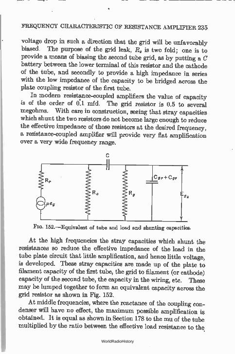
FREQUENCY CHARACTERISTIC OF RESISTANCE AMPLIFIER 235
voltage drop in such a direction that the grid will be unfavorably biased. The purpose of the grid leak, R, is two fold; one is to provide a means of biasing the second tube grid, as by putting a C battery between the lower terminal of this resistor and the cathode of the tube, and secondly to provide a high impedance in series with the low impedance of the capacity to be bridged across the plate coupling resistor of the first tube.
In modern resistance-coupled amplifiers the value of capacity is of the order of 0:1 mfd. The grid resistor is 0.5 to several megohms. With care in construction, seeing that stray capacities which shunt the two resistors do not become large enough to reduce the effective impedance of those resistors at the desired frequency, a resistance-coupled amplifier will provide very flat amplification over a very wide frequency range.
152.—Equivalent of tube and load and shunting capacities.
At the high frequencies the stray capacities which shunt the resistances so reduce the effective impedance of the load in the tube plate circuit that little amplification, and hence little voltage, is developed. These stray capacities are made up of the plate to filament capacity of the first tube, the grid to filament (or cathode) capacity of the second tube, the capacity in the wiring, etc. These may be lumped together to form an equivalent capacity across the grid resistor as shown in Fig. 152.
At middle frequencies, where the reactance of the coupling con-denser will have no effect, the maximum possible amplification is obtained. It is equal as shown in Section 178 to the mu of the tube multiplied by the ratio between the effective load resistance to the
WorldRadioHistory
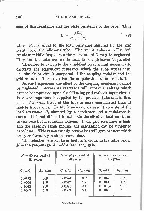
236 AUDIO AMPLIFIERS
sum of this resistance and the plate resistance of the tube. Thus
II G — Re q • Reg R,
where Re. is equal to the load resistance shunted by the grid resistance of the following tube. The circuit is shown in Fig. 152. At these middle frequencies the reactance of C may be neglected. Therefore the tube has, as its load, three re.sistances in parallel.
Therefore to calculate the amplification it is first necessary to calculate the equivalent resistance which the tube works into, i.e., the shunt circuit composed of the coupling resistor and the grid resistor. Then calculate the amplification as in formula 2.
At /ow frequencies the effect of the coupling condenser cannot be neglected. Across its reactance will appear a voltage which cannot be impressed upon the following grid-cathode input circuit. It is a voltage that is supplied by the previous tube and is then lost. The load, then, of the tube is more complicated than at middle frequencies. In the low-frequency case it consists of the load resistance R. shunted by a condenser and a resistance in series. It is not difficult to calculate the effective load resistance in this case but it is rather tedious. If the grid resistance is high, and the capacity large enough, the calculation can be simplified as follows. This is not strictly correct but will give answers which compare favorably with measured data.
The relation between these factors is shown in the table below. N is the percentage of middle frequency gain.
(2)
N = 90 per cent at 50 cycles
N = 80 per cent at 50 cycles
N = 70 per ceitt at 50 cycles
C, mfd. R9, meg. C, mfd. R9, meg. C, mfd. R9, meg.
0.0132 0.5 0.0084 0.5 0.0062 0.5 0.0066 1.0 0.0042 1.0 0.0031 1.0 0.0033 2.0 0.0021 2.0 0.00156 2.0 0.0013 5.0 0.0008 5.0 0.0006 5.0
WorldRadioHistory
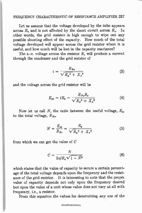
FREQUENCY CHARACTERISTIC OF RESISTANCE AMPLIFIER 237
Let us assume that the voltage developed by the tube appears across R. and is not affected by the shunt circuit across R.. In other words, the grid resistor is high enough to wipe out any possible shunting effect of the capacity. How much of the total voltage developed will appear across the grid resistor where it is useful, and how much will be lost in the capacity reactance?
The a.-c. voltage across the resistor R. will produce a current through the condenser and the grid resistor of
- 1/R02 + X.2
ER0
and the voltage across the grid resistor will be
ER.Ro Ea = iR, — v R.2 ±
1.2
(3)
(4}
Now let us call N, the ratio between the useful voltage, E., to the total voltage, ER..
E„2 N = — R, ERo V I 02 ± X02
from which we can get the value of C
N
C — 27rfR,V17N-2
(5)
(6)
which states that the value of capacity to secure a certain percent-age of the total voltage depends upon the frequency and the resist-ance of the grid resistor. It is interesting to note that the propel value of capacity depends not only upon the frequency desired but upon the value of a unit whose value does not vary at all with frequency, i.e., a resistor.
From this equation the values for determining any one of the
WorldRadioHistory
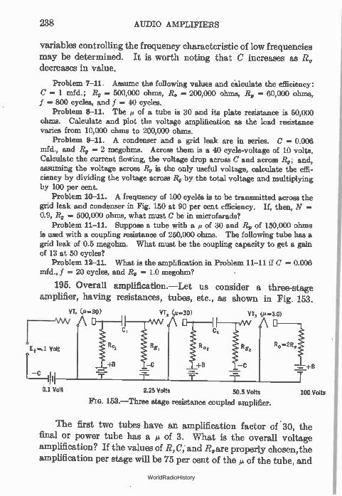
238 AUDIO AMPLIFIERS
variables controlling the frequency characteristic of low frequencies may be determined. It is worth noting that (J increases as Ro decreases in value.
Problem 7-11. Assume the following values and calculate the efficiency: C = 1 mfd.; R, = 500,000 ohms, R. = 200,000 ohms, R„ = 60,000 ohms, f --- 800 cycles, and f = 40 cycles.
Problem 8-11. The of a tube is 30 and its plate resistance is 60,000 ohms. Calculate and plot the voltage amplification as the load resistance varies from 10,000 ohms to 200,000 ohms.
Problem 9-11. A condenser and a grid leak are in series. C = 0.006 mfd., and R, = 2 megohms. Across them is a 40 cycle-voltage of 10 volts. Calculate the current flowing, the voltage drop across C and across Rg; and, assuming the voltage across Rg is the only useful voltage, calculate the effi-ciency by dividing the voltage across Rg by the total voltage and multiplying by 100 per cent.
Problem 10-11. A frequency of 100 cyclés is to be transmitted across the grid leak and condenser in Fig. 150 at 90 per cent efficiency. If, then, N = 0.9, R„, = 500,000 ohms, what must C be in microfarads?
Problem 11-11. Suppose a tube with a µ of 30 and Rp of 150,000 ohms is used with a coupling resistance of 250,000 ohms. The following tube has a grid leak of 0.5 megohm. What must be the coupling capacity to get a gain of 13 at 50 cycles?
Problem 12-11. What is the amplification in Problem 11-11 if C = 0.006 mfd., f = 20 cycles, and Rg = 1.0 megohm?
195. Overall amplification.—Let us consider a three-stage amplifier, having resistances, tubes, etc., as shown in Fig. 153.
VT, (a..30) NW A
Ei Volt
—c
0.1 Volt
VT, (i4=30)
wv A tcRgi +B 0,
VT, (µ=3.0)
Am A
— +0
R0=2R,.
2.25 Volts 50.5 Volts
153.— Three stage resistance coupled amplifier. 100 volts
The first two tubes have an amplification factor of 30, the final or power tube has a µ of 3. What is the overall voltage amplification? If the values of R,C, and Ro are properly chosen, the amplification per stage will be 75 per cent of the et of the tube, and
WorldRadioHistory
PLATE BATTERY REQUIREMENTS 239
what the first tube amplifies will be amplified again by the second. That is, if an input of 0.1 volt is applied to the grid-filament input of the first tube a voltage of 0.1 X .75 X 30 or 2.25 volts will be ap-plied to the second, and a voltage of 2.25 X 30 X .75 or 50.5 volts to the third input; and if the resistance into which this tube works has twice the value of the plate resistance of the tube, two-thirds of the total a.-c. plate voltage of the last tube will be applied to the load. That is, the load will have across it a voltage equal to 50 X 3 X or 100 volts.
The overall voltage amplification in such a case will be 100 ÷ 0.1 or 1000. This is equal numerically to the product of the voltage gain of the individual stages. Thus if each stage has a gain of N, two stages will have a gain of N2, three stages a gain of N3, etc. In this case .it will be (22.5)2 X 3 X 2/3 = 1000 (approximately).
196. Plate battery requirements.—One of the objections to the resistance amplifier is the excessive plate battery voltages that are necessary. The voltage on the plate of a tube in whose plate cir-cuit is a high resistance is not the voltage of the battery but this voltage minus the voltage drop across the resistor in the plate circuit. We want the a.-c. voltage drop across this resistance to be high but the d.-c. voltage drop to be low. As an example sup-pose a tube has a plate resistance, R,, of 60,000 ohms when the plate voltage (E,) is 100 volts. To get 75 per cent of the µ of the tube as the overall amplification from grid input voltage to the voltage output across the resistor, we need a resistance in the plate circuit of 180,000 ohms. Suppose under these conditions the plate current is 1 ma. What plate battery voltage is necessary if 100 volts are required on the plate?
The plate voltage may be found from
E, = Eb — I,R,
100 = Eb — 0.001 X 180,000
Eb -= 280 volts.
Now the tube will amplify with fewer volts on the plate than this—as many manufacturers and experimenters have proved—but
WorldRadioHistory
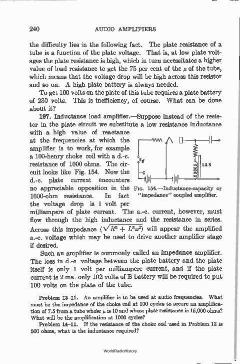
240 AUDIO AMPLIFIERS
the difficulty lies in the following fact. The plate resistance of a tube is a function of the plate voltage. That is, at low plate volt-ages the plate resistance is high, which in turn necessitates a higher value of load resistance to get the 75 per cent of the et of the tube, which means that the voltage drop will be high across this resistor and so on. A high plate battery is always needed.
To get 100 volts on the plate of this tube requires a plate battery of 280 volts. This is inefficiency, of course. What can be done about it?
197. Inductance load amplifier.—Suppose instead of the resis-tor in the plate circuit we substitute a low resistance inductance with a high value of reactance at the frequencies at which the —mm 1— ° amplifier is to work, for example a 100-henry choke coil with a d.-c.
Eg
cuit looks like Fig. 154. Now the c resistance of 1000 ohms. The cir-
d.-c. plate current encounters '111 no appreciable opposition in the FIG. 154.—Inductance-capacity
1000-ohm resistance. In fact "impedance" coupled amplifier.
the voltage drop is 1 volt per milliampere of plate current. The a.-c. current, however, must flow through the high inductance and the resistance in series.
Across this impedance (VR2 -I- L2w2) will appear the amplified a.-c. voltage which may be used to drive another amplifier stage if desired.
Such an amplifier is commonly called an impedance amplifier. The loss in d.-c. voltage between the plate battery and the plate itself is only 1 volt per milliampere current, and if the plate current is 2 ma. only 102 volts of B battery will be required to put 100 volts on the plate of the tube.
Problem 13-11. An amplifier is to be used at audio frequencies. What must be the impedance of the choke coil at 100 cycles to secure an amplifica-tion of 7.5 from a tube whose a is 10 and whose plate resistance is 15,000 ohms? What will be the amplification at 1000 cycles?
Problem 14-11. If the resistance of the choke coil used in Problem 13 is 500 ohms, what is the inductance required?
L&R
or
WorldRadioHistory
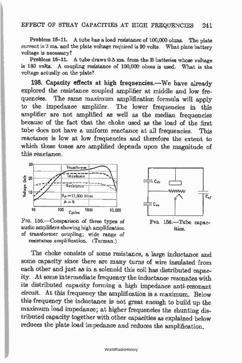
EFFECT OF STRAY CAPACITIES AT HIGH FREQUENCIES 241
Problem 15-11. A tube has a load resistance of 100,000 ohms. The plate current is 2 ma. and the plate voltage required is 90 volts. What plate battery voltage is necessary?
Problem 16-11. A tube draws 0.5 ma. from the B batteries whose voltage is 180 volts. A coupling resistance of 100,000 ohms is used. What is the voltage actually on the plate?
198. Capacity effects at high frequencies.—We have already explored the resistance coupled amplifier at middle and low fre-quencies. The same maximum amplification formula will apply to the impedance amplifier. The lower frequencies in this amplifier are not amplified as well as the median frequencies because of the fact that the choke used as the load of the first tube does not have a uniform reactance at all frequencies. This reactance is low at low frequencies and therefore the extent to which these tones are amplified depends upon the magnitude of this reactance.
30
zo
3
Transforms
e TrZnán; — —
• — e Resistance
Rp ,=17,300 Ohms
10 100 1000 10,030 Cycles
155.—Comparison of three types of audio amplifiers showing high amplification of transformer coupling; wide range of
resistance amplification. (Terman.)
Fm. 156.—Tube capac-ities.
The choke consists of some resistance, a large inductance and some capacity since there are many turns of wire insulated from each other and just as in a solenoid this coil has distributed capac-ity. At some intermediate frequency the inductance resonates with its distributed capacity forming a high impedance anti-resonant circuit. At this frequency the amplification is a maximum. Below this frequency the inductance is not great enough to build up the maximum load impedance; at higher frequencies the shunting dis-tributed capacity together with other capacities as explained below reduces the plate load impedance and reduces the amplification.
WorldRadioHistory
242 AUDIO AMPLIFIERS
The impedance amplifier saves B batteries since the voltage drop is much less than in a resistance coupled amplifier. The latter, however, will have a flat characteristic over a much wider range of frequencies. In addition the choke costs much more than a resistance; for these reasons the impedance coupled ampli-fier is seldom used.
Both amplifiers suffer at high frequencies because of the capaci-ties which shunt the grid resistor and the plate coupling resistor (or choke). The percentage of the maximum possible amplifica-tion that is attained at high frequencies in a resistance coupled amplifier is
Nhf - 1
(7)
where Rhf is the equivalent resistance made up of R„ of the first tube, R, the coupling resistance, R, the grid resistance of the second tube, and Xc is the reactance of the various capacities shunted across these resistances.
In the impedance coupled amplifier the percentage of the maximum possible amplification that is secured at low frequencies is given by an exactly similar expression in which XL is substi-tuted for Xc in this case standing for the inductive reactance of the choke.
To attain 70 per cent of the maximum possible amplification at a low frequency the reactance of the coupling condenser (or the choke) must equal the coupling resistance in ohms. At high frequencies the reduction in amplification will be about 5 per cent if the shunting capacities have a reactance equal to about three times the equivalent resistance as used in formula 2. At three times this frequency the amplification will have fallen to about 70 per cent of the maximum.
In both amplifiers the greatest voltage gain will be secured with high et tubes; the best frequency characteristic will be secured with low µ tubes.
These effects are illustrated in the curve in Fig. 157, taken from a Radio Club of America paper by A. V. Loughran, published in Radio Broadcaet, August, 1927, and in 155 after Terman.
WorldRadioHistory
practice CO may vary from 20 to as high as 300 mmfd. depending upon the intrinsic values of its components and the amplifica-tion of the system. That is, if the Cglf = 3.0 mmfd., and C„ =-8.0 mmfd. and the effective ampli-fication of the system is 20, becomes 3 plus 8 X 20 or 163 mmfd —which is an appreciable capacity and not at all what one would expect. The effective capacity across the input to the tube is a function of the et of the tube; thus the greater the amplification factor the more trouble one gets into because of this capacity-multiplying effect. Low 1.5 tubes are not so troubled, but their amplification is low; and so the amplifier designer and experimenter must compromise between a good frequency characteristic and a high gain. If the gain is good the high frequencies are discriminated against, and if the characteristic is very good the overall gain is likely to be low.
EFFECT OF STRAY CAPACITIES AT HIGH FREQUENCIES 243
Not only do the tubes and wiring capacities, which are repre-sented in Fig. 152, play havoc with high frequencies, but the effect of the grid-plate capacity of the second tube is multiplied by the la of the tube—a very interesting and unfortunate fact.
The capacities which cause trouble at high frequencies are:
(1) Grid-filament capacity, Cd. (2) Plate-filament capacity, Ca. (3) Plate-grid capacity, C„. (4) Stray capacities in wiring, etc.
The capacity C, across the input to the tube is equal to
C, = Cie C„ (go ± 1),
where Jh is the effective amplification in the circuit, and the other factors are as itemized above and shown in Fig. 156.
These values for the Radiotron UX-240, a tube adapted for resistance-coupled amplifiers, are CPI = 1.5 mmfd., C,,, = 3 to 4 5 mmfd , and Cap = 8.8 mmfd. In I500
E I000
o 503 o
L.650 »Met
III
000.000 Ohms
7./ ".-.---..«hem2150,000 OhrIns
Re-2 Megohms 0g=-0.0 05 MM. I I I
É g I Frequency-Cycles
157.—Frequency characteris-
tic of resistance- and inductance-
coupled amplifiers.
à
WorldRadioHistory
244 AUDIO AMPLIFIERS
Problem 17-11. The la of a tube is 8, its grid-filament capacity is 6 mmfd., its plate-grid capacity is 8.0 mmfd. The effective amplification of the circuit is 7, and stray capacities across the filament and grid circuit amount to 2 mmfd. What is the effective shunting capacity Ce
199. Frequency characteristic of amplifiers.—So far we have discussed only isolated points in our frequency response, either high, medium or low frequencies. What happens at other points? In the case of the resistance coupled circuit the reactance of the coupling condenser reduces the amplification at lower frequencies as indicated before; in the impedance amplifier the reactance of the choke limits the response. If the response at any frequency is calculated it will be less at lower frequencies and will rise to the maximum possible amplification, which will in general be higher in the impedance coupled stage than in the resistance stage.
At the higher frequencies in both amplifiers the shunting capacities of tube and wiring control the characteristic. For example, a resistance shunted by a capacity will have the following effective resistance
Rer co2R2c2
and in the table below will be found some values of a quarter-megohm shunted by 60 mmfd
Frequency Effective resistance in ohms 2,000 246,000 4,000 234,000 6,000 218,000 8,000 200,000 10,000 182,000
If the resistor is one megohm and the capacities rise to 300 mmfd., the effective load becomes only 53,000 ohms although it is 965,000 ohms at 100 cycles. This represents a tremenduous drop.
Therefore the stray capacities must be kept low. As shown above, the capacity between tube elements is effective in reducing the amplification particularly that existing between grid and plate of the second tube. This value is multiplied by the (effective gain in the circuit plus 1). Therefore the higher the gain the greater becomes the difficulty of keeping the response up at the
WorldRadioHistory
TUNED INDUCTANCE AMPLIFIER 245
high frequencies. The higher the coupling resistor the greater in effect become these capacities. Therefore for flat amplification it is almost necessary to use low-g tubes with low gain per stage.
Example 2-11. Suppose a 1-megohm resistor is in the plate circuit of a tube and that 10 volts are developed across it. If 100,000 ohms are shunted across it, the effective impedance becomes 0.91 X 10⁶, and if the current is the same the voltage developed has been reduced to 0.91 volt. Now, sup-pose 10 volts are developed across 100,000 ohms and that another 100,000-ohm resistor is shunted across it. What is the resultant reduction in voltage? Clearly it is 50 per cent—a much smaller percentage reduction.
Problem 18-11. A tube with an amplification factor of 30 and a plate resistance of 150,000 ohms is used with a half-megohm coupling resistance. Suppose that in construction a path of soldering flux is placed across the terminals of this resistor accidentally so that the half-megohm is effectively shunted by 100,000 ohms. What is the resultant amplification? What is the amplification without the shunting resistance? What is the percentage loss due to the flux?
200. Tuned inductance amplifier.—In both the resistance load and the inductance load amplifier the maximum amplification is attained when the impedance in the plate circuit is a maximum. ff, then, we desire to transmit only one frequency, say 1000 cycles, we can get greater amplification by tuning the inductance with a shunt ?.ondenser so that we have an anti-resonant circuit in the plate circuit of the tube, as shown in Fig. 158. If an inductance of 0.1 henry is tuned Fm. 158.—Tuned inductance with a 0.254-mfd. condenser the resonant frequency will be about 1000 cycles. If the coil has a resistance of 100 ohms the impedance of the anti-resonant circuit will be roughly 3950 ohms whereas the reactance of the coil alone will be only 628 ohms. Tuning the coil therefore increases the load impedance in the plate circuit by about 6.3 times.
The voltage gain will be given by the formula of Section 178:
G = R. + R;
R.
output.
WorldRadioHistory
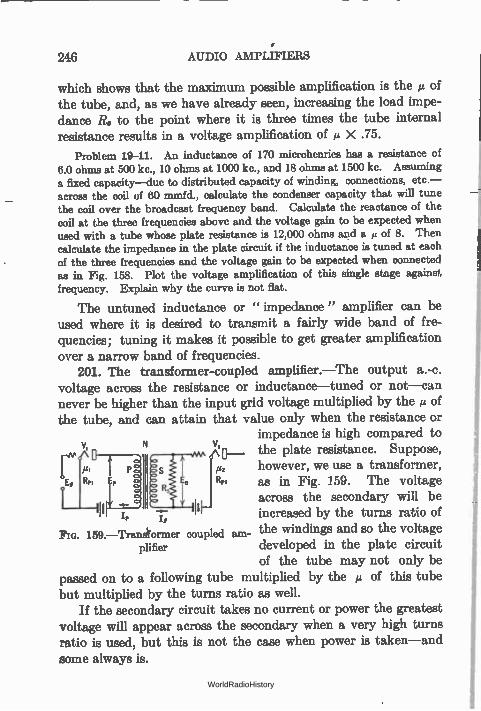
246 AUDIO AMPLIFIERS
which shows that the maximum possible amplification is the µ of the tube, and, as we have already seen, increasing the load impe-dance R. to the point where it is three times the tube internal resistance results in a voltage amplification of g X .75.
Problem 19-11. An inductance of 170 microhenries has a resistance of 6.0 ohms at 500 kc., 10 ohms at 1000 kc., and 18 ohms at 1500 kc. Assuming a fixed capacity—due to distributed capacity of winding, connections, etc.— across the coil of 60 mmfd., calculate the condenser capacity that will tune-the coil over the broadcast frequency band. Calculate the reactance of the coil at the three frequencies above and the voltage gain to be expected when used with a tube whose plate resistance is 12,000 ohms and a of 8. Then calculate the impedance in the plate circuit if the inductance is tuned at each of the three frequencies and the voltage gain to be expected when connected as in Fig. 158. Plot the voltage amplification of this single stage against frequency. Explain why the curve is not flat.
The untuned inductance or " impedance" amplifier can be used where it is desired to transmit a fairly wide band of fre-quencies; tuning it makes it possible to get greater amplification over a narrow band of frequencies.
201. The transformer-coupled amplifier.—The output a.-c. voltage across the resistance or inductance—tuned or not—can never be higher than the input grid voltage multiplied by the g of the tube, and can attain that value only when the resistance or
impedance is high compared to v, 0.__ the plate resistance. Suppose,
rfi Rry Rpz /22
however, we use a transformer, as in Fig. 159. The voltage
1 l across the secondary will be /, increased by the turns ratio of
Pm. 159.—Trawiformer coupled am- the windings and so the voltage plifier developed in the plate circuit
of the tube may not only be passed on to a following tube multiplied by the g of this tube but multiplied by the turns ratio as well.
If the secondary circuit takes no current or power the greatest voltage will appear across the secondary when a very high turns ratio is used, but this is not the case when power is taken—and some always is.
WorldRadioHistory
THE TRANSFORMER-COUPLED AMPLIFIER 247
The maximum voltage across the secondary will be obtained when the turns ratio is given by the expression
R, N2 = —
where R, and R„ are the resistances between which the transformer works. When such a turns ratio is used the voltage across the secondary is given by
E„,N E, (max.) —
2 (7)
All of this assumes that a perfect transformer is used, that is, one which has no d.-c. resistance, no magnetic leakage, and infinite primary and secondary reactances. If the resistance of the load across the secondary is 1 megohm, and the plate resistance of the tube is 10,000 ohms, the proper turns ratio,
N , I1,000,000 10,
\! 10,000
and the voltage gain from (7) is
E, = /21 X 5 = 40 if pi = 8.
The foregoing mathematics discloses several interesting points. In the first place it is possible to get much greater voltage amplifica-tion by means of a transformer than is possible with the same tube and either resistance or inductance output. In the second place, for every ratio of resistance across the secondary and primary of the transformer there is a certain turns ratio which will produce the maximum voltage step-up. This means that once the resist-ances on either side of the transformer are determined, the turns ratio for maximum voltage gain is fixed. This, in turn, means that
WorldRadioHistory
248 AUDIO AMPLIFIERS
a transformer can be used as an impedance adjusting device, that is, a coupling device between two circuits of different impedance, one of which acts as a source of voltage and the other is the recipi-ent of a voltage, amplified or not.
Whenever the impedances of the two sides of the transformer are not that indicated by the expression above, there is a loss in secondary voltage, a transmission loss, engineers say. Whenever two circuits are to be coupled together with the least loss in voltage or power the proper turns ratio transformer must be used, that is, N2 = Z./Z„, where Z, and Z. are the impedances between which the transformer works.
Problem 20-11. A tube whose plate resistance is 12,000 ohms (UX-201—A) works into a resistance, R., of 600,000 ohms. What is the proper turns ratio, and what is voltage gain if g = 87 If E., = 1 volt what voltage will appear across R.?
Problem 21-11. One tube whose plate resistance is 25,000 ohms is con-nected to another whose grid circuit has a resistance of 400,000 ohms. What is the turns ratio of the transformer for maximum voltage amplification?
Problem 22-11. An " output " transformer is to be used to connect a loud speaker to a tube. The impedance of the loud speaker at the desired frequency is 4000 ohms, the tube has a resistance of 2000 ohms. What is the proper value of N?
Problem 23-11. A telephone line has an impedance of 600 ohms. The a.-c. voltages in the plate circuit of a 6000-ohm tube are to be transferred to this line. What must be done to effect such a transfer with least power loss?
202. Transformer with no secondary load.—If the secondary of the transformer works into a true no-load impedance, that is, an open circuit, or R, -= infinity, the voltage appearing across the secondary will be ,LE, multiplied by the turns ratio of the trans-former and not, as given in (7) itE, X N/2. The voltage gain is equal to
2 irfLiN G — •Ni1-17 --(1 ) 2
/ Rp2 ± (2 rfLi)2 X
where L1 = inductance of the primary, etc.
Example 3-11. Transformers of a few years ago had very little primary inductance. Assume an inductance of 2 henrys, f = 800 cycles, p = 8, and
WorldRadioHistory
THE ADVANTAGE OF THE TRANSFORMER 249
= 10,000 ohms, N = 4. Calculate the voltage amplification. Then assume f = 80 cycles and calculate G.
G - 8 2 X 3.14 X 800 X 2 X 4 ,
V108 ± (2 X 3.14 X 800 X 2)2
If f = 80 cycles
2 X 3.14 X 80 X 2 X 4 G 8 , 3.2.
'V108 ± (2 X 3.14 X 80 X 2) 2
Problem 24-11.—What is the maximum shunting capacity in Problem 11-11 if the gain at 10,000 cycles is down not more than 10 per cent from the value at, say, 1000 cycles?
- 22.7
203. The advantage of the transformer.—The transformer has the great advantage that it can contribute toward the voltage amplification, and can contribute toward the maximum power output when the load resistance or impedance differs from the tube resistance. In addition, high B battery voltages are not necessary. A transformer can be constructed so that it has little loss in
itself. This loss is due the d.-c. resistance of the windings, the fact that perfect coupling between primary and secondary is not attained, and because of iron losses, that is, currents set up in the iron core represent a loss in power which must be supplied from the source. This power therefore does not get out of the trans-former and cannot appear in the output.
If a good transformer is used, its transmission loss is small. Its effect, then, upon the circuit is of two sorts; first it may contribute toward the voltage gain by having a voltage step up in it; second, it may be used to "match" the load resistance to the tube resist-ance. Let us suppose the tube resistance is 10,000 ohms, and that the secondary load resistance is 100,000 ohms. A resistance of this value interposed in the plate circuit of a tube will not have the maximum power developed in it. (See Section 180.) But if we use the proper transformer such that N2 = 10, this 100,000 ohms will look, to the tube, like a resistance of 100,000 X .01 or 10,000 ohms—the condition for maximum voltage and maximum power.
The transformer can always be forgotten if we substitute for
WorldRadioHistory
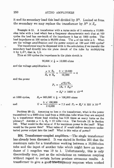
250 AUDIO AMPLIFIERS
it and its secondary load this load divided by N2. Looked at from the secondary we may replace the transformer by N2 X Z,.
Example 4-11. A transformer with a turns ratio of 3 connects a 10,000-ohm tube with a load which has a frequency characteristic such that at 100 cycles the load has one-tenth of the impedance it has at 1000 cycles. The load impedance at 100 cycles is 90,000 ohms. The » of the tube is 8. What are the voltage amplification and the power output at 100 and 1000 cycles?
The transformer may be dispensed with in the calculation if we transfer the secondary load directly into the plate circuit of the tube by multiplying it by 1/N2, that is, 1/9.
Thus at 100 cycles the impedance in the plate circuit is
90,000 X = 10,000 ohms
and the voltage amplification is
ei X E. 8 X 10,000 4
Rs, 20,000 -
and the power
plE2IR«, Po =
(Ro Rp)'
E92 x 1600 X 10 -4
at 1000 cycles, Re 900,000 X + = 100,000 ohms
8 X 100,000 and G - - 7.3 and Po = Ea' X 533 X 10-6
110,000
Problem 25-11. Assuming no loss in the transformer, what is the power transmitted to a 6000-ohm load from a 2000-ohm tube when they are coupled by a transformer whose load winding has 2.24 times as many turns as the primary? Assume = 3, E, = 10 volts r.m.s. Use formula (5) in Section 180. What would be the value of N for maximum power in the load? What would be the power then? What value of N would deliver maximum undis-torted power output into the load? What is this value of power?
204. Transformer-coupled amplifiers.—The single transformer has already been discussed. It was stated in Section 201 that the maximum ratio for a transformer working between a 10,000-ohm tube and the input of another tube which might have an impe-dance of 1 megohm was 10 to 1. Unfortunately, this is only theoretically true, just as the calculations on resistance coupling without regard to certain factors produce erroneous results. A transformer to give a good low-frequency response when worked WorldRadioHistory
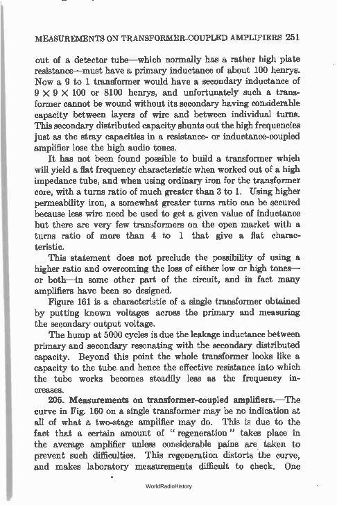
MEASUREMENTS ON TRANSFORMER-COUPLED AMPLIFIERS 251
out of a detector tube—which normally has a rather high plate resistance—must have a primary inductance of about 100 henrys. Now a 9 to 1 transformer would have a secondary inductance of 9 X 9 X 100 or 8100 henrys, and unfortunately such a trans-former cannot be wound without its secondary having considerable capacity between layers of wire and between individual turns. This secondary distributed capacity shunts out the high frequencies just as the stray capacities in a resistance- or inductance-coupled amplifier lose the high audio tones.
It has not been found possible to build a transformer which will yield a flat frequency characteristic when worked out of a high impedance tube, and when using ordinary iron for the transformer core, with a turns ratio of much greater than 3 to 1. Using higher permeability iron, a somewhat greater turns ratio can be secured because less wire need be used to get a given value of inductance but there are very few transformers on the open market with a turns ratio of more than 4 to 1 that give a flat charac-teristic.
This statement does not preclude the possibility of using a higher ratio and overcoming the loss of either low or high tones— or both—in some other part of the circuit, and in fact many amplifiers have been so designed.
Figure 161 is a characteristic of a single transformer obtained by putting known voltages across the primary and measuring the secondary output voltage.
The hump at 5000 cycles is due the leakage inductance between primary and secondary resonating with the secondary distributed capacity. Beyond this point the whole transformer looks like a capacity to the tube and hence the effective resistance into which the tube works becomes steadily less as the frequency in-creases.
205. Measurements on transformer-coupled amplillers.—The curve in Fig. 160 on a single transformer may be no indication at all of what a two-stage amplifier may do. This is due to the fact that a certain amount of " regeneration" takes place in the average amplifier unless considerable pains are taken to prevent such difficulties. This regeneration distorts the curve, and makes laboratory measurements difficult to check. One
WorldRadioHistory
252 AUDIO AMPLIFIERS
day the curve may be one thing, and on the next it may be
different.
7.0
6.0
5.0
ILI 4.0
3.0
2.0
1.0
100 200 500 1,000
Cycles
Fm. 160.— Characteristic of single audio transformer.
5,000 10,000
206. Calculation of overall voltage amplification.—Let us con-sider the amplifier in Fig. 161. The overall amplification is the
113 Tz 13 ft=8 1:1
E.
R.
Fla. 161.—How a voltage E, is amplified in a transformer coupled amplifier.
ratio between the voltage, E0 across the output load and that
across the input, E.
WorldRadioHistory
CALCULATION 9P OVERALL VOLTAGE AMPLIFICATION 253
Eo 3 X 8 X 3 X 8
-RI-Rp Ei Ei
576 R0
Ei (Ro 14)
where R, = plate resistance of last tube.
It is actually not possible to realize all this amplification because it is never possible to realize the full µ of the tubes. The voltage gain measured and calculated will check very closely, usually.
Now suppose we apply an input voltage of, say, 0.1 volt across the primary of the first transformer. Across the secondary this will become 3 X 0.1 or 0.3 volt and so the value of the C bias for this first tube which is fed out of the secondary of T1 need not be greater than 1 volt since that will take care of severe overload, and if the tube is a 201-Vi. type a plate voltage of 45 will be sufficient. Somewhat better amplification and fidelity will result by using 90 volts on the plate and 4.5 volts bias on the grid, since the plate resistance will be somewhat less under these conditions. If the impedance of the following transformer as looked at from the tube is high compared to the R, of this first tube—as it will be at fre-quencies of the order of 1000 cycles if the transformer is any good at all—nearly all of the et of this tube will be realized. Across the primary of the second transformer, T2, then will appear a voltage of 0.3 X 8 or 2.4 volts and across the secondary a voltage of 7.2 volts which will require C bias of 9 volts and about 135 volts on the plate. The tube should be a 112 type. This voltage will be multiplied by 8 times in this tube and will appear across the output load as 38.4 volts provided the load is twice the resistance of the last tube. This voltage across a 10,000-ohm load will produce 73.8 milliwatts of power.
207. Reflex amplifiers.—When two sets of frequencies of widely different order are to be amplified it is possible to make one tube serve as both a low-frequency and as a high-frequency amplifier. Such systems in which the energy from a tube is
WorldRadioHistory
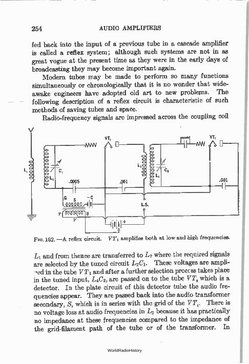
P rebeee
254 AUDIO AMPLIFIERS
fed back into the input of a previous tube in a cascade amplifier is called a reflex system; although such systems are not in as great vogue at the present time as they were in the early days of broadcasting they may become important again.
Modern tubes may be made to perform so many functions simultaneously or chronologically that it is no wonder that wide-awake engineers have adopted old art to new problems. The following description of a reflex circuit is characteristic of such methods of saving tubes and space.
Radio-frequency signals are impressed across the coupling coil
VT,
.001
o
LS. o
—41111
Fla. 162. —A reflex circuit. VT1 amplifies both at low and high frequencies.
L1 and from thence are transferred to L2 where the required signals are selected by the tuned circuit L2C1. These voltages are ampli-ed in the tube VT1 and after a further selection procEss takes place
in the tuned input, L4C2, are passed on to the tube VT, which is a detector. In the plate circuit of this detector tube the audio fre-quencies appear. They are passed back into the audio transformer secondary, S, which is in series with the grid of the VT,. There is no voltage loss at audio frequencies in L2 because it has practically no impedance at these frequencies compared to the impedance of the grid-filament path of the tube or of the transformer. In
WorldRadioHistory
TRANSFORMER-COUPLED AMPLIFIERS 255
this tube the audio frequencies are amplified and are passed into the head phones or loud speaker or other audio amplifiers as noted at L.S. This load is by-passed by a large condenser so that no radio-frequency voltages are lost there. Of course there are audio-frequency voltages across the primary, 1,3, of the inter-tube trans-former but they are very small because this primary has practically no impedance to audio frequencies. And because of the very poor coupling to tube 2 at audio frequencies, practically no audio volt-ages appear across the input to the demodulator tube VT,. We have then two tubes serving as radio-frequency amplifier, detector and low-frequency amplifier.
208. Inverse duplex.—The first tube in a radio set is the one which has the least to do—the incoming signals are usually weak compared to those which later tubes will have to handle. In the Inverse Duplex system (Grimes) in use to some extent among battery operated sets an ingenious circuit was employed, taking advantage of the fact that the first tube has small voltages to contend with.
In this circuit the first tube was the first r.-f. tube and the final audio tube. The second r.-.f. tube was the first a.-f. tube. Thus the path of the signal was from the first to second r.-f. tube to the detector and then to the second to first r.-f. tubes acting as first and second audio tubes.
Nowadays the antenna voltages in the city where many power-ful broadcast stations are in operation may run to appreciable fractions of a volt. Therefore it is no longer true that the first tube is not overworked. In fact the screen-grid tube which came to be universally employed as a radio-frequency amplifier had a characteristic so short that strong local signals drove the plate current down to the lower bend of the characteristic or reduced the plate current to zero and caused very bad distortion called cross modulation, etc. Therefore the variable-a came into existence.
Tubes are no longer expensive. Therefore there is little need to reflex them—but in places where space is a factor an extra tube or two makes a great difference.
WorldRadioHistory
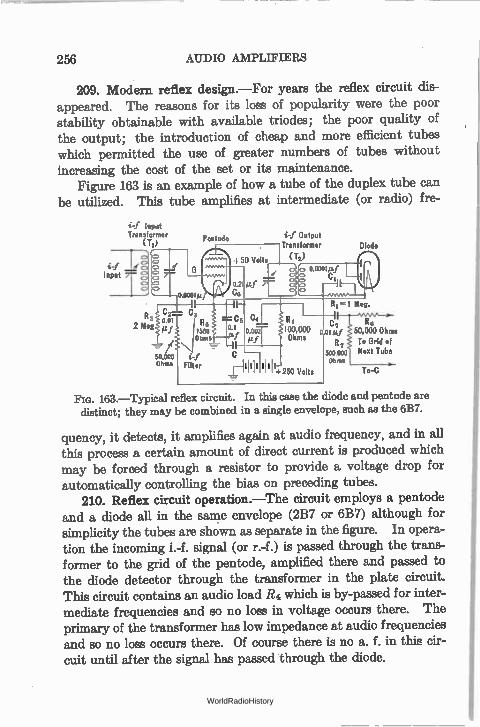
2.56 AUDIO AMPLIFIERS
209. Modern reflex design.—For years the reflex circuit dis-appeared. The reasons for its loss of popularity were the poor stability obtainable with available triodes; the poor quality of the output; the introduction of cheap and more efficient tubes which permitted the use of greater numbers of tubes without increasing the cost of the set or its maintenance.
Figure 163 is an example of how a tube of the duplex tube can be utilized. This tube amplifies at intermediate (or radio) f re-
i-f Input Transformer
(Ti
50.0o0 i-j Ohms Filter
Pentode
C5 0.1 taf
NI III +250 Volts
i-f Output Transformer
(;)
Diode
R6 50,000 Ohms To Grid of Next Tube
a To-C
163.—Typical reflex circuit. In this case the diode and pentode are distinct; they may be combined in a single envelope, such as the 6B7.
quency, it detects, it amplifies again at audio frequency, and in all this process a certain amount of direct current is produced which may be forced through a resistor to provide a voltage drop for automatically controlling the bias on preceding tubes.
210. Reflex circuit operation.—The circuit employs a pentode and a diode all in the same envelope (2B7 or 6B7) although for simplicity the tubes are shown as separate in the figure. In opera-tion the incoming i.-f. signal (or r.-f.) is passed through the trans-former to the grid of the pentode, amplified there and passed to the diode detector through the transformer in the plate circuit. This circuit contains an audio load R4 which is by-passed for inter-mediate frequencies and so no loss in voltage occurs there. The primary of the transformer has low impedance at audio frequencies and so no loss occurs there. Of course there is no a. f. in this cir-cuit until after the signal has passed through the diode.
WorldRadioHistory
" EQUALIZING " 257
The a.f. produced in the diode is coupled to the grid of the pentode through R1 and C2. Condenser C3 permits i.f. to get to the cathode of the pentode but is of such high impedance at audio frequencies that these voltages are impressed upon the grid of that tube.
After being amplified again in the pentode the audio frequencies build up a voltage across R4 and are then passed on to the following stage through C7 and Rs.
Although the values given in the diagram are designed for use at intermediate frequencies, the combination of pentode and diode may be employed at radio frequencies if desired. Such a combi-nation should have the sensitivity, as a one-tube receiver, of the triode-crystal detector so popular before commercial set manu-facturing took the bulk of set building away from the home build-ers. It is probable that such a circuit would have greater sensi-tivity because of the high gain possible in the pentode. Certainly it would be more stable. For example, calculation tends to show • that the amplification at i.f. would be of the order of 100 and of 50 at audio frequencies. Since the transformer T2 has a step-down ratio the overall amplification would be somewhat less than the product of these two figures.
211. "Equsiii7ing."—It is possible by means of correcting circuits to get almost any kind of frequency response curve desired. For example, if a certain amplifier is deficient at low frequencies, one stage may be made resonant to these frequencies and so pull up the characteristic. If the amplifier tends to sing at some frequency, a loss may be put in at this frequency, and the overall curve will be flatter than without the equalizer. In the telephone plant the use of equalizing networks is very important and has come to be almost an exact science. These consist of resistances, inductances, and condensers. Equalizing usually results in an overall loss in amplification; that is, some loss is incurred which must be made up by additional stages. In other words one gains a better characteristic at the expense of amplification. In some
amplifiers a better low-frequency response is secured by tuning the primary of the transformer by a capacity to a low frequency.
7.)
WorldRadioHistory
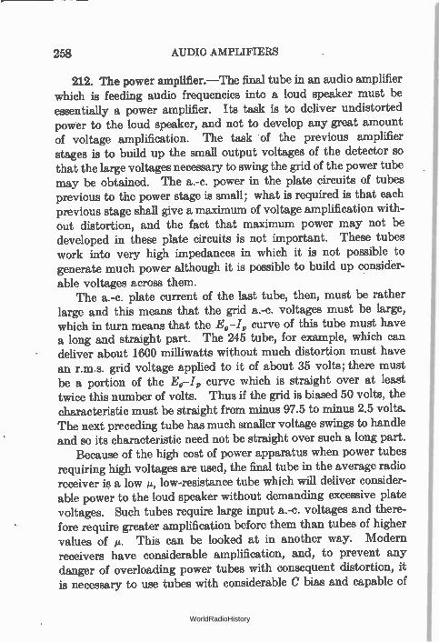
258 AUDIO AMPLIFIERS
212. The power amplifier.—The final tube in an audio amplifier which is feeding audio frequencies into a loud speaker must be essentially a power amplifier. Its task is to deliver undistorted power to the loud speaker, and not to develop any great amount of voltage amplification. The task of the previous amplifier stages is to build up the small output voltages of the detector so that the large voltages necessary to swing the grid of the power tube may be obtained. The a.-c. power in the plate circuits of tubes previous to the power stage is small; what is required is that each previous stage shall give a maximum of voltage amplification with-out distortion, and the fact that maximum power may not be developed in these plate circuits is not important. These tubes work into very high impedances in which it is not possible to generate much power although it is possible to build up consider-able voltages across them.
The a.-c. plate current of the last tube, then, must be rather large and this means that the grid a.-c. voltages must be large, which in turn means that the Eg-I, curve of this tube must have a long and straight part. The 245 tube, for example, which can deliver about 1600 milliwatts without much distortion must have an r.m.s. grid voltage applied to it of about 35 volts; there must be a portion of the E0-I„ curve which is straight over at least twice this number of volts. Thus if the grid is biased 50 volts, the characteristic must be straight from minus 97.5 to minus 2.5 volts. The next preceding tube has much smaller voltage swings to handle and so its characteristic need not be straight over such a long part.
Because of the high cost of power apparatus when power tubes requiring high voltages are used, the final tube in the average radio receiver is a low II, low-resistance tube which will deliver consider-able power to the loud speaker without demanding excefflive plate voltages. Such tubes require large input a.-c. voltages and there-fore require greater amplification before them than tubes of higher values of is. This can be looked at in another way. Modern receivers have considerable amplification, and, to prevent any danger of overloading power tubes with consequent distortion, it is necessary to use tubes with considerable C bias and capable of
WorldRadioHistory
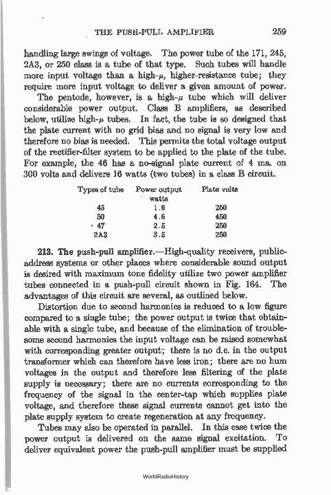
THE PUSH-PULL AMPLIFIER 259
handling large swings of voltage. The power tube of the 171, 245, 2A3, or 250 class is a tube of that type. Such tubes will handle more input voltage than a high-g, higher-resistance tube; they require more input voltage to deliver a given amount of power.
The pentode, however, is a high-s tube which will deliver considerable power output. Class B amplifiers, as described below, utilize high-g tubes. In fact, the tube is so designed that the plate current with no grid bias and no signal is very low and therefore no bias is needed. This permits the total voltage output of the rectifier-filter system to be applied to the plate of the tube. For example, the 46 has a no-signal plate current of 4 ma. on 300 volts and delivers 16 watts (two tubes) in a class B circuit.
Types of tube Power output Plate volts watts
45 1.6 250 50 4.6 450 • 47 2.5 250 2A3 3.5 250
213. The push-pull amplifier.—High-quality receivers, public-address systems or other places where considerable sound output is desired with maximum tone fidelity utilize two power amplifier tubes connected in a push-pull circuit shown in Fig. 164. The advantages of this circuit are several, as outlined below.
Distortion due to second harmonics is reduced to a low figure compared to a single tube; the power output is twice that obtain-able with a single tube, and because of the elimination of trouble-some second harmonics the input voltage can be raised somewhat with corresponding greater output; there is no d.c. in the output transformer which can therefore have less iron; there are no hum voltages in the output and therefore less filtering of the plate supply is necessary; there are no currents corresponding to the frequency of the signal in the center-tap which supplies plate voltage, and therefore these signal currents cannot get into the plate supply system to create regeneration at any frequency.
Tubes may also be operated in parallel. In this case twice the power output is delivered on the same signal excitation. To deliver equivalent power the push-pull amplifier must be supplied
WorldRadioHistory
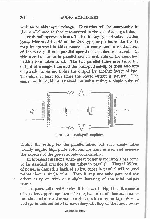
260 AUDIO AMPLIFIERS
with twice this input voltage. Distortion will be comparable in the parallel case to that encountered in the use of a single tube.
Push-pull operation is not limited to any type of tube. Either low-s triodes of the 45 or the 2A3 type, or pentodes like the 47 may be operated in this manner. In many cases a combination of the push-pull and parallel operation of tubes is utilized. In this case two tubes in parallel are on each side of the amplifier, making four tubes in all. The two parallel tubes give twice the output of a single tube and the push-pull set-up of these two sets of parallel tubes multiplies the output by another factor of two. Therefore at least four times the power output is secured. The same result could be attained by substituting a single tube of.
164.—Push-pull amplifier.
double the rating for the parallel tubes, but such single tubes usually require high plate voltages, are large in size, and increase the expense of the power supply considerably.
In broadcast stations where great power is required it has come to be standard practice to use tubes in parallel. Thus if 25 kw. of power is desired, a bank of 10 kw. tubes in parallel will be used rather than a single tube. Then if any one tube goes bad the others carry on with only slight lowering of the total output power.
The push-pull amplifier circuit is shown in Fig. 164. It consists of a center-tapped input transformer, two tubes of identical charac-teristics, and a transformer, or a choke, with a center tap. When a voltage is induced into the secondary winding of the input trans-
WorldRadioHistory
THE PUSH-PULL AMPLIFIER 261
former one grid becomes less negative a certain amount and the other grid becomes more negative the same amount.
If the C bias, which is attached to the center of the input wind-ing, is 35 volts and if across the kitire secondary winding appears a peak a.-c. voltage of 20, one tube has its negative grid voltage increased by 10 volts, or to 45 volts, and the other decreased by 10 volts, or to minus 25 volts. Therefore one plate current increases and the other decreases. These variations in a.-c. plate current flow through the output winding and may be transferred to the load. These plate circuit current variations are out of phase by 180°, one increasing, the other decreasing a like amount. One tube" pushes" current through the output, the other" pulls" current through it. Suppose both tubes pushed at the same time. What would happen? If they both pushed the same amount and at the same time no current would flow through the output wind-ing because the two currents would neutralize each other.
If, then, we can cause the second harmonic currents to be in phase, that is, to push or pull at the same instant, and the same amount, they will not get into the load, and distortion due to these extra currents will not appear in our loud speaker. This is exactly what the push-pull system does.
Because the input voltage across such an amplifier is divided into two parts this amplifier requires twice the input voltage to give the same output power—unless the turns ratio of the input transformer is doubled, which is difficult to carry out in practice. Because of the push-pull arrangement, however, considerable over-loading can be tolerated before the third harmonics which are not canceled out become objectionable. And there is another advan-tage—the output transformer or choke need not have such a large core because of the fact that the d.-c. currents in the two halves are flowing in opposite directions; and since the two windings are closely coupled the resultant magnetization of the core is very low. Since the two windings are connected " series aiding" so far as a.-c. currents are concerned, the total inductance is increased. Not only less iron is necessary but less copper as well. The proper match between the tubes (twice the impedance of a single tube) and the loud speaker can be obtained by the use of such a transformer.
WorldRadioHistory
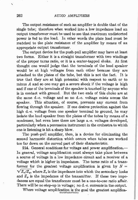
262 AUDIO AMPLIFIERS
The output resistance of such an amplifier is double that of the single tube; therefore when worked into a low impedance load an output transformer must be used to see that maximum undistorted power is fed to the load. In other words the plate load must be matched to the plate resistance of the amplifier by means of an appropriate output transformer.
The output device for the push-pull amplifier may have at least two forms. Either it is a straight transformer with two windings of the proper turns ratio, or it is a center-tapped choke. At first thought one would judge that the terminals of the loud speaker would be at high voltages from each other because they are attached to the plates of the tube, but this is not the fact. It is true that they are at high potential with respect to earth or to minus A and so one may get a severe shock if the voltage is high and if one of the terminals of the speaker is touched by anyone who is in contact with ground. But the two ends of this choke are at the same d.-c. voltage and so no d.-c. voltage exists across the speaker. This situation, of course, prevents any current from flowing through the speaker. If one desires protection against the high d.-c. voltage from one speaker terminal to ground, he may isolate the loud speaker from the plates of the tubes by means of a condenser, but even here there are large a.-c. voltages developed, particularly when a percussion instrument in the orchestra to which one is listening is hit a sharp blow.
The push-pull amplifier, then, is a device for eliminating the second harmonic distortion which occurs when tubes are worked too far down on the curved part of their characteristic.
214. General conditions for voltage and power amplification.— In general, voltage amplification must always take place between a source of voltage in a low impedance circuit and a receiver of a voltage which is higher in impedance. The turns ratio of a trans-former for the greatest voltage amplification is given by N —
where Z. is the impedance into which the secondary looks and Z, is the impedance of the transmitter. If these two impe-dances are equal the transformer must be a one-to-one ratio affair. There will be no step-up in voltage; no d.-c. currents in the output.
Where voltage amplification is the goal the greatest amplifica-WorldRadioHistory
POWER NECESSARY FOR GOOD LOUD-SPEAKER OPERATION 263
tion will be attained when working from a very low impedance device into a very high impedance device, for example a tube with a low plate resistance working into a tube with a very high grid-filament resistance. This means that the grid of the following tube must never be permitted to go positive, for then the input resistance of this circuit becomes quite low and the amplification falls and amplitude distortion results.
Where quality of reproduction, that is, a flat frequency charac-teristic is desired, best results can be attained between two low impedance devices, for example a tube of low plate resistance working into a tube of low grid-filament resistance. In other words high voltage amplification and high fidelity of response are at odds, especially when it is desired to get both within a few stages of audio. One may get as much voltage amplification out of a single tube with a ;4 of 6 and a transformer with a turns ratio of 12 as he can out of two such tubes and a transformer with a turns ratio of 2, but in the second case he will get a fiat frequency charac-teristic from 60 to 6000 cycles whereas in the other case he will get a characteristic that is flat nowhere, and in fact is very sharply peaked.
When one wants high amplification and high quality he must get it in several stages, and not all at once.
When one speaks of power amplification the conditions are not the same as for voltage amplification—in general. Power amplification may take place only by the aid of a tube which releases power from a set of local batteries, or from a power line. The maximum power is transferred when the impedances of the transmitter and the receiver are equal whether these impedances are high or low. But in general, power amplification implies the use of a tube which has a fairly low plate resistance which is worked into a fairly low impedance circuit or its equivalent secured by means of a transformer.
215. Power necessary for good loud-speaker operation. —In 1928 about 95 per cent of all commercially manufactured receivers used the 171 type of tube. The year 1929 saw the introduction of the 245 type and the still larger 250 type which provides a much greater margin of safety against overloading. The use of push-
WorldRadioHistory
"111e9WIIIIRffluirpre...iimure.muinememimene
264 AUDIO AMPLIFIERS
pull amplifiers is another step toward protection against overload-ing and as such is to be encouraged. In the average home push-pull 245 type tubes provide sufficient power output (3.5 watts) and a factor of safety -against overloading.
216. Class B amplification.—A type of amplification that promised much, but which has not come into wide use, was class B, characterized by the fact that the grids of the tubes were actually driven positive by the signal so that they drew current and power from the driving source.
Two tubes must be used; they are connected just as any other push-pull amplifier. No C bias is used, the tubes being specially built with a high la so that with no bias the plate current is small.
16
14
12
-;;Io e
c.',12• 1; c▪ f:
0_ •-• 8 4
4 2
sT-1 ° o
I I Type 46 l i Ef 72.5 Volts R. C. 1
Input Clams A One Type 46 Piste Volts 250 Grid Volts =-33
Output Class 8 One Type 46 — Plate Volts = 303 Grid Volts =0
Voltege Ratio Input Transtormer 2.2 17`.Lc.-
Peak Power Eft. =79 Input Transtemer e — Output Load.
," Plate to Plate em 3.503 Ohm
te Type 48
Type 46 —et.> 4
-.1441
— ii - PK' Type 4li %teen%
? "
Harmonics
1-11r
Grid Current 1
0 2 4 6 8 lO 12 Driver Signal Volts (Rms)
165.—Characteristics of Class B Amplification.
When the excitation is applied little or no current flows in the plate circuits except on the half-cycles which make the grid positive. Since the tubes are already drawing little current, making the grid more negative cannot result in greater current flow; therefore current flows only during the positive half-cycles.
Where the ordinary push-pull circuit, connected and biased for class A operation, draws plate current in both halves at all times, one tube taking more current when the other takes less from the plate supply source, class B tubes draw current in spurts. When
WorldRadioHistory
COMPARISON OF PUSH-PULL AND PARALLEL TUBES 265
one tube grid is going negative the other is going positive. The latter tube draws current; the other tube does not.
The amount of current each tube draws depends upon the exciting grid voltage. The power output of such a pair of tubes may be very high; the distortion may be made quite low by care-ful design. Since the current taken from the plate supply system varies with the exciting voltage applied to the tube grids, the voltage regulation of this supply must be very good. That is, the terminal voltage of the filter must not drop appreciably when a sudden large current is drawn from it. For this reason the recti-fier usually employed is a mercury-vapor tube which has a very low and constant voltage drop across it regardless of the current taken from it. This voltage drop amounts to about 15-20 volts.
Since the grids of the two tubes are driven positive, they will draw current. This flow of current represents power and this power must be supplied by the previous tube. The previous tube is usually called a" driver" and is connected to the class B tubes through a step-down input transformer. Distortion present in the driver stage will go through the power stage to appear in the output. Therefore this stage must be carefully designed.
The 46 is a tube specially designed for this service. With 300 volts on the plates, zero bias, load resistance of 5200 ohms and with an average power input (grid to grid) of 950 nailliwatts— nearly one watt—the two tubes will deliver 16 watts.
In 1933 the functions of several tubes were combined into one envelope. Thus the two tubes of a class B stage were put into a single bulb, for example the 79, which has a 6.3 volt heater and will produce 5.5 watts on 180 volts.
Another interesting combination of tubes especially designed for a.-f. amplification is the 2B6 in which a single heater supplies two cathodes. There are two grids and two plates. The grid of the second section is connected within the tube to the cathode of the first tube which is above ground potential by the bias of the second tube. The plate of the first tube is connected to B plus, the second plate feeds the output into a transformer. The second grid draws power which is supplied from the first section. With a signal input to the second tube of 25 volts, r.m.s., a power output of 4 watts is obtained.
WorldRadioHistory
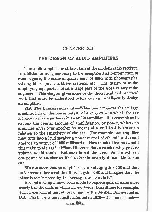
CHAPTER XII
THE DESIGN OF AUDIO AMPLIFIERS
THE audio amplifier is at least half of the modern radio receiver. In addition to being necessary to the reception and reproduction of radio signals, the audio amplifier may be used with phonographs, talking films, public address systems, etc. The design of audio amplifying equipment forms a large part of the work of any radio engineer. This chapter gives some of the theoretical and practical work that must be understood before one can intelligently design an amplifier.
218. The transmission unit.—When one compares the voltage amplification of the power output of any system in which the ear is likely to play a part—as in an audio amplifier—it is convenient to express the greater amount of amplification, or power, which one amplifier gives over another by means of a unit that bears some relation to the sensitivity of the ear. For example one amplifier may turn into a loud speaker a power output of 800 milliwatts and another an output of 1000 milliwatts. How much difference would this make to the ear? Offhand it seems that a considerably greater volume would result. But such is not the case. Such a ratio of one power to another as 1000 to 800 is scarcely discernible to the ear.
We can state that an amplifier has a voltage gain of 50 and that under some other condition it has a gain of 60 and imagine that the latter is easily noted by the average ear. But is it?
Several attempts have been made to express gain in units more nearly like the units in which the ear hears, logarithmic for example. Such a convenient unit of loss or gain is the decibel, abbreviated as DB. The Bel was universally adopted in 1928—it is ten decibels-
266 WorldRadioHistory
THE TRANSMISSION UNIT 267
and is named in honor of Dr. Alexander Graham Bell, the inventor of the telephone. The difference in two powers differing by one DB is just discernible to the ear.
The DB is a logarithmic unit---that is, each time the amount of power of a device is doubled—or multiplied by 2—we add 3 DB. When the power is increased ten-fold—multiplied by 10—we add 10 DB. Here, then, is the second advantage in the DB. We can add them, instead of multiplying them. For example let us suppose the voltage amplification of an amplifier is 25 and that it is to be connected after another similar amplifier. What is the voltage gain? Evidently, if the second amplifies what the first gives it, the overall gain will by 252 or 625. Here we must multiply 25 by 25, which is awkward. But if we knew that one amplifier had a voltage gain corresponding to 25 DB and was to be used after another of similar characteristics, we would state that the overall gain was 25 plus 25 or 50 DB. The DB is defined as " ten times the common logarithm of the ratio of two powers," or
/s/DB = 10 logio (Pi/P2) (1)
in which N is the number of DB by which the two powers P1 and P2 differ. The table below gives some easily remembered values of DB and their corresponding power or voltage and current ratios:
NPR Approximate Power Ratio
Approximate Voltage or
Current Ratio
3 2.0 1.41 4 2.5 1.59 6 4 2.0 7 5 2.24 9 8 2.82 10 10 3.16 20 100 10.0 23 200 14.1 30 1000 31.6
Let us consider an amplifier with an output power of 100 milli-watts. How much must we increase its power output before the
WorldRadioHistory
268 THE DESIGN OF AUDIO AMPLIFIERS
ear can just detect the difference? Suppose we double the output. The ratio is then 200/100 or 2 and the DB corresponding to this power ratio is 3. The ear can detect one DB difference and using a table of DB or a slide rule we find that 1 DB corresponds to a power ratio of 1.25 roughly. Thus the power output to which 100 milliwatts must be increased before the ear can detect the differ-ence is such that P = P2/100 = 1.25 or 125 milliwatts. Adding another DB brings the level up to 160 mw. and another unit brings it to 200 mw., as indicated above.
In this case it would have been foolish to go to great efforts to effect an output of 115 compared to an output of 100—because the ear could not tell the difference. In fact the ear can only with some difficulty tell the difference between the amplifiers differing by 3 DB—double the power—unless single tones are used and then only in a quiet room.
219. Voltage and current ratios.—Strictly speaking the DB should be used only when expressing the ratios of powers. Let us suppose two amplifiers are feeding current into equal resistances. The currents are different. How can we express in DB the advan-tage of the one as a current amplifier? We need only find out the ratio of the powers as before, and multiply the logarithm of this ratio by 10. Thus,
pr = /12 R
P2 = /22 R
112 R DB = 10 log PI/P2 = 10 log 122 R
/12 = 10 log
/2-
= 20 log —, / 2
(2)
If the resistances are not equal (2) becomes
/iViir E 1WITI El V.1.72 DB = 20 log _ 20 log _ /-- — 20 log (3) /2V R2 E2/ V 'R2 E2 Viil
WorldRadioHistory
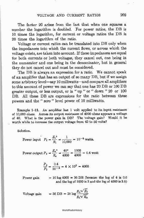
VOLTAGE AND CURRENT RATIOS 269
The factor 20 arises from the fact that when one squares a number the logarithm is doubled. For power ratios, the DB is 10 times the logarithm, for current or voltage ratios the DB is 20 times the logarithm of the ratio.
Voltage or current ratios can be translated into DB only when the impedances into which the current flows, or across which the voltage exists, are taken into account. If these impedances are equal for both currents or both voltages, they cancel out, one being in the numerator and one being in the denominator, but in general they do not cancel out and must be considered.
The DB is always an expression for a ratio. We cannot speak of an amplifier that has an output of so many DB, but if we assign some arbitrary level—say 10 milliwatts—and compare all amplifiers to this amount of power we can say that one has 20 DB or 100 DB greater output, or less output, or is " up " or " down" 20 or 100 DB. All these DB are expressions for the ratio between these powers and the " zero " level power of 10 milliwatts.
Example 1-12. An amplifier has 1 volt applied to its input resistance of 10,000 ohms. Across its output resistance of 4000 ohms appears a voltage of 40. What is the power gain in DB? The voltage gain? Would it be worth while to increase the output voltage from 40 to 50 volts?
Solution.
Ei 2 1 Power input Pi = = - 10-4 watts.
it 10,000
E.2 402 1600 Power output P. = — = = 0.4 watt
R. 4000 4000
Power gain
Voltage gain
P. 0.4 = = 4 x 103 = 4000
Pi 10-4
= 10 log 4000 = 36 DB (because the log of 4 is 0.6 and the log of 1000 is 3 and the log of 4000 is 3.6)
= 36 DB = 20 log ECV-É-0
WorldRadioHistory
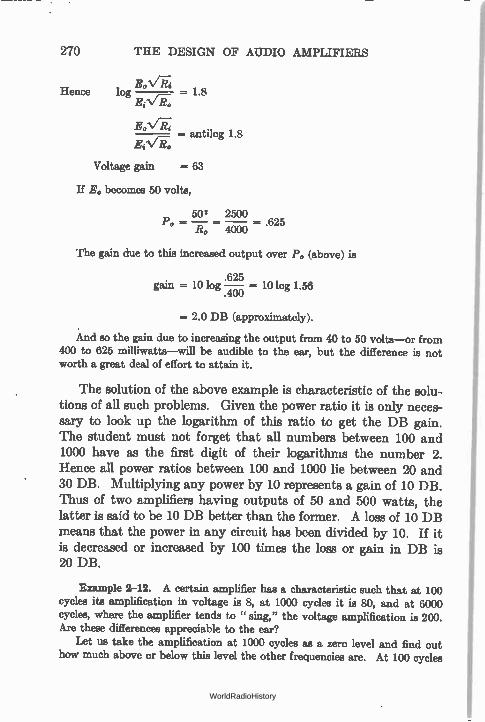
270 THE DESIGN OF AUDIO AMPLIFIERS
Hence log - 1.8 Ei V R.
- antilog 1.8 E;144
Voltage gain = 63
If E0 becomes 50 volts,
502 2500 P. = = 40-To = .625
The gain due to this increased output over P. (above) is
gain = 10 log 625 = 10 log 1.56 .400
= 2.0 DB (approximately).
And so the gain due to increasing the output from 40 to 50 volts—or from 400 to 625 milliwatts—will be audible to the ear, but the difference is not worth a great deal of effort to attain it.
The solution of the above example is characteristic of the solu-tions of all such problems. Given the power ratio it is only neces-sary to look up the logarithm of this ratio to get the DB gain. The student must not forget that all numbers between 100 and 1000 have as the first digit of their logarithms the number 2. Hence all power ratios between 100 and 1000 lie between 20 and 30 DB. Multiplying any power by 10 represents a gain of 10 DB. Thus of two amplifiers having outputs of 50 and 500 watts, the latter is said to be 10 DB better than the former. A loss of 10 DB means that the power in any circuit has been divided by 10. If it is decreased or increased by 100 times the loss or gain in DB is 20 DB.
Example 2-12. A certain amplifier has a characteristic such that at 100 cycles its amplification in voltage is 8, at 1000 cycles it is 80, and at 6000 cycles, where the amplifier tends to " sing," the voltage amplification is 200. Are these differences appreciable to the ear?
Let us take the amplification at 1000 cycles as a zero level and find out how much above or below this level the other frequencies are. At 100 cycles
WorldRadioHistory
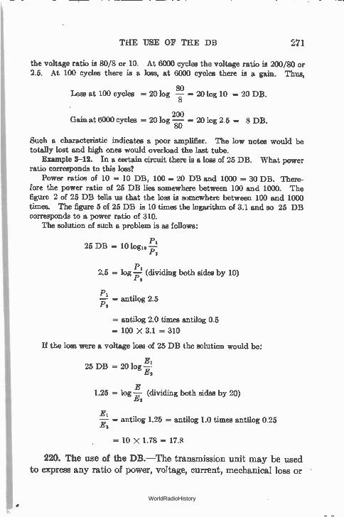
THE USE OF THE DB 271
the voltage ratio is 80/8 or 10. At 6000 cycles the voltage ratio is 200/80 or 2.5. At 100 cycles there is a loas, at 6000 cycles there is a gain. Thus,
80 Loss at 100 cycles = 20 log = 201og 10 = 20 DB.
200 Gain at 6000 cycles = 20 log — = 20 log 2.5 = 8 DB.
80
Such a characteristic indicates a poor amplifier. The low notes would be totally lost and high ones would overload the last tube.
Example 3-12. In a certain circuit there is a loss of 25 DB. What power ratio corresponds to this loss?
Power ratios of 10 = 10 DB, 100 = 20 DB and 1000 = 30 DB. There-fore the power ratio of 25 DB lies somewhere between 100 and 1000. The figure 2 of 25 DB tells us that the loss is somewhere between 100 and 1000 times. The figure 5 of 25 DB is 10 times the logarithm of 3.1 and so 25 DB corresponds to a power ratio of 310.
The solution of such a problem is as follows:
25 DB = 10 logio — PS
2.5 = log — (dividing both aides by 10) Ps
PI — = antilog 2.5 P2
= antilog 2.0 times antilog 0.5
= 100 X 3.1 = 310
If the loss were a voltage loss of 25 DB the solution would be:
EI 25 DB = 20 log —
Es
E 1.25 = log — (dividing both sides by 20)
ES
—Ei = antilog 1.25 antilog 1.0 times antilog 0.25 E2
= 10 X 1.78 = 17.8
220. The use of the DB.—The transmission unit may be used to express any ratio of power, voltage, current, mechanical loss or
WorldRadioHistory
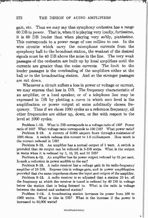
272 THE DESIGN OF AUDIO AMPLIFIERS
gain, etc. Thus we may say that symphony orchestra has a range 60 DB in power. That is, when it is playing very loudly, fortissimo, it is 60 DB louder than when playing very softly, pianissimo. This corresponds to a power range of one million to one. In the wire 'circuits which carry the microphone currents from the symphony hall to the broadcast station, the weakest of the desired signals must be 40 DB above the noise in the line. The very weak passages of the orchestra are built up by local amplifiers until the currents are greater than the noise currents. The limit to the louder passages is the overloading of the amplifiers either at the hall or in the broadcasting station. And so the stronger passages are cut down.
Whenever a circuit suffers a loss in power or voltage or current, we may express that loss in DB. The frequency characteristic of an amplifier, or a loud speaker, or of a telephone line may be expressed in DB by plotting a curve in which zero level is the amplification or power output at some arbitrarily chosen fre-quency. Thus if we chose 1000 cycles as a reference frequency, all other frequencies are either up, down, or flat with respect to the level at 1000 cycles.
Problem 1-12. What in DB corresponds to a voltage ratio of 100? Power ratio of 100? What voltage ratio corresponds to 100 DB? What power ratio?
Problem 2-12. A current of 0.006 ampere flows through a resistance of 1000 ohms. A switch reduces this current to 1.0 milliampere. How much is the current reduced in DB?
Problem 3-12. An amplifier has a normal output of 1 watt. A switch is provided that its output can be reduced in 5-DB steps. What is the output in watts when it is reduced by 5, 10, 20, and 25 DB?
Problem 4-12. An amplifier has its power output reduced by 25 per cent. Is such a reduction in power audible to the ear?
Problem 5-12. A radio receiver has a voltage gain in its radio-frequency amplifier of 50 DB. Express this in voltage gain, and in power amplification provided that the same impedance closes the input and output of the amplifier.
Problem 6-12. A radio receiver is so adjusted that a station 20 kc. off the frequency at which the receiver is tuned is reduced by 40 DB in voltage below the station that is being listened to. What is the ratio in voltage between the desired and undesired station?
Problem 7-12. A broadcasting station increases; its power from 500 to 5000 watts. What is this in DB? What is the increase if the power is increased to 50,000 watts?
WorldRadioHistory
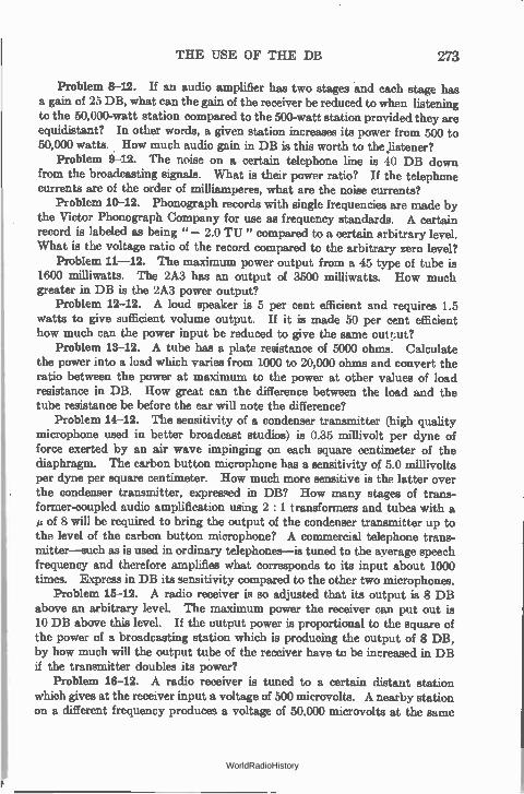
THE USE OF THE DB 273
Problem 8-12. If an audio amplifier has two stages and each stage has a gain of 25 DB, what can the gain of the receiver be reduced to when listening to the 50,000-watt station compared to the 500-watt station provided they are equidistant? In other words, a given station increases its power from 500 to 50,000 watts. How much audio gain in DB is this worth to the listener?
Problem 9-12. The noise on a certain telephone line is 40 DB down from the broadcasting signals. What is their power ratio? If the telephone currents are of the order of milliamperes, what are the noise currents?
Problem 10-12. Phonograph records with single frequencies are made by the Victor Phonograph Company for use as frequency standards. A certain record is labeled as being " - 2.0 TU" compared to a certain arbitrary level. What is the voltage ratio of the record compared to the arbitrary zero level?
Problem 11-12. The maximum power output from a 45 type of tube is 1600 milliwatts. The 2A3 has an output of 3500 milliwatts. How much greater in DB is the 2A3 power output?
Problem 12-12. A loud speaker is 5 per cent efficient and requires 1.5 watts to give sufficient volume output. If it is made 50 per cent efficient how much can the power input be reduced to give the same outt.ut?
Problem 13-12. A tube has a plate resistance of 5000 ohms. Calculate the power into a load which varies from 1000 to 20,000 ohms and convert the ratio between the power at maximum to the power at other values of load resistance in DB. How great can the difference between the load and the tube resistance be before the ear will note the difference?
Problem 14-12. The sensitivity of a condenser transmitter (high quality microphone used in better broadcast studios) is 0.35 millivolt per dyne of force exerted by an air wave impinging on each square centimeter of the diaphragm. The carbon button microphone has a sensitivity of 5.0 millivolts per dyne per square centimeter. How much more sensitive is the latter over the condenser transmitter, expressed in DB? How many stages of trans-former-coupled audio amplification using 2 : 1 transformers and tubes with a et of 8 will be required to bring the output of the condenser transmitter up to the level of the carbon button microphone? A commercial telephone trans-mitter—such as is used in ordinary telephones—is tuned to the average speech frequency and therefore amplifies what corresponds to its input about 1000 times. Express in DB its sensitivity compared to the other two microphones.
Problem 15-12. A radio receiver is so adjusted that its output is 8 DB above an arbitrary level. The maximum power the receiver can put out is 10 DB above this level. If the output power is proportional to the square of the power of a broadcasting station which is producing the output of 8 DB, by how much will the output tube of the receiver have to be increased in DB if the transmitter doubles its power?
Problem 18-12. A radio receiver is tuned to a certain distant station which gives at the receiver input a voltage of 500 microvolts. A nearby station on a different frequency produces a voltage of 50.000 microvolts at the same
WorldRadioHistory
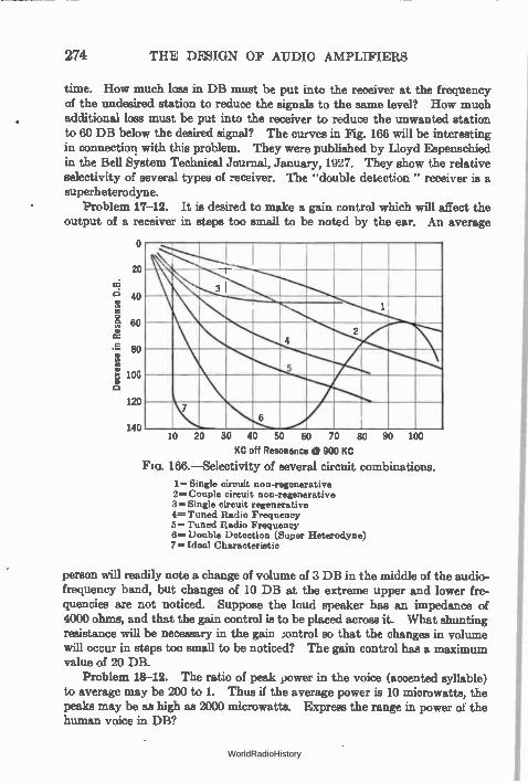
274 THE DESIGN OF AUDIO AMPLIFIERS
time. How much loas in DB must be put into the receiver at the frequency of the undesired station to reduce the signals to the same level? How much additional loss must be put into the receiver to reduce the unwanted station to 60 DB below the desired signal? The curves in Fig. 166 will be interesting in connection with this problem. They were published by Lloyd Espenschied in the Bell System Technical Journal, January, 1927. They show the relative selectivity of several types of receiver. The "double detection" receiver is a superheterodyne.
Problem 17-12. It is desired to make a gain control which will affect the output of a receiver in steps too small to be noted by the ear. An average
o
20
oi 40
o .• 60
. E 80 1Y,
10C
120
140
3
7 6
10 20 30 40 50 60 70 80 90 100
KC off Resonance @ 900 KC
Fro. 166.—Selectivity of several circuit combinations.
1.= Single circuit non-regenerative 2= Couple circuit non-regenerative 3= Single circuit regenerative 4= Tuned Radio Frequency 5 Tuned Radio Frequency 6= Double Detection (Super Heterodyne) 7= Ideal Characteristic
person will readily note a change of volume of 3 DB in the middle of the audio-frequency band, but changes of 10 DE at the extreme upper and lower fre-quencies are not noticed. Suppose the loud speaker has an impedance of 4000 ohms, and that the gain control is to be placed across it. What shunting resistance will be necessary in the gain control so that the changes in volume will occur in steps too small to be noticed? The gain control has a maximum value of 20 DB.
Problem 18-12. The ratio of peak power in the voice (accented syllable) to average may be 200 to 1. Thus if the average power is 10 microwatts, the peaks may be as high as 2000 microwatts. Express the range in power of the human voice in DB?
WorldRadioHistory
THREE GENERAL TYPES OF AMPLIFIERS 275
221. Three general types of amplifiers.—Amplifiers have been divided into three general types according to which part of the grid-plate characteristic is used and according to the magnitude of the applied signal voltage. Class A amplifiers are operated so that plate current flows at all times; the grid is not usually driven positive; the plate current represents exactly the input signal. It has low efficiency and low output.
Class B amplifiers have the grid biased almost to plate current cut-off; plate current flows to any extent only when the grid is on the positive half cycle of input voltage, and during this half cycle the plate current in an ideal amplifier will represent exactly the input grid voltage. This amplifier has medium output and efficiency.
Class C amplifiers are operated so biased that no plate current flows when the grid is not excited, and as a matter of fact it flows only during a portion of the half cycle when the grid is driven positive or at least less negative. This amplifier has high effi-ciency and high power output. The distortion inherent in this type of amplification precludes its use for speech or musical ampli-fication. It is useful at radio frequencies where harmonics generated will be filtered out of the antenna, for example, by tuned circuits resonant only to the fundamental.
Amplifiers are often spoken of as voltage, current, or power amplifiers. These are more general terms and are used to indicate that one or the other of these three fundamental electrical quan-tities is amplified particularly. Voltage amplification is the ratio of the output voltage to the input voltage; likewise current and power amplification are ratios of the output to the input.
Radio-frequency amplifiers for use in receivers are invariably voltage amplifiers; in transmitters they may be power amplifiers. In the latter case the tube and associated circuits may produce very little, or no, amplification, merely acting as an isolating cir-cuit or a " buffer " stage to separate two circuits.
276. Transformer working out of high impedance.—Some manufacturers make transformers of different ratios, usually two, a low ratio to work out of a detector, and a higher ratio to work out of the first audio tube. Why is this?
WorldRadioHistory
276 TkJJ DESIGN OF AUDIO AMPLIFIERS
A tube has a lower plate resistance the higher the voltage on its plate and the lower the negative voltage on its grid. A 201-A type tube operating as an amplifier under normal conditions, that is, 90 volts on the plate and minus 4.5 on the grid, has a resistance of about 12,000 ohms. A detector tube usually has a much higher plate resistance because the plate voltage is lower. The normal detector plate voltage is 45 although many detectors are operated with but 22.5 volts on the plate. In addition many detectors, of the C bias type, have large negative biases put on the grid. The result is that instead of a resistance of 12,000 ohms out of which the amplifier must work there is a resistance of from 20,000 to 40,000 ohms.
We have already seen that a large part of the a.-c. voltage in the plate circuit of a tube will be usefully impressed on the load resistance if that resistance is several times the tube resistance. If we couple the detector tube to the amplifier through a resistance, say of the order of 100,000 ohms, we shall impress a good share of the detector plate a.-c. voltage on this amplifier—and it will be more or less independent of frequency. But if we use a trans-former which is a complicated combination of inductance, resist-ance, and capacity, the tube and transformer will have a frequency characteristic which shows little amplification at low frequencies, high at middle frequencies and little again at hfgh frequencies unless we are careful to get the correct circuit constants. A transformer to work out of a high impedance and to give a
good characteristic from 100 to 5000 cycles must have a greater primary inductance than a transformer which will work out of a lower impedance. The following are the reasons why such a trans-former has a low turns ratio. The number of turns that can be placed on a secondary without increasing the distributed capacity to a prohibitive figure is limited. This means that the turns ratio is controlled entirely by the number of turns on the primary. Increasing the number of turns to get a high inductance decreases the turns ratio. A transformer, on the other hand, which works out of an amplifier tube and hence out of a lower resistance, may have fewer primary turns and still give a good frequency char-acteristic, and so the turns ratio will be somewhat greater.
WorldRadioHistory
RUI.F.S FOR THE AMPLIFIER DESIGNER 277
222. Rules for the amplifier designer.—In general the rules the amplifier designer must follow are these:
1. He must so design the amplifier that no stage can overload even on the strongest signals that are to be received. This implies that each tube has its proper C bias and plate voltage.
2. In the plate circuit of each tube must be a sufficient impe-dance that at low audio frequencies the characteristic is straight and not curved. This implies that the E,—I„ curve for a circuit may be one thing for 1000 cycles and another for 100 cycles— which is correct when apparatus is used that has reactance. At 1000 cycles the tube works into one impedance—at 100 cycles into a much lower one.
3. He will get a better characteristic—although less gain—from low impedance, low g tubes. This will require more tubes, of course, to get a predetermined amount of amplification.
4. He will get more amplification—but a poorer characteristic with high-g, high-impedance tubes.
5. The more tubes in the amplifier, the greater will be the noise in the output due to " tube noise." Where the amplification must be carried to a high degree, special tubes with low internal noise must be used, for example, in the microphone amplifier.
6. The more tubes and the higher the overall gain of the amplifier the greater will be troubles from instability and from unwanted pickup from nearby a.-c. magnetic fields.
These are general rules and statements, and it will not pay to be dogmatic about them. They may work in some instances, and fail in another.
The maximum voltage amplification that can be secured from a transformer-coupled stage is g times the turns ratio of the transformer. If the impedance into which the tube works—the reactance of the primary if the secondary is open-circuited—is two times the plate resistance of the tube, 89 per cent of the g of the tube will be realized. If the impedance of the transformer at the lowest frequency it is desired to amplify is two times R„, the amplification at this frequency will be 75 per cent of the maximum possible, and nearly 100 per cent of the maximum possible will
WorldRadioHistory
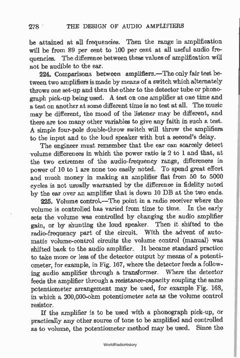
278 THE DESIGN OF AUDIO AMPLIFIERS
be attained at all frequencies. Then the range in amplification will be from 89 per cent to 100 per cent at all useful audio fre-quencies. The difference between these values of amplification will not be audible to the ear.
224. Comparisons between amplifiers.—The only fair test be-tween two amplifiers is made by means of a switch which alternately throws one set-up and then the other to the detector tube or phono-graph pick-up being used. A test on one amplifier at one time and a test on another at some different time is no test at all. The music may be different, the mood of the listener may be different, and there are too many other variables to give any faith in such a test. A simple four-pole double-throw switch will throw the amplifiers to the input and to the loud speaker with but a second's delay.
The engineer must remember that the ear can scarcely detect volume differences in which the power ratio is 2 to 1 and that, at the two extremes of the audio-frequency range, differences in power of 10 to 1 are none too easily noted. To spend great effort and much money in making an amplifier flat from 50 to 5000 cycles is not usually warranted by the difference in fidelity noted by the ear over an amplifier that is down 10 DB at the two ends.
225. Volume control.—The point in a radio receiver where the volume is controlled has varied from time to time. In the early sets the volume was controlled by changing the audio amplifier gain, or by shunting the loud speaker. Then it shifted to the radio-frequency part of the circuit. With the advent of auto-matic volume-control circuits the volume control (manual) was shifted back to the audio amplifier. It became standard practice to take more or less of the detector output by means of a potenti-ometer, for example, in Fig. 167, where the detector feeds a follow-ing audio amplifier through a transformer. Where the detector feeds the amplifier through a resistance-capacity coupling the same potentiometer arrangement may be used, for example Fig. 168, in which a 200,000-ohm potentiometer acts as the volume control resistor.
If the amplifier is to be used with a phonograph pick-up, or practically any other source of tone to be amplified and controlled as to volume, the potentiometer method may be used. Since the
WorldRadioHistory
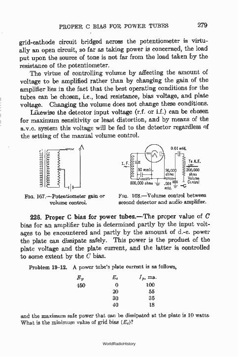
PROPER C BIAS FOR POWER TUBES 279
grid-cathode circuit bridged across the potentiometer is virtu-ally an open circuit, so far as taking power is concerned, the load put upon the source of tone is not far from the load taken by the resistance of the potentiometer.
The virtue of controlling volume by affecting the amount of voltage to be amplified rather than by changing the gain of the amplifier lies in the fact that the best operating conditions for the tubes can be chosen, i.e., load resistance, bias voltage, and plate voltage. Changing the volume does not change these conditions.
Likewise the detector input voltage (r.f. or i.f.) can be chosen for maximum sensitivity or least distortion, and by means of the a.v.c. system this voltage will be fed to the detector regardless of the setting of the manual volume control.
167.--Potentiometer gain or volume control.
I. F.
50 mmf
0.04 mid.
50,00 ohms 2°°:iX42 oirn
Volume 500,000 ohms „. 001 6 Cudrol
mid. v
168.—Volume control between second detector and audio amplifier.
226. Proper C bias for power tubes.—The proper value of C bias for an amplifier tube is determined partly by the input volt-ages to be encountered and partly by the amount of d.-c. power the plate can dissipate safely. This power is the product of the plate voltage and the plate current, and the latter is controlled to some extent by the C bias.
Problem 19-12. A power tube's plate current is as follows,
E p
450 20 30 40
J,,, ma.
100 55 35 18
and the maximum safe power that can be dissipated at the plate is 10 watts What is the minimum value of grid bias (E0)?
WorldRadioHistory
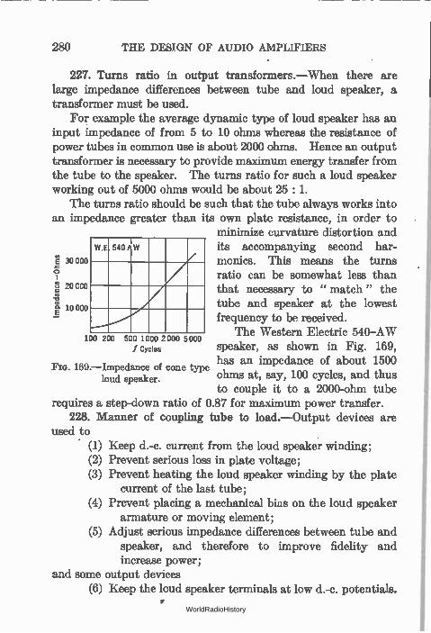
280 THE DESIGN OF AUDIO AMPLIFIERS
227. Turns ratio in output transformers.—When there are large impedance differences between tube and loud speaker, a transformer must be used.
For example the average dynamic type of loud speaker has an input impedance of from 5 to 10 ohms whereas the resistance of power tubes in common use is about 2000 ohms. Hence an output transformer is necessary to provide maximum energy transfer from the tube to the speaker. The turns ratio for such a loud speaker working out of 5000 ohms would be about 25 : 1.
The turns ratio should be such that the tube always works into an impedance greater than its own plate resistance, in order to
minimize curvature distortion and en 540 P W its accompanying second har-
t io 000
a 30 000 y ratio can be somewhat less than § 20 CCO
monies. This means the turns
that necessary to " match" the tube and speaker at the lowest frequency to be received.
200 500 1 000 2000 5000 The Western Electric 540-AW no f Cycles speaker, as shown in Fig. 169,
has an impedance of about 1500 Fœ. I69.—Impedance of cone type
ohms at, say, 100 cycles, and thus to couple it to a 2000-ohm tube
requires a step-down ratio of 0.87 for maximum power transfer. 228. Manner of coupling tube to load.—Output devices are
used to (1) Keep d.-c. current from the loud speaker winding; (2) Prevent serious loss in plate voltage; (3) Prevent heating the loud speaker winding by the plate
current of the last tube; (4) Prevent placing a mechanical bias on the loud speaker
armature or moving element; (5) Adjust serious impedance differences between tube and
speaker, and therefore to improve fidelity and increase power;
and some output devices (6) Keep the loud speaker terminals at low d.-c. potentials.
loud speaker.
WorldRadioHistory
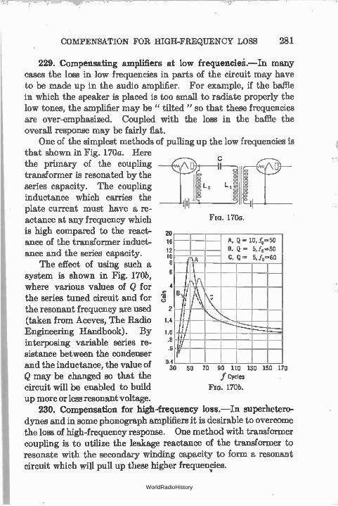
COMPENSATION FOR HIGH-FREQUENCY LOSS 281
229. Compensating amplifiers at low frequencies.—In many cases the loss in low frequencies in parts of the circuit may have to be made up in the audio amplifier. For example, if the baffle in which the speaker is placed is too small to radiate properly the low tones, the amplifier may be " tilted " so that these frequencies are over-emphasized. Coupled with the loss in the baffle the overall response may be fairly flat.
One of the simplest methods of pulling up the low frequencies is that shown in Fig. 170a. Here the primary of the coupling transformer is resonated by the series capacity. The coupling inductance which carries the plate current must have a re-actance at any frequency which is high compared to the react- 20 ance of the transformer induct- 16
12 ance and the series capacity. 10 The effect of using such a 8
system is shown in Fig. 170b, 6 where various values of Q for 4
the series tuned circuit and for the resonant frequency are used 2 (taken from Aceves, The Radio 1.4
Engineering Handbook). By i.o interposing variable series re- .8
.6 sistance between the condenser
4 and the inductance, the value of O. Q may be changed so that the circuit will be enabled to build up more or less resonant voltage.
230. Compensation for high-frequency loss.—In superhetero-dynes and in some phonograph amplifiers it is desirable to overcome the loss of high-frequency response. One method with transformer coupling is to utilize the leakage reactance of the transformer to resonate with the secondary winding capacity to form a resonant circuit which will pull up these higher frequencies.
Fia. 170a.
A. Q = 10,4=50
B. Q — 5,4=50
C, Q = 5,4=60 A
B ..
I
1 i I i
50 70 90 110 130 150 170 f Cycles
170b.
WorldRadioHistory

Electronics' Chart of
Sound Frequency Characteristics
WIND INSTRUMENTS
BASS TUBA
INSTIIUME SIRING
HUMAN 11 VOICE
r—
A BC D EF G A •
SC
FRENCH HORN
BASS CLARINE BASSOON
r4ETTLE DRUH-1
in ate FLUT E
TRUMPESIA
— — =_ — 70Fr 11-rCELLO
r - -172:
ALTO ;SieRAN°1- 1
I n1 I D EF O A BC D EF 6 A BC D EF 13 A BC D EF 6 A
$1P8 CYCLES PER SECOND
Is assg e etse,s e l'•• MIDDLE C
BC D IF 6 BC
PICCOLO —
D EF DC I I I I I
I I I I I
THE DESIGN OF AUDIO AMPLIFIERS
WorldRadioHistory
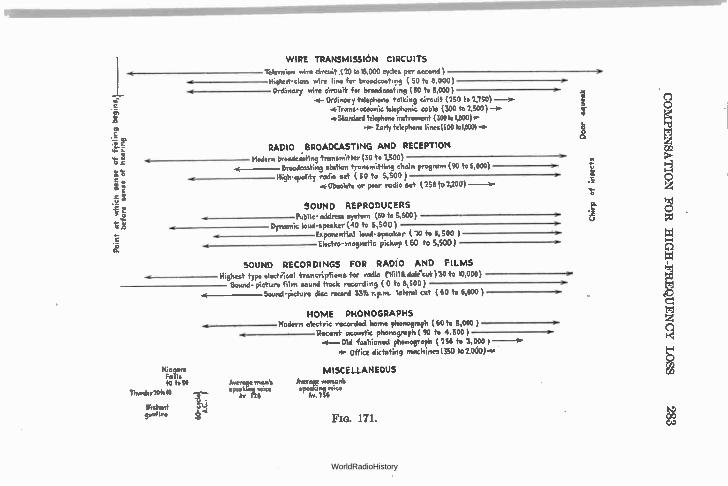
WIRE TRANSMISSION CIRCUITS
TelevIsion wire circuit (20 to 18,000 cycles per second )
Highest class wire line for broadcasting ( 50 to 8,000) Ordinary wire circuit for broadcasting (50 to 5,000 )
4-- Ordinary telephone talking circuit (150 to 2,150) *Trans-oceanic telephonic cable (300 to 1,500 ) —sr •Standard telephone instrument (100 to 1,800)4.
re.- Early telephone lines(500 to1,600)
RADIO BROADCASTING AND RECEPTION
4 Modern broadcasting transmitter (30 to 1,500) Broadcasting station transmitting chain program (90 to 5,000)
High-guality radio set ( 50 to 5,500 ) 'w. Obsolete or poor radio set ( 256 to 2,300 )
SOUND REPRODUCERS
o Pubfic address system (60 to 5,500) Dynamic loud-speaker (40 to 5,500 )
Ev,p nential loud-speaker (10 to 5,500 ) Electro- magnetic pickup 560 to 5,500)
SOUND RECORDINGS FOR RADi0 AND FILMS
Highest type electrical troncriptions for radio (Sill& dalAut )30 to 10,000) Sound picture film sound track recording ( 0 to 8,500 )
Sound-Picture disc record 33Vo r.p.m. lateral cut ( 60 +o 6,000 )
Niagara Falls 40 to 50
Thunder/Ito40
Distant gnf,re 1-o
Average man's specA.,kinmo‘ce
HOME PHONOGRAPHS Modern electric recorded home phonograph (60 to 5,000 ) Recent acoustic phonograph ( 90 to 4,500 )
4— Old fashioned phonograph (256 to 3,000 )--ar
Office dictating machines(350 102.000)4-
MISCELLANEOUS
Average woman's speaking voice
Av 166
Fia. 171.
Door squeak
Chirp
of in
sect
s
COMPENSATION FOR HIGH-FREQUENCY LOSS
WorldRadioHistory
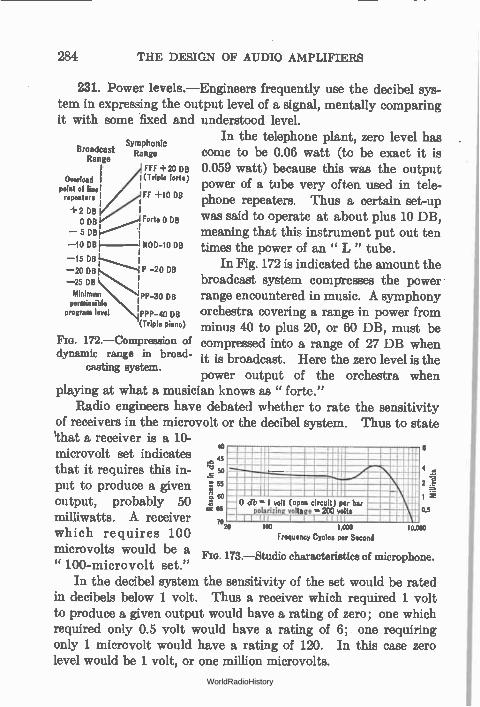
281 THE DESIGN OF AUDIO AMPLIFIERS
231. Power levels.—Engineers frequently use the decibel sys-tem in expressing the output level of a signal, mentally comparing it with some fixed and understood level.
In the telephone plant, zero level has Symphonic
Broadcast Range come to be 0.06 watt (to be exact it is Range
FFF +20 DB 0.059 watt) because this was the output point of line I (Triple forte) I power of a tube very often used in tele-Overload
repeaters FF +10 DB 1 phone repeaters. Thus a certain set-up +2 DB i 0 DB Forte 0 DB was said to operate at about plus 10 DB,
.1 — 5 DB I meaning that this instrument put out ten —10 DB i MOD-10 oe times the power of an " L " tube. 1 —15 DB 1-...........4 -20 DB In Fig. 172 is indicated the amount the _ 20 00 —25 DB s............... j P I
i broadcast system compresse,s the power Minimum N'-30 DB range encountered in music. A symphony permissible I
program level IPPP-40 DB orchestra covering a range in power from (Triple piano) minus 40 to plus 20, or 60 DB, must be
Fm. I72.—Compression of compressed into a range of 27 DB when dynamic range in broad- it is broadcast. Here the zero level is the
casting system. power output of the orchestra when
playing at what a musician knows as " forte." Radio engineers have debated whether to rate the sensitivity
of receivers in the microvolt or the decibel system. Thus to state %hat a receiver is a 10-microvolt set indicates .045 that it requires this in- '2 50 4
-ftr-r 4\ 2 \\ e
put to produce a given 55
output, probably 50 r460- o db = 1 volt (open circuit) per bar
milliwatts. A receiver lerizin " I Z ets 0.5
which requires 100 7020
microvolts would be a 173.—Studio characteristics of microphone.
" 100-microvolt set." In the decibel system the sensitivity of the set would be rated
in decibels below 1 volt. Thus a receiver which required 1 volt to produce a given output would have a rating of zero; one which required only 0.5 volt would have a rating of 6; one requiring only 1 microvolt would have a rating of 120. In this case zero level would be 1 volt, or one million microvolts.
40
too cow Frequency Cycles per Second
WorldRadioHistory
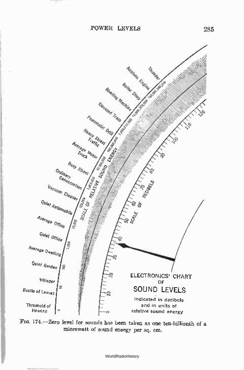
POWER LEVELS
A d/4
14,
elee Ake -1.1;' pee,
ec,4 °to,
i1e1 Se 01 r
c),
et'be ,,eeeer L4, Quiet 4 y 11%04
Aver age office
Quiet °ffice
Average Divellin
Quiet Garde
Whisper
Rustle of Leaves
Threshold of Hearing
ELECTRONICS' CHART OF
SOUND LEVELS
Indicated in decibels and in units of
relative sound energy
285
174.—Zero level for sounds has been taken as one ten-billionth of a microwatt of sound energy per sq. cm.
WorldRadioHistory
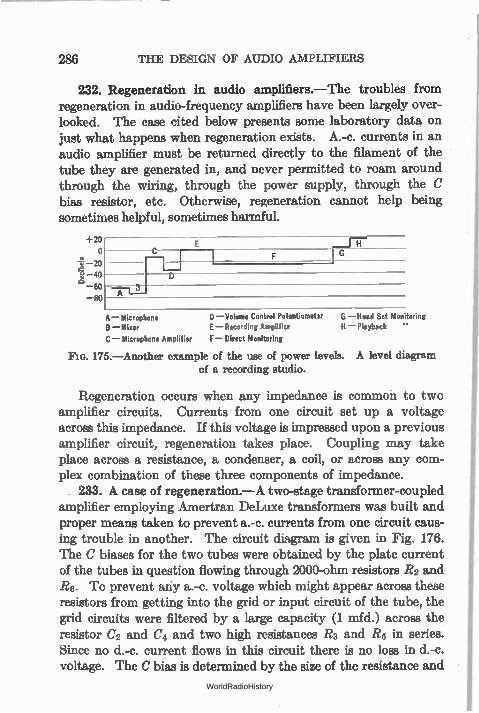
286 THE DESIGN OF AUDIO AMPLIFIERS
232. Regeneration in audio amplifiers.—The troubles from regeneration in audio-frequency amplifiers have been largely over-looked. The case cited below presents some laboratory data on just what happens when regeneration exists. A.-c. currents in an audio amplifier must be returned directly to the filament of the tube they are generated in, and never permitted to roam around through the wiring, through the power supply, through the C bias resistor, etc. Otherwise, regeneration cannot help being sometimes helpful, sometimes harmful.
1.20 0
—20 40 60
so
H C
A
A— Microphone D —Volume Control Potentiomet3r B —Mixer (—Recording Amplifier
C — Microphone Amplifier F — Direct Monitoring
175.—Another example of the use of power levels. A level diagram
of a recording studio.
G —Head Set Monitoring H —Playback "
Regeneration occurs when any impedance is common to two amplifier circuits. Currents from one circuit set up a voltage across this impedance. If this voltage is impressed upon a previous amplifier circuit, regeneration takes place. Coupling may take place across a resistance, a condenser, a coil, or across any com-plex combination of these three components of impedance. . 233. A case of regeneration.—A two-stage transformer-coupled
amplifier employing Amertran DeLuxe transformers was built and proper means taken to prevent a.-c. currents from one circuit caus-ing trouble in another. The circuit diagram is given in Fig. 176. The C biases for the two tubes were obtained by the plate current of the tubes in question flowing through 2000-ohm resistors R2 and Rg. To prevent any a.-c. voltage which might appear across these resistors from getting into the grid or input circuit of the tube, the grid circuits were filtered by a large capacity (1 mfd.) across the resistor C2 and C4 and two high resistances R3 and R5 in series. Since no d.-c. current flows in this circuit there is no loss in d.-c. voltage. The C bias is determined by the size of the resistance and
WorldRadioHistory
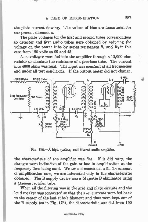
A CASE OF REGENERATION 287
the plate current flowing. The values of bias are immaterial for our present discussion.
The plate voltages for the first and second tubes corresponding to detector and first audio tubes were obtained by reducing the voltage on the power tube by series resistances RI and R4 in this case from 180 volts to 90 and 45.
A.-c. voltages were fed into the amplifier through a 12,000-ohm resistor to simulate the resistance of a previous tube. The current into 4000 ohms was read. The input was constant at all frequencies and under all test conditions. If the output meter did not change,
10000 Ohms 12000 Ohms T,
Beat Frequency Oscillator
1.0 Mfd — 1.0 Mfd.
C2 C, 90 0.5 Meg. 2000 Ohms
—B Ground +220
Fm. 176.—A high quality, well-filtered audio amplifier.
4 Mfd.
the characteristic of the amplifier was flat. If it did vary, the changes were indicative of the gain or loss in amplification at the frequency then being used. We are not concerned with the amount of amplification now, we are interested only in the characteristic obtained. The B supply device was a Majestic B eliminator using a gaseous rectifier tube.
When all the filtering was in the grid and plate circuits and the loud speaker was connected so that the a.-c. currents were fed back to the center of the last tube's filament and thus were kept out of the B supply (as in Fig. 176), the characteristic was flat from 100
WorldRadioHistory
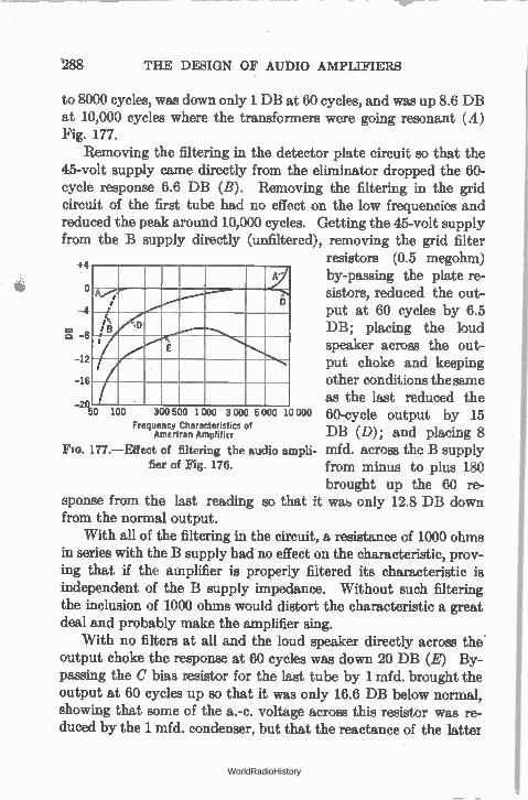
to 8000 cycles, was down only 1 DB at 60 cycles, and was up 8.6 DB at 10,000 cycles where the transformers were going resonant (A) Fig. 177.
Removing the filtering in the detector plate circuit so that the 45-volt supply came directly from the eliminator dropped the 60-cycle response 6.6 DB (B). Removing the filtering in the grid circuit of the first tube had no effect on the low frequencies and reduced the peak around 10,000 cycles. Getting the 45-volt supply from the B supply directly (unfiltered), removing the grid filter
resistors (0.5 megohm) by-passing the plate re-sistors, reduced the out-put at 60 cycles by 6.5
03 DB; placing the loud
'288 THE DESIGN OF AUDIO AMPLIFIERS
, g
D -4 ;
i< s D
8 D
f E
12
16
20 300 500 1 000 3 000 5 000 10 000
Frequency Characteristics of Amertran Amplificr
FIG. 177.—Effect of filtering the audio ampli-fier of Fig. 176.
sponse from the last reading so that from the normal output.
With all of the filtering in the circuit, a resistance of 1000 ohms in series with the B supply had no effect on the characteristic, prov-ing that if the amplifier is properly filtered its characteristic is independent of the B supply impedance. Without such filtering the inclusion of 1000 ohms would distort the characteristic a great deal and probably make the amplifier sing.
With no filters at all and the loud speaker directly across the' output choke the response at 60 cycles was down 20 DB (E) By-passing the C bias resistor for the last tube by 1 mfd. brought the output at 60 cycles up so that it was only 16.6 DB below normal, showing that some of the a.-c. voltage across this resistor was re-duced by the 1 mfd. condenser, but that the reactance of the latter
speaker across the out-put choke and keeping other conditions the same as the last reduced the
50 100 60-cycle output by 15 DB (D); and placing 8 mfd. across the B supply from minus to plus 180 brought up the 60 re-
it was only 12.8 DB down
WorldRadioHistory
FILTERING IN AUDIO AMPLIFIERS 289
was still appreciable compared with the resistor, 2000 ohms. To keep all of the a.-c. voltage out of this circuit the capacity would have to be much greater than 1 mfd.
In another case by-passing the C bias resistor in the first audio stage brought up the response of a two-stage amplifier over 6 DB at 6000 cycles. A.-c. voltages across this resistor were fed into the tube so that they were out of phase with the voltages there due to the grid input and, of course, detracted from the output at this frequency. This case was one involving the resonance condition where the capacity across the secondary resonated with the leakage inductance of the transformer so that a large a.-c. current went through the C bias resistor. When this resistor was by-passed its impedance to 6000 cycles was reduced and so the out-of-phase voltage set up there and introduced into the circuit was de-creased, bringing up the output of the amplifier at this frequency.
It is most important to properly filter the C bias circuit of high-mu tubes, such as pentodes, because of the high amplification in the tube. Otherwise the out-of-phase voltage set up across the bias resistance by the a.c. in the plate current flowing through this resistor will cause serious degeneration.
234. Filtering in audio amplifiers.—A filter in an audio ampli-fier, as indicated in the last section, is designed to keep out of a certain circuit a.-c. currents of a certain frequency or frequencies. Let us look at grid circuit of the first tube in Fig. 176. Plate current flowing through the resistance R2 causes a voltage drop. This drop is utilized as the C bias for the tube. If a.-c. currents flow through the resistance, they, too, cause a voltage drop, and since this resistance is now part of the grid circuit the voltages are impressed on the grid. Since the plate and grid a.-c. voltages are out of phase, these unwanted voltages getting into the grid circuit from the plate circuit cause a reduction in the amplification.
If the inductance in the plate circuit is 100 henrys and the fre-quency is 100 cycles, the current through the 2000 ohm resistance R2 will be such that for every volt across the inductance there will be 0.032 volt across the resistor. This voltage is impressed on the grid of the tube and if multipled by 8 will reappear in the plate
WorldRadioHistory
290 THE DESIGN OF AUDIO AMPLIFIERS
circuit as though coming into the system from the outside via the transformer. Thus a 25 per cent reduction in output will occur. This is a loss of 2.0 DB in voltage.
Now this loss may be reduced by by-passing the resistor so that the impedance offered to 100-cycle currents is smaller and so the voltage there will be smaller. A 1 mfd. condenser C2 has a reactance of 1600 ohms at 100 cycles and when placed across this resistor will reduce the voltage there by a ratio of 2000 to 1250. Much greater isolation of the grid circuit will take place, however, if a high resistance R3 is placed in series with the grid and a by-pass condenser C2 is placed as shown in Fig. 176. Still greater isolation and freedom from unwanted coupling will occur if the plate circuit is filtered too, either through a resistance R4 or through a low-resistance, high-reactance choke and, of course, a condenser C3. Such filtering prevents a.-c. current from flowing through the C bias resistor. Grid-circuit filtering reduces the effect of such a.-c. currents as do get into C bias resistors.
In all such circuits, and indeed in radio-frequency amplifiers, too, the a.-c. currents in the plate should be returned directly to the cathode of the tube in question. They should not be permitted to go back through any part of the B supply or even through the leads to it. The condenser should be a part of the amplifier, and the choke or resistor may be a part of the B supply, although it is preferable to have it in the amplifier itself. Then the amplifier is forever independent of its source of plate voltage.
The purpose of the series impedance in such filter circuits is to impose a high series loss on any a.-c. voltages or currents that may try to get into the grid or out of the plate circuit. The purpose of the condenser is to provide a low loss shunt path for these same voltages or currents to get to the filament. Any a.c. current that gets through the resistance or choke must .be very greatly attenuated and on arriving at the grid end of such a series impe-dance it finds an easy path to the filament which is at ground potential, and therefore does not affect the plate or grid as the case may be. In case of plate filtering, a.-e. currents find an easy path to the filament through the condenser and a high impedance path to the B supply.
WorldRadioHistory
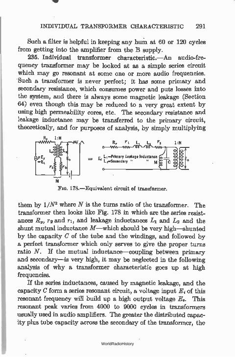
INDIVIDUAL TRANSFORMER CHARACTERISTIC 291
Such a filter is helpful in keeping any hum at 60 or 120 cycles from getting into the amplifier from the B supply.
235. Individual transformer characteristic.—An audio-fre-quency transformer may be looked at as a simple series circuit which may go resonant at some one or more audio frequencies. Such a transformer is never perfect; it has some primary and secondary resistance, which consumes power and puts losses into the system, and there is always some magnetic leakage (Section 64) even though this may be reduced to a very great extent by using high permeability cores, etc. The secondary resistance and leakage inductance may be transferred to the primary circuit, theoretically, and for purposes of analysis, by simply multiplying
R 1 N r, r2 1:N
L, =Primary Leakage Inductance = L i—Secondary "
FIG. 178.—Equivalent circuit of transformer.
them by 1/N2 where N is the turns ratio of the transformer. The transformer then looks like Fig. 178 in which are the series resist-ances R,, r2 and ri, and leakage inductances L1 and in and the shunt mutual inductance M—which should be very high—shunted by the capacity C of the tube and the windings, and followed by a perfect transformer which only serves to give the proper turns ratio N. If the mutual inductance—coupling between primary and secondary—is very high, it may be neglected in the following analysis of why a transformer characteristic goes up at high frequencies.
If the series inductances, caused by magnetic leakage, and the capacity C form a series resonant circuit, a voltage input Ei of this resonant frequency will build up a high output voltage E0. This resonant peak varies from 4000 to 9000 cycles in transformers usually used in audio amplifiers. The greater the distributed capac-ity plus tube capacity across the secondary of the transformer, the
WorldRadioHistory
292 THE THE DESIGN OF AUDIO AMPLIFIERS
lower in frequency is this peak. If the series resistances, due to primary and secondary resistance and other losses, is low enough the "Q" (Section 125) may be high enough for the circuit to oscillate at this resonant frequency, or to sing, as amplifier engineers say. Since the plate resistance of the tube is part of the series re-sistance, any decrease in R, through use of a low-resistance tube will increase the tendency to peak or to sing at the high resonant fre-quency. Such a rise at the high-frequency end of the audio band may be seen in Fig. 161.
So much for the high audio frequencies. What happens at low frequencies? At low frequencies the series leakage inductance is not of importance because of the low impedance to low frequencies. The ratio between the tube plate resistance and the mutual reac-tance of the transformer, which is large, determines how much of the low-frequency voltage generated in the plate circuit of the tube is usefully applied to the transformer. If the plate resistance is high, or the mutual reactance is low—a poor transformer—the low frequencies will be largely lost in the tube and will not be im-pressed upon the amplifier. If the capacity across the transformer resonates with this mutual inductance another peak may occur in the response characteristic of the tube and transformer. This peak will be at a low frequency, and in some cases may occur as low as several hundred cycles. After this resonance occurs, there is a tendency for the response to fall off, and in some poorly designed transformers a rapid rise in amplification at say 500 cycles is fol-lowed by an equally rapid drop beyond 1000 or 2000 cycles. This tendency to drop off at high frequencies is usually overcome by the tendency to rise due to series resonance between the capacity and the leakage inductance. Making the plate resistance of the tube very high drops out all the low frequencies.
Some tricks can be played with individual transformer circuits to change the response. For example a resistance in the secondary circuit, either next to the grid or next to the filament (a C bias resistor for example) will drop off the high-frequency response. If next to the filament, as is customary for C bias requirements, the current through the capacity of the secondary of the trans-former flows through the resistance and sets up an out-of-phase
WorldRadioHistory
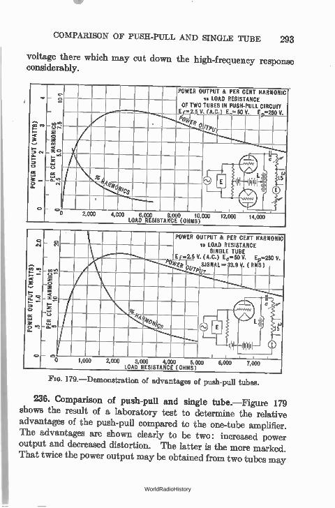
COMPARISON OF PUSH-PULL AND SINGLE TUBE 293
voltage there which may cut down the high-frequency response considerably.
POWER OUTPUT & PER CENT HARMONIC vs LOAD RESISTANCE
OF TWO TUBES IN PUSH-PULL CIRCUIT E1=2.5 V (1t,C.) E 50 V Ef 250 V.
[ogee.
.1k ,14
0 2,000 4,C00 L 6, DAD
000 RESIS
8, TANC
000 E (0
10, HMS)
C.1
0 1,000 2,000 3,000 4,000 5,000 LOAD RESISTANCE (OHMS)
POWER OUTPUT & PER CENT HARMONIC vs LOAD RESISTANCE
SINGLE TUBE E1.2.5 V. (A.C.) En-50 V. 4..250 V.
Poiiti71— SIGNAL = 33.9 V. ( RMS)
6,000 7,000
FIG. 179.— Demonstration of advantages of push-pull tubes.
236. Comparison of push-pull and single tube.—Figure 179 shows the result of a laboratory test to determine the relative advantages of the push-pull compared to the one-tube amplifier. The advantages are shown clearly to be two: increased power output and decreased distortion. The latter is the more marked. That twice the power output may be obtained from two tubes may
WorldRadioHistory
294 THE DESIGN OF AUDIO AMPLIFIERS
seem obvious; but that the distortion would be reduced to much less than one-half is not so apparent. It is a fact, however, and it is one of the reasons why all high-class receivers and public-address amplifiers use two tubes in push-pull.
237. Direct-coupled amplifiers.—It is possible to make a resistance-coupled amplifier respond to and amplify very low a.-c. frequencies by increasing the size of the coupling condenser. But there is a limit. In time it takes so long to charge the large coup-ling capacity that difficulties are encountered. For example, no matter how large the coupling condenser, direct current (zero frequency) will not go through it. And in many cases it is desir-able to amplify direct currents.
If the coupling condenser is eliminated, the grid of the second tube will be at a high positive potential because it is directly con-nected to the plate of the previous tube—unless the cathodes of the two tubes are at different potentials with respect to ground. If, for example, the second cathode can be isolated from the first so that the grid of the second tube is negative with respect to its own cathode, even though it may be positive with respect to the first cathode, then the circuit will amplify direct currents and voltages.
With filament types of tubes this necessitates two filament batteries insulated from each other, one of which is considerably above ground potential. With heater-type tubes, however, the two cathodes may be appreciably different in potential even though the two filaments which heat the cathodes may be operated from the same battery or transformer. In this case one cathode is higher in potential than the heater; therefore adequate insulation must exist between heater and cathode.
In Fig. 180a is a simple circuit representing a" direct-coupled" amplifier, of which the Loftin-White circuit is a more or less special case. Note that both heaters are run from the same transformer, but that the cathodes are at different potentials; that the grid of the second tube is connected directly to the plate of the first tube, but that adequate bias exists between grid and cathode of the second tube. A typical amplifier with a voltage gain of 56 DB (613) is shown
WorldRadioHistory
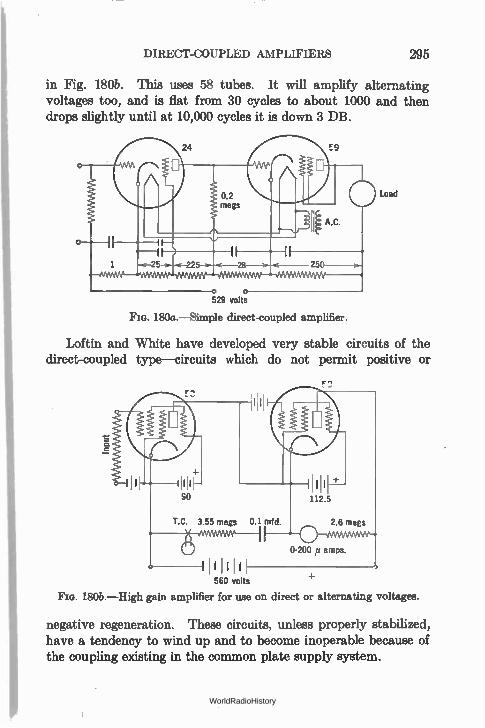
DIRECT-COUPLED AMPLIFIERS 295
in Fig. 180b. This uses 58 tubes. It will amplify alternating voltages too, and is flat from 30 cycles to about 1000 and then drops slightly until at 10,000 cycles it is down 3 DB.
o o 529 volts
Load
FIG. 180a.—Simple direct-coupled amplifier.
Loftin and White have developed very stable circuits of the direct-coupled type—circuits which do not permit positive or
560 volts
180b.—High gain amplifier for use on direct or alternating voltages.
negative regeneration. These circuits, unless properly stabilized, have a tendency to wind up and to become inoperable because of the coupling existing in the common plate supply system.
WorldRadioHistory
CHAPTER XIII
HIGH-FREQUENCY AMPLIFIERS
THERE are three basic qualities which must be weighed not only by the designer of a radio receiver but by the purchaser and ultimate user as well. These are the sensitivity, the selectivity, and the fidelity of the receiver. The sensitivity of a receiver is an indication of the overall amplification from antenna-ground bind-ing posts to loud speaker. A receiver that is very sensitive requires but a small input voltage to deliver considerable output power. The selectivity of a receiver is an indication of its ability to dis-criminate between wanted and unwanted signals. An infinitely selective receiver would be one that would respond only to a given station and not at all to another no matter how powerful this un-desired signal was, nor how close in frequency it was to the desired signal. That there is no such receiver goes without saying. The fidelity of a receiver tells how well it reproduces what takes place in the broadcasting studio. If a certain voltage at 100 cycles is set up in the broadcasting studio, then an equal amount of 100 cycles should come out of the receiver, no more and no less. The same should be true at 1000 and at 10,000 cycles. In other words a receiver that delivers a perfectly faithful signal is one which has a perfectly flat audio-frequency response curve from antenna to loud speaker input. It has a high degree of fidelity. A receiver that is perfectly selective, infinitely sensitive, and
delivers a perfectly faithful signal is impossible to obtain. A receiver which is selective and sensitive enough for practical pur-poses, and the frequency curve of which is so good that the ear would not detect its infidelity is not difficult to design, to build, or to operate.
It is an unfortunate fact, however, that the human ear is so 296
WorldRadioHistory
FIELD STRENGTH 297
easily deceived. Every engineer of any experience has had trained musicians congratulate him on the " perfect" tone quality of some assembly of apparatus whose frequency characteristic was anything but good and whose content of harmonics was anything but low. All broadcast and phonograph music suffers tremendous distortion at the start of its journey by being greatly compressed in volume range—the reason being the inability of lines, frame-millers, and receivers to handle the volume range.
238. Purpose of r.-f. and 1.-f. amplification.—Although the majority of receivers are used in cities where very little r.-f. amplification is necessary, so strong are the signals from local stations, yet manufacturers have never seen fit to make receivers of low r.-f. gain. They feel that some sets will be used in the rural districts and under other adverse conditions, and since selectivity is secured at the same time as sensitivity, the vast majority of receivers have much more r.-.f. and i.-f. amplification than is necessary.
• 239. Field strength.—The voltage that is set up across a receiv-ing antenna is called the field strength of the transmitter at that particular point on the earth's surface. It is of the order of microvolts or millivolts, and because a higher antenna will pick up a greater signal—that is, the voltage across it will be greater— it is the practice to rate field strength as so many microvolts or millivolts per meter. Thus an antenna that has an effective height of one meter and has four microvolts across it is situated in a field strength of four microvolts per meter. The effective height of the antenna is somewhat less than its actual physical height above ground, and in most receiver measurements is assumed as four meters (13 feet). An antenna that has an effective height of 4 meters and a voltage of 10 microvolts across it is immersed in an electric field due to some transmitting station whose strength is 2.5 microvolts per meter.
The greater the field strength at a given point the more volume one can get out of a receiver with a fixed amdunt of amplification. Similarly the greater the field strength the less receiver amplifica-tion is necessary to give out a certain amount of power.
Dr. Alfred N. Goldsmith, in the Proceedings of the I.R.E.,
WorldRadioHistory
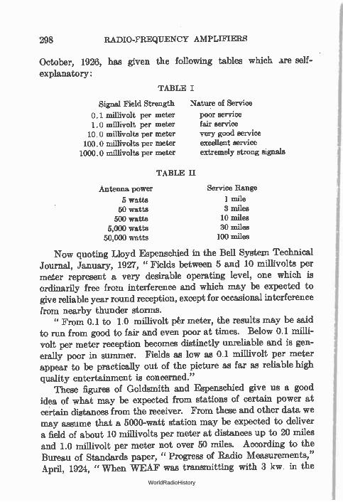
1.0 millivolt per meter 10.0 millivolts per meter 100.0 millivolts per meter
1000.0 millivolts per meter
TABLE II
Antenna power
5 watts 50 watts
500 watts 5,000 watts
50,000 watts
298 RADIO-FREQUENCY AMPLIFIERS
October, 1926, has given the following tables which are self-explanatory :
TABLE I
Signal Field Strength Nature of Service
0.1 millivolt per meter poor service fair service very good service excellent service extremely strong signals
Service Range
1 mile 3 miles 10 miles 30 miles 100 miles
Now quoting Lloyd Espenschied in the Bell System Technical Journal, January, 1927, " Fields between 5 and 10 millivolts per meter represent a very desirable operating level, one which is ordinarily free from interference and which may be expected to give reliable year round reception, except for occasional interference from nearby thunder storms. " From 0.1 to 1.0 millivolt pér meter, the results may be said
to run from good to fair and even poor at times. Below 0.1 milli-volt per meter reception becomes distinctly unreliable and is gen-erally poor in summer. Fields as low as 0.1 millivolt per meter appear to be practically out of the picture as far as reliable high
quality entertainment is concerned." These figures of Goldsmith and Espenschied give us a good
idea of what may be expected from stations of certain power at certain distances from the receiver. From these and other data we may assume that a 5000-watt station may be expected to deliver a field of about 10 millivolts per meter at distances up to 20 miles and 1.0 millivolt per meter not over 50 miles. According to the Bureau of Standards paper, " Progress of Radio Measurements," April, 1924, " When WEAF was transmitting with 3 kw. in the
WorldRadioHistory
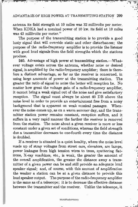
ADVANTAGt OF HIGH POWER AT TRANSMITTING STATION 299
antenna its field strength at 10 miles was 32 millivolts per meter. When KDKA had a nominal power of 10 kw. its field at 10 miles was 43 millivolts per meter."
The purpose of the transmitting station is to provide a good lusty signal that will override static and other disturbances; the purpose of the radio-frequency amplifier is to provide the listener with good loud signals from the field strengths which the stations produce.
240. Advantage of high power at transmitting station.—What-
ever voltage exists across the antenna, whether noise or desired signal, is amplified by the radio-frequency amplifier; there is there-fore a distinct advantage, so far as the receiver is concerned, in using large amounts of power at the transmitting station. The greater the ratio of signal to noise the better will reception be. No matter how great the voltage gain of a radio-frequency amplifier, it cannot bring a weak signal out of the noise and give satisfactory reception. The signal must always be about 40 DB above the noise level in order to provide an entertainment free from a noisy background that is apparent on weak musical passages. When-ever the noise comes up, as on a warm summer day, and the trans-mitter station power remains constant, reception suffers, and it suffers in a very rapid manner the farther the receiver is removed from the station. The noise about a given receiver is more or less constant under a given set of conditions, whereas the field strength due a transmitter decreases to one-fourth every time the distance is doubled.
If a receiver is situated in a quiet locality, where the noise level made up of stray voltages from street cars, elevators, arc lamps, power leakages from high tension wires to trees, sputtering flat-irons, X-ray machines, etc., is weak, the greater the amount of the overall amplification, the greater the distance away a trans-mitter of a given power can be and still provide an adequate loud speaker signal; and, of course, with this amount of amplification the weaker a station can be at a given distance to provide this loud speaker output. The purpose of the radio-frequency amplifier is the same as of a telescope; it is to decrease the effective distance between the transmitter and the receiver. Unlike the telescope, it
WorldRadioHistory
300 RADIO-FREQUENCY AMPLIFIERS
cannot be aimed at a particular station but must pick up all the r.-f. voltages not only between it and the desired station but in other directions as well. If the power of the transmitter is increased by 10 DB (ten times the power) the receiver amplifier can be made 10 DB less sensitive and thus unwanted signals are automatically reduced 10 DB compared to the desired signal.
241. The task of the radio-frequency amplifier.—The r.-f. amplifier employed in a broadcast frequency receiver may differ decidedly from that used in a receiver serving other purposes or tuned to other frequencies. For example it is possible to make a much more efficient amplifier if it is to work at one frequency instead of at any one of many. A broadcast receiver, for example, must be capable of amplifying at any frequency between 500 and 1500 kc. It must be easily changed from one frequency to another, and its amplification at all frequencies within this band should be uniform. If it selects and amplifies too, its task is much more difficult to perform, as we shall see.
The energy thrust upon the ether from a given broadcasting station is a complex bit of wave motion. If the microphone is idle, what comes from the antenna may be considered as a very narrow band, at say 600 kc., called the carrier wave. If a tone, say 1000 cycles (1 kc.), is put into the microphone, the antenna current has in it frequencies not only of 600 kc. but 599 and 601 as well, and when music is broadcast the frequencies in the antenna may be varying between zero and 5000 cycles above and below the carrier from instant to instant. These frequencies on either side of the carrier are called the side bands. The characteristics of the transmitter must be such that each of these audio frequencies is given equal power compared to the others. The resonance curve of the antenna system of the transmitter, then, must not be sharp but must be rather flat or dull as shown in Fig. 181. It must have a rather flat top from 5 kc. below to 5 kc. above its carrier fre-quency.
If audio frequencies up to 5000 cycles are transmitted, each station requires a channel 10 kc. wide for its transmission, and if there are 1000 kc. available there are 100 channels or places for 100 simultaneous transmissions.
WorldRadioHistory
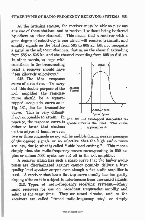
THREE TYPES OF RADIO-FREQUENCY RECEIVING SYSTEMS 301
At the listening station, the receiver must be able to pick out any one of these stations, and to receive it without being bothered by others on other channels. This means that a receiver with a good degree of selectivity is one which will receive, transmit, and amplify signals on the band from 595 to 605 kc. but not recognize a signal in the adjacent channels, that is, on the channel extending from 585 to 595 kc. and the channel extending from 605 to 615 kc. In other words, to cope with conditions in the broadcasting band a receiver should have " ten kilocycle selectivity."
242. The ideal response curve of a receiver.—To carry out this double purpose of the Antenna •
Cuffed r.-f. amplifier the response curve should be a square-topped steep-side curve as in Fig. 181, like the transmitter curve. This is very difficult if not impossible to attain. In Fia. 181.—A flat-topped steep-sided re-practice, the response curve is sponse curve is the ideal. This curve either so broad that stations approaches it.
on the adjacent band, or even two or three channels away, will be audible during weaker passages of the desired signals, or so selective that the high audio tones are lost, due to what is called " side band cutting." This means simply that the radio-frequency waves corresponding to 600 kc. plus or minus 5000 cycles are cut off in the r.-f. amplifier. A receiver which has such a sharp curve that the higher audio
tones are discriminated against cannot possibly deliver a high quality loud speaker output even though a flat audio amplifier is used. A receiver that has a flat-top curve usually has too gently sloping sides so it is subject to interference from unwanted signals.
243. Types of radio-frequency receiving systems.—Many radio receivers for use on broadcast frequencies amplify and select at the same time. They use tuned circuits, and so the receivers are called "tuned radio-frequency sets," or simply
10 KC
5000 000
Cycles Cycles
WorldRadioHistory
302 RADIO-FREQUENCY AMPLIFIERS
" t.r.f." Because of the steepness of a resonance curve, the overall response of several circuits to frequencies off resonance is dimin-ished, and is a logarithmic function. That is, if two amplifiers deliver ten times as much voltage at resonance as they do at some other frequency the total discrimination in favor of a desired signal is 100 times in a two-stage amplifier, or 10N if there are N stages.
Another type of receiver, the super-heterodyne or double detec-tor, changes the frequency of the incoming signal to a lower fre-quency and then amplifies at this frequency.
Systems have been devised and operated whereby the selec-tivity and sensitivity were not secured in the same circuits. Thus in one receiver all the amplification was secured in an untuned amplifier.
In another system (Polydoroff) an improvement in selectivity without sacrifice in gain is obtained by varying the inductance of the coils to tune them over the proper range rather than by varying the capacity. This is done by pushing into the inductances an iron-dust core of special construction thereby changing the permeability of the core on which the coils are wound.
In still another type of coils (Ferrocart) iron dust is used to impregnate paper sheets which are pressed into cores on which the wire is wound. It is claimed that a better Q can be obtained, less space is required, and greater selectivity per stage may be secured.
Problem 1-13. The response curve of a single tuned circuit in a radio-fre-quency amplifier is given in Fig. 182. Remembering that the amplification of two stages is the square of one stage, calculate and plot the result of using two such stages. Then calculate and plot the response curve in percentages, using the response at resonance at 100 per cent. Finally, plot this curve in DB using the response at resonance as 0 DB; and, remembering that a station 10 kc. off resonance must be about minus 40 DB in voltage if it is not to be too loud during weak passages of the resonance signal, determine if two stages of such amplification and selection are sufficient. If not, would another stage be sufficient? How many DB does a single stage " put down" a signal 20 kc. off resonance; how many DB down is it after passing through two stages; how many after going through three stages?
Problem 2-13. Suppose a station increases its power from 500 watts to 5000 watts and thereby increases its" service range" (radius) from 10 miles to 30 miles. Suppose the density of population in the area covered by the station's signals is 140 people per square mile. Calculate how many more people
WorldRadioHistory
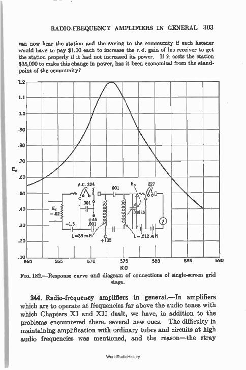
RADIO-FREQUENCY AMPLIFIERS IN GENERAL 303
can now hear the station and the saving to the community if each listener would have to pay $1.00 each to increase the r.-f. gain of his receiver to get the station properly if it had not increased its power. If it costs the station $35,000 to make this change in power, has it been economical from the stand-point of the community?
L2
1.1
1.0
.90
.so
.70
E,
.60
.50
.40
.30
.20
10 560 565 570 575 580 585 590
KC
Fio. 182.—Response curve and diagram of connections of single-screen grid stage.
A.C. 224 227 001
E, .001
-.02
+45
0 035
-1.5 .001 I I I
L=85 mH +135
L-.212 mH
244. Radio-frequency amplifiers in general.—In amplifiers which are to operate at fiequencies far above the audio tones with which Chapters XI and XII dealt, we have, in addition to the problems encountered there, several new ones. The difficulty in maintaining amplification with ordinary tubes and circuits at high audio frequencies was mentioned, and the reason—the stray
WorldRadioHistory
304 RADIO-FREQUENCY AMPLIFIERS
capacities and those due to the tube input circuit—was discussed. These stray capacities in a radio-frequency circuit become much more important, not only for their shunting effect—which is severe at frequencies of the order of one million cycles—but because of other interesting phenomena which will be discussed at this point.
245. Effect of tube input capacity.—In general a voltage amplifier must be one which works from a low impedance into a high impedance load. The problem in all tube amplifying circuits in which high-voltage amplification—at the expense of low-power amplification if necessary— is desired, is to get a high impedance for the tube to work into. Suppose this load impedance is a resistor shunted by the succeeding tube grid-filament path. The effect of the input capacity of this tube upon the load impedance was discussed in Section 198. If the frequency at which the amplifiér is to work is multiplied by 100, the shunting effect of the condenser becomes 100 times as great.
Problem 3-13. A tube with a plate resistance of 12,000 ohms and a et of 8 has a resistor in its plate circuit of 50,000 ohms. The following tube is a UX-240 with an effective µ of 20 and a grid-filament capacity of 4.0 mmfd., a plate-grid capacity of 8.8 mmfd., and a plate-filament capacity of 1.5 mmfd. Other capacities across its ouput circuit bring up the total plate-filament capacity to 6.0 mmfd. What will be the impedance in the plate circuit of the first tube and what will be the voltage gain at 10, 100, 10(X) kc.7 (Section 178.)
Now it is generally assumed that if an amplifier tube has a sufficiently high grid bias that no grid current flows, the input impedance of the tube is infinitely high and acts as a pure capacity which is given by the expression
Co = C„ (G ± 1),
where G = the effective amplification;
C„ = the plate-grid capacity;
= the grid-filament capacity.
If this were true at radio frequencies, as is usually true at audio frequencies, we could find a way to get around the shunting effect of the input capacity. But at high frequencies this is not exactly true. The fact that the input impedance is not a pure capacity
WorldRadioHistory
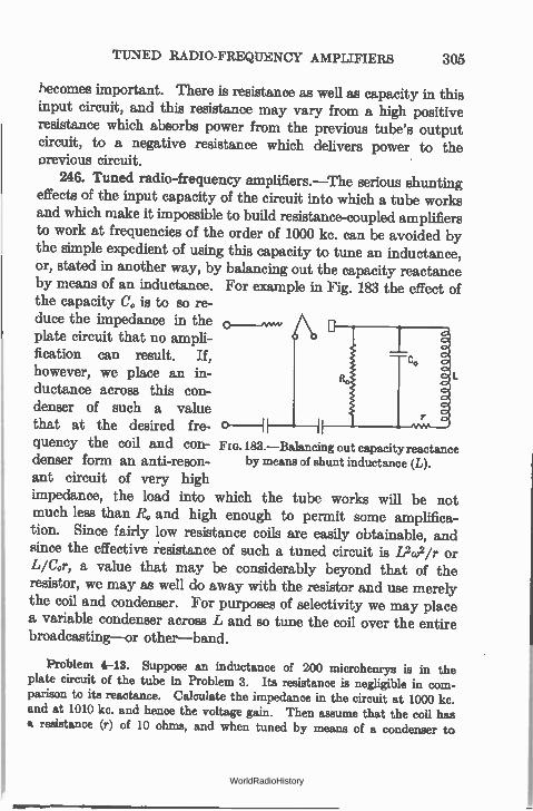
TUNED RADIO-FREQUENCY AMPLIFIERS 305
becomes important. There is resistance as well as capacity in this input circuit, and this resistance may vary from a high positive resistance which absorbs power from the previous tube's output circuit, to a negative resistance which delivers power to the orevious circuit.
246. Tuned radio-frequency amplifiers.—The serious shunting effects of the input capacity of the circuit into which a tube works and which make it impossible to build resistance-coupled amplifiers to work at frequencies of the order of 1000 kc. can be avoided by the simple expedient of using this capacity to tune an inductance, or, stated in another way, by balancing out the capacity reactance by means of an inductance. For example in Fig. 183 the effect of the capacity Co is to so re-duce the impedance in the plate circuit that no ampli-fication can result. If, however, we place an in-ductance across this con-denser of such a value that at the desired fre- 0-1
quency the coil and con- FIG. 183.—Balancing out capacity reactance denser form an anti-reson- by means of shunt inductance (L).
ant circuit of very high impedance, the load into which the tube works will be not much less than R. and high enough to permit some amplifica-tion. Since fairly low resistance coils are easily obtainable, and since the effective resistance of such a tuned circuit is L2w2/r or L/Cor, a value that may be considerably beyond that of the resistor, we may as well do away with the resistor and use merely the coil and condenser. For purposes of selectivity we may place a variable condenser across L and so tune the coil over the entire broadcasting—or other—band.
Problem 4-13. Suppose an inductance of 200 microhenrys is in the plate circuit of the tube in Problem 3. Its resistance is negligible in com-parison to its reactance. Calculate the impedance in the circuit at 1000 kc. and at 1010 kc. and hence the voltage gain. Then assume that the coil has Q. resistance (r) of 10 ohms, and when tuned by means of a condenser to
WorldRadioHistory
306 RADIO-FREQUENCY AMPLIFIERS
1000 kc. calculate the impedance in the circuit at 1000 kc. and at 1010 kc. Calculate the voltage gain of tube and load, and the relative advantage of the tuned circuit in selectivity over the untuned inductance.
The advantages of such a circuit are: first, the effect of the capacity Co is eliminated; second, the effective resistance in the plate circuit of the tube may be made as high as we desire by making the inductance large and its resistance low (effective values of 100,000 ohms are not difficult to attain); and third, where a resistance amplifier would be absolutely non-selective, this tuned amplifier can be made very selective.
247. Effect of negative input resistance.—Now, such a tuned radio-frequency amplifier works out very nicely theoretically, and practically comes quite close to the final solution, except for one thing. This is the changing input resistance of the tube.
The input impedance of a tube is not a pure capacity. It is a capacity and a resistance. The value of this resistance may be high and positive if the load in the plate circuit of this tube is negative in sign—a capacity load, or negative if the load is induc-tive and of sufficient value. For example the curves in Fig. 184 (taken from Bureau of Standards Circular No.351, Effect of Load on Input Impedance of Tubes, by J. M. Miller) show the input resist-ance of a typical tube at various values of inductance and resist-ance in the plate circuit. In other words, the minute we put an inductance in the plate circuit of a radio-frequency amplifier, we have done something to the grid circuit of that tube. If (1) the inductance is high enough, we have decreased the input resistance of the tube to a very low value; if (2) the inductance is increased still more, the input resistance becomes negative.
Up to the point when the input resistance becomes negative, it takes power from the circuit to which it is attached, because any r.-f. currents flowing through this resistance must suffer an /2R loss. But the minute the resistance becomes negative, power is fed into the circuit to which the tube is attached. Now, feeding power into that circuit has the same effect as decreasing the resistance of that circuit by some other means, and when sufficient power is fed into the circuit that all of its resistance has been reduced to zero, radio-frequency currents flow although the input is removed from
WorldRadioHistory
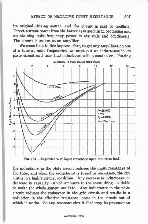
EFFECT OF NEGATIVE INPUT RESISTANCE 307
its original driving source, and the circuit is said to oscillate. Direct-current power from the batteries is used up in producing and maintaining radio-frequency power in the coils and condensers. The circuit is useless as an amplifier.
We come then to this impasse, that, to get any amplification out of a tube at radio frequencies, we must put an inductance in its plate circuit and tune that inductance with a condenser. Putting
+1
o
-2 o
g -3
.2 â 4
.5 -5
-6
-7
-8
2
Inductance In Plate Circuit Millihenries
4 6 8 10 12 14
..10 0000
e '..) ..." oe'e
Oçe
1=318000 ji -6 Rp =20 000
COP = COF = CPO
2 e
.1, e IlL 1
0 q e
FIG. 184.—Dependence of input reaistance upon inductive load.
the inductance in the plate circuit reduces the input resistance of the tube, and when the inductance is tuned to resonance, the cir-cuit is in a highly critical condition. Any increase in inductance, or decrease in capacity—which amounts to the same thing—is liable to make the whole system oscillate. Any inductance in the plate circuit reduces the resistance in the grid circuit and results in a reduction in the effective resistance losses in the circuit out of which it works. So any resonant circuit that may be present—an
WorldRadioHistory
308 RADIO-FREQUENCY AMPLIFIERS
antenna for instance—becomes very sharply tuned, and the higher audio frequencies are completely lost. The circuit is said to be regenerating. Regeneration is merely a minor case of oscillation.
For the moment let us forget this trouble from regeneration and oscillation with the remark that it is caused by the inter-electrode capacity of the tube, and is of sufficient magnitude to have pre-vented efficient r.-f. amplifiers from becoming generally used for a long time after the need for such equipment was felt. Let us look into the tuned radio-frequency amplifier, just as though we never heard of oscillation or regeneration, and see what engineer-ing we can bring to bear on the problem of getting the most ampli-fication and the best fidelity with the apparatus at hand.
248. Engineering the tuned radio-frequency amplifier.—The inductance and capacity required for resonance at any point in the broadcast frequency band (550 to 1500 kc.) may be calculated easily. These values are more or less fixed by the sizes of con-densers generally available. Let us suppose their values are such that with the resistance of the coil taken into consideration they produce an effective resistance at resonance L/Cr (an anti-resonant circuit) of 100,000 ohms. In the plate circuit of a 12,000-ohm tube this load should give considerable amplification except for the fact that bridging a resistance of 12,000 ohms across such a coil-con-denser combination would have the same result as adding consider-able resistance in series with the coil, and therefore the effective resistance into which the tube works will decrease at an alarming rate.
For example, if the effective resistance of a coil condenser com-bination is 100,000 ohms and is shunted by a 12,000-ohm tube, the equivalent impedance is now reduced to 10,700 ohms which represents the same change produced in the selectivity of the anti-resonant circuit as if its resistance had been increased by some-thing over nine times. Of course this would give a very poor degree of selectivity, and the voltage amplification would not be as high as desired.
If, however, we use a transformer with a step-up ratio from the plate of one tube to the next grid circuit, the plate resistance is stepped up by the turns ratio squared and is then placed upon the
WorldRadioHistory
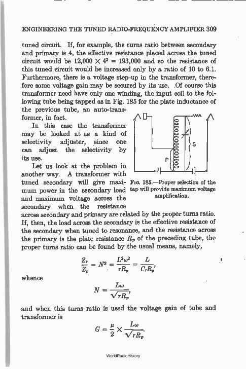
ENGINEERING THE TUNED RADIO-FREQUENCY AMPLIFIER 309
tuned circuit. If, for example, the turns ratio between secondary and primary is 4, the effective resistance placed across the tuned circuit would be 12,000 X e = 193,000 and so the resistance of this tuned circuit would be increased only by a ratio of 10 to 6.1. Furthermore, there is a voltage step-up in the transformer, there-fore some voltage gain may be secured by its use. Of course this transformer need have only one winding, the input coil to the fol-lowing tube being tapped as in Fig. 185 for the plate inductance of the previous tube, an auto-trans-former, in fact.
In this case the transformer may be looked at as a kind of selectivity adjuster, since one can adjust the selectivity by its use.
Let us look at the problem in another way. A transformer with tuned secondary will give maxi- Fla. 185.—Proper selection of the
mum power in the secondary load tap will provide maximum voltage and maximum voltage across the amplification.
secondary when the resistance across secondary and primary are related by the proper turns ratio. If, then, the load across the secondary is the effective resistance of the secondary when tuned to resonance, and the resistance across the primary is the plate resistance R,, of the preceding tube, the proper turns ratio can be found by the usual means, namely,
2, 1)(02 L ip = N2 = =
Crli, whence
N — Lw
and when this turns ratio is used the voltage gain of tube and transformer is
µ Lw G — X .
2 N/rRp
WorldRadioHistory
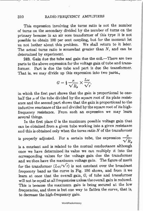
310 RADIO-FREQUENCY AMPLIFIERS
This expression involving the turns ratio is not the number of turns on the secondary divided by the number of turns on the primary because in an air core transformer of this type it is not possible to obtain 100 per cent coupling, but for the moment. Jet us not bother about this problem. We shall return to it later. The actual turns ratio is somewhat greater than N, and can be determined by experiment.
249. Gain due the tube and gain due the coil.—There are two parts to the above expression for the voltage gain of tube and trans-former. Part is due the tube and part is due the transformer. That is, we may divide up this expression into two parts.,
iz Lw
17-7-
in which the first part shows that the gain is proportional to one-half the » of the tube divided by the square root of its plate resist-ance and the second part shows that the gain is proportional to the inductive reactance of the coil divided by the square root of its high-frequency resistance. From such an expression we may learn
several things. In the first place G is the maximum possible voltage gain that
can be obtained .from a given tube working into a given resistance and this is obtained only when the turns ratio N of the transformer
is properly adjusted. For a certain tube, the expression VTZ„
is a constant and is related to the mutual conductance although once we have determined its value we can multiply it into the corresponding values for the voltage gain due the transformer and we then have the maximum voltage gain. The figure of merit
for the transformer (Lco/N/r) is not constant over the broadcast frequency band as the curve in Fig. 186 shows, and from it we learn at once that the overall gain, G, of tube and transformer will not be equal at all frequencies unless the overall gain is reduced. This is because the maximum gain is being secured at the low frequencies, and there is but one way to flatten the curve, that is, to decrease the high-frequency gain.
WorldRadioHistory
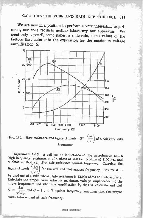
GAIN DUE THE TUBE AND GAIN DUE THE COIL 311
We are now in a position to perform a very interesting experi-ment, one that requires neither laboratory nor apparatus. We need only a pencil, some paper, a slide rule, some values of the factors that enter into the expression for the maximum voltage amplification, G.
ZD
(el S
20 200 R
4llíî. 44 15 15
0 0
cri >tr.
5
1000 1200
Frequency KC
1400
coL Fla. 186.—How resistance and figure of merit "Q" ( —) of a coil vary with r
500
50
00
50
00
50
frequency.
Experiment 1-13. A coil has an inductance of 168 rnicrohenrys, and a high-frequency resistance, r, of 4 ohms at 700 kc., 6 ohms at 1100 kc., and 9 ohms at 1500 kc. Plot this resistance against frequency. Calculate the
Lc.) figure of merit ()for the coil and plot against frequency. Assume it to
V r
be used out of a tube whose plate resistance is 12,000 ohms and whose p is 8. Calculate the proper turns ratio for maximum voltage amplification at the
above frequencies and what the amplification is, that is, calculate and plot Lw
N = —, and G=ip XN against frequency, assuming that the proper V Rpr
turns ratio is used at each frequency.
WorldRadioHistory
312 RADIO-FREQUENCY AMPLIFIERS
Then calculate N and the voltage amplification at 1000 kc. of such a coil and a 199 tube with a plate resistance of 16,000 ohms and µ of 6.6, and then when a 240 type tube is used. It has a plate resistance of 150,000 ohms and a et of 30.
Problem 5-13. The effective resistance of a coil-condenser combination is 100,000 ohms when the resistance of the coil is 10 ohms. That is, LIC r = 100,000 ohms, where r is the series resistance. Calculate what the equiv-alent resistance of such a circuit is when shunted by 10,000 ohms. (Two resistances in parallel have a resistance equivalent to their product divided by their sum.) Then assuming that this value is the effective resistance of another tuned circuit having the same L and C but a different aeries resistance, cal-culate what the value of r is.
Problem 6-13. A tube of 5000 ohms (UX-112A) is to be used as an r.-f. amplifier and to be worked into a tuned circuit whose effective resistance is 120,000 ohms. What is the proper turns ratio for maximum voltage amplifica-tion and what is the amplification? Remembering that a resistance across a primary of a transformer is equivalent to another resistance across the secon-dary stepped up by the square of the turns ratio of this transformer, what is the equivalent resistance that is placed across the tuned circuit by this trans-former? What happens to the effective resistance LIC r of this circuit?
Problem 7-13. A voltage gain of 10 is desired. The plate resistance of the tube is 12,000 ohms, its is is 15, the inductance of the coil is 186 micro-henrys, and the capacity is 0.0001 mfd. What is the maximum resistance the coil can have?
250. Effect of coupling.—The foregoing argument on maximum possible amplification of tube and its accompanying transformer has been based on the assumption that the coupling between primary and secondary was adjusted to the proper value at each frequency. Actually, such is seldom or never the case, and even if it were it is doubtful if receiver designers would so choose the coupling that maximum amplification would result owing to the decrease in selectivity of the circuits under these conditions.
In general the voltage amplification of a tube and transformer when the secondary is tuned may be expressed as
u2mL2
G — w2M2'
which involves not only the resistance of the apparatus (R, and R.) on the two sides of the transformer but the coupling M in the transformer itself. If we go into the laboratory and measure the
WorldRadioHistory
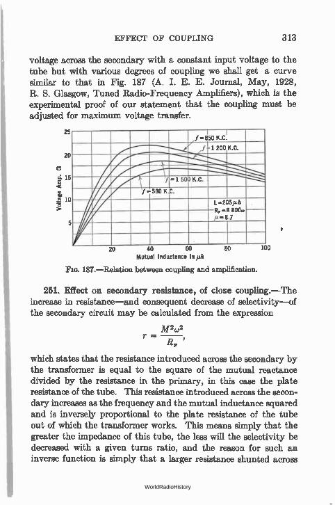
EFFECT OF COUPLING 313
voltage across the secondary with a constant input voltage to the tube but with various degrees of coupling we shall get a curve similar to that in Fig. 187 (A. I. E. E. Journal, May, 1928, R. S. Glasgow, Tuned Radio-Frequency Amplifiers), which is the experimental proof of our statement that the coupling must be adjusted for maximum voltage transfer.
25 f = 850 K.C.
f -1 200 K.C. 20
d 15 E =-1 500 K.C.
f =580 K.C.
L -205/a R-8 800. -
20 40 60 80 Mutual Inductance in irth
FIG. 187.—Relation between coupling and amplification.
100
•
251. Effect on secondary resistance, of close coupling.—The increase in resistance—and consequent decrease of selectivity—of the secondary circuit may be calculated from the expression
m2w2 r —
RD
which states that the resistance introduced across the secondary by the transformer is equal to the square of the mutual reactance divided by the resistance in the primary, in this case the plate resistance of the tube. This resistance introduced across the secon-dary increases 88 the frequency and the mutual inductance squared and is inversely proportional to the plate resistance of the tube out of which the transformer works. This means simply that the greater the impedance of this tube, the less will the selectivity be decreased with a given turns ratio, and the reason for such an inverse function is simply that a larger resistance shunted across
WorldRadioHistory
314 RADIO-FREQUENCY AMPLIFIERS
the tuned circuit will introduce less resistance in series with that circuit than will a smaller resistance across the circuit. No matter what the plate resistance, if M is adjusted for maximum possible voltage amplification the selectivity of the secondary circuit will be cut in half, because this selectivity is a function of the series resistance of the secondary which is doubled when the turns ratio is such that G is a maximum. Now the coupling between primary and secondary is controlled not only by the physical proximity of the two windings, but upon the number of turns in the primary, if the secondary turns are held constant. Therefore, decreasing the primary turns will increase the selectivity and decrease the amount of voltage amplification. Mathematical analysis of the problem will show that decreasing the turns in the primary from the number required for optimum voltage transfer to zero, only increases the selectivity by a factor of two. This means simply that when the number of turns in the primary is zero, none of the plate resistance of the tube is transferred to the secondary circuit, and, of course, then the selectivity of the secondary is its selectivity when stand-ing alone. No voltage is transferred under this condition, and so such selectivity for a single stage is never attained.
There is another variable factor in this transformer, this is the ratio of L to C. We have already discussed the voltage gain and selectivity as controlled by the secondary resistance and the turns ratio and the plate resistance of the previous tube. Calling upon either experimental proof or mathematical analysis, we can show that the greater the inductance of the secondary, other factors being maintained, the greater will be the selectivity of the system, and that when the secondary is adjusted to give the maximum amplification, given by
R,R, = w2L2
(where co = 2 it- X resonant frequency) the selectivity will depend upon the ratio of L to R, (secondary resistance) only and that if the circuit is adjusted for the greatest amplification for a desired signal it will also give the smallest amplification to an unwanted signal (K. W. Jarvis, Proc. I. R. E., May, 1927). Other curves
WorldRadioHistory
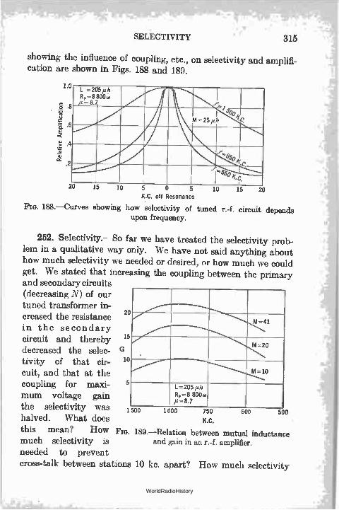
SELECTIVITY 315
showing the influence of coupling, etc., on selectivity and amplifi-cation are shown in Figs. 188 and 189.
1. , L =205 Ft, = 8
ylz 800o
1600 M=25 ph
_ t 10 15 20
K.C. off Resonance
Pm. 188.—Curves showing how selectivity of tuned r.-f. circuit depends upon frequency.
252. Selectivity.—So far we have treated the selectivity prob-lem in a qualitative way only. We have not said anything about how much selectivity we needed or desired, or how much we could get. We stated that increasing the coupling between the primary and secondary circuits (decreasing N) of our tuned transformer in-creased the resistance in the secondary circuit and thereby decreased the selec-tivity of that cir-cuit, and that at the coupling for maxi-mum voltage gain the selectivity was halved. What does
this mean? How Fm. 189.—Relation between mutual inductance much selectivity is and gain in an r.-f. amplifier. needed to prevent
cross-talk between stations 10 kc. apart? How much selectivity
20
15 .-..-
10
5 L=205 ph 4=8 800w 12=8.7
1 1000 750
K.C.
600 500
WorldRadioHistory
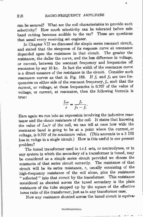
316 RADIO-FREQUENCY AMPLIFERS
can be secured? What are the coil characteristics to provide such selectivity? How much selectivity can be tolerated before side band cutting becomes audible to the ear? These are questions
that assail every receiving set engineer. In Chapter VII we discussed the simple series resonant circuit,
and stated that the steepness of its response curve at resonance depended upon the resistance in that circuit. The greater the resistance, the duller the curve, and the less difference in voltage, or current, between the resonant frequency and frequencies off resonance by say 10 kc. In fact the width of the resonance curve is a direct measure of the resistance in the circuit. Consider such resonance curves as that in Fig. 188. If fi and f2 are two fre-quencies on either side of the resonant frequency, fr, such that the current, or voltage, at these frequencies is 0.707 of the value of voltage, or current, at resonance, then the following formula is
true: Lw f,
r
Here again we run into an expression involving the inductive reac-tance and the ohmic resistance of the coil. It states that knowing the value of Lcuir of the coil, we can tell at once how wide the resonance band is going to be at a point where the current, or voltage, is 0.707 of its maximum value. (This amounts to a 3 DB loss in voltge in a single circuit.) How is this useful in our present
problem? The tuned transformer used in t.r.f. sets, or neutrodynes, or in
any system in which the secondary of a transformer is tuned, may be considered as a simple series circuit provided we choose the constants of that series circuit correctly. The resistance of that circuit will be its series resistance, r, usually consisting of the high-frequency resistance of the coil alone, plus the resistance " reflected " into that circuit by the transformer. This resistance considered as shunted across the tuned secondary is the plate resistance of the tube stepped up by the square of the effective turns ratio of the transformer, just as in any transformer case.
Now any resistance shunted across the tuned circuit is equiva-
WorldRadioHistory
SELECTIVITY 317
lent to a smaller resistance in series with the circuit, and such a resistance is the controlling factor in determining the width of the resonance curve. And since selectivity is but a term describing the width of this resonance curve, we have in our hands all the necessary facts regarding the voltage amplification and the selec-tivity of such circuits.
For example, at the coupling between the primary and secon-dary for maximum voltage amplification the effective turns ratio is given by
Z. L2c02 N2 = Z, rR,
which means that the secondary of the coil will 15e shunted by a resistance equal to the plate resistance of the previous tube mul-tiplied by the turns ratio squared, and this numerically will be equal to the effective resistance of the tuned secondary, L2w2/r. Now the secondary effective resistance, being shunted by another resistance equal to it numerically, becomes half its former value (two .equal resistances in parallel have a resultant resistance of one-half of one of them). Such a decrease in effective resistance can also be produced in one other way—by increasing the resist-ance of the coil to twice its normal value. And what effect has doubling the coil resistance upon selectivity? Clearly it halves it, because selectivity may be thought of as proportional to Lw/r and doubling r halves this factor.
The following example may fix the whole problem in one's mind.
Example 1-13. Consider a coil whose inductance is 200 microhenrys, and whose resistance r at 1000 kc. is 10 ohms. This coil is to be tuned and fitted with a primary to work out of a tube whose plate resistance is 12,000 ohms and whose ja is 8. What is the proper turns ratio for maximum voltage amplification? What is the voltage amplification? What is the width of the frequency band with and without the tube connected across the primary?
Effective resistance of coil-condenser alone
L2W2 (200 X 10 -2)2 (108 X 6.28) 2
10
-- 158,000 ohms
WorldRadioHistory
318 RADIO-FREQUENCY AMPLIFIERS
Width of frequency band when / = .707 maximum value
.frr r
Tco =
10$ X 10
200 X 10-$ X 6.28 X 10$
8000 cycles.
Turns ratio for maximum voltage amplification
\ 158,000
; N 12,000 Voltage gain
eco 8 X 200 X 10-$ X 6.28 X 10$
2 V17 7-?,, 214-2-,F00 1/1-13
= 14.5 times.
Resistance reflected from primary to secondary
= Z,, X N2
= 12,000 X 13 = 158,000.
New effective resistance of secondary circuit
158,000 X 158,000 - 79,000 ohms = Vws .
158,000 -I- 158,000
New effective series resistance in secondary
L2£02 158,000 X 10 =R, - 20.
79,000 79,000
Width of frequency band where / = .707 maximum value
frrei 108 X 20 = — — — Lw 200 X 10-6 X 6.28 X 100
= 16,000 cycles.
This indicates that a voltage gain of 14.5 would be obtained with such a coil-condenser combination and tube at a frequency of 1000 kc. and that at a frequency 8000 cycles either above or below resonance, the current in the secondary circuit, or the voltage across it, would be 0.707 of its value at exact resonance. This
WorldRadioHistory
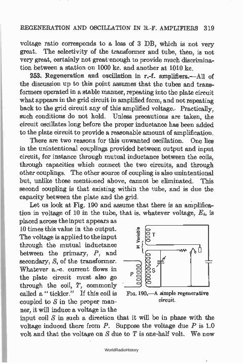
REGENERATION AND OSCILLATION IN R.-F. AMPLIFIERS 319
voltage ratio corresponds to a loss of 3 DB, which is not very great. The selectivity of the transformer and tube, then, is not very great, certainly not great •enough to provide much discrimina-tion between a station on 1000 kc. and another at 1010 kc.
253. Regeneration and oscillation in r.-f. amplifiers.—All of the discussion up to this point assumes that the tubes and trans-formers operated in a stable manner, repeating into the plate circuit what appears in the grid circuit in amplified form, and not repeating back to the grid circuit any of this amplified voltage.. Practically, such conditions do not hold. Unless precautions are taken, the circuit oscillates long before the proper inductance has been added to the plate circuit to provide a reasonable amount of amplification.
There are two reasons for this unwanted oscillation. One lies in the unintentional couplings provided between output and input circuit, for instance through mutual inductance between the coils, through capacities which connect the two circuits, and through other couplings. The other source of coupling is also unintentional but, unlike those mentioned above, cannot be eliminated. This second coupling is that existing within the tube, and is due the capacity between the plate and the grid.
Let us look at Fig. 190 and assume that there is an aniplifics.-tion in voltage of 10 in the tube, that is. whatever voltage, E, is placed across the input appears as 10 times this value in the output. The voltage is applied to the input through the mutual inductance between the primary, P, and secondary, S, of the transformer. Whatever a.-c. current flows in the plate circuit must also go through the coil, T, commonly called a " tickler." If this coil is Fm. 190.—A simple regenerative coupled to S in the proper man-ner, it will induce a voltage in the input coil S in such a direction that it will be in phase with the voltage induced there from P. Suppose the voltage due P is LO volt and that the voltage on $ due to T is one-half volt. We now
circuit.
WorldRadioHistory
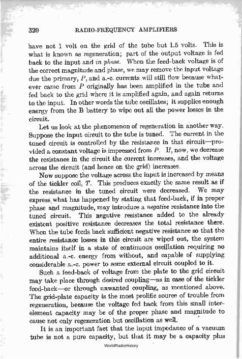
320 RADIO-FREQUENCY AMPLIFIERS
have not 1 volt on the grid of the tube but 1.5 volts. This is what is known as regeneration; part of the output voltage is fed back to the input and in phase. When the feed-back voltage is of the correct magnitude and phase, we may remove the input voltage due the primary, P, and a.-c. currents will still flow because what-ever came from P originally has been amplified in the tube and fed back to the grid where it is amplified again, and again returns to the input. In other words the tube oscillates; it supplies enough energy from the B battery to wipe out all the power losses in the
circuit. Let us look at the phenomenon of regeneration in another way.
Suppose the input circuit to the tube is tuned. The current in the tuned circuit is controlled by the resistance in that circuit—pro-vided a constant voltage is impressed from P. If, now, we decrease the resistance in the circuit the current increases, and the voltage across the circuit (and hence on the grid) increases.
Now suppose the voltage across the input is increased by means of the tickler coil, T. This produces exactly the same result as if the resistance in the tuned circuit were decreased. We may express what has happened by stating that feed-back, if in proper phase and magnitude, may introduce a negative resistance into the tuned circuit. This negative resistance added to the already existent positive resistance decreases the total resistance there. When the tube feeds back sufficient negative resistance so that the entire resistance losses in this circuit are wiped out, the system maintains itself in a state of continuous oscillation requiring no additional a.-c. energy from without, and capable of supplying considerable a.-c. power to some external circuit coupled to it.
Such a feed-back of voltage from the plate to the grid circuit may take place through desired coupling—as in case of the tickler feed-back—or through unwanted coupling, as mentioned above. The grid-plate capacity is the most prolific source of trouble from regeneration, because the voltage fed back from this small inter-element capacity may be of the proper phase and magnitude to cause not only regeneration but oscillation as well.
It is an important fact that the input impedance of a vacuum tube is not a pure capacity, but that it may be a capacity plus
WorldRadioHistory
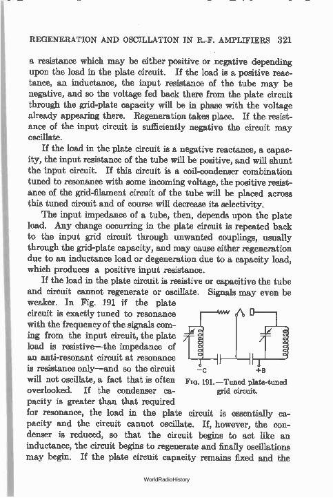
REGENERATION AND OSCILLATION IN R.-F. AMPLIFIERS 321
a resistance which may be either positive or negative depending upon the load in the plate circuit. If the load is a positive reac-tance, an inductance, the input resistance of the tube may be negative, and so the voltage fed back there from the plate circuit through the grid-plate capacity will be in phase with the voltage already appearing there. Regeneration takes place. If the resist-ance of the input circuit is sufficiently negative the circuit may oscillate.
If the load in the plate circuit is a negative reactance, a capac-ity, the input resistance of the tube will be positive, and will shunt the input circuit. If this circuit is a coil-condenser combination tuned to resonance with some incoming voltage, the positive resist-ance of the grid-filament circuit of the tube will be placed across this tuned circuit and of course will decrease its selectivity.
The input impedance of a tube, then, depends upon the plate load. Any change occurring in the plate circuit is repeated back to the input grid circuit through unwanted couplings, usually through the grid-plate capacity, and may cause either regeneration due to an inductance load or degeneration due to a capacity load, which produces a positive input resistance.
If the load in the plate circuit is resistive or capacitive the tube and circuit cannot regenerate or oscillate. Signals may even be weaker. In Fig. 191. if the plate circuit is exactly tuned to resonance with the frequency of the signals com-ing from the input circuit, the plate load is resistive—the impedance of an anti-resonant circuit at resonance is resistance only—and so the circuit will not oscillate, a fact that is often F. 191.—Tuned plate-tuned overlooked. If the condenser ca- grid circuit.
pacity is greater than that required for resonance, the load in the plate circuit is essentially ca-pacity and the circuit cannot oscillate. If, however, the con-denser is reduced, so that the circuit begins to act like an inductance, the circuit begins to regenerate and finally oscillations may begin. If the plate circuit capacity remains fixed and the
—C +B
WorldRadioHistory
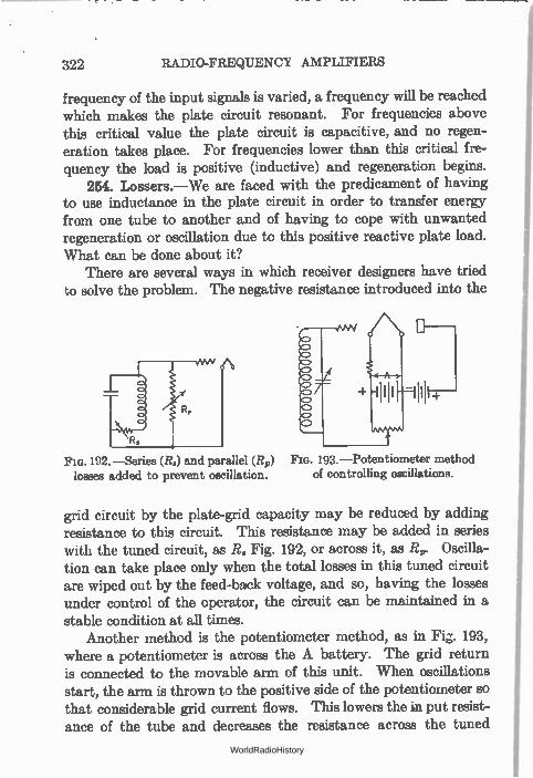
322 RADIO-FREQUENCY AMPLIFIERS
frequency of the input signals is varied, a frequency will be reached which makes the plate circuit resonant. For frequencies above this critical value the plate circuit is capacitive, and no regen-eration takes place. For frequencies lower than this critical fre-quency the load is positive (inductive) and regeneration begins.
254. Lossers.—We are faced with the predicament of having to use inductance in the plate circuit in order to transfer energy from one tube to another and of having to cope with unwanted regeneration or oscillation due to this positive reactive plate load. What can be done about it?
There are several ways in which receiver designers have tried to solve the problem. The negative resistance introduced into the
Flo. 192. —Series (R.) and parallel (R,) Pia. 193.—Potentiometer method losses added to prevent oscillation, of controlling oscillations.
grid circuit by the plate-grid capacity may be reduced by adding resistance to this circuit. This resistance may be added in series with the tuned circuit, as R, Fig. 192, or across it, as R„. Oscilla-tion can take place only when the total losses in this tuned circuit are wiped out by the feed-back voltage, and so, having the losses under control of the operator, the circuit can be maintained in a stable condition at all times.
Another method is the potentiometer method, as in Fig. 193, where a potentiometer is across the A battery. The grid return is connected to the movable arm of this unit. When oscillations start, the arm is thrown to the positive side of the potentiometer so that considerable grid current flows. This lowers the in put resist-ance of the tube and decreases the resistance across the tuned
WorldRadioHistory
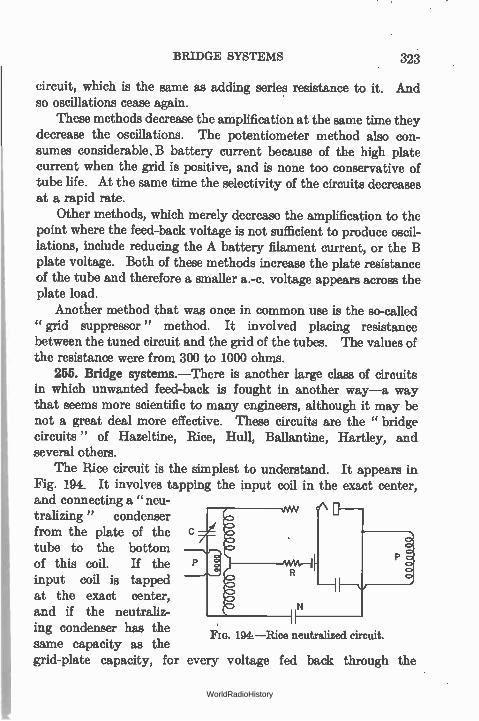
BRIDGE SYSTEMS 323
circuit, which is the same as adding series resistance to it. And so oscillations cease again.
These methods decrease the amplification at the same time they decrease the oscillations. The potentiometer method also con-sumes considerable. B battery current because of the high plate current when the grid is positive, and is none too conservative of tube life. At the same time the selectivity of the circuits decreases at a rapid rate.
Other methods, which merely decrease the amplification to the point where the feed-back voltage is not sufficient to produce oscil-lations, include reducing the A battery filament current, or the B plate voltage. Both of these methods increase the plate resistance of the tube and therefore a smaller a.-c. voltage appears across the plate load.
Another method that was once in common use is the so-called "grid suppressor" method. It involved placing resistance between the tuned circuit and the grid of the tubes. The values of the resistance were from 300 to 1000 ohms.
255. Bridge systems.—There is another large class of circuits in which unwanted feed-back is fought in another way—a way that seems more scientific to many engineers, although it may be not a great deal more effective. These circuits are the " bridge circuits" of Hazeltine, Rice, Hull, Ballantine, Hartley, and several others.
The Rice circuit is the simplest to understand. It appears in Fig. 194. It involves tapping the input coil in the exact center, and connecting a " neu-tralizing " condenser from the plate of the tube to the bottom of this coil. If the input coil is tapped at the exact center, and if the neutraliz-ing condenser has the
Fr' G. 194.—Rice neutralized circuit. same capacity as the grid-plate capacity, for every voltage fed back through the
WorldRadioHistory
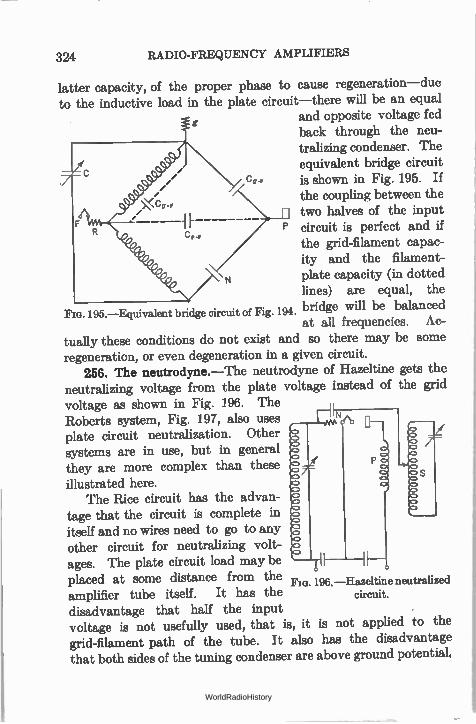
324 RADIO-FREQUENCY AMPLIFIERS
latter capacity, of the proper phase to cause regeneration—due to the inductive load in the plate circuit—there will be an equal
and opposite voltage fed back through the neu-tralizing condenser. The equivalent bridge circuit is shown in Fig. 195. If the coupling between the two halves of the input circuit is perfect and if the grid-filament capac-ity and the filament-plate capacity (in dotted lines) are equal, the
Fia. 195.—Equivalent bridge circuit of Fig. 194. bridge will be balanced at all frequencies. Ac-
tually these conditions do not exist and so there may be some regeneration, or even degeneration in a given circuit.
256. The neutrodyne.—The neutrodyne of Hazeltine gets the neutralizing voltage from the plate voltage instead of the grid voltage as shown in Fig. 196. The Roberts system, Fig. 197, also uses plate circuit neutralization. Other systems are in use, but in general they are more complex than these illustrated here.
The Rice circuit has the advan-tage that the circuit is complete in itself and no wires need to go to any other circuit for neutralizing volt-ages. The plate circuit load may be placed at some distance from the Fla. 196.—Hazeltine neutralized amplifier tube itself. It has the disadvantage that half the input voltage is not usefully used, that is, it is not applied to the grid-filament path of the tube. It also has the disadvantage that both sides of the tuning condenser are above ground potential,
P
circuit.
WorldRadioHistory
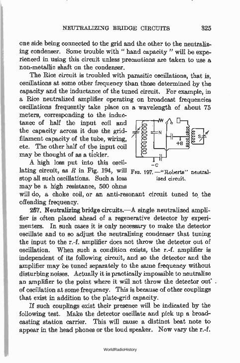
NEUTRALIZING BRIDGE CIRCUITS 325
one side being connected to the grid and the other to the neutraliz-ing condenser. Some trouble with " hand capacity" will be expe-rienced in using this circuit unless precautions are taken to use a non-metallic shaft on the condenser.
The Rice circuit is troubled with parasitic oscillations, that is, oscillations at some other frequency than those determined by the capacity and the inductance of the tuned circuit. For example, in a Rice neutralized amplifier operating on broadcast frequencies oscillations frequently take place on a wavelength of about 75 meters, corresponding to the induc-tance of half the input coil and the capacity across it due the grid-filament capacity of the tube, wiring, etc. The other half of the input coil may be thought of as a tickler. A high loss put into this oscil-
lating circuit, as R in Fig. 194, will Fie. 197. —" Roberta" neutral-
stop all such oscillations. Such a loss ized circuit.
may be a high resistance, 500 ohms will do, a choke coil, or an anti-resonant circuit tuned to. the offending frequency.
257. Neutralizing bridge circuits.—A single neutralized ampli-fier is often placed ahead of a regenerative detector by experi-menters. In such cases it is only necessary to make the detector oscillate and to so adjust the neutralizing condenser that tuning the input to the r.-f. amplifier does not throw the detector out of oscillation. When such a condition exists, the r.-f. amplifier is independent of its following circuit, and so the detector and the amplifier may be tuned separately to the same frequency without disturbing noises. Actually it is practically impossible to neutralize an amplifier to the point where it will not throw the detector oue of oscillation at some frequency. This is because of other couplings that exist in addition to the plate-grid capacity.
If such couplings exist their presence will be indicated by the following test. Make the detector oscillate and pick up a broad-casting station carrier. This will cause a distinct beat note to appear in the head phones or the loud speaker. Now vary the r.-f.
- c
WorldRadioHistory
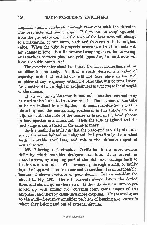
326 RADIO-FREQUENCY AMPLIFIERS
amplifier tuning condenser through resonance with the detector. The beat note will now change. If there are no couplings aside from the grid-plate capacity the tone of the beat note will change to a maximum, or minimum, pitch and then return to its original value. When the tube is properly neutralized this beat note will not change in tone. But if unwanted couplings exist due to wiring, or capacities between plate and grid apparatus, the beat note will have a double hump in it.
The experimenter should not take the exact neutralizing of his amplifier too seriously. All that is really desired is a value of capacity such that oscillations will not take place in the r.-f. amplifier at any frequency within the band that will be tuned over. As a matter of fact a slight misadjustment may increase the strength of the signals.
If an oscillating detector is not used, another method may be used which leads to the same result. The filament of the tube to be neutralized is not lighted. A buzzer-modulated signal is picked up and the neutralizing condenser in this tube's circuit is adjusted until the note of the buzzer as heard in the head phones or loud speaker is a minimum. Then the tube is lighted and the next stage is neutralized in the same manner.
Such a method is faulty in that the plate-grid capacity of a tube is not the same lighted as unlighted, but practically the method leads to stable amplifiers, and this is the ultimate object of neutralization.
258. Filtering r.-f. circuits.—Oscillation is the most serious difficulty which amplifier designers run into. It is caused, as stated above, by coupling part of the plate a.-c. voltage back to the input of the tube. When occurring through wiring, or faulty layout of apparatus, or from one coil to another, it is unpardonable, 'because it shows evidence of poor design. Let us consider the circuit in Fig. 198. The r.-f. currents should follow the dotted lines, and should go nowhere else. If they do they are sure to get mixed up with similar r.-f. currents from other stages of the amplifier, and thereby cause unwanted coupling. This is analogous to the audio-frequency amplifier problem of keeping a.-c. currents where they belong and out of external circuits.
WorldRadioHistory
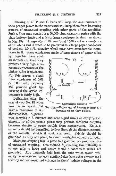
FILTERING R.-F. CIRCUITS 327
Filtering of all B and C leads will keep the a.-c. currents in their proper places in the circuit and will keep them from becoming sources of unwanted coupling with other parts of the amplifier. Such a filter may consist of a 50,000-ohm resistor in series with the plate battery leads and a fairly large condenser in shunt as shown in Fig. 198. A capacity of 100 mmfd. at 1500 kc. has a reactance of 103 ohms and is much to be preferred to a large paper condenser of perhaps 1.0 mfd. capacity which may have considerable induc-tance in it. Some condensers made of large sheets of paper rolled up together have such an inductance that they present a very high anti-resonant reactance at the higher radio frequencies. For this reason a small mica condenser of 0.01 or 0.001 mfd. capacity will provide good by-passing if the series im-pedance is fairly high.
Ballantine cites the case of two No. 18 wires (ph Impedance Series Pat
two inches apart that Fin. 198. —Proper use of filtering to keep r.-f. have a reactance of 5.8 ohms per foot. A ground wire carrying r.-f. currents and near a grid wire also carrying r.-f. currents or of the proper phase may provide sufficient coupling between circuits to cause trouble from regeneration. No a.-c. currents should be permitted to flow through the filament circuits, or the metallic shields if such are used. Shields should be grounded at only one place, to avoid circulating currents in them.
Magnetic coupling from a plate to a grid coil is a prolific source of unwanted coupling. One method of avoiding this difficulty is to use coils in large and heavy metallic containers which are grounded. Any magnetic field from the coils which would ordi-narily become mixed up with similar fields from other circuits (and thereby induce unwanted voltages in them) induce voltages in the
Currents where they belong.
WorldRadioHistory
328 RADIO-FREQUENCY AMPLIFIERS
grounded shield instead. It must be remembered that the induced voltage is capable of setting up an r.-f. current in this shielding and that the PR loss in power in the shields must be supplied from the power in the coils themselves. This results in an equivalent increase in the resistance of the coils inside the shield and a decrease
L.2,2 in their inductance. This, of course, decreases the coil's
factor with consequent decrease in both amplification and selec-tivity. When coils are to be shielded they usually have small diam-eters and small fields. This construction minimizes the increase in resistance and decrease in inductance.
Modern practice is to filter every circuit with series resistance and shunt capacities to ground. Thus the r.-f. currents are returned directly to the cathode of the tube whence they come. None are permitted to get into the plate voltage supply; screens of multi-grid tubes are carefully grounded and filtered. So extensive is the filtering in modern complex circuits that ten or more resistors and an equivalent number of capacitors do nothing but keep r.-f. currents where they belong.
259. Use of screen-grid tube as r.-f. amplifiers.—The screen-grid tube removed the necessity for neutralizing the grid-plate capacity; but it did not remove the necessity for carefully shield-ing " hot " leads, for shielding the coils, and for taking many precautions to prevent feed-back. In one case a manufacturer found his receiver unstable. One coil was nearly completely shielded but the end near the metal chassis was open. A hole had been cut in this chassis so that the remaining metal plate resembled a large closed loop of wire. This metal loop picked up r.-f. currents from the partially shielded coil, transferred them to an adjacent grid lead, and caused regeneration. It was necessary to cut a slot in the chassis to break up the closed loop of metal; and several hours of frantic hunting for the trouble were required to discover this simple cause of feed-back.
Some manufacturers spray their tubes with a metallic coating which is grounded to the cathode of the tube. Not only does this provide some shielding for the inner tube elements but also it seems to reduce the capacities, with consequent relief from some
WorldRadioHistory
GAIN WITH SCREEN-GRID TUBE 329
measure of external shielding. In general, however, all manu-facturers shield all coils, filter all circuits, and go to considerable pains to prevent unwanted regeneration.
260. Gain with screen-grid tube.—The screen-grid tube has almost completely displaced the triode as an amplifier at high frequencies, not only because it is easier to control on account of the greatly decreased grid-plate capacity (about 0.007 compared to 3 mmfd.), but also because of greater stage gain, due to its higher internal resistance and to its higher amplification factor. Greater selectivity may be obtained per stage than with triodes.
Using the formulas given in Section 249 for the gain of tube and coil it may be calculated that with a secondary inductance and resistance such that a load impedance of 100,000 ohms is obtained, a gain of 200 is possible with a 58 tube having a resistance of 0.8 megohm, a mutual conductance of 1600, and an amplification factor of 1280. In practice the gain is not permitted to go so high at broadcast frequencies largely because it would tend toward making the set instable. Gains of 30 to 60 per stage at broadcast frequencies and more may be obtained. For example, with a particular interstage coil wound with Litz wire so that the capacity is low (bank wound) a gain of 62.5 at 1500 kc. and 42.5 at 550 kc. was obtained. The coil tuned from 1700 kc. to 550 kc.
One of the difficulties of getting high gain out of screen-grid tubes at broadcast frequencies is the necessity of having a high mutual inductance between primary and secondary of the inter-stage transformer. This arises from the fact that the formula on page 314 giving the relation between mutual inductance and gain shows that for maximum gain the coupling between coils increases as the plate resistance of the tube increases. Thus in a typical calculation the mutual inductance between coils amounted to 325 microhenries while the secondary standing alone had an induc-tance of 180 microhenries. This implies a very large primary with appreciable distributed capacity.
Interstage coils have been made and widely used with high-inductance primary coils. In other receivers both primary and secondary are tuned increasing the impedance into which the screen-grid tube works. In a typical receiver the primary and
WorldRadioHistory
330 RADIO-FREQUENCY AMPLIFIERS
secondary of the interstage i.-f. transformers and- the primary of the r.-f. interstage transformer had inductances of 5 5 millihenries; the antenna coil was 0.9 millihenry.
Modern practice is to use small coils, well shielded, usually of Litz, universally or bank wound and of as high Q as can be obtained. Considerable loss to the higher audio frequencies occurs in stages using such coils with high-resistance tubes; but this loss cuts out tube noise, static, and other undesirable noise which the public seems not to like. The Q values are of the order of 100 at i.f.
261. Selectivity with screen-grid tubes.—With low-resistance tubes, triodes for example, the maximum amplification per stage is obtained when the load the tube works into equals the tube load. Under these conditions the Q of the circuit is one-half the Q of the coil-condenser combination. This is due to the fact that the effective resistance of this anti-resonant circuit, numerically equal to the product of the reactances divided by the coil resistance, is shunted by a resistance (the internal tube resistance) equal to itself. Therefore the effective resistance has been reduced by a factor of 2, which is the same result as if the coil resistance had been doubled.
With screen-grid tubes the tube resistance is so high that it is difficult to make a tuned circuit with an effective resistance equal to the tube resistance. In other words, whatever the effective resistance of the tuned circuit, it is shunted by a resistance much larger than itself; therefore the Q of the circuit is reduced by much less than a factor of 2. Therefore the selectivity of the stage is much better than if a low-resistance tube were used.
Thus the use of screen-grid tubes has increased not only the gain per stage but also the selectivity per stage. The actual value of the selectivity may be ascertained as follows.
Suppose the tube resistance to be bridged directly across the tuned circuit. Across this circuit is impressed the input grid voltage multiplied by the mutual conductance of the tube. Thus the voltage at resonance divided by the voltage at any other frequency, which will give us an idea of the selectivity, will be expressed as
egG,vZo _ co
e„Ge
WorldRadioHistory
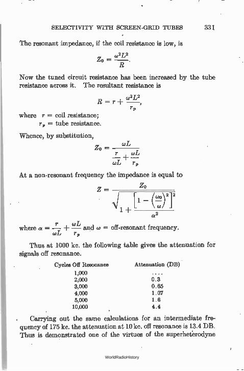
SELECTIVITY WITH SCREEN-GRID TUBES 331
The resonant impedance, if the coil resistance is low, is
,2L2
zo
Now the tuned circuit resistance has been increased by the tube resistance across it. The resultant resistance is
,2 L2 R = r
r„ where r = coil resistance;
r„ = tube resistance.
Whence, by substitution,
Zo — r , coL — — coL r„
wL
At a non-resonant frequency the impedance is equal to
Zo Z —
Ni [IL N 12 1 +
2 a
where a = —r —caL and co = off-resonant frequency. coL r„
Thus at 1000 kc. the following table gives the attenuation for signals off resonance.
Cycles Off Resonance Attenuation (DB)
1,000 2,000 0.3 3,000 0.65 4,000 1.07 5,000 1.6 10,000 4.4
. Carrying out the same calculations for an intermediate fre-quency of 175 kc. the attenuation at 10 kc. off resonance is 13.4 DB. Thus is demonstrated one of the virtues of the superheterodyne
WorldRadioHistory
332 RADIO-FREQUENCY AMPLIFIERS
system—the increased selectivity per stage possible at the lower frequency. This is because 10 kc. off resonance at 175 kc. is much further from the resonance peak than it is at 1000 kc. To secure the same selectivity at broadcast as at intermediate frequencies, more stages must be used. Thus the superheterodyne system, in which the incoming signal is lowered in frequency, is a more economical system than the tuned r.-f. system in which all the gain and selectivity are obtained at the incoming frequency.
262. Automatic tone control.—The fact that the variations in resistance of the tube shunted across a tuned circuit (in this case the interstage transformer) have some effect upon the selectivity of that circuit may be used to advantage in automatically con-trolling the tone fidelity of the receiver. For example, if the internal resistance of the tube is made to vary inversely with the signal strength so that at high signal strengths the resistance of the tube will be low, the shunting effect of the tube will be greatest on strong local stations, the decrease in selectivity will be greatest for these stations, and for weaker signals the circuits will become more and more selective.
The advantage of such a circuit would be in the suppression of higher audio notes on weak, noisy signals already partially sub-merged in static or other racket. On strong locals, which ride in above all local noise, the selectivity of the circuits would be rela-tively poor and no side-band cutting would take place.
If, for example, a 58 type tube is used and the suppressor grid is varied in voltage becoming more negative as the signal increases, the plate resistance will decrease, producing a loss in selectivity in the interstage circuit and an effective increase in tone fidelity. The plate resistance of the 58 changes from 0.8 megohm (control grid = — 3) at zero volts on the suppressor to 50,000 ohms at —30 on the suppressor. This will produce an appreciable loading effect upon the interstage circuits especially at intermediate frequencies.
In a typical case the interstage transformer had both primary and secondary tuned, the coupling was fairly loose (40 per cent of critical coupling), and a loss of 3 to 4 DB at 3000 • to 4000 cycles was obtained over the range of plate resistance men-tioned above. The transformer had the following characteristics:
WorldRadioHistory
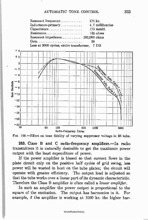
AUTOMATIC TONE CONTROL 333
Resonant frequency 175 kc.
Inductance-primary 4.7 millihenries
Capacitance 175 mmfd.
Resistance 135 ohms
Resonant impedance 200,000 ohms
Gain 56
Loss at 3000 cycles, entire transformer, 7 DB
• 2
0
• 2
• 4
• 6
• 8
10
12 14
16
18
2Q
-......... -... tf
4. ifee---------------- 41 \tee>,
-.N. Y 74'
16,
1
_ 50 100 500
Audio-Frequency Cycles
Fie. 199.—Effect on tone fidelity of varying suppressor voltage in 58 tube.
263. Class B and C radio-frequency amplifiers.—In radio transmitters it is naturally desirable to get the maximum power output with the least expenditure of power.
If the power amplifier is biased so that current flows in the plate circuit only on the positive half cycles of grid swing, less power will be wasted in heat on the tube plates; the circuit will operate with greater efficiency. The output load is adjusted so that the tube works over a linear part of its dynamic characteristic. Therefore the Class B amplifier is often called a linear amplifier.
In such an amplifier the power output is proportional to the square of the excitation. The output has harmonics in it. For example, if the amplifier is working at 1000 kc. the higher har-
1000 5000
WorldRadioHistory
334 RADIO-FREQUENCY AMPLIFIERS
monies will be 2000 and 3000 kc. But since the output is tuned to 1000 kc. these higher harmonics, far removed from the resonant frequency, will build up very low voltages and will not radiate.
Still greater efficiency can be obtained from a Class C amplifier where the grid is so over-biased that plate current flows for only a fraction of the cycle which drives the grid positive. Efficiencies as high as 85 per cent (compared to 70 per cent for Class B at 100 per cent modulation) can be obtained.
This amplifier is often used as a modulated amplifier because the output is a function of the square of the plate voltage. It can • also be used to increase the percentage modulation.
264. Ultra-high-frequency amplifiers.—The history of the short waves, those below 200 meters, will undoubtedly be repeated on the very short waves, below 10 meters.
In 1932-1933 when the tubes with dome-shaped top were developed new possibilities for waves of the order of 5 meters were opened up. Prior to this time much difficulty was experienced in making stable oscillators at waves of 5 meters or somewhat above, and amplification at such wavelengths was impossible. The dome-shaped tubes, however, with smaller elements and better shielding made possible efficient operation at 5 meters.
In 1933, other very interesting developments took place. B. J. Thompson described before the Institute of Radio Engineers, in June of that year, work he had carried on for months leading toward the ultimate manufacture of tubes especially designed for ultra-short-wave work. His premise is interesting—if you reduce the physical dimensions of the tubes their interelectrode capacity will go down but the tube constants will remain the same. Thus a tube, say a triode of mutual conductance of 1000 and an amplifica-tion factor of 10, might have a grid-plate capacity of 3.3 mmfd. If all dimensions were reduced by a factor of 10, the electrical char-acteristics would not change but the capacity between plate and grid would be reduced by a factor of 10.
With such tubes, which were scarcely larger than a thimble, amplification at wavelengths less than 1 meter is possible. Oscillators operate without trouble at 1 meter; and a super-heterodyne was made which would give a gain of 4 per stage at this wavelength prior to the frequency changing.
WorldRadioHistory
CHAPTER XIV
DETECTION
SUPPOSE we have received a signal and have amplified it in a radio-frequency amplifier. How may it be detected, or demodu-lated so that it can be put into an audio amplifier and then a loud speaker?
Up to the present time we have considered the applications of the vacuum tube which call for its operation on a straight part of its characteristic where little distortion takes place. We have considered the tube only as an amplifier. We shall discuss now the uses for the curved part of the characteristic.
Tubes act as amplifiers either with or without distortion and as detectors and modulators in which distortion is the essential feature. The latter uses of the tube require a curved character-istic. The output no longer is an exact replica of the input.
265. Distorting tubes.—In Section 188 we were able to calcu-late the amount of distortion (second • harmonics) that resulted when the tube was worked on a curved part of its characteristic, and found that in the distortion process a certain amount of d.-c. current was generated. In other words a pure sine wave voltage put on the grid-filament input of a tube resulted in an output current or voltage composed of not only the frequency that was put on the input but some additional frequencies and some additional d.-c. current as well.
If we desire to get d.-c. current from an a.-c. voltage, the tube acts as a rectifier. If we desire to get audio-frequency voltages from a modulated r.-f. voltage, the tube acts as a detector. If we desire to mix two frequencies, say a low audible frequency with a high or radio frequency, we put them both into a modulator. All of these uses require a non-linear characteristic. Detectors and
335 WorldRadioHistory
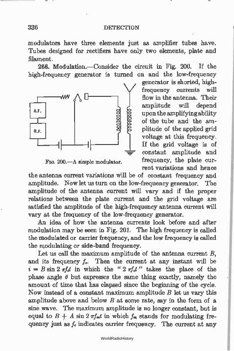
336 DETECTION
modulators have three elements just as amplifier tubes have. Tubes designed for rectifiers have only two elements, plate and filament.
266. Modulation.—Consider the circuit in Fig. 200. If the high-frequency generator is turned on and the low-frequency
generator is shorted, high-
A.F.
frequency currents will flow in the antenna. Their
upon the amplifying ability of the tube and the am-
R.F. plitude of the applied grid voltage at this frequency.
amplitude will depend
If the grid voltage is of constant amplitude and frequency, the plate cur-rent variations and hence
the antenna current variations Will be of constant frequency and amplitude. Now let us turn on the low-frequency generator. The amplitude of the antenna current will vary and if the proper relations between the plate current and the grid voltage are satisfied the amplitude of the high-frequency antenna current will vary at the frequency of the low-frequency generator.
An idea of how the antenna currents look before and after modulation may be seen in Fig. 201. The high frequency is called the modulated or carrier frequency, and the low frequency is called the modulating or side-band frequency.
Let us call the maximum amplitude of the antenna current B, and its frequency fc. Then the current at any instant will be i = B sin 2 rfct in which the " 2 elct" takes the place of the phase angle O but expresses the same thing exactly, namely the amount of time that has elapsed since the beginning of the cycle. Now instead of a constant maximum amplitude B let us vary this amplitude above and below B at some rate, say in the form of a sine wave. The maximum amplitude is no longer constant, but is equal to B ± A sin 2 Irfmt in which fm stands for modulating fre-quency just as fc indicates carrier frequency. The current at any
Fro. 200.—A simple modulator.
WorldRadioHistory
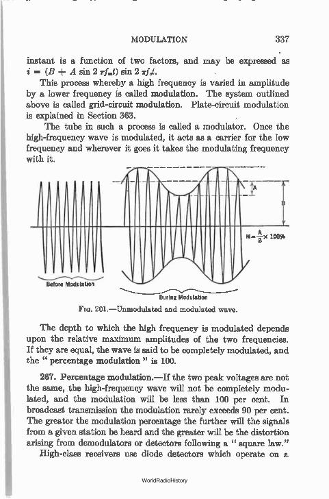
MODULATION 337
instant is a function of two factors, and may be expressed as = (B ± A sin 2 rf,„t) sin 2 irfct. This process whereby a high frequency is varied in amplitude
by a lower frequency is called modulation. The system outlined above is called grid-circuit modulation. Plate-circuit modulation is explained in Section 363.
The tube in such a process is called a modulator. Once the high-frequency wave is modulated, it acts as a carrier for the low frequency and wherever it goes it takes the modulating frequency with it.
Before Modulation
During Modulation
FIG. 201.—Unmodulated and modulated wave.
The depth to which the high frequency is modulated depends upon the relative maximum amplitudes of the two frequencies. If they are equal, the wave is said to be completely modulated, and he " percentage modulation" is 100.
267. Percentage modulation.—If the two peak voltages are not the same, the high-frequency wave will not be completely modu-lated, and the modulation will be less than 100 per cent. In broadcast transmission the modulation rarely exceeds 90 per cent. The greater the modulation percentage the further will the signals from a given station be heard and the greater will be the distortion arising from demodulators or detectors following a " square law."
High-class receivers use diode detectors which operate on a
WorldRadioHistory
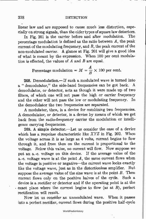
338 DETECTION
linear law and are supposed to cause much less distortion, espe-cially on strong signals, than the older types of square law detectors.
In Fig. 201 is the carrier before and after modulation. The percentage modulation is defined as the ratio between A, the peak current of the modulating frequency, and B, the peak current of the non-modulated carrier. A glance at Fig. 201 will give a good idea of what is meant by the expression. When 100 per cent modula-tion is effected, the values of A and B are equal.
A Percentage modulation = M = — X 100 per cent.
268. Demodulation.—If such a modulated wave is turned into a " demodulator," the side-band frequencies can be got back. A demodulator, or detector, acts as though it were made up of two filters, of which one will not pass the high or carrier frequency and the other will not pass the low or modulating frequency. In the demodulator the two frequencies are separated. A modulator, then, is a device for combining two frequencies.
A demodulator, or detector, is a device by means of which we get back from the radio-frequency carrier the modulation or intelli-gence carrying frequencies.
269. A simple detector.—Let us consider the case of a device which has a response characteristic like XYZ in Fig. 202. When the voltage across it is as large as 4 volts, current begins to flow through it, and from then on the current is proportional to the voltage. Below this value, no current will flow. Now suppose we put an a.-c. voltage on this device. If the average value of the a.-c. voltage wave is at the point A, the same current flows when the voltage is positive or negative—the current wave looks exactly like the voltage wave, just as in the distortionle,ss amplifier. But suppose the average value of the sine wave is at the point B. Then current flows only on the positive halves of the cycle. Such a device is a rectifier or detector and if the operating point is at the exact place where the current begins to flow (as at B), perfect rectification will result.
Now let us consider an unmodulated wave. When it passes into a perfect rectifier, current flows during the positive half-cycle
WorldRadioHistory
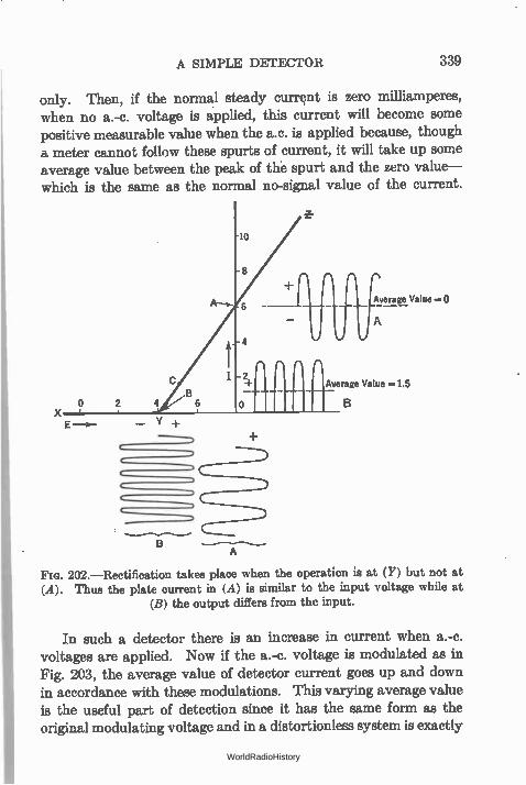
A SIMPLE DETECTOR 339
only. Then, if the normal steady current is zero milliamperes, when no a.-c. voltage is applied, this current will become some positive measurable value when the a.c. is applied because, though a meter cannot follow these spurts of current, it will take up some average value between the peak of thé spurt and the zero value— which is the same as the normal no-signal value of the current.
Y + E
A
Average Value =1.5
202.—Rectification takes place when the operation is at (Y) but not at (A). Thus the plate current in (A) is similar to the input voltage while at
(B) the output differs from the input.
In such a detector there is an increase in current when a.-c. voltages are applied. Now if the a.-c. voltage is modulated as in Fig. 203, the average value of detector current goes up and down in accordance with these modulations. This varying average value is the useful part of detection since it has the same form as the original modulating voltage and in a distortionless system is exactly
WorldRadioHistory
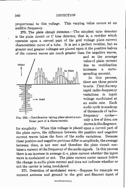
340 DETECTION
proportional to this voltage. This varying value occurs at an audible frequency.
270. The plate circuit detector.—The simplest tube detector is the plate circuit or C bias detector, that is, a rectifier which operates upon a curved part of the grid voltage plate current characteristic curve of a tube. It is not a perfect rectifier, but as greater and greater voltages are placed upon it the positive halves of the current waves are much greater than the negative waves,
and so the average value of plate current
output f due to rectification Av. Value increases a corre-
sponding amount. In this process,
there are three points to note. First the very rapid radio-frequency variations in input
Input voltage modulated at an audio rate. Each audio cycle is made up of thousands of radio-
FIG. 203.—Rectification taking place about a non- frequency cycles—
linear part of a characteristic. only a few of them are shown in the diagrams
for simplicity. When this voltage is placed upon a curved part of the plate curve, the difference between the positive and negative current waves takes the form of the audio variations. Because these positive and negative portions differ in amplitude, the average between them is not zero and therefore the plate circuit con-tains a current of the frequency of the audio signals. In this process there is an increase in average d.-c. plate current whether the input wave is modulated or not. The plate current meter cannot follow the change in audio plate current and does not indicate whether or not the carrier is being modulated.
271. Detection of modulated wave.—Suppose for example we connect antenna and ground to the grid and filament input of
WorldRadioHistory
DETECTION OF MODULATED WAVE 341
a tube. A nearby station is putting into the ether an unmodu-lated wave. As soon as we tune to this station's frequency a voltage is developed across the input circuit to the tube; this a.-c. voltage fluctuates the grid voltage, and a change takes place in the average value of the plate current. If the station is powerful enough, and if it is modulated with a key—that is, if its antenna current is started and stopped in accordance to some code—we can use a sensitive relay in the plate circuit of our detector and either read the signals directly from the relay or operate a telegraph sounder with it, or light a lamp, or fire a gun or do anything else which it is required to control by radio. If the transmitted fre-quency is 1000 kc. it may be necessary to tune the input of the tube to this frequency. A pair of telephones in the plate circuit of the detector, in place of the relay, will indicate by means of clicks when the transmitter started and stopped the antenna current but would not give off any sound in the middle of dots and dashes. If, how-ever, we operated a buzzer with the relay we could read the signals by the audible sound of the buzzer.
We can get around the difficulty of needing a receiving buzzer by having a buzzer or " chopper" at the transmitting station. Now when the key is pressed, the modulated 1000-kc. wave is sent into the ether. If the modulator tone, say 1000 cycles, has a maximum amplitude equal to the maximum value of the 1000-kc. voltage, the antenna current will be doubled 1000 times a second when these two voltages will be in phase. At 1000 other instants the two voltages will be out of phase and the antenna current will be reduced to zero. Across the receiving tube is a 1000-kc. voltage broken up into 1000-cycle sections—modulated as we say.
Now if we place a pair of telephones in the plate circuit of the detector tube, it will offer a certain amount of impedance to these 1000-cycle sections of 1000-kc. currents. A voltage will be built up across the telephones, and our ears will tell us that 1000-cycle signals are being received. The d.-c. plate current meter will still indicate an increase in average plate current when the transmitter key is pressed, but of course its needle cannot follow the 1000-cycle variations. Neither will a relay indicate that the 1000-kc. input is modulated, because it is too sluggish to follow the variations,
WorldRadioHistory
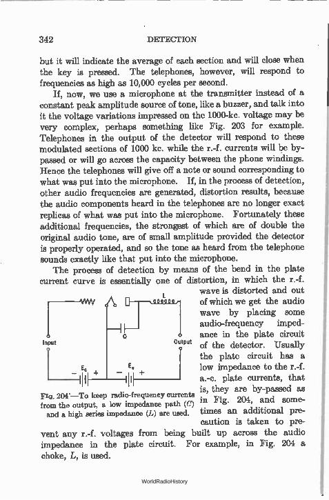
342 DETECTION
but it will indicate the average of each section and will close when the key is pressed. The telephones, however, will respond to frequencies as high as 10,000 cycles per second.
If, now, we use a microphone at the transmitter instead of a constant peak amplitude source of tone, like a buzzer, and talk into it the voltage variations impressed on the 1000-kc. voltage may be very complex, perhaps something like Fig. 203 for example. Telephones in the output of the detector will respond to these modulated sections of 1000 kc. while the r.-f. currents will be by-passed or will go across the capacity between the phone windings. Hence the telephones will give off a note or sound corresponding to what was put into the microphone. If, in the process of detection, other audio frequencies are generated, distortion results, because the audio components heard in the telephones are no longer exact replicas of what was put into the microphone. Fortunately these additional frequencies, the strongest of which are of double the original audio tone, are of small amplitude provided the detector is properly operated, and so the tone as heard from the telephone sounds exactly like that put into the microphone.
The process of detection by means of the bend in the plate current curve is essentially one of distortion, in which the r.-f.
wave is distorted and out VANA of which we get the audio
wave by placing some audio-frequency imped-ance in the plate circuit
Input Output of the detector. Usually
+ impedance the plate circuit has a low pedance to the r.-f. a.-c. plate currents, that
E 1 .
Flo. 204.—To keep radio-frequency currents is, they are by-passed as in from the output, a low impedance path (C) Fig. 204, and some-
and a high series impedance (L) are used. times an additional pre-caution is taken to pre-
vent any r.-f. voltages from being built up across the audio impedance in the plate circuit. For example, in Fig. 204 a choke, L, is used.
WorldRadioHistory
THE VACUUM TUBE VOLTMETER 343
272. Conditions for best detection.—There are several variable factors in such a detector circuit as shown in Fig. 204. One is the grid bias, Ec, and the other is the plate voltage. Some combina-tion of these two voltages will create the greatest amount of a.-f. voltage across a given impedance when a given r.-f. voltage is put on the grid. The C bias is governed to some extent by the ampli-tude of the r.-f. voltages to be put on the grid of the tube.
If an r.-f. voltage of 1 volt maximum is to be impressed on the grid of the tube, a C bias of slightly over this value wlll take care of the signals and offer a certain margin of safety.- The prob-lem then is to find the plate voltage that will put the operating point at a place of great sensitivity. Values for an ordinary tube of the 201-A type are about minus 4 5 with a plate voltage of 45 and minus 9 with a plate voltage of 90.
In such a detector the greater the r.-f. voltage the greater the change in average plate current and the greater the audio signal in the output load. With a given r.-f. voltage the audio signal will be proportional to the amount of modulation at the transmitter. That is, if the power from the radio oscillator at the transmitter is constant but the voltage coming from the microphone varies, the audio notes at the receiver should vary in exact proportion to the microphone notes.
Otherwise there is distortion. The audio notes with a fixed modulation vary approximately as the square of the r.-f. voltage when the latter are small. That is, doubling the radio-frequency voltage across the antenna will result in multiplying by 4 the audio tones from the detector. Actually the square law holds only over the certain small part of the plate current curve, for example: for low input signal voltages. The law is less than a square func-tion for large input voltages. The change in d.-c. current (increase) is independent of the modulation and a meter in the plate circuit will not tell whether or not the r.-f. input is being modulated.
273. The vacuum tube voltmeter.—The detector may be cali-brated and used as an a.-c. voltmeter. Such vacuum tube volt-meters are useful at all audio and nearly all radio frequencies, and can be made to read d.-c. voltages. The range of voltages that can be measured is very large, the upper limit being the voltage the
WorldRadioHistory
344 DETECTION
tube can stand without breaking down, and the lower limit depend-ing upon the sensitivity of the indicating instrument.
The principle of such devices is simple. The operating point is chosen, by adjusting the C bias and the plate voltage, so that it is on a point of considerable curvature. When an a.-c. voltage is put on the grid, rectification takes place in the plate circuit, and the d.-c. part of the rectification product is read on a d.-c. instru-ment. If the voltmeter is properly biased, its input resistance is very high and it takes so little power from the device whose voltage is being measured that it may be considered as having no effect upon the circuit.
The choice of C bias depends upon the input voltages to be measured. Let us suppose we are to measure a peak voltage of 5 volts. Clearly the C bias cannot be less than this because of the decreased input resistance when the grid draws current and the effect of such a meter upon the circuit under measurement. The C bias would be some value over 5 volts, 6 for example. The next step is to fix the plate voltage. This is determined by the range in input volts to be measured, and the kind of instrument used to read the d.-c. current. For greatest accuracy E, should be such that the greatest deflection of the current meter will be obtained by the given input voltage. In general a voltage range of about 5 to 1 is all that can be read with an ordinary voltmeter, that is, from about 0.5 volt to 3.0 volts. The problem then is to choose a plate voltage that will enable the desired range to cover com-pletely the scale of the meter being used.
For measurements of average voltages, say up to 10 or 15 volts and as low as 0.5 or 1.0 volt, a microammeter reading 200 micro-amperes and costing about $35 is a good instrument. A small laboratory model of milliammeter reading 1.0 or 1.5 milliamperes can be used although the accuracy of measurement will not be so great as with a more sensitive instrument.
274. Adjusting a voltmeter.—What is desired is the greatest change in plate current with a given a.-c. voltage. In Fig. 205 are some curves taken with a 3-volt, 60-milliampere tube, showing the plate current at various values of a.-c. grid voltage and at various values of plate voltages. The change in plate current, that
WorldRadioHistory
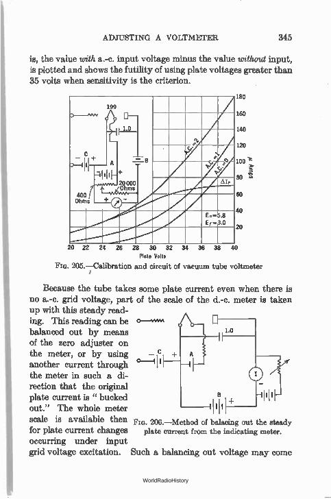
ADJUSTING A VOLTMETER 345
is, the value with a.-c. input voltage minus the value without input, is plotted and shows the futility of using plate voltages greater than 35 volts when sensitivity is the criterion.
199
1.0
set'
C — +
0--1111----
400 Ohms
=Ili
L eve s.,_.uns
i 4- 20000
=9
ci Y
.> o
Pr
LI, lp
Eo 5.8 Ef - 3.0
180
160
140
120
100 -e
3
60
40
20
20 22 24 26 28 30 32 34 36 38 40 Plate Volts
Fla. 205.—Calibration and circuit of vacuum tube voltmeter
Because the tube takes some plate current even when there is no a.-c. grid voltage, part of the scale of the d.-c. meter is taken up with this steady read-ing. This reading can be balanced out by means of the zero adjuster on the meter, or by using _ another current through °_ I' the meter in such a di-rection that the original plate current is " bucked out." The whole meter
scale is available then Fia. 206.—Method of balacing out the steady for plate current changes plate current from the indicating meter.
occurring under input grid voltage excitation. Such a balancing out voltage may come
WorldRadioHistory
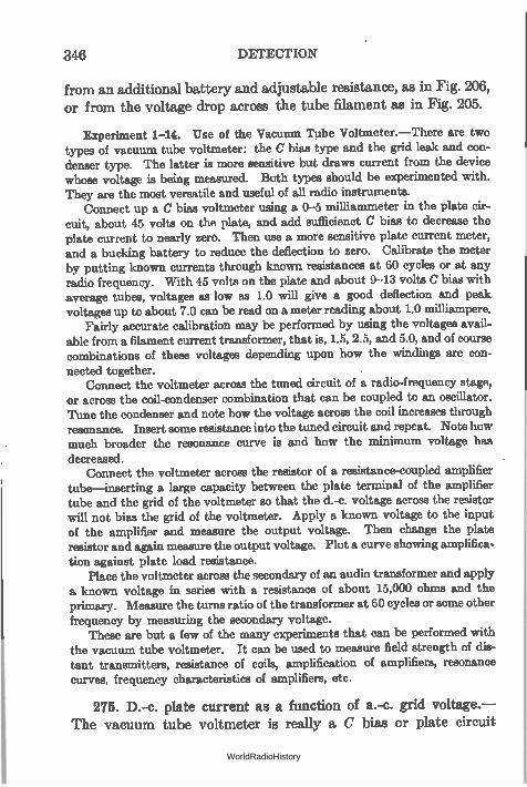
346 DETECTION
from an additional battery and adjustable resistance, as in Fig. 206, or from the voltage drop across the tube filament as in Fig. 205.
Experiment 1-14. Use of the Vacuum Tube Voltmeter.—There are two types of vacuum tube voltmeter: the C bias type and the grid leak and con-denser type. The latter is more sensitive but draws current from the device whose voltage is being measured. Both types should be experimented with. They are the most versatile and useful of all radio instruments.
Connect up a C bias voltmeter using a 0-5 milliammeter in the plate cir-cuit, about 45 volts on the plate, and add sufficienct C bias to decrease the plate current to nearly zero. Then use a more sensitive plate current meter, and a bucking battery to reduce the deflection to zero. Calibrate the meter by putting known currents through known resistances at 60 cycles or at any radio frequency. With 45 volts on the plate and about 9--13 volts C bias with average tubes, voltages as low as 1.0 will give a good deflection and peak voltages up to about 7.0 can be read on a meter reading about 1.0 milliampere.
Fairly accurate calibration may be performed by using the voltages avail-able from a filament current transformer, that is, 1.5, 2.5, and 5.0, and of course combinations of these voltages depending upon how the windings are con-
nected together. Connect the voltmeter across the tuned circuit of a radio-frequency stage,
or across the coil-condenser combination that can be coupled to an oscillator. Tune the condenser and note how the voltage across the coil increases through resonance. Insert some resistance into the tuned circuit and repeat. Note how much broader the resonance curve is and how the minimum voltage has decreased.
Connect the voltmeter across the resistor of a resistance-coupled amplifier
tube—inserting a large capacity between the plate terminal of the amplifier tube and the grid of the voltmeter so that the d.-c. voltage across the resistor will not bias the grid of the voltmeter. Apply a known voltage to the input of the amplifier and measure the output voltage. Then change the plate resistor and again measure the output voltage. Plot a curve showing amplifica-tion against plate load resistance.
Place the voltmeter across the secondary of an audio transformer and apply a known voltage in series with a resistance of about 15,000 ohms and the primary. Measure the turns ratio of the transformer at 60 cycles or some other
frequency by measuring the secondary voltage. These are but a few of the many experiments that can be performed with
the vacuum tube voltmeter. It can be used to measure field strength of dis-tant transmitters, resistance of coils, amplification of amplifiers, resonance curves, frequency characteristics of amplifiers, etc.
275. D.-c. plate current as a function of a.-c. grid voltage.— The vacuum tube voltmeter is really a C bias or plate circuit
WorldRadioHistory
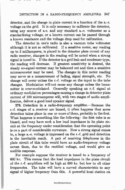
DETECTION IN A RADIO-FREQUENCY AMPLIFIER 347
detector, and the change in plate current is a function of the a.-c. voltage on the grid. It is only necessary to calibrate the detector, using any source of a.c. and any standard a.-c. voltmeter as a standardizing voltage, or a known current can be passed through a known resistance and the voltage drop used for calibration.
The detector in one's radio is also a vacuum tube voltmeter although it is not so calibrated. If a sensitive meter, say reading up to 5 milliamperes, is placed in the detector plate circuit of any radio receiver, changes in the reading will be noted when a strong signal is tuned in. If the detector is a grid leak and condenser type, the reading will decrease. If greatest sensitivity is desired, the steady no-signal current may be balanced out and then a sensitive microammeter may be used. The changes in this meter reading may serve as a measurement of fading, signal strength, etc. No change will occur unless the r.-f. voltage on the input to the tube changes. Modulation will not cause any change unless the trans-mitter is over-modulated. Generally speaking an r.-f. signal at ordinary modulation percentages causing a change in detector plate current of 100 microamperes will, with two stages of audio ampli-fication, deliver a good loud speaker signal.
276. Detection in a radio-frequency amplifier.—Because the r.-f. stages of a receiver are biased, it often happens that some detection takes place in one or more of them, probably in the first. What happens is something like the following: the first tube is so biased, and may have such a low load impedance in its plate cir-cuit at the frequency under consideration that the operating point is on a part of considerable curvature. Now a strong signal comes in, a large a.-c. voltage is impressed on the r.-f. grid and detection is the inevitable result. A pair of receiving tèlephones in the plate circuit of this tube would have an audio-frequency voltage across them, due to the rectified voltage, and would give an audible response.
For example suppose the receiver is tuned to a frequency of 600 kc. This means that the load impedance in the plate circuit of the r.-f. amplifiers will be high at 600 kc. but low to all other frequencies. The tube will have a curved characteristic to any signal of higher frequency than this. A powerful local station on
WorldRadioHistory
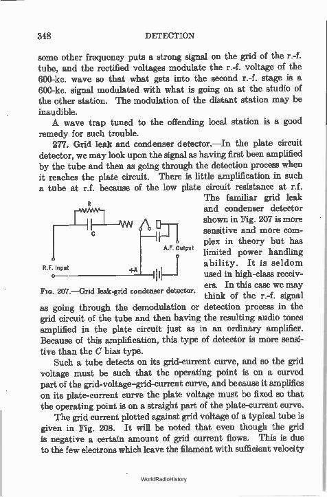
some other frequency puts a strong signal on the grid of the r.-f. tube, and the rectified voltages modulate the r.-f. voltage of the 600-kc. wave so that what gets into the second r.-f. stage is a 600-kc. signal modulated with what is going on at the studio of the other station. The modulation of the distant station may be inaudible. A wave trap tuned to the offending local station is a good
remedy for such trouble. 277. Grid leak and condenser detector.—In the plate circuit
detector, we may look upon the signal as having first been amplified by the tube and then as going through the detection process when it reaches the plate circuit. There is little amplification in such a tube at r.f. because of the low plate circuit resistance at r.f.
The familiar grid leak and condenser detector shown in Fig. 207 is more sensitive and more com-plex in theory but has
A.F. Output limited power handling R F. Input r I ability. It is seldom
used in high-class receiv-ers. In this case we may think of the r.-f. signal
as going through the demodulation or detection process in the grid circuit of the tube and then having the resulting audio tones amplified in the plate circuit just as in an ordinary amplifier. Because of this amplification, this type of detector is more sensi-tive than the C bias type.
Such a tube detects on its grid-current curve, and so the grid voltage must be such that the operating point is on a curved part of the grid-voltage-grid-current curve, and because it amplifies on its plate-current curve the plate voltage must be fixed so that the operating point is on a straight part of the plate-current curve.
The grid current plotted against grid voltage of a typical tube is given in Fig. 208. It will be noted that even though the grid is negative a certain amount of grid current flows. This is due to the few electrons which leave the filament with sufficient velocity
348 DETECTION
+A
Fla. 207.—Grid leak-grid condenser detector.
WorldRadioHistory
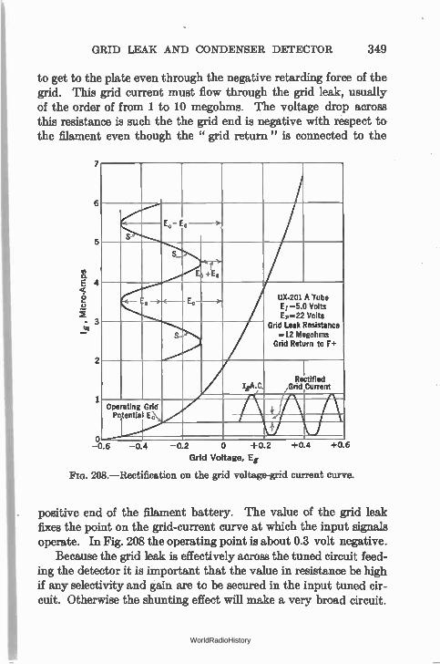
GRID LEAK AND CONDENSER DETECTOR 349
to get to the plate even through the negative retarding force of the grid. This grid current must flow through the grid leak, usually of the order of from 1 to 10 megohms. The voltage drop across this resistance is such the the grid end is negative with respect to the filament even though the " grid return" is connected to the
te
7
6
5
0 -0.4 -02 0 +02
Grid Voltage, Eg
208.— Rectification on the grid voltage-grid current curve.
Ec, E,
S
---
S
E, +E.
, —).-c-- , —).-c-- E„---ii- UX-201 A Tube Ef -5.0 Volts Er-22 Volts
Grid Leak Resistance =12 Megohms
Grid Return to F+
ii.A.C. /V\I\ Rectified Grid Current
Ope Potentia
ating Grid Ec,
+
positive end of the filament battery. The value of the grid leak fixes the point on the grid-current curve at which the input signals operate. In Fig. 208 the operating point is about 0.3 volt negative.
Because the grid leak is effectively across the tuned circuit feed-ing the detector it is important that the value in resistance be high if any selectivity and gain are to be secured in the input tuned cir-cuit. Otherwise the shunting effect will make a very broad circuit.
+0.6 +04
WorldRadioHistory
350 DETECTION
278. Effect of grid leak and condenser values.—Changes in grid leak value produce no other change in the detector action than is produced by changing the operating point. This is the entire purpose of the grid leak. The purpose of the grid condenser is to by-pass the high resistance so far as r.-f. currents are con-cerned so that the greatest possible r.-f. voltage may be built up across the grid-filament input of the tube. If the condenser is too small, there will be an appreciable r.-f. voltage loss in it, and the tube will not get all possible of the input signal. If the grid con-denser is too large, the audio-frequency voltages built up across the grid leak will be by-passed. The grid condenser with modern types of tubes should never be greater than 0.00025 mfd. and a value of 0.0001 may be used satisfactorily. Smaller condensers than this produce some loss in r.-f. voltage, and result in de-creased sensitivity.
279. Detector action.—When an input signal is applied to the tube the grid voltage changes in accordance with the incoming signal just as it does in the case of an amplifier or a plate current detector. These changes in grid voltage produce a change in grid current in accordance with movements up and down on the curve of Fig. 208. Because of the curvature the grid current increases more when the grid is positive than it decreases during the negative half-cycles of input voltage. The result is a net change in grid current, in this case an increase. This increase in grid current pro-duces an increased voltage drop across the grid leak and a greater negative voltage in the grid. This increase in bias causes a decrease in plate current. It will be remembered that an input signal caused an increase in plate current in the plate circuit detector. These audio grid current changes produce corresponding plate current changes whence they are passed on to the audio amplifier.
In practice, then, modulated r.f. voltages are put on the input to a detector; within this detector the modulations are separated from the carrier that brought them to the receiver; and finally these modulations in the form of a.f. frequencies are applied to a plate-circuit load—usually the input to an a.f. amplifier.
How this separation of carrier from modulation takes place, and how much a.f. one gets out of a given detector with a given input
WorldRadioHistory
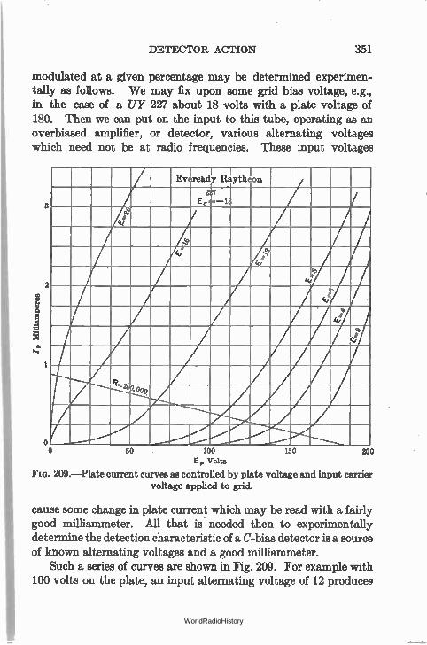
DETECTOR ACTION 351
modulated at a given percentage may be determined experimen-tally as follows. We may fix upon some grid bias voltage, e.g., in the case of a UY 227 about 18 volts with a plate voltage of 180. Then we can put on the input to this tube, operating as an overbiased amplifier, or detector, various alternating voltages which need not be at radio frequencies. These input voltages
oo
Ev ready Rayth
21.7
60 100
EF, Volts
Fin. 209.—Plate current curves as controlled by plate voltage and input carrier voltage applied to grid.
eon
ze.
150 200
cause some change in plate current which may be read with a fairly good milliammeter. All that is needed then to experimentally determine the detection characteristic of a C-bias detector is a source of known alternating voltages and a good milliammeter.
Such a series of curves are shown in Fig. 209. For example with 100 volts on the plate, an input alternating voltage of 12 produces
WorldRadioHistory
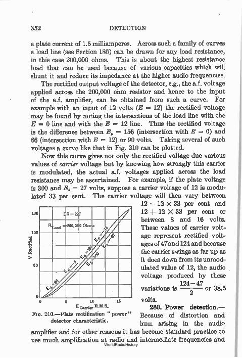
352 DETECTION
a plate current of 1.5 milliamperes. Across such a family of curves a load line (see Section 186) can be drawn for any load resistance, in this case 200,000 ohms. This is about the highest resistance load that can be used because of various capacities which will shunt it and reduce its impedance at the higher audio frequencies.
The rectified output voltage of the detector, e.g., the a.f. voltage applied across the 200,000 ohm resistor and hence to the input of the a.f. amplifier, can be obtained from such a curve. For example with an input of 12 volts (E = 12) the rectified voltage may be found by noting the intersections of the load line with the E = 0 line and with the E = 12 line. Thus the rectified voltage is the difference between Ez, = 156 (intersection with E = 0) and 66 (intersection with E = 12) or 90 volts. Taking several of such voltages a curve like that in Fig. 210 can be plotted.
Now this curve gives not only the rectified voltage due various values of carrier voltage but by knowing how strongly this carrier is modulated, the actual a.f. voltages applied across the load resistance may be ascertained. For example, if the plate voltage is 300 and Ec =- 27 volts, suppose a carrier voltage of 12 is modu-lated 33 per cent. The carrier voltage will then vary between
12 — 12 X 33 per cent and
between 8 and 16 volts. 12 -F 12 X 33 per cent or
These values of carrier volt-
130 -227
O Ohrra %
loo / e e age represent rectified volt-
rà G--- ages of 47 and 124 and because e, a e the carrier swings as far up as > it does down from its unmod-
60 ulated value of 12, the audio voltage produced by these
variations is 124 —47 or 38.5 2
<c, o
5 10 volts.
E Carrier R.M.S. 280. Power detection.-210.—Plate rectification " power " Because of distortion and
detector characteristic. hum arising in the audio
amplifier and for other reasons it has become standard practice to use much amplification at radio and intermediate frequencies and
WorldRadioHistory
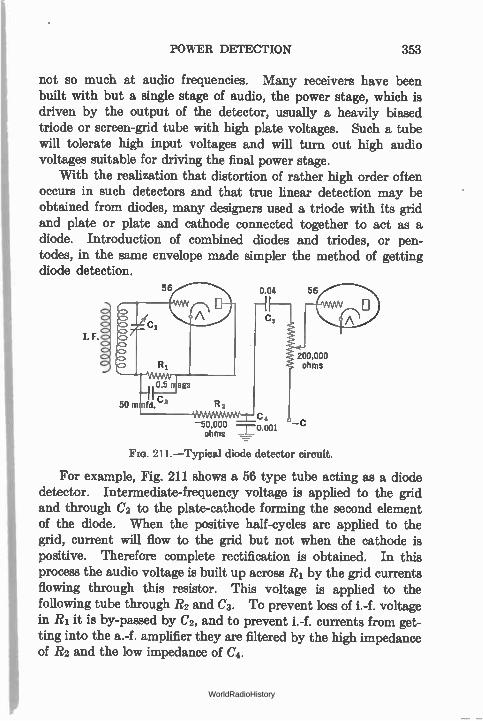
POWER DETECTION 353
not so much at audio frequencies. Many receivers have been built with but a single stage of audio, the power stage, which is driven by the output of the detector, usually a heavily biased triode or screen-grid tube with high plate voltages. Such a tube will tolerate high input voltages and will turn out high audio voltages suitable for driving the final power stage.
With the realization that distortion of rather high order often occurs in such detectors and that true linear detection may be obtained from diodes, many designers used a triode with its grid and plate or plate and cathode connected together to act as a diode. Introduction of combined diodes and triodes, or pen-todes, in the same envelope made simpler the method of getting diode detection.
I. F.
56
105 rtlegs C 50 mmfd. 2 R 2
0.04 56
MAMMA,W,W=C 4
- 50,000 —r-0.001 ohms
200.000 ohms
Fro. 211.—Typical diode detector circuit.
For example, Fig. 211 shows a 56 type tube acting as a diode detector. Intermediate-frequency voltage is applied to the grid and through C2 to the plate-cathode forming the second element of the diode. When the positive half-cycles are applied to the grid, current will flow to the grid but not when the cathode is positive. Therefore complete rectification is obtained. In this process the audio voltage is built up across R1 by the grid currents flowing through this resistor. This voltage is applied to the following tube through R2 and C3. To prevent loss of i.-f. voltage in RI it is by-passed by C2, and to prevent i.-f. currents from get-ting into the a.-f. amplifier they are filtered by the high impedance of R2 and the low impedance of C4.
WorldRadioHistory
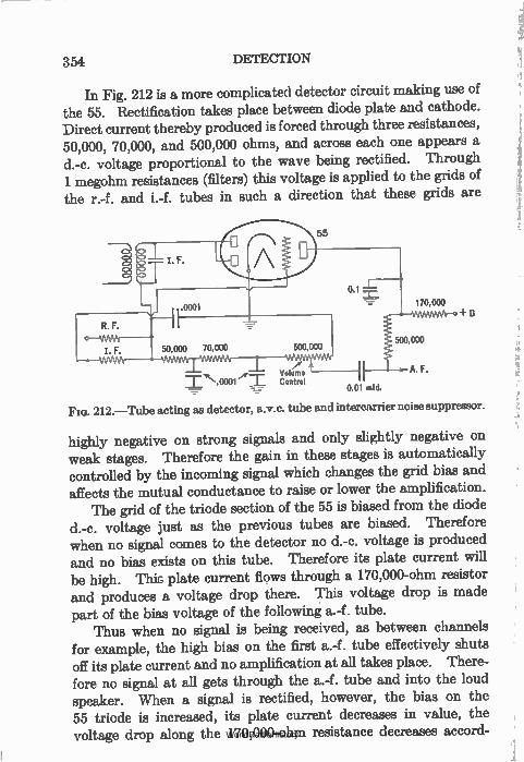
354 DETECTION
In Fig. 212 is a more complicated detector circuit making use of the 55. Rectification takes place between diode plate and cathode. Direct current thereby produced is forced through three resistances, 50,000, 70,000, and 500,000 ohms, and across each one appears a d.-c. voltage proportional to the wave being rectified. Through 1 megohm resistances (filters) this voltage is applied to the grids of the r.-f. and i.-f. tubes in such a direction that these grids are
1:3
••• Volume Control
0.01 mid.
212.—Tube acting as detector, a.v.c. tube and intercarrier noise suppressor.
highly negative on strong signals and only slightly negative on weak stages. Therefore the gain in these stages is automatically controlled by the incoming signal which changes the grid bias and affects the mutual conductance to raise or lower the amplification.
The grid of the triode section of the 55 is biased from the diode d.-c. voltage just as the previous tubes are biased. Therefore when no signal comes to the detector no d.-c. voltage is produced and no bias exists on this tube. Therefore its plate current will be high. This plate current flows through a 170,000-ohm resistor and produces a voltage drop there. This voltage drop is made part of the bias voltage of the following a.-f. tube.
Thus when no signal is being received, as between channels for example, the high bias on the first a.-f. tube effectively shuts off its plate current and no amplification at all takes place. There-fore no signal at all gets through the a.-f. tube and into the loud speaker. When a signal is rectified, however, the bias on the 55 triode is increased, its plate current decreases in value, the voltage drop along the 170,000-ohm resistance decreases accord-
lj
WorldRadioHistory
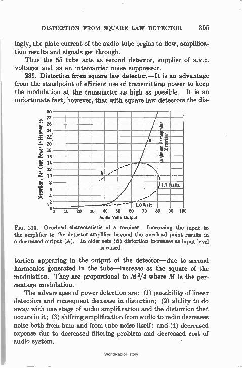
DISTORTION FROM SQUARE LAW DETECTOR 355
ingly, the plate current of the audio tube begins to flow, amplifica-tion results and signals get through.
Thus the 55 tube acts as second detector, supplier of a.v.c. voltages and as an intercarrier noise suppressor.
281. Distortion from square law detector.—It is an advantage from the standpoint of efficient use of transmitting power to keep the modulation at the transmitter as high as possible. It is an unfortunate fact, however that with square law detectors the dis-
Dist
orti
on,
Per Cent P
ower
in Ha
rmon
ics
30 28
26
24
22
20
18
16
14
12
10
8
6
4
o
a., .o i.... a .
8 ,:ii .g E r e e -- _,........_ ,,,,
A .'' '., ,
À1.7 Watts
2-11.0
i ...,
..--•{ Watt
10 20 30 40 50 60
Audio Volts Output
70 80 90 100
FIG. 213.—Overload characteristic of a receiver. Increasing the input to the amplifier to the detector-amplifier beyond the overload point results in a decreased output (A). In older sets (B) distortion increases as input level
is raised.
tortion appearing in the output of the detector—due to second harmonics generated in the tube—increase as the square of the modulation. They are proportional to M 2/4 where M is the per-centage modulation.
The advantages of power detection are: (1) possibility of linear detection and consequent decrease in distortion; (2) ability to do away with one stage of audio amplification and the distortion that occurs in it; (3) shifting amplification from audio to radio decreases noise both from hum and from tube noise itself; and (4) decreased expense due to decreased filtering problem and decreased cost of audio system.
WorldRadioHistory
CHAPTER XV
RECEIVING SYSTEMS
THERE are two general types of receiving circuits in use: (1) the tuned r.-f. receiver; and (2) the superheterodyne. There are other systems such as the simple regenerative circuit of many types, and the super-regenerator in which the circuit is allowed to build up almost to the oscillation point and is then quenched. The simple regenerative set has almost passed out of existence; the super-regenerator has not as yet come into wide use.
282. The tuned radio-frequency set.—This type of circuit was once most popular. Until the owners of the superheterodyne patent permitted its wide use, the tuned r.-f. set was the only one that could be generally sold. It suffered from various faults; poor selectivity at high radio frequencies, and excessive selectivity and low gain at the lower frequencies. Until the Neutrodyne was exploited the t.r.f. set was unstable and had low sensitivity.
For a time this circuit was not so popular as the super; then the desire for very small inexpensive sets coupled with the develop-ment of better tubes and some circuit features brought the t.r.f. set back into popularity. Further development of the iron-cored r.-f. transformers with the ability to tune a circuit by inductance variation may make the t.r.f. set once more the standard.
283. The superheterodyne.—The double detector or super-heterodyne circuit operates on a very interesting principle. It has inherently more sensitivity than the t.r.f. set and is more selective.
The stage gain possible, with stability, at broadcast or higher frequencies is not sufficient to make a really sensitive receiver unless several stages are employed. For a number of reasons much greater amplification can be obtained at lower signal
356
WorldRadioHistory
THE PHENOMENON OF BEATS 357
frequencies. If, then, we can change ah incoming frequency of say 1000 kc. to 100 or even 50 kc., we can get as much amplification in two stages as are obtained from four stages at the original fre-quency. This means simplification in apparatus, and because of the lower frequencies the problems of stability and shielding are also simplified. An additional advantage lies in the constant band width passed by the amplifier, regardless of the frequency of the incoming signal. How is such a frequency change performed?
284. The phenomenon of beats.—Suppose two loud speakers are attached to two oscillators, one generating a 1000-cycle tone and the other an 1800-cycle tone. When these two tones enter the ear, the listener hears not only the two individual tones but an 800-cycle tone too. If one of the two original tones is modulated at another frequency, say 50 cycles at a given per cent, this 800-cycle tone will be so modulated. By turning this modulated 800-cycle tone into a demodulator, the 50-cycle modulations can be got back.
The two frequencies above are said to beat with each other and the difference frequency is called the beat note. If the two oscil-lators are adjusted so that they are at zero beat they have the same frequency and no beat note will be heard. In addition to the two beating frequencies and the difference of the two (the difference or beat frequency) there is a third frequency generated. This is the sum of the two beating frequencies. It is called the sum frequency. Thus in the above case there are in the ear 1800-, 1000-, 800- and 2800-cycle tones.
Now suppose we are receiving a 1000-kc. signal and want to turn it into a 100-kc. signal. All we need is a local oscillator which turns out either 1100-kc. or .900-kc. signals. We turn these two signals into a mixing tube where the difference or beat frequency is generated, put its output through a filter which cuts off every-thing but the 100-kc. signal (which is now modulated at the same modulations as the incoming 1000-kc. signal), and amplify it in an intermediate-frequency amplifier. After sufficient amplification has been attained the 100-kc. signal is put through a demodulator and the original microphone modulations secured. These fre-quencies can be put through an audio-frequency amplifier of con-
WorldRadioHistory
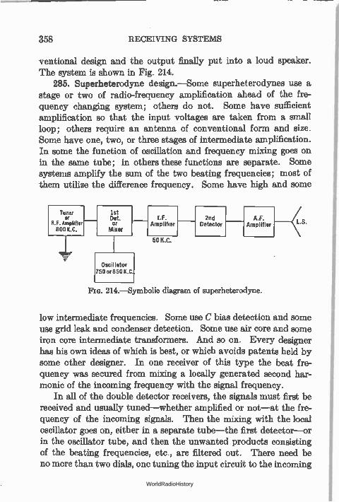
358 RECEIVING SYSTEMS
ventional design and the output finally put into a loud speaker. The system is shown in Fig. 214.
285. Superheterodyne design.—Some superheterodynes use a stage or two of radio-frequency amplification ahead of the fre-quency changing system; others do not. Some have sufficient amplification so that the input voltages are taken from a small loop; others require an antenna of conventional form and size. Some have one, two, or three stages of intermediate amplification. In some the function of oscillation and frequency mixing goes on in the same tube; in others these functions are separate. Some systems amplify the sum of the two beating frequencies; most of them utilize the difference frequency. Some have high and some
Tuner or
8.1. Amplifier 800 K.C.
1st Det. Or
Mixer
Oscillator 750 or 850 K.C.
1.F. Amplifier
50 K.C.
2nd Detector
A.F. Amplifier
214.—Symbolic diagram of superheterodyne.
low intermediate frequencies. Some use C bias detection and some use grid leak and condenser detection. Some use air core and some iron core intermediate transformers. And so on. Every designer has his own ideas of which is best, or which avoids patents held by some other designer. In one receiver of this type the beat fre-quency was secured from mixing a locally generated second har-monic of the incoming frequency with the signal frequency.
In all of the double detector receivers, the signals must first be received and usually tuned—whether amplified or not—at the fre-quency of the incoming signals. Then the mixing with the local oscillator goes on, either in a separate tube—the first detector—or in the oscillator tube, and then the unwanted products consisting of the beating frequencies, etc., are filtered out. There need be no more than two dials, one tuning the input circuit to the incoming
WorldRadioHistory
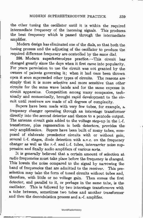
MODERN SUPERHETERODYNE PRACTICE 359,
the other tuning the oscillator until it is within the required intermediate frequency of the incoming signals. This produces. the beat frequency which is passed through the intermediate amplifier.
Modern design has eliminated one of the dials, so that both the tuning process and the adjusting of the oscillator to produce the required difference frequency are controlled by the same dial.
286. Modern superheterodyne practice.—This circuit has changed greatly since the days when it first came into popularity. For years permission to use the circuit was not granted by the owners of patents governing it; when it had once been thrown open it soon superseded other types of circuits. The reasons are simply that it is more selective and more sensitive than other circuits for the same wave bands and for the same expense in circuit apparatus. Competition among many companies, tech-nically and economically, brought rapid development to the cir-cuit until receivers are made of all degrees of complexity.
Supers have been made with very few tubes, for example, a. frequency changer operating through an interstage transformer directly into the second detector and thence to a pentode output. The antenna circuit gain added to the voltage step-up in the i.-f. transformer, plus regeneration in both detectors, provides the only amplification. Supers have been built of many tubes, com-posed of elaborate preselector circuits with or without gain, several i.-f. stages, diode detection with a.v.c. on the frequency changer as well as the r.-f. and i.-f. tubes, intercaffier noise sup-pression and finally audio amplifiers of various sorts.
It is generally believed that a certain amount of selection at radio frequencies must take place before the frequency is changed. This lowers the noise compared to the signal by narrowing the band of frequencies that are admitted to the receiver. This pre-selection may take the form of tuned circuits without tubes and, therefore, with little or no voltage gain. Then comes the first detector, and parallel to it, or perhaps in the same tube, is the oscillator. This is followed by two interstage transform.trs with a tube between, sometimes two tubes and another transformer and then the demodulation process and a.-f. amplifier.
WorldRadioHistory
360 RECEIVING SYSTEMS
Considerable use has been made of antenna coils in which the primary has a high inductance tending to resonate the system to a frequency below the lowest radio frequency to be received. This brings up the sensitivity of the receiver at the lower end of the tuning range and flattens out the reception characteristic.
Radio-frequency coils are usually made of Litz wire to sharpen these preselecting circuits. The intermediate stages are some-times of Litz, but in general more than sufficient selectivity is obtainable at intermediate frequencies with solid wire coils. Oscillator circuits have been worked out which give uniform out-put over the tunable range. The i.-f. coils are usually tuned both on the primary and secondary sides in an effort to broaden out the top of the response and not cut high frequencies too much.
400
0 —40 —30 —20 —15 —10 0 5 10
Control Grid Volts Oscillator Peak Volts
PIG. 215.—First detector characteristics—type 35 with 250 volts on plate, 90 volts on screen. Left curve with oscillator voltage of 4.6 rms.
The curve in Fig. 215 gives a new type of measurement, the ratio of the i.-f. current in the first detector plate circuit to the r.-f. signal voltage on the grid. This gives a measure of the effi-ciency of the 35 variable-mu tube, as a frequency converter. The figure also shows the ability to control the sensitivity of the frequency-changing function by increasing the negative bias on the grid of the tube. This function may be automatically con-trolled by the strength of the incoming signals.
WorldRadioHistory
REPEAT POINTS 361
287. Repeat points.—Early receivers suffered from many faults. The ability, or the curse, of getting a given station at more than two points on the tuning dial was one of these faults.
Suppose that the beat or intermediate frequency is 50 kc. and that a station on 600 kc. is to be received. Now the oscillator can be set at either 600 plus or 600 minus 50 kc. to produce the required beat frequency which will carry with it the modulation into the i.-f. amplifier. Therefore, the operator can tune in the desired station at two points on his oscillator dial.
This trouble is avoided by tuning the input to the set at the same time that the oscillator is tuned and making the input circuits so sharp that when the input is tuned away from the 600-kc. station by twice the intermediate frequency such a small voltage will get into the receiver that the signal will not be heard.
It is general practice to make the oscillator generate frequencies higher than the incoming frequency. Thus if the intermediate frequency is 50 kc. the range will be from 550 plus 50 kc. to 1500 plus 50 kc. or the oscillator will tune from 600 kc. to 1550 kc. at the same time that the input circuits are tuned from 550 to 1500 kc.
As a typical example suppose that an 800-kc. station is to be received. The input will be tuned to this frequency; the oscil-lator to 850 kc. But if the input is tuned to 700 kc. and the oscillator to 750 kc. the required difference of 50 kc. will exist between the 800-kc. station and the local oscillator. Therefore, unless the input circuits are sharply tuned so that the station will produce little voltage when the set is tuned 100 kc. away from the station, trouble will exist with repeat points.
Furthermore, consider the set tuned to 800 kc. (oscillator to 850 kc.). Now suppose a local station to be operating on 700 kc. Between this undesired station and the oscillator will be a 50-kc. difference, and unless there is sufficient selectivity in the input both stations will be heard. This is called " image frequency" trouble, the channel differing from the desired station by twice the intermediate frequency being called the image frequency.
There is still another cause for repeat points. If the oscillator generates harmonics, they may heterodyne a higher frequency incoming signal according to the following reason. Suppose the oscillator is set at 600 kc. but generates a strong second harmonic,
WorldRadioHistory
362 RECEIVING SYSTEMS
1200 kc. This harmonic will provide the proper 50-kc. beat note with either a 1150- or a 1250-kc. station at the same time the funda-mental heterodynes a 550 or 650 station. Such harmonics can be reduced by making the oscillations feeble, by reducing the plate voltage or by placing a large resistance in the plate circuit to make its characteristic straight, or by giving the grid the proper bias.
Let us suppose, however, that the beat frequency is 600 kc. The oscillator frequency range must be from 550 plus 600, or 1150 kc., to 1500 plus 600 or 2100 kc., and there will be no repeat points due to heterodyning two incoming signals to give the required 600-kc. beat frequency.
The use of a radio-frequency amplifier ahead of the frequency system will provide considerable discrimination against unwanted stations. It must be tuned to the required station at the same time the oscillator is tuned so that it gives the required beat fre-quency. Increased selectivity in the r.-f. amplifier will provide selectivity not only against image frequencies, but also against stations differing from the desired station by the intermediate frequency, and will add something to the " adjacent channel" selectivity which is largely secured from the i.-f. amplifier.
Thus it has become standard practice to use two or three stages of tuned radio frequency ahead of the frequency changer in high-class supers. There are still other sources of interference, for example harmonics of the oscillator heterodyning undesired stations or harmonics generated in the second detector, etc.
288. Choice of intermediate frequency.—When preceded by some preselection, the chance of image-frequency trouble decreases as the intermediate frequency increases. At the same time the chance of trouble from stations separated from the desired station by the intermediate frequency is decreased. For these reasons it is desirable to have a high intermediate frequency.
With a low intermediate frequency the chances of harmonic troubles due to energy from the second detector getting back to the input of the set are lessened because only the higher, and weaker, harmonics would fall in the broadcast band. At the same time, lower frequencies are amplified better in the i.-f. amplifier. And, finally, more selectivity against adjacent channels can be obtained if the intermediate frequency is low.
WorldRadioHistory
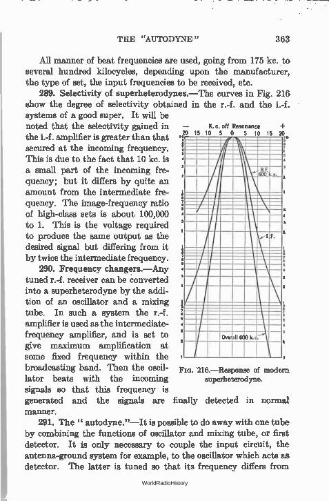
THE "AUTODYNE " 363
All manner of beat frequencies are used, going from 175 kc. to several hundred kilocycles, depending upon the manufacturer, the type of set, the input frequencies to be received, etc.
289. Selectivity of superheterodynes.—The curves in Fig. 216 show the degree of selectivity obtained in the r.-f. and the i.-f. systems of a good super. It will be noted that the selectivity gained in K. c. off Resonance
jo 15 10 5 0 5 10 15 20 the i.-f. amplifier is greater than that secured at the incoming frequency. :6
3
This is due to the fact that 10 kc. is a small part of the incoming fre-quency; but it differs by quite an amount from the intermediate fre-quency. The image-frequency ratio 5 of high-class sets is about 100,000
1 to 1. This is the voltage required 2 to produce the same output as the I F. desired signal but differing from it 5 by twice the intermediate frequency. 5
290. Frequency changers.—Any 4
tuned r.-f. receiver can be converted into a superheterodyne by the addi-tion of an oscillator and a mixing tube. In such a system the r.-f. amplifier is used as the intermediate-frequency amplifier, and is set to give maximum amplification at some fixed frequency within the broadcasting band. Then the oscil- FIG. 216.—Response of modern
lator beats with the incoming superheterodyne.
signals so that this frequency is generated and the signals are finally detected in normal manner.
291. The " autodyne."—It is possible to do away with one tube by combining the functions of oscillator and mixing tube, or first detector. It is only necessary to couple the input circuit, the antenna-ground system for example, to the oscillator which acts as. detector. The latter is tuned so that its frequency differs from
Overall 600 ka;
WorldRadioHistory
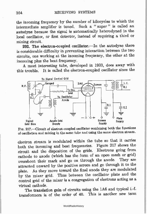
364 RECEIVING SYSTEMS
the incoming frequency by the number of kilocycles to which the intermediate amplifier is tuned. Such a " super" is called an autodyne because the signal is automatically heterodyned in the local oscillator, or first detector, instead of requiring a third or mixing circuit.
292. The electron-coupled oscillator.—In the autodyne there is considerable difficulty in preventing interaction between the two circuits, one working at the incoming frequency, the other at the incoming plus the beat frequency. A most interesting tube, developed in 1933, does away with
this trouble. It is called the electron-coupled oscillator since the
To Signal Control Grid
R.F.
o Signal
Grid Bias
1--0.1
o — o o 0 Mode Grid Screen
Supply Supply
Plate Supply
217.—Circuit of electron-coupled oscillator combining both the functions of oscillation and mixing in the same tube and using the same electron stream.
electron stream is modulated within the tube so that it carries both the incoming and beat frequencies. Figure 217 shows the circuit and the disposition of the grids. Electrons going from cathode to anode (which has the form of an open mesh or grid) overshoot their mark and go on through the anode. They are attracted onward by the positive screen and go through it to the plate. As they move toward the final anode they are modulated by the mixer grid. Thus between the oscillator plate and the control grid of the mixer is a congregation of electrons acting as a
virtual cathode. The translation gain of circuits using the 1A6 and typical i.-f.
transformers is of the order of 40. This is another new term
WorldRadioHistory
SHORT-WAVE RECEIVER CIRCUITS 365
produced by the modern tubes and circuits. It is the gain in converting radio frequency to intermediate frequency. Thus a microvolt of radio frequency put into the frequency changer becomes 40 microvolts of intermediate frequency in the output.
293. " Short-wave" receivers.—The majority of the traffic carried on in the higher frequency bands, from 1500 to 15,000 kc., is in code and it is not necessary to transmit a very wide range of frequencies to convey good signals.
The usual short-wave receiver for code reception consists of an " autodyne " detector, that is, an oscillating detector which is detuned from the incoming signal by about 1000 cycles. The plate circuit has a low impedance to both the locally generated and the incoming frequency but a high impedance to the 1000-cycle note which is amplified by an ordinary audio amplifier and then,passed into a pair of head phones. Frequently, one or more screen-grid tubes are used between the detector and the antenna, to provide somewhat greater amplification, to prevent interaction between antenna and detector, and to prevent oscillations in the detector circuit from getting into the antenna and being radiated from it.
Of course it is possible to make the beat frequency between the detector oscillation and the incoming signal some intermediate fre-quency and to pass it into an intermediate-frequency amplifier. Many of the short-wave " adapters " consist of such apparatus. The intermediate-frequency amplifier can be the usual radio-fre-quency amplifier from a broadcast receiver. To receive short-wave signals on a super designed for broadcast frequencies, it is only necessary to have a second input circuit, or taps on the broad-cast input circuit, to reduce the wavelengths it tunes to.
Other adapters are merely oscillating detectors which are plugged into the detector socket of a broadcast receiver. The tube gets its filament and plate voltage from this socket, and passes its 1000-cycle beat note into the audio amplifier of the broadcast receiver.
294. Short-wave receiver circuits.—The short-wave receiver detector can be made to oscillate in any of the standard regenera-tive circuits. Since the detector is to work at very high frequencies where any stray capacities or shunt paths become of great impor-
WorldRadioHistory
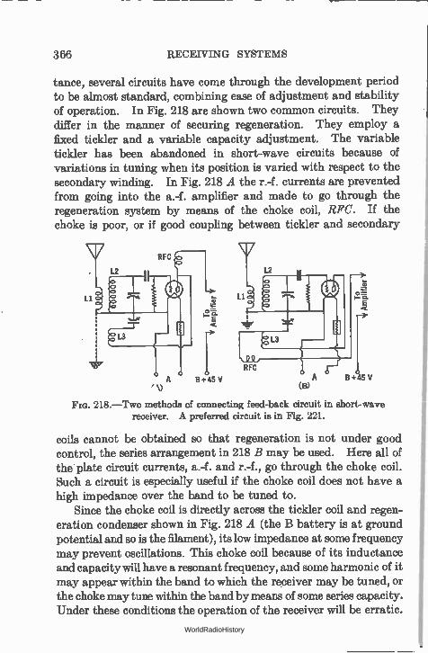
366 RECEIVING SYSTEMS
tance, several circuits have come through the development period to be almost standard, combining ease of adjustment and stability of operation. In Fig. 218 are shown two common circuits. They differ in the manner of securing regeneration. They employ a fixed tickler and a variable capacity adjustment. The variable tickler has been abandoned in short-wave circuits because of variations in tuning when its position is varied with respect to the secondary winding. In Fig. 218 A the r.-f. currents are prevented from going into the a.-f. amplifier and made to go through the regeneration system by means of the choke coil, RFC. If the choke is poor, or if good coupling between tickler and secondary
RFC
L2 12
Li
L3
e‘)
o= E
A 5+45 V
Li
RFC
13
(le
o r-E
B + 45 V
Fm. 218.—Two methods of connecting feed-back circuit in short-wave receiver. A preferred circuit is in Fig. 221.
coils cannot be obtained so that regeneration is not under good control, the series arrangement in 218 B may be used. Here all of the plate circuit currents, a.-f. and r.-f., go through the choke coil. Such a circuit is especially useful if the choke coil does not have a high impedance over the band to be tuned to.
Since the choke coil is directly across the tickler coil and regen-eration condenser shown in Fig. 218 A (the B battery is at ground potential and so is the filament), its low impedance at some frequency may prevent oscillations. This choke coil because of its inductance and capacity will have a resonant frequency, and some harmonic of it may appear within the band to which the receiver may be tuned, or the choke may tune within the band by means of some series capacity. Under these conditions the operation of the receiver will be erratic.
WorldRadioHistory
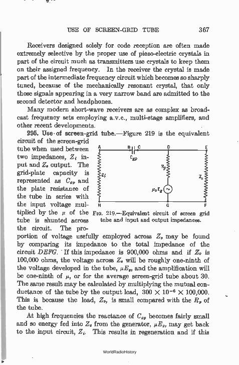
USE OF SCREEN-GRID TUBE 367
Receivers designed solely for code reception are often made extremely selective by the proper use of piezo-electric crystals in part of the circuit much as transmitters use crystals to keep them on their assigned frequency. In the receiver the crystal is made part of the intermediate frequency circuit which becomes so sharply tuned, because of the mechanically resonant crystal, that only those signals appearing in a very narrow band are admitted to the second detector and headphones.
Many modern short-wave receivers are as complex as broad-cast frequency sets employing a.v.c., multi-stage amplifiers, and other recent developments.
295. Use• of screen-grid tube.—Figure 219 is the equivalent circuit of the screen-grid tube when used between B C
two impedances, Zi in-put and Z. output. The grid-plate capacity is represented as C„ and the plate resistance of the tube in series with the input voltage mul-tiplied by the u of the no. 219.—Equivalent circuit of screen grid
tube is shunted across tube and input and output impedances.
the circuit. The pro-portion of voltage usefully employed across Z. may be found by comparing its impedance to the total impedance of the circuit DEFG. - If this impedance is 900,000 ohms and if Zo is 100,000 ohms, the voltage across Zo will be roughly one-ninth of the voltage developed in the tube, pen and the amplification will be one-ninth of µ, or for the average screen-grid tube about 30. The same result may be calculated by multiplying the mutual con-ductance of the tube by the output load, 300 X 10-6 X 100,000. This is because the load, Z., is small compared with the 14 of the tube.
At high frequencies the reactance of C„ becomes fairly small and so energy fed into Z. from the generator, 1.4E,, may get back to the input circuit, Z. This results in regeneration and if this
H G F
WorldRadioHistory
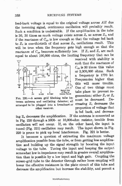
368 RECEIVING SYSTEMS
feed-back voltage is equal to the original voltage across AH due the incoming signal, continuous oscillation will probably result. Such a condition is undesirable. If the amplification in the tube is 30, 30 times as much voltage exists across Z. as across Z, and if the reactance of CO, is low enough so that the voltage fed back to Zi is one-thirtieth of that across Z0, oscillations result. This will be true when the frequency gets high enough so that the reactance of C„ becomes sufficiently low. If Zi and Z. are each equal to about 100,000 ohms, the limiting frequency that can be
received with stability is C2 1.4 such that the reactance of
C„ is 30 times this value or 3,000,000 ohms. Such a frequency is 1770 kc. Frequencies higher than this will cause trouble.
CL o One of two things must Bottom View of Plug for take place to prevent re-
Detector Socket generation: either Zi or Z. must be decreased. De-creasing Zi decreases the proportion of voltage that is fed back, and decreas-
ing Z,, decreases the amplification. If the antenna is connected as in Fig. 220 through a 5000- or 10,000-ohm resistor, trouble from oscillation will not occur. If, on the other hand, the input is tuned (Fig. 221) oscillation may result. The input shown in Fig. 220 is prone to pick up local interference. Fig. 221 is better.
It becomes a question of extracting the maximum voltage amplification possible from the tube, or from getting less amplifica-tion and building up the signal strength by boosting the input voltage to the tube. Tuning the input and keeping the output somewhat low in impedance may result in greater overall amplifica-tion than is possible by a low input and high gain. Coupling the screen-grid tube to the detector through rather loose coupling will lower the effective resistance in the plate circuit of this tube and decrease the amplification but increase the stability, and permit a
A- A+ 5+45V 11+135V FIG. 220.—A screen grid blocking tube be-tween antenna and oscillating detector; all arranged to be plugged into a broadcast or
other receiver.
WorldRadioHistory
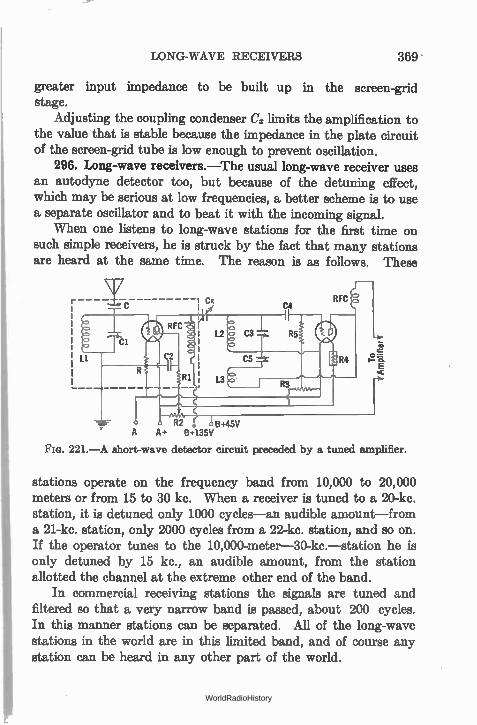
LONG-WAVE RECEIVERS 369 -
greater input impedance to be built up in the screen-grid stage.
Adjusting the coupling condenser C. limits the amplification to the value that is stable because the impedance in the plate circuit of the screen-grid tube is low enough to prevent oscillation.
296. Long-wave receivers.—The usual long-wave receiver uses an autodyne detector too, but because of the detuning effect, which may be serious at low frequencies, a better scheme is to use a separate oscillator and to beat it with the incoming signal.
When one listens to long-wave stations for the first time on such simple receivers, he is struck by the fact that many stations are heard at the same time. The reason is as follows. These
R2 B+45V A A+ B+135V
FIG. 221.—A short-wave detector circuit preceded by a tuned amplifier.
stations operate on the frequency band from 10,000 to 20,000 meters or from 15 to 30 kc. When a receiver is tuned to a 20-kc. station, it is detuned only 1000 cycles—an audible amount—from a 21-kc. station, only 2000 cycles from a 22-kc. station, and so on. If the operator tunes to the 10,000-meter-30-kc.—station he is only detuned by 15 kc., an audible amount, from the station allotted the channel at the extreme other end of the band.
In commercial receiving stations the signals are tuned and filtered so that a very narrow band is passed, about 200 cycles. In this manner stations can be separated. All of the long-wave stations in the world are in this limited band, and of course any station can be heard in any other part of the world.
WorldRadioHistory
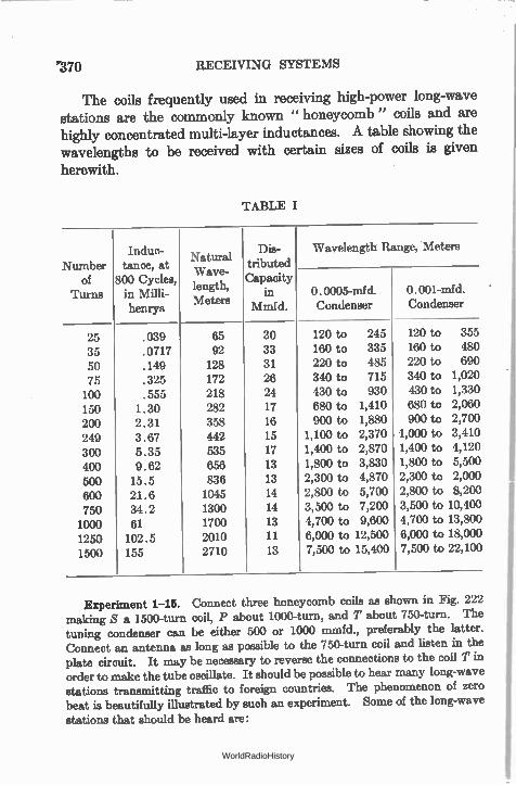
'370 RECEIVING SYSTEMS
The coils frequently used in receiving high-power long-wave stations are the commonly known " honeycomb " coils and are highly concentrated multi-layer inductances. A table showing the wavelengths to be received with certain sizes of coils is given
herewith.
TABLE I
Number of
Turns
Indue- tance, at
800 Cycles, in Milli- henrys
Natural Wave-lgth, en Meters
Dis- tributed Capacity
in Mmtd.
Wavelength Range, Meters
O. 0005-mfd. Condenser
O. 001-mfd. Condenser
25 .039 65 30 120 to 245 120 to 355
35 .0717 92 33 160 to 335 160 to 480
50 .149 128 31 220 to 485 220 to 690
75 .325 172 26 340 to 715 340 to 1,020
100 .555 218 24 430 to 930 430 to 1,330
150 1.30 282 17 680 to 1,410 680 to 2,060
200 2.31 358 16 900 to 1,880 900 to 2,700
249 3.67 442 15 1,100 to 2,370 1,000 to 3,410
300 5.35 535 17 1,400 to 2,870 1,400 to 4,120
400 9.62 656 13 1,800 to 3,830 1,800 to 5,500
500 15.5 836 13 2,300 to 4,870 2,300 to 2,00(
600 21.6 1045 14 2,800 to 5,700 2,800 to 8,20(
750 34.2 1300 14 3,500 to 7,200 3,500 to 10,40(
1000 61 1700 13 4,700 to 9,600 4,700 to 13,80(
1250 102 . 5 2010 11 6,000 to 12,500 6,000 to 18,00(
1500 155 2710 13 7,500 to 15,400 7,500 to 22,10(
Experiment 1-15. Connect three honeycomb coils as shown in Fig. 222 making S a 1500-turn coil, P about 1000-turn, and T about 750-turn. The tuning condenser can be either 500 or 1000 mmfd., preferably the latter. Connect an antenna as long as possible to the 750-turn coil and listen in the plate circuit. It may be necessary to reverse the connections to the coil T in order to make the tube oscillate. It should be possible to hear many long-wave stations transmitting traffic to foreign countries. The phenomenon of zero beat is beautifully illustrated by such an experiment. Some of the long-wave
stations that should be heard are:
WorldRadioHistory
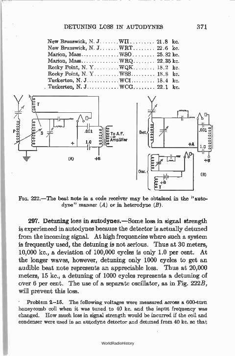
DETUNING LOSS IN AUTODYNES 371
New Brunswick, N. J WI! 21.8 kc. New Brunswick, N. J WRT 22.6 kc. Marion, Mass WS0 25.82 kc. Marion, Mass WRQ 22.35 kc. Rocky Point, N Y WQK 18.2 kc. Rocky Point, N Y WSS 18.8 kc. Tuckerton, N. J WC! 18.4 kc. . Tuckerton, N. J WCG 22.1 kc.
.001
1.0
(A) +B
To A.F.
Amplifier
222.—The beat note in a code receiver may be obtained in the auto-dyne" manner (A) or in heterodyne (B).
297. Detuning loss in aut,odynes.—Some loss in signal strength is experienced in autodynes because the detector is actually detuned from the incoming signal. At high frequencies where such a system is frequently used, the detuning is not serious. Thus at 30 meters, 10,000 kc., a deviation of 100,000 cycles is only 1.0 per cent. At the longer waves, however, detuning only 1000 cycles to get an audible beat note represents an appreciable loss. Thus at 20,000 meters, 15 kc., a detuning of 1000 cycles represents a detuning of over 6 per cent. The use of a separate oscillator, as in Fig. 222B, will prevent this loss.
' Problem 2-15. The following voltages were measured across a 600-turn honeycomb coil when it was tuned to 40 kc. and the input frequency was changed. How much loss in signal strength would be incurred if the coil and condenser were used in an autodyne detector and detuned from 40 kc. so that
WorldRadioHistory
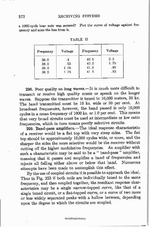
372 RECEIVING SYSTEMS
a 1000-cycle bear note was secured? Plot the curve of voltage against fre-
quency and note the loss from it.
TABLE II
Frequency Voltage Frequency Voltage
38.0 .4 40.0 2.5
38.5 .65 40.5 1.75
39.0 1.05 41.0 .95
39.5 1 75 41 5 .55
298. Poor quality on long waves.—It is much more difficult to transmit or receive high quality music or speech on the longer waves. Suppose the transmitter is tuned to 10,000 meters, 30 kc. The band transmitted must be 10 kc. wide or 30 per cent. At broadcast frequencies, however, the band passed is only 10,000 cycles in a mean frequency of 1000 kc. or 1.0 per cent. This means that very broad circuits must be used at intermediate or low ratio frequencies, which in turn means poorly selective circuits.
299. Band-pass amplifiers.—The ideal response characteristic of a receiver would be a flat top with very steep sides. The flat top should be approximately 10,000 cycles wide, or more, and the sharper the sides the more selective would be the receiver without cutting off the higher modulation frequencies. An amplifier with such a characteristic may be said to be a " band-pass " amplifier, meaning that it pasees and amplifies a band of frequencies and rejects all falling either above or below that band. Numerous attempts have been made to accomplish this effect.
By the use of coupled circuits it is possible to approach the ideal. Thus in Fig. 223 if both coils are individually tuned to the same frequency, and then coupled together, the resultant response char-acteristics may be a single narrow-topped curve, like that of a single tuned circuit, or a flat-topped curve, or a curve of two more or less widely separated peaks with a hollow between, depending upon the degree to which the circuits are coupled.
WorldRadioHistory
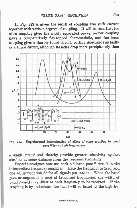
"BAND PASS" RECEIVERS 373
In Fig. 223 is given the result of coupling two such circuits together with various degrees of coupling. It will be seen that too close coupling gives the widely separated peaks, proper coupling gives a comparatively flat-topped characteristic, and too loose coupling gives a sharply tuned circuit, cutting side-bands as badly as a single circuit, although its sides drop more precipitously than
1.2
1.1
1.0
.9
.8
.7
.6
.5
.4
.3
.2
.1
3
M..9 pH
AM.440 ,
Single Coil
1 2
M=4/21-1
LI
M y/:41
+67 +135 r f 2 ) Input—. 26 Volts
L, —IL —2 i2111.111 I
,••••560 KC
o 10 20 30 40 50 60
KC
223.—Experimental determination of effect of close coupling in band pass filter at high frequencies.
a single circuit and thereby provide greater selectivity against stations at some distance from the resonant frequency.
Superheterodynes now use such a " band pass" circuit in the intermediate frequency amplifier. Here the frequency is fixed, and one adjustment will do for all signals put into it. When the band pass arrangement is used at broadcast frequencies, the width of band passed may differ at each frequency to be received. If the coupling is by inductance the band will be broad at the high fre-
WorldRadioHistory
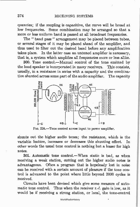
374 RECEIVING SYSTEMS
quencies; if the coupling is capacitive, the curve will be broad at low frequencies. Some combination may be arranged so that a more or less uniform band is passed at all broadcast frequencies.
The " band pass" arrangement may be placed between tubes, or several stages of it may be placed ahead of the amplifier, and thus used to filter out the desired band before any amplification takes place. In the latter case an untuned amplifier is necessary, that is, a system which amplifies all frequencies more or less alike.
300. Tone control.—Manual control of the tone emitted by the loud speaker is incorporated in many receivers. This consists, usually, in a resistance in series with a capacity and the combina-tion shunted across some part of the audio amplifier. The capacity
E 2 î
C-)
56 20 1, 3: Eg 46 g o 0
u,
224.—Tone control across input to power amplifier.
46
+B —C +13
shunts out the higher audio tones; the resistance, which is the variable feature, increases or decreases this shunting effect. In other words the usual tone control is nothing but a losser for high notes.
301. Automatic tone control.—When static is bad, as when receiving a weak station, cutting out the higher audio notes is advantageous. Often a program that is hopelessly lost in noise can be received with a certain amount of pleasure if the tone con-trol is advanced to the point where little beyond 2000 cycles is received.
Circuits have been devised which give some measure of auto-matic tone control. Thus when the receiver r.-f. gain is low, as it would be if receiving a strong station, or local, the tone-control
WorldRadioHistory
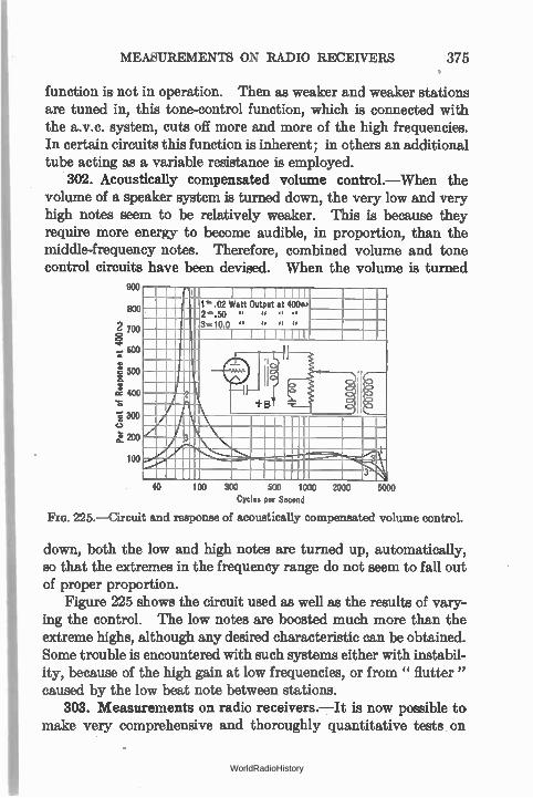
MEASUREMENTS ON RADIO RECEIVERS 375 •
function is not in operation. Then as weaker and weaker stations are tuned in, this tone-control function, which is connected with the a.v.c. system, cuts off more and more of the high frequencies. In certain circuits this function is inherent; in others an additional tube acting as a variable resistance is employed.
302. Acoustically compensated volume control.—When the volume of a speaker system is turned down, the very low and very high notes seem to be relatively weaker. This is because they require more energy to become audible, in proportion, than the middle-frequency notes. Therefore, combined volume and tone control circuits have been devised. When the volume is turned
900
800
2 700 8
600
500
Ce 400
300
k 200
100
1 1 1 1 1 1 11 1".02 Watt Output at 400ea 2..50 II 18 II el
3. 10.0 II II Of 11
1 1 1 1
2
40 100 300 500 1000 2000 Cycles per Second
225.—Circuit and response of acoustically compensated volume control.
o o 8
3
5000
down, both the low and high notes are turned up, automatically, so that the extremes in the frequency range do not seem to fall out of proper proportion.
Figure 225 shows the circuit used as well as the results of vary-ing the control. The low notes are boosted much more than the extreme highs, although any desired characteristic can be obtained. Some trouble is encountered with such systems either with instabil-ity, because of the high gain at low frequencies, or from " flutter " caused by the low beat note between stations.
303. Measurements on radio receivers.—It is now possible to make very comprehensive and thoroughly quantitative tests on
WorldRadioHistory
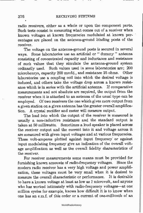
376 RECEIVING SYSTEMS
radio receivers, either as a whole or upon the component parts. Such tests consist in measuring what comes out of a receiver when known voltages at known frequencies modulated at known per-centages are placed on the antenna-ground binding posts of the receiver.
The voltage on the antenna-ground posts is secured in several ways. Some laboratories use an artificial or " dummy " antenna consisting of concentrated capacity and inductance and resistance of such values that they simulate the antenna-ground system ordinarily used. Such values used in some laboratories are: 200 microhenrys, capacity 200 mmfd., and resistance 25 ohms. Other laboratories use a coupling coil into which the desired voltage is induced, and others take the voltage drop across a known resist-ance which is in series with the artificial antenna. If comparative measurements and not absolute are required, the output from the receiver when it is attached to an antenna of the usual type can be employed. Of two receivers the one which gives more output from a given station on a given antenna has the greater overall amplifica-tion. A crystal rectifier and meter will measure output.
The load into which the output of the receiver is measured is usually a non-inductive resistance and the standard output is taken at 50 milliwatts. Sometimes a loud speaker is placed across the receiver output and the current into it and voltage across it are measured with given input voltages and at various frequencies. These volt-amperes plotted against input frequency or against input modulating frequency give an indication of the overall volt-age amplification as well as the overall fidelity characteristics of the receiver.
For receiver measurements some means must be provided for furnishing known amounts of radio-frequency voltages. Since the modern radio receiver has a very high voltage and power amplifi-cation, these voltages must be very small when it is desired to measure the overall characteristic or performance. It is desirable to have a known voltage at least as low as 1 microvolt, and anyone who has worked intimately with radio-frequency voltages—at one million cycles for example, knows how difficult it is to know when one has an e.m.f. of this order or a current of one-millionth of an
WorldRadioHistory
MEASUREMENTS ON RADIO RECEIVERS 377
ampere. The laboratory worker must know how much current or voltage he has, and he must be certain that his meter shows all the current or voltage, no more and no less.
135 V. 6 V.
B+
,e 0.25 Z 0.5 Z0.25
Audio Oscillator
'rid Ohms
/0.5 e_ imroyeir A+
4 . 0.5 4 .0.5
A —0—
Local Antenna
Twisted Leads
Module on Contr I
Radio Oscine°
0.5
Modulation Voltmeter
Ground
0.002
Tuning
Output Meter
Decade *Remoter
Radio Control 0.5
Radio Current Meter
226.—Circuit diagram and method of using signal generator.
2,.9.
The circuit diagram in Fig. 226 is that of a General Radio Signal Generator, a device which consists of a radio-frequency
WorldRadioHistory
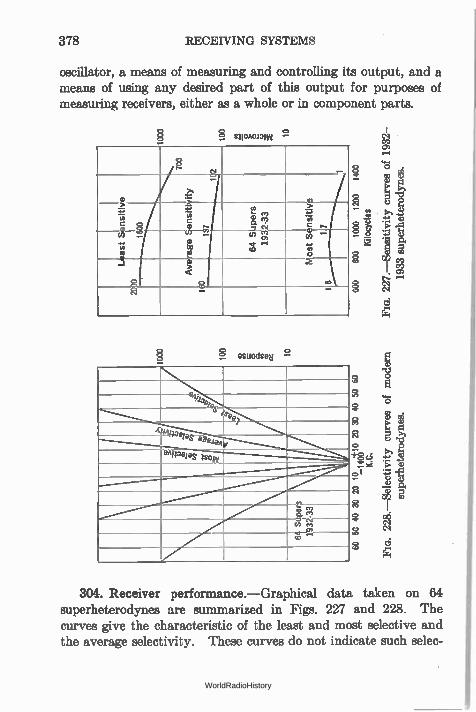
378 RECEIVING SYSTEMS
oscillator, a means of measuring and controlling its output, and a means of using any desired part of this output for purposes of measuring receivers, either as a whole or in component parts.
sliononund 9
e. e
-1
-7
east Sensitiv
1
1600
--................,
0 es E. 0? 3 el
> on
r• w --cn
a)
t3.
or
"-
o 0
3
8
2
lieSUOd SOH 9
Ill%
fe&e7
4 041joems aseja4v
eAneelas jsovi
e =-(4---v. col
01. .-•
304. Receiver performance.—Graphical data taken on 64 superheterodyne,s are summarized in 227 and 228. The curves give the characteristic of the least and most selective and the average selectivity. These curves do not indicate such selec-
WorldRadioHistory
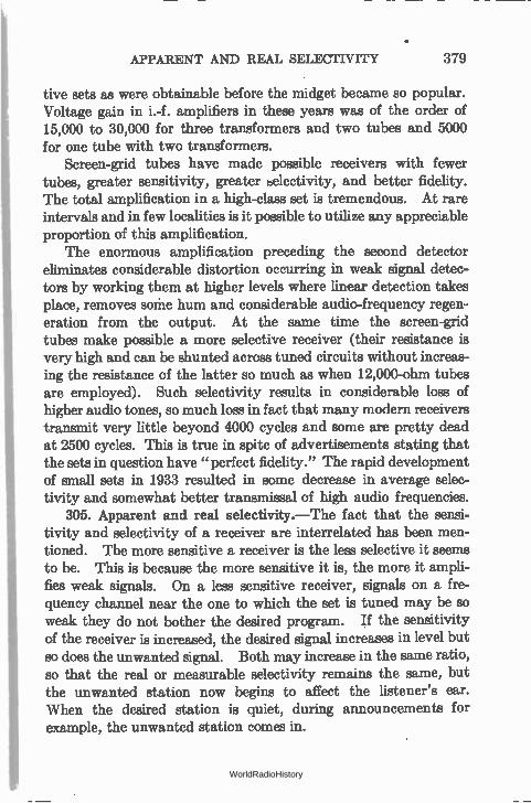
APPARENT AND REAL SELECTIVITY 379
tive sets as were obtainable before the midget became so popular. Voltage gain in i.-f. amplifiers in these years was of the order of 15,000 to 30,000 for three transformers and two tubes and 5000 for one tube with two transformers.
Screen-grid tubes have made possible receivers with fewer tubes, greater sensitivity, greater belectivity, and better fidelity. The total amplification in a high-class set is tremendous. At rare intervals and in few localities is it possible to utilize any appreciable proportion of this amplification.
The enormous amplification preceding the second detector eliminates considerable distortion occurring in weak signal detec-tors by working them at higher levels where linear detection takes place, removes some hum and considerable audio-frequency regen-eration from the output. At the same time the screen-grid tubes make possible a more selective receiver (their resistance is very high and can be shunted across tuned circuits without increas-ing the resistance of the latter so much as when 12,000-ohm tubes are employed). Such selectivity results in considerable loss of higher audio tones, so much loss in fact that many modern receivers transmit very little beyond 4000 cycles and some are pretty dead at 2500 cycles. This is true in spite of advertisements stating that the sets in question have " perfect fidelity." The rapid development of small sets in 1933 resulted in some decrease in average selec-tivity and somewhat better transmissal of high audio frequencies.
305. Apparent and real selectivity.—The fact that the sensi-tivity and selectivity of a receiver are interrelated has been men-tioned. The more sensitive a receiver is the less selective it seems to be. This is because the more sensitive it is, the more it ampli-fies weak signals. On a less sensitive receiver, signals on a fre-quency channel near the one to which the set is tuned may be so weak they do not bother the desired program. If the sensitivity of the receiver is increased, the desired signal increases in level but so does the unwanted signal. Both may increase in the same ratio, so that the real or measurable selectivity remains the same, but the unwanted station now begins to affect the listener's ear. When the desired station is quiet, during announcements for example, the unwanted station comes in.
WorldRadioHistory
380 RECEIVING SYSTEMS
The answer is to decrease the sensitivity of the receiver so that the unwanted signal is again pressed below the level (A in Fig. 229) where it is bothersome, and if more volume is required to increase the audio-frequency amplification. Some receivers have a sensi-tivity control and a volume control. The first operates on the radio-frequency amplifier, the latter may operate on either the radio- or the audio-frequency amplifier. In Fig. 229 the vertical lines represent broadcasting signals. In E, three of them are being received, the 1000 kc. the loudest. In A only' one signal, at 1000 kc., is entering the receiver.
306. Importance of shape of con-500 denser plates.—A receiver can be calibrated so that' each degree of its dial may represent one channel
,„ \\.9 /
no width, 10 kc., or it may be cali- brated in wavelengths so that turn-
ing the dial a certain number of
r io degrees turns through a certain number of meters. Or a combina- tion of "straight frequency line"
4.. and "straight wavelength line" tuning may be effected. With a semi-
Frequency in Kilocycles 990 1000 1010 1020 circular plate condenser a greater
229.—Illustrating real d number of frequency channels, each an
apparent selectivity. 10 kc. wide, will be passed over by a given number of dial degrees at
the high frequencies than at the low, and the effect upon the operator is an apparent decrease in selectivity of his receiver at short wavelengths.
307. Automatic volume control.—Great advance has been made in controlling the volume of the receiver automatically. There are at least two virtues: fading is overcome to some extent; tuning through local stations will not produce blasts of volume which are not only annoying but often destructive to loud speakers.
There are many automatic volume-control circuits (known as " a.v.c.") but they all depend upon a rectification of the signal with resultant production of direct current which, flowing through a resistance, produces a voltage drop that varies with the signal
A
WorldRadioHistory
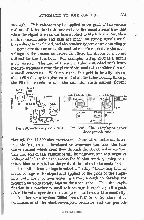
AUTOMATIC VOLUME CONTROL 381
strength. This voltage may be applied to the grids of the various r.-f. or i.-f. tubes (or both) inversely as the signal strength so that when the signal is weak the bias applied to the tubes is low, their mutual conductance and gain are high; on strong signals much bias voltage is developed, and the sensitivity goes down accordingly.
Some circuits use an additional tube; others produce the a.v.c. voltage in the second detector; in others the diodes of a 55 are utilized for this function. For example, in Fig. 230a is a simple a.v.c. circuit. The grid of the a.v.c. tube is supplied with inter-mediate frequency from the plate of the final i.-f. amplifier through a small condenser. With no signal this grid is heavily biased, about 60 volts, by the plate current of all the tubes flowing through the 60-ohm resistance and the oscillator plate current flowing
To 2nd 581.F. I Dot.
(noon)
—13
230a.—Simple a.v.c. circuit.
Elect. Coup. Osc.-Trans.
B-
230b.—Circuit employing duplex diode pentode tube.
through the 17,500-ohm resistance. Now when sufficient inter-mediate frequency is developed to overcome this bias, the tube draws current which must flow through the 500,000-ohm resistor. The grid end of this resistance will be negative, and this negative voltage added to the drop across the 60-ohm resistor, acting as an initial bias, is applied to the grids of the tubes to be controlled.
The initial bias voltage is called a " delay," indicating that no a.v.c. voltage is developed and applied to the grids of the ampli-fiers until the incoming signal is strong enough to develop the required 60 volts steady bias on the a.v.c. tube. Thus the ampli-fication is a maximum until this voltage is reached; all signals after this value operate the a.v.c. system and reduce the sensitivity.
Another a.v.c. system (230b) uses a 6B7 to control the mutual conductance of the electron-coupled oscillator and the pentode
WorldRadioHistory
382 RECEIVING- SYSTEMS
section in the same envelope with the a.v.c. diode plates of the 6B7. 308. Noise suppressor systems.—In an a.v.c. receiver the
sensitivity is at maximum when no signal is being received, for example between carrier signals. Therefore any static or other radio noise will be amplified to the limit of the circuit and be passed to the loud speaker.
Circuits have been developed which shut off this noise. In gen-eral they so reduce the amplification of some part of the a.-f. system that, when no carrier voltage is received, nothing gets through to the audio amplifier and loud speaker. A typical circuit of such an inter-carrier noise suppressor, or " q.a.v.c.," is shown in Fig. 212.
309. Shielding.—In any high-gain amplifier it is necessary to prevent any source of high energy from being coupled in any way to a point of low energy. For example, if the plate lead of a tube near the detector feeds voltage by coupling of any sort to the grid lead of a previous tube, regeneration and instability will result.
Proper filtering by series resistance and shunt capacity of all plate grid and screen voltages will aid in keeping r.-f. or i.-f. currents where they belong. All inductances must be shielded; often grid wires are run in shielded wire.
Now placing a coil in a metal box seems like a simple trick to keep the lines of force from that coil from getting mixed up with lines of force from another coil. But the size of the metal box, its material, the size of the coil, whether or not the metal box is grounded, and to what, and whether it carries current or not—all these things enter into the problem of shielding.
The subtraction of energy from the tuned circuit by the shield has the same effect as though the resistance of the tuned circuit were increased. In other words, if currents are induced in the shield, the effective resistance of the coil is increased, its selectivity factor goes down, the voltage gain due the coil and condenser is decreased. It is also true that the inductance of the coil decreases too, so that the value of effective resistance, or Q, L2w2/r, is greatly decreased. The nearer the coil is to the shield, and the greater the resistance of the shield, the greater is the power loss in it.
The shield should never carry current. It should be heavy and from the best conductor possible, and all joints in it should be
WorldRadioHistory
LOUD SPEAKERS 383
carefully soldered. It should be connected at only one point to a heavy conductor leading to the common ground of the set. Holes in it for leading-in or -out wires should be small.
From the electrical standpoint, copper is better than brass or aluminum; from the standpoint of weight and cost per pound, copper is handicapped.
It is interesting to consider the circuit as a transformer and its load. The resistance of the shield represents the load across the transformer. The power in this load is taken from the generator which is the tuned circuit. As a matter of fact any two wires which couple any two circuits together may be considered as a transformer, one acting as the primary and the other as the secon-dary. The power wasted in the load on the secondary wire must come from the generator or the circuit attached to the primary wire and represents an increase in the resistance of the circuit attached to this wire, and a decrease in its inductance.
310. Loud speakers.—The loud speaker is the final link in the broadcasting system, and because of its position with respect to the listener it is frequently blamed for much of the bad reproduction that really originates somewhere else.
The task of the loud speaker is to translate into sound energy the electrical energy in the power tube. It must do this as effec-tively and faithfully as possible. It is useless to design and operate a high-class amplifier with a poor loud speaker. The wide range of tones coming from the amplifier is lost in the loud speaker and does not get to the listener. Likewise, it is absurd to install a perfect loud speaker in the hope that the fidelity of reproduction from an antiquated or poorly engineered receiver will be bettered. The full benefit of a perfect loud speaker cannot be attained until the com-plete chain of apparatus is perfect—amplifier, power tube, plate voltage supply, loud speaker, etc.
Loud speakers in general are notoriously inefficient—the best in common use is not over 30 per cent. Most of them are less than 5 per cent efficient. Some of them reproduce the whole audio range of tones with almost equal fidelity. Others reproduce only a very small section of the audio spectrum—such were the short-horned loud speakers of a few years ago.
WorldRadioHistory
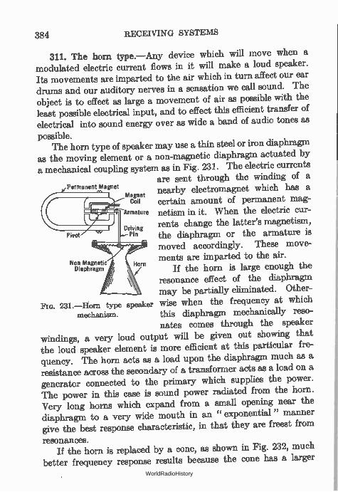
384 RECEIVING SYSTEMS
311. The horn type.—Any device which will move when a modulated electric current flows in it will make a loud speaker. Its movements are imparted to the air which in turn affect our ear drums and our auditory nerves in a sensation we call sound. The object is to effect as large a movement of air as possible with the least possible electrical input, and to effect this efficient transfer of electrical into sound energy over as wide a band of audio tones as
possible. The horn type of speaker may use a thin steel or iron diaphragm
as the moving element or a non-magnetic diaphragm actuated by a mechanical coupling system as in Fig. 231. The electric currents
are sent through the winding of a Permanent Magnet nearby electromagnet which has a
certain amount of permanent mag--Armature netism in it. When the electric cur-
rents change the latter's magnetism, the diaphragm or the armature is moved accordingly. These move-ments are imparted to the air.
If the horn is large enough the resonance effect of the diaphragm may be partially eliminated. Other-
FIG. 231.—Horn type speaker wise when the frequency at which mechanism, this diaphragm mechanically reso-
nates comes through the speaker
windings, a very loud output will be given out showing that the loud speaker element is more efficient at this particular fre-quency. The horn acts as a load upon the diaphragm much as a resistance across the secondary of a transformer acts as a load on a generator connected to the primary which supplies the power. The power in this case is sound power radiated from the horn. Very long horns which expand from a small opening near the diaphragm to a very wide mouth in an " exponential " manner give the best response characteristic, in that they are freest from
resonances. If the horn is replaced by a cone, as shown in Fig. 232, much
better frequency response results because the cone has a larger
Pivot
Non Magnetic Diaphragm
Magnet Coil
Driving Pin
Horn
WorldRadioHistory
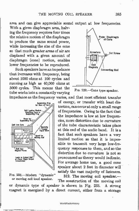
THE MOVING COIL SPEAKER 385
area and can give appreciable sound output at low frequencies. With a given diaphragm area, halv-ing the frequency requires four times the relative motion of the diaphragm P perf Diaphragm
o Cone to produce the same sound power, while increasing the size of the cone so that much greater areas of air are
Set Screw displaced with a given amount of diaphragm (cone) motion, enables lower frequencies to be reproduced.
Such speakers have an impedance I Connecting Rod
that increases with frequency, being about 1000 ohms at 100 cycles and running as high as 40,000 ohms at 5000 cycles. This means that the tube works into a constantly varying impedance as the frequency varies, and that most efficient transfer
of energy, or transfer with least dis-epParroPC:4°
tortion, can occur at only a small range Soft Leather Washer atiachms Cone to of frequencies. Owing to the fact that Supportrng Ring
the impedance is low at low frequen-cies, more distortion due to curvature of the tube characteristic takes place at this end of the audio band. It is a fact that such speakers have a very limited motion so that it is impos-sible to transmit very large low-fre-quency responses to them, and so the distortion due to curvature is not so pronounced as theory would indicate. For average home use, a good cone speaker about 2 feet in diameter will satisfy the vast majority of listeners.
FIG. 233.—M odern • ' dynamic " 312. The moving coil speaker.— or moving coil loud speaker.
The construction of the moving coil or dynamic type of speaker is shown in Fig. 233. A strong magnet is energized by a direct current, either from a storage
Brace for Supporting Moo
loft Iron Core
Soft teRn Magnet Orante
Leads to Output Coil ff of Power Stage Output Transformer
232.—Cone type speaker.
—
WorldRadioHistory
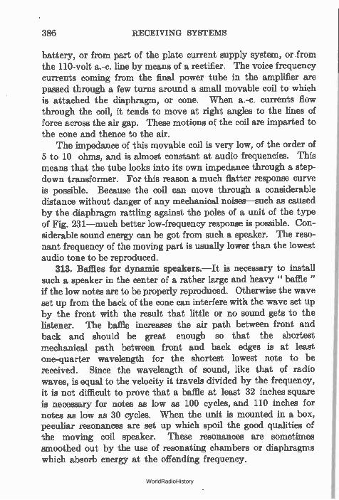
386 RECEIVING SYSTEMS
battery, or from part of the plate current supply system, or from the 110-volt a.-c. line by means of a rectifier. The voice frequency currents coming from the final power tube in the amplifier are passed through a few turns around a small movable coil to which is attached the diaphragm, or cone. When a.-c. currents flow through the coil, it tends to move at right angles to the lines of force across the air gap. These motions of the coil are imparted to the cone and thence to the air.
The impedance of this movable coil is very low, of the order of 5 to 10 ohms, and is almost constant at audio frequencies. This means that the tube looks into its own impedance through a step-down transformer. For this reason a much flatter response curve is possible. Because the coil can move through a considerable distance without danger of any mechanical noises—such as caused by the diaphragm rattling against the poles of a unit of the type of Fig. 231—much better low-frequency response is possible. Con-siderable sound energy can be got from such a speaker. The reso-nant frequency of the moving part is usually lower than the lowest audio tone to be reproduced.
313. Baffles for dynamic speakers.—It is necessary to install such a speaker in the center of a rather large and heavy " baffle " if the low notes are to be properly reproduced. Otherwise the wave set up from the back of the cone can interfere with the wave set up by the front with the result that little or no sound gets to the listener. The baffle increases the air path between front and back and should be great enough so that the shortest mechanical path between front and back edges is at least one-quarter wavelength for the shortest lowest note to be received. Since the wavelength of sound, like that of radio waves, is equal to the velocity it travels divided by the frequency, it is not difficult to prove that a baffle at least 32 inches square is necessary for notes as low as 100 cycles, and 110 inches for notes as low as 30 cycles. When the unit is mounted in a box, peculiar resonances are set up which spoil the good qualities of the moving coil speaker. These resonances are sometimes smoothed out by the use of resonating chambers or diaphragms which absorb energy at the offending frequency.
WorldRadioHistory
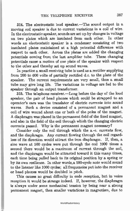
THE TELEPHONE RECEIVER 387
314. The electrostatic loud speaker.—The sound output in a moving coil speaker is due to current variations in a coil of wire. In the electrostatic speaker, sounds are set up by changes in voltage on two plates which are insulated from each other. In other words an electrostatic speaker is a condenser consisting of two insulated plates maintained at a high potential difference with respect to each other. Across the plates are added the changing potentials coming from the last amplifier tube. These changing potentials cause a motion of one plate of the speaker with respect to the other and thereby set up sound waves.
In practice a small receiving tube is used as a rectifier supplying from 200 to 600 volts of partially rectified d.c. to the plate of the speaker. The current requirements are very small, thus a small tube may give long life. The variations in voltage are fed to the speaker through an output transformer.
315. The telephone receiver.—Long before the day of the loud speaker, the pair of head phones which could be strapped to an operator's ears was the translator of electric currents into sound waves. Such a device consisted of a permanent magnet and a coil of wire wound about one or both of the poles of the magnet. A diaphragm was placed in the permanent field of the fixed magnet, and also in the field of the coil through which the changing electric currents passed. Why is the permanent magnet necessary?
Consider only the coil through which the a.-c. currents flow, and the diaphragm. Any current flowing through the coil regard-less of its direction would attract the iron diaphragm. If, then, a sine wave at 500 cycles were put through the coil 1000 times a second there would be a maximum of current through the coil, and the diaphragm would be attracted toward it this many times, each time being pulled back to its original position by a spring or by its own resilience. In other words, a 500-cycle note would sound to the listener like 1000 cycles; all frequencies put into the receiver or head phones would be doubled in pitch.
This causes no great difficulty in code reception, but in voice reception it would be strange indeed. If, however, the diaphragm is always under some mechanical tension by being near a strong permanent magnet, then smaller variations in magnetism, due to
WorldRadioHistory
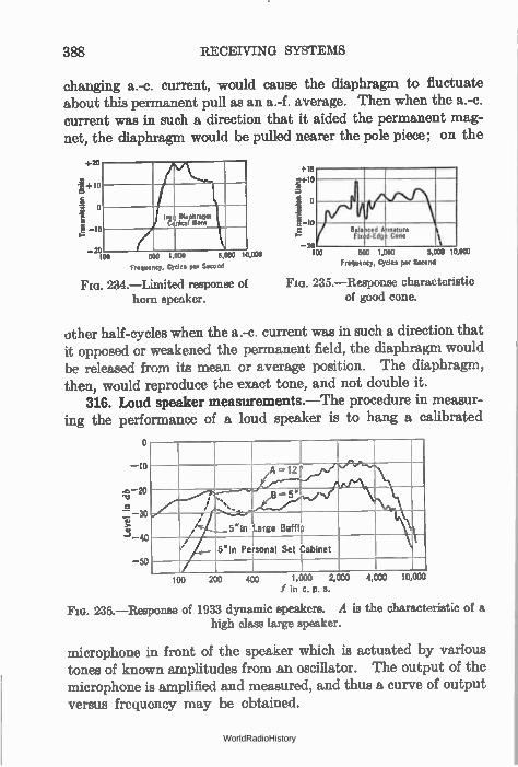
388 RECEIVING SYSTEMS
changing a.-c. current, would cause the diaphragm to fluctuate about this permanent pull as an a.-f. average. Then when the a.-c. current was in such a direction that it aided the permanent mag-net, the diaphragm would be pulled nearer the pole piece; on the
+20
—g+10
o —20
100
trot Cc
Ellepereqm Meal Horn
Frequency, Cycles per Second
li
Bala seed A mature Fix d.Edgf Cone 1
1
+15
1.1+10
20
2 10
—20 500 1,000 5,000 10,000 100 500 1,000 5,000 10.000
Frequency, Cycles per Second
FIG). 234.—Limited response of Da. 235.—Response characteristic of good cone. horn speaker.
other half-cycles when the a.-c. current was in such a direction that it opposed or weakened the permanent field, the diaphragm would be released from its mean or average position. The diaphragm, then, would reproduce the exact tone, and not double it.
316. Loud speaker measurements.—The procedure in measur-ing the performance of a loud speaker is to hang a calibrated
o
10
-o 20
.E 30
3 40
50
I / \ s
t f rin Large Barn / I 5"in Personal Set Cabinet
100 200 400 ,i,IAIU
f in c. p. s.
FIG. 236.—Response of 1933 dynamic speakers. A is the characteristic of a high class large speaker.
microphone in front of the speaker which is actuated by various tones of known amplitudes from an oscillator. The output of the microphone is amplified and measured, and thus a curve of output versus frequency may be obtained.
WorldRadioHistory
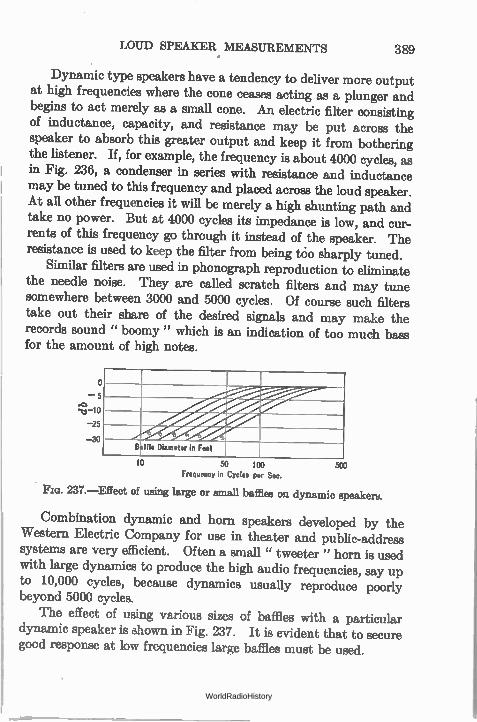
LOUD SPEAKER MEASUREMENTS 389
Dynamic type speakers have a tendency to deliver more output at high frequencies where the cone ceases acting as a plunger and begins to act merely as a small cone. An electric filter consisting of inductance, capacity, and resistance may be put across the speaker to absorb this greater output and keep it from bothering the listener. If, for example, the frequency is about 4000 cycles, as in Fig. 236, a condenser in series with resistance and inductance may be tuned to this frequency and placed across the loud speaker. At all other frequencies it will be merely a high shunting path and take no power. But at 4000 cycles its impedance is low, and cur-rents of this frequency go through it instead of the speaker. The resistance is used to keep the filter from being tcio sharply tuned.
Similar filters are used in phonograph reproduction to eliminate the needle noise. They are called scratch filters and may tune somewhere between 3000 and 5000 cycles. Of course such filters take out their share of the desired signals and may make the records sound " boomy " which is an indication of too much bass for the amount of high notes.
0
5
5
S
) Baffle Diameter in Feet
10 50 100 Frequency in Cycles per Sec.
PIG. 237.—Effect of using large or small baffles on dynamic speakers.
Combination dynamic and horn speakers developed by the Western Electric Company for use in theater and public-address systems are very efficient. Often a small " tweeter " horn is used with large dynamics to produce the high audio frequencies, say up to 10,000 cycles, because dynamics usually reproduce poorly beyond 5000 cycles.
The effect of using various sizes of baffles with a particular dynamic speaker is shown in Fig. 237. It is evident that to secure good response at low frequencies large baffles must be used.
500
WorldRadioHistory
CHAPTER XVI
RECTIFIERS AND POWER SUPPLY APPARATUS
TUBES which distort may act as rectifiers to transform a.-c. currents into d.-c. currents and thereby be useful as sources of uni-directional current either for charging batteries or for supplying plate voltages to a receiver or other device. Such tubes have only two elements, the .source of electrons and the plate or receiver of electrons. Tubes of this general type have been developed for high-voltage, low-current work, as for supplying transmitters with plate voltage, or for low-voltage, high-current work for battery charging. Rectifier tubes may be high vacuum and may handle several hundred thousand volts, or they may be gaseous to handle several thousand amperes, and for special purposes they may have grids in them, then being known as controlled rectifiers (Grid-glow tubes and Thyratrons.)
317. The fundamental rectifier circuit.—When such a two-element tube filament is heated to a proper temperature electrons will flow to the plate provided it is at a higher positive potential than the filament. If an a.-c. voltage is connected between the filament and the plate (Fig. 238) an electron current will flow to the plate when the latter is positive and not when it is negative. In other words current flows on the halves of the cycle when the plate is positive; on the halves of the cycle when the plate is negative, the electrons return to the filament as fast as they escape. The a.-c. voltage may be introduced into the plate-filament path by means of a transformer, which also supplies the heating current for the filaments. A d.-c. meter in the plate circuit would read a certain amount
of current which would be a value somewhere between the maxi-mum current that flowed during each positive half-cycle, and zero. The meter needle would not follow the rapid spurts of current and so would assume some average value. If we consider as the input
390 WorldRadioHistory
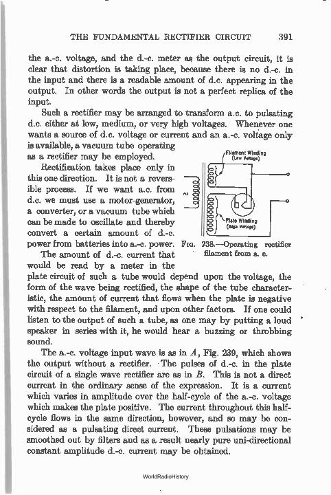
THE FUNDAMENTAL RECTIFIER CIRCUIT 391
the a.-c. voltage, and the d.-c. meter as the output circuit, it is clear that distortion is taking place, because there is no d.-c. in the input and there is a readable amount of d.c. appearing in the output. In other words the output is not a perfect replica of the input.
Such a rectifier may be arranged to transform a.c. to pulsating d.c. either at low, medium, or very high voltages. Whenever one wants a source of d.c. voltage or current and an a.-c. voltage only is available, a vacuum tube operating
Filament Winding as a rectifier may be employed. Rectification takes place only in
this one direction. It is not a revers-ible process. If we want a.c. from d.c. we must use a motor-generator, a converter, or a vacuum tube which can be made to oscillate and thereby convert a certain amount of d.-c. power from batteries into a.-c. power.
The amount of d.-e. current that would be read by a meter in the plate circuit of such a tube would depend upon the voltage, the form of the wave being rectified, the shape of the tube character-istic, the amount of current that flows when the plate is negative with respect to the filament, and upon other factors. If one could listen to the output of such a tube, as one may by putting a loud speaker in series with it, he would hear a buzzing or throbbing sound.
The a.-c. voltage input wave is as in A, Fig. 239, which shows the output without a rectifier. The pulses of d.-c. in the plate circuit of a single wave rectifier are as in B. This is not a direct current in the ordinary sense of the expression. It is a current which varies in amplitude over the half-cycle of the a.-c. voltage which makes the plate positive. The current throughout this half-cycle flows in the same direction, however, and so may be con-sidered as a pulsating direct current. These pulsations may be smoothed out by filters and as a result nearly pure uni-directional constant amplitude d.-c. current may be obtained.
238.—Operating rectifier filament from a. c.
WorldRadioHistory
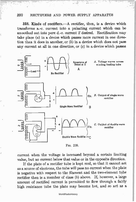
392 RECTIFIERS AND POWER SUPPLY APPARATUS
318. Kinds of rectillers.—A rectifier, then, is a device which transforms a.-c. current into a pulsating current which can be smoothed out into pure d.-c. current if desired. Rectification may take place (a) in a device which passes more current in one direc-tion than it does in another, or (b) in a device which does not pass any current at all in one direction, or (c) in a device which passes
Appearance of Output at X winding feeding tube
A No Rectifier
Single Wave Rectifier
Etc.
B
A. Voltage waves across
B. Output of single wave rectifier
C. Output of double wave Etc. rectifier
Double Wave Rectifiei —c
Fla. 239.
current when the voltage is increased beyond a certain limiting value, but no current below that value or in the opposite direction.
If the plate of a rectifier tube is kept cool, so that it cannot act as a source of electrons, the tube will pass no current when the plate is negative with respect to the filament and the two-element tube rectifier then is a member of class (b) above. If, however, a large amount of rectified current is permitted to flow through a fairly high resistance tube the plate may become hot, and so act as a
WorldRadioHistory
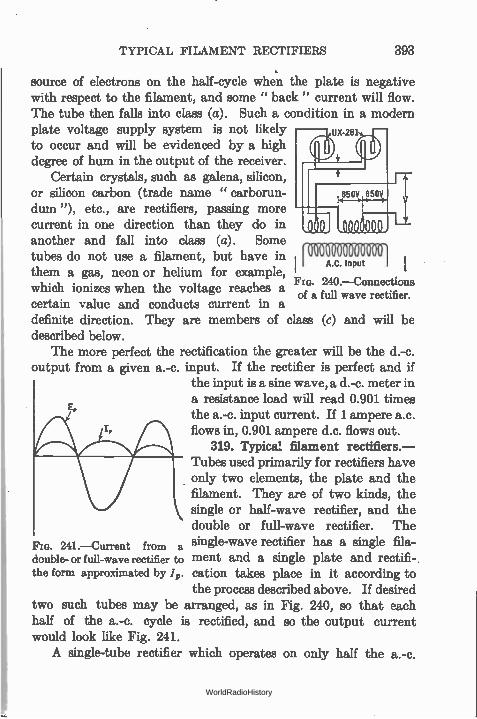
TYPICAL FILAMENT RECTIFIERS 393
source of electrons on the half-cycle when the plate is negative with respect to the filament, and some " back " current will flow. The tube then falls into class (a). Such a condition in a modern plate voltage supply system is not likely UX-28I
to occur and will be evidenced by a high degree of hum in the output of the receiver.
Certain crystals, such as galena, silicon, or silicon carbon (trade name " carborun-dum "), etc., are rectifiers, passing more current in one direction than they do in another and fall into class (a). Some tubes do not use a filament, but have in A.C. Inputn ] them a gas, neon or helium for example,
240.—Connections which ionizes when the voltage reaches a of a full wave rectifier.
certain value and conducts current in a definite direction. They are members of class (c) and will be described below.
The more perfect the rectification the greater will be the d.-c. output from a given a.-c. input. If the rectifier is perfect and if
the input is a sine wave, a d.-c. meter in a resistance load will read 0.901 times the a.-c. input current. If 1 ampere a.c. flows in, 0.901 ampere d.c. flows out.
319. Typical filament rectifiers.— Tubes used primarily for rectifiers have only two elements, the plate and the filament. They are of two kinds, the single or half-wave rectifier, and the double or full-wave rectifier. The single-wave rectifier has a single fila-ment and a single plate and rectifi-cation takes place in it according to the process described above. If desired
two such tubes may be arranged, as in Fig. 240, so that each half of the a.-c. cycle is rectified, and so the output current would look like Fig. 241. A single-tube rectifier which operates on only half the a.-c.
241.—Current from a double- or full-wave rectifier to the form approximated by ./„.
WorldRadioHistory
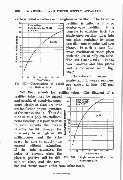
394
cycle is 500
400
300
200 a
100 M 90
80 to 70
e2 (.) 50
o 40 •••••
G. 50
RECTIFIERS AND POWER SUPPLY APPARATUS
called a half-wave or single-wave rectifier. The two-tube rectifier is called a full- or
Plate Voltage Plate Current per Anode EF— 5.0 V
CX 380
double-wave rectifier. It is possible to combine both the single-wave rectifier tubes into one glass container by using two filaments in series and two plates. In such a case full-wave rectification takes place with the use of only one tube. The 280 is such a tube. It has two filaments and two plates
20 and is connected as in Fig. 239C.
o 20 40 50 80 70 80 Characteristic curves of Plate Voltage single- and full-wave rectifiers
Fm. 242.—Characteristic of double wave rectifier tube. 243.
320. Requirements for rectifier tubes.—The filament of a rectifier tube must be rugged and capable of supplying many more electrons than are ever needed for the proper operation of the output circuit. Thus if a tube is to supply 125 milliam-peres steadily, it is possible that in some circuits the instan-taneous current through the tube may be as high as 300 milliamperes and the tube must be able to supply this current without saturating. If the tube saturates, the pulse of current when the plate is positive will be diffi-cult to filter, and the recti-fier and circuit would suffer from other faults.
Plate Voltage Plate Current EF-7.5 V
CX 31
Plate Current Mi
llia
mper
es
500
400
300
200
ioo
so
60 50
40
30
20
10 0 40 80 tza
Plate Vol age
243.—Single wave rectifier characteristic.
160 200
are shown in Figs. 242 and
240
tube
WorldRadioHistory
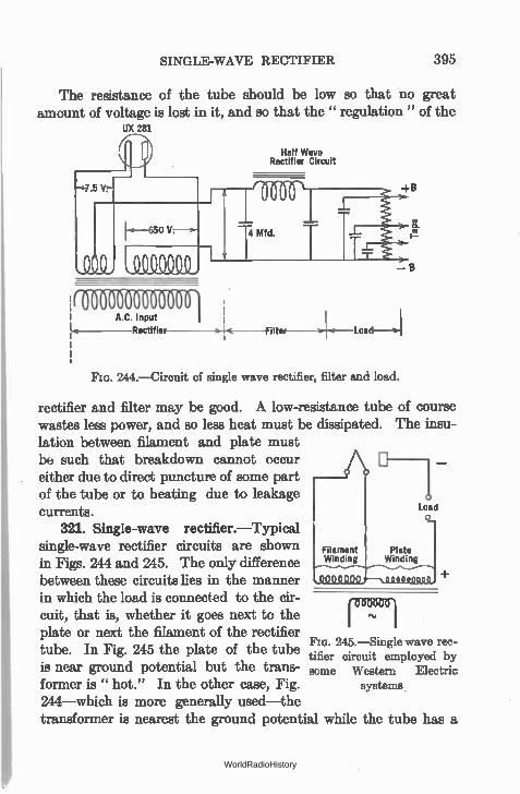
SINGLE-WAVE RECTIFIER 395
The resistance of the tube should be low so that no great amount of voltage is lost in it, and so that the " regulation " of the
IJX 281
MIME' A.C. Input
Rectifier
Half Wave Rectifier Circuit
> Filter Load---v1
244.—Circuit of single wave rectifier, filter and load.
rectifier and filter may be good. A low-resistance tube wastes less power, and so less heat must be dissipated. lation between filament and plate must be such that breakdown cannot occur either due to direct puncture of some part of the tube or to heating due to leakage currents.
321. Single-wave rectifier.—Typical single-wave rectifier circuits are shown in Figs. 244 and 245. The only difference between these circuits lies in the manner in which the load is connected to the cir-cuit, that is, whether it goes next to the plate or next the filament of the rectifier tube. In Fig. 245 the plate of the tube is near ground potential but the trans-former is " hot." In the other case, Fig. 244—which is more generally used—the transformer is nearest the ground potential while the tube
of course The insu-
1
Load
Plate Winding
245.—Single wave rec-tifier circuit employed by some Western Electric
systems
has a
WorldRadioHistory
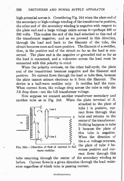
396 RECTIFIERS AND POWER SUPPLY APPARATUS
high potential across it. Considering Fig. 244 when the plate end of the secondary or high-voltage winding of the transformer is positive, the other end of the secondary winding is negative with respect to the plate end and a large voltage exists across it—perhaps 400 or 500 volts. This makes the end of the load attached to this end of the transformer negative; and as we proceed in this direction, through the load and back to the filament of the tube, the circuit becomes more and more positive. The filament of a rectifier, then, is the positive end of the circuit so far as the load is con-cerned. The plate end is the negative or grounded end so far as the load is concerned, and a voltmeter across the load must be connected with this polarity in mind.
When the polarity reverses, on the other half-cycle, the plate end of the transformer becomes negative and the filament end positive. No current flows through the load or tube then, because the plate cannot attract electrons to it from the filament. The device is a half-wave rectifier only. It rectifies half the time. When current flows, the voltage drop across the tube is only the IR drop there—not the full transformer voltage.
Now suppose we connect another transformer secondary and another tube as in Fig. 246. When the plate terminal of S,
attached to the plate of tube 1 is positive, cur-rent flows through that
+ tube and returns to the center of the transformer. Nothing happens in tube 2 because the plate of this tube is negative. When the direction of the a.-c. voltage reverses,
246.—Direction of flow of current in full the plate of tube 2 be-comes positive and cur-rent flows through this
tube returning through the center of the secondary winding as before. Current flows in a given direction through the load resist-ance regardless of which tube is passing current.
wave rectifier.
WorldRadioHistory
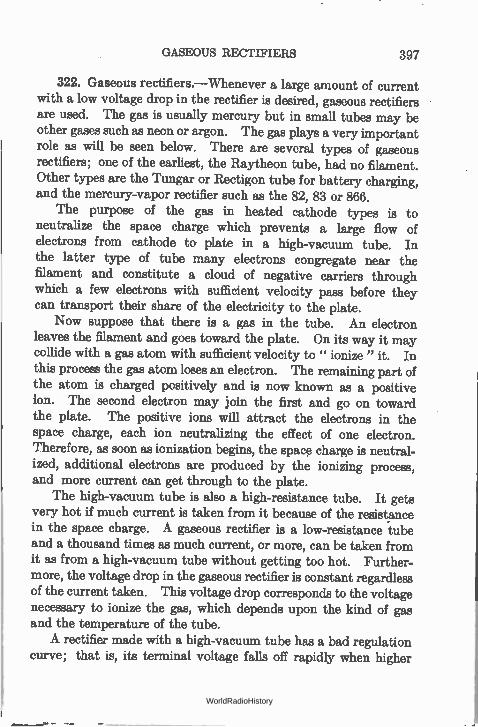
GASEOUS RECTIFIERS 397
322. Gaseous rectifiers.—Whenever a large amount of current with a low voltage drop in the rectifier is desired, gaseous rectifiers are used. The gas is usually mercury but in small tubes may be other gases such as neon or argon. The gas plays a very important role as will be seen below. There are several types of gaseous rectifiers; one of the earliest, the Raytheon tube, had no filament. Other types are the Tungar or Rectigon tube for battery charging, and the mercury-vapor rectifier such as the 82, 83 or 866.
The purpose of the gas in heated cathode types is to neutralize the space charge which prevents a large flow of electrons from cathode to- plate in a high-vacuum tube. In the latter type of tube many electrons congregate near the filament and constitute a cloud of negative carriers through which a few electrons with sufficient velocity pass before they can transport their share of the electricity to the plate.
Now suppose that there is a gas in the tube. An electron leaves the filament and goes toward the plate. On its way it may collide with a gas atom with sufficient velocity to " ionize " it. In this process the gas atom loses an electron. The remaining part of the atom is charged positively and is now known as a positive ion. The second electron may join the first and go on toward the plate. The positive ions will attract the electrons in the space charge, each ion neutralizing the effect of one electron. Therefore, as soon as ionization begins, the space charge is neutral-ized, additional electrons are produced by the ionizing process, and more current can get through to the plate.
The high-vacuum tube is also a high-resistance tube. It gets very hot if much current is taken from it because of the resistance in the space charge. A gaseous rectifier is a low-resistance tube and a thousand times as much current, or more, can be taken from it as from a high-vacuum tube without getting too hot. Further-more, the voltage drop in the gaseous rectifier is constant regardless of the current taken. This voltage drop corresponds to the voltage necessary to ionize the gas, which depends upon the kind of gas and the temperature of the tube. A rectifier made with a high-vacuum tube has a bad regulation
curve; that is, its terminal voltage falls off rapidly when higher
WorldRadioHistory
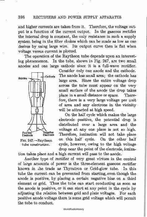
398 RECTIFIERS AND POWER SUPPLY APPARATUS
and higher currents are taken from it. Therefore, the voltage out-put is a function of the current output. In the gaseous rectifier the internal drop is constant, the only resistance in such a supply system being in the filter chokes which can be made as low as one desires by using large wire. Its output curve then is flat when voltage versus current is plotted.
The operation of the Raytheon tube depends upon an interest-ing phenomenon. In the tube, shown in Fig. 247, are two small anodes and one large cathode since it is a full-wave rectifier.
Consider only one anode and the cathode. A d Cathode The anode has small area; the cathode has
es no large area. Since the entire voltage drop across the tube must appear on the very small surface of the anode the drop takes place in a small distance or space. There-fore, there is a very large voltage per unit of area and any electrons in the vicinity will be attracted at high speed.
On the half cycle which makes the large electrode positive, the potential drop is distributed over a large area and the voltage at any one place is not so high.
Positive Negative Electrode Electrode Therefore, ionization will not take place
247.—Raytheon on this half cycle. On the other half tube construction. cycle, however, owing to the high voltage
drop near the point of the electrode, ioniza-tion takes place and a high current will pass to the anode.
Another type of rectifier of very great virtues in the control of large amounts of power is the three-element gaseous rectifier known in he trade as Thyratron or Grid-glow tube. In this tube the current can be prevented from starting, even though the anode is positive, by placing a certain negative bias on a third element or grid. Thus the tube can start conducting as soon as the anode is positive, or it can start at any point in the cycle by adjusting the relation between grid and plate voltages. For each positive anode voltage there is some grid voltage which will permit the tube to conduct.
WorldRadioHistory
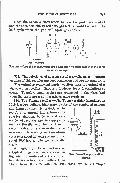
THE TUNGAR RECTIFIER 399
Once the anode current starts to flow the grid loses control and the tube acts like an ordinary gas rectifier until the end of the half cycle when the grid will again get control.
25 5
E = 180
when I =100 ma
248.—Use of a rectifier with two plates and two series cathodes to double the input voltage.
323. Characteristics of gaseous rectifiers.—The most important features of this rectifier are good regulation and low internal drop.
The output is somewhat harder to filter than the output of a high-vacuum rectifier; there is a tendency for r.-f. oscillations to occur. Therefore small chokes are connected in the plate lead when the tubes are used in sensitive radio receivers.
324. The Tungar rectifier.—The Tungar rectifier introduced in 1916 is a low-voltage, high-current tube of the combined gaseous and filament type. It is designed to rectify a.-c. current into a form suit-able for charging batteries, and as a matter of fact was used to supply cur-rent for the filament circuits of some early models of a.-c.-operated radio receivers. Its starting or breakdown voltage is about 15 volts and useful life about 2000 hours. The gas is usually argon. A diagram of the connections of Filament
a typical tungar rectifier are shown in Winding 249.—Tungar rectifier
Fig. 249. It consists of a transformer circuit. to reduce the input a.-c. voltage from 115 to from 30 to 75 volts; the tube itself, which is a simple
Plate Winding
A.C.
WorldRadioHistory
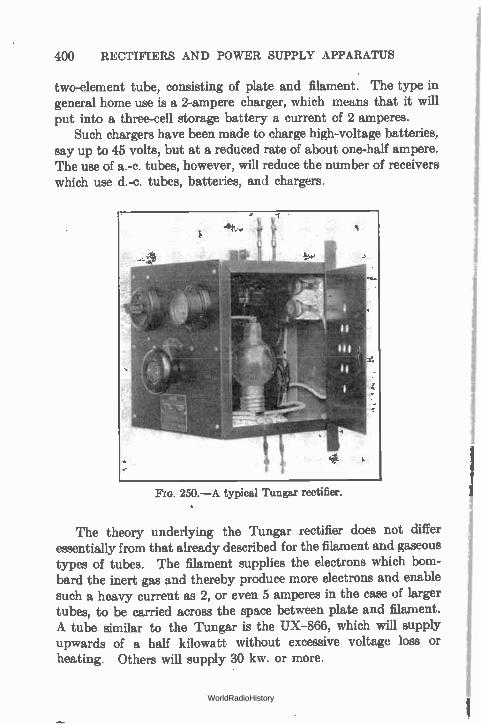
400 RECTIFIERS AND POWER SUPPLY APPARATUS
two-element tube, consisting of plate and filament. The type in general home use is a 2-ampere charger, which means that it will put into a three-cell storage battery a current of 2 amperes.
Such chargers have been made to charge high-voltage batteries, say up to 45 volts, but at a reduced rate of about one-half ampere. The use of a.-c. tubes, however, will reduce the number of receivers which use d.-c. tubes, batteries, and chargers.
FIG. 250.—A typical Tungar rectifier.
The theory underlying the Tungar rectifier does not differ essentially from that already described for the filament and gaseous types of tubes. The filament supplies the electrons which bom-bard the inert gas and thereby produce more electrons and enable such a heavy current as 2, or even 5 amperes in the case of larger tubes, to be carried across the space between plate and filament. A tube similar to the Tungar is the UX-866, which will supply upwards of a half kilowatt without excessive voltage loss or heating. Others will supply 30 kw. or more.
WorldRadioHistory
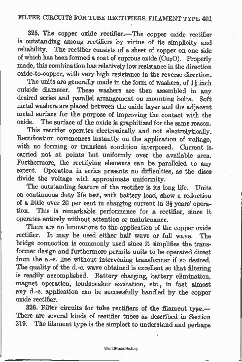
FILTER CIRCUITS FOR TUBE RECTIFIERS, FILAMENT TYPE 401
325. The copper oxide rectifier.—The copper oxide rectifier is outstanding among rectifiers by virtue of its simplicity and reliability. The rectifier consists of a sheet of copper on one side of which has been formed a coat of cuprous oxide (Cu2O). Properly made, this combination has relatively low resistance in the direction oxide-to-copper, with very high resistance in the reverse direction.
The units are generally made in the form of washers, of 1 inch outside diameter. These washers are then assembled in any desired series and parallel arrangement on mounting bolts. Soft metal washers are placed between the oxide layer and the adjacent metal surface for the purpose of improving the contact with the oxide. The surface of the oxide is graphitized for the same reason.
This rectifier operates electronically and not electrolytically. Rectification commences instantly on the application of voltage, with no forming or transient condition interposed. Current is. carried not at points but uniformly over the available area. Furthermore, the rectifying elements can be paralleled to any extent. Operation in series presents no difficulties, as the discs divide the voltage with approximate uniformity.
The outstanding feature of the rectifier is its long life. Units on continuous duty life test, with battery load, show a reduction of a little over 20 per cent in charging current in 3¡ years' opera-tion. This is remarkable performance for a rectifier, since it operates entirely without attention or maintenance.
There are no limitations to the application of the copper oxide rectifier. It may be used either half wave or full wave. The bridge connection is commonly used since it simplifies the trans-former design and furthermore permits units to be operated direct from the a.-c. line without intervening transformer if so desired. The quality of the d.-c. wave obtained is excellent so that filtering is readily accomplished. Battery charging, battery elimination, magnet operation, loudspeaker excitation, etc., in fact almost any d.-c. application can be successfully handled by the copper oxide rectifier.
326. Filter circuits for tube rectifiers of the filament type.— There are several kinds of rectifier tubes as described in Section 319. The filament type is the simplest to understand and perhaps
WorldRadioHistory
402 RECTIFIERS AND POWER SUPPLY APPARATUS
the most commonly used and for this reason has been described in detail.
The output of the rectifier circuit is not an even flow of current at all. In a loud speaker it would make considerable noise, or if used in a radio receiver without further alteration the hum would be intolerable. The next step after rectification is filtering. A good plate voltage supply device, then, consists first of a
transformer which raises the a.-c. voltage to the value required by the receiver plus the losses in voltage in rectifier, filter and voltage divider. Second, the rectifier which performs the task already described. In the third place comes the filter whose task it is to smooth out the pulsations of current in the plate circuit of the rec-tifier so that the final product will be d.c. of constant amplitude and a minimum amount of a.c. in it, and of a voltage high enough • to supply the voltage and current required by the receiver and amplifier as well as the losses in the device itself. A conventional filter circuit consists of series inductances which
smooth out the ripples of current and keep the current flowing at the a.-c. voltage reversals, and shunt condensers which act as reservoirs of voltage as described in Section 73. A two-section filter, that is, two chokes and their accompanying condensers, is usually employed. The amount of filtering necessary dependa entirely upon the amount of residual hum that is tolerable after the filtering has taken place. A very quiet power supply device is required in those receivers which have a rather high audio-frequency voltage amplification and which amplify frequencies as low as 120 to 60 cycles.
There is always a certain amount of a.-c. voltage left after the filtering has taken place. This voltage is a matter of millivolts compared to several hundred volts of d.c., but even these small a.-c. voltages may become objectionable when a loud speaker that is efficient at low frequencies is used. This voltage is a combination of the fundamental frequency, 60 cycles, and its harmonics. In double-wave power supply devices the second harmonic or 120 cycles is particularly strong. A good loud speaker which reproduces notes as low as 120 cycles
will hum badly when used with a power amplifier which gets its
WorldRadioHistory
REGULATION 403
voltages from a poorly filtered supply. Even with a very good filter, some a.-c. voltages are likely to be picked up by the cores of audio transformers if they are near power transformers carrying a.-c. currents. The ultimate extent to which hum may be reduced may be the amount that transformers can be shielded from stray fields, and not the extent to which a rectifier's output may be filtered. The push-pull amplifier may be operated from incom-pletely filtered supply. The rest of the current required from the B eliminator can be carefully filtered at reduced cost.
327. Regulation.—After passing through the filter the circuit returns to the transformer through the terminal resistance which acts as a potentiometer to reduce the full voltage to the values desired. If the full voltage is 180 volts, a tap at the proper place will give 90 volts and another will give 45 volts for the detector tube. Now it is apparent that the voltage across this resistance depends upon the current through it, and if there were no other resistances in the circuit Ohm's law would tell us at once what the voltage across the resistance would be. Unfortunately the transformer, the rectifier tube, and the filter chokes all have resistance, so that the greater the current taken from the whole device the lower is the voltage across its output. From batteries one gets 90 volts for his tubes whether he runs one or a dozen of them; the drain from the batteries is all that changes. With a voltage supply device, however, the voltage at the amplifier tap would be less than 90 if the current taken from it exceeds a certain amount. This is a distinct disadvantage from every standpoint but one.
In a high-resistance system it is difficult to blow up tubes. If a B battery is put across a tube, the filament immediately becomes very bright and probably burns up because too much current goes through it. The current that can be taken from a high-resistance device is limited and so it is doubtful if enough current could be secured to damage the tube. This, however, is a rather dubious advantage. A series of curves showing the output voltage at various output
current drains gives what is known as the regulation of the device, that is, the manner in which its voltage drops with increase in cur-
WorldRadioHistory
404 RECTIFIERS AND POWER SUPPLY APPARATUS
rent taken from it. The history of plate supply devices can be traced in a record of the regulation of such units, the older they are the worse their regulation curves, or the higher their internal resistance. The steep regulation curve of an early " B eliminator" may be seen in Fig. 251.
Outp
ut Volts D.C
.
300
280
260
240
220
200
180
160
140
120
100
80
40
40
20
O
192 513 Eliminator"
5 10 15 20
• Output m A
251.—Regulation curve of early "B eliminator." Note the great voltage drop.
25 30 35
328. A typical rectifier-filter system.—Several curves showing the relation between the current and voltage in a modern rectifier-
filter are shown in Fig. 252. The losses in voltage are those due the IR drop in the resistance
of the tube and the transformer. In Fig. 252 the voltage across the output resistance of the filter would be less than these voltages by the drop in the filter resistance. If the filter chokes have a d.-c. resistance of 1000 ohms there would be an additional drop of 1 volt per milliampere of current from it. A transformer which supplies 220 volts to each plate of a CX-
380 tube will deliver a voltage of 220 across the input to the filter
WorldRadioHistory
A TYPICAL RECTIFIER-FILTER SYSTEM 405
and if the latter has a resistance of 1000 ohms about will appear across the out-put at a current drain of 65 ma.
The variations in trans-former voltage, current through the tube, and steady load current are shown in the oscillographs in Fig. 253. The fact that abnormally high instan-taneous values of currents must be passed by the tube is clearly shown in the tube current wave. No current
1100
o 1000
be
900
5 15 800 '111 '5 ° ? 700
600
500
400
300
150 volts
1 1 1 1 Output of UX 281
— Typical Recifter Circuit
N e20k
Ok di.
°4P/ 4
eki, /7 ete • di
et
10 20 30 40 50 60 70 80 90100110120
Half Wave Rectification Output Milliamperes
Fm. 252.—Output of modern rectifier. flows until the transformer voltage reaches a certain minimum value and current ceases to flow as the voltage across the transformer secondary decreases. The peak current rises as high as 310 milliamperes; and on the
1000 o
Transformer Voltage
22
500 °
0
300
200 •ii
100 2 Tube Current
0
200 . •ic
150
100
50 Load Current 0
FIG. 253a.—High instantaneous cur-rent required from rectifier with
capacitive input.
1000 . ••••
500 0 > Transformer Voltayg
0
300 , •"Ç
200 m
100 ..... ,.....d.-- -••••—.._.__.....----„,„ o Tube Current
200 .. 150
100
50 Load Current 0
253b.—Reduced tube current in an inductance input filter.
assumption that the resistance of the tube remains constant, the power lost in it increases as the square of the current, showing that this high current puts a severe burden on the tube. As a
WorldRadioHistory
406 RECTIFIERS AND POWER SUPPLY APPARATUS
matter of fact the internal resistance of the tube is almost con-stant, decreasing somewhat at higher current loads.
If the first filter condenser is removed and placed across the output, as shown in Fig. 254, not only does the peak current passed by the tube decrease, thereby decreasing the power lost in it, but the regulation is improved. The disadvantage of such a connec-tion is slightly greater hum output and the fact that the output voltage is decreased by about 20 per cent. This loss in voltage may be made up by increasing the secondary voltage of the trans-former, and even then the power losses in the tube will be less. The peak current passed through the tube in the second case is about 140 milliamperes when a steady current of 125 ma. is
L1 L2 L1 L2
To Rectifier
a FIG. 254.—Two types of filter; a. inductance input, and b. capacity input.
required, thereby reducing the power losses in the tube by about 35 per cent.
The connection which omits the first filter condenser increases the life of the tube, permits the use of a tube whose emission has fallen below the point at which the tube would be useless in a capacity input filter, gives better regulation at current drains over 20 ma., reduces the filament emission required, and reduces the heating of the tube.
Using chokes of 11.5 and 13.5 henries for L1 and L2 and 4-mfd. and 8-mfd. condensers as C1 and C2, a hum output of 44 millivolts was reported as typical. Although the amount of hum that can be tolerated is a matter of opinion, the following figures may be useful. With a sensitive dynamic speaker in a 3-foot baffle, a 120-cycle voltage of 540 millivolts across the primary of the trans-
WorldRadioHistory
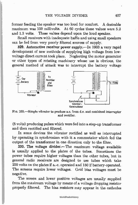
THE VOLTAGE DIVIDER 407
former feeding the speaker was too loud for comfort. A desirable maximum was 150 millivolts. At 60 cycles these values were 5.2 and 1.3 volts. These values depend upon the loud speaker.
Small receivers with inadequate bale and using small speakers can be fed from very poorly filtered sources of supply.
329. Automotive receiver power supply.—In 1933 a very rapid development of new methods of supplying high voltage from low-voltage direct current took place. Neglecting the motor generator or other types of rotating machinery whose use is obvious, the general method of attack was to interrupt the battery voltage
=_ Car =_Batiery
Vibrator
To Rectifier and Filter
Synchronous Vibrator
Commutator
Fm. 255.—Simple vibrator to produce a.c. from d.c. and combined interrupter and rectifier.
(6 volts) producing pulses which were fed into a step-up transformer and then rectified and filtered.
In some devices the vibrator rectified as well as interrupted by operating in synchronism with it a commutator which fed the output of the transformer in one direction only to the filter.
330. The voltage divider.—The maximum voltage available is usually applied to the plates of the tubes. Sometimes the power tubes require higher voltages than the other tubes, but in general radio receivers are designed to use tubes which take 250 volts on the plates if a.-c. operated and 180 if battery-operated. The screens require lower voltages. Grid bias voltages must be negative.
The screen and lower positive voltages are usually supplied from the maximum voltage by means of a voltage dropping resistor properly filtered. The bias resistors may appear in the cathodes
WorldRadioHistory
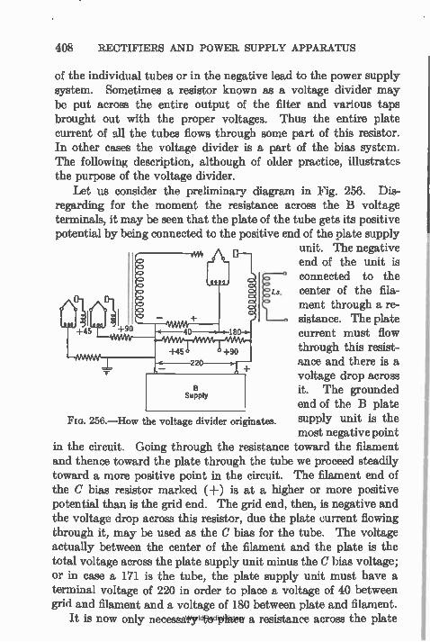
408 RECTIFIERS AND POWER SUPPLY APPARATUS
of the individual tubes or in the negative lead to the power supply system. Sometimes a resistor known as a voltage divider may be put across the entire output of the filter and various taps brought out with the proper voltages. Thus the entire plate current of all the tubes flows through some part of this resistor. In other cases the voltage divider is a part of the bias system. The following description, although of older practice, illustrates the purpose of the voltage divider.
Let us consider the preliminary diagram in Fig. 256. Dis-regarding for the moment the resistance across the B voltage terminals, it may be seen that the plate of the tube gets its positive potential by being connected to the positive end of the plate supply
unit. The negative end of the unit is connected to the center of the fila-ment through a re-sistance. The plate
+45 current must flow through this resist-ance and there is a voltage drop across it. The grounded end of the B plate supply unit is the most negative point
in the circuit. Going through the resistance toward the filament and thence toward the plate through the tube we proceed steadily toward a more positive point in the circuit. The filament end of the C bias resistor marked (+) is at a higher or more positive potential than is the grid end. The grid end, then, is negative and the voltage drop across this resistor, due the plate current flowing through it, may be used as the C bias for the tube. The voltage actually between the center of the filament and the plate is the total voltage across the plate supply unit minus the C bias voltage; or in case a 171 is the tube, the plate supply unit must have a terminal voltage of 220 in order to place a voltage of 40 between grid and filament and a voltage of 180 between plate and filament.
It is now only necessary to place a resistance across the plate
256.—How the voltage divider originates.
WorldRadioHistory
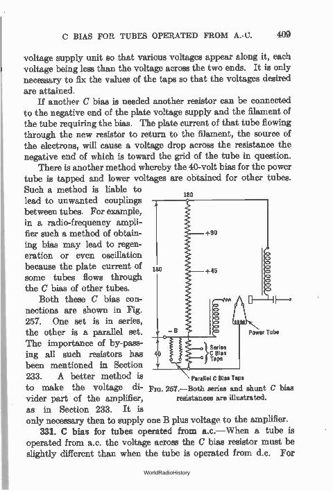
C BIAS FOR TUBES OPERATED FROM A.- C. 409
voltage supply unit so that various voltages appear along it, each voltage being less than the voltage across the two ends. It is only necessary to fix the values of the taps so that the voltages desired are attained.
If another C bias is needed another resistor can be connected to the negative end of the plate voltage supply and the filament of the tube requiring the bias. The plate current of that tube flowing through the new resistor to return to the filament, the source of the electrons, will cause a voltage drop across the resistance the negative end of which is toward the grid of the tube in question.
There is another method whereby the 40-volt bias for the power tube is tapped and lower voltages are obtained for other tubes. Such a method is liable to
180 lead to unwanted couplings between tubes. For example, in a radio-frequency ampli-fier such a method of obtain- +90
ing bias may lead to regen-eration or even oscillation because the plate current of 180 +45
some tubes flows through the C bias of other tubes.
Both these C bias con-nections are shown in Fig. 257. One set is in series, the other is a parallel set. - B Power Tube
The importance of by-pass-ing all such resistors has 40 }Series C Blas
been mentioned in Section Taps
233. A better method is Parallel C Bias Taps
to make the voltage di- F. 257.—Both series and shunt C bias vider part of the amplifier, resistances are illustrated.
as in Section 233. It is only necessary then to supply one B plus voltage to the amplifier.
331. C bias for tubes operated from a.c.—When a tube is operated from a.c. the voltage across the C bias resistor must be slightly different than when the tube is operated from d.c. For
WorldRadioHistory
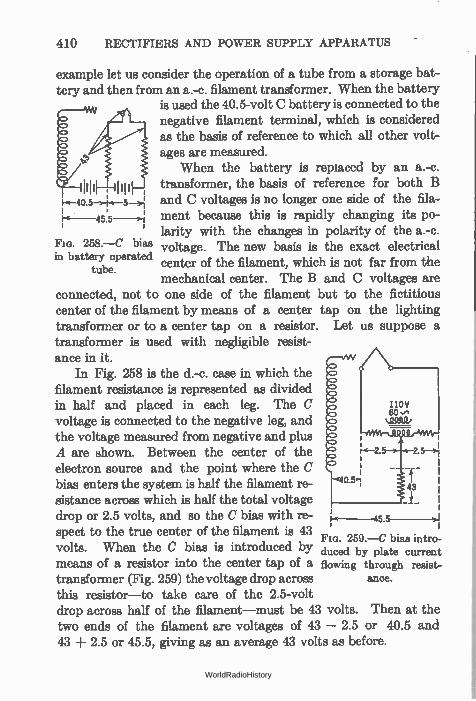
410 RECTIFIERS AND POWER SUPPLY APPARATUS
example let us consider the operation of a tube from a storage bat-tery and then from an a.-c. filament transformer. When the battery
is used the 40.5-volt C battery is connected to the negative filament terminal, which is considered as the basis of reference to which all other volt-ages are measured.
When the battery is replaced by an a.-c. transformer, the basis of reference for both B and C voltages is no longer one side of the fila-ment because this is rapidly changing its po-larity with the changes in polarity of the a.-c. voltage. The new basis is the exact electrical center of the filament, which is not far from the mechanical center. The B and C voltages are
connected, not to one side of the filament but to the fictitious center of the filament by means of a center tap on the lighting transformer or to a center tap on a resistor. Let us suppose a transformer is used with negligible resist-ance in it.
In Fig. 258 is the d.-c. case in which the filament resistance is represented as divided in half and placed in each leg. The C voltage is connected to the negative leg, and the voltage measured from negative and plus A are shown. Between the center of the electron source and the point where the C bias enters the system is half the filament re-sistance across which is half the total voltage drop or 2.5 volts, and so the C bias with re-spect to the true center of the filament is 43 volts. When the C bias is introduced by means of a resistor into the center tap of a transformer (Fig. 259) the voltage drop across this resistor—to take care of the 2.5-volt drop across half of the filament—must be 43 volts. Then at the two ends of the filament are voltages of 43 — 2.5 or 40.5 and 43 ± 2.5 or 45.5, giving as an average 43 volts as before.
, 1111
Ire- 4513-4
Fia. 258.—C bias in battery operated
tube.
1-6-45.5
Fia. 259.—C bias intro-duced by plate current flowing through resist-
ance.
WorldRadioHistory
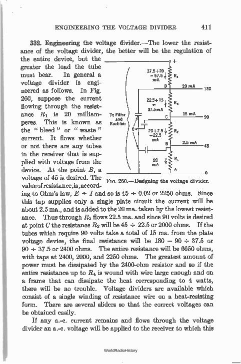
ENGINEERING THE VOLTAGE DIVIDER 411
332. Engineering the voltage divider.—The lower the resist-ance of the voltage divider, the better will be the regulation of the entire device, but the greater the load the tube must bear. In general a voltage divider is engi-neered as follows. In Fig. 260, suppose the current flowing through the resist-ance R1 is 20 milliam-peres. This is known as the " bleed " or " waste " 20+2.5 4 current. It flows whether
-22.5 mA
or not there are any tubes B 45
in the receiver that is sup-plied with voltage from the device. At the point B, a voltage of 45 is desired. The value of resistance, is, accord-ing to Ohm's law, E ÷ I and so is 45 ÷ 0.02 or 2250 ohms. Since this tap supplies only a single plate circuit the current will be about 2.5 ma., and is added to the 20 ma. taken by the lowest resist-ance. Thus through R2 flows 22.5 ma. and since 90 volts is desired at point C the resistance R2 will be 45 ÷ 22.5 or 2000 ohms. If the tubes which require 90 volts take a total of 15 ma. from the plate voltage device, the final resistance will be 180 — 90 ÷ 37.5 or 90 ÷ 37.5 or 2400 ohms. The entire resistance will be 6650 ohms, with taps at 2400, 2000, and 2250 ohms. The greatest amount of power must be dissipated by the 2400-ohm resistor and so if the entire resistance up to R4 is wound with wire large enough and on a frame that can dissipate the heat corresponding to 4 watts, there will be no trouble. Voltage dividers are available which consist of a single winding of resistance wire on a heat-resisting form. There are several sliders so that the correct voltages can be obtained easily.
If any a.-c. current remains and flows through the voltage divider an a.-c. voltage will be applied to the receiver to which this
37.5+ 20 = 57.5 R4 mA
D 20 mA
22.5+15 1 t
37.5 mA
R,
15 mA
mA 20 4 R,
To Filter and
Rectifier
2.5 mA
180
90
o 260.—Designing the voltage divider.
WorldRadioHistory
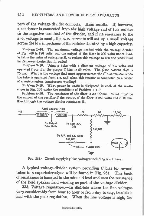
412 RECTIFIERS AND POWER SUPPLY APPARATUS
part of the voltage divider connects. Hum results. If, however, a condenser is connected from the high voltage end of this resistor to the negative terminal of the divider, and if its reactance to the a.-c. voltage is small, the a.-c. currents will set up a small voltage across the low impedance of the resistor shunted by a high capacity.
Problem 1-16. The maximum voltage needed with the voltage divider of Fig. 260 is 180 volts, but the output of the filter is 200 volts under load. What is the value of resistance R4 to reduce this voltage to 180 and what must be its power dissipation ia watts?
Problem 2-16. Using a tube with a filament voltage of 7.5 volts and operated from d.c. the proper C bias is 50 volts. The plate current then is 25 ma. What is the voltage that must appear across the C bias resistor when the tube is operated from a.c. and when this resistor is connected to a center of a resistanceless transformer winding?
Problem 3-16. What power in watts is dissipated in each of the resist-ances in Fig. 260 under the conditions of Problem 1-167
Problem 4-16. The resistance of the filter is 300 ohms. What must be the output of the rectifier if the output of the filter is 250 volts and if 40 ma. flow through the voltage divider resistance Re
Loud Speaker Field —B 75
To Output To First A.F. Tube Grids Grid
To R.F. and I.F. Grids 500,000
60
500,000
0.25
17,500
261.—Circuit supplying bias voltages including a.v.c. bias.
A typical voltage-divider system providing C bias for several tubes in a superheterodyne will be found in Fig. 261. This bank of resistances is inserted in the minus B lead and uses the resistance of the loud speaker field winding as part of the voltage divider.
333. Voltage regulation.—In districts where the line voltages vary considerably from hour to hour or from day to day, trouble is had with the poor regulation. When the line voltage is high, the
WorldRadioHistory
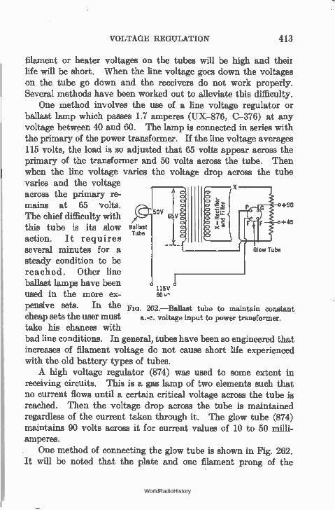
VOLTAGE REGULATION 413
filament or heater voltages on the tubes will be high and their life will be short. When the line voltage goes down the voltages on the tube go down and the receivers do not work properly. Several methods have been worked out to alleviate this difficulty.
One method involves the use of a line voltage regulator or ballast lamp which passes 1.7 amperes (UX-876, C-376) at any voltage between 40 and 60. The lamp is connected in series with the primary of the power transformer. If the line voltage averages 115 volts, the load is so adjusted that 65 volts appear across the primary of the transformer and 50 volts across the tube. Then when the line voltage varies the voltage drop across the tube varies and the voltage across the primary re-mains at 65 volts. +90
50V The chief difficulty with 6 if
action. It requires +45 this tube is its slow Ballast
Tube
several minutes for a Glow Tube
steady condition to be reached. Other line ballast lamps have been
115V used in the more ex- 60 v•
pensive sets. In the Fia. 262.—Ballast tube to maintain constant cheap sets the user must a.-c. voltage input to power transformer.
take his chances with bad line conditions. In general, tubes have been so engineered that increases of filament voltage do not cause short life experienced with the old battery types of tubes. A high voltage regulator (874) was used to some extent in
receiving circuits. This is a gas lamp of two elements such that no current flows until a certain critical voltage across the tube is reached. Then the voltage drop across the tube is maintained regardless of the current taken through it. The glow tube (874) maintains 90 volts across it for current values of 10 to 50 milli-amperes. . One method of connecting the glow tube is shown in Fig. 262. It will be noted that the plate and one filament prong of the
WorldRadioHistory
414 RECTIFIERS AND POWER SUPPLY APPARATUS
4-prong socket are connected in series with the line and the trans-former primary. Since there are only two elements in the tube, these prongs are shorted within the base. Therefore the circuit in which such a tube is used will not operate until the tube is placed in its socket. The tube thereby acts as a switch preventing premature operation, or operation without the voltage regulator in position to carry out its function.
The flood of cheap sets put out in 1932-33 paid little attention to the problem of fluctuating voltages in the home. Economy was one reason, the manufacturer desiring to put as little in the receiver as possible, to keep the price low. It is also true that modern tubes are not so sensitive, in life or performance, to voltage variations. Tubes last well over 1000 hours in the average receiver in spite of the hard usage they must tolerate.
WorldRadioHistory
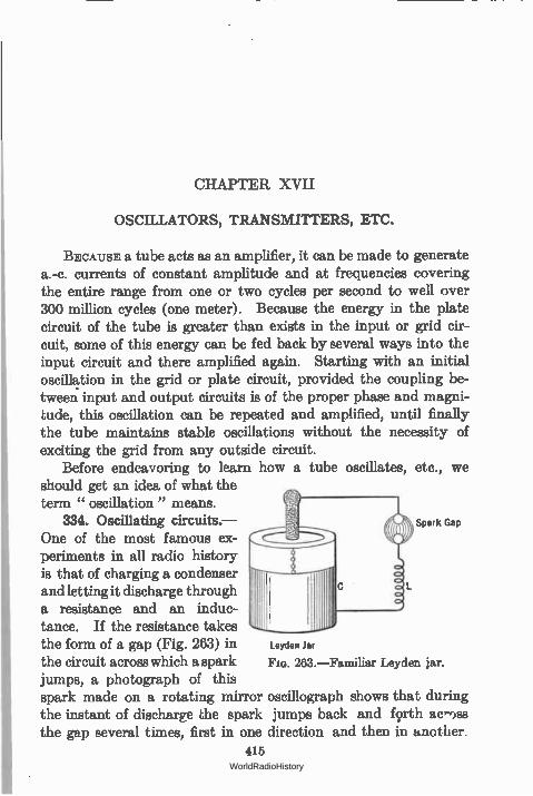
CHAPTER XVII
OSCILLATORS, TRANSMITTERS, ETC.
BECAUSE a tube acts as an amplifier, it can be made to generate a.-c. currents of constant amplitude and at frequencies covering the entire range from one or two cycles per second to well over 300 million cycles (one meter). Because the energy in the plate circuit of the tube is greater than exists in the input or grid cir-cuit, some of this energy can be fed back by several ways into the input circuit and there amplified again. Starting with an initial oscillation in the grid or plate circuit, provided the coupling be-tween input and output circuits is of the proper phase and magni-tude, this oscillation can be repeated and amplified, until finally the tube maintains stable oscillations without the necessity of exciting the grid from any outside circuit.
Before endeavoring to learn how a tube oscillates, etc., we should get an idea of what the term " oscillation " means.
334. Oscillating circuits.— Spark Gap
One of the most famous ex-periments in all radio history is that of charging a condenser and letting it discharge through a resistance and an induc-tance. If the resistance takes the form of a gap (Fig. 263) in the circuit across which a spark jumps, a photograph of this spark made on a rotating mirror oscillograph shows that during the instant of discharge the spark jumps back and fprth acrems the gap several times, first in one direction and then in another.
415
Leyden Jar
263.—Familiar Leyden jar.
WorldRadioHistory
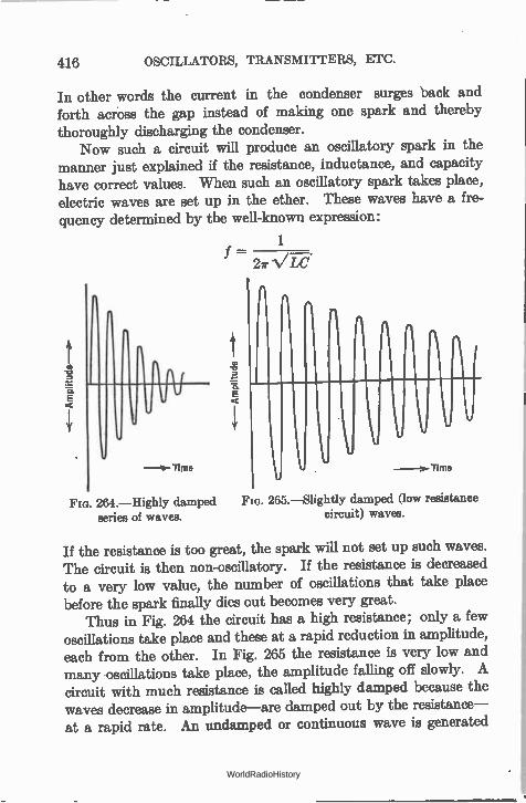
416 OSCILLATORS, TRANSMITTERS, ETC.
In other words the current in the condenser surges back and forth across the gap instead of making one spark and thereby thoroughly discharging the condenser.
Now such a circuit will produce an oscillatory spark in the manner just explained if the resistance, inductance, and capacity have correct values. When such an oscillatory spark takes place, electric waves are set up in the ether. These waves have a fre-quency determined by the well-known expression:
E
—Ne-Time
- 2ir
P_
E
1
L.
V. s- Time
Fer. 264.—Highly damped Flo. 265.—Slightly damped (low resistance series of waves, circuit) waves.
If the resistance is too great, the spark will not set up such waves. The circuit is then non-oscillatory. If the resistance is decreased to a very low value, the number of oscillations that take place before the spark finally dies out becomes very great.
Thus in Fig. 264 the circuit has a high resistance; only a few oscillations take place and these at a rapid reduction in amplitude, each from the other. In Fig. 265 the resistance is very low and many oscillations take place, the amplitude falling off slowly. A circuit with much resistance is called highly damped because the waves decrease in amplitude—are damped out by the resistance— at a rapid rate. An undamped or continuous wave is generated
WorldRadioHistory
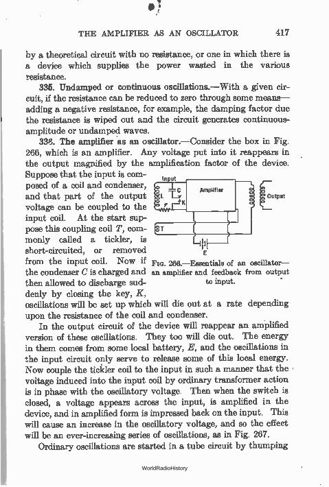
THE AMPLIFIER AS AN OSCILLATOR 417
by a theoretical circuit with no resistance, or one in which there is a device which supplies the power wasted in the various resistance.
335. Undamped or continuous oscillations.—With a given cir-cuit, if the resistance can be reduced to zero through some means— adding a negative resistance, for example, the damping factor due the resistance is wiped out and the circuit generates continuous-amplitude or undamped waves.
336. The amplifier as an oscillator.—Consider the box in Fig. 266, which is an amplifier. Any voltage put into it reappears in the output magnified by the amplification factor of the device. Suppose that the input is com-posed of a coil and condenser, and that part of the output output voltage can be coupled to the input coil. At the start sup-pose this coupling coil T, com-monly called a tickler, is short-circuited, or removed from the input coil. Now if the condenser C is charged and then allowed to discharge sud-denly by closing the key, K, oscillations will be set up which will die out at a rate depending upon the resistance of the coil and condenser.
In the output circuit of the device will reappear an amplified version of these oscillations. They too will die out. The energy in them comes from some local battery, E, and the oscillations in the input circuit only serve to release some of this local energy. Now couple the tickler coil to the input in such a manner that the voltage induced into the input coil by ordinary transformer action is in phase with the oscillatory voltage. Then when the switch is closed, a voltage appears across the input, is amplified in the device, and in amplified form is impressed back on the input. This will cause an increase in the oscillatory voltage, and so the effect will be an ever-increasing series of oscillations, as in Fig. 267.
Ordinary oscillations are started in a tube circuit by thumping
E
266.—Eseentiale of an oscillator— an amplifier and feedback from output
to input.
WorldRadioHistory
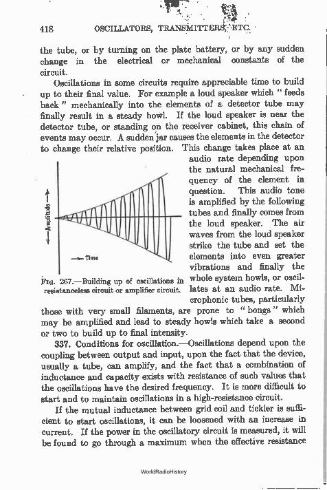
418 OSCILLATORS, TRANSMITTERS, ETC.
the tube, or by turning on the plate battery, or by any sudden change in the electrical or mechanical constants of the circuit.
Oscillations in some circuits require appreciable time to build up to their final value. For example a loud speaker which " feeds back" mechanically into the elements of a detector tube may finally result in a steady howl. If the loud speaker is near the detector tube, or standing on the receiver cabinet, this chain of events may occur. A sudden jar causes the elements in the detector to change their relative position. This change takes place at an
audio rate depending upon the natural mechanical fre-quency of the element in question. This audio tone
41 is amplified by the following tubes and finally comes from the loud speaker. The air waves from the loud speaker strike the tube and set the
Time elements into even greater vibrations and finally the
ÉIG. 267.—Building up of oscillations in whole system howls, or oscil-resistanceless circuit or amplifier circuit, lates at an audio rate. Mi-
crophonic tubes, particularly those with very small filaments, are prone to " bongs " which may be amplified and lead to steady howls which take a second or two to build up to final intensity.
337. Conditions for oscillation.—Oscillations depend upon the coupling between output and input, upon the fact that the device, usually a tube, can amplify, and the fact that a combination of inductance and capacity exists with resistance of such values that the oscillations have the desired frequency. It is more difficult to start and to maintain oscillations in a high-resistance circuit.
If the mutual inductance between grid coil and tickler is suffi-cient to start oscillations, it can be loosened with an increase in current. If the power in the oscillatory circuit is measured, it will be found to go through a maximum when the effective resistance
WorldRadioHistory
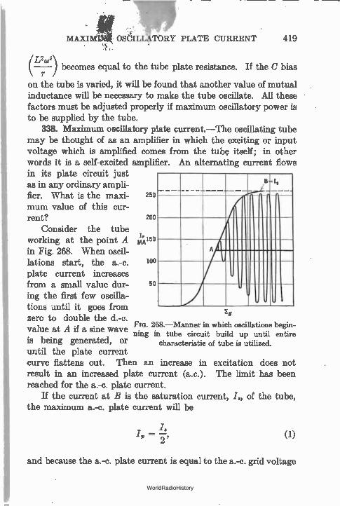
A
Eg
• e
MAXIM oSCILIZtToRY PLATE CURRENT 419 .ï
(--"2.112 ) becomes equal to the tube plate resistance. If the C bias
on the tube is varied, it will be found that another value of mutual inductance will be necessary to make the tube oscillate. All these factors must be adjusted properly if maximum oscillatory power is to be supplied by the tube.
338. Maximum oscillatory plate current. —The oscillating tube may be thought of as an amplifier in which the exciting or input voltage which is amplified comes from the tube itself; in other words it is a self-excited amplifier. An alternating current flows in its plate circuit just as in any ordinary ampli-fier. What is the maxi- 250
mum value of this cur-rent? 200
Consider the tube working at the point A mA150 in Fig. 268. When oscil-lations start, the a.-c. 100
plate current increases from a small value dur- 50
lag the first few oscilla-tions -until it goes from zero to double the d.-c.
FIG. 268.—Manner in which oscillations begin-value at A if a sine wave ning in tube circuit build up until entire
is being generated, or characteristic of tube is utilized. until the plate current curve flattens out. Then an increase in excitation does not result in an increased plate current (a.c.). The limit has been reached for the a.-c. plate current.
If the current at B is the saturation current, I, of the tube, the maximum a.-c. plate current will be
(1)
and because the a.-c. plate current is equal to the a.-c. grid voltage
WorldRadioHistory
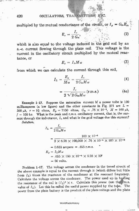
420 OSCILLATORS,
multipled by the mutual conductance of tile
- 2 Gm' (2)
which is also equal to the voltage induCèd in thè grid coil by an a.-c. current flowing through the plate coil. This voltage is the current in the oscillatory circuit multiplied by the mutual reac-tance, or
= ILA 1 co
from which we can calculate the current through this coil,
E„ — — (4) Mw 2 G',,M w
/, (r ms.) (4a)
2 N/2 GmMco
Example 1-17. Suppose the saturation current bf a power tube is 100 milliamperes (a low figure) and the other constants in Fig. 271 are L = 500 »h, r = IQ ohms, Rj, =- 7150 ohms, Gm = .76 X 10 -3, M = 160 eth, f = 100 kc. What is the peak and r.m.s. oscillatory current, that is, the cur-rent through the inductance, L, and what is the grid voltage due this current?
Solution.
(3)
r.
100 X 10 -3
2 x 6.28 x 100,000 X .76 X 10 -3 X 160 X 10-3
= 0.655 ampere = .465 r.m.s.
.E g -= I LAI co . = .655 X 160 X 10 -6 X 6.28 X 103
= 66 volts.
Problem 1-17. The voltage across the condenser in the tuned circuit of the above example is equal to the. current through it (which differs but little from IL) times the reactance of the condenser at the resonant frequency.
Ijt Calculate the voltage across the condenser. The power used up in h ing the resistance of the coil is (IL)' X r. Calculate this power (use t .s. value of IL): Let this be called the useful power supplied by the tupe. The power from the plate battery is the product of the plate voltage and the plate
WorldRadioHistory
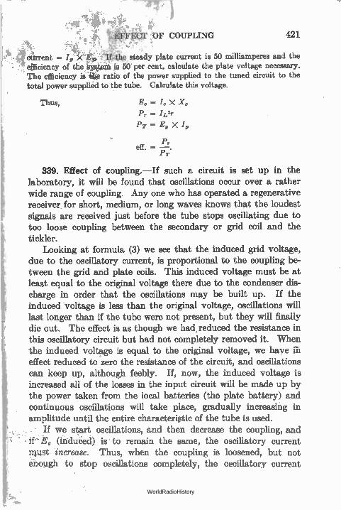
741 e.
EFFECT OF COUPLING 421
étirrent = /,, Xep. "Up tele steady plate current is 50 milliamperes and the , efficiency of the,is¡uttéM is 50. per cent, calculate the plate voltage necessary. The efficiency is ratio of the power supplied to the tuned circuit to the total power supplied to the tube. Calculate this voltage.
Thus, Ec = Ic X Xc
Pr = I L'r PT = Ey X
Pr eff. =
1-7;
339. Effect of coupling.— If such a circuit is set up in the laboratory, it will be found that oscillations occur over a rather wide range of coupling. Any one who has operated a regenerative receiver , for short, medium, or long waves knows that the loudest signals are received just before the tube stops oscillating due to too loose coupling between the secondary or grid coil and the tickler.
Looking at formula (3) we see that the induced grid voltage, due to the oscillatory current, is proportional to the coupling be-tween the grid and plate coils. This induced voltage must be at least equal to the original voltage there due to the condenser dis-charge in order that the oscillations may be built up. If the induced voltage is less than the original voltage, oscillations will last longer than if the tube were not present, but they will finally die out. The effect is as though we had, reduced the resistance in this oscillatory circuit but had not completely removed it. When the induced voltage is equal to the original voltage, we have ill effect reduced to zero the resistance of the circuit, and oscillations can keep up, although feebly. If, now, the induced voltage is increased all of the losses in the input circuit will be made up by the power taken from the local batteries (the plate battery) and continuous oscillations will take place, gradually increasing in amplitude until the entire characteristic of the tube is used. - • If we start oscillations, and then decrease the coupling, and
• if- E, (induced) is to remain the same, the oscillatory current must increase. Thus, when the coupling is loosened, but not enough to stop oscillations completely, the oscillatory current
WorldRadioHistory
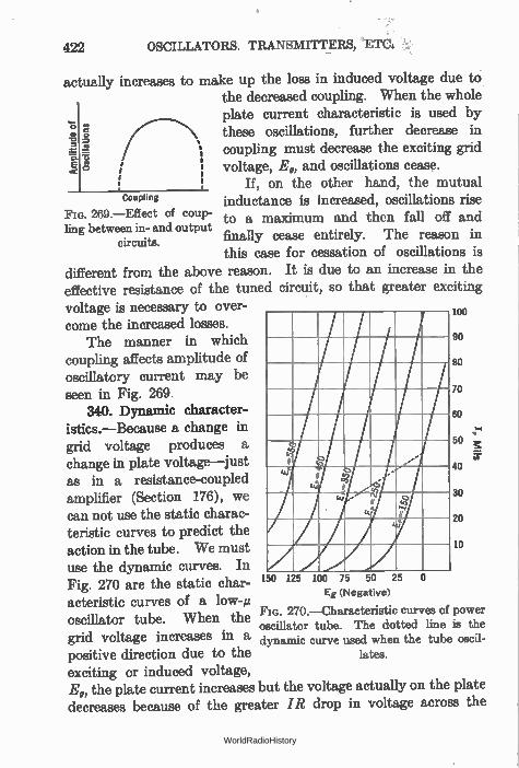
422 OSCILLATORS. TRANSMITTERS, "ETC.
actually increases to make up the loss in induced voltage due to the decreased coupling. When the whole plate current characteristic is used by these oscillations, further decrease in coupling must decrease the exciting grid voltage, E„ and oscillations cease.
If, on the other hand, the mutual inductance is increased, oscillations rise to a maximum and then fall off and finally cease entirely. The reason in this case for cessation of oscillations is
different from the above reason. It is due to an increase in the effective resistance of the tuned circuit, so that greater exciting voltage is necessary to over- 100
come the increased losses. The manner in which
coupling affects amplitude of oscillatory current may be seen in Fig. 269.
340. Dynamic character-istics.—Because a change in grid voltage produces a change in plate voltage—just as in a resistance-coupled amplifier (Section 176), we can not use the static charac-teristic curves to predict the action in the tube. We must use the dynamic curves. In Fig. 270 are the static char-acteristic curves of a oscillator tube. When the grid voltage increases in a positive direction due to the exciting or induced voltage, E„ the plate current increases but the voltage actually on the plate decreases because of the greater IR drop in voltage across the
E o
Coupling
269.—Effect of coup-ling between in- and output
circuits.
o
90
so
70
60
50 E
ito
30
20
10
150 125 100 75 50 25
Eg (Negative)
FIG. 270.—Characteristic curves of power oscillator tube. The dotted line is the dynamic curve used when the tube oscil-
lates.
WorldRadioHistory

- CONDITIONS FOR OSCILLATION 423
plate load. The operating point then may move along a curve like the dotted line. Because of the decreased slope of the dynamic curve compared to the static characteristic, the mutual conduc-tance has decreased too, and it is not strictly correct to use the static value in equations (1), etc. It is approximately correct, however, unless the load in the plate circuit has a very high effec-tive resistance, for example, a low-resistance circuit. In practice Ehis load is made up of not only the resistance always in the cir-cuit but the resistance " reflected " into it by transformer action by coupling an antenna to the plate coil by means of a mutual inductance and so has a fairly low effective resistance.
Modern tubes have such high values of saturation current that they are never operated at the point at which the d.-c. plate current is half the saturation value. Instead, they are so biased that the average value is such that the power dissipated on the plate is within the limits of safe heating. Then if sine waves are generated, the maximum value of the a.-c. plate current is twice the value read on the d.-c. meter. This value should be used in problems and examples instead of the saturation value. For example a UX-210 has a saturation current of an ampere or more, but such a tube could never be operated so that the d.-c. plate current would be of the order of 500 ma. B
Instead it is usually less than 100 ma. 341. Conditions for oscillation.—
When the tube and circuit oscillate we can state that the resistance of the LCR ircuit has been decreased to the point e IL
that any oscillation starting there will not be damped out. In other words,
if the resistance of the circuit is R, we 271.—Tuned plate cir-must supply —R to it in order to get cuit (grid tickler) oscillator. sustained oscillations.
In the circuit shown in Fig. 271 the value of resistance of the circuit when coupled to the grid coil is
L 1.LM R
CR, •
WorldRadioHistory
424 OSCILLATORS, TRANSMITTERS, ETC.
Now all of the factors in this equation are positive with the exception of M which may be either positive or negative depending upon how L is coupled to the grid coil. When it is connected so that oscillations occur, M is negative, and so the resistance R, in the oscillatory circuit is decreased. If the coupling coil is reversed, the total resistance in the oscillatory circuit is increased, and of course sustained oscillations cannot be built up. By making L, C, and M have the proper value, we can either add resist-ance to the oscillatory circuit—and then no oscillations are pos-sible, decrease the total resistance to zero, or make it negative.
The latter case is true when L ±izM is greater than R. CR,
The conditions for oscillation then are:
L eiM R CR,
or
or
M L ± CRRP
CR L M — —
G. µ
where the sign e means " is equal to or greater than,"
and ± means " plus or minus."
Another useful approximation is that the oscillatory current, /L, is equal to /„ multiplied by the Q of the circuit. A number of facts can be gathered from these formulas. The
better the tube, that is, the greater its mutual conductance, G„„ the looser can be the coupling and still maintain oscillations; with a given tube whose mutual conductance is fixed, and with a given coil-condenser combination, a certain mutual inductance is required to start and maintain oscillations; the greater the resistance in
WorldRadioHistory
EFFICIENCY OF AN OSCILLATOR 425
the tuned circuit the better the tube must be with a given mutual to maintain oscillations.
Problem 2-17. The mutual conductance of a power tube is 1500 micromhos, its amplification factor is 7.6 and its plate resistance is 3500 ohms. It is desired to generate oscillations of a frequency of 1000 kc. The coil to be used, in a tuned plate circuit as in Fig. 271, has an inductance of 200 microhenrys and a resistance of 30 ohms. Calculate the mutual inductance required to main-tain oscillations. If the peak plate current is 100 ma.:—
What is the maximum current, IL, that can exist in the oscillatory circuit? If the power in this oscillatory circuit is /i2 X r and r is its resistance (30 ohms) what is the power dissipated there?
342. Efficiency of an oscillator.—As in an amplifier, when the grid is not excited, the power taken from the plate battery is equal to I,E,, and this power is dissipated in heating the plate of the tube. When oscillations take place the plate current and plate voltage vary about their average or non-oscillating values. The power taken from the battery does not change, but the power wasted in heating the plate decreases, part of it going into the load —just as in an amplifier (Section 189).
If the operating point is such that when the tube oscillates its maximum a.-c. is twice the value read in a d.-c. meter and once in each cycle is just reduced to zero plate current, the efficiency is 50 per cent. In Fig. 268 the average plate current is 0.125 ampere. The minimum value it can reach is zero and the greatest value it can reach is twice this value of 0.25 ampere. At the same time the plate voltage variations are from zero to twice the average value. In other words the variations in plate current are 0.125 ampere plus and minus 0.125 ampere, and the plate voltage is E, volts plus and. minus E, volts. This is an a.-c. voltage whose maximum value is E, volts, and an a.-c. plate current whose maxi-mum is 0.125 ampere.
The power, as in a resistive a.-c. circuit, is the product of the effective current and the effective voltage, or
E I E I P = 1-/- X -÷ - "
v 2 v 2 2
and since the power supplied by the plate battery is E,/„, one-half the power taken from the battery is wasted in the tube and one-
WorldRadioHistory
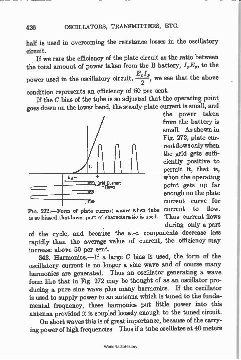
426 OSCILLATORS, TRANSMITTERS, ETC.
half is used in overcoming the resistance losses in the oscillatory
circuit. If we rate the efficiency of the plate circuit as the ratio between
the total amount of power taken from the B battery, IRE„, to the
power used in the oscillatory circuit, —2 , we see that the above
condition represents an efficiency of 50 per cent. If the C bias of the tube is so adjusted that the operating point
goes down on the lower bend, the steady plate current is small, and the power taken from the battery is small. As shown in Fig. 272, plate cur-rent flows only when the grid gets suffi-ciently positive to
1, permit it, that is, Eg - when the operating
Grid Current Flows point gets up far
enough on the plate current curve for
Fm. 272.—Form of plate current waves when tube current to flow. is so biased that lower part of characteristic is used. Thus current flows
during only a part of the cycle, and because the a.-c. components decrease less rapidly than the average value of current, the efficiency may increase above 50 per cent.
343. Harmonics.--If a large C bias is used, the form of the oscillatory current is no longer a sine wave and of course many harmonics are generated. Thus an oscillator generating a wave form like that in Fig. 272 may be thought of as an oscillator pro-ducing a pure sine wave plus many harmonics. If the oscillator is used to supply power to an antenna which is tuned to the funda-mental frequency, these harmonics put little power into this antenna provided it is coupled loosely enough to the tuned circuit.
On short waves this is of great importance, because of the carry-ing power of high frequencies. Thus if a tube oscillates at 40 meters
WorldRadioHistory
POWER OUTPUT OF AN OSCILLATOR TUBE 427
and puts out even a comparatively weak second harmonic on 20 meters, the latter signal can be heard over an area of many hundreds or even thousands of miles. A broadcasting station operating on 500 meters with a strong second harmonic can ruin another station's program operating on 250 meters, and so on.
There are times when it is desirable to generate a wave form that has many harmonics, or a particular harmonic of large ampli-tude. For example a quartz crystal is frequently used to control the frequency of a transmitter. Because the thickness of the quartz plate varies inversely as the frequency, for a high-frequency circuit the crystal is very thin and there is danger of its breaking. For this reason a thicker crystal is used and a harmonic of the oscillator which it controls is used to drive a power amplifier which works into the antenna,. The crystal circuit, then, is an oscillator which should generate a large second harmonic. By suit-ably adjusting the C bias such an output can be attained.
Such a highly biased tube will have strong harmonics of much higher order than the second, and if the frequency of the crystal is accurately known these higher harmonic components of the output of the tube can be used as standards of frequency over a very wide range. It is frequently possible to count up to the 50th harmonic of such a circuit. Thus if the fundamental frequency of the crystal is 500 kc., the 10th harmonic would be 5000 kc., and the 50th would be 25,000 kc.
344. Power output of an oscillator tube.—The power output from an oscillating tube depends upon the efficiency of the circuit and the amount of power that can safely be dissipated at the plate. If the circuit is 50 per cent efficient and if the tube can safely dissipate 50 watts on the plate, the output power is evidently 50 watts. If, however, a high C bias is used and a larger plate voltage, the steady power taken from the battery may increase appreciably but a smaller proportion of it is lost in the tube and of course more power into the load (the tuned circuit) obtained. Thus if the tube is 70 per cent efficient, and can dissipate 50 watts internally, the ouput power can be 116 watts and the total power supplied by the battery 167 watts.
When an amateur manages to put into his transmitting tube
WorldRadioHistory
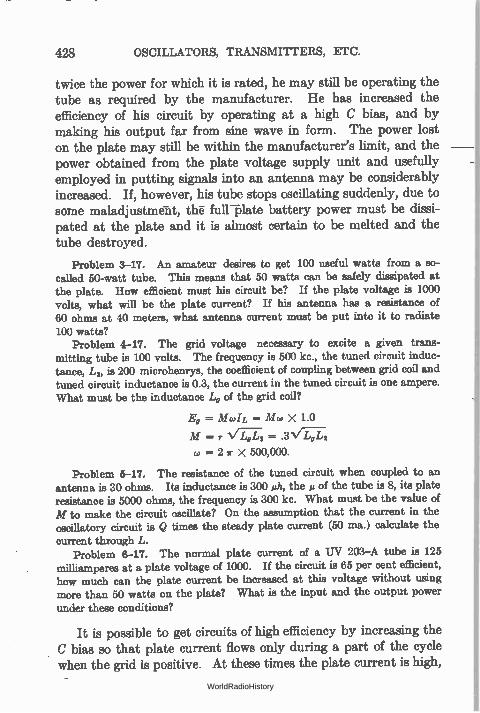
428 OSCILLATORS, TRANSMITTERS, ETC.
twice the power for which it is rated, he may still be operating the tube as required by the manufacturer. He has increased the efficiency of his circuit by operating at a high C bias, and by making his output far from sine wave in form. The power lost on the plate may still be within the manufacturer's limit, and the power obtained from the plate voltage supply unit and usefully employed in putting signals into an antenna may be considerably increased. If, however, his tube stops oscillating suddenly, due to some maladjustment, the full—plate battery power must be dissi-pated at the plate and it is almost certain to be melted and the tube destroyed.
Problem 3-17. An amateur desires to get 100 useful watts from a so-called 50-watt tube. This means that 50 watts can be safely dissipated at the plate. How efficient must his circuit be? If the plate voltage is 1000 volts, what will be the plate current? If his antenna has a resistance of 60 ohms at 40 meters, what antenna current must be put into it to radiate
100 watts? Problem 4-17. The grid voltage necessary to excite a given trans-
mitting tube is 100 volts. The frequency is 500 kc., the tuned circuit induc-tance, In, is 200 microhenrys, the coefficient of coupling between grid coil and tuned circuit inductance is 0.3, the current in the tuned circuit is one ampere. What must be the inductance L, of the grid coil?
E, = Mcoh = Mw X 1.0
M = N/ Tdol; = .3V/.7. 2
w = 2 r X 500,000.
Problem 5-17. The resistance of the tuned circuit when coupled to an antenna is 30 ohms. Its inductance is 300 mh, the µ of the tube is 8, its plate resistance is 5000 ohms, the frequency is 300 kc. What must be the value of M to make the circuit oscillate? On the assumption that the current in the oscillatory circuit is Q times the steady plate current (50 ma.) calculate the current through L.
Problem 6-17. The normal plate current of a UV 203—A tube is 125 milliamperes at a plate voltage of 1000. If the circuit is 65 per cent efficient, how much can the plate current be increased at this voltage without using more than 50 watts on the plate? What is the input and the output power under these conditions?
It is possible to get circuits of high efficiency by increasing the C bias so that plate current flows only during a part of the cycle when the grid is positive. At these times the plate current is high,
WorldRadioHistory
OBTAINING GRID BIAS BY MEANS OF RESISTANCE LEAK 429
but at the same time the voltage actually on the plate is low— because of the fact that the grid and plate voltages are 1800 out of phase and because of the high voltage lost in the load when the current is high—and so the power wasted at the plate is low. If the voltage at the plate could be reduced to zero no power would be lost there and the efficiency would be 100 per cent. Such con-ditions cannot happen, of course.
If the plate voltage is reduced to a value comparable to the grid voltage, the electrons from the filament would divide and more would go to the grid than ordinarily, with the result that the plate current would decrease. This would tend to increase the plate voltage, and so the limiting condition of zero plate voltage cannot be secured.
345. Maximum power output of oscillator.—As in an amplifier, the maximum power is converted from the battery to the load when the load resistance is equal to the tube plate resistance. Thus in Fig. 271 the effective resistance of the load is L2c02/r which must be equal to R„ for maximum power output. This is not the condition for maximum efficiency, but is the condition for maxi-mum power output under a given set of conditions. As a matter of fact the efficiency under these conditions is 50 per cent.
346. Obtaining grid bias by means of resistance leak.—During the part of a cycle when the grid is positive (shaded area in Fig. 272) the grid draws current. When the grid is negative it takes no current. There is in the grid circuit, then, an average grid cur-rent. This current can be made to flow through a resistance and, as in the case of a detector tube, be used to maintain the grid at a negative potential with respect to the filament. Since grid current flows it follows that some power must be wasted in the grid circuit. This power is that wasted in the grid leak, usually of the order of 5000 to 10,000 ohms, and that wasted in the grid-filament resist-ance. This power must be supplied by the plate battery, and lowers the overall efficiency of the tube and circuit. If the current is permitted to become very high the power dissipated in the grid may become too great for the tube to handle, and breakdown results.
In high-frequency circuits, the grid-filament capacity has low
WorldRadioHistory
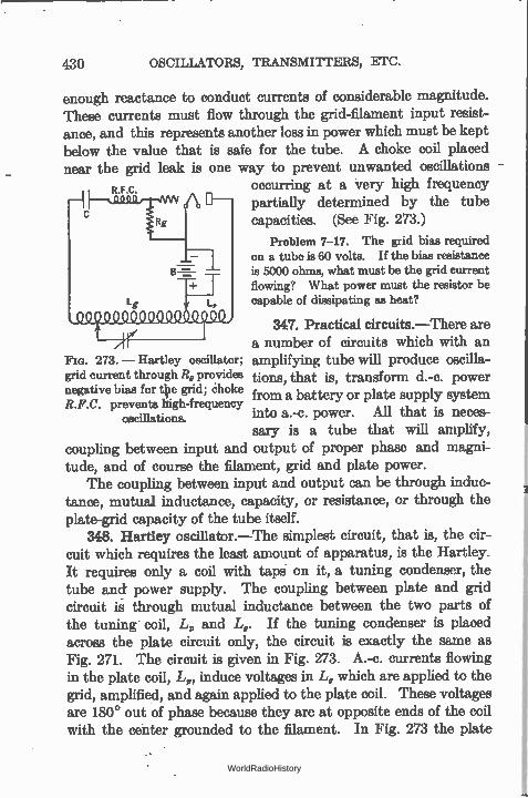
430 OSCILLATORS, TRANSMITTERS, ETC.
enough reactance to conduct currents of considerable magnitude. These currents must flow through the grid-filament input resist-ance, and this represents another loss in power which must be kept below the value that is safe for the tube. A choke coil placed near the grid leak is one way to prevent unwanted oscillations
R.F.C. occurring at a very high frequency partially determined by the tube capacities. (See Fig. 273.)
Problem 7-17. The grid bias required on a tube is 60 volts. If the bias resistance is 5000 ohms, what must be the grid current flowing? What power must the resistor be capable of dissipating as heat?
347. Practical circuits.—There are a number of circuits which with an amplifying tube will produce oscilla-tions, that is, transform d.-c. power from a battery or plate supply system into a.-c. power. All that is neces-sary is a tube that will amplify,
coupling between input and output of proper phase and magni-tude, and of course the filament, grid and plate power.
The coupling between input and output can be through induc-tance, mutual inductance, capacity, or resistance, or through the plate-grid capacity of the tube itself.
348. Hartley oscillator.—The simplest circuit, that is, the cir-cuit which requires the least amount of apparatus, is the Hartley. It requires only a coil with taps on it, a tuning condenser, the tube and power supply. The coupling between plate and grid circuit is through mutual inductance between the two parts of the tuning coil, L, and L„. If the tuning condenser is planed across the plate circuit only, the circuit is exactly the same as Fig. 271. The circuit is given in Fig. 273. A.-c. currents flowing in the plate coil, L,, induce voltages in L, which are applied to the grid, amplified, and again applied to the plate coil. These voltages are 180° out of phase because they are at opposite ends of the coil with the center grounded to the filament. In Fig. 273 the plate
FIG. 273. — Hartley oscillator; grid current through R, provides negative bias for tie grid; choke R.F.C. prevents high-frequency
oscillations.
WorldRadioHistory
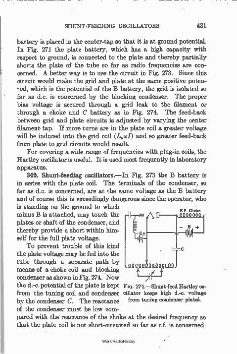
SHUNT-FEEDING OSCILLATORS 431
battery is placed in the center-tap so that it is at ground potential. In Fig. 271 the plate battery, which has a high capacity with respect to ground, is connected to the plate and thereby partially shorts the plate of the tube so far as radio frequencies are con-cerned. A better way is to use the circuit in Fig. 273. Since this circuit would make the grid and plate at the same positive poten-tial, which is the potential of the B battery, the grid is isolated so far as d.c. is concerned by the blocking condenser. The proper bias voltage is secured through a grid leak to the filament or through a choke and C battery as in Fig. 274. The feed-back between grid and plate circuits is adjusted by varying the center filament tap. If more turns are in the plate coil a greater voltage will be induced into the grid coil (Led) and so greater feed-back from plate to grid circuits would result.
For covering a wide range of frequencies with plug-in coils, the Hartley oscillator is useful. It is used most frequently in laboratory apparatus.
349. Shunt-feeding oscillators.—In Fig. 273 the B battery is in series with the plate coil. The terminals of the condenser, so far as d.c. is concerned, are at the same voltage as the B battery and of course this is exceedingly dangerous since the operator, who is standing on the ground to which
R F Choke minus B is attached, may touch the plates or shaft of the condenser, and
— B thereby provide a short within him- - c+ self for the full plate voltage.
To prevent trouble of this kind the plate voltage may be fed into the tube through a separate path by means of a choke coil and blocking condenser as shown in Fig. 274. Now the d.-c. potential of the plate is kept FIG. 274.—Shunt-feed Hartley os.. from the tuning coil and condenser cillator keeps high d.-c. voltage by the condenser C. The reactance from tuning condenser plates.
of the condenser must be low com-pared with the reactance of the choke at the desired frequency so that the plate coil is not short-circuited so far as r.f. is concerned.
WorldRadioHistory
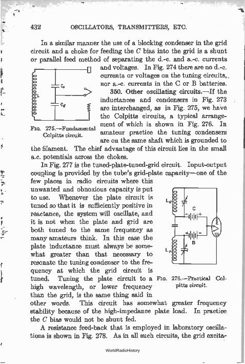
„
432 OSCILLATORS, TRANSMITTERS, ETC.
In a similar manner the use of a blocking condenser in the grid circuit and a choke for feeding the C bias into the grid is a shunt or parallel feed method of separating the d.-c. and a.-c. currents
and voltages. In Fig. 274 there are no d.-c. currents or voltages on the tuning circuits, nor a.-c. currents in the C or B batteries.
350. Other oscillating circuits.—If the inductances and condensers in Fig. 273 are interchanged, as in Fig. 275, we have the Colpitts circuits, a typical arrange-ment of which is shown in Fig. 276. In
275.—Fundamental amateur practice the tuning condensers are on the same shaft which is grounded to
the filament. The chief advantage of this circuit lies in the small a.c. potentials across the chokes.
In Fig. 277 is the tuned-plate-tuned-grid circuit. Input-output coupling is provided by the tube's grid-plate capacity—one of the few places in radio circuits where this unwanted and obnoxious capacity is put to use. Whenever the plate circuit is tuned so that it is sufficiently positive in reactance, the system will oscillate, and it is not when the plate and grid are both tuned to the same frequency as many amateurs think. In this case the plate inductance must always be some-what greater than that necessary to resonate the tuning condenser to the fre-quency at which the grid circuit is tuned. Tuning the plate circuit to a Fm. 276.—Practical Col-high wavelength, or lower frequency pitta circuit.
than the grid, is the same thing said in other words. This circuit has somewhat greater frequency stability because of the high-impedance plate load. In practice the C bias would not be shunt fed. A resistance feed-back that is employed in laboratory oscilla-
tions is shown in Fig. 278. As in all such circuits, the grid excita-
Colpitts circuit.
WorldRadioHistory
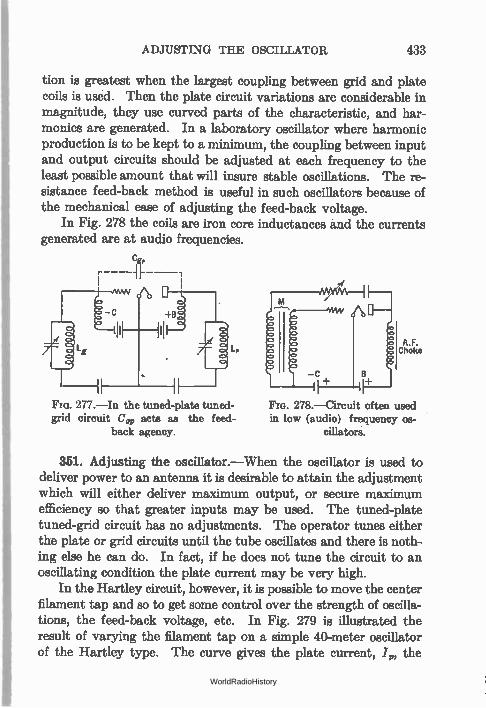
ADJUSTING THE OSCILLATOR 433
tion is greatest when the largest coupling between grid and plate coils is used. Then the plate circuit variations are considerable in magnitude, they use curved parts of the characteristic, and har-monics are generated. In a laboratory oscillator where harmonic production is to be kept to a minimum, the coupling between input and output circuits should be adjusted at each frequency to the least possible amount that will insure stable oscillations. The re-sistance feed-back method is useful in such oscillators because of the mechanical ease of adjusting the feed-back voltage.
In Fig. 278 the coils are iron core inductances and the currents generated are at audio frequencies.
Cg,
g
277.—In the tuned-plate tuned-grid circuit Cg, acts as the feed-
back agency.
A.F. Choke
278.—Circuit often used in low (audio) frequency os-
cillators.
351. Adjusting the oscillator.—When the oscillator is used to deliver power to an antenna it is desirable to attain the adjustment which will either deliver maximum output, or secure maximum efficiency so that greater inputs may be used. The tuned-plate tuned-grid circuit has no adjustments. The operator tunes either the plate or grid circuits until the tube oscillates and there is noth-ing else he can do. In fact, if he does not tune the circuit to an oscillating condition the plate current may be very high.
In the Hartley circuit, however, it is possible to move the center filament tap and so to get some control over the strength of oscilla-tions, the feed-back voltage, etc. In Fig. 279 is illustrated the result of varying the filament tap on a simple 40-meter oscillator of the Hartley type. The curve gives the plate current, /„, the
WorldRadioHistory
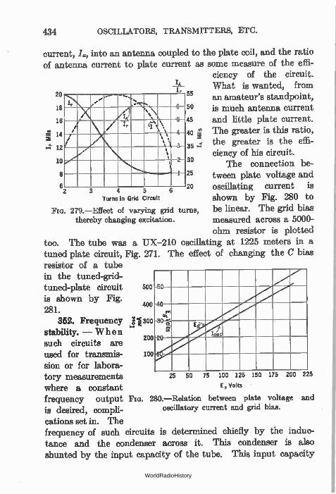
434 OSCILLATORS, TRANSMITTERS, ETC.
current, L, into an antenna coupled to the plate coil, and the ratio of antenna current to plate current as some measure of the effi-
ciency of the circuit. What is wanted, from an amateur's standpoint, is much antenna current and little plate current. The greater is this ratio, the greater is the effi-ciency of his circuit.
The connection be-tween plate voltage and oscillating current is shown by Fig. 280 to be linear. The grid bias measured across a 5000-
a
20
18
16
14
12
10
8
6
1P\/'
••••
>V:. 6
/ 1 %‘›
i / I, el"\• 4
s, s /
.\ \ , % 3
.." \ 2-
1
3 4 5
IA
55
50
45
40 -`-1
35
30
25
20
Turns in Grid Circuit
279.—Effect of varying grid turns, thereby changing excitation.
ohm resistor is plotted
too. The tube was a UX-210 oscillating at 1225 meters in a tuned plate circuit, Fig. 271. The effect of changing the C bias resistor of a tube in the tuned-grid-tuned-plate circuit 500
is shown by Fig. 281.
352. Frequency stability. — When such circuits are used for transmis- 100
sion or for labora-tory measurements 25
where a constant E, vons frequency output Fia. 280.—Relation between plate voltage and is desired, compli- oscillatory current and grid bias.
cations set in. The frequency of such circuits is determined chiefly by the induc-tance and the condenser across it. This condenser is also shunted by the input capacity of the tube. This input capacity
-50
-40
-30-e-
-2
E
75 100 125 150 175
Iosc
400
jI300
200
50 200 225
WorldRadioHistory
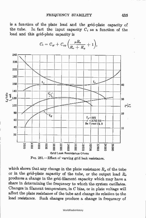
FREQUENCY STABILITY 435
is a function of the plate load and the grid-plate capacity of the tube. In fact the input capacity Ci as a function of the load and this grid-plate capacity is
( gRo
1?c, R, / = Cui C„
C9U
220
200
180
160
140
120
100
80
60
40
20
/
la ........b..,......../.........'
1X:
7 .......-
Eg Ep-385
3750 DL
f De FSrest
$0 9
IV D 0 0
4.• 0, 03 ..... Nà C, o o 0 NI a 0, 03 O C. 0 0 0 0 C. 0 0 0 C, C. 0 C. C. C, 0 0 0
C. 0 0 0 C. 0
r0 N 0 0 0
N., N a 0, 0 0 0 0 0 0
Grid Leak Resistance Ohms
FIG. 281.—Effect of varying grid leak resistance.
40
30
20
10
which shows that any change in the plate resistance R„ of the tube or in the grid-plate capacity of the tube, or the output load R, produces a change in the grid-filament capacity which may have a share in determining the frequency to which the system oscillates. Changes in filament temperature, in C bias, or in plate voltage will affect the plate resistance of the tube and change its relation to the load resistance. Such changes produce a change in frequency of
WorldRadioHistory
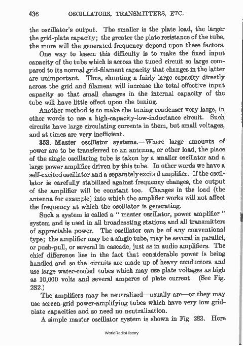
436 OSCILLATORS, TRANSMITTERS, ETC.
the oscillator's output. The smaller is the plate load, the larger the grid-plate capacity; the greater the plate resistance of the tube, the more will the generated frequency depend upon these factors.
One way to lessen this difficulty is to make the fixed input capacity of the tube which is across the tuned circuit so large com-pared to its normal grid-filament capacity that changes in the latter are unimportant. Thus, shunting a fairly large capacity directly across the grid and filament will increase the total effective input capacity so that small changes in the internal capacity of the tube will have little effect upon the tuning.
Another method is to make the tuning condenser very large, in other words to use a high-capacity-low-inductance circuit. Such circuits have large circulating currents in them, but small voltages, and at times are very inefficient.
353. Master oscillator systems.—Where large amounts of power are to be transferred to an antenna, or other load, the place of the single oscillating tube is taken by a smaller oscillator and a large power amplifier driven by this tube. In other words we have a self-excited oscillator and a separately excited amplifier. If the oscil-lator is carefully stabilized against frequency changes, the output of the amplifier will be constant too. Changes in the load (the antenna for example) into which the amplifier works will not affect the frequency at which the oscillator is generating.
Such a system is called a " master oscillator, power amplifier" system and is used in all broadcasting stations and all transmitters of appreciable power. The oscillator can be of any conventional type; the amplifier may be a single tube, may be several in parallel, or push-pull, or several in cascade, just as in audio amplifiers. The chief difference lies in the fact that considerable power is being handled and so the circuits are made up of heavy conductors and use large water-cooled tubes which may use plate voltages as high as 10,000 volts and several amperes of plate current. (See Fig. 282.)
The amplifiers may be neutralized—usually are—or they may use screen-grid power-amplifying tubes which have very low grid-plate capacities and so need no neutralization. A simple master oscillator system is shown in Fig. 283. Here
WorldRadioHistory
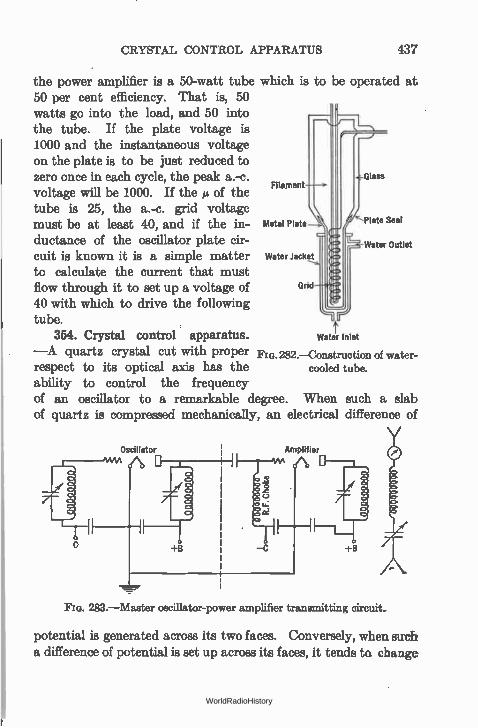
CRYSTAL CONTROL APPARATUS 437
the power amplifier is a 50-watt tube which is to be operated at 50 per cent efficiency. That is, 50 watts go into the load, and 50 into the tube. If the plate voltage is 1000 and the instantaneous voltage on the plate is to be just reduced to zero once in each cycle, the peak a.-c. Glass
voltage will be 1000. If the ei of the ont
is 25, the a.-c. grid voltage must be at least 40, and if the in- Metal Plate Plate Seal
ductance of the oscillator plate cir- iII Water Outlet
cuit is known it is a simple matter Water Jacket
to calculate the current that must flow through it to set up a voltage of Grid
40 with which to drive the following tube.
354. Crystal control apparatus. —A quartz crystal cut with proper FIG. 282.—Construction of water-
respect to its optical axis has the cooled tube.
ability to control the frequency of an oscillator to a remarkable degree. When such a slab of quartz is compressed mechanically, an electrical difference of
Water Inlet
Oscillator Amplifier
+B +B
283.—Master oscillator-power amplifier transmitting circuit..
potential is generated across its two faces. Conversely, when such a difference of potential is set up across its faces, it tends ta change
WorldRadioHistory
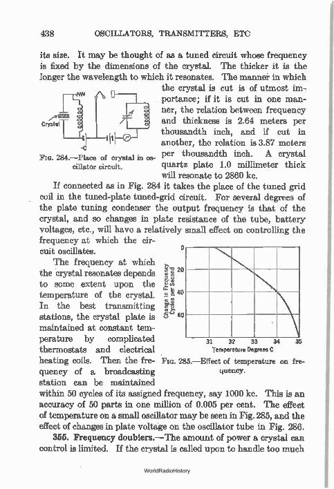
Crystal
438 OSCILLATORS, TRANSMITTERS, ETC
its size. It may be thought of as a tuned circuit whose frequency is fixed by the dimensions of the crystal. The thicker it is the longer the wavelength to which it resonates. The manner in which
the crystal is cut is of utmost im-portance; if it is cut in one man-ner, the relation between frequency
rt:
and thickness is 2.64 meters per
-c 284.—Place of crystal in os-
cillator circuit.
thousandth inch, and if cut in another, the relation is 3.87 meters per thousandth inch. A crystal quartz plate 1.0 millimeter thick will resonate to 2860 kc.
If connected as in Fig. 284 it takes the place of the tuned grid coil in the tuned-plate tuned-grid circuit. For several degrees of the plate tuning condenser the output frequency is that of the crystal, and so changes in plate resistance of the tube, battery voltages, etc., will have a relatively small effect on controlling the frequency at which the cir-cuit oscillates.
The frequency at which «e' 2 the crystal resonates depends 20E.
to some extent upon the E'en
temperature of the crystal. l=k 4° In the best transmitting ve stations, the crystal plate is C.' 6°
maintained at constant tem-perature by complicated thermostats and electrical heating coils. Then the fre- Fio. 285.—Effect of temperature on fre-quency of a broadcasting station can be maintained within 50 cycles of its assigned frequency, say 1000 kc. This is an accuracy of 50 parts in one million of 0.005 per cent. The effect of temperature on a small oscillator may be seen in Fig. 285, and the effect of changes in plate voltage on the oscillator tube in Fig. 286.
355. Frequency doublers.—The amount of power a crystal can control is limited. If the crystal is called upon to handle too much
31 32 33 34
Temperature Degrees C
quency.
35
WorldRadioHistory
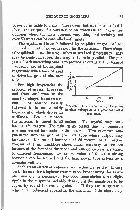
FREQUENCY DOUBLERS 439
power it is liable to crack. The power that can be controlled is about the output of a 5-watt tube on broadcast and higher fre-quencies where the plate becomes very thin, and certainly not over 50 watts can be controlled with safety.
The crystal oscillator is followed by amplifier stages until the required amount of power is ready for the antenna. These stages of amplification can be single tubes neutralized if necessary; they may be push-pull tubes, they may be tubes in parallel. The pur-pose of each succeeding tube is to provide a voltage at the required frequency and of the required magnitude which may be used to drive the grid of the next tube.
For high frequencies the problem of crystal breakage, and from oscillation in the amplifier stages, becomes seri-ous. The method usually followed is to use a fairly large crystal which drives an oscillator. Let us suppose the antenna is tuned to 40 meters. The crystal may oscil-late at 160 meters. The tube is so biased that it generates a strong second harmonic, or 80 meters. This 80-meter out-put is fed into the grid of the next tube, whose output may be tuned to the second harmonic of 80 meters, or 40 meters. Neither of these amplifiers shows much tendency to oscillate because of the fact that the input and output circuits are tuned to different frequencies. By proper values of C bias a strong harmonic can be secured and the final power tube driven by a 40-meter voltage.
Such transmitters can operate from either a.c. or d.c. If they are to be used for telephone transmission, broadcasting, for exam-ple, pure d.c. is necessary. For code transmission some slight ripple in the output is probably desirable if the signals are to be copied by ear at the receiving station. If they are to operate a relay and mechanical apparatus, the character of the signal may
150
20
boat
.2 40 c.) c.)
60 50 100
EpV0ItS
286.—Effect on frequency of changes in plate voltage of a crystal-controlled
oscillator.
WorldRadioHistory
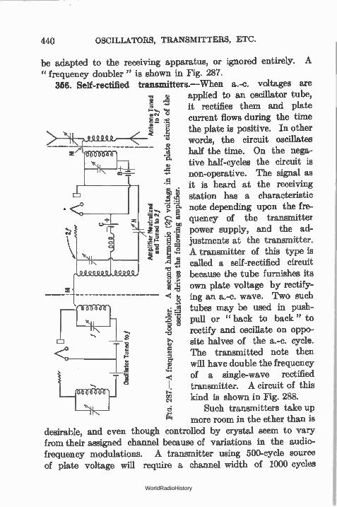
440 OSCILLATORS, TRANSMITTERS, ETC.
be adapted to the receiving apparatus, or ignored entirely. A " frequency doubler" is shown in Fig. 287.
356. Self-rectified transmitters.—When a.-c. voltages are -o. o applied to an oscillator tube, •-.., .-_, it rectifies them and plate =
current flows during the time E the plate is positive. In other -e words, the circuit oscillates
- e .3 half the time. On the nega-tive half-cycles the circuit is
-a .. non-operative. The signal as .5
4 it is heard at the receiving cl)
lâ) station has a characteristic • 1 15 q note depending upon the fre-
+ .o'c•,; > Ei t - cs1 to quency of the transmitter z r a ce
..:-4. I AI .5 power supply, and the ad-ijustments at the transmitter. V, 1 ..z A transmitter of this type is
-e' -ci called a self-rectified circuit .. -0 0 2 because the tube furnishes its 0 , 4 own plate voltage by rectify-
- ing an a.-c. wave. Two such tubes may be used in push-
.‘0 2 pull or " back to back" to e o
•-. -o rectify and oscillate on oppo-o ›, site halves of the a.-c. cycle. -
e
F— .6 E The transmitted note then will have double the frequency
CJ a '1? e o.
1 < of a single-wave rectified I. transmitter. A circuit of this
r.. oo kind is shown in Fig. 288. oq r5 Such transmitters take up e more room in the ether than is
desirable, and even though controlled by crystal seem to vary from their assigned channel because of variations in the audio-frequency modulations. A transmitter using 500-cycle source of plate voltage will require a channel width of 1000 cycles
WorldRadioHistory
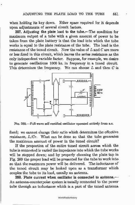
ADJUSTING THE PLATE LOAD TO THE TUBE 441
when holding its key down. Ether space required for it depends upon adjustments of several circuit factors.
357. Adjusting the plate load to the tube.—The condition for maximum output of a tube with a given amount of power to be taken from the plate battery is that the load into which the tube works is equal to the plate resistance of the tube. The load is the resistance of the tuned circuit. Now the value of L and C are more or less fixed in this circuit, which leaves the series resistance as the only independent variable factor. Suppose, for example, we desire to generate oscillations 1000 kc. in frequency in a tuned circuit. This determines the frequency. We can choose L and then C is
E, 60 ,v
288.—Full-wave self-rectified oscillator operated entirely from a.c.
fixed; we cannot change their ratio which determines the effective resistance, L/Cr. What can be done so that the tube generates the maximum amount of power in the tuned circuit?
If the proportion of the entire tuned circuit across which the tube is connected is varied the impedance into which the tube works will be stepped down; and by properly choosing the plate tap in Fig. 289 the proper load will be presented for the tube to work into so that the maximum power will be delivered. The inductance of the tuned circuit may be looked upon as a transformer which couples the tube to its load, usually an antenna.
358. Plate current when oscillator is connected to antenna.— An antenna-counterpoise system is usually connected to the power tube through an inductance which is a part of the tuned antenna
WorldRadioHistory
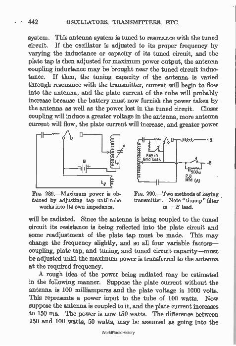
442 OSCILLATORS, TRANSMITTERS, ETC.
system. This antenna system is tuned to resonance with the tuned circuit. If the oscillator is adjusted to its proper frequency by varying the inductance or capacity of its tuned circuit, and the plate tap is then adjusted for maximum power output, the antenna coupling inductance may be brought near the tuned circuit induc-tance. If then, the tuning capacity of the antenna is varied through resonance with the transmitter, current will begin to flow into the antenna, and the plate current of the tube will probably increase because the battery must now furnish the power taken by the antenna as well as the power lost in the tuned circuit. Closer coupling will induce a greater voltage in the antenna, more antenna current will flow, the plate current will increase, and greater power
Lg
289.—Maximum power is ob-tained by adjusting tap until tube
works into Its own impedance.
Key in Grid Leak
5004, 2.0 Mfd (A)
-8
290.—Two methods of keying transmitter. Note "thump" filter
in —B lead.
will be radiated. Since the antenna is being coupled to the tuned circuit its resistance is being reflected into the plate circuit and some readjustment of the plate tap must be made. This may change the frequency slightly, and so all four variable factors— coupling, plate tap, and tuning, and tuned circuit capacity—must be adjusted until the maximum power is transferred to the antenna at the required frequency. A rough idea of the power being radiated may be estimated
in the following manner. Suppose the plate current without the antenna is 100 milliamperes and the plate voltage is 1000 volts. This represents a power input to the tube of 100 watts. Now suppose the antenna is coupled to it, and the plate current increases to 150 ma. The power is now 150 watts. The difference between 150 and 100 watts, 50 watts, may be assumed as going into the
WorldRadioHistory

KEYING A TRANSMITTER 443
antenna. If the antenna current is measured, a rough estimate of the antenna resistance may be had. The method is not at accurate unless a sine wave is being radiated and then only approximately.
359. Keying a transmitter.—There are several methods of modulating the oscillations of a transmitter so that they may con-vey intelligence from one operator to another. The tube may be caused to cease oscillations, the antenna circuit may be broken or closed or the frequency to which the oscillator is tuned may be changed in accordance with the manipulations of the key. A key placed in the plate voltage supply (Fig. 291) will cut off the power. This method is not successful with well-filtered systems because of
Key in Mid Tap Key in Power
Transformer Primary
291.—Keying in "center tap" or in transformer primary.
the time taken to completely discharge the condensers. An alterna-tive place for the key is the grid circuit, as in Fig. 288 or 290. If the grid leak or the C bias lead is opened by the key, there will be no path for the electrons trapped on the grid to escape. The grid will them assume a large negative voltage which will reduce the plate current to such low value that oscillations cease.
If the key is placed in the plate lead it must break the full power to the tube, and its contacts must be able to handle the cur-rent without heating and without breakdown from the voltage drop across the key as it is opening.
The voltages and currents in the grid circuit are much lower. Both of these methods of starting and stopping the oscillations are abrupt and provide the nearby ether with profound shocks known among the amateur fraternity as " key thumps" and
WorldRadioHistory
444 OSCILLATORS, TRANSMITTERS, ETC.
cordially hated by listeners to other transmissions. Various thump filters have been devised to start and stop the oscillations in the tube less abruptly. One method is to let the tube oscillate feebly during the periods the key is up by placing a high resistance across the key contacts. Another is to place a resistance, capacity, and inductance across the key contacts. The condenser charges and discharges slowly and prevents the abrupt opening of the plate power circuit. The inductance (about 0.5 to 2 henrys) slows up the start of oscillatons.
Keying can be accomplished as in Fig. 291 but generally the
break is made between the filament and the connection to minus B, which is also attached to the grid. In other words the filament only is cut loose. This is called " keying in the common lead"
and is quite common. 360. Too close coupling to antenna.—If the closed circuit is
properly tuned and the antenna coupled to it, it may be found that the emitted wave is no longer of the desired frequency or that the tube refuses to oscillate or that as the antenna tuning condenser is varied two maxima of antenna current will be noted. Such trouble will occur whenever both circuits are tuned to the same frequency and then too closely coupled or when the two circuits have slightly different frequencies and are coupled together.
Good amateur practice dictates that the antenna circuit should be tuned as closely as possible to the closed circuit frequency by watching the antenna ammeter. Then the coupling is reduced or the circuit detuned until the antenna meter reads about 75 per cent of its maximum reading under any adjustment. Then there is little likelihood that the transmitter will suddenly decide to transmit on a frequency to which the receiver is not tuned. When the antenna tuning condenser is varied, with such loose coupling between antenna and tuned circuit, there will be but a single sharp resonance peak. There will be no danger that the frequency of transmission will jump from one peak to another, and thereby clutter up the ether with unintelligent dots and
dashes. 361. Methods of connecting oscillator to antenna.— It is pos-
sible for the inductance and capacity of the antenna-counterpoise
WorldRadioHistory
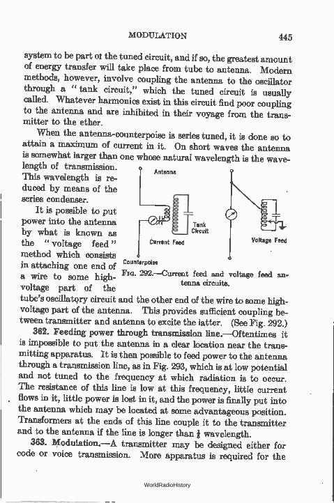
MODULATION 445
system to be part or the tuned circuit, and if so, the greatest amount of energy transfer will take place from tube to antenna. Modern methods, however, involve coupling the antenna to the oscillator through a " tank circuit," which the tuned circuit is usually called. Whatever harmonics exist in this circuit find poor coupling to the antenna and are inhibited in their voyage from the trans-mitter to the ether.
When the antenna-counterpoise is series tuned, it is done so to attain a maximum of current in it. On short waves the antenna is somewhat larger than one whose natural wavelength is the wave-length of transmission.
Antenna This wavelength is re-duced by means of the series condenser.
It is possible to put power into the antenna Tank
by what is known as Circuit
the " voltage feed " Current Feed Voltage Feed
method which consists in attaching one end of Counterpoise
a wire to some high- 292.—Current feed and voltage feed an-
tenna circuits. voltage part of the tube's oscillatory circuit and the other end of the wire to some high-voltage part of the antenna. This provides sufficient coupling be-tween transmitter and antenna to excite the latter. (See Fig. 292.)
362. Feeding power through transmission line.—Oftentimes it is impossible to put the antenna in a clear location near the trans-mitting apparatus. It is then possible to feed power to the antenna through a transmission line, as in Fig. 293, which is at low potential and not tuned to the frequency at which radiation is to occur. The resistance of this line is low at this frequency, little current flows in it, little power is lost in it, and the power is finally put into the antenna which may be located at some advantageous position. Transformen at the ends of this line couple it to the transmitter and to the antenna if the line is longer than wavelength.
363. Modulation.—A transmitter may be designed either for code or voice transmission. More apparatus is required for the
WorldRadioHistory
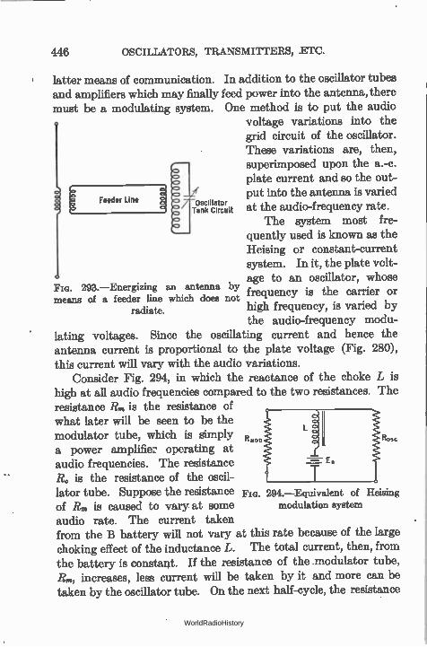
446 OSCILLATORS, TRANSMITTERS, .ETC.
latter means of communication. In addition to the oscillator tubes and amplifiers which may finally feed power into the antenna, there must be a modulating system. One method is to put the audio
voltage variations into the grid circuit of the oscillator. These variations are, then, E l/ Tank osc„,.., circuit superimposed upon the a.-c. plate current and so the out-put into the antenna is varied at the audio-frequency rate.
The system most fre-quently used is known as the Heising or constant-current system. In it, the plate volt-age to an oscillator, whose
293.—Energizing an antenna by means of a feeder line which does not frequency is the carrier or
radiate. high frequency, is varied by the audio-frequency modu-
lating voltages. Since the oscillating current and hence the antenna current is proportional to the plate voltage (Fig. 280), this current will vary with the audio variations.
Consider Fig. 294, in which the reactance of the choke L is high at all audio frequencies compared to the two resistances. The resistance R., is the resistance of what later will be seen to be the modulator tube, which is simply R. ROSC
a power amplifier operating at audio frequencies. The resistance R. is the resistance of the oscil-lator tube. Suppose the resistance of Rm is caused to vary at some audio rate. The current taken from the B battery will not vary at this rate because of the large choking effect of the inductance L. The total current, then, from the battery is constant. If the resistance of the modulator tube, Rm, increases, less current will be taken by it and more can be taken by the oscillator tube. On the next half-cycle, the resistance
o Feeder Line
Fm. 294.—Equivalent of Heising modulation system
WorldRadioHistory
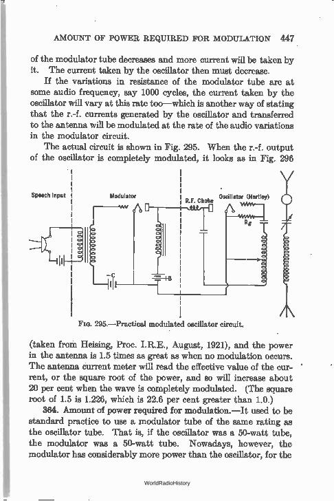
AMOUNT OF POWER REQUIRED FOR MODULATION 447
of the modulator tube decreases and more current will be taken by it. The current taken by the oscillator then must decrease.
If the variations in resistance of the modulator tube are at some audio frequency, say 1000 cycles, the current taken by the oscillator will vary at this rate too—which is another way of stating that the r.-f. currents generated by the oscillator and transferred to the antenna will be modulated at the rate of the audio variations in the modulator circuit.
The actual circuit is shown in Fig. 295. When the r.-f. output of the oscillator is completely modulated, it looks as in Fig. 296
Speech Input
r10
Modulator Oscillator (Hartley) R.F. Choke
Rg
FIG. 295.—Practical modulated oscillator circuit.
(taken from Heising, Proc. I.R.E., August, 1921), and the power in the antenna is 1.5 times as great as when no modulation occurs. The antenna current meter will read the effective value of the cur-rent, or the square root of the power, and so will increase about 20 per cent when the wave is completely modulated. (The square root of 1.5 is 1.226, which is 22.6 per cent greater than 1.0.)
364. Amount of power required for modulation.—It used to be standard practice to use a modulator tube of the same rating as the oscillator tube. That is, if the oscillator was a 50-watt tube, the modulator was a 50-watt tube. Nowadays, however, the modulator has considerably more power than the oscillator, for the
WorldRadioHistory
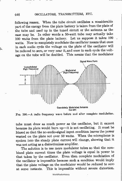
448 OSCILLATORS, TRANSMITTERS, ETC.
following reason. When the tube circuit oscillates a considerable part of the energy from the plate battery is taken from the plate of the tube and used up in the tuned circuit or the antenna as the case may be. In other words a 50-watt tube may actually take 100 watts from the plate battery. Let us suppose it takes 100 watts. Now to completely modulate the oscillator means that once in each audio cycle the voltage on the plate of the oscillator will be reduced to zero, or very near it, and once in each cycle the volt-age on the tube will be doubled. This means that the modulator
Signal Wave Form
Unmodulated High Frequency •
Modulated „1,-41igh Frequency
Completely Modulated Antenna Current
Fla. 296.—A radio frequency wave before and after complete modulation.
tube must draw as much power as the oscillator, but it cannot because its plate would burn up—it is not oscillating. It must be biased so that the no-audio-signal input condition leaves the power wasted on the plate not over 50 watts. When the microphone is spoken into the steady plate current will change, showing that it was not acting as a distortionless amplifier.
The solution is to use more modulator tubes so that the com-bined plate current times the plate voltage is equal in power to that taken by the oscillator. Even then complete modulation of the oscillator is impossible because such a condition would imply that the plate voltage on the modulator would be reduced to zero at some instants. This is impossible without severe distortion.
WorldRadioHistory
INCREASE OF ANTENNA CURRENT WITH MODULATION 449
The result is that modern equipment operates the modulator tubes at higher voltages than the oscillator.
There is another difficulty in the modulation procedure. The antenna current under 100 per cent modulation indicates that 50 per cent more power is being supplied. This power must come from the modulator. In addition to supplying to the oscillator peak voltages equal to the steady voltage of the oscillator B battery, the modulator must supply the additional 50 per cent of power. Since the modulator, acting as an amplifier, cannot be very effi-cient, a large battery of tubes is required in the modulating system.
365. Modulation at low power.—Suppose, however, we modulate the output of a small tube and amplify it. We shall save on modulation equipment, because we can modulate a 5-watt tube, say with a 50-watt tube, and when small quantities of power are to be used efficiency does not matter. The succeeding power amplifiers, however, must each carry the additional 50 per cent increase in power, if the wave is to be completely modulated, and so little has been gained. It is a problem of whether to build a large modulating equipment acting at audio frequencies or large radio amplifier equipment.
366. Increase of antenna current with modulation.—The antenna current of a transmitter will increase when that station is modulated because the power into the antenna increases by the amount of the modulation. Therefore the increase in antenna current can be taken as a measure of the amount of modulation in percentage. This additional power is represented by the side bands of modulation.
The average power in the carrier is /2R/2. The amplitude of the current in each side band is the current in the carrier multiplied by m/2, where m is the percentage modulation. Therefore the power in each side band is m2/2R/8, and the total power for the carrier and side bands, on the basis that each side band is a replica of the other, is
total antenna power = PR(1 ± m2/2) 2
WorldRadioHistory
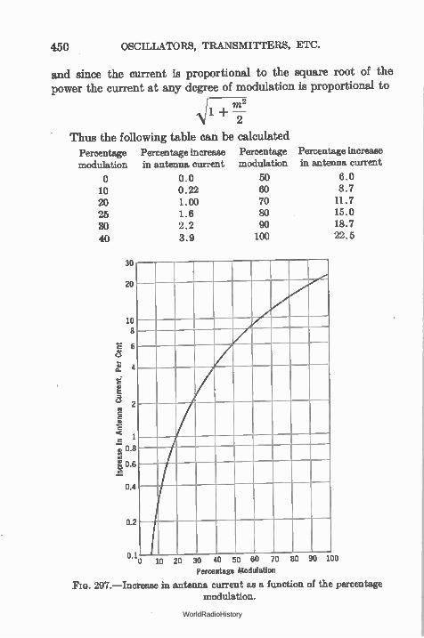
450 OSCILLATORS, TRANSMUTERS, ETC.
and since the current is proportional to the square root of the power the current at any degree of modulation is proportional to
11 1- ---M22
Thus the following table can be calculated Percentage modulation
o 10 20 25 30 40
30
20
10 8
2
Percentage increase in antenna current
0.0 0.22 1.00 1.8 2.2 3.9
Percentage Percentage increase modulation in antenna current
50 6.0 60 8.7 70 11.7 80 15.0 90 18.7 100 22.5
1 E
0.8
,•`"'"7,' 0.6
0.4
0.2
0.10 10 20 30 40 50 60 70 80 90 100 Percentage Modulation
Fla. 297.—Increase in antenna current as a function of the percentage modulation.
WorldRadioHistory
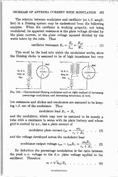
INCREASE OF ANTENNA CURRENT WITH MODULATION 451
The relation between modulator and oscillator (or r.-f. ampli-fier) in a Heising system may be understood from the following analysis. When the oscillator is working properly, not being modulated, its apparent resistance is the plate voltage divided by the plate current, or the plate voltage squared divided by the watts taken by the tube. Thus
Ep E92 oscillator resistance Ro = —7 = Ti7 . . . . (1)
1 90 rr 0
This must be the load into which the modulator works, since the Heising choke is assumed to be of high impedance but very
Mod.
To R. F.
Amp. or
Csc.
To R. F.
Amp. or
Osc.
Mod.
FM. 298.—Conventional Heising modulator and on right method of increasing percentage modulation and decreasing saturation of core.
low resistance and chokes and condensers are assumed to be keep-ing r.-f. out of the modulator. Thus
modulator load RL = Ro
and the modulator, which may now be assumed to be merely a tube with a resistance in series with its plate battery and whose grid is excited by a.c., has a plate current of
Pea modulator plate current ip„. — . . (2) rp
and the voltage developed across the modulator load
PeoRL modulator output voltage ep. = ipmRL — (3) rp -F RL
By definition the percentage modulation is the ratio between the peak a.-c. voltage to the d.-c. plate voltage applied to the oscillator. Therefore
m = Ve,/E9 (4)
WorldRadioHistory
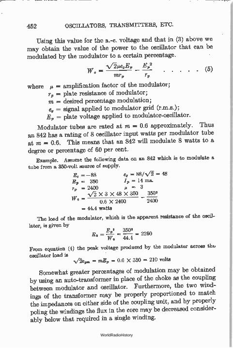
452 OSCILLATORS, TRANSMITTERS, ETC.
Using this value for the a.-c. voltage and that in (3) above we may obtain the value of the power to the oscillator that can be modulated by the modulator to a certain percentage.
-VIte0E„ E,2 0 — mrp r,
(5)
where = amplification factor of the modulator; r, = plate resistance of modulator; m = desired percentage modulation; e,= signal applied to modulator grid (r.m.s.); E, = plate voltage applied to modulator-oscillator.
Modulator tubes are rated at m = 0.6 approximately. Thus an 842 has a rating of 8 oscillator input watts per modulator tube at m = 0.6. This means that an 842 will modulate 8 watts to a degree or percentage of 60 per cent.
Example. Assume the following data on an 842 which is to modulate a tube from a 350-volt source of supply.
Ec = —88 ea = 88/N/i = 48 E,, = 350 /9 = 14 ma.
= 3 r = 2400 Vi X 3 X 48 X 350 3502
— 0.6 X 2400 2400
= 44.4 watts
The load of the modulator, which is the apparent resistance of the oscil-
lator, is given by E 2 3502
R0 = = = 2260 W o 44.4
From equation (4) the peak voltage produced by the modulator across tho
oscillator load is = mE, = 0.6 X 350 = 210 volts
Somewhat greater percentages of modulation may be obtained by using an auto-transformer in place of the choke as the coupling between modulator and oscillator. Furthermore, the two wind-ings of the transformer may be properly proportioned to match the impedances on either side of the coupling unit, and by properly poling the windings the flux in the core may be decreased consider-ably below that required in a single winding.
WorldRadioHistory
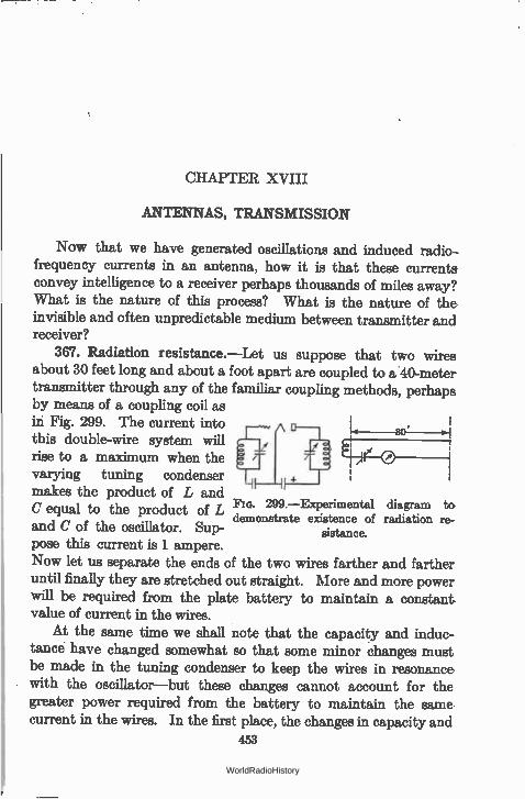
CHAPTER XVIII
ANTENNAS, TRANSMISSION
Now that we have generated oscillations and induced radio-frequency currents in an antenna, how it is that these currents convey intelligence to a receiver perhaps thousands of miles away? What is the nature of this process? What is the nature of the invisible and often unpredictable medium between transmitter and receiver?
367. Radiation resistance.—Let us suppose that two wires about 30 feet long and about a foot apart are coupled to a 40-meter transmitter through any of the familiar coupling methods, perhaps by means of a coupling coil as in Fig. 299. The current into this double-wire system will rise to a maximum when the varying tuning condenser makes the product of L and
299.—Experimental diagram to C equal to the product of L demonstrate existence of radiation re-
and C of the oscillator. Sup- sistance.
pose this current is 1 ampere. Now let us separate the ends of the two wires farther and farther until finally they are stretched out straight. More and more power will be required from the plate battery to maintain a constant value of current in the wires.
At the same time we shall note that the capacity and induc-tance have changed somewhat so that some minor changes must be made in the tuning condenser to keep the wires in resonance with the oscillator—but these changes cannot account for the greater power required from the battery to maintain the same current in the wires. In the first place, the changes in capacity and
453
WorldRadioHistory
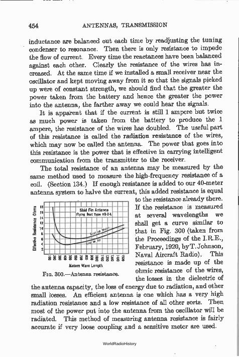
454 ANTENNAS, TRANSMISSION
inductance are balanced out each time by readjusting the tuning condenser to resonance. Then there is only resistance to impede the flow of current. Every time the reactances have been balanced against each other. Clearly the resistance of the wires has in-creased. At the same time if we installed a small receiver near the oscillator and kept moving away from it so that the signals picked up were of constant strength, we should find that the greater the power taken from the battery and hence the greater the power into the antenna, the farther away we could hear the signals.
It is apparent that if the current is still 1 ampere but twice as much power is taken from the battery to produce the 1 ampere, the resistance of the wires has doubled. The useful part of this resistance is called the radiation resistance of the wires, which may now be called the antenna. The power that goes into this resistance is the power that is effective in carrying intelligent communication from the transmitter to the receiver.
The total resistance of an antenna may be measured by the same method used to measure the high-frequency resistance of a coil. (Section 134.) If enough resistance is added to our 40-meter antenna system to halve the current, this added resistance is equal
to the resistance already there. le I ill 18 Skid Fin Antenna H the resistance is measured
%na 14 Boat Type 118-2-L at several wavelengths we I
12 shall get a curve similar to 10 that in Fig. 300 (taken from
the Proceedings of the I.R.E., 6 4 2 February, 1920, by T. Johnson,
Naval Aircraft Radio). This resistance is made up of the ohmic resistance of the wires, the losses in the dielectric of
the antenna capacity, the loss of energy due to radiation, and other small losses. An efficient antenna is one which has a very high radiation resistance and a low resistance of all other sorts. Then most of the power put into the antenna from the oscillator will be radiated. This method of measuring antenna resistance is fairly accurate if very loose coupling and a sensitive meter are used.
Effe
ctiv
e Re
sist
ance
Ohms
àárià"§à'§§§à•gge-g Meters Wave Length
FIG. 300.—Antenna resistance.
WorldRadioHistory
CALCULATION OF THE RECEIVED CURRENT 455
The radiation resistance of most short-wave antennas used below the fundamental wavelength is of the order of 100 ohms and it requires a transmitter output of 100 watts to put 1 ampere into it. The current that goes into an antenna is a variable factor, and because one antenna has 1 ampere and another 2 amperes in it it may not mean that the second one is twice as good. The place in the antenna-ground or antenna-counterpoise system where the current is read and the physical surroundings of the antennas may be much more important in determining the effective radia-tion than the current into it.
368. The radiation field.—The energy which is taken by the radiation resistance is used in setting up about the antenna a radiation field. This field consists of both a magnetic field and an electrostatic field. This radiation field moves away from the antenna with a speed equal to the velocity of light, and its strength at any distance is inversely proportional to the distance.
When the lines of force making up this radiation field cut a conductor such as a receiving antenna a voltage is induced in this con-ductor and if amplified and demodulated it becomes the received part of the communication thrust upon the ether by the transmitter.
This brief and very inadequate explanation of what happens in the ether does not state how it happens. Most radio engineers, however, are interested in the result rather than the means and so wemust be satisfied with the knowledge that current into an antenna produces a radiation field about the antenna, that the intensity of this field varies inversely with the square of the distance, and that when this field cuts across a conductor to which is attached a receiving apparatus a voltage is developed which is the bearer of the messages sent out at the transmitter.
369. Calculation of the received current—If the antenna at the transmitter is the type used on shipboard, that is, a high " flat-top," and a " down lead," and if the receiving antenna is similar in construction, the received current as a function of the transmitting current, the dimensions of the antennas, and their distance apart, is
= 188 14141, I,
RXd
WorldRadioHistory
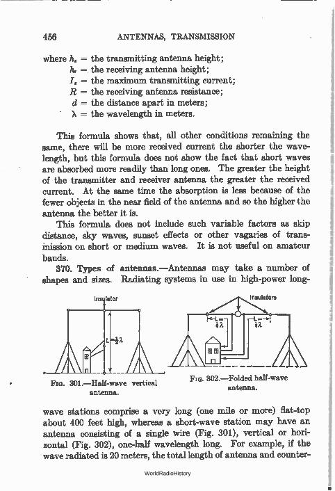
456 ANTENNAS, TRANSMISSION
where h. = the transmitting antenna height; h, = the receiving antenna height; ./„ = the maximum transmitting current; R = the receiving antenna resistance; d = the distance apart in meters; X = the wavelength in meters.
This formula shows that, all other conditions remaining the same, there will be more received current the shorter the wave-length, but this formula does not show the fact that short waves are absorbed more readily than long ones. The greater the height of the transmitter and receiver antenna the greater the received current. At the same time the absorption is less because of the fewer objects in the near field of the antenna and so the higher the antenna the better it is.
This formula does not include such variable factors as skip distance, sky waves, sunset effects or other vagaries of trans-mission on short or medium waves. It is not useful on amateur bands.
370. Types of antennas.—Antennas may take a number of shapes and sizes. Radiating systems in use in high-power long-
Ins lator Insulators
Flo. 302.—Folded half-wave antenna.
Fm. 301.—Half-wave vertical antenna.
wave stations comprise a very long (one mile or more) flat-top about 400 feet high, whereas a short-wave station may have an antenna consisting of a single wire (Fig. 301), vertical or hori-zontal (Fig. 302), one-half wavelength long. For example, if the wave radiated is 20 meters, the total length of antenna and counter-
WorldRadioHistory
DIRECTIONAL ANTENNAS 457
poise wire will be 10 meters, or about 30 feet. On shipboard the " down lead" may come from the end of the horizontal part or from the center. In portable installations an umbrella type is used, that is, an insulated mast which is held up in the air by insulated wires which act as the radiating system.
The larger the antenna the more energy it will pick up, either from desired stations or from other electrical disturbances such as static. The tendency is to use large antennas for transmitting, so that a large amount of power can be put into the radiation field, and small antennas for receiving so that the ratio of signal to static will be large.
The ordinary antenna used for broadcast reception consists of a single wire more or less horizontal or vertical as the case may be, and up to a hundred feet long. Receivers are engineered with an average antenna in mind and more recent receivers, using screen-grid tubes, require no antenna at all, but pick up enough energy from a small wire or loop to obviate the unsightly and dan-gerous practice of installing wires op the roofs of buildings, on telephone poles and in trees.
371. Directional antennas.—For broadcasting intelligence over a wide area an antenna which transmits equally well in all direc-tions is desirable. Such is the vertical antenna. When a station is constructed to operate with one other station only, it is a waste of power to transmit its signals in all directions. Such stations use directional antennas, that is, radiating systems which transmit better in one direction, say north-south, than they do in any other. Even then energy goes out in two directions, north and south, and the receiving station is, of course, in only one direction from the transmitter. .
The loop is a directional antenna. It receives better in the direction towards which the narrow dimension points. Its pick-up ability is something like Fig. 303, in which it is pointed east-west and picks up very little energy from a north-south direction. In connection with a sensitive receiver, it may be used to determine the direction whence the signals come. It is the heart of the direction-finding stations which are situated along the coasts of the world. When a ship wants bearings, its signals are picked up
WorldRadioHistory
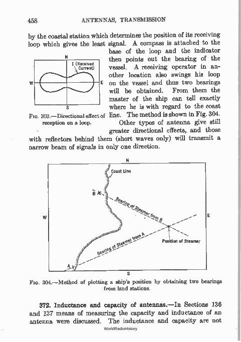
458 ANTENNAS, TRANSMISSION
by the coastal station which determines the position of its receiving loop which gives the least signal. A compass is attached to the
base of the loop and the indicator then points out the bearing of the vessel. A receiving operator in an-other location also swings his loop
E on the vessel and thus two bearings will be obtained. From them the master of the ship can tell exactly where he is with regard to the coast
FIG. 303.—Directional effect of line. The method is shown in Fig. 304. reception on a loop. Other types of antenna give still
greater directional effects, and those with reflectors behind them (short waves only) will transmit a narrow beam of signals in only one direction.
I (Received Current)
N
E
304.—Method of plotting a ship's position by obtaining two bearings from land stations.
372. Inductance and capacity of antennas.—In Sections 136 and 137 means of measuring the capacity and inductance of an antenna were discussed. The inductance and capacity are not
WorldRadioHistory
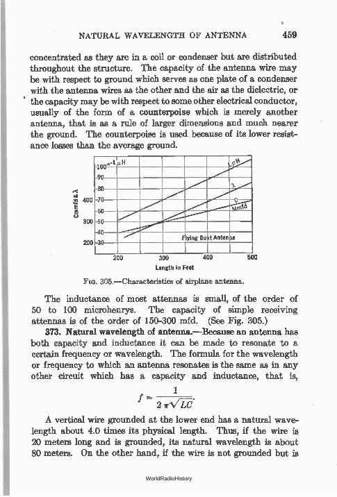
NATURAL WAVELENGTH OF ANTENNA 459
concentrated as they are in a coil or condenser but are distributed throughout the structure. The capacity of the antenna wire may be with respect to ground which serves as one plate of a condenser with the antenna wires as the other and the air as the dielectric, or the capacity may be with respect to some other electrical conductor, usually of the form of a counterpoise which is merely another antenna, that is as a rule of larger dimensions and much nearer the ground. The counterpoise is used because of its lower resist-ance losses than the average ground.
400
E C.)
300
200
100 -LaH 400
,
90
80
-70 tree
60
50
-40 Flying Boat Anten la
-30
200 300 400
Length in Feet
305.—Characteristics of airplane antenna.
500
The inductance of most attennas is small, of the order of 50 to 100 microhenrys. The capacity of simple receiving attennas is of the order of 150-300 mfd. (See Fig. 305.)
373. Natural wavelength of antenna.—Because an antenna has both capacity and inductance it can be made to resonate to a certain frequency or wavelength. The formula for the wavelength or frequency to which an antenna resonates is the same as in any other circuit which has a capacity and inductance, that is,
1
f - 2 7r.VM .
A vertical wire grounded at the lower end has a natural wave-length about 4.0 times its physical length. Thus, if the wire is 20 meters long and is grounded, its natural wavelength is about 80 meters. On the other hand, if the wire is not grounded but is
WorldRadioHistory
460 ANTENNAS, TRANSMISSION
considered as being two wires, an antenna and counterpoise with maximum dirrent in the center, the natural wavelength is roughly twice the length in meters. Thus, an antenna 20 meters long (30 feet in antenna and 30 feet in counterpoise) will radiate a wave of 40 meters if not connected to the ground. This antenna is called the Hertz because it is the type used by that investigator.
The Hertz antenna can also be made to radiate on any of its harmonics. If its natural wavelength is 40 meters it will radiate at 20 meters or if excited properly by an oscillator, at 10 meters.
374. Loading an antenna.—In case an antenna does not have the required inductance to bring its wavelength to the desired value, additional concentrated inductance can be placed in the down lead and the antenna " loaded " up to the desired wave-length. Since the coil cannot radiate to any extent and since its resistance must be added to the resistance of the antenna system, loading makes the entire system inefficient. The small antenna gets poor " hold " on the ether; the higher current causes greater power loss.
375. Decreasing the wavelength of an antenna.—If the antenna is too large to tune to the desired wavelength its natural wavelength can be reduced by placing a condenser in series with it. This reduces the effective capacity and as a result reduces its wave-length. The wavelength cannot be reduced below one-half the natural wavelength. Here again, loss in power in the condenser must be subtracted from the power that would go into the radia-tion resistance and so the losses in the condenser must be paid for in inefficiency. Fortunately, it is possible to build a condenser whose resistance may be very low at the frequency at which it is to be worked, and so a series capacity does not add much resistance to the antenna.
376. Short-wave transmission.—Because of the fact that short waves were highly absorbed, it was thought for many years that this portion of the radio-frequency spectrum was worthless. It was largely for this reason that amateurs were permitted to operate there. No one else wanted the short waves. Strangely enough, these short waves, once thought worthless, are now being fought for by radio communication companies the world over.
WorldRadioHistory
FADING 461
The .radiation field as it goes out from the antenna is absorbed by all conductors which exist in its field. According to theory, the shorter the wavelength the greater the absorption so that for waves shorter than 100 meters very little energy arrives at a receiver any distance away. Amateurs, however, discovered that these waves did arrive at much more distant points than theory permitted and a new theory had to be developed.
Waves are radiated from the antenna at all angles to the horizontal. The ground wave which the old theory dealt with goes near the surface; some radiation leaves the antenna at a high angle and shoots off into space. Some distance above the earth is an ionized layer which is a fairly good conductor of elec-trical disturbances. It therefore reflects a certain amount of the sky wave which returns to earth and may be received by any antenna in its path.
The ground wave is soon absorbed. The sky wave does not come down to earth in the immediate vicinity of the transmitter. Between the area covered by the ground wave and the sky wave there is a dead spot known as the skip distance. Signals are not received there except with the greatest difficulty and with con-siderable irregularity. In the daytime this skip distance is about 200 miles at 40 meters and 800 miles at 20 meters. Beyond the skip distance the signals are audible and fall off in intensity until they are again inaudible.
By properly choosing the frequency for the time of day it is possible to maintain a continuous communication with another station at any given distance. In other words, distance, time of day, season, and frequency are related. The table at the back of this book was compiled by L. C. Young of the Naval Research Laboratory.
It is because of the sky wave that amateurs working with less than 100 watts in an antenna are frequently able to communicate over several thousand miles on waves below 80 meters. Above 300 meters the skip distance is negligible, the sky wave is not important, except as noted in Section 377.
377. Fading.—The Kennelly-Heaviside layer, as the ionized conducting layer which is about 100 miles above the earth is called, varies in height and density from moment to moment, from day
WorldRadioHistory
462 ANTENNAS, TRANSMISSION
to day, and from season to season, and so the reflected wave varies in intensity. This is one cause of fading. Amateurs and other workers on short waves are the ones who have to contend most with this phenomenon since it is less effective on longer waves. It is of some importance on broadcast frequencies but at lower frequencies becomes of less and less value. When the sky wave and the ground wave arrive at a receiving station out of phase with each other, the received signal will be decreased in strength. This accounts for fading experienced on broadcast frequencies.
The automatic volume control discussed in previous sections will eliminate much of the troubles due to fading. The result of fading to the listener will be the apparent rise and fall of noise; when the signal gets weak the sensitivity of the amplifier rises bringing in more noise, and vice versa. The a.v.c. system, or the unlimited increase of power at the transmitter, will not eliminate fading in which the side bands fade less than the carrier with the effect that the carrier as it arrives at the receiver is over-modulated with resultant distortion.
Fading that varies with the frequency of modulation sometimes occurs; nothing can be done to correct it at the receiver.
378. Comparison of night and day reception.—The shorter the wavelength the greater the difference between night and day trans-mission and reception. On long waves there is little difference. At night signals are somewhat louder. On broadcast frequencies the difference is marked, especially in winter. Signals can be heard at night which are inaudible during the day. On short waves the skip distance becomes much greater at night. Why is this?
During the day the sun pours radiation into our atmosphere ionizing the particles which constitute it. These ionized particles absorb radiation of all kinds. Once absorbed, their energy is lost and they cannot transmit intelligence to distant receiving stations. At night this ionization ceases, the absorption of radio waves decreases and signals again reach out. The Kennelly-Heaviside layer of ionized particles which reflects the sky wave on the frequencies above 3000 kc. is very low in the daytime. The skip distance is not so great then as it is on a winter night when the reflecting layer is high, 100 miles or more above the earth.
379. Static.—Static is part of the noisy background that is
WorldRadioHistory
ELIMINATION OF MAN-MADE INTERFERENCE 463
sometimes of sufficient strength to interfere with the reception of signals. It is caused by natural phenomena, such as discharges of electricity between clouds at different potential or from clouds to earth. It is not the same noise that is caused by a leaky trans-mission line, defective power transformers, wires rubbing in trees and sparking, or other noises which come under the heading of man-made static. All of the latter noises can be eliminated. Static cannot be eliminated but its effects can be reduced. A receiver that operates from a very small antenna will pick
up less disturbing noise than a large antenna high above the earth The loop antenna which can be pointed at the desired signal, or any other directional antenna, will not pick up static or unwanted signals from other directions and will produce a greater signal to static ratio. It has the effect of reducing static. A number of schemes have been devised to reduce the static to
the level of the signal, but none has yet been made that will eliminate the static without also eliminating the signal. Both are produced by the same fundamental phenomenon—the charge and discharge of a condenser. One is produced in a broadcasting sta-tion by man, the other in the sky by nature.
Static is more bothersome during hot summer weather when the clouds are highly charged. The more sensitive one's receiver the further away the storms can be and still disturb reception. Man-made static is bothersome at all times of the year and at any time of the day or night. In the future all man-made static will be illegal, just as it is now illegal to operate an automobile without a muffler.
380. Elimination of man-made interference.—Considerable advance has been made towards the elimination of radio inter-ference from all manner of sparking machines. The sparks mu be eliminated or the electric waves they set up must be prevented from radiating much energy. If the sparks occur in a large system of wires the energy radiated may be considerable and may ruin radio reception over a large area. This radiated energy may be strongest at the natural frequency of the radiating wires but, because of the high resistance of the spark gap, the disturbance may cover a very wide band of frequencies.
WorldRadioHistory
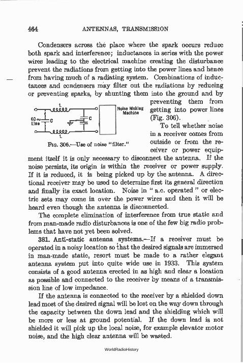
464 ANTENNAS, TRANSMISSION
Condensers across the place where the spark occurs reduce both spark and interference; inductances in series with the power wires leading to the electrical machine creating the disturbance prevent the radiations from getting into the power lines and hence from having much of a radiating system. Combinations of induc-tances and condensers may filter out the radiations by reducing or preventing sparks, by shunting them into the ground and by
preventing them from 0—T, us Q o Noise Making Machine getting into power lines
e (Fig. 306). Line l—
c—L..9 To tell whether noise in a receiver comes from outside or from the re-ceiver or power equip-
ment itself it is only necessary to disconnect the antenna. If the noise persists, its origin is within the receiver or power supply. If it is reduced, it is being picked up by the antenna. A direc-tional receiver may be used to determine first its general direction and finally its exact location. Noise in " a.c. operated" or elec-tric sets may come in over the power wires and then it will be heard even though the antenna is disconnected.
The complete elimination of interference from true static and from man-made radio disturbances is one of the few big radio prob-lems that have not yet been solved.
381. Anti-static antenna systems.—If a receiver must be operated in a noisy location so that the desired signals are immersed in man-made static, resort must be made to a rather elegant antenna system put into quite wide use in 1933. This system consists of a good antenna erected in as high and clear a location as possible and connected to the receiver by means of a transmis-sion line of low impedance.
If the antenna is connected to the receiver by a shielded down lead most of the desired signal will be lost on the way down through the capacity between the down lead and the shielding which will be more or less at ground potential. If the down lead is not shielded it will pick up the local noise, for example elevator motor noise, and the high clear antenna will be wasted.
306.—Use of noise "filter."
WorldRadioHistory
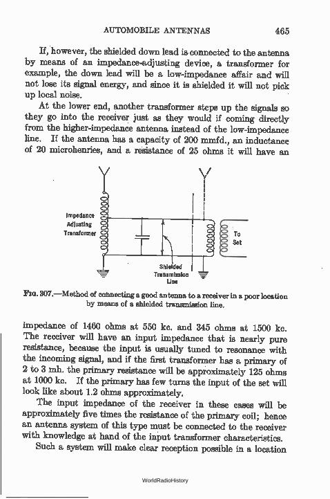
AUTOMOBILE ANTENNAS 465
If, however, the shielded down lead is connected to the antenna by means of an impedance-adjusting device, a transformer for example, the down lead will be a low-impedance affair and will not lose its signal energy, and since it is shielded it will not pick up local noise.
At the lower end, another transformer steps up the signals so they go into the receiver just as they would if coming directly from the higher-impedance antenna instead of the low-impedance line. If the antenna has a capacity of 200 mmfd, an inductance of 20 microhenries, and a resistance of 25 ohms it will have an
Impedance
Adjusting
Transformer
----,--
\ / v
Shielded Transmission
Line
To Set
Fla. 307.—Method of connecting a good antenna to a receiver in a poor location by means of a shielded transmission line.
impedance of 1460 ohms at 550 kc. and 345 ohms at 1500 kc. The receiver will have an input impedance that is nearly pure resistance, because the input is usually tuned to resonance with the incoming signal, and if the first transformer has a primary of 2 to 3 mh. the primary resistance will be approximately 125 ohms at 1000 kc. If the primary has few turns the input of the set will look like about 1.2 ohms approximately.
The input impedance of the receiver in these cases will be approximately five times the resistance of the primary coil; hence an antenna system of this type must be connected to the receiver with knowledge at hand of the input transformer characteristics.
Such a system will make clear reception possible in a location
WorldRadioHistory
466 ANTENNAS, TRANSMISSIONS
where little else but noise is heard with an ordinary antenna. The circuit in Fig. 307 is typical of these systems.
382. Automobile antennas.—Antennas for mobile services as in automobiles, aircraft, etc., present a difficult problem. In the first place the effective height possible is small; secondly the structure must be simple and rigid. In automobiles the usual aerial is imbedded in the roof and consists of chicken wire or other netting. Here it is not only partially shielded by the metal parts of the top, but is exposed to noise brought to it by the dome light wires and originating in the spark plugs and distributor.
In a few cases a metal plate has been suspended under the car. Here the effective height is often greater than that of the roof antenna; and the danger of picking up spark-plug noise seems to be less.
In aircraft the antenna is a simple pole mounted rigidly, over which the wire is strung and insulated from the ship proper. Similarly in police radio systems working on short waves, a simple rod is mounted in the rear, or the front, of the chassis and is tuned to the desired wavelength.
Some attempt has been made to use transmission lines in auto-mobiles, the aerial being placed as far out of the field of the wiring of the car as possible. Modern practice seems to be to damp the oscillating circuits in the car, or aircraft, sufficiently with resist-ances near the spark plugs, so that radiation from this source is not bad enough to disturb communication.
WorldRadioHistory
CHAPTER XIX
FACSIMILE AND TELEVISION TRANSMISSION
A NEW factor enters when pictures or television images are to be transmitted over wire or radio circuits. This is the factor of time. Picture transmission is much like code transmission; television is more like voice or music transmission—but both picture and television are more complex than the earlier methods of transmitting intelligence.
In code transmission the listener gets one letter after another and after recording them he may form an accurate idea of what the sender has in mind. In picture transmission the receiver puts down small pieces of the final picture in the order in which the sender transmits them, much like a cross-word puzzle, and after a certain time he gets an accurate idea of what the original pic-ture is.
In voice or music transmission, time enters to a limited extent only, since the listener is not called upon to remember the exact sound that he has just heard. He is interested only in the tone or sound that is at a given instant impressing itself upon his ears. But if we wish to transmit 10 orchestras simultaneously, 10 trans-mitters, 10 channels and 10 receivers are required. Here is where the factor of time enters. A single channel could transmit all 10 orchestras provided they could play one after another.
383. The problem of picture transmission.—There is no known method of transmitting a picture so that the listener sees all of it simultaneously with the sender. All known methods consist in taking the picture apart, transmitting the parts, and then in putting them together again at the receiver. In facsimile transmission the time required may be fast or slow. It may take a week to transmit a single picture or it may be transmitted in a
467 WorldRadioHistory
468 FACSIMILE AND TELEVISION TRANSMISSION
second. But in the latter case a high premium must be paid for
speed. In television we must perforce transmit the pictures at a high
speed. Not only does the problem of chronological tra.nsmission enter but the problem of simultaneity as well.
384. Picture elements.—If one looks at a newspaper photo-graph with a hand lens he will see that it is made up of small dots of ink, and he will realize that there is not much detail in the picture. If helooks at a photo in a high-class magazine he will discover that much greater detail is present—in other words, the dots are smaller and are placed closer together. If he looks at a photograph he will see almost infinite detail since the dots are microscopically small and almost infinitely close together.
It takes about 50 dots across and 50 dots down a picture to make a face recognizable. If there are five times this number of dots in the same space the picture will have much greater detail. If this mosaic of 50 X 50 or 2500 dots is placed in an area the size of a postage stamp the picture may be viewed at close range; but if it is put on a screen 10 feet across, each dot being multiplied in size accordingly, the same degree of detail will be present but the picture must be viewed at a much greater distance.
Newspaper cuts have detail corresponding to about 55 dots per linear inch; high-class magazine cuts have about 100 to 200 dots per inch, a 4 by 5 inch photograph may involve as many as 100,000,000 separate dots of light and darkness.
Let us consider the 50-dot-per-inch picture. If this picture, say one inch square, is to be transmitted in one second, all the dots must be sent in this time. That is, 2500 dots or impulses per second may be transmitted and received. This will give us a picture one inch square. If the picture is to be 10 inches square and therefore include more objects the number of impulses per second will be 2500 X 100 or 250,000.
These figures correspond to 2500 and 250,000 cycles per second, and if transmitted by carrier frequency, the side-band width must be 5000 cycles and 500,000 cycles wide respectively. In this manner one of the most serious problems of television enters— to transmit good detail in a short space of time requires a very
WorldRadioHistory
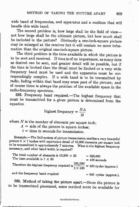
METHOD OF TAKING THE PICTURE APART 469
wide band of frequencies, and apparatus and a medium that will handle this wide band.
The second problem is, how large shall be the field of view— not how large shall be the ultimate picture, but how much shall be included in the picture? Obviously a one-inch-square picture may be enlarged at the receiver but it will contain no more infor-mation than the original one-inch-square picture.
The third problem is the time available in which the picture is to be sent and received. If time is of no importance, as many dots as desired can be sent, and greater detail will be possible, but if the time is limited then the detail must be limited or a very wide frequency band must be used and the apparatus must be cor-respondingly complex. If a wide band is to be transmitted by radio, fading within that band may erase part of the picture; and of course there is always the problem of the available space in the radio-frequency spectrum.
385. Frequency band required.—The highest frequency that must be transmitted for a given picture is determined from the equation
highest frequency = NA 2f
where N is the number of elements per square inch; A = side of the picture in square inches; t = time in seconds for transmission.
Example.—The Bell system of picture transmission enables a very beautiful picture 5 X 7 inches with equivalent detail of 10,000 elements per square inch to be transmitted in approximately 7 minutes. What is the highest frequency necessary, and what band width is required?
The total number of elements is 10,000 X 35 = 350,000 The time available is 7 X 60 = 420 seconds
350,000 Therefore the highest frequency required is 2 X 420 — 420 cycles (approx.)
and the frequency band required = 840 cycles (approx.).
386. Method of taking the picture apart.—Since the picture is to be transmitted piecemeal, some method must be available for
WorldRadioHistory
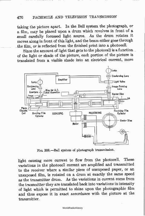
470 FACSIMILE AND TELEVISION TRANSMISSION
taking the picture apart. In the Bell system the photograph, or a film, may be placed upon a drum which revolves in front of a small carefully focussed light source. As the drum rotates it moves along in front of this light, and the beam either goes through the film, or is reflected from the finished print into a photocell.
Since the amount of light that gets to the photocell is a function of the light or shade of the picture, each portion of the picture is translated from a visible shade into an electrical current, more
Lamp
Condensing Lens
Aperture —
image --Fermin Len
Photo Electric
Cell Sending Film Cylinder
SENDING
No or
Lamp
Condensing Lens
Light Valve
Image Forming Lens
Sector Disc
Fm. 308.—Bell system of photograph transmission.
aceiving Film Cylinder
Sector Disc
light causing more current to flow from the photocell. These variations in the photocell current are amplified and transmitted to the receiver where a similar piece of unexposed paper, or an unexposed film, is rotated on a drum at exactly the same speed as the transmitter drum. As the variations in current come from the transmitter they are translated back into variations in intensity of light which is permitted to shine upon the photographic film and thus expose it in exact accordance with the picture at the -transmitter.
WorldRadioHistory
PUTTING THE PICTURE TOGETHER AGAIN 471
This method of taking the picture apart is called scanning, and in all television methods some scanning scheme must be employed. In all such schemes a photocell is employed to trans-late the variations in light to variations in an electric current which may be transmitted after amplification to the receiver over a wire or may be used to modulate a carrier of a radio transmitter.
The frequency band calculated in the above example is the narrowest possible band; if good detail is desired, higher fre-quencies corresponding to the higher harmonics of the highest frequency must be transmitted. Thus when a picture is com-posed of alternate white and jet-black portions, the photocell gets a sudden illumination, or a steep wave front, and the electric current coming from the photocell must have a similar wave front. This means that the current must start and stop suddenly—and such circuits are extremely difficult to obtain and to maintain. Any inductance and capacity in the circuit would tend to flatten this steep wave front with the result that the received picture would not have as white a white, nor as black a black, as the original. In other words, distortion would result. Steep wave fronts imply tones with numerous harmonics; therefore the second or third harmonic of the highest fundamental tone should be trans-mitted for high fidelity.
387. Putting the picture together again.—Once the picture is in the form of variable electrical currents and transmitted to the receiver it becomes necessary to reconvert these impulses into a visible picture. One method is to use a sensitive galvanometer which carries a mirror whose movements, under the variations in incoming current, cause more or less light to fall upon the sensitive photographic film.
In another system (Cooley) the incoming signal caused a high-frequency, high-potential spark or corona discharge to spark through a paper, thus burning minute holes in it in accordance with the original picture. Or these sparks may be made to turn some chemical dark in color and thus leave an impression on the receiving paper.
In still other methods hot jets of air are turned on or off in accordance with the modulations of the transmitter; these jets
WorldRadioHistory
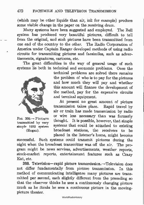
472 FACSIMILE AND TELEVISION TRANSMISSION
(which may be other liquids than air, ink for example) produce some visible change in the paper on the receiving drum.
Many systems have been suggested and employed. The Bell system has produced very beautiful pictures, difficult to tell from the original, and such pictures have been transmitted from one end of the country to the other. The Radio Corporation of America under Captain Ranger developed methods of using radio circuits for transmitting pictures and facsimiles, such as adver-tisements, signatures, cartoons, etc.
The great difficulties in the way of general usage of such systems lie both in technical and economic problems. Once the
technical problems are solved there remains .00111eL the problem of who is to pay for the pictures
and how much they will pay and whether this amount will finance the development of the method, pay for the expensive circuits and terminal equipment.
At present no great amount of picture transmission takes place. Rapid travel by air or train has made transmission by radio or wire less necessary than was formerly thought. It is possible, however, that simple systems that could be attached to existing broadcast stations, the receivers to be placed in the listener's home, might become
successful. Such systems could transmit pictures during the night when the broadcast transmitter was off the air. The pro-gram might be news services, advertisements, weather reports, stock-market reports, entertainment features such as Crazy Kat, etc.
388. Television—rapid picture transmission.—Television does not differ fundamentally from picture transmission. In this method of communicating intelligence many pictures are trans-mitted per second, each slightly different from the preceding so that the observer thinks he sees a continuously changing picture much as he thinks he sees a continuous picture in the moving-picture theater.
Fm. 309.—Picture transmitted by very simple 1933 system
(Hogan).
WorldRadioHistory
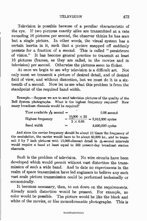
TELEVISION 473
Television is possible because of a peculiar characteristic of the eye. If two pictures exactly alike are transmitted at a rate exceeding 16 pictures per second, the observer thinks he has seen but a single picture. In other words, the visual system has a certain inertia in it, such that a picture snapped off suddenly persists for a fraction of a second. This is called " persistence of vision." It has become general practice to transmit at least 16 pictures (frames, as they are called, in the movies and in television) per second. Otherwise the pictures seem to flicker.
At once we begin to see why television is a difficult art. Not only must we transmit a picture of desired detail, and of desired field of view, and without distortion, but we must do it in a six-teenth of a second. Now let us see what this problem is from the standpoint of the required band width.
Example.—Suppose we are to send television pictures of the quality of the Bell System photographs. What is the highest frequency required? How many broadcast channels would be required?
Time available second = • 0.06 second
Highest frequency = 10,000 X 35— 2,915,000 cycles 2 X 0.06
Band width 5,830,000 cycles
And since the carrier frequency should be about 10 times the frequency of the modulation, the carrier would have to be about 60,000 kc., and to trans-mit 5 by 7 inch pictures with 10,000-element detail in 11r-second intervals would require a band at least equal to 583 present-day broadcast station channels.
Such is the problem of television. No wire circuits have been developed which would permit without vast distortion the trans-mission of such a wide band. And to date no experiments in the realm of space transmission have led engineers to believe any such vast scale picture transmission could be performed technically or economically.
It becomes necessary, then, to cut down on the requirements. Already much distortion would be present. For example, no color would be possible. The picture would be like the black and white of the movies, or like monochromatic photographs. This is
WorldRadioHistory

474 FACSIMILE AND TELEVISION TRANSMISSION
probably no great loss. Then we would have to cut down on the field of view so that a 5 by 7 photograph with several figures might become a smaller picture with fewer figures, or the same size with much less detail.
In general, all these limitations have been employed in experi-ments. Up to the present most systems have used 24 or 48 lines or dots per linear inch, corresponding to a detail of 242 (576) or 482 (2304) elements per square inch—much less detail than would be found in a 10,000-element picture. These individual pictures are transmitted at 20 frames per second, requiring a band width of 11,520 and 46,080 cycles respectively.
389. Scanning the image.—In general there are two methods of scanning the image. In one case the image is brightly illumi-nated by several sources of light. The image is focussed upon a rotating disc which is pierced with a series of holes in a spiral as shown in Fig. 310. As the spiral rotates, the holes trace across the image, which has been greatly reduced by the lens, one after another in a series of parallel lines. The light that gets through the holes falls upon a photocell and is there translated into electric currents. In one complete rotation of the disc the holes have traversed the entire picture, or frame.
In the other general method a single high-intensity source of light shines through the holes upon the image, and the reflected light is viewed by several photocells. Thus a single spot (the flying spot) traces itself across the image from one side to another and from top to bottom.
Experiments of Dr. H. E. Ives of the Bell Laboratories show that the first method would require that the object be illuminated with a 16,000-candlepower arc at a distance of about 4 feet to secure an image bright enough that the currents from the photo-cell would be above the noise level. Therefore the flying-spot
method is more generally used. Lenses in place of holes in the disc improve the efficiency
somewhat, but the difficulty of making, say, 48 lenses of exactly the same focus and of placing them in the periphery of a disc so that they line up their individual images properly increases the technical and mechanical problems appreciably. Deep blue light
WorldRadioHistory
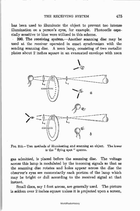
THE RECEIVING SYSTEM 475
has been used to illuminate the object to prevent too intense illumination on a person's eyes, for example. Photocells espe-cially sensitive to blue were utilized in this scheme.
390. The receiving system.—Another scanning disc may be used at the receiver operated in exact synchronism with the sending scanning disc. A neon lamp, consisting of two metallic plates about 2 inches square in an evacuated envelope with neon
ft"
310.—Two methods of illuminating and scanning an object. The lower is the " flying spot" system.
gas admitted, is placed before the scanning disc. The voltage across this lamp is modulated by the incoming signals so that as the scanning disc rotates and holes appear across the disc the observer's eyes see momentarily each portion of the lamp which may be bright or dull according to the received signal at that instant.
Small discs, say 1 foot across, are generally used. The picture is seldom over 2 inches square unless it is projected upon a screen,
WorldRadioHistory
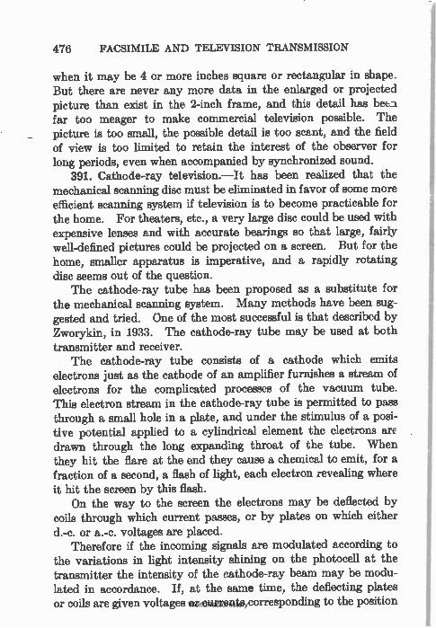
476 FACSIMILE AND TELEVISION TRANSMISSION
when it may be 4 or more inches square or rectangular in shape. But there are never any more data in the enlarged or projected picture than exist in the 2-inch frame, and this detail has beta far too meager to make commercial television possible. The picture is too small, the possible detail is too scant, and the field of view is too limited to retain the interest of the observer for long periods, even when accompanied by synchronized sound.
391. Cathode-ray television.—It has been realized that the mechanical scanning disc must be eliminated in favor of some more efficient scanning system if television is to become practicable for the home. For theaters, etc., a very large disc could be used with expensive lenses and with accurate bearings so that large, fairly well-defined pictures could be projected on a screen. But for the home, smaller apparatus is imperative, and a rapidly rotating disc seems out of the question.
The cathode-ray tube has been proposed as a substitute for the mechanical scanning system. Many methods have been sug-gested and tried. One of the most successful is that described by Zworykin, in 1933. The cathode-ray tube may be used at both transmitter and receiver.
The cathode-ray tube consists of a cathode which emits electrons just as the cathode of an amplifier furnishes a stream of electrons for the complicated processes of the vacuum tube. This electron stream in the cathode-ray tube is permitted to pass through a small hole in a plate, and under the stimulus of a posi-tive potential applied to a cylindrical element the electrons arc drawn through the long expanding throat of the tube. When they hit the flare at the end they cause a chemical to emit, for a fraction of a second, a flash of light, each electron revealing where it hit the screen by this flash.
On the way to the screen the electrons may be deflected by coils through which current passes, or by plates on which either d.-c. or a.-c. voltages are placed.
Therefore if the incoming signals are modulated according to the variations in light intensity shining on the photocell at the transmitter the intensity of the cathode-ray beam may be modu-lated in accordance. If, at the same time, the deflecting plates or coils are given voltages or currents corresponding to the position WorldRadioHistory
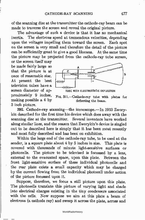
CATHODE-RAY SCANNING 477
of the scanning disc at the transmitter the cathode-ray beam can be made to traverse the screen and reveal the original picture.
The advantage of such a device is that it has no mechanical inertia. The electrons speed at tremendous velocities, depending upon the voltages impelling them toward the screen. Each spot on the screen is very small and therefore the detail of the picture can be sufficiently great to give a good likeness. At the same time the picture may be projected from the cathode-ray tube screen, or the screen itself may be made fairly large so that the picture is at „à ,•••
1-, once of reasonable size. At present the best
television tubes have a —.11.1.1, screen diameter of ap-
proximately 9 inches, 311.—Cathode-ray tube with plates for making possible a 4 by 5 inch picture.
392. .Cathode-ray scanning—the iconoscope.—In 1933 Zwory-kin described for the first time his device which does away with the scanning disc at the transmitter. Several inventors have worked along similar lines, and the reason that Zworykin's device is singled out to be described here is simply that it has been most recently and most fully described and has been on exhibition.
Within the large end of the cathode-ray tube, to be used at the sender, is a square plate about 4 by 5 inches in size. This plate is covered with thousands of minute light-sensitive surfaces or photocells. The picture to be televised is focussed by a lens, external to the evacuated space, upon this plate. Between the front light-sensitive surface of these individual photocells and the rear plate exists a small capacity which may be charged by the current flowing from the individual photocell under action of the picture focussed upon it.
Suppose, therefore, we focus a still picture upon this plate. The photocells translate this picture of varying light and shade into electrical charges existing in the tiny condensers associated with the cells. Now suppose we aim at this plate a beam of electrons (a cathode ray) and sweep it across the plate, across and
TUBE WITH ELECTROSTATIC DEFLECTION
deflecting the beam.
WorldRadioHistory
478 FACSIMILE AND TELEVISION TRANSMISSION
up and down. In other words we shall make the cathode-ray beam scan this plate of photocells. Each time it strikes the photo-cell it discharges the condenser associated with that photocell. The discharge current may be amplified, transmitted to the receiv-ing station, and utilized there to modulate another cathode-ray beam which is sweeping across, or scanning, a screen which lights up momentarily when an electron hits it. If these— two cathode-ray beams are operated in/Synchronism the picture will be recreated
at the receiver. The advantages of the cathode-ray scanner are that it is more
efficient from the standpoint of using the available light—for the entire picture is illuminated all the time in this case and not just momentarily; and the cathode-ray beam can move with extreme rapidity—Zworykin states that 250 lines per inch is not difficult to attain. Further advantages are saving of space and freedom from the troubles of rotating machinery.
But not all the problems of television are solved by the cathode-ray tube. The transmitter and receiver are complex and expen-sive; and the programs will be vastly more expensive than programs which are merely heard and not looked at.
Such are the problems of transmitting still pictures and moving pictures over wires and over space radio. It is probable that television of large scenes will first be made through the medium of moving-picture film. This is the only method by which suffi-cient light can be obtained with existing apparatus to do justice to any but a very restricted field of view.
The problem of space in the ether for high-quality transmission points to the ultra-high frequencies as the only solution. Other, and probably more important, services already tax the available frequencies above 10 meters wavelength. Between this wave-length (30,000 kilocycles) and 5 meters (60,000 kc.) there are 1000 channels three times as wide as existing broadcast bands, and there are 30 channels each 1,000,000 cycles wide, which is sufficient for good television. But already other services are making demands upon some of these channels. And so by the time television is ready for exploitation it may be that the chan-nels at present idle may be put to full use.
WorldRadioHistory
INDEX
A "A" battery, 166 "Abac," 129 Acceptor circuit, 137 Adjusting a vacuum tube voltmeter,
344 Air gap, effect on inductance, 72 Alternating current, effective value
of, 95 frequency, 51, 89 instantaneous value of, 90 maximum, or peak value of, 91 period, 51 root-mean-square value of, 96 tubes, 190 work done by, 51
Alternating-current circuits, 89-119 power in, 117 series, 109
characteristics of, 113 terminology used re, 95 tube tester, 188
Alternation, 51, 89 Ammeter-voltmeter method of meas-
uring resistance, 33 Ammeters, 30 Ampere, 9, 11
turns, 48 Amplification, 228
calculation of, 252 purpose of r-f and i-f, 297
Amplification factor of tube, 175 constant, to measure, 185 meaning of, 177
Amplifier, see Audio, 228-295 as oscillator, 417
Amplifier, band pass, 372 frequency characteristics of, 244 high-frequency, 296-334 reflex, 253 tube, 202-227
Angles, functions of, 92 Antenna, anti-static, 464
automobile, 466 capacity, 458 counterpoise, 459 current increase with modulation,
449 directional, 457 inductance, 161, 458 loading, 460 types of, 456 wavelength of, 160
decreasing, 460 natural, 459
Anti-resonant circuit, 132, 136 Apparatus, power supply, 390-414 Apparent and real selectivity, 379 Atom, 3 Audio amplifiers, 228-295
cascade, 233 Class A, 275 Class B, 264, 275 Class C, 275 compensation, 281 coupling tube to load, 280 design, rules for, 277 direct-coupled, 294 equalizing, 257 filtering, 289 frequency characteristic, 233 impedance, 240, 246
479
WorldRadioHistory
480 INDEX
Audio amplifiers, inductance load, 240 inverse duplex, 255 Loftin-White, 294 need of, 228 overloading, 212 power, 258 pueh-pull, 259 reflex, 253 regeneration in, 286 requirements of, 231 transformer in, advantage of, 249 transformer-coupled, 246 transmission unit of, 266 tube as an, 202-227 tuned inductance, 245 volume control, 278
Autodyne, 363, 364 detuning loss in, 371
Automobile antenna, 466 Auto-transformer, 69
"B" battery, 167 "B-eliminator" curve, 15 Baffles for loud speakers, 386 Ballast tube, 413 Batteries, 38
"A," 166 "B," 167 "C," 173 requirement of plate, 239
Beats, phenomenon of, 357 Bel, 266 Bell system of television, 470 Bias, "C" or grid, 173
for alternating-current tubes, 409 for power tubes, 279 means of obtaining, 196 on plate current, effect of, 171
Bridge methods of determining tube factors, 185
neutralizing, 323, 325 Broadcast frequency tuning coils, 62 By-pass condenser, 86, 104
"C" battery, 173 bias, 171, 173, 196, 279, 409 means of obtaining, 196
Calibrating a wavemeter, 152 by clicks, 156 by harmonics, 153
Calibration of a variable inductance, 71
Capacities, effect of stray, 241 in radio-frequency circuit, 304
Capacitive circuit, 75 reactance, 102
comparison of, 104 Capacity, 74-88
as a reservoir, 74 centimeter of, 77 combinations of resistance with,
106 in a power supply device, 75 input filter, 406 of antenna, 161, 458 of coils, distributed, 146 of condenser, 77 measurement of, 105, 160
reactance, 102, 305 tube input, effect of, 304 unit of, 77
Carrier frequency, 336 wave, 300
Cascade amplifiers, 233 Cathode, 166, 191 Cathode ray tube scanning, 478 Cell, battery, 38 common dry, 40 internal resistance of, 41 polarization of, 43 primary, 38 secondary or storage, 38, 40 testing, 42
Cells, in parallel, 44 in series, 44 in series-parallel arrangement, 45
Centimeter of capacity, 77
WorldRadioHistory
INDEX 481
Characteristic curves, dynamic, 206 of receiving tube, 171 of screen-grid tubes, 199 slopes of, as tube constants, 181
Characteristics of a series circuit, 113 Charged bodies, 1 Charges, electrical, 1
laws of, 2 Choke coil, 104 Circuit, acceptor, 137
anti-resonant, 132 capacitive, 75 equivalent tube, 177, 209 filter, for rectifier, 401
regulation of, 403 fundamental rectifier, 390 inductive, 75 measuring resistance of, 159 receiving, 149 rejector, 136 Rice, 325 selectivity of, 139 series resonant, 120
Circuit diagram, of receiver, 192 of signal generator, 377
Circuits, alternating-current, 89-119 bridge, 323 coupled, 57 noise suppressor, 354, 382 oscillating, 415, 430 parallel, 25, 27 primary, 49 secondary, 49 series, 24
alternating-current, 109 resonant, 136
short-wave receiver, 365 typical receiving, 162
Coefficient of coupling, 64 Coils, bank wound, 148
broadcast tuning, 62 coupling, 63 distributed capacity, 146 Ferrocart, 302
Coils, "honey comb," 370 inductance, 62 Litz wire, 329, 360 multilayer, 63 Polydoroff, 302 properties of, 149-164 resistance of, 144, 163 measurement of, 158
Comparison of reactances, 104 night and day reception, 462 push-pull and single tube, 293
Comparisons between amplifiers, 278 Condenser, 75
by-pass, 86 capacity of, 77 measurement of, 160
capacity formulas, 85 charge in, 75
time constant of, 78, 81 conducting plates of, 84 discharged, 78 electricity in, 77 Leyden jar, 76 potential energy of, 76
in electrostatic field, 80 tests, 83
Condenser plates, shape of, 380 Condensers, direct-current resistance
of, 81 in alternating-current circuits, 81 in parallel, 87, 88 in series, 87, 88 leakage resistance of, 81 measurements of capacity, 105, 160 power loss, 83 properties, 149-164 sizes of radio, 85 time constant, 81 tuning, 86
Conductance, 6, 23 mutual, 180
importance of, 181 measurement of, 184
Conducting plates of condenser, 84
WorldRadioHistory
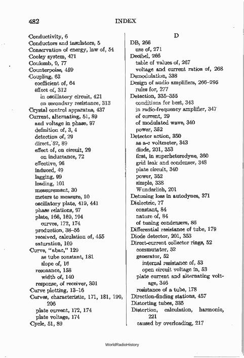
482 INDEX
Conductivity, 6 Conductors and insulators, 5 Conservation of energy, law of, 54 Cooley system, 471 Coulomb, 9, 77 Counterpoise, 459 Coupling, 63
coefficient of, 64 effect of, 312
in oscillatory circuit, 421 on secondary resistance, 313
Crystal control apparatus, 437 Current, alternating, 51, 89 and voltage in phase, 97 definition of, 3, 4 detection of, 29 direct, 52, 89 effect of, on circuit, 29 on inductance, 72
effective, 96 induced, 49 lagging, 99 leading, 101 measurement, 30 meters to measure, 10 oscillatory plate, 419, 441 phase relations, 97 plate, 166, 169, 194
curves, 172, 174 production, 38-56 received, calculation of, 455 saturation, 169
Curve, "abac," 129 as tube constant, 181 slope of, 16
resonance, 158 width of, 140
response, of receiver, 301 Curve plotting, 13-16 Curves, characteristic, 171, 181, 199,
206 plate current, 172, 174 plate voltage, 174
Cycle, 51, 89
D DB, 266
use of, 271 Decibel, 266
table of values of, 267 voltage and current ratios of, 268
Demodulation, 338 Design of audio amplifiers, 266-295
rules for, 277 Detection, 335-355
conditions for best, 343 in radio-frequency amplifier, 347 of current, 29 of modulated wave, 340 power, 352
Detector action, 350 as a-c voltmeter, 343 diode, 201, 353 first, in superheterodyne, 360 grid leak and condenser, 348 plate circuit, 340 power, 352 simple, 338 Wunderlich, 201
Detuning loss in autodynes, 371 Dielectric, 77
constant, 84 nature of, 84 of tuning condensers, 86
Differential resistance of tube, 179 Diode detector, 201, 353 Direct-current collector rings, 52 commutator, 52 generator, 52
internal resistance of, 53 open circuit voltage in, 53
plate current and alternating volt-age, 346
resistance of a tube, 178 Direction-finding stations, 457 Distorting tubes, 335 Distortion, calculation, harmonic,
221 caused by overloading, 217
WorldRadioHistory
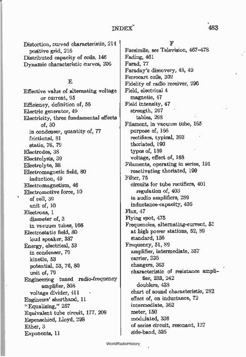
INDEX- .483
Distortion, curved characteristic, 214 positive grid, 216
Distributed capacity of coils, 146 Dynamic characteristic curves, 206
E
Effective value of alternating voltage or current, 95
Efficiency, definition of, 56 Electric generator, 49 Electricity, three fundamental effects
of, 30 in condenser, quantity of, 77 frictional, 81 static, 76, 79
Electrodes, 38 Electrolysis, 39 Electrolyte, 38 Electromagnetic field, 80
induction, 49 Electromagnetism, 46 Electromotive force, 10
of cell, 39 unit of, 10
Electrons, 1 diameter of, 3 in vacuum tubes, 166
Electrostatic field, 80 loud speaker, 387
Energy, electrical, 53 in condenser, 79 kinetic, 53 potential, 53, 76, 80 unit of, 79
Engineering tuned radio-frequency amplifier, 308
voltage divider, 411 Engineers' shorthand, 11 "Equalizing," 257 Equivalent tube circuit, 177, 209 Espenschied, Lloyd, 298 Ether, 3 Exponents, 11
Facsimile, see Television, 467-478 Fading, 461 Farad, 77 Faraday's discovery, 48, 49 Ferrocart coils, 302 Fidelity of radio receiver, 296 Field, electrical 4
magnetic, 47 Field intensity, 47
strength, 297 tables, 298
Filament, in vacuum tube, 165 purpose of, 166 rectifiers, typical, 393 thoriated, 190 types of, 189 voltage, effect of, 168
Filaments, operating in series, 191 reactivating thoriated, 190
Filter, 75 circuits for tube rectifiers, 401
regulation of, 403 in audio amplifiers, 289 inductance-capacity, 406
Flux, 47 Flying spot, 475 Frequencies, alternating-current, 51
at high power stations, 52, 89 standard, 156
Frequency, 51, 89 amplifier, intermediate, 357 carrier, 336 changers, 363 characteristic of resistance ampli-
fier, 233, 242 doublers, 438
chart of sound characteristic, 282 effect of, on inductance, 72 intermediate, 362 meter, 150 modulated, 336 of series circuit, resonant, 127 side-band, 336
WorldRadioHistory
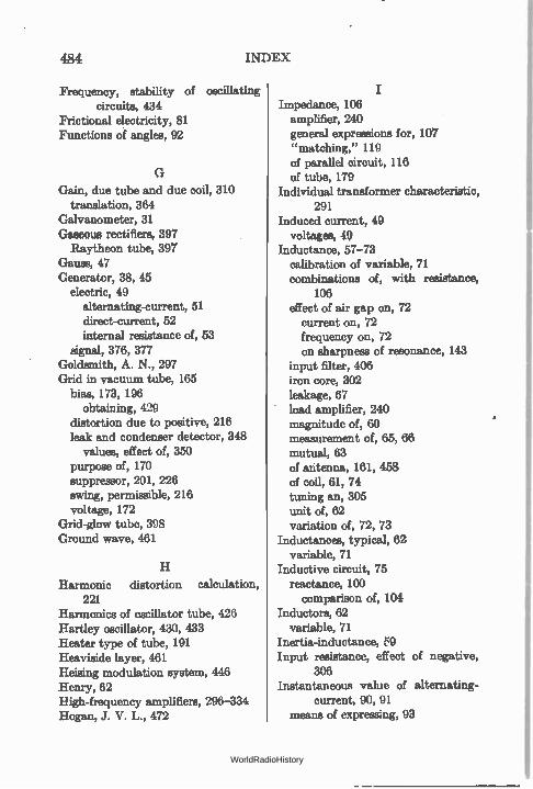
484 INDEX
Frequency, stability of oscillating circuits, 434
Frictional electricity, 81 Functions of angles, 92
G
Gain, due tube and due coil, 310 translation, 364
Galvanometer, 31 Gaseous rectifiers, 397 Raytheon tube, 397
Gauss, 47 Generator, 38, 45
electric, 49 alternating-current, 51 direct-current, 52 internal resistance of, 53
signal, 376, 377 Goldsmith, A. N., 297 Grid in vacuum tube, 165
bias, 173, 196 obtaining, 429
distortion due to positive, 216 leak and condenser detector, 348
values, effect of, 350 purpose of, 170 suppressor, 201, 226 swing, permissible, 216 voltage, 172
Grid-glow tube, 398 Ground wave, 461
H
Harmonic distortion calculation, 221
Harmonics of oscillator tube, 426 Hartley oscillator, 430, 433 Heater type of tube, 191 Heaviside layer, 461 Heising modulation system, 446 Henry, 62 High-frequency amplifiers, 296-334 Hogan, J. V. L., 472
Impedance, 106 amplifier, 240 general expressions for, 107 "matching," 119 of parallel circuit, 116 of tube, 179
Individual transformer characteristic, 291
Induced current, 49 voltages, 49
Inductance, 57-73 calibration of variable, 71 combinations of, with resistance,
106 effect of air gap on, 72
current on, 72 frequency on, 72 on sharpness of resonance, 143
input filter, 406 iron core, 302 leakage, 67 load amplifier, 240 magnitude of, 60 measurement of, 65, 66 mutual, 63 of antenna, 161, 458 of coil, 61, 74 tuning an, 305 unit of, 62 variation of, 72, 73
Inductances, typical, 62 variable, 71
Inductive circuit, 75 reactance, 100
comparison of, 104 Inductors, 62
variable, 71 Inertia-inductance, 59 Input resistance, effect of negative,
306 Instantaneous value of alternating-
current, 90, 91 means of expressing, 93
WorldRadioHistory
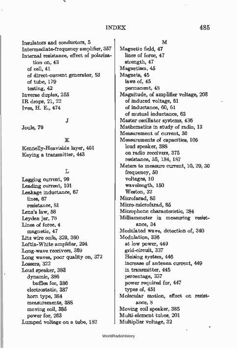
INDEX 485
Insulators and conductors, 5 Intermediate-frequency amplifier, 357 Internal resistance, effect of polariza-
tion on, 43 of cell, 41 of direct-current generator, 53 of tube, 179 testing, 42
Inverse duplex, 255 IR drops, 21, 22 Ives, H. E., 474
Joule, 79
Kennelly-Heaviside layer, 461 Keying a transmitter, 443
Lagging current, 99 Leading current, 101 Leakage inductance, 67
linea, 67 resistance, 81
Lenz's law, 58 Leyden jar, 76 Linea of force, 4
magnetic, 47 Litz wire coils, 329, 360 Loftin-White amplifier, 294 Long-wave receivers, 369 Long waves, poor quality on, 372 Lossers, 322 Loud speaker, %R.3
dynamic, 386 baffles for, 386
electrostatic, 387 horn type, 384 measurements, 388 moving coil, 385 power for, 263
Lumped voltage on a tube, 182
Magnetic field, 47 lines of force, 47 strength, 47
Magnetism, 45 Magnets, 45
laws of, 45 permanent, 48
Magnitude, of amplifier voltage, 208 of induced voltage, 61 of inductance, 60, 61 of mutual inductance, 63
Master oscillator systems, 436 Mathematics in study of radio, 13 Measurement of current, 30 Measurements of capacities, 105
loud speaker, 388 on radio receivers, 375 resistance, 35, 184, 187
Meters to measure current, 10, 29, 30 frequency, 50 voltages, 10 wavelength, 150 Weston, 32
Microfarad, 85 Micro-microfarad, 85 Microphone characteristic, 284 Milliammeter in measuring resist-
ance, 34 Modulated wave, detection of, 340 Modulation, 336
at low power, 449 grid-circuit, 337 Heising system, 446 increase of antenna current, 449 in transmitter, 445 percentage, 337 power required for, 447 types of, 451
Molecular motion, effect on resist-ance, 8
Moving coil speaker, 385 Multi-element tubes, 201 Multiplier voltage, 32
WorldRadioHistory
486 INDEX
N
Negative input resistance, 306 Neutrodyne, 324 Noise suppressor circuit, 354, 382
O
Oersted's experiment, 45 Ohm, 7 Ohm's law, 20-37
graphs of, 22-24 ways of stating, 20
Operating filaments in series, 191 Operating points, 202 Oscillating circuits, 415
coupling in, 421, 444 dynamic characteristics of, 422 frequency doublers, 438 highly damped, 416 practical, 430 stability of, 434 various, 432
Oscillation, conditions for, 418, 423 undamped or continuous, 417
Oscillator, adjusting, 433 connecting to antenna, 444 crystal control in, 437 efficiency of, 425 electron-coupled, 364 Hartley, 430, 433 maximum power output, 429 shunt feeding, 431 systems, master, 436 power output, 427 transmitters, etc., 415-452 tube, harmonics of, 426
Output choke, 22 Overall voltage amplification, 238 Overloading, amplifier, 212
Parallel cells, 44 Parallel circuits, 25, 115
characteristics of, 27
Parallel circuits, impedance of, 116 phase in, 116 resonance, 131, 136
Peak value of alternating current, 91 Pentode, 226 Period, 51 Permeability, of iron, 47
of core, 00 Permissible grid swing, 216 Phase, 91
angle, 91, 94 sine of, 91, 92
in parallel circuits, 116 in series circuit, 111 of Ep, Eg, and /9, 207 relations between current and volt-
age, 97 Plate, battery requirements, 239
circuit detector, 340 curves, 172, 174 in vacuum tube, 165, 184 oscillator, 441 purpose of, 166 resistance, measurement, 187 symbol, 166 voltage, effect of, 168, 170, 174
Polarization, 43 means to overcome effects of, 43
Poles, 47 Polydoroff coils, 302 Power, amplification, 211, 262
apparent, 119 detection, 352 diagrams, 222 electrical, 53 expressions for, 55 factor, 119 for loud speaker, 263 in alternating-current circuits, 117 in transformer circuits, 68 into resonance circuit, 126 level, 284 loss in condensers, 83 lost in resistance, 54
WorldRadioHistory
INDEX 487
Power, output, 210 calculation, 221 of oscillator tube, 427
supply apparatus, 390-414 automotive receiver, 407
Protons, 1 Push-pull amplifier, 259
tube, comparison of, 293
Q Q, of circuit, 123
of coil, 145
R Radiation field, 455
resistance, 453 Radio-frequency amplifier, Class B,
333 Class C, 333 detection in, 347 engineering tuned, 308 intermediate-frequency, 357 negative input resistance in, 306 purpose of, 299 task of, 300 tube input capacity of, 304
Radio-frequency amplifiers, 296-334 in general, 303 neutralizing bridge circuits in, 325 receiving systems, 301, 356 regeneration and oscillation in, 319 selectivity in, 315-319 tuned, 305 ultra-high, 334
Ranger, Capt. R. H., 472 Ratio, arms, 37
voltage and current, 268 Raytheon tube, 397 Reactance, capacitive, 102
comparison of inductive and capaci-tive, 104
inductive, 100 Reactivating thoriated filaments, 190 Receiver, automotive, 407 "band pass," 372, 373, 374
Receiver, broadcast, 300 fidelity of, 296 long-wave, 369 measurements on, 375 response curve of, 301 selectivity of, 296 sensitivity of, 296 short-wave, 365 superheterodyne, 356, 358 telephone, 387 tuning a, 149 "universal" a.c.-d.c., 194
Receiving circuits, typical, 162 Receiving systems, 356-389
types of, 301, 356 Reception, night and day, 462 Recording studio diagram, 286 Rectifier, 75
circuit, fundamental, 390 filter circuit for, 401 -filter system, 404 gaseous, 397
characteristics of, 398 Raytheon tube, 397
kinds of, 392 single-wave, 395 tubes, requirements for, 394 Tungar, 399 typical filament, 393
Rectifiers and power supply appara-tus, 390-414
Reflex amplifiers, 253 modern design, 256
Regeneration, in audio amplifiers, 286
in radio-frequency amplifiers, 325 Regulation of filter circuit, 403 Rejector circuit, 136 "Repeat points," 361 Resistance, 6
box, 37 coil, bearing on selectivity, 163 measurement of, 158
coils, 144
WorldRadioHistory
488 INDEX
Resistance, combinations of, 106 differential, 179 effect, of molecular motion on, 8
of temperature on, 8 on series resonant circuit, 125
effective, 134 high-frequency, 45 Internal, of cell, 41
of generator, 53 of tube, 179
leak, obtaining grid bias by, 429 leakage, 81 measurement, 33-37, 184, 187 negative, 320 negative input, 306 output load, 205 plate, 179, 184, 187 radiation, 453 ratio arms, 37 temperature, coefficient of, 8 unit of, 7
Resonance, 114, 120-148 circuit, 120 power into, 126
curve, width of, 140 minimum current, 133 parallel, 131 sharpness of, 138, 140 zero reactance, 133
Resonant frequency of circuit, 127, 134
Response of receiver, 301 Rice circuit, 323 Root-mean-square value, 96
S
Saturation current, 169 Scanning, 471, 474, 478 Screen-grid tube, 197, 199
at short waves, 367 gain, 329 selectivity, 330
Selectivity, 315 apparent and real, 379
Selectivity, of circuit, 139 combinations, 274
of radio receiver, 296, 301 of superheterodyne, 363 with screen-grid tubes, 330
Self-inductance, 59 Sensitivity, of meters, 32
of radio receiver, 296 Series, aiding, 63, 64
cells in, 44 operating filaments in, 191 opposing, 64
Series, alternating-current circuits, 109
characteristics of, 113 phase in, 111 resonant, 120
Series and parallel circuits, 24 resonant, 136
acceptor, 137 rejector, 136 uses of, 136
Series resonant circuit, 120 characteristic of, 123 effective of resistance on, 125 power into, 126 resonant frequency of, 127
Shape of condenser plates, 380 Sharpness of resonance, 138
effect of inductance and capacity on, 143
Shielding, 382 Short-wave receivers, 365
transmission, 460 Shunt-feeding oscillators, 431 Side band, 300
cutting, 301 frequency, 336
Signal generator, 376, 377 Sine wave of voltage, 51 Single slide tuning coil, 70, 71 Single-wave rectifier, 395 Skip distance, 461 Sky wave, 461
WorldRadioHistory
INDEX 489
Slide wire bridge, 37 Slopes as tube constants, 181 Solenoid, 46, 63 Sound frequency chart, 282 Sound level chart, 285 Static, 83, 462 man-made, 463
elimination of, 463, 464 natural, 463
Static electricity, 76, 79 Supercontrol tubes, 200 Superheterodyne, 356
design, 358 electron-coupled oscillator, 364 "repeat points" in, 360 selectivity, 363 translation gain, 364
Suppressor grid, 201, 226, 332 Symbols, 17-19
Telephone receiver, 387 Television and facsimile, 467-478
Bell system of photograph trans-mission, 470
cathode ray scanning, 477, 478 Cooley system, 471 frequency band required, 469 flying spot, 475 llogan's facsimile system, 472 iconoscope, 477 Ives' picture transmission, 474 persistence of vision, 473 picture elements, 468 Ranger's facsimile, 472 scanning, 471, 474, 478 ultra-high frequencies, 478 Zworykin's iconoscope, 477
Temperature coefficient of resistance,
Thompson, B. J., 334 Thoriated filaments, reactivating, 190 Thyratron, 398
Time of charge of condenser, 78 constant, 81
Tone control, automatic, 332, 374 with suppressor grid, 332
Transformer, 66 advantage of, in amplifier, 249 auto-, 69 characteristics, individual, 291 circuits, power in, 68 -coupled amplifier, 246 losses, 68 output, 280 turns ratio in, 280 with no secondary load, 248
Translation gain, 364 Transmission, 453-464
line, feeding power through, 445 short-wave, 460 unit, 266
Transmitter, field strength of, 297 keying, 443 modulation in, 445
Transmitters, adjusting plate load in, 441
plate current, 441 self-rectified, 440
Transmitting station, high power at. 299
purpose of, 299 Triangle functions, 92 Tube, alternating current, 190
as an amplifier, 202-227 ballast, 413 constants, measurement of, 184 C bias, 409 factors, method for determining
185 filaments, types of, 189 grid-glow, 398 heater type, 191 input capacity, 304 multi-element, 201 power output of oscillator, 427 Raytheon, 397
WorldRadioHistory
490 INDEX
Tube, rectifier, 394 supercontrol, 200 tester, alternating current, 188
thyratron, 398 vacuum (see Vacuum) variable mu, 200
Tuned inductance amplifier, 245 radio-frequency amplifiers, 305, 308
receiving set, 356 Tungar rectifier, 399 Tuning condensers, 86
receiver, 149
U
Universal a.c.-d.c., 194
V Vacuum tube, 165-201 "A" battery, 166 alternating-current, 190 alternating-current tester for, 188 amplification constant, 175, 177,
185 "B" battery, 167 characteristic curves, 171
slopes of, as constants, 181 constants, measurements of, 184
slopes as, 181 construction of, 165 direct-current resistance of, 178 equivalent tube circuit, 177, 209 factors, bridge methods of deter-
mining, 185 filament in, 165
purpose of, 166 filaments, operating in series, 191 grid in, 165
bias, 171, 173, 196 purpose of, 170 voltage, 172
heater types of, 191 cathode, 191
impedance of, 179 internal resistance of, 179
Vacuum tube, "lumped" voltage on, 182
measurement of constants, 184-187
mutual conductance of, 180 importance of, 181
measurement of, 184 plate in, 165
current curves, 172, 174 purpose of plate, 166
resistance, 179, 184, 187 voltage, 168, 170 voltage curves, 174
resistance of, 179 differential, 179 direct-current, 178 internal, 179 plate, 179, 184, 187
saturation current, 169 screen-grid, 197
characteristic curves, 199 space charge in, 166 thoriated, 190 types of, 189 variable-mu, 200 voltage, 168 voltmeter, 343
use of, 346 Variable inductances, 71 Variable-mu tube, 200 Variometer, 72 Vector, 94 Vibrator, 407 Volt, 10 Voltage amplification, 262 and current ratios, 268 divider, 21, 407, 411 doubler, 399 drop, 21 effect of filament, 168 effective, 96 grid, 172, 346 induced, 49, 61 magnitude of amplified, 208
WorldRadioHistory
INDEX 491
Voltage amplification, open-circuit, 53
phase relations of, 97 plate battery, 239 plate-current curves, 174 regulation, 412 sine wave of, 51
Voltmeter, 10 adjusting, 344 vacuum tube, 343
use of, 346 Voltmeter method of measuring re-
sistance, 34 low resistance, and milliammeter,
34 Voltmeters, 31
multiplier, 32 sensitive, 32
Volume control, 278 automatic, 380
Volume control, automatic circuit, 354 compensated, 375
Wavelength, 129 of antenna, 160, 459, 460
Wavelengths, table of, 370 Wavemeter, 150
calibrating, 152 by clicks, 156 by harmonics, 153
heterodyne, 151 Weston meters, 32, 34 Wheatstone bridge, 35, 65 Width of resonance curve, 140
Zero beat, 357 Zero potential, 83 Zworykin, V. K., 477
WorldRadioHistory
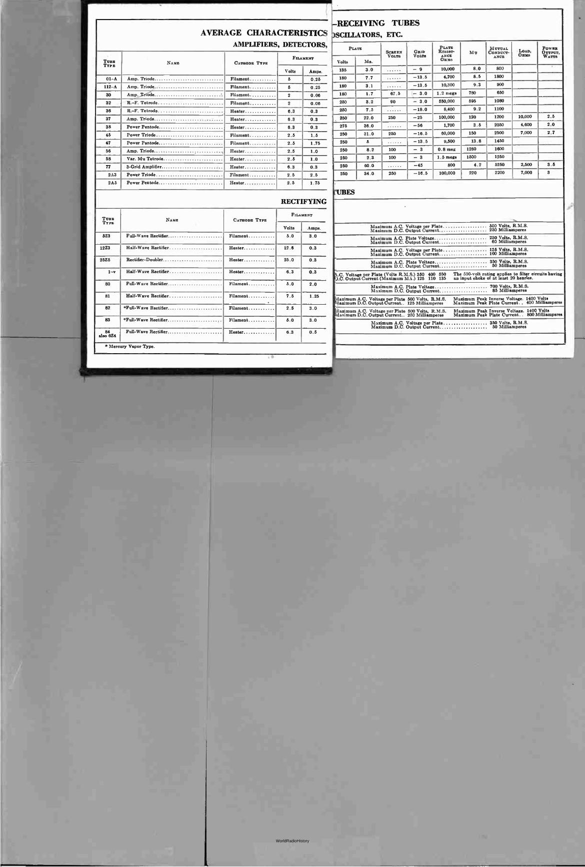
AVERAGE CHARACTERISTICS
AMPLIFIERS, DETECTORS,
TUBE TYPE
NAME CATHODE TYPE FILAMENT
Volts Amps.
01-A Amp. Triode Filament 5 5
2
2
0.25
0.25
0.06
0.06
112-A Amp. Triode Filament Filament
30 A m p„.. _Trróde Filament
32 R.-F. Tetrode Filament Filament
36 R.-F. Tetrode Heater 8.3
6.3
6.3
0.3
0.3
0.3
37 Amp. Triode Heater
38 Power Pentode Heater
45 Power Triode Filament 2.5
2 . 5
1 . 5
1.75 47 Power Pentode Filament
86 Amp. Triode . Heater 2 . 5
2.5
1.0
1.0 58 Var. Mu Tetrode Heater
77 3-Grid Amplifier Heater 8.3 0.3
2A3 Power Triode Filament 2 . 5 2 . 5
2A5 Power Pentode Heater 2 . 5 1.75
RECTIFYING
TUBE TYPE
NAME CATHODE TYPE FILAMENT
Volts Amps.
5Z3 Full-Wave Rectifier Filament 5.0
12.6
3.0
0.3
0.3
0.3
12Z3 Half-Wave Rectifier Heater
25Z5 Rectifier-Doubler Heater 25.0
1-v Half-Wave Rectifier Heater 6.3
80 Full-Wave Rectifier Filament 5.0 2.0
81 Half-Wave Rectifier Filament 7.5
2.5
1.25
3.0
3.0
0.5
82 *Full-Wave Rectifier Filament
83 *Full-Wave Rectifier Filament 5.0
6.3 84 suo 6Z4
Full-Wave Rectifier Heater
*Mercury Vapor Type.
-RECEIVING
3SCILLATORS,
TUBES
ETC.
PLATE SCREEN VOLTS
GRID VOLTS
PLATE RESIST- A NCE °Hun
M U M UTUAL CONDUCT-
ANCE LOAD, OEMs
POWER OUTPUT, W ATTS
Volta Ma.
135 3.0 - 9 10,000 8.0
8 . 5
800
180 7.7 -13.5 4,700 1800
180 3.1 -13.5 10,300 9.3 900
180 1.7 87.5 - 3.0 1.2 mega 780
595
650
1080 250 3.2 90 - 3.0 550,000
250 7.5 -18.0 8,400 9.2 1100
250 22.0 250 -25 100,000 120 1200 10,000 2.5
275 36.0 -56 1,700 3.5
150
2050
2500
1450
4,600
7,000
2.0
2.7 250 31.0 250 -16.5 60,000
250 5 -13.5 9,500 13.8
250 8.2 100 - 3 0.8 meg 1280 1600
250 2.3 100 - 3 1.5 mega 1500 1250
2,500
7,000
3.8
3
250 60.0 -45 800 4.2
220
5250
2200 250 34.0 250 -16.5 100,000
'UBES
Maximum A.C. Voltage per Plate 500 Volta, R.M.S. Maximum D.C. Output Current 250 Milliamperes
Maximum A.C. Plate Voltage 250 Volts, R.M.S. Maximum D.C. Output Current 60 Milliamperes
125 Volts, R.M.S. lanIinimuumm à .... (\:;oulttpag eenretPenlatte f 100 Milliamperes
Maximum A.C. Plate Voltage 350 Volte, R.M.S. Maximum D.C. Output Current 50 Milliamperes
N.C. Voltage per Plate (Volts R.M.S.) 350 400 550 The 550-volt rating applies to filter circuits having D.C. Output Current (Maximum MA.) 125 110 135 an input choke of at least 20 henries.
Maximum A.C. Plate Voltage 700 Volts, R.M.S. Maximum D.C. Output Current 85 Milliamperes
Maximum A.C. Voltage per Plate 500 Volts, R.M.S. Maximum Peak Inverse Voltage. 1400 Volte 4aximum D.C. Output Current.. 125 Milliamperes Maximum Peak Plate Current. . 400 Milliamperes
Maximum A.C. Voltage per Plate 500 Volts, R.M.S. Maximum Peak Inverse Voltage. 1400 Volts Maximum D.C. Output Current.. 250 Milliamperes Maximum Peak Plate Current.. 800 Milliamperes
Maximum A.C. Voltage per Plate 350 Volts, R.M.S. Maximum D.C. Output Current 50 Milliamperes
***kip/mown*
WorldRadioHistory
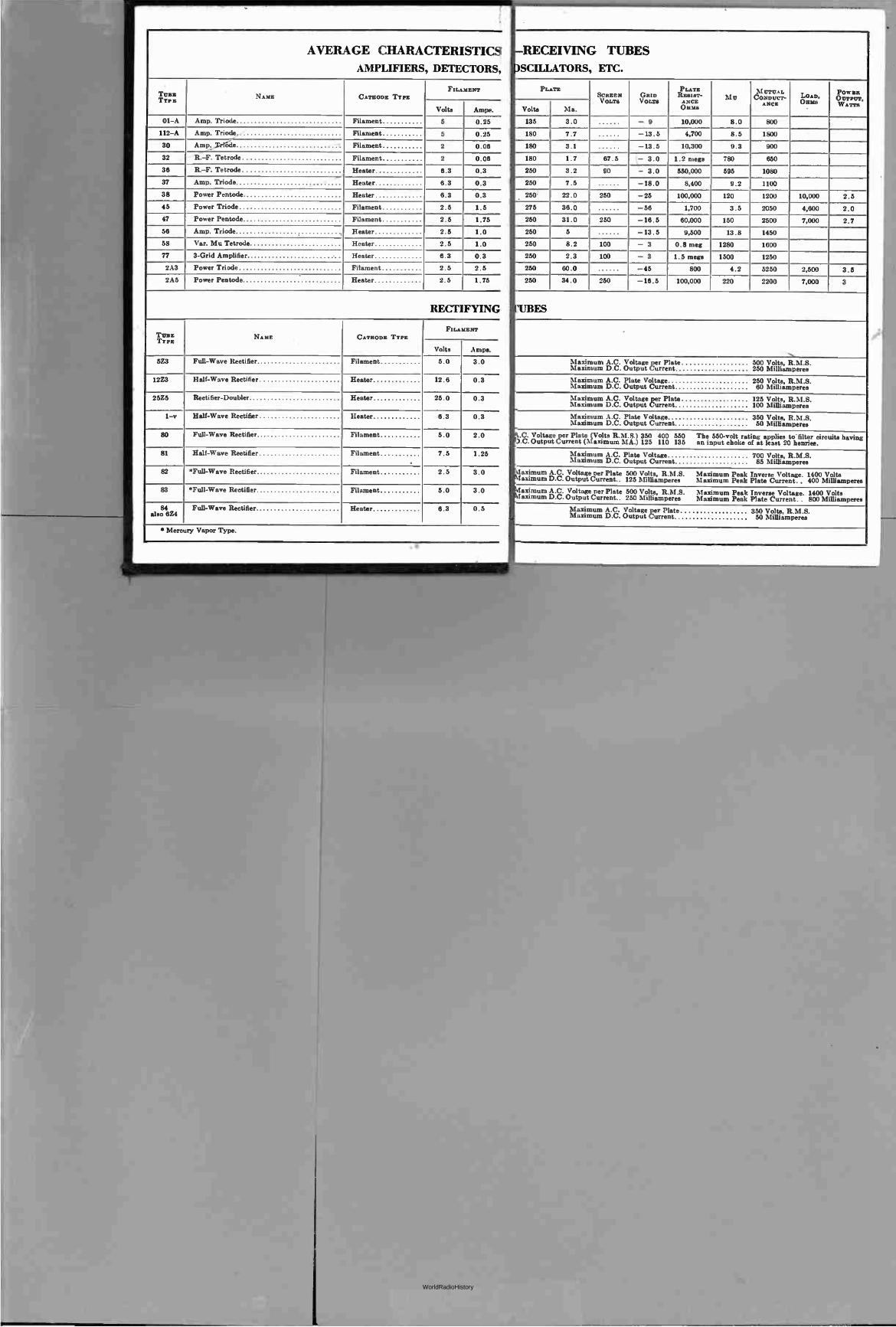
AVERAGE CHARACTERISTICS
AMPLIFIERS, DETECTORS,
Twos TYP z
NAME CATHODE TYPE FILAMENT
Volte
5
Amps.
0.25 01-A Amp. Triode Filament
112-A Amp. Triode Filament 5
2
2
8.3
0.25
0.06
0.06
0.3
0.3
0.3
30 Amp. ode ' Filament
32 R.-F. Tetrode Filament
38 R.-F. Tetrode Heater Heater
37 Amp. Triode Heater 6.3
8.3 38 Power Pentode Heater
45 Power Triode Filament 2.5
2.5
1.5
1.75
1.0
1.0
0.3
47 Power Pentode Filament
58 Amp. Triode . , Heater 2.5
2.5 58 Var. Mu Tetrode Heater
77 3-Grid Amplifier Heater 8.3
2A3 Power Triode Filament 2.5 2.5
2A5 Power Pentode Heater 2.5 1.75
RECTIFYING
TUBE TYPE
NAME CATHODE TYPE FILAMENT
Volte Amps.
5Z3 Full-Wave Rectifier Filament 5.0
12.6
3.0
0.3 12Z3 Half-Wave Rectifier Heater
25Z5 Rectifier-Doubler Heater 25.0
8.3
0.3
0.3 1-v Half-Wave Rectifier Heater
80 Full-Wave Rectifier Filament 5.0 2.0
81 Half-Wave Rectifier Filament 7.5 1.25
82 *Full-Wave Rectifier Filament 2.5 3.0
83 *Full-Wave Rectifier Filament 5.0 3.0
84 also 6Z4
Full-Wave Rectifier Heater 8.3 0.5
. Mercury Vapor Type.
RECEIVING
SCLILATORS,
TUBES
ETC.
PLATE SCREEN VOLTS
GRID V ours
PLATE RESIST- ANCE OBEs
Mu M UTUAL CONDUCT- ANCE
Lou, Onus
POWER OUTPUT, W ATTS
Volta Ma.
135 3.0 - 9 10,000 8.0 800
180 7.7 -13.5 4,700 8.5 1800
180 3.1 -13.5 10,300 9.3 900
650 180 1.7 87.5 - 3.0 1.2 mega
550,000
780
250 3.2 90 - 3.0 595 1080
250 7.5 -18.0 8,400 9.2 1100
250' 22.0 250 -25 100,000 120 1200 10,000 2.5
2.0
2.7
275 36.0 -58 1,700 3.5 2050 4,800
7,000 250 31.0 250 -18.5
-13.5
60,000 150 2500
250 5 9,500 13.8 1450
250 8.2 100 - 3
- 3
0.8 meg 1280 1600
250 2.3 100 1.5 mega 1500 1250
250 80.0 -45 800 4.2 5250 2,500 3.5
3 250 34.0 250 -18.5 100,000 220 2200 7,000
ES
, Maximum A.C. Voltage per Plate 500 Volte, R.M.S. Maximum D.C. Output Current 250 Milliamperes
Maximum A.C. Plate Voltage 250 Volts, R.M.S. Maximum D.C. Output Current 60 Milliamperes
Maximum A.C. Voltage per Plate 125 Volts, R.M.S. Maximum D.C. Output Current 100 Milliamperes
Maximum A.C. Plate Voltage 350 Volts, R.M.S. Maximum D.C. Output Current 50 Milliamperes
.C. Voltage per Plate (Volts R.M.S.) 350 400 550 The 550-volt rating applies to filter circuits having D.C. Output Current (Maximum MA.) 125 110 135 an input choke of at least 20 henries.
Maximum A.C. Plate Voltage 700 Volts, H.M.S. Maximum D.C. Output Current 85 Milliamperes
aximum A.C. Voltage per Plate 500 Volts, R.M.S. Maximum Peak Inverse Voltage. 1400 Volta aximum D.C. Output Current.. 125 Milliamperes Maximum Peak Plate Current.. 400 Milliamperes
daxirnum A.C. Voltage per Plate 500 Volte, R.M.S. Maximum Peak Inverse Voltage. 1400 Volta aximum D.C. Output Current.. 250 Milliamperes Maximum Peak Plate Current.. 800 Milliamperes
Maximum A.C. Voltage per Plate 350 Volts, R.M.S. Maximum D.C. Output Current 50 Milliamperes
WorldRadioHistory
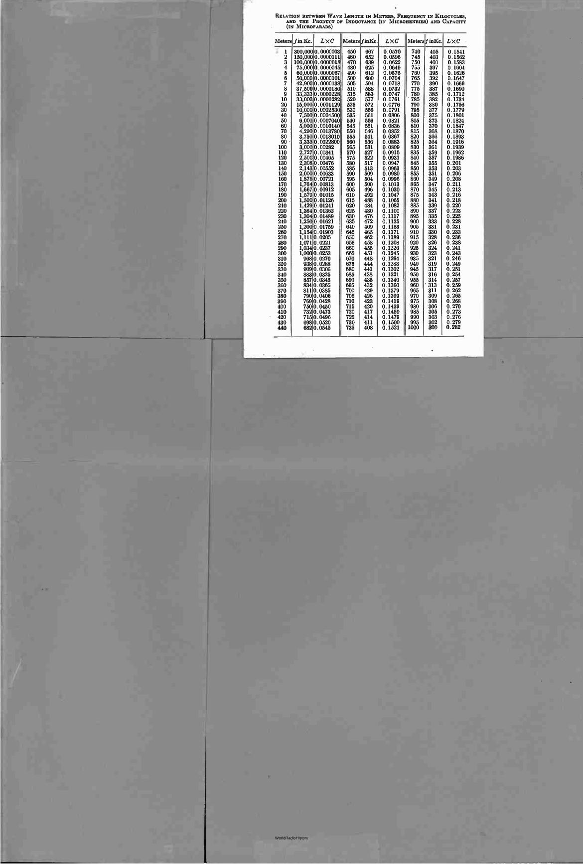
RELATION BETWEEN WAVE LENGTH IN METERS, FREQUENCY IN KILOCYCLES, AND THE PRODUCT OF INDUCTANCE (IN MICROHENRIES) AND CAPACITY (IN M ICROFARADS)
Meters fin Kc. L X C Meters finKc. LXC Meters f inKc. LXC
1 300,000 0. 0000003 450 667 0.0570 740 405 0.1541 2 150,000 0. 0000111 460 652 0.0596 745 403 0.1562 3 100,000 0. 0000018 470 639 0.0622 750 400 0.1583 4 75,000 0. 0000045 480 625 0.0649 755 397 0.1604 5 60,000 0. 0000057 490 612 0.0676 760 395 0.1626 6 50,000 0. 0000101 500 600 0.0704 765 392 0.1647 7 42,900 0. 0000138 505 594 0.0718 770 390 0.1669 8 37,500 0. 0000180 510 588 0.0732 775 387 0.1690 9 33,333 0. 0000228 515 583 0.0747 780 385 0.1712 10 33,000 0. 0000282 520 577 0.0761 •785 382 0.1734 20 15,000 0. 0001129 525 572 0.0776 790 380 0.1756 30 10,000 0. 0002530 530 566 0.0791 795 377 0.1779 40 7,500 0. 0004500 535 561 0.0806 800 375 0.1801 50 6,000 0. 0007040 540 556 0.0821 805 373 0.1824 60 5,000 0. 0010140 545 551 0.0836 810 370 0.1847 70 4,290 0.0013780 550 546 0.0852 815 368 0.1870 80 3,750 0.0018010 555 541 0.0867 820 366 0.1893 90 3,333 0. 0022800 560 536 0.0883 825 364 0.1916 100 3,000 0. 00282 565 531 0.0899 830 361 0.1939 110 2,727 0.00341 570 527 0.0915 835 359 0.1962 120 2,500 0. 00405 575 522 0.0931 840 357 0.1986 130 2,308 0.00476 580 517 0.0947 845 355 0.201 140 2,143 0.00552 585 513 0.0963 850 353 0.203 150 2,000 0. 00633 590 509 0.0980 855 351 0.206 160 1,875 0.00721 595 504 0.0996 860 349 0.208 170 1,764 0. 00813 600 500 0.1013 865 347 0.211 180 1,667 0.00912 605 496 0.1030 870 345 0.213 190 1,579 0.01015 610 492 0.1047 875 343 0.216 200 1,500 0.01126 615 488 0.1065 880 341 0.218 210 1,429 0. 01241 620 484 0.1082 885 339 0.220 220 1,364 0. 01362 625 480 0.1100 890 337 0.223 230 1,304 0.01489 630 476 0.1117 895 335 0.225 240 1,250 0. 01621 635 472 0.1135 900 333 0.228 250 1,200 0.01759 640 469 0.1153 905 331 0.231 260 1,154 0.01903 645 465 0.1171 910 330 0.233 270 1,111 0.0205 650 462 0.1189 915 328 0.236 280 1,071 0.0221 655 458 0.1208 920 326 0.238 290 1,034 0.0237 660 455 0.1226 925 324 0.241 300 1,000 0.0253 665 451 0.1245 930 323 0.243 310 9680.0270 670 448 0.1264 935 321 0.246 320 9380.0288 675 444 0.1283 940 319 0.249 330 909 0.0306 680 441 0.1302 945 317 0.251 340 8830.0325 685 438 0.1321 950 316 0.254 350 8570.0345 690 435 0.1340 955 314 0.257 360 834 0.0365 695 432 0.1360 960 313 0.259 370 8110.0385 700 429 0.1379 965 311 0.262 380 790 0.0406 705 426 0.1399 970 309 0.265 390 7690.0428 710 423 0.1419 975 308 0.268 400 7500.0450 715 420 0.1439 980 306 0.270 410 732 0.0473 720 417 0.1459 985 305 0.273 420 7150.0496 725 414 0.1479 990 303 0.276 430 6980.0520 730 411 0.1500 995 302 0.279 440 682 0.0545 735 408 0.1521 1000 300 0.282
WorldRadioHistory
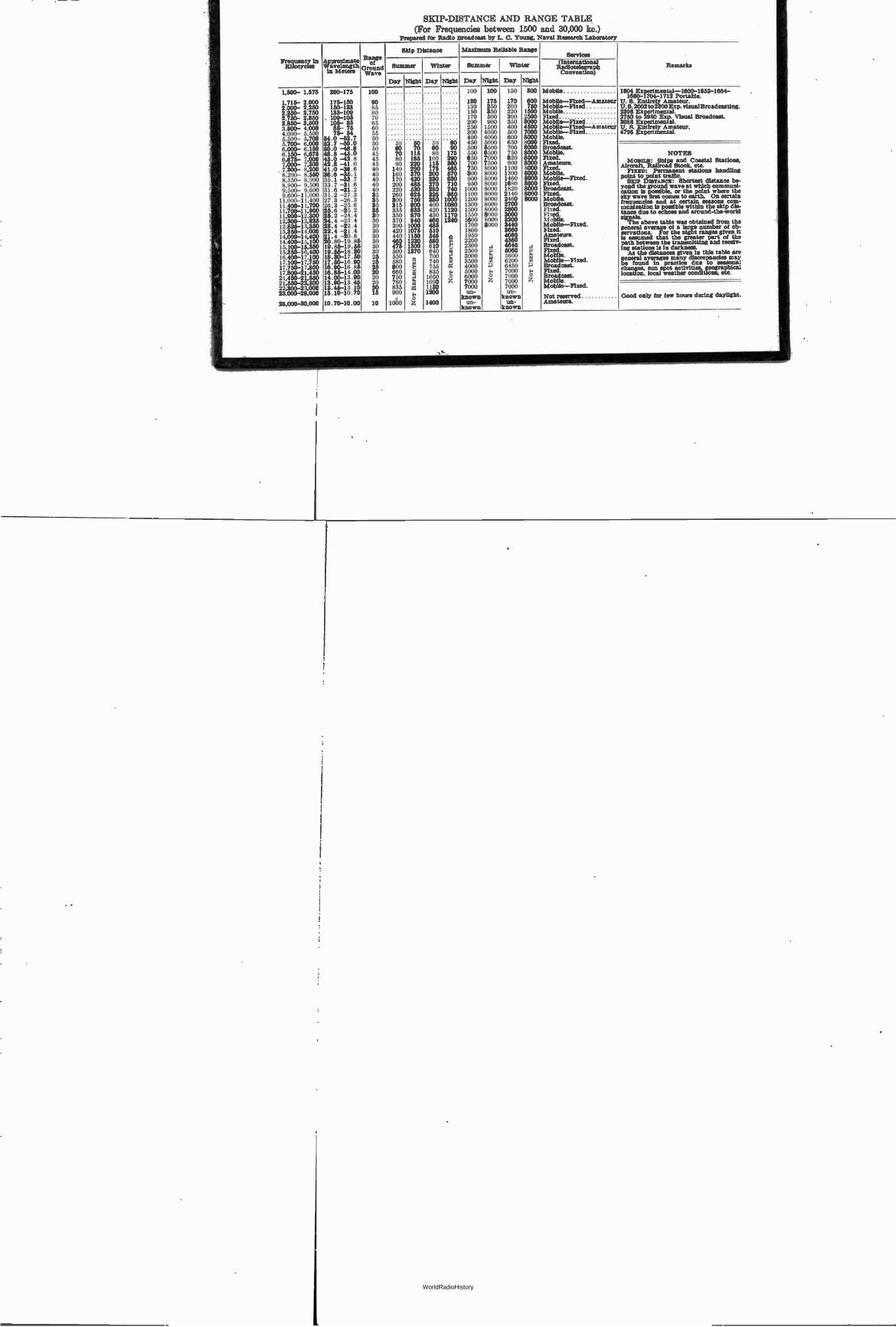
SKIP-DISTANCE AND RANGE TABLE (For Frequencies between 1500 and 30,000 kc.)
Prepared for Radio Broadcast by L. C. Young, Naval Research Laboratory
Fra loicenygresin
,,,,
Vavegngili in Meters
Range
td Ground Wave
Skip Distance Maximum Reliable Range Services
Remarks SSummer Summer
Day Night
Winter Winter (International Radiotelegraph Convention)
Day Night Day Night Day Night
C §M§§§8§e§88R§§8§§8§M§88nUM8§§ I
.
.,-. -. mcve
o
n man.
•s..-,m,e...00•rule
-; eic.i.i.4.i.e.e.i.etz.,:
e.i.se.;444.e.i.ei-e,4.6 g
é âéfiétékéttééééééééqeq
e"
eMé é
„; ..i.iii.d.e.e.seizizeos.6.2=4==n14 É
200-175 100 100 100 100 150
I
NOT U
SEFUL
111111111111111ffigg g
Mobile 1604 Experimental-1600-1652-1664-1680-1704-1712 Portable.
175-150 90 120 120 175 170 Mobile-Fixed-Amateur U. S. Entirely Amateur. 150-133 85 130 250 200 Moblle-Fixed II. 8.2002 to 2300 Exp. visual Broadcasting. 133-109 80 150 150 350 220 Mobile 2398 Experimental. 109-105 70 170 170 500 300 Fixed 2750 to 2950 Exp. Visual Broadcast. 105- 85 65 200 200 900 350 Mobile-Fixed 3088 Experimental. 85- 75 80 250 250 500 400 Mobile-Fixed-Amateur U. S. Entirely Amateur. 75- 54 55 300 300 4000 500 Mobile-FLxed 4795 Experimental.
54.0 -52.7 50 400 400 000 600 Mobile. 52.7 -50.0 150 50 50 50 60 450 5000 650 Fixed. 50.0 -48.8 50 60 70 60 90 500 500 700 Broadcast. 48.8 -45.0 45 70 115 80 175 550 500 750 Mobile. NOTES 45.0 -42.8 42.8 -41.0 41.0 -36.6 36.6 -35.1 35.1 -33.7 33.7 -31.6 31.6 -31.2 31.2 -27.3 27.3 -26.3 28.3 -25.6 25.6 -25.2 25. 2 -24.4 24.4 -23.4 23.4 -22.4 22.4 -21.4 21.4 -20.8 20.80-19.85 19.85-19.55 19 .55-18 . 30 18.30-17.50 17 . 50-16 . 90 16 .90-16 .85 16.85-14.00 14.00-13.90
45 45 40 40 40 40 40 35 35 35 35 30 30 30 30 30 30 30 30 25 25 25 20 20
80 90 140 160 170 200 220 260 300 315 335 350 370 390 420 440 460 475 500 550 580 800 660 750
185 220 290 370 420 485 530 825 750 800 835 870 940 1000 1075 1150 1230 1300 1370 , - g
100 115 175 200 230 270 280 325 380 400 420 430 460 485 510 545 580 610 640 700 740 755 835 1050
290 360 465 570 630 710 740 860 1000 1080 1120 1170 1240
n is. U I.1 C Id ce e 2
650 700 750 800 900 950 1000 1100 1200 1300 1500 1550 1600 1700 1800 1950 2200 2300 2500 3000 3500 4000 5000 6000
000 500 000 000 000 000 000 000 000 000 000 000 000 000
e ,,, w P e 2
820 900 1100 1300 1460 1680 1820 2140 2460 2700 2800 3000 3200 3440 3660 4060 4360 4640 5060 5600 6200 6450 7000 7000
Fixed. Amateurs. Fixed. Mobile. Mobile-Fixed. Fixed. Broadcast. Fixed, Mobile. Broadcast. Fixed. Fixed. Mobile. Mobile-Fixed. Fixed. Amateurs. Fixed. Broadcast. Fixed, Mobile. Mobile-Fixed. Broadcast. Fixed, Broadcast.
MOBILE: Ships and Coastal Stations, Aircraft, Railroad Stock, etc.
FIXED: Permanent stations handling point to point traffic.
SKIP Durrawcz: Shortest distance be-yond the ground wave at which communi-cation is possible, or the point where the sky wave first comes to earth. On certain frequencies and at certain seasons corn-munIcation Is possible within the skip dis-tance due to echoes and around-the-world signals. The above table was obtained from the
general average of a large number of ob-servations. For the night ranges given It Is assumed that the greater part of the path between the transmitting and recelv-lug stations is In darkness. As the distances given In this table are
general averages many discrepancies may be found in practice due to seasonal changes, sun spot activities, geographical location, local weather conditions, etc.
13.90-13.45 20 780
ï
1090 A 7000 A 7000 Mobile. 13.45-13.10 20 835 1130 7000 7000 Mobile-Fixed. 13.10-10.70 15 900 ,
o 1200 un-
known UD-
known Not reserved Good only for few hours during daylight.
10 . 70-10 .00 10 1060 Z 1400 Un- un- Amateurs. known known
WorldRadioHistory