W600 SERIES HYDRAULIC PUMP - jbj Techniques
18
uk distributor for quality products for mechanical & fluid power jbj Techniques Limited, www.jbj.co.uk W600 SERIES HYDRAULIC PUMP
-
Upload
khangminh22 -
Category
Documents
-
view
4 -
download
0
Transcript of W600 SERIES HYDRAULIC PUMP - jbj Techniques

uk distributor for
quality products for mechanical & fluid power jbj Techniques Limited, www.jbj.co.uk
W600 SERIES HYDRAULIC PUMP

Concentric AB-W600 PUMPS-US-2011-72
Model Code 030 035 040 045 050 060 070 080 100 120Displacement cm3/rev 3 3.5 4 4.5 5 6 7 8 10 12 in3/rev .183 .214 .244 .275 .305 .366 .427 .488 .610 .732Inlet Pressure BAR (PSI) min. 0.2 BAR below atmospheric (6 IN.HG) max. 2.0 BAR (29 PSI)Max. Continous Pressure (P1) (BAR 276 BAR 221 186 PSI) 4000 PSI 3200 2700Max. Intermittent Pressure (P2) (BAR 290 BAR 241 207 PSI) 4200 PSI * 3500 3000Min. Rotational Speed At (P1) 700 **Max. Rotational Speed At (P1) *** 4000 3600 3450 3000 2500Input Power KW 1.51 1.76 2.01 2.26 2.51 3.01 3.51 4.02 4.02 4.07 P1 @ 1000 RPM HP 2.0 2.4 2.7 3.0 3.4 4.0 4.7 5.4 5.4 5.5 * For P2 pressures greater than 4200 PSI, consult factory. ** For rotational speeds less than 700 RPM, consult factory.
W600
Performance Information
The W600 offers a compact package with the high per-formance of the W Series gear pumps and fluid motors. It is a through bore bushing type de-sign constructed of high strength aluminum housings and cast iron end covers. The W600 Series small package makes it suitable for a wide range of equipment appli-cations from material handling, aerial lift and bus, to turf care, agriculture and construction.
The hydraulic performance, flexibility, high efficiency, low and high speed operation, low noise performance and the variety of options have established the W Series as the standard by which other pump performance is mea-sured.
The W600 product line is avail-able also as fluid motors in both single and birotational designs. The same flange, shaft, and port-
ing options are available as well as optional all-aluminum front flange and rear cover for reduced product weight.
This catalog illustrates the options available for the W600 family as well as performance and dimen-sional information. An easy to follow ordering guide is also included.
Compact Hydraulic Gear PumpFeaturing Integrated Valve Packages
SOUND LEVEL
13 Tooth Design With Superior Trapping Confi guration For Quiet Operation
FLEXIBILITY
SAE, ISO & DIN ShaftsMounting Flanges, PortStyles, Integrated Valves,Multiple Section Pumps
QUALITY
ISO 9001 Registered
PRESSURE
(P1) 276 BAR (4000 PSI) *(P2) 290 BAR (4200 PSI)
SPEED
Maximum 4000 RPM **Minimum 700 RPM at
4000 PSI (276 BAR)Continuous
EFFICIENCY
Overall 88%Volumetric 98%Mechanical 90%
.
.
.
.
.
.

Concentric AB-W600 PUMPS-US-2011-7 3
DIMENSIONS & MOUNTING FLANGE OPTIONS
4-BOLT (4F17) ORDER CODE 01 & 21*
For its displacement and pressure range, the W600 family features one of the most compact envelopes available from any manufacturer. Standard inter-national mounting flange options are outlined below. Dimensions shown outside of brackets are metric units. (See top of page 4 for dimensional chart showing "X" and "Y" dimensions.)
SAE "AA" 2-BOLT ORDER CODE 02 (Dry Mount) / ORDER CODE 22 (Wet Mount)
SAE "A" 2-BOLT ORDER CODE 03 (Dry Mount) / ORDER CODE 33 (Wet Mount)
* Flange 21 for use with flex coupling drive code TA only.
Y
7.36.9
[.287][.272]
3.303.04
[.130][.120]
XMAX.
12.7[.50]
25.4 [1.000]
25.4 [1.000]
73 [2.87]MAX.
25.4[1.000]
25.4[1.000]
73[2.87]MAX.
OUTLETINLET
4X 9.53 [.375]
86 [3.39]MAX.
69[2.72]MAX.
106.4[4.189]
INLET OUTLET
4X 32o
125[4.92]MAX.
6.356.10[.25][.24]
12.7[.50]
14.95[.588]MAX.
Y
11.710.2[.46][.40]
69[2.72]MAX.
R 12.3[.48]MIN.
ROTATION
Y11.210.2[.44][.40]
6.356.10[.25][.24]
12.7[.50]
82.6[3.252]
OUTLETINLET
4X 21o
105[4.134]MAX.
69[2.72]MAX.
THESE HOLES NOT PRESENTON CODE 22 WET MOUNT
THESE HOLES NOT PRESENTON CODE 33 WET MOUNT
86[3.39]MAX.
55.3[2.177]
55.3[2.177]
86[3.39]MAX.
Ø 65 [2.56]MAX.
XMAX.
50.8050.75
[2.000][1.998]
Ø
10.4[.41]
Ø
97 [3.82]MAX.
Ø
11.0[.43]
Ø
82.5582.50
[3.250][3.248]
Ø
XMAX.
42.25045.212
[1.7815][1.7800]
Ø
55.3[2.177]

Concentric AB-W600 PUMPS-US-2011-74
A critical element which must be considered when specifying a W600 pump for your application is the shaft drive system. Concentric has both the product and the application experience to insure that your W600 pump incorporates the correct shaft for your application. The following depict the 7 standard shaft options for the W600 family. Our flexible manufacturing capabilities can accommodate a wide variety of shaft configurations.
5/8 " STRAIGHT KEYED SHAFT SAE "A" ORDER CODE CA
SHAFT OPTIONS
STRAIGHT KEYED SHAFT SAE "AA" ORDER CODE AA
3.18 x 3.18 x 25.4[.125 x .125 x 1.0]KEY
14.0813.82[.554][.544]
38.637.6[1.52][1.48]
3.97 x 3.97 x 19.05[.156 x .156 x .75]KEY
32.531.5[1.28][1.24]
SAE "AA" SPLINE ORDER CODE EA SAE "A" SPLINE ORDER CODE FA
27.526.5[1.08][1.04]
20.019.6[.79][.77]
14.613.9[.57][.54]
EXTERNAL INVOLUTE SPLINE20/40 DP, 9 TOOTH,FLAT ROOT, SIDE FIT
32.531.5[1.28][1.24]
24.123.7[.95][.91]
18.317.9[.72][.71]
EXTERNAL INVOLUTE SPLINE16/32 DP, 9 TOOTH,FLAT ROOT, SIDE FIT
DIMENSIONS & MOUNTING FLANGE OPTIONS(See dimensional drawings on page 3.)
17.7317.47[.698][.688]
Ø
15.8815.85[.625][.624]
Ø
12.3212.19[.485][.480]
Ø 15.4615.32[.608][.603]
Ø
12.7012.67[.500][.498]
Ø
Order Displacement X Max. X Max. Y Port Y Port Approx. Wt.
Code cm3 in3 (2-Bolt) (4-Bolt) (2-Bolt) (4-Bolt) kgs. {lbs.]
030 3.0 .183 81.8 105.7 42.8 66.9 2.43 [3.22] [4.16] [1.69] [2.63] [5.3]035 3.5 .214 81.8 105.7 43.7 67.7 2.46 [3.22] [4.16] [1.72] [2.67] [5.40]040 4.0 .244 82.5 106.4 44.4 68.4 2.48 [3.25] [4.19] [1.75] [2.69] [5.45]045 4.5 .275 83.9 107.8 47.3 71.3 2.50 [3.30] [4.24] [1.86] [2.81] [5.5]050 5.0 .305 85.3 109.3 47.3 71.3 2.53 [3.36] [4.30] [1.86] [2.81] [5.6]060 6.0 .366 89.1 113.0 47.3 71.3 2.58 [3.51] [4.45] [1.86] [2.81] [5.7]070 7.0 .427 92.2 115.1 47.3 71.3 2.63 [3.63] [4.53] [1.86] [2.81] [5.8]080 8.0 .488 96.4 120.3 47.3 71.3 2.68 [3.80] [4.74] [1.86] [2.81] [5.9]100 10.0 .610 99.9 123.8 49.0 73.0 2.78 [3.93] [4.87] [1.93] [2.87] [6.1]120 12.0 .732 105.8 129.7 52.0 76.0 2.88 [4.17] [5.11] [2.05] [2.99] [6.3]

Concentric AB-W600 PUMPS-US-2011-7 5
SINGLE SECTION SHAFT LOADING
P1 x V < MAX PERMITTED VALUE IN TABLE BELOW
WHERE: WHERE: P1 = PRESSURE (BAR) P1 = PRESSURE (PSI) V = DISPLACEMENT (CM3/REV) V = DISPLACEMENT (IN3/REV)
FLEX COUPLING DRIVE SHAFT ORDER CODE TA
44.243.2[1.74][1.70]
18.518.1[.73][.71]
2.131.88[.084][.074]
1:8 TAPER
SPRING LOCKWASHER (ANSI B18.21.1 1972)
1/2-20 UNF-2B HEX NUTTORQUE 50 + 10 Nm [37 + 7 LB.FT.]
8.37.5[.328][.285]6.22
6.15[.245][.242]
6.46.0[.250][.234] FLAT
3.22.4[.13][.09]
1/4-20 UNC-2BX 12.7 [.50] DEEP
5.16[.203]
2.79[.110]
11.0010.95[.433][.431]
SHAFT OPTIONS
#505 WOODRUFF KEY(ANSI B17.2-1967 R1978)
TANG DRIVE SHAFT ORDER CODE PASAE "A" TAPERED SHAFT ORDER CODE LA
14.9614.91[.589][.587]
15.8515.79[.624][.622]
Ø16.115.6[.635][.615]
Ø
CALCULATIONS USING
ENGLISH UNITS
SHAFT MAX.PERMITTED
OPTION VALUE
AA 4600 CA 5005 EA 2418 FA 4640 LA 7506 PA 1163 TA 900
CALCULATIONS USING
METRIC UNITS
SHAFT MAX.PERMITTED
OPTION VALUE
AA 5060 CA 5500 EA 2660 FA 5240 LA 8257 PA 1314 TA 990
Concentric AB-W600 PUMPS-US-2011-76
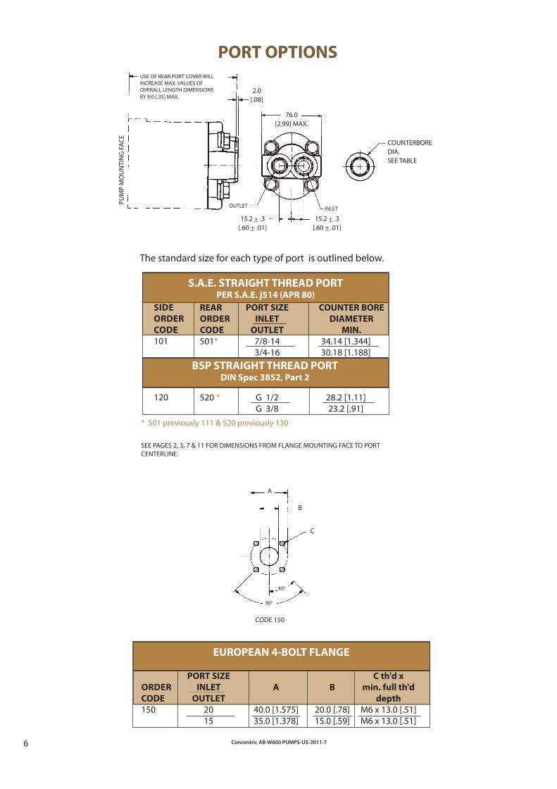
EUROPEAN 4-BOLT FLANGE
PORT SIZE C th'd x
ORDER INLET A B min. full th'd
CODE OUTLET depth
150 20 40.0 [1.575] 20.0 [.78] M6 x 13.0 [.51] 15 35.0 [1.378] 15.0 [.59] M6 x 13.0 [.51]
BSP STRAIGHT THREAD PORT DIN Spec 3852, Part 2
REAR PORT SIZE COUNTER BORE
ORDER INLET DIAMETER
CODE OUTLET MIN.
501* 7/8-14 34.14 [1.344] 3/4-16 30.18 [1.188]
520 * G 1/2 28.2 [1.11] G 3/8 23.2 [.91]
PORT OPTIONS
PUM
P M
OU
NTI
NG
FAC
E
The standard size for each type of port is outlined below.
USE OF REAR PORT COVER WILLINCREASE MAX. VALUES OFOVERALL LENGTH DIMENSIONSBY 9.0 [.35] MAX.
2.0[.08]
COUNTERBOREDIA.SEE TABLE
S.A.E. STRAIGHT THREAD PORTPER S.A.E. j514 (APR 80)
INLET
15.2 + .3[.60 + .01]
15.2 + .3[.60 + .01]
OUTLET
SEE PAGES 2, 3, 7 & 11 FOR DIMENSIONS FROM FLANGE MOUNTING FACE TO PORT CENTERLINE.
A
B
C
45o
90o
CODE 150
* 501 previously 111 & 520 previously 130
76.0[2.99] MAX.
SIDE
ORDER
CODE
101
120

Concentric AB-W600 PUMPS-US-2011-7 7
Order Displacement P Q (To Port Approx. Wt. R S (To Port Approx. Wt. T Approx. Wt. N L (To Port
Code + 0.26 Centerline) P Section Max. Centerline) R Section + 0.26 T Section + 0.26 Centerline)
cm3 in3 [+ 0.010] kg. [lbs.] kg. [lbs.] [+ 0.010] kg. [lbs.] [+ 0.010]
030 3.0 0.183 68.3 42.8 2.27 61.9 25.4 1.26 50.9 1.12 92.24 66.9 [2.69] [1.69] [5.0] [2.44] [1.00] [2.77] [2.00] [2.4] [3.63] [2.63] 035 3.5 0.214 69.8 43.7 2.30 63.4 26.3 1.29 52.4 1.15 93.74 67.7 [2.75] [1.72] [5.1] [2.50] [1.04] [2.83] [2.06] [2.5] [3.69] [2.67] 040 4.0 0.244 71.3 44.4 2.32 64.9 27.0 1.31 53.9 1.17 95.24 68.4 [2.81] [1.75] [5.1] [2.56] [1.06] [2.88] [2.12] [2.6] [3.75] [2.69] 045 4.5 0.275 72.7 47.3 2.34 66.3 29.9 1.33 55.3 1.19 96.64 71.3 [2.86] [1.86] [5.2] [2.61] [1.18] [2.93] [2.18] [2.6] [3.80] [2.81] 050 5.0 0.305 74.2 47.3 2.37 67.8 29.9 1.35 56.8 1.22 98.14 71.3 [2.92] [1.86] [5.2] [2.67] [1.18] [2.97] [2.24] [2.7] [3.86] [2.81] 060 6.0 0.366 77.1 47.3 2.41 70.7 29.9 1.41 59.7 1.27 101.04 71.3 [3.04] [1.86] [5.3] [2.78] [1.18] [3.10] [2.35] [2.8] [3.98] [2.81] 070 7.0 0.427 80.0 47.3 2.47 73.6 29.9 1.46 62.6 1.32 103.94 71.3 [3.15] [1.86] [5.4] [2.90] [1.18] [3.21] [2.46] [2.9] [4.09] [2.81] 080 8.0 0.488 82.9 47.3 2.52 76.5 29.9 1.51 65.5 1.37 106.84 71.3 [3.26] [1.86] [5.6] [3.01] [1.18] [3.32] [2.58] [3.0] [4.21] [2.81] 100 10.0 0.610 88.7 49.0 2.62 82.3 31.6 1.61 71.3 1.47 112.64 73.0 [3.49] [1.93] [5.8] [3.24] [1.24] [3.54] [2.81] [3.2] [4.43] [2.87] 120 12.0 0.732 94.6 52.0 2.72 88.2 34.6 1.71 77.2 1.57 118.54 76.0 [3.72] [2.05] [6.0] [3.47] [1.36] [3.76] [3.04] [3.4] [4.67] [2.99]
W600 MULTIPLE PUMPS
The W600 off ers multiple pump confi gu rations up to 3 sections. Multiple pumps provide multiple hydraulic functions from one power source at a signifi cantly lower cost than separate pumps.
The drawings and charts provide dimen sional information as well as shaft and coupling load information for W600 two and three section pumps. If the shaft loading, coupling, and section sequence requirements outlined on pages 4 and 5 are met, W600 multiple pumps will exhibit the same performance as W600 single section pumps outlined on page 2 of this catalog.
(For counterclockwise rotation,inlet and outlet are reversed.)
DOUBLE SECTION / DUAL INLET
TRIPLE SECTION / TRIPLE INLET
Dimensions P & Q are for use with Flange Options 02 and 03.
CWROTATION
INLET OUTLET
QP
S
R MAX.
CWROTATION P
SQT
S
RMAX.
INLET OUTLET
(For counterclockwise rotation,inlet and outlet are reversed.)
Dimensions P & Q are for use with Flange Options 02 and 03.

Concentric AB-W600 PUMPS-US-2011-78
CALCULATIONS USING
METRIC UNITS
SHAFT MAX.PERMITTED
OPTION VALUE
AA 5060 CA 5500 EA 2660 FA 5240 LA 8257 PA 1314 TA 990
CALCULATIONS USING
ENGLISH UNITS
SHAFT MAX.PERMITTED
OPTION VALUE
AA 4600 CA 5005 EA 2418 FA 4640 LA 7506 PA 1164 TA 900
MULTIPLE SECTION SHAFT LOADING
P1 x V < MAX PERMITTED VALUE IN TABLE BELOW
WHERE: WHERE: P1 = PRESSURE (BAR) P1 = PRESSURE (PSI) V = DISPLACEMENT (CM3/REV) V = DISPLACEMENT (IN3/REV)
W600 MULTIPLE PUMPS
Dimensions N & L are for use with Flange Options 01 and 21.
REDUCED INLET MULTIPLE PUMPSBased on your application requirements the W600 mul-tiple pump may be supplied with a single inlet on two section pump applications and dual inlets on three sec-tion pump appli cations. Reduced inlets provide overall system savings by reducing the cost of redundant inlet hose and fi ttings. Contact Concentric regarding your reduced inlet multiple pump application.
The W600 off ers multiple pump confi gurations up to 3 sections. Multiple pumps provide multiple hydraulic functions from one power source at a signifi cantly lower cost than separate pumps.
The drawings and charts provide dimensional informa-tion as well as shaft and coupling load information for the W600 two and three section pumps. If the shaft loading, coupling, and section sequence requirements outlined on this page are all met, the W600 multiple pump will exhibit the same performance as the W600 single section pumps outlined on page 2 of this catalog.
NL
S
R MAX.CW
ROTATION
INLET OUTLET
COUPLING LOADING
TWO SECTION:(P2 x V2) < 2427 (METRIC) 2150 (ENGLISH)
THREE SECTION:(P2 x V2) + (P3 xV3) < 2427 (METRIC) 2150 (ENGLISH)
In multiple pumps, shaft end section must have largest displacement. Each consecutive section must have dis-placement equal to or smaller than section preceding.
(For counterclockwise rotation,inlet and outlet are reversed.)

Concentric AB-W600 PUMPS-US-2011-7 9
OPTIONSLALBLCLDJBJCJD
DESCRIPTION Lift/Hold/Lower with Rear Ports and Cartridge Relief Lift/Hold/Lower with Rear Ports and Low Profi le Relief Lift/Hold/Lower with Side Ports and Cartridge Relief Lift/Hold/Lower with Side Ports and Low Profi le Relief Relief & Check Valve with Rear Ports and Low Profi le Relief Relief & Check Valve with Side Ports and Cartridge Relief Relief & Check Valve with Side Ports and Low Profi le Relief
VALVE OPTIONSAn optional rear cover provides multiple valve options for the W600 family. Rotation as viewed from drive end.
SCHEMATICS / DIMENSIONAL DRAWINGS(See bottom of page 9 for dimensional chart showing "A" and "B" dimensions.)
Note: Opposite rotation requires rotating valve body
180o.
LA, LB
LC, LD
33.00[1.299]
OUTLET PORT
3/4 - 16 (SAE 8)
B
NOTE: Dimensions are in milimeters (mm). Inches are shown in brackets [ ].
0.80[.031]
12.7[.50]
TANK PORT3/4 - 16 (SAE 8)
10.70[.421]
DUAL SPADE CONNECTOR SHOWN/OTHER CONNECTOR STYLES AVAILABLECOIL VOLTAGE MUST BE SPECIFIED
Available With Relief Valve Options 4H, 5H & 6H
MODEL CODE LA
83.10[3.272]
56.61[2.229]
81.6[3.212]
31.24[1.230]
10.35[.407]
B
Available With Relief Valve Options 1H, 2H & 3H
33.00[1.299]
0.80[.031]
12.7[.50]
TANK PORT3/4 - 16 (SAE 8)
10.70 [.421]
DUAL SPADE CONNECTOR SHOWN/OTHER CONNECTOR STYLES AVAILABLECOIL VOLTAGE MUST BE SPECIFIED
OUTLET PORT
3/4 - 16 (SAE 8)
MODEL CODE LB
56.61[2.229]
83.10[3.272]
10.35[.407]
MODEL CODE LC
BA
33.00[1.299]
0.80[.031]
7.9[.31]
10.35[.407]
TANK PORT3/4 - 16 (SAE 8)
10.70 [.421] SIDE OUTLET PORT3/4 - 16 (SAE 8)
DUAL SPADE CONNECTOR SHOWN/OTHER CONNECTOR STYLES AVAILABLECOIL VOLTAGE MUST BE SPECIFIED
Available With Relief Valve Options 4H, 5H & 6H
83.10[3.272]
B
33.00[1.299]
0.80[.031]
7.9[.31]
10.35[.407]
TANK PORT3/4 - 16 (SAE 8)
10.70 [.421]
DUAL SPADE CONNECTOR SHOWN/OTHER CONNECTOR STYLES AVAILABLECOIL VOLTAGE MUST BE SPECIFIED
SIDE OUTLET PORT3/4 - 16 (SAE 8)
MODEL CODE LD
56.61[2.229]
83.10[3.272]
31.24[1.230]
56.61[2.229]
81.6[3.212]
Available With Relief Valve Options 1H, 2H & 3H

Concentric AB-W600 PUMPS-US-2011-710
"B" MAX. TO
PORT
C'BORE
(IN)
5.475.535.595.645.705.815.936.046.276.50
Dim. B
MOUNTING FLANGE TYPE (4-Bolt)
Dim. A
VALVE OPTIONS
SCHEMATICS / DIMENSIONAL DRAWINGS (Cont.)
B
33.00[1.299]
0.80[.031]
12.7[.50]
TANK PORT3/4 - 16 (SAE 8)
10.70 [.421]INLET PORT
OUTLET PORT
Available With Relief Valve Options 1H, 2H & 3H
MODEL CODE JBNOTE: Dimensions are in milimeters (mm). Inches are shown in brackets [ ].
56.61[2.229]83.10
[3.272]
31.24[1.230]
JB, JC
JD
B
33.00[1.299]
0.80[.031]
7.9[.31]
TANK PORT3/4 - 16 (SAE 8)
10.70 [.421]
MODEL CODE JC
INLETPORT
OUTLET PORT
56.61[2.229]
83.10[3.272]
A
Available With Relief Valve Options 4H, 5H & 6H81.6
[3.212]
B
A33.00[1.299]
0.80[.031]
7.9[.31]
TANK PORT3/4 - 16 (SAE 8)
10.70 [.421]SIDE OUTLET PORT3/4 - 16 (SAE 8)
INLETPORT
Available With Relief Valve Options 4H, 5H & 6H
MODEL CODE JD
83.10[3.272]
56.61[2.229]
Dim. B
NOMINAL TO
PORT CL ON
VALVE BODY
(IN)
4.154.214.274.324.384.504.614.734.955.19
NOMINAL TO
PORT CL ON
VALVE BODY
(MM)
105.4106.9108.4109.8111.3114.2117.1120.0125.8131.7
DISP
(CC)
33.54
4.55678
1012
"B" MAX. TO
PORT
C'BORE
(IN)
4.524.584.644.704.764.874.985.105.335.56
NOMINAL TO
PORT CL ON
VALVE BODY
(MM)
81.583.084.585.987.490.393.296.1
101.9107.8
Dim. A
Installation Dimensions for Single Section W600 Pumps(See dimensional drawings on page 9 and above.)
MOUNTING FLANGE TYPE (A, A-A, RECT.)
NOMINAL TO
PORT CL ON
VALVE BODY
(IN)
3.213.273.333.383.443.563.673.784.014.24
"B" MAX. TO
PORT C'BORE
(MM)
114.9116.4117.9119.3120.8123.7126.6129.5135.3141.2
"B" MAX. TO
PORT
C'BORE
(MM)
138.9140.4141.9143.3144.8147.7150.6153.5159.3165.2
DISP
(CC)
33.54
4.55678
1012

Concentric AB-W600 PUMPS-US-2011-7 11
RELIEF VALVE APPLICATION GUIDE
2.02.53.03.54.05.06.07.08.0
7.69.5
11.413.215.119.022.726.530.3
Note: For recommended application, see Relief Valve Selection table below.
PRESSURE (PSI)
2600-
3000
3H3H3H4H4H4H4H5H5H
3100-
3300
3H3H3H3H4H4H4H6H6H
FL
OW
(G
PM
)
PRESSURE (BAR)
34-
69
1H4H4H5H5H5H5H5H5H
110-
138
2H2H2H4H4H4H5H5H5H
176-
207
3H3H3H4H4H4H4H5H5H
214-
228
3H3H3H3H4H4H4H6H6H
76-
103
2H2H4H4H4H5H5H5H5H
145-
172
2H2H2H4H4H4H4H5H5H
3400-
4000
3H3H3H3H6H6H6H6H6H
1600-
2000
2H2H2H4H4H4H5H5H5H
GPM LPM
Selection Example: 6 GPM & 2200 PSI relief valve needed (Option 4H recommended).
FL
OW
(L
PM
)
OPTIONS
IH
2H
3H
4H
5H
6H
RELIEF VALVE TYPE WITH PRESSURE & FLOW LIMITS
Low Profi le Relief Valve (1000 PSI MAX., 2 GPM MAX.)
Low Profi le Relief Valve (1100 - 1500 PSI, 2.5 GPM MAX.) (1600 - 2500 PSI, 3 GPM MAX.)
Low Profi le Relief Valve (3000 - 3400 PSI, 3 GPM MAX.) (3500 - 4000 PSI, 3.5 GPM MAX.)
Cartridge Relief Valve (3300 PSI, 6 GPM MAX.)
Cartridge Relief Valve (3000 PSI MAX., 8 GPM MAX.)
Cartridge Relief Valve (4000 PSI MAX., 8 GPM MAX.)
500-
1000
1H4H4H5H5H5H5H5H5H
1100-
1500
2H2H4H4H4H5H5H5H5H
2100-
2500
2H2H2H4H4H4H4H5H5H
W600 DISTRIBUTOR STOCK PUMPSW600 SERIES PUMPS WITH 4-BOLT MOUNT, 1/2" SAE "AA" STRAIGHT DRIVE SHAFT, AND SAE STRAIGHT THREAD SIDE PORTS
DISPLACEMENT SAE SIDE PORTS MODEL CATALOG
IN.3 CC ROTATION IN OUT NUMBER X-REF
.183 3 CCW 7/8-14 3/4-16 1303285 WP06A1B030L01AA101N .183 3 CW 7/8-14 3/4-16 1303286 WP06A1B030R01AA101N .214 3.5 CCW 7/8-14 3/4-16 1303287 WP06A1B035L01AA101N .214 3.5 CW 7/8-14 3/4-16 1303288 WP06A1B030R01AA101N .244 4.0 CCW 7/8-14 3/4-16 1303289 WP06A1B040L01AA101N .244 4.0 CW 7/8-14 3/4-16 1303290 WP06A1B040R01AA101N .305 5.0 CCW 7/8-14 3/4-16 1303293 WP06A1B050L01AA101N .305 5.0 CW 7/8-14 3/4-16 1303294 WP06A1B050R01AA101N .366 6.0 CW 7/8-14 3/4-16 1303296 WP06A1B060R01AA101N .427 7.0 CCW 7/8-14 3/4-16 1303297 WP06A1B070L01AA101N .427 7.0 CW 7/8-14 3/4-16 1303298 WP06A1B070R01AA101N .488 8.0 CCW 7/8-14 3/4-16 1303299 WP06A1B080L01AA101N .732 12.0 CCW 7/8-14 3/4-16 1303303 WP06A1B120L01AA101N .732 12.0 CW 7/8-14 3/4-16 1303304 WP06A1B120R01AA101N
W600 SERIES PUMPS WITH SAE “A” 2-BOLT MOUNT, 1/2" SAE "AA" STRAIGHT DRIVE SHAFT, AND SAE STRAIGHT THREAD SIDE PORTS
DISPLACEMENT SAE SIDE PORTS MODEL CATALOG
IN.3 CC ROTATION IN OUT NUMBER X-REF
.183 3 CCW 7/8-14 3/4-16 1303305 WP06A1B030L33AA101N .183 3 CW 7/8-14 3/4-16 1303306 WP06A1B030R33AA101N .214 3.5 CCW 7/8-14 3/4-16 1303307 WP06A1B035L33AA101N .214 3.5 CW 7/8-14 3/4-16 1303308 WP06A1B035R33AA101N .244 4.0 CCW 7/8-14 3/4-16 1303309 WP06A1B040L33AA101N .244 4.0 CW 7/8-14 3/4-16 1303310 WP06A1B040R33AA101N .305 5.0 CCW 7/8-14 3/4-16 1303313 WP06A1B050L33AA101N .305 5.0 CW 7/8-14 3/4-16 1303314 WP06A1B050R33AA101N .427 7.0 CCW 7/8-14 3/4-16 1303317 WP06A1B070L33AA101N .427 7.0 CW 7/8-14 3/4-16 1303318 WP06A1B070R33AA101N .732 12.0 CCW 7/8-14 3/4-16 1303323 WP06A2B230L33AA101N .732 12.0 CW 7/8-14 3/4-16 1303324 WP06A1B120R33AA101A
W600 SERIES PUMPS WITH SAE “A” 2-BOLT MOUNT, 9 TOOTH SPLINE DRIVE SHAFT, AND SAE STRAIGHT THREAD SIDE PORTS
DISPLACEMENT SAE SIDE PORTS MODEL CATALOG
IN.3 CC ROTATION IN OUT NUMBER X-REF
.183 3 CCW 7/8-14 3/4-16 1303325 WP06A1B030L33FA101N .183 3 CW 7/8-14 3/4-16 1303326 WP06A1B030R33FA101N .214 3.5 CCW 7/8-14 3/4-16 1303327 WP06A1B035L33FA101N .214 3.5 CW 7/8-14 3/4-16 1303328 WP06A1B035R33FA101N .244 4.0 CCW 7/8-14 3/4-16 1303329 WP06A1B040L33FA101N .244 4.0 CW 7/8-14 3/4-16 1303330 WP06A1B040R33FA101N .305 5.0 CCW 7/8-14 3/4-16 1303333 WP06A1B050L33FA101N .305 5.0 CW 7/8-14 3/4-16 1303334 WP06A1B050R33FA101N .427 7.0 CCW 7/8-14 3/4-16 1303337 WP06A1B070L33FA101N .427 7.0 CW 7/8-14 3/4-16 1303338 WP06A1B070R33FA101N .732 12.0 CCW 7/8-14 3/4-16 1303343 WP06A1B120L33FA101N .732 12.0 CW 7/8-14 3/4-16 1303344 WP06A1B120R33FA101N .366 6.0 CW 7/8-14 3/4-16 1303380 WP06A1B060R33FA501N .488 8.0 CW 7/8-14 3/4-16 1303381 WP06A1B080R33CA501N
234-
276
3H3H3H3H6H6H6H6H6H

Concentric AB-W600 PUMPS-US-2011-712
EXTERNAL SIDE & THRUST LOAD OPTIONS
DIMENSIONS
Dimensions shown in brackets are in English units. Dimensions shown outside of brackets are metric units.
FLUIDS
Most premium grade petroleum base fl uids can be used with W600 pumps. Optimum operating viscosity is 16-63 cSt (80-288 SSU) at maximum rated speed. Minimum operating viscosity is 11 cSt (63 SSU). Maximum operat-ing viscosity is 750 cSt (3409 SSU). Maximum cold start viscosity is 2000 cSt (9091 SSU). Contact Concentric for additional information regarding the W600 performance using other fl uids.
The W600 pump is recommended for direct axial drive. If your application incorporates a drive imposing radial and/or thrust loads, submit the application information requested below to your Concentric representative.
INSTALLATION INFORMATION
NOTE: ABOVE SKETCHES DEPICT CLOCKWISE ROTATION. FOR COUNTERCLOCKWISE ROTATION, 90o AND 270o POSITIONS ARE REVERSED.
270o dW
P
OPERATING TEMPERATURES
Fluid temperature range:
Mineral Oil Max. 93oC (200oF) continuous Max. 105oC (221oF) intermittent FILTRATION
Proper filtration is critical to the trouble free operation of any hydrau-lic system. For optimum pump life at maximum pres sure ISO 4406/1986 (Code 18/14) is recommended. A 10-micron filter sized to accom-modate full system return fl ow is recommended for most operating environments.
INLET CONDITIONS
Inlet vacuum should not exceed 0.35 Bar below atmospheric pressure (10 In.Hg.). Continuous operation at vacuums in ex cess of 0.2 Bar below atmospheric pressure (6 In.Hg.) are not recommended. Max. gauge pressure for pressurized in let is 0.2 Bar (29 PSI).
PRESSURE RATINGS
PULLEY DRIVE0o
180o a
a
dW
P
WHERE:
= DISTANCE TO GEAR OR PULLEY CENTER FROM PUMP MOUNTING FACE= PITCH DIA. OF GEAR OR PULLEY
= ANGLE OF DRIVING GEAR OR PULLEY CENTER RELATIVE TO THE PUMPS VERTICAL CENTERLINE= TENSION LOAD BELT(S) ARE TIGHTENED TO
270o
180o
0o
dW
a
GEAR DRIVE
P2
P1
TIME
P1 - ContinuousP2 - Intermittent
Total cycle for P2 is 30 seconds.
20 SEC.MAX.
PRES
SURE

Concentric AB-W600 PUMPS-US-2011-7 13
All pumps require a minimum 25-piece order with the
exception of those options designated with "+"
(100-piece minimum). A selected number of distributor
stock pumps are available with no minimum order quantity.
9 10 11 12
ORDERING INFORMATION
1 2 3 3 3 4 5 6 7 7 7 8
STANDARD PUMP VALVE OPTIONS
VA
LVE
OP
TIO
N
PO
RT
SE
AL
MA
TE
RIA
LD
ISP
LA
CE
ME
NT
DIS
PL
AC
EM
EN
T
DIS
PL
AC
EM
EN
T
RO
TAT
ION
FL
AN
GE
SH
AF
T
PO
RT
PO
RT
RE
LIE
F V
ALV
E
SE
TT
ING
RE
LIE
F V
ALV
E
TY
PE
VA
LVE
TY
PE
DE
SIG
N C
OD
E
LD 1H R35 012**
L*
CO
IL V
OLT
AG
E
EXAMPLE WP06A3 B 100 080 060 R 02 EA 101 101 101 L
Your Options WP06A3
1. DESIGN CODE
WP06A1 - Single Pump WP06A2 - Double Pump WP06A3 - Triple Pump WP06A4 - Quadruple Pump
2. SEAL MATERIAL
B Buna V Viton C Combination of Both
3. DISPLACEMENT
Order Code Cm.3 In.3
030 3 .183 035 3.5 .214 040 4 .244 045 4.5 .275 050 5 .305 060 6 .366 070 7 .427 080 8 .488 100 10 .610 120 12 .732
4. ROTATION
R Clockwise L Counter Clockwise
5. MOUNTING FLANGES
01/21 JSB Off set 4-Bolt (4F17) + 02 SAE "AA" 2-Bolt (Dry Mount) 03 SAE "A" 2-Bolt (Dry Mount) 22 SAE "AA" 2-Bolt (Wet Mount) 33 SAE "A" 2-Bolt (Wet Mount) + Flange 21 for use with fl ex coupling drive code TA only.
6. DRIVE SHAFTS
AA SAE "AA" Straight Shaft 1/2" Dia. CA SAE Straight Shaft 5/8" dia. EA SAE "AA" Spline (9 Tooth) FA SAE "A" Spline (9 Tooth) LA SAE "A" Tapered (1:8) PA Tang 1/4" TA JSB Flex Coupling Drive
7. STANDARD PORTING
DISP. SIDE REAR
ORDER PORT PORT
CODE CODE CODE DESCRIPTION
030-120 101 501* SAE Straight Thread (7/8-14,3/4-16) 030-120 120 520* BSPP Straight Thread (G1/2, G3/8) 030-120 150 N/A European 4-Bolt Flange (20,15) * 501 previously 111 and 520 previously 130 Note: Above are standard off erings. For other porting options, please contact factory.
8. VALVE OPTIONS
J Check & Relief Valve with External Relief Drain L Lift, Hold & Lower with External Relief Drain N Not Applicable
9. VALVE TYPE DESIGNATIONS
*A Rear Outlet Port / Cartridge Relief & Cartridge Check Valve (3/4-16 Ports) *B Rear Outlet Port / Low Profi le Relief & Cartridge Check Valve (3/4-16 Ports) *C Side Outlet Port / Cartridge Relief & Cartridge Check Valve (3/4-16 Ports) *D Side Outlet Port / Low Profi le Relief & Cartridge Check Valve (3/4-16 Ports) NN Not Applicable * Represents Option J or L as shown in #8 (Valve Options). Option JA not available.
10. RELIEF VALVE TYPES
1H Low Profi le Relief Valve (1000 PSI Max. / 2 GPM Max.) 2H Low Profi le Relief Valve (1100-1500 PSI / 2.5 GPM Max.) (1600-2000 PSI / 3 GPM Max.) 3H Low Profi le Relief Valve (3000-3400 PSI / 3 GPM Max.) (3500-4000 PSI / 3.5 GPM Max.) 4H Cartridge Relief Valve (3500 PSI / 6 GPM Max.) 4E Cartridge Relief Valve (3500 PSI / 6 GPM Max.) 5H Cartridge Relief Valve (3000 PSI / 8 GPM Max.) 5E Cartridge Relief Valve (3000 PSI / 8 GPM Max.) 6H Cartridge Relief Valve (4000 PSI / 8 GPM Max.) 6E Cartridge Relief Valve (4000 PSI / 8 GPM Max.) NN Not Applicable H = Hidden Adjustment / E = External Adjustment
11. RELIEF VALVE SETTINGS
R**
** Relief pressure divided by 100. Available in 100 PSI increments to 4000 PSI. Example: R35 = 3500 PSI NN Not Applicable Note: Relief valve setting is defi ned at .25 GPM full bypass.
12. COIL VOLTAGE **
010 10 VDC 012 12 VDC 024 24 VDC 036 36 VDC 048 48 VDC 110 110 VDC 115 115 VAC 230 230 VDC NN Not Applicable ** Coil voltage is only specifi ed when option "L - Lift, Hold & Lower with External Relief
Drain" is selected for Valve Options.

Cast Iron Pumps Heavy Duty
GC Series Pumps
Displacements
1.06 to 11.65 cc
GC Series High/Low Pumps High Pressure Displacements
1.06 to 4.22 ccLow Pressure Displacements
4.22 to 12.71 ccMaximum Pressure
276 barMaximum Speed
4,000 rpm
W-Series Pumps
W100 Displacements
0.50 to 2.00 ccW300 Displacements
0.80 to 5.70 ccW600 Displacements
4 to 12 ccW900 Displacements
5 to 31 ccW1200 Displacements
25 to 33 ccW1500 Displacements
19 to 50 ccMaximum Pressure
276 barMaximum Speed
500 to 4,000 rpm
D Series Pumps
Displacements
03.80 to 22.85 cc
D Series High/Low Pumps High Pressure Displacements
7.62 ccLow Pressure Displacements
15.24 to 22.86 ccMaximum Pressure
207–276 barMaximum Speed
3,600 – 4,000 rpm
WK900 CALMA Pumps
Displacements
5 to 27 ccMaximum Pressure
230 barMaximum Speed
4,000 rpm
F12 & F15 Ferra Series Pumps
F12 Displacements
16 – 41 ccF15 Displacements
19 to 50 ccMaximum Pressure
276 barMaximum Speed
3,600 rpm
Cast Iron
Displacements
1.06 to 161 ccSpeed
Up to 10,000 rpm
Aluminum
Displacements
4 to 50 ccSpeed
Up to 4,000 rpm
Flow Dividers
Fluid Motors
GC & D Series
GC Displacements
1.58 to 8.47 ccD Displacements
3.8 to 13.32 ccMaximum Pressure
310 barMaximum Input Flow Per Section
14 gpm (53 lpm)
Aluminum Pumps Medium/Light Duty
F20/F30 Pumps & F20-LS/F30-LSLoad Sense Ferra Series Pumps
Displacements
23 to 161 ccMaximum Pressure
276 barMaximum Speed
3,600 rpm
PUMPS & MOTORS

PUMP/MOTORS (DC/AC)
DC Voltage Range
12 to 72 VDCAC Horsepower Range
0.367749 to 2.2065 kWPump Displacements
0.65 to 28 ccMaximum Pressure
4276 bar
HE “BOX” POWER PACKS
Voltage Range
12 to 24 VDCPump Displacements
0.80 to 6.36 ccMaximum Pressure
230 barReservoirs
HB800 POWER PACKS
Voltage Range
12 to 24 VDCPump Displacements
0.60 to 1.5 ccReservoirs
0.5 to 3.8 litres plasticMaximum Pressure
180 bar
BIROTATIONAL POWER PACKS
Voltage Range
12 to 24 VDC, 115 to 230 VACPump Displacements
0.80 to 2.11 ccReservoirs
1.9 to 2.8 litres plastic,3.8 to 7.6 litres steel
HE1000 SERIES POWER PACKS
Voltage Range
12 to 24 VDCPump Displacements
0.24 to 2 ccMaximum Pressure
230 barReservoirs
0.5 to 3.8 litres plastic
AC POWER PACKS GC-9500 SERIES
Displacements
1.06 to 22.85 ccMaximum Pressure
207 barMaximum Speed
3,600 rpmReservoirs
19 to 76 litres steel
HE2000 SERIES POWER PACKS
Voltage Range
12 to 24 VDC, 115 to 230 VACPump Displacements
0.80 to 6.36 ccMaximum Pressure
230 barReservoirs
0.9 to 15 litres steel, 0.76 to 1.6 litres plastic
32.84 to 19 litres steel
HE-Q (QUIET) POWER PACKS Voltage Range
24 VDCWQ300 Pump Displacements
1.2 to 5.7 ccNoise
42dB(A)
Only Concentric offers this extensive range of products worldwide.
POWER PACKS

uk distributor foruk distributor for
quality products for mechanical & fluid power
jbj Techniques Limited
www.jbj.co.uk
28 Trowers Way,
Holmethorpe Industrial Estate
Redhill, Surrey RH1 2LW
UNITED KINGDOM
tel: 01737 767493
fax: 01737 772041
email: [email protected]
Concentric will not accept responsibility for any
catalogue errors and reserves the right to
modify its products without prior notice. This
also applies to products already ordered,
provided that such modifications can be made
without affecting technical specifications. All
trademarks in this material are properties of
their respective owners.
Concentric is an innovator in flow
control and fluid power, supplying
proprietary systems and components
for trucks, buses and industrial vehicles,
worldwide. With 1,156 employees and yearly
sales exceeding 1,977 million Swedish Kronor,
Concentric AB is listed on the Stockholm Stock
Exchange (www.concentricAB.com).

jbj Techniques Limited
providing . . .
a diverse range of
mechanical drive & transmission
solutions to industrial markets,
including design engineering,
product supply
& after-sales service . . .
as extensive as the selection is,
couplings make up a fraction
of jbj’s portfolio
ensuring a continuing high-
quality service in which
customers can have complete
confidence.
overview videooverview videooverview video»»»
overview videooverview videooverview video»»»
jbj Techniques is a specialist supplier of high-quality
products for the mechanical power transmission and
fluid power sectors. The company offers a high level
of in-house expertise plus a huge selection of products
to meet a very broad range of customer applications.
From specification, through technical advice and
manufacture to after-sales support, jbj Techniques
provides a comprehensive and valued service to the
power transmission and hydraulics industries. The
company fields a UK-wide team of technical sales
engineers to ensure that the business is close to its
customers, and it enjoys excellent associations with
European manufacturers, acting as sole UK distributor
in many cases.
jbj’s team is recognised for its expertise in the
selection and configuration of hydraulic and mechanical
transmission systems. Able to draw on an extensive
product range that provides the building blocks for
bespoke systems both large and small, the in-house
design team offers a complete service, ranging from an
assessment of customer requirements to full technical
backup, including product specification, CAD based
system design, system build and certification. Moreover,
customers can take advantage of jbj’s own machine-
shop facilities and skilled engineers to guarantee quality
and control costs.
jbj Techniques provides probably the widest range
of couplings available within the UK with 14 different
designs and 22 different styles of gear couplings alone.
The product portfolio includes miniature couplings, all-
steel gear couplings, flexible spider couplings, shaft
couplings, torque limiting couplings, disc and grid type
couplings, ATEX compliant and shaft locking devices.
However, as extensive as the selection is, couplings
make up a fraction of jbj’s portfolio. In addition, the
company can provide gearboxes, clutches, pumps,
hydraulic motors, flowmeters, fluid power accessories
- including cooling systems, reservoirs, seals and
indicators - as well as a variety of bell housings and
flanges, to name just a few of the product categories.
jbj Techniques Limited is proud of it’s relationship
and reputation with customers and suppliers. The
core client base is stable and loyal, which is testament
to the quality of service provided by the company. A
similar relationship exists with suppliers, ensuring a
continuing high-quality service in which customers can
have complete confidence.
an excellence in engineeringan excellence in engineeringan excellence in engineering
comprehensive range of components www.jbj.co.ukcomprehensive range of components www.jbj.co.uk
Gear Pumps/MotorsGear Pumps/MotorsGear Pumps/Motors Mini Power PacksMini Power PacksMini Power Packs Screw PumpsScrew PumpsScrew Pumps
Oil Bath ClutchesOil Bath ClutchesOil Bath Clutches
Pneumatic Motors & StartersPneumatic Motors & StartersPneumatic Motors & Starters BD Clutches & GearboxesBD Clutches & GearboxesBD Clutches & Gearboxes BDS ClutchesBDS ClutchesBDS Clutches Planetary GearboxesPlanetary GearboxesPlanetary Gearboxes
CoolersCoolersCoolers
Splitter GearboxesSplitter GearboxesSplitter Gearboxes
BellhousingsBellhousingsBellhousingsLSHT Motors/Geared MotorsLSHT Motors/Geared MotorsLSHT Motors/Geared Motors Torsional CouplingsTorsional CouplingsTorsional Couplings
Torsionally Flexible CouplingsTorsionally Flexible CouplingsTorsionally Flexible Couplings Permanent Magnetic CouplingsPermanent Magnetic CouplingsPermanent Magnetic Couplings
Hydraulic AdaptorsHydraulic AdaptorsHydraulic Adaptors Engine Adaptor KitsEngine Adaptor KitsEngine Adaptor Kits DampersDampersDampers
Anti-static/Flameproof CouplingsAnti-static/Flameproof CouplingsAnti-static/Flameproof Couplings
Torque Limiting CouplingsTorque Limiting CouplingsTorque Limiting Couplings
Vane PumpsVane PumpsVane Pumps
Tyre CouplingsTyre CouplingsTyre CouplingsTorsionally Rigid CouplingsTorsionally Rigid CouplingsTorsionally Rigid Couplings
Axial & Radial Piston MotorsAxial & Radial Piston MotorsAxial & Radial Piston Motors
Pressure IntensifiersPressure IntensifiersPressure Intensifiers
Tanks/AccessoriesTanks/AccessoriesTanks/Accessories Fluid Level IndicatorsFluid Level IndicatorsFluid Level Indicators FlangesFlangesFlangesFlow DividersFlow DividersFlow Dividers Range of ATEX certificatedRange of ATEX certificatedRange of ATEX certificated
YouTube
toto
Large CombinationsLarge Combinationsto
Large Combinations
fromfrom
SmallSmallIndividual ComponentsIndividual Components
from
SmallIndividual Components
01737 767493 [email protected] www.jbj.co.uk
quality products for mechanical & fluid powerquality products for mechanical & fluid power
- registered in England No: 1185469 -jbj Techniques Limited is ISO certificated,committed to international coordination& unification of industrial standards.
A range of products ATEX certificatedto directive 94/9/E requirements

jbj Techniques Limited28 Trowers Way Holmethorpe Industrial Estate
Redhill Surrey RH1 2LW. UNITED KINGDOM
01737 767493 [email protected] www.jbj.co.uk
quality products for mechanical & fluid power
registered in England No: 1185469 jbj Techniques Limited is ISO certificated,committed to international coordination &unification of industrial standards.
A range of products ATEX certificatedto directive 94/9/EC requirements
set by James Harris, jbj Techniques Limited
YouTube
UK distributor