
w ds Vh ,e fc;fjax ,lh bZ,e;w@,ebZ,e - RDSO
34
CAMTECH\E\2007\TM-BRG-EMU\1.0 Maintenance Handbook on TM Bearing of AC EMU/MEMU March, 2007 1 Hkkjr ljdkj Hkkjr ljdkj Hkkjr ljdkj Hkkjr ljdkj GOVERNMENT OF INDIA jsy ea =ky; jsy ea =ky; jsy ea =ky; jsy ea =ky; MINISTRY OF RAILWAYS ,lh bZ,e;w@,ebZ,e;w ds Vh ,e fc;fjax ,lh bZ,e;w@,ebZ,e;w ds Vh ,e fc;fjax ,lh bZ,e;w@,ebZ,e;w ds Vh ,e fc;fjax ,lh bZ,e;w@,ebZ,e;w ds Vh ,e fc;fjax ds ds ds ds vuqj{k.k dh y?kq iqfLrdk vuqj{k.k dh y?kq iqfLrdk vuqj{k.k dh y?kq iqfLrdk vuqj{k.k dh y?kq iqfLrdk MAINTENANCE HANDBOOK ON TM BEARING OF AC EMU/MEMU TARGET GROUP – TECHNICIANS & SUPERVISORS OF AC EMU/MEMU CAR SHEDS, WORKSHOPS Centre for Advanced Maintenance TECHnology Excellence in Maintenance egkjktiqj egkjktiqj egkjktiqj egkjktiqj, Xokfy;j & Xokfy;j & Xokfy;j & Xokfy;j & 474 020 474 020 474 020 474 020 Maharajpur, GWALIOR - 474 020 dseVsd@bZ@2006@Vh,e&chvkjth&bZ,e;w@1-0 CAMTECH/E/2006/TM-BRG-EMU/1.0 ekpZ] 2007 ekpZ] 2007 ekpZ] 2007 ekpZ] 2007 March, 2007 ds oy dk;Z ky;hu mi;ksx gs rq (For Official Use Only)
-
Upload
khangminh22 -
Category
Documents
-
view
6 -
download
0
Transcript of w ds Vh ,e fc;fjax ,lh bZ,e;w@,ebZ,e - RDSO

CAMTECH\E\2007\TM-BRG-EMU\1.0
Maintenance Handbook on TM Bearing of AC EMU/MEMU March, 2007
1
Hkkjr ljdkj Hkkjr ljdkj Hkkjr ljdkj Hkkjr ljdkj GOVERNMENT OF INDIA
jsy ea=ky;jsy ea=ky;jsy ea=ky;jsy ea=ky; MINISTRY OF RAILWAYS
,lh bZ,e;w@,ebZ,e;w ds Vh ,e fc;fjax ,lh bZ,e;w@,ebZ,e;w ds Vh ,e fc;fjax ,lh bZ,e;w@,ebZ,e;w ds Vh ,e fc;fjax ,lh bZ,e;w@,ebZ,e;w ds Vh ,e fc;fjax ds ds ds ds
vuqj{k.k dh y?kq iqfLrdkvuqj{k.k dh y?kq iqfLrdkvuqj{k.k dh y?kq iqfLrdkvuqj{k.k dh y?kq iqfLrdk
MAINTENANCE HANDBOOK
ON
TM BEARING OF AC EMU/MEMU
TARGET GROUP – TECHNICIANS & SUPERVISORS OF AC
EMU/MEMU CAR SHEDS, WORKSHOPS
Centre for Advanced Maintenance TECHnology
Excellence in Maintenance
egkjktiqjegkjktiqjegkjktiqjegkjktiqj, Xokfy;j & Xokfy;j & Xokfy;j & Xokfy;j & 474 020474 020474 020474 020 Maharajpur, GWALIOR - 474 020
dseVsd@bZ@2006@Vh,e&chvkjth&bZ,e;w@1-0 CAMTECH/E/2006/TM-BRG-EMU/1.0
ekpZ] 2007ekpZ] 2007ekpZ] 2007ekpZ] 2007 March, 2007
dsoy dk;Zky;hu mi;ksx gsrq (For Official Use Only)

CAMTECH\E\2007\TM-BRG-EMU\1.0
Maintenance Handbook on TM Bearing of AC EMU/MEMU March, 2007
2
,lh bZ,e;w@,ebZ,e;w ds Vh ,e fc;fjax ,lh bZ,e;w@,ebZ,e;w ds Vh ,e fc;fjax ,lh bZ,e;w@,ebZ,e;w ds Vh ,e fc;fjax ,lh bZ,e;w@,ebZ,e;w ds Vh ,e fc;fjax ds ds ds ds
vuqj{k.k dh y?kq iqfLrdkvuqj{k.k dh y?kq iqfLrdkvuqj{k.k dh y?kq iqfLrdkvuqj{k.k dh y?kq iqfLrdk
MAINTENANCE HANDBOOK
ON
TM BEARING OF AC EMU/MEMU
TARGET GROUP – TECHNICIANS & SUPERVISORS OF AC
EMU/MEMU CAR SHEDS, WORKSHOPS

CAMTECH\E\2007\TM-BRG-EMU\1.0
Maintenance Handbook on TM Bearing of AC EMU/MEMU March, 2007
3
FOREWORD
With increasing passenger traffic in Metropolitans & their connected cities, reliability of AC EMU/ MEMUs has become very important. Proper maintenance of TM Bearings is important to ensure trouble free operation of EMU/MEMUs.
CAMTECH has prepared this handbook to cover all essential aspects of maintenance and overhauling of TM Bearings of AC EMU/MEMUs. It describes technical details, description of different parts, various maintenance schedules including, failures, causes and their remedies. It also describes method for condition monitoring of bearings by Shock Pulse Measurement.
I am sure the handbook will prove to be very useful to our maintenance staff in EMU car sheds/ workshops. CAMTECH, Gwalior Pramod Kumar Date: 10th April, 2007 Executive Director

CAMTECH\E\2007\TM-BRG-EMU\1.0
Maintenance Handbook on TM Bearing of AC EMU/MEMU March, 2007
4
PREFACE
The traction motor is one of the most important equipment of AC EMU/ MEMU. Proper maintenance of TM Bearing is essential to ensure reliability of AC EMU/ MEMUs in service.
This handbook on maintenance of TM Bearings of AC EMU/MEMU has been prepared by CAMTECH with the objective of making our maintenance personnel aware of correct maintenance and overhaul techniques to be adopted in field.
It is clarified that this handbook does not supersede any existing provisions laid down by RDSO or Railway Board. The handbook is for guidance only and it is not a statutory document.
I am sincerely thankful to Exe. Director/ EMU, RDSO/LKO and different Railways for their valuable comments. I am also thankful to all field personnel who helped us in preparing this handbook.
Technology upgradation and learning is a continuous process. Hence feel free to write to us for any addition or modification in this handbook. We shall highly appreciate your contribution in this direction. CAMTECH, Gwalior Jaideep Gupta Date:31.03.2007 Director/Electrical

CAMTECH\E\2007\TM-BRG-EMU\1.0
Maintenance Handbook on TM Bearing of AC EMU/MEMU March, 2007
5
Chapter No. Description Page No.
Foreword iii Preface iv Contents v Correction Slip vi
1. GENERAL 01 1.1 INTRODUCTION 01 1.2 ARMATURE BEARINGS 01
1.2.1 TECHNICAL DETAILS 02 1.2.2 LUBRICATION 02 1.2.3 ARMATURE BEARINGS AS PART OF TRACTION MOTOR 02
1.3 STORAGE AND HANDLING OF BEARINGS 03 1.3.1 SURROUNDING CONDITION 03 1.3.2 PACKING 04
2. MAINTENANCE 05
2.1 DAY/ NIGHT, TRIP INSPECTION, IA & IC 05 2.2 OVERHAULING OF BEARINGS 05
2.2.1 REMOVING THE ARMATURE AND ARMATURE BEARINGS 05 2.2.2 CLEANING OF ARMATURE BEARINGS 11 2.2.3 CHECKING OF ARMATURE BEARINGS 11 2.2.4 REASSEMBLING OF ARMATURE BEARINGS 11
2.3 TOOLS REQUIRED 15 2.3.1 TOOLS 15 2.3.2 SPECIAL TOOLS 15
2.4 ACCESSORIES REQUIRED FOR MOUNTING 16 2.5 IMPORTANT SUGGESTIONS 16
3. SHOCK PULSE MEASUREMENT 17 3.1 INTRODUCTION 17 3.2 DEVELOPMENT OF BEARING CONDITION 17 3.3 TECHNICAL SPECIFICATIONS 18 3.4 PROCEDURE 18
4. TYPE OF DEFECTS 19 4.1 COMMON DEFECTS 19 4.1.1 FATIGUE 19 4.1.2 DIRT 19 4.1.3 CORROSION 20 4.1.4 ELECTRIC CURRENT 20 4.1.5 BRINELLING 20 4.1.6 VIBRATION AND NOISE 20 4.2 TROUBLE SHOOTING CHART 21
5. DO’S AND DON’TS 23 5.1 DO’S 23 5.2 DON’TS 25 REFERENCES 27
CCOONNTTEENNTTSS

CAMTECH\E\2007\TM-BRG-EMU\1.0
Maintenance Handbook on TM Bearing of AC EMU/MEMU March, 2007
6
ISSUE OF CORRECTION SLIP
The correction slips to be issued in future for this handbook will be numbered as follows: CAMTECH/E/2007/TM-BRG-EMU/1.0/ C.S. # XX date--- Where “XX” is the serial number of the concerned correction slip (starting from 01 onwards). CORRECTION SLIPS ISSUED
Sr. No. Date of issue Page no. and Item no. modified
Remarks

CAMTECH\E\2007\TM-BRG-EMU\1.0
Maintenance Handbook on TM Bearing of AC EMU/MEMU March, 2007
CHAPTER 1
GENERAL 1.1 INTRODUCTION
Roller bearings are vital part of traction system provided on traction motor at both ends i.e. penion end and commutator end. They are mainly grease lubricated cylendrical roller bearings and are used to support armature of traction motor. They are subjected to severe impact due to track irregularties, lateral thrust and some times due to wheel skid of motor coach. Bearings consists of steel shell with rollers in the brass cage. Bearings made of right materials, dimensional accuracy, proper installation and lubrication gives trouble free service for years. These are robust mechanical components. Correct handling, cleaniness, accuracy and care are necessary steps to be kept in mind during storing and maintenance. The maintenance simply mean that they should be protected from dirt and moisture, correct fitment and lubrication.
In AC EMU/MEMU, Traction Motor type 4601 AZ/BZ/BY/BX manufactured by
BHEL is used. It is a D.C. series wound, four poles, self ventilated motor arranged for axle mounting on sleeve bearings and supported on the opposite side by resilient suspension unit. The flanges of the axle suspension bearings limit transverse movement.
1.2 ARMATURE BEARINGS
The armature is supported on grease lubricated roller bearings at both ends. Bearing assemblies are sealed type, thereby lubrication is only required during overhauling (18 months). The commutator end bearing locates the armature axially, while the pinion end bearing is capable of taking care of any axial play between armature and frame.
Figure 1.1 TRACTION MOTOR 4601 AZ
Figure 1.2 ARMATURE BEARING

CAMTECH\E\2007\TM-BRG-EMU\1.0
Maintenance Handbook on TM Bearing of AC EMU/MEMU March, 2007
2
1.2.1 Technical Details
ARMATURE BEARINGS PINION END COMMUTATOR END
Manufacturer SKF/FAG/NSK/ NTN SKF/FAG/NSK/NTN
Type NU 326M/C4 VA 301
NUP 318 VA 301
Diametrical clearance of free bearing when new
0.145 to 0.190 mm 0.105 to 0.140 mm
Diametrical clearance after assembling
0.04 to 0.16 mm 0.03 to 0.12 mm
Fit between inner race and shaft
0.080 to 0.20 mm interference
0.065 to 0.025 mm interference
Fit between outer race and bearing housing
0.025 mm interference to 0.035 mm clearance
0.020 mm interference to 0.030 mm clearance
Housing dimensions 279.948 – 280.00 mm 189.98 – 190.00 mm
1.2.2 Lubrication
DETAILS PINION END COMMUTATOR END Type of grease Esso Andok-BR, Esso Andok-BR, Alternative grease Lithon-3 (HPC), Lithon-3 (HPC), Servogem RR3 (IOC) Servogem RR3 (IOC) Quantity for first fill 550 Gms 315 Gms Replenishment period During POH During POH
1.2.3 Armature Bearings as a Part of Traction Motor
Armature bearings and different parts of traction motor are shown in figure 1.3.
Figure 1.3 CROSS SECTION OF TRACTION MOTOR

CAMTECH\E\2007\TM-BRG-EMU\1.0
Maintenance Handbook on TM Bearing of AC EMU/MEMU March, 2007
3
Details of Figure 1.3
1. Main pole bolt 19 Brush holder clamp bolt
2 Air duct 20 Axle suspension bearing
3 Main field coil 21 Axle cap
4 Adapter plate 22 Axle shield
5 Fan chamber 23 Compole bolt
6 Armature fan 24 Compole coil
7 CE outer bearing cap bolt 25 Magnet frame
8 Outer bearing cap CE 26 PE bearing cap
9 Bearing wiper CE 27 PE inner bearing sleeve
10 Fan nut 28 PE bearing wiper
11 Fan nut locking washer 29 Gear case
12 Armature nut 30 Pinion
13 Armature bearing CE 31 Shaft
14 Bearing cartridge CE 32 Armature bearing PE
15 Bearing cartridge bolt 33 PE bearing cap socket screw
16 Axle flange dust guard 34 End shield PE
17 Wiper felt seal 35 Gear wheel
18 Brush holder clamp 36 Gear case felt seal
1.3 STORAGE AND HANDLING OF BEARINGS
Bearing being a critical machine component, it is necessary to ensure its ready availability whenever needed. Therefore proper storage is quite necessary to preserve a bearing for a very long time. There are various factors like bearing material, rust preventions, packing, surrounding condition and grease used for lubrication which have great influence on the storage of bearings. The details are given below:
1.3.1 Surrounding Conditions
The storeroom must be free from dust. Double door can be installed in the room to prevent dust entry. Ideal ambient temperature should be 20°C - 25°C. Relative humidity should not exceed 60%. An air dehumidifier may be installed in place where relative air humidity is high. No aggressive chemicals such as acids, ammonia or chlorinated lime, should be kept in the bearing room. No direct exposure to sun. large bearings with relatively thin walled rings should not be stored upright (Fig a) but should be kept flat and supported over their whole circumference (Fig b).
Figure a Figure b

CAMTECH\E\2007\TM-BRG-EMU\1.0
Maintenance Handbook on TM Bearing of AC EMU/MEMU March, 2007
4
� Do not stack too many bearing on top of each other, otherwise the bearing and its wrapping may lead to corrosion problems. Utilise old stock first.
� Ensure absolute cleanliness while handling the bearings.
1.3.2 Packing
Store bearings in their original packing to protect them against contamination and corrosion. Open package only at the assembly site immediately prior to mounting. In case it is necessary to open package, re-packing should be done as following:
Thoroughly wash and clean the bearing if found dry/dirty before re-packing. Three
bath washing system may be used for this purpose.
Keep the bearing in a vessel filled with Kerosene oil for about half an hour and then wash to take out dirt. Clean with filtered oil in another vessel. Finally clean with petrol or mineral turpentine oil. Now allow to dry completely. Cleaning or drying with compressed air is strictly prohibited. Dip the washed and dry bearing in anti corrosive oil. Escape excess oil and repack in a waterproof seal able plastic bag. No anti corrosive oil coating is necessary if bearings are preserved with MoS2. Do not leave the bearings unwrapped and exposed to flying metal chips and other foreign particles.
Whenever it is necessary to do any electric welding on the TM/bogie frame the roller bearing should be avoided from electric circuit by connecting the earthing cable close to the spot being welded.
*****
CAMTECH\E\2007\TM-BRG-EMU\1.0
Maintenance Handbook on TM Bearing of AC EMU/MEMU March, 2007
5
CHAPTER 2
MAINTENANCE
Periodic maintenance of roller bearings is essential to ensure safety, reliability and continuous operation of traction motors over long time periods.
Following maintenance schedules to be followed for EMU/MEMU.
Type of schedules Periodicity
Day/night Yes Trip inspection 10 days IA 45 days IC 180 days (Six monthly) POH 18 months
2.1 DAY/NIGHT, TRIP INSPECTION, IA & IC
An attention to be paid only if, there is an special report from operating personnel during day/night, trip inspection, IA and IC schedules.
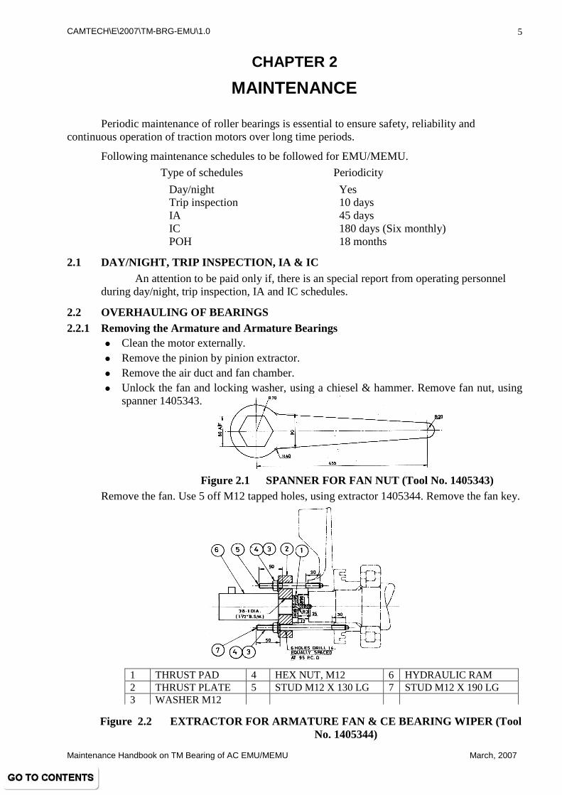
2.2 OVERHAULING OF BEARINGS 2.2.1 Removing the Armature and Armature Bearings
� Clean the motor externally. � Remove the pinion by pinion extractor. � Remove the air duct and fan chamber. � Unlock the fan and locking washer, using a chiesel & hammer. Remove fan nut, using
spanner 1405343.
Figure 2.1 SPANNER FOR FAN NUT (Tool No. 1405343) Remove the fan. Use 5 off M12 tapped holes, using extractor 1405344. Remove the fan key.
Figure 2.2 EXTRACTOR FOR ARMATURE FAN & CE BEARIN G WIPER (Tool No. 1405344)
1 THRUST PAD 4 HEX NUT, M12 6 HYDRAULIC RAM 2 THRUST PLATE 5 STUD M12 X 130 LG 7 STUD M12 X 190 LG 3 WASHER M12

CAMTECH\E\2007\TM-BRG-EMU\1.0
Maintenance Handbook on TM Bearing of AC EMU/MEMU March, 2007
6
� Remove the outer bearing wiper CE. Use 6 off M12 tapped holes using extractor
1405344 as shown above.
� Dismantle the outer bearing cap by unscrewing 8 nos. of M12 bolts and using 3 off M12 tapped holes provided in outer bearing cap.
� Remove the bearing lip of CE bearing and store it to same bearing.
� Fit the CE bearing plate 1405461. The object of this plate is to provide a means of pivotting the armature on a wooden block when turning it from the vertical to the horizontal position or vice-versa, and thus to protect the bearing labyrinths and the commutator.
� Remove three bolts equally spaced from the PE bearing cap. Assemble the retaining ring PE 1405397 over the shaft and apply the end shield PE using three holes.
1 Body 130 dia x 135 LG 3 Pad 12 TK x 22 x 36 LG 2 Arms 25 tk x 70 x 115 LG 4 Hex bolt M12 x 95 LG
8 Holes Dia 13.5 S/Face Dia 32 on 210.80 PCD spaced as shown
1 Body 122 dia x 125 LG 2 Plate 25 TK x 232.5 dia 3 Hex bolt, M12 x 30LG
Figure 2.3 RETAINING PLATE FOR CE BEARING (Tool N o. 1405461)
Figure 2.4 RETAINING RING PE (Tool No. 1405397)

CAMTECH\E\2007\TM-BRG-EMU\1.0
Maintenance Handbook on TM Bearing of AC EMU/MEMU March, 2007
7
� Fit the lifting cap PE 1405398, screw tightly so that the retaining ring PE 1405397 butts against the bearing wiper PE. Tighten the retaining ring bolts uniformly to avoid any slackness between the bearing cap PE and the retaining ring.
� Remove two bolts from the PE end
shield and replace them with two M20 eye bolts 1405978, ensuring that the eye bolts are aligned correctly, use packing washer if necessary.
Figure 2.6 EYE BOLT M20 (Tool No. 1405978)
� Using these eye bolts and lifting shackle 1405977 (safety work load = 2.0 tonnes) turn the motor and place it on suitable wooden blocks 300 mm height keeping its armature auxiliary vertical with CE down.
Figure 2.7 LIFTING SHACKLE (Tool No. 1405977)
Drill & Tap M20
16
19
40
14
72 40
35
30
M20 P-25
COARSE
33
Figure 2.5 LIFTING CAP PE (Tool No. 1405398)
1 Cap dia 135 x 120 LG 2 Eye bolt M20
4

CAMTECH\E\2007\TM-BRG-EMU\1.0
Maintenance Handbook on TM Bearing of AC EMU/MEMU March, 2007
8
� Lift the carbon brushes and protect the commutator with pressboard. Disconnect the brush flexible and remove brushes.
� Disconnect the brush holder leads so that the bottom and axle side connections are accessible through the axle side inspection opening.
� Top brush holder lead must be disconnected from the brush holder through the top commutator opening and then remove brush holder.
� The connection to the nose side brush holder is then accessible through the top commutator opening. Disconnect the lead.
� Remove the nose side, axle side and bottom side brush holders.
� Recheck tightness of the bolts of retaining ring 1405397 and tighten them uniformly to take up any slackness that may have developed owing to the downward movement of the armature.
� Remove the remaining end shield bolts and the two eyebolts insert two guide studs
1405976 diametrically opposite in the magnet frame.
Figure 2.8 GUIDE STUD M20 (Tool No. 1405976)
� Insert three forcing screws 1405975 into the withdrawal holes of the end shield to force it out of its fit.
Figure 2.9 FORCING SCREW M20 (Tool No. 1405975)
� Remove the end shield PE and bearing cartridge CE off their spigots uniformly by tightening the forcing screws a little at a time. Carry out this operation carefully so as to avoid any damage to the CE bearing.
� Carefully and gradually lift the armature vertically from the frame and lower it horizontally on wooden ‘V’-block. The height of the wooden blocks should be high enough to ensure that the armature is clear out of the ground.
� Turn the frame in horizontal position using lifting shackle 1405977 and eye bolts 1405978 screwed onto the bolts holes meant for PE end shield.
� Dismantle the lifting cap 1405398 and retaining ring 1405397.

CAMTECH\E\2007\TM-BRG-EMU\1.0
Maintenance Handbook on TM Bearing of AC EMU/MEMU March, 2007
9
� Remove the bearing wiper PE using extractor 1405399.
1 Thrust plate 3 Stud M12 x 225 LG, P-4.8 2 Thrust pad 4 Hex nut, M12 P-4.8
Figure 2.10 EXTRACTOR FOR BEARING WIPER PE (Tool No. 1405399)
� Unscrew the bolts and remove PE outer bearing cap using three forcing screws 1405975. (M12)
Figure 2.11 FORCING SCREW M12 (Tool No. 1405975)
� Using lifting shackle 1405977 and suitable lifting sling carefully remove the end shield from the armature together with PE bearing.
� Withdraw the PE bearing from the end shield using extractor 1405401.
1 Thrust plate 25 x 60 x 355 3 Pulling plate 12TK x 80 x 50 5 Forcing screw M20 2 Pulling bar dia 32 x 60LG 4 Hex nut M20
Figure 2.12 EXTRACTOR FOR PE BEARING OUTER RACE FROM END SHIELD PE (Tool No. 1405401)
Solid Hydraulic Ram EPCO – 20T 2” Stroke
14 4
M12 1.75 Pitch
12

CAMTECH\E\2007\TM-BRG-EMU\1.0
Maintenance Handbook on TM Bearing of AC EMU/MEMU March, 2007
10
� Clean PE bearing inner race & sleeve PE in position if it is not necessary to remove
these components. Smear the components with clean oil and cover the PE bearing inner race with protecting sleeve 1405400.
1 Bush 2 Sleeve 2.5 TK x 85 x 540 3 Hex bolt M20 x 25LG
Figure 2.13 PROTECTING SLEEVE FOR PE BEARING (TOOL NO. 1405400)
� Remove CE bearing cartridge together with CE bearing from the armature shaft using extractor 1405391.
1 Thrust plate 3 Stud M12 x 225 LG 5 Solid hydraulic ram 2 Thrust pad 4 Hex nut M12 P4.8
Figure 2.14 EXTRACTOR FOR CE BEARING AND CARTRIDGE (Tool No. 1405391)
� Extract CE bearing to avoid any damage while lifting the armature. To avoid damages use lifting cap 1405394.
1 Cap dia 80 x 70LG 2 Eye bolt, M20
Figure2.15LIFTING CAP CE (Tool No.1405394)
M20, 2.5P x 45L
Weld
10 x 450
Tap M20 M56 x 2 Pitch

CAMTECH\E\2007\TM-BRG-EMU\1.0
Maintenance Handbook on TM Bearing of AC EMU/MEMU March, 2007
11
� Withdraw CE bearing inner race and assemble protecting sleeve 1405393 to protect the surfaces of the shaft for any damage while lifting the armature. To avoid damages use lifting cap 1405394.
1 Sleeve 2 TK x 90 x 360LG 2 Bush dia 110 x 95LG
3 Special hex nut
2.2.2 Cleaning of Armature Bearing
To clean the dismounted armature bearings, put them into a vessel containing kerosene heated up to about 60° C without degreasing and leave them as they are, for more than 10 minutes. After that, blow away sticking grease with compressed air. Repeat the procedures more than twice. Wash the bearings finally with a clean kerosene and blow away adhering kerosene completely with dry air. For the final washing, use white spirit or ORION 510 diluted with kerosene in the ratio of 1:6. Do not use heavily oxidised or foul oil. Wash hands with a degreasing agent such as ethyl alcohol carefully for preventing the bearings from getting rusty.
2.2.3 Checking of Armature Bearings
� Check visually for roughness, scratch, bruise discoloration and rust etc.
� Check while moving the rollers for wear of retainer, looseness of rivets.
� Check for inner and outer ring of same serial number.
� Ensure that there is no abnormality.
� If fit for service but immediate reassembling is not possible due to other defects on armature/stator, store with some identification of armature serial number from which these are removed.
� Replace with new set if required. 2.2.4 Reassembling of Armature Bearings
� Check and ensure that the distance between the CE bearing abutment face & PE bearing sleeve face is 575.35/575.70 mm.
� Grease PE bearing forcing the grease between rollers, cage, outer race and labyrinth. Press the bearing into the end shield using a screw press. Ensure that the identification mark on the bearing is facing towards the outside of the machine.
Figure 2.16 PROTECTIVE SLEEVE CE (Tool No. 1405393)

CAMTECH\E\2007\TM-BRG-EMU\1.0
Maintenance Handbook on TM Bearing of AC EMU/MEMU March, 2007
12
� Lift the end shield PE using lifting shackle 1405977 and assemble it into the bearing inner race, taking care not to damage the inner race with edges of rollers.
� Slide PE spacer 1405979 onto the shaft butting against the PE bearing inner race. The spacer is temporarily used in place of the bearing wiper PE to facilitate run outs and diametrical clearances checks on the PE bearing after assembling the armature in the magnet frame.
� Fit retaining ring PE 1405397 and bolt it on to the end-shield. At this stage do not fully tighten the studs 1405976, bolt lifting shackle 1405977 on to the shaft end and fully tighten its bolts. Now fully tighten the studs 1405976.
� Grease CE bearing cartridge, grease CE bearing, forcing the grease between rollers, cage outer race and labyrinths. Assemble CE bearing along with the cartridge onto the shaft using pressing tackle 1405341 or using induction heater.
1 Sleeve 115 dia x 120 LG 4 Hollow hydraulic ram 10 ton x 2” stroke 2 Nut 70 dia x 72 P 4.8 5 Washer M20 3 Sleeve 114 dia x 95 LG 6 Hex nut M 20 x 2.5P 7 Stud M20 x 370 LG
Figure 2.19 PRESSING TACKLE FOR CE BEARING (Tool No. 1405341)
D1 D L C A
111.85
112.00
154.00 42.00
41.85
8.0 45°
Figure 2.17 SPACER (Tool no. 1405979)
12
Figure 2.18 GUIDE STUD M 16 (Tool No. 1405976)

CAMTECH\E\2007\TM-BRG-EMU\1.0
Maintenance Handbook on TM Bearing of AC EMU/MEMU March, 2007
13
� Grease the outer bearing cap CE and assemble on the bearing cartridge and tighten the bolts using new lock washers.
� Screw any two-guide studs 1405976 diametrically opposite tapped holes in the CE bearing cartridge spigot into the magnet frame .
� Screw two eye bolts M20, 1405978 in the tapped holes of magnet frame at PE end shield. Up-end the frame and place it CE down on three wooden blocks of 300 mm high, level the frame in true vertical position, by using spirit level. Remove the eye-bolts and fit two guide studs 1405976 M 20 for guiding the PE end shield during armature assembly.
� Lift the armature vertically using lifting cap PE 1405398 already mounted earlier and lower it carefully and gradually ensuring that the CE bearing cartridge and armature winding are not damaged.
� Fit and tighten the PE end shield bolts uniformly. Replace guide studs 1405976 with eye bolts 1405978. This operation will force the CE bearing cartridge into its seating. If, cartridge to frame fit is tight, insert the cartridge bolts and tighten them uniformly in steps with the end shield bolts.
� Using one of the lifting eyes cast on the motor frame and two eye bolts 1405978 M 20, turn the frame to a horizontal position, resting the pinion end of the frame on wooden block 100mm high.
� Remove retaining ring PE 1405397, lifting cap 1405398 and PE spacer 1405979.
Measure the bearing run outs and diametrical clearances as follows, taking great care to prevent dirt from falling into the grease and the bearing.
a. Attach a armature with a magnetic base, with the end of the armature shaft and arrange the pointer to bear against the bearing outer race as near the centre as possible, avoiding all identification marks on the outer race.
b. Rotate the armature and read the run out of the bearing outer race cage, ensuring that the armature is kept forward (on the wooden block 100mm high under the PE assisting in this respect to eliminate any end play). The maximum permissible run out for bearing outer race is:
CE 0.10mm PE 0.10mm
If the run out exceeds the above limit, carefully examine the assembly for burrs or for dirt under the fits of the cartridge, end shield or frame.
c. Fit the dial gauge to the outer race of the bearing or a flat portion of the end shield and arrange the spindle to bear against the inner race face of the bearing as near the centre as possible, but avoiding all identification marks. Rotate the armature and read the run out of the inner race. The maximum permissible run out for bearing inner race is:
CE 0.013 mm PE 0.013 mm
d. Check the diametrical clearance between each roller and inner race at the bearing. Place the edge of the filler gauge against the roller and the inner race where they make contact with each other.
Turn the shaft just to roll the top roller on the filler gauge. Insert different filler gauges until the clearance is established. The maximum diametrical clearance is:
PE 0.16 mm CE 0.12 mm

CAMTECH\E\2007\TM-BRG-EMU\1.0
Maintenance Handbook on TM Bearing of AC EMU/MEMU March, 2007
14
� Fit the PE outer bearing cap and tighten the bolts fully. Shrink fit the PE outer bearing wiper onto the shaft by heating it to 90 to 100 deg. C above ambient. When cold, tap it with light hammer and copper drift to ensure its proper fitting.
� Fit the CE bearing separate lip. Fill the grease in CE outer bearing cap and assemble it by using new lock washers and bolt. Smear grease on outside labyrinths of cap. Ensure that no metal swarf remains in the bearing. Replace cartridge guide studs 1405976 with bolts.
� Shrink fit the CE outer bearing wiper onto the shaft by heating it to 90 to 100 deg. C above ambient. Press the wiper while hot by pressing tackle 1405342. Tap the bearing wiper CE using light hammer and copper drift when it is cold to ensure that sleeve is fully butting against the bearing lip.
1 Sleeve 115 dia x 60 LG 5. Washer M20 2 Nut 6 Hex nut M20 x 2.5P 3. Sleeve 7 Stud M20 x 370LG 4 Hollow hydraulic ram 10 ton x 50mm stroke
Figure 2.19 PRESSING TACKLE FOR CE OUTER BEARING WIPER
(Tool No. 1405342)
� Fit the key onto the shaft key way.
� Fit the fan onto the shaft by heating it at 90°C to 100°C above ambient.
� Fit the fan nut and lock washer quickly but do not lock it, follow up with nut as the fan cools, tightening with the spanner 1405343. Finally lock, when cold.
S.N. Description
of the item Parameters
verified Mode of
inspection/ testing Permissible value Actual
value
1 PE bearing Diametrical clearance
Filler gauge 0.145 to 0.190 mm
2 CE bearing Diametrical clearance
Filler gauge 0.105 to 0.140 mm
3. PE bearing Grease quantity Weight 550 gm.
4 CE bearing Grease quantity Weight 315 gm.

CAMTECH\E\2007\TM-BRG-EMU\1.0
Maintenance Handbook on TM Bearing of AC EMU/MEMU March, 2007
15
2.3 TOOLS REQUIRED
Following tools are required for the maintenance & overhauling of roller bearings on traction motor. Special tools are shown in overhauling procedure.
2.3.1 Tools
� Spanner : 19, 24 & 30 A/F. � Allen keys : 5, 8 & 10mm � Chisel, Spirit level, wooden blocks, Meggar 1000 V, Oven, Light hammer, Copper drift,
Screw press etc. 2.3.2 Special Tools
SN Description Tool No. 1. Hydraulic ram, hollow, 20T, 100m stroke with pump, EPCO make Std. 2. Hydraulic ram, solid, 20T, 100mm stroke with pump, EPCO make Std. 3. Forcing screws for PE outer bearing cap & CE bearing cartridge (3 off) 1405975 4. Forcing screw for end shield (2 off) 1405975 5. Guide studs for end shield (2 off) 1405976 6. Guide studs for CE bearing cartridge 1405976 7. Lifting shackle (2 off) 1405977 8. Eye bolt M 20 1405978 9. Spacer 1405979 10. SKF oil pump 1405980 11. Injector attachment for SKF oil pump (Type 227982) 1405981 12. Stud 1405982 13. Thrust pad 1405983 14. Pressing tackle for CE bearing 1405341 15. Pressing tackle for CE outer wiper 1405342 16. Spanner for fan nut 1405343 17. Extractor for armature fan and CE bearing wiper 1405344 18. Extractor for details 1405390 19. Extractor for CE bearing & Cartridge 1405391 20. Extractor for CE bearing from Cartridge 1405392 21. Protecting sleeve CE 1405393 22. Lifting cap CE 1405394 23. Pinion injection safety plate 1405395 24. Pinion positioning gauge 1405396 25. Retaining ring PE 1405397 26. Lifting cap PE 1405398 27. Extractor from bearing wiper PE 1405399 28. Protection sleeve for PE bearing 1405400 29. Extractor for PE bearing outer race from end shield PE 1405401 30. Extractor for PE bearing inner race 1405402 31. Extractor for PE bearing sleeve 1405403 32. Retaining plate for CE bearing 1405461

CAMTECH\E\2007\TM-BRG-EMU\1.0
Maintenance Handbook on TM Bearing of AC EMU/MEMU March, 2007
16
2.4 ACCESSORIES REQUIRED FOR MOUNTING
SN ACCESSORIES
1. Dial indicator snap gauge
2. Dial bore gauge
3. Feeler gauges
4. Temperature measuring instrument
5. Sonar detector
6. FAG easy check
7. Lubricator FAG motion guard
8. Hand pump sets
9. Collet type mechanical extractor for tightly fitted inner
10. Anti corrosion oil spray
11. Preservation oil P555
12. Oil for bearing heating Enclo 68, Servo system 68
2.5 IMPORTANT SUGGESTIONS
� Clean and dust free assembly area is a must.
� Each time the workmen should wash hands in white spirit or petrol before handling bearings and components.
� Assembly area should have air conditioners installed. There should be no fan to avoid blowing of dust into the bearings and components.
� Only trained and selected persons should be permitted to do bearing assembly of motor.
� If possible, clean uniforms should be supplied to workmen.
� Water separator to compressed air supply connection should be incorporated.
� There should be assembly records signed by workmen/ supervisor/ inspector.
*****

CAMTECH\E\2007\TM-BRG-EMU\1.0
Maintenance Handbook on TM Bearing of AC EMU/MEMU March, 2007
17
CHAPTER 3
SHOCK PULSE MEASUREMENT
3.1 INTRODUCTION The shock pulse method is a unique measuring technique for condition control of
rolling bearings to give maintenance staff the ability to measure mechanical state of bearings at any stage of their service life. This method is very useful to avoid removing good bearings and to find damage bearings in time for a planned replacement.
All rotating rolling bearings emits shock pulses, i.e. pressure waves generated in the contact zone between the loaded rolling elements and the raceway. A specially tuned transducer amplifies high frequency shock signals and filters out machine vibrations. The transducer output is a rapid sequence of electric pulses, proportional to the amplitude of the shock waves. Shock pulses are measured on a decibel scale (dB = decibel shock value). The carpet value dBc is a measurement of large number of relatively weak shock pulses, while the maximum value dBm represents a sample of the strong pulses in the pattern. Shock value readings and the green - yellow - red condition scale are the peak readings.
3.2 DEVELOPMENT OF BEARING CONDITION The results of the many factors i.e. lubrication, misalignment, faulty installation,
vibration and wear affect the service life of a bearing. A new correctly installed and
loaded bearing have a low shock pulse level in the green zone for most of its service life. The shock level increases gradually. High level shock patterns with very distinctive peaks indicates surface damaged thus approaches end of the bearing’s life.
Lack of lubricant between rolling element and raceway, either due to poor
lubrication or excessive load, can raise the shock level of a bearing to the yellow zone. Damage sustained during installation will put it straight into the red, bad condition sector.
Velocity
Figure 3.1

CAMTECH\E\2007\TM-BRG-EMU\1.0
Maintenance Handbook on TM Bearing of AC EMU/MEMU March, 2007
18
3.3 TECHNICAL SPECIFICATIONS
Measuring range, SPM -9 to 99 dBsv
Resolution, SPM 1 dBsv
Measuring range, VIB 0.5-99.9 mm/s rms
Resolution, VIB 0.1 mm/s
Accuracy, VIB ± (0.2 mm/s + 2 % of reading)
Temperature range 0°C to 50°C
Power 6 x 1.5 V LR6 cells or rechargeable cells
Size, T2000 300 x 150 x 85 mm
Weight, T2000 0.85 kg.
Display Liquid crystal
3.4 PROCEDURE
This bearing tester is the direct successor to shock pulse measurement. Monitor the health of bearings as per following method: � Select correct class of the machine in SPM. � Connect the shock pulse transducer assembly to the instrument. � Select SPM button on the instrument. � Touch the shock pulse transducer probe on the bearing bracket or housing in running
condition. � Select [M] button. � Observed the display on the instrument. � Record the velocity alongwith the zone. � Analyse the condition of the bearing according to green - yellow - red zone. � In yellow zone machine running with higher velocity needs frequent checking.
*****
Figure 3.2 Figure 3.3

CAMTECH\E\2007\TM-BRG-EMU\1.0
Maintenance Handbook on TM Bearing of AC EMU/MEMU March, 2007
19
CHAPTER 4
TYPE OF DEFECTS
4.1 COMMON DEFECTS Any one of the following common defect can lead to bearing troubles.
� Error in machine design.
� Faulty operation.
� Faulty maintenance.
� Improper environments.
� Lack of adequate lubrication.
Other defects are as following : 4.1.1 Fatigue
Other factors such as mis-alignment, internal pre- loading, or vibration may have been the underlying cause of high load.
The passage of electric current, fretting, corrosion, and defects in the bearing material itself may result in physical defects at which high stress concentration develop to cause early fatigue.
4.1.2 Dirt Presence of dirt in a bearing usually shows up as dents,
scratches, or wear of the cage and bearing surfaces. With corrosion, the markings will almost exists on other surfaces of bearing as well as in the path of rolling elements. Indentations of a raceway caused by hard brittle particles are shown in figure 4.1.
When highly magnified, it will be seen that the raised edges of the indentations are being worn by subsequent running of the bearing as shown in figure 4.2.
Indentations in a
raceway can also be caused by soft particles as shown in figure 4.3.
Brass, Aluminium, or even wood or paper can indent a rolling surface.
Figure 4.1
Figure 4.2 Figure 4.3

CAMTECH\E\2007\TM-BRG-EMU\1.0
Maintenance Handbook on TM Bearing of AC EMU/MEMU March, 2007
20
4.1.3 Corrosion
Moisture, sulphur and chlorine in the atmosphere, and corrosive lubricants attacks rolling elements of the bearing. When corrosion spot are worn away during bearing operation, the resulting roughened surface is subject to early fatigue at the points of stress concentrations. Soda base greases are particularly effective in taking up small amount of moisture in a bearing to prevent rust. These greases also function as rust inhibitors if dissolved in a larger quantity of water.
4.1.4 Electric Current
When there is either an alternating current or direct current, voltage difference of 0.5 to 1 Volt or more between shaft and bearing housing, electric wear of the bearing surfaces is likely to occur. At such voltages, current will pass through the very thin film of lubricant between the loaded rolling elements and the raceways of the bearing. With the continual moving of the bearing elements, the passage of the current is interrupted with the generation of sparks and arcing. This sparking & arcing causes melting at microscopic points of high temperature and small pits are generated in the metal. Difficulty may show up in high speed mechanical units in which a static charge is built up on the rotating element.
When a sudden surge current passes through the
journal bearings of a locomotive, a series of relatively large pits are encountered as shown in figure 4.4.
The continuos passage of small electric currents results in a multitude of small electrical craters over the bearing surface. Initially, these pits gives a frosted appearance, and becomes quite pronounced within even a few hours of operation. In a longer period of time, this frosting gradually reverts to a fluted is shown in figure 4.5.
4.1.5 Brinelling
Improper handling, pounding, and force on the outer ring during mounting bearing on a shaft are frequent causes of brinelling in a bearing. False brinelling is a wear phenomenon. The appearance of the area damaged by wear is very similar to the permanent plastic indentations of a brinelled surface, hence the name “false brinelling” .
False brinelling can occur on the raceways and rollers of a cylindrical roller bearing on a traction motor standing ideal on a vibrating platform as shown in figure 4.6.
4.1.6 Vibration and Noise For this reason the balancing of the traction motor armature to be checked and at the
same time bearings radial clearance, groove wobble etc. also to be checked. The passage of electric current may have resulted in wear, fluting of the bearing surfaces, and vibrations.
Figure 4.4
Figure 4.5
Figure 4.6

CAMTECH\E\2007\TM-BRG-EMU\1.0
Maintenance Handbook on TM Bearing of AC EMU/MEMU March, 2007
21
4.2 TROUBLE SHOOTING CHART
CAUSE REMEDY
1 Overheated bearing
a. Inadequate lubrication Provide proper grease.
b. Excessive lubricant churning
Fill grease housing only half full, use oil mist.
c. Inadequate internal clearance
Use bearing of proper size, allow for differential thermal expansion, reduce interference of shaft and housing fits, correct/ replace any housing out of roundness or warping.
d. High seal friction. Scratch felt, lubricate seals.
e. Excessive pre loading. Use gaskets or shims to relieve axial preload with opposed pair or with two held bearings on a shaft subjected to thermal expansion.
f. Spinning outer ring. Use closer housing fit.
g. Mis-alignment Check for mis-alignment of bearing seats, shaft and housing shoulders.
2. Noisy bearing, vibration
a. Wrong type of grease. Check recommendations and instructions issued by competent authority.
b In-sufficient lubrication
Provide proper grease.
c. Defective bearing Check for brinelling, fatigue, wear, groove wobble, poor cage etc. Replace bearing, if required.
d. Dirt Clean bearing housing, replace worn seals, improve sealing arrangement, eliminate source of dirt.
e. Corrosion Improve sealing to keep out corrosive elements, use corrosion resisting lubricant.
g. Un-balance. Balance the armature.
h. Mis-alignment. Check for mis-alignment of bearing seats and shaft and housing shoulders.

CAMTECH\E\2007\TM-BRG-EMU\1.0
Maintenance Handbook on TM Bearing of AC EMU/MEMU March, 2007
22
CAUSE REMEDY
i. Improper mounting Correct dirty or off-square shaft, housing shoulders and seats. Avoid brinelling caused by pounding on bearing.
j. False brinelling Use vibration mounts for machine to isolate from platform during idle periods.
k. Seal rub Check for metal bearing seal or shield rubbing on shaft, shaft shoulders, or housing.
3. Loss of Lubricant a. Leakage of housing split.
Use thin layer of gasket cement, replace housing.
b. Grease leakage. Fill the specified quantity of grease to eliminate any pressure causing airflow through bearing. Use new or improved seals.
c. Dry, caked residue. Use silicon or other high temperature grease, cool bearing housing.
4. Hard turning of shaft
a. Excessive bearing Preload.
Use less interference fit on shaft or in housing. Select bearing with greater internal clearance where heat conduction expand shaft and inner bearing ring.
b. Heavy seal rub. Scratch felt seals to reduce their friction, use a seal with clearance on the shaft.
c. Dirt. Clean housing and use fresh lubricant.
d. Corrosion. Improve sealing to keep out corrosive elements, use corrosion resisting lubricant.
e. Lack of lubrication. Eliminate possibility for loss of lubricant by leakage.
f. Incorrect lubricant. Check recommendations and instructions issued by competent authority.
*****

CAMTECH\E\2007\TM-BRG-EMU\1.0
Maintenance Handbook on TM Bearing of AC EMU/MEMU March, 2007
23
CHAPTER 5
DO’S & DON’TS
5.1 DO'S
� Do keep all tools gauges and instruments in working condition.
� Do keep all tools, gauges and instruments in easily accessible and
earmarked places.
� Do use only recommended tools, gauges and instruments with due
care.
� Do clean the tools, gauges and instruments after use and keep
those back in proper place.
� Do keep all commonly used tools and gauges in a handy toolbox.
� Do carry tools and gauges in the toolbox, to working place.
� Do wear shoes and helmet from safety point of view.
� Do be vigilant & careful in workplace & surroundings
� Do follow proper instructions for the use of tools, gauges and instruments.
� Do ensure, all the gauges are periodically checked for their accuracy.
� Do tighten nuts & bolts fully by applying proper torque.
� Do work with full of confidence.
� Do protect bearings from dust/cotton/metal particles by keeping them covered.
� Do test the property/quality of new as well as released grease.
� Do fill new grease/oil for lubrication.
� Do check all the tools, jigs & fixtures for any deviation.
� Do ensure use of torque wrench for tightening bolts, whenever recommended.
� Do follow recommended maintenance practices only.
� Do preserve the bearings in the storage conditions recommended by the supplier.
� Do store the bearings flat, resting on their entire circumference/ periphery.
� Do adopt ‘FIFO’ (First in first out) system for consumption of bearings.
� Do use only specified and proven tools.
� Do always measure the critical dimensions/ parameters of mating components of
bearing and verify with drawing.
Figure 5.1

CAMTECH\E\2007\TM-BRG-EMU\1.0
Maintenance Handbook on TM Bearing of AC EMU/MEMU March, 2007
24
� Do periodic calibration of measuring instruments and gauges and maintain their
records.
� Do use identification tags/ stickers for timely calibration before expiry of due date.
� Do inspect bearing seats and other mating components before mounting and ensure they
are free from any defect/ damage.
� Do check the free rotation of the bearing prior to its mounting.
� Do check the radial clearance of the bearing prior to its mounting.
� Do apply smearing/ mounting paste on the bearing seats in order to prevent fretting
corrosion and facilitate smooth mounting/ dismounting of bearings.
� Do always keep stamped side of bearing faces towards outside to facilitate inspection
and identification of the bearing.
� Do always select the right lubricant for optimum service life of the bearings.
� Do tight nuts and bolts fully by applying specified torque.
� Do record complete observations on the bearing failure and inform the supplier.
� Do use shock pulse meter (SPM) for monitoring the condition of roller bearing & keep a record of the readings.
� Do use specified pullers and fixtures for bearing removal.
� Do ensure that all specified clearances are maintained properly.

CAMTECH\E\2007\TM-BRG-EMU\1.0
Maintenance Handbook on TM Bearing of AC EMU/MEMU March, 2007
25
5.2 DON’TS
� Don't wear loose clothes and chappals.
� Don't use defective tools, gauges and instruments.
� Don't use over size/ improper tools.
� Don't carry loose tools, gauges etc. separately.
� Don't apply unsafe methods of working.
� Don't use oversize bolts/screws, nuts and washers.
� Don't use flat spring washer.
� Don't leave tools, gauges and instruments at working place after completion of work.
� Don't smoke at work place.
� Don’t put spurious/ re-conditioned bearings into service.
� Don’t follow short cut or unsafe method of working.
� Don’t unnecessarily open the bearing cartons and disturb the original packing.
� Don’t mix up the components of different bearings or make.
� Don’t use non-standard mating components.
� Don’t mount the bearings on undersize or oversize mating components.
� Don’t use compressed air for cleaning of bearings.
� Don’t use open flame heating or welding torches for extracting the bearings.
� Don’t reuse the rubber-sealing ring, felt seals and locking plates etc.
� Don’t mix up the grease of different grades or even different make.
� Don’t expose greased bearings and other components with the atmosphere/ sun light.
� Don’t compromise with critical dimensions/ tolerances on bearings and other mating components.
� Don’t use cotton waste or dirty clothes to wipe the bearings.
� Don’t scratch or nick the bearing surfaces.
� Don’t ignore any symptom, which may cause failure in service.
� Don’t exceed the limit of clearances and other maintenance instruction.
� Don’t work in order confidence.
� Don’t allow dust or other foreign particles i.e. jute particles, metal particles, scrapped insulation, scrapped mica particles; saw dust etc. mixed up in grease.
� Don’t allow grease container as well as bearings, open to atmosphere.
� Don’t carry the grease in the empty container of different grade of grease oil, chemicals/solvent/paints.
� Don’t reuse the grease if fallen down on floor.
Figure 5.2
Figure 5.3

CAMTECH\E\2007\TM-BRG-EMU\1.0
Maintenance Handbook on TM Bearing of AC EMU/MEMU March, 2007
26
� Don’t carry out the work of cleaning and greasing simultaneously.
� Don’t do the greasing with dirty grease gun/ nozzel, greasing inlet valve or nipple.
� Don’t leave the nipple/grease cover in open condition after greasing.
� Don’t place the grease gun here and there.
� Don’t interchange the axle cap from one stator to another stator.
� Don’t clean the bearing in the chemicals/solvent other than kerosene or petrol.
� Don’t clean or remove the bearings by heat treatment method.
� Don’t re-use condemned bearing and racers.
� Don’t assemble a TM interchanging End-shields, Rocker assembly and Armature from other TM.
� Don’t strike or pressure fit the bearings unduly, during reassembling.
*****

CAMTECH\E\2007\TM-BRG-EMU\1.0
Maintenance Handbook on TM Bearing of AC EMU/MEMU March, 2007
27
REFERENCES
1. AC Traction Maintenance & Operation Manual (ACTM) Vol.III 1994. 2. Maintenance Manual for 25 kV Board gauge AC and Main Line Electrical Multiple
Unit (Electrical Equipment) issued by BHEL/Bhopal. Book no. MM/AC-M/EMU/003, Jan., 2001.
3. Maintenance Manual issued by M/s FAG for Roller Bearings.

CAMTECH\E\2007\TM-BRG-EMU\1.0
Maintenance Handbook on TM Bearing of AC EMU/MEMU March, 2007
28
To upgrade maintenance technologies and methodologies and achieve improvement in productivity, performance of all Railway assets and manpower which inter-alia would cover reliability, availability, utilisation and efficiency.
OOUURR OOBBJJEECCTTIIVVEE
If you have any suggestions and any specific Comments please write to us. Contact person : Director (Elect.) Postal Address : Indian railways
Centre for Advanced Maintenance technology, Maharajpur, Gwalior. Pin code – 474 020
Phone : 0751 – 2470740
0751 – 2470803 Fax : 0751 - 2470841