
Manual Datalogic Magellan 3410VSi - Bz Tech
323
Leitor Fixo Datalogic Magellan 3410VSi Com tecnologia de ponta, o Magellan 3419VSi da Datalogic é alimentado por um única conexão USB 5V, proporcionando excelente desempenho e fácil conexão com qualquer sistema de vendas. Com um grande campo de visão e recursos de geração de imagens, o Leitor Datalogic 3410VSi fornece excelente desempenho em códigos de barras difíceis de ler e leitura perfeita de uma ampla variedade de códigos de barras. O Datalogic Magellan 3419VSi permite varredura de alta velocidade e digitalização de apresentação técnicas, garantindo a máxima produtividade e facilidade ergonômica, mesmo com códigos truncados (abreviados), fora das especificações ou mal impressos. www.bztech.com.br
-
Upload
khangminh22 -
Category
Documents
-
view
1 -
download
0
Transcript of Manual Datalogic Magellan 3410VSi - Bz Tech

Leitor Fixo Datalogic Magellan 3410VSi Com tecnologia de ponta, o Magellan 3419VSi da Datalogic é alimentado por um única conexão USB 5V, proporcionando excelente desempenho e fácil conexão com qualquer sistema de vendas. Com um grande campo de visão e recursos de geração de imagens, o Leitor Datalogic 3410VSi fornece excelente desempenho em códigos de barras difíceis de ler e leitura perfeita de uma ampla variedade de códigos de barras. O Datalogic Magellan 3419VSi permite varredura de alta velocidade e digitalização de apresentação técnicas, garantindo a máxima produtividade e facilidade ergonômica, mesmo com códigos truncados (abreviados), fora das especificações ou mal impressos.
www.bztech.com.br

MAGELLAN™ 3410VSi
PRODUCT REFERENCE GUIDE
Omni-Directional Imaging Scanner

Datalogic S.r.l.Via S. Vitalino, 13 40012 Calderara di Reno — ItalyTel. +39 051 3147011Fax +39 051 3147205
©2021 Datalogic S.p.A. and /or its affiliates
All rights reserved. Without limiting the rights under copyright, no part of this documentation may be repro-duced, stored in or introduced into a retrieval system, or transmitted in any form or by any means, or for any purpose, without the express written permission of Datalogic S.p.A. and/or its affiliates.Owners of Datalogic products are hereby granted a non-exclusive, revocable license to reproduce and trans-mit this documentation for the purchaser's own internal business purposes. Purchaser shall not remove or alter any proprietary notices, including copyright notices, contained in this documentation and shall ensur e that all notices appear on any reproductions of the documentation.Electronic versions of this document may be downloaded from the Datalogic website (www.datalogic.com). If you visit our website and would like to make comments or suggestions about this or other Datalogic publica-tions, please let us know via the "Contact" page.
Disclaimer
Datalogic has taken reasonable measures to provide information in this manual that is complete and accurate, however, Datalogic shall not be liable for technical or editorial errors or omissions contained herein, nor for incidental or consequential damages resulting from the use of this material. Datalogic reserves the right to change any specification at any time without prior notice.
Trademarks
Datalogic and the Datalogic logo are registered trademarks of Datalogic S.p.A. in many countries, including the U.S.A. and the E.U.Magellan is a trademark of Datalogic S.p.A. or of Datalogic and/or its affiliates, registered in many countries, including the U.S. and the E.U.
Patents
See www.patents.datalogic.com for patent list.
The content of this manual refers to software version DR9401453.

PRODUCT REFERENCE GUIDE i
TABLE OF CONTENTS
CHAPTER 1. GETTING STARTED ............................................................................... 1About This Manual ........................................................................................................... 1
Manual Conventions ........................................................................................................................... 1SCANNER FEATURES ...................................................................................................... 2Connecting the Scanner ................................................................................................... 3Mount Installation ............................................................................................................ 5
Wall Mount .......................................................................................................................................... 6Countertop Mount ............................................................................................................................... 6Adjustable Riser .................................................................................................................................. 6
CHAPTER 2. PROGRAMMING .................................................................................... 7About Programming your Scanner .................................................................................... 7
Programming with Barcodes ............................................................................................................. 8Getting Started .................................................................................................................................... 9
Programming Mode ................................................................................................................... 9Programming Session ...................................................................................................................... 10If You Make a Mistake... .................................................................................................................... 11
Return to Factory Settings ....................................................................................................... 11Datalogic Scanalyzer ........................................................................................................................ 12Using a Bar Code Mask .................................................................................................................... 13Going Green ...................................................................................................................................... 13
Bar Code Mask ...............................................................................................................14GENERAL SCANNER FEATURES ......................................................................................15
SCANNING FEATURES ..................................................................................................................... 161D Double Read Timeout ............................................................................................................... 162D Double Read Timeout ............................................................................................................... 17Double Read Table Size ................................................................................................................. 18
DIGITAL WATERMARK (DIGIMARC®) FEATURES ........................................................................... 19Digital Watermark (Digimarc) Enable ........................................................................................... 19Digital Watermark (Digimarc) Double Read Timeout .................................................................. 20Digital Watermark (Digimarc) Data Format ................................................................................. 21Sleep Mode Timer .......................................................................................................................... 221D Inverse Read Control ................................................................................................................ 232D Inverse Read Control ................................................................................................................ 24
LED AND BEEPER INDICATORS ...................................................................................................... 25Power On Alert ............................................................................................................................... 25Reading Illumination Duration ...................................................................................................... 26Illumination During Disable Mode ................................................................................................. 27Object Sense Control ..................................................................................................................... 28External Read Indicator (ERI) ........................................................................................................ 29ERI Timeout .................................................................................................................................... 29Good Read LED Idle State ............................................................................................................. 30Scanner Control Button Options ................................................................................................... 31Good Read Beep Control ............................................................................................................... 32Good Read Beep Frequency .......................................................................................................... 33Good Read Beep Length ................................................................................................................ 34

ii MAGELLAN™ 3410VSI
Good Read Beep Volume ............................................................................................................... 35Good Read When to Indicate ......................................................................................................... 36Illumination Blank on Beep ........................................................................................................... 37Host Download to Handheld .......................................................................................................... 38Handheld Host Download Timeout ............................................................................................... 38
IMAGING FEATURES .......................................................................................................39IMAGING FEATURES ......................................................................................................................... 40
Image Capture to the Host by Host Command ............................................................................. 40Image Capture to the Host by Camera Button ............................................................................. 41
Camera Button Mode ................................................................................................................ 41Image Destination ..................................................................................................................... 42Picture Retrieval Timeout ......................................................................................................... 43
Image Capture Delay ...................................................................................................................... 45Image Format ................................................................................................................................. 46Image Size ...................................................................................................................................... 47Image Brightness ........................................................................................................................... 48Image Contrast ............................................................................................................................... 50Image Compression ....................................................................................................................... 52Region of Interest (ROI) ................................................................................................................. 53
CELL PHONE SETTINGS ................................................................................................................... 55Cell Phone Mode ............................................................................................................................ 55
Cell Mode Percent ..................................................................................................................... 56INTERFACE RELATED FEATURES ....................................................................................57
INTERFACE SELECTION ................................................................................................................... 58Interface Type ................................................................................................................58
RS-232 Interface Selection ............................................................................................................ 58USB Interface Selection ................................................................................................................. 59Keyboard Interface Selection ........................................................................................................ 59
INTERFACE FEATURES .................................................................................................................... 60Maximum Host-Transmitted Message Length ............................................................................ 60Ignore Host Commands ................................................................................................................. 61
RS-232 Interface Features ..............................................................................................62RS-232 Baud Rate .......................................................................................................................... 62RS-232 Number of Data Bits ......................................................................................................... 64RS-232 Number of Stop Bits ......................................................................................................... 64RS-232 Parity ................................................................................................................................. 65RS-232 Hardware Control ............................................................................................................. 66RS-232 Intercharacter Delay ......................................................................................................... 67RS-232 Software Flow Control ..................................................................................................... 68RS-232 Beep on ASCII BEL ............................................................................................................ 69Beep on Not on File ........................................................................................................................ 70RS-232 ACK NAK Features ........................................................................................................... 71
ACK NAK Enable ....................................................................................................................... 71RS-232 ACK Character ............................................................................................................. 72RS-232 NAK Character ............................................................................................................. 73RS-232 Retry on ACK NAK Timeout ........................................................................................ 74RS-232 ACK NAK Timeout Value ............................................................................................. 75RS-232 ACK NAK Retry Count ................................................................................................. 76RS-232 ACK NAK Error Handling ............................................................................................ 77
RS-232 Indicate Transmission Failure .......................................................................................... 78USB-COM Interface Features ..........................................................................................79
USB-COM Interface Setup ............................................................................................................. 79USB Power Compliance ................................................................................................................. 80
USB-OEM Interface Features ..........................................................................................81USB OEM Scanner Device Type ..................................................................................................... 81USB OEM Additional Interface Options ......................................................................................... 82
USB Keyboard Features ..................................................................................................83

PRODUCT REFERENCE GUIDE iii
Keyboard Layout ............................................................................................................................ 83USB Keyboard Country Mode ........................................................................................................ 83USB Keyboard Caps Lock State .................................................................................................... 86USB Keyboard Send Control Characters ...................................................................................... 87Quiet Interval .................................................................................................................................. 88USB Keyboard Intercharacter Delay ............................................................................................. 89USB Keyboard Additional Interface Options ................................................................................. 90
DATA EDITING ................................................................................................................91Data Editing Overview .....................................................................................................92
Please Keep In Mind... .............................................................................................................. 92GLOBAL PREFIX/SUFFIX .................................................................................................................. 93
Global Prefix ................................................................................................................................... 93Global Suffix ...................................................................................................................................... 94
AIM ID ............................................................................................................................95Label ID .........................................................................................................................96
Label ID Control ............................................................................................................................. 96Setting Label ID .............................................................................................................................. 97
1D Symbologies ........................................................................................................................ 972D Symbologies .............................................................................................................................. 102Global Mid-Label ID ........................................................................................................................ 104
Case Conversion ...........................................................................................................105Character Conversion ...................................................................................................1061D SYMBOLOGY PROGRAMMING....................................................................................107
1D Symbologies ........................................................................................................................... 107COUPON CONTROL ......................................................................................................................... 108
Coupon Control Enable ................................................................................................................ 108Coupon Label Priority Timer ....................................................................................................... 110
UPC-A .............................................................................................................................................. 111UPC-A Enable ............................................................................................................................... 111UPC-A Number System Character Transmission ...................................................................... 112UPC-A Check Character Transmission ....................................................................................... 113UPC-A Minimum Read ................................................................................................................. 114Expand UPC-A to EAN-13 ........................................................................................................... 115UPC-E ........................................................................................................................................... 116UPC-E Enable ............................................................................................................................... 116UPC-E Number System Character Transmission ...................................................................... 117UPC-E Check Character Transmission ....................................................................................... 118Expand UPC-E to UPC-A ............................................................................................................. 119Expand UPC-E to EAN-13 ........................................................................................................... 120UPC-E Minimum Read ................................................................................................................. 121EAN-13 ......................................................................................................................................... 122EAN-13 Enable ............................................................................................................................. 122EAN-13 First Character Transmission ....................................................................................... 123EAN-13 Check Character Transmission ..................................................................................... 124EAN-13 ISBN Conversion Enable ................................................................................................ 125EAN-13 Minimum Read ............................................................................................................... 126
EAN-8 .............................................................................................................................................. 127EAN-8 Enable ............................................................................................................................... 127EAN-8 Check Character Transmission ....................................................................................... 128Expand EAN-8 to EAN-13 ........................................................................................................... 129EAN-8 Minimum Read ................................................................................................................. 130EAN-8 Guard Insertion ................................................................................................................ 131EAN-8 Guard Substitution ........................................................................................................... 132EAN-8/Jan-8 Both Guards Substitution ..................................................................................... 133EAN-8 Stitch Exact Label Halves ................................................................................................ 134EAN-8 Stitch Unlike Label Halves ............................................................................................... 135EAN-8 Minimum Segment Length .............................................................................................. 136

iv MAGELLAN™ 3410VSI
EAN-8 Decoding Levels ...............................................................................................................138OTHER UPC/EAN OPTIONS .............................................................................................................139
In-Store Printed Label Minimum Read .......................................................................................139UPC/EAN Guard Insertion ............................................................................................................140UPC/EAN Stitch Exact Label Halves ...........................................................................................141UPC/EAN Stitch Unlike Label Halves ..........................................................................................142UPC/EAN Minimum Segment Length .........................................................................................143Price Weight Check ......................................................................................................................145Enable EAN Two Label ................................................................................................................146EAN Two Label Minimum Read ...................................................................................................147EAN Two Label Combined Transmission ...................................................................................148Add-ons ........................................................................................................................................149P2 Add-on Minimum Read ..........................................................................................................150P5 Add-on Minimum Read ..........................................................................................................152UPC/EAN Composites ..................................................................................................................155
GTIN .................................................................................................................................................156GTIN Enable ..................................................................................................................................156
GS1 DATABAR .................................................................................................................................157DATABAR OMNIDIRECTIONAL .......................................................................................................157
DataBar Omnidirectional Enable .................................................................................................157DataBar Omnidirectional/EAN-128 Emulation ...........................................................................158DataBar Omnidirectional 2D Component Enable .......................................................................159DataBar Omnidirectional Minimum Read ...................................................................................160DataBar Omnidirectional Double Read Timeout ........................................................................161
DATABAR LIMITED .........................................................................................................................162DataBar Limited Enable ...............................................................................................................162DataBar Limited Minimum Read .................................................................................................163DataBar Limited 2D Component Enable .....................................................................................164DataBar Limited EAN128 Emulation Enable ..............................................................................165
DATABAR EXPANDED ....................................................................................................................166DataBar Expanded Enable ...........................................................................................................166DataBar Expanded EAN-128 Emulation .....................................................................................167DataBar Expanded 2D Component Enable .................................................................................168DataBar Expanded Minimum Read .............................................................................................169DataBar Expanded Length Control .............................................................................................170DataBar Expanded Length 1 ........................................................................................................171DataBar Expanded Length 2 ........................................................................................................172DataBar Expanded Reverse Retry ...............................................................................................173Code 39 .........................................................................................................................................174Code 39 Enable .............................................................................................................................174Code 39 Start Stop Character Transmission ..............................................................................175Code 39 Check Character Calculation .........................................................................................176Code 39 Check Character Transmission .....................................................................................177Code 39 Full ASCII ........................................................................................................................178Code 39 Minimum Read ...............................................................................................................179Code 39 Length Control ...............................................................................................................180Code 39 Length 1 .........................................................................................................................181Code 39 Length 2 .........................................................................................................................182Code 39 Stitching .........................................................................................................................183Code 39 Require Margins ............................................................................................................184Code 32 Italian Pharmacode ........................................................................................................185Code 32 Italian Pharmacode Enable ...........................................................................................185Code 32 Start Stop Character Transmission ..............................................................................186Code 32 Check Character Transmission .....................................................................................187Code 128 .......................................................................................................................................188Code 128 Enable ...........................................................................................................................188Code 128 Transmit Function Characters ....................................................................................189

PRODUCT REFERENCE GUIDE v
Expand Code128 to Code 39 ........................................................................................................ 190Code 128 Minimum Read ............................................................................................................ 191Code 128 Length Control ............................................................................................................. 192Code 128 Length 1 ....................................................................................................................... 193Code 128 Length 2 ....................................................................................................................... 194Code 128 Stitching ....................................................................................................................... 195EAN-128 ....................................................................................................................................... 196EAN-128 Enable ........................................................................................................................... 196Interleaved 2 of 5 (I 2 OF 5) ......................................................................................................... 197Interleaved 2 of 5 (I 2 OF 5) Enable ............................................................................................. 197I 2 of 5 Check Character Calculation ........................................................................................... 198I 2 of 5 Check Character Transmission ....................................................................................... 199I 2 of 5 Minimum Read ................................................................................................................. 200I 2 of 5 Length Control ................................................................................................................. 201I 2 of 5 Length 1 ........................................................................................................................... 202I 2 of 5 Length 2 ........................................................................................................................... 203Codabar ........................................................................................................................................ 204Codabar Enable ............................................................................................................................ 204Codabar Start Stop Character Transmission .............................................................................. 205Codabar Start Stop Character Set ............................................................................................... 206Codabar Start Stop Character Match .......................................................................................... 207Codabar Check Character Calculation ........................................................................................ 208Codabar Check Character Transmission .................................................................................... 209Codabar Minimum Read .............................................................................................................. 210Codabar Length Control .............................................................................................................. 211Codabar Length 1 ......................................................................................................................... 212Codabar Length 2 ......................................................................................................................... 213Codabar Require Margins ............................................................................................................ 214Code 93 ......................................................................................................................................... 215Code 93 Enable ............................................................................................................................ 215Code 93 Minimum Read .............................................................................................................. 216Code 93 Length Control ............................................................................................................... 217Code 93 Length 1 ......................................................................................................................... 218Code 93 Length 2 ......................................................................................................................... 219MSI ................................................................................................................................................ 220MSI Enable .................................................................................................................................... 220MSI Check Character Calculation ................................................................................................ 221MSI Number of Check Characters ............................................................................................... 222MSI Check Character Transmission ............................................................................................ 223MSI Minimum Read ...................................................................................................................... 224MSI Length Control ...................................................................................................................... 225MSI Length 1 ................................................................................................................................ 226MSI Length 2 ................................................................................................................................ 227Standard 2 of 5 ............................................................................................................................. 228Standard 2 of 5 Enable ................................................................................................................. 228Standard 2 of 5 Check Character Calculation ............................................................................. 229Standard 2 of 5 Check Character Transmission ......................................................................... 230Standard 2 of 5 Minimum Read ................................................................................................... 231Standard 2 of 5 Length Control ................................................................................................... 232Standard 2 of 5 Length 1 ............................................................................................................. 233Standard 2 of 5 Length 2 ............................................................................................................. 234
2D SYMBOLOGIES / BAR CODES ....................................................................................2352D CODES ........................................................................................................................................ 235DATA MATRIX .................................................................................................................................. 236
Data Matrix Enable ...................................................................................................................... 236Data Matrix Length Control ......................................................................................................... 237
Configuring Variable Length Decoding: ................................................................................. 237

vi MAGELLAN™ 3410VSI
Data Matrix Length 1, Length 2 Programming Instructions ................................................238GS1 Datamatrix Enable ................................................................................................................239
PDF 417 ...........................................................................................................................................240PDF 417 Enable ............................................................................................................................240PDF 417 Length Control ..............................................................................................................241
PDF 417 Length 1, Length 2 Programming Instructions .....................................................242PDF 417 Read Option ...................................................................................................................243
MICRO PDF 417 ...............................................................................................................................244Micro PDF 417 Enable ..................................................................................................................244Micro PDF 417 Length Control ....................................................................................................245
Micro PDF 417 Length 1, Length 2 Programming Instructions ...........................................246Micro PDF 417 128 Emulation .....................................................................................................247
QR CODE ..........................................................................................................................................248QR Code Enable ............................................................................................................................248QR Code Length Control ..............................................................................................................249
QR Code Length 1, Length 2 Programming Instructions .....................................................250QR Code URL Link Enable ...........................................................................................................251GS1 QR Code Enable ....................................................................................................................252
MICRO QR CODE ..............................................................................................................................253Micro QR Code Enable ..................................................................................................................253Micro QR Code Length Control ....................................................................................................254
Micro QR Code Length 1, Length 2 Programming Instructions ...........................................255AZTEC CODE ....................................................................................................................................256
Aztec Enable .................................................................................................................................256Aztec Length Control ...................................................................................................................257
Aztec Length 1, Length 2 Programming Instructions ..........................................................258HAN XIN CODE ................................................................................................................................259Han Xin Enable ................................................................................................................................259DOTCODE .........................................................................................................................................260Dotcode Enable ...............................................................................................................................260
CHAPTER 3. REFERENCES ................................................................................... 261Global Prefix/Suffix ...................................................................................................... 262Label ID ....................................................................................................................... 263Length Control ............................................................................................................. 264
Configuring Variable Length Decoding: ......................................................................................... 264Length 1, Length 2 Programming Instructions .............................................................................264
PRODUCT SPECIFICATIONS .................................................................................... 265Technical Specifications ................................................................................................ 266
Decoding Capability .........................................................................................................................266Electrical Specifications ..................................................................................................................266Environmental .................................................................................................................................266Interfaces .........................................................................................................................................267Optional Features ............................................................................................................................267
Physical Characteristics ................................................................................................ 268Scanner Dimensions ...............................................................................................................268
Reading Performance ................................................................................................... 269Reading Ranges ..............................................................................................................................269
Safety & Regulatory ..................................................................................................... 269Utilities ........................................................................................................................ 270Warranty ..................................................................................................................... 270LED and Beeper Indicators ............................................................................................ 270Error Codes .................................................................................................................. 271
CABLE PINOUTS..................................................................................................... 272Standard Cable Pinouts (Primary Interface Cables) ........................................................ 272

PRODUCT REFERENCE GUIDE vii
ALPHA-NUMERIC KEYPAD ......................................................................................273FACTORY DEFAULT SETTINGS ................................................................................275
Factory Default Settings ......................................................................................................... 275
KEYBOARD FUNCTION KEY MAPPINGS....................................................................285 USB Function Key Usage Map .............................................................................................. 285
HOST COMMANDS...................................................................................................292Accepting RS-232 AND USB COM Commands .................................................................292
SAMPLE SYMBOLS..................................................................................................2931D Symbol Samples ......................................................................................................2932D Sample Symbols ......................................................................................................295Composite Sample Symbols ..........................................................................................296
MICROSD CARD.......................................................................................................297microSDHC Compatibility ..............................................................................................298
microSD Card Insertion .................................................................................................................. 298microSD Card Removal .................................................................................................................. 299
Autorun File Processing ................................................................................................299microSD Function Summary ..........................................................................................299microSD Function Details ..............................................................................................300
From Scanner to microSD Card ..................................................................................................... 300Capture and save an image to a microSD card by button press .......................................... 300Export a Configuration file from the Scanner to the microSD card ..................................... 300
From microSD Card to Scanner ..................................................................................................... 301Application code load to scanner ........................................................................................... 301Configuration load to scanner ................................................................................................ 301
HANDHELD DATA FORMAT REQUIREMENTS ............................................................302Handheld Data Format Requirements General ................................................................302
Datalogic Handheld Data Format Requirements .......................................................................... 302GS1 DataBar Omnidirectional ................................................................................................ 303GS1 DataBar Expanded .......................................................................................................... 303UPC-A ...................................................................................................................................... 303UPC-A with 2-Digit Supplemental ......................................................................................... 303UPC-A with 5-Digit Supplemental ......................................................................................... 303UPC-E ...................................................................................................................................... 303UPC-E with 2-Digit Supplemental ......................................................................................... 303UPC-E with 5-Digit Supplemental ......................................................................................... 304EAN-8 ...................................................................................................................................... 304EAN-8 with 2-Digit Supplemental ......................................................................................... 304EAN-8 with 5-Digit Supplemental ......................................................................................... 304EAN-13 .................................................................................................................................... 304EAN-13 with 2-Digit Supplemental ....................................................................................... 304EAN-13 with 5-Digit Supplemental ....................................................................................... 304Code 39 ................................................................................................................................... 304Code 39-Pharmacode ............................................................................................................. 305I 2 of 5 ...................................................................................................................................... 305Codabar ................................................................................................................................... 305Code 128 ................................................................................................................................. 305MSI .......................................................................................................................................... 306Code 93 ................................................................................................................................... 306PDF417 .................................................................................................................................... 306
AIM Formats ................................................................................................................................... 306UPC-A ...................................................................................................................................... 306UPC-E ...................................................................................................................................... 307EAN-13 .................................................................................................................................... 307EAN-8 ...................................................................................................................................... 307

viii MAGELLAN™ 3410VSI
2-Digit Supplemental ..............................................................................................................3075-Digit Supplemental ..............................................................................................................307Bookland .................................................................................................................................307Code 39 ....................................................................................................................................308Codabar ...................................................................................................................................308MSI ...........................................................................................................................................308Code 93 ....................................................................................................................................308RSS-14 ....................................................................................................................................308RSS Expanded .........................................................................................................................309I 2 of 5 ......................................................................................................................................309Code 128 / EAN128 .................................................................................................................309PDF417 ....................................................................................................................................309“Unknown” AIM ID (an AIM ID which is not specified above) ................................................309
PRODUCT REFERENCE GUIDE 1
CHAPTER 1GETTING STARTED
ABOUT THIS MANUALThis manual provides advanced user information, including connection, program-ming, product and cable specifications, and other useful references. For additional information, such as installation, maintenance, troubleshooting and warranty infor-mation, see the Quick Reference Guide (QRG). Copies of other publications for this product can be downloaded free of charge from the website listed on the back cover of this manual.On leaving the factory, units are programmed for the most common terminal and communications settings. If you need to change these settings, custom program-ming can be accomplished by scanning the bar codes in this guide. The most com-mon default settings for features/options are indicated by a green arrow.
Manual ConventionsThe symbols listed below are used in this manual to notify the reader of key issues or procedures that must be observed when using the scanner:
NOTE
The CAUTION symbol advises you of actions that could damage equipment or property.
NOTES contain information necessary for properly diagnosing, repairing and operating the scanner.
CAUTION

SCANNER FEATURES
2 MAGELLAN™ 3410VSI
SCANNER FEATURESThe Magellan™ 3410VSi On-Counter Vertical Presentation Scanner is designed for small counter retail checkout environments where there is a relatively high number of transactions with a fairly small number of items per transaction. The scanner has a reduced footprint, allowing more room for item merchandising of high margin impulse items clustered around the POS (Point of Sale).
Figure 1. Scanner Features - Front View
Scanner Button
Camera Button
Scan
Cable Connector Cover
Window
Good Read Lamp
Figure 2. Scanner Features - Back View
Cable Routing Area
Serial Number Label
Regulatory
USB MicroB/ MicroSD Card Port
Label

MANUAL CONVENTIONS
PRODUCT REFERENCE GUIDE 3
Figure 3. Scanner Features - Bottom View
USB Aux Port
PowerHost Port
EAS Wire Cavity
USB Micro-B MicroSD Card
CONNECTING THE SCANNERThe scanner kit you ordered to match your interface should provide a compatible cable for your installation. Alternatively, it may be possible to connect using a cable from a previously existing installation. Check with your technical support representa-tive about compatibility before connecting. For Powering Off Terminal (POT), please reference Electrical Specifications on page A-266 of Appendix A to ensure your Host Terminal’s power supply is compatible, or contact Datalogic Technical Support. The USB AUX PORT will only be supported by using a 12V power supply or using a USB + POWER 12V port. If the scanner is powered only by the standard USB cable as shown in Figure 6, an auxiliary scanner will not be supported.Use the appropriate instructions below when you’re ready to connect the scanner to the terminal, PC or other host device. Upon completing the connection, proceed to the Interface Related Features section of this manual and scan the bar code to select the correct interface type.
RS-232 Serial Connection : Turn off power to the terminal/PC and connect the scan-ner to the terminal/PC serial port via the RS-232 cable as shown in the following fig-ures. If the terminal will not support POT (Power Off the Terminal) to supply scanner power, use the approved power supply (AC Adapter).

CONNECTING THE SCANNER
4 MAGELLAN™ 3410VSI
Figure 4. USB + Power Cable Power Off the Terminal
Terminal (PC)
RJ Host PortConnector
Power
USB + Power CablePower Off the Terminal (POT)
Figure 5. Powered by AC Adapter
USB
RS-232
RS-232 and USB Cables Powered by AC Adapter
To Terminal (PC)
USB Connection : Connect the scanner to a USB port on the terminal/PC using the correct USB cable for the interface type you ordered. Reference the figures on this and the previous page.
USB installations may require a power connection via an approved A/C Adapter as shown. For example, this would be the case if the scanner is connected along with a number of other devices to a non-powered USB hub.

MANUAL CONVENTIONS
PRODUCT REFERENCE GUIDE 5
Figure 6. USB Cable Type A Power Off the Terminal
USB
To Terminal (PC)
USB Type A Power Off the Terminal
NOTE: This cable (or similar) will not support a USB peripheral. The system must be powered by 12V in order for a peripheral to be attached to the AUX USB PORT.
MOUNT INSTALLATIONOptions for mounting the scanner to a wall or countertop include an L-Bracket or an adjustable riser. Figure 7 shows the scanner being seated in an L-Bracket.
Figure 7. L-Bracket Mount
Scanner
L-Bracket
Wall Mounting Screws
Countertop Mounting Screws
Move the scanner toward the bracket in a diagonal motion to seat it.

MOUNT INSTALLATION
6 MAGELLAN™ 3410VSI
Wall MountAttach the L-Bracket to the wall, securing it in the desired position with two screws through the two holes in the back face of the L-Bracket as shown in Figure 7. It is recommended to use two pan head (8.2mm or 5/16” maximum head diameter) #8 screw with a thread profile that suits the mounting surface material in the wall.
Countertop MountIf using the L-Bracket alone for countertop installation, secure the bracket in place using two screws through the bottom face of the bracket (see Figure 7). It is recom-mended to use two pan head (8.2mm or 5/16” maximum head diameter) #8 screw with a thread profile that suits the mounting surface material in the countertop.
CAUTION: Do not use a countersink type of screw head. Damage will occur from use of a countersunk screw head in the plastic screw bosses
Adjustable RiserThe Adjustable Riser may be attached as shown.
Figure 8. Using the Adjustable Riser
Scanner
Riser
CAUTION

PRODUCT REFERENCE GUIDE 7
CHAPTER 2PROGRAMMING
ABOUT PROGRAMMING YOUR SCANNERThis PRG lists the master defaults for the Magellan 3410VSi. These master defaults can be modified depending on the configuration file loaded into the scanner at the time of manufacture. This allows the user to customize and adapt the scanner per-formance for their changing needs. Specific configuration settings are also opti-mized for the active host interface. Datalogic Technical Support can assist with creating custom configurations. The scanner is typically factory-configured with a set of default features standard to the interface type you ordered. The scanner’s programmable feature settings can be modified to accommodate your system’s unique requirements. If you need to change these settings, custom programming can be accomplished using one of the following methods:
Programming Barcodes: The programming bar code labels contained in this manual will allow you to customize and configure features and settings for your scanner. Go to "Programming with Barcodes" on page 8 to get started.
Datalogic Scanalyzer Configuration Utility: An additional programming option is to use Datalogic’s Scanalyzer software configuration utility, available for free down-load from the Datalogic website. See "Datalogic Scanalyzer" on page 12 for more information.
NOTE: When you program the scanner using either of the methods listed above, the scanner will store the changes until reprogrammed or returned to factory defaults.

ABOUT PROGRAMMING YOUR SCANNER
8 MAGELLAN™ 3410VSI
Programming with Barcodes If you have little or no prior experience with programming using barcode labels, you should review the next few pages of this section to familiarize yourself with the basics of scanner programming before performing any changes to your configura-tion. Most scanner programming falls within general categories:
General Scanner Features: features common to all interface types. Examples include beeper adjustments such as volume and length, read verification settings, etc.
Imaging Features: settings specific to Imaging
Interface Related Features: mandatory settings necessary to allow communication. Examples of these settings are: RS-232 baud rate and parity.
Ensure that your planned modifications are compatible with the current inter-face.
Data Editing: Additional information sent to the host computer along with the bar-code data. This combination of barcode data and supplementary user-defined data is called a “message string.” The features in this chapter can be used to build spe-cific user-defined data into a message string.
Symbology Programming: Gives the scanner the capability to autodiscriminate as few as one and as many as all available symbologies. For optimal scanner perfor-mance enable only those symbologies required. Additionally the scanner may be programmed with the standard options available for the various symbologies, such as check digit, minimum label length, fixed and variable length bar codes, etc.The barcode programming section lists the factory default settings for each of the menu commands for the standard RS-232 interface, indicated by green shading. Exceptions to default settings for the other interfaces can be found in Appendix D.If you experience difficulties, have questions or require additional information, con-tact your local distributor, or call your dealer or sales representative.

GETTING STARTED
PRODUCT REFERENCE GUIDE 9
Getting StartedAfter scanning the interface barcode from the Interface Features section, you can select other options and customize your scanner through use of the instructions and programming barcodes available in that section and also the Data Editing and Symbologies chapters of this manual.
When you program the scanner using any of the methods above, the scanner will store the changes until reprogrammed or returned to factory defaults.
Programming ModeScan the Enter/Exit Programming Mode barcode found at the top of applicable pages) once to enter Programming Mode. After the scanner is in Programming Mode, you can scan a number of parameter settings before scanning the Enter/Exit Programming Mode barcode a second time, which will then accept your changes, exit Programming Mode, reset the scanner and return it to normal operation.
While in Programming Mode, your scanner will read the 2D programming bar codes in this manual regardless of whether 2D reading capability has been enabled as an option.
The scanner will exit Programming Mode under any of the following conditions:
— the programming sequence has been completed or the Enter/Exit Program-ming Mode bar code is scanned.
— five minutes have passed without scanning activity. Any data programmed during the current session will be ignored, and the scanner will reset and revert to its condition previous to initiating the exited session.
— power is disconnected. Disconnecting power during Programming Mode, before scanning the Enter/Exit Programming Mode bar code, will cause all new settings to be ignored1. On powerup, the scanner will return to previ-ous settings.
While in Programming Mode, the scanner only recognizes the special programming bar codes contained in this programming guide. See Appendix A for information about scanner indications while in the Programming Mode.Some programming barcode labels, like the label on page 11, require only the scan of that single label to enact the change. Most of the programming labels in this manual, however, require the scanner to be placed in Programming Mode prior to scanning them.
1. Exception: If an interface bar code had been read while in Programming Mode, the scanner will operate on the default settings for the new interface.

ABOUT PROGRAMMING YOUR SCANNER
10 MAGELLAN™ 3410VSI
Programming SessionA typical programming session is conducted as follows:
1. Scan the Enter/Exit Programming Mode bar code to place the scanner in Program-ming Mode. Depending upon its current programming, the scanner may emit a beep or beeps, indicating it has read the bar code and the green LED will flash on and off slowly while the scanner remains in Programming Mode. Normal scanning functions are disabled.
2. Scan the programming bar code(s) to make the desired changes. The beeper will sound as programming barcode labels are scanned, indicating progress during scanner configuration. The beep may vary depending upon the feature being configured.
NOTE: If a bar code is scanned that changes the scanner’s interface, all previous configuration items scanned in the programming session are lost.
NOTE: Not all features are available for all interfaces and the scanner will sound an error tone when scanning programming bar codes for features invalid to the current interface. Only features supported by the currently active interface will be implemented.
Additionally, when programming a feature requiring you to scan single digits to set a multi-digit number, such as Minimum Label Length, do not scan bar code (or any item tag/item value bar code) before completing all input. To do so will result in an error tone and cause the scanner to exit Programming Mode. Under these circumstances, the current feature you were trying to set is not applied, but any previous bar codes scanned during the session will still take effect.
NOTE: It is recommended that programming sessions be limited to one feature at a time. Should you make a mistake in the programming sequence, it can be difficult to discover where an error has been made if several features are pro-grammed at once. Additionally, it can be confusing to determine which features may or may not have been successfully set following such a session.
3. Scan the Enter/Exit Programming Mode bar code to save any new settings and exit Programming Mode. The scanner will sound a beep and reset upon exiting Programming Mode, and the green LED will return to its usual state (on steady or off).
4. Maintain a good record of all changes made to ensure that you know if the original factory settings have been changed.

IF YOU MAKE A MISTAKE...
PRODUCT REFERENCE GUIDE 11
If You Make a Mistake...If, during a programming session, you find that you are unsure of the scanner’s set-tings or wish to reset the scanner’s configuration, use the Return to Factory Settings label below to return the scanner’s configuration to the factory settings. Scanning this label will also reset any changes made during previous programming sessions.
Return to Factory SettingsScan the bar code below to return the scanner to the default settings configured at the factory for the currently active interface. This bar code is typically used to return the scanner to a “known” operating state when the present programming status is not known, faulty, or suspect.
Standard Product Default Settings
NOTE: DO NOT scan the Enter/Exit Programming Mode bar code before and after scanning this bar code.
CAUTION: Use this bar code with caution, since it will reset ALL features that may have been programmed since the scanner’s installation.

ABOUT PROGRAMMING YOUR SCANNER
12 MAGELLAN™ 3410VSI
Datalogic Scanalyzer The Datalogic website offers free download of the Datalogic Scanalyzer Configura-tion and Maintenance Tool. This program may be used instead of or in addition to the programming labels in this manual. The Datalogic Scanalyzer Configuration and Maintenance Tool (‘Scanalyzer tool’) is a Microsoft Windows®-based utility for current Datalogic Fixed Retail Products. The Scanalyzer tool has the ability to manage your Datalogic Fixed Retail Scanner, offer-ing the following capabilities:
• Create and print your own programming barcode labels for scanning.• Create, save, modify, upload, and download configuration files.• Examine scanner configuration and compare to other files or default values.• Read and modify individual configuration items on the scanner via a command
interface.• Read and save scanner information such as firmware version, model number
and interface.• Update scanner firmware. • Read, save and send scanner event logs and statistics.
Its is recommended that you have some familiarity with the product as well as a fundamental knowledge of the various operating modes prior to making any changes.

USING A BAR CODE MASK
PRODUCT REFERENCE GUIDE 13
Using a Bar Code MaskThe programming bar codes in this manual have been placed as multiples per page. In order to present them only one at a time to the scanner, a bar code mask is pro-vided on the opposite side of this page.
Going GreenThank you for using the bar code mask on the opposite side of this page. This man-ual has been formatted to minimize the quantity of pages needed to provide all of the programming bar codes available for this product.

BAR CODE MASK
14 MAGELLAN™ 3410VSI
BAR CODE MASK
Cut a hole in this page and remove it from the manual as indicated to create a sleeve through which bar codes (starting in the following section) can be individu-ally viewed and scanned, if needed. It is important that only one bar code at a time be presented to the scanner.
Bar Code Mask Sheet
Bar Code
Manual (folded)

PRODUCT REFERENCE GUIDE 15
CONFIGURATION | GENERAL SCANNER FEATURES
SCANNING FEATURES starting on page 16
•1D Double Read Timeout on page 16•2D Double Read Timeout on page 17•Double Read Table Size on page 18•Digital Watermark (Digimarc®) Features on page
19- Digital Watermark (Digimarc) Enable on page
19- Digital Watermark (Digimarc) Double Read
Timeout on page 20- Digital Watermark (Digimarc) Data Format on
page 21
•Sleep Mode Timer on page 22•1D Inverse Read Control on page 23•2D Inverse Read Control on page 24
LED AND BEEPER INDICATORS starting on page 25
•Power On Alert on page 25•Reading Illumination Duration on page 26•Illumination During Disable Mode on page 27•Object Sense Control on page 28•External Read Indicator (ERI) on page 29•ERI Timeout on page 29•Good Read LED Idle State on page 30•Scanner Control Button Options on page 31
•Good Read Beep Control on page 32•Good Read Beep Frequency on page 33•Good Read Beep Length on page 34•Good Read Beep Volume on page 35•Good Read When to Indicate on page 36•Illumination Blank on Beep on page 37
HOST DOWNLOAD TO HANDHELD starting on page 38•Handheld Host Download Timeout on page 38
SECTION CONTENTS

ENTER/EXIT PROGRAMMING MODE
16 MAGELLAN™ 3410VSI
SCANNING FEATURES
1D Double Read TimeoutThe 1D Double Read Timeout feature specifies the minimum allowable time which must pass before reading the same 1D label again (e.g. two identical items in suc-cession).To set the Double Read Timeout:
1. Scan the Enter/Exit Programming Mode bar code.
2. Scan your selection from the bar codes below. You’ll need to cover any unused bar codes on this and the facing page to ensure that the scanner reads only the bar code you intend to scan.
3. Complete the programming sequence by scanning the Enter/Exit Program-ming Mode bar code.
NOTE
004D1E(CR)
1D Double Read Timeout = 300ms
004D28(CR)
004D3C(CR)
1D Double Read Timeout = 600ms
004D50(CR)
1D Double Read Timeout = 800ms
NOTE: If the incidence of multiple reads is not acceptable, increase the Double Read Timeout setting to a higher value.
1D Double Read Timeout = 400ms

ENTER/EXIT PROGRAMMING MODE
PRODUCT REFERENCE GUIDE 17
2D Double Read TimeoutThe 2D Double Read Timeout feature specifies the minimum allowable time which must pass before reading the same 2D label again (e.g. two identical items in suc-cession).To set this feature:
1. Scan the Enter/Exit Programming Mode bar code.
2. Scan your selection from the bar codes below. You’ll need to cover any unused bar codes on this and the facing page to ensure that the scanner reads only the bar code you intend to scan.
3. Complete the programming sequence by scanning the Enter/Exit Program-ming Mode bar code.
NOTE
03DF1E(CR)
2D Double Read Timeout = 300ms
03DF28(CR)
2D Double Read Timeout = 400ms
03DF3C(CR)
2D Double Read Timeout = 600ms
03DF46(CR)
03DF50(CR)
2D Double Read Timeout = 800ms
If the incidence of multiple reads is not acceptable, increase the Timeout setting to a higher value.
2D Double Read Timeout = 700ms
ENTER/EXIT PROGRAMMING MODE
18 MAGELLAN™ 3410VSI
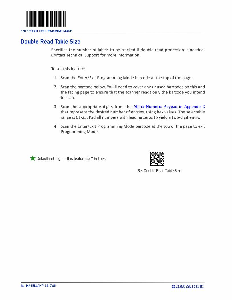
Double Read Table SizeSpecifies the number of labels to be tracked if double read protection is needed. Contact Technical Support for more information.
To set this feature:
1. Scan the Enter/Exit Programming Mode barcode at the top of the page.
2. Scan the barcode below. You’ll need to cover any unused barcodes on this and the facing page to ensure that the scanner reads only the barcode you intend to scan.
3. Scan the appropriate digits from the Alpha-Numeric Keypad in Appendix C that represent the desired number of entries, using hex values. The selectable range is 01-25. Pad all numbers with leading zeros to yield a two-digit entry.
4. Scan the Enter/Exit Programming Mode barcode at the top of the page to exit Programming Mode.
1505(CR)
Set Double Read Table Size
Default setting for this feature is: 7 Entries

ENTER/EXIT PROGRAMMING MODE
PRODUCT REFERENCE GUIDE 19
DIGITAL WATERMARK (DIGIMARC®) FEATURES
Digital Watermark (Digimarc) EnableEnables/Disables the ability of the scanner to decode Digimarc® Digital Water-marks.To set this feature:
1. Scan the Enter/Exit Programming Mode bar code.
2. Scan your selection from the bar codes below. You’ll need to cover any unused bar codes on this and the facing page to ensure that the scanner reads only the bar code you intend to scan.
3. Complete the programming sequence by scanning the Enter/Exit Program-ming Mode bar code.
049000(CR)
049001(CR)
Digital Watermark (Digimarc) = Enable
Digital Watermark (Digimarc) = Disable
ENTER/EXIT PROGRAMMING MODE
20 MAGELLAN™ 3410VSI
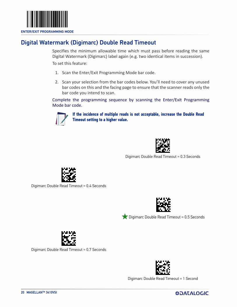
Digital Watermark (Digimarc) Double Read TimeoutSpecifies the minimum allowable time which must pass before reading the same Digital Watermark (Digimarc) label again (e.g. two identical items in succession).To set this feature:
1. Scan the Enter/Exit Programming Mode bar code.
2. Scan your selection from the bar codes below. You’ll need to cover any unused bar codes on this and the facing page to ensure that the scanner reads only the bar code you intend to scan.
Complete the programming sequence by scanning the Enter/Exit Programming Mode bar code.
NOTE
00521E(CR)
Digimarc Double Read Timeout = 0.3 Seconds
005228(CR)
Digimarc Double Read Timeout = 0.4 Seconds
005232(CR)
005246(CR)
Digimarc Double Read Timeout = 0.7 Seconds
005264(CR)
Digimarc Double Read Timeout = 1 Second
If the incidence of multiple reads is not acceptable, increase the Double Read Timeout setting to a higher value.
Digimarc Double Read Timeout = 0.5 Seconds
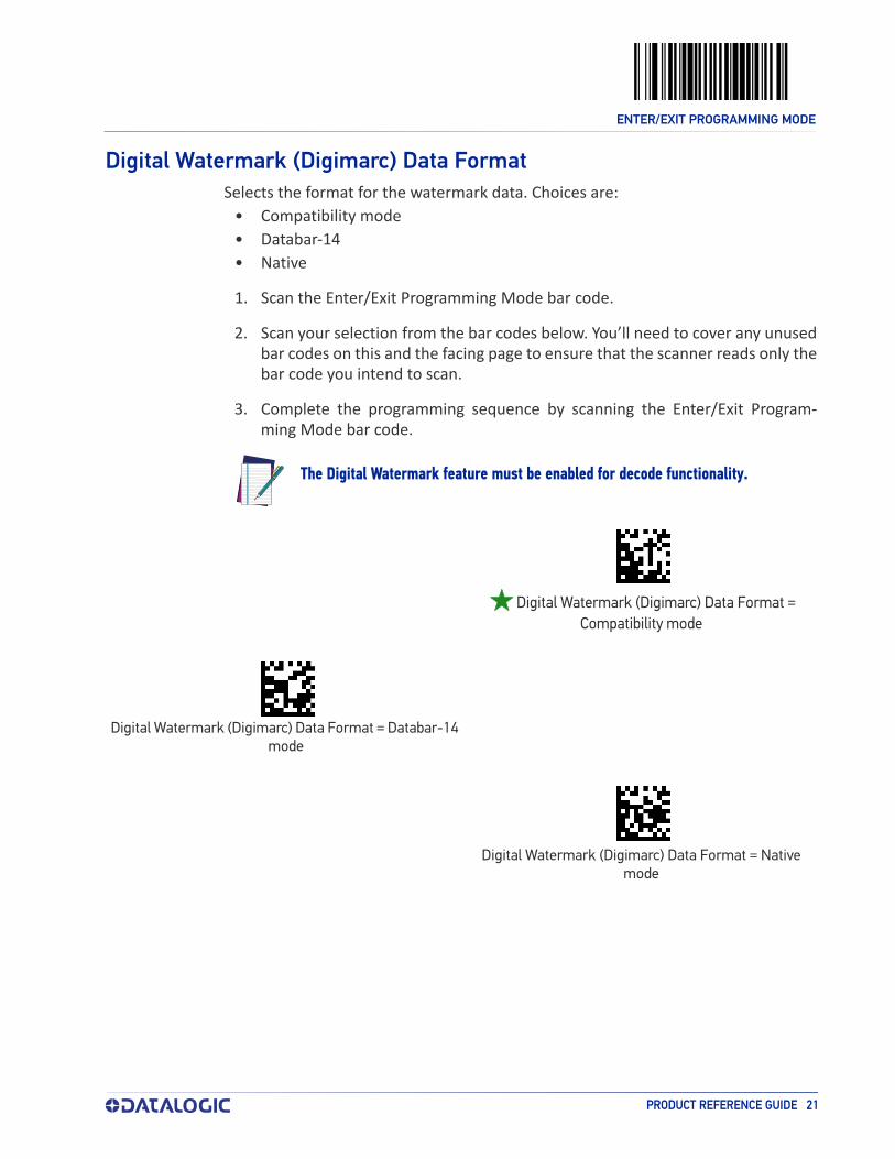
ENTER/EXIT PROGRAMMING MODE
PRODUCT REFERENCE GUIDE 21
Digital Watermark (Digimarc) Data FormatSelects the format for the watermark data. Choices are:
• Compatibility mode• Databar-14• Native
1. Scan the Enter/Exit Programming Mode bar code.
2. Scan your selection from the bar codes below. You’ll need to cover any unused bar codes on this and the facing page to ensure that the scanner reads only the bar code you intend to scan.
3. Complete the programming sequence by scanning the Enter/Exit Program-ming Mode bar code.
NOTE
049200(CR)
049201(CR)
Digital Watermark (Digimarc) Data Format = Databar-14 mode
049202(CR)
Digital Watermark (Digimarc) Data Format = Native mode
The Digital Watermark feature must be enabled for decode functionality.
Digital Watermark (Digimarc) Data Format = Compatibility mode

ENTER/EXIT PROGRAMMING MODE
22 MAGELLAN™ 3410VSI
Sleep Mode TimerThis feature specifies the amount of time of inactivity (with no label reads) before the scanner enters sleep mode.To set this feature:
1. Scan the Enter/Exit Programming Mode bar code.
2. Scan the bar code, Set Sleep Mode Timer on page 22 below. You’ll need to cover any unused bar codes on this and the facing page to ensure that the scanner reads only the bar code you intend to scan.
3. Scan the appropriate digits from the Alpha-Numeric Keypad in Appendix C that represent the desired time interval. The selectable range is 000-255 in 15 second increments. Pad all numbers with leading zeros to yield a three-digit entry (000-255).
4. Scan the Enter/Exit Programming Mode bar code to exit Programming Mode.
03AF(CR)
Set Sleep Mode Timer
Default setting for this feature is: 5 minutes

ENTER/EXIT PROGRAMMING MODE
PRODUCT REFERENCE GUIDE 23
1D Inverse Read ControlThis configuration item is used to toggle inverted label reading for 1D bar codes, for example, a label printed as white on black as opposed to black on white.
1. Scan the Enter/Exit Programming Mode bar code.
2. Scan your selection from the bar codes below. You’ll need to cover any unused bar codes on this and the facing page to ensure that the scanner reads only the bar code you intend to scan.
3. Finish by scanning the Enter/Exit Programming Mode bar code.032D00(CR)
032D01(CR)
1D Inverse Read Control = Inverse (white bar color / black space color)
032D02\r
1D Inverse Read Control = Normal + Inverse
(auto detect bar / space colors)
1D Inverse Read Control = Normal (black bar color / white space color)

ENTER/EXIT PROGRAMMING MODE
24 MAGELLAN™ 3410VSI
2D Inverse Read ControlThis configuration item is used to toggle inverted label reading for 2D bar codes, for example, a label printed as white on black as opposed to black on white. Use the instructions for 1D Inverse Read Control above..
040C00(CR)
040C01(CR)
2D Inverse Read Control = Inverse (white bar color / black space color)
040C02(CR)
2D Inverse Read Control = Normal + Inverse (auto detect bar / space colors)
2D Inverse Read Control = Normal (black bar color / white space color)

ENTER/EXIT PROGRAMMING MODE
PRODUCT REFERENCE GUIDE 25
LED AND BEEPER INDICATORS
Power On AlertDisables or enables the indication that the scanner has finished all its power up tests and is now ready for operation (usually a single beep).
020700(CR)
Power-up Tone Control = No Tone
020701(CR)
Power-up Tone Control = Play Tone
ENTER/EXIT PROGRAMMING MODE
26 MAGELLAN™ 3410VSI
Reading Illumination DurationThis feature specifies how long the illumination stays on after a label or label seg-ment is read.
To set this feature:
1. Scan the Enter/Exit Programming Mode bar code.
2. Scan your selection from the bar codes below. You’ll need to cover any unused bar codes on this and the facing page to ensure that the scanner reads only the bar code you intend to scan.
3. Complete the programming sequence by scanning the Enter/Exit Program-ming Mode bar code.
04EB14(CR)
Reading Illumination Duration = 1 Seconds
04EB3C(CR)
Reading Illumination Duration = 3 Seconds
04EB64(CR)
Reading Illumination Duration = 5 Seconds
ENTER/EXIT PROGRAMMING MODE
PRODUCT REFERENCE GUIDE 27
Illumination During Disable Mode This feature allows illumination to be turned off when the scanner is in “disable” mode. It determines if the imager illumination is controlled by host interface enable/disable commands.
Disable = Illumination is not controlled by host enable/disable commands, illu-mination stays on when disabled.
Enable = Illumination is controlled by host enable/disable commands, illumi-nation is on when enabled and off when disabled.
To set this feature:
1. Scan the Enter/Exit Programming Mode bar code.
2. Scan your selection from the bar codes below.
3. Complete the programming sequence by scanning the Enter/Exit Program-ming Mode bar code.
063A00(CR)
Illumination During Disable Mode = Disable
063A01(CR)
Illumination During Disable Mode = Enable
ENTER/EXIT PROGRAMMING MODE
28 MAGELLAN™ 3410VSI
Object Sense Control This feature determines whether the main illumination is controlled by the Object Sensing system, or alternatively, stays continuously on.
Enable = Illumination is controlled by using Object Sense
Disable = Normal illumination is used but it goes off during sleep mode / dis-able mode
To set this feature:
1. Scan the Enter/Exit Programming Mode bar code.
2. Scan your selection from the bar codes below. You’ll need to cover any unused bar codes on this and the facing page to ensure that the scanner reads only the bar code you intend to scan.
3. Complete the programming sequence by scanning the Enter/Exit Program-ming Mode bar code.
02FD01(CR)04EA40(CR)04CD0B(CR)
02FD00(CR)04EA8B(CR)
Object Sense Control =Disable
Object Sense Control = Enable

ENTER/EXIT PROGRAMMING MODE
PRODUCT REFERENCE GUIDE 29
External Read Indicator (ERI) NOTE
00F900(CR)
00F901(CR)
ERI Active State = Active High
This feature is available only through use of a special cable.
ERI TimeoutSpecifies the amount of time the External Read Indicator (ERI) signal is held active for a good read. Sets the ERI timeout duration using hex values from 000 to 255 in increments of ten milliseconds (10ms or 0.01 seconds).
To configure this feature:
1. Scan the “Enter/Exit Programming Mode” bar code above to place the unit in Programming Mode.
2. Scan “Set ERI Timeout,” followed by the two digits (zero padded) from the Alpha-Numeric Keypad in Appendix C representing the desired time value.
3. Exit programming mode by scanning the “Enter/Exit Programming Mode” bar code again.
Default setting for this feature is:00FA(CR)
Set ERI Timeout
ERI Active State = Active Low
002 -20ms

ENTER/EXIT PROGRAMMING MODE
30 MAGELLAN™ 3410VSI
Good Read LED Idle StateThis feature specifies the state of the green scanner LEDs when the scanner is idle and ready to read a label. Options are:
• Off• On dim
To set the Scanner LEDs Idle State:
1. Scan the Enter/Exit Programming Mode bar code.
2. Scan your selection from the bar codes below. You’ll need to cover any unused bar codes on this and the facing page to ensure that the scanner reads only the bar code you intend to scan.
3. Complete the programming sequence by scanning the Enter/Exit Program-ming Mode bar code.
030101(CR)
Scanner LED Idle State = Off
030102(CR)
Scanner LED Idle State = On Dim

ENTER/EXIT PROGRAMMING MODE
PRODUCT REFERENCE GUIDE 31
Scanner Control Button OptionsConfigure the Scanner Control Button to one of the following modes of operation:
• Enable all functions: Volume, tone, diagnostics and reset.• Enable only volume, tone and reset.• Enable reset only.• Disable all button functions
To set the desired Scanner Control Button Option:
1. Scan the Enter/Exit Programming Mode bar code.
2. Scan your selection from the bar codes below. You’ll need to cover any unused bar codes on this and the facing page to ensure that the scanner reads only the bar code you intend to scan.
3. Complete the programming sequence by scanning the Enter/Exit Program-ming Mode bar code.
05AF00(CR)
Scanner Control Button = Enable All Functions
05AF01(CR)
05AF02(CR)
Scanner Control Button = Enable Reset Only
05AF03(CR)
Scanner Control Button = Disable All Functions
Scanner Control Button = Enable Only Volume Tone and Reset

ENTER/EXIT PROGRAMMING MODE
32 MAGELLAN™ 3410VSI
Good Read Beep ControlThis feature enables/disables scanner beep upon successfully decoding of a label.
To set this feature:
1. Scan the Enter/Exit Programming Mode bar code.
2. Scan your selection from the bar codes below. You’ll need to cover any unused bar codes on this and the facing page to ensure that the scanner reads only the bar code you intend to scan.
3. Complete the programming sequence by scanning the Enter/Exit Program-ming Mode bar code.
006700(CR)
Good Read Beep Control = Disable
006701(CR)
Good Read Beep Control = Enable

ENTER/EXIT PROGRAMMING MODE
PRODUCT REFERENCE GUIDE 33
Good Read Beep FrequencyAdjusts the scanner’s good read beep to sound at low, medium, or high frequency (controls the beeper’s pitch/tone).
• Low• Medium• High
To set this feature:
1. Scan the Enter/Exit Programming Mode bar code.
2. Scan your selection from the bar codes below. You’ll need to cover any unused bar codes on this and the facing page to ensure that the scanner reads only the bar code you intend to scan.
3. Complete the programming sequence by scanning the Enter/Exit Program-ming Mode bar code.
001400(CR)
Good Read Beep Frequency = Low
001401(CR)
001402(CR)
Good Read Beep Frequency = High
Good Read Beep Frequency = Medium

ENTER/EXIT PROGRAMMING MODE
34 MAGELLAN™ 3410VSI
Good Read Beep LengthSpecifies the duration of a good read beep.
To set this feature:
1. Scan the Enter/Exit Programming Mode bar code.
2. Scan the bar code, Set Good Read Beep Length on page 34. You’ll need to cover any unused bar codes on this and the facing page to ensure that the scanner reads only the bar code you intend to scan.
3. Scan the appropriate digits from the Alpha-Numeric Keypad in Appendix C that represent the desired good read beep length setting. The selectable range is 1-255, which is the timeout in 10-millisecond increments. Times have a tol-erance of +/-25%. Pad all single and double digit numbers with leading zeroes to yield a three-digit entry (001-255).
Examples:
001 = 10ms
005 = 50ms
040 = 400ms
4. The scanner will automatically exit Programming Mode when the appropriate amount of digits have been scanned
0016(CR)
Set Good Read Beep Length
Default setting for this feature is:
.
008 - 80ms

ENTER/EXIT PROGRAMMING MODE
PRODUCT REFERENCE GUIDE 35
Good Read Beep VolumeSelects the beeper volume upon a good read beep. There are five selectable vol-umes, with each volume increment adding approximately five decibels to the previ-ous level:
• Low • Medium High• Medium Low • High• Medium
1. Scan the Enter/Exit Programming Mode bar code.
2. Scan your selection from the bar codes below. You’ll need to cover any unused bar codes on this and the facing page to ensure that the scanner reads only the bar code you intend to scan.
3. Complete the programming sequence by scanning the Enter/Exit Program-ming Mode bar code.
001900(CR)
Good Read Beep Volume = Low
001901(CR)
Good Read Beep Volume = Medium Low
001902(CR)
001903(CR)
Good Read Beep Volume = Medium High
001904(CR)
Good Read Beep Volume = High
Good Read Beep Volume = Medium

ENTER/EXIT PROGRAMMING MODE
36 MAGELLAN™ 3410VSI
Good Read When to IndicateThis feature specifies when the scanner will provide indication (beep and/or flash its green LEDs) upon successfully reading a bar code.
• Good Read = Indicate after decode. • Good Read = Indicate after transmit.• Good Read = Indicate after CTS goes inactive, then active.
This mode applies to RS-232 STD and RS-232 WN interfaces only. If set in other interfaces, “Indicate after decode” mode will be implemented.
• Good Read = Indicate after each output structure proofed. When beeping after each output structure decoded, if there are multiple out-put structures, there is a delay after the beep has finished. This delay is equal to the Good Read Beep Length on page 34.
To set the Good Read When to Indicate feature:
1. Scan the Enter/Exit Programming Mode bar code.
2. Scan the desired mode bar code from those provided below You’ll need to cover any unused bar codes on facing pages to ensure that the scanner reads only the bar code you intend to scan.
3. Scan the Enter/Exit Programming Mode bar code to complete.
009900(CR)
009901(CR)
Good Read When to Indicate = After Transmit
009902(CR)
Good Read When to Indicate = After CTS goes Inactive,Then Active
009903(CR)
Good Read When to Indicate = After Each OutputStructure Proofed
Good Read When to Indicate = After Decode

ENTER/EXIT PROGRAMMING MODE
PRODUCT REFERENCE GUIDE 37
Illumination Blank on BeepEnable this feature to turn off illumination while sound is playing.
To set this feature:
1. Scan the Enter/Exit Programming Mode barcode at the top of the page.
2. Scan your selection from the barcodes below.
3. Complete the programming sequence by scanning the Enter/Exit Program-ming Mode barcode.
150E00(CR)
150E01(CR)
Illumination Blank on Beep = Enable
Illumination Blank on Beep = Disable

ENTER/EXIT PROGRAMMING MODE
38 MAGELLAN™ 3410VSI
Host Download to HandheldAttached Datalogic handheld scanners can be updated via the host port. Contact Technical Support for details.
Handheld Host Download TimeoutThis feature sets the timeout (in seconds) to wait for a response from the handheld when performing a host download to the handheld.
To set this feature:
1. Scan the Enter/Exit Programming Mode bar code.
2. Scan the bar code below, Set Handheld HDL Timeout. You’ll need to cover any unused bar codes on this and the facing page to ensure that the scanner reads only the bar code you intend to scan.
3. Scan the appropriate digits from the Alpha-Numeric Keypad in Appendix Cthat represent the desired delay. The selectable range is 001-255, which is the delay in 1-second increments. Pad all single and double digit numbers with leading zeroes to yield a three-digit entry (001-255).
4. Complete the programming sequence by scanning the Enter/Exit Program-ming Mode bar code.Examples:002 = 2 seconds005 = 5 seconds015 = 15 seconds
04EF(CR)
Set Handheld HDL Timeout
Default setting for this feature is: 15 seconds

PRODUCT REFERENCE GUIDE 39
CONFIGURATION | IMAGING FEATURES
IMAGING FEATURES starting on page 40
•Image Capture to the Host by Host Command on page 40•Image Capture to the Host by Camera Button on page 41
- Camera Button Mode on page 41- Image Destination on page 42
•Picture Retrieval Timeout on page 43•Image Capture Delay on page 45•Image Format on page 46•Image Size on page 47•Image Brightness on page 48•Image Contrast on page 50•Image Compression on page 52•Region of Interest (ROI) on page 53
CELL PHONE SETTINGS starting on page 55
•Cell Phone Mode on page 55•Cell Mode Percent on page 56
SECTION CONTENTS

ENTER/EXIT PROGRAMMING MODE
40 MAGELLAN™ 3410VSI
IMAGING FEATURES
Image Capture to the Host by Host CommandThis feature is only available for RS-232 and USB COM interfaces.
NOTE
NOTE: If the USB COM interface has been selected, follow the instructions in USB-COM Interface Setup on page 79.
The host command format is as follows:P<cnt>pSBCwhere:
P - ASCII 'P' used as preamble of pass-through commands<cnt> - binary value of 4 indicating 4 bytes to followp - ASCII lowercase 'p' ; command to take a pictureS - size value of image as ASCII character
‘S’ == uses scanner's configuration value ‘0’-VGA, (640X480)‘1’-WVGA, (752X480)‘2’-SXGA, (1280x800)‘3’-CIF (320x240)
B - brightness value in ASCII‘B’ == uses scanner's configuration value CI_IMAGE_BRIGHTNESS else ‘0’ thru’9’ specifies brightness
C - contrast value in ASCII‘C’ == uses scanner configuration value CI_IMAGE_CONTRAST else ‘0’ thru’9’ specifies contrast
IF the image is of a type the scanner supports, capture and transmission occurs, and the command is of proper format THEN
The scanner will transmit an ACK (0x06) to the Host in response to this com-mand.The image data transmission starts with a 4 byte binary field representing (Big Endian) number of bytes to follow.If the “number of bytes to follow” value is zero, there was a problem with gen-erating the image and the request should be retried.
ELSEThe scanner will transmit a BEL (0x07) to the Host in response to this com-mand.
ENDIF

ENTER/EXIT PROGRAMMING MODE
PRODUCT REFERENCE GUIDE 41
Image Capture to the Host by Camera ButtonPerform the following steps to set up the Camera Button.
1. Set the Camera Button Mode to enabled.
2. Set the Image Capture destination to host port.
3. Press the camera button.Scanner will beep for a few seconds, then take picture and send the Image Retrieval Event label to the POS to indicate image is ready. The data content of the event label is:
A856102000239
The POS sends the picture retrieval command to initiate picture download from the scanner. Format of the command is:
P\x02pG
The scanner sends the picture to the POS with the transmission format described in the previous section, “Image Capture By Host Command”.
Camera Button ModeThis feature enables or disables the camera button.
05B000(CR)
05B001(CR)
Camera Button Mode = Enable
Camera Button Mode = Disabled

ENTER/EXIT PROGRAMMING MODE
42 MAGELLAN™ 3410VSI
Image Destination
Specifies the destination for pictures/images taken with a camera button press.
042500(CR)
042501\r
Image Destination = SD carda
a. Contact Customer Service for more information on using this feature.
042503\r
Image Destination = Host port
Image Destination = Disable

ENTER/EXIT PROGRAMMING MODE
PRODUCT REFERENCE GUIDE 43
Picture Retrieval TimeoutThis feature sets the amount of time after the picture retrieval label is sent to the POS that the scanner will allow subsequent picture taking requests via button press.
NOTE
042300(CR)
If set to 0, the picture retrieval timeout will not be used and a picture will remain accessible until another is taken or the scanner is reset.
Picture Retrieval Timeout = 0
042301(CR)
Picture Retrieval Timeout = 1 second
042302(CR)
Picture Retrieval Timeout = 2 seconds
042303(CR)
Picture Retrieval Timeout = 3 seconds
042304(CR)
Picture Retrieval Timeout = 4 seconds
042305(CR)
Picture Retrieval Timeout = 5 seconds

ENTER/EXIT PROGRAMMING MODE
44 MAGELLAN™ 3410VSI
Picture Retrieval Timeout (continued)
042306(CR)
Picture Retrieval Timeout = 6 seconds
042307(CR)
Picture Retrieval Timeout = 7 seconds
042308(CR)
Picture Retrieval Timeout = 8 seconds
042309(CR)
Picture Retrieval Timeout = 9 seconds
04230A(CR)
Picture Retrieval Timeout = 10 seconds

ENTER/EXIT PROGRAMMING MODE
PRODUCT REFERENCE GUIDE 45
Image Capture Delay
This feature specifies the amount of time after the image capture is initiated by a button press until the picture is taken.
042700(CR)
Image Capture Delay = 0 seconds
042701(CR)
Image Capture Delay = 1 second
042702(CR)
Image Capture Delay = 2 seconds
042705(CR)
04270A(CR)
Image Capture Delay = 10 seconds
Image Capture Delay = 5 seconds

ENTER/EXIT PROGRAMMING MODE
46 MAGELLAN™ 3410VSI
Image FormatThis feature specifies the output format for images taken using the camera function of the scanner.Choices are:
• JPG• BMP
03E900(CR)
03E901(CR)
Image Format = BMP
Image Format = JPG

ENTER/EXIT PROGRAMMING MODE
PRODUCT REFERENCE GUIDE 47
Image SizeThis feature specifies the size of the captured image. Choices are:
VGA : Video Graphics Array. 640 x 480 pixels, cropped.WVGA. Wide Video Graphics Array, 752 x 480 pixels, cropped.Full Size. 1280 x 800 pixels, full image.QVGA. 320 x 240 pixels, cropped.Scaled VGA. Video Graphics Array, 640 x 480 pixels, scaled.ROI. The size of an ROI image is determined by the value of the ROI setting. See "Region of Interest (ROI)" on page 53.
03EA00(CR)
03EA01(CR)
Image Size = WVGA
03EA02(CR)
Image Size = Full Size
03EA03(CR)
Image Size = QVGA
03EA04(CR)
Image Size = Scaled VGA
03EA05(CR)
Image Size = ROI
Image Size = VGA

ENTER/EXIT PROGRAMMING MODE
48 MAGELLAN™ 3410VSI
Image BrightnessSpecifies the image brightness value. The selectable range is from 0 to 10, with 10 being the brightest.
03EB00(CR)
03EB01(CR)
Image Brightness = 1
03EB02(CR)
Image Brightness = 2
03EB03(CR)
Image Brightness = 3
03EB04(CR)
Image Brightness = 4
03EB05(CR)
Image Brightness = 5
03EB06(CR)
Image Brightness = 6
03EB07(CR)
Image Brightness = 7
Image Brightness = 0

ENTER/EXIT PROGRAMMING MODE
PRODUCT REFERENCE GUIDE 49
Image Brightness — continued
03EB08(CR)
Image Brightness = 8
03EB09(CR)
Image Brightness = 9
03EB0A(CR)
Image Brightness = 10

ENTER/EXIT PROGRAMMING MODE
50 MAGELLAN™ 3410VSI
Image ContrastThis feature sets the contrast level for a captured image. The selectable range is from 0 to 10, with 0 being the lowest and 10 being the highest contrast.
03EC00(CR)
03EC01(CR)
Image Contrast = 1
03EC02(CR)
Image Contrast = 2
03EC03(CR)
Image Contrast = 3
03EC04(CR)
Image Contrast = 4
03EC05(CR)
Image Contrast = 5
03EC06(CR)
Image Contrast = 6
03EC07(CR)
Image Contrast = 7
Image Contrast = 0

ENTER/EXIT PROGRAMMING MODE
PRODUCT REFERENCE GUIDE 51
Image Contrast — continued
03EC08(CR)
Image Contrast = 8
03EC09(CR)
Image Contrast = 9
03EC0A(CR)
Image Contrast = 10

ENTER/EXIT PROGRAMMING MODE
52 MAGELLAN™ 3410VSI
Image CompressionSpecifies the starting image compression factor.
03ED05(CR)
Image Compression = 5
03ED0A(CR)
Image Compression = 10
03ED19(CR)
Image Compression = 25
03ED32(CR)
Image Compression = 50
03ED46(CR)
Image Compression = 70
03ED50(CR)
Image Compression = 80
03ED5A(CR)
Image Compression = 90
03ED64(CR)
Image Compression = 100

ENTER/EXIT PROGRAMMING MODE
PRODUCT REFERENCE GUIDE 53
Region of Interest (ROI)This feature specifies the X-Y coordinates for the Region of Interest (ROI). The region of interest coordinates are defined as follows:
Where xmax is the x-size of a full size image (1279 pixels), and ymax is the y-size of a full size image (799 pixels). For example, a coordinate set of 0, 639, 400, 799 will produce the bottom left section of a full size image.
NOTE
Picture coordinates are NOT defined on a Cartesian coordinate plane.
• Byte [0]-[1]: 16 bit hex value xmin• Byte [2]-[3]: 16 bit hex value xmax• Byte [4]-[5]: 16 bit hex value ymin• Byte [6]-[7]: 16 bit hex value ymax
NOTES
NOTE: If the xmax/ymax values are configured larger than the maximum values above, they will default to 1 less than their respective maximum values.
If the xmin/ymin values are configured larger than xmax/ymax, they will default to 0.
Images extracted with ROI must be in JPG format.

ENTER/EXIT PROGRAMMING MODE
54 MAGELLAN™ 3410VSI
Region of Interest (continued)
04EC000004FF0000031F\r
04EC0000027F0000018F\r
Region of Interest = upper left quadrant
04EC028004FF0000018F\r
Region of Interest = upper right quadrant
04EC0000027F0190031F\r
Region of Interest = lower left quadrant
04EC028004FF0190031F\r
Region of Interest = lower right quadrant
Region of Interest = default

ENTER/EXIT PROGRAMMING MODE
PRODUCT REFERENCE GUIDE 55
CELL PHONE SETTINGS
Cell Phone ModeEnables/disables the operating mode for mobile phone read.
• In Toggle mode each host command toggles the mode. • In Timer Expiration mode, a single host command enters Cell Phone mode but it is
exited at timer expiration. The timer is not restarted on a label read. • In Always On mode, the scanner stays on regardless of host command or button push.
It will not enter sleep mode.
046700(CR)
Cell Phone Mode = Toggle
046701(CR)
Cell Phone Mode = Timer Expiration
046702(CR)
Cell Phone Mode = Always On

ENTER/EXIT PROGRAMMING MODE
56 MAGELLAN™ 3410VSI
Cell Mode PercentSpecifies the rate of frames dedicated to reading cell phones. Cell reading feature must be enabled for this to be active. The setting reflects a variable setting (or per-centage) of frames dedicated to cell reading.
NOTE
150A4000(CR)151A01(CR)
Cell Mode Percent = 5% (Very Low)
150A2000(CR)151A01(CR)
150A1000(CR)151A01(CR)
Cell Mode Percent = 20% (Medium)
150A0800(CR)151A01(CR)
Cell Mode Percent = 30% (Medium High)
150A0600(CR)151A01(CR)
Cell Mode Percent = 50% (High)
As the percentage is increased, object sense (if enabled) will become less responsive. Anything above 10% will have a negative impact on scanning per-formance.
Cell Mode Percent = 10% (Low)

PRODUCT REFERENCE GUIDE 57
CONFIGURATION | INTERFACE RELATED FEATURES
starting on page 58
•USB-COM Interface Setup on page 79•RS-232 Interface Selection on page 58
•USB Interface Selection on page 59•Keyboard Interface Selection on page 59
starting on page 60
•Maximum Host-Transmitted Message Length on page 60
•Ignore Host Commands on page 61
RS-232 INTERFACE FEATURES starting on page 62
•RS-232 Baud Rate on page 62•RS-232 Number of Data Bits on page 64•RS-232 Number of Stop Bits on page 64•RS-232 Parity on page 65•RS-232 Hardware Control on page 66•RS-232 Intercharacter Delay on page 67•RS-232 Software Flow Control on page 68•RS-232 Beep on ASCII BEL on page 69
•Beep on Not on File on page 70•RS-232 ACK NAK Features on page 71
- ACK NAK Enable on page 71- RS-232 ACK Character on page 72- RS-232 NAK Character on page 73- RS-232 Retry on ACK NAK Timeout on page
74- RS-232 ACK NAK Timeout Value on page 75- RS-232 ACK NAK Retry Count on page 76- RS-232 ACK NAK Error Handling on page 77
•RS-232 Indicate Transmission Failure on page 78
USB-COM INTERFACE FEATURES starting on page 79
•USB-COM Interface Setup on page 79 •USB Power Compliance on page 80
USB-OEM INTERFACE FEATURES starting on page 81
•USB OEM Scanner Device Type on page 81
USB KEYBOARD FEATURES starting on page 83
•Keyboard Layout on page 83•USB Keyboard Country Mode on page 83•USB Keyboard Caps Lock State on page 86•USB Keyboard Send Control Characters on page
87
•Quiet Interval on page 88•USB Keyboard Intercharacter Delay on page 89•USB Keyboard Additional Interface Options on
page 90
SECTION CONTENTS
INTERFACE SELECTION
INTERFACE FEATURES

ENTER/EXIT PROGRAMMING MODE
58 MAGELLAN™ 3410VSI
INTERFACE SELECTION
INTERFACE TYPESpecifies the current scanner interface.
NOTE
NOTE
NOTE
NOTE: When an interface is selected, the scanner loads the configuration for that interface as the selection is made. Any custom configurations done in the previous interface will not be carried over to the configuration for the new inter-face.
CAUTION: Great care should be taken to select the correct interface type, since you can cause damage to the scanner and/or POS terminal by attempting to change to an incompatible interface. ALWAYS make interface selections with the host cable DISCONNECTED.
NOTE: If the scanner’s interface type must be changed, always be sure that interface configuration is the FIRST item scanned during a programming ses-sion. (Selecting an interface type resets ALL other configuration items to the factory default for that interface type.)
NOTE: The correct interface cable is generally included for the reader interface type you ordered.
RS-232 Interface SelectionRemember to cover any unused bar codes on this and the facing page to ensure that the scanner reads only the bar code you intend to scan.
000105(CR)
Interface Type = RS-232 Standard
000112(CR)
Interface Type = RS-232 Wincor-Nixdorf
CAUTION: Great care should be taken to select the correct interface type, since you can cause damage to the scanner and/or POS terminal by attempting to change to an incompatible interface. ALWAYS make interface selections with the host cable DISCONNECTED.
CAUTION
CAUTION

INTERFACE TYPE ENTER/EXIT PROGRAMMING MODE
PRODUCT REFERENCE GUIDE 59
USB Interface SelectionRemember to cover any unused bar codes on this and the facing page to ensure that the scanner reads only the bar code you intend to scan.
000145(CR)
Interface Type = USB OEM
00010D(CR)
Interface Type = USB TEC
000147(CR)
Interface Type = USB COM
CAUTION: Great care should be taken to select the correct interface type, since you can cause damage to the scanner and/or POS terminal by attempting to change to an incompatible interface. ALWAYS make interface selections with the host cable DISCONNECTED.
Keyboard Interface SelectionRemember to cover any unused bar codes on this and the facing page to ensure that the scanner reads only the bar code you intend to scan.
000135(CR)
Interface Type = USB Keyboard
CAUTION: Great care should be taken to select the correct interface type, since you can cause damage to the scanner and/or POS terminal by attempting to change to an incompatible interface. ALWAYS make interface selections with the host cable DISCONNECTED.
CAUTION
CAUTION

ENTER/EXIT PROGRAMMING MODE
60 MAGELLAN™ 3410VSI
INTERFACE FEATURES
Maximum Host-Transmitted Message LengthSpecifies the maximum number of data characters allowed in messages transmitted to the host.To set the Maximum Host-Transmitted Message Length:
1. Scan the Enter/Exit Programming Mode bar code.
2. Scan the bar code, Set Maximum Host-Transmitted Message Length on page 60 below. You’ll need to cover any unused bar codes on this and the facing page to ensure that the scanner reads only the bar code you intend to scan.
3. Scan the appropriate digits from Appendix C, Alpha-Numeric Keypad that rep-resent the desired maximum host-transmitted message length. The selectable range is 0-249 data characters. (Labels that are longer than this length are not read.) Pad all single and double digit numbers with leading zeroes to yield a three-digit entry (000-249).
NOTE
NOTE: If this configuration item is set to 0 (000), there is no general length limit imposed on data being transmitted to the host.
4. The scanner will automatically exit Programming Mode when the appropriate amount of digits have been scanned.
Default setting for this feature is:06B1(CR)
Set Maximum Host-Transmitted Message Length000 - No general limit imposed

INTERFACE TYPE ENTER/EXIT PROGRAMMING MODE
PRODUCT REFERENCE GUIDE 61
Ignore Host CommandsWhen set to ignore host commands, the scanner will ignore all host commands except the minimum set necessary to keep the interface active and transmit labels. For normal operation of the interface, select Obey Host Commands.
04F400(CR)
04F401(CR)
Ignore Host Commands = Ignore
Ignore Host Commands = Don’t Ignore

ENTER/EXIT PROGRAMMING MODE
62 MAGELLAN™ 3410VSI
RS-232 INTERFACE FEATURESNOTE
NOTE: A setting of no parity with 7 data bits is invalid and will default to 8 data bits and no parity.
RS-232 Baud Rate
001D04(CR)
RS-232 Baud Rate = 1200
001D03(CR)
RS-232 Baud Rate = 2400
001D02(CR)
RS-232 Baud Rate = 4800
001D01(CR)
001D00(CR)
RS-232 Baud Rate = 19200
001D06(CR)
RS-232 Baud Rate = 38400
RS-232 Baud Rate = 9600
001D07(CR)
RS-232 Baud Rate = 57600
001D08(CR)
RS-232 Baud Rate = 115200
001D09(CR)
RS-232 Baud Rate = 230400
RS-232 INTERFACE FEATURES ENTER/EXIT PROGRAMMING MODE
PRODUCT REFERENCE GUIDE 63
RS-232 Baud Rate (continued)

ENTER/EXIT PROGRAMMING MODE
64 MAGELLAN™ 3410VSI
RS-232 Number of Data BitsSpecifies number of data bits required for sending and receiving data.
NOTE
NOTE: A setting of 7 data bits with no parity will default to 8 data bits and no parity.
.
009B00(CR)
RS-232 Number of Data Bits = 7
009B01(CR)
RS-232 Number of Stop BitsSpecifies number of stop bits required for sending and receiving data
002200(CR)
002201(CR)
RS-232 Number of Stop Bits = 2
RS-232 Number of Data Bits = 8
RS-232 Number of Stop Bits = 1

RS-232 INTERFACE FEATURES ENTER/EXIT PROGRAMMING MODE
PRODUCT REFERENCE GUIDE 65
RS-232 ParitySpecifies parity required for sending and receiving data.Options for this setting are:
• RS-232 PARITY = NONE• RS-232 PARITY = EVEN• RS-232 PARITY = ODD
NOTE
NOTE: A setting of no parity with 7 data bits will default to 8 data bits and no parity.
.
001F00(CR)
001F01(CR)
RS-232 Parity = Even
001F02(CR)
RS-232 Parity = Odd
RS-232 Parity = None

ENTER/EXIT PROGRAMMING MODE
66 MAGELLAN™ 3410VSI
RS-232 Hardware ControlEnables/disables use of the RS-232 CTS signal for flow control and/or scan control.Options are:
• Disable — The scanner transmits to the host regardless of any activity on the CTS line.
• Enable CTS Flow Control — The CTS signal controls transmission of data to the host.
• Enable CTS Scan Control — The CTS line must be active for scanner to read and transmit data. While the CTS line is inactive, scanner remains in a host- dis-abled state; following a successful label transmission, the CTS signal must tran-sition to inactive and then to active to enable scanning for the next label.
• Enable Magellan SL CTS Scan Control — Follows the same hardware protocol as older Magellan SL scanners.
020F00(CR)
020F01(CR)
RS-232 Hardware Control = Enable CTS Flow Control
020F02(CR)
RS-232 Parity = Enable CTS Scan Control
020F03(CR)
RS-232 Hardware Control = Enable MGL SL CTS Scan Control
RS-232 Hardware Control = Disable

RS-232 INTERFACE FEATURES ENTER/EXIT PROGRAMMING MODE
PRODUCT REFERENCE GUIDE 67
RS-232 Intercharacter DelaySpecifies delay between the end of one character and the beginning of the next in 10-millisecond increments. This delay is inserted after each data character transmit-ted. If the transmission speed is too high, the system may not be able to receive all characters. You may need to adjust the delay to make the system work properly.To set the RS-232 Intercharacter Delay:
1. Scan the Enter/Exit Programming Mode bar code.
2. Scan the bar code below, Set RS-232 Intercharacter Delay.
3. Scan the appropriate digits from the Alpha-Numeric Keypad in Appendix C that represent the desired delay. The selectable range is 0-100, which is the delay in 10-millisecond increments. Pad all single and double digit numbers with leading zeroes to yield a three-digit entry (000-100).
Examples:
001 = 10ms
005 = 50ms
040 = 400ms
100 = 1,000ms (1 second)
4. The scanner will automatically exit Programming Mode when the appropriate amount of digits have been scanned.
Default setting for this feature is: 009C(CR)
Set RS-232 Intercharacter Delay
00 - No Intercharacter Delay

ENTER/EXIT PROGRAMMING MODE
68 MAGELLAN™ 3410VSI
RS-232 Software Flow ControlEnables/disables RS-232 Flow Control using XON/ XOFF characters.
NOTE
NOTE: This item will be ignored when the feature, RS-232 NAK Character, is enabled
To set this feature:
1. Scan the Enter/Exit Programming Mode bar code.
2. Scan either the enable or disable bar code below. You’ll need to cover any unused bar codes on this and the facing page to ensure that the scanner reads only the bar code you intend to scan.
3. Complete the programming sequence by scanning the Enter/Exit Program-ming Mode bar code.
002100(CR)
002101(CR)
RS-232 Software Flow Control= Enable
RS-232 Software Flow Control= Disable

RS-232 INTERFACE FEATURES ENTER/EXIT PROGRAMMING MODE
PRODUCT REFERENCE GUIDE 69
RS-232 Beep on ASCII BELEnables/disables ability of scanner to beep (sound a good read tone) on receiving an ASCII BEL (07 hex).
069D00(CR)
069D01(CR)
RS-232 Beep on ASCII BEL = Enable
RS-232 Beep on ASCII BEL = Disable

ENTER/EXIT PROGRAMMING MODE
70 MAGELLAN™ 3410VSI
Beep on Not on FileSelect for the host to beep (or not) when a not-on-file condition is detected by the host.
045100(CR)
RS-232 Beep on Not on File = Muted
045101(CR)
045102(CR)
RS-232 Beep on Not on File = Medium Volume
045103(CR)
RS-232 Beep on Not on File = High Volume
RS-232 Beep on Not on File = Low Volume

RS-232 INTERFACE FEATURES ENTER/EXIT PROGRAMMING MODE
PRODUCT REFERENCE GUIDE 71
RS-232 ACK NAK Features
ACK NAK EnableEnables/disables the ability of the scanner to support the RS-232 ACK/NAK proto-col. When configured, the scanner and/or host sends an “ACK” when it receives data properly, and sends “NAK” when the data is in error. Selections are:
• Disable ACK NAK• Enable for Label Transmission — the scanner expects an ACK/NAK response
from the host when a label is sent)• Enable for Host Acknowledgment — Enabled for Host Commands (the scanner
will respond with ACK/NAK when the host sends a command)• Enable for Label & Host — Enabled for both Label Transmission & Host Com-
mand acknowledgment.To select the option for RS-232 ACK NAK Enable:
1. Scan the Enter/Exit Programming Mode bar code.
2. Scan the desired option from bar codes below and on the following page. You’ll need to cover any unused bar codes on this and the facing page to ensure that the scanner reads only the bar code you intend to scan.
3. Complete by scanning the Enter/Exit Programming Mode bar code.
061100(CR)
061101(CR)
RS-232 ACK NAK = Enable for Label Transmission
061102(CR)
RS-232 ACK NAK = Enable for Host Acknowledgement
061103(CR)
RS-232 ACK NAK = Enable for Label & Host
RS-232 ACK NAK = Disable

ENTER/EXIT PROGRAMMING MODE
72 MAGELLAN™ 3410VSI
RS-232 ACK CharacterThis feature specifies which ASCII character will be used as an ACK character.
NOTE
NOTE: DO NOT set this feature to use previously defined characters such as XON, XOFF or host commands as this will conflict with normal operation of these characters. 8-bit data is not recognized when the feature, RS-232 Number of Data Bits, is set to 7 data bits.
To specify the RS-232 ACK Character:
1. Scan the Enter/Exit Programming Mode bar code.
2. Scan the bar code, SET RS-232 ACK Character below. You’ll need to cover any unused bar codes on this and the facing page to ensure the scanner reads only the bar code you intend to scan.
3. Scan the appropriate digits from the Alpha-Numeric Keypad in Appendix C that represent the hex designation for the desired character. A table contain-ing the ASCII Character Set and their corresponding Hex Values is available in the inside back cover of this manual. ASCII parameters must be input by scan-ning a pair of hexadecimal digits for the desired character. For example, if ASCII “A” were the desired ACK character, you would scan the digits “4”, then “1” (the ASCII corresponding hex value).
4. The scanner will automatically exit Programming Mode when the appropriate amount of digits/characters have been scanned.
Default setting for this feature is: 031F(CR)
Set RS-232 ACK Character
06

RS-232 INTERFACE FEATURES ENTER/EXIT PROGRAMMING MODE
PRODUCT REFERENCE GUIDE 73
RS-232 NAK CharacterThis feature specifies which ASCII character will be used as a NAK character.
NOTE
NOTE: DO NOT set this feature to use previously defined characters such as XON, XOFF or host commands as this will conflict with normal operation of these characters. 8-bit data is not recognized when the feature, RS-232 Number of Data Bits, is set to 7 data bits.
To specify the RS-232 NAK Character:
1. Scan the Enter/Exit Programming Mode bar code.
2. Scan the bar code, SET RS-232 NAK Character below. You’ll need to cover any unused bar codes on this and the facing page to ensure the scanner reads only the bar code you intend to scan.
3. Scan the appropriate digits from the Alpha-Numeric Keypad in Appendix C that represent the hex designation for the desired character. A table contain-ing the ASCII Character Set and their corresponding Hex Values is available in the inside back cover of this manual. ASCII parameters must be input by scan-ning a pair of hexadecimal digits for the desired character. For example, if ASCII “A” were the desired NAK character, you would scan the digits “4”, then “1” (the ASCII corresponding hex value).
4. The scanner will automatically exit Programming Mode when the appropriate amount of digits/characters have been scanned.
Default setting for this feature is: 0320(CR)
Set RS-232 NAK Character
15

ENTER/EXIT PROGRAMMING MODE
74 MAGELLAN™ 3410VSI
RS-232 Retry on ACK NAK TimeoutThis option specifies the action scanner performs on expiration of the RS-232 ACK NAK Timeout Value.
032100(CR)
RS-232 Retry on ACK NAK Timeout = Disable
032101(CR)
RS-232 Retry on ACK NAK Timeout = Enable

RS-232 INTERFACE FEATURES ENTER/EXIT PROGRAMMING MODE
PRODUCT REFERENCE GUIDE 75
RS-232 ACK NAK Timeout ValueThis item specifies the time the scanner will wait for an ACK character from the host following a label transmission.
• 0 = Infinite timeout• 1 - 75 = Timeout in 200-millisecond increments
To set the ACK NAK Timeout Value:
1. Scan the Enter/Exit Programming Mode bar code.
2. Scan the bar code below, Set RS-232 ACK NAK Timeout Value. You’ll need to cover any unused bar codes on this and the facing page to ensure that the scanner reads only the bar code you intend to scan.
3. Scan the appropriate digits from the Alpha-Numeric Keypad in Appendix C that represent the desired timeout. A setting of 0 specifies an infinite timeout. The remaining selectable range is 1-75, which is the timeout in 200-millisec-ond increments. Pad all single digit numbers with a leading zero to yield a two-digit entry (00-75).
Examples:
00 = Infinite timeout
01 = 200ms
05 = 1,000ms (1 second)
40 = 8,000ms (8 seconds)
75 = 15,000ms (15 seconds)The scanner will automatically exit Programming Mode when the appropriate amount of digits have been scanned.
Default setting for this feature is: 0606(CR)
Set RS-232 ACK NAK Timeout Value
01 - 200ms
ENTER/EXIT PROGRAMMING MODE
76 MAGELLAN™ 3410VSI
RS-232 ACK NAK Retry CountThis feature sets the number of times for the scanner to retry a label transmission under a retry condition.To set the RS-232 ACK NAK Retry Count:
1. Scan the Enter/Exit Programming Mode bar code.
2. Scan the bar code, Set RS-232 ACK NAK Retry Count below. You’ll need to cover any unused bar codes on this and the facing page to ensure that the scanner reads only the bar code you intend to scan.
3. Scan the appropriate digits from the Alpha-Numeric Keypad in Appendix C that represent the desired number. The selectable range is 000-255 resets. Pad all single and double digit numbers with leading zeroes to yield a three-digit entry (000-255).
NOTE
NOTE: A setting of 255 specifies “retry forever.”
4. The scanner will automatically exit Programming Mode when the appropriate amount of digits have been scanned.
Default setting for this feature is: 0608(CR)
Set RS-232 ACK NAK Retry Count
003 - Three retrys

RS-232 INTERFACE FEATURES ENTER/EXIT PROGRAMMING MODE
PRODUCT REFERENCE GUIDE 77
RS-232 ACK NAK Error HandlingThis item specifies the method the scanner will use to handle errors detected while waiting to receive the ACK character from the host. Errors include unrecognized host commands and communication errors such as parity or framing errors.
• Ignore Errors (recommended setting)• Assume ACK (risk of lost label data)• Assume NAK (risk of duplicate label)
032300(CR)
032301(CR)
RS-232 ACK NAK Error Handling = Assume ACK
032302(CR)
RS-232 ACK NAK Error Handling = Assume NAK
RS-232 ACK NAK Error Handling = Ignore Errors

ENTER/EXIT PROGRAMMING MODE
78 MAGELLAN™ 3410VSI
RS-232 Indicate Transmission FailureThis feature enables / disables the ability of the scanner to sound a bad label beep indication when a transmission failure occurs.To set this feature:
1. Scan the Enter/Exit Programming Mode bar code.
2. Scan the desired option from the bar codes below. You’ll need to cover any unused bar codes on this and the facing page to ensure that the scanner reads only the bar code you intend to scan.
3. Complete the programming sequence by scanning the Enter/Exit Program-ming Mode bar code.
032200(CR)
RS-232 Indicate Transmission Failure = Disable
032201(CR)
RS-232 Indicate Transmission Failure = Enable

USB-COM INTERFACE FEATURES ENTER/EXIT PROGRAMMING MODE
PRODUCT REFERENCE GUIDE 79
USB-COM INTERFACE FEATURES
USB-COM Interface SetupBefore plugging your scanner into the Host PC, please ensure you have already cop-ied the executable DLS USB-COM driver file to your PC and that the scanner’s inter-face is set to USB COM. The DLS USB-COM driver (for Windows operating systems) is provided by Datalogic or downloaded from the Datalogic website.
1. Execute the DLS USB-COM driver file.
2. When the scanner is first plugged into the PC, Windows will bring up the “Found New Hardware” message.
3. The installation is complete.
NOTE
NOTE: Contact your Datalogic Representative for information about USB-COM operation with other major PC operating systems.

ENTER/EXIT PROGRAMMING MODE
80 MAGELLAN™ 3410VSI
USB Power ComplianceThis feature enables / disables the ability of the Universal Interface to hold off system con-troller power until after USB POS Host enumeration.To set this feature:
1. Scan the Enter/Exit Programming Mode barcode at the top of the page.
2. Scan the desired option from the barcodes below. Cover unused barcodes on this and the facing page to ensure that the scanner reads only the barcode you intend to scan.
3. Complete by scanning the Enter/Exit Programming Mode barcode.
150F00(CR)
USB Power Compliance = Disable
150F01(CR)
USB Power Compliance = Enable

USB-OEM INTERFACE FEATURES ENTER/EXIT PROGRAMMING MODE
PRODUCT REFERENCE GUIDE 81
USB-OEM INTERFACE FEATURES
USB OEM Scanner Device TypeThe OEM-USB protocol allows for the scanner to be identified as one of two differ-ent types of bar code scanners. Depending on what other scanners you may already have connected to a USB POS, you may need to change this setting to enable all scanners to communicate. Options are:
• Table Top Scanner• Handheld Scanner
To set this feature:
1. Scan the Enter/Exit Programming Mode bar code.
2. Scan your selection from the bar codes below. You’ll need to cover any unused bar codes on this and the facing page to ensure that the scanner reads only the bar code you intend to scan.
3. Complete the programming sequence by scanning the Enter/Exit Program-ming Mode bar code.
050D00(CR)
050D01(CR)
USB OEM Scanner Device Type = Handheld Scanner
USB OEM Scanner Device Type = Table Top Scan-ner
ENTER/EXIT PROGRAMMING MODE
82 MAGELLAN™ 3410VSI
USB OEM Additional Interface Options
To set this feature:
1. Scan the Enter/Exit Programming Mode bar code.
2. Scan your selection from the bar codes below. You’ll need to cover any unused bar codes on this and the facing page to ensure that the scanner reads only the bar code you intend to scan.
Complete the programming sequence by scanning the Enter/Exit Programming Mode bar code
055101(CR)
USB OEM Interfaces Option2 = Enable scanner at first enumeration after BusReset
055100(CR)
USB OEM Interfaces Option2 = Disable scanner at first enumeration after BusReset

USB KEYBOARD FEATURES ENTER/EXIT PROGRAMMING MODE
PRODUCT REFERENCE GUIDE 83
USB KEYBOARD FEATURESAs a keyboard interface, the scanner supports most popular PC terminals.
Keyboard LayoutThe Keyboard Layout option supports many countries. For details about Keyboard Layout, please refer to your operating system manual.
USB Keyboard Country ModeThis feature specifies the country/language that will be supported by the keyboard.
USB KEYBOARD COUNTRY MODE
030200(CR)
030201(CR)
USB Keyboard Country Mode = USA
USB Keyboard Country Mode = Belgium
030202(CR)
USB Keyboard Country Mode = Britain
030203(CR)
USB Keyboard Country Mode = Denmark
030204(CR)
USB Keyboard Country Mode = France
030205(CR)
USB Keyboard Country Mode = Germany
030206(CR)
ENTER/EXIT PROGRAMMING MODE
84 MAGELLAN™ 3410VSI
USB Keyboard Country Mode = Italy
030207(CR)
USB Keyboard Country Mode =Norway
030208(CR)
USB Keyboard Country Mode = Portugal
030209(CR)
USB Keyboard Country Mode = Spain
03020A(CR)
USB Keyboard Country Mode = Sweden
03020B(CR)
USB Keyboard Country Mode = Switzerland
03020C(CR)
USB Keyboard Country Mode =Japanese 106-key
03020D(CR)
USB Keyboard Country Mode = Hungary
USB KEYBOARD COUNTRY MODE (Continued)
03020E(CR)
USB KEYBOARD FEATURES ENTER/EXIT PROGRAMMING MODE
PRODUCT REFERENCE GUIDE 85
USB Keyboard Country Mode =Czech Republic
03020F(CR)
USB Keyboard Country Mode = Slovakia
030210(CR)
USB Keyboard Country Mode = Romania
030211(CR)
USB Keyboard Country Mode =Croatia
030212(CR)
USB Keyboard Country Mode = Poland
030213 (CR)
USB Keyboard Country Mode =French Canadian
030214 (CR)
USB Keyboard Country Mode = Turkish
USB KEYBOARD COUNTRY MODE (Continued)

ENTER/EXIT PROGRAMMING MODE
86 MAGELLAN™ 3410VSI
USB Keyboard Caps Lock StateThis feature specifies the format in which the scanner sends character data. Selections are:
Caps Lock OFF: Send character data in normal format
Caps Lock ON: Send character data in reverse case
Shift Lock Mode: This setting results in a Caps Lock OFF functionality.
Caps Lock Compensation Mode: This only applies to USB Keyboard. For other inter-faces, this setting results in a Caps Lock OFF functionality.
1. Scan the Enter/Exit Programming Mode bar code.
2. Scan the desired selection from the bar codes below. You’ll need to cover any unused bar codes on this and the facing page to ensure that the scanner reads only the bar code you intend to scan.
3. Complete by scanning the Enter/Exit Programming Mode bar code.
030400(CR)
030401(CR)
USB Keyboard Caps Lock State = Caps Lock ON
030402(CR)
USB Keyboard Caps Lock State = Shift Lock Mode
030403(CR)
USB Keyboard Caps Lock State = Caps Lock Compensation
USB Keyboard Caps Lock State = Caps Lock OFF

USB KEYBOARD FEATURES ENTER/EXIT PROGRAMMING MODE
PRODUCT REFERENCE GUIDE 87
USB Keyboard Send Control CharactersThis feature specifies how the scanner transmits ASCII control characters to the host.
NOTE
NOTE: Affects suffix and prefix characters. When disabled, only ASCII characters between 20H and 127H inclusive (space... delete) plus special characters 0DH (carriage return), 08H (backspace), 27H (ESC), 09H (right tab) and 0BH (left tab) are transmitted.
Choices are:
Disable: No control characters are sent to the host.
Enable transmission of control characters to host: Control characters are sent to the host.
Send characters between 00H and 1FH: Send characters between 00H and 1FH according to special function-key mapping table (This is used to send keys that are not in normal ASCII set; a unique set is provided for each available scancode set).
1. Scan the Enter/Exit Programming Mode bar code.
2. Scan the bar code for the desired setting below. You’ll need to cover any unused bar codes on this and the facing page to ensure that the scanner reads only the bar code you intend to scan.
3. Complete by scanning the Enter/Exit Programming Mode bar code.
02C500(CR)
02C501(CR)
Keyboard Send Control Characters =Enable transmission of control characters to host
02C502(CR)
USB Keyboard No Keyboard Support = Send characters between 00H and 1FH
Keyboard Send Control Characters = Disable

ENTER/EXIT PROGRAMMING MODE
88 MAGELLAN™ 3410VSI
Quiet IntervalThis setting specifies the amount of time to monitor for keyboard activity before breaking the keyboard connection.To set this feature:
1. Scan the Enter/Exit Programming Mode bar code.
2. Scan the bar code below, Set Quiet Interval. You’ll need to cover any unused bar codes on this and the facing page to ensure that the scanner reads only the bar code you intend to scan.
3. Scan the appropriate digits from the Alpha-Numeric Keypad in Appendix C that represent the desired time interval. The selectable range is 001-100, which is the interval in 10-millisecond increments. Pad all single and double digit numbers with leading zeroes to yield a three-digit entry (001-100).
Examples:
001 = 10ms
005 = 50ms
040 = 400ms
100 = 1,000ms (1 second)
4. The scanner will automatically exit Programming Mode when the appropriate amount of digits have been scanned
Default setting for this feature is:0303(CR)
Set Quiet Interval
.
00A - 100ms

USB KEYBOARD FEATURES ENTER/EXIT PROGRAMMING MODE
PRODUCT REFERENCE GUIDE 89
USB Keyboard Intercharacter DelaySpecifies a time delay between characters.To set this feature:
1. Scan the Set USB Keyboard Intercharacter Delay bar code below.
2. Scan the appropriate characters/digits from the Alpha-Numeric Keypad in Appendix C that represent the desired delay. The selectable range for this option is any decimal value from 00 (no delay) to 99 in 10 ms increments. A table containing the ASCII Character Set and their corresponding decimal val-ues is available in the inside back cover of this manual. ASCII parameters must be input by scanning decimal digits for each character. Pad all single digit num-bers with leading zero to yield a two-digit entry (00-99). Thus, to set an inter-character delay of 70ms, bar codes containing the digits ‘0’ and ‘7’ must be scanned.
3. Complete the programming sequence by scanning the Enter/Exit Program-ming Mode bar code.
0287(CR)
Set USB Keyboard Intercharacter Delay
Default setting for this feature is: 01 (10ms)
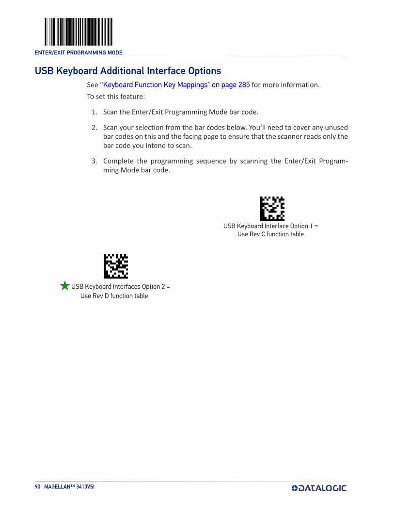
ENTER/EXIT PROGRAMMING MODE
90 MAGELLAN™ 3410VSI
USB Keyboard Additional Interface OptionsSee "Keyboard Function Key Mappings" on page 285 for more information.To set this feature:
1. Scan the Enter/Exit Programming Mode bar code.
2. Scan your selection from the bar codes below. You’ll need to cover any unused bar codes on this and the facing page to ensure that the scanner reads only the bar code you intend to scan.
3. Complete the programming sequence by scanning the Enter/Exit Program-ming Mode bar code.
055048CR)
USB Keyboard Interface Option 1 = Use Rev C function table
055040(CR)
USB Keyboard Interfaces Option 2 = Use Rev D function table

PRODUCT REFERENCE GUIDE 91
CONFIGURATION | DATA EDITING
DATA EDITING OVERVIEW starting on page 92
GLOBAL PREFIX/SUFFIX starting on page 93•Global Prefix on page 93•Global Suffix on page 94
starting on page 95
LABEL ID starting on page 96•Label ID Control on page 96•Setting Label ID on page 97•1D Symbologies on page 97•2D Symbologies on page 102
CASE CONVERSION starting on page 105
CHARACTER CONVERSION starting on page 106
SECTION CONTENTS
AIM ID

ENTER/EXIT PROGRAMMING MODE
92 MAGELLAN™ 3410VSI
DATA EDITING OVERVIEWWhen a bar code is scanned, additional information can be sent to the host com-puter along with the bar code data. This combination of bar code data and supple-mentary user-defined data is called a “message string.” The features in this chapter can be used to build specific user-defined data into a message string.There are several types of selectable data characters that can be sent before and after scanned data. You can specify if they should be sent with all symbologies, or only with specific symbologies. The figure below shows the available elements you can add to a message string:
Breakdown of a Message String
Prefix SuffixAIM IDLabel ID Label IDBar Code Data
00 - 20 Characters (ASCII)
Label ID Transmission:Enable this option to transmit the Label ID you configure for
the scanned symbology.
AIM ID: This function is used to identify and display the common label identifier for its symbology. When enabled, this ID code will be transmitted before the scanned bar code data.
OR...
Please Keep In Mind...• Modifying a message string is not a mandatory requirement. Data editing is
sophisticated feature allowing highly customizable output for advanced users. Factory default settings for data editing is typically set to NONE.
• A prefix or suffix may be applied (reference the 1D Symbology Programming chapter for these settings) or across all symbologies (set via the Global fea-tures in this chapter).
• You can add any character from the ASCII Character Set (from 00-FF) on the inside back cover of this manual as a prefix, suffix or Label ID.
• Enter prefixes and suffixes in the order in which you want them to appear on the output.

ENTER/EXIT PROGRAMMING MODE
PRODUCT REFERENCE GUIDE 93
GLOBAL PREFIX/SUFFIX
Global PrefixThis feature applies to RS-232 (Standard or Wincor-Nixdorf), USB-COM, USB-TEC, and USB Keyboard interfaces. It specifies the prefix that is added to the beginning of label transmission.
1. Scan the Enter/Exit Programming Mode bar code.2. Scan the bar code Set Global Prefix below. Cover any unused bar codes to
ensure the scanner reads only the bar code you intend to scan.3. Scan the appropriate characters/digits from the Alpha-Numeric Keypad on page
273 that represent the hex designation for the desired character(s). The ASCII Character Set and their corresponding Hex Values are shown on the inside back cover of this manual. ASCII parameters must be input by scanning a pair of hexadecimal digits for each character. Thus, to set a two-character value of AB, bar codes containing the digits 4 1 4 2 must be scanned. The selectable range for this option is any hex value from 00 to FF. Up to 20 hex pairs can be designated.
NOTE
NOTE: To specify “No Global Prefix,” scan 00.
4. If designating the full 20 hex pairs, the scanner will exit Programming Mode when the appropriate amount of digits have been scanned. If designating less than 20 hex pairs, you can end the programming sequence early by scanning the Terminate Sequence bar code.
5. Complete by scanning the Enter/Exit Programming Mode bar code.
031D(CR)
Set Global Prefix
00000(CR)
Terminate Sequence
Default setting for this feature is:
00 - No Global Prefix

ENTER/EXIT PROGRAMMING MODE
94 MAGELLAN™ 3410VSI
Global SuffixThis feature applies to RS-232 (Standard or Wincor-Nixdorf), USB-COM, USB-TEC, and USB Keyboard interfaces. It specifies the suffix that is added to end of a label trans-mission. Three standard options are available below. Contact your dealer for other alternate settings for this feature.
• No Global Suffix• CR — Carriage Return• CR LF — Carriage Return, Line Feed
To set the Global Suffix:
1. Scan the Enter/Exit Programming Mode bar code.
2. Scan your selection from the bar codes below.
3. Complete the programming sequence by scanning the Enter/Exit Program-ming Mode bar code.
031E00(CR)
Global Suffix = No Global Suffix
031E0D00(CR)
031E0D0A00(CR)
Global Suffix = CR LF
Global Suffix = CR

GLOBAL SUFFIX ENTER/EXIT PROGRAMMING MODE
PRODUCT REFERENCE GUIDE 95
AIM IDAIM (Automatic Identification Manufacturers) label identifiers are assigned from a globally standardized list — as opposed to custom label ID characters you select yourself — and can be included with scanned bar code data. AIM label identifiers consist of three characters as follows:
• A close brace character (ASCII ‘]’), followed by...• A code character (see the table below), followed by...• A modifier character (the modifier character is symbol dependent)
SYMBOLOGY CHAR SYMBOLOGY CHAR SYMBOLOGY CHAR
UPC/EAN E GS1 Omnidirectional, GS1 Expanded e QR Code and Micro QR Q
Code 39 A Standard 2 of 5 S Aztec z
Codabar F ISBN Xa
a. ISBN (X with a 0 modifier character). X is used for all unknown label types.
DotCode J
Interleaved 2 of 5 I Datamatrix d OCR and MICR oCode 93 G PDF417 and MicroPDF L Digimarc +
Code 128/EAN 128 C MSI Plessey M Han Xin (China Sensible) Code Xa
AIM ID
Prefix SuffixLabel ID Label IDBar Code DataAIM ID
03A900(CR)
03A901(CR)
Global AIM ID = Enable
Global AIM ID = Disable
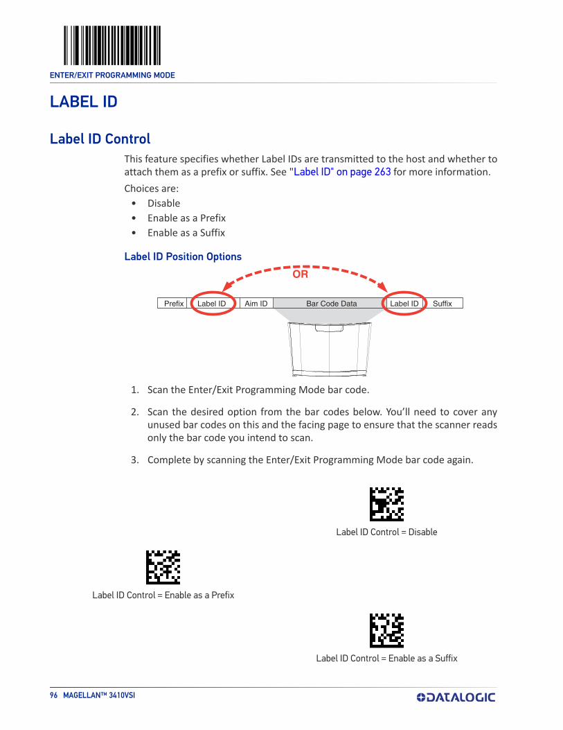
ENTER/EXIT PROGRAMMING MODE
96 MAGELLAN™ 3410VSI
LABEL ID
Label ID ControlThis feature specifies whether Label IDs are transmitted to the host and whether to attach them as a prefix or suffix. See "Label ID" on page 263 for more information. Choices are:
• Disable• Enable as a Prefix• Enable as a Suffix
Label ID Position
OR
Prefix SuffixLabel ID Label IDBar Code DataAim ID
Options
1. Scan the Enter/Exit Programming Mode bar code.
2. Scan the desired option from the bar codes below. You’ll need to cover any unused bar codes on this and the facing page to ensure that the scanner reads only the bar code you intend to scan.
3. Complete by scanning the Enter/Exit Programming Mode bar code again.
020500(CR)
Label ID Control = Disable
020501(CR)
Label ID Control = Enable as a Prefix
020502(CR)
Label ID Control = Enable as a Suffix
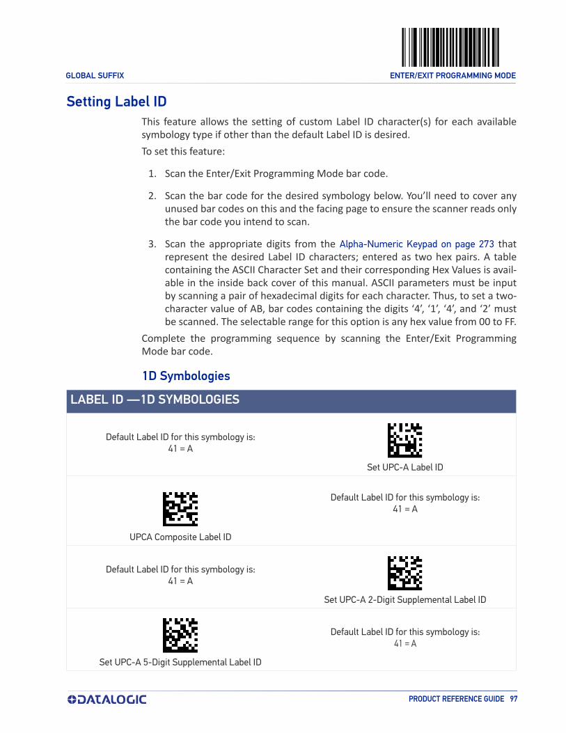
GLOBAL SUFFIX ENTER/EXIT PROGRAMMING MODE
PRODUCT REFERENCE GUIDE 97
Setting Label IDThis feature allows the setting of custom Label ID character(s) for each available symbology type if other than the default Label ID is desired.To set this feature:
1. Scan the Enter/Exit Programming Mode bar code.
2. Scan the bar code for the desired symbology below. You’ll need to cover any unused bar codes on this and the facing page to ensure the scanner reads only the bar code you intend to scan.
3. Scan the appropriate digits from the Alpha-Numeric Keypad on page 273 that represent the desired Label ID characters; entered as two hex pairs. A table containing the ASCII Character Set and their corresponding Hex Values is avail-able in the inside back cover of this manual. ASCII parameters must be input by scanning a pair of hexadecimal digits for each character. Thus, to set a two-character value of AB, bar codes containing the digits ‘4’, ‘1’, ‘4’, and ‘2’ must be scanned. The selectable range for this option is any hex value from 00 to FF.
Complete the programming sequence by scanning the Enter/Exit Programming Mode bar code.
1D Symbologies
LABEL ID —1D SYMBOLOGIES
Default Label ID for this symbology is:41 = A
0024(CR)
Set UPC-A Label ID
05B3(CR)
UPCA Composite Label ID
Default Label ID for this symbology is:41 = A
Default Label ID for this symbology is:41 = A
002D(CR)
Set UPC-A 2-Digit Supplemental Label ID
002E(CR)
Set UPC-A 5-Digit Supplemental Label ID
Default Label ID for this symbology is:41 = A

ENTER/EXIT PROGRAMMING MODE
98 MAGELLAN™ 3410VSI
Default Label ID for this symbology is:45 = E
0025(CR)
Set UPC-E Label ID
05B2(CR)
UPC-E Composite Label ID
Default Label ID for this symbology is:45 = E
Default Label ID for this symbology is:45 = E
002F(CR)
Set UPC-E 2-Digit Supplemental Label ID
0030(CR)
Set UPC-E 5-Digit Supplemental Label ID
Default Label ID for this symbology is:45 = E
Default Label ID for this symbology is:46 = F
0027(CR)
Set EAN-13 Label ID
05B5(CR)
EAN-13 Composite Label ID
Default Label ID for this symbology is:46 = F
Default Label ID for this symbology is:46 = F
0031(CR)
Set EAN-13 2-Digit Supplemental Label ID
0032(CR)
Set EAN-13 5-Digit Supplemental Label ID
Default Label ID for this symbology is:46 = F
LABEL ID —1D SYMBOLOGIES (CONTINUED)

GLOBAL SUFFIX ENTER/EXIT PROGRAMMING MODE
PRODUCT REFERENCE GUIDE 99
Default Label ID for this symbology is:4646 = FF
0026(CR)
Set EAN-8 Label ID
05B4(CR)
EAN-8 Composite Label ID
Default Label ID for this symbology is:4646 = FF
Default Label ID for this symbology is:4646 = FF
0033(CR)
Set EAN-8 2-Digit Supplemental Label ID
0034(CR)
Set EAN-8 5-Digit Supplemental Label ID
Default Label ID for this symbology is:4646 = FF
Default Label ID for this symbology is:47 = G
0560(CR)
Set GTIN Label ID
0561(CR)
Set GTIN 2-Digit Supplemental Label ID
Default Label ID for this symbology is:4732 = G2
Default Label ID for this symbology is:4735 = G5
0562(CR)
Set GTIN 5-Digit Supplemental Label ID
04DA(CR)
Set DataBar Omnidirectional Label ID
Default Label ID for this symbology is:5234 = R4
Default Label ID for this symbology is:5234 = R4
0366(CR)
Set DataBar Omnidirectional Composite Label ID
LABEL ID —1D SYMBOLOGIES (CONTINUED)

0357(CR)
ENTER/EXIT PROGRAMMING MODE
100 MAGELLAN™ 3410VSI
Set DataBar Limited Label ID
Default Label ID for this symbology is:5258 = RX
Default Label ID for this symbology is:5258 = RX
04DB(CR)
DataBar Expanded Label ID
0367(CR)
DataBar Expanded Composite Label ID
Default Label ID for this symbology is:5258 = RX
Default Label ID for this symbology is:5258 = RX
0365(CR)
Set DataBar Limited Composite Label ID
0035(CR)
Code 39 Label ID
Default Label ID for this symbology is:2A = *
Default Label ID for this symbology is:41 = A
00F0(CR)
Code 32 Label ID
0039(CR)
Code 128 Label ID
Default Label ID for this symbology is:23 = #
Default Label ID for this symbology is:66 = f
0556(CR)
Code 128 ISBT Label ID
0419(CR)
EAN 128 Label ID
Default Label ID for this symbology is:50 = P
LABEL ID —1D SYMBOLOGIES (CONTINUED)

GLOBAL SUFFIX ENTER/EXIT PROGRAMMING MODE
PRODUCT REFERENCE GUIDE 101
Default Label ID for this symbology is:69 = i
0036(CR)
I 2 of 5 Label ID
0037(CR)
Codabar Label ID
Default Label ID for this symbology is:25 = %
Default Label ID for this symbology is:26 = &
0038(CR)
Code 93 Label ID
00BD(CR)
MSI Label ID
Default Label ID for this symbology is:40 = @
Default Label ID for this symbology is:73 = s
049C(CR)
Standard 2 of 5 Label ID
046A(CR)
ISBN Label ID
Default Label ID for this symbology is:49 = I
Default Label ID for this symbology is:57 = W
0559\r
Industrial 2 of 5 Label ID
LABEL ID —1D SYMBOLOGIES (CONTINUED)

ENTER/EXIT PROGRAMMING MODE
102 MAGELLAN™ 3410VSI
2D Symbologies
LABEL ID — 2D SYMBOLOGIES
Default Label ID for this symbology is:446D = Dm
0105(CR)
Data Matrix Label ID
05A9(CR)
PDF 417 Label ID
Default Label ID for this symbology is:50 = P
Default Label ID for this symbology is:6D50 = mP
0353(CR)
Micro PDF 417 Label ID
03DC(CR)
QR Code Label ID
Default Label ID for this symbology is:5152 = QR
Default Label ID for this symbology is:2451 = $Q
0429(CR)
Micro QR Code Label ID
0435(CR)
Aztec Label ID
Default Label ID for this symbology is:417A = Az
Default Label ID for this symbology is:4467 = Dg
125D(CR)
GS1 Datamatrix label ID
125C(CR)
GS1 QR Code label ID
Default Label ID for this symbology is:5147 = QG
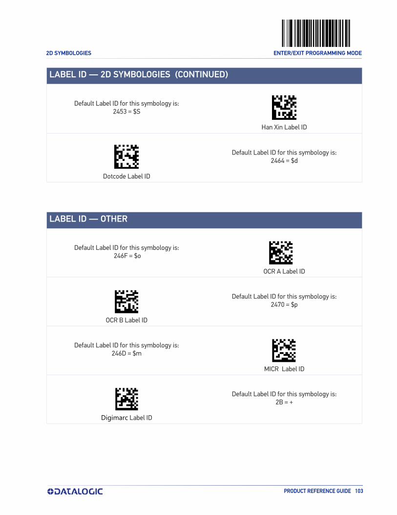
2D SYMBOLOGIES ENTER/EXIT PROGRAMMING MODE
PRODUCT REFERENCE GUIDE 103
Default Label ID for this symbology is:2453 = $S
0536(CR)
Han Xin Label ID
0538CR)
Dotcode Label ID
Default Label ID for this symbology is:2464 = $d
Default Label ID for this symbology is: 246F = $o
055E\r
OCR A Label ID
055F\r)
OCR B Label ID
Default Label ID for this symbology is:2470 = $p
Default Label ID for this symbology is:246D = $m
12BC\r
MICR Label ID
04A1\r
Digimarc Label ID
Default Label ID for this symbology is:2B = +
LABEL ID — 2D SYMBOLOGIES (CONTINUED)
LABEL ID — OTHER

ENTER/EXIT PROGRAMMING MODE
104 MAGELLAN™ 3410VSI
Global Mid-Label IDThis feature specifies a global mid-label ID that is added between two bar codes for transmission.To set this feature:
1. Scan the Enter/Exit Programming Mode bar code.
2. Scan the Set Global Mid-Label ID on page 104 bar code below. You’ll need to cover any unused bar codes on this and the facing page to ensure the scanner reads only the bar code you intend to scan.
3. Scan the appropriate digits from the Appendix C, Alpha-Numeric Keypad that represent the desired mid-label ID characters; entered as two hex pairs. A table containing the ASCII Character Set and their corresponding Hex Values is available in the inside back cover of this manual. ASCII parameters must be input by scanning a pair of hexadecimal digits for each character. Thus, to set a two-character value of AB, bar codes containing the digits ‘4’, ‘1’, ‘4’, and ‘2’ must be scanned. The selectable range for this option is any hex value from 00 to FF.
Complete the programming sequence by scanning the Enter/Exit Programming Mode bar code.
Default Label ID for this symbology is:
04C7(CR)
Set Global Mid-Label ID00 = No Global Mid-label ID
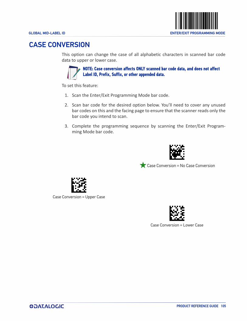
GLOBAL MID-LABEL ID ENTER/EXIT PROGRAMMING MODE
PRODUCT REFERENCE GUIDE 105
CASE CONVERSIONThis option can change the case of all alphabetic characters in scanned bar code data to upper or lower case.
NOTE
NOTE: Case conversion affects ONLY scanned bar code data, and does not affect Label ID, Prefix, Suffix, or other appended data.
To set this feature:
1. Scan the Enter/Exit Programming Mode bar code.
2. Scan bar code for the desired option below. You’ll need to cover any unused bar codes on this and the facing page to ensure that the scanner reads only the bar code you intend to scan.
3. Complete the programming sequence by scanning the Enter/Exit Program-ming Mode bar code.
033100(CR)
033101(CR)
Case Conversion = Upper Case
033102(CR)
Case Conversion = Lower Case
Case Conversion = No Case Conversion

ENTER/EXIT PROGRAMMING MODE
106 MAGELLAN™ 3410VSI
CHARACTER CONVERSIONCharacter conversion is an eight byte configuration item. The eight bytes are 4 character pairs represented in hexadecimal ASCII values. The first character in the pair is the char-acter that will be converted. The second character in the pair is the character to convert to. If the character to convert in a pair is FF, then no conversion is done.For example, if you have the character conversion configuration item set to the fol-lowing:41423132FFFFFFFFThe first pair is 4142 or AB (41 hex is an ASCII capital A, 42 hex is an ASCII capital B) and the second pair is 3132 or 12 (31 hex is an ASCII 1, 32 is an ASCII 2). The other two pairs are FFFF and FFFF.With the label, AG15TA81, it would look as follows after the character conversion: BG25TB82.The A characters were converted to the B character and the 1 characters were con-verted to the numeral 2 character. Nothing is done with the last two character pairs, since they are all FF.To set Character Conversion:
1. Scan the Enter/Exit Programming Mode bar code.2. Scan the Character Conversion bar code.3. Determine the desired string. Up to sixteen positions can be determined as in
the above example. Next, turn to the ASCII Chart on the inside back cover of this manual and find the equivalent hex digits needed to fulfill the string.
NOTE
NOTE: The positions not used must be filled with the character ‘F’.
4. Turn to the Alpha-Numeric Keypad on page 273 and scan the bar codes repre-senting the hex characters determined in the previous step. When the last character is scanned, the scanner will sound a triple beep.
5. Complete the programming sequence by scanning the Enter/Exit Program-ming Mode bar code.
Default setting for this feature is:0332(CR)
Set Character Conversion
FFFFFFFFFFFFFFFF (No Character Conversion)

PRODUCT REFERENCE GUIDE 107
CONFIGURATION | 1D SYMBOLOGY PROGRAMMING
1D Symbologies
NOTE
NOTE: If the scanner’s interface type must be changed, always be sure that interface configuration is the FIRST item scanned during a programming ses-sion. (Selecting an interface type resets ALL other configuration items — including symbology programming — to factory default for that interface type.)
The following pages contain configuration information concerning the various bar code types (symbologies) the scanner supports.
COUPON CONTROL starting on page 108 DATABAR EXPANDED starting on page 166
starting on page 111 CODE 39 starting on page 174
starting on page 116 CODE 32 ITALIAN PHARMACODE starting on page 185
starting on page 122 CODE 128 starting on page 188
starting on page 127 starting on page 196
OTHER UPC/EAN OPTIONS starting on page 139
INTERLEAVED 2 OF 5 (I 2 OF 5) starting on page 197
starting on page 156 CODABAR starting on page 204
GS1 DATABAR starting on page 157 CODE 93 starting on page 215
DATABAR OMNIDIRECTIONAL starting on page 157
starting on page 220
DATABAR LIMITED starting on page 162 STANDARD 2 OF 5 starting on page 228
SECTION CONTENTS
UPC-A
UPC-E
EAN-13EAN-8 EAN-128
GTIN
MSI

ENTER/EXIT PROGRAMMING MODE
108 MAGELLAN™ 3410VSI
COUPON CONTROL
Coupon Control EnableThis feature is used to control the method of processing coupon labels. For the pur-poses of this feature, coupon labels are defined as (1) UPC-A labels that start with a ‘5’; or (2) GS1 DataBar Expanded labels that start with ‘8110’
Enable UPC-A Coupons : UPCA coupon labels will decode but RSS/Databar Expanded coupon labels will not. RSS/Databar Expanded labels that are not coupon labels will decode and all UPCA labels will decode.
Enable GS1 DataBar Expanded Coupons : RSS/Databar Expanded coupon labels will decode but UPCA coupon labels will not. UPCA labels that are not coupon labels and all RSS/Databar Expanded labels will decode.
Priority to UPC-A Coupons: UPCA coupon labels will be given priority.
Priority to GS1 DataBar Expanded Coupons : DataBar coupon labels will be given priority.
1. Scan the Enter/Exit Programming Mode bar code.
2. Scan your choice from the Coupon Control selections below. You’ll need to cover any unused bar codes on this and the facing page to ensure that the scanner reads only the bar code you intend to scan.
3. Complete by scanning the Enter/Exit Programming Mode bar code.
03B900(CR)
Coupon Control = Disable
03B901(CR)
Coupon Control = Enable UPC-A Coupons

03B902(CR)
ENTER/EXIT PROGRAMMING MODE
PRODUCT REFERENCE GUIDE 109
Coupon Control Enable — continued
Coupon Control = Enable GS1 DataBar ExpandedCoupons
03B903CR)
Coupon Control = Priority to UPC-A Coupons
03B904(CR)
Coupon Control = Priority to GS1 DataBar Expanded Coupons

ENTER/EXIT PROGRAMMING MODE
110 MAGELLAN™ 3410VSI
Coupon Label Priority TimerThis feature sets the duration of the UPCA / DataBar coupon label priority timer.To set this feature:
1. Scan the Enter/Exit Programming Mode bar code.
2. Scan your selection from the bar codes below. You’ll need to cover any unused bar codes on this and the facing page to ensure that the scanner reads only the bar code you intend to scan.
3. Complete the programming sequence by scanning the Enter/Exit Program-ming Mode bar code.
037F0A(CR)
Coupon Label Priority Timer = 0.1 Seconds
037F14(CR)
037F1E(CR)
Coupon Label Priority Timer = 0.3 Seconds
037F28CR)
Coupon Label Priority Timer = 0.4 Seconds
037F32(CR)
Coupon Label Priority Timer = 0.5 Second
037F64CR)
Coupon Label Priority Timer = 1 Second
Coupon Label Priority Timer = 0.2 Seconds
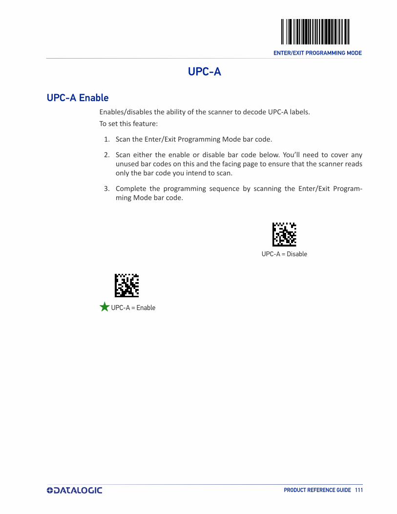
ENTER/EXIT PROGRAMMING MODE
PRODUCT REFERENCE GUIDE 111
UPC-A
UPC-A EnableEnables/disables the ability of the scanner to decode UPC-A labels.To set this feature:
1. Scan the Enter/Exit Programming Mode bar code.
2. Scan either the enable or disable bar code below. You’ll need to cover any unused bar codes on this and the facing page to ensure that the scanner reads only the bar code you intend to scan.
3. Complete the programming sequence by scanning the Enter/Exit Program-ming Mode bar code.
02D000(CR)
UPC-A = Disable
02D001(CR)
UPC-A = Enable

ENTER/EXIT PROGRAMMING MODE
112 MAGELLAN™ 3410VSI
UPC-A Number System Character TransmissionEnables/disables transmission of a UPC-A number system character.
NOTE
NOTE: This item is ignored when the advanced feature, Full Label Edit, is enabled.
To set this feature:
1. Scan the Enter/Exit Programming Mode bar code.
2. Scan either the enable or disable bar code below. You’ll need to cover any unused bar codes on this and the facing page to ensure that the scanner reads only the bar code you intend to scan.
3. Complete the programming sequence by scanning the Enter/Exit Program-ming Mode bar code.
00D300(CR)
UPC-A Number System Character Transmission =Disable
00D301(CR)
UPC-A Number System Character Transmission = Enable

ENTER/EXIT PROGRAMMING MODE
PRODUCT REFERENCE GUIDE 113
UPC-A Check Character TransmissionEnables/disables transmission of a UPC-A check character.
NOTE
NOTE: This item is ignored when the advanced feature, Full Label Edit, is enabled.
To set this feature:
1. Scan the Enter/Exit Programming Mode bar code.
2. Scan either the enable or disable bar code below. You’ll need to cover any unused bar codes on this and the facing page to ensure that the scanner reads only the bar code you intend to scan.
3. Complete the programming sequence by scanning the Enter/Exit Program-ming Mode bar code.
00B700(CR)
UPC-A Check Character Transmission = Disable
00B701(CR)
UPC-A Check Character Transmission = Enable

ENTER/EXIT PROGRAMMING MODE
114 MAGELLAN™ 3410VSI
UPC-A Minimum ReadThis feature specifies the minimum number of consecutive UPC-A decodes before is accepted as good read.To set this feature:
1. Scan the ENTER/EXIT Programming Mode bar code.
2. Scan your selection from the bar codes below. You’ll need to cover any unused bar codes on this and the facing page to ensure that the scanner reads only the bar code you intend to scan.
3. Complete the programming sequence by scanning the ENTER/EXIT Program-ming Mode bar code.
006101(CR)
006102(CR)
UPC-A Minimum Read = 2
006103(CR)
UPC-A Minimum Read = 3
006104(CR)
UPC-A Minimum Read = 4
UPC-A Minimum Read = 1

ENTER/EXIT PROGRAMMING MODE
PRODUCT REFERENCE GUIDE 115
Expand UPC-A to EAN-13Enables/disables expansion of UPC-A labels to EAN/JAN-13.To set this feature:
1. Scan the Enter/Exit Programming Mode bar code.
2. Scan either the enable or disable bar code below. You’ll need to cover any unused bar codes on this and the facing page to ensure that the scanner reads only the bar code you intend to scan.
3. Complete the programming sequence by scanning the Enter/Exit Program-ming Mode bar code.
004300(CR)
004301(CR)
Expand UPC-A to EAN-13 = Enable
Expand UPC-A to EAN-13 = Disable

ENTER/EXIT PROGRAMMING MODE
116 MAGELLAN™ 3410VSI
UPC-E
UPC-E EnableEnables/disables the ability of the scanner to decode UPC-E labels.To set this feature:
1. Scan the Enter/Exit Programming Mode bar code.
2. Scan either the enable or disable bar code below. You’ll need to cover any unused bar codes on this and the facing page to ensure that the scanner reads only the bar code you intend to scan.
3. Complete the programming sequence by scanning the Enter/Exit Program-ming Mode bar code.
02D100(CR)
UPC-E = Disable
02D101(CR)
UPC-E = Enable

ENTER/EXIT PROGRAMMING MODE
PRODUCT REFERENCE GUIDE 117
UPC-E Number System Character TransmissionEnables/disables transmission of a UPC-E number system character.
NOTE
NOTE: This item is ignored when the advanced feature, Full Label Edit, is enabled.
To set this feature:
1. Scan the Enter/Exit Programming Mode bar code.
2. Scan either the enable or disable bar code below. You’ll need to cover any unused bar codes on this and the facing page to ensure that the scanner reads only the bar code you intend to scan.
3. Complete the programming sequence by scanning the Enter/Exit Program-ming Mode bar code.
024800(CR)
UPC-E Number System Character Transmission = Dis-able
024801(CR)
UPC-E Number System Character Transmission = Enable

ENTER/EXIT PROGRAMMING MODE
118 MAGELLAN™ 3410VSI
UPC-E Check Character TransmissionEnables/disables transmission of a UPC-E check character.
NOTE
NOTE: This item is ignored when the advanced feature, Full Label Edit, is enabled.
To set this feature:
1. Scan the Enter/Exit Programming Mode bar code.
2. Scan either the enable or disable bar code below. You’ll need to cover any unused bar codes on this and the facing page to ensure that the scanner reads only the bar code you intend to scan.
3. Complete the programming sequence by scanning the Enter/Exit Program-ming Mode bar code.
004000(CR)
UPC-E Check Character Transmission = Disable
004001(CR)
UPC-E Check Character Transmission = Enable

ENTER/EXIT PROGRAMMING MODE
PRODUCT REFERENCE GUIDE 119
Expand UPC-E to UPC-AEnables/disables expansion of UPC-E labels to UPC-A.To set this feature:
1. Scan the Enter/Exit Programming Mode bar code.
2. Scan either the enable or disable bar code below. You’ll need to cover any unused bar codes on this and the facing page to ensure that the scanner reads only the bar code you intend to scan.
3. Complete the programming sequence by scanning the Enter/Exit Program-ming Mode bar code.
004100(CR)
004101(CR)
Expand UPC-E to UPC-A = Enable
Expand UPC-E to UPC-A = Disable

ENTER/EXIT PROGRAMMING MODE
120 MAGELLAN™ 3410VSI
Expand UPC-E to EAN-13Enables/disables expansion of UPC-E labels to EAN/JAN-13.To set this feature:
1. Scan the Enter/Exit Programming Mode bar code.
2. Scan either the enable or disable bar code below. You’ll need to cover any unused bar codes on this and the facing page to ensure that the scanner reads only the bar code you intend to scan.
3. Complete the programming sequence by scanning the Enter/Exit Program-ming Mode bar code.
040200(CR)
040201(CR)
Expand UPC-E to EAN-13 = Enable
Expand UPC-E to EAN-13 = Disable

ENTER/EXIT PROGRAMMING MODE
PRODUCT REFERENCE GUIDE 121
UPC-E Minimum ReadThis feature specifies the minimum number of consecutive UPC-E decodes before is accepted as good read.To set this feature:
1. Scan the ENTER/EXIT Programming Mode bar code.
2. Scan your selection from the bar codes below. You’ll need to cover any unused bar codes on this and the facing page to ensure that the scanner reads only the bar code you intend to scan.
3. Complete the programming sequence by scanning the ENTER/EXIT Program-ming Mode bar code.
006201(CR)
006202(CR)
UPC-E Minimum Read = 2
006203(CR)
UPC-E Minimum Read = 3
006204(CR)
UPC-E Minimum Read = 4
UPC-E Minimum Read = 1

ENTER/EXIT PROGRAMMING MODE
122 MAGELLAN™ 3410VSI
EAN-13
EAN-13 Enable
Enables/disables the ability of the scanner to decode EAN/JAN-13 labels.To set this feature:
1. Scan the Enter/Exit Programming Mode bar code.
2. Scan either the enable or disable bar code below. You’ll need to cover any unused bar codes on this and the facing page to ensure that the scanner reads only the bar code you intend to scan.
3. Complete the programming sequence by scanning the Enter/Exit Program-ming Mode bar code.
02D300(CR)
EAN-13 = Disable
02D301(CR)
EAN-13 = Enable

ENTER/EXIT PROGRAMMING MODE
PRODUCT REFERENCE GUIDE 123
EAN-13 First Character TransmissionEnables/disables transmission of EAN/JAN-13 first character.
NOTE
NOTE: This item is ignored when the advanced feature, Full Label Edit, is enabled.
To set this feature:
1. Scan the Enter/Exit Programming Mode bar code.
2. Scan either the enable or disable bar code below. You’ll need to cover any unused bar codes on this and the facing page to ensure that the scanner reads only the bar code you intend to scan.
3. Complete the programming sequence by scanning the Enter/Exit Program-ming Mode bar code.
024400(CR)
EAN-13 First Character Transmission = Disable
024401(CR)
EAN-13 First Character Transmission = Enable
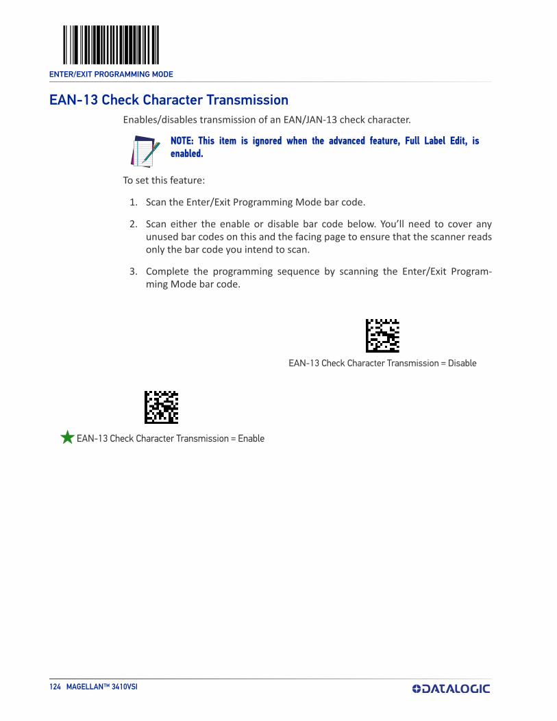
ENTER/EXIT PROGRAMMING MODE
124 MAGELLAN™ 3410VSI
EAN-13 Check Character TransmissionEnables/disables transmission of an EAN/JAN-13 check character.
NOTE
NOTE: This item is ignored when the advanced feature, Full Label Edit, is enabled.
To set this feature:
1. Scan the Enter/Exit Programming Mode bar code.
2. Scan either the enable or disable bar code below. You’ll need to cover any unused bar codes on this and the facing page to ensure that the scanner reads only the bar code you intend to scan.
3. Complete the programming sequence by scanning the Enter/Exit Program-ming Mode bar code.
00B900(CR)
EAN-13 Check Character Transmission = Disable
00B901(CR)
EAN-13 Check Character Transmission = Enable

ENTER/EXIT PROGRAMMING MODE
PRODUCT REFERENCE GUIDE 125
EAN-13 ISBN Conversion EnableEnables/disables conversion of EAN/JAN-13 labels starting with 978 to Bookland ISBN labels.
To set this feature:
1. Scan the Enter/Exit Programming Mode bar code.
2. Scan either the enable or disable bar code below. You’ll need to cover any unused bar codes on this and the facing page to ensure that the scanner reads only the bar code you intend to scan.
3. Complete the programming sequence by scanning the Enter/Exit Program-ming Mode bar code.
02AA00(CR)
02AA01(CR)
EAN-13 ISBN Conversion = Enable
EAN-13 ISBN Conversion = Disable

ENTER/EXIT PROGRAMMING MODE
126 MAGELLAN™ 3410VSI
EAN-13 Minimum ReadThis feature specifies the minimum number of consecutive EAN-13 decodes before is accepted as good read.To set this feature:
1. Scan the ENTER/EXIT Programming Mode bar code.
2. Scan your selection from the bar codes below. You’ll need to cover any unused bar codes on this and the facing page to ensure that the scanner reads only the bar code you intend to scan.
3. Complete the programming sequence by scanning the ENTER/EXIT Program-ming Mode bar code.
006401(CR)
006402(CR)
EAN-13 Minimum Read = 2
006403(CR)
EAN-13 Minimum Read = 3
006404(CR)
EAN-13 Minimum Read = 4
EAN-13 Minimum Read = 1

ENTER/EXIT PROGRAMMING MODE
PRODUCT REFERENCE GUIDE 127
EAN-8
EAN-8 EnableEnables/disables the ability of the scanner to decode EAN/JAN-8 labels.To set this feature:
1. Scan the Enter/Exit Programming Mode bar code.
2. Scan either the enable or disable bar code below. You’ll need to cover any unused bar codes on this and the facing page to ensure that the scanner reads only the bar code you intend to scan.
3. Complete the programming sequence by scanning the Enter/Exit Program-ming Mode bar code.
02D200(CR)
EAN-8 = Disable
02D201(CR)
EAN-8 = Enable

ENTER/EXIT PROGRAMMING MODE
128 MAGELLAN™ 3410VSI
EAN-8 Check Character TransmissionEnables/disables transmission of an EAN/JAN-8 check character.
NOTE
NOTE: This item is ignored when the advanced feature, Full Label Edit, is enabled.
To set this feature:
1. Scan the Enter/Exit Programming Mode bar code.
2. Scan either the enable or disable bar code below. You’ll need to cover any unused bar codes on this and the facing page to ensure that the scanner reads only the bar code you intend to scan.
3. Complete the programming sequence by scanning the Enter/Exit Program-ming Mode bar code.
00B800(CR)
EAN-8 Check Character Transmission = Disable
00B801(CR)
EAN-8 Check Character Transmission = Enable

ENTER/EXIT PROGRAMMING MODE
PRODUCT REFERENCE GUIDE 129
Expand EAN-8 to EAN-13Enables/disables expansion of EAN/JAN-8 labels to EAN/JAN-13.To set this feature:
1. Scan the Enter/Exit Programming Mode bar code.
2. Scan either the enable or disable bar code below. You’ll need to cover any unused bar codes on this and the facing page to ensure that the scanner reads only the bar code you intend to scan.
3. Complete the programming sequence by scanning the Enter/Exit Program-ming Mode bar code.
021B00(CR)
021B01(CR)
Expand EAN-8 to EAN-13 = Enable
Expand EAN-8 to EAN-13 = Disable

ENTER/EXIT PROGRAMMING MODE
130 MAGELLAN™ 3410VSI
EAN-8 Minimum ReadThis feature specifies the minimum number of consecutive EAN-8 decodes before is accepted as good read.To set this feature:
1. Scan the ENTER/EXIT Programming Mode bar code.
2. Scan your selection from the bar codes below. You’ll need to cover any unused bar codes on this and the facing page to ensure that the scanner reads only the bar code you intend to scan.
3. Complete the programming sequence by scanning the ENTER/EXIT Program-ming Mode bar code.
006501(CR)
006502(CR)
EAN-8 Minimum Read = 2
006503(CR)
EAN-8 Minimum Read = 3
006504(CR)
EAN-8 Minimum Read = 4
EAN-8 Minimum Read = 1

ENTER/EXIT PROGRAMMING MODE
PRODUCT REFERENCE GUIDE 131
EAN-8 Guard InsertionThis setting enables the insertion of either a missing leading or trailing guard to a scanned bar code.To set this feature:
1. Scan the Enter/Exit Programming Mode bar code.
2. Scan either the enable or disable bar code below. You’ll need to cover any unused bar codes on this and the facing page to ensure that the scanner reads only the bar code you intend to scan.
3. Complete the programming sequence by scanning the Enter/Exit Program-ming Mode bar code.
054300(CR)
054301(CR)
EAN-8 Guard Insertion = Enable
EAN-8 Guard Insertion = Disable

ENTER/EXIT PROGRAMMING MODE
132 MAGELLAN™ 3410VSI
EAN-8 Guard SubstitutionThis setting enables the scanner to substitute a guard pattern for even-parity 6 for EAN8/JAN8 labels.To set this feature:
1. Scan the Enter/Exit Programming Mode bar code.
2. Scan either the enable or disable bar code below. You’ll need to cover any unused bar codes on this and the facing page to ensure that the scanner reads only the bar code you intend to scan.
3. Complete the programming sequence by scanning the Enter/Exit Program-ming Mode bar code.
02FB00(CR)
02FB01(CR)
EAN-8 Guard Insertion = Enable
EAN-8 Guard Insertion = Disable

ENTER/EXIT PROGRAMMING MODE
PRODUCT REFERENCE GUIDE 133
EAN-8/Jan-8 Both Guards SubstitutionEnables/disables the ability of the scanner to find an EAN/JAN8 guard pattern in cases where the EAN/JAN8 margin makes the guard look like a character.
To set this feature:
1. Scan the Enter/Exit Programming Mode bar code.
2. Scan either the enable or disable bar code below. You’ll need to cover any unused bar codes on this and the facing page to ensure that the scanner reads only the bar code you intend to scan.
3. Complete the programming sequence by scanning the Enter/Exit Program-ming Mode bar code.
03CA00(CR)
03CA01(CR)
EAN-8/JAN-8 Both Guards Substitution = Enable
EAN-8/JAN-8 Both Guards Substitution = Disable

ENTER/EXIT PROGRAMMING MODE
134 MAGELLAN™ 3410VSI
EAN-8 Stitch Exact Label HalvesThis setting enables the stitching of exact EAN-8 label halves with no overlapping characters.To set this feature:
1. Scan the Enter/Exit Programming Mode bar code.
2. Scan either the enable or disable bar code below. You’ll need to cover any unused bar codes on this and the facing page to ensure that the scanner reads only the bar code you intend to scan.
3. Complete the programming sequence by scanning the Enter/Exit Program-ming Mode bar code.
054400(CR)
054401(CR)
EAN-8 Stitch Exact Label Halves = Enable
EAN-8 Stitch Exact Label Halves = Disable

ENTER/EXIT PROGRAMMING MODE
PRODUCT REFERENCE GUIDE 135
EAN-8 Stitch Unlike Label HalvesThis setting enables the stitching of two EAN-8 label halves together that may have different characters.To set this feature:
1. Scan the Enter/Exit Programming Mode bar code.
2. Scan either the enable or disable bar code below. You’ll need to cover any unused bar codes on this and the facing page to ensure that the scanner reads only the bar code you intend to scan.
3. Complete the programming sequence by scanning the Enter/Exit Program-ming Mode bar code.
054500(CR)
054501(CR)
EAN-8 Stitch Unlike Label Halves = Enable
EAN-8 Stitch Unlike Label Halves = Disable
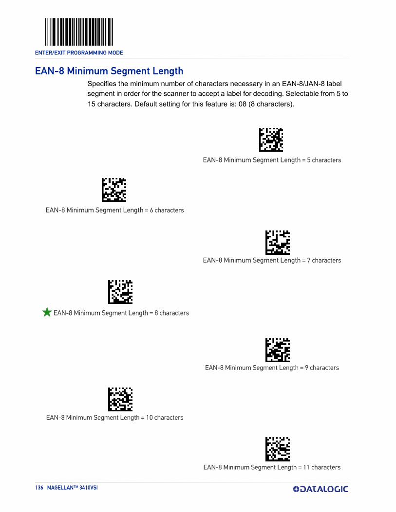
ENTER/EXIT PROGRAMMING MODE
136 MAGELLAN™ 3410VSI
EAN-8 Minimum Segment LengthSpecifies the minimum number of characters necessary in an EAN-8/JAN-8 label segment in order for the scanner to accept a label for decoding. Selectable from 5 to 15 characters. Default setting for this feature is: 08 (8 characters).
EAN-8 Minimum Segment Length = 5 characters
EAN-8 Minimum Segment Length = 6 characters
EAN-8 Minimum Segment Length = 7 characters
EAN-8 Minimum Segment Length = 8 characters
EAN-8 Minimum Segment Length = 9 characters
EAN-8 Minimum Segment Length = 10 characters
EAN-8 Minimum Segment Length = 11 characters
049D05(CR)
049D06(CR)
049D07(CR)
049D08(CR)
049D09(CR)
049D0A(CR)
049D0B(CR)

ENTER/EXIT PROGRAMMING MODE
PRODUCT REFERENCE GUIDE 137
EAN-8 Minimum Segment Length (continued)
EAN-8 Minimum Segment Length = 12 characters
EAN-8 Minimum Segment Length = 13 characters
EAN-8 Minimum Segment Length = 14 characters
EAN-8 Minimum Segment Length = 15 characters
049D0C(CR)
049D0D(CR)
049D0E(CR)
049D0F(CR)

ENTER/EXIT PROGRAMMING MODE
138 MAGELLAN™ 3410VSI
EAN-8 Decoding LevelsDecoding levels allow the decoder to be set to perform at one of four selectable lev-els:
• Very Conservative — Slower scan time, virtually eliminates misreads. The most secure setting.
• Slightly More Aggressive — Faster scanning, more aggressive, yet minimizes misreads.
• Moderately Aggressive — Even faster scanning, even more aggressive.• Very Aggressive — Fastest scan speed, most aggressive.
050E01(CR)
050E02(CR)
EAN-8 Decoding Level = Slightly More Aggressive
050E03(CR)
EAN-8 Decoding Level = Moderately Aggressive
050E04(CR)
EAN-8 Decoding Level = Very Aggressive
CAUTION: Use caution when setting this feature, as more aggressive settings for this feature allow a higher potential for misreads.
CAUTION
EAN-8 Decoding Level = Very Conservative

ENTER/EXIT PROGRAMMING MODE
PRODUCT REFERENCE GUIDE 139
OTHER UPC/EAN OPTIONSThe following pages contain other selectable features for UPC/EAN symbologies:
In-Store Printed Label Minimum Read on page 139 Price Weight Check on page 145UPC/EAN Guard Insertion on page 140 Enable EAN Two Label on page 146UPC/EAN Stitch Exact Label Halves on page 141 Add-ons on page 149UPC/EAN Stitch Unlike Label Halves on page 142 UPC/EAN Composites on page 155UPC/EAN Minimum Segment Length on page 143
In-Store Printed Label Minimum ReadThis feature specifies the minimum number of consecutive In-Store Printed Label decodes before is accepted as good read.To set this feature:
1. Scan the ENTER/EXIT Programming Mode bar code.
2. Scan your selection from the bar codes below. You’ll need to cover any unused bar codes on this and the facing page to ensure that the scanner reads only the bar code you intend to scan.
3. Complete the programming sequence by scanning the ENTER/EXIT Program-ming Mode bar code.
008501(CR)
008502(CR)
In-Store Printed Label Minimum Read = 2
008503(CR)
In-Store Printed Label Minimum Read = 3
008504(CR)
In-Store Printed Label Minimum Read = 4
In-Store Printed Label Minimum Read = 1
ENTER/EXIT PROGRAMMING MODE
140 MAGELLAN™ 3410VSI
UPC/EAN Guard InsertionThis setting enables the insertion of either a missing leading or trailing guard to a scanned bar code.To set this feature:
1. Scan the Enter/Exit Programming Mode bar code.
2. Scan either the enable or disable bar code below. You’ll need to cover any unused bar codes on this and the facing page to ensure that the scanner reads only the bar code you intend to scan.
3. Complete the programming sequence by scanning the Enter/Exit Program-ming Mode bar code.
054000(CR)
054001(CR)
UPC/EAN Guard Insertion = Enable
UPC/EAN Guard Insertion = Disable

ENTER/EXIT PROGRAMMING MODE
PRODUCT REFERENCE GUIDE 141
UPC/EAN Stitch Exact Label HalvesThis setting enables the stitching of exact UPC-A/EAN-13 label halves with no over-lapping characters.To set this feature:
1. Scan the Enter/Exit Programming Mode bar code.
2. Scan either the enable or disable bar code below. You’ll need to cover any unused bar codes on this and the facing page to ensure that the scanner reads only the bar code you intend to scan.
3. Complete the programming sequence by scanning the Enter/Exit Program-ming Mode bar code.
054100(CR)
054101(CR)
UPC/EAN Stitch Exact Label Halves = Enable
UPC/EAN Stitch Exact Label Halves = Disable
ENTER/EXIT PROGRAMMING MODE
142 MAGELLAN™ 3410VSI
UPC/EAN Stitch Unlike Label HalvesThis setting enables the stitching of two UPC-A/EAN-13 label halves together that may have different characters.To set this feature:
1. Scan the Enter/Exit Programming Mode bar code.
2. Scan either the enable or disable bar code below. You’ll need to cover any unused bar codes on this and the facing page to ensure that the scanner reads only the bar code you intend to scan.
3. Complete the programming sequence by scanning the Enter/Exit Program-ming Mode bar code.
054200(CR)
054201(CR)
UPC/EAN Stitch Unlike Label Halves = Enable
UPC/EAN Stitch Unlike Label Halves = Disable

ENTER/EXIT PROGRAMMING MODE
PRODUCT REFERENCE GUIDE 143
UPC/EAN Minimum Segment LengthThis feature specifies the minimum number of characters needed in a UPC/EAN seg-ment in order to be accepted for decoding.To set this feature:
1. Scan the Enter/Exit Programming Mode bar code.
2. Scan the bar code for the desired setting below. You’ll need to cover any unused bar codes on this and the facing page to ensure that the scanner reads only the bar code you intend to scan.
3. Complete the programming sequence by scanning the Enter/Exit Program-ming Mode bar code.
048F05(CR)
048F06(CR)
UPC/EAN Minimum Segment Length = 6 Characters
048F07(CR)
UPC/EAN Minimum Segment Length = 7 Characters
048F08(CR)
UPC/EAN Minimum Segment Length = 8 Characters
048F09(CR)
UPC/EAN Minimum Segment Length = 9 Characters
UPC/EAN Minimum Segment Length = 5 Charac-ters
ENTER/EXIT PROGRAMMING MODE
144 MAGELLAN™ 3410VSI
UPC/EAN Minimum Segment Length — continued
UPC/EAN Minimum Segment Length = 10 Characters
UPC/EAN Minimum Segment Length = 11 Characters
UPC/EAN Minimum Segment Length = 12 Characters
UPC/EAN Minimum Segment Length = 13 Characters
UPC/EAN Minimum Segment Length = 14 Characters
UPC/EAN Minimum Segment Length =15 Characters
048F0A(CR)
048F0B(CR)
048F0C(CR)
048F0D(CR)
048F0E(CR)
048F0F(CR)

ENTER/EXIT PROGRAMMING MODE
PRODUCT REFERENCE GUIDE 145
Price Weight CheckEnables/disables calculation and verification of price/weight check digits. Applies to all UPC-A and EAN/JAN-13 labels with eligible1 Number System/First Character dig-its.Options are:
• Disable• 4-digit price/weight• 5-digit price/weight
• 4-digit European price/weight• 5-digit European price/weight
To set this feature:
1. Scan the Enter/Exit Programming Mode bar code.
2. Scan the bar code representing the desired option below or on the following pages. You’ll need to cover any unused bar codes on facing pages to ensure that the scanner reads only the bar code you intend to scan.
3. Complete the programming sequence by scanning the Enter/Exit Program-ming Mode bar code.
005C00(CR)
005C01(CR)
Price Weight Check = 4-digit price/weight
005C02(CR)
Price Weight Check = 5-digit price/weight
1. Price Weight Check generally applies to UPC-A labels with a Number System Digit of 2 and EAN/JAN-13 labels with a First Character of 2. There are a total of six flag digits corresponding to the six types. Checking applies depending upon which type is enabled.
Price Weight Check = Disable

ENTER/EXIT PROGRAMMING MODE
146 MAGELLAN™ 3410VSI
Price Weight Check (continued)
Enable EAN Two LabelEnables/disables the ability of the scanner to decode EAN two-label pairs.To set this feature:
1. Scan the Enter/Exit Programming Mode bar code.
2. Scan either the enable or disable bar code below. You’ll need to cover any unused bar codes on this and the facing page to ensure that the scanner reads only the bar code you intend to scan.
3. Complete the programming sequence by scanning the Enter/Exit Program-ming Mode bar code.
NOTE
004400(CR)
004401(CR)
EAN Two Label = Enable
NOTE: Contact Customer Support for details about advanced programming for this feature.
Price Weight Check = 4-digit European price/weight
Price Weight Check = 5-digit European price/weight
005C03(CR)
005C04(CR)
EAN Two Label = Disable

ENTER/EXIT PROGRAMMING MODE
PRODUCT REFERENCE GUIDE 147
EAN Two Label Minimum ReadThis feature specifies the minimum number of consecutive EAN Two Label decodes before is accepted as good read.To set this feature:
1. Scan the ENTER/EXIT Programming Mode bar code.
2. Scan your selection from the bar codes below. You’ll need to cover any unused bar codes on this and the facing page to ensure that the scanner reads only the bar code you intend to scan.
3. Complete the programming sequence by scanning the ENTER/EXIT Program-ming Mode bar code.
008601(CR)
008602(CR)
EAN Two Label Minimum Read = 2
008603(CR)
EAN Two Label Minimum Read = 3
008604(CR)
EAN Two Label Minimum Read = 4
EAN Two Label Minimum Read = 1

ENTER/EXIT PROGRAMMING MODE
148 MAGELLAN™ 3410VSI
EAN Two Label Combined TransmissionEnables/disables the transmitting of an EAN two label pair as one label.To set this feature:
1. Scan the Enter/Exit Programming Mode bar code.
2. Scan either the enable or disable bar code below. You’ll need to cover any unused bar codes on this and the facing page to ensure that the scanner reads only the bar code you intend to scan.
3. Complete the programming sequence by scanning the Enter/Exit Program-ming Mode bar code.
02E200(CR)
02E201(CR)
EAN Two Label Combined Transmission = Enable
EAN Two Label Combined Transmission = Disable

ENTER/EXIT PROGRAMMING MODE
PRODUCT REFERENCE GUIDE 149
Add-onsThe scanner is capable of processing different types of add-on codes, including:
• 2-Digit Supplemental• 5-Digit Supplemental
Options are provided on the following pages for your convenience:• Disable all add-ons — The scanner will not look for or read add-ons.• Optional 2-Digit and 5-Digit Supplemental — Bar Codes can be read which
include 2-Digit or 5-Digit Supplementals, however, it is not required that add-ons be included in bar codes.
NOTE
NOTE: Contact customer support for advanced programming of optional and con-ditional add-ons.
To set this feature:
1. Scan the Enter/Exit Programming Mode bar code.
2. Scan the bar code representing the desired option on this and the following page. You’ll need to cover any unused bar codes on facing pages to ensure that the scanner reads only the bar code you intend to scan.
3. Complete the programming sequence by scanning the Enter/Exit Program-ming Mode bar code.
051000(CR)051100(CR)
051001(CR)051101(CR)
Add-ons = Optional 2-Digit and 5-Digit Supplemental
Add-ons = Disable All Add-ons

ENTER/EXIT PROGRAMMING MODE
150 MAGELLAN™ 3410VSI
P2 Add-on Minimum ReadThis feature specifies the minimum number of times a P2 add-on must decode before it is marked valid.To set this feature:
1. Scan the Enter/Exit Programming Mode bar code.
2. Scan the bar code representing the desired option on this and the following page. You’ll need to cover any unused bar codes on facing pages to ensure that the scanner reads only the bar code you intend to scan.
3. Complete by scanning the Enter/Exit Programming Mode bar code.
005F02(CR)
005F03(CR)
P2 Add-on Minimum Read = 3
005F04(CR)
P2 Add-on Minimum Read = 4
005F05(CR)
P2 Add-on Minimum Read = 5
005F06(CR)
P2 Add-on Minimum Read = 6
005F07(CR)
P2 Add-on Minimum Read = 7
P2 Add-on Minimum Read = 2

ENTER/EXIT PROGRAMMING MODE
PRODUCT REFERENCE GUIDE 151
P2 Add-on Minimum Read — continued
P2 Add-on Minimum Read = 8
P2 Add-on Minimum Read = 9
P2 Add-on Minimum Read = 10
P2 Add-on Minimum Read = 11
P2 Add-on Minimum Read = 12
P2 Add-on Minimum Read = 13
P2 Add-on Minimum Read = 14
P2 Add-on Minimum Read = 15
005F08(CR)
005F09(CR)
005F0A(CR)
005F0B(CR)
005F0C(CR)
005F0D(CR)
005F0E(CR)
005F0F(CR)

ENTER/EXIT PROGRAMMING MODE
152 MAGELLAN™ 3410VSI
P5 Add-on Minimum ReadThis feature specifies the minimum number of times a P5 add-on must decode before it is marked valid.To set this feature:
1. Scan the Enter/Exit Programming Mode bar code.
2. Scan the bar code representing the desired option on this and the following page. You’ll need to cover any unused bar codes on facing pages to ensure that the scanner reads only the bar code you intend to scan.
3. Complete the programming sequence by scanning the Enter/Exit Program-ming Mode bar code.
007D01(CR)
007D02(CR)
P5 Add-on Minimum Read = 2
007D03(CR)
P5 Add-on Minimum Read = 3
007D04(CR)
P5 Add-on Minimum Read = 4
007D05(CR)
P5 Add-on Minimum Read = 5
007D06(CR)
P5 Add-on Minimum Read = 6
P5 Add-on Minimum Read = 1
ENTER/EXIT PROGRAMMING MODE
PRODUCT REFERENCE GUIDE 153
P5 Add-on Minimum Read — continued
P5 Add-on Minimum Read = 7
P5 Add-on Minimum Read = 8
P5 Add-on Minimum Read = 9
P5 Add-on Minimum Read = 10
P5 Add-on Minimum Read = 11
P5 Add-on Minimum Read = 12
P5 Add-on Minimum Read = 13
007D07(CR)
007D08(CR)
007D09(CR)
007D0A(CR)
007D0B(CR)
007D0C(CR)
007D0D(CR)

ENTER/EXIT PROGRAMMING MODE
154 MAGELLAN™ 3410VSI
P5 Add-on Minimum Read — continued
P5 Add-on Minimum Read = 14
P5 Add-on Minimum Read = 15
007D0E(CR)
007D0F(CR)
ENTER/EXIT PROGRAMMING MODE
PRODUCT REFERENCE GUIDE 155
UPC/EAN CompositesEnables/Disables Composites for the UPC/EAN families of labels.
The value is a bit field where the bits mean the following:• A setting of 0 (zero) disables this feature.• Bit0 - if set enabled Composites for UPCE, if clear disables Composites for
UPCE• Bit1 - if set enabled Composites for UPCA, if clear disables Composites for
UPCA• Bit2 - if set enabled Composites for EAN8, if clear disables Composites for
EAN8• Bit3 - if set enabled Composites for EAN13, if clear disables Composites for
EAN13
To set this feature:
1. Scan the Enter/Exit Programming Mode bar code.
2. Scan the bar code below. You’ll need to cover any unused bar codes on this and the facing page to ensure that the scanner reads only the bar code you intend to scan.
3. Scan the appropriate digits from the Alpha-Numeric Keypad on page 273 that represent the desired number. The selectable range is 0-15 resets. Pad all sin-gle and double digit numbers with leading zeroes to yield a two-digit entry (00-15).
4. Complete the programming sequence by scanning the Enter/Exit Program-ming Mode bar code.
Default setting for this feature is:02FE(CR)
SetUPC/EAN Composites
00 - Disabled

ENTER/EXIT PROGRAMMING MODE
156 MAGELLAN™ 3410VSI
GTIN
GTIN EnableEnables/Disables the ability to convert UPCE, UPCA, EAN8, and EAN13 labels into the GTIN 14-character format.
NOTE
NOTE: If add-on information is present on the base label prior to the conversion taking place, the add-on information will be appended to the converted GTIN bar code.
To set this feature:
1. Scan the Enter/Exit Programming Mode bar code.
2. Scan either the enable or disable bar code below. You’ll need to cover any unused bar codes on this and the facing page to ensure that the scanner reads only the bar code you intend to scan.
3. Complete the programming sequence by scanning the Enter/Exit Program-ming Mode bar code.
051500(CR)
051501(CR)
GTIN = Enable
GTIN = Disable

ENTER/EXIT PROGRAMMING MODE
PRODUCT REFERENCE GUIDE 157
GS1 DATABARThe symbology family GS1 DataBar™ was formerly known as Reduced Space Sym-bology (RSS). For the purpose of simplicity, GS1 DataBar variants are listed in this manual as “DataBar.”
DATABAR OMNIDIRECTIONAL
DataBar Omnidirectional EnableEnables/disables the ability of the scanner to decode DataBar Omnidirectional labels.To set this feature:
1. Scan the ENTER/EXIT Programming Mode bar code.
2. Scan either the enable or disable bar code below. You’ll need to cover any unused bar codes on this and the facing page to ensure that the scanner reads only the bar code you intend to scan.
3. Complete the programming sequence by scanning the ENTER/EXIT Program-ming Mode bar code.
04D000(CR)
04D001(CR)
DataBar Omnidirectional = Enable
DataBar Omnidirectional = Disable

ENTER/EXIT PROGRAMMING MODE
158 MAGELLAN™ 3410VSI
DataBar Omnidirectional/EAN-128 EmulationEnables/disables the ability of DataBar Omnidirectional to be transmitted as EAN-128.
1. To set this feature:
2. Scan the ENTER/EXIT Programming Mode bar code.
3. Scan either the enable or disable bar code below. You’ll need to cover any unused bar codes on this and the facing page to ensure that the scanner reads only the bar code you intend to scan.
4. Complete the programming sequence by scanning the ENTER/EXIT Program-ming Mode bar code.
04D400(CR)
04D401(CR)
DataBar Omnidirectional/EAN-128 Emulation = Enable
DataBar Omnidirectional/EAN-128 Emulation = Disable

ENTER/EXIT PROGRAMMING MODE
PRODUCT REFERENCE GUIDE 159
DataBar Omnidirectional 2D Component EnableWhen this feature is enabled, the software will not decode an DataBar Omnidirec-tional bar code with a 2D component associated with it, and the 2D component will be discarded.To set this feature:
1. Scan the ENTER/EXIT Programming Mode bar code.
2. Scan your selection from the bar codes below. You’ll need to cover any unused bar codes on this and the facing page to ensure that the scanner reads only the bar code you intend to scan.
3. Complete the programming sequence by scanning the ENTER/EXIT Program-ming Mode bar code.
04D600(CR)
04D601(CR)
DataBar Omnidirectional 2D Component = Enable
DataBar Omnidirectional 2D Component = Disable

ENTER/EXIT PROGRAMMING MODE
160 MAGELLAN™ 3410VSI
DataBar Omnidirectional Minimum ReadThis feature specifies the minimum number of consecutive DataBar Omnidirec-tional decodes before is accepted as good read.To set this feature:
1. Scan the ENTER/EXIT Programming Mode bar code.
2. Scan your selection from the bar codes below. You’ll need to cover any unused bar codes on this and the facing page to ensure that the scanner reads only the bar code you intend to scan.
3. Complete the programming sequence by scanning the ENTER/EXIT Program-ming Mode bar code.
04D201(CR)
04D202(CR)
DataBar Omnidirectional Minimum Read = 2
04D203(CR)
DataBar Omnidirectional Minimum Read = 3
04D204(CR)
DataBar Omnidirectional Minimum Read = 4
DataBar Omnidirectional Minimum Read = 1

ENTER/EXIT PROGRAMMING MODE
PRODUCT REFERENCE GUIDE 161
DataBar Omnidirectional Double Read TimeoutSpecifies the minimum allowable time which must pass before reading the same DataBar Omnidirectional label again (e.g. two identical items in succession).To set this feature:
1. Scan the Enter/Exit Programming Mode bar code.
2. Scan your selection from the bar codes below. You’ll need to cover any unused bar codes on this and the facing page to ensure that the scanner reads only the bar code you intend to scan.
3. Complete the programming sequence by scanning the Enter/Exit Program-ming Mode bar code.
00510A(CR)
DataBar Omnidirectional Double ReadTimeout = 0.5 Seconds
005114(CR)
DataBar Omnidirectional Double ReadTimeout = 1 Second
005132(CR)
DataBar Omnidirectional Double Read
00513C(CR)
DataBar Omnidirectional Double ReadTimeout = 3 Seconds
005146(CR)
DataBar Omnidirectional Double ReadTimeout = 3.5 Seconds
Timeout = 2.5 Seconds

ENTER/EXIT PROGRAMMING MODE
162 MAGELLAN™ 3410VSI
DATABAR LIMITED
DataBar Limited EnableEnables/disables the ability of the scanner to decode DataBar Limited labels.
To set this feature:
1. Scan the ENTER/EXIT Programming Mode bar code.
2. Scan either the enable or disable bar code below. You’ll need to cover any unused bar codes on this and the facing page to ensure that the scanner reads only the bar code you intend to scan.
3. Complete the programming sequence by scanning the ENTER/EXIT Program-ming Mode bar code.
035400(CR)
035401(CR)
Databar Limited = Enable
Databar Limited = Disable

ENTER/EXIT PROGRAMMING MODE
PRODUCT REFERENCE GUIDE 163
DataBar Limited Minimum ReadThis feature specifies the minimum number of consecutive Databar Limited decodes before is accepted as good read.
To set this feature:
1. Scan the ENTER/EXIT Programming Mode bar code.
2. Scan either the enable or disable bar code below. You’ll need to cover any unused bar codes on this and the facing page to ensure that the scanner reads only the bar code you intend to scan.
3. Complete the programming sequence by scanning the ENTER/EXIT Program-ming Mode bar code.
035501(CR)
035502(CR)
Databar Limited Minimum Read = 2
035503(CR)
Databar Limited Minimum Read = 3
035504(CR)
Databar Limited Minimum Read = 4
Databar Limited Minimum Read = 1

ENTER/EXIT PROGRAMMING MODE
164 MAGELLAN™ 3410VSI
DataBar Limited 2D Component EnableThis feature controls if a 2D label component be decoded when a Databar Limited base label is decoded.
To set this feature:
1. Scan the ENTER/EXIT Programming Mode bar code.
2. Scan either the enable or disable bar code below. You’ll need to cover any unused bar codes on this and the facing page to ensure that the scanner reads only the bar code you intend to scan.
3. Complete the programming sequence by scanning the ENTER/EXIT Program-ming Mode bar code.
035800(CR)
035801(CR)
Databar Limited 2D Component = Enable
Databar Limited 2D Component = Disable

ENTER/EXIT PROGRAMMING MODE
PRODUCT REFERENCE GUIDE 165
DataBar Limited EAN128 Emulation Enable
Enables/disables GS1-EAN128 emulation for GS1 Databar Limited.
To set this feature:
1. Scan the ENTER/EXIT Programming Mode bar code.
2. Scan either the enable or disable bar code below. You’ll need to cover any unused bar codes on this and the facing page to ensure that the scanner reads only the bar code you intend to scan.
3. Complete the programming sequence by scanning the ENTER/EXIT Program-ming Mode bar code.
036300(CR)
036301(CR)
Databar Limited EAN128 Emulation = enable
Databar Limited EAN128 Emulation = disable

ENTER/EXIT PROGRAMMING MODE
166 MAGELLAN™ 3410VSI
DATABAR EXPANDED
DataBar Expanded EnableEnables/disables the ability of the scanner to decode DataBar Expanded labels.To set this feature:
1. Scan the ENTER/EXIT Programming Mode bar code.
2. Scan either the enable or disable bar code below. You’ll need to cover any unused bar codes on this and the facing page to ensure that the scanner reads only the bar code you intend to scan.
3. Complete the programming sequence by scanning the ENTER/EXIT Program-ming Mode bar code.
04D100(CR)
04D101(CR)
DataBar Expanded = Enable
DataBar Expanded = Disable

ENTER/EXIT PROGRAMMING MODE
PRODUCT REFERENCE GUIDE 167
DataBar Expanded EAN-128 EmulationEnables/disables EAN 128 emulation for DataBar Expanded.To set this feature:
1. Scan the ENTER/EXIT Programming Mode bar code.
2. Scan either the enable or disable bar code below. You’ll need to cover any unused bar codes on this and the facing page to ensure that the scanner reads only the bar code you intend to scan.
3. Complete the programming sequence by scanning the ENTER/EXIT Program-ming Mode bar code.
04D500(CR)
04D501(CR)
DataBar Expanded EAN-128 Emulation = Enable
DataBar Expanded EAN-128 Emulation = Disable

ENTER/EXIT PROGRAMMING MODE
168 MAGELLAN™ 3410VSI
DataBar Expanded 2D Component EnableWhen this feature is enabled, the software will not decode an DataBar Expanded bar code with a 2D component associated with it, and the 2D component will be discarded.To set this feature:
1. Scan the ENTER/EXIT Programming Mode bar code.
2. Scan your selection from the bar codes below. You’ll need to cover any unused bar codes on this and the facing page to ensure that the scanner reads only the bar code you intend to scan.
3. Complete the programming sequence by scanning the ENTER/EXIT Program-ming Mode bar code.
04D700(CR)
04D701(CR)
DataBar Expanded 2D Component = Enable
DataBar Expanded 2D Component = Disable

ENTER/EXIT PROGRAMMING MODE
PRODUCT REFERENCE GUIDE 169
DataBar Expanded Minimum ReadThis feature specifies the minimum number of consecutive DataBar Expanded decodes before is accepted as good read.To set this feature:
1. Scan the ENTER/EXIT Programming Mode bar code.
2. Scan your selection from the bar codes below. You’ll need to cover any unused bar codes on this and the facing page to ensure that the scanner reads only the bar code you intend to scan.
3. Complete the programming sequence by scanning the ENTER/EXIT Program-ming Mode bar code.
04D301(CR)
04D302(CR)
DataBar Expanded Minimum Read = 2
04D303(CR)
DataBar Expanded Minimum Read = 3
04D304(CR)
DataBar Expanded Minimum Read = 4
DataBar Expanded Minimum Read = 1

ENTER/EXIT PROGRAMMING MODE
170 MAGELLAN™ 3410VSI
DataBar Expanded Length ControlThis feature specifies either variable-length or fixed-length decoding for DataBar Expanded.To set this feature:
1. Scan the ENTER/EXIT Programming Mode bar code.
2. Scan your selection from the bar codes below. You’ll need to cover any unused bar codes on this and the facing page to ensure that the scanner reads only the bar code you intend to scan.
3. Complete the programming sequence by scanning the ENTER/EXIT Program-ming Mode bar code.
04BD00(CR)
04BD01(CR)
DataBar Expanded Length Control = Fixed Length
DataBar Expanded Length Control = Variable Length

ENTER/EXIT PROGRAMMING MODE
PRODUCT REFERENCE GUIDE 171
DataBar Expanded Length 1Length 1 is the minimum label length if in variable length mode, or the first fixed length if in fixed length mode. Length includes the bar code's data characters only.To set this feature:
1. Scan the ENTER/EXIT Programming Mode bar code.
2. Scan the bar code, Set DataBar Expanded Length 1 on page 171 below. You’ll need to cover any unused bar codes on this and the facing page to ensure that the scanner reads only the bar code you intend to scan.
3. Scan the appropriate digits from the Alpha-Numeric Keypad in Appendix C that represent the desired label length. The selectable range for this option is 00 to 74. Pad all single digit numbers with a leading zero to yield a two-digit entry (00-74).
4. Complete the programming sequence by scanning the ENTER/EXIT Program-ming Mode bar code.
04BE(CR)
Set DataBar Expanded Length 1
Default setting for this feature = 01
ENTER/EXIT PROGRAMMING MODE
172 MAGELLAN™ 3410VSI
DataBar Expanded Length 2Length 2 is the maximum label length if in variable length mode, or the second fixed length if in fixed length mode. Length includes the bar code's data characters only.
NOTE
NOTE: When in Fixed Length mode, if Length 2 is set to the value of 00 (zero), then only Length 1 will apply.
To set this feature:
1. Scan the ENTER/EXIT Programming Mode bar code.
2. Scan the bar code, Set DataBar Expanded Length 2 on page 172 below. You’ll need to cover any unused bar codes on this and the facing page to ensure that the scanner reads only the bar code you intend to scan.
3. Scan the appropriate digits from the Alpha-Numeric Keypad in Appendix C that represent the desired label length. The selectable range for this option is 00 to 74. Pad all single digit numbers with a leading zero to yield a two-digit entry (00-74).
4. Complete the programming sequence by scanning the ENTER/EXIT Program-ming Mode bar code.
04BF(CR)
Set DataBar Expanded Length 2
Default setting for this feature = 4A (length = 74)

ENTER/EXIT PROGRAMMING MODE
PRODUCT REFERENCE GUIDE 173
DataBar Expanded Reverse RetryEnables/disables the reading of out of specification labels where the last row has been printed in reverse.
• When enabled, DataBar Expanded Stacked labels that have the last row incor-rectly printed in reverse will be re-decoded.
• When disabled, DataBar Expanded Stacked labels that have the last row incor-rectly printed in reverse will not be read.
To set this feature:
1. Scan the ENTER/EXIT Programming Mode bar code.
2. Scan your selection from the bar codes below. You’ll need to cover any unused bar codes on this and the facing page to ensure that the scanner reads only the bar code you intend to scan.
3. Complete the programming sequence by scanning the ENTER/EXIT Program-ming Mode bar code.
04D800(CR)
04D801(CR)
DataBar Expanded Reverse Retry = Enable
DataBar Expanded Reverse Retry = Disable

ENTER/EXIT PROGRAMMING MODE
174 MAGELLAN™ 3410VSI
Code 39
Code 39 EnableEnables/disables the ability of the scanner to decode Code 39 labels.To set this feature:
1. Scan the ENTER/EXIT Programming Mode bar code.
2. Scan either the enable or disable bar code below. You’ll need to cover any unused bar codes on this and the facing page to ensure that the scanner reads only the bar code you intend to scan.
3. Complete the programming sequence by scanning the ENTER/EXIT Program-ming Mode bar code.
008E00(CR)
Code 39 = Disable
008E01(CR)
Code 39 = Enable
ENTER/EXIT PROGRAMMING MODE
PRODUCT REFERENCE GUIDE 175
Code 39 Start Stop Character TransmissionEnables/disables transmission of Code 39 start and stop characters.
NOTE
NOTE: This item is ignored when the advanced feature, Full Label Edit, is enabled
To set this feature:
1. Scan the ENTER/EXIT Programming Mode bar code.
2. Scan either the enable or disable bar code below. You’ll need to cover any unused bar codes on this and the facing page to ensure that the scanner reads only the bar code you intend to scan.
3. Complete the programming sequence by scanning the ENTER/EXIT Program-ming Mode bar code.
022400(CR)
022401(CR)
Code 39 Start Stop Character Transmission = Enable
Code 39 Start Stop Character Transmission = Dis-able

ENTER/EXIT PROGRAMMING MODE
176 MAGELLAN™ 3410VSI
Code 39 Check Character CalculationEnables/disables calculation and verification of an optional Code 39 check charac-ter. When disabled, any check character in label is treated as a data character.
NOTE
NOTE: If check calculation is disabled, the risk is increased that a misread can occur.
To set this feature:
1. Scan the ENTER/EXIT Programming Mode bar code.
2. Scan either the enable or disable bar code below. You’ll need to cover any unused bar codes on this and the facing page to ensure that the scanner reads only the bar code you intend to scan.
3. Complete the programming sequence by scanning the ENTER/EXIT Program-ming Mode bar code.
005500(CR)
005501(CR)
Code 39 Check Character Calculation = Enable
Code 39 Check Character Calculation = Disable

ENTER/EXIT PROGRAMMING MODE
PRODUCT REFERENCE GUIDE 177
Code 39 Check Character TransmissionEnables/disables transmission of optional Code 39 check character.
NOTE
NOTE: This item is ignored when the advanced feature, Full Label Edit, is enabled.
To set this feature:
1. Scan the ENTER/EXIT Programming Mode bar code.
2. Scan either the enable or disable bar code below. You’ll need to cover any unused bar codes on this and the facing page to ensure that the scanner reads only the bar code you intend to scan.
3. Complete the programming sequence by scanning the ENTER/EXIT Program-ming Mode bar code.
008A00(CR)
Code 39 Check Character Transmission = Disable
008A01(CR)
Code 39 Check Character Transmission = Enable

ENTER/EXIT PROGRAMMING MODE
178 MAGELLAN™ 3410VSI
Code 39 Full ASCIIEnables/disables the ability of the scanner to translate to Code 39 full ASCII labels.To set this feature:
1. Scan the ENTER/EXIT Programming Mode bar code.
2. Scan either the enable or disable bar code below. You’ll need to cover any unused bar codes on this and the facing page to ensure that the scanner reads only the bar code you intend to scan.
3. Complete the programming sequence by scanning the ENTER/EXIT Program-ming Mode bar code.
022F00(CR)
022F01(CR)
Code 39 Full ASCII = Enable
Code 39 Full ASCII = Disable
ENTER/EXIT PROGRAMMING MODE
PRODUCT REFERENCE GUIDE 179
Code 39 Minimum ReadThis feature specifies the minimum number of consecutive Code 39 decodes before is accepted as good read.To set this feature:
1. Scan the ENTER/EXIT Programming Mode bar code.
2. Scan your selection from the bar codes below. You’ll need to cover any unused bar codes on this and the facing page to ensure that the scanner reads only the bar code you intend to scan.
3. Complete the programming sequence by scanning the ENTER/EXIT Program-ming Mode bar code.
006B01(CR)
006B02(CR)
Code 39 Minimum Read = 2
006B03(CR)
Code 39 Minimum Read = 3
006B04(CR)
Code 39 Minimum Read = 4
Code 39 Minimum Read = 1

ENTER/EXIT PROGRAMMING MODE
180 MAGELLAN™ 3410VSI
Code 39 Length ControlThis feature specifies whether variable-length or fixed-length decoding will be set for Code 39.To set this feature:
1. Scan the ENTER/EXIT Programming Mode bar code.
2. Scan your selection from the bar codes below. You’ll need to cover any unused bar codes on this and the facing page to ensure that the scanner reads only the bar code you intend to scan.
3. Complete the programming sequence by scanning the ENTER/EXIT Program-ming Mode bar code.
04B100(CR)
04B101(CR)
Code 39 Length Control = Fixed Length
Code 39 Length Control = Variable Length

ENTER/EXIT PROGRAMMING MODE
PRODUCT REFERENCE GUIDE 181
Code 39 Length 1If Code 39 Length Control is set to Fixed-Length decoding, this feature specifies Code 39 first fixed length. If Code 39 Length Control is set to Variable-Length decod-ing, this feature specifies the minimum label length.To set this feature:
1. Scan the ENTER/EXIT Programming Mode bar code.
2. Scan the bar code, Set Code 39 Length 1 on page 181 below. You’ll need to cover any unused bar codes on this and the facing page to ensure that the scanner reads only the bar code you intend to scan.
3. Scan the appropriate digits from the Alpha-Numeric Keypad in Appendix C that represent the desired label length. The selectable range for this option is 00 to 50. Pad all single digit numbers with a leading zero to yield a two-digit entry (00-50).
4. Complete the programming sequence by scanning the ENTER/EXIT Program-ming Mode bar code.
04B2(CR)
Set Code 39 Length 1
Default setting for this feature = 02

ENTER/EXIT PROGRAMMING MODE
182 MAGELLAN™ 3410VSI
Code 39 Length 2If Code 39 Length Control is set to Fixed-Length decoding, this feature specifies Code 39 second fixed length. If Code 39 Length Control is set to Variable-Length decoding, this feature specifies the maximum label length.
NOTE
NOTE: When in Fixed Length mode, if Length 2 is set to the value of 00, then only Length 1 will apply
To set this feature:
1. Scan the ENTER/EXIT Programming Mode bar code.
2. Scan the bar code, Set Code 39 Length 2 on page 182 below. You’ll need to cover any unused bar codes on this and the facing page to ensure that the scanner reads only the bar code you intend to scan.
3. Scan the appropriate digits from the Alpha-Numeric Keypad in Appendix C that represent the desired label length. The selectable range for this option is 00, no second fixed length, or 01 to 50. Pad all single digit numbers with a leading zero to yield a two-digit entry (00-50).
4. Complete the programming sequence by scanning the ENTER/EXIT Program-ming Mode bar code.
04B3(CR)
Set Code 39 Length 2
Default setting for this feature = 32 (length = 50)

ENTER/EXIT PROGRAMMING MODE
PRODUCT REFERENCE GUIDE 183
Code 39 StitchingEnables/disables stitching for Code 39 labels. When parts of a Code 39 bar code are presented to the scanner with this feature enabled, the bar code parts will be assembled by the scanner’s software, and the data will be decoded if all bar code proofing requirements are met.To set this feature:
1. Scan the ENTER/EXIT Programming Mode bar code.
2. Scan your selection from the bar codes below. You’ll need to cover any unused bar codes on this and the facing page to ensure that the scanner reads only the bar code you intend to scan.
3. Complete the programming sequence by scanning the ENTER/EXIT Program-ming Mode bar code.
00D100(CR)
Code 39 Stitching = Disable
00D101(CR)
Code 39 Stitching = Enable

ENTER/EXIT PROGRAMMING MODE
184 MAGELLAN™ 3410VSI
Code 39 Require MarginsEnables/disables the requirement that quiet zones be present in a Code 39 bar code.To set this feature:
1. Scan the ENTER/EXIT Programming Mode bar code.
2. Scan either the enable or disable bar code below. You’ll need to cover any unused bar codes on this and the facing page to ensure that the scanner reads only the bar code you intend to scan.
3. Complete the programming sequence by scanning the ENTER/EXIT Program-ming Mode bar code.
04BA00(CR)
04BA01(CR)
Code 39 Require Margins = Quiet Zones Required
Code 39 Require Margins = Quiet Zones Not Required

ENTER/EXIT PROGRAMMING MODE
PRODUCT REFERENCE GUIDE 185
Code 32 Italian Pharmacode
Code 32 Italian Pharmacode EnableEnables/disables the ability of the scanner to decode Italian Pharmaceutical Code 39 labels.To set this feature:
1. Scan the ENTER/EXIT Programming Mode bar code.
2. Scan either the enable or disable bar code below. You’ll need to cover any unused bar codes on this and the facing page to ensure that the scanner reads only the bar code you intend to scan.
3. Complete the programming sequence by scanning the ENTER/EXIT Program-ming Mode bar code.
00EE00(CR)
00EE01(CR)
Code 32 Italian Pharmacode Enable = Enable
Code 32 Italian Pharmacode Enable = Disable
ENTER/EXIT PROGRAMMING MODE
186 MAGELLAN™ 3410VSI
Code 32 Start Stop Character TransmissionEnables/ disables transmission of start and stop characters for Code 32.
NOTE
NOTE: This item is ignored when the advanced feature, Full Label Edit, is enabled.
To set this feature:
1. Scan the ENTER/EXIT Programming Mode bar code.
2. Scan either the enable or disable bar code below. You’ll need to cover any unused bar codes on this and the facing page to ensure that the scanner reads only the bar code you intend to scan.
3. Complete the programming sequence by scanning the ENTER/EXIT Program-ming Mode bar code.
00F600(CR)
00F601(CR)
Code 32 Start Stop Character Transmission = Enable
Code 32 Start Stop Character Transmission = Dis-able
ENTER/EXIT PROGRAMMING MODE
PRODUCT REFERENCE GUIDE 187
Code 32 Check Character TransmissionEnables/disables transmission of Code 32 check character.
NOTE
NOTE: This item is ignored when the advanced feature, Full Label Edit, is enabled.
To set this feature:
1. Scan the ENTER/EXIT Programming Mode bar code.
2. Scan either the enable or disable bar code below. You’ll need to cover any unused bar codes on this and the facing page to ensure that the scanner reads only the bar code you intend to scan.
3. Complete the programming sequence by scanning the ENTER/EXIT Program-ming Mode bar code.
00EF00(CR)
00EF01(CR)
Code 32 Check Character Transmission = Enable
Code 32 Check Character Transmission = Disable

ENTER/EXIT PROGRAMMING MODE
188 MAGELLAN™ 3410VSI
Code 128
Code 128 Enable
Enables/disables the ability of the scanner to decode Code 128 labels.To set this feature:
1. Scan the ENTER/EXIT Programming Mode bar code.
2. Scan either the enable or disable bar code below. You’ll need to cover any unused bar codes on this and the facing page to ensure that the scanner reads only the bar code you intend to scan.
3. Complete the programming sequence by scanning the ENTER/EXIT Program-ming Mode bar code.
009200(CR)
Code 128 = Disable
009201(CR)
Code 128 = Enable

ENTER/EXIT PROGRAMMING MODE
PRODUCT REFERENCE GUIDE 189
Code 128 Transmit Function CharactersEnables/disables transmission of Code 128 function characters 1, 2, 3, and 4.
NOTE
NOTE: Disabled is the recommended setting for all interfaces.
To set this feature:
1. Scan the ENTER/EXIT Programming Mode bar code.
2. Scan either the enable or disable bar code below. You’ll need to cover any unused bar codes on this and the facing page to ensure that the scanner reads only the bar code you intend to scan.
3. Complete the programming sequence by scanning the ENTER/EXIT Program-ming Mode bar code.
02C700(CR)
02C701(CR)
Code 128 Transmit Function Characters = Enable
Code 128 Transmit Function Characters = Disable

ENTER/EXIT PROGRAMMING MODE
190 MAGELLAN™ 3410VSI
Expand Code128 to Code 39Enables/disables expansion of Code 128 labels to Code 39.To set this feature:
1. Scan the ENTER/EXIT Programming Mode bar code.
2. Scan either the enable or disable bar code below. You’ll need to cover any unused bar codes on this and the facing page to ensure that the scanner reads only the bar code you intend to scan.
3. Complete the programming sequence by scanning the ENTER/EXIT Program-ming Mode bar code.
069600(CR)
069601(CR)
Expand Code128 to Code 39 = Enable
Expand Code128 to Code 39 = Disable

ENTER/EXIT PROGRAMMING MODE
PRODUCT REFERENCE GUIDE 191
Code 128 Minimum ReadThis feature specifies the minimum number of consecutive Code 128 decodes before is accepted as good read.To set this feature:
1. Scan the ENTER/EXIT Programming Mode bar code.
2. Scan your selection from the bar codes below. You’ll need to cover any unused bar codes on this and the facing page to ensure that the scanner reads only the bar code you intend to scan.
3. Complete the programming sequence by scanning the ENTER/EXIT Program-ming Mode bar code.
006F01(CR)
006F02(CR)
Code 128 Minimum Read = 2
006F03(CR)
Code 128 Minimum Read = 3
006F04(CR)
Code 128 Minimum Read = 4
Code 128 Minimum Read = 1

ENTER/EXIT PROGRAMMING MODE
192 MAGELLAN™ 3410VSI
Code 128 Length ControlThis feature specifies whether variable-length or fixed-length decoding will be set for Code 128.To set this feature:
1. Scan the ENTER/EXIT Programming Mode bar code.
2. Scan your selection from the bar codes below. You’ll need to cover any unused bar codes on this and the facing page to ensure that the scanner reads only the bar code you intend to scan.
3. Complete the programming sequence by scanning the ENTER/EXIT Program-ming Mode bar code.
04B700(CR)
04B701(CR)
Code 128 Length Control = Fixed Length
Code 128 Length Control = Variable Length

ENTER/EXIT PROGRAMMING MODE
PRODUCT REFERENCE GUIDE 193
Code 128 Length 1If Code 128 Length Control is set to Fixed-Length decoding, this feature specifies Code 128 first fixed length. If Code 128 Length Control is set to Variable-Length decoding, this feature specifies the minmum label length.To set this feature:
1. Scan the ENTER/EXIT Programming Mode bar code.
2. Scan the bar code, Set Code 128 Length 1 on page 193 below. You’ll need to cover any unused bar codes on this and the facing page to ensure that the scanner reads only the bar code you intend to scan.
3. Scan the appropriate digits from the Alpha-Numeric Keypad in Appendix C that represent the desired label length. The selectable range for this option is 01 to 80. Pad all single digit numbers with a leading zero to yield a two-digit entry (01-80).
4. Complete the programming sequence by scanning the ENTER/EXIT Program-ming Mode bar code.
04B8(CR)
Set Code 128 Length 1
Default setting for this feature = 01

ENTER/EXIT PROGRAMMING MODE
194 MAGELLAN™ 3410VSI
Code 128 Length 2If Code 128 Length Control is set to Fixed-Length decoding, this feature specifies Code 128 second fixed length. If Code 128 Length Control is set to Variable-Length decoding, this feature specifies the maximum label length.
NOTE
NOTE: When in Fixed Length mode, if Length 2 is set to the value of 00 (zero), then only Length 1 will apply.
To set this feature:
1. Scan the ENTER/EXIT Programming Mode bar code.
2. Scan the bar code, Set Code 128 Length 2 on page 194 below. You’ll need to cover any unused bar codes on this and the facing page to ensure that the scanner reads only the bar code you intend to scan.
3. Scan the appropriate digits from the Alpha-Numeric Keypad in Appendix C that represent the desired label length. The selectable range for this option is 01 to 80. Pad all single digit numbers with a leading zero to yield a two-digit entry (01-80).
4. Complete the programming sequence by scanning the ENTER/EXIT Program-ming Mode bar code.
04B9(CR)
Set Code 128 Length 2
Default setting for this feature = 50 (length = 80)

ENTER/EXIT PROGRAMMING MODE
PRODUCT REFERENCE GUIDE 195
Code 128 StitchingEnables/disables stitching for Code 128 labels. When parts of a Code 128 bar code are presented to the scanner with this feature enabled, the bar code parts will be assembled by the scanner’s software, and the data will be decoded if all bar code proofing requirements are met.To set this feature:
1. Scan the ENTER/EXIT Programming Mode bar code.
2. Scan your selection from the bar codes below. You’ll need to cover any unused bar codes on this and the facing page to ensure that the scanner reads only the bar code you intend to scan.
3. Complete the programming sequence by scanning the ENTER/EXIT Program-ming Mode bar code.
06A800(CR)
Code 128 Stitching = Disable
06A801(CR)
Code 128 Stitching = Enable

ENTER/EXIT PROGRAMMING MODE
196 MAGELLAN™ 3410VSI
EAN-128
EAN-128 EnableEnables/disables the ability of the scanner to translate EAN128 labels to the EAN128 data format.To set this feature:
1. Scan the ENTER/EXIT Programming Mode bar code.
2. Scan either the enable or disable bar code below. You’ll need to cover any unused bar codes on this and the facing page to ensure that the scanner reads only the bar code you intend to scan.
3. Complete the programming sequence by scanning the ENTER/EXIT Program-ming Mode bar code.
02D800(CR)
02D801(CR)
EAN-128 = Transmit EAN128 labels in EAN128 data for-mat
EAN-128 = Transmit EAN128 labels in Code128 data format
ENTER/EXIT PROGRAMMING MODE
PRODUCT REFERENCE GUIDE 197
Interleaved 2 of 5 (I 2 OF 5)
Interleaved 2 of 5 (I 2 OF 5) EnableEnables/disables the ability of the scanner to decode Interleaved 2 of 5 labels.To set this feature:
1. Scan the ENTER/EXIT Programming Mode bar code.
2. Scan either the enable or disable bar code below. You’ll need to cover any unused bar codes on this and the facing page to ensure that the scanner reads only the bar code you intend to scan.
3. Complete the programming sequence by scanning the ENTER/EXIT Program-ming Mode bar code.
009000(CR)
009001(CR)
I 2 of 5 = Enable
I 2 of 5 = Disable

ENTER/EXIT PROGRAMMING MODE
198 MAGELLAN™ 3410VSI
I 2 of 5 Check Character CalculationEnables/disables calculation and verification of an optional Interleaved 2 of 5 check character.
NOTE
NOTE: If check character calculation is disabled, the risk is increased that a misread can occur. When disabled, any check characters in a bar code are treated as data characters.
1. To set this feature:
2. Scan the ENTER/EXIT Programming Mode bar code.
3. Scan either the enable or disable bar code below. You’ll need to cover any unused bar codes on this and the facing page to ensure that the scanner reads only the bar code you intend to scan.
4. Complete the programming sequence by scanning the ENTER/EXIT Program-ming Mode bar code.
007000(CR)
007001(CR)
I 2 of 5 Check Character Calculation = Enable
I 2 of 5 Check Character Calculation = Disable
ENTER/EXIT PROGRAMMING MODE
PRODUCT REFERENCE GUIDE 199
I 2 of 5 Check Character TransmissionEnables/disables transmission of an optional Interleaved 2 of 5 check character.
NOTE
NOTE: This feature applies only when I 2 of 5 Check Character Calculation is enabled. This item is ignored when the advanced feature, Full Label Edit, is enabled.
To set this feature:
1. Scan the ENTER/EXIT Programming Mode bar code.
2. Scan either the enable or disable bar code below. You’ll need to cover any unused bar codes on this and the facing page to ensure that the scanner reads only the bar code you intend to scan.
3. Complete the programming sequence by scanning the ENTER/EXIT Program-ming Mode bar code.
008B00(CR)
I 2 of 5 Check Character Transmission = Disable
008B01(CR)
I 2 of 5 Check Character Transmission = Enable

ENTER/EXIT PROGRAMMING MODE
200 MAGELLAN™ 3410VSI
I 2 of 5 Minimum ReadThis feature specifies the minimum number of consecutive I 2 of 5 decodes before is accepted as good read.To set this feature:
1. Scan the ENTER/EXIT Programming Mode bar code.
2. Scan your selection from the bar codes below. You’ll need to cover any unused bar codes on this and the facing page to ensure that the scanner reads only the bar code you intend to scan.
3. Complete the programming sequence by scanning the ENTER/EXIT Program-ming Mode bar code.
006D01(CR)
006D02(CR)
I 2 of 5 Minimum Read = 2
006D03(CR)
I 2 of 5 Minimum Read = 3
006D04(CR)
I 2 of 5 Minimum Read = 4
I 2 of 5 Minimum Read = 1

ENTER/EXIT PROGRAMMING MODE
PRODUCT REFERENCE GUIDE 201
I 2 of 5 Length ControlThis feature specifies whether variable-length or fixed-length decoding will be set for I 2 of 5.To set this feature:
1. Scan the ENTER/EXIT Programming Mode bar code.
2. Scan your selection from the bar codes below. You’ll need to cover any unused bar codes on this and the facing page to ensure that the scanner reads only the bar code you intend to scan.
3. Complete the programming sequence by scanning the ENTER/EXIT Program-ming Mode bar code.
022B00(CR)
022B01(CR)
I 2 of 5 Length Control = Fixed Length
I 2 of 5 Length Control = Variable Length

ENTER/EXIT PROGRAMMING MODE
202 MAGELLAN™ 3410VSI
I 2 of 5 Length 1If I 2 of 5 Length Control is set to Fixed-Length decoding, this feature specifies I 2 of 5 first fixed length. If I 2 of 5 Length Control is set to Variable-Length decoding, this feature specifies the minimum label length.To set this feature:
1. Scan the ENTER/EXIT Programming Mode bar code.
2. Scan the bar code, Set I 2 of 5 Length 1 on page 202 below. You’ll need to cover any unused bar codes on this and the facing page to ensure that the scanner reads only the bar code you intend to scan.
3. Scan the appropriate digits from the Alpha-Numeric Keypad in Appendix C that represent the desired label length. The selectable range for this option is 02 to 50, even numbers only. Pad all single digit numbers with a leading zero to yield a two-digit entry (02-50).
4. Complete the programming sequence by scanning the ENTER/EXIT Program-ming Mode bar code.
0056(CR)
Set I 2 of 5 Length 1
Default setting for this feature = Length 06

ENTER/EXIT PROGRAMMING MODE
PRODUCT REFERENCE GUIDE 203
I 2 of 5 Length 2If I 2 of 5 Length Control is set to Fixed-Length decoding, this feature specifies I 2 of 5 second fixed length. If I 2 of 5 Length Control is set to Variable-Length decoding, this feature specifies the maximum label length.
NOTE
NOTE: When in Fixed Length mode, if Length 2 is set to the value of 00 (zero), then only Length 1 will apply.
To set this feature:
1. Scan the ENTER/EXIT Programming Mode bar code.
2. Scan the bar code, Set I 2 of 5 Length 2 on page 203 below. You’ll need to cover any unused bar codes on this and the facing page to ensure that the scanner reads only the bar code you intend to scan.
3. Scan the appropriate digits from the Alpha-Numeric Keypad in Appendix C that represent the desired label length. The selectable range for this option is 00, or 02 to 50; even numbers only. Pad all single digit numbers with a leading zero to yield a two-digit entry (02-50).
4. Complete the programming sequence by scanning the ENTER/EXIT Program-ming Mode bar code.
0057(CR)
Set I 2 of 5 Length 2
Default setting for this feature = 32 (length = 50)
ENTER/EXIT PROGRAMMING MODE
204 MAGELLAN™ 3410VSI
Codabar
Codabar EnableEnables/disables the ability of the scanner to decode Codabar labels.To set this feature:
1. Scan the ENTER/EXIT Programming Mode bar code.
2. Scan either the enable or disable bar code below. You’ll need to cover any unused bar codes on this and the facing page to ensure that the scanner reads only the bar code you intend to scan.
3. Complete the programming sequence by scanning the ENTER/EXIT Program-ming Mode bar code.
008F00(CR)
008F01(CR)
Codabar = Enable
Codabar = Disable

ENTER/EXIT PROGRAMMING MODE
PRODUCT REFERENCE GUIDE 205
Codabar Start Stop Character TransmissionEnables/disables transmission of Codabar start and stop characters.
NOTE
NOTE: This item is ignored when the advanced feature, Full Label Edit, is enabled.
To set this feature:
1. Scan the ENTER/EXIT Programming Mode bar code.
2. Scan either the enable or disable bar code below. You’ll need to cover any unused bar codes on this and the facing page to ensure that the scanner reads only the bar code you intend to scan.
3. Complete the programming sequence by scanning the ENTER/EXIT Program-ming Mode bar code.
009300(CR)
Codabar Start Stop Character Transmission = Disable
009301(CR)
Codabar Start Stop Character Transmission = Enable

ENTER/EXIT PROGRAMMING MODE
206 MAGELLAN™ 3410VSI
Codabar Start Stop Character SetThis feature specifies the format of transmitted Codabar start/stop characters.Options are:
• ABCD/TN* E• ABCD/ABCD• abcd/tn* e• abcd/abcd
To set this feature:
1. Scan the ENTER/EXIT Programming Mode bar code.
2. Scan the bar code below or from the following page representing the desired option. You’ll need to cover any unused bar codes and facing pages to ensure that the scanner reads only the bar code you intend to scan.
3. Complete the programming sequence by scanning the ENTER/EXIT Program-ming Mode bar code.
022E00(CR)
Codabar Start Stop Character Set = ABCD/TN* E
022E01(CR)
Codabar Start Stop Character Set = ABCD/ABCD
022E02(CR)
Codabar Start Stop Character Set = abcd/tn* e
022E03(CR)
Codabar Start Stop Character Set = abcd/abcd

ENTER/EXIT PROGRAMMING MODE
PRODUCT REFERENCE GUIDE 207
Codabar Start Stop Character MatchEnables/disables the requirement that Codabar start and stop characters match.To set this feature:
1. Scan the ENTER/EXIT Programming Mode bar code.
2. Scan either the enable or disable bar code below. You’ll need to cover any unused bar codes on this and the facing page to ensure that the scanner reads only the bar code you intend to scan.
3. Complete the programming sequence by scanning the ENTER/EXIT Program-ming Mode bar code.
023200(CR)
023201(CR)
Codabar Start Stop Character Match = Enable
Codabar Start Stop Character Match = Disable

ENTER/EXIT PROGRAMMING MODE
208 MAGELLAN™ 3410VSI
Codabar Check Character CalculationEnables/disables calculation and verification of an optional Codabar check charac-ter.
NOTE
NOTE: If check character calculation is disabled, the risk is increased that a misread can occur. When disabled, any check characters in a bar code are treated as data characters.
To set this feature:
1. Scan the ENTER/EXIT Programming Mode bar code.
2. Scan either the enable or disable bar code below. You’ll need to cover any unused bar codes on this and the facing page to ensure that the scanner reads only the bar code you intend to scan.
3. Complete the programming sequence by scanning the ENTER/EXIT Program-ming Mode bar code.
007100(CR)
007101(CR)
Codabar Check Character Calculation = Enable
Codabar Check Character Calculation = Disable

ENTER/EXIT PROGRAMMING MODE
PRODUCT REFERENCE GUIDE 209
Codabar Check Character TransmissionEnables/disables transmission of an optional Codabar check character.
NOTE
NOTE: Applies only when Codabar Check Character Calculation is enabled. This item is ignored when the advanced feature, Full Label Edit, is enabled.
To set this feature:
1. Scan the ENTER/EXIT Programming Mode bar code.
2. Scan either the enable or disable bar code below. You’ll need to cover any unused bar codes on this and the facing page to ensure that the scanner reads only the bar code you intend to scan.
3. Complete the programming sequence by scanning the ENTER/EXIT Program-ming Mode bar code.
008C00(CR)
Codabar Check Character Transmission = Disable
008C01(CR)
Codabar Check Character Transmission = Enable

ENTER/EXIT PROGRAMMING MODE
210 MAGELLAN™ 3410VSI
Codabar Minimum ReadThis feature specifies the minimum number of consecutive Codabar decodes before is accepted as good read.To set this feature:
1. Scan the ENTER/EXIT Programming Mode bar code.
2. Scan your selection from the bar codes below. You’ll need to cover any unused bar codes on this and the facing page to ensure that the scanner reads only the bar code you intend to scan.
3. Complete the programming sequence by scanning the ENTER/EXIT Program-ming Mode bar code.
006C01(CR)
006C02(CR)
Codabar Minimum Read = 2
006C03(CR)
Codabar Minimum Read = 3
006C04(CR)
Codabar Minimum Read = 4
Codabar Minimum Read = 1

ENTER/EXIT PROGRAMMING MODE
PRODUCT REFERENCE GUIDE 211
Codabar Length ControlThis feature specifies whether variable-length or fixed-length decoding will be set for Codabar.To set this feature:
1. Scan the ENTER/EXIT Programming Mode bar code.
2. Scan your selection from the bar codes below. You’ll need to cover any unused bar codes on this and the facing page to ensure that the scanner reads only the bar code you intend to scan.
3. Complete the programming sequence by scanning the ENTER/EXIT Program-ming Mode bar code.
023300(CR)
023301(CR)
Codabar Length Control = Fixed Length
Codabar Length Control = Variable Length

ENTER/EXIT PROGRAMMING MODE
212 MAGELLAN™ 3410VSI
Codabar Length 1If Codabar Length Control is set to Fixed-Length decoding, this feature specifies Codabar first fixed length. If Codabar Length Control is set to Variable-Length decoding, this feature specifies the minimum label length.To set this feature:
1. Scan the ENTER/EXIT Programming Mode bar code.
2. Scan the bar code, Set Codabar Length 1 on page 212 below. You’ll need to cover any unused bar codes on this and the facing page to ensure that the scanner reads only the bar code you intend to scan.
3. Scan the appropriate digits from the Alpha-Numeric Keypad in Appendix C that represent the desired label length. The selectable range for this option is 03 to 50. Pad all single digit numbers with a leading zero to yield a two-digit entry (03-50).
4. Complete the programming sequence by scanning the ENTER/EXIT Program-ming Mode bar code.
0238(CR)
Set Codabar Length 1
Default setting for this feature = 03

ENTER/EXIT PROGRAMMING MODE
PRODUCT REFERENCE GUIDE 213
Codabar Length 2If Codabar Length Control is set to Fixed-Length decoding, this feature specifies Codabar second fixed length. If Codabar Length Control is set to Variable-Length decoding, this feature specifies the maximum label length.
NOTE
NOTE: When in Fixed Length mode, if Length 2 is set to the value of 00 (zero), then only Length 1 will apply.
To set this feature:
1. Scan the ENTER/EXIT Programming Mode bar code.
2. Scan the bar code, Set Codabar Length 2 on page 213 below. You’ll need to cover any unused bar codes on this and the facing page to ensure that the scanner reads only the bar code you intend to scan.
3. Scan the appropriate digits from the Alpha-Numeric Keypad in Appendix C that represent the desired label length. The selectable range for this option is 00 (meaning ignore this length), or 03 to 50. Pad all single digit numbers with a leading zero to yield a two-digit entry (03-50).
4. Complete the programming sequence by scanning the ENTER/EXIT Program-ming Mode bar code.
0239(CR)
Set Codabar Length 2
Default setting for this feature is Length = 32 (length = 50)
ENTER/EXIT PROGRAMMING MODE
214 MAGELLAN™ 3410VSI
Codabar Require MarginsEnables/disables the requirement that quiet zones be present in a Codabar bar code.To set this feature:
1. Scan the ENTER/EXIT Programming Mode bar code.
2. Scan either the enable or disable bar code below. You’ll need to cover any unused bar codes on this and the facing page to ensure that the scanner reads only the bar code you intend to scan.
3. Complete the programming sequence by scanning the ENTER/EXIT Program-ming Mode bar code.
068D00(CR)
068D01(CR)
Codabar Require Margins = Quiet Zones Required
Codabar Require Margins = Quiet Zones Not Required

ENTER/EXIT PROGRAMMING MODE
PRODUCT REFERENCE GUIDE 215
Code 93
Code 93 EnableEnables/disables the ability of the scanner to decode Code 93 labels.To set this feature:
1. Scan the ENTER/EXIT Programming Mode bar code.
2. Scan either the enable or disable bar code below. You’ll need to cover any unused bar codes on this and the facing page to ensure that the scanner reads only the bar code you intend to scan.
3. Complete the programming sequence by scanning the ENTER/EXIT Program-ming Mode bar code.
009100(CR)
009101(CR)
Code 93 = Enable
Code 93 = Disable
ENTER/EXIT PROGRAMMING MODE
216 MAGELLAN™ 3410VSI
Code 93 Minimum ReadThis feature specifies the minimum number of consecutive Code 93 decodes before is accepted as good read.To set this feature:
1. Scan the ENTER/EXIT Programming Mode bar code.
2. Scan your selection from the bar codes below. You’ll need to cover any unused bar codes on this and the facing page to ensure that the scanner reads only the bar code you intend to scan.
3. Complete the programming sequence by scanning the ENTER/EXIT Program-ming Mode bar code.
006E01(CR)
006E02(CR)
Code 93 Minimum Read = 2
006E03(CR)
Code 93 Minimum Read = 3
006E04(CR)
Code 93 Minimum Read = 4
Code 93 Minimum Read = 1

ENTER/EXIT PROGRAMMING MODE
PRODUCT REFERENCE GUIDE 217
Code 93 Length ControlThis feature specifies whether variable-length or fixed-length decoding will be set for Code 93.To set this feature:
1. Scan the ENTER/EXIT Programming Mode bar code.
2. Scan your selection from the bar codes below. You’ll need to cover any unused bar codes on this and the facing page to ensure that the scanner reads only the bar code you intend to scan.
3. Complete the programming sequence by scanning the ENTER/EXIT Program-ming Mode bar code.
068700(CR)
068701(CR)
Code 93 Length Control = Fixed Length
Code 93 Length Control = Variable Length

ENTER/EXIT PROGRAMMING MODE
218 MAGELLAN™ 3410VSI
Code 93 Length 1If Code 93 Length Control is set to Fixed-Length decoding, this feature specifies Code 93 first fixed length. If Code 93 Length Control is set to Variable-Length decod-ing, this feature specifies the minimum label length.To set this feature:
1. Scan the ENTER/EXIT Programming Mode bar code.
2. Scan the bar code, Set Code 93 Length 1 on page 218 below. You’ll need to cover any unused bar codes on this and the facing page to ensure that the scanner reads only the bar code you intend to scan.
3. Scan the appropriate digits from the Alpha-Numeric Keypad in Appendix C that represent the desired label length. The selectable range for this option is 01 to 50. Pad all single digit numbers with a leading zero to yield a two-digit entry (01-50).
4. Complete the programming sequence by scanning the ENTER/EXIT Program-ming Mode bar code.
0685(CR)
Set Code 93 Length 1
Default setting for this feature = 01
ENTER/EXIT PROGRAMMING MODE
PRODUCT REFERENCE GUIDE 219
Code 93 Length 2If Code 93 Length Control is set to Fixed-Length decoding, this feature specifies Code 93 second fixed length. If Code 93 Length Control is set to Variable-Length decoding, this feature specifies the maximum label length.
NOTE
NOTE: When in Fixed Length mode, if Fixed Length 2 is set to the value of 00 (zero), then only Length 1 will apply.
To set this feature:
1. Scan the ENTER/EXIT Programming Mode bar code.
2. Scan the bar code, Set Code 93 Length 2 on page 219 below. You’ll need to cover any unused bar codes on this and the facing page to ensure that the scanner reads only the bar code you intend to scan.
3. Scan the appropriate digits from the Alpha-Numeric Keypad in Appendix C that represent the desired label length. The selectable range for this option is 00 (meaning ignore this length), or 01 to 50. Pad all single digit numbers with a leading zero to yield a two-digit entry (01-50).
4. Complete the programming sequence by scanning the ENTER/EXIT Program-ming Mode bar code.
0686(CR)
Set Code 93 Length 2
Default setting for this feature = 32 (length = 50)
ENTER/EXIT PROGRAMMING MODE
220 MAGELLAN™ 3410VSI
MSI
MSI EnableEnables/disables the ability of the scanner to decode MSI labels.To set this feature:
1. Scan the ENTER/EXIT Programming Mode bar code.
2. Scan either the enable or disable bar code below. You’ll need to cover any unused bar codes on this and the facing page to ensure that the scanner reads only the bar code you intend to scan.
3. Complete the programming sequence by scanning the ENTER/EXIT Program-ming Mode bar code.
00C100(CR)
00C101(CR)
MSI = Enable
MSI = Disable

ENTER/EXIT PROGRAMMING MODE
PRODUCT REFERENCE GUIDE 221
MSI Check Character CalculationEnables/disables calculation and verification of optional MSI check characters.
NOTE
NOTE: If check character calculation is disabled, the risk is increased that a misread can occur. When disabled, any check characters in a bar code are treated as data characters.
To set this feature:
1. Scan the ENTER/EXIT Programming Mode bar code.
2. Scan either the enable or disable bar code below. You’ll need to cover any unused bar codes on this and the facing page to ensure that the scanner reads only the bar code you intend to scan.
3. Complete the programming sequence by scanning the ENTER/EXIT Program-ming Mode bar code.
021600(CR)
MSI Check Character Calculation = Disable
021601(CR)
MSI Check Character Calculation = Enable

ENTER/EXIT PROGRAMMING MODE
222 MAGELLAN™ 3410VSI
MSI Number of Check CharactersSpecifies number of MSI check characters to be calculated and verified.
NOTE
NOTE: Check characters are always modulus 10.
To set this feature:
1. Scan the ENTER/EXIT Programming Mode bar code.
2. Scan the bar code below representing the desired number of MSI check char-acters to be calculated and verified. You’ll need to cover any unused bar codes on this and the facing page to ensure that the scanner reads only the bar code you intend to scan.
3. Complete the programming sequence by scanning the ENTER/EXIT Program-ming Mode bar code.
021700(CR)
021701(CR)
MSI Number of Check Characters = 2
MSI Number of Check Characters = 1

ENTER/EXIT PROGRAMMING MODE
PRODUCT REFERENCE GUIDE 223
MSI Check Character TransmissionEnables/disables transmission of optional MSI check characters.
NOTE
NOTE: This feature applies only when MSI Check Character Calculation on page 221 is enabled. This item is ignored when the advanced feature, Full Label Edit, is enabled.
To set this feature:
1. Scan the ENTER/EXIT Programming Mode bar code.
2. Scan either the enable or disable bar code below. You’ll need to cover any unused bar codes on this and the facing page to ensure that the scanner reads only the bar code you intend to scan.
3. Complete the programming sequence by scanning the ENTER/EXIT Program-ming Mode bar code.
00BE00(CR)
MSI Check Character Transmission = Disable
00BE01(CR)
MSI Check Character Transmission = Enable

ENTER/EXIT PROGRAMMING MODE
224 MAGELLAN™ 3410VSI
MSI Minimum ReadThis feature specifies the minimum number of consecutive MSI decodes before is accepted as good read.To set this feature:
1. Scan the ENTER/EXIT Programming Mode bar code.
2. Scan your selection from the bar codes below. You’ll need to cover any unused bar codes on this and the facing page to ensure that the scanner reads only the bar code you intend to scan.
3. Complete the programming sequence by scanning the ENTER/EXIT Program-ming Mode bar code.
00BF01(CR)
00BF02(CR)
MSI Minimum Read = 2
00BF03(CR)
MSI Minimum Read = 3
00BF04(CR)
MSI Minimum Read = 4
MSI Minimum Read = 1

ENTER/EXIT PROGRAMMING MODE
PRODUCT REFERENCE GUIDE 225
MSI Length ControlThis feature specifies whether variable-length or fixed-length decoding will be set for MSI.To set this feature:
1. Scan the ENTER/EXIT Programming Mode bar code.
2. Scan your selection from the bar codes below. You’ll need to cover any unused bar codes on this and the facing page to ensure that the scanner reads only the bar code you intend to scan.
3. Complete the programming sequence by scanning the ENTER/EXIT Program-ming Mode bar code.
020000(CR)
020001(CR)
MSI Length Control = Fixed Length
MSI Length Control = Variable Length

ENTER/EXIT PROGRAMMING MODE
226 MAGELLAN™ 3410VSI
MSI Length 1If MSI Length Control is set to Fixed-Length decoding, this feature specifies MSI first fixed length. If MSI Length Control is set to Variable-Length decoding, this feature specifies the minimum label length.To set this feature:
1. Scan the ENTER/EXIT Programming Mode bar code.
2. Scan the bar code below. You’ll need to cover any unused bar codes on this and the facing page to ensure that the scanner reads only the bar code you intend to scan.
3. Scan the appropriate digits from the Alpha-Numeric Keypad in Appendix C that represent the desired label length. The selectable range for this option is 4 to 16. Pad all single digit numbers with a leading zero to yield a two-digit entry (04-16).
4. Complete the programming sequence by scanning the ENTER/EXIT Program-ming Mode bar code.
00CB(CR)
Set MSI Length 1
Default setting for this feature = 04

ENTER/EXIT PROGRAMMING MODE
PRODUCT REFERENCE GUIDE 227
MSI Length 2If MSI Length Control is set to Fixed-Length decoding, this feature specifies MSI sec-ond fixed length. If MSI Length Control is set to Variable-Length decoding, this fea-ture specifies the maximum label length.
NOTE
NOTE: When in Fixed Length mode, if Length 2 is set to the value 00 (zero), then only Length 1 will apply.
To set this feature:
1. Scan the ENTER/EXIT Programming Mode bar code.
2. Scan the bar code, Set MSI Length 2 on page 227 below. You’ll need to cover any unused bar codes on this and the facing page to ensure that the scanner reads only the bar code you intend to scan.
3. Scan the appropriate digits from the Alpha-Numeric Keypad in Appendix C that represent the desired label length. The selectable range for this option is 00 (meaning ignore this length), or 04 to 16. Pad all single digit numbers with a leading zero to yield a two-digit entry (00, 04-16).
4. Complete the programming sequence by scanning the ENTER/EXIT Program-ming Mode bar code.
00CC(CR)
Set MSI Length 2
Default setting for this feature = 10 (length = 16)

ENTER/EXIT PROGRAMMING MODE
228 MAGELLAN™ 3410VSI
Standard 2 of 5
Standard 2 of 5 EnableEnables/disables the ability of the scanner to decode Standard 2 of 5 labels.To set this feature:
1. Scan the ENTER/EXIT Programming Mode bar code.
2. Scan either the enable or disable bar code below. You’ll need to cover any unused bar codes on this and the facing page to ensure that the scanner reads only the bar code you intend to scan.
3. Complete the programming sequence by scanning the ENTER/EXIT Program-ming Mode bar code.
049400(CR)
049401(CR)
Standard 2 of 5 = Enable
Standard 2 of 5 = Disable
ENTER/EXIT PROGRAMMING MODE
PRODUCT REFERENCE GUIDE 229
Standard 2 of 5 Check Character CalculationEnables/disables calculation and verification of an optional Standard 2 of 5 check character.
NOTE
NOTE: If check character calculation is disabled, the risk is increased that a misread can occur. When disabled, any check character in a bar code is treated as data character.
To set this feature:
1. Scan the ENTER/EXIT Programming Mode bar code.
2. Scan either the enable or disable bar code below. You’ll need to cover any unused bar codes on this and the facing page to ensure that the scanner reads only the bar code you intend to scan.
3. Complete the programming sequence by scanning the ENTER/EXIT Program-ming Mode bar code.
049600(CR)
049601(CR)
Standard 2 of 5 Check Character Calculation = Enable
Standard 2 of 5 Check Character Calculation = Disable

ENTER/EXIT PROGRAMMING MODE
230 MAGELLAN™ 3410VSI
Standard 2 of 5 Check Character TransmissionEnables/disables transmission of an optional Standard 2 of 5 check character.
NOTE
NOTE: This feature applies only when Standard 2 of 5 Check Character Calcu-lation on page 229 is enabled. This item is ignored when the advanced feature, Full Label Edit, is enabled.
To set this feature:
1. Scan the ENTER/EXIT Programming Mode bar code.
2. Scan either the enable or disable bar code below. You’ll need to cover any unused bar codes on this and the facing page to ensure that the scanner reads only the bar code you intend to scan.
3. Complete the programming sequence by scanning the ENTER/EXIT Program-ming Mode bar code.
049B00(CR)
Standard 2 of 5 Check Character Transmission = Dis-able
049B01(CR)
Standard 2 of 5 Check Character Transmission = Enable

ENTER/EXIT PROGRAMMING MODE
PRODUCT REFERENCE GUIDE 231
Standard 2 of 5 Minimum ReadThis feature specifies the minimum number of consecutive Standard 2 of 5 decodes before is accepted as good read.To set this feature:
1. Scan the ENTER/EXIT Programming Mode bar code.
2. Scan your selection from the bar codes below. You’ll need to cover any unused bar codes on this and the facing page to ensure that the scanner reads only the bar code you intend to scan.
3. Complete the programming sequence by scanning the ENTER/EXIT Program-ming Mode bar code.
049501(CR)
049502(CR)
Standard 2 of 5 Minimum Read = 2
049503(CR)
Standard 2 of 5 Minimum Read = 3
049504(CR)
Standard 2 of 5 Minimum Read = 4
Standard 2 of 5 Minimum Read = 1

ENTER/EXIT PROGRAMMING MODE
232 MAGELLAN™ 3410VSI
Standard 2 of 5 Length ControlThis feature specifies whether variable-length or fixed-length decoding will be set for Standard 2 of 5.To set this feature:
1. Scan the ENTER/EXIT Programming Mode bar code.
2. Scan your selection from the bar codes below. You’ll need to cover any unused bar codes on this and the facing page to ensure that the scanner reads only the bar code you intend to scan.
3. Complete the programming sequence by scanning the ENTER/EXIT Program-ming Mode bar code.
049700(CR)
049701(CR)
Standard 2 of 5 Length Control = Fixed Length
Standard 2 of 5 Length Control = Variable Length

ENTER/EXIT PROGRAMMING MODE
PRODUCT REFERENCE GUIDE 233
Standard 2 of 5 Length 1If Standard 2 of 5 Length Control is set to Fixed-Length decoding, this feature speci-fies Standard 2 of 5 first fixed length. If Standard 2of 5 Length Control is set to Vari-able-Length decoding, this feature specifies the minimum label length.To set this feature:
1. Scan the ENTER/EXIT Programming Mode bar code.
2. Scan the bar code, Set Standard 2 of 5 Length 1 on page 233 below. You’ll need to cover any unused bar codes on this and the facing page to ensure that the scanner reads only the bar code you intend to scan.
3. Scan the appropriate digits from the Alpha-Numeric Keypad in Appendix C that represent the desired label length. The selectable range for this option is 1 to 50. Pad all single digit numbers with a leading zero to yield a two-digit entry (01-50).
4. Complete the programming sequence by scanning the ENTER/EXIT Program-ming Mode bar code.
0498(CR)
Set Standard 2 of 5 Length 1
Default setting for this feature = 08

ENTER/EXIT PROGRAMMING MODE
234 MAGELLAN™ 3410VSI
Standard 2 of 5 Length 2If Standard 2 of 5 Length Control is set to Fixed-Length decoding, this feature speci-fies Standard 2 of 5 second fixed length. If Standard 2of 5 Length Control is set to Variable-Length decoding, this feature specifies the maximum label length.
NOTE
NOTE: When in Fixed Length mode, if Length 2 is set to the value of 00 (zero), then only Length 1 will apply.
To set this feature:
1. Scan the ENTER/EXIT Programming Mode bar code.
2. Scan the bar code, Set Standard 2 of 5 Length 2 on page 234 below. You’ll need to cover any unused bar codes on this and the facing page to ensure that the scanner reads only the bar code you intend to scan.
3. Scan the appropriate digits from the Alpha-Numeric Keypad in Appendix C that represent the desired label length. The selectable range for this option is 1 to 50. Pad all single digit numbers with a leading zero to yield a two-digit entry (01-50).
4. Complete the programming sequence by scanning the ENTER/EXIT Program-ming Mode bar code.
0499(CR)
Set Standard 2 of 5 Length 2
Default setting for this feature = 32 (length = 50)

PRODUCT REFERENCE GUIDE 235
CONFIGURATION | 2D SYMBOLOGIES / BAR CODES
2D CODESNOTE
NOTE: If the scanner’s interface type must be changed, always be sure that interface configuration is the FIRST item scanned during a programming ses-sion. (Selecting an interface type resets ALL other configuration items — including symbology programming — to the factory default for that interface type.)
The following pages contain configuration information concerning the various 2D bar code types the scanner supports.
DATA MATRIX starting on page 236
starting on page 240
MICRO PDF 417 starting on page 244
QR CODE starting on page 248
MICRO QR CODE starting on page 253
AZTEC CODE starting on page 256
HAN XIN CODE starting on page 259
DOTCODE starting on page 260
SECTION CONTENTS
PDF 417

ENTER/EXIT PROGRAMMING MODE
236 MAGELLAN™ 3410VSI
DATA MATRIX
Data Matrix EnableEnables/disables the ability of the scanner to decode Data Matrix labels.To set this feature:
1. Scan the Enter/Exit Programming Mode bar code.
2. Scan either the enable or disable bar code below. You’ll need to cover any unused bar codes on this and the facing page to ensure that the scanner reads only the bar code you intend to scan.
3. Complete the programming sequence by scanning the Enter/Exit Program-ming Mode bar code.
010000(CR)
010001(CR)
Data Matrix = Enable
Data Matrix = Disable

ENTER/EXIT PROGRAMMING MODE
PRODUCT REFERENCE GUIDE 237
Data Matrix Length Control
Fixed Length Decoding: When fixed length decoding is enabled, the scanner will decode a bar code if the label length matches one of the configurable fixed lengths.
Variable Length Decoding: When variable length decoding is enabled, the scanner will decode a bar code if the label length falls in the range of the configurable mini-mum and maximum length.
1. Scan the ENTER/EXIT Programming Mode bar code.
2. Scan the Fixed Length Decoding bar code.
3. Scan the ENTER/EXIT Programming Mode bar code.
4. Set Length 1 to the first fixed length using the Data Matrix Length 1, Length 2 Pro-gramming Instructions on page 238 that follow this page.
5. Set Length 2 to the second fixed length (or to ‘0000’ if there is only one fixed length) using the Data Matrix Length 1, Length 2 Programming Instructions on page 238.
Configuring Variable Length Decoding:
1. Scan the ENTER/EXIT Programming Mode bar code.
2. Scan the Variable Length Decoding bar code.
3. Scan the ENTER/EXIT Programming Mode bar code.
4. Set Length 1 to the minimum length using the Data Matrix Length 1, Length 2 Programming Instructions on page 238 that follow this page.
5. Set Length 2 to the maximum length using the Data Matrix Length 1, Length 2 Programming Instructions on page 238.
010200(CR)
010201(CR)
Data Matrix Length Control = Fixed Length
Data Matrix Length Control = Variable Length
ENTER/EXIT PROGRAMMING MODE
238 MAGELLAN™ 3410VSI
Data Matrix Length 1, Length 2 Programming InstructionsIf Data Matrix Length Control is set to Fixed-Length decoding, this feature specifies Data Matrix first fixed length. If Data Matrix Length Control is set to Variable-Length decoding, this feature specifies the minimum label length.
NOTE
NOTE: For Data Matrix bar codes, only the data characters are included in the length calculations.
To set this feature:
1. Scan the ENTER/EXIT Programming Mode bar code.
2. Scan the bar code, Set Data Matrix Length 1 on page 238or Set Data Matrix Length 2on page 238 below. You’ll need to cover any unused bar codes on this and the facing page to ensure that the scanner reads only the bar code you intend to scan.
3. Scan the appropriate digits from the Alpha-Numeric Keypad in Appendix C that represent the desired label length. The selectable range for this option is 0001 to 3116. Pad all numbers with leading zeros to yield a four-digit entry (0001-3116).
4. Complete the programming sequence by scanning the ENTER/EXIT Program-ming Mode bar code.
0103(CR)
Set Data Matrix Length 1
0104(CR)
Set Data Matrix Length 2
Default setting for this feature = 0001
Default setting for this feature = 0320 (length = 800)

ENTER/EXIT PROGRAMMING MODE
PRODUCT REFERENCE GUIDE 239
GS1 Datamatrix EnableEnables/disables the ability of the scanner to decode GS1 Datamatrix labels.Four settings are available for this feature:
• 00=Transmit GS1 Datamatrix labels as standard Datamatrix labels• 01=Transmit GS1 Datamatrix labels as GS1 Datamatrix labels• 02=Do not decode GS1 Datamatrix labels• 03=Transmit GS1 Datamatrix labels as GS1 Datamatrix labels. Do not decode
standard Datamatrix labels.To set this feature:
1. Scan the Enter/Exit Programming Mode bar code.
2. Scan your selection from the bar codes below. Cover any unused bar codes on this and the facing page to ensure that the scanner reads only the bar code you intend to scan.
3. Complete the programming sequence by scanning the Enter/Exit Program-ming Mode bar code.
047400(CR)
047401CR)
Transmit GS1 Datamatrix labels as GS1 Datamatrix labels
047402(CR)
Do not decode GS1 Datamatrix labels
047403CR)
Transmit GS1 Datamatrix labels as GS1 Datamatrix labels. Do not decode standard Datamatrix labels
Transmit GS1 Datamatrix labels as standard Datamatrix labels

ENTER/EXIT PROGRAMMING MODE
240 MAGELLAN™ 3410VSI
PDF 417
PDF 417 EnableEnables the processing of PDF417 labels.
To set this feature:
1. Scan the Enter/Exit Programming Mode bar code.
2. Scan either the enable or disable bar code below. You’ll need to cover any unused bar codes on this and the facing page to ensure that the scanner reads only the bar code you intend to scan.
3. Complete the programming sequence by scanning the Enter/Exit Program-ming Mode bar code.
05A100(CR)
PDF 417 = Disable
05A101(CR)
PDF 417 = Enable

ENTER/EXIT PROGRAMMING MODE
PRODUCT REFERENCE GUIDE 241
PDF 417 Length Control
Fixed Length Decoding: When fixed length decoding is enabled, the scanner will decode a bar code if the label length matches one of the configurable fixed lengths.
Variable Length Decoding: When variable length decoding is enabled, the scanner will decode a ar code if the label length falls in the range of the configurable mini-mum and maximum length.Configuring Fixed Length Decoding:
1. Scan the ENTER/EXIT Programming Mode bar code.
2. Scan the Fixed Length Decoding bar code.
3. Scan the ENTER/EXIT Programming Mode bar code.
4. Set Length 1 to the first fixed length using the PDF 417 Length 1, Length 2 Pro-gramming Instructions on page 242 that follow this page.
5. Set Length 2 to the second fixed length (or to ‘0000’ if there is only one fixed length) using the PDF 417 Length 1, Length 2 Programming Instructions on page 242.
Configuring Variable Length Decoding:
1. Scan the ENTER/EXIT Programming Mode bar code.
2. Scan the Variable Length Decoding bar code.
3. Scan the ENTER/EXIT Programming Mode bar code.
4. Set Length 1 to the minimum length using the PDF 417 Length 1, Length 2 Pro-gramming Instructions on page 242 that follow this page.
5. Set Length 2 to the maximum length using the PDF 417 Length 1, Length 2 Pro-gramming Instructions on page 242.
05A300(CR)
05A301(CR)
PDF 417 Length Control = Fixed Length
PDF 417 Length Control = Variable Length

ENTER/EXIT PROGRAMMING MODE
242 MAGELLAN™ 3410VSI
PDF 417 Length 1, Length 2 Programming InstructionsIf PDF417 Length Control is set to Fixed-Length decoding, this feature specifies PDF417 first fixed length. If PDF417 Length Control is set to Variable-Length decod-ing, this feature specifies the minimum label length.
NOTE
NOTE: This tag is only valid for units with a model id that supports PDF.
Length 1 is the minimum label length if in variable length mode, or the first fixed length if in fixed length mode. Length 2 is the maximum label length if in variable length mode, or the second fixed length if in fixed length mode. Length includes the bar code's data characters only. Any value > 2710 will be consid-ered to be 2710.
To set this feature:
1. Scan the ENTER/EXIT Programming Mode bar code.
2. Scan the bar code, Set PDF 417 Length 1 on page 242 or Set PDF 417 Length 2 on page 242 below. You’ll need to cover any unused bar codes on this and the fac-ing page to ensure that the scanner reads only the bar code you intend to scan.
3. Scan the appropriate digits from the Alpha-Numeric Keypad in Appendix C that represent the desired label length. The selectable range for this option is 0001 to 2710. Pad all numbers with leading zeros to yield a four-digit entry (0001-2710).
4. Complete the programming sequence by scanning the ENTER/EXIT Program-ming Mode bar code.
05A6(CR)
Set PDF 417 Length 1
05A7(CR)
Set PDF 417 Length 2
Default setting for this feature = 0001
Default setting for this feature = 0A96 (length = 2710)

ENTER/EXIT PROGRAMMING MODE
PRODUCT REFERENCE GUIDE 243
PDF 417 Read OptionThis feature specifies an additional read control option for PDF 417 bar codes.To set this feature:
1. Scan the Enter/Exit Programming Mode bar code.
2. Scan either the enable or disable bar code below. You’ll need to cover any unused bar codes on this and the facing page to ensure that the scanner reads only the bar code you intend to scan.
3. Complete the programming sequence by scanning the Enter/Exit Program-ming Mode bar code.
05A400(CR)
05A401(CR)
PDF 417 Read Option = Turn Off CodewordLength Checking
PDF 417 Read Option = None

ENTER/EXIT PROGRAMMING MODE
244 MAGELLAN™ 3410VSI
MICRO PDF 417
Micro PDF 417 EnableEnables/disables the ability of the scanner to decode Micro PDF 417 labels.To set this feature:
1. Scan the Enter/Exit Programming Mode bar code.
2. Scan either the enable or disable bar code below. You’ll need to cover any unused bar codes on this and the facing page to ensure that the scanner reads only the bar code you intend to scan.
3. Complete the programming sequence by scanning the Enter/Exit Program-ming Mode bar code.
034E00(CR)
034E01(CR)
Micro PDF 417 = Enable
Micro PDF 417 = Disable

ENTER/EXIT PROGRAMMING MODE
PRODUCT REFERENCE GUIDE 245
Micro PDF 417 Length Control
Fixed Length Decoding: When fixed length decoding is enabled, the scanner will decode a bar code if the label length matches one of the configurable fixed lengths.
Variable Length Decoding: When variable length decoding is enabled, the scanner will decode a ar code if the label length falls in the range of the configurable mini-mum and maximum length.Configuring Fixed Length Decoding:
1. Scan the ENTER/EXIT Programming Mode bar code.
2. Scan the Fixed Length Decoding bar code.
3. Scan the ENTER/EXIT Programming Mode bar code.
4. Set Length 1 to the first fixed length using the Micro PDF 417 Length 1, Length 2 Programming Instructions on page 246 that follow this page.
5. Set Length 2 to the second fixed length (or to ‘0000’ if there is only one fixed length) using the Micro PDF 417 Length 1, Length 2 Programming Instructions on page 246.
Configuring Variable Length Decoding:
1. Scan the ENTER/EXIT Programming Mode bar code.
2. Scan the Variable Length Decoding bar code.
3. Scan the ENTER/EXIT Programming Mode bar code.
4. Set Length 1 to the minimum length using the Micro PDF 417 Length 1, Length 2 Programming Instructions on page 246 that follow this page.
5. Set Length 2 to the maximum length using the Micro PDF 417 Length 1, Length 2 Programming Instructions on page 246.
035B00(CR)
035B01(CR)
Micro PDF 417 Length Control = Fixed Length
Micro PDF 417 Length Control = Variable Length

ENTER/EXIT PROGRAMMING MODE
246 MAGELLAN™ 3410VSI
Micro PDF 417 Length 1, Length 2 Programming InstructionsIf Micro PDF 417 Length Control is set to Fixed-Length decoding, this feature speci-fies Micro PDF 417 first fixed length. If Micro PDF 417 Length Control is set to Vari-able-Length decoding, this feature specifies the minimum label length.
NOTE
NOTE: This tag is only valid for units with a model ID that supports PDF.
Length 1 is the minimum label length if in variable length mode, or the first fixed length if in fixed length mode. Length 2 is the maximum label length if in variable length mode, or the second fixed length if in fixed length mode. Length includes the bar code's data characters only. Any value > 0366 will be consid-ered to be 0366.
To set this feature:
1. Scan the ENTER/EXIT Programming Mode bar code.
2. Scan the bar code, Set Micro PDF 417 Length 1 on page 246 or Set Micro PDF 417 Length 2 on page 246 below. You’ll need to cover any unused bar codes on this and the facing page to ensure that the scanner reads only the bar code you intend to scan.
3. Scan the appropriate digits from the Alpha-Numeric Keypad in Appendix C that represent the desired label length. The selectable range for this option is 0001 to 0366. Pad all numbers with leading zeros to yield a four-digit entry (0001-0366).
4. Complete the programming sequence by scanning the ENTER/EXIT Program-ming Mode bar code.
0350(CR)
Set Micro PDF 417 Length 1
0351(CR)
Set Micro PDF 417 Length 2
Default setting for this feature = 0001
Default setting for this feature = 016E (length = 366)

ENTER/EXIT PROGRAMMING MODE
PRODUCT REFERENCE GUIDE 247
Micro PDF 417 128 EmulationThis feature specifies which AIM ID to use for Micro PDF 417 labels when perform-ing Code 128 or EAN 128 emulation.To set this feature:
1. Scan the Enter/Exit Programming Mode bar code.
2. Scan the bar code below for the desired setting. You’ll need to cover any unused bar codes on this and the facing page to ensure that the scanner reads only the bar code you intend to scan.
3. Complete the programming sequence by scanning the Enter/Exit Program-ming Mode bar code.
032700(CR)
032701(CR)
Micro PDF 417 128 Emulation = Code 128 / EAN128 AIM ID and label type when emulating EAN128 or Code 128
Micro PDF 417 128 Emulation = Micro PDF AIM ID and label type when emulating EAN128 or Code 128

ENTER/EXIT PROGRAMMING MODE
248 MAGELLAN™ 3410VSI
QR CODE
QR Code EnableEnables/disables the ability of the scanner to decode QR Code labels.To set this feature:
1. Scan the Enter/Exit Programming Mode bar code.
2. Scan your selection from the bar codes below. You’ll need to cover any unused bar codes on this and the facing page to ensure that the scanner reads only the bar code you intend to scan.
3. Complete the programming sequence by scanning the Enter/Exit Program-ming Mode bar code.
03D700(CR)
03D701(CR)
QR Code = Enable
QR Code = Disable

ENTER/EXIT PROGRAMMING MODE
PRODUCT REFERENCE GUIDE 249
QR Code Length Control
Fixed Length Decoding: When fixed length decoding is enabled, the scanner will decode a bar code if the label length matches one of the configurable fixed lengths.
Variable Length Decoding: When variable length decoding is enabled, the scanner will decode a ar code if the label length falls in the range of the configurable mini-mum and maximum length.Configuring Fixed Length Decoding:
1. Scan the ENTER/EXIT Programming Mode bar code.
2. Scan the Fixed Length Decoding bar code.
3. Scan the ENTER/EXIT Programming Mode bar code.
4. Set Length 1 to the first fixed length using the QR Code Length 1, Length 2 Pro-gramming Instructions on page 250 that follow this page.
5. Set Length 2 to the second fixed length (or to ‘0000’ if there is only one fixed length) using the QR Code Length 1, Length 2 Programming Instructions on page 250.
Configuring Variable Length Decoding:
1. Scan the ENTER/EXIT Programming Mode bar code.
2. Scan the Variable Length Decoding bar code.
3. Scan the ENTER/EXIT Programming Mode bar code.
4. Set Length 1 to the minimum length using the QR Code Length 1, Length 2 Pro-gramming Instructions on page 250 that follow this page.
5. Set Length 2 to the maximum length using the QR Code Length 1, Length 2 Pro-gramming Instructions on page 250.
03D900(CR)
03D901(CR)
QR Code Length Control = Fixed Length
QR Code Length Control = Variable Length

ENTER/EXIT PROGRAMMING MODE
250 MAGELLAN™ 3410VSI
QR Code Length 1, Length 2 Programming InstructionsIf QR Code Length Control is set to Fixed-Length decoding, this feature specifies QR Code first fixed length. If QR Code Length Control is set to Variable-Length decoding, this feature specifies the minimum label length.
NOTE
NOTE: Length 1 is the minimum label length if in variable length mode, or the first fixed length if in fixed length mode. Length 2 is the maximum label length if in variable length mode, or the second fixed length if in fixed length mode. Length includes the bar code's data characters only. Any value > 2710 will be considered to be 2710.
To set this feature:
1. Scan the ENTER/EXIT Programming Mode bar code.
2. Scan the bar code, Set QR Code Length 1 on page 250 or Set QR Code Length 2 on page 250 below. You’ll need to cover any unused bar codes on this and the fac-ing page to ensure that the scanner reads only the bar code you intend to scan.
3. Scan the appropriate digits from the Alpha-Numeric Keypad in Appendix C that represent the desired label length. The selectable range for this option is 0001 to 2710. Pad all numbers with leading zeros to yield a four-digit entry (001-02710).
4. Complete the programming sequence by scanning the ENTER/EXIT Program-ming Mode bar code.
03DA(CR)
Set QR Code Length 1
03DB(CR)
Set QR Code Length 2
Default setting for this feature = 0001
Default setting for this feature = 0A96 (length = 2710)

ENTER/EXIT PROGRAMMING MODE
PRODUCT REFERENCE GUIDE 251
QR Code URL Link EnableEnables/Disables the decoding of QR codes with a URL link on imagers other than the optional Customer Service Scanner (CSS).To set this feature:
1. Scan the Enter/Exit Programming Mode bar code.
2. Scan your selection from the bar codes below. Cover any unused bar codes on this and the facing page to ensure that the scanner reads only the bar code you intend to scan.
3. Complete the programming sequence by scanning the Enter/Exit Program-ming Mode bar code.
03A100(CR)
03A101(CR)
QR Code URL Link = Enable
QR Code URL Link = Disable

ENTER/EXIT PROGRAMMING MODE
252 MAGELLAN™ 3410VSI
GS1 QR Code EnableThis feature controls the ability of the scanner to decode GS1 QR Code labels.Four settings are available:
• 00=Transmit GS1 QRCode labels as standard QRCode labels• 01=Transmit GS1 QRCode labels as GS1 QRCode labels. Decode standard
QRCode labels and transmit as standard QRCode labels.• 02=Do not decode GS1 QRCode labels• 03=Transmit GS1 QRCode labels as GS1 QRCode labels. Do not decode stan-
dard QRCode labels.
To set this feature:
1. Scan the Enter/Exit Programming Mode bar code.
2. Scan your selection from the bar codes below. Cover unused bar codes if needed, to ensure that the scanner reads only the bar code you intend to scan.
3. Complete the programming sequence by scanning the Enter/Exit Program-ming Mode bar code.
047500(CR)
047501(CR)
GS1 QR Code = 01 Transmit GS1 QRCode labels as GS1 QRCode labels. Decode standard QRCode labels and
transmit as standard QRCode labels
047502(CR)
GS1 QR Code = 02 Do not decode GS1 QRCode labels
047503(CR)
GS1 QR Code = 03 Transmit GS1 QRCode labels as GS1 QRCode labels. Do not decode standard QRCode labels
GS1 QR Code = 00 Transmit GS1 QRCode labels as standard QR Code labels

ENTER/EXIT PROGRAMMING MODE
PRODUCT REFERENCE GUIDE 253
MICRO QR CODE
Micro QR Code EnableEnables/disables the ability of the scanner to decode Micro QRCode labels.To set this feature:
1. Scan the Enter/Exit Programming Mode bar code.
2. Scan your selection from the bar codes below. Cover any unused bar codes on this and the facing page to ensure that the scanner reads only the bar code you intend to scan.
3. Complete the programming sequence by scanning the Enter/Exit Program-ming Mode bar code.
042800(CR)
042801(CR)
Micro QR Code = Enable
Micro QR Code = Disable

ENTER/EXIT PROGRAMMING MODE
254 MAGELLAN™ 3410VSI
Micro QR Code Length Control
Fixed Length Decoding: When fixed length decoding is enabled, the scanner will decode a bar code if the label length matches one of the configurable fixed lengths.
Variable Length Decoding: When variable length decoding is enabled, the scanner will decode a ar code if the label length falls in the range of the configurable mini-mum and maximum length.Configuring Fixed Length Decoding:
1. Scan the ENTER/EXIT Programming Mode bar code.
2. Scan the Fixed Length Decoding bar code.
3. Scan the ENTER/EXIT Programming Mode bar code.
4. Set Length 1 to the first fixed length using the Micro QR Code Length 1, Length 2 Programming Instructions on page 255 that follow this page.
5. Set Length 2 to the second fixed length (or to ‘0000’ if there is only one fixed length) using the Micro QR Code Length 1, Length 2 Programming Instructions on page 255.
Configuring Variable Length Decoding:
1. Scan the ENTER/EXIT Programming Mode bar code.
2. Scan the Variable Length Decoding bar code.
3. Scan the ENTER/EXIT Programming Mode bar code.
4. Set Length 1 to the minimum length using the Micro QR Code Length 1, Length 2 Programming Instructions on page 255 that follow this page.
5. Set Length 2 to the maximum length using the Micro QR Code Length 1, Length 2 Programming Instructions on page 255.
042A00(CR)
042A01(CR)
Micro QR Code Length Control = Fixed Length
Micro QR Code Length Control = Variable Length

ENTER/EXIT PROGRAMMING MODE
PRODUCT REFERENCE GUIDE 255
Micro QR Code Length 1, Length 2 Programming InstructionsIf Micro QR Code Length Control is set to Fixed-Length decoding, this feature speci-fies Micro QR Code first fixed length. If Micro QR Code Length Control is set to Vari-able-Length decoding, this feature specifies the minimum label length.
NOTE
NOTE: Length 1 is the minimum label length if in variable length mode, or the first fixed length if in fixed length mode. Length 2 is the maximum label length if in variable length mode, or the second fixed length if in fixed length mode. Length includes the bar code's data characters only. Any value > 3700 will be considered to be 3700.
To set this feature:
1. Scan the ENTER/EXIT Programming Mode bar code.
2. Scan the bar code, Set Aztec Length 1 on page 258 or Set Micro QR Code Length 2on page 255 below. You’ll need to cover any unused bar codes on this and the facing page to ensure that the scanner reads only the bar code you intend to scan.
3. Scan the appropriate digits from the Alpha-Numeric Keypad in Appendix C that represent the desired label length. The selectable range for this option is 0001 to 3700. Pad all numbers with leading zeros to yield a four-digit entry (0001-3700).
4. Complete the programming sequence by scanning the ENTER/EXIT Program-ming Mode bar code.
042B(CR)
Set Micro QR Code Length 1
042C(CR)
Set Micro QR Code Length 2
Default setting for this feature = 0001
Default setting for this feature = 0E74 (length = 3700)

ENTER/EXIT PROGRAMMING MODE
256 MAGELLAN™ 3410VSI
AZTEC CODE
Aztec EnableEnables/disables the ability of the scanner to decode Aztec labels.To set this feature:
1. Scan the Enter/Exit Programming Mode bar code.
2. Scan your selection from the bar codes below. Cover any unused bar codes on this and the facing page to ensure that the scanner reads only the bar code you intend to scan.
3. Complete the programming sequence by scanning the Enter/Exit Program-ming Mode bar code.
043000(CR)
043001(CR)
Aztec = Enable
Aztec = Disable
ENTER/EXIT PROGRAMMING MODE
PRODUCT REFERENCE GUIDE 257
Aztec Length Control
Fixed Length Decoding: When fixed length decoding is enabled, the scanner will decode a bar code if the label length matches one of the configurable fixed lengths.
Variable Length Decoding: When variable length decoding is enabled, the scanner will decode a bar code if the label length falls in the range of the configurable mini-mum and maximum length.Configuring Fixed Length Decoding:
1. Scan the ENTER/EXIT Programming Mode bar code.
2. Scan the Fixed Length Decoding bar code.
3. Scan the ENTER/EXIT Programming Mode bar code.
4. Set Length 1 to the first fixed length using the Aztec Length 1, Length 2 Program-ming Instructions on page 258 that follow this page.
5. Set Length 2 to the second fixed length (or to ‘0000’ if there is only one fixed length) using the Aztec Length 1, Length 2 Programming Instructions on page 258.
Configuring Variable Length Decoding:
1. Scan the ENTER/EXIT Programming Mode bar code.
2. Scan the Variable Length Decoding bar code.
3. Scan the ENTER/EXIT Programming Mode bar code.
4. Set Length 1 to the minimum length using the Aztec Length 1, Length 2 Program-ming Instructions on page 258 that follow this page.
5. Set Length 2 to the maximum length using the Aztec Length 1, Length 2 Pro-gramming Instructions on page 258.
043200(CR)
043201(CR)
Aztec Length Control = Fixed Length
Aztec Length Control = Variable Length

ENTER/EXIT PROGRAMMING MODE
258 MAGELLAN™ 3410VSI
Aztec Length 1, Length 2 Programming InstructionsIf Aztec Length Control is set to Fixed-Length decoding, this feature specifies Aztec first fixed length. If Aztec Length Control is set to Variable-Length decoding, this fea-ture specifies the minimum label length.
NOTE
NOTE: Length 1 is the minimum label length if in variable length mode, or the first fixed length if in fixed length mode. Length 2 is the maximum label length if in variable length mode, or the second fixed length if in fixed length mode. Length includes the bar code's data characters only. Any value > 3700 will be considered to be 3700.
To set this feature:
1. Scan the ENTER/EXIT Programming Mode bar code.
2. Scan the bar code, Set Aztec Length 1 on page 258 or Set Aztec Length 2 on page 258 below. You’ll need to cover any unused bar codes on this and the facing page to ensure that the scanner reads only the bar code you intend to scan.
3. Scan the appropriate digits from the Alpha-Numeric Keypad in Appendix C that represent the desired label length. The selectable range for this option is 0001 to 3700. Pad all numbers with leading zeros to yield a four-digit entry (0001-3700).
4. Complete the programming sequence by scanning the ENTER/EXIT Program-ming Mode bar code.
0433(CR)
Set Aztec Length 1Default setting for this feature = 0001
0434(CR)
Set Aztec Length 2Default setting for this feature = 0E74 (length = 3700)

ENTER/EXIT PROGRAMMING MODE
PRODUCT REFERENCE GUIDE 259
HAN XIN CODE
Han Xin EnableEnables/disables the ability of the scanner to decode Han Xin labels.
To set this feature:
1. Scan the Enter/Exit Programming Mode barcode at the top of the page.
2. Scan either the enable or disable barcode below. You’ll need to cover any unused bar-codes on this and the facing page to ensure that the scanner reads only the barcode you intend to scan.
3. Complete the programming sequence by scanning the Enter/Exit Programming Mode barcode.
053500(CR)
053501(CR)
Han Xin Code = Enable
Han Xin Code = Disable

ENTER/EXIT PROGRAMMING MODE
260 MAGELLAN™ 3410VSI
DOTCODE
Dotcode EnableEnables/disables the ability of the scanner to decode Dotcode labels.
To set this feature:
1. Scan the Enter/Exit Programming Mode barcode at the top of the page.
2. Scan either the enable or disable barcode below. You’ll need to cover any unused bar-codes on this and the facing page to ensure that the scanner reads only the barcode you intend to scan.
3. Complete the programming sequence by scanning the Enter/Exit Programming Mode barcode.
053700(CR)
053701(CR)
Dotcode = Enable
Dotcode = Disable

PRODUCT REFERENCE GUIDE 261
CHAPTER 3REFERENCES
This section contains explanations and examples of selected bar code features. See the programming sections for the actual bar code labels used to configure the reader.
GLOBAL PREFIX/SUFFIX starting on page 262
LABEL ID starting on page 263
LENGTH CONTROL starting on page 264
SECTION CONTENTS

GLOBAL PREFIX/SUFFIX
262 MAGELLAN™ 3410VSI
GLOBAL PREFIX/SUFFIXUp to 20 ASCII characters may be added as a prefix (in a position before the bar code data) and/or as a suffix (in a position following the bar code data) as shown.
Prefix and Suffix Positions
Prefix SuffixAIM IDLabel ID Label IDBar Code Data
00 - 20 Characters (ASCII)
ANDOR
OR...
Example: Setting a PrefixIn this example, we’ll set a prefix for all symbologies.
1. Determine which ASCII character(s) are to be added to scanned bar code data. In this example, we’ll add a dollar sign (‘$’) as a prefix.
2. Scan the Enter/Exit Programming Mode bar code.
3. Scan the SET PREFIX bar code.
4. Reference the ASCII Character Set on the inside back cover of this manual, to find the hex value assigned to the desired character. The corresponding hex number for the ‘$’ character is 24. To enter this selection code, scan the ‘2’ and ‘4’ bar codes from Appendix C Alpha-Numeric Keypad.
5. Scan the END bar code once to finish the string, then scan END again to exit Programming Mode.
NOTE
NOTE: If all 20 characters will be used in the prefix or suffix, do not scan the END bar code to finish the string. It is done automatically.
6. The resulting message string would appear as follows:Scanned bar code data:12345Resulting message string output: $12345
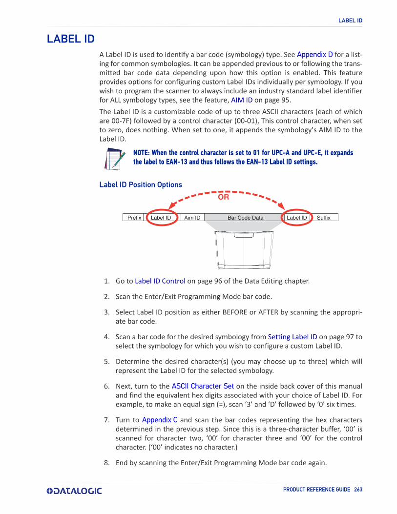
LABEL ID
PRODUCT REFERENCE GUIDE 263
LABEL IDA Label ID is used to identify a bar code (symbology) type. See Appendix D for a list-ing for common symbologies. It can be appended previous to or following the trans-mitted bar code data depending upon how this option is enabled. This feature provides options for configuring custom Label IDs individually per symbology. If you wish to program the scanner to always include an industry standard label identifier for ALL symbology types, see the feature, AIM ID on page 95.The Label ID is a customizable code of up to three ASCII characters (each of which are 00-7F) followed by a control character (00-01), This control character, when set to zero, does nothing. When set to one, it appends the symbology’s AIM ID to the Label ID.
NOTE
NOTE: When the control character is set to 01 for UPC-A and UPC-E, it expands the label to EAN-13 and thus follows the EAN-13 Label ID settings.
Label ID Position Options
OR
Prefix SuffixLabel ID Label IDBar Code DataAim ID
1. Go to Label ID Control on page 96 of the Data Editing chapter.
2. Scan the Enter/Exit Programming Mode bar code.
3. Select Label ID position as either BEFORE or AFTER by scanning the appropri-ate bar code.
4. Scan a bar code for the desired symbology from Setting Label ID on page 97 to select the symbology for which you wish to configure a custom Label ID.
5. Determine the desired character(s) (you may choose up to three) which will represent the Label ID for the selected symbology.
6. Next, turn to the ASCII Character Set on the inside back cover of this manual and find the equivalent hex digits associated with your choice of Label ID. For example, to make an equal sign (=), scan ‘3’ and ‘D’ followed by ‘0’ six times.
7. Turn to Appendix C and scan the bar codes representing the hex characters determined in the previous step. Since this is a three-character buffer, ‘00’ is scanned for character two, ‘00’ for character three and ‘00’ for the control character. (‘00’ indicates no character.)
8. End by scanning the Enter/Exit Programming Mode bar code again.

LENGTH CONTROL
264 MAGELLAN™ 3410VSI
LENGTH CONTROL
Fixed Length Decoding: When fixed length decoding is enabled, the scanner will decode a bar code if the label length matches one of the configurable fixed lengths.
Variable Length Decoding: When variable length decoding is enabled, the scanner will decode a bar code if the label length falls in the range of the configurable mini-mum and maximum length.Configuring Fixed Length Decoding:
1. Scan the Enter/Exit Programming Mode bar code.
2. Scan the Fixed Length Decoding bar code for the desired symbology.
3. Scan the Enter/Exit Programming Mode bar code.
4. Set Length 1 to the first fixed length by following the Length 1, Length 2 Pro-gramming Instructions below.
5. Set Length 2 to the second fixed length (or to ‘00’ if there is only one fixed length) by following the Length 1, Length 2 Programming Instructions below.
Configuring Variable Length Decoding:
1. Scan the Enter/Exit Programming Mode bar code.
2. Scan the Variable Length Decoding bar code for the desired symbology.
3. Scan the Enter/Exit Programming Mode bar code.
4. Set Length 1 to the first variable length by following the Length 1, Length 2 Programming Instructions below.
5. Set Length 2 to the second variable length by following the Length 1, Length 2 Programming Instructions below.
Length 1, Length 2 Programming Instructions
1. Scan the Enter/Exit Programming Mode bar code.
2. Scan either the Set Length 1 or Set Length 2 bar code for the desired symbol-ogy.
3. Turn to Appendix C and scan the two digits (zero padded) representing the length in decimal notation. The number of characters that can be set varies, depending upon the symbology. Reference the page for your selected symbol-ogy to see specific variables.
4. Scan the Enter/Exit Programming Mode bar code

265 MAGELLAN™ 3410VSI
APPENDIX APRODUCT SPECIFICATIONS
TECHNICAL SPECIFICATIONS starting on page 266• DECODING CAPABILITY starting on page 266• ELECTRICAL SPECIFICATIONS starting on page 266• ENVIRONMENTAL starting on page 266• INTERFACES starting on page 267• OPTIONAL FEATURES starting on page 267• OPTIONAL FEATURES starting on page 267
PHYSICAL CHARACTERISTICS starting on page 268
READING PERFORMANCE starting on page 269• READING RANGES starting on page 269
SAFETY & REGULATORY starting on page 269
UTILITIES starting on page 270
WARRANTY starting on page 270
LED AND BEEPER INDICATORS starting on page 270
ERROR CODES starting on page 271
SECTION CONTENTS

TECHNICAL SPECIFICATIONS
266 MAGELLAN™ 3410VSI
TECHNICAL SPECIFICATIONS
Decoding Capability
1D / Linear Codes Autodiscriminates All Standard 1D Codes Including GS1 Databar™ Linear Codes.
2D Codes Aztec Code; Data Matrix; QR Code
Stacked CodesGS1 Databar Composites; GS1 Databar Expanded Stacked; GS1 Databar Stacked; GS1 Databar Stacked Omnidirec-tional; MicroPDF417; PDF417
Digital Watermarks Optional Support For Digimarc® Barcodes/GS1 DW Code
Electrical Specifications
AC Power Requirements AC Input: 100-240 Vac, 50-60 Hz; DC Input: 5-12 V
Power ConsumptionMaximum: 2.25W @ 5V; 3.3W @ 12V Typical (RMS): 1.6W @ 5V; 2.1W @ 12V Sleep Mode (RMS): 0.95W @ 5V; 1.25W @ 12V
Environmental
Ambient Light 0 - 86,100 Lux
ESD Protection (Air Discharge) 25 kV
Humidity (Non-condensing) 5 - 95%
Particulate And Water Sealing IP52
Temperature Operating: 10 to 40 °C / 50 to 104 °F Storage/transport: -40 to 70 °C / -40 to 158 °F
ITEM DESCRIPTION
ITEM DESCRIPTION
ITEM DESCRIPTION

INTERFACES
PRODUCT REFERENCE GUIDE 267
Interfaces
Interfaces USB Keyboard; USB COM; OEM (IBM) USB; USB-TEC; RS-232
Auxiliary Port Powered Type A USB (USB Com requires power supply or 12V Host power)
Optional Features
EAS FeaturesGood Read signal available for use with various EAS hardware, such as Checkpoint Systems and Sensormatic devices.
Value Added Features Diagnostic Reporting; Host Download; Magellan ULE Scripting
PARAMETER SPECIFICATION
PARAMETER SPECIFICATION

PHYSICAL CHARACTERISTICS
268 MAGELLAN™ 3410VSI
PHYSICAL CHARACTERISTICS
Dimensions Magellan Model 3410VSi: 13.7 X 15.2 X 9.4 cm / 5.4 X 6.0 X 3.7 inWeight 0.6 kg /1.3 lb
5.4"13.7cm
6"15.2cm
3.7"9.4cm
Scanner Dimensions
PARAMETER SPECIFICATION

READING RANGES
PRODUCT REFERENCE GUIDE 269
READING PERFORMANCE
Image Capture Graphic Formats: BMP, JPEGImager Sensor 1280 X 800
Light Source Multiple Diffused LEDS, Orientation and Wavelength Optimized for Eye Comfort
Print Contrast Ratio (Minimum) 25%Read Height 14.0 cm / 5.5 inRead Rate (Maximum) 30 Million Pixels per Second
Reading Angle Pitch: +/- 65°; Roll (Tilt): 0 - 360°; Skew (Yaw): +/- 75°
Reading Indicators Audio Beeper w/Adjustable Tone and Volume; Good Read LED; Good Transmission
Resolution (Maximum) 5 Mil
Reading Ranges
Typical Depth Of Field Printing Resolution, Symbol Length, Scan Angle, Con-trast and Ambient Light Dependent
1D / Linear Codes5 Mils: 0 to 6.4 cm / 0 to 2.5 in10 Mils: 0 to 15.2 cm / 0 to 6.0 in13 Mils: 0 to 20.3 cm / 0 to 8.0 in
2D Codes (Optional)
6.6 Mils: PDF: 0 to 5.1 cm / 0 to 2.0 in 10 Mils: PDF: 0 to 12.7 cm / 0 to 5.0 in10 Mils: Data Matrix: 0 to 6.4 cm / 0 to 2.5 in20 Mils: Data Matrix: 0 to 18.0 cm / 0 to 7.0 in
SAFETY & REGULATORY
Agency Approvals The product meets necessary safety and regulatory approvals for its intended use.
Environmental Compliance Complies to China RoHS; Complies to EU RoHS
LED Classification EN62471 and IEC62471 Lamp Illumination - Exempt Group
PARAMETER SPECIFICATION
PARAMETER SPECIFICATION
PARAMETER SPECIFICATION

UTILITIES
270 MAGELLAN™ 3410VSI
UTILITIES
Scanalyzer Magellan Scanalyzer Configuration Software is avail-able for download at no charge.
OPOS / JavaPOSJavaPOS Utilities are available for download at no charge.OPOS Utilities are available for download at no charge.
WARRANTY
Warranty 3-year Factory Warranty
LED AND BEEPER INDICATORSThe scanner’s beeper sounds and its green LED illuminates to indicate various func-tions or errors on the scanner. The tables below list these indications. The scanner’s functions are programmable, and so may or may not be turned on. For example, certain indications such as the power-up beep can be disabled using programming bar code labels.
Power-on indication Constant bright green Indicates the scanner is running power-up tests
and is not yet ready for operation.Good Read Indication Bright green flash Indicates a bar code has been read and decoded.
Scanner Ready Constant dim green The scanner is ready for operation.
Sleep ModeGreen LED flashes every 2 seconds (10mS on, 1990mS off).
The scanner is in Sleep Mode. To wake the scanner up, move an object in front of its window or press the Scanner Button. This indication is optionally configurable, and may have been programmed to behave differently.
Host Disable Constant green flash at 1 Hz (100mS on, 900mS off)
The scanner is disabled due to receiving a disable command from the POS terminal.
DiagnosticsVaries (see Error Codes on page 271 for more informa-tion)
The LED can provide diagnostic feedback if the scanner discovers a problem during SelfTest.
Prog. Mode Constant green flash at 1 Hz (500 ms on, 500 ms off). The scanner is in Programming Mode.
PARAMETER SPECIFICATION
LED INDICATION
INDICATION COMMENT

Power On Beep Single beep
The Power-On LED indication is a configurable fea-ture which can be enabled or disabled. When enabled, this beep Indicates the scanner has fin-ished all its power-up tests and is now ready for operation.
Good Read Indication Single beep
The good read beep indication is configurable. Options include: Enable/disable, frequency, duration and volume. See "LED and Beeper Indicators" on page 25 for more information.
Diagnostics Varies (see “Error Codes” for more information)
The Beeper can provide diagnostic feedback if the scanner discovers a problem during SelfTest.
Programming Mode Indications
Varies depending upon the feature(s) being configured.
The Beeper will sound as programming bar code labels are scanned, indicating progress during scan-ner configuration.
READING RANGES
PRODUCT REFERENCE GUIDE 271
ERROR CODESIf an error is detected, the scanner will sound a long low tone (for three seconds) and flash its LED, indicating a failure. When this occurs, press the Scanner Pushbut-ton to hear the error code. If it is configured to do so, the scanner will sound a series of beeps corresponding to the error code and/or flash its LED simultaneous to the beeps. The table below describes what these codes mean and what action should be taken for each.
1 Configuration
Contact Helpdesk for assistance
2 Host Interface 6 Main PCB
10 Button Error11 USB Device13 CPLD ID
BEEPER INDICATION
INDICATION COMMENT
NUMBER OF LED
FLASHES/BEEPS
ERROR CORRECTIVE ACTION

PRODUCT REFERENCE GUIDE 272
APPENDIX BCABLE PINOUTS
STANDARD CABLE PINOUTS (PRIMARY INTERFACE CABLES)
Pin # RS-232 USB-OEMUSB, USB Keyboard, USB COM
D+ D+
CTS
D- D-
RTS
RxD
TxD
Vin Vin/VBUS Vin/VBUS
GND GND GND
ERI ERI ERI
1
2
3
4
5
6
7
8
9
10

273 MAGELLAN™ 3410VSI
APPENDIX CALPHA-NUMERIC KEYPAD
A
B
C
D
E
F

1
2
3
4
5
6
7
8
9
0
274 MAGELLAN™ 3410VSI

275 MAGELLAN™ 3410VSI
APPENDIX DFACTORY DEFAULT SETTINGS
The following table provides a listing of the most common factory settings for the interfaces shown.
NOTE
NOTE: Some of the individual interfaces listed in the defaults table below appear in the same column since they share similar feature settings with few (if any) exceptions. Keep in mind though, that the actual configuration storage area for each inter-face is unique and that updates & changes to factory defaults can be made at any time without notice.
Factory Default Settings
Feature DefaultMaster RS-232
RS-232Wincor- Nixdorf
Keyboard USB COM /USB TEC USB OEM
General Scanner Features1D Double Read Time-out
28 (400ms) 28 (400ms) 28 (400ms) 28 (400ms) 28 (400ms) 28 (400ms)
2D Double Read Time-out 46 (700ms) 46 (700ms) 46 (700ms) 46 (700ms) 46 (700ms) 46 (700ms)
Double Read Table Size 7 Entries 7 Entries 7 Entries 7 Entries 7 Entries 7 EntriesDigital Watermark (Digimarc) Enable
00 (disable) 00 (disable) 00 (disable) 00 (disable) 00 (disable) 00 (disable)
Digital Watermark (Digimarc) Double Read Timeout
32 (500ms) 32 (500ms) 32 (500ms) 32 (500ms) 32 (500ms) 32 (500ms)
Digital Watermark (Digimarc) Data Format
00 (compati-bility mode)
00 (compati-bility mode)
00 (compati-bility mode)
00 (compati-bility mode)
00 (compati-bility mode)
00 (compati-bility mode)
Sleep Mode Timer 14 (5 minutes)
14 (5 minutes)
14 (5 minutes)
14 (5 minutes)
14 (5 minutes)
14 (5 minutes)
1D Inverse Read Con-trol
00 (normal) 00 (normal) 00 (normal) 00 (normal) 00 (normal) 00 (normal)
2D Inverse Read Con-trol
00 (normal) 00 (normal) 00 (normal) 00 (normal) 00 (normal) 00 (normal)
Power On Alert 01 (enable) 01 (enable) 01 (enable) 01 (enable) 01 (enable) 01 (enable)Reading Illumination Duration
64 (5 sec) 64 (5 sec) 64 (5 sec) 64 (5 sec) 64 (5 sec) 64 (5 sec)

276 MAGELLAN™ 3410VSI
Illumination During Disable Mode
01 (enable) 01 (enable) 01 (enable) 01 (enable) 01 (enable) 01 (enable)
Object Sense Control 01 (enable) 01 (enable) 01 (enable) 01 (enable) 01 (enable) 01 (enable)External Read Indica-tor (ERI)
00 (Active Low)
00 (Active Low)
00 (Active Low)
00 (Active Low)
00 (Active Low)
00 (Active Low)
ERI Timeout 02 (20ms) 02 (20ms) 02 (20ms) 02 (20ms) 02 (20ms) 02 (20ms)Good Read LED Idle State 02 (on dim) 02 (on dim) 02 (on dim) 02 (on dim) 02 (on dim) 02 (on dim)
Scanner Control But-ton Options
01 (enable only volume,
tone, and reset)
01 (enable only volume,
tone, and reset)
01 (enable only volume,
tone, and reset)
01 (enable only volume,
tone, and reset)
01 (enable only volume,
tone, and reset)
01 enable only volume,
tone, and reset)
Good Read Beep Con-trol
01 (enable) 01 (enable) 01 (enable) 01 (enable) 01 (enable) 01 (enable)
Good Read Beep Fre-quency 01 (med.) 01 (med.) 01 (med.) 01 (med.) 01 (med.) 01 (med.)
Good Read Beep Length
08 (80ms) 08 (80ms) 08 (80ms) 08 (80ms) 08 (80ms) 08 (80ms)
Good Read Beep Vol-ume
02 (med) 02 (med) 02 (med) 02 (med) 02 (med) 02 (med)
Good Read When to Indicate
00 (after decode)
00 (after decode)
00 (after decode)
00 (after decode)
00 (after decode)
00 (after decode)
Illumination Blank on Beep 00 (disable)
Handheld Host Down-load Timeout
0F (15 seconds)
0F (15 seconds)
0F (15 seconds)
0F (15 seconds)
0F (15 seconds)
0F (15 seconds)
Imaging FeaturesCamera Button Mode 00 (disable) 00 (disable) 00 (disable) 00 (disable) 00 (disable) 00 (disable)Image Destination 00 (disable) 00 (disable) 00 (disable) 00 (disable) 00 (disable) 00 (disable)Picture Retrieval Time-out
05 (5 sec.) 05 (5 sec.) 05 (5 sec.) 05 (5 sec.) 05 (5 sec.)
Image Capture Delay 05 (5 sec.) 05 (5 sec.) 05 (5 sec.) 05 (5 sec.) 05 (5 sec.) 05 (5 sec.)Image Format 00 (JPG) 00 (JPG) 00 (JPG) 00 (JPG) 00 (JPG) 00 (JPG)Image Size 00 (VGA) 00 (VGA) 00 (VGA) 00 (VGA) 00 (VGA) 00 (VGA)Image Brightness 00 (Level 0) 00 (Level 0) 00 (Level 0) 00 (Level 0) 00 (Level 0) 00 (Level 0)Image Contrast 00 (Level 0) 00 (Level 0) 00 (Level 0) 00 (Level 0) 00 (Level 0) 00 (Level 0)
Image Compression 64 (Compres-sion = 100
64 (Compres-sion = 100
64 (Compres-sion = 100
64 (Compres-sion = 100
64 (Compres-sion = 100
64 (Compres-sion = 100
Region of Interest (ROI)000004FF000
0031F (full size)
000004FF0000031F (full
size)
000004FF0000031F (full
size)
000004FF0000031F (full
size)
000004FF0000031F (full
size)
000004FF0000031F (full
size)
Cell Phone Mode 02 (always on)
02 (always on)
02 (always on)
02 (always on)
02 (always on)
02 (always on)
Cell Mode Percent Low Low Low Low Low LowInterface Related Features
Feature DefaultMaster RS-232
RS-232Wincor- Nixdorf
Keyboard USB COM /USB TEC USB OEM

PRODUCT REFERENCE GUIDE 277
Maximum Host-Trans-mitted Message Length
00 (no length limit)
00 (no length limit)
00 (no length limit)
00 (no length limit)
00 (no length limit)
00 (no length limit)
Ignore Host Commands 00 (don’t ignore)
00 (don’t ignore)
00 (don’t ignore)
00 (don’t ignore)
00 (don’t ignore)
00 (don’t ignore)
RS-232 Baud Rate 01 (9600) 01 (9600) 01 (9600) 01 (9600)RS-232 Number of Data Bits
01 (8 data bits)
01 (8 data bits)
01 (8 data bits)
01 (8 data bits)
RS-232 Number of Stop Bits 00 (1 stop bit) 00 (1 stop bit) 00 (1 stop bit) 00 (1 stop bit)
RS-232 Parity 00 (none) 00 (none) 02 (odd) 00 (none)
RS-232 Hardware Con-trol
00 (disable) 00 (disable)01 (enable
CTS flow con-trol)
00 (disable)
RS-232 Intercharacter Delay 00 (no delay) 00 (no delay) 00 (no delay) 00 (no delay)
RS-232 Software Flow Control
00 (disable) 00 (disable) 00 (disable) 00 (disable)
RS-232 Beep on ASCII BEL
00 (disable) 00 (disable) 00 (disable) 00 (disable)
Beep on Not on File 01 (low vol) 01 (low vol) 01 (low vol) 01 (low vol) 01 (low vol)ACK NAK Enable 00 (disable) 00 (disable) 00 (disable) 00 (disable)RS-232 ACK Character 06 (ACK) 06 (ACK) 06 (ACK) 06 (ACK)RS-232 NAK Character 15 (NAK) 15 (NAK) 15 (NAK) 15 (NAK)RS-232 Retry on ACK NAK Timeout
01 (enable) 01 (enable) 01 (enable) 01 (enable)
RS-232 ACK NAK Tim-eout Value 01 (200ms) 01 (200ms) 01 (200ms) 01 (200ms)
RS-232 ACK NAK Retry Count
03(3 retries)
03(3 retries)
03(3 retries)
03(3 retries)
RS-232 ACK NAK Error Handling
00 (ignore) 00 (ignore) 00 (ignore) 00 (ignore)
RS-232 Indicate Trans-mission Failure 01 (enable) 01 (enable) 01 (enable) 01 (enable)
USB Power Compliance 00 (disable) 00 (disable) 00 (disable) 01 (enable) 00 (disable) 00 (disable)USB OEM Scanner Device Type
00 (table top) 00 (table top)
USB OEM Additional Interface Options
00 (disabled upon enu-meration)
00 (disabled upon enu-meration)
USB Keyboard Country Mode
00 (USA) 00 (USA)
USB Keyboard Caps Lock State
00 (caps lock OFF)
00 (caps lock OFF)
USB Keyboard Send Control Characters 00 (disable) 00 (disable)
Feature DefaultMaster RS-232
RS-232Wincor- Nixdorf
Keyboard USB COM /USB TEC USB OEM

278 MAGELLAN™ 3410VSI
Quiet Interval 0A (100ms) 0A (100ms)USB Keyboard Inter-character Delay
01 (10ms) 01 (10ms)
USB Keyboard Addi-tional Interface Options
40 (Rev D) 00 00 40 (Rev D) 40 (Rev D)/00 46
Data Editing
Global Prefix 00 (noprefix)
00 (noprefix)
00 (noprefix)
00 (noprefix)
00 (noprefix)
00 (noprefix)
Global Suffix 0D00 (CR) 0D00 (CR) 0D00 (CR) 0D00 (CR) 0D00 (CR) 0D00 (CR)AIM ID 00 (disable) 00 (disable) 00 (disable) 00 (disable) 00 (disable)
Label ID 01 (Enable as prefix)
01 (Enable as prefix)
01 (Enable as prefix)
01 (Enable as prefix)
01 (Enable as prefix)
Global Mid-Label ID 00 (no mid-label ID)
00 (no mid-label ID)
00 (no mid-label ID)
00 (no mid-label ID)
00 (no mid-label ID)
Case Conversion 00 (no case conversion)
00 (no case conversion)
00 (no case conversion)
00 (no case conversion)
00 (no case conversion)
00 (no case conversion)
Character Conversion
FFFFFFFFFFFFFFFF (no character
conversion)
FFFFFFFFFFFFFFFF (no character
conversion)
FFFFFFFFFFFFFFFF (no character
conversion)
FFFFFFFFFFFFFFFF (no character
conversion)
FFFFFFFFFFFFFFFF (no character
conversion)
FFFFFFFFFFFFFFFF (no character
conversion)1D Symbology Programming
Coupon Control Enable04 (Databar coupon label
priority)
04 (Databar coupon label
priority)
04 (Databar coupon label
priority)
04 (Databar coupon label
priority)
04 (Databar coupon label
priority)
04 (Databar coupon label
priority)Coupon Label Priority Timer
14 (200ms) 14 (200ms) 14 (200ms) 14 (200ms) 14 (200ms) 14 (200ms)
UPC-A Enable 01 (enable) 01 (enable) 01 (enable) 01 (enable) 01 (enable) 01 (enable)UPC-A Number System Character Transmis-sion
01 (enable) 01 (enable) 01 (enable) 01 (enable) 01 (enable) 01 (enable)
UPC-A Check Character Transmission
01 (enable) 01 (enable) 01 (enable) 01 (enable) 01 (enable) 01 (enable)
UPC-A Minimum Read 01 (1 read)
01 (1 read)
01 (1 read)
01 (1 read)
01 (1 read)
01(1 read)
Expand UPC-A to EAN-13 00 (disable) 00 (disable) 01 (enable) 00 (disable) 00 (disable) 00 (disable)
UPC-E Enable 01 (enable) 01 (enable) 01 (enable) 01 (enable) 01 (enable) 01 (enable)UPC-E Number System Character Transmis-sion
01 (enable) 01 (enable) 01 (enable) 01 (enable) 01 (enable) 01 (enable)
UPC-E Check Character Transmission 01 (enable) 01 (enable) 00 (disable) 01 (enable) 01 (enable) 01 (enable)
Expand UPC-E to UPC-A
00 (disable) 00 (disable) 00 (disable) 00 (disable) 00 (disable) 00 (disable)
Expand UPC-E to EAN-13
00 (disable) 00 (disable) 00 (disable) 00 (disable) 00 (disable) 00 (disable)
Feature DefaultMaster RS-232
RS-232Wincor- Nixdorf
Keyboard USB COM /USB TEC USB OEM

PRODUCT REFERENCE GUIDE 279
UPC-E Minimum Read 01 (1 read) 01 (1 read) 01 (1 read) 01 (1 read) 01 (1 read) 01 (1 read)EAN-13 01 (enable) 01 (enable) 01 (enable) 01 (enable) 01 (enable) 01 (enable)EAN-13 First Charac-ter Transmission
01 (enable) 01 (enable) 01 (enable) 01 (enable) 01 (enable) 01 (enable)
EAN-13 Check Charac-ter Transmission
01 (enable) 01 (enable) 01 (enable) 01 (enable) 01 (enable) 01 (enable)
EAN-13 ISBN Conver-sion Enable 00 (disable) 00 (disable) 00 (disable) 00 (disable) 00 (disable) 00 (disable)
EAN-13 Minimum Read 01 (1 read)
01 (1 read)
01 (1 read)
01 (1 read)
01 (1 read)
01 (1 read)
EAN-8 01 (enable) 01 (enable) 01 (enable) 01 (enable) 01 (enable) 01 (enable)EAN-8 Check Character Transmission
01 (enable) 01 (enable) 01 (enable) 01 (enable) 01 (enable) 01 (enable)
Expand EAN-8 to EAN-13
00 (disable) 00 (disable) 00 (disable) 00 (disable) 00 (disable) 00 (disable)
EAN-8 Minimum Read 01 (1 read)
01 (1 read)
01 (1 read)
01 (1 read)
01 (1 read)
01 (1 read)
EAN-8 Guard Insertion 00 (disable) 00 (disable) 00 (disable) 00 (disable) 00 (disable) 00 (disable)EAN-8 Guard Substitu-tion
00 (disable) 00 (disable) 00 (disable) 00 (disable) 00 (disable) 00 (disable)
EAN-8/Jan-8 Both Guards Substitution
00 (disable) 00 (disable) 00 (disable) 00 (disable) 00 (disable) 00 (disable)
EAN-8 Stitch Exact Label Halves
00 (disable) 00 (disable) 00 (disable) 00 (disable) 00 (disable) 00 (disable)
EAN-8 Stitch Unlike Label Halves
00 (disable) 00 (disable) 00 (disable) 00 (disable) 00 (disable) 00 (disable)
EAN-8 Minimum Seg-ment Length
08 (8 chars)
08(8 chars)
08(8 chars)
08(8 chars)
08(8 chars)
08(8 chars)
EAN-8 Decoding Levels 01 (very conservative)
01 (very conservative)
01 (very conservative)
01 (very conservative)
01 (very conservative)
01 (very conservative)
In-Store Printed Label Minimum Read
01 (1 read)
01 (1 read)
01 (1 read)
01 (1 read)
01 (1 read)
01 (1 read)
UPC/EAN Guard Inser-tion
00 (disable) 00 (disable) 00 (disable) 00 (disable) 00 (disable) 00 (disable)
UPC/EAN Stitch Exact Label Halves 00 (disable) 00 (disable) 00 (disable) 00 (disable) 00 (disable) 00 (disable)
UPC/EAN Stitch Unlike Label Halves
00 (disable) 00 (disable) 00 (disable) 00 (disable) 00 (disable) 00 (disable)
UPC/EAN Minimum Segment Length
05 (5 char.) 05 (5 char.) 05 (5 char.) 05 (5 char.) 05 (5 char.) 05 (5 char.)
Price Weight Check 00 (disable) 00 (disable) 00 (disable) 00 (disable) 00 (disable) 00 (disable)Enable EAN Two Label 00 (disable) 00 (disable) 00 (disable) 00 (disable) 00 (disable) 00 (disable)EAN Two Label Mini-mum Read
01 (1 read)
01 (1 read)
01 (1 read)
01 (1 read)
01 (1 read)
01 (1 read)
Feature DefaultMaster RS-232
RS-232Wincor- Nixdorf
Keyboard USB COM /USB TEC USB OEM

280 MAGELLAN™ 3410VSI
EAN Two Label Com-bined Transmission
00 (disable) 00 (disable) 00 (disable) 00 (disable)
Add-ons disable all disable all disable all disable all disable all disable allP2 Add-on Minimum Read
02 (2 reads) 02 (2 reads) 02 (2 reads) 02 (2 reads) 02 (2 reads) 02 (2 reads)
P5 Add-on Minimum Read
01 (1 read)
01 (1 read)
01 (1 read)
01 (1 read)
01 (1 read)
01 (1 read)
UPC/EAN Composites 00 (disable) 00 (disable) 00 (disable) 00 (disable) 00 (disable)GTIN 00 (disable) 00 (disable) 00 (disable) 00 (disable) 00 (disable)DataBar Omnidirec-tional Enable
00 (disable) 00 (disable) 00 (disable) 00 (disable) 00 (disable) 00 (disable)
DataBar Omnidirec-tional/EAN-128 Emula-tion
00 (disable) 00 (disable) 00 (disable) 00 (disable) 00 (disable) 00 (disable)
DataBar Omnidirec-tional 2D Component Enable
00 (disable) 00 (disable) 00 (disable) 00 (disable) 00 (disable) 00 (disable)
DataBar Omnidirec-tional Minimum Read
01 (1 read)
01 (1 read)
01 (1 read)
01 (1 read)
01 (1 read)
01 (1 read)
DataBar Omnidirec-tional Double Read Timeout
32 (2.5 Sec.) 32 (2.5 Sec.) 32 (2.5 Sec.) 32 (2.5 Sec.) 32 (2.5 Sec.) 32 (2.5 Sec.)
DataBar Limited Enable
00 (disable) 00 (disable) 00 (disable) 00 (disable) 00 (disable) 00 (disable)
DataBar Limited Mini-mum Read 01 (1 read) 01 (1 read) 01 (1 read) 01 (1 read) 01 (1 read) 01 (1 read)
DataBar Limited 2D Component Enable
00 (disable) 00 (disable) 00 (disable) 00 (disable) 00 (disable) 00 (disable)
DataBar Limited EAN128 Emulation Enable
00 (disable) 00 (disable) 00 (disable) 00 (disable) 00 (disable) 00 (disable)
DataBar Expanded 00 (disable) 00 (disable) 00 (disable) 00 (disable) 00 (disable) 00 (disable)DataBar Expanded EAN-128 Emulation
00 (disable) 00 (disable) 00 (disable) 00 (disable) 00 (disable) 00 (disable)
DataBar Expanded 2D Component Enable
00 (disable) 00 (disable) 00 (disable) 00 (disable) 00 (disable) 00 (disable)
DataBar Expanded Minimum Read
01 (1 read)
01 (1 read)
01 (1 read)
01 (1 read)
01 (1 read)
01 (1 read)
DataBar Expanded Length Control
00(variable)
00(variable)
00(variable)
00(variable)
00(variable)
00(variable)
DataBar Expanded Length 1
01(1 char)
01(1 char)
01(1 char)
01(1 char)
01(1 char)
01(1 char)
DataBar Expanded Length 2
4A (74 chars)
4A (74 chars)
4A (74 chars)
4A (74 chars)
4A (74 chars)
4A (74 chars)
Feature DefaultMaster RS-232
RS-232Wincor- Nixdorf
Keyboard USB COM /USB TEC USB OEM

PRODUCT REFERENCE GUIDE 281
DataBar Expanded Reverse Retry
00 (disable) 00 (disable) 00 (disable) 00 (disable) 00 (disable) 00 (disable)
Code 39 01 (enable) 01 (enable) 01 (enable) 01 (enable) 01 (enable) 01 (enable)Code 39 Start Stop Character Transmis-sion
00 (disable) 00 (disable) 00 (disable) 00 (disable) 00 (disable) 00 (disable)
Code 39 Check Charac-ter Calculation
00 (disable) 00 (disable) 00 (disable) 00 (disable) 00 (disable) 00 (disable)
Code 39 Check Charac-ter Transmission
01 (enable) 01 (enable) 01 (enable) 01 (enable) 01 (enable) 01 (enable)
Code 39 Full ASCII 00 (disable) 00 (disable) 00 (disable) 00 (disable) 00 (disable) 00 (disable)
Code 39 Minimum Read 01 (1 read)
01 (1 read)
01 (1 read)
01 (1 read)
01 (1 read)
01 (1 read)
Code 39 Length Control 00(variable)
00(variable)
00(variable)
00(variable)
00(variable)
00(variable)
Code 39 Length 1 02 (2 chars) 02 (2 chars) 02 (2 chars) 02 (2 chars) 02 (2 chars) 02 (2 chars)Code 39 Length 2 32 (50 chars) 32 (50 chars) 32 (50 chars) 32 (50 chars) 32 (50 chars) 32 (50 chars)Code 39 Stitching 01 (enable) 01 (enable) 01 (enable) 01 (enable) 01 (enable) 01 (enable)Code 39 Require Mar-gins
00 (disable) 00 (disable) 00 (disable) 00 (disable) 00 (disable) 00 (disable)
Code 32 Italian Phar-macode
00 (disable) 00 (disable) 00 (disable) 00 (disable) 00 (disable) 00 (disable)
Code 32 Start Stop Character Transmis-sion
00 (disable) 00 (disable) 00 (disable) 00 (disable) 00 (disable) 00 (disable)
Code 32 Check Charac-ter Transmission 00 (disable) 00 (disable) 00 (disable) 00 (disable) 00 (disable)
Code 128 01 (enable) 01 (enable) 01 (enable) 01 (enable) 01 (enable) 01 (enable)Code 128 Transmit Function Characters
00 (disable) 00 (disable) 00 (disable) 00 (disable) 00 (disable) 00 (disable)
Expand Code128 to Code 39
00 (disable) 00 (disable) 00 (disable) 00 (disable) 00 (disable) 00 (disable)
Code 128 Minimum Read
01 (1 read)
01 (1 read)
01 (1 read)
01 (1 read)
01 (1 read)
01 (1 read)
Code 128 Length Con-trol
00(variable)
00(variable)
00(variable)
00(variable)
00(variable)
00(variable)
Code 128 Length 1 01 (1 char) 01 (1 char) 01 (1 char) 01 (1 char) 01 (1 char) 01 (1 char)Code 128 Length 2 50 (80 chars) 50 (80 chars) 50 (80 chars) 50 (80 chars) 50 (80 chars) 50 (80 chars)Code 128 Stitching 01 (enable) 01 (enable) 01 (enable) 01 (enable) 01 (enable) 01 (enable)
EAN-128
00 (transmit EAN128 labels as
Code 128)
00 (transmit EAN128 labels as
Code 128)
00 (transmit EAN128 labels as
Code 128)
00 (transmit EAN128 labels as
Code 128)
00 (transmit EAN128 labels as
Code 128)
00 (transmit EAN128 labels as
Code 128)Interleaved 2 of 5 (I 2 OF 5) 00 (disable) 00 (disable) 00 (disable) 00 (disable) 00 (disable) 00 (disable)
Feature DefaultMaster RS-232
RS-232Wincor- Nixdorf
Keyboard USB COM /USB TEC USB OEM

282 MAGELLAN™ 3410VSI
I 2 of 5 Check Character Calculation
00 (disable) 00 (disable) 00 (disable) 00 (disable) 00 (disable) 00 (disable)
I 2 of 5 Check Character Transmission
01 (enable) 01 (enable) 01 (enable) 01 (enable) 01 (enable) 01 (enable)
I 2 of 5 Minimum Read 01 (1 read)
01 (1 read)
01 (1 read)
01 (1 read)
01 (1 read)
01 (1 read)
I 2 of 5 Length Control 00(variable)
00(variable)
00(variable)
00(variable)
00(variable)
00(variable)
I 2 of 5 Length 1 06 (6 chars) 06 (6 chars) 06 (6 chars) 06 (6 chars) 06 (6 chars) 06 (6 chars)I 2 of 5 Length 2 32 (50 chars) 32 (50 chars) 32 (50 chars) 32 (50 chars) 32 (50 chars) 32 (50 chars)Codabar 00 (disable) 00 (disable) 00 (disable) 00 (disable) 00 (disable) 00 (disable)Codabar Start Stop Character Transmis-sion
01 (enable) 01 (enable) 01 (enable) 01 (enable) 01 (enable) 01 (enable)
Codabar Start Stop Character Set
03 (abcd/abcd) 03 (abcd/abcd 03 (abcd/abcd 03 (abcd/abcd 03 (abcd/abcd 03 (abcd/abcd
Codabar Start Stop Character Match
00 (disable) 00 (disable) 00 (disable) 00 (disable) 00 (disable) 00 (disable)
Codabar Check Charac-ter Calculation
00 (disable) 00 (disable) 00 (disable) 00 (disable) 00 (disable) 00 (disable)
Codabar Check Charac-ter Transmission
01 (enable) 01 (enable) 01 (enable) 01 (enable) 01 (enable) 01 (enable)
Codabar Minimum Read
01 (1 read)
01 (1 read)
01 (1 read)
01 (1 read)
01 (1 read)
01 (1 read)
Codabar Length Con-trol
00(variable)
00(variable)
00(variable)
00(variable)
00(variable)
00(variable)
Codabar Length 1 03 (3 chars) 03 (3 chars) 03 (3 chars) 03 (3 chars) 03 (3 chars) 03 (3 chars)Codabar Length 2 32 (50 chars) 32 (50 chars) 32 (50 chars) 32 (50 chars) 32 (50 chars) 32 (50 chars)Codabar Require Mar-gins
00 (disable) 00 (disable) 00 (disable) 00 (disable) 00 (disable) 00 (disable)
Code 93 00 (disable) 00 (disable) 00 (disable) 00 (disable) 00 (disable) 00 (disable)
Code 93 Minimum Read 01 (1 read)
01 (1 read)
01 (1 read)
01 (1 read)
01 (1 read)
01 (1 read)
Code 93 Length Control 00(variable)
00(variable)
00(variable)
00(variable)
00(variable)
00(variable)
Code 93 Length 1 01 (1 char) 01 (1 char) 01 (1 char) 01 (1 char) 01 (1 char) 01 (1 char)Code 93 Length 2 32 (50 chars) 32 (50 chars) 32 (50 chars) 32 (50 chars) 32 (50 chars) 32 (50 chars)MSI 00 (disable) 00 (disable) 00 (disable) 00 (disable) 00 (disable)MSI Check Character Calculation
01 (enable) 01 (enable) 01 (enable) 01 (enable) 01 (enable)
MSI Number of Check Characters 00 (1 char) 00 (1 char) 00 (1 char) 00 (1 char) 00 (1 char)
MSI Check Character Transmission
01 (enable) 01 (enable) 01 (enable) 01 (enable) 01 (enable)
Feature DefaultMaster RS-232
RS-232Wincor- Nixdorf
Keyboard USB COM /USB TEC USB OEM

PRODUCT REFERENCE GUIDE 283
MSI Minimum Read 01 (1 read)
01 (1 read)
01 (1 read)
01 (1 read)
01 (1 read)
MSI Length Control 00(variable)
00(variable)
00(variable)
00(variable)
00(variable)
MSI Length 1 04 (4 chars) 04 (4 chars) 04 (4 chars) 04 (4 chars) 04 (4 chars)MSI Length 2 10 (16 chars) 10 (16 chars) 10 (16 chars) 10 (16 chars) 10 (16 chars)Standard 2 of 5 00 (disable) 00 (disable) 00 (disable) 00 (disable) 00 (disable) 00 (disable)Standard 2 of 5 Check Character Calculation
00 (disable) 00 (disable) 00 (disable) 00 (disable) 00 (disable) 00 (disable)
Standard 2 of 5 Check Character Transmis-sion
01 (enable) 01 (enable) 01 (enable) 01 (enable) 01 (enable) 01 (enable)
Standard 2 of 5 Length Control
00 (disable) 00 (disable) 00 (disable) 00 (disable) 00 (disable) 00 (disable)
Standard 2 of 5 Length Control
00(variable)
00(variable)
00(variable)
00(variable)
00(variable)
00(variable)
Standard 2 of 5 Length 1
08 (8 chars) 08 (8 chars) 08 (8 chars) 08 (8 chars) 08 (8 chars) 08 (8 chars)
Standard 2 of 5 Length 2
32 (50 chars) 32 (50 chars) 32 (50 chars) 32 (50 chars) 32 (50 chars) 32 (50 chars)
2D Symbology ProgrammingData Matrix 00 (disable) 00 (disable) 00 (disable) 00 (disable) 00 (disable) 00 (disable)Data Matrix Length Control
00(variable)
00(variable)
00(variable)
00(variable)
00(variable)
00(variable)
Set Data Matrix Length 1
0001 (1 char) 0001 (1 char) 0001 (1 char) 0001 (1 char) 0001 (1 char) 0001 (1 char)
Set Data Matrix Length 2
0320 (800 chars)
0320 (800 chars)
0320 (800 chars)
0320 (800 chars)
0320 (800 chars)
0320 (800 chars)
GS1 Datamatrix Enable
00(transmit as
std Data-matrix label)
00(transmit as
std Data-matrix label)
01(transmit as GS1 Data-
matrix label)
00(transmit as
std Data-matrix label)
00(transmit as
std Data-matrix label)
00(transmit as
std Data-matrix label)
PDF 417 Enable 01 (enable) 01 (enable) 01 (enable) 01 (enable) 01 (enable) 01 (enable)PDF 417 Length Con-trol
00(variable)
00(variable)
00(variable)
00(variable)
00(variable)
00(variable)
Set PDF 417 Length 1 0001 (1 char) 0001 (1 char) 0001 (1 char) 0001 (1 char) 0001 (1 char) 0001 (1 char)
Set PDF 417 Length 2 0A96 (2710 chars)
0A96 (2710 chars)
0A96 (2710 chars)
0A96 (2710 chars)
0A96 (2710 chars)
0A96 (2710 chars)
PDF 417 Read Option
00 (enforce codeword
length checking)
00 (enforce codeword
length checking)
00 (enforce codeword
length checking)
00 (enforce codeword
length checking)
00 (enforce codeword
length checking)
00 (enforce codeword
length checking)
Micro PDF 417 00 (disable) 00 (disable) 00 (disable) 00 (disable) 00 (disable) 00 (disable)Micro PDF 417 Length Control
00(variable)
00(variable)
00(variable)
00(variable)
00(variable)
00(variable)
Feature DefaultMaster RS-232
RS-232Wincor- Nixdorf
Keyboard USB COM /USB TEC USB OEM
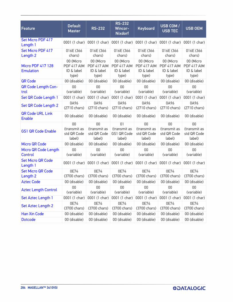
284 MAGELLAN™ 3410VSI
Set Micro PDF 417 Length 1
0001 (1 char) 0001 (1 char) 0001 (1 char) 0001 (1 char) 0001 (1 char) 0001 (1 char)
Set Micro PDF 417 Length 2
016E (366 chars)
016E (366 chars)
016E (366 chars)
016E (366 chars)
016E (366 chars)
016E (366 chars)
Micro PDF 417 128 Emulation
00 (Micro PDF 417 AIM
ID & label type)
00 (Micro PDF 417 AIM
ID & label type)
00 (Micro PDF 417 AIM
ID & label type)
00 (Micro PDF 417 AIM
ID & label type)
00 (Micro PDF 417 AIM
ID & label type)
00 (Micro PDF 417 AIM
ID & label type)
QR Code 00 (disable) 00 (disable) 00 (disable) 00 (disable) 00 (disable) 00 (disable)QR Code Length Con-trol
00(variable)
00(variable)
00(variable)
00(variable)
00(variable)
00(variable)
Set QR Code Length 1 0001 (1 char) 0001 (1 char) 0001 (1 char) 0001 (1 char) 0001 (1 char) 0001 (1 char)
Set QR Code Length 2 0A96 (2710 chars)
0A96 (2710 chars)
0A96 (2710 chars)
0A96 (2710 chars)
0A96 (2710 chars)
0A96 (2710 chars)
QR Code URL Link Enable
00 (disable) 00 (disable) 00 (disable) 00 (disable) 00 (disable) 00 (disable)
GS1 QR Code Enable
00(transmit as std QR Code
label)
00(transmit as std QR Code
label)
01(transmit as GS1 QR Code
label)
00(transmit as std QR Code
label)
00(transmit as std QR Code
label)
00(transmit as std QR Code
label)Micro QR Code 00 (disable) 00 (disable) 00 (disable) 00 (disable) 00 (disable) 00 (disable)Micro QR Code Length Control
00(variable)
00(variable)
00(variable)
00(variable)
00(variable)
00(variable)
Set Micro QR Code Length 1
0001 (1 char) 0001 (1 char) 0001 (1 char) 0001 (1 char) 0001 (1 char) 0001 (1 char)
Set Micro QR Code Length 2
0E74 (3700 chars)
0E74 (3700 chars)
0E74 (3700 chars)
0E74 (3700 chars)
0E74 (3700 chars)
0E74 (3700 chars)
Aztec Code 00 (disable) 00 (disable) 00 (disable) 00 (disable) 00 (disable) 00 (disable)
Aztec Length Control 00(variable)
00(variable)
00(variable)
00(variable)
00(variable)
00(variable)
Set Aztec Length 1 0001 (1 char) 0001 (1 char) 0001 (1 char) 0001 (1 char) 0001 (1 char) 0001 (1 char)
Set Aztec Length 2 0E74 (3700 chars)
0E74 (3700 chars)
0E74 (3700 chars)
0E74 (3700 chars)
0E74 (3700 chars)
0E74 (3700 chars)
Han Xin Code 00 (disable) 00 (disable) 00 (disable) 00 (disable) 00 (disable) 00 (disable)Dotcode 00 (disable) 00 (disable) 00 (disable) 00 (disable) 00 (disable) 00 (disable)
Feature DefaultMaster RS-232
RS-232Wincor- Nixdorf
Keyboard USB COM /USB TEC USB OEM
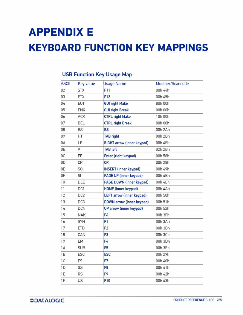
PRODUCT REFERENCE GUIDE 285
APPENDIX EKEYBOARD FUNCTION KEY MAPPINGS
USB Function Key Usage Map
ASCII Key value Usage Name Modifier/Scancode
02 STX F11 00h 44h
03 ETX F12 00h 45h
04 EOT GUI right Make 80h 00h
05 ENQ GUI right Break 00h 00h
06 ACK CTRL right Make 10h 00h
07 BEL CTRL right Break 00h 00h
08 BS BS 00h 2Ah
09 HT TAB right 00h 2Bh
0A LF RIGHT arrow (inner keypad) 00h 4Fh
0B VT TAB left 02h 2Bh
0C FF Enter (right keypad) 00h 58h
0D CR CR 00h 28h
0E SO INSERT (inner keypad) 00h 49h
0F SI PAGE UP (inner keypad) 00h 4Bh
10 DLE PAGE DOWN (inner keypad) 00h 4Eh
11 DC1 HOME (inner keypad) 00h 4Ah
12 DC2 LEFT arrow (inner keypad) 00h 50h
13 DC3 DOWN arrow (inner keypad) 00h 51h
14 DC4 UP arrow (inner keypad) 00h 52h
15 NAK F6 00h 3Fh
16 SYN F1 00h 3Ah
17 ETB F2 00h 3Bh
18 CAN F3 00h 3Ch
19 EM F4 00h 3Dh
1A SUB F5 00h 3Eh
1B ESC ESC 00h 29h
1C FS F7 00h 40h
1D GS F8 00h 41h
1E RS F9 00h 42h
1F US F10 00h 43h

286 MAGELLAN™ 3410VSI
The following keys can be optionally configured to correspond to the Rev C version of this function table. See "USB Keyboard Additional Interface Options" on page 90 to set this feature.ASCII Key value Usage Name Modifier/Scancode
02 STX F11 00h 44h
03 ETX F12 00h 45h
04 EOT GUI right Make 80h 00h
05 ENQ GUI right Break 00h 00h
ASCII (hex) ASCII code Key Scancode
02 STX ALT left Make 38h
03 ETX ALT left Break B8h
04 EOT CTRL left Make 1Dh
05 ENQ CTRL left Break 9Dh
06 ACK CTRL right Make E0h 1Dh
07 BEL CTRL right Break E0h 9Dh
08 BS BS 0Eh
09 HT TAB right 0Fh
0A LF RIGHT arrow (inner keypad) 4Dh + E0
0B VT TAB left 0Fh + S
0C FF Enter (inner keypad) 1Ch + E0
0D CR CR 1Ch
0E SO INSERT (inner keypad) 52h + E0
0F SI PAGE UP (inner keypad) 49h + E0
10 DLE PAGE DOWN (inner keypad) 51h + E0
11 DC1 HOME (inner keypad) 47h + E0
12 DC2 LEFT arrow (inner keypad) 4Bh + E0
13 DC3 DOWN arrow (inner keypad) 50h + E0
14 DC4 UP arrow (inner keypad) 48h + E0
Scanset 1 Function Key Map

ASCII (hex) ASCII code Key Scancode
02 STX ALT left Make 11h
03 ETX ALT left Break F0h 11h
04 EOT CTRL left Make 14h
05 ENQ CTRL left Break F0h 14h
06 ACK CTRL right Make E0h 14h
07 BEL CTRL right Break E0h F0h 14h
08 BS BS 66h
09 HT TAB right 0Dh
0A LF RIGHT arrow (inner keypad) 74h + E0
0B VT TAB left 0Dh + S
0C FF Enter (right keypad) 5Ah + E0
0D CR CR 5Ah
0E SO INSERT (inner keypad) 70h + E0
0F SI PAGE UP (inner keypad) 7Dh + E0
10 DLE PAGE DOWN (inner keypad) 7Ah + E0
11 DC1 HOME (inner keypad) 6Ch + E0
12 DC2 LEFT arrow (inner keypad) 6Bh + E0
13 DC3 DOWN arrow (inner keypad) 72h + E0
14 DC4 UP arrow (inner keypad) 75h + E0
15 NAK F6 0Bh
16 SYN F1 05h
17 ETB F2 06h
18 CAN F3 04h
19 EM F4 0Ch
1A SUB F5 03h
1B ESC ESC 76h
1C FS F7 83h
1D GS F8 0Ah
1E RS F9 01h
1F US F10 09h
PRODUCT REFERENCE GUIDE 287
Scanset 2 Function Key Map
Scanset 3, 102-Key Function Key Map
ASCII (hex) ASCII code Key Scancode
02 STX ALT left Make 19h
03 ETX ALT left Break F0h 19h
04 EOT CTRL left Make 11h
05 ENQ CTRL left Break F0h 11h
06 ACK CTRL right Make 58h

288 MAGELLAN™ 3410VSI
07 BEL CTRL right Break F0h 58h
08 BS BS 66h
09 HT TAB right 0Dh
0A LF RIGHT arrow (inner keypad) 6Ah
0B VT TAB left 0Dh + S
0C FF Enter (inner keypad) 79h
0D CR CR 5Ah
0E SO INSERT (inner keypad) 67h
0F SI PAGE UP (inner keypad) 6Fh
10 DLE PAGE DOWN (inner keypad) 6Dh
11 DC1 HOME (inner keypad) 6Eh
12 DC2 LEFT arrow (inner keypad) 61h
13 DC3 DOWN arrow (inner keypad) 60h
14 DC4 UP arrow (inner keypad) 63h
15 NAK F6 2Fh
16 SYN F1 07h
17 ETB F2 0Fh
18 CAN F3 17h
19 EM F4 1Fh
1A SUB F5 27h
1B ESC ESC 08h
1C FS F7 37h
1D GS F8 3Fh
1E RS F9 47h
1F US F10 4Fh
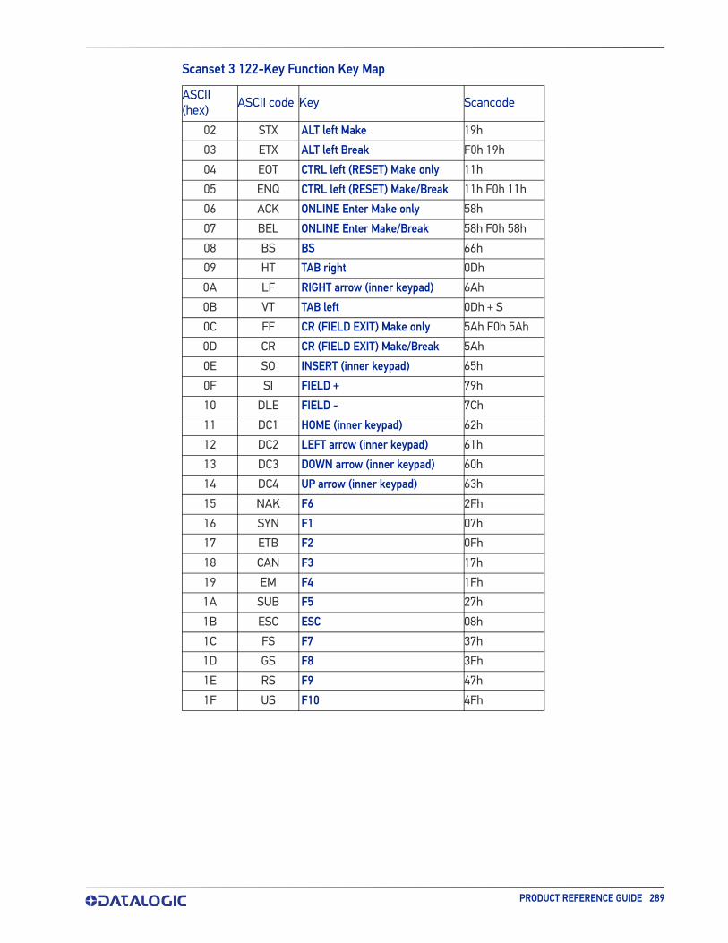
ASCII (hex) ASCII code Key Scancode
02 STX ALT left Make 19h
03 ETX ALT left Break F0h 19h
04 EOT CTRL left (RESET) Make only 11h
05 ENQ CTRL left (RESET) Make/Break 11h F0h 11h
06 ACK ONLINE Enter Make only 58h
07 BEL ONLINE Enter Make/Break 58h F0h 58h
08 BS BS 66h
09 HT TAB right 0Dh
0A LF RIGHT arrow (inner keypad) 6Ah
0B VT TAB left 0Dh + S
0C FF CR (FIELD EXIT) Make only 5Ah F0h 5Ah
0D CR CR (FIELD EXIT) Make/Break 5Ah
0E SO INSERT (inner keypad) 65h
0F SI FIELD + 79h
10 DLE FIELD - 7Ch
11 DC1 HOME (inner keypad) 62h
12 DC2 LEFT arrow (inner keypad) 61h
13 DC3 DOWN arrow (inner keypad) 60h
14 DC4 UP arrow (inner keypad) 63h
15 NAK F6 2Fh
16 SYN F1 07h
17 ETB F2 0Fh
18 CAN F3 17h
19 EM F4 1Fh
1A SUB F5 27h
1B ESC ESC 08h
1C FS F7 37h
1D GS F8 3Fh
1E RS F9 47h
1F US F10 4Fh
PRODUCT REFERENCE GUIDE 289
Scanset 3 122-Key Function Key Map

ASCII value ASCII code Key Scancode
02h STX ALT left Make 31h
03h ETX ALT left Break B1h
04h EOT CTRL left Make 41h
05h ENQ CTRL left Break C1h
06h ACK CTRL right Make 41h
07h BEL CTRL right Break C1h
08h BS BS 3Eh
09h HT TAB right 3Ch
0Ah LF RIGHT arrow (inner keypad) 4Dh
0Bh VT TAB left 3Ch + S
0Ch FF Enter (right keypad) 60h
0Dh CR CR 3Bh
0Eh SO INSERT (inner keypad) 52h
0Fh SI PAGE UP (inner keypad) 49h
10h DLE PAGE DOWN (inner keypad) 51h
11h DC1 HOME (inner keypad) 4Ch
12h DC2 LEFT arrow (inner keypad) 4Bh
13h DC3 DOWN arrow (inner keypad) 4Ah
14h DC4 UP arrow (inner keypad) 4Eh
15h NAK F6 6Dh
16h SYN F1 68h
17h ETB F2 69h
18h CAN F3 6Ah
19h EM F4 6Bh
1Ah SUB F5 6Ch
1Bh ESC ESC 3Dh
1Ch FS F7 6Eh
1Dh GS F8 6Fh
1Eh RS F9 70h
1Fh US F10 71h
290 MAGELLAN™ 3410VSI
Japanese DOS Function Key Map

PRODUCT REFERENCE GUIDE 291
NEC 9801-Key Function Key Map
ASCII value ASCII code Key Scancode
00h NUL unused n/a
01h SOH CR 1Ch
02h STX CAPS LOCK ON (make) 71h
03h ETX CAPS LOCK OFF (break) F1h
04h EOT CTRL left Make 74h
05h ENQ CTRL left Break F4h
06h ACK CTRL-C 60h
07h BEL n/a n/a
08h BS BS 0Eh
09h HT TAB right 0Fh
0Ah LF RIGHT arrow (inner keypad) 3Ch
0Bh VT TAB left 0Fh + S
0Ch FF DELETE 39h
0Dh CR CR 1Ch
0Eh SO INSERT (inner keypad) 38h
0Fh SI KATAKANA LOCK ON (Make) 72h
10h DLE KATAKANA LOCK OFF (Break) F2h
11h DC1 HOME (inner keypad) 3Eh
12h DC2 LEFT arrow (inner keypad) 3Bh
13h DC3 DOWN arrow (inner keypad) 3Dh
14h DC4 UP arrow (inner keypad) 3Ah
15h NAK F6 67h
16h SYN F1 62h
17h ETB F2 63h
18h CAN F3 64h
19h EM F4 65h
1Ah SUB F5 66h
1Bh ESC ESC 00h
1Ch FS F7 68h
1Dh GS F8 69h
1Eh RS F9 6Ah
1Fh US F10 6Bh

292 MAGELLAN™ 3410VSI
APPENDIX FHOST COMMANDS
ACCEPTING RS-232 AND USB COM COMMANDSThe scanner responds to the following RS-232 and USB COM commands:
COMMAND ASCII HEX COMMENT
Enable Scanner E 0x45
Disable Scanner D 0x44
Reset Scanner R 0x52
Not On File Indication F 0x46 Long series of beeps
Beep Good Read Tone B 0x42Beeps if Good Read Beep is enabled
Force Good Read Tone ! 0x01
Beeps regardless of beep set-ting
Identification request i 0x69 Returns long responsea
a. Call Tech Support for information.
Health request h 0x68 Returns long responsea
Status request s 0x73 Returns long responsea
Beep on ASCII BEL ! 0x07 Beeps if Beep on ASCII BEL is enabled
If one of the above commands is received, the scanner will perform the steps indi-cated for the command. Host commands for other interfaces are also available. Contact Tech Support for more details.Also see the section “Image Capture to the Host by Host Command” on page 40 for details concerning that feature.

PRODUCT REFERENCE GUIDE 293
APPENDIX GSAMPLE SYMBOLS
1D SYMBOL SAMPLES
0 1234567890
UPC-A
0 5
1234567890
Interleaved 2 of 5
Code 128
Code 128
9 780330 290951
EAN-13
BC321
Code 39
A13579B
Codabar
123456-9$
Code 93

1D SYMBOL SAMPLES
294 MAGELLAN™ 3410VSI
1D Symbols (continued)
0100123456789050
GS1 DataBar Expanded
(01)00123456789012
GS1 DataBar Omnidirectional 123456
Code 2 of 5
(01)16543210987654
GS1 DataBar Limited

PRODUCT REFERENCE GUIDE 295
2D SAMPLE SYMBOLS
A12B3C
BV17453
1314H17LL
PDF 417
Micro PDF 417
Datamatrix
QR Code
35900G9
Micro QR Code
Aztec
This is an Aztec Code
ABCDEF

COMPOSITE SAMPLE SYMBOLS
296 MAGELLAN™ 3410VSI
COMPOSITE SAMPLE SYMBOLS
GS1 DataBar Limited Composite
GS1 DataBar Truncated Composite

PRODUCT REFERENCE GUIDE 297
APPENDIX HMICROSD CARD
MICROSDHC COMPATIBILITY starting on page 298•microSD Card Insertion•microSD Card Removal
AUTORUN FILE PROCESSING starting on page 299
MICROSD FUNCTION SUMMARY starting on page 299
MICROSD FUNCTION DETAILS starting on page 300•From Scanner to microSD Card•From microSD Card to Scanner

MICROSDHC COMPATIBILITY
298 MAGELLAN™ 3410VSI
MICROSDHC COMPATIBILITYAt the time of this writing, the microSD card interface for this product supports SD-Memory Card Specifications/ Part 1. Physical Layer Specification; Version 1.01, but the processor MCI can communicate with SDHC Cards. For example, the scanner can perform the functions specified in this appendix for the SDA 2.0 specification. Both FAT16 and FAT32 formats are supported.Filenames are limited to the 8.3 file naming format (i.e., FILENAME.EXT), and MUST be capitalized.
microSD Card Insertion
1. Read all of these instructions before starting.
2. If you have not already done so, remove the scanner from its installed position to allow access to the microSD card slot.
3. Separate the scanner from its back cover.
4. Ensure there are no other cables attached to the scanner, then apply power and wait for the reset beep.
5. Lift and rotate the rubber cover to access the card slot, then carefully insert the microSD card into the slot until it "clicks" into place.
Scanner
microSD Card
Push down pastflush to seat, then carefully release
Seated card
CAUTION: The microSD card slot is spring loaded. Keep your finger lightly in place atop the card until you are sure it is fully seated in place. See the illustra-tion on the following page.
Use your finger or thumbnail to push in on the top edge of the card to be slightly below flush with the scanner enclosure when inserting or removing the card. This will engage/disengage the spring mechanism.
Never insert tools or other foreign objects into the microSD card slot.
6. If installed properly, you should immediately hear an audible signal upon insertion or removal of a microSD card. Various operations will also be indi-cated by the scanner’s good read LED.
CAUTION

MICROSD CARD REMOVAL
PRODUCT REFERENCE GUIDE 299
microSD Card Removal
1. Push in gently using your finger or thumbnail to disengage and remove the microSD card. Remember to keep your finger in place atop the card’s edge to avoid accidentally “launching” the card from the spring-loaded slot.
2. Reconnect all cables which were disconnected earlier.
AUTORUN FILE PROCESSINGAfter insertion of the card, the scanner will mount the microSD card and search for the file “AUTORUN.DLS”. Embedded in that file is a validation pattern of the ASCII strings “$START$” and “$END$” located at the respective starting and ending of the file.If the validation pattern is found, the file may contain any of the following com-mands. The scanner will parse the file taking action according to these commands. Filenames in this format specify a user-defined name.Example AUTORUN.DLS file:
$START$ (required)
CONFIG, FILENAME.TEX DUMPSTATS, FILENAME.TXTDUMPCFG, FILENAME.TEXLOADSW, FILENAME.S37$END$ (required)
MICROSD FUNCTION SUMMARYThe following table summarizes various functions of microSD card. Contact tech support regarding upgrade license for new features.
FUNCTION Export Status
Export Configuration
Load Applic
Load Config
Load CPLD Codea
Feature Upgradeb
Direction
Scanner microSD Card
√ √
microSD Card Scanner
√ √ √ √
Initiated byScanning a label √ √AUTORUN.DLS file in microSD card √ √ √ √ √ √
a. The only way to load CPLD code (i.e., FPGA code) is to load a new application package.b. The only way to do a feature upgrade is to load a new application package.

MICROSD FUNCTION DETAILS
300 MAGELLAN™ 3410VSI
MICROSD FUNCTION DETAILS
From Scanner to microSD Card
Capture and save an image to a microSD card by button press
1. Insert the secure microSD card into the scanner.
2. Place the item to be captured in front of the scanner.
3. Press and release the Camera Button for one second. The scanner will auto-matically capture and save the image to the microSD card.
4. The scanner will emit an audible signal when complete, and the image is saved to the microSD card.
Export a Configuration file from the Scanner to the microSD card
By AUTORUN.DLS file
1. Generate a text file by any text editor as follows and save it as AUTORUN.DLS.$START$DUMPCFG,SDCONFIG.TEX (Filename can be anything, for example “SOME-THING.TEX”)
$END$2. Save or copy file AUTORUN.DLS to microSD card
3. Insert the microSD card to scanner.
4. Wait for 3 seconds; a scanner configuration file named SDCONFIG.TXT is saved to the microSD card.
NOTE
NOTE: The microSD card must contain a secure file to save images. Contact Cus-tomer Support for more details about this feature.
The image file name range is from image-1 to image-999. If the same name already exists in the microSD card, the scanner skips that name and uses the next.
Image format (.BMP, .JPG), image size (VGA, WVGA, Full size), Brightness (0~9), contrast (0~9), and JPG compression ratio (0~100) are defined in config-uration.

FROM MICROSD CARD TO SCANNER
PRODUCT REFERENCE GUIDE 301
From microSD Card to Scanner
Application code load to scanner
By AUTORUN.DLS file
1. Generate a text file by any text editor as follows and save it as AUTORUN.DLS$START$LOADSW,R96-APP1.S37$END$
2. Save or copy file AUTORUN.DLS to microSD card and copy the application code (example R96-APP1.S37) to the microSD card.
3. Insert the microSD card into the scanner.
4. Upon scanner audio indication of completion, the application code R96-APP1.S37 is loaded to the scanner. Typically, this takes about 45 seconds.
Configuration load to scanner
By Autorun file
1. Generate a text file by any text editor as follows and save it as AUTORUN.DLS$START$CONFIG,R96-CFG1.TEX$END$
2. Save or copy the autorun.dls file, and copy the CPLD code (example R96-CFG1.TEX) to the microSD card.
3. Insert the microSD card into the scanner.
4. Upon scanner audio indication of completion, configuration R96-CFG1.TEX is loaded to the scanner.

302 MAGELLAN™ 3410VSI
APPENDIX IHANDHELD DATA FORMAT REQUIREMENTS
This appendix provides application notes to describe the general format of data that can be accepted by the scanner from a handheld scanner connected via the USB port.
HANDHELD DATA FORMAT REQUIREMENTS GENERAL• USB handhelds enumerate as a CDC ACM serial device.• USB devices should also bracket the data with the RTS equivalent.• The time between character transmission can be no longer than 50 millisec-
onds.• Symbologies requiring fixed lengths (UPC/EAN) will enforce length require-
ments for validation of the label.• Handheld will be required to transmit start and stop characters for Codabar
and Code39 labels.• Appropriate industrial length requirements will be enforced (if configured) for
validation of the label.• Maximum label lengths will be enforced for label validation (i.e. labels longer
than the maximum label size will not be validated).• Standard Datalogic formats generally use a single prefix character. See specific
formats section.• Maximum label size allowed including identifiers is 2714 bytes• Recommendations:
•Handheld should not be configured for audible label read indication.•Handheld should not be configured for visual label read indication.•Handheld should not be configured for continuous label read mode.
Datalogic Handheld Data Format RequirementsThe following sections describe label transmission formats that are typically observed in factory configurations of Datalogic handheld scanners.

DATALOGIC HANDHELD DATA FORMAT REQUIREMENTS
PRODUCT REFERENCE GUIDE 303
GS1 DataBar Omnidirectional • Prefix must be ASCII characters ‘R4’• Check character must be included in label• Application identifier “01” must follow the prefix and preceed the base label• Label length excluding prefix characters must be 16 characters. • Example: ‘R40101044123456789’
GS1 DataBar Expanded• Prefix must be ASCII characters ‘R4’• Check character must be included in label
UPC-A• Number system must be included in label data.• Check digit must be included in label data and is assumed to be correct.• Prefix must be an ASCII character 'A' - total length including prefix must be 13.• Example: 'A060992011187'.
UPC-A with 2-Digit Supplemental• Number system must be included in label data.• Check digit must be included in label data and is assumed to be correct.• Supplemental data is appended to base label.• Prefix must be an ASCII character 'A' - total length including prefix must be 15.• Example: 'A06099201118712'.
UPC-A with 5-Digit Supplemental• Number system must be included in label data• Check digit must be included in label data and is assumed to be correct• Prefix must be an ASCII character 'A' - total length including prefix must be 18• Example: 'A06099201118712345'
UPC-E• Number system must be included in label data• Check digit must be included in label data and is assumed to be correct• Prefix must be an ASCII character 'E' - total length including prefix must be 9• Example: 'E09988750'
UPC-E with 2-Digit Supplemental• Number system must be included in label data.• Check digit must be included in label data and is assumed to be correct.• Supplemental data is appended to base label.• Prefix must be an ASCII character 'E' - total length including prefix must be 11.• Example: 'E0998875012'.

HANDHELD DATA FORMAT REQUIREMENTS GENERAL
304 MAGELLAN™ 3410VSI
UPC-E with 5-Digit Supplemental• Number system must be included in label data.• Check digit must be included in label data and is assumed to be correct.• Prefix must be an ASCII character 'E' - total length including prefix must be 14.• Example: 'E0998875012345'.
EAN-8• Check digit must be included in label data and is assumed to be correct• Prefix must be an ASCII characters 'FF' - total length including prefix must be
10• Example: 'FF00210126'
EAN-8 with 2-Digit Supplemental• Check digit must be included in label data and is assumed to be correct.• Supplemental data is appended to base label.• Prefix must be an ASCII characters 'FF' - total length including prefix must be
12.• Example: 'FF0021012612'.
EAN-8 with 5-Digit Supplemental• Check digit must be included in label data and is assumed to be correct.• Prefix must be an ASCII characters 'FF' - total length including prefix must be
15.• Example: 'FF0021012612345'.
EAN-13• Check digit must be included in label data and is assumed to be correct• Prefix must be an ASCII character 'F'- total length including prefix must be 14• Example: 'F1101234567891'
EAN-13 with 2-Digit Supplemental• Check digit must be included in label data and is assumed to be correct• Supplemental data is appended to base label• Prefix must be an ASCII character 'F'- total length including prefix must be 16• Example: 'F110123456789112'
EAN-13 with 5-Digit Supplemental• Check digit must be included in label data and is assumed to be correct.• Prefix must be an ASCII character 'F'- total length including prefix must be 19.• Example: 'F110123456789112345'.
Code 39• Check character must be included in label data.

DATALOGIC HANDHELD DATA FORMAT REQUIREMENTS
PRODUCT REFERENCE GUIDE 305
• Label length including start, stop and check characters and excluding prefix character must meet requirements imposed by the main scanner's fixed or variable label length control for this symbology type.
• Start and stop characters "*" must be included in label.• Prefix must be an ASCII character '*'.• Example : '**Code 39.TEST*'.
Code 39-Pharmacode• Check character must be included in label data.• Label length including start, stop and check characters and excluding prefix
character must meet requirements imposed by the main scanner's fixed or variable label length control for this symbology type.
• Start and stop characters "*" must be included in label.• Prefix must be an ASCII character 'p'.• Example: 'p*123456789*'.
I 2 of 5• Check character must be included in label data.• Label length including check characters and excluding prefix character must
meet requirements imposed by the main scanner's fixed or variable label length control for this symbology type.
• Prefix must be an ASCII character 'i'.• Example: 'i0123456789'.
Codabar• Check character must be included in label data.• Label length including check character and excluding prefix character must
meet requirements imposed by the main scanner's fixed or variable label length control for this symbology type.
• Prefix must be an ASCII character '%'.• Start stop character sets must meet the matching requirement set forth by the
scanner configuration item Codabar Start Stop Character Match.• Start stop character sets must be of the form ABCD/ABCD and must be
included in the label.• Example: '%s$99.95s' (the lower case ‘s’ at each end of the example is a place-
holder for the start stop character set).
Code 128• Prefix must be an ASCII character '#'.• Label length excluding prefix character or function code 3 for Code 128 pro-
gramming labels must meet requirements imposed by the main scanner's fixed or variable label length control for this symbology type.

HANDHELD DATA FORMAT REQUIREMENTS GENERAL
306 MAGELLAN™ 3410VSI
• Function characters may be transmitted as a hexadecimal value 8x. Where x correlates to function characters 1 thru 4 as follows:
• x80 = function code 1• x81 = function code 2• x82 = function code 3• x83 = function code 4• For Code 128 programming labels the format is of the general form '#/82nn-
nnn/r ' - /82 is hexadecimal 82 and /r is carriage return.• Example: '#Code_128.Test'.
MSI• Check character must be included in label data.• Label length including check character and excluding prefix character must
meet requirements imposed by the main scanner's fixed or variable label length control for this symbology type.
• Prefix must be an ASCII character '@'.• Example: '@144769254'.
Code 93• Prefix must be an ASCII character '&'.• Label length excluding prefix character must meet requirements imposed by
the main scanner's fixed or variable label length control for this symbology type.
• Example: '&Code93-test'.
PDF417• Prefix must be an ASCII character 'P'.• Label length excluding prefix character cannot exceed 300 characters. In addi-
tion to this, label length excluding prefix character must meet requirements imposed by the main scanner’s fixed or variable label length control for this symbology type.
AIM FormatsAIM specifies a 3-character string that is attached as a prefix to the label data for transmission. Because AIM specifies one identifier for UPC-A, UPC-E and EAN-13 labels, UPC-A, UPC-E and EAN-13 will be received from the handheld and transmit-ted by the scanner as EAN-13. The ']' character must be the first character received in the label transmission from the handheld.The following sections describe the prefix strings and identify what specific label characteristics can be supported.
UPC-A• AIM does not specify UPC-A as a separate symbology using this transmission
format - labels will be transmitted as EAN-13.• Example: ']E00060992011187'.

AIM FORMATS
PRODUCT REFERENCE GUIDE 307
UPC-E• AIM does not specify UPC-E as a separate symbology using this transmission
format - labels will be transmitted as EAN-13.• Example: ']E00000000998875'.
EAN-13• Check digit must be included in label data and is assumed to be correct.• Prefix must be ASCII characters ']E0'- total length including prefix must be 16.• Example: ']E01101234567891'.
EAN-8• Check digit must be included in label data and is assumed to be correct.• Prefix must be ASCII characters ']E4' - total length including prefix must be 11.• Example: ']E400210126'.
2-Digit Supplemental• Supplemental data is appended to any EAN base label.• Prefix must be ASCII characters ']E1'.• length of Supplemental data including prefix must be 5. Total required length
is 21 for EAN-13 and 16 for EAN-8.• Examples: add-on portion is highlighted data is underlined.
5-Digit Supplemental• Supplemental data is appended to any EAN base label.• Prefix must be ASCII characters ']E2'.• Length of supplemental data including prefix must be 8. Total required length
is 24 for EAN-13 and 19 for EAN-8.• Examples: add-on portion is highlighted data is underlined.
Bookland• The 'Bookland' / ISBN code will be formatted as a vendor specific AIM label.• Prefix must be ASCII characters ']X0'.
UPC-A 2-Digit add-on ']E00060992011187]E112'
UPC-E 2-Digit add-on ']E00000000998875]E112'
EAN-8 2-Digit add-on ']E400210126]E112'
EAN-13 2-Digit add-on ']E01101234567891]E112'
UPC-A 5-Dgit add-on ']E00060992011187]E212345'
UPC-E 5-Digit add-on ']E00000000998875]E212345'
EAN-8 5-Digit add-on ']E400210126]E212345'
EAN-13 5-Digit add-on ']E01101234567891]E212345'
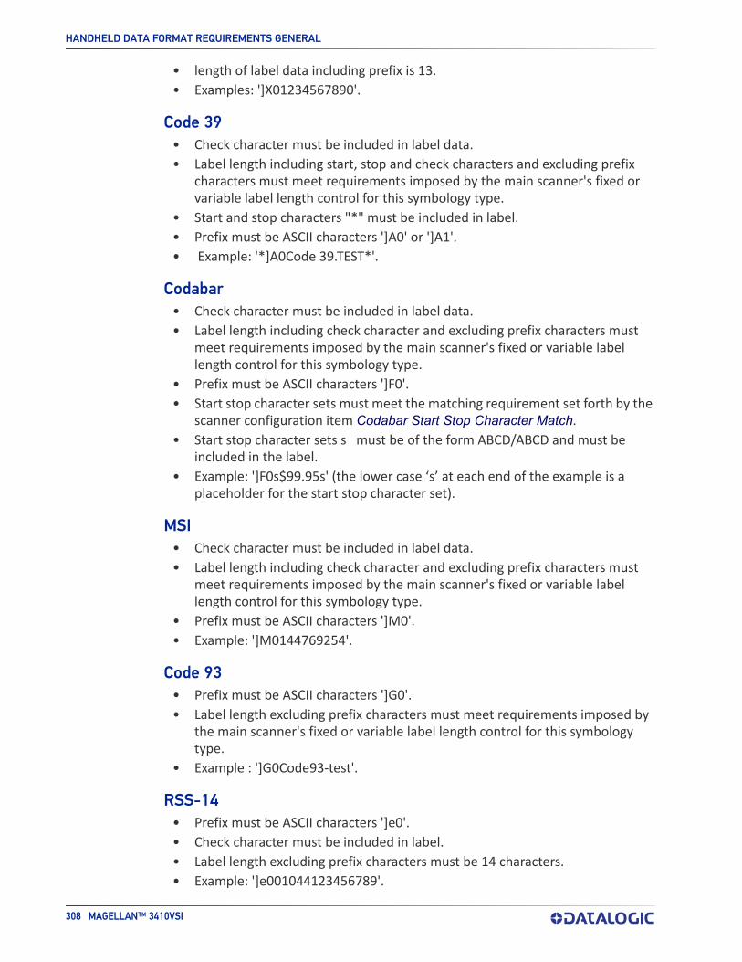
HANDHELD DATA FORMAT REQUIREMENTS GENERAL
308 MAGELLAN™ 3410VSI
• length of label data including prefix is 13.• Examples: ']X01234567890'.
Code 39• Check character must be included in label data.• Label length including start, stop and check characters and excluding prefix
characters must meet requirements imposed by the main scanner's fixed or variable label length control for this symbology type.
• Start and stop characters "*" must be included in label.• Prefix must be ASCII characters ']A0' or ']A1'.• Example: '*]A0Code 39.TEST*'.
Codabar• Check character must be included in label data.• Label length including check character and excluding prefix characters must
meet requirements imposed by the main scanner's fixed or variable label length control for this symbology type.
• Prefix must be ASCII characters ']F0'.• Start stop character sets must meet the matching requirement set forth by the
scanner configuration item Codabar Start Stop Character Match.• Start stop character sets s must be of the form ABCD/ABCD and must be
included in the label.• Example: ']F0s$99.95s' (the lower case ‘s’ at each end of the example is a
placeholder for the start stop character set).
MSI• Check character must be included in label data.• Label length including check character and excluding prefix characters must
meet requirements imposed by the main scanner's fixed or variable label length control for this symbology type.
• Prefix must be ASCII characters ']M0'.• Example: ']M0144769254'.
Code 93• Prefix must be ASCII characters ']G0'.• Label length excluding prefix characters must meet requirements imposed by
the main scanner's fixed or variable label length control for this symbology type.
• Example : ']G0Code93-test'.
RSS-14• Prefix must be ASCII characters ']e0'.• Check character must be included in label.• Label length excluding prefix characters must be 14 characters.• Example: ']e001044123456789'.
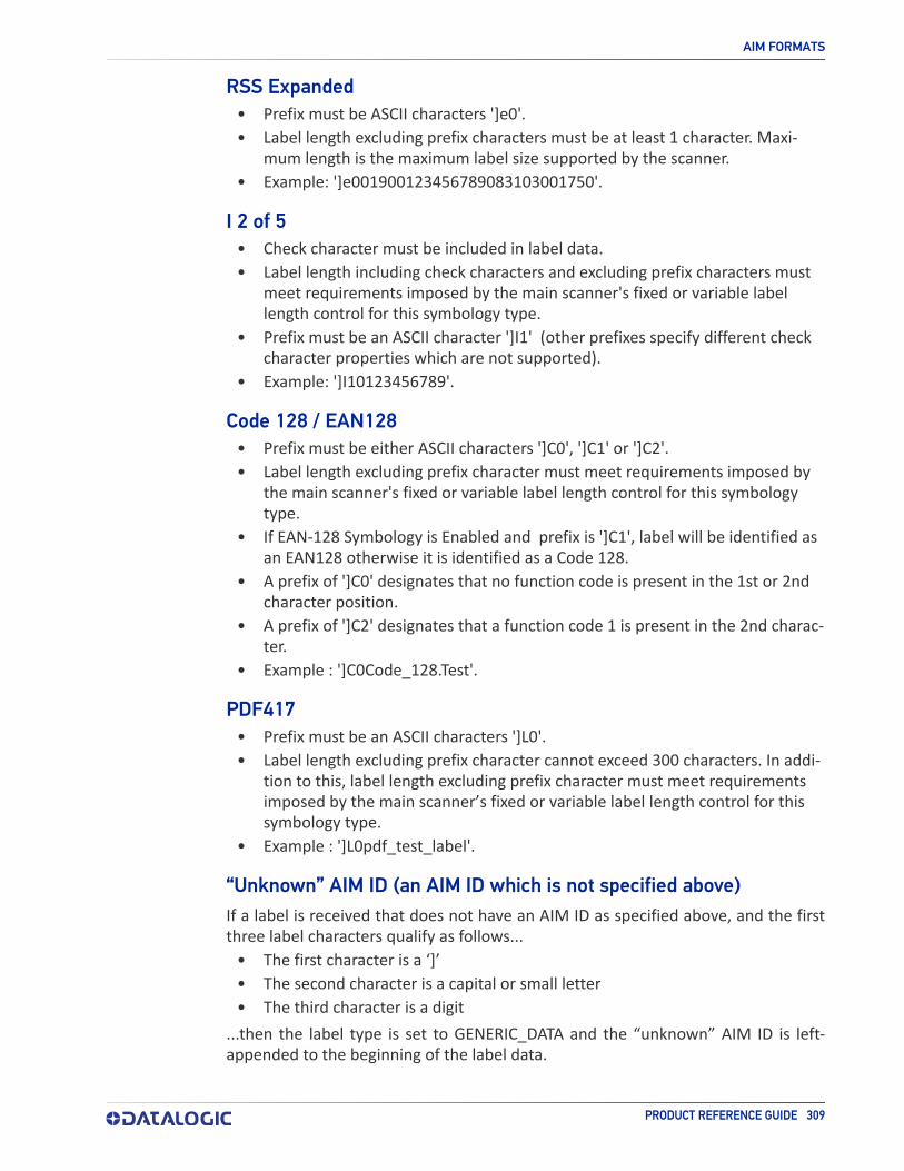
AIM FORMATS
PRODUCT REFERENCE GUIDE 309
RSS Expanded• Prefix must be ASCII characters ']e0'.• Label length excluding prefix characters must be at least 1 character. Maxi-
mum length is the maximum label size supported by the scanner.• Example: ']e001900123456789083103001750'.
I 2 of 5• Check character must be included in label data.• Label length including check characters and excluding prefix characters must
meet requirements imposed by the main scanner's fixed or variable label length control for this symbology type.
• Prefix must be an ASCII character ']I1' (other prefixes specify different check character properties which are not supported).
• Example: ']I10123456789'.
Code 128 / EAN128• Prefix must be either ASCII characters ']C0', ']C1' or ']C2'.• Label length excluding prefix character must meet requirements imposed by
the main scanner's fixed or variable label length control for this symbology type.
• If EAN-128 Symbology is Enabled and prefix is ']C1', label will be identified as an EAN128 otherwise it is identified as a Code 128.
• A prefix of ']C0' designates that no function code is present in the 1st or 2nd character position.
• A prefix of ']C2' designates that a function code 1 is present in the 2nd charac-ter.
• Example : ']C0Code_128.Test'.
PDF417• Prefix must be an ASCII characters ']L0'.• Label length excluding prefix character cannot exceed 300 characters. In addi-
tion to this, label length excluding prefix character must meet requirements imposed by the main scanner’s fixed or variable label length control for this symbology type.
• Example : ']L0pdf_test_label'.
“Unknown” AIM ID (an AIM ID which is not specified above)If a label is received that does not have an AIM ID as specified above, and the first three label characters qualify as follows...
• The first character is a ‘]’• The second character is a capital or small letter• The third character is a digit
...then the label type is set to GENERIC_DATA and the “unknown” AIM ID is left-appended to the beginning of the label data.

HANDHELD DATA FORMAT REQUIREMENTS GENERAL
310 MAGELLAN™ 3410VSI
NOTES

ASCII Character Set
ASCII Char. Hex No. ASCII
Char. Hex No. ASCII Char. Hex No. ASCII
Char.HexNo.
NULSOHSTXETXEOTENQACKBELBSHTLFVTFFCRSOSI
DLEDC1DC2DC3DC4NAKSYNETBCANEM
SUBESCFSGSRSUS
000102030405060708090A0B0C0D0E0F101112131415161718191A1B1C1D1E1F
SP!“#$%&’()*+,-./0123456789:;<=>?
202122232425262728292A2B2C2D2E2F303132333435363738393A3B3C3D3E3F
@ABCDEFGHIJKLMNOPQRSTUVWXYZ[\]^_
404142434445464748494A4B4C4D4E4F505152535455565758595A5B5C5D5E5F
‘abcdefghijkl
mnopqrstuvwxyz{|}~
DEL
606162636465666768696A6B6C6D6E6F707172737475767778797A7B7C7D7E7F

Datalogic S.r.l.Via S. Vitalino, 13 | 40012 Calderara di Reno | Bologna - ItalyTel. +39 051 3147011 | Fax +39 051 3147205
©2021 Datalogic S.p.A. and /or its affiliates • All rights reserved • Without limiting the rights under copyright, no part of this documentation may be reproduced , stored in or introduced into a retrieval system, or transmitted in any form or by any means, or for any purpose, without the express written permission of Datalogi c S.p.A. and/or its affiliates • Datalogic and the Datalogic logo are registered trade-marks of Datalogic S.p.A. in many countries, including the U.S. and the E.U.
www.datalogic.com
820118900 (Rev A) January 2021