
VW 60307 Electrical Connections Ultrasonic Welding on ...
40
Group standard VW 60307 Issue 2019-11 Class. No.: 69302 Descriptors: cable, conductor, copper, electrical cable, stranded conductor, ultrasonic welding, weld node Electrical Connections Ultrasonic Welding on Stranded Conductors Requirements for and Testing of Copper Weld Nodes Previous issues VW 60307: 1998-11, 2002-08, 2004-10, 2005-05 Changes The following changes have been made to VW 60307: 2005-05: a) Standard completely revised, expanded, and restructured b) General basic principles regarding the joining method incorporated c) Specifications for conductors with reduced cross sections added d) Specifications for the evaluation of weld nodes with a conductor cross section A L > 30 mm 2 added e) Qualification and release definitions added f) Revision record in "Earlier issues" corrected. Contents Page Scope ......................................................................................................................... 2 Definitions .................................................................................................................. 2 Symbols ..................................................................................................................... 3 Abbreviations ............................................................................................................. 4 Basic principles for making weld nodes ..................................................................... 4 Ultrasonic welding ...................................................................................................... 4 Welding tools and characteristic sizes ....................................................................... 5 Welding process ......................................................................................................... 7 Welding parameters ................................................................................................. 10 Weld node ................................................................................................................ 13 Joint characteristic values ........................................................................................ 15 Requirements ........................................................................................................... 17 General information .................................................................................................. 17 Welding machine ...................................................................................................... 17 1 2 3 4 5 5.1 5.2 5.3 5.4 5.5 5.6 6 6.1 6.2 Always use the latest version of this standard. This electronically generated standard is authentic and valid without signature. A comma is used as the decimal sign. The English translation is believed to be accurate. In case of discrepancies, the German version controls. Page 1 of 40 All rights reserved. No part of this document may be provided to third parties or reproduced without the prior consent of one of the Volkswagen Group’s Standards departments. | internal © Volkswagen Aktiengesellschaft VWNORM-2019-10
-
Upload
khangminh22 -
Category
Documents
-
view
4 -
download
0
Transcript of VW 60307 Electrical Connections Ultrasonic Welding on ...

Group standard VW 60307Issue 2019-11
Class. No.: 69302
Descriptors: cable, conductor, copper, electrical cable, stranded conductor, ultrasonic welding, weld node
Electrical Connections
Ultrasonic Welding on Stranded ConductorsRequirements for and Testing of Copper Weld Nodes
Previous issues
VW 60307: 1998-11, 2002-08, 2004-10, 2005-05
Changes
The following changes have been made to VW 60307: 2005-05:a) Standard completely revised, expanded, and restructuredb) General basic principles regarding the joining method incorporatedc) Specifications for conductors with reduced cross sections addedd) Specifications for the evaluation of weld nodes with a conductor cross section AL> 30 mm2
addede) Qualification and release definitions addedf) Revision record in "Earlier issues" corrected.
ContentsPage
Scope ......................................................................................................................... 2Definitions .................................................................................................................. 2Symbols ..................................................................................................................... 3Abbreviations ............................................................................................................. 4Basic principles for making weld nodes ..................................................................... 4Ultrasonic welding ...................................................................................................... 4Welding tools and characteristic sizes ....................................................................... 5Welding process ......................................................................................................... 7Welding parameters ................................................................................................. 10Weld node ................................................................................................................ 13Joint characteristic values ........................................................................................ 15Requirements ........................................................................................................... 17General information .................................................................................................. 17Welding machine ...................................................................................................... 17
123455.15.25.35.45.55.666.16.2
Always use the latest version of this standard.This electronically generated standard is authentic and valid without signature. A comma is used as the decimal sign.The English translation is believed to be accurate. In case of discrepancies, the German version controls.
Page 1 of 40
All rights reserved. No part of this document may be provided to third parties or reproduced without the prior consentof one of the Volkswagen Group’s Standards departments. | internal© Volkswagen Aktiengesellschaft VWNORM-2019-10

Page 2VW 60307: 2019-11
Process monitoring .................................................................................................. 17Cables ...................................................................................................................... 19Weld node ................................................................................................................ 21Position of weld node in the wiring harness ............................................................. 24Tests ......................................................................................................................... 28Mechanical tests ...................................................................................................... 28Environmental test ................................................................................................... 30Release/qualification ................................................................................................ 32Release tests ........................................................................................................... 32Qualification matrix ................................................................................................... 33Applicable documents .............................................................................................. 39Additional explanations ............................................................................................ 40General information .................................................................................................. 40Cable insulation circumscribed circle ....................................................................... 40Compression ............................................................................................................ 40Height-width ratio ..................................................................................................... 40
6.36.46.56.677.17.288.18.29Appendix AA.1A.2A.3A.4
Scope
This standard defines the requirements for cable connections for cables with copper stranded con-ductors, as well as the corresponding testing. This standard defines the geometric and mechani-cal/technological properties of weld nodes joined with ultrasonic welding.
Definitions
AmplitudeThe biggest lengthening of the sonotrode vibration, expressed as the ratio to the maximum ampli-tude defined by the design
Node variantNode configuration with differences in number, cross section, structure, and materials between thecables being connected
Pressing dimensionPosition of the anvil after it presses the inserted cable ends together after the welding tools areclosed
Welding pressurePressure used to generate the contact pressure with which the anvil acts, during pre-compressingand welding, on the conductors being welded
Welding energyEnergy that must be introduced into the weld nodes
Weld nodePermanent electrical and mechanical connection between various cable ends between strandedcables.
1
2

Page 3VW 60307: 2019-11
Welding dimensionPosition of the anvil after the specified welding energy has been introduced into the node and thewelding operation is completed
Welding timeThe time that the ultrasonic waves act on the material being welded until the required welding en-ergy has been introduced into the weld node
Special nodeNode with a harder pressing dimension check or node structure not described in this standard andfor which individual tests as per table 3 are required
Symbols
Welding areaActual conductor cross section of the individual stranded conductorsEffective weld node cross sectionDistance between node insulation and permanent bending pointCable cross sectionEffective length of anti-peeling protection elementDistance between connected nodesTotal actual cross section (actual cross section)Flash widthNode widthDegree of compressionMachine capability indexDiameter of an individual strand in a stranded conductorDiameter of the circumscribed circle of the cable insulationContact pressureBending forcePeeling forceTensile forceEffective node heightFlash heightNode heightMeasured node heightCorrection value for the node surfaceMeasuring device widthLength of weld stop zoneDistance between welding area and cable insulationStrand end projectionConductor i (i = 1, 2, etc.)Length of evidently melted or joined cable insulationLength of welding zoneLength of fused-on cable insulationLength of insulation connection reinforcement with duct tape or heat-shrinktubingCenter of weld nodeNumber of strands in a stranded conductor i (i = 1, 2, etc.)Welding power
3
AAiAKaKiFACapavKA0bGbKCCmkdiDUFFBFpeFpuheffhGhKhKmKLlala, ALilDLilPlslTlV
MniP

Page 4VW 60307: 2019-11
Welding dimensionUpper exposure temperatureLower exposure temperatureTimeTime of exposure with temperature To
Time of exposure with temperature Tu
Deviation as a percentageLoose strand angle
Abbreviations
Build sample approvalPart owning developer, e.g., at Volkswagen/Audi, who owns the semi-finish-ed product (yard goods) or assembled cablesEngineering Data Management System (Volkswagen system)Customized wiring harnessQualification matrix
Basic principles for making weld nodes
Ultrasonic welding
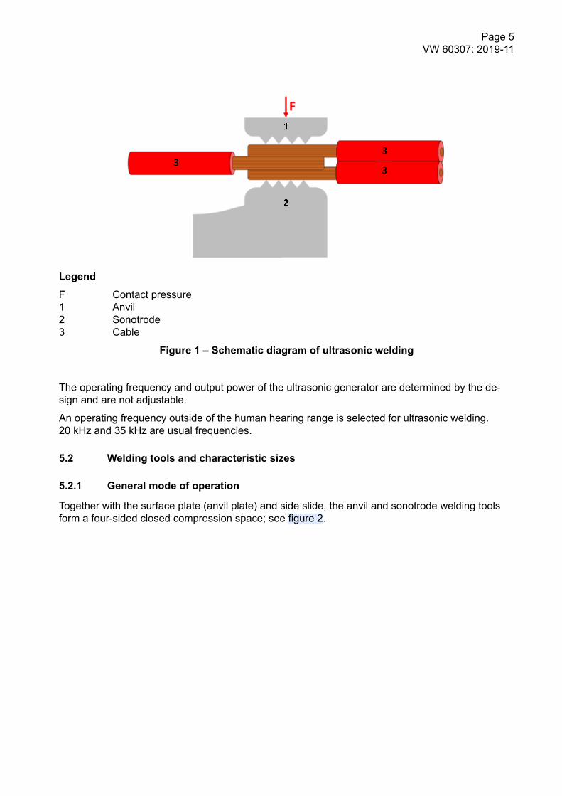
The stripped ends of vehicle cables are permanently connected to each other with mechanical vi-bration energy and the simultaneously acting contact pressure; see figure 1.
The sonotrode's deflection with a specific amplitude causes the parts being welded to undergohigh-frequency relative motion under relatively low pressure. Much like with diffusion welding, thematerial at the contact surfaces is welded in the solid phase and, in the case of materials with anidentical structure, a crystalline joint will be formed there. The welding is homogenous and resultsin both high strength and excellent electrical conductivity. Structural changes in the parent materialoccur only in a very small area; the rest of the part keeps its structure and basic strength.
sToTuttotuxα
4
BMGBTV
HyperKVSKSKQ matrix
5
5.1
Page 5VW 60307: 2019-11
LegendF Contact pressure1 Anvil2 Sonotrode3 Cable
Figure 1 – Schematic diagram of ultrasonic welding
The operating frequency and output power of the ultrasonic generator are determined by the de-sign and are not adjustable.
An operating frequency outside of the human hearing range is selected for ultrasonic welding.20 kHz and 35 kHz are usual frequencies.
Welding tools and characteristic sizes
General mode of operation
Together with the surface plate (anvil plate) and side slide, the anvil and sonotrode welding toolsform a four-sided closed compression space; see figure 2.
5.2
5.2.1

Page 6VW 60307: 2019-11
Legend1 Anvil2 Sonotrode3 Side slide4 Surface plate5 Gap
Figure 2 – Schematic diagram of welding tools with direction of motion
Sonotrode and anvil
In order to allow for the low-loss transmission of sound energy, the anvil (counter surface) and thesonotrode (active tool) have a tool profile structure on their surface.
The anvil is used to apply the contact pressure to the material being welded and the welding mo-tion is transmitted by the sonotrode. The amplitude of the sonotrode movement is controlled or setelectronically.
The sonotrode and the anvil are wear parts. The durability of the sonotrode and the anvil is influ-enced to a large degree by the stress placed on them as a result of the structure of the nodes be-ing welded, among other factors.
Side slide and surface plate
The distance between the side slide and surface plate determines the node width. In order to beable to adjust the welding space width in line with the node size, the side slide is adjustable. To-gether with the anvil's contact pressure, which can be varied, this makes it possible to achieveidentical surface pressure conditions for all node variants and sizes.
The side slide and the surface plate are wear parts.
Gap size
The gap size between the sonotrode and the surface plate, as well as between the sonotrode andthe side slide, is required in order for the sonotrode to be able to freely move for welding. However,
5.2.2
5.2.3
5.2.4

Page 7VW 60307: 2019-11
excessively large gap sizes will result in strands undesirably migrating into them; see also the flashformation information in section 5.5.3.
Insertion aid
General information
In order to mix the cable ends being welded together in a targeted manner, an insertion aid may berequired in order to ensure ideal welding between the cable ends.
Triangular or mixing insertion aid
A triangular or mixing insertion aid is a special tool that makes it possible to weld the conductorends together on top of each other; see figure 3
Figure 3 – Triangular or mixing insertion aid
Side slide for pre-adjustment
The side slide is already moved forward to the welding and node width before the welding opera-tion and before the cable ends are inserted. This reduces the insertion area and minimizes the riskof cable ends being inserted next to each other; see figure 4.
Figure 4 – Pre-adjustment with side slide
Welding process
Procedure
The flowchart in figure 5 shows the steps in the welding process.
5.2.5
5.2.5.1
5.2.5.2
5.2.5.3
5.3
5.3.1

Page 8VW 60307: 2019-11
Figure 5 – Welding process steps
Cable end insertion and positioning
Procedure
The stripped ends of the cables being joined are placed inside the compression space. After thewelding process starts, the anvil moves out of its side parking position.
Good positioning is characterized by the conductor end terminating flush with the welding profileedges or a comparable, optional stranded conductor stop; see figure 6.
Figure 6 – Correct position of cable ends
5.3.2
5.3.2.1

Page 9VW 60307: 2019-11
Possible insertion errors
The following insertion and positioning errors are possible:
1. Side splicesSide splices may be produced particularly when there is an even number of conductor endswith the exact same cross section. These side splices are unable to effectively absorb normalforces F; see figure 7.
LegendF Force normal to side splice1 Anvil2 Sonotrode3 Side splice4 Conductor
Figure 7 – Side splices
2. The positioning is not correct; see figure 8 and figure 9.
Figure 8 – Cable end not inserted sufficiently
Figure 9 – Cable end inserted too far
3. The insulation was inserted as well.
Figure 10 – Cable insulation in weld node
4. The wrong cable(s), or the wrong number of cables, were inserted.
5.3.2.2

Page 10VW 60307: 2019-11
Pressing dimension recording and check
After the welding tools are closed, the anvil will press the inserted cable ends together. The result-ing anvil position is referred to as the "pressing dimension."
The desired value for the pressing dimension depends on the node variant (see figure 11), the an-vil and sonotrode positions, and the defined closing force.
LegendAK Weld node cross sectionp Pressing dimension
Figure 11 – Pressing dimension as a function of node cross section
Welding operation
If the pressing dimension matches the desired value, the welding operation will be started automat-ically: The welding power (see section 5.4.2.2) will be applied during the welding time (seesection 5.4.3.2) under the welding pressure (see section 5.4.2.1) and the welded joint will be made.
The welding operation will end when the specified welding energy has been introduced into thenode. The resulting anvil position is referred to as the "welding dimension."
Welding dimension and welding time recording and check
The welding dimension and welding time determined after the welding operation must be com-pared with the corresponding reference values in order to verify the degree of energy input.
A certain part of the introduced welding energy is always converted to heat. The bigger the nodesize, the bigger the thermal load on the cable insulation. The requirements in section 6.5.5 apply.
Welding parameters
General information
In order to ensure consistent welding quality, the required welding parameters for each node var-iant are verified as per the qualification matrix (see section 8) and saved (see section 6.2).
The starting parameters are stored in the machine controller by cross section and are adjusted inline with the mechanical requirements (see section 7.1) if necessary; see figure 12.
5.3.3
5.3.4
5.3.5
5.4
5.4.1

Page 11VW 60307: 2019-11
LegendP Welding powers Welding dimensiont Welding time
Figure 12 – User interface for the machine controller (example) showing the adjustablewelding parameters (A) and the resulting welding parameters (B) as per table 1
Table 1 – Welding parameters from figure12
No. in figure 12Welding parameters
Adjustable (A) Resulting (B)
1 Cross section —
2 Welding pressure —
3 Weld width —
4 Amplitude —
5 Energy —
6 — Pressing dimension
7 — Welding dimension
8 — Welding time
Adjustable welding parameters
The welding parameters (see section 5.4.2.1 to section 5.4.2.4) must be set in a node-specificmanner.
5.4.2

Page 12VW 60307: 2019-11
Amplitude
The amplitude has a large effect on the degree of compression (see section 5.6.2) and must bekept constant for all the welds for a node variant.
Unit: Absolute value in micrometers (µm) or as a percentage (%)
Welding pressure
The contact pressure resulting from the welding pressure must be defined in a node-specific man-ner and significantly affects the degree of compression (see section 5.6.2). It is controlled or setelectronically.
Unit: bar (for pneumatic anvil drives; different for alternative drives)
Welding energy
The welding energy must be defined in a node-specific manner and significantly affects the degreeof compression.
The welding energy (green area in figure 12) is the integral of the welding power over the weldingtime.
Unit: Watt seconds (Ws)
Weld width
The weld width determines the later weld node width. The weld width must be specified based onthe total weld node cross section. For this purpose, the side slide moves to the set position and,together with the sonotrode, anvil, and surface plate, forms the welding space (see alsosection 6.5.4).
Unit: Millimeters (mm)
Resulting welding parameters
General information
The adjustable welding parameters result in the following in a node-specific manner: Pressing di-mension (see section 5.3.3), welding dimension (see section 5.3.5), and welding time (seesection 5.4.3.2).
Welding time
The welding time serves as the check dimension for process monitoring. The reference value forthe welding time is defined when calibrating the node variant (making the reference node) (seesection 6.2).
Unit: Milliseconds (ms)
5.4.2.1
5.4.2.2
5.4.2.3
5.4.2.4
5.4.3
5.4.3.1
5.4.3.2

Page 13VW 60307: 2019-11
Weld node1)
Weld node types
Connecting node
In connecting nodes, cables terminate in two directions; see figure 13.
Figure 13 – Connecting node (side view)
Terminal node
In terminal nodes, call cables terminate in one single direction; see figure 14.
Figure 14 – Terminal node (side view)
Node size/total cross section
General information
The nominal size of the weld node is the total of the nominal cross sections of the conductors be-ing welded.
The width of the weld node is determined or influenced by the distance between the side slide andthe surface plate (see section 5.2.3). The height of the weld node is determined or influenced bythe welding parameters (see section 5.4).
The welding dimension (see section 5.3.5) is not necessarily the same as the measurable or effec-tive node height.
Measurable node height
The weld node's surface is significantly shaped by the welding tool's ripple structure. Accordingly,the measurable node height is measured using at least two wave peaks (see figure 15). Weld nodeflash must not be included in node dimension measurements, and must be removed if necessary.
The measurable node height is evaluated as per the qualification matrix (see section 8).
5.5
5.5.1
5.5.1.1
5.5.1.2
5.5.2
5.5.2.1
5.5.2.2
1) Weld nodes are also referred to as splices.

Page 14VW 60307: 2019-11
LegendhKm Measured node heightL Measuring device width (e.g., caliper)
Figure 15 – Measuring the node dimensions
Effective node height
As per formula (1), the effective node height takes into account the node surface structure (tool im-pression) and is required in order to determine the degree of compression (see section 5.6.2):
heff = hKm − K
Legendheff Effective node heighthKm Measured node heightK Correction value for the node surface2)
(1)
Node width
The node width (see dimension B in figure 17) is required in order to determine the degree of com-pression (see section 5.6.2).
Node length
A distinction must be made between weld stop zones and welding zones when it comes to thenode length and to the welding area length.
The sonotrode and anvil weld stop zones are optimized in terms of mechanical node requirements.
The length of the welding area is an anvil-specific and sonotrode-specific dimension.
The node geometry is verified as per figure 16 starting from the center of the sonotrode and anvilimpressions on the weld node (sonotrode center):
5.5.2.3
5.5.2.4
5.5.2.5
2) K = 0,2 mm, unless otherwise specified.

Page 15VW 60307: 2019-11
LegendA Welding area (sonotrode width dimension)la Length of weld stop zonela, ALi Length of weld stop zone between welding area and cable insulationlD Strand end projectionls Length of welding zoneM Center of weld node
Figure 16 – Node length
Flash
Flash may form at the edges of the weld node due to the gaps between the sonotrode, surfaceplate, and side slide.
LegendbG Flash widthbK Weld node widthhG Flash height
Figure 17 – Flash on weld node
Requirements as per section 6.5.6 and qualification matrix (see section 8).
Joint characteristic values
Height-width ratio
The ultrasonic welding process makes it possible to introduce the welding energy only from oneboundary surface of the rectangular joint. The node-width-to-node-height ratio has a large influ-ence on the energy penetration into the material being welded.
The height-width ratio specifications apply (see section 6.5.4).
5.5.3
5.6
5.6.1

Page 16VW 60307: 2019-11
Degree of compression
Welding under an acting force means that the node is compressed, i.e., the strands will be de-formed and the spaces between the strands will be made significantly smaller.
The degree of compression is defined as the ratio of the total actual conductor cross sections tothe effective node cross section; see formula (2).
Degree of compression
C = A0
AK
× 100 %
LegendAK Effective node cross sectionA0 Total actual cross section (actual cross section)C Degree of compression
(2)
The total of the actual conductor cross sections of the stranded conductors forming the node is cal-culated as per formula (3):
LegendAi Actual cross section of individual conductor
(3)
The individual actual conductor cross sections are calculated as the total of the strand cross sec-tions of the stranded conductor as per formula (4):
Ai = ni × π4
d2i
LegendAi Actual conductor cross section of the stranded conductordi Diameter of an individual strandni Number of strands
(4)
The effective node cross section is calculated as per formula (5) using the effective node heightand the node width; see also figure 17.
AK = bK × heff
LegendAK Effective node cross sectionbK Node widthheff Effective node height
(5)
5.6.2

Page 17VW 60307: 2019-11
Requirements
General information
The weld node quality can be measured with nondestructive methods only if certain conditions aremet. The requirements defined in section 6.2 to section 6.6 must be met in order to ensure that theweld node properties will be maintained under economically feasible production conditions.
The requirements must be checked as per the qualification matrix (see section 8).
Welding machine
The welding parameters (see section 5.4) are stored as starting parameters in the welding ma-chine's software. Automatic process monitoring and energy control is required.
The welding jig must be adequate for the weld nodes being made in terms of the following charac-teristics:– Compression space– Welding power– Error detection
The weld width setting must be reproducible in a sufficiently precise manner and must not bechanged by external influences.
Timely tool maintenance (see section 6.3.4.5) must be ensured based on the number of weldingoperations or a comparable metric.
Using node-specific welding parameters for identical machine models is permissible only if the ma-chine and tool manufacturing tolerances are effectively compensated for with suitable calibration.The manufacturer's specifications must be observed.
Every time after welding machines are set up again or relocated, test welds and tests as per thequalification matrix (see section 8) are required.
Repairs and maintenance work must be carried out exclusively by trained and authorized person-nel. The manufacturer's specifications must be observed.
A CmK of 1,67 must be verified for the capabilities required as per the qualification matrix (seetable 5).
Process monitoring
General information
The monitoring criteria are the welding time (see section 5.4.3.2), the pressing dimension (seesection 5.3.3), and the welding dimension (see section 5.3.5).
In order to ensure reliable error detection, the measuring system resolution must be at least0,01 mm.
Insertion position
The cable ends must be straight and as parallel to each other as possible. It must be ensured thatno strands stick out.
6
6.1
6.2
6.3
6.3.1
6.3.2

Page 18VW 60307: 2019-11
The stranded conductors with the largest strand diameters must be placed on the side facing thesonotrode (see section 5.3.2). Due to practical considerations, cables with the largest insulationouter diameter can be inserted on the sonotrode side after a corresponding check.
If necessary, an insertion aid (see section 5.2.5) must be used.
The cables' insulation ends must be positioned identically with suitable measures. The weld nodeinsulation requirements in the wet area (see section 6.6.5.3) must be met.
If an insertion error is detected (see section 5.3.2.2), it must not be possible to run the welding op-eration.
Pressing dimension and welding dimension
Insertion errors that result in a change in height (see section 5.3.2) and a deviation percentage xfrom weld node cross section AK must be detected by the machine controller. The following appliesto x within this context:– x = 7% if weld node cross section AK < 5 mm2
– x = 5% if weld node cross section AK ≥ 5 mm2
In order to reliably detect when there are missing cables, the smallest conductor cross sectionmust be at least 9% (if AK < 5 mm2) or 7% (if AK ≥ 5 mm2) of the total cross section.
The pressing dimension (see section 5.3.3) must be determined during the process for each weldand compared with the verified desired value.
The welding operation is allowed to be started again after the cause behind a pressing dimensionerror is fixed, but no more than three times.
Welding operation
General information
If the node height or anvil position expected in the tolerance range cannot be reached within themaximum permissible welding time (see section 5.4.3.2), the welding operation must be aborted.These nodes are not allowed to be rewelded and must be reliably removed from the productionprocess. It is permissible to strip and weld the cable ends again under consideration of the cable'spermissible minimum length. This length must be specified by the user.
After the welding operation, every node must be visually inspected for strands that are sticking outor have been squeezed out (see section 6.5.7). These strands must be removed under considera-tion of the permissible node cross section reduction (see section 6.3.3).
Welding time
The welding time (see section 5.4.3.2) is allowed to be continued, i.e., increased, in order to reachthe required delivery of energy, but must not exceed the reference value by more than 15%.
Welding tool
In order to optimize the mechanical properties, notches must be effectively avoided in the tool pro-file's edge zones. This can be achieved, among other ways, with the use of weld stop zones inwhich the sonotrode and anvil surface ripple structure gradually disappears in the branch-off direc-tion.
6.3.3
6.3.4
6.3.4.1
6.3.4.2
6.3.4.3

Page 19VW 60307: 2019-11
Gap size
The gap size (see section 5.2.4) must be set as per the machine manufacturer's or tool manufac-turer's specifications.
Tool inspection interval
Unless otherwise defined, the wear parts (see section 5.2) must be checked at regular intervals.The first check must be after 50 000 welding operations at the latest, and 25 000 welding opera-tions after that as per the qualification matrix (see section 8). The intervals must be adjusted in linewith the requirements.
Wear parts must be replaced as per the machine manufacturer's or tool manufacturer's specifica-tions (genuine parts by the manufacturer must be used exclusively).
Impurities
Impurities can negatively influence the weld properties and must be effectively prevented.
The condition of the tool surfaces must be carefully checked with each inspection; copper and dirtparticles must be removed if necessary.
Cables
Materials and dimensions
The materials and dimensions of the cables being joined must conform to VW 60306-1 andVW 60306-4.
Welding tinned cable ends is impermissible.
Stripping
A standardized nominal strip length must be used within a weld node.
In general, the specifications in VW 60330 apply to stripping.
The strip length must be verified under consideration of the number and cross section of the indi-vidual conductors, the tool width, and other requirements for downstream processes (water leak-tightness; see section 6.6.5.3).
Number of conductors
The number of conductors is limited as per table 2.
6.3.4.4
6.3.4.5
6.3.4.6
6.4
6.4.1
6.4.2
6.4.3

Page 20VW 60307: 2019-11
Table 2 – Maximum permissible number of conductors in weld node
Node variant Node type
Terminal node Connecting node
Standard node ≤ 7 ≤ 5 per side
Node with harder pressing dimension check 8 to 15 6 to 8 per side;maximum total of 15
In the case of weld nodes with a large number of conductors, handling is more difficult and detect-ing insertion errors (see section 5.3.2.2) with a pressing dimension check is harder. These weldnodes must be qualified as special nodes as per the Q matrix in section 8. It must be checkedwhether suitable additional measures are required in order to ensure the correct conductor posi-tioning.
The weld node insulation specifications (see section 6.6.5) must be observed.
Individual conductor combinations and cross sections
The required insertion check (see section 5.3.3) limits the usability of small individual conductorcross sections. Table 3 Lists the possible cross section combinations.
Table 3 – Permissible combinations (cross section jumps) of individualconductors
Cross section area in mm2
Conductor cross sec-tionAL1
Conductor cross section AL2
0,13 0,35 0,5 0,75 1 1,5 2,5 4 6 10
0,13 X X X (X) (X) — — — — —
0,35 X X X X X — — — —
0,5 X X X X X — — —
0,75 X X X X — — —
1 X X X X — —
1,5 X X X X —
2,5 X X X X
4 X X X
6 X X
10 X
X—(X)
Permissible combinationImpermissible combinationIndividual check required
If the specified condition cannot be implemented in a single weld node, splitting the node into multi-ple connected weld nodes is required.
For the dimensioning of the cable between the nodes, the permissible current-carrying capacity ofboth weld nodes must be taken into account; the distances between these weld nodes must bemaintained as per section 6.6.4.1.
The combination options for conductor cross sections that are not included in table 3 – especiallyintermediate cross sections (see VW 60306-1, "Thin-walled cable – Conductor structure,
6.4.4

Page 21VW 60307: 2019-11
asymmetrical, stranded/flexible, type B" table) – must be evaluated as per the monitoring criteria(see section 6.3.3).
The individual check for special nodes must be carried out as per the qualification matrix (seesection 8).
Weld node
General requirements
The anvil and sonotrode impressions must be clearly recognizable on the node surface in the weld-ing area.
Cracks and fractures in the weld node are impermissible.
The individual conductors' insertion position must conform to section 6.3.2.
Strength values
Peeling and tensile strengths
In terms of the minimum requirements concerning strength, a distinction is made between the fol-lowing reasons for testing: Capability testing, cable release, and tests during production
The joint quality is determined by measuring the pull-off or peeling force as per section 7.1.2 andsection 7.1.3; for minimum values, see table 4.
Table 4 – Specifications for peeling and pull-off forces
Reason for testing/tests
Conductor crosssection
Capability test Cable release Test during produc-tion
mm2
Peeling forceN
Pull-out forceN
Peeling forceN
Peeling forceN
0,13 5 50 12 10
0,35 12 50 24 15
0,5 15 60 30 19
0,75 23 85 46 29
1,0 35 140 55 44
1,5 45 150 65 56
2,5 70 200 110 88
4,0 100 310 160 125
6,0 130 450 200 163
10 150 500 230 188
Specifications for conductor cross sections not included in table 4 are interpolated for intermediatecross sections (see VW 60306-1, "Thin-walled cable – Conductor structure, asymmetrical, stran-ded/flexible, type B" table) and extrapolated for larger cross sections.
6.5
6.5.1
6.5.2
6.5.2.1

Page 22VW 60307: 2019-11
Flexural strength
Strands must not break at the transition point to the weld zone.
Strands must not loosen or become detached at the weld node.
The flexural strength must be tested as per section 7.1.4.
Voltage drop
The test must be carried out as per section 7.2.2.
The following maximum values are permissible for the voltage drop relative to a test current of 1 A:– New condition: 0,01 mV– After environmental test (see section 7.2): 0,05 mV
Height-width ratio
The weld node height-width ratio depends on the node size and is shown in figure 18. The nodewidth is set by the machine controller based on the node cross section. The node height is a result-ing welding parameter (see section 5.4.3). Accordingly, an exact height-width ratio does not makesense within this context.
Figure 18 – Typical node height (hK) to node width (bK) ratio (thick line) with dispersionrange
The height-width ratio for larger weld nodes must be extrapolated accordingly.
Thermal effect
Influence of node size
When welding, the production of heat is unavoidable. No special thermal effects are to be expectedfor node cross sections AK < 30 mm2. Node cross sections AK ≥ 30 mm2 require a special evalua-tion of the thermal effects.
The thermal effects specified in section 6.5.5.2 to section 6.5.5.4 must be avoided or minimized asfar as possible, but are not a quality characteristic.
6.5.2.2
6.5.3
6.5.4
6.5.5
6.5.5.1

Page 23VW 60307: 2019-11
Oxidation tints
If any oxidation tints are produced, the welding parameters and the condition of the sonotrode andanvil must be checked for wear and suitability.
Cable insulation fused on
Insulation aged as a result of heat is effectively supported mechanically during the node insulationprocess (see section 6.6.5). See figure 19.
LegendlT Length of fused-on cable insulation
Figure 19 – Fused-on cable insulation
Fused-on cable insulation is permissible if lT << 3 mm evidently.
Cable insulation elements melting together
Connections between different cable insulation elements can result between cables with the samebranch-off direction as a result of the insulation materials melting; see figure 20.
LegendlP Length of evidently melted or joined cable insulationlV Length of insulation connection reinforcement with duct tape or heat-shrink tubing
Figure 20 – Cable insulation elements melted together
This connection must be reinforced with duct tape (see section 6.6.5.2) or heat-shrink tubing (seesection 6.6.5.3) with a length lP > 10 mm.
If the cables are evidently connected over a length lV that is equal to or greater than the insulationdiameter of the maximum individual conductor, the welding parameters and the condition of the so-notrode and anvil must be checked for wear and suitability.
6.5.5.2
6.5.5.3
6.5.5.4

Page 24VW 60307: 2019-11
Flash
Flash formation is an indicator of tool wear.
Even if the flash is not a quality characteristic, it must still be minimized effectively. The followingdimensions as per section 5.5.3 must be adhered to.– bG ≤ 0,2 mm– hG ≤ 0,5 mm
Strands that are sticking out or have been squeezed out
Strands that are loose, have been squeezed out, or are sticking out are impermissible. They mustbe placed close to the rest, or removed under consideration of the permissible cross section reduc-tion.
If there are snags even with the correct settings, these snags must be placed close to the rest. Flatloose strands, i.e., those with a loose strand angle α > 90°, do not have to be placed close to therest; see figure 21.
Legendα Loose strand angle
Figure 21 – Strand squeezed out with the corresponding loose strand angle
Compression
All strands must be deformed and joined with each other; the individual strands must be recogniza-ble in a transverse microsection.
The degree of compression must be verified with pull-out and peeling force tests as per the qualifi-cation matrix (see section 8).
Position of weld node in the wiring harness
General information
Fasteners (e.g., cable ties) must not be positioned on the electrical (see section 6.6.5) or mechani-cal (see section 6.6.6) weld protector.
When making wiring harnesses, the strength values that can be reached depending on the crosssection must be taken into account with appropriate measures.
In particular for smaller conductor cross sections, there must not be any bending/redirection points,harness assembly pins, or other risks of mechanical loading in the area of weld nodes.
6.5.6
6.5.7
6.5.8
6.6
6.6.1

Page 25VW 60307: 2019-11
Minimum distance from permanent bend points
The wiring harness design must ensure that weld nodes are positioned in such a way that no exter-nal mechanical loads will act on the weld nodes in the corresponding installed condition. DistanceaKiF from permanent bend points must be at least 300 mm (see figure 22 and figure 23).
LegendaKiF Distance between node insulation and permanent bending point1 Node insulation2 Permanent bending point (secured or bending point)
Figure 22 – Terminal node tied back (shown without the required securing element)
NOTE: Figure 22 shows the tied-back terminal node without the required securing element.
LegendaKiF Distance between node insulation and permanent bending point1 Node insulation2 Permanent bending point (secured or bending point)
Figure 23 – Distance dimension for the connecting node
Minimum contact element distance
Contact elements can be loaded mechanically by welding energy transmitted by the cable. In allcases, at least the recommendation from the latest screening list documented in HyperKVS (seeexample in figure 24) must be adhered to. For contacts for which a minimum length is not specifiedin the screening list, the distance between the contact element and the weld node must be at least400 mm.
Figure 24 – Example of screening list in HyperKVS
If the specified distance between the contact element and the weld node cannot be implementedwith the design, only contact elements suitable for this situation are allowed to be used.
6.6.2
6.6.3

Page 26VW 60307: 2019-11
The suitability of the contact elements can be gathered from the supplementary component docu-mentation (TDO) documented in HyperKVS under the corresponding part number (see example infigure 25).
Figure 25 – Supplementary component documentation in HyperKVS using contact elementN 108 551 as an example
Distances between weld nodes
Distances between connected weld nodes
If the permissible combination (see section 6.4.4) requires connected weld nodes, a distance avK ofat least 60 mm is required between these weld nodes; see figure 26.
LegendavK Distance between connected nodes1 Connected node 12 Connected node 2
Figure 26 – Distance between connected nodes
Distances for twisted cables
Distances in the case of twisted cables must be maintained as per the corresponding PerformanceSpecification3).
Weld node insulation
General information
Weld nodes must be electrically insulated, as far as possible, immediately after welding before thenext production step in order to effectively protect, in particular, weld nodes with small individualconductors from mechanical loading (see section 6.6.6).
6.6.4
6.6.4.1
6.6.4.2
6.6.5
6.6.5.1
3) See HyperKVS, LAH 000 900 AC.

Page 27VW 60307: 2019-11
Insulation for weld nodes in the dry area
Before a weld node is used in the dry area, the weld node must be insulated at least with coatedduct tape as per VW 60360-1.
Insulation for weld nodes in the wet area
For the insulation for weld nodes in the wet area, heat-shrink tubing, e.g., with adhesive on the in-side, must be used, and the requirements in VW 60360-3 must be observed4).
In the case of connecting nodes (section 5.5.1.1), the individual cables must be distributed in sucha way that the circumscribed circles on both sides will have the same size as much as possible.
Mechanical protection for weld nodes
General information
Weld nodes must resist a mechanical peeling force of at least 45 N for wiring harness assembly.
If the mechanical strength (see table 4) is not verifiable with the individual cable joint, the finishedwiring harness must be used to evaluate whether effective additional measures for mechanicallyprotecting the weld node, e.g., anti-peeling protection element and securing with additional turn,are required.
Anti-peeling protection element
In order to protect the weld node from mechanical loads resulting from the cable being pulled, ananti-peeling protection element must be added for the cable ends as shown in figure 27. This anti-peeling protection element absorbs forces acting on this area and, in addition, prevents the weldnode from having to absorb mechanical loads as a result of length balancing or excess cablelengths. The length of anti-peeling protection element ap must be at least 50 mm.
Legendap Effective length of anti-peeling protection element1 Node2 Anti-peeling protection element
Figure 27 – Anti-peeling protection element
The anti-peeling protection element must then be tied back as shown in figure 28.
6.6.5.2
6.6.5.3
6.6.6
6.6.6.1
6.6.6.2
4) For water-protected nodes, Test Specification PV 5507 is currently being developed.

Page 28VW 60307: 2019-11
Figure 28 – Anti-peeling protection element tied back for pull relief (tied back terminal nodeshown without required securing element)
Tests
Mechanical tests
General information
Tensile and peeling force tests as per DIN EN 60512-16-4 must be carried out with a speed of50 mm/min.
Tensile force test
For a weld node type, the smallest nominal conductor cross section must always be tested. Weldnodes in which the strands of the conductor being tested lie against the anvil-side node surfacemust be selected.
The test samples must be used without weld node insulation (see section 6.6.5) and without me-chanical protection (see section 6.6.6).
In order to avoid shearing forces, opposite conductors must be selected in such a way that the lon-gitudinal axis of the node is parallel to the clamped cable ends; see figure 29.
LegendFpu Tensile force
Figure 29 – Tensile force test
7
7.1
7.1.1
7.1.2

Page 29VW 60307: 2019-11
The tensile force test must be carried out with the smallest possible node variant (seesection 8.1.1.3.1).
The pull-out forces for pulling out the conductors from the weld node must reach the values definedin table 4.
Peeling force test
The peeling force test is carried out with different weld nodes for the various test objectives in thequalification matrix (see section 8).
For a weld node type, the smallest nominal conductor cross section must always be tested. Weldnodes in which the conductor being tested lies against the anvil-side node surface must be selec-ted. The test setup is shown in figure 30.
The test samples must be used without weld node insulation (see section 6.6.5) and without me-chanical protection (see section 6.6.6).
If the peeling force test reveals that the tested conductor was significantly covered by other con-ductors, this measured value cannot be used and the measurement must be repeated.
The nominal cross section of the opposite conductor must at least be as large as that of the con-ductor being tested. If necessary, multiple conductors can be grouped together.
LegendFpe Peeling force
Figure 30 – Peeling force test
The peeling forces for peeling the conductors from the weld node must reach the values defined intable 4.
7.1.3

Page 30VW 60307: 2019-11
Bend test
The weld node cables on top on the anvil side must be bent back up 90° and then back to the origi-nal position twice. The weld node is secured in place and the force is applied to the cables beingtested at a distance of 30 mm from the weld node.
LegendFB Bending force
Figure 31 – Bend test
The bend test must be carried out with the following node variants:– Smallest possible node cross section (see section 8.1.1.3.1)– Medium node cross section (see section 8.1.1.3.2)– Largest possible node cross section with smallest number of conductors (see
section 8.1.1.3.3)– Largest possible node cross section with largest number of conductors (see section 8.1.1.3.4)
The flexural strength requirements in section 6.5.2.2 must be met.
Environmental test
Test sequence
The following test sequence must be followed:1. Initial visual inspection2. Initial voltage drop test (see section 7.2.2)3. Temperature shock loading (see section 7.2.3)4. Damp heat loading5. Thermal loading6. Final voltage drop test (see section 7.2.2)7. Final visual inspection8. Peeling force test (see section 7.1.3)
Voltage drop
The voltage drop test as per DIN EN 60512-2-1 is carried out as per figure 32.
In order to ensure a robust measurement, the test current density is 5 A/mm2; the value for thesmaller nominal cross section must be used if there are various cross sections.
The voltage drop across the weld node is calculated by subtracting the individual voltage drops ofthe conductors between points A/B and C/D from the total voltage drop between points A/D.
7.1.4
7.2
7.2.1
7.2.2

Page 31VW 60307: 2019-11
Figure 32 – Test setup for measuring the voltage drop
Temperature shock loading
144 cycles as per figure 33 must be performed.
LegendTo Upper exposure temperature (135 °C)Tu Lower exposure temperature (-40 °C)to Time of exposure with To (15 min)tu Time of exposure with Tu (15 min)
Figure 33 – Temperature shock cycle
The acclimatization period from Tu to To must not exceed 10 s.
Damp heat loading
In order to test loading with damp heat, 7 cycles in the condensation atmosphere with alternatinghumidity & air temperature (AHT) as per DIN EN ISO 6270-2 must be carried out.
Thermal loading
The thermal stability must be tested 168 h at 105 °C in the forced air oven.
7.2.3
7.2.4
7.2.5

Page 32VW 60307: 2019-11
Release/qualification
Release tests
Capability tests
Qualification cases
Capability tests must be carried out in the following qualification cases:
Type release (machine type release), machine capability and inspection (see table 5), node re-lease for special nodes (see table 7), and cable release for build sample approval (BMG)/produc-tion release (see table 8).
The requirements as per table 4 must be met.
Node variants
Manufacturability test and initial release
An initial release is required for all individual node variants (individual nodes and production no-des). Within a company group, it is allowed to use the release verification from other locations if themachine type and semi-finished product (yard goods) are identical.
Initial releases for special nodes and after making parameter adjustments (see qualification matrixin table 7) must be location-specific.
Individual node variant/shop order release
The test must be carried out as per the order configuration, i.e., on the node variants required for awiring harness being produced.
Typical individual node
As a typical individual node, a weld node that represents the general machine capability must betested.
The characteristic feature is an identical node structure with a large batch size.
The cable manufacturer defines a release node for checks after maintenance or during inspection.
Boundary samples for the typical individual node
The smallest weld node and the largest weld node in the lower and upper cross section ranges ofthe machine type must be tested. The cable manufacturer defines the test for the node configura-tion.
Typical production node
The characteristic feature is a varying node structure with a small batch size, usually welded in se-quence.
The cable manufacturer defines the weld node that must be tested.
8
8.1
8.1.1
8.1.1.1
8.1.1.2
8.1.1.2.1
8.1.1.2.2
8.1.1.2.3
8.1.1.2.4
8.1.1.2.5

Page 33VW 60307: 2019-11
Node cross sections
Smallest possible node cross section
The smallest node cross section of the machine process range (e.g., 3 × 0,13 mm2) must be tes-ted.
Medium node cross section
30% of the total cross section of the largest possible node cross section must be tested as persection 8.1.1.3.3 and section 8.1.1.3.4.
Largest possible node cross section, smallest number of conductors
The largest node cross section of the machine process range must be tested for continuous opera-tion testing. The node structure has as few individual conductors as possible.
Largest possible node cross section, largest number of conductors
The largest node cross section of the machine process range must be tested for continuous opera-tion testing. The node structure has as many individual conductors as possible.
Preparation tests
Calibrating production releases and weld nodes (making reference nodes), using adjusted weldingparameters as per the specifications in the qualification matrix in table 7; specification values asper table 4.
Cable release
The requirements as per table 4 must be met.
Process verification as per table 8 must be carried out for the cable release.
Test during production
The specification values in table 4 apply to tests during production.
Qualification matrix
The requirements must be verified with different scopes depending on the specific situation and asper the specifications in table 5 to table 9.
8.1.1.3
8.1.1.3.1
8.1.1.3.2
8.1.1.3.3
8.1.1.3.4
8.1.2
8.1.3
8.1.4
8.2

Page 34VW 60307: 2019-11
Table 5 – Qualification matrix for machine release
Characteristic m/e Section Type release Capability Inspection
Machine man-ufacturer
Machinemanufacturer& cable man-
ufacturer
Cable manu-facturer
Qualification tests
Peeling force test m Section 7.1.3
Individual node variant m Section 8.1.1.2.2 — — —
Typical individual node m Section 8.1.1.2.3 — — ≥ 25
Typical production node m Section 8.1.1.2.5 — — —
Boundary samples for the typical individualnode
m Section 8.1.1.2.4 — 50 (r) each —
Smallest possible node cross section m Section 8.1.1.3.1 50 (r) — —
Medium node cross section m Section 8.1.1.3.2 50 (r) — —
Largest possiblenode cross section
Minimum number ofconductors
m Section 8.1.1.3.3 50 (r) — —
Maximum number ofconductors
m Section 8.1.1.3.4 50 (r) — —
Tensile force test m Section 7.1.2 50 (r) — —
Bend test m Section 7.1.4 1 — —
Environmental test m Section 7.2 — — —
Degree of compression e Section 5.6.2 — 1 —
Error detection
Pressing and welding dimensions e Section 6.3.3 10 1 1
Welding operation e Section 6.3.4 10 1 1
Visual inspection
General requirements e Section 6.5.1 100% 100% 100%
Strands that are sticking out or have beensqueezed out
e Section 6.5.7 100% 100% 100%
Flash e Section 6.5.6 100% 100% 100%
Cable insulation fused on e Section 6.5.5.3 100% 100% 100%
Cable insulation elements melting together e Section 6.5.5.4 100% 100% 100%
Dimensions
Measurable node height m Section 5.5.2.2 v v —
Node length e Section 5.5.2.5 v v v
Projection lD e Section 5.5.2.5 v v v
Insulation distance la, ALi e Section 5.5.2.5 v v v
Documentation
Photographic documentation — — 2 (v, w) — —

Page 35VW 60307: 2019-11
Table 5 (continued)
Characteristic m/e Section Type release Capability Inspection
Machine man-ufacturer
Machinemanufacturer& cable man-
ufacturer
Cable manu-facturer
emrvw
EvaluateMeasureIncluding capability verificationFirst and last nodes of the welding batchje An image of the weld node's sonotrode side and an image of the weld node's anvil side
The numbers in the columns indicate the number of test samples.
Table 6 – Qualification matrix for the production release of weld nodes
Characteristic m/e Section ProductionPre-assembly
Production at theassembly line (e.g.,
KSK)
Cable manufacturer Cable manufacturer
Qualification tests
Peeling force test m Section 7.1.3
Individual node variant m Section 8.1.1.2.2 — —
Typical individual node m Section 8.1.1.2.3 2 (t) —
Typical production node m Section 8.1.1.2.5 — 3 (u) each
Boundary samples for the typical individualnode
m Section 8.1.1.2.4 — —
Smallest possible node cross section m Section 8.1.1.3.1 — —
Medium node cross section m Section 8.1.1.3.2 — —
Largest possiblenode cross section
Minimum number ofconductors
m Section 8.1.1.3.3 — —
Maximum number ofconductors
m Section 8.1.1.3.4 — —
Tensile force test m Section 7.1.2 — —
Bend test m Section 7.1.4 — —
Environmental test m Section 7.2 — —
Degree of compression e Section 5.6.2 — —
Error detection
Pressing and welding dimensions e Section 6.3.3 — —
Welding operation e Section 6.3.4 — —
Visual inspection
General requirements e Section 6.5.1 100% 100%
Strands that are sticking out or have beensqueezed out
e Section 6.5.7 100% 100%
Flash e Section 6.5.6 100% 100%

Page 36VW 60307: 2019-11
Table 6 (continued)
Characteristic m/e Section ProductionPre-assembly
Production at theassembly line (e.g.,
KSK)
Cable manufacturer Cable manufacturer
Cable insulation fused on e Section 6.5.5.3 100% a) 100% a)
Cable insulation elements melting together e Section 6.5.5.4 100% a) 100% a)
Dimensions
Measurable node height m Section 5.5.2.2 — —
Node length e Section 5.5.2.5 2 b) 2 b)
Projection lD e Section 5.5.2.5 2 b) 2 b)
Insulation distance la, ALi e Section 5.5.2.5 2 b) 2 b)
Documentation
Photographic documentation — — — —
metu
MeasureEvaluatePer batchDaily; always the same node combination
The numbers in the columns indicate the number of test samples.
a) Only for node cross sections AK > 30 mm2; otherwise, random samples as per cable manufacturer specification.b) The typical individual and production nodes are evaluated accordingly before the peeling force tests.
Table 7 – Qualification matrix for weld nodes
Characteristic m/e Section Standard node Special node
Initi
alre
leas
eC
alib
ratin
gkn
own
node
sPa
ram
eter
chan
ge
Initi
alre
leas
eC
alib
ratin
gkn
own
node
sPa
ram
eter
chan
ge
Cable manufacturer Cable manufactur-er + part owner
Qualification tests
Peeling force test m Section 7.1.3
Individual node variant m Section 8.1.1.2.2 50 (r) 3 3 50 (r) 3 3
Typical individual node m Section 8.1.1.2.3 50 (r) 3 3 50 (r) 3 3
Typical production node m Section 8.1.1.2.5 50 (r) 3 3 50 (r) 3 3
Boundary samples for the typical individualnode
m Section 8.1.1.2.4 — —
Smallest possible node cross section m Section 8.1.1.3.1 — —
Medium node cross section m Section 8.1.1.3.2 — —
Largest possiblenode cross section
Minimum number ofconductors
m Section 8.1.1.3.3 — —
Maximum number ofconductors
m Section 8.1.1.3.4 — —

Page 37VW 60307: 2019-11
Table 7 (continued)
Tensile force test m Section 7.1.2 — —
Bend test m Section 7.1.4 — 1
Environmental test m Section 7.2 — —
Degree of compression e Section 5.6.2 — —
Error detection
Pressing and welding dimensions e Section 6.3.3 — 10
Welding operation e Section 6.3.4 — 10
Visual inspection
General requirements e Section 6.5.1 100% 100%
Strands that are sticking out or have beensqueezed out
e Section 6.5.7 100% 100%
Flash e Section 6.5.6 100% 100%
Cable insulation fused on e Section 6.5.5.3 100% 100%
Cable insulation elements melting together e Section 6.5.5.4 100% 100%
Dimensions
Measurable node height m Section 5.5.2.2 v v
Node length e Section 5.5.2.5 v v
Projection lD e Section 5.5.2.5 v v
Insulation distance la, ALi e Section 5.5.2.5 v v
Documentation
Photographic documentation — — — —
merv
MeasureEvaluateIncluding capability verificationFirst and last nodes of the welding batch
The numbers in the columns indicate the number of test samples.
Table 8 – Qualification matrix for cable release
Characteristics m/e Section BMG/production re-lease
Process verification
BTV Cable manufacturer
Qualification tests
Peeling force test m Section 7.1.3 300 (r) 5
Individual node variant m Section 8.1.1.2.2 — —
Typical individual node m Section 8.1.1.2.3 — —
Typical production node m Section 8.1.1.2.5 — —
Boundary samples for the typical individualnode
m Section 8.1.1.2.4 — —
Smallest possible node cross section m Section 8.1.1.3.1 — —
Medium node cross section m Section 8.1.1.3.2 — —

Page 38VW 60307: 2019-11
Table 8 (continued)
Characteristics m/e Section BMG/production re-lease
Process verification
BTV Cable manufacturer
Largest possiblenode cross section
Minimum number ofconductors
m Section 8.1.1.3.3 — —
Maximum number ofconductors
m Section 8.1.1.3.4 — —
Tensile force test m Section 7.1.2 50 (r) —
Bend test m Section 7.1.4 25 —
Environmental test m Section 7.2 10 —
Peeling force test after environment test e Section 7.1.3 25 —
Error detection
Pressing and welding dimensions e Section 6.3.3 — —
Welding operation e Section 6.3.4 — —
Visual inspection
General requirements e Section 6.5.1 100% 100%
Strands that are sticking out or have beensqueezed out
e Section 6.5.7 100% 100%
Flash e Section 6.5.6 100% 100%
Cable insulation fused on e Section 6.5.5.3 100% 100%
Cable insulation elements melting together e Section 6.5.5.4 100% 100%
Dimensions
Measurable node height m Section 5.5.2.2 v v
Node length e Section 5.5.2.5 v v
Projection lD e Section 5.5.2.5 v v
Insulation distance la, ALi e Section 5.5.2.5 v v
Documentation
Photographic documentation — — 2 (v, w) —
emrvw
EvaluateMeasureIncluding capability verificationFirst and last nodes of the welding batchje An image of the weld node's sonotrode side and an image of the weld node's anvil side
The numbers in the columns indicate the number of test samples.
Table 9 – Specifications for wiring harness design
Characteristic m/e Section Drawing checka)
Cable manufacturer + part owner
Number of cables e Section 6.4.3 x
Individual cable combinations and cross sections e Section 6.4.4 x
Node size e Section 6.5.5 x

Page 39VW 60307: 2019-11
Table 9 (continued)
Characteristic m/e Section Drawing checka)
Cable manufacturer + part owner
Strands that are sticking out or have been squeezed out e Section 6.5.7 x
Position of weld node in the wiring harness e Section 6.6 x
Weld node insulation e Section 6.6.5 x
Mechanical protection for weld nodes e Section 6.6.6 x
mex
MeasureEvaluateRisk analysis
a) Design review and for submission of quotation
Applicable documents
The following documents cited are necessary to the application of this document:
Some of the cited documents are translations from the German original. The translations of Ger-man terms in such documents may differ from those used in this standard, resulting in terminologi-cal inconsistency.
Standards whose titles are given in German may be available only in German. Editions in otherlanguages may be available from the institution issuing the standard.
VW 60306-1 Electrical Cables in Motor Vehicles; Part 1: Copper Cable; Single-Core,Unshielded
VW 60306-4 Elektrische Leitungen für Kraftfahrzeuge - Leitungen aus Kupferlegier-ung; einadrig, ungeschirmt
VW 60330 Crimp Connections; Solderless Electrical Connections
VW 60360-1 Protection Systems for Wiring Harnesses in Motor Vehicles AdhesiveTapes; Test Guideline
VW 60360-3 Protection Systems for Wiring Harnesses in Motor Vehicles; Test Re-quirements for Sleeves, Hoses, and Tubing
DIN EN 60512-16-4 Connectors for electronic equipment - Tests and measurements - Part16-4: Mechanical tests on contacts and terminations - Test 16d: Tensilestrength (crimped connections)
DIN EN 60512-2-1 Connectors for electronic equipment - Tests and measurements - Part2-1: Electrical continuity and contact resistance tests; Test 2a: Contactresistance; Millivolt level method
DIN EN ISO 6270-2 Paints and varnishes - Determination of resistance to humidity - Part 2:Condensation (in-cabinet exposure with heated water reservoir)
9

Page 40VW 60307: 2019-11
Additional explanations
General information
The explanations in section A.2 to section A.4 are intended to make this standard easier to under-stand and are provided for information purposes only. If these explanations contradict specifica-tions, definitions, requirements, or tests, the explanations must be disregarded in terms of thosecontradictions, i.e., specifications take precedence.
Cable insulation circumscribed circle
The circumscribed circle containing the cable insulation elements as per figure A.1 must have thesame size as much as possible in both branch-off directions, particularly in the case of connectingnodes that need to be sealed (see section 6.4.3 and section 6.6.5.3). The cables are distributedaccordingly on both sides.
Figure A.1 – Circumscribed circle for the cable insulation elements with diameter DU
Compression
The gaps between the individual wires must not be connected to each other.
Height-width ratio
The height-width ratio is a node dimension that has been found to be advantageous in real life. Anexact value cannot be specified for the height-width ratio when taking into account the manufactur-ing tolerances for the node height and width and the welding dimension as a check size. The dis-persion range shown in figure 18 is taken into account for the aforementioned influences.
Appendix A (informative)
A.1
A.2
A.3
A.4


