q%(& 41ps ,1 &,0( y42(&s /,,q%(& @*,0 &,/%4$ 1(-K,*q&n 5 ...
Upload
khangminh22Category
view
5download
0
ISSN No. 0971-4413
VSDu¨ykWth Q¨dl
Parachutes, Aerostats and Beyond A Bimonthly S&T Magazine of DRDO Vol. 26 No. 5, September-October 2018

TechnologyFocusVSDu¨ykWth Q¨dl
Aerial Delivery Research & Development Establishment Agra (ADRDE) made a humble beginning at Kanpur during the later part of 1950s, consisting of two aerial delivery sections, namely-Chief Inspectorate of Textiles and Clothing (CIT&C) and Chief Inspectorate of General Stores (CIGS) under the control of Director General of Inspection (DGI). Primarily, these two sections were responsible for the indigenisation of parachutes and related equipment for paradropping of men and materials. Subsequently, these sections moved over to Agra during 1965 and transfigured into a full-fledged establishment called
Chief Inspectorate of Aerial Delivery Equipment (CIADE). This DGI establishment came under the fold of DRDO in May 1968 and ADRDE was established in January 1969 at Agra. The charter of duties of the establishment also got revised which included development of Heavy Dropping System, Brake Parachute System and Towed Target System. Thus, the laboratory which started as two small sections in the textile and clothing and general stores group underwent a series of transformations, expansions and matured into an R&D Establishment under DRDO. During the resurgence of DRDO in 1980s, the activities of this establishment were reviewed and ADRDE was brought under cover of Directorate of Aeronautics. With this, the scope of activities of ADRDE widened further to include programs like Aircraft Arrester Barrier, Air Cushion Vehicle and Balloon Technology. During last two decades, ADRDE has taken up projects on Paratrooper’s Parachute Systems, Cargo and Heavy Equipment Dropping Systems, Aircraft Brake Parachute System, Armament Delivery Parachute System, Recovery Parachute System, Balloon Barrage and Surveillance System, Aerostat of Small and Medium Class Capacities and recently on Airship and related applications. The establishment is poised to meet the ever increasing requirements of the Services and space organisations by developing state-of-the-art systems. Today ADRDE parachute systems, productionised by ordnance parachute factory Kanpur, are being used by Army, Navy and Air Force. ADRDE parachutes have been successfully used in space missions, fighter aircrafts and for para-dropping of heavy duty payloads (3 Ton, 7 Ton and 16 Ton weight class) including BMP. Successful development of medium size aerostat based surveillance system has paved the way for taking up challenge of development of large size aerostat system. Endeavour in the area of small size airship has opened up new horizons for setting up airship-based surveillance systems for national as well as homeland security.
Arun Kumar Saxena Director, ADRDE
From the Desk of Guest Editor
2 September-October 2018 Parachutes, Aerostats and Beyond

TechnologyVSDu¨ykWth Q¨dl Focus
Parachute Tactical Assault–Main
The Parachute Tactical Assault–Main (PTA (M)) is an import substitution for GQ low level parachute. It is an advanced personnel parachute system which has been used by Indian Air Forces (IAF) for deployment of troops from aircraft, like AN-32, C-130, etc. This parachute system is equipped with advanced aerodynamic shape design like anti-inversion net, air scoops and mesh covered stability slots for smooth opening and flight performance.
Personnel Parachutes
Parameters PTA-M (India)Payload (AUW) 120 kgDeployment speed Up to 240 km/hrDeployment altitude 250 m AGL Drop zone altitude Sea level to 4000 m AMSLMain parachute type AeroconicalDiameter, Do 10 mPacked weight 15 kgRate of descent 5-6 m/s at sea levelOther features Anti-inversion design Air scoops for smooth opening Stability slots for low oscillations
Parachute Tactical Assault System-High Speed and Static Line Paratroopers parachute forms
backbone of IAF for its strategic tactical mission at hostile remote locations which is not connected via regular transport infrastructure. IAF currently
own a variety of military aircrafts and helicopters like IL-76, AN-32, C-130, C-17, MI-17, etc. for deployment of paratroopers. Each aircraft has got different flight envelope, structure, operating conditions and of different make (mostly USA and Russia) which in turn requires unique paratrooper parachutes and accessories for its mission. In due course of time this
results in accumulation of large variety of parachutes which results in special training needs exclusive to parachute type, complex inventory management and parachute specific task force.
The laboratory understands the needs of Indian Army and has developed an advanced and unique parachute system via extensive research and testing (approved by CEMILAC) which can address the above problems. The newly developed paratrooper parachute system is based on common main parachute and harness system and is capable of being deployed from all types of aircrafts owned by Indian army with modular changes. The main parachute has got advanced features and performance as compared to existing Indian parachute system and worldwide in terms of deployment, operation, control, pack volume, mass and flight performance.
The Pilotless Target Aircraft (PTA) system includes a family of variants with same canopy and harness, and can be customised to suit varied
PARACHUTE SYSTEMS
3Parachutes, Aerostats and Beyond September-October 2018

TechnologyFocusVSDu¨ykWth Q¨dl
4 September-October 2018 Parachutes, Aerostats and Beyond
Paratroopers Tactical Assault-High Speed
Paratroopers Tactical Assault-High Speed (PTA-HS) is an advanced version of existing PTA (G) personnel parachutes system. The PTA-HS parachute system will enhance the capability of paratroopers in terms of deployment speed and deployment
Exit from IL-76 and
deployment of stabiliser
Activation of AAD after 5 sec and
deployment of main parachute
Touch down on main parachute
PTA-HS deployment Sequence
altitude. With this system the paratroopers can carry 50 kg combat load and deploy at speed up to 400 kmph keeping maximum shock value within permissible limit.
PTA-HS is a two stage parachute system comprising of stabiliser parachute and main parachute. The stabiliser parachute is deployed
System performanceAll up weight 140 kg (Max)Max release speed 400 Kmph (IAS)Drop altitude 250 m (AGL) - 8000 m (AMSL)Rate of descent < 5 m/s for 140 kg AUWSteerability Steering 360o in either direction via control togglesEquipment data for main parachuteParachute type ToroidalCanopy area 100 m2
System weight <14 kg (excluding reserve)Deployment methodMain Static line deploys stabiliser parachute AAD deploys main parachute after 5 sec delayReserve Reserve ripcordCanopy construction (main)Canopy fabric 32 gsm nylon fabricSuspension line 250 kgf nylon cordage 318 kgf Polyester cordageOther equipmentStabiliser parachute Solid canopy with canopy cap and vanes at suspension lines for improved stabilityReserve parachute Flat circular with canopy cap for quick deployment
System Specifications for PTA-HS
mission requirements as follows:
PTA-HS–For high speed deployment from aircrafts like IL-76
PTA-SL–For static line deployment from low, flying and low speed aircrafts and helicopters like AN-32, C-130, C-17, MI-17, etc.
Parachute Tactical Assault System-High Speed and Static Line
through static line and is remained connected with the paratroopers till predetermined time or altitude as preset in Automatic Activation Device (AAD).
Once the paratrooper attained the preset time, AAD releases the stabiliser parachute which in turn extracts and deploys main parachute.

TechnologyVSDu¨ykWth Q¨dl
5
Focus
Parachutes, Aerostats and Beyond September-October 2018
Paratroopers Tactical Assault–Static Line
Paratroopers Tactical Assault–Static Line (PTA-SL) is an advanced version of existing PTA-M personnel parachutes system and it will enhance the capability of IAF in terms of
System SpecificationsSystem performanceAll up weight 140 kg (Max)Max release speed 240 Kmph (IAS)Drop altitude 250 m (AGL) - 8000 m (AMSL)Rate of descent <5 m/s for 140 kg AUWSteerability Steering 360o in either direction via control togglesEquipment data for main parachuteParachute type ToroidalCanopy area 100 m2
System weight <12 kg (excluding reserve)Deployment methodMain Static lineReserve Reserve ripcordCanopy construction (main)Canopy fabric 32 gsm Nylon fabricSuspension line 250 kgf Nylon cordage; 318 kgf polyester cordageOther equipmentReserve parachute Flat circular with canopy cap for quick deloyment
Universal Reserve for PTA-HS and PTA-SL
Universal reserve parachute has been designed to be used in both PTA-HS and PTA-SL. The unique canopy design aided with elastic assisted pack cover enables quick extraction and deployment of canopy without the need of auxiliary parachute.
The parachute can be deployed by either hand and reserve ripcord is designed to be pulled in any direction for the deployment.
Paratroopers Tactical Assault–Static Line (PTA-SL)
added flight performance and maneuverability. This is a single stage paratroopers parachute system which can be deployed via static line to speed of 240 kmph.
Features◊ Lowest rate of descent among all
paratroopers parachute worldwide
◊ Lowest opening shock
◊ 360o steering capability
◊ Light weight and compact packing
◊ Universal harness
Features◊ Quick and clean deployment process
◊ Canopy cap eliminates requirement of drogue
◊ Increased drag due to special canopy shape
◊ Elastic assisted pack cover flap for quick opening
◊ Can be deployed even in case of partial main failure
Universal reserve for PTA-HS and PTA-SL

TechnologyFocusVSDu¨ykWth Q¨dl
6 September-October 2018 Parachutes, Aerostats and Beyond
System SpecificationsSystem performanceAll up weight 140 kg (Max)Max release speed 400 Kmph (IAS)Drop altitude 250 m (AGL) - 8000 m (AMSL)Rate of descent < 8.5 m/s for 140 kg AUWEquipment data for canopyParachute type Flat circular with canopy capCanopy area 50 m2
System weight < 6 kgDeployment MethodReserve Centrally located reserve rip cord handle allow the deployment by either hand
Combat Free Fall System
Combat Free Fall (CFF) System, jointly developed by ADRDE, Agra and Defence Bioengineering and Electromedical Laboratory (DEBEL), Bangalore, provides total solution to paratrooper for jumping from as high as 30,000 feet, gliding upto 30 km range and landing at desired target. The system consists of 9-cell ram air parachutes, state-of-the-art Oxygen system, safety devices, jumpsuits, helmet mounted hands-free communication system, navigation aids, gloves, shoes, etc. The system can be used in High Altitude High Opening (HAHO) and High Altitude Low Opening (HALO) modes.
Parachute can be deployed just after exit, i.e., HAHO mode or after a free fall for some altitude, i.e., HALO mode. CFF system has capability to glide 3.3 times of altitude at which it has been deployed.
The glide ratio of 3.3:1 is achieved using a high performance 9-cell ram air parachute packed in tandem pack cover fitted on back of paratrooper. The main and reserve parachute
canopies used in CFF are identical; therefore compactness of team is maintained even in case of any un-likely event with any of team member. Moreover reserve and main canopies can be interchanged in order to make maximum utilisation of system within specified calendar life of the system and avoiding absolution of reserve canopy without any use.
To overcome breathing problems of paratrooper associated with high altitude jump and also flying in aircraft, a complete oxygen breathing system
has been developed. This consists of Pre-breather Console (PBC) fitted in the aircraft for breathing requirement of paratrooper in aircraft and Personnel Bail-out System (PBOS) for breathing of each paratrooper during jump. Each PBC has a capacity to provide enough breathing oxygen for six paratroopers for 40 minutes flying on 100 per cent oxygen and each PBOS has 20 minutes breathing oxygen.
However, actual time duration can be more depending on the altitude of flying as Dilution Demand Oxygen Regulator (DDOR) provides right quantity of air and oxygen mixture depending up on altitude of operations/flying.
To make paratrooper safe and comfortable from adversaries of high altitude jumps, protective clothing has been developed. Right type of clothes can be chosen from two types of protective clothing, depending on the altitude and environment, most likely faced by a trooper from which jump has been planned.
To maintain communication from

TechnologyVSDu¨ykWth Q¨dl
7
Focus
Parachutes, Aerostats and Beyond September-October 2018
commander to team members, a helmet mounted Radio Transmission (RT) communicator has been provided. Thus leader/team member can communicate with command/leader to make operation a success. Cypres have been used as automatic activation devices for opening of reserve parachute.
Cypres deploys reserve parachute automatically in case of any malfunction of main parachute.
Emergency Escape Parachute System –
SU-30The aircrew ejection parachute
systems provide an avenue of escape for the pilot from disabled SU-30 aircraft both over land and water. The parachute system consists of stabiliser parachute and pilot parachute. ADRDE has developed parachute system and RCMA(K), CEMILAC provided airworthiness coverage during indigenisation.
Emergency escape parachute system
Combat free fall system
SpecificationsMass of pilot 138 kg (max)Mass of parachute 10 kgDeployment speed 650 Kmph (TAS)Terminal speed 6 m/sg-load < 16 g

TechnologyFocusVSDu¨ykWth Q¨dl
8 September-October 2018 Parachutes, Aerostats and Beyond
ISRO’s objective of the Human Spaceflight Programme (HSP) is to carry three astronauts in a crew module into low earth orbit by launch vehicle GSLV MK-III. On completion of mission, the crew module will re-enter into earth’s atmosphere and finally it will land over the sea with the help of Recovery Parachute System (RPS). The design of the parachute system (RPS) should cater all mission abort situations followed by redundancy in each subsystem to avoid any single component failures.
Recovery Concept◊ Apex cover separation at 15.3 km altitude and at speed of 276 m/s
◊ Deployment of drogue parachute with the aid of pilot chute which stabilises and decelerates the system to 70 m/s up to altitude of three km
◊ Extraction and deployment of main parachute using drogue parachute which decelerate the crew module to safe landing
CARE MissionTotal system level test in real
time environment was conducted in Crew Module Atmospheric Re-entry Experiment (CARE) mission. The module was launched by GSLV MK-III from Satish Dhawan Space Center, SHAR, Sriharikota. The objective of the test was to test the re-entry of crew module and its safe landing on sea by parachute system.
The crew module was released from GSLV MK-III vehicle at 126 km above earth surface. The parachute recovery command initiated at 15.4 km. All the parachutes were worked as expected. The main parachutes were disconnected form crew module at touchdown.
Recovery System for Human Spaceflight Programme speed of 10-11 m/s and disconnect on touchdown by pyrotechnically actuated release units.

TechnologyVSDu¨ykWth Q¨dl
9
Focus
Parachutes, Aerostats and Beyond September-October 2018
Lakshya PTA is an unmanned aerial vehicle, which is launched from the ground or a ship in a weapon training range. It is commanded and piloted from the ground by maneuverability to simulate enemy threat. It tows a sub-target to be cost-effective. All weapon engagements take place with the tow target, which has Radar/IR signature augmentations, to make the system cost-effective. During weapon engagement scoring information, viz., miss distance of supersonic shells or missiles is given to assess weapon crew proficiency.
Recovery Parachute SystemAt the end of the mission, or
if specified system malfunctions, Lakshya is recovered through a parachute recovery system.
Two stage parachute recovery system is recommended for safe recovery of Lakshya. During recovery, the tail cone pulls out the 1st stage drogue parachute. The drogue parachute inflates and decelerates the Lakshya to a safe main parachute deployment speed. Till the Lakshya reaches the safe deployment speed of main parachute, its deployment is prevented by a bag line, which gets cut only at the predetermined delay/altitude by the dual redundant bag line cutters.
A barometric altitude switch with timer in the recovery circuits inhibits the main parachute from opening above 1500 m altitude. When both conditions stated above are satisfied, the bag line cutter operates. The main parachute packed in the main bag which is housed in a metallic para container then gets pulled out by the drogue parachute. The main
Lakshya Recovery Parachute Mk-II
Drogue PackCover
Tall ConeDrogue Para Lakshya
Main Parachute
Main Pack Cover
parachute inflates and decelerates the Lakshya further to a safe touchdown speed.
ADRDE has designed and developed the recovery parachute system MK-I for Lakshya PTA successfully. The MK-II version of recovery system for Lakshya PTA is designed with increased margin of safety capable of taking higher load than expected. The recovery system comprises one drogue and one main parachute system. Compare to MK-I design, the size of the drogue parachute is increased from 1.83 m to 2.44 m in diameter to facilitate more favourable speed of deployment for main parachute. To achieve more uniform and lesser loading on main parachute, the number of rigging line has been increased from 40 to 48 keeping the size of the parachute same as that of the MK-I version. All the tapes and cords were replaced by Kevlar material to increase the strength to weight ratio of the system. The scheme of latest proven joints is used in the parachutes to enhance the joint efficiency. This improved MK-II recovery
system also meeting all the packing and volume requirement provided in Lakshya PTA.
Flight-In-Air-Mass for Torpedo Advanced Light
The torpedo is an underwater weapon developed by NSTL which is being launched from ship or helicopter. The torpedo weighs 220 kg and maximum underwater speed of 33 knots. During air launch from SK 42 B helicopter, the torpedo is facilitated with a parachute system developed by ADRDE which controls the trajectory of the torpedo in air and provides a safe splashdown speed and water entry angle.

TechnologyFocusVSDu¨ykWth Q¨dl
10 September-October 2018 Parachutes, Aerostats and Beyond
Controlled Aerial Delivery System
Controlled Aerial Delivery System (CADS) is used for precise delivery of payload upto 500 kg at predetermined location by making use of maneuverable capabilitites of Ram Air Parachute (RAP).
CADS uses Global Positioning Systems (GPS) for the coordinates, altitude and heading sensors for heading information during its flight. CADS with its onboard electronics unit autonomously steers its flight path towards target location by operating control lanyards of RAP.
SpecificationsParachute Ram Air ParachutePayload capacity 500 kg (including skid board)Stand off distance 2.5 times of the drop height (AGL)Wind-conditions 15 Knots (surface winds)Circular error probability 100 mDescent rate 4.25-1.5 m/s Mode of operation Autonomous with manual override capabilityForward speed 40 kmphDrop altitude 1000 m- 7620 m
Brake ParachutesBrake parachutes are used for
reducing the speed of aircraft after landing prior to application of frictional wheel brake. In addition to this it provides an additional safety to the aircraft during emergency, like aborted take-off or malfunctioning of brakes or landing at short and/or wet runways.
The laboratory has developed brake parachutes for different aircrafts like LCA, Su-30, Mig-series of aircrafts, Jaguar, Mirage-2000, etc. Today all the leading fighter aircrafts in service with IAF are equipped with these. Brake parachutes have been successfully deployed and are under production at Ordnance Parachute Factory.
These parachutes developed by ADRDE are cost-effective and reliable. They have a long shelf and service life and are at par with imported OEM parachutes in performance.
Unicross LCA brake parachute Unicross brake parachute for MiG-29
Ring slot brake parachute for hawk (AJT) Unicross twin canopy brake parachute for SU-30
Features◊ Mission data programmed before drop
◊ Simple to use and maintain
◊ Day and night operation possible
Brake Parachutes for all the IAF fighter aircrafts have been indigenously designed by ADRDE.

TechnologyVSDu¨ykWth Q¨dl
11
Focus
Parachutes, Aerostats and Beyond September-October 2018
Heavy Drop SystemHeavy Drop System (HDS) is used for
para drop of military stores (vehicle/a m m u n i t i o n / e q u i p m e n t ) . H D S paradrop is one of the specialised areas, in which, the growth of expertise at ADRDE has reached a stage matching with the international standards. Some of these have been attempted only by few developed countries. ADRDE has developed various types of HDS so far for transport aircraft such as AN-32 and IL-76 for three ton, seven tons and sixteen ton weight class of military stores respectively. HDS for three ton and seven ton have already been inducted into Indian Army and Indian Navy.
Heavy Drop System-P7Heavy Drop (P-7) system for IL-76
aircraft consists of a platform and parachute system. This parachute system comprises of five main canopies, five Brake chutes, two auxiliary chutes, one extractor parachute. The platform is a metallic structure made up of Aluminum/steel alloys.
The specifications for heavy drop system are
◊ All up mass: 8500 kg
◊ Payload: 7000 kg
◊ Platform Mass: 1110 kg approx.
◊ Parachute system: 500 kg approx.
◊ Drop speed: 260–400 kmph
◊ Overall dimensions: 4216 X 2602 X 193 mm
Naval Version of Heavy Drop System has also been developed and delivered to Navy.
Heavy Drop System-16THeavy drop system-16T comprising
of platform and parachute subsystem, is used for para drop of military stores of 16T weight class such as BMP, supplies and ammunition from IL-76 heavy lift aircraft. The system has been designed and developed indigenously and has demonstrated its all terrain paradrop capability in plain, desert and High Altitude Areas (HAA).
◊ Payload mass (max): 15000 kg
◊ Platform size: 7210X3210X220 mm
◊ Mass of Platform: 2700 kg
◊ Platform material: High strength steel alloy
◊ Mass of parachutes: 2000 kg
◊ Drop altitude: 1000 m-4000 m
◊ Flight speed: 320–400 kmph
◊ Drop life: 5 drops/10 years
Air Supported Inflatable Radome
Air supported inflatable radome of 80 feet diameter has been developed indigenously by ADRDE with an objective to serve as a shelter to provide controlled environment for effective and continuous functioning of expensive electronic and strategic systems for civil and military applications.
Inflatable radome system comprises of radome envelope with airlock tunnel, air blower units, electrical control system, air conditioning units and emergency generator.
The radome envelope is fabricated with transparent PVC coated Polyester specially designed to sustain harsh, highly degrading environmental conditions for desired operational life. The envelope is inflated with heavy duty air blowers. The PLC based,
closed loop, electrical control system monitors the wind conditions and maintains the temperature and the pressure inside the Radome envelope to desired limits.
The system is operational 24X7 and it meets the demanding high degree of reliability.

TechnologyFocusVSDu¨ykWth Q¨dl
12 September-October 2018 Parachutes, Aerostats and Beyond
The reliability has been achieved using high quality components, adequate redundancy and state-of-the-art manufacturing and integration processes.
Salient features of the system are as follows:
◊ Shape: Hemispherical
◊ Size: 80 feet diameter
◊ Normal working pressure: 4 mbar (gauge) for wind speed up to 80 km/h
◊ Maximum working pressure: 9 mbar (gauge) for wind speed 80 to 120 km/h
◊ Ambient condition: temperature 20º C to 55ºC and RH 20 to 95 per cent
◊ Inside condition: temperature 20º to 25ºC and RH 40 to 50 per cent
◊ Power supply: 380-440 V, 50 Hz, 3 Ph
◊ Electrical control system: PLC based
◊ Emergency generator: 10 kVA silent DG set with AMF panel
Aerostat SystemsAerostat systems are deployed
for a wide variety of applications, viz., monitoring, surveillance, intelligence gathering, broadcasting, communication relay, etc. The laboratory has developed 250 cu.m. aerostat (BLISS), 200 cu.m. aerostat system (AKASHDEEP) and 3500 cu.m. aerostat system (NAKSHATRA). Nakshatra is a medium size, aerostat surveillance system with COMINT functionality.
It comprises of helium filled balloon made of advanced PU
Air supported inflatable radome
Aerostat system

TechnologyVSDu¨ykWth Q¨dl
13
Focus
Parachutes, Aerostats and Beyond September-October 2018
coated/laminated nylon, active pressure control and monitoring system, remotely operable power supply, electro-optical tether, electro-hydraulic winching and mooring system, high voltage power transmission system, electro-optic analog and digital links, helium gas management system and ground support systems.
Broad System Specifications◊ Aerostat type: Re–locatable
◊ Balloon size: 38 m class
◊ Balloon volume: ~3500 cum
◊ Payload capacity: 300 kg
◊ Max operating altitude: 1 km AMSL at STP
◊ Endurance: 14 days
◊ Fabric: Advanced multilayer PU coated/laminated
◊ Lifting gas: Helium
◊ Payload: Comint (Any combination of payloads, viz., EO, ELINT, radar, etc. with total weight upto 300 kg can also be integrated)
◊ Monitoring station: 14 post inside EMI/EMC shielded trailer mounted shelter
◊ Data link: Multichannel mixed signal electro-optic link
◊ Tether: Electro-optic textile cable
◊ Winching and Mooring: Electro- hydraulic
◊ Raising and lowering time: 30 minutes
◊ Power source: Trailer mounted diesel generators with requirement based power generation feature
◊ Operating temperature: -10º C to + 55º C
◊ Winds: 70 knots (survival), 50 knots (operational)
◊ Installation: On winch using aerostat inflation net
Various critical technologies involved in the development of aerostat system are :
Aerostat EnvelopeThe tethered aerostat envelope
is a pressurised fabric enclosure containing the lifting gas, i.e., helium to provide the sufficient buoyancy for carrying the useful payloads to the altitude. The aerostat envelope is also aerodynamically shaped to have minimum drag and required lifting capability. Different components of envelope include hull, fins, ballonet, load patches and lines or ropes. The hull is the main helium containing compartment and helium or air filled fins have been attached at the rear end of the hull and provide stability to the aerostat. Air filled ballonet provides the space for gas expansion
or contraction due to variation in altitude of operation or temperature. A series of ropes called confluence lines connect the hull to a single point called confluence point, to which the main tether is attached. These lines are connected to the envelope using load patches.
The envelope fabric is made of high performance PU coated nylon which provides high strength, low helium permeability and effective protection from ultraviolet rays. The modern design tools used during the development of aerostat envelope include the solid modelling approach including the development of flat patterns, Computational Fluid Dynamics (CFD), Wind Tunnel Testing, (WTT) Finite Element Method (FEM) and dynamic modelling.
The envelope is having a huge volume of about 3500 m3 with a length of about 40 m. The design of this envelope has been carried out inhouse completely and during the trials the envelope has achieved all the design targets.
Outer sheathLightning braldMechanical strength member in multiple layers
Separator tape
Power core
Optical fiber core
Power core

TechnologyFocusVSDu¨ykWth Q¨dl
14 September-October 2018 Parachutes, Aerostats and Beyond
Active Pressure Control and Health Monitoring System
Active Pressure Control and Health Monitoring System (APCHMS) monitor the health of the aerostat and also maintains the aerodynamic shape of the aerostat by controlling the aerostat differential pressure with-in the specified limits during raising, lowering and mooring conditions. To achieve this, system works on the principle of close loop ON/OFF control philosophy. The system comprises of differential pressure sensor as feedback element. Blower actuator assembly is mounted on ballonet, which comprises of air blower and actuator based valve to open and close the blower air inlet.
ADRDE has developed ‘fail safe control unit with redundant controller’
to meet requirement of onboard balloon pressure control and health monitoring during flight of aerostat systems. In this system, a carrier board to accommodate two redundant ARM architecture based single board computer, failure detection and selection logic for active controller and IO lines has been developed .
Electro-Optical TetherElectro-optical tether is one of the
most important sub-systems of an aerostat system. It is the only hard link between aerostat balloon and ground winch and mooring system. Design of tether is based on the parameters, viz., mechanical strength, power transmission, Lightning current, etc.
Salient Features◊ Mechanical strength more than 12000 kgf
◊ Power transmission capability up to 04 KW
◊ Lightning survivability more than 100 KA
◊ Diameter-18.5 mm and weight-325 kg/km
◊ High BW data communication capability using optical fiber
◊ Sustainability in harsh environmental conditions
Winch and Mooring System
Winch and mooring system comprises of two subsystems
◊ Winch subsystem, used for launch, recovery and holding the aerostat envelope
◊ Mooring system, holds the aerostat envelope at ground in no flight condition and provides the platform for maintenance of aerostat envelope and integration of the payloads to the balloon.
The principle of hydrostatic drive technology is used to develop winch for medium size aerostat. Hydrostatic drives are widely recognised as an excellent means of power transmission when variable output speed is required. They offer fast response, maintain precise speed under varying loads, and allow infinitely variable speed control from zero to maximum. Unlike other mechanical transmissions, hydrostatics have a continuous power curve without peaks and valleys, and they can increase available torque without shifting gears.
It contains a pressure compensated, load sensing variable displacement axial piston pump hydraulic actuator, proportional valve bank and all required controls in one simple
Main Features of APCHMSController Dual redundant Cortex-M4 ARM SAM4E Analog I/O 16 channel AI, 4 AOSerial I/O 4 channel RS232, 4 channel RS422 and1
channel EthernetDigital I/O 12 channel digital input,12 channel digital ouput Relayed output 10 nos of EM relay and 2 nos. of SSRData link RF, Optic and EthernetPower i/p Max 50 W at 28 ± 4 V DCEnvironment MIL-STD-810GEMI/EMC MIL-STD-461/462Protection IP65
Microcontroller1 Outputs
Inputs
Microcontroller2 Outputs
Failure sensingH/W
Control Switching
Broad Architecture of APCHMS

TechnologyVSDu¨ykWth Q¨dl
15
Focus
Parachutes, Aerostats and Beyond September-October 2018
package. Such a system provides all the noted advantages of a conventional hydraulic system. It has been designed for raising and lowering the aerostat at the speed of 75 m/minute at 3400 kgf load and it can sustain a load up to 10 ton. For mooring system slewing bearing is used which can take high radial loads, high axial loads and tilting moments.
Multi-channel Mixed Signal Electro-optic Link
Multi-channel/mixed signal data link been developed to multiplex multiprotocol and RF signals over optical fiber using Dense Wavelength Division Multiplexing (DWDM) technique. System comprises of two segments: airborne segment and ground segment. Both the units are connected through single mode optical fiber of length 1.5 km, Fiber Optic Rotary Joint (FORJ) and number of patch cords. Airborne segment convert electrical signals to optical
and multiplex over different DWDM compatible wavelengths. Ground segment should de-multiplex and convert from optical to electrical.
The system allows transmission of six IF signals (10 MHz-200 MHz), two RF signals (400 MHz-2500 MHz), six ethernet, four serial and three video signals from airborne segment to the ground segment though optical fiber. It also allows one RF signal (1 GHz-18 GHz) from ground segment to the airborne segment for system testing. The system caters to the requirement of all the payloads-V/UHF direction finding, V/UHF monitoring, MW monitoring and GSM monitoring system.DWDM technique has been used for multiplexing/de-multiplexing. Distributed Feedback (DFB) lasers with Thermo-electric Cooler (TEC) has been used for electrical-to-optical conversion. Inline EDFA has been used for amplification of optical signals, to counter the optical signal attenuation in the signal path.
Power Management System
The Power management system is developed as an integral part of Integrated Aerostat Surveillance system (IASS), i.e., NAKSHATRA and can be used with other project and system which has upto 500 KVA power requirement. It comprises four DG sets (4X125 KVA). All four DG-sets can be operated in any combination with the help of control panel. Power management system is smart machine and an advanced mobile power generation system developed by ADRDE.
The system generates the electrical power, distribution and controls automatically all ground based systems. The system is capable to synchronise all DG sets to meet out the power requirements. The system also have monitoring and logging of generation and load parameters.
Broad Specification ◊ 4 X 125 KVA diesel power plant
◊ 3-phase 4-wire, 415 V ± 5 %, 50 Hz ± 1 %,
◊ Silent (noise level < 75dB at 1 m)
◊ Operating temperature: -20 0C to +55 0C
◊ Advanced trailer mounted mobile power generation system
◊ Real time monitoring of power generation and power supply to load
◊ Automatic functioning of PMS DG- sets ON/OFF as per power requirement
◊ Dimensions: 11.9 m X 2.6 m X 3.7 m
◊ Fuel storage: 1300 l
Winch and mooring system

TechnologyFocusVSDu¨ykWth Q¨dl
16 September-October 2018 Parachutes, Aerostats and Beyond
Special Features◊ Mobile and easy to deploy in field
◊ Fuel efficient for varying power requirement
◊ Highly redundant and reliable for different power requirement
◊ Multipurpose supply system for field equipment
◊ Single pack generation, synchronisation, protection and distribution system
◊ Auto and manual mode operation
◊ Complied latest CPCB norms (BHARAT-II)
◊ Data logging of generation and load parameter
AirshipAn airship is an engine-driven
lighter-than-aircraft that can be moved and steered form one point to another point thus covering a trajectory of interest. The conventional airship is essentially a low speed vehicle with very high fuel efficiency. Moreover, its endurance, one of its key benefits,
can be of several orders of magnitude greater than of a heavier than aircraft.
ADRDE has taken up a project development of Unmanned Small Airship System (USAS) as a technology demonstrator with payload capacity of 25 kg, flying altitude of up to 500 meter (AMSL) and an endurance of 04 hours. Presently system is under developmental stages.Main subsystems of the airships include
◊ Balloon envelope
◊ Propulsion system
◊ Thrust vectoring system
◊ Fins with actuators
◊ Power system
◊ Flight control system
◊ Gondola
The airship envelope is a pressurised fabric enclosure containing the lifting gas, i.e., helium to provide the sufficient buoyancy for carrying the useful payloads to the altitude. It is aerodynamically shaped to have minimum drag and required lifting capability. Different components of
envelope include hull, tail structure, ballonet, load patches and lines. The hull is the main helium containing compartment and tail group with control surface is attached at the rear end of the hull to control the airship movement and also to provide stability. Air filled ballonet provides the space for gas expansion or contraction due to variation in altitude of operation or temperature. A series of lines/ropes namely suspension lines, mooring lines, handling lines, nose lines and fin guy lines are connected to the envelope using load patches.
Propulsion system of the airship has the fundamental task of steering the vehicle on its desired flight paths. It is finalised to mount engine-propeller assemblies with thrust vectoring capability on each side of the gondola. System will be able to vector the thrust in the pitch plane and this configuration will allow the airship to utilise its propulsion system to generate different possible control forces and moments about its body axes compared to conventional aircrafts, which can generate only a single–direction thrust force using their propulsion systems. Propulsion
Power Management System
TechnologyVSDu¨ykWth Q¨dl
17
Focus
Parachutes, Aerostats and Beyond September-October 2018
system will also be running generators to produce electric power to run different onboard electronic sub-systems of the airship. These are propelled through thrust generated by motor propeller unit.
Airship has different modes of flight like take-off, cruise, landing, turning, etc. The thrust is required in different directions for different modes of flight. A single unit has been conceptualised in such a way that motor propeller combination produces thrust and this thrust is vectored in different directions as per requirement. The unit that performs this vectoring of thrust
is known as thrust vector system. With the help of thrust vector system, the produced thrust can be vectored in any direction within the design span of thrust. The system is also utilised for directional control of airship by providing differential thrust.
Fin is an aerodynamic surface which is used to control the airship. It generate the counter force from the air which strike on it. It is having two part control surface and fix surface. Fixed part guide the air to control surface. Control surface can be rotate with the help of electro-mechanical actuator. Fin is mounted at the rear of
envelope. It provides longitudinal as well as lateral directional control to the airship during various flight modes. It is rigidly attached to the envelope so that their orientation with respect to envelope remains fixed during airship operation.
Flight Control System (FCS) enable the airship to travel through the predefined path in autonomous/ manual mode. FCS performs various functions, viz., execution of guidance navigation and control algorithm, issuing commands to actuators for required control surface deflections, issuing commands for propulsion
Airship
Fin assemblyGondola

TechnologyFocusVSDu¨ykWth Q¨dl
18 September-October 2018 Parachutes, Aerostats and Beyond
system for Ignition ON/OFF and throttle control, issuing command for thrust vectoring system, Envelope pressure maintenance necessary for retaining its aerodynamic shape and health monitoring of all sub-systems.
The power is generated by the alternator and is distributed to various LRUs after necessary conversions. Gondola is housed at the belly of the airship. The gondola is needed to fulfill two main functions; first is to hold the engine propulsion system and accessories in place and transfer the engine thrust to the airship and second is to house the electronics/electrical equipment and accessories for the airship operation. The qualitative requirements for gondola are low weight and low interference drag. So it has to be large enough to enclose the various accessories in aerodynamic shape.
Airship system will employ advanced technologies such as composite materials, modern electronic system, fly-by-wire transmission controls and the latest theories in stability, control and aerodynamics. The major lifting capacity to USAS will be provided through the helium and minor would be contributed by propulsion system increasing the endurance for the same amount of fuel. The payload of airships is generally limited by the gas lift available in the climatic conditions prevailing at the cruise flight altitude.
First scaled down prototype airship of 45 m3 size utilising available fabric in ADRDE and COTS available items has been developed by CUSATS-young scientist centre of ADRDE for generating the preliminary flight data. The major specifications of this prototype are:
◊ Cruise speed: 10 m/s
◊ Wind speed (max): 5 m/s
◊ Max flying altitude: 200 m (AGL Agra)
◊ Endurance (Max): 2 h
◊ Lifting gas: He (98 %)
◊ Ballast/payload: 8 kg
Flight data generation, mathematical model generation, Implementation of autonomous flight control system is under development.Likely spin-offs including applications for civil use, if any
◊ Aerial photography
◊ Surveillance and monitoring
◊ Disaster management, etc.
Aircraft Arrester Barrier System
The purpose of aircraft arrester barrier system is to engage a fighter aircraft to halt its forward momentum in the event of aborted take-off or landing over run with minimal damage to aircraft or injury to the crew. An aircraft arrester barrier system consists of the following subsystems:
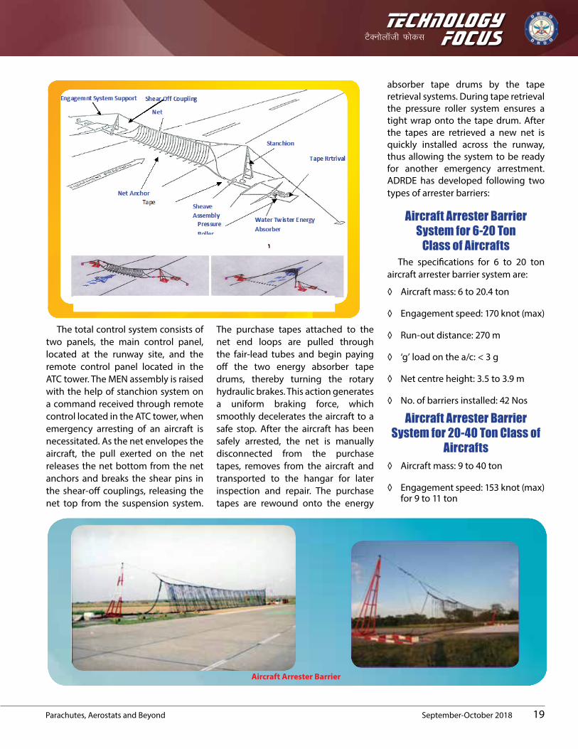
Engagement system envelops the aircraft during its arrestment. It consists of a Multiple Element Net (MEN) assembly, which, when suspended across the runway, forms a complete envelope of protection for an aircraft to be engaged. To prevent the MEN assembly from drifting due to wind pressure, its bottom straps are anchored to the runway with the help of 17 net anchors fitted over the entire width of the runway. Engagement system support connects the engagement system to the stanchions and to release the engagement
system when an aircraft is arrested. It is a set of three components, viz., suspension cable, shear-off coupling and suspension cable anchor.
Stanchion system provides support and remote controlled operation for erecting and lowering the MEN assembly.
Purchase tape is the main energy transmission link between the multi MEN assembly and the energy absorber unit. It is a woven nylon belt with ultraviolet resistant treatment to increase wear properties and to provide dimensional stability. Energy absorber system is used for gradually absorbing the kinetic energy of the aircraft during the run out distance, after its engagement in the net. It is a rotary hydraulic braking device. The connection of energy absorber with the net is made by means of purchase tape.
Pressure roller assembly, located adjacent to each energy absorber, is installed to maintain pressure against the purchase tapes as they are being wound on to the tape drums. A tight, even wrap of the purchase tape, in addition to saving space in the tape drum, also helps in minimising force fluctuations during an aircraft arrestment.
Sheave assembly is to guide the purchase tape on and off the energy absorber tape drum. During retraction of the purchase tapes after an arrestment, each absorber sheave assembly keeps it free from twisting, maintains it in a vertical position, and guides it onto the tape drum. Electrical control system is used to control the electrical operation of raising and lowering the stanchion system and operation of the tape retrieval system.
TechnologyVSDu¨ykWth Q¨dl
19
Focus
Parachutes, Aerostats and Beyond September-October 2018
The total control system consists of two panels, the main control panel, located at the runway site, and the remote control panel located in the ATC tower. The MEN assembly is raised with the help of stanchion system on a command received through remote control located in the ATC tower, when emergency arresting of an aircraft is necessitated. As the net envelopes the aircraft, the pull exerted on the net releases the net bottom from the net anchors and breaks the shear pins in the shear-off couplings, releasing the net top from the suspension system.
The purchase tapes attached to the net end loops are pulled through the fair-lead tubes and begin paying off the two energy absorber tape drums, thereby turning the rotary hydraulic brakes. This action generates a uniform braking force, which smoothly decelerates the aircraft to a safe stop. After the aircraft has been safely arrested, the net is manually disconnected from the purchase tapes, removes from the aircraft and transported to the hangar for later inspection and repair. The purchase tapes are rewound onto the energy
absorber tape drums by the tape retrieval systems. During tape retrieval the pressure roller system ensures a tight wrap onto the tape drum. After the tapes are retrieved a new net is quickly installed across the runway, thus allowing the system to be ready for another emergency arrestment.ADRDE has developed following two types of arrester barriers:
Aircraft Arrester Barrier System for 6-20 Ton
Class of Aircrafts The specifications for 6 to 20 ton
aircraft arrester barrier system are:
◊ Aircraft mass: 6 to 20.4 ton
◊ Engagement speed: 170 knot (max)
◊ Run-out distance: 270 m
◊ ‘g’ load on the a/c: < 3 g
◊ Net centre height: 3.5 to 3.9 m
◊ No. of barriers installed: 42 Nos
Aircraft Arrester Barrier System for 20-40 Ton Class of
Aircrafts◊ Aircraft mass: 9 to 40 ton
◊ Engagement speed: 153 knot (max) for 9 to 11 ton
Aircraft Arrester Barrier

TechnologyFocusVSDu¨ykWth Q¨dl
20 September-October 2018 Parachutes, Aerostats and Beyond
◊ 160 knot (max) for 11 to 40 ton
◊ Run-out Distance: 270 m
◊ ‘g’ load on the a/c: < 3 g
◊ Net centre height: 4.7 to 4.9 m
◊ No. of barriers installed: 08 Nos
ADRDE developed 20 ton class
arrester barrier engaged an aircraft (MiG-21) at Srinagar Airforce Station on 20th September 2016 in emergency. Forty-six arrester barriers have been installed in various Airforce stations.
FACILITIESModeling and
SimulationModeling, analysis and simulation
is available for design, analysis and related simulation of parts, components, assemblies, subsystems and systems pertaining to various projects of ADRDE. Various high end hardware and softwares such as Autocad, Solid works, Cosmos works, CATIA V5-R20, Ansys, Gambit, ICEM CFD, Fluent, LS-Dyna, Hypermesh, Mathcad and SYMBOLS Sonata for Bond graph modeling are available.Following activities are also part of this facility:
◊ Preparation, amendment and printing of textile and mechanical drawings
◊ Solid modeling of parts and assemblies
◊ Shape optimisation and crash analysis
Linear, non-linear, static and dynamic finite element analysis of parts and assemblies to determine following:
◊ Maximum stress
◊ Maximum strain
◊ Maximum deformation
◊ Factor of safety
◊ Mode shapes and modal values
Computational fluid dynamics analysis of parts and assemblies to estimate:
◊ Forces and moments
◊ Pressure distribution over body
◊ Store separation study
◊ Bond graph modeling and simulation of multi-domain systems
Electronics and Instrumention
Electronics and Instrumentation (EI) facility (SSCD) is committed to provide instrumentation support for design and development of parachutes, floatation systems, heavy drop systems, aerostat and allied systems. The laboratory is equipped with various sensors and data acquisition system which is being used in different instrumentation requirements. Three types of data acquisition systems, i.e., PC based online data acquisition system, microcontroller based onboard data acquisition system and FM/FM Telemetry systems are being used for inhouse, air drop and RTRS trials of decelerators and others systems. Various sensors like load cells of different types and capacities, pressure transducers, accelerometers, impact sensors, temperature sensors, tilt sensors and gyro, etc. are also available to capture
physical parameters. Section strain measurement facility for metallic structures has also been established succesfully. Parameters which can be measured with this facility are:
◊ Snatch force, opening force and steady force of parachute during air drop trials
◊ Filling time of parachutes
◊ Impact measurement during inhouse impact test and airdrop trials
◊ Burst pressure measurement of aerostats and scale down model of balloons and SRE floats
◊ Rate of descent/terminal velocity of decelerators
◊ Deceleration/acceleration profiles of payload during RTRS and airdrop trial of decelerators
◊ Payload oscillation measurement
◊ Strain measurement on metallic structures
Textile TestTextile facility is equipped with
modern textile test equipment to test various parameters of textile materials, viz., fabrics, tapes, cordage, etc. used in parachutes, balloons and aircraft arrester barrier. The facility includes high and low pressure air permeability machine for determining air permeability of various fabrics

TechnologyVSDu¨ykWth Q¨dl Focus
We have been receiving a tremendous appreciation & good words on the contents, quality, and presentation of Technology Focus and we intend to continue with our efforts. The editorial team requests your support to further improving it. The feedback form as below would be one of the resource that would provide us your level of satisfaction and newer aspects you would want to incorporate in the Technology Focus.
Rate the Technology Focus as a medium to present DRDO's technology and product developments ?
Excellent Good Satisfactory Needs improvement
Is Technology Focus highlighting developments of DRDO appropriately ? If no, kindly suggest ?
Yes No
How do you rate the quality of photographs in the Technology Focus ?
Excellent Good Satisfactory Needs improvement
Optimal number of pages you would like for the Technology Focus ?
16 Pages 20 Pages 24 Pages 28 Pages
Prefered medium of Technology Focus ?
Print Online (PDF) E-pub Video Magazine
Whether magazine is delivered on time ?
Yes No
What should be the frequency of Technology Focus ?
Bimonthly Quarterly Half-yearly
For updates of Technology Focus, Kindly provide your e-mail id ?
E-mail :
Suggestions, to further improve the Technology Focus ?
-----------------------------------------------------------------------------------------------------------------------------------------------------------------------------------------------------------------------------------------------------------------------------------------------------------------------------------------------------------------------------------------------------------------------------------------------
Signature
Name :
Address :
Feedback for Technology Focus

TechnologyFocusVSDu¨ykWth Q¨dl
Your feedback is valuable for us. Kindly fill the feedback form and send to
DirectorDefence Scientific Information & Documentation Centre (DESIDOC)
Defence Research & Development Organisation (DRDO) Ministry of Defence
Metcalfe House Delhi - 110 054
Telephone: 011-23902403, 23902472Fax: 011-23819151; 011-23813465
E-mail: [email protected]; [email protected]; [email protected]

TechnologyVSDu¨ykWth Q¨dl
23
Focus
Parachutes, Aerostats and Beyond September-October 2018
used in the development. Universal testing machines for determination of breaking strength of fabrics, tapes, webbing’s, etc. of capacity ranges upto 150 kN using hydraulic and neumatic grips machines for determination of twist and text of yarn, bursting strength of woven, knitted fabrics are also available. The textile test facility is equipped with the following machines:
◊ Computer controlled Zwich UTM machine (10 kN and 100 kN)
◊ Horizontal textile testing machine (10 kN and 100 kN)
◊ Electronic air permeability tester
◊ Digital thickness tester
◊ Analytical balance
◊ Fabric inspection machine
◊ Bursting strength tester
Mechanical TestMechanical test facility is equipped
with facilities to test metal components right from development phase to acceptance for bulk production. The facility is equipped with the following machines:
◊ Universal testing machine
◊ Spring testing machine
◊ Computerised hardness testing machine
◊ Tensile testing machine
◊ Digital plating thickness tester
◊ Ultrasonic flaw detector
◊ Climatic test chamber
◊ Thermal shock chamber
◊ Impact testing machine
◊ Temperature humidity altitude chamber
Chemical TestChemical test facility is engaged
in analytical, volumetric and environmental analysis; a fundamental approach for the development and production of reliable metal/textile components used in parachutes and allied technologies. The chemical facility is equiped to analyse textile, metal and synthetic materials used in the arena of parachutes, balloons and allied aerial delivery systems. The facility is equipped with the following machines:
◊ Xeno test equipment (to test accelerated ageing of textiles)
◊ Washing fastness tester
◊ Salt mist/fog chamber
◊ Optical emission spectrometer
◊ Digital pH meter
◊ Digital plating thickness tester
Flight Test LabIt undertakes the certification of
ADRDE developed products, based on testing of its various functional parameters in actual/simulated flight trials. It prepares simulated dummy loads and accomplish packing of parachutes. Lifting trials on indigenously developed parachutes systems are also done.
Prototype Fabrication Facility (Mechanical)It is fitted with conventional
machines and have the facilities of machining, tool and die making, press work, installation of system, fitting, heat treatment, ASC and gas welding (ferrous), finishing and wood working, etc. Development and fabrication of tooling, metal component, system integration, appliances/machines repairing and maintenance, modifications of components and preparation of test samples for chemical analysis are carried out here.
Prototype Fabrication Facility (Textile)
This is equipped with computerised two/one needle industrial lock stitch sewing machines. An array of plain lock stitch sewing machines to cater the need of basic work of parachute manufacturing, moderate to heavy duty zigzag sewing machines used to prepare harness, riser, etc. of any parachute system. PFW(T) have unique distinction of having super heavy, weight zigzag sewing machine to prepare zigzag stitch on tapes of 18-20 mm thickness. Fabrication of textile components, repairing, maintenance and modifications of parachute components and preparation of test samples for environmental testing and analysis. Fabrication of parachutes for -LCA (brake and spin recovery), SRE, Hybrid parachute for MiG-29, arrester barrier tapes were carried out here.

TechnologyFocusVSDu¨ykWth Q¨dl
24
Local CorrespondentsAgra: Shri S.M. Jain, Aerial Delivery Research and Development Establishment (ADRDE) Ahmednagar: Shri S Muthukrishnan, Vehicles Research & Development Establishment (VRDE)Ambernath: Dr Susan Titus, Naval Materials Research Laboratory (NMRL) Bengaluru: Shri Subbukutti S., Aeronautical Development Establishment, (ADE); Smt MR Bhuvaneswari, Centre for Airborne Systems (CABS); Smt Faheema A.G.J., Centre for Artificial Intelligence & Robotics (CAIR); Shri R. Kamalakannan, Centre for Military Airworthiness & Certification (CEMILAC); Ms Josephine Nirmala, Defence Avionics Research Establishment (DARE); Shri Nagesa B.K., Gas Turbine Research Establishment (GTRE); Dr Sushant Chhatre, Microwave Tube Research & Development Centre (MTRDC)Chandigarh: Shri Neeraj Srivastava, Terminal Ballistics Research Laboratory (TBRL); Shri H S Gusain, Snow & Avalanche Study Establishment (SASE)Chennai: Shri P.D. Jayram, Combat Vehicles Research & Development Establishment (CVRDE)Dehradun: Shri Abhai Mishra, Defence Electronics Applications Laboratory (DEAL); Shri J.P. Singh, Instruments Research & Development Establishment (IRDE) Delhi: Dr Rajendra Singh, Centre for Fire, Explosive & Environment Safety (CFEES); Dr Dipti Prasad, Defence Institute of Physiology & Allied Sciences (DIPAS); Dr Dolly Bansal, Defence Institute of Psychological Research (DIPR); Shri Ram Prakash, Defence Terrain
Research Laboratory (DTRL); Dr Anjani Tiwari, Institute of Nuclear Medicine and Allied Sciences (INMAS); Smt Anjana Sharma, Institute for Systems Studies & Analyses (ISSA); Dr D.P. Ghai, Laser Science & Technology Centre (LASTEC); Ms Noopur Shrotriya, Scientific Analysis Group (SAG); Dr Mamta Khaneja, Solid State Physics Laboratory (SSPL)Gwalior: Shri R.K. Srivastava, Defence R&D Establishment (DRDE)Haldwani: Dr Atul Grover, Dr Ranjit Singh, Defence Institute of Bio-Energy Research (DIBER)Hyderabad: Dr JK Rai, Advanced Numerical Research & Analysis Group (ANURAG); Shri A.R.C. Murthy, Defence Electronics Research Laboratory (DLRL); Dr Manoj Kumar Jain, Defence Metallurgical Research Laboratory (DMRL); Dr K Nageswara Rao, Defence Research & Development Laboratory (DRDL)Jodhpur: Shri Ravindra Kumar, Defence Laboratory (DL)Kanpur: Shri AK Singh, Defence Materials & Stores Research & Development Establishment (DMSRDE)Kochi: Smt Letha M.M., Naval Physical Oceanographic Laboratory (NPOL)Leh: Dr Tsering Stobden, Defence Institute of High Altitude Research (DIHAR)Pune: Dr (Mrs) J.A. Kanetkar, Armament Research and Development Establishment (ARDE); Dr Himanshu Shekhar, High Energy Materials Research Laboratory (HEMRL)Tezpur: Dr Jayshree Das, Defence Research Laboratory (DRL)Visakhapatnam: Dr (Mrs) V Vijaya Sudha, Naval Science & Technological Laboratory (NSTL)
Technology Focus focuses on the technological developments in the organisation covering the products, processes and technologies.
Editor-in-Chief Dr Alka Suri
Senior Editor B. Nityanand
Editor Dipti Arora
Pre-press Anita Bisht
Printing
SK Gupta Hans Kumar
Marketing
Tapesh SinhaR.P Singh
ikBd vius lq>ko laiknd] VSDuksykWth Qksdl] MslhMkWd] esVdkWQ gkml] fnYyh-110 054 dks Hkst ldrs gSaA
nwjHkk"k% 011-23902403, 23902472
QSDl% 011-23819151; 011-23813465
bZ&esy% [email protected]; [email protected]; [email protected]
baVjusV% www.drdo.gov.in/drdo/English/index.jsp?pg=techfocus.jsp
Readers may send their suggestions to the Editor, Technology Focus DESIDOC, Metcalfe House Delhi-110 054Telephone: 011-23902403, 23902472Fax: 011-23819151; 011-23813465E-mail: [email protected]; [email protected]; [email protected]: www.drdo.gov.in/drdo/English/index.jsp?pg=techfocus.jsp
MslhMkWd }kjk izdkf’kr
Published by DESIDOC
RNI No. 55787/93
Copyright © 2022 FDOKUMEN