
Volume-primitive based three-dimensional medical image rendering: Customized architectural...
16
Comput. & Graphics Vol. 16, No. 1, pp. 85-100, 1992 0097-8493/92 $5.00 + .00 Printed in Great Britain, © 1992 Pergamon Press pie Technical Section VOLUME-PRIMITIVE BASED THREE-DIMENSIONAL MEDICAL IMAGE RENDERING: CUSTOMIZED ARCHITECTURAL APPROACHES MARTIN R. STYTZ* Air Force Institute of Technology, Department of Electrical and Computer Engineering, Wright-Patterson AFB, OH 45433 and OPHIR FRIEDER George Mason University, Department of Computer Science, Fairfax, VA 22030 Abstract--This paper examines seven computer architectures specificallydesigned to rapidly render 3D medical images from voxel data. The paper opens with a discussionof work on architectures for 3D medical image renderingand then specifiesparameters for assessing the performanceof a 3D medical image rendering architecture. We then describe and assessthe 3DP 4, the Cube, the INSIGHT, the PARCUM II, the PICAP II, the Voxel Flinger, and the Voxel Processor architectures. For each machine the rendering speed, image resolution, underlying data model, image quality, parallel processingstrategy, and 3D display technique are discussed. The architecture for each machine is characterized by its data storage technique, computational architecture, and parallelism strategy. l. INTRODUCTION 3D medical imaging is the subspecialty of volume vi- sualization and computer graphics that addresses issues associated with the rendering and display of medical image data.* 3D medical imaging had its beginnings in the late 1970s and has since become a recognized adjunct to traditional 2D medical data display tech- niques. 3D medical imaging is currently used to plan craniofacial surgery, for traumatology, in orthopedics, for disease diagnosis, for teaching, and for radiation treatment planning. To enable these uses, 3D medical imaging attempts to compute an accurate, clinically useful 3D depiction of the data as rapidly as possible. Early efforts in 3D medical imaging, see [ 1, 2 ], con- centrated upon demonstrating the clinical utility of 3D medical imaging and used low-power, general-purpose processors for the image rendering task. Their primary focus was upon reducing image rendering time by per- forming data classification in a preprocessing step, with the output of this step being a 1D or 2D data model of a particular organ. However, rendering still took hours, so batch processing was used to perform 3D medical image rendering. Subsequently, researchers investigated the use of customized architectures and alternative data models for reducing image rendering time and increasing the utility of the image by im- proving its quality and information content. Before turning to a description of the customized 3D medical image rendering machines that are the focus of the present paper, a brief review of other machines for 3D imaging is presented below. * To whom correspondence should be addressed. * The data to be imagedis gathered usinga medicalimaging modality such as Positron Emission Tomography, Comput- erized Tomography, Magnetic Resonance Imaging, Ultra- sound, or Single Photon Emission Computed Tomography. The MIPG machines*[ 1, 3-6 ] and work at Cornell, [2], led the way with their demonstration of the utility of 3D medical images constructed from extracted con- tour or surface models of individual organs.* The utility of the data models, surface extraction techniques, and shading algorithms employed in these machines is demonstrated by their use in later machines. Farrell's machine[9 ] demonstrates the usefulness of false color, composited images in a medical imaging environment. The two Fuchs/Poulton machines[10, 11] establish that the pixel coloring computational bottleneck can be overcome by expending hardware resources at the pixel level. The Fuchs/Poulton machines also dem- onstrate the usefulness of a pipeline architecture for computing volume visualizations. The work at the Mayo Clinic, described in [ 12-14 ], demonstrates techniques for rendering images with a set of cooper- ating processes. The rendering tool is named the AN- ALYZE* system and has a capability for the display of both 2D contour-based and 3D volume-based im- ages. Several current commercial machines reflect a nar- rower range of approaches to the 3D medical image rendering problem than is the case for the research machines. The Ardent Titan,* AT&T Pixel Machine, the Pixar machines, the Stellar GS2000 t, and the Sun t Originallyat the State University of New York in Buffalo, later at the University of Pennsylvania. *A MIPG designed, PC-based rendering system using al- gorithms derived from the early MIPG work is described in [7,8]. t ANALYZE for UNIX workstationsis available from CE- MAX, Inc, 46750 Freemont Blvd., Suite 207, Freemont, CA, 94538. *The Stellar and Ardent Computer Corporations merged to form Stardent Computer in 1989. The Ardent architecture is marketed as the Stardent 1000 and 3000 machines, the Stellar architecture is marketed as the Stardent 2000 machine. 85
Transcript of Volume-primitive based three-dimensional medical image rendering: Customized architectural...

Comput. & Graphics Vol. 16, No. 1, pp. 85-100, 1992 0097-8493/92 $5.00 + .00 Printed in Great Britain, © 1992 Pergamon Press pie
Technical Section
VOLUME-PRIMITIVE BASED THREE-DIMENSIONAL MEDICAL IMAGE RENDERING: CUSTOMIZED
ARCHITECTURAL APPROACHES
MARTIN R. STYTZ* Air Force Institute of Technology, Department of Electrical and Computer Engineering,
Wright-Patterson AFB, OH 45433
and
O P H I R F R I E D E R George Mason University, Department of Computer Science, Fairfax, VA 22030
Abstract--This paper examines seven computer architectures specifically designed to rapidly render 3D medical images from voxel data. The paper opens with a discussion of work on architectures for 3D medical image rendering and then specifies parameters for assessing the performance of a 3D medical image rendering architecture. We then describe and assess the 3DP 4, the Cube, the INSIGHT, the PARCUM II, the PICAP II, the Voxel Flinger, and the Voxel Processor architectures. For each machine the rendering speed, image resolution, underlying data model, image quality, parallel processing strategy, and 3D display technique are discussed. The architecture for each machine is characterized by its data storage technique, computational architecture, and parallelism strategy.
l . I N T R O D U C T I O N
3D medical imaging is the subspecialty of volume vi- sualization and computer graphics that addresses issues associated with the rendering and display of medical image data.* 3D medical imaging had its beginnings in the late 1970s and has since become a recognized adjunct to traditional 2D medical data display tech- niques. 3D medical imaging is currently used to plan craniofacial surgery, for traumatology, in orthopedics, for disease diagnosis, for teaching, and for radiation treatment planning. To enable these uses, 3D medical imaging attempts to compute an accurate, clinically useful 3D depiction of the data as rapidly as possible.
Early efforts in 3D medical imaging, see [ 1, 2 ], con- centrated upon demonstrating the clinical utility of 3D medical imaging and used low-power, general-purpose processors for the image rendering task. Their primary focus was upon reducing image rendering time by per- forming data classification in a preprocessing step, with the output of this step being a 1D or 2D data model of a particular organ. However, rendering still took hours, so batch processing was used to perform 3D medical image rendering. Subsequently, researchers investigated the use of customized architectures and alternative data models for reducing image rendering time and increasing the utility of the image by im- proving its quality and information content. Before turning to a description of the customized 3D medical image rendering machines that are the focus of the present paper, a brief review of other machines for 3D imaging is presented below.
* To whom correspondence should be addressed. * The data to be imaged is gathered using a medical imaging
modality such as Positron Emission Tomography, Comput- erized Tomography, Magnetic Resonance Imaging, Ultra- sound, or Single Photon Emission Computed Tomography.
The MIPG machines*[ 1, 3-6 ] and work at Cornell, [2], led the way with their demonstration of the utility of 3D medical images constructed from extracted con- tour or surface models of individual organs.* The utility of the data models, surface extraction techniques, and shading algorithms employed in these machines is demonstrated by their use in later machines. Farrell's machine[9 ] demonstrates the usefulness of false color, composited images in a medical imaging environment. The two Fuchs/Poulton machines[10, 11] establish that the pixel coloring computational bottleneck can be overcome by expending hardware resources at the pixel level. The Fuchs/Poulton machines also dem- onstrate the usefulness of a pipeline architecture for computing volume visualizations. The work at the Mayo Clinic, described in [ 12-14 ], demonstrates techniques for rendering images with a set of cooper- ating processes. The rendering tool is named the AN- ALYZE* system and has a capability for the display of both 2D contour-based and 3D volume-based im- ages.
Several current commercial machines reflect a nar- rower range of approaches to the 3D medical image rendering problem than is the case for the research machines. The Ardent Titan,* AT&T Pixel Machine, the Pixar machines, the Stellar GS2000 t, and the Sun
t Originally at the State University of New York in Buffalo, later at the University of Pennsylvania.
* A MIPG designed, PC-based rendering system using al- gorithms derived from the early MIPG work is described in [7,8].
t ANALYZE for UNIX workstations is available from CE- MAX, Inc, 46750 Freemont Blvd., Suite 207, Freemont, CA, 94538.
* The Stellar and Ardent Computer Corporations merged to form Stardent Computer in 1989. The Ardent architecture is marketed as the Stardent 1000 and 3000 machines, the Stellar architecture is marketed as the Stardent 2000 machine.
85

86 MARTIN R. STYTZ and OPHIR FRIEDER
TAAC-1 all use image rendering pipelines with some form of hardware assist at the pixel generation level. A significant aspect of these machines is their common decision to place the image rendering algorithms in software rather than hardware, thus providing a ca- pability for future enhancements to the 3D medical image rendering algorithms. These commercial ma- chines achieve a high rendering rate within a general- purpose architecture by using custom pixel-coloring hardware, parallelism, pipelined computation, and/or high-speed general purpose CPUs.
The Pixar machines[15, 16] reflect the low end of the performance scale, with its "pipeline" existing only in a logical sense. The "pipeline" is realized by making multiple passes over the data set, with the results of each pass composited into a final image. The hardware assist for pixel generation is limited to a dual-ported frame-buffer that allows direct access to the video image by both the Chap and the video display generator. The Pixar machine employs a customized processor, the Chap, to perform volume projection calculations. This machine is significant both for its demonstration of image compositing techniques for 3D medical imaging and for its high-quality images, The Sun TAAC- 1 [ 17, 18] limits its "pipeline" to instruction-commanded reconfiguration of the processing unit. The perfor- mance of the TAAC- 1 comes from its ability to rapidly access 3D arrays and through the use of rapidly com- puted scene previewing to limit the amount of time required to achieve the desired volume presentation before rendering the full image. The AT&T Pixel Ma- chine [ 19-21 ] provides both a multistage pipeline and dedicated-hardware support for pixel shading calcu- lations, resulting in a significant performance im- provement over the TAAC-1 and Pixar efforts. How- ever, when rendering voxel-based images, the perfor- mance of the AT&T Pixel Machine is limited by the narrowness of its pipeline. The Ardent (see [22, 23 ]) and Stellar (see [ 24-26 ] ) architectures have dedicated hardware for pixel shading calculations and multistage pipelines for performing 3D medical imaging rendering computations. These machines provide a wider image rendering pipeline than the AT&T Pixel Machine, thereby achieving a significant increase in 3D medical image rendering speed. Further descriptions of these systems can be found in [27, 28]. Previous surveys of customized computer architectures for voxel-based image rendering are found in [29-31 ]. The interested reader is referred to [27, 28, 32] for a detailed descrip- tion of 3D medical imaging operations, terminology, and algorithms. The books by Kaufman [ 33 ], and by Nielson et a/.[34], contain a collection of seminal works in the broader computer graphics field of volume visualization.
The above solutions to the 3D medical imaging problem range from the straightforward (i.e., the MIPG machine, which uses insightful algorithms on the com- puter that is already available in the medical equip- ment) to the very specialized (the Pixel Planes ma- chines). The development of the Titan, Stellar, and AT&T Pixel Machine architectures reflects the ap-
pearance of a commercial market for a general-purpose high-speed volume-primitive based rendering capabil- ity. In these machines, the twin goals of high image quality and real-time performance have not been met, but they do make significant strides toward the attain- ment of a real-time 3D medical image display envi- ronment.
To perform 3D medical imaging, three stages of processing are performed. The first phase is data clas- sification. This processing phase classifies voxels within the volume according to one or more parameters, with the goal being the detection of the voxels having certain properties of interest. One example of classification is the thresholding operation, which selects for display the voxels in the volume having a value that satisfies some user-specified voxel value criteria. The second phase is volume projection. This phase of processing moves voxel data values from object space to screen space. The operations performed in this stage are geo- metric operations (rotation, scaling, and translation), volume traversal (by ray casting, back-to-front pro- cessing, or front-to-back processing), hidden-surface removal, object/image space* anti-aliasing, object/ image space surface normal calculations, and per- spective. Depending upon the type of 3D medical im- age desired, some or all of these operations are per- formed to render an image. The final processing stage is pixel coloring. This processing phase performs screen space surface normal calculations, shading, and screen space anti-aliasing. Depending upon the architecture of the machine, these three phases of rendering may be overlapped or interspersed. However, classification is performed at some time before volume projection, which in turn is performed at some time before pixel coloring.
The machines that are the subject of this paper were designed to rapidly render 3D medical images from volume-based primitives, either voxels or octrees, and are the initial architectures for this type of 3D medical image rendering. Because the medical imaging mo- dality data sets are large and because the machines strive to compute renderings rapidly, the computa- tional challenges faced by these machines in the volume projection phase of 3D medical image rendering are noteworthy. For this reason, the strategies and design techniques employed in these machines are worthy of examination. The machines we discuss in this paper were designed to address the computational cost in- curred in the second, volume projection, phase of 3D medical imaging. These architectures were customized to rapidly move data through the second phase by a combination of novel memory access techniques, dis- tributed computation, and pipelined operation.
Several system parameters can be used to assess the overall performance ofa 3D medical imaging machine.
t The 3D coordinate system that contains the digitized sample of patient space is object space. The 3D coordinate system that contains the view of object space desired by the user is image space. The 2D coordinate system that portrays the visible portions of image space is screen space.

Medical image rendering 87
These parameters rate both the accuracy and the speed of a 3D medical image rendering. The parameters we use to evaluate the performance of an architecture are rendering speed, image resolution, architecture gen- erality, underlying data model, type of rendering, image quality, degree of parallelism, and 3D display device used to display the image. The following paragraphs define these attributes.
The rendering speed parameter specifies the ren- dering display rate. Typical rendering speeds encom- pass a range of performance from 10-12 hours in an overnight, batch-job oriented display environment to a 30+ frames-per-second, highly-interactive processing environment. In general, the rendering speed attained by a machine depends on the parallelism of the archi- tecture and the speed of memory access. The image resolution parameter assesses the ability of the machine to render the image at the resolution of the data ac- quisition device. The generality of the image rendering architecture depicts the capability of the machine to perform other data processing tasks, and so amortize the cost of the machine among several applications. In this paper, our focus is upon customized 3D medical imaging machine architectures designed to generate 3D images at an interactive rate. These customized machines have traded-offgenerality of use for rendering speed.
The data model used affects both the amount of data-classification preprocessing and actual rendering time required to compute the image. All data models employ a segmentation procedure to classify the mo- dality data as part of the rendering operation. The dif- ferences between the data models lie in the timing of the classification and the representation used to store the result of the classification. The contour, 1 D-prim- itive, approach uses sets of l D contours to form a de- scription of the boundary of an object of interest within the individual slices that form a 3D volume. The boundary is represented in each slice as a sequence of points connected by directed line segments. The se- quence of points corresponds to the voxels in the object that are connected and that lie on the border between the object and the surrounding material. 2D data models, exemplified by organ surface models, use a 2D primitive to depict the surface of an organ or object within a volume. Commonly used primitives are 2D tiles that connect directed contours and visible voxel faces. The formation of a l D or 2D data model of an organ surface requires substantial preprocessing to ex- tract the desired organ surface, but the benefit is rapid rendering of the organ. The challenge faced when using these models is accurate classification of the organ sur- faces, and this remains an open research issue for soft- tissue surfaces. 3D models use 3D primitives, exem- plified by the octree and voxel data models, to depict an entire volume. These models lie at the other end of the data-classification preprocessing and run-time processing spectrum. This model requires little to no data-classification preprocessing but demands sub- stantial run-time processing to render an image. In this review, we focus upon machines that employ the voxel
or octree data models. The reader is referred to [32, 35, 36 ] for surveys of these three data models.
In 3D medical imaging, image quality can be as- sessed by the shading algorithm used and the method of anti-aliasing employed. The shading algorithm de- termines the realism of the lighting transition between objects, and portions of the same object, lying at dif- ferent depths within the visualized volume. The pro- cessing options available range from simple depth-only shading to Phong shading, with a steady increase in computational cost as the quality of the shading com- putation improves. All else being equal, displayed medical image quality is more dependent upon the method used to calculate the surface normal than upon the illumination model, so we use the technique em- ployed for calculating the surface normal to classify the shading methodology employed in each machine. The machines discussed in this survey use five different techniques: depth shading, colored-range method, z- gradient, gray-scale gradient, and congradient. Depth shading does not calculate the surface normal and as- signs pixel color based solely upon the depth of the voxel the pixel portrays. The colored range method (see [37]) does not calculate a surface normal. This technique determines pixel color based upon the type of tissue displayed at the pixel and the depth of the voxel being portrayed. The other three techniques, z- gradient [ 38 ], gray-gradient [ 39-43b ] and congra- dient [ 44 ] estimate the surface normal. The z-gradient technique calculates the change in the z'-dimension between neighboring entries in the z-buffer and uses this value to approximate the local surface normal. The gray-gradient technique calculates the change in materials ratios between neighboring entries in the z- buffer and uses this value to approximate the local sur- face normal. Congradient shading estimates the surface normal for each voxel face using the relative orientation of the neighboring voxels and expresses the orientation as an orientation code. The orientation codes are de- termined by computing the gradient between the voxel face and the faces of the adjoint voxel faces, as in gra- dient shading.
The anti-aliasing parameter describes the capability of the machine to depict features that are not oriented along the y- or x-axis. Anti-aliasing improves the ap- parent quality of the image by smoothing edges in the rendered image. Anti-aliasing can be performed in screen space, image space, or in object space. Screen space techniques for anti-aliasing, such as supersam- pling, commonly use some form of area-weighted av- eraging to compute anti-aliased pixel values. Object and image space techniques, such as trilinear inter- polation, use some form of distance-weighted averaging to compute an anti-aliased pixel value.
The type of rendering computed can be classified into one of two major classes of 3D medical image rendering techniques: surface and volume rendering. A surface rendering, as in [ 3, 4, 7 ], presents the user with a display of the surface of a single object. A volume rendering, as in [ 15, 45-47 ], displays multiple surfaces or the entire volume and presents the user with a vi-

88 MARTIN R. STYTZ and OPHIR FRIEDER
sualization of the entire space. Volume rendering uses 3D primitives as the input data type whereas a surface rendering can be computed from 1 D, 2D, or 3D prim- itives. Currently, there are four major types of volume rendering: volume rendering using multiple threshold windows, volumetric compositing, max-rain display, and radiographic display. Volume rendering using multiple threshold windows uses the threshold windows to extract different tissue types from the volume. The tissues are displayed with hidden surfaces removed, only the surfaces of the extracted tissues that are visible from the observer's location are portrayed. Volumetric compositing generates an image containing multiple semi-opaque and /o r opaque tissue surfaces in a two step process. The first step is determination of the blend of materials present in each voxel, which yields an opacity value and a color for the voxel. The second step is the combination of the voxel opacity and color values into a single representation of light attenuation by the voxels along the viewer's line-of-sight through image space. Max-min display, also called angiographic display, determines the shade at each screen space pixel using the maximum (or minimum) voxel value en- countered along the path of each ray cast from each screen space pixel through image space. Radiographic display determines the shade at each screen space pixel from a weighted sum of the voxel values encountered along the path of each ray cast from each screen space pixel through image space.
Another question to be addressed when evaluating a 3D medical imaging architecture is the device used for rendered image display. The common approach is to display the rendered volume upon a 2D display, in a 2 1/2D format, but the capability for displaying the volume as a true 3D image has been demonstrated (see [12, 48-50]. The machines in this survey are all designed to display their output upon 2D CRT displays.
The degree of parallelism parameter indicates the capability of the machine architecture to rapidly per- form 3D medical image rendering. Because the focus of this paper is upon techniques for rapidly rendering 3D medical images from volume primitives, we restrict the assessment of degree of parallelism to the nature of the parallelism employed for volume projection cal- culations. In addition, the description of each machine focuses on the components of the machine that perform the volume projection operations.
The following paragraphs summarize seven special- purpose, high-speed architectures for 3D medical im- aging: 3DP 4, Cube, INSIGHT, PARCUM II, PICAP II, Voxel Flinger, and Voxel Processor machines.
2. O H A S H I ' S 3 D P ~ SYSTEM The 3DP 4 (Three -Dimens iona l Perspective
PEARY t Projection Processor), described in [ 51 ], is a customized computer architecture designed to per- form animation of scenes composed of many objects. The design uses a parallel-processing architecture with
several independent memories for processing subcubes of an image for display. The 3DP 4 has five major com- ponents, the host, the PEARYs, the Visible Voxel De- tection Processors ( W D P s ) , Merge Processors, and a Shading Processor. Figure 1 contains a diagram of the system.
The host processor is responsible for the user inter- face and for updating position and rotation parameters for the Visible Voxel Detection Processors and Merge Processors. The machine can hold a 256- X 256- × 256-voxel volume distributed among 64 PEARYs, with each PEARY holding a 64- X 64- X 64-voxel subcube of the scene. Each subcube may contain one or more objects, with objects allowed to span several PEARYs. To render a volume, each VVDP begins by accessing the individual PEARY(s) holding the object it is as- signed to process. The VVDPs then processes the beams t of voxels in the PEARY to determine the voxel along each beam that lies closest to the viewer. To perform rotation at low computational cost the VVDPs use a linear interpolating projection method. This technique amounts to rotating the voxels at each end of a beam to their final location in image space and then interpolating along the beam between these end- points to determine the location of the intermediate voxels in image space. The VVDP uses a z-buffer to determine the voxel lying closest to the observer. The output from each VVDP is placed into a Depth buffer and a Color buffer for use by the Merge Processor. The Merge Processor merges the output of the VVDPs into a single image for display. In this stage, a z-buffer al- gorithm is used to determine the voxel closest to the observer. Since the inputs are composed of several dis- crete images, this approach insures proper intersection of objects. The merge processor also keeps track of the object written to each output location for later use by the Shading Processor. Upon completion of the merge operation, the output from this stage is found in the Merge Processor's output depth map, color map and object id map. The Shading Processor uses these maps to render the final 512- X 512-pixel 3D medical image. The shading processor uses gradient shading in con- junction with the object id map to render the image and to minimize the introduction of artifactual edges into the final display.
Ohashi does not report using an anti-aliasing tech- nique in 3DP 4 machine. To date, the machine has been simulated in software. The rendering rate achieved by the simulator is not a real-time display rate. The authors claim that the display rate will improve with the use of faster memories, as memory access is the primary system bottleneck. The implemented system is esti- mated to be capable of computing a surface rendering in 0.17 seconds.
3. KAUFMAN'S CUBE ARCHITECTURE Kaufman's Cube machine[52-54], was developed
to permit 3D interaction with both medical images and geometric objects in real-time. The system devel-
t PEARY stands for Picture Element Array, and is a three- t A beam of voxels is a row or column of voxels within the dimensional array of voxels, scene.

Medical image rendering
Host [
Depth Buffer
DepthMap olorMap
89
LegGed
VVDP - Visible Voxel D e t e ~ o n
Proceltsof
MP - Merging lboc~or SP - ShKlin s Processor
Fig. 1.3DP* architecture (based upon [51]).
o p m e n t p lan calls for the p roduc t ion of a system with 512- × 512-pixel resolut ion and a 512- × 512- × 512- voxel m e m o r y capacity, t hough the cur ren t hardware prototype supports a 16- × 16- × 16-voxel scene. The mach ine has a two-part processing strategy. The first par t is the use of a novel 3D-memory architecture to enable s imul taneous retrieval of all the voxels in a beam. The second par t is the use of beam-level parallel
processing to s imultaneously process all the voxels in a beam. Figure 2 contains a diagram of the architecture of the Cube machine .
The mach ine consists of a host and five ma jo r com- ponents , the 3D frame buffer, the cubic frame buffer, 3D geometry processor, the voxel mult iple write bus, and the 3D viewing processor. The 3D frame buffer processor (FBP3) is responsible for loading 3D voxel-
Cubic Frame Buffer
3D Interaction
3D Scanner Lefend
FBP3 - 3d frame buffer processor GP3 - 3D geometry processor VP3 - 3D viewing processor FB - Frame Buffer VP - Video Processor
Fig. 2. Kaufman's Cube machine architecture (based upon [52]).
90 MARTIN R. STYTZ and OPHIR FRIEDER
-q °n I
3D Model ~ I
Solids Engine TM
Legend
MAP - Manipulation and Analysis Processor
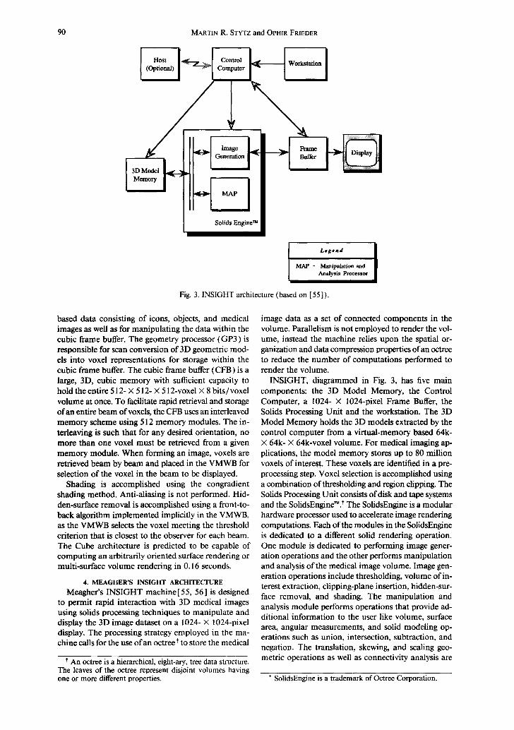
Fig. 3. INSIGHT architecture (based on [55]).
based data consisting of icons, objects, and medical images as well as for manipulating the data within the cubic frame buffer. The geometry processor (GP3) is responsible for scan conversion of 3D geometric mod- els into voxel representations for storage within the cubic frame buffer. The cubic frame buffer (CFB) is a large, 3D, cubic memory with sufficient capacity to hold the entire 512- X 512- × 512-voxel X 8 bits/voxel volume at once. To facilitate rapid retrieval and storage of an entire beam of voxels, the CFB uses an interleaved memory scheme using 512 memory modules. The in- terleaving is such that for any desired orientation, no more than one voxel must be retrieved from a given memory module. When forming an image, voxels are retrieved beam by beam and placed in the VMWB for selection of the voxel in the beam to be displayed.
Shading is accomplished using the congradient shading method. Anti-aliasing is not performed. Hid- den-surface removal is accomplished using a front-to- back algorithm implemented implicitly in the VMWB, as the VMWB selects the voxel meeting the threshold criterion that is closest to the observer for each beam. The Cube architecture is predicted to be capable of computing an arbitrarily oriented surface rendering or multi-surface volume rendering in 0.16 seconds.
4. MEAGHER'S INSIGHT ARCHITECTURE Meagher's INSIGHT machine [ 55, 56 ] is designed
to permit rapid interaction with 3D medical images using solids processing techniques to manipulate and display the 3D image dataset on a 1024- X 1024-pixel display. The processing strategy employed in the ma- chine calls for the use of an octree t to store the medical
t An octree is a hierarchical, eight-ary, tree data structure. The leaves of the octree represent disjoint volumes having o n e or more different properties.
image data as a set of connected components in the volume. Parallelism is not employed to render the vol- ume, instead the machine relies upon the spatial or- ganization and data compression properties of an octree to reduce the number of computations performed to render the volume.
INSIGHT, diagrammed in Fig. 3, has five main components: the 3D Model Memory, the Control Computer, a 1024- X 1024-pixel Frame Buffer, the Solids Processing Unit and the workstation. The 3D Model Memory holds the 3D models extracted by the control computer from a virtual-memory based 64k- X 64k- X 64k-voxel volume. For medical imaging ap- plications, the model memory stores up to 80 million voxels of interest. These voxels are identified in a pre- processing step. Voxel selection is accomplished using a combination ofthresholding and region clipping. The Solids Processing Unit consists of disk and tape systems and the SolidsEngine~. t The SolidsEngine is a modular hardware processor used to accelerate image rendering computations. Each of the modules in the SolidsEngine is dedicated to a different solid rendering operation. One module is dedicated to performing image gener- ation operations and the other performs manipulation and analysis of the medical image volume. Image gen- eration operations include thresholding, volume of in- terest extraction, clipping-plane insertion, hidden-sur- face removal, and shading. The manipulation and analysis module performs operations that provide ad- ditional information to the user like volume, surface area, angular measurements, and solid modeling op- erations such as union, intersection, subtraction, and negation. The translation, skewing, and scaling geo- metric operations as well as connectivity analysis are
t SolidsEngine is a trademark of Octree Corporation.
Medical image rendering
Object I Genea'ator
MVE Selector
~ [ Host I
I H' u H . Address Convertor l - I Projection Processor Memory
91
Legend
MVE - Macro Volume Element
IP - Illumination Processor
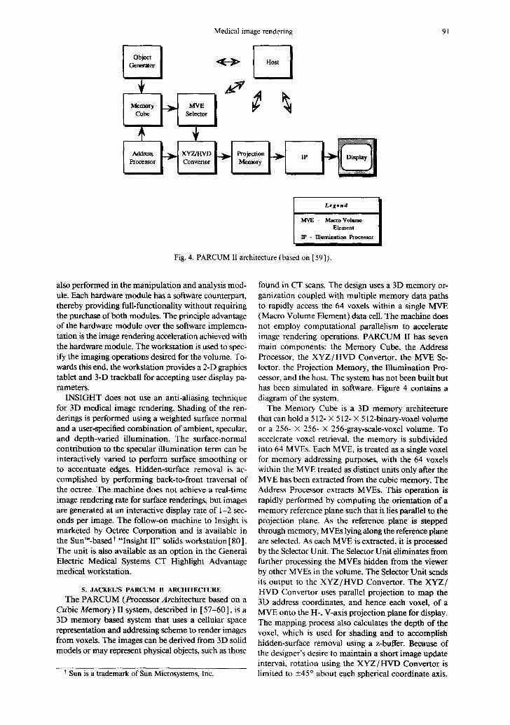
Fig. 4. PARCUM II architecture (based on [59]).
also performed in the manipulation and analysis mod- ule. Each hardware module has a software counterpart, thereby providing full-functionality without requiring the purchase of both modules. The principle advantage of the hardware module over the software implemen- tation is the image rendering acceleration achieved with the hardware module. The workstation is used to spec- ify the imaging operations desired for the volume. To- wards this end, the workstation provides a 2-D graphics tablet and 3-D trackball for accepting user display pa- rameters.
INSIGHT does not use an anti-aliasing technique for 3D medical image rendering. Shading of the ren- derings is performed using a weighted surface normal and a user-specified combination of ambient, specular, and depth-varied illumination. The surface-normal contribution to the specular illumination term can be interactively varied to perform surface smoothing or to accentuate edges. Hidden-surface removal is ac- complished by performing back-to-front traversal of the octree. The machine does not achieve a real-time image rendering rate for surface renderings, but images are generated at an interactive display rate of 1-2 sec- onds per image. The follow-on machine to Insight is marketed by Octree Corporation and is available in the Sun'M-based t "Insight II" solids workstation [80]. The unit is also available as an option in the General Electric Medical Systems CT Highlight Advantage medical workstation.
5. JACKEL'S PARCUM II ARCHITECTURE The PARCUM (Processor Architecture based on a
Cubic Memory) II system, described in [57-60], is a 3D memory based system that uses a cellular space representation and addressing scheme to render images from voxels. The images can be derived from 3D solid models or may represent physical objects, such as those
Sun is a trademark of Sun Microsystems, Inc.
found in CT scans. The design uses a 3D memory or- ganization coupled with multiple memory data paths to rapidly access the 64 voxels within a single MVE (Macro Volume Element) data cell. The machine does not employ computational parallelism to accelerate image rendering operations. PARCUM II has seven main components: the Memory Cube, the Address Processor, the XYZ/HVD Convertor, the MVE Se- lector, the Projection Memory, the Illumination Pro- cessor, and the host. The system has not been built but has been simulated in software. Figure 4 contains a diagram of the system.
The Memory Cube is a 3D memory architecture that can hold a 512- × 512- X 512-binary-voxel volume or a 256- X 256- X 256-gray-scale-voxel volume. To accelerate voxel retrieval, the memory is subdivided into 64 MVEs. Each MVE, is treated as a single voxel for memory addressing purposes, with the 64 voxels within the MVE treated as distinct units only after the MVE has been extracted from the cubic memory. The Address Processor extracts MVEs. This operation is rapidly performed by computing the orientation of a memory reference plane such that it lies parallel to the projection plane. As the reference plane is stepped through memory, MVEs lying along the reference plane are selected. As each MVE is extracted, it is processed by the Selector Unit. The Selector Unit eliminates from further processing the MVEs hidden from the viewer by other MVEs in the volume. The Selector Unit sends its output to the XYZ/HVD Convertor. The XYZ/ HVD Convertor uses parallel projection to map the 3D address coordinates, and hence each voxel, of a MVE onto the H-, V-axis projection plane for display. The mapping process also calculates the depth of the voxel, which is used for shading and to accomplish hidden-surface removal using a z-buffer. Because of the designer's desire to maintain a short image update interval, rotation using the XYZ/HVD Convertor is limited to +45 ° about each spherical coordinate axis.
92 MARTIN R. STYTZ and OPHIR FRIEDER
Memory Bus
Host
Control and Results ~'
Use~ Input
Video Exchange
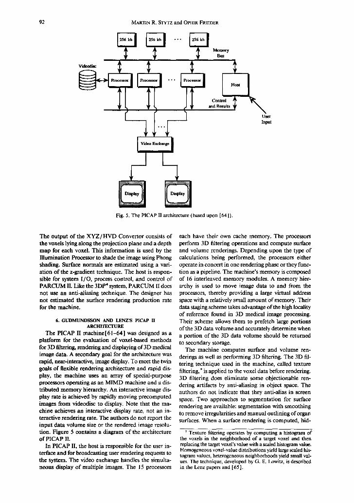
Fig. 5. The PICAP II architecture (based upon [64]).
The output of the X Y Z / H V D Convertor consists of the voxels lying along the projection plane and a depth map for each voxel. This information is used by the Illumination Processor to shade the image using Phong shading. Surface normals are estimated using a vari- ation of the z-gradient technique. The host is respon- sible for system I /O, process control, and control of PARCUM II. Like the 3DP 4 system, PARCUM II does not use an anti-aliasing technique. The designer has not estimated the surface rendering production rate for the machine.
6. GUDMUNDSSON AND LENZ'S PICAP II ARCH1TECFURE
The PICAP II machine [ 61-64 ] was designed as a platform for the evaluation of voxel-based methods for 3D filtering, rendering and displaying of 3D medical image data. A secondary goal for the architecture was rapid, near-interactive, image display. To meet the twin goals of flexible rendering architecture and rapid dis- play, the machine uses an array of special-purpose processors operating as an MIMD machine and a dis- tributed memory hierarchy. An interactive image dis- play rate is achieved by rapidly moving precomputed images from videodisc to display. Note that the ma- chine achieves an interactive display rate, not an in- teractive rendering rate. The authors do not report the input data volume size or the rendered image resolu- tion. Figure 5 contains a diagram of the architecture of PICAP II.
In PICAP II, the host is responsible for the user in- terface and for broadcasting user rendering requests to the system. The video exchange handles the simulta- neous display of multiple images. The 15 processors
each have their own cache memory. The processors perform 3D filtering operations and compute surface and volume renderings. Depending upon the type of calculations being performed, the processors either operate in concert in one rendering phase or they func- tion as a pipeline. The machine's memory is composed of 16 interleaved memory modules. A memory hier- archy is used to move image data to and from the processors, thereby providing a large virtual address space with a relatively small amount of memory. Their data staging scheme takes advantage of the high locality of reference found in 3D medical image processing. Their scheme allows them to prefetch large portions of the 3D data volume and accurately determine when a portion of the 3D data volume should be returned to secondary storage.
The machine computes surface and volume ren- derings as well as performing 3D filtering. The 3D fil- tering technique used in the machine, called texture filtering, t is applied to the voxel data before rendering. 3D filtering does eliminate some objectionable ren- dering artifacts by anti-aliasing in object space. The authors do not indicate that they anti-alias in screen space. Two approaches to segmentation for surface rendering are available: segmentation with smoothing to remove irregularities and manual outlining of organ surfaces. When a surface rendering is computed, hid-
t Texture filtering operates by computing a histogram of the voxels in the neighborhood of a target voxel and then replacing the target voxel's value with a scaled histogram value. Homogeneous voxel-value distributions yield large scaled his- togram values, heterogeneous neighborhoods yield small val- ues. The technique, developed by G. E. Lowitz, is described in the Lenz papers and [65].

Medical image rendering
I Host I
2D Array Processor
l System l Processor
System Bus I
L .
I- Fig. 6. The Voxel Flinger (based upon [66, 67]).
3D An'ay Processor
93
den-surface removal is accomplished by traversing the volume from front-to-back. Each pixel displays the value of the first voxel encountered in image space that maps to the pixel location in screen space. The operator can choose to shade surface renderings using either the depth, colored-range, or z-gradient shading techniques. Volume renderings are radiographic displays computed from voxel data that had a 3D filter applied to it.
7. REALITY IMAGING'S VOXEL FLINGER The Voxel Flinger[66, 67] is a commercial machine
designed to perform 2D image processing, 3D medical image volume and surface rendering, and medical im- age measurement functions for radiology and surgery planning at an interactive rate. The machine computes a shaded surface rendering by extracting the target or- gan by thresholding and then shading the result using either depth or surface-normal based shading. The machine can compute both radiographic and angio- graphic (max intensity) volume renderings. The Voxel Flinger achieves its interactive display rate by using two parallel pipelines to transform object space voxel coordinates and data into screen space pixel coordi- nates and data.
The Voxel Flinger, diagrammed in Fig. 6, consists of four major hardware components. These are the host, the system processor, the 3D processor, and the 2D processor. The host is the file server for the machine. The system processor, a Motorola 68020, controls the operation of the Voxel Flinger, provides the host and operator interfaces to the machine, and generates lookup tables. The 2D processor (also called the array processor) performs 2D operations on the data such as shading and image decompression.
The 3D processor, also called the volume processor, performs 3D coordinate transformation, voxel value interpolation, and hidden-surface removal. The 3D processor performs its computations in two parallel pipelines, one for voxel coordinate information and the other for voxel value information, that terminate at a z-buffer. The 3D processor is itself composed of eight elements: the transform sequencer, voxel mem-
ory, the voxel interpolator, the cut transforms proces- sor, voxel lookup, the spatial transforms processor, the perspective processor, and the z-buffer. Figure 7 depicts the 3D processor.
The voxel memory holds the source voxel data. The transform sequencer controls readout of the voxel memory and interslice interpolation. The voxel inter- polator performs interslice interpolation using either a user setable isotropic interpolation pattern, nearest neighbor interpolation, linear interpolation or cubic convolution interpolation using the voxel values in the four neighboring slices. The cut transforms processor performs clipping plane and spherical, cylindrical, and elliptical cut operations. The voxel lookup table has two separate functions. One of its tasks is to send grayscale and transparency data t to the z-buffer. The other function is to output a transformation tag to the spatial transform processor, which allows it to inde- pendently manipulate up to 4 image components. The spatial transforms component converts object space coordinates to screen space coordinates. The perspec- tive component provides a user-controllable degree of perspective in the rendered image. The z-buffer per- forms hidden-surface removal when the machine is computing a surface rendering, performs summing for radiographic volume renderings, and holds the maxi- mum grayscale value at each pixel for angiographic volume renderings.
The Voxel Flinger can hold between 32 and 128 512- X 512-voxel slices of medical imaging modality data. The machine's rendering rate performance varies nearly linearly with the number of voxels to be ren- dered. The Voxel Flinger also uses a successive refine- ment rendering strategy to accelerate the rendering rate when the data set is large and the user is interacting with the data. On typical medical data sets, the Voxel Flinger can render a 128- × 128- × 128-voxel input
t The voxel lookup table uses the object tag, the cut trans- forms output, and grayscale value for each voxel to determine each voxel's transparency value.

94 MARTIN R. STYTZ and OPHIR FR1EDER
Transform b
q v-, H v-, H v-, I Memory Intmpolator Lookup
1 Fig. 7. The Voxel Flinger 3D processor (based upon [ 66, 67]).
Z Buffer
to a 256- × 256-pixel display in 0.2 seconds. Again on typical medical data sets, a 512- × 512- × 512-voxel volume can be rendered to a 512- × 512-pixel display in 0.6-4.6 seconds depending upon the rate of user interaction. Anti-aliasing is performed in object space by the voxel interpolator when the operator selects tri- linear or cubic convolution interpolation. The machine does not anti-alias in screen space.
8. GOLDWASSER AND REYNOLD'S VOXEL PROCESSOR ARCHITECTURE
The Voxel Processor architecture was described by Goldwasser and Reynolds in [ 68, 69 ]. The Voxel Pro- cessor machine is designed to process discrete subcubes of a volume in real-time using multiple, independent processors. The complete machine, as described in [68], is not implemented. The uniprocessor-based Voxelscope II TM, a commercial machine marketed by Dynamic Digital Displays t that incorporates the par- allel primitives introduced in the Voxel Processor ar- chitecture, is described in [68b]. ~ Figure 8 contains a diagram of the architecture of the Voxel Processor ma- chine.
The processing strategy calls for dividing the volume into 64 small, independently processed, octant-shaped volumes composed ofvoxels. The architecture employs medium-grain parallel processing to simultaneously process the 64 octant-shaped subvolumes. The output from the 64 processors is then merged in back-to-front order to form one final image. There are seven com- ponents to the rendering pipeline. These components are the host computer, the object access unit, the object memory system (64 modules each storing a 64 cube of voxels), the 64 processing elements (PE's), the in- termediate processors (IP's), the output processor (OP), and th e post-processor.
The host computer handles object data acquisition, database management, and complex object manipu- lation. The host is also responsible for generating the Sequence Control Tables (SCTs) used by the PEs, IPs, and OP to control their back-to-front rendering op-
t The characteristics of this machine are summarized in Table l at the end of this paper.
* Previous Dynamic Digital Displays Voxel Processor ar- chitectures are described in [70, 7 l].
erations. The object access unit supports object data- base management by the host and manages commu- nication between the Voxel Processor and host. The object memory system (OMS) is composed of 64 memory modules distributed among the 64 processing elements. The OMS provides the 16M bytes of RAM required to hold a 256- X 256- X 256-voxel volume. The PEs compute mini-pictures from their own 64- X 64- X 64-voxel sections of the scene. During operation, the PEs access the data in their own subeube in back- to-front order without contention with other PEs. This computation yields the 2D subimage visible at that processor given the current set of user inputs. The next two stages of the rendering pipeline perform the task of merging the 64 separate pictures into a single picture that portrays the data volume. The OP forms the final image by merging the contents of the eight IP output buffers into a 512- X 512-pixel frame buffer. Once the image is in the frame buffer, the post-processor per- forms the shading, brightness, and pseudo-coloring re- quired to form a 3D medical image.
Shading is accomplished using either gradient shad- ing or distance shading. The machine can use two dif- ferent anti-aliasing techniques. The first technique is based on the display of the centers of the visible faces of each voxel and the other is supersampling. Hidden- surface removal is accomplished using the recursive back-to-front algorithm described in [ 69 ]. Organ sur- faces are extracted by thresholding. The Voxel Pro- cessor is predicted to be capable of computing a surface rendering within 0.03 seconds, which is a real-time display rate.
SUMMARY
In the preceding pages we have described and dis- cussed the 3DP 4, Cube, INSIGHT, PARCUM II, PICAP II, Voxel Flinger, and Voxel Processor architec- tures. One prominent characteristic of these approaches is that customization limits the rendering flexibility of the machines. Many of the machines can perform only one type of rendering. None of the machines that can compute both surface and volume renderings, Cube, PICAP II, and Voxel Flinger, offer volumetric com- positing as a volume rendering option.
These seven machines accelerate the volume pro- jection operation by using customized hardware and

Medical image rendering
Object Memory Bus
~ eeeo •
OP Bus
L#f~nd
PiE - lhroee~ing Ei~aeat IP - Intermediate Pro~ OP- Ou~ut Proe©.c~
I
I 7.u, I
I
Fig. 8. The Voxel Processor architecture (based upon [69]).
95
algorithms. The machines have each adopted one or more techniques that customize the architecture of the machine in an effort to rapidly render images. Two basic acceleration strategies are evident. The first, multi-voxel access, is employed in the INSIGHT, PARCUM II, and Cube systems. These machines are designed to move large numbers of voxel values from memory to processing unit in one memory access cycle. INSIGHT uses an octree to store data values and to retrieve them quickly, and so achieves multivoxel ac- cess by exploiting data compression. On the other hand, the PARCUM II and Cube machines use specialized memory access architectures to achieve the same goal. The other acceleration strategy is rapid voxel value processing by employing computational parallelism. This approach is taken in the PICAP II, 3DP 4, Cube, PARCUM II, Voxel Flinger, and Voxel Processor ma- chines. No one approach to computational parallelism dominates among these machines. The Cube and Voxel Processor machines are SIMD architectures, with the Voxel Processor using a pipeline to further increase its rendering throughput. The PICAP II and 3DP 4 ma- chines are MIMD architectures, with 3DP 4 using a pipeline to increase its rendering throughput. The Voxel Flinger and PARCUM II are neither SIMD or MIMD. These two machines rely upon multistage hardware pipelines to distribute and overlap compu- tations and so reduce volume projection time. Note
CAG 16:I-G
that the PICAP II, Voxel Processor, and 3DP 4 ma- chines also distribute memory to eliminate memory access contention as part of their strategy for mini- mizing rendering time.
Many of the machines use customized computa- tional units to rapidly perform volume or surface ren- dering computations. The Cube, Voxel Processor, 3DP 4, PARCUM II, and Voxel Flinger architectures all employ custom processors. In these five machines, the computational elements are simplified and can perform only those computations required for their particular machine to render an image. Typically, these computations are limited to coordinate transformation and output voxel value assignment. To further reduce volume projection time, these machines embed the volume projection algorithms in the hardware of the computational units.
Less customization for improving image quality is evident among the machines. Most of the machines do not perform anti-aliasing, presumably because of the time expended performing this operation. The shading algorithms are typically state-of-the-art for the time period in which the machine was designed and built. Several of the machines, the Voxel Processor, 3DP*, the Voxel Flinger, Cube, and PARCUM II, em- ploy custom designed shading processors to minimize the amount of time devoted to performing shading. As in the area of rendering technique, these machines

~D
Arc
hite
ctur
e
Para
llel
ism
St
rate
gy
Dat
a M
odel
Typ
e of
R
ende
ring
R
ende
ring
Sp
eed
Ant
i-al
iasi
ng
Sha
ding
T
echn
ique
Dev
elop
men
t A
rena
M
achi
ne S
tatu
s
3DP
4
Pipe
line
of
MIM
D
para
llel
pr
oces
sors
Sim
ulta
neou
s,
inde
pend
ent
beam
-wis
e op
erat
ion
on
disj
oint
su
bvol
umes
V
oxel
Surf
ace
Inte
ract
ive,
a f
ew
seco
nds
per
rend
erin
g N
o
Z-G
radi
ent
Res
earc
h
Soft
war
e si
mul
atio
n
Cub
e
Cub
e pr
oces
sor
cons
isti
ng o
f th
ree
dedi
cate
d pr
oces
sors
an
d a
com
mon
bu
s
Rep
eate
d pa
rall
el
acce
ss to
be
ams
of
voxe
ls
Vox
el
Vol
ume
and
Surf
ace
Thi
rty-
five
re
nder
ings
/ se
e
No
Con
grad
ient
Res
earc
h
Smal
l-sc
ale
hard
war
e pr
otot
ype,
fu
ll
func
tion
al
emul
atio
n in
sof
twar
e
Tab
le 1
. Cus
tom
ized
thr
ee-d
imen
sion
al m
edic
al i
mag
ing
mac
hine
arc
hite
ctur
es.
Insi
ght
PA
RC
UM
II
PIC
AP
II
Vox
el F
ling
er
Mod
ular
, oc
tree
-bas
ed
Pip
elin
e co
mpo
sed
of
Con
trol
ler
and
MIM
D
Tw
o pa
rall
el p
ipel
ines
so
lids
eng
ine
thre
e co
mpu
tati
on
arra
y of
pro
cess
ors
term
inat
ing
in a
z-
unit
s bu
ffer
N/A
F
etch
of
a 64
-vox
el
Sim
ulta
neou
s T
wo
para
llel
pip
elin
es
Mac
ro-v
oxel
by
oper
atio
n on
pr
ojec
t coo
rdin
ate
the
proc
esso
r di
sjoi
nt l
inea
r an
d gr
aysc
ale
data
ar
rays
fr
om o
bjec
t spa
ce
to s
cree
n sp
ace.
Oct
ree-
base
d so
lid
Vox
el
Vox
el
Vox
el
desc
ript
ion
Surf
ace
Surf
ace
Vol
ume
and
Surf
ace
Vol
ume
and
Surf
ace
Inte
ract
ive,
a f
ew
Tw
o-th
ree
12 o
rtho
gona
l 0.
2-8.
4 se
c se
cond
s pe
r re
nder
ings
/min
ute
proj
ecti
ons/
see
depe
ndin
g on
dat
a re
nder
ing
volu
me
No
No
Yes
, in
obj
ect s
pace
Y
es,
in i
mag
e sp
ace
Dep
th c
uein
g w
ith
a Z
-Gra
dien
t D
epth
, C
olor
ed-r
ange
, D
epth
, G
radi
ent
wei
ghte
d su
rfac
e-
Z-G
radi
ent
norm
al t
erm
C
omm
erci
al
Res
earc
h R
esea
rch
Com
mer
cial
Mar
kete
d, f
ollo
w-o
n M
emor
y cu
be
In u
se
Mar
kete
d m
achi
ne
oper
atio
nal,
m
anuf
actu
red
by
soft
war
e O
ctre
e C
orp.
em
ulat
ion
of
rem
aini
ng
com
pone
nts
Vox
el P
roce
ssor
Oct
ree-
stru
ctur
ed
pipe
line
of
SIM
D
proc
esso
rs
Sim
ulta
neou
s,
inde
pend
ent
recu
rsiv
e op
erat
ion
on
disj
oint
su
bvol
umes
V
oxel
Surf
ace
Thi
rty
rend
erin
gs/s
ec
Yes
, in
scr
een
spac
e
Z-G
radi
ent
Res
earc
h
Pro
posa
l
Vox
elsc
ope
II
Hos
t-co
ntro
lled
pi
peli
ne
cons
isti
ng o
f co
ordi
nate
and
da
ta t
rans
form
pr
oces
sors
, ra
ster
izin
g ou
tput
vo
xel b
uffe
r, a
nd
fram
e bu
ffer
P
ipel
ine
to o
verl
ap
com
puta
tion
s
Vox
el
Vol
ume
and
Surf
ace
Inte
ract
ive,
one
or
a fe
w s
econ
ds p
er
rend
erin
g Y
es,
in s
cree
n sp
ace
as a
pro
cess
ing
opti
on
Z-
or g
ray-
Gra
dien
t
Com
mer
cial
Mar
kete
d
Medical image rendering 97
have sacrificed algorithm choice and implementation flexibility for computational speed. The salient char- acteristics of each machine are summarized in Table 1.
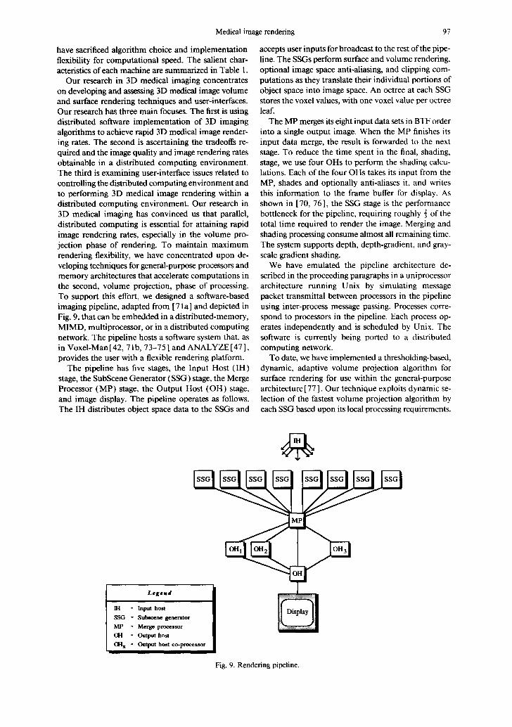
Our research in 3D medical imaging concentrates on developing and assessing 3D medical image volume and surface rendering techniques and user-interfaces. Our research has three main focuses. The first is using distributed software implementation of 3D imaging algorithms to achieve rapid 3D medical image render- ing rates. The second is ascertaining the tradeoffs re- quired and the image quality and image rendering rates obtainable in a distributed computing environment. The third is examining user-interface issues related to controlling the distributed computing environment and to performing 3D medical image rendering within a distributed computing environment. Our research in 3D medical imaging has convinced us that parallel, distributed computing is essential for attaining rapid image rendering rates, especially in the volume pro- jection phase of rendering. To maintain maximum rendering flexibility, we have concentrated upon de- veloping techniques for general-purpose processors and memory architectures that accelerate computations in the second, volume projection, phase of processing. To support this effort, we designed a software-based imaging pipeline, adapted from [ 71 a ] and depicted in Fig. 9, that can be embedded in a distributed-memory, MIMD, multiprocessor, or in a distributed computing network. The pipeline hosts a software system that, as in Voxel-Man [ 42, 71 b, 73-75 ] and ANALYZE [ 47 ], provides the user with a flexible rendering platform.
The pipeline has five stages, the Input Host (IH) stage, the SubScene Generator (SSG) stage, the Merge Processor (MP) stage, the Output Host (OH) stage, and image display. The pipeline operates as follows. The IH distributes object space data to the SSGs and
accepts user inputs for broadcast to the rest of the pipe- line, The SSGs perform surface and volume rendering, optional image space anti-aliasing, and clipping com- putations as they translate their individual portions of object space into image space. An octree at each SSG stores the voxel values, with one voxel value per octree leaf.
The MP merges its eight input data sets in BTF order into a single output image. When the MP finishes its input data merge, the result is forwarded to the next stage. To reduce the time spent in the final, shading, stage, we use four OHs to perform the shading calcu- lations. Each of the four OHs takes its input from the MP, shades and optionally anti-aliases it, and writes this information to the frame buffer for display. As shown in [ 70, 76 ], the SSG stage is the performance bottleneck for the pipeline, requiring roughly ] of the total time required to render the image. Merging and shading processing consume almost all remaining time. The system supports depth, depth-gradient, and gray- scale gradient shading.
We have emulated the pipeline architecture de- scribed in the proceeding paragraphs in a uniprocessor architecture running Unix by simulating message packet transmittal between processors in the pipeline using inter-process message passing. Processes corre- spond to processors in the pipeline. Each process op- erates independently and is scheduled by Unix. The software is currently being ported to a distributed computing network.
To date, we have implemented a thresholding-based, dynamic, adaptive volume projection algorithm for surface rendering for use within the general-purpose architecture [ 77 ]. Our technique exploits dynamic se- lection of the fastest volume projection algorithm by each SSG based upon its local processing requirements.
Legend ]~~ ~ l - I n p u t hos t [ ~ 1 S S G - Subscene generator MY - Merge processor (1-1 - O u t p u t host O H x - Output host co-processor
I
Fig. 9. Rendering pipeline.

98 MARTIN R. STYTZ and OPHIR FRIEDER
m
Performance of Dynamic Volume Projection Algorithm On a 32 x 32 x 32 Data Volume 2000 I
1800 . . .
161111 t ~
1400~ N ~
1200 , , ,
0 • • • I " • • i • • ! • • •
o
o----- Basic BTF . Adaptive BTF 7. Adaptive FTB • Nominal Dynamic
20 40 60 80 tO0
Cutting Hane Depth (voxels)
Fig. 10. Image rendering elapsed time vs. clipping plane location for the basic, adaptive BTF, adaptive FTB, and dynamic volume projection algorithms with 100% voxel selection.
To realize a capability for dynamic algorithm selection, we designed two adaptive volume projection algo- rithms. Each algorithm provides a performance im- provement over the non-adaptive versions. Of equal importance is that each algorithm performs best under different processing conditions. Building upon this foundation, we formulated a dynamic volume projec- tion algorithm. Because the pipeline permits indepen- dent operation by its component processors, a dynamic algorithm selection strategy offers the opportunity for localized optimal volume projection algorithm selec- tion. The dynamic volume projection algorithm cap- italizes upon the strengths of each adaptive algorithm by allowing each SSG to select the algorithm that offers the best performance for its particular processing sit- uation. As illustrated in Fig. 10, the dynamic volume projection algorithm provides an average 50% perfor- mance improvement over its component algorithms.
Our present research is pursuing two avenues. The first involves development and experimentation with techniques for volume rendering by compositing in a distributed computing environment, with image space sampled by either ray casting[45, 46] or by splat- ting[78 ]. The second thrust is assessing the quality and acceptability of surface renderings that use spot noise texturing [ 79 ] instead of shading to impart a sense of depth and surface orientation to the rendered image.
REFERENCES 1. E. Artzy, G. Frieder, G. T. Herman, and H. K. Liu, A
system for three-dimensional dynamic display of organs from computed tomograms. Proceedings of the Sixth Conference on Computer Applications in Radiology & Computer/Aided Analysis of Radiological Images, New- port Beach, CA, 285-290 (June 1979).
2. A. Sunguroffand D. Greenberg, Computer generated im- ages for medical applications. Comp. Graph. 12(3), 196- 202 (August 1978).
3. L. S. Chen, G. T. Herman, C. R. Meyer, R. A. Reynolds, and J. K. Udupa, 3D83--An easy-to-use soitware package
for three-dimensional display from computed tomograms. IEEE Computer Society Joint International Symposium on Medical Images and Icons, Arlington, VA, 309-316 (July 1984).
4. G. Frieder, G. T. Herman, C. Meyer, and J. Udupa, Large software problems for small computers: An example from medical imaging. IEEE Software 2 (5), 37-47 (September 1985).
5. G. T. Herman and H. K. Liu, Display of three-dimen- sional information in computed tomography. Journal of Computer Assisted Tomography (Computed Tomogra- phy) 1( l ), 155-160 (1977).
6. G.T. Herman and H. K. Liu, Three-dimensional display of human organs from computed tomograms. Computer Graphics and Image Processing 9, 1-21 (1979).
7. J. K. Udupa, S. P. Raya, and W. A. Barrett, A PC-based 3D imaging system for biomedical data. First Conference on Visualization in Biomedical Computing, Atlanta, GA, 295-303 (22-25 May 1990).
8. S. P. Raya, J. K. Udupa, and W. A. Barrett, A PC-based 3D imaging system: Algorithms, software, and hardware considerations. Computerized Medical Imaging and Graphics 14(5), 353-370 (1990).
9. E.J. Farrell, W. C. Yang, and R. Zappulla, Animated 3D CT imaging. IEEE Computer Graphics and Applications 5(12), 26-30 (December 1985).
10. H. Fuchs, G. D. Abram, and E. D. Grant, Near real-time shaded display of rigid objects. Comp. Graph. 17 (3), 65- 69 (July 1983).
11. H. Fuchs, J. Poulton, J. Eyles, T. Greer, J. Goldfeatber, D. Ellsworth, S. Molnar, and G. Turk, Pixel-planes 5: A heterogeneous multiprocessor graphics system using pro- cessor-enhanced memories. Comp. Graph. 23(4), 79-88 (July 1989).
12. L. D. Harris, J. J. Camp, E. L. Ritman, and R. A. Robb, Three-dimensional display and analysis of tomographic volume images utilizing a varifocal mirror. IEEE Trans- actions on Medical Imaging MI-5( 2 ), 67-72 ( June 1986).
13. R.A. Robb and C. Barillot, Interactive 3-D image display and analysis. In D. P. Casasent and A. G. Tescher (Eds.): Proceedings of the Society of Photo-Optical Instrumen- tation Engineers: Hybrid Image and Signal Processing, SPIE 939, Orlando, FL, 173-202 (1988).
14. R.A. Robb and C. Barillot, Interactive display and analysis of 3-D medical images. IEEE Transactions on Medical Imaging 8( 3 ), 217-226 (September 1989 ).

Medical image rendering 99
15. R. A. Drebin, L. Carpenter, and P. Hanrahan, Volume rendering. Comp. Graph. 22(4), 65-74 (August 1988).
16. A. Levinthal and T. Porter, Chalr--A SIMD graphics processor. Computer Graphics 18(3), 77-82 (July 1984).
17. J. D. Austin and T. Van Hook, Medical image processing on an enhanced workstation. Medical Imaging II: Image Data Management and Display, SPIE 914, 1317-1324 (1988).
18. E.R. Johnson and C. E. Mosher, Jr., Integration of volume rendering and geometric graphics. Proceedings of the Chapel Hill Workshop on Volume Visualization, Chapel Hill, NC 1-7 (18-19 May 1989).
19. AT&T Pixel Machines Inc. Holmdel, NJ PIClib TM- The Pixel Machine's Graphics Library (June 1988 ).
20. AT&T Pixel Machines Inc. Holmdel, NJ The Pixel Ma- chine 900 Series (June 1988).
21. AT&T Pixel Machines Inc. Holmdel, NJ The Pixel Ma- chine System Architecture: A Technical Report ( 1989 ).
22. T. Diede, C. F. Hagenmaier, G. S. Miranker, J. J. Rubin- stein, and W. S. Worley, Jr, The Titan graphics super- computer architecture. Computer 21(9), 13-29 (Sep- tember 1988).
23. G. S. Miranker, J. Rubinstein, and J. Sanguinetti, Squeezing a cray-class supercomputer into a single-user package. Thirty-Third IEEE Computer Society Interna- tional Conference, San Francisco, CA, 452-456 (29 Feb- ruary-4 March 1988).
24. B. Apgar, B. Bersack, and A. Mammen, A display system for the stellar graphics supercomputer model GS 1000 TM. Comp. Grap. 22(4), 255-262 (August 1988).
25. L. M. Gelberg, J. F. MacMann, and C. J. Mathias, Graphics, image processing, and the stellar graphics su- percomputer. Imaging Workstations and Document Input Systems, SPIE 1074, Los Angeles, CA, 89-96 (17-20 January, 1989).
26. L.M. Gelberg, D. Kamins, and J. Vroom, VEX: A volume exploratorium, an integrated toolkit for interactive volume visualization. Proceedings of the Chapel Hill Conference on Volume Visualization, Chapel Hill, NC, 21-26 ( 18- 19 May 1989).
27. M. R. Stytz and O. Frieder, Computer systems for 3D diagnostic imaging: An analysis of the state-of-the-art. CRC Critical Reviews in Biomedical Engineering 19( 1 ), 1-46 (July 1991 ).
28. M. R, Stytz, G. Frieder, and O. Frieder, Three-dimen- sional medical imaging: Algorithms and computer sys- tems, A CM Computing Surveys 23, (4) (December 1991 ).
29. A. Kaufman, Voxel-based architectures for 3D graphics. Proceedings IFIP '86, 361-366 (1986).
30. A. Kaufman, R. Bakalash, D. Cohen, and R. Yagel, Ar- chitectures for volume rendering. In A. Kaufman (Ed.): Volume Visualization. IEEE Computer Society Press, 311-320 (1990).
31. A. Kaufman, R. Bakalash, D. Cohen, and R. Yagel, A survey of architectures for volume rendering. IEEE En- gineering in Medicine and Biology, 18-23 (December 1990).
32. J. K. Udupa and G. T, Herman. 3D Imaging in Medicine, Boca Raton, FL, CRC Press ( 1991 ).
33. A. Kaufman. Volume Visualization, Washington, D.C., IEEE Computer Society Press ( 1991 ).
34. G. M. Nielson and B. D. Shriver, (Eds.); Rosenblum, Lawrence J. (Assoc. Ed.). Visualization in Scientific Computing, Washington, D.C., IEEE Computer Society Press (1990).
35. E. J. Farrell and R. A. Zappulla, Three-dimensional data visualization and biomedical applications. CRC Critical Reviews in Biomedical Engineering 16(4), 323-363 (1989).
36. G. T. Herman, S. S. Trivedi, and J. K. Udupa, Manip- ulation of 3D imagery. In V. L. Newhouse (Ed.): Progress" in Medical Imaging, Springer-Verlag, New York, 123- 157 (1988).
37. E. J . Farrell, R. Zappulla, and W. C. Yang, Color 3-D imaging of normal and pathologic intracranial structures. IEEE Computer Graphics and Applications 4(10), 5-17 (September 1984),
38. D. Gordon and R. A. Reynolds, Image space shading of 3-Dimensional objects. Computer Vision, Graphics, and Image Processing, 29, 361-376 ( 1985 ).
39. C. Barillot, B. Gibaud, L. M. Luo, and I. M. Scarabin, 3- D representation of anatomic structures from CT ex- aminations. Biostereometrics "85, SPIE 602, Cannes, France, 307-314 (3-6 December 1985). H, E. Cline, W. E. Lorenson, S. Ludke, C. R. Crawford, and B. C. Teeter, Two algorithms for the three-dimen- sional reconstruction of tomograms. Med. Phys. 15(3), 320-327 (May/June 1988). K. H. Hohne and R. Bernstein, Shading 3D images from CT using gray-level gradients. IEEE Transactions on Medical Imaging MI-5( 1 ), 45-47 (March 1986). K. H. Hohne, M. Bomans, A. Pommert, M. Riemer, C. Schiers, U. Tiede, and G. Wiebecke, 3D visualization of tomographic volume data using the generalized voxel model. The Visual Computer 6(1), 28-36 (February 1990). W. E. Lorenson and H. E. Cline, Marching cubes: A high resolution 3D surface construction algorithm. Comp. Graph. 21(4), 163-169 (July 1987).
43b.U. Tiede, K. H. Hohne, and M. Riemer, Comparison of surface rendering techniques for 3-D tomographic objects. Proceedings of the International Symposium: CAR '87, Computer Assisted Radiology, Berlin, West Germany, 599-610 ( 1987 ).
44. D. Cohen, A. Kaufman, and R. Bakalash, Real-time dis- crete shading. The Visual Computer 6(3), (January 1990).
45. M. Levoy, Display of surfaces from volume data. IEEE Computer Graphics and Applications 8 ( 5 ), 29-37 (May 1988).
46. M. Levoy, Efficient ray tracing of volume data. ACM Transactions on Graphics 9 ( 3 ), 245-261 (July 1990).
47. R. A. Robb and D. P. Hanson, ANALYZE: A software system for biomedical image analysis. First Conference on Visualization in Biomedical Computing, Atlanta, GA, 507-518 (22-25 May 1990).
48. H. Fuchs, S. M. Pizer, L.-C. Tsai, S. H. Bloomberg, and E. R. Heinz, Adding a true 3-D display to a raster graphics system. IEEE Computer Graphics and Applications 2(7), 73-78 (September 1982).
49. R. A. Robb, A workstation for interactive display and analysis of multidimensional biomedical images. Pro- ceedings of the International Symposium: CAR '87, Computer Assisted Radiology, Bedim West Germany, 642-656 (1987).
50. S. E. Wixson, True volume visualization of medical data. Proceedings of the Chapel Hill Workshop on Volume Vi- sualization, Chapel Hill, NC, 77-83, ( 18-19 May 1989).
51. T. Ohashi, T. Uchiki, and M. Tokoro, A three-dimen- sional shaded display method for voxel-based represen- tation. Proceedings of Eurographics "85, Nice, France, 221-232 (September 1985).
52. A. Kaufman, The cube workstation--A 3-D voxel-based graphics environment. The Visual Computer 4 (4), 210- 221 (October 1988).
53. A. Kaufman and R. Bakalash, Memory and processing architecture for 3D voxel-based imagery. IEEE Computer Graphics and Applications 8(6), 10-23 (November 1988).
54. A. Kaufman and R. Bakalash, Parallel processing for 3D voxel-based graphics. In P. M. Dew, R. A. Earnshaw, and T. R. Heywood (Eds). Parallel Processing for Computer Vision and Display, Workingham, England, Addison- Wesley, 471-478 (1989).
55. D. J. Meagher, Interactive solids processing for medical
40.
41.
42.
43.

100 MARTIN R. STYTZ and OPHIR FRIEDER
analysis and planning. Proceedings NCGA '84, Anaheim, CA, 96-106 (May 1984).
56. D. J. Meagher, Applying solids processing methods to medical planning. Proceedings NCGA "85, Dallas, TX, 101-109 (April 1985).
57. H. U. Lemke, K. Bosing, M. Engelhorn, D. Jackel, B. Knobloch, H. Scharnweber, H. S. Stiehl, and K. D. Ton- nies, 3-D computer graphic work station for biomedical information modeling and display. Medical Imaging, SPIE 767, Newport Beach, CA 586-592 (1-6 February 1987).
58. D. Jackel, The graphics PARCUM system: A 3D-memory based computer architecture for processing and display of solid models. Computer Graphics Forum, 4( 1 ), 21- 32 (January 1985).
59. D. Jackel and W. Strasser, Reconstructing solids from tomographic scans--The PARCUM II system. Advances in Computer Graphics Hardware II, Springer Interna- tional, Berlin, Germany, 101-109 (1988).
60. H.S. Stiehl and D. Jackel, On a framework for processing and visualizing spatial images. Proceedings of the Inter- national Symposium: CAR '87, Computer Assisted Ra- diology, Berlin, West Germany, 665-670 (1987 ).
61. P. E. Danielsson, B. Kruse, and B. Gudmundsson, Mem- ory Hierarchies in PICAP II. Proceedings of the IEEE Workshop on Picture Data Description and Management, Asilomar, CA 275-280 (27-28 August 1980).
62. R. Lenz, B. Gudmundsson, and B. Lindskog, Manipu- lation and display of 3-D images for surgical planning. Medical Image Processing, SPIE 593, Cannes, France, 96-102 (2-3 December 1985).
63. R. Lenz, P. E. Danielsson, S. Cronstrom, and B. Gud- mundsson, Presentation and perception of 3-D images. In Hohne, Karl Heinz (Ed.): Pictorial Information Sys- tems in Medicine: Proceedings of the NATO Advanced Study Institute on Pictorial Information Systems in Med- icine, Heidelberg, Germany, Springer-Vedag, Berlin, Germany, 459-468 (1986).
64. R. Lenz, B. Gudmundsson, B. Lindskog, and P. E. Dan- ielsson, Display of density volumes, IEEE Computer Graphics and Applications 6 ( 7 ), 20-29 ( July 1986 ).
65. G. E. Lowitz, Can a local histogram really map texture information?. Pattern Recognition 16(2), 141-147 (1983).
66. Reality Imaging Corporation, Solon, OH. Voxel Flinger TM
3-D Imaging System OEM Integration Guide, 1st Edition (January 1990).
67. Reality Imaging Corporation, Solon, OH. Voxel Flinger" System Overview (1990).
68. S. M. Goldwasser, R. A. Reynolds, T. Bapty, D. Baraff, J. Summers, D. A. Talton, and E. Walsh, Physician's workstation with real-time performance. IEEE Computer Graphics and Applications 5(12), 44-57 (December 1985).
68b.R.A. Reynolds, S. M. Goldwasser, M. E. Donham, E. D. Wyatt, M. A. Peterson, L. A. Widerman, D. A. Talton, and E. S. Walsh, VOXELSCOPE: A system for the exploration of multidimensional medical data. Nordic Workshop on Visualization and Analysis of Scientific and Technical Computations on High-Performance Comput- ers, Umea, Sweden (25-28 September, 1990).
69. S. M. Goldwasser and R. A. Reynolds, Real-time display and manipulation of 3-D medical objects: The voxei pro- cessor architecture. Computer Vision, Graphics and Image Processing 39, 1-27 (1987).
70. S. M. Goldwasser, R. A. Reynolds, D. A. Talton, and E. S. Walsh, High-performance graphics processors for medical imaging applications. Proceedings of the Inter- national Conference on Parallel Processing for Computer Vision and Display, University of Leeds, United King- dom, 1-13 ( 12-15 January 1988).
71. S. M. Goldwasser, R. A. Reynolds, D. A. Talton, and E. S. Walsh, High performance graphics processors for medical imaging applications. In P. M. Dew, R. A. Earn- shaw, and T. R. Heywood (Eds). Parallel Processing for Computer Vision and Display, Workingham, England, Addison-Wesley, 461-470 (1989).
7 la.M.R. Stytz. Three-Dimensional Medlcal Image Analysis Using Local Dynamic Algorithm Selection on a Multiple- Instruction, Multiple-Data Architecture. Ph.D. Disserta- tion, Department of Electrical Engineering and Computer Science, The University of Michigan, 476 pp. (December 1989).
71b.M. Bomans, K. H. Hohne, U. Tiede, and M. Reimer, 3- D Segmentation of MR Images of the head for 3-D display. IEEE Transactions on Medical Imaging 9(2 ), 177-183 (June 1990).
72. K.H. Hohne, M. Bomans, U. Tiede, M. Riemer, Display of multiple 3D objects using the generalized voxel-model. Medical Imaging 11: Image Data Management and Dis- play, SPIE 914, Newport Beach, CA, 850--854 (31 Jan- uary-5 February 1988).
73. A. Pommert, U. Tiede, G. Wiebecke, and K. H. Hohne, Surface shading in tomographic volume visualization: A comparative study. First Conference on Visualization in Biomedical Computing, Atlanta, GA, 19-26 (22-25 May 1990).
74. U. Tiede, M. Riemer, M. Bomans, and K. H. Hohne, Display techniques for 3-D tomographic volume data. Proceedings of the Ninth Annual Conference and Expo- sition of the National Computer Graphics Association, NCGA '88, Anaheim, CA, 188-197 (20-24 March 1988).
75. U. Tiede, K. H. Hohne, M. Bomans, A. Pommert, M. Riemer, and G. Wiebecke, Investigation of medical 3D- rendering algorithms. 1EEE Computer Graphics and Ap- plications, 10(2), 41-53 (March 1990).
76. G. Frieder, O. Frieder, M. Stytz, A high performance par- allel approach to medical imaging. Frontiers "88, IEEE Second Symposium on the Frontiers of Massively Parallel Computation, Fairfax, VA, 282-288 (October 1988).
77. M. R. Stytz and O. Frieder, Dynamic adaptive surface rendering within a distributed memory multiprocessor, The Journal of Systems and Software.
78. L. Westover, Footprint evaluation for volume rendering. Comp. Graph. 24(4), 367-376 (August 1990).
79. J. J. van Wijk, Spot noise-texture synthesis for data vi- sualization. Comp. Graph. 25 (4), 309-318 ( July 1991 ).
80. D. J. Meagher, Fourth-generation computer graphics hardware using octrees. Proceedings of the Twelfth Annual Conference and Exposition of the National Computer Graphics Association "91, Chicago, IL, 316-325 (April 1991).