
Troubleshooting and Customized Engineering at the Limit
6
CHEMICAL ENGINEERING TRANSACTIONS VOL. 69, 2018 A publication of The Italian Association of Chemical Engineering Online at www.aidic.it/cet Guest Editors: Elisabetta Brunazzi, Eva Sorensen Copyright © 2018, AIDIC Servizi S.r.l. ISBN 978-88-95608-66-2; ISSN 2283-9216 Troubleshooting and Customized Engineering at the Limit Christian Geipel, Markus Schrüfer, Uwe Franz, Matthias Rödel, Benjamin Pechtold RVT Process Equipment GmbH, Paul-Rauschert-Str.6, 96349 Steinwiesen, Germany [email protected] State-of-the-art design know how combined with specific process experience allows to design column performance and capacity more and more to the limit. This is achieved by reduction of safety margins and the use of customized column internals. On the other hand however, there is a trend towards higher inaccuracies of column shells and dimensions of column attachments (“out-of-tolerance”) as well as lower qualified installation workforce. The trade-off between invest and quality is often dominated by short-term economic considerations. The resulting problems then have to be solved during installation and typically in an extremely tight time-schedule.This paper presents different field experiences that RVT-PE encountered in this context and explains the solutions that were developed. Problem #1: Inclination of column trays In this example, high support ring tolerances - that were only detected after the trays were installed – led to unacceptably high inclination of many trays in a column. The standard way of repairing uneven trays is very time and cost consuming, due to the fact that the trays have to be partially or fully disassembled. RVT-PE has designed a new, time and money saving solution, with which the sagging of trays is rectified and the unevenness of support ring is corrected. Problem #2: High liquid velocities at liquid distributor inlet nozzles In column test runs of a trough type liquid distributor, a client detected extreme splashing at the inlet and in consequence poor distribution quality. The reason was a too small inlet nozzle and therefore very high liquid velocities. As changing the nozzle size wasn’t feasible, the distribution system had to be optimized to eliminate the negative effects of the high inlet velocity. Additionally the optimized distribution system had to fit to the constricted area in the column. Problem #3: Liquid Distributor for low liquid loads in fouling applications and very high gas loads RVT developed a novel liquid distributor for a vacuum column for crude oil distillation. This distributor combines the insensitivity against coking of a spray nozzle distributor with the low liquid entrainment generation of a line distributor. 1. Introduction Although numerous examples of troubleshootings of mass transfer columns have been reported, each incident is a new challenge for the troubleshooting team. First of all, it is extremely important to understand the root cause of problem and the resulting consequences. Basically, two scenarios can be distinguished. Either, mechanical problems like inaccurate weld-in parts are found during installation and it has to be estimated whether the impact on column performance will be significant. Or the column shows unsatisfying performance after startup and the mechanisms that lead to the problem have to be identified and a solution needs to be found. In both cases, a thorough investigation of the mechanical, hydrodynamic and process situation is required. Based on this information, a new solution to solve the problem can be developed. This solution then has to be evaluated with respect to expected result, performance under all operating conditions and mechanical stability. Furthermore, criteria like availability, lifetime, efficiency, invest and installation cost have to be considered. In the following sections RVT PE present two recent cases of troubleshooting. • In chapter 2 a troubleshooting for tray column is described. Next to the explanation of the problem and its impact, the new rectification method is presented. DOI: 10.3303/CET1869084 Please cite this article as: Geipel C., Schrufer M., Franz U., Rodel M., Pechtold B., 2018, Troubleshooting and customized enginnering at the limit, Chemical Engineering Transactions, 69, 499-504 DOI: 10.3303/CET1869084 499
-
Upload
khangminh22 -
Category
Documents
-
view
0 -
download
0
Transcript of Troubleshooting and Customized Engineering at the Limit

CHEMICAL ENGINEERING TRANSACTIONS
VOL. 69, 2018
A publication of
The Italian Association
of Chemical Engineering Online at www.aidic.it/cet
Guest Editors: Elisabetta Brunazzi, Eva Sorensen Copyright © 2018, AIDIC Servizi S.r.l. ISBN 978-88-95608-66-2; ISSN 2283-9216
Troubleshooting and Customized Engineering at the Limit Christian Geipel, Markus Schrüfer, Uwe Franz, Matthias Rödel, Benjamin Pechtold RVT Process Equipment GmbH, Paul-Rauschert-Str.6, 96349 Steinwiesen, Germany [email protected]
State-of-the-art design know how combined with specific process experience allows to design column performance and capacity more and more to the limit. This is achieved by reduction of safety margins and the use of customized column internals. On the other hand however, there is a trend towards higher inaccuracies of column shells and dimensions of column attachments (“out-of-tolerance”) as well as lower qualified installation workforce. The trade-off between invest and quality is often dominated by short-term economic considerations. The resulting problems then have to be solved during installation and typically in an extremely tight time-schedule.This paper presents different field experiences that RVT-PE encountered in this context and explains the solutions that were developed. Problem #1: Inclination of column trays In this example, high support ring tolerances - that were only detected after the trays were installed – led to unacceptably high inclination of many trays in a column. The standard way of repairing uneven trays is very time and cost consuming, due to the fact that the trays have to be partially or fully disassembled. RVT-PE has designed a new, time and money saving solution, with which the sagging of trays is rectified and the unevenness of support ring is corrected. Problem #2: High liquid velocities at liquid distributor inlet nozzles In column test runs of a trough type liquid distributor, a client detected extreme splashing at the inlet and in consequence poor distribution quality. The reason was a too small inlet nozzle and therefore very high liquid velocities. As changing the nozzle size wasn’t feasible, the distribution system had to be optimized to eliminate the negative effects of the high inlet velocity. Additionally the optimized distribution system had to fit to the constricted area in the column. Problem #3: Liquid Distributor for low liquid loads in fouling applications and very high gas loads RVT developed a novel liquid distributor for a vacuum column for crude oil distillation. This distributor combines the insensitivity against coking of a spray nozzle distributor with the low liquid entrainment generation of a line distributor.
1. Introduction Although numerous examples of troubleshootings of mass transfer columns have been reported, each incident is a new challenge for the troubleshooting team. First of all, it is extremely important to understand the root cause of problem and the resulting consequences. Basically, two scenarios can be distinguished. Either, mechanical problems like inaccurate weld-in parts are found during installation and it has to be estimated whether the impact on column performance will be significant. Or the column shows unsatisfying performance after startup and the mechanisms that lead to the problem have to be identified and a solution needs to be found. In both cases, a thorough investigation of the mechanical, hydrodynamic and process situation is required. Based on this information, a new solution to solve the problem can be developed. This solution then has to be evaluated with respect to expected result, performance under all operating conditions and mechanical stability. Furthermore, criteria like availability, lifetime, efficiency, invest and installation cost have to be considered. In the following sections RVT PE present two recent cases of troubleshooting.
• In chapter 2 a troubleshooting for tray column is described. Next to the explanation of the problem and its impact, the new rectification method is presented.
DOI: 10.3303/CET1869084
Please cite this article as: Geipel C., Schrufer M., Franz U., Rodel M., Pechtold B., 2018, Troubleshooting and customized enginnering at the limit, Chemical Engineering Transactions, 69, 499-504 DOI: 10.3303/CET1869084
499
• The next topic is a sometimes underestimated problem about nozzle sizes. Chapter 3 describes the impact of wrong nozzle design on poor liquid distributor performance and how this problem can be solved without modifying the nozzle.
The other part of the report addresses customized engineering. This design practice could be described as a realization of specific customer requirements to a feasible design. Often, these specific components are chosen when conventional internals showed disadvantages during operation. For an appropriate design, it is important to understand the process, the reasons for the undesirable effects, the influence of changes and the requirements of the customer. In the last topic of this report a specific case of customized engineering is described.
• In chapter 4 a project for one of the most critical columns in petrochemical industry is presented. A vacuum distillation tower stands out with its critical system properties, high gas loads, low liquid loads and fouling tendency. For this column RVT-PE developed a new kind of liquid distributor.
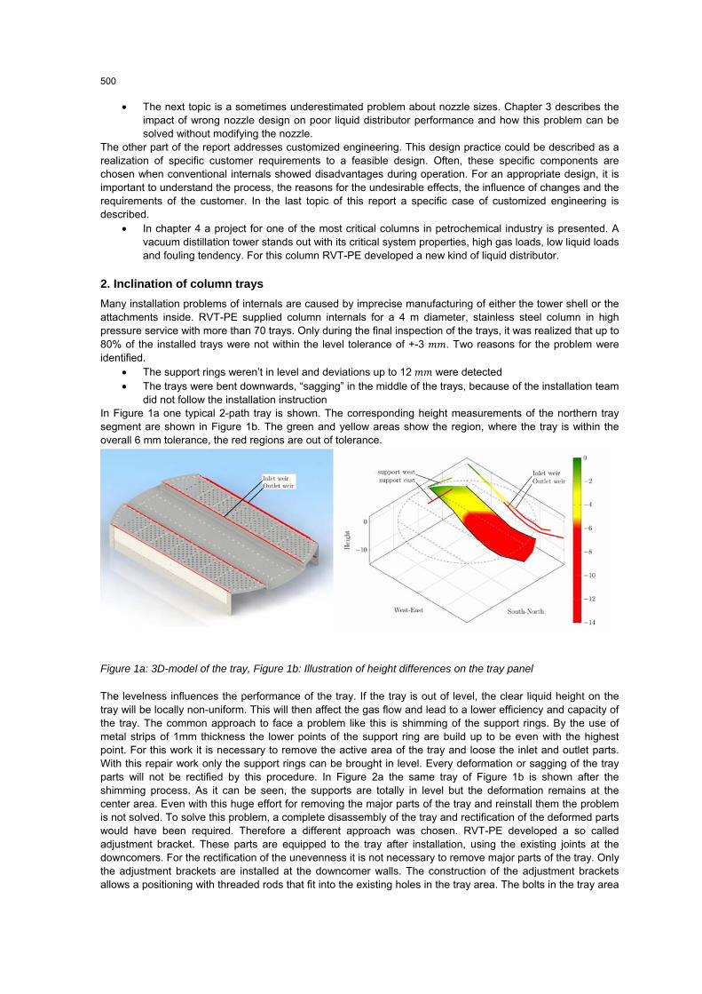
2. Inclination of column trays Many installation problems of internals are caused by imprecise manufacturing of either the tower shell or the attachments inside. RVT-PE supplied column internals for a 4 m diameter, stainless steel column in high pressure service with more than 70 trays. Only during the final inspection of the trays, it was realized that up to 80% of the installed trays were not within the level tolerance of +-3 . Two reasons for the problem were identified.
• The support rings weren’t in level and deviations up to 12 were detected • The trays were bent downwards, “sagging” in the middle of the trays, because of the installation team
did not follow the installation instruction In Figure 1a one typical 2-path tray is shown. The corresponding height measurements of the northern tray segment are shown in Figure 1b. The green and yellow areas show the region, where the tray is within the overall 6 mm tolerance, the red regions are out of tolerance.
Figure 1a: 3D-model of the tray, Figure 1b: Illustration of height differences on the tray panel
The levelness influences the performance of the tray. If the tray is out of level, the clear liquid height on the tray will be locally non-uniform. This will then affect the gas flow and lead to a lower efficiency and capacity of the tray. The common approach to face a problem like this is shimming of the support rings. By the use of metal strips of 1mm thickness the lower points of the support ring are build up to be even with the highest point. For this work it is necessary to remove the active area of the tray and loose the inlet and outlet parts. With this repair work only the support rings can be brought in level. Every deformation or sagging of the tray parts will not be rectified by this procedure. In Figure 2a the same tray of Figure 1b is shown after the shimming process. As it can be seen, the supports are totally in level but the deformation remains at the center area. Even with this huge effort for removing the major parts of the tray and reinstall them the problem is not solved. To solve this problem, a complete disassembly of the tray and rectification of the deformed parts would have been required. Therefore a different approach was chosen. RVT-PE developed a so called adjustment bracket. These parts are equipped to the tray after installation, using the existing joints at the downcomers. For the rectification of the unevenness it is not necessary to remove major parts of the tray. Only the adjustment brackets are installed at the downcomer walls. The construction of the adjustment brackets allows a positioning with threaded rods that fit into the existing holes in the tray area. The bolts in the tray area
500

have to be removed and are replaced by the threaded rods of the bracket. The threaded rods are used to adjust the height of the tray area and to fix the tray panel like the bolted joint before. Figure 2b shows the same tray like Figure 1b after installation of the adjustment brackets. More than 90% of the tray area are within the allowable level tolerance of 6mm. Only the support ring area at the east is still out of level tolerance.
Figure 2a: Illustration of the height differences after shimming, Figure 2b: Illustration of height differences after installation of brackets
But in comparison to the shimming process the effort is much smaller. Using the adjustment bracket avoids the removal of major tray parts, so work can be done much faster and easier and the result is even better. The former maldistribution problem of gas and liquid over the complete tray can be reduced to a negligible part of the active area. The mechanical stability of the bracket and trays were verified by an In-house FEM-calculation. The client decided against the conventional and established process of shimming and chose the new solution with the adjustment brackets.
3. High liquid velocities at liquid distributor inlet nozzles A client realized a high amount of liquid splashing out of the pre-distributor and – as a result – poor liquid distribution. Figure 3a shows the existing design of the pre-distributor box. It is fed by two inlet nozzles and additionally by downpipes from a collector tray above. The analysis of the problem revealed that the inlet nozzle in the column wall was too small and caused liquid inlet velocities of up to 4.5 / at the distributor. In Figure 3b the center inlet is shown. The liquid momentum causes deflection of the liquid stream at the bottom of the pre-distributor box and the liquid splashes out of the box.
Figure 3a: Sketch of original distributor, Figure 3b: Picture of the splashing liquid at center inlet
The task was to design a new pre-distributor box for the distributor in such a way, that there was no necessity to replace the nozzles. The load range should be designed for a minimum of 19 ³/ ²/ℎ up to 134 ³/ ²/ℎ. The new pre-distributor was equipped with two stages of calming devices, see Figure 4a. All inlet nozzles are now equipped with separate inflow boxes. At the bottom, the inflow boxes are closed with perforated plates for better distribution and momentum reduction. To equalize the upward flowing liquid along the pre-distributor a
501

second perforated plate is installed. The outlet of the inflow boxes is located below this plate, so that the liquid has to pass two stages of predistribution. This will also equalize the liquid momentum. The outlet slots at the side walls, covered with the downcomer channels, are relocated upwards. To reduce the momentum of the liquid from the downpipes, funnel-shaped guiding plates are installed along the pre-distributor box. The new pre-distributor box is improved by these constructive adjustments, see Figure 4a and 4b, and thus able to handle the high liquid velocities of the inlet nozzles. The performance of the new pre-distributor box including the downpipes was then checked in the RVT-PE test center, see Figure 4c. Various operating points at each feed point were investigated and showed good performance with regard to splashing and liquid distribution. Also the installation at site went smoothly and the distributor showed good performance.
Figure 4a: Sketch of the modified pre-distributor box, Figure 4b: 3D-model of the pre-distributor box, Figure 4c: New pre-distributor in the test rig at RVT-PE test center
4. Development of a Liquid Distributor for low liquid loads in fouling applications and very high gas loads The present case illustrates engineering and design for a capacity increase of a vacuum column. The existing column was replaced by a new one (diameter 7 ) and several operating experiences should be addressed by new internals solutions. Especially in the pump-around sections the liquid recirculation should be reduced to cut operating cost, as described at Sala M., Bonet J. (2014). On the other hand, fouling of the packings had to be controlled by uniform wetting of the packed bed. Experience showed that entrainment to the bed above had to be reduced compared to the previously used nozzle distributors. The goal was to reduce the irrigation density to less than 1 ³/ ²/ℎ. The F-factor was up to 3 , superficial. The liquid is a mixture of various hydrocarbons and is carrying solids with it. Therefore, a minimum orifice diameter of 4.5 was chosen to avoid plugging of the spray nozzles.
Figure 5a: Picture of a spray nozzle distributor test at RVT workshop, Figure 5b: Flow pattern of spray nozzle distributor and gas stream, Figure 5c: Sketch of spray nozzle arrangement and coverage
4.1 Spray nozzles distributors
For this application spray nozzle distributors are used conventionally. The advantage of spray nozzles is that one nozzle irrigates a large area of the packing surface, see Figure 5, illustrates the spray pattern of a nozzle distributor. To ensure equal distribution, a coverage of >200% is typically recommended.
502

The advantages of the spray nozzle distributor are high plugging resistance, the ability to distribute low liquid loads and the simple design. Drawback of spray distributors is higher liquid entrainment, especially at high gas velocities, see Figure 5b.
4.2 Gravity distributors
Another conventional type of distributors are gravity distributors. Typical gravity distributors are trough type distributors, see Figure 6a, with ground holes or elevated holes in the sidewalls, see Figure 6b. An important design criteria is the number of drip points in relation to the column area, so called drip point density. The drip point density is chosen depending on the used packing type. In order to achieve a homogeneous liquid distribution, liquid flow through each drip point should be equal. This can be guaranteed by a minimum liquid head over the drip point. Especially for large column diameter this value should be within 40-60 . The calculation basis for the diameter of the orifices is the law of Torricelli. Because of the low liquid velocities and the separation of gas and liquid flow, the risk of entrainment is considerably reduced. Furthermore these distributors show a very high distribution quality and a large operating range. Main drawback for the present application is that for low liquid loads, the resulting hole size would be extremely small.
Figure 6a: 3D-model of a trough distributor, Figure 6b: Illustration of ground-, side-holes and line distributor A way to overcome this is the reduction of the primary drip points in combination with a drip point multiplier, like it is done for splash plate or line distributors, see Figure 6b. In these devices, the outflowing liquid from one orifice splashes against a baffle plate and then divides into multiple streams that feed different secondary drip points, see Figure 6b. A second advantage is, that the liquid is “protected” from the gas-stream, so that droplet entrainment risk can be significantly reduced. For the present case, also this design is not applicable due still relatively small holes in combination with fouling service.
4.3 The new RVT-PE flat fan spray nozzle baffle plate distributor
The main disadvantage of the conventional line distributors is the number of orifices. To ensure a proper liquid distribution along the trough, one orifice every 70 – 100 is needed, see Figure 6b distance “L”. By using nozzles with a flat spray pattern and a wide spray angle the distance “L” could be enlarged to 1000 – 1600 , see Figure 7b. The number of distribution points could be reduced to 5 – 10% and hence enables an enlargement of the orifice diameter. By using flat fan nozzles it is possible to encapsulate the spray cone. As a result, there is no contact between the upstreaming gas and the spray. The housing of the flat cones can be designed very slim. This leads to a high free cross section of the distributor and a lower pressure drop for the gas. This RVT-PE patented liquid distributor, see Figure 7a, combines the advantages of the line distributor and spray nozzle distributor and has the following characteristics / features:
• very low entrainment of liquid due to the encapsulated spray nozzles • high operation reliability due to the relatively big orifice diameter • non sensitive regarding misalignment/unevenness • low pressure drop (gas side)
The distributor was used for several packed beds in vacuum columns and shows good performance in operation.
503

Figure 7a: 3D-Modell of flat fan spray nozzle baffle plate distributor Figure 7b: Detail of spray nozzle arrangement, distance “L” as required nozzle distance
5. Conclusions While many tasks in distillation and absorption applications can be addressed with well-established methods and equipment, there will always be some very specific problems that require highly individual solutions. These problems may be complex requirements specific to certain processes or project specific problems like out-of-tolerance weld-in parts. To specifically design components, the most beneficial approach is a discussion that also includes detailed analysis of the experience of the end user. The design of the components then often is the result of experience, simulation of fluid dynamics and mechanical stability and/or pilot tests. For troubleshooting issues, often the most economic and fastest way to solve these issues is modifications of column internals. As the problems typically occur during installation on site, a solution has to be found within an extremely short time frame. This requires that the internals supplier evaluates possible solutions with regard to feasibility, impacts on process, mechanical integrity and is also able to do detail design and manufacturing within a the shortest possible time frame. The three examples above show typical troubleshooting and customized engineering examples of RVT-PE. The combination of experience, simulation of fluid dynamics and mechanical stability as well as the own production facilities combined with a large test center allowed us to provide solutions within a very short time frame.
References
Sala M., Bonet J., Plesu V., Bonet-Ruiz A.E., Iancu P., Llorens J., 2014, Minimum Gas/Liquid Flow Rate for Absorption Columns, Chemical Engineering Transactions, 39, 241-246.
504