Volume I Getting Started With MPLAB Harmony
558
MPLAB® Harmony Help - Volume I - Getting Started with MPLAB Harmony MPLAB Harmony Integrated Software Framework v1.11 © 2013-2017 Microchip Technology Inc. All rights reserved.
-
Upload
khangminh22 -
Category
Documents
-
view
0 -
download
0
Transcript of Volume I Getting Started With MPLAB Harmony

MPLAB® Harmony Help - Volume I -Getting Started with MPLAB
Harmony
MPLAB Harmony Integrated Software Framework v1.11
© 2013-2017 Microchip Technology Inc. All rights reserved.

Volume I: Getting Started With MPLAB Harmony This volume introduces the MPLAB® Harmony Integrated Software Framework.
Description
MPLAB Harmony is a layered framework of modular libraries that provide flexible and interoperable software "building blocks" for developing embedded PIC32 applications. MPLAB Harmony is also part of a broad and expandable ecosystem, providing demonstration applications, third-party offerings, and convenient development tools, such as the MPLAB Harmony Configurator (MHC), which integrate with the MPLAB X IDE and MPLAB XC32 language tools.
Legal Notices
Please review the Software License Agreement prior to using MPLAB Harmony. It is the responsibility of the end-user to know and understand the software license agreement terms regarding the Microchip and third-party software that is provided in this installation. A copy of the agreement is available in the <install-dir>/doc folder of your MPLAB Harmony installation.
The OPENRTOS® demonstrations provided in MPLAB Harmony use the OPENRTOS evaluation license, which is meant for demonstration purposes only. Customers desiring development and production on OPENRTOS must procure a suitable license. Please refer to one of the following documents, which are located in the <install-dir>/third_party/rtos/OPENRTOS/Documents folder of your MPLAB Harmony installation, for information on obtaining an evaluation license for your device:
• OpenRTOS Click Thru Eval License PIC32MXxx.pdf
• OpenRTOS Click Thru Eval License PIC32MZxx.pdf
TIP!Throughout this documentation, occurrences of <install-dir> refer to the default MPLAB Harmony installation path:
• Windows: C:/microchip/harmony/<version>
• Mac OS/Linux: ~/microchip/harmony/<version>
Volume I: Getting Started With MPLAB Harmony
© 2013-2017 Microchip Technology Inc. MPLAB Harmony v1.11 2

Guided Tour
Provides a quick guided tour of the MPLAB Harmony installation and documentation and describes where to find additional information and help.
Description
Where to Begin
The help documentation provides a comprehensive source of information on how to use and understand MPLAB Harmony. However, you don't need to read the entire document before you start working with MPLAB Harmony.
Prior to using MPLAB Harmony, it is recommended to review the Release Notes for any known issues. A PDF copy of the release notes is provided in the <install-dir>/doc folder of your installation.
New Users
If you are completely new to MPLAB Harmony, it is best to follow the Guided Tour.
More Experienced Users
If you are already somewhat familiar with the MPLAB Harmony installation and online resources and you want to jump right into a specific topic, you can use the links in the following table.
Start here... If you...
Release Contents ...want to know what is included in this release.
Release Notes ...want to know what is new in this release and to learn of any known issues.
Prerequisites ...want to make sure that you have everything you need to begin working with MPLAB Harmony.
Using the Help ...want help using the documentation.
What is MPLAB Harmony? ...are new to MPLAB Harmony and need to understand the basic concepts.
MPLAB Harmony Development ...want to know how to develop MPLAB Harmony-compatible applications and libraries and how to bestdistribute and integrate them into an existing installation.
Creating Your First Project ...are ready to start creating your own MPLAB Harmony applications.
Porting and Updating to MPLABHarmony
...are a MLA user and you need to port your application to MPLAB Harmony or you need information onupdating an existing MPLAB Harmony project to a newer version of MPLAB Harmony.
Applications Help ...want to build and use the demonstration and example applications included in the installation.
MPLAB Harmony FrameworkReference
...want to look up details on how to use the MPLAB Harmony framework libraries.
Third-Party Products Help ...need help with one of the third-party products included in this installation.
Board Support Package Help ...want to look up details on how to use MPLAB Harmony Board Support Packages.
Utilities Help ...need help using the MPLAB Harmony Configurator (MHC) or one of the other utilities included in thisinstallation.
MHC Developer's Guide ...want information on how to create your own MPLAB Harmony library and integrated help.
Volume I: Getting Started With MPLAB Harmony Guided Tour
© 2013-2017 Microchip Technology Inc. MPLAB Harmony v1.11 3

MPLAB Harmony CompatibilityGuide
...want to ensure software libraries you create are compatible with MPLAB Harmony.
Test Libraries Help ...want to know how to test your own MPLAB Harmony libraries.
Support ...need additional assistance.
Tips and Tricks ...want to learn more efficient and effective ways to use MPLAB Harmony.
Glossary ...need an explanation of the terms used in MPLAB Harmony.
Web Resources
Describes the main MPLAB Harmony Web site, from which you can download the installer and individual documents. Also describes where to find additional information, training, and the MPLAB Harmony online community.
Description
There are many Internet resources available for MPLAB Harmony, starting with the main MPLAB Harmony Web site:
www.microchip.com/harmony.
This site contains introductory information and links to download the MPLAB Harmony installer and related documentation (also included in the installation). It also provides links to other resources you may require such as the MPLAB X IDE and XC32 language tools.
If you have not already done so, you can download the appropriate installer for your development workstation from the MPLAB Harmony Web site using the Downloads tab, as shown in the following figure.
Note: The MPLAB Harmony installer is available for the Windows®, Linux, and Mac OS X platforms.
Volume I: Getting Started With MPLAB Harmony Guided Tour Web Resources
© 2013-2017 Microchip Technology Inc. MPLAB Harmony v1.11 4

Note: Refer to The Microchip Web Site for additional information.
Developer Help
Describes the Microchip Developer Help wiki site, which includes instructional videos and training.
Description
If you’re new to MPLAB Harmony development, online training is available from the Microchip Developer Help site:
microchip.wikidot.com/harmony:start. This site provides short introductory videos, self-paced training modules, and answers to frequently asked questions.
Volume I: Getting Started With MPLAB Harmony Guided Tour Developer Help
© 2013-2017 Microchip Technology Inc. MPLAB Harmony v1.11 5

Online Discussion Forum
Describes the MPLAB Harmony online community discussion forum.
Description
If you would like to interact with other MPLAB Harmony developers to share tips and tricks, you can sign onto the Microchip forums where you will find a forum dedicated to discussions about MPLAB Harmony. The Microchip Web Forums can be accessed online at: http://www.microchip.com/forums. From the Forums menu, select Development Tools > MPLAB Harmony.
Note: Refer to Microchip Forums for additional information.
Volume I: Getting Started With MPLAB Harmony Guided Tour Installation
© 2013-2017 Microchip Technology Inc. MPLAB Harmony v1.11 6

Installation
Describes the contents and organization of the MPLAB Harmony installation.
Description
Default MPLAB Harmony Installation folders
By default, MPLAB Harmony is installed into a version-specific folder.
• On Microsoft Windows Computers: C:\Microchip\harmony\<version>
• On Linux and Mac OS X Computers: ~/microchip/harmony/<version>
Where <version> is the version number of the installation. For example, v1_06.
Top-level Installation Folders
Within the main installation folder, the top-level folders organize the contents of the installation by type. It is best to become familiar with the organization of the installation because it is mirrored in the documentation, in the configuration tree, and elsewhere for consistency.
apps Folder
The apps folder contains application projects that demonstrate how to use various MPLAB Harmony libraries. Applications are grouped by type into sub-folders, as follows:
• Technology (bluetooth, bootloaders,tcpip, rtos, usb)
• Market (audio, crypto, gfx)
• MPLAB Harmony Layer (drivers, fs)
• Board (examples, meb_ii, tests)
You can use these projects to explore the capabilities of MPLAB Harmony and the supported demonstration and development boards. They also provide excellent examples of how to use the libraries for different purposes and you can use them as a starting point for your own projects.
bin Folder
The bin folder contains prebuilt binary (.a) files for some of the MPLAB Harmony libraries. Most libraries are provided as source code or generated from templates, which are provided in source form. However, there are a few libraries for which source code must be specially licensed. Also, the MPLAB Harmony peripheral libraries (PLIBs), while provided in source form, are also provided prebuilt at a high-level of optimization (-03) so that users of the free version of the MPLAB XC32 C/C++ Compiler can take advantage of them.
bsp Folder
The bsp folder contains Board Support Packages (BSP) for the supported Microchip demonstration and development boards. An MPLAB Harmony BSP provides board-specific initialization and support code, configuration settings, and definitions that can be utilized by applications to more easily utilize the components provided on the selected board. Use of a BSP is not strictly required, because MPLAB Harmony libraries and applications can be configured without them. However, they are provided as a convenience to save the developer time tracing schematics and selecting configuration settings.
build Folder
The build folder provides MPLAB X IDE projects for the prebuilt libraries (in the bin folder) that are also provided in source form (like the PLIBs). This allows developers to modify settings such as optimization level or debug symbol support and rebuild the binary files, if desired.
config Folder
The config folder contains Hconfig configuration files for the MPLAB Harmony Configurator (MHC) graphical configuration utility used to simplify configuration of MPLAB Harmony projects. Hconfig files define the configuration options and menu choices for MPLAB Harmony libraries. They
Volume I: Getting Started With MPLAB Harmony Guided Tour Installation
© 2013-2017 Microchip Technology Inc. MPLAB Harmony v1.11 7

are linked together in a tree and you will find config folders and Hconfig files throughout the installation.
doc Folder
The doc folder contains the MPLAB Harmony Help documentation. It is provided in three formats: PDF, CHM, and HTML. The PDF format is an easily portable format, useful when viewing the documentation on a variety of devices and operating systems. When using this format, be sure to open your viewer’s “Bookmarks” pane for easiest navigation. The CHM format is a popular Windows format that is useful when viewing the documentation on a Windows computer outside of the MPLAB X IDE. And, the MHC utilizes the HTML format (in the html subdirectory) to provide context-specific help from within the configuration tree. Refer to Using the Help for detailed information on each Help format.
framework Folder
The framework folder contains the MPLAB Harmony framework libraries, including all source code, interface header files, templates and configuration files.
Framework libraries are grouped in sub-folders by layer (drivers, system, peripheral, and osal) or by middleware library (bluetooth, crypto, decoder, gfx, math, tcpip, and usb) or by purpose (sample and test). Some of the groupings, particularly the layer groupings, are further broken down by peripheral or sub-system.
third_party Folder
The third_party folder groups all offerings provided by MPLAB Harmony third-party partners.
utilities Folder
The utilities folder contains development utilities, such as a the Microchip MIB Compiler (mib2bib) and most notably, the MPLAB Harmony Configurator (MHC) plug-in for MPLAB X IDE.
Documentation
Describes the documentation provided in the MPLAB Harmony installation.
Description
As mentioned in the Installation section, the documentation is provided in the doc folder in three formats (PDF, CHM, and HTML). All three formats of the documentation provide the same content. The Help content is organized into the following six volumes:
• Volume I: Getting Started With MPLAB Harmony
• Volume II: MPLAB Harmony Configurator (MHC)
• Volume III: MPLAB Harmony Development
• Volume IV: MPLAB Harmony Framework Reference
• Volume V: Third-Party Products
• Volume VI: Utilities
Note: The individual Help volumes are only provided as PDF files. In addition to these files, a combined PDF that contains all sixvolumes, is also provided in your installation of MPLAB Harmony.
Volume I: Getting Started With MPLAB Harmony contains this brief guided tour, release information such as release contents and release notes, and information about how to get started using installing the MHC, using applications and BSPs, and creating your first project.
Volume II: MPLAB Harmony Configurator (MHC) contains the MPLAB Harmony Configurator User’s guide, describing how to use the MHC, and the MPLAB Harmony Configurator Developer’s Guide, describing how to develop new configuration files and templates to integrate new libraries into the MHC. It also contains the MPLAB Harmony Graphics Composer User’s Guide, describing how to use the composer to create graphical
Volume I: Getting Started With MPLAB Harmony Guided Tour Documentation
© 2013-2017 Microchip Technology Inc. MPLAB Harmony v1.11 8

user interfaces for your embedded devices.
Volume III: MPLAB Harmony Development explains key MPLAB Harmony design concepts, provides information on porting existing libraries and applications to MPLAB Harmony, and lists general MPLAB Harmony development tips and tricks. It also contains guides for MPLAB Harmony compatibility, developing middleware and device drivers, and using the test harness library.
Volume IV: MPLAB Harmony Framework Reference is the interface definition usage reference for all MPLAB Harmony framework libraries. It provides a complete API reference for every library, each of which contains the following sections.
• Introduction – A brief description of the library
• Using the Library – An overview of the library and description of it’s abstraction model, along with information on the common usage models for the library that include example code
• Configuring the Library – Information describing the libraries configuration and build options (the MHC’s Help browser heavily references this section)
• Library Interface – The complete programmer’s dictionary of interface functions, data types, and other definitions
• Files – A listing of the library’s interface header files
When using a library for the first time, it is best to read through the Introduction and Using the Library sections to understand what the library does and how to use it. Then, when developing your own applications, refer to the Library Interface section for detailed information on function usage. The Help provides a convenient table of API functions, fully hyperlinked to complete descriptions for each. An example of the Library Interface section table for the ADC Peripheral Library from the CHM Help is shown in the following figure.
The help sections in this volume for the libraries are grouped and organized in the same way that the source code for the libraries are organize under the framework folder within the installation.
Volume V: Third-Party Products provides information on the third-party offerings included in the installation.
Volume VI: Utilities provides information on the development utilities provided in the installation, with the exception of the MHC, which has been provided in it’s own volume due to its significance to MPLAB Harmony.
Note: Refer to Using the Help for detailed information on the Help formats provided in MPLAB Harmony.
Volume I: Getting Started With MPLAB Harmony Guided Tour Documentation
© 2013-2017 Microchip Technology Inc. MPLAB Harmony v1.11 9

What is MPLAB Harmony?
This topic provides an overview of MPLAB Harmony.
Description
Microchip MPLAB® Harmony is the result of a holistic, aggregate approach to creating firmware solutions for embedded systems using Microchip PIC32 microcontrollers. As shown in the following diagram, MPLAB Harmony consists of portable, modular and compatible libraries provided by Microchip and third-party ecosystem partners. MPLAB Harmony also includes easy-to-use development utilities like the MPLAB Harmony Configurator (MHC) plug-in for the MPLAB X IDE, which accelerate development of highly capable and reusable PIC32 embedded firmware applications.
MPLAB® Harmony Block Diagram
Designed almost completely in the C language (see Note), MPLAB Harmony takes key elements of modular and object-oriented design, adds in the flexibility to use a Real-Time Operating System (RTOS) or work without one if you prefer, and provides a framework of software modules that are easy to use, configurable for your specific needs, and that work together in complete harmony.
Note: MPLAB Harmony has not been tested with C++; therefore, support for this programming language is not supported.
Portability
Portability is a concern that is often overlooked when a silicon manufacturer provides software. However, breadth of solutions is a hallmark strength of Microchip, and MPLAB Harmony provides simple libraries to abstract away part-specific details and make a Microchip device easy to use, regardless of which device you choose. Any time you design a new product or update an existing one, cost must be balanced with capabilities; however, cost is more than just the bill of materials – it’s also the Non-Refundable Engineering (NRE) cost to design and develop your solution. MPLAB Harmony provides peripheral libraries, device drivers, and other libraries that use clear and consistent interfaces, requiring little or no change in your application code and minimizing the engineering time and effort for each new design.
Device Drivers
The primary purpose of a MPLAB Harmony device driver (or "driver") is to provide a simple and highly abstracted interface to a peripheral, allowing your application (or any other module in the system) to interact with a peripheral through a consistent set of functions. A driver is responsible for managing access to a peripheral, so that requests from different modules do not conflict with each other, and for managing the state of that peripheral so that it always operates correctly.
Peripheral Libraries
A Peripheral Library (PLIB) is a simple access library that provides a consistent (but very low level) interface to a peripheral that is "on board" the MCU. PLIBs hide register details, making it easier to write drivers that support multiple microcontroller families, but they are not normally used by applications directly to interact with peripherals, as they provide little abstraction, and because they require the caller to manage the detailed operation of a peripheral (including preventing conflicting requests from other modules). Because of the lack of conflict protection in a PLIB, only one module in a system should directly access the PLIB for a peripheral. Therefore, PLIBs are primarily used to implement device drivers (and some system services) to make them portable.
Volume I: Getting Started With MPLAB Harmony What is MPLAB Harmony?
© 2013-2017 Microchip Technology Inc. MPLAB Harmony v1.11 10

Modularity
MPLAB Harmony libraries are modular software "building blocks" that allow you to divide-and-conquer your firmware design. The interface to each library consists of a highly cohesive set of functions (not globally accessible variables or shared registers), so that each module can manage its own resources. If one module needs to use the resources of another module, it calls that module's interface functions to do so. Interfaces between modules are kept simple with minimal inter-dependencies so that modules are loosely coupled to each other. This approach helps to eliminate conflicts between modules and allows them to be more easily used together like building blocks to create the solutions you need.
Middleware Libraries
The normal usage models of some of the more complex peripherals, (i.e., USB or network interfaces) require interpreting complex protocols or may require substantial additional processing to produce useable results, such as drawing graphical images on an LCD screen with an LCD controller peripheral. Therefore, while a device driver may be completely sufficient for a simple peripheral like a UART, some peripherals require what is frequently called "middleware" (aptly named because it sits between your application and the hardware abstraction_layer or "driver"_layer). MPLAB Harmony provides several middleware library "stacks" to manage these more complex peripherals and provide the functionality you need and expect.
MPLAB Harmony middleware "stacks" are usually built upon device drivers and system services so that they can be supported on any Microchip microcontroller for which the required driver or service is supported. However, special purpose implementations may be available that integrate the driver, certain services, and various modules within the "stack" for efficiency.
System Services
MPLAB Harmony system services are responsible for managing shared resources so that other modules, such as drivers, middleware, and applications, do not conflict on shared resources. For example, if the TCP/IP, USB, and Graphics stacks attempted to concurrently use the Timer2 peripheral to perform some periodic task, they would very likely interfere with each other. However, if instead they used a timer system service (as the following image illustrates), it is the responsibility of the system service to keep the separate requests from interfering with each other. The timer service can be configured as desired for a specific system (for example, you may decide to use Timer3 instead of Timer2) isolating the necessary changes to the configuration of a single module and preventing potential conflicts.
The use of a system service is very similar the use of a device driver, except that a driver normally requires the caller to "open" it to create a unique client-to-driver association. A system service does not normally require the caller to open the service before using it because system services are frequently shared by many clients within the system.
Compatibility
MPLAB Harmony modules (drivers, system services, and middleware – excluding PLIBs) are "active". This means when an application calls a module's interface function, the call will usually return immediately (unless a RTOS is in use) and the module will continue working on its own to complete the operation. Most modules will then provide a notification mechanism so the caller (i.e., client) can determine when the operation has finished.
Most MPLAB Harmony modules are implemented as cooperative state machines. The following image shows the basic idea of how this works. Each module has an "Initialize" function and each module has one (or more) "Tasks" function(s) to maintain its state machine(s). The state machines of all modules are initialized, shortly after the system comes out of reset in "main". After that (in a polled configuration, with no OS), the system drops into a "super loop" where each module's state machine function is repeatedly called, one after the other, to allow it to do the next "task" necessary to keep its state machine running. This allows the system to keep all modules running using a cooperative or shared "multi-tasking" technique. Modules (under control of your application) interact with each other by calling the interface functions of other modules (as illustrated in the following figure) and the system-wide "super loop" keeps all modules in the system running so they stay "active" and do their jobs.
Volume I: Getting Started With MPLAB Harmony What is MPLAB Harmony?
© 2013-2017 Microchip Technology Inc. MPLAB Harmony v1.11 11

This method is not suitable for all needs; therefore, other configurations are possible. However, a polled configuration is the simplest to understand and it best illustrates the basic concept of how MPLAB Harmony allows independent modules to operate cooperatively within an embedded system. To interact with each other, otherwise independent library and application modules make calls to each other's Application Program Interface (API) functions, as shown in the following diagram. Calls into a library are made through well-defined API functions and calls back to the client may be made through callback functions, statically linked (at build time) or dynamically registered at run-time and called using a function pointer.
Flexibility
The basic MPLAB Harmony model of cooperating state machine driven modules, when combined with a little configurability, becomes flexible enough to meet the needs of almost any embedded system. For example, if you are using multiple identical peripherals, MPLAB Harmony has "dynamic" driver implementations that can manage all instances of a peripheral with a single instance of the driver code. You might also have a need for multiple "client" modules to use the same instance of a peripheral at the same time (such as the timer example, described previously). To manage this need, MPLAB Harmony has driver implementations that are intelligent enough to manage requests from multiple clients. On the other hand, your needs may be simpler than that. So, static and single client implementations are also available for key libraries to help reduce the amount of code and data storage needed for your system.
Or, your system may need to combine several middleware stacks and multiple, potentially independent, applications. If that is the case, the simple polling operation, using the "super loop" method frequently seen in simple embedded systems may not be sufficient. Wwhen you start adding more modules, it becomes more and more difficult to meet the timing requirements of all peripherals using a simple polled super loop.
Fortunately, MPLAB Harmony modules are written so that (where appropriate) their state machines can be run directly from an Interrupt Service Routine (ISR) or a RTOS thread. Using an ISR allows you to eliminate the latency of waiting for the execution of other modules in the loop to finish before a time-critical event is serviced, and it allows you to use the interrupt prioritization capabilities available on Microchip devices to ensure that your system responds to events in the real world in real-time.
Volume I: Getting Started With MPLAB Harmony What is MPLAB Harmony?
© 2013-2017 Microchip Technology Inc. MPLAB Harmony v1.11 12

Additionally, the ability to schedule and prioritize different tasks for different modules can be obtained for modules that are not associated with a specific processor interrupt (such as many middleware modules and your application) using a RTOS. In fact, that is one of the main reasons to use a RTOS. When your system becomes complex enough that you start struggling to meet your timing requirements using the super loop method, it’s time to use a RTOS.
Fortunately, MPLAB Harmony module state machine functions can be called from a loop in a RTOS thread just as easily as they can be called from a polled "super loop" in a system without a RTOS. To allow this, modules are designed to be "thread safe" by calling semaphore, mutex, and critical section operations through an Operating System Abstraction_Layer_(OSAL). The OSAL provides a consistent set of functions to call, regardless of which RTOS is being used (or even if no RTOS is used). This method makes the choice of RTOS to use, if any, into a configuration option. MPLAB Harmony supports several OS and non-OS configurations and support for more operating systems is possible. All that is required is to implement the OSAL functions appropriately for the desired OS.
Configurability
Most MPLAB Harmony libraries support a variety of build-time configuration options:
• Selection of the supported Microchip microcontroller
• Interrupt-driven or polled execution
• Static or Dynamic peripheral instance selection
• Single-client or Multi-client support
• Other library-specific options
MPLAB Harmony libraries are designed to allow you to select a variety of configuration options to tailor them to your specific usage. For example, you may be able to select buffer sizes for data transfer modules or clock sources for timer modules. The set of configuration options for each library is identified and explained in the Help documentation (along with the interface and usage information) and the MPLAB Harmony Configurator (MHC) utility is provided to help simplify the process of configuring your system exactly the way you want and to get you started with a set of initial source files for your project.
Project Structure
To facilitate configurability, MPLAB Harmony projects are normally structured in a way that isolates the code necessary to configure a "system" from the library code and from your application code, as shown in the following figure.
The next figure shows how application, library, and configuration files are organized within the MPLAB X IDE project.
Volume I: Getting Started With MPLAB Harmony What is MPLAB Harmony?
© 2013-2017 Microchip Technology Inc. MPLAB Harmony v1.11 13

In a MPLAB Harmony project, the main.c file is kept very simple and consistent (containing primarily, just the super loop previously discussed). The application files (app.c and app.h in the previous figure) are separate from configuration files in the system_config sub-folders, so it is possible for a single application to have more than one configuration. (Usage of this capability can be seen in example and demonstration projects included with the installation of MPLAB Harmony.) The library modules that make up the MPLAB Harmony framework (in the framework folder) use the definitions provided in the selected configuration header (system_config.h, highlighted with a gray background in the previous figure) to specify the configuration options you selected when you configured the project. Finally the processor-specific peripheral libraries are provided as both a prebuilt binary (.a linker file) and as in-line source code to allow for maximum build efficiency for your firmware projects.
Summary
MPLAB Harmony provides a complete framework for developing your firmware solutions using Microchip microcontrollers and development tools. The firmware libraries and tools that make up the MPLAB Harmony framework are modular and compatible, making them simple to use. They're flexible and configurable, making them easy to tailor to your specific needs. And, they're portable across the full range of Microchip PIC32 microcontrollers, so you are sure to find a supported device that meets your needs.
Project Layout
This topic explains how a MPLAB Harmony project is organized.
Description
A sample project has been created to show you the structure of a MPLAB Harmony project. The "sample" project is available in the following folder, within your MPLAB Harmony installation root folder:
<install-dir>/apps/examples/sample/firmware/sample.X
You should open this project in MPLAB X IDE and follow along with this guide.
A MPLAB Harmony project is organized within MPLAB X IDE, as shown in the following figure.
Volume I: Getting Started With MPLAB Harmony What is MPLAB Harmony? Project Layout
© 2013-2017 Microchip Technology Inc. MPLAB Harmony v1.11 14

This organization consists of a few key "logical" folders and C language files, as follows.
The Header Files and Source Files Folders
The MPLAB X IDE separates C-language files into header (.h) files and source (.c) files by placing the header files in a top-level Header Files logical folder and the source files in a top-level Source Files logical folder. This distinction is for display only within the MPLAB X IDE and these folders do not appear on disk. Also, in most cases, logical folders that appear as sub-folders of these top-level folders are duplicated in both the Header Files and Source Files top-level logical folders because header and source files are kept together on disk.
The app Folder
This folder contains the main.c and app.c source files and the app.h header file.
The app (i.e., application) folder and its sub-folders contain all of the project-specfic source and header files (but not the shared files stored in the framework folder, which are discussed later). In a simple project, the app folder contains the main.c, app.c, and app.h files and a system_config sub-folder. More complex projects will very likely contain additional files, as needed. In a MPLAB Harmony project, the main.c file normally contains the C language main function and little or nothing else. The logic of the main function is consistent across all MPLAB Harmony projects and should not need to be changed. The app.c file normally contains the logic of the application itself. This is where the desired overall behavior of your system is usually implemented (although complex systems may have multiple applications).
The app.h file defines data types and other definitions required by the application or interface prototypes for functions the application wants to share with other applications or the system.
The system_config Folder
The system_config folder contains one or more subdirectories, each of which corresponds to an individual configuration of your project. MPLAB Harmony projects may have multiple configurations. Each project configuration creates a different variation of your embedded system with potentially different hardware or features. In each configuration, you can select a different set of libraries or modules, select different build parameters for each module and even select different source files for your application(s). A configuration consists of a specific set of properties (tools settings) in MPLAB X IDE, a set of source files that define the build parameters, and a set of source and header files that control which modules are initialized and maintained in your system.
Volume I: Getting Started With MPLAB Harmony What is MPLAB Harmony? Project Layout
© 2013-2017 Microchip Technology Inc. MPLAB Harmony v1.11 15

In MPLAB X IDE, the project configuration can be selected by using a pull-down menu in the tool bar at the top of the window or by right-clicking the project name and selecting Properties. In most example and demonstration projects distributed with MPLAB Harmony, the name of each MPLAB X IDE configuration will match the name of the associated folder within the system_config folder in the project (the 795_pim_e16 folder in the sample project). When a specific MPLAB X IDE configuration is selected, the configuration files for that configuration are included in the build and the configuration files in other configuration folders are excluded from the build.
Note: This is the project convention used by the example and demonstration projects provided with MPLAB Harmony. You, of course,may organize your own projects any way you desire. However, it is recommended to follow this convention if you use multipleconfigurations in your projects. We think you'll appreciate the power and flexibility it provides.
Configuration Files:
• system_config.h
• system_init.c
• system_tasks.c
• system_interrupt.c
• system_exceptions.c
• system_definitions.h
This set of files define a configuration of the system. The purpose of each of these files is described in more detail in the following sections. But, the basic idea is that you may want different configurations of your application for different hardware boards, different Microchip microcontrollers, or different feature sets, depending on your specific needs.
Allowing different configurations of the same application logic makes your application more flexible and provides a well-organized way to deal with the sort of variation that usually occurs in any project of sufficient size and complexity. This technique helps to eliminate the duplication of code (and labor) that would otherwise be necessary to manage multiple related projects. Of course, if you don't need or want that flexibility, all of these files are specifically created for your project and you can make any modifications to them that you like. The choice is always yours.
Note: The relative path, from the MPLAB X IDE project folder to the configuration folder (containing the system_config.h file)for each project configuration is automatically placed in the "Includes directories" list in the compiler properties for eachconfiguration of the MPLAB X IDE project by the MHC.
The framework Folder
The framework logical folder contains the source files for the MPLAB Harmony framework and libraries. Depending on your project configuration, there can be many, many files and sub-folders within this folder. These files are for MPLAB Harmony libraries that you should not need to edit. In fact, the framework source files are not normally located in your project. Instead, these files are included in your project directly from the MPLAB Harmony installation (using relative directory paths). All of the actual files stay in the MPLAB Harmony installation folder, out of the way.
Volume I: Getting Started With MPLAB Harmony What is MPLAB Harmony? Project Layout
© 2013-2017 Microchip Technology Inc. MPLAB Harmony v1.11 16

Notes: 1. You always have the option of copying the framework files directly into your project's source folder, if desired. In fact, doing so is a good idea if you plan to move or distribute your project separately from the MPLAB Harmony installation.
2. In most cases, the "logical folder" organization within the MPLAB X IDE project matches exactly with the physical directory organization within the MPLAB Harmony installation (and within your project directory) on your disk drive. This is done to keep things simple and consistent so you only need to learn a single layout. But, there are a couple of notable exceptions.
• MPLAB X IDE has a convention of splitting out "Header Files" (.h) and "Source Files" (.c), so that the virtual folder organization in project separates the files in to these two groups and the physical directories on disk do not
• In a MPLAB Harmony example or demonstration project, the app folder will correspond to the src directory on disk within the firmware folder of the project
The Main File
This topic describes the logic of the main.c file and the C language main function in a MPLAB Harmony project.
Description
The C language entry point for a MPLAB Harmony embedded application is the main function. This function is defined in the main.c file, generated in the project's app folder (or src directory on disk) by the MHC. The main function (see the following example) implements a simple "super loop", commonly used in embedded applications that do not make use of an operating system.
Example main Function Logic int main ( void ){ /* Initialize all MPLAB Harmony modules, including application(s). */ SYS_Initialize ( NULL ); while ( true ) { /* Maintain state machines of all polled MPLAB Harmony modules. */ SYS_Tasks ( ); } /* Execution should not come here during normal operation */ return ( EXIT_FAILURE );}
The SYS_Initialize Function
The first thing the main function does is to call a function named SYS_Initialize. The purpose of the SYS_Initialize function is to initialize every software module in the system. MPLAB Harmony is based upon a model of cooperating state machines. Therefore, this function must ensure that every module's state machine is placed in a valid initial state. The implementation of this function is one of the things generated by the MHC to configure a MPLAB Harmony system. This function's definition is generated in the system_init.c file, described in the system_init.c section.
Note: The SYS_Initialize function signature has a "void *" input parameter. This is so that it may later be implemented in a library andan arbitrary initialization data structure may be passed into it. However, for a statically implemented SYS_Initialize function (whichwill normally be the case if you implement it yourself), this parameter is unnecessary and can be passed as "NULL".
The "Super Loop"
After all of the modules in the system have been initialized, the main function executes an infinite loop to keep the system running. This is commonly called a "super loop" as it is the outer-most loop, within which the entire system operates. This loop never exits. So, the code that exists after the end of that loop should never be executed and is only included there for safety, clarity, and syntactical completeness.
The SYS_Tasks File and the SYS_Tasks Function
Inside of the "super loop", the main function calls the SYS_Tasks function. The purpose of the SYS_Tasks function is to poll every module in the system to ensure that it continues to operate. This is how the system maintains the state machines of all polled modules. (Note that some modules may be interrupt driven and thus, not called from the SYS_Tasks function.) The implementation of the SYS_Tasks function is generated by the MHC in the system_tasks.c file, which is described in the system_tasks.c section.
The Application File(s)
This topic describes the normal structure of MPLAB Harmony application files.
Description
From the point of view of a MPLAB Harmony system, an application consists of two basic functions:
• APP_Initialize
• APP_Tasks
Volume I: Getting Started With MPLAB Harmony What is MPLAB Harmony? Project Layout
© 2013-2017 Microchip Technology Inc. MPLAB Harmony v1.11 17

The application's initialization function (APP_Initialize) is normally called from the SYS_Initialize function, which is called from main before entering the top-level loop. The application's "tasks" function (APP_Tasks) is normally called from the SYS_Tasks function, which is called from main from inside the top-level loop. This is how the application's state machine is initialized and "polled" so that it can do its job. The SYS_Initialize function is normally implemented in the system_init.c file and the SYS_Tasks function is normally implemented in the system_tasks.c file. That is the convention for example and demonstration projects distributed with MPLAB Harmony and that is the case for projects generated by the MHC. You may do as you choose in your own projects, but it is recommended to follow this convention as it will make it easier to manage multiple configurations if you need them and it will be consistent with the MHC and other tools.
Application Initialization
An application's initialization function places the application's state machine in its initial state and may perform additional initialization if necessary. This function must not block and it should not call the routines of any other modules that may block. If something needs to be initialized that may take time to complete, that initialization should be done in the application's state machine (i.e., in its "Tasks" function).
Sample Application Initialization Function:void APP_Initialize ( void ){ /* Place the App state machine in its initial state. */ appData.state = APP_STATE_INIT; appData.usartHandle = DRV_HANDLE_INVALID;}
The sample project's initialization function initializes an internal variable and places the application's state machine in its initial state by assigning the APP_STATE_INIT enumeration value into the "state" member of the data structure that contains all of the data required by the application (appData). This structure is defined globally, but is only ever accessed by the application itself. The application's initialization function is called from the SYS_Initialize function (defined in system_init.c), which is called from main after a system Reset. Using this technique, the application is initialized (along with the rest of the system) whenever the system comes out of Reset.
Application Tasks
The application's state machine breaks up the job that the application must do into several short "tasks" that it can complete quickly, but between which it must wait for some other module to complete some tasks of its own. (In this case the other module is the USART driver.) Once each short task has completed successfully, the application transitions to another state to perform the next short task.
Example Application Tasks Function:void APP_Tasks ( void ){ /* Handle returned by USART for buffer submitted */ DRV_HANDLE usartBufferHandle; /* Check the application's current state. */ switch ( appData.state ) { /* Keep trying to open the driver until we succeed. */ case APP_STATE_INIT: { /* open an instance of USART driver */ appData.usartHandle = DRV_USART_Open(APP_UART_DRIVER_INDEX, DRV_IO_INTENT_WRITE); if (appData.usartHandle != DRV_HANDLE_INVALID ) { /* Update the state */ appData.state = APP_STATE_SEND_MESSAGE; } break; } /* Send the message when the driver is ready. */ case APP_STATE_SEND_MESSAGE: { /* Submit message to USART */ DRV_USART_BufferAddWrite(appData.usartHandle, &usartBufferHandle, APP_HELLO_STRING, strlen(APP_HELLO_STRING)); if ( usartBufferHandle != DRV_HANDLE_INVALID ) { /* Message is accepted. Driver will transmit. */ appData.state = APP_STATE_IDLE; } break;
Volume I: Getting Started With MPLAB Harmony What is MPLAB Harmony? Project Layout
© 2013-2017 Microchip Technology Inc. MPLAB Harmony v1.11 18

} /* Idle state */ case APP_STATE_IDLE: default: { /* Do nothing. */ break; } }}
Sample Application States
The sample application's "tasks" function breaks the operation of the application down in to the following states using a "switch" statement with the following "cases".
• APP_STATE_INIT
• APP_STATE_SEND_MESSAGE
• APP_STATE_IDLE
The sample application is placed into the APP_STATE_INIT state by the application's initialization function before the "tasks" function is ever called. So, the first time the APP_Tasks function is called, the switch statement executes the code under this case and the first short "task" the sample application attempts to do is open the USART driver to obtain a handle so that it can transfer data over the USART. Notice that the application checks the value of the handle returned from the DRV_USART_Open function to ensure that it is valid before it transitions to the APP_STATE_SEND_MESSAGE state. If the value of the handle retuned be the driver's "open" function is invalid (equal to DRV_HANDLE_INVALID), the application stays in the APP_STATE_INIT state and continues trying to open the USART driver every time its "tasks" function is called. his technique allows a polled state machine to wait for something that it requires before continuing to avoid making inappropriate transitions to new states.
Once the application has a valid handle to the USART driver, it executes the code under the APP_STATE_SEND_MESSAGE case the next time its APP_Tasks function is called. In this state, the application calls a USART driver data transfer routine (DRV_USART_BufferAdd) to send the data data buffer string defined by the system_config.h header. Then, it checks the handle returned by the DRV_USART_BufferAddWrite function to see if it is valid. If the buffer handle is valid, it indicates that the USART driver has accepted the buffer and will take responsibility for the data transfer from that point forward. The application does not have to do anything else to cause the data transfer to occur. However, if the buffer is not accepted by the driver (in which case the handle returned by the DRV_USART_BufferAddWrite function would be invalid), the application stays in the APP_STATE_SEND_MESSAGE and tries again the next time the APP_Tasks function is called.
Once the application has successfully passed the buffer to the USART driver, it transitions to the APP_STATE_IDLE state where it stays and does nothing any time its "tasks" function is called. Its job is done! A more complex application would go on to some other task or potentially begin the process again. But, this is a simple "Hello World" sample application.
Note: The application is normally initialized last, after all other modules in the system have been initialized. But, it should never assumethat any other module has completed its initialization when the application is initialized or when its "tasks" function is first called.Instead, it should always check the return value or status from any other module it calls to ensure that the call succeeded beforemoving on to the next state. Following this rule makes applications more robust and allows them to handle errors more effectively.
System Configurations
This section describes the files that make up a system configuration.
Description
In MPLAB Harmony, a system configuration consists of a set of files that define the build options, how the system is initialized, and how it runs after it has been initialized. The purpose of each of these files is described in the topics in this section.
system_config.h
This topic describes the purpose of system configuration header file.
Description
System Configuration
In MPLAB Harmony, most library modules require a set of build time configuration options that define a variety of parameters (such as buffer sizes, maximum or minimum limits, and default behavior). To configure a library for your specific needs, its configuration options can be defined using C language preprocessor #define statements. The set of configuration options supported is described for each library in the "Configuring the Library" section of its help document and most libraries provide a template and example configuration header files in a config sub-folder within their src folder.
To obtain its build configuration options, every library includes the same common top-level configuration file that is named system_config.h, and it is generated by the MHC as part of your system configuration. The relative directory path to configuration directory that contains this file is
Volume I: Getting Started With MPLAB Harmony What is MPLAB Harmony? Project Layout
© 2013-2017 Microchip Technology Inc. MPLAB Harmony v1.11 19

defined in the build properties of your project configuration by the MHC so that the compiler can find it in its include file search path.
Example Configuration system_config.h Header // *****************************************************************************// *****************************************************************************// Section: System Service Configuration// *****************************************************************************// ***************************************************************************** // *****************************************************************************/* Common System Service Configuration Options*/#define SYS_VERSION_STR "1.07"#define SYS_VERSION 10700 // *****************************************************************************/* Clock System Service Configuration Options*/#define SYS_CLK_FREQ 80000000ul#define SYS_CLK_BUS_PERIPHERAL_1 80000000ul#define SYS_CLK_UPLL_BEFORE_DIV2_FREQ 7999992ul#define SYS_CLK_CONFIG_PRIMARY_XTAL 8000000ul#define SYS_CLK_CONFIG_SECONDARY_XTAL 32768ul /*** Ports System Service Configuration ***/#define SYS_PORT_AD1PCFG ~0xffff#define SYS_PORT_CNPUE 0x0#define SYS_PORT_CNEN 0x0 // *****************************************************************************// *****************************************************************************// Section: Driver Configuration// *****************************************************************************// ***************************************************************************** // *****************************************************************************/* USART Driver Configuration Options*/ #define DRV_USART_INTERRUPT_MODE false#define DRV_USART_BYTE_MODEL_SUPPORT false#define DRV_USART_READ_WRITE_MODEL_SUPPORT true#define DRV_USART_BUFFER_QUEUE_SUPPORT true#define DRV_USART_QUEUE_DEPTH_COMBINED 16#define DRV_USART_CLIENTS_NUMBER 1#define DRV_USART_SUPPORT_TRANSMIT_DMA false#define DRV_USART_SUPPORT_RECEIVE_DMA false#define DRV_USART_INSTANCES_NUMBER 1 #define DRV_USART_PERIPHERAL_ID_IDX0 USART_ID_2#define DRV_USART_OPER_MODE_IDX0 DRV_USART_OPERATION_MODE_NORMAL#define DRV_USART_OPER_MODE_DATA_IDX0 0x00#define DRV_USART_INIT_FLAG_WAKE_ON_START_IDX0 false#define DRV_USART_INIT_FLAG_AUTO_BAUD_IDX0 false#define DRV_USART_INIT_FLAG_STOP_IN_IDLE_IDX0 false#define DRV_USART_INIT_FLAGS_IDX0 0#define DRV_USART_BRG_CLOCK_IDX0 80000000#define DRV_USART_BAUD_RATE_IDX0 9600#define DRV_USART_LINE_CNTRL_IDX0 DRV_USART_LINE_CONTROL_8NONE1#define DRV_USART_HANDSHAKE_MODE_IDX0 DRV_USART_HANDSHAKE_NONE#define DRV_USART_XMIT_INT_SRC_IDX0 INT_SOURCE_USART_2_TRANSMIT#define DRV_USART_RCV_INT_SRC_IDX0 INT_SOURCE_USART_2_RECEIVE#define DRV_USART_ERR_INT_SRC_IDX0 INT_SOURCE_USART_2_ERROR #define DRV_USART_XMIT_QUEUE_SIZE_IDX0 10#define DRV_USART_RCV_QUEUE_SIZE_IDX0 10 #define DRV_USART_POWER_STATE_IDX0 SYS_MODULE_POWER_RUN_FULL
Volume I: Getting Started With MPLAB Harmony What is MPLAB Harmony? Project Layout
© 2013-2017 Microchip Technology Inc. MPLAB Harmony v1.11 20

// *****************************************************************************// *****************************************************************************// Section: Application Configuration// *****************************************************************************// ***************************************************************************** #define APP_UART_DRIVER_INDEX DRV_USART_INDEX_0#define APP_HELLO_STRING "Hello World\r\n"
The previous example defines configuration options for the application, system services, and USART driver used in the "pic32mx795_pim_e16" configuration of the sample project.
system_init.c
This topic describes the purpose of the system initialization file.
Description
In a MPLAB Harmony project, the SYS_Initialization function is called from the main function in order to initialize all modules in the system. This function is implemented as part of a system configuration by the MHC in a file named system_init.c. This file may also include other necessary global system items that must be implemented in order to initialize a system such as processor configuration bits and module initialization global data structures.
Example system_init.c File // ****************************************************************************// ****************************************************************************// Section: Configuration Bits// ****************************************************************************// **************************************************************************** /*** DEVCFG0 ***/ #pragma config DEBUG = OFF#pragma config ICESEL = ICS_PGx2#pragma config PWP = OFF#pragma config BWP = OFF#pragma config CP = OFF /*** DEVCFG1 ***/ #pragma config FNOSC = PRIPLL#pragma config FSOSCEN = OFF#pragma config IESO = ON#pragma config POSCMOD = XT#pragma config OSCIOFNC = OFF#pragma config FPBDIV = DIV_1#pragma config FCKSM = CSDCMD#pragma config WDTPS = PS1048576#pragma config FWDTEN = OFF /*** DEVCFG2 ***/ #pragma config FPLLIDIV = DIV_2#pragma config FPLLMUL = MUL_20#pragma config FPLLODIV = DIV_1#pragma config UPLLIDIV = DIV_12#pragma config UPLLEN = OFF /*** DEVCFG3 ***/ #pragma config USERID = 0xffff#pragma config FSRSSEL = PRIORITY_7#pragma config FMIIEN = OFF#pragma config FETHIO = OFF#pragma config FCANIO = OFF#pragma config FUSBIDIO = OFF#pragma config FVBUSONIO = OFF
Volume I: Getting Started With MPLAB Harmony What is MPLAB Harmony? Project Layout
© 2013-2017 Microchip Technology Inc. MPLAB Harmony v1.11 21

// *****************************************************************************// *****************************************************************************// Section: Driver Initialization Data// *****************************************************************************// ***************************************************************************** const DRV_USART_INIT drvUsart0InitData ={ .moduleInit.value = DRV_USART_POWER_STATE_IDX0, .usartID = DRV_USART_PERIPHERAL_ID_IDX0, .mode = DRV_USART_OPER_MODE_IDX0, .modeData.AddressedModeInit.address = DRV_USART_OPER_MODE_DATA_IDX0, .flags = DRV_USART_INIT_FLAGS_IDX0, .brgClock = DRV_USART_BRG_CLOCK_IDX0, .lineControl = DRV_USART_LINE_CNTRL_IDX0, .baud = DRV_USART_BAUD_RATE_IDX0, .handshake = DRV_USART_HANDSHAKE_MODE_IDX0, .interruptTransmit = DRV_USART_XMIT_INT_SRC_IDX0, .interruptReceive = DRV_USART_RCV_INT_SRC_IDX0, .queueSizeTransmit = DRV_USART_XMIT_QUEUE_SIZE_IDX0, .queueSizeReceive = DRV_USART_RCV_QUEUE_SIZE_IDX0,}; // *****************************************************************************// *****************************************************************************// Section: Module Initialization Data// *****************************************************************************// ***************************************************************************** const SYS_DEVCON_INIT sysDevconInit ={ .moduleInit = {0},}; // *****************************************************************************// *****************************************************************************// Section: System Data// *****************************************************************************// ***************************************************************************** /* Structure to hold the object handles for the modules in the system. */SYSTEM_OBJECTS sysObj; // ****************************************************************************// ****************************************************************************// Section: System Initialization// ****************************************************************************// **************************************************************************** void SYS_Initialize ( void* data ){ /* Core Processor Initialization */ SYS_CLK_Initialize( NULL ); sysObj.sysDevcon = SYS_DEVCON_Initialize(SYS_DEVCON_INDEX_0, (SYS_MODULE_INIT*)&sysDevconInit); SYS_DEVCON_PerformanceConfig(SYS_CLK_SystemFrequencyGet()); SYS_PORTS_Initialize(); /* Initialize Drivers */ sysObj.drvUsart0 = DRV_USART_Initialize(DRV_USART_INDEX_0, (SYS_MODULE_INIT *)&drvUsart0InitData); /* Initialize the Application */ APP_Initialize();}
In addition to the SYS_Initialize function implementation, the previous example, the system_init.c file from the "pic32mx_795_pim_e16" configuration of the "sample" project, defines the processor configuration bits, data structures used to initialize the USART driver and device control service, and a global sysObj data structure used for the USART driver Device Control System Service returned by their initialization functions.
Volume I: Getting Started With MPLAB Harmony What is MPLAB Harmony? Project Layout
© 2013-2017 Microchip Technology Inc. MPLAB Harmony v1.11 22

Note the SYSTEM_OBJECTS data type for the sysObj date structure is defined in the system_definitions.h section.
system_tasks.c
This topic describes the purpose of the system tasks file.
Description
Since MPLAB Harmony modules are state machine driven, they each have a "Tasks" function that must be called repeatedly (from the system-wide "super loop" in main or from an ISR or OS thread). The "Tasks" functions are all called from the top-level SYS_Initialize function that is normally implemented in a file called system_tasks.c that is generated by the MHC as part of a system configuration.
Example system_tasks.c File void SYS_Tasks ( void ){ /* Maintain system services */ SYS_DEVCON_Tasks(sysObj.sysDevcon); /* Maintain Device Drivers */ DRV_USART_TasksTransmit(sysObj.drvUsart0); DRV_USART_TasksReceive(sysObj.drvUsart0); DRV_USART_TasksError (sysObj.drvUsart0); /* Maintain the application's state machine. */ APP_Tasks();}
The system_tasks.c file for the "pic32mx_795_pim_e16" configuration of the "sample" project, contains only the implementation of the SYS_Tasks function for that configuration. This function calls the tasks function of the Device Control System Service, the USART driver's tasks functions (it has three, one each for transmitter, receiver, and error-handling tasks), passing in the object handle returned from the driver's initialization routine, and it calls the application's tasks function APP_Tasks to keep the state machines of all three modules running.
system_interrupt.c
This topic describes the purpose of the system interrupts file.
Description
In an interrupt-driven configuration, any modules (such as drivers or system services) that can be driven from an interrupt must have their interrupt-capable tasks function(s) called from an Interrupt Service Routine (ISR) "vector" function instead of from the SYS_Tasks function. The form of the definition of the ISR vector function is dependent on what type of PIC32 microcontroller on which the system is running. So, any vector functions required are normally implemented as part of the a specific system configuration in a file normally named system_interrupt.c.
Since the sample application is entirely polled, its system_interrupt.c file does not contain any ISR vector functions. Refer to any interrupt-driven demonstration or example application to see how vector functions are implemented.
system_definitions.h
This topic describes the purpose of the system definitions header file.
Description
The system configuration source files (system_init.c, system_tasks.c, and system_interrupt.c) all require a definition of the system objects data structure and an extern declaration of it. The MHC generates these items in the system_definitions.h header file and the system source files all include that header file.
For example, the sample application defines the following structure definition and extern declaration. typedef struct{SYS_MODULE_OBJ sysDevcon;SYS_MODULE_OBJ drvUsart0; } SYSTEM_OBJECTS; extern SYSTEM_OBJECTS sysObj;
This structure holds the object handles returned by the Initialize functions for the device control and USART modules (in system_init.c) because they must be passed into the associated Tasks functions (called in system_tasks.c), which is why the system global sysObj structure requires an extern declaration. The MHC generates object handle variables in this structure for every instance of an active module in the system.
Additionally, the system configuration source files require the interface headers for all libraries and applications included in the system so that they have prototypes for their Initialize and Tasks functions. In the sample application, the system_definitions.h file includes the following interface headers (and standard C headers).
Volume I: Getting Started With MPLAB Harmony What is MPLAB Harmony? Project Layout
© 2013-2017 Microchip Technology Inc. MPLAB Harmony v1.11 23

#include <stdint.h>#include <stddef.h>#include <stdbool.h>#include "system/common/sys_common.h"#include "system/common/sys_module.h"#include "system/clk/sys_clk.h"#include "system/clk/sys_clk_static.h"#include "system/devcon/sys_devcon.h"#include "driver/usart/drv_usart.h"#include "system/ports/sys_ports.h"
Note: The system_configuration.h header file should not be included by the application (app.c, app.h , or other) source filesbecause it provides direct extern access to system objects and these objects should not be utilized by the application directly.The application (or other modules) should only interact with a module through its defined Application Program Interface (API), orclient interface, not through the system objects or system functions that require that object.
system_exceptions.c
This topic describes the purpose of the system exceptions source file.
Description
The system_exceptions.c source file provides a skeletal implementation of the general exception handler function (shown below), overriding the weak function implementation provide by the MPLAB XC32 C/C++ Compiler that simply hangs in an endless loop. void _general_exception_handler ( void ){ /* Mask off the ExcCode Field from the Cause Register. Refer to the MIPs Software User's manual. */ _excep_code = (_CP0_GET_CAUSE() & 0x0000007C) >> 2; _excep_addr = _CP0_GET_EPC(); _cause_str = cause[_excep_code]; SYS_DEBUG_PRINT(SYS_ERROR_ERROR, "\nGeneral Exception %s (cause=%d, addr=%x).\n", _cause_str, _excep_code, _excep_addr); while (1) { SYS_DEBUG_BreakPoint(); }}
If a general exception occurs, this implementation will capture the address of the instruction that caused the exception in the _excep_addr variable, the cause code in the _excep_code variable and use a look-up table indexed by the cause to provide a debug message describing the exception if debug message support is enabled. Then, the function will hit a hard-coded debug breakpoint (in Debug mode) and hang in a loop to prevent runaway execution.
This implementation is provided to assist with development and debugging. The user is encouraged to modify this implementation to suit the needs of their system.
The Configuration-specific "framework" Folder
This topic describes the configuration-specific framework folder.
Description
The interface (i.e., API) headers and the source files for the dynamic implementations of all MPLAB Harmony libraries are contained in the main framework folder (<install-dir>\framework). However, the MHC generates any static implementations of the MPLAB Harmony libraries. These generated source files are all configuration specific because they are generated with knowledge of the configuration selections. Thus, they are placed in a configuration-specific framework folder. For consistency, the organization of the sub-folder tree of the configuration-specific framework folder matches the organization of the main framework folder.
For example, the configuration-specific framework folder for the pic32mx795_pim_e16 configuration of the sample project contains the source files for the static, MHC-generated implementations of the Clock System Service and the Ports System Service, as shown in the following figure.
Volume I: Getting Started With MPLAB Harmony What is MPLAB Harmony? Project Layout
© 2013-2017 Microchip Technology Inc. MPLAB Harmony v1.11 24

Other Configuration-specific Files
This topic describes two other (non C-language) configuration-specific files.
Description
There are two additional (non-C language) files generated by the MHC and placed into the configuration-specific folder. The first file, <config-name>.mhc, captures the configuration selections made by the user. The second file, which is always named configuration.xml, captures the various checksums and additional information required by the MHC to identify which generated files have been edited externally and to store miscellaneous other information it requires (such as the path to the MPLAB Harmony installation).
Volume I: Getting Started With MPLAB Harmony What is MPLAB Harmony? Project Layout
© 2013-2017 Microchip Technology Inc. MPLAB Harmony v1.11 25

Release Information
Provides MPLAB Harmony release information, include release notes, release contents, release types, and explains the version numbering system.
A PDF copy of the Release Notes is provided in the <install-dir>/doc folder of your MPLAB Harmony installation.
Release Notes
This topic provides the release notes for this version of MPLAB Harmony.
Description
MPLAB Harmony Version: v1.11 Release Date: April 2017
Software Requirements
Before using MPLAB Harmony, ensure that the following are installed:
• MPLAB X IDE 3.60
• MPLAB XC32 C/C++ Compiler 1.43
• MPLAB Harmony Configurator 1.11.xx
Updating to This Release of MPLAB Harmony
Updating to this release of MPLAB Harmony is relatively simple. For detailed instructions, please refer to Porting and Updating to MPLAB Harmony.
What is New and Known Issues
The following tables list the features that have been changed or added and any known issues that have been identified since the last release of MPLAB Harmony. Any known issues that have yet to be resolved were retained from the previous release.
MPLAB Harmony:
Feature Additions and Updates Known Issues
General MPLAB Harmony has not been tested with C++;therefore, support for this programming language is notsupported.
The "-O1" optimization level is recommended whenbuilding any projects that include the MPLAB Harmonyprebuilt binary (.a file) peripheral library. This isnecessary so that the linker will remove code fromunused sections (for peripheral library features that arenot used). Alternately, you may select "Remove UnusedSections" in the General options for the xc32-ld(linker) properties dialog box.
The MPLAB Harmony uninstaller will delete all filesinstalled by the installer, even if they were modified bythe user. However, the uninstaller will not delete newfiles added by the user to the MPLAB Harmonyinstallation folder.
The MPLAB Harmony Display Manager plug-in providescomplete configuration and simulation support to theLCC generated driver, and also provides basic supportfor all other graphics controller drivers. Full configurationand simulation support for the other graphics controllerdrivers will be added in a future release of MPLABHarmony.
Middleware and Libraries:
Feature Additions and Updates Known Issues
Bootloader Library The UDP bootloader does not compile for PIC32MZ deviceswhen microMIPS is selected.
Volume I: Getting Started With MPLAB Harmony Release Information Release Notes
© 2013-2017 Microchip Technology Inc. MPLAB Harmony v1.11 26

Crypto Library N/A Migrating projects that use the hardware Crypto library, andhave multiple configurations, may run into a compile issue afterregenerating code. MPLAB X IDE will show that thepic32mz-crypt.h and pic32mz-hash.c files are excludedfrom the configuration, even though it tried to add them. Thecompiler will generate errors, saying that certain Cryptofunctions cannot be referenced. To work around this issue,remove both files (pic32mz-crypt.h andpic32mz-hash.c) from the project and use the MPLABHarmony Configurator (MHC) to regenerate all configurationsthat use these files.
Decoder Libraries Due to memory requirements and the amount of availableSRAM, some decoders cannot operate concurrently with otherdecoders. However, each decoder will operate individually inthe universal_audio_decoders demonstration.
File System Found and fixed potential null pointerexception in the unmount function.
Graphics Libraries JPEG decoding does not support progressive scanned images.
Some transparency-incorporated animated GIF images maydemonstrate tearing.
The generated LCCG driver supports display resolution up toWVGA or equivalent.
TCP/IP Stack SMTPC:
• API to abort a message, which is useful when retries are needed is currently not available
• Multiple DNS addresses to provide a more reliable mail transmission is currently not available
• Support for the optional mail header fields is currently not available
USB Device Library N/A The USB Device Stack has been tested in limited capacity withRTOS.
While running the USB Device Stack on a PIC32MZ familydevice, the stack requires three seconds to initialize forPIC32MZ EC devices and three milliseconds for PIC32MZ EFdevices.
Volume I: Getting Started With MPLAB Harmony Release Information Release Notes
© 2013-2017 Microchip Technology Inc. MPLAB Harmony v1.11 27

USB Host Library Removed MHC support for USB Host Betasoftware. Support for USB Host Beta APIs willbe removed in future releases.
The following USB Host Stack functions are not implemented:
• USB_HOST_BusResume
• USB_HOST_DeviceSuspend
• USB_HOST_DeviceResume
The Hub, Audio v1.0, and HID Host Client Drivers have been tested in limited capacity.
The USB Host Stack has been tested in limited capacity with RTOS.
Polled mode operation has not been tested.
Attach/Detach behavior has been tested in a limited capacity.
While running the USB Host Stack on a PIC32MZ family device, the stack requires three seconds to initialize for PIC32MZ EC devices and three milliseconds for PIC32MZ EF devices.
The USB Host Layer does not perform overcurrent checking. This feature will be available in a future release of MPLAB Harmony.
The USB Host Layer does not check for the Hub Tier Level. This feature will be available in a future release of MPLAB Harmony.
The USB Host Layer will only enable the first configuration when there are multiple configurations. If there are no interface matches in the first configuration, this causes the device to be become inoperative. Multiple configuration enabling will be activated in a future release of the of MPLAB Harmony.
The MSD Host Client Driver has been tested with a limited number of commercially available USB Flash drives.
The MSD Host Client Driver and the USB Host Layer have not been tested for read/write throughput. This testing will be done in a future release of MPLAB Harmony.
The MSD Host Client Driver and SCSI block driver can only be used with the File system if the file system Auto-Mount feature is enabled.
The MSD Host Client Driver has not been tested with Multi-LUN Mass Storage Device and USB Card Readers.
USB Host Library
(continued)
The USB Host SCSI Block Driver, the CDC Client Driver, andthe Audio Host Client Driver only support single-clientoperation. Multi-client operation will be enabled in a futurerelease of MPLAB Harmony.
USB HID Host Client driver has not been tested with multipleusage devices.
Sending of output or feature report has not been tested.
The USB Audio Host Client driver does not provideimplementation for the following functions:
• USB_HOST_AUDIO_V1_DeviceObjHandleGet
• USB_HOST_AUDIO_V1_FeatureUnitChannelVolumeRangeGet
• USB_HOST_AUDIO_V1_FeatureUnitChannelVolumeSubRangeNumbersGet
• USB_HOST_AUDIO_V1_StreamSamplingFrequencyGet
• USB_HOST_AUDIO_V1_TerminalIDGet
Volume I: Getting Started With MPLAB Harmony Release Information Release Notes
© 2013-2017 Microchip Technology Inc. MPLAB Harmony v1.11 28

Device Drivers:
Feature Additions and Updates Known Issues
LCC . The MPLAB Harmony Graphics Composer (MHGC) isnot capable of providing a palette table; therefore, usersmust supply a uint16_t array of 256 16 bpp RGB colorsto the LCC Driver using the DRV_GFX_PalletteSetfunction. The content of this array will serve to map colorindices to TFT display colors.
The DMA Trigger Source setting in MHC has changed. Ifyour project's setting is on 3, 5, 7 or 9, MHC will flag itas red. Please change to either 2, 4, 6, or 8. All theodd-numbered timers are removed from selection. Whilethese timers are functional at default, only theeven-numbered timers (2, 4, 6, 8) will accept changes inprescaler values.
I2C N/A I2C Driver Using the Peripheral and the Bit-bangedImplementation:
• Has only been tested in a single master environment
• Does not support RTOS; therefore, it is not thread-safe when used in a RTOS environment
• Has not been tested in a Polled environment
• Operation in power-saving modes has not been tested
I2C Driver Using the Bit-banged Implementation:
• Non-blocking and uses a Timer resource for performing I2C operations. This Timer resource cannot be used for any other Timer needs.
• The Timer Interrupt priority should be one of the highest priority interrupts in the application
• Testing of this implementation has been done only with a system clock of 200 MHz and a peripheral bus clock of 100 MHz for the Timer
• Can be configured to work only in Master mode
• Only available in the dynamic driver setting
• The baud rate is dependent on CPU utilization. It has been tested to run reliably up to 100 kHz.
• Does not support PIC32MX family devices
• Only works on the SCL and SDA pins of the corresponding I2C peripheral
• Only works in Interrupt mode
MRF24WN Wi-Fi New wdrvext_mx.a, wdrvext_ec.a, andwdrvext_mz.a library files.
S1D13517 The S1D13517 Driver does not support the getting of apixel or array of pixels from the S1D13517 framebufferand does not support font rendering when Anti-aliasingis enabled.
Secure Digital (SD) Card N/A The SD Card Driver has not been tested in a highfrequency interrupt environment.
SPI N/A The SPI Slave mode with DMA is not operational. Thisissue will be corrected in a future release of MPLABHarmony.
SPI Flash Flash features such as high-speed read, hold, andwrite-protect are not supported by the driver library.
Static implementation of the driver library is not available.
Volume I: Getting Started With MPLAB Harmony Release Information Release Notes
© 2013-2017 Microchip Technology Inc. MPLAB Harmony v1.11 29

USB The USB Driver Library has been tested in limitedcapacity with RTOS.
While running the USB Driver Library on a PIC32MZfamily device, the stack requires three seconds toinitialize for PIC32MZ EC devices and three millisecondsfor PIC32MZ EF devices.
Some APIs for USB Host Driver Library may change inthe next release.
USB Host Driver Library Polled mode operation has notbeen tested.
USB Host Driver Library Attach/Detach behavior hasbeen tested in a limited capacity.
System Services:
Feature Additions and Updates Known Issues
DMA
Peripheral Libraries:
Feature Additions and Updates Known Issues
ADCHS N/A FIFO is not supported in this version of the peripherallibrary.
SQI N/A A SQI clock divider value higher than CLK_DIV_16 willnot work. To achieve optimal SQI clock speeds, use aSQI clock divider value lower than CLK_DIV_16.
Note: This issue is applicable to any applicationsthat use the SQI module.
Volume I: Getting Started With MPLAB Harmony Release Information Release Notes
© 2013-2017 Microchip Technology Inc. MPLAB Harmony v1.11 30

Applications:
Feature Additions and Updates Known Issues
Audio Demonstrations Changed in Universal_audio_decoders to limit directorydepth in the file system. This will prevent an exception ifthat otherwise would occur beyond 6 sub-directorylevels.
usb_headset, usb_microphone, and usb_speakerDemonstrations:
• When switching between these applications, the Windows driver may become confused by the type of device that is connected. For example, audio streaming is prevented by the driver. If a condition like this occurs, do the following to remedy the issue:
1. While the device is connected, uninstall the driver.
2. A restart of the Windows operating system may also be required.
universal_audio_decoder Demonstration:
• The 270f512lpim_bt_audio_dk and pic32mz_da_sk_meb2 configurations do not support the display. The display may appear to be ON but is blank because the backlight is illuminated.
• The 270f512lpim_bt_audio_dk configuration does not support the WMA and AAC decoders.
• Volume control is only available on the bt_audio_dk and 270f512lpim_bt_audio_dk configurations
• Minor audio glitches are present for 96 kHz WAVE audio files by default buffer size. As a workaround, eliminating glitches by using a larger buffer size.
• Audio glitches may appear when playing high sampling rate AAC files. The higher the sampling rate, the more severe the glitch.
• Some USB Flash drives may not work with this demonstration
• Due to memory limitations, the Speex Decoder and the WMA Decoder cannot operate concurrently with other decoders
audio_tone Demonstration:
• The display is static
• Switch debounce is not implemented
usb_speaker Demonstration:
• The left and right output channels are swapped for the pic32mz_ef_sk_meb2 configuration at the output connector. Note: This is an issue with the MEB II hardware and not the application software.
• The mute feature (as controlled from the PC) does not function
usb_headset:
The mute feature (as controlled from the PC) does not function.
mac_audio_hi_res Demonstration:
Muting the audio at the PC only works properly the first time
Bluetooth Demonstrations Fixed issues found in WVGA display on a2dp_avrcpdemo. This is a premium demonstration.
Graphics have been temporarily turned off/removed inall PIC32MZ DA configurations and will be madeavailable in a future release
File SystemDemonstrations
LED_3, which is used to indicate demonstration successdoes not illuminate, which affects the followingdemonstrations:
• sdcard_fat_single_disk (pic32mz_da_sk_adma configuration)
• sdcard_msd_fat_multi_disk (pic32mz_da_sk_meb2 configuration)
As a work around, the user can place a breakpoint in the application code to see the status of the demonstrations.
Volume I: Getting Started With MPLAB Harmony Release Information Release Notes
© 2013-2017 Microchip Technology Inc. MPLAB Harmony v1.11 31

Graphics Demonstrations Starter kit PKOB programming and debugging mayproduce the following error: The programmer could notbe started: Failed to program the target device. If thismessage occur, repower the device and the applicationwill start. If debugging is required, the suggested workaround is to install the appropriate header onto thestarter kit using MPLAB REAL ICE.
The following issues apply to the external_resourcesdemonstration:
• Currently, JPEG decode support has been enabled for internal storage only
• During the demonstration, latency is observed in fetching the images from external off-chip memory, which causes slow population of the display while rendering the images on screen memory.
• A similar latency to the previous issue is also seen while displaying JPEG images on-screen due to the delay caused by JPEG run-time decoding
MEB II Demonstrations The segger_emwin demonstration application does notyet include touch input.
RTOS Demonstrations The SEGGER embOS Library with FPU support isrequired for PIC32MZ EF configuration and the userneeds to explicitly include this. By default, the librarywithout FPU support is included.
System Service LibraryExamples
N/A The command_appio demonstration does not functionusing MPLAB X IDE v3.06, but is operational with v3.00.
TCP/IP Wi-FiDemonstrations
N/A The tcpip_tcp_client demonstration using theENC24xJ600 or the ENC28J60 configurations does notwork properly if the SPI Driver enables DMA. Pleasedisable the SPI DMA option for these configurations.This will be corrected in a future release of MPLABHarmony.
Test Applications N/A The FreeRTOS configurations for use with the PIC32MZEF Starter Kit have the floating-point library disabled inthe project options.
USB Demonstrations The msd_basic Device demonstration application whenbuilt using PIC32MZ devices, requires that the SCSIEnquiry response data structure to be placed in RAM.Placing this data structure in program Flash memorycauses the enquiry response to become corrupted. Thisissue will be corrected in a future release.
The hid_basic_keyboard Host demonstration captureskeystrokes from A-Z, a-z, 0-9, Shift and CAPS LOCKkey only. The keyboard LED glow functionality andsupport for other key combinations will be updated in afuture release.
In the audio_speaker Host demonstration, Plug and Playmay not work for the pic32mz_ef_sk_int_dyn andpic32mx_usb_sk2_int_dyn configurations. This issue willbe corrected in a future release.
In the hub_msd Host demonstration application, Hubplug and play detection may occasionally fail. However,if the hub is plugged in before the PIC32MZ device isreleased from reset, the demonstration applicationoperates as expected. This issue is under investigationand a correction will be available in a future release ofMPLAB Harmony.
It is recommended to use a self-powered hub whileattempting to use the available hub demonstrationapplications. The VBUS supply regulator on the starterkit may not be able to meet the current requirements ofa bus-powered hub, which would then causeunpredictable demonstration application behavior.
Volume I: Getting Started With MPLAB Harmony Release Information Release Notes
© 2013-2017 Microchip Technology Inc. MPLAB Harmony v1.11 32

Build Framework:
Feature Additions and Updates Known Issues
Bluetooth Stack Library N/A
Math Libraries DSP Fixed-Point Math Library:
• Optimized only for PIC32MZ devices with microAptiv™ core features, which utilize DSP ASE
• Will not function with the _Fract data type
LibQ Fixed-Point Math Library:
• Optimized for PIC32MZ devices with microAptiv core features
• The _fast functions have reduced precision
Utilities:
Feature Additions and Updates Known Issues
MPLAB HarmonyConfigurator (MHC)
N/A • The MHC does not support changing the relative path from the project to the source files within the MPLAB Harmony installation, once the project has been created
• When viewing the MPLAB Harmony Help in the MHC, the Index is accessible, but is not functional. This is due to a limitation in the browser that is utilized by MHC. As a work around, the Index is accessible and functional when the HTML Help is opened in an external Web browser.
• A tab character after "---endhelp---" in a .hconfig file may cause the next configuration symbol to be skipped
Third-Party Software:
Feature Additions and Updates Known Issues
SEGGER emWin GraphicsLibrary
N/A Only the LCC display controller is supported. Support forother display controllers is not available in this release.
An API to retrieve the Dialog widget handle is notavailable in this release.
Release Contents
This topic lists the contents of this release and identifies each module.
Description
This table lists the contents of this release, including a brief description, and the release type (Alpha, Beta, Production, or Vendor).
Middleware and Libraries:
<install-dir>/framework/ Description Release Type
bluetooth/cdbt Bluetooth Stack Library (Basic) Production
bluetooth/premium/audio/cdbt
bluetooth/premium/audio/decoder/sbc
Bluetooth Audio Stack Library (Premium)
SBC Decoder Library (Premium)
Production
Production
bootloader Bootloader Library Production
classb Class B Library Production
crypto Microchip Cryptographic Library Production
Volume I: Getting Started With MPLAB Harmony Release Information Release Contents
© 2013-2017 Microchip Technology Inc. MPLAB Harmony v1.11 33

decoder/bmp/BmpDecoder
decoder/bmp/GifDecoder
decoder/bmp/JpegDecoder
decoder/audio_decoders/decoder_opus
decoder/speex
decoder/premium/decoder_aac
decoder/premium/decoder_mp3
decoder/premium/decoder_wma
BMP Decoder Library
GIF Decoder Library
JPEG Decoder Library
Opus Decoder Library
Speex Decoder Library
AAC Decoder Library (Premium)
MP3 Decoder Library (Premium)
WMA Decoder Library (Premium)
Beta
Beta
Beta
Beta
Beta
Beta
Beta
Beta
gfx Graphics Library Production
math/dsp DSP Fixed-Point Math Library API header for PIC32MZ devices Production
math/libq LibQ Fixed-Point Math Library API header for PIC32MZ devices Production
net/pres MPLAB Harmony Network Presentation Layer Beta
test Test Harness Library Production
tcpip TCP/IP Network Stack Production
usb USB Device Stack
USB Host Stack
Production
Beta
Device Drivers:
<install-dir>/framework/driver/ Description Release Type
adc Analog-to-Digital Converter (ADC) Driver
Dynamic Implementation
Static Implementation
Beta
Beta
camera/ovm7690 OVM7690 Camera Driver
Dynamic Implementation only
Beta
can Controller Area Network (CAN) Driver
Static Implementation only Beta
cmp Comparator Driver
Static Implementation only
Beta
codec/ak4384
codec/ak4642
codec/ak4953
codec/ak7755
AK4384 Codec Driver
Dynamic Implementation only
AK4642 Codec Driver
Dynamic Implementation only
AK4953 Codec Driver
Dynamic Implementation only
AK7755 Codec Driver
Dynamic Implementation only
Production
Production
Production
Production
cpld CPLD XC2C64A Driver
Static Implementation only Production
enc28j60 ENC28J60 Driver Library
Dynamic Implementation only
Beta
encx24j600 ENCx24J600 Driver Library
Dynamic Implementation only Beta
ethmac Ethernet Media Access Controller (MAC) Driver
Dynamic Implementation only Production
ethphy Ethernet Physical Interface (PHY) Driver
Dynamic Implementation only Production
flash Flash Driver
Static Implementation only Beta
Volume I: Getting Started With MPLAB Harmony Release Information Release Contents
© 2013-2017 Microchip Technology Inc. MPLAB Harmony v1.11 34

gfx/controller/lcc Low-Cost Controllerless (LCC) Graphics Driver
Dynamic Implementation only Production
gfx/controller/otm2201a OTM2201a LCD Controller Driver
Dynamic Implementation only Production
gfx/controller/s1d13517 Epson S1D13517 LCD Controller Driver
Dynamic Implementation only Production
gfx/controller/ssd1289 Solomon Systech SSD1289 Controller Driver
Dynamic Implementation only
Production
gfx/controller/ssd1926 Solomon Systech SSD1926 Controller Driver
Dynamic Implementation only Production
gfx/controller/tft002 TFT002 Graphics Driver
Dynamic Implementation only Production
i2c Inter-Integrated Circuit (I2C) Driver
Dynamic Implementation
Static Implementation
Alpha
Alpha
i2s Inter-IC Sound (I2S) Driver
Dynamic Implementation only Beta
ic Input Capture Driver
Static Implementation only Beta
nvm Non-Volatile Memory (NVM) Driver
Dynamic Implementation
Static Implementation
Beta
Beta
oc Output Compare Driver
Static Implementation only Beta
pmp Parallel Master Port (PMP) Driver
Dynamic Implementation
Static Implementation
Production
Beta
rtcc Real-Time Clock and Calendar (RTCC) Driver
Static Implementation only Beta
sdcard SD Card Driver (client of SPI Driver)
Dynamic Implementation only Beta
spi Serial Peripheral Interface (SPI) Driver
Dynamic Implementation
Static Implementation
Production
Beta
spi_flash/sst25vf016b
spi_flash/sst25vf020b
spi_flash/sst25vf064c
spi_flash/sst25
SPI Flash Drivers
Dynamic Implementation only
Dynamic Implementation only
Dynamic Implementation only
Dynamic Implementation only
Alpha
Alpha
Alpha
Aplha
tmr Timer Driver
Dynamic Implementation
Static Implementation
Production
Beta
touch/adc10bit
touch/ar1021
touch/mtch6301
touch/mtch6303
ADC 10-bit Touch Driver
Dynamic Implementation only
AR1021 Touch Driver
Dynamic Implementation only
MTCH6301 Touch Driver
Dynamic Implementation only
MTCH6303 Touch Driver
Static Implementation only
Beta
Beta
Beta
Beta
Volume I: Getting Started With MPLAB Harmony Release Information Release Contents
© 2013-2017 Microchip Technology Inc. MPLAB Harmony v1.11 35

usart Universal Synchronous/Asynchronous Receiver/Transmitter (USART) Driver
Dynamic Implementation
Static Implementation
Production
Beta
usbfs
usbhs
PIC32MX Universal Serial Bus (USB) Controller Driver (USB Device)
Dynamic Implementation only
PIC32MZ Universal Serial Bus (USB) Controller Driver (USB Device)
Dynamic Implementation only
Production
Production
usbfs
usbhs
PIC32MX Universal Serial Bus (USB) Controller Driver (USB Host)
Dynamic Implementation only
PIC32MZ Universal Serial Bus (USB) Controller Driver (USB Host)
Dynamic Implementation only
Beta
Beta
wifi/mrf24w
wifi/mrf24wn
Wi-Fi Driver for the MRF24WG controller
Dynamic Implementation only
Wi-Fi Driver for the MRF24WN controller
Dynamic Implementation only
Production
Production
System Services:
<install-dir>/framework/system/ Description Release Type
clk Clock System Service Library
Dynamic Implementation
Static Implementation
Production
Production
command Command Processor System Service Library
Dynamic Implementation only Production
common Common System Service Library Beta
console Console System Service Library
Dynamic Implementation
Static Implementation
Beta
Alpha
debug Debug System Service Library
Dynamic Implementation only Beta
devcon Device Control System Service Library
Dynamic Implementation only Production
dma Direct Memory Access System Service Library
Dynamic Implementation Production
fs File System Service Library
Dynamic Implementation only Production
int Interrupt System Service Library
Static Implementation only Production
memory Memory System Service Library
Static Implementation only Beta
msg Messaging System Service Library
Dynamic Implementation only Beta
ports Ports System Service Library
Static Implementation only Production
random Random Number Generator System Service Library
Static Implementation only Production
reset Reset System Service Library
Static Implementation only Beta
tmr Timer System Service Library
Dynamic Implementation only Beta
touch Touch System Service Library
Dynamic Implementation only Beta
Volume I: Getting Started With MPLAB Harmony Release Information Release Contents
© 2013-2017 Microchip Technology Inc. MPLAB Harmony v1.11 36

wdt Watchdog Timer System Service Library
Static Implementation only Beta
Peripheral Libraries:
<install-dir>/framework/ Description Release Type
peripheral Peripheral Library Source Code for all Supported PIC32Microcontrollers
Production
PIC32MX1XX/2XX 28/36/44-pin Family Production
PIC32MX1XX/2XX/5XX 64/100-pin Family Production
PIC32MX320/340/360/420/440/460 Family Production
PIC32MX330/350/370/430/450/470 Family Production
PIC32MX5XX/6XX/7XX Family Production
PIC32MZ Embedded Connectivity (EC) Family Production
PIC32MZ Embedded Connectivity with Floating Point Unit (EF) Family Production
Operating System Abstraction Layer (OSAL):
<install-dir>/framework/ Description Release Type
osal Operating System Abstraction Layer (OSAL) Production
Board Support Packages (BSP):
<install-dir>/bsp/ Description Release Type
bt_audio_dk BSP for the PIC32 Bluetooth Audio Development Kit. Production
chipkit_wf32 BSP for the chipKIT™ WF32™ Wi-Fi Development Board. Production
chipkit_wifire BSP for the chipKIT™ Wi-FIRE Development Board. Production
pic32mx_125_sk BSP for the PIC32MX1/2/5 Starter Kit. Production
pic32mx_125_sk+lcc_pictail+qvga BSP for the Low-Cost Controllerless (LCC) Graphics PICtail Plus Daughter Board withthe Graphics Display Truly 3.2" 320x240 Board connected to the PIC32MX1/2/5 StarterKit.
Production
pic32mx_125_sk+meb BSP for the PIC32MX1/2/5 Starter Kit connected to the Multimedia Expansion Board(MEB).
Production
pic32mx_bt_sk BSP for the PIC32 Bluetooth Starter Kit. Production
pic32mx_eth_sk BSP for the PIC32 Ethernet Starter Kit. Production
pic32mx_eth_sk2 BSP for the PIC32 Ethernet Starter Kit II. Production
pic32mx_pcap_db BSP for the PIC32 GUI Development Board with Projected Capacitive Touch. Production
pic32mx_usb_digital_audio_ab BSP for the PIC32 USB Audio Accessory Board Production
pic32mx_usb_sk2 BSP the PIC32 USB Starter Kit II. Production
pic32mx_usb_sk2+lcc_pictail+qvga BSP for the Low-Cost Controllerless (LCC) Graphics PICtail Plus Daughter Board withthe Graphics Display Truly 3.2" 320x240 Board connected to the PIC32 USB Starter KitII.
Production
pic32mx_usb_sk2+lcc_pictail+wqvga BSP for the Low-Cost Controllerless (LCC) Graphics PICtail Plus Daughter Board withthe Graphics Display Powertip 4.3" 480x272 Board connected to the PIC32 USB StarterKit II.
Production
pic32mx_usb_sk2+meb BSP for the Multimedia Expansion Board (MEB) connected to the PIC32 USB Starter KitII.
Production
pic32mx_usb_sk2+s1d_pictail+vga BSP for the Graphics Controller PICtail Plus Epson S1D13517 Daughter Board with theGraphics Display Truly 5.7" 640x480 Board connected to the PIC32 USB Starter Kit II.
Production
pic32mx_usb_sk2+s1d_pictail+wqvga BSP for the Graphics Controller PICtail Plus Epson S1D13517 Daughter Board with theGraphics Display Powertip 4.3" 480x272 Board connected to the PIC32 USB Starter KitII.
Production
Volume I: Getting Started With MPLAB Harmony Release Information Release Contents
© 2013-2017 Microchip Technology Inc. MPLAB Harmony v1.11 37

pic32mx_usb_sk2+s1d_pictail+wvga BSP for the Graphics Controller PICtail Plus Epson S1D13517 Daughter Board withGraphics Display Truly 7" 800x400 Board connected to the PIC32 USB Starter Kit II.
Production
pic32mx_usb_sk2+ssd_pictail+qvga BSP for the Graphics LCD Controller PICtail Plus SSD1926 Daughter Board withGraphics Display Truly 3.2" 320x240 Board connected to the PIC32 USB Starter Kit II.
Production
pic32mx_usb_sk3 BSP for the PIC32 USB Starter Kit III. Production
pic32mx270f512l_pim+bt_audio_dk BSP for the PIC32MX270F512L Plug-in Module (PIM) connected to the PIC32 BluetoothAudio Development Kit.
Production
pic32mx460_pim+e16 BSP for the PIC32MX460F512L Plug-in Module (PIM) connected to the Explorer 16Development Board.
Production
pic32mx470_pim+e16 BSP for the PIC32MX450/470F512L Plug-in Module (PIM) connected to the Explorer 16Development Board.
Production
pic32mx795_pim+e16 BSP for the PIC32MX795F512L Plug-in Module (PIM) connected to the Explorer 16Development Board.
Production
pic32mz_ec_pim+bt_audio_dk BSP for the PIC32MZ2048ECH144 Audio Plug-in Module (PIM) connected to the PIC32Bluetooth Audio Development Kit.
Production
pic32mz_ec_pim+e16 BSP for the PIC32MZ2048ECH100 Plug-in Module (PIM) connected to the Explorer 16Development Board.
Production
pic32mz_ec_sk BSP for the PIC32MZ Embedded Connectivity (EC) Starter Kit. Production
pic32mz_ec_sk+meb2 BSP for the Multimedia Expansion Board II (MEB II) connected to the PIC32MZEmbedded Connectivity (EC) Starter Kit.
Production
pic32mz_ec_sk+meb2+wvga BSP for the Multimedia Expansion Board II (MEB II) with the 5" WVGA PCAP DisplayBoard (see Note) connected to the PIC32MZ Embedded Connectivity (EC) Starter Kit.
Note: Please contact your local Microchip Sales Office for information on obtainingthe 5" WVGA PCAP Display Board.
Production
pic32mz_ec_sk+s1d_pictail+vga BSP for the Graphics Controller PICtail Plus Epson S1D13517 Daughter Board with theGraphics Display Truly 5.7" 640x480 Board connected to the PIC32MZ EmbeddedConnectivity (EC) Starter Kit.
Production
pic32mz_ec_sk+s1d_pictail+wqvga BSP for the Graphics Controller PICtail Plus Epson S1D13517 Daughter Board with theGraphics Display Powertip 4.3" 480x272 Board connected to the PIC32MZ EmbeddedConnectivity (EC) Starter Kit.
Production
pic32mz_ec_sk+s1d_pictail+wvga BSP for the Graphics Controller PICtail Plus Epson S1D13517 Daughter Board with the5" WVGA PCAP Display Board (see Note) connected to the PIC32MZ EmbeddedConnectivity with Floating Point Unit (EC) Starter Kit.
Note: Please contact your local Microchip Sales Office for information on obtainingthe 5" WVGA PCAP Display Board.
Production
pic32mz_ef_pim+bt_audio_dk BSP for the PIC32MZ2048EFH144 Audio Plug-in Module (PIM) connected to the PIC32Bluetooth Audio Development Kit.
Production
pic32mz_ef_pim+e16 BSP for the PIC32MZ2048EFH100 Plug-in Module (PIM) connected to the Explorer 16Development Board.
Production
pic32mz_ef_sk BSP for the PIC32MZ Embedded Connectivity with Floating Point (EF) Starter Kit. Production
pic32mz_ef_sk+meb2 BSP for the Multimedia Expansion Board II (MEB II) connected to the PIC32MZEmbedded Connectivity with Floating Point Unit (EF) Starter Kit.
Production
pic32mz_ef_sk+meb2+wvga BSP for the Multimedia Expansion Board II (MEB II) with the 5" WVGA PCAP DisplayBoard (see Note) connected to the PIC32MZ Embedded Connectivity with FloatingPoint Unit (EF) Starter Kit.
Note: Please contact your local Microchip Sales Office for information on obtainingthe 5" WVGA PCAP Display Board.
Production
pic32mz_ef_sk+s1d_pictail+vga BSP for the Graphics Controller PICtail Plus Epson S1D13517 Daughter Board with theGraphics Display Truly 5.7" 640x480 Board connected to the PIC32MZ EmbeddedConnectivity with Floating Point Unit (EF) Starter Kit.
Production
pic32mz_ef_sk+s1d_pictail+wqvga BSP for the Graphics Controller PICtail Plus Epson S1D13517 Daughter Board with theGraphics Display Powertip 4.3" 480x272 Board connected to the PIC32MZ EmbeddedConnectivity with Floating Point Unit (EF) Starter Kit.
Production
wifi_g_db BSP for the Wi-Fi G Demo Board. Production
Volume I: Getting Started With MPLAB Harmony Release Information Release Contents
© 2013-2017 Microchip Technology Inc. MPLAB Harmony v1.11 38

Audio Applications:
<install-dir>/apps/audio/ Description Release Type
audio_microphone_loopback Audio Microphone Loopback Demonstration Production
audio_tone Audio Tone Demonstration Production
mac_audio_hi_res Hi-resolution Audio Demonstration Production
sdcard_usb_audio USB Audio SD Card Demonstration Beta
universal_audio_decoders Universal Audio Decoder Demonstration Production
usb_headset USB Audio Headset Demonstration Production
usb_microphone USB Audio Microphone Demonstration Production
usb_speaker USB Audio Speaker Demonstration Production
Bluetooth Applications:
<install-dir>/apps/bluetooth/ Description Release Type
data/data_basic Bluetooth® Basic Data Demonstration Production
data/data_temp_sens_rgb Bluetooth Temperature Sensor and RGB Data Demonstration Production
premium/audio/a2dp_avrcp Bluetooth Premium Audio Demonstration Production
Bootloader Applications:
<install-dir>/apps/bootloader/ Description Release Type
basic Basic Bootloader Demonstration Production
LiveUpdate Live Update Demonstration Production
Class B Applications:
<install-dir>/apps/classb/ Description Release Type
ClassBDemo Class B Library Demonstration Production
Cryptographic Applications:
<install-dir>/apps/crypto/ Description Release Type
encrypt_decrypt Crypto Peripheral Library MD5 Encrypt/Decrypt Demonstration Production
large_hash Crypto Peripheral Library Hash Demonstration Production
Driver Applications:
<install-dir>/apps/driver/ Description Release Type
i2c/i2c_rtcc I2C RTCC Demonstration Production
nvm/nvm_read_write NVM Demonstration Production
spi/serial_eeprom SPI Demonstration Production
spi/spi_loopback SPI Demonstration Production
spi_flash/sst25vf020b SPI Flash SST25VF020B Device Demonstration Production
usart/usart_echo USART Demonstration Production
usart/usart_loopback USART Loopback Demonstration Production
Volume I: Getting Started With MPLAB Harmony Release Information Release Contents
© 2013-2017 Microchip Technology Inc. MPLAB Harmony v1.11 39

Example Applications:
<install-dir>/apps/examples/ Description Release Type
my_first_app MPLAB Harmony Tutorial Example Solution N/A
peripheral MPLAB Harmony Compliant Peripheral Library Examples Production
system MPLAB Harmony Compliant System Service Library Examples Production
External Memory Programmer Applications:
<install-dir>/apps/programmer/ Description Release Type
external_flash External Flash Bootloader Demonstration Production
sqi_flash External Memory Programmer SQI Flash Demonstration Production
File System Applications:
<install-dir>/apps/fs/ Description Release Type
nvm_fat_single_disk Single-disk Non-Volatile Memory FAT FS Demonstration Production
nvm_mpfs_single_disk Single-disk Non-Volatile Memory MPFS Demonstration Production
nvm_sdcard_fat_mpfs_multi_disk Multi-disk Non-Volatile Memory FAT FS MPFS Demonstration Production
nvm_sdcard_fat_multi_disk Multi-disk Non-Volatile Memory FAT FS Demonstration Production
sdcard_fat_single_disk Single-disk SD Card FAT FS Demonstration Production
sdcard_msd_fat_multi_disk Multi-disk SD Card MSD FAT FS Demonstration Production
sst25_fat SST25 Flash FAT FS Demonstration Alpha
Graphics Applications:
<install-dir>/apps/gfx/ Description Release Type
basic_image_motion Basic Image Motion Graphics Library Demonstration Production
emwin_quickstart SEGGER emWin Quick Start Demonstration Production
external_resources Stored Graphics Resources External Memory Access Demonstration Production
graphics_showcase Graphics Low-Cost Controllerless (LCC) WVGA Demonstration Production
lcc Low-Cost Controllerless (LCC) Graphics Demonstration Production
media_image_viewer Graphics Media Image Viewer Demonstration Production
object Graphics Object Layer Demonstration Production
primitive Graphics Primitives_Layer_Demonstration Production
resistive_touch_calibrate Resistive Touch Calibration Demonstration Production
s1d13517 Epson S1D13517 LCD Controller Demonstration Production
ssd1926 Solomon Systech SSD1926 Controller Demonstration Production
Multimedia Expansion Board II (MEB II) Applications:
<install-dir>/apps/meb_ii/ Description Release Type
gfx_camera Graphics Camera Demonstration Production
gfx_cdc_com_port_single Combined Graphics and USB CDC Demonstration Production
gfx_photo_frame Graphics Photo Frame Demonstration Production
gfx_web_server_nvm_mpfs Combined Graphics and TCP/IP Web Server Demonstration Production
emwin SEGGER emWin® Capabilities on MEB II Demonstration Beta
Volume I: Getting Started With MPLAB Harmony Release Information Release Contents
© 2013-2017 Microchip Technology Inc. MPLAB Harmony v1.11 40

RTOS Applications:
<install-dir>/apps/rtos/ Description Release Type
embos SEGGER embOS® Demonstrations Production
freertos FreeRTOS™ Demonstrations Production
openrtos OPENRTOS Demonstrations Production
threadx Express Logic ThreadX Demonstrations Production
uC_OS_II Micriµm® µC/OS-II™ Demonstrations Beta
uC_OS_III Micriµm® µC/OS-III™ Demonstrations Production
TCP/IP Applications:
<install-dir>/apps/tcpip/ Description Release Type
berkeley_tcp_client Berkeley TCP/IP Client Demonstration Production
berkeley_tcp_server Berkeley TCP/IP Server Demonstration Production
berkeley_udp_client Berkeley TCP/IP UDP Client Demonstration Production
berkeley_udp_relay Berkeley TCP/IP UDP Relay Demonstration Production
berkeley_udp_server Berkeley TCP/IP UDP Server Demonstration Production
wolfssl_tcp_client wolfSSL TCP/IP TCP Client Demonstration Production
wolfssl_tcp_server wolfSSL TCP/IP TCP Server Demonstration Production
snmpv3_nvm_mpfs SNMPv3 Non-Volatile Memory Microchip Proprietary File System Demonstration Production
snmpv3_sdcard_fatfs SNMPv3 Non-Volatile Memory SD Card FAT File System Demonstration Production
tcpip_tcp_client TCP/IP TCP Client Demonstration Production
tcpip_tcp_client_server TCP/IP TCP Client Server Demonstration Production
tcpip_tcp_server TCP/IP TCP Server Demonstration Production
tcpip_udp_client TCP/IP UDP Client Demonstration Production
tcpip_udp_client_server TCP/IP UDP Client Server Demonstration Production
tcpip_udp_server TCP/IP UDP Server Demonstration Production
web_server_nvm_mpfs Non-Volatile Memory Microchip Proprietary File System Web Server Demonstration Production
web_server_sdcard_fatfs SD Card FAT File System Web Server Demonstration Production
wifi_easy_configuration Wi-Fi® EasyConf Demonstration Production
wifi_g_demo Wi-Fi G Demonstration Production
wifi_wolfssl_tcp_client Wi-Fi wolfSSL TCP/IP Client Demonstration Production
wifi_wolfssl_tcp_server Wi-Fi wolfSSL TCP/IP Server Demonstration Production
wolfssl_tcp_client wolfSSL TCP/IP Client Demonstration Production
wolfssl_tcp_server wolfSSL TCP/IP Server Demonstration Production
Test Applications:
<install-dir>/apps/meb_ii/ Description Release Type
test_sample MPLAB Harmony Test Sample Application Alpha
USB Device Applications:
<install-dir>/apps/usb/device/ Description Release Type
cdc_com_port_dual CDC Dual Serial COM Ports Emulation Demonstration Production
cdc_com_port_single CDC Single Serial COM Port Emulation Demonstration Production
Volume I: Getting Started With MPLAB Harmony Release Information Release Contents
© 2013-2017 Microchip Technology Inc. MPLAB Harmony v1.11 41

cdc_msd_basic CDC Mass Storage Device (MSD) Demonstration Production
cdc_serial_emulator CDC Serial Emulation Demonstration Production
cdc_serial_emulator_msd CDC Serial Emulation MSD Demonstration Production
hid_basic Basic USB Human Interface Device (HID) Demonstration Production
hid_joystick USB HID Class Joystick Device Demonstration Production
hid_keyboard USB HID Class Keyboard Device Demonstration Production
hid_mouse USB HID Class Mouse Device Demonstration Production
hid_msd_basic USB HID Class MSD Demonstration Production
msd_basic USB MSD Demonstration Production
msd_fs_spiflash USB MSD SPI Flash File System Demonstration Production
msd_sdcard USB MSD SD Card Demonstration Production
vendor USB Vendor (i.e., Generic) Demonstration Production
USB Host Applications:
<install-dir>/apps/usb/host/ Description Release Type
audio_speaker USB Audio v1.0 Host Class Driver Demonstration Production
cdc_basic USB CDC Basic Demonstration Production
cdc_msd USB CDC MSD Basic Demonstration Production
hid_basic_keyboard USB HID Host Keyboard Demonstration Production
hid_basic_mouse USB HID Host Mouse Demonstration Production
hub_cdc_hid USB HID CDC Hub Demonstration Production
hub_msd USB MSD Hub Host Demonstration Production
msd_basic USB MSD Host Simple Thumb Drive Demonstration Production
Prebuilt Binaries:
<install-dir>/bin/framework Description Release Type
bluetooth Prebuilt PIC32 Bluetooth Stack Libraries Production
bluetooth/premium/audio Prebuilt PIC32 Bluetooth Audio Stack Libraries (Premium) Production
decoder/premium/aac_microaptiv Prebuilt AAC Decoder Library for PIC32MZ Devices with microAptiv Core Features(Premium)
Beta
decoder/premium/aac_pic32mx Prebuilt AAC Decoder Library for PIC32MX Devices (Premium) Beta
decoder/premium/mp3_microaptiv Prebuilt MP3 Decoder Library for PIC32MZ Devices with microAptiv Core Features(Premium)
Production
decoder/premium/mp3_pic32mx Prebuilt MP3 Decoder Library for PIC32MX Devices (Premium) Production
decoder/premium/wma_microaptiv Prebuilt WMA Decoder Library for PIC32MZ Devices with microAptiv Core Features(Premium)
Beta
decoder/premium/wma_pic32mx Prebuilt WMA Decoder Library for PIC32MX Devices (Premium) Beta
math/dsp Prebuilt DSP Fixed-Point Math Libraries for PIC32MZ Devices Production
math/libq Prebuilt LibQ Fixed-Point Math Libraries for PIC32MZ Devices Production
math/libq/libq_c Prebuilt Math library with C-implementations compatible with both Pic32MX andPic32MZ devices. (NOTE: These routines are not compatible with the functions of thelibq library)
Beta
peripheral Prebuilt Peripheral Libraries Production/
Beta
Volume I: Getting Started With MPLAB Harmony Release Information Release Contents
© 2013-2017 Microchip Technology Inc. MPLAB Harmony v1.11 42

Build Framework:
<install-dir>/build/framework/ Description Release Type
math/libq LibQ Library Build Project Production
math/libq LibQ_C Library Build Project Alpha
peripheral Peripheral Library Build Project Production
Utilities:
<install-dir>/utilities/ Description Release Type
mhc/plugins/displaymanager/displaymanager.jar MPLAB Harmony Display Manager Plug-in Beta
mhc/com-microchip-mplab-modules-mhc.nbm MPLAB Harmony Configurator (MHC) Plug-in
MPLAB Harmony Graphics Composer (included in the MHC plug-in)
Production
Beta
mib2bib/mib2bib.jar Compiled Custom Microchip MIB script (snmp.mib) to generate snmp.bib andmib.h
Production
mpfs_generator/mpfs2.jar TCP/IP MPFS File Generator and Upload Utility Production
segger/emwin SEGGER emWin utilities used by MPLAB Harmony emWin demonstrationapplications
Vendor
tcpip_discoverer/tcpip_discoverer.jar TCP/IP Microchip Node Discoverer Utility Production
Third-Party Software:
<install-dir>/third_party/ Description Release Type
decoder Decoder Library Source Distribution Vendor
gfx/emwin SEGGER emWin® Graphics Library Distribution Vendor
rtos/embOS SEGGER embOS® Distribution Vendor
rtos/FreeRTOS FreeRTOS Source Distribution with Support for PIC32MZ Devices Vendor
rtos/MicriumOSII Micriµm® µC/OS-II™ Distribution Vendor
rtos/MicriumOSIII Micriµm® µC/OS-III™ Distribution Vendor
rtos/OpenRTOS OPENRTOS Source Distribution with Support for PIC32MZ Devices Vendor
rtos/ThreadX Express Logic ThreadX Distribution Vendor
segger/emwin SEGGER emWin® Pro Distribution Vendor
tcpip/wolfssl wolfSSL (formerly CyaSSL) Embedded SSL Library_Open_Source-based Demonstration Vendor
tcpip/iniche InterNiche Library Distribution Vendor
Documentation:
<install-dir>/doc/ Description Release Type
harmony_help.pdf MPLAB Harmony Help in Portable Document Format (PDF) Production
harmony_help.chm MPLAB Harmony Help in Compiled Help (CHM) format Production
html/index.html MPLAB Harmony Help in HTML format Production
harmony_compatibility_worksheet.pdf PDF form for use in determining the level of MPLAB Harmony compatibility and tocapture any exceptions or restrictions to the compatibility guidelines
Production
harmony_release_brief_v1.11.pdf MPLAB Harmony Release Brief, providing "at-a-glance" release information Production
harmony_release_notes_v1.11.pdf MPLAB Harmony Release Notes in PDF Production
harmony_license_v1.11.pdf MPLAB Harmony Software License Agreement in PDF Production
Volume I: Getting Started With MPLAB Harmony Release Information Release Types
© 2013-2017 Microchip Technology Inc. MPLAB Harmony v1.11 43

Release Types
This section describes the release types and their meaning.
Description
MPLAB Harmony module releases can be one of three different types, as shown in the following illustration.
Alpha Release
An alpha release version of a module is usually an initial release. Alpha releases will have complete implementations of their basic feature set, they are functionally unit tested and will build correctly. An alpha release is a great "preview" of what a new development Microchip is working on and it can be very helpful for exploring new features. However, it has not gone through the complete formal test process and it is almost certain that some of its interface will change before the production version is released, and therefore, is not recommended for production use.
Beta Release
A beta release version of a module has gone through the internal interface review process and has had formal testing of its functionality. Also, issues reported from the alpha release will have been fixed or documented. When a module is in a beta version, you can expect it to function correctly in normal circumstances and you can expect that its interface is very close to the final form (although changes can still be made if required). However, it has not had stress or performance testing and it may not fail gracefully if used incorrectly. A beta release is not recommended for production use, but it can be used for development.
Production Release
By the time a module is released in a production form, it is feature complete, fully tested, and its interface is "frozen". All known issues from previous releases will have been fixed or documented. The existing interface will not change in future releases. It may be expanded with additional features and additional interface functions, but existing interface functions will not change. This is stable code with a stable Application Program Interface (API) that you can rely on for production purposes.
Version Numbers
This section describes the meaning of MPLAB Harmony version numbers.
Description
MPLAB Harmony Version Numbering Scheme
MPLAB Harmony uses the following version numbering scheme:
<major>.<minor>[.<dot>][<release type>]
Where:
<major> = Major revision (significant change that affects many or all modules)
<minor> = Minor revision (new features, regular releases)
[.<dot>] = Dot release (error corrections, unscheduled releases)
[<release type>] = Release Type (a for alpha and b for beta, if applicable). Production release versions do not include a release type letter.
Version String
The SYS_VersionStrGet function will return a string in the format:
"<major>.<minor>[.<patch>][<type>]"
Volume I: Getting Started With MPLAB Harmony Release Information Version Numbers
© 2013-2017 Microchip Technology Inc. MPLAB Harmony v1.11 44

Where:
<major> is the module's major version number
<minor> is the module's minor version number
<patch> is an optional "patch" or "dot" release number (which is not included in the string if it equals "00")
<type> is an optional release type of "a" for alpha and "b" for beta. This type is not included if the release is a production version (i.e., not an alpha or a beta)
Note: The version string will not contain any spaces.
Example: "0.03a""1.00"
Version Number
The version number returned from the SYS_VersionGet function is an unsigned integer in the following decimal format (not in a BCD format).
<major> * 10000 + <minor> * 100 + <patch>
Where the numbers are represented in decimal and the meaning is the same as described in Version String.
Note: There is no numerical representation of the release type.
Example:
For version "0.03a", the value returned is equal to: 0 * 10000 + 3 * 100 + 0.
For version "1.00", the value returned is equal to: 1 * 100000 + 0 * 100 + 0.
Volume I: Getting Started With MPLAB Harmony Release Information Version Numbers
© 2013-2017 Microchip Technology Inc. MPLAB Harmony v1.11 45

Prerequisites
This section describes the required set of tools that should be installed before using MPLAB Harmony.
Description
Before using MPLAB Harmony, ensure that the following development tools and plug-in are installed:
Development Tools:
• MPLAB X IDE v3.40 or later
• MPLAB XC32 C/C++ Compiler v1.42
MPLAB X IDE plug-in:
MPLAB Harmony Configurator v1.09.xx
Installing a Plug-in Module
This topic provides information on installing a MPLAB X IDE plug-in module.
Description
Before you begin using MPLAB Harmony, it is recommended to install any MPLAB X IDE plug-in modules that you may need. These plug-ins are included in your MPLAB Harmony installation. Refer to the Release Contents > Utilities section of the MPLAB Harmony Release Notes PDF for the list and locations of the available plug-ins. A copy of the release notes are provided in the <install-dir>/doc folder of your installation.
As an example, the MPLAB Harmony Configurator plug-in module is used. This file is located at: <install-dir>/utilities/mhc/com-microchip-mplab-modules-mhc.nbm.
TIP!Throughout this documentation, occurrences of <install-dir> refer to the default MPLAB Harmony installation path:
• Windows: C:/microchip/harmony/<version>
• Mac OS/Linux: ~/microchip/harmony/<version>
Installing a Plug-in Module
Notes: 1. If any plug-ins were previously installed, MPLAB X IDE will inform you of any available updates from the update center.
2. Refer to the "Add Plug-in Tools" section of the "MPLAB X IDE User’s Guide" (DS50002027) for more information on how to install a plug-in through the update center. This document is available from the MPLAB X IDE web site at: http://www.microchip.com/mplab.
The following example describes how to install the MHC plug-in module. This procedure can be applied to any of the plug-ins by substituting the name of the plug-in you want to install.
1. Start MPLAB X IDE and select Tools > Plugins.
2. Select the Downloaded tab and click Add Plugins....
3. Navigate to the desired.nbm plug-in file, and then click Open.
Volume I: Getting Started With MPLAB Harmony Prerequisites Installing a Plug-in Module
© 2013-2017 Microchip Technology Inc. MPLAB Harmony v1.11 46

3. Ensure that the Install check box for the plug-in is selected and click Install.
4. Follow the prompts from the installation and continue until the installation completes. (Do not be concerned if the version you are installing is signed but not trusted, simply click Continue). Once the installation has finished you can close the Plugins dialog box.
5. To verify the installation, select Tools > Plugins and select the Installed tab. The plug-in you installed should be included in the list.
Volume I: Getting Started With MPLAB Harmony Prerequisites Installing a Plug-in Module
© 2013-2017 Microchip Technology Inc. MPLAB Harmony v1.11 47

Applications Help
This section provides information on the various application demonstrations that are included in MPLAB Harmony.
Description
Applications determine how MPLAB Harmony libraries (device drivers, middleware, and system services) are used to do something useful. In a MPLAB Harmony system, there may be one main application, there may be multiple independent applications or there may be one or more Operating System (OS) specific applications. Applications interact with MPLAB Harmony libraries through well defined interfaces. Applications may operate in a strictly polling environment, they may be interrupt driven, they may be executed in OS-specific threads, or they may be written so as to be flexible and easily configured for any of these environments. Applications generally fit into one of the following categories.
Demonstration Applications
Demonstration applications are provided (with MPLAB Harmony or in separate installations) to demonstrate typical or interesting usage models of one or more MPLAB Harmony libraries. Demonstration applications can demonstrate realistic solutions to real-life problems.
Sample Applications
Sample applications are extremely simple applications provided with MPLAB Harmony as examples of how to use individual features of a library. They will not normally accomplish anything useful on their own. They are provided primarily as documentation to show how to use a library.
Audio Demonstrations
This section provides information on the Audio Demonstrations provided in your installation of MPLAB Harmony.
Introduction
MPLAB Harmony Audio Demonstrations Help.
Description
This help file contains instructions and associated information about MPLAB Harmony Audio demonstration applications, which are contained in the MPLAB Harmony Library distribution.
Demonstrations
Provides instructions on how to run the demonstration applications.
audio_microphone_loopback
This section provides information on the supported demonstration boards, how to configure the hardware (if needed), and how to run the demonstration.
Description
In this demonstration application, the AK4642 Codec Driver sets up the AK4642 Codec, which is the on-board device on the Audio Codec Daughter Board AK4642EN, and can receive audio data through the microphone onboard the daughter board and sends this audio data out through the on-board headphones. The Audio Codec Daughter Board AK4642EN, which is available for purchase from Microchip, can be connected to the PIC32 Bluetooth Audio Development Kit.
The demonstration application also shows how to configure the I2S client and DMA channels for applications that need two-way data communication between the Codec and the PIC32 microcontroller.
Refer to the Framework Help > Driver Libraries Help > Decoder Libraries Help > AK4642 Codec Driver Library section for more information on the driver, including configuration details as well as the available APIs.
The DRV_CODEC_IO_INTENT_READWRITE mode of the AK4642EN Codec Driver is useful when the application can guarantee that the I2S playback buffers (even if it is zeros) are the same size and same sampling rate as the microphone (record) buffers that are received over I2S.
Building the Application
This section identifies the MPLAB X IDE project name and location and lists and describes the available configurations for the demonstration.
Description
To build this project, you must open the audio_microphone_loopback.X project in MPLAB X IDE, and then select the desired configuration.
The following tables list and describe the project and supported configurations. The parent folder for these files is <install-dir>/apps/audio/audio_microphone_loopback.
Volume I: Getting Started With MPLAB Harmony Applications Help Audio Demonstrations
© 2013-2017 Microchip Technology Inc. MPLAB Harmony v1.11 48

MPLAB X IDE Project
This table lists the name and location of the MPLAB X IDE project folder for the demonstration.
Project Name Location
audio_microphone_loopback.X <install-dir>/apps/audio/audio_microphone_loopback/firmware
MPLAB X IDE Project Configurations
This table lists and describes the supported configurations of the demonstration, which are located within ./firmware/src/system_config.
Project Configuration Name BSP Used Description
bt_audio_dk_16bit bt_audio_dk This demonstration runs on the PIC32MX470F512L PIM mounted onthe PIC32 Bluetooth Audio Development Kit and the Audio CodecDaughter Board AK4642EN. The default configuration is for 16-bitdata width, 48000 Hz sampling frequency, and I2S Audio protocol.
In MHC, the Audio protocol can be changed in the I2S driver and theCodec Driver is automatically configured for the appropriate audiodata format corresponding to I2S protocol set.
The Data width can be changed to be 24-bit as that is supported bythe Codec. The SPI communication width setting and the I2S audiodata format should be selected corresponding to 24-bit width by theapplication user. The Codec Driver automatically configures itself tothe correct data format once the I2S format is specified.
pic32mx270f512l_pim_bt_audio_dk pic32mx270f512l_pim+bt_audio_dk This demonstration runs on the PIC32MX270F512L PIM mounted onthe PIC32 Bluetooth Audio Development Kit and the Audio CodecDaughter Board AK4642EN. The default configuration is for 16-bitdata width, 48000 Hz sampling frequency, and I2S Audio protocol.
In MHC, the Audio protocol can be changed in the I2S driver and theCodec Driver is automatically configured for the appropriate audiodata format corresponding to I2S protocol set.
The Data width can be changed to be 24-bit as that is supported bythe Codec. The SPI communication width setting and the I2S audiodata format should be selected corresponding to 24-bit width by theapplication user. The Codec Driver automatically configures itself tothe correct data format once the I2S format is specified.
pic32mz_ef_pim_bt_audio_dk pic32mz_ef_pim+bt_audio_dk This demonstration runs on the PIC32MZ2048EFH144 PIM mountedon the PIC32 Bluetooth Audio Development Kit and the Audio CodecDaughter Board AK4642EN. The default configuration is for 16-bitdata width, 48000 Hz sampling frequency, and I2S Audio protocol.
In MHC, the Audio protocol can be changed in the I2S driver and theCodec Driver is automatically configured for the appropriate audiodata format corresponding to I2S protocol set.
The Data width can be changed to be 24-bit as that is supported bythe Codec. The SPI communication width setting and the I2S audiodata format should be selected corresponding to 24-bit width by theapplication user. The Codec Driver automatically configures itself tothe correct data format once the I2S format is specified.
Configuring the Hardware
This section describes how to configure the supported hardware.
Description
PIC32 Bluetooth Audio Development Kit with PIC32MX270F512L PIM for Bluetooth Audio Development Kit and the Audio Codec Daughter Board AK4642EN (see Note)
Switch S1 on the PIC32 Bluetooth Audio Development Board should be set to PIM_MCLR.
PIC32 Bluetooth Audio Development Kit with the PIC32MX470F512L and the Audio Codec Daughter Board AK4642EN (see Note)
Switch S1 on the PIC32 Bluetooth Audio Development Board should be set to PIC32_MCLR.
PIC32 Bluetooth Audio Development Kit with PIC32MZ2048EFH144 Plug-in Module (PIM) and the Audio Codec Daughter Board AK4642EN (see Note)
Volume I: Getting Started With MPLAB Harmony Applications Help Audio Demonstrations
© 2013-2017 Microchip Technology Inc. MPLAB Harmony v1.11 49

Switch S1 on the PIC32 Bluetooth Audio Development Board should be set to PIM_MCLR.
Note: The PIC32 Bluetooth Audio Development Kit includes an Audio DAC Daughter Board; however, the Audio DAC Daughter Boardmust be replaced by the Audio Codec Daughter Board AK4642.
Running the Demonstration
This section demonstrates how to run the demonstration.
Description
Important!
Prior to using this demonstration, it is recommended to review the MPLAB Harmony Release Notes for any known issues. A PDFcopy of the release notes is provided in the <install-dir>/doc folder of your installation.
Do the following to run the demonstration:
1. Compile and program the target device. While compiling, select the appropriate MPLAB X IDE project configuration based on the demonstration board. Refer to Building the Application for details.
2. Connect speakers or headphones to the line-out line connector on the Audio Codec Daughter Board AK4642EN.
3. The on-board microphone (MIC3) will begin capturing surrounding audio and start looping it through the Codec to the microprocessor and back to the Codec headphones where you should be able to audibly observe the microphone input. An easy way to test this is to gently rub the microphone with your fingertip and listen for the resulting sound in your speaker or headphones.
audio_tone
This section provides instructions and information about the MPLAB Harmony Codec Driver demonstration application, which is included in the MPLAB Harmony Library distribution.
Description
In this demonstration application, the Codec Driver sets up the Codec, which is present on the development board. The demonstration sends out generated audio waveforms (sine tone and chirp) with parameters modifiable through a Graphic User Interface (GUI) based on the MPLAB Harmony Graphics Library graphics and on-board push buttons. Success is indicated by an audible output corresponding to displayed parameters.
The sine tone is of any frequency that is four times less than the sampling rate using a 32-bit fixed point algorithm. The tone can be continuously modified in frequency so as to also generate a chirp waveform. A timer is used control the duration of the sine tone or chirp, based on displayed settings modified by the buttons.
To know more about the MPLAB Harmony Codec Drivers, configuring the Codec Drivers, and the APIs provided by the Codec Drivers, refer to Codec Driver Libraries.
Building the Application
This section identifies the MPLAB X IDE project name and location and lists and describes the available configurations for the demonstration.
Description
To build this project, you must open the audio_tone.X project in MPLAB X IDE, and then select the desired configuration.
The following tables list and describe the project and supported configurations. The parent folder for these files is <install-dir>/apps/audio/audio_tone.
MPLAB X IDE Project
This table lists the name and location of the MPLAB X IDE project folder for the demonstration.
Project Name Location
audio_tone.X <install-dir>/apps/audio/audio_tone/firmware
MPLAB X IDE Project Configurations
This table lists and describes the supported configurations of the demonstration, which are located within ./firmware/src/system_config.
Project Configuration Name BSP Used Description
bt_audio_dk_16bit_48000_RJ bt_audio_dk This demonstration runs on the PIC32MX470F512L device on the PIC32 Bluetooth AudioDevelopment Kit and the Audio DAC Daughter Board. The configuration is for a sine tone or chirpsignal with 16-bit data width, 48000 Hz sampling frequency, and right-justified audio protocol.
Volume I: Getting Started With MPLAB Harmony Applications Help Audio Demonstrations
© 2013-2017 Microchip Technology Inc. MPLAB Harmony v1.11 50

bt_audio_dk_24bit_44100_I2S bt_audio_dk This demonstration runs on the PIC32MX470F512L device on the PIC32 Bluetooth AudioDevelopment Kit and the Audio DAC Daughter Board. The configuration is for a sine tone or chirpsignal with 24-bit data width, 44100 Hz sampling frequency, and right-justified audio protocol.
Configuring the Hardware
This section describes how to configure the supported hardware.
Description
PIC32 Bluetooth Audio Development Kit and Audio DAC Daughter Board
Switch S1 on the PIC32 Bluetooth Audio Development Board should be set to PIC32_MCLR.
Running the Demonstration
This section demonstrates how to run the demonstration.
Description
Both continuous sine tones and finite length sine tones and chirps can be generated. Table 1 provides a summary of the button actions that can used to control the audio output waveform characteristics. Figure 2 shows the location of the display functionality that interacts with the buttons controls and how it reflects the current state of the audio output.
Compile and program the target device. While compiling, select the appropriate MPLAB X IDE project configuration based on the demonstration board. Refer to Building the Application for details.
1. Connect speakers or headphones to the line-out line connector of the Audio DAC/Codec Daughter Board (see Figure 1).
2. The tone can be quite loud, especially when using a pair of headphones. Before running the demonstration, turn the volume control, P2, which is located on the back of the PIC32 Audio DAC Daughter Board, all the way clockwise, and then turn it counterclockwise until the tone can be heard clearly.
3. Initially, a continuous 440 Hz sine tone can be heard, as indicated on the "f1 Hz" digital meter display.
4. SW4 will turn the audio on or off, as indicated by the audible output and the display of "Sine Tone - OFF" or "Sine Tone - ON"
5. Modifiable parameters are selected by pressing SW1, which cycles through the parameters displayed as "f1 (Hz)", f2 (Hz), and "t (ms)". Initially, the "f1 (Hz)" parameter is selected. The value of any selected parameter can be changed by using SW5/SW6 to raise or lower the value, respectively. The "f2 (Hz)" parameter, is the chirp final frequency. The "t (ms)" parameter is the duration of the signal in milliseconds. Note that as SW1 is pressed, there will be no change on the display; however, the demonstration is advancing to the next parameter, and then wraps around.
Note: A long press (5 seconds) of SW 1 will set the selected parameter value to its minimum allowable value. A long press of SW2 willset the maximum value.
5. The Sine Tone or Chirp modes are selected by pressing SW2. The output automatically turns off when a new mode is selected. Pressing SW4 initiates the audible output based on the current settings of the parameters.
Notes: 1. When the "t (ms)" parameter is displayed as 99999, a continuous sine tone is generated at the "f1 (Hz)" frequency for either mode. Incrementing the value by pressing SW3 will initiate finite length chirps or sine tones starting from 0 and increasing by 10 ms steps for each increment/decrement.
2. Long presses of SW5/SW3 will accelerate the incrementing/decrementing of the selected value.
6. The displayed sampling frequency can be verified by probing the point "LRCK Pin Point" of the Audio DAC/Codec Daughter Board (PIC32 Bluetooth Audio Development Kit configurations), as shown in Figure 1.
7. The signal frequency of the continuous Sine Tone output can be verified by probing the "Line Out Point" of the Audio DAC/Codec Daughter Board, as shown in Figure 1. The frequency should match the "f1 (Hz)" display value. Finite length sine tones and chirp parameters can also be verified by probing this point with a storage oscilloscope.
Figure 1: Audio DAC Daughter Board on PIC32 Bluetooth Audio Development Kit
Volume I: Getting Started With MPLAB Harmony Applications Help Audio Demonstrations
© 2013-2017 Microchip Technology Inc. MPLAB Harmony v1.11 51

Figure 2: Audio Tone Graphics Display
Control Descriptions
Table 1: Button Controls
Control Description
SW1 f1/f2/t parameter selection (long press - parameter minimum value).
SW2 Chirp/Sine mode selection (long press - parameter maximum value).
SW3/SW5 Parameter increment/decrement (long press - accelerates increment/decrement).
SW4 Audio ON/OFF
Note: Finite length waveforms will play, and then turn OFF.
mac_audio_hi_res
Demonstrates a USB Audio 2.0 Device that emulates a USB speaker.
Description
This demonstration application uses the USB Audio 2.0 Device class to implement a speaker. This demonstration is considered a Beta version and will be updated in a future release of MPLAB Harmony.
Note: This demonstration can be used only with an Apple Mac personal computer such as the Apple MacBook Air OS X 10.9.4 withiTunes 11.2.1 or VLC media player version 2.2.1. Any versions prior to those listed may not work with this demonstration.
Volume I: Getting Started With MPLAB Harmony Applications Help Audio Demonstrations
© 2013-2017 Microchip Technology Inc. MPLAB Harmony v1.11 52

Building the Application
This section identifies the MPLAB X IDE project name and location and lists and describes the available configurations for the High-resolution Audio Demonstration.
Description
To build this project, you must open the mac_audio_hi_res.X project in MPLAB X IDE, and then select the desired configuration.
The following tables list and describe the project and supported configurations. The parent folder for these files is <install-dir>/apps/audio/mac_audio_hi_res.
MPLAB X IDE Project
This table lists the name and location of the MPLAB X IDE project folder for the demonstration.
Project Name Location
mac_audio_hi_res.X <install-dir>/apps/audio/mac_audio_hi_res/firmware
MPLAB X IDE Project Configurations
This table lists and describes the supported configurations of the demonstration, which are located within ./firmware/src/system_config.
Project Configuration Name BSP Used Description
pic32mz_ef_pim_bt_audio_dk pic32mz_ef_pim+bt_audio_dk Select this MPLAB X IDE project configuration to run the demonstration on thePIC32 Bluetooth Audio Development Kit configured for Interrupt mode anddynamic operation. This configuration also requires the PIC32MZ2048EFH144Audio PIM.
Configuring the Hardware
Describes how to configure the supported hardware.
Description
PIC32 Bluetooth Audio Development Kit or PIC32MZ2048EFH144 Audio Plug-in Module (PIM)
1. Insert the PIC32MZ Audio PIM onto the PIC32 Bluetooth Audio Development Kit.
2. Switch S1 on the PIC32 Bluetooth Audio Development Kit should set to PIM_MCLR.
3. Connect headphones to the jack on the Audio DAC Daughter Board, which is included with the PIC32 Bluetooth Audio Development Kit.
Running the Demonstration
Provides instructions on how to build and run the High-resolution Audio Demonstration.
Description
This demonstration functions as a speaker when plugged into a computer that supports USB Audio 2.0 devices.
Notes: 1. At the time of release, only Apple MAC personal computers natively support Audio 2.0 USB devices.
2. The demonstration has been tested with a third-party Audio 2.0 USB device driver on Windows® 7.
Do the following to run the demonstration:
1. Build the demonstration application and program the device.
2. Connect the device to a computer. For example, an Apple Mac book.
3. Use a feature of the computer that outputs sound to a speaker. On the Apple Mac book with OS X 10.9.4, the Audio MIDI Setup application could be used, as follows:
• Open Audio MIDI Setup
Volume I: Getting Started With MPLAB Harmony Applications Help Audio Demonstrations
© 2013-2017 Microchip Technology Inc. MPLAB Harmony v1.11 53

• Right click Harmony USB Speaker 2.0, which is listed in the left column
• Select Use this device for sound output
4. Open the Audio player (iTunes or VLC) and play the audio of your choice.
5. The feature unit only supports Mute control. Audio being played can also be muted using switch SW4 on the development board.
6. The audio volume can be controlled through the computer media player (iTunes or VLC on Apple Mac book) and also through the switches SW1 and SW2 on the development board.
7. Note that some applications lock into a sound source when they open or close (such as some Web browsers or plug-ins). Therefore, if the speaker is plugged in with a Web page or an already playing video, the sound may not be redirected to the USB-based speakers until the browser is closed and reopened.
8. The audio device created in this demonstration has the following characteristics:
• Supported sampling rates:
• 32000 Hz
Volume I: Getting Started With MPLAB Harmony Applications Help Audio Demonstrations
© 2013-2017 Microchip Technology Inc. MPLAB Harmony v1.11 54
• 44100 Hz
• 48000 Hz
• 88200 Hz
• 96000 Hz
• 176400 Hz
• 192000 Hz
• 2-Channel (Stereo)
• PCM format (24 bits per sample)
Sampling Rate
The demonstration application allows the default sampling rate (set to 192000 Hz) to be changed. This can be done using the following procedure on an Apple Mac book.
1. If audio is being played, Stop it (PAUSE on iTunes).
2. Open the Audio MIDI Setup application.
3. Select Harmony USB Speaker 2.0 listed in the left column.
4. In the right pane, select the desired sampling rate from the Format drop-down menu, as shown in the following figure.
5. Verify that the sampling rate has changed on the display on the board.
6. Select ‘PLAY’ on the Audio player to play the audio with the changed sampling rate.
sdcard_usb_audio
Demonstrates playback of audio files stored on a SD card and audio data streamed over a USB interface.
Description
This application demonstrates an audio player application by playing audio files stored on a SD card. This demonstration also acts as a USB speaker with audio data streaming from a personal computer to PIC32 device.
Full-Speed USB is used for communication between the host computer and PIC32 device. The application also provides a Graphical User Interface with touch screen support to access and randomly select media tracks, and also provides controls to increase or decrease volume and mute or unmute the audio output. Additionally, the demonstration provides an option to select the media source, either a SD card or USB. The application supports playing 48 kHz, 16-bit audio.
Note: The Audio Player application only support playback of WAVE (.wav) files.
Volume I: Getting Started With MPLAB Harmony Applications Help Audio Demonstrations
© 2013-2017 Microchip Technology Inc. MPLAB Harmony v1.11 55

Bulding the Application
This section identifies the MPLAB X IDE project name and location and lists and describes the available configurations for the demonstration.
Description
To build this project, you must open the sdcard_usb_audio.X project in MPLAB X IDE, and then select the desired configuration.
The following tables list and describe the project and supported configurations. The parent folder for these files is <install-dir>/apps/audio/sdcard_usb_audio.
MPLAB X IDE Project
This table lists the name and location of the MPLAB X IDE project folder for the demonstration.
Project Name Location
sdcard_usb_audio.X <install-dir>/apps/audio/sdcard_usb_audio/firmware
MPLAB X IDE Project Configurations
This table lists and describes the supported configurations of the demonstration, which are located within ./firmware/src/system_config.
Project Configuration Name
BSP Used Description
pic32mz_ef_sk_meb2 pic32mz_ef_sk+meb2 This configuration runs on the PIC32MZ EF Starter Kit connected to the MEB II.
The micro SD card is used in SPI mode and is configured for Interrupt mode and dynamicoperation. The USB library is configured for Full-Speed operation in Audio Device mode.
The Codec is interfaced over I2C for command and I2S for data and uses DMA for data transfers.The Codec is also configured for 16-bit data width and 4 8kHz sampling frequency.
The graphical display is driven by the LCC driver and uses DMA for data transfers. The touchscreen driver is interfaced using I2C configured for Interrupt mode and dynamic operation.
Configuring the Hardware
This section describes how to configure the supported hardware.
Description
PIC32MZ EF Starter Kit and MEB II
No hardware related configuration or jumper setting changes are necessary. However, ensure that the micro SD card with .wav audio files is inserted into the SD Card slot.
Running the Demonstration
This section demonstrates how to run the demonstration.
Description
Note: Prior to using this demonstration, it is recommended to review the MPLAB Harmony Release Notes for any known issues. A PDFcopy of the release notes is provided in the <install-dir>/doc folder of your installation.
In MPLAB X IDE, compile and program the target device. While compiling, select the appropriate MPLAB X IDE project configuration for the demonstration board. These configurations set the target processor and the board, to be used in the output interface.
This demonstration plays .wav audio files stored on SD card as the storage media, when the source of audio is selected as SD card (default audio source).
When the source of audio is selected as USB, the demonstration plays audio data streamed by PC over a USB interface. The device can then be used as USB speaker.
Refer to Building the Application for details.
Do the following to run the demonstration:
1. Insert your micro SD card into the SD card slot (J8) on the MEB II board. Ensure that the SD card contains .wav audio files.
2. Connect speakers or headphones to the headphone out (HP OUT) on the MEB II.
3. Connect power to the board.
4. By default, the application has the SD card selected as the audio source. After the board powers up, the GUI should appear like the following figure. As shown in the figure, the default audio source selected is SD card, with tracks displayed in the tracks list box. You can scroll through the tracks list using the up/down scroll buttons allowing you to select and play random tracks. The volume slider will allow you to
Volume I: Getting Started With MPLAB Harmony Applications Help Audio Demonstrations
© 2013-2017 Microchip Technology Inc. MPLAB Harmony v1.11 56

increase/decrease the volume and the mute button to mute/unmute audio.
6. Plug in the headphones and you should be able to hear the audio track being played from the SD card.
7. Connect the board using the USB micro-B connector for the MEB II to the Host computer with a standard USB cable.
8. Change the audio source to USB, by selecting the ‘USB’ radio button on the GUI. The GUI should now appear like the following figure. The track list will be blank and the scroll buttons disabled, as the audio will be streamed by the host computer.
9. Allow the Host computer to acknowledge, install drivers (if needed), and enumerate the device. No special software is necessary on the host side.
10. If needed, configure the Host computer to use the MPLAB Harmony USB speaker as the selected audio device. This may be done in the system configuration or Control Panel depending on the operating system.
11. Play audio on the Host computer. This may be done with a standard media player or through a variety of sources including operating system
Volume I: Getting Started With MPLAB Harmony Applications Help Audio Demonstrations
© 2013-2017 Microchip Technology Inc. MPLAB Harmony v1.11 57

generated sounds or video.
12. Listen to the audio output on the speakers or headphones connected to the board. You can adjust the volume and mute/unmute either by the application running on the host, or from the on board GUI.
13. You can easily switch between the two sources of audio, SD card and USB, through the radio button selection on the GUI.
universal_audio_decoders
This section provides information on the supported demonstration boards, how to configure the hardware (if needed), and how to run the demonstration.
Description
The Universal Audio Decoder application configures the development board to be in USB Host mode. The application supports the FAT32 file system. When a mass storage device is connected to the development board, the application begins to scan the root directory. Once the scan is complete, the first track in the list will be opened and played. The fill buffer routine will read a chunk of data as an input to the decoder of the supported file format. The decoder will decode the packet and send the first frame of audio data to the codec driver through I2S Driver and the output will be audible through the speakers. The following block diagram depicts a representation of the application.
Button controls provide support to traverse the directory tree and play audio files from other directories or sub-directories. By default, the application only supports WAVE (.wav) format files.
In addition to WAVE formats, the application also supports MP3, AAC, WMA, ADPCM, and Speex provided the decoder libraries and the supported source files are added as plug-ins. The MP3, AAC, and WMA are premium packages and must be purchased. Refer to the Microchip Premium MPLAB Harmony Audio web page (www.microchip.com/pic32harmonypremiumaudio) for information.
Once purchased, the MP3, AAC, and WMA decoder modules can be added to the application as described in Selecting the Decoders Using MHC.
If support for any decoder is not available or was removed using MHC, the particular file format will not be scanned.
Audio Format
Package Sampling Rates (kHz)
Description
ADPCM Free ofcharge
8, 16 Adaptive Delta Pulse Code Modulation (ADPCM) is a sub-class of the Microsoft waveform (.wav) fileformat. In this demonstration, it only decodes ADPCM audio, which has a WAV header. The extension namefor this format is pcm or PCM.
Speex Free ofcharge
8, 16 Speex is an Open Source/Free Software patent-free audio compression format designed for speech. In thisdemonstration, only Speex bit-streams within an Ogg container can be decoded. The extension name forthis format is spx or SPX.
WAVE Free ofcharge
8 through96
The WAVE file format is the native file format used by Microsoft Windows for storing digital audio data.
AAC Premium(must bepurchased)
8, 11.025,12, 16,22.05, 24,32, 44.1,48, 64,88.2, and96
The AAC format is a lossy digital compression format of audio data with an ADTS header. The AAC decodersupports MPEG-2 and MPEG-4 AAC. To make sure the AAC audio files work with the AAC decoder, youcan always convert any audio files to MPEG-2, 4 AAC files by a MPEG-2, 4 AAC encoder, one knownworking encoder is FAAC (Freeware Advanced Audio Coder).
MP3 Premium(must bepurchased)
32, 44.1,and 48
The MPEG1 Layer 3 is a lossy digital compression format for audio data.
WMA Premium(must bepurchased)
8, 11.025,16, 22.05,32, 44.1,and 48
The Windows Media Application (WMA) format allows storing digital audio using lossy compressionalgorithm. The WMA decoder supports the ASF container format. The Windows Media Encoder 9 Series canbe downloaded from the Microsoft website to convert any audio files to WMA v9.2 files to work with thisWMA decoder.
Note: The AAC and MP3 Decoder Libraries have two versions: PIC32MX (for use with PIC32MX devices) and microAptiv (for use withPIC32MZ devices with the microAptiv core). When selecting either the AAC or MP3 library in MHC, for PIC32MX devices, thePIC32MX version of the library will be automatically added in the project. For PIC32MZ devices that have the microAptiv core, themicroAptiv version of the library will be added in the project. Theoretically, MHC will automatically add the correct library; however,be sure to use the correct libraries on different devices.
The macro DISK_MAX_DIRS and DISK_MAX_FILES in system_config.h under each configuration, determines the maximum number of directories that should be scanned at each level, and the maximum number of songs in total the demonstration should scan. For each
Volume I: Getting Started With MPLAB Harmony Applications Help Audio Demonstrations
© 2013-2017 Microchip Technology Inc. MPLAB Harmony v1.11 58

configuration, the value could be different. For example, for the PIC32MX270F512L PIM, DISK_MAX_FILES can be approximately 600, while for the PIC32MZ EF Starter Kit, DISK_MAX_FILES may be as large as 800.
Refer to AAC Decoder Library, MP3 Decoder Library, and WMA Decoder Library in the Framework Help, as well as the Microchip Premium MPLAB Harmony Audio web page (www.microchip.com/pic32harmonypremiumaudio) for additional information on the Decoder Libraries.
Building the Application
This section identifies the MPLAB X IDE project name and location and lists and describes the available configurations for the demonstration.
Description
To build this project, you must open the universal_audio_decoders.X project in MPLAB X IDE, and then select the desired configuration.
The following tables list and describe the project and supported configurations. The parent folder for these files is <install-dir>/apps/audio/universal_audio_decoders.
MPLAB X IDE Project
This table lists the name and location of the MPLAB X IDE project folder for the demonstration.
Project Name Location
universal_audio_decoders.X <install-dir>/apps/audio/universal_audio_decoders/firmware
MPLAB X IDE Project Configurations
This table lists and describes the supported configurations of the demonstration, which are located within ./firmware/src/system_config.
Project Configuration Name
BSP Used Description
ak7755_bt_audio_dk bt_audio_dk This configuration runs on the PIC32 Bluetooth Audio Development Kit with theAK7755 Codec Daughter Board.
bt_audio_dk bt_audio_dk This configuration runs on the PIC32 Bluetooth Audio Development Kit with theAudio DAC Daughter Board included with the kit.
270f512lpim_bt_audio_dk pic32mx270f512l_pim+bt_audio_dk This configuration runs on the PIC32MX270F512L PIM and the PIC32 BluetoothAudio Development Kit with the Audio DAC Daughter Board included with the kit.
pic32mz_da_sk_meb2 pic32mz_da_sk+meb2+wvga This configuration runs on the PIC32MZ DA Starter Kit and the MultimediaExpansion Board II.
Configuring the Hardware
This section describes how to configure the supported hardware.
Description
PIC32 Bluetooth Audio Development Kit
Attach the desired Codec Daughter Board (AK7755 or PIC32 DAC Audio) to the PIC32 Bluetooth Development Board. Switch S1 should be set to PIC32_MCLR.
PIC32 Bluetooth Audio Development Kit and PIC32MZ Audio PIM or PIC32MX270F512L Plug-in Module (PIM)
Attach the PIC32 DAC Audio Daughter Board to the PIC32 Bluetooth Development Board. Switch S1 should be set to PIM_MCLR.
PIC32MZ DA Starter Kit and MEB II with the 5" WVGA PCAP Display Board (see Note)
No hardware related configuration or jumper setting changes are necessary.
Note: Please contact your local Microchip sales office for information on obtaining the 5" WVGA PCAP Display Board.
Selecting the Decoders Using MHC
This topic describes how to select the decoders using the MPLAB Harmony Configurator (MHC).
Description
The application supports the WAVE, Compact MP3, AAC (ADTS header), WMA (v9.2), ADPCM (WAV header), and Speex (Ogg container) audio formats.
Volume I: Getting Started With MPLAB Harmony Applications Help Audio Demonstrations
© 2013-2017 Microchip Technology Inc. MPLAB Harmony v1.11 59

Note: The MP3, AAC, and WMA Decoder Libraries are premium packages and must be purchased. Refer to the Microchip PremiumMPLAB Harmony Audio web page (www.microchip.com/pic32harmonypremiumaudio) for information.
The audio format can be chosen as required using MHC as follows:
1. Open the project on MPLAB X IDE and select the project configuration depending upon the hardware.
2. Open the MHC and select the Decoder, as shown in the following figure.
3. Select Use audio decoders libraries? and the list of available decoders will be listed in the drop-down menu.
4. Select the decoders that are required and click Generate to add the supporting decoder files and libraries to the project.
Running the Demonstration
This section demonstrates how to run the demonstration.
Description
Note: Prior to using this demonstration, it is recommended to review the MPLAB Harmony Release Notes for any known issues. A PDFcopy of the release notes is provided in the <install-dir>/doc folder of your installation.
Compile and program the target device. While compiling, select the appropriate MPLAB X IDE project configuration based on the demonstration board. These configurations set the target processor, the board and the Codec to be used in the output interface.
Refer to Building the Application for details.
Do the following to run the demonstration:
1. Connect speakers or headphones to the output line connector on the Audio DAC Daughter Board (included with the PIC32 Bluetooth Audio Development Kit), or the headphone (HP Out) connector on the Audio Codec Daughter Board AK7755, or the Speaker Out/Line Out connectors on the Multimedia Expansion Board II (MEB II), as appropriate.
2. Connect power to the board. The system will be in a wait state for USB to be connected. The LEDs, D5, D6, and D7 (PIC32 Bluetooth Audio Development Board only), will be OFF during the wait state. Screen displays are for the PIC32 Bluetooth Audio Development Board configurations.
Volume I: Getting Started With MPLAB Harmony Applications Help Audio Demonstrations
© 2013-2017 Microchip Technology Inc. MPLAB Harmony v1.11 60

3. Connect a USB mass storage device that contains songs of supported audio format. The application by default can stream WAVE (.wav) format audio files.
4. When the USB device is connected the system will scan for audio files. The LEDs, D5 and D7 (PIC32 Bluetooth Audio Development Board only), will be ON during scanning.
5. Once the scanning is complete, listen to the audio output on the speakers or headset connected to the board. The LED, D5, will be ON for WAVE audio, the LED, D6, will be ON for AAC, and the LED, D7, will be ON for MP3 (PIC32 Bluetooth Audio Development Board only).
LED States (PIC32 Bluetooth Audio Development Board only)
State D5 D6 D7
Wait for USB OFF OFF OFF
Scan for files ON OFF ON
WAVE audio stream ON OFF OFF
AAC audio stream OFF ON OFF
MP3 audio stream OFF OFF ON
WMA audio stream OFF ON ON
Demonstration Controls
Component Label PIC32 Bluetooth Audio Development Kit PIC32MZ EF Starter Kit
Switch SW1 N/A Next Track (Toggle)/Fast Forward (Long Hold)
Switch SW2 N/A Play/Pause (Toggle)
Switch SW3 Next Track (Toggle)/Fast Forward (Long Hold) Previous Track (Toggle)/Fast Rewind (Long Hold)
Switch SW4 Play/Pause (Toggle) N/A
Switch SW5 Previous Track (Toggle)/Fast Rewind (Long Hold) N/A
Volume I: Getting Started With MPLAB Harmony Applications Help Audio Demonstrations
© 2013-2017 Microchip Technology Inc. MPLAB Harmony v1.11 61

usb_headset
This section provides information on the supported demonstration boards, how to configure the hardware (if needed), and how to run the demonstration.
Description
In this demonstration application, the system is configured as a USB headset. The system will interface to a USB Host (such as a personal computer), which can accommodate a USB device class headset. The embedded system will enumerate with a USB audio device endpoint and enable the system to send playback audio and receive record audio simultaneously from the USB port. This uses a standard USB Full-Speed implementation.
The system is capable of multiple configurations that deal with different hardware platforms and Codecs.
The output audio stream is then available in analog format via a hardware connection, typically to headphones or speakers. The input audio stream is an internal onboard microphone when using the AK4642EN Daughter Board on the PIC32 Bluetooth Audio Development Kit, or from and external condenser microphone connected to the MEB II.
The AK4642 Codec with I2S audio is used for the PIC32 Bluetooth Audio Development Kit. The AK4953 Codec drivers with I2S audio is utilized for the PIC32MZ EF Starter Kit. The Codec Driver uses a common API for each Codec type with the application requiring separate read and write clients to handle record data from the microphone and playback to the speaker.
The embedded system will configure the AK4642 or AK4953 Codec using the I2C port. Bidirectional audio will be streamed over the I2S port to or from the Codec. The embedded system will take the data from the audio USB interface, and format it for output using a Codec driver. The Codec Driver sets up the audio output interface, timing, DMA channels and buffer to enable a continuous audio stream to or from the Codec I2S channel. A I2S data channel can operate at various sampling rates. Stereo (utilizing a left and right audio channel) is used for both audio playback and recording from the microphone, despite only one channel (mono) audio provided by the microphone. The microphone audio will be on only one of the channels with the other being zero (0). The stereo I2S data that is received on the record channel of the USB is converted to single channel audio before being sent over USB. Three sampling rates are provided by the USB connection: 16, 32, and 48 kHz. The I2S sampling rate is changed to match the USB rate whenever USB rate is changed.
The usb_headset demonstration application uses the MPLAB Harmony USB Library and Codec Driver to demonstrate simultaneous speaker playback and microphone record functions at a selectable 16, 32, or 48 kHz sampling rate to a windows computer.
When either the record or playback channel sampling rate is changed, it also changes to the same rate for the other. Therefore, the rates on the Host computer must be consistent for both record and playback.
The demonstration has two working configurations, for the following implementation hardware:
• bt_audio_dk_ak4642 configuration:
• Board - PIC32 Bluetooth Audio Development Kit
• Processor - PIC32MX470F512L
• Codec - AK4642
• Mic - mems internal
• pic32MZ_ef_sk_meb2 configuration:
• Board - PIC32MZ Embedded Connectivity with Floating Point Unit (EF) Starter Kit (SK) mounted on a Multimedia Expansions Board II (MEB II)
• Processor - Pic32MZ2048EFM144
• Codec - AK4953 (on the MEB II)
• Mic - external condenser
Building the Application
This section identifies the MPLAB X IDE project name and location and lists and describes the available configurations for the demonstration.
Description
To build this project, you must open the usb_headset.X project in MPLAB X IDE, and then select the desired configuration.
The following tables list and describe the project and supported configurations. The parent folder for these files is <install-dir>/apps/audio/usb_headset.
MPLAB X IDE Project
This table lists the name and location of the MPLAB X IDE project folder for the demonstration.
Project Name Location
usb_headset.X <install-dir>/apps/audio/usb_headset/firmware
MPLAB X IDE Project Configurations
This table lists and describes the supported configurations of the demonstration, which are located within ./firmware/src/system_config.
Volume I: Getting Started With MPLAB Harmony Applications Help Audio Demonstrations
© 2013-2017 Microchip Technology Inc. MPLAB Harmony v1.11 62

Project Configuration Name
BSP Used Description
bt_audio_dk_ak4642 bt_audio_dk This configuration runs on the PIC32 Bluetooth Audio Development Kit with theAudio Codec Daughter Board AK4642EN.
pic32mz_ef_sk_meb2 pic32mz_ef_sk+meb2 This configuration runs on the PIC32MZ EF Starter Kit with the MEB II.
Configuring the Hardware
This section describes how to configure the supported hardware.
Description
PIC32 Bluetooth Audio Development Kit and Audio Codec Daughter Board AK4642EN
Switch S1 on the PIC32 Bluetooth Audio Development Board should be set to PIC32_MCLR.
PIC32MZ EF Starter Kit and MEB II
LCD_PCLK should be jumpered to the EBIOE pin for the EBI Memory. This jumper is located on the bottom of the starter kit when it is connected.
Running the Demonstration
This section demonstrates how to run the demonstration.
Description
Important! Prior to using this demonstration, it is recommended to review the MPLAB Harmony Release Notes for any known issues.A PDF copy of the release notes is provided in the <install-dir>/doc folder of your installation.
Compile and program the target device. While compiling, select the appropriate MPLAB X IDE project configuration based on the demonstration board. These configurations set the target processor, the board and the CODEC to be used in the output interface. Refer to Building the Application for details.
Do the following to run the demonstration:
1. Connect speakers or headphones to the Line Out or headphone (HP Out) connector on the PIC32 Audio DAC Daughter Board AK4642EN or the HP Out connector on the MEB II. The MEB II requires than an external condenser microphone be attached to the MIC IN.
2. Connect power to the board.
3. Connect the development hardware (Device) to the Host computer with a standard USB cable (mini-B connector for the PIC32 Audio Development Board, or micro-B connector for the MEB II).
4. Allow the Host computer to acknowledge, install drivers (if needed) and enumerate the device. No special software is necessary on the host side.
5. Configure the Host computer to use the "USB Headset Example" as both the playback and recording device at the same sampling rate. This is done by opening the Sound Window (i.e., right clicking the Loudspeaker icon, located at the lower right of the tool bar), and selecting ether Record devices or Playback devices. First, find the record and playback devices associated with the demonstration and make them the default device. The sample rate can be changed for both record and playback devices and must be the same. This is done by right clicking the device and using the Advanced tab.
Note: The Skype Echo/Sound Recorder Test is a simple way to demonstrate headset operation, where you will hear audio from aremote source and it will record voice for playback from this source.
6. Play audio on the host computer. This may be done with a standard media player or through a variety of sources. You should hear this audio through the headphones connected to the HP Out jack of the board.
7. At the same time as playback, audio can be recorded via the microphone connected to the MIC IN jack of the board using an application such as Windows Sound Recorder or Audacity.
Note: The Codec Record/Playback sampling rate may not align with the separate USB playback and record sampling rates until the"Record and Playback" tabs of the "Sound" window have been selected in sequence.
usb_microphone
This section provides information on the supported demonstration boards, how to configure the hardware (if needed), and how to run the demonstration.
Description
In this demonstration application, the system is configured as a USB microphone. The system will interface to a USB Host (such as a personal
Volume I: Getting Started With MPLAB Harmony Applications Help Audio Demonstrations
© 2013-2017 Microchip Technology Inc. MPLAB Harmony v1.11 63

computer), which can accommodate a USB device class microphone. The embedded system will enumerate with a USB audio device endpoint and enable the system to input audio from the USB port. This demonstration uses a standard USB Full-Speed implementation.
The embedded system will take the data from a microphone via the Codec Driver and send it to the audio USB interface. The Codec Driver sets up the audio output interface, timing, DMA channels and buffer to enable a continuous audio stream. The digital audio is processed through an I2S data channel at typically 16 kHz. The input audio stream is then available to the host computer. The AK4642 Codec is utilized with the PIC33MX470F512L microcontroller on the PIC32 Bluetooth Audio Development Kit.
Building the Application
This section identifies the MPLAB X IDE project name and location and lists and describes the available configurations for the demonstration.
Description
To build this project, you must open the usb_microphone.X project in MPLAB X IDE, and then select the desired configuration.
The following tables list and describe the project and supported configurations. The parent folder for these files is <install-dir>/apps/audio/usb_microphone.
MPLAB X IDE Project
This table lists the name and location of the MPLAB X IDE project folder for the demonstration.
Project Name Location
usb_microphone.X <install-dir>/apps/audio/usb_microphone/firmware
MPLAB X IDE Project Configurations
This table lists and describes the supported configurations of the demonstration, which are located within ./firmware/src/system_config.
Project Configuration Name
BSP Used Description
bt_audio_dk_ak4642 bt_audio_dk This configuration runs on the PIC32 Bluetooth Audio Development Kit with the AudioCodec Daughter Board AK4642EN.
Configuring the Hardware
This section describes how to configure the supported hardware.
Description
PIC32 Bluetooth Audio Development Kit with the Audio Codec Daughter Board AK4642EN
Switch S1 on the PIC32 Bluetooth Audio Development Board should be set to PIC32_MCLR/
Running the Demonstration
This section demonstrates how to run the demonstration.
Description
Important! Prior to using this demonstration, it is recommended to review the MPLAB Harmony Release Notes for any known issues.A PDF copy of the release notes is provided in the <install-dir>/doc folder of your installation.
Compile and program the target device. While compiling, select the appropriate MPLAB X IDE project configuration based on the demonstration board. These configurations set the target processor, the board and the Codec to be used in the output interface. Refer to Building the Application for details.
Do the following to run the demonstration:
1. PIC32 Audio DAC Daughter Board AK4642EN provides an on-board microphone. Place it near the source of audio to be recorded.
2. Connect power to the board.
3. Connect the board using the USB mini-B connector (Device) to the Host computer with a standard USB cable.
4. Allow the Host computer to acknowledge, install drivers (if needed), and enumerate the device. No special software is necessary on the Host side.
5. If needed, configure the Host computer to use the usb_microphone as the selected audio recording device. For Windows, this is done in the "Recording Devices" dialog accessed by right clicking the loudspeaker icon in the taskbar.
Note: The device "Harmony USB Microphone Example" should be available along with a sound level meter indication audio input.
6. Open a recording application and record from the USB microphone source.
Volume I: Getting Started With MPLAB Harmony Applications Help Audio Demonstrations
© 2013-2017 Microchip Technology Inc. MPLAB Harmony v1.11 64

7. Playback of the recording should demonstrate that the audio is being received from the microphone and saved on the Host Computer.
usb_speaker
This section provides information on the supported demonstration boards, how to configure the hardware (if needed), and how to run the demonstration.
Description
In this demonstration application, the system is configured as a USB speaker. The system will interface to a USB Host (such as a personal computer), which can accommodate a USB device class headset. The embedded system will enumerate with a USB audio device endpoint and enable the system to output audio from the USB port. This demonstration uses a standard USB Full-Speed implementation.
The embedded system will take the data from the audio USB interface, and format it for output using a Codec driver. The Codec driver sets up the audio output interface, timing, DMA channels and buffer to enable a continuous audio stream. The digital audio is processed through an I2S data channel at typically 48 kHz.
The output audio stream is then available in analog format via a hardware connection, typically to headphones or speakers.
The system is capable of multiple configurations that deal with different hardware platforms and Codecs.
Building the Application
This section identifies the MPLAB X IDE project name and location and lists and describes the available configurations for the demonstration.
Description
To build this project, you must open the usb_speaker.X project in MPLAB X IDE, and then select the desired configuration.
The following tables list and describe the project and supported configurations. The parent folder for these files is <install-dir>/apps/audio/usb_speaker.
MPLAB X IDE Project
This table lists the name and location of the MPLAB X IDE project folder for the demonstration.
Project Name Location
usb_speaker.X <install-dir>/apps/audio/usb_speaker/firmware
MPLAB X IDE Project Configurations
This table lists and describes the supported configurations of the demonstration, which are located within ./firmware/src/system_config.
Project Configuration Name BSP Used Description
bt_audio_dk bt_audio_dk This configuration runs on the PIC32 Bluetooth Audio Development Kitusing the Audio DAC Daughter Board included with the kit.
bt_audio_dk_ak4642 bt_audio_dk This configuration runs on the PIC32 Bluetooth Audio Development Kitwith the Audio Codec Daughter Board AK4642EN.
pic32mx270f512l_pim_bt_audio_dk pic32mx270f512l_pim+bt_audio_dk This configuration runs on the PIC32 Bluetooth Audio Development Kitconfigured with the PIC32MX270F512L PIM and the Audio DACDaughter Board included with the kit.
pic32mz_ef_pim_bt_audio_dk pic32mz_ef_pim+bt_audio_dk This configuration runs on the PIC32 Bluetooth Audio Development Kitconfigured with the PIC32MZ2048EFH144 PIM and the Audio DACDaughter Board included with the kit.
pic32mz_ef_sk_meb2 pic32mz_ef_sk+meb2 This configuration runs on the PIC32MZ EF Starter Kit with the MEB II.
Configuring the Hardware
This section describes how to configure the supported hardware.
Description
PIC32 Bluetooth Audio Development Kit and the Audio DAC Daughter Board (included in the kit)
Switch S1 on the PIC32 Bluetooth Audio Development Board should be set to PIC32_MCLR.
PIC32 Bluetooth Audio Development Kit and the Audio Codec Daughter Board AK4642EN (see Note)
Switch S1 on the PIC32 Bluetooth Audio Development Board should be set to PIC32_MCLR.
Volume I: Getting Started With MPLAB Harmony Applications Help Audio Demonstrations
© 2013-2017 Microchip Technology Inc. MPLAB Harmony v1.11 65

Note: The PIC32 Bluetooth Audio Development Kit includes an Audio DAC Daughter Board; however, the Audio DAC Daughter Boardmust be replaced by the Audio Codec Daughter Board AK4642.
PIC32 Bluetooth Audio Development Kit with PIC32MX270F512L PIM and the Audio Codec Daughter Board AK4384EN
Switch S1 on the PIC32 Bluetooth Audio Development Board should be set to PIC32_MCLR.
PIC32MZ EF Starter Kit and the Multimedia Expansion Board II (MEB II)
No hardware related configuration or jumper setting changes are necessary.
Running the Demonstration
This section demonstrates how to run the demonstration.
Description
Important! Prior to using this demonstration, it is recommended to review the MPLAB Harmony Release Notes for any known issues.A PDF copy of the release notes is provided in the <install-dir>/doc folder of your installation.
Compile and program the target device. While compiling, select the appropriate MPLAB X IDE project configuration based on the demonstration board. These configurations set the target processor, the board and the CODEC to be used in the output interface. Refer to Building the Application for details.
Do the following to run the demonstration:
1. Connect speakers or headphones to the headphone (HP) or line-out connector on the Audio DAC Daughter Board or the PIC32 Audio Codec Daughter Board AK4642EN, or the MEB II, as appropriate.
2. Connect power to the board.
3. Connect the board using the USB mini-B connector (Device) for the PIC32 Bluetooth Audio Development Board, or the USB micro-B connector for the MEB II to the Host computer with a standard USB cable.
4. Allow the Host computer to acknowledge, install drivers (if needed) and enumerate the device. No special software is necessary on the host side.
5. If needed, configure the Host computer to use the usb_speaker outputs as the selected audio device. This may be done in the system configuration or "Control Panel" depending on the operating system. For Windows, this is done in the Playback Devices dialog, which is accessed by right clicking the loudspeaker icon in the taskbar.
6. Play audio on the Host computer. This may be done with a standard media player or through a variety of sources including operating system generated sounds or video.
7. Listen to the audio output on the speakers or headphones connected to the board. The volume will typically be adjusted by the host.
Bluetooth Demonstrations
This section provides descriptions of the PIC32 Bluetooth® Stack Library demonstrations.
Introduction
PIC32 Bluetooth Stack Library Demonstration Applications Help.
Description
The standard installation of MPLAB Harmony contains a variety of Bluetooth-related firmware projects that demonstrate the capabilities of the MPLAB Harmony PIC32 Bluetooth Stack Library. This library, which is considered the "basic" Bluetooth Stack , includes basic demonstrations that are referred to as "Data Demonstrations". This section describes the hardware requirement and procedures to run these Basic Bluetooth Stack firmware projects on Microchip demonstration and development boards.
In addition to the Data Demonstrations provided with the PIC32 Bluetooth Basic Stack Library, additional "Premium Demonstrations", which are available for purchase, demonstrate the capabilities of the PIC32 Bluetooth Audio Stack Library. Information is provided in the Premium Demonstrations section on how to obtain, configure, and run these demonstrations.
To learn more about MPLAB Harmony stacks and libraries refer to the related documentation in Volume IV: MPLAB Harmony Framework Reference.
Demonstrations
This section provides information on the standard Data Demonstrations, as well as the purchased Premium Demonstrations.
Demonstration Functionality
Describes the functionality of the demonstrations.
Volume I: Getting Started With MPLAB Harmony Applications Help Bluetooth Demonstrations
© 2013-2017 Microchip Technology Inc. MPLAB Harmony v1.11 66

Description
Basic Functionality
Bluetooth Module
The PIC32 Bluetooth Starter Kit and the PIC32 Bluetooth Audio Development Kit provide hardware support for the BlueCore® CSR8811™.
CSR8811
The CSR8811 is a single-chip radio and baseband IC for Bluetooth 2.4 GHz systems including Enhanced Data Rate (EDR) to 3 Mbps and Bluetooth low energy. The CSR8811 supports Bluetooth Class 1 transmission, and supports multiple device connection. The PIC32 Bluetooth Starter Kit and the PIC32 Bluetooth Audio Development Kit use a module based on the CSR8811 radio in its default configuration (see Note).
Note: The Flairmicro BTM805 module using the CSR8811 device is integrated in the PIC32 Bluetooth Starter Kit and is integrated in theBTM805 Bluetooth Daughter Board that is mounted on the PIC32 Bluetooth Audio Development Kit.
Bluetooth Device IDs
The Bluetooth software remembers and stores in Flash memory the last 10 unique Bluetooth device IDs to which it successfully paired to facilitate faster automatic reconnection when there is no currently active Bluetooth connection. If Bluetooth is turned OFF on a user smartphone that is currently connected and re-enabled later, it will automatically reconnect if in range or when it comes back into range.
Note: Currently, the demonstration does not have support for SPI Flash memory due to limitations in MPLAB Harmony, and therefore,the pairing information will not be stored or recovered on a power or hardware reset.
Bluetooth Device Address
When the development kit is powered on, it generates a random unique Bluetooth Device Address for any given development kit hardware. Optionally, at design time, the user can specify a Bluetooth Device Address in the application code of the development kit.
The device address is a six byte hexadecimal value. The macro, BT_DEVICE_ID, defines the first four bytes of the hexadecimal value and BT_DEVICE_ID_2LSB defines the last two bytes of the hexadecimal value. The last two bytes of the device address can be randomized by enabling BT_DEVICE_ID_2LSB_RANDOMIZE. These macros are defined in btconfig.h.
Setting a specific hard-coded device address is not recommended during the design and development state, as Bluetooth connection problems may be experienced if another development board with the same Bluetooth Device Address is within range.
Additional Bluetooth Resources
Provides information on additional Bluetooth demonstration resources.
Description
In addition to the demonstration capabilities described in the Demonstrations section, additional Bluetooth demonstration resources are available.
Other Android Applications
The Bluetooth data smartphone demonstration can also be executed using the Bluetooth SPP-pro application. This app can be downloaded by visiting:
https://play.google.com/store/apps/details?id=mobi.dzs.android.BLE_SPP_PRO&hl=en
Once installed, the commands can be sent and received in CMD line mode/Keyboard mode of the terminal emulator of the application. The commands will be sent and received in the format shown in the following table.
Windows Handset Applications
For a Windows mobile handset, the commands can be sent and received via data terminal. The application can be downloaded by visiting:
http://www.windowsphone.com/en-us/store/app/bt-terminal/09d679af-bdd8-40b2-b54e-56d68aeb03e0
Once installed, the commands can be sent and received from the terminal emulator of the application. The commands can be sent and received in the format shown in the following table.
Bluetooth Data Windows Personal Computer Demonstration Setup
Program the device with the hex file, data_temp_sens_rgb.X.production.hex.
1. On the Windows personal computer, select Start> Control Panel > Hardware and Sounds > Add a device. A list of available Bluetooth devices appears.
2. From the list, select BTSK.
3. Open a terminal emulator. For this example PuTTY was used. This Windows application can be obtained by visiting:
http://www.chiark.greenend.org.uk/~sgtatham/putty/download.html
4. A connection is required to be established between PuTTY and the PIC32 Bluetooth Starter Kit development board. This can be done by selecting the "Serial" Connection type and the COM port assigned to the board in the PuTTY configuration window. The assigned COM ports can be identified from Device Manager > Ports.
Volume I: Getting Started With MPLAB Harmony Applications Help Bluetooth Demonstrations
© 2013-2017 Microchip Technology Inc. MPLAB Harmony v1.11 67

5. Once connection is established, the following commands can be sent.
Command Description
R Programs LED for 100% of Red
G Programs LED for 100% of Green
B Programs LED for 100% of Blue
r Programs LED for 50% of Red
g Programs LED for 50% of Green
b Programs LED for 50% of Blue
Data Demonstrations
This topic provides information on how to run the PIC32 Bluetooth Basic Stack Library "Data Demonstration" applications that are included free-of-charge in this release of MPLAB Harmony.
data_basic
This section provides information on the supported demonstration boards, how to configure the hardware (if needed), and how to run the demonstration.
Description
This demonstration performs full duplex data transfer over the Bluetooth link. The demonstration allows a user to perform terminal emulation and echo characters from an Android Smartphone over a Bluetooth connection to the development boards, and then back to the Smartphone emulation application screen.
The data transfer from the smartphone to the development board is demonstrated by the user sending (by keying in characters from the Android Smartphone application. The reception of data is shown by blinking of two LEDs from OFF to ON and back to the OFF state.
The data transfer from the development board to the smartphone is demonstrated by the user sending (by pressing buttons on top of the board). The data received by the smartphone is displayed on its screen as ‘Button 1’, ‘Button 2’, etc.
Building the Application
This section identifies the MPLAB X IDE project name and location and lists and describes the available configurations for the Bluetooth Demonstration.
Description
To build this project, you must open the data_basic.X project in MPLAB X IDE, and then select the desired configuration.
The following tables list and describe the project and supported configurations. The parent folder for these files is <install-dir>/apps/bluetooth/data_basic.
MPLAB X IDE Project
This table lists the name and location of the MPLAB X IDE project folder for the demonstration.
Project Name Location
data_basic.X <install-dir>/apps/bluetooth/data_basic/firmware
MPLAB X IDE Project Configurations
This table lists and describes the supported configurations of the demonstration, which are located within ./firmware/src/system_config.
Project Configuration Name BSP Used Description
bt_audio_dk bt_audio_dk Select this MPLAB X IDE project configuration to run thedemonstration on the PIC32 Bluetooth Audio Development Kit.
pic32mx270f512l_pim_bt_audio_dk pic32mx270f512l_pim+bt_audio_dk Select this MPLAB X IDE project configuration to run thedemonstration on the PIC32 Bluetooth Audio Development Kit usingthe PIC32MX270F512L PIM.
pic32mz_ef_sk_meb2 pic32mz_ef_sk+meb2 Select this MPLAB X IDE project configuration to run thedemonstration on the PIC32MZ EF Starter Kit attached to theMultimedia Expansion Board II (MEB II).
Volume I: Getting Started With MPLAB Harmony Applications Help Bluetooth Demonstrations
© 2013-2017 Microchip Technology Inc. MPLAB Harmony v1.11 68

bt_audio_dk_freertos bt_audio_dk Select this MPLAB X IDE project configuration to run thedemonstration on the PIC32 Bluetooth Audio Development Kit.
pic32mz_ef_pim_bt_audio_dk pic32mz_ef_pim+bt_audio_dk Select this MPLAB X IDE project configuration to run thedemonstration on the PIC32 Bluetooth Audio Development Kit usingthe PIC32MZ2048EFH144 Audio Plug-in Module (PIM).
Configuring the Hardware
Describes how to configure the supported hardware.
Description
PIC32 Bluetooth Audio Development Kit
No hardware related configuration or jumper setting changes are necessary.
PIC32 Bluetooth Audio Development Kit and PIC32MX270F512L Plug-in Module (PIM)
No hardware related configuration or jumper setting changes are necessary.
Running the Demonstration
Provides instructions on how to build and run the Bluetooth basic data demonstration.
Description
This demonstration performs basic SPP full-duplex data transmission.
Note: Before running the demonstration, it is necessary to install the Bluetooth SPP-pro Android application. See Additional BluetoothResources > Other Android Applications in the Demonstrations section for details.
Running the Demonstration
1. Compile and program the target device. While compiling, select the appropriate MPLAB X IDE project configuration based on the demonstration board. Refer to Building the Application for details.
2. The running of Bluetooth device demonstration is indicated when LED1 and LED2 turn ON.
3. Enable Bluetooth on your smartphone.
4. Start the Android application on your smartphone.
5. Scan for the available Bluetooth devices. The target Bluetooth device should also be displayed in the list of available devices on your smartphone.
6. The name of the target Bluetooth device will be one of the following:
Configuration Device Name
bt_audio_dk BTAD
pic32mx270f512l_pim_bt_audio_dk BTAD
Note: Occasionally, the name of the Bluetooth device is not resolved and will appear as "null". After some time the name will changefrom "null" to the configuration specific name mentioned previously. The visible MAC Address will be fixed for the first eight digitsand the last four will vary (12:34:45:78:XX: XX).
7. Select the device to pair and_connect.
Volume I: Getting Started With MPLAB Harmony Applications Help Bluetooth Demonstrations
© 2013-2017 Microchip Technology Inc. MPLAB Harmony v1.11 69

8. If the connection is successful, the message "connected to <Device Name>" appears on top of the screen.
9. Select the "CMD Line Mode" tab, enter characters and press the "Send" button. The reception of characters by the Bluetooth device is indicated by the LEDs, ‘LED4’ and ‘LED5’, switching from OFF to ON and back to OFF. Every time data is received the Bluetooth device repeats this sequence.
9. Data can also be sent from the Bluetooth device to the connected smartphone. This can be done by pressing the switches SW1 to SW5 placed on the development board. When the switch is pressed the two LEDs, 'LED4' and 'LED5', should toggle from OFF to ON and back to OFF. The smartphone receives the data and displays "Button 1" for the SW1/S1 switch, "Button 2" for the SW2 switch, "Button 3" for the SW3 switch, "Button 4" for the SW4 switch, and "Button 5" for the SW5 switch.
The following table describes the controls used in the supported configuration of the demonstration.
Control bt_audio_dk
LED1 Red Color LED 'D5' on the PIC32 Bluetooth Audio Development Kit development board.
LED2 Red Color LED 'D6' on the PIC32 Bluetooth Audio Development Kit development board.
Volume I: Getting Started With MPLAB Harmony Applications Help Bluetooth Demonstrations
© 2013-2017 Microchip Technology Inc. MPLAB Harmony v1.11 70

LED3 Red Color LED 'D7' on the PIC32 Bluetooth Audio Development Kit development board.
LED4 Red Color LED 'D8' on the of the PIC32 Bluetooth Audio Development Kit development board.
LED5 Red Color LED 'D9' on the PIC32 Bluetooth Audio Development Kit development board.
SW1/S1 SW1 switch located on the PIC32 Bluetooth Audio Development Kit development board.
SW2 SW2 switch located on the PIC32 Bluetooth Audio Development Kit development board.
SW3 SW3 switch located on the PIC32 Bluetooth Audio Development Kit development board.
SW4 SW4 switch located on the PIC32 Bluetooth Audio Development Kit development board.
SW5 SW5 switch located on the PIC32 Bluetooth Audio Development Kit development board.
Demonstration Display
The following figure describes the display format when running the demonstration.
Connection Status
The color of the Connection Status icon on the display indicates the Bluetooth status of the demonstration, as described in the following table.
Icon Color
Display Example Description
Gray Bluetooth is not paired and connected.
White Bluetooth is paired, but is not connected.
Blue Bluetooth is paired and connected.
Demonstration Commands
Commands to control different aspects of the demonstration are listed in the following table. Note that all commands are case-sensitive and commands that are recognized by the demonstration will not display in the Text Field by default. To see all text that is transmitted, a "DISPLAY_ALL" or "DAI" command must be sent first.
Commands Sent Over Bluetooth
Command Shortcut Action Example
DISPLAY_ALL DAI Displays all text. DISPLAY_ALL
Volume I: Getting Started With MPLAB Harmony Applications Help Bluetooth Demonstrations
© 2013-2017 Microchip Technology Inc. MPLAB Harmony v1.11 71

DISPLAY_ALL_STOP DAS Stop displaying all messages and will only display non-recognized commands(default).
DISPLAY_ALL_STOP
ledx on ('x' = 1-5) Turns on the specified virtual LED (LED1 = left, LED5 = right). led3on
ledx off ('x' = 1-5) Turns off the specified virtual LED (LED1 = left, LED5 = right). led3off
ledx toggle ('x' = 1-5) Toggles the state of the specified virtual LED (LED1 = left, LED5 = right). led3toggle
Lx ('x' = 1-31) Displays a binary pattern using the virtual LEDs (MSB = left, LSB = right). L21
255,03,R,G,B The color of the virtual RGB LED is modified to the specified RGB value, varying from0-254, respectively.
255,03,127,127,127
data_temp_sens_rgb
This section provides information on the supported demonstration boards, how to configure the hardware (if needed), and how to run the demonstration.
Description
This demonstration performs full duplex data transfer over the Bluetooth link. The demonstration allows the user to send and receive SPP data with an Android OS-based Smartphone using Microchip’s PIC32 Bluetooth Starter Kit application. The PIC32 Bluetooth Starter Kit Android Application allows users to send and receive SPP data with an Android OS-based smartphone to Microchip’s PIC32 Bluetooth Starter Kit. Please refer to the "PIC32 Bluetooth Starter Kit User's Guide" (DS70005190) for additional information. The application file, BTSK_Android_App.apk, is located in the <install-dir>/apps/bluetooth/data_temp_sens_rgb/android_app folder of your MPLAB Harmony installation.
The data transfer from the Android phone to the PIC32 Bluetooth Starter Kit is demonstrated by the user sending the red, green, and blue data by operating the ‘COLOR’ tab on the intuitive GUI of the Android application to create a color. The resulting color, once received, would be displayed by the Cree high output multi-color LED on the PIC32 Bluetooth Starter Kit.
The data transfer from the PIC32 Bluetooth Starter Kit to the Android phone is demonstrated by the user requesting the temperature measurement value by operating the ‘TEMPERATURE’ tab on the intuitive GUI of the Android application. The request, once received by the PIC32 Bluetooth Starter Kit application, sends the latest values by reading the temperature sensor on the starter kit. The Android application receives the temperature values and displays them on the dynamically updating ‘TEMPERATURE’ tab.
Building the Application
This section identifies the MPLAB X IDE project name and location and lists and describes the available configurations for the Bluetooth Demonstration.
Description
To build this project, you must open the data_temp_sens_rgb.X project in MPLAB X IDE, and then select the desired configuration.
The following tables list and describe the project and supported configurations. The parent folder for these files is <install-dir>/apps/bluetooth/data_temp_sens_rgb.
MPLAB X IDE Project
This table lists the name and location of the MPLAB X IDE project folder for the demonstration.
Project Name Location
data_temp_sens_rgb.X <install-dir>/apps/bluetooth/data_temp_sens_rgb/firmware
MPLAB X IDE Project Configurations
This table lists and describes the supported configurations of the demonstration, which are located within ./firmware/src/system_config.
Project Configuration Name
BSP Used Description
pic32mx_bt_sk pic32mx_bt_sk Select this MPLAB X IDE project configuration to run the demonstration on thePIC32 Bluetooth Starter Kit.
Configuring the Hardware
Describes how to configure the supported hardware.
Volume I: Getting Started With MPLAB Harmony Applications Help Bluetooth Demonstrations
© 2013-2017 Microchip Technology Inc. MPLAB Harmony v1.11 72

Description
PIC32 Bluetooth Starter Kit
No hardware related configuration or jumper setting changes are necessary.
Running the Demonstration
Provides instructions on how to build and run the Bluetooth temperature sensor and RGB data demonstration.
Description
This demonstration allows the SPP data transfer/receive of temperature sensor and RGB data.
Note: Before running the demonstration, it is necessary to install the PIC32 Bluetooth Starter Kit Android application to your Android v4.0or later smartphone.
Installing the PIC32 Bluetooth Starter Kit Android Application
1. Install the Android application, BTSK_Android_App.apk, to your Android 4.0 or later smartphone. This file is available in the following MPLAB Harmony installation folder: <install-dir>/apps/bluetooth/data_temp_sens_rgb/android_app.
2. Connect the Android device to a computer using a mini-B USB connector.
3. It is suggested to copy the Android application into the Download folder of the Android device.
4. On the Android device, select My Files>All Files>Download>BTSK_Android_App.apk.
5. After selecting the .apk file, the warning message, "blocking installation", will appear.
6. Select Settings and the security window will appear.
7. Choose the option to install applications from unknown sources.
Volume I: Getting Started With MPLAB Harmony Applications Help Bluetooth Demonstrations
© 2013-2017 Microchip Technology Inc. MPLAB Harmony v1.11 73

8. Once the option is selected, a warning will appear, as shown in the following figure.
9. After selecting OK a window will appear requesting confirmation for installing the application.
10. Once the installation is complete, select Open to run the application, as shown in the following figure.
Running the Temperature Sensor and RGB Demonstration
1. Compile and program the target device with the hex file, data_temp_sens_rgb.X.production.hex.
2. Select the PIC32 Bluetooth Starter Kit on the Android device and a window will appear, as shown in the following figure.
Volume I: Getting Started With MPLAB Harmony Applications Help Bluetooth Demonstrations
© 2013-2017 Microchip Technology Inc. MPLAB Harmony v1.11 74

3. Select the Bluetooth Starter Kit icon in the application window.
4. If prompted, turn on Bluetooth by selecting Yes.
5. There are three methods for performing the next steps depending on the phone and Android version you are using. [A] Pressing the Microchip logo and the words "Bluetooth Starter Kit", [B] pressing the on-screen Menu button [B] (if supported), or [C] Pressing the Menu button (hardware). In general, if you have a hardware button you will not have an on-screen button and vice versa. After opening the menu, select Connect a device - Insecure.
6. Select the option "Connect a device – Insecure" and a window will appear showing a list of paired device and option to scan for devices, as shown in the following figure.
Volume I: Getting Started With MPLAB Harmony Applications Help Bluetooth Demonstrations
© 2013-2017 Microchip Technology Inc. MPLAB Harmony v1.11 75

7. A list of paired devices will appear. If this is the first time connecting with the PIC32 Bluetooth Starter Kit, select Scan for Devices. It should be noted that sometimes the name is not resolved and will appear as "null". After some time the name will change from "null" to "BTSK". The MAC Address will be fixed for the first eight digits and the last four will vary (12:34:45:78: XX: XX) when the device is programmed with code.
8. When selected, the Android application will pair and_connect_with the PIC32 Bluetooth Starter Kit. Accept any pair requests, as follows.
9. Status indicators will confirm that the connection was successful, as shown in the following figure.
Volume I: Getting Started With MPLAB Harmony Applications Help Bluetooth Demonstrations
© 2013-2017 Microchip Technology Inc. MPLAB Harmony v1.11 76

Note: If the application was unable to_connect, verify that the PIC32 Bluetooth Starter Kit is powered on, within range, and is notconnected to another Bluetooth device.
LED Color Control
The application consists of three color sliders for Red (R), Green (G), and Blue (B), respectively. The color of the LED is programmed as the slider (1) is modified. The color of the LED can also be modified using the increment button or the decrement button (2). Similarly, the color can be modified by selecting the color based on hue and saturation on the color palette (3). The slider and the increment/decrement buttons send commands to the PIC32 Bluetooth Starter Kit via SPP to program the LED color. The colors of R, G, and B can vary from 0 to 254, respectively. The color bar (4) indicates the resulting modified color of the RGB combination. The LED changes in real-time to approximate the color in the color bar. The LED color will be of an uncalibrated nature of the integrated three color diodes.
This is a demonstration of full-duplex data transmission from and to the Android device to the development board. Each time the color is modified, a command is sent in a string format via SPP to the development board. The command sent can be viewed in the Text menu.
Temperature Sensor
Select the Temperature menu on the Android application and the window will appear as shown in the next figure. Fahrenheit temperature readings are shown in a graph, which updates automatically as new readings are received. The graph is zoomable and scrollable in the X direction. The last received reading is also displayed as large text.
The PIC32 Bluetooth Starter Kit has a temperature sensor and once Start is selected, the temperature will be updated for every second by default in a periodic mode. The update rate can be modified from 250 milliseconds to 8 seconds by using the increment or the decrement button (1). The time duration can also be modified by the slider provided in the application (2). Once the time duration is set, select Set Timer to initiate periodic update for the modified duration. The temperature update can be halted by selecting Stop. Start/Stop and Set Timer sends/receives commands to/from the PIC32 Bluetooth Starter Kit through SPP full-duplex transmission. The commands sent and received can be viewed in the Text menu.
Volume I: Getting Started With MPLAB Harmony Applications Help Bluetooth Demonstrations
© 2013-2017 Microchip Technology Inc. MPLAB Harmony v1.11 77

Text Control
LED Control
The LED color can be modified by sending command via Terminal emulator of the app. Select the Text menu to view the terminal window of the application. To modify the LED color the following command is sent in the format, 255, 03, R, G, B, where:
• 255 is the command to modify the LED color.
• 03 determines the number of Bytes to be sent, currently it is 3 (R, G, B)
• R specifies the value for Red color from 0-254
• G specifies the value for Green color from 0-254
• B specifies the value for Blue from 0-254
For example, 255, 03, 127, 60, 128 (R = 127, G = 60, B = 128)
The commands ‘r' or ‘g' or ‘b' set the LED to 50% of Red, Green, or Blue, respectively. Similarly, the commands ‘R' or ‘G' or ‘B' set the LED to 100% of Red, Green, or Blue, respectively. Refer to Table 1: Text Commands for details.
Temperature Control
The command 254 is sent to the PIC32 Bluetooth Starter Kit via SPP data transmission. This command transmits the current temperature to the Android device terminal emulator once on request. Similarly, command 253 is sent to the PIC32 Bluetooth Starter Kit to receive the current temperature on a periodic time period for every one second by default. The rate of the update can be modified by the following command 252, with the time in milliseconds.
252 - Command the update timer rate change. The periodic temperature update can be stopped by sending command 253.
Refer to Table 1: Text Commands for details.
Table 1: Text Commands
Feature Command TX Format RX Format Description Example
LED 255 255,03,R,G,B N/A The led color is modified depending on the value of R, G and Bvarying from 0-254 respectively.
255,03,127,127,127
LED R R N/A Programs LED for 100% of Red R
LED G G N/A Programs LED for 100% of Green G
LED B B N/A Programs LED for 100% of Blue B
LED r r N/A Programs LED for 50% of Red r
LED g g N/A Programs LED for 50% of Green g
LED b b N/A Programs LED for 50% of Blue b
Temperature 254 254 Temperaturein Fahrenheit
On transmitting 254 command , the PIC32 Bluetooth Starter Kitsends the current temperature once per request
254
Temperature 253 253 253,temperaturein Fahrenheit
On transmitting 253, the PIC32 Bluetooth Starter Kit updates thetemperature for every one second
TX: 253
RX:253,80
Volume I: Getting Started With MPLAB Harmony Applications Help Bluetooth Demonstrations
© 2013-2017 Microchip Technology Inc. MPLAB Harmony v1.11 78

Temperature 252 252, rate inmilliseconds
253,temperature
Programs LED for 100% of Green TX: 253,399
RX: 253,80
Temperature 253 253 N/A The periodic display can be halted by resending 253 N/A
Premium Demonstrations
This topic provides information on how to obtain, build, configure, and run the purchased "Premium" demonstration.
Description
For information on purchasing the premium demonstration, please refer to the Microchip Premium MPLAB Harmony Audio web page (www.microchip.com/pic32harmonypremiumaudio).
a2dp_avrcp
Note: The Premium Demonstrations are not included in the standard release of MPLAB Harmony and must be purchased. Refer to theMicrochip Premium MPLAB Harmony Audio web page (www.microchip.com/pic32harmonypremiumaudio) for more information.
This section provides information on the supported demonstration boards, how to configure the hardware (if needed), and how to run the demonstration.
Description
This demonstration performs streaming of wireless Bluetooth audio from any smartphone (i.e., Apple, Samsung, Google, etc.), personal computer, or Bluetooth-enabled device. The demonstration supports the following features:
• A2DP
• AVRCP
• SSP
• SBC Decoder
Building the Application
This section identifies the MPLAB X IDE project name and location and lists and describes the available configurations for the Premium Demonstration.
Description
To build this project, you must open the a2dp_avrcp.X project in MPLAB X IDE, and then select the desired configuration.
The following tables list and describe the project and supported configurations. The parent folder for these files is <install-dir>/apps/bluetooth/premium/audio/a2dp_avrcp.
Volume I: Getting Started With MPLAB Harmony Applications Help Bluetooth Demonstrations
© 2013-2017 Microchip Technology Inc. MPLAB Harmony v1.11 79

MPLAB X IDE Project
This table lists the name and location of the MPLAB X IDE project folder for the demonstration.
Project Name Location
a2dp_avrcp.X <install-dir>/apps/bluetooth/premium/audio/a2dp_avrcp/firmware
MPLAB X IDE Project Configurations
This table lists and describes the supported configurations of the demonstration, which are located within ./firmware/src/system_config.
Project Configuration Name
BSP Used Description
ak7755_bt_audio_dk bt_audio_dk Select this MPLAB X IDE project configuration to run the demonstration on thePIC32 Bluetooth Audio Development Kit with the AKM AK7755 Codec.
bt_audio_dk bt_audio_dk Select this MPLAB X IDE project configuration to run the demonstration on thePIC32 Bluetooth Audio Development Kit.
pic32mz_da_sk_meb2 pic32mz_da_sk+meb2 Select this MPLAB X IDE project configuration to run the demonstration on thePIC32MZ DA Starter Kit attached to the Multimedia Expansion Board II (MEB II).
pic32mz_ef_sk_meb2 pic32mz_ef_sk+meb2 Select this MPLAB X IDE project configuration to run the demonstration on thePIC32MZ EF Starter Kit attached to the Multimedia Expansion Board II (MEB II).
pic32mz_ec_sk_meb2 pic32mz_ec_sk+meb2 Select this MPLAB X IDE project configuration to run the demonstration on thePIC32MZ EC Starter Kit attached to the Multimedia Expansion Board II (MEB II).
pic32mz_ef_sk_meb2_wvga pic32mz_ef_sk+meb2+wvga Select this MPLAB X IDE project configuration to run the demonstration on thePIC32MZ EF Starter Kit attached to the Multimedia Expansion Board II (MEB II) andthe 5.0" WVGA display.
Configuring the Hardware
Describes how to configure the supported hardware.
Description
PIC32 Bluetooth Audio Development Kit
No hardware related configuration or jumper setting changes are necessary.
PIC32MZ DA Starter Kit and MEB II
No hardware related configuration or jumper setting changes are necessary.
PIC32 Bluetooth Audio Development Kit and AK7755 Codec
No hardware related configuration or jumper setting changes are necessary.
PIC32MZ EF Starter Kit and MEB II
Move jumper J9 to short pins 1 and 2 (external LCCG mode).
PIC32MZ EC Starter Kit and MEB II and 5.0" WVGA Display
Move jumper J9 to short pins 1 and 2 (external LCCG mode).
Running the Demonstration
Provides instructions on how to build and run the Premium audio demonstration
Description
1. Build and program the target device. While building, select the appropriate MPLAB X IDE project configuration based on the demonstration board. Refer to Building the Application for details.
2. When LED2 and LED3 turn ON, this indicates that the demonstration is running on the PIC32 Bluetooth Audio Development Kit.
3. Enable Bluetooth on the Bluetooth audio device (for example, Smartphone).
4. Scan for the available Bluetooth devices. The target Bluetooth device should also be displayed in the list of available devices on your Bluetooth audio device.
5. The name of the target Bluetooth device will be as follows:
Volume I: Getting Started With MPLAB Harmony Applications Help Bluetooth Demonstrations
© 2013-2017 Microchip Technology Inc. MPLAB Harmony v1.11 80

Configuration Device Name
bt_audio_dk Microchip A2DP
ak7755_bt_audio_dk Microchip A2DP
pic32mz_da_sk_meb2 BT_DA + MEB-II
pic32mz_ec_sk_meb2 BT_MZ EC + MEB-II
pic32mz_ef_sk_meb2 BT_MZ EF + MEB-II
pic32mz_ef_sk_meb2_wvga BT_MZ EF + MEB-II + WVGA
Note: Occasionally, the name of the Bluetooth device is not resolved and will appear as "null". After some time the name will changefrom "null" to the configuration-specific name previously mentioned. The visible MAC Address will be fixed for the first eight digitsand the last four will vary (12:34:45:78:XX: XX).
6. Select the device to pair and connect.
7. If prompted by your device for a PIN, enter 0000.
8. If the connection is successful, the message "connected to <Device Name>" appears at the top of the screen of your Bluetooth audio device.
9. Connect a speaker or headphones to the line-out/headphone jack of the development board.
10. Select the music track and tap Play.
Demonstration Controls
Bluetooth Mode Control bt_audio_dk and
ak7755_bt_audio_dk
pic32mz_da_sk_meb2
Shuffle (Toggle) / Force BluetoothDevice to Unpair
SW1 Switch, SW1, located on top of the board. N/A
Repeat Track (Toggle) / BluetoothDevice Disconnect
SW2 Switch, SW2, located on top of the board. N/A
Next Track/Fast Forward SW3 Switch, SW3, located on top of the board. N/A
Play/Pause (Toggle) / Soft Mute(toggle)
SW4 Switch, SW4, located on top of the board. N/A
Previous Track / Rewind SW5/S1 Switch, SW5, located on top of the board. N/A
N/A LED1 Red LED, D5, located on top of the board. Red LED, D3, located on top ofthe board.
Bluetooth Device Connection Ready LED2 Red LED, D6, located on top of the board. Red LED, D4, located on top ofthe board.
Bluetooth Device Connection Ready LED3 Red LED, D7, located on top of the board. Red LED, D5, located on top ofthe board.
Audio Stream Indication LED4 Red LED, D8, located on top of the board. Red LED, D6, located on top ofthe board.
N/A LED5 Red LED, D9, located on top of the board. Red LED, D7, located on top ofthe board.
CPU Exception Error LED1-LED5 Red LEDs, D5-D9, located on top of the board. Red LEDs, D3-D7, located ontop of the board.
a2dp_avrcp Premium Demonstration Touch Display Controls
The touch screen demonstration controls listed in the following table are available for these configurations:
• pic32mz_ec_sk_meb2
• pic32mz_ef_sk_meb2
• pic32mz_ef_sk_meb2_wvga
Icon Function
Plays music and audio.
Stops music and audio, and in most instances, will also close the device application.
Volume I: Getting Started With MPLAB Harmony Applications Help Bluetooth Demonstrations
© 2013-2017 Microchip Technology Inc. MPLAB Harmony v1.11 81

Pauses music and audio.
Plays the previous track.
Plays the next track.
Increases the volume using the AVRCP Volume Up command.
Note: Not all device applications will change volume with this command.
Decreases the volume using the AVRCP Volume Down command.
Note: Not all device applications will change volume with this command.
Mutes (silences) the device using the AVRCP Volume Mute command.
Note: Not all device applications will change volume with this command.
Shuffles tracks.
The following figure illustrates the display.
Bootloader Demonstrations
This section provides descriptions of the Bootloader demonstrations.
Introduction
Bootloader Demonstration Applications Help.
Description
This distribution package contains firmware projects that demonstrate the capabilities of the MPLAB Harmony Bootloader. This section describes the hardware requirement and procedures to run these firmware projects on Microchip demonstration and development boards.
To learn more about MPLAB Harmony stacks and libraries refer to the related documentation in Volume IV: MPLAB Harmony Framework Reference.
Volume I: Getting Started With MPLAB Harmony Applications Help Bootloader Demonstrations
© 2013-2017 Microchip Technology Inc. MPLAB Harmony v1.11 82

Demonstrations
This topic provides information on how to run the Bootloader demonstration applications included in this release.
basic
This section provides information on the supported demonstration boards, how to configure the hardware (if needed), and how to run the demonstration.
Description
This demonstration implements a Bootloader that resides in boot Flash. With the Bootloader operating on the target device, the device can then be programmed with application code without the need for an external programmer or debugger.
The Bootloader is, operationally, similar to the bootloader described in AN1388 "PIC32 Bootloader", and will work with the personal computer application provided with the related source archive file. The application note and archive file are available for download from the Microchip web site (www.microchip.com).
Building the Application
This section identifies the MPLAB X IDE project name and location and lists and describes the available configurations for the Bootloader Demonstration.
Description
To build this project, you must open the basic.X project in MPLAB X IDE, and then select the desired configuration.
The following tables list and describe the project and supported configurations. The parent folder for these files is <install-dir>/apps/bootloader/basic.
MPLAB X IDE Project
This table lists the name and location of the MPLAB X IDE project folder for the demonstration.
Project Name Location
basic.X <install-dir>/apps/bootloader/basic/firmware
MPLAB X IDE Project Configurations
This table lists and describes the supported configurations of the demonstration, which are within ./firmware/src/system_config.
Project Configuration Name
BSP(s) Used Description
udp_pic32mx_eth_sk pic32mx_eth_sk Demonstrates the UDP Ethernet mode on the PIC32 Ethernet Starter Kit.
udp_pic32mz_ec_sk pic32mz_ec_sk Demonstrates the UDP Ethernet mode on the PIC32MZ EC Starter Kit.
udp_pic32mz_ef_sk pic32mz_ef_sk Demonstrates the UDP Ethernet mode on the PIC32MZ EF Starter Kit
udp_pic32mz_da_sk pic32mz_da_sk Demonstrates the UDP Ethernet mode on the PIC32MZ DA Starter Kit.
usart_pic32mx_eth_sk pic32mx_eth_sk Demonstrates the UART bootloader on the PIC32 Ethernet Starter Kit.
usart_pic32mz_ec_sk pic32mz_ec_sk Demonstrates UART bootloader on the PIC32MZ EC Starter Kit.
Note: This demonstration does not rely on the hardware encryption module.
usart_pic32mz_ef_sk pic32mz_ef_sk Demonstrates UART bootloader on the PIC32MZ EF Starter Kit.
Note: This demonstration does not rely on the hardware encryption module.
usart_pic32mz_da_sk pic32mz_da_sk Demonstrates UART bootloader on the PIC32MZ DA Starter Kit.
Note: This demonstration does not rely on the hardware encryption module.
usbdevice_pic32mx_usb_sk2 pic32mx_usb_sk2 Demonstrates the USB Device mode on the PIC32 USB Starter Kit II.
usbdevice_pic32mz_ec_sk pic32mz_ec_sk Demonstrates the USB Device mode on the PIC32MZ EC Starter Kit.
usbdevice_pic32mz_ef_sk pic32mz_ef_sk Demonstrates the USB Device mode on the PIC32MZ EF Starter Kit.
usbhost_pic32mx_usb_sk2 pic32mx_usb_sk2 Demonstrates the USB Host bootloader on the PIC32 USB Starter Kit II.
usbhost_pic32mz_ec_sk pic32mz_ec_sk Demonstrates the USB Host bootloader on the PIC32MZ EC Starter Kit.
Note: This demonstration does not rely on the hardware encryption module.
Volume I: Getting Started With MPLAB Harmony Applications Help Bootloader Demonstrations
© 2013-2017 Microchip Technology Inc. MPLAB Harmony v1.11 83

usbhost_pic32mz_ef_sk pic32mz_ef_sk Demonstrates the USB Host bootloader on the PIC32MZ EF Starter Kit.
Note: This demonstration does not rely on the hardware encryption module.
Configuring the Hardware
Describes how to configure the supported hardware.
Description
The following configuration information is for UART mode.
PIC32 Ethernet Starter Kit, PIC32 Ethernet Starter Kit II, or PIC332 USB Starter Kit II
UART communication is done through the UART2 module. The U2RX and U2TX pins can be accessed through the Starter Kit I/O Expansion Board. One way to do this is with the MCP2200 Breakout Module. Connect the TX pin of the module to pin 46 on connector J11. Connect the RX pin of the module to pin 48 on connector J11. Connect GND pins together to ensure shared grounding.
Figure 1 and Figure 2 show the hardware configuration and close-ups of the jumper wire connections.
Figure 1 - Hardware Configuration
Figure 2 - Jumper Wire Connections
PIC32MZ EC Starter Kit
UART communication is done through the UART1 module, routed through PPS to RPF0 and RPF1. The U1RX and U1TX pins can be accessed through the PIC32MZ Starter Kit Adapter Board. One way to do this is with the MCP2200 Breakout Module. Connect the TX pin of the module to the EBID10 pin of JP3 on the underside of the adapter. Connect the RX pin of the module to the EBID11 pin of JP1 on the underside of the adapter. Connect grounds between the module and the starter kit to ensure shared grounding.
Volume I: Getting Started With MPLAB Harmony Applications Help Bootloader Demonstrations
© 2013-2017 Microchip Technology Inc. MPLAB Harmony v1.11 84

Note: When running the UDP bootloader on the PIC32MZ EC Starter Kit, the bootloader may not run due to a connection issue betweenthe starter kit and the LAN8740 PHY daughter card.
Please refer to the Product Change Notice for the LAN8740 PHY Daughter card for options to correct this issue. This PCN isavailable from the PIC32MZ EC Starter Kit web page at:
http://www.microchip.com/Developmenttools/ProductDetails.aspx?PartNO=Dm320006
Figure 3 and Figure 4 show the hardware configuration.
Figure 3 - Hardware Configuration (Front)
Figure 4 - Hardware Configuration (Back)
PIC32MZ EF Starter Kit
Connect the host computer to J11 of the PIC32MZ EF Starter Kit.
PIC32MZ Graphics (DA) Starter Kit
Connect the host computer to J5 of the PIC32MZ DA Starter Kit.
Running the Demonstration
Provides instructions on how to build and run the Bootloader demonstration.
Volume I: Getting Started With MPLAB Harmony Applications Help Bootloader Demonstrations
© 2013-2017 Microchip Technology Inc. MPLAB Harmony v1.11 85

Description
Personal Computer-based Host Demonstration
Do the following when using the configurations:
Operation
The bootloader is operated as follows:
1. Select the configuration suitable for the target hardware.
2. Compile and program the device.
3. Hold down SW3 on the starter kit to force bootloader operation.
4. LED1 will start blinking to indicate the bootloader is operating. If a program had previously been programmed, it may be necessary to hold down SW3 prior to applying power to the board or resetting the board.
5. Open the personal computer Host program from the AN1388 source archive file.
6. Select the appropriate communication path:
• UART - Leave the baud rate at 115,200
• UDP - Keep the IP address at 192.168.1.11 and the UDP port at 6234
• USB Device - Keep the VID at 0x4D8 and the PID at 0x03C
7. Click Connect to_connect_to the bootloader and get the version.
8. If the bootloader connects, the personal computer Host application will indicate the version of the bootloader.
At this point, the bootloader is ready to accept a new application for programming into the program Flash. A demonstration application is provided, which is configured in a linker script to only operate in program Flash.
Setup
The demonstration application is prepared as follows:
1. Open the dma_led_pattern.X project from <install-dir>/apps/examples/peripheral/dma/firmware.
2. Select the configuration suitable for the target hardware.
3. Compile the program, but do not program the device.
Programming the Device
With the demonstration application compiled, the generated hex file can now be programmed into the device using the bootloader.
To program the application into the device:
1. On the personal computer Host application described in AN1388, click Load Hex File.
2. Navigate to <install-dir>/apps/examples/peripheral/dma/firmware/dma_led_pattern.X/dist/<configuration>/production/<configuration>.X.production.hex. Select it and click Open.
3. Click Erase-Program-Verify.
4. The program will then be transferred to the bootloader, which will program the application.
5. When the program has been programmed, click Run Application to start the program.
6. If the application has been programmed correctly, the green and red LEDs will blink in an alternating pattern.
7. Click Disconnect to release the Host Application.
USB Host-based Demonstration
Do the following when using the configurations:
Operation
The bootloader is operated as follows:
1. Select the configuration suitable for the target hardware.
2. Compile and program the device.
3. Hold down SW3 on the starter kit to force bootloader operation.
If a program had previously been programmed, it may be necessary to hold down SW3 prior to applying power to the board or resetting the board.
Setup
The demonstration application is prepared as follows:
1. Open the dma_led_pattern.X project from <install-dir>/apps/examples/peripheral/dma/firmware/.
2. Select the configuration suitable for the target hardware.
3. Compile the program, but do not program the device.
4. Copy the resultant .hex file to the flash drive that will be inserted into the target USB port. The file can be located at <install-dir>/apps/examples/peripheral/dma/firmware/dma_led_pattern.X/dist/<platform>/production/dma_led_pattern.X.production.hex.
5. Rename the hex file on the Flash drive to image.hex.
Programming the Device
Volume I: Getting Started With MPLAB Harmony Applications Help Bootloader Demonstrations
© 2013-2017 Microchip Technology Inc. MPLAB Harmony v1.11 86

With the demonstration application compiled, the generated hex file can now be programmed into the device using the bootloader.
To program the application into the device:
1. Insert the Flash drive into the type-A USB port on the starter kit.
2. The program will be loaded from the Flash drive and programmed into the device.
3. Remove the Flash drive when the program starts running.
LiveUpdate
This section provides information on the supported demonstration boards, how to configure the hardware (if needed), and how to run the demonstration.
Description
This demonstration implements a live update bootloader that looks for a change during start-up that swaps the Flash panels on the PIC32MZ EC Starter Kit. The same sample application as the basic bootloader demonstration can be used as the application source for a programming example with this bootloader demonstration.
The bootloader is, operationally, similar to the bootloader described in AN1388 "PIC32 Bootloader", and will work with the personal computer application provided with the related source archive file. The application note and archive file are available for download from the Microchip web site (www.microchip.com).
Building the Application
This section identifies the MPLAB X IDE project name and location and lists and describes the available configurations for the Bootloader Demonstration.
Description
To build this project, you must open the liveUpdate.X project in MPLAB X IDE, and then select the desired configuration.
The following tables list and describe the project and supported configurations. The parent folder for these files is <install-dir>/apps/bootloader/LiveUpdate.
MPLAB X IDE Project
This table lists the name and location of the MPLAB X IDE project folder for the demonstration.
Project Name Location
liveUpdate.X <install-dir>/apps/bootloader/LiveUpdate/firmware
MPLAB X IDE Project Configurations
This table lists and describes the supported configurations of the demonstration, which are within ./firmware/src/system_config.
Project Configuration Name
BSP(s) Used Description
usart_pic32mz_ec_sk pic32mz_ec_sk Demonstrates the UART bootloader on the PIC32MZ EC Starter Kit.
Note: This demonstration does not rely on the hardware encryption module.
usart_pic32mz_ef_sk pic32mz_ef_sk Demonstrates the UART bootloader on the PIC32MZ EF Starter Kit.
Note: This demonstration does not rely on the hardware encryption module.
Configuring the Hardware
Describes how to configure the supported hardware.
Description
PIC32MZ EC Starter Kit
UART communication is done through the UART1 module, routed through PPS to RPF0 and RPF1. The U1RX and U1TX pins can be accessed through the PIC32MZ Starter Kit Adapter Board. One way to do this is with the MCP2200 Breakout Module. Connect the TX pin of the module to the EBID10 pin of JP3 on the underside of the adapter. Connect the RX pin of the module to the EBID11 pin of JP1 on the underside of the adapter. Connect grounds between the module and the starter kit to ensure shared grounding.
Figure 3 and Figure 4 show the hardware configuration.
Figure 3 - Hardware Configuration (Front)
Volume I: Getting Started With MPLAB Harmony Applications Help Bootloader Demonstrations
© 2013-2017 Microchip Technology Inc. MPLAB Harmony v1.11 87

Figure 4 - Hardware Configuration (Back)
PIC32MZ EF Starter Kit
Connect the host computer to J11 of the PIC32MZ EF Starter Kit.
PIC32MZ Graphics (DA) Starter Kit
Connect the host computer to J5 of the PIC32MZ DA Starter Kit.
Running the Demonstration
Provides instructions on how to build and run the Bootloader demonstration.
Description
Personal Computer-based Host Demonstration
Do the following when using the configurations:
Operation
The bootloader is operated as follows:
1. Select the configuration suitable for the target hardware.
2. Compile and program the device.
3. LED1 will start blinking to indicate the program is operating.
Volume I: Getting Started With MPLAB Harmony Applications Help Bootloader Demonstrations
© 2013-2017 Microchip Technology Inc. MPLAB Harmony v1.11 88

4. Open the personal computer Host program from the AN1388 source archive file.
5. Select the appropriate communication path:
• UART - Leave the baud rate at 115,200
• UDP - Keep the IP address at 192.168.1.11 and the UDP port at 6234
• USB Device - Keep the VID at 0x4D8 and the PID at 0x03C
6. Click Connect to connect_to the bootloader and obtain the version.
7. If the program connects, the personal computer Host application will indicate the version of the bootloader.
At this point, the bootloader is ready to accept a new application for programming into the program Flash. A demonstration application is provided, which is configured in a linker script to only operate in program Flash.
Setup
The demonstration application is prepared as follows:
1. Open the dma_led_pattern.X project from <install-dir>/apps/examples/peripheral/dma/firmware.
2. Select the configuration suitable for the target hardware.
3. Compile the program, but do not program the device.
Programming the Device
With the demonstration application compiled, the generated hex file can now be programmed into the device using LiveUpdate.
To program the application into the device:
1. On the personal computer Host application described in AN1388, click Load Hex File.
2. Navigate to <install-dir>/apps/examples/peripheral/dma/firmware/dma_led_pattern.X/dist/<configuration>/production/<configuration>.X.production.hex. Select it and click Open.
3. Click Erase-Program-Verify.
4. The program will then be transferred to the device, which will program the application into the second Flash panel.
5. When the program has been programmed, click Run Application to start the program.
6. If the application has been programmed correctly, the green and red LEDs will blink in an alternating pattern.
7. Click Disconnect to release the Host Application.
USB Host-based Demonstration
Do the following when using the configurations:
Operation
The bootloader is operated as follows:
1. Select the configuration suitable for the target hardware.
2. Compile and program the device.
Setup
The demonstration application is prepared as follows:
1. Open the dma_led_pattern.X project from <install-dir>/apps/examples/peripheral/dma/firmware/.
2. Select the configuration suitable for the target hardware.
3. Compile the program, but do not program the device.
4. Copy the resultant .hex file to the flash drive that will be inserted into the target USB port. The file can be located at <install-dir>/apps/examples/peripheral/dma/firmware/dma_led_pattern.X/dist/<platform>/production/dma_led_pattern.X.production.hex.
5. Rename the hex file on the Flash drive to image.hex.
Programming the Device
With the demonstration application compiled, the generated hex file can now be programmed into the device using the bootloader.
To program the application into the device:
1. Insert the Flash drive into the type-A USB port on the starter kit.
2. The program will be loaded from the Flash drive and programmed into the device.
3. Remove the Flash drive when the program starts running.
Class B Library Demonstrations
This section provides descriptions of the Class B Library demonstrations.
Introduction
Class B Library Demonstration Applications Help.
Volume I: Getting Started With MPLAB Harmony Applications Help Class B Library Demonstrations
© 2013-2017 Microchip Technology Inc. MPLAB Harmony v1.11 89

Description
This distribution package contains one Class B-related firmware project that demonstrates the capabilities of the MPLAB Harmony Class B Library. This section describes the hardware requirement and procedures to run these firmware projects on Microchip demonstration and development boards.
To learn more about MPLAB Harmony stacks and libraries refer to the related documentation in Volume IV: MPLAB Harmony Framework Reference.
Demonstrations
This topic provides information on how to run the Class B Library demonstration applications included in this release.
ClassBDemo
This section provides information on the supported demonstration boards, how to configure the hardware (if needed), and how to run the demonstration.
Description
This application invokes each of the Class B Safety software Library interfaces one at a time and collects the responses into a single structure. This demonstrates the use of the library, as well as some of the prerequisites that must be met to use the library.
Building the Application
This section identifies the MPLAB X IDE project name and location and lists and describes the available configurations for the Class B Library demonstration.
Description
To build this project, you must open the ClassBDemo.X project in MPLAB X IDE, and then select the desired configuration.
The following tables list and describe the project and supported configurations. The parent folder for these files is <install-dir>/apps/crypto/ClassBDemo.
MPLAB X IDE Project
This table lists the name and location of the MPLAB X IDE project folder for the demonstration.
Project Name Location
ClassBDemo.X <install-dir>/apps/crypto/ClassBDemo/firmware
MPLAB X IDE Project Configurations
This table lists and describes the supported configurations of the demonstration, which are within ./firmware/src/system_config.
Project Configuration Name
BSP(s) Used Description
pic32mx_eth_sk2 pic32mx_eth_sk2 Demonstrates each of the Class B Safety Library functions on the PIC32 EthernetStarter Kit II.
pic32mz_ef_sk pic32mz_ef_sk Demonstrates each of the Class B Safety Library functions on the PIC32MZ EFStarter Kit.
Configuring the Hardware
Describes how to configure the supported hardware.
Description
PIC32 Ethernet Starter Kit II
No hardware related configuration or jumper setting changes are necessary.
PIC32MZ EF Starter Kit
No hardware related configuration or jumper setting changes are necessary.
Volume I: Getting Started With MPLAB Harmony Applications Help Class B Library Demonstrations
© 2013-2017 Microchip Technology Inc. MPLAB Harmony v1.11 90

Running the Demonstration
Provides instructions on how to build and run the Class B Library demonstration.
Description
This demonstration tests device core components and demonstrates the use of the Class B Software Safety Library API.
1. Select the desired MPLAB X IDE project configuration:
• pic32mz_ef_sk (for PIC32MZ EF devices)
• pic32mx_eth_sk (for PIC32MX devices)
2. Build the selected configuration in the MPLAB X IDE project and program the demonstration board by selecting Debug Main Project from the Debug Menu. The program should build, download, and run.
3. Either single step into, or step over each test in turn. As each test completes, look at the appropriate bit of the ClassB_Test_Flags structure. They will be set with either a '1' indicating failure or a '0' indicating success.
Crypto Demonstrations
This section provides descriptions of the Crypto demonstrations.
Introduction
Crypto Library Demonstration Applications Help.
Description
This distribution package contains three Crypto-related firmware projects that demonstrate the capabilities of the MPLAB Harmony Crypto Library. This section describes the hardware requirement and procedures to run these firmware projects on Microchip demonstration and development boards.
To learn more about MPLAB Harmony stacks and libraries refer to the related documentation in Volume IV: MPLAB Harmony Framework Reference.
Demonstrations
This topic provides information on how to run the Crypto Library demonstration applications included in this release.
encrypt_decrypt
This section provides information on the supported demonstration boards, how to configure the hardware (if needed), and how to run the demonstration.
Description
This demonstration exercises several cryptographic functions, including MD5, TDES, DES, AES, RSA, ECC, and Random Number Generation, to verify that the software or hardware is performing correctly. While the demonstration is running, the yellow LED on the starter kit will light to indicate processing. If all functions execute successfully, the green LED on the starter kit will illuminate.
When testing hardware encryption, the Starter Kit with Crypto Engine (DM320006-C) must be used. Software encryption can be performed on either PIC32MX795F512L or any version of PIC32MZ device.
Building the Application
This section identifies the MPLAB X IDE project name and location and lists and describes the available configurations for the Crypto Demonstration.
Description
To build this project, you must open the encrypt_decrypt.X project in MPLAB X IDE, and then select the desired configuration.
The following tables list and describe the project and supported configurations. The parent folder for these files is <install-dir>/apps/crypto/encrypt_decrypt.
MPLAB X IDE Project
This table lists the name and location of the MPLAB X IDE project folder for the demonstration.
Volume I: Getting Started With MPLAB Harmony Applications Help Crypto Demonstrations
© 2013-2017 Microchip Technology Inc. MPLAB Harmony v1.11 91

Project Name Location
encrypt_decrypt.X <install-dir>/apps/crypto/encrypt_decrypt/firmware
MPLAB X IDE Project Configurations
This table lists and describes the supported configurations of the demonstration, which are within ./firmware/src/system_config.
Project Configuration Name
BSP(s) Used Description
pic32mx_eth_sk pic32mx_eth_sk Demonstrates encryption, decryption, hashing, and random number generation using SoftwareLibraries on the PIC32 Ethernet Starter Kit.
pic32mz_ec_sk_hw pic32mz_ec_sk Demonstrates encryption, decryption, hashing, and random number generation using the HardwareEncryption module on the PIC32MZ Embedded Connectivity (EC) Starter Kit with Crypto.
pic32mz_ef_sk_hw pic32mz_ef_sk Demonstrates encryption, decryption, hashing, and random number generation using the HardwareEncryption module on the PIC32MZ Embedded Connectivity with Floating Point Unit (EF) Starter Kitwith Crypto.
pic32mz_da_sk_hw pic32mz_da_sk Demonstrates encryption, decryption, hashing, and random number generation using the HardwareEncryption module on the PIC32MZ DA Starter Kit with Crypto.
pic32mz_ec_sk_sw pic32mz_ec_sk Demonstrates encryption, decryption, hashing, and random number generation using SoftwareLibraries on the PIC32MZ Embedded Connectivity (EC) Starter Kit.
pic32mz_ef_sk_sw pic32mz_ef_sk Demonstrates encryption, decryption, hashing, and random number generation using SoftwareLibraries on the PIC32MZ Embedded Connectivity with Floating Point Unit (EC) Starter Kit.
Configuring the Hardware
Describes how to configure the supported hardware.
Description
PIC32 Ethernet Starter Kit
No hardware related configuration or jumper setting changes are necessary.
PIC32MZ DA Starter Kit
No hardware related configuration or jumper setting changes are necessary.
PIC32MZ EC Starter Kit
No hardware related configuration or jumper setting changes are necessary.
PIC32MZ EF Starter Kit
No hardware related configuration or jumper setting changes are necessary.
Running the Demonstration
Provides instructions on how to build and run the Crypto demonstration.
Description
This demonstration exercises various encryption, decryption, hashing, and random number functions.
1. First compile and program the target device. While compiling, select the configuration for the hardware in use.
2. Observe the status of LEDs on the starter kit. The yellow LED will be illuminated while the demonstration executes. If all function passes succeed, the green LED will illuminate. If an error occurred, the red LED is illuminated.
large_hash
This section provides information on the supported demonstration boards, how to configure the hardware (if needed), and how to run the demonstration.
Volume I: Getting Started With MPLAB Harmony Applications Help Crypto Demonstrations
© 2013-2017 Microchip Technology Inc. MPLAB Harmony v1.11 92

Description
This application demonstrates how to execute hashes on large blocks of data. In this case, the demonstration performs MD5, SHA-1, SHA-256, SHA-384, and SHA-512 hashing on a 512 * 1024 block of the letter 'a'.
On PIC32MZ devices, which have adequate Flash memory, the linker script is configured to create the 512 * 1024 block starting at physical address 0x9D08_0000.
The application runs the hashes in two ways:
• On PIC32MZ devices, the first way it runs it is by passing the entire 512 * 1024 block in one function call.
• With the second way, which is the only one that runs on PIC32MX devices, it passes a 1024 block of the letter 'a' that is allocated on the stack to the engine, doing it 512 times.
After the hashing has been performed, the application outputs via the system console the results of the hashing, and the time it took to perform each form. It then compares the generated hashes with known values for each algorithm. If all tests pass, the green LED is lit, and a message is presented through the system console. If any tests fail, the red LED is lit, and a corresponding message is presented through the system console.
When testing hardware encryption, the PIC32MZ EC Starter Kit configured with the Crypto Engine (DM320006-C) must be used. Software encryption can be performed on any version of a PIC32MX or PIC32MZ device.
Building the Application
This section identifies the MPLAB X IDE project name and location and lists and describes the available configurations for the Crypto Demonstration.
Description
To build this project, you must open the large_hash.X project in MPLAB X IDE, and then select the desired configuration.
The following tables list and describe the project and supported configurations. The parent folder for these files is <install-dir>/apps/crypto/large_hash.
MPLAB X IDE Project
This table lists the name and location of the MPLAB X IDE project folder for the demonstration.
Project Name Location
large_hash.X <install-dir>/apps/crypto/large_hash/firmware
MPLAB X IDE Project Configurations
This table lists and describes the supported configurations of the demonstration, which are within ./firmware/src/system_config.
Project Configuration Name
BSP(s) Used Description
pic32mx_eth_sk pic32mx_eth_sk Demonstrates hashing large blocks of data using Software Libraries on the PIC32 EthernetStarter Kit.
pic32mz_ec_sk_hw pic32mz_ec_sk Demonstrates hashing large blocks of data using the Hardware Encryption module on thePIC32MZ Embedded Connectivity (EC) Starter Kit with Crypto.
pic32mz_ef_sk_hw pic32mz_ef_sk Demonstrates hashing large blocks of data using the Hardware Encryption module on thePIC32MZ Embedded Connectivity with Floating Point Unit (EF) Starter Kit with Crypto.
pic32mz_da_sk_hw pic32mz_da_sk Demonstrates hashing large blocks of data using the Hardware Encryption module on thePIC32MZ Graphics (DA) Starter Kit with Crypto.
pic32mz_ec_sk_sw pic32mz_ec_sk Demonstrates hashing large blocks of data using Software Libraries on the PIC32MZEmbedded Connectivity (EC) Starter Kit.
pic32mz_ef_sk_sw pic32mz_ef_sk Demonstrates hashing large blocks of data using Software Libraries on the PIC32MZEmbedded Connectivity with Floating Point Unit (EF) Starter Kit.
Configuring the Hardware
Describes how to configure the supported hardware.
Description
PIC32 Ethernet Starter Kit
UART communication is done through the UART2 module. The U2RX and U2TX pins can be accessed through the Starter Kit I/O Expansion Board. One way to do this is with the MCP2200 Breakout Module. Connect the TX pin of the module to pin 46 on connector J11. Connect the RX pin of the module to pin 48 on connector J11. Connect GND pins together to ensure shared grounding.
Volume I: Getting Started With MPLAB Harmony Applications Help Crypto Demonstrations
© 2013-2017 Microchip Technology Inc. MPLAB Harmony v1.11 93

Figure 1 and Figure 2 show the hardware configuration and close-ups of the jumper wire connections.
Figure 1 - Hardware Configuration
Figure 2 - Jumper Wire Connections
PIC32MZ EF Starter Kit
No hardware related configuration or jumper setting changes are necessary.
PIC32MZ DA Starter Kit
No hardware related configuration or jumper setting changes are necessary.
PIC32MZ Embedded Connectivity (EC) Starter Kit
UART communication is done through the UART1 module, routed through PPS to RPF0 and RPF1. The U1RX and U1TX pins can be accessed through the PIC32MZ Starter Kit Adapter Board. One way to do this is with the MCP2200 Breakout Module. Connect the TX pin of the module to the EBID10 pin of JP3 on the underside of the adapter. Connect the RX pin of the module to the EBID11 pin of JP1 on the underside of the adapter. Connect grounds between the module and the starter kit to ensure shared grounding.
Figure 3 and Figure 4 show the hardware configuration.
Figure 3 - Hardware Configuration (Front)
Volume I: Getting Started With MPLAB Harmony Applications Help Crypto Demonstrations
© 2013-2017 Microchip Technology Inc. MPLAB Harmony v1.11 94

Figure 4 - Hardware Configuration (Back)
Running the Demonstration
Provides instructions on how to build and run the Crypto demonstration.
Description
This demonstration exercises hashing functions on large blocks of data.
1. First, compile and program the target device. While compiling, select the configuration suitable for hardware.
2. Open a serial terminal program, such as PuTTY or TeraTerm, and connect it to the serial port for the MCP2200 Breakout Module. The serial configuration is 115200 baud, 8 data bits, no parity bit, 1 stop bit.
3. Observe the status of LEDs on the starter kit. The yellow LED will be illuminated while the demonstration executes. If all function passes succeed, the green LED will illuminate. If an error occurred, the red LED is illuminated.
4. Observe the output of the program in the serial terminal program. It will report the results of the hashes, and the cycles taken to execute. The actual cycles taken will depend on the hardware used, and the size of the buffers available to the hardware engine. The following example shows the output using the PIC32MZ EC Starter Kit configured with the Crypto Engine:
Starting the test.
MD5 from Flash: 30C2557E8302A5BEB290C71520D87F42 took 481405 clock cycles
MD5 from feed: 30C2557E8302A5BEB290C71520D87F42 took 804934 clock cycles
SHA from Flash: F7FEC128D7FCD59222BA37368D3B7210D4C7B6EF took 481151 clock cycles
Volume I: Getting Started With MPLAB Harmony Applications Help Crypto Demonstrations
© 2013-2017 Microchip Technology Inc. MPLAB Harmony v1.11 95

SHA from feed: F7FEC128D7FCD59222BA37368D3B7210D4C7B6EF took 804901 clock cycles
SHA256 from Flash: 85A84A75886E8A526DBEC4E16E3375FAA307B4AEAD79C9ED3264C0477A6F6EBA took 702033 clock cycles
SHA256 from feed: 85A84A75886E8A526DBEC4E16E3375FAA307B4AEAD79C9ED3264C0477A6F6EBA took 806480 clock cycles
SHA384 from Flash: A550561A6330048EFE826A97E5FED843FA1CE646A9BF546CCB433C2FCB0E54821C4C945EED9A592B5BF43157E212F277 took 45452328 clock cycles
SHA384 from feed: A550561A6330048EFE826A97E5FED843FA1CE646A9BF546CCB433C2FCB0E54821C4C945EED9A592B5BF43157E212F277 took 45391039 clock cycles
SHA512 from Flash: 7F49157FB359B39EA6DA934DC9A10709FEDF8846D139D0E637A3C0FC833B6F42703858DBACEE28F4489B5E95FAB5E5655A25F838B0DC7BF3C84C7CC0264F6A4F took 45807606 clock cycles
SHA512 from feed: 7F49157FB359B39EA6DA934DC9A10709FEDF8846D139D0E637A3C0FC833B6F42703858DBACEE28F4489B5E95FAB5E5655A25F838B0DC7BF3C84C7CC0264F6A4F took 45775518 clock cycles
All tests passed.
Driver Demonstrations
This section provides descriptions of the Driver demonstrations.
I2C Driver Demonstrations
This topic provides descriptions of the I2C Driver demonstrations.
Introduction
This help file contains instructions and associated information about MPLAB Harmony I2C Driver application demonstrations, which are included in the MPLAB Harmony Library distribution.
Description
This application demonstrates the capabilities of the MPLAB Harmony I2C Driver. This section describes the hardware requirements and procedures to build and run the demonstration project using Microchip development tools.
One demonstration application is provided:
• i2c_rtcc - In this demonstration, one instance of the I2C peripherals acts as a Master and sends and receives data from two an external slave device. The slave device is the external MCP7049N Real-Time Clock Calendar (RTCC) device.
To know more about the MPLAB Harmony I2C Driver, configuring the driver and APIs provided by the I2C Driver, refer to the I2C Driver Library Help documentation.
Demonstrations
This topic provides information on how to run the I2C Driver demonstration applications included in this release.
i2c_rtcc
This section provides information on the supported demonstration boards, how to configure the hardware (if needed), and how to run the demonstration.
Building the Application
This section identifies the MPLAB X IDE project name and location and lists and describes the available configurations for the I2C RTCC demonstration.
Description
To build this project, you must open the i2c_rtcc.X project in MPLAB X IDE, and then select the desired configuration.
The following tables list and describe the project and supported configurations. The parent folder for these files is <install-dir>/apps/driver/i2c/i2c_rtcc.
MPLAB X IDE Project
This table lists the name and location of the MPLAB X IDE project folder for the demonstration.
Volume I: Getting Started With MPLAB Harmony Applications Help Driver Demonstrations
© 2013-2017 Microchip Technology Inc. MPLAB Harmony v1.11 96

Project Name Location
i2c_rtcc.X <install-dir>/apps/driver/i2c/i2c_rtcc/firmware
MPLAB X IDE Project Configurations
This table lists and describes the supported configurations of the demonstration, which are located within ./firmware/src/system_config.
Project Configuration Name
BSP Used Description
pic32mx795_pim_e16 pic32mx795_pim+e16 The purpose of this configuration is to demonstrate I2C Master mode transfer setupin Interrupt mode and dynamic operation. The hardware used is thePIC32MX795F512L PIM connected to the Explorer 16 Development Board.
pic32mz_ec_sk_meb2 pic32mz_ec_sk+meb2 The purpose of this configuration is to demonstrate I2C Master mode transfer setupin Interrupt mode and dynamic operation. The hardware used is the PIC32MZ ECStarter Kit connected to the MEB II.
pic32mz_ef_sk_meb2 pic32mz_ef_sk+meb2 The purpose of this configuration is to demonstrate I2C Master mode transfer setupin Interrupt mode and dynamic operation. The hardware used is the PIC32MZ EFStarter Kit connected to the MEB II.
pic32mz_da_sk_meb2_wvga pic32mz_da_sk+meb2+wvga The purpose of this configuration is to demonstrate I2C Master mode transfer setupin Interrupt mode and dynamic operation. The hardware used is the PIC32MZGraphics (DA) Starter Kit connected to the MEB II.
Configuring the Hardware
Describes how to configure the supported hardware.
Description
Note: The i2c_rtcc demonstration was tested on the Microchip MCP7949N RTCC device. The address of this device is 0xDE.
Explorer 16 Development Board with the PIC32MX795F512L PIM
• Before attaching the PIC32MX795F512L PIM to the Explorer 16 Development Board, ensure that the processor select switch (S2) is in the PIM Position
• Short JP2 on the Explorer 16 Development Board to enable the LEDs
If a Starter Kit I/O Expansion Board is used, make the following connections:
• Jumper I/O Expansion board J11 pin 36 (SDA2) and J11 pin 38 (SCL2) should be pulled up to 3.3V through a 2.2k ohm resistor
If an external RTCC is used, make the following connections:
• Jumper I/O Expansion board J11 pin 36 (SDA2) and J11 pin 38 (SCL2) to the corresponding lines of an external I2C device
• If an external I2C device is connected, ensure that the Master and Slave device share a common ground.
If a PICtail™ Plus Daughter Board is used, make the following connections:
• PICtail Plus Daughter Board pins RA2 (SCL2) and RA3 (SDA2) should be pulled up to 3.3V through a 2.2k ohm resistor
If an external RTCC is used, make the following connections:
• Jumper PICtail Plus Daughter Board pins RA2 (SCL2) and pin RA3 (SDA2) to the corresponding SCL and SDA lines of an external I2C device
• If an external I2C device is connected, ensure that the Master and Slave device share a common ground
PIC32MZ EC Starter Kit or PIC32MZ EF Starter Kit or PIC32MZ Graphics (DA) Starter Kit connected to the MEB II
The jumper JP2 on PIC32MZ EC/EF Starter Kit should connected according to the debugger/programmer used, as follows:
• If PKOB is used, pins 1 and 3 and pins 2 and 4 should be shorted
• If MPLAB REAL ICE or MPLAB ICD 3 is being used, pins 1 and 3 and pins 2 and 4 should be left open
The connections pertaining to I2C are as follows:
• Connect MEB II J2 pin 3 (SCL2) to the corresponding SCL line of the external I2C device
• Connect MEB II J2 pin 5 (SDA2) to the corresponding SDA line of the external I2C device
• If an external I2C device is connected, ensure that the Master and Slave device share a common ground
Running the Demonstration
Provides instructions on how to build and run the I2C RTCC demonstration.
Description
1. This demonstration shows how to configure and make use of the I2C Driver APIs to support buffered operation of I2C in Interrupt mode. In this
Volume I: Getting Started With MPLAB Harmony Applications Help Driver Demonstrations
© 2013-2017 Microchip Technology Inc. MPLAB Harmony v1.11 97

demonstration, the I2C is configured as single instance and single client.
Once the demonstration application is compiled successfully for the selected configuration, the firmware can be programmed into the target device.
To run the demonstration in Debug mode, perform the following steps:
1. Select the appropriate configuration from the MPLAB X IDE Project Properties based on the target hardware.
2. Select your device programmer from the Hardware Tool menu in MPLAB X IDE.
3. Select either Debug > Debug Main Project or click Debug Main Project in the toolbar.
4. Build the selected configuration in the MPLAB X IDE project and program the demonstration board.
The I2C Driver configures the I2C2 instance of the I2C peripheral in Master mode. The SDA and SCL lines are connected to the Microchip MCP7940N RTCC device as described in Configuring the Hardware. The Master writes to sequential memory locations in SRAM memory of the RTCC device. The Master then reads back the content from the same page.
The contents of the buffer variable can be checked to determine the result of the operation.
The expected results are shown in the following table.
Test Case Contents of Buffer
I2C2 (Master) RXbuffer_4[] = "3RTCCSLAVE" (data received from RTCC device)
NVM Driver Demonstration
This topic provides descriptions of the NVM Driver demonstration.
Introduction
This help file contains instructions and associated information about MPLAB Harmony NVM Driver Library application demonstrations, which are included in the MPLAB Harmony Library distribution.
Description
This application demonstrates the capabilities of the MPLAB Harmony NVM Driver Library. This section describes the hardware requirement and procedures to build and run the demonstration project on Microchip development tools. In this demonstration application, the NVM driver is used to access the internal Flash memory of PIC32MX and PIC32MZ Devices to perform Write and Read operations and indicates the result by LED.
To know more about MPLAB Harmony NVM driver, configuring the NVM driver and the APIs provided by the NVM driver, refer to the MPLAB Harmony NVM Driver Library documentation.
Demonstrations
This topic provides information on how to run the NVM Driver demonstration applications included in this release.
nvm_read_write
This section provides information on the supported demonstration boards, how to configure the hardware (if needed), and how to run the demonstration.
Building the Application
This section identifies the MPLAB X IDE project name and location and lists and describes the available configurations for the NVM Read/Write Demonstration.
Description
To build this project, you must open the nvm_read_write.X project in MPLAB X IDE, and then select the desired configuration.
The following tables list and describe the project and supported configurations. The parent folder for these files is <install-dir>/apps/driver/nvm/nvm_read_write.
MPLAB X IDE Project
This table lists the name and location of the MPLAB X IDE project folder for the demonstration.
Project Name Location
nvm_read_write.X <install-dir>/apps/driver/nvm/nvm_read_write/firmware
MPLAB X IDE Project Configurations
This table lists and describes the supported configurations of the demonstration, which are located within ./firmware/src/system_config.
Volume I: Getting Started With MPLAB Harmony Applications Help Driver Demonstrations
© 2013-2017 Microchip Technology Inc. MPLAB Harmony v1.11 98

Project Configuration Name
BSP Used Description
pic32mx_usb_sk2 pic32mx_usb_sk2 The purpose of this configuration is to execute the demonstration on a PIC32MX family deviceusing the PIC32 USB Starter Kit II with the dynamic NVM Driver implementation.
pic32mx_usb_sk2_sta pic32mx_usb_sk2 The purpose of this configuration is to execute the demonstration on a PIC32MX family deviceusing the PIC32 USB Starter Kit II with the static NVM Driver implementation.
pic32mz_ec_sk pic32mz_ec_sk The purpose of this configuration is to execute the demonstration on a PIC32MZ EC family deviceusing the PIC32MZ Embedded Connectivity (EC) Starter Kit with the dynamic NVM Driverimplementation.
pic32mz_ec_sk_sta pic32mz_ec_sk The purpose of this configuration is to execute the demonstration on a PIC32MZ EC family deviceusing the PIC32MZ Embedded Connectivity (EC) Starter Kit with the static NVM Driverimplementation.
pic32mz_ef_sk pic32mz_ef_sk The purpose of this configuration is to execute the demonstration on a PIC32MZ EF family deviceusing the PIC32MZ Embedded Connectivity with Floating Point Unit (EF) Starter Kit with thedynamic NVM Driver implementation.
Configuring the Hardware
Describes how to configure the supported hardware.
Description
PIC32 USB Starter Kit II
No hardware related configuration or jumper setting changes are necessary.
PIC32MZ EC Starter Kit
No hardware related configuration or jumper setting changes are necessary.
PIC32MZ EF Starter Kit
No hardware related configuration or jumper setting changes are necessary.
Running the Demonstration
This section describes how to run the NVM Driver demonstration.
Description
This is a simple demonstration to show how to configure and make use of NVM Driver APIs to implement and access the on-board Flash memory of PIC32MX and PIC32MZ devices.
How to Run This Demonstration Application
Once the demonstration application is compiled successfully, you are ready to program the firmware in the target device.
To run the demonstration in Debug mode, perform the following steps:
1. Select the appropriate configuration from the MPLAB X IDE Project Properties based on the target hardware.
2. Select your device programmer from the Hardware Tool menu in MPLAB X IDE.
3. Select either Debug > Debug Main Project or click Debug Main Project in the toolbar.
4. Build the selected configuration in the MPLAB X IDE project and program the demonstration board.
The execution status (pass/fail) of the demonstration is indicated by LEDs on the demonstration board, as shown in the following table.
Demonstration Board Success Indication Failure Indication
PIC32 USB Starter Kit II Green LED Red LED
PIC32MZ EC Starter Kit
PIC32MZ EF Starter Kit
Green LED Red LED
The demonstration application makes use of 32 KB of NVM memory area starting at address DRV_NVM_MEDIA_START_ADDRESS.
The application does the following:
• Erases the entire 32 KB of memory and verifies the erase operation by reading back the data
• Performs sequential writes within a page by queuing the write operations. Reads back and verifies the data.
• Repeats step 1 to erase all data of the previous operation
• Performs random writes to addresses spread across the available memory area. This operation demonstrates the queuing of the write operations at the driver layer. It also demonstrates the usage of the driver event handler to track the completion of the queued operations.
Volume I: Getting Started With MPLAB Harmony Applications Help Driver Demonstrations
© 2013-2017 Microchip Technology Inc. MPLAB Harmony v1.11 99

Reads back and verifies the data.
• Repeats step 1 to erase all data from the previous operation
• Performs an EraseWrite operation. This operation demonstrates the usage of the EraseWrite feature
SPI Driver Demonstrations
This topic provides descriptions of the SPI Driver demonstrations.
Introduction
This help file contains instructions and associated information about MPLAB Harmony SPI driver application demonstrations, which are included in the MPLAB Harmony Library distribution.
Description
This application demonstrates the capabilities of the MPLAB Harmony SPI Driver. This section describes the hardware requirements and procedures to build and run the demonstration project using Microchip development tools.
Three demonstration applications are provided:
• serial_eeprom - In this demonstration application, the SPI Driver is used to access the external EEPROM in the Explorer 16 Development Board to perform Write and Read operations and indicates the result by LED
• spi_loopback - In this demonstration application, the SPI driver is used to transfer data between the SPI master and slave on the same device and indicates the result by LED
• spi_multislave - In this demonstration application, the SPI Driver is used to transfer data between a single master and two slaves on the same device by using the Slave Select (SS) feature and indicates the result by LED
To know more about the MPLAB Harmony SPI driver, configuring the SPI driver and APIs provided by the SPI driver, refer to the SPI Driver Library documentation.
Demonstrations
This topic provides information on how to run the SPI Driver demonstration applications included in this release.
serial_eeprom
This section provides information on the supported demonstration boards, how to configure the hardware (if needed), and how to run the demonstration.
In this demonstration application, the SPI Driver is used to access the external EEPROM in the Explorer 16 Development Board to perform Write and Read operations and indicates the result by LED.
Building the Application
This section identifies the MPLAB X IDE project name and location and lists and describes the available configurations for the Serial EEPROM Demonstration.
Description
To build this project, you must open the serial_eeprom.X project in MPLAB X IDE, and then select the desired configuration.
The following tables list and describe the project and supported configurations. The parent folder for these files is <install-dir>/apps/driver/spi/serial_eeprom.
MPLAB X IDE Project
This table lists the name and location of the MPLAB X IDE project folder for the demonstration.
Project Name Location
serial_eeprom.X <install-dir>/apps/driver/spi/serial_eeprom/firmware
MPLAB X IDE Project Configurations
This table lists and describes the supported configurations of the demonstration, which are located within ./firmware/src/system_config.
Volume I: Getting Started With MPLAB Harmony Applications Help Driver Demonstrations
© 2013-2017 Microchip Technology Inc. MPLAB Harmony v1.11 100

Project Configuration Name
BSP Used Description
pic32mx360_pim_e16 pic32mx795_pim+e16 The purpose of this configuration is to execute the demonstration using thePIC32MX360F512L PIM connected to the Explorer 16 Development Board configured forInterrupt mode and dynamic operation.
pic32mx795_pim_e16 pic32mx795_pim+e16 The purpose of this configuration is to execute the demonstration using thePIC32MX795F512L PIM connected to the Explorer 16 Development Board configured forInterrupt mode and dynamic operation.
pic32mx795_pim_e16_sta pic32mx795_pim+e16 The purpose of this configuration is to execute the demonstration using thePIC32MX795F512L PIM connected to the Explorer 16 Development Board configured forInterrupt mode and static operation.
Configuring the Hardware
Describes how to configure the supported hardware.
Description
Explorer 16 Development Board with the PIC32MX795F512L PIM
• Before attaching the PIC32MX795F512L PIM to the Explorer 16 Development Board, ensure that the processor select switch (S2) is in the PIM Position
• Short JP2 on the Explorer 16 Development Board to enable the LEDs
Explorer 16 Development Board with the PIC32MX360F512L PIM
• Before attaching the PIC32MX360F512L PIM to the Explorer 16 Development Board, ensure that the processor select switch (S2) is in the PIM Position
• Short JP2 on the Explorer 16 Development Board to enable the LEDs
Running the Demonstration
This section demonstrates how to run the SPI Driver Serial EEPROM Demonstration.
Description
This demonstration shows how to configure and make use of the SPI Driver APIs to implement and access the on-board EEPROM of the Explorer 16 Development Board.
How to run this demonstration application:
Once the demonstration application is successfully compiled, you are ready to program the firmware in the target device.
To run the demonstration in debug mode, perform the following steps:
1. Select your device programmer from Project Properties > Hardware Tools in MPLAB X IDE.
2. Select either Debug > Debug Main Project or click Debug Main Project in the toolbar.
Once the device is successfully programmed, you can observe that the LED in the Explorer 16 Development Board has been turned ON. This shows the demonstration project ran successfully. The result of the programming can be read through the other LEDs. If LED "D9" is turned ON, it indicates the EEPROM W/R functionality has failed. If LED "D10" is turned ON, it indicates the EEPROM W/R functionality has passed.
spi_loopback
This section provides information on the supported demonstration boards, how to configure the hardware (if needed), and how to run the demonstration.
In this demonstration application, the SPI driver is used to transfer data between the SPI Master and Slave on the same device and indicates the result by LED.
Building the Application
This section identifies the MPLAB X IDE project name and location and lists and describes the available configurations for the SPI Loopback Demonstration.
Description
To build this project, you must open the spi_loopback.X project in MPLAB X IDE, and then select the desired configuration.
The following tables list and describe the project and supported configurations. The parent folder for these files is <install-dir>/apps/driver/spi/spi_loopback.
Volume I: Getting Started With MPLAB Harmony Applications Help Driver Demonstrations
© 2013-2017 Microchip Technology Inc. MPLAB Harmony v1.11 101

MPLAB X IDE Project
This table lists the name and location of the MPLAB X IDE project folder for the demonstration.
Project Name Location
spi_loopback.X <install-dir>/apps/driver/spi/spi_loopback/firmware
MPLAB X IDE Project Configurations
This table lists and describes the supported configurations of the demonstration, which are located within ./firmware/src/system_config.
Project Configuration Name BSP Used Description
pic32mx_usb_sk2_int_dyn pic32mx_usb_sk2 Demonstrates SPI loopback on the PIC32 USB Starter Kit II configured for Interruptmode and dynamic operation.
pic32mx_usb_sk2_int_sta pic32mx_usb_sk2 Demonstrates SPI loopback on the PIC32 USB Starter Kit II configured for Interruptmode and static operation.
pic32mx_usb_sk2_poll_dyn pic32mx_usb_sk2 Demonstrates SPI loopback on the PIC32 USB Starter Kit II configured for Polledmode and dynamic operation.
pic32mz_ec_sk_int_dyn pic32mz_ec_sk Demonstrates SPI loopback on the PIC32MZ Embedded Connectivity (EC) StarterKit configured for Interrupt mode and dynamic operation.
pic32mz_ec_sk_int_dyn_dma pic32mz_ec_sk Demonstrates SPI loopback on the PIC32MZ Embedded Connectivity (EC) StarterKit configured for Interrupt mode and dynamic operation using DMA.
pic32mz_ec_sk_int_sta pic32mz_ec_sk Demonstrates SPI loopback on the PIC32MZ Embedded Connectivity (EC) StarterKit configured for Interrupt mode and static operation.
pic32mz_ec_sk_poll_dyn pic32mz_ec_sk Demonstrates SPI loopback on the PIC32MZ Embedded Connectivity (EC) StarterKit configured for Polled mode and dynamic operation.
pic32mz_ef_sk_int_dyn pic32mz_ef_sk Demonstrates SPI loopback on the PIC32MZ Embedded Connectivity with FloatingPoint Unit (EF) Starter Kit configured for Interrupt mode and dynamic operation.
pic32mz_ef_sk_poll_dyn pic32mz_ef_sk Demonstrates SPI loopback on the PIC32MZ Embedded Connectivity with FloatingPoint Unit (EF) Starter Kit configured for Polled mode and dynamic operation.
pic32mz_da_sk_int_dyn pic32mz_da_sk Demonstrates SPI loopback on the PIC32MZ Graphics (DA) Starter Kit configuredfor Interrupt mode and dynamic operation.
pic32mz_da_sk_poll_dyn pic32mz_da_sk Demonstrates SPI loopback on the PIC32MZ Graphics (DA) Starter Kit configuredfor Polled mode and dynamic operation.
pic32mz_ef_sk_int_dyn_16b pic32mz_ef_sk Demonstrates SPI multi-slave on the PIC32MZ Embedded Connectivity withFloating Point Unit (EF) Starter Kit configured for Interrupt mode and dynamicoperation in microMIPS mode.
pic32mz_ef_sk_int_dyn_freertos pic32mz_ef_sk Demonstrates SPI multi-slave on the PIC32MZ Embedded Connectivity withFloating Point Unit (EF) Starter Kit configured for Interrupt mode and dynamicoperation with FreeRTOS.
pic32mx_usb_sk2_int_dyn_freertos pic32mx_usb_sk2 Demonstrates SPI loopback on the PIC32 USB Starter Kit II configured for Interruptmode and dynamic operation with FreeRTOS.
Configuring the Hardware
Describes how to configure the supported hardware.
Description
Required Hardware
This demonstration requires the following hardware:
• PIC32MZ EC Starter Kit or PIC32MZ EF Starter Kit or PIC32MZ DA Starter Kit
• PIC32MZ Starter Kit Adapter Board
• Starter Kit I/O Expansion Board
Depending on the starter kit in use, the SPI1 and SPI2 modules or SPI1 and SPI3 modules are used in this demonstration. PIC32MZ devices support the Peripheral Pin Select (PPS) feature. The SPI Pins of the SPI modules on this device are required to be configured using the PPS. Any related pin mapping (PPS) configuration code along with other port initialization can be found in the sys_port_static.c file.
Note: To know more about the PIC32MZ PPS feature and pin configuration, please refer to Section 12.3 "Peripheral Pin Select(PPS)" in the "I/O Ports" chapter of the specific device data.
Volume I: Getting Started With MPLAB Harmony Applications Help Driver Demonstrations
© 2013-2017 Microchip Technology Inc. MPLAB Harmony v1.11 102

PIC32MZ EC Starter Kit and PIC32MZ EF Starter Kit Configuration
1. Connect (using wires) the pins on the Starter Kit I/O Expansion Board, as shown in the following figure. This hardwired connection would_connect_the SPI1 lines to the SPI2 lines of the PIC32MZ2048ECH144 device on the PIC32MZ EC Starter Kit or the PIC32MZ2048EFM144 device on the PIC32MZ EF Starter Kit.
2. Next, attach the desired starter kit, the PIC32MZ Starter Kit Adapter Board, and the Starter Kit I/O Expansion Board, as shown in the following figure (in this example the PIC32MZ EC Starter Kit is shown).
PIC32MZ EC and PIC32MZ EF Pin Mapping
The following table illustrates how the SPI1 and SPI2 pins for the PIC32MZ EC and PIC32MZ EF devices are mapped and connected to each other through the Starter Kit I/O Expansion Board.
SPI Module
SPI Lines PIC32MZ2048ECH144 or PIC32MZ2048EFM144 Device Pin #
Analog Pin
PIC32MZ2048ECH144 or PIC32MZ2048EFM144 Port Pin Name/Function
Pin # on I/O Expansion Board J10 Connector
For this demonstration, attach this pin to:
SPI1 SCK1 109 No SCK1 41 SCK2
SPI1 SDI1 69 AN32 RPD14 44 SDO2
SPI1 SDO1 98 No RPD10 43 SDI2
SPI1 /SS Not Used Not Used Not Used Not Used Not Used
SPI2 SCK2 14 AN14 SCK2 23 SCK1
SPI2 SDI2 121 No RPD7 24 SDO1
SPI2 SDO2 25 AN45 RPB5 25 SDI1
SPI2 /SS Not Used Not Used Not Used Not Used Not Used
Volume I: Getting Started With MPLAB Harmony Applications Help Driver Demonstrations
© 2013-2017 Microchip Technology Inc. MPLAB Harmony v1.11 103

PIC32MZ DA Starter Kit Configuration
1. Connect (using wires) the pins on the Starter Kit I/O Expansion Board, as shown in the following figure. This hardwired connection would connect the SPI1 lines to the SPI3 lines of the PIC32MZ2048DAB288 device on the PIC32MZ DA Starter Kit.
2. Jumper JP5, which is located on the back of the PIC32MZ Starter Kit Adapter Board, should have pin 1 and pin 2 shorted.
3. Next, attach the desired starter kit, the PIC32MZ DA Adapter Board, and the Starter Kit I/O Expansion Board, as shown in the following figure.
PIC32MZ DA Pin Mapping
The following table illustrates how the SPI1 and SPI3 pins for the PIC32MZ DA devices are mapped and connected to each other through the Starter Kit I/O Expansion Board.
SPI Module
SPI Lines
PIC32MZ2064DAB288 Device Pin #
Analog Pin
PIC32MZ2064DAB288 Port Pin Name/Function
Pin # on I/O Expansion Board J10 Connector
Pin # on I/O Expansion Board J11 Connector
For this demonstration, attach this pin to:
SPI1 SCK1 M04 No SCK1 41 N/A SCK3
SPI1 SDI1 E18 AN22 RPD14 44 N/A SDO3
SPI1 SDO1 J18 AN5 RPB10 N/A 52 SDI3
SPI1 /SS Not Used Not Used Not Used Not Used Not Used Not Used
SPI3 SCK3 J17 AN29 SCK3 N/A 21 SCK1
SPI3 SDI3 A12 AN12 RPC1 N/A 54 SDO1
SPI3 SDO3 A14 AN9 RPB1 37 N/A SDI1
SPI3 /SS Not Used Not Used Not Used Not Used Not Used Not Used
PIC32 USB Starter Kit II
This demonstration requires the following hardware:
• PIC32 USB Starter Kit II
• Starter Kit I/O Expansion Board
In this demonstration application, the SPI1 and SPI2 modules are used.
1. Connect (using wires) the pins on the Starter Kit I/O Expansion Board, as shown in the following figure. This hardwired connection would attach the SPI1 lines to the SPI2 lines of the PIC32MX795F512L device on the PIC32 USB Starter Kit II through the Starter Kit I/O Expansion Board.
Volume I: Getting Started With MPLAB Harmony Applications Help Driver Demonstrations
© 2013-2017 Microchip Technology Inc. MPLAB Harmony v1.11 104

2. Next,_connect_the PIC32 USB Starter Kit II and the Starter Kit I/O Expansion Board, as shown in the following figure.
For the PIC32MX795F512L device, the SPI modules has dedicated I/O pins.
PIC32 USB Starter Kit II Pin Mapping
The following table illustrates how the SPI1 and SPI2 pins are mapped and connected to each other through the Starter Kit I/O Expansion Board.
SPI Module SPI Lines PIC32MX795F512L Device Pin #
PIC32MX795F512L Port Pin Name/Function
Pin # on I/O Expansion Board J10 Connector
For this demonstration, attach this pin to:
SPI1 SCK1 70 SCK1 41 SCK2
SPI1 SDI1 9 SDI1 44 SDO2
SPI1 SDO1 72 SDO1 43 SDI2
SPI1 /SS Not Used Not Used Not Used Not Used
SPI2 SCK2 10 SCK2 23 SCK1
SPI2 SDI2 11 SDI2 24 SDO1
SPI2 SDO2 12 SDO2 25 SDI1
SPI2 /SS Not Used Not Used Not Used Not Used
Volume I: Getting Started With MPLAB Harmony Applications Help Driver Demonstrations
© 2013-2017 Microchip Technology Inc. MPLAB Harmony v1.11 105

Running the Demonstration
This section demonstrates how to run the SPI Driver SPI Loopback Demonstration.
Description
This demonstration shows how to configure and make use of the SPI Driver APIs to support multiple SPI hardware instances to multiple clients of the driver in both interrupt mode and polled mode. This demonstration shows the SPI driver's "multi-instance multi-client" feature.
Once the demonstration application is compiled successfully, you are ready to program the firmware in the target device.
To run the demonstration in Debug mode, perform the following steps:
1. Select the appropriate configuration from the MPLAB X IDE Project Properties based on the target hardware.
2. Select your device programmer from the Hardware Tool menu in MPLAB X IDE.
3. Select either Debug > Debug Main Project or click Debug Main Project in the toolbar.
4. Build the selected configuration in the MPLAB X IDE project and program the demonstration board.
The SPI Driver configures the SPI1 as Master and SPI2 as Slave on the same PIC32 device (SPI3 is configured as the Slave when using the PIC32MZ DA Starter Kit). The SPI1 and SPI2 lines are connected to each other as described in Configuring the Hardware. The Master sends a chunk of data (64 bytes) to the Slave. The data is sent and received back on the same PIC32 device through the SPI. The data is looped back to the sender.
Upon execution of the program, the SPI Master (SPI1) will transmit a sequence of character string/data through the SPI channel using the settings defined in the application to SPI1.
After transmitting the data from SPI1, the driver will read SPI2 for any data received. if the data is received, the program will verify the validity of the received data. Based on the verification result, the program will go either to a success or error state.
If an error occurs, or if the transmitted data is not the same as the received data, LED2 (Yellow) of the starter kit will illuminate, which indicates the demonstration has failed.
If the transmitted data is exactly the same as the received data, LED3 (Green) of the starter kit will illuminate, which indicates the demonstration was successful.
spi_multislave
This section provides information on the supported demonstration boards, how to configure the hardware (if needed), and how to run the demonstration.
Description
In this demonstration application, the SPI driver is used to demonstrate the single Master and multiple Slaves capability of the SPI protocol using the DRV_SPI_ClientConfigure function of the SPI Driver to switch between slaves.
There are two data transfers in this demonstration, where the Master transfers a chunk of data to each Slave.
The Slaves are selected using the Slave Select (/SSx) pins, which means that when the Slave /SSx pin is active-low, only the Slave can receive the data. Therefore, while one Slave is receiving the data, the other Slave is kept idle by making the /SSx pin of that Slave high.
Building the Application
This section identifies the MPLAB X IDE project name and location and lists and describes the available configurations for the SPI Multi-slave Demonstration.
Description
To build this project, you must open the spi_multislave.X project in MPLAB X IDE, and then select the desired configuration.
The following tables list and describe the project and supported configurations. The parent folder for these files is <install-dir>/apps/driver/spi/spi_multislave.
MPLAB X IDE Project
This table lists the name and location of the MPLAB X IDE project folder for the demonstration.
Project Name Location
spi_multislave.X <install-dir>/apps/driver/spi/spi_multislave/firmware
MPLAB X IDE Project Configurations
This table lists and describes the supported configurations of the demonstration, which are located within ./firmware/src/system_config.
Volume I: Getting Started With MPLAB Harmony Applications Help Driver Demonstrations
© 2013-2017 Microchip Technology Inc. MPLAB Harmony v1.11 106

Project Configuration Name BSP Used Description
pic32mz_ec_sk_int_dyn pic32mz_ec_sk Demonstrates SPI multi-slave on the PIC32MZ Embedded Connectivity (EC) Starter Kitconfigured for Interrupt mode and dynamic operation.
pic32mz_ec_sk_int_sta pic32mz_ec_sk Demonstrates SPI multi-slave on the PIC32MZ Embedded Connectivity (EC) Starter Kitconfigured for Interrupt mode and static operation.
pic32mz_ef_sk_int_dyn pic32mz_ef_sk Demonstrates SPI multi-slave on the PIC32MZ Embedded Connectivity with FloatingPoint Unit (EF) Starter Kit configured for Interrupt mode and dynamic operation.
pic32mz_ef_sk_int_dyn_16b pic32mz_ef_sk Demonstrates SPI multi-slave on the PIC32MZ Embedded Connectivity with FloatingPoint Unit (EF) Starter Kit configured for Interrupt mode and dynamic operation inmicroMIPS mode.
pic32mz_ef_sk_int_dyn_freertos pic32mz_ef_sk Demonstrates SPI multi-slave on the PIC32MZ Embedded Connectivity with FloatingPoint Unit (EF) Starter Kit configured for Interrupt mode and dynamic operation withFreeRTOS.
Configuring the Hardware
Describes how to configure the supported hardware.
Description
Required Hardware
This demonstration requires the following hardware:
• PIC32MZ EC Starter Kit or PIC32MZ EF Starter Kit
• PIC32MZ Starter Kit Adapter Board
• Starter Kit I/O Expansion Board
SPI1, SPI2 and SPI3 modules are used in this demonstration as Master, Slave 1 and Slave 2 respectively. In addition, two GPIO pins are used to control the Slave Select (/SSx) pins.
PIC32MZ devices support the Peripheral Pin Select (PPS) feature. The SPI Pins of the SPI modules on this device must be configured using the PPS.
Note: To know more about the PIC32MZ PPS feature and pin configuration, please refer to Section 12.3 "Peripheral Pin Select(PPS)" in the "I/O Ports" chapter of the specific device data.
PIC32MZ EC Starter Kit and PIC32MZ EF Starter Kit Configuration
1. Short the pins on the J10 and J11 headers of the Starter Kit I/O Expansion Board, as follows:
• Pin 41 (J10), pin 23 (J10) and pin 48 (J11): SCK1, SCK2, and SCK3
• Pin 43 (J10), pin 24 (J10) and pin 52 (J11): SDO1, SDI2, and SDI3
• Pin 44 (J10), pin 25 (J10) and pin 37 (J11): SDI1, SDO2, and SDO3
• Pin 34 (J10) and pin 26 (J10): RH10 and SS2
• Pin 33 (J10) and pin 46 (J11): RH15 and SS3
2. Next, attach the desired starter kit, the PIC32MZ EC Adapter Board, and the Starter Kit I/O Expansion Board, as shown in the following figure (in this example the PIC32MZ EC Starter Kit is shown).
Volume I: Getting Started With MPLAB Harmony Applications Help Driver Demonstrations
© 2013-2017 Microchip Technology Inc. MPLAB Harmony v1.11 107

PIC32MZ EC and PIC32MZ EF Pin Mapping
The following table illustrates how the SPI1, SPI2, and SPI3 pins for the PIC32MZ EC and PIC32MZ EF devices are mapped and connected to each other through the Starter Kit I/O Expansion Board.
Running the Demonstration
This section demonstrates how to run the SPI Driver SPI Multi-slave Demonstration.
Description
Once the demonstration application is compiled successfully, you are ready to program the firmware in the target device.
To run the demonstration in Debug mode, perform the following steps:
1. Select the appropriate configuration from the MPLAB X IDE Project Properties based on the target hardware.
2. Select your device programmer from the Hardware Tool menu in MPLAB X IDE.
3. Select either Debug > Debug Main Project or click Debug Main Project in the toolbar.
Once the device is successfully programmed, you can observe that the LEDs in the starter kit have turned ON. This indicates that the demonstration project ran successfully. The result of the programming can be read through the LEDs.
The SPI Driver configures SPI1 as the Master and SPI2 and SPI3 as Slaves on the same PIC32 device. The SPI1, SPI2 and SPI3 lines are connected to each other as described in Configuring the Hardware.
The Master sends a chunk of data (numbers 0 to 63, total 64 bytes) to the Slave 1 in the first transfer and sends one more chunk of data (numbers 64 to 1, total 64 bytes) to the Slave 2 in the second transfer.
The respective Slaves are selected in the each transfer using the /SS2 and /SS3 pins, which are driven by the GPIO pins RH10 and RH15, respectively.
Volume I: Getting Started With MPLAB Harmony Applications Help Driver Demonstrations
© 2013-2017 Microchip Technology Inc. MPLAB Harmony v1.11 108

The following table explains the states of SPI Slaves in different stages of the application:
After the completion of both transfers, the received data for both of the slaves is verified with the transmitted data:
• If the data received by SPI2 matches with the data transmitted in the first transfer, LED2 (YELLOW) will illuminate
• If the data received by SPI3 matches with the data transmitted in the second transfer, LED3 (GREEN) will illuminate
• If both the transfers were not completed or the data of any Slave does not match, LED1 (RED) will illuminate
SPI Flash Driver Demonstrations
This topic provides descriptions of the SST25VF020B SPI Flash Driver demonstrations.
Introduction
This help file contains instructions and associated information about the MPLAB Harmony SPI Flash Driver application demonstration, which is included in the MPLAB Harmony Library distribution.
Description
This application demonstrates the capabilities of the MPLAB Harmony SPI Flash Driver. This section describes the hardware requirements and procedures to build and run the demonstration project using Microchip development tools.
Demonstrations
This topic provides information on how to run the SPI Flash Driver demonstration application included in this release.
sst25vf020b
This demonstration uses the SST25VF020B SPI Flash Driver to erase, write, and read from the on-board SST25VF020B Flash through SPI and verifies whether or not operation occurred correctly.
Building the Application
This section identifies the MPLAB X IDE project name and location and lists and describes the available configurations for the SPI Flash Driver Demonstration.
Description
To build this project, you must open the sst25vf020b.X project in MPLAB X IDE, and then select the desired configuration.
The following tables list and describe the project and supported configurations. The parent folder for these files is <install-dir>/apps/driver/spi_flash/sst25vf020b.
MPLAB X IDE Project
This table lists the name and location of the MPLAB X IDE project folder for the demonstration.
Project Name Location
sst25vf020b.X <install-dir>/apps/driver/spi_flash/sst25vf020b/firmware
MPLAB X IDE Project Configurations
This table lists and describes the supported configurations of the demonstration, which are located within ./firmware/src/system_config.
Project Configuration Name
BSP Used Description
bt_audio_dk_int_dyn bt_audio_dk This configuration runs on the PIC32 Bluetooth Audio Development Kit. The SPI Driver andSST25VF20B SPI Flash Driver are configured for Interrupt mode and dynamic operation.
Volume I: Getting Started With MPLAB Harmony Applications Help Driver Demonstrations
© 2013-2017 Microchip Technology Inc. MPLAB Harmony v1.11 109

Configuring the Hardware
Describes how to configure the supported hardware.
Description
PIC32 Bluetooth Audio Development Kit
• Ensure Switch S1 is set to PIC32_MCLR
Running the Demonstration
This section describes how to run the SPI Flash Driver demonstration.
Description
To run this demonstration:
1. First compile and program the target device. While compiling, select the configuration suitable for hardware.
2. Observe the status of LEDs on the development kit. If LED 8 and LED 9 are illuminated, this indicates the demonstration is working correctly. If either of LED 5 or LED 6 are illuminated, this indicates the demonstration is not working correctly.
USART Driver Demonstrations
This topic provides descriptions of the USART Driver demonstrations.
Introduction
This section provides instructions and information about the MPLAB Harmony USART Driver demonstration applications, which are included in the MPLAB Harmony Library distribution.
Description
This application demonstrates how to use the MPLAB Harmony USART Driver. This section describes the hardware requirement and procedures to build and execute the demonstration project on Microchip development tools. Two demonstration are provided:
• usart_echo - In this demonstration application, the USART Driver will initially transmit strings of data, and then accept_any characters received and transmit the data back. Error or success status is indicated by LED.
• usart_loopback - In this demonstration application, the USART driver "multi-instance multi-client" feature is used. The application uses two USART hardware instances of the same PIC32 device. Application transmits chunk of data (64 bytes) on USART1, receives it at USART2, transmits back from USART2 to USART1. USART1 receives back all the data that was transmitted. The data is looped back to USART1.
To know more about the MPLAB Harmony USART driver, configuring the USART Driver and the APIs provided by the USART Driver, refer to USART Driver Library documentation.
Demonstrations
This topic provides information on how to run the USART Driver demonstration applications included in this release.
usart_echo
This section provides information on the supported demonstration boards, how to configure the hardware (if needed), and how to run the demonstration.
Building the Application
This section identifies the MPLAB X IDE project name and location and lists and describes the available configurations for the USART Echo Demonstration.
Description
To build this project, you must open the usart_echo.X project in MPLAB X IDE, and then select the desired configuration.
The following tables list and describe the project and supported configurations. The parent folder for these files is <install-dir>/apps/driver/usart/usart_echo.
MPLAB X IDE Project
This table lists the name and location of the MPLAB X IDE project folder for the demonstration.
Volume I: Getting Started With MPLAB Harmony Applications Help Driver Demonstrations
© 2013-2017 Microchip Technology Inc. MPLAB Harmony v1.11 110

Project Name Location
usart_echo.X <install-dir>/apps/driver/usart/usart_echo/firmware
MPLAB X IDE Project Configurations
This table lists and describes the supported configurations of the demonstration, which are located within ./firmware/src/system_config.
Project Configuration Name BSP Used Description
pic32mx795_pim_e16_int_dyn pic32mx795_pim+e16 This demonstration runs on the PIC32MX795F512L PIM and the Explorer 16Development Board configured for Interrupt mode and dynamic operation.
pic32mx795_pim_e16_int_sta pic32mx795_pim+e16 This demonstration runs on the PIC32MX795F512L PIM and the Explorer 16Development Board configured for Interrupt mode and static operation.
pic32mx795_pim_e16_poll_dyn pic32mx795_pim+e16 This demonstration runs on the PIC32MX795F512L PIM and the Explorer 16Development Board configured for Polled mode and dynamic operation.
pic32mx795_pim_e16_poll_sta pic32mx795_pim+e16 This demonstration runs on the PIC32MX795F512L PIM and the Explorer 16Development Board configured for Polled mode and static operation.
pic32mx795_pim_int_dyn_freertos pic32mx795_pim+e16 FreeRTOS version of this demonstration, which runs on the PIC32MX795F512LPIM and the Explorer 16 Development Board configured for Interrupt mode anddynamic operation.
Configuring the Hardware
This section describes how to configure the supported hardware.
Description
Explorer 16 Development Board
Following are the hardware configuration settings required to execute this demonstration.
1. Before attaching the PIC32MX795F512L PIM to the Explorer 16 Development Board, ensure that the processor select switch (S2) is in the PIM Position.
2. Short JP2 on the Explorer 16 Development Board to enable the LEDs.
PIC32MX795F512L PIM
No hardware related configuration or jumper setting changes are necessary.
Running the Demonstration
This section demonstrates how to run the USART Driver Demonstration.
Description
Once the demonstration application has been compiled successfully for the intended configuration, program the firmware into the target device.
Upon execution, the application will transmit the following strings through the USART using the settings defined in the application. *******************************************************Welcome to Microchip USART Driver Demo Application.Press any character, the character will be echoed back.Press 'ESC' key to exit the Demo Application.*******************************************************
After transmitting the text, the firmware will read any characters received through the USART and it will transmit back the same data. If the received character is "ESC" (0x1B), the program will enter into Idle mode. Once in Idle mode, the firmware will neither transmit nor receive any data. If the application enters Idle mode, LED 5 of the Explorer 16 Development Board will illuminate. If any error occurs, LED 9 of the Explorer 16 Development Board will illuminate.
usart_loopback
This section provides information on the supported demonstration boards, how to configure the hardware (if needed), and how to run the demonstration.
Building the Application
This section identifies the MPLAB X IDE project name and location and lists and describes the available configurations for the USART Loopback
Volume I: Getting Started With MPLAB Harmony Applications Help Driver Demonstrations
© 2013-2017 Microchip Technology Inc. MPLAB Harmony v1.11 111

Demonstration.
Description
To build this project, you must open the usart_loopback.X project in MPLAB X IDE, and then select the desired configuration.
The following tables list and describe the project and supported configurations. The parent folder for these files is <install-dir>/apps/driver/usart/usart_loopback.
MPLAB X IDE Project
This table lists the name and location of the MPLAB X IDE project folder for the demonstration.
Project Name Location
usart_loopback.X <install-dir>/apps/driver/usart/usart_loopback/firmware
MPLAB X IDE Project Configurations
This table lists and describes the supported configurations of the demonstration, which are located within ./firmware/src/system_config.
Project Configuration Name
BSP Used Description
pic32mx_usb_sk2_int_dyn pic32mx_usb_sk2 Demonstrates USART loopback on the PIC32 USB Starter Kit II configured for Interruptmode and dynamic operation.
pic32mx_usb_sk2_int_sta pic32mx_usb_sk2 Demonstrates USART loopback on the PIC32 USB Starter Kit II configured for Interruptmode and static operation.
pic32mx_usb_sk2_poll_dyn pic32mx_usb_sk2 Demonstrates USART loopback on the PIC32 USB Starter Kit II configured for Polledmode and dynamic operation.
pic32mz_ec_sk_int_dyn pic32mz_ec_sk Demonstrates USART loopback on the PIC32MZ Embedded Connectivity (EC) Starter Kitconfigured for Interrupt mode and dynamic operation.
pic32mz_ec_sk_int_sta pic32mz_ec_sk Demonstrates USART loopback on the PIC32MZ Embedded Connectivity (EC) Starter Kitconfigured for Interrupt mode and static operation.
pic32mz_ec_sk_poll_dyn pic32mz_ec_sk Demonstrates USART loopback on the PIC32MZ Embedded Connectivity (EC) Starter Kitconfigured for Polled mode and dynamic operation.
pic32mz_ef_sk_int_dyn pic32mz_ef_sk Demonstrates USART loopback on the PIC32MZ Embedded Connectivity with FloatingPoint Unit (EF) Starter Kit configured for Interrupt mode and dynamic operation.
pic32mz_ef_sk_poll_dyn pic32mz_ef_sk Demonstrates USART loopback on the PIC32MZ Embedded Connectivity with FloatingPoint Unit (EF) Starter Kit configured for Polled mode and dynamic operation.
pic32mz_da_sk_int_dyn pic32mz_da_sk Demonstrates USART loopback on the PIC32MZ Graphics (DA) Starter Kit configured forInterrupt mode and dynamic operation.
pic32mz_da_sk_poll_dyn pic32mz_da_sk Demonstrates USART loopback on the PIC32MZ Graphics (DA) Starter Kit configured forPolled mode and dynamic operation.
pic32mz_ef_sk_int_dyn_16b pic32mz_ef_sk microMIPS version of the demonstration, which demonstrates USART loopback on thePIC32MZ Embedded Connectivity with Floating Point Unit (EF) Starter Kit configured forInterrupt mode and dynamic operation.
Configuring the Hardware
Describes how to configure the supported hardware.
Description
PIC32MZ EC Starter Kit or PIC32MZ EF Starter Kit or PIC32MZ DA Starter Kit
Note: For space consideration, only the PIC32MZ EC Starter Kit is shown. However, the following configuration information applies toeither starter kit.
This demonstration requires the following hardware:
• PIC32MZ EC Starter Kit or PIC32MZ EF Starter Kit or PIC32MZ DA Starter Kit
• PIC32MZ Starter Kit Adapter Board
• Starter Kit I/O Expansion Board
PIC32MZ EC and PIC32MZ EF Starter Kit
In this demonstration application, the USART1 and USART2 modules are used. PIC32MZ devices support the Peripheral Pin Select (PPS) feature. The USART pins of the USART modules on this device are required to be configured using the PPS.
Volume I: Getting Started With MPLAB Harmony Applications Help Driver Demonstrations
© 2013-2017 Microchip Technology Inc. MPLAB Harmony v1.11 112

Note: To learn more about the PIC32MZ PPS feature and pin configuration, please refer to Section 12.3 "Peripheral Pin Select (PPS)"in the "I/O Ports" chapter of the specific device data sheet. These documents are available for download from the Microchip website (www.microchip.com).
1. Connect (using wires) the pins on the Starter Kit I/O Expansion Board, as shown in the following figure. This hardwired connection would_connect_the USART1 lines to the USART2 lines of the PIC32MZ2048ECH144 device on the PIC32MZ EC Starter Kit or the PIC32MZ2048EFM144 device on the PIC32MZ EF Starter Kit.
2. Next,_connect either the PIC32MZ EC Starter Kit or the PIC32MZ EF Starter Kit, the PIC32MZ Starter Kit Adapter Board, and the Starter Kit I/O Expansion Board, as shown in the following figure.
PIC32MZ DA Starter Kit
1. Connect (using wires) the pins on the Starter Kit I/O Expansion Board, as shown in the following figure. This hardwired connection would_connect_the USART1 lines to the USART2 lines of the PIC32MZ2064DAB288 device on the PIC32MZ DA Starter Kit.
Volume I: Getting Started With MPLAB Harmony Applications Help Driver Demonstrations
© 2013-2017 Microchip Technology Inc. MPLAB Harmony v1.11 113

For this demonstration, the PIC32MZ Port Pins are mapped with USART functionality. The PPS mapping and Port Pin Mode Configuration to Digital mode (Only for the Analog pins) source code is in the system_init.c file SYS_Initialize function.
PIC32MZ EC Starter Kit or PIC32MZ EF Starter Kit
The following table illustrates how the USART1 and USART2 pins are mapped and connected to each other through the Starter Kit I/O Expansion Board.
USART Module
USART Lines
PIC32MZ2048ECH144 or PIC32MZ2048EFM Device Pin #
Analog Pin
PIC32MZ2048ECH144 or PIC32MZ2048EFM Port Pin Name/Function
Pin # on I/O Expansion Board J10 Connector
Pin # on I/O Expansion Board Pin J11 Connector
For this Demonstration, attach this pin to:
USART1 TX 13 AN19 PMRD 13 N/A USART2 RX
USART1 RX 48 AN49 PMA7 53 N/A USART2 TX
USART2 TX 61 AN9 RPB14 N/A 48 USART1 RX
USART2 RX 62 AN10 RPB15 N/A 46 USART1 TX
PIC32MZ DA Starter Kit
The following table illustrates how the USART1 and USART2 pins are mapped and connected to each other through the Starter Kit I/O Expansion Board.
USART Module
USART Lines
PIC32MZ2064DAB288 Device Pin #
Analog Pin
PIC32MZ2064DAB288 Port Pin Name/Function
Pin # on I/O Expansion Board J10 Connector
Pin # on I/O Expansion Board Pin J11 Connector
For this Demonstration, attach this pin to:
USART1 TX A14 AN9 RPB1 37 N/A USART2 RX
USART1 RX A12 AN12 RPC1 54 N/A USART2 TX
USART2 TX B09 AN23 RPG9 N/A 58 USART1 RX
USART2 RX B10 AN26 RPE09 N/A 46 USART1 TX
PIC32 USB Starter Kit II
This demonstration requires the following hardware:
• PIC32 USB Starter Kit II
• Starter Kit I/O Expansion Board
In this demonstration application, the USART and USART2 modules are used.
1. Connect (using wires) the pins on the Starter Kit I/O Expansion Board, as shown in the following figure. This hardwired connection would_connect_the USART1 lines to the USART2 lines of the PIC32MX795F512L device on the PIC32 USB Starter Kit II through the Starter Kit I/O Expansion Board.
Volume I: Getting Started With MPLAB Harmony Applications Help Driver Demonstrations
© 2013-2017 Microchip Technology Inc. MPLAB Harmony v1.11 114

2. Next,_connect_the PIC32 USB Starter Kit II and the Starter Kit I/O Expansion Board, as shown in the following figure.
For the PIC32MX795F512L device, the USART modules has dedicated I/O pins.
The following table illustrates how the USART1 and USART2 pins are mapped and connected to each other through the Starter Kit I/O Expansion Board.
USART Module USART Lines
PIC32MX795F512L Device Pin #
PIC32MX795F512L Port Pin Name/Function
Pin # on I/O Expansion Board J11 Connector
For this demonstration, attach this pin to:
USART1 TX 53 U1TX 43 U2RX
USART1 RX 52 U1RX 41 U2TX
USART2 TX 50 U2TX 48 U1RX
USART2 RX 49 U2RX 46 U1TX
Running the Demonstration
This section demonstrates how to run the USART Driver USART Loopback Demonstration.
Description
This demonstration shows how to configure and make use of the USART Driver APIs to support multiple USART hardware instances to multiple clients of the driver in both interrupt mode and polled mode. This demonstration shows the USART driver's "multi-instance multi-client" feature.
Once the demonstration application is compiled successfully, you are ready to program the firmware in the target device.
To run the demonstration in Debug mode, perform the following steps:
1. Select the appropriate configuration from the MPLAB X IDE Project Properties based on the target hardware.
2. Select your device programmer from the Hardware Tool menu in MPLAB X IDE.
3. Select either Debug > Debug Main Project or click Debug Main Project in the toolbar.
4. Build the selected configuration in the MPLAB X IDE project and program the demonstration board.
The USART Driver configures the USART1 and USART2 modules on the same PIC32 device as defined in the system_config.h file. The
Volume I: Getting Started With MPLAB Harmony Applications Help Driver Demonstrations
© 2013-2017 Microchip Technology Inc. MPLAB Harmony v1.11 115

USART1 and USART2 lines are connected to each other as described in Configuring the Hardware. USART1 sends a chunk of data (64 bytes) to USART2. USART2 sends back the same data to USART1. The data is sent and received back on the same USART module through another USART. The data is looped back to the sender.
Upon execution of the program, the USART1 will transmit a sequence of character string/data through the USART1 TX channel using the settings defined in the application for USART1.
After transmitting the data from USART1, the driver will read USART2 for any data received. If the data is received, the same data is sent back to USART1. The program will verify the received data to the transmitted data and enter into Idle mode.
Once in Idle mode, the firmware will neither transmit nor receive any data. If the application enters Idle mode, LED2 (Yellow) of the starter kit will illuminate.
If any error occurs, or if the transmitted data is not same to received data, LED1 (Red) of the starter kit will illuminate, which indicates the demonstration has failed.
If the transmitted data and received data on UART1 is same, LED3 (Green) of the starter kit will illuminate, which indicates the demonstration was successful.
Examples
Provides information on MPLAB Harmony example applications. The MPLAB Harmony example applications provide simple single-purpose application projects that illustrate how to use a selected MPLAB Harmony library. These are the working examples of source code that is provided throughout the MPLAB Harmony documentation.
my_first_app
Describes the my_first_app example.
Description
The MPLAB Harmony my_first_app example application provides the solution described in the Creating Your First Project tutorial.
Peripheral Library Examples
This topic describes the peripheral library examples.
Introduction
The example applications for MPLAB peripheral libraries (PLIBs) provide very simple single-purpose examples of how to use MPLAB Harmony peripheral libraries.
Description
Peripheral libraries (PLIBs) are the lowest level libraries provided with MPLAB Harmony. They provide a functional abstraction of the peripherals available on Microchip microcontrollers to hide differences in register details that can exist from device to device. However, they do not maintain any state data (at least not any that isn't stored in the hardware registers) from call to call and they do not provide any protection of the peripheral's resources. As such, any code that calls the PLIB for a peripheral must take responsibility for ownership of that peripheral and is responsible for managing the behavior of that peripheral.
As such, PLIBs are normally only used by MPLAB Harmony device drivers or system services. However, there are some times when it is necessary and appropriate to interact with a PLIB directly from an application. Therefore, simple examples are provided to show how to use the interfaces to the peripheral libraries. These examples are available in the MPLAB Harmony installation in the following location: <install-dir>/apps/examples/peripheral.
PIC32MX device examples are written for the Explorer 16 Development Board with a PIC32MX795F512L PIM. PIC32MZ device examples are written for the PIC32MZ Embedded Connectivity (EC) Starter Kit. The examples are tested and working on the Explorer 16 Development Board, the PIC32 USB Starter Kit II, and the PIC32MZ Embedded Connectivity (EC) Starter Kit, and the appropriate board configuration for each project can be selected in MPLAB X IDE.
ADC Peripheral Library Examples
This topic provides descriptions of the ADC Peripheral Library examples.
Introduction
ADC Peripheral Library Demonstration Applications Help
Description
This distribution package contains one ADC related firmware project that demonstrates the capabilities of the MPLAB Harmony ADC Peripheral Library.
Volume I: Getting Started With MPLAB Harmony Applications Help Examples
© 2013-2017 Microchip Technology Inc. MPLAB Harmony v1.11 116

This section describes the hardware requirement and procedures to run this firmware project on Microchip demonstration and development boards.
To learn more about MPLAB Harmony stacks and libraries refer to the related documentation in Volume IV: MPLAB Harmony Framework Reference.
Demonstrations
This topic provides information on how to run the ADC Peripheral Library demonstration applications included in this release.
adc_pot
This section provides information on the supported demonstration boards, how to configure the hardware (if needed), and how to run the demonstration.
Description
This example reads the potentiometer, R6 on the Explorer 16 Development Board using a PIC32MX795F512L PIM. The results of the read are displayed on the LEDs. As the potentiometer is adjusted, the LEDs displayed will "slide" up or down.
Building the Application
This section identifies the MPLAB X IDE project name and location and lists and describes the available configurations for the ADC Peripheral Library demonstration.
Description
To build this project, you must open the adc_pot.X project in MPLAB X IDE, and then select the desired configuration.
The following tables list and describe the project and supported configurations. The parent folder for these files is <install-dir>/apps/examples/peripheral/adc/adc_pot.
MPLAB X IDE Project
This table lists the name and location of the MPLAB X IDE project folder for the demonstration.
Project Name Location
adc_pot.X <install-dir>/apps/examples/peripheral/adc/adc_pot/firmware
MPLAB X IDE Project Configurations
This table lists and describes the supported configurations of the demonstration, which are located within ./firmware/src/system_config.
Project Configuration Name
BSP Used Description
pic32mx795_pim_e16 pic32mx795_pim+e16 Demonstrates the ADC reading potentiometer R6 on the PIC32MX795F512LPIM and the Explorer 16 Development Board.
Configuring the Hardware
Describes how to configure the supported hardware.
Description
PIC32MX795F512L PIM, Explorer 16 Development Board, and Starter Kit I/O Expansion Board
No hardware related configuration or jumper setting changes are necessary.
Running the Demonstration
Provides instructions on how to build and run the ADC demonstration.
Description
This demonstration reads the setting of the potentiometer through the ADC.
1. First compile and program the target device. While compiling, select the available configuration for the hardware in use.
2. Turn the potentiometer R6 in either direction. Check the state of the LEDs on the Explorer 16 Development Board. As the potentiometer is turned clockwise, more LEDs will be lit. As the potentiometer is turned counter-clockwise, fewer LEDs are lit.
adc_pot_dma
This section provides information on the supported demonstration boards, how to configure the hardware (if needed), and how to run the demonstration.
Volume I: Getting Started With MPLAB Harmony Applications Help Examples
© 2013-2017 Microchip Technology Inc. MPLAB Harmony v1.11 117

Description
This example reads the potentiometer, R6 on the Explorer 16 Development Board (PIC32MX795F512L PIM) using the ADC while storing data on RAM using DMA.
Building the Application
This section identifies the MPLAB X IDE project name and location and lists and describes the available configurations for the ADC Peripheral Library demonstration.
Description
To build this project, you must open the adc_pot_dma.X project in MPLAB X IDE, and then select the desired configuration.
The following tables list and describe the project and supported configurations. The parent folder for these files is <install-dir>/apps/examples/peripheral/adc/adc_pot_dma.
MPLAB X IDE Project
This table lists the name and location of the MPLAB X IDE project folder for the demonstration.
Project Name Location
adc_pot_dma.X <install-dir>/apps/examples/peripheral/adc/adc_pot_dma/firmware
MPLAB X IDE Project Configurations
This table lists and describes the supported configurations of the demonstration, which are located within ./firmware/src/system_config.
Project Configuration Name
BSP Used Description
pic32mx795_pim_e16 pic32mx795_pim+e16 Demonstrates the ADC using a DMA channel to read the potentiometer R6 on thePIC32MX795F512L PIM and the Explorer 16 Development Board.
Configuring the Hardware
Describes how to configure the supported hardware.
Description
PIC32MX795F512L PIM, Explorer 16 Development Board, and Starter Kit I/O Expansion Board
No hardware related configuration or jumper setting changes are necessary.
Running the Demonstration
Provides instructions on how to build and run the ADC demonstration.
Description
This demonstration reads the setting of the potentiometer through the ADC.
1. First compile and program the target device. While compiling, select the available configuration for the hardware in use.
2. Turn the potentiometer R6 in either direction. Check the state of the LEDs on the Explorer 16 Development Board. As the potentiometer is turned clockwise, more LEDs will be lit. As the potentiometer is turned counter-clockwise, fewer LEDs are lit.
12-bit High-Speed SAR ADC (ADCHS) Peripheral Library Examples
This topic provides descriptions of the 12-bit High-Speed SAR ADC (ADCHS) Peripheral Library examples.
Introduction
12-bit High-Speed SAR ADC (ADCHS) Peripheral Library Demonstration Applications Help
Description
This distribution package contains one ADC-related firmware project that demonstrates the capabilities of the MPLAB Harmony ADCHS Peripheral Library.
This section describes the hardware requirement and procedures to run this firmware project on Microchip demonstration and development boards.
To learn more about MPLAB Harmony stacks and libraries refer to the related documentation in Volume IV: MPLAB Harmony Framework Reference.
Volume I: Getting Started With MPLAB Harmony Applications Help Examples
© 2013-2017 Microchip Technology Inc. MPLAB Harmony v1.11 118

Demonstrations
This topic provides information on how to run the ADCHS Peripheral Library demonstration applications included in this release.
adchs_3ch_dma
This section provides information on the supported demonstration boards, how to configure the hardware (if needed), and how to run the demonstration.
Description
This example demonstrates the use of system DMA to automatically store conversion data of three ADC channels into three separate buffers. Each channel is set to sample at a conversion rate of 2 Msps using a single timer trigger to synchronize the conversion of all three channels. An average converted data displays on a terminal emulator, such as RealTerm.
This application is to be used with PIC32MZ Embedded Connectivity with Floating Point Unit (EF) Starter Kit using the Starter Kit I/O Expansion Board with the Adapter Board, or PIC32MZ Graphics (DA) Starter Kit.
Building the Application
This section identifies the MPLAB X IDE project name and location and lists and describes the available configurations for the ADCHS Peripheral Library demonstration.
Description
To build this project, you must open the adchs_3ch_dma.X project in MPLAB X IDE, and then select the desired configuration.
The following tables list and describe the project and supported configurations. The parent folder for these files is <install-dir>/apps/examples/peripheral/adchs/adchs_3ch_dma.
MPLAB X IDE Project
This table lists the name and location of the MPLAB X IDE project folder for the demonstration.
Project Name Location
adchs_3ch_dma.X <install-dir>/apps/examples/peripheral/adchs/adchs_3ch_dma/firmware
MPLAB X IDE Project Configurations
This table lists and describes the supported configurations of the demonstration, which are located within ./firmware/src/system_config.
Project Configuration Name
BSP Used Description
pic32mz_ef_sk pic32mz_ef_sk Demonstrates operation of three system DMA channels to store conversion of a Class 1 analog input(potentiometer) when connected to the PIC32MZ EF Starter Kit using the Starter Kit I/O Expansion Boardand the PIC32MZ EC Starter Kit Adapter Board.
pic32mz_da_sk pic32mz_da_sk Demonstrates operation of three system DMA channels to store conversion of a Class 1 analog inputwhen connected to the PIC32MZ DA Starter Kit.
Configuring the Hardware
Describes how to configure the supported hardware.
Description
PIC32MZ Embedded Connectivity with Floating Point Unit (EF) Starter Kit
1. Connect the PIC32MZ EF Starter Kit to the PIC32MZ EC Starter Kit Adapter Board.
2. Connect the combination of two boards (as described in Step 1) on the Starter Kit I/O Expansion Board.
3. Three analog signals or three potentiometers of suitable value (4.7K or 10K, with two ends to 3.3V and the GND pin of J11) should be connected; and wipers of the potentiometers to J11 pin 34 and 33 (AN0 and AN2) and J10 pin 32 (AN2) on the Starter Kit I/O Expansion Board.
4. Connect a mini-USB cable from a PC to the mini-USB connector J11 on the PIC32MZ EF Starter Kit.
5. Power the Starter Kit I/O Expansion Board with a 9V power supply.
PIC32MZ Graphics (DA) Starter Kit
1. A 3 analog signal or 3 potentiometer of suitable value (4.7K or 10K) should be connected with two ends to 3.3V and the GND pin of J11; and wiper of potentiometer to J15 pin 16, 36, and 13 (AN2, AN3, and AN4) PIC32MZ EF Starter Kit.
2. Power and download firmware to the Starter Kit by connecting a mini-USB cable from a PC to the mini-USB connector J19 (DEGUG) on the PIC32MZ EF Starter Kit.
Volume I: Getting Started With MPLAB Harmony Applications Help Examples
© 2013-2017 Microchip Technology Inc. MPLAB Harmony v1.11 119

3. Connect a mini-USB cable from a PC to the mini-USB connector J11 on the PIC32MZ EF Starter Kit.
Running the Demonstration
Provides instructions on how to build and run the ADCHS Peripheral Library demonstration.
Description
To build this project, you must open the adchs_3ch_dma.X project in MPLAB X IDE, and then select the desired configuration.
Do the following to run the demonstration:
1. First compile and program the target device. While compiling, select the available configuration for the hardware in use.
2. Launch a terminal emulator (RealTerm/Tera Term, etc.,) and select the appropriate COM port and set the serial port settings to 115200-N-1.
3. Launch the demonstration. The following message will appear in the console window: Result: 3171.
4. This example demonstrates the use of system DMA to automatically store conversion data of three ADC channels into three separate buffers. Each channel is set to sample at a conversion rate of 2 Msps using a single timer trigger to synchronize the conversion of all three channels. An average converted data displays on a terminal emulator, such as RealTerm.
The following figure shows a working terminal emulator window.
adchs_oversample
This section provides information on the supported demonstration boards, how to configure the hardware (if needed), and how to run the demonstration.
Description
This example demonstration reads the potentiometer that is connected to the PIC32MZ DA Starter Kit or the PIC32MZ EF Starter Kit using the Starter Kit I/O Expansion Board with the PIC32MZ EC Starter Kit Adapter Board, and performs oversampling of the converted data and displays the higher resolution ADC converted readings on a terminal emulator (such as RealTerm).
Building the Application
This section identifies the MPLAB X IDE project name and location and lists and describes the available configurations for the ADCHS Peripheral Library demonstration.
Description
To build this project, you must open the adchs_oversample.X project in MPLAB X IDE, and then select the desired configuration.
The following tables list and describe the project and supported configurations. The parent folder for these files is <install-dir>/apps/examples/peripheral/adchs/adchs_oversample.
MPLAB X IDE Project
This table lists the name and location of the MPLAB X IDE project folder for the demonstration.
Project Name Location
adchs_oversample.X <install-dir>/apps/examples/peripheral/adchs/adchs_oversample/firmware
Volume I: Getting Started With MPLAB Harmony Applications Help Examples
© 2013-2017 Microchip Technology Inc. MPLAB Harmony v1.11 120

MPLAB X IDE Project Configurations
This table lists and describes the supported configurations of the demonstration, which are located within ./firmware/src/system_config.
Project Configuration Name
BSP Used Description
pic32mz_ef_sk pic32mz_ef_sk Demonstrates operation of a digital filter in Oversampling mode, while converting a Class 1 analog input(potentiometer) when connected to the PIC32MZ EF Starter Kit using the Starter Kit I/O Expansion Boardand the PIC32MZ EC Starter Kit Adapter Board.
pic32mz_da_sk pic32mz_da_sk Demonstrates operation of a digital filter in Oversampling mode, while converting a Class 1 analog input(potentiometer) when connected to the PIC32MZ DA Starter Kit.
Configuring the Hardware
Describes how to configure the supported hardware.
Description
PIC32MZ Embedded Connectivity with Floating Point Unit (EF) Starter Kit
1. Connect the PIC32MZ EF Starter Kit to the PIC32MZ EC Starter Kit Adapter Board.
2. Connect the combination of two boards (as described in Step 1) on the Starter Kit I/O Expansion Board.
3. A potentiometer of suitable value (4.7K or 10K) should be connected with two ends to 3.3V and the GND pin of J11; and wiper of potentiometer to pin 34 of J11 on the Starter Kit I/O Expansion Board.
4. Connect a mini-USB cable from a PC to the mini-USB connector J11 on the PIC32MZ EF Starter Kit.
5. Power the Starter Kit I/O Expansion Board with a 9V power supply.
PIC32MZ Graphics (DA) Starter Kit
1. A potentiometer of suitable value (4.7K or 10K) should be connected with two ends to 3.3V and the GND pin of J11; and the wiper of the potentiometer to pin 36 of J15 on the PIC32MZ DA Starter Kit.
2. Connect a mini-USB cable from a PC to the mini-USB connector J11 on the PIC32MZ DA Starter Kit.
3. Connect a mini-USB cable from a PC to the DEBUG mini-USB connector J19 to power the starter kit.
Running the Demonstration
Provides instructions on how to build and run the ADCHS Peripheral Library demonstration.
Description
This demonstration oversamples the converted data of the potentiometer using digital filters. Do the following to run the demonstration:
1. First compile and program the target device. While compiling, select the available configuration for the hardware in use.
2. Launch a terminal emulator (RealTerm/Tera Term, etc.,) and select the appropriate COM port and set the serial port settings to 115200-N-1.
3. Launch the demonstration. The following message will appear in the console window: Result: 3171.
4. As the potentiometer is turned, the "Result:" on the console shows the high resolution ADC converted value.
5. The higher resolution data can be verified by first running the adchs_pot demonstration and observing the 12-bit converted data. Later, keeping the potentiometer setting same, the adchs_oversample demonstration is run and the higher resolution 15-bit converted data can be observed and verified. Theoretical calculation is as follows:
• Max count of 12 bit resolution: 4096
• Max count of 15 bit resolution: 32768
• ADC Ref input voltage: 3.3 Volts
Consider an analog input of 0.319 Volts:
• 12-bit resolution ADC reading (obtained by adchs_pot): ((4096/3.3) * 0.319) = 396
• 15-bit resolution ADC reading (oversampled by adchs_oversample): ((32768/3.3) * 0.319) = 3167
The following figure shows a working terminal emulator window.
Volume I: Getting Started With MPLAB Harmony Applications Help Examples
© 2013-2017 Microchip Technology Inc. MPLAB Harmony v1.11 121

adchs_pot
This section provides information on the supported demonstration boards, how to configure the hardware (if needed), and how to run the demonstration.
Description
This example demonstration reads the potentiometer that is connected to the PIC32MZ DA Starter Kit or the PIC32MZ EF Starter Kit using the Starter Kit I/O Expansion Board with the PIC32MZ EC Starter Kit Adapter Board.
Building the Application
This section identifies the MPLAB X IDE project name and location and lists and describes the available configurations for the ADCHS Peripheral Library demonstration.
Description
To build this project, you must open the adchs_pot.X project in MPLAB X IDE, and then select the desired configuration.
The following tables list and describe the project and supported configurations. The parent folder for these files is <install-dir>/apps/examples/peripheral/adchs/adchs_pot.
MPLAB X IDE Project
This table lists the name and location of the MPLAB X IDE project folder for the demonstration.
Project Name Location
adchs_pot.X <install-dir>/apps/examples/peripheral/adchs/adchs_pot/firmware
MPLAB X IDE Project Configurations
This table lists and describes the supported configurations of the demonstration, which are located within ./firmware/src/system_config.
Project Configuration Name
BSP Used Description
pic32mz_ef_sk pic32mz_ef_sk Demonstrates a read of the potentiometer by the ADC when connected to the PIC32MZ EF StarterKit using the Starter Kit I/O Expansion Board and the PIC32MZ EC Starter Kit Adapter Board.
pic32mz_da_sk pic32mz_da_sk Demonstrates a read of the potentiometer by the ADC when connected to the PIC32MZ DA StarterKit.
Configuring the Hardware
Describes how to configure the supported hardware.
Volume I: Getting Started With MPLAB Harmony Applications Help Examples
© 2013-2017 Microchip Technology Inc. MPLAB Harmony v1.11 122

Description
PIC32MZ Embedded Connectivity with Floating Point Unit (EF) Starter Kit
1. Connect the PIC32MZ EF Starter Kit to the PIC32MZ EC Starter Kit Adapter Board.
2. Connect the combination of two boards (as described in Step 1) on the Starter Kit I/O Expansion Board.
3. A potentiometer of suitable value (4.7K or 10K) should be connected with two ends to 3.3V and the GND pin of J11; and wiper of potentiometer to pin 34 of J11 on the Starter Kit I/O Expansion Board.
4. Connect a mini-USB cable from a PC to the mini-USB connector J11 on the PIC32MZ EF Starter Kit.
5. Power the Starter Kit I/O Expansion Board with a 9V power supply.
PIC32MZ Graphics (DA) Starter Kit
1. A potentiometer of suitable value (4.7K or 10K) should be connected with two ends to 3.3V and the GND pin of J11; and the wiper of the potentiometer to pin 36 of J15 on the PIC32MZ DA Starter Kit.
2. Connect a mini-USB cable from a PC to the mini-USB connector J11 on the PIC32MZ DA Starter Kit.
3. Connect a mini-USB cable from a PC to the DEBUG mini-USB connector J19 to power the starter kit.
Running the Demonstration
Provides instructions on how to build and run the ADCHS Peripheral Library demonstration.
Description
This demonstration reads the setting of the potentiometer through the ADC.
1. First compile and program the target device. While compiling, select the available configuration for the hardware in use.
2. Launch a terminal emulator (RealTerm/Tera Term, etc.,) and select the appropriate COM port and set the serial port settings to 115200-N-1.
3. Launch the demonstration. The following messages will appear in the console window:
• Comparator 1 has detected the ADC value to be between 0 and 1000
• Result: 960
4. As the potentiometer is turned, the "Result:" on the console shows the ADC converted value. Four digital comparators process the ADC converted value and generate an event. The conditions for digital comparator events are as follows:
• Digital Comparator 1 generates an event when the ADC converted value is between 0 to 1000. All LEDs on the starter remain OFF.
• Digital Comparator 2 generates an event when the ADC converted value is between 1100 to 2000. Also, LED D1 on the starter kit turns ON.
• Digital Comparator 3 generates an event when the ADC converted value is between 2100 to 3000. Also, LED D1 and D2 on the starter kit turn ON.
• Digital Comparator 4 generates an event when the ADC converted value is between 3100 to 4000. Also, all LEDs on the starter kit turn ON.
5. The following figure shows a working terminal emulator window.
adchs_sensor
This section provides information on the supported demonstration boards, how to configure the hardware (if needed), and how to run the demonstration.
Volume I: Getting Started With MPLAB Harmony Applications Help Examples
© 2013-2017 Microchip Technology Inc. MPLAB Harmony v1.11 123

Description
This peripheral library example demonstrates the conversion of three Class 2 and one Class 3 analog inputs in Channel Scan mode, triggered by a Timer3 match. On the MEB II board, the chosen three Class 2 analog inputs are connected to the three axes of an accelerometer and the Class 3 analog input is connected to a temperature sensor. The demonstration application code uses the converted value of the three axes of the accelerometer, converts them into the tilt of the three axes, and displays the results on the serial port terminal (in radians). Also, the converted data from the temperature sensor is scaled to degrees Celsius and displayed on the serial port terminal.
Building the Application
This section identifies the MPLAB X IDE project name and location and lists and describes the available configurations for the ADCHS Peripheral Library demonstration.
Description
To build this project, you must open the adchs_sensor.X project in MPLAB X IDE, and then select the desired configuration.
The following tables list and describe the project and supported configurations. The parent folder for these files is <install-dir>/apps/examples/peripheral/adchs/adchs_sensor.
MPLAB X IDE Project
This table lists the name and location of the MPLAB X IDE project folder for the demonstration.
Project Name Location
adchs_sensor.X <install-dir>/apps/examples/peripheral/adchs/adchs_sensor/firmware
MPLAB X IDE Project Configurations
This table lists and describes the supported configurations of the demonstration, which are located within ./firmware/src/system_config.
Project Configuration Name
BSP Used Description
pic32mz_ef_sk_meb2 pic32mz_ef_sk+meb2 Demonstrates the scan conversion feature with a timer trigger, while converting three Class 2analog inputs (accelerometer) and one Class 3 analog input (temperature sensor) whenconnected to the PIC32MZ EF Starter Kit on the MEB II.
pic32mz_da_sk_meb2 pic32mz_da_sk+meb2 Demonstrates the scan conversion feature with a timer trigger, while converting three Class 2analog inputs (accelerometer) and one Class 3 analog input (temperature sensor) whenconnected to the PIC32MZ DA Starter Kit on the MEB II.
Configuring the Hardware
Describes how to configure the supported hardware.
Description
PIC32MZ EF Starter Kit connected to the MEB II
1. Mount the PIC32MZ EF Starter Kit on the MEB II.
2. Connect a mini-USB cable from a PC to the mini-USB connector J11 on the PIC32MZ EF Starter Kit.
3. Power the Starter Kit I/O Expansion Board with a 9V power supply on the MEB II or through the Debug connector (J3) on SK.
Note: The accelerometer y and z axes are connected to AN7 (RB12) and AN8 (RB13) on the PIC32MZ EF Starter kit. The same pinsare also used for switch inputs, SW1 and SW2. During the application initialization, the ports are configured as analog. Whilerunning this demonstration care should be taken not to press SW1 or SW2. Otherwise, the converted ADC values will be incorrect.
PIC32MZ DA Starter Kit connected to the MEB II
1. Mount the PIC32MZ DA Starter Kit on the MEB II.
2. Connect a mini-USB cable from a PC to the mini-USB connector J11 on the PIC32MZ DA Starter Kit.
3. Power the Starter Kit I/O Expansion Board with a 9V power supply on the MEB II or through the Debug connector (J3) on SK.
Running the Demonstration
Provides instructions on how to build and run the ADCHS Peripheral Library demonstration.
Description
This demonstration reads the accelerometer and temperature sensor. Do the following to run the demonstration:
1. First compile and program the target device. While compiling, select the available configuration for the hardware in use.
2. Launch a terminal emulator (RealTerm/Tera Term, etc.,) and select the appropriate COM port and set the serial port settings to 115200-N-1.
3. Launch the demonstration. The following messages will appear in the console window:
Volume I: Getting Started With MPLAB Harmony Applications Help Examples
© 2013-2017 Microchip Technology Inc. MPLAB Harmony v1.11 124

• Temp: 27 deg C
• x-axis: 0.001 radians
• y-axis: 0.01 radians
• z-axis: 1.52 radians
4. As the MEB II board is tilted, the angles for each axis displayed on the console windows changes.
5. If the temperature sensor "U8" is heated (by touching), the displayed temperature on the console window changes.
The following figure shows a working terminal emulator window.
adchs_touchsense
This section provides information on the supported demonstration boards, how to configure the hardware (if needed), and how to run the demonstration.
Description
This peripheral library example demonstrates the Capacitive Voltage Divider (CVD) feature of the ADCHS Peripheral Library and analog channel scan features using the PIC32MZ EF Starter Kit and the touch pad (B2) on the Multimedia Expansion Board II (MEB II).
Building the Application
This section identifies the MPLAB X IDE project name and location and lists and describes the available configurations for the ADCHS Peripheral Library demonstration.
Description
To build this project, you must open the adchs_touchsense.X project in MPLAB X IDE, and then select the desired configuration.
The following tables list and describe the project and supported configurations. The parent folder for these files is <install-dir>/apps/examples/peripheral/adchs/adchs_touchsense.
MPLAB X IDE Project
This table lists the name and location of the MPLAB X IDE project folder for the demonstration.
Project Name Location
adchs_touchsense.X <install-dir>/apps/examples/peripheral/adchs/adchs_touchsense/firmware
MPLAB X IDE Project Configurations
This table lists and describes the supported configurations of the demonstration, which are located within ./firmware/src/system_config.
Project Configuration Name
BSP Used Description
pic32mz_ef_sk_meb2 pic32mz_ef_sk+meb2 Demonstrates the CVD feature of ADCHS while converting a Class 3 analog input (AN28), inScan mode when connected to the PIC32MZ EF Starter Kit on the MEB II.
Volume I: Getting Started With MPLAB Harmony Applications Help Examples
© 2013-2017 Microchip Technology Inc. MPLAB Harmony v1.11 125

pic32mz_da_sk_meb2 pic32mz_da_sk+meb2 Demonstrates the CVD feature of ADCHS while converting a Class 3 analog input (AN28), inScan mode when connected to the PIC32MZ DA Starter Kit on the MEB II.
Configuring the Hardware
Describes how to configure the supported hardware.
Description
PIC32MZ EF Starter Kit and MEB II
1. Mount the PIC32MZ EF Starter Kit on the MEB II.
2. Connect a mini-USB cable from a PC to the mini-USB connector J11 on the PIC32MZ EF Starter Kit.
3. Power the Starter Kit I/O Expansion Board with a 9V power supply on the MEB II or through the debug connector (J3) on the PIC32MZ EF Starter Kit.
PIC32MZ DA Starter Kit and MEB II
1. Mount the PIC32MZ DA Starter Kit on the MEB II.
2. Connect a mini-USB cable from a PC to the mini-USB connector J11 on the PIC32MZ DA Starter Kit.
3. Power the Starter Kit I/O Expansion Board with a 9V power supply on the MEB II or through the debug connector (J3) on the PIC32MZ DA Starter Kit.
Running the Demonstration
Provides instructions on how to build and run the ADCHS Peripheral Library demonstration.
Description
This example demonstrates the CVD feature of ADCHS and senses the touch event on the B2 touchpad of the MEB II.
1. First compile and program the target device. While compiling, select the available configuration for the hardware in use.
2. Launch a terminal emulator (RealTerm/Tera Term, etc.,) and select the appropriate COM port and set the serial port settings to 115200-N-1.
3. Launch the demonstration.
4. Touch the B2 touch pad on the MEB II. The B2 touch pad is located on the LCD side of the MEB II and not on the starter kit side of MEB II. Once touched, the LED D4 on the MEB II illuminates and "Touch Detected!!!" is displayed on the serial terminal program. This display repeats every 1 second, until B2 is no longer being touched.
5. Once B2 is not longer being touched, the LED D4 turns off and after a brief delay, LED D3 illuminates.
The following figure shows a working terminal emulator window.
Pipelined ADC (ADCP) Peripheral Library Examples
This topic provides descriptions of the Pipelined Analog-to-Digital Converter (ADCP) Peripheral Library examples.
Volume I: Getting Started With MPLAB Harmony Applications Help Examples
© 2013-2017 Microchip Technology Inc. MPLAB Harmony v1.11 126

Introduction
Pipelined ADC Peripheral Library Demonstration Applications Help
Description
This distribution package contains one ADC related firmware project that demonstrates the capabilities of the MPLAB Harmony Pipelined ADC Peripheral Library.
This section describes the hardware requirement and procedures to run this firmware project on Microchip demonstration and development boards.
To learn more about MPLAB Harmony stacks and libraries refer to the related documentation in Volume IV: MPLAB Harmony Framework Reference.
Demonstrations
This topic provides information on how to run the Pipelined ADC Peripheral Library demonstration applications included in this release.
adcp_cal
This section provides information on the supported demonstration boards, how to configure the hardware (if needed), and how to run the demonstration.
Description
This example illustrates how to configure the Pipelined ADC prior to using it for normal operations. It also illustrates the required errata setup of channel, oversampling, and DMA transfer of data to achieve the best results.
Building the Application
This section identifies the MPLAB X IDE project name and location and lists and describes the available configurations for the Pipelined ADC calibration demonstration.
Description
To build this project, you must open the adcp_cal.X project in MPLAB X IDE, and then select the desired configuration.
The following tables list and describe the project and supported configurations. The parent folder for these files is <install-dir>/apps/examples/peripheral/adcp/adcp_cal.
MPLAB X IDE Project
This table lists the name and location of the MPLAB X IDE project folder for the demonstration.
Project Name Location
adcp_cal.X <install-dir>/apps/examples/peripheral/adcp/adcp_cal/firmware
MPLAB X IDE Project Configurations
This table lists and describes the supported configurations of the demonstration, which are located within ./firmware/src/system_config.
Project Configuration Name
BSP Used Description
pic32mz_ec_pim_e16 pic32mz_ec_pim+e16 Using the PIC32MZ2048ECH100 Plug-in Module (PIM) connected to the Explorer 16Development Board, this demonstration illustrates a software calibration step that is neededbefore using the Pipelined ADC. This calibration calculates the DC offset by sampling the internalvoltage reference (IVREF) attached to the ADC.
Configuring the Hardware
Describes how to configure the supported hardware.
Description
PIC32MZ2048ECH100 PIM, Explorer 16 Development Board, and Starter Kit I/O Expansion Board
The software is configured to use an external VREF+ and VREF- attached to pins 33 and 32, respectively, of the PIM. This can be accomplished through the Starter Kit I/O Expansion board or a PICtail™ Prototyping Daughter Board.
The VREF+ pin voltage needs to be applied either after, or at the same time as the main VDD power is applied. The software is set to accept 3.3V as the VREF+ voltage. The software is set to accept 0.0V as the VREF- voltage, so that pin may be connected to GND or AVSS.
Volume I: Getting Started With MPLAB Harmony Applications Help Examples
© 2013-2017 Microchip Technology Inc. MPLAB Harmony v1.11 127

If another voltage is used for VREF+ or VREF-, the corresponding setting in the software, in adcp.h, needs to be updated to make the calculations correct.
The potentiometer R6 on the Explorer 16 Development Board can be used to drive one of the inputs in the demonstration. Run a jumper between RB5 and RG8 on the PICtail prototyping daughter board, inserted into the PICtail slot. This board can also be used to set up the VREF+ and VREF- connections.
VREF+ can be set up by connecting RB9 on the PICtail prototyping daughter board to +3.3V. VREF- can be set up by connecting RB8 on the PICtail Prototyping Daughter Board.
Running the Demonstration
Provides instructions on how to build and run the Pipelined ADC demonstration.
Description
This demonstration shows how the Pipelined ADC module operates on PIC32MZ devices in accordance with the Errata and Data Sheet clarifications.
1. Connect and program the device using your debugger.
2. Set a breakpoint in app.c, near line 234, which reads: appData.state = APP_STATE_NORMALIZE_DATA;
3. Set a breakpoint in app.c, near line 241, which reads: appData.state = APP_STATE_DISPLAY_DATA;
4. Run the program.
5. When the program reaches the first breakpoint, you can use the debugger variables window to observe the data in appData.ADC_Data1.
6. Continue running the program from the breakpoint.
7. When the program reaches the second breakpoint, you can use the debugger variables window to observe the data in appData.ADC_Data1. This data has now been normalized, meaning that the values have been converted to 8-bit results. This would be the data an application would use.
8. Continue running the program to collect a new set of data, repeating Steps 5 through 7, as desired. If you have connected the jumper to allow potentiometer R6 operation, turn the potentiometer and observe the change in results.
9. The scale of the readings on the channel connected to the potentiometer is also reflected on the LEDs of the Explorer 16 Development Board.
Note: Timer3 is used to trigger the ADC scan automatically. If the number of channels to be used is changed, the Timer3 period needsto be adjusted accordingly.
Do the following to make the adjustment:
1. Open the Microchip Harmony Configurator.
2. Load the configuration for the adcp_cal project.
3. Navigate to Harmony Framework Configuration > Drivers > Timer > Use Timer Driver? and select TMR Driver Instance 0.
4. Change the Timer Period value according to this formula:
• Timer Period = 721 * APP_NUM_ANX_PINS (where, APP_NUM_ANX_PINS is defined in adcp_config.h and represents the number of pins to sample)
5. Generate and run the demonstration again
BMX Peripheral Library Examples
This topic provides descriptions of the BMX Peripheral Library examples.
Introduction
BMX Peripheral Library Demonstration Applications Help
Description
This distribution package contains one BMX related firmware project that demonstrates the capabilities of the MPLAB Harmony BMX Peripheral Library.
This section describes the hardware requirement and procedures to run this firmware project on Microchip demonstration and development boards.
To learn more about MPLAB Harmony stacks and libraries refer to the related documentation in Volume IV: MPLAB Harmony Framework Reference.
Demonstrations
This topic provides information on how to run the BMX Peripheral Library demonstration applications included in this release.
Volume I: Getting Started With MPLAB Harmony Applications Help Examples
© 2013-2017 Microchip Technology Inc. MPLAB Harmony v1.11 128

mem_partition
This section provides information on the supported demonstration boards, how to configure the hardware (if needed), and how to run the demonstration.
Description
This example sets up a memory partition in the PIC32MX device for Kernel and User segments. If the memory is set correctly, the LEDs on the Explorer 16 Development Board are lit.
Building the Application
This section identifies the MPLAB X IDE project name and location and lists and describes the available configurations for the BMX Peripheral Library BMX Handler demonstration.
Description
To build this project, you must open the mem_partition.X project in MPLAB X IDE, and then select the desired configuration.
The following tables list and describe the project and supported configurations. The parent folder for these files is <install-dir>/apps/examples/peripheral/bmx/mem_partition.
MPLAB X IDE Project
This table lists the name and location of the MPLAB X IDE project folder for the demonstration.
Project Name Location
mem_partition.X <install-dir>/apps/examples/peripheral/bmx/mem_partition/firmware
MPLAB X IDE Project Configurations
This table lists and describes the supported configurations of the demonstration, which are located within ./firmware/src/system_config.
Project Configuration Name
BSP Used Description
pic32mx795_pim_e16 pic32mx795_pim+e16 Demonstrates the BMX memory partition demonstration on thePIC32MX795F512L PIM and Explorer 16 Development Board.
Configuring the Hardware
Describes how to configure the supported hardware.
Description
PIC32MX795F512L PIM and Explorer 16 Development Board
No hardware related configuration or jumper setting changes are necessary.
Running the Demonstration
Provides instructions on how to build and run the BMX demonstration.
Description
This demonstration sets up Kernel and User memory partitions through the BMX Peripheral Library.
1. First compile and program the target device. While compiling, select the configuration suitable for the hardware in use.
2. Observe the status of the LEDs on the Explorer 16 Development Board. If the memory was correctly partitioned, the LEDs on the Explorer 16 Development Board are lit.
CAN Peripheral Library Examples
This topic provides descriptions of the CAN demonstrations.
Introduction
CAN Library Demonstration Applications Help.
Description
This distribution package contains one CAN-related firmware project that demonstrates the capabilities of the MPLAB Harmony CAN Library. This section describes the hardware requirement and procedures to run this firmware project on Microchip demonstration and development boards.
Volume I: Getting Started With MPLAB Harmony Applications Help Examples
© 2013-2017 Microchip Technology Inc. MPLAB Harmony v1.11 129

To learn more about MPLAB Harmony stacks and libraries, refer to the related documentation in Volume IV: MPLAB Harmony Framework Reference.
Demonstrations
This topic provides information on how to run the CAN Library demonstration applications included in this release.
echo_send
This section provides information on the supported demonstration boards, how to configure the hardware (if needed), and how to run the demonstration.
Description
This demonstration shows how to use the CAN Peripheral Library and CAN peripheral on a device to send out a message over the CAN bus. This demonstration uses message filtering to echo back user data sent to its specific address. This demonstration does not use a CAN Driver or the CAN Stack.
Building the Application
This section identifies the MPLAB X IDE project name and location and lists and describes the available configurations for the CAN Demonstration.
Description
To build this project, you must open the echo_send.X project in MPLAB X IDE, and then select the desired configuration.
The following tables list and describe the project and supported configurations. The parent folder for these files is <install-dir>/apps/examples/peripheral/can/echo_send.
MPLAB X IDE Project
This table lists the name and location of the MPLAB X IDE project folder for the demonstration.
Project Name Location
echo_send.X <install-dir>/apps/examples/peripheral/can/echo_send/firmware
MPLAB X IDE Project Configurations
This table lists and describes the supported configurations of the demonstration, which are within ./firmware/src/system_config.
Project Configuration Name BSP(s) Used Description
pic32mx_125_sk pic32mx_125_sk Demonstrates sending a message over the CAN bus on the PIC32MX1/2/5 Starter Kit.
pic32mz_ec_sk_io_ebrd_can_pictail pic32mz_ec_sk Demonstrates sending a message over the CAN bus using the CAN/LIN PICtail PlusDaughter Board and the PIC32MZ EC Starter Kit connected to the PIC32MZ Starter KitAdapter Board and Starter Kit I/O Expansion Board.
pic32mz_ef_sk_io_ebrd_can_pictail pic32mz_ef_sk Demonstrates sending a message over the CAN bus using the CAN/LIN PICtail PlusDaughter Board and the PIC32MZ EF Starter Kit connected to the PIC32MZ Starter KitAdapter Board and Starter Kit I/O Expansion Board.
pic32mz_da_sk_io_ebrd_can_pictail pic32mz_da_sk Demonstrates sending a message over the CAN bus using the CAN/LIN PICtail PlusDaughter Board and the PIC32MZ DA Starter Kit connected to the PIC32MZ Starter KitAdapter Board and Starter Kit I/O Expansion Board.
pic32mx_usb_sk2 pic32mx_usb_sk2 Demonstrates sending a message over the CAN bus using the combined CAN/LINPICtail Plus Daughter Board and the PIC32 USB Starter Kit II.
Configuring the Hardware
Describes how to configure the supported hardware.
Description
PIC32MX1/2/5 Starter Kit
No hardware related configuration or jumper setting changes are necessary.
PIC32 USB Starter Kit II
No hardware related configuration or jumper setting changes are necessary.
Volume I: Getting Started With MPLAB Harmony Applications Help Examples
© 2013-2017 Microchip Technology Inc. MPLAB Harmony v1.11 130

PIC32MZ EC Starter Kit or PIC32MZ EF Starter Kit connected to the PIC32MZ Starter Kit Adapter Board
On the PIC32MZ Starter Kit Adapter Board, short pins 1 and 2 of JP1 and short pins 1 and 2 of JP3
PIC32MZ DA Starter Kit connected to the PIC32MZ Starter Kit Adapter Board and Starter Kit I/O Expansion Board
On the PIC32MZ Starter Kit Adapter Board, JP1 and JP3 should be open for this to work.
On the Starter Kit I/O Expansion Board configure the following jumpers:
• Set J11 pin 12 to J11 pin 7
• Set J11pin 9 to J11 pin 8
CAN/LIN PICtail Plus Daughter Board
• For CAN1, set J4 to 1 and J2 to 2-3
• For CAN2, use RE5 and RE4 by setting J15 and J16 to 1-2
Running the Demonstration
Provides instructions on how to build and run the CAN demonstration.
Description
The following are required to run this demonstration:
• MPLAB X IDE
• MPLAB XC32 C/C++ Compiler
Note: Prior to using this demonstration, it is recommended to review the MPLAB Harmony Release Notes for the specific versions. APDF copy of the release notes is provided in the <install-dir>/doc folder of your installation.
• One of the following:
• PIC32MX1/2/5 Starter Kit
• CAN/LIN PICtail Plus Daughter Board and PIC32 USB Starter Kit II combination
• PIC32MZ EC Starter Kit or PIC32MZ EF Starter Kit or PIC32MZ DA Starter Kit
• One Microchip CAN BUS Analyzer (APGDT002) or equivalent
• One DB9 cable
• Two USB A-to-B mini cables
• A personal computer
Hardware Example
The following figure illustrates the hardware setup for the PIC32MX1/2/5 Starter Kit.
Refer to "CAN BUS Analyzer User's Guide" (DS50001848) for further operating instructions regarding the CAN BUS Analyzer.
For more information on the CAN Bus, visit: http://www.can-cia.org/
Do the following to run the demonstration:
1. Connect one end of the DB9 cable to the starter kit and the other end to the CAN BUS Analyzer.
2. Connect the USB cables to J3 on the starter kit and to the CAN BUS Analyzer.
3. Open the CAN BUS Analyzer software.
4. Configure the Analyzer for the Baud Rate Selected inside MHC (1 Mbps Typical), Normal Operation, Termination Resistor: ON.
Volume I: Getting Started With MPLAB Harmony Applications Help Examples
© 2013-2017 Microchip Technology Inc. MPLAB Harmony v1.11 131

5. Start MPLAB X IDE and open the project, echo_send.X.
6. Program the starter kit.
7. Open the Rolling Trace window in the CAN BUS Analyzer software.
8. Press the button(s) on the starter kit to see the output in the trace window.
9. Open the Transmit window.
10. To get a response from the starter kit, the following address must be used: ID = 0x201. Following the address, enter the DLC, which is the Data Length Code (the number of bytes to follow). For example, if 0x201, DLC, Byte1, Byte2, Byte3, Byte4 was entered, the starter kit will respond with: 0x102, DLC, Byte1, Byte2, Byte3, Byte4.
Demonstration Output
The following figure shows the Rolling Trace send/receive output from the CAN Bus Analyzer.
Button Press Mapping
SW1 Press - 0x12C, 2, 0x0B, 0x16.
The following figure shows the Rolling Trace output message.
Comparator Peripheral Library Examples
This topic provides descriptions of the Comparator Peripheral Library examples.
Introduction
Comparator Peripheral Library Demonstration Applications Help
Description
This distribution package contains one Comparator related firmware project that demonstrates the capabilities of the MPLAB Harmony Comparator Peripheral Library.
This section describes the hardware requirement and procedures to run this firmware project on Microchip demonstration and development boards.
Volume I: Getting Started With MPLAB Harmony Applications Help Examples
© 2013-2017 Microchip Technology Inc. MPLAB Harmony v1.11 132

To learn more about MPLAB Harmony stacks and libraries refer to the related documentation in Volume IV: MPLAB Harmony Framework Reference.
Demonstrations
This topic provides information on how to run the Comparator Peripheral Library demonstration applications included in this release.
simple_comparator
This section provides information on the supported demonstration boards, how to configure the hardware (if needed), and how to run the demonstration.
Description
This example sets up the Comparator in the PIC32MX device to compare the potentiometer input on inverting input to the reference voltage on non-inverting input. Depending on the comparison, one half of the LEDs on the Explorer 16 Development Board will be lit.
Building the Application
This section identifies the MPLAB X IDE project name and location and lists and describes the available configurations for the Comparator Peripheral Library demonstration.
Description
To build this project, you must open the simple_comparator.X project in MPLAB X IDE, and then select the desired configuration.
The following tables list and describe the project and supported configurations. The parent folder for these files is <install-dir>/apps/examples/peripheral/cmp/simple_comparator.
MPLAB X IDE Project
This table lists the name and location of the MPLAB X IDE project folder for the demonstration.
Project Name Location
simple_comparator.X <install-dir>/apps/examples/peripheral/cmp/simple_comparator/firmware
MPLAB X IDE Project Configurations
This table lists and describes the supported configurations of the demonstration, which are located within ./firmware/src/system_config.
Project Configuration Name BSP Used Description
pic32mx795_pim_e16 pic32mx795_pim+e16 Simple comparator demonstration on the PIC32MX795F512L PIM andExplorer 16 Development Board.
pic32mx795_pim_e16_freertos pic32mx795_pim+e16 FreeRTOS version of the simple comparator demonstration on thePIC32MX795F512L PIM and Explorer 16 Development Board.
Configuring the Hardware
Describes how to configure the supported hardware.
Description
PIC32MX795F512L PIM and Explorer 16 Development Board
No hardware related configuration or jumper setting changes are necessary.
Running the Demonstration
Provides instructions on how to build and run the Comparator demonstration.
Description
This demonstration sets up the analog comparator to trigger an interrupt when the inverting and non-inverting inputs change relative value.
1. First compile and program the target device. While compiling, select the configuration suitable for the hardware in use.
2. Observe the status of the LEDs on the Explorer 16 Development Board. Depending on the comparison between the inverting and non-inverting inputs, one half of the LEDs (D3-D6 or D7-D10) will be lit.
CVREF Peripheral Library Examples
This topic provides descriptions of the CVREF Peripheral Library examples.
Volume I: Getting Started With MPLAB Harmony Applications Help Examples
© 2013-2017 Microchip Technology Inc. MPLAB Harmony v1.11 133

Introduction
CVREF Peripheral Library Demonstration Applications Help.
Description
This distribution package contains one CVREF related firmware project that demonstrates the capabilities of the MPLAB Harmony CVREF Peripheral Library.
This section describes the hardware requirement and procedures to run this firmware project on Microchip demonstration and development boards.
To learn more about MPLAB Harmony stacks and libraries refer to the related documentation in Volume IV: MPLAB Harmony Framework Reference.
Demonstrations
This topic provides information on how to run the CVREF Peripheral Library demonstration applications included in this release.
triangle_wave
This section provides information on the supported demonstration boards, how to configure the hardware (if needed), and how to run the demonstration.
Description
This example sets up the CVREF voltage divider in the PIC32 devices to create a triangle waveform that can be observed on an oscilloscope.
Building the Application
This section identifies the MPLAB X IDE project name and location and lists and describes the available configurations for the CVREF Peripheral Library demonstration.
Description
To build this project, you must open the triangle_wave.X project in MPLAB X IDE, and then select the desired configuration.
The following tables list and describe the project and supported configurations. The parent folder for these files is <install-dir>/apps/examples/peripheral/cvref/triangle_wave.
MPLAB X IDE Project
This table lists the name and location of the MPLAB X IDE project folder for the demonstration.
Project Name Location
triangle_wave.X <install-dir>/apps/examples/peripheral/cvref/triangle_wave/firmware
MPLAB X IDE Project Configurations
This table lists and describes the supported configurations of the demonstration, which are located within ./firmware/src/system_config.
Configuration Name BSP Used Description
pic32mx795_pim_e16 pic32mx795_pim+e16 CVREF triangle wave demonstration on the PIC32MX795F512L PIM andExplorer 16 Development Board.
pic32mz_ec_pim_e16 pic32mz_ec_pim+e16 CVREF triangle wave demonstration on the PIC32MZ2048ECH100 PIM andExplorer 16 Development Board.
pic32mz_ef_pim_e16 pic32mz_ef_pim+e16 CVREF triangle wave demonstration on the PIC32MZ2048EFH100 PIM andExplorer 16 Development Board.
pic32mz_da_sk pic32mz_da_sk CVREF triangle wave demonstration on the PIC32MZ DA Starter Kit.
pic32mx795_pim_e16_freertos pic32mx795_pim+e16 FreeRTOS version of the CVREF triangle wave demonstration on thePIC32MX795F512L PIM and Explorer 16 Development Board.
pic32mz_ef_pim_e16_freertos pic32mz_ef_pim+e16 FreeRTOS version of the CVREF triangle wave demonstration on thePIC32MZ2048EFH100 PIM and Explorer 16 Development Board.
pic32mz_ef_sk_16b pic32mz_ef_sk microMIPS version of the CVREF triangle wave demonstration on thePIC32MZ EF Starter Kit.
Volume I: Getting Started With MPLAB Harmony Applications Help Examples
© 2013-2017 Microchip Technology Inc. MPLAB Harmony v1.11 134

Configuring the Hardware
Describes how to configure the supported hardware.
Description
PIC32MX795F512L PIM and Explorer 16 Development Board
Attach an oscilloscope probe to RB10, which is the CVREFOUT pin.
PIC32MZ2048ECH100 PIM and Explorer 16 Development Board
Attach an oscilloscope probe to RB10, which is the CVREFOUT pin.
PIC32MZ2048EFH100 PIM and Explorer 16 Development Board
Attach an oscilloscope probe to RB10, which is the CVREFOUT pin.
PIC32MZ DA Starter Kit and Starter Kit I/O Expansion Board
Attach an oscilloscope probe to RB10, which is the CVREFOUT pin.
Running the Demonstration
Provides instructions on how to build and run the CVREF demonstration.
Description
This demonstration changes the voltage output on the CVREF pin to create a triangle waveform, which can be observed using an oscilloscope.
1. First compile and program the target device. While compiling, select the configuration suitable for the hardware in use.
2. Observe the output of the CVREFOUT pin using the oscilloscope. A triangle waveform of different voltage levels should be observed.
DDR Peripheral Library Examples
This topic provides descriptions of the DDR Peripheral Library examples.
Introduction
DDR Peripheral Library Demonstration Applications Help
Description
This distribution package contains one DDR related firmware project that demonstrates the capabilities of the MPLAB Harmony DDR Peripheral Library.
This section describes the hardware requirement and procedures to run this firmware project on Microchip demonstration and development boards.
To learn more about MPLAB Harmony stacks and libraries refer to the related documentation in Volume IV: MPLAB Harmony Framework Reference.
Demonstrations
This topic provides information on how to run the DDR Peripheral Library demonstration applications included in this release.
Description
This release contains one demonstration:
• write_read_ddr2
write_read_ddr2
This section provides information on the supported demonstration boards, how to configure the hardware (if needed), and how to run the demonstration.
Description
This example demonstration tests the Micron MT47H64M16 device that is included on the PIC32MZ Graphics (DA) Family Starter Kit.
Building the Application
This section identifies the MPLAB X IDE project name and location and lists and describes the available configurations for the DDR Peripheral Library demonstration.
Volume I: Getting Started With MPLAB Harmony Applications Help Examples
© 2013-2017 Microchip Technology Inc. MPLAB Harmony v1.11 135

Description
To build this project, you must open the write_read_ddr2.X project in MPLAB X IDE, and then select the desired configuration.
The following tables list and describe the project and supported configurations. The parent folder for these files is <install-dir>/apps/examples/peripheral/ddr/write_read_ddr2.
MPLAB X IDE Project
This table lists the name and location of the MPLAB X IDE project folder for the demonstration.
Project Name Location
write_read_ddr2.X <install-dir>/apps/examples/peripheral/ddr/write_read_ddr2/firmware
MPLAB X IDE Project Configurations
This table lists and describes the supported configurations of the demonstration, which are located within ./firmware/src/system_config.
Project Configuration Name BSP Used Description
pic32mz_da_sk pic32mz_da_sk Demonstrates DDR functionality on the PIC32MZ Graphics (DA)Starter Kit.
Configuring the Hardware
Describes how to configure the supported hardware.
Description
PIC32MZ DA Starter Kit
No hardware related configuration or jumper setting changes are necessary.
Running the Demonstration
Provides instructions on how to build and run the DDR demonstration.
Description
This demonstration tests the functionality of the DDR SDRAM included on the PIC32MZ Graphics (DA) Family Starter Kit.
1. First compile and program the target device. While compiling, select the available configuration for the hardware in use.
2. Run the application. LED1 and LED2 (Red and Yellow) will flash as the DDR is being filled. LED2 and LED3 (Yellow and Green) will flash as the DDR is read and the pattern verified. LED3 (Green) will flash if all patterns match those written. LED1 (RED) will flash if any pattern does not match the one written.
3. Pressing Switch 1 at any time will restart the test.
DMA Peripheral Library Examples
This topic provides descriptions of the DMA Peripheral Library examples.
Introduction
DMA Peripheral Library Demonstration Applications Help
Description
This distribution package contains one DMA related firmware project that demonstrates the capabilities of the MPLAB Harmony DMA Peripheral Library.
This section describes the hardware requirement and procedures to run this firmware project on Microchip demonstration and development boards.
To learn more about MPLAB Harmony stacks and libraries refer to the related documentation in Volume IV: MPLAB Harmony Framework Reference.
Demonstrations
This topic provides information on how to run the DMA Peripheral Library demonstration applications included in this release.
dma_led_pattern
This section provides information on the supported demonstration boards, how to configure the hardware (if needed), and how to run the
Volume I: Getting Started With MPLAB Harmony Applications Help Examples
© 2013-2017 Microchip Technology Inc. MPLAB Harmony v1.11 136

demonstration.
Description
This demonstration displays a pattern stored in Flash on LEDs using DMA transfers (by exercising the DMA Peripheral Library), which are triggered by a Timer1 interrupt.
Building the Application
This section identifies the MPLAB X IDE project name and location and lists and describes the available configurations for the DMA Peripheral Library DMA Handler demonstration.
Description
To build this project, you must open the dma_led_pattern.X project in MPLAB X IDE, and then select the desired configuration.
The following tables list and describe the project and supported configurations. The parent folder for these files is <install-dir>/apps/examples/peripheral/dma/dma_led_pattern.
MPLAB X IDE Project
This table lists the name and location of the MPLAB X IDE project folder for the demonstration.
Project Name Location
dma_led_pattern.X <install-dir>/apps/examples/peripheral/dma/dma_led_pattern/firmware
MPLAB X IDE Project Configurations
This table lists and describes the supported configurations of the demonstration, which are located within ./firmware/src/system_config.
Project Configuration Name
BSP Used Description
bootloader_pic32mx_eth_sk pic32mx_eth_sk This configuration is used and programmed by the Bootloader Demonstrations.Refer to those demonstrations for more information.
bootloader_pic32mz_ec_sk pic32mz_ec_sk This configuration is used and programmed by the Bootloader Demonstrations.Refer to those demonstrations for more information.
bootloader_pic32mz_da_sk pic32mz_da_sk This configuration is used and programmed by the Bootloader Demonstrations.Refer to those demonstrations for more information.
pic32mx795_pim_e16 pic32mx795_pim+e16 Demonstrates the DMA led pattern on PIC32MX795F512L PIM and Explorer 16Development Board combination.
pic32mz_ec_sk pic32mz_ec_sk Demonstrates the DMA LED pattern on the PIC32MZ Embedded Connectivity (EC)Starter Kit.
pic32mz_ef_sk pic32mz_ef_sk Demonstrates the DMA LED pattern on the PIC32MZ Embedded Connectivity withFloating Point Unit (EF) Starter Kit.
pic32mz_da_sk pic32mz_da_sk Demonstrates the DMA LED pattern on the PIC32MZ Graphics (DA) Starter Kit.
Configuring the Hardware
Describes how to configure the supported hardware.
Description
PIC32MZ EC Starter Kit
No hardware related configuration or jumper setting changes are necessary.
PIC32MZ EF Starter Kit
No hardware related configuration or jumper setting changes are necessary.
PIC32MZ DA Starter Kit
No hardware related configuration or jumper setting changes are necessary.
PIC32MX795F512L PIM and Explorer 16 Development Board
No hardware related configuration or jumper setting changes are necessary.
Running the Demonstration
Provides instructions on how to build and run the DMA demonstration.
Volume I: Getting Started With MPLAB Harmony Applications Help Examples
© 2013-2017 Microchip Technology Inc. MPLAB Harmony v1.11 137

Description
This demonstration triggers an interrupt based on the DMA alarm.
1. First compile and program the target device. While compiling, select the configuration for the hardware in use.
2. Observe the pattern on the LEDs upon successful execution. The pattern will repeat and continuously blink the LEDs in succession. If there is a failure, the LEDs will stop toggling.
EBI Peripheral Library Examples
This topic provides descriptions of the EBI Peripheral Library examples.
Introduction
External Bus Interface (EBI) Peripheral Library Demonstration Applications Help
Description
This distribution package contains an EBI SRAM read/write demonstration project that demonstrates the capabilities of the EBI and its ability to store data and access data that is attached to it.
This section describes the hardware requirement and procedures to run these firmware projects on Microchip demonstration and development boards.
To learn more about MPLAB Harmony stacks and libraries refer to the related documentation in Volume IV: MPLAB Harmony Framework Reference.
Demonstrations
This topic provides information on how to run the EBI Peripheral Library demonstration applications included in this release.
sram_read_write
This section provides information on the supported demonstration boards, how to configure the hardware (if needed), and how to run the demonstration.
Building the Application
for the EBI Peripheral Library SRAM Read/Write Demonstration.
Description
To build this project, you must open the sram_read_write.X project in MPLAB X IDE, and then select the desired configuration.
The following tables list and describe the project and supported configurations. The parent folder for these files is <install-dir>/apps/examples/peripheral/ebi/sram_read_write.
MPLAB X IDE Project
This table lists the name and location of the MPLAB X IDE project folder for the demonstration.
Project Name Location
sram_read_write.X <install-dir>/apps/examples/peripheral/ebi/sram_read_write
MPLAB X IDE Project Configurations
This table lists and describes the supported configurations of the demonstration, which are located within ./firmware/src/system_config.
Project Configuration Name
BSP Used Description
pic32mz_ec_sk_meb2 pic32mz_ec_sk+meb2 Demonstrates SRAM read/write on the PIC32MZ EC Starter Kit with theMEB II.
pic32mz_ef_sk_meb2 pic32mz_ef_sk+meb2 Demonstrates SRAM read/write on the PIC32MZ EF Starter Kit with theMEB II.
Configuring the Hardware
Describes how to configure the supported hardware.
Volume I: Getting Started With MPLAB Harmony Applications Help Examples
© 2013-2017 Microchip Technology Inc. MPLAB Harmony v1.11 138

Description
PIC32MZ EC Starter Kit and MEB II
No hardware related configuration or jumper setting changes are necessary.
PIC32MZ EF Starter Kit and MEB II
No hardware related configuration or jumper setting changes are necessary.
Running the Demonstration
Provides instructions on how to build and run the EBI basic demonstration.
Description
Please use the following procedure to run the demonstration:
1. Load the demonstration project into MPLAB X IDE.
2. Connect the PIC32MZ EC Starter Kit to the MEB II.
3. Connect the USB cable to the mini-B debugger port on the PIC32MZ EC Starter Kit and the other end to the computer.
4. Build, download, and run the demonstration project on the target board.
There are four states to the state machine in this demonstration, APP_STATE_WRITE, APP_STATE_READBACK, APP_STATE_DONE, and APP_STATE_FAIL.
The demonstration will initialize the EBI hardware module. After the hardware had been configured, the demonstration will write in a walking address to the entire memory array. After the demonstration has finished writing in data, it reads back the entire memory array and checks it against the expected data.
If the check PASSES, the demonstration will go to APP_STATE_DONE state where it will remain and indicate the demonstration success by turning ON LED3 (GREEN LED) of the PIC32MZ EC Starter Kit.
If the check FAILS, the demonstration will go to APP_STATE_FAIL state where it will remain and indicate the failure by turning ON LED1 (RED LED) of the PIC32MZ EC Starter Kit.
I2C Peripheral Library Examples
This topic provides descriptions of the I2C Peripheral Library examples.
Introduction
I2C Peripheral Library Demonstration Applications Help
Description
This distribution package contains I2C-related firmware projects that demonstrate the capabilities of the MPLAB Harmony I2C Peripheral Library.
This section describes the hardware requirement and procedures to run these firmware projects on Microchip demonstration and development boards.
To learn more about MPLAB Harmony stacks and libraries refer to the related documentation in Volume IV: MPLAB Harmony Framework Reference.
Demonstrations
This topic provides information on how to run the I2C Peripheral Library demonstration applications included in this release.
i2c_interrupt
This section provides information on the supported demonstration boards, how to configure the hardware (if needed), and how to run the demonstration.
Building the Application
This section identifies the MPLAB X IDE project name and location and lists and describes the available configurations for the I2C Peripheral Library example demonstration.
Description
To build this project, you must open the i2c_interrupt.X project in MPLAB X IDE, and then select the desired configuration.
The following tables list and describe the project and supported configurations. The parent folder for these files is <install-dir>/apps/examples/peripheral/i2c/i2c_interrupt.
MPLAB X IDE Project
This table lists the name and location of the MPLAB X IDE project folder for the demonstration.
Volume I: Getting Started With MPLAB Harmony Applications Help Examples
© 2013-2017 Microchip Technology Inc. MPLAB Harmony v1.11 139

Project Name Location
i2c_interrupt.X <install-dir>/apps/examples/peripheral/i2c/i2c_interrupt/firmware
MPLAB X IDE Project Configurations
This table lists and describes the supported configurations of the demonstration, which are located within ./firmware/src/system_config.
Project Configuration Name
BSP Used Description
pic32mx795_pim_e16 pic32mx795_pim+e16 The purpose of this configuration is to demonstrate I2C Master mode transfer setupin Interrupt mode and static operation. The hardware used is thePIC32MX795F512L PIM connected to the Explorer 16 Development Board.
pic32mz_ec_sk_meb2 pic32mz_ec_sk+meb2 The purpose of this configuration is to demonstrate I2C Master mode transfer setupin Interrupt mode and static operation. The hardware used is the PIC32MZ ECStarter Kit connected to the MEB II.
pic32mz_da_sk_meb2_wvga pic32mz_da_sk+meb2+wvga The purpose of this configuration is to demonstrate I2C Master mode transfer setupin Interrupt mode and static operation. The hardware used is the PIC32MZGraphics (DA) Starter Kit connected to the MEB II.
Configuring the Hardware
Describes how to configure the supported hardware.
Description
Note: The i2c_interrupt demonstration was tested on the Microchip MCP7949N RTCC device. The address of this device is 0xDE.
Explorer 16 Development Board with the PIC32MX795F512L PIM
• Before attaching the PIC32MX795F512L PIM to the Explorer 16 Development Board, ensure that the processor select switch (S2) is in the PIM Position
• Short JP2 on the Explorer 16 Development Board to enable the LEDs
If a Starter Kit I/O Expansion Board is used, make the following connections:
• Jumper I/O Expansion board J11 pin 36 (SDA2) and J11 pin 38 (SCL2) should be pulled up to 3.3V through a 2.2k ohm resistor
If an external RTCC is used, make the following connections:
• Jumper I/O Expansion board J11 pin 36 (SDA2) and J11 pin 38 (SCL2) to the corresponding lines of an external I2C device
• If an external I2C device is connected, ensure that the Master and Slave device share a common ground.
If a PICtail Plus Daughter Board is used, make the following connections:
• PICtail Plus Daughter Board pins RA2 (SCL2) and RA3 (SDA2) should be pulled up to 3.3V through a 2.2k ohm resistor
If an external RTCC is used, make the following connections:
• Jumper PICtail Plus Daughter Board pins RA2 (SCL2) and pin RA3 (SDA2) to the corresponding SCL and SDA lines of an external I2C device
• If an external I2C device is connected, ensure that the Master and Slave device share a common ground
PIC32MZ EC Starter Kit, PIC32MZ EF Starter Kit, PIC32MZ Graphics (DA) Starter Kit connected to MEB II
The jumper JP2 on PIC32MZ EC/EF Starter Kit should be connected according to the debugger/programmer used, as follows:
• If PKOB is used, pins 1 and 3 and pins 2 and 4 should be shorted
• If MPLAB REAL ICE or MPLAB ICD 3 is being used, pins 1 and 3 and pins 2 and 4 should be left open
The connections pertaining to I2C are as follows:
• Connect MEB II J2 pin 3 (SCL2) to the corresponding SCL line of the external I2C device
• Connect MEB II J2 pin 5 (SDA2) to the corresponding SDA line of the external I2C device
• If an external I2C device is connected, ensure that the Master and Slave device share a common ground
Running the Demonstration
Provides instructions on how to build and run the I2C demonstration.
Description
1. This demonstration shows how to configure and make use of the I2C Driver APIs to support buffered operation of I2C in Interrupt mode. In this demonstration, the I2C is configured as single instance and single client.
Once the demonstration application is compiled successfully for the selected configuration, the firmware can be programmed into the target device.
To run the demonstration in Debug mode, perform the following steps:
1. Select the appropriate configuration from the MPLAB X IDE Project Properties based on the target hardware.
2. Select your device programmer from the Hardware Tool menu in MPLAB X IDE.
Volume I: Getting Started With MPLAB Harmony Applications Help Examples
© 2013-2017 Microchip Technology Inc. MPLAB Harmony v1.11 140

3. Select either Debug > Debug Main Project or click Debug Main Project in the toolbar.
4. Build the selected configuration in the MPLAB X IDE project and program the demonstration board.
The I2C Driver configures the I2C2 instance of the I2C peripheral in Master mode. The SDA and SCL lines are connected to the Microchip MCP7940N RTCC device as described in Configuring the Hardware. The Master writes to sequential memory locations in SRAM memory of the RTCC device. The Master then reads back the content from the same page.
The contents of the buffer variable can be checked to determine the result of the operation.
The expected results are shown in the following table.
Test Case Contents of Buffer
I2C2 (Master) RXbuffer_6[] = "3RTCCSLAVE" (data received from RTCC device)
Input Capture Peripheral Library Examples
This topic provides descriptions of the Input Capture Peripheral Library examples.
Introduction
Input Capture Peripheral Library Demonstration Applications Help
Description
This distribution package contains one Input Capture related firmware project that demonstrates the capabilities of the MPLAB Harmony Input Capture Peripheral Library.
This section describes the hardware requirement and procedures to run this firmware project on Microchip demonstration and development boards.
To learn more about MPLAB Harmony stacks and libraries refer to the related documentation in Volume IV: MPLAB Harmony Framework Reference.
Demonstrations
This topic provides information on how to run the Input Capture Peripheral Library demonstration applications included in this release.
ic_basic
This section provides information on the supported demonstration boards, how to configure the hardware (if needed), and how to run the demonstration.
Description
This demonstration exercise the timer capture based on the rising edge of the Input Capture 1 pin (RD8). The timer capture value is stored in 'CaptureTime' variable.
Building the Application
This section identifies the MPLAB X IDE project name and location and lists and describes the available configurations for the Input Capture Peripheral Library Input Capture Handler demonstration.
Description
To build this project, you must open the ic_basic.X project in MPLAB X IDE, and then select the desired configuration.
The following tables list and describe the project and supported configurations. The parent folder for these files is <install-dir>/apps/examples/peripheral/ic/ic_basic.
MPLAB X IDE Project
This table lists the name and location of the MPLAB X IDE project folder for the demonstration.
Project Name Location
ic_basic.X <install-dir>/apps/examples/peripheral/ic/ic_basic/firmware
MPLAB X IDE Project Configurations
This table lists and describes the supported configurations of the demonstration, which are located within ./firmware/src/system_config.
Volume I: Getting Started With MPLAB Harmony Applications Help Examples
© 2013-2017 Microchip Technology Inc. MPLAB Harmony v1.11 141

Project Configuration Name
BSP Used Description
pic32mx_usb_sk2 pic32mx_usb_sk2 Demonstrates the Input Capture Peripheral Library on the PIC32 USB Starter Kit II andthe I/O Expansion Board combination.
Configuring the Hardware
Describes how to configure the supported hardware.
Description
PIC32 USB Starter Kit II and Starter Kit I/O Expansion Board
No hardware related configuration or jumper setting changes are necessary.
Running the Demonstration
Provides instructions on how to build and run the IC demonstration.
Description
This demonstration triggers an interrupt.
1. First compile and program the target device. While compiling, select the configuration suitable for the hardware in use.
2. LED3 will turn ON once a successful input capture has been made.
NVM Peripheral Library Examples
This topic provides descriptions of the NVM Peripheral Library examples.
Introduction
NVM Peripheral Library Demonstration Applications Help
Description
This distribution package contains one Flash-related firmware project that demonstrates the capabilities of the MPLAB Harmony NVM Peripheral Library.
This section describes the hardware requirement and procedures to run this firmware project on Microchip demonstration and development boards.
To learn more about MPLAB Harmony stacks and libraries refer to the related documentation in Volume IV: MPLAB Harmony Framework Reference.
Demonstrations
This topic provides information on how to run the NVM Peripheral Library demonstration applications included in this release.
flash_modify
This section provides information on the supported demonstration boards, how to configure the hardware (if needed), and how to run the demonstration.
Description
This demonstration does the following:
• Erases a page in the program Flash
• Writes a row of data into the program Flash
• Reads and verifies the written data
• Indicates the success or failure of the operation through on-board LEDs
Building the Application
This section identifies the MPLAB X IDE project name and location and lists and describes the available configurations for the NVM Peripheral Library demonstration.
Description
To build this project, you must open the flash_modify.X project in MPLAB X IDE, and then select the desired configuration.
The following tables list and describe the project and supported configurations. The parent folder for these files is
Volume I: Getting Started With MPLAB Harmony Applications Help Examples
© 2013-2017 Microchip Technology Inc. MPLAB Harmony v1.11 142

<install-dir>/apps/examples/peripheral/flash/flash_modify.
MPLAB X IDE Project
This table lists the name and location of the MPLAB X IDE project folder for the demonstration.
Project Name Location
flash_modify.X <install-dir>/apps/examples/peripheral/flash/flash_modify/firmware
MPLAB X IDE Project Configurations
This table lists and describes the supported configurations of the demonstration, which are located within ./firmware/src/system_config.
Project Configuration Name BSP Used Description
pic32mx795_pim_e16 pic32mx795_pim+e16 Demonstrates the NVM Peripheral Library on the PIC32MX795F512L PIM andExplorer 16 Development Board combination.
pic32mz_ec_sk pic32mz_ec_sk Demonstrates the NVM Peripheral Library on the PIC32MZ Embedded Connectivity(EC) Starter Kit.
pic32mz_ef_sk pic32mz_ef_sk Demonstrates the NVM Peripheral Library on the PIC32MZ Embedded Connectivitywith Floating Point Unit (EF) Starter Kit.
pic32mz_da_sk pic32mz_da_sk Demonstrates the NVM Peripheral Library on the PIC32MZ Graphics (DA) StarterKit.
pic32mz_ef_sk_16b pic32mz_ef_sk Demonstrates the NVM Peripheral Library with 16-bit configuration on the PIC32MZEmbedded Connectivity with Floating Point Unit (EF) Starter Kit.
pic32mz795_pim_e16_freertos pic32mx795_pim+e16 Demonstrates the NVM Peripheral Library on the PIC32MX795F512L PIM andExplorer 16 Development Board combination with FreeRTOS.
pic32mz_ef_sk_freertos pic32mz_ef_sk Demonstrates the NVM Peripheral Library on the PIC32MZ Embedded Connectivitywith Floating Point Unit (EF) Starter Kit with FreeRTOS.
Configuring the Hardware
Describes how to configure the supported hardware.
Description
PIC32MX795F512L PIM and Explorer 16 Development Board
• Switch S2 should be set to PIM
• Jumper J2 should be in place
PIC32MZ EC Starter Kit
Remove Jumper JP1.
PIC32MZ EF Starter Kit
Remove Jumper JP1.
PIC32MZ DA Starter Kit
No hardware related configuration or jumper setting changes are necessary.
Running the Demonstration
Provides instructions on how to build and run the NVM demonstration.
Description
This demonstration exercises internal Flash erase, write, and read operations through the NVM Peripheral Library.
1. First compile and program the target device. While compiling, select the configuration suitable for the hardware in use.
2. Upon successful execution of the demonstration, the LEDs on the respective hardware turn ON to indicate success or failure. Refer to the following table for the LED status for the different configurations.
Project Configuration Success State Failure State
pic32mx795_pim_e16 LED4 ON LED3 ON
Volume I: Getting Started With MPLAB Harmony Applications Help Examples
© 2013-2017 Microchip Technology Inc. MPLAB Harmony v1.11 143

pic32mz_ec_sk
pic32mz_ef_sk
pic32mz_da_sk
LED3 ON LED1 ON
Output Compare Peripheral Library Examples
This topic provides descriptions of the Output Compare Peripheral Library examples.
Introduction
Output Compare Peripheral Library Demonstration Applications Help.
Description
This distribution package contains one Output Compare related firmware project that demonstrates the capabilities of the MPLAB Harmony Output Compare Peripheral Library.
This section describes the hardware requirement and procedures to run this firmware project on Microchip demonstration and development boards.
To learn more about MPLAB Harmony stacks and libraries refer to the related documentation in Volume IV: MPLAB Harmony Framework Reference.
Demonstrations
This topic provides information on how to run the Output Compare Peripheral Library demonstration applications included in this release.
oc_pwm
This section provides information on the supported demonstration boards, how to configure the hardware (if needed), and how to run the demonstration.
Description
This demonstration generates a 40 kHz PWM with a 25% duty cycle on the Output Compare 1 output pin.
Building the Application
This section identifies the MPLAB X IDE project name and location and lists and describes the available configurations for the Output Compare Peripheral Library Output Compare Handler demonstration.
Description
To build this project, you must open the oc_pwm.X project in MPLAB X IDE, and then select the desired configuration.
The following tables list and describe the project and supported configurations. The parent folder for these files is <install-dir>/apps/examples/peripheral/oc/oc_pwm.
MPLAB X IDE Project
This table lists the name and location of the MPLAB X IDE project folder for the demonstration.
Project Name Location
oc_pwm.X <install-dir>/apps/examples/peripheral/oc/oc_pwm
MPLAB X IDE Project Configurations
This table lists and describes the supported configurations of the demonstration, which are located within ./firmware/src/system_config.
Project Configuration Name
BSP Used Description
pic32mx_usb_sk2 pic32mx_usb_sk2 Demonstrates the Output Compare PWM on PIC32 USB Starter Kit II.
pic32mz_ec_sk pic32mz_ec_sk+meb2 Demonstrates the Output Compare PWM on the PIC32MZ EC Starter Kit andMEB II combination.
pic32mz_ef_sk pic32mz_ef_sk+meb2 Demonstrates the Output Compare PWM on the PIC32MZ EF Starter Kit andMEB II combination.
Volume I: Getting Started With MPLAB Harmony Applications Help Examples
© 2013-2017 Microchip Technology Inc. MPLAB Harmony v1.11 144

pic32mz_da_sk pic32mz_da_sk+meb2 Demonstrates the Output Compare PWM on the PIC32MZ DA Starter Kit andMEB II combination.
Configuring the Hardware
Describes how to configure the supported hardware.
Description
PIC32 USB Starter Kit II and Starter Kit I/O Expansion Board
No hardware related configuration or jumper setting changes are necessary.
PIC32MZ EC Starter Kit and MEB II
No hardware related configuration or jumper setting changes are necessary.
PIC32MZ EF Starter Kit and MEB II
No hardware related configuration or jumper setting changes are necessary.
PIC32MZ DA Starter Kit and MEB II
No hardware related configuration or jumper setting changes are necessary.
Running the Demonstration
Provides instructions on how to build and run the OC demonstration.
Description
This demonstration exhibits the generated PWM on the Output Compare pin.
1. First compile and program the target device. While compiling, select the configuration suitable for the hardware in use.
2. The user should see a 40 kHz signal with 25% duty cycle on the oscilloscope on the following pins for the respective configurations:
• pic32mx_usb_sk2: Output Compare 1 output pin on the I/O Expansion Board
• pic32mz_ec_sk or pic32mz_ef_sk: Output Compare 5 output pin (pin 22) on the PICtail connector of the MEB II
Oscillator Peripheral Library Examples
This topic provides descriptions of the Oscillator Peripheral Library examples.
Introduction
Oscillator Peripheral Library Demonstration Applications Help
Description
This distribution package contains one Oscillator related firmware project that demonstrates the capabilities of the MPLAB Harmony Oscillator Peripheral Library.
This section describes the hardware requirement and procedures to run this firmware project on Microchip demonstration and development boards.
To learn more about MPLAB Harmony stacks and libraries refer to the related documentation in Volume IV: MPLAB Harmony Framework Reference.
Demonstrations
This topic provides information on how to run the Oscillator Peripheral Library demonstration applications included in this release.
osc_config
This section provides information on the supported demonstration boards, how to configure the hardware (if needed), and how to run the demonstration.
Description
This example demonstrates how to change the system clock source and PLL values during run-time.
Building the Application
This section identifies the MPLAB X IDE project name and location and lists and describes the available configurations for the Oscillator Peripheral
Volume I: Getting Started With MPLAB Harmony Applications Help Examples
© 2013-2017 Microchip Technology Inc. MPLAB Harmony v1.11 145

Library.
Description
To build this project, you must open the osc_config.X project in MPLAB X IDE, and then select the desired configuration.
The following tables list and describe the project and supported configurations. The parent folder for these files is <install-dir>/apps/examples/peripheral/osc/osc_config.
MPLAB X IDE Project
This table lists the name and location of the MPLAB X IDE project folder for the demonstration.
Project Name Location
osc_config.X <install-dir>/apps/examples/peripheral/osc/osc_config/firmware
MPLAB X IDE Project Configurations
This table lists and describes the supported configurations of the demonstration, which are located within ./firmware/src/system_config.
Project Configuration Name
BSP Used Description
pic32mx_usb_sk2 pic32mx_usb_sk2 Demonstrates the Timer3 interrupt on the PIC32 USB Starter Kit II.
pic32mz_ec_sk pic32mz_ec_sk Demonstrates the Timer3 interrupt on the PIC32MZ Embedded Connectivity (EC)Starter Kit.
pic32mz_ef_sk pic32mz_ef_sk Demonstrates the Timer3 interrupt on the PIC32MZ Embedded Connectivity withFloating Point Unit (EF) Starter Kit.
pic32mz_da_sk pic32mz_da_sk Demonstrates the Timer3 interrupt on the PIC32MZ Graphics (DA) Starter Kit.
Configuring the Hardware
Describes how to configure the supported hardware.
Description
PIC32MZ DA Starter Kit
No hardware related configuration or jumper setting changes are necessary.
PIC32MZ EC Starter Kit
No hardware related configuration or jumper setting changes are necessary.
PIC32MZ EF Starter Kit
No hardware related configuration or jumper setting changes are necessary.
PIC32 USB Starter Kit II
No hardware related configuration or jumper setting changes are necessary.
Running the Demonstration
Provides instructions on how to build and run the Oscillator demonstration.
Description
This demonstration configures the Oscillator for different setups at run-time.
1. First compile and program the target device. While compiling, select the appropriate configuration for the hardware in use.
2. LED3 will turn ON if the clock settings have changed during run-time.
PMP Peripheral Library Examples
This topic provides descriptions of the PMP Peripheral Library examples.
Introduction
PMP Peripheral Library Demonstration Applications Help
Volume I: Getting Started With MPLAB Harmony Applications Help Examples
© 2013-2017 Microchip Technology Inc. MPLAB Harmony v1.11 146

Description
This distribution package contains one PMP related firmware project that demonstrates the capabilities of the MPLAB Harmony PMP Peripheral Library.
This section describes the hardware requirement and procedures to run this firmware project on Microchip demonstration and development boards.
To learn more about MPLAB Harmony stacks and libraries refer to the related documentation in Volume IV: MPLAB Harmony Framework Reference.
Demonstrations
This topic provides information on how to run the PMP Peripheral Library demonstration applications included in this release.
pmp_lcd
This section provides information on the supported demonstration boards, how to configure the hardware (if needed), and how to run the demonstration.
Description
This example initializes the LCD on the Explorer 16 Development Board and a sends string of information to it using the PMP Peripheral Library.
Building the Application
for the PMP Peripheral Library PMP Alarm Demonstration.
Description
To build this project, you must open the pmp_lcd.X project in MPLAB X IDE, and then select the desired configuration.
The following tables list and describe the project and supported configurations. The parent folder for these files is <install-dir>/apps/examples/peripheral/pmp/pmp_lcd.
MPLAB X IDE Project
This table lists the name and location of the MPLAB X IDE project folder for the demonstration.
Project Name Location
pmp_lcd.X <install-dir>/apps/examples/peripheral/pmp/pmp_lcd/firmware
MPLAB X IDE Project Configurations
This table lists and describes the supported configurations of the demonstration, which are located within ./firmware/src/system_config.
Project Configuration Name
BSP Used Description
pic32mx795_pim_e16 pic32mx795_pim+e16 Demonstrates the PMP LCD configuration on the Explorer 16 DevelopmentBoard with the PIC32MX795F512L PIM.
Configuring the Hardware
Describes how to configure the supported hardware.
Description
PIC32MX795F512L PIM and Explorer 16 Development Board
No hardware related configuration or jumper setting changes are necessary.
Running the Demonstration
Provides instructions on how to build and run the PMP demonstration.
Description
This demonstration shows the PMP/counter capabilities using PMP peripheral library functions.
1. First compile and program the target device. While compiling, select the configuration suitable for the hardware in use.
2. Check the LCD of the Explorer 16 Development Board. The message, "Hello! Testing...", should appear on the display at run-time.
Ports Peripheral Library Examples
This topic provides descriptions of the PORTS Peripheral Library examples.
Volume I: Getting Started With MPLAB Harmony Applications Help Examples
© 2013-2017 Microchip Technology Inc. MPLAB Harmony v1.11 147

Introduction
Ports Peripheral Library Demonstration Applications Help.
Description
This distribution package contains two Ports related firmware projects that demonstrate the capabilities of the MPLAB Harmony Ports Peripheral Library.
This section describes the hardware requirement and procedures to run these firmware projects on Microchip demonstration and development boards.
To learn more about MPLAB Harmony stacks and libraries refer to the related documentation in Volume IV: MPLAB Harmony Framework Reference.
Demonstrations
This topic provides information on how to run the Ports Peripheral Library demonstration applications included in this release.
blinky_leds
This section provides information on the supported demonstration boards, how to configure the hardware (if needed), and how to run the demonstration.
Description
This example blinks an LED with the selected frequency.
Building the Application
This section identifies the MPLAB X IDE project name and location and lists and describes the available configurations for the Ports Peripheral Library.
Description
To build this project, you must open the blinky_leds.X project in MPLAB X IDE, and then select the desired configuration.
The following tables list and describe the project and supported configurations. The parent folder for these files is <install-dir>/apps/examples/peripheral/ports/blinky_leds.
MPLAB X IDE Project
This table lists the name and location of the MPLAB X IDE project folder for the demonstration.
Project Name Location
blinky_leds.X <install-dir>/apps/examples/peripheral/ports/blinky_leds/firmware
MPLAB X IDE Project Configurations
This table lists and describes the supported configurations of the demonstration, which are located within ./firmware/src/system_config.
Project Configuration Name
BSP Used Description
pic32mx_eth_sk pic32mx_eth_sk Demonstrates the Ports Peripheral Library on the PIC32 Ethernet Starter Kit.
pic32mz_ec_sk pic32mz_ec_sk Demonstrates the Ports Peripheral Library on the PIC32MZ Embedded Connectivity (EC)Starter Kit.
pic32mz_ef_sk pic32mz_ef_sk Demonstrates the Ports Peripheral Library on the PIC32MZ Embedded Connectivity withFloating Point Unit (EF) Starter Kit.
pic32mz_da_sk pic32mz_da_sk Demonstrates the Ports Peripheral Library on the PIC32MZ Graphics (DA) Starter Kit.
pic32mz_ef_sk_16b pic32mz_ef_sk Demonstrates the Ports Peripheral Library with 16-bit configuration on the PIC32MZEmbedded Connectivity with Floating Point Unit (EF) Starter Kit.
Configuring the Hardware
Describes how to configure the supported hardware.
Volume I: Getting Started With MPLAB Harmony Applications Help Examples
© 2013-2017 Microchip Technology Inc. MPLAB Harmony v1.11 148

Description
PIC32 Ethernet Starter Kit
No hardware related configuration or jumper setting changes are necessary.
PIC32MZ EC Starter Kit
No hardware related configuration or jumper setting changes are necessary.
PIC32MZ EF Starter Kit
No hardware related configuration or jumper setting changes are necessary.
PIC32MZ DA Starter Kit
No hardware related configuration or jumper setting changes are necessary.
Running the Demonstration
Provides instructions on how to build and run the PORTS demonstration.
Description
This demonstration exercises the Ports Peripheral Library functionality.
1. First compile and program the target device. While compiling, select the configuration suitable for the hardware in use.
2. Observe that LED3 is blinking.
3. Change the value of APP_LED_BLINK_DELAY in app.h, and then compile and run the code. Observe the change in frequency of the blinking of the LED.
cn_interrupt
This section provides information on the supported demonstration boards, how to configure the hardware (if needed), and how to run the demonstration.
Description
This example controls LED toggling using change notice interrupts associated with the peripheral libraries and specific hardware.
Building the Application
This section identifies the MPLAB X IDE project name and location and lists and describes the available configurations for the Ports Peripheral Library.
Description
To build this project, you must open the cn_interrupt.X project in MPLAB X IDE, and then select the desired configuration.
The following tables list and describe the project and supported configurations. The parent folder for these files is <install-dir>/apps/examples/peripheral/ports/cn_interrupt.
MPLAB X IDE Project
This table lists the name and location of the MPLAB X IDE project folder for the demonstration.
Project Name Location
cn_interrupt.X <install-dir>/apps/examples/peripheral/ports/cn_interrupt/firmware
MPLAB X IDE Project Configurations
This table lists and describes the supported configurations of the demonstration, which are located within ./firmware/src/system_config.
Project Configuration Name
BSP Used Description
pic32mx_eth_sk pic32mx_eth_sk Demonstrates the Ports Peripheral Library on the PIC32 Ethernet Starter Kit.
pic32mx_eth_sk_freertos pic32mx_eth_sk Demonstrates the Ports Peripheral Library on the PIC32 Ethernet Starter Kit withFreeRTOS enabled.
pic32mz_ec_sk pic32mz_ec_sk Demonstrates the Ports Peripheral Library on the PIC32MZ Embedded Connectivity(EC) Starter Kit.
Volume I: Getting Started With MPLAB Harmony Applications Help Examples
© 2013-2017 Microchip Technology Inc. MPLAB Harmony v1.11 149

pic32mz_ef_sk pic32mz_ef_sk Demonstrates the Ports Peripheral Library on the PIC32MZ Embedded Connectivitywith Floating Point Unit (EF) Starter Kit.
pic32mz_ef_sk_freertos pic32mz_ef_sk Demonstrates the Ports Peripheral Library on the PIC32MZ Embedded Connectivitywith Floating Point Unit (EF) Starter Kit with FreeRTOS enabled.
pic32mz_ef_sk_16b pic32mz_ef_sk Demonstrates the Ports Peripheral Library with 16-bit configuration on the PIC32MZEmbedded Connectivity with Floating Point Unit (EF) Starter Kit.
pic32mz_da_sk pic32mz_da_sk Demonstrates the Ports Peripheral Library on the PIC32MZ Graphics (DA) Starter Kit.
Configuring the Hardware
Describes how to configure the supported hardware.
Description
PIC32MZ EC Starter Kit
No hardware related configuration or jumper setting changes are necessary.
PIC32MZ EF Starter Kit
No hardware related configuration or jumper setting changes are necessary.
PIC32MZ DA Starter Kit
No hardware related configuration or jumper setting changes are necessary.
PIC32 Ethernet Starter Kit
No hardware related configuration or jumper setting changes are necessary.
Running the Demonstration
Provides information on how to build and run the Change Notice Interrupt demonstration.
Description
This demonstration controls LED toggling using change notice interrupts. The on-board switch with debouncing logic is used for the change notice interrupt.
1. First compile and program the target device. While compiling, select the configuration suitable for the hardware in use.
2. Check the state of LED3, which should be blinking.
3. If you press Switch 1 on the starter kit once, LED3 stops blinking.
4. If you press Switch 1 again, LED3 resumes blinking.
5. Steps 3 and 4 can be repeated multiple times.
Power Peripheral Library Examples
This topic provides descriptions of the Power Peripheral Library examples.
Introduction
Power Peripheral Library Demonstration Applications Help.
Description
This distribution package contains two Power related firmware project that demonstrates the capabilities of the MPLAB Harmony Power Peripheral Library.
This section describes the hardware requirement and procedures to run this firmware project on Microchip demonstration and development boards.
To learn more about MPLAB Harmony stacks and libraries refer to the related documentation in Volume IV: MPLAB Harmony Framework Reference.
Demonstrations
This topic provides information on how to run the Power Peripheral Library demonstration applications included in this release.
Volume I: Getting Started With MPLAB Harmony Applications Help Examples
© 2013-2017 Microchip Technology Inc. MPLAB Harmony v1.11 150

deep_sleep_mode
This section provides information on the supported demonstration boards, how to configure the hardware (if needed), and how to run the demonstration.
Description
This demonstration puts the device into Deep Sleep mode and uses the Deep Sleep Watchdog Timer (DSWDT) to wake the device. This example also demonstrates the use of the Deep Sleep General Purpose Registers (DSGPRs) to save the application-critical content.
Building the Application
This section identifies the MPLAB X IDE project name and location and lists and describes the available configurations for the Power Peripheral Library Deep Sleep Mode demonstration.
Description
To build this project, you must open the deep_sleep_mode.X project in MPLAB X IDE, and then select the desired configuration.
The following tables list and describe the project and supported configurations. The parent folder for these files is <install-dir>/apps/examples/peripheral/power/deep_sleep_mode.
MPLAB X IDE Project
This table lists the name and location of the MPLAB X IDE project folder for the demonstration.
Project Name Location
deep_sleep_mode.X <install-dir>/apps/examples/peripheral/power/deep_sleep_mode/firmware
MPLAB X IDE Project Configurations
This table lists and describes the supported configurations of the demonstration, which are located within ./firmware/src/system_config.
Project Configuration Name BSP Used Description
pic32mz_da_sk pic32mz_da_sk Demonstrates Deep Sleep mode on the PIC32MZ Graphics (DA) FamilyStarter Kit.
Configuring the Hardware
Describes how to configure the supported hardware.
Description
PIC32MZ DA Starter Kit
No hardware related configuration or jumper setting changes are necessary.
Running the Demonstration
Provides instructions on how to build and run the Power demonstration.
Description
This demonstration places the device into Deep Sleep mode and then wakes it up using the Deep Sleep Watchdog Timer (DSWDT).
1. Compile and program the target device. While compiling, select the configuration suitable for the hardware in use.
2. Check the state of the LEDs. Treat LED3, LED2, and LED1 as binary BIT2, BIT1, and BIT0, respectively. Observe the binary count from 000 to 111, which repeats.
3. Press Switch 2 at any count value to place the device into Deep Sleep mode. Observe that the counting stops and the device will be in Deep Sleep mode until the DSWDT times out (approximately 5 seconds).
4. After 5 seconds, the device wakes up from Deep Sleep and resumes counting.
Basic Operation
The application displays the binary count on LEDs. When Switch 2 is pressed, the application stores the count value into the Deep Sleep General Purpose Register (DSGPR0) and places the device into Deep Sleep mode.
Upon the DSWDT time-out event, the device wakes up and the application checks whether the device was in Deep Sleep mode. If it was, the count value in DSGPR0 is read and the device resumes the LED count from that value.
sleep_mode
This section provides information on the supported demonstration boards, how to configure the hardware (if needed), and how to run the
Volume I: Getting Started With MPLAB Harmony Applications Help Examples
© 2013-2017 Microchip Technology Inc. MPLAB Harmony v1.11 151

demonstration.
Description
This demonstration uses the Watchdog Timer to wake the device from Sleep mode and then toggle LEDs based on the status.
Building the Application
This section identifies the MPLAB X IDE project name and location and lists and describes the available configurations for the Power Peripheral Library Sleep Mode demonstration.
Description
To build this project, you must open the sleep_mode.X project in MPLAB X IDE, and then select the desired configuration.
The following tables list and describe the project and supported configurations. The parent folder for these files is <install-dir>/apps/examples/peripheral/power/sleep_mode.
MPLAB X IDE Project
This table lists the name and location of the MPLAB X IDE project folder for the demonstration.
Project Name Location
sleep_mode.X <install-dir>/apps/examples/peripheral/power/sleep_mode/firmware
MPLAB X IDE Project Configurations
This table lists and describes the supported configurations of the demonstration, which are located within ./firmware/src/system_config.
Project Configuration Name
BSP Used Description
pic32mx_eth_sk pic32mx_eth_sk Demonstrates Sleep mode on the PIC32 Ethernet Starter Kit.
pic32mz_ef_sk pic32mz_ef_sk Demonstrates Sleep mode on the PIC32MZ Embedded Connectivity with FloatingPoint Unit (EF) Starter Kit.
pic32mz_da_sk pic32mz_da_sk Demonstrates Sleep mode on the PIC32MZ Graphics (DA) Starter Kit.
pic32mz_ef_sk_16b pic32mz_ef_sk Demonstrates Sleep mode with 16-bit configuration on the PIC32MZ EmbeddedConnectivity with Floating Point Unit (EF) Starter Kit.
Configuring the Hardware
Describes how to configure the supported hardware.
Description
PIC32MZ EF Starter Kit
No hardware related configuration or jumper setting changes are necessary.
PIC32MZ DA Starter Kit
No hardware related configuration or jumper setting changes are necessary.
PIC32 Ethernet Starter Kit
No hardware related configuration or jumper setting changes are necessary.
Running the Demonstration
Provides instructions on how to build and run the Power demonstration.
Description
This demonstration puts the device in Sleep mode and than wakes it using the Watchdog Timer.
1. First compile and program the target device. While compiling, select the configuration suitable for the hardware in use.
2. Check the state of the LEDs. LED1 should glow for a few seconds and then turn off and then LED3 will begin toggling.
Reset Peripheral Library Examples
This topic provides descriptions of the Reset Peripheral Library examples.
Volume I: Getting Started With MPLAB Harmony Applications Help Examples
© 2013-2017 Microchip Technology Inc. MPLAB Harmony v1.11 152

Introduction
Reset Peripheral Library Demonstration Applications Help
Description
This distribution package contains one Reset related firmware project that demonstrates the capabilities of the MPLAB Harmony Reset Peripheral Library.
This section describes the hardware requirement and procedures to run this firmware project on Microchip demonstration and development boards.
To learn more about MPLAB Harmony stacks and libraries refer to the related documentation in Volume IV: MPLAB Harmony Framework Reference.
Demonstrations
This topic provides information on how to run the Reset Peripheral Library demonstration applications included in this release.
reset_handler
This section provides information on the supported demonstration boards, how to configure the hardware (if needed), and how to run the demonstration.
Description
This example performs checks on various reset flags, assigning each one to an I/O port pin. If the flag is set, the corresponding LED is turned ON. All of the flags can then be cleared by pressing a switch on the board.
Building the Application
This section identifies the MPLAB X IDE project name and location and lists and describes the available configurations for the Reset Peripheral Library Reset Handler demonstration.
Description
To build this project, you must open the reset_handler.X project in MPLAB X IDE, and then select the desired configuration.
The following tables list and describe the project and supported configurations. The parent folder for these files is <install-dir>/apps/examples/peripheral/reset/reset_handler.
MPLAB X IDE Project
This table lists the name and location of the MPLAB X IDE project folder for the demonstration.
Project Name Location
reset_handler.X <install-dir>/apps/examples/peripheral/reset/reset_handler/firmware
MPLAB X IDE Project Configurations
This table lists and describes the supported configurations of the demonstration, which are located within ./firmware/src/system_config.
Project Configuration Name
BSP Used Description
pic32mx795_pim_e16 pic32mx795_pim+e16 Demonstrates the Reset Peripheral Library on the PIC32MX795F512L PIM andthe Explorer 16 Development Board.
pic32mz_ec_sk pic32mz_ec_sk Demonstrates the Reset Peripheral Library on the PIC32MZ EC Starter Kit.
pic32mz_ef_sk pic32mz_ef_sk Demonstrates the Reset Peripheral Library on the PIC32MZ EF Starter Kit.
pic32mz_da_sk pic32mz_da_sk Demonstrates the Reset Peripheral Library on the PIC32MZ DA Starter Kit.
pic32mx795_pim_e16_16b pic32mx795_pim+e16 microMIPS version of the demonstration, which demonstrates the ResetPeripheral Library on the PIC32MX795F512L PIM and the Explorer 16Development Board.
pic32mz_ef_sk_16b pic32mz_ef_sk microMIPS version of the demonstration, which demonstrates the ResetPeripheral Library on the PIC32MZ EF Starter Kit.
Configuring the Hardware
Describes how to configure the supported hardware.
Volume I: Getting Started With MPLAB Harmony Applications Help Examples
© 2013-2017 Microchip Technology Inc. MPLAB Harmony v1.11 153

Description
PIC32MX795F512L PIM and Explorer 16 Development Board
Jumper JP2 should be connected (shorted) for the LEDs to function.
PIC32MZ EC Starter Kit
No hardware related configuration or jumper setting changes are necessary.
PIC32MZ EF Starter Kit
No hardware related configuration or jumper setting changes are necessary.
PIC32MZ DA Starter Kit
No hardware related configuration or jumper setting changes are necessary.
Running the Demonstration
Provides instructions on how to build and run the RESET demonstration.
Description
This demonstration finds the reason for a Reset and illuminates the LEDs accordingly.
First compile and program the target device. While compiling, select the configuration suitable for the hardware in use.
PIC32MX795F512L PIM with Explorer 16 Development Board:
Check the status of the LEDs to observe the different reasons for a Reset, as follows:
1. Press Switch S6 to clear all Reset flags, which turns all LEDs OFF.
2. Press the MCLR switch on the board to cause a Reset. LED D9 should turn ON.
3. Unplug the power and plug it again to cause a Power-on Reset (POR). LED D5 should turn ON.
4. Press the MCLR switch again. LED D5 and D9 should both turn ON.
5. Press Switch S6 again to clear all Resets, which turns all LEDs OFF.
6. Press Switch S4 to enable the Watchdog Timer. After a few seconds, LED 10 should turn ON indicating a WDT reset has occurred.
These steps can be repeated from the beginning.
PIC32MZ EC Starter Kit or PIC32MZ EF Starter or PIC32MZ DA Starter Kit:
1. Press Switch S3 to clear all Reset flags, which turns all LEDs OFF.
2. Press Switch S1 to enable the Watchdog Timer. After a few seconds, LED 1 should turn ON indicating a WDT reset has occurred.
Note: A POR clears all the other Reset flags, with the exception of a BOR and a POR flags.
RTCC Peripheral Library Examples
This topic provides descriptions of the RTCC Peripheral Library examples.
Introduction
RTCC Peripheral Library Demonstration Applications Help
Description
This distribution package contains one RTCC related firmware project that demonstrates the capabilities of the MPLAB Harmony RTCC Peripheral Library.
This section describes the hardware requirement and procedures to run this firmware project on Microchip demonstration and development boards.
To learn more about MPLAB Harmony stacks and libraries refer to the related documentation in Volume IV: MPLAB Harmony Framework Reference.
Demonstrations
This topic provides information on how to run the RTCC Peripheral Library demonstration applications included in this release.
Volume I: Getting Started With MPLAB Harmony Applications Help Examples
© 2013-2017 Microchip Technology Inc. MPLAB Harmony v1.11 154

rtcc_alarm
This section provides information on the supported demonstration boards, how to configure the hardware (if needed), and how to run the demonstration.
Description
This demonstration sets up the RTCC module to function as an alarm, which goes off at 6:00 AM every morning. The time is set to 5:59:55, so the alarm will trigger 5 seconds after running the code.
Building the Application
for the RTCC Peripheral Library RTCC Alarm Demonstration.
Description
To build this project, you must open the rtcc_alarm.X project in MPLAB X IDE, and then select the desired configuration.
The following tables list and describe the project and supported configurations. The parent folder for these files is <install-dir>/apps/examples/peripheral/rtcc/rtcc_alarm.
MPLAB X IDE Project
This table lists the name and location of the MPLAB X IDE project folder for the demonstration.
Project Name Location
rtcc_alarm.X <install-dir>/apps/examples/peripheral/rtcc/rtcc_alarm/firmware
MPLAB X IDE Project Configurations
This table lists and describes the supported configurations of the demonstration, which are located within ./firmware/src/system_config.
Project Configuration Name
BSP Used Description
pic32mx795_pim_e16 pic32mx795_pim+e16 Demonstrates the RTCC alarm on the PIC32MX795F512L PIM and Explorer 16Development Board combination.
pic32mz_ec_sk pic32mz_ec_sk Demonstrates the RTCC alarm on PIC32MZ Embedded Connectivity (EC) StarterKit.
pic32mz_ef_sk pic32mz_ef_sk Demonstrates the RTCC alarm on PIC32MZ Embedded Connectivity with FloatingPoint Unit (EF) Starter Kit.
pic32mz_da_sk pic32mz_da_sk Demonstrates the RTCC alarm on PIC32MZ Graphics (DA) Starter Kit.
Configuring the Hardware
Describes how to configure the supported hardware.
Description
PIC32MZ EC Starter Kit
No hardware related configuration or jumper setting changes are necessary.
PIC32MZ EF Starter Kit
No hardware related configuration or jumper setting changes are necessary.
PIC32MZ DA Starter Kit
No hardware related configuration or jumper setting changes are necessary.
PIC32MX795F512L PIM and Explorer 16 Development Board
No hardware related configuration or jumper setting changes are necessary.
Running the Demonstration
Provides instructions on how to build and run the RTCC Alarm demonstration.
Description
This demonstration triggers an interrupt based on the RTCC alarm.
Volume I: Getting Started With MPLAB Harmony Applications Help Examples
© 2013-2017 Microchip Technology Inc. MPLAB Harmony v1.11 155

1. First compile and program the target device. While compiling, select the configuration suitable for the hardware in use.
2. Check the state of the LEDs (D3 on the Explorer 16 Development Board or LED3 on the starter kit). The LED ON status indicates success and LED OFF status indicates failure.
SPI Peripheral Library Examples
This topic provides descriptions of the SPI Peripheral Library examples.
Introduction
SPI Peripheral Library Demonstration Applications Help
Description
This distribution package contains two SPI related firmware project that demonstrates the capabilities of the MPLAB Harmony SPI Peripheral Library.
This section describes the hardware requirement and procedures to run this firmware project on Microchip demonstration and development boards.
To learn more about MPLAB Harmony stacks and libraries refer to the related documentation in Volume IV: MPLAB Harmony Framework Reference.
Demonstrations
This topic provides information on how to run the SPI Peripheral Library demonstration applications included in this release.
spi_loopback
This section provides information on the supported demonstration boards, how to configure the hardware (if needed), and how to run the demonstration.
Description
This demonstration loops back data transfer. This example assumes that the SPI SDO (output) is connected to the SDI (input).
Building the Application
This section identifies the MPLAB X IDE project name and location and lists and describes the available configurations for the SPI Peripheral Library Flash Read in PIO Mode Demonstration.
Description
To build this project, you must open the spi_loopback.X project in MPLAB X IDE, and then select the desired configuration.
The following tables list and describe the project and supported configurations. The parent folder for these files is <install-dir>/apps/examples/peripheral/spi/spi_loopback.
MPLAB X IDE Project
This table lists the name and location of the MPLAB X IDE project folder for the demonstration.
Project Name Location
spi_loopback.X <install-dir>/apps/examples/peripheral/spi/spi_loopback/firmware
MPLAB X IDE Project Configurations
This table lists and describes the supported configurations of the demonstration, which are located within ./firmware/src/system_config.
Project Configuration Name BSP Used Description
pic32mx_usb_sk2 pic32mx_usb_sk2 Demonstrates the SPI loopback on the PIC32 USB Starter Kit II and the Starter Kit I/OExpansion Board combination.
pic32mx795_pim_e16 pic32mx795_pim+e16 Demonstrates the SPI loopback on the PIC32MX795F512L PIM, Explorer 16Development Board, and the Starter Kit I/O Expansion Board combination.
pic32mz_ec_sk pic32mz_ec_sk Demonstrates the SPI loopback on the PIC32MZ Embedded Connectivity (EC) StarterKit and the Starter Kit I/O Expansion Board combination.
pic32mz_ef_sk pic32mz_ef_sk Demonstrates the SPI loopback on the PIC32MZ Embedded Connectivity with FloatingPoint Unit (EF) Starter Kit and the Starter Kit I/O Expansion Board combination.
Volume I: Getting Started With MPLAB Harmony Applications Help Examples
© 2013-2017 Microchip Technology Inc. MPLAB Harmony v1.11 156

pic32mz_da_sk pic32mz_da_sk Demonstrates the SPI loopback on the PIC32MZ Graphics (DA) Starter Kit and theStarter Kit I/O Expansion Board combination.
pic32mz_ef_sk_16b pic32mz_ef_sk Demonstrates the SPI loopback on the PIC32MZ Embedded Connectivity with FloatingPoint Unit (EF) Starter Kit and the Starter Kit I/O Expansion Board combination inmicroMIPS mode.
pic32mz_ef_sk_freertos pic32mz_ef_sk Demonstrates the SPI loopback on the PIC32MZ Embedded Connectivity with FloatingPoint Unit (EF) Starter Kit and the Starter Kit I/O Expansion Board combination withFreeRTOS.
pic32mx795_pim_e16_freertos pic32mx795_pim+e16 Demonstrates the SPI loopback on the PIC32MX795F512L PIM, Explorer 16Development Board, and the Starter Kit I/O Expansion Board combination withFreeRTOS.
Configuring the Hardware
Describes how to configure the supported hardware.
Description
PIC32MX795F512L PIM, Explorer 16 Development Board, and Starter Kit I/O Expansion Board
• Connect (using wires) the SDI1 and SDO1 pins on the Starter Kit I/O expansion board
• Connect the Starter Kit I/O Expansion Board to the Explorer 16 Development Board and mount the PIM on the development board
PIC32MZ EC Starter Kit and Starter Kit I/O Expansion Board
• Connect (using wires) the SDI2 pin (J11 pin 32) and SDO2 pin (J10 pin 35) on the Starter Kit I/O Expansion Board
• Connect the PIC32MZ EC Starter Kit with the adapter board to the Starter Kit I/O Expansion Board
PIC32MZ EF Starter Kit and Starter Kit I/O Expansion Board
• Connect (using wires) the SDI2 pin (J11 pin 32) and SDO2 pin (J10 pin 35) on the Starter Kit I/O Expansion Board
• Connect the PIC32MZ EF Starter Kit with the adapter board to the Starter Kit I/O Expansion Board
PIC32MZ DA Starter Kit and Starter Kit I/O Expansion Board
• Connect (using wires) the SDI1 pin (J11 pin 52) and SDO1 pin (J10 pin 44) on the Starter Kit I/O Expansion Board
• Connect the PIC32MZ DA Starter Kit with the adapter board to the Starter Kit I/O Expansion Board
PIC32 USB Starter Kit II and Starter Kit I/O Expansion Board
• Connect (using wires) the SDI1 and SDO1 pins on the Starter Kit I/O Expansion Board
• Connect the Starter Kit I/O Expansion Board to the PIC32 USB Starter Kit II
Running the Demonstration
Provides instructions on how to build and run the SPI PIO mode transfer demonstration.
Description
This demonstration loops back data on the SPI module (SPI1 and SPI2 when using the PIC32MZ EC Starter Kit or the PIC32MZ EF Starter Kit, and SPI1 and SPI3 when using the PIC32MZ DA Starter Kit.
1. First compile and program the target device. While compiling, select the configuration suitable for the hardware in use.
2. Check the state of LEDs:
• LED D4 and D5 on the Explorer 16 Development Board
• LED3 and LED2 on the PIC32 USB Starter Kit II, PIC32MZ EC Starter Kit, PIC32MZ EF Starter Kit, or PIC32MZ DA Starter Kit.
3. If the demonstration was successful, the LED D5 or LED3 illuminates. If the demonstration fails, LED D4 or LED2 illuminates.
SQI Peripheral Library Examples
This topic provides descriptions of the SQI Peripheral Library examples.
Introduction
SQI Peripheral Library Demonstration Applications Help
Description
This distribution package contains two SQI related firmware projects that demonstrate the capabilities of the MPLAB Harmony SQI peripheral libraries. This section describes the hardware requirement and procedures to run these firmware projects on Microchip demonstration and development boards.
To learn more about MPLAB Harmony stacks and libraries refer to the related documentation in Volume IV: MPLAB Harmony Framework Reference.
Volume I: Getting Started With MPLAB Harmony Applications Help Examples
© 2013-2017 Microchip Technology Inc. MPLAB Harmony v1.11 157

Demonstrations
This topic provides information on how to run the SQI Peripheral Library demonstration applications included in this release.
flash_read_dma_mode
This section provides information on the supported demonstration boards, how to configure the hardware (if needed), and how to run the demonstration.
Description
This demonstration application exercises SQI module in DMA mode, by reading a page in the SQI Flash (SST26VF032/SST26VF032B) device on the PIC32MZ EC Starter Kit or the PIC32MZ EF Starter Kit. This demonstration uses PIO mode to write the Flash. Following steps describe the functionality per the calls during run time:
1. Sets up SQI to run at 25 MHz. (system_init.c:: SYS_Initialize, app.c:: APP_Initialize)
2. Once the clock frequency is programmed, the demonstration prepares the connected Serial Flash device for a write read transaction (app.c:: APP_Tasks:: APP_STATE_INIT_FLASH:: SQI_Flash_Setup).
3. Reads the device ID of the attached Flash device (app.c:: APP_Tasks:: APP_STATE_FLASH_ID_READ:: SQI_FlashID_Read).
4. Writes a page in Flash in PIO mode (app.c:: APP_Tasks:: APP_STATE_WRITE_FLASH:: SQI_PIO_PageWrite(FLASH_PAGE_ADDR)).
5. Reads the contents of the page in Flash using DMA mode and compares it to the data written to make sure the operation is successful (app.c:: APP_Tasks:: APP_STATE_READ_FLASH_DMA_MODE:: SQI_DMA_Read(FLASH_PAGE_ADDR)).
6. Indicates demonstration success using LED3 (Green LED) on the starter kit (app.c:: APP_Tasks:: APP_STATE_DONE:: BSP_SwitchONLED(LED_GRN)).
7. LED3 OFF, indicates demonstration FAILURE (stuck in one of the states).
Building the Application
This section identifies the MPLAB X IDE project name and location and lists and describes the available configurations for the SQI Peripheral Library Flash Read in DMA Mode Demonstration.
Description
To build this project, you must open the flash_read_dma_mode.X project in MPLAB X IDE, and then select the desired configuration.
The following tables list and describe the project and supported configurations. The parent folder for these files is <install-dir>/apps/examples/peripheral/sqi/flash_read_dma_mode.
MPLAB X IDE Project
This table lists the name and location of the MPLAB X IDE project folder for the demonstration.
Project Name Location
flash_read_dma_mode.X <install-dir>/apps/examples/peripheral/sqi/flash_read_dma_mode/firmware
MPLAB X IDE Project Configurations
This table lists and describes the supported configurations of the demonstration, which are located within ./firmware/src/system_config.
Project Configuration Name
BSP Used Description
pic32mz_ec_sk pic32mz_ec_sk Demonstrates the SQI DMA mode transfer on the PIC32MZ EC Starter Kit.
pic32mz_ef_sk pic32mz_ef_sk Demonstrates the SQI DMA mode transfer on the PIC32MZ EF Starter Kit.
pic32mz_da_sk pic32mz_da_sk Demonstrates the SQI DMA mode transfer on the PIC32MZ DA Starter Kit.
Configuring the Hardware
Describes how to configure the supported hardware.
Description
PIC32MZ DA Starter Kit
No hardware related configuration or jumper setting changes are necessary.
PIC32MZ EC Starter Kit
No hardware related configuration or jumper setting changes are necessary.
Volume I: Getting Started With MPLAB Harmony Applications Help Examples
© 2013-2017 Microchip Technology Inc. MPLAB Harmony v1.11 158

PIC32MZ EF Starter Kit
No hardware related configuration or jumper setting changes are necessary.
Running the Demonstration
Provides instructions on how to build and run the SQI DMA mode transfer demonstration.
Description
This demonstration allows page writes and reads to/from an SQI Flash device.
1. First compile and program the target device. While compiling, select the appropriate configuration for the starter kit in use.
2. Check the state of LED3 on the starter kit in use to determine the status of the demonstration (LED ON indicates success, LED OFF indicates failure).
flash_read_pio_mode
This section provides information on the supported demonstration boards, how to configure the hardware (if needed), and how to run the demonstration.
Description
This demonstration application exercises the SQI module in PIO mode, by writing and reading a page in the SQI Flash (SST26VF032/SST26F032B) device on the PIC32MZ EC Starter Kit or PIC32MZ EF Starter Kit using the SQI Peripheral Library.
The following steps describe the functionality per the calls during run-time:
1. Sets up SQI to run at 25 MHz. (system_init.c:: SYS_Initialize, app.c:: APP_Initialize).
2. Once the clock frequency is programmed, the demonstration prepares the connected Serial Flash device for a write read transaction (app.c:: APP_Tasks:: APP_STATE_INIT_FLASH:: SQI_Flash_Setup).
3. Reads the device ID of the attached Flash device (app.c:: APP_Tasks:: APP_STATE_FLASH_ID_READ:: SQI_FlashID_Read)
4. Writes a page in Flash in PIO mode (app.c:: APP_Tasks:: APP_STATE_WRITE_FLASH:: SQI_PIO_PageWrite(FLASH_PAGE_ADDR)).
5. Reads the contents of the page in Flash and compares it to the data written to make sure the operation is successful (app.c:: APP_Tasks:: APP_STATE_READ_FLASH_PIO_MODE:: SQI_PIO_Read(FLASH_PAGE_ADDR)).
6. Indicates demonstration success using LED3 (Green LED) on the starter kit (app.c:: APP_Tasks:: APP_STATE_DONE:: BSP_SwitchONLED(LED_GRN)).
7. LED3 OFF, indicates demonstration FAILURE (stuck in one of the states).
Building the Application
This section identifies the MPLAB X IDE project name and location and lists and describes the available configurations for the SQI Peripheral Library Flash Read in PIO Mode Demonstration.
Description
To build this project, you must open the flash_read_pio_mode.X project in MPLAB X IDE, and then select the desired configuration.
The following tables list and describe the project and supported configurations. The parent folder for these files is <install-dir>/apps/examples/peripheral/sqi/flash_read_pio_mode.
MPLAB X IDE Project
This table lists the name and location of the MPLAB X IDE project folder for the demonstration.
Project Name Location
flash_read_pio_mode.X <install-dir>/apps/examples/peripheral/sqi/flash_read_pio_mode/firmware
MPLAB X IDE Project Configurations
This table lists and describes the supported configurations of the demonstration, which are located within ./firmware/src/system_config.
Project Configuration Name
BSP Used Description
pic32mz_ec_sk pic32mz_ec_sk Demonstrates the SQI PIO mode transfer on the PIC32MZ EC Starter Kit.
pic32mz_ef_sk pic32mz_ef_sk Demonstrates the SQI PIO mode transfer on the PIC32MZ EF Starter Kit.
pic32mz_da_sk pic32mz_da_sk Demonstrates the SQI PIO mode transfer on the PIC32MZ DA Starter Kit.
Configuring the Hardware
Describes how to configure the supported hardware.
Volume I: Getting Started With MPLAB Harmony Applications Help Examples
© 2013-2017 Microchip Technology Inc. MPLAB Harmony v1.11 159

Description
PIC32MZ DA Starter Kit
No hardware related configuration or jumper setting changes are necessary.
PIC32MZ EC Starter Kit
No hardware related configuration or jumper setting changes are necessary.
PIC32MZ EF Starter Kit
No hardware related configuration or jumper setting changes are necessary.
Running the Demonstration
Provides instructions on how to build and run the SQI PIO mode transfer demonstration.
Description
This demonstration allows page writes and reads to/from an SQI Flash device.
1. First compile and program the target device. While compiling, select the appropriate configuration for the starter kit in use.
2. Check the state of LED3 on the starter kit in use to determine the status of the demonstration (LED3 ON indicates success, LED3 OFF indicates failure).
flash_read_xip_mode
This section provides information on the supported demonstration boards, how to configure the hardware (if needed), and how to run the demonstration.
Description
This demonstration application exercises the SQI module in XIP mode, by reading a page in the SQI Flash (SST26VF032/SST26VF032B) device on the PIC32MZ EC Starter Kit or the PIC32MZ EF Starter Kit. This demonstration uses PIO mode to write the Flash.
The following steps describe the functionality per the calls during run-time:
1. Sets up SQI to run at 25 MHz. (system_init.c:: SYS_Initialize, app.c:: APP_Initialize)
2. Once the clock frequency is programmed, the demonstration prepares the connected Serial Flash device for a write read transaction (app.c:: APP_Tasks:: APP_STATE_INIT_FLASH:: SQI_Flash_Setup).
3. Reads the device ID of the attached Flash device (app.c:: APP_Tasks:: APP_STATE_FLASH_ID_READ:: SQI_FlashID_Read).
4. Writes a page in Flash in PIO mode (app.c:: APP_Tasks:: APP_STATE_WRITE_FLASH:: SQI_PIO_PageWrite(FLASH_PAGE_ADDR)).
5. Reads the contents of the page in Flash using DMA mode and compares it to the data written to make sure the operation is successful (app.c:: APP_Tasks:: APP_STATE_READ_FLASH_DMA_MODE:: SQI_XIP_Read(FLASH_PAGE_ADDR)).
6. Indicates demonstration success using LED3 (Green LED) on the starter kit (app.c:: APP_Tasks:: APP_STATE_DONE:: BSP_SwitchONLED(LED_GRN)).
7. LED3 OFF, indicates demonstration FAILURE (stuck in one of the states).
Building the Application
This section identifies the MPLAB X IDE project name and location and lists and describes the available configurations for the SQI Peripheral Library Flash Read in XIP Mode Demonstration.
Description
To build this project, you must open the flash_read_xip_mode.X project in MPLAB X IDE, and then select the desired configuration.
The following tables list and describe the project and supported configurations. The parent folder for these files is <install-dir>/apps/examples/peripheral/sqi/flash_read_pio_mode.
MPLAB X IDE Project
This table lists the name and location of the MPLAB X IDE project folder for the demonstration.
Project Name Location
flash_read_xip_mode.X <install-dir>/apps/examples/peripheral/sqi/flash_read_xip_mode/firmware
MPLAB X IDE Project Configurations
This table lists and describes the supported configurations of the demonstration, which are located within ./firmware/src/system_config.
Project Configuration Name
BSP Used Description
pic32mz_ef_sk pic32mz_ef_sk Demonstrates the SQI XIP mode transfer on the PIC32MZ EF Starter Kit.
Volume I: Getting Started With MPLAB Harmony Applications Help Examples
© 2013-2017 Microchip Technology Inc. MPLAB Harmony v1.11 160

pic32mz_da_sk pic32mz_da_sk Demonstrates the SQI XIP mode transfer on the PIC32MZ DA Starter Kit.
Configuring the Hardware
Describes how to configure the supported hardware.
Description
PIC32MZ DA Starter Kit
No hardware related configuration or jumper setting changes are necessary.
PIC32MZ EF Starter Kit
No hardware related configuration or jumper setting changes are necessary.
Running the Demonstration
Provides instructions on how to build and run the SQI XIP mode transfer demonstration.
Description
This demonstration allows page writes and reads to/from an SQI Flash device.
1. First compile and program the target device. While compiling, select the appropriate configuration for the starter kit in use.
2. Check the state of LED3 on the starter kit to determine the status of the demonstration (LED3 ON indicates success, LED3 OFF indicates failure).
Timer Peripheral Library Examples
This topic provides descriptions of the TMR Peripheral Library examples.
Introduction
Timer Peripheral Library Demonstration Applications Help
Description
This distribution package contains one Timer related firmware project that demonstrates the capabilities of the MPLAB Harmony Timer Peripheral Library.
This section describes the hardware requirement and procedures to run this firmware project on Microchip demonstration and development boards.
To learn more about MPLAB Harmony stacks and libraries refer to the related documentation in Volume IV: MPLAB Harmony Framework Reference.
Demonstrations
This topic provides information on how to run the Timer Peripheral Library demonstration applications included in this release.
timer3_interrupt
This section provides information on the supported demonstration boards, how to configure the hardware (if needed), and how to run the demonstration.
Description
This demonstration uses Timer3 in 32-bit mode to generate an interrupt based on the time-out (1 second).
Building the Application
This section identifies the MPLAB X IDE project name and location and lists and describes the available configurations for the TMR Peripheral Library TMR Alarm Demonstration.
Description
To build this project, you must open the timer3_interrupt.X project in MPLAB X IDE, and then select the desired configuration.
The following tables list and describe the project and supported configurations. The parent folder for these files is <install-dir>/apps/examples/peripheral/tmr/timer3_interrupt.
MPLAB X IDE Project
This table lists the name and location of the MPLAB X IDE project folder for the demonstration.
Volume I: Getting Started With MPLAB Harmony Applications Help Examples
© 2013-2017 Microchip Technology Inc. MPLAB Harmony v1.11 161

Project Name Location
timer3_interrupt.X <install-dir>/apps/examples/peripheral/tmr/timer3_interrupt/firmware
MPLAB X IDE Project Configurations
This table lists and describes the supported configurations of the demonstration, which are located within ./firmware/src/system_config.
Project Configuration Name
BSP Used Description
pic32mx795_pim_e16 pic32mx795_pim+e16 Demonstrates the Timer3 interrupt on the PIC32MX795F512L PIM and Explorer 16Development Board combination.
pic32mx_usb_sk2 pic32mx_usb_sk2 Demonstrates the Timer3 interrupt on the PIC32 USB Starter Kit II.
pic32mz_ec_sk pic32mz_ec_sk Demonstrates the Timer3 interrupt on the PIC32MZ Embedded Connectivity (EC)Starter Kit.
pic32mz_ef_sk pic32mz_ef_sk Demonstrates the Timer3 interrupt on the PIC32MZ Embedded Connectivity withFloating Point Unit (EF) Starter Kit.
pic32mz_da_sk pic32mz_da_sk Demonstrates the Timer3 interrupt on the PIC32MZ Graphics (DA) Starter Kit.
pic32mz_ef_sk_16b pic32mz_ef_sk Demonstrates the Timer3 interrupt with 16-bit configuration on the PIC32MZEmbedded Connectivity with Floating Point Unit (EF) Starter Kit.
pic32mx_usb_sk2_freertos pic32mx_usb_sk2 Demonstrates the Timer3 interrupt on the PIC32 USB Starter Kit II with FreeRTOSrunning on the configuration.
pic32mz_ef_sk_freertos pic32mz_ef_sk Demonstrates the Timer3 interrupt on the PIC32MZ Embedded Connectivity withFloating Point Unit (EF) Starter Kit with FreeRTOS running on the configuration.
Configuring the Hardware
Describes how to configure the supported hardware.
Description
PIC32MX795F512L PIM and Explorer 16 Development Board
Jumper JP2 should be connected (shorted) for the LEDs to function.
PIC32MZ EC Starter Kit
No hardware related configuration or jumper setting changes are necessary.
PIC32MZ EF Starter Kit
No hardware related configuration or jumper setting changes are necessary.
PIC32MZ DA Starter Kit
No hardware related configuration or jumper setting changes are necessary.
PIC32 USB Starter Kit II
No hardware related configuration or jumper setting changes are necessary.
Running the Demonstration
Provides instructions on how to build and run the TMR demonstration.
Description
This demonstration shows the timer/counter capabilities using TMR peripheral library functions.
1. First compile and program the target device. While compiling, select the configuration suitable for the hardware in use.
2. Check the state of the LEDs. LED3 ON status indicates success and LED3 OFF status indicates failure.
USART Peripheral Library Examples
This topic provides descriptions of the USART Peripheral Library examples.
Volume I: Getting Started With MPLAB Harmony Applications Help Examples
© 2013-2017 Microchip Technology Inc. MPLAB Harmony v1.11 162
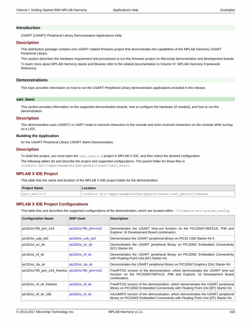
Introduction
USART (USART) Peripheral Library Demonstration Applications Help
Description
This distribution package contains one USART related firmware project that demonstrates the capabilities of the MPLAB Harmony USART Peripheral Library.
This section describes the hardware requirement and procedures to run this firmware project on Microchip demonstration and development boards.
To learn more about MPLAB Harmony stacks and libraries refer to the related documentation in Volume IV: MPLAB Harmony Framework Reference.
Demonstrations
This topic provides information on how to run the USART Peripheral Library demonstration applications included in this release.
uart_basic
This section provides information on the supported demonstration boards, how to configure the hardware (if needed), and how to run the demonstration.
Description
This demonstration uses USART2 in UART mode to transmit characters to the console and echo received characters on the console while turning on a LED.
Building the Application
for the USART Peripheral Library USART Alarm Demonstration.
Description
To build this project, you must open the uart_basic.X project in MPLAB X IDE, and then select the desired configuration.
The following tables list and describe the project and supported configurations. The parent folder for these files is <install-dir>/apps/examples/peripheral/usart/uart_basic.
MPLAB X IDE Project
This table lists the name and location of the MPLAB X IDE project folder for the demonstration.
Project Name Location
uart_basic.X <install-dir>/apps/examples/peripheral/usart/uart_basic/firmware
MPLAB X IDE Project Configurations
This table lists and describes the supported configurations of the demonstration, which are located within ./firmware/src/system_config.
Configuration Name BSP Used Description
pic32mx795_pim_e16 pic32mx795_pim+e16 Demonstrates the USART time-out function on the PIC32MX795F512L PIM andExplorer 16 Development Board combination.
pic32mx_usb_sk2 pic32mx_usb_sk2 Demonstrates the USART peripheral library on PIC32 USB Starter Kit II.
pic32mz_ec_sk pic32mz_ec_sk Demonstrates the USART peripheral library on PIC32MZ Embedded Connectivity(EC) Starter Kit.
pic32mz_ef_sk pic32mz_ef_sk Demonstrates the USART peripheral library on PIC32MZ Embedded Connectivitywith Floating Point Unit (EF) Starter Kit.
pic32mz_da_sk pic32mz_da_sk Demonstrates the USART peripheral library on PIC32MZ Graphics (DA) Starter Kit.
pic32mx795_pim_e16_freertos pic32mx795_pim+e16 FreeRTOS version of the demonstration, which demonstrates the USART time-outfunction on the PIC32MX795F512L PIM and Explorer 16 Development Boardcombination.
pic32mz_ef_sk_freertos pic32mz_ef_sk FreeRTOS version of the demonstration, which demonstrates the USART peripherallibrary on PIC32MZ Embedded Connectivity with Floating Point Unit (EF) Starter Kit.
pic32mz_ef_sk_16b pic32mz_ef_sk microMIPS version of the demonstration, which demonstrates the USART peripherallibrary on PIC32MZ Embedded Connectivity with Floating Point Unit (EF) Starter Kit.
Volume I: Getting Started With MPLAB Harmony Applications Help Examples
© 2013-2017 Microchip Technology Inc. MPLAB Harmony v1.11 163

Configuring the Hardware
Describes how to configure the supported hardware.
Description
PIC32MX795F512L PIM and Explorer 16 Development Board
Connect a standard serial cable or USB-to-RS-232 adapter cable between the personal computer and the Explorer 16 Development Board P1 (UART) port.
PIC32MZ EC Starter Kit or PIC32MZ EF Starter Kit
The optional MCP2200 Breakout Module (ADM00393), which is a USB-to-UART serial converter adapter board, may be used to run this demonstration. If the Breakout Module will be used, an additional interface is required. The acceptable interface is the Starter Kit I/O Expansion Board with the PIC32MZ Starter Kit Adapter Board (AC320006). Jumper from pins 58 and 23 of J10 header to RX and TX of the Breakout module, respectively. In addition, connect GND.
PIC32MZ DA Starter Kit
Connect a USB cable to the J5 Mini Type B connector on the PIC32MZ DA Starter Kit. Connect this USB cable to the computer running the terminal emulation program.
PIC32 USB Starter Kit II
The optional MCP2200 Breakout Module, which is a USB-to-UART serial converter adapter board, may be used to run this demonstration. If the Breakout Module will be used, an additional interface is required. The acceptable interface is the Starter Kit I/O Expansion Board. Jumper from pins 48 and 46 of J11 header to RX and TX of the Breakout Module, respectively. In addition, GND must be shorted.
Running the Demonstration
Provides instructions on how to build and run the USART demonstration.
Description
This demonstration shows the USART capabilities using the USART Peripheral Library functions.
1. First compile and program the target device. While compiling, select the configuration suitable for the hardware in use.
2. Launch a console client (OS native/Tera Term, etc.,) and set the serial port settings to 9600-N-1.
3. Launch the demonstration. The following messages will appear in the console window:
*** UART Interrupt-driven Application Example *** *** Type some characters and observe the LED turn ON ***
4. As indicated in the message, notice the typed characters echoed on the console window and LED.
5. Turn on LED (D3 on Explorer 16 Development Board or LED3 on the PIC32 USB Starter Kit II, PIC32MZ EC Starter Kit, PIC32MZ EF Starter Kit, and PIC32MZ DA Starter Kit) indicating interrupt processing.
WDT Peripheral Library examples
This topic provides descriptions of the WDT Peripheral Library examples.
Introduction
Watchdog Timer (WDT) Peripheral Library Demonstration Applications Help
Description
This distribution package contains one WDT related firmware project that demonstrates the capabilities of the MPLAB Harmony Watchdog Timer Peripheral Library.
This section describes the hardware requirement and procedures to run this firmware project on Microchip demonstration and development boards.
To learn more about MPLAB Harmony stacks and libraries refer to the related documentation in Volume IV: MPLAB Harmony Framework Reference.
Demonstrations
This topic provides information on how to run the WDT Peripheral Library demonstration applications included in this release.
wdt_timeout
This section provides information on the supported demonstration boards, how to configure the hardware (if needed), and how to run the
Volume I: Getting Started With MPLAB Harmony Applications Help Examples
© 2013-2017 Microchip Technology Inc. MPLAB Harmony v1.11 164

demonstration.
Description
This demonstration exercises the watchdog time-out function using the WDT Peripheral Library.
Building the Application
for the WDT Peripheral Library WDT Alarm Demonstration.
Description
To build this project, you must open the wdt_timeout.X project in MPLAB X IDE, and then select the desired configuration.
The following tables list and describe the project and supported configurations. The parent folder for these files is <install-dir>/apps/examples/peripheral/wdt/wdt_timeout.
MPLAB X IDE Project
This table lists the name and location of the MPLAB X IDE project folder for the demonstration.
Project Name Location
wdt_timeout.X <install-dir>/apps/examples/peripheral/wdt/wdt_timeout/firmware
MPLAB X IDE Project Configurations
This table lists and describes the supported configurations of the demonstration, which are located within ./firmware/src/system_config.
Configuration Name BSP Used Description
pic32mx795_pim_e16 pic32mx795_pim+e16 Demonstrates the WDT time-out function on the PIC32MX795F512L PIM andExplorer 16 Development Board combination.
pic32mx_usb_sk2 pic32mx_usb_sk2 Demonstrates the WDT time-out function on the PIC32 USB Starter Kit II.
pic32mz_ec_sk pic32mz_ec_sk Demonstrates the WDT time-out function on the PIC32MZ Embedded Connectivity(EC) Starter Kit.
pic32mz_ef_sk pic32mz_ef_sk Demonstrates the WDT time-out function on the PIC32MZ Embedded Connectivitywith Floating Point Unit (EF) Starter Kit.
pic32mz_da_sk pic32mz_da_sk Demonstrates the WDT time-out function on the PIC32MZ Graphics (DA) Starter Kit.
pic32mx795_pim_e16_freertos pic32mx795_pim+e16 FreeRTOS version of the demonstration, which demonstrates the WDT time-outfunction on the PIC32MX795F512L PIM and Explorer 16 Development Boardcombination.
pic32mz_ef_sk_freertos pic32mz_ef_sk FreeRTOS version of the demonstration, which demonstrates the WDT time-outfunction on the PIC32MZ Embedded Connectivity with Floating Point Unit (EF)Starter Kit.
pic32mz_ef_sk_16b pic32mz_ef_sk microMIPS version of the demonstration, which demonstrates the WDT time-outfunction on the PIC32MZ Embedded Connectivity with Floating Point Unit (EF)Starter Kit.
Configuring the Hardware
Describes how to configure the supported hardware.
Description
PIC32 USB Starter Kit II
No hardware related configuration or jumper setting changes are necessary.
PIC32MZ EC Starter Kit
No hardware related configuration or jumper setting changes are necessary.
PIC32MZ EF Starter Kit
No hardware related configuration or jumper setting changes are necessary.
PIC32MZ DA Starter Kit
No hardware related configuration or jumper setting changes are necessary.
Volume I: Getting Started With MPLAB Harmony Applications Help Examples
© 2013-2017 Microchip Technology Inc. MPLAB Harmony v1.11 165

PIC32MX795F512L PIM and Explorer 16 Development Board
No hardware related configuration or jumper setting changes are necessary.
Running the Demonstration
Provides instructions on how to build and run the WDT time-out demonstration.
Description
This demonstration exercises the WDT time-out function.
1. First compile and program the target device. While compiling, select the configuration suitable for the hardware in use.
2. The LEDs (LED1 on the PIC32 USB Starter Kit II, PIC32MZ EC Starter Kit, PIC32MZ EF Starter Kit and PIC32MZ DA Starter Kit, or LED D3 on the Explorer 16 Development Board) will blink during normal operation.
3. Press Switch 1 (PIC32 USB Starter Kit II, PIC32MZ EC Starter Kit, PIC32MZ EF Starter Kit and PIC32MZ DA Starter Kit) or Switch S3 (Explorer 16 Development Board) for the WDT time-out reset. If the demonstration is successful, LED3 (PIC32 USB Starter Kit II, PIC32MZ EC Starter Kit, PIC32MZ EF Starter Kit, and PIC32MZ DA Starter Kit) or LED D5 (Explorer 16 Development Board) will illuminate. If they do not, this indicates demonstration failure.
System Service Library Examples
Introduction
The example applications provide very simple single-purpose examples of how to use MPLAB Harmony system service libraries.
Description
System services have two primary types of implementations:
• System Service Libraries
• Low-Level Support
Most system service libraries follow the same basic model as a device driver (directly using a peripheral library to access hardware) or a middleware library (using a device driver to access hardware) as the rest of the system.
Command Processor System Service Examples
This topic provides descriptions of the Command Processor System Service examples.
Introduction
Command Processor System Service Library Demonstration Applications Help.
Description
This distribution package contains a firmware project that demonstrates the capabilities of the MPLAB Harmony Command Processor System Service. This section describes the hardware requirement and procedures to run this firmware project on Microchip demonstration and development boards.
To learn more about MPLAB Harmony stacks and libraries refer to the related documentation in Volume IV: MPLAB Harmony Framework Reference.
Demonstrations
This topic provides information on how to run the Command Processor System Service Library demonstration applications included in this release.
command_appio
This section provides information on the supported demonstration boards, how to configure the hardware (if needed), and how to run the demonstration.
Description
This demonstration application exercises the Command Processor System Service by receiving user keyboard input and displaying the output string to the PIC AppIO window in MPLAB X IDE.
The demonstration application does the following:
1. Launches the application via MPLAB REAL ICE to a target device.
2. Displays "Ready to accept command input" in the PIC AppIO window in MPLAB X IDE at initialization.
Volume I: Getting Started With MPLAB Harmony Applications Help Examples
© 2013-2017 Microchip Technology Inc. MPLAB Harmony v1.11 166

3. Listens for user command input.
4. Supports two simple commands native to this application.
Building the Application
This section identifies the MPLAB X IDE project name and location and lists and describes the available configurations for the Command Processor System Service Demonstration.
Description
To build this project, you must open the command_appio.X project in MPLAB X IDE, and then select the desired configuration.
The following tables list and describe the project and supported configurations. The parent folder for these files is <install-dir>/apps/examples/system/command_appio
MPLAB X IDE Project
This table lists the name and location of the MPLAB X IDE project folder for the demonstration.
Project Name Location
command_appio.X <install-dir>/apps/examples/system/command_appio/firmware
MPLAB X IDE Project Configurations
This table lists and describes the supported configurations of the demonstration, which are located within ./firmware/src/system_config.
Project Configuration Name
BSP Used Description
pic32mx_usb_sk2 pic32mx_usb_sk2 Demonstrates application I/O using the PIC32 USB Starter Kit II, the Starter Kit I/OExpansion Board and the MPLAB REAL ICE in-circuit emulator.
Configuring the Hardware
Describes how to configure the supported hardware.
Description
PIC32 USB Starter Kit II
This demonstration requires the MPLAB REAL ICE in-circuit emulator and the Starter Kit I/O Expansion Board.
Running the Demonstration
Provides instructions on how to build and run the Command Processor System Service demonstration.
Description
Do the following to run the demonstration:
1. Ensure that the PIC32 USB Starter Kit II, the Starter Kit I/O Expansion Board, and the MPLAB REAL ICE in-circuit emulator are connected and ready.
2. Open the PIC AppIO window in MPLAB X IDE by selecting Window > Debugging > PIC AppIO.
3. Make sure the Output Format in PIC AppIO is set to "Text" (the default is 8-bit hex).
4. Debug the project.
5. Wait for "Ready to accept command input" to display in the Output Format section.
6. Type keyboard input into the Input Format bar and press <ENTER>.
7. Typing "help" will display the general help sections. Typing "help app" will display the commands unique to the application including a brief description.
8. Try the commands listed by "help app".
Volume I: Getting Started With MPLAB Harmony Applications Help Examples
© 2013-2017 Microchip Technology Inc. MPLAB Harmony v1.11 167

Console System Service Examples
This topic provides descriptions of the Console System Service examples.
Introduction
Console System Service Library Demonstration Applications Help.
Description
This distribution package contains a firmware project that demonstrates the capabilities of the MPLAB Harmony Console System Service. This section describes the hardware requirement and procedures to run this firmware project on Microchip demonstration and development boards.
To learn more about MPLAB Harmony stacks and libraries refer to the related documentation in Volume IV: MPLAB Harmony Framework Reference.
Demonstrations
This topic provides information on how to run the Console System Service Library demonstration applications included in this release.
multi_instance_console
This section provides information on the supported demonstration boards, how to configure the hardware (if needed), and how to run the demonstration.
Description
This demonstration illustrates the read and write operation on the Console when multiple Console instances are running simultaneously. The project has three configurations, the first configuration demonstrates simultaneous operation of the UART Console and the USB CDC Console, the second configuration shows the UART Console and the AppIO Console and the third configuration shows the USB CDC Console and the AppIO Console.
The application perform the following tasks:
• Each instance of Console prints a welcome message and prompts the user to enter a string
• The string that is entered by the user is echoed back to the Console
• The read operation completion can be checked through both polling and by indication of a callback
• The application is designed so that the two Console instances can run independently of each other
Libraries Used
The Console System Service resides as the top layer. The UART and USB Drivers are used depending on the choice of Console selected. The UART and USB Drivers call their respective Peripheral Libraries (PLIBs) to interact with the hardware. If AppIO is selected as the Console choice, the AppIO service is used, which is provided with the MPLAB X IDE C/C++ XC32 Compiler.
The application interacts directly with the Console System Service Library. The Console System Service Library, depending upon the choice of console driver, makes calls to the UART, USB, or AppIO.
Building the Application
This section identifies the MPLAB X IDE project name and location and lists and describes the available configurations for the Command Processor System Service Demonstration.
Description
To build this project, you must open the multi_instance_console.X project in MPLAB X IDE, and then select the desired configuration.
The following tables list and describe the project and supported configurations. The parent folder for these files is <install-dir>/apps/examples/system/multi_instance_console
MPLAB X IDE Project
This table lists the name and location of the MPLAB X IDE project folder for the demonstration.
Project Name Location
multi_instance_console.X <install-dir>/apps/examples/system/multi_instance_console/firmware
MPLAB X IDE Project Configurations
This table lists and describes the supported configurations of the demonstration, which are located within ./firmware/src/system_config.
Volume I: Getting Started With MPLAB Harmony Applications Help Examples
© 2013-2017 Microchip Technology Inc. MPLAB Harmony v1.11 168

Project Configuration Name
BSP Used Description
pic32mx_usb_sk2 pic32mx_usb_sk2 Demonstrates USB CDC and AppIO Console instances running simultaneously on thePIC32 USB Starter Kit II.
pic32mx795_pim_e16 pic32mx795_pim+e16 Demonstrates UART and AppIO Console instances running simultaneously on the thePIC32MX795F512L PIM with the Explorer 16 Development Board.
pic32mz_ef_sk_meb2 pic32mz_ef_sk+meb2 Demonstrates UART and USB CDC Console instances running simultaneously on thePIC32MZ Embedded Connectivity with Floating Point Unit (EF) Starter Kit.
Configuring the Hardware
Describes how to configure the supported hardware.
Description
PIC32 USB Starter Kit II
This demonstration requires the MPLAB REAL ICE in-circuit emulator for communication with AppIO and the Starter Kit I/O Expansion Board.
PIC32MX795F512L PIM with the Explorer 16 Development Board
This demonstration requires the MPLAB REAL ICE in-circuit emulator for communication with AppIO.
PIC32MZ Embedded Connectivity with Floating Point Unit (EF) Starter Kit
No hardware related configuration or jumper setting changes are necessary.
Running the Demonstration
Provides instructions on how to build and run the Console System Service demonstration.
Description
Depending on the hardware in use, use on the of the following three procedures to run the demonstration.
PIC32 USB Starter Kit II
This demonstration writes and reads to/from a terminal program running on a personal computer host and also from the AppIO interface in MPLAB X IDE.
This demonstration utilizes the PIC32 USB Starter Kit II and requires the starter kit to be paired with the Starter Kit I/O Expansion Board.
Since AppIO uses the Debug interface, it also requires the MPLAB REAL ICE in-circuit emulator.
1. In MPLAB X IDE, select the hardware configuration to be used. Compile and program the target device in Debug mode with the selected configuration.
2. Open the AppIO window in MPLAB X IDE by selecting Window > Debugging > PIC AppIO.
3. Ensure that the Output Format in PIC AppIO is set to "Text" (the default is 8-bit hex), as shown in the following figure.
4. Before connecting the micro-USB cable to the host computer, the demonstration must be running for the terminal program to recognize the USB COM device. Once the demonstration is running, start a terminal emulator program (Tera Term shown) with serial port settings (921600 baud, 8 bit data, no parity, 1 bit stop, no flow control), as shown in the following figure.
Volume I: Getting Started With MPLAB Harmony Applications Help Examples
© 2013-2017 Microchip Technology Inc. MPLAB Harmony v1.11 169

Demonstration Output
When running the program in debug mode, the AppIO interface will display messages, as shown in the following figure.
It is important to note that the AppIO interface implements a blocking read call expecting data from debug interface until the user enters a RETURN, so all of the necessary AppIO read operations should be executed first before proceeding with the USB Console.
USB can be executed only after the AppIO demonstration is complete. A display similar to the following figure can be expected after execution of the USB Console demonstration.
Volume I: Getting Started With MPLAB Harmony Applications Help Examples
© 2013-2017 Microchip Technology Inc. MPLAB Harmony v1.11 170

PIC32MX795F512 PIM and Explorer 16 Development Board
This demonstration reads and writes to a terminal program running on a personal computer host and also from the AppIO interface in MPLAB X IDE.
This demonstration utilizes the PIC32795F512L PIM paired with the Explorer 16 Development Board.
1. In MPLAB X IDE, select the hardware configuration to be used. Compile and program the target device in Debug mode with the selected configuration.
2. Open the AppIO window in MPLAB X IDE by selecting Window > Debugging > PIC AppIO.
3. Ensure that the Output Format in PIC AppIO is set to "Text" (the default is 8-bit hex), as shown in the following figure.
4. Connect the Explorer 16 Development Board to the host personal computer using a RS-232 UART connection.
5. A terminal program like Tera Term can be used with the settings shown in the following figure.
Demonstration Output
When running the program in debug mode, the AppIO interface will display messages, as shown in the following figure.
Volume I: Getting Started With MPLAB Harmony Applications Help Examples
© 2013-2017 Microchip Technology Inc. MPLAB Harmony v1.11 171

It is important to note that the AppIO interface implements a blocking read call, expecting data from debug interface until the user enters a RETURN, so all of the necessary AppIO read operations should be executed first before proceeding with the UART Console.
Once AppIO operation is complete, the UART Console can be executed. A display similar to the following figure can be expected.
PIC32MZ EF Starter Kit
This demonstration reads and writes and to a terminal program running on a personal computer host that uses the UART and USB CDC 2 Console.
This demonstration utilizes the PIC32MZ EF Starter Kit.
1. In MPLAB X IDE, select the hardware configuration to be used. Compile and program the target device in Debug mode with the selected configuration.
2. Connect the PIC32MZ EF Starter Kit to the host personal computer using a mini-USB cable for the UART connection and a micro-USB cable for the USB connection.
3. A terminal program such as Tera Term can be used with the following UART settings.
Volume I: Getting Started With MPLAB Harmony Applications Help Examples
© 2013-2017 Microchip Technology Inc. MPLAB Harmony v1.11 172

4. Before connecting the micro-USB cable to the host computer, the demonstration must be running for the terminal program to recognize the USB COM device. Once the demonstration is running, start a terminal emulator program (e.g., Tera Term) with serial port with the following USB settings: (921600 baud, 8 bit data, no parity, 1 bit stop, no flow control), as shown in the following figure.
Demonstration Output
Since the UART and USB Console are running independently, the order in which the user interacts with each Console is irrelevant.
The UART Console should show an output similar to the following figure.
Volume I: Getting Started With MPLAB Harmony Applications Help Examples
© 2013-2017 Microchip Technology Inc. MPLAB Harmony v1.11 173

The USB Console should show an output similar to the following figure.
Debug System Service Examples
This topic provides descriptions of the Debug System Service examples.
Introduction
Debug System Service Library Demonstration Applications Help.
Description
This distribution package contains a firmware project that demonstrates the capabilities of the MPLAB Harmony Debug System Service. This section describes the hardware requirement and procedures to run this firmware project on Microchip demonstration and development boards.
To learn more about MPLAB Harmony stacks and libraries refer to the related documentation in Volume IV: MPLAB Harmony Framework Reference.
Demonstrations
This topic provides information on how to run the Debug System Service Library demonstration applications included in this release.
debug_uart
This section provides information on the supported demonstration boards, how to configure the hardware (if needed), and how to run the demonstration.
Volume I: Getting Started With MPLAB Harmony Applications Help Examples
© 2013-2017 Microchip Technology Inc. MPLAB Harmony v1.11 174

Description
This demonstration application exercises the Debug and Console System Services by routing messages from the Debug System Service through the Console System Service to a terminal program running on a personal computer via the UART communications protocol.
The demonstration application does the following:
• Demonstrates a direct console write by outputting a string to the terminal
• Demonstrates formatted and unformatted message writes to the terminal
• Demonstrates the use of the global error level
• Demonstrates debug output messaging using both polling and callback notification of completion
• Demonstrates what happens when the write queue overflows
• Demonstrates console flush in reaction to an error condition
• Demonstrates console read using both polling and callback notification
• Demonstrates an echo function in which the characters are written back to the terminal as they are read
Building the Application
This section identifies the MPLAB X IDE project name and location and lists and describes the available configurations for the Debug System Service Demonstration.
Description
To build this project, you must open the debug_uart.X project in MPLAB X IDE, and then select the desired configuration.
The following tables list and describe the project and supported configurations. The parent folder for these files is <install-dir>/apps/examples/system/debug_uart
MPLAB X IDE Project
This table lists the name and location of the MPLAB X IDE project folder for the demonstration.
Project Name Location
debug_uart.X <install-dir>/apps/examples/system/debug_uart/firmware
MPLAB X IDE Project Configurations
This table lists and describes the supported configurations of the demonstration, which are located within ./firmware/src/system_config.
Project Configuration Name
BSP Used Description
pic32mx795_pim_e16 pic32mx795_pim+e16 Demonstration console communication via UART RS-232 using the Explorer 16Development Board and the PIC32MX795F512L PIM.
pic32mz_ef_sk pic32mz_ef_sk Demonstration console communication via UART RS-232 using using the PIC32MZEF Starter Kit.
pic32mz_da_sk pic32mz_da_sk Demonstration console communication via UART RS-232 using the PIC32MZ DAStarter Kit.
Configuring the Hardware
Describes how to configure the supported hardware.
Description
PIC32MX795F512L PIM combined with the Explorer 16 Development Board
No hardware related configuration or jumper setting changes are necessary.
PIC32MZ DA Starter Kit
No hardware related configuration or jumper setting changes are necessary.
PIC32MZ EF Starter Kit
No hardware related configuration or jumper setting changes are necessary.
Running the Demonstration
Provides instructions on how to build and run the Debug System Service demonstration.
Description
This demonstration writes and reads to/from a terminal program running on a personal computer host.
Volume I: Getting Started With MPLAB Harmony Applications Help Examples
© 2013-2017 Microchip Technology Inc. MPLAB Harmony v1.11 175

1. First compile and program the target device. While compiling, select the configuration for the hardware in use.
2. Connect the Explorer 16 Development Board to the host personal computer using a RS-232 UART connection.
3. The demonstration must be running for the terminal program to recognize the COM device. Start a terminal emulator program (Tera Term shown).
4. Press SW1 to start the demonstration.
5. Follow the instructions on the terminal.
debug_usb_cdc_2
This section provides information on the supported demonstration boards, how to configure the hardware (if needed), and how to run the demonstration.
Volume I: Getting Started With MPLAB Harmony Applications Help Examples
© 2013-2017 Microchip Technology Inc. MPLAB Harmony v1.11 176

Description
This demonstration application exercises the Debug and Console System Services by routing messages from the Debug System Service through the Console System Service to a terminal program running on a personal computer via the USB-CDC communications protocol.
The demonstration application does the following:
• Demonstrates a direct console write by outputting a string to the terminal
• Demonstrates formatted and unformatted message writes to the terminal
• Demonstrates the use of the global error level
• Demonstrates debug output messaging using both polling and callback notification of completion
• Demonstrates what happens when the write queue overflows
• Demonstrates console flush in reaction to an error condition
• Demonstrates console read using both polling and callback notification
• Demonstrates an echo function in which the characters are written back to the terminal as they are read
Building the Application
This section identifies the MPLAB X IDE project name and location and lists and describes the available configurations for the Debug System Service Demonstration.
Description
To build this project, you must open the debug_usb_cdc_2.X project in MPLAB X IDE, and then select the desired configuration.
The following tables list and describe the project and supported configurations. The parent folder for these files is <install-dir>/apps/examples/system/debug_usb_cdc_2
MPLAB X IDE Project
This table lists the name and location of the MPLAB X IDE project folder for the demonstration.
Project Name Location
debug_usb_cdc_2.X <install-dir>/apps/examples/system/debug_usb_cdc_2/firmware
MPLAB X IDE Project Configurations
This table lists and describes the supported configurations of the demonstration, which are located within ./firmware/src/system_config.
Project Configuration Name
BSP Used Description
pic32mx_usb_sk2 pic32mx_usb_sk2 Demonstrates console communication through USB with the PIC32 USB StarterKit II.
pic32mz_ec_sk pic32mz_ec_sk Demonstrates console communication through USB with the PIC32MZ EC StarterKit.
pic32mz_ef_sk pic32mz_ef_sk Demonstrates console communication through USB with the PIC32MZ EF StarterKit.
Configuring the Hardware
Describes how to configure the supported hardware.
Description
PIC32MZ EC Starter Kit
No hardware related configuration or jumper setting changes are necessary.
PIC32MZ EF Starter Kit
No hardware related configuration or jumper setting changes are necessary.
PIC32 USB Starter Kit II
No hardware related configuration or jumper setting changes are necessary.
Running the Demonstration
Provides instructions on how to build and run the Debug System Service demonstration.
Description
This demonstration writes and reads to/from a terminal program running on a personal computer host.
1. First compile and program the target device. While compiling, select the pic32mz_ec_sk configuration for the PIC32MZ EC Starter Kit, the
Volume I: Getting Started With MPLAB Harmony Applications Help Examples
© 2013-2017 Microchip Technology Inc. MPLAB Harmony v1.11 177

pic32mz_ef_sk configuration for the PIC32MZ EF Starter Kit, or the pic32mx_usb_sk2 configuration for the PIC32MX USB Starter Kit II.
2. Connect the starter kit to the host personal computer using an A to micro-A/B USB cable.
3. The demonstration must be running for the terminal program to recognize the COM device. Start a terminal emulator program (Tera Term shown) with serial port with the following settings: (921600 baud, 8 bit data, no parity, 1 bit stop, no flow control).
4. The terminal will indicate a successful connection. Press any key on the computer to start the demonstration.
5. Follow the instructions on the terminal.
Device Control System Service Examples
This topic provides descriptions of the Device Control System Service examples.
Introduction
Device Control System Service Library Demonstration Applications Help.
Description
This distribution package contains a firmware project that demonstrates the capabilities of the MPLAB Harmony Device Control System Service.
Volume I: Getting Started With MPLAB Harmony Applications Help Examples
© 2013-2017 Microchip Technology Inc. MPLAB Harmony v1.11 178

This section describes the hardware requirement and procedures to run this firmware project on Microchip demonstration and development boards.
To learn more about MPLAB Harmony stacks and libraries refer to the related documentation in Volume IV: MPLAB Harmony Framework Reference.
Demonstrations
This topic provides information on how to run the Device Control System Service Library demonstration applications included in this release.
devcon_cache_clean
This section provides information on the supported demonstration boards, how to configure the hardware (if needed), and how to run the demonstration.
Description
This example application demonstrates how cache coherency issues arise when transferring data out of memory using DMA. The MPLAB Harmony Device Control System Service contains various cache functions, which are used in this example to resolve the problem.
The application first allocates two buffers, with the intention of copying the data in one buffer to the other using DMA. The source buffer is first loaded with data and then the DMA transfer is initiated. After the transfer is complete, it is clear that the two buffers contain different values. This is an issue relating to cache coherency. When data is written by the CPU, it is stored in the cache but it is not written back to RAM unless the line is evicted or an explicit cache write-back instruction is executed. The cache instructions are accessed through the Device Control System Service and serve as a wrapper to the underlying MIPS® cache operations.
In this specific example, the data in the source buffer was never written back to RAM before being transferred to the destination buffer using DMA. Data that is stored in cache but has not yet been written back to RAM is termed "dirty". In the second part of the application, the correct method of maintaining cache coherency is demonstrated. After writing data to the source buffer, the function SYS_DEVCON_DataCacheClean is executed, forcing the data to be written back to main memory. When the DMA transfer is initiated, it then pulls the data out of RAM and transfers it to the destination buffer – this time, the data in both buffers will match.
If the application runs as intended, the red and green LEDs will be lit. The yellow LED will only be lit if an error has occurred.
Building the Application
This section identifies the MPLAB X IDE project name and location and lists and describes the available configurations for the Device Control System Service Cache Clean Demonstration.
Description
To build this project, you must open the devcon_cache_clean.X project in MPLAB X IDE, and then select the desired configuration.
The following tables list and describe the project and supported configurations. The parent folder for these files is <install-dir>/apps/examples/system/devcon.
MPLAB X IDE Project
This table lists the name and location of the MPLAB X IDE project folder for the demonstration.
Project Name Location
devcon_cache_clean.X <install-dir>/apps/examples/system/devcon/devcon_cache_clean/firmware
MPLAB X IDE Project Configurations
This table lists and describes the supported configurations of the demonstration, which are located within ./firmware/src/system_config.
Project Configuration Name
BSP Used Description
pic32mz_ec_sk pic32mz_ec_sk Demonstrates Device Control System Service cache functions using the PIC32MZ ECStarter Kit.
pic32mz_ef_sk pic32mz_ef_sk Demonstrates Device Control System Service cache functions using the PIC32MZ EFStarter Kit.
pic32mz_da_sk pic32mz_da_sk Demonstrates Device Control System Service cache functions using the PIC32MZ DAStarter Kit.
pic32mz_ef_sk_16b pic32mz_ef_sk Demonstrates Device Control System Service cache functions in microMIPS mode usingthe PIC32MZ EF Starter Kit.
Configuring the Hardware
Describes how to configure the supported hardware.
Volume I: Getting Started With MPLAB Harmony Applications Help Examples
© 2013-2017 Microchip Technology Inc. MPLAB Harmony v1.11 179

Description
PIC32MZ EC Starter Kit
No hardware related configuration or jumper setting changes are necessary.
PIC32MZ EF Starter Kit
No hardware related configuration or jumper setting changes are necessary.
PIC32MZ DA Starter Kit
No hardware related configuration or jumper setting changes are necessary.
Running the Demonstration
Provides instructions on how to build and run the demonstration.
Description
This application demonstrates the necessity and proper use of the SYS_DEVCON_DataCacheClean function.
1. First compile and program the target device. When compiling, select the correct configuration for the device.
2. Observe the LEDs on the starter kit development board. If the red and green LEDs are both lit, the application executed successfully. If the yellow LED is lit, an error has occurred.
devcon_cache_invalidate
This section provides information on the supported demonstration boards, how to configure the hardware (if needed), and how to run the demonstration.
Description
This example application demonstrates how cache coherency issues arise when transferring data into memory using DMA. The MPLAB Harmony Device Control System Service contains various cache functions, which are used in this example to resolve the problem.
The application first allocates three buffers – two source buffers and one destination buffer. The two source buffers are filled with two different sets of data. The first buffer is copied to the destination buffer using DMA and the application checks to ensure they both contain the same data (which they do). The second source buffer is then copied to the destination buffer using DMA and once again the data is compared. This time the data does not match and once again, it is due to a cache coherency issue.
After the first DMA transfer and read of the destination buffer, the data is pulled into the cache. The second DMA transfer then updates the data contained in the destination buffer, but only the data contained in RAM. As far as the cache is aware, the stale data in the cache still matches the fresh data that is now in RAM. The cache simply sees that it is already storing a copy of the destination buffer, so it need not bother to pull the fresh data into itself when the CPU does the second set of reads. What we need is a way to tell the CPU to get rid of the stale cached data and pull in fresh data from main memory – this is known as an ‘invalidate'. The example application demonstrates the proper technique for taking care of this issue. After the second DMA transfer, the destination buffer must be invalidated with the use of the function SYS_DEVCON_DataCacheInvalidate. This marks the data of interest in the cache as invalid. Now when the CPU performs a read on the destination buffer, fresh data is pulled out of main memory and into the cache, before being presented to the CPU.
If the application runs as intended, the red and green LEDs will be lit. The yellow LED will only be lit if an error has occurred.
Building the Application
This section identifies the MPLAB X IDE project name and location and lists and describes the available configurations for the Device Control System Service Cache Invalidate Demonstration.
Description
To build this project, you must open the devcon_cache_invalidate.X project in MPLAB X IDE, and then select the desired configuration.
The following tables list and describe the project and supported configurations. The parent folder for these files is <install-dir>/apps/examples/system/devcon.
MPLAB X IDE Project
This table lists the name and location of the MPLAB X IDE project folder for the demonstration.
Project Name Location
devcon_cache_invalidate.X <install-dir>/apps/examples/system/devcon/devcon_cache_invalidate/firmware
MPLAB X IDE Project Configurations
This table lists and describes the supported configurations of the demonstration, which are located within ./firmware/src/system_config.
Volume I: Getting Started With MPLAB Harmony Applications Help Examples
© 2013-2017 Microchip Technology Inc. MPLAB Harmony v1.11 180

Project Configuration Name
BSP Used Description
pic32mz_ec_sk pic32mz_ec_sk Demonstrates Device Control System Service cache functions using the PIC32MZ ECStarter Kit.
pic32mz_ef_sk pic32mz_ef_sk Demonstrates Device Control System Service cache functions using the PIC32MZ EFStarter Kit.
pic32mz_da_sk pic32mz_da_sk Demonstrates Device Control System Service cache functions using the PIC32MZ DAStarter Kit.
pic32mz_ef_sk_16b pic32mz_ef_sk Demonstrates Device Control System Service cache functions in microMIPS mode usingthe PIC32MZ EF Starter Kit.
Configuring the Hardware
Describes how to configure the supported hardware.
Description
PIC32MZ EC Starter Kit
No hardware related configuration or jumper setting changes are necessary.
PIC32MZ EF Starter Kit
No hardware related configuration or jumper setting changes are necessary.
PIC32MZ DA Starter Kit
No hardware related configuration or jumper setting changes are necessary.
Running the Demonstration
Provides instructions on how to build and run the demonstration.
Description
This application demonstrates the necessity and proper use of the SYS_DEVCON_DataCacheInvalidate API.
1. First compile and program the target device. When compiling, select the correct configuration for the device.
2. Observe the LEDs on the starter kit development board. If the red and green LEDs are both lit, the application executed successfully. If the yellow LED is lit, an error has occurred.
devcon_sys_config_perf
This section provides information on the supported demonstration boards, how to configure the hardware (if needed), and how to run the demonstration.
Description
This demonstration provides an example of how to initialize the service and configure optimum system performance using the SYS_DEVCON_PerformanceConfig API.
The demonstration application does the following:
• Initializes the Device Control System Service
• Calls the SYS_DEVCON_PerformanceConfig API
• Waits in a busy loop
Building the Application
This section identifies the MPLAB X IDE project name and location and lists and describes the available configurations for the Device Control System Service Demonstration.
Description
To build this project, you must open the devcon_sys_config_perf.X project in MPLAB X IDE, and then select the desired configuration.
The following tables list and describe the project and supported configurations. The parent folder for these files is <install-dir>/apps/examples/system/devcon.
MPLAB X IDE Project
This table lists the name and location of the MPLAB X IDE project folder for the demonstration.
Volume I: Getting Started With MPLAB Harmony Applications Help Examples
© 2013-2017 Microchip Technology Inc. MPLAB Harmony v1.11 181

Project Name Location
devcon_sys_config_perf.X <install-dir>/apps/examples/system/devcon/devcon_sys_config_perf/firmware
MPLAB X IDE Project Configurations
This table lists and describes the supported configurations of the demonstration, which are located within ./firmware/src/system_config.
Project Configuration Name
BSP Used Description
pic32mx_eth_sk pic32mx_eth_sk Demonstrates various Device Control System Service cache functions using the PIC32Ethernet Starter Kit.
pic32mz_ec_sk pic32mz_ec_sk Demonstrates Device Control System Service cache functions using the PIC32MZ ECStarter Kit.
pic32mz_ef_sk pic32mz_ef_sk Demonstrates Device Control System Service cache functions using the PIC32MZ EFStarter Kit.
pic32mz_da_sk pic32mz_da_sk Demonstrates Device Control System Service cache functions using the PIC32MZ DAStarter Kit.
pic32mz_ef_sk_16b pic32mz_ef_sk Demonstrates Device Control System Service cache functions in microMIPS mode usingthe PIC32MZ EF Starter Kit.
Configuring the Hardware
Describes how to configure the supported hardware.
Description
PIC32MZ EC Starter Kit
No hardware related configuration or jumper setting changes are necessary.
PIC32MZ EF Starter Kit
No hardware related configuration or jumper setting changes are necessary.
PIC32MZ DA Starter Kit
No hardware related configuration or jumper setting changes are necessary.
PIC32 Ethernet Starter Kit
No hardware related configuration or jumper setting changes are necessary.
Running the Demonstration
Provides instructions on how to build and run the Device Control System Service demonstration.
Description
This demonstration initializes the Device Control System Service and demonstrates the use of the SYS_DEVCON_PerformanceConfig API.
1. Select the desired MPLAB X IDE project configuration:
• pic32mz_ec_sk (for PIC32MZ EC devices)
• pic32mz_ef_sk (for PIC32MZ EF devices)
• pic32mz_da_sk (for PIC32MZ DA devices)
• pic32mx_eth_sk (for PIC32MX devices)
2. Build the selected configuration in the MPLAB X IDE project and program the demonstration board by selecting Debug Main Project from the Debug Menu. The program should build, download, and run.
3. Select Pause from the Debug menu. The program should pause in one of Tasks routines.
4. To verify that the device was initialized correctly, select Window > PIC Memory Views > Peripherals and check for the following:
• for PIC32MZ, verify in the PRECON register
• PFMWS is set to 2
• PREFEN is set to 3
• PIC32MX, verify in the CHECON register
• PFMWS is set to 2
• PREFEN is set to 3
Volume I: Getting Started With MPLAB Harmony Applications Help Examples
© 2013-2017 Microchip Technology Inc. MPLAB Harmony v1.11 182

DMA System Service Examples
This topic provides descriptions of the DMA System Service examples.
Introduction
DMA System Service Library Demonstration Applications Help.
Description
This distribution package contains a firmware project that demonstrates the capabilities of the MPLAB Harmony DMA System Service. This section describes the hardware requirement and procedures to run this firmware project on Microchip demonstration and development boards.
To learn more about MPLAB Harmony stacks and libraries refer to the related documentation in Volume IV: MPLAB Harmony Framework Reference.
Demonstrations
This topic provides information on how to run the DMA System Service Library demonstration applications included in this release.
dma_crc
This section provides information on the supported demonstration boards, how to configure the hardware (if needed), and how to run the demonstration.
Description
This application demonstrates how to use the special function of CRC computation of the PIC32 DMA module by using the MPLAB Harmony DMA System Service Library. This section describes the hardware requirement and procedures to build and execute the demonstration project on Microchip development tools.
In this demonstration application, the DMA System Service sets up a memory to memory data transfer. It also enables the CRC engine to compute the CRC of the data being transferred from source location to destination location.
To know more about the MPLAB Harmony DMA System Service, configuring the DMA System Service and the APIs provided by the DMA System service, refer to the DMA System Service Library section of the help.
Building the Application
This section identifies the MPLAB X IDE project name and location and lists and describes the available configurations for the DMA System Service Demonstration.
Description
To build this project, you must open the dma_crc.X project in MPLAB X IDE, and then select the desired configuration.
The following tables list and describe the project and supported configurations. The parent folder for these files is <install-dir>/apps/examples/system/dma.
MPLAB X IDE Project
This table lists the name and location of the MPLAB X IDE project folder for the demonstration.
Project Name Location
dma_crc.X <install-dir>/apps/examples/system/devcon/dma_crc/firmware
MPLAB X IDE Project Configurations
This table lists and describes the supported configurations of the demonstration, which are located within ./firmware/src/system_config.
Project Configuration Name
BSP Used Description
pic32mz_ef_sk pic32mz_ef_sk This demonstration runs on the PIC32MZ2048EFM144 device on-board the PIC32MZ EF starter kit.The configuration can be used for generating CRC using a 16-bit polynomial in background mode.
Configuring the Hardware
Describes how to configure the supported hardware.
Volume I: Getting Started With MPLAB Harmony Applications Help Examples
© 2013-2017 Microchip Technology Inc. MPLAB Harmony v1.11 183

Description
PIC32MZ EF Starter Kit
No hardware related configuration or jumper setting changes are necessary.
Running the Demonstration
Provides instructions on how to build and run the demonstration.
Description
1. Compile the demonstration application. While compiling, select the appropriate MPLAB X IDE project configuration based on the demonstration board. Refer to Building the Application for details.
2. Run the demonstration application in Debug mode by clicking Debug in MPLAB X IDE
3. The LED2 should illuminate. The illumination of LED2 indicates that the data is being transferred from the source to the destination and the CRC is computed as the data was transferred.
4. Click Pause in the MPLAB X IDE.
5. In the Variables window, observe the debug variable blockCrc. The blockCrc variable should have a value 0x31C3, which is the CRC value for 16-bit polynomial with an initial seed value of ‘0’.
Note on CRC Calculation: The CRC computation on the various websites usually uses the table approach method for CRC calculation. The table approach CRC calculation method generally pads the incoming message with extra 0 bits (16 bits in the case of a 16-bit polynomial, and 32 bits in the case of 32-bit polynomial). The PIC32 DMA CRC generation does not pad with any extra bits. The PIC32 DMA CRC calculation engine strictly calculates CRC of the input data buffer.
To obtain comparable results with the websites we have to append extra bits; 16 bits, or two zeros (bytes) for 16-bit polynomial computation. 32 bits or four zeros (bytes) for 32-bit polynomial computation. Therefore, the data transfer call in our DMA System Service CRC computation application has the size appended with polynomial length as shown in the following example:
RTCC System Service Examples
This topic provides descriptions of the RTCC System Service examples.
Introduction
RTCC System Service Library Demonstration Applications Help.
Description
This distribution package contains a firmware project that demonstrates the capabilities of the MPLAB Harmony RTCC System Service. This section describes the hardware requirement and procedures to run this firmware project on Microchip demonstration and development boards.
To learn more about MPLAB Harmony stacks and libraries refer to the related documentation in Volume IV: MPLAB Harmony Framework Reference.
Demonstrations
This topic provides information on how to run the RTCC System Service Library demonstration applications included in this release.
rtcc_timestamps
This section provides information on the supported demonstration boards, how to configure the hardware (if needed), and how to run the demonstration.
Description
This demonstration application shows how to use the RTCC System Service. A simple callback is registered with the RTCC System Service and the alarm causes the current time to be stored in an array. The RTCC System Service can be set to be interrupt-driven to increase efficiency in that it will only be called when the alarm interrupt occurs.
Building the Application
This section identifies the MPLAB X IDE project name and location and lists and describes the available configurations for the Command Processor System Service Demonstration.
Volume I: Getting Started With MPLAB Harmony Applications Help Examples
© 2013-2017 Microchip Technology Inc. MPLAB Harmony v1.11 184

Description
To build this project, you must open the rtcc_timestamps.X project in MPLAB X IDE, and then select the desired configuration.
The following tables list and describe the project and supported configurations. The parent folder for these files is <install-dir>/apps/examples/system/rtcc/rtcc_timestamps
MPLAB X IDE Project
This table lists the name and location of the MPLAB X IDE project folder for the demonstration.
Project Name Location
rtcc_timestamps.X <install-dir>/apps/examples/system/rtcc/rtcc_timestamps/firmware
MPLAB X IDE Project Configurations
This table lists and describes the supported configurations of the demonstration, which are located within ./firmware/src/system_config.
Project Configuration Name BSP Used Description
pic32mz_ef_sk pic32mz_ef_sk RTCC demonstration using the PIC32MZ EF Starter Kit.
pic32mz_ef_sk_freertos pic32mz_ef_sk FreeRTOS version of the RTCC demonstration using the PIC32MZ EF Starter Kit.
Configuring the Hardware
Describes how to configure the supported hardware.
Description
PIC32MZ EF Starter Kit
No hardware related configuration or jumper setting changes are necessary.
Running the Demonstration
Provides instructions on how to build and run the RTCC System Service demonstration.
Description
Do the following to run the demonstration:
1. Compile the demonstration application. While compiling, select the appropriate MPLAB X IDE project configuration based on the hardware in use. Refer to Building the Application for details.
2. As shown in the following figure, create a breakpoint near line 155 with the following text:
• appData.rtccTimeStateMachine = APP_RTCC_TIMESTAMP_DONE;
3. Run the demonstration application in Debug mode by clicking Debug in MPLAB X IDE.
4. When the debug session reaches the breakpoint (in approximately 10 seconds), the 'timestamps' array can be observed with the timestamps recorded at each second, as shown in the following figure.
Volume I: Getting Started With MPLAB Harmony Applications Help Examples
© 2013-2017 Microchip Technology Inc. MPLAB Harmony v1.11 185

External Memory Programmer Demonstrations
This section provides descriptions of the External Memory Programmer demonstrations.
Introduction
External Memory Programmer Demonstration Applications Help.
Description
This section describes the hardware requirement and procedures to run the External Memory Programmer firmware projects on Microchip demonstration and development boards.
To learn more about MPLAB Harmony stacks and libraries refer to the related documentation in Volume IV: MPLAB Harmony Framework Reference.
Demonstrations
This topic provides information on how to run the Programmer demonstration applications included in this release.
external_flash
This section provides information on the supported demonstration boards, how to configure the hardware (if needed), and how to run the demonstration.
Description
This demonstration implements a bootloader that resides in boot Flash. With the bootloader operating on the target device, the device can then program an external SPI Flash memory device (SST25FV016B or similar). This can be useful in programming external SPI Flash memory on Graphics PICtail daughter boards.
The bootloader is, operationally, similar to the bootloader described in AN1388 "PIC32 Bootloader", and will work with the personal computer application provided with the related source archive file. The application note and archive file are available for download from the Microchip web site (www.microchip.com).
Building the Application
This section identifies the MPLAB X IDE project name and location and lists and describes the available configurations for the External Flash Demonstration.
Description
To build this project, you must open the external_flash.X project in MPLAB X IDE, and then select the desired configuration.
The following tables list and describe the project and supported configurations. The parent folder for these files is <install-dir>/apps/programmer/external_flash.
MPLAB X IDE Project
This table lists the name and location of the MPLAB X IDE project folder for the demonstration.
Volume I: Getting Started With MPLAB Harmony Applications Help External Memory Programmer Demonstrations
© 2013-2017 Microchip Technology Inc. MPLAB Harmony v1.11 186

Project Name Location
external_flash.X <install-dir>/apps/programmer/external_flash/firmware
MPLAB X IDE Project Configurations
This table lists and describes the supported configurations of the demonstration, which are within ./firmware/src/system_config.
Project Configuration Name
BSP(s) Used Description
usbdevice_pic32mx_usb_sk2 pic32mx_usb_sk2 Demonstrates external SPI Flash programming capabilities on the PIC32 USB Starter KitII, connected to a Graphics Controller PICtail Plus Epson S1D13517 board (AC164127).
Configuring the Hardware
Describes how to configure the supported hardware.
Description
PIC32 USB Starter Kit II
On the S1D13517 board, the jumpers need to be configured for operations using SPI 2 as the interface to the PIC32 device.
JP3 (SCK), JP4 (MOSI), JP5 (MISO), and JP6 (CS) should all be in the 2-3 (SPI 2) position.
Running the Demonstration
Provides instructions on how to build and run the External Flash demonstration.
Description
Personal Computer-based Host Demonstration
Do the following when using the configurations:
Operation
The bootloader is operated as follows:
1. Select the configuration suitable for the target hardware.
2. Compile and program the device.
3. Hold down SW3 on the starter kit to force bootloader operation.
4. LED1 will start blinking to indicate the bootloader is operating. If a program had previously been programmed, it may be necessary to hold down SW3 prior to applying power to the board or resetting the board.
5. Open the personal computer Host program from the AN1388 source archive file.
6. Select the appropriate communication path:
• UART - Leave the baud rate at 115,200
• UDP - Keep the IP address at 192.168.1.11 and the UDP port at 6234
• USB Device - Keep the VID at 0x4D8 and the PID at 0x03C
7. Click Connect to_connect_to the bootloader and get the version.
8. If the bootloader connects, the personal computer Host application will indicate the version of the bootloader.
At this point, the bootloader is ready to accept a new application for programming into the program Flash. A demonstration application is provided, which is configured in a linker script to only operate in program Flash.
Setup
Create a hex file containing external SPI memory data (Graphics Resource Data is an example).
Programming the Device
With the demonstration application compiled, the generated hex file can now be programmed into the device using the bootloader.
To program the application into the device:
1. On the personal computer Host application described in AN1388, click Load Hex File.
2. Navigate to the data file meant to be programmed into external SPI flash (Graphics Resource Data is an example). Select the file and click Open.
3. Click Erase-Program-Verify.
4. The data will then be transferred to the bootloader, which will program the external SPI Flash.
5. Click Disconnect to release the Host Application.
Volume I: Getting Started With MPLAB Harmony Applications Help External Memory Programmer Demonstrations
© 2013-2017 Microchip Technology Inc. MPLAB Harmony v1.11 187

sqi_flash
This section provides information on the supported demonstration boards, how to configure the hardware (if needed), and how to run the demonstration.
Description
Applications that use large bitmap images or multiple page menu screens, which require several images or large or multiple font packages, etc., have a very large memory requirement for their graphics resources. In such applications, storing these graphics resources on-chip may result in insufficient memory or may be prohibitive to a possible cost benefit. A solution is to store the graphics resources to off-chip memory, such as non-volatile memory, thereby preserving the on-chip memory for program memory and allowing for more complex functional features. The pic32mz_ef_sk_meb2_gfx_ext_res configuration in the application can be used to store the external graphics resources onto external SQI Flash memory.
Another usage for external memory devices is for storing program routines and data. On PIC32MZ devices, the SQI peripheral can be configured to use the memory in eXecute-In-Place, or XIP, mode. When configured this way, the external memory appears in the memory space of the PIC32 device, and the running program can reference this memory the same as any other memory space, such as Program Flash and RAM. When the memory space in KSEG2 (cached) or KSEG3 (uncached) is referenced, the SQI peripheral automatically interfaces with the memory device and transfers the data in the appropriate direction without any further CPU intervention.
The current application, sqi_flash, serves as an external memory programmer to flash the off-chip non-volatile memory with the resources which can then be accessed by other applications saving on-chip memory for other programs and resources. The pic32mz_ef_sk_mebii_gfx_ext_res configuration of the sqi_flash application needs the resources to be stored externally in the form of a resource file that would be programmed into the external memory. An example resource file, gfx_resources_ext.hex, has already been generated and is available to the user within the <install-dir>\apps\gfx\external_resources\firmware\src\system_config\pic32mz_ef_sk+meb2\ folder.
The MPLAB Harmony Graphics Composer, which is the primary tool used by the MPLAB Harmony application for configuring the graphic design for the application, has the ability to generate the required resource file containing the binary data for all of the graphics images to be stored on external memory. As previously mentioned, the default name for the file generated by MHGC is gfx_resources_ext.hex. Refer to the MPLAB X IDE online help and Volume II: MPLAB Harmony Configurator (MHC) > MPLAB Harmony Graphics Composer User's Guide section for usage information. For more information on creating the gfx_resources_ext.hex file, please refer to the Applications Help > Graphics Demonstrations > external_resources demonstration.
The sqi_flash application requires the resource file gfx_resources_ext.hex file to be copied from the computer to a USB Flash drive, which has a FAT32 file system installed. The USB Flash drive is then plugged into the development board and the application scans the USB Flash drive for the resource file. The sqi_flash application copies the resource file sector by sector and flashes the binary resource content onto the SQI Flash external memory.
The pic32_mz_ef_sk configuration needs an image.hex file containing the program and data information to be flashed onto the sqi_flash application. In addition, ensure that the Flash drive is connected to the development board prior to programming the PIC32 device.
Building the Application
This section identifies the MPLAB X IDE project name and location and lists and describes the available configurations for the Programmer Demonstration.
Description
To build this project, you must open the sqi_flash.X project in MPLAB X IDE, and then select the desired configuration.
The following tables list and describe the project and supported configurations. The parent folder for these files is <install-dir>/apps/programmer/sqi_flash.
MPLAB X IDE Project
This table lists the name and location of the MPLAB X IDE project folder for the demonstration.
Project Name Location
sqi_flash.X <install-dir>/apps/programmer/sqi_flash/firmware
MPLAB X IDE Project Configurations
This table lists and describes the supported configurations of the demonstration, which are within ./firmware/src/system_config.
Volume I: Getting Started With MPLAB Harmony Applications Help External Memory Programmer Demonstrations
© 2013-2017 Microchip Technology Inc. MPLAB Harmony v1.11 188

Project Configuration Name BSP(s) Used Description
pic32mz_ef_sk_mebii_gfx_ext_res pic32mz_ef_sk+meb2 SQI Flash demonstration for the Multimedia Expansion Board II (MEB II) connectedto the PIC32MZ EF Starter Kit and the Graphics Display Powertip 4.3" 480x272Board. The PIC32MZ EF Starter Kit has a 4 MB SQI Flash memory device, which isused as the external non-volatile memory for this application. This is theconfiguration used for flashing external graphics resources onto external SQI Flashmemory.
pic32mz_ef_sk pic32mz_ef_sk SQI Flash demonstration for the PIC32MZ EF Starter Kit by itself with no otherinterface is required. However, the image name for the name of the file on the USBFlash drive, image.hex, is different.
Configuring the Hardware
Describes how to configure the supported hardware.
Description
PIC32MZ EF Starter Kit and MEB II
The MEB II has two memory options External or Internal; however, this demonstration must be run in Internal mode. Configure the MEB II, as follows:
• EBIWE and LCD_PCLK (J9) must be closed (the jumper is located on the back of the MEB II board)
• Ensure that any MHC setting is defined to only use internal SRAM
The current internal/external memory setting for the application can be verified in MHC by selecting Harmony Framework Configuration > Drivers > Graphics Controllers > LCC > Use LCC Driver > Memory Interface Mode.
Configuring MHC
Provides information the MHC settings required for the demonstration application.
Description
PIC32MZ Embedded Connectivity with Floating Point Unit (EF) Starter Kit with pic32mz_ef_sk_mebii_gfx_ext_res Configuration
When using the PIC32MZ EF Starter Kit, and powering it from the Debug port (J3), please insert a jumper onto JP1 to ensure the USB Flash drive has the correct power.
Configuring the MHC
The following are MHC settings that were modified from the default values. Refer to Volume II: MPLAB Harmony Configurator (MHC) for information on using MHC.
Drivers
The Graphics Controllers selection shows LCC was selected using the ‘Use LCC driver’ option. The Memory Interface Mode selected is Internal Memory. This is due to the fact that we want to load the program on internal memory and we are configuring the hardware with the jumper to match internal memory.
Volume I: Getting Started With MPLAB Harmony Applications Help External Memory Programmer Demonstrations
© 2013-2017 Microchip Technology Inc. MPLAB Harmony v1.11 189

System Services
Select File System with the following settings:
BSP
The BSP selected for the supported configuration is PIC32MZ EF Starter Kit in combination w\Multimedia Expansion Board II - pic32mz_ef_sk_meb2.
Clock Diagram
Open the clock configurator section and make sure the following values are selected for the different clock settings as required for the pic32mz_sk_ef_meb2 configuration
• Primary Oscillator frequency: 24 MHz, EC mode
• USB PLL: 480 MHz
• System Clock: 200 MHz
• PB Clock: 100 MHz
• REFCLKO: The Reference Clock (REFCLK) uses the System Clock (SYSCLK) as the reference and generates the master clock for SPI modules at 200 MHz
Application-specific Software Setup
SQI external memory support: Since a formal SQI driver is not available in MPLAB Harmony, the external memory programmer uses the SQI Peripheral Library. Please note that the source and header file for SQI enabling have been manually included in the project.
SourceFiles/drv_nvm_flash_sqi_sst26.c HeaderFiles/drv_nvm_flash_sqi_sst26.h
Also note that, to refer to these files a preprocessor macro has been added to the application properties named SST26VF_B.
Volume I: Getting Started With MPLAB Harmony Applications Help External Memory Programmer Demonstrations
© 2013-2017 Microchip Technology Inc. MPLAB Harmony v1.11 190

This application uses the gfx_resources_ext.hex file loaded on the USB Flash drive mentioned in the description.
PIC32MZ EF Starter Kit with pic32mz_ef_sk Configuration
Configuring the MHC
The following are MHC settings that were modified from the default values. Refer to Volume II: MPLAB Harmony Configurator (MHC) for information on using MHC.
System Services
Select File System with the following settings:
BSP
The BSP selected for the supported configuration is PIC32MZ EF Starter Kit - pic32mz_ef_sk.
Clock Diagram
Open the clock configurator section and make sure the following values are selected for the different clock settings as required for the pic32mz_sk_ef configuration:
• Primary Oscillator frequency: 24 MHz, EC mode
• USB PLL: 480 MHz
• System Clock: 200 MHz
• PB Clock: 100 MHz
• REFCLKO: The Reference Clock (REFCLK) uses the System Clock (SYSCLK) as the reference and generates the master clock for SPI modules at 200 MHz
Application-specific Software Setup
SQI external memory support: Since a formal SQI driver is not available in MPLAB Harmony, the external memory programmer uses the SQI Peripheral Library. Please note that the source and header file for SQI enabling have been manually included in the project.
SourceFiles/drv_nvm_flash_sqi_sst26.c HeaderFiles/drv_nvm_flash_sqi_sst26.h
Also note that, to refer to these files a preprocessor macro has been added to the application properties named SST26VF_B.
This programmer also uses the same Intex HEX file processing that is used in the bootloader demonstrations, but it does not use the Bootloader Library, nor a bootloader linker script.
Running the Demonstration
Provides instructions on how to build and run the External Memory Programmer SQI Flash demonstration.
Description
The sqi_flash application loads the required image.hex file or the gfx_resources_ext.hex file to an off-chip external memory to facilitate large resource requirements, which would not be easily accommodated on on-chip internal memory. The external memory programmer is operated as follows:
Volume I: Getting Started With MPLAB Harmony Applications Help External Memory Programmer Demonstrations
© 2013-2017 Microchip Technology Inc. MPLAB Harmony v1.11 191

pic32mz_ef_sk_mebii_gfx_ext_res Configuration:
1. The external resources to be flashed onto the external memory are required by the sqi_flash application in the form of a HEX text file with the default name gfx_resources_ext.hex. If you do not have the resource binary file, you can obtain it from the following MPLAB Harmony installation folder: <install-dir>\apps\gfx\external_resources\firmware\src\system_config\pic32mz_ef_sk+meb2\.
2. Connect a USB Flash drive to the computer port and copy the gfx_resources_ext.hex file from <install-dir>\apps\gfx\external_resources\firmware\src\system_config\pic32mz_ef_sk+meb2\ to the USB Flash drive.
3. After the file has finished being copied to the USB Flash drive, remove the USB Flash drive from the computer and insert it into the USB host connector on the PIC32MZ EF Starter Kit board
4. Program the PIC32MZ device with the external memory programmer application, sqi_flash. This application flashes the gfx_resources_ext.hex file available on the USB Flash drive to the external SQI memory.
5. The display will convey the beginning of the flashing process to the user and also change the status to ‘Finished Writing’ once the flashing is complete. Also, the Green LED3 will light to indicate completion of the operation. Please make sure that the USB thumb drive is not unplugged while the program is actively flashing the memory.
pic32mz_ef_sk Configuration:
1. The program/data image to be programmed onto the external memory are required by sqi_flash in the form of a HEX text file with the default name image.hex.
2. Connect a USB Flash drive to the computer port and copy the image.hex file from the source directory onto the USB Flash drive.
3. After the file has finished being copied to the USB Flash drive, remove the USB Flash drive from the computer and insert it into the USB host connector on the PIC32MZ EF Starter Kit board.
4. Program the PIC32MZ device with the external memory programmer application, sqi_flash. This application flashes the image.hex file available on the USB Flash drive to the external SQI memory.
5. The green LED, LED3, will illuminate to indicate completion of the operation. Please make sure that the USB Flash drive is not disconnected while the program is actively flashing the memory.
File System Demonstrations
This section provides descriptions of the File System demonstrations.
Introduction
MPLAB Harmony File System Demonstration Help.
Description
This help file contains instructions and associated information about MPLAB Harmony File System demonstration applications, which are contained in the MPLAB Harmony Library distribution.
Demonstrations
Provides instructions on how to run the demonstration applications.
nvm_fat_single_disk
This demonstration uses a FAT12 image of a file on NVM Flash memory and demonstrates the working of all file system functions.
Description
This demonstration shows an example of implementing a FAT12 disk in device Flash memory. The demonstration contains a FAT12 disk imageconsisting of a Master Boot Record (MBR) sector, Logical Boot Sector, File Allocation Table, and Root Directory Area.
The demonstration opens an existing file named FILE.TXT and performs all file system related function calls on the file: SYS_FS_FileStat,SYS_FS_FileSize, SYS_FS_FileSeek, and SYS_FS_FileEOF. Finally, the string "Hello World" is written to this file. The string is then read andcompared with the string that was written to the file. If the string compare is successful, LED indication is provided.
Building the Application
This section identifies the MPLAB X IDE project name and location and lists and describes the available configurations for the NVM FAT Single Disk Demonstration.
Description
To build this project, you must open the nvm_fat_single_disk.X project in MPLAB X IDE, and then select the desired configuration.
The following tables list and describe the project and supported configurations. The parent folder for these files is <install-dir>/apps/fs/nvm_fat_single_disk.
Volume I: Getting Started With MPLAB Harmony Applications Help File System Demonstrations
© 2013-2017 Microchip Technology Inc. MPLAB Harmony v1.11 192

MPLAB X IDE Project
This table lists the name and location of the MPLAB X IDE project folder for the demonstration.
Project Name Location
nvm_fat_single_disk.X <install-dir>/apps/fs/nvm_fat_single_disk/firmware
MPLAB X IDE Project Configurations
This table lists and describes the supported configurations of the demonstration, which are located within ./firmware/src/system_config.
Project Configuration Name BSP Used Description
pic32mx_bt_sk_int_dyn pic32mx_bt_sk This configuration runs on PIC32 Bluetooth Starter Kit. The media drivers areconfigured for Interrupt mode and dynamic operation.
pic32mx_usb_sk_int_dyn pic32mx_usb_sk2 This configuration runs on the PIC32 USB Starter Kit II. The media drivers areconfigured for Interrupt mode and dynamic operation.
pic32mx_usb_sk_int_dyn_freertos pic32mx_usb_sk2 This configuration runs on the PIC32 USB Starter Kit II and makes use of FreeRTOSas the underlying RTOS. The media drivers are configured for Interrupt mode anddynamic operation.
pic32mx_usb3_sk_int_dyn pic32mx_usb_sk3 This configuration runs on PIC32 USB Starter Kit III. The media drivers are configuredfor Interrupt mode and dynamic operation.
pic32mz_ec_sk_int_dyn pic32mz_ec_sk This configuration runs on the PIC32MZ EC Starter Kit. The media drivers areconfigured for Interrupt mode and dynamic operation.
pic32mz_ef_sk_int_dyn pic32mz_ef_sk This configuration runs on the PIC32MZ EF Starter Kit. The media drivers areconfigured for Interrupt mode and dynamic operation.
pic32mz_ef_sk_int_dyn_freertos pic32mz_ef_sk This configuration runs on the PIC32MZ EF Starter Kit and makes use of FreeRTOSas the underlying RTOS. The media drivers are configured for Interrupt mode anddynamic operation.
Configuring the Hardware
Describes how to configure the supported hardware.
Description
PIC32 USB Starter Kit II
No hardware related configuration or jumper setting changes are necessary.
PIC32 USB Starter Kit III
No hardware related configuration or jumper setting changes are necessary.
PIC32 Bluetooth Starter Kit
No hardware related configuration or jumper setting changes are necessary.
PIC32MZ EC Starter Kit
No hardware related configuration or jumper setting changes are necessary.
PIC32MZ EF Starter Kit
No hardware related configuration or jumper setting changes are necessary.
Running the Demonstration
Provides instructions on how to build and run the NVM FAT single disk demonstration.
Description
Select the MPLAB X IDE project configuration:
• pic32mx_usb_sk2_int_dyn (for PIC32MX devices)
• pic32mx_usb_sk_int_dyn_freertos (for PIC32MX devices)
• pic32mx_bt_sk_int_dyn (for PIC32MX devices)
• pic32mx_usb_sk3_int_dyn (for PIC32MX devices)
• pic32mz_ec_sk_int_dyn (for PIC32MZ EC devices)
Volume I: Getting Started With MPLAB Harmony Applications Help File System Demonstrations
© 2013-2017 Microchip Technology Inc. MPLAB Harmony v1.11 193

• pic32mz_ef_sk_int_dyn (for PIC32MZ EF devices)
• pic32mz_ef_sk_int_dyn_freertos (for PIC32MZ EF devices)
Build the selected configuration in the MPLAB X IDE project and program the demonstration board. The execution status (pass/fail) of the demonstration is indicated by LEDs on the demonstration board.
Demonstration Board Demonstration Success Demonstration Failure
PIC32 USB Starter Kit II LED3 LED1
PIC32 Bluetooth Starter Kit Green LED Red LED
PIC32 USB Starter Kit III LED3 LED1
PIC32MZ EC Starter Kit
PIC32MZ EF Starter Kit
Green LED Red LED
About the Demonstration:
This demonstration shows an example of:
• Implementing a FAT12 disk in device Flash memory
• Opening a file for read or write
• Implements file system functions
• Closing a file
The demonstration contains a FAT12 disk image consisting of a Master Boot Record (MBR) sector, Logical Boot Sector, File Allocation Table, andRoot Directory Area. This image is implemented in the file nvm_disk_images.c (this is project configuration specific file and is contained in thenvm_disk_images logical folder in the MPLAB X IDE project). The image contains a single file named FILE.TXT which contains the string"Data".
The demonstration opens an existing file named FILE.TXT and performs all file system related function calls on the file: SYS_FS_FileStat,SYS_FS_FileSize, SYS_FS_FileSeek, and SYS_FS_FileEOF. Finally, the string "Hello World" is written to this file. The string is then read andcompared with the string that was written to the file. If the string compare is successful, LED indication is provided.
The demonstration application logic is implemented as a state machine in the APP_Tasks function in the file main.c.
1. The disk is first mounted using the SYS_FS_Mount function. The /dev/nvma1 path instructs the mount command to mount an internal Flash volume. The volume is mounted against a FAT type file system and mounted at /mnt/myDrive/.
2. If the mount is successful, the application opens a file FILE.TXT for reading and writing (SYS_FS_FILE_OPEN_READ_PLUS) with a SYS_FS_FileOpen function. The valid file handle is received once a successful opening of the file is performed.
3. If file open is successful, the status of file FILE.TXT is stored in the appData.fileStatus structure, using SYS_FS_FileStat function.
4. If the file status check is successful, the size of the FILE.TXT is checked by passing the file handle to the SYS_FS_FileSize function.
5. If the file size check is successful, the size of file is compared with the size element received earlier as a part of appData.fileStatus structure. If both values match, the code moves to the next step of file seek.
6. The file pointer is then moved by 4 bytes from the start of the file by calling the function SYS_FS_FileSeek and passing parameter as SYS_FS_SEEK_SET (seek from the beginning of the file).
7. If the file seek operation is successful, the file pointer should have reached the end of the file. This is because, the content of the FILE.TXT had only 4 byte string = "Data". The end of file is verified by calling the function SYS_FS_FileEOF. If the function returns "true" (end of file reached), the next step is performed.
8. In the next step, the file pointer is moved again by [(-1)*size of file], from the end of the file by calling the function SYS_FS_FileSeek and passing parameter SYS_FS_SEEK_END (seek from the end of the file).
9. If the file seek operation is successful, the file pointer should have reached the beginning of the file. Then, 4 Bytes are read from the file using SYS_FS_FileRead function (into a buffer).
10. If the read is successful, the content of file (present in the buffer) is compared with the "Data" string. If the comparison passed, the code moves to the next step.
11. In the next step, the file pointer is moved again by [(-1)*size of file], from the end of the file by calling the function SYS_FS_FileSeek() and passing parameter SYS_FS_SEEK_END (seek from the end of the file).
12. If the file seek operation is successful, the string "Hello World" is written to the file using SYS_FS_FileWrite function.
13. If the write operation is successful, the file pointer is moved to the beginning of the file.
14. If the file seek is successful, the contents of the file is read using SYS_FS_FileRead function (into a buffer).
15. If the read operation is successful, the content of the file (present in the buffer) is compared with the "Hello World" string using the strcmp function. A LED indicates the success of the demonstration.
nvm_mpfs_single_disk
This demonstration uses a MPFS image of two files on NVM Flash memory and demonstrates the working of all file system functions.
Description
This demonstration shows an example of implementing a MPFS disk in device Flash memory. The demonstration contains a MPFS disk image in the internal Flash memory. The disk image contains two files named:
• FILE.txt, Size = 11 Bytes. The content of the file is: "Hello World".
Volume I: Getting Started With MPLAB Harmony Applications Help File System Demonstrations
© 2013-2017 Microchip Technology Inc. MPLAB Harmony v1.11 194

• TEST.txt, Size = 72 Bytes. The content of the file is: "This file contains a test string and it is meant for testing. 1234567890".
The demonstration performs all file system related function calls on the file: SYS_FS_FileRead, SYS_FS_FileStat, SYS_FS_FileSize, SYS_FS_FileSeek, SYS_FS_FileEOF. If all tests are successful, LED indication is provided.
Building the Application
This section identifies the MPLAB X IDE project name and location and lists and describes the available configurations for the NVM MPFS Single Disk Demonstration.
Description
To build this project, you must open the nvm_mpfs_single_disk.X project in MPLAB X IDE, and then select the desired configuration.
The following tables list and describe the project and supported configurations. The parent folder for these files is <install-dir>/apps/fs/nvm_mpfs_single_disk.
MPLAB X IDE Project
This table lists the name and location of the MPLAB X IDE project folder for the demonstration.
Project Name Location
nvm_mpfs_single_disk.X <install-dir>/apps/fs/nvm_mpfs_single_disk/firmware
MPLAB X IDE Project Configurations
This table lists and describes the supported configurations of the demonstration, which are located within ./firmware/src/system_config.
Project Configuration Name BSP Used Description
pic32mx_bt_sk_int_dyn pic32mx_bt_sk This configuration runs on PIC32 Bluetooth Starter Kit. The media drivers areconfigured for Interrupt mode and dynamic operation.
pic32mx_usb_sk_int_dyn pic32mx_usb_sk2 This configuration runs on the PIC32 USB Starter Kit II. The media drivers areconfigured for Interrupt mode and dynamic operation.
pic32mx_usb_sk_int_dyn_freertos pic32mx_usb_sk2 This configuration runs on the PIC32 USB Starter Kit II and makes use of FreeRTOSas the underlying RTOS. The media drivers are configured for Interrupt mode anddynamic operation.
pic32mx_usb3_sk_int_dyn pic32mx_usb_sk3 This configuration runs on PIC32 USB Starter Kit III. The media drivers are configuredfor Interrupt mode and dynamic operation.
pic32mz_ec_sk_int_dyn pic32mz_ec_sk This configuration runs on the PIC32MZ EC Starter Kit. The media drivers areconfigured for Interrupt mode and dynamic operation.
pic32mz_ef_sk_int_dyn pic32mz_ef_sk This configuration runs on the PIC32MZ EF Starter Kit. The media drivers areconfigured for Interrupt mode and dynamic operation.
pic32mz_ef_sk_int_dyn_freertos pic32mz_ef_sk This configuration runs on the PIC32MZ EF Starter Kit and makes use of FreeRTOSas the underlying RTOS. The media drivers are configured for Interrupt mode anddynamic operation.
Configuring the Hardware
Describes how to configure the supported hardware.
Description
PIC32 USB Starter Kit II
No hardware related configuration or jumper setting changes are necessary.
PIC32 USB Starter Kit III
No hardware related configuration or jumper setting changes are necessary.
PIC32 Bluetooth Starter Kit
No hardware related configuration or jumper setting changes are necessary.
PIC32MZ EC Starter Kit
No hardware related configuration or jumper setting changes are necessary.
PIC32MZ EF Starter Kit
No hardware related configuration or jumper setting changes are necessary.
Volume I: Getting Started With MPLAB Harmony Applications Help File System Demonstrations
© 2013-2017 Microchip Technology Inc. MPLAB Harmony v1.11 195

Running the Demonstration
Provides instructions on how to build and run the NVM MPFS single disk demonstration.
Description
Select the MPLAB X IDE project configuration:
• pic32mx_usb_sk2_int_dyn (for PIC32MX devices)
• pic32mx_usb_sk_int_dyn_freertos (for PIC32MX devices)
• pic32mx_usb_sk3_int_dyn (for PIC32MX devices)
• pic32mx_bt_sk_int_dyn (for PIC32MX devices)
• pic32mz_ec_sk_int_dyn (for PIC32MZ EC devices)
• pic32mz_ef_sk_int_dyn (for PIC32MZ EF devices)
• pic32mz_ef_sk_int_dyn_freertos (for PIC32MZ EF devices)
Build the selected configuration in the MPLAB X IDE project and program the demonstration board. The execution status (pass/fail) of the demonstration is indicated by LEDs on the demonstration board.
Demonstration Board Demonstration Success Demonstration Failure
PIC32 USB Starter Kit II
PIC32 USB Starter Kit III
LED3 LED1
PIC32 Bluetooth Starter Kit Green LED Red LED
PIC32MZ EC Starter Kit
PIC32MZ EF Starter Kit
Green LED Red LED
About the demonstration:
This demonstration shows an example of:
• Implementing a MPFS disk in device Flash memory
• Opening a file for read
• Implements all the file system functions
• Closing a file
This demonstration shows an example of implementing a MPFS disk in device Flash memory. The demonstration contains a MPFS disk image inthe internal Flash memory. The disk image contains two files named:
• FILE.txt, Size = 11 bytes. The content of the file is: "Hello World".
• TEST.txt, Size = 72 bytes. The content of the file is: "This file contains a test string and it is meant for testing. 1234567890".
The demonstration application logic is implemented as a state machine in the APP_Tasks function in the file main.c.
1. The disk is first mounted using the SYS_FS_Mount function. The /dev/nvma1 path instructs the mount command to mount an internal Flash volume. The volume is mounted against a MPFS2 type file system and mounted at /mnt/myDrive/.
2. If the mount is successful, the application opens a file FILE.txt for reading with a SYS_FS_FileOpen function.
3. If the open is successful, the application opens another file TEST.txt for reading with SYS_FS_FileOpen function.
4. If the open is successful, the application checks for size of file FILE.txt, by passing the handle obtained during file open, to the function SYS_FS_FileSize.
5. If the file size matches the known value of 11 bytes, the application moves the file pointer for the file TEST.txt 10 bytes from the end of file, using the function SYS_FS_FileSeek.
6. If file seek is successful, 10 bytes of content of the file TEST.txt is read into the application buffer, using the function SYS_FS_FileRead.
7. If read is successful, the application buffer content is compared with the known string of 1234567890 using the strncmp function.
8. If the comparison is successful, the application checks if the file pointer for file "TEST.txt" has reached the end of file using the SYS_FS_FileEOF function.
9. If end of file is reached, a LED indicates the success of the demonstration.
nvm_sdcard_fat_mpfs_multi_disk
This demonstration uses NVM and a Secure Digital (SD) Card with MPFS and FAT image of file and performs a read/write/verify operation from file of one media to another media.
Description
This demonstration shows an example of using the MPLAB Harmony File System to access files across multiple disks and multiple file system. The demonstration contains a MPFS disk image in the internal Flash memory. The disk image contains a file named abc.txt with content "Hello World". Another disk is a SD card, which is formatted to FAT (FAT16 or FAT32). The demonstration reads the contents of abc.txt from the disk implemented on internal Flash memory and writes the contents to FILE.TXT on the SD card. A successful write is indicated by an illuminated
Volume I: Getting Started With MPLAB Harmony Applications Help File System Demonstrations
© 2013-2017 Microchip Technology Inc. MPLAB Harmony v1.11 196

LED.
Building the Application
This section identifies the MPLAB X IDE project name and location and lists and describes the available configurations for the NVM SD Card FAT MPFS Multi-disk Demonstration
Description
To build this project, you must open the nvm_sdcard_fat_mpfs_multi_disk.X project in MPLAB X IDE, and then select the desired configuration.
The following tables list and describe the project and supported configurations. The parent folder for these files is <install-dir>/apps/fs/nvm_sdcard_fat_mpfs_multi_disk.
MPLAB X IDE Project
This table lists the name and location of the MPLAB X IDE project folder for the demonstration.
Project Name Location
nvm_sdcard_fat_mpfs_multi_disk.X <install-dir>/apps/fs/nvm_sdcard_fat_mpfs_multi_disk/firmware
MPLAB X IDE Project Configurations
This table lists and describes the supported configurations of the demonstration, which are located within ./firmware/src/system_config.
Project Configuration Name BSP Used Description
pic32mx795_pim_e16_int_dyn pic32mx795_pim+e16 This configuration runs on the Explorer 16 Development Board using thePIC32MX795F512L PIM and PICtail Daughter Board for SD and MMC. Themedia drivers are configured for Interrupt mode and dynamic operation.
pic32mx795_pim_e16_int_dyn_freertos pic32mx795_pim+e16 This configuration runs on the Explorer 16 Development Board using thePIC32MX795F512L PIM and PICtail Daughter Board for SD and MMC andmakes use of FreeRTOS as the underlying RTOS. The media drivers areconfigured for Interrupt mode and dynamic operation.
pic32mx470_pim_e16_int_dyn pic32mx470_pim+e16 This configuration runs on the Explorer 16 Development Board using thePIC32MX470F512L PIM and PICtail Daughter Board for SD and MMC. Themedia drivers are configured for Interrupt mode and dynamic operation.
pic32mz_ec_sk_int_dyn pic32mz_ec_sk+meb2 This configuration runs on the PIC32MZ EC Starter Kit connected to the MEBII. The media drivers are configured for Interrupt mode and dynamic operation.
pic32mz_ef_sk_int_dyn pic32mz_ef_sk+meb2 This configuration runs on the PIC32MZ EF Starter Kit connected to the MEB II.The media drivers are configured for Interrupt mode and dynamic operation.
pic32mz_ef_sk_int_dyn_freertos pic32mz_ef_sk+meb2 This configuration runs on the PIC32MZ EF Starter Kit connected to the MEB IIand makes use of FreeRTOS as the underlying RTOS. The media drivers areconfigured for Interrupt mode and dynamic operation.
Configuring the Hardware
Describes how to configure the supported hardware.
Description
Explorer 16 Development Board, PIC32MX450/470F512L Plug-in Module (PIM) or PIC32MX795F512L Plug-in Module (PIM), and PICtail Daughter Board for SD and MMC
Use the following instructions for all Explorer 16 Development Board-based demonstration boards.
Since some peripheral functions are multiplexed through the Peripheral Pin Select (PPS) feature, the hardware on the following PIM must be modified by connecting the PIM pins, as follows:
PIC32MX470F512L PIM (MA320002-2) - PIM pin 99 to PIM pin 24 for CS
Refer to PIC32MX450/470F512L Plug-in Module (PIM) or PIC32MX795F512L Plug-in Module (PIM) for PIM pin locations.
Use the following general test setup for either PIM:
1. Insert the PIM into the Explorer 16 Development Board PIM connector.
2. Jumpers JP1, JP2 and JP3 on the PICtail Daughter Board for SD and MMC should_connect_to points 1 and 2 on their respective connectors (see PICtail Daughter Board for SD and MMC).
3. Insert the Daughter Board into the PICtail Plus connector on the Explorer 16 Development Board.
Volume I: Getting Started With MPLAB Harmony Applications Help File System Demonstrations
© 2013-2017 Microchip Technology Inc. MPLAB Harmony v1.11 197

4. Insert a SD card into the SD card connector on the Daughter Board.
5. Power up the board.
PIC32MZ EC Starter Kit and MEB II
No hardware setting change is required. Insert the microSD card into the connector and power up the board.
PIC32MZ EF Starter Kit and MEB II
No hardware setting change is required. Insert the microSD card into the connector and power up the board.
Running the Demonstration
Provides instructions on how to build and run the NVM SD card FAT MPFS multi disk demonstration.
Description
Select the MPLAB X IDE project configuration:
• pic32mx795_pim_e16_int_dyn (for PIC32MX devices)
• pic32mx795_pim_e16_int_dyn_freertos (for PIC32MX devices)
• pic32mx470_pim_e16_int_dyn (for PIC32MX devices)
• pic32mz_ec_sk_int_dyn (for PIC32MZ EC devices)
• pic32mz_ef_sk_int_dyn (for PIC32MZ EF devices)
• pic32mz_ef_sk_int_dyn_freertos (for PIC32MZ EF devices)
Insert the SD card, which contains the file FILE.TXT (the file contains some arbitrary existing content).
Compile the selected configuration in the MPLAB X IDE project and run the code. After a few seconds, once the LED illuminates, remove the SD card from the SD Card PICtail Daughter Board and insert it into the SD card reader on a personal computer. Examine the contents of the file named FILE.TXT. The file should contain the string "Hello World".
Demonstration Board Demonstration Success Demonstration Failure
Explorer 16 Development Board LED5 (D5) LED6 (D6)
PIC32MZ EC Starter Kit
PIC32MZ EF Starter Kit
Green LED Red LED
About the Demonstration:
This demonstration shows an example of:
• Implementing a multi-disk demonstration with MPFS on internal Flash memory (NVM) and FAT File system (FAT16/ FAT32) on SD card
• Opening two files from two different disks and read the contents of the file from the first disk and write into the file of the second disk
• Closing the files
The demonstration contains a MPFS disk image in the internal Flash memory. The disk image contains a file named abc.txt with content "HelloWorld". Another disk is a SD card, which is formatted to FAT (FAT16 or FAT32). The demonstration reads the contents of abc.txt from the diskimplemented on internal Flash memory and writes the contents to FILE.TXT on the SD card. A successful write is indicated by illumination of anLED.
The demonstration application logic is implemented as a state machine in the APP_Tasks function in the file main.c.
1. The first disk is mounted using the SYS_FS_Mount function. The /dev/nvma1 path instructs the mount command to mount a internal Flash volume. The volume is mounted against a MPFS2 type file system and mounted at /mnt/myDrive1/.
2. If the mount is successful, the second disk is mounted using the SYS_FS_Mount function. The /dev/mmcblka1 path instructs the mount command to mount a SD card volume. The volume is mounted against a FAT type file system and mounted at /mnt/myDrive2/.
3. If the mount is successful, the application opens the file abc.txt from /mnt/myDrive1/ for reading and FILE.TXT from /mnt/myDrive2/ for writing with the SYS_FS_FileOpen function.
4. If the file open is successful, the application reads 13 bytes from abc.txt of the internal Flash volume using SYS_FS_FileRead.
5. If the read is successful, the application closes abc.txt from the internal Flash volume, and then writes the 13 bytes into FILE.TXT of the SD card volume using the SYS_FS_FileWrite function. If the file write is successful, the application closes FILE.TXT from the SD card volume.
6. If file close is successful, a LED indicates the success of the operation.
nvm_sdcard_fat_multi_disk
This demonstration uses NVM and a Secure Digital (SD) card as media, searches a file from the NVM media, opens and reads the file, and then writes the data into another file in the SD card media.
Description
This demonstration shows an example of using the MPLAB Harmony File System to access files across multiple media. The demonstrationcontains a FAT12 disk image consisting of a Master Boot Record (MBR) sector, Logical Boot Sector, File Allocation Table, and Root DirectoryArea, placed in the internal Flash memory (NVM). Also, a SD card is used as another disk, which might have FAT16 or FAT32 implemented on it(dependent on the formatting of SD card). The demonstration searches the NVM media for a named FILE.TXT, opens and reads the contents of
Volume I: Getting Started With MPLAB Harmony Applications Help File System Demonstrations
© 2013-2017 Microchip Technology Inc. MPLAB Harmony v1.11 198

the file in NVM and copies the contents to the file, FILE.TXT, in the SD card. Once the copy is successful, an addition string "Test is successful"is added to the file. If the write operation is successful, LED indication is provided.
Building the Application
This section identifies the MPLAB X IDE project name and location and lists and describes the available configurations for the NVM SD Card FAT Multi-disk Demonstration.
Description
To build this project, you must open the nvm_sdcard_fat_multi_disk.X project in MPLAB X IDE, and then select the desired configuration.
The following tables list and describe the project and supported configurations. The parent folder for these files is <install-dir>/apps/fs/nvm_sdcard_fat_multi_disk.
MPLAB X IDE Project
This table lists the name and location of the MPLAB X IDE project folder for the demonstration.
Project Name Location
nvm_sdcard_fat_multi_disk.X <install-dir>/apps/fs/nvm_sdcard_fat_multi_disk/firmware
MPLAB X IDE Project Configurations
This table lists and describes the supported configurations of the demonstration, which are located within ./firmware/src/system_config.
Project Configuration Name BSP Used Description
pic32mx795_pim_e16_int_dyn pic32mx795_pim+e16 This configuration runs on the Explorer 16 Development Board using thePIC32MX795F512L PIM and PICtail Daughter Board for SD and MMC. Themedia drivers are configured for Interrupt mode and dynamic operation.
pic32mx795_pim_e16_int_dyn_freertos pic32mx795_pim+e16 This configuration runs on the Explorer 16 Development Board using thePIC32MX795F512L PIM and PICtail Daughter Board for SD and MMC andmakes use of FreeRTOS as the underlying RTOS. The media drivers areconfigured for Interrupt mode and dynamic operation.
pic32mx470_pim_e16_int_dyn pic32mx470_pim+e16 This configuration runs on the Explorer 16 Development Board using thePIC32MX470F512L PIM and PICtail Daughter Board for SD and MMC. Themedia drivers are configured for Interrupt mode and dynamic operation.
pic32mz_ec_sk_int_dyn pic32mz_ec_sk+meb2 This configuration runs on the PIC32MZ EC Starter Kit connected to the MEBII. The media drivers are configured for Interrupt mode and dynamic operation.
pic32mz_ef_sk_int_dyn pic32mz_ef_sk+meb2 This configuration runs on the PIC32MZ EF Starter Kit connected to the MEB II.The media drivers are configured for Interrupt mode and dynamic operation.
pic32mz_ef_sk_int_dyn_freertos pic32mz_ef_sk+meb2 This configuration runs on the PIC32MZ EF Starter Kit connected to the MEB IIand makes use of FreeRTOS as the underlying RTOS. The media drivers areconfigured for Interrupt mode and dynamic operation.
Configuring the Hardware
Describes how to configure the supported hardware.
Description
Explorer 16 Development Board, PIC32MX450/470F512L Plug-in Module (PIM) or PIC32MX795F512L Plug-in Module (PIM), and PICtail Daughter Board for SD and MMC
Use the following instructions for all Explorer 16 Development Board-based demonstration boards.
Since some peripheral functions are multiplexed through the Peripheral Pin Select (PPS) feature, the hardware on the following PIM must be modified by connecting the PIM pins, as follows:
PIC32MX470F512L PIM (MA320002-2) - PIM pin 99 to PIM pin 24 for CS
Refer to PIC32MX450/470F512L Plug-in Module (PIM) or PIC32MX795F512L Plug-in Module (PIM) for PIM pin locations.
Use the following general test setup for either PIM:
1. Insert the PIM into the Explorer 16 Development Board PIM connector.
2. Jumpers JP1, JP2 and JP3 on the PICtail Daughter Board for SD and MMC should_connect_to points 1 and 2 on their respective connectors (see PICtail Daughter Board for SD and MMC).
3. Insert the Daughter Board into the PICtail Plus connector on the Explorer 16 Development Board.
Volume I: Getting Started With MPLAB Harmony Applications Help File System Demonstrations
© 2013-2017 Microchip Technology Inc. MPLAB Harmony v1.11 199

4. Insert a SD card into the SD card connector on the Daughter Board.
5. Power up the board.
PIC32MZ EC Starter Kit and MEB II
No hardware setting change is required. Insert the microSD card into the connector and power up the board.
PIC32MZ EF Starter Kit and MEB II
No hardware setting change is required. Insert the microSD card into the connector and power up the board.
Running the Demonstration
Provides instructions on how to build and run the NVM SD card FAT multi-disk demonstration.
Description
Select the MPLAB X IDE project configuration:
• pic32mx795_pim_e16_int_dyn (for PIC32MX devices)
• pic32mx795_pim_e16_int_dyn_freertos (for PIC32MX devices)
• pic32mx470_pim_e16_int_dyn (for PIC32MX devices)
• pic32mz_ec_sk_int_dyn (for PIC32MZ EC devices)
• pic32mz_ef_sk_int_dyn (for PIC32MZ EF devices)
• pic32mz_ef_sk_int_dyn_freertos (for PIC32MZ EF devices)
Insert the SD card, which contains the file FILE.TXT and the file contains "abc" (some arbitrary existing content).
Compile the selected configuration in the MPLAB X IDE project and run the code. After a few seconds, once the LED is illuminated, remove theSD card from the Board and insert it into the SD card reader on a personal computer. Examine the contents of the file named FILE.TXT. The fileshould contain the string "This data from NVM Disk Test is successful".
Demonstration Board Demonstration Success Demonstration Failure
Explorer 16 Development Board LED5 (D5) LED6 (D6)
PIC32MZ EC Starter Kit
PIC32MZ EF Starter Kit
Green LED Red LED
About the demonstration:
This demonstration shows an example of:
• Implementing a multi-disk demonstration with FAT12 on internal Flash memory (NVM) and FAT File system (FAT16/FAT32) on a SD card
• Opening two files from two different disks, read content of file from first disk and write into the file of second disk
• Closing the files
The demonstration contains a FAT12 disk image consisting of a Master Boot Record (MBR) sector, Logical Boot Sector, File Allocation Table, Root Directory Area, placed in the internal Flash memory (NVM). Also, a SD card is used as another disk, which might have FAT16 or FAT32 implemented on it (depends on the formatting of SD card).The demonstration searches the NVM media for a file named FILE.TXT, opens and reads the contents of the file in NVM and copies the contents to FILE.TXT to the SD Card. Once the copy is successful, an additional string "Test is successful" is added to the file. If the write operation is successful, LED indication is provided.
The demonstration application logic is implemented as a state machine in the APP_Tasks function in the file main.c.
1. The first disk is mounted using the SYS_FS_Mount function. The /dev/nvma1 path instructs the mount command to mount a internal Flash volume. The volume is mounted against a FAT type file system and mounted at /mnt/myDrive1/.
2. If the mount is successful, the second disk is mounted using the SYS_FS_Mount function. The /dev/mmcblka1 path instructs the mount command to mount a SD card volume. The volume is mounted against a FAT type file system and mounted at /mnt/myDrive2/.
3. If the mount is successful, the application opens the root directory of /mnt/myDrive1/ with the function SYS_FS_DirOpen.
4. If the directory open is successful, the application searches for the file, FILE.TXT, using the wildcard character FIL*.*. The function used for directory search is SYS_FS_DirSearch.
5. If the directory search returns a file found, the directory is closed with the function SYS_FS_DirClose. Also, the searched file name is compared with the FILE.TXT name.
6. If the file name matches successfully, the application opens the file, FILE.TXT, from /mnt/myDrive1/ for reading and FILE.TXT from /mnt/myDrive2/ for writing with a SYS_FS_FileOpen function.
7. If the file open is successful, the application reads 27 Bytes from FILE.TXT of internal Flash volume using SYS_FS_FileRead.
8. If the read is successful, the application closes FILE.TXT from internal Flash volume and then writes the 27 bytes into FILE.TXT of SD card volume using SYS_FS_FileWrite.
9. If the write is successful, a character and string are written to the file using SYS_FS_FileCharacterPut and SYS_FS_FileStringPut.
10. If the write is successful, the application closes FILE.TXT from the SD card volume.
11. If file close is successful, a LED indicates the success of the operation.
Volume I: Getting Started With MPLAB Harmony Applications Help File System Demonstrations
© 2013-2017 Microchip Technology Inc. MPLAB Harmony v1.11 200

sdcard_fat_single_disk
This demonstration uses a Secure Digital (SD) card with a FAT file system as media, performs a read/write/verify operation on the files using long file names (LFN), and performs directory creation.
Description
This demonstration shows an example of using the MPLAB Harmony File System to access and modify the contents of a SD card. Thedemonstration opens a file named FILE_TOO_LONG_NAME_EXAMPLE_123.JPG on the SD card, reads the content of the file, creates a directorynamed Dir1 and inside the directory, writes the content into another file FILE_TOO_LONG_NAME_EXAMPLE_123_1.JPG (creates a copy of onefile into another file, inside a directory).
The input file FILE_TOO_LONG_NAME_EXAMPLE_123.JPG is not provided along with the release package. It could be any arbitrary JPEG (image)file chosen by the user and then renamed to FILE_TOO_LONG_NAME_EXAMPLE_123.JPG. The reason for choosing a JPEG file for test purposesis that the duplicate file, FILE_TOO_LONG_NAME_EXAMPLE_123_1.JPG, created by the FS demonstration could be easily verified for correctnessby inserting the SD card into a computer and opening the FILE_TOO_LONG_NAME_EXAMPLE_123_1.JPG file. If the file opens for viewing on thecomputer, the test is deemed to have passed. Otherwise, if the file does not open (i.e., is corrupted), the test will be considered to have failed.Since the demonstration creates a directory named Dir1, it is important that the a folder with the same name does not exist on the SD card. If adirectory named Dir1 is already present on the SD card, the demonstration will fail.
Building the Application
This section identifies the MPLAB X IDE project name and location and lists and describes the available configurations for the SD Card FAT Single Disk Demonstration.
Description
To build this project, you must open the sdcard_fat_single_disk.X project in MPLAB X IDE, and then select the desired configuration.
The following tables list and describe the project and supported configurations. The parent folder for these files is <install-dir>/apps/fs/sdcard_fat_single_disk.
MPLAB X IDE Project
This table lists the name and location of the MPLAB X IDE project folder for the demonstration.
Project Name Location
sdcard_fat_single_disk.X <install-dir>/apps/fs/sdcard_fat_single_disk/firmware
MPLAB X IDE Project Configurations
This table lists and describes the supported configurations of the demonstration, which are located within ./firmware/src/system_config.
Project Configuration Name BSP Used Description
pic32mx795_pim_e16_int_dyn pic32mx795_pim+e16 This configuration runs on the Explorer 16 Development Board using thePIC32MX795F512L PIM and PICtail Daughter Board for SD and MMC. Themedia drivers are configured for Interrupt mode and dynamic operation.
pic32mx795_pim_e16_int_dyn_freertos pic32mx795_pim+e16 This configuration runs on the Explorer 16 Development Board using thePIC32MX795F512L PIM and PICtail Daughter Board for SD and MMC andmakes use of FreeRTOS as the underlying RTOS. The media drivers areconfigured for Interrupt mode and dynamic operation.
pic32mx470_pim_e16_int_dyn pic32mx470_pim+e16 This configuration runs on the Explorer 16 Development Board using thePIC32MX470F512L PIM and PICtail Daughter Board for SD and MMC. Themedia drivers are configured for Interrupt mode and dynamic operation.
pic32mz_ec_sk_int_dyn pic32mz_ec_sk+meb2 This configuration runs on the PIC32MZ EC Starter Kit connected to the MEBII. The media drivers are configured for Interrupt mode and dynamic operation.
pic32mz_ef_sk_int_dyn pic32mz_ef_sk+meb2 This configuration runs on the PIC32MZ EF Starter Kit connected to the MEB II.The media drivers are configured for Interrupt mode and dynamic operation.
pic32mz_ef_sk_int_dyn_freertos pic32mz_ef_sk+meb2 This configuration runs on the PIC32MZ EF Starter Kit connected to the MEB IIand makes use of FreeRTOS as the underlying RTOS. The media drivers areconfigured for Interrupt mode and dynamic operation.
pic32mz_da_sk_adma pic32mz_da_sk This configuration runs on the PIC32MZ DA Starter Kit. The media driver isconfigured to use SD Host Controller ADMA2 Transfer mode operation.
Volume I: Getting Started With MPLAB Harmony Applications Help File System Demonstrations
© 2013-2017 Microchip Technology Inc. MPLAB Harmony v1.11 201

Configuring the Hardware
Describes how to configure the supported hardware.
Description
Explorer 16 Development Board, PIC32MX450/470F512L Plug-in Module (PIM) or PIC32MX795F512L Plug-in Module (PIM), and PICtail Daughter Board for SD and MMC
Use the following instructions for all Explorer 16 Development Board-based demonstration boards.
Since some peripheral functions are multiplexed through the Peripheral Pin Select (PPS) feature, the hardware on the following PIM must be modified by connecting the PIM pins, as follows:
PIC32MX470F512L PIM (MA320002-2) - PIM pin 99 to PIM pin 24 for CS
Refer to PIC32MX450/470F512L Plug-in Module (PIM) or PIC32MX795F512L Plug-in Module (PIM) for PIM pin locations.
Use the following general test setup for either PIM:
1. Insert the PIM into the Explorer 16 Development Board PIM connector.
2. Jumpers JP1, JP2 and JP3 on the PICtail Daughter Board for SD and MMC should_connect_to points 1 and 2 on their respective connectors (see PICtail Daughter Board for SD and MMC).
3. Insert the Daughter Board into the PICtail Plus connector on the Explorer 16 Development Board.
4. Insert a SD card into the SD card connector on the Daughter Board.
5. Power up the board.
PIC32MZ EC Starter Kit and MEB II
No hardware setting change is required. Insert the microSD card into the connector and power up the board.
PIC32MZ EF Starter Kit and MEB II
No hardware setting change is required. Insert the microSD card into the connector and power up the board.
PIC32MZ DA Starter Kit and MEB II
No hardware setting change is required.
Running the Demonstration
Provides instructions on how to build and run the SD card FAT single disk demonstration.
Description
Select the MPLAB X IDE project configuration:
• pic32mx795_pim_e16_int_dyn (for PIC32MX devices)
• pic32mx795_pim_e16_int_dyn_freertos (for PIC32MX devices)
• pic32mx470_pim_e16_int_dyn (for PIC32MX devices)
• pic32mz_ec_sk_int_dyn (for PIC32MZ EC devices)
• pic32mz_ef_sk_int_dyn (for PIC32MZ EF devices)
• pic32mz_ef_sk_int_dyn_freertos (for PIC32MZ EF devices)
• pic32mz_da_sk_adma (for PIC32MZ DA devices)
Insert the SD card, which contains the file named FILE_TOO_LONG_NAME_EXAMPLE_123.JPG. The file can be of any size.
Compile the selected configuration in the MPLAB X IDE project and run the code. After a few seconds, once the LED illuminates, remove the SD card from the SD Card PICtail Daughter Board (for PIC32MX) or MEB II (for PIC32MZ) and insert it into the SD card reader on a personal computer. Upon examining the contents of the SD card, a directory Dir1 will have been created. Inside the Dir1 folder, a file named FILE_TOO_LONG_NAME_EXAMPLE_123_1.JPG will be present. The file, FILE_TOO_LONG_NAME_EXAMPLE_123_1.JPG, will be a copy of FILE_TOO_LONG_NAME_EXAMPLE_123.JPG. Verify that both files open for viewing on a personal computer.
Demonstration Board Demonstration Success Demonstration Failure
Explorer 16 Development Board LED5 (D5) LED6 (D6)
PIC32MZ Embedded Connectivity (EC) Starter Kit Green LED Red LED
About the Demonstration:
This demonstration shows an example of:
• Implementing a FAT File system (FAT16/ FAT32) on a SD card
• Implementing long file name (LFN)
• Opening a file for read or write
• Closing a file
The demonstration opens a file named FILE_TOO_LONG_NAME_EXAMPLE_123.JPG on the SD Card, reads the content of the file, creates a
Volume I: Getting Started With MPLAB Harmony Applications Help File System Demonstrations
© 2013-2017 Microchip Technology Inc. MPLAB Harmony v1.11 202

directory named Dir1 and inside the directory, writes the content into another file FILE_TOO_LONG_NAME_EXAMPLE_123_1.JPG (creates a copy of one file into another file, inside a directory).
The demonstration application logic is implemented as a state machine in the APP_Tasks function in the file main.c.
1. The disk is first mounted using the SYS_FS_Mount function. The /dev/mmcblka1 path instructs the mount command to mount a SD card volume. The volume is mounted against a FAT type file system and mounted at /mnt/myDrive/.
2. If the mount is successful, the volume is unmounted by passing the mount name /mnt/myDrive to SYS_FS_Unmount function. This unmounting is done for demonstration purposes only. Real applications do not need to unmount unless it is required for the application.
3. If the unmount is successful, the mounting process is repeated.
4. If the mount is successful, the application opens the file FILE_TOO_LONG_NAME_EXAMPLE_123.JPG for reading with the SYS_FS_FileOpen function.
5. If the file open is successful,the application creates a directory named Dir1, with the SYS_FS_DirectoryMake function.
6. If the directory creation is successful, the application opens the file, FILE_TOO_LONG_NAME_EXAMPLE_123_1.JPG, inside the directory Dir1 for writing with the SYS_FS_FileOpen function. The attributes for file write is selected as "SYS_FS_FILE_OPEN_WRITE". Therefore, if the file does not exist, the file is created.
7. If the file open is successful, 512 bytes from the file FILE_TOO_LONG_NAME_EXAMPLE_123.JPG is read into application buffer using the SYS_FS_FileRead function.
8. If the file read successful, the 512 bytes is written from the application buffer to the FILE_TOO_LONG_NAME_EXAMPLE_123_1.JPG file using the SYS_FS_FileWrite function.
9. If the write operation is successful, the end of file for FILE_TOO_LONG_NAME_EXAMPLE_123.JPG is checked. If the end of file is not reached, the process of reading and writing continues (step 7 and step 8).
10. Once the end of the file is reached, both files are closed with the SYS_FS_FileClose function.
11. Finally, a LED indicates the success of the demonstration.
sdcard_msd_fat_multi_disk
This demonstration uses a USB Flash drive and a Secure Digital (SD) card as media. The application searches for a file on the USB Flash drive, opens and reads the file, and then writes the data into another file in the SD card media.
Description
This demonstration searches for a file using wildcard characters "mch*.*", reads the content of the file, and then writes the contents of the file to the SD card.
The demonstration application logic is implemented as a state machine in the APP_USB_MSDTasks and APP_SDCardTasks functions in the file app.c.
Building the Application
This section identifies the MPLAB X IDE project name and location and lists and describes the available configurations for the SD Card MSD FAT Multi-disk Demonstration.
Description
To build this project, you must open the sdcard_msd_fat_multi_disk.X project in MPLAB X IDE, and then select the desired configuration.
The following tables list and describe the project and supported configurations. The parent folder for these files is <install-dir>/apps/fs/sdcard_msd_fat_multi_disk.
MPLAB X IDE Project
This table lists the name and location of the MPLAB X IDE project folder for the demonstration.
Project Name Location
sdcard_msd_fat_multi_disk.X <install-dir>/apps/fs/sdcard_msd_fat_multi_disk/firmware
MPLAB X IDE Project Configurations
This table lists and describes the supported configurations of the demonstration, which are located within ./firmware/src/system_config.
Project Configuration Name BSP Used Description
pic32mz_ec_sk_meb2 pic32mz_ec_sk+meb2 This configuration runs on PIC32MZ EC Starter Kit with the MEB II. The media driversare configured for Interrupt mode and dynamic operation.
pic32mz_ef_sk_meb2 pic32mz_ef_sk+meb2 This configuration runs on PIC32MZ EF Starter Kit with the MEB II. The media driversare configured for Interrupt mode and dynamic operation.
pic32mz_ef_sk_meb2_freertos pic32mz_ef_sk+meb2 This configuration runs on the PIC32MZ EF Starter Kit connected to the MEB II andmakes use of FreeRTOS as the underlying RTOS. The media drivers are configuredfor Interrupt mode and dynamic operation.
Volume I: Getting Started With MPLAB Harmony Applications Help File System Demonstrations
© 2013-2017 Microchip Technology Inc. MPLAB Harmony v1.11 203

pic32mz_da_sk_meb2 pic32mz_da_sk+meb2 This configuration runs on PIC32MZ DA Starter Kit with the MEB II. The media driversare configured for Interrupt mode and dynamic operation.
Configuring the Hardware
Describes how to configure the supported hardware.
Description
PIC32MZ EC Starter Kit and MEB II
No hardware related configuration or jumper setting changes are necessary.
PIC32MZ EF Starter Kit and MEB II
No hardware related configuration or jumper setting changes are necessary.
PIC32MZ DA Starter Kit and MEB II
No hardware related configuration or jumper setting changes are necessary.
Running the Demonstration
Provides instructions on how to build and run the SD card MSD FAT multi-disk demonstration.
Description
This demonstration shows an example of:
• Implementing a FAT File System on a SD card and a USB Flash drive
• Opening a file for read or write
• Searching for a file
• Checking for end of the file
• Closing a file
Do the following to run the demonstration:
1. Select the desired MPLAB X IDE project configuration for the hardware in use.
2. Copy the mchpLogo.bmp file from <install-dir>/apps/fs/sdcard_msd_fat_multi_disk/firmware/src to the USB Flash drive.
3. Insert the SD card into the MEB II.
4. Inset the USB Flash drive card into the starter kit.
5. Compile the selected configuration in the MPLAB X IDE project and run the code.
6. The demonstration searches for the mchpLogo.bmp on the USB Flash drive and copies it from the USB Flash drive to the SD card. The Green LED indicates the file has been successfully copied from the USB Flash drive to SD card.
7. Remove the SD card from the MEB II board and_connect_it to a personal computer to verify that the mchpLogo.bmp file is available on SD card.
Demonstration Board Demonstration Success Demonstration Failure
PIC32MZ EC Starter Kit
PIC32MZ EF Starter Kit
PIC32MZ DA Starter Kit
Green LED ON Red LED ON
This demonstration searches for a file using wildcard characters "mch*.*", reads the content of the file, and then writes the contents of the file to the SD card.
The demonstration application logic is implemented as a state machine in the APP_USB_MSDTasks and APP_SDCardTasks functions in the file app.c.
The demonstration process is as follows:
1. The SD card is mounted using the SYS_FS_Mount function. The /dev/mmcblka1 path instructs the mount function to mount a SD card volume. The volume is mounted with a FAT file system and mounted as /mnt/sdDrive/.
2. If the mount is successful, the SD card state machine waits until the USB Flash drive is connected and mounted.
3. The USB MSD task function opens an instance of the USB Host stack and enables the USB Host operations before mounting the USB Flash drive.
4. The USB Flash drive is mounted once it is connected using the SYS_FS_Mount function. The /dev/sda1 path instructs the mount function to mount a SD USB Flash drive volume. The volume is mounted with the FAT file system as /mnt/msdDrive/.
5. If the USB Flash drive is mounted successfully, the application opens the root directory on the USB Flash drive and searches for the file using the wildcard characters "mch*.*" using SYS_FS_DirSearch.
6. If the search operation is successful, the application opens the file in read mode using SYS_FS_FileOpen.
7. If the file open is successful, the application sets the current working directory as sdDrive using SYS_FS_CurrentDriveSet and creates a new
Volume I: Getting Started With MPLAB Harmony Applications Help File System Demonstrations
© 2013-2017 Microchip Technology Inc. MPLAB Harmony v1.11 204

file on the SD card in write mode. The name of the new file is the same as was returned from SYS_FS_DirSearch.
8. If the file is created successfully, the application reads the data from the file on the USB Flash drive using SYS_FS_FileRead and writes it to the file on the SD card using SYS_FS_FileWrite until the end of file is reached.
9. Once the end of the file is reached, both files are closed with the SYS_FS_FileClose function.
10. Green LED indicates successful operation.
sst25_fat
This application demonstrates the use of the MPLAB Harmony File System with SST25 Flash media.
Description
This application demonstrates the use of the MPLAB Harmony File System with SST25 Flash media. The application formats the SST25 Flash media, opens a file named “newFile.txt”, and writes the string “Hello World” to the file. The string is then read and compared with the string that was written to the file. If the string comparison is successful, LED indication is provided.
Building the Application
This section identifies the MPLAB X IDE project name and location and lists and describes the available configurations for the SST25 Flash Demonstration.
Description
To build this project, you must open sst25_fat.X project in MPLAB X IDE, and then select the desired configuration.
The following tables list and describe the project and supported configurations. The parent folder for these files is <install-dir>/apps/fs/sst25_fat.
MPLAB X IDE Project
This table lists the name and location of the MPLAB X IDE project folder for the demonstration.
Project Name Location
sst25_fat.X <install-dir>/apps/fs/sst25_fat/firmware
MPLAB X IDE Project Configurations
This table lists and describes the supported configurations of the demonstration, which are located within ./firmware/src/system_config.
Project Configuration Name BSP Used Description
bt_audio_dk_int_dyn bt_audio_dk This configuration runs on PIC32 Bluetooth Audio Development Kit.
Configuring the Hardware
Describes how to configure the supported hardware.
Description
PIC32 Bluetooth Audio Development Kit
Ensure that switch S1 is set to PIC32_MCLR.
Running the Demonstration
Provides instructions on how to build and run the SST25 Flash demonstration.
Description
This demonstration illustrates the how the MPLAB Harmony File System works with the SST25VF SPI Flash media. The application does the following:
• Formats the SPI Flash media
• Opens a file named “newFile.txt”
• Writes the string “Hello World” to the file and then flushes the data onto the disk using the Sync operation
• Performs a file size check using the Stat operation, does a seek to the end of the file. The end of file is verified by using the EOF check operation.
• Another seek to the beginning of the file is done. The file data is read and compared. If the comparison is successful, the file is closed.
• The application then enters an Idle state and LED D9 is turned ON to indicate the demonstration was successful
Volume I: Getting Started With MPLAB Harmony Applications Help File System Demonstrations
© 2013-2017 Microchip Technology Inc. MPLAB Harmony v1.11 205

• If an error occurs at any stage of the demonstration, LED D8 is turned ON to indicate the demonstration failed
Graphics Demonstrations
This section provides descriptions of the Graphics demonstrations.
Introduction
Graphics Library demonstrations applications Help.
Description
This distribution package contains a variety of Graphics-related firmware projects that demonstrate the capabilities of the MPLAB Harmony Graphics library. This help file describes the hardware requirement and procedures to run these firmware projects on Microchip graphics boards.
This help file contains instructions and associated information about MPLAB Harmony Graphics Demonstration applications, which are contained in the MPLAB Harmony Library distribution.
Prior to using this demonstration, it is recommended to review the MPLAB Harmony Release Notes for any known issues. A PDF copy of the release notes is provided in the <install-dir>/doc folder of your installation.
To know more about MPLAB Harmony Graphics, configuring the library and the APIs provided; refer to the Graphics Library documentation.
Graphic Demonstration Description
basic_image_motion Demonstrates the ability of the Graphics Library to depict motion by rapid display of a sequence ofstatic images that differ from each other.
emwin_quickstart Demonstrates integration of SEGGER emWin GUI application code with MPLAB Harmony.
external_resources Demonstrates access of graphics resources stored on external memory.
graphics_showcase Demonstrates advanced graphics features offered by MPLAB Harmony.
lcc Demonstrates alpha blending, performance, images, and animation when using the on-boardsoftware-based graphics controller.
media_image_viewer Demonstrates real-time image decoding via FAT32 File System stored on external media.
object Demonstrates various user-interface widgets supported by the Graphics Library. The demonstration isconstructed using the MPLAB Harmony Graphics Composer.
primitive Demonstrates the types of primitive lines, rectangles, circles, and shapes as well as images on multiplescreens as constructed using the MPLAB Harmony Graphics Composer. The user observes eachscreen through cyclical iteration.
resistive_touch_calibrate Demonstrates a steady-state solution for calibrating through on-screen calibration prompts.
s1d13517 Demonstrates a slideshow, speed test, gradients, and alpha blending.
ssd1926 Demonstrates decoding and displaying of JPEG images utilizing the Solomon Systech SSD1926graphics controller.
wvga_glcd Demonstrates using Graphics LCD (GLCD) controller with the WVGA display.
Demonstrations
This topic provides information on how to run the Graphics Library demonstration applications included in this release.
basic_image_motion
The Basic Image Motion demonstration shows the ability of the Graphics Library to depict motion by rapid display of a sequence of static images that differ from each other.
Description
This application demonstrates how the Graphics Library and tools can be used to depict simple motion on the screen with displaying slightly different static images in quick succession. The ‘double buffering’ feature allows the application to use two framebuffers stored on Flash memory to enhance the display quality and demonstrate smooth motion. The double buffering feature is turned on as a part of the settings in MPLAB Harmony Configurator (MHC), which is picked up by the Graphics Library and the framebuffer is accordingly updated. The double buffering rate sets an upper limit on how fast the images can be changed to depict motion. This fastest achievable speed also varies with the size of the images to be redrawn, bigger the images, slower the fastest achievable motion.
The image formats used are JPEG and BMP. All image resources are stored on the Flash memory.
The demonstration provides the following features:
Volume I: Getting Started With MPLAB Harmony Applications Help Graphics Demonstrations
© 2013-2017 Microchip Technology Inc. MPLAB Harmony v1.11 206

• The application loads with a PIC32 logo flash screen that brings the logo into focus and fades away
• The home screen loads with two selection options: one for a thermostat screen and another for a 3D icon spin demonstration
• The thermostat menu shows a rotating fan that changes speed with the temperature setting, which can be increased or decreased in predetermined finite jumps
• The 3D icon spin menu shows a spinning Microchip logo. A slider offers five spinning speeds and the rotations per minute (rpm) is displayed for each selected speed
Building the Application
This section identifies the MPLAB X IDE project name and location and lists and describes the available configurations for the Basic Image Motion Demonstration.
Description
To build this project, you must open the basic_image_motion.X project in MPLAB X IDE, and then select the desired configuration.
The following tables list and describe the project and supported configurations. The parent folder for these files is <install-dir>/apps/gfx/basic_image_motion.
MPLAB X IDE Project
This table lists the name and location of the MPLAB X IDE project folder for the demonstration.
Project Name Location
basic_image_motion.X <install-dir>/apps/gfx/basic_image_motion/firmware
MPLAB X IDE Project Configurations
This table lists and describes the supported configurations of the demonstration, which are located within ./firmware/src/system_config.
Project Configuration Name
BSP Used Description
basic_image_motion pic32mz_ef_sk+meb2 Demonstration for the Multimedia Expansion Board II (MEB II) connected tothe PIC32MZ EF Starter Kit.
Configuring the Hardware
Describes how to configure the supported hardware.
Description
PIC32MZ EF Starter Kit and MEB II
EBIOE and LCD_PCLK (J9) must be closed. The jumper (J9) is available on the bottom side of the MEB II board.
Configuring the MHC
Provides information on MPLAB Harmony Configurator settings required for the demonstration.
Description
Drivers
Graphics Controller
The Graphics Controller selection shows the LCC Driver being selected using ‘Use LCC driver’. The Memory Interface mode selected is External Memory. This loads the program with all the resources on the 2 MB Flash memory available on the starter kit as opposed to the 512 KB RAM. External memory with its larger memory capacity is required for the application for the use of the double buffering feature, which uses two framebuffers. The hardware is accordingly configured with the jumper to match external memory setting of EBIOE and LCD_PCLK (J9) closed. Refer to the Graphics Driver Library for additional information.
I2C
The I2C Driver is selected automatically with the selection of LCC. For I2C, the software implementation of I2C is selected, which uses the bit-banged approach, as opposed to the hardware I2C. This is specific to the PIC32MZ EF Starter Kit. Refer to the I2C Driver Library for additional information.
Display
The Display Driver setting is selected to be the NewHaven 4.3"’ PCAP WQVGA display. Refer to the MPLAB Harmony Display Manager User's Guide for additional information.
Volume I: Getting Started With MPLAB Harmony Applications Help Graphics Demonstrations
© 2013-2017 Microchip Technology Inc. MPLAB Harmony v1.11 207

Touch Sensitivity Issue and Related Setting
With the current I2C, Touch, and Display Drivers, there is increased touch sensitivity being observed with the default settings of these drivers. This sensitivity could result in multiple interrupts being registered for a single touch and different touch location being fired non-deterministically. To work around this issue, it is necessary to change some of the I2C and Display Driver settings.
• The I2C Driver clock frequency was changed from 50 kHz to 10 kHz
• The display driver Master clock timing prescaler was changed from 8 to 16. This changes the pixel clock and the H-Sync timing, slowing the refresh rate
These settings can be observed in the following three images:
Volume I: Getting Started With MPLAB Harmony Applications Help Graphics Demonstrations
© 2013-2017 Microchip Technology Inc. MPLAB Harmony v1.11 208

Interrupts
The option ‘Use External Interrupts’ is selected to accept touch input as the external interrupt for button actions and slideshow transitions in the application.
BSP
The BSP selected for the supported configuration is PIC32MZ EF Starter Kit in combination with the MEB II: pic32mz_ef_sk_meb2. Refer to the Configuring the Oscillator Module Using the MHC Clock Configurator for additional information.
Clock Diagram
Open the clock configurator section and make sure the following values are selected for the different clock settings as required for the pic32mz_sk_ef_meb2 configuration:
• Primary Oscillator Frequency: 24 MHz
• USB PLL: 48 MHz
• System Clock: 200 MHz
• Peripheral Bus Clock: 100 MHz
• REFCLKO: The Reference Clock (REFCLK) uses the System Clock (SYSCLK) as the reference and generates the master clock for SPI modules at 200 MHz. Refer to the Configuring the Oscillator Module Using the MHC Clock Configurator for additional information.
Pin Table
The clock, debug, and power pins will be selected as per the BSP. Pin selection specific to the application to be noted is for touch:port/pin RE8 must be selected as INT1. Refer to the MPLAB Harmony Graphical Pin Manager for additional information.
Running the Demonstration
Provides instructions on how to build and run the Basic Image Motion demonstration.
Description
Perform the following steps to run the demonstration:
1. The application boots with a flash screen displaying a PIC32 logo coming into focus and then fading out.
Volume I: Getting Started With MPLAB Harmony Applications Help Graphics Demonstrations
© 2013-2017 Microchip Technology Inc. MPLAB Harmony v1.11 209

2. The flash screen clears to display the main menu. The main menu shows two selection options: one for a thermostat menu and one for the 3D icon spin menu.
3. The thermostat menu displays a rotating fan and a thermometer with four settings of speed available. The speed of the fan increases as temperature decreases and vice versa, which are both being changed in finite and predetermined increments or decrements by the up and down arrow buttons. The value displayed on screen as a dummy temperature value, is in fact the timer value in milliseconds for the delay used to move through the static images to depict motion. Note that the upper and lower limits on speed and temperature setting are indicated by the buttons being grayed out.
Volume I: Getting Started With MPLAB Harmony Applications Help Graphics Demonstrations
© 2013-2017 Microchip Technology Inc. MPLAB Harmony v1.11 210

4. The 3D icon spin menu shows the Microchip logo spinning around a slightly moving vertical axis. A slider at the bottom of the screen allows the user to change the spinning speed. There are five predetermined speed settings and the rotations per minute (rpm) for each of the speed settings are displayed on the side.
5. The transitions from the thermostat or the 3D icon spin menu to the Main menu using the Home button are accompanied with the flash screen briefly displaying the PIC32 logo coming into focus and fading out.
emwin_quickstart
Demonstrates integration of SEGGER emWin GUI application code with MPLAB Harmony.
Description
Demonstration Screens
The demonstration consists of three screens created using the SEGGER emWin GUIBuilder utility:
• Home
• Number Churning
• Text Alignment
Each screen uses different widgets from the SEGGER emWin Graphics Library. The Home screen uses the following widgets:
• Framewin : Home Screen
Volume I: Getting Started With MPLAB Harmony Applications Help Graphics Demonstrations
© 2013-2017 Microchip Technology Inc. MPLAB Harmony v1.11 211

• Image : MPLAB Harmony Logo and SEGGER logo
• Text: Powered by and emWin
• Button: Next
Demonstration Screens
Press the Next button to navigate from the Home screen to the Number Churning screen. The Number Churning screen uses the following widgets:
• Framewin : Number Churning
• Slider : Single Slider with 10 divisions. The Slider position is updated by both touch input and spinbox.
• Spinbox : Three-digit spinbox with value updated by both arrow buttons and slider
• Button: Previous and Next
• Text: Move the slider or press up/down arrow button to change the number
Press the Next button to navigate from Number Churning Screen to Text Alignment screen. Similarly, press the Previous button to navigate from Number Churning Screen back to the Home screen. The Text Alignment screen consists of the following widgets:
• Framewin: Text Alignment
• Radio: Six radio buttons with each radio button affecting the alignment of the Alignment text
• Text: Horizontal Alignment, Vertical Alignment, center, left, top, right, bottom, and Change text alignment by pressing the radio button
Press the Previous button to navigate from Text Alignment screen back to the Number Churning screen.
SEGGER emWin and MPLAB Harmony Integration
C File Integration
The SEGGER emWin GUIBuilder utility has generated three C files with one file per screen. All files are added to the project within the logical folder app\emwin_gui. To integrate the generated files with MPLAB Harmony, the application uses the emWin GUI Wrapper. On selection of the emWin GUI Wrapper within MHC, the MHC code generation tool will generate the required wrapper library. Similarly, for Touch integration, an emWin Touch Wrapper Library is also available. The appropriate emWin GUI Wrapper and emWin Touch Wrapper APIs need to be called under the application code. Refer to GUI and Touch Wrapper Library for SEGGER emWIN for more information.
Display Controller Integration
Another important part is the integration of the display controller. This demonstration uses the PIC32MZ EF Starter Kit and the Multimedia Expansion Board II (MEB II). The display controller driver selected is LCC with internal memory configuration. The appropriate display controller driver APIs are called by the LCDConf.c file. This file will be generated by the emWin GUI Wrapper and will be added within the project logical folder system_config\third_party\gfx\emwin\config.
Please note that to run the demonstration using the LCC driver with the internal memory configuration, a jumper setting is required. If the jumper setting is not properly configured, the demonstration may fail to run with the display. See Configuring the Hardware for more details on the appropriate jumper settings.
Include Files
There are few include files referenced by the emWin application code. These files, which must be added manually to the project include path are located in the following folders of your installation of MPLAB Harmony:
• <install-dir>\bin\framework\gfx\segger_emwin\inc
• <install-dir>\apps\gfx\emwin_quickstart\firmware\src\system_config\pic32mz_ef_sk_meb2\third_party\gfx\emwin\config
Building the Application
This section identifies the MPLAB X IDE project name and location and lists and describes the available configurations for the emWin Quick Start Demonstration.
Description
To build this project, you must open the emwin_quickstart.X project in MPLAB X IDE, and then select the desired configuration.
The following tables list and describe the project and supported configurations. The parent folder for these files is <install-dir>/apps/gfx/emwin_quickstart.
MPLAB X IDE Project
This table lists the name and location of the MPLAB X IDE project folder for the demonstration.
Project Name Location
emwin_quickstart.X <install-dir>/apps/gfx/emwin_quickstart/firmware
MPLAB X IDE Project Configurations
This table lists and describes the supported configurations of the demonstration, which are located within ./firmware/src/system_config.
Volume I: Getting Started With MPLAB Harmony Applications Help Graphics Demonstrations
© 2013-2017 Microchip Technology Inc. MPLAB Harmony v1.11 212

Project Configuration Name
BSP Used Description
pic32mz_ef_sk_meb2 pic32mz_ef_sk+meb2 SEGGER emWin GUI demonstration for the Multimedia Expansion Board II (MEB II)connected to the PIC32MZ Embedded Connectivity with Floating Point Unit (EF) Starter Kit.
Configuring the Hardware
Describes how to configure the supported hardware.
Description
PIC32MZ EF Starter Kit and MEB II
The MEB II uses LCC as the display controller driver. LCC can be configured to use internal or external RAM for the frame buffer. This demonstration uses the LCC driver with internal RAM as frame buffer. To configure the MEB II to use internal RAM, EBIWE and LCD_PCLK (J9) must be closed.
Running the Demonstration
Provides instructions on how to build and run the emWin Quick Start demonstration.
Description
Perform the following steps to run the demonstration:
1. Open the emwin_quickstart project in MPLAB X IDE. The project file, emwin_quickstart.X, is located in the <install-dir>\apps\gfx\emwin_quickstart\firmware of your installation.
2. From the Project tab of MPLAB X IDE, right click the project and select Set as Main Project. This will ensure that the correct project is built and run in case multiple projects are open at the same time. By default. the pic32mz_ef_sk_meb2 configuration will be selected as current project configuration.
3. To clean and build the project, right click the project and select Clean and Build.
4. To run the application, connect the demonstration platform to the host computer and select the Make and Program Device tab in MPLAB X IDE. This will program the device with the newly build project hex file and run the demonstration.
external_resources
Demonstrates access of graphics resources stored on external memory.
Description
This demonstration provides information on how to access graphics resources that are stored on external memory.
This capability is useful for applications that have large graphics resource requirements, such as storing large bitmap files or multiple page menu screens that require several images or large or multiple font packages, etc. In these instances, storing these graphics resources on-chip may result in insufficient memory or may be prohibitive to a possible cost benefit. A solution is to store the graphics resources to off-chip memory, such as non-volatile memory, thereby preserving the on-chip memory for program memory and allowing for more complex functional features.
To demonstrate how to access graphics resources stored on an external memory device, three components are needed:
• File Packaging
• Bootloader Application
• Fetch Application
Figure 1: External Resources Process Diagram
Volume I: Getting Started With MPLAB Harmony Applications Help Graphics Demonstrations
© 2013-2017 Microchip Technology Inc. MPLAB Harmony v1.11 213

File Packaging
The resources to be stored externally need to be packaged into a resource file that would be flashed into the external memory. The MPLAB Harmony Graphics Composer, which is the primary tool used by the MPLAB Harmony application for configuring the graphic design for the application, has the ability to generate the required resource file containing the binary data for all of the graphics images to be stored on external memory.
Refer to the MPLAB X IDE online help and Volume II: MPLAB Harmony Configurator (MHC) > MPLAB Harmony Graphics Composer User's Guide for usage information.
The graphics composer has the capability to manage the application assets by importing different resources including images, fonts, etc., into an application. The Graphics Composer Management window in Figure 2 shows the selection of the storage location for each graphics resource, as either external or internal memory. Generating the graphics composer configuration creates the gfx_resources_ext.hex file. In future versions of the MPLAB Harmony Graphics Composer it is planned to include the ability to store different resources on different external memories and specify which external memory (e.g., SQI, SPI, etc.) is targeted for each individual resource. At present, the specific external memory chosen to store the resources is indicated with the starting address for the external memory. The Settings tab in the Asset window as shown in Figure 2 has a field for entering the External memory address. In this project as we are using SQI flash, the starting address of 0x30000000 has been specified. This information is incorporated into the gfx_resources_ext.hex file.
Figure 2: Graphics Composer Management Window
Volume I: Getting Started With MPLAB Harmony Applications Help Graphics Demonstrations
© 2013-2017 Microchip Technology Inc. MPLAB Harmony v1.11 214

Memory Writer Application
A memory writer application is required to flash the gfx_resources_ext.hex file containing the binary data of the external graphics resources into the desired external non-volatile memory. The memory writer application, sqi_flash, uses a USB Flash drive, which has a FAT32 file system installed, in the Host mode as the source for the gfx_resources_ext.hex file. The USB Flash drive in the Host mode is scanned by the memory writer for this file and it is flashed onto the SQI Flash external memory. Refer to External Memory Programmer Demonstrations> sqi_flash for usage information.
Fetch Application
The third component is the application that actually fetches the stored external graphics resources and uses or processes these resources.
The external_resources application will demonstrate the fetching of the externally stored graphics images and using the MPLAB Harmony framework drivers, display controllers, etc., and display those resources on the screen. This application has been created to have a large memory requirement for its graphics resources that are larger than the available on-chip memory space. The graphics resources used are large bitmap images displayed as a slideshow with touch input to transition between the slides. Using the MPLAB Harmony Graphics Composer, the external_resources application generates the graphic design and configuration of the bitmap images on the screen and this also generates the gfx_resources_ext.hex file that the external memory programmer application uses to flash the external memory.
Building the Application
This section identifies the MPLAB X IDE project name and location and lists and describes the available configurations for the External Resources Demonstration.
Description
To build this project, you must open the external_resources.X project in MPLAB X IDE, and then select the desired configuration.
The following tables list and describe the project and supported configurations. The parent folder for these files is <install-dir>/apps/gfx/external_resources.
MPLAB X IDE Project
This table lists the name and location of the MPLAB X IDE project folder for the demonstration.
Project Name Location
external_resources.X <install-dir>/apps/gfx/external_resources/firmware
MPLAB X IDE Project Configurations
This table lists and describes the supported configurations of the demonstration, which are located within ./firmware/src/system_config.
Project Configuration Name
BSP Used Description
pic32mz_ef_sk_meb2 pic32mz_ef_sk+meb2 External Resource demonstration for the Multimedia Expansion Board II (MEB II) connected tothe PIC32MZ EF Starter Kit and the Graphics Display Powertip 4.3" 480x272 Board.
The daughter board in the PIC32MZ EF Starter Kit has a 4 MB SQI Flash memory device, whichis used as the external non-volatile memory for this application.
Configuring the Hardware
Describes how to configure the supported hardware.
Description
PIC32MZ EF Starter Kit and MEB II with Graphics Display Powertip 4.3" 480x272 Board
The MEB II has two memory options External or Internal; however, this demonstration must be run in Internal mode. Configure the
MEB II, as follows:
• EBIWE and LCD_PCLK (J9) must be closed (the jumper is located on the back of the MEB II board)
• Ensure that any MHC setting is defined to only use internal SRAM
The current internal/external memory setting for the application can be verified in MHC by selecting Harmony Framework
Configuration > Drivers > Graphics Controllers > LCC > Use LCC Driver > Memory Interface Mode.
Volume I: Getting Started With MPLAB Harmony Applications Help Graphics Demonstrations
© 2013-2017 Microchip Technology Inc. MPLAB Harmony v1.11 215

Configuring the MHC
Provides information on MPLAB Harmony Configurator settings required for the demonstration.
Description
The following are some of the MHC settings that were modified from the default values.
Drivers
The Graphics Controller selection shows the LCC Driver being selected using ‘Use LCC driver’. The Memory Interface Mode selected is Internal Memory. This is due to the fact that we want to load the program on internal memory and we are configuring the hardware with the jumper to match internal memory.
I2C is selected in addition to LCC. For I2C we are selecting the software implementation of I2C which uses the bit-banged approach as opposed to the hardware I2C. This is specific to the PIC32MZ EF Starter Kit. Also important to note is that the bit-banged I2C implementation requires that the interrupt priority be changed.
The interrupt priorities for the modules in use must be arranged from high to low in the following order (see the following figure for details):
• I2C interrupt has the highest priority (e.g., priority 6)
• MTCH6301 interrupt (external interrupt) lower than I2C, but higher than LCC DMA (e.g., priority 5)
• LCC DMA interrupt lower than the MTCH6301 interrupt (e.g., priority 4)
Graphics Library
This selection enables all of the Graphics Object Library (GOL) features required by the application. It also enables the graphics design features through the MPLAB Harmony Graphics Composer. Designing in the graphics composer automatically selects the different GOL components such as buttons, widgets, images, screens, etc., as used on the graphics composer design windows.
Specifically selected options are:
• Use Input devices > Enable Touch Support
• Use Images > Enable JPEG Support
Volume I: Getting Started With MPLAB Harmony Applications Help Graphics Demonstrations
© 2013-2017 Microchip Technology Inc. MPLAB Harmony v1.11 216

Interrupts
The option ‘Use External Interrupts’ is selected to accept touch input as the external interrupt for button actions and slideshow transitions in the application.
BSP
The BSP selected for the supported configuration is PIC32MZ EF Starter Kit in combination with the MEB II: pic32mz_ef_sk_meb2.
Clock Diagram
Open the clock configurator section and make sure the following values are selected for the different clock settings as required for the pic32mz_sk_ef_meb2 configuration:
• Primary Oscillator frequency: 24 MHz
• USB PLL: 48 MHz
• System Clock: 200 MHz
• Peripheral Bus Clock: 100 MHz
• REFCLKO: The Reference Clock (REFCLK) uses the System Clock (SYSCLK) as the reference and generates the master clock for SPI modules at 200 MHz
Pin Table
The clock, debug, and power pins will be selected as per the BSP. Pin selection specific to the application to be noted is for touch:port/pin RE8 must be selected as INT1.
Application-specific Software Setup
SQI external memory support: A formal SQI driver is not available in MPLAB Harmony. Therefore, the SQI Peripheral Library in MPLAB Harmony is used. Please note that the source and header files for SQI enabling have been manually included in the project:
• SourceFiles/framework/sqi_flash/drv_nvm_flash_sqi_sst26.c
• HeaderFiles/framework/drv_nvm_flash_sqi_sst26.h
Also note that to refer to these files, a preprocessor macro has been added to the application properties named SST26VF_B.
Running the Demonstration
Provides instructions on how to build and run the External Resources demonstration.
Description
1. In this step we are using the MPLAB Harmony Graphics Composer portion of the external_resources application to create the gfx_resources_ext.hex file. Open the <install-dir>\apps\gfx\external_resourcesexternal_resources folder on the computer. The external resources to be stored on the external non-volatile memory are available in the gfx_resources_ext.hex file. In this demonstration, the file has already been generated and is available in the <install-dir>\apps\gfx\external_resources\firmware\src\system_config\pic32mz_ef_sk+meb2\ folder. This file will be
Volume I: Getting Started With MPLAB Harmony Applications Help Graphics Demonstrations
© 2013-2017 Microchip Technology Inc. MPLAB Harmony v1.11 217

required by the external memory programmer application to flash the SQI memory. If the user chooses to change the graphics design or external resources, the project external_resources should be opened using MPLAB X IDE and the graphics should be changed using the graphics composer. Any change to the graphics would require regenerating the configuration and regenerating the gfx_resources_ext.hex file before being used by the external memory programmer application. This process requires both MPLAB X IDe and MPLAB Harmony. Refer to the MPLAB X IDE online help and Volume II: MPLAB Harmony Configurator (MHC) > MPLAB Harmony Graphics Composer User's Guide for usage information.
2. Connect a USB Flash drive, which is mounted with a FAT32 file system, into the computer port and copy the gfx_resources_ext.hex file from apps\gfx\external_resources\firmware\src\system_config\pic32mz_ef_sk+meb2\ onto the Flash drive.
3. Next, connect the USB Flash drive to the Host connector on the PIC32MZ EF Starter Kit daughter board.
4. Program the board with the programmer/sqi_flash application using the pic32mz_ef_sk_meb2_gfx_ext_res configuration. This application flashes the gfx_resources_ext.hex file available on the USB Flash drive into the external SQI memory. Refer to External Memory Programmer Demonstrations> sqi_flash for usage information.
5. The external_resources application is the third component that actually fetches and displays the external resources stored in external SQI memory. Program the external_resources application onto the device. The application demonstrates both internal and external resources being used together by distributing the images between internal and external memory. The first menu screen has two buttons, one for external and one for internal resources. Selecting one starts a slideshow, which accepts touch input to transition between slides and displays either the prestored external images or the internal images on screen. The internal images consist of bitmaps, as well as JPEG images, to demonstrate JPEG support and run-time JPEG decode for internal resources. The menu also has a third button that briefly describes the demonstration.
6. Please note that once the external resources have been flashed into the SQI memory, it is not required to re-flash the resources every time while using the external_resources application. However if the user changes the graphics design in the external_resources demonstration, the configuration needs to be regenerated and the new gfx_resources_ext.hex file needs to be reflashed to external memory using Step 2. This is to ensure that the external graphics resources being flashed on external memory are in sync with the new graphics composer design utilizing the resources. Failure to do so will result in externally stored graphics images not being displayed correctly on screen.
Note: Currently, JPEG decode support has been enabled for internal storage. During the demonstration it can be observed that latencyfetching the images from external off-chip memory causes slow population of the display while rendering the images on screenmemory. A similar latency is also seen while displaying JPEG images on screen due to the delay caused by JPEG run-timedecoding.
graphics_showcase
Provides information on the demonstration.
Description
Demonstrates a sub-set of capabilities offered by the Graphics Library utilizing Low-Cost Controllerless features and the MTCH6303 PCAP Touch Controller with the 5" WVGA PCAP Display Board (see Note). Additional configurations supporting the 4.3" WQVGA PCAP Display Board that comes standard with the MEB II are also included as reference.
Note: Please contact your local Microchip sales office for information on obtaining the 5" WVGA PCAP Display Board.
The demonstration includes the following features:
• WVGA display
• Integrated MTCH6303 PCAP touch input
• Low-Cost Controllerless (LCC) Graphics driver
• 16-bit color depth support (65535 unique colors)
• JPEG and BMP images stored on internal Flash
• Real-time JPEG decode and rendering
• 16-bit Unicode character font support
• Multi-lingual localized menu (Chinese Traditional and Chinese Simplified)
• Console output debugging
Building the Application
This topic identifies the MPLAB X IDE project name and location and lists and describes the available configurations for the Graphics Showcase Demonstration.
Description
To build this project, you must open the graphics_showcase.X project in MPLAB X IDE, and then select the desired configuration.
The following tables list and describe the project and supported configurations. The parent folder for these files is <install-dir>/apps/gfx/graphics_showcase.
MPLAB X IDE Project
This table lists the name and location of the MPLAB X IDE project folder for the demonstration.
Volume I: Getting Started With MPLAB Harmony Applications Help Graphics Demonstrations
© 2013-2017 Microchip Technology Inc. MPLAB Harmony v1.11 218

Project Name Location
graphics_showcase.X <install-dir>/apps/gfx/graphics_showcase/firmware
MPLAB X IDE Project Configurations
This table lists and describes the supported configurations of the demonstration, which are located within ./firmware/src/system_config.
Project Configuration Name
BSP Used Description
pic32mz_ef_sk pic32mz_ef_sk+meb2 Demonstration for the Multimedia Expansion Board II (MEB II) connected to thePIC32MZ EF Starter Kit.
pic32mz_ef_sk_meb2_wvga pic32mz_ef_sk+meb2+wvga Demonstration for the Multimedia Expansion Board II (MEB II) connected to thePIC32MZ EF Starter Kit utilizing the 5" WVGA PCAP Display Board.
Configuring the Hardware
Describes how to configure the supported hardware.
Description
PIC32MZ EF Starter Kit and MEB II
EBIOE and LCD_PCLK (J9) must be closed. The jumper (J9) is available on the bottom side of the MEB II board.
This demonstration also has a Debug Console enabled via UART over USB. You will need a USB Type-A to USB Type-B cable. Connect the cable to the port as shown in the following figure. Also configure the terminal emulator software with the serial port settings of: 8-bit, Non-parity, 1 Stop bit, and No Flow Control.
Configuring the MHC
Provides information on MPLAB Harmony Configurator settings required for the demonstration.
Description
The following figure shows the MHC Driver settings that were modified from the default values:
• Horizontal Front Porch: 42
• Vertical Back Porch: 36
• Vertical Front Porch: 13
Volume I: Getting Started With MPLAB Harmony Applications Help Graphics Demonstrations
© 2013-2017 Microchip Technology Inc. MPLAB Harmony v1.11 219

Running the Demonstration
Provides instructions on how to build and run the Graphics Showcase demonstration.
Description
On successful power-on, the demonstration will display a similar menu to that shown in the following figure:
The demonstration is separated into four parts:
1. The Slideshow mode consists of a series of JPEG images rendered at 16-bpp color depth. The demonstration will cycle to the next slide upon time-out via a timer, which can be configured through the Settings sub-menu. Tapping the image will skip to the next slide without the need to
Volume I: Getting Started With MPLAB Harmony Applications Help Graphics Demonstrations
© 2013-2017 Microchip Technology Inc. MPLAB Harmony v1.11 220

wait for the timer. Press and hold to keep the image from cycling.
2. The Touch Test mode brings up a simple screen that tracks and records the touch location. The X and Y coordinates are displayed through the digital meter widgets on the right. The X/Y coordinates are also displayed through the debug console.
3. Under the Settings menu you may change the timing of the slides using a slider. The other feature is the multi-lingual support of this demonstration. Touching any of radio buttons will allow you to change the language displayed for the entire demonstration between English and either Traditional or Simplified Chinese.
4. The demonstrated Features can be displayed through the last selection on the main menu.
Application Functions and Prototypes
Functions
Name Description
APP_ChangeMode Changes the current application mode
APP_GenerateSysMsgGet Generate Sys Msg Touch Data
APP_HandleLanguageSetting Changes the current application language settings
APP_HandleTouchTest Sends current x/y touch values to the digital meter in the Touch Test screen
APP_ProcessModeState Changes the currnet application state base on the current selected mode
APP_RedrawRectangle Set the redraw the rectangle in the touch test screen
APP_TouchMessageCallback Touch event callback routine.
APP_UpdateFeatureList Updates the Feature List to be displayed, base on the language setting
APP_UpdateLanguageTexts Updates the Settings text to be displayed, base on the language setting
APP_UpdateMainMenu Updates the Main Menu text to be displayed, base on the language setting
APP_UpdateSlideShowTips Updates the Slideshow instructrion text to be displayed, base on the language setting
Description
Lists the functions and prototypes available for the demonstration, which are provided in the app.h header file.
Functions
APP_ChangeMode Function
Changes the current application mode
File
graphics_showcase_app.h
Cvoid APP_ChangeMode(APP_MODES mode);
Description
This is function is setup to be called on a release event by a screen button to help navigate between modes. When called, this function sets up any necessary steps to switch to the requested mode.
Function
void APP_ChangeMode( APP_MODES mode);
APP_GenerateSysMsgGet Function
Generate Sys Msg Touch Data
File
graphics_showcase_app.h
Cbool APP_GenerateSysMsgGet();
Returns
true if touch event is processed.
Remark: This function is here because the MTCH6303 driver has not been integrated to SYS Touch. This function is doing normally what SYS Touch should be doing
Volume I: Getting Started With MPLAB Harmony Applications Help Graphics Demonstrations
© 2013-2017 Microchip Technology Inc. MPLAB Harmony v1.11 221

Description
This function is called in APP_Tasks() every cycle to determine press/still press/release situations and then send out the result via SYS MSG, the recipient of the message should be the GOL library where it uses the data to handle widget behavior.
Function
bool APP_GenerateSysMsgGet( void )
APP_HandleLanguageSetting Function
Changes the current application language settings
File
graphics_showcase_app.h
Cvoid APP_HandleLanguageSetting(APP_LANGUAGES language);
Description
This is function is setup to be called on a select event by a radio button to select the language. When called, this function sets up any necessary steps to switch to the requested language.
Function
void APP_HandleLanguageSetting( APP_LANGUAGES language);
APP_HandleTouchTest Function
Sends current x/y touch values to the digital meter in the Touch Test screen
File
graphics_showcase_app.h
Cvoid APP_HandleTouchTest();
Description
Handles the reporting of the euclidean coordinate values to the digital meter in the Touch Test screen
Function
void APP_HandleTouchTest( void );
APP_ProcessModeState Function
Changes the currnet application state base on the current selected mode
File
graphics_showcase_app.h
Cvoid APP_ProcessModeState();
Description
This is function is called to handle transitioning to a new state if a mode change has been requested by the user.
Function
void APP_ProcessModeState( void );
APP_RedrawRectangle Function
Set the redraw the rectangle in the touch test screen
File
graphics_showcase_app.h
Cvoid APP_RedrawRectangle();
Volume I: Getting Started With MPLAB Harmony Applications Help Graphics Demonstrations
© 2013-2017 Microchip Technology Inc. MPLAB Harmony v1.11 222

Description
When called, this function clears the touch screen test area by repainting a rectangle in the test area.
Function
void APP_RedrawRectangle( void );
APP_TouchMessageCallback Function
Touch event callback routine.
File
graphics_showcase_app.h
Cvoid APP_TouchMessageCallback(SYS_MSG_OBJECT * pMsg);
Description
This is the callback from the GFX_HGC layer to inform the application of a touch event. pMsg includes the current touch behavior and the touch position is reported via the Touch System Service
Remarks
This function is registered via GFX_HGC_RegisterAppTouchCallback in APP_Initialize(). This function is only included in the build when not using MTCH6303 touch driver. This is because the Touch System Service is not supported by MTCH6303 touch driver for MPLAB Harmony v1.07.
Function
void APP_TouchMessageCallback ( SYS_MSG_OBJECT *pMsg );
APP_UpdateFeatureList Function
Updates the Feature List to be displayed, base on the language setting
File
graphics_showcase_app.h
Cvoid APP_UpdateFeatureList();
Description
This is called in APP_Tasks() during the Feature List mode to draw the correct set of feature list to display, base on the language setting (English, Chinese Traditional, and Chinese Simplified)
Function
void APP_UpdateFeatureList( void );
APP_UpdateLanguageTexts Function
Updates the Settings text to be displayed, base on the language setting
File
graphics_showcase_app.h
Cvoid APP_UpdateLanguageTexts();
Description
This is called in APP_Tasks() during the Settings mode to draw the correct set of settings text to display, base on the language setting (English, Chinese Traditional, and Chinese Simplified)
Function
void APP_UpdateLanguageTexts( void );
APP_UpdateMainMenu Function
Updates the Main Menu text to be displayed, base on the language setting
File
graphics_showcase_app.h
Volume I: Getting Started With MPLAB Harmony Applications Help Graphics Demonstrations
© 2013-2017 Microchip Technology Inc. MPLAB Harmony v1.11 223

Cvoid APP_UpdateMainMenu();
Description
This is called in APP_Tasks() during the Main Menu mode to draw the correct set of text to display, base on the language setting (English, Chinese Traditional, and Chinese Simplified)
Function
void APP_UpdateMainMenu( void );
APP_UpdateSlideShowTips Function
Updates the Slideshow instructrion text to be displayed, base on the language setting
File
graphics_showcase_app.h
Cvoid APP_UpdateSlideShowTips();
Description
This is called in APP_Tasks() during the Slideshow mode to draw the correct set of text to display, base on the language setting (English, Chinese Traditional, and Chinese Simplified)
Function
void APP_UpdateSlideShowTips( void );
Data Types and Constants
lcc
Demonstrates the advanced capabilities of the Graphics Library utilizing the software graphics controller.
Description
This demonstration provides the ability to display alpha blend and gradient colors through the software graphics controller. The demonstration renders four folders for alpha blend, gradient, picture-in-picture (PIP), and performance for all PIC32 devices.
For PIC32MX devices, the demonstration runs on the PICtail Plus Low-Cost Controllerless (LCC) Daughter Board, and on PIC32MZ devices, it runs on the Multimedia Expansion Board II (MEB II).
This demonstration requires the use of memory external to the microcontroller. The memory is provided on the board, but must be configured with a hardware jumper.
Important!
To set up the external memory, a jumper setting on the board is required. Failure to configure this jumper setting will prevent thedisplay from working, although the software may still run. See Configuring the Hardware for details on the appropriate jumpersettings.
Building the Application
This section identifies the MPLAB X IDE project name and location and lists and describes the available configurations for the Low-Cost Controllerless (LCC) Demonstration.
Description
To build this project, you must open the lcc.X project in MPLAB X IDE, and then select the desired configuration.
The following tables list and describe the project and supported configurations. The parent folder for these files is <install-dir>/apps/gfx/lcc.
MPLAB X IDE Project
This table lists the name and location of the MPLAB X IDE project folder for the demonstration.
Project Name Location
lcc.X <install-dir>/apps/gfx/lcc/firmware
Volume I: Getting Started With MPLAB Harmony Applications Help Graphics Demonstrations
© 2013-2017 Microchip Technology Inc. MPLAB Harmony v1.11 224

MPLAB X IDE Project Configurations
This table lists and describes the supported configurations of the demonstration, which are located within ./firmware/src/system_config.
Project Configuration Name BSP Used Description
pic32mx_pcap_db pic32mx_pcap_db LCC demonstration for the Low-Cost Controllerless (LCC) Graphicsusing the PIC32 GUI Development Board with Projected CapacitiveTouch.
pic32mx_usb_sk2_lcc_pictail_wqvga pic32mx_usb_sk2+lcc_pictail+wqvga LCC demonstration for the Low-Cost Controllerless (LCC) GraphicsPICtail Plus Daughter Board with the Graphics Display Powertip4.3" 480x272 Board connected to the PIC32 USB Starter Kit II.
pic32mz_ef_sk_meb2 pic32mz_ef_sk+meb2 LCC demonstration for the Multimedia Expansion Board II (MEB II)connected to the PIC32MZ Embedded Connectivity with FloatingPoint Unit (EF) Starter Kit.
Configuring the Hardware
Describes how to configure the supported hardware.
Description
PIC32 USB Starter Kit II
No hardware related configuration or jumper setting changes are necessary.
PIC32 USB Starter Kit II and Low-Cost Controllerless (LCC) Graphics PICtail Plus Daughter Board
Make the following changes to the daughter board:
• Set J4 to 2-3 for external SRAM use. The jumper must be set to enable display operation. Ensure that any MHC setting defines external SRAM use only.
• Set jumpers J6-J19 to (2-3) for 16-bit (565) color mode
PIC32MZ EF Starter Kit and MEB II
The MEB II has two memory options External or Internal; however, this demonstration must be run in External mode; therefore, EBIOE and LCD_PCLK (J9) must be closed. The jumper is located on the bottom side of the MEB II board. Ensure that any MHC setting is defined to only use external SRAM.
The current internal/external memory setting for the application can be verified in MHC by selecting Harmony Framework Configuration > Drivers > Graphics Controllers > LCC > Use LCC Driver > Memory Interface Mode.
Running the Demonstration
Provides instructions on how to build and run the LCC demonstration.
Description
This demonstration shows the Graphics Library interfacing with the Low-Cost Controllerless (LCC) software display controller. It shows alpha blending, gradient, panning, and double buffering capabilities through the Graphics Library.
1. Load the demonstration project into MPLAB X IDE.
2. Build, Download, and Run the demonstration project on the target board.
3. Use the graphics buttons to navigate between screens.
Volume I: Getting Started With MPLAB Harmony Applications Help Graphics Demonstrations
© 2013-2017 Microchip Technology Inc. MPLAB Harmony v1.11 225

Demonstration Output
The demonstration renders four folders for alpha blend, gradient, picture-in-picture (PIP), and performance. Touch one of the folders to activate the demonstration. Touching arrow buttons will move the screen in the arrow direction
• PIP: Demonstrates the moving cursor represented by different images and a bevel shape with gradient applied
• Speed: Draws random bars of random size at random locations demonstrating the speed of drawing bars
• Alpha blend: Demonstrates alpha blending feature applied to three buttons, which blends them with the background. The background is an image of MPLAB Harmony's "Integrate" and "Harmonize" logo
• Paging: Demonstrates background color changing effects using multiple surfaces. In this demonstration, the background color changes with the weather. The demonstration also draws a cloud image and includes text showing the date, time, and temperature.
Troubleshooting TIP!When executing the application, if the display is static and is either all bright or all dark, it is likely that thememory setting is incorrect. See Configuring the Hardware for additional information.
media_image_viewer
Demonstrates real-time image decoding via FAT32 File System stored on external media.
Description
This demonstration provides the ability to load and render image files via a FAT32 File System stored on external SD card media.
The image formats supported in this demonstration includes JPEG, BMP, static GIF, transparent GIF and animated GIF. The application also demonstrates the ability of the MPLAB Harmony Graphics Library to automatically perform best-fit to the screen by down-sizing images with a higher pixel resolution than the screen.
The auto-mount feature from the File System Service is utilized by the application such that the SD card media can be ejected and swapped at run-time.
Building the Application
This section identifies the MPLAB X IDE project name and location and lists and describes the available configurations for the Media Image Viewer Demonstration.
Description
To build this project, you must open the media_image_viewer.X project in MPLAB X IDE, and then select the desired configuration.
The following tables list and describe the project and supported configurations. The parent folder for these files is <install-dir>/apps/gfx/media_image_viewer.
MPLAB X IDE Project
This table lists the name and location of the MPLAB X IDE project folder for the demonstration.
Volume I: Getting Started With MPLAB Harmony Applications Help Graphics Demonstrations
© 2013-2017 Microchip Technology Inc. MPLAB Harmony v1.11 226

Project Name Location
media_image_viewer.X <install-dir>/apps/gfx/media_image_viewer/firmware
MPLAB X IDE Project Configurations
This table lists and describes the supported configurations of the demonstration, which are located within ./firmware/src/system_config.
Project Configuration Name
BSP Used Description
pic32mz_ef_sk_meb2 pic32mz_ef_sk+meb2 Demonstration for the Multimedia Expansion Board II (MEB II) connected to thePIC32MZ Embedded Connectivity with Floating Point Unit (EF) Starter Kit.
pic32mz_ef_sk_meb2_wvga pic32mz_ef_sk+meb2+wvga Demonstration for the Multimedia Expansion Board II (MEB II) connected to thePIC32MZ Embedded Connectivity with Floating Point Unit (EF) Starter Kit with theWVGA display.
Application Header File
This table lists and describes the application header file used by the demonstration, which is located within ./firmware/src.
Project Configuration Name
Description
app.h This header file provides function prototypes and data type definitions for the application. Some of these are required by thesystem (such as the APP_Initialize and APP_Tasks prototypes) and some of them are only used internally by the application(such as the APP_STATES definition). Both are defined in this file for convenience.
Configuring the Hardware
Describes how to configure the supported hardware.
Description
PIC32MZ EF Starter Kit and MEB II
The MEB II has two memory options External or Internal; however, this demonstration must be run in External mode; therefore, EBIOE and LCD_PCLK (J9) must be closed. The jumper is located on the bottom side of the MEB II board. Ensure that any MHC setting is defined to only use external SRAM.
The current internal/external memory setting for the application can be verified in MHC by selecting Harmony Framework Configuration > Drivers > Graphics Controllers > LCC > Use LCC Driver > Memory Interface Mode.
Configuring the MHC
Provides information on MPLAB Harmony Configurator settings required for the demonstration.
Description
The following figure shows the MHC Driver settings that were modified from the default values:
• Horizontal Front Porch: 42
• Vertical Back Porch: 36
• Vertical Front Porch: 13
Volume I: Getting Started With MPLAB Harmony Applications Help Graphics Demonstrations
© 2013-2017 Microchip Technology Inc. MPLAB Harmony v1.11 227

Running the Demonstration
Provides instructions on how to build and run the Media Image Viewer demonstration.
Description
Perform the following steps to run the demonstration.
1. Load the demonstration project into MPLAB X IDE.
2. Build, Download, and Run the demonstration project on the target board.
3. Insert a SD card (formatted for FAT or FAT32) with JPEG, BMP, and/or GIF images to the SD card socket, which is located on the back of the MEB II. The application is designed to allow the SD card to be ejected and swapped at run-time. However, there is a limitation to this feature. The application will not be able to recover if the SD card is ejected when an image is partially loaded on screen.
4. If a SD card is not present, or the application had problems reading the SD card, a screen will appear with the message "Please insert SD card".
5. When the application is able to detect the SD card, it will automatically proceed to search the card and discover all the images on the card. If the application detects a large number of images, a screen will appear with the message "Searching for images".
6. Once the SD card has been read by the application, the following menu is displayed.
Volume I: Getting Started With MPLAB Harmony Applications Help Graphics Demonstrations
© 2013-2017 Microchip Technology Inc. MPLAB Harmony v1.11 228

7. Pressing the Slideshow virtual button on the screen will open a set of brief instructions on how to navigate between images during Slideshow mode. Tap anywhere on the screen and the application will proceed to render every image detected on the SD card. The image formats supported are JPEG, BMP and GIF (see Note). A limited amount of animated GIF and semi-transparent GIFs are also supported. Image rendering time may vary, depending on image resolution, file size (larger for BMP) and decoding time (JPEG and GIF). The application will perform a best-fit to the screen, automatically down-sizing for images with a resolution that is larger than the screen resolution.
Note: Progressive scan JPEG images are not supported.
8. The Settings button will direct you to the settings menu. The pause time between slides can be adjusted here. Also available for turning on/off is the image meta data that is displayed in the upper left corner. For the PIC32MZ EF Starter Kit plus MEB II configuration, the settings menu also includes the ability to enable and disable double buffering at run-time as an option to enhance display quality.
9. The Feature List button provides a list of the hardware and software features demonstrated in this application.
Application Functions and Prototypes
Functions
Name Description
APP_DoubleBufferingEnable API from the UI to application to enable/disable double buffering.
APP_GoToNextSlide Set the slideshow to the next slide.
APP_IsSupportedFile Callback handler to check if the file is supported.
APP_MetaDataEnable API from the UI to application to enable/disable meta data display.
APP_ReadNextImageHeader Read and prepare the next image header.
APP_SetSlidePauseTime Sets Slide Pause Interval Time.
Data Types and Constants
Name Description
APP_DISK_FILE_NODE This is type APP_DISK_FILE_NODE.
APP_DISK_FILE_PATH This is type APP_DISK_FILE_PATH.
APP_DISK_MAX_DIRS
APP_DISK_MAX_FILES This is macro APP_DISK_MAX_FILES.
APP_LANGUAGES Enumeration of the languages supported in this application
Description
Lists the functions and prototypes available for the demonstration, which are provided in the app.h header file.
Functions
Volume I: Getting Started With MPLAB Harmony Applications Help Graphics Demonstrations
© 2013-2017 Microchip Technology Inc. MPLAB Harmony v1.11 229

APP_DoubleBufferingEnable Function
API from the UI to application to enable/disable double buffering.
File
media_image_viewer_app.h
Cvoid APP_DoubleBufferingEnable(bool enable);
Description
When called, this function updates the double buffering flag in the application.
Function
void APP_DoubleBufferingEnable(bool enable)
APP_GoToNextSlide Function
Set the slideshow to the next slide.
File
media_image_viewer_app.h
Cvoid APP_GoToNextSlide();
Description
When called, this function sets up any necessary steps to switch to the next slide.
Function
void APP_GoToNextSlide( void );
APP_IsSupportedFile Function
Callback handler to check if the file is supported.
File
media_image_viewer_app.h
Cbool APP_IsSupportedFile(char * name);
Description
This function confirms if the files are supported by the application.
Function
void APP_IsSupportedFile(char *name)
APP_MetaDataEnable Function
API from the UI to application to enable/disable meta data display.
File
media_image_viewer_app.h
Cvoid APP_MetaDataEnable(bool enable);
Description
When called, this function updates the meta data display flag in the application.
Function
void APP_MetaDataEnable(bool enable)
APP_ReadNextImageHeader Function
Read and prepare the next image header.
Volume I: Getting Started With MPLAB Harmony Applications Help Graphics Demonstrations
© 2013-2017 Microchip Technology Inc. MPLAB Harmony v1.11 230

File
media_image_viewer_app.h
Cbool APP_ReadNextImageHeader();
Description
This function is set up to the next image resource header.
Function
bool APP_ReadNextImageHeader( void )
APP_SetSlidePauseTime Function
Sets Slide Pause Interval Time.
File
media_image_viewer_app.h
Cvoid APP_SetSlidePauseTime(int timeInSec);
Description
This function is set up to be called on a touch event by the slider bar in the Settings menu.
Function
void APP_SetSlidePauseTime( int timeInSec );
Data Types and Constants
APP_DISK_FILE_NODE Structure
File
media_image_viewer_app.h
Ctypedef struct { SYS_FS_FSTAT fstat; char path[255];} APP_DISK_FILE_NODE;
Description
This is type APP_DISK_FILE_NODE.
APP_DISK_FILE_PATH Structure
File
media_image_viewer_app.h
Ctypedef struct { char path[255];} APP_DISK_FILE_PATH;
Description
This is type APP_DISK_FILE_PATH.
APP_DISK_MAX_DIRS Macro
File
media_image_viewer_app.h
C#define APP_DISK_MAX_DIRS 100
Volume I: Getting Started With MPLAB Harmony Applications Help Graphics Demonstrations
© 2013-2017 Microchip Technology Inc. MPLAB Harmony v1.11 231

Section
Type Definitions
APP_DISK_MAX_FILES Macro
File
media_image_viewer_app.h
C#define APP_DISK_MAX_FILES 1000
Description
This is macro APP_DISK_MAX_FILES.
APP_LANGUAGES Enumeration
Enumeration of the languages supported in this application
File
graphics_showcase_app.h
Ctypedef enum { APP_LANG_ENGLISH, APP_LANG_CHINESE_TRAD, APP_LANG_CHINESE_SIMP} APP_LANGUAGES;
Description
APP_LANGUAGES
This enum is to help track the three languages supported in this application: English, Chinese Traditional, and Chinese Simplified.
object
An example of standard user-interface widgets of the Graphics Library.
Description
The object demonstration enables screen design using the MPLAB Harmony Graphics Composer through the standard types of objects/widgets that exist in the Graphics Object Layer (GOL) of the Graphics Library. The demonstration is composed of several pages of examples.
Important!
This demonstration must be run in Internal Memory mode. See Configuring the Hardware for additional details on the setup of theavailable memory.
Viewing the Screen Designs
The screen designs can be viewed by activating the MPLAB Harmony Graphics Composer from within the MPLAB Harmony Configurator, by selecting Graphics Composer using the Launch Utility icon in the MPLAB Harmony Configurator toolbar. Refer to the MPLAB Harmony Graphics Composer User's Guide for more information.
Volume I: Getting Started With MPLAB Harmony Applications Help Graphics Demonstrations
© 2013-2017 Microchip Technology Inc. MPLAB Harmony v1.11 232

Building the Application
This section identifies the MPLAB X IDE project name and location and lists and describes the available configurations for the Graphics Object Library Demonstration.
Description
To build this project, you must open the object.X project in MPLAB X IDE, and then select the desired configuration.
Volume I: Getting Started With MPLAB Harmony Applications Help Graphics Demonstrations
© 2013-2017 Microchip Technology Inc. MPLAB Harmony v1.11 233

The following tables list and describe the project and supported configurations. The parent folder for these files is <install-dir>/apps/gfx/object.
MPLAB X IDE Project
This table lists the name and location of the MPLAB X IDE project folder for the demonstration.
Project Name Location
object.X <install-dir>/apps/gfx/object/firmware
MPLAB X IDE Project Configurations
This table lists and describes the supported configurations of the demonstration, which are located within ./firmware/src/system_config.
Project Configuration Name BSP Used Description
pic32mx_usb_sk2_s1d_pictail_vga pic32mx_usb_sk2+s1d_pictail+vga Object demonstration for the Graphics LCD Controller PICtail PlusS1D13517 Daughter Board with Graphics Display Truly 5.7"640x480 Board connected to the PIC32 USB Starter Kit II.
pic32mx_usb_sk2_s1d_pictail_wvga pic32mx_usb_sk2+s1d_pictail+wvga Object demonstration for the Graphics LCD Controller PICtail PlusS1D13517 Daughter Board with Graphics Display Truly 7" 800x480Board connected to the PIC32 USB Starter Kit II.
pic32mz_ef_sk_meb2 pic32mz_ef_sk+meb2 Object demonstration for the Multimedia Expansion Board II (MEBII) connected to the PIC32MZ Embedded Connectivity with FloatingPoint Unit (EF) Starter Kit.
Configuring the Hardware
Describes how to configure the supported hardware.
Description
PIC32 USB Starter Kit II
No hardware related configuration or jumper setting changes are necessary.
PIC32MZ EF Starter Kit
No hardware related configuration or jumper setting changes are necessary.
Graphics LCD Controller PICtail Plus Epson S1D13517 Daughter Board
No hardware related configuration or jumper setting changes are necessary.
MEB II
The MEB II has two memory options External or Internal; however, this demonstration must be run in Internal mode. Configure the MEB II, as follows:
• EBIWE and LCD_PCLK (J9) must be closed (the jumper is located on the back of the MEB II board)
• Ensure that any MHC setting is defined to only use internal SRAM
The current internal/external memory setting for the application can be verified in MHC by selecting Harmony Framework Configuration > Drivers > Graphics Controllers > LCC > Use LCC Driver > Memory Interface Mode.
Running the Demonstration
Provides instructions on how to build and run the object demonstration.
Description
This demonstration shows screen designing using the MPLAB Harmony Graphics Composer by using pre-canned graphics object (widget) capabilities of the Object Layer (GOL) of the Graphics Library. Objects such as Button, Check Box, Edit Box, Group Box, Progress Bar, Radio Button, and Text Entry are rendered on several display screens.
1. Load the demonstration project into MPLAB X IDE.
2. Build, Download, and Run the demonstration project on the target board.
3. The initial screen should be similar to the following:
Volume I: Getting Started With MPLAB Harmony Applications Help Graphics Demonstrations
© 2013-2017 Microchip Technology Inc. MPLAB Harmony v1.11 234

4. Sample the demonstration by touching various widgets on the screen.
5. Use the Next and Previous buttons to cycle through the demonstration.
Demonstration Output
The demonstration renders each object demonstration onto a window. To navigate from one window to another, arrow buttons are provided on the left and right of each rendered window. The available demonstrations are as follows:
• Buttons: A window with the title "Buttons" is rendered and multiple buttons with rectangle, bevel, and circular shapes are drawn. Each button demonstrates different states supported by the MPLAB Harmony Graphics Library.
• Check box: Demonstrates the change in text alignment of a button after a alignment is selected using a check box. In addition, different states supported by the check box widget are demonstrated.
• Radio buttons: Demonstrates the radio button feature and states supported by the feature
• Group box: Demonstrates the group box feature of the MPLAB Harmony Graphics library. The alignment of the text under group box is modified as per the selection of the state for the group box. In addition, a change in the window title string is demonstrated.
• Progress bar: Demonstrates the progress bar feature of the MPLAB Harmony Graphics Library by drawing a progress bar with its value updating run time and also demonstrates how fast the platform can update the value of progress bar
• List box: Demonstrates the list box feature of the MPLAB Harmony Graphics Library by selecting entries in the list box. The entries can be aligned to center by selecting the center alignment check box.
• Digital Meter: Demonstrates the digital meter widget of the MPLAB Harmony Graphics Library. The value displayed changes continuously by pressing the Accelerate/Deaccelerate button.
• Meter: Demonstrates the meter widget of the MPLAB Harmony Graphics Library. It is displayed as full round and quarter round dials and demonstrates the configurable display properties of the meter. The value displayed changes continuously by pressing the Accelerate/Deaccelerate button.
Troubleshooting TIP!When executing the application, if the display is static and is either all bright or all dark, it is likely that thememory setting is incorrect. See Configuring the Hardware for additional information.
primitive
An example of primitive drawing capabilities of the Graphics Library using the MPLAB Harmony Graphics Composer.
Description
The Primitive example demonstrates primitive rendering of geometry, images, and fonts. The demonstration displays various circles, lines, rectangles, images depths, alias and non-aliased fonts.
This demonstration may run in either internal memory or external memory mode. The external memory is provided on the MEB II board. See Configuring the Hardware for additional details on setup of the available memory.
Volume I: Getting Started With MPLAB Harmony Applications Help Graphics Demonstrations
© 2013-2017 Microchip Technology Inc. MPLAB Harmony v1.11 235

Viewing the Screen Designs
The screen designs can be viewed by activating the MPLAB Harmony Graphics Composer from within the MPLAB Harmony Configurator, by clicking Execute within Graphics Library > Create a Design With MPLAB Harmony Graphics Composer.
Volume I: Getting Started With MPLAB Harmony Applications Help Graphics Demonstrations
© 2013-2017 Microchip Technology Inc. MPLAB Harmony v1.11 236

Building the Application
This section identifies the MPLAB X IDE project name and location and lists and describes the available configurations for the Graphics Primitive Library Demonstration.
Description
To build this project, you must open the primitive.X project in MPLAB X IDE, and then select the desired configuration.
The following tables list and describe the project and supported configurations. The parent folder for these files is <install-dir>/apps/gfx/primitive.
MPLAB X IDE Project
This table lists the name and location of the MPLAB X IDE project folder for the demonstration.
Project Name Location
primitive.X <install-dir>/apps/gfx/primitive/firmware
MPLAB X IDE Project Configurations
This table lists and describes the supported configurations of the demonstration, which are located within ./firmware/src/system_config.
Project Configuration Name BSP used Description
bt_audio_dk bt_audio_dk Primitive demonstration for the PIC32 Bluetooth AudioDevelopment Kit.
pic32mx_125_sk_lcc_pictail_qvga pic32mx_125_sk+lcc_pictail+qvga Primitive demonstration for the Low-Cost Controllerless (LCC)Graphics PICtail Plus Daughter Board with the Graphics DisplayTruly 3.2" 320x240 Board connected to the PIC32MX1/2/5 StarterKit.
pic32mx_usb_sk2_lcc_pictail_wqvga pic32mx_usb_sk2+lcc_pictail+wqvga Primitive demonstration for the Low-Cost Controllerless (LCC)Graphics PICtail Plus Daughter Board with the Graphics DisplayPowertip 4.3" 480x272 Board connected to the PIC32 USBStarter Kit II.
pic32mx_usb_sk2_meb pic32mx_usb_sk2+meb Primitive demonstration for the Multimedia Expansion Board(MEB) connected to the PIC32 USB Starter Kit II.
pic32mx_usb_sk2_s1d_pictail_wqvga pic32mx_usb_sk2+s1d_pictail+wqvga Primitive demonstration for the Graphics Controller PICtail PlusEpson S1D13517 Daughter Board with the Graphics DisplayPowertip 4.3" 480x272 Board connected to the PIC32 USBStarter Kit II.
pic32mx_usb_sk2_ssd_pictail_qvga pic32mx_usb_sk2+ssd_pictail+qvga Primitive demonstration for the Graphics LCD Controller PICtailPlus SSD1926 Daughter Board with Graphics Display Truly 3.2"320x240 Board connected to the PIC32 USB Starter Kit II.
pic32mz_ef_sk_meb2 pic32mz_ef_sk_meb2 Primitive demonstration for the Multimedia Expansion Board II(MEB II) connected to the PIC32MZ Embedded Connectivity withFloating Point Unit (EF) Starter Kit.
pic32mz_ef_sk_s1d_pictail_wqvga pic32mz_ef_sk+s1d_pictail+wqvga Primitive demonstration for the Graphics Controller PICtail PlusEpson S1D13517 Daughter Board with the Graphics DisplayPowertip 4.3" 480x272 Board connected to the PIC32MZEmbedded Connectivity with Floating Point Unit (EF) Starter Kit.
Configuring the Hardware
Describes how to configure the supported hardware.
Description
PIC32 USB Starter Kit II and MEB
No hardware related configuration or jumper setting changes are necessary.
PIC32MZ EF Starter Kit and MEB II
The MEB II has two memory options: External or Internal:
Volume I: Getting Started With MPLAB Harmony Applications Help Graphics Demonstrations
© 2013-2017 Microchip Technology Inc. MPLAB Harmony v1.11 237

• When running a demonstration in External mode, EBIOE and LCD_PCLK (J9) must be closed. The jumper (J9) is available on the bottom side of the MEB II board.
• When running a demonstration in Internal mode EBIWE and LCD_PCLK (J9) must be closed. The jumper (J9) is available on the bottom side of the MEB II board.
The current internal/external memory setting for the application can be verified in MHC by selecting Harmony Framework Configuration > Drivers > Graphics Controllers > LCC > Use LCC Driver > Memory Interface Mode.
Graphics LCD Controller PICtail Plus SSD1926 Daughter Board
General set up:
The PIC32MZ Starter Kit Adapter Board is required to use a starter kit with the daughter board.
Set up the PMP interface:
The demonstration can only be run in 8-bit PMP mode; therefore, set JP2 to PARALLEL-8 bit. The setting for the PMP mode in MHC can be verified by selecting Harmony Framework Configuration >Drivers > PMP > Transfer Size. Ensure that this setting is PMP_DATA_SIZE_8_BITS.
Graphics LCD Controller PICtail Plus Epson S1D13517 Daughter Board
General set up:
PIC32MZ EF Starter Kit:
The PIC32MZ EF Starter Kit has a PKOB mode (JP2):
• When programming using PKOB, JP2 must be closed
• When programming using MPLAB REAL ICE, JP2 must be open
The PIC32MZ Starter Kit Adapter Board is required to use a starter kit with the daughter board.
• Set jumpers JP1 (CAN_RX) and JP2 (RC3) for display output, as shown in the following figures:
Bottom Side of Adapter Board
PIC32MZ EF Starter Kit connected to the Adapter Board
Volume I: Getting Started With MPLAB Harmony Applications Help Graphics Demonstrations
© 2013-2017 Microchip Technology Inc. MPLAB Harmony v1.11 238

PIC32MZ EF Starter Kit and Adapter Board connected to the Graphics Controller PICtail Plus Epson S1D13517 Daughter Board
PIC32MZ EF Starter Kit and Adapter Board connected to the Graphics Controller PICtail Plus Epson S1D13517 Daughter Board and theGraphics Display Truly 7" 800x480 Board
Volume I: Getting Started With MPLAB Harmony Applications Help Graphics Demonstrations
© 2013-2017 Microchip Technology Inc. MPLAB Harmony v1.11 239

Note: To ensure correct demonstration display operation, this board configuration should remain flat and be kept away from obstructionsthat would cause a bend of the PICtail display connector that exists between the Graphics Controller PICtail Plus EpsonS1D13517 Daughter Board and the Graphics Display Truly 5.7” and 7” boards.
Set up the PMP interface:
The demonstration can only be run in 8-bit PMP mode; therefore, open JP2. The setting for the PMP mode in MHC can be verified by selecting Harmony Framework Configuration >Drivers > PMP > Transfer Size. Ensure that this setting is PMP_DATA_SIZE_8_BITS.
• When running the demonstration in the 8-bit PMP interface mode, open JP2
• When running the demonstration in the 16-bit PMP interface mode, close JP2
Low-Cost Controllerless (LCC) Graphics PICtail Plus Daughter Board
• Set J4 to 2-3 for external SRAM use. Ensure the MHC settings are set to only use external SRAM.
• Set jumpers J6-J19 to (2-3) for 16-bit (565) color mode
The current internal/external memory setting for the application can be verified in MHC by selecting Harmony Framework Configuration > Drivers > Graphics Controllers > LCC > Use LCC Driver > Memory Interface Mode.
Running the Demonstration
Provides instructions on how to build and run the Primitive demonstration.
Description
This demonstration shows basic primitive capabilities of the Primitive Layer of Graphics Library by rendering 2D geometry, fonts, and images.
1. Load the demonstration project into MPLAB X IDE.
2. Build, Download, and Run the demonstration project on the target board.
3. The first screen should be similar to the following:
Volume I: Getting Started With MPLAB Harmony Applications Help Graphics Demonstrations
© 2013-2017 Microchip Technology Inc. MPLAB Harmony v1.11 240

Demonstration Output
The output of this demonstration is as follows:
• Drawing rectangles
• Drawing color filled rectangles
• Drawing one 16 BPP image
Troubleshooting TIP!When executing the application, if the display is static and is either all bright or all dark, it is likely that thememory setting is incorrect. See Configuring the Hardware for additional information.
resistive_touch_calibrate
Demonstrates user-level application code to calibrate an AR1021 Resistive Touch Screen Controller.
Description
This application demonstrates a steady-state solution for calibrating through on-screen calibration prompts. Essentially, this demonstration presents displayed calibration targets as required by the AR1021 specification.
Building the Application
This section identifies the MPLAB X IDE project name and location and lists and describes the available configurations for the Graphics Resistive Touch Calibration Demonstration.
Description
To build this project, you must open the resistive_touch_calibrate.X project in MPLAB X IDE, and then select the desired configuration.
The following tables list and describe the project and supported configurations. The parent folder for these files is <install-dir>/apps/gfx/resistive_touch_calibrate.
MPLAB X IDE Project
This table lists the name and location of the MPLAB X IDE project folder for the demonstration.
Project Name Location
resistive_touch_calibrate.X <install-dir>/apps/gfx/resistive_touch_calibrate/firmware
MPLAB X IDE Project Configurations
This table lists and describes the supported configurations of the demonstration, which are located within ./firmware/src/system_config.
Volume I: Getting Started With MPLAB Harmony Applications Help Graphics Demonstrations
© 2013-2017 Microchip Technology Inc. MPLAB Harmony v1.11 241

Project Configuration Name BSP used Description
resistive_touch_calibrate pic32mx_usb_sk2_s1d_pictail_vga Graphics resistive touch calibration demonstration.
Configuring the Hardware
Describes how to configure the supported hardware.
Description
Graphics Display Truly 5.7" 640 x 480 Board
• Set the AR1020 touch controller by setting the four AR1020 jumpers, J1, J2, J3, and J4, as shown in the following figure
• Leave the MCU row of pins open
Configuring the MHC
Provides information on MPLAB Harmony Configurator settings required for the demonstration.
Description
The following are some of the MHC settings that were modified from the default values.
Note: For additional value range information refer to the "AR1000 Series Resistive Touch Screen Controller Data Sheet" (DS41393),which is available for download from the Microchip web site (www.microchip.com).
Drivers
The AR1021 Touch Driver is automatically selected when the BSP is selected.
The SPI Driver is automatically selected when the AR1021 Driver is selected.
Volume I: Getting Started With MPLAB Harmony Applications Help Graphics Demonstrations
© 2013-2017 Microchip Technology Inc. MPLAB Harmony v1.11 242

Graphics Library
The Graphics Library is automatically selected when the BSP is selected.
System Services
The Touch System Service is automatically selected with the BSP is selected.
BSP
The BSP selected for the configuration is pic32mx_usb_sk2_s1d_pictail_vga.
Pin Table
The AR1021 requires remapping. This is done through the Pin Table.
Running the Demonstration
Provides instructions on how to build and run the Resistive Touch Calibration demonstration.
Description
Perform the following steps to run the demonstration:
1. Power the development board using a USB-mini-B power connector.
2. Program the application onto the board using MPLAB X IDE or IPE.
3. The demonstration will display a main screen with Graphics Button widgets.
4. Touch the display to determine if calibration is required.
5. To calibrate, press Switch 1, to start the calibration routine.
6. The calibration routine will display four calibration targets (i.e., a red circle) in sequence. Touch each target as it appears on the display. The target will go from color “red” to color “green” on acceptance. After the last target is prompted, the user interface will redisplay the main screen to allow the user to test calibration.
7. To change calibration parameters, rerun the MHC configuration for the AR1021 Touch Driver.
s1d13517
Graphics Controller PICtail™ Plus Epson S1D13517 Board demonstration.
Description
This demonstration shows how gradients, scrolling, background drawing, speed testing, alpha-blending, and application capabilities using the Epson (S1D13517) graphics controller that resides on the Graphics Controller PICtail™ Plus Epson S1D13517 Board.
Building the Application
This section identifies the MPLAB X IDE project name and location and lists and describes the available configurations for the S1D13517 Demonstration
Volume I: Getting Started With MPLAB Harmony Applications Help Graphics Demonstrations
© 2013-2017 Microchip Technology Inc. MPLAB Harmony v1.11 243

Description
To build this project, you must open the s1d13517.X project in MPLAB X IDE, and then select the desired configuration.
The following tables list and describe the project and supported configurations. The parent folder for these files is <install-dir>/apps/gfx/s1d13517.
MPLAB X IDE Project
This table lists the name and location of the MPLAB X IDE project folder for the demonstration.
Project Name Location
s1d13517.X <install-dir>/apps/gfx/s1d13517/firmware
MPLAB X IDE Project Configurations
This table lists and describes the supported configurations of the demonstration, which are located within ./firmware/src/system_config.
Project Configuration Name BSP Used Description
pic32mx_usb_sk2_s1d_pictail_vga pic32mx_usb_sk2+s1d_pictail+vga S1D13517 demonstration for the Graphics Controller PICtail PlusEpson S1D13517 Daughter Board with the Graphics Display Truly5.7" 640x480 Board connected to the PIC32 USB Starter Kit II.
pic32mx_usb_sk2_s1d_pictail_wvga pic32mx_usb_sk2+s1d_pictail+wvga S1D13517 demonstration for the Graphics Controller PICtail PlusEpson S1D13517 Daughter Board with Graphics Display Truly 7"800x400 Board connected to the PIC32 USB Starter Kit II.
Configuring the Hardware
Describes how to configure the supported hardware.
Description
PIC32 USB Starter Kit II
No hardware related configuration or jumper setting changes are necessary.
Graphics LCD Controller PICtail Plus Epson S1D13517 Daughter Board
General set up:
• Set the SPI Channel used by setting the four SPI1 or SPI2 jumpers
• Leave JP1 open
Set up the PMP interface:
• When running the demonstration in the 8-bit PMP interface mode, open JP2
• When running the demonstration in the 16-bit PMP interface mode, close JP2
Running the Demonstration
Provides instructions on how to build and run the S1D13517 demonstration.
Description
This demonstration shows the Graphics Library interfacing with the Solomon Systech S1D13517 external display controller. It shows alpha-blending, gradient, panning, and double buffering capabilities through the Graphics Library.
1. Load the demonstration project into MPLAB X IDE.
2. Build, Download, and Run the demonstration project on the target board.
3. Use the touch buttons to navigate to various screens.
Volume I: Getting Started With MPLAB Harmony Applications Help Graphics Demonstrations
© 2013-2017 Microchip Technology Inc. MPLAB Harmony v1.11 244

Demonstration Output
Demonstrates gradients, scrolling, background drawing, speed testing, alpha-blending, and application
capabilities using the Epson (S1D13517) graphics controller. Touch demonstration buttons on the left side of the display are used to run each demonstration.
• Comfort: Demonstrates the Air Conditioner control menu
• Speed: Demonstrates the speed at which the random shape and size of filled rectangles are drawn
• Gradients: Demonstrates the different modes of the gradient feature with start (red) and end (black) color
• AlphaBlending: Demonstrates how the background is blended with a color-shaded foreground with alpha of foreground changing run-time from maximum to minimum
• Info: Displays information about each demonstration
ssd1926
Shows how to display JPEG images using the Solomon Systech (SSD1926) graphics controller that resides on the PICtail™ Plus SSD1926 Daughter Board.
Description
The SSD1926 demonstration shows how to decode of JPEG images from an SD card utilizing the JPEG decoder capabilities of the Solomon Systech SSD1926 graphics controller.
This demonstration showcases hardware features that are unique to the LCD Controller Solomon Systech SSD1926. The two unique features are the hardware JPEG decoder and the hardware 4-bit SD card interface on the SSD1926.
This demonstration only runs with QVGA (320x240) displays and not the WQVGA (480x272). The reason begin there is only 256 Kbytes of RAM available on the SSD1926. If configured for a WQVGA display at 16 bpp color depth, 255 Kbytes of frame buffer space is required, and not enough RAM is left for the JPEG decoding. Therefore, this demonstration only runs on a QVGA setup.
The demonstration uses the Microchip Memory Disk Drive File System (MDDFS) Interface Library with the Microchip Graphics Library working on the Graphics LCD Controller PICtail™ Plus SSD1926 Board (AC164127-5) mounted with the SD Card receptacle.
Building the Application
This section identifies the MPLAB X IDE project name and location and lists and describes the available configurations for the SSD1926 Demonstration.
Description
Note: By default, the project is configured to run in 8-bit PMP interface mode. 16-bit PMP mode is not supported at this time.
Volume I: Getting Started With MPLAB Harmony Applications Help Graphics Demonstrations
© 2013-2017 Microchip Technology Inc. MPLAB Harmony v1.11 245

To build this project, you must open the ssd1926.X project in MPLAB X IDE, and then select the desired configuration.
The following tables list and describe the project and supported configurations. The parent folder for these files is <install-dir>/apps/gfx/ssd1926.
MPLAB X IDE Project
This table lists the name and location of the MPLAB X IDE project folder for the demonstration.
Project Name Location
ssd1926.X <install-dir>/apps/gfx/ssd1926/firmware
MPLAB X IDE Project Configurations
This table lists and describes the supported configurations of the demonstration, which are located within ./firmware/src/system_config.
Project Configuration Name BSP Used Description
pic32mx_usb_sk2_ssd_pictail_qvga pic32mx_usb_sk2+ssd_pictail+qvga SSD1926 demonstration for the Graphics LCD Controller PICtail PlusSSD1926 Daughter Board with Graphics Display Truly 3.2" 320x240Board connected to the PIC32 USB Starter Kit II.
Configuring the Hardware
Describes how to configure the supported hardware.
Description
PIC32 USB Starter Kit II
No hardware related configuration or jumper setting changes are necessary.
Graphics LCD Controller PICtail Plus SSD1926 Daughter Board
General set up:
• Set the SPI Flash Chip Select signal to use RD1 by setting JP3 to RD1-FLASH CS
• Leave JP1 open
Set up the PMP interface:
• This demonstration is only supported in 8-bit PMP interface mode. To run the demonstration, set JP2 to PARALLEL-8 bit
Running the Demonstration
Provides instructions on how to build and run the SSD1926 demonstration.
Description
This demonstration shows GFX Library interfacing with the Epson SSD1926 external display controller. It shows photo frames read from an SD Card interfaced to the display controller.
1. Insert a SD card and load the images from the demonstration resources folder.
2. Load the demonstration project into MPLAB X IDE.
3. Build, Download, and Run the demonstration project on the target board.
4. Observe a sequence of photo frames stored on the SD card.
Demonstration Output
With the SD card loaded with the images from the demonstration resources folder; the following is demonstrated:
• Microchip Logo
• Sample Video
• Scene 1
• Scene 2
• Scene 3
• Scene 4
• Scene 5
wvga_glcd
Provides information on the demonstration.
Volume I: Getting Started With MPLAB Harmony Applications Help Graphics Demonstrations
© 2013-2017 Microchip Technology Inc. MPLAB Harmony v1.11 246

Description
Demonstrates the advanced capabilities of the Graphics Library utilizing the Graphics LCD (GLCD) controller and the MTCH6303 PCAP Touch Controller with the 5" WVGA PCAP Display Board (see Note).
Note: This demonstration is intended for PIC32MZ DA Early Adopters and is distributed separately from the official MPLAB Harmony1.07 release. For information on obtaining the installer and/or the 5" WVGA PCAP Display Board, please contact your localMicrochip sales office.
The goal of this application is to demonstrate the capability of the GLCD Controller to render four layers simultaneously (one base layer plus three layers with individual alpha and color modes), as well as to demonstrate basic functionality of the MTCH6303.
The demonstration also has Debug Console capability built-in to show the single-touch accuracy of the MTCH6303, as well as to demonstrate using the Console System Service as a screen calibration tool.
This demonstration was developed for PIC32MZ DA Early Adopters has only a subset of its graphics functionality supported by MPLAB Harmony Graphics Composer and the Graphics Object Library. It does not utilize the GPU peripheral. Since the Touch System Service does not support the MTCH6303 driver currently, the application accesses the driver directly.
The demonstration includes the following features:
• 24-bit true color (16.7M)
• Three simultaneous rendered graphical layers
• Per-pixel dynamic alpha blending
• Global-layer dynamic alpha blending
• Touch interactive circle at Layer 1 over image at Layer 0
• Persistent menu at Layer 2 hardware blended over Layers 1 and 0
• JPEG-compressed image stored on internal Flash
• Real-time JPEG decode and rendering
• DDR2 SDRAM memory utilization
• Non-synchronized double-buffered rendering
• WVGA display at 40+ Hz refresh rate
• Integrated MTCH6303 PCAP touch interface (non-gestured single-touch)
Building the Application
This topic identifies the MPLAB X IDE project name and location and lists and describes the available configurations for the Graphics LCD (GLCD) Controller WVGA Demonstration.
Description
To build this project, you must open the wvga_glcd.X project in MPLAB X IDE, and then select the desired configuration.
The following tables list and describe the project and supported configurations. The parent folder for these files is <install-dir>/apps/gfx/wvga_glcd.
MPLAB X IDE Project
This table lists the name and location of the MPLAB X IDE project folder for the demonstration.
Project Name Location
wvga_glcd.X <install-dir>/apps/gfx/wvga_glcd/firmware
MPLAB X IDE Project Configurations
This table lists and describes the supported configurations of the demonstration, which are located within ./firmware/src/system_config.
Project Configuration Name
BSP Used Description
pic32mz_da_sk_meb2_wvga pic32mz_da_sk+meb2+wvga GLCD demonstration for the Multimedia Expansion Board II (MEB II)connected to the PIC32MZ Graphics (DA) Starter Kit.
Application Header File
This table lists and describes the application header file used by the demonstration, which is located within ./firmware/src.
Volume I: Getting Started With MPLAB Harmony Applications Help Graphics Demonstrations
© 2013-2017 Microchip Technology Inc. MPLAB Harmony v1.11 247

Project Configuration Name
Description
app.h This header file provides function prototypes and data type definitions for the application. Some of these are required by thesystem (such as the APP_Initialize and APP_Tasks prototypes) and some of them are only used internally by the application(such as the APP_STATES definition). Both are defined in this file for convenience.
Configuring the Hardware
Describes how to configure the supported hardware.
Description
PIC32MZ DA Starter Kit and MEB II
EBIOE and LCD_PCLK (J9) must be closed. The jumper (J9) is available on the bottom side of the MEB II board.
This demonstration also has a Debug Console enabled via UART over USB. You will need a USB Type-A to USB Type-B cable. Connect the cable to the port as shown in the following figure. Also configure the terminal emulator software with the serial port settings of: 8-bit, Non-parity, 1 Stop bit, and No Flow Control.
Running the Demonstration
Provides instructions on how to build and run the GLCD WVGA demonstration.
Description
The demonstration has three modes:
• Home mode
• Full Screen Slide Show mode
• Touch Responsive Bubble mode
The side menu is rendered on the top layer, which is real-time alpha blending over two layers.
Home Mode
This mode contains a list of features that is demonstrated by the application, while demonstrating global-layer alpha blending at the same time.
Home Mode Example
Application Functions and Prototypes
a) Functions
Name Description
APP_DrawBubble Draws the bubble during Touch Responsive Bubble mode
APP_DrawMenu Draws the menu on Layer2 base on current state of the application
Volume I: Getting Started With MPLAB Harmony Applications Help Graphics Demonstrations
© 2013-2017 Microchip Technology Inc. MPLAB Harmony v1.11 248

APP_FillMenuBackBuffer Pre-cache Menu Image Assets in a back buffer
APP_Initialize MPLAB Harmony application initialization routine.
APP_IsCircle Checks if a point (x,y) is part of the bubble or not
APP_MoveBubble Performs the bubble movement in Touch Responsive Bubble mode
APP_ProcessMenu Process touch events to the menu and handles mode transitions
APP_SelectNewSlide Selects a new slide
APP_Tasks MPLAB Harmony Demo application tasks function
APP_TouchEventHandler Touch event callback routine.
APP_HandleHomeSlide Changes transparency and images during Home Mode
APP_PrepareHomeMode Prepares buffers and layers in the application for Home Mode
APP_ReceiveMenuTouch Receives and records the touch menu event
b) Data Types and Constants
Name Description
APP_DATA Holds application data
APP_MODES Application modes enumeration
APP_STATES Application states enumeration
APP_GLCD_LAYER0_BUFFER_ADDR Defines the base memory address for the secondary buffer for GLCD Layer 0
APP_GLCD_LAYER1_BUFFER_ADDR Defines the base memory address for the secondary buffer for GLCD Layer 1
APP_GLCD_LAYER2_BUFFER_ADDR Defines the base memory address for the secondary buffer for GLCD Layer 2
APP_GLCD_LAYER2_HOR_RES The horizontal resolution of GLCD Layer 2
APP_GLCD_LAYER1_ALPHA_RESOLUTION Determines the smoothness of the fading and showing of the Microchip and Harmony logos
APP_HOME_MODE_SEMI_TRANSPARENT_ALPHA_VALUE Home mode uses this value to keep the Microchip and Harmony logos at semi-transparent levels
APP_TRANSPARENT_ALPHA_VALUE Value the GLCD driver accepts as 100% transparent
APP_MENU_STATES Application menu states enumeration
Description
Lists the functions and prototypes available for the demonstration, which are provided in the app.h header file.
a) Functions
APP_DrawBubble Function
Draws the bubble during Touch Responsive Bubble mode
File
wvga_glcd_app.h
Cvoid APP_DrawBubble();
Returns
None.
Description
This function is called every SYS_TASK cycle to render the bubble on Layer 1. Location to draw the bubble is based on the most recent touch location as reported by the MTCH6303 touch driver.
The function manages a double buffering scheme locally to improve visual quality. This function is responsible for rendering the entire Layer 1. This means it "brute force" color and alpha value to every single pixel of the entire 800x480 surface. Various optimization schemes were tried, none provided visual satisfactory results.
Function
void APP_DrawBubble ( void )
Volume I: Getting Started With MPLAB Harmony Applications Help Graphics Demonstrations
© 2013-2017 Microchip Technology Inc. MPLAB Harmony v1.11 249

APP_DrawMenu Function
Draws the menu on Layer2 base on current state of the application
File
wvga_glcd_app.h
Cvoid APP_DrawMenu();
Returns
None.
Description
This function is called constructs the menu at runtime based on appData.mode and appData.menuMode. It handles drawing the transition movement of the menu.
It performs all these by references to the pre-cached menu assets in the back buffer (see APP_FillMenuBackBuffer).
Function
void APP_DrawMenu ( void )
APP_FillMenuBackBuffer Function
Pre-cache Menu Image Assets in a back buffer
File
wvga_glcd_app.h
Cvoid APP_FillMenuBackBuffer();
Returns
None.
Description
This function is called to pre-cache JPEG image assets to a memory location. The starting address for the location of where each image is cached is stored in appData, to be used later for drawing the menu.
The function also applies full transparent alpha value by using a ranged mask (RGB 000000 to D0D0D0) to create the smooth curved front part of the menu.
Lastly, semi-transparent alpha values is applied to every pixel of the image assets such the when the resulting menu is semi-transparent on render.
Function
void APP_FillMenuBackBuffer ( void )
APP_Initialize Function
MPLAB Harmony application initialization routine.
File
wvga_glcd_app.h
Cvoid APP_Initialize();
Returns
None.
Description
This function initializes the Harmony application. It places the application in its initial state and prepares it to run so that its APP_Tasks function can be called.
Remarks
This routine must be called from the SYS_Initialize function.
Volume I: Getting Started With MPLAB Harmony Applications Help Graphics Demonstrations
© 2013-2017 Microchip Technology Inc. MPLAB Harmony v1.11 250

Preconditions
All other system initialization routines should be called before calling this routine (in "SYS_Initialize").
Function
void APP_Initialize ( void )
APP_IsCircle Function
Checks if a point (x,y) is part of the bubble or not
File
wvga_glcd_app.h
Cbool APP_IsCircle(uint32_t centerX, uint32_t centerY, uint32_t x, uint32_t y);
Returns
true if in the circle
Description
Uses a radius checking scheme to determine whether the point is part of the circle or not
Parameters
Parameters Description
uint32_t centerX, uint32_t centerY cartesian coordinates of the center of the circle
uint32_t x, uint32_t y cartesian coordinates of the point to check
Function
bool APP_IsCircle(uint32_t centerX, uint32_t centerY, uint32_t x, uint32_t y)
APP_MoveBubble Function
Performs the bubble movement in Touch Responsive Bubble mode
File
wvga_glcd_app.h
Cvoid APP_MoveBubble();
Returns
None.
Description
This function is called every APP_TASK cycle to reposition the bubble's current position based on the most recent touch position. Instead of rendering the bubble exactly at the touch point, this function performs linear interpolation between the most recent touch position with the current bubble position. This creates a pleasant movement/follow effect.
Function
void APP_MoveBubble ( void )
APP_ProcessMenu Function
Process touch events to the menu and handles mode transitions
File
wvga_glcd_app.h
Cvoid APP_ProcessMenu();
Returns
None.
Volume I: Getting Started With MPLAB Harmony Applications Help Graphics Demonstrations
© 2013-2017 Microchip Technology Inc. MPLAB Harmony v1.11 251

Description
This function is called every APP_TASK cycle to detect if a touch menu event has occurred. It handles all the initial setup required when it detects a user request to transition between modes.
Function
void APP_ProcessMenu ( void )
APP_SelectNewSlide Function
Selects a new slide
File
wvga_glcd_app.h
Cvoid APP_SelectNewSlide();
Returns
None.
Description
This function is called during Slide Mode to initiate a GFX_HGC_ChangeScreen call. This triggers the code generated by Harmony Composer to change screen. The JPEG image selected for the slide is decoded in runtime in a double buffering scheme. Where the decode occurs to a draw buffer, that is swapped with the render buffer at completion of the decode. Wihtout this scheme, the image would be rendered with a curtain effect, due to the block-by-block decoding algorithm of the JPEG decoder.
Double buffering is handled automatically by the GFX_Primitive layer.
Function
void APP_SelectNewSlide ( void )
APP_Tasks Function
MPLAB Harmony Demo application tasks function
File
wvga_glcd_app.h
Cvoid APP_Tasks();
Returns
None.
Description
This routine is the Harmony Demo application's tasks function. It defines the application's state machine and core logic.
Remarks
This routine must be called from SYS_Tasks() routine.
Preconditions
The system and application initialization ("SYS_Initialize") should be called before calling this.
Function
void APP_Tasks ( void )
APP_TouchEventHandler Function
Touch event callback routine.
File
wvga_glcd_app.h
Cvoid APP_TouchEventHandler(DRV_MTCH6303_BUFFER_EVENT event, DRV_MTCH6303_BUFFER_HANDLE bufferHandle, uintptr_t context);
Volume I: Getting Started With MPLAB Harmony Applications Help Graphics Demonstrations
© 2013-2017 Microchip Technology Inc. MPLAB Harmony v1.11 252

Returns
None.
Description
This function is a callback function for the MTCH6303 driver to call when a touch event has occured. The data of the touch event is cached in appData.touchData. If the application is in Touch Responsive Bubble mode, the application converts the raw value from the touch driver to cartesian coordinates calibrated to 800x480 WVGA resolution. It then stores the coordinates in appData.targetX and targetY as the most recent touch data.
If the touch event is in the region of the menu, it will call APP_ReceiveMenuTouch to forward the menu procession portion.
Function
void APP_TouchEventHandler(
DRV_MTCH6303_BUFFER_EVENT event,
DRV_MTCH6303_BUFFER_HANDLE bufferHandle,
uintptr_t context);
APP_HandleHomeSlide Function
Changes transparency and images during Home Mode
File
wvga_glcd_app.h
Cvoid APP_HandleHomeSlide();
Returns
None.
Description
This function fluctuates the global-layer alpha value of Layer 1. It changes the Layer 1 image between the Harmony and Microchip Logo by pointing the GLCD to render seperate buffers where the JPEG images are pre-cached.
Function
void APP_HandleHomeSlide ( void )
APP_PrepareHomeMode Function
Prepares buffers and layers in the application for Home Mode
File
wvga_glcd_app.h
Cvoid APP_PrepareHomeMode();
Returns
None.
Description
This function pre-caches two JPEG images (Harmony & Microchip Logos) on seperate buffers to be rendered on Layer 1. It sets Layer 1's blend function to be controlled by the global-layer alpha value. It sets Layer 1's global-layer global value to 0 (full opacity).
It then points the GLCD to render the Feature list on Layer 0 and the Harmony logo on Layer 1.
Function
void APP_PrepareHomeMode ( void )
APP_ReceiveMenuTouch Function
Receives and records the touch menu event
File
wvga_glcd_app.h
Volume I: Getting Started With MPLAB Harmony Applications Help Graphics Demonstrations
© 2013-2017 Microchip Technology Inc. MPLAB Harmony v1.11 253

Cvoid APP_ReceiveMenuTouch();
Returns
None.
Description
This function handles incoming touch event and records it as for processing by the application later in APP_ProcessMenu
Function
void APP_ReceiveMenuTouch ( void )
b) Data Types and Constants
APP_DATA Structure
Holds application data
File
wvga_glcd_app.h
Ctypedef struct { uint8_t bufferIndex1; APP_STATES state; APP_MENU_STATES menuMode; APP_MODES mode; APP_MODES menuButtonMode; GFX_COLOR* pixelBuffer0A; GFX_COLOR* pixelBuffer0B; GFX_COLOR* pixelBuffer1A; GFX_COLOR* pixelBuffer1B; GFX_COLOR* pixelBuffer2A; GFX_COLOR* pixelBuffer2B; uint16_t targetX; uint16_t targetY; uint16_t currentX; uint16_t currentY; uint16_t menuCollapsedX; uint16_t menuExpandedX; uint32_t menuTipFrontX; int16_t menuTouchX; int16_t menuTouchY; bool touchContact; SYS_TMR_HANDLE sysTmrHandle; DRV_HANDLE hDrvMTCH6303; DRV_MTCH6303_BUFFER_HANDLE hTouchDataBuff; DRV_MTCH6303_TOUCH_DATA touchData; GFX_COLOR* backBufferMenuTip; GFX_COLOR* backBufferMenuTipPressed; GFX_COLOR* backBufferMenuTipExpanded; GFX_COLOR* backBufferMenuButtonHome; GFX_COLOR* backBufferMenuButtonSlides; GFX_COLOR* backBufferMenuButtonBubble; GFX_COLOR* backBufferMenuButtonSetting; int backBufferWidth; bool fadeLayer1; int32_t layerAlpha; GFX_RESOURCE_HDR* currentLayer1Image;} APP_DATA;
Members
Members Description
uint8_t bufferIndex1; Index to keep track of layer1 buffers, this is use exclusively for the Touch Responsive Bubble mode
APP_STATES state; The application's current state
APP_MENU_STATES menuMode; The menu's current state
Volume I: Getting Started With MPLAB Harmony Applications Help Graphics Demonstrations
© 2013-2017 Microchip Technology Inc. MPLAB Harmony v1.11 254

APP_MODES mode; The application's current mode
APP_MODES menuButtonMode; This is used to help track button behavior on the semi-transparent sliding menu
GFX_COLOR* pixelBuffer0A; layer 0
GFX_COLOR* pixelBuffer0B; Pointer to base memory address of one of the double buffers for Layer 0
GFX_COLOR* pixelBuffer1A; Pointer to base memory address of one of the double buffers for Layer 1
GFX_COLOR* pixelBuffer1B; Pointer to base memory address of one of the double buffers for Layer 1
GFX_COLOR* pixelBuffer2A; Pointer to base memory address of the rendering buffer for Layer 2
GFX_COLOR* pixelBuffer2B; Pointer to base memory address of the asset pre-cache buffer for Layer 2
uint16_t targetX; X-coordinate for a valid touch event
uint16_t targetY; Y-coordinate for a valid touch event
uint16_t currentX; X-coordinate for the current location of the Touch Responsive Bubble
uint16_t currentY; Y-coordinate for the current location of the Touch Responsive Bubble
uint16_t menuCollapsedX; Used to store the X-coordinate location for the menu when collapsed. This value is calculated at start-up, using the resolution of Layer 2 and the width of the menu art asset.
uint16_t menuExpandedX; Used to store the X-coordinate location for the menu when expanded. This value is calculated at start-up, using the resolution of Layer 2 and the width of the menu art assets.
uint32_t menuTipFrontX; Used to store the X-coordinate location for the menu while the menu is in one of the transition states. This value is calculated at runtime, using the resolution of Layer 2 and the width of the menu art assets.
int16_t menuTouchX; X-coordinate for a valid menu touch event
int16_t menuTouchY; Y-coordinate for a valid menu touch event
bool touchContact; Used to track if the user has stopped touching the screen Normally, this behavior can be tracked by the Touch System Service
SYS_TMR_HANDLE sysTmrHandle; Timer System Service handle, used to track the delay between slides while the application is in the Fullscreen Slideshow mode
DRV_HANDLE hDrvMTCH6303; MTCH6303 Driver Handle
DRV_MTCH6303_BUFFER_HANDLE hTouchDataBuff;
MTCH6303 Buffer handle
DRV_MTCH6303_TOUCH_DATA touchData; MTCH6303 Touch Data, we are using single touch only
GFX_COLOR* backBufferMenuTip; Pointer used to keep track of pre-cached art asset of the menu tip with the arrow un-lit
GFX_COLOR* backBufferMenuTipPressed; Pointer used to keep track of pre-cached art asset of the menu tip with the arrow lit
GFX_COLOR* backBufferMenuTipExpanded; Pointer used to keep track of pre-cached art asset of the menu tip with the arrow lit and pointing to the right
GFX_COLOR* backBufferMenuButtonHome; Pointer used to keep track of pre-cached art asset of the menu buttons with the Home mode button lit
GFX_COLOR* backBufferMenuButtonSlides; Pointer used to keep track of pre-cached art asset of the menu buttons with the Fullscreen Slideshow mode button lit
GFX_COLOR* backBufferMenuButtonBubble; Pointer used to keep track of pre-cached art asset of the menu buttons with the Touch Responsive Bubble mode button lit
GFX_COLOR* backBufferMenuButtonSetting; Pointer used to keep track of pre-cached art asset of the menu buttons with the Settings button lit
int backBufferWidth; Keeps track of the total width of the back buffer
bool fadeLayer1; If true, fades layer 1, if false, reveals layer 1
int32_t layerAlpha; Keeps track of global alpha of layer 1
GFX_RESOURCE_HDR* currentLayer1Image; Keeps track of the current layer 1 image
Description
Application Data
This structure holds the application's data.
Remarks
See inline comments for specifics.
APP_MODES Enumeration
Application modes enumeration
File
wvga_glcd_app.h
Volume I: Getting Started With MPLAB Harmony Applications Help Graphics Demonstrations
© 2013-2017 Microchip Technology Inc. MPLAB Harmony v1.11 255

Ctypedef enum { APP_MODE_HOME, APP_MODE_BUBBLE, APP_MODE_SLIDES} APP_MODES;
Members
Members Description
APP_MODE_HOME Home mode: Microchip/ MPLAB Harmony image rendered at Layer 0 Layer 1 is disabled Layer 2 renders the semi-transparent sliding menu
APP_MODE_BUBBLE Touch Responsive Bubble mode: Last image from previous mode rendered at Layer 0 Layer 1 renders the touch responsive dynamic alpha-blended bubble Layer 2 renders the semi-transparent sliding menu
APP_MODE_SLIDES Full Screen Slideshow mode: Slideshow images rendered at Layer 0, cycles every 2000 msecs Layer 1 is disabled Layer 2 renders the semi-transparent sliding menu
Description
APP_MODES
This enumeration defines the valid application modes enumerations. There are three modes supported: Home, Touch Responsive Bubble and Full Screen Slideshow
Remarks
See inline comments for specifics.
APP_STATES Enumeration
Application states enumeration
File
wvga_glcd_app.h
Ctypedef enum { APP_STATE_INIT = 0, APP_STATE_TOUCH_INIT, APP_STATE_TOUCH_EVENT_REGISTER, APP_STATE_IDLE, APP_STATE_MANAGE_SLIDES, APP_STATE_MANAGE_BUBBLE, APP_STATE_MANAGE_HOME} APP_STATES;
Members
Members Description
APP_STATE_INIT = 0 Application's state machine's initial state.
APP_STATE_TOUCH_INIT MTCH6303 driver client initialize
APP_STATE_TOUCH_EVENT_REGISTER MTCH6303 event handler set
APP_STATE_IDLE Processes touches to the menu, handles mode switches, redraws menu if needed
APP_STATE_MANAGE_SLIDES Manages the Full Screen Slideshow mode
APP_STATE_MANAGE_BUBBLE Manages the Touch Responsive Bubble mode
APP_STATE_MANAGE_HOME Manages the Home mode
Description
APP_STATES
This enumeration defines the valid application states. These states determine the behavior of the application at various times.
APP_GLCD_LAYER0_BUFFER_ADDR Macro
Defines the base memory address for the secondary buffer for GLCD Layer 0
File
wvga_glcd_app.h
Volume I: Getting Started With MPLAB Harmony Applications Help Graphics Demonstrations
© 2013-2017 Microchip Technology Inc. MPLAB Harmony v1.11 256

C#define APP_GLCD_LAYER0_BUFFER_ADDR GFX_GLCD_LAYER0_DBL_BASEADDR
Description
APP_GLCD_LAYER0_BUFFER_ADDR
This memory address location is defined to support a double buffer rendering scheme for layer 0.
Remarks
The address space chosen is in the DDR2 address space (0xA8000000 - 0xA9FFFFFF) unique to the PIC32MZ2048DAB288 device.
APP_GLCD_LAYER1_BUFFER_ADDR Macro
Defines the base memory address for the secondary buffer for GLCD Layer 1
File
wvga_glcd_app.h
C#define APP_GLCD_LAYER1_BUFFER_ADDR GFX_GLCD_LAYER1_DBL_BASEADDR
Description
APP_GLCD_LAYER1_BUFFER_ADDR
This memory address location is defined to support a double buffer rendering scheme for layer 1.
Remarks
The address space chosen is in the DDR2 address space (0xA8000000 - 0xA9FFFFFF) unique to the PIC32MZ2048DAB288 device.
APP_GLCD_LAYER2_BUFFER_ADDR Macro
Defines the base memory address for the secondary buffer for GLCD Layer 2
File
wvga_glcd_app.h
C#define APP_GLCD_LAYER2_BUFFER_ADDR GFX_GLCD_LAYER2_DBL_BASEADDR
Description
APP_GLCD_LAYER2_BUFFER_ADDR
This memory address location is defined to support a asset pre-load back buffer rendering scheme for layer 2.
Remarks
The address space chosen is in the DDR2 address space (0xA8000000 - 0xA9FFFFFF) unique to the PIC32MZ2048DAB288 device.
APP_GLCD_LAYER2_HOR_RES Macro
The horizontal resolution of GLCD Layer 2
File
wvga_glcd_app.h
C#define APP_GLCD_LAYER2_HOR_RES GFX_GLCD_LAYER2_RES_X
Description
APP_GLCD_LAYER2_HOR_RES
This is needed for various positional cross-mapping of line buffer with screen pixel.
Remarks
The address space chosen is in the DDR2 address space (0xA8000000 - 0xA9FFFFFF) unique to the PIC32MZ2048DAB288 device.
APP_GLCD_LAYER1_ALPHA_RESOLUTION Macro
Determines the smoothness of the fading and showing of the Microchip and Harmony logos
Volume I: Getting Started With MPLAB Harmony Applications Help Graphics Demonstrations
© 2013-2017 Microchip Technology Inc. MPLAB Harmony v1.11 257

File
wvga_glcd_app.h
C#define APP_GLCD_LAYER1_ALPHA_RESOLUTION 7500
Description
APP_GLCD_LAYER1_ALPHA_RESOLUTION
Increases the resolution of 0 to 255 alpha value range
Remarks
Tuned to for build optimization O3 and Os
APP_HOME_MODE_SEMI_TRANSPARENT_ALPHA_VALUE Macro
Home mode uses this value to keep the Microchip and Harmony logos at semi-transparent levels
File
wvga_glcd_app.h
C#define APP_HOME_MODE_SEMI_TRANSPARENT_ALPHA_VALUE 180
Description
APP_HOME_MODE_SEMI_TRANSPARENT_ALPHA_VALUE
This value represents watermark-like semi-transparent in RGBA8888 color scheme
APP_TRANSPARENT_ALPHA_VALUE Macro
Value the GLCD driver accepts as 100% transparent
File
wvga_glcd_app.h
C#define APP_TRANSPARENT_ALPHA_VALUE 255
Description
APP_TRANSPARENT_ALPHA_VALUE
This value represents 100% transparent in RGBA8888 color scheme
APP_MENU_STATES Enumeration
Application menu states enumeration
File
wvga_glcd_app.h
Ctypedef enum { APP_MENU_STATE_INIT, APP_MENU_STATE_COLLAPSED, APP_MENU_STATE_COLLAPSED_PRESSED, APP_MENU_STATE_EXPANDED, APP_MENU_STATE_EXPAND_TRANSITION, APP_MENU_STATE_COLLAPSE_TRANSITION} APP_MENU_STATES;
Members
Members Description
APP_MENU_STATE_INIT Initial state, the menu will only be in this mode at launch
APP_MENU_STATE_COLLAPSED State when the menu is collapsed, renders the asset showing the arrow button un-lit
APP_MENU_STATE_COLLAPSED_PRESSED State when the menu is collapsed, renders the asset showing the arrow button lit
APP_MENU_STATE_EXPANDED State when the menu is expanded, composes two assets to form the menu, the tip and the bar with the buttons
Volume I: Getting Started With MPLAB Harmony Applications Help Graphics Demonstrations
© 2013-2017 Microchip Technology Inc. MPLAB Harmony v1.11 258

APP_MENU_STATE_EXPAND_TRANSITION Transition state from collapsed to expanded
APP_MENU_STATE_COLLAPSE_TRANSITION Transition state from expanded to collasped
Description
APP_MENU_MODES
This enumeration defines the valid application menu states enumerations. These states determine the behavior of the sliding menu at various times.
Remarks
See inline comments for specifics.
MEB II Demonstrations
This section provides descriptions of the MEB II demonstrations.
Introduction
MEB II Demonstration Applications Help
Description
This help file describes the hardware requirements and procedures to run the MEB II-related firmware projects.
To learn more about MPLAB Harmony stacks and libraries refer to the related documentation in Volume IV: MPLAB Harmony Framework Reference.
Demonstrations
This topic provides information on how to run the MEB II demonstration applications included in this release.
gfx_camera
Provides information on the gfx_camera demonstration and application requirements.
Description
The gfx_camera demo (apps/meb_ii/gfx_camera/firmware/gfx_camera.X) exercises the Omnivision camera sensor running on the MEB II. It utilizes LCC graphics with the DMA of the PIC32 to bring graphics from a camera sensor to an LCD without the need of a graphics controller.
Application Process
Prior to running the demonstration, an application needs to perform the following steps:
1. The system should have completed necessary setup initializations.
2. The I2C driver object should have been initialized by calling DRV_I2C_Initialize.
3. The Timer driver object should have been initialized by calling DRV_Timer_Initialize.
4. The Output Control driver object should have been initialized by calling DRV_OC_Initialize.
5. The Camera OVM7690 driver object should have been initialized by calling DRV_CAMERA_OVM7690_Initialize.
6. Open the Camera OVM7690 driver client by calling DRV_CAMERA_OVM7690_Open.
7. Pass the Graphics Frame buffer address to Camera OVM7690 Driver by calling DRV_CAMERA_OVM7690_FrameBufferAddressSet.
8. Set the Frame Rectangle area by calling DRV_CAMERA_OVM7690_FrameRectSet.
9. Set Other Camera settings such as: soft reset, enabling pclk, enabling href, enabling vsync, output color format, reversing HREF polarity, gating clock to the HREF, pixel clock frequency, sub-sampling mode by calling DRV_CAMERA_OVM7690_RegisterSet.
10. Start the Camera OVM7690 by calling DRV_CAMERA_OVM7690_Start.
Building the Application
This section identifies the MPLAB X IDE project name and location and lists and describes the available configurations for the Graphics Library Demonstration.
Description
To build this project, you must open the gfx_camera.X project in MPLAB X IDE, and then select the desired configuration.
The following tables list and describe the project and supported configurations. The parent folder for these files is <install-dir>/apps/meb_ii/gfx_camera.
Volume I: Getting Started With MPLAB Harmony Applications Help MEB II Demonstrations
© 2013-2017 Microchip Technology Inc. MPLAB Harmony v1.11 259

MPLAB X IDE Project
This table lists the name and location of the MPLAB X IDE project folder for the demonstration.
Project Name Location
gfx_camera.X <install-dir>/apps/meb_ii/gfx_camera/firmware
MPLAB X IDE Project Configurations
This table lists and describes the supported configurations of the demonstration, which are located within ./firmware/src/system_config.
Project Configuration Name
BSP Used Description
pic32mz_ef_sk_meb2 pic32mz_ef_sk+meb2 Select this MPLAB X IDE project configuration to run the demonstration on the MultimediaExpansion Board II (MEB II) connected to the PIC32MZ Embedded Connectivity with FloatingPoint Unit (EF) Starter Kit.
Configuring the Hardware
Describes how to configure the supported hardware.
Description
PIC32MZ EF Starter Kit and MEB II
Jumper J9 on the MEB II should be set to (EBIWE – LCD_PCLK).
Running the Demonstration
Provides instructions on how to build and run demonstration.
Description
Use the following procedure to run the demonstration:
1. Load demonstration project into MPLAB X IDE.
2. Connect the mini-B debugger port on-board the starter kit to a USB port on the Development computer using the USB cable provided in the kit.
3. Build, Download, and Run demonstration project on the target board.
4. An image should appear on the WQVGA LCD displaying the information from the camera sensor.
gfx_cdc_com_port_single
This demonstration application creates a GFX USB CDC Device that enumerates as a single COM port on the host personal computer. The application demonstrates two-way communication between the USB device and the personal computer host. The application allows the user to enter keypad digits and a backspace from a PC host USB/Serial program to the GFX UI keypad edit box display.
Building the Application
This section identifies the MPLAB X IDE project name and location and lists and describes the available configurations for the Graphics Library Demonstration.
Description
To build this project, you must open the gfx_cdc_com_port_single.X project in MPLAB X IDE, and then select the desired configuration.
The following tables list and describe the project and supported configurations. The parent folder for these files is <install-dir>/apps/meb_ii/gfx_cdc_com_port_single.
MPLAB X IDE Project
This table lists the name and location of the MPLAB X IDE project folder for the demonstration.
Project Name Location
gfx_cdc_com_port_single.X <install-dir>/apps/meb_ii/gfx_cdc_com_port_single/firmware
Volume I: Getting Started With MPLAB Harmony Applications Help MEB II Demonstrations
© 2013-2017 Microchip Technology Inc. MPLAB Harmony v1.11 260

MPLAB X IDE Project Configurations
This table lists and describes the supported configurations of the demonstration, which are located within ./firmware/src/system_config.
Project Configuration Name
BSP Used Description
pic32mz_ef_sk_meb2 pic32mz_ef_sk+meb2 Select this MPLAB X IDE project configuration to run the demonstration on the MultimediaExpansion Board II (MEB II) connected to the PIC32MZ Embedded Connectivity with FloatingPoint Unit (EF) Starter Kit.
Configuring the Hardware
Describes how to configure the supported hardware.
Description
PIC32MZ EF Starter Kit
No hardware related configuration or jumper setting changes are necessary.
PIC32MZ EF Starter Kit and MEB II
No hardware related configuration or jumper setting changes are necessary.
Running the Demonstration
Provides instructions on how to build and run the demonstration.
Description
This demonstration allows the device to appear like a serial (COM) port to the host.
1. To run this demonstration first compile and program the target device. While compiling, select the pic32mz_ef_sk_meb2 configuration. Attach the device to the host. If the host is a personal computer and this is the first time you have connected this device to the computer, you may be asked for an .inf file.
2. Select the Install from a list or specific location (Advanced) option. Point to the <install_dir>/apps/usb/cdc_com_port_single/inf directory.
3. Once the device is successfully installed, open up a terminal program, such as HyperTerminal. Select the appropriate COM port. On most machines this will be COM4 or higher.
4. Once connected to the device, there are two ways to run this example project. Typing a numerical key in the terminal window will result in the device echoing the key pressed onto the terminal and in the text box displayed onto the MEB II board display.
Note: Some terminal programs, such as HyperTerminal, require users to click the disconnect button before removing the device from thecomputer. Failing to do so may result in having to close and open the program again to reconnect to the device.
gfx_photo_frame
This demonstration application shows the capabilities of GFX, USB middleware, and the SQI. In this demonstration, off-chip SQI Flash memory (SST26VF032) is used as a medium to store images through the USB-CDC, XMODEM protocol, and then render those images on the MEB II display through the GFX Stack.
The demonstration includes four example WQVGA-aligned images, which are downloaded onto the SQI Flash at different locations, and then displayed on the screen through COM port commands and also rendered as slides through push button.
Building the Application
This section identifies the MPLAB X IDE project name and location and lists and describes the available configurations for the Graphics Photo Frame Demonstration.
Description
To build this project, you must open the gfx_photo_frame.X project in MPLAB X IDE, and then select the desired configuration.
The following tables list and describe the project and supported configurations. The parent folder for these files is <install-dir>/apps/meb_ii/gfx_photo_frame.
MPLAB X IDE Project
This table lists the name and location of the MPLAB X IDE project folder for the demonstration.
Volume I: Getting Started With MPLAB Harmony Applications Help MEB II Demonstrations
© 2013-2017 Microchip Technology Inc. MPLAB Harmony v1.11 261

Project Name Location
gfx_photo_frame.X <install-dir>/apps/meb_ii/gfx_photo_frame/firmware
MPLAB X IDE Project Configurations
This table lists and describes the supported configurations of the demonstration, which are located within ./firmware/src/system_config.
Project Configuration Name
BSP Used Description
pic32mz_ef_sk_meb2 pic32mz_ef_sk+meb2 Select this MPLAB X IDE project configuration to run the demonstration on the MultimediaExpansion Board II (MEB II) connected to the PIC32MZ Embedded Connectivity with FloatingPoint Unit (EF) Starter Kit.
Configuring the Hardware
Describes how to configure the supported hardware.
Description
PIC32MZ EF Starter Kit and MEB II
The MEB II has two memory options: External or Internal. This demonstration is supported in Internal mode only. Before running the demonstration, ensure that the EBIWE and LCD_PCLK (J9) pins on the MEB II are closed.
Running the Demonstration
Provides instructions on how to build and run demonstration.
Description
Use the following procedure to run the demonstration:
1. Load the demonstration project into MPLAB X IDE.
2. Connect the MEB II to the PIC32MZ EF Starter Kit.
3. Connect the mini-B debugger port on-board the starter kit to a USB port on the development computer using the USB cable provided in the kit. In addition, connect the micro-B USB connector on the bottom of the starter kit. This will create a USB CDC device on the USB bus. To communicate with the software, connect to this device though a standard terminal program and set the baud rate to 921,600 baud.
Note: In case the USB driver is not automatically recognized by the development computer, please use the driver support files providedin <install-dir>/apps/meb_ii/gfx_photo_frame/inf to update the driver.
4. Build, Download, and Run the demonstration project on the target board.
5. Once the MEB II display goes blank, launch a console client (OS native/Tera Term, etc.), select the serial port, and set the serial port settings to 115200-N-1
Note: Focusing in console client and pressing the Enter key should show the 'Application started' string in the console indicating properstart of application.
6. Press Enter again in the console client to see the '>' prompt, indicating the demonstration is ready to take commands.
7. Send a 'help' command to see the list of commands supported by the demonstration.
8. Send an ‘erase' command to erase the entire SQI Flash. The console will return ‘Erasing FLASH’ followed by ‘Erase complete' to indicate
Volume I: Getting Started With MPLAB Harmony Applications Help MEB II Demonstrations
© 2013-2017 Microchip Technology Inc. MPLAB Harmony v1.11 262

completion of erase operation.
9. Send a ‘display 0x00000000’ command (which will display a frame at address ‘0’ of SQI Flash) and notice that the MEB II display turns white, as in the erased state, the SQI Flash has all 'F' characters, which will be loaded into the frame buffer.
10. Send a ‘ptest 0x00000000 0xf800 0x20' command to load a test pattern into the SQI Flash, which writes the first 32 pages in Flash with 0x20 (RED) pattern. The console will return ‘Programming test pattern complete', once the test pattern is loaded into the SQI Flash.
11. Send a ‘display 0x00000000' command and notice the first couple of lines on the display turn RED.
12. Send an ‘erase' command to erase the entire SQI Flash.
13. To download the images provided with the demonstration into the Flash, repeat the following steps:
• Send a download [ignore bytes] command
Note: The argument, ignore bytes, is not required. By default, the demonstration will use the value: 108. Well known values to ignore are108, 124, and 188. The first, third, and fourth images in this demonstration use = 188. The second image will use the default andwill not require an ignore. Each image in the demonstration takes 0x3FC00 of Flash.
• Send a download [ignore bytes] command. Console will return ‘Start XMODEM download' indicating XMODEM ready
• Select File >Transfer > XMODEM-Send and use a traditional checksum XMODEM transfer and select the image to send by browsing to <install-dir>/apps/meb_ii/gfx_photo_frame and press send. This will load the image directly into the GFX frame buffer and show the image on display.
Note: XMODEM sometimes is erratic, in which case this step would have to be repeated.
• Send a ‘pcopy <ADDRESS>' command to copy the image into SQI Flash at the <ADDRESS> location. The console returns the following to indicate the status:
‘...............................................................................................................................................................................................
...............................................................................................................................................................................................
...............................................................................................................................................................................................
...............................................................................................................................................................................................
...............................................................................................................................................................................................
...............................................................
Copy complete'
Note: ADDRESS = 0x00000000 for first image, 0x0003FC00 for second image, 0x0007F800 for third image, and 0x000BF400 for fourthimage.
14. Once all of the images are copied into the SQI Flash, send a ‘display <ADDRESS>' command to load the stored images onto the display.
15. The ‘S1' switch on the MEB II can be pressed to view the images in a slide show.
16. Refer to the following console window capture for a summary of commands described in the previous steps:
Volume I: Getting Started With MPLAB Harmony Applications Help MEB II Demonstrations
© 2013-2017 Microchip Technology Inc. MPLAB Harmony v1.11 263

gfx_web_server_nvm_mpfs
The GFX TCP/IP NVM MPFS web server demonstration (apps\meb_ii\gfx_web_server_nvm_mpfs\firmware\pic32_eth_web_server.X) exercises the HTTP web server running on PIC32 devices. The Non-Volatile Memory (NVM) Microchip Proprietary File System (MPFS) web server demonstration has the web pages stored in internal Flash and accessed through the MPFS API. The IP Address of the IP address of the Web server is displayed on the Graphical UI.
Building the Application
This section identifies the MPLAB X IDE project name and location and lists and describes the available configurations for the Graphics Web Server NVM MPFS Demonstration.
Volume I: Getting Started With MPLAB Harmony Applications Help MEB II Demonstrations
© 2013-2017 Microchip Technology Inc. MPLAB Harmony v1.11 264

Description
To build this project, you must open the pic32_eth_web_server.X project in MPLAB X IDE, and then select the desired configuration.
The following tables list and describe the project and supported configurations. The parent folder for these files is <install-dir>/apps/meb_ii/gfx_web_server_nvm_mpfs.
MPLAB X IDE Project
This table lists the name and location of the MPLAB X IDE project folder for the demonstration.
Project Name Location
pic32_eth_web_server.X <install-dir>/apps/meb_ii/gfx_web_server_nvm_mpfs/firmware
MPLAB X IDE Project Configurations
This table lists and describes the supported configurations of the demonstration, which are located within ./firmware/src/system_config.
Project Configuration Name
BSP Used Description
pic32mz_ef_sk_meb2 pic32mz_ef_sk+meb2 Select this MPLAB X IDE project configuration to run the demonstration on the MultimediaExpansion Board II (MEB II) connected to the PIC32MZ Embedded Connectivity with FloatingPoint Unit (EF) Starter Kit.
Configuring the Hardware
Describes how to configure the supported hardware.
Description
PIC32MZ EF Starter Kit and MEB II
No hardware related configuration or jumper setting changes are necessary.
Running the Demonstration
Provides instructions on how to build and run demonstration.
Description
To view the web page hosted by the demonstration application, open a web browser and direct it to the board running the HTTP server by typing the URL in the address bar (for example, http://mchpboard_e), and then pressing Enter.
Note: The NetBIOS name of the TCP/IP application is specified at the time the TCP/IP stack is initialized, which is usually in thehostName member of the tcpip_stack_init.c:: TCPIP_HOSTS_CONFIGURATION structure. The NetBIOS service must beenabled for the PIC32 demonstration to respond to NetBIOS queries. Alternatively, you can use the IPv4 or IPv6 address (if IPv6is enabled) of the board directly, for example, http://192.168.1.131 or http://[fdfe:dcba:9876:1:204:a3ff:fe12:128e].
Please use the following procedure to run the demonstration:
1. Load the demonstration project into MPLAB X IDE.
2. Connect the mini-B debugger port on-board the starter kit to a USB port on the development computer using the USB cable provided in the kit.
3. Connect the RJ-45 Ethernet port on the starter kit to a network hub or an Ethernet port on the development computer using the Ethernet patch cord provided in the kit.
4. Build, Download, and Run the demonstration project on the target board.
5. A HTTP server is hosted by the demonstration application. Open_a web browser and type http://<ip address>. The IP address is displayed on the graphical user interface.
• Real-time hardware control and Dynamic Variables - On the Overview page the LEDs can be clicked to toggle LEDs on the starter kit. The buttons on the board can be pressed to see the buttons on the web page toggle. The dynamic variables can be updated in real time on the HTTP server.
Note: LED functionality part of the demonstration is somewhat limited due to errata items related to the functional multiplexing on GPIOand Ethernet pins.
• Form Processing - Input can be handled from the client by using GET and POST methods.
• Authentication - Shows an example to restricted access feature commonly used.
• Cookies - Shows the example of storing small text stings on the client side.
Volume I: Getting Started With MPLAB Harmony Applications Help MEB II Demonstrations
© 2013-2017 Microchip Technology Inc. MPLAB Harmony v1.11 265

• File Uploads - Shows an example of file upload using POST method. The HTTP server can_accept_a user defined MPFS/MPFS2 image file for web pages.
• Send E-mail - Shows a simple SMTP POST methods.
• Dynamic DNS - Exercise Dynamic DNS capabilities.
• Network Configuration - MAC address, host name and IP address of the PIC32 EF Starter Kit board can be viewed in the Network Configuration page and some configuration can be updated.
segger_emwin
This demonstration shows basic and advanced capabilities of the SEGGER emWin Graphics Library utilizing the software graphics controller on a LCD display.
Description
The segger_emwin demonstration provides the ability to display some of the many features supported by the SEGGER emWin Graphics Library as a simple Graphical User Interface (GUI) demonstration.
SEGGER emWin is designed to provide an efficient, processor and LCD controller-independent GUI for any application that operates with a graphical LCD. Some of the features demonstrated in the application include GUIs showing alpha blending, sprites, radial menu operations, listing and tree widget features, multiple layer and drawing on the layers, use of different image formats, coloring features provided by the library, etc.
Currently, the demonstration includes the PIC32MZ Embedded Connectivity with Floating Point Unit (EF) Starter Kit on a Multimedia Expansion Board II (MEB II), which has controllerless graphics on a WQVGA LCD display.
This demonstration requires the use of internal memory (SRAM). The memory setting must be configured with a hardware jumper and corresponding MHC setting needs to be selected.
Important! To set up the internal memory, a jumper setting on the board is required. Failure to configure this jumper setting willprevent the display from working, although the software may still run. See Configuring the Hardware for details onthe appropriate jumper settings.
Building the Application
This section identifies the MPLAB X IDE project name and location and lists and describes the available configurations for the SEGGER emWin MEB II Demonstration.
Description
To build this project, you must open the segger_emwin.X project in MPLAB X IDE, and then select the desired configuration.
The following tables list and describe the project and supported configurations. The parent folder for these files is <install-dir>/apps/meb_ii/segger_emwin.
MPLAB X IDE Project
This table lists the name and location of the MPLAB X IDE project folder for the demonstration.
Project Name Location
segger_emwin.X <install-dir>/apps/meb_ii/segger_emwin/firmware
MPLAB X IDE Project Configurations
This table lists and describes the supported configurations of the demonstration, which are located within ./firmware/src/system_config.
Project Configuration Name
BSP Used Description
pic32mz_ef_sk_meb2 pic32mz_ef_sk+meb2 Select this MPLAB X IDE project configuration to run the demonstration on the MultimediaExpansion Board II (MEB II) connected to the PIC32MZ EF Starter Kit.
Configuring the Hardware
Describes how to configure the supported hardware.
Description
PIC32MZ EF Starter Kit and MEB II
The MEB II has two memory options, External or Internal; however, this demonstration must be run in Internal mode by implementing the following settings:
• EBIWE and LCD_PCLK (J9) must be closed. This jumper is located on the bottom of the MEB II
Volume I: Getting Started With MPLAB Harmony Applications Help MEB II Demonstrations
© 2013-2017 Microchip Technology Inc. MPLAB Harmony v1.11 266

• Ensure that any MHC setting is defined to only use internal SRAM. The current internal/external memory setting for the application can be verified in MHC by selecting Harmony Framework Configuration > Drivers > Graphics Controllers > LCC > Use LCC Driver > Memory Interface Mode
Running the Demonstration
Provides instructions on how to build and run demonstration.
Description
This demonstration shows the Graphics Library interfacing with the Low-Cost Controllerless (LCC) software display controller. The demonstration displays some of the many features supported by the SEGGER emWin graphics library as a simple GUI demonstration.
Use the following procedure to run the demonstration:
1. Load the demonstration project into MPLAB X IDE.
2. Build, Download, and Run the demonstration project on the target board (see Note).
3. This is a GUI only demonstration; there is no touch input being processed.
Note: Upon building, the pic32mz_ef_sk_meb2 configuration warnings related to the Floating Point Unit. This is due to the fact thatemWin does not support floating point even though the PIC32MZ EF Starter Kit has a floating point unit.
Demonstration Screens
The following are the different screens that demonstrate the various graphics features:
• Radial menu - Select an icon from a radial menu. Changing the selection is done using emWin motion support.
• Bargraph demo - Shows a bar graph using alpha blending
• Antialiased text - Shows anti-aliased text with different anti-aliasing qualities. Outputs anti-aliased text on different backgrounds (2 bpp, 4 bpp)
• Transparent dialog – Uses alpha blending for transparency effect on moving background
• Washing machine - Shows a washing machine demonstration with blue dolphin sprites moving on top of the application
• Iconview demo - Uses the ICONVIEW widget for showing an icon-based menu, which is often required in hand held devices. Shows the change of selection and change of icon text alignment.
• Treeview widget - Shows a customized TREEVIEW widget. Demonstrates hierarchical view of items in a directory and some sprites, show/hide lines, moving cursor, open/close nodes, change selection modes, setting images, show/hide lines.
• Listview widget - Shows the use of a LISTVIEW widget. Demonstrates changing order, enable sorting, using reverse/normal sorting order, moving rows, coloring row/column individual elements in the list.
• Drawing a graph - Uses the GRAPH widget to visualize a function graph (e.g., heartbeat, sine waves)
• High speed – Demonstrates multi-layer clipping and highly optimized drivers
• Pixels speed – Demonstrates pixel speed as pixels per seconds
• Bitmaps - Demonstrates *.BMP files by displaying all bitmaps of the Windows directory. Palette-based bitmaps, changing the pallete, bmp, gif, jpeg, 12, 16, 24 bpp formats, alpha bitmaps, changing color, grayscale bitmaps.
• Color bar - Shows a color bar with gradient bars (Black > Color, White > Color). Integrated color management, which finds the optimized color for any logical color.
RTOS Demonstrations
This section provides descriptions of the RTOS demonstrations.
Introduction
RTOS Demonstration Applications Help
Description
This distribution package contains a variety of RTOS-based firmware projects that demonstrate the capabilities of the MPLAB Harmony services and stacks integrated with RTOS running on PIC32 devices. This section describes the hardware requirement and procedures to run these firmware projects on Microchip demonstration and development boards.
To learn more about MPLAB Harmony stacks and libraries refer to the related documentation in Volume IV: MPLAB Harmony Framework Reference.
Source Code Disclaimers
OPENRTOS
The OPENRTOS demonstrations provided in MPLAB Harmony use the OPENRTOS evaluation license, which is meant for demonstration purposes only. Customers desiring development and production on OPENRTOS must procure a suitable license. Please refer to one of the following documents, which are located in the third-party folder of the MPLAB Harmony installation, for information on obtaining an evaluation
Volume I: Getting Started With MPLAB Harmony Applications Help RTOS Demonstrations
© 2013-2017 Microchip Technology Inc. MPLAB Harmony v1.11 267

license for your device:
• OpenRTOS Click Thru Eval License PIC32MXxx.pdf
• OpenRTOS Click Thru Eval License PIC32MZxx.pdf
Micriµm
All µC/OS-III demonstrations have added the crt0.S "C" run-time library start-up file to the project. The demonstration sets the linker option "do not link startup code". This is necessary for µC/OS-III to work correctly with PIC32 devices as the general exception vector is located in crt0.S. µC/OS-III overrides this interrupt source (general exception handler) to perform OS-specific functionality.
If the user wants to implement their own application using µC/OS-III and a PIC32 device, they must add the crt0.S file to their project and override the general exception interrupt vector. See the current RTOS examples for this implementation.
A crt0.S template file can be found in the MPLAB XC32 C/C++ Compiler installation directory: ..\Microchip\xc32\<version>\pic32-libs\libpic32.
Important! The Micriµm µC/OS-II and µC/OS-III source code that is distributed with MPLAB Harmony is for FREE short-termevaluation, for educational use, or peaceful research. If you plan or intend to use µC/OS-II and µC/OS-III in a commercialapplication/product, you need to contact Micriµm to properly license µC/OS-II and µC/OS-III for its use in yourapplication/product. The source code is provided for your convenience and to help you experience µC/OS-II and µC/OS-III.The fact the source is provided does NOT mean that you can use it commercially without paying a licensing fee.Knowledge of the source code may NOT be used to develop a similar product. If you are unsure about whether you needto obtain a license for your application, please contact Micriµm and discuss the intended use with a sales representative(www.micrium.com).
Express Logic ThreadX
The source code for the ThreadX RTOS is not freely distributed. To obtain source code and the proper licensing agreement go to the Express Logic ThreadX website: http://rtos.com/products/threadx/.
SEGGER embOS
The source code for the SEGGER embOS RTOS is not freely distributed. To obtain source code and the proper licensing agreement go to the SEGGER embOS website: https://www.segger.com/license-models.html.
Express Logic ThreadX Demonstrations
basic
This section provides information on the supported demonstration boards, how to configure the hardware (if needed), and how to run the demonstration.
Description
Source Code Disclaimer
The source code for this ThreadX RTOS demonstration is not freely distributed. To obtain source code and the proper licensing agreement go to the Express Logic ThreadX website: http://rtos.com/products/threadx/. So that ThreadX can work with the applicable MPLAB Harmony demonstrations, install the source in the following location: <install-dir>/third_party/rtos/ThreadX/.
The demonstrations will not compile unless the source code is provided and installed in the correct location.
Building the Application
This section identifies the MPLAB X IDE project name and location and lists and describes the available configurations for the ThreadX Basic Demonstration.
Description
To build this project, you must open the basic_threadx.X project in MPLAB X IDE, and then select the desired configuration.
The following tables list and describe the project and supported configurations. The parent folder for these files is <install-dir>/apps/rtos/threadx/basic.
MPLAB X IDE Project
This table lists the name and location of the MPLAB X IDE project folder for the demonstration.
Project Name Location
basic_threadx.X <install-dir>/apps/rtos/threadx/basic
MPLAB X IDE Project Configurations
This table lists and describes the supported configurations of the demonstration, which are located within ./src/system_config.
Volume I: Getting Started With MPLAB Harmony Applications Help RTOS Demonstrations
© 2013-2017 Microchip Technology Inc. MPLAB Harmony v1.11 268

Project Configuration Name
BSP Used Description
pic32mz_ef_sk pic32mz_ef_sk This configuration runs on the PIC32MZ EF Starter Kit.
pic32mz_ef_sk_microMIPS pic32mz_ef_sk This configuration runs on the PIC32MZ EF Starter Kit inmicroMIPS™ mode.
pic32mx_sk pic32mx_usb_sk2, pic32mx_usb_sk3,pic32mx_eth_sk, and pic32mx_eth_sk2
This configuration runs on PIC32MX-based starter kits: PIC32Ethernet Starter Kit, PIC32 Ethernet Starter Kit II, PIC32 USBStarter Kit II, PIC32 USB Starter Kit III.
Configuring the Hardware
Describes how to configure the supported hardware.
Description
PIC32 Ethernet Starter Kit, PIC32 Ethernet Starter Kit II, PIC32 USB Starter Kit II, and PIC32 USB Starter Kit III
No hardware related configuration or jumper setting changes are necessary.
PIC32MZ EF Starter Kit
No hardware related configuration or jumper setting changes are necessary.
Running the Demonstration
Provides instructions on how to build and run the ThreadX basic demonstration.
Description
Once the demonstration is up and running an LED will toggle every 500 ms. This demonstration will show the RTOS running with the selected hardware.
gfx
This section provides information on the supported demonstration boards, how to configure the hardware (if needed), and how to run the demonstration.
Description
Source Code Disclaimer
The source code for this ThreadX RTOS demonstration is not freely distributed. To obtain source code and the proper licensing agreement go to the Express Logic ThreadX website: http://rtos.com/products/threadx/. So that ThreadX can work with the applicable MPLAB Harmony demonstrations, install the source in the following location: <install-dir>/third_party/rtos/ThreadX/.
The demonstrations will not compile unless the source code is provided and installed in the correct location.
Building the Application
This section identifies the MPLAB X IDE project name and location and lists and describes the available configurations for the ThreadX and MPLAB Harmony Graphics Library Demonstration.
Description
To build this project, you must open the gfx_threadx.X project in MPLAB X IDE, and then select the desired configuration.
The following tables list and describe the project and supported configurations. The parent folder for these files is <install-dir>/apps/rtos/threadx/gfx.
MPLAB X IDE Project
This table lists the name and location of the MPLAB X IDE project folder for the demonstration.
Project Name Location
gfx_threadx.X <install-dir>/apps/rtos/threadx/gfx
MPLAB X IDE Project Configurations
Volume I: Getting Started With MPLAB Harmony Applications Help RTOS Demonstrations
© 2013-2017 Microchip Technology Inc. MPLAB Harmony v1.11 269

This table lists and describes the supported configurations of the demonstration, which are located within ./src/system_config.
Project Configuration Name
BSP Used Description
pic32mx_usb_sk2_meb pic32mx_usb_sk2+meb This configuration runs on the PIC32 USB Starter Kit II and the MEB.
pic32mz_ef_sk_meb2 pic32mz_ef_sk+meb2 This configuration runs on the PIC32MZ EF Starter Kit and the MEBII.
Configuring the Hardware
Describes how to configure the supported hardware.
Description
PIC32MZ EF Starter Kit with MEB II
No hardware related configuration or jumper setting changes are necessary.
PIC32 USB Starter Kit II with MEB
No hardware related configuration or jumper setting changes are necessary.
Running the Demonstration
Provides instructions on how to build and run the ThreadX and MPLAB Harmony Graphics Library Demonstration.
Description
Power the board, open the demonstration with MPLAB X IDE, and then build and load the demonstration. The LCD screen color will change every 500 ms, and user LEDs will toggle every 500 ms.
There are two tasks in the application, and three interrupts in this application/system.
The lowest priority task, LEDblinkTask, controls toggling of the LEDs. The highest priority task, DisplayTask, changes the color of the LCD screen by calling the appropriate MPLAB Harmony Graphics Library function.
The CPU core timer hardware interrupt is used by the RTOS to source the RTOS Tick. DMA channel 1 interrupt is used to call the appropriate MPLAB Harmony graphics driver function, which takes all graphics work queued up by the application and physically writes it out to the LCD display. SYSCALL general exception is invoked by the RTOS and is used to process the task context switch routine
gfx_usb
This section provides information on the supported demonstration boards, how to configure the hardware (if needed), and how to run the demonstration.
Description
Source Code Disclaimer
The source code for this ThreadX RTOS demonstration is not freely distributed. To obtain source code and the proper licensing agreement go to the Express Logic ThreadX website: http://rtos.com/products/threadx/. So that ThreadX can work with the applicable MPLAB Harmony demonstrations, install the source in the following location: <install-dir>/third_party/rtos/ThreadX/.
The demonstrations will not compile unless the source code is provided and installed in the correct location.
Building the Application
This section identifies the MPLAB X IDE project name and location and lists and describes the available configurations for the ThreadX and MPLAB Harmony Graphics and USB Library Demonstration.
Description
To build this project, you must open the gfx_usb_threadx.X project in MPLAB X IDE, and then select the desired configuration.
The following tables list and describe the project and supported configurations. The parent folder for these files is <install-dir>/apps/rtos/threadx.
MPLAB X IDE Project
This table lists the name and location of the MPLAB X IDE project folder for the demonstration.
Project Name Location
gfx_usb_threadx.X <install-dir>/apps/rtos/threadx/gfx_usb
Volume I: Getting Started With MPLAB Harmony Applications Help RTOS Demonstrations
© 2013-2017 Microchip Technology Inc. MPLAB Harmony v1.11 270

MPLAB X IDE Project Configurations
This table lists and describes the supported configurations of the demonstration, which are located within ./src/system_config.
Project Configuration Name
BSP Used Description
pic32mz_ef_sk_meb2 pic32mz_ef_sk+meb2 This configuration runs on the PIC32MZ EF Starter Kit and the MEBII.
pic32mx_usb_sk2_meb pic32mx_usb_sk2+meb This configuration runs on the PIC32 USB Starter Kit II and the MEB.
Configuring the Hardware
Describes how to configure the supported hardware.
Description
PIC32MZ EF Starter Kit with MEB II
No hardware related configuration or jumper setting changes are necessary.
PIC32 USB Starter Kit II with MEB
No hardware related configuration or jumper setting changes are necessary.
Running the Demonstration
Provides instructions on how to build and run the ThreadX and MPLAB Harmony Graphics plus USB Library.
Description
Power the board, open the demonstration with MPLAB X IDE, and then build and load the demonstration. A USB keyboard will be emulated when a micro USB cable is plugged into J4 on the PIC32MZ EC Starter Kit. Keystrokes, a-z and 1-9, will be sent when the push button SW3 is pressed. The LCD screen color will change every 500 ms, and the user LED, D3, will toggle every 500 ms.
There are four tasks and five interrupts used in this application/system.
SystemUSBDeviceTask is the highest priority task and is responsible for getting all USB data queued up by the application ready for sending over the USB by calling the appropriate MPLAB Harmony USB stack function. ApplicationUSBDeviceTask is the next highest priority task. ApplicationUSBDeviceTask emulates the keyboard key presses when it detects that the push button SW3 is being pressed. ApplicationDisplayTask changes the color of the entire LCD screen by calling the appropriate MPLAB Harmony Graphics Library function. ApplicationLEDblinkTask is the lowest priority task and toggles the user LED, D3, every 500 ms.
CPU core timer hardware interrupt is used by the RTOS to source the RTOS Tick. The Timer2 hardware interrupt is used to call the MPLAB Harmony Timer Driver function. This is a hardware requirement of the MPLAB Harmony USB stack. A DMA channel 1 interrupt is used to call the appropriate MPLAB Harmony graphics driver function, which takes all graphics work queued up the application and physically writes it out to the LCD display. A USB general event interrupt is used to call the appropriate MPLAB Harmony USB driver function, which takes all USB data queued up by the application and physically writes it out to the USB hardware. A SYSCALL general exception, is invoked by the RTOS and is used to process the task context switch routine.
usb
This section provides information on the supported demonstration boards, how to configure the hardware (if needed), and how to run the demonstration.
Description
Source Code Disclaimer
The source code for this ThreadX RTOS demonstration is not freely distributed. To obtain source code and the proper licensing agreement go to the Express Logic ThreadX website: http://rtos.com/products/threadx/. So that ThreadX can work with the applicable MPLAB Harmony demonstrations, install the source in the following location: <install-dir>/third_party/rtos/ThreadX/.
The demonstrations will not compile unless the source code is provided and installed in the correct location.
Building the Application
This section identifies the MPLAB X IDE project name and location and lists and describes the available configurations for the ThreadX and MPLAB Harmony Graphics plus USB Library Demonstration.
Description
To build this project, you must open the usb_threadx.X project in MPLAB X IDE, and then select the desired configuration.
Volume I: Getting Started With MPLAB Harmony Applications Help RTOS Demonstrations
© 2013-2017 Microchip Technology Inc. MPLAB Harmony v1.11 271

The following tables list and describe the project and supported configurations. The parent folder for these files is <install-dir>/apps/rtos/threadx/usb.
MPLAB X IDE Project
This table lists the name and location of the MPLAB X IDE project folder for the demonstration.
Project Name Location
usb_threadx.X <install-dir>/apps/rtos/threadx/usb
MPLAB X IDE Project Configurations
This table lists and describes the supported configurations of the demonstration, which are located within ./src/system_config.
Project Configuration Name
BSP Used Description
pic32mz_ef_sk pic32mz_ef_sk This configuration runs on the PIC32MZ EF Starter Kit.
pic32mx_usb_sk2 pic32mx_usb_sk2 This configuration runs on the PIC32 USB Starter Kit II.
Configuring the Hardware
Describes how to configure the supported hardware.
Description
PIC32MZ EF Starter Kit
No hardware related configuration or jumper setting changes are necessary.
PIC32 USB Starter Kit II
No hardware related configuration or jumper setting changes are necessary.
Running the Demonstration
Provides instructions on how to build and run the ThreadX and MPLAB Harmony USB Library demonstration.
Description
Power the board, open the demonstration with MPLAB X IDE, and then build and load the demonstration. A USB keyboard will be emulated when a micro USB cable is plugged into J4 on the PIC32MZ EC Starter Kit. Keystrokes, a-z and 1-9, will be sent when the push button SW3 is pressed. The user LED, D3, will toggle every 500 ms.
There are three tasks and four interrupts used in this application/system.
SystemUSBDeviceTask is the highest priority task and is responsible for getting all USB data queued up by the application ready for sending over the USB by calling the appropriate MPLAB Harmony USB stack function. ApplicationUSBDeviceTask is the next highest priority task. ApplicationUSBDeviceTask emulates the keyboard key presses when it detects that the push button SW3 is being pressed. ApplicationLEDblinkTask is the lowest priority task and toggles the user LED, D3, every 500 ms.
CPU core timer hardware interrupt is used by the RTOS to source the RTOS Tick. The Timer2 hardware interrupt is used to call the MPLAB Harmony Timer Driver function. USB general event interrupt is used to call the appropriate MPLAB Harmony USB driver function, which takes all USB data queued up by the application and physically writes it out to the USB hardware. The SYSCALL general exception is invoked by the RTOS and is used to process the task context switch routine.
FreeRTOS Demonstrations
basic
This section provides information on the supported demonstration boards, how to configure the hardware (if needed), and how to run the demonstration.
Description
The demonstration blinks the three user LEDs on a starter kit to show the RTOS threads that are running and to indicate status.
Building the Application
This section identifies the MPLAB X IDE project name and location and lists and describes the available configurations for the FreeRTOS Basic
Volume I: Getting Started With MPLAB Harmony Applications Help RTOS Demonstrations
© 2013-2017 Microchip Technology Inc. MPLAB Harmony v1.11 272

Demonstration.
Description
To build this project, you must open the basic_freertos.X project in MPLAB X IDE, and then select the desired configuration.
The following tables list and describe the project and supported configurations. The parent folder for these files is <install-dir>/apps/rtos/freertos.
MPLAB X IDE Project
This table lists the name and location of the MPLAB X IDE project folder for the demonstration.
Project Name Location
basic_freertos.X <install-dir>/apps/rtos/freertos/basic
MPLAB X IDE Project Configurations
This table lists and describes the supported configurations of the demonstration, which are located within ./src/system_config.
Project Configuration Name
BSP(s) Used Description
pic32mx_sk pic32mx_usb_sk2, pic32mx_usb_sk3,pic32mx_eth_sk, and pic32mx_eth_sk2
This configuration runs on PIC32MX-based starter kits: PIC32Ethernet Starter Kit, PIC32 Ethernet Starter Kit II, PIC32 USBStarter Kit II, PIC32 USB Starter Kit III.
pic32mx_sk_mips16 pic32mx_usb_sk2, pic32mx_usb_sk3,pic32mx_eth_sk, and pic32mx_eth_sk2
This configuration runs on PIC32MX-based starter kits inMIPS16 mode: PIC32 Ethernet Starter Kit, PIC32 EthernetStarter Kit II, PIC32 USB Starter Kit II, PIC32 USB Starter KitIII.
pic32mz_sk pic32mz_ec_sk This configuration runs on the PIC32MZ EC Starter Kit.
pic32mz_ef_sk pic32mz_ef_sk This configuration runs on the PIC32MZ EF Starter Kit.
pic32mz_ef_sk_microMIPS pic32mz_ef_sk This configuration runs on the PIC32MZ EF Starter Kit inmicroMIPS™ mode
Configuring the Hardware
Describes how to configure the supported hardware.
Description
PIC32 Ethernet Starter Kit, PIC32 Ethernet Starter Kit II, PIC32 USB Starter Kit II, and PIC32 USB Starter Kit III
No hardware related configuration or jumper setting changes are necessary.
PIC32MZ EC Starter Kit
No hardware related configuration or jumper setting changes are necessary.
PIC32MZ EF Starter Kit
No hardware related configuration or jumper setting changes are necessary.
Running the Demonstration
Provides instructions on how to build and run the FreeRTOS basic demonstration.
Description
Please use the following procedure to run the demonstration:
1. Load the demonstration project into MPLAB X IDE.
2. Connect the mini-B debugger port on-board either the PIC32MX or PIC32MZ target board to a USB port on the development computer using the USB cable provided in the kit.
3. Build, download, and run the demonstration project on the target board.
The demonstration application features the following:
• Application creates one queue and four tasks. One task that sends the data using the FreeRTOS queue to the two tasks that wait for the data in the queue. (QueueReceiveTask2 priority is higher than the QueueReceiveTask1 priority.)
• QueueReceiveTask2 receives the data first, toggles the LED, and then sleeps for the specified time
• QueueReceiveTask1 receives the next data since QueueReceiveTask2 is not in running state
• QueueReceiveTask1 receives the data, toggles the LED and waits for the data arrival
Volume I: Getting Started With MPLAB Harmony Applications Help RTOS Demonstrations
© 2013-2017 Microchip Technology Inc. MPLAB Harmony v1.11 273

cdc_com_port_dual
This section provides information on the supported demonstration boards, how to configure the hardware (if needed), and how to run the demonstration.
This RTOS based demonstration application creates a USB CDC Device that enumerates as two serial ports on the USB Host personal computer. This application demonstrates the ability of the MPLAB Harmony USB Stack to operate in an Real-Time Operating System (this example uses FreeRTOS) and to support multiple instances of the same device class.
Building the Application
This section identifies the MPLAB X IDE project name and location and lists and describes the available configurations for this demonstration application.
Description
To build this project, you must open the cdc_com_port_dual.X project in MPLAB X IDE, and then select the desired configuration.
The following tables list and describe the project and supported configurations. The parent folder for these files is <install-dir>/apps/rtos/freertos/cdc_com_port_dual.
MPLAB X IDE Project
This table lists the name and location of the MPLAB X IDE project folder for the demonstration.
Project Name Location
cdc_com_port_dual.X <install-dir>/apps/rtos/freertos/cdc_com_port_dual/firmware
MPLAB X IDE Project Configurations
This table lists and describes the supported configurations of the demonstration, which are located within ./firmware/src/system_config.
Project Configuration Name
BSP Used Description
pic32mx_usb_sk2_int_dyn pic32mx_usb_sk2 Select this configuration to run the demonstration application on the PIC32 USB Starter Kit IIin Interrupt mode and dynamic operation.
pic32mz_ec_sk_int_dyn pic32mz_ec_sk Select this configuration to run the demonstration application on the PIC32MZ EmbeddedConnectivity (EC) Starter Kit in Interrupt mode and dynamic operation.
pic32mz_ef_sk_int_dyn pic32mz_ef_sk Select this configuration to run the demonstration application on the PIC32MZ EmbeddedConnectivity with Floating Point Unit (EF) Starter Kit in Interrupt mode and dynamic operation.
Configuring the Hardware
Describes how to configure the supported hardware.
Description
PIC32 USB Starter Kit II
Remove jumper JP2.
PIC32MZ EC Starter Kit
Remove jumper JP1.
PIC32MZ EF Starter Kit
Remove jumper JP1.
Running the Demonstration
Provides instructions on how to build and run the cdc_com_port_dual demonstration.
Description
Refer to the Running the Demonstration topic for the bare-metal (non RTOS) version of the cdc_com_port_dual demonstration applications for running the demonstration.
The demonstration application contains six tasks. A description of these tasks is as follows:
• The FrameworkTasks task is created in the SYS_Tasks function. This task calls the USB Device Layer Tasks function (USB_DEVICE_Tasks). The priority of this task is designed to be the lowest when compared to the priorities of other tasks. Hence this tasks runs when all other tasks
Volume I: Getting Started With MPLAB Harmony Applications Help RTOS Demonstrations
© 2013-2017 Microchip Technology Inc. MPLAB Harmony v1.11 274

are either in blocked state or not ready to run.
• The APP_USB_DEVICE_Open task is created in the APP_Tasks function. This task creates all the semaphores and message queues needed for the application. It creates 4 tasks which implement the application logic. It attempts to open the Device Layer and then blocks on the xSemaphoreBlockUsbConfigure semaphore. The xSemaphoreBlockUsbConfigure is given in the USB Device Layer Event Handler when the device is configured by the Host. The tasks then resumes the 4 application logic tasks and suspends itself.
• The APP_CDC1Read Task is created in the APP_USB_DEVICE_Open task. It schedules a read on the CDC1 instance and then blocks on the CDC1 instance xSemaphoreCDCReadComplete semaphore. This semaphore is given in the Read Complete event in the CDC Application Event Handler. The tasks will then post the data that it has received from the Host to the CDC 1 instance Message Queue.
• The APP_CDC2Read Task is created in the APP_USB_DEVICE_Open task. It schedules a read on the CDC2 instance and then blocks on the CDC2 instance xSemaphoreCDCReadComplete semaphore. This semaphore is given in the Read Complete event in the CDC Application Event Handler. The tasks will then post the data that it has received from the Host to the CDC 1 instance Message Queue.
• The APP_CDC1Write Task is created in the APP_USB_DEVICE_Open task. It blocks on the CDC 2 message queue. When APP_CDC2Read Task posts a message to this queue, the APP_CDC1Write gets ready to run and the writes the data (received on the queue) to the CDC 1. This data is then transferred to the Host.
• The APP_CDC2Write Task is created in the APP_USB_DEVICE_Open task. It blocks on the CDC 1 message queue. When APP_CDC1Read Task posts a message to this queue, the APP_CDC2Write gets ready to run and the writes the data (received on the queue) to the CDC 2. This data is then transferred to the Host.
cdc_msd_basic
Building the Application
This section identifies the MPLAB X IDE project name and location and lists and describes the available configurations for this demonstration application.
Description
To build this project, you must open the cdc_msd_basic.X project in MPLAB X IDE, and then select the desired configuration.
The following tables list and describe the project and supported configurations. The parent folder for these files is <install-dir>/apps/rtos/freertos/cdc_msd_basic.
MPLAB X IDE Project
This table lists the name and location of the MPLAB X IDE project folder for the demonstration.
Project Name Location
cdc_msd_basic.X <install-dir>/apps/rtos/freertos/cdc_msd_basic/firmware
MPLAB X IDE Project Configurations
This table lists and describes the supported configurations of the demonstration, which are located within ./firmware/src/system_config.
Project Configuration Name
BSP Used Description
pic32mx_usb_sk2_int_dyn pic32mx_usb_sk2 Select this configuration to run the demonstration application on the PIC32 USB Starter Kit IIin Interrupt mode and dynamic operation.
pic32mz_ec_sk_int_dyn pic32mz_ec_sk Select this MPLAB X IDE project configuration to run the demonstration on the PIC32MZEmbedded Connectivity (EC) Starter Kit configured for Interrupt mode and dynamic operation.
Configuring the Hardware
Describes how to configure the supported hardware.
Description
PIC32 USB Starter Kit II
JP2 should be in place if the attached USB device is bus-powered. It should be removed if the attached USB device is self-powered.
PIC32MZ Embedded Connectivity (EC) Starter Kit
Remove jumper JP1.
Running the Demonstration
Provides instructions on how to build and run the cdc_msd_basic demonstration.
Volume I: Getting Started With MPLAB Harmony Applications Help RTOS Demonstrations
© 2013-2017 Microchip Technology Inc. MPLAB Harmony v1.11 275

Description
This USB Host demonstration application exercises the CDC and MSD interfaces on the attached composite USB device.
1. Open the project in MPLAB X IDE and select the desired project configuration.
2. Build the code and program the device.
3. Follow the directions for setting up and running the cdc_serial_emulator_msd USB device demonstration.
4. Connect the UART (P1) port on the Explorer 16 Development Board (running the cdc_serial_emulator_msd demonstration) to a USB Host personal computer via a commercially available Serial-to-USB Dongle.
5. Start a terminal program on the USB Host personal computer and select the Serial-to-USB Dongle as the communication port. Select the baud rate as 9600, no parity, 1 Stop bit and no flow control.
6. Connect the mini – B connector on the USB PICtail Plus Daughter Board, of the cdc_serial_emulator_msd demonstration setup, to the Type-A USB host connector on the starter kit.
7. A prompt (DATA :) will be displayed immediately on the terminal emulation program.
8. Type a string less than 12 characters and press the <Enter> key. The string entered here will be stored in the MSD device in a file named file.txt.
9. Step 8 can be repeated. Data entered in the prompt will be appended to the file.
10. Unplug the USB Device from the Host and_connect_it a personal computer host to examine the contents of the Mass Storage Device. This should contain a file named file.txt and this should contain the data that was entered at the terminal program prompt.
Tasks
This USB Host demonstration application contains four tasks. Descriptions of these tasks is as follows:
• The FrameworkTasks task is created in the SYS_Tasks function. This task calls the USB Host Layer Tasks function (USB_HOST_Tasks). The priority of this task is designed to be the lowest when compared to the priorities of other tasks. Hence this tasks runs when all other tasks are either in blocked state or not ready to run.
• The APP_USB_HOST_Open task is created in the APP_Tasks function. This task creates all the semaphores and message queues needed for the application. It creates two tasks that implement the application logic. It attempts to open the Host Layer and then enable USB Host Operation. The task then resumes the two application logic tasks and suspends itself.
• The APP_USBHostCDCTask Task is created in the APP_USB_HOST_Open task. It blocks on xSemaphoreUSBCDCAttach semaphore. This semaphore is given in the Application CDC Class Driver event handler when a CDC device is enumerated. The task then prints a prompt and schedules a read from the CDC interface of the attached USB device. When data is available, it posts the xSemaphoreCDCReadComplete semaphore.
• The APP_USBHostMSDTask Task is created in the APP_USB_HOST_Open task. It blocks on the xSemaphoreUSBMSDAttach semaphore. This semaphore is given in the Application MSD event Handler when a MSD device is enumerated. The task then mounts the attached storage media and then blocks on the xSemaphoreCDCReadComplete semaphore. The xSemaphoreCDCReadComplete semaphore is given by the APP_USBHostCDCTask task when the CDC Host has received data. The APP_USBHostMSDTask Task will then open a file on the mounted drive and will append the data (received from CDC) in the file. It closes the file, and then appends on xSemaphoreCDCReadComplete semaphore again.
gfx
This section provides information on the supported demonstration boards, how to configure the hardware (if needed), and how to run the demonstration.
Building the Application
This section identifies the MPLAB X IDE project name and location and lists and describes the available configurations for the FreeRTOS and MPLAB Harmony Graphics Demonstration.
Description
To build this project, you must open the gfx_freertos.X project in MPLAB X IDE, and then select the desired configuration.
The following tables list and describe the project and supported configurations. The parent folder for these files is <install-dir>/apps/rtos/freertos.
MPLAB X IDE Project
This table lists the name and location of the MPLAB X IDE project folder for the demonstration.
Project Name Location
gfx_freertos.X <install-dir>/apps/rtos/freertos/gfx
MPLAB X IDE Project Configurations
This table lists and describes the supported configurations of the demonstration, which are located within ./firmware/src/system_config.
Volume I: Getting Started With MPLAB Harmony Applications Help RTOS Demonstrations
© 2013-2017 Microchip Technology Inc. MPLAB Harmony v1.11 276

Project Configuration Name
BSP Used Description
pic32mz_ec_sk_meb2 pic32mz_ec_sk+meb2 This configuration runs on the PIC32MZ EC Starter Kit and the MEB II.
pic32mz_ef_sk_meb2 pic32mz_ef_sk+meb2 This configuration runs on the PIC32MZ EF Starter Kit and the MEB II.
pic32mx_usb_sk2_meb pic32mx_usb_sk2+meb This configuration runs on the PIC32 USB Starter Kit II and the MEB.
Configuring the Hardware
Describes how to configure the supported hardware.
Description
PIC32MZ EC Starter Kit with the MEB II
No hardware related configuration or jumper setting changes are necessary.
PIC32MZ EF Starter Kit with the MEB II
No hardware related configuration or jumper setting changes are necessary.
PIC32 USB Starter Kit II with the MEB
No hardware related configuration or jumper setting changes are necessary.
Running the Demonstration
Provides instructions on how to build and run the FreeRTOS RTOS with Graphics demonstration.
Description
Power the board, open the demonstration with MPLAB X IDE, and then build and load the demonstration. The LCD screen color will change every 500 ms, and user LEDs will toggle every 500 ms.
There are two tasks in the application, and three interrupts in this application/system.
The lowest priority task, LEDblinkTask, controls toggling of the LEDs. The highest priority task, DisplayTask, changes the color of the LCD screen, by calling the appropriate MPLAB Harmony Graphics Library function.
The Timer1 hardware interrupt is used by the RTOS to source the RTOS Tick. DMA channel 1 interrupt is used to call the appropriate MPLAB Harmony graphics driver function, which takes all graphics work queued up the application and physically write it out to the LCD display. Software interrupt 0, is invoked by the RTOS and is used to process the task context switch routine.
tcpip_client_server
This section provides information on the supported demonstration boards, how to configure the hardware (if needed), and how to run the demonstration.
Description
The TCP/IP Client Server application, tcpip_client_server, demonstrates how to run multiple TCP and UDP servers and clients using the TCP/IP Stack in an RTOS environment. The demonstration also has the HTTP Web server running using the Non-Volatile Memory (NVM) Microchip Proprietary File System (MPFS) to store the web pages in the internal PIC32 Flash.
Building the Application
This section identifies the MPLAB X IDE project name and location and lists and describes the available configurations for the FreeRTOS and MPLAB Harmony TCP/IP Demonstration.
Description
To build this project, you must open the tcpip_client_server.X project in MPLAB X IDE, and then select the desired configuration.
The following tables list and describe the project and supported configurations. The parent folder for these files is <install-dir>/apps/rtos/freertos.
MPLAB X IDE Project
This table lists the name and location of the MPLAB X IDE project folder for the demonstration.
Project Name Location
tcpip_client_server.X <install-dir>/apps/rtos/freertos/tcpip_client_server/firmware
MPLAB X IDE Project Configurations
Volume I: Getting Started With MPLAB Harmony Applications Help RTOS Demonstrations
© 2013-2017 Microchip Technology Inc. MPLAB Harmony v1.11 277

This table lists and describes the supported configurations of the demonstration, which are located within ./firmware/src/system_config.
Project Configuration Name
BSP Used Description
pic32mz_ec_sk pic32mz_ec_sk This configuration runs on the PIC32MZ EC Starter Kit and the Starter Kit I/OExpansion Board.
pic32mx_eth_sk pic32mx_eth_sk This configuration runs on the PIC32 Ethernet Starter Kit and the Starter Kit I/OExpansion Board.
Configuring the Hardware
Describes how to configure the supported hardware.
Description
PIC32MZ EC Starter Kit connected to the Starter Kit I/O Expansion Board
No jumper settings are required for this configuration.
The demonstration makes extensive use of the UART. To use the UART output, you will need to connect an RS-232 level-shifter to UART2 on the Starter Kit I/O Expansion Board. From J11, connect U2TX (48) to the level-shifter TX and connect U2RX (46) to the level-shifter RX. Use any +5V and GND to complete the wiring of the RS-232 level-shifter. The baud rate is 115.2 kBaud, N81.
PIC32 Ethernet Starter Kit connected to the Starter Kit I/O Expansion Board
No jumper settings are required for this configuration.
The demonstration makes extensive use of the UART. To use the UART output, you will need to connect an RS-232 level-shifter to UART2 on the Starter Kit I/O Expansion Board. From J11, connect U2TX (48) to the level-shifter TX and connect U2RX (46) to the level-shifter RX. Use any +5V and GND to complete the wiring of the RS-232 level-shifter. The baud rate is 115.2 kBaud, N81.
Running the Demonstration
Provides instructions on how to build and run the FreeRTOS RTOS with TCP/IP demonstration.
Description
The run the demonstration application, apply power to the board, open the demonstration with MPLAB X IDE, and then build and load the demonstration.
This demonstration runs IPv4 only on the Ethernet interface. To view the Web page hosted by the demonstration application, open a Web browser and direct it to the board running the HTTP server by typing the URL in the address bar (for example, http://mchpboard_e), and then pressing Enter.
Notes: 1. The NetBIOS name of the TCP/IP application is specified at the time the TCP/IP stack is initialized, which is usually in the hostName member of the tcpip_stack_init.c:: TCPIP_HOSTS_CONFIGURATION structure. The NetBIOS service must be enabled for the PIC32 demonstration to respond to NetBIOS queries (the NetBIOS service is enabled by default for this demo). Alternatively, you can use the IPv4 of the board directly, for example, http://192.168.1.131.
2. The IPv4 address can be obtained from running the TCP/IP Discovery application on the PC side. It requires that the TCP/IP Announce module is enabled when building the stack (the Announce module is enabled by default in this application).
Advanced Features
To use the advanced features of this demonstration, a system console must be enabled for the application. A serial console is preferred and is enabled by default for the demonstration. Alternatively, the application can be reconfigured using MHC to use the USB console.
The PIC32MZ configuration has Telnet enabled by default. A Telnet connection could be also used for delivering the commands needed by the application. On the PIC32MX configuration, the Telnet module is not enabled due to limited memory resources.
The PIC32MZ configuration is preferred for running this demonstration as the PIC32MX version may run out of memory at run-time.
TCP/IP Tasks
There are four TCP/IP tasks in the application that demonstrate the use of IPv4 TCP and UDP sockets in a multi-threaded system. Each of these tasks implements (and registers with the system command processor) specific commands. The commands allow the corresponding sockets to be opened and to start the communication with the remote hosts. On all hosts, the server sockets must first be opened, and then have the client sockets connect to them. There are also commands for configuring each socket/communication channel.
Following the model in this application, extra commands could be added for any of the tasks to achieve desired operation.
Each of these communication channels can be exercised simultaneously or in turn. For the purposes of the demonstration, at least two different communication channels should be opened simultaneously to put in evidence the multi-threaded behavior.
A common scenario listing the console commands and steps needed for running this demonstration would be:
1. Start app1 – TCP server:
Volume I: Getting Started With MPLAB Harmony Applications Help RTOS Demonstrations
© 2013-2017 Microchip Technology Inc. MPLAB Harmony v1.11 278

• Start the PIC32 TCP server socket that listens on port 9760 by issuing the console command: topen_s1<CR>
• On the client side (PC, etc.) open a client that connects over TCP to the PIC32 server using port 9760. Use any network tools (netcat, etc.) or special applications, scripts (TCL, Python, etc.) to transmit and receive data files.
2. Start app2 – TCP client:
• On the remote host side (PC, etc.) open a TCP server that listens for incoming connections on port 9761. Use any network tools (netcat, etc.) or special applications, scripts (TCL, Python, etc.) to receive (and transmit) data files.
• Set the PIC32 client side address and port for the server to connect to, for example: tsrv4_c1 192.168.100.101 9761<CR>
• Start the PIC32 TCP client socket by issuing the console command: topen_c1<CR>
3. Start app3 – UDP server:
• Start the PIC32 UDP server socket that listens on port 32323 by issuing the console command: uopen_s1<CR>
• On the client side (PC, etc.) open a client that connects over UDP to the PIC32 server using port 32323. Use any network tools (netcat, etc.) or special applications, scripts (TCL, Python, etc.) to transmit and receive data files.
4. Start app4 – UDP client:
• On the remote host side (PC, etc.) open a UDP server that listens for incoming connections on port 32324. Use any network tools (netcat, etc.) or special applications, scripts (TCL, Python, etc.) to receive (and transmit) data files.
• Set the PIC32 client side address and port for the server to connect to, for example: usrv4_c1 192.168.100.101 32324<CR>
• Start the PIC32 UDP client socket by issuing the console command: uopen_c1<CR>
5. Now that you have the TCP/IP tasks running you can check the progress at run time. These commands give the RX and TX statistics showing the amount of data transferred by each task:
• tstat_s1<CR>
• tstat_c1<CR>
• ustat_s1<CR>
• ustat_c1<CR>
6. Once the data transfer is completed, close the TCP/IP sockets (if not already closed by the remote party):
• tclose_s1<CR>
• tclose_c1<CR>
• uclose_s1<CR>
• uclose_c1<CR>
TCP/IP Task Descriptions and Commands
app1.c::TCP server
This task uses a TCP server socket that listens by default on port 9760 to implement a simple relay server. Any message that is received on that TCP port will be relayed back to the originating socket. The following table lists and describes the available commands
Command Description
topen_s1 Opens the listening TCP server socket.
tmsg_s1 Sends a short message using this socket to the remote client.
tabort_s1 Sends an abort/RST to the remote client and stops the communication.
tclose_s1 Closes the socket and stops the communication.
ttxsize_s1 Sets the TX buffer size of the server socket. The larger the buffer the more memory is used by the socket and themore efficient is the transfer. Default value is 2048 bytes.
trxsize_s1 Sets the RX buffer size of the server socket. The larger the buffer the more memory is used by the socket and themore efficient is the transfer. Default value is 2048 bytes.
tdisplay_s1 Enables displaying of the received messages locally to the system console.
tstat_s1 Displays/clears the current TX and RX statistics for the current connection.
app2.c::TCP client
This task uses a TCP client socket to connect to a remote server that listens by default on port 9761. Any message that is received by the socket can be optionally displayed locally. The client has the possibility of sending messages to the server. The following table lists and describes the available commands.
Command Description
topen_c1 Opens the TCP client socket.
tmsg_c1 Sends a message to the remote server.
tabort_c1 Sends an abort/RST to the server and stops the communication.
tclose_c1 Closes the socket and stops the communication.
tsrv4_c1 Sets the server IPv4 address and port. The default values are 192.168.100.101 and 9761.
Volume I: Getting Started With MPLAB Harmony Applications Help RTOS Demonstrations
© 2013-2017 Microchip Technology Inc. MPLAB Harmony v1.11 279

tasync_c1 Enables the continuous transmission of messages to the server.
tdisplay_c1 Enables displaying of the received messages locally to the system console.
tstat_c1 Displays/clears the current TX and RX statistics for the current connection.
app3.c::UDP server
This task uses a UDP server socket that listens by default on port 32323 to implement a simple relay server. Any message that is received on that UDP port will be relayed back to the originating socket. The following table lists and describes the available commands.
Command Description
uopen_s1 Opens the listening UDP server socket.
uclose_s1 Closes the socket and stops the communication.
ustnet_s1 Selects the strict network option for the UDP socket (incoming connections from any network are allowed or onlyfrom the network that initiated the first connection).
ustport_s1 Selects the strict port option for the UDP socket (incoming connections from any host port are allowed or only fromthe port that was used when the connection was first initiated).
ustadd_s1 Selects the strict address option for the UDP socket (incoming connections from any host address are allowed oronly from the address that was used when the connection was first initiated).
udisplay_s1 Enables displaying of the received messages locally to the system console.
ustat_s1 Displays/clears the current TX and RX statistics for the current connection.
utxsize_s1 Sets the TX buffer size of the server socket. The larger the buffer the more memory is used by the socket and themore efficient is the transfer. Default value is 1024 bytes. Note that this value should not be made larger than 1460for an Ethernet network (to avoid packets larger than the link MTU).
app4.c::UDP client
This task uses a UDP client socket to connect to a remote server that listens by default on port 32324. Any message that is received by the socket can be optionally displayed locally. The client has the possibility of sending messages to the server. The following table lists and describes the available commands.
Command Description
uopen_c1 Opens the UDP client socket.
umsg_c1 Sends a message to the remote server.
uclose_c Closes the socket and stops the communication.
usrv4_c1 Sets the server IPv4 address and port. The default values are 192.168.100.101 and 32324.
uasync_c1 Enables the continuous transmission of messages to the server.
udisplay_c1 Enables displaying of the received messages locally to the system console.
ustat_c1 Displays/clears the current TX and RX statistics for the current connection.
utxsize_c1 Sets the TX buffer size of the server socket. The larger the buffer the more memory is used by the socket and themore efficient is the transfer. Default value is 1024 bytes. Note that this value should not be made larger than 1460for an Ethernet network (to avoid packets larger than the link MTU).
Micrium uC_OS_II Demonstrations
basic
This section provides information on the supported demonstration boards, how to configure the hardware (if needed), and how to run the demonstration.
Description
The demonstration blinks a user LED on a starter kit to show the RTOS threads that are running and to indicate status.
Legal Disclaimer
The source code for this demonstration is not freely distributed. To obtain the proper licensing agreement go to the Micriµm website: http://www.micrium.com. The Micriµm µC/OS-II source has been installed in the following location, <install_dir>/third_party/rtos/MicriumOSII/Software, so that the applicable MPLAB Harmony demonstrations can work.
Volume I: Getting Started With MPLAB Harmony Applications Help RTOS Demonstrations
© 2013-2017 Microchip Technology Inc. MPLAB Harmony v1.11 280

Building the Application
This section identifies the MPLAB X IDE project name and location and lists and describes the available configurations for the Micriµm µC/OS-II Basic Demonstration.
Description
To build this project, you must open the basic_ucos_II.X project in MPLAB X IDE, and then select the desired configuration.
The following tables list and describe the project and supported configurations. The parent folder for these files is <install-dir>/apps/rtos/uC_OS_II.
MPLAB X IDE Project
This table lists the name and location of the MPLAB X IDE project folder for the demonstration.
Project Name Location
basic_ucos_II.X <install-dir>/apps/rtos/uC_OS_II/basic
MPLAB X IDE Project Configurations
This table lists and describes the supported configurations of the demonstration, which are located within ./src/system_config.
Project Configuration Name
BSP Used Description
pic32mx_usb_sk2 pic32mx_usb_sk2 This configuration runs on the PIC32 USB Starter Kit II.
pic32mz_ef_sk pic32mz_ef_sk This configuration runs on the PIC32MZ EF Starter Kit.
pic32mz_ef_sk_microMIPS pic32mz_ef_sk This configuration runs on the PIC32MZ EF Starter Kit in microMIPSmode.
Configuring the Hardware
Describes how to configure the supported hardware.
Description
PIC32MZ EC Starter Kit
No hardware related configuration or jumper setting changes are necessary.
PIC32MZ EF Starter Kit
No hardware related configuration or jumper setting changes are necessary.
PIC32 USB Starter Kit II
No hardware related configuration or jumper setting changes are necessary.
Running the Demonstration
Provides instructions on how to build and run the Micriµm µC/OS-II basic demonstration.
Description
In this demonstration, there is one user task and one hardware interrupt. The one user task, LEDBlinkTask, is responsible for toggling the user LED to show that the RTOS and the application are up and running. The hardware interrupt is used by the RTOS to run the RTOS Tick. The internal core timer is used as the source for the hardware interrupt.
Once the demonstration is up and running an LED will toggle every 500 ms. This demonstration will show the RTOS running with the selected hardware.
Micrium uC/OS-III Demonstrations
basic
This section provides information on the supported demonstration boards, how to configure the hardware (if needed), and how to run the demonstration.
Volume I: Getting Started With MPLAB Harmony Applications Help RTOS Demonstrations
© 2013-2017 Microchip Technology Inc. MPLAB Harmony v1.11 281

Description
The demonstration blinks a user LED on a starter kit to show the RTOS threads that are running and to indicate status.
Legal Disclaimer
The source code for this demonstration is not freely distributed. To obtain the proper licensing agreement go to the Micriµm website: http://www.micrium.com. The Micriµm µC/OS-III source has been installed in the following location, <install_dir>/third_party/rtos/MicriumOSIII/Software, so that the applicable MPLAB Harmony demonstrations can work.
Building the Application
This section identifies the MPLAB X IDE project name and location and lists and describes the available configurations for the Micriµm µC/OS-III Basic Demonstration.
Description
To build this project, you must open the basic_ucos_III.X project in MPLAB X IDE, and then select the desired configuration.
The following tables list and describe the project and supported configurations. The parent folder for these files is <install-dir>/apps/rtos/uC_OS_III.
MPLAB X IDE Project
This table lists the name and location of the MPLAB X IDE project folder for the demonstration.
Project Name Location
basic_ucos_III.X <install-dir>/apps/rtos/uC_OS_III/basic
MPLAB X IDE Project Configurations
This table lists and describes the supported configurations of the demonstration, which are located within ./src/system_config.
Project Configuration Name
BSP Used Description
pic32mx_usb_sk2 pic32mx_usb_sk2 This configuration runs on the PIC32 USB Starter Kit II.
pic32mz_ef_sk pic32mz_ef_sk This configuration runs on the PIC32MZ EF Starter Kit.
pic32mz_ef_sk_microMIPS pic32mz_ef_sk This configuration runs on the PIC32MZ EF Starter Kit in microMIPSmode
Configuring the Hardware
Describes how to configure the supported hardware.
Description
PIC32MZ EF Starter Kit
No hardware related configuration or jumper setting changes are necessary.
PIC32 USB Starter Kit II
No hardware related configuration or jumper setting changes are necessary.
Running the Demonstration
Provides instructions on how to build and run the Micriµm µC/OS-III basic demonstration.
Description
In this demonstration, there is one user task and one hardware interrupt. The one user task, LEDBlinkTask, is responsible for toggling the user LED to show that the RTOS and the application are up and running. The hardware interrupt is used by the RTOS to run the RTOS Tick. The internal core timer is used as the source for the hardware interrupt.
Once the demonstration is up and running an LED will toggle every 500 ms. This demonstration will show the RTOS running with the selected hardware.
gfx
This section provides information on the supported demonstration boards, how to configure the hardware (if needed), and how to run the
Volume I: Getting Started With MPLAB Harmony Applications Help RTOS Demonstrations
© 2013-2017 Microchip Technology Inc. MPLAB Harmony v1.11 282

demonstration.
Description
Legal Disclaimer
The source code for this demonstration is not freely distributed. To obtain the proper licensing agreement go to the Micriµm website: http://www.micrium.com. The Micriµm µC/OS-III source has been installed in the following location, <install_dir>/third_party/rtos/MicriumOSIII/Software, so that the applicable MPLAB Harmony demonstrations can work.
Building the Application
This section identifies the MPLAB X IDE project name and location and lists and describes the available configurations for the Micriµm µC/OS-III and MPLAB Harmony Graphics Library Demonstration.
Description
To build this project, you must open the gfx_ucosIII.X project in MPLAB X IDE, and then select the desired configuration.
The following tables list and describe the project and supported configurations. The parent folder for these files is <install-dir>/apps/rtos/uC_OS_III/gfx.
MPLAB X IDE Project
This table lists the name and location of the MPLAB X IDE project folder for the demonstration.
Project Name Location
gfx_ucosIII.X <install-dir>/apps/rtos/uC_OS_III/gfx
MPLAB X IDE Project Configurations
This table lists and describes the supported configurations of the demonstration, which are located within ./src/system_config.
Project Configuration Name
BSP Used Description
pic32mx_usb_sk2_meb pic32mx_usb_sk2+meb This configuration runs on the PIC32 USB Starter Kit II and the MEB.
pic32mz_ef_sk_meb2 pic32mz_ef_sk+meb2 This configuration runs on the PIC32MZ EF Starter Kit and the MEBII.
Configuring the Hardware
Describes how to configure the supported hardware.
Description
PIC32MZ EF Starter Kit with MEB II
No hardware related configuration or jumper setting changes are necessary.
PIC32 USB Starter Kit II with MEB
No hardware related configuration or jumper setting changes are necessary.
Running the Demonstration
Provides instructions on how to build and run the Micriµm µC/OS-III and MPLAB Harmony Graphics Library Demonstration.
Description
Power the board, open the demonstration with MPLAB X IDE, and then build and load the demonstration. The LCD screen color will change every 500 ms, and user LEDs will toggle every 500 ms.
There are two tasks in the application, and three interrupts in this application/system.
The lowest priority task, LEDblinkTask, controls toggling of the LEDs. The highest priority task, DisplayTask, changes the color of the LCD screen by calling the appropriate MPLAB Harmony Graphics Library function.
The CPU core timer hardware interrupt is used by the RTOS to source the RTOS Tick. DMA channel 1 interrupt is used to call the appropriate MPLAB Harmony graphics driver function, which takes all graphics work queued up by the application and physically writes it out to the LCD display. SYSCALL general exception is invoked by the RTOS and is used to process the task context switch routine
Volume I: Getting Started With MPLAB Harmony Applications Help RTOS Demonstrations
© 2013-2017 Microchip Technology Inc. MPLAB Harmony v1.11 283

gfx_usb
This section provides information on the supported demonstration boards, how to configure the hardware (if needed), and how to run the demonstration.
Description
Legal Disclaimer
The source code for this demonstration is not freely distributed. To obtain the proper licensing agreement go to the Micriµm website: http://www.micrium.com. The Micriµm µC/OS-III source has been installed in the following location, <install_dir>/third_party/rtos/MicriumOSIII/Software, so that the applicable MPLAB Harmony demonstrations can work.
Building the Application
This section identifies the MPLAB X IDE project name and location and lists and describes the available configurations for the Micriµm µC/OS-III and MPLAB Harmony Graphics and USB Library Demonstration.
Description
To build this project, you must open the gfx_usb_ucos_III.X project in MPLAB X IDE, and then select the desired configuration.
The following tables list and describe the project and supported configurations. The parent folder for these files is <install-dir>/apps/rtos/uC_OS_III.
MPLAB X IDE Project
This table lists the name and location of the MPLAB X IDE project folder for the demonstration.
Project Name Location
gfx_usb_ucos_III.X <install-dir>/apps/rtos/uC_OS_III/gfx_usb
MPLAB X IDE Project Configurations
This table lists and describes the supported configurations of the demonstration, which are located within ./src/system_config.
Project Configuration Name
BSP Used Description
pic32mz_ef_sk_meb2 pic32mz_ef_sk+meb2 This configuration runs on the PIC32MZ EF Starter Kit and the MEBII.
pic32mx_usb_sk2_meb pic32mx_usb_sk2+meb This configuration runs on the PIC32 USB Starter Kit II and the MEB.
Configuring the Hardware
Describes how to configure the supported hardware.
Description
PIC32MZ EF Starter Kit with MEB II
No hardware related configuration or jumper setting changes are necessary.
PIC32 USB Starter Kit II with MEB
No hardware related configuration or jumper setting changes are necessary.
Running the Demonstration
Provides instructions on how to build and run the Micriµm µC/OS-III and MPLAB Harmony Graphics plus USB Library.
Description
Power the board, open the demonstration with MPLAB X IDE, and then build and load the demonstration. A USB keyboard will be emulated when a micro USB cable is plugged in to the starter kit. Keystrokes, a-z and 1-9, will be sent when the push button SW3 is pressed. The LCD screen color will change every 500 ms, and the user LED, D3, will toggle every 500 ms.
There are four tasks and five interrupts used in this application/system.
SystemUSBDeviceTask is the highest priority task and is responsible for getting all USB data queued up by the application ready for sending over the USB by calling the appropriate MPLAB Harmony USB stack function. ApplicationUSBDeviceTask is the next highest priority task. ApplicationUSBDeviceTask emulates the keyboard key presses when it detects that the push button SW3 is being pressed. ApplicationDisplayTask changes the color of the entire LCD screen by calling the appropriate MPLAB Harmony Graphics Library function.
Volume I: Getting Started With MPLAB Harmony Applications Help RTOS Demonstrations
© 2013-2017 Microchip Technology Inc. MPLAB Harmony v1.11 284

ApplicationLEDblinkTask is the lowest priority task and toggles the user LED, D3, every 500 ms.
CPU core timer hardware interrupt is used by the RTOS to source the RTOS Tick. The Timer2 hardware interrupt is used to call the MPLAB Harmony Timer Driver function. This is a hardware requirement of the MPLAB Harmony USB stack. A DMA channel 1 interrupt is used to call the appropriate MPLAB Harmony graphics driver function, which takes all graphics work queued up the application and physically writes it out to the LCD display. A USB general event interrupt is used to call the appropriate MPLAB Harmony USB driver function, which takes all USB data queued up by the application and physically writes it out to the USB hardware. A SYSCALL general exception, is invoked by the RTOS and is used to process the task context switch routine.
usb
This section provides information on the supported demonstration boards, how to configure the hardware (if needed), and how to run the demonstration.
Description
Legal Disclaimer
The source code for this demonstration is not freely distributed. To obtain the proper licensing agreement go to the Micriµm website: http://www.micrium.com. The Micriµm µC/OS-III source has been installed in the following location, <install_dir>/third_party/rtos/MicriumOSIII/Software, so that the applicable MPLAB Harmony demonstrations can work.
Building the Application
This section identifies the MPLAB X IDE project name and location and lists and describes the available configurations for the Micriµm µC/OS-III and MPLAB Harmony Graphics plus USB Library Demonstration.
Description
To build this project, you must open the usb_ucos_III.X project in MPLAB X IDE, and then select the desired configuration.
The following tables list and describe the project and supported configurations. The parent folder for these files is <install-dir>/apps/rtos/uC_OS_III/usb.
MPLAB X IDE Project
This table lists the name and location of the MPLAB X IDE project folder for the demonstration.
Project Name Location
usb_ucos_III.X <install-dir>/apps/rtos/uC_OS_III/usb
MPLAB X IDE Project Configurations
This table lists and describes the supported configurations of the demonstration, which are located within ./src/system_config.
Project Configuration Name
BSP Used Description
pic32mz_ef_sk pic32mz_ef_sk This configuration runs on the PIC32MZ EF Starter Kit.
pic32mx_usb_sk2 pic32mx_usb_sk2 This configuration runs on the PIC32 USB Starter Kit II.
Configuring the Hardware
Describes how to configure the supported hardware.
Description
PIC32MZ EF Starter Kit
No hardware related configuration or jumper setting changes are necessary.
PIC32 USB Starter Kit II
No hardware related configuration or jumper setting changes are necessary.
Running the Demonstration
Provides instructions on how to build and run the Micriµm µC/OS-III and MPLAB Harmony USB Library demonstration.
Description
Power the board, open the demonstration with MPLAB X IDE, and then build and load the demonstration. A USB keyboard will be emulated when a micro USB cable is plugged in to the starter kit. Keystrokes, a-z and 1-9, will be sent when the push button SW3 is pressed. The user LED, D3,
Volume I: Getting Started With MPLAB Harmony Applications Help RTOS Demonstrations
© 2013-2017 Microchip Technology Inc. MPLAB Harmony v1.11 285

will toggle every 500 ms.
There are three tasks and four interrupts used in this application/system.
SystemUSBDeviceTask is the highest priority task and is responsible for getting all USB data queued up by the application ready for sending over the USB by calling the appropriate MPLAB Harmony USB stack function. ApplicationUSBDeviceTask is the next highest priority task. ApplicationUSBDeviceTask emulates the keyboard key presses when it detects that the push button SW3 is being pressed. ApplicationLEDblinkTask is the lowest priority task and toggles the user LED, D3, every 500 ms.
CPU core timer hardware interrupt is used by the RTOS to source the RTOS Tick. The Timer2 hardware interrupt is used to call the MPLAB Harmony Timer Driver function. USB general event interrupt is used to call the appropriate MPLAB Harmony USB driver function, which takes all USB data queued up by the application and physically writes it out to the USB hardware. The SYSCALL general exception is invoked by the RTOS and is used to process the task context switch routine.
OPENRTOS Demonstrations
basic
This section provides information on the supported demonstration boards, how to configure the hardware (if needed), and how to run the demonstration.
Description
The demonstration blinks the three user LEDs on a starter kit to show the RTOS threads that are running and to indicate status.
Building the Application
This section identifies the MPLAB X IDE project name and location and lists and describes the available configurations for the OPENRTOS Basic Demonstration.
Description
To build this project, you must open the basic_openrtos.X project in MPLAB X IDE, and then select the desired configuration.
The following tables list and describe the project and supported configurations. The parent folder for these files is <install-dir>/apps/rtos/openrtos/basic.
MPLAB X IDE Project
This table lists the name and location of the MPLAB X IDE project folder for the demonstration.
Project Name Location
basic_openrtos.X <install-dir>/apps/rtos/openrtos/basic
MPLAB X IDE Project Configurations
This table lists and describes the supported configurations of the demonstration, which are located within ./firmware/src/system_config.
Project Configuration Name
BSP Used Description
pic32mz_sk pic32mz_ec_sk This configuration runs on the PIC32MZ EC Starter Kit.
pic32mx_sk pic32mx_usb_sk2, pic32mx_usb_sk3, pic32mx_eth_sk,and pic32mx_eth_sk2
This configuration runs on PIC32MX-based starter kits: PIC32Ethernet Starter Kit, PIC32 Ethernet Starter Kit II, PIC32 USBStarter Kit II, and PIC32 USB Starter Kit III.
Configuring the Hardware
Describes how to configure the supported hardware.
Description
PIC32 Ethernet Starter Kit, PIC32 Ethernet Starter Kit II, PIC32 USB Starter Kit II, and PIC32 USB Starter Kit III
No hardware related configuration or jumper setting changes are necessary.
PIC32MZ EC Starter Kit
No hardware related configuration or jumper setting changes are necessary.
Volume I: Getting Started With MPLAB Harmony Applications Help RTOS Demonstrations
© 2013-2017 Microchip Technology Inc. MPLAB Harmony v1.11 286

Running the Demonstration
Provides instructions on how to build and run the OPENRTOS basic demonstration.
Description
Once the demonstration is up and running an LED will toggle every 500 ms. This demonstration will show the RTOS running with the selected hardware. The demonstration blinks the three user LEDs on a starter kit to show the RTOS threads that are running and to indicate status.
cdc_com_port_dual
This section provides information on the supported demonstration boards, how to configure the hardware (if needed), and how to run the demonstration.
This RTOS based demonstration application creates a USB CDC Device that enumerates as two serial ports on the USB Host personal computer. This application demonstrates the ability of the MPLAB Harmony USB Stack to operate in an Real-Time Operating System (this example uses OPENRTOS) and to support multiple instances of the same device class.
Building the Application
This section identifies the MPLAB X IDE project name and location and lists and describes the available configurations for this demonstration application.
Description
To build this project, you must open the cdc_com_port_dual.X project in MPLAB X IDE, and then select the desired configuration.
The following tables list and describe the project and supported configurations. The parent folder for these files is <install-dir>/apps/rtos/openrtos/cdc_com_port_dual.
MPLAB X IDE Project
This table lists the name and location of the MPLAB X IDE project folder for the demonstration.
Project Name Location
cdc_com_port_dual.X <install-dir>/apps/rtos/openrtos/cdc_com_port_dual/firmware
MPLAB X IDE Project Configurations
This table lists and describes the supported configurations of the demonstration, which are located within ./firmware/src/system_config.
Project Configuration Name
BSP Used Description
pic32mx_usb_sk2_int_dyn pic32mx_usb_sk2 Select this configuration to run the demonstration application on the PIC32 USB Starter Kit IIin Interrupt mode and dynamic operation.
pic32mz_ec_sk_int_dyn pic32mz_ec_sk Select this configuration to run the demonstration application on the PIC32MZ EmbeddedConnectivity (EC) Starter Kit in Interrupt mode and dynamic operation.
pic32mz_ef_sk_int_dyn pic32mz_ef_sk Select this configuration to run the demonstration application on the PIC32MZ EmbeddedConnectivity with Floating Point Unit (EF) Starter Kit in Interrupt mode and dynamic operation.
Configuring the Hardware
Describes how to configure the supported hardware.
Description
PIC32 USB Starter Kit II
Remove jumper JP2.
PIC32MZ EC Starter Kit
Remove jumper JP1.
PIC32MZ EF Starter Kit
Remove jumper JP1.
Volume I: Getting Started With MPLAB Harmony Applications Help RTOS Demonstrations
© 2013-2017 Microchip Technology Inc. MPLAB Harmony v1.11 287

Running the Demonstration
Provides instructions on how to build and run the cdc_com_port_dual demonstration.
Description
Refer to the Running the Demonstration topic for the bare-metal (non RTOS) version of the cdc_com_port_dual demonstration applications for running the demonstration.
The demonstration application contains six tasks. A description of these tasks is as follows:
• The FrameworkTasks task is created in the SYS_Tasks function. This task calls the USB Device Layer Tasks function (USB_DEVICE_Tasks). The priority of this task is designed to be the lowest when compared to the priorities of other tasks. Hence this tasks runs when all other tasks are either in blocked state or not ready to run.
• The APP_USB_DEVICE_Open task is created in the APP_Tasks function. This task creates all the semaphores and message queues needed for the application. It creates 4 tasks which implement the application logic. It attempts to open the Device Layer and then blocks on the xSemaphoreBlockUsbConfigure semaphore. The xSemaphoreBlockUsbConfigure is given in the USB Device Layer Event Handler when the device is configured by the Host. The tasks then resumes the 4 application logic tasks and suspends itself.
• The APP_CDC1Read Task is created in the APP_USB_DEVICE_Open task. It schedules a read on the CDC1 instance and then blocks on the CDC1 instance xSemaphoreCDCReadComplete semaphore. This semaphore is given in the Read Complete event in the CDC Application Event Handler. The tasks will then post the data that it has received from the Host to the CDC 1 instance Message Queue.
• The APP_CDC2Read Task is created in the APP_USB_DEVICE_Open task. It schedules a read on the CDC2 instance and then blocks on the CDC2 instance xSemaphoreCDCReadComplete semaphore. This semaphore is given in the Read Complete event in the CDC Application Event Handler. The tasks will then post the data that it has received from the Host to the CDC 1 instance Message Queue.
• The APP_CDC1Write Task is created in the APP_USB_DEVICE_Open task. It blocks on the CDC 2 message queue. When APP_CDC2Read Task posts a message to this queue, the APP_CDC1Write gets ready to run and the writes the data (received on the queue) to the CDC 1. This data is then transferred to the Host.
• The APP_CDC2Write Task is created in the APP_USB_DEVICE_Open task. It blocks on the CDC 1 message queue. When APP_CDC1Read Task posts a message to this queue, the APP_CDC2Write gets ready to run and the writes the data (received on the queue) to the CDC 2. This data is then transferred to the Host.
cdc_msd_basic
Demonstrates host support for a composite USB Device in a RTOS application.
Description
This demonstration application creates a USB Host application that demonstrates operation of composite USB Device. The Host application enumerates the CDC and MSD interfaces on the attached composite devices and then operates these in one application. The demonstration application uses a RTOS to create thread that manage the CDC and MSD aspects of the Host application.
Building the Application
This section identifies the MPLAB X IDE project name and location and lists and describes the available configurations for this demonstration application.
Description
To build this project, you must open the cdc_msd_basic.X project in MPLAB X IDE, and then select the desired configuration.
The following tables list and describe the project and supported configurations. The parent folder for these files is <install-dir>/apps/rtos/openrtos/cdc_msd_basic.
MPLAB X IDE Project
This table lists the name and location of the MPLAB X IDE project folder for the demonstration.
Project Name Location
cdc_msd_basic.X <install-dir>/apps/rtos/openrtos/cdc_msd_basic/firmware
MPLAB X IDE Project Configurations
This table lists and describes the supported configurations of the demonstration, which are located within ./firmware/src/system_config.
Project Configuration Name
BSP Used Description
pic32mx_usb_sk2_int_dyn pic32mx_usb_sk2 Select this configuration to run the demonstration application on the PIC32 USBStarter Kit II in Interrupt mode and dynamic operation.
Volume I: Getting Started With MPLAB Harmony Applications Help RTOS Demonstrations
© 2013-2017 Microchip Technology Inc. MPLAB Harmony v1.11 288

Configuring the Hardware
Describes how to configure the supported hardware.
Description
PIC32 USB Starter Kit II
JP2 should be in place if the attached USB device is bus-powered. It should be removed if the attached USB device is self-powered.
Running the Demonstration
Provides instructions on how to build and run the cdc_msd_basic demonstration.
Description
This USB Host demonstration application exercises the CDC and MSD interfaces on the attached composite USB device.
1. Open the project in MPLAB X IDE and select the desired project configuration.
2. Build the code and program the device.
3. Follow the directions for setting up and running the cdc_serial_emulator_msd USB device demonstration.
4. Connect the UART (P1) port on the Explorer 16 Development Board (running the cdc_serial_emulator_msd demonstration) to a USB Host personal computer via a commercially available Serial-to-USB Dongle.
5. Start a terminal program on the USB Host personal computer and select the Serial-to-USB Dongle as the communication port. Select the baud rate as 9600, no parity, 1 Stop bit and no flow control.
6. Connect the mini – B connector on the USB PICtail Plus Daughter Board, of the cdc_serial_emulator_msd demonstration setup, to the Type-A USB host connector on the starter kit.
7. A prompt (DATA :) will be displayed immediately on the terminal emulation program.
8. Type a string less than 12 characters and press the <Enter> key. The string entered here will be stored in the MSD device in a file named file.txt.
9. Step 8 can be repeated. Data entered in the prompt will be appended to the file.
10. Unplug the USB Device from the Host and_connect_it a personal computer host to examine the contents of the Mass Storage Device. This should contain a file named file.txt and this should contain the data that was entered at the terminal program prompt.
Tasks
This USB Host demonstration application contains four tasks. Descriptions of these tasks is as follows:
• The FrameworkTasks task is created in the SYS_Tasks function. This task calls the USB Host Layer Tasks function (USB_HOST_Tasks). The priority of this task is designed to be the lowest when compared to the priorities of other tasks. Hence this tasks runs when all other tasks are either in blocked state or not ready to run.
• The APP_USB_HOST_Open task is created in the APP_Tasks function. This task creates all the semaphores and message queues needed for the application. It creates two tasks that implement the application logic. It attempts to open the Host Layer and then enable USB Host Operation. The task then resumes the two application logic tasks and suspends itself.
• The APP_USBHostCDCTask Task is created in the APP_USB_HOST_Open task. It blocks on xSemaphoreUSBCDCAttach semaphore. This semaphore is given in the Application CDC Class Driver event handler when a CDC device is enumerated. The task then prints a prompt and schedules a read from the CDC interface of the attached USB device. When data is available, it posts the xSemaphoreCDCReadComplete semaphore.
• The APP_USBHostMSDTask Task is created in the APP_USB_HOST_Open task. It blocks on the xSemaphoreUSBMSDAttach semaphore. This semaphore is given in the Application MSD event Handler when a MSD device is enumerated. The task then mounts the attached storage media and then blocks on the xSemaphoreCDCReadComplete semaphore. The xSemaphoreCDCReadComplete semaphore is given by the APP_USBHostCDCTask task when the CDC Host has received data. The APP_USBHostMSDTask Task will then open a file on the mounted drive and will append the data (received from CDC) in the file. It closes the file, and then appends on xSemaphoreCDCReadComplete semaphore again.
gfx
This section provides information on the supported demonstration boards, how to configure the hardware (if needed), and how to run the demonstration.
Building the Application
This section identifies the MPLAB X IDE project name and location and lists and describes the available configurations for the OPENRTOS and MPLAB Harmony Graphics Library Demonstration.
Description
To build this project, you must open the gfx_openrtos.X project in MPLAB X IDE, and then select the desired configuration.
The following tables list and describe the project and supported configurations. The parent folder for these files is
Volume I: Getting Started With MPLAB Harmony Applications Help RTOS Demonstrations
© 2013-2017 Microchip Technology Inc. MPLAB Harmony v1.11 289

<install-dir>/apps/rtos/openrtos.
MPLAB X IDE Project
This table lists the name and location of the MPLAB X IDE project folder for the demonstration.
Project Name Location
gfx_openrtos.X <install-dir>/apps/rtos/openrtos/gfx
MPLAB X IDE Project Configurations
This table lists and describes the supported configurations of the demonstration, which are located within ./src/system_config.
Project Configuration Name
BSP Used Description
pic32mz_ec_sk_meb2 pic32mz_ec_sk+meb2 This configuration runs on the PIC32MZ EC Starter Kit and the MEBII.
pic32mx_usb_sk2_meb pic32mx_usb_sk2+meb This configuration runs on the PIC32 USB Starter Kit II and the MEB.
Configuring the Hardware
Describes how to configure the supported hardware.
Description
PIC32MZ EC Starter Kit connected to the MEB II
No hardware related configuration or jumper setting changes are necessary.
PIC32 USB Starter Kit II connected to the MEB
No hardware related configuration or jumper setting changes are necessary.
Running the Demonstration
Provides instructions on how to build and run the OPENRTOS and MPLAB Harmony Graphics Library demonstration.
Description
Power the board, open the demonstration with MPLAB X IDE, and then build and load the demonstration. The LCD screen color will change every 500 ms, and user LEDs will toggle every 500 ms.
There are two tasks in the application, and three interrupts in this application/system.
The lowest priority task, LEDblinkTask, controls toggling of the LEDs. The highest priority task, DisplayTask, changes the color of the LCD screen, by calling the appropriate MPLAB Harmony Graphics Library function.
The Timer1 hardware interrupt is used by the RTOS to source the RTOS Tick. DMA channel 1 interrupt is used to call the appropriate MPLAB Harmony graphics driver function, which takes all graphics work queued up the application and physically write it out to the LCD display. Software interrupt 0, is invoked by the RTOS and is used to process the task context switch routine.
SEGGER embOS Demonstrations
basic
This section provides information on the supported demonstration boards, how to configure the hardware (if needed), and how to run the demonstration.
Description
The demonstration blinks the three user LEDs on a starter kit to show the RTOS threads that are running and to indicate status.
Legal Disclaimer
The source code for this SEGGER embOS RTOS demonstration is not freely distributed. To obtain source code and the proper licensing agreement go to the SEGGER embOS website: https://www.segger.com/license-models.html. The SEGGER embOS source must be installed in the following location: <install-dir>/third_party/rtos/embOS so that the applicable MPLAB Harmony demonstrations can work.
Volume I: Getting Started With MPLAB Harmony Applications Help RTOS Demonstrations
© 2013-2017 Microchip Technology Inc. MPLAB Harmony v1.11 290

Building the Application
This section identifies the MPLAB X IDE project name and location and lists and describes the available configurations for the SEGGER embOS Basic Demonstration.
Description
To build this project, you must open the basic_embos.X project in MPLAB X IDE, and then select the desired configuration.
The following tables list and describe the project and supported configurations. The parent folder for these files is <install-dir>/apps/rtos/embos/basic.
MPLAB X IDE Project
This table lists the name and location of the MPLAB X IDE project folder for the demonstration.
Project Name Location
basic_embos.X <install-dir>/apps/rtos/embos/basic/firmware
MPLAB X IDE Project Configurations
This table lists and describes the supported configurations of the demonstration, which are located within ./src/system_config.
Project Configuration Name
BSP Used Description
pic32mx_usb_sk2 pic32mx_usb_sk2 This configuration runs on the PIC32 USB Starter Kit II.
pic32mz_ef_sk pic32mz_ef_sk This configuration runs on the PIC32MZ EF Starter Kit.
pic32mz_ef_sk_microMIPS pic32mz_ef_sk This configuration runs on the PIC32MZ EF Starter Kit in microMIPS™mode
Configuring the Hardware
Describes how to configure the supported hardware.
Description
PIC32MZ EF Starter Kit
No hardware related configuration or jumper setting changes are necessary.
PIC32 USB Starter Kit II
No hardware related configuration or jumper setting changes are necessary.
Running the Demonstration
Provides instructions on how to build and run the SEGGER embOS basic demonstration.
Description
In this demonstration, there is one user task and one hardware interrupt. A user task is responsible for toggling the user LEDs to show that the RTOS and the application are up and running. The hardware interrupt is used by the RTOS to run the RTOS Tick. The internal core timer is used as the source for the hardware interrupt.
Once the demonstration is up and running a LED will toggle every 500 ms. This demonstration will show the RTOS running with the selected hardware.
gfx
This section provides information on the supported demonstration boards, how to configure the hardware (if needed), and how to run the demonstration.
Description
Legal Disclaimer
The source code for this SEGGER embOS RTOS demonstration is not freely distributed. To obtain source code and the proper licensing agreement go to the SEGGER embOS website: https://www.segger.com/license-models.html. The SEGGER embOS source must be installed in the following location: <install-dir>/third_party/rtos/embOS so that the applicable MPLAB Harmony demonstrations can work
Volume I: Getting Started With MPLAB Harmony Applications Help RTOS Demonstrations
© 2013-2017 Microchip Technology Inc. MPLAB Harmony v1.11 291

Building the Application
This section identifies the MPLAB X IDE project name and location and lists and describes the available configurations for the SEGGER embOS and MPLAB Harmony Graphics Library Demonstration.
Description
To build this project, you must open the gfx_embos.X project in MPLAB X IDE, and then select the desired configuration.
The following tables list and describe the project and supported configurations. The parent folder for these files is <install-dir>/apps/rtos/embos/gfx.
MPLAB X IDE Project
This table lists the name and location of the MPLAB X IDE project folder for the demonstration.
Project Name Location
gfx_embos.X <install-dir>/apps/rtos/embos/gfx/firmware
MPLAB X IDE Project Configurations
This table lists and describes the supported configurations of the demonstration, which are located within ./src/system_config.
Project Configuration Name
BSP Used Description
pic32mx_usb_sk2_meb pic32mx_usb_sk2+meb This configuration runs on the PIC32 USB Starter Kit II and the MEB.
pic32mz_ef_sk_meb2 pic32mz_ef_sk+meb2 This configuration runs on the PIC32MZ EF Starter Kit and the MEBII.
Configuring the Hardware
Describes how to configure the supported hardware.
Description
PIC32MZ EF Starter Kit with MEB II
No hardware related configuration or jumper setting changes are necessary.
PIC32 USB Starter Kit II with MEB
No hardware related configuration or jumper setting changes are necessary.
Running the Demonstration
Provides instructions on how to build and run the SEGGER embOS and MPLAB Harmony Graphics Library Demonstration.
Description
Power the board, open the demonstration with MPLAB X IDE, and then build and load the demonstration. The LCD screen color will change every 500 ms, and user LEDs will toggle every 500 ms.
There is one task in the application and three interrupts in this application/system.
The user task controls toggling of a user LED and changes the LCD screen color by calling the appropriate MPLAB Harmony Graphics Library function.
The CPU core timer hardware interrupt is used by the RTOS to source the RTOS Tick. DMA channel 1 interrupt is used to call the appropriate MPLAB Harmony graphics driver function, which takes all graphics work queued up by the application and physically writes it out to the LCD display. SYSCALL general exception is invoked by the RTOS and is used to process the task context switch routine
gfx_usb
This section provides information on the supported demonstration boards, how to configure the hardware (if needed), and how to run the demonstration.
Description
Legal Disclaimer
The source code for this SEGGER embOS RTOS demonstration is not freely distributed. To obtain source code and the proper licensing agreement go to the SEGGER embOS website: https://www.segger.com/license-models.html. The SEGGER embOS source must be installed in
Volume I: Getting Started With MPLAB Harmony Applications Help RTOS Demonstrations
© 2013-2017 Microchip Technology Inc. MPLAB Harmony v1.11 292

the following location: <install-dir>/third_party/rtos/embOS so that the applicable MPLAB Harmony demonstrations can work
Building the Application
This section identifies the MPLAB X IDE project name and location and lists and describes the available configurations for the SEGGER embOS and MPLAB Harmony Graphics and USB Library Demonstration.
Description
To build this project, you must open the gfx_usb_embos.X project in MPLAB X IDE, and then select the desired configuration.
The following tables list and describe the project and supported configurations. The parent folder for these files is <install-dir>/apps/rtos/embos/gfx_usb.
MPLAB X IDE Project
This table lists the name and location of the MPLAB X IDE project folder for the demonstration.
Project Name Location
gfx_usb_embos.X <install-dir>/apps/rtos/embos/gfx_usb/firmware
MPLAB X IDE Project Configurations
This table lists and describes the supported configurations of the demonstration, which are located within ./src/system_config.
Project Configuration Name
BSP Used Description
pic32mz_ef_sk_meb2 pic32mz_ef_sk+meb2 This configuration runs on the PIC32MZ EF Starter Kit and the MEBII.
pic32mx_usb_sk2_meb pic32mx_usb_sk2+meb This configuration runs on the PIC32 USB Starter Kit II and the MEB.
Configuring the Hardware
Describes how to configure the supported hardware.
Description
PIC32MZ EF Starter Kit with MEB II
No hardware related configuration or jumper setting changes are necessary.
PIC32 USB Starter Kit II with MEB
No hardware related configuration or jumper setting changes are necessary.
Running the Demonstration
Provides instructions on how to build and run the SEGGER embOS and MPLAB Harmony Graphics plus USB Library.
Description
Power the board, open the demonstration with MPLAB X IDE, and then build and load the demonstration. A USB keyboard will be emulated when a micro USB cable is plugged in to the starter kit. Keystrokes, a-z and 1-9, will be sent when the push button SW3 is pressed. The LCD screen color will change every 500 ms, and the user LED (D3 on the MEB II), will toggle every 500 ms.
There are four tasks and five interrupts used in this application/system.
SystemUSBDeviceTask is the highest priority task and is responsible for getting all USB data queued up by the application ready for sending over the USB by calling the appropriate MPLAB Harmony USB stack function. ApplicationUSBDeviceTask is the next highest priority task. ApplicationUSBDeviceTask emulates the keyboard key presses when it detects that the push button SW3 is being pressed. ApplicationDisplayTask changes the color of the entire LCD screen by calling the appropriate MPLAB Harmony Graphics Library function. ApplicationLEDblinkTask is the lowest priority task and toggles the user LED (D3 on the MEB II) every 500 ms.
CPU core timer hardware interrupt is used by the RTOS to source the RTOS Tick. The Timer2 hardware interrupt is used to call the MPLAB Harmony Timer Driver function. This is a hardware requirement of the MPLAB Harmony USB stack. A DMA channel 1 interrupt is used to call the appropriate MPLAB Harmony graphics driver function, which takes all graphics work queued up the application and physically writes it out to the LCD display. A USB general event interrupt is used to call the appropriate MPLAB Harmony USB driver function, which takes all USB data queued up by the application and physically writes it out to the USB hardware. A SYSCALL general exception, is invoked by the RTOS and is used to process the task context switch routine.
usb
This section provides information on the supported demonstration boards, how to configure the hardware (if needed), and how to run the
Volume I: Getting Started With MPLAB Harmony Applications Help RTOS Demonstrations
© 2013-2017 Microchip Technology Inc. MPLAB Harmony v1.11 293

demonstration.
Description
Legal Disclaimer
The source code for this SEGGER embOS RTOS demonstration is not freely distributed. To obtain source code and the proper licensing agreement go to the SEGGER embOS website: https://www.segger.com/license-models.html. The SEGGER embOS source must be installed in the following location: <install-dir>/third_party/rtos/embOS so that the applicable MPLAB Harmony demonstrations can work
Building the Application
This section identifies the MPLAB X IDE project name and location and lists and describes the available configurations for the SEGGER embOS and MPLAB Harmony Graphics plus USB Library Demonstration.
Description
To build this project, you must open the usb_embos.X project in MPLAB X IDE, and then select the desired configuration.
The following tables list and describe the project and supported configurations. The parent folder for these files is <install-dir>/apps/rtos/embos/usb.
MPLAB X IDE Project
This table lists the name and location of the MPLAB X IDE project folder for the demonstration.
Project Name Location
usb_embos.X <install-dir>/apps/rtos/embos/usb/firmware
MPLAB X IDE Project Configurations
This table lists and describes the supported configurations of the demonstration, which are located within ./src/system_config.
Project Configuration Name
BSP Used Description
pic32mz_ef_sk pic32mz_ef_sk This configuration runs on the PIC32MZ EF Starter Kit.
pic32mx_usb_sk2 pic32mx_usb_sk2 This configuration runs on the PIC32 USB Starter Kit II.
Configuring the Hardware
Describes how to configure the supported hardware.
Description
PIC32MZ EF Starter Kit
No hardware related configuration or jumper setting changes are necessary.
PIC32 USB Starter Kit II
No hardware related configuration or jumper setting changes are necessary.
Running the Demonstration
Provides instructions on how to build and run the SEGGER embOS and MPLAB Harmony USB Library demonstration.
Description
Power the board, open the demonstration with MPLAB X IDE, and then build and load the demonstration. A USB keyboard will be emulated when a micro USB cable is plugged in to the starter kit. Keystrokes, a-z and 1-9, will be sent when the push button SW3 is pressed. A user LED will toggle every 500 ms.
There are three tasks and four interrupts used in this application/system.
SystemUSBDeviceTask is the highest priority task and is responsible for getting all USB data queued up by the application ready for sending over the USB by calling the appropriate MPLAB Harmony USB stack function. ApplicationUSBDeviceTask is the next highest priority task. ApplicationUSBDeviceTask emulates the keyboard key presses when it detects that the push button SW3 is being pressed. ApplicationLEDblinkTask is the lowest priority task and toggles the user LED every 500 ms.
CPU core timer hardware interrupt is used by the RTOS to source the RTOS Tick. The Timer2 hardware interrupt is used to call the MPLAB Harmony Timer Driver function. USB general event interrupt is used to call the appropriate MPLAB Harmony USB driver function, which takes all USB data queued up by the application and physically writes it out to the USB hardware. The SYSCALL general exception is invoked by the RTOS and is used to process the task context switch routine.
Volume I: Getting Started With MPLAB Harmony Applications Help TCP/IP Demonstrations
© 2013-2017 Microchip Technology Inc. MPLAB Harmony v1.11 294

TCP/IP Demonstrations
This section provides descriptions of the TCP/IP demonstrations.
Introduction
TCP/IP and Wi-Fi® Demonstration Applications Help
Description
TCP/IP Demonstrations
This section describes Microchip's TCP/IP Demonstration projects, including information about demonstration-hardware compatibility and also provides the information about how to configure and run the demonstrations.
Wi-Fi Demonstrations
This distribution package contains a variety of Wi-Fi-based firmware projects that demonstrate the capabilities of the MPLAB Harmony Wi-Fi services and TCP/IP Stack running on PIC32 devices. This section describes the hardware requirements and procedures to run these firmware projects on Microchip demonstration and development boards.
Refer to the Wi-Fi Demonstration Configuration Matrix for demonstration support information.
Wi-Fi Demonstration Configuration Matrix
Provides Wi-Fi demonstration support information.
Description
The following matrix provides information for the Wi-Fi demonstrations.
Volume I: Getting Started With MPLAB Harmony Applications Help TCP/IP Demonstrations
© 2013-2017 Microchip Technology Inc. MPLAB Harmony v1.11 295

Wi-Fi Console Commands
This section describes the demonstration support commands available for the Wi-Fi Web Server and EasyConfig demonstrations.
Description
Note: Refer to the following documentation, which is available for download from the Microchip website:
• Microchip MRF24W Getting Started Guide for MRF24WB0MA/A, MRF24WG0MA/B for MLA v5 (DS52108)
• Microchip Wi-Fi® G Demo Board User's Guide (DS50002147)
Please be sure to consult the website for the latest version of the documentation.
Both the Web Server and the EasyConfig demonstrations support Wi-FI Console commands, which enable control over the Wi-Fi settings. All of the following commands, with the exception of rftest, are available for both the MRF24WG and MRF24WN Wi-Fi Drivers. The rftest command is only available for use with the MRF24WN Wi-Fi Driver.
Volume I: Getting Started With MPLAB Harmony Applications Help TCP/IP Demonstrations
© 2013-2017 Microchip Technology Inc. MPLAB Harmony v1.11 296

Command: eraseconf
Parameters Description
None. Wi-Fi console command to erase saved Wi-Fi configuration in memory.
Command: iwconfig
Parameters Description
[ ssid <name>] name: Specifies the name of the SSID (1-32 ASCII characters).
[ mode <idle |managed> ]
idle: Disconnected from the current configuration.
managed: Connects in infrastructure mode to the currently set SSID.
[ power <enable |disable> ]
enable: Enables all Power-Saving features (PS_POLL). Will wake up to check for all types of traffic (unicast, multicast, andbroadcast).
disable: Disables any Power-Saving features. Will always be in an active power state.
[ security <mode> ] mode: open/wep40/wep104/wpa/wpa2/pin/pbc. For example:iwconfig security open
iwconfig security wep40 <key>
iwconfig security wep104 <key>
iwconfig security wpa <key>
iwconfig security wpa2 <key>
iwconfig security pin <pin>
iwconfig security pbc
[ scan ] Starts a Wi-Fi scan.
[ scanget<scan_index> ]
scan_index: Retrieves the scan result after the scan completes (1 - n).
Command: mac
Parameters Description
None. Wi-Fi console command to retrieve the MAC address of the MRF24WN module.
Command: readconf
Parameters Description
None. Wi-Fi console command to read saved Wi-Fi configuration in memory.
Command: rftest (for use with the MRF24WN Wi-Fi Driver only)
Volume I: Getting Started With MPLAB Harmony Applications Help TCP/IP Demonstrations
© 2013-2017 Microchip Technology Inc. MPLAB Harmony v1.11 297

Parameters Description
[ rate <packet_count |packet_size |channelheader_type > ]
Wi-Fi console command to perform regulatory test.
rate (in Mbps):
• 0 = 1
• 1 = 2
• 2 = 5.5
• 3 = 11
• 4 = 6
• 5 = 9
• 6 = 12
• 7 = 18
• 8 = 24
• 9 = 36
• 10 = 48
• 11 = 54
• 12 = 6.5
• 13 = 13
• 14 = 19.5
• 15 = 26
• 16 = 39
• 17 = 52
• 18 = 58.5
packet_count: Number of transmits (1 through 14).
packet_size: Payload size (0 to 1400).
channel: 1 through 14.
header_type: 0 - Beacon frame; 1 - QoS data frame; 2 through 4 Address data frame.
Command: saveconf
Parameters Description
None. Wi-Fi console command to save Wi-Fi configuration to memory.
Demonstrations
Description of TCP/IP Stack Library Demonstration Application.
Description
PHY Driver Support
All of the PIC32MX and PIC32MZ projects that are part of the distribution and use the Microchip reference development boards are preconfigured with specific PHY Drivers. Where the board supports different PHY daughter boards, the default PHY could be changed. To use a different PHY for a specific board the following must be done:
1. Use the MHC to configure your project to use the correct PHY and make sure that both the correct PHY address and configuration flags are used for the particular PHY daughter board. The MII/RMII and I/O configuration flags for the PHY board should match the project configuration fuses.
2. Regenerate the project and make sure that the new PHY driver is selected for the configuration that you're using.
Alternatively, you can manually set up your project, as follows:
• The project should select the PHY driver that corresponds to the PHY Daughter Board (i.e, LAN8720, LAN8740, LAN9303, etc.) in use for the selected configuration
• Modify for the TCPIP_EMAC_PHY_ADDRESS and TCPIP_EMAC_PHY_CONFIG_FLAGS to have the correct PHY address (the PHY address for both the SMSC PHY Daughter Boards is usually zero, for example) and the configuration flags (MII/RMII, I/O pin configuration, etc.)
• Or update directly the tcpip_stack_init.c:: tcpipMACPIC32INTInitData structure to have the correct PHY address and the configuration flags
• Make sure that the configuration fuses are properly selected to match your hardware and PHY board
• Rebuild the project
Volume I: Getting Started With MPLAB Harmony Applications Help TCP/IP Demonstrations
© 2013-2017 Microchip Technology Inc. MPLAB Harmony v1.11 298

berkeley_tcp_client
This configuration demonstrates creating an Internet client that uses the Berkeley API to create a TCP/IP connection to a web server.
Building the Application
This section identifies the MPLAB X IDE project name and location and lists and describes the available configurations for the Berkeley TCP Client Demonstration.
Description
To build this project, you must open the berkeley_tcp_client.X project in MPLAB X IDE, and then select the desired configuration.
The following tables list and describe the project and supported configurations. The parent folder for these files is <install-dir>/apps/tcpip/berkeley_tcp_client.
Warning
When using the Microchip Harmony Configurator (MHC), care must be taken when generating the code to not erase the USBdescriptors in the system_init.c file.
MPLAB X IDE Project
This table lists the name and location of the MPLAB X IDE project folder for the demonstration.
Project Name Location
berkeley_tcp_client.X <install-dir>/apps/tcpip/berkeley_tcp_client/firmware
MPLAB X IDE Project Configurations
This table lists and describes the supported configurations of the demonstration, which are located within ./firmware/src/system_config.
Project Configuration Name
BSP Used Description
pic32mx_eth_sk pic32mx_eth_sk Demonstrates the Berkeley TCP Client on the PIC32 Ethernet Starter Kit.
pic32mx_eth_sk2 pic32mx_eth_sk2 Demonstrates the Berkeley TCP Client on the PIC32 Ethernet Starter Kit II.
pic32mz_ec_sk pic32mz_ec_sk Demonstrates the Berkeley TCP Client on the PIC32MZ EC Starter Kit.
pic32mz_ef_sk pic32mz_ef_sk Demonstrates the Berkeley TCP Client on the PIC32MZ EF Starter Kit.
Configuring the Hardware
Describes how to configure the supported hardware.
Description
PIC32 Ethernet Starter Kit
No hardware related configuration or jumper setting changes are necessary.
PIC32 Ethernet Starter Kit II
No hardware related configuration or jumper setting changes are necessary.
PIC32MZ EC Starter Kit
No hardware related configuration or jumper setting changes are necessary.
PIC32MZ EF Starter Kit
No hardware related configuration or jumper setting changes are necessary.
Running the Demonstration
This section provides instructions on how to build and run the demonstration.
Description
To use this demonstration, a USB cable needs to be connected to the micro-B USB connector on the bottom of the starter kit in use. When the demonstration runs, it will create a USB CDC device on the USB bus. The demonstration can be executed once you have connected to this device though a standard terminal program, set the baud rate to 921,600 baud, and a valid IP address has been received by the device.
Volume I: Getting Started With MPLAB Harmony Applications Help TCP/IP Demonstrations
© 2013-2017 Microchip Technology Inc. MPLAB Harmony v1.11 299

Establish a connection between the router or switch with the PIC32 Ethernet Starter Kit using the RJ45 connector. Ensure the router or switch is connected to the Internet.
There is only one command available in the demonstration from the serial port:
openurl <url> - The <url> argument must be a fully formed URL; for instance, http://www.microchip.com/
After that one command is input, the demonstration will make a DNS query, and then open a connection to the requested URL and perform a simple HTTP PUT command. The results will be sent to the serial port.
berkeley_tcp_server
This configuration demonstrates creating an Internet server that uses the Berkeley API to create a TCP/IP echo server on port 9764.
Building the Application
This section identifies the MPLAB X IDE project name and location and lists and describes the available configurations for the Berkeley TCP Server Demonstration.
Description
To build this project, you must open the berkeley_tcp_server.X project in MPLAB X IDE, and then select the desired configuration.
The following tables list and describe the project and supported configurations. The parent folder for these files is <install-dir>/apps/tcpip/berkeley_tcp_server.
Warning
When using the Microchip Harmony Configurator (MHC), care must be taken when generating the code to not erase the USBdescriptors in the system_init.c file.
MPLAB X IDE Project
This table lists the name and location of the MPLAB X IDE project folder for the demonstration.
Project Name Location
berkeley_tcp_server.X <install-dir>/apps/tcpip/berkeley_tcp_server/firmware
MPLAB X IDE Project Configurations
This table lists and describes the supported configurations of the demonstration, which are located within ./firmware/src/system_config.
Project Configuration Name
BSP Used Description
pic32mx_eth_sk pic32mx_eth_sk Demonstrates the Berkeley TCP Server on the PIC32 Ethernet Starter Kit.
pic32mx_eth_sk2 pic32mx_eth_sk2 Demonstrates the Berkeley TCP Server on the PIC32 Ethernet Starter Kit II.
pic32mz_ec_sk pic32mz_ec_sk Demonstrates the Berkeley TCP Server on the PIC32MZ EC Starter Kit.
pic32mz_ef_sk pic32mz_ef_sk Demonstrates the Berkeley TCP Server on the PIC32MZ EF Starter Kit.
Configuring the Hardware
Describes how to configure the supported hardware.
Description
PIC32 Ethernet Starter Kit
No hardware related configuration or jumper setting changes are necessary.
PIC32 Ethernet Starter Kit II
No hardware related configuration or jumper setting changes are necessary.
PIC32MZ EC Starter Kit
No hardware related configuration or jumper setting changes are necessary.
PIC32MZ EF Starter Kit
No hardware related configuration or jumper setting changes are necessary.
Volume I: Getting Started With MPLAB Harmony Applications Help TCP/IP Demonstrations
© 2013-2017 Microchip Technology Inc. MPLAB Harmony v1.11 300

Running the Demonstration
This section provides instructions on how to build and run the demonstration.
Description
The demonstration does not offer any additional functionality through the serial port; however, the current IP can be checked. As soon as a valid IP has been assigned through DHCP to the demonstration, it is then ready to accept a TCP/IP connection on 9760. The demonstration will echo back everything it receives along the connection.
A USB cable can be connected to the micro-B USB connector on the bottom of the starter kit in use. This will create a USB CDC device on the USB bus. To communicate with the software, connect to this device though a standard terminal program and set the baud rate to 921,600 baud.
berkeley_udp_client
This configuration demonstrates creating an Internet client that uses the Berkeley API to create a UDP/IP connection to a specified port.
Building the Application
This section identifies the MPLAB X IDE project name and location and lists and describes the available configurations for the Berkeley UDP Client Demonstration.
Description
To build this project, you must open the berkeley_udp_client.X project in MPLAB X IDE, and then select the desired configuration.
The following tables list and describe the project and supported configurations. The parent folder for these files is <install-dir>/apps/tcpip/berkeley_udp_client.
Warning
When using the Microchip Harmony Configurator (MHC), care must be taken when generating the code to not erase the USBdescriptors in the system_init.c file.
MPLAB X IDE Project
This table lists the name and location of the MPLAB X IDE project folder for the demonstration.
Project Name Location
berkeley_udp_client.X <install-dir>/apps/tcpip/berkeley_udp_client/firmware
MPLAB X IDE Project Configurations
This table lists and describes the supported configurations of the demonstration, which are located within ./firmware/src/system_config.
Project Configuration Name
BSP Used Description
pic32mx_eth_sk pic32mx_eth_sk Demonstrates the Berkeley UDP Client on the PIC32 Ethernet Starter Kit.
pic32mx_eth_sk2 pic32mx_eth_sk2 Demonstrates the Berkeley UDP Client on the PIC32 Ethernet Starter Kit II.
pic32mz_ec_sk pic32mz_ec_sk Demonstrates the Berkeley UDP Client on the PIC32MZ EC Starter Kit.
pic32mz_ef_sk pic32mz_ef_sk Demonstrates the Berkeley UDP Client on the PIC32MZ EF Starter Kit.
Configuring the Hardware
Describes how to configure the supported hardware.
Description
PIC32 Ethernet Starter Kit
No hardware related configuration or jumper setting changes are necessary.
PIC32 Ethernet Starter Kit II
No hardware related configuration or jumper setting changes are necessary.
PIC32MZ EC Starter Kit
No hardware related configuration or jumper setting changes are necessary.
Volume I: Getting Started With MPLAB Harmony Applications Help TCP/IP Demonstrations
© 2013-2017 Microchip Technology Inc. MPLAB Harmony v1.11 301

PIC32MZ EF Starter Kit
No hardware related configuration or jumper setting changes are necessary.
Running the Demonstration
This section provides instructions on how to build and run the demonstration.
Description
To use this demonstration, a USB cable needs to be connected to the micro-B USB connector on the bottom of the starter kit in use. When the demonstration runs, it will create a USB CDC device on the USB bus. The demonstration can be executed once you have connected to this device though a standard terminal program, set the baud rate to 921,600 baud, and a valid IP address has been received by the device.
There are three sequential commands that can be used from the console:
• setudppacketoptions <hostname> <port> <message> - This command specifies where to send the UDP packet and what to have in the message
• getudppacketoptions - This command displays the current options
• sendudppacket - This command sends a UDP packet
After the sendudppacket command is input, the demonstration will make a DNS query to look up the host name and send a UDP packet to that host.
The output message will be received by the UDP server and by the UDP port that is configured by the command setudppacketoptions.
berkeley_udp_relay
This application demonstrates the use of multiple sockets for both sending and receiving. There are three different sub-functions of this application:
• UDP Relay, which accepts UDP packets on one socket, and sends the packets out on a different socket
• UDP Relay Client, which generates UDP traffic that is compatible with the UDP Relay Server
• UDP Relay Server, which receives and checks traffic for a packet count and reports is any packets are dropped
Building the Application
This section identifies the MPLAB X IDE project name and location and lists and describes the available configurations for the Berkeley UDP Relay Demonstration.
Description
To build this project, you must open the berkeley_udp_relay.X project in MPLAB X IDE, and then select the desired configuration.
The following tables list and describe the project and supported configurations. The parent folder for these files is <install-dir>/apps/tcpip/berkeley_udp_relay.
Warning
When using the Microchip Harmony Configurator (MHC), care must be taken when generating the code to not erase the USBdescriptors in the system_init.c file.
MPLAB X IDE Project
This table lists the name and location of the MPLAB X IDE project folder for the demonstration.
Project Name Location
berkeley_udp_relay.X <install-dir>/apps/tcpip/berkeley_udp_relay/firmware
MPLAB X IDE Project Configurations
This table lists and describes the supported configurations of the demonstration, which are located within ./firmware/src/system_config.
Project Configuration Name
BSP Used Description
pic32mx_eth_sk pic32mx_eth_sk Demonstrates the Berkeley UDP Relay on the PIC32 Ethernet Starter Kit.
pic32mx_eth_sk2 pic32mx_eth_sk2 Demonstrates the Berkeley UDP Relay on the PIC32 Ethernet Starter Kit II.
pic32mz_ec_sk pic32mz_ec_sk Demonstrates the Berkeley UDP Relay on the PIC32MZ EC Starter Kit.
pic32mz_ef_sk pic32mz_ef_sk Demonstrates the Berkeley UDP Relay on the PIC32MZ EF Starter Kit.
Volume I: Getting Started With MPLAB Harmony Applications Help TCP/IP Demonstrations
© 2013-2017 Microchip Technology Inc. MPLAB Harmony v1.11 302

Configuring the Hardware
Describes how to configure the supported hardware.
Description
PIC32 Ethernet Starter Kit
No hardware related configuration or jumper setting changes are necessary.
PIC32 Ethernet Starter Kit II
No hardware related configuration or jumper setting changes are necessary.
PIC32MZ EC Starter Kit
No hardware related configuration or jumper setting changes are necessary.
PIC32MZ EF Starter Kit
No hardware related configuration or jumper setting changes are necessary.
Running the Demonstration
This section provides instructions on how to build and run the demonstration.
Description
To use this demonstration, a USB cable needs to be connected to the micro-B USB connector on the bottom of the starter kit in use.
When the demonstration runs, it will create a USB CDC device on the USB bus. The demonstration can be executed once you have connected to this device though a standard terminal program, set the baud rate to 921,600 baud, and a valid IP address has been received by the device.
Also, establish a connection between the router or switch with the PIC32 Ethernet Starter Kit using the RJ45 connector. Ensure the router or switch is connected to the Internet.
This application demonstrates a simple UDP packet relay. Functionality has also been put in place to generate packets and to receive packets on the same device. IPv6 has not been tested.
Demonstration Commands
There is are several different commands available in the demonstration from the console port:
General Application Commands:
• current - Displays the current configuration
• start - Starts the packet relay service
• stop - Stops the packet relay service
• reportinterval <seconds> - Sets the interval between reports to the console
Relay Service Configuration:
• relayhost <host name> - Sets the host to which packets are to be relayed
• relayport <port number> - Sets the port to which packets are to be relayed
• ipv4port <port number> - Sets the IPv4 port that the relay server will listen to for packets to relay
• ipv6port <port number> - Sets the IPv6 port that the relay server will listen to for packets to relay
Relay Client Configuration and Commands:
• relayclienthost <host name> - Sets the host to which packets are to be sent
• relayclientport <port number> - Sets the port to which packets are to be sent
• relayclientiter <number> - The number of packets to generate
• relayclientstart - Starts the relay client. This command must be used after the general application start. After a start is called, and the first packet is received by either the relay or the relay server, periodic updates will be sent to the console with information about the number of packets and bytes received.
berkeley_udp_server
This configuration demonstrates creating an Internet server that uses the Berkeley API to create a UDP/IP echo server on port 9764.
Building the Application
This section identifies the MPLAB X IDE project name and location and lists and describes the available configurations for the Berkeley UDP Server Demonstration.
Volume I: Getting Started With MPLAB Harmony Applications Help TCP/IP Demonstrations
© 2013-2017 Microchip Technology Inc. MPLAB Harmony v1.11 303

Description
To build this project, you must open the berkeley_udp_server.X project in MPLAB X IDE, and then select the desired configuration.
The following tables list and describe the project and supported configurations. The parent folder for these files is <install-dir>/apps/tcpip/berkeley_udp_server.
Warning
When using the Microchip Harmony Configurator (MHC), care must be taken when generating the code to not erase the USBdescriptors in the system_init.c file.
MPLAB X IDE Project
This table lists the name and location of the MPLAB X IDE project folder for the demonstration.
Project Name Location
berkeley_udp_server.X <install-dir>/apps/tcpip/berkeley_udp_server/firmware
MPLAB X IDE Project Configurations
This table lists and describes the supported configurations of the demonstration, which are located within ./firmware/src/system_config.
Project Configuration Name
BSP Used Description
pic32mx_eth_sk pic32mx_eth_sk Demonstrates the Berkeley UDP Server on the PIC32 Ethernet Starter Kit.
pic32mx_eth_sk2 pic32mx_eth_sk2 Demonstrates the Berkeley UDP Server on the PIC32 Ethernet Starter Kit II.
pic32mz_ec_sk pic32mz_ec_sk Demonstrates the Berkeley UDP Server on the PIC32MZ EC Starter Kit.
pic32mz_ef_sk pic32mz_ef_sk Demonstrates the Berkeley UDP Server on the PIC32MZ EF Starter Kit.
Configuring the Hardware
Describes how to configure the supported hardware.
Description
PIC32 Ethernet Starter Kit
No hardware related configuration or jumper setting changes are necessary.
PIC32 Ethernet Starter Kit II
No hardware related configuration or jumper setting changes are necessary.
PIC32MZ EC Starter Kit
No hardware related configuration or jumper setting changes are necessary.
PIC32MZ EF Starter Kit
No hardware related configuration or jumper setting changes are necessary.
Running the Demonstration
This section provides instructions on how to build and run the demonstration.
Description
The demonstration does not offer any additional functionality through the serial port; however, the current IP can be checked. As soon as a valid IP has been assigned through DHCP to the demonstration, it is then ready to accept a UDP/IP connection on 9760. The demonstration will echo back everything it receives along the connection.
A USB cable can be connected to the micro-B USB connector on the bottom of the starter kit in use. This will create a USB CDC device on the USB bus. To communicate with the software, connect to this device though a standard terminal program and set the baud rate to 921,600 baud.
snmpv3_nvm_mpfs
SNMPv3 NVM MPFS demonstration.
Volume I: Getting Started With MPLAB Harmony Applications Help TCP/IP Demonstrations
© 2013-2017 Microchip Technology Inc. MPLAB Harmony v1.11 304

Building the Application
This section identifies the MPLAB X IDE project name and location and lists and describes the available configurations for the SNMPv3 NVM MPFS Demonstration.
Description
To build this project, you must open the snmpv2_nvm_mpfs.X project in MPLAB X IDE, and then select the desired configuration.
The Non-Volatile Memory (NVM) Microchip Proprietary File System (MPFS) has the snmp.bib file along with other web page files stored in internal Flash and are accessed through the MPFS API.
The following tables list and describe the project and supported configurations. The parent folder for these files is <install-dir>/apps/tcpip/snmpv3_nvm_mpfs.
MPLAB X IDE Project
This table lists the name and location of the MPLAB X IDE project folder for the demonstration.
Project Name Location
snmpv3_nvm_mpfs.X <install-dir>/apps/tcpip/snmpv3_nvm_mpfs/firmware
MPLAB X IDE Project Configurations
This table lists and describes the supported configurations of the demonstration, which are located within ./firmware/src/system_config.
Project Configuration Name
BSP Used Description
pic32_eth_sk pic32mx_eth_sk Demonstrates the SNMPv3 NVM MPFS on the PIC32 Ethernet Starter Kit in Interruptmode and dynamic operation.
pic32mz_ef_sk pic32mz_ef_sk Demonstrates the SNMPv3 NVM MPFS on the PIC32MZ EF Starter Kit in Interrupt modeand dynamic operation.
Configuring the Hardware
Describes how to configure the supported hardware.
Description
PIC32MZ EF Starter Kit
No hardware related configuration or jumper setting changes are necessary.
PIC32 Ethernet Starter Kit
No hardware related configuration or jumper setting changes are necessary.
Running the Demonstration
This section provides instructions on how to build and run the demonstration.
Description
Use the following procedure to run the demonstration:
1. Load the demonstration project into MPLAB X IDE.
2. Connect the mini-B debugger port on-board the starter kit in use to a USB port on the development computer using the USB cable provided in the kit.
3. Connect the RJ-45 Ethernet port on the starter kit board to a network hub or an Ethernet port on the development computer using the Ethernet patch cord provided in the kit.
4. Build, download, and run the demonstration project on the target board.
5. A SNMP and SNMPv3 server is hosted by the demonstration application.
6. Run tcpip_discoverer to get the IPv4 and IPv6 address for the board.
7. Open a SNMP manager (iREASONING SNMP manager is recommended) and configure the IPv4 or IPv6 address.
Note: Refer to the iREASONING Networks MIB Browser section in the Third-Party help for complete details on using and configuring theapplication using the iREASONING SNMP Manager.
Volume I: Getting Started With MPLAB Harmony Applications Help TCP/IP Demonstrations
© 2013-2017 Microchip Technology Inc. MPLAB Harmony v1.11 305

8. Connect a USB cable to the micro-B USB connector on the bottom of the PIC32 Ethernet Starter Kit. When the demonstration runs, it will create a USB CDC device on the USB bus. Connect to this device though a standard terminal program, and set the baud rate to 921,600 baud. You can observe the IP address details and query the stack using the console interface.
SNMP MIB Browser
Several SNMP MIB browsers are available. Users can also install a customized MIB browser specific to their application.
SNMP Get, GetNext, GetBulk, Set request and response are working as expected for SNMP v1/v2/v3 versions.
• For SNMP v2c , the Agent is configured with three Read communities ("public", "read", " ") and three Write communities ("private","write","public").
• For SNMP v3, the Agent is configured as per the following table:
Type USER 1 USER 2 USER 3
USM User microchip SnmpAdmin root
Security Level auth, priv auth, no priv no auth, no priv
Auth Algorithm MD5 SHA1 N/A
Auth Password auth12345 ChandlerUS N/A
Privacy Algorithm AES N/A N/A
Privacy Password priv12345 N/A N/A
The Microchip SNMP Stack supports both TRAP version 1 and TRAP version 2. This demonstration trap output is a multi-varbind SNMPv3 TRAP version 2. Users may be required to configure the Trap receiver as per the SNMP browser selection.
HTTP Configuration for SNMPv2c Community
It is possible to dynamically configure the Read and Write community names through the SNMP Configuration web page. Access the web page using http://mchpboard_e/mpfsupload or http://<Board IP address>(for IPv6 it should be http://<Ipv6 address>:80/index.html), and then access the SNMP Configuration web page through the navigation bar. Use "admin" for the username and "microchip" for the password.
Warning
When using the Microchip Harmony Configurator (MHC), care must be taken when generating the code to not erase the USBdescriptors in the system_init.c file.
snmpv3_sdcard_fatfs
SNMPv3 SD Card FAT File System demonstration.
Volume I: Getting Started With MPLAB Harmony Applications Help TCP/IP Demonstrations
© 2013-2017 Microchip Technology Inc. MPLAB Harmony v1.11 306

Building the Application
This section identifies the MPLAB X IDE project name and location and lists and describes the available configurations for the SNMPv3 SD Card FAT FS Demonstration.
Description
To build this project, you must open the snmpv3_sdcard_fatfs.X project in MPLAB X IDE, and then select the desired configuration.
The SD Card FAT FS has the snmp.bib file with other web pages stored in an external SD card and is accessed through a FAT FS API.
The following tables list and describe the project and supported configurations. The parent folder for these files is <install-dir>/apps/tcpip/snmpv3_sdcard_fatfs.
MPLAB X IDE Project
This table lists the name and location of the MPLAB X IDE project folder for the demonstration.
Project Name Location
snmpv3_sdcard_fatfs.X <install-dir>/apps/tcpip/snmpv3_sdcard_fatfs/firmware
MPLAB X IDE Project Configurations
This table lists and describes the supported configurations of the demonstration, which are located within ./firmware/src/system_config.
Project Configuration Name
BSP Used Description
pic32_eth_sk pic32mx_eth_sk Demonstrates the access of a SNMP file on a microSD card through the FAT file system on the PIC32Ethernet Starter Kit using the Starter Kit I/O Expansion Board with the PICtail daughter board for SD andMMC cards. The demonstration runs in Interrupt mode and dynamic operation.
pic32mz_ef_sk pic32mz_ef_sk+meb2 Demonstrates the access of a SNMP file on a microSD card through the FAT file system on thePIC32MZ EF Starter Kit and the MEB II board combination. The demonstration runs in Interrupt modeand dynamic operation.
Configuring the Hardware
Describes how to configure the supported hardware.
Description
PIC32MZ EF Starter Kit with the MEB II
1. Connect the starter kit to the application board connector on the MEB II.
2. Make sure a microSD card is formatted and loaded with the snmp.bib file along with the web pages provided in the <install-dir>/apps/tcpip/web_server_sdcard_fatfs/firmware/src/web_pages folder.
3. Insert the microSD card with the web pages into the microSD card slot (J8) on the MEB II.
PIC32 Ethernet Starter Kit with the Starter Kit Expansion Board
1. Connect the PIC32 Ethernet Starter Kit to the I/O expansion board.
2. Make sure a SD card is formatted and loaded with the snmp.bib file along with the web pages provided within the <install-dir>apps/tcpip/snmpv3_sdcard_fatfs/firmware/src/web_pages folder.
3. Insert the SD card into the PICtail Daughter Board for SD and MMC cards with the snmp.bib file along with web pages into the SPI1 slot (J4 - starts slot count from 1) of the PIC32 I/O Expansion Board.
Note: The SD card on the PICtail daughter board should face the PIC32 Ethernet Starter Kit.
Running the Demonstration
This section provides instructions on how to build and run the demonstration.
Description
Please refer to the Running the Demonstration section for the snmpv3_nvm_mpfs configuration, as the process is the same for this configuration.
Note: Ensure that the SD card with the snmp.bib file and the Web pages is inserted as detailed in Configuring the Hardware.
Volume I: Getting Started With MPLAB Harmony Applications Help TCP/IP Demonstrations
© 2013-2017 Microchip Technology Inc. MPLAB Harmony v1.11 307

tcpip_tcp_client
This configuration demonstrates creating an Internet client that uses the MPLAB Harmony TCP API to create a TCP/IP connection to a web server.
Building the Application
This section identifies the MPLAB X IDE project name and location and lists and describes the available configurations for the TCP/IP TCP Client Demonstration.
Description
To build this project, you must open the tcpip_tcp_client.X project in MPLAB X IDE, and then select the desired configuration.
The following tables list and describe the project and supported configurations. The parent folder for these files is <install-dir>/apps/tcpip/tcpip_tcp_client.
Warning
When using the Microchip Harmony Configurator (MHC), care must be taken when generating the code to not erase the USBdescriptors in the system_init.c file.
MPLAB X IDE Project
This table lists the name and location of the MPLAB X IDE project folder for the demonstration.
Project Name Location
tcpip_tcp_client.X <install-dir>/apps/tcpip/tcpip_tcp_client/firmware
MPLAB X IDE Project Configurations
This table lists and describes the supported configurations of the demonstration, which are located within ./firmware/src/system_config.
Project Configuration Name BSP Used Description
pic32mx_eth_sk2 pic32mx_eth_sk2 Demonstrates the TCP/IP TCP Client on the PIC32 Ethernet Starter Kit II.
pic32mz_ef_sk pic32mz_ef_sk Demonstrates the TCP/IP TCP Client on the PIC32MZ EF Starter Kit.
pic32mx_eth_sk2_enc28j60 pic32mx_eth_sk2 Demonstrates the TCP/IP TCP Client on the PIC32 Ethernet Starter Kit II connected tothe 10 Mbps Ethernet PICtail Plus Daughter Board and Starter Kit I/O Expansion Boardusing the ENC28J60 Driver Library.
pic32mx_eth_sk2_encx24j600 pic32mx_eth_sk2 Demonstrates the TCP/IP TCP Client on the PIC32 Ethernet Starter Kit II connected tothe Fast 100Mbps Ethernet PICtail Plus Daughter Board and Starter Kit I/O ExpansionBoard using the ENCx24J600 Driver Library.
Configuring the Hardware
Describes how to configure the supported hardware.
Description
PIC32 Ethernet Starter Kit II
No hardware related configuration or jumper setting changes are necessary.
PIC32MZ EF Starter Kit
No hardware related configuration or jumper setting changes are necessary.
PIC32 Ethernet Starter Kit II, Fast 100Mbps Ethernet PICtail Plus Daughter Board, and Starter Kit I/O Expansion Board
The Fast 100Mbps Ethernet PICtail Plus Daughter Board is connected to J4 on the Starter Kit I/O Expansion Board board by sliding the J2 PICtail Plus (SPI) card edge into the top of the connector so that the white arrows on the two boards line up. The PICtail daughter board is inserted so that it uses SPI1. Pins 26 and 47 on J11 need to be jumpered to allow the CS line to be controlled by the PIC32. ThePIC32 Ethernet Starter Kit II is connected to J1 on the Starter Kit I/O Expansion board. Please refer to the following figure for more detail.
Volume I: Getting Started With MPLAB Harmony Applications Help TCP/IP Demonstrations
© 2013-2017 Microchip Technology Inc. MPLAB Harmony v1.11 308

PIC32 Ethernet Starter Kit II, Ethernet PICtail Plus Daughter Board, and Starter Kit I/O Expansion Board
The 10 Mbps Ethernet PICtail Plus Daughter Board is connected to J4 on the Starter Kit I/O Expansion Board board by sliding the J2 PICtail Plus (SPI) card edge into the top of the connector. The PICtail daughter board is inserted so that it uses SPI1. Pins 26 and 47 on J11 need to be jumpered to allow the CS line to be controlled by the PIC32. The PIC32 Ethernet Starter kit II is connected to J1 on the Starter Kit I/O Expansion board.
Using the previous figures as a reference, replace the Fast 100 Mbps Ethernet PICtail Plus Daughter Board with the Ethernet PICtail Plus Daughter Board for this configuration. The RJ45 of the PICtail should be towards the edge connectors of the Starter Kit I/O Expansion Board.
Running the Demonstration
This section provides instructions on how to build and run the demonstration.
Description
To use this demonstration, a USB cable needs to be connected to the micro-B USB connector on the bottom of the starter kit in use. When the demonstration runs, it will create a USB CDC device on the USB bus. The demonstration can be executed once you have connected to this device though a standard terminal program, set the baud rate to 921,600 baud, and a valid IP address has been received by the device.
There is only one command available in the demonstration from the serial port:
openurl <url> - The <url> argument must be a fully formed URL; for instance, http://www.microchip.com/
After that one command is input, the demonstration will make a DNS query, and then open a connection to the requested URL and perform a simple HTTP PUT command. The results will be sent to the serial port.
tcpip_tcp_client_server
This configuration demonstrates creating an Internet client and an Internet server that uses the MPLAB Harmony TCP API. This demonstration shows how the TCP/IP loopback works, and is a combination of the TCP/IP Client and TCP/IP Server application.
Building the Application
This section identifies the MPLAB X IDE project name and location and lists and describes the available configurations for the TCP/IP TCP Client Server Demonstration.
Description
To build this project, you must open the tcpip_tcp_client_server.X project in MPLAB X IDE, and then select the desired configuration.
The following tables list and describe the project and supported configurations. The parent folder for these files is <install-dir>/apps/tcpip/tcpip_tcp_client_server.
Volume I: Getting Started With MPLAB Harmony Applications Help TCP/IP Demonstrations
© 2013-2017 Microchip Technology Inc. MPLAB Harmony v1.11 309

Warning
When using the Microchip Harmony Configurator (MHC), care must be taken when generating the code to not erase the USBdescriptors in the system_init.c file.
MPLAB X IDE Project
This table lists the name and location of the MPLAB X IDE project folder for the demonstration.
Project Name Location
tcpip_tcp_client_server.X <install-dir>/apps/tcpip/tcpip_tcp_client_server/firmware
MPLAB X IDE Project Configurations
This table lists and describes the supported configurations of the demonstration, which are located within ./firmware/src/system_config.
Project Configuration Name
BSP Used Description
pic32mx_eth_sk2 pic32mx_eth_sk2 Demonstrates the TCP/IP TCP Client Server on the PIC32 Ethernet Starter KitII.
pic32mz_ef_sk pic32mz_ef_sk Demonstrates the TCP/IP TCP Client Server on the PIC32MZ EF Starter Kit.
Configuring the Hardware
Describes how to configure the supported hardware.
Description
PIC32 Ethernet Starter Kit II
No hardware related configuration or jumper setting changes are necessary.
PIC32MZ EF Starter Kit
No hardware related configuration or jumper setting changes are necessary.
Running the Demonstration
This section provides instructions on how to build and run the demonstration.
Description
To use this demonstration, a USB cable needs to be connected to the micro-B USB connector on the bottom of the starter kit in use. When the demonstration runs, it will create a USB CDC device on the USB bus. The demonstration can be executed once you have connected to this device though a standard terminal program, set the baud rate to 921,600 baud, and a valid IP address has been received by the device.
There is only one command available in the demonstration from the serial port:
openurl <url> - The <url> argument must be a fully formed URL; for instance, http://www.microchip.com/
After that one command is input, the demonstration will make a DNS query, and then open a connection to the requested URL and perform a simple HTTP PUT command. The results will be sent to the serial port.
tcpip_tcp_server
This configuration demonstrates creating an Internet server that uses the MPLAB Harmony TCP API to create a TCP/IP echo server on port 9764.
Building the Application
This section identifies the MPLAB X IDE project name and location and lists and describes the available configurations for the TCP/IP TCP Server Demonstration.
Description
To build this project, you must open the tcpip_tcp_server.X project in MPLAB X IDE, and then select the desired configuration.
The following tables list and describe the project and supported configurations. The parent folder for these files is <install-dir>/apps/tcpip/tcpip_tcp_server.
Volume I: Getting Started With MPLAB Harmony Applications Help TCP/IP Demonstrations
© 2013-2017 Microchip Technology Inc. MPLAB Harmony v1.11 310

Warning
When using the Microchip Harmony Configurator (MHC), care must be taken when generating the code to not erase the USBdescriptors in the system_init.c file.
MPLAB X IDE Project
This table lists the name and location of the MPLAB X IDE project folder for the demonstration.
Project Name Location
tcpip_tcp_server.X <install-dir>/apps/tcpip/tcpip_tcp_server/firmware
MPLAB X IDE Project Configurations
This table lists and describes the supported configurations of the demonstration, which are located within ./firmware/src/system_config.
Project Configuration Name
BSP Used Description
pic32mx_eth_sk2 pic32mx_eth_sk2 Demonstrates the TCP/IP TCP Server on the PIC32 Ethernet Starter Kit II.
pic32mz_ef_sk pic32mz_ef_sk Demonstrates the TCP/IP TCP Server on the PIC32MZ EF Starter Kit.
Configuring the Hardware
Describes how to configure the supported hardware.
Description
PIC32 Ethernet Starter Kit II
No hardware related configuration or jumper setting changes are necessary.
PIC32MZ EF Starter Kit
No hardware related configuration or jumper setting changes are necessary.
Running the Demonstration
This section provides instructions on how to build and run the demonstration.
Description
The demonstration does not offer any additional functionality through the serial port; however, the current IP can be checked. As soon as a valid IP has been assigned through DHCP to the demonstration, it is then ready to accept a TCP/IP connection on 9764. The demonstration will echo back everything it receives along the connection.
A USB cable can be connected to the micro-B USB connector on the bottom of the starter kit in use. This will create a USB CDC device on the USB bus. To communicate with the software, connect to this device though a standard terminal program and set the baud rate to 921,600 baud.
tcpip_udp_client
This configuration demonstrates creating an Internet client that uses the MPLAB Harmony UDP API to create a UDP/IP connection to a specified port.
Building the Application
This section identifies the MPLAB X IDE project name and location and lists and describes the available configurations for the TCP/IP UDP Client Demonstration.
Description
To build this project, you must open the tcpip_udp_client.X project in MPLAB X IDE, and then select the desired configuration.
The following tables list and describe the project and supported configurations. The parent folder for these files is <install-dir>/apps/tcpip/tcpip_udp_client.
Warning
When using the Microchip Harmony Configurator (MHC), care must be taken when generating the code to not erase the USBdescriptors in the system_init.c file.
Volume I: Getting Started With MPLAB Harmony Applications Help TCP/IP Demonstrations
© 2013-2017 Microchip Technology Inc. MPLAB Harmony v1.11 311

MPLAB X IDE Project
This table lists the name and location of the MPLAB X IDE project folder for the demonstration.
Project Name Location
tcpip_udp_client.X <install-dir>/apps/tcpip/tcpip_udp_client/firmware
MPLAB X IDE Project Configurations
This table lists and describes the supported configurations of the demonstration, which are located within ./firmware/src/system_config.
Project Configuration Name
BSP Used Description
pic32mx_eth_sk2 pic32mx_eth_sk2 Demonstrates the TCP/IP UDP Client on the PIC32 Ethernet Starter Kit II.
pic32mz_ef_sk pic32mz_ef_sk Demonstrates the TCP/IP UDP Client on the PIC32MZ EF Starter Kit.
Configuring the Hardware
Describes how to configure the supported hardware.
Description
PIC32 Ethernet Starter Kit II
No hardware related configuration or jumper setting changes are necessary.
PIC32MZ EF Starter Kit
No hardware related configuration or jumper setting changes are necessary.
Running the Demonstration
This section provides instructions on how to build and run the demonstration.
Description
To use this demonstration, a USB cable needs to be connected to the micro-B USB connector on the bottom of the starter kit in use. When the demonstration runs, it will create a USB CDC device on the USB bus. The demonstration can be executed once you have connected to this device though a standard terminal program, set the baud rate to 921,600 baud, and a valid IP address has been received by the device.
There are three commands that can be used from the console:
• setudppacketoptions <hostname> <port> <message> - This command specifies where to send the UDP packet and what to have in the message
• getudppacketoptions - This command displays the current options
• sendudppacket - This command sends a UDP packet
After the sendudppacket command is input, the demonstration will make a DNS query to look up the host name and send a UDP packet to that host.
tcpip_udp_client_server
This configuration demonstrates creating an Internet client and an Internet server that uses the MPLAB Harmony UDP API. This demonstration shows how the UDP/IP loopback works, and is a combination of the TCP/IP UDP Client and TCP/IP UDP Server application.
Building the Application
This section identifies the MPLAB X IDE project name and location and lists and describes the available configurations for the TCP/IP UDP Client Server Demonstration.
Description
To build this project, you must open the tcpip_udp_client_server.X project in MPLAB X IDE, and then select the desired configuration.
The following tables list and describe the project and supported configurations. The parent folder for these files is <install-dir>/apps/tcpip/tcpip_udp_client_server.
Volume I: Getting Started With MPLAB Harmony Applications Help TCP/IP Demonstrations
© 2013-2017 Microchip Technology Inc. MPLAB Harmony v1.11 312

Warning
When using the Microchip Harmony Configurator (MHC), care must be taken when generating the code to not erase the USBdescriptors in the system_init.c file.
MPLAB X IDE Project
This table lists the name and location of the MPLAB X IDE project folder for the demonstration.
Project Name Location
tcpip_udp_client_server.X <install-dir>/apps/tcpip/tcpip_udp_client_server/firmware
MPLAB X IDE Project Configurations
This table lists and describes the supported configurations of the demonstration, which are located within ./firmware/src/system_config.
Project Configuration Name
BSP Used Description
pic32mx_eth_sk2 pic32mx_eth_sk2 Demonstrates the TCP/IP UDP Client Server on the PIC32 Ethernet Starter KitII.
pic32mz_ef_sk pic32mz_ef_sk Demonstrates the TCP/IP UDP Client Server on the PIC32MZ EF Starter Kit.
Configuring the Hardware
Describes how to configure the supported hardware.
Description
PIC32 Ethernet Starter Kit II
No hardware related configuration or jumper setting changes are necessary.
PIC32MZ EF Starter Kit
No hardware related configuration or jumper setting changes are necessary.
Running the Demonstration
This section provides instructions on how to build and run the demonstration.
Description
To use this demonstration, a USB cable needs to be connected to the micro-B USB connector on the bottom of the starter kit in use. When the demonstration runs, it will create a USB CDC device on the USB bus. The demonstration can be executed once you have connected to this device though a standard terminal program, set the baud rate to 921,600 baud, and a valid IP address has been received by the device.
There are three commands that can be used from the console:
• setudppacketoptions <hostname> <port> <message> - This command specifies where to send the UDP packet and what to have in the message
• getudppacketoptions - This command displays the current options
• sendudppacket - This command sends a UDP packet
After the sendudppacket command is input, the demonstration will make a DNS query to look up the host name and send a UDP packet to that host.
The UDP Client can be configured to send UDP data to the host, configured using the commands previously described.
The UDP server in this demonstration waits for the client connection and data at port 9760.
As the server receives the data from the external UDP client, the data is shared to the UDP Client to transmit back to the external UDP Server.
The data received over UDP by the server is looped backed using the UDP Client.
tcpip_udp_server
This configuration demonstrates creating an Internet server that uses the MPLAB Harmony UDP API to create a UDP/IP echo server on port 9760.
Building the Application
This section identifies the MPLAB X IDE project name and location and lists and describes the available configurations for the TCP/IP UDP Server Demonstration.
Volume I: Getting Started With MPLAB Harmony Applications Help TCP/IP Demonstrations
© 2013-2017 Microchip Technology Inc. MPLAB Harmony v1.11 313

Description
To build this project, you must open the tcpip_udp_server.X project in MPLAB X IDE, and then select the desired configuration.
The following tables list and describe the project and supported configurations. The parent folder for these files is <install-dir>/apps/tcpip/tcpip_udp_server.
Warning
When using the Microchip Harmony Configurator (MHC), care must be taken when generating the code to not erase the USBdescriptors in the system_init.c file.
MPLAB X IDE Project
This table lists the name and location of the MPLAB X IDE project folder for the demonstration.
Project Name Location
tcpip_udp_server.X <install-dir>/apps/tcpip/tcpip_udp_server/firmware
MPLAB X IDE Project Configurations
This table lists and describes the supported configurations of the demonstration, which are located within ./firmware/src/system_config.
Project Configuration Name
BSP Used Description
pic32mx_eth_sk2 pic32mx_eth_sk2 Demonstrates the TCP/IP UDP Server on the PIC32 Ethernet Starter Kit II.
pic32mz_ef_sk pic32mz_ef_sk Demonstrates the TCP/IP UDP Server on the PIC32MZ EF Starter Kit.
Configuring the Hardware
Describes how to configure the supported hardware.
Description
PIC32 Ethernet Starter Kit II
No hardware related configuration or jumper setting changes are necessary.
PIC32MZ EF Starter Kit
No hardware related configuration or jumper setting changes are necessary.
Running the Demonstration
This section provides instructions on how to build and run the demonstration.
Description
The demonstration does not offer any additional functionality through the serial port; however, the current IP can be checked. As soon as a valid IP has been assigned through DHCP to the demonstration, it is then ready to accept a UDP/IP connection on 9760. The demonstration will echo back everything it receives along the connection.
A USB cable can be connected to the micro-B USB connector on the bottom of the starter kit in use. This will create a USB CDC device on the USB bus. To communicate with the software, connect to this device though a standard terminal program and set the baud rate to 921,600 baud.
web_net_server_nvm_mpfs
Web Net Server Non-volatile Memory (NVM) MPFS TCP/IP demonstration.
Building the Application
This section identifies the MPLAB X IDE project name and location and lists and describes the available configurations for the TCP/IP Web Net Server Demonstration.
Description
To build this project, you must open the pic32_eth_web_server.X project in MPLAB X IDE, and then select the desired configuration.
The following tables list and describe the project and supported configurations. The parent folder for these files is <install-dir>/apps/tcpip/web_net_server_nvm_mpfs.
Volume I: Getting Started With MPLAB Harmony Applications Help TCP/IP Demonstrations
© 2013-2017 Microchip Technology Inc. MPLAB Harmony v1.11 314

Warning
When using the Microchip Harmony Configurator (MHC), care must be taken when generating the code to not erase the USBdescriptors in the system_init.c file.
MPLAB X IDE Project
This table lists the name and location of the MPLAB X IDE project folder for the demonstration.
Project Name Location
pic32_eth_web_server.X <install-dir>/apps/tcpip/web_net_server_nvm_mpfs/firmware
MPLAB X IDE Project Configurations
This table lists and describes the supported configurations of the demonstration, which are located within ./firmware/src/system_config.
Project Configuration Name
BSP Used Description
pic32mx_eth_sk pic32mx_eth_sk Demonstrates the web server hosted on internal Flash through Microchip proprietary file systemon the PIC32 Ethernet Starter Kit.
pic32mx_eth_sk2 pic32mx_eth_sk2 Demonstrates the web server hosted on internal Flash through Microchip proprietary file systemon the PIC32 Ethernet Starter Kit II.
pic32mz_ec_sk pic32mz_ec_sk Demonstrates the web server hosted on internal Flash through Microchip proprietary file systemon the PIC32MZ EC Starter Kit.
pic32mz_ef_sk pic32mz_ef_sk Demonstrates the web server hosted on internal Flash through Microchip proprietary file systemon the PIC32MZ EF Starter Kit.
Configuring the Hardware
Describes how to configure the supported hardware.
Description
PIC32 Ethernet Starter Kit
No hardware related configuration or jumper setting changes are necessary.
PIC32 Ethernet Starter Kit II
No hardware related configuration or jumper setting changes are necessary.
PIC32MZ EC Starter Kit
No hardware related configuration or jumper setting changes are necessary.
PIC32MZ EF Starter Kit
No hardware related configuration or jumper setting changes are necessary.
Configuring the MHC
Provides information on the MHC configuration for the demonstration.
Description
MHC Configuration:
1. From Harmony Framework Configuration > TCPIP Stack select HTTP NET Server.
2. Leave the default settings. The HTTP server listening port should be already set to 443 for encrypted connections, as shown in the following figure; however, change this value to 80 if unencrypted connection is required:
Volume I: Getting Started With MPLAB Harmony Applications Help TCP/IP Demonstrations
© 2013-2017 Microchip Technology Inc. MPLAB Harmony v1.11 315

3. Enable the MPLAB Harmony Networking Presentation Layer, as follows:
• Ensure that the TCP/IP stack is used as transport layer
• Select Support Stream Connections? (for TCP support)
• Select Support Server Connections? (for HTTPS support)
• Select Support Client Connections? (for encrypted SMTP support)
• Select Support Client Certificate? and Support Server Certificate? (as appropriate)
4. Enable Third Party Libraries > TCPIP > wolfSSL > Use wolfSSL. Ensure that the wolfSSL client and wolfSSL server are enabled depending on your HTTP and SMTP selection, as shown in the following figure:
Volume I: Getting Started With MPLAB Harmony Applications Help TCP/IP Demonstrations
© 2013-2017 Microchip Technology Inc. MPLAB Harmony v1.11 316

5. As shown in the following figure, select HTTP Net Server from Harmony Framework Configuration >TCPIP Stack. Ensure that the “Enable the Processing SSI Commands” is enabled. Leave the default settings or expand the item and adjust to your application needs.
6. This version of the HTTP Net MHC configuration allows for the explicit selection of the dynamic variables processing. Ensure that this option is also selected.
Note: For demonstrations that use SSI, the file inclusion is now done in a standard way using .htm files.
For example, <!--#include virtual="header.htm">. These files may contain dynamic variables, other SSI commands, orinclude other files. As shown in the following figure, ensure that when using the mpfs2.jar image generation tool that *.htm isadded using Advanced Settings > Do Not Compress.
Volume I: Getting Started With MPLAB Harmony Applications Help TCP/IP Demonstrations
© 2013-2017 Microchip Technology Inc. MPLAB Harmony v1.11 317

Running the Demonstration
This section provides instructions on how to build and run the PIC32 Ethernet Web Net Server demonstration.
Description
To view the web page hosted by the demonstration application, open a web browser and direct it to the board running the HTTP server by typing the URL in the address bar (for example, http://mchpboard_e), and then pressing Enter.
Notes: 1. The NetBIOS name of the TCP/IP application is specified at the time the TCP/IP stack is initialized, which is usually in the hostName member of the tcpip_stack_init.c:: TCPIP_HOSTS_CONFIGURATION structure. The NetBIOS service must be enabled for the PIC32 demonstration to respond to NetBIOS queries. Alternatively, you can use the IPv4 or IPv6 address (if IPv6 is enabled) of the board directly, for example, http://192.168.1.131 or http://[fdfe:dcba:9876:1:204:a3ff:fe12:128e].
2. The IPv4 and IPv6 addresses can be obtained from running the TCP/IP Discovery application on the PC side. It requires that the TCP/IP Announce module is enabled when building the stack.
Demonstration Process
Please use the following procedure to run the demonstration:
1. Load the demonstration project into MPLAB X IDE.
2. Connect the mini-B debugger port on-board the starter kit in use to a USB port on the Development computer using the USB cable provided in the kit.
3. Connect the RJ-45 Ethernet port on the starter kit board to a network hub or an Ethernet port on the development computer using the Ethernet patch cord provided in the kit.
4. Build, download, and run the demonstration project on the target board.
5. A HTTP server is hosted by the demonstration application. Open_a web browser and direct it to the board running the HTTP server by typing the URL in the address bar (for example, http://mchpboard_e), and then pressing Enter.
The demonstration application features following:
• Real-time Hardware Control and Dynamic Variables - On the Overview page the LEDs can be clicked to toggle the LEDs on the PIC32 Ethernet Starter Kit board. The buttons on the PIC32 Ethernet Starter Kit board can be pressed to toggle the Buttons on the web page. The dynamic variables can be updated in real-time on the HTTP server.
Note: The LED functionality portion of the demonstration is somewhat limited due to issue related to the functional multiplexing on GPIOand Ethernet pins on different supported hardware.
• Form Processing - Input can be handled from the client by using GET and POST methods (this functionality controls the on-board LEDs and will be operational only on Explorer 16 Development Board)
• Authentication - Shows an example of the commonly used restricted access feature
• Cookies - Shows an example of storing small text stings on the client side
• File Uploads - Shows an example of file upload using the POST method. The HTTP server can_accept_a user-defined MPFS/MPFS2 image file for web pages.
• Send E-mail - Shows simple SMTP POST methods
• Dynamic DNS - Exercises Dynamic DNS capabilities
• Network Configuration - The MAC address, host name, and IP address of the PIC32 Ethernet Starter Kit board can be viewed in the Network
Volume I: Getting Started With MPLAB Harmony Applications Help TCP/IP Demonstrations
© 2013-2017 Microchip Technology Inc. MPLAB Harmony v1.11 318

Configuration page and some configurations can be updated
• MPFS Upload - A new set of web pages can be uploaded to the web server using this feature, which is accessed through http://mchpboard_e/mpfsupload.
Notes: 1. The location of the MPFS image is fixed at the beginning of the Flash page (aligned to the page boundary). The size of the MPFS upload is limited to 64K in the demonstration, which it can be expanded by changing NVM_MEDIA_SIZE to the desired size (restricted based on the available size) and overriding the EBASE address using the following linker command:
• --defsym=_ebase_address=0x9D0xxxx (where, xxxx = 9D000000+NVM_MEDIA_SIZE)
2. The MPFS UPLOAD functionality has to be enabled when the project is built.
web_server_nvm_mpfs
This topic contains the Web Server Non-volatile Memory (NVM) MPFS TCP/IP demonstrations.
pic32_eth_web_server
This section describes the steps necessary to begin using the PIC32 Ethernet Web Server Demonstration Application.
Description
This demonstration exercises the HTTP web server running on PIC32 devices. The Non-Volatile Memory (NVM) Microchip Proprietary File System (MPFS) web server demonstration has the web pages stored in internal Flash and are accessed through the MPFS API.
Volume I: Getting Started With MPLAB Harmony Applications Help TCP/IP Demonstrations
© 2013-2017 Microchip Technology Inc. MPLAB Harmony v1.11 319

Building the Application
This section identifies the MPLAB X IDE project name and location and lists and describes the available configurations for the TCP/IP Web Server Demonstration.
Description
To build this project, you must open the pic32_eth_web_server.X project in MPLAB X IDE, and then select the desired configuration.
The following tables list and describe the project and supported configurations. The parent folder for these files is <install-dir>/apps/tcpip/web_server_nvm_mpfs.
Warning
When using the Microchip Harmony Configurator (MHC), care must be taken when generating the code to not erase the USBdescriptors in the system_init.c file.
MPLAB X IDE Project
This table lists the name and location of the MPLAB X IDE project folder for the demonstration.
Project Name Location
pic32_eth_web_server.X <install-dir>/apps/tcpip/web_server_nvm_mpfs/firmware
MPLAB X IDE Project Configurations
This table lists and describes the supported configurations of the demonstration, which are located within ./firmware/src/system_config.
Project Configuration Name
BSP Used Description
pic32mx_eth_sk pic32mx_eth_sk Demonstrates the web server hosted on internal Flash through Microchip proprietary file systemon the PIC32 Ethernet Starter Kit.
pic32mx_eth_sk2 pic32mx_eth_sk2 Demonstrates the web server hosted on internal Flash through Microchip proprietary file systemon the PIC32 Ethernet Starter Kit II.
pic32mz_ec_sk pic32mz_ec_sk Demonstrates the web server hosted on internal Flash through Microchip proprietary file systemon the PIC32MZ EC Starter Kit.
pic32mz_ef_sk pic32mz_ef_sk Demonstrates the web server hosted on internal Flash through Microchip proprietary file systemon the PIC32MZ EF Starter Kit.
Configuring the Hardware
Describes how to configure the supported hardware.
Description
PIC32 Ethernet Starter Kit
No hardware related configuration or jumper setting changes are necessary.
PIC32 Ethernet Starter Kit II
No hardware related configuration or jumper setting changes are necessary.
PIC32MZ EC Starter Kit
No hardware related configuration or jumper setting changes are necessary.
PIC32MZ EF Starter Kit
No hardware related configuration or jumper setting changes are necessary.
Running the Demonstration
This section provides instructions on how to build and run the PIC32 Ethernet Web Server demonstration.
Description
To view the web page hosted by the demonstration application, open a web browser and direct it to the board running the HTTP server by typing
Volume I: Getting Started With MPLAB Harmony Applications Help TCP/IP Demonstrations
© 2013-2017 Microchip Technology Inc. MPLAB Harmony v1.11 320

the URL in the address bar (for example, http://mchpboard_e), and then pressing Enter.
Notes: 1. The NetBIOS name of the TCP/IP application is specified at the time the TCP/IP stack is initialized, which is usually in the hostName member of the tcpip_stack_init.c:: TCPIP_HOSTS_CONFIGURATION structure. The NetBIOS service must be enabled for the PIC32 demonstration to respond to NetBIOS queries. Alternatively, you can use the IPv4 or IPv6 address (if IPv6 is enabled) of the board directly, for example, http://192.168.1.131 or http://[fdfe:dcba:9876:1:204:a3ff:fe12:128e].
2. The IPv4 and IPv6 addresses can be obtained from running the TCP/IP Discovery application on the PC side. It requires that the TCP/IP Announce module is enabled when building the stack.
Demonstration Process
Please use the following procedure to run the demonstration:
1. Load the demonstration project into MPLAB X IDE.
2. Connect the mini-B debugger port on-board the starter kit in use to a USB port on the Development computer using the USB cable provided in the kit.
3. Connect the RJ-45 Ethernet port on the starter kit board to a network hub or an Ethernet port on the development computer using the Ethernet patch cord provided in the kit.
4. Build, download, and run the demonstration project on the target board.
5. A HTTP server is hosted by the demonstration application. Open_a web browser and direct it to the board running the HTTP server by typing the URL in the address bar (for example, http://mchpboard_e), and then pressing Enter.
The demonstration application features following:
• Real-time Hardware Control and Dynamic Variables - On the Overview page the LEDs can be clicked to toggle the LEDs on the PIC32 Ethernet Starter Kit board. The buttons on the PIC32 Ethernet Starter Kit board can be pressed to toggle the Buttons on the web page. The dynamic variables can be updated in real-time on the HTTP server.
Note: The LED functionality portion of the demonstration is somewhat limited due to issue related to the functional multiplexing on GPIOand Ethernet pins on different supported hardware.
• Form Processing - Input can be handled from the client by using GET and POST methods (this functionality controls the on-board LEDs and will be operational only on Explorer 16 Development Board)
• Authentication - Shows an example of the commonly used restricted access feature
• Cookies - Shows an example of storing small text stings on the client side
• File Uploads - Shows an example of file upload using the POST method. The HTTP server can_accept_a user-defined MPFS/MPFS2 image file for web pages.
• Send E-mail - Shows simple SMTP POST methods
• Dynamic DNS - Exercises Dynamic DNS capabilities
• Network Configuration - The MAC address, host name, and IP address of the PIC32 Ethernet Starter Kit board can be viewed in the Network Configuration page and some configurations can be updated
• MPFS Upload - A new set of web pages can be uploaded to the web server using this feature, which is accessed through http://mchpboard_e/mpfsupload.
Notes: 1. The location of the MPFS image is fixed at the beginning of the Flash page (aligned to the page boundary). The size of the MPFS upload is limited to 64K in the demonstration, which it can be expanded by changing NVM_MEDIA_SIZE to the desired size (restricted based on the available size) and overriding the EBASE address using the following linker command:
• --defsym=_ebase_address=0x9D0xxxx (where, xxxx = 9D000000+NVM_MEDIA_SIZE)
2. The MPFS UPLOAD functionality has to be enabled when the project is built.
Volume I: Getting Started With MPLAB Harmony Applications Help TCP/IP Demonstrations
© 2013-2017 Microchip Technology Inc. MPLAB Harmony v1.11 321

pic32_eth_wifi_web_server
This section describes the steps necessary to begin using the PIC32 Ethernet Wi-Fi Web Server Demonstration Application.
Description
The Wi-Fi Web Server demonstration (apps\tcpip\web_server_nvm_mpfs\firmware) exercises the HTTP web server running on PIC32 devices. The Non-Volatile Memory (NVM) Microchip Proprietary File System (MPFS) web server demonstration has the web pages stored in internal Flash and are accessed through the MPFS API.
Wi-Fi Demonstration Matrix
Refer to Wi-Fi Demonstration Configuration Matrix for additional information.
Notes: 1. Due to a hardware limitation, the pic32mz_ec_sk+meb2 and pic32mz_ef_sk+meb2 configurations in the Ethernet and Wi-Fi Web server demonstration (pic32_eth_wifi_web_server), exercises a Web server through Wi-Fi only. The work around is explained in the Configuring the Hardware topic.
2. For the pic32mz_ec_sk+meb2 or pic32mz_ef_sk+meb2 configuration, either or both the MRF24WG Wi-Fi module and MRF24WN Wi-Fi PICtail may be installed, but only one Wi-Fi module will be active depending on the MHC selection of the MRF24W. If the MRF24WG Wi-Fi module is selected, it will not work if the MRF24WN Wi-Fi PICtail is installed.
3. For the Wi-Fi demonstration to function properly on the MEB II development board, the board should be powered with a 9V-15V DC power supply. Also on the PIC32MZ EC or PIC32MZ EF Starter Kit board, JP1 jumper should be Open (no jumper).
Volume I: Getting Started With MPLAB Harmony Applications Help TCP/IP Demonstrations
© 2013-2017 Microchip Technology Inc. MPLAB Harmony v1.11 322

Building the Application
This section identifies the MPLAB X IDE project name and location and lists and describes the available configurations for the PIC32 Ethernet Wi-Fi Web Server Demonstration.
Description
To build this project, you must open the pic32_eth_wifi_web_server.X project in MPLAB X IDE, and then select the desired configuration.
The following tables list and describe the project and supported configurations. The parent folder for these files is <install-dir>/apps/tcpip/web_server_nvm_mpfs.
MPLAB X IDE Project
This table lists the name and location of the MPLAB X IDE project folder for the demonstration.
Project Name Location
pic32_eth_wifi_web_server.X <install-dir>/apps/tcpip/web_server_nvm_mpfs/firmware
MPLAB X IDE Project Configurations
This table lists and describes the supported configurations of the demonstration, which are located within ./firmware/src/system_config.
Project Configuration Name BSP Used Description
pic32mx_eth_sk+ioexp pic32mx_eth_sk Demonstration running on the PIC32 Ethernet Starter Kit connected to the StarterKit I/O Expansion Board with the MRF24WG PICtail Daughter Board.
pic32mz_ec_sk+ioexp pic32mz_ec_sk Demonstration running on the PIC32MZ EC Starter Kit connected to the StarterKit I/O Expansion Board with the MRF24WG PICtail Daughter Board.
pic32mz_ec_sk+meb2 pic32mz_ec_sk+meb2 Demonstration running on the PIC32MZ EC Starter Kit connected to theMultimedia Expansion Board II (MEB II) with the MRF24WG PICtail DaughterBoard.
pic32mx_eth_sk+ioexp+freertos pic32mx_eth_sk FreeRTOS version of the demonstration running on the PIC32 Ethernet Starter Kitconnected to the Starter Kit I/O Expansion Board with the MRF24WG PICtailDaughter Board.
pic32mx_eth_sk+ioexp+11n+freertos pic32mx_eth_sk FreeRTOS version of the demonstration running on the PIC32 Ethernet Starter Kitconnected to the Starter Kit I/O Expansion Board with the MRF24WN PICtailDaughter Board.
pic32mz_ec_sk+ioexp+freertos pic32mz_ec_sk FreeRTOS version of the demonstration running on the PIC32MZ EC Starter Kitconnected to the Starter Kit I/O Expansion Board with the MRF24WG PICtailDaughter Board.
pic32mz_ec_sk+ioexp+11n+freertos pic32mz_ec_sk FreeRTOS version of the demonstration running on the PIC32MZ EC Starter Kitconnected to the Starter Kit I/O Expansion Board with the MRF24WN PICtailDaughter Board.
pic32mz_ec_sk+meb2+freertos pic32mz_ec_sk+meb2 FreeRTOS version of the demonstration running on the PIC32MZ EC Starter Kitconnected to the Multimedia Expansion Board II (MEB II) with the MRF24WGPICtail Daughter Board.
pic32mz_ec_sk+meb2+11n+freertos pic32mz_ec_sk+meb2 FreeRTOS version of the demonstration running on the PIC32MZ EC Starter Kitconnected to the Multimedia Expansion Board II (MEB II) with the MRF24WNPICtail Daughter Board.
pic32mz_ef_sk+ioexp pic32mz_ef_sk Demonstration running on the PIC32MZ EF Starter Kit connected to the I/OExpansion board with the MRF24WG PICtail Daughter Board.
pic32mz_ef_sk+ioexp+freertos pic32mz_ef_sk FreeRTOS version of the demonstration running on the PIC32MZ EF Starter Kitconnected to the I/O Expansion board with the MRF24WG PICtail Daughter Board
pic32mz_ef_sk+meb2 pic32mz_ef_sk+meb2 Demonstration running on the PIC32MZ EF Starter Kit connected to the MEB IIwith the MRF24WG PICtail Daughter Board.
pic32mz_ef_sk+meb2+freertos pic32mz_ef_sk+meb2 FreeRTOS version of the demonstration running on the PIC32MZ EF Starter Kitconnected to the I/O Expansion board with the MRF24WG PICtail Daughter Board.
pic32mz_ef_sk+ioexp+11n+freertos pic32mz_ef_sk FreeRTOS version of the demonstration running on the PIC32MZ EF Starter Kitconnected to the I/O Expansion board with the MRF24WN PICtail Daughter Board.
pic32mz_ef_sk+meb2+11n+freertos pic32mz_ef_sk FreeRTOS version of the demonstration running on the PIC32MZ EF Starter Kitconnected to the MEB II with the MRF24WN PICtail Daughter Board.
Volume I: Getting Started With MPLAB Harmony Applications Help TCP/IP Demonstrations
© 2013-2017 Microchip Technology Inc. MPLAB Harmony v1.11 323

Configuring the Hardware
Describes how to configure the supported hardware.
Description
PIC32 Ethernet Starter Kit with PIC32MX795F512L, MRF24WG0MA Wi-Fi G PICtail/PICtail Plus Daughter Board, and Starter Kit I/O Expansion Board
Configure the Starter Kit I/O Expansion Board jumper modifications, as described in the following figure:
On-board Jumper: J10/pin 56 to J10/pin 37 (white jumper cable)
PIC32 Ethernet Starter Kit with PIC32MX795F512L, MRF24WN0MA Wi-Fi PICtail/PICtail Plus Daughter Board, and Starter Kit I/O Expansion Board
Configure the Starter Kit I/O Expansion Board jumper modifications, as described in the following figure:
On-board Jumpers: J10/pin 12 to J11/pin 8 (red jumper cable0, and J10/pin 56 to J10/pin 37 (orange jumper cable).
Volume I: Getting Started With MPLAB Harmony Applications Help TCP/IP Demonstrations
© 2013-2017 Microchip Technology Inc. MPLAB Harmony v1.11 324

MRF24WG0MA Wi-Fi module, 4.3" WQVGA PCAP Display Board, and Multimedia Expansion Board II (MEB II)
Configure the hardware, as shown in the following figures:
Front Configuration
Back Configuration
Volume I: Getting Started With MPLAB Harmony Applications Help TCP/IP Demonstrations
© 2013-2017 Microchip Technology Inc. MPLAB Harmony v1.11 325

MRF24WG0MA Wi-Fi module, MRF24WN0MA Wi-Fi PICtail/PICtail Plus Daughter Board, 4.3" WQVGA PCAP Display Board, and Multimedia Expansion Board II (MEB II)
Configure the hardware, as shown in the following figures:
Front Configuration
Back Configuration
Volume I: Getting Started With MPLAB Harmony Applications Help TCP/IP Demonstrations
© 2013-2017 Microchip Technology Inc. MPLAB Harmony v1.11 326

PIC32MZ EC Starter Kit with PIC32MZ2048ECH144, MRF24WG0MA Wi-Fi G module, MRF24WN0MA Wi-Fi PICtail/PICtail Plus Daughter Board, 4.3" WQVGA PCAP Display Board, and Multimedia Expansion Board II (MEB II)
Note: The PIC32MZ EC Starter Kit, shown in the following figure, can also be interchanged with the PIC32MZ EF Starter Kit withPIC32MZ2048EFM144.
Volume I: Getting Started With MPLAB Harmony Applications Help TCP/IP Demonstrations
© 2013-2017 Microchip Technology Inc. MPLAB Harmony v1.11 327
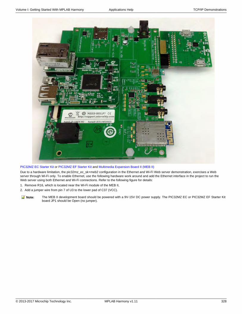
PIC32MZ EC Starter Kit or PIC32MZ EF Starter Kit and Multimedia Expansion Board II (MEB II)
Due to a hardware limitation, the pic32mz_ec_sk+meb2 configuration in the Ethernet and Wi-Fi Web server demonstration, exercises a Web server through Wi-Fi only. To enable Ethernet, use the following hardware work around and add the Ethernet interface in the project to run the Web server using both Ethernet and Wi-Fi connections. Refer to the following figure for details:
1. Remove R16, which is located near the Wi-Fi module of the MEB II,
2. Add a jumper wire from pin 7 of U3 to the lower pad of C37 (VCC).
Note: The MEB II development board should be powered with a 9V-15V DC power supply. The PIC32MZ EC or PIC32MZ EF Starter Kitboard JP1 should be Open (no jumper).
Volume I: Getting Started With MPLAB Harmony Applications Help TCP/IP Demonstrations
© 2013-2017 Microchip Technology Inc. MPLAB Harmony v1.11 328

PIC32MZ EC Starter Kit with PIC32MX2048ECH144, MRF24WG0MA Wi-Fi G PICtail/PICtail Plus Daughter Board, and Starter Kit I/O Expansion Board
Configure the hardware, as shown in the following figure:
PIC32MZ EC Starter Kit, MRF24WN0MA Wi-Fi PICtail/PICtail Plus Daughter Board, and Starter Kit I/O Expansion Board
Note: The PIC32MZ EC Starter Kit, shown in the following figure, can also be interchanged with the PIC32MZ EF Starter Kit withPIC32MZ2048EFM144.
Configure the hardware, as shown in the following figure:
Volume I: Getting Started With MPLAB Harmony Applications Help TCP/IP Demonstrations
© 2013-2017 Microchip Technology Inc. MPLAB Harmony v1.11 329

On-board Jumper: J10/pin 12 to J11/pin 8 (white jumper cable)
Running the Demonstration
This section provides instructions on how to build and run the PIC32 Ethernet Wi-Fi Web Server demonstration.
Description
To view the web page hosted by the demonstration application, open a web browser and direct it to the board running the HTTP server by typing the URL in the address bar (for example, http://mchpboard_w), and then pressing Enter.
This demonstration runs on two interfaces, Ethernet and Wi-Fi. A second web browser tab could be opened pointing to the other interface (http://mchpboard_e) to have both interfaces running simultaneously.
Notes: 1. The NetBIOS name of the TCP/IP application is specified at the time the TCP/IP stack is initialized, which is usually in the hostName member of the tcpip_stack_init.c:: TCPIP_HOSTS_CONFIGURATION structure. The NetBIOS service must be enabled for the PIC32 demonstration to respond to NetBIOS queries. Alternatively, you can use the IPv4 or IPv6 address (if IPv6 is enabled) of the board directly, for example, http://192.168.1.131 or http://[fdfe:dcba:9876:1:204:a3ff:fe12:128e].
2. The IPv4 and IPv6 addresses can be obtained from running the TCP/IP Discovery application on the PC side. It requires that the TCP/IP Announce module is enabled when building the stack.
3. For the Wi-Fi demonstration to function properly on MEB2 development board, the board should be powered with a 9V-15V DC power supply. Also on the PIC32MZ EC or PIC32MZ EF Starter Kit board, JP1 jumper should be Open (no jumper).
Please refer to the Demonstration Process in the Running the Demonstration section for the pic32_eth_web_server configuration, as the process is the same for this configuration.
Note: Refer to Wi-Fi Console Commands for information on the commands that enable control over the Wi-Fi settings.
Volume I: Getting Started With MPLAB Harmony Applications Help TCP/IP Demonstrations
© 2013-2017 Microchip Technology Inc. MPLAB Harmony v1.11 330

pic32_wifi_web_server
This section describes the steps necessary to begin using the PIC32 Wi-Fi Web Server Demonstration Application.
Description
The Wi-Fi Web Server demonstration (<install-dir>\apps\tcpip\web_server_nvm_mpfs\firmware) exercises the HTTP Web Server running on PIC32 devices. The Non-Volatile Memory (NVM) Microchip Proprietary File System (MPFS) Web Server demonstration has the Web pages stored in internal Flash and are accessed through the MPFS API.
Wi-Fi Demonstration Matrix
Refer to Wi-Fi Demonstration Configuration Matrix for additional information.
Building the Application
This section identifies the MPLAB X IDE project name and location and lists and describes the available configurations for the PIC32 Wi-Fi Web Server Demonstration.
Description
To build this project, you must open the pic32_wifi_web_server.X project in MPLAB X IDE, and then select the desired configuration.
The following tables list and describe the project and supported configurations. The parent folder for these files is <install-dir>/apps/tcpip/web_server_nvm_mpfs.
MPLAB X IDE Project
Volume I: Getting Started With MPLAB Harmony Applications Help TCP/IP Demonstrations
© 2013-2017 Microchip Technology Inc. MPLAB Harmony v1.11 331

This table lists the name and location of the MPLAB X IDE project folder for the demonstration.
Project Name Location
pic32_wifi_web_server.X <install-dir>/apps/tcpip/web_server_nvm_mpfs/firmware
MPLAB X IDE Project Configurations
This table lists and describes the supported configurations of the demonstration, which are located within ./firmware/src/system_config.
Project Configuration Name BSP Used Description
chipkit_wf32 chipkit_wf32 Demonstration running on the chipKIT™ WF32™ Wi-Fi Development Board withthe PIC32MX695F512L and the MRF24WG PICtail module.
pic32mx795_pim+e16 pic32mx795_pim+e16 Demonstration running on the PIC32MX795F512L PIM and the Explorer 16Development Board with the MRF24WG PICtail Daughter Board.
pic32mx795_pim+e16+freertos pic32mx795_pim+e16 FreeRTOS version of the demonstration running on the PIC32MX795F512L PIMand the Explorer 16 Development Board with the MRF24WG PICtail DaughterBoard.
pic32mx795_pim+e16+11n+freertos pic32mx795_pim+e16 FreeRTOS version of the demonstration running on the PIC32MX795F512L PIMon the Explorer 16 Development Board with the MRF24WN PICtail DaughterBoard.
Configuring the Hardware
Describes how to configure the supported hardware.
Description
chipKIT™ WF32™ Wi-Fi Development Board with on-board MRF24WG PICtail and PIC32MX695F512L MCU
The console output uses the USB/Serial connector on the board at 115,200 baud, 8-bit data, No parity, 1 Stop bit, with No Flow control.
The following figure shows the hardware configuration.
PIC32MX795F512L PIM with the Explorer 16 Development Board and MRF24WG PICtail Daughter Board
• Connect the MRF24WG PICtail Daughter Board into the PICtail Plus slot closest to the MCU. The module should face into the board and be placed all the way to the end on the pin 1 side of the connector.
• The console output uses the DB9 connector on the board at 115200 baud, 8-bit data, No parity, 1 Stop bit, with No Flow Control
The following figure shows the hardware configuration.
Volume I: Getting Started With MPLAB Harmony Applications Help TCP/IP Demonstrations
© 2013-2017 Microchip Technology Inc. MPLAB Harmony v1.11 332

PIC32MX795F512L PIM with the Explorer 16 Development Board and MRF24WN PICtail Daughter Board
• Connect the MRF24WN PICtail Daughter Board into the PICtail Plus slot closest to the MCU. The module should face into the board and be placed all the way to the end on the pin 1 side of the connector.
• The console output uses the DB9 connector on the board at 115200 baud, 8-bit data, No parity, 1 Stop bit, with No Flow Control
The following figure shows the hardware configuration.
Running the Demonstration
This section provides instructions on how to build and run the PIC32 Wi-Fi Web Server demonstration.
Description
To view the web page hosted by the demonstration application, open a web browser and direct it to the board running the HTTP server by typing the URL in the address bar (for example, http://mchpboard_w), and then pressing Enter.
Volume I: Getting Started With MPLAB Harmony Applications Help TCP/IP Demonstrations
© 2013-2017 Microchip Technology Inc. MPLAB Harmony v1.11 333

Notes: 1. The NetBIOS name of the TCP/IP application is specified at the time the TCP/IP stack is initialized, which is usually in the hostName member of the tcpip_stack_init.c:: TCPIP_HOSTS_CONFIGURATION structure. The NetBIOS service must be enabled for the PIC32 demonstration to respond to NetBIOS queries. Alternatively, you can use the IPv4 or IPv6 address (if IPv6 is enabled) of the board directly, for example, http://192.168.1.131 or http://[fdfe:dcba:9876:1:204:a3ff:fe12:128e].
2. The IPv4 and IPv6 addresses can be obtained from running the TCP/IP Discovery application on the PC side. It requires that the TCP/IP Announce module is enabled when building the stack.
Please refer to the Demonstration Process in the Running the Demonstration section for the pic32_eth_web_server configuration, as the process is the same for this configuration.
Note: Refer to Wi-Fi Console Commands for information on the commands that enable control over the Wi-Fi settings.
web_server_sdcard_fatfs
Web Server SD Card FAT File System TCP/IP demonstration.
Building the Application
This section identifies the MPLAB X IDE project name and location and lists and describes the available configurations for the Web Server SD Card FAT FS Demonstration.
Description
To build this project, you must open the pic32_eth_web_server.X project in MPLAB X IDE, and then select the desired configuration.
Volume I: Getting Started With MPLAB Harmony Applications Help TCP/IP Demonstrations
© 2013-2017 Microchip Technology Inc. MPLAB Harmony v1.11 334

The following tables list and describe the project and supported configurations. The parent folder for these files is <install-dir>/apps/tcpip/web_server_sdcard_fatfs.
Warning
When using the Microchip Harmony Configurator (MHC), care must be taken when generating the code to not erase the USBdescriptors in the system_init.c file.
MPLAB X IDE Project
This table lists the name and location of the MPLAB X IDE project folder for the demonstration.
Project Name Location
pic32_eth_web_server.X <install-dir>/apps/tcpip/web_server_sdcard_fatfs/firmware
MPLAB X IDE Project Configurations
This table lists and describes the supported configurations of the demonstration, which are located within ./firmware/src/system_config.
Project Configuration Name BSP Used Description
pic32mx_eth_sk2_sd_mmc_pictail pic32mx_eth_sk2 Demonstrates the Web Server hosted on a microSD card through the FAT filesystem on the PIC32 Ethernet Starter Kit II and the PICtail Daughter Board for SDand MMC.
pic32mz_ef_sk_meb2 pic32mz_ef_sk+meb2 Demonstrates the Web Server hosted on a microSD card through the FAT filesystem on the PIC32MZ EF Starter Kit and the MEB II combination.
Configuring the Hardware
Describes how to configure the supported hardware.
Description
PIC32 Ethernet Starter Kit with the Starter Kit I/O Expansion Board and PICtail Daughter Board for SD and MMC
• Plug the PIC32 Ethernet Starter Kit into application board connector (J1) on the Starter Kit I/O Expansion Board
• Plug the PICtail Daughter Board for SD and MMC into the PICtail connector (J4) on the Starter Kit I/O Expansion Board
• Make sure a SD card is formatted and loaded with the web pages provided within the apps/tcpip/web_server_sdcard_fatfs/firmware/src/web_pages2_sdcard folder
• Insert the SD card with the web pages into the SD card slot (J1) on the PICtail Daughter Board for SD and MMC into the PICtail connector
• Connect a USB cable to the micro-B USB connector on the bottom of the PIC32 Ethernet Starter Kit. When the demonstration runs, it will create a USB CDC device on the USB bus. Connect to this device though a standard terminal program, and set the baud rate to 921,600 baud. You can observe the IP address details and query the stack using the console interface.
PIC32 Ethernet Starter Kit II with the Starter Kit I/O Expansion Board and PICtail Daughter Board for SD and MMC
• Plug the PIC32 Ethernet Starter Kit II into application board connector (J1) on the Starter Kit I/O Expansion Board
• Plug the PICtail Daughter Board for SD and MMC into the PICtail connector (J4) on the Starter Kit I/O Expansion Board
• Make sure a SD card is formatted and loaded with the web pages provided within the apps/tcpip/web_server_sdcard_fatfs/firmware/src/web_pages2_sdcard folder
• Insert the SD card with the web pages into the SD card slot (J1) on the PICtail Daughter Board for SD and MMC into the PICtail connector
• Connect a USB cable to the micro-B USB connector on the bottom of the PIC32 Ethernet Starter Kit II. When the demonstration runs, it will create a USB CDC device on the USB bus. Connect to this device though a standard terminal program, and set the baud rate to 921,600 baud. You can observe the IP address details and query the stack using the console interface.
PIC32MZ EC Starter Kit or PIC32MZ EF Starter Kit with the MEB II
• Plug the desired starter kit into the application board connector on the MEB II
• Ensure a microSD card is formatted and loaded with the web pages provided within the apps/tcpip/web_server_sdcard_fatfs/firmware/src/web_pages2_sdcard directory.
• Insert the microSD card with the web pages into the microSD card slot (J8) on the MEB II
• Connect a USB cable to the micro-B USB connector on the bottom of the PIC32MZ EC Starter Kit
• When the demonstration runs, it will create a USB CDC device on the USB bus. Connect to this device though a standard terminal program, and set the baud rate to 921,600 baud. You can observe the IP address details and query the stack using the console interface.
Running the Demonstration
This section provides instructions on how to build and run the TCP/IP SD Card FAT FS Web Server demonstration.
Volume I: Getting Started With MPLAB Harmony Applications Help TCP/IP Demonstrations
© 2013-2017 Microchip Technology Inc. MPLAB Harmony v1.11 335

Description
To view the web page hosted by the demonstration application, open a web browser and direct it to the board running the HTTP server by typing the URL in the address bar (for example, http://mchpboard_e), and then pressing Enter.
Notes: 1. The NetBIOS name of the TCP/IP application is specified at the time the TCP/IP stack is initialized, which is usually in the hostName member of the tcpip_stack_init.c:: TCPIP_HOSTS_CONFIGURATION structure. The NetBIOS service must be enabled for the PIC32 demonstration to respond to NetBIOS queries. Alternatively, you can use the IPv4 or IPv6 address (if IPv6 is enabled) of the board directly, for example, http://192.168.1.131 or http://[fdfe:dcba:9876:1:204:a3ff:fe12:128e].
2. The IPv4 and IPv6 addresses can be obtained from running the TCP/IP Discovery application on the PC side. It requires that the TCP/IP Announce module is enabled when building the stack.
Please refer to the Demonstration Process in the Running the Demonstration section for the pic32_eth_web_server configuration of the web_server_nvm_mpfs demonstration, as the process is the same for this configuration.
wifi_easy_configuration
This topic contains the Wi-Fi Easy Configuration TCP/IP demonstration.
Description
This demonstration shows how to connect a MRF24WG or MRF24WN Wi-Fi device with no keyboard or display to a wireless network.
Wi-Fi Demonstration Matrix
Refer to Wi-Fi Demonstration Configuration Matrix for additional information.
Notes: 1. For the pic32mz_ec_sk+meb2 or pic32mz_ef_sk+meb2 configuration, either or both the MRF24WG Wi-Fi module and MRF24WN Wi-Fi PICtail may be installed, but only one Wi-Fi module will be active depending on the MHC selection of the MRF24W. If the MRF24WG Wi-Fi module is selected, it will not work if the MRF24WN Wi-Fi PICtail is installed.
2. For the Wi-Fi demonstration to function properly on the MEB II development board, the board should be powered with a 9V-15V DC power supply. Also on the PIC32MZ EC or PIC32MZ EF Starter Kit board, JP1 jumper should be Open (no jumper).
Building the Application
This section identifies the MPLAB X IDE project name and location and lists and describes the available configurations for the PIC32 Wi-Fi Easy Configuration Demonstration.
Description
To build this project, you must open the wifi_easy_configuration.X project in MPLAB X IDE, and then select the desired configuration.
The following tables list and describe the project and supported configurations. The parent folder for these files is <install-dir>/apps/tcpip/wifi_easy_configuration.
MPLAB X IDE Project
This table lists the name and location of the MPLAB X IDE project folder for the demonstration.
Project Name Location
wifi_easy_configuration.X <install-dir>/apps/tcpip/wifi_easy_configuration/firmware
MPLAB X IDE Project Configurations
This table lists and describes the supported configurations of the demonstration, which are located within ./firmware/src/system_config.
Project Configuration Name BSP Used Description
pic32mx_eth_sk_ioexp pic32mx_eth_sk Demonstration running on the PIC32MZ EC Starter Kit using the I/O ExpansionBoard with the MRF24WG PICtail Daughter Board.
pic32mx_eth_sk_ioexp+freertos pic32mx_eth_sk FreeRTOS version of the demonstration running on the PIC32MZ EC Starter Kitconnected to the I/O Expansion Board with the MRF24WG PICtail DaughterBoard.
pic32mx795_pim+e16 pic32mx795_pim+e16 Demonstration running on the PIC32MX795F512L PIM on the Explorer 16Development Board with the MRF24WG PICtail Daughter Board.
Volume I: Getting Started With MPLAB Harmony Applications Help TCP/IP Demonstrations
© 2013-2017 Microchip Technology Inc. MPLAB Harmony v1.11 336

pic32mx795_pim+e16+freertos pic32mx795_pim+e16 FreeRTOS version of the demonstration running on the PIC32MX795F512L PIMon the Explorer 16 Development Board with the MRF24WG PICtail DaughterBoard.
pic32mz_ec_sk_ioexp pic32mz_ec_sk Demonstration running on the PIC32MZ EC Starter Kit connected to the I/OExpansion board with the MRF24WG PICtail Daughter Board.
pic32mz_ec_sk_ioexp+freertos pic32mz_ec_sk FreeRTOS version of the demonstration running on the PIC32MZ EC Starter Kitconnected to the I/O Expansion board with the MRF24WG PICtail DaughterBoard.
pic32mz_ec_sk+meb2 pic32mz_ec_sk+meb2 Demonstration running on the PIC32MZ EC Starter Kit connected to the MEB IIwith the MRF24WG PICtail Daughter Board.
pic32mz_ec_sk+meb2+freertos pic32mz_ec_sk+meb2 FreeRTOS version of the demonstration running on the PIC32MZ EC Starter Kitconnected to the MEB II with the MRF24WG PICtail Daughter Board.
pic32mx795_pim+e16+11n+freertos pic32mx795_pim+e16 FreeRTOS version of the demonstration running on the PIC32MX795F512L PIMon the Explorer 16 Development Board with the MRF24WN PICtail DaughterBoard.
pic32mx_eth_sk_ioexp+11n+freertos pic32mx_eth_sk Demonstration running FreeRTOS on the PIC32 Ethernet Starter Kit connected tothe Starter Kit I/O Expansion Board with the MRF24WN PICtail Daughter Board.
pic32mz_ec_sk_ioexp+11n+freertos pic32mz_ec_sk Demonstration running FreeRTOS on the PIC32MZ EC Starter Kit connected tothe Starter Kit I/O Expansion Board with the MRF24WN PICtail Daughter Board.
pic32mz_ec_sk_meb2+11n+freertos pic32mz_ec_sk+meb2 Demonstration running FreeRTOS on the PIC32MZ EC Starter Kit and the MEB II.
pic32mz_ef_sk+ioexp pic32mz_ef_sk Demonstration running on the PIC32MZ EF Starter Kit connected to the I/OExpansion board with the MRF24WG PICtail Daughter Board
pic32mz_ef_sk+ioexp+freertos pic32mz_ef_sk FreeRTOS version of the demonstration running on the PIC32MZ EF Starter Kitconnected to the I/O Expansion board with the MRF24WG PICtail DaughterBoard.
pic32mz_ef_sk+meb2 pic32mz_ef_sk+meb2 Demonstration running on the PIC32MZ EF Starter Kit connected to the MEB IIwith the MRF24WG PICtail Daughter Board.
pic32mz_ef_sk+meb2+freertos pic32mz_ef_sk+meb2 FreeRTOS version of the demonstration running on the PIC32MZ EF Starter Kitconnected to the I/O Expansion board with the MRF24WG PICtail DaughterBoard.
pic32mz_ef_sk+ioexp+11n+freertos pic32mz_ef_sk FreeRTOS version of the demonstration running on the PIC32MZ EF Starter Kitconnected to the I/O Expansion board with the MRF24WN PICtail DaughterBoard.
pic32mz_ef_sk+meb2+11n+freertos pic32mz_ef_sk FreeRTOS version of the demonstration running on the PIC32MZ EF Starter Kitconnected to the MEB II with the MRF24WN PICtail Daughter Board.
Configuring the Hardware
Describes how to configure the supported hardware.
Description
PIC32MX795F512L PIM with the Explorer 16 Development Board and MRF24WG PICtail Daughter Board
• Connect the MRF24WG PICtail Daughter Board into the PICtail Plus slot closest to the MCU. The module should face into the board and be placed all the way to the end on the pin 1 side of the connector.
• The console output uses the DB9 connector on the board at 115200 baud, 8-bit data, No parity, 1 Stop bit, with No Flow Control
The following figure shows the hardware configuration.
Volume I: Getting Started With MPLAB Harmony Applications Help TCP/IP Demonstrations
© 2013-2017 Microchip Technology Inc. MPLAB Harmony v1.11 337

PIC32MX795F512L PIM with the Explorer 16 Development Board and MRF24WN PICtail Daughter Board
• Connect the MRF24WN PICtail Daughter Board into the PICtail Plus slot closest to the MCU. The module should face into the board and be placed all the way to the end on the pin 1 side of the connector.
• The console output uses the DB9 connector on the board at 115200 baud, 8-bit data, No parity, 1 Stop bit, with No Flow Control
The following figure shows the hardware configuration.
PIC32 Ethernet Starter Kit, MRF24WG0MA Wi-Fi G PICtail/PICtail Plus Daughter Board, and Starter Kit I/O Expansion Board
Configure the Starter Kit I/O Expansion Board jumper modifications, as described in the following figure:
On-board Jumper: J10/pin 56 to J10/pin 37 (white jumper cable)
Volume I: Getting Started With MPLAB Harmony Applications Help TCP/IP Demonstrations
© 2013-2017 Microchip Technology Inc. MPLAB Harmony v1.11 338

PIC32 Ethernet Starter Kit, MRF24WN0MA Wi-Fi PICtail/PICtail Plus Daughter Board, and Starter Kit I/O Expansion Board
Configure the Starter Kit I/O Expansion Board jumper modifications, as described in the following figure:
On-board Jumpers: J10/pin 12 to J11/pin 8 (red jumper cable), and J10/pin 56 to J10/pin 37 (orange jumper cable).
MRF24WG0MA Wi-Fi G module, 4.3" WQVGA PCAP Display Board, and Multimedia Expansion Board II (MEB II)
Configure the hardware, as shown in the following figures:
Front Configuration
Volume I: Getting Started With MPLAB Harmony Applications Help TCP/IP Demonstrations
© 2013-2017 Microchip Technology Inc. MPLAB Harmony v1.11 339

Back Configuration
MRF24WF0MA Wi-Fi module, MRF24WN0MA Wi-Fi PICtail/PICtail Plus Daughter Board, 4.3" PCAP Display Board, and Multimedia Expansion Board II (MEB II)
Configure the hardware, as shown in the following figures:
Front Configuration
Volume I: Getting Started With MPLAB Harmony Applications Help TCP/IP Demonstrations
© 2013-2017 Microchip Technology Inc. MPLAB Harmony v1.11 340

Back Configuration
Volume I: Getting Started With MPLAB Harmony Applications Help TCP/IP Demonstrations
© 2013-2017 Microchip Technology Inc. MPLAB Harmony v1.11 341

PIC32MZ EC Starter Kit with PIC32MZ2048ECH144, MRF24WG0MA Wi-Fi module, MRF24WN0MA Wi-Fi PICtail/PICtail Plus Daughter Board, 4.3" WQVGA PCAP Display Board, and Multimedia Expansion Board II (MEB II)
Note: The PIC32MZ EC Starter Kit, shown in the following figure, can also be interchanged with the PIC32MZ EF Starter Kit withPIC32MZ2048EFM144.
Volume I: Getting Started With MPLAB Harmony Applications Help TCP/IP Demonstrations
© 2013-2017 Microchip Technology Inc. MPLAB Harmony v1.11 342

PIC32MZ EC Starter Kit or PIC32MZ EF Starter Kit and MEB II
Due to a hardware limitation, the pic32mz_ec_sk+meb2 configuration in the Ethernet and Wi-Fi Web server demonstration, exercises a Web server through Wi-Fi only. To enable Ethernet, use the following hardware work around and add the Ethernet interface in the project to run the Web server using both Ethernet and Wi-Fi connections. Refer to the following figure for details:
1. Remove R16, which is located near the Wi-Fi module of the MEB II.
2. Add a jumper wire from pin 7 of U3 to the lower pad of C37 (VCC).
Note: The MEB II development board should be powered with a 9V-15V DC power supply. The PIC32MZ EC or PIC32MZ EF Starter Kitboard JP1 should be Open (no jumper).
Volume I: Getting Started With MPLAB Harmony Applications Help TCP/IP Demonstrations
© 2013-2017 Microchip Technology Inc. MPLAB Harmony v1.11 343
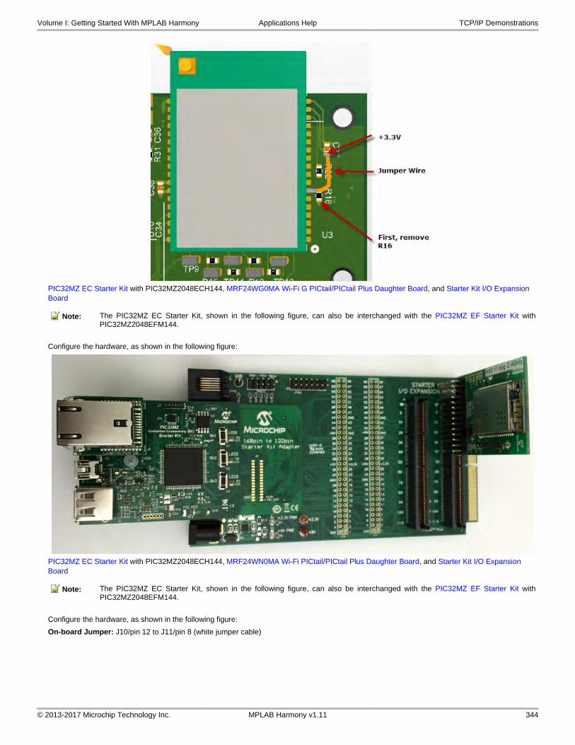
PIC32MZ EC Starter Kit with PIC32MZ2048ECH144, MRF24WG0MA Wi-Fi G PICtail/PICtail Plus Daughter Board, and Starter Kit I/O Expansion Board
Note: The PIC32MZ EC Starter Kit, shown in the following figure, can also be interchanged with the PIC32MZ EF Starter Kit withPIC32MZ2048EFM144.
Configure the hardware, as shown in the following figure:
PIC32MZ EC Starter Kit with PIC32MZ2048ECH144, MRF24WN0MA Wi-Fi PICtail/PICtail Plus Daughter Board, and Starter Kit I/O Expansion Board
Note: The PIC32MZ EC Starter Kit, shown in the following figure, can also be interchanged with the PIC32MZ EF Starter Kit withPIC32MZ2048EFM144.
Configure the hardware, as shown in the following figure:
On-board Jumper: J10/pin 12 to J11/pin 8 (white jumper cable)
Volume I: Getting Started With MPLAB Harmony Applications Help TCP/IP Demonstrations
© 2013-2017 Microchip Technology Inc. MPLAB Harmony v1.11 344

Running the Demonstration
This section provides instructions on how to build and run the Wi-Fi Easy Configuration demonstration with the MRF24WG or MRF24WN Wi-Fi module.
Description
Notes: 1. Refer to Wi-Fi Console Commands for information on the commands that enable control over the Wi-Fi settings.
2. For the Wi-Fi demonstration to function properly on MEB2 development board, the board should be powered with a 9V-15V DC power supply. Also on the PIC32MZ EC or PIC32MZ EF Starter Kit board, JP1 jumper should be Open (no jumper).
The demonstration does the following:
• Scans the area and stores the list of Access Points in memory
• Switches to SoftAP mode allowing another device to_connect_to it (smartphone or personal computer)
• After a smartphone or personal computer wirelessly connects to the MRF24WG or MRF24WN, a web page is served to it
• That web page will display the Access Point (AP) list (from step 1)
• From the smartphone you can select the desired AP and command the MRF24WG or MRF24WN to_connect_to that AP
• MRF24WG or MRF24WN will_connect_to the selected AP and store the configuration information in non-volatile memory
Use the following procedure to run the demonstration:
1. Load the demonstration project into MPLAB X IDE.
2. Connect the mini-B debugger port on-board the starter kit to a USB port on the development computer using the USB cable provided in the kit.
3. Build, download, and run the demonstration project on the board.
4. When the demonstration runs, it scans for local Access Points and outputs the results to the serial console. After the scan results, the MRF24WG or MRF24WN goes into SoftAP mode (where it behaves like an Access Point) and outputs the following to the serial console (MRF24WG output is shown): ==========================*** Wi-Fi EZConfig Demo ***==========================Device: MRF24WG (0x3108)Domain: FCCMAC: 00 1E C0 10 20 32SSID: MCHPSoftAPNetwork Type: SoftAPScan Type: Passive ScanChannel List: 6Beacon Timeout: 40Retry Count: 3Security: OpenSecurity Key:Tx Mode: 802.11bg mixedPower Save: disabledIP Config: dynamic
Volume I: Getting Started With MPLAB Harmony Applications Help TCP/IP Demonstrations
© 2013-2017 Microchip Technology Inc. MPLAB Harmony v1.11 345

Start Wi-Fi Connect . . .MRF24W IP Address: 0.0.0.0MRF24W IP Address: 192.168.1.25MRF24W Event: Connection Successful Connected BSSID : 00:00:00:00:00:00 Channel: 0
5. From a smartphone or personal computer,_connect_to the ’MCHPSoftAP’ network, which is the SoftAP network started by the demonstration. Then, bring up a web page by entering the IP address of the SoftAP network into the smartphone browser. This is the IP address displayed in step 4 (e.g., 192.168.1.25). When the web page is displayed:
a. Select Network Configuration, and then Scan for Wireless Networks. The MRF24WG or MRF24WN will display the list of wireless networks on the web page.
b. Select the desired AP to which the MRF24WG or MRF24WN should_connect_by clicking the name of the AP.
c. The MRF24WG or MRF24WN will then_connect_to that Access Point and write the configuration information to non-volatile memory.
d. The console output will show the new connection taking place
6. If you rerun the demonstration, it will automatically_connect_the selected AP as the configuration data stored in non-volatile memory will be used to reconnect to the desired AP.
7. To reset and run the demonstration from the beginning, erase the stored configuration by bringing up the demonstration, and at the command line type iw_eraseconf.
Volume I: Getting Started With MPLAB Harmony Applications Help TCP/IP Demonstrations
© 2013-2017 Microchip Technology Inc. MPLAB Harmony v1.11 346

wifi_g_demo
Wi-Fi G Demo Board TCP/IP demonstration.
Description
This demonstration showcases a browser-based device configuration application to configure and program an embedded Wi-Fi device that does not have a natural keyboard and screen. By using the internal Web server that accompanies the Microchip TCP/IP Stack, end-users can use their browser as a conduit for programming the device with the correct network parameters.
Wi-Fi Demonstration Matrix
Refer to Wi-Fi Demonstration Configuration Matrix for additional information.
Building the Application
This section identifies the MPLAB X IDE project name and location and lists and describes the available configurations for the PIC32 Wi-Fi G Demonstration.
Description
To build this project, you must open the wifi_g_demo.X project in MPLAB X IDE, and then select the desired configuration.
The following tables list and describe the project and supported configurations. The parent folder for these files is <install-dir>/apps/tcpip/wifi_g_demo.
MPLAB X IDE Project
This table lists the name and location of the MPLAB X IDE project folder for the demonstration.
Project Name Location
wifi_g_demo.X <install-dir>/apps/tcpip/wifi_g_demo/firmware
MPLAB X IDE Project Configurations
This table lists and describes the supported configurations of the demonstration, which are located within ./firmware/src/system_config.
Project Configuration Name BSP Used Description
wifi_g_demo wifi_g_db Demonstration running on the Wi-Fi G Demo Board.
Configuring the Hardware
Describes how to configure the supported hardware.
Description
Wi-Fi G Demo Board with the PICkit™ 3 In-Circuit Debugger
No hardware related configuration or jumper setting changes are necessary.
Volume I: Getting Started With MPLAB Harmony Applications Help TCP/IP Demonstrations
© 2013-2017 Microchip Technology Inc. MPLAB Harmony v1.11 347

Running the Demonstration
This section provides instructions on how to build and run the Wi-Fi G demonstration.
Description
This demonstration showcases a browser-based device configuration application to configure and program an embedded Wi-Fi device that does not have a natural keyboard and screen. By using the internal Web server that accompanies the Microchip TCP/IP Stack, end-users can use their browser as a conduit for programming the device with the correct network parameters.
For a wireless network, an end-user would need to have knowledge of at least the following information:
• SSID
• Security Type (None, WEP, WPA-PSK, WPA2-PSK, WPA-PSK AUTO)
• Security PSK Key or Passphrase
The application also has the ability to scan for all networks in the vicinity of the device, and display them to the user. The user will also be given additional information about the network, such as whether security is enabled, or how far away the other network is. Users are also given the opportunity to enter all the network information manually, which is required when trying to connect to a network with a hidden SSID.
Running the Demonstration
This demonstration can be loaded and run on the Wi-Fi G Demo Board. In addition, a PICkit 3 In-Circuit Debugger is required for use with MPLAB X IDE to program the Wi-Fi G Demo Board.
Use the following procedure to run the demonstration:
1. Load the wifi_g_demo demonstration project into MPLAB X IDE.
2. Select Run to build and program the Wi-Fi G Demo Board with the demo Hex image.
Volume I: Getting Started With MPLAB Harmony Applications Help TCP/IP Demonstrations
© 2013-2017 Microchip Technology Inc. MPLAB Harmony v1.11 348

Note: Refer to the "Wi-Fi G Demo Board User's Guide" (DS50002147) for additional information on using and programming the Wi-FiDemo Board.
wifi_wolfssl_tcp_client
This configuration provides a Wi-Fi wolfSSL TCP/IP Client demonstration.
Description
Wi-Fi Demonstration Matrix
Refer to Wi-Fi Demonstration Configuration Matrix for additional information.
Volume I: Getting Started With MPLAB Harmony Applications Help TCP/IP Demonstrations
© 2013-2017 Microchip Technology Inc. MPLAB Harmony v1.11 349

Building the Application
This section identifies the MPLAB X IDE project name and location and lists and describes the available configurations for the TCP/IP Ethernet Wi-Fi wolfSSL TCP Client Demonstration.
Description
To build this project, you must open the wifi_wolfssl_tcp_client.X project in MPLAB X IDE, and then select the desired configuration.
The following tables list and describe the project and supported configurations. The parent folder for these files is <install-dir>/apps/tcpip/wifi_wolfssl_tcp_client.
MPLAB X IDE Project
This table lists the name and location of the MPLAB X IDE project folder for the demonstration.
Project Name Location
wifi_wolfssl_tcp_client.X <install-dir>/apps/tcpip/wifi_wolfssl_tcp_client/firmware
MPLAB X IDE Project Configurations
This table lists and describes the supported configurations of the demonstration, which are located within ./firmware/src/system_config.
Project Configuration Name
BSP Used Description
pic32mx_eth_sk+ioexp pic32mx_eth_sk Wi-Fi wolfSSL TCP Client demonstration on the PIC32 Ethernet Starter Kit connected to theStarter Kit I/O Expansion Board with the MRF24WG PICtail Daughter Board.
pic32mz_ec_sk+ioexp pic32mz_ec_sk Wi-Fi wolfSSL TCP Client demonstration on the PIC32MZ EC Starter Kit connected to theStarter Kit I/O Expansion Board with the MRF24WG PICtail Daughter Board.
Configuring the Hardware
Describes how to configure the supported hardware.
Description
PIC32 Ethernet Starter Kit, MRF24WG0MA Wi-Fi G PICtail/PICtail Plus Daughter Board, and Starter Kit I/O Expansion Board
Configure the Starter Kit I/O Expansion Board jumper modifications, as described in the following figure:
On-board Jumper: J10/pin 56 to J10/pin 37 (white jumper cable)
Volume I: Getting Started With MPLAB Harmony Applications Help TCP/IP Demonstrations
© 2013-2017 Microchip Technology Inc. MPLAB Harmony v1.11 350

PIC32MZ Embedded Connectivity (EC) Starter Kit, MRF24WG0MA Wi-Fi G PICtail/PICtail Plus Daughter Board, and Starter Kit I/O Expansion Board
For the PIC32MZ EC Starter Kit, the on-board jumper, J10/pin 56 to J10/pin 37 (white jumper cable) is not required. Configure the hardware as shown in the following figure:
Running the Demonstration
This section provides instructions on how to build and run the demonstration.
Description
This demonstration can be executed via Ethernet or Wi-Fi.
To use this demonstration, a USB cable needs to be connected to the micro-B USB connector on the bottom of the starter kit in use. When the demonstration runs, it will create a USB CDC device on the USB bus. The demonstration can be executed once you have connected to this device though a standard terminal program, set the baud rate to 921,600 baud, and a valid IP address has been received by the device.
There are three commands available in the demonstration from the serial port:
• openurl <url> - The <url> argument must be a fully formed URL; for instance, http://www.microchip.com/
• ipmode <mode> - The <mode> argument selects the IP version. 0 - Any IP version, 4 - IPv4 only, 6 - IPv6 only
• stats - Output the statistics of the previous openurl run. Statistics such as how long each phase of the connection took, and how many bytes were transferred.
After the openurl command is input, the demonstration will make a DNS query, and then open a connection to the requested URL and perform a simple HTTP PUT command. The results will be sent to the serial port. If a https URL is specified, the connection will first undergo SSL negotiation before sending the HTTP PUT command.
If ipmode is set to '0' (Any), the demonstration will favor IPv6 over IPv4, which means it will look for the IPv6 address before the IPv4 address.
Volume I: Getting Started With MPLAB Harmony Applications Help TCP/IP Demonstrations
© 2013-2017 Microchip Technology Inc. MPLAB Harmony v1.11 351

wifi_wolfssl_tcp_server
This configuration provides a Wi-Fi wolfSSL TCP/IP Server demonstration.
Description
Wi-Fi Demonstration Matrix
Refer to Wi-Fi Demonstration Configuration Matrix for additional information.
Building the Application
This section identifies the MPLAB X IDE project name and location and lists and describes the available configurations for the TCP/IP Ethernet Wi-Fi wolfSSL TCP Server Demonstration.
Description
To build this project, you must open the wifi_wolfssl_tcp_server.X project in MPLAB X IDE, and then select the desired configuration.
The following tables list and describe the project and supported configurations. The parent folder for these files is <install-dir>/apps/tcpip/wifi_wolfssl_tcp_server.
MPLAB X IDE Project
This table lists the name and location of the MPLAB X IDE project folder for the demonstration.
Project Name Location
wifi_wolfssl_tcp_server.X <install-dir>/apps/tcpip/wifi_wolfssl_tcp_server/firmware
MPLAB X IDE Project Configurations
This table lists and describes the supported configurations of the demonstration, which are located within ./firmware/src/system_config.
Volume I: Getting Started With MPLAB Harmony Applications Help TCP/IP Demonstrations
© 2013-2017 Microchip Technology Inc. MPLAB Harmony v1.11 352

Project Configuration Name
BSP Used Description
pic32mx_eth_sk+ioexp pic32mx_eth_sk Wi-Fi wolfSSL TCP Server demonstration on the PIC32 Ethernet Starter Kit connected to theStarter Kit I/O Expansion Boardwith the MRF24WG PICtail Daughter Board.
pic32mz_ec_sk+ioexp pic32mz_ec_sk Wi-Fi wolfSSL TCP Server demonstration on the PIC32MZ EC Starter Kit connected to theStarter Kit I/O Expansion Board with the MRF24WG PICtail Daughter Board.
Configuring the Hardware
Describes how to configure the supported hardware.
Description
PIC32 Ethernet Starter Kit with PIC32MX795F512L, MRF24WG0MA Wi-Fi G PICtail/PICtail Plus Daughter Board, and Starter Kit I/O Expansion Board
Configure the Starter Kit I/O Expansion Board jumper modifications, as described in the following figure:
On-board Jumper: J10/pin 56 to J10/pin 37 (white jumper cable)
PIC32MZ EC Starter Kit with PIC32MZ2048ECH144, MRF24WG0MA Wi-Fi G PICtail/PICtail Plus Daughter Board, and Starter Kit I/O Expansion Board
For the PIC32MZ EC Starter Kit, the on-board jumper, J10/pin 56 to J10/pin 37 (white jumper cable) is not required. Configure the hardware as shown in the following figure:
Volume I: Getting Started With MPLAB Harmony Applications Help TCP/IP Demonstrations
© 2013-2017 Microchip Technology Inc. MPLAB Harmony v1.11 353

Running the Demonstration
This section provides instructions on how to build and run the demonstration.
Description
This demonstration can be executed via Ethernet or Wi-Fi.
To use this demonstration, a USB cable needs to be connected to the micro-B USB connector on the bottom of the starter kit in use. When the demonstration runs, it will create a USB CDC device on the USB bus. The demonstration can be executed once you have connected to this device though a standard terminal program, set the baud rate to 921,600 baud, and a valid IP address has been received by the device.
There are three commands available in the demonstration from the serial port:
• openurl <url> - The <url> argument must be a fully formed URL; for instance, http://www.microchip.com/
• ipmode <mode> - The <mode> argument selects the IP version. 0 - Any IP version, 4 - IPv4 only, 6 - IPv6 only
• stats - Output the statistics of the previous openurl run. Statistics such as how long each phase of the connection took, and how many bytes were transferred.
After the openurl command is input, the demonstration will make a DNS query, and then open a connection to the requested URL and perform a simple HTTP PUT command. The results will be sent to the serial port. If a https URL is specified, the connection will first undergo SSL negotiation before sending the HTTP PUT command.
If ipmode is set to '0' (Any), the demonstration will favor IPv6 over IPv4, which means it will look for the IPv6 address before the IPv4 address.
Volume I: Getting Started With MPLAB Harmony Applications Help TCP/IP Demonstrations
© 2013-2017 Microchip Technology Inc. MPLAB Harmony v1.11 354

Volume I: Getting Started With MPLAB Harmony Applications Help TCP/IP Demonstrations
© 2013-2017 Microchip Technology Inc. MPLAB Harmony v1.11 355

Volume I: Getting Started With MPLAB Harmony Applications Help TCP/IP Demonstrations
© 2013-2017 Microchip Technology Inc. MPLAB Harmony v1.11 356

Volume I: Getting Started With MPLAB Harmony Applications Help TCP/IP Demonstrations
© 2013-2017 Microchip Technology Inc. MPLAB Harmony v1.11 357

Volume I: Getting Started With MPLAB Harmony Applications Help TCP/IP Demonstrations
© 2013-2017 Microchip Technology Inc. MPLAB Harmony v1.11 358

Volume I: Getting Started With MPLAB Harmony Applications Help TCP/IP Demonstrations
© 2013-2017 Microchip Technology Inc. MPLAB Harmony v1.11 359

wolfssl_tcp_client
wolfSSL TCP Client demonstration.
Description
This configuration demonstrates creating an Internet client that uses the MPLAB Harmony TCP API to create a TCP/IP connection to a Web server. The connection can either be clear text, or it can use SSL to encrypt the connection with wolfSSL. The demonstration can use either IPv4 or IPv6.
Wi-Fi Demonstration Matrix
Refer to Wi-Fi Demonstration Configuration Matrix for additional information.
Volume I: Getting Started With MPLAB Harmony Applications Help TCP/IP Demonstrations
© 2013-2017 Microchip Technology Inc. MPLAB Harmony v1.11 360

Building the Application
This section identifies the MPLAB X IDE project name and location and lists and describes the available configurations for the wolfSSL TCP Client Demonstration.
Description
To build this project, you must open the wolfssl_tcp_client.X project in MPLAB X IDE, and then select the desired configuration.
The following tables list and describe the project and supported configurations. The parent folder for these files is <install-dir>/apps/tcpip/wolfssl_tcp_client.
Warning
When using the Microchip Harmony Configurator (MHC), care must be taken when generating the code to not erase the USBdescriptors in the system_init.c file.
MPLAB X IDE Project
This table lists the name and location of the MPLAB X IDE project folder for the demonstration.
Project Name Location
wolfssl_tcp_client.X <install-dir>/apps/tcpip/wolfssl_tcp_client/firmware
MPLAB X IDE Project Configurations
This table lists and describes the supported configurations of the demonstration, which are located within ./firmware/src/system_config.
Project Configuration Name
BSP Used Description
pic32mx_eth_sk pic32mx_eth_sk Demonstrates the wolfSSL TCP Client on the PIC32 Ethernet Starter Kit.
pic32mx_eth_sk2 pic32mx_eth_sk2 Demonstrates the wolfSSL TCP Client on the PIC32 Ethernet Starter Kit II.
pic32mz_ec_sk pic32mz_ec_sk Demonstrates the wolfSSL TCP Client on the PIC32MZ EC Starter Kit.
pic32mz_ef_sk pic32mz_ef_sk Demonstrates the wolfSSL TCP Client on the PIC32MZ EF Starter Kit.
Configuring the Hardware
Describes how to configure the supported hardware.
Description
PIC32 Ethernet Starter Kit
No hardware related configuration or jumper setting changes are necessary.
PIC32 Ethernet Starter Kit II
No hardware related configuration or jumper setting changes are necessary.
PIC32MZ EC Starter Kit
No hardware related configuration or jumper setting changes are necessary.
PIC32MZ EF Starter Kit
No hardware related configuration or jumper setting changes are necessary.
Running the Demonstration
This section provides instructions on how to build and run the demonstration.
Description
To use this demonstration, a USB cable needs to be connected to the micro-B USB connector on the bottom of the starter kit in use. When the demonstration runs, it will create a USB CDC device on the USB bus. The demonstration can be executed once you have connected to this device though a standard terminal program, set the baud rate to 921,600 baud, and a valid IP address has been received by the device.
There are three commands available in the demonstration from the serial port:
• openurl <url> - The <url> argument must be a fully formed URL; for instance, http://www.microchip.com/
• ipmode <mode> - The <mode> argument selects the IP version. 0 - Any IP version, 4 - IPv4 only, 6 - IPv6 only
• stats - Output the statistics of the previous openurl run. Statistics such as how long each phase of the connection took, and how many bytes were transferred.
Volume I: Getting Started With MPLAB Harmony Applications Help TCP/IP Demonstrations
© 2013-2017 Microchip Technology Inc. MPLAB Harmony v1.11 361

After the openurl command is input, the demonstration will make a DNS query, and then open a connection to the requested URL and perform a simple HTTP PUT command. The results will be sent to the serial port. If a https URL is specified, the connection will first undergo SSL negotiation before sending the HTTP PUT command.
If ipmode is set to '0' (Any), the demonstration will favor IPv6 over IPv4, which means it will look for the IPv6 address before the IPv4 address.
wolfssl_tcp_server
wolfSSL TCP Server demonstration.
Description
This configuration demonstrates creating a simple Internet Web server, that operates with clear text (TCP Port 80), and with encrypted text (TCP Port 443). If IPv6 is enabled than the demonstration also serves both types of connections on IPv6. The Web server only serves one page with the text 'Nothing Here' to all Web clients.
Wi-Fi Demonstration Matrix
Refer to Wi-Fi Demonstration Configuration Matrix for additional information.
Building the Application
This section identifies the MPLAB X IDE project name and location and lists and describes the available configurations for the wolfSSL TCP Client Demonstration.
Description
To build this project, you must open the wolfssl_tcp_server.X project in MPLAB X IDE, and then select the desired configuration.
The following tables list and describe the project and supported configurations. The parent folder for these files is <install-dir>/apps/tcpip/wolfssl_tcp_server.
Warning
When using the Microchip Harmony Configurator (MHC), care must be taken when generating the code to not erase the USBdescriptors in the system_init.c file.
MPLAB X IDE Project
This table lists the name and location of the MPLAB X IDE project folder for the demonstration.
Project Name Location
wolfssl_tcp_server.X <install-dir>/apps/tcpip/wolfssl_tcp_server/firmware
MPLAB X IDE Project Configurations
This table lists and describes the supported configurations of the demonstration, which are located within ./firmware/src/system_config.
Project Configuration Name
BSP Used Description
pic32mx_eth_sk pic32mx_eth_sk Demonstrates the wolfSSL TCP Server on the PIC32 Ethernet Starter Kit.
pic32mx_eth_sk2 pic32mx_eth_sk2 Demonstrates the wolfSSL TCP Server on the PIC32 Ethernet Starter Kit II.
pic32mz_ec_sk pic32mz_ec_sk Demonstrates the wolfSSL TCP Server on the PIC32MZ EC Starter Kit.
pic32mz_ef_sk pic32mz_ef_sk Demonstrates the wolfSSL TCP Server on the PIC32MZ EF Starter Kit.
Configuring the Hardware
Describes how to configure the supported hardware.
Description
PIC32 Ethernet Starter Kit
No hardware related configuration or jumper setting changes are necessary.
PIC32 Ethernet Starter Kit II
No hardware related configuration or jumper setting changes are necessary.
PIC32MZ EC Starter Kit
No hardware related configuration or jumper setting changes are necessary.
Volume I: Getting Started With MPLAB Harmony Applications Help TCP/IP Demonstrations
© 2013-2017 Microchip Technology Inc. MPLAB Harmony v1.11 362

PIC32MZ EF Starter Kit
No hardware related configuration or jumper setting changes are necessary.
Running the Demonstration
This section provides instructions on how to build and run the demonstration.
Description
The demonstration does not offer any additional functionality through the serial port; however, the current IP can be checked. As soon as a valid IP has been assigned through DHCP to the demonstration, it is ready to serve Web pages. Use any Web browser (i.e., Chrome, Internet Explorer, Firefox, etc.) to connect to the Web server with either http:// or https://.
A USB cable can be connected to the micro-B USB connector on the bottom of the starter kit in use. This will create a USB CDC device on the USB bus. To communicate with the software, connect to this device though a standard terminal program and set the baud rate to 921,600 baud.
Test Applications
Test applications demonstrate the use of the MPLAB Harmony Test Harness and predefined test libraries.
Introduction
Test Applications Help
Description
This help file contains instructions and associated information about MPLAB Harmony Test applications, which are contained in the MPLAB Harmony distribution.
Applications
Provides instructions on how to run the Test applications.
test_sample
The MPLAB Harmony Test Sample demonstrates the use of the Test Harness to validate a sample library module.
Description
The Test Harness controls initialization and execution of each test, as well as the library it tests. The Test Harness accumulates results given to it by the test and determines an over-all pass or fail result. If debug system output is supported and configured, which, in this demonstration is not, these results will be displayed textually on the terminal display in use. Otherwise, as demonstrated in this application, a debugger must be used to determine the results.
Building the Application
This section identifies the MPLAB X IDE project name and location and lists and describes the available configurations for the Test Sample application.
Description
To build this project, you must open the test_sample.X project in MPLAB X IDE, and then select the desired configuration.
The following tables list and describe the project and supported configurations. The parent folder for these files is <install-dir>/apps/tests/test_sample.
MPLAB X IDE Project
This table lists the name and location of the MPLAB X IDE project folder for the demonstration.
Project Name Location
test_sample.X <install-dir>/apps/tests/test_sample/firmware
MPLAB X IDE Project Configurations
This table lists and describes the supported configurations of the demonstration, which are located within ./firmware/src/system_config.
Volume I: Getting Started With MPLAB Harmony Applications Help Test Applications
© 2013-2017 Microchip Technology Inc. MPLAB Harmony v1.11 363

Project Configuration Name BSP Used
Description
e16mx795f512_freertos_interrupt None. This configuration runs on the Explorer 16 Development Board with the PIC32MX795F512L PIM. Itexecutes the included test in a FreeRTOS thread and runs the associated library in interrupt-drivenmode.
e16mx795f512_freertos_polled None. This configuration runs on the Explorer 16 Development Board with the PIC32MX795F512L PIM. Itexecutes the included test in a FreeRTOS thread and runs the associated library in a polled mode ina different thread.
e16mx795f512_interrupt None. This configuration runs on the Explorer 16 Development Board with the PIC32MX795F512L PIM. Itexecutes the included test in a bare-metal (no-RTOS) "super" loop environment and runs theassociated library in an interrupt-driven mode.
e16mx795f512_polled None. This configuration runs on the Explorer 16 Development Board with the PIC32MX795F512L PIM. Itexecutes the included test and the library under test in a bare-metal (no-RTOS) "super" loopenvironment.
pic32mz_ec_sk_freertos_polled None. This configuration runs on the PIC32MZ EC Starter Kit. It executes the included test in a FreeRTOSthread and runs the associated library in a polled mode in a different thread.
pic32mz_ec_sk_freertos_interrupt None. This configuration runs on the PIC32MZ EC Starter Kit. It executes the included test in a bare-metal(no-RTOS) "super" loop environment and runs the associated library in an interrupt-driven mode.
pic32mz_ec_sk_interrupt None. This configuration runs on the PIC32MZ EC Starter Kit. It executes the included test in a bare-metal(no-RTOS) "super" loop environment and runs the associated library in an interrupt-driven mode.
pic32mz_ec_sk_polled None. This configuration runs on the PIC32MZ EC Starter Kit. It executes the included test and the libraryunder test in a bare-metal (no-RTOS) "super" loop environment.
pic32mz_ef_sk_freertos_polled None. This configuration runs on the PIC32MZ EF Starter Kit. It executes the included test in a FreeRTOSthread and runs the associated library in a polled mode in a different thread.
pic32mz_ef_sk_freertos_interrupt None. This configuration runs on the PIC32MZ EF Starter Kit. It executes the included test in a bare-metal(no-RTOS) "super" loop environment and runs the associated library in an interrupt-driven mode.
pic32mz_ef_sk_interrupt None. This configuration runs on the PIC32MZ EF Starter Kit. It executes the included test and the libraryunder test in a bare-metal (no-RTOS) "super" loop environment.
pic32mz_ef_sk_polled None. This configuration runs on the PIC32MZ EF Starter Kit. It executes the included test and the libraryunder test in a bare-metal (no-RTOS) "super" loop environment.
Configuring the Hardware
Describes how to configure the supported hardware.
Description
Explorer 16 Development Board with the PIC32MX795F512L PIM
Before attaching the PIC32MX795F512L PIM to the Explorer 16 Development Board, ensure that the processor select switch (S2) is in the PIM Position.
No hardware related configuration or jumper setting changes are necessary for the PIM itself.
PIC32MZ EC Starter Kit
No hardware related configuration or jumper setting changes are necessary.
PIC32MZ EF Starter Kit
No hardware related configuration or jumper setting changes are necessary.
Running the Application
Provides instructions on how to build and run the Test Sample application.
Description
To run the Test Sample application, select the desired configuration, build the application in Debug mode, program it to the associated hardware, and execute it under control of a debugger.
As the demonstration runs, the Test Harness Library accumulates results provided to it by the test. If System Debug output were supported and configured, the results would be displayed textually on the debug terminal display in use. However, depending upon the testing needs or the hardware used, it may not be possible to support a debug output method and none is supported in any of the configurations included in this demonstration. Therefore, it is necessary to utilize the debugger to analyze the TEST_HARNESS_DATA structure to determine the results of the test. When all tests are complete (or when a failure occurs), the Test Harness will execute a hard-coded breakpoint and stop. At that time, you may use the debugger to obtain the results.
Volume I: Getting Started With MPLAB Harmony Applications Help Test Applications
© 2013-2017 Microchip Technology Inc. MPLAB Harmony v1.11 364

The following members of this structure give the overall results once the test harness enters its Idle state:
• testsCount - This is the total number of tests executed
• testsPassed - This is the number of tests that reported no sub-test failures, resulting in an overall passing result
• result - This is the final result, which is true (1) if all sub-tests in all tests passed; otherwise, it is false (0).
USB Demonstrations
This section provides descriptions of the USB demonstrations.
Introduction
USB Library Demonstration Applications Help
Description
This distribution package contains a variety of USB-related firmware projects that demonstrate the capabilities of the MPLAB Harmony USB stack. This section describes the hardware requirement and procedures to run these firmware projects on Microchip demonstration and development boards.
To know more about the MPLAB Harmony USB stack and configuring the USB stack and the APIs provided by the USB stack, refer to the USB Library documentation.
Program, Data Memory, and Stack Component Memory
Refer to USB Device Stack Demonstration Application Program and Data Memory Requirements and USB Device Stack Component Memory Requirements for important memory information.
Pen Drive Tests
Refer to USB MSD Host USB Pen Drive Tests for information on the tests conducted on USB Flash devices.
USB Device Stack Demonstration Application Program and Data Memory Requirements
Provides information on program and data memory requirements, as well as pen drive test specifications.
Description
Program Memory and Data Memory Requirements with -O1 Optimization
The following table shows the program memory and data memory requirements of the USB Device Stack demonstration applications. All size figures are in bytes. Demonstration applications were compiled with the MPLAB XC32 C/C++ Compiler, v1.40, with –O1 optimization.
Volume I: Getting Started With MPLAB Harmony Applications Help USB Demonstrations
© 2013-2017 Microchip Technology Inc. MPLAB Harmony v1.11 365

Note: The msd_basic, cdc_msd_basic, and the hid_msd_basic demonstrations use the PIC32 program Flash memory as the MSDstorage media. The difference in Data Memory requirements between the PIC32MX and PIC32MZ microcontrollers for thesedemonstration examples, is due to an application demonstration buffer whose size is equal to the erase page size of the PIC32microcontroller. On the PIC32MX795F512L, this size is 4096 bytes. On the PIC32MZ2048ECH144, the erase page size is 16 KB.
Program Memory and Data Memory Requirements with -Os Optimization
The following table shows the program memory and data memory requirements of the USB Device Stack demonstration applications. All size figures are in bytes. Demonstration applications were compiled with the MPLAB XC32 C/C++ Compiler, v1.40, with –Os optimization.
Volume I: Getting Started With MPLAB Harmony Applications Help USB Demonstrations
© 2013-2017 Microchip Technology Inc. MPLAB Harmony v1.11 366

USB Device Stack Component Memory Requirements
Provides memory requirements.
Description
The following table shows the Program and Data Memory requirements for individual components in the MPLAB Harmony USB Device Stack.
Device Stack Component Program Memory
Data Memory
Device Layer 5688 184
CDC Function Driver 2420 64 + (36 * Queue Size)
MSD Function Driver 5352 217
HID Function Driver 2376 40 + (36 * Queue Size)
Vendor 912 8 + (36 * Queue Size)
PIC32MX USB Driver 5636 144 + (32 * Number of Endpoints)
PIC32MZ USB Driver 10244 192 + (32 * Number of Endpoints)
Notes: 1. Memory requirements (in bytes) for a single instance.
2. Size measured for USB Device Stack Components in MPLAB Harmony.
3. Data Memory does not include function call stack memory size.
USB MSD Host USB Pen Drive Tests
Provides pen drive test specifications.
Description
USB MSD Host USB Pen Drive Tests
The following table lists the commercially available USB pen drives, which have been tested to successfully enumerate with the MSD Host Driver
Volume I: Getting Started With MPLAB Harmony Applications Help USB Demonstrations
© 2013-2017 Microchip Technology Inc. MPLAB Harmony v1.11 367

in the MPLAB Harmony USB Host. Note that if the USB pen drive you are using in not included in the table, this indicates that this USB pen drive has not been tested with the MSD Host Driver. However, the USB pen drive could still potentially work with MSD Host Driver. Some USB pen drives in this table did not have their manufacturer or model data available. The USB Pen drives were tested with the msd_basic USB Host demonstration in the latest version of the MPLAB Harmony USB Host Stack.
VID PID Manufacturer Model/Drive Capacity
0x1B1C 0x1A0F Corsair Components Flash Voyager Go 8 GB
0x03F0 0x0AB7 Hewlett-Packard 64 GB
0xABCD 0x1234 Microchip Technology Inc. 4 GB
0x125F 0xCB10 Adata Dashdrive UV100 8 GB
0x8644 0x8003 Verico T Series 16 GB
0x8564 0x1000 Transcend USB 3.0 32 GB
0x0951 0x16A7 Dell Kingston Technology 16 GB
0x0718 0x0704 Imation 16 GB Pen Drive
0x048D 0x1168 iBall Jaldi 16 GB Pen Drive
0x058F 0x6366 Alcor Micro AXL 32 GB
0x154B 0x005B PNY Cube 16 GB
0x0930 0x6544 Toshiba Hatabusa Pen Drive 8 GB
0x058F 0x6387 Alcor ZipMem 16 GB
0x090C 0x1000 Silicon Motion Inc. Axl 8GB
0x18A5 0x0245 Verbatim Store N Go Audio USB 8 GB
0x05DC 0xC75C Lexar USB Pen Drive 8 GB
0x1005 0xb113 Apacer 8 GB (AH233)
0x054C 0x06B0 Sony 8 GB
0x054C 0x0862 Sony Micro Vault USM-V 8 GB
0x0781 0x557c SanDisk 8 GB
0x1E4E 0x3257 Etron iBall 16 GB
0x1EC9 0x0101 Moserbaer Swivel 16 GB Pen Drive
0x0BDA 0x0109 SanDisk Standard A and Mini-B connector 16 GB
0x1908 0x1320 ZBEL Wrist Band Flash Drive 4 GB
0x0951 0x1665 Kingston Data Traveler SE9 16 GB
USB HID Host Keyboard and Mouse Tests
Description
The following table lists the commercially available USB keyboards and mouse, which have been tested to successfully enumerate with the HID Host Driver in the MPLAB Harmony USB Host. Note that if the USB HID device you are using in not included in the table, this indicates that this USB HID device has not been tested, but could still potentially work with the HID Host Driver.
Volume I: Getting Started With MPLAB Harmony Applications Help USB Demonstrations
© 2013-2017 Microchip Technology Inc. MPLAB Harmony v1.11 368

Demonstration Application Configurations
This topic provides information on the available USB demonstration project configurations.
Description
The available USB Demonstration application MPLAB X IDE projects feature support for multiple configurations. Selecting these configurations allow for the demonstration projects to run across different PIC32 microcontrollers and development boards. The following project configurations are available:
Configuration name Description
pic32mx_usb_sk2_int_dyn Selecting this configuration will set up the demonstration application to run on the PIC32 USB Starter Kit IIdevelopment board, with the PIC32MX795F512L microcontroller. The USB Stack will be configured for Interruptmode operation and the USB Driver will be configured for Dynamic operation mode.
pic32mx_usb_sk2_poll_dyn Selecting this configuration will set up the demonstration application to run on the PIC32 USB Starter Kit IIdevelopment board, with the PIC32MX795F512L microcontroller. The USB Stack will be configured for Polledmode operation and the USB driver will be configured for Dynamic operation mode.
pic32mx_usb_sk3_int_dyn Selecting this configuration will set up the demonstration application to run on the PIC32 USB Starter Kit IIIdevelopment board, with the PIC32MX470F512L microcontroller. The USB Stack will be configured for Interruptmode operation and the USB Driver will be configured for Dynamic operation mode.
pic32mx_usb_sk2_int_sta Selecting this configuration will set up the demonstration application to run on the PIC32 USB Starter Kit IIdevelopment board, with the PIC32MX795F512L microcontroller. The USB Stack will be configured for interruptmode operation and the USB Driver will be configured for Static operation mode.
pic32mz_bt_audio_int_dyn Selecting this configuration will setup the demonstration application to run on the PIC32 Bluetooth AudioDevelopment Kit along with the a PIC32MZ20148ECH144 microcontroller. The USB Device stack will beconfigured for Interrupt mode of operation and the USB Driver will be configured for dynamic operation mode.
pic32mx_bt_sk_int_dyn Selecting this configuration will set up the demonstration application to run on the PIC32 Bluetooth Starter Kitdevelopment board, with the PIC32MX270F256D microcontroller. The USB Stack will be configured for Interruptmode operation and the USB Driver will be configured for dynamic operation mode.
pic32mz_da_sk_int_dyn Selecting this configuration will set up the demonstration application to run on the PIC32MZ DA Starter Kitdevelopment board, with the PIC32MZ2064DAB288 microcontroller. The USB Stack will be configured forInterrupt mode operation and the USB Driver will be configured for Dynamic operation mode.
pic32mz_ec_sk_int_dyn Selecting this configuration will set up the demonstration application to run on the PIC32MZ EC Starter Kitdevelopment board, with the PIC32MZ2048ECH144 microcontroller. The USB Stack will be configured forInterrupt mode operation and the USB Driver will be configured for Dynamic operation mode.
pic32mz_ec_sk_poll_dyn Selecting this configuration will set up the demonstration application to run on the PIC32MZ EC Starter Kitdevelopment board, with the PIC32MC2048ECH144 microcontroller. The USB Stack will be configured forPolled mode operation and the USB Driver will be configured for Dynamic operation mode.
pic32mz_ec_sk_meb2_int_dyn Selecting this configuration will set up the demonstration application to run on the PIC32MZ EC Starter Kit, withthe PIC32MZ2048ECH144 microcontroller board attached to the MEB II. The USB Stack will be configured forInterrupt mode operation and the USB Driver will be configured for Dynamic operation mode.
Volume I: Getting Started With MPLAB Harmony Applications Help USB Demonstrations
© 2013-2017 Microchip Technology Inc. MPLAB Harmony v1.11 369

pic32mz_ef_sk_int_dyn Selecting this configuration will set up the demonstration application to run on the PIC32MZ EF Starter Kit, withthe PIC32MZ2048EFM144 microcontroller. The USB Stack will be configured for Interrupt mode operation andthe USB Driver will be configured for Dynamic operation mode.
pic32mz_ef_sk_poll_dyn Selecting this configuration will set up the demonstration application to run on the PIC32MZ EF Starter Kitdevelopment board, with the PIC32MZ2048EFM144 microcontroller. The USB Stack will be configured forPolled mode operation and the USB Driver will be configured for Dynamic operation mode.
pic32mx795_pim_e16_int_dyn Selecting this configuration will set up the demonstration application to run on the Explorer 16 DevelopmentBoard along with the PIC32MX795F512L microcontroller Plug In Module and USB PICtail Plus Daughter Board.The USB Stack will be configured for Interrupt mode operation and the USB Driver will be configured forDynamic operation mode.
pic32mx460_pim_e16_int_dyn Selecting this configuration will set up the demonstration application to run on the Explorer 16 DevelopmentBoard along with the PIC32MX460F512L microcontroller Plug In Module and USB PICtail Plus Daughter Board.The USB Stack will be configured for Interrupt mode operation and the USB Driver will be configured forDynamic operation mode.
pic32mx470_curiosity Selecting this configuration will set up the demonstration application to run on the PIC32MX470 CuriosityDevelopment Board, with the PIC32MX470F512H microcontroller. The USB Stack will be configured forInterrupt mode operation and the USB Driver will be configured for Dynamic operation mode.
pic32mz_ef_curiosity Selecting this configuration will set up the demonstration application to run on the PIC32MZ EF CuriosityDevelopment Board, with the PIC32MZ2048EFM100 microcontroller. The USB Stack will be configured forInterrupt mode operation and the USB Driver will be configured for Dynamic operation mode.
The following figure shows how a configuration can be selected in MPLAB X IDE.
Alternatively, the active configuration can be selected in the Project Properties.
USB Device Demonstrations Matrix
The following table shows the availability of a configuration across available USB Device demonstration applications. Green indicates support. Red indicates no support.
USB Host Demonstration Matrix
The following table shows the availability of a configuration across available USB Host demonstration applications. Green indicates support. Red indicates no support.
Volume I: Getting Started With MPLAB Harmony Applications Help USB Demonstrations
© 2013-2017 Microchip Technology Inc. MPLAB Harmony v1.11 370

Demonstrations
The USB Demonstrations are grouped into USB Device Stack and USB Host Stack Demonstrations.
Device
This section describes the USB Device demonstrations.
Description
The MPLAB Harmony USB Device Stack demonstration applications uses LEDs on the development board to indicate the USB state of the device. The following table provides details on the development board specific LEDs and the USB Device State these indicate when active. This indication scheme is implemented by all USB Device Stack Demonstration applications.
USB Device State and LED Indication
Demonstration Board Reset State Configured State
Suspended State
Explorer 16 Development Board and PIM D3, D4 D5 D4, D5
PIC32 USB Starter Kit II LED1, LED2 LED3 LED2, LED3
PIC32MZ Embedded Connectivity (EC) Starter Kit LED1, LED2 LED3 LED2, LED3
PIC32MZ Embedded Connectivity with Floating Point Unit (EF) Starter Kit LED1, LED2 LED3 LED2, LED3
PIC32 USB Starter Kit III LED1, LED2 LED3 LED2, LED3
PIC32 Bluetooth Starter Kit Red LED, Green LED Blue LED Green LED, Blue LED
PIC32MX470 Curiosity Development Board LED1, LED2 LED3 LED2, LED3
PIC32MZ EF Curiosity Development Board LED1, LED2 LED3 LED2, LED3
cdc_com_port_dual
Demonstrates a USB CDC device, emulating dual serial COM ports - one looping back into the other.
Description
This demonstration application creates a USB CDC Device that enumerates as two serial ports on the USB Host personal computer. This application demonstrates the ability of the MPLAB Harmony USB Device Stack to support multiple instances of the same Device class.
Building the Application
This section identifies the MPLAB X IDE project name and location and lists and describes the available configurations for the USB CDC Device
Volume I: Getting Started With MPLAB Harmony Applications Help USB Demonstrations
© 2013-2017 Microchip Technology Inc. MPLAB Harmony v1.11 371
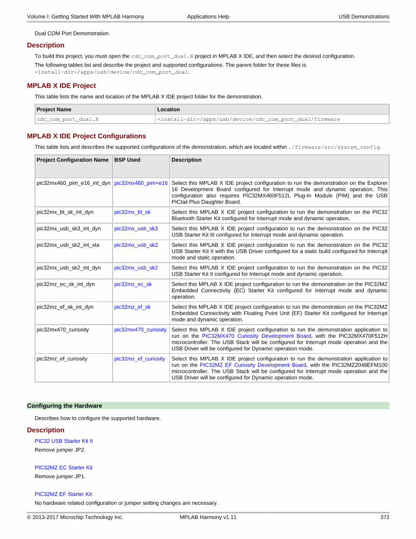
Dual COM Port Demonstration.
Description
To build this project, you must open the cdc_com_port_dual.X project in MPLAB X IDE, and then select the desired configuration.
The following tables list and describe the project and supported configurations. The parent folder for these files is <install-dir>/apps/usb/device/cdc_com_port_dual.
MPLAB X IDE Project
This table lists the name and location of the MPLAB X IDE project folder for the demonstration.
Project Name Location
cdc_com_port_dual.X <install-dir>/apps/usb/device/cdc_com_port_dual/firmware
MPLAB X IDE Project Configurations
This table lists and describes the supported configurations of the demonstration, which are located within ./firmware/src/system_config.
Project Configuration Name BSP Used Description
pic32mx460_pim_e16_int_dyn pic32mx460_pim+e16 Select this MPLAB X IDE project configuration to run the demonstration on the Explorer16 Development Board configured for Interrupt mode and dynamic operation. Thisconfiguration also requires PIC32MX460F512L Plug-In Module (PIM) and the USBPICtail Plus Daughter Board.
pic32mx_bt_sk_int_dyn pic32mx_bt_sk Select this MPLAB X IDE project configuration to run the demonstration on the PIC32Bluetooth Starter Kit configured for Interrupt mode and dynamic operation.
pic32mx_usb_sk3_int_dyn pic32mx_usb_sk3 Select this MPLAB X IDE project configuration to run the demonstration on the PIC32USB Starter Kit III configured for Interrupt mode and dynamic operation.
pic32mx_usb_sk2_int_sta pic32mx_usb_sk2 Select this MPLAB X IDE project configuration to run the demonstration on the PIC32USB Starter Kit II with the USB Driver configured for a static build configured for Interruptmode and static operation.
pic32mx_usb_sk2_int_dyn pic32mx_usb_sk2 Select this MPLAB X IDE project configuration to run the demonstration on the PIC32USB Starter Kit II configured for Interrupt mode and dynamic operation.
pic32mz_ec_sk_int_dyn pic32mz_ec_sk Select this MPLAB X IDE project configuration to run the demonstration on the PIC32MZEmbedded Connectivity (EC) Starter Kit configured for Interrupt mode and dynamicoperation.
pic32mz_ef_sk_int_dyn pic32mz_ef_sk Select this MPLAB X IDE project configuration to run the demonstration on the PIC32MZEmbedded Connectivity with Floating Point Unit (EF) Starter Kit configured for Interruptmode and dynamic operation.
pic32mx470_curiosity pic32mx470_curiosity Select this MPLAB X IDE project configuration to run the demonstration application torun on the PIC32MX470 Curiosity Development Board, with the PIC32MX470F512Hmicrocontroller. The USB Stack will be configured for Interrupt mode operation and theUSB Driver will be configured for Dynamic operation mode.
pic32mz_ef_curiosity pic32mz_ef_curiosity Select this MPLAB X IDE project configuration to run the demonstration application torun on the PIC32MZ EF Curiosity Development Board, with the PIC32MZ2048EFM100microcontroller. The USB Stack will be configured for Interrupt mode operation and theUSB Driver will be configured for Dynamic operation mode.
Configuring the Hardware
Describes how to configure the supported hardware.
Description
PIC32 USB Starter Kit II
Remove jumper JP2.
PIC32MZ EC Starter Kit
Remove jumper JP1.
PIC32MZ EF Starter Kit
No hardware related configuration or jumper setting changes are necessary.
Volume I: Getting Started With MPLAB Harmony Applications Help USB Demonstrations
© 2013-2017 Microchip Technology Inc. MPLAB Harmony v1.11 372

PIC32 USB Starter Kit III
Remove jumper JP1.
PIC32 Bluetooth Starter Kit
Jumper J8 should either be shorted between pins 2 and 3 or should be completely open.
PIC32MX460F512L PIM
Jumper J10 should be removed. This plug-in module should be used along with the Explorer 16 Development Board and the USB PICtail Plus daughter board. The microcontroller PIM should be plugged into the PIM_socket_on the board. The USB PICtail Plus daughter board should be connected to the edge connector J9.
On the Explorer 16 Development Board:
• Switch S2 should be set to PIM
• Jumper JP2 should be in place
On the USB PICtail Plus Daughter Board:
• Jumper JP1 should be in place
• Jumper JP2 and JP4 should be removed
On the PIC32MX460F512L PIM:
• Keep jumper J10 open
• Keep all jumpers in J9 open
PIC32MX470 Curiosity Development Board
Ensure that a jumper is placed at 4-3 on J8.
PIC32MZ EF Curiosity Development Board
Ensure that a jumper is placed at 4-3 on J8.
Running the Demonstration
Provides instructions on how to build and run the CDC Dual COM Port demonstration.
Description
This demonstration allows the device to appear like dual serial (COM) ports to the host. Do the following to run this demonstration:
1. First compile and program the target device. While compiling, select the appropriate MPLAB X IDE project configuration based on the demonstration board. Refer to Building the Application for details.
2. Attach the device to the host. If the host is a personal computer and this is the first time you have plugged this device into the computer you may be prompted for a .inf file.
3. Select the "Install from a list or specific location (Advanced)" option. Specify the <install-dir>/apps/usb/device/cdc_com_port_dual/inf directory.
Volume I: Getting Started With MPLAB Harmony Applications Help USB Demonstrations
© 2013-2017 Microchip Technology Inc. MPLAB Harmony v1.11 373

4. Once the device is successfully installed, open up two instances of a terminal program, such as HyperTerminal. Select the appropriate COM port for each of these terminal instance.
5. The LEDs on the demonstration board will indicate the USB state of the device, as described in the USB Device State and LED Indication Table in the Device section.
6. To run the demonstration, type a character or string in one terminal window. The same character or string appears on the second terminal window. Similarly, any character typed in the second window appears in the first window.
Note: Some terminal programs, like HyperTerminal, require users to click the disconnect button before removing the device from thecomputer. Failing to do so may result in having to close and open the program again to reconnect to the device.
cdc_com_port_single
Demonstrates a USB CDC device, emulating a serial COM port.
Description
This demonstration application creates a USB CDC Device that enumerates as a single COM port on the host personal computer. The application demonstrates two-way communication between the USB device and the personal computer host.
Building the Application
This section identifies the MPLAB X IDE project name and location and lists and describes the available configurations for the USB CDC Device Single COM Port Demonstration.
Description
To build this project, you must open the cdc_com_port_single.X project in MPLAB X IDE, and then select the desired configuration.
The following tables list and describe the project and supported configurations. The parent folder for these files is <install-dir>/apps/usb/device/cdc_com_port_single.
MPLAB X IDE Project
This table lists the name and location of the MPLAB X IDE project folder for the demonstration.
Project Name Location
cdc_com_port_single.X <install-dir>/apps/usb/device/cdc_com_port_single/firmware
MPLAB X IDE Project Configurations
This table lists and describes the supported configurations of the demonstration, which are located within ./firmware/src/system_config.
Volume I: Getting Started With MPLAB Harmony Applications Help USB Demonstrations
© 2013-2017 Microchip Technology Inc. MPLAB Harmony v1.11 374

Project Configuration Name BSP Used Description
pic32mx460_pim_e16_int_dyn pic32mx460_pim+e16 Select this MPLAB X IDE project configuration to run the demonstration on theExplorer 16 Development Board configured for Interrupt mode and dynamicoperation. This configuration also requires PIC32MX460F512L Plug-In Module(PIM) and the USB PICtail Plus Daughter Board.
pic32mx_usb_sk2_poll_dyn pic32mx_bt_sk Select this MPLAB X IDE project configuration to run the demonstration on thePIC32 USB Starter Kit II with the USB Device Stack configured for Polled mode anddynamic operation.
pic32mx_usb_sk3_int_dyn pic32mx_usb_sk3 Select this MPLAB X IDE project configuration to run the demonstration on thePIC32 USB Starter Kit III configured for Interrupt mode and dynamic operation.
pic32mx_usb_sk2_int_sta pic32mx_usb_sk2 Select this MPLAB X IDE project configuration to run the demonstration on thePIC32 USB Starter Kit II with the USB Driver configured for Interrupt mode andstatic operation.
pic32mx_usb_sk2_int_dyn pic32mx_usb_sk2 Select this MPLAB X IDE project configuration to run the demonstration on thePIC32 USB Starter Kit II configured for Interrupt mode and dynamic operation.
pic32mz_da_sk_int_dyn pic32mz_da_sk Select this MPLAB X IDE project configuration to run the demonstration on thePIC32MZ Graphics (DA) Starter Kit configured for Interrupt mode and dynamicoperation.
pic32mz_ec_sk_int_dyn pic32mz_ec_sk Select this MPLAB X IDE project configuration to run the demonstration on thePIC32MZ Embedded Connectivity (EC) Starter Kit configured for Interrupt mode anddynamic operation.
pic32mz_ec_sk_poll_dyn pic32mz_ec_sk Select this MPLAB X IDE project configuration to run the demonstration on thePIC32MZ Embedded Connectivity (EC) Starter Kit with the USB Device Stackconfigured for Polled mode and dynamic operation.
pic32mz_ef_sk_int_dyn_micromips pic32mz_ef_sk Select this MPLAB X IDE project configuration to run the demonstration on thePIC32MZ Embedded Connectivity with Floating Point Unit (EF) Starter Kitconfigured in microMIPS mode for Interrupt mode and dynamic operation.
pic32mz_ef_sk_int_dyn pic32mz_ef_sk Select this MPLAB X IDE project configuration to run the demonstration on thePIC32MZ Embedded Connectivity with Floating Point Unit (EF) Starter Kitconfigured for Interrupt mode and dynamic operation.
pic32mz_ef_sk_poll_dyn pic32mz_ef_sk Select this MPLAB X IDE project configuration to run the demonstration on thePIC32MZ Embedded Connectivity with Floating Point Unit (EF) Starter Kit with theUSB Device Stack configured for Polled mode and dynamic operation.
pic32mx_125_sk_int_dyn pic32mx_125_sk Select this MPLAB X IDE project configuration to run the demonstration on thePIC32MX1/2/5 Starter Kit with the USB Device Stack configured for Interrupt modeand dynamic operation.
Configuring the Hardware
Describes how to configure the supported hardware.
Description
PIC32 USB Starter Kit II
Remove jumper JP2.
PIC32MZ DA Starter Kit
No hardware related configuration or jumper setting changes are necessary.
PIC32MZ EC Starter Kit
Remove jumper JP1.
PIC32MZ EF Starter Kit
No hardware related configuration or jumper setting changes are necessary.
PIC32 USB Starter Kit III
Remove jumper JP1.
PIC32MX460F512L PIM
Jumper J10 should be removed. This plug-in module should be used along with the Explorer 16 Development Board and the USB PICtail Plus daughter board. The microcontroller PIM should be plugged into the PIM_socket_on the board. The USB PICtail Plus daughter board should be connected to the edge connector J9.
On the Explorer 16 Development Board:
Volume I: Getting Started With MPLAB Harmony Applications Help USB Demonstrations
© 2013-2017 Microchip Technology Inc. MPLAB Harmony v1.11 375

• Switch S2 should be set to PIM
• Jumper JP2 should be in place
On the USB PICtail Plus Daughter Board:
• Jumper JP1 should be in place
• Jumper JP2 and JP4 should be removed
On the PIC32MX460F512L PIM:
• Keep jumper J10 open
• Keep all jumpers in J9 open
Running the Demonstration
Provides instructions on how to build and run the CDC Single COM Port demonstration.
Description
This demonstration allows the device to appear like a serial (COM) port to the host. Do the following to run this demonstration:
1. First compile and program the target device. While compiling, select the appropriate MPLAB X IDE project configuration based on the demonstration board. Refer to Building the Application for details.
2. Attach the device to the host. If the host is a personal computer and this is the first time you have plugged this device into the computer, you may be prompted for a .inf file.
3. Select the "Install from a list or specific location (Advanced)" option. Specify the <install-dir>/apps/usb/device/cdc_com_port_single/inf directory.
4. Once the device is successfully installed, open up a terminal program, such as HyperTerminal and select the appropriate COM port. On most machines this will be COM5 or higher. Set the communication properties to 9600 baud, 1 Stop bit and No parity, with Flow Control set to None.
Volume I: Getting Started With MPLAB Harmony Applications Help USB Demonstrations
© 2013-2017 Microchip Technology Inc. MPLAB Harmony v1.11 376

5. The LEDs on the demonstration board will indicate the USB state of the device, as described in the USB Device State and LED Indication Table in the Device section.
6. Once connected to the device, there are two ways to run this example project:
• a) Typing a key in the terminal window will result in the attached device echoing the next letter. Therefore, if the letter 'b' is pressed, the device will echo 'c'.
• b) If the push button is pressed, the device will echo "PUSH BUTTON PRESSED" to the terminal window.
The following table shows the switch buttons to be pressed for different demonstration boards.
Demonstration Board Button
PIC32 USB Starter Kit II
PIC32 USB Starter Kit III
PIC32MZ Graphics (DA) Starter Kit
PIC32MZ Embedded Connectivity (EC) Starter Kit
PIC32MZ Embedded Connectivity with Floating Point Unit (EF) Starter Kit
SW1
Explorer 16 Development Board S3
Note: Some terminal programs, like HyperTerminal, require users to click the disconnect button before removing the device from thecomputer. Failing to do so may result in having to close and open the program again to reconnect to the device.
cdc_msd_basic
Demonstrates a composite USB device emulating a COM port and Flash drive.
Description
This demonstration application creates a composite USB Device that enumerates as a COM port and as Flash drive simultaneously.
Building the Application
This section identifies the MPLAB X IDE project name and location and lists and describes the available configurations for the USB CDC MSD Composite Device Demonstration.
Description
To build this project, you must open the cdc_msd_basic.X project in MPLAB X IDE, and then select the desired configuration.
The following tables list and describe the project and supported configurations. The parent folder for these files is <install-dir>/apps/usb/device/cdc_msd_basic.
MPLAB X IDE Project
This table lists the name and location of the MPLAB X IDE project folder for the demonstration.
Project Name Location
cdc_msd_basic.X <install-dir>/apps/usb/device/cdc_msd_basic/firmware
MPLAB X IDE Project Configurations
This table lists and describes the supported configurations of the demonstration, which are located within ./firmware/src/system_config.
Project Configuration Name
BSP Used Description
pic32mx_usb_sk2_int_dyn pic32mx_usb_sk2 Select this MPLAB X IDE project configuration to run the demonstration on the PIC32 USBStarter Kit II configured for Interrupt mode and dynamic operation.
pic32mz_ec_sk_int_dyn pic32mz_ec_sk Select this MPLAB X IDE project configuration to run the demonstration on the PIC32MZEmbedded Connectivity (EC) Starter Kit configured for Interrupt mode and dynamic operation.
pic32mz_ef_sk_int_dyn pic32mz_ef_sk Select this MPLAB X IDE project configuration to run the demonstration on the PIC32MZEmbedded Connectivity with Floating Point Unit (EF) Starter Kit configured for Interrupt modeand dynamic operation.
Volume I: Getting Started With MPLAB Harmony Applications Help USB Demonstrations
© 2013-2017 Microchip Technology Inc. MPLAB Harmony v1.11 377

Configuring the Hardware
Description
PIC32 USB Starter Kit II
Remove jumper JP2.
PIC32MZ EC Starter Kit
Remove jumper JP1.
PIC32MZ EF Starter Kit
No hardware related configuration or jumper setting changes are necessary.
Running the Demonstration
Provides instructions on how to build and run the USB CDC MSD Composite Device demonstration.
Description
This demonstration application creates a composite USB Device that works simultaneously as a CDC and as a MSD device. This application combines the functionality of the cdc_com_port_single and msd_basic demonstration applications into one device.
Refer to Running the Demonstration section of the cdc_com_port_single demonstration and the Running the Demonstration section of the msd_basic demonstration for details on exercising the CDC and MSD device features, respectively.
The LEDs on the demonstration board will indicate the USB state of the device, as described in the USB Device State and LED Indication Table in the Device section.
cdc_serial_emulator
This application demonstrates the use of the CDC device class in implementing a USB-to-Serial Dongle.
Description
This application demonstrates the use of the CDC device class in implementing a USB-to-Serial Dongle. The application enumerates a COM port on the personal computer. Data received through the CDC USB interface is forwarded to a UART. Data received on the UART is forwarded to the CDC USB interface. This emulates a USB-to-Serial Dongle.
Building the Application
This section identifies the MPLAB X IDE project name and location and lists and describes the available configurations for the USB CDC Device USB-to-Serial Demonstration.
Description
To build this project, you must open the cdc_serial_emulator.X project in MPLAB X IDE, and then select the desired configuration.
The following tables list and describe the project and supported configurations. The parent folder for these files is <install-dir>/apps/usb/device/cdc_serial_emulator.
MPLAB X IDE Project
This table lists the name and location of the MPLAB X IDE project folder for the demonstration.
Project Name Location
cdc_serial_emulator.X <install-dir>/apps/usb/device/cdc_serial_emulator/firmware
MPLAB X IDE Project Configurations
This table lists and describes the supported configurations of the demonstration, which are located within ./firmware/src/system_config.
Project Configuration Name BSP Used Description
pic32mx795_pim_e16_int_dyn pic32mx795_pim+e16 Select this MPLAB X IDE project configuration to run the demonstration on the Explorer16 Development Board configured for Interrupt mode and dynamic operation. Thisconfiguration also requires the PIC32MX795F512L Plug-In Module (PIM) and the USBPICtail Plus Daughter Board.
Volume I: Getting Started With MPLAB Harmony Applications Help USB Demonstrations
© 2013-2017 Microchip Technology Inc. MPLAB Harmony v1.11 378

pic32mz_ef_sk_int_dyn pic32mz_ef_sk Select this MPLAB X IDE project configuration to run the demonstration on the PIC32MZEF Starter Kit configured for Interrupt mode and dynamic operation.
Configuring the Hardware
Describes how to configure the supported hardware.
Description
PIC32MZ EF Starter Kit
No hardware related configuration or jumper setting changes are necessary.
PIC32MX795F512L PIM)
Jumper J10 should be removed. Jumper J1 and J2 should_connect_to positions 1 and 2. This PIM should be used along with the Explorer 16 Development Board and the USB PICtail Plus daughter board. The microcontroller PIM should be plugged into the PIM_socket_on the board. The USB PICtail Plus daughter board should be connected to the edge connector J9.
On the Explorer 16 Development Board:
• Switch S2 should be set to PIM
• Jumper JP2 should be in place
On the USB PICtail Plus Daughter Board:
• Jumper JP1 should be in place
• Jumper JP2 and JP4 should be removed
On the PIC32MX795F512L PIM:
• Keep jumper J10 open
• Keep all jumpers in J9 open
• Jumper J1 should be shorted between positions 1 and 2. This configuration is only applicable for the PIC32MX795F512L USB CAN PIM (MA320003), and not the PIC32MX795F512L USB PIM (MA320002).
• Jumper J2 should be shorted between positions 1 and 2. This configuration is only applicable for the PIC32MX795F512L USB CAN PIM (MA320003) and not the PIC32MX795F512L USB PIM (MA320002).
Running the Demonstration
Provides instructions on how to build and run the CDC Serial Emulator Demonstration.
Prior to using this demonstration, it is recommended to review the MPLAB Harmony Release Notes for any known issues. A PDF copy of the release notes is provided in the <install-dir>/doc folder of your installation.
Description
This application demonstrates the use of the CDC Device class in implementing a USB-to-Serial Dongle. The application enumerates a COM port on the personal computer. Data received through the CDC USB interface is forwarded to a UART. Data received on the UART is forwarded to the CDC USB interface. This emulates a USB-to-Serial Dongle.
1. Open_the project in MPLAB X IDE and select the desired configuration.
2. Build the code and program the device.
3. Depending on the hardware in use, do one of the following:
• If you are using the Explorer 16 board, connect the mini-B device connector on the USB PICtail Plus Daughter Board to the personal computer
• If you a are using the PIC32MZ EF starter kit, connect the micro-USB device connector to the personal computer
Volume I: Getting Started With MPLAB Harmony Applications Help USB Demonstrations
© 2013-2017 Microchip Technology Inc. MPLAB Harmony v1.11 379

7. Select the "Install from a list or specific location (Advanced)" option. Specify the <install-dir>/apps/usb/device/cdc_serial_emulator/inf directory.
The LEDs on the demonstration board will indicate the USB state of the device, as described in the USB Device State and LED Indication Table in the Device section.
8. Open_a terminal emulation program of your choice and select the enumerated USB COM port.
9. Connect the USB-to-Serial Dongle to the same personal computer.
10. Open_another instance of the terminal emulation program and select the USB-to-Serial Dongle.
11. Connect the serial connector of the USB-to-Serial Dongle to the UART connector (P1) on the Explorer 16 Development Board.
12. Choose a baud rate of 9600, 1 Stop bit and no parity while opening both of the terminal emulation programs.
The setup should be similar to the following diagram.
Volume I: Getting Started With MPLAB Harmony Applications Help USB Demonstrations
© 2013-2017 Microchip Technology Inc. MPLAB Harmony v1.11 380

Any text entered into the terminal 1 program will be echoed on terminal 2 and vice versa.
cdc_serial_emulator_msd
Demonstrates a USB to Serial Dongle combined with a MSD class.
Description
This demonstration application creates a USB Device that combines the functionality of the cdc_serial_emulator and msd_basic demonstration applications.
Building the Application
This section identifies the MPLAB X IDE project name and location and lists and describes the available configurations for the this demonstration application.
Description
To build this project, you must open the cdc_serial_emulator_msd.X project in MPLAB X IDE, and then select the desired configuration.
The following tables list and describe the project and supported configurations. The parent folder for these files is <install-dir>/apps/usb/cdc_serial_emulator_msd.
MPLAB X IDE Project
This table lists the name and location of the MPLAB X IDE project folder for the demonstration.
Project Name Location
cdc_serial_emulator_msd.X <install-dir>/apps/usb/device/cdc_serial_emulator_msd/firmware
MPLAB X IDE Project Configurations
This table lists and describes the supported configurations of the demonstration, which are located within ./firmware/src/system_config.
Project Configuration Name BSP Used Description
pic32mx795_pim_e16_int_dyn pic32mx795_pim+e16 Select this MPLAB X IDE project configuration to run the demonstration on the Explorer16 Development Board configured for Interrupt mode and dynamic operation. Thisconfiguration also requires the PIC32MX795F512L Plug-In Module (PIM) and the USBPICtail Plus Daughter Board.
Configuring the Hardware
Describes how to configure the supported hardware.
Description
PIC32MX795F512L PIM
Jumper J10 should be removed. Jumper J1 and J2 should_connect_to positions 1 and 2. This PIM should be used along with the Explorer 16 Development Board and the USB PICtail Plus daughter board. The microcontroller PIM should be plugged into the PIM_socket_on the board. The USB PICtail Plus daughter board should be connected to the edge connector J9.
On the Explorer 16 Development Board:
Volume I: Getting Started With MPLAB Harmony Applications Help USB Demonstrations
© 2013-2017 Microchip Technology Inc. MPLAB Harmony v1.11 381

• Switch S2 should be set to PIM
• Jumper JP2 should be in place
On the USB PICtail Plus Daughter Board:
• Jumper JP1 should be in place
• Jumper JP2 and JP4 should be removed
On the PIC32MX795F512L PIM:
• Keep jumper J10 open.
• Keep all jumpers in J9 open
• Jumper J1 should be shorted between positions 1 and 2
• Jumper J2 should be shorted between positions 1 and 2
Running the Demonstration
Provides instructions on how to build and run the demonstration.
Description
This demonstration functions as a composite USB Device that combines the features of the devices created by the cdc_serial_emulator and the msd_basic demonstration applications. Refer to Running the Demonstration section of the cdc_serial_emulator demonstration and Running the Demonstration section of the msd_basic demonstration for details on exercising the CDC and MSD functions, respectively.
The LEDs on the demonstration board will indicate the USB state of the device, as described in the USB Device State and LED Indication Table in the Device section.
hid_basic
This demonstration application creates a custom HID device that can be controlled by a personal computer-based utility.
Description
This application creates a custom HID device that can be controlled by a personal computer-based utility. The device allows the USB Host utility to control the LEDs on the board and query the status of a switch.
Building the Application
This section identifies the MPLAB X IDE project name and location and lists and describes the available configurations for the USB HID Basic Demonstration.
Description
To build this project, you must open the hid_basic.X project in MPLAB X IDE, and then select the desired configuration.
The following tables list and describe the project and supported configurations. The parent folder for these files is <install-dir>/apps/usb/device/hid_basic.
MPLAB X IDE Project
This table lists the name and location of the MPLAB X IDE project folder for the demonstration.
Project Name Location
hid_basic.X <install-dir>/apps/usb/device/hid_basic/firmware
MPLAB X IDE Project Configurations
This table lists and describes the supported configurations of the demonstration, which are located within ./firmware/src/system_config.
Project Configuration Name BSP Used Description
pic32mx460_pim_e16_int_dyn pic32mx460_pim+e16 Select this MPLAB X IDE project configuration to run the demonstration on the Explorer16 Development Board configured for Interrupt mode and dynamic operation. Thisconfiguration also requires the PIC32MX460F512L Plug-In Module (PIM) and the USBPICtail Plus Daughter Board.
pic32mx_usb_sk3_int_dyn pic32mx_usb_sk3 Select this MPLAB X IDE project configuration to run the demonstration on the PIC32USB Starter Kit III configured for Interrupt mode and dynamic operation.
pic32mx_usb_sk2_int_dyn pic32mx_usb_sk2 Select this MPLAB X IDE project configuration to run the demonstration on the PIC32USB Starter Kit II configured for Interrupt mode and dynamic operation.
Volume I: Getting Started With MPLAB Harmony Applications Help USB Demonstrations
© 2013-2017 Microchip Technology Inc. MPLAB Harmony v1.11 382

pic32mz_ec_sk_int_dyn pic32mz_ec_sk Select this MPLAB X IDE project configuration to run the demonstration on the PIC32MZEmbedded Connectivity (EC) Starter Kit configured for Interrupt mode and dynamicoperation.
pic32mz_ef_sk_int_dyn pic32mz_ef_sk Select this MPLAB X IDE project configuration to run the demonstration on the PIC32MZEmbedded Connectivity with Floating Point Unit (EF) Starter Kit configured for Interruptmode and dynamic operation.
Configuring the Hardware
Describes how to configure the supported hardware.
Description
PIC32 USB Starter Kit II
Remove jumper JP2.
PIC32MZ EC Starter Kit
Remove jumper JP1.
PIC32MZ EF Starter Kit
No hardware related configuration or jumper setting changes are necessary.
PIC32 USB Starter Kit III
Remove jumper JP1.
PIC32MX460F512L PIM
Jumper J10 should be removed. This plug-in module should be used along with the Explorer 16 Development Board and the USB PICtail Plus daughter board. The microcontroller PIM should be plugged into the PIM_socket_on the board. The USB PICtail Plus daughter board should be connected to the edge connector J9.
On the Explorer 16 Development Board:
• Switch S2 should be set to PIM
• Jumper JP2 should be in place
On the USB PICtail Plus Daughter Board:
• Jumper JP1 should be in place
• Jumper JP2 and JP4 should be removed
On the PIC32MX460F512L PIM:
• Keep jumper J10 open
• Keep all jumpers in J9 open
Running the Demonstration
Provides instructions on how to build and run the HID Basic demonstration.
Description
This demonstration uses the selected hardware platform as a HID class USB device, but uses the HID class for general purpose I/O operations. While compiling, select the appropriate MPLAB X IDE project configuration based on the demonstration board. Refer to Building the Application for details.
Typically, the HID class is used to implement human interface products, such as mice and keyboards. The HID protocol, is however, quite flexible, and can be adapted and used to send/receive general purpose data to/from a USB device. Using the HID class for general purpose I/O operations is quite advantageous, in that it does not require any kind of custom driver installation process. HID class drivers are already provided by and are distributed with common operating systems. Therefore, upon plugging in a HID class device into a typical computer system, no user installation of drivers is required, the installation is fully automatic.
The LEDs on the demonstration board will indicate the USB state of the device, as described in the USB Device State and LED Indication Table in the Device section.
HID devices primarily communicate through one interrupt IN endpoint and one interrupt OUT endpoint. In most applications, this effectively limits the maximum achievable bandwidth for full speed HID devices to 64 kBytes/s of IN traffic, and 64 kBytes/s of OUT traffic (64 kB/s, but effectively "full duplex").
The GenericHIDSimpleDemo.exe program, and the associated firmware demonstrate how to use the HID protocol for basic general purpose USB data transfer.
Before you can run the GenericHIDSimpleDemo.exe executable, you will need to have the Microsoft® .NET Framework Version 2.0 Redistributable Package (later versions are probably acceptable, but have not been tested) installed on your computer. Programs that were built in the Visual Studio® .NET languages require the .NET redistributable package. The redistributable package can be freely downloaded from Microsoft’s website. Users of Windows Vista® operating systems will not need to install the .NET framework, as it comes preinstalled as part of the operating system.
Volume I: Getting Started With MPLAB Harmony Applications Help USB Demonstrations
© 2013-2017 Microchip Technology Inc. MPLAB Harmony v1.11 383

Launching the Application
To launch the application, simply double click the executable GenericHIDSimpleDemo.exe in the <install-dir>\apps\usb\device\hid_basic\bin directory. A property sheet similar to the following should appear:
Note: If instead of this window, an error message appears while trying to launch the application, it is likely the Microsoft .NET FrameworkVersion 2.0 Redistributable Package has not yet been installed. Please install it and try again.
Send/Receive Packets
To begin sending/receiving packets to the device, you must first find and_connect_ to the device. As configured by default, the application is looking for HID class USB devices with VID = 0x04D8 and PID = 0x003F. The device descriptor in the firmware project meant to be used with this demonstration uses the same VID/PID. If you plug in a USB device programmed with the correct precompiled .hex file, and click Connect, the other push buttons should become enabled. If clicking Connect has no effect, it is likely the USB device is either not connected, or has not been programmed with the correct firmware.
Clicking Toggle LED(s) should send a single packet of general purpose generic data to the HID class USB peripheral device. The data will arrive on the interrupt OUT endpoint. The firmware has been configured to receive this generic data packet, parse the packet looking for the Toggle LED(s) command, and should respond appropriately by controlling the LED(s) on the demonstration board.
The Get Pushbutton State option will send one packet of data over the USB to the peripheral device (to the interrupt OUT endpoint) requesting the current push button state. The firmware will process the received Get Pushbutton State command, and will prepare an appropriate response packet depending upon the pushbutton state.
The following table shows the button that has to be pressed on the demonstration board to see the change in the push button state.
Demonstration Board Button
PIC32 USB Starter Kit II
PIC32 USB Starter Kit III
PIC32MZ Embedded Connectivity (EC) Starter Kit
PIC32MZ Embedded Connectivity with Floating Point Unit (EF) Starter Kit
SW1
Explorer 16 Development Board S3
hid_joystick
Demonstrates a USB HID device emulating a joystick.
Description
This demonstration application creates a custom HID joystick. This application is only intended to demonstrate creation of Joystick HID Report descriptors and may not be a definite end solution. The end application requirements may need the report descriptor to be modified.
Building the Application
This section identifies the MPLAB X IDE project name and location and lists and describes the available configurations for the USB HID Joystick Demonstration.
Description
To build this project, you must open the hid_joystick.X project in MPLAB X IDE, and then select the desired configuration.
The following tables list and describe the project and supported configurations. The parent folder for these files is <install-dir>/apps/usb/device/hid_joystick.
MPLAB X IDE Project
This table lists the name and location of the MPLAB X IDE project folder for the demonstration.
Project Name Location
hid_joystick.X <install-dir>/apps/usb/device/hid_joystick/firmware
Volume I: Getting Started With MPLAB Harmony Applications Help USB Demonstrations
© 2013-2017 Microchip Technology Inc. MPLAB Harmony v1.11 384

MPLAB X IDE Project Configurations
This table lists and describes the supported configurations of the demonstration, which are located within ./firmware/src/system_config.
Project Configuration Name BSP Used Description
pic32mx460_pim_e16_int_dyn pic32mx460_pim+e16 Select this MPLAB X IDE project configuration to run the demonstration on the Explorer16 Development Board configured for Interrupt mode and dynamic operation. Thisconfiguration also requires the PIC32MX460F512L Plug-In Module (PIM) and the USBPICtail Plus Daughter Board.
pic32mx_usb_sk3_int_dyn pic32mx_usb_sk3 Select this MPLAB X IDE project configuration to run the demonstration on the PIC32USB Starter Kit III configured for Interrupt mode and dynamic operation.
pic32mx_usb_sk2_int_dyn pic32mx_usb_sk2 Select this MPLAB X IDE project configuration to run the demonstration on the PIC32USB Starter Kit II configured for Interrupt mode and dynamic operation.
pic32mz_ec_sk_int_dyn pic32mz_ec_sk Select this MPLAB X IDE project configuration to run the demonstration on the PIC32MZEmbedded Connectivity (EC) Starter Kit configured for Interrupt mode and dynamicoperation.
pic32mz_ef_sk_int_dyn pic32mz_ef_sk Select this MPLAB X IDE project configuration to run the demonstration on the PIC32MZEmbedded Connectivity with Floating Point Unit (EF) Starter Kit configured for Interruptmode and dynamic operation.
Configuring the Hardware
Describes how to configure the supported hardware.
Description
PIC32 USB Starter Kit II
Remove jumper JP2.
PIC32MZ EC Starter Kit
Remove jumper JP1.
PIC32MZ EF Starter Kit
No hardware related configuration or jumper setting changes are necessary.
PIC32 USB Starter Kit III
Remove jumper JP1.
PIC32MX460F512L PIM
Jumper J10 should be removed. This plug-in module should be used along with the Explorer 16 Development Board and the USB PICtail Plus daughter board. The microcontroller PIM should be plugged into the PIM_socket_on the board. The USB PICtail Plus daughter board should be connected to the edge connector J9.
On the Explorer 16 Development Board:
• Switch S2 should be set to PIM
• Jumper JP2 should be in place
On the USB PICtail Plus Daughter Board:
• Jumper JP1 should be in place
• Jumper JP2 and JP4 should be removed
On the PIC32MX460F512L PIM:
• Keep jumper J10 open
• Keep all jumpers in J9 open
Running the Demonstration
Provides instructions on how to build and run the USB HID Joystick demonstration.
Description
This demonstration uses the selected hardware platform as a USB Joystick. Select the appropriate MPLAB X IDE project configuration based on the demonstration board. Refer to Building the Application for details.
The LEDs on the demonstration board will indicate the USB state of the device, as described in the USB Device State and LED Indication Table in the Device section.
Volume I: Getting Started With MPLAB Harmony Applications Help USB Demonstrations
© 2013-2017 Microchip Technology Inc. MPLAB Harmony v1.11 385

To test the joystick feature, navigate to the <install-dir>/apps/usb/device/hid_joystick/bin directory and open JoystickTester.exe:
Pressing the button will cause the device to:
• Indicate that the "x" button is pressed, but no others
• Move the hat switch to the "east" position
• Move the X and Y coordinates to their extreme values
The Following table shows the button that has to be pressed on the demonstration board to emulate the joystick.
Demonstration Board Button
PIC32 USB Starter Kit II
PIC32 USB Starter Kit III
PIC32MZ Embedded Connectivity (EC) Starter Kit
PIC32MZ Embedded Connectivity with Floating Point Unit (EF) Starter Kit
SW1
Explorer 16 Development Board S3
Volume I: Getting Started With MPLAB Harmony Applications Help USB Demonstrations
© 2013-2017 Microchip Technology Inc. MPLAB Harmony v1.11 386

hid_keyboard
Demonstrates a USB HID device, emulating a keyboard.
Description
This demonstration application creates a Generic HID keyboard. Pressing a key on the board emulates a keyboard key press.
Building the Application
This section identifies the MPLAB X IDE project name and location and lists and describes the available configurations for the USB HID Keyboard Demonstration.
Description
To build this project, you must open the hid_keyboard.X project in MPLAB X IDE, and then select the desired configuration.
The following tables list and describe the project and supported configurations. The parent folder for these files is <install-dir>/apps/usb/device/hid_keyboard.
MPLAB X IDE Project
This table lists the name and location of the MPLAB X IDE project folder for the demonstration.
Project Name Location
hid_keyboard.X <install-dir>/apps/usb/device/hid_keyboard/firmware
MPLAB X IDE Project Configurations
This table lists and describes the supported configurations of the demonstration, which are located within ./firmware/src/system_config.
Project Configuration Name BSP Used Description
pic32mx460_pim_e16_int_dyn pic32mx460_pim+e16 Select this MPLAB X IDE project configuration to run the demonstration on the Explorer16 Development Board configured for Interrupt mode and dynamic operation. Thisconfiguration also requires the PIC32MX460F512L Plug-In Module (PIM) and the USBPICtail Plus Daughter Board.
pic32mx_usb_sk3_int_dyn pic32mx_usb_sk3 Select this MPLAB X IDE project configuration to run the demonstration on the PIC32USB Starter Kit III configured for Interrupt mode and dynamic operation.
pic32mx_usb_sk2_int_dyn pic32mx_usb_sk2 Select this MPLAB X IDE project configuration to run the demonstration on the PIC32USB Starter Kit II configured for Interrupt mode and dynamic operation.
pic32mz_ec_sk_int_dyn pic32mz_ec_sk Select this MPLAB X IDE project configuration to run the demonstration on the PIC32MZEmbedded Connectivity (EC) Starter Kit configured for Interrupt mode and dynamicoperation.
pic32mz_ef_sk_int_dyn pic32mz_ef_sk Select this MPLAB X IDE project configuration to run the demonstration on the PIC32MZEmbedded Connectivity with Floating Point Unit (EF) Starter Kit configured for Interruptmode and dynamic operation.
Configuring the Hardware
Describes how to configure the supported hardware.
Description
PIC32 USB Starter Kit II
Remove jumper JP2.
PIC32MZ EC Starter Kit
Remove jumper JP1.
PIC32MZ EF Starter Kit
No hardware related configuration or jumper setting changes are necessary.
PIC32 USB Starter Kit III
Remove jumper JP1.
PIC32MX460F512L PIM
Volume I: Getting Started With MPLAB Harmony Applications Help USB Demonstrations
© 2013-2017 Microchip Technology Inc. MPLAB Harmony v1.11 387

Jumper J10 should be removed. This plug-in module should be used along with the Explorer 16 Development Board and the USB PICtail Plus daughter board. The microcontroller PIM should be plugged into the PIM_socket_on the board. The USB PICtail Plus daughter board should be connected to the edge connector J9.
On the Explorer 16 Development Board:
• Switch S2 should be set to PIM
• Jumper JP2 should be in place
On the USB PICtail Plus Daughter Board:
• Jumper JP1 should be in place
• Jumper JP2 and JP4 should be removed
On the PIC32MX460F512L PIM:
• Keep jumper J10 open
• Keep all jumpers in J9 open
Running the Demonstration
Provides instructions on how to build and run the USB HID Keyboard demonstration.
Description
This demonstration uses the selected hardware platform as a USB keyboard. While compiling, select the appropriate MPLAB X IDE project configuration based on the demonstration board. Refer to Building the Application for details.
The LEDs on the demonstration board will indicate the USB state of the device, as described in the USB Device State and LED Indication Table in the Device section.
Before pressing the button, select a window in which it is safe to type text freely. Pressing the button on the demonstration board will cause the device to print a character on the screen.
The following table shows the button that has to be pressed on the demonstration board to print a character.
Demonstration Board Button
PIC32 USB Starter Kit II
PIC32 USB Starter Kit III
PIC32MZ Embedded Connectivity (EC) Starter Kit
PIC32MZ Embedded Connectivity with Floating Point Unit (EF) Starter Kit
SW1
Explorer 16 Development Board S3
hid_mouse
Demonstrates a USB HID device, emulating a mouse pointing device.
Description
This demonstration application creates a USB HID based two-button mouse device. When connected, the device emulates mouse operation by moving the cursor in a circular pattern.
Building the Application
This section identifies the MPLAB X IDE project name and location and lists and describes the available configurations for the USB HID Mouse Demonstration.
Description
To build this project, you must open the hid_mouse.X project in MPLAB X IDE, and then select the desired configuration.
The following tables list and describe the project and supported configurations. The parent folder for these files is <install-dir>/apps/usb/device/hid_mouse.
MPLAB X IDE Project
This table lists the name and location of the MPLAB X IDE project folder for the demonstration.
Project Name Location
hid_mouse.X <install-dir>/apps/usb/device/hid_mouse/firmware
Volume I: Getting Started With MPLAB Harmony Applications Help USB Demonstrations
© 2013-2017 Microchip Technology Inc. MPLAB Harmony v1.11 388

MPLAB X IDE Project Configurations
This table lists and describes the supported configurations of the demonstration, which are located within ./firmware/src/system_config.
Project Configuration Name BSP Used Description
pic32mx460_pim_e16_int_dyn pic32mx460_pim+e16 Select this MPLAB X IDE project configuration to run the demonstration on the Explorer16 Development Board configured for Interrupt mode and dynamic operation. Thisconfiguration also requires the PIC32MX460F512L Plug-In Module (PIM) and the USBPICtail Plus Daughter Board.
pic32mx_usb_sk3_int_dyn pic32mx_usb_sk3 Select this MPLAB X IDE project configuration to run the demonstration on the PIC32USB Starter Kit III configured for Interrupt mode and dynamic operation.
pic32mx_usb_sk2_int_dyn pic32mx_usb_sk2 Select this MPLAB X IDE project configuration to run the demonstration on the PIC32USB Starter Kit II configured for Interrupt mode and dynamic operation.
pic32mz_da_sk_int_dyn pic32mz_da_sk Select this MPLAB X IDE project configuration to run the demonstration on the PIC32MZGraphics (DA) Starter Kit configured for Interrupt mode and dynamic operation.
pic32mz_ec_sk_int_dyn pic32mz_ec_sk Select this MPLAB X IDE project configuration to run the demonstration on the PIC32MZEmbedded Connectivity (EC) Starter Kit configured for Interrupt mode and dynamicoperation.
pic32mz_ef_sk_int_dyn pic32mz_ef_sk Select this MPLAB X IDE project configuration to run the demonstration on the PIC32MZEmbedded Connectivity with Floating Point Unit (EF) Starter Kit configured for Interruptmode and dynamic operation.
Configuring the Hardware
Describes how to configure the supported hardware.
Description
PIC32 USB Starter Kit II
Remove jumper JP2.
PIC32MZ DA Starter Kit
No hardware related configuration or jumper setting changes are necessary.
PIC32MZ EC Starter Kit
Remove jumper JP1.
PIC32MZ EF Starter Kit
No hardware related configuration or jumper setting changes are necessary.
PIC32 USB Starter Kit III
Remove jumper JP1.
PIC32MX460F512L PIM
Jumper J10 should be removed. This plug-in module should be used along with the Explorer 16 Development Board and the USB PICtail Plus daughter board. The microcontroller PIM should be plugged into the PIM_socket_on the board. The USB PICtail Plus daughter board should be connected to the edge connector J9.
On the Explorer 16 Development Board:
• Switch S2 should be set to PIM
• Jumper JP2 should be in place
On the USB PICtail Plus Daughter Board:
• Jumper JP1 should be in place
• Jumper JP2 and JP4 should be removed
On the PIC32MX460F512L PIM:
• Keep jumper J10 open
• Keep all jumpers in J9 open
Running the Demonstration
Provides instructions on how to build and run the HID Mouse Demonstration.
Volume I: Getting Started With MPLAB Harmony Applications Help USB Demonstrations
© 2013-2017 Microchip Technology Inc. MPLAB Harmony v1.11 389

Description
This demonstration uses the selected hardware platform as a USB mouse. While compiling, select the appropriate MPLAB X IDE project configuration based on the demonstration board. Refer to Building the Application for details.
The LEDs on the demonstration board will indicate the USB state of the device, as described in the USB Device State and LED Indication Table in the Device section.
Before connecting the board to the computer through the USB cable please be aware that the device will begin moving the mouse cursor on the computer. There are two ways to stop the device from allowing the cursor to continue to move. The first way is to disconnect the device from the computer. The second is to press the correct button on the hardware platform. Pressing the button again will cause the mouse cursor to start moving in a circle again.
The following table shows the button that has to be pressed on the demonstration board to stop the circular motion:
Demonstration Board Button
PIC32 USB Starter Kit II
PIC32 USB Starter Kit III
PIC32MZ Graphics (DA) Starter Kit
PIC32MZ Embedded Connectivity (EC) Starter Kit
PIC32MZ Embedded Connectivity with Floating Point Unit (EF) Starter Kit
SW1
Explorer 16 Development Board S3
hid_msd_basic
Demonstrates a HID Device Class and MSD class composite USB Device.
Description
This demonstration application creates a USB Device that combines the functionality of the hid_basic and msd_basic demonstration applications.
Building the Application
This section identifies the MPLAB X IDE project name and location and lists and describes the available configurations for the this demonstration application.
Description
To build this project, you must open the hid_msd_basic.X project in MPLAB X IDE, and then select the desired configuration.
The following tables list and describe the project and supported configurations. The parent folder for these files is <install-dir>/apps/usb/device/hid_msd_basic.
MPLAB X IDE Project
This table lists the name and location of the MPLAB X IDE project folder for the demonstration.
Project Name Location
hid_msd_basic.X <install-dir>/apps/usb/device/hid_msd_basic/firmware
MPLAB X IDE Project Configurations
This table lists and describes the supported configurations of the demonstration, which are located within ./firmware/src/system_config.
Project Configuration Name
BSP Used Description
pic32mx_usb_sk2_int_dyn pic32mx_usb_sk2 Select this configuration to run the demonstration application on the PIC32 USB Starter Kit IIconfigured for Interrupt mode and dynamic operation.
pic32mz_ec_sk_int_dyn pic32mz_ec_sk Select this configuration to run the demonstration application on the PIC32MZ EmbeddedConnectivity (EC) Starter Kit configured for Interrupt mode and dynamic operation.
pic32mz_ef_sk_int_dyn pic32mz_ef_sk Select this configuration to run the demonstration application on the PIC32MZ EmbeddedConnectivity with Floating Point Unit (EF) Starter Kit configured for Interrupt mode and dynamicoperation.
Volume I: Getting Started With MPLAB Harmony Applications Help USB Demonstrations
© 2013-2017 Microchip Technology Inc. MPLAB Harmony v1.11 390

Configuring the Hardware
Describes how to configure the supported hardware.
Description
PIC32 USB Starter Kit II
Remove jumper JP2.
PIC32MZ EC Starter Kit
Remove jumper JP1.
PIC32MZ EF Starter Kit
No hardware related configuration or jumper setting changes are necessary.
Running the Demonstration
Provides instructions on how to build and run the demonstration.
Description
This demonstration functions as composite USB Device that combines the features of the devices created by the hid_basic and the msd_basic demonstration applications. Refer to Running the Demonstration section of the hid_basic demonstration and Running the Demonstration section of the msd_basic demonstration for details on exercising the HID and MSD functions, respectively.
The LEDs on the demonstration board will indicate the USB state of the device, as described in the USB Device State and LED Indication Table in the Device section.
msd_basic
Demonstrates a USB MSD Device emulating a Flash Drive.
Description
This demonstration application creates a Flash drive using the Mass Storage Device Class.
Building the Application
This section identifies the MPLAB X IDE project name and location and lists and describes the available configurations for the USB MSD Basic Demonstration.
Description
To build this project, you must open the msd_basic.X project in MPLAB X IDE, and then select the desired configuration.
The following tables list and describe the project and supported configurations. The parent folder for these files is <install-dir>/apps/usb/device/msd_basic.
MPLAB X IDE Project
This table lists the name and location of the MPLAB X IDE project folder for the demonstration.
Project Name Location
msd_basic.X <install-dir>/apps/usb/device/msd_basic/firmware
MPLAB X IDE Project Configurations
This table lists and describes the supported configurations of the demonstration, which are located within ./firmware/src/system_config.
Project Configuration Name
BSP Used Description
pic32mx_bt_sk_int_dyn pic32mx_bt_sk Select this MPLAB X IDE project configuration to run the demonstration on the PIC32Bluetooth Starter Kit configured for Interrupt mode and dynamic operation.
pic32mx_usb_sk2_poll_dyn pic32mx_usb_sk2 Select this MPLAB X IDE project configuration to run the demonstration on the PIC32 USBStarter Kit II with the USB Device Stack configured for Polled mode and dynamic operation..
pic32mx_usb_sk2_int_dyn pic32mx_usb_sk2 Select this MPLAB X IDE project configuration to run the demonstration on the PIC32 USBStarter Kit II configured for Interrupt mode and dynamic operation.
Volume I: Getting Started With MPLAB Harmony Applications Help USB Demonstrations
© 2013-2017 Microchip Technology Inc. MPLAB Harmony v1.11 391

pic32mx_usb_sk3_int_dyn pic32mx_usb_sk3 Select this MPLAB X IDE project configuration to run the demonstration on the PIC32 USBStarter Kit III configured for Interrupt mode and dynamic operation.
pic32mz_ec_sk_poll_dyn pic32mz_ec_sk Select this MPLAB X IDE project configuration to run the demonstration on the PIC32MZEmbedded Connectivity (EC)Starter Kit with the USB Device Stack configured for Polled modeand dynamic operation.
pic32mz_ec_sk_int_dyn pic32mz_ec_sk Select this MPLAB X IDE project configuration to run the demonstration on the PIC32MZEmbedded Connectivity (EC) Starter Kit configured for Interrupt mode and dynamic operation.
pic32mz_ef_sk_int_dyn pic32mz_ef_sk Select this MPLAB X IDE project configuration to run the demonstration on the PIC32MZEmbedded Connectivity with Floating Point Unit (EF) Starter Kit configured for Interrupt modeand dynamic operation.
pic32mz_ef_sk_poll_dyn pic32mz_ef_sk Select this MPLAB X IDE project configuration to run the demonstration on the PIC32MZEmbedded Connectivity with Floating Point Unit (EF) Starter Kit configured for Polled modeand dynamic operation.
Configuring the Hardware
Describes how to configure the supported hardware.
Description
PIC32 USB Starter Kit II
Remove jumper JP2.
PIC32MZ EC Starter Kit
Remove jumper JP1.
PIC32MZ EF Starter Kit
No hardware related configuration or jumper setting changes are necessary.
PIC32 USB Starter Kit III
Remove jumper JP1.
PIC32 Bluetooth Starter Kit
No hardware related configuration or jumper settings required.
PIC32MX460F512L PIM
Jumper J10 should be removed. This plug-in module should be used along with the Explorer 16 Development Board and the USB PICtail Plus daughter board. The microcontroller PIM should be plugged into the PIM_socket_on the board. The USB PICtail Plus daughter board should be connected to the edge connector J9.
On the Explorer 16 Development Board:
• Switch S2 should be set to PIM
• Jumper JP2 should be in place
On the USB PICtail Plus Daughter Board:
• Jumper JP1 should be in place
• Jumper JP2 and JP4 should be removed
Running the Demonstration
Provides instructions on how to build and run the USB MSD Basic demonstration.
Description
This demonstration uses the selected hardware platform as a logical drive on the computer using the internal Flash of the device as the drive storage media. Connect the hardware platform to a computer through a USB cable. The device should appear as a new drive on the computer named "Drive Name". The drive can used to store files.
The LEDs on the demonstration board will indicate the USB state of the device, as described in the USB Device State and LED Indication Table in the Device section.
Note: Reprogramming the development board will cause any stored files to be erased.
msd_fs_spiflash
This application demonstrates accessing the SPI Flash connected to the PIC32 device as a media by multiple clients.
Volume I: Getting Started With MPLAB Harmony Applications Help USB Demonstrations
© 2013-2017 Microchip Technology Inc. MPLAB Harmony v1.11 392

Description
This application demonstrates accessing the SPI Flash connected to the PIC32 device as a media by multiple clients. When connected via USB to the Host Computer, the SPI Flash is shown as the storage media. The Host writes files to the media, which is later accessed by the application running on the PIC32 device using the File System.
Building the Application
This section identifies the MPLAB X IDE project name and location and lists and describes the available configurations for the USB MSD File System SPI Flash Demonstration.
Description
To build this project, you must open the msd_fs_spiflash.X project in MPLAB X IDE, and then select the desired configuration.
The following tables list and describe the project and supported configurations. The parent folder for these files is <install-dir>/apps/usb/device/msd_fs_spiflash.
MPLAB X IDE Project
This table lists the name and location of the MPLAB X IDE project folder for the demonstration.
Project Name Location
msd_fs_spiflash.X <install-dir>/apps/usb/device/msd_fs_spiflash/firmware
MPLAB X IDE Project Configurations
This table lists and describes the supported configurations of the demonstration, which are located within ./firmware/src/system_config.
Project Configuration Name
BSP Used Description
bt_audio_dk_int_dyn bt_audio_dk Select this MPLAB X IDE project configuration to run the demonstration on the PIC32Bluetooth Audio Development Kit.
Configuring the Hardware
Describes how to configure the supported hardware.
Description
PIC32 Bluetooth Audio Develoment Kit
Ensure that switch S1 is set to PIC32_MCLR.
Running the Demonstration
Provides instructions on how to build and run the USB MSD File System SPI Flash demonstration.
Description
This demonstration shows an example of:
• Accessing the media attached to PIC32 by multiple clients
• Application running on the PIC32 firmware accesses the media using the MPLAB Harmony File System
When connected to the USB Host the very first time, the user is expected to format the media and create a file named FILE.TXT in the root directory of the media. The user can update the file to provide input for the application to glow the LEDs present on the development kit. The application running on the PIC32 reads and interprets the data present in the file and accordingly turns ON or OFF the LEDs LED8 and LED9 of the development kit. The format of input in the file FILE.TXT should be as follows:
• For turning ON an LED:
• LED8:1
• LED9:1
• For turning OFF an LED:
• LED8:0
• LED9:0
After having set the appropriate values in the file, the user can then press and release the wwitch SW1 located on the development kit for the MPLAB Harmony File System running on the PIC32 to act upon the contents of the file.
The FS state machine of the demonstration is only triggered by the switch SW1. When the user presses and releases SW1 the following occurs:
Volume I: Getting Started With MPLAB Harmony Applications Help USB Demonstrations
© 2013-2017 Microchip Technology Inc. MPLAB Harmony v1.11 393

• LED5 is turned ON to indicate that the FS state machine is running
• The USB is detached
• The file system on the SPI Flash is mounted
• The contents of FILE.TXT is read and acted upon. Depending on the values set in the file, the LEDs are either turned ON or OFF.
• Next, the file system is unmounted and the USB is reattached
• LED5 is turned OFF to indicate that FS state machine is no longer running
• If LED6 is turned ON during any part of the demonstration, this indicates the demonstration has failed
msd_sdcard
Demonstrates data transfer from a SD card and a computer through USB MSD.
Description
This application demonstrates the usage of a SD card reader through the USB Mass Storage Device (MSD) class to transfer data between a computer and SD card. High-Speed USB is used for communication between the Host computer and the PIC32 device, while a SD card is used as the storage medium.
Building the Application
This section identifies the MPLAB X IDE project name and location and lists and describes the available configurations for the USB MSD SD Card Demonstration.
Description
To build this project, you must open the msd_sdcard.X project in MPLAB X IDE, and then select the desired configuration.
The following tables list and describe the project and supported configurations. The parent folder for these files is <install-dir>/apps/usb/device/msd_sdcard.
MPLAB X IDE Project
This table lists the name and location of the MPLAB X IDE project folder for the demonstration.
Project Name Location
msd_sdcard.X <install-dir>/apps/usb/device/msd_sdcard/firmware
MPLAB X IDE Project Configurations
This table lists and describes the supported configurations of the demonstration, which are located within ./firmware/src/system_config.
Project Configuration Name
BSP Used Description
pic32mz_ec_sk_int_dyn pic32mz_ec_sk+meb2 Select this MPLAB X IDE project configuration to run the demonstration on the PIC32MZ ECStarter Kit connected to the MEB II. The media drivers are configured for Interrupt mode anddynamic operation.
Configuring the Hardware
Describes how to configure the supported hardware.
Description
PIC32MZ Embedded Connectivity (EC) Starter Kit and Multimedia Expansion Board II (MEB II)
No hardware related configuration or jumper settings required.
Running the Demonstration
Provides instructions on how to build and run the USB MSD SD Card demonstration.
Description
This demonstration uses the selected hardware platform as a logical drive on the computer using the SD card as the drive storage media. Connect the hardware platform to a computer through a USB cable. The device should appear as a new drive on the computer named "Drive Name". The drive can then be used to store files.
The LEDs on the demonstration board will indicate the USB state of the device, as described in the USB Device State and LED Indication Table in
Volume I: Getting Started With MPLAB Harmony Applications Help USB Demonstrations
© 2013-2017 Microchip Technology Inc. MPLAB Harmony v1.11 394

the Device section.
vendor
Demonstrates a custom USB Device created by using the USB Device Layer Endpoint functions.
Description
This demonstration application creates a custom USB device using the USB Device Layer Endpoint functions.
Building the Application
This section identifies the MPLAB X IDE project name and location and lists and describes the available configurations for the Vendor USB Device Demonstration.
Description
To build this project, you must open the vendor.X project in MPLAB X IDE, and then select the desired configuration.
The following tables list and describe the project and supported configurations. The parent folder for these files is <install-dir>/apps/usb/device/vendor.
MPLAB X IDE Project
This table lists the name and location of the MPLAB X IDE project folder for the demonstration.
Project Name Location
vendor.X <install-dir>/apps/usb/device/vendor/firmware
MPLAB X IDE Project Configurations
This table lists and describes the supported configurations of the demonstration, which are located within ./firmware/src/system_config.
Project Configuration Name BSP Used Description
pic32mx460_pim_e16_int_dyn pic32mx460_pim+e16 Select this MPLAB X IDE project configuration to run the demonstration on the Explorer16 Development Board configured for Interrupt mode and dynamic operation. Thisconfiguration also requires the PIC32MX460F512L Plug-In Module (PIM) and the USBPICtail Plus Daughter Board.
pic32mx_usb_sk3_int_dyn pic32mx_usb_sk3 Select this MPLAB X IDE project configuration to run the demonstration on the PIC32USB Starter Kit III configured for Interrupt mode and dynamic operation.
pic32mx_usb_sk2_int_dyn pic32mx_usb_sk2 Select this MPLAB X IDE project configuration to run the demonstration on the PIC32USB Starter Kit II configured for Interrupt mode and dynamic operation.
pic32mz_ec_sk_int_dyn pic32mz_ec_sk Select this MPLAB X IDE project configuration to run the demonstration on the PIC32MZEmbedded Connectivity (EC) Starter Kit configured for Interrupt mode and dynamicoperation.
pic32mz_ef_sk_int_dyn pic32mz_ef_sk Select this MPLAB X IDE project configuration to run the demonstration on the PIC32MZEmbedded Connectivity with Floating Point Unit (EF) Starter Kit configured for Interruptmode and dynamic operation.
Configuring the Hardware
Describes how to configure the supported hardware.
Description
PIC32 USB Starter Kit II
Remove jumper JP2.
PIC32MZ EC Starter Kit
Remove jumper JP1.
PIC32MZ EF Starter Kit
No hardware related configuration or jumper setting changes are necessary.
PIC32 USB Starter Kit III
Remove jumper JP1.
Volume I: Getting Started With MPLAB Harmony Applications Help USB Demonstrations
© 2013-2017 Microchip Technology Inc. MPLAB Harmony v1.11 395

PIC32MX460F512L PIM
Jumper J10 should be removed. This plug-in module should be used along with the Explorer 16 Development Board and the USB PICtail Plus daughter board. The microcontroller PIM should be plugged into the PIM_socket_on the board. The USB PICtail Plus daughter board should be connected to the edge connector J9.
On the Explorer 16 Development Board:
• Switch S2 should be set to PIM
• Jumper JP2 should be in place
On the USB PICtail Plus Daughter Board:
• Jumper JP1 should be in place
• Jumper JP2 and JP4 should be removed
On the PIC32MX460F512L PIM:
• Keep jumper J10 open
• Keep all jumpers in J9 open
Running the Demonstration
Provides instructions on how to build and run the Vendor USB Device demonstration.
Description
The Vendor device can be exercised by using the WinUSB PnP Demonstration application, which is provided in your installation of MPLAB Harmony.
The LEDs on the demonstration board will indicate the USB state of the device, as described in the USB Device State and LED Indication Table in the Device section.
This application allows the state of the LEDs on the board to be toggled and indicates the state of a switch (pressed/released) on the board.
To launch the application, double click WinUSB PnP Demo.exe located in <install dir>/apps/usb/device/vendor/bin. A dialog box similar to the following should appear:
Pressing the Toggle LED button will cause the LED on the board to toggle. The Pushbutton State field in the application indicates the state of a button on connected USB Device. Pressing the switch on the development board will update the Pressed/Not Pressed status of the Pushbutton State field.
Demonstration Board Button
PIC32 USB Starter Kit II
PIC32 USB Starter Kit III
PIC32MZ Embedded Connectivity (EC) Starter Kit
PIC32MZ Embedded Connectivity with Floating Point Unit (EF) Starter Kit
SW1
Explorer 16 Development Board S3
Host
This section describes the USB Host demonstrations.
audio_speaker
This application demonstrates the use of the Audio v1.0 Host Class Driver to enumerate and operate an audio speaker device.
Description
This application demonstrates the use of the Audio v1.0Host Class Driver to enumerate and an audio speaker device. The application uses the USB Host Layer and Audio 1.0 class driver to enumerate an Audio v1.0 USB device. The demonstration host application then operates and uses the functionality of the attached audio speaker device.
Volume I: Getting Started With MPLAB Harmony Applications Help USB Demonstrations
© 2013-2017 Microchip Technology Inc. MPLAB Harmony v1.11 396

Building the Application
This section identifies the MPLAB X IDE project name and location and lists and describes the available configurations for the USB Device Audio Speaker Demonstration.
Description
To build this project, you must open the audio_speaker.X project in MPLAB X IDE, and then select the desired configuration.
The following tables list and describe the project and supported configurations. The parent folder for these files is <install-dir>/apps/usb/host/audio_speaker.
MPLAB X IDE Project
This table lists the name and location of the MPLAB X IDE project folder for the demonstration.
Project Name Location
audio_speaker.X <install-dir>/apps/usb/host/audio_speaker/firmware
MPLAB X IDE Project Configurations
This table lists and describes the supported configurations of the demonstration, which are located within ./firmware/src/system_config.
Project Configuration Name
BSP Used Description
pic32mx_usb_sk2_int_dyn pic32mx_usb_sk2 Select this MPLAB X IDE project configuration to run the demonstration on the PIC32 USBStarter Kit II configured for Interrupt mode and dynamic operation.
pic32mz_ec_sk_int_dyn pic32mz_ec_sk Select this MPLAB X IDE project configuration to run the demonstration on the PIC32MZEmbedded Connectivity (EC) Starter Kit configured for Interrupt mode and dynamic operation.
pic32mz_ef_sk_int_dyn pic32mz_ef_sk Select this MPLAB X IDE project configuration to run the demonstration on the PIC32MZEmbedded Connectivity with Floating Point Unit (EF) Starter Kit configured for Interrupt modeand dynamic operation.
Configuring the Hardware
Describes how to configure the supported hardware.
Description
PIC32 USB Starter Kit II
JP2 should be in place.
PIC32MZ EC Starter Kit
JP1 should be in place and the Ethernet plug-in board should be removed.
PIC32MZ EF Starter Kit
No hardware related configuration or jumper setting changes are necessary.
Running the Demonstration
Provides instructions on how to build and run the USB Host Audio v1.0 Basic Demo.
Description
This application demonstrates the use of the Audio v1.0 Host Class Driver to enumerate and operate an Audio v1.0 Device. The application uses the USB Host layer and Audio v1.0 class driver to enumerate a Audio v1.0 USB device. The demonstration host application then operates and uses the functionality of the attached Audio v1.0 Device.
Prior to using this demonstration, it is recommended to review the MPLAB Harmony Release Notes for any known issues. A PDF copy of the release notes is provided in the <install-dir>/doc folder of your installation.
1. Open the project in MPLAB X IDE and select the desired project configuration.
2. Build the code and program the device.
3. Attach a commercially available USB speaker to the board.
4. LED1 is turned ON if the attached device is accepted by the Audio 1.0 class driver.
5. The speaker should produce a 1 kHz sine wave.
6. LED2 will continue blinking if the demonstration application cannot accept the device.
Volume I: Getting Started With MPLAB Harmony Applications Help USB Demonstrations
© 2013-2017 Microchip Technology Inc. MPLAB Harmony v1.11 397

7. Press switch SW1 to mute the audio.
8. Press switch SW2 to unmute the audio
cdc_basic
This application demonstrates the use of the CDC Host Class Driver to enumerate and operate a CDC Device.
Description
This application demonstrates the use of the CDC Host Class Driver to enumerate and operate a CDC Device. The application uses the USB Host_layer and CDC class driver to enumerate a CDC USB device. The demonstration host application then operates and uses the functionality of the attached CDC Device.
Building the Application
This section identifies the MPLAB X IDE project name and location and lists and describes the available configurations for the USB CDC Host Basic Demonstration.
Description
To build this project, you must open the cdc_basic.X project in MPLAB X IDE, and then select the desired configuration.
The following tables list and describe the project and supported configurations. The parent folder for these files is <install-dir>/apps/usb/host/cdc_basic.
MPLAB X IDE Project
This table lists the name and location of the MPLAB X IDE project folder for the demonstration.
Project Name Location
cdc_basic.X <install-dir>/apps/usb/host/cdc_basic/firmware
MPLAB X IDE Project Configurations
This table lists and describes the supported configurations of the demonstration, which are located within ./firmware/src/system_config.
Project Configuration Name
BSP Used Description
pic32mx_usb_sk2_int_dyn pic32mx_usb_sk2 Select this MPLAB X IDE project configuration to run the demonstration on the PIC32 USBStarter Kit II configured for Interrupt mode and dynamic operation.
pic32mx_usb_sk2_poll_dyn pic32mx_usb_sk2 Select this MPLAB X IDE project configuration to run the demonstration on the PIC32 USBStarter Kit II configured for Polled mode and dynamic operation.
pic32mz_ec_sk_int_dyn pic32mz_ec_sk Select this MPLAB X IDE project configuration to run the demonstration on the PIC32MZEmbedded Connectivity (EC) Starter Kit configured for Interrupt mode and dynamic operation.
pic32mz_ec_sk_poll_dyn pic32mz_ec_sk Select this MPLAB X IDE project configuration to run the demonstration on the PIC32MZEmbedded Connectivity (EC) Starter Kit configured for Polled mode and dynamic operation.
pic32mz_ef_sk_int_dyn pic32mz_ef_sk Select this MPLAB X IDE project configuration to run the demonstration on the PIC32MZEmbedded Connectivity with Floating Point Unit (EF) Starter Kit configured for Interrupt modeand dynamic operation.
Configuring the Hardware
Describes how to configure the supported hardware.
Description
PIC32 USB Starter Kit II
JP2 should be in place.
PIC32MZ EC Starter Kit
JP1 should be in place and the Ethernet plug-in board should be removed.
PIC32MZ EF Starter Kit
No hardware related configuration or jumper setting changes are necessary.
Volume I: Getting Started With MPLAB Harmony Applications Help USB Demonstrations
© 2013-2017 Microchip Technology Inc. MPLAB Harmony v1.11 398

Running the Demonstration
Provides instructions on how to build and run the USB Host CDC Basic Demo.
Description
This application demonstrates the use of the CDC Host Class Driver to enumerate and operate a CDC Device. The application uses the USB Host_layer and CDC class driver to enumerate a CDC USB device. The demonstration host application then operates and uses the functionality of the attached CDC Device.
Prior to using this demonstration, it is recommended to review the MPLAB Harmony Release Notes for any known issues. A PDF copy of the release notes is provided in the <install-dir>/doc folder of your installation.
1. Open_the project in MPLAB X IDE and select the desired project configuration.
2. Build the code and program the device.
3. Follow the directions for setting up and running the cdc_serial_emulator USB device demonstration.
4. Connect the UART (P1) port on the Explorer 16 Development Board (running the cdc_serial_emulator demonstration) to a USB Host personal computer via a commercially available Serial-to-USB Dongle.
5. Start a terminal program on the USB Host personal computer and select the Serial-to-USB Dongle as the communication port. Select the baud rate as 9600, no parity, 1 Stop bit and no flow control.
6. Connect the mini – B connector on the USB PICtail Plus Daughter Board, of the cdc_serial_emulator demonstration setup, to the Type-A USB host connector on the starter kit.
7. A prompt (LED :) will be displayed immediately on the terminal emulation program.
8. Pressing either the 1, 2, or 3 key on the USB Host keyboard will cause LED 1, 2, or 3 on the PIC32 Starter kit (running the USB CDC Host application) to switch on, respectively.
9. The prompt will again be displayed on terminal emulation program, and step 8 can be repeated.
The setup should be similar to the following diagram.
The cdc_serial_emulator demonstration emulates a USB-to-Serial Dongle. The CDC Host (running the cdc_basic demonstration application) sends the prompt message to the CDC device. The CDC device forwards the prompt to the UART port from where it is transmitted to the personal computer USB Host through the USB-to-Serial Dongle. A key press on the personal computer USB Host is transmitted to the CDC device, which in turn presents the key press data to the CDC host. The cdc_basic demonstration then analyzes the key press data and switches on the respective LED.
cdc_msd
Demonstrates host support for multiple device classes.
Description
This demonstration application creates a USB Host that can support different device classes in one application.
Volume I: Getting Started With MPLAB Harmony Applications Help USB Demonstrations
© 2013-2017 Microchip Technology Inc. MPLAB Harmony v1.11 399

Building the Application
This section identifies the MPLAB X IDE project name and location and lists and describes the available configurations for this USB CDC MSD Host Demonstration.
Description
To build this project, you must open the cdc_msd.X project in MPLAB X IDE, and then select the desired configuration.
The following tables list and describe the project and supported configurations. The parent folder for these files is <install-dir>/apps/usb/host/cdc_msd.
MPLAB X IDE Project
This table lists the name and location of the MPLAB X IDE project folder for the demonstration.
Project Name Location
cdc_msd.X <install-dir>/apps/usb/host/cdc_msd/firmware
MPLAB X IDE Project Configurations
This table lists and describes the supported configurations of the demonstration, which are located within ./firmware/src/system_config.
Project Configuration Name
BSP Used Description
pic32mx_usb_sk2_int_dyn pic32mx_usb_sk2 Select this MPLAB X IDE project configuration to run the demonstration on the PIC32 USBStarter Kit II configured for Interrupt mode and dynamic operation.
pic32mz_ec_sk_int_dyn pic32mz_ec_sk Select this MPLAB X IDE project configuration to run the demonstration on the PIC32MZEmbedded Connectivity (EC) Starter Kit configured for Interrupt mode and dynamic operation.
pic32mz_ef_sk_int_dyn pic32mz_ef_sk Select this MPLAB X IDE project configuration to run the demonstration on the PIC32MZEmbedded Connectivity with Floating Point Unit (EF) Starter Kit configured for Interrupt modeand dynamic operation.
Configuring the Hardware
Describes how to configure the supported hardware.
Description
PIC32 USB Starter Kit II
JP2 should be in place.
PIC32MZ EC Starter Kit
JP1 should be in place and the Ethernet plug-in board should be removed.
PIC32MZ EF Starter Kit
No hardware related configuration or jumper setting changes are necessary.
Running the Demonstration
Provides instructions on how to build and run the USB CDC MSD demonstration.
Description
This demonstration application creates a USB Host application that enumerates a CDC and a MSD device. This application combines the functionality of the Host cdc_basic and msd_basic demonstration applications into one application. If a CDC device is connected, the demonstration application behaves like the cdc_basic host application. If a MSD device is connected, the demonstration application behaves like the msd_basic host application.
Refer to Running the Demonstration section of the host cdc_basic demonstration and the Running the Demonstrationsection of the host msd_basic demonstration for details on exercising the CDC and MSD host aspects of the demonstration.
hid_basic_keyboard
Demonstrates using the USB HID Host Client driver with the Keyboard Usage driver to facilitate the use of a USB HID Keyboard with a PIC32 USB Host.
Volume I: Getting Started With MPLAB Harmony Applications Help USB Demonstrations
© 2013-2017 Microchip Technology Inc. MPLAB Harmony v1.11 400

Description
This application demonstrates the use of the USB HID Host Client Driver to enumerate and operate a HID keyboard device. The application uses the USB Host layer, HID Client driver and HID Keyboard Usage driver to enumerates a USB keyboard and understand keyboard press release events.
The keyboard events are displayed using a terminal emulator on a personal computer.
Building the Application
This section identifies the MPLAB X IDE project name and location and lists and describes the available configurations for the USB HID Basic Keyboard Demonstration.
Description
To build this project, you must open the hid_basic_keyboard.X project in MPLAB X IDE, and then select the desired configuration.
The following tables list and describe the project and supported configurations. The parent folder for these files is <install-dir>/apps/usb/host/hid_basic_keyboard.
MPLAB X IDE Project
This table lists the name and location of the MPLAB X IDE project folder for the demonstration.
Project Name Location
hid_basic_keyboard.X <install-dir>/apps/usb/host/hid_basic_keyboard/firmware
MPLAB X IDE Project Configurations
This table lists and describes the supported configurations of the demonstration, which are located within ./firmware/src/system_config.
Project Configuration Name BSP Used Description
pic32mx795_pim_e16_int_dyn pic32mx795_pim+e16 Select this MPLAB X IDE project configuration to run the demonstration configured forInterrupt mode and dynamic operation on the PIC32MX795F512L PIM connected to theExplorer 16 Development Board with the USB PICtail Plus Daughter Board attached.
pic32mz_ef_sk_int_dyn pic32mz_ef_sk Select this MPLAB X IDE project configuration to run the demonstration on the PIC32MZEmbedded Connectivity with Floating Point Unit (EF) Starter Kit configured for Interruptmode and dynamic operation.
Configuring the Hardware
Describes how to configure the supported hardware.
Description
PIC32MZ Embedded Connectivity with Floating Point Unit (EF) Starter Kit
No hardware related configuration or jumper setting changes are necessary.
Explorer 16 Development Board:
• Switch S2 should be set to PIM
USB PICtail Plus Daughter Board:
• Jumper the Host Enable pins
• Device Enable and OTG Enable should be open
PIC32MX795F512L Plug-in Module (PIM):
• Keep jumper J10 open
• Keep all jumpers in J9 open
• Jumper J1 should be shorted between positions 1 and 2. This configuration is only applicable for the PIC32MX795F512L USB CAN PIM (MA320003), and not the PIC32MX795F512L USB PIM (MA320002).
• Jumper J2 should be shorted between positions 1 and 2. This configuration is only applicable for the PIC32MX795F512L USB CAN PIM (MA320003) and not the PIC32MX795F512L USB PIM (MA320002).
For the pic32mx795_pim_e16_int_dyn configuration:
1. Ensure that the PIC32MX795F512L PIM is connected properly to the PIM socket on the Explorer 16 Development Board.
2. Connect the Serial Port connector on the Explorer 16 Development Board to a PC using a Serial-to-USB converter cable.
3. Connect the USB PICtail Plus Daughter Board to the horizontal edge connector (J9) of the Explorer 16 Development Board.
Volume I: Getting Started With MPLAB Harmony Applications Help USB Demonstrations
© 2013-2017 Microchip Technology Inc. MPLAB Harmony v1.11 401

For the pic32mz_ef_sk_int_dyn configuration:
Connect the USB to the UART connector (J11) on the PIC32MZ EF Starter Kit to a PC using a USB micro cable.
Running the Demonstration
Provides instructions on how to build and run the USB HID Basic Keyboard demonstration.
Description
1. Open the project in MPLAB X IDE and select the project configuration.
2. Build the code and program the device.
3. Launch a terminal emulator, such as Tera Term, and select the appropriate COM port and set the serial port settings to 115200-N-1.
4. If a USB keyboard is not connected to the Host connector using J4 on the USB PICtail Plus Daughter Board, the terminal emulator window will show the Connect Keyboard prompt.
5. Attach a USB keyboard to the Host connector of the target hardware. The message, Keyboard Connected, will appear in the terminal emulator window.
6. Begin typing on the keyboard and the appropriate keys should be displayed on the serial terminal. Subsequent press and release of modifier keys (i.e., CAPS LOCK, NUM LOCK, etc.) will result in the appropriate keyboard LEDs to turning ON and OFF.
7. Disconnecting the keyboard will result in the message, Connect Keyboard.
hid_basic_mouse
Demonstrates USB Host application support for a USB HID mouse.
Description
This application demonstrates the use of the USB HID Host Client Driver to enumerate and operate a HID mouse device. The application uses the USB Host layer, HID Client driver and HID Mouse Usage driver to enumerates USB mouse and understand mouse generated data.
Mouse-specific events are demonstrated by cursor movements on the MEB II display screen. Mouse button clicks are indicated by LEDs.
Building the Application
This section identifies the MPLAB X IDE project name and location and lists and describes the available configurations for the USB Host HID Basic Mouse Demonstration.
Description
To build this project, you must open the hid_basic_mouse.X project in MPLAB X IDE, and then select the desired configuration.
The following tables list and describe the project and supported configurations. The parent folder for these files is <install-dir>/apps/usb/host/hid_basic_mouse.
MPLAB X IDE Project
This table lists the name and location of the MPLAB X IDE project folder for the demonstration.
Project Name Location
hid_basic_mouse.X <install-dir>/apps/usb/host/hid_basic_mouse/firmware
MPLAB X IDE Project Configurations
This table lists and describes the supported configurations of the demonstration, which are located within ./firmware/src/system_config.
Project Configuration Name
BSP Used Description
pic32mz_ec_sk_meb2 pic32mz_ec_sk+meb2 Select this MPLAB X IDE project configuration to run the demonstration on thePIC32MZ EC Starter Kit and the MEB II.
pic32mz_ef_sk_meb2 pic32mz_ef_sk+meb2 Select this MPLAB X IDE project configuration to run the demonstration on thePIC32MZ EF Starter Kit and the MEB II.
Volume I: Getting Started With MPLAB Harmony Applications Help USB Demonstrations
© 2013-2017 Microchip Technology Inc. MPLAB Harmony v1.11 402

Configuring the Hardware
Describes how to configure the supported hardware.
Description
PIC32MZ EC Starter Kit and MEB II
1. Ensure that the PIC32MZ EC Starter Kit is securely fastened into the MEB II expansion board.
2. JP1 on the PIC32MZ EC Starter Kit should be in place.
3. The Ethernet plug-in module on the PIC32MZ EC Starter Kit should be removed.
PIC32MZ EF Starter Kit and MEB II
Ensure that the PIC32MZ EC Starter Kit is securely fastened into the MEB II expansion board.
Running the Demonstration
Provides instructions on how to build and run the USB Host HID Basic Mouse demonstration.
Description
This application demonstrates the use of the HID Host Client Driver to enumerate USB HID mouse and establish communication with the mouse. The application uses the USB Host layer, HID client driver and the MPLAB Harmony Graphics Library to enumerate a USB HID mouse and capture mouse-specific events on the USB Host side.
Prior to using this demonstration, it is recommended to review the MPLAB Harmony Release Notes for any known issues. A PDF copy of the release notes is provided in the <install-dir>/doc folder of your installation.
1. Open the project in MPLAB X IDE and select the desired project configuration.
2. Build the code and program the device.
3. If a USB mouse is not connected to the USB Host connector on the PIC32MZ EC/EF Starter Kit, the display on the MEB II will show a “Connect Mouse” prompt on a red background.
4. Attach a USB mouse to the Host connector on the PIC32MZ EC/EF Starter Kit. The “Connect Mouse” prompt will disappear and the cursor (a small white dot) will appear on the screen.
5. Moving the mouse will move the cursor. Mouse button clicks will toggle LEDs on the MEB II.
Refer to the following table for LED indication details.
Mouse Click MEB II
Left D3
Right D4
Middle D5
Lower Left D6
Lower Right D7
6. Disconnecting the mouse will cause the "Connect Mouse" prompt to reappear.
hub_cdc_hid
Demonstrates the enumeration of a HID mouse and CDC emulator device via an external hub.
Description
This application demonstrates the capability of the USB Host Stack to access and manage multiple USB Devices through a Hub. The demonstration application enumerates a HID mouse and CDC emulator device via an external hub. The host will demonstrate the communication from the CDC emulator device and the HID mouse.
Building the Application
This topic identifies the MPLAB X IDE project name and location and lists and describes the available configurations for the USB Host HUB CDC HID Demonstration.
Description
To build this project, you must open the hub_cdc_hid.X project in MPLAB X IDE, and then select the desired configuration.
The following tables list and describe the project and supported configurations. The parent folder for these files is <install-dir>/apps/usb/host/hub_cdc_hid.
Volume I: Getting Started With MPLAB Harmony Applications Help USB Demonstrations
© 2013-2017 Microchip Technology Inc. MPLAB Harmony v1.11 403

MPLAB X IDE Project
This table lists the name and location of the MPLAB X IDE project folder for the demonstration.
Project Name Location
hub_cdc_hid.X <install-dir>/apps/usb/host/hub_cdc_hid/firmware
MPLAB X IDE Project Configurations
This table lists and describes the supported configurations of the demonstration, which are located within ./firmware/src/system_config.
Project Configuration Name
BSP Used Description
pic32mx_usb_sk2_int_dyn pic32mx_usb_sk2 Select this MPLAB X IDE project configuration to run the demonstration on the PIC32 USBStarter Kit II configured for Interrupt mode and dynamic operation.
pic32mz_ec_sk_int_dyn pic32mz_ec_sk Select this MPLAB X IDE project configuration to run the demonstration on the PIC32MZ ECStarter Kit configured for Interrupt mode and dynamic operation.
pic32mz_ef_sk_int_dyn pic32mz_ef_sk Select this MPLAB X IDE project configuration to run the demonstration on the PIC32MZ EFStarter Kit configured for Interrupt mode and dynamic operation.
Configuring the Hardware
Describes how to configure the supported hardware.
Description
PIC32 USB Starter Kit II
JP2 should be in place.
PIC32MZ EC Starter Kit
JP1 should be in place and the Ethernet plug-in board should be removed.
PIC32MZ EF Starter Kit
No hardware related configuration or jumper setting changes are necessary.
Running the Demonstration
Provides instructions on how to build and run the USB Host HUB CDC HID demonstration.
Description
This application demonstrates the capability of the USB Host Stack to access and manage multiple USB Devices through a Hub. The demonstration application enumerates a HID mouse and CDC emulator device via an external hub. The host will demonstrate the communication from the CDC emulator device and the HID mouse.
1. Open the project in MPLAB X IDE and select the desired project configuration.
2. Build the code and program the device.
3. Connect a hub to the Type A Host connector on the desired board.
4. Connect a mouse to a spare port on the hub.
5. Connect the CDC emulator device to another spare port on the hub.
6. Click the mouse to toggle LEDs on the starter kit.
7. On the personal computer, open a terminal emulator. At the prompt, (LED:), enter 1, 2, or 3 to toggle the LEDs on the starter kit.
hub_msd
This application demonstrates the capability of the USB Host stack to support multiple MSD device through a hub.
Description
This application demonstrates the use of the Hub Driver and the MSD Host Client Driver, with File System, to support multiple MSD devices and Hub. The demonstration application copies a file from one pen driver into another pen drive.
Volume I: Getting Started With MPLAB Harmony Applications Help USB Demonstrations
© 2013-2017 Microchip Technology Inc. MPLAB Harmony v1.11 404

Building the Application
This section identifies the MPLAB X IDE project name and location and lists and describes the available configurations for the USB Host Hub MSD Demonstration.
Description
To build this project, you must open the hub_msd.X project in MPLAB X IDE, and then select the desired configuration.
The following tables list and describe the project and supported configurations. The parent folder for these files is <install-dir>/apps/usb/host/hub_msd.
MPLAB X IDE Project
This table lists the name and location of the MPLAB X IDE project folder for the demonstration.
Project Name Location
hub_msd.X <install-dir>/apps/usb/host/hub_msd/firmware
MPLAB X IDE Project Configurations
This table lists and describes the supported configurations of the demonstration, which are located within ./firmware/src/system_config.
Project Configuration Name
BSP Used Description
pic32mx_usb_sk2_int_dyn pic32mx_usb_sk2 Select this MPLAB X IDE project configuration to run the demonstration on the PIC32 USBStarter Kit II configured for Interrupt mode and dynamic operation.
pic32mz_ec_sk_int_dyn pic32mz_ec_sk Select this MPLAB X IDE project configuration to run the demonstration on the PIC32MZEmbedded Connectivity (EC) Starter Kit configured for Interrupt mode and dynamic operation.
pic32mz_ef_sk_int_dyn pic32mz_ef_sk Select this MPLAB X IDE project configuration to run the demonstration on the PIC32MZEmbedded Connectivity with Floating Point Unit (EF) Starter Kit configured for Interrupt modeand dynamic operation.
Configuring the Hardware
Describes how to configure the supported hardware.
Description
PIC32 USB Starter Kit II
JP2 should be in place.
PIC32MZ EC Starter Kit
JP1 should be in place and the Ethernet plug-in board should be removed.
PIC32MZ EF Starter Kit
No hardware related configuration or jumper setting changes are necessary.
Running the Demonstration
Provides instructions on how to build and run the USB Host Hub MSD demonstration.
Description
This application demonstrates the capability of the USB Host Stack to access and manage multiple USB Devices through a Hub. The demonstration application copies a file from one USB pen drive (i.e., a USB Flash storage device) to another USB pen drive, where these pen drives are attached to a hub.
Note: The demonstration will search for a file named file.txt on any of the connected pen drives. Such a file should be created onone of the pen drives through any suitable method.
1. Open the project in MPLAB X IDE and select the desired project configuration.
2. Build the code and program the device.
3. Connect a hub to the Type A Host connector on the desired board.
4. Connect a USB Pen drive containing an arbitrary file named file.txt to a spare port on the hub.
5. Connect another USB pen drive to another spare port on the hub.
6. The application will copy the file file.txt from the drive containing this file to the other drive. The copied file will be renamed as
Volume I: Getting Started With MPLAB Harmony Applications Help USB Demonstrations
© 2013-2017 Microchip Technology Inc. MPLAB Harmony v1.11 405

newfile.txt. LED 2 on the demonstration board will illuminate to indicate completion of the file transfer.
7. Disconnect the drives and confirm demonstration success by inserting them into a personal computer and verifying the file transfer completed as expected.
The demonstration application will always be in state where it waits for two pen drives to be connected to the hub and at least one of these pen drives contains a file named file.txt.
msd_basic
This application demonstrates the use of the MSD Host Class Driver to write a file to USB Flash Drive.
Description
This application demonstrates the use of the MSD Host Class Driver to write a file to a USB Flash drive. The application uses the USB Host_layer , MSD class driver and the MPLAB Harmony File System Framework to enumerate a USB Flash drive and to write a file to it.
Building the Application
This section identifies the MPLAB X IDE project name and location and lists and describes the available configurations for the USB MSD Host Class Driver Demonstration.
Description
To build this project, you must open the msd_basic.X project in MPLAB X IDE, and then select the desired configuration.
The following tables list and describe the project and supported configurations. The parent folder for these files is <install-dir>/apps/usb/host/msd_basic.
MPLAB X IDE Project
This table lists the name and location of the MPLAB X IDE project folder for the demonstration.
Project Name Location
msd_basic.X <install-dir>/apps/usb/host/msd_basic/firmware
MPLAB X IDE Project Configurations
This table lists and describes the supported configurations of the demonstration, which are located within ./firmware/src/system_config.
Project Configuration Name
BSP Used Description
chipkit_wf32 chipkit_wf32 Demonstration running on the chipKIT WF32 Development Board.
chipkit_wifire chipkit_wifire Demonstration running on the chipKIT Wi-FIRE Development Board.
pic32mx_usb_sk2_int_dyn pic32mx_usb_sk2 Select this MPLAB X IDE project configuration to run the demonstration on the PIC32 USBStarter Kit II configured for Interrupt mode and dynamic operation.
pic32mx_usb_sk3_int_dyn pic32mx_usb_sk3 Select this MPLAB X IDE project configuration to run the demonstration on the PIC32 USBStarter Kit III with the PIC32MX470F512L microcontroller configured for Interrupt mode anddynamic operation.
pic32mz_da_sk_int_dyn pic32mz_da_sk Select this MPLAB X IDE project configuration to run the demonstration on the PIC32MZGraphics (DA) Starter Kit configured for Interrupt mode and dynamic operation.
pic32mz_ec_sk_int_dyn pic32mz_ec_sk Select this MPLAB X IDE project configuration to run the demonstration on the PIC32MZEmbedded Connectivity (EC) Starter Kit configured for Interrupt mode and dynamic operation.
pic32mz_ef_sk_int_dyn pic32mz_ef_sk Select this MPLAB X IDE project configuration to run the demonstration on the PIC32MZEmbedded Connectivity with Floating Point Unit (EF) Starter Kit configured for Interrupt modeand dynamic operation.
pic32mx470_curiosity pic32mx470_curiosity Select this MPLAB X IDE project configuration to run the demonstration application to run onthe PIC32MX470 Curiosity Development Board, with the PIC32MX470F512H microcontroller.The USB Stack will be configured for Interrupt mode operation and the USB Driver will beconfigured for Dynamic operation mode.
pic32mz_ef_curiosity pic32mz_ef_curiosity Select this MPLAB X IDE project configuration to run the demonstration application to run onthe PIC32MZ EF Curiosity Development Board, with the PIC32MZ2048EFM100microcontroller. The USB Stack will be configured for Interrupt mode operation and the USBDriver will be configured for Dynamic operation mode.
Volume I: Getting Started With MPLAB Harmony Applications Help USB Demonstrations
© 2013-2017 Microchip Technology Inc. MPLAB Harmony v1.11 406

Configuring the Hardware
Describes how to configure the supported hardware.
Description
PIC32 USB Starter Kit II
JP2 should be in place.
PIC32 USB Starter Kit III
JP1 should be in place.
PIC32MZ DA Starter Kit
No hardware related configuration or jumper setting changes are necessary.
PIC32MZ EC Starter Kit
JP1 should be in place and the Ethernet plug-in board should be removed.
PIC32MZ EF Starter Kit
No hardware related configuration or jumper setting changes are necessary.
chipKIT WF32 Wi-Fi Development Board
No hardware related configuration or jumper setting changes are necessary.
chipKIT Wi-FIRE Development Board
No hardware related configuration or jumper setting changes are necessary.
PIC32MX470 Curiosity Development Board
• Ensure that a jumper is placed at 4-3 on J8
• Place a jumper on J13 to drive VBUS in Host mode
PIC32MZ EF Curiosity Development Board
• Ensure that a jumper is placed at 4-3 on J8
• Place a jumper on J13 to drive VBUS in Host mode
Running the Demonstration
Provides instructions on how to build and run the USB Host MSD Basic demonstration.
Description
This application demonstrates the use of the MSD Host Class Driver to write a file to USB Flash drive. The application uses the USB Host_layer, MSD class driver and the MPLAB Harmony File System Framework to enumerate a USB Flash drive and to write a file to it.
Prior to using this demonstration, it is recommended to review the MPLAB Harmony Release Notes for any known issues. A PDF copy of the release notes is provided in the <install-dir>/doc folder of your installation.
1. Open_the project in MPLAB X IDE and select the desired project configuration.
2. Build the code and program the device.
3. With the code running, attach a USB Flash drive to the Host connector on the desired starter kit.
4. The demonstration application will then create a file named file.txt. It will then write the text "Hello World" to this file, and then close the file.
5. The demonstration will then move to Idle mode, which is indicated when LED2 on the starter kit illuminates.
6. The USB Flash drive can then be attached to a USB Host personal computer to verify the demonstration application operation.
7. Steps 3 through 6 can be repeated.
8. If the USB Flash drive already contains a file with the name file.txt, the demonstration application will append the text "Hello World" to the end of the file contents.
9. LED1 on the starter kit illuminates if the file creation or write failed.
Volume I: Getting Started With MPLAB Harmony Applications Help USB Demonstrations
© 2013-2017 Microchip Technology Inc. MPLAB Harmony v1.11 407

Board Support Packages Help
This section describes the Board Support Packages (BSP) that are available in MPLAB Harmony.
Introduction
This topic provides information for the Board Support Package (BSP) in MPLAB Harmony.
Description
A Board Support Package (BSP) provides code and configuration items necessary to support board-specific hardware. A BSP may be provided for Microchip development or demonstration boards or may be defined by customers for their own boards, which is recommended to make it easy to support multiple boards in the future, even if only a single board exists when a project is first created (see Developing a New BSP for more information).
A BSP may contain a board-specific configuration header (bsp_config.h and possibly others), a board-specific system initialization file (bsp_sys_init.c), a file containing board-specific ISR implementations (bsp_sys_int.c), a board-specific system "tasks" routine (implemented in a bsp_sys_tasks.c file), and even board-specific driver implementations (each with its own directory).
Everything that is contained within a BSP can be either used by or replaced by application specific items if desired. For example, the application may configure the system initialization routine (SYS_Initialize) to directly call a board-specific initialization routine (BSP_Initialize) or it can use the BSP-specific initialization routine as an example from which to start developing application-specific board initialization code. Normally, Microchip demonstration applications will use the BSP code directly to avoid duplication of board-specific code.
Developing a New BSP
Customers who want to develop their own BSPs can use an existing Microchip BSP as a starting point. To do this, simply copy an existing BSP folder, rename it to something appropriate for the board, and then make any changes necessary to define the board-specific items that application configurations may use. Then, add the BSP to the MPLAB Harmony Configurator (MHC) and it will be available for any new applications developed for that board.
To add a new BSP to the MHC, refer to the instructions in Adding New BSPs in the MPLAB Harmony Configurator Developer's Guide, which is located within Utilities Help > MPLAB Harmony Configurator Help.
Locating Demonstrations
Within the individual demonstration board topics in the Development Tools section, you will find part numbers, product links, and a list of demonstrations that are available for each board.
Using the BSP
This sections provides information on using a BSP.
Description
A BSP configuration header defines configuration options that are "fixed" by the board. That is, any option that cannot be changed unless the hardware on the board is changed may be defined in a BSP's bsp_config.h file (or in a file included by it). This will normally include board parameters such as the oscillator frequency for a fixed-frequency oscillator or convenient names by which board-specific features may be identified (such as which pins_connect_to switches or LEDs). It may also include options for libraries and drivers that can be used by an application running on that board that are "fixed" by the hardware on the board. However, it may not define all options necessary for a library, only the board-specific options. Application-specific headers may include BSP-specific headers to define the board-hardware-specific options or it may define them itself, thus overriding a BSP's options.
System Initialization
This topic describes BSP system initialization.
Description
Normally, an application will define or configure the SYS_Initialize routine in any way that is necessary to initialize the system as desired. However, board-specific initialization may be necessary. When it is, a BSP must implement a board-specific initialization routine named BSP_Initialize that performs any necessary low-level board initialization necessary to support normal system operation. The BSP_Initialize routine may have an associated "initialization" structure, a pointer to which may be passed in as a parameter, to define any application-specific parameters necessary to initialize any low-level board hardware. Low-level board hardware may be things like power subsystems, bus enable signals, or other items necessary for basic board operations. It should not include the initialization of board-specific drivers as that is done separately. However, a BSP may define initialization data used to initialize board-specific drivers if that data is "fixed" by the board.
Volume I: Getting Started With MPLAB Harmony Board Support Packages Help Using the BSP
© 2013-2017 Microchip Technology Inc. MPLAB Harmony v1.11 408

Board Drivers
This topic describes the board drivers of the BSP.
Description
Some peripheral hardware may not be directly built into the microcontroller. For example, devices such as external Codecs, EEPROMs, etc., may be built onto a board and will not be available as peripherals in the microcontroller. Devices such as these still need device drivers and these drivers still need to follow the MPLAB harmony driver architecture. However, they will not normally be provided as part of the standard MPLAB Harmony driver set for Microchip microcontrollers. Instead, all files related to drivers for devices mounted on Microchip development boards will be contained within the bsp/drivers directory. Otherwise, they follow the same rules as all other MPLAB Harmony device drivers.
Interrupt Service Routine (ISR) Implementation
This topic describes BSP Interrupt Service Routine (ISR) implementation.
Description
Like the SYS_Initialize routine, an ISR may be implemented by an application in any way necessary to support the desired system behavior. Unlike the initialization support, a BSP-specific ISR implementation should never be called by the application-specific ISR implementation. It must either be used exactly as defined by the BSP or the application's system interrupt support must define its own ISR implementation. If the application defines its own implementation, the BSP ISR can be used as an example.
Building the BSP
This topic describes the files necessary to build a BSP.
Description
Board Support Package (BSP) Files
The BSP files are provided in the <install-dir>/bsp folder of your MPLAB Harmony installation. Within the bsp folder are the individual Board Support Package folders, each of which contain the files to be included. See Board Support Packages for the complete list of available BSPs.
Interface Files
This table lists and describes the header and C files that must be included (i.e., using #include) by any application that uses a BSP.
Source Folder Name:
<install-dir>/bsp/<bsp_name>/
Description
bsp_config.h This file contains the data types, constants, and function prototypes for initialization and control ofthe selected BSP.
bsp_sys_init.c This file contains initialization and control functions for the selected BSP.
Board Support Packages
Provides information on the individual board support packages provide in the installation of MPLAB Harmony.
bt_audio_dk
PIC32 Bluetooth Audio Development Kit BSP.
Description
This BSP is intended for the PIC32 Bluetooth Audio Development Kit.
The following figure illustrates the hardware configuration.
Volume I: Getting Started With MPLAB Harmony Board Support Packages Help Board Support Packages
© 2013-2017 Microchip Technology Inc. MPLAB Harmony v1.11 409

chipkit_wf32
chipKIT™ WF32™ Wi-Fi Development Board BSP.
Description
This BSP is intended for the chipKIT™ WF32™ Wi-Fi Development Board.
Note: If a USB Host application is used, the board will not be able to power the USB device without one of the following:
Using an external power supply (9V or greater) connected to J17
- or -
Bypassing the on-board voltage regulator by removing the jumpers on J16 and only connecting VU to 5V0.
Warning: Do not connect an external power supply in this configuration, or the 5V rail on the board will be supplied with theexternal voltage directly, which could result in damage to the board.
The following figure illustrates the hardware configuration.
Volume I: Getting Started With MPLAB Harmony Board Support Packages Help Board Support Packages
© 2013-2017 Microchip Technology Inc. MPLAB Harmony v1.11 410

chipkit_wifire
chipKIT™ Wi-FIRE Development Board BSP.
Description
This BSP is intended for the chipKIT Wi-FIRE Development Board.
Note: If a USB Host application is used, the board will not be able to power the USB device without one of the following:
Using an external power supply (9V or greater) connected to J15
- or -
Bypassing the on-board voltage regulator by removing the jumpers on J17 and only connecting VU to 5V0.
Warning: Do not connect an external power supply in this configuration, or the 5V rail on the board will be supplied with theexternal voltage directly, which could result in damage to the board.
The following figure illustrates the hardware configuration.
Volume I: Getting Started With MPLAB Harmony Board Support Packages Help Board Support Packages
© 2013-2017 Microchip Technology Inc. MPLAB Harmony v1.11 411

pic32mx_125_sk
PIC32MX1/2/5 Starter Kit BSP.
Description
This BSP is intended for the PIC32MX1/2/5 Starter Kit.
The following figure illustrates the hardware configuration.
pic32mx_125_sk+lcc_pictail+qvga
PIC32MX1/2/5 Starter Kit plus the Low-Cost Controllerless (LCC) Graphics PICtail Plus Daughter Board with the Graphics Display Truly 3.2" 320x240 Board BSP.
Volume I: Getting Started With MPLAB Harmony Board Support Packages Help Board Support Packages
© 2013-2017 Microchip Technology Inc. MPLAB Harmony v1.11 412

Description
This BSP is intended for the Low-Cost Controllerless (LCC) Graphics PICtail Plus Daughter Board with the Graphics Display Truly 3.2" 320x240 Board connected to the PIC32MX1/2/5 Starter Kit.
The following figure illustrates the hardware configuration.
pic32mx_125_sk+meb
PIC32MX1/2/5 Starter Kit plus MEB BSP.
Description
This BSP is intended for the Multimedia Expansion Board (MEB) connected to the PIC32MX1/2/5 Starter Kit.
The following figure illustrates the hardware configuration.
Volume I: Getting Started With MPLAB Harmony Board Support Packages Help Board Support Packages
© 2013-2017 Microchip Technology Inc. MPLAB Harmony v1.11 413

pic32mx_bt_sk
PIC32 Bluetooth Starter Kit BSP.
Description
This BSP is intended for the PIC32 Bluetooth Starter Kit.
The following figure illustrates the hardware configuration.
pic32mx_eth_sk
PIC32 Ethernet Starter Kit BSP.
Description
This BSP is intended for the PIC32 Ethernet Starter Kit.
The following figure illustrates the hardware configuration.
Volume I: Getting Started With MPLAB Harmony Board Support Packages Help Board Support Packages
© 2013-2017 Microchip Technology Inc. MPLAB Harmony v1.11 414

pic32mx_eth_sk2
PIC32 Ethernet Starter Kit II BSP.
Description
This BSP is intended for the PIC32 Ethernet Starter Kit II.
The following figure illustrates the hardware configuration.
pic32mx_pcap_db
PIC32 GUI Development Board with Projected Capacitive Touch BSP.
Description
This BSP is intended for the PIC32 GUI Development Board with Projected Capacitive Touch.
The following figure illustrates the hardware configuration.
pic32mx_usb_digital_audio_ab
PIC32 USB Digital Audio Accessory Board BSP.
Description
This BSP is intended for the PIC32 USB Digital Audio Accessory Board.
The following figure illustrates the hardware configuration.
Volume I: Getting Started With MPLAB Harmony Board Support Packages Help Board Support Packages
© 2013-2017 Microchip Technology Inc. MPLAB Harmony v1.11 415

pic32mx_usb_sk2
PIC32 USB Starter Kit II BSP.
Description
This BSP is intended for the PIC32 USB Starter Kit II.
The following figure illustrates the hardware configuration.
Volume I: Getting Started With MPLAB Harmony Board Support Packages Help Board Support Packages
© 2013-2017 Microchip Technology Inc. MPLAB Harmony v1.11 416

pic32mx_usb_sk2+lcc_pictail+qvga
PIC32 USB Starter Kit II plus the Low-Cost Controllerless (LCC) Graphics PICtail Plus Daughter Board with the Graphics Display Truly 3.2" 320x240 Board BSP.
Description
This BSP is intended for the Low-Cost Controllerless (LCC) Graphics PICtail Plus Daughter Board with the Graphics Display Truly 3.2" 320x240 Board connected to the PIC32 USB Starter Kit II.
The following figure illustrates the hardware configuration.
pic32mx_usb_sk2+lcc_pictail+wqvga
PIC32 USB Starter Kit II plus the Low-Cost Controllerless (LCC) Graphics PICtail Plus Daughter Board with Graphics Display Powertip 4.3" 480x272 Board BSP.
Description
This BSP is intended for the Low-Cost Controllerless (LCC) Graphics PICtail Plus Daughter Board with the Graphics Display Powertip 4.3" 480x272 Board connected to the PIC32 USB Starter Kit II.
The following figure illustrates the hardware configuration.
Volume I: Getting Started With MPLAB Harmony Board Support Packages Help Board Support Packages
© 2013-2017 Microchip Technology Inc. MPLAB Harmony v1.11 417

pic32mx_usb_sk2+meb
PIC32 USB Starter Kit II plus MEB BSP.
Description
This BSP is intended for the Multimedia Expansion Board (MEB) connected to the PIC32 USB Starter Kit II.
The following figure illustrates the hardware configuration.
pic32mx_usb_sk2+s1d_pictail+vga
PIC32 USB Starter Kit II plus the Graphics Controller PICtail Plus Epson S1D13517 Daughter Board with Graphics Display Truly 5.7" 640x480 Board BSP.
Description
This BSP is intended for the Graphics Controller PICtail Plus Epson S1D13517 Daughter Board with the Graphics Display Truly 5.7" 640x480 Board connected to the PIC32 USB Starter Kit II.
The following figure illustrates the hardware configuration.
Volume I: Getting Started With MPLAB Harmony Board Support Packages Help Board Support Packages
© 2013-2017 Microchip Technology Inc. MPLAB Harmony v1.11 418

pic32mx_usb_sk2+s1d_pictail+wqvga
PIC32 USB Starter Kit II plus the Graphics Controller PICtail Plus Epson S1D13517 Daughter Board with the Graphics Display Powertip 4.3" 480x272 Board BSP.
Description
This BSP is intended for the Graphics Controller PICtail Plus Epson S1D13517 Daughter Board with the Graphics Display Powertip 4.3" 480x272 Board connected to the PIC32 USB Starter Kit II.
The following figure illustrates the hardware configuration.
pic32mx_usb_sk2+s1d_pictail+wvga
PIC32 USB Starter Kit II plus the Graphics Controller PICtail Plus Epson S1D13517 Daughter Board with Graphics Display Truly 7" 800x400 Board BSP.
Description
This BSP is intended for the Graphics Controller PICtail Plus Epson S1D13517 Daughter Board with Graphics Display Truly 7" 800x400 Board connected to the PIC32 USB Starter Kit II.
The following figure illustrates the hardware configuration.
pic32mx_usb_sk2+ssd_pictail+qvga
PIC32 USB Starter Kit II plus the Graphics LCD Controller PICtail Plus SSD1926 Daughter Board with Graphics Display Truly 3.2" 320x240 Board BSP.
Volume I: Getting Started With MPLAB Harmony Board Support Packages Help Board Support Packages
© 2013-2017 Microchip Technology Inc. MPLAB Harmony v1.11 419

Description
This BSP is intended for the Graphics LCD Controller PICtail Plus SSD1926 Daughter Board with Graphics Display Truly 3.2" 320x240 Board connected to the PIC32 USB Starter Kit II.
The following figure illustrates the hardware configuration.
pic32mx_usb_sk3
PIC32 USB Starter Kit III BSP.
Description
This BSP is intended for the PIC32 USB Starter Kit III.
The following figure illustrates the hardware configuration.
Volume I: Getting Started With MPLAB Harmony Board Support Packages Help Board Support Packages
© 2013-2017 Microchip Technology Inc. MPLAB Harmony v1.11 420

pic32mx270f512l_pim+bt_audio_dk
PIC32MX270F512L Plug-in Module (PIM) plus PIC32 Bluetooth Audio Development Kit.
Description
This BSP is intended for the PIC32MX270F512L Plug-in Module (PIM) connected to the PIC32 Bluetooth Audio Development Kit.
The following figure illustrates the hardware configuration.
Volume I: Getting Started With MPLAB Harmony Board Support Packages Help Board Support Packages
© 2013-2017 Microchip Technology Inc. MPLAB Harmony v1.11 421

pic32mx460_pim+e16
PIC32MX460F512L Plug-in Module (PIM) plus Explorer 16 Development Board BSP.
Description
This BSP is intended for the PIC32MX460F512L Plug-in Module (PIM) connected to the Explorer 16 Development Board.
The following figure illustrates the hardware configuration.
Volume I: Getting Started With MPLAB Harmony Board Support Packages Help Board Support Packages
© 2013-2017 Microchip Technology Inc. MPLAB Harmony v1.11 422

pic32mx470_curiosity
PIC32MX470 Curiosity Development Board BSP.
Description
This BSP is intended for the PIC32MX470 Curiosity Development Board.
The following figure illustrates the hardware configuration.
Volume I: Getting Started With MPLAB Harmony Board Support Packages Help Board Support Packages
© 2013-2017 Microchip Technology Inc. MPLAB Harmony v1.11 423

pic32mx470_pim+e16
PIC32MX450/470F512L Plug-in Module (PIM) plus Explorer 16 Development Board BSP.
Description
This BSP is intended for the PIC32MX450/470F512L Plug-in Module (PIM) connected to the Explorer 16 Development Board.
The following figure illustrates the hardware configuration.
pic32mx795_pim+e16
PIC32MX795F512L Plug-in Module (PIM) plus Explorer 16 Development Board BSP.
Description
This BSP is intended for the PIC32MX795F512L Plug-in Module (PIM) connected to the Explorer 16 Development Board.
The following figure illustrates the hardware configuration.
Volume I: Getting Started With MPLAB Harmony Board Support Packages Help Board Support Packages
© 2013-2017 Microchip Technology Inc. MPLAB Harmony v1.11 424

pic32mz_da_sk
PIC32MZ Graphics (DA) Starter Kit BSP.
Description
This BSP is intended for the PIC32MZ Graphics (DA) Starter Kit.
The following figure illustrates the hardware configuration.
Volume I: Getting Started With MPLAB Harmony Board Support Packages Help Board Support Packages
© 2013-2017 Microchip Technology Inc. MPLAB Harmony v1.11 425

pic32mz_da_sk+meb2
PIC32MZ Graphics (DA) Starter Kit plus MEB II BSP.
Description
This BSP is intended for the Multimedia Expansion Board II (MEB II) connected to the PIC32MZ Graphics (DA) Starter Kit.
The following figure illustrates the hardware configuration.
Volume I: Getting Started With MPLAB Harmony Board Support Packages Help Board Support Packages
© 2013-2017 Microchip Technology Inc. MPLAB Harmony v1.11 426

pic32mz_da_sk+meb2+wvga
PIC32MZ Graphics (DA) Starter Kit plus MEB II and 5" WVGA PCAP Display Board BSP.
Description
This BSP is intended for the Multimedia Expansion Board II (MEB II) with the 5" WVGA PCAP Display Board (see Note 1) connected to the PIC32MZ Graphics (DA) Starter Kit.
Note: Please contact your local Microchip sales office for information on obtaining the 5" WVGA PCAP Display Board.
The following figure illustrates the hardware configuration.
Volume I: Getting Started With MPLAB Harmony Board Support Packages Help Board Support Packages
© 2013-2017 Microchip Technology Inc. MPLAB Harmony v1.11 427

pic32mz_ec_pim+bt_audio_dk
PIC32MZ2048ECH144 Audio Plug-in Module (PIM) plus PIC32 Bluetooth Audio Development Kit BSP.
Description
This BSP is intended for the PIC32MZ2048ECH144 Audio Plug-in Module (PIM) connected to the PIC32 Bluetooth Audio Development Kit.
The following figure illustrates the hardware configuration.
Volume I: Getting Started With MPLAB Harmony Board Support Packages Help Board Support Packages
© 2013-2017 Microchip Technology Inc. MPLAB Harmony v1.11 428

pic32mz_ec_pim+e16
PIC32MZ2048ECH100 Plug-in Module (PIM) plus Explorer 16 Development Board BSP.
Description
This BSP is intended for the PIC32MZ2048ECH100 Plug-in Module (PIM) connected to the Explorer 16 Development Board.
The following figure illustrates the hardware configuration.
Volume I: Getting Started With MPLAB Harmony Board Support Packages Help Board Support Packages
© 2013-2017 Microchip Technology Inc. MPLAB Harmony v1.11 429

pic32mz_ec_sk
PIC32MZ EC Starter Kit BSP.
Description
This BSP is intended for the PIC32MZ Embedded Connectivity (EC) Starter Kit.
The following figure illustrates the hardware configuration.
pic32mz_ec_sk+meb2
PIC32MZ EC Starter Kit plus MEB II BSP.
Volume I: Getting Started With MPLAB Harmony Board Support Packages Help Board Support Packages
© 2013-2017 Microchip Technology Inc. MPLAB Harmony v1.11 430

Description
This BSP is intended for the Multimedia Expansion Board II (MEB II) connected to the PIC32MZ Embedded Connectivity (EC) Starter Kit.
The following figure illustrates the hardware configuration.
pic32mz_ec_sk+meb2+wvga
PIC32MZ EC Starter Kit plus MEB II and 5" WVGA PCAP Display Board BSP.
Description
This BSP is intended for the Multimedia Expansion Board II (MEB II) with the 5" WVGA PCAP Display Board (see the following Note) connected to the PIC32MZ Embedded Connectivity (EC) Starter Kit.
Note: Please contact your local Microchip sales office for information on obtaining the 5" WVGA PCAP Display Board.
The following figure illustrates the hardware configuration.
Volume I: Getting Started With MPLAB Harmony Board Support Packages Help Board Support Packages
© 2013-2017 Microchip Technology Inc. MPLAB Harmony v1.11 431

pic32mz_ec_sk+s1d_pictail+vga
PIC32MZ EC Starter Kit plus Graphics Controller PICtail Plus Epson S1D13517 Daughter Board with Graphics Display Powertip 4.3" 480x272 Board BSP.
Description
This BSP is intended for the Graphics Controller PICtail Plus Epson S1D13517 Daughter Board with the Graphics Display Truly 5.7" 640x480 Board connected to the PIC32MZ Embedded Connectivity (EC) Starter Kit.
Note: The starter kit shown in the following figure is the PIC32MZ EF Starter Kit. The PIC32MZ EC and PIC32MZ EF starter kits areidentical with the exception of the on-board device, so the hardware configuration is the same regardless of which starter kit isused.
Volume I: Getting Started With MPLAB Harmony Board Support Packages Help Board Support Packages
© 2013-2017 Microchip Technology Inc. MPLAB Harmony v1.11 432

pic32mz_ec_sk+s1d_pictail+wqvga
PIC32MZ EC Starter Kit plus Graphics Controller PICtail Plus Epson S1D13517 Daughter Board with Graphics Display Powertip 4.3" 480x272 Board BSP.
Description
This BSP is intended for the Graphics Controller PICtail Plus Epson S1D13517 Daughter Board with the Graphics Display Powertip 4.3" 480x272 Board connected to the PIC32MZ Embedded Connectivity (EC) Starter Kit with the PIC32MZ Starter Kit Adapter Board.
Note: The PIC32MZ EC Adapter Board is required when using the Graphics Controller PICtail Plus Epson S1D13517 Daughter Boardwith the PIC32MZ EC Starter Kit.
The following figure illustrates the hardware configuration.
Volume I: Getting Started With MPLAB Harmony Board Support Packages Help Board Support Packages
© 2013-2017 Microchip Technology Inc. MPLAB Harmony v1.11 433

pic32mz_ec_sk+s1d_pictail+wvga
PIC32MZ EC Starter Kit plus Graphics Controller PICtail Plus Epson S1D13517 Daughter Board and Graphics Display Truly 7" 800x400 Board BSP.
Description
This BSP is intended for the Graphics Controller PICtail Plus Epson S1D13517 Daughter Board with Graphics Display Truly 7" 800x400 Board connected to the PIC32MZ Embedded Connectivity (EC) Starter Kit.
pic32mz_ef_curiosity
PIC32MZ EF Curiosity Development Board BSP.
Description
This BSP is intended for the PIC32MZ EF Curiosity Development Board.
The following figure illustrates the hardware configuration.
Volume I: Getting Started With MPLAB Harmony Board Support Packages Help Board Support Packages
© 2013-2017 Microchip Technology Inc. MPLAB Harmony v1.11 434

pic32mz_ef_pim+bt_audio_dk
PIC32MZ2048EFH144 Audio Plug-in Module (PIM) plus PIC32 Bluetooth Audio Development Kit BSP.
Description
This BSP is intended for the PIC32MZ2048EFH144 Audio Plug-in Module (PIM) connected to the PIC32 Bluetooth Audio Development Kit.
Note: The PIM shown in the following figure is the PIC32MZEC2048. The PIC32MZ EC and PIC32MZ EF PIMs are identical with theexception of the on-board device, so the hardware configuration is the same regardless of which PIM is used.
Volume I: Getting Started With MPLAB Harmony Board Support Packages Help Board Support Packages
© 2013-2017 Microchip Technology Inc. MPLAB Harmony v1.11 435

pic32mz_ef_pim+e16
PIC32MZ2048EFH100 Plug-in Module (PIM) plus Explorer 16 Development Board BSP.
Description
This BSP is intended for the PIC32MZ2048EFH100 Plug-in Module (PIM) connected to the Explorer 16 Development Board.
Note: The PIM shown in the following figure is the PIC32MZEC2048. The PIC32MZ EC and PIC32MZ EF PIMs are identical with theexception of the on-board device, so the hardware configuration is the same regardless of which PIM is used.
Volume I: Getting Started With MPLAB Harmony Board Support Packages Help Board Support Packages
© 2013-2017 Microchip Technology Inc. MPLAB Harmony v1.11 436

pic32mz_ef_sk
PIC32MZ EF Starter Kit BSP.
Description
This BSP is intended for the PIC32MZ Embedded Connectivity (EF) Starter Kit.
The following figure illustrates the hardware configuration.
Volume I: Getting Started With MPLAB Harmony Board Support Packages Help Board Support Packages
© 2013-2017 Microchip Technology Inc. MPLAB Harmony v1.11 437

pic32mz_ef_sk+meb2
PIC32MZ EF Starter Kit plus MEB II BSP.
Description
This BSP is intended for the Multimedia Expansion Board II (MEB II) connected to the PIC32MZ Embedded Connectivity with Floating Point Unit (EF) Starter Kit.
Note: The starter kit shown in the following figure is the PIC32MZ EC Starter Kit. The PIC32MZ EC and PIC32MZ EF starter kits areidentical with the exception of the on-board device, so the hardware configuration is the same regardless of which starter kit isused.
The following figure illustrates the hardware configuration.
pic32mz_ef_sk+meb2+wvga
PIC32MZ EF Starter Kit plus MEB II and 5" WVGA PCAP Display Board BSP.
Description
This BSP is intended for the Multimedia Expansion Board II (MEB II) with the 5" WVGA PCAP Display Board (see Note 1) connected to the PIC32MZ Embedded Connectivity with Floating Point Unit (EF) Starter Kit.
Notes: 1. Please contact your local Microchip sales office for information on obtaining the 5" WVGA PCAP Display Board.
2. The starter kit shown in the following figure is the PIC32MZ EC Starter Kit. The PIC32MZ EC and PIC32MZ EF starter kits are identical with the exception of the on-board device, so the hardware configuration is the same regardless of which starter kit is used.
Volume I: Getting Started With MPLAB Harmony Board Support Packages Help Board Support Packages
© 2013-2017 Microchip Technology Inc. MPLAB Harmony v1.11 438

pic32mz_ef_sk+s1d_pictail+vga
PIC32MZ EF Starter Kit plus Graphics Controller PICtail Plus Epson S1D13517 Daughter Board with Graphics Display Powertip 4.3" 480x272 Board BSP.
Description
This BSP is intended for the Graphics Controller PICtail Plus Epson S1D13517 Daughter Board with the Graphics Display Truly 5.7" 640x480 Board connected to the PIC32MZ Embedded Connectivity with Floating Point Unit (EF) Starter Kit.
The following figure illustrates the hardware configuration.
Volume I: Getting Started With MPLAB Harmony Board Support Packages Help Board Support Packages
© 2013-2017 Microchip Technology Inc. MPLAB Harmony v1.11 439

pic32mz_ef_sk+s1d_pictail+wqvga
PIC32MZ EF Starter Kit plus Graphics Controller PICtail Plus Epson S1D13517 Daughter Board with Graphics Display Powertip 4.3" 480x272 Board BSP.
Description
This BSP is intended for the Graphics Controller PICtail Plus Epson S1D13517 Daughter Board with the Graphics Display Powertip 4.3" 480x272 Board connected to the PIC32MZ Embedded Connectivity with Floating Point Unit (EF) Starter Kit with the PIC32MZ Starter Kit Adapter Board.
Note: The starter kit shown in the following figure is the PIC32MZ EC Starter Kit. The PIC32MZ EC and PIC32MZ EF starter kits areidentical with the exception of the on-board device, so the hardware configuration is the same regardless of which starter kit isused.
The following figure illustrates the hardware configuration.
wifi_g_db
Wi-Fi® G Demo Board BSP.
Description
This BSP is intended for the Wi-Fi G Demo Board.
The following figure illustrates the hardware configuration.
Volume I: Getting Started With MPLAB Harmony Board Support Packages Help Board Support Packages
© 2013-2017 Microchip Technology Inc. MPLAB Harmony v1.11 440

Library Interface
Provides information on BSP functions, structs, types, and macros.
Data Types and Constants
Name Description
BSP_LED Defines the LEDs available on this board.
BSP_SWITCH_STATE Defines possible states of the switches on this board.
BSP_LED_STATE Enumerates the supported LED states.
BSP_SWITCH Defines the switches available on this board.
BSP_OSC_FREQUENCY Defines the frequency value of crystal/oscillator used on the board
Initialization Functions
Name Description
BSP_Initialize Performs the necessary actions to initialize a board.
LED Control Functions
Name Description
BSP_LEDOff Switches OFF the specified LED.
BSP_LEDOn Switches ON the specified LED.
BSP_LEDStateGet Returns the present state of the LED.
BSP_LEDStateSet Controls the state of the LED.
BSP_LEDToggle Toggles the state of the LED between BSP_LED_STATE_ON and BSP_LED_STATE_OFF.
Other Functions
Name Description
BSP_SwitchStateGet Returns the present state (pressed or not pressed) of the specified switch.
Description
The header file for each BSP library uses the file named bsp_config.h.
Volume I: Getting Started With MPLAB Harmony Board Support Packages Help Library Interface
© 2013-2017 Microchip Technology Inc. MPLAB Harmony v1.11 441

Initialization Functions
BSP_Initialize Function
Performs the necessary actions to initialize a board.
File
bsp_config_template.h
Cvoid BSP_Initialize();
Returns
None.
Description
This function initializes the LED and Switch ports on the board. This function must be called by the user before using any APIs present on this BSP.
Remarks
None.
Preconditions
None.
Example//Initialize the BSPBSP_Initialize();
Function
void BSP_Initialize(void)
LED Control Functions
BSP_LEDOff Function
Switches OFF the specified LED.
File
bsp_config_template.h
Cvoid BSP_LEDOff(BSP_LED led);
Returns
None.
Description
This function switches OFF the specified LED.
Remarks
None.
Preconditions
BSP_Initialize() should have been called.
Example// Initialize the BSPBSP_Initialize();
Volume I: Getting Started With MPLAB Harmony Board Support Packages Help Library Interface
© 2013-2017 Microchip Technology Inc. MPLAB Harmony v1.11 442

// Switch off LED1 on the board BSP_LEDOff(BSP_LED_1);
Parameters
Parameters Description
led The LED to switch off
Function
void BSP_LEDOff( BSP_LED led);
BSP_LEDOn Function
Switches ON the specified LED.
File
bsp_config_template.h
Cvoid BSP_LEDOn(BSP_LED led);
Returns
None.
Description
This function switches ON the specified LED.
Remarks
None.
Preconditions
BSP_Initialize() should have been called.
Example// Initialize the BSPBSP_Initialize(); // Switch on LED1 on the board BSP_LEDOn(BSP_LED_1);
Parameters
Parameters Description
led The LED to switch on
Function
void BSP_LEDOn( BSP_LED led);
BSP_LEDStateGet Function
Returns the present state of the LED.
File
bsp_config_template.h
CBSP_LED_STATE BSP_LEDStateGet(BSP_LED led);
Returns
The ON/OFF state of the LED.
Description
This function returns the present state of the LED.
Volume I: Getting Started With MPLAB Harmony Board Support Packages Help Library Interface
© 2013-2017 Microchip Technology Inc. MPLAB Harmony v1.11 443

Remarks
None.
Preconditions
BSP_Initialize() should have been called.
Example// Initialize the BSPBSP_Initialize(); // Check if LED2 is offif(BSP_LED_STATE_OFF == BSP_LEDStateGet(BSP_LED_2){ // Switch on the LED. BSP_LEDStateSet(BSP_LED_2, BSP_LED_STATE_ON);}
Parameters
Parameters Description
led The LED to whose status needs to be obtained
Function
BSP_LED_STATE BSP_LEDStateGet(BSP_LED led);
BSP_LEDStateSet Function
Controls the state of the LED.
File
bsp_config_template.h
Cvoid BSP_LEDStateSet(BSP_LED led, BSP_LED_STATE state);
Returns
None.
Description
This function allows the application to specify the state of the LED.
Remarks
None.
Preconditions
BSP_Initialize() should have been called.
Example// Initialize the BSPBSP_Initialize(); // Switch on LED1 on the board BSP_LEDStateSet(BSP_LED_1, BSP_LED_STATE_ON); // Switch off LED2 on the board BSP_LEDStateSet(BSP_LED_2, BSP_LED_STATE_OFF);
Parameters
Parameters Description
led The LED to operate on
state The state to be set
Volume I: Getting Started With MPLAB Harmony Board Support Packages Help Library Interface
© 2013-2017 Microchip Technology Inc. MPLAB Harmony v1.11 444

Function
void BSP_LEDStateSet( BSP_LED led, BSP_LED_STATE state);
BSP_LEDToggle Function
Toggles the state of the LED between BSP_LED_STATE_ON and BSP_LED_STATE_OFF.
File
bsp_config_template.h
Cvoid BSP_LEDToggle(BSP_LED led);
Returns
None.
Description
This function toggles the state of the LED between BSP_LED_STATE_ON and BSP_LED_STATE_OFF.
Remarks
None.
Preconditions
BSP_Initialize() should have been called.
Example// Initialize the BSPBSP_Initialize(); // Switch on LED1 on the board BSP_LEDStateSet(BSP_LED_1, BSP_LED_STATE_ON); // Switch off LED2 on the board BSP_LEDStateSet(BSP_LED_2, BSP_LED_STATE_OFF); // Toggle state of LED3BSP_LEDToggle(BSP_LED_3);
Parameters
Parameters Description
led The LED to toggle
Function
void BSP_LEDToggle( BSP_LED led);
Other Functions
BSP_SwitchStateGet Function
Returns the present state (pressed or not pressed) of the specified switch.
File
bsp_config_template.h
CBSP_SWITCH_STATE BSP_SwitchStateGet(BSP_SWITCH bspSwitch);
Returns
The pressed released state of the switch.
Volume I: Getting Started With MPLAB Harmony Board Support Packages Help Library Interface
© 2013-2017 Microchip Technology Inc. MPLAB Harmony v1.11 445
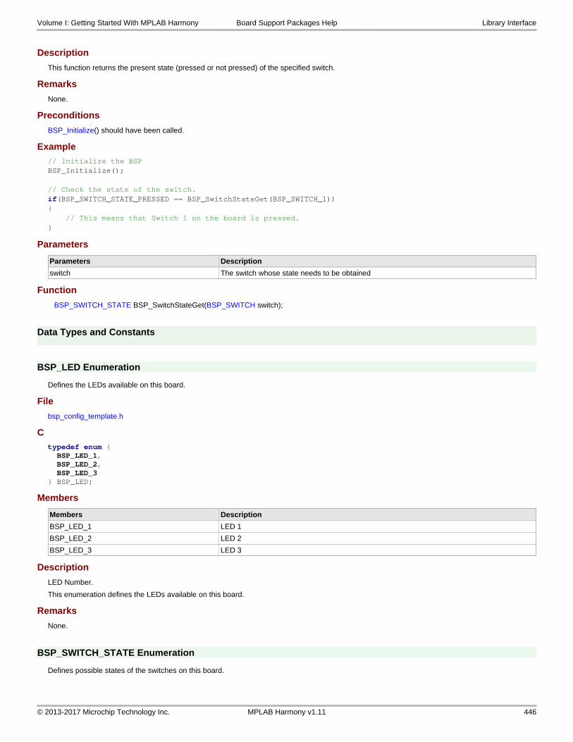
Description
This function returns the present state (pressed or not pressed) of the specified switch.
Remarks
None.
Preconditions
BSP_Initialize() should have been called.
Example// Initialize the BSPBSP_Initialize(); // Check the state of the switch.if(BSP_SWITCH_STATE_PRESSED == BSP_SwitchStateGet(BSP_SWITCH_1)){ // This means that Switch 1 on the board is pressed.}
Parameters
Parameters Description
switch The switch whose state needs to be obtained
Function
BSP_SWITCH_STATE BSP_SwitchStateGet(BSP_SWITCH switch);
Data Types and Constants
BSP_LED Enumeration
Defines the LEDs available on this board.
File
bsp_config_template.h
Ctypedef enum { BSP_LED_1, BSP_LED_2, BSP_LED_3} BSP_LED;
Members
Members Description
BSP_LED_1 LED 1
BSP_LED_2 LED 2
BSP_LED_3 LED 3
Description
LED Number.
This enumeration defines the LEDs available on this board.
Remarks
None.
BSP_SWITCH_STATE Enumeration
Defines possible states of the switches on this board.
Volume I: Getting Started With MPLAB Harmony Board Support Packages Help Library Interface
© 2013-2017 Microchip Technology Inc. MPLAB Harmony v1.11 446

File
bsp_config_template.h
Ctypedef enum { BSP_SWITCH_STATE_PRESSED, BSP_SWITCH_STATE_RELEASED} BSP_SWITCH_STATE;
Members
Members Description
BSP_SWITCH_STATE_PRESSED Switch pressed
BSP_SWITCH_STATE_RELEASED Switch not pressed
Description
BSP Switch state.
This enumeration defines the possible states of the switches on this board.
Remarks
None.
BSP_LED_STATE Enumeration
Enumerates the supported LED states.
File
bsp_config_template.h
Ctypedef enum { BSP_LED_STATE_OFF, BSP_LED_STATE_ON} BSP_LED_STATE;
Members
Members Description
BSP_LED_STATE_OFF LED State is on
BSP_LED_STATE_ON LED State is off
Description
LED State
This enumeration defines the supported LED states.
Remarks
None.
BSP_SWITCH Enumeration
Defines the switches available on this board.
File
bsp_config_template.h
Ctypedef enum { BSP_SWITCH_1, BSP_SWITCH_2, BSP_SWITCH_3} BSP_SWITCH;
Volume I: Getting Started With MPLAB Harmony Board Support Packages Help Library Interface
© 2013-2017 Microchip Technology Inc. MPLAB Harmony v1.11 447

Members
Members Description
BSP_SWITCH_1 SWITCH 1
BSP_SWITCH_2 SWITCH 2
BSP_SWITCH_3 SWITCH 3
Description
BSP Switch.
This enumeration defines the switches available on this board.
Remarks
None.
BSP_OSC_FREQUENCY Macro
Defines the frequency value of crystal/oscillator used on the board
File
bsp_config_template.h
C#define BSP_OSC_FREQUENCY
Description
Oscillator Frequency
This macro defines the frequency value of the crystal/oscillator used on the board.
Files
Files
Name Description
bsp_config_template.h Board Support Package configuration file.
Description
This section lists the files associated with the Board Support Packages.
bsp_config_template.h
Board Support Package configuration file.
Enumerations
Name Description
BSP_LED Defines the LEDs available on this board.
BSP_LED_STATE Enumerates the supported LED states.
BSP_SWITCH Defines the switches available on this board.
BSP_SWITCH_STATE Defines possible states of the switches on this board.
Functions
Name Description
BSP_Initialize Performs the necessary actions to initialize a board.
BSP_LEDOff Switches OFF the specified LED.
BSP_LEDOn Switches ON the specified LED.
BSP_LEDStateGet Returns the present state of the LED.
BSP_LEDStateSet Controls the state of the LED.
BSP_LEDToggle Toggles the state of the LED between BSP_LED_STATE_ON and BSP_LED_STATE_OFF.
BSP_SwitchStateGet Returns the present state (pressed or not pressed) of the specified switch.
Volume I: Getting Started With MPLAB Harmony Board Support Packages Help Files
© 2013-2017 Microchip Technology Inc. MPLAB Harmony v1.11 448

Macros
Name Description
BSP_OSC_FREQUENCY Defines the frequency value of crystal/oscillator used on the board
Description
Board Support Package Configuration File.
This file contains the configuration APIs for use with Board Support Packages.
File Name
bsp_config.h
Company
Microchip Technology Inc.
Volume I: Getting Started With MPLAB Harmony Board Support Packages Help Files
© 2013-2017 Microchip Technology Inc. MPLAB Harmony v1.11 449

Supported Development Boards
Information on the development tools (i.e., hardware) used by the MPLAB Harmony Board Support Packages and demonstration applications.
Description
This section provides details on the development tools that are used by the board support packages and demonstration applications.
169-pin LFBGA CPU Daughter Board
Provides information on the 169-pin LFBGA CPU Daughter Board.
Description
Microchip Part Number:
Please contact your local Microchip sales office for information on obtaining this daughter board.
Available Demonstrations
Feature Demonstrations
Peripheral Library Examples • dma_led_pattern
Hardware Layout
Audio Codec Daughter Board AK4642EN
Provides information on the Audio Codec AK4642EN Daughter Board.
Description
Microchip Part Number:
AC320100
Volume I: Getting Started With MPLAB Harmony Supported Development Boards Audio Codec Daughter Board AK4642EN
© 2013-2017 Microchip Technology Inc. MPLAB Harmony v1.11 450

Product Page:
http://www.microchip.com/AC320100
Available Demonstrations
Feature Demonstrations
Audio • audio_microphone_loopback
Hardware Layout
CAN/LIN PICtail Plus Daughter Board
Provides information on the CAN/LIN PICtail Plus Daughter Board.
Description
Microchip Part Number:
AC164130-2
Product Page:
http://www.microchip.com/DevelopmentTools/ProductDetails.aspx?PartNO=ac164130-2
Available Demonstrations
Feature Demonstrations
CAN • echo_send
Hardware Layout
Volume I: Getting Started With MPLAB Harmony Supported Development Boards CAN/LIN PICtail Plus Daughter Board
© 2013-2017 Microchip Technology Inc. MPLAB Harmony v1.11 451

chipKIT WF32 Wi-Fi Development Board
Provides information on the chipKIT™ WF32™ Wi-Fi Development Board.
Description
Microchip Part Number:
TDGL021
Product Page:
http://www.microchip.com/DevelopmentTools/ProductDetails.aspx?PartNO=TDGL021
Available Demonstrations
Feature Demonstrations
TCP/IP • pic32_wifi_web_server
USB Device • hid_mouse
USB Host • msd_basic
Hardware Layout
Volume I: Getting Started With MPLAB Harmony Supported Development Boards chipKIT WF32 Wi-Fi Development Board
© 2013-2017 Microchip Technology Inc. MPLAB Harmony v1.11 452

chipKIT Wi-FIRE Development Board
Provides information on the chipKIT™ Wi-FIRE Development Board.
Description
Microchip Part Number:
TDGL021-2
Product Page:
http://www.microchip.com/Developmenttools/ProductDetails.aspx?PartNO=TDGL021-2
Available Demonstrations
Feature Demonstrations
USB Device • cdc_com_port_single
USB Host • msd_basic
Hardware Layout
Volume I: Getting Started With MPLAB Harmony Supported Development Boards chipKIT Wi-FIRE Development Board
© 2013-2017 Microchip Technology Inc. MPLAB Harmony v1.11 453

Explorer 16 Development Board
Provides information on the Explorer 16 Development Board.
Description
Microchip Part Number:
DM240001
Product Page:
http://www.microchip.com/stellent/idcplg?IdcService=SS_GET_PAGE&nodeId=1406&dDocName=en024858&part=DM240001
Available Demonstrations
Feature Demonstrations
Drivers • i2c_eeprom
• serial_eeprom
File System • nvm_sdcard_fat_mpfs_multi_disk
• sdcard_fat_single_disk
Peripheral Library Examples • adc_pot
• adcp_cal
• flash_modify
• i2c_eeprom_rw
• i2c_loopback
• mem_partition
• pmp_lcd
• reset_handler
• rtcc_alarm
• simple_comparator
• spi_loopback
• timer3_interrupt
• triangle_wave
• uart_basic
• wdt_timeout
System Service Examples • debug_uart
TCP/IP • wifi_easy_configuration
• web_server_nvm_mpfs
Volume I: Getting Started With MPLAB Harmony Supported Development Boards Explorer 16 Development Board
© 2013-2017 Microchip Technology Inc. MPLAB Harmony v1.11 454

Test • harness
USB Device • cdc_com_port_dual
• cdc_com_port_single
• cdc_serial_emulator
• cdc_serial_emulator_msd
• hid_basic
• hid_joystick
• hid_keyboard
• hid_mouse
• msd_basic
• vendor
Hardware Layout
Switch/Button Descriptions
1. S1 - Reset button (MCLR)/
2. S2 - Processor switch. This switch determines which processor is running, the processor on the board or the processor on the Plug-In-Module (PIM).
3. S3, S4, S5, and S6 - Application switches. For information about which pin is connected to this switch, please refer to the Information Sheet for the PIM in use.
4. D3 through D10 - Application LEDs. For information about which pin is connected to this LED, please refer to the Information Sheet for the PIM in use.
Ethernet PICtail Plus Daughter Board
Provides information on the Ethernet PICtail Plus Daughter Board.
Description
Microchip Part Number:
AC164123
Product Page:
Volume I: Getting Started With MPLAB Harmony Supported Development Boards Ethernet PICtail Plus Daughter Board
© 2013-2017 Microchip Technology Inc. MPLAB Harmony v1.11 455

http://www.microchip.com/AC164123
Available Demonstrations
Feature Demonstrations
TCP/IP • tcpip_tcp_client
Hardware Layout
Fast 100Mbps Ethernet PICtail Plus Daughter Board
Provides information on the Fast 100Mbps Ethernet PICtail Plus Daughter Board.
Description
Microchip Part Number:
AC164132
Product Page:
http://www.microchip.com/AC164132
Available Demonstrations
Feature Demonstrations
TCP/IP • tcpip_tcp_client
Hardware Layout
Volume I: Getting Started With MPLAB Harmony Supported Development Boards Fast 100Mbps Ethernet PICtail Plus Daughter
© 2013-2017 Microchip Technology Inc. MPLAB Harmony v1.11 456

Graphics Controller PICtail Plus Epson S1D13517 Daughter Board
Provides information about the Graphics LCD Controller PICtail Plus Epson S1D13517 Daughter Board.
Description
Microchip Part Number:
AC164127-7
Product Page:
http://www.microchip.com/DevelopmentTools/ProductDetails.aspx?PartNO=ac164127-7
Available Demonstrations
Feature Demonstrations
Graphics • primitive
• s1d13517
Hardware Layout
Volume I: Getting Started With MPLAB Harmony Supported Development Boards Graphics Controller PICtail Plus Epson
© 2013-2017 Microchip Technology Inc. MPLAB Harmony v1.11 457

Graphics Display Truly 3.2" 320x240 Board
Provides information on the Graphics Display Truly 3.2" 320x240 Board.
Description
The Graphics Display Truly 3.2 240x320 Board is a demonstration board for evaluating Microchip graphic display solutions and the Graphics Library for 16- and 32-bit microcontrollers.
Microchip Part Number
AC164127-4
Product Page
http://www.microchip.com/Developmenttools/ProductDetails.aspx?PartNO=AC164127-4
Available Demonstrations
Feature Demonstrations
Graphics • object
• primitive
• ssd1926
Hardware Layout
Volume I: Getting Started With MPLAB Harmony Supported Development Boards Graphics Display Truly 3.2" 320x240 Board
© 2013-2017 Microchip Technology Inc. MPLAB Harmony v1.11 458

Graphics Display Powertip 4.3" 480x272 Board
Provides information on the Graphics Display Powertip 4.3" 480x272 Board.
Description
The Graphics Display Powertip 4.3" 480x272 Board is a demonstration board for evaluating Microchip's graphic display solutions and the Graphics Library for 16- and 32- bit microcontrollers.
Microchip Part Number
AC164127-6
Product Page
http://www.microchip.com/Developmenttools/ProductDetails.aspx?PartNO=AC164127-6
Available Demonstrations
Feature Demonstrations
Graphics • lcc
• primitive
Hardware Layout
Volume I: Getting Started With MPLAB Harmony Supported Development Boards Graphics Display Powertip 4.3" 480x272 Board
© 2013-2017 Microchip Technology Inc. MPLAB Harmony v1.11 459

Graphics Display Truly 5.7" 640x480 Board
Provides information on the Graphics Display Truly 5.7" 640x480 Board.
Description
The Graphics Display Truly 5.7" 640x480 Board is a demonstration board for evaluating Microchip's graphic display solution and Graphics Library for 16- and 32-bit microcontrollers
Microchip Part Number
AC164127-8
Product Page
http://www.microchip.com/Developmenttools/ProductDetails.aspx?PartNO=AC164127-8
Available Demonstrations
Feature Demonstrations
Graphics • s1d13517
Hardware Layout
Volume I: Getting Started With MPLAB Harmony Supported Development Boards Graphics Display Truly 5.7" 640x480 Board
© 2013-2017 Microchip Technology Inc. MPLAB Harmony v1.11 460

Graphics Display Truly 7" 800x480 Board
Provides information on the Graphics Display Truly 7" 800x480 Board.
Description
The Graphics Display Truly 7" 800x480 Board is a demonstration board for evaluating Microchip's graphic display solution and Graphics Library for 16- and 32-bit microcontrollers.
Microchip Part Number
AC164127-9
Product Page
http://www.microchip.com/DevelopmentTools/ProductDetails.aspx?PartNO=ac164127-9
Available Demonstrations
Feature Demonstrations
Graphics • s1d13517
Hardware Layout
Volume I: Getting Started With MPLAB Harmony Supported Development Boards Graphics Display Truly 7" 800x480 Board
© 2013-2017 Microchip Technology Inc. MPLAB Harmony v1.11 461

Graphics LCD Controller PICtail Plus SSD1926 Daughter Board
Provides information on the Graphics LCD Controller PICtail Plus SSD1926 Daughter Board.
Description
Microchip Part Number:
AC164127-5
Product Page:
http://www.microchip.com/DevelopmentTools/ProductDetails.aspx?PartNO=ac164127-5
Available Demonstrations
Feature Demonstrations
Graphics • object
• primitive
• ssd1926
Hardware Layout
Volume I: Getting Started With MPLAB Harmony Supported Development Boards Graphics LCD Controller PICtail Plus SSD1926
© 2013-2017 Microchip Technology Inc. MPLAB Harmony v1.11 462

Low-Cost Controllerless (LCC) Graphics PICtail Plus Daughter Board
Provides information on the Low-Cost Controllerless (LCC) Graphics PICtail Plus Daughter Board.
Description
Microchip Part Number:
AC164144
Product Page:
http://www.microchip.com/DevelopmentTools/ProductDetails.aspx?PartNO=ac164144
Available Demonstrations
Feature Demonstrations
Graphics • lcc
• primitive
Hardware Layout
Volume I: Getting Started With MPLAB Harmony Supported Development Boards Low-Cost Controllerless (LCC) Graphics PICtail
© 2013-2017 Microchip Technology Inc. MPLAB Harmony v1.11 463

MCP2200 Breakout Module
Provides information on the MCP2200 Breakout Module.
Description
The MCP2200 Breakout Module is a development and evaluation platform for the USB-to-UART serial converter MCP2200 device. The module is comprised of a single Dual In-Line Package (DIP) form-factor board.
Microchip Part Number:
ADM00393
Product Page:
http://www.microchip.com/DevelopmentTools/ProductDetails.aspx?PartNO=ADM00393
Available Demonstrations
Feature Demonstrations
Crypto • large_hash
Bootloader • LiveUpdate
Peripheral Library Examples • uart_basic
Hardware Layout
Volume I: Getting Started With MPLAB Harmony Supported Development Boards MCP2200 Breakout Module
© 2013-2017 Microchip Technology Inc. MPLAB Harmony v1.11 464

MPLAB REAL ICE
Provides information on the MPLAB REAL ICE In-Circuit Emulator.
Description
Microchip Part Number:
DV244005
Product Page:
http://www.microchip.com/DevelopmentTools/ProductDetails.aspx?PartNO=dv244005
MRF24WG0MA Wi-Fi G PICtail/PICtail Plus Daughter Board
Provides information on the MRF24WG0MA Wi-Fi G PICtail/PICtail Plus Daughter Board.
Description
Microchip Part Number:
AC164149
Volume I: Getting Started With MPLAB Harmony Supported Development Boards MRF24WG0MA Wi-Fi G PICtail/PICtail Plus
© 2013-2017 Microchip Technology Inc. MPLAB Harmony v1.11 465

Microchip Product Page:
http://www.microchip.com/Developmenttools/ProductDetails.aspx?PartNO=AC164149
Available Demonstrations
Feature Demonstrations
TCP/IP • pic32_eth_wifi_web_server
• wifi_easy_configuration
• wifi_wolfssl_tcp_client
• wifi_wolfssl_tcp_server
Hardware Layout
MRF24WN0MA Wi-Fi PICtail/PICtail Plus Daughter Board
Provides information on the MRF24WN0MA Wi-Fi PICtail/PICtail Plus Daughter Board.
Description
Microchip Part Number:
AC164153
Microchip Product Page:
http://www.microchip.com/Developmenttools/ProductDetails.aspx?PartNO=AC164153
Available Demonstrations
Feature Demonstrations
TCP/IP • pic32_eth_wifi_web_server
• wifi_easy_configuration
Hardware Layout
Volume I: Getting Started With MPLAB Harmony Supported Development Boards MRF24WN0MA Wi-Fi PICtail/PICtail Plus
© 2013-2017 Microchip Technology Inc. MPLAB Harmony v1.11 466

Multimedia Expansion Board (MEB)
Provides information on the Multimedia Expansion Board (MEB).
Description
Microchip Part Number:
DM320005
Product Page:
http://www.microchip.com/Developmenttools/ProductDetails.aspx?PartNO=DM320005
Available Demonstrations
Feature Demonstrations
Graphics • primitive
Hardware Layout (Front)
Volume I: Getting Started With MPLAB Harmony Supported Development Boards Multimedia Expansion Board (MEB)
© 2013-2017 Microchip Technology Inc. MPLAB Harmony v1.11 467

Hardware Layout (Back)
Volume I: Getting Started With MPLAB Harmony Supported Development Boards Multimedia Expansion Board (MEB)
© 2013-2017 Microchip Technology Inc. MPLAB Harmony v1.11 468

Multimedia Expansion Board II (MEB II)
Provides information on the Multimedia Expansion Board II (MEB II).
Description
Microchip Part Number
DM320005-2
Product Page
http://www.microchip.com/DevelopmentTools/ProductDetails.aspx?PartNO=dm320005-2
Available Demonstrations
Feature Demonstrations
Audio • audio_tone
Bluetooth • a2dp_avrcp
• data_basic
Crypto • large_hash
External Memory Programmer • sqi_flash
Graphics • lcc
• object
• primitive
MEB II • gfx_cdc_com_port_single
• gfx_photo_frame
• gfx_web_server_nvm_mpfs
TCP/IP • web_server_nvm_mpfs
Volume I: Getting Started With MPLAB Harmony Supported Development Boards Multimedia Expansion Board II (MEB II)
© 2013-2017 Microchip Technology Inc. MPLAB Harmony v1.11 469

USB Device • audio_speaker
• msd_sdcard
Hardware Layout (Front)
Hardware Layout (Back)
Volume I: Getting Started With MPLAB Harmony Supported Development Boards Multimedia Expansion Board II (MEB II)
© 2013-2017 Microchip Technology Inc. MPLAB Harmony v1.11 470

PIC32 Audio DAC Daughter Board
Provides information on the PIC32 Audio DAC Daughter Board (AK4384VT).
Description
Microchip Part Number:
AC320032-2
Product Page:
http://www.microchip.com/Developmenttools/ProductDetails.aspx?PartNO=AC320032-2
Available Demonstrations
Feature Demonstrations
Audio • audio_tone
• mac_audio_hi_res
• usb_headset
• universal_audio_decoders
Hardware Layout
Volume I: Getting Started With MPLAB Harmony Supported Development Boards PIC32 Audio DAC Daughter Board
© 2013-2017 Microchip Technology Inc. MPLAB Harmony v1.11 471

PIC32 Bluetooth Audio Development Kit
Provides information on the PIC32 Bluetooth Audio Development Kit.
Description
Microchip Part Number:
DV320032
Product Page:
http://www.microchip.com/Developmenttools/ProductDetails.aspx?PartNO=DV320032
Available Demonstrations
Feature Demonstrations
Audio • audio_microphone_loopback
• audio_tone
• mac_audio_hi_res
• usb_headset
• universal_audio_decoders
Bluetooth • 2dp_avrcp
• data_basic
Graphics • primitive
Hardware Layout
Volume I: Getting Started With MPLAB Harmony Supported Development Boards PIC32 Bluetooth Audio Development Kit
© 2013-2017 Microchip Technology Inc. MPLAB Harmony v1.11 472

PIC32 Bluetooth Starter Kit
Provides information on the PIC32 Bluetooth Starter Kit.
Description
Microchip Part Number:
DM320018
Product Page:
http://www.microchip.com/Developmenttools/ProductDetails.aspx?PartNO=DM320018
Volume I: Getting Started With MPLAB Harmony Supported Development Boards PIC32 Bluetooth Starter Kit
© 2013-2017 Microchip Technology Inc. MPLAB Harmony v1.11 473

Available Demonstrations
Feature Demonstrations
Audio • universal_audio_decoders
• usb_headset
Bluetooth • a2dp_avrcp
• data_basic
• data_temp_sens_rgb
File System • nvm_fat_single_disk
• nvm_mpfs_single_disk
Graphics • primitive
USB Device • cdc_com_port_dual
• msd_basic
Hardware Layout (Front)
Hardware Layout (Back)
Volume I: Getting Started With MPLAB Harmony Supported Development Boards PIC32 Bluetooth Starter Kit
© 2013-2017 Microchip Technology Inc. MPLAB Harmony v1.11 474

PIC32 Ethernet Starter Kit
Provides information on the PIC32 Ethernet Starter Kit.
Description
Microchip Part Number:
DM320004
Product Page:
http://www.microchip.com/DevelopmentTools/ProductDetails.aspx?PartNO=dm320004
Available Demonstrations
Feature Demonstrations
RTOS • basic (FreeRTOS)
• basic (OPENRTOS)
• basic (ThreadX)
Volume I: Getting Started With MPLAB Harmony Supported Development Boards PIC32 Ethernet Starter Kit
© 2013-2017 Microchip Technology Inc. MPLAB Harmony v1.11 475

TCP/IP • berkeley_tcp_client
• berkeley_tcp_server
• berkeley_udp_client
• berkeley_udp_relay
• berkeley_udp_server
• snmpv3_nvm_mpfs
• snmpv3_sdcard_fatfs
• tcpip_tcp_client
• tcpip_tcp_client_server
• tcpip_tcp_server
• tcpip_udp_client
• tcpip_udp_client_server
• tcpip_udp_server
• web_server_nvm_mpfs
• web_server_sdcard_fatfs
• wifi_easy_configuration
• wifi_wolfssl_tcp_client
• wolfssl_tcp_client
• wolfssl_tcp_server
Hardware Layout
PIC32 Ethernet Starter Kit II
Provides information on the PIC32 Ethernet Starter Kit II.
Description
Microchip Part Number:
DM320004-2
Product Page:
http://www.microchip.com/DevelopmentTools/ProductDetails.aspx?PartNO=DM320004-2
Volume I: Getting Started With MPLAB Harmony Supported Development Boards PIC32 Ethernet Starter Kit II
© 2013-2017 Microchip Technology Inc. MPLAB Harmony v1.11 476

Available Demonstrations
Feature Demonstrations
RTOS • basic (FreeRTOS)
• basic (OPENRTOS)
• basic (ThreadX)
TCP/IP • berkeley_tcp_client
• berkeley_tcp_server
• berkeley_udp_client
• berkeley_udp_relay
• berkeley_udp_server
• tcpip_tcp_client
• tcpip_tcp_client_server
• tcpip_tcp_server
• tcpip_udp_client
• tcpip_udp_client_server
• tcpip_udp_server
• web_server_nvm_mpfs
• web_server_sdcard_fatfs
• wifi_easy_configuration
• wolfssl_tcp_client
• wolfssl_tcp_server
Hardware Layout
PIC32 GUI Development Board with Projected Capacitive Touch
Provides information on the PIC32 GUI Development Board with Projected Capacitive Touch.
Description
Microchip Part Number:
DM320015
Product Page:
http://www.microchip.com/DevelopmentTools/ProductDetails.aspx?PartNO=dm320015
Available Demonstrations
Feature Demonstrations
Graphics • lcc
Volume I: Getting Started With MPLAB Harmony Supported Development Boards PIC32 GUI Development Board with Projected
© 2013-2017 Microchip Technology Inc. MPLAB Harmony v1.11 477

Hardware Layout
PIC32 USB Digital Audio Accessory Board
Provides information on the PIC32 USB Digital Audio Board.
Description
Microchip Part Number:
DM320014
microchipDIRECT Product Page:
http://www.microchip.com/DevelopmentTools/ProductDetails.aspx?PartNO=dm320014
Available Demonstrations
Feature Demonstrations
Audio • audio_tone
Hardware Layout
PIC32 USB Starter Kit II
Provides information on the PIC32 USB Starter Kit II.
Volume I: Getting Started With MPLAB Harmony Supported Development Boards PIC32 USB Starter Kit II
© 2013-2017 Microchip Technology Inc. MPLAB Harmony v1.11 478

Description
Microchip Part Number:
DM320003-2
Product Page:
http://www.microchip.com/DevelopmentTools/ProductDetails.aspx?PartNO=dm320003-2
Available Demonstrations
Feature Demonstrations
Drivers • nvm_read_write
External Memory Programmer • external_flash
File System • nvm_fat_single_disk
• nvm_mpfs_single_disk
FreeRTOS • basic
• cdc_com_port_dual
• cdc_msd_basic
• gfx
Graphics • lcc
• object
• primitive
• s1d13517
• ssd1926
OPENRTOS • basic
• gfx
• cdc_com_port_dual
• cdc_msd_basic
Micrium Micriµm µC/OS-II
• basic
Micriµm µC/OS-III
• gfx
• gfx_usb
• usb
SEGGER embOS • gfx
• gfx_usb
• usb
System Services • command_appio
• debug_usb_cdc_2
ThreadX • basic
• gfx
• gfx_usb
• usb
Volume I: Getting Started With MPLAB Harmony Supported Development Boards PIC32 USB Starter Kit II
© 2013-2017 Microchip Technology Inc. MPLAB Harmony v1.11 479

TCP/IP • berkeley_tcp_client
• berkeley_tcp_server
• berkeley_udp_client
• berkeley_udp_relay
• berkeley_udp_server
• tcpip_tcp_client
• tcpip_tcp_client_server
• tcpip_tcp_server
• tcpip_udp_client
• tcpip_udp_client_server
• tcpip_udp_server
• web_server_nvm_mpfs
• wifi_easy_configuration
• wolfssl_tcp_client
• wolfssl_tcp_server
Peripheral Library Example Applications • echo_send
• ic_basic
• i2c_eeprom_rw
• oc_pwm
• osc_config
• spi_loopback
• timer3_interrupt
• uart_basic
• usart_loopback
• wdt_timeout
USB • cdc_com_port_dual
• cdc_com_port_single
• cdc_basic
• cdc_msd_basic
• cdc_msd
• hid_basic
• hid_msd_basic
• hid_joystick
• hid_keyboard
• hid_mouse
• msd_basic
• msd_basic (Host)
• vendor
Hardware Layout
Volume I: Getting Started With MPLAB Harmony Supported Development Boards PIC32 USB Starter Kit II
© 2013-2017 Microchip Technology Inc. MPLAB Harmony v1.11 480

PIC32 USB Starter Kit III
Provides information on the PIC32 USB Starter Kit III.
Description
Microchip Part Number:
DM320003-2
Product Page:
http://www.microchip.com/Developmenttools/ProductDetails.aspx?PartNO=DM320003-3
Available Demonstrations
Feature Demonstrations
File System • nvm_fat_single_disk
• nvm_mpfs_single_disk
RTOS • basic (FreeRTOS)
• basic (OPENRTOS)
• basic (ThreadX)
USB • cdc_basic
• cdc_com_port_dual
• cdc_com_port_single
• hid_basic
• hid_joystick
• hid_keyboard
• hid_mouse
• msd_basic
• vendor
Volume I: Getting Started With MPLAB Harmony Supported Development Boards PIC32 USB Starter Kit III
© 2013-2017 Microchip Technology Inc. MPLAB Harmony v1.11 481

Hardware Layout
PIC32MX1/2/5 Starter Kit
Provides information on the PIC32MX1/2/5 Starter Kit.
Description
Microchip Part Number:
DM320100
Product Page:
http://www.microchip.com/Developmenttools/ProductDetails.aspx?PartNO=DM320100
Available Demonstrations
Feature Demonstrations
CAN echo_send
USB Device cdc_com_port_single
Hardware Layout (Front)
Volume I: Getting Started With MPLAB Harmony Supported Development Boards PIC32MX1/2/5 Starter Kit
© 2013-2017 Microchip Technology Inc. MPLAB Harmony v1.11 482

Hardware Layout (Back)
PIC32MX270F256D Plug-in Module (PIM)
Provides information on the PIC32MX270F256D Plug-in Module (PIM).
Description
Two PIC32MX270F256D PIMs are available, one for use with the PIC32 Bluetooth Audio Development Kit, and one for use with the Explorer 16 Development Board.
Microchip Part Number:
MA320013
This PIM is required while using the PIC32 Bluetooth Audio Development Kit
Volume I: Getting Started With MPLAB Harmony Supported Development Boards PIC32MX270F256D Plug-in Module (PIM)
© 2013-2017 Microchip Technology Inc. MPLAB Harmony v1.11 483

microchipDIRECT Product Page:
http://www.microchip.com/Developmenttools/ProductDetails.aspx?PartNO=MA320013
Available Demonstrations
Feature Demonstrations
USB Device • cdc_com_port_dual
• msd_basic
Hardware Layout
Microchip Part Number:
MA320014
This PIM is required while using the Explorer 16 Development Board.
microchipDIRECT Product Page:
http://www.microchip.com/DevelopmentTools/ProductDetails.aspx?PartNO=MA320014
PIC32MX270F512L Plug-in Module (PIM)
Provides information on the PIC32MX270F512L Plug-in Module (PIM).
Volume I: Getting Started With MPLAB Harmony Supported Development Boards PIC32MX270F512L Plug-in Module (PIM)
© 2013-2017 Microchip Technology Inc. MPLAB Harmony v1.11 484

Description
Microchip Part Number:
MA320017
This PIM is for use with the PIC32 Bluetooth Audio Development Kit.
microchipDIRECT Product Page:
http://www.microchip.com/Developmenttools/ProductDetails.aspx?PartNO=MA320017
Available Demonstrations
Feature Demonstrations
Audio • universal_audio_decoders
• usb_headset
Hardware Layout
PIC32MX360F512L Plug-in Module (PIM)
Provides information on the PIC32MX360F512L Plug-in Module (PIM).
Description
Microchip Part Number:
MA320001
microchipDIRECT Product Page:
http://www.microchip.com/Developmenttools/ProductDetails.aspx?PartNO=MA320001
Available Demonstrations
Feature Demonstrations
SPI Driver • spi_eeprom
Hardware Layout
Volume I: Getting Started With MPLAB Harmony Supported Development Boards PIC32MX360F512L Plug-in Module (PIM)
© 2013-2017 Microchip Technology Inc. MPLAB Harmony v1.11 485

PIC32MX460F512L Plug-in Module (PIM)
Provides information on the PIC32MX460F512L Plug-in Module (PIM).
Description
Microchip Part Number:
MA320002
microchipDIRECT Product Page:
http://www.microchip.com/Developmenttools/ProductDetails.aspx?PartNO=MA320002
Available Demonstrations
Feature Demonstrations
USB Device • cdc_com_port_dual
• cdc_com_port_single
• hid_basic
• hid_joystick
• hid_keyboard
• hid_mouse
• vendor
Hardware Layout
PIC32MX450/470F512L Plug-in Module (PIM)
Provides information on the PIC32MX450/470F512L Plug-in Module (PIM).
Description
Microchip Part Number:
Volume I: Getting Started With MPLAB Harmony Supported Development Boards PIC32MX450/470F512L Plug-in Module (PIM)
© 2013-2017 Microchip Technology Inc. MPLAB Harmony v1.11 486

MA320002-2
microchipDIRECT Product Page:
http://www.microchipdirect.com/ProductSearch.aspx?Keywords=MA320002-2
Available Demonstrations
Feature Demonstrations
File System • nvm_sdcard_fat_mpfs_multi_disk
• sdcard_fat_single_disk
Hardware Layout
PIC32MX470 Curiosity Development Board
Provides information on the PIC32MX470 Curiosity Development Board.
Description
Microchip Part Numbers:
DM320103
Microchip Product Pages:
http://www.microchip.com/Developmenttools/ProductDetails.aspx?PartNO=DM320103
Available Demonstrations
Feature Demonstrations
USB Device cdc_com_port_dual
USB Host msd_basic
Hardware Layout
Volume I: Getting Started With MPLAB Harmony Supported Development Boards PIC32MX470 Curiosity Development Board
© 2013-2017 Microchip Technology Inc. MPLAB Harmony v1.11 487

PIC32MX570F512L Plug-in Module (PIM)
Provides information on the PIC32MX570F512L Plug-in Module (PIM).
Description
Microchip Part Number:
MA320015
microchipDIRECT Product Page:
http://www.microchipdirect.com/ProductSearch.aspx?Keywords=MA320015
Available Demonstrations
Feature Demonstrations
File System • nvm_sdcard_fat_mpfs_multi_disk
• nvm_sdcard_fat_multi_disk
• sdcard_fat_single_disk
Hardware Layout
Volume I: Getting Started With MPLAB Harmony Supported Development Boards PIC32MX795F512L Plug-in Module (PIM)
© 2013-2017 Microchip Technology Inc. MPLAB Harmony v1.11 488

PIC32MX795F512L Plug-in Module (PIM)
Provides information on the PIC32MX795F512L Plug-in Module (PIM).
Description
This PIM is required while using the Explorer 16 Development Board.
Microchip Part Number:
MA320003
microchipDIRECT Product Page:
http://www.microchipdirect.com/productsearch.aspx?keywords=MA320003
Available Demonstrations
Feature Demonstrations
Crypto • encrypt_decrypt
Drivers • i2c_eeprom
• i2c_eeprom_rw
• i2c_loopback
• serial_eeprom
• spi_loopback
• uart_basic
• usart_echo
• usart_loopback
File System • nvm_sdcard_fat_mpfs_multi_disk
• sdcard_fat_single_disk
Peripheral Library Example Applications • adc_pot
• mem_partition
• simple_comparator
• triangle_wave
• dma_led_pattern
• flash_modify
• pmp_lcd
• rtcc_alarm
• timer3_interrupt
• wdt_timeout
System Services • debug_uart
Test • harness
TCP/IP • web_server_nvm_mpfs
• wifi_easy_configuration
USB • cdc_serial_emulator
• cdc_serial_emulator_msd
Hardware Layout
Volume I: Getting Started With MPLAB Harmony Supported Development Boards PIC32MZ2048ECH100 Plug-in Module (PIM)
© 2013-2017 Microchip Technology Inc. MPLAB Harmony v1.11 489

PIC32MZ2048ECH100 Plug-in Module (PIM)
Provides information on the PIC32MZ2048ECH100 Plug-in Module (PIM).
Description
Microchip Part Number:
MA320012
microchipDIRECT Product Page:
http://www.microchipdirect.com/productsearch.aspx?keywords=MA320012
Available Demonstrations
Feature Demonstrations
Peripheral Library Examples • adcp_cal
• triangle_wave
System Services • debug_uart
Hardware Layout
PIC32MZ2048EFH100 Plug-in Module (PIM)
Provides information on the PIC32MZ2048EFH100 Plug-in Module (PIM).
Description
Microchip Part Number:
MA320019
Microchip Product Page:
http://www.microchip.com
Available Demonstrations
Feature Demonstrations
Peripheral Library Examples • triangle_wave
Hardware Layout
Volume I: Getting Started With MPLAB Harmony Supported Development Boards PIC32MZ2048EFH100 Plug-in Module (PIM)
© 2013-2017 Microchip Technology Inc. MPLAB Harmony v1.11 490

PIC32MZ2048ECH144 Audio Plug-in Module (PIM)
Provides information on the PIC32MZ2048ECH144 Audio Plug-in Module (PIM).
Description
Microchip Part Number:
MA320016
microchipDIRECT Product Page:
http://www.microchipdirect.com/productsearch.aspx?keywords=MA320016
Available Demonstrations
Feature Demonstrations
Audio Demonstrations • audio_tone
• mac_audio_hi_res
Hardware Layout
PIC32MZ2048EFH144 Audio Plug-in Module (PIM)
Provides information on the PIC32MZ2048EFH144 Audio Plug-in Module (PIM).
Description
Microchip Part Number:
MA320018
microchipDIRECT Product Page:
http://www.microchipdirect.com/productsearch.aspx?keywords=MA320018
Available Demonstrations
Volume I: Getting Started With MPLAB Harmony Supported Development Boards PIC32MZ2048EFH144 Audio Plug-in Module
© 2013-2017 Microchip Technology Inc. MPLAB Harmony v1.11 491

Feature Demonstrations
Audio Demonstrations • audio_tone
• mac_audio_hi_res
Hardware Layout
PIC32MZ Audio PIM
Provides information on the PIC32MZ Audio PIM.
Description
Microchip Part Number:
MA320016
Microchip Product Page:
http://www.microchip.com/Developmenttools/ProductDetails.aspx?PartNO=MA320016
Available Demonstrations
Feature Demonstrations
Audio • mac_audio_hi_res
• universal_audio_decoders
• usb_headset
Hardware Layout
Volume I: Getting Started With MPLAB Harmony Supported Development Boards PIC32MZ Audio PIM
© 2013-2017 Microchip Technology Inc. MPLAB Harmony v1.11 492

PIC32MZ EF Curiosity Development Board
Provides information on the PIC32MZ EF Curiosity Development Board.
Description
Microchip Part Numbers:
DM320104
Microchip Product Pages:
http://www.microchip.com/Developmenttools/ProductDetails.aspx?PartNO=DM320104
Available Demonstrations
Feature Demonstrations
USB Device cdc_com_port_dual
USB Host msd_basic
Hardware Layout
Volume I: Getting Started With MPLAB Harmony Supported Development Boards PIC32MZ EF Curiosity Development Board
© 2013-2017 Microchip Technology Inc. MPLAB Harmony v1.11 493

PIC32MZ Embedded Connectivity (EC) Starter Kit
Provides information on the PIC32MZ Embedded Connectivity (EC) Starter Kit.
Description
Microchip Part Numbers:
DM320006
DM320006-C (with Crypto Engine)
Microchip Product Pages:
http://www.microchip.com/Developmenttools/ProductDetails.aspx?PartNO=DM320006
http://www.microchip.com/Developmenttools/ProductDetails.aspx?PartNO=DM320006-C
Available Demonstrations
Feature Demonstrations
Audio • audio_tone
• universal_audio_decoders
• usb_headset
Bluetooth • data_basic
• a2dp_avrcp
Bootloader • basic
• LiveUpdate_application
• LiveUpdate
Crypto • encrypt_decrypt
• large_hash
Drivers • i2c_eeprom
• nvm_read_write
• spi_loopback
• spi_multislave
• usart_loopback
Volume I: Getting Started With MPLAB Harmony Supported Development Boards PIC32MZ Embedded Connectivity (EC) Starter Kit
© 2013-2017 Microchip Technology Inc. MPLAB Harmony v1.11 494

File System • nvm_fat_single_disk
• nvm_mpfs_single_disk
• nvm_sdcard_fat_mpfs_multi_disk
• nvm_sdcard_fat_multi_disk
• sdcard_fat_single_disk
• sdcard_msd_fat_multi_disk
Graphics • lcc
• object
• primitive
MEB II • gfx_cdc_com_port_single
• gfx_photo_frame
• gfx_web_server_nvm_mpfs
• segger_emwin
Peripheral Library Examples • echo_send
• dma_led_pattern
• sram_read_write
• flash_modify
• oc_pwm
• osc_config
• blinky_leds
• sleep_mode
• reset_handler
• rtcc_alarm
• spi_loopback
• flash_read_pio_mode
• flash_read_dma_mode
• timer3_interrupt
• uart_basic
• wdt_timeout
RTOS ThreadX:
• gfx
• gfx_usb
• usb
FreeRTOS:
• basic
• cdc_com_port_dual
• gfx
Micriµm µC/OS-II
• basic
Micriµm µC/OS-III
• basic
• gfx
• gfx_usb
• usb
OPENRTOS:
• basic
• cdc_com_port_dual
• gfx
SEGGER embOS:
• basic
• gfx
• gfx_usb
• usb
System Service Examples • debug_usb_cdc_2
• devcon_cache_clean
• devcon_sys_config_perf
Volume I: Getting Started With MPLAB Harmony Supported Development Boards PIC32MZ Embedded Connectivity (EC) Starter Kit
© 2013-2017 Microchip Technology Inc. MPLAB Harmony v1.11 495

TCP/IP • berkeley_tcp_client
• berkeley_tcp_server
• berkeley_udp_client
• berkeley_udp_relay
• berkeley_udp_server
• snmpv3_nvm_mpfs
• snmpv3_sdcard_fatfs
• tcpip_tcp_client
• tcpip_tcp_client_server
• tcpip_tcp_server
• tcpip_udp_client
• tcpip_udp_client_server
• tcpip_udp_server
• web_server_nvm_mpfs
• web_server_sdcard_fatfs
• wifi_wolfssl_tcp_client
• wifi_easy_configuration
• wolfssl_tcp_client
• wolfssl_tcp_server
USB Device • audio_speaker
• cdc_com_port_dual
• cdc_com_port_single
• cdc_msd_basic
• hid_basic
• hid_joystick
• hid_keyboard
• hid_mouse
• hid_msd_basic
• msd_basic
• vendor
USB Host • cdc_basic
• cdc_msd
• hid_basic_mouse
• msd_basic
• msd_sdcard
Hardware Layout (Front)
Volume I: Getting Started With MPLAB Harmony Supported Development Boards PIC32MZ Embedded Connectivity (EC) Starter Kit
© 2013-2017 Microchip Technology Inc. MPLAB Harmony v1.11 496

Hardware Layout (Back)
PIC32MZ Embedded Connectivity with Floating Point Unit (EF) Starter Kit
Provides information on the PIC32MZ Embedded Connectivity with Floating Point Unit (EF) Starter Kit.
Description
Microchip Part Numbers:
DM320007 (without Crypto)
DM320007-C (with Crypto)
Volume I: Getting Started With MPLAB Harmony Supported Development Boards PIC32MZ Embedded Connectivity with Floating
© 2013-2017 Microchip Technology Inc. MPLAB Harmony v1.11 497

Microchip Product Page:
http://www.microchip.com/Developmenttools/ProductDetails.aspx?PartNO=DM320007
http://www.microchip.com/Developmenttools/ProductDetails.aspx?PartNO=DM320007-C
Available Demonstrations
Feature Demonstrations
Audio • audio_tone
• universal_audio_decoders
• usb_headset
Bluetooth • data_basic
• a2dp_avrcp
Bootloader • basic
• LiveUpdate_application
• LiveUpdate
Crypto • encrypt_decrypt
• large_hash
Drivers • i2c_rtcc
• nvm_read_write
• spi_loopback
• spi_multislave
• usart_loopback
External Memory Programmer • sqi_flash
File System • nvm_fat_single_disk
• nvm_mpfs_single_disk
• nvm_sdcard_fat_mpfs_multi_disk
• nvm_sdcard_fat_multi_disk
• sdcard_fat_single_disk
• sdcard_msd_fat_multi_disk
Graphics • lcc
• object
• primitive
MEB II • gfx_cdc_com_port_single
• gfx_photo_frame
• gfx_web_server_nvm_mpfs
• segger_emwin
Peripheral Library Examples • echo_send
• dma_led_pattern
• sram_read_write
• flash_modify
• oc_pwm
• osc_config
• blinky_leds
• sleep_mode
• reset_handler
• rtcc_alarm
• spi_loopback
• flash_read_pio_mode
• flash_read_dma_mode
• timer3_interrupt
• uart_basic
• wdt_timeout
Volume I: Getting Started With MPLAB Harmony Supported Development Boards PIC32MZ Embedded Connectivity with Floating
© 2013-2017 Microchip Technology Inc. MPLAB Harmony v1.11 498

RTOS ThreadX:
• gfx
• gfx_usb
• usb
FreeRTOS:
• basic
• cdc_com_port_dual
• gfx
Micriµm µC/OS-II
• basic
Micriµm µC/OS-III
• basic
• gfx
• gfx_usb
• usb
OPENRTOS:
• basic
• cdc_com_port_dual
• gfx
SEGGER embOS:
• basic
• gfx
• gfx_usb
• usb
System Service Examples • debug_usb_cdc_2
• devcon_cache_clean
• devcon_sys_config_perf
TCP/IP • berkeley_tcp_client
• berkeley_tcp_server
• berkeley_udp_client
• berkeley_udp_relay
• berkeley_udp_server
• snmpv3_nvm_mpfs
• snmpv3_sdcard_fatfs
• tcpip_tcp_client
• tcpip_tcp_client_server
• tcpip_tcp_server
• tcpip_udp_client
• tcpip_udp_client_server
• tcpip_udp_server
• web_server_nvm_mpfs
• web_server_sdcard_fatfs
• wifi_wolfssl_tcp_client
• wifi_easy_configuration
• wolfssl_tcp_client
• wolfssl_tcp_server
USB Device • audio_speaker
• cdc_com_port_dual
• cdc_com_port_single
• cdc_msd_basic
• hid_basic
• hid_joystick
• hid_keyboard
• hid_mouse
• hid_msd_basic
• msd_basic
• vendor
Volume I: Getting Started With MPLAB Harmony Supported Development Boards PIC32MZ Embedded Connectivity with Floating
© 2013-2017 Microchip Technology Inc. MPLAB Harmony v1.11 499

USB Host • cdc_basic
• cdc_msd
• hid_basic_mouse
• msd_basic
Hardware Layout
Note: The hardware layout is subject to change and my differ from the photograph provided.
PIC32MZ Graphics (DA) Starter Kit
Provides information on the PIC32MZ Graphics (DA) Starter Kit.
Description
Microchip Part Numbers:
DM320008 (without Crypto)
DM320008-C (with Crypto)
Microchip Product Page:
http://www.microchip.com/Developmenttools/ProductDetails.aspx?PartNO=DM320008
http://www.microchip.com/Developmenttools/ProductDetails.aspx?PartNO=DM320008-C
Available Demonstrations
Feature Demonstrations
Audio • audio_tone
• universal_audio_decoders
Bluetooth • a2dp_avrcp
Bootloader • basic
• LiveUpdate
Crypto • encrypt_decrypt
• large_hash
Drivers • i2c_rtcc
• nvm_read_write
• spi_loopback
• usart_loopback
Volume I: Getting Started With MPLAB Harmony Supported Development Boards PIC32MZ Graphics (DA) Starter Kit
© 2013-2017 Microchip Technology Inc. MPLAB Harmony v1.11 500

Graphics • wvga_glcd
MEB II • gfx_cdc_com_port_single
• gfx_photo_frame
• gfx_web_server_nvm_mpfs
Peripheral Library Examples • adchs_3ch_dma
• adchs_oversample
• adchs_pot
• adchs_sensor
• adchs_touchsense
• echo_send
• triangle_wave
• dma_led_pattern
• i2c_interrupt
• i2c_polling
• flash_modify
• oc_pwm
• osc_config
• blinky_leds
• deep_sleep_mode
• sleep_mode
• reset_handler
• rtcc_alarm
• spi_loopback
• flash_read_dma_mode
• flash_read_pio_mode
• flash_read_xip_mode
• timer3_interrupt
• uart_basic
• wdt_timeout
RTOS ThreadX:
• basic
FreeRTOS:
• basic
Micriµm µC/OS-II
• basic
Micriµm µC/OS-III
• basic
OPENRTOS:
• basic
SEGGER embOS:
• basic
System Service Examples • debug_uart
• devcon_cache_clean
• devcon_cache_invalidate
• devcon_sys_config_perf
TCP/IP • tcpip_tcp_client
• web_server_nvm_mpfs
USB Device • cdc_com_port_dual
• hid_mouse
USB Host • msd_basic
Hardware Layout
Volume I: Getting Started With MPLAB Harmony Supported Development Boards PIC32MZ Graphics (DA) Starter Kit
© 2013-2017 Microchip Technology Inc. MPLAB Harmony v1.11 501

PIC32MZ Starter Kit Adapter Board
Provides information on the PIC32MZ Starter Kit Adapter Board.
Description
Microchip Part Number:
AC320006
Microchip Product Page:
http://www.microchip.com/Developmenttools/ProductDetails.aspx?PartNO=AC320006
Available Demonstrations
Feature Demonstrations
Crypto • large_hash
Drivers • spi_loopback
• usart_loopback
USB Device • hid_basic
Hardware Layout
Volume I: Getting Started With MPLAB Harmony Supported Development Boards PIC32MZ Starter Kit Adapter Board
© 2013-2017 Microchip Technology Inc. MPLAB Harmony v1.11 502

PICkit 3 In-Circuit Debugger
Provides information on the PICkit™ 3 In-Circuit Debugger.
Description
Microchip Part Number:
PG164130
Microchip Product Page:
http://www.microchip.com/Developmenttools/ProductDetails.aspx?PartNO=PG164130
Available Demonstrations
Feature Demonstrations
TCP/IP Demonstrations • wifi_g_demo
Hardware Layout
Volume I: Getting Started With MPLAB Harmony Supported Development Boards PICtail Daughter Board for SD and MMC
© 2013-2017 Microchip Technology Inc. MPLAB Harmony v1.11 503

PICtail Daughter Board for SD and MMC
Provides information on the PICtail Daughter Board for SD and MMC.
Description
Microchip Part Number:
AC164122
Microchip Product Page:
http://www.microchip.com/Developmenttools/ProductDetails.aspx?PartNO=AC164122
Available Demonstrations
Feature Demonstrations
File System • sdcard_fat_single_disk
• nvm_sdcard_fat_mpfs_multi_disk
• nvm_sdcard_fat_multi_disk
TCP/IP • snmpv3_sdcard_fatfs
• web_server_sdcard_fatfs
Hardware Layout
Prototype PICtail Plus Daughter Board
Provides information on the Prototype PICtail Plus Daughter Board.
Description
Microchip Part Number:
AC164126
Microchip Product Page:
http://www.microchip.com/Developmenttools/ProductDetails.aspx?PartNO=AC164126
Volume I: Getting Started With MPLAB Harmony Supported Development Boards Prototype PICtail Plus Daughter Board
© 2013-2017 Microchip Technology Inc. MPLAB Harmony v1.11 504

Available Demonstrations
Feature Demonstrations
Drivers • i2c_loopback
Hardware Layout
Starter Kit I/O Expansion Board
Provides information on the Starter Kit I/O Expansion Board.
Description
Microchip Part Number:
DM320002
Microchip Product Page:
http://www.microchip.com/DevelopmentTools/ProductDetails.aspx?PartNO=DM320002
Available Demonstrations
Feature Demonstrations
Bootloader • basic
• LiveUpdate_application
• LiveUpdate
Crypto • large_hash
Drivers • spi_loopback
• usart_loopback
Peripheral Library Examples • adc_pot
• adcp_cal
• i2c_eeprom_rw
• ic_basic
• spi_loopback
• uart_basic
System Services • command_appio
Volume I: Getting Started With MPLAB Harmony Supported Development Boards Starter Kit I/O Expansion Board
© 2013-2017 Microchip Technology Inc. MPLAB Harmony v1.11 505

TCP/IP • snmpv3_sdcard_fatfs
• tcpip_tcp_client
• web_server_nvm_mpfs
• web_server_sdcard_fatfs
• wifi_wolfssl_tcp_client
Hardware Layout
USB PICtail Plus Daughter Board
Provides information on the USB PICtail Plus Daughter Board.
Description
Microchip Part Number:
AC164131
Microchip Product Page:
http://www.microchip.com/Developmenttools/ProductDetails.aspx?PartNO=AC164131
Available Demonstrations
Feature Demonstrations
FreeRTOS • cdc_msd_basic
Volume I: Getting Started With MPLAB Harmony Supported Development Boards USB PICtail Plus Daughter Board
© 2013-2017 Microchip Technology Inc. MPLAB Harmony v1.11 506

USB Device • audio_speaker
• cdc_com_port_dual
• cdc_com_port_single
• cdc_serial_emulator
• cdc_serial_emulator_msd
• hid_basic
• hid_joystick
• hid_keyboard
• hid_mouse
• vendor
USB Host • cdc_basic
Hardware Layout
Wi-Fi G Demo Board
Provides information on the Wi-Fi G Demo Board.
Description
Microchip Part Number:
DV102412
Microchip Product Page:
http://www.microchip.com/Developmenttools/ProductDetails.aspx?PartNO=dv102412
Available Demonstrations
Feature Demonstrations
TCP/IP • wifi_g_demo
Hardware Layout
Volume I: Getting Started With MPLAB Harmony Supported Development Boards Wi-Fi G Demo Board
© 2013-2017 Microchip Technology Inc. MPLAB Harmony v1.11 507

Volume I: Getting Started With MPLAB Harmony Supported Development Boards Wi-Fi G Demo Board
© 2013-2017 Microchip Technology Inc. MPLAB Harmony v1.11 508

Creating Your First Project
This tutorial guides you through the process of using the MPLAB Harmony Configurator (MHC) and MPLAB Harmony libraries to develop your first MPLAB Harmony project.
Overview
Lists the basic steps necessary to create a MPLAB Harmony application using the MHC.
Description
MPLAB Harmony provides a convenient MPLAB X IDE plug-in configuration utility, the MPLAB Harmony Configurator (MHC), which you can use to easily create MPLAB Harmony-based projects. This tutorial will show you how to use the MHC to quickly create your first MPLAB Harmony application using the following steps:
• Step 1: Create a New Project
• Step 2: Configure the Processor Clock
• Step 3: Configure Key Device Settings
• Step 4: Configure the I/O Pins
• Step 5: Add and Configure Libraries
• Step 6: Generate the Project's Starter Files
• Step 7: Develop the Application
Your first application should be extremely simple. The example used in this tutorial blinks an LED on the selected platform to provide an application heartbeat health indicator. For guidance on using MPLAB Harmony to develop more capable applications, please refer the Help documentation listed in the Summary section.
Prerequisites and Assumptions
Describes the prerequisites for starting this tutorial and the assumptions made when it was written.
Description
Before beginning this tutorial, ensure that you have installed the MPLAB X IDE and necessary language tools as described in Volume I: Getting Started With MPLAB Harmony > Prerequisites. In addition, an appropriate hardware platform is required.
The example project in this tutorial utilizes the PIC32MZ Embedded Connectivity (EC) Starter Kit. In the event you do not have this development hardware, refer to the Supported Development Boards section for a list of available development boards that you could use to complete this tutorial.
To complete this tutorial you will need to know the following about your selected hardware platform:
• The name of the PIC32 device it uses
• The Primary Oscillator input clock frequency and desired processor clock frequency
• The debugger interface settings
• The I/O Port and Pin that connect to the desired indicator LED
• The input clock source and frequency for the timer selected to blink the indicator LED
Please refer to the documentation for the selected hardware platform and PIC32 device for this information, as described in Volume I: Getting Started With MPLAB Harmony > Guided Tour > Documentation.
Finally, this tutorial assumes that you have some familiarity with the following; however, you should be able to follow the directions in this tutorial with very little experience:
• MPLAB X IDE development and debugging fundamentals
• C language programming
• PIC32 product family and supported development boards
Step 1: Create a New Project
Provides directions for creating a new empty MPLAB Harmony project.
Description
After launching MPLAB X IDE and ensuring that the MHC plug-in is properly installed, you can create a new MPLAB Harmony project using the following the directions.
1. Select New Project from the MPLAB X IDE File menu (shown by the red arrow in the following figure), which opens the New Project dialog and launches the New Project wizard.
Volume I: Getting Started With MPLAB Harmony Creating Your First Project Step 1: Create a New Project
© 2013-2017 Microchip Technology Inc. MPLAB Harmony v1.11 509

2. In the Choose Project pane of the New Project window, 1) select Microchip Embedded, 2) select 32-bit MPLAB Harmony Project, 3) and then click Next, which opens the Name and Location pane in the New Project dialog window.
3. Select the desired MPLAB Harmony installation by 1) clicking the folder icon next to the Harmony Path display box, 2) navigating to and selecting the folder for the desired MPLAB Harmony distribution (by default, this is the folder matching the installation’s version number), and 3) clicking Open, as shown in the following figure. The path to the desired MPLAB Harmony installation should now be displayed.
Volume I: Getting Started With MPLAB Harmony Creating Your First Project Step 1: Create a New Project
© 2013-2017 Microchip Technology Inc. MPLAB Harmony v1.11 510

4. As shown in the following figure, choose your project location, name, and initial configuration name by 1) entering the new project name, “blinky” in this example (by default, the MHC will locate this in the apps folder of the selected MPLAB Harmony installation), 2) entering a new configuration name, pic32_ec_sk in this example, as shown in the following figure (a configuration is commonly named after the board it uses, but you can use any name that meaningfully identifies the configuration), 3) selecting the target device on the PIC32MZ EC Starter Kit in use (see the following Note), and 4) click Finish.
Note: There are two versions of the PIC32MZ EC Starter Kit, which use different microcontrollers:
• DM320006-C (with Crypto Engine) uses the PIC32MZ2048ECM144
• DM320006 (without Crypto Engine) uses the PIC32MZ2048ECH144
Depending on the starter kit in use, you will need to select the appropriate device.
After clicking Finish, the New Project wizard will create several new folders on disk within the project location folder and an empty MPLAB X IDE project (i.e., no source files exist within the folder).
Generated Folders: <project-location>/<project-name> firmware <project-name>.X src system_config <configuration-name>
Where <project-location>, <project-name>, and <configuration-name> match the values provided in the New Project Name and Location window (in this example, C:\microchip\harmony\v1_06, blinky, and pic32_ec_sk).
Volume I: Getting Started With MPLAB Harmony Creating Your First Project Step 1: Create a New Project
© 2013-2017 Microchip Technology Inc. MPLAB Harmony v1.11 511

After creating the empty project, the New Project wizard will launch the MHC plug-in so that you may configure the project.
From within MPLAB X IDE, depending on the current layout of the MPLAB X IDE panes, you should see something similar to the following figure, which should display the following items:
1. The empty project (with no files).
2. The MPLAB Harmony configuration tree.
3. The MPLAB Harmony Help system.
4. The MPLAB Harmony Configurator (MHC) output window.
Note: The MPLAB Harmony new project wizard will automatically set the new project as the main project in MPLAB X IDE. This isrequired because the MHC will not launch if there is no currently selected main project open within the MPLAB X IDE.
The project you have just created (see arrow 1, in the previous figure) is empty, meaning it does not yet contain any source files. In later steps, you will use the MHC to generate an initial set of source files for the initial configuration of your project. You will use the MPLAB Harmony configuration tree (see arrow 2) to make the selections for your initial configuration. As you select items in the configuration tree, you will see help for that item appear in the help window (see arrow 3). As you use the MHC, it will display activity, warning, and possibly error messages in the output window (see arrow 4), depending on the level of output for which it is set. By default, it only displays key activity and error messages.
Step 2: Configure the Processor Clock
Provides instructions on how to use the MHC to configure the processor clock.
Description
After creating a new blank MPLAB Harmony project, the next step is to use the interactive clock diagram in the MHC to configure the processor clock. To do this, use the following process. The numbered red arrows in the following clock diagram show the location of each step in the process.
1. Select the clock diagram in the MPLAB Harmony Configurator pane.
2. Select the External Clock (EC) mode for the primary oscillator.
3. Enter the primary oscillator input clock frequency (24 MHz for the PIC32MZ EC Starter Kit).
4. Select the primary oscillator (POSC) as the system PLL input clock.
Note: Values that are not supported on the selected device appear in red and must be changed to a supported value
5. Select the system PLL (SPLL) from the oscillator multiplexer (FNOSC).
6. Click Auto-Calculate.
7. Enter the desired system frequency (200 MHz for the PIC32MZ EC Starter Kit).
8. Click Apply.
Volume I: Getting Started With MPLAB Harmony Creating Your First Project Step 2: Configure the Processor Clock
© 2013-2017 Microchip Technology Inc. MPLAB Harmony v1.11 512
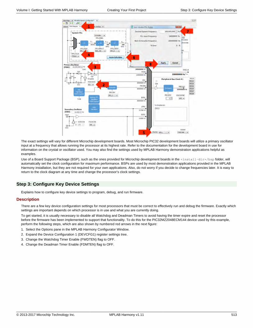
The exact settings will vary for different Microchip development boards. Most Microchip PIC32 development boards will utilize a primary oscillator input at a frequency that allows running the processor at its highest rate. Refer to the documentation for the development board in use for information on the crystal or oscillator used. You may also find the settings used by MPLAB Harmony demonstration applications helpful as examples.
Use of a Board Support Package (BSP), such as the ones provided for Microchip development boards in the <install-dir>/bsp folder, will automatically set the clock configuration for maximum performance. BSPs are used by most demonstration applications provided in the MPLAB Harmony installation, but they are not required for your own applications. Also, do not worry if you decide to change frequencies later. It is easy to return to the clock diagram at any time and change the processor’s clock settings.
Step 3: Configure Key Device Settings
Explains how to configure key device settings to program, debug, and run firmware.
Description
There are a few key device configuration settings for most processors that must be correct to effectively run and debug the firmware. Exactly which settings are important depends on which processor is in use and what you are currently doing.
To get started, it is usually necessary to disable all Watchdog and Deadman Timers to avoid having the timer expire and reset the processor before the firmware has been implemented to support that functionality. To do this for the PIC32MZ2048ECM144 device used by this example, perform the following steps, which are also shown by numbered red arrows in the next figure:
1. Select the Options pane in the MPLAB Harmony Configurator Window.
2. Expand the Device Configuration 1 (DEVCFG1) register settings tree.
3. Change the Watchdog Timer Enable (FWDTEN) flag to OFF.
4. Change the Deadman Timer Enable (FDMTEN) flag to OFF.
Volume I: Getting Started With MPLAB Harmony Creating Your First Project Step 3: Configure Key Device Settings
© 2013-2017 Microchip Technology Inc. MPLAB Harmony v1.11 513

Additionally, it is often necessary to ensure that the in-circuit emulator interface and other debugging capabilities like instruction trace (for devices that support it) are properly configured. Most PIC32 starter kits do not utilize JTAG, so it will need to be disabled, and instruction trace is not required for this tutorial and will need to be disabled. To do this for the PIC32MZ2048ECM144 device used by this demonstration, perform the following steps.
1. Expand the Device Configuration 0 (DEVCFG0) register settings tree.
2. Change the JTAG Enable (JTAGEN) setting to OFF.
3. Change the In-circuit Emulator Communication Channel Select (ICESEL) setting to ICSxPGx2. The ICSxPG setting must match the debug channel used on the physical hardware.
4. Change the Trace Enable (TRCEN) setting to OFF.
When you select the <device name> Device Configuration item within the MHC Options tree, the MHC Help window will show information describing the device configuration settings for the processor selected for the main project’s currently selected configuration. You may also reference information about the device’s configuration settings in the compiler’s user guide and in the device’s data sheet. If your hardware and debugger connections are correct and you are unable to program, debug, or run code on the device, it is very likely that one of these key device configuration settings is incorrect. You must ensure that these settings are correct before continuing.
Volume I: Getting Started With MPLAB Harmony Creating Your First Project Step 4: Configure the I/O Pins
© 2013-2017 Microchip Technology Inc. MPLAB Harmony v1.11 514

Step 4: Configure the I/O Pins
Provides an example of how to use the MHC to configure I/O pins.
Description
After configuring the processor clock and key settings, configure any general purpose I/O pins required by your project using the interactive Pin Diagram and Pin Settings panes provided by the MHC.
For example, the PIC32MZ EC Starter Kit has LED1 connected to port pin RH0. Therefore, that pin will need to be set as an output to blink the heartbeat indicator LED, by performing the following actions.
1. Select the Pin Settings tab in the MHC pane.
2. Scroll to pin 43, RH0 and select it as a digital output pin by clicking the Out Direction (TRIS) button. (You can accept the default Low initial output level.)
3. Select Digital mode.
Often, boards will have switches and LEDs and it is a good idea to provide some sort of heartbeat indicator to show that the application is running, particularly during development. Therefore, you will normally configure a few general purpose I/O pins when you first create a project. However, do not worry about configuring all of your I/O pins when you first create a new project. Predefined BSPs will automatically configure the I/O pins for LEDs and switches for supported Microchip development boards. (Refer to Board Support Packages Help for more information on BSPs.) And, you can return to the Pin Settings and Pin Diagram tabs in the MHC at any time to update your I/O port settings.
Step 5: Add and Configure Libraries
Demonstrates how to add and configure a library required by an application.
Description
The MHC allows you to configure basic application features and select and configure the desired MPLAB Harmony libraries. Click the Options tab to select this pane, as shown by the red arrow in the following figure.
Volume I: Getting Started With MPLAB Harmony Creating Your First Project Step 5: Add and Configure Libraries
© 2013-2017 Microchip Technology Inc. MPLAB Harmony v1.11 515

In this example, you can accept the default application configuration settings, but you will need to utilize the Timer Driver. To access the Timer Driver configuration options, you must expand the Harmony Framework configuration tree by clicking the plus (+) icons next to Drivers and Timer.
1. Expand the Drivers tree.
2. Expand the Timer driver’s configuration tree.
3. Enable use of the Timer Driver, by selecting the check box next to Use Timer Driver, as shown in the following figure. This will expand the Timer Driver configuration options. For this example, you can accept all of the default options. This will configure the Timer Driver to use a single interrupt-driven dynamic implementation as instance 0 (DRV_TMR_INDEX_0). That instance will utilize hardware Timer Peripheral 1
Volume I: Getting Started With MPLAB Harmony Creating Your First Project Step 5: Add and Configure Libraries
© 2013-2017 Microchip Technology Inc. MPLAB Harmony v1.11 516

(TMR_ID_1) in 16-bit mode with a maximum prescale divisor of 256, using the internal peripheral bus clock as the timer’s clock source.
The blinky example application used in this tutorial will also utilize the Ports System Service (SYS_PORTS). However, that service is enabled by default and you have already configured it previously, using the Pin Settings pane. Also, the SYS CLOCK service (previously configured using the interactive clock diagram) is enabled by default. To see which libraries are enabled and how they’re configured, select the Options Tree icon to see the limited view of the options tree that shows only the active libraries, as shown in the following figure.
When viewing the limited Options Tree and showing only the active libraries, the Tree View icon shows a black slash through it and only the currently enabled libraries are shown in the MHC configuration tree, as shown in the following figure. Click the Tree View icon again to return to the full view.
Volume I: Getting Started With MPLAB Harmony Creating Your First Project Step 6: Generate the Project's Starter Files
© 2013-2017 Microchip Technology Inc. MPLAB Harmony v1.11 517

Step 6: Generate the Project's Starter Files
Describes how to generate the project’s starter files.
Description
Once the initial configuration options have been selected in the MHC, click the Generate Code icon, as shown in the following figure to generate the initial set of source files for your application.
Accept the default location for the configuration setting's (.mhc) file and click Save in the Modified Configuration dialog (see the following figure), unless you have previously saved the current configuration settings. This file stores the selections made in the MHC window.
Accept the default settings and click Generate in the File Generation dialog, as shown in the next figure.
Notes: 1. Selecting 'Overwrite any local changes automatically' will cause the MHC to overwrite the existing configuration fields with the newly generated versions. If this option is not selected, the MHC will identify when configuration files have been changed and when it does it will open a diff/merge utility so that you can choose which changes to keep. By default, this option is not selected.
2. If the 'Create a backup of the current project state' option is selected (enabled by default), the MHC will generate a back-up of the current configuration settings before updating them. Refer to the MPLAB Harmony Configurator User's Guide for details on using and restoring configurations.
3. If the 'Enable recommended compiler optimizations' option is selected (enabled by default), the MHC will automatically enable a minimal level of optimization (equivalent to -O1 on the XC32 command line) in the project settings. To change this setting, refer to the MPLAB X IDE project Properties window.
This will cause the MHC to generate an initial set of project source files, based on your current configuration selections. This set of files will include the following application files, as shown in the MPLAB X IDE Project window.
Generated Header Files
The app.h header file contains definitions and prototypes required by the application or by other modules that use the application.
The system_config.h header file defines build options and is included by all other files that require any configuration options.
The system_definitions.h header file provides definitions required by the system configuration files.
These files implement a configuration of an MPLAB Harmony firmware system. They are generated in a configuration-specific folder (pic32_ec_sk folder in this example, as follows).
Generated Source Files
Volume I: Getting Started With MPLAB Harmony Creating Your First Project Step 6: Generate the Project's Starter Files
© 2013-2017 Microchip Technology Inc. MPLAB Harmony v1.11 518

The main.c source file contains a standard MPLAB Harmony C-language main function.
The app.c source file contains the application logic state machine.
The system files (system_*.c) implement the (pic32_ec_sk) configuration of the system.
The system_init.c file contains the standard MPLAB Harmony SYS_Initialize function (and supporting code) that is called by main to initialize all modules in the system.
The system_tasks.c file implements the standard MPLAB Harmony SYS_Tasks function that is called in a loop by main to keep the state machines of all non-interrupt-driven modules running in the system.
The system_interrupt.c file implements the Interrupt Service Routine (ISR) functions for any interrupt-driven modules in the system.
Finally, the system_exceptions.c file implements any exception-handling functions required by the system.
The MHC generates some MPLAB Harmony libraries, either wholly or in part, using knowledge of configuration selections made by the user, which makes them configuration specific. The app/system_config/<configuration>/framework folder contains these configuration-specific files that are conceptually part of the MPLAB Harmony framework, not the application.
Refer to the Project Layout section for additional information on the files generated by the MHC.
Notes: 1. The app folder, as displayed in MPLAB X IDE, corresponds to the src folder on disk.
2. The top-level (non-configuration-specific) <install-dir>/framework folder corresponds to the top-level framework folder in the MPLAB Harmony installation directory. Files in this folder are referenced and used by your project, but are not copied into the project-specific folders.
Step 7: Develop the Application
Describes how to develop MPLAB Harmony application logic, using the Blinky Heartbeat Indicator project as an example.
Description
Once the initial set of application and configuration files have been generated, you’re ready to begin developing your application logic. To do this, you will modify some of the generated files, adding your own custom code. Some of these files, such as app.h and app.c, are only generated once, when the project is initially created. These are starter files where you are intended to do most of your development. Other files (like the system configuration files) are under control of the MHC. You can, and will occasionally need to modify these files; however, you need not worry about losing your changes if you regenerate the project files. The MHC will open a diff tool when it detects that you have modified a file and allow you to choose which changes you want to keep and which ones you want to update.
Note: A default diff tool is included in MPLAB X IDE. However, you can replace this tool with one of your own preference. Refer to theMPLAB X IDE documentation for details on how to use a custom diff tool.
Heartbeat Indicator
For this example, you will develop a heartbeat indicator. The heartbeat indicator is an LED that blinks at a regular pace (a rate of about one-half Hz) as long as your application’s main tasks function (APP_Tasks) is running properly. If your APP_Tasks function is called too slowly or becomes blocked, the heartbeat indicator will slow down or stop blinking. This functionality is a good thing to have in most projects (particularly during development), so this example is a good place to start most new applications.
The state variables that belong to an application are usually managed in a data structure called APP_DATA. To implement the heartbeat indicator, add the following variables to this structure in app.h, as follows.
Heartbeat Variables:
• heartbeatTimer – Heartbeat timer driver handle
• heartbeatCount – Count of heartbeat timer driver alarms
• heartbeatToggle – A flag indicating when to toggle the heartbeat LED
Updated APP_DATA Structure in app.h typedef struct{ /* The application's current state */ APP_STATES state; /* Heartbeat driver timer handle. */
Volume I: Getting Started With MPLAB Harmony Creating Your First Project Step 7: Develop the Application
© 2013-2017 Microchip Technology Inc. MPLAB Harmony v1.11 519

DRV_HANDLE heartbeatTimer; /* Heartbeat timer timeout count. */ unsigned int heartbeatCount; /* Heartbeat LED toggle flag. */ bool heartbeatToggle; } APP_DATA;
You will also need to add an idle state to the application’s state machine so that the application has a state to which it can transition after its initial state has started the heartbeat timer running. To do this, add the APP_STATE_IDLE entry to the APP_STATES enumeration, also defined in the following app.h header file
Updated APP_STATES Enumeration in app.h typedef enum{ /* Application's state machine's initial state. */ APP_STATE_INIT=0, /* Application state machine's idle state. */ APP_STATE_IDLE, APP_STATE_SERVICE_TASKS, } APP_STATES;
While you’re editing the app.h file, this would be a good time to add include statements for the Timer Driver and Ports System Service header files (drv_tmr.h and sys_ports.h, respectively) to app.h to provide the prototypes that the application’s heartbeat code will require, as follows.
Included Files in app.h #include <stdint.h>#include <stdbool.h>#include <stddef.h>#include <stdlib.h>#include "system_config.h"#include "system_definitions.h"#include "driver/tmr/drv_tmr.h"#include "system/ports/sys_ports.h"
There are several application-specific configuration constants that are used in place of hard-coded values. There will also be a few other constants needed to identify things such as the indicator LED port and pin numbers, the timer alarm period, and maxim alarm counts, as follows.
Application-Specific Configuration Constants
• APP_HEARTBEAT_TMR
• APP_HEARTBEAT_TMR_IS_PERIODIC
• APP_HEARTBEAT_TMR_PERIOD
• APP_HEARTBEAT_COUNT_MAX
• APP_HEARTBEAT_PORT
• APP_HEARTBEAT_PIN
These macros are best defined in the system_config.h header file. Defining them as application-specific configuration options in the system_config.h header allows the heartbeat logic to be easily changed to use a different timer instance or a different indicator port pin in different configurations of the application, if desired.
Application-Specific Configuration Macros in system_config.h #define APP_HEARTBEAT_TMR DRV_TMR_INDEX_0#define APP_HEARTBEAT_TMR_IS_PERIODIC true#define APP_HEARTBEAT_TMR_PERIOD 0xFE51#define APP_HEARTBEAT_COUNT_MAX 6#define APP_HEARTBEAT_PORT PORT_CHANNEL_H#define APP_HEARTBEAT_PIN PORTS_BIT_POS_0
The usage of these items will be discussed in more detail in the following sections, but first, the application should initialize these new variables to ensure that they will have appropriate initial values when the application’s state machine function (APP_Tasks) is called at a later time. To do this, update the APP_Initialize function in the app.c file, as follows.
Updated APP_Initialize Funciton in app.c void APP_Initialize ( void ){ /* Place the App state machine in its initial state. */ appData.state = APP_STATE_INIT; appData.heartbeatTimer = DRV_HANDLE_INVALID; appData.heartbeatCount = 0; appData.heartbeatToggle = false;}
Volume I: Getting Started With MPLAB Harmony Creating Your First Project Step 7: Develop the Application
© 2013-2017 Microchip Technology Inc. MPLAB Harmony v1.11 520

To use the Timer Driver, it must first be opened and a handle to it obtained from the driver’s Open function (DRV_TMR_Open). This must be done in the application’s state machine (in the APP_STATE_INIT state) before the application can call any other Timer Driver functions. If a valid handle is returned from the driver’s Open function, an alarm callback (to a function to be defined later by the application) can be registered with the driver by calling DRV_TMR_AlarmRegister and the timer can be started by calling DRV_TMR_Start function.
If the handle returned from the driver’s Open function is invalid, the application should stay in its initial state (APP_STATE_INIT) and try again next time its state-machine function is called. Once the application has successfully opened the Timer Driver, registered a callback, and started the timer, it can move to the next state (APP_STATE_IDLE) by assigning a new value to the appData.state variable.
The following updated code shows how to implement the logic previously described.
Updated APP_Tasks Switch Statement in app.c switch ( appData.state ){ case APP_STATE_INIT: { appData.heartbeatTimer = DRV_TMR_Open( APP_HEARTBEAT_TMR, DRV_IO_INTENT_EXCLUSIVE); if ( DRV_HANDLE_INVALID != appData.heartbeatTimer ) { DRV_TMR_AlarmRegister(appData.heartbeatTimer, APP_HEARTBEAT_TMR_PERIOD, APP_HEARTBEAT_TMR_IS_PERIODIC, (uintptr_t)&appData, APP_TimerCallback); DRV_TMR_Start(appData.heartbeatTimer); appData.state = APP_STATE_IDLE; } break; } case APP_STATE_IDLE: { break; } default: { break; }}
The APP_HEARTBEAT_TMR macro identifies which instance of the Timer Driver was configured for its use. The APP_HEARTBEAT_TMR_IS_PERIODIC macro is mostly provided as documentation (heartbeat timer would always have to be periodic, so that value could be hard-coded), but it does help make the call to DRV_TMR_AlarmRegister easier to read and understand. The APP_HEARTBEAT_PORT and APP_HEARTBEAT_PIN macros define the I/O port pin that will be used to toggle the heartbeat indicator LED.
The APP_HEARTBEAT_TMR_PERIOD macro defines the counter period used to divide down the timer alarm (a.k.a., interrupt or match) period (which must be 16 bits to match the timer) and the APP_HEARTBEAT_COUNT_MAX macro defines how many times the heartbeat logic (which you will implement shortly) will count that alarm occurrence before it toggles the indicator LED. These macros are used, in combination with the system clock and timer prescale divisor settings, to define the indicator blink rate. The timers in the PIC32MZ2048ECM144 device receive their input clocks from peripheral bus clock 3 (PBCLK3). You can see this from the MHC’s interactive clock diagram by looking at the PBCLK3 tab in the following diagram.
Volume I: Getting Started With MPLAB Harmony Creating Your First Project Step 7: Develop the Application
© 2013-2017 Microchip Technology Inc. MPLAB Harmony v1.11 521

PBCLK3 was configured (by default) with a divisor of 2 from the system clock, and providing a 100 MHz input clock to the timers (based on the previously selected clock configuration settings). Next, observe that the timer prescale divisor was configured with a value of 256, as selected (again by default) in the Timer Driver instance 0 configuration settings, as shown in the following diagram.
This allows you to calculate the timer counter rate as shown in the next diagram.
With this information and the knowledge that the alarm period must be 16 bits (to match the timer counter) as required by the parameter data type for the DRV_TMR_AlarmRegister function, you can determine (with a little trial and error) a large timer alarm period to minimize the number of alarm interrupts required while still giving a very small error, as shown in the following diagram.
With six alarms per second, you simply need to count alarm occurrences before toggling the indicator LED to give a nice leisurely heartbeat indicator blink rate.
Volume I: Getting Started With MPLAB Harmony Creating Your First Project Step 7: Develop the Application
© 2013-2017 Microchip Technology Inc. MPLAB Harmony v1.11 522

The logic to count the heartbeat alarms must be implemented in the app.c file in the APP_TimerCallback function (as follows) because that is the function that was registered with the Timer Driver by the DRV_TMR_AlarmRegister function.
Timer Callback Function in app.c static void APP_TimerCallback ( uintptr_t context, uint32_t alarmCount ){ appData.heartbeatCount++; if (appData.heartbeatCount >= APP_HEARTBEAT_COUNT_MAX) { appData.heartbeatCount = 0; appData.heartbeatToggle = true; }}
In an interrupt-driven configuration of the Timer Driver (as was previously selected in the Timer Driver configuration options), this function will be called from an ISR context. Therefore, it must do a minimal amount of work and it must have no possibility of corrupting any data shared by the rest of the application. For this reason, the appData.HeartBeatCount variable (once initialized) must only be updated by this callback function. So, to signal that the application needs to toggle the heartbeat indicator LED, the callback function sets a Boolean flag (appData.heartbeatToggle) using an atomic (single-instruction) assignment statement, allowing the count variable to be ignored by the rest of the application logic.
With the heartbeat indicator’s toggle rate managed independently by the timer driver, the APPS_Tasks function only needs to check the appData.heartbeatToggle flag and use the PORTS system service SYS_PORTS_PinToggle function to toggle the indicator LED pin (identified by the APP_HEARTBEAT_PORT and APP_HEARTBEAT_PIN macros).
Once the appData.heartbeatToggle flag is set, this logic will toggle the indicator pin and reset the flag (also done with an atomic single-instruction assignment). This could be done within the application’s main switch statement, but that would complicate it unnecessarily once other states were added and the heartbeat indicator should run independently as a parallel (if extremely simple) state machine. Therefore, it is far better to implement this logic outside of the switch statement, but still within the APP_Tasks function, as shown in the following complete APP_Tasks function implementation.
Complete APP_Tasks Implementation in app.c void APP_Tasks ( void ){ /* Signal the application's heartbeat. */ if (appData.heartbeatToggle == true) { SYS_PORTS_PinToggle(PORTS_ID_0, APP_HEARTBEAT_PORT, APP_HEARTBEAT_PIN); appData.heartbeatToggle = false; } /* Check the application's current state. */ switch ( appData.state ) { /* Application's initial state. */ case APP_STATE_INIT: { appData.heartbeatTimer = DRV_TMR_Open( APP_HEARTBEAT_TMR, DRV_IO_INTENT_EXCLUSIVE); if ( DRV_HANDLE_INVALID != appData.heartbeatTimer ) { DRV_TMR_AlarmRegister(appData.heartbeatTimer, APP_HEARTBEAT_TMR_PERIOD, APP_HEARTBEAT_TMR_IS_PERIODIC, (uintptr_t)&appData, APP_TimerCallback); DRV_TMR_Start(appData.heartbeatTimer); appData.state = APP_STATE_IDLE; } break; } case APP_STATE_IDLE: { break; }
Volume I: Getting Started With MPLAB Harmony Creating Your First Project Step 7: Develop the Application
© 2013-2017 Microchip Technology Inc. MPLAB Harmony v1.11 523

default: { break; } }}
This implementation ensures that the heartbeat indicator blinks correctly when the APP_Tasks function is being called at a sufficient rate. However, if the main loop becomes blocked and the function is not called often enough, the heartbeat indicator will blink more slowly, change its duty cycle, or stop entirely even though the timer interrupts may continue to occur at the normal rate. This behavior makes it useful as an indicator of the health of the application's state machine.
As you develop the application logic, build, run, and test the project each time you add a new bit of functionality. If it does not behave as you expect, use the debugging capabilities supported by the MPLAB X IDE and the debugger interface you have to determine what the logic actually does, and then you can fix any incorrect behavior. Once you have a working heartbeat indicator, you have successfully created your first MPLAB Harmony project.
Summary
Summarizes the teachings of this tutorial and describes where to find additional help.
Description
This tutorial has demonstrated how to create a new MPLAB Harmony project, use the MHC to configure the processor clocks, ports, and other settings, and to enable and configure MPLAB Harmony libraries. It has also provided a good starting point for your own custom applications by providing an application health heartbeat indicator.
Although this tutorial performs only one pass through these steps, it is generally best to build up an application module-by-module, making multiple passes through this process as needed for each new library, module, or feature you add to your system. This allows you to build up your application one piece at a time and to test each new feature as your project develops into a complete solution.
Additional Information
You are now ready to begin developing your own MPLAB Harmony applications. Please refer to the following MPLAB Harmony Help volumes for additional information:
• Volume II: MPLAB Harmony Configurator (MHC) - For details on how to use and develop the MHC
• Volume III: MPLAB Harmony Development - For a better understanding of key concepts of MPLAB Harmony and additional information on how to develop your own libraries, drivers and other items for MPLAB Harmony
• Volume IV: MPLAB Harmony Framework Reference - For interface details and information on how to use the libraries provided in the MPLAB Harmony installation
• Volume V: Third-Party Products - For information on third party products provided with the MPLAB Harmony installation
• Volume VI: Utilities - For information on utilities (used during development and testing) that are provided with the MPLAB Harmony installation
Enjoy!
Volume I: Getting Started With MPLAB Harmony Creating Your First Project Summary
© 2013-2017 Microchip Technology Inc. MPLAB Harmony v1.11 524

Using MHC Application Templates to Create an Application
This tutorial guides you through the process of using the MPLAB Harmony Configurator (MHC) application templates to develop a MPLAB Harmony application.
Description
The MHC provides Application Templates that can be used to create a baseline working project (i.e., application).
In this tutorial, the project will be minimal, but will be able to perform a high-level function (e.g., transmit a string with a fully configured USART) without a lot of peripheral configuration and connecting code together.
The software module connections are made by the precoded application templates. These templates generate one (or more) specific applications based on the module(s) chosen (i.e., USART, SPI).
This tutorial will describe the process for using MHC to choose ‘Application Templates’, choose a function (e.g., USART transmit) and generate the code in less than a minute and be running ‘Hello World’.
• Step 1: Select Your Application Template
• Step 2: Save the Configuration
• Step 3: Generate the Code
• Step 4: Build the Code
• Step 5: Building on the Application Template
• Step 6: Integrating Multiple Modules
• Step 7: Creating Multiple Applications
• Step 8: Application Peripheral Integrity
Once you have a working application, you can modify it further to provide a more specific application to suit your needs.
Prerequisites and Assumptions
Describes the prerequisites for starting this tutorial and the assumptions made when it was written.
Description
Before beginning this tutorial, ensure that you have installed the MPLAB X IDE and necessary language tools as described in Volume I: Getting Started With MPLAB Harmony > Prerequisites. In addition, an appropriate hardware platform is required.
The example project in this tutorial utilizes the PIC32MZ Embedded Connectivity (EC) Starter Kit. In the event you do not have this development hardware, refer to the Volume I: Getting Started With MPLAB Harmony > Supported Development Boards section for a list of available development boards that you could use to complete this tutorial.
To complete this tutorial you will need to know the following about your selected hardware platform:
• The name of the PIC32 device it uses
• The Primary Oscillator input clock frequency and desired processor clock frequency
• The debugger interface settings
• The input clock source and frequency for the timer selected to blink the indicator LED
Please refer to the documentation for the selected hardware platform and PIC32 device for this information, as described in Volume I: Getting Started With MPLAB Harmony > Guided Tour > Documentation.
Finally, this tutorial assumes that you have some familiarity with the following; however, you should be able to follow the directions in this tutorial with very little experience:
• MPLAB X IDE development and debugging fundamentals
• C language programming
• PIC32 product family and supported development boards
Step 1: Select Your Application Template
Describes opening MHC and selecting your application.
Description
Perform the following steps to select your application template:
1. In MPLAB X IDE, start the MPLAB Harmony Configurator (MHC) by selecting Tools > Embedded > MPLAB Harmony Configurator.
Volume I: Getting Started With MPLAB Harmony Using MHC Application Templates to Create an Step 1: Select Your Application Template
© 2013-2017 Microchip Technology Inc. MPLAB Harmony v1.11 525

2. Within MPLAB Harmony & Application Configuration, expand Application Configuration > Application 0 Configuration and make the selections shown in the following figure.
Step 2: Save the Configuration
Describes saving the application.
Description
After making the initial selections, save the configuration by clicking the Save icon, and then clicking Save, as shown in the following figure.
Volume I: Getting Started With MPLAB Harmony Using MHC Application Templates to Create an Step 3: Generate the Code
© 2013-2017 Microchip Technology Inc. MPLAB Harmony v1.11 526

Step 3: Generate the Code
Describes how to generate the code for the new application.
Description
Next, generate the application code by clicking the Generate Code icon, and then clicking Generate, as shown in the following figure. Code generation should complete without errors. You now have a code base that is ready to be built.
Step 4: Build the Code
Describes how to build and debug the application code.
Description
The next step is the build and start a debug session by clicking the Debug icon, as shown in the following figure. Once the application is running, refer to the Help for the specific application template to see the results.
Volume I: Getting Started With MPLAB Harmony Using MHC Application Templates to Create an Step 5: Building on the Application Template
© 2013-2017 Microchip Technology Inc. MPLAB Harmony v1.11 527

Step 5: Building on the Application Template
Describes how to build on the existing application template by modifying the configuration and template parameters.
Description
Modifying Configurations
The configuration for supporting peripherals can be changed to new values, and then new code can be generated. For example, change the baud rate for the USART or change the alarm time mask for the RTCC.
Some application templates require that supporting modules be modified to be used. These templates will have a comment in the configuration menu that will state where the configuration change should be made, as shown in the following figure.
Changing Template Parameters
Some templates have parameters that can be changed, as shown in the following figure.
Step 6: Integrating Mutiple Modules
Describes how to integrate multiple modules into your application.
Volume I: Getting Started With MPLAB Harmony Using MHC Application Templates to Create an Step 6: Integrating Mutiple Modules
© 2013-2017 Microchip Technology Inc. MPLAB Harmony v1.11 528

Description
When building an application, it is possible to select more than one module. For example, you can choose the SPI and USART modules in one application and modify the code with multiple modules to communicate with each other as producers and consumers.
As an example, the RTCC System Service can be added to the project as a producer, as shown in the following figure.
After regenerating the code, modify the APP_RTCC_TIMESTAMP_Callback function to make it a ‘producer’. This function will put data into the array that the USART task checks. Then, modify the USART task to be the ‘consumer’. Note that the RTCC state machine will never quit because the code that increments the index for the timestamp array has been abandoned. void APP_RTCC_TIMESTAMP_Callback(SYS_RTCC_ALARM_HANDLE handle, uintptr_t context){ /* save typing and help readability */ timestampsT *times = (timestampsT *)context; /* the handle will tell us it is our handle – check data sent */ if ((handle == appHandle) && times && !appData.tx_count) { SYS_RTCC_BCD_TIME timestamp; SYS_RTCC_STATUS status = SYS_RTCC_TimeGet(×tamp); if (SYS_RTCC_STATUS_OK == status) { /* get the seconds out that is in BDC and set the flag */ app_tx_buf[0]= ((timestamp >> 8) & 0xF) + ‘0’; appData.tx_count = 1; } }}
Modify the USART_Task so that it watches the tx_count, which is now just a flag for data present. If there is data, it will be sent out the USART and tx_count will be marked as clear. By default, the RTCC System Service is only running once per second. static void USART_Task (void){ if (appData.tx_count) { if(!DRV_USART_TransmitBufferIsFull(appData.handleUSART0)) { DRV_USART_WriteByte(appData.handleUSART0, app_tx_buf[0]); appData.tx_count = 0; } }}
Now the USART will output 0-9 at each second.
Volume I: Getting Started With MPLAB Harmony Using MHC Application Templates to Create an Step 7: Creating Multiple Applications
© 2013-2017 Microchip Technology Inc. MPLAB Harmony v1.11 529

Step 7: Creating Multiple Applications
Provides information on creating multiple applications.
Description
With MHC, it is possible to create up to 10 applications. Using multiple applications allows you to perform multiple operations at the same time. For example, you can have one application read from the file system and another application can write to the file system.
Each application has its own state machine and variables with independent data scope of each other. The state machines of the individual applications run ‘concurrently’ with one state machine being called, and then the next instead of having one state machine to do all the work. This allows separating the work into more logical and understandable ‘chunks’.
Step 8: Application Peripheral Integrity
Describes application templates that have peripherals associated by 'instances'.
Description
Some of the application templates have peripherals associated by ‘instances’. These peripheral instances need to be configured in their respective section of the configuration tool. Make sure the peripheral instance specified in the application template configuration matches the instance number in the peripheral configuration. For the USART Application Template section the following option should be set:
Next, connect to USART driver configuration:
Volume I: Getting Started With MPLAB Harmony Using MHC Application Templates to Create an Step 8: Application Peripheral Integrity
© 2013-2017 Microchip Technology Inc. MPLAB Harmony v1.11 530

Summary
Summarizes the teachings of this tutorial and describes where to find additional help.
Description
The application templates described in this tutorial are no substitute for good engineering and design in a large project, but are a valuable start to a project by providing configuration, initialization, ‘glue’ and an execution loop.
Break up your application into logical parts and select which parts need to be together (consume and produce) and which may benefit from being separate. Use multiple applications to support separate, unrelated functionality and combine both for a complex solution.
Additional Information
Please refer to the following MPLAB Harmony Help volumes for additional information:
• Volume II: MPLAB Harmony Configurator (MHC) - For details on how to use and develop the MHC
• Volume III: MPLAB Harmony Development - For a better understanding of key concepts of MPLAB Harmony and additional information on how to develop your own libraries, drivers and other items for MPLAB Harmony
• Volume IV: MPLAB Harmony Framework Reference - For interface details and information on how to use the libraries provided in the MPLAB Harmony installation
• Volume V: Third-Party Products - For information on third party products provided with the MPLAB Harmony installation
• Volume VI: Utilities - For information on utilities (used during development and testing) that are provided with the MPLAB Harmony installation
Enjoy!
Volume I: Getting Started With MPLAB Harmony Using MHC Application Templates to Create an Summary
© 2013-2017 Microchip Technology Inc. MPLAB Harmony v1.11 531

Quick Start Guides
This section provides brief user material to enable users to get started quickly with a process or procedure.
Graphics and Touch Quick Start Guides
Provides information on how to create a new touch input-enabled project using the MPLAB Harmony Graphics Composer.
PIC32MX USB Starter Kit II Plus MEB
Provides information on how to create a new touch input-enabled project for the PIC32MZ USB Starter Kit II and the Multimedia Expansion Board (MEB) using the MPLAB Harmony Graphics Composer.
Description
Use the following steps to create a new MPLAB Harmony project with touch input capability for your MPLAB Harmony graphics.
1. Create a new MPLAB Harmony project using the instructions provided in Step 1: Create the New Project and select the PIC32MX795F512L as the device.
2. Perform the following configuration changes in the MHC Tree:
• Use BSP, selecting PIC32MX USB Starter Kit 2 w\Multimedia Expansion Board
• Graphics Library > Harmony Graphics Library > Use Graphics Library > set to enable
• Graphics Library > Harmony Graphics Library > Use Graphics Library > Use MPLAB Harmony Graphics Composer Design > set to enable
• Graphics Library > Harmony Graphics Library > Use Graphics Library > Use Input Devices? > set to enable
• Graphics Library > Harmony Graphics Library > Use Graphics Library > Use Input Devices? > Enable Touchscreen Support > set to enable
3. You are now ready to use the MPLAB Harmony Graphics Composer to design your touch-enabled graphics user interface. See the Getting Started section in the MPLAB Harmony Graphics Composer User's Guide for additional information.
Additional Details
To provide this level of ease-of-use, the MHC Tree is built-in with some auto-configuration features. The following provides a detailed explanation of what exactly is going on "under-the-hood".
This section involves some basic knowledge of the workings of HConfig. See Volume I: MPLAB Harmony Configurator (MHC > MPLAB Harmony Configurator Developer's Guide > hconfig Files for additional information.
To see how the auto-configuration logic is setup, you may want to review the file bsp\config\DS60001156.hconfig, specifically at the definition for the hconfig Boolean variable, BSP_PIC32MX_USB_SK2_MEB. config BSP_PIC32MX_USB_SK2_MEB depends on USE_BSP depends on DS60001156 select BSP_TRIGGER select BSP_JTAG select BSP_POSC_8MHz select USE_GFX_TRULY_32_240X320_NEEDED if BSP_GRAPHICS_NEEDED select USE_DRV_GFX_SSD1926_NEEDED if BSP_GRAPHICS_NEEDED select USE_DRV_TOUCH_ADC10BIT_NEEDED if BSP_TOUCH_INPUT_NEEDED bool "PIC32MX USB Starter Kit 2 w/ Multimedia Expansion Board (MEB)"
Focusing on the bold lines in the previous code example, when the BSP selection for the PIC32MX USB Starter Kit II with the Multimedia Expansion Board is made, the LCD performance specification and touch driver technology requirement can be inferred by the MHC Tree.
When the 'Use Graphics Library' option is enabled, the MHC Tree enables the Truly 3.2-inch 240x320 (QVGA) display support (Drivers > Graphics Display). For the display controller driver, the SSD1926 and SSD1289 are enabled (Drivers > Graphics Controller).
The MPLAB Harmony Graphics Composer also updates its display screen size to match.
When 'Enable Touchscreen' is enabled, the MHC Tree enables the 10-bit ADC Resistive Touch driver (Driver -> Touch -> ADC10BIT).
Three system services are needed to support the 10-bit ADC Touch driver. These are the Touch System Service, the Message System Service and the Interrupt System Service, which are also enabled automatically because they are a dependency for the ADC 10-bit Resistive Touch Driver. To review the logic, you may want to review the files under framework\system\touch\config\sys_touch.hconfig, framework\system\msg\config\sys_msg.hconfig, and framework\system\int\config\sys_int.hconfig.
PIC32MZ Plus MEB II
Provides information on how to create a new touch input-enabled project for the PIC32MZ Embedded Connectivity with Floating Point Unit (EF) Starter Kit and the Multimedia Expansion Board II (MEB II) with the 4.3" WVQGA PCAP Display using the MPLAB Harmony Graphics Composer.
Volume I: Getting Started With MPLAB Harmony Quick Start Guides Graphics and Touch Quick Start Guides
© 2013-2017 Microchip Technology Inc. MPLAB Harmony v1.11 532

Description
Use the following steps to create a new MPLAB Harmony project with touch input capability for your MPLAB Harmony Graphics Composer design.
1. Create a new MPLAB Harmony project using the instructions provided in MPLAB Harmony Configurator User's Guide > Using MHC to Create a New Application > Step 1: Create the New Project and select the PIC32MZ2048ECM144 as the device.
2. Perform the following configuration changes in the MHC Tree:
• Use BSP, selecting PIC32MZ EC Starter Kit w/Multimedia Expansion Board (MEB) II
• Graphics Library > Use Graphics Library > set to enable
• Graphics Library > Use Graphics Library > Use MPLAB Harmony Graphics Composer Design > set to enable
3. Next, set Pin Manager > Map External Interrupt 1 (INT1) to Pin 23 (RE8). Refer to the MPLAB Harmony Configurator User's Guide > MPLAB Harmony Graphical Pin Manager section for assistance.
4. You are now ready to use the MPLAB Harmony Graphics Composer to design your touch-enabled graphics user interface. See the Getting Started section in the MPLAB Harmony Graphics Composer User's Guide for additional information.
Additional Details
To provide this level of ease-of-use, the MHC Tree is built-in with some auto-configuration features. The following provides a detailed explanation of what takes place "under the hood".
This section involves some basic knowledge of the workings of HConfig. See Volume I: MPLAB Harmony Configurator (MHC > MPLAB Harmony Configurator Developer's Guide > hconfig Files for additional information.
To see how the auto-configuration logic is setup, you may want to review the file bsp\config\DS60001320.hconfig, specifically at the definition for the hconfig Boolean variable BSP_PIC32MZ_EF_SK_MEB2. config BSP_PIC32MZ_EF_SK_MEB2 depends on USE_BSP depends on DS60001320 select BSP_TRIGGER select BSP_POSC_24MHz select BSP_USE_USBSWITCH select USE_GFX_NEWHAVEN_43_480X272_PCAP_NEEDED if BSP_GRAPHICS_NEEDED select USE_DRV_GFX_LCC_NEEDED if BSP_GRAPHICS_NEEDED select USE_DRV_TOUCH_MTCH6301_NEEDED if BSP_TOUCH_INPUT_NEEDED select DRV_I2C_BIT_BANG_NEEDED if BSP_TOUCH_INPUT_NEEDED set DRV_TOUCH_MTCH6301_INTERRUPT_SOURCE to "INT_SOURCE_EXTERNAL_1" if BSP_TOUCH_INPUT_NEEDED && BSP_PIC32MZ_EF_SK_MEB2_WVGA set EXT_INT_PERIPHERAL_ID_IDX0 to "INT_EXTERNAL_INT_SOURCE1" if BSP_TOUCH_INPUT_NEEDED && BSP_PIC32MZ_EF_SK_MEB2 set EXT_INT_PRIORITY_IDX0 to "INT_PRIORITY_LEVEL5" if BSP_TOUCH_INPUT_NEEDED && BSP_PIC32MZ_EF_SK_MEB2 set EXT_INT_POLARITY_IDX0 to "INT_EDGE_TRIGGER_RISING" if BSP_TOUCH_INPUT_NEEDED && BSP_PIC32MZ_EF_SK_MEB2 bool "PIC32MZ EF Starter Kit w/ Multimedia Expansion Board (MEB) II"
Focusing on the bold lines in the previous code example, when the BSP selection for the PIC32MZ EF Starter Kit with the Multimedia Expansion Board II is made, the LCD performance specification and touch driver technology requirement can be inferred by the MHC Tree.
When the 'Use Graphics Library' option is enabled, the MHC Tree enables the NewHaven 4.3-inch 480x272 (WQVGA) with PCAP display support (Drivers > Graphics Display). For the display controller driver, the Low-Cost Controllerless (LCC) driver is enabled (Drivers > Graphics Controller).
MPLAB Harmony Graphics Composer also updates its display screen size to match.
When 'Enable Touchscreen' is enabled, the MHC Tree enables the MTCH6301 Touch driver (Driver > Touch > MTCH6301). The MTCH6301 Touch Driver has a dependency on the I2C peripheral operating in bit-bang interrupt mode. Therefore, these options are also enabled.
Three system services are needed to support the touch input stack. These are the Touch System Service, the Message System Service and the Interrupt System Service (System Service > Touch, System Service > Message, System Service > Interrupt). Since the interrupt for the PCAP touch is external, the external interrupt option is required. All of these are also enabled automatically because they are a dependency for the MTCH6301Touch Driver. To review the logic, you may want to review the files within framework\system\touch\config\sys_touch.hconfig, framework\system\msg\config\sys_msg.hconfig, and framework\system\int\config\sys_int.hconfig.
Note the use of the 'set' command to establish values for some of the hconfig variables.
External Interrupt Source 1 is set because the EXT1 module provides a means to map the PCAP touch interrupt to pin 23 via PPS.
The priority levels of the touch interrupt and the LCC DMA interrupt are set at their values respective to ensure the I2C bit-bang driver (default interrupt priority level 6) can receive adequate processing time.
Each component has various configuration settings that default to our suggested settings. They are made available for you to configure if needed.
The intent here is for this to serve as a template for setting up the BSP for your own board.
Display Manager Quick Start Guide
Provides information on how to use the MPLAB Harmony Display Manager plug-in to configure graphics display and graphics controller settings.
Volume I: Getting Started With MPLAB Harmony Quick Start Guides Display Manager Quick Start Guide
© 2013-2017 Microchip Technology Inc. MPLAB Harmony v1.11 533

Features
Provides a brief overview of the various features of the MPLAB Harmony Display Manager plug-in.
Description
For detailed information on the Display Manager, please refer to Volume II: MPLAB Harmony Configurator (MHC) > MPLAB Harmony Display Manager User's Guide.
The following figure illustrates the Display Manager screen. Descriptions for each numbered area follow the figure.
1. Active Area / Hidden Area Diagram – This mimics the display active area transposed over the hidden area as often shown in display data sheets. It also provides a simulation of how the display behaves on the hardware.
2. Display Timing Simulation – These timing diagrams simulate the display timing and can be used as a reference to the timing diagrams often shown in display data sheets. It also provides a simulation of the behavior of the graphics controller (Note: Currently, the only graphics controller supported is the LCC).
3. Display Selection – This is the area to select a display currently supported by the Harmony framework. To set up your own display, select Customize.
4. Generate Controller Driver Selection – Select the desired graphics controller for generating a driver (Note: For the current release, only the LCC driver is supported).
5. Display / Graphics Controller Settings – The goal of the Display Manager is to abstract the essential settings needed to support a new graphics display. The settings shown in the Display Settings window reflect the timing characteristics that allow the graphics controller to support the display. For a detailed walk-through of these settings, please refer to the MPLAB Harmony Display Manager User's Guide.
Volume I: Getting Started With MPLAB Harmony Quick Start Guides Display Manager Quick Start Guide
© 2013-2017 Microchip Technology Inc. MPLAB Harmony v1.11 534

Support
This section provides support information for MPLAB Harmony.
Using the Help
This topic contains general information that is useful to know to maximize using the MPLAB Harmony help.
Description
Help Formats
MPLAB Harmony Help is provided in three formats:
• Stand-alone HyperText Markup Language (HTML)
• Microsoft Compiled HTML Help (CHM)
• Adobe® Portable Document Format (PDF)
TIP!When using the MPLAB Harmony Help PDF, be sure to open the "bookmarks" if they are not already visible to assist in documentnavigation. See Using the Help for additional information.
Help File Locations
Each of these help files are included in your installation of MPLAB Harmony in the following locations:
• HTML - <install-dir>/doc/html/index.html
• CHM - <install-dir>/doc/help_harmony.chm
• PDF - <install-dir>/doc/help_harmony.pdf
Refer to Help Features for more information on using each output format.
Where to Begin With the Help
The help documentation provides a comprehensive source of information on how to use and understand MPLAB Harmony. However, you don't need to read the entire document before you start working with MPLAB Harmony.
Prior to using MPLAB Harmony, it is recommended to review the Release Notes for any known issues. A PDF copy of the release notes is provided in the <install-dir>/doc folder of your installation.
New Users
If you are completely new to MPLAB Harmony, it is best to follow the Guided Tour provided in Volume I: Getting Started With MPLAB Harmony.
Experienced Users
If you are already somewhat familiar with the MPLAB Harmony installation and online resources and you want to jump right into a specific topic, you can follow the links provided in the table in Volume 1: Getting Started With MPLAB Harmony > Guided Tour.
Trademarks
Provides information on trademarks used in this documentation.
Description
Trademarks
The Microchip name and logo, the Microchip logo, AnyRate, dsPIC, FlashFlex, flexPWR, Heldo, JukeBlox, KeeLoq, KeeLoq logo, Kleer, LANCheck, LINK MD, MediaLB, MOST, MOST logo, MPLAB, OptoLyzer, PIC, PICSTART, PIC32 logo, RightTouch, SpyNIC, SST, SST logo, SuperFlash and UNI/O are registered trademarks of Microchip Technology Incorporated in the U.S.A. and other countries.
ClockWorks, The Embedded Control Solutions Company, ETHERSYNCH, Hyper Speed Control, HyperLight Load, IntelliMOS, mTouch, Precision Edge, and QUIET-WIRE are registered trademarks of Microchip Technology Incorporated in the U.S.A.
Analog-for-the-Digital Age, Any Capacitor, AnyIn, AnyOut, BodyCom, chipKIT, chipKIT logo, CodeGuard, dsPICDEM, dsPICDEM.net, Dynamic Average Matching, DAM, ECAN, EtherGREEN, In-Circuit Serial Programming, ICSP, Inter-Chip Connectivity, JitterBlocker, KleerNet, KleerNet logo, MiWi, motorBench, MPASM, MPF, MPLAB Certified logo, MPLIB, MPLINK, MultiTRAK, NetDetach, Omniscient Code Generation, PICDEM, PICDEM.net, PICkit, PICtail, PureSilicon, RightTouch logo, REAL ICE, Ripple Blocker, Serial Quad I/O, SQI, SuperSwitcher, SuperSwitcher II, Total Endurance, TSHARC, USBCheck, VariSense, ViewSpan, WiperLock, Wireless DNA, and ZENA are trademarks of Microchip Technology Incorporated in the U.S.A. and other countries.
SQTP is a service mark of Microchip Technology Incorporated in the U.S.A.
Silicon Storage Technology is a registered trademark of Microchip Technology Inc. in other countries.
GestIC is a registered trademarks of Microchip Technology Germany II GmbH & Co. KG, a subsidiary of Microchip Technology Inc., in other countries.
All other trademarks mentioned herein are property of their respective companies.
Volume I: Getting Started With MPLAB Harmony Support Using the Help
© 2013-2017 Microchip Technology Inc. MPLAB Harmony v1.11 535

© 2016, Microchip Technology Incorporated, Printed in the U.S.A., All Rights Reserved.
01/25/2016
Typographic Conventions
This topic describes the typographic conventions used in the MPLAB Harmony Help.
Description
The MPLAB Harmony Help uses the following typographic conventions:
Convention Represents Example
TIP!Provides helpful information toassist the user.
Note: Provides useful information to theuser.
Important!
Provides important information tothe user.
Warning
Warns the user of a potentiallyharmful issue.
Followed by Greenitalicized text
Indicates a process step that isautomated by the MPLABHarmony Configurator (MHC).
Italic Characters Referenced documentation andemphasized text.
• MPLAB X IDE User's Guide
• ...is the only option.
Initial Capitalization • A window
• A dialog
• A menu selection
• the Output window
• the SaveAs dialog
• the Enable Programmer menu
Quotation Marks A field name in a window or dialog. "Save project before build"
Italic text with rightangle bracket
A menu path. File > Save
Bold Characters • Topic headings
• A dialog button
• Prerequisites
• Click OK
Courier New textenclosed in anglebrackets
A key on the keyboard. Press <Ctrl><V>.
Courier New text • Sample source code
• File names
• File paths
• #define START
• system_config.h
• <install-dir>/apps/examples
Square Brackets Optional arguments. command [options] file [options]
Curly Braces andPipe Character
Choice of mutually exclusivearguments; an OR selection.
errorlevel {0|1}
Recommended Reading
The following Microchip documents are available and recommended as supplemental reference resources.
Description
Using the MPLAB Harmony Help Documentation
If you are new to MPLAB Harmony, read the Understanding MPLAB Harmony section and follow the Creating Your First Project tutorial to create your first MPLAB Harmony application.
For an overview of the libraries, demonstration projects, and other resources provided in the MPLAB Harmony installation, review the tables in the Release Contents section of the MPLAB Harmony Release Notes. A PDF copy of the Release Notes is provided in the <install-dir>/doc
Volume I: Getting Started With MPLAB Harmony Support Using the Help
© 2013-2017 Microchip Technology Inc. MPLAB Harmony v1.11 536

folder of your installation.
Refer to the Applications Help section for more information on the demonstration projects and the Framework Reference section for more information on the libraries that make up the MPLAB Harmony framework. There are also help sections available for the third-party material, board support packages, and prebuilt libraries that you should review for more information on each of those items.
The help documentation for each MPLAB Harmony library is organized into common topics:
• Introduction - This section provides a brief description of the library for those who are new to it
• Using the Library - Read this section to understand the library's usage model and see examples of how to use the library's interface functions to create the solutions you need
• Files, Building the Library, and Configuring the Library - These sections describe how to add the library to your project and configure it for your desired usage
• Library Interface - This section provides a convenient programmer's reference dictionary of the library's interface functions, data types, and constants with a convenient hyper-linked summary table. Use it while you are developing your own applications.
PIC32 Family Reference Manual Sections
PIC32 Family Reference Manual sections are available, which explain the operation of the PIC32 microcontroller family architecture and peripheral modules. The specifics of each device family are discussed in the individual family’s device data sheet.
To access this documentation, please visit, http://www.microchip.com/pic32/ and click Documentation. Then, expand Reference Manual to see the list of available sections.
PIC32 Device Data Sheets
Refer to the appropriate device data sheet for device-specific information and specifications.
Reference information found in these data sheets includes:
• Device memory maps
• Device pin out and packaging details
• Device electrical specifications
• List of peripherals included on the devices
To access this documentation, please visit, http://www.microchip.com/pic32/ and click Documentation. Then, expand Data Sheets to see the list of available documents.
MPLAB® XC32 C/C++ Compiler User’s Guide (DS50001686)
This document details the use of Microchip’s MPLAB XC32 Compiler for PIC32 microcontrollers to develop 32-bit applications. Please visit the Microchip website to access the latest version of this document.
MPLAB® X IDE User’s Guide (DS50002027)
Consult this document for more information pertaining to the installation and implementation of the MPLAB X IDE software. Please visit the Microchip website to access the latest version of this document.
Documentation Feedback
This topic includes information on how to provide feedback on this documentation.
Description
Your valuable feedback can be provided to Microchip in several ways. Regardless of the method you use to provide feedback, please include the following information whenever possible:
• The Help platform you are viewing:
• Adobe® Portable Document Format (PDF)
• Windows® Compiled Help (CHM)
• HyperText Markup Language (HTML)
• The title of the topic and the section in which it resides
• A clear description of the issue or improvement
How To Send Your Feedback
It is preferred that you use one of the following two methods to provide your feedback:
• Through the Documentation Feedback link, which is available in the header and footer of each topic when viewing compiled Help (CHM) or HTML Help
• By email at: [email protected]
If either of the two previous methods are inconvenient, you may also provide your feedback by:
• Contacting your local Field Applications Engineer
• Contacting Customer Support at: http://support.microchip.com
Volume I: Getting Started With MPLAB Harmony Support Using the Help
© 2013-2017 Microchip Technology Inc. MPLAB Harmony v1.11 537

Help Features
Describes the features available in the Help files provided in MPLAB Harmony.
Description
Cross-document Linking
The six MPLAB Harmony PDF volumes that are available for separate download from the MPLAB Harmony website provide cross-document links. To ensure that the cross-document links resolve correctly, all six volumes must reside in the same folder. If you choose to copy the files to another location, all volumes must exist in that same folder to enable the cross-document linking.
Refer to PDF Help Features for additional information on cross-document linking and PDF page navigation.
CHM Help Features
Provides detailed information on the features available in the CHM Help file.
Description
The MPLAB Harmony CHM file (<install-dir>/doc/help_harmony.chm) provides many useful features for accessing Help content. Figure 1 shows the initial Help window.
Figure 1: Initial CHM Help View
Help Icons
Several icons are provided in the interface of the Help, which aid in accessing the Help content.
Table 1: Help Icon Features
Help Icon Description
Use the Hide icon to turn off the left Help pane. Once the Hide icon is selected, it is replaced with the Show icon. Clicking theShow icon restores the left Help pane.
Use the Locate icon to visually locate the Help topic you are viewing in the Contents. Clicking the Locate icon causes the currenttopic to be highlighted in blue in the Contents pane.
Use the Back icon to move back through the previously viewed topics in the order in which they were viewed.
Volume I: Getting Started With MPLAB Harmony Support Using the Help
© 2013-2017 Microchip Technology Inc. MPLAB Harmony v1.11 538

Use the Forward icon to move forward through the previously viewed topics in the order in which they were viewed.
Use the Home icon to return to the first topic in the Help.
Use the Print icon to print the current topic or the selected heading and all subtopics.
Use the Options icon to:
• Hide tabs
• Locate a topic
• Go Back, Forward, and Home
• Stop
• Refresh
• Set Internet Explorer options
• Print topics
• Turn Search Highlight Off and On
Topic Window
The Topic Window displays the current topic. In addition to the Help content, special links are provided in the upper portion of the window, as shown in Figure 2. Table 2 lists and describes the different links by their category
Figure 2: Help Links
Table 2: Help Links
Link Category Description
Topic Path The full path of the current topic is provided at the top and bottom of each topic,beginning with the top-level section name.
Support and Feedback Links:
• Documentation Feedback
• Microchip Support
Click this link to send feedback in the form of an email (see Note 1).
Click this link to open the Microchip Support Web page.
Main Help Links:
• Contents
• Index
• Home
Click this link to open the Contents in the left pane.
Click this link to open the Index in the left pane (see Note 2).
Click this link to go to the initial Help topic (see Note 2).
Navigation Links:
• Previous
• Up
• Next
Click this link to go back to the previously viewed topic.
Click this link to go to the parent section of the topic.
Click this link to go to the next topic.
Notes: 1. To use the Documentation Feedback link, you must have an email system, such as Outlook configured. Clicking the link automatically opens a new email window and populates the recipient and subject lines.
2. The Home and Index links do not appear initially. Once you begin traversing the topics, they dynamically appear.
Tabs
The CHM Help provides four Tabbed windows: Contents, Index, Search, and Favorites.
Contents
The Contents tab displays the top-level topics/sections. Figure 3 shows the initial view when the CHM Help is first opened.
Figure 3: Initial Contents Tab View
Volume I: Getting Started With MPLAB Harmony Support Using the Help
© 2013-2017 Microchip Technology Inc. MPLAB Harmony v1.11 539

As topics are explored, the information in the Contents tab dynamically updates. For example, by clicking Prebuilt Libraries Help and using the Next link in the current topic to traverse through this section, the collapsed section automatically expands and the current topic is highlighted in light gray, as shown in Figure 4.
Figure 4: Current Topic Highlighting
Index
Clicking the Index tab results in an alphabetic list of all Help index entries. Figure 5 shows the default Index interface.
Figure 5: Default Index Interface
• To locate a specific entry, enter the keyword in the Type in the keyword to find: box. As you type, the index list dynamically updates.
• To display the desired item in the list, select the item and click Display, or double-click the desired item. The related content appears in the Help window.
Search
Clicking the Search tab provides an efficient way to find specific information. Figure 6 shows the default Search interface.
Figure 6: Default Search Interface
Volume I: Getting Started With MPLAB Harmony Support Using the Help
© 2013-2017 Microchip Technology Inc. MPLAB Harmony v1.11 540

• Enter the specific word or words in the Type in the word(s) to search for: box
• Clicking the drop-down arrow provides the list of previously searched words
• The right arrow provides Advanced Search options: AND, OR, NEAR, and NOT
• Located at the bottom left of the Search window, three options are provided to narrow-down your search. By default, Match similar words is selected. To reduce the number of returned words, clear this box and select Search titles only, which restricts the search to only the topic titles in the Help, as shown in Figure 7.
Figure 7: Search Titles Only
• The Title column provides the list of related topics
• The Location column lists in which Help system the topic was found (see Note)
• The Rank column determines to search result that most closely matches the specified word
Note: The Location column is automatically included in the CHM Help when the Advanced Search features are implemented and cannotbe excluded. Its purpose is to provide the name of the Help system in which the topic is located for Help output that is generatedfrom multiple sources. Since the MPLAB Harmony Help is contained within a single Help system, this information is the same forall searches. Do not confuse this column to mean the actual topic location.
Favorites
Use the Favorites tab to create a custom list of topics that you may want to repeatedly access. Figure 8 shows the default Favorites interface.
Figure 8: Default Favorites Interface
Volume I: Getting Started With MPLAB Harmony Support Using the Help
© 2013-2017 Microchip Technology Inc. MPLAB Harmony v1.11 541

• The title of the current topic is shown in the Current topic: box.
• Click Add to add the topic to the Topics: list, as shown in Figure 9.
• Click Display to view the selected topic.
• Click Remove to remove the selected topic from the list of favorites.
Figure 9: Adding a Favorite Topic
HTML Help Features
Provides detailed information on the features available in the stand-alone HTML Help.
Description
The HTML Help output for MPLAB Harmony has two purposes. First, it can be used as "stand-alone" Help. Second, the HTML files are used by the MPLAB Harmony Configurator (MHC) when using MHC in MPLAB X IDE.
Stand-alone HTML Help
To use the HTML Help in a "stand-alone" manner, open the file, <install-dir>/doc/index.html, in your browser of choice. Click Allow blocked content if a message appears regarding ActiveX controls.
The following figure shows the initial view after opening the HTML Help.
Volume I: Getting Started With MPLAB Harmony Support Using the Help
© 2013-2017 Microchip Technology Inc. MPLAB Harmony v1.11 542

The following links are provided:
• Table of Contents - Located at the top left, clicking this link opens the Table of Contents in the right frame
• Topic Path - At the top and bottom of each topic, the full path to the current topic is listed
• Microchip Logo - Clicking this image opens a new browser tab and displays the Microchip website (www.microchip.com)
• Contents - The Contents topic is a static file, which displays and lists the major sections available in the Help in the left frame. Due to a restriction with the Help browser used by the MHC, a dynamic Contents topic cannot be used.
• Home - This link returns to the Introduction topic (see Note 1)
• Previous and Next navigation links - Use these links to traverse through the Help topics
• Documentation Feedback - Use this link to provide feedback in the form of an email (see Note 2)
• Microchip Support - Use this link to open the Support page of the Microchip website
Notes: 1. The Home link does not appear initially. Once you begin traversing the topics, it dynamically appears.
2. To use the Documentation Feedback link, you must have an email system such as Outlook configured. Clicking the link automatically opens a new email message and populates the recipient and subject lines.
PDF Help Features
Provides detailed information on the features available in the PDF version of the Help.
Description
The MPLAB Harmony Help provided in Portable Document Format (PDF) provides many useful features. By default, PDF bookmarks should be visible when opening the file. If PDF bookmarks are not visible, click the PDF Bookmark icon, which is located near the top of the left navigation pane or by selecting View > Show/Hide > Navigation Panes > Bookmarks.
To make full use of the PDF features, it is recommended that Adobe products be used to view the documentation (see Note).
Help on how to use the PDF features is available through your copy of Acrobat (or Acrobat Reader) by clicking Help in the main menu.
Note: The MPLAB Harmony Help PDF files can be viewed using a PDF viewer or reader that is compatible with Adobe PDF Version 7.0or later.
Cross-document Linking
The six MPLAB Harmony PDF volumes that are available for separate download from the MPLAB Harmony website, provide cross-document links. By default, Adobe Acrobat specifies that cross-document links be opened in the same window. If this option is set, you will need to use the PDF Navigation features to return to the original topic. You can navigate pages by either using the menu by selecting View > Page Navigation > Previous View; Next View, as shown in the following figure, or by using the <Alt> plus <Left Arrow> or <Right Arrow> keys.
Volume I: Getting Started With MPLAB Harmony Support Using the Help
© 2013-2017 Microchip Technology Inc. MPLAB Harmony v1.11 543

To change the default setting so that a cross-linked PDF is to open in a new window, edit your Adobe Acrobat Preferences by selecting Edit > Preferences and clear the Open cross-document links in same window option, as shown in the following figure. Once you have changed this option, it will remain set for all PDFs until you change it back to the default.
Microchip Website
This topic provides general information on the Microchip website.
Description
The Microchip website can be accessed online at: http://www.microchip.com
Accessible by most Internet browsers, the following information is available:
Product Support
• Data sheets
• Silicon errata
• Application notes and sample programs
• Design resources
• User’s guides
• Hardware support documents
• Latest software releases and archived software
General Technical Support
• Frequently Asked Questions (FAQs)
• Technical support requests
• Online discussion groups
• Microchip consultant program member listings
Business of Microchip
• Product selector and ordering guides
• Latest Microchip press releases
• Listings of seminars and events
• Listings of Microchip sales offices, distributors, and factory representatives
Microchip Forums
This topic provides information on the Microchip Web Forums.
Description
The Microchip Web Forums can be accessed online at: http://www.microchip.com/forums
Microchip provides additional online support via our web forums.
Volume I: Getting Started With MPLAB Harmony Support Microchip Forums
© 2013-2017 Microchip Technology Inc. MPLAB Harmony v1.11 544

The Development Tools Forum is where the MPLAB Harmony forum discussion group is located. This forum handles questions and discussions concerning the MPLAB Harmony Integrated Software Framework and all associated libraries and components.
Additional Development Tool discussion groups include, but are not limited to:
• MPLAB X IDE - This forum handles questions and discussions concerning the released versions of the MPLAB X Integrated Development Environment (IDE)
• MPLAB XC32 - This forum handles questions and discussions concerning Microchip’s 32-bit compilers, assemblers, linkers, and related tools for PIC32 microcontrollers
• Tips and Tricks - This forum provides shortcuts and quick workarounds for Microchip's development tools
• FAQs - This forum includes Frequently Asked Questions
Additional forums are also available.
Customer Support
This topic provides information for obtaining support from Microchip.
Description
Users of Microchip products can receive assistance through several channels:
• Distributor or Representative
• Local Sales Office (see Contact Microchip Technology to locate your local sales office)
• Field Application Engineer (FAE)
• Technical Support (http://support.microchip.com)
Contact Microchip Technology
Worldwide sales and service contact information for Microchip Technology Inc.
Description
The following table provides worldwide sales and service contact information.
Volume I: Getting Started With MPLAB Harmony Support Contact Microchip Technology
© 2013-2017 Microchip Technology Inc. MPLAB Harmony v1.11 545

Americas Asia/Pacific Asia/Pacific (Continued) Europe
Corporate Office
2355 West Chandler Blvd.
Chandler, AZ 85224-6199
Tel: 480-792-7200
Atlanta
Duluth, GA
Tel: 678-957-9614
Austin, TX
Tel: 512-257-3370
Boston
Westborough, MA
Tel: 774-760-0087
Chicago
Itasca, IL
Tel: 630-285-0071
Cleveland
Independence, OH
Tel: 216-447-0464
Dallas
Addison, TX
Tel: 972-818-7423
Detroit
Novi, MI
Tel: 248-848-4000
Houston, TX
Tel: 281-894-5983
Indianapolis
Noblesville, IN
Tel: 317-773-8323
Los Angeles
Mission Viejo, CA
Tel: 949-462-9523
New York, NY
Tel: 631-435-6000
San Jose, CA
Tel: 408-735-9110
Canada - Toronto
Tel: 905-673-0699
Asia Pacific Office
Suites 3707-14, 37th Floor
Tower 6, The Gateway
Harbour City, Kowloon
Hong Kong
Tel: 852-2943-5100
Australia - Sydney
Tel: 61-2-9868-6733
China - Beijing
Tel: 86-10-8569-7000
China - Chengdu
Tel: 86-28-8665-5511
China - Chongqing
Tel: 86-23-8980-9588
China - Dongguan
Tel: 86-769-8702-9880
China - Hangzhou
Tel: 86-571-8792-8115
China - Hong Kong SAR
Tel: 852-2943-5100
China - Nanjing
Tel: 86-25-8473-2460
China - Qingdao
Tel: 86-532-8502-7355
China - Shanghai
Tel: 86-21-5407-5533
China - Shenyang
Tel: 86-24-2334-2829
China - Shenzhen
Tel: 86-755-8864-2200
China - Wuhan
Tel: 86-27-5980-5300
China - Xian
Tel: 86-29-8833-7252
China - Xiamen
Tel: 86-592-2388138
China - Zhuhai
Tel: 86-756-3210040
India - Bangalore
Tel: 91-80-3090-4444
India - New Delhi
Tel: 91-11-4160-8631
India - Pune
Tel: 91-20-3019-1500
Japan - Osaka
Tel: 81-6-6152-7160
Japan - Tokyo
Tel: 81-3-6880- 3770
Korea - Daegu
Tel: 82-53-744-4301
Korea - Seoul
Tel: 82-2-554-7200
Malaysia - Kuala Lumpur
Tel: 60-3-6201-9857
Malaysia - Penang
Tel: 60-4-227-8870
Philippines - Manila
Tel: 63-2-634-9065
Singapore
Tel: 65-6334-8870
Taiwan - Hsin Chu
Tel: 886-3-5778-366
Taiwan - Kaohsiung
Tel: 886-7-213-7828
Taiwan - Taipei
Tel: 886-2-2508-8600
Thailand - Bangkok
Tel: 66-2-694-1351
Austria - Wels
Tel: 43-7242-2244-39
Denmark - Copenhagen
Tel: 45-4450-2828
France - Paris
Tel: 33-1-69-53-63-20
Germany - Dusseldorf
Tel: 49-2129-3766400
Germany - Karlsruhe
Tel: 49-721-625370
Germany - Munich
Tel: 49-89-627-144-0
Germany - Pforzheim
Tel: 49-7231-424750
Italy - Milan
Tel: 39-0331-742611
Italy - Venice
Tel: 39-049-7625286
Netherlands - Drunen
Tel: 31-416-690399
Poland - Warsaw
Tel: 48-22-3325737
Spain - Madrid
Tel: 34-91-708-08-90
Sweden - Stockholm
Tel: 46-8-5090-4654
UK - Wokingham
Tel: 44-118-921-5800
07/14/2015
Glossary
This topic contains a glossary of general MPLAB Harmony terms.
Description
Glossary of MPLAB Harmony Terms
Term Definition
Application One or more application modules define the overall behavior of a MPLAB Harmony system. Applications are eitherdemonstrations or examples provided with the installation or are implemented by you, using MPLAB Harmony libraries toaccomplish a desired task.
Client A client module is any module that uses the services (calls the interface functions) of another module.
Volume I: Getting Started With MPLAB Harmony Support Glossary
© 2013-2017 Microchip Technology Inc. MPLAB Harmony v1.11 546

Configuration A MPLAB Harmony configuration consists of static definitions (C language #define statements), executable source code, andother definitions in a set of files that are necessary to create a working MPLAB Harmony system. (See the System Configurationssection for additional information.)
ConfigurationOptions
Configuration options are the specific set of #define statements that are required by any specific MPLAB Harmony library tospecify certain parameters (such as buffer sizes, minimum and maximum values, etc.) build that library. Configuration options aredefined in the system_config.h system-wide configuration header.
Driver A "driver" (or device driver) is a MPLAB Harmony software module designed to control and provide access to a specificperipheral, either built into or external to the microcontroller.
Driver Index Dynamic MPLAB Harmony drivers (and other dynamic modules) can manage the more than one instance of the peripheral (andother resources) that they control. The "driver index" is a static index number (0, 1, 2,...) that identifies which instance of thedriver is to be used.
Note: The driver index is not necessarily identical to the peripheral index. The association between these two is made whenthe driver is initialized.
DriverInstance
An instance of a driver (or other module) consists of a complete set of the memory (and other resources) controlled by thedriver's code. Selection of which set of resources to control is made using a driver index.
Note: Even though there may be multiple instances of the resources managed by a dynamic driver, there is only ever oneinstance of the actual object code. However, static drivers always maintain a 1:1 relationship between resource and codeinstances.
Framework The MPLAB Harmony framework consists of a set of libraries (and the rules and conventions used to create those libraries) thatcan be used to create MPLAB Harmony systems.
Handle A handle is a value that allows one software module to "hold" onto a specific instance of some object owned by another softwaremodule (analogous to the way a valet holds the handle of a suitcase), creating a link between the two software modules. Ahandle is an "opaque" value, meaning that the "client" module (the module that receives and holds the handle) must not attemptto interpret the contents or meaning of the handle value. The value of the handle is only meaningful to the "server" module (themodule that provides the handle). Internal to the server module, the handle may represent a memory address or it may representa zero-based index or any other value, as required by the "server" module to identify the "object" to which the client is linked bythe handle.
InitializationOverrides
Initialization overrides are configuration options that can be defined to statically override (at build time) parameters that arenormally passed into the "Initialize" function of a driver or other MPLAB Harmony module. This mechanism allows you to staticallyinitialize a module, instead of dynamically initializing the module.
Interface The interface to a module is the set of functions, data types, and other definitions that must be used to interact with that module.
Middleware The term "middleware" is used to describe any software that fits between the application and the device drivers within a MPLABHarmony system. This term is used to describe libraries that use drivers to access a peripheral, and then implementcommunication protocols (such as TCP/IP, USB protocols, and graphics image processing), as well as other more complexprocessing, which is required to use certain peripherals, but is not actually part of controlling the peripheral itself.
Module A MPLAB Harmony software module is a closely related group of functions controlling a related set of resources (memory andregisters) that can be initialized and maintained by the system. Most MPLAB Harmony modules provide an interface for clientinteraction. However, "headless" modules with no interface are possible.
PeripheralIndex
A peripheral index is a static label (usually an C language "enum" value) that is used to identify a specific instance of a peripheral.
Note: Unlike a driver index, which always starts at '0', a peripheral index may be internally represented as any number, letter,or even a base address and the user should not rely on the value itself, but only the label.
PeripheralInstance
An instance of a peripheral is a complete set of the registers (and internal physical resources) necessary to provide the corefunctionality of a given type of peripheral (either built into or external to the microcontroller).
Note: A specific peripheral instance is identified using a peripheral index.
System A MPLAB Harmony system is a complete set of libraries, applications, and configuration items loaded and executing on a specifichardware platform (microcontroller, board, and external peripherals) or the source items necessary to build such a system.
Note: Since a system can multiple configurations, one MPLAB Harmony project may support multiple systems throughmultiple supported configurations. See the demonstration applications included in the installation for examples.
SystemService
A system service is a MPLAB Harmony module that provides access to and/or control of common system resources (memoryand registers) with which other modules (drivers, middleware, libraries and application) may interact.
Note: System services, much like drivers, manage sharing of resources so as to avoid conflicts between modules that wouldotherwise occur if each module attempted to manage the share resource itself. But, unlike drivers, system services do notnormally need to be "opened" to use them.
Volume I: Getting Started With MPLAB Harmony Support Glossary
© 2013-2017 Microchip Technology Inc. MPLAB Harmony v1.11 547

Index
1
12-bit High-Speed SAR ADC (ADCHS) Peripheral Library Examples 118
169-pin LFBGA CPU Daughter Board 450
A
a2dp_avrcp 79
ADC Peripheral Library Examples 116
adc_pot 117
adc_pot_dma 117
adchs_3ch_dma 119
adchs_oversample 120
adchs_pot 122
adchs_sensor 123
adchs_touchsense 125
adcp_cal 127
Additional Bluetooth Resources 67
APP_ChangeMode function 221
APP_DATA structure 254
APP_DISK_FILE_NODE structure 231
APP_DISK_FILE_PATH structure 231
APP_DISK_MAX_DIRS macro 231
APP_DISK_MAX_FILES macro 232
APP_DoubleBufferingEnable function 230
APP_DrawBubble function 249
APP_DrawMenu function 250
APP_FillMenuBackBuffer function 250
APP_GenerateSysMsgGet function 221
APP_GLCD_LAYER0_BUFFER_ADDR macro 256
APP_GLCD_LAYER1_ALPHA_RESOLUTION macro 257
APP_GLCD_LAYER1_BUFFER_ADDR macro 257
APP_GLCD_LAYER2_BUFFER_ADDR macro 257
APP_GLCD_LAYER2_HOR_RES macro 257
APP_GoToNextSlide function 230
APP_HandleHomeSlide function 253
APP_HandleLanguageSetting function 222
APP_HandleTouchTest function 222
APP_HOME_MODE_SEMI_TRANSPARENT_ALPHA_VALUE macro 258
APP_Initialize function 250
APP_IsCircle function 251
APP_IsSupportedFile function 230
APP_LANGUAGES enumeration 232
APP_MENU_STATES enumeration 258
APP_MetaDataEnable function 230
APP_MODES enumeration 255
APP_MoveBubble function 251
APP_PrepareHomeMode function 253
APP_ProcessMenu function 251
APP_ProcessModeState function 222
APP_ReadNextImageHeader function 230
APP_ReceiveMenuTouch function 253
APP_RedrawRectangle function 222
APP_SelectNewSlide function 252
APP_SetSlidePauseTime function 231
APP_STATES enumeration 256
APP_Tasks function 252
APP_TouchEventHandler function 252
APP_TouchMessageCallback function 223
APP_TRANSPARENT_ALPHA_VALUE macro 258
APP_UpdateFeatureList function 223
APP_UpdateLanguageTexts function 223
APP_UpdateMainMenu function 223
APP_UpdateSlideShowTips function 224
Application Functions and Prototypes 221, 229, 248
Applications 363
Applications Help 48
Audio Codec Daughter Board AK4642EN 450
Audio Demonstrations 48
audio_microphone_loopback 48
audio_speaker 396
audio_tone 50
B
basic 83, 268, 272, 280, 281, 286, 290
basic_image_motion 206
berkeley_tcp_client 299
berkeley_tcp_server 300
berkeley_udp_client 301
berkeley_udp_relay 302
berkeley_udp_server 303
blinky_leds 148
Bluetooth Demonstrations 66
BMX Peripheral Library Examples 128
Board Drivers 409
Board Support Package
bt_audio_dk 409
Development Tools 450
pic32mx_125_sk 412
pic32mx_bt_sk 414
pic32mx_eth_sk 414
pic32mx_eth_sk2 415
pic32mx_pcap_db 415
pic32mx_usb_sk2 416
pic32mx_usb_sk2+lcc_pictail+qvga 417
pic32mx_usb_sk2+lcc_pictail+wqvga 417
pic32mx_usb_sk2+meb 418
pic32mx_usb_sk2+s1d_pictail+vga 418
pic32mx_usb_sk2+s1d_pictail+wqvga 419
pic32mx_usb_sk2+s1d_pictail+wvga 419
pic32mx_usb_sk2+ssd_pictail+qvga 419
pic32mx_usb_sk3 420
pic32mx270f512l_pim+bt_audio_dk 421
pic32mx460_pim+e16 422
pic32mx470_pim+e16 424
pic32mx795_pim+e16 424
pic32mz_ec_pim+bt_audio_dk 428
pic32mz_ec_pim+e16 429
pic32mz_ec_sk 430
pic32mz_ec_sk+meb2 430
pic32mz_ec_sk+meb2+wvga 431
pic32mz_ec_sk+s1d_pictail+wqvga 433
Board Support Packages 409
Board Support Packages Help 408
Bootloader Demonstrations 82
Index
© 2013-2017 Microchip Technology Inc. MPLAB Harmony v1.11 548

bsp_config_template.h 448
BSP_Initialize function 442
BSP_LED enumeration 446
BSP_LED_STATE enumeration 447
BSP_LEDOff function 442
BSP_LEDOn function 443
BSP_LEDStateGet function 443
BSP_LEDStateSet function 444
BSP_LEDToggle function 445
BSP_OSC_FREQUENCY macro 448
BSP_SWITCH enumeration 447
BSP_SWITCH_STATE enumeration 446
BSP_SwitchStateGet function 445
bt_audio_dk 409
Building the Application 48, 50, 53, 59, 62, 64, 65, 68, 72, 79, 83, 87, 90, 91, 93, 96, 98, 100, 101, 106, 109, 110, 111, 117, 118, 119, 120, 122, 124, 125, 127, 129, 130, 133, 134, 135, 137, 138, 139, 141, 142, 144, 145, 147, 148, 149, 151, 152, 153, 155, 156, 158, 159, 160, 161, 163, 165, 167, 168, 175, 177, 179, 180, 181, 183, 184, 186, 188, 192, 195, 197, 199, 201, 203, 205, 207, 212, 215, 218, 224, 226, 233, 237, 241, 243, 245, 247, 259, 260, 261, 264, 266, 268, 269, 270, 271, 272, 274, 275, 276, 277, 281, 282, 283, 284, 285, 286, 287, 288, 289, 291, 292, 293, 294, 299, 300, 301, 302, 303, 305, 307, 308, 309, 310, 311, 312, 313, 314, 320, 323, 331, 334, 336, 347, 350, 352, 361, 362, 363, 371, 374, 377, 378, 381, 382, 384, 387, 388, 390, 391, 393, 394, 395, 397, 398, 400, 401, 402, 403, 405, 406
ADC Peripheral Library Demonstration (adc_pot) 117
ADC Peripheral Library Demonstration (adc_pot_dma) 118
ADCHS Peripheral Library Demonstration (adchs_3ch_dma) 119
ADCHS Peripheral Library Demonstration (adchs_oversample) 120
ADCHS Peripheral Library Demonstration (adchs_pot) 122
ADCHS Peripheral Library Demonstration (adchs_sensor) 124
ADCHS Peripheral Library Demonstration (adchs_touchsense) 125
Audio Demonstrations (audio_microphone_loopback) 48
Audio Demonstrations (audio_tone) 50
Audio Demonstrations (mac_audio_hi_res) 53
Audio Demonstrations (sdcard_usb_audio) 56
Audio Demonstrations (universal_audio_decoders) 59
Audio Demonstrations (usb_headset) 62
Audio Demonstrations (usb_microphone) 64
Audio Demonstrations (usb_speaker) 65
BMX Peripheral Library Demonstration (mem_partition) 129
Bootloader Demonstration (basic) 83
Bootloader Demonstration (LiveUpdate_uart_bootloader) 87
CAN Library Demonstration (echo_send) 130
Class B Library Demonstration (ClassBDemo) 90
Command Processor System Service Library Demonstration (command_appio) 167
Comparator Peripheral Library Demonstration (simple_comparator) 133
Console System Service Library Demonstration (multi_instance_console) 168
Crypto Library Demonstration (encrypt_decrypt) 91
Crypto Library Demonstration (large_hash) 93
CVREF Peripheral Library Demonstration (triangle_wave) 134
DDR Peripheral Library Demonstration (write_read_ddr2) 135
Debug System Service Library Demonstration (debug_uart) 175
Debug System Service Library Demonstration (debug_usb_cdc_2) 177
Device Control System Service Library Demonstration (devcon_cache_clean) 179
Device Control System Service Library Demonstration
(devcon_cache_invalidate) 180
Device Control System Service Library Demonstration (devcon_sys_config_perf) 181
DMA Peripheral Library Demonstration (dma_led_pattern) 137
DMA System Service Library Demonstration (dma_crc) 183
EBI Peripheral Library Demonstration (sram_read_write) 138
External Memory Programmer Demonstration (external_flash) 186
External Memory Programmer Demonstration (sqi_flash) 188
File System Demonstrations (nvm_fat_single_disk) 192
File System Demonstrations (nvm_mpfs_single_disk) 195
File System Demonstrations (nvm_sdcard_fat_mpfs_multi_disk) 197
File System Demonstrations (nvm_sdcard_fat_multi_disk) 199
File System Demonstrations (sdcard_fat_single_disk) 201
File System Demonstrations (sdcard_msd_fat_multi_disk) 203
File System Demonstrations (sst25_fat) 205
Graphics Demonstration (basic_image_motion) 207
Graphics Demonstration (emwin_quickstart) 212
Graphics Demonstration (external_resources) 215
Graphics Demonstration (lcc) 224
Graphics Demonstrations (graphics_showcase) 218
Graphics Demonstrations (s1d13517) 243
Graphics Demonstrations (ssd1926) 245
Graphics Demonstrations (wvga_glcd) 247
Graphics Library Demonstrations (media_image_viewer) 226
Graphics Library Demonstrations (object) 233
Graphics Library Demonstrations (primitive) 237
I2C Driver Demonstration (i2c_rtcc) 96
I2C Peripheral Library Demonstration (i2c_interrupt) 139
Input Capture Peripheral Library Demonstration (ic_basic) 141
MEB II Demonstrations (gfx_camera) 259
MEB II Demonstrations (gfx_cdc_com_port_single) 260
MEB II Demonstrations (gfx_photo_frame) 261
MEB II Demonstrations (gfx_web_server_nvm_mpfs) 264
NVM Driver Demonstration (nvm_read_write) 98
NVM Peripheral Library Demonstration (nvm_modify) 142
Oscillator Peripheral Library Demonstration (osc_config) 145
Output Compare Peripheral Library Demonstration (oc_pwm) 144
PIC32 Bluetooth Stack Demonstrations (data_basic) 68
PIC32 Bluetooth Stack Library Demonstrations (a2dp_avrcp) 79
PIC32 Bluetooth Stack Library Demonstrations (data_temp_sens_rgb) 72
Pipelined ADC Peripheral Library Demonstration (adcp_cal) 127
PMP Peripheral Library Demonstration (pmp_lcd) 147
Ports Peripheral Library Demonstration (blinky_leds) 148
Ports Peripheral Library Demonstrations (cn_interrupt) 149
Power Peripheral Library Demonstration (deep_sleep_mode) 151
Power Peripheral Library Demonstration (sleep_mode) 152
Reset Peripheral Library Demonstration (reset_handler) 153
RTCC Peripheral Library Demonstration (rtcc_alarm) 155
RTCC System Service Library Demonstration (rtcc_timestamps) 184
RTOS Demonstrations/FreeRTOS (basic) 272
RTOS Demonstrations/FreeRTOS (cdc_com_port_dual) 274
RTOS Demonstrations/FreeRTOS (cdc_msd_basic) 275
RTOS Demonstrations/FreeRTOS (gfx) 276
RTOS Demonstrations/FreeRTOS (tcpip_client_server) 277
RTOS Demonstrations/Micriµm (basic) 281, 282
RTOS Demonstrations/Micriµm (gfx) 283
RTOS Demonstrations/Micriµm (gfx_usb) 284
Index
© 2013-2017 Microchip Technology Inc. MPLAB Harmony v1.11 549

RTOS Demonstrations/OPENRTOS (basic) 286
RTOS Demonstrations/OPENRTOS (cdc_com_port_dual) 287
RTOS Demonstrations/OPENRTOS (cdc_msd_basic) 288
RTOS Demonstrations/OPENRTOS (gfx) 289
RTOS Demonstrations/SEGGER embOS (basic) 291
RTOS Demonstrations/SEGGER embOS (gfx) 292
RTOS Demonstrations/SEGGER embOS (gfx_usb) 293
RTOS Demonstrations/SEGGER embOS (usb) 294
RTOS Demonstrations/ThreadX (basic) 268
RTOS Demonstrations/ThreadX (gfx) 269
RTOS Demonstrations/ThreadX (gfx_usb) 270
RTOS Demonstrations/ThreadX (usb) 271
SPI Demonstrations (spi_loopback) 156
SPI Driver Demonstration (serial_eeprom) 100
SPI Driver Demonstration (spi_loopback) 101
SPI Driver Demonstration (spi_multislave) 106
SPI Flash Driver Demonstration (sst25vf020b) 109
SQI Demonstrations (flash_read_dma_mode) 158
SQI Demonstrations (flash_read_pio_mode) 159
SQI Demonstrations (flash_read_xip_mode) 160
TCPIP Demonstrations (berkeley_tcp_client) 299
TCPIP Demonstrations (berkeley_tcp_server) 300
TCPIP Demonstrations (berkeley_udp_client) 301
TCPIP Demonstrations (berkeley_udp_relay) 302
TCPIP Demonstrations (berkeley_udp_server) 303
TCPIP Demonstrations (pic32_eth_wifi_web_server) 323
TCPIP Demonstrations (pic32_wifi_web_server) 331
TCPIP Demonstrations (snmpv3_nvm_mpfs) 305
TCPIP Demonstrations (snmpv3_sdcard_fatfs) 307
TCPIP Demonstrations (tcpip_tcp_client) 308
TCPIP Demonstrations (tcpip_tcp_client_server) 309
TCPIP Demonstrations (tcpip_tcp_server) 310
TCPIP Demonstrations (tcpip_udp_client) 311
TCPIP Demonstrations (tcpip_udp_client_server) 312
TCPIP Demonstrations (tcpip_udp_server) 313
TCPIP Demonstrations (web_net_server_nvm_mpfs) 314
TCPIP Demonstrations (web_server_nvm_mpfs) 320
TCPIP Demonstrations (web_server_sdcard_fatfs) 334
TCPIP Demonstrations (wifi_easyconf) 336
TCPIP Demonstrations (wifi_wolfssl_tcp_client) 350
TCPIP Demonstrations (wifi_wolfssl_tcp_server) 352
TCPIP Demonstrations (wolfssl_tcp_client) 361
TCPIP Demonstrations (wolfssl_tcp_server) 362
Test Applications (test_sample) 363
TMR Peripheral Library Demonstration (timer3_interrupt) 161
USART Driver Demonstration (usart_echo) 110
USART Driver Demonstration (usart_loopback) 111
USART Peripheral Library Demonstration (uart_basic) 163
USB Demonstrations (cdc_msd_basic) 377
USB Device Demonstrations (audio_speaker) 397
USB Device Demonstrations (cdc_com_port_dual_build) 371
USB Device Demonstrations (cdc_com_port_single) 374
USB Device Demonstrations (cdc_serial_emulator) 378
USB Device Demonstrations (cdc_serial_emulator_msd) 381
USB Device Demonstrations (hid_basic) 382
USB Device Demonstrations (hid_joystick) 384
USB Device Demonstrations (hid_keyboard) 387
USB Device Demonstrations (hid_mouse) 388
USB Device Demonstrations (hid_msd_basic) 390
USB Device Demonstrations (msd_basic) 391
USB Device Demonstrations (msd_fs_spiflash) 393
USB Device Demonstrations (msd_sdcard) 394
USB Device Demonstrations (vendor_device) 395
USB Host Demonstrations (cdc_basic) 398
USB Host Demonstrations (cdc_msd) 400
USB Host Demonstrations (hid_basic_mouse) 402
USB Host Demonstrations (hub_cdc_hid) 403
USB Host Demonstrations (hub_msd) 405
USB Host Demonstrations (msd_basic) 406
WDT Peripheral Library Demonstration (wdt_timeout) 165
Building the BSP 409
Bulding the Application 56
C
CAN Peripheral Library Examples 129
CAN/LIN PICtail Plus Daughter Board 451
cdc_basic 398
cdc_com_port_dual 274, 287, 371
cdc_com_port_single 374
cdc_msd 399
cdc_msd_basic 275, 288, 377
cdc_serial_emulator 378
cdc_serial_emulator_msd 381
chipKIT WF32 Wi-Fi Development Board 452
chipKIT Wi-FIRE Development Board 453
chipkit_wf32 410
chipkit_wifire 411
CHM Help Features 538
Class B Library Demonstrations 89
ClassBDemo 90
cn_interrupt 149
Command Processor System Service Examples 166
command_appio 166
Comparator Peripheral Library Examples 132
Compiler 26
Configuring MHC 189
Configuring the Hardware 49, 51, 53, 56, 59, 63, 64, 65, 69, 72, 80, 84, 87, 90, 92, 93, 97, 99, 101, 102, 107, 110, 111, 112, 117, 118, 119, 121, 122, 124, 126, 127, 129, 130, 133, 135, 136, 137, 138, 140, 142, 143, 145, 146, 147, 148, 150, 151, 152, 153, 155, 157, 158, 159, 161, 162, 164, 165, 167, 169, 175, 177, 179, 181, 182, 183, 185, 187, 189, 193, 195, 197, 199, 202, 204, 205, 207, 213, 215, 219, 225, 227, 234, 237, 242, 244, 246, 248, 260, 261, 262, 265, 266, 269, 270, 271, 272, 273, 274, 275, 277, 278, 281, 282, 283, 284, 285, 286, 287, 289, 290, 291, 292, 293, 294, 299, 300, 301, 303, 304, 305, 307, 308, 310, 311, 312, 313, 314, 315, 320, 324, 332, 335, 337, 347, 350, 353, 361, 362, 364, 372, 375, 378, 379, 381, 383, 385, 387, 389, 391, 392, 393, 394, 395, 397, 398, 400, 401, 403, 404, 405, 407
ADC Demonstrations (adc_pot) 117
ADC Demonstrations (adc_pot_dma) 118
ADCHS Demonstrations (adchs_3ch_dma) 119
ADCHS Demonstrations (adchs_oversample) 121
ADCHS Demonstrations (adchs_pot) 122
ADCHS Demonstrations (adchs_sensor) 124
ADCHS Demonstrations (adchs_touchsense) 126
Audio Demonstrations (audio_microphone_loopback) 49
Audio Demonstrations (audio_tone) 51
Audio Demonstrations (mac_audio_hi_res) 53
Audio Demonstrations (sdcard_usb_audio) 56
Index
© 2013-2017 Microchip Technology Inc. MPLAB Harmony v1.11 550

Audio Demonstrations (universal_audio_decoders) 59
Audio Demonstrations (usb_headset) 63
Audio Demonstrations (usb_microphone) 64
Audio Demonstrations (usb_speaker) 65
BMX Demonstrations (mem_partition) 129
Bootloader Demonstration (basic) 84
Bootloader Demonstration (LiveUpdate_uart_bootloader) 87
CAN Library Demonstration (echo_send) 130
Class B Library Demonstration (ClassBDemo) 90
Command Processor System Service Library Demonstration (command_appio) 167
Console System Service Library Demonstration (multi_instance_console) 169
Crypto Library Demonstration (encrypt_decrypt) 92
Crypto Library Demonstration (large_hash) 93
DDR Peripheral Library Demonstration (write_read_ddr2) 136
Debug System Service Library Demonstration (debug_uart) 175
Debug System Service Library Demonstration (debug_usb_cdc_2) 177
Device Control System Service Library Demonstration (devcon_cache_clean) 179
Device Control System Service Library Demonstration (devcon_cache_invalidate) 181
Device Control System Service Library Demonstration (devcon_sys_config_perf) 182
DMA Demonstrations (dma_led_pattern) 137
DMA System Service Library Demonstration (dma_crc) 183
EBI Demonstrations (sram_read_write) 138
External Memory Programmer Demonstration (external_flash) 187
External Memory Programmer Demonstration (sqi_flash) 189
File System Demonstrations (nvm_fat_single_disk) 193
File System Demonstrations (nvm_mpfs_single_disk) 195
File System Demonstrations (nvm_sdcard_fat_mpfs_multi_disk) 197
File System Demonstrations (nvm_sdcard_fat_multi_disk) 199
File System Demonstrations (sdcard_fat_single_disk) 202
File System Demonstrations (sdcard_msd_fat_multi_disk) 204
File System Demonstrations (sst25_fat) 205
Graphics Demonstration (basic_image_motion) 207
Graphics Demonstration (emwin_quickstart) 213
Graphics Demonstration (external_resources) 215
Graphics Demonstration (lcc) 225
Graphics Demonstrations (graphics_showcase) 219
Graphics Demonstrations (s1d13517) 244
Graphics Demonstrations (ssd1926) 246
Graphics Demonstrations (wvga_glcd) 248
Graphics Library Demonstrations (media_image_viewer) 227
Graphics Library Demonstrations (object) 234
Graphics Library Demonstrations (primitive) 237
I2C Demonstrations (i2c_interrupt) 140
I2C Driver Demonstration (i2c_rtcc) 97
Input Capture Demonstrations (ic_basic) 142
MEB II Demonstration (gfx_photo_frame) 262
MEB II Demonstration (gfx_web_server_nvm_mpfs) 265
MEB II Demonstrations (gfx_camera) 260
MEB II Demonstrations (gfx_cdc_com_port_single) 261
NVM Demonstrations (nvm_modify) 143
NVM Driver Demonstration (nvm_read_write) 99
Oscillator Demonstrations (osc_config) 146
Output Compare Demonstrations (oc_pwm) 145
PIC32 Bluetooth Stack Library Demonstrations (a2dp_avrcp) 80
PIC32 Bluetooth Stack Library Demonstrations (data_basic) 69
PIC32 Bluetooth Stack Library Demonstrations (data_temp_sens_rgb) 72
Pipelined ADC Demonstrations (adcp_cal) 127
PMP Demonstrations (pmp_lcd) 147
Ports Demonstrations (blinky_leds) 148
Ports Peripheral Library Demonstrations (cn_interrupt) 150
Power Demonstrations (deep_sleep_mode) 151
Power Demonstrations (sleep_mode) 152
Reset Demonstrations (reset_handler) 153
Reset Demonstrations (simple_comparator) 133
Reset Demonstrations (triangle_wave) 135
RTCC Demonstrations (rtcc_alarm) 155
RTCC System Service Library Demonstration (rtcc_timestamps) 185
RTOS Demonstration/FreeRTOS (gfx) 277
RTOS Demonstration/FreeRTOS (tcpip_client_server) 278
RTOS Demonstrations/FreeRTOS (basic) 273
RTOS Demonstrations/FreeRTOS (cdc_com_port_dual) 274
RTOS Demonstrations/FreeRTOS (cdc_msd_basic) 275
RTOS Demonstrations/Micriµm (basic) 281, 282
RTOS Demonstrations/Micriµm (gfx) 283
RTOS Demonstrations/Micriµm (gfx_usb) 284
RTOS Demonstrations/Micriµm (usb) 285
RTOS Demonstrations/OPENRTOS (basic) 286
RTOS Demonstrations/OPENRTOS (cdc_com_port_dual) 287
RTOS Demonstrations/OPENRTOS (cdc_msd_basic) 289
RTOS Demonstrations/OPENRTOS (gfx) 290
RTOS Demonstrations/SEGGER embOS (basic) 291
RTOS Demonstrations/SEGGER embOS (gfx) 292
RTOS Demonstrations/SEGGER embOS (gfx_usb) 293
RTOS Demonstrations/SEGGER embOS (usb) 294
RTOS Demonstrations/ThreadX (basic) 269
RTOS Demonstrations/ThreadX (gfx) 270
RTOS Demonstrations/ThreadX (gfx_usb) 271
RTOS Demonstrations/ThreadX (usb) 272
SPI Demonstrations (spi_loopback) 157
SPI Driver Demonstration (serial_eeprom) 101
SPI Driver Demonstration (spi_loopback) 102
SPI Driver Demonstration (spi_multislave) 107
SPI Flash Driver Demonstration (sst25vf020b) 110
SQI Demonstrations (flash_read_pio_mode) 159
SQI Demonstrations (flash_read_xip_mode) 161
TCPIP Demonstrations (berkeley_tcp_client) 299
TCPIP Demonstrations (berkeley_tcp_server) 300
TCPIP Demonstrations (berkeley_udp_client) 301
TCPIP Demonstrations (berkeley_udp_relay) 303
TCPIP Demonstrations (berkeley_udp_server) 304
TCPIP Demonstrations (pic32_eth_wifi_web_server) 324
TCPIP Demonstrations (pic32_wifi_web_server) 332
TCPIP Demonstrations (snmpv3_nvm_mpfs) 305
TCPIP Demonstrations (snmpv3_sdcard_fatfs) 307
TCPIP Demonstrations (tcpip_tcp_client) 308
TCPIP Demonstrations (tcpip_tcp_client_server) 310
TCPIP Demonstrations (tcpip_tcp_server) 311
TCPIP Demonstrations (tcpip_udp_client) 312
TCPIP Demonstrations (tcpip_udp_client_server) 313
TCPIP Demonstrations (tcpip_udp_server) 314
Index
© 2013-2017 Microchip Technology Inc. MPLAB Harmony v1.11 551

TCPIP Demonstrations (web_net_server_nvm_mpfs) 315
TCPIP Demonstrations (web_server_nvm_mpfs) 320
TCPIP Demonstrations (web_server_sdcard_fatfs) 335
TCPIP Demonstrations (wifi_easyconf) 337
TCPIP Demonstrations (wifi_wolfssl_tcp_client) 350
TCPIP Demonstrations (wifi_wolfssl_tcp_server) 353
TCPIP Demonstrations (wolfssl_tcp_client) 361
TCPIP Demonstrations (wolfssl_tcp_server) 362
Test Applications (test_sample) 364
TMR Demonstrations (timer3_interrupt) 162
USART Demonstration (usart_echo) 111
USART Demonstrations (uart_basic) 164
USART Driver Demonstration (usart_loopback) 112
USB Device Demonstration (cdc_com_port_dual) 372
USB Device Demonstration (cdc_com_port_single) 375
USB Device Demonstration (cdc_serial_emulator) 379
USB Device Demonstration (cdc_serial_emulator_msd) 381
USB Device Demonstration (hid_basic) 383
USB Device Demonstration (hid_keyboard) 387
USB Device Demonstration (hid_mouse) 389
USB Device Demonstration (hid_msd_basic) 391
USB Device Demonstrations (audio_speaker) 397
USB Device Demonstrations (cdc_msd_basic) 378
USB Device Demonstrations (hid_joystick) 385
USB Device Demonstrations (msd_basic) 392
USB Device Demonstrations (msd_fs_spiflash) 393
USB Device Demonstrations (msd_sdcard) 394
USB Device Demonstrations (vendor_device) 395
USB Host Demonstration (cdc_basic) 398
USB Host Demonstrations (cdc_msd) 400
USB Host Demonstrations (hid_basic_mouse) 403
USB Host Demonstrations (hub_cdc_hid) 404
USB Host Demonstrations (hub_msd) 405
USB Host Demonstrations (msd_basic) 407
WDT Demonstrations (wdt_timeout) 165
Configuring the Hardware\SQI Demonstrations (flash_read_dma_mode) 158
Configuring the MHC 207, 216, 219, 227, 242, 315
Configuring the MHC\Graphics Demonstration (basic_image_motion) 207
Configuring the MHC\Graphics Demonstration (external_resources) 216
Console System Service Examples 168
Contact Microchip Technology 545
Creating Your First Project 509
Overview 509
Prerequisites and Assumptions 509, 525
Crypto Demonstrations 91
Customer Support 545
CVREF Peripheral Library Examples 133
D
Data Demonstrations 68
data_basic 68
data_temp_sens_rgb 72
DDR Peripheral Library Examples 135
Debug System Service Examples 174
debug_uart 174
debug_usb_cdc_2 176
deep_sleep_mode 151
Demonstration Application Configurations 369
Demonstration Boards
Explorer 16 Development Board 454
Graphics Controller PICtail Plus Epson S1D13517 Daughter Board 457
Graphics Display Powertip 4.3" 480x272 Board 459
Graphics Display Truly 3.2" 320x240 Board 458
Graphics Display Truly 5.7" 640x480 Board 460
Graphics Display Truly 7" 800x480 Board 461
Graphics LCD Controller PICtail Plus SSD1926 Daughter Board 462
Low-Cost Controllerless (LCC) Graphics PICtail Plus Daughter Board 463
MCP2200 Breakout Module 464
Multimedia Expansion Board (MEB) 467
Multimedia Expansion Board II (MEB II) 469
PIC32 Bluetooth Audio Development Kit 472
PIC32 Bluetooth Starter Kit 473
PIC32 Ethernet Starter Kit 475
PIC32 USB Starter Kit II 478
PIC32 USB Starter Kit III 481
PIC32MX270F256D Plug-in Module (PIM) 483
PIC32MX460F512L Plug-in Module (PIM) 486
PIC32MX795F512L Plug-in Module (PIM) 489
PIC32MZ Embedded Connectivity (EC) Starter Kit 494
PIC32MZ Starter Kit Adapter Board 502
PIC32MZ2048ECH100 Plug-in Module (PIM) 490
PICtail Daughter Board for SD and MMC 504
Starter Kit IO Expansion Board 505
USB PICtail Plus Daughter Board 506
Demonstration Functionality 66
Demonstrations 48, 66, 83, 90, 91, 96, 98, 100, 109, 110, 117, 119, 127, 128, 130, 133, 134, 135, 136, 138, 139, 141, 142, 144, 145, 147, 148, 150, 153, 154, 156, 158, 161, 163, 164, 166, 168, 174, 179, 183, 184, 186, 192, 206, 259, 298, 371
ADC Peripheral Library 117
ADCHS Peripheral Library 119
Audio Demonstrations (audio_microphone_loopback) 48
BMX Peripheral Library 128
Bootloader 83
CAN Library 130
Class B Library 90
Command Processor System Service Library 166
Comparator Peripheral Library 133
Console System Service Library 168
Crypto Library 91
CVREF Peripheral Library 134
DDR Peripheral Library 135
Debug System Service Library 174
Device Control System Service Library 179
DMA Peripheral Library 136
DMA System Service Library 183
EBI Peripheral Library 138
File System 192
Graphics Library 206
I2C Driver 96
I2C Peripheral Library 139
Input Capture Peripheral Library 141
MEB II Demonstrations 259
NVM Driver 98
Index
© 2013-2017 Microchip Technology Inc. MPLAB Harmony v1.11 552

NVM Peripheral Library 142
OSC Peripheral Library 145
Output Compare Peripheral Library 144
PIC32 Bluetooth Stack Library 68
Pipelined ADC Peripheral Library 127
PMP Peripheral Library 147
Ports Peripheral Library 148
Power Peripheral Library 150
Programmer 186
Reset Peripheral Library 153
RTCC Peripheral Library 154
RTCC System Service Library 184
SPI Driver 100
SPI Flash Driver 109
SPI Peripheral Library 156
SQI Peripheral Library 158
TCPIP 298
TMR Peripheral Library 161
USART Driver 110
USART Peripheral Library 163
USB 371
WDT Peripheral Library 164
devcon_cache_clean 179
devcon_cache_invalidate 180
devcon_sys_config_perf 181
Developer Help 5
Device 371
Device Control System Service Examples 178
Display Manager Quick Start Guide 533
DMA Peripheral Library Examples 136
DMA System Service Examples 183
dma_crc 183
dma_led_pattern 136
Documentation 8
Documentation Feedback 537
Driver Demonstrations 96
E
EBI Peripheral Library Examples 138
echo_send 130
emwin_quickstart 211
encrypt_decrypt 91
Ethernet PICtail Plus Daughter Board 455
Examples 116
Explorer 16 Development Board 454
Express Logic ThreadX Demonstrations 268
External Memory Programmer Demonstrations 186
external_flash 186
external_resources 213
F
Fast 100Mbps Ethernet PICtail Plus Daughter Board 456
Features 534
File System Demonstrations 192
Files 448
Board Support Packages 448
flash_modify 142
flash_read_dma_mode 158
flash_read_pio_mode 159
flash_read_xip_mode 160
FreeRTOS Demonstrations 272
G
gfx 269, 276, 282, 289, 291
gfx_camera 259
gfx_cdc_com_port_single 260
gfx_photo_frame 261
gfx_usb 270, 284, 292
gfx_web_server_nvm_mpfs 264
Glossary 546
Graphics and Touch Quick Start Guides 532
Graphics Controller PICtail Plus Epson S1D13517 Daughter Board 457
Graphics Demonstrations 206
Graphics Display Powertip 4.3" 480x272 Board 459
Graphics Display Truly 3.2" 320x240 Board 458
Graphics Display Truly 5.7" 640x480 Board 460
Graphics Display Truly 7" 800x480 Board 461
Graphics LCD Controller PICtail Plus SSD1926 Daughter Board 462
graphics_showcase 218
Guided Tour 3
H
Help Features 538
hid_basic 382
hid_basic_keyboard 400
hid_basic_mouse 402
hid_joystick 384
hid_keyboard 387
hid_mouse 388
hid_msd_basic 390
Host 396
HTML Help Features 542
hub_cdc_hid 403
hub_msd 404
I
I2C Driver Demonstrations 96
I2C Peripheral Library Examples 139
i2c_interrupt 139
i2c_rtcc 96
ic_basic 141
Input Capture Peripheral Library Examples 141
Installation 7
Installing a Plug-in Module 46
Interrupt Service Routine (ISR) Implementation 409
Introduction 48, 66, 82, 89, 91, 96, 98, 100, 109, 110, 116, 118, 127, 128, 129, 132, 134, 135, 136, 138, 139, 141, 142, 144, 145, 146, 148, 150, 153, 154, 156, 157, 161, 163, 164, 166, 168, 174, 178, 183, 184, 186, 192, 206, 259, 267, 295, 363, 365, 408
ADC Demonstrations 116
ADCHS Demonstrations 118
BMX Demonstrations 128
Bootloader Demonstrations 82
CAN Library Demonstrations 129
Class B Library Demonstrations 89
CMP Demonstrations 132
Command Processor System Service Library Demonstrations 166
Index
© 2013-2017 Microchip Technology Inc. MPLAB Harmony v1.11 553

Console System Service Library Demonstrations 168
Crypto Library Demonstrations 91
CVREF Demonstrations 134
DDR Demonstrations 135
Debug System Service Library Demonstrations 174
Device Control System Service Library Demonstrations 178
DMA Demonstrations 136
DMA System Service Library Demonstrations 183
EBI Demonstrations 138
External Memory Programmer Demonstrations 186
File System Demonstrations 192
I2C Demonstrations 139
I2C Driver Demonstrations 96
IC Demonstrations 141
NVM Demonstrations 142
NVM Driver Demonstrations 98
OC Demonstrations 144
OSC Demonstrations 145
Peripheral Library Example Applications 116
PIC32 Bluetooth Stack Library Demonstrations 66
Pipelined ADC Demonstrations 127
PMP Demonstrations 146
PORTS Demonstrations 148
Power Demonstrations 150
RESET Demonstrations 153
RTCC Demonstrations 154
RTCC System Service Library Demonstrations 184
RTOS Demonstrations 267
SEGGER emWin MEB II Demonstration 259
SPI Demonstrations 156
SPI Driver Demonstrations 100, 109
SQI Demonstrations 157
TCPIP Demonstrations 295
Test Help 363
TMR Demonstrations 161
USART Demonstrations 163
USART Driver Demonstration 110
USB Demonstrations 365
WDT Demonstrations 164
L
large_hash 92
lcc 224
Library Interface 441
LiveUpdate 87
Low-Cost Controllerless (LCC) Graphics PICtail Plus Daughter Board 463
M
mac_audio_hi_res 52
MCP2200 Breakout Module 464
MEB II Demonstrations 259
media_image_viewer 226
mem_partition 129
MHC 26
Micrium uC/OS-III Demonstrations 281
Micrium uC_OS_II Demonstrations 280
Microchip Forums 544
Microchip Website 544
MPLAB Harmony Configurator 26
MPLAB REAL ICE 465
MPLAB X IDE 26
MPLAB XC32 Compiler 26
MRF24WG0MA Wi-Fi G PICtail/PICtail Plus Daughter Board 465
MRF24WN0MA Wi-Fi PICtail/PICtail Plus Daughter Board 466
msd_basic 391, 406
msd_fs_spiflash 392
msd_sdcard 394
multi_instance_console 168
Multimedia Expansion Board (MEB) 467
Multimedia Expansion Board II (MEB II) 469
my_first_app 116
N
NVM Driver Demonstration 98
NVM Peripheral Library Examples 142
nvm_fat_single_disk 192
nvm_mpfs_single_disk 194
nvm_read_write 98
nvm_sdcard_fat_mpfs_multi_disk 196
nvm_sdcard_fat_multi_disk 198
O
object 232
oc_pwm 144
Online Discussion Forum 6
OPENRTOS Demonstrations 286
osc_config 145
Oscillator Peripheral Library Examples 145
Other Configuration-specific Files 25
Output Compare Peripheral Library Examples 144
Overview 509
P
PDF Help Features 543
Peripheral Library Examples 116
PIC32 Audio DAC Daughter Board 471
PIC32 Bluetooth Audio Development Kit 472
PIC32 Bluetooth Starter Kit 473
PIC32 Ethernet Starter Kit 475
PIC32 Ethernet Starter Kit II 476
PIC32 GUI Development Board with Projected Capacitive Touch 477
PIC32 USB Digital Audio Accessory Board 478
PIC32 USB Starter Kit II 478
PIC32 USB Starter Kit III 481
pic32_eth_web_server 319
pic32_eth_wifi_web_server 322
pic32_wifi_web_server 331
PIC32MX USB Starter Kit II Plus MEB 532
pic32mx_125_sk 412
pic32mx_125_sk+lcc_pictail+qvga 412
pic32mx_125_sk+meb 413
pic32mx_bt_sk 414
pic32mx_eth_sk 414
pic32mx_eth_sk2 415
pic32mx_pcap_db 415
pic32mx_usb_digital_audio_ab 415
pic32mx_usb_sk2 416
Index
© 2013-2017 Microchip Technology Inc. MPLAB Harmony v1.11 554

pic32mx_usb_sk2+lcc_pictail+qvga 417
pic32mx_usb_sk2+lcc_pictail+wqvga 417
pic32mx_usb_sk2+meb 418
pic32mx_usb_sk2+s1d_pictail+vga 418
pic32mx_usb_sk2+s1d_pictail+wqvga 419
pic32mx_usb_sk2+s1d_pictail+wvga 419
pic32mx_usb_sk2+ssd_pictail+qvga 419
pic32mx_usb_sk3 420
PIC32MX1/2/5 Starter Kit 482
PIC32MX270F256D Plug-in Module (PIM) 483
PIC32MX270F512L Plug-in Module (PIM) 484
pic32mx270f512l_pim+bt_audio_dk 421
PIC32MX360F512L Plug-in Module (PIM) 485
PIC32MX450/470F512L Plug-in Module (PIM) 486
pic32mx460_pim+e16 422
PIC32MX460F512L Plug-in Module (PIM) 486
PIC32MX470 Curiosity Development Board 487
pic32mx470_curiosity 423
pic32mx470_pim+e16 424
PIC32MX570F512L Plug-in Module (PIM) 488
pic32mx795_pim+e16 424
PIC32MX795F512L Plug-in Module (PIM) 489
PIC32MZ Audio PIM 492
PIC32MZ EF Curiosity Development Board 493
PIC32MZ Embedded Connectivity (EC) Starter Kit 494
PIC32MZ Embedded Connectivity with Floating Point Unit (EF) Starter Kit 497
PIC32MZ Graphics (DA) Starter Kit 500
PIC32MZ Plus MEB II 532
PIC32MZ Starter Kit Adapter Board 502
pic32mz_da_sk 425
pic32mz_da_sk+meb2 426
pic32mz_da_sk+meb2+wvga 427
pic32mz_ec_pim+bt_audio_dk 428
pic32mz_ec_pim+e16 429
pic32mz_ec_sk 430
pic32mz_ec_sk+meb2 430
pic32mz_ec_sk+meb2+wvga 431
pic32mz_ec_sk+s1d_pictail+vga 432
pic32mz_ec_sk+s1d_pictail+wqvga 433
pic32mz_ec_sk+s1d_pictail+wvga 434
pic32mz_ef_curiosity 434
pic32mz_ef_pim+bt_audio_dk 435
pic32mz_ef_pim+e16 436
pic32mz_ef_sk 437
pic32mz_ef_sk+meb2 438
pic32mz_ef_sk+meb2+wvga 438
pic32mz_ef_sk+s1d_pictail+vga 439
pic32mz_ef_sk+s1d_pictail+wqvga 440
PIC32MZ2048ECH100 Plug-in Module (PIM) 490
PIC32MZ2048ECH144 Audio Plug-in Module (PIM) 491
PIC32MZ2048EFH100 Plug-in Module (PIM) 490
PIC32MZ2048EFH144 Audio Plug-in Module (PIM) 491
PICkit 3 In-Circuit Debugger 503
PICtail Daughter Board for SD and MMC 504
Pipelined ADC (ADCP) Peripheral Library Examples 126
PMP Peripheral Library Examples 146
pmp_lcd 147
Ports Peripheral Library Examples 147
Power Peripheral Library Examples 150
Premium Demonstrations 79
Prerequisites 26, 46
Prerequisites and Assumptions 509, 525
primitive 235
Project Layout 14
Prototype PICtail Plus Daughter Board 504
Q
Quick Start Guides 532
R
Recommended Reading 536
Release Contents 33
Release Information 26
Release Notes 26
Release Types 44
Requirements 26
Reset Peripheral Library Examples 152
reset_handler 153
resistive_touch_calibrate 241
RTCC Peripheral Library Examples 154
RTCC System Service Examples 184
rtcc_alarm 155
rtcc_timestamps 184
RTOS Demonstrations 267
Running the Application 364
SPI Driver Demonstration (spi_loopback) 106
SPI Driver Demonstration (spi_multislave) 108
Test Applications (test_sample) 364
USART Driver Demonstration (usart_loopback) 115
Running the Demonstration 50, 51, 53, 56, 60, 63, 64, 66, 69, 73, 80, 85, 88, 91, 92, 95, 97, 99, 101, 106, 108, 110, 111, 115, 117, 118, 120, 121, 123, 124, 126, 128, 129, 131, 133, 135, 136, 137, 139, 140, 142, 143, 145, 146, 147, 149, 150, 151, 152, 154, 155, 157, 159, 160, 161, 162, 164, 166, 167, 169, 175, 177, 180, 181, 182, 184, 185, 187, 191, 193, 196, 198, 200, 202, 204, 205, 209, 213, 217, 220, 225, 228, 234, 240, 243, 244, 246, 248, 260, 261, 262, 265, 267, 269, 270, 271, 272, 273, 274, 275, 277, 278, 281, 282, 283, 284, 285, 287, 288, 289, 290, 291, 292, 293, 294, 299, 301, 302, 303, 304, 305, 307, 309, 310, 311, 312, 313, 314, 318, 320, 330, 333, 335, 345, 348, 351, 354, 361, 363, 373, 376, 378, 379, 382, 383, 385, 388, 389, 391, 392, 393, 394, 396, 397, 399, 400, 402, 403, 404, 405, 407
Audio Demonstrations (audio_microphone_loopback) 50
Audio Demonstrations (audio_tone) 51
Audio Demonstrations (mac_audio_hi_res) 53
Audio Demonstrations (sdcard_usb_audio) 56
Audio Demonstrations (universal_audio_decoders) 60
Audio Demonstrations (usb_headset) 63
Audio Demonstrations (usb_microphone) 64
Audio Demonstrations (usb_speaker) 66
Bootloader Demonstration (basic) 85
Bootloader Demonstration (LiveUpdate_uart_bootloader) 88
CAN Library Demonstration (echo_send) 131
Class B Library Demonstration (ClassBDemo) 91
Command Processor System Service Library Demonstration (command_appio) 167
Console System Service Library Demonstration (multi_instance_console) 169
Crypto Library Demonstration (encrypt_decrypt) 92
Crypto Library Demonstration (large_hash) 95
Index
© 2013-2017 Microchip Technology Inc. MPLAB Harmony v1.11 555

Debug System Service Library Demonstration (debug_uart) 175
Debug System Service Library Demonstration (debug_usb_cdc_2) 177
Device Control System Service Library Demonstration (devcon_cache_clean) 180
Device Control System Service Library Demonstration (devcon_cache_invalidate) 181
Device Control System Service Library Demonstration (devcon_sys_config_perf) 182
DMA System Service Library Demonstration (dma_crc) 184
External Memory Programmer Demonstration (external_flash) 187
External Memory Programmer Demonstration (sqi_flash) 191
File System Demonstrations (nvm_fat_single_disk) 193
File System Demonstrations (nvm_mpfs_single_disk) 196
File System Demonstrations (nvm_sdcard_fat_mpfs_multi_disk) 198
File System Demonstrations (nvm_sdcard_fat_multi_disk) 200
File System Demonstrations (sdcard_fat_single_disk) 202
File System Demonstrations (sdcard_msd_fat_multi_disk) 204
File System Demonstrations (sst25_fat) 205
Graphics Demonstrations (graphics_showcase) 220
Graphics Demonstrations (s1d13517) 244
Graphics Demonstrations (ssd1926) 246
Graphics Demonstrations (wvga_glcd) 248
Graphics Library Demonstrations (media_image_viewer) 228
Graphics Library Demonstrations (object) 234
Graphics Library Demonstrations (primitive) 240
I2C Driver Demonstration (i2c_rtcc) 97
MEB II Demonstrations (gfx_camera) 260
NVM Driver Demonstration (nvm_read_write) 99
PIC32 Bluetooth Stack Library Demonstrations (a2dp_avrcp) 80
PIC32 Bluetooth Stack Library Demonstrations (data_basic) 69
PIC32 Bluetooth Stack Library Demonstrations (data_temp_sens_rgb) 73
Ports Peripheral Library Demonstrations (cn_interrupt) 150
RTCC System Service Library Demonstration (rtcc_timestamps) 185
RTOS Demonstrations/FreeRTOS (basic) 273
RTOS Demonstrations/FreeRTOS (cdc_com_port_dual) 274
RTOS Demonstrations/FreeRTOS (cdc_msd_basic) 275
RTOS Demonstrations/FreeRTOS (gfx) 277
RTOS Demonstrations/FreeRTOS (tcpip_client_server) 278
RTOS Demonstrations/Micriµm (basic) 281, 282
RTOS Demonstrations/Micriµm (gfx) 283
RTOS Demonstrations/Micriµm (gfx_usb) 284
RTOS Demonstrations/Micriµm (usb) 285
RTOS Demonstrations/OPENRTOS (basic) 287
RTOS Demonstrations/OPENRTOS (cdc_com_port_dual) 288
RTOS Demonstrations/OPENRTOS (cdc_msd_basic) 289
RTOS Demonstrations/OPENRTOS (gfx) 290
RTOS Demonstrations/SEGGER embOS (basic) 291
RTOS Demonstrations/SEGGER embOS (gfx) 292
RTOS Demonstrations/SEGGER embOS (gfx_usb) 293
RTOS Demonstrations/SEGGER embOS (usb) 294
RTOS Demonstrations/ThreadX (basic) 269
RTOS Demonstrations/ThreadX (gfx) 270
RTOS Demonstrations/ThreadX (gfx_usb) 271
RTOS Demonstrations/ThreadX (usb) 272
SPI Driver Demonstration (serial_eeprom) 101
SPI Flash Driver Demonstration (sst25vf020b) 110
TCPIP Demonstrations (berkeley_tcp_client) 299
TCPIP Demonstrations (berkeley_tcp_server) 301
TCPIP Demonstrations (berkeley_udp_client) 302
TCPIP Demonstrations (berkeley_udp_relay) 303
TCPIP Demonstrations (berkeley_udp_server) 304
TCPIP Demonstrations (pic32_eth_wifi_web_server) 330
TCPIP Demonstrations (pic32_wifi_web_server) 333
TCPIP Demonstrations (snmpv3_nvm_mpfs) 305
TCPIP Demonstrations (snmpv3_sdcard_fatfs) 307
TCPIP Demonstrations (tcpip_tcp_client) 309
TCPIP Demonstrations (tcpip_tcp_client_server) 310
TCPIP Demonstrations (tcpip_tcp_server) 311
TCPIP Demonstrations (tcpip_udp_client) 312
TCPIP Demonstrations (tcpip_udp_client_server) 313
TCPIP Demonstrations (tcpip_udp_server) 314
TCPIP Demonstrations (web_net_server_nvm_mpfs) 318
TCPIP Demonstrations (web_server_nvm_mpfs) 320
TCPIP Demonstrations (web_server_sdcard_fatfs) 335
TCPIP Demonstrations (wifi_easyconf) 345
TCPIP Demonstrations (wifi_wolfssl_tcp_client) 351
TCPIP Demonstrations (wifi_wolfssl_tcp_server) 354
TCPIP Demonstrations (wolfssl_tcp_client) 361
TCPIP Demonstrations (wolfssl_tcp_server) 363
USART Demonstrations (usart_echo) 111
USB Demonstrations (cdc_com_port_dual) 373
USB Demonstrations (cdc_serial_emulator) 379
USB Demonstrations (cdc_serial_emulator_msd) 382
USB Device Demonstration (hid_basic) 383
USB Device Demonstration (hid_keyboard) 387
USB Device Demonstration (hid_msd_basic) 391
USB Device Demonstrations (audio_speaker) 397
USB Device Demonstrations (cdc_com_port_single) 376
USB Device Demonstrations (cdc_msd_basic) 378
USB Device Demonstrations (hid_joystick) 385
USB Device Demonstrations (hid_keyboard) 388
USB Device Demonstrations (hid_mouse) 389
USB Device Demonstrations (msd_basic) 392
USB Device Demonstrations (msd_fs_spiflash) 393
USB Device Demonstrations (msd_sdcard) 394
USB Device Demonstrations (vendor_device) 396
USB Host Demonstrations (cdc_basic) 399
USB Host Demonstrations (cdc_msd) 400
USB Host Demonstrations (hid_basic_mouse) 403
USB Host Demonstrations (hub_cdc_hid) 404
USB Host Demonstrations (hub_msd) 405
USB Host Demonstrations (msd_basic) 407
Running the Demonstration\ADC Demonstrations (adc_pot) 117
Running the Demonstration\ADC Demonstrations (adc_pot_dma) 118
Running the Demonstration\ADCHS Demonstrations (adchs_3ch_dma) 120
Running the Demonstration\ADCHS Demonstrations (adchs_oversample) 121
Running the Demonstration\ADCHS Demonstrations (adchs_pot) 123
Running the Demonstration\ADCHS Demonstrations (adchs_sensor) 124
Running the Demonstration\ADCHS Demonstrations (adchs_touchsense) 126
Running the Demonstration\BMX Demonstrations (mem_partition) 129
Running the Demonstration\DDR Peripheral Library Demonstration (write_read_ddr2) 136
Running the Demonstration\DMA Demonstrations (dma_led_pattern) 137
Index
© 2013-2017 Microchip Technology Inc. MPLAB Harmony v1.11 556

Running the Demonstration\EBI Demonstrations (sram_read_write) 139
Running the Demonstration\Graphics Demonstration (basic_image_motion) 209
Running the Demonstration\Graphics Demonstration (emwin_quickstart) 213
Running the Demonstration\Graphics Demonstration (external_resources) 217
Running the Demonstration\Graphics Demonstration (lcc) 225
Running the Demonstration\I2C Demonstrations (i2c_interrupt) 140
Running the Demonstration\Input Capture Demonstrations (ic_basic) 142
Running the Demonstration\MEB II Demonstrations (gfx_cdc_com_port_single) 261
Running the Demonstration\MEB II Demonstrations (gfx_photo_frame) 262
Running the Demonstration\MEB II Demonstrations (gfx_web_server_nvm_mpfs) 265
Running the Demonstration\NVM Demonstrations (nvm_modify) 143
Running the Demonstration\Oscillator Demonstrations (osc_config) 146
Running the Demonstration\Output Compare Demonstrations (oc_pwm) 145
Running the Demonstration\Pipelined ADC Demonstrations (adcp_cal) 128
Running the Demonstration\PMP Demonstrations (pmp_lcd) 147
Running the Demonstration\Ports Demonstrations (blinky_leds) 149
Running the Demonstration\Power Demonstrations (deep_sleep_mode) 151
Running the Demonstration\Power Demonstrations (sleep_mode) 152
Running the Demonstration\Reset Demonstrations (reset_handler) 154
Running the Demonstration\Reset Demonstrations (simple_comparator) 133
Running the Demonstration\Reset Demonstrations (triangle_wave) 135
Running the Demonstration\RTCC Demonstrations (rtcc_alarm) 155
Running the Demonstration\SPI Demonstrations (spi_loopback) 157
Running the Demonstration\SQI Demonstrations (flash_read_dma_mode) 159
Running the Demonstration\SQI Demonstrations (flash_read_pio_mode) 160
Running the Demonstration\SQI Demonstrations (flash_read_xip_mode) 161
Running the Demonstration\TMR Demonstrations (timer3_interrupt) 162
Running the Demonstration\USART Demonstrations (uart_basic) 164
Running the Demonstration\WDT Demonstrations (wdt_timeout) 166
S
s1d13517 243
sdcard_fat_single_disk 201
sdcard_msd_fat_multi_disk 203
sdcard_usb_audio 55
SEGGER embOS Demonstrations 290
segger_emwin 266
Selecting the Decoders Using MHC 59
serial_eeprom 100
simple_comparator 133
sleep_mode 151
snmpv3_nvm_mpfs 304
snmpv3_sdcard_fatfs 306
SPI Driver Demonstrations 100
SPI Flash Driver Demonstrations 109
SPI Peripheral Library Examples 156
spi_loopback 101, 156
spi_multislave 106
SQI Peripheral Library Examples 157
sqi_flash 188
sram_read_write 138
ssd1926 245
sst25_fat 205
sst25vf020b 109
Starter Kit I/O Expansion Board 505
Step 1: Create a New Project 509
Step 1: Select Your Application Template 525
Step 2: Configure the Processor Clock 512
Step 2: Save the Configuration 526
Step 3: Configure Key Device Settings 513
Step 3: Generate the Code 527
Step 4: Build the Code 527
Step 4: Configure the I/O Pins 515
Step 5: Add and Configure Libraries 515
Step 5: Building on the Application Template 528
Step 6: Generate the Project's Starter Files 518
Step 6: Integrating Mutiple Modules 528
Step 7: Creating Multiple Applications 530
Step 7: Develop the Application 519
Step 8: Application Peripheral Integrity 530
Summary 524, 531
Support 535
Supported Development Boards 450
System Configurations 19
System Initialization 408
System Service Library Examples 166
system_config.h 19
system_definitions.h 23
system_exceptions.c 24
system_init.c 21
system_interrupt.c 23
system_tasks.c 23
T
TCP/IP Demonstrations 295
tcpip_client_server 277
tcpip_tcp_client 308
tcpip_tcp_client_server 309
tcpip_tcp_server 310
tcpip_udp_client 311
tcpip_udp_client_server 312
tcpip_udp_server 313
Test Applications 363
test_sample 363
The Application File(s) 17
The Configuration-specific "framework" Folder 24
The Main File 17
Timer Peripheral Library Examples 161
timer3_interrupt 161
Trademarks 535
triangle_wave 134
Typographic Conventions 536
U
uart_basic 163
universal_audio_decoders 58
Index
© 2013-2017 Microchip Technology Inc. MPLAB Harmony v1.11 557

USART Driver Demonstrations 110
USART Peripheral Library Examples 162
usart_echo 110
usart_loopback 111
usb 271, 285, 293
USB Demonstrations 365
USB Device Stack Component Memory Requirements 367
USB Device Stack Demonstration Application Program and Data Memory Requirements 365
USB HID Host Keyboard and Mouse Tests 368
USB MSD Host USB Pen Drive Tests 367
USB PICtail Plus Daughter Board 506
usb_headset 62
usb_microphone 63
usb_speaker 65
Using MHC Application Templates to Create an Application 525
Using the BSP 408
Using the Help 535
V
vendor 395
Version Numbers 44
Volume I: Getting Started With MPLAB Harmony 2
W
WDT Peripheral Library examples 164
wdt_timeout 164
Web Resources 4
web_net_server_nvm_mpfs 314
web_server_nvm_mpfs 319
web_server_sdcard_fatfs 334
What is MPLAB Harmony? 10
Wi-Fi Console Commands 296
Wi-Fi Demonstration Configuration Matrix 295
Wi-Fi G Demo Board 507
wifi_easy_configuration 336
wifi_g_db 440
wifi_g_demo 347
wifi_wolfssl_tcp_client 349
wifi_wolfssl_tcp_server 352
wolfssl_tcp_client 360
wolfssl_tcp_server 362
write_read_ddr2 135
wvga_glcd 246
X
XC32 26
Index
© 2013-2017 Microchip Technology Inc. MPLAB Harmony v1.11 558