Volume 3: Solutions for an entire home, building or campus
708
Sensors Keypads Temperature Controls RF wireless controls GRAFIK Eye® 4000 Quantum® HomeWorks® QS Softswitch128® (XPS) LCP128 ™ Fluorescent ballasts and LED drivers Shades Volume 3: Solutions for an entire home, building or campus Systems Components
-
Upload
khangminh22 -
Category
Documents
-
view
0 -
download
0
Transcript of Volume 3: Solutions for an entire home, building or campus

Sensors
Keypads Temperature Controls
RF wireless controls
GRAFIK Eye® 4000 Quantum® HomeWorks® QSSoftswitch128® (XPS)
LCP128™
Fluorescent ballasts and LED drivers
Shades
Volume 3: Solutions for an entire home, building or campus
Systems
Components

| 1.800.523.9466 | www.lutron.comVolume 3 P/N 367-2102 REV A
Specification Guides | Lutron® solutions for projects of every size
Volume 2 (P/N 367-2066) Solutions for small/medium rooms• Add integrated control of window shades
and tie in with A/V or other building systems• Wired or wireless communication for retrofit,
renovation, or new construction
Volume 3 (P/N 367-2102) Solutions for an entire home, building, or campus
• Manage control of daylight and electric light on any scale
• Homeowners and facility managers can maximize energy efficiency, comfort, convenience, and productivity
• Display and optimize light and energy use across the entire system
Solutions for large/multiple rooms• Expand control to larger spaces and across
multiple rooms—even an entire floor• Wireless components and digital
devices provide for easy reconfiguration without re-wiring
Volume 1 (P/N 367-1746) Basic devices and single-space systems
• Tie multiple dimmers and switches together with wireless sensors and remote controls
• Perfect for retrofit, renovation, or new construction
Commercial Residential

1www.lutron.com | 1.800.523.9466 | Volume 3 P/N 367-2102 REV A
Lutron® | Table of contents
Introduction
02 Expanded table of contents for systems and components
06 Energy-saving strategies for an entire home, building, or campus
07 Scalable light management solutions
08 Whole building solutions
09 Whole home, building, or campus solutions
10 Voltages and energy-saving strategies by system
System overviews
Systems for an entire home, building, or campus
12 Softswitch128® (XPS)
26 LCP128™
44 GRAFIK Eye® 4000
72 Quantum®
108 HomeWorks® QS
System components
144 Processors
158 Power panels
210 Primary controls
286 Sub-controls
422 Energy-saving sensors
468 Control interfaces
512 Power interfaces
542 Ballasts and drivers
596 Software applications and system programming
612 Quantum Select
616 Shading systems
630 Wallplates and accessories
670 Ivalo® fixtures
Appendix
680 Glossary
692 Voltages by country
695 International radio frequencies
698 International backbox styles
701 Power draw units
705 Lutron trademarks

2 | 1.800.523.9466 | www.lutron.comVolume 3 P/N 367-2102 REV A
Lutron® |
System overviews Softswitch® 128 (XPS) LCP128™
GRAFIK Eye® 4000 Quantum®
HomeWorks® QS
Processors Quantum light management hub (QP2) Quantum light management hub (QP3) HomeWorks QS processor HomeWorks QS hybrid repeater HomeWorks QS module interface
Power panels Softswitch 128 switching panel LCP128 dimming panel LCP128 spec grade dimming panel XP switching panels LP dimming panels GP dimming panels Custom combination panel (CCP) DCI dimming panels HomeWorks QS remote power
feed-through panel HomeWorks QS remote power panel
with breakers HomeWorks QS adaptive dimming module HomeWorks QS dimming
remote power module HomeWorks QS relay remote power module HomeWorks QS motor remote power module HomeWorks QS fan remote power module HomeWorks QS spec grade panel
Primary controls: Main units, Energi Savr Nodes™, dimmers and switches
GRAFIK Eye® 4000 series control unit GRAFIK Eye 4000 series slider control unit GRAFIK Eye QS main unit Energi Savr Node™ with EcoSystem®
Energi Savr Node for 0-10 V/with Energi Savr Node Softswitch®
Energi Savr Node with EcoSystem (DIN-rail) Energi Savr Node for DALI (DIN-rail) Energi Savr Node phase adaptive (DIN-rail) HomeWorks QS designer dimmers
and switches HomeWorks QS hybrid seeTouch® keypad HomeWorks QS tabletop lamp dimmer HomeWorks QS RF plug-in modules HomeWorks QS wallbox power module HomeWorks QS power module
with EcoSystem (DIN-rail) HomeWorks QS DALI power module (DIN-rail) HomeWorks QS phase adaptive power
module (DIN-rail) HomeWorks QS switching/0-10 V power
module (DIN-rail) HomeWorks QS motor control power
module (DIN-rail)
Expanded table of contents for systems and components

3www.lutron.com | 1.800.523.9466 | Volume 3 P/N 367-2102 REV A
Sub-controls: Keypads and wireless controls
Ceiling-mount infrared receiver Infrared (IR) remote control Entrance control Traditional opening wallstation 2-button wallstation Architectural wallstation Slim-button wallstation Large-button wallstation European-style wallstation Architrave® wallstation seeTouch® keypad seeTouch window treatment keypad Partition status keypad/wallstation Keyswitch Multi-channel theatrical consoles EcoSystem IR remote control and
IR receiver QS infrared (IR) eye Pico® wireless control Pico wired control EcoSystem® wallstation seeTouch QS keypad International seeTouch QS wallstation QS Keyswitch HomeWorks QS designer-style
seeTouch wired keypad HomeWorks QS designer-style
seeTouch wireless keypad HomeWorks QS Architectural-style
seeTouch keypad HomeWorks QS International
seeTouch keypad HomeWorks QS wireless tabletop keypad HomeWorks QS dynamic keypad HomeWorks QS visor control transmitter seeTemp wall control TouchPRO Wireless® thermostat
Energy-saving sensors Radio Powr Savr™ ceiling-mount
wireless occupancy/vacancy sensor Radio Powr Savr corner, hallway, and
wall-mount occupancy/vacancy sensors Radio Powr Savr ceiling-mount
daylight sensors Wall-mount temperature sensor Radio shadow sensor LOS-C series ceiling-mount occupancy sensor LOS-W series wall-mount occupancy sensor High-bay occupancy sensor Photosensor Daylight sensor Daylight sensor packages Infrared partition status sensor Power packs
Control interfaces Wallbox contact closure input interface Contact closure output interface Contact closure input/output interface Ethernet interface RS232 interface Time clock/programming interface DMX 512 output interface DMX 512 input interface Infrared interface Daylight controller AC motor group controller Sivoia® QED controller QS contact closure input/output interface QS RS232/Ethernet interface QS DMX512 output control interface QS sensor module QS motor group controller Energy meter Emergency lighting interface Data link repeater HVAC controller HomeWorks QS visor control receiver
4 | 1.800.523.9466 | www.lutron.comVolume 3 P/N 367-2102 REV A
Lutron® |
Power interfaces Phase-adaptive power module 3-wire fluorescent power module Phase-adaptive power module
with 3-wire fluorescent input Switching power module Power booster Electronic low-voltage interface Fluorescent dimming ballast interface 0-10 V interface Pulse width modulation interface Synthetic minimum load interface EcoSystem dimming power module EcoSystem switching power module EcoSystem fixture module EcoSystem 0-10 V interface
Ballasts and drivers EcoSystem® H-series ballasts Hi-lume® 3D ballasts EcoSystem ballasts EcoSystem ballast for
compact fluorescent lamps (CFL) Hi-lume® ballasts Tu-Wire® ballasts Hi-lume A-series LED drivers EcoSystem LED drivers
Software applications and system programming
GRAFIK Eye Liason™ software Q-Admin™ software for lights Q-Admin™ software for shades Custom floor plan software Green Glance® software Q-Reporting software BACnet software Personna PC software Q-Control+ software PC Desktop/Laptop software Q-Manager™ server HomeWorks® QS software
Quantum Select
Shading systems Overview of shades
Wallplates, accessories and additional information
Architectural wallplates and accessories Designer Claro®/Satin Colors®
wallplates and accessories International accessories International square wallplate for Pico®
QS link power supplies Electronic low-voltage transformer Lamp socket wiring tester Lockable cover Enclosure for QS control interfaces Mounting rack for QS control interfaces Cable/wiring Mounting Ganging and derating Engraving Custom control options
Expanded table of contents for systems and components

5www.lutron.com | 1.800.523.9466 | Volume 3 P/N 367-2102 REV A
Overview of Ivalo® fixtures Ivalo
Appendix Glossary Voltages by country International radio frequencies International backbox styles Power draw units Lutron® trademarks

6 | 1.800.523.9466 | www.lutron.comVolume 3 P/N 367-2102 REV A
Lutron® |
Strategy Potential savings1
High-end trim sets the maximum light level, based on customer requirements, in each space.
10%-20% Lighting 2
Occupancy/vacancy sensing turns lights on when occupants are in a space and off when people vacate the space.
20%-60% Lighting 3
Daylight harvesting dims electric lights when daylight is available to light the space.
25%-60% Lighting 4
Personal dimming control gives occupants the ability to set the light level.
10%-20% Lighting 5
Controllable window shading moves shades to reduce glare and solar heat gain.
10%-30% AC 6
Scheduling provides scheduled changes in light levels based on time of day.
Variable
Demand response automatically reduces lighting loads during times of peak electricity usage
30%-50% 7 during peak period
Temperature control automatically sets back the temperature, so less energy is used when heating or cooling a room.
Variable
Energy-saving strategies for an entire home, building or campus
Energy-saving strategies
Max: 100% Max: 80%
80%
Occupied: On Vacant: Off
7am: Dim 7pm: Off
Full On Dim
Full On Dim
Shade Open Shade Closed
1. Although combining savings for a building from individual room strategies is not strictly additive, solutions that utilize all strategies typically save 60% or more. Glenn Hughes, director of construction for The New York Times Company building in New York City, reports 75% lighting energy savings using Lutron systems. Jeff Choma, manager of mechanical and electrical systems at Georgian College in Ontario Canada, reports 70% lighting energy savings using Lutron systems. Lighting energy savings exceeding 60% are frequently reported by customers using Lutron solutions as part of an overall energy-saving design program.
2. The Illuminating Engineering Society of North America Lighting Handbook (Rea, 2000) recommends use of light reduction factors that create an initially overlighted space. Savings from high-end trim mitigates these factors as well as other architectural constraints that cause overlighting.
3. VonNieda B, Maniccia D, & Tweed A. 2000. An analysis of the energy and cost savings potential of occupancy sensors for commercial lighting systems. Proceedings of the Illuminating Engineering Society. Paper #43.
4. Brambley MR, et al. 2005. Advanced sensors and controls for building applications: Market assessment and potential R&D pathways. Pacific Northwest National Laboratory: prepared for U.S. Department of Energy.
5. Galasiu AD, et al. 2007. Energy-saving lighting control systems for open-plan offices: A field study. Leukos. 4(1) pg. 7-29.
6. Lutron commissioned study by Herrick Laboratories. Purdue University. 2011.
7. Newsham GR & Birt B. 2010. Demand-responsive lighting: a filed study. Leukos. 6(3) pg. 203-225.
Full On Dim

7www.lutron.com | 1.800.523.9466 | Volume 3 P/N 367-2102 REV A
Lutron® |
• Hotels• Casinos• Health-care facilities• Convention centers
• Stadiums• Colleges/Universities• Office buildings• Corporate headquarters
• Medium and large residences
• Retail stores• Restaurants• Ballrooms• Lobbies
• Auditoriums• Building exteriors• Parking garages• Office buildings
Commercial
Residential
Whole building/campus solutions
Whole home solutions
Scalable light management solutions

INTERNATIONAL MODELS AVAILABLE
INTERNATIONAL MODELS AVAILABLE
INTERNATIONAL MODELS AVAILABLE
8 | 1.800.523.9466 | www.lutron.comVolume 3 P/N 367-2102 REV A
Lutron® |
LCP128
Softswitch128 (XPS)
GRAFIK Eye 4000
LCP128 is an easily configured lighting control system that offers end-user control of all the dimmed and switched lighting in the space. The LCP128 system maximizes the aesthetics of the space allowing selection of lighting scenes manually from intuitive wallstations or automatically via time clock scheduling.
Offering occupancy sensing, scheduling, and manual control, the XPS system offers flexible lighting control for switching applications. The Liquid Crystal Display (LCD) controller provides menu-driven configuration and allows button-by-button programming for the entire system.
GRAFIK Eye 4000 is a flexible lighting control solution that adapts to the needs of the space. GRAFIK Eye 4000 provides dimming and switching control and offers a number of premium features such as integration with shading solutions, sequencing and partitioning.
• Ballrooms• Auditoriums• Houses of worship• Museums• Restaurants• Retail spaces
• Restaurants• Retail stores• Banquet rooms• Lobbies• Parking garages• Building exteriors
• Restaurants• Retail stores• Banquet rooms• Lobbies• Parking garages• Building exteriors
Whole building solutions
Systems available for whole building Softswitch128® (XPS)• Panel-based switching• Easy to install and program• Integrated astronomical time clock
LCP128™
• Panel-based switching and dimming
• Easy to install and program• Integrated astronomical time clock
GRAFIK Eye® 4000• Dimming, switching
and daylight control• PC-based set-up software• Partition status indication

INTERNATIONAL MODELS AVAILABLE
INTERNATIONAL MODELS AVAILABLE
9www.lutron.com | 1.800.523.9466 | Volume 3 P/N 367-2102 REV A
Lutron® |
Whole home solutions
Whole building/campus solutions
HomeWorks QSHomeWorks QS offers total home control by incorporating lights, shades, HVAC, sensors and appliances for increased energy-savings.
QuantumQuantum total light management maximizes the efficient use of light to improve comfort and productivity, simplify operations, and save energy. The Quantum system dims or switches all electric lighting, and simultaneously controls daylight using automated shades. In addition, Quantum easily integrates with building management systems through a simple point of contact.
• Medium and large residences
• Office buildings• Hotels• Health care
facilities• Convention
centers• Stadiums• Colleges/
Universities• Corporate
headquarters
Whole home, building, or campus solutions
Systems available for whole home, building, or campus Quantum®
• Dimming, switching and daylight control• Interoperability with other building systems• Load shed and Smart Grid interactivity
HomeWorks® QS• Dimming, switching and daylight control• Interoperability with other home automation
controls or systems• Load shed and Smart Grid interactivity

10 | 1.800.523.9466 | www.lutron.comVolume 3 P/N 367-2102 REV A
Lutron® |
Softswitch128® (XPS) (pg. 12)
LCP128™ (pg. 26)
GRAFIK Eye® 4000 (pg. 44) Quantum® (pg. 72)
HomeWorks® QS (pg. 108)
Voltage availability1
100 V
110 V-127 V
127 V (NOM)
120 V
220 V-240 V
230 V (CE)
277 V
347 V 4 4
Energy-saving strategies
Max: 100% Max: 80%
80%
High-end trim
Occupied: On Vacant: Off
Personal dimming control
2 2
Full On Dim
Occupancy/vacancy sensing
Full On Dim
Daylight harvesting 3 3
Shade Open Shade Closed
Scheduling
7am: Dim 7pm: Off
Temperature control
Full On Dim
Controllable window shades
Demand response
1 For voltage requirements by country refer to the chart on pg. 692.2 Personal control via infrared (IR) receiver with IR remote control3 Daylight harvesting via switching only4 XP switching panel available for 347 V
Voltages and energy-saving strategies by system

11www.lutron.com | 1.800.523.9466 | Volume 3 P/N 367-2102 REV A
Softswitch128® (XPS) (pg. 12)
LCP128™ (pg. 26)
GRAFIK Eye® 4000 (pg. 44) Quantum® (pg. 72)
HomeWorks® QS (pg. 108)
Voltage availability1
100 V
110 V-127 V
127 V (NOM)
120 V
220 V-240 V
230 V (CE)
277 V
347 V 4 4
Energy-saving strategies
Max: 100% Max: 80%
80%
High-end trim
Occupied: On Vacant: Off
Personal dimming control
2 2
Full On Dim
Occupancy/vacancy sensing
Full On Dim
Daylight harvesting 3 3
Shade Open Shade Closed
Scheduling
7am: Dim 7pm: Off
Temperature control
Full On Dim
Controllable window shades
Demand response

Small building solutions | Softswitch128® (XPS)
12 | 1.800.523.9466 | www.lutron.comVolume 3 P/N 367-2102 REV A
Designed for projects with up to 512 relays, the Softswitch128 (XPS) system provides switching control of all lighting circuits—interior and exterior. XPS systems utilize switching panels with built-in astronomical time-clock, integrated visual display lighting programmers, and Lutron Softswitch 1,000,000 cycle relay technology to provide code-compliant switching functions. The system enables efficient and cost-effective installation and simple commissioning.
Feature highlights
• Panel-based switching• Scheduling• Occupancy/vacancy sensing• Daylight harvesting
Typical applications
• Retail stores• Lobbies • Parking garages • Building exteriors/landscape
seeTouch® keypad
LOS-C Series ceiling-mount sensor
Typical components

Volume 3 P/N 367-2102 REV A 13 www.lutron.com | 1.800.523.9466 |
Daylight sensor package
Softswitch128 (XPS) switching panel
Contact closure input/output interfaces
Small building solutions | Softswitch128® (XPS)
14 15 | 1.800.523.9466 | www.lutron.com www.lutron.com | 1.800.523.9466 |Volume 3 P/N 367-2102 REV A
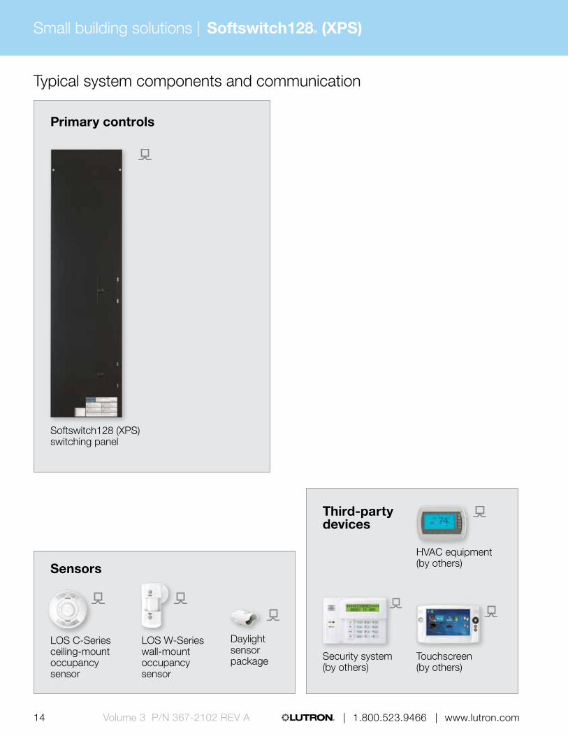
Typical system components and communication
Primary controls
Sensors
Third-party devices
Softswitch128 (XPS) switching panel
LOS C-Series ceiling-mount occupancy sensor
LOS W-Series wall-mount occupancy sensor
Daylight sensor package Security system
(by others)Touchscreen (by others)
HVAC equipment (by others)
14 15 | 1.800.523.9466 | www.lutron.com www.lutron.com | 1.800.523.9466 | Volume 3 P/N 367-2102 REV A
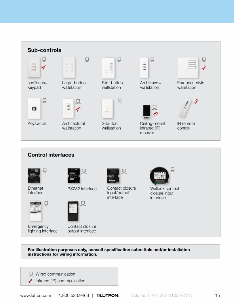
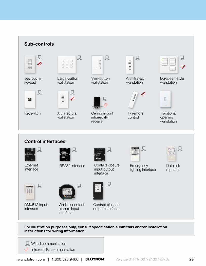
Sub-controls
Control interfaces
European-style wallstation
Architectural wallstation
2-button wallstation
Keyswitch
Architrave™ wallstation
Slim-button wallstation
Large-button wallstation
seeTouch® keypad
Emergency lighting interface
Ethernet interface
RS232 interface Contact closure input/output interface
Wallbox contact closure input interface
Ceiling-mount infrared (IR) receiver
IR remote control
For illustration purposes only, consult specification submittals and/or installation instructions for wiring information.
Wired communication
Infrared (IR) communication
Contact closure output interface

Small building solutions | Softswitch128® (XPS)
16 17 | 1.800.523.9466 | www.lutron.com www.lutron.com | 1.800.523.9466 |Volume 3 P/N 367-2102 REV A
Understanding how to build a Softswitch128 (XPS) system
1. Power panel selection Select power panel(s) based on number
of relays being switched
2. Design choices Choose wallstations and sensors based on
the functionality required and the aesthetic desired to compliment the space.
3. Integration/connecting to third-party devices
Utilize control interfaces to connect to third-party devices and systems, such as touchscreens, A/V equipment and security systems.
4. Shades Connect to third-party motorized shades
via contact closure output.
5. Software and programming Softswitch128 (XPS) can be programmed
through button-presses via the Liquid Crystal Display (LCD) controller located within the power panel.
Power panelsThe main devices in the system that handle the power and control for lighting loads and distribute commands to sub-controls, sensors, control interfaces and lighting loads.
Softswitch128 switching panel
• Switching panel for up to 48 switching circuits with integrated astronomical time clock and LCD controller for programming
• LCD controller provides easy-to-use, menu-based control and configuration of the entire system
• Feed and load wiring only, no other wiring or assembly required
Mini: W: 15.88 in (403 mm) H: 24.50 in (622 mm) D: 4.21 in (105 mm)
Standard: W: 15.88 in (403 mm) H: 59.5 in (1511 mm) D: 4.21 in (107 mm)
Large: W: 23.50 in (597 mm) H: 63.50 in (1613 mm) D: 6.30 in (160 mm)
Extra large: W: 23.50 in (597 mm) H: 82.50 in (2096 mm) D: 6.30 in (160 mm)
POWERED BY
120 V110-127 V127 V NOM220-240 V230 V CE
277 V

Small building solutions | Softswitch128® (XPS)
16 17 | 1.800.523.9466 | www.lutron.com www.lutron.com | 1.800.523.9466 | Volume 3 P/N 367-2102 REV A
Softswitch128 power panel summary
Softswitch128 switching panel
Load voltages
120 V, 110-127 V,
127 V (NOM)277 V 347 V 220-240 V 230 V (CE)
Dimmed loads
Incandescent/halogen
Magnetic low-voltage
Electronic low-voltage
/ Fluorescent and LED (3-wire)
/ Fluorescent and LED (EcoSystem®)
Tu-Wire® Fluorescent
/ Fluorescent and LED (0-10 V)
/ Fluorescent and LED (PWM)
/ Fluorescent and LED (DALI)
LED (2-wire forward phase)
/ CFL/LED (screw-base) Neon/cold cathode
Switched loads
Non-dim lighting (loads above)
HID
Motor loads
Fan loads
Panel / module voltage 120/277 V 120/277 V 347 V 220-240 V 230 V (CE)
Frequency 50/60 Hz 50/60 Hz 50/60 Hz 50/60 Hz 50/60 Hz
Maximum load per circuit16 A;
0.5 HP16 A;
1.5 HP16 A
16 A; 0.5 HP
16 A 0.5 HP
Power interfaces Compatible load control (no interfaces)

Small building solutions | Softswitch128® (XPS)
18 19 | 1.800.523.9466 | www.lutron.com www.lutron.com | 1.800.523.9466 |Volume 3 P/N 367-2102 REV A
Sub-controlsSub-controls are accessory components that provide additional control locations for increased convenience.
Traditional opening wallstation
• Simple wallstation with one tap button with or without status LED
• Provides toggle functionality for any zone(s) in the system
• Available in White• W: 2.86 in (73 mm)
H: 4.60 in (117 mm) D: 1.31 in (33 mm) Profile: 0.23 in (6 mm)
POWERED BY
OMX link
POWERED BY
Battery
POWERED BY
OMX link
BACKBOX
U.S. style
POWERED BY
OMX link
BACKBOX
U.S. style
Ceiling-mount infrared (IR) receiver
• Provides control of lighting via IR handheld remote controls by providing access point
• Allows scene selection and all off functionality
• Compatible with all Lutron® IR remote controls
• Available in white• Diameter: 3.50 in (89 mm)
Depth: 3.00 in (76 mm) Profile: 0.75 in (20 mm)
Infrared (IR) remote control
• Models available with four or eight scene control
• Off button turns all lights off• Available in White and Black• W: 1.50 in (38 mm)
H: 5.69 in (145 mm) D: 0.88 in (22 mm)
2-button wallstation
• Simple, intuitive wallstation ideal for use in entryways
• Status LEDs indicate which wallstation button has been activated
• Functionality includes scene selection and all off
• Available in 17 finishes• W: 2.75 in (70 mm)
H: 4.56 in (116 mm) D: 1.38 in (35 mm) Profile: 0.31 in (8 mm)

Small building solutions | Softswitch128® (XPS)
18 19 | 1.800.523.9466 | www.lutron.com www.lutron.com | 1.800.523.9466 | Volume 3 P/N 367-2102 REV A
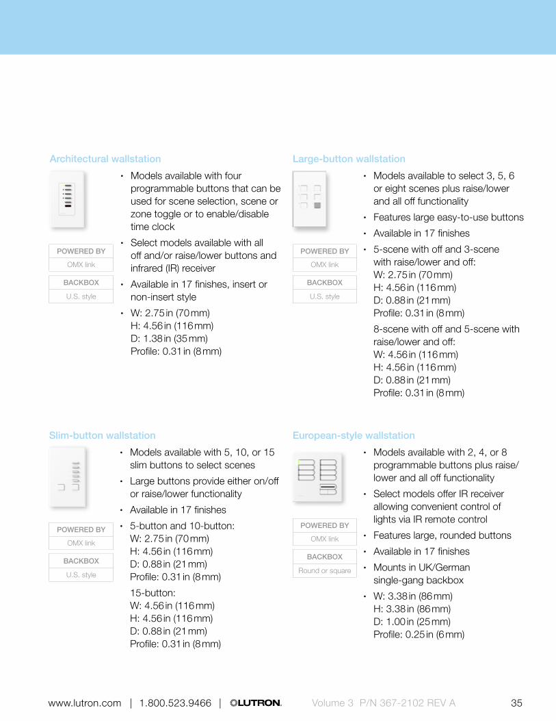
Slim-button wallstation
• Models available with 5, 10, or 15 slim buttons to select scenes
• Large buttons provide on/off functionality
• Available in 17 finishes• 5-button and 10-button:
W: 2.75 in (70 mm) H: 4.56 in (116 mm) D: 0.88 in (21 mm) Profile: 0.31 in (8 mm)
15-button (2-gang) W: 4.56 in (116 mm) H: 4.56 in (116 mm) D: 0.88 in (21 mm) Profile: 0.31 in (8 mm)
Architectural wallstation
• Models available with four programmable buttons that can be used for scene selection, zone toggle or to enable/disable time clock
• Select models available with all off and infrared (IR) receiver
• Available in 17 finishes, insert or non-insert style
• W: 2.75 in (70 mm) H: 4.56 in (116 mm) D: 1.38 in (35 mm) Profile: 0.31 in (8 mm)
POWERED BY
OMX link
BACKBOX
U.S. style
POWERED BY
OMX link
BACKBOX
U.S. style
POWERED BY
OMX link
BACKBOX
Round or square
POWERED BY
OMX link
BACKBOX
U.S. style
European-style wallstation
• Models available with 2, 4, or 8 programmable buttons plus all off functionality
• Select models offer IR receiver allowing convenient control of lights via IR remote control
• Features large, rounded buttons• Available in 17 finishes• Mounts in UK/German
single-gang backbox• W: 3.38 in (86 mm)
H: 3.38 in (86 mm) D: 1.00 in (25 mm) Profile: 0.25 in (6 mm)
Large-button wallstation
• Models available to select five or eight scenes plus all off functionality
• Features large easy-to-use buttons• Available in 17 finishes• 5-scene with off:
W: 2.75 in (70 mm) H: 4.56 in (116 mm) D: 0.88 in (21 mm) Profile: 0.31 in (8 mm)
8-scene with off (2-gang): W: 4.56 in (116 mm) H: 4.56 in (116 mm) D: 0.88 in (21 mm) Profile: 0.31 in (8 mm)

Small building solutions | Softswitch128® (XPS)
20 21 | 1.800.523.9466 | www.lutron.com www.lutron.com | 1.800.523.9466 |Volume 3 P/N 367-2102 REV A
POWERED BY
OMX link
BACKBOX
U.S. style
POWERED BY
OMX link
BACKBOX
U.S. style
POWERED BY
OMX link
BACKBOX
Lutron supplied
Architrave wallstation
• Models available with two or four programmable buttons that can be used for scene selection, zone toggle or to enable/disable time clock
• Four button models are available with slim or large buttons
• Two button model available with slim buttons only
• Available in 16 finishes• Slim-button:
W: 1.75 in (44 mm) H: 4.50 in (114 mm) D: 1.75 in (44 mm) Profile: 0.13 in (3 mm)
Large-button: W: 1.50 in (38 mm) H: 5.16 in (131 in) D: 1.99 in (51 mm) Profile: 0.13 in (3 mm)
seeTouch® keypad
• Models available with 1-7 programmable buttons that can be used for scene selection, zone toggle or to enable/disable time clock
• Select models available with all off and infrared receiver
• Backlit buttons or text make it easy to find and operate keypad in low-light conditions
• Available in 40 finishes• W: 2.75 in (70 mm)
H: 4.56 in (116 mm) D: 1.38 in (35 mm) Profile: 0.31 in (8 mm)
Keyswitch
• Provides scene selection or enable/disable time clock functionality
• Limits access to lighting control, ideal for public spaces
• Available in 17 finishes, insert or non-insert style
• W: 2.75 in (70 mm) H: 4.56 in (116 mm) D: 1.38 in (35 mm) Profile: 0.31 in (8 mm)
Sub-controls (continued)Sub-controls are accessory components that provide additional control locations for increased convenience.

Small building solutions | Softswitch128® (XPS)
20 21 | 1.800.523.9466 | www.lutron.com www.lutron.com | 1.800.523.9466 | Volume 3 P/N 367-2102 REV A
SensorsWired sensors add convenience by detecting occupancy/vacancy and daylight adjusting accordingly.
POWERED BY
20-24 V DC from power pack
POWERED BY
20-24 V DC from power pack
Wired LOS-C and LOS-W series occupancy sensors
• Automatically turns lighting scenes/zones on and/or off based on space occupancy
• Sensor technology options include passive infrared, ultrasonic and dual technology
• Wall-mount and ceiling-mount models available
• Available in White• Ceiling-mount:
Diameter: 4.50 in (114 mm) Depth: 1.40 in (38 mm)
Wall-mount: W: 2.70 in (69 mm) H: 5.25 in (133 mm) D: 3.90 in (99 mm)
Wired high-bay occupancy sensors
• Automatically turns lighting scenes/zones on and/or off based on space occupancy
• Passive infrared sensor designed for use in high-bay applications
• Maximum mounting height 45 ft (14 m)
• Surface-mount and end-mount models available
• Available in White• 180° and 360° surface-mount:
Diameter: 4 in (102 mm) Depth: 1.5 in (38 mm)
180° end-mount: W: 4.00 in (102 mm) H: 4.50 in (114 mm) D: 1.50 in (38 mm)
360° end-mount: W: 3.60 in (91 mm) H: 4.40 in (112 mm) D: 2.00 in (51 mm)
Small building solutions | Softswitch128® (XPS)
22 23 | 1.800.523.9466 | www.lutron.com www.lutron.com | 1.800.523.9466 |Volume 3 P/N 367-2102 REV A
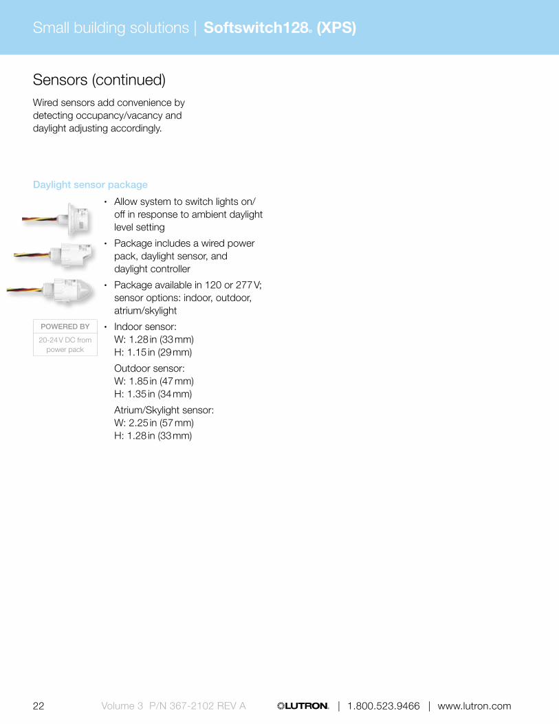
Sensors (continued)Wired sensors add convenience by detecting occupancy/vacancy and daylight adjusting accordingly.
Daylight sensor package
• Allow system to switch lights on/off in response to ambient daylight level setting
• Package includes a wired power pack, daylight sensor, and daylight controller
• Package available in 120 or 277 V; sensor options: indoor, outdoor, atrium/skylight
• Indoor sensor: W: 1.28 in (33 mm) H: 1.15 in (29 mm)
Outdoor sensor: W: 1.85 in (47 mm) H: 1.35 in (34 mm)
Atrium/Skylight sensor: W: 2.25 in (57 mm) H: 1.28 in (33 mm)
POWERED BY
20-24 V DC from power pack

Small building solutions | Softswitch128® (XPS)
22 23 | 1.800.523.9466 | www.lutron.com www.lutron.com | 1.800.523.9466 | Volume 3 P/N 367-2102 REV A
Control interfacesUse control interfaces to combine Lutron® lighting controls with other third-party devices and systems for advanced integration
RS232 interface
• Allows integration with touchscreen, PC, A/V system or other digital equipment that supports RS232 communication
• Control and monitor switching panel
• Monitor lighting scenes• W: 4.26 in (108 mm)
H: 5.26 in (134 mm) D: 1.06 in (27 mm)
POWERED BY
OMX link or external transformer (12-24 V DC)
POWERED BY
OMX link or external transformer (12-24 V DC)
POWERED BY
OMX link or external transformer (12-24 V DC)
POWERED BY
OMX link or external transformer (12-24 V DC)
Wallbox contact closure input interface
• Provides seven contact closure inputs
• Interfaces with third-party low-voltage switches to provide an alternative keypad aesthetic
• Mounts behind third-party low-voltage switch in backbox
• Diameter: 2.31 in (59 mm) Depth: 0.81 in (20 mm)
Contact closure output interface
• Provides eight dry contact closure outputs
• Compatible with motorized projection screens, window treatments and A/V equipment that have contact closure output
• Offers both normally open and normally closed contacts
• W: 5.75 in (146 mm) H: 10.75 in (273 mm) D: 2.00 in (50 mm)
Contact closure input/output interface
• Provides five inputs and five dry contact closure outputs
• Compatible with motion/occupancy sensors, movable walls, security systems and other products that have contact closure input/output
• Outputs provide both normally open and normally closed contacts
• W: 4.26 in (108 mm) H: 5.26 in (134 mm) D: 1.06 in (27 mm)

Small building solutions | Softswitch128® (XPS)
24 25 | 1.800.523.9466 | www.lutron.com www.lutron.com | 1.800.523.9466 |Volume 3 P/N 367-2102 REV A
Ethernet interface
• Allows integration with touchscreen, PC, A/V system or other digital equipment that supports TC/ICP communication over Ethernet
• Control and monitor switching panel
• Monitor lighting scenes• W: 4.26 in (108 mm)
H: 5.26 in (134 mm) D: 1.06 in (27 mm)
Emergency lighting interface
• Turns all or designated lighting loads to “full on” output or other programmed emergency light level
• Senses the normal line-voltage on all phases of power
• Provides inputs for a Fire Alarm Control Panel
• UL 924 listed as “Emergency Lighting and Power Equipment”
• W: 5.00 in (127 mm) H: 7.75 in (197 mm) D: 2.50 in (64 mm)
POWERED BY
OMX link
POWERED BY
OMX link or 20-24 V DC from
power pack
Control interfaces (continued)Use control interfaces to combine Lutron lighting controls with other third-party devices and systems for advanced integration
Data link repeater
• Allows power panel links to be extended beyond their maximum distances
• Extends the maximum distance and increases the power of the OMX link
• W: 5.00 in (127 mm) H: 7.75 in (197 mm) D: 2.50 in (64 mm)
POWERED BY
120 V110-127 V127 V NOM220-240 V230 V (CE)
Small building solutions | Softswitch128® (XPS)
24 25 | 1.800.523.9466 | www.lutron.com www.lutron.com | 1.800.523.9466 | Volume 3 P/N 367-2102 REV A
Software and programmingThe Softswitch128 (XPS) system is programmed at the Liquid Crystal Display (LCD) controller located within the power panel.
Button-press programming via Softswitch128 LCD controller
• Programming performed directly at the Softswitch128 panel for easy access
• Program wallstations to recall light patterns, toggle any switch leg(s), activate delay-to-off and activate contact closures on a button by button basis
• Set-up up to 500 user-defined time clock events within seven daily schedules and 40 holiday schedules

Small building solutions | LCP128™
26 | 1.800.523.9466 | www.lutron.comVolume 3 P/N 367-2102 REV A
seeTouch keypad
Ceiling-mount infrared receiver
LCP128 control system allows control of up to 128 lighting circuits—dimmed and switched—into one simple system. LCP128 systems use prewired panels with integrated visual display programmers and built-in astronomical time clock, allowing for easy and cost-effective installation and commissioning.
Feature highlights
• Panel-based dimming and switching• Preset scene control• Scheduling• Audio visual integration
Typical applications
• Restaurant• Retail stores• Banquet room• Lobbies
Typical components

Volume 3 P/N 367-2102 REV A 27 www.lutron.com | 1.800.523.9466 |
Infrared remote control
Wired LOS-W wall-mount occupancy sensor
Hi-lume 3D ballast
LCP128 dimming panel
3-wire fluorescent power module
RS232 interface

Small building solutions | LCP128™
28 29 | 1.800.523.9466 | www.lutron.com www.lutron.com | 1.800.523.9466 |Volume 3 P/N 367-2102 REV A
Sensors Third-party devices
Typical system components and communication
Primary controls
LOS C-Series ceiling-mount occupancy sensor
LOS W-Series wall-mount occupancy sensor
LCP128 dimming panel
LCP128 spec grade dimming panel
A/V equipment (by others)
Multi-channel theatrical console
Wired high-bay occupancy sensor
Ethernet interface
RS232 interface Contact closure input/output interface
28 29 | 1.800.523.9466 | www.lutron.com www.lutron.com | 1.800.523.9466 | Volume 3 P/N 367-2102 REV A
Sub-controls
Control interfaces
Ceiling mount infrared (IR) receiver
Architectural wallstation
Keyswitch
European-style wallstation
Architrave™ wallstation
Slim-button wallstation
Large-button wallstation
seeTouch® keypad
Contact closure output interface
Emergency lighting interface
Data link repeater
IR remote control
DMX512 input interface
For illustration purposes only, consult specification submittals and/or installation instructions for wiring information.
Traditional opening wallstation
Wallbox contact closure input interface
Wired communication
Infrared (IR) communication

Small building solutions |
30 | 1.800.523.9466 | www.lutron.comVolume 3 P/N 367-2102 REV A
LCP128™
Power panelsThe main devices in the system that handle the power for lighting loads and distribute commands to sub-controls, sensors, control interfaces and lighting loads.
Understanding how to build an LCP128 system
1. Power panel selection Select power panel(s) based on load type and
size and the method of control required.
2. Design choices Choose wallstations and sensors based on
functionality required and the aesthetic desired to compliment the space.
3. Integration/connecting to third-party devices
Utilize control interfaces to connect to third-party devices and systems, such as security systems, A/V equipment and stageboards.
4. Shades Connect to third-party motorized shades
via contact closure output.
5. Software and programming LCP128 can be programmed through
button-presses.
LCP128 dimming panel
• Combination dimming and switching panel for up to 36 circuits with integrated astronomical time clock and LCD controller for programming
• LCD controller provides easy-to-use menu-based control and configuration of the entire system
• Feed and load wiring only, no other wiring or assembly required
Mini: W: 15.88 in (403 mm) H: 24.50 in (622 mm) D: 4.21 in (107 mm)
Standard: W: 15.88 in (403 mm) H: 59.50 in (1511 mm) D: 4.21 in (107 mm)
LCP128 spec grade dimming panel
• Combination dimming and switching panel for up to 24 circuits with integrated astronomical time clock and LCD controller for programming
• LCD controller provides easy-to-use menu based control and configuration of the entire system
• Feed and load wires only, no other wiring or assembly required
• W: 28.00 in (711 mm) H: 37.00 in (940 mm) D: 12.00 in (304 mm)
POWERED BY
120 V110-127 V127 V NOM220-40 V230 V CE
277 V
POWERED BY
120 V110-127 V127 V NOM
277 V

Small building solutions | LCP128™
31 | 1.800.523.9466 | www.lutron.com www.lutron.com | 1.800.523.9466 | Volume 3 P/N 367-2102 REV A
LCP128 power panel summary
LCP128 dimming panel
Dimming modules Electronic low-voltage dimming module
Load voltages
120 V, 110-127 V,
127 V (NOM)230 V (CE) 220-240 V 230 V (CE) 220-240 V
Dimmed loads
Incandescent/halogen
Magnetic low-voltage PB-CE PB-AU
Electronic low-voltage PA ELVI-CE ELVI-AU
/ Fluorescent and LED (3-wire) 3F FDBI-AU FDBI-AU
/ Fluorescent and LED (EcoSystem®)
Tu-Wire® Fluorescent
/ Fluorescent and LED (0-10 V) TVM, TVI TVM, TVI TVM, TVI TVM, TVI TVM, TVI
/ Fluorescent and LED (PWM) TVM, PWM TVM TVM, PWM TVM TVM, PWM
/ Fluorescent and LED (DALI) TVM1 TVM1 TVM1 TVM1 TVM1
LED (2-wire forward phase)
/ CFL/LED (screw-base) PAPB-CE, ELVI-CE
PB-AU, ELVI-AU
2 2
Neon/cold cathode PB-CE PB-AU
Switched loads
Non-dim lighting (loads above) TVI TVI, PWM
HID SW, TVI, PWM TVI TVI, PWM TVI TVI, PWM
Motor loads SW, TVI, PWM TVI TVI, PWM TVI TVI, PWM
Fan loads (switched or speed control) SW, TVI, PWM TVI TVI, PWM TVI TVI, PWM
Panel / module voltage 120 V 230 V (CE) 220-240 V220-240 V
(CE)220-240 V
(CE)
Frequency 50/60 Hz 50/60 Hz 50/60 Hz 50/60 Hz 50/60 Hz
Minimum load 25 W 40 W 40 W 10 W 10 W
Maximum load per circuit 16 A 10 A 16 A 10 A 10 A
Maximum load per module 16 A 13 A 16 A 16 A 16 A
Power interfaces Compatible load control (no interfaces)
3F: 3-wire fluorescent power module pg. 516ELVI-AU: Electronic low-voltage interface (AU) pg. 524
ELVI-CE: Electronic low-voltage interface (CE) pg. 524FDBI-AU: Fluorescent dimming ballast interface (AU) pg. 526PA: Phase adaptive power module pg. 514PB-AU: Power booster pg. 522
PB-CE: Power booster (CE) pg. 522PWM: Pulse width modulation interface pg. 530SW: Switching power module pg. 520TVI: 0-10 V interface pg. 528TVM: Ten-volt module in panel
1 DALI broadcast only2 Reverse phase only. Forward
phase loads will require a power booster for proper dimming

32 33 | 1.800.523.9466 | www.lutron.com www.lutron.com | 1.800.523.9466 |
Small building solutions |
32 | 1.800.523.9466 | www.lutron.comVolume 3 P/N 367-2102 REV A
LCP128™
LCP128 power panel summary
LCP128 dimming panel LCP128 dimming panel
Adaptive dimming modules Fan speed module Motor module Switching module LCP128 spec grade dimming panel
Load voltages Load voltages
120 V, 110-127 V,
127 V (NOM)230 V (CE) 220-240 V
120 V, 110-127 V,
127 V (NOM)
120 V, 110-127 V,
127 V (NOM)
120 V, 110-127 V, 127 V (NOM),
220-240 V, 230 V (CE), 347 V
120 V, 110-127 V,
127 V (NOM)277 V
Dimmed loads Dimmed loads
Incandescent/halogen
Magnetic low-voltage
Electronic low-voltage 3 3
/ Fluorescent and LED (3-wire) 3F FDBI-AU
/ Fluorescent and LED (EcoSystem®)
Tu-Wire® Fluorescent
/ Fluorescent and LED (0-10 V) TVM, TVI TVM, TVI TVM, TVI TVM, TVI TVM, TVI
/ Fluorescent and LED (PWM) TVM, PWM TVM TVM, PWM TVM, PWM TVM, PWM
/ Fluorescent and LED (DALI) TVM 1 TVM 1 TVM 1 TVM 1 TVM 1
LED (2-wire forward phase)
/ CFL/LED (screw-base) 2 2 2 3 3
Neon/cold cathode
Switched loads Switched loads
Non-dim lighting (loads above) SW, TVI, PWM TVI TVI, PWM
HID SW, TVI, PWM TVI TVI, PWM
Motor loads SW, TVI, PWM TVI TVI, PWM
(AC loads only)SW, TVI, PWM SW, TVI, PWM
Fan loads (switched or speed control) SW, TVI, PWM TVI TVI, PWM SW, TVI, PWM SW, TVI, PWM
Panel / module voltage 120 V 220-240 V (CE) 220-240 V (CE) 120 V 120 V 100-277 V (CE) 120 V 277 V
Frequency 50/60 Hz 50/60 Hz 50/60 Hz 50/60 Hz 50/60 Hz 50/60 Hz 50/60 Hz 50/60 Hz
Minimum load 10 W 10 W 10 W 0.25 A — — 10 W 10 W
Maximum load per circuit 10 A 8 A 8 A 2 A5 A;
0.5 HP
16 A; 0.5 HP (120 V), 1.5 HP (277 V),
0.5 HP (220-240 V)16 A 16 A
Maximum load per module 16 A 13 A 16 A 16 A 16 A (see per circuit rating) — —
Power interfaces Compatible load control (no interfaces) 3F: 3-wire fluorescent power module pg. 516 ELVI-AU: Electronic low-voltage interface (AU) pg. 524 ELVI-CE: Electronic low-voltage interface (CE) pg. 524
FDBI-AU: Fluorescent dimming ballast interface (AU) pg. 526 PA: Phase adaptive power module pg. 514 PB-AU: Power booster pg. 522 PB-CE: Power booster (CE) pg. 522PWM: Pulse width modulation interface pg. 530 SW: Switching power module pg. 520 TVI: 0-10 V interface pg. 528 TVM: Ten-volt module in panel
1 DALI broadcast only2 Visit www.lutron.com/LEDtool for a complete list of LEDs compatible with this module

32 33 | 1.800.523.9466 | www.lutron.com www.lutron.com | 1.800.523.9466 | Volume 3 P/N 367-2102 REV A | 1.800.523.9466 | www.lutron.com
LCP128 power panel summary
LCP128 dimming panel LCP128 dimming panel
Adaptive dimming modules Fan speed module Motor module Switching module LCP128 spec grade dimming panel
Load voltages Load voltages
120 V, 110-127 V,
127 V (NOM)230 V (CE) 220-240 V
120 V, 110-127 V,
127 V (NOM)
120 V, 110-127 V,
127 V (NOM)
120 V, 110-127 V, 127 V (NOM),
220-240 V, 230 V (CE), 347 V
120 V, 110-127 V,
127 V (NOM)277 V
Dimmed loads Dimmed loads
Incandescent/halogen
Magnetic low-voltage
Electronic low-voltage 3 3
/ Fluorescent and LED (3-wire) 3F FDBI-AU
/ Fluorescent and LED (EcoSystem®)
Tu-Wire® Fluorescent
/ Fluorescent and LED (0-10 V) TVM, TVI TVM, TVI TVM, TVI TVM, TVI TVM, TVI
/ Fluorescent and LED (PWM) TVM, PWM TVM TVM, PWM TVM, PWM TVM, PWM
/ Fluorescent and LED (DALI) TVM 1 TVM 1 TVM 1 TVM 1 TVM 1
LED (2-wire forward phase)
/ CFL/LED (screw-base) 2 2 2 3 3
Neon/cold cathode
Switched loads Switched loads
Non-dim lighting (loads above) SW, TVI, PWM TVI TVI, PWM
HID SW, TVI, PWM TVI TVI, PWM
Motor loads SW, TVI, PWM TVI TVI, PWM
(AC loads only)SW, TVI, PWM SW, TVI, PWM
Fan loads (switched or speed control) SW, TVI, PWM TVI TVI, PWM SW, TVI, PWM SW, TVI, PWM
Panel / module voltage 120 V 220-240 V (CE) 220-240 V (CE) 120 V 120 V 100-277 V (CE) 120 V 277 V
Frequency 50/60 Hz 50/60 Hz 50/60 Hz 50/60 Hz 50/60 Hz 50/60 Hz 50/60 Hz 50/60 Hz
Minimum load 10 W 10 W 10 W 0.25 A — — 10 W 10 W
Maximum load per circuit 10 A 8 A 8 A 2 A5 A;
0.5 HP
16 A; 0.5 HP (120 V), 1.5 HP (277 V),
0.5 HP (220-240 V)16 A 16 A
Maximum load per module 16 A 13 A 16 A 16 A 16 A (see per circuit rating) — —
Power interfaces Compatible load control (no interfaces) 3F: 3-wire fluorescent power module pg. 516 ELVI-AU: Electronic low-voltage interface (AU) pg. 524 ELVI-CE: Electronic low-voltage interface (CE) pg. 524
FDBI-AU: Fluorescent dimming ballast interface (AU) pg. 526 PA: Phase adaptive power module pg. 514 PB-AU: Power booster pg. 522 PB-CE: Power booster (CE) pg. 522PWM: Pulse width modulation interface pg. 530 SW: Switching power module pg. 520 TVI: 0-10 V interface pg. 528 TVM: Ten-volt module in panel
3 Forward phase only. Not all ELV transformers and dimmable CFL/LED dim properly with forward phase control; may require phase-adaptive power module for proper dimming; for reverse phase, a phase-adaptive power module will be required

Small building solutions | LCP128™
34 35 | 1.800.523.9466 | www.lutron.com www.lutron.com | 1.800.523.9466 |Volume 3 P/N 367-2102 REV A
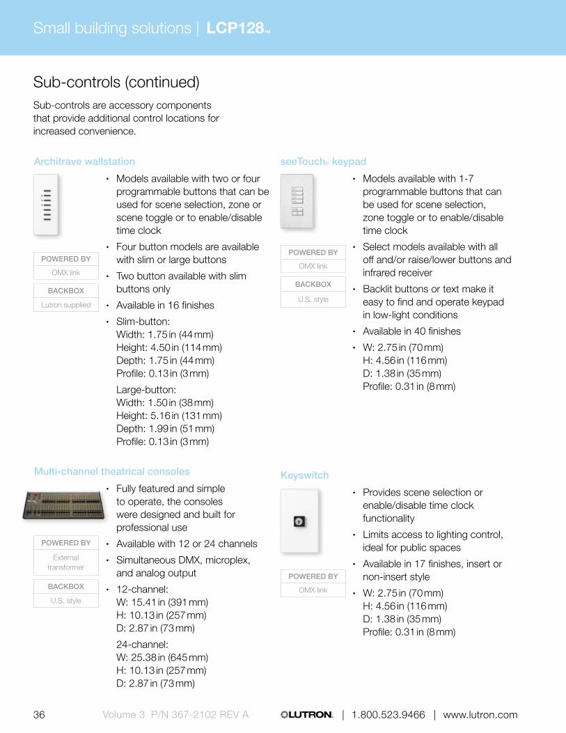
Sub-controlsSub-controls are accessory components that provide additional control locations for increased convenience.
Traditional opening wallstation
• Simple wallstation with one tap button with or without status LED
• Provides toggle functionality for any zone(s) in the system
• Available in White• W: 2.86 in (73 mm)
H: 4.60 in (117 mm) D: 1.31 in (33 mm) Profile: 0.23 in (6 mm)
Ceiling-mount infrared (IR) receiver
• Provides control of lighting via IR handheld remote controls by providing access point
• Allows scene selection, raise/lower scenes and all off functionality
• Compatible with all Lutron IR remote controls
• Available in White• Diameter: 3.50 in (89 mm)
Depth: 3.00 in (76 mm) Profile: 0.75 in (20 mm)
IR remote control
• Models available with four or eight scene control
• Offers master raise/lower and all off buttons
• Available in White and Black• W: 1.50 in (38 mm)
H: 5.69 in (145 mm) D: 0.88 in (22 mm)
2-button wallstation
• Simple, intuitive wallstation ideal for use in entryways
• Status LEDs indicate which wallstation button has been activated
• Functionality includes scene selection, raise/lower, and all off
• Available in 17 finishes• Width: 2.75 in (70 mm)
Height: 4.56 in (116 mm) Depth: 1.38 in (35 mm) Profile: 0.31 in (8 mm)
POWERED BY
Battery
POWERED BY
OMX link
POWERED BY
OMX link
BACKBOX
U.S. style
POWERED BY
OMX link
BACKBOX
U.S. style
34 35 | 1.800.523.9466 | www.lutron.com www.lutron.com | 1.800.523.9466 | Volume 3 P/N 367-2102 REV A
POWERED BY
OMX link
BACKBOX
U.S. style
POWERED BY
OMX link
BACKBOX
Round or square
POWERED BY
OMX link
BACKBOX
U.S. style
Slim-button wallstation
• Models available with 5, 10, or 15 slim buttons to select scenes
• Large buttons provide either on/off or raise/lower functionality
• Available in 17 finishes• 5-button and 10-button:
W: 2.75 in (70 mm) H: 4.56 in (116 mm) D: 0.88 in (21 mm) Profile: 0.31 in (8 mm)
15-button: W: 4.56 in (116 mm) H: 4.56 in (116 mm) D: 0.88 in (21 mm) Profile: 0.31 in (8 mm)
Architectural wallstation
• Models available with four programmable buttons that can be used for scene selection, scene or zone toggle or to enable/disable time clock
• Select models available with all off and/or raise/lower buttons and infrared (IR) receiver
• Available in 17 finishes, insert or non-insert style
• W: 2.75 in (70 mm) H: 4.56 in (116 mm) D: 1.38 in (35 mm) Profile: 0.31 in (8 mm)
European-style wallstation
• Models available with 2, 4, or 8 programmable buttons plus raise/lower and all off functionality
• Select models offer IR receiver allowing convenient control of lights via IR remote control
• Features large, rounded buttons• Available in 17 finishes• Mounts in UK/German
single-gang backbox• W: 3.38 in (86 mm)
H: 3.38 in (86 mm) D: 1.00 in (25 mm) Profile: 0.25 in (6 mm)
Large-button wallstation
• Models available to select 3, 5, 6 or eight scenes plus raise/lower and all off functionality
• Features large easy-to-use buttons• Available in 17 finishes• 5-scene with off and 3-scene
with raise/lower and off: W: 2.75 in (70 mm) H: 4.56 in (116 mm) D: 0.88 in (21 mm) Profile: 0.31 in (8 mm)
8-scene with off and 5-scene with raise/lower and off: W: 4.56 in (116 mm) H: 4.56 in (116 mm) D: 0.88 in (21 mm) Profile: 0.31 in (8 mm)
POWERED BY
OMX link
BACKBOX
U.S. style
Small building solutions |
36 | 1.800.523.9466 | www.lutron.comVolume 3 P/N 367-2102 REV A
LCP128™
Multi-channel theatrical consoles
• Fully featured and simple to operate, the consoles were designed and built for professional use
• Available with 12 or 24 channels• Simultaneous DMX, microplex,
and analog output• 12-channel:
W: 15.41 in (391 mm) H: 10.13 in (257 mm) D: 2.87 in (73 mm)
24-channel: W: 25.38 in (645 mm) H: 10.13 in (257 mm) D: 2.87 in (73 mm)
Sub-controls (continued)Sub-controls are accessory components that provide additional control locations for increased convenience.
POWERED BY
OMX link
POWERED BY
OMX link
BACKBOX
U.S. style
POWERED BY
OMX link
BACKBOX
Lutron supplied
POWERED BY
External transformer
BACKBOX
U.S. style
Architrave wallstation
• Models available with two or four programmable buttons that can be used for scene selection, zone or scene toggle or to enable/disable time clock
• Four button models are available with slim or large buttons
• Two button available with slim buttons only
• Available in 16 finishes• Slim-button:
Width: 1.75 in (44 mm) Height: 4.50 in (114 mm) Depth: 1.75 in (44 mm) Profile: 0.13 in (3 mm)
Large-button: Width: 1.50 in (38 mm) Height: 5.16 in (131 mm) Depth: 1.99 in (51 mm) Profile: 0.13 in (3 mm)
seeTouch® keypad
• Models available with 1-7 programmable buttons that can be used for scene selection, zone toggle or to enable/disable time clock
• Select models available with all off and/or raise/lower buttons and infrared receiver
• Backlit buttons or text make it easy to find and operate keypad in low-light conditions
• Available in 40 finishes• W: 2.75 in (70 mm)
H: 4.56 in (116 mm) D: 1.38 in (35 mm) Profile: 0.31 in (8 mm)
Keyswitch
• Provides scene selection or enable/disable time clock functionality
• Limits access to lighting control, ideal for public spaces
• Available in 17 finishes, insert or non-insert style
• W: 2.75 in (70 mm) H: 4.56 in (116 mm) D: 1.38 in (35 mm) Profile: 0.31 in (8 mm)

Small building solutions | LCP128™
37 | 1.800.523.9466 | www.lutron.com www.lutron.com | 1.800.523.9466 | Volume 3 P/N 367-2102 REV A
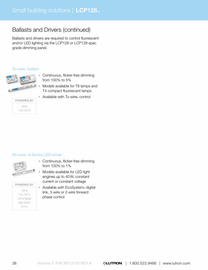
Ballasts and DriversBallasts and drivers are required to control fluorescent and/or LED lighting via the LCP128 or LCP128 spec grade dimming panel.
EcoSystem ballasts for compact fluorescent lamps (CFL)
• Continuous flicker free dimming from 100% to 5% for T4 compact fluorescent lamps
• Available with 3-wire control
EcoSystem ballast
• Continuous, flicker-free dimming from 100% to 10%
• Models available for T8, T8 reduced wattage, T5, T5 reduced wattage and T5HO lamps
• Wired sensors can connect directly to the ballast
• Available with EcoSystem® digital link or 3-wire control
Hi-lume 3D ballast
• Continuous, flicker-free dimming from 100% to 0.3% for T8, T5 and T5HO lamps, and 5% for T5 twin-tube and T5HO 80 W lamps
• Available with EcoSystem® digital link or 3-wire control
Hi-lume ballast
• Continuous flicker free dimming from 100% to 1%
• Models available for T5HO lamps and T4 compact fluorescent lamps
• Available with 3-wire control
POWERED BY
120 V110-127 V127 V NOM220-240 V
277 V
POWERED BY
120 V110-127 V127 V NOM220-240 V
277 V
POWERED BY
120 V110-127 V
277 V
POWERED BY
120 V110-127 V127 V NOM220-240 V
277 V
Small building solutions |
38 | 1.800.523.9466 | www.lutron.comVolume 3 P/N 367-2102 REV A
LCP128™
Tu-wire® ballast
• Continuous, flicker-free dimming from 100% to 5%
• Models available for T8 lamps and T4 compact fluorescent lamps
• Available with Tu-wire® control
Ballasts and Drivers (continued)Ballasts and drivers are required to control fluorescent and/or LED lighting via the LCP128 or LCP128 spec grade dimming panel.
POWERED BY
120 V110-127 V
POWERED BY
120 V110-127 V127 V NOM220-240 V
277 V
Hi-lume® A-Series LED driver
• Continuous, flicker-free dimming from 100% to 1%
• Models available for LED light engines up to 40 W, constant current or constant voltage
• Available with EcoSystem® digital link, 3-wire or 2-wire forward phase control

Small building solutions | LCP128™
39 | 1.800.523.9466 | www.lutron.com www.lutron.com | 1.800.523.9466 | Volume 3 P/N 367-2102 REV A
SensorsWired sensors add convenience by detecting occupancy/vacancy and daylight adjusting accordingly.
POWERED BY
20-24 V DC from power pack
POWERED BY
20-24 V DC from power pack
Wired high-bay occupancy sensors
• Automatically turns lighting scenes/zones on and/or off based on space occupancy
• Passive infrared sensor designed for use in high-bay applications
• Maximum mounting height 45 ft (14 m)
• Surface-mount and end-mount models available
• Available in White• 180° and 360° surface-mount:
Diameter: 4.00 in (102 mm) Depth: 1.50 in (38 mm)
180° end-mount: W: 4.00 in (102 mm) H: 4.50 in (114 mm) D: 1.50 in (38 mm)
360° end-mount: W: 3.60 in (91 mm) H: 4.40 in (112 mm) D: 2.00 in (51 mm)
Wired LOS-C and LOS-W series occupancy sensors
• Automatically turns lighting scenes/zones on and/or off based on space occupancy
• Sensor technology options include passive infrared, ultrasonic and dual technology
• Wall-mount and ceiling-mount models available
• Available in White• Ceiling-mount:
Diameter: 4.50 in (114 mm) Depth: 1.40 in (38 mm)
Wall-mount: W: 2.70 in (69 mm) H: 5.25 in (133 mm) D: 3.90 in (99 mm)
Small building solutions |
40 | 1.800.523.9466 | www.lutron.comVolume 3 P/N 367-2102 REV A
LCP128™
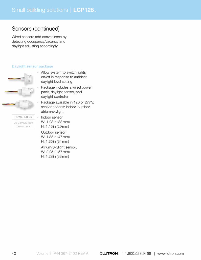
Sensors (continued)Wired sensors add convenience by detecting occupancy/vacancy and daylight adjusting accordingly.
Daylight sensor package
• Allow system to switch lights on/off in response to ambient daylight level setting
• Package includes a wired power pack, daylight sensor, and daylight controller
• Package available in 120 or 277 V; sensor options: indoor, outdoor, atrium/skylight
• Indoor sensor: W: 1.28 in (33 mm) H: 1.15 in (29 mm)
Outdoor sensor: W: 1.85 in (47 mm) H: 1.35 in (34 mm)
Atrium/Skylight sensor: W: 2.25 in (57 mm) H: 1.28 in (33 mm)
POWERED BY
20-24 V DC from power pack

Small building solutions | LCP128™
41 | 1.800.523.9466 | www.lutron.com www.lutron.com | 1.800.523.9466 | Volume 3 P/N 367-2102 REV A
Control interfacesUse control interfaces to combine Lutron® lighting controls with other third-party devices and systems for advanced integration. Interfaces may also provide connection points for other Lutron devices.
RS232 interface
• Allows integration with touchscreen, PC, A/V system or other digital equipment that supports RS232 communication
• Control and monitor switching panel
• Monitor lighting scenes• W: 4.26 in (108 mm)
H: 5.26 in (134 mm) D: 1.06 in (27 mm)
POWERED BY
OMX link or external transformer (12-24 V DC)
POWERED BY
OMX link or external transformer (12-24 V DC)
POWERED BY
OMX link or external transformer (12-24 V DC)
POWERED BY
OMX link or external transformer (12-24 V DC)
Wallbox contact closure input interface
• Provides seven contact closure inputs
• Interfaces with third-party low-voltage switches to provide an alternative keypad aesthetic
• Mounts behind third-party low-voltage switch in backbox
• Diameter: 2.31 in (59 mm) Depth: 0.81 in (20 mm)
Contact closure output interface
• Provides eight dry contact closure outputs
• Compatible with motorized projection screens, window treatments and A/V equipment that have contact closure output
• Offers both normally open and normally closed contacts
• W: 5.75 in (146 mm) H: 10.75 in (273 mm) D: 2.00 in (50 mm)
Contact closure input/output interface
• Provides five inputs and five dry contact closure outputs
• Compatible with motion/occupancy sensors, movable walls, security systems and other products that have contact closure input/output
• Outputs provide both normally open and normally closed contacts
• W: 4.26 in (108 mm) H: 5.26 in (134 mm) D: 1.06 in (27 mm)

Small building solutions |
42 | 1.800.523.9466 | www.lutron.comVolume 3 P/N 367-2102 REV A
LCP128™
Ethernet interface
• Allows integration with touchscreen, PC, A/V system or other digital equipment that supports TC/ICP communication over Ethernet
• Control and monitor switching panel
• Monitor lighting scenes• W: 4.26 in (108 mm)
H: 5.26 in (134 mm) D: 1.06 in (27 mm)
DMX512 input interface
• Provides an interface between DMX512/1190 compatible stage lighting console and the system
• Supports up to 32 consecutive channel levels from the entire range of 512 channels
• Control can be shared between systems
• W: 5.00 in (127 mm) H: 7.75 in (197 mm) D: 2.50 in (84 mm)
Emergency lighting interface
• Turns all or designated lighting loads to “full on” output or other programmed emergency light level
• Senses the normal line-voltage on all three phases of power
• Provides inputs for a Fire Alarm Control Panel
• UL 924 listed as "Emergency Lighting and Power Equipment"
• W: 5.00 in (127 mm) H: 7.75 in (197 mm) D: 2.50 in (64 mm)
POWERED BY
OMX link or 20-24 V DC from
power pack
POWERED BY
120 V110-27 V
127 V NOM220-240 V230 V (CE)
Control interfaces (continued)Use control interfaces to combine Lutron® lighting controls with other third-party devices and systems for advanced integration
Data link repeater
• Allows power panel links to be extended beyond their maximum distances
• Extends the maximum distance and increases the power of the OMX link
• W: 5.00 in (127 mm) H: 7.75 in (197 mm) D: 2.50 in (64 mm)
POWERED BY
OMX link or external transformer (12-24 V DC)
POWERED BY
OMX link or external transformer (12-24 V DC)

Small building solutions | LCP128™
43 | 1.800.523.9466 | www.lutron.com www.lutron.com | 1.800.523.9466 | Volume 3 P/N 367-2102 REV A
Software and programmingThe LCP128 system is programmed at the Liquid Crystal Display (LCD) controller located within the power panel.
Button-press programming via Softswitch128 LCD controller
• Programming performed directly at the LCP128 panel for easy access
• Program wallstations to recall scenes, raise/lower circuits, activate delay-to-off and activate contact closures on a button-by-button basis
• Set-up up to 500 user-defined time clock events within seven daily schedules and 40 holiday schedules

GRAFIK Eye® 4000Small building solutions |
44 | 1.800.523.9466 | www.lutron.comVolume 3 P/N 367-2102 REV A
GRAFIK Eye 4000 lighting control system is designed to provide dimming, switching, and daylight control. The system consists of pre-wired panels, GRAFIK Eye control units, wallstations, and control interfaces. The system is ideal for multi-use areas and partitionable spaces.
Feature highlights
• Preset scene control• Daylight harvesting• Partitioning• Shade integration
Typical applications
• Ballrooms• Auditoriums• Houses of worship• Museums
GRAFIK Eye 4500 main unit
Typical components
Wired photosensor

45 www.lutron.com | 1.800.523.9466 | Volume 3 P/N 367-2102 REV A
Time clock / programming interface
Large-button wallstation
Daylight controller
Sivoia® QED shade GP dimming panel

GRAFIK Eye® 4000Small building solutions |
46 | 1.800.523.9466 | www.lutron.comVolume 3 P/N 367-2102 REV A
Typical system components and communication
Primary controls
GRAFIK Eye 4100/4500 control unit GRAFIK Eye 4000 Series slider control unit
Power panels
Shading systems
Sivoia QED panel power supply
Sivoia QED roller shade
Sivoia® QED controller
LP dimming panel XP switching panelGP dimming panel DCI dimming panel

47 | 1.800.523.9466 | www.lutron.com www.lutron.com | 1.800.523.9466 | Volume 3 P/N 367-2102 REV A
Sub-controls
seeTouch® keypad
European-style wallstation
Slim-button wallstation
Architectural wallstation
Control interfaces
Contact closure input/output interface
Daylight controllerRS232 interface
Time clock / programming interface
Infrared partitioning sensor
Sensors Third-party devices
LOS C-Series occupancy sensors
Multi-channel theatrical console
PC desktop
DMX512 output interface
Large-button wallstation
Architrave™ wallstation
For illustration purposes only, consult specification submittals and/or installation instructions for wiring information.
Wired communication
Infrared (IR) communication
Wired photosensor

GRAFIK Eye® 4000Small building solutions |
48 | 1.800.523.9466 | www.lutron.comVolume 3 P/N 367-2102 REV A
Understanding how to build a GRAFIK Eye 4000 system
1. Power panel selection Select power panels based on load type and
size, and the method of control required.
2. Design choices Choose control units, wallstations, and sensors
based on functionality required and the aesthetic desired to compliment the space
3. Integration/connecting to third-party devices
Utilize control interfaces to connect to third-party devices and systems, such as touchscreens, A/V equipment and theatrical equipment.
4. Shades Wired Sivoia® QED shading solutions offer
convenient control of daylight at the touch of a button.
5. Software and programming GRAFIK Eye 4000 can be programmed
through PC-based software or button-presses.
Power panelsThe power panels provide remote dimming and switching capability for all common light sources, including incandescent, fluorescent, LED, CFL, halogen, and neon/cold cathode.
GP dimming panel
• Panel is typically used for high-performance architectural dimming
• Provides power and dimming for up to 144 circuits
• Feed-through or branch circuit breakers panels are available
• Mini: W: 11.00 in (279 mm) H: 21.13 in (537 mm) D: 6.25 in (160 mm) Standard: W: 28.00 in (711 mm) H: 37.00 in (940 mm) D: 12.00 in (304 mm) Large (GP36): W: 26.13 in (653 mm) H: 87.00 in (2175 mm) D: 14.13 in (360 mm) Large: W: 52.31 in (1308 mm) H: 87.00 in (2175 mm) D: 14.13 in (360 mm) Extra Large: W: 52.31 in (1308 mm) H: 87.00 in (2175 mm) D: 28.25 in (720 mm)
POWERED BY
100 V
120 V
110‑127 V
127 V NOM
220‑2 40 V
230 V CE
277 V

GRAFIK Eye® 4000Small building solutions |
49 | 1.800.523.9466 | www.lutron.com www.lutron.com | 1.800.523.9466 | Volume 3 P/N 367-2102 REV A
LP dimming panel
• Panel is typically used for commercial dimming projects with numerous small loads
• Provides power and dimming for up to 32 dimming legs (up to eight modules, four outputs per module)
• Panels include branch circuit breakers
• Mini: W: 15.88 in (403 mm) H: 24.50 in (622 mm) D: 4.21 in (107 mm) Standard: W: 15.88 in (403 mm) H: 59.50 in (1511 mm) D: 4.21 in (107 mm)
XP switching panel
• Million-cycle switching panel employs Lutron patented Softswitch technology
• Provides power and switching for up to 48 switching legs
• Feed-through or branch circuit breaker panels are available
• Mini: W: 15.88 in (403 mm) H: 24.50 in (622 mm) D: 4.21 in (107 mm) Standard: W: 15.88 in (403 mm) H: 59.50 in (1511 mm) D: 4.21 in (107 mm) Large: W: 23.50 in (597 mm) H: 63.50 in (1613 mm) D: 6.30 in (160 mm) Extra Large: W: 23.50 in (597 mm) H: 82.50 in (2096 mm) D: 6.30 in (160 mm)
POWERED BY
120 V
110‑127 V
127 V NOM
220‑2 40 V
230 V CE
277 V
347 V
POWERED BY
120 V
110‑127 V
127 V NOM
220‑2 40 V
230 V CE

GRAFIK Eye® 4000Small building solutions |
50 | 1.800.523.9466 | www.lutron.comVolume 3 P/N 367-2102 REV A
Power panels (continued)The power panels provide remote dimming and switching capability for all common light sources, including incandescent, fluorescent, LED, CFL, halogen, and neon/cold cathode.
POWERED BY
120 V110‑127 V220‑2 40 V230 V CE
DCI dimming panel
• Dimming panel featuring direct current that is ideal for projects that require no radio frequency interference
• Provides power and dimming for up to three circuits
• Lamps are free of flicker and audible noise throughout the entire dimming range
• W: 28.00 in (711 mm) H: 37.00 in (940 mm) D: 12.00 in (304 mm)
Custom combination panel (CCP)
• Combination dimming and switching panel that is ideal for projects with numerous small loads
• Provides power and dimming for up to 32 dimming / switching legs
• Choose modules based on load type and control required
• Panels include branch circuit breakers
• W: 15.88 in (403 mm) H: 59.50 in (1511 mm) D: 4.21 in (107 mm)
POWERED BY
120 V110‑127 V

GRAFIK Eye® 4000Small building solutions |
51 | 1.800.523.9466 | www.lutron.com www.lutron.com | 1.800.523.9466 | Volume 3 P/N 367-2102 REV A
GRAFIK Eye 4000 power panel summary GP panel
Load voltage
120 V, 110-127 V,
127 V (NOM)277 V
230 V (CE)
220-240 V
Dimmed loads
Incandescent/halogen
Magnetic low-voltage
Electronic low-voltage 1 1 1 1
/ Fluorescent and LED (3-wire)
/ Fluorescent and LED (EcoSystem®)
Tu-Wire® Fluorescent
/ Fluorescent and LED (0-10 V) TVM, TVI TVM, TVI TVM, TVI TVM, TVI
/ Fluorescent and LED (PWM) TVM, PWM TVM, PWM TVM TVM, PWM
/ Fluorescent and LED (DALI) TVM 2 TVM 2 TVM 2 TVM 2
LED (2-wire forward phase)
/ CFL/LED (screw-base) 1 1 1 1
Neon/cold cathode
Switched loads
Non-dim lighting (loads above)
HID
Motor loads SW, TVI, PWM SW, TVI, PWM TVI TVI, PWM
Fan loads SW, TVI, PWM SW, TVI, PWM TVI TVI, PWM
Panel / module voltage 120 V 277 V 230 V (CE) 220-240 V
Frequency 50/60 Hz 50/60 Hz 50/60 Hz 50/60 Hz
Minimum load 10 W 10 W 10 W 10 W
Maximum load per circuit 16 A 16 A 16 A 16 A
Maximum load per module — — — —
1 Foward phase only. Not all ELV transformers and dimmable CFL/LEDs dim properly with forward phase control; may require phase-adaptive power module or electronic low voltage interface for proper dimming. For reverse phase, a phase adaptive power module or electronic low-voltage interface will be required.
2 DALI broadcast only
Power interfaces Compatible load control (no interfaces)
TVI: 0-10 V interface pg. 528PWM: Pulse width modulation interface pg. 530
SW: Switching power module pg. 520TVM: Ten-volt module in panel

GRAFIK Eye® 4000Small building solutions |
52 | 1.800.523.9466 | www.lutron.comVolume 3 P/N 367-2102 REV A
GRAFIK Eye 4000 power panel summary (cont.)
DCI dimming panel
LP panel XP switching panel
Load voltage Load voltage
120 V, 110-127 V
120 V, 110-127 V,
127 V (NOM)230 V (CE) 220-240 V
120 V, 110-127 V, 127 V (NOM)
277 V 347 V 230 V (CE) 220-240 V
Dimmed loads Dimmed loads
Incandescent/halogen
Magnetic low-voltage
Electronic low-voltage PA ELVI-CE ELVI-AU
/ Fluorescent and LED (3-wire) 3F FDBI-AU
/ Fluorescent and LED (EcoSystem®)
Tu-Wire® Fluorescent
/ Fluorescent and LED (0-10 V) TVM, TVI TVM, TVI TVM, TVI
/ Fluorescent and LED (PWM) TVM, PWM TVM TVM, PWM
/ Fluorescent and LED (DALI) TVM * TVM * TVM *
LED (2-wire forward phase)
/ CFL/LED (screw-base) PAPB-CE, ELVI-CE
PB-AU, ELVI-AU
Neon/cold cathode
Switched loads Switched loads
Non-dim lighting (loads above)
HID SW, TVI, PWM TVI TVI, PWM
Motor loads SW, TVI, PWM TVI TVI, PWM
Fan loads SW, TVI, PWM TVI TVI, PWM
Panel / module voltage 120 V 120 V 230 V (CE) 220-240 V 120/277 V 120/277 V 347 V 230 V (CE) 220-240 V
Frequency 60 Hz 50/60 Hz 50/60 Hz 50/60 Hz 50/60 Hz 50/60 Hz 50/60 Hz 50/60 Hz 50/60 Hz
Minimum load 10 W 25 W 40 W 40 W — — — — —
Maximum load per circuit 10 A; 1200 W 16 A 10 A 16 A 16 A; 0.5 HP 16 A; 1.5 HP 16 A 16 A; 0.5 HP 16 A; 0.5 HP
Maximum load per module 10 A; 1200 W 16 A 13 A 16 A (see per circuit rating) (see per circuit rating) (see per circuit rating) (see per circuit rating) (see per circuit rating)
* DALI broadcast only
Power interfaces Compatible load control (no interfaces) 3F: 3-wire fluorescent power module pg. 516 EVLI-AU: Electronic low-voltage interface (AU) pg. 524 ELVI-CE: Electronic low-voltage interface (CE) pg. 524
FDBI-AU: Fluorescent dimming ballast interface (AU) pg. 526 PA: Phase adaptive power module pg. 514 PB-AU: Power booster pg. 522 PB-CE: Power booster (CE) pg. 522 PWM: Pulse width modulation interface pg. 530 SW: Switching power module pg. 520 TVI: 0-10 V interface pg. 528 TVM: Ten-volt module in panel

GRAFIK Eye® 4000Small building solutions |
53 | 1.800.523.9466 | www.lutron.com www.lutron.com | 1.800.523.9466 | Volume 3 P/N 367-2102 REV A
GRAFIK Eye 4000 power panel summary (cont.)
DCI dimming panel
LP panel XP switching panel
Load voltage Load voltage
120 V, 110-127 V
120 V, 110-127 V,
127 V (NOM)230 V (CE) 220-240 V
120 V, 110-127 V, 127 V (NOM)
277 V 347 V 230 V (CE) 220-240 V
Dimmed loads Dimmed loads
Incandescent/halogen
Magnetic low-voltage
Electronic low-voltage PA ELVI-CE ELVI-AU
/ Fluorescent and LED (3-wire) 3F FDBI-AU
/ Fluorescent and LED (EcoSystem®)
Tu-Wire® Fluorescent
/ Fluorescent and LED (0-10 V) TVM, TVI TVM, TVI TVM, TVI
/ Fluorescent and LED (PWM) TVM, PWM TVM TVM, PWM
/ Fluorescent and LED (DALI) TVM * TVM * TVM *
LED (2-wire forward phase)
/ CFL/LED (screw-base) PAPB-CE, ELVI-CE
PB-AU, ELVI-AU
Neon/cold cathode
Switched loads Switched loads
Non-dim lighting (loads above)
HID SW, TVI, PWM TVI TVI, PWM
Motor loads SW, TVI, PWM TVI TVI, PWM
Fan loads SW, TVI, PWM TVI TVI, PWM
Panel / module voltage 120 V 120 V 230 V (CE) 220-240 V 120/277 V 120/277 V 347 V 230 V (CE) 220-240 V
Frequency 60 Hz 50/60 Hz 50/60 Hz 50/60 Hz 50/60 Hz 50/60 Hz 50/60 Hz 50/60 Hz 50/60 Hz
Minimum load 10 W 25 W 40 W 40 W — — — — —
Maximum load per circuit 10 A; 1200 W 16 A 10 A 16 A 16 A; 0.5 HP 16 A; 1.5 HP 16 A 16 A; 0.5 HP 16 A; 0.5 HP
Maximum load per module 10 A; 1200 W 16 A 13 A 16 A (see per circuit rating) (see per circuit rating) (see per circuit rating) (see per circuit rating) (see per circuit rating)
Power interfaces Compatible load control (no interfaces) 3F: 3-wire fluorescent power module pg. 516 EVLI-AU: Electronic low-voltage interface (AU) pg. 524 ELVI-CE: Electronic low-voltage interface (CE) pg. 524
FDBI-AU: Fluorescent dimming ballast interface (AU) pg. 526 PA: Phase adaptive power module pg. 514 PB-AU: Power booster pg. 522 PB-CE: Power booster (CE) pg. 522 PWM: Pulse width modulation interface pg. 530 SW: Switching power module pg. 520 TVI: 0-10 V interface pg. 528 TVM: Ten-volt module in panel
GRAFIK Eye® 4000Small building solutions |
54 | 1.800.523.9466 | www.lutron.comVolume 3 P/N 367-2102 REV A
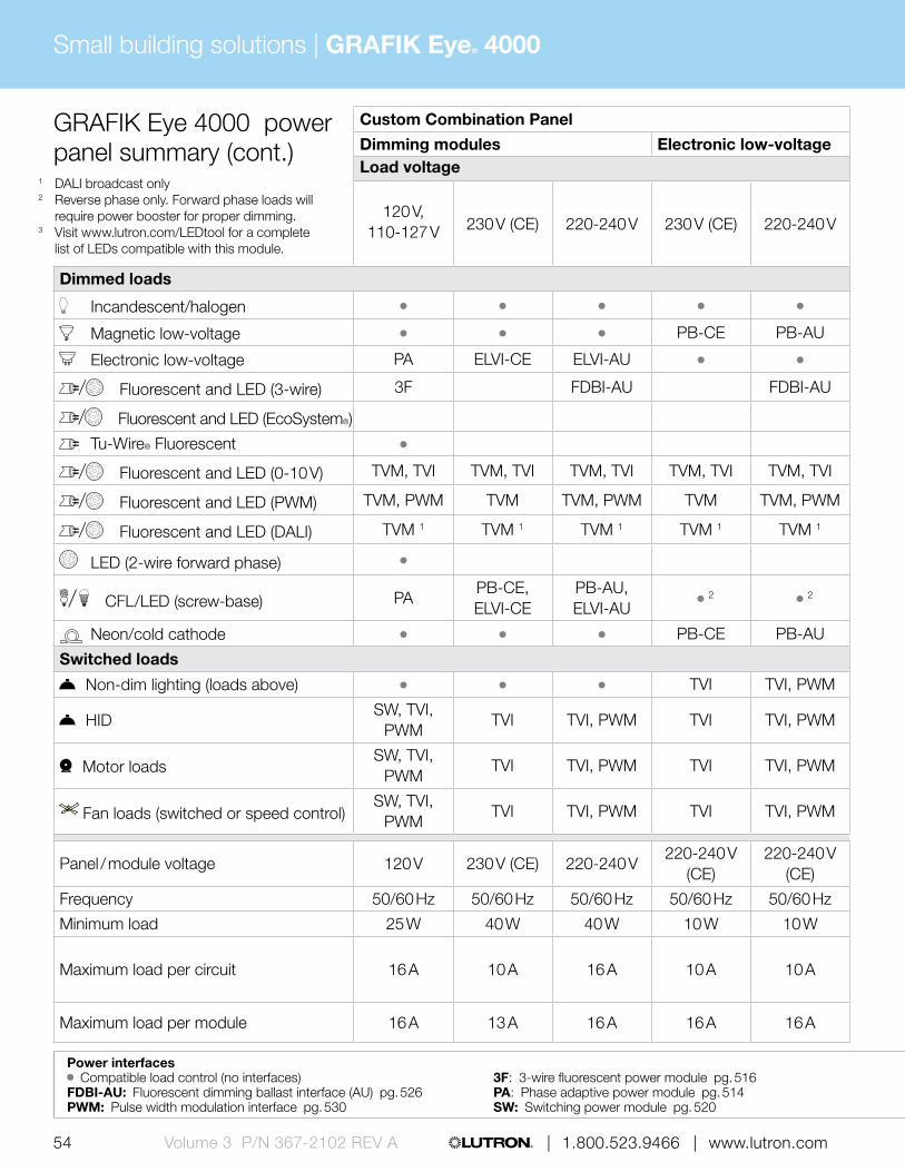
GRAFIK Eye 4000 power panel summary (cont.)
Custom Combination Panel Custom Combination Panel
Dimming modules Electronic low-voltage Adaptive dimming modules Fan speed module Motor module Switching moduleLoad voltage Load voltage
120 V, 110-127 V 230 V (CE) 220-240 V 230 V (CE) 220-240 V
120 V, 110-127 V 230 V (CE) 220-240 V 120 V 120 V
120 V, 110-127 V, 220-240 V, 230 V (CE),
277 V, 347 V
Dimmed loads Dimmed loads
Incandescent/halogen
Magnetic low-voltage PB-CE PB-AU
Electronic low-voltage PA ELVI-CE ELVI-AU
/ Fluorescent and LED (3-wire) 3F FDBI-AU FDBI-AU 3F FDBI-AU
/ Fluorescent and LED (EcoSystem®)
Tu-Wire® Fluorescent
/ Fluorescent and LED (0-10 V) TVM, TVI TVM, TVI TVM, TVI TVM, TVI TVM, TVI TVM, TVI TVM, TVI TVM, TVI
/ Fluorescent and LED (PWM) TVM, PWM TVM TVM, PWM TVM TVM, PWM TVM, PWM TVM TVM, PWM
/ Fluorescent and LED (DALI) TVM 1 TVM 1 TVM 1 TVM 1 TVM 1 TVM 1 TVM 1 TVM 1
LED (2-wire forward phase)
/ CFL/LED (screw-base) PAPB-CE, ELVI-CE
PB-AU, ELVI-AU
2 2 3 3 3
Neon/cold cathode PB-CE PB-AU
Switched loads Switched loads
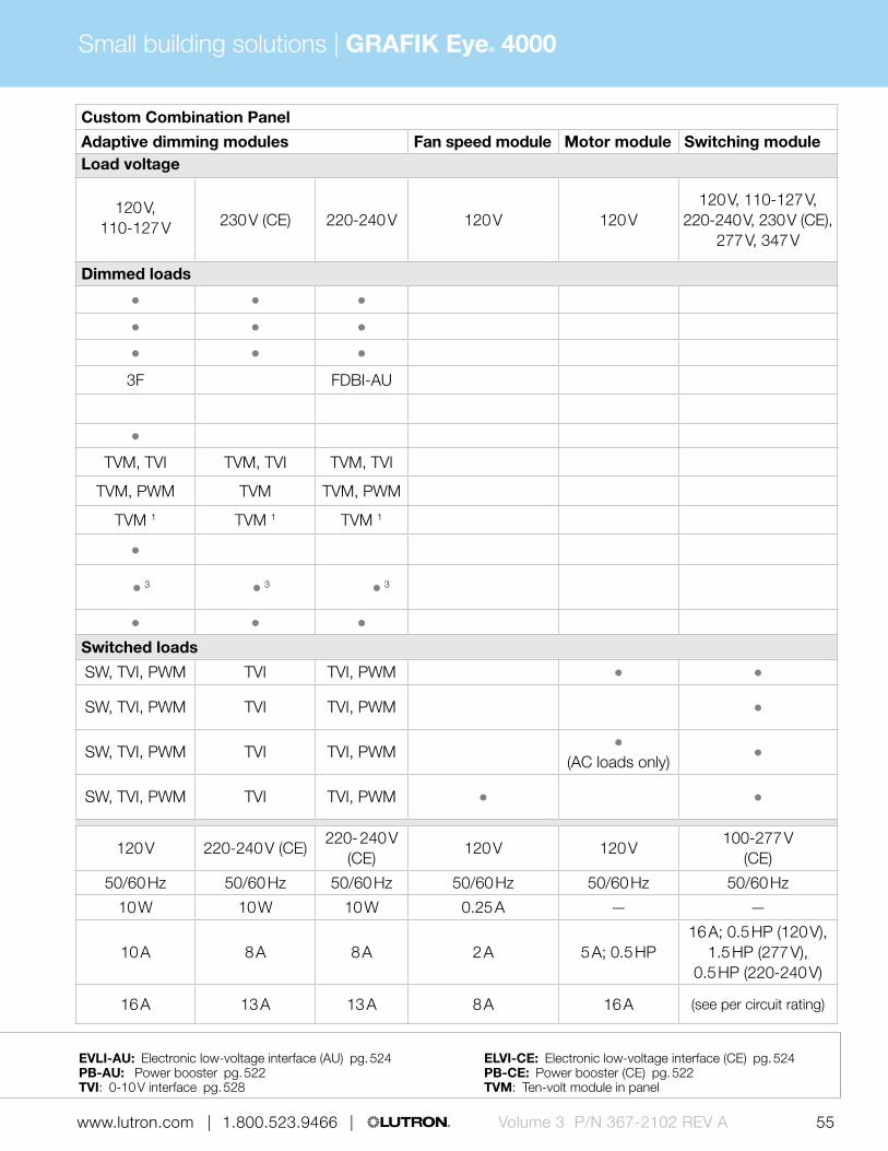
Non-dim lighting (loads above) TVI TVI, PWM SW, TVI, PWM TVI TVI, PWM
HIDSW, TVI,
PWMTVI TVI, PWM TVI TVI, PWM SW, TVI, PWM TVI TVI, PWM
Motor loadsSW, TVI,
PWMTVI TVI, PWM TVI TVI, PWM SW, TVI, PWM TVI TVI, PWM
(AC loads only)
Fan loads (switched or speed control)SW, TVI,
PWMTVI TVI, PWM TVI TVI, PWM SW, TVI, PWM TVI TVI, PWM
Panel / module voltage 120 V 230 V (CE) 220-240 V220-240 V
(CE)220-240 V
(CE)120 V 220-240 V (CE)
220- 240 V (CE)
120 V 120 V100-277 V
(CE)
Frequency 50/60 Hz 50/60 Hz 50/60 Hz 50/60 Hz 50/60 Hz 50/60 Hz 50/60 Hz 50/60 Hz 50/60 Hz 50/60 Hz 50/60 Hz
Minimum load 25 W 40 W 40 W 10 W 10 W 10 W 10 W 10 W 0.25 A — —
Maximum load per circuit 16 A 10 A 16 A 10 A 10 A 10 A 8 A 8 A 2 A 5 A; 0.5 HP16 A; 0.5 HP (120 V),
1.5 HP (277 V), 0.5 HP (220-240 V)
Maximum load per module 16 A 13 A 16 A 16 A 16 A 16 A 13 A 13 A 8 A 16 A (see per circuit rating)
Power interfaces Compatible load control (no interfaces) 3F: 3-wire fluorescent power module pg. 516 EVLI-AU: Electronic low-voltage interface (AU) pg. 524 ELVI-CE: Electronic low-voltage interface (CE) pg. 524
FDBI-AU: Fluorescent dimming ballast interface (AU) pg. 526 PA: Phase adaptive power module pg. 514 PB-AU: Power booster pg. 522 PB-CE: Power booster (CE) pg. 522 PWM: Pulse width modulation interface pg. 530 SW: Switching power module pg. 520 TVI: 0-10 V interface pg. 528 TVM: Ten-volt module in panel
1 DALI broadcast only2 Reverse phase only. Forward phase loads will
require power booster for proper dimming.3 Visit www.lutron.com/LEDtool for a complete
list of LEDs compatible with this module.
GRAFIK Eye® 4000Small building solutions |
55 | 1.800.523.9466 | www.lutron.com www.lutron.com | 1.800.523.9466 | Volume 3 P/N 367-2102 REV A
GRAFIK Eye 4000 power panel summary (cont.)
Custom Combination Panel Custom Combination Panel
Dimming modules Electronic low-voltage Adaptive dimming modules Fan speed module Motor module Switching moduleLoad voltage Load voltage
120 V, 110-127 V 230 V (CE) 220-240 V 230 V (CE) 220-240 V
120 V, 110-127 V 230 V (CE) 220-240 V 120 V 120 V
120 V, 110-127 V, 220-240 V, 230 V (CE),
277 V, 347 V
Dimmed loads Dimmed loads
Incandescent/halogen
Magnetic low-voltage PB-CE PB-AU
Electronic low-voltage PA ELVI-CE ELVI-AU
/ Fluorescent and LED (3-wire) 3F FDBI-AU FDBI-AU 3F FDBI-AU
/ Fluorescent and LED (EcoSystem®)
Tu-Wire® Fluorescent
/ Fluorescent and LED (0-10 V) TVM, TVI TVM, TVI TVM, TVI TVM, TVI TVM, TVI TVM, TVI TVM, TVI TVM, TVI
/ Fluorescent and LED (PWM) TVM, PWM TVM TVM, PWM TVM TVM, PWM TVM, PWM TVM TVM, PWM
/ Fluorescent and LED (DALI) TVM 1 TVM 1 TVM 1 TVM 1 TVM 1 TVM 1 TVM 1 TVM 1
LED (2-wire forward phase)
/ CFL/LED (screw-base) PAPB-CE, ELVI-CE
PB-AU, ELVI-AU
2 2 3 3 3
Neon/cold cathode PB-CE PB-AU
Switched loads Switched loads
Non-dim lighting (loads above) TVI TVI, PWM SW, TVI, PWM TVI TVI, PWM
HIDSW, TVI,
PWMTVI TVI, PWM TVI TVI, PWM SW, TVI, PWM TVI TVI, PWM
Motor loadsSW, TVI,
PWMTVI TVI, PWM TVI TVI, PWM SW, TVI, PWM TVI TVI, PWM
(AC loads only)
Fan loads (switched or speed control)SW, TVI,
PWMTVI TVI, PWM TVI TVI, PWM SW, TVI, PWM TVI TVI, PWM
Panel / module voltage 120 V 230 V (CE) 220-240 V220-240 V
(CE)220-240 V
(CE)120 V 220-240 V (CE)
220- 240 V (CE)
120 V 120 V100-277 V
(CE)
Frequency 50/60 Hz 50/60 Hz 50/60 Hz 50/60 Hz 50/60 Hz 50/60 Hz 50/60 Hz 50/60 Hz 50/60 Hz 50/60 Hz 50/60 Hz
Minimum load 25 W 40 W 40 W 10 W 10 W 10 W 10 W 10 W 0.25 A — —
Maximum load per circuit 16 A 10 A 16 A 10 A 10 A 10 A 8 A 8 A 2 A 5 A; 0.5 HP16 A; 0.5 HP (120 V),
1.5 HP (277 V), 0.5 HP (220-240 V)
Maximum load per module 16 A 13 A 16 A 16 A 16 A 16 A 13 A 13 A 8 A 16 A (see per circuit rating)
Power interfaces Compatible load control (no interfaces) 3F: 3-wire fluorescent power module pg. 516 EVLI-AU: Electronic low-voltage interface (AU) pg. 524 ELVI-CE: Electronic low-voltage interface (CE) pg. 524
FDBI-AU: Fluorescent dimming ballast interface (AU) pg. 526 PA: Phase adaptive power module pg. 514 PB-AU: Power booster pg. 522 PB-CE: Power booster (CE) pg. 522 PWM: Pulse width modulation interface pg. 530 SW: Switching power module pg. 520 TVI: 0-10 V interface pg. 528 TVM: Ten-volt module in panel

GRAFIK Eye® 4000Small building solutions |
56 | 1.800.523.9466 | www.lutron.comVolume 3 P/N 367-2102 REV A
Primary controlsThe main devices in a lighting control system that distribute commands to sub-controls, sensors, and control interfaces.
GRAFIK Eye 4000/4500 control unit
• Models available to control up to 24 zones of lighting
• Provides push-button recall of four preset light scenes plus off on control unit
• Stores up to 12 additional user-programmable scenes
• Available in 42 finishes• 2-zone:
W: 5.56 in (141 mm) H: 4.56 in (116 mm) D: 1.94 in (49 mm) Profile: 0.31 in (8 mm) 3-zone: W: 7.25 in (184 mm) H: 4.56 in (116 mm) D: 1.94 in (49 mm) Profile: 0.31 in (8 mm) 4-, 6-, 8-, 16-, and 24-zone: W: 8.94 in (227 mm) H: 4.56 in (116 mm) D: 1.94 in (49 mm) Profile: 0.31 in (8 mm)
GRAFIK Eye 4000 Series slider control unit
• Models available to control up to 8 zones of lighting
• Provides push-button recall of a single lighting scene plus off on control unit
• Stores up to 11 additional user-programmable scenes
• Allows full-range dimming plus slide-to-off utilizing zone sliders
• Available in nine finishes• 3- and 4-zone:
W: 6.69 in (168 mm) H: 4.56 in (116 mm) D: 1.94 in (49 mm) Profile: 0.31 in (8 mm) 6- and 8-zone: W: 8.31 in (211 mm) H: 4.56 in (116 mm) D: 1.94 in (49 mm) Profile: 0.31 in (8 mm)
POWERED BY
GRX link
BACKBOX
U.S. style
POWERED BY
GRX link
BACKBOX
U.S. style

GRAFIK Eye® 4000Small building solutions |
57 | 1.800.523.9466 | www.lutron.com www.lutron.com | 1.800.523.9466 | Volume 3 P/N 367-2102 REV A
Sub-controlsSub-controls are accessory components that provide additional control locations for increased convenience.
POWERED BY
GRX link
POWERED BY
Battery
POWERED BY
GRAFIK Eye main unit
BACKBOX
U.S. style
POWERED BY
GRX link
BACKBOX
U.S. style
Ceiling-mount infrared (IR) receiver
• Provides control of lighting via IR handheld remote controls by providing an access point
• Allows scene selection, raise/lower scenes and all off functionality
• Compatible with all Lutron IR remote controls
• Available in White• Diameter: 3.50 in (89 mm)
Depth: 3.00 in (76 mm) Profile: 0.75 in (20 mm)
IR remote control
• Models available with four or eight scene control
• Offers master raise/lower and all off buttons
• Available in White and Black• W: 1.50 in (38 mm)
H: 5.69 in (145 mm) D: 0.88 in (22 mm)
2-button wallstation
• Simple, intuitive wallstation ideal for use in entry ways
• Status LEDs indicate which wallstation button has been activated
• Functionality includes scene selection, raise/lower, partitioning and all off
• Available in 17 finishes• W: 2.75 in (70 mm)
H: 4.56 in (116 mm) D: 1.38 in (35 mm) Profile: 0.31 in (8 mm)
Entrance control
• One button control toggles the connected GRAFIK Eye control unit between Scene 1 and Off
• Connects direct to the GRAFIK Eye control unit
• Ideal for projects that utilize the maximum number of keypads/wallstations
• Available in 17 finishes• W: 2.75 in (70 mm)
H: 4.56 in (116 mm) D: 1.38 in (35 mm) Profile: 0.31 in (8 mm)

GRAFIK Eye® 4000Small building solutions |
58 | 1.800.523.9466 | www.lutron.comVolume 3 P/N 367-2102 REV A
Architectural wallstation
• Models available with four programmable buttons that can be used for scene selection, scene or zone toggle or to enable/disable time clock
• Select models available with all off and/or raise/lower buttons and infrared (IR) receiver
• Available in 17 finishes, insert or non-insert style in
• W: 2.75 in (70 mm) H: 4.56 in (116 mm) D: 1.38 in (35 mm) Profile: 0.31 in (8 mm)
Slim-button wallstation
• Models available with 5, 10, or 15 slim buttons to select scenes
• Large buttons provide either on/off or raise/lower functionality
• Available in 17 finishes• 5-button and 10-button:
W: 2.75 in (70 mm) H: 4.56 in (116 mm) D: 0.88 in (21 mm) Profile: 0.31 in (8 mm)
15-button: W: 4.56 in (116 mm) H: 4.56 in (116 mm) D: 0.88 in (21 mm) Profile: 0.31 in (8 mm)
Large-button wallstation
• Models available to select 3, 5, 6 or eight scenes plus raise/lower and all off functionality
• Features large easy-to-use buttons• Available in 17 finishes• 5-scene with off and 3-scene with
raise/lower and off: W: 2.75 in (70 mm) H: 4.56 in (116 mm) D: 0.88 in (21 mm) Profile: 0.31 in (8 mm)
8-scene with off and 5-scene with raise/lower and off: W: 4.56 in (116 mm) H: 4.56 in (116 mm) D: 0.88 in (21 mm) Profile: 0.31 in (8 mm)
European-style wallstation
• Models available with 2, 4, or 8 programmable buttons plus raise/lower and all off functionality
• Select models offer IR receiver allowing convenient control of lights via IR remote control
• Features large, rounded buttons• Available in 17 finishes• Mounts in UK/German single-gang
backbox• W: 3.38 in (86 mm)
H: 3.38 in (86 mm) D: 1.0 in (25 mm) Profile: 0.25 in (6 mm)
POWERED BY
GRX link
BACKBOX
U.S. style
POWERED BY
GRX link
BACKBOX
U.S. style
POWERED BY
GRX link
BACKBOX
U.S. style
POWERED BY
GRX link
BACKBOX
Round or square
Sub-controls (continued)Sub-controls are accessory components that provide additional control locations for increased convenience.

GRAFIK Eye® 4000Small building solutions |
59 | 1.800.523.9466 | www.lutron.com www.lutron.com | 1.800.523.9466 | Volume 3 P/N 367-2102 REV A
POWERED BY
GRX link
BACKBOX
Lutron® supplied
Architrave wallstation
• Models available with four programmable buttons that can be used for scene selection, zone or scene toggle or to enable/disable time clock
• Offers all off button and is available with slim or large buttons
• Available in 16 finishes• Slim-button:
Width: 1.75 in (44 mm) Height: 4.50 in (114 mm) Depth: 1.75 in (44 mm) Profile: 0.13 in (3 mm)
Large-button: Width: 1.50 in (38 mm) Height: 5.16 in (131 mm) Depth: 1.99 in (51 mm) Profile: 0.13 in (3 mm)
POWERED BY
GRX link
BACKBOX
U.S. style
POWERED BY
GRX link
BACKBOX
U.S. style
seeTouch keypad
• Models available with 1-7 programmable buttons that can be used for scene selection, zone toggle or to enable/disable time clock
• Select models available with all off and/or raise/lower buttons and infrared receiver
• Backlit buttons or text make it easy to find and operate keypad in low-light conditions
• Available in 40 finishes• W: 2.75 in (70 mm)
H: 4.56 in (116 mm) D: 1.38 in (35 mm) Profile: 0.31 in (8 mm)
seeTouch window treatment keypad
• Allows control of one or more window treatment zones simultaneously on GRAFIK Eye control unit
• Can control Sivoia QED and AC motorized treatments (interface required)
• Offers Open, Close, Preset and other functionalities
• Available in 20 finishes• W: 2.75 in (70 mm)
H: 4.56 in (116 mm) D: 1.38 in (35 mm) Profile: 0.31 in (8 mm)

GRAFIK Eye® 4000Small building solutions |
60 | 1.800.523.9466 | www.lutron.comVolume 3 P/N 367-2102 REV A
POWERED BY
GRX link
BACKBOX
U.S. style
POWERED BY
External transformer
Keyswitch
• Provides scene selection, enable/disable time clock, partitioning, sequencing and other functionality
• Limits access to lighting control, ideal for public spaces
• Available in 17 finishes, insert or non-insert style
• W: 2.75 in (70 mm) H: 4.56 in (116 mm) D: 1.38 in (35 mm) Profile: 0.31 in (8 mm)
Multi-channel theatrical consoles
• Fully featured and simple to operate, the consoles were designed and built for professional use
• Available with 12 or 24 channels• Simultaneous DMX, microplex,
and analog output• 12-channel:
W: 15.41 in (391 mm) H: 10.13 in (257 mm) D: 2.87 in (73 mm)
24-channel: W: 25.38 in (645 mm) H: 10.13 in (257 mm) D: 2.87 in (73 mm)
POWERED BY
GRX link
BACKBOX
U.S. style
Partition status keypad/wallstation
• Coordinates lighting for up to four movable walls (five rooms)
• Available in three wallstation styles – seeTouch, Architectural and European-style
• seeTouch and Architectural wallstations are available with custom-engraved faceplates with project floor plan
• seeTouch (without custom-engraved faceplate): W: 2.75 in (70 mm) H: 4.56 in (116 mm), D: 1.06 in (27 mm) Profile: 0.31 in (8 mm)
Architectural (without custom-engraved faceplate): W: 2.75 in (70 mm) H: 4.56 in (116 mm) D: 1.38 in (35 mm) Profile: 0.31 in (8 mm)
European-style: W: 3.38 in (86 mm) H: 3.38 in (86 mm) D: 1.00 in (25 mm) Profile: 0.25 in (6 mm)
Sub-controls (continued)Sub-controls are accessory components that provide additional control locations for increased convenience.

GRAFIK Eye® 4000Small building solutions |
61 | 1.800.523.9466 | www.lutron.com www.lutron.com | 1.800.523.9466 | Volume 3 P/N 367-2102 REV A
Ballasts and DriversBallasts and drivers are required to control fluorescent and/or LED lighting via the LCP128 dimming panel with or LCP128 spec grade dimming.
POWERED BY
120 V110-127 V127 V NOM220-240 V
277 V
POWERED BY
120 V110-127 V127 V NOM220-240 V
277 V
POWERED BY
120 V127 V
127 V NOM220-240 V
277 V
POWERED BY
120 V110-277 V
277 V
EcoSystem ballast
• Continuous, flicker-free dimming from 100% to 10%
• Models available for T8, T8 reduced wattage, T5, T5 reduced wattage, and T5HO lamps
• Wired sensors can connect directly to the ballast
• Available with EcoSystem® digital link or 3-wire control
Hi-lume 3D ballast
• Continuous, flicker-free dimming from 100% to 0.3% for T8, T5 and T5HO lamps, and 5% for T5 twin-tube and T5HO 80 W lamps
• Available with EcoSystem digital link or 3-wire control
EcoSystem ballasts for compact fluorescent lamps (CFL)
• Continuous flicker free dimming from 100% to 5% for T4 compact fluorescent lamps
• Available with EcoSystem digital link or 3-wire control
Hi-lume ballast
• Continuous flicker free dimming from 100% to 1%
• Models available for T5HO lamps and T4 compact fluorescent lamps
• Available with 3-wire control

GRAFIK Eye® 4000Small building solutions |
62 | 1.800.523.9466 | www.lutron.comVolume 3 P/N 367-2102 REV A
POWERED BY
120 V
110-127 V
127 V NOM
220-240 V
277 V
POWERED BY
120 V110-277 V
Hi-lume A-Series LED driver
• Continuous, flicker-free dimming from 100% to 1%
• Models available for LED light engines up to 40 W, constant current or constant voltage
• Available with EcoSystem digital link, 3-wire, or 2-wire forward phase control
Tu-wire ballast
• Continuous, flicker-free dimming from 100% to 5%
• Models available for T8 lamps and T4 compact fluorescent lamps
• Available with Tu-wire control
Ballasts and Drivers (continued)Ballasts and drivers are required to control fluorescent and/or LED lighting via the LCP128 dimming panel with or LCP128 spec grade dimming.

GRAFIK Eye® 4000Small building solutions |
63 | 1.800.523.9466 | www.lutron.com www.lutron.com | 1.800.523.9466 | Volume 3 P/N 367-2102 REV A
SensorsWired sensors add convenience by detecting occupancy/vacancy, daylight and partitioning and adjusting accordingly.
Wired high-bay occupancy sensors
• Automatically turns lighting scenes/zones on and/or off based on space occupancy
• Passive IR sensor designed for use in high-bay applications
• Maximum mounting height 45 ft (14 m)
• Surface-mount and end-mount models available
• Available in White 180° and 360° surface-mount:
Diameter: 4 in (102 mm) Depth: 1.5 in (38 mm)
180° end-mount: W: 4.00 in (102 mm) H: 4.50 in (114 mm) D: 1.50 in (38 mm)
360° end-mount: W: 3.60 in (91 mm) H: 4.40 in (112 mm) D: 2.00 in (51 mm)
POWERED BY
20-24 V DC from power pack
POWERED BY
20-24 V DC from power pack
Wired LOS-C and LOS-W series occupancy sensors
• Automatically turns lighting scenes/zones on and/or off based on space occupancy
• Sensor technology options include passive infrared (IR), ultrasonic and dual technology
• Connects to system via contact closure input interface (power pack required)
• Wall-mount and ceiling-mount models available
• Available in White• Ceiling-mount:
Diameter: 4.50 in (114 mm) Depth: 1.40 in (38 mm)
Wall-mount: W: 2.70 in (69 mm) H: 5.25 in (133 mm) D: 3.90 in (99 mm)

GRAFIK Eye® 4000Small building solutions |
64 | 1.800.523.9466 | www.lutron.comVolume 3 P/N 367-2102 REV A
Daylight sensor package
• Allow system to switch lights on/off in response to ambient daylight level setting
• Package includes a wired power pack, daylight sensor, and daylight controller
• Package available in 120 or 277 V; sensor options: indoor, outdoor, atrium/skylight
• Indoor sensor: W: 1.28 in (33 mm) H: 1.15 in (29 mm)
Outdoor sensor: W: 1.85 in (47 mm) H: 1.35 in (34 mm)
Atrium/Skylight sensor: W: 2.25 in (57 mm) H: 1.28 in (33 mm)
POWERED BY
20-24 V DC from power pack
POWERED BY
Daylight controller
POWERED BY
external transformer (12-24 V DC)
Sensors (continued)Wired sensors add convenience by detecting occupancy/vacancy, daylight and partitioning and adjusting accordingly.
Wired photosensor
• Monitors ambient daylight levels and communicates to daylight controller (required)
• Allows controller to adjust lighting automatically
• Available in White• Diameter: 1.18 in (30 mm)
Depth: 1.25 in (32 mm) Profile: 0.69 in (17 mm)
Infrared (IR) partition sensor
• IR transmitter/receiver pair detects open/closed status of partition and coordinates lighting preset functions
• Sensors must be mounted in a position where the partition separates the transmitter and receiver when the partition is closed
• Requires contact closure input/output interface for operation
• Surface mounted• Available in White• Diameter: 4.56 in (159 mm)
Depth: 2.69 in (68 mm) Profile: 1.50 in (38 mm)

GRAFIK Eye® 4000Small building solutions |
65 | 1.800.523.9466 | www.lutron.com www.lutron.com | 1.800.523.9466 | Volume 3 P/N 367-2102 REV A
Control interfacesUse control interfaces to combine Lutron lighting controls with other third-party devices and systems for advanced integration. Interfaces may also provide connection points for other Lutron devices.
RS232 interface
• Allows integration with touchscreen, PC, A/V system or other digital equipment that supports RS232 communication
• Control and monitor switching panel
• Monitor lighting scenes• W: 4.26 in (108 mm)
H: 5.26 in (134 mm) D: 1.06 in (27 mm)
POWERED BY
GRX link or external transformer (12-24 V DC)
Contact closure input/output interface
• Provides five inputs and five dry contact closure outputs
• Compatible with motion/occupancy sensors, movable walls, security systems and other products that have contact closure input/output
• Outputs provide both normally open and normally closed contacts
• W: 4.26 in (108 mm) H: 5.26 in (134 mm) D: 1.06 in (27 mm)
POWERED BY
GRX link or external transformer (12-24 V DC)
POWERED BY
GRX link or external transformer (12-24 V DC)
Wallbox contact closure input interface
• Provides seven contact closure inputs
• Interfaces with third-party low-voltage switches to provide an alternative keypad aesthetic
• Mounts behind third-party low-voltage switch in backbox
• Diameter: 2.31 in (59 mm) Depth: 0.81 in (20 mm)
POWERED BY
GRX link or external transformer (12-24 V DC)
Contact closure output interface
• Provides eight dry contact closure outputs
• Compatible with motorized projection screens, window treatments and A/V equipment that have contact closure output
• Offers both normally open and normally closed contacts
• W: 5.75 in (146 mm) H: 10.75 in (273 mm) D: 2.00 in (50 mm)

GRAFIK Eye® 4000Small building solutions |
66 | 1.800.523.9466 | www.lutron.comVolume 3 P/N 367-2102 REV A
Time clock/programming interface
• Integrates the system with a PC or other digital equipment that supports RS232 or TCP/IP communication
• Built-in astronomical time clock provides ability to schedule lighting events
• Acts as a programming interface for GRAFIK Eye 4500 control units
• W: 4.26 in (108 mm) H: 5.26 in (134 mm) D: 1.06 in (27 mm)
Ethernet interface
• Allows integration with touchscreen, PC, A/V system or other digital equipment that supports TC/ICP communication over Ethernet
• Control and monitor switching panel
• Monitor lighting scenes• W: 4.26 in (108 mm)
H: 5.26 in (134 mm) D: 1.06 in (27 mm)
POWERED BY
GRX link or external transformer (12-24 V DC)
POWERED BY
GRX link or external transformer (12-24 V DC)
POWERED BY
GRX link or external transformer (12-24 V DC)
POWERED BY
GRX link or external transformer (12-24 V DC)
Control interfaces (continued)Use control interfaces to combine Lutron lighting controls with other third-party devices and systems for advanced integration. Interfaces may also provide connection points for other Lutron devices.
Infrared interface
• Allows auxiliary systems equipped with an infrared (IR) emitter to control the system by accessing functions using IR codes
• Two types of codes available: Lutron standard and Lutron PRO
• W: 1.75 in (45 mm) H: 4.10 in (105 mm) D: 0.90 in (23 mm)
DMX512 output interface
• Allows GRAFIK Eye control unit to operate lighting and other equipment that uses the DMX512 protocol
• Converts GRAFIK Eye zone intensities into DMX512 channel settings
• Each zone is assigned to a DMX512 channel
• W: 5.00 in (127 mm) H: 7.75 in (197 mm) D: 2.50 in (84 mm)

GRAFIK Eye® 4000Small building solutions |
67 | 1.800.523.9466 | www.lutron.com www.lutron.com | 1.800.523.9466 | Volume 3 P/N 367-2102 REV A
POWERED BY
GRX link
BACKBOX
U.S. style
POWERED BY
GRX link
BACKBOX
U.S. style
POWERED BY
GRX link or
20-24 V DC from power pack
Emergency lighting interface
• Turns designated lighting loads to “full on” output or other programmed emergency light level
• Senses the normal line-voltage on all three phases of power
• Provides inputs for a Fire Alarm Control Panel
• UL 924 listed as "Emergency Lighting and Power Equipment"
• W: 5.00 in (127 mm) H: 7.75 in (197 mm) D: 2.50 in (64 mm)
POWERED BY
110-127 V127 V NOM
120 V
Sivoia QED controller
• Provides programming and control of one group of Sivoia QED window treatments
• Allows window treatments to be controlled independently or to be incorporated into the lighting scenes
• Available in 17 finishes• W: 2.75 in (70 mm)
H: 4.56 in (116 mm) D: 1.38 in (35 mm) Profile: 0.31 in (8 mm)
AC motor group controller
• 4-channel AC motor controller that provides capability to seamlessly integrate AC motorized window treatments into the system
• Allows window treatments to be controlled independently or to be incorporated into the lighting scenes
• W: 12.00 in H: 7.90 in (200 mm) D: 2.75 in (70 mm)
Daylight controller
• Automatically selects preset scenes in response to ambient daylight
• Features range qualification time which eliminates lighting level fluctuations
• Works with up to three Lutron wired photosensors or one 0-10 V photosensor by others
• Available in White• W: 8.94 in (227 mm)
H: 4.56 in (116 mm) D: 1.94 in (49 mm) Profile: 0.31 in (8 mm)

GRAFIK Eye® 4000Small building solutions |
68 | 1.800.523.9466 | www.lutron.comVolume 3 P/N 367-2102 REV A
Data link repeater
• Allows power panel links to be extended beyond their maximum distances
• Links may be extended 2,000 ft (600 m) for every repeater added
• W: 5.0 in (127 mm) H: 7.75 in (197 mm) D: 2.50 in (64 mm)
POWERED BY
120 V127 V
127 V NOM220-240 V
230 V
Control interfaces (continued)Use control interfaces to combine Lutron lighting controls with other third-party devices and systems for advanced integration. Interfaces may also provide connection points for other Lutron devices.

GRAFIK Eye® 4000Small building solutions |
69 | 1.800.523.9466 | www.lutron.com www.lutron.com | 1.800.523.9466 | Volume 3 P/N 367-2102 REV A
ShadesSivoia QED wired shading systems offer convenient control of daylight at the touch of a button.
Sivoia QED shades
• Shades offer ultra-quiet precision control of daylight
• Styles include:
– Roller shades – Tensioned shades – Roman shades with CERUS® safety technology – Drapery tracks – Kirbé® vertical drapery systems – Venetian blinds
• Includes a wide variety of fabric offerings to meet every need
Sivoia QED power supply (individual and smart panel)
• 24 V DC supply that provides power to shade and drapery drive units
• Simple wiring scheme 4-conductor low voltage link to provide power and communication to Sivoia QED wired electronic drive units
• 4-conductor panel is available in 120 V and 230 V models

GRAFIK Eye® 4000Small building solutions |
70 | 1.800.523.9466 | www.lutron.comVolume 3 P/N 367-2102 REV A
Software and programmingGRAFIK Eye 4000 systems can be programmed via PC-based software or through button-press programming at the panel or wallstation.
GRAFIK Eye Liaison software
• Windows-based utility that allows the programming of a GRAFIK Eye 4500 series main unit
• Programming functionality includes setting scenes, addressing control units and scheduling events
• Allows the extraction of system information and the back-up of programming data
Button-press programming via panel or wallstation
• Assign circuits to zones on the on the control units via the buttons of the panel circuit selector
• Use the keypad/wallstation buttons to assign the keypads/wallstations to the control units
• DIP-switches are used to set-up the address and functionality of the keypads/wallstations and control interfaces

GRAFIK Eye® 4000Small building solutions |
71 | 1.800.523.9466 | www.lutron.com www.lutron.com | 1.800.523.9466 | Volume 3 P/N 367-2102 REV A

72 | 1.800.523.9466 | www.lutron.comVolume 3 P/N 367-2102 REV A
Whole building solutions | Quantum®
Pico® wireless control
Radio Powr Savr™ daylight sensor
Quantum Total Light Management maximizes the efficient use of light to improve comfort and productivity, simplify operations, and save energy. The Quantum system dims or switches all electric lighting, while simultaneously controlling daylight using automated shades.
Feature highlights
• Dimming, switching and shade control
• Energy management• Wired and wireless sensors,
keypads and shades• Building management
system integration
Typical applications
• Office buildings• Healthcare facilities• Convention centers• Hotels• Colleges/Universities
Typical components

73 www.lutron.com | 1.800.523.9466 | Volume 3 P/N 367-2102 REV A
Sivoia® QS wired shades
seeTouch® QS keypad
Energi Savr Node™ with EcoSystem
Green Glance®
Quantum® light management hub (QP2)
Radio Powr Savr™ occupancy/vacancy sensor
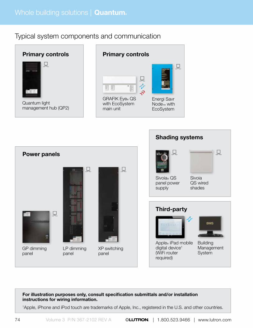
74 | 1.800.523.9466 | www.lutron.comVolume 3 P/N 367-2102 REV A
Whole building solutions | Quantum®
Typical system components and communication
LP dimming panel
XP switching panel
GP dimming panel
Power panels
Third-party
Apple® iPad mobile digital device1 (WiFi router required)
Building Management System
Shading systems
Sivoia® QS panel power supply
Energi Savr Node™ with EcoSystem
Sivoia QS wired shades
Primary controls Primary controls
Quantum light management hub (QP2)
GRAFIK Eye® QS with EcoSystem main unit
For illustration purposes only, consult specification submittals and/or installation instructions for wiring information.1Apple, iPhone and iPod touch are trademarks of Apple, Inc., registered in the U.S. and other countries.
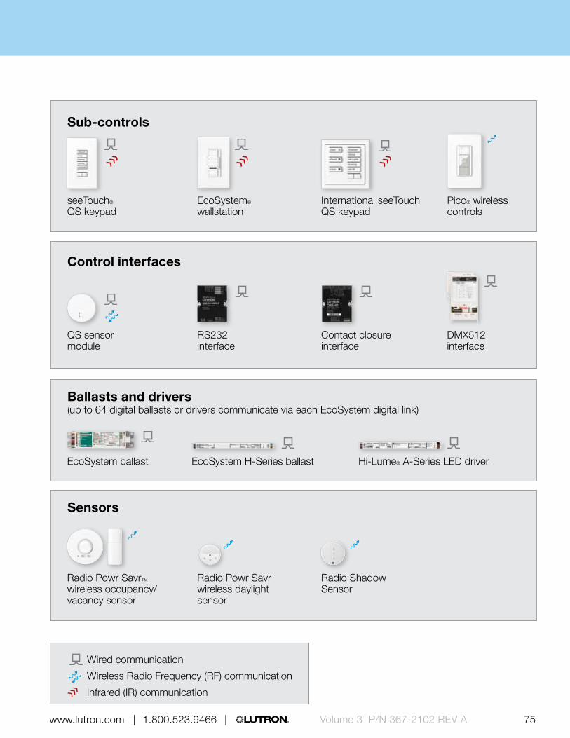
75 | 1.800.523.9466 | www.lutron.com www.lutron.com | 1.800.523.9466 | Volume 3 P/N 367-2102 REV A
Control interfaces
QS sensor module
Contact closure interface
RS232 interface
DMX512 interface
EcoSystem ballast
Ballasts and drivers (up to 64 digital ballasts or drivers communicate via each EcoSystem digital link)
EcoSystem H-Series ballast Hi-Lume® A-Series LED driver
Sub-controls
seeTouch® QS keypad
EcoSystem® wallstation
International seeTouch QS keypad
Pico® wireless controls
Sensors
Radio Powr Savr™ wireless occupancy/vacancy sensor
Radio Powr Savr wireless daylight sensor
Radio Shadow Sensor
Wired communication
Wireless Radio Frequency (RF) communication
Infrared (IR) communication
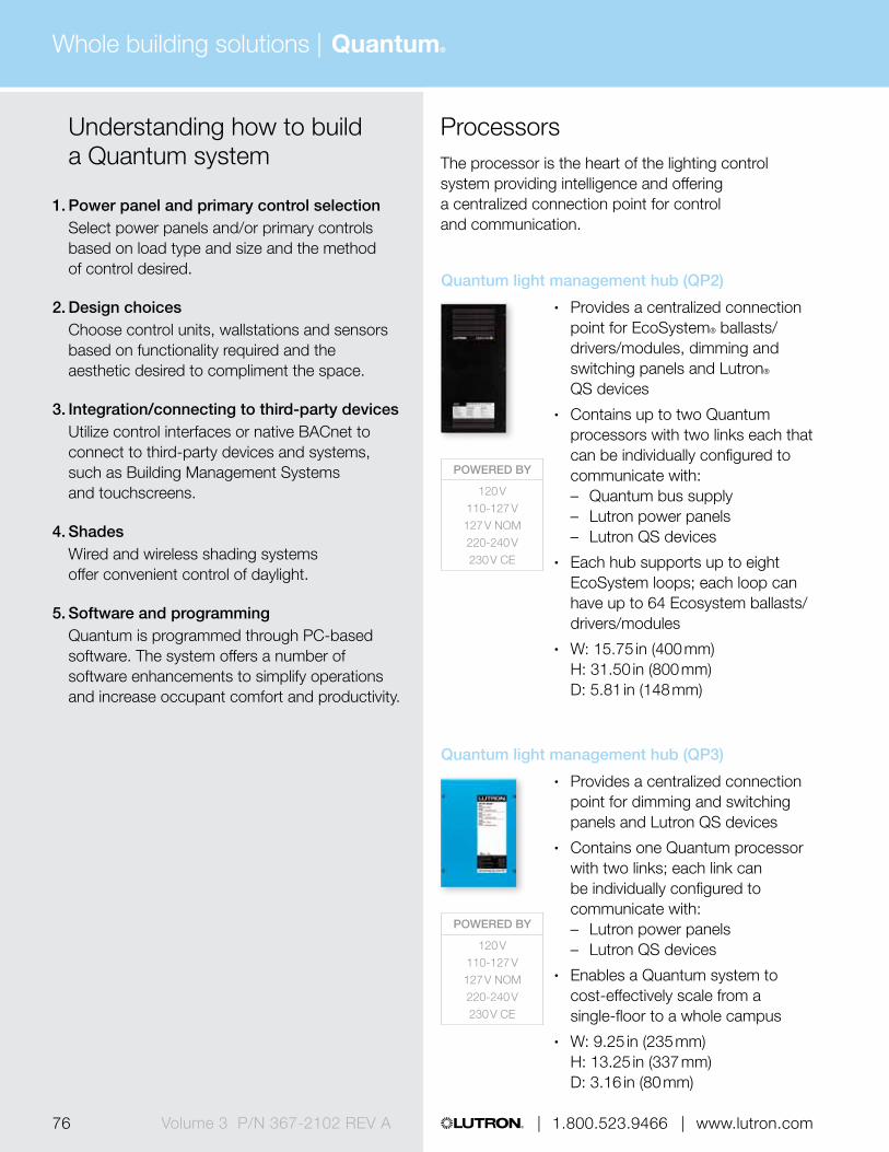
Whole building solutions | Quantum®
76 | 1.800.523.9466 | www.lutron.comVolume 3 P/N 367-2102 REV A
Understanding how to build a Quantum system
1. Power panel and primary control selection Select power panels and/or primary controls
based on load type and size and the method of control desired.
2. Design choices Choose control units, wallstations and sensors
based on functionality required and the aesthetic desired to compliment the space.
3. Integration/connecting to third-party devices Utilize control interfaces or native BACnet to
connect to third-party devices and systems, such as Building Management Systems and touchscreens.
4. Shades Wired and wireless shading systems
offer convenient control of daylight.
5. Software and programming Quantum is programmed through PC-based
software. The system offers a number of software enhancements to simplify operations and increase occupant comfort and productivity.
ProcessorsThe processor is the heart of the lighting control system providing intelligence and offering a centralized connection point for control and communication.
POWERED BY
120 V110-127 V127 V NOM220-240 V230 V CE
POWERED BY
120 V110-127 V127 V NOM220-240 V230 V CE
Quantum light management hub (QP2)
• Provides a centralized connection point for EcoSystem® ballasts/drivers/modules, dimming and switching panels and Lutron® QS devices
• Contains up to two Quantum processors with two links each that can be individually configured to communicate with: – Quantum bus supply – Lutron power panels – Lutron QS devices
• Each hub supports up to eight EcoSystem loops; each loop can have up to 64 Ecosystem ballasts/drivers/modules
• W: 15.75 in (400 mm) H: 31.50 in (800 mm) D: 5.81 in (148 mm)
Quantum light management hub (QP3)
• Provides a centralized connection point for dimming and switching panels and Lutron QS devices
• Contains one Quantum processor with two links; each link can be individually configured to communicate with: – Lutron power panels – Lutron QS devices
• Enables a Quantum system to cost-effectively scale from a single-floor to a whole campus
• W: 9.25 in (235 mm) H: 13.25 in (337 mm) D: 3.16 in (80 mm)

Whole building solutions | Quantum®
77 | 1.800.523.9466 | www.lutron.com www.lutron.com | 1.800.523.9466 | Volume 3 P/N 367-2102 REV A
Power panelsThe power panels provide remote dimming and switching capability for all common light sources, including incandescent, fluorescent, LED, CFL, and neon/cathode.
POWERED BY
120 V110-127 V127 V NOM220-240 V230 V CE
POWERED BY
120 V110-127 V127 V NOM220-240 V230 V CE
277 V
GP dimming panel)
• Panel is typically used for high-performance architectural dimming
• Provides power and dimming for up to 144 circuits
• Feed-though or branch circuit breaker panels are available
• Mini: W: 11.00 in (279 mm) H: 21.13 in (537 mm) D: 6.25 in (160 mm)
Standard: W: 28.00 in (711 mm) H: 37.00 in (940 mm) D: 12.00 in (304 mm)
Large (GP36): W: 26.13 in (653 mm) H: 87.00 in (2175 mm) D: 14.13 in (360 mm)
Large: W: 52.31 in (1308 mm) H: 87.00 in (2175 mm) D: 14.13 in (360 mm)
Extra large: W: 52.31 in (1308 mm) H: 87.00 in (2175 mm) D: 28.25 in (720 mm)
LP dimming panel
• Panel is typically used for commercial dimming panels projects with numerous small loads
• Provides power and dimming for up to 32 dimming legs (up to 8 modules, four outputs per module)
• Panels include branch circuit breakers
• Mini: W: 15.88 in (403 mm) H: 24.50 in (622 mm) D: 4.21 in (107 mm)
Standard: W: 15.88 in (403 mm) H: 59.50 in (1511 mm) D: 4.21 in (107 mm)

Whole building solutions | Quantum®
78 | 1.800.523.9466 | www.lutron.comVolume 3 P/N 367-2102 REV A
Power panels (continued)The power panels provide remote dimming and switching capability for all common light sources, including incandescent, fluorescent, LED, CFL, and neon/cathode.
POWERED BY
120 V110-127 V127 V NOM220-240 V230 V CE
277 V347 V
POWERED BY
120 V110-127 V220-240 V230 V CE
POWERED BY
120 V
XP switching panel
• Million-cycle switching panel employs Lutron patented Softswitch technology
• Provides power and switching for up to 48 switching legs
• Feed-though or branch circuit breaker panels available
• Mini: W: 15.88 in (403 mm) H: 24.50 in (622 mm) D: 4.21 in (107 mm)
Standard: W: 15.88 in (403 mm) H: 59.50 in (1511 mm) D: 4.21 in (107 mm)
Large: W: 23.50 in (597 mm) H: 63.50 in (1613 mm) D: 6.30 in (160 mm)
Extra large: W: 23.50 in (597 mm) H: 82.50 in (2096 mm) D: 6.30 in (160 mm)
Custom combination panel (CCP)
• Combination dimming and switching panel that is ideal for projects with numerous small loads
• Provides power and dimming for up to 32 dimming/switching legs
• Choose modules based on load type and control required
• Panels include branch circuit breakers
• W: 15.88 in (403 mm) H: 59.50 in (1511 mm) D: 4.21 in (107 mm)
DCI dimming panel
• Dimming panel featuring direct current that is ideal for projects that require no radio frequency interference
• Provides power and dimming for up to three circuits
• Lamps are free of flicker and audible noise throughout the entire dimming range
• W: 28.00 in (711 mm) H: 37.00 in (940 mm) D: 12.00 in (304 mm)

Whole building solutions | Quantum®
79 | 1.800.523.9466 | www.lutron.com www.lutron.com | 1.800.523.9466 | Volume 3 P/N 367-2102 REV A
Quantum power panel summary GP panel
Load voltage
120 V, 110-127 V,
127 V (NOM)277 V 230 V (CE) 220-240 V
Dimmed loads
Incandescent/halogen
Magnetic low-voltage
Electronic low-voltage 1 1 1 1
/ Fluorescent and LED (3-wire)
/ Fluorescent and LED (EcoSystem®)
Tu-Wire® fluorescent
/ Fluorescent and LED (0-10 V) TVM, TVI TVM, TVI TVM, TVI TVM, TVI
/ Fluorescent and LED (PWM) TVM, PWM TVM, PWM TVM TVM, PWM
/ Fluorescent and LED (DALI) TVM 2 TVM 2 TVM 2 TVM 2
LED (2-wire forward phase)
/ CFL/LED (screw-base) 1 1 1 1
Neon/cold cathode
Switched loads
Non-dim lighting (loads above)
HID
Motor loadsSW, TVI,
PWMSW, TVI,
PWMTVI TVI, PWM
Fan loadsSW, TVI,
PWMSW, TVI,
PWMTVI TVI, PWM
Panel / module voltage 120 V 277 V 230 V (CE) 220-240 V
Frequency 50/60 Hz 50/60 Hz 50/60 Hz 50/60 Hz
Minimum load 10 W 10 W 10 W 10 W
Maximum load per circuit 16 A 16 A 16 A 16 A
Maximum load per module — — — —
Power interfaces Compatible load control (no interfaces) TVM: Ten-volt module in panel
SW: Switching power module pg. 520 TVI: 0-10 V interface pg. 528PWM: Pulse width modulation interface pg. 530
1 Foward phase only. Not all ELV transformers and dimmable CFL/LEDs dim properly with forward phase control; may require phase-adaptive power module or electronic low voltage interface for proper dimming. For reverse phase, a phase adaptive power module or electronic low-voltage interface will be required.
2 DALI broadcast only

Whole building solutions | Quantum®
80 | 1.800.523.9466 | www.lutron.comVolume 3 P/N 367-2102 REV A
Quantum power panel summary (cont.) LP panel
DCI dimming panel
XP switching panel
Load voltage Load voltage
120 V, 110-127 V,
127 V (NOM)230 V (CE) 220-240 V
120 V, 110-127 V
120 V, 110-127 V, 127 V (NOM)
277 V 347 V 230 V (CE) 220-240 V
Dimmed loads Dimmed loads
Incandescent/halogen
Magnetic low-voltage
Electronic low-voltage PA ELVI-CE ELVI-AU
/ Fluorescent and LED (3-wire) 3F FDBI-AU
/ Fluorescent and LED (EcoSystem®)
Tu-Wire® fluorescent
/ Fluorescent and LED (0-10 V) TVM, TVI TVM, TVI TVM, TVI
/ Fluorescent and LED (PWM) TVM, PWM TVM TVM, PWM
/ Fluorescent and LED (DALI) TVM* TVM* TVM*
LED (2-wire forward phase)
/ CFL/LED (screw-base) PAPB-CE, ELVI-CE
PB-AU, ELVI-AU
Neon/cold cathode
Switched loads Switched loads
Non-dim lighting (loads above)
HIDSW, TVI,
PWMTVI TVI, PWM
Motor loadsSW, TVI,
PWMTVI TVI, PWM
Fan loadsSW, TVI,
PWMTVI TVI, PWM
Panel / module voltage 120 V 230 V (CE) 220-240 V 120 V 120/277 V 120/277 V 347 V 230 V (CE) 220-240 V
Frequency 50/60 Hz 50/60 Hz 50/60 Hz 60 Hz 50/60 Hz 50/60 Hz 50/60 Hz 50/60 Hz 50/60 Hz
Minimum load 25 W 40 W 40 W 10 W — — — — —
Maximum load per circuit 16 A 10 A 16 A 10 A; 1200 W 16 A; 0.5 HP 16 A; 1.5 HP 16 A 16 A; 0.5 HP 16 A; 0.5 HP
Maximum load per module 16 A 13 A 16 A 10 A; 1200 W (see per circuit rating) (see per circuit rating) (see per circuit rating) (see per circuit rating) (see per circuit rating)
Power interfaces Compatible load control (no interfaces) 3F: 3-wire fluorescent power module pg. 516 ELVI-AU: Electronic low-voltage interface (AU) pg. 524 ELVI-CE: Electronic low-voltage interface (CE) pg. 524
FDBI-AU: Fluorescent dimming ballast interface (AU) pg. 526 PA: Phase adaptive power module pg. 514 PB-AU: Power booster pg. 522 PB-CE: Power booster (CE) pg. 522PWM: Pulse width modulation interface pg. 530 SW: Switching power module pg. 520 TVI: 0-10 V interface pg. 528 TVM: Ten-volt module in panel
* DALI broadcast only

Whole building solutions | Quantum®
81 | 1.800.523.9466 | www.lutron.com www.lutron.com | 1.800.523.9466 | Volume 3 P/N 367-2102 REV A
Quantum power panel summary (cont.) LP panel
DCI dimming panel
XP switching panel
Load voltage Load voltage
120 V, 110-127 V,
127 V (NOM)230 V (CE) 220-240 V
120 V, 110-127 V
120 V, 110-127 V, 127 V (NOM)
277 V 347 V 230 V (CE) 220-240 V
Dimmed loads Dimmed loads
Incandescent/halogen
Magnetic low-voltage
Electronic low-voltage PA ELVI-CE ELVI-AU
/ Fluorescent and LED (3-wire) 3F FDBI-AU
/ Fluorescent and LED (EcoSystem®)
Tu-Wire® fluorescent
/ Fluorescent and LED (0-10 V) TVM, TVI TVM, TVI TVM, TVI
/ Fluorescent and LED (PWM) TVM, PWM TVM TVM, PWM
/ Fluorescent and LED (DALI) TVM* TVM* TVM*
LED (2-wire forward phase)
/ CFL/LED (screw-base) PAPB-CE, ELVI-CE
PB-AU, ELVI-AU
Neon/cold cathode
Switched loads Switched loads
Non-dim lighting (loads above)
HIDSW, TVI,
PWMTVI TVI, PWM
Motor loadsSW, TVI,
PWMTVI TVI, PWM
Fan loadsSW, TVI,
PWMTVI TVI, PWM
Panel / module voltage 120 V 230 V (CE) 220-240 V 120 V 120/277 V 120/277 V 347 V 230 V (CE) 220-240 V
Frequency 50/60 Hz 50/60 Hz 50/60 Hz 60 Hz 50/60 Hz 50/60 Hz 50/60 Hz 50/60 Hz 50/60 Hz
Minimum load 25 W 40 W 40 W 10 W — — — — —
Maximum load per circuit 16 A 10 A 16 A 10 A; 1200 W 16 A; 0.5 HP 16 A; 1.5 HP 16 A 16 A; 0.5 HP 16 A; 0.5 HP
Maximum load per module 16 A 13 A 16 A 10 A; 1200 W (see per circuit rating) (see per circuit rating) (see per circuit rating) (see per circuit rating) (see per circuit rating)
Power interfaces Compatible load control (no interfaces) 3F: 3-wire fluorescent power module pg. 516 ELVI-AU: Electronic low-voltage interface (AU) pg. 524 ELVI-CE: Electronic low-voltage interface (CE) pg. 524
FDBI-AU: Fluorescent dimming ballast interface (AU) pg. 526 PA: Phase adaptive power module pg. 514 PB-AU: Power booster pg. 522 PB-CE: Power booster (CE) pg. 522PWM: Pulse width modulation interface pg. 530 SW: Switching power module pg. 520 TVI: 0-10 V interface pg. 528 TVM: Ten-volt module in panel

Whole building solutions | Quantum®
82 | 1.800.523.9466 | www.lutron.comVolume 3 P/N 367-2102 REV A
GRAFIK Eye 4000 power panel summary (cont.)
Custom Combination Panel Custom Combination Panel
Dimming modules Electronic low-voltage modules Adaptive dimming modules Switching module
Load voltage Load voltage
120 V, 110-127 V 230 V (CE) 220-240 V 230 V (CE) 220-240 V120 V,
110-127 V 230 V (CE) 220-240 V120 V, 110-127 V,
220-240 V, 230 V (CE), 277 V, 347 V
Dimmed loads Dimmed loads
Incandescent/halogen
Magnetic low-voltage PB-CE PB-AU
Electronic low-voltage PA ELVI-CE ELVI-AU
/ Fluorescent and LED (3-wire) 3F FDBI-AU FDBI-AU 3F FDBI-AU
/ Fluorescent and LED (EcoSystem®)
Tu-Wire® fluorescent
/ Fluorescent and LED (0-10 V) TVM, TVI TVM, TVI TVM, TVI TVM, TVI TVM, TVI TVM, TVI TVM, TVI TVM, TVI
/ Fluorescent and LED (PWM) TVM, PWM TVM TVM, PWM TVM TVM, PWM TVM, PWM TVM TVM, PWM
/ Fluorescent and LED (DALI) TVM 1 TVM 1 TVM 1 TVM 1 TVM 1 TVM 1 TVM 1 TVM 1
LED (2-wire forward phase)
/ CFL/LED (screw-base) PA PB-CE, ELVI-CE PB-AU, ELVI-AU 2 2 3 3 3
Neon/cold cathode PB-CE PB-AU
Switched loads Switched loads
Non-dim lighting (loads above) TVI TVI, PWM SW, TVI, PWM TVI TVI, PWM
HID SW, TVI, PWM TVI TVI, PWM TVI TVI, PWM SW, TVI, PWM TVI TVI, PWM
Motor loads SW, TVI, PWM TVI TVI, PWM TVI TVI, PWM SW, TVI, PWM TVI TVI, PWM
Fan loads (switched or speed control) SW, TVI, PWM TVI TVI, PWM TVI TVI, PWM SW, TVI, PWM TVI TVI, PWM
Panel / module voltage 120 V 230 V (CE) 220-240 V 220-240 V (CE) 220-240 V (CE) 120 V 220-240 V (CE)220- 240 V
(CE)100-277 V (CE)
Frequency 50/60 Hz 50/60 Hz 50/60 Hz 50/60 Hz 50/60 Hz 50/60 Hz 50/60 Hz 50/60 Hz 50/60 Hz
Minimum load 25 W 40 W 40 W 10 W 10 W 10 W 10 W 10 W —
Maximum load per circuit 16 A 10 A 16 A 10 A 10 A 10 A 8 A 8 A16 A; 0.5 HP (120 V),
1.5 HP (277 V), 0.5 HP (220-240 V)
Maximum load per module 16 A 13 A 16 A 16 A 16 A 16 A 13 A 13 A (see per circuit rating)
Power interfaces Compatible load control (no interfaces) 3F: 3-wire fluorescent power module pg. 516 ELVI-AU: Electronic low-voltage interface (AU) pg. 524 ELVI-CE: Electronic low-voltage interface (CE) pg. 524
FDBI-AU: Fluorescent dimming ballast interface (AU) pg. 526 PA: Phase adaptive power module pg. 514 PB-AU: Power booster pg. 522 PB-CE: Power booster (CE) pg. 522PWM: Pulse width modulation interface pg. 530 SW: Switching power module pg. 520 TVI: 0-10 V interface pg. 528 TVM: Ten-volt module in panel
1 DALI broadcast only2 Reverse phase only. Forward phase loads will
require a power booster for proper dimming.3 Visit www.lutron.com/LEDtool for a complete
list of LEDs compatible with this module.

Whole building solutions | Quantum®
83 | 1.800.523.9466 | www.lutron.com www.lutron.com | 1.800.523.9466 | Volume 3 P/N 367-2102 REV A
GRAFIK Eye 4000 power panel summary (cont.)
Custom Combination Panel Custom Combination Panel
Dimming modules Electronic low-voltage modules Adaptive dimming modules Switching module
Load voltage Load voltage
120 V, 110-127 V 230 V (CE) 220-240 V 230 V (CE) 220-240 V120 V,
110-127 V 230 V (CE) 220-240 V120 V, 110-127 V,
220-240 V, 230 V (CE), 277 V, 347 V
Dimmed loads Dimmed loads
Incandescent/halogen
Magnetic low-voltage PB-CE PB-AU
Electronic low-voltage PA ELVI-CE ELVI-AU
/ Fluorescent and LED (3-wire) 3F FDBI-AU FDBI-AU 3F FDBI-AU
/ Fluorescent and LED (EcoSystem®)
Tu-Wire® fluorescent
/ Fluorescent and LED (0-10 V) TVM, TVI TVM, TVI TVM, TVI TVM, TVI TVM, TVI TVM, TVI TVM, TVI TVM, TVI
/ Fluorescent and LED (PWM) TVM, PWM TVM TVM, PWM TVM TVM, PWM TVM, PWM TVM TVM, PWM
/ Fluorescent and LED (DALI) TVM 1 TVM 1 TVM 1 TVM 1 TVM 1 TVM 1 TVM 1 TVM 1
LED (2-wire forward phase)
/ CFL/LED (screw-base) PA PB-CE, ELVI-CE PB-AU, ELVI-AU 2 2 3 3 3
Neon/cold cathode PB-CE PB-AU
Switched loads Switched loads
Non-dim lighting (loads above) TVI TVI, PWM SW, TVI, PWM TVI TVI, PWM
HID SW, TVI, PWM TVI TVI, PWM TVI TVI, PWM SW, TVI, PWM TVI TVI, PWM
Motor loads SW, TVI, PWM TVI TVI, PWM TVI TVI, PWM SW, TVI, PWM TVI TVI, PWM
Fan loads (switched or speed control) SW, TVI, PWM TVI TVI, PWM TVI TVI, PWM SW, TVI, PWM TVI TVI, PWM
Panel / module voltage 120 V 230 V (CE) 220-240 V 220-240 V (CE) 220-240 V (CE) 120 V 220-240 V (CE)220- 240 V
(CE)100-277 V (CE)
Frequency 50/60 Hz 50/60 Hz 50/60 Hz 50/60 Hz 50/60 Hz 50/60 Hz 50/60 Hz 50/60 Hz 50/60 Hz
Minimum load 25 W 40 W 40 W 10 W 10 W 10 W 10 W 10 W —
Maximum load per circuit 16 A 10 A 16 A 10 A 10 A 10 A 8 A 8 A16 A; 0.5 HP (120 V),
1.5 HP (277 V), 0.5 HP (220-240 V)
Maximum load per module 16 A 13 A 16 A 16 A 16 A 16 A 13 A 13 A (see per circuit rating)
Power interfaces Compatible load control (no interfaces) 3F: 3-wire fluorescent power module pg. 516 ELVI-AU: Electronic low-voltage interface (AU) pg. 524 ELVI-CE: Electronic low-voltage interface (CE) pg. 524
FDBI-AU: Fluorescent dimming ballast interface (AU) pg. 526 PA: Phase adaptive power module pg. 514 PB-AU: Power booster pg. 522 PB-CE: Power booster (CE) pg. 522PWM: Pulse width modulation interface pg. 530 SW: Switching power module pg. 520 TVI: 0-10 V interface pg. 528 TVM: Ten-volt module in panel
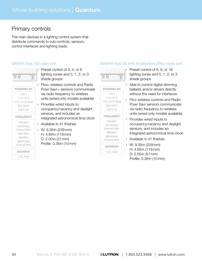
Whole building solutions | Quantum®
84 | 1.800.523.9466 | www.lutron.comVolume 3 P/N 367-2102 REV A
Primary controlsThe main devices in a lighting control system that distribute commands to sub-controls, sensors, control interfaces and lighting loads.
POWERED BY
120 V110-127 V
110-127 V NOM220-240 V230 V CE
FREQUENCY
434 MHz434 limited
channel MHz865 MHz868 MHz
868 limited channel MHz
BACKBOX
U.S. style
POWERED BY
120 V110-127 V
110-127 V NOM220-240 V230 V CE
FREQUENCY
434 MHz434 limited
channel MHz868 MHz
868 limited channel MHz
BACKBOX
U.S. style
GRAFIK Eye® QS main unit
• Preset control of 3, 4, or 6 lighting zones and 0, 1, 2, or 3 shade groups
• Pico® wireless controls and Radio Powr SavrTM sensors communicate via radio frequency to wireless units (wired only models available)
• Provides wired inputs to occupancy/vacancy and daylight sensors, and includes an integrated astronomical time clock
• Available in 41 finishes• W: 9.38 in (239 mm)
H: 4.69 in (119 mm) D: 2.00 in (51 mm) Profile: 0.38 in (10 mm)
GRAFIK Eye QS with EcoSystem®/DALI main unit
• Preset control of 6, 8, or 16 lighting zones and 0, 1, 2, or 3 shade groups
• Able to control digital dimming ballasts and/or drivers directly without the need for interfaces
• Pico wireless controls and Radio Powr Savr sensors communicate via radio frequency to wireless units (wired only models available)
• Provides wired inputs to occupancy/vacancy and daylight sensors, and includes an integrated astronomical time clock
• Available in 41 finishes• W: 9.38 in (239 mm)
H: 4.69 in (119 mm) D: 2.00 in (51 mm) Profile: 0.38 in (10 mm)

Whole building solutions | Quantum®
85 | 1.800.523.9466 | www.lutron.com www.lutron.com | 1.800.523.9466 | Volume 3 P/N 367-2102 REV A
* Requires 120 V control input
Quantum primary control summary GRAFIK Eye® QS main units
Load voltage
120 V, 110-127 V, 127 V (NOM)
277 V* 220-240 V
Dimmed loads
Incandescent/halogen PA
Magnetic low-voltage PA
Electronic low-voltage PA PA ELVI-AU
/ Fluorescent and LED (3-wire) 3F 3F FDBI-AU
/ Fluorescent and LED (EcoSystem®)
Tu-Wire® fluorescent
/ Fluorescent and LED (0-10 V) TVI TVI TVI
/ Fluorescent and LED (PWM) PWM PWM PWM
/ Fluorescent and LED (DALI)
LED (2-wire forward phase)
/ CFL/LED (screw-base) PA PA PB-AU, ELVI-AU
Neon/cold cathode
Switched loads
Non-dim lighting (loads above) SW, TVI, PWM
HID SW, TVI, PWM SW, TVI, PWM TVI, PWM
Motor loads SW, TVI, PWM SW, TVI, PWM TVI, PWM
Fan loads SW, TVI, PWM SW, TVI, PWM TVI, PWM
Panel / module voltage120-127 V/ 220-240 V
120-127 V/ 220-240 V
120-127 V/ 220-240 V
Frequency 50/60 Hz 50/60 Hz 50/60 Hz
Minimum load 25 25 40
Maximum load per circuit800 W,
600 W (MLV)800 W,
600 W (MLV)1200 W,
960 W (MLV)
Maximum load per module2000 W,
1600 (MLV)2000 W,
1600 (MLV)3000 W,
2400 W (MLV)
Power interfaces Compatible load control (no interfaces) PWM: Pulse width modulation interface pg. 530
SW: Switching power module pg. 520 TVI: 0-10 V interface pg. 528

Whole building solutions | Quantum®
86 | 1.800.523.9466 | www.lutron.comVolume 3 P/N 367-2102 REV A
* Requires 120 V control input
Quantum primary control summary (cont.) GRAFIK Eye® QS main units
GRAFIK Eye QS with DALI main units
GRAFIK Eye® QS with EcoSystem main units
Load voltage Load voltage
230 V (CE) 220-240 V220-240 V, 230 V (CE)
120 V, 110-127 V, 127 V NOM
277 V* 347 V* 220-240 V
Dimmed loads Dimmed loads
Incandescent/halogen PA
Magnetic low-voltage PA
Electronic low-voltage ELVI-CE ELVI-AU PA PA ELVI-AU
/ Fluorescent and LED (3-wire) FDBI-AU 3F, BMF, BMJ 3F, BMF, BMJ FDBI-AU
/ Fluorescent and LED (EcoSystem®)
Tu-Wire® fluorescent
/ Fluorescent and LED (0-10 V) TVI TVI TVI, LMF TVI, LMF TVI
/ Fluorescent and LED (PWM) PWM PWM PWM PWM
/ Fluorescent and LED (DALI)
LED (2-wire forward phase)
/ CFL/LED (screw-base) PB-CE, ELVI-CE PB-AU, ELVI-AU PA PA PB-AU, ELVI-AU
Neon/cold cathode
Switched loads Switched loads
Non-dim lighting (loads above) XPJ, SW, TVI, PWM
HID TVI TVI, PWM SW, TVI, PWM SW, TVI, PWM TVI, PWM
Motor loads TVI TVI, PWM XPJ, SW, TVI, PWM XPJ, SW, TVI, PWM TVI, PWM
Fan loads (switched or speed control) TVI TVI, PWM XPJ, SW, TVI, PWM XPJ, SW, TVI, PWM TVI, PWM
Main unit voltage 230 V (CE) 230 V (CE) 230 V (CE)120-127 V/ 220-240 V
120-127 V/ 220-240 V
120-127 V/ 220-240 V
120-127 V/ 220-240 V
Frequency 50/60 Hz 50/60 Hz 50/60 Hz 50/60 Hz 50/60 Hz 50/60 Hz 50/60 Hz
Minimum capacity per zone 40 40 — 25 25 25 40
Maximum capacity per zone500 W,
400 W (MLV)500 W,
400 W (MLV)—
800 W, 600 W (MLV)
800 W, 600 W (MLV)
800 W, 600 W (MLV)
1200 W, 960 W (MLV)
Unit capacity
3-zone: 1500 W, 1200 W (MLV);
4-zone: 2000 W, 1600 W (MLV);
6-zone: 2300 W
3-zone: 1500 W, 1200 W (MLV);
4-zone: 2000 W, 1600 W (MLV);
6-zone: 2300 W
64 DALI ballasts2000 W,
1600 W (MLV)2000 W,
1600 W (MLV)2000 W,
1600 W (MLV)3000 W,
2400 W (MLV)
Power interfaces Compatible load control (no interfaces) 3F: 3-wire fluorescent power module pg. 516 BMJ: EcoSystem dimming power module pg. 534 BMF: EcoSystem fixture module pg. 538
ELVI-AU: Electronic low-voltage interface (AU) pg. 524 ELVI-CE: Electronic low-voltage interface (CE) pg. 524 FDBI-AU: Fluorescent dimming ballast interface (AU) pg. 526 PA: Phase adaptive power module pg. 514PB-AU: Power booster pg. 522 PB-CE: Power booster (CE) pg. 522 PWM: Pulse width modulation interface pg. 530 SW: Switching power module pg. 520TVI: 0-10 V interface pg. 528 WBX: Phase adaptive power module with 3-wire input pg. 518 XPJ: EcoSystem switching power module pg. 536 LMF: 0-10 V to EcoSystem interface pg. 540

Whole building solutions | Quantum®
87 | 1.800.523.9466 | www.lutron.com www.lutron.com | 1.800.523.9466 | Volume 3 P/N 367-2102 REV A
Quantum primary control summary (cont.) GRAFIK Eye® QS main units
GRAFIK Eye QS with DALI main units
GRAFIK Eye® QS with EcoSystem main units
Load voltage Load voltage
230 V (CE) 220-240 V220-240 V, 230 V (CE)
120 V, 110-127 V, 127 V NOM
277 V* 347 V* 220-240 V
Dimmed loads Dimmed loads
Incandescent/halogen PA
Magnetic low-voltage PA
Electronic low-voltage ELVI-CE ELVI-AU PA PA ELVI-AU
/ Fluorescent and LED (3-wire) FDBI-AU 3F, BMF, BMJ 3F, BMF, BMJ FDBI-AU
/ Fluorescent and LED (EcoSystem®)
Tu-Wire® fluorescent
/ Fluorescent and LED (0-10 V) TVI TVI TVI, LMF TVI, LMF TVI
/ Fluorescent and LED (PWM) PWM PWM PWM PWM
/ Fluorescent and LED (DALI)
LED (2-wire forward phase)
/ CFL/LED (screw-base) PB-CE, ELVI-CE PB-AU, ELVI-AU PA PA PB-AU, ELVI-AU
Neon/cold cathode
Switched loads Switched loads
Non-dim lighting (loads above) XPJ, SW, TVI, PWM
HID TVI TVI, PWM SW, TVI, PWM SW, TVI, PWM TVI, PWM
Motor loads TVI TVI, PWM XPJ, SW, TVI, PWM XPJ, SW, TVI, PWM TVI, PWM
Fan loads (switched or speed control) TVI TVI, PWM XPJ, SW, TVI, PWM XPJ, SW, TVI, PWM TVI, PWM
Main unit voltage 230 V (CE) 230 V (CE) 230 V (CE)120-127 V/ 220-240 V
120-127 V/ 220-240 V
120-127 V/ 220-240 V
120-127 V/ 220-240 V
Frequency 50/60 Hz 50/60 Hz 50/60 Hz 50/60 Hz 50/60 Hz 50/60 Hz 50/60 Hz
Minimum capacity per zone 40 40 — 25 25 25 40
Maximum capacity per zone500 W,
400 W (MLV)500 W,
400 W (MLV)—
800 W, 600 W (MLV)
800 W, 600 W (MLV)
800 W, 600 W (MLV)
1200 W, 960 W (MLV)
Unit capacity
3-zone: 1500 W, 1200 W (MLV);
4-zone: 2000 W, 1600 W (MLV);
6-zone: 2300 W
3-zone: 1500 W, 1200 W (MLV);
4-zone: 2000 W, 1600 W (MLV);
6-zone: 2300 W
64 DALI ballasts2000 W,
1600 W (MLV)2000 W,
1600 W (MLV)2000 W,
1600 W (MLV)3000 W,
2400 W (MLV)
Power interfaces Compatible load control (no interfaces) 3F: 3-wire fluorescent power module pg. 516 BMJ: EcoSystem dimming power module pg. 534 BMF: EcoSystem fixture module pg. 538
ELVI-AU: Electronic low-voltage interface (AU) pg. 524 ELVI-CE: Electronic low-voltage interface (CE) pg. 524 FDBI-AU: Fluorescent dimming ballast interface (AU) pg. 526 PA: Phase adaptive power module pg. 514PB-AU: Power booster pg. 522 PB-CE: Power booster (CE) pg. 522 PWM: Pulse width modulation interface pg. 530 SW: Switching power module pg. 520TVI: 0-10 V interface pg. 528 WBX: Phase adaptive power module with 3-wire input pg. 518 XPJ: EcoSystem switching power module pg. 536 LMF: 0-10 V to EcoSystem interface pg. 540

Whole building solutions | Quantum®
88 | 1.800.523.9466 | www.lutron.comVolume 3 P/N 367-2102 REV A
Primary controls (continued)The main devices in a lighting control system that distribute commands to sub-controls, sensors, control interfaces and lighting loads.
POWERED BY
Panel:120 V
110-127 V127 V NOM220-240 V
277 V
DIN-rail:220-240 V230 V CE
POWERED BY
Panel:120 V
110-127 V127 V NOM220-240 V
277 V
DIN-rail:220-240 V230 V CE
POWERED BY
220-240 V230 V CE
Energi Savr NodeTM with EcoSystem
• Provides control of up to 64 or 128 EcoSystem® compatible devices
• Wired communication with keypads/wallstations, sensors and control interfaces via the QS link
• Wireless communication with Pico® wireless sensors and Radio Powr SavrTM sensors via a QS sensor module
• Panel: W: 9.25 in (162 mm) H: 13.25 in (335 mm) D: 3.16 in (80 mm)
• DIN-rail; W: 6.36 in (162 mm) H: 3.53 in (90 mm) D: 2.39 in (61 mm)
Energi Savr Node for DALI
• Provides control of two loops of DALI compliant digital addressable loads; up to 128 DALI compatible devices
• Each DALI loop can control a maximum of 16 zones
• Wired communication with keypads/wallstations, sensors and control interfaces via the QS link
• Wireless communication with Pico wireless sensors and Radio Powr Savr sensors via a QS sensor module
• W: 6.36 in (162 mm) H: 3.53 in (90 mm) D: 2.39 in (61 mm)
Energi Savr Node with Softswitch/ Energi Savr Node for Switching
• Controls up to four zones of lighting fixtures
• Provides easy integration of occupancy sensors, daylight sensors, and digital light controls for switching applications
• Wired communication with keypads/wallstations, sensors and control interfaces via the QS link
• Wireless communication with Pico wireless sensors and Radio Powr Savr sensors via a QS sensor module
• Panel: W: 9.25 in (235 mm) H: 13.25 in (337 mm) D: 3.16 in (80 mm)
• DIN-rail: W: 6.36 in (162 mm) H: 3.53 in (90 mm) D: 2.39 in (61 mm)
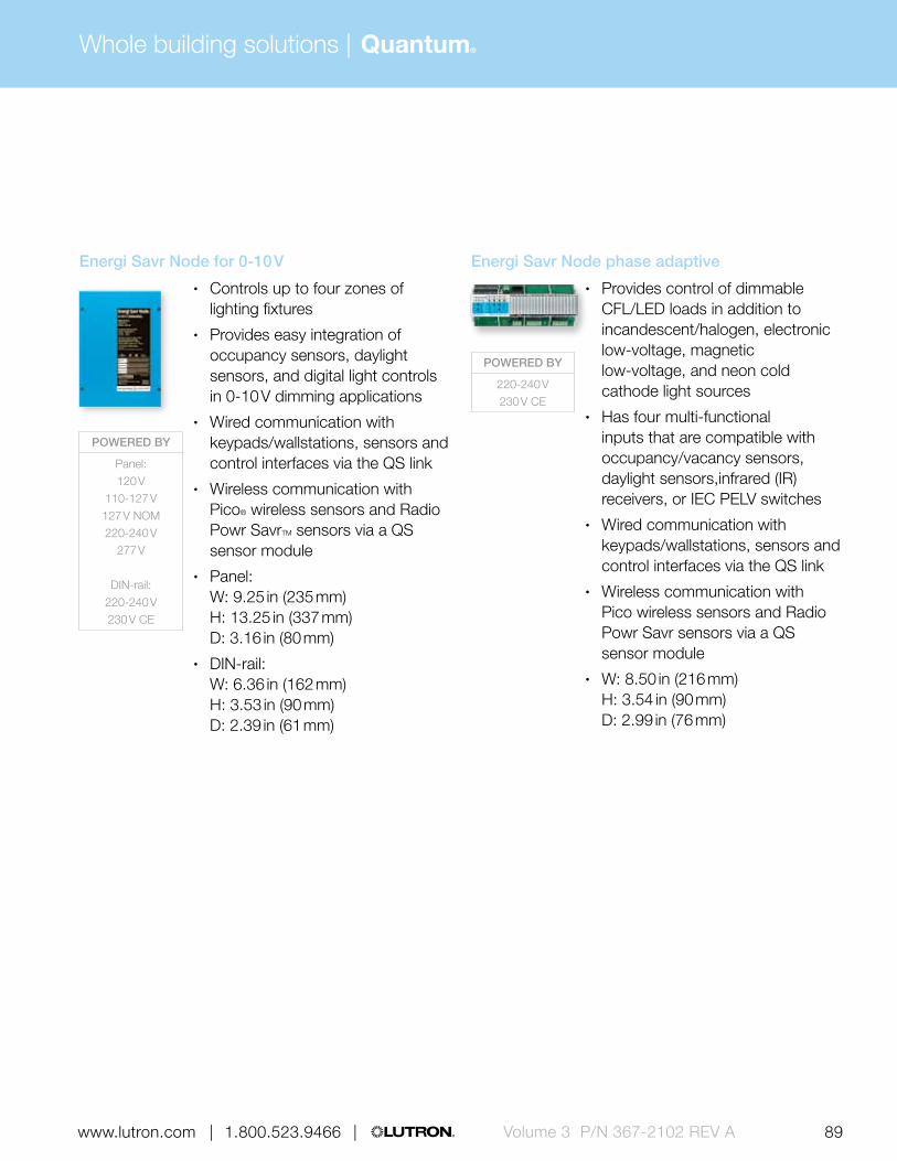
Whole building solutions | Quantum®
89 | 1.800.523.9466 | www.lutron.com www.lutron.com | 1.800.523.9466 | Volume 3 P/N 367-2102 REV A
POWERED BY
220-240 V230 V CE
Energi Savr Node phase adaptive
• Provides control of dimmable CFL/LED loads in addition to incandescent/halogen, electronic low-voltage, magnetic low-voltage, and neon cold cathode light sources
• Has four multi-functional inputs that are compatible with occupancy/vacancy sensors, daylight sensors,infrared (IR) receivers, or IEC PELV switches
• Wired communication with keypads/wallstations, sensors and control interfaces via the QS link
• Wireless communication with Pico wireless sensors and Radio Powr Savr sensors via a QS sensor module
• W: 8.50 in (216 mm) H: 3.54 in (90 mm) D: 2.99 in (76 mm)
POWERED BY
Panel:120 V
110-127 V127 V NOM220-240 V
277 V
DIN-rail:220-240 V230 V CE
Energi Savr Node for 0-10 V
• Controls up to four zones of lighting fixtures
• Provides easy integration of occupancy sensors, daylight sensors, and digital light controls in 0-10 V dimming applications
• Wired communication with keypads/wallstations, sensors and control interfaces via the QS link
• Wireless communication with Pico® wireless sensors and Radio Powr SavrTM sensors via a QS sensor module
• Panel: W: 9.25 in (235 mm) H: 13.25 in (337 mm) D: 3.16 in (80 mm)
• DIN-rail: W: 6.36 in (162 mm) H: 3.53 in (90 mm) D: 2.39 in (61 mm)

Whole building solutions | Quantum®
90 | 1.800.523.9466 | www.lutron.comVolume 3 P/N 367-2102 REV A
1 To control 347 V loads, use Energi Savr Node with EcoSystem fed by 120 V
2 Does not provide interlock between outputs
Quantum primary control summary Energi Savr NodeTM with EcoSystem®
Energi Savr Node with EcoSystem
(DIN-rail)
Energi Savr Node for DALI
(DIN-rail)Energi Savr Node with Softswitch
Load voltage Load voltage
120 V, 110-127 V, 127 V NOM
277 V 220-240 V 347 V1 220-240 V, 230 V (CE)
220-240 V, 230 V (CE)
120 V, 110-127 V,
127 V (NOM)277 V 220-240 V 347 V
Dimmed loads Dimmed loads
Incandescent/halogen BMJ + WBX BMJ + WBX BMJ + WBX
Magnetic low-voltage BMJ + WBX BMJ + WBX BMJ + WBX
Electronic low-voltage BMJ + WBX BMJ + WBX BMJ + WBX
/ Fluorescent and LED (3-wire) BMJ, BMF BMJ, BMF BMJ, BMF
/ Fluorescent and LED (EcoSystem®)
Tu-Wire® fluorescent BMJ + WBX
/ Fluorescent and LED (0-10 V) LMF LMF LMF
/ Fluorescent and LED (PWM)
/ Fluorescent and LED (DALI)
LED (2-wire forward phase)
/ CFL/LED (screw-base) BMJ + WBX BMJ + WBX BMJ + WBX
Neon/cold cathode BMJ + WBX BMJ + WBX BMJ + WBX
Switched loads Switched loads
Non-dim lighting (loads above) XPJ XPJ XPJ
HID
Motor loads XPJ XPJ XPJ 2 2 2
Fan loads XPJ XPJ XPJ
Energi Savr Node voltage 120-277 V 120-277 V 120-277 V 120-277 V 220-240 V (CE) 220-240 V (CE) 120-277 V 120-277 V 120-277 V 120-127 V
Frequency 50/60 Hz 50/60 Hz 50/60 Hz 50/60 Hz 50/60 Hz 50/60 Hz 50/60 Hz 50/60 Hz 50/60 Hz 50/60 Hz
Maximum capacity per loop/zone64 EcoSystem
devices64 EcoSystem
devices64 EcoSystem
devices64 EcoSystem
devices64 EcoSystem
devices64 DALI devices
16 A; 0.5 HP 16 A; 0.5 HP 16 A; 0.5 HP 16 A
Power interfaces Compatible load control (no interfaces) BMJ: EcoSystem dimming power module pg. 534 LMF: EcoSystem to 0-10 V interface pg. 540 WBX: Phase adaptive power module with 3-wire input pg. 518
XPJ: EcoSystem switching power module pg. 536

Whole building solutions | Quantum®
91 | 1.800.523.9466 | www.lutron.com www.lutron.com | 1.800.523.9466 | Volume 3 P/N 367-2102 REV A
Quantum primary control summary Energi Savr NodeTM with EcoSystem®
Energi Savr Node with EcoSystem
(DIN-rail)
Energi Savr Node for DALI
(DIN-rail)Energi Savr Node with Softswitch
Load voltage Load voltage
120 V, 110-127 V, 127 V NOM
277 V 220-240 V 347 V1 220-240 V, 230 V (CE)
220-240 V, 230 V (CE)
120 V, 110-127 V,
127 V (NOM)277 V 220-240 V 347 V
Dimmed loads Dimmed loads
Incandescent/halogen BMJ + WBX BMJ + WBX BMJ + WBX
Magnetic low-voltage BMJ + WBX BMJ + WBX BMJ + WBX
Electronic low-voltage BMJ + WBX BMJ + WBX BMJ + WBX
/ Fluorescent and LED (3-wire) BMJ, BMF BMJ, BMF BMJ, BMF
/ Fluorescent and LED (EcoSystem®)
Tu-Wire® fluorescent BMJ + WBX
/ Fluorescent and LED (0-10 V) LMF LMF LMF
/ Fluorescent and LED (PWM)
/ Fluorescent and LED (DALI)
LED (2-wire forward phase)
/ CFL/LED (screw-base) BMJ + WBX BMJ + WBX BMJ + WBX
Neon/cold cathode BMJ + WBX BMJ + WBX BMJ + WBX
Switched loads Switched loads
Non-dim lighting (loads above) XPJ XPJ XPJ
HID
Motor loads XPJ XPJ XPJ 2 2 2
Fan loads XPJ XPJ XPJ
Energi Savr Node voltage 120-277 V 120-277 V 120-277 V 120-277 V 220-240 V (CE) 220-240 V (CE) 120-277 V 120-277 V 120-277 V 120-127 V
Frequency 50/60 Hz 50/60 Hz 50/60 Hz 50/60 Hz 50/60 Hz 50/60 Hz 50/60 Hz 50/60 Hz 50/60 Hz 50/60 Hz
Maximum capacity per loop/zone64 EcoSystem
devices64 EcoSystem
devices64 EcoSystem
devices64 EcoSystem
devices64 EcoSystem
devices64 DALI devices
16 A; 0.5 HP 16 A; 0.5 HP 16 A; 0.5 HP 16 A
Power interfaces Compatible load control (no interfaces) BMJ: EcoSystem dimming power module pg. 534 LMF: EcoSystem to 0-10 V interface pg. 540 WBX: Phase adaptive power module with 3-wire input pg. 518
XPJ: EcoSystem switching power module pg. 536

Whole building solutions | Quantum®
92 | 1.800.523.9466 | www.lutron.comVolume 3 P/N 367-2102 REV A
Quantum primary control summary (cont.)
Energi Savr NodeTM for switching (DIN-rail)
Energi Savr Node for 0-10 V Energi Savr Node for 0-10 V (DIN-rail) Energi Savr Node phase adaptive (DIN-rail)
Load voltage Load voltage
220-240 V, 230 V (CE)
120 V, 110-127 V,
127 V (NOM)277 V 220-240 V
220-240 V, 230 V (CE)
230 V (CE)220-240 V
Dimmed loads Dimmed loads
Incandescent/halogen
Magnetic low-voltage
Electronic low-voltage
/ Fluorescent and LED (3-wire) FDBI-AU
/ Fluorescent and LED (EcoSystem®)
Tu-Wire® fluorescent
/ Fluorescent and LED (0-10 V) TVI TVI
/ Fluorescent and LED (PWM) PWM
/ Fluorescent and LED (DALI)
LED (2-wire forward phase)
/ CFL/LED (screw-base) * *
Neon/cold cathode
Switched loads Switched loads
Non-dim lighting (loads above) TVI TVI, PWM
HID TVI TVI, PWM
Motor loads TVI TVI, PWM
Fan loads TVI TVI, PWM
Energi Savr Node voltage220-240 V
(CE)120-277 V 120-277 V 120-277 V 220-240 V (CE) 220-240 V (CE) 220-240 V (CE)
Frequency 50/60 Hz 50/60 Hz 50/60 Hz 50/60 Hz 50/60 Hz 50/60 Hz 50/60 Hz
Maximum capacity per loop/zone 10 A16 A, 50 mA
(0-10 V); 0.5 HP
16 A, 50 mA (0-10 V); 1.5 HP
16 A, 50 mA (0-10 V); 1.5 HP
10 A, 50 mA (0-10 V)
Zone: 1: 800 W, 600 W (MLV/NCC); Zone 2-4: 500 W, 375 W
(MLV/NCC)
Zone: 1: 800 W, 600 W (MLV/NCC); Zone 2-4: 500 W, 375 W
(MLV/NCC)
Power interfaces Compatible load control (no interfaces) TVI: 0-10 V interface pg. 528 FDBI-AU: Fluorescent dimming ballast interface (AU) pg. 526 PWM: Pulse width modulation interface pg. 530
* Visit www.lutron.com/LEDtool for a complete list of LEDs compatible with this module.

Whole building solutions | Quantum®
93 | 1.800.523.9466 | www.lutron.com www.lutron.com | 1.800.523.9466 | Volume 3 P/N 367-2102 REV A
Quantum primary control summary (cont.)
Energi Savr NodeTM for switching (DIN-rail)
Energi Savr Node for 0-10 V Energi Savr Node for 0-10 V (DIN-rail) Energi Savr Node phase adaptive (DIN-rail)
Load voltage Load voltage
220-240 V, 230 V (CE)
120 V, 110-127 V,
127 V (NOM)277 V 220-240 V
220-240 V, 230 V (CE)
230 V (CE)220-240 V
Dimmed loads Dimmed loads
Incandescent/halogen
Magnetic low-voltage
Electronic low-voltage
/ Fluorescent and LED (3-wire) FDBI-AU
/ Fluorescent and LED (EcoSystem®)
Tu-Wire® fluorescent
/ Fluorescent and LED (0-10 V) TVI TVI
/ Fluorescent and LED (PWM) PWM
/ Fluorescent and LED (DALI)
LED (2-wire forward phase)
/ CFL/LED (screw-base) * *
Neon/cold cathode
Switched loads Switched loads
Non-dim lighting (loads above) TVI TVI, PWM
HID TVI TVI, PWM
Motor loads TVI TVI, PWM
Fan loads TVI TVI, PWM
Energi Savr Node voltage220-240 V
(CE)120-277 V 120-277 V 120-277 V 220-240 V (CE) 220-240 V (CE) 220-240 V (CE)
Frequency 50/60 Hz 50/60 Hz 50/60 Hz 50/60 Hz 50/60 Hz 50/60 Hz 50/60 Hz
Maximum capacity per loop/zone 10 A16 A, 50 mA
(0-10 V); 0.5 HP
16 A, 50 mA (0-10 V); 1.5 HP
16 A, 50 mA (0-10 V); 1.5 HP
10 A, 50 mA (0-10 V)
Zone: 1: 800 W, 600 W (MLV/NCC); Zone 2-4: 500 W, 375 W
(MLV/NCC)
Zone: 1: 800 W, 600 W (MLV/NCC); Zone 2-4: 500 W, 375 W
(MLV/NCC)
Power interfaces Compatible load control (no interfaces) TVI: 0-10 V interface pg. 528 FDBI-AU: Fluorescent dimming ballast interface (AU) pg. 526 PWM: Pulse width modulation interface pg. 530

Whole building solutions | Quantum®
94 | 1.800.523.9466 | www.lutron.comVolume 3 P/N 367-2102 REV A
Sub-controlsSub-controls are accessory components that provide additional control locations for increased convenience.
POWERED BY
BatteryPOWERED BY
Battery
POWERED BY
QS link, 1/2 PDU
POWERED BY
Battery
FREQUENCY
434 MHz 434 limited
channel MHz865 MHz868 MHz
868 limited channel MHz
EcoSystem® IR remote control and IR receiver
• Allows user to adjust the lights from minimum to maximum and set and recall a favorite scene
• Infrared (IR) remote control communicates via IR signal to the IR receiver
• Available in White• IR remote control:
W: 1.51 in (38 mm) H: 4.61 in (117 mm) D: 0.55 in (14 mm)
• IR receiver: Diameter: 1.18 in (30 mm) Depth: 1.25 in (32 mm) Profile: .0.69 in (17 mm
QS IR Eye
• Provides IR control via Lutron IR remote controls and IR integration
• Allows control via third-party IR remotes
• Integrates shade and lighting devices via a single IR eye
• Available in White• Diameter: 1.19 in (30 mm)
Depth: 0.75 in (19 mm) Cord length: 7.25 in (184 mm)
IR remote control
• Models available with four or eight scene control
• Offers master raise/lower and all off buttons
• Available in White and Black• W: 1.50 in (38 mm)
H: 5.69 in (145 mm) D: 0.88 in (22 mm)
Pico wireless control
• Controls scenes and zones of light • Four button configurations
available with options for preset and raise/lower
• Available in five finishes• Can be a wall-mount, tabletop,
car visor or hand-held control• W: 1.30 in (33 mm)
H: 2.60 in (66 mm) D: 0.31 in (8 mm)

Whole building solutions | Quantum®
95 | 1.800.523.9466 | www.lutron.com www.lutron.com | 1.800.523.9466 | Volume 3 P/N 367-2102 REV A
POWERED BY
20 V DC from ESN, or ballast/
module with input or
QS link, 1 PDU
BACKBOX
U.S. style
POWERED BY
QS link, 1 PDU
BACKBOX
U.S. style
POWERED BY
QS link, 1 PDU
BACKBOX
Round or square
POWERED BY
20 V DC from ESN, or ballast/
module with input or
QS link, 1 PDU (with QSM)
BACKBOX
U.S. style
Pico wired control
• Controls scenes and zones of light • Four button configurations
available with options for preset and raise/lower
• Available in five finishes• W: 2.94 in (75 mm)
H: 4.69 in (119 mm) D: 1.98 in (40 mm) Profile: 0.31 in (8 mm)
EcoSystem wallstation
• 4-button model with scene and zone toggle functionality
• Infrared (IR) receiver allowing convenient control of lights via IR remote control
• Available in four finishes • W: 2.94 in (75 mm)
H: 4.69 in (119 mm) D: 1.56 in (40 mm) Profile: 0.31 in (8 mm)
seeTouch QS keypad
• Models available with 1-7 programmable buttons that can be used for scene selection, zone toggle, sequencing and partitioning
• Select models available with all off and/or raise/lower buttons and IR receiver
• Backlit buttons or text make it easy to find and operate keypad in low-light conditions
• Available in 41 finishes• W: 2.75 in (70 mm)
H: 4.56 in (116 mm) D: 1.38 in (35 mm) Profile: 0.31 in (8 mm)
International seeTouch QS keypad
• Models available with 2-7 programmable buttons that can used for scene selection, zone toggle, sequencing and partitioning
• Select models available with all off and/or raise/lower buttons and IR receiver
• Backlit buttons or text make it easy to find and operate keypad in low-light conditions
• Available in 12 finishes• W: 3.38 in (86 mm)
H: 3.38 in (86 mm) D: 1.06 in (27 mm) Profile: 0.31 in (8 mm)

Whole building solutions | Quantum®
96 | 1.800.523.9466 | www.lutron.comVolume 3 P/N 367-2102 REV A
Sub-controls (continued)Sub-controls are accessory components that provide additional control locations for increased convenience.
POWERED BY
QS link, 1 PDU
BACKBOX
U.S. style
POWERED BY
120 V
QS keyswitch
• Provides key-only access to lighting controls; ideal for public spaces
• Can recall preset light levels, fine tune, enable/disable, open/close, and start/stop
• Available in eight finishes• W: 2.72 in (69 mm)
H: 4.57 in (116 mm) D: 1.77 in (45 mm) Profile: 0.28 in (7 mm)
Multi-channel theatrical consoles
• Fully featured and simple to operate the consoles were designed and built for professional use
• Available with 12 or 24 channels• Simultaneous DMX, microplex,
and analog output• 12-channel:
W: 15.41 in (391 mm) H: 10.13 in (257 mm) D: 2.87 in (73 mm)
24-channel: W: 25.38 in (645 mm) H: 10.13 in (257 mm) D: 2.87 in (73 mm)

Whole building solutions | Quantum®
97 | 1.800.523.9466 | www.lutron.com www.lutron.com | 1.800.523.9466 | Volume 3 P/N 367-2102 REV A
Ballast and driversBallasts and drivers are required to dim fluorescent and/or LED lighting and to control via processor, power panel, and/or primary control.
POWERED BY
120 V110-127 V127 V NOM220-240 V
277 V
POWERED BY
120 V110-127 V127 V NOM220-240 V
277 V
POWERED BY
120 V110-127 V127 V NOM220-240 V
277 V
POWERED BY
120 V110-127 V127 V NOM220-240 V230 V CE
277 V347 V
EcoSystem ballasts for compact fluorescent lamps (CFL)
• Continuous flicker free dimming from 100% to 5% for T4 compact fluorescent lamps
• Available with EcoSystem digital link or 3-wire control
EcoSystem ballast
• Continuous, flicker-free dimming from 100% to 10%
• Models available for T8, T8 reduced wattage, T5, T5 reduced wattage and T5HO lamps
• Wired sensors can connect directly to the ballast
• Available with EcoSystem® digital link or 3-wire control
EcoSystem H-Series ballast
• Continuous, flicker-free dimming from 100% to 1%
• Models available for T8, T5, and T5HO lamps
• Available with EcoSystem digital link
Hi-lume 3D ballast
• Continuous, flicker-free dimming from 100% to 0.3% for T8, T5 and T5HO lamps, and 5% for T5 twin-tube and T5HO 80 W lamps
• Available with EcoSystem digital link or 3-wire control

Whole building solutions | Quantum®
98 | 1.800.523.9466 | www.lutron.comVolume 3 P/N 367-2102 REV A
Ballast and driversBallasts and drivers are required to dim fluorescent and/or LED lighting and to control via processor, power panel, and/or primary control.
POWERED BY
120 V110-127 V
277 V
POWERED BY
120 V110-127 V
POWERED BY
220-240 V230 V CE
POWERED BY
120 V110-127 V127 V NOM220-240 V
277 V
Hi-lume ballast
• Continuous flicker free dimming from 100% to 1%
• Models available for T5HO lamps and T4 compact fluorescent lamps
• Available with 3-wire control
Tu-wire ballast
• Continuous, flicker-free dimming from 100% to 5%
• Models available for T8 lamps and T4 compact fluorescent lamps
• Available with Tu-wire® control
Hi-lume A-Series LED driver
• Continuous, flicker-free dimming from 100% to 1%
• Models available for LED light engines up to 40 W, constant current or constant voltage
• Available with EcoSystem digital link, 3-wire or 2-wire forward phase control
EcoSystem LED driver
• Continuous, flicker-free dimming from 100% to 1%
• Models available for LED light engines up to 25 W, constant current or constant voltage
• Available with EcoSystem digital link

Whole building solutions | Quantum®
99 | 1.800.523.9466 | www.lutron.com www.lutron.com | 1.800.523.9466 | Volume 3 P/N 367-2102 REV A
SensorsWired and wireless sensors add convenience by detecting occupancy/vacancy, daylight, and partitioning and adjust the light accordingly.
Radio Powr Savr™ wireless occupancy/vacancy sensor
• Automatically turns lighting scenes/zones on and/or off based on space occupancy
• Models available as occupancy/ vacancy or vacancy only
• Passive infrared (PIR) with Lutron® exclusive XCT technology
• 10-year battery life• Available in White• Ceiling-mount:
Diameter: 3.57 in (91 mm) Depth: 1.13 in (29 mm)
Wall-mount: W: 1.80 in (46 mm) H: 4.35 in (110 mm) D: 1.35 in (34 mm)
Radio Powr Savr wireless daylight sensor
• Automatically adjusts lighting zones based on amount of daylight entering a space
• Ability to disable on a scene-by-scene basis
• Ceiling-mounted• 10-year battery life• Diameter: 1.60 in (41 mm)
Depth: 0.70 in (17 mm)
POWERED BY
Battery
FREQUENCY
434 MHz434 limited
channel MHz865 MHz
(ceiling mount only)868 MHz
(ceiling mount only)868 limited
channel MHz (ceiling mount only)
POWERED BY
Battery
FREQUENCY
434 MHz434 limited
channel MHz865 MHz868 MHz
868 limited channel MHz
POWERED BY
Battery
FREQUENCY
434 MHz
Wireless
Radio Shadow wireless sensor
• Enhances the performance of Hyperion® solar-adaptive shading systems
• Maximizes available views and occupant comfort when shadows are cast on building or when cloudy conditions prevail
• 10-year battery life• Diameter: 1.60 in (41 mm)
Depth: 0.70 in (17 mm)
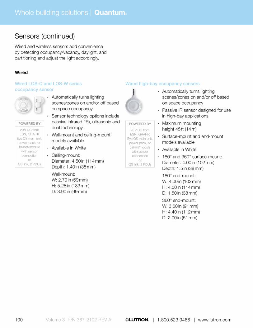
Whole building solutions | Quantum®
100 | 1.800.523.9466 | www.lutron.comVolume 3 P/N 367-2102 REV A
Wired
Wired LOS-C and LOS-W series occupancy sensor
• Automatically turns lighting scenes/zones on and/or off based on space occupancy
• Sensor technology options include passive infrared (IR), ultrasonic and dual technology
• Wall-mount and ceiling-mount models available
• Available in White• Ceiling-mount:
Diameter: 4.50 in (114 mm) Depth: 1.40 in (38 mm)
Wall-mount: W: 2.70 in (69 mm) H: 5.25 in (133 mm) D: 3.90 in (99 mm)
Sensors (continued)Wired and wireless sensors add convenience by detecting occupancy/vacancy, daylight, and partitioning and adjust the light accordingly.
POWERED BY
20 V DC from ESN, GRAFIK
Eye QS main unit, power pack, or ballast/module
with sensor connection
or QS link, 2 PDUs
POWERED BY
20 V DC from ESN, GRAFIK
Eye QS main unit, power pack, or ballast/module
with sensor connection
or QS link, 2 PDUs
Wired high-bay occupancy sensors
• Automatically turns lighting scenes/zones on and/or off based on space occupancy
• Passive IR sensor designed for use in high-bay applications
• Maximum mounting height 45 ft (14 m)
• Surface-mount and end-mount models available
• Available in White• 180° and 360° surface-mount:
Diameter: 4.00 in (102 mm) Depth: 1.5 in (38 mm)
180° end-mount: W: 4.00 in (102 mm) H: 4.50 in (114 mm) D: 1.50 in (38 mm)
360° end-mount: W: 3.60 in (91 mm) H: 4.40 in (112 mm) D: 2.00 in (51 mm)

Whole building solutions | Quantum®
101 | 1.800.523.9466 | www.lutron.com www.lutron.com | 1.800.523.9466 | Volume 3 P/N 367-2102 REV A
POWERED BY
20 V DC from ESN or
ballast/module with sensor connection
or QS link, ½ PDU
POWERED BY
External transformer (12-24 V DC)
POWERED BY
20-24 V DC from power pack
Wired daylight sensor
• Automatically adjusts lighting zones based on amount of daylight entering a space
• Ability to disable on a scene-by-scene basis
• Includes integral infrared receiver • Ceiling-mounted• Available in White• Diameter: 1.18 in (30 mm)
Depth: 1.25 in (32 mm) Profile: 0.69 in (17 mm)
Daylight sensor package
• Allow system to switch lights on/off in response to ambient daylight level setting
• Package includes a wired power pack, daylight sensor, and daylight controller
• Package available in 120 or 277 V; sensor options: indoor, outdoor, atrium/skylight
• Indoor sensor: W: 1.28 in (33 mm) H: 1.15 in (29 mm)
Outdoor sensor: W: 1.85 in (47 mm) H: 1.35 in (34 mm)
Atrium/Skylight sensor: W: 2.25 in (57 mm) H: 1.28 in (33 mm)
IR Partition Sensor
• IR transmitter/receiver pair detects open/closed status of partition and coordinates lighting preset functions
• Sensors must be mounted in a position where the partition separates the transmitter and receiver when the partition is closed
• Requires QS contact closure input/output interface or seeTouch® QS keypad for operation
• Surface-mounted• Available in White• W: 4.56 in (159 mm)
H: 2.69 in (68 mm) D: 1.50 in (38 mm)

Whole building solutions | Quantum®
102 | 1.800.523.9466 | www.lutron.comVolume 3 P/N 367-2102 REV A
Control interfacesUse control interfaces to combine Lutron® lighting controls with other third-party devices and systems for advanced integration.
POWERED BY
QS link 3 PDUs or
external transformer (12-24 V DC)
POWERED BY
QS link 3 PDUs or
external transformer (12-24 V DC)
POWERED BY
QS link 2 PDUs or
external transformer (12-24 V DC)
POWERED BY
QS link 3 PDUs
FREQUENCY
434 MHz434 limited
channel MHz865 MHz868 MHz
868 limited channel MHz
QS RS232/Ethernet interface
• Allows integration with a touchscreen, PC, A/V system, or other digital equipment that supports RS232 communication, or TCP/IP communication over Ethernet
• Monitor lighting scenes and levels, and shade positions
• Features include raise and lower areas and zones, and scene activation
• W: 4.26 in (108 mm) H: 5.26 in (134 mm) D: 1.06 in (27 mm)
QS DMX512 output interface
• Allows zones on a GRAFIK Eye® QS to control DMX512-controlled devices
• Any zone on the GRAFIK Eye QS can be mapped to either a single DMX512 channel or to three RGB DMX512 channels
• W: 4.26 in (108 mm) H: 5.26 in (134 mm) D: 1.06 in (27 mm)
QS sensor module
• Integrates additional Lutron wireless and wired sensors and controls through the QS link
• Connects up to four Lutron wired sensors or controls and ten each of the wireless devices—occupancy/vacancy sensors, daylight sensors and Pico® wireless controls
• Junction box or ceiling-mount options available
• Diameter: 4.04 in (103 mm) Depth: 0.74 in (19 mm) Profile: 0.43 in (11 mm)
QS contact closure interface
• Provides five contact closure inputs and five contact closure outputs
• Allows integration with third-party equipment, such as motion/occupancy sensors, time clocks and movable walls
• Features include scene selection, partitioning, occupancy sensing, zone toggle, panic, control lockout, and after-hours start/stop
• W: 4.26 in (108 mm) H: 5.26 in (134 mm) D: 1.06 in (27 mm)

Whole building solutions | Quantum®
103 | 1.800.523.9466 | www.lutron.com www.lutron.com | 1.800.523.9466 | Volume 3 P/N 367-2102 REV A
POWERED BY
External transformer (24 V DC)
POWERED BY
120 V277 V347 V
POWERED BY
120 V110-127 V127 V NOM220-240 V
230 V
Emergency lighting interface
• Turns all or designated lighting loads to “full on” output or other programmed emergency light levels
• Senses the normal line-voltage on all three phases of power
• Provides inputs for a Fire Alarm Control Panel
• UL 924 listed as "Emergency Lighting and Power Equipment"
• W: 5.00 in (127 mm) H: 7.75 in (197 mm) D: 2.50 in (64 mm)
Energy meter
• Provides accurate, real time energy measurement of lighting, HVAC, and/or plug loads coupled with verification capability via Quantum software
• Each meter includes one set of three split-core current sensors
• Metered data contributes to LEED certification
• Meter: W: 7.00 in (178 mm) H: 7.50 in (191 mm) D: 3.25 in (83 mm)
Data link repeater
• Allows power panel links to be extended beyond their maximum distances
• Links may be extended 2,000 ft (600 m) for every repeater added
• Models available for 120 V and 220-240 V (CE)
• W: 5.00 in (127 mm) H: 7.75 in (197 mm) D: 2.5 in (64 mm)
QS motor group controller (DIN-rail)
• Allows seamless integration with AC blinds, shades, louvers, projection screens, or any compatible AC motors
• Provides four independently controllable AC raise/lower outputs from one common AC input feed
• W: 6.40 in (162 mm) H: 3.50 in (90 mm) D: 2.40 in (61 mm)
POWERED BY
120-240 V120-240 V (CE)

| 1.800.523.9466 | www.lutron.com104 | 1.800.523.9466 | www.lutron.comVolume 3 P/N 367-2102 REV A
Whole building solutions | Quantum®
ShadesSivoia® QS wired shading systems offer convenient control of daylight at the touch of a button and can be controlled via Hyperion® solar adaptive shading software.
Sivoia QS wired shades
• Shades offer ultra-quiet precision control of daylight
• Styles include:
– Roller shades – Tensioned shades – Roman shades with CERUS® safety technology – Drapery tracks – Kirbé® vertical drapery systems – Venetian blinds
• Includes a wide variety of fabric offerings to meet every need
• Wired shades communicate via the QS link
FREQUENCY
External transformer (12-24 V DC)
Sivoia QS power supply
• 12-24 V supply that provides power to shade and drapery drive units
• Various form factors available
POWERED BY
120 V110-127 V127 V NOM220-240 V230 V CE

Whole building solutions | Quantum®
105 | 1.800.523.9466 | www.lutron.com www.lutron.com | 1.800.523.9466 | Volume 3 P/N 367-2102 REV A | 1.800.523.9466 | www.lutron.com
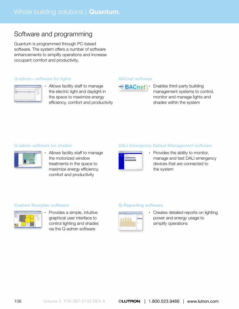
| 1.800.523.9466 | www.lutron.com
Whole building solutions | Quantum®
106 | 1.800.523.9466 | www.lutron.comVolume 3 P/N 367-2102 REV A
Software and programmingQuantum is programmed through PC-based software. The system offers a number of software enhancements to simplify operations and increase occupant comfort and productivity.
Q-adminTM software for lights
• Allows facility staff to manage the electric light and daylight in the space to maximize energy efficiency, comfort and productivity
Q-admin software for shades
• Allows facility staff to manage the motorized window treatments in the space to maximize energy efficiency, comfort and productivity
Custom floorplan software
• Provides a simple, intuitive graphical user interface to control lighting and shades via the Q-admin software
BACnet software
• Enables third-party building management systems to control, monitor and manage lights and shades within the system
DALI Emergency Ballast Management software
• Provides the ability to monitor, manage and test DALI emergency devices that are connected to the system
Q-Reporting software
• Creates detailed reports on lighting power and energy usage to simplify operations

107 | 1.800.523.9466 | www.lutron.com www.lutron.com | 1.800.523.9466 | Volume 3 P/N 367-2102 REV A | 1.800.523.9466 | www.lutron.com
Green Glance® software
• Allows real-time and historical lighting energy data to be displayed on an LCD display or computer monitor
Q-Control +
• Allows control and programming of the system via an Apple iPad mobile device
• Provides mobile control and monitoring of area lighting and window treatments
Personna® PC
• Allows the occupants of the building personal control of their lighting and window treatments from any device that can run web browser

Entire home solutions | HomeWorks® QS
108 | 1.800.523.9466 | www.lutron.comVolume 3 P/N 367-2102 REV A
HomeWorks QS is designed for residential applications, integrating control of all light. The system also integrates with third-party equipment to provide control of HVAC and A/V systems. And it does all that while saving energy.
Feature highlights
• Preset multi-room scenes• Smart device control• Temperature control• Astronomical time clock• PC-based programming• Demand response capable
Designer-style seeTouch® keypad
Ivalo® lighting
Pico® wireless controlsRemote power feed-through panel
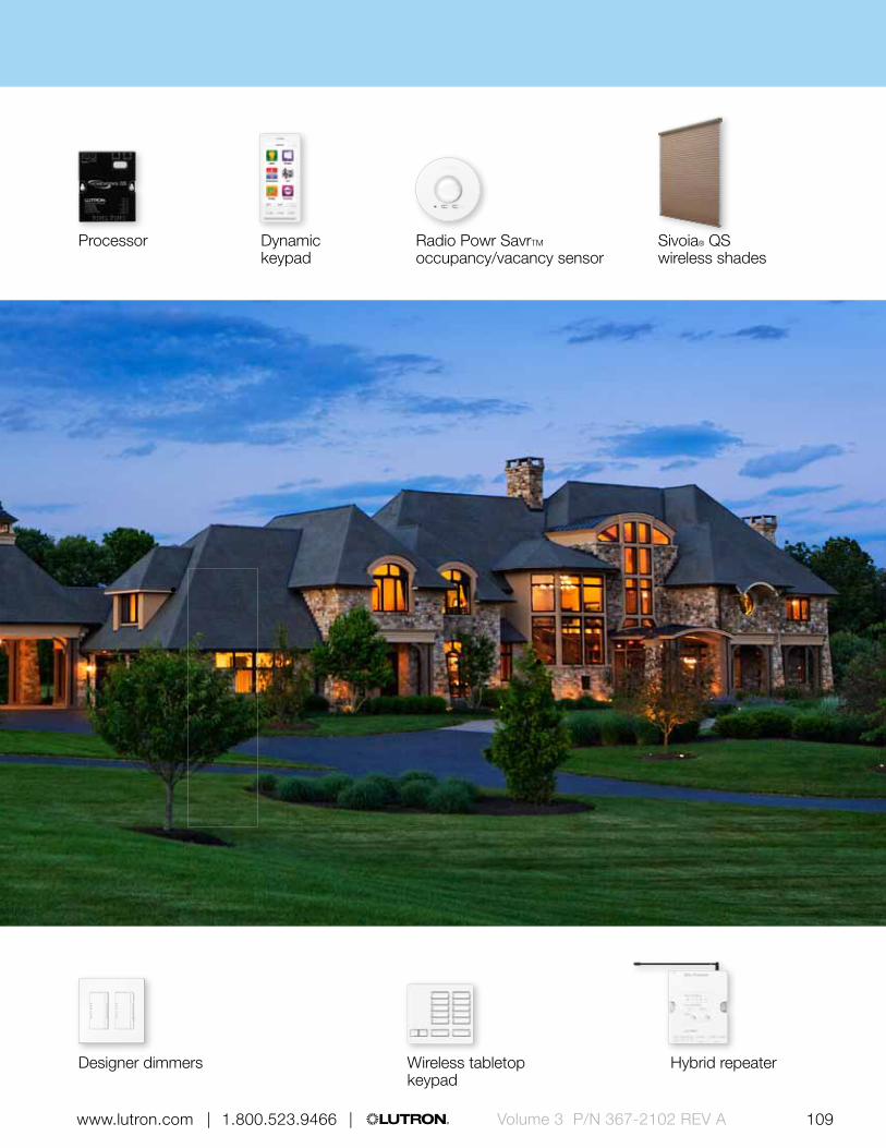
Entire Home solutions | HomeWorks® QS
Volume 3 P/N 367-2102 REV A 109 www.lutron.com | 1.800.523.9466 |
Sivoia® QS wireless shades
Wireless tabletop keypad
Designer dimmers Hybrid repeater
Radio Powr SavrTM occupancy/vacancy sensor
Processor Dynamic keypad

110 111 | 1.800.523.9466 | www.lutron.com www.lutron.com | 1.800.523.9466 |P/N 367-2102 REV A
Entire home solutions | HomeWorks® QS
Primary controls
Typical system components and how they communicate
Power panels
Wallbox power module
GRAFIK Eye® QS main unit
Dimmers and switches
Tabletop lamp dimmer
Plug-in modules
Hybrid keypad
Shades
QS power supply
Sivoia® QS wired/wireless shades
Sensors
Processors
Hybrid repeaterProcessor
Remote power panel with remote power modules
Spec grade panel
Radio Powr Savr™ wireless ceiling-mount, and corner-, hallway- and wall-mount occupancy/vacancy sensor
Wireless temperature sensor
For illustration purposes only, consult specification submittals and/or installation instructions for wiring information.
Power module (DIN-rail)

110 111 | 1.800.523.9466 | www.lutron.com www.lutron.com | 1.800.523.9466 | P/N 367-2102 REV A
Sub-controls
Tabletop keypad
Car visor control transmitter
TouchPRO® Wireless thermostat
seeTemp® wall control
Pico® wireless control
seeTouch® keypads Dynamic keypad
Control interfaces
Contact closure DMX RS232 Visor control receiver HVAC controller
A/V equipment (by others)
Touch panel control (by others)
Home control and app (mobile device by others)
IR remote control (by others)
Security system (by others)
Garage door opener (by others)
HVAC equipment (by others)
Third-party devices
For individual product capacities, wireless ranges, and specific wiring/communication information, see the component pages beginning on pg. 210.
Wired communication
Wireless Radio Frequency (RF) communication
Infrared (IR) communication

Entire home solutions | HomeWorks® QS
112 113 | 1.800.523.9466 | www.lutron.com www.lutron.com | 1.800.523.9466 |Volume 3 P/N 367-2102 REV A
How to build a HomeWorks QS system
1. Select a design option Determine if the system will have a centralized
(powered remotely, minimized wall clutter), localized (switches replaced by system dimmers/switches) or a hybrid of the two
2. Determine control station plan Choose the location of keypads/wallstations
based on the habits of the residents, then select the control station aesthetic to compliment the space
3. Add convenience and expand functionality Complete the design with tabletop keypads,
lamp dimmers and plug-in modules.
4. Integration/connecting to third-party devices Utilize controllers and control interfaces to
connect to third-party devices and systems, such as HVAC and A/V systems
5. Shades Wired and wireless shading systems offer
convenient control of daylight.
6. Software and programming HomeWorks QS is programmed through
PC-based software. The system also offers a convenient mobile app, allowing the control of the lights, shades and HVAC remotely.
ProcessorsThe processor is the heart of the lighting control system providing intelligence and offering a centralized connection point for control and communication.
POWERED BY
120 V110-127 V127 V NOM220-240 V230 V (CE)
FREQUENCY
434 MHz434 limited
channel MHz865 MHz868 MHz
868 limited channel MHz
Processor
• Provides control and communication to HomeWorks QS components
• Contains two links each that can be individually configured to communicate with:— HomeWorks/HomeWorks QS
power panels— HomeWorks QS wired devices— HomeWorks QS wireless devices
• Two-built in Ethernet links• W: 4.25 in (108 mm)
H: 5.25 in (133 mm) D: 1.06 in (27 mm)
Hybrid repeater
• Adds radio frequency (RF) communication to a HomeWorks QS system
• Extends the range of the RF signals of the wireless devices
• Up to four repeaters can be added to the RF link of a HomeWorks QS processor
• W: 4.25 in (108 mm) H: 5.25 in (133 mm) D: 1.06 in (27 mm)

Entire Home solutions | HomeWorks® QS
112 113 | 1.800.523.9466 | www.lutron.com www.lutron.com | 1.800.523.9466 | Volume 3 P/N 367-2102 REV A
POWERED BY
120 V110-127 V127 V NOM220-240 V277 V (CE)
Module Interface
• Controls up to eight remote power modules (RPMs) in a remote power panel enclosure
• Manages the communication between the RPMs and the HomeWorks QS processor
• Compatible with all HomeWorks QS RPMs
• W: 13.13 in (333 mm) H: 3.00 in (76 mm) D: 3.63 in (92 mm)

Entire home solutions | HomeWorks® QS
114 115 | 1.800.523.9466 | www.lutron.com www.lutron.com | 1.800.523.9466 |Volume 3 P/N 367-2102 REV A
Power PanelsThe power panels provide remote dimming and switching capability for all common light sources, including incandescent, fluorescent, LED, CFL, and neon/cathode.
POWERED BY
120 V 110-127 V 127 V NOM 220-240 V 230 V CE
POWERED BY
120 V 110-127 V 127 V NOM 220-240 V 230 V CE
Remote power feed-through panel
• Can house up to 8 remote power modules (RPMs) in any combination, one module interface, up to two processors or interfaces and two power supplies
• May be distributed throughout the home for added wiring flexibility
• 5-module: W: 14.38 in (365 mm) H: 32.00 in (810 mm) D: 4.25 in (105 mm)
8-module: W: 14.38 in (365 mm) H: 59.00 in (1500 mm) D: 4.25 in (105 mm)
Remote power panel with breakers
• Can house up to 8 remote power modules (RPMs) in any combination, 1-module interface, and breakers
• Available with standard, arc-fault and international breakers
• May be distributed throughout the home for added wiring flexibility
• 2-module: W: 15.13 in (384 mm); H: 24.00 in (610 mm); D: 4.13 in (105 mm)
8-module: W: 15.13 in (384 mm); H: 59.00 in (1500 mm); D: 4.13 in (105 mm)
8-module (international): W: 16.88 in (427 mm); H: 63.00 in (1600 mm); D: 4.00 in (102 mm)
POWERED BY
120 V 110-127 V 127 V NOM 220-240 V 230 V CE
POWERED BY
120 V110-127 V127 V NOM
Spec grade panel
• Panel is typically used for high-performance architectural dimming
• Provides power and dimming for up to 72 circuits
• Circuits rated for 16 A• Standard:
W: 28.00 in (711 mm); H: 37.00 in (940 mm); D: 12.00 in (304 mm)
Large (36): W: 26.13 in (653 mm); H: 87.00 in (2175 mm); D: 14.13 in (360 mm)
Large (48-72): W: 52.31 in (1308 mm); H: 87.00 in (2175 mm); D: 14.13 in (360 mm)
Dimming remote power module
• Controls up to 4 circuits of lighting• Mounts in HomeWorks QS
remote power feed-through or breaker panel
• W: 3.88 in (98 mm) H: 7.00 in (178 mm) D: 3.50 in (89 mm)

Entire Home solutions | HomeWorks® QS
114 115 | 1.800.523.9466 | www.lutron.com www.lutron.com | 1.800.523.9466 | Volume 3 P/N 367-2102 REV A
POWERED BY
120 V 110-127 V 127 V NOM 220-240 V 230 V CE
POWERED BY
120 V 110-127 V 127 V NOM 220-240 V 230 V CE
Adaptive dimming remote power module
• Controls up to 4 circuits of lighting• Automatically selects leading edge
or trail edge dimming• Mounts in HomeWorks QS
remote power feed-through or breaker panel
• W: 3.88 in (98 mm) H: 7.00 in (178 mm) D: 3.50 in (89 mm)
POWERED BY
120 V 110-127 V 127 V NOM
POWERED BY
120 V 110-127 V 127 V NOM 220-240 V
Motor remote power module
• Controls up to 4 circuits of 3-wire AC motor loads
• Mounts in HomeWorks QS remote power feed-through or breaker panel
• W: 3.88 in (98 mm) H: 7.88 in (200 mm) D: 2.80 in (73 mm)
Fan speed remote power module
• Provides four-speed control to 4 circuits of ceiling fans
• Mounts in HomeWorks QS remote power feed-through or breaker panel
• W: 3.88 in (98 mm) H: 7.88 in (200 mm) D: 2.80 in (73 mm)
Relay remote power module
• Controls up to 4 circuits of switched lighting, fans or motor loads
• Mounts in HomeWorks QS remote power feed-through or breaker panel
• W: 3.88 in (98 mm) H: 7.00 in (178 mm) D: 3.50 in (89 mm)

Entire home solutions | HomeWorks® QS
116 117 | 1.800.523.9466 | www.lutron.com www.lutron.com | 1.800.523.9466 |Volume 3 P/N 367-2102 REV A
HomeWorks QS power panel summary
Spec grade panel Dimming modules
Load voltages Load voltages
120 V, 110-127 V,
127 V (NOM) 277 V 230 V (CE) 220-240 V
120 V, 110-127 V,
127 V (NOM) 230 V (CE) 220-240 V
Dimmed loads Dimmed loads
Incandescent/halogen
Magnetic low-voltage
Electronic low-voltage 1 1 1 1 PA ELVI-CE ELVI-AU
Fluorescent and LED (3-wire) 3F FDBI-AU
Fluorescent and LED (EcoSystem®)
Tu-wire® fluorescent
Fluorescent and LED (0-10 V) TVM, TVI TVM, TVI TVM, TVI TVM, TVI TVM, TVI TVM, TVI TVM, TVI
Fluorescent and LED (PWM) TVM, PWM TVM, PWM TVM TVM, PWM TVM, PWM TVM TVM, PWM
Fluorescent and LED (DALI) TVM 2 TVM 2 TVM 2 TVM 2 TVM 1 TVM 1 TVM 1
LED (2-wire forward adaptive)
CFL/LED (screw-base) 1 1 1 1 PA PB-CE, ELVI-CE PB-AU, ELVI-AU
Neon/cold cathode*
Switched loads Switched loads
Non-dim lighting (loads above)
HID SW, TVI, PWM TVI TVI, PWM
Motor loadsSW, TVI,
PWMSW, TVI,
PWMTVI TVI, PWM SW, TVI, PWM TVI TVI, PWM
Fan loadsSW, TVI,
PWMSW, TVI,
PWMTVI TVI, PWM SW, TVI, PWM TVI TVI, PWM
Panel/module voltage 120 V 277 V 230 V (CE) 220-240 V 120 V 230 V (CE) 220-240 V
Frequency 50/60 Hz 50/60 Hz 50/60 Hz 50/60 Hz 50/60 Hz 50/60 Hz 50/60 Hz
Minimum load 10 W 10 W 10 W 10 W 25 W 40 W 40 W
Maximum load per circuit 16 A 16 A 16 A 16 A 16 A 10 A 16 A
Maximum load per module — — — — 16 A 13 A 16 A
Power interfaces Compatible load control (no interfaces) 3F: 3-wire fluorescent power module pg. 516 ELVI-AU: Electronic low-voltage interface (AU) pg. 524 ELVI-CE: Electronic low-voltage interface (CE) pg. 524
FDBI-AU: Fluorescent dimming ballast interface (AU) pg. 526 PA: Phase adaptive power module pg. 514 PB-AU: Power booster pg. 522 PB-CE: Power booster (CE) pg. 522PWM: Pulse width modulation interface pg. 530 SW: Switching power module pg. 520 TVI: 0-10 V interface pg. 528 TVM: Ten-volt module in panel
1 Foward phase only. Not all ELV transformers and dimmable CFL/LEDs dim properly with forward phase control; may require phase-adaptive power module or electronic low voltage interface for proper dimming. For reverse phase, a phase adaptive power module or electronic low-voltage interface will be required.
2 DALI broadcast only

Entire Home solutions | HomeWorks® QS
116 117 | 1.800.523.9466 | www.lutron.com www.lutron.com | 1.800.523.9466 | Volume 3 P/N 367-2102 REV A
HomeWorks QS power panel summary
Spec grade panel Dimming modules
Load voltages Load voltages
120 V, 110-127 V,
127 V (NOM) 277 V 230 V (CE) 220-240 V
120 V, 110-127 V,
127 V (NOM) 230 V (CE) 220-240 V
Dimmed loads Dimmed loads
Incandescent/halogen
Magnetic low-voltage
Electronic low-voltage 1 1 1 1 PA ELVI-CE ELVI-AU
Fluorescent and LED (3-wire) 3F FDBI-AU
Fluorescent and LED (EcoSystem®)
Tu-wire® fluorescent
Fluorescent and LED (0-10 V) TVM, TVI TVM, TVI TVM, TVI TVM, TVI TVM, TVI TVM, TVI TVM, TVI
Fluorescent and LED (PWM) TVM, PWM TVM, PWM TVM TVM, PWM TVM, PWM TVM TVM, PWM
Fluorescent and LED (DALI) TVM 2 TVM 2 TVM 2 TVM 2 TVM 1 TVM 1 TVM 1
LED (2-wire forward adaptive)
CFL/LED (screw-base) 1 1 1 1 PA PB-CE, ELVI-CE PB-AU, ELVI-AU
Neon/cold cathode*
Switched loads Switched loads
Non-dim lighting (loads above)
HID SW, TVI, PWM TVI TVI, PWM
Motor loadsSW, TVI,
PWMSW, TVI,
PWMTVI TVI, PWM SW, TVI, PWM TVI TVI, PWM
Fan loadsSW, TVI,
PWMSW, TVI,
PWMTVI TVI, PWM SW, TVI, PWM TVI TVI, PWM
Panel/module voltage 120 V 277 V 230 V (CE) 220-240 V 120 V 230 V (CE) 220-240 V
Frequency 50/60 Hz 50/60 Hz 50/60 Hz 50/60 Hz 50/60 Hz 50/60 Hz 50/60 Hz
Minimum load 10 W 10 W 10 W 10 W 25 W 40 W 40 W
Maximum load per circuit 16 A 16 A 16 A 16 A 16 A 10 A 16 A
Maximum load per module — — — — 16 A 13 A 16 A
Power interfaces Compatible load control (no interfaces) 3F: 3-wire fluorescent power module pg. 516 ELVI-AU: Electronic low-voltage interface (AU) pg. 524 ELVI-CE: Electronic low-voltage interface (CE) pg. 524
FDBI-AU: Fluorescent dimming ballast interface (AU) pg. 526 PA: Phase adaptive power module pg. 514 PB-AU: Power booster pg. 522 PB-CE: Power booster (CE) pg. 522PWM: Pulse width modulation interface pg. 530 SW: Switching power module pg. 520 TVI: 0-10 V interface pg. 528 TVM: Ten-volt module in panel
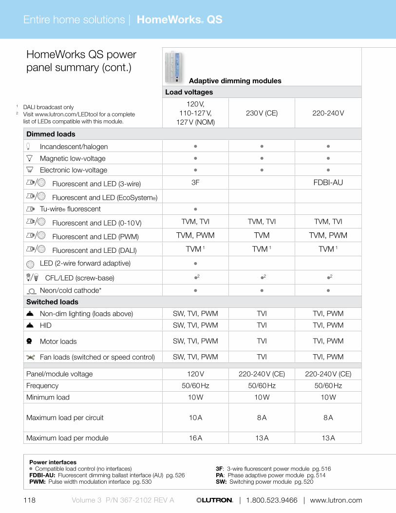
Entire home solutions | HomeWorks® QS
118 119 | 1.800.523.9466 | www.lutron.com www.lutron.com | 1.800.523.9466 |Volume 3 P/N 367-2102 REV A
HomeWorks QS power panel summary (cont.)
Adaptive dimming modules Fan speed
module Motor module Switching module
Load voltages Load voltages
120 V, 110-127 V,
127 V (NOM)230 V (CE) 220-240 V 120 V 120 V 220-240 V
120 V, 110-127 V, 127 V (NOM), 230 V (CE),
277 V, 347 V
Dimmed loads Dimmed loads
Incandescent/halogen
Magnetic low-voltage
Electronic low-voltage
Fluorescent and LED (3-wire) 3F FDBI-AU
Fluorescent and LED (EcoSystem®)
Tu-wire® fluorescent
Fluorescent and LED (0-10 V) TVM, TVI TVM, TVI TVM, TVI
Fluorescent and LED (PWM) TVM, PWM TVM TVM, PWM
Fluorescent and LED (DALI) TVM 1 TVM 1 TVM 1
LED (2-wire forward adaptive)
CFL/LED (screw-base) 2 2 2
Neon/cold cathode*
Switched loads Switched loads
Non-dim lighting (loads above) SW, TVI, PWM TVI TVI, PWM
HID SW, TVI, PWM TVI TVI, PWM
Motor loads SW, TVI, PWM TVI TVI, PWM
(AC loads only)
(AC loads only)
Fan loads (switched or speed control) SW, TVI, PWM TVI TVI, PWM
Panel/module voltage 120 V 220-240 V (CE) 220-240 V (CE) 120 V 120 V 220-240 V 100-277 V (CE)
Frequency 50/60 Hz 50/60 Hz 50/60 Hz 50/60 Hz 50/60 Hz 50/60 Hz 50/60 Hz
Minimum load 10 W 10 W 10 W 0.25 A — — —
Maximum load per circuit 10 A 8 A 8 A 2 A 5 A; 0.25 HP 5 A; 0.25 HP16 A; 0.5 HP (12 V),
1.5 HP (277 V), 0.5 HP (220-240 V)
Maximum load per module 16 A 13 A 13 A 8 A 16 A 16 A (see per circuit rating)
Power interfaces Compatible load control (no interfaces) 3F: 3-wire fluorescent power module pg. 516 ELVI-AU: Electronic low-voltage interface (AU) pg. 524 ELVI-CE: Electronic low-voltage interface (CE) pg. 524
FDBI-AU: Fluorescent dimming ballast interface (AU) pg. 526 PA: Phase adaptive power module pg. 514 PB-AU: Power booster pg. 522 PB-CE: Power booster (CE) pg. 522PWM: Pulse width modulation interface pg. 530 SW: Switching power module pg. 520 TVI: 0-10 V interface pg. 528 TVM: Ten-volt module in panel
1 DALI broadcast only2 Visit www.lutron.com/LEDtool for a complete
list of LEDs compatible with this module.

Entire Home solutions | HomeWorks® QS
118 119 | 1.800.523.9466 | www.lutron.com www.lutron.com | 1.800.523.9466 | Volume 3 P/N 367-2102 REV A
HomeWorks QS power panel summary (cont.)
Adaptive dimming modules Fan speed
module Motor module Switching module
Load voltages Load voltages
120 V, 110-127 V,
127 V (NOM)230 V (CE) 220-240 V 120 V 120 V 220-240 V
120 V, 110-127 V, 127 V (NOM), 230 V (CE),
277 V, 347 V
Dimmed loads Dimmed loads
Incandescent/halogen
Magnetic low-voltage
Electronic low-voltage
Fluorescent and LED (3-wire) 3F FDBI-AU
Fluorescent and LED (EcoSystem®)
Tu-wire® fluorescent
Fluorescent and LED (0-10 V) TVM, TVI TVM, TVI TVM, TVI
Fluorescent and LED (PWM) TVM, PWM TVM TVM, PWM
Fluorescent and LED (DALI) TVM 1 TVM 1 TVM 1
LED (2-wire forward adaptive)
CFL/LED (screw-base) 2 2 2
Neon/cold cathode*
Switched loads Switched loads
Non-dim lighting (loads above) SW, TVI, PWM TVI TVI, PWM
HID SW, TVI, PWM TVI TVI, PWM
Motor loads SW, TVI, PWM TVI TVI, PWM
(AC loads only)
(AC loads only)
Fan loads (switched or speed control) SW, TVI, PWM TVI TVI, PWM
Panel/module voltage 120 V 220-240 V (CE) 220-240 V (CE) 120 V 120 V 220-240 V 100-277 V (CE)
Frequency 50/60 Hz 50/60 Hz 50/60 Hz 50/60 Hz 50/60 Hz 50/60 Hz 50/60 Hz
Minimum load 10 W 10 W 10 W 0.25 A — — —
Maximum load per circuit 10 A 8 A 8 A 2 A 5 A; 0.25 HP 5 A; 0.25 HP16 A; 0.5 HP (12 V),
1.5 HP (277 V), 0.5 HP (220-240 V)
Maximum load per module 16 A 13 A 13 A 8 A 16 A 16 A (see per circuit rating)
Power interfaces Compatible load control (no interfaces) 3F: 3-wire fluorescent power module pg. 516 ELVI-AU: Electronic low-voltage interface (AU) pg. 524 ELVI-CE: Electronic low-voltage interface (CE) pg. 524
FDBI-AU: Fluorescent dimming ballast interface (AU) pg. 526 PA: Phase adaptive power module pg. 514 PB-AU: Power booster pg. 522 PB-CE: Power booster (CE) pg. 522PWM: Pulse width modulation interface pg. 530 SW: Switching power module pg. 520 TVI: 0-10 V interface pg. 528 TVM: Ten-volt module in panel

Entire home solutions | HomeWorks® QS
120 121 | 1.800.523.9466 | www.lutron.com www.lutron.com | 1.800.523.9466 |Volume 3 P/N 367-2102 REV A
Tabletop lamp dimmer
• Lamp dimmers incorporate advanced features such as fade on/fade off, delay fade off, and rapid full on
• Fine tune scenes by pressing and holding raise/lower buttons
• Available in Snow and Midnight• Easy to install, no wiring required• W: 2.94 in (75 mm)
H: 4.69 in (119 mm) D: 1.25 in (32 mm) Profile: 0.31 in (8 mm)
Hybrid keypad
• Functions as a dimmer and keypad combined into a single device
• Fine tune scenes by pressing and holding raise/lower buttons
• Available in 26 finishes• Mounts in standard 1-gang
U.S. backbox• Can be mounted with other
devices in multi-gang wallplate• W: 2.94 in (75 mm)
H: 4.69 in (119 mm) D: 1.25 in (32 mm) Profile: 0.31 in (8 mm)
Primary controlsThe main devices in a lighting control system that distribute commands to sub-controls, control interfaces and lighting loads.
POWERED BY
120 V 110-127 V 127 V NOM
277 V
FREQUENCY
434 MHz
POWERED BY
120 V 110-127 V 127 V NOM
FREQUENCY
434 MHz
POWERED BY
120 V 110-127 V 127 V NOM
FREQUENCY
434 MHz
POWERED BY
120 V 110-127 V 127 V NOM
277 V
FREQUENCY
434 MHz
Designer dimmer
• Dimmers incorporate advanced features such as fade on/fade off, delay fade off, and rapid full on
• Remote dimmer available• Available in 26 finishes• Mounts in standard 1-gang
U.S. backbox• Can be mounted with other
devices in multi-gang wallplate• W: 2.94 in (75 mm)
H: 4.69 in (119 mm) D: 1.25 in (32 mm) Profile: 0.31 in (8 mm)
Designer switch
• Functions as a standard switch• Remote switch available• Available in 26 finishes• Mounts in standard 1-gang
U.S. backbox• Can be mounted with other
devices in multi-gang wallplate• W: 2.94 in (75 mm)
H: 4.69 in (119 mm) D: 1.25 in (32 mm) Profile: 0.31 in (8 mm)

Entire Home solutions | HomeWorks® QS
120 121 | 1.800.523.9466 | www.lutron.com www.lutron.com | 1.800.523.9466 | Volume 3 P/N 367-2102 REV A
Plug-in dimming or appliance module
• Dimming module functions like a lamp dimmer, incorporating advanced control features
• Appliance module switches up 15 A of general purpose load
• Available in Snow and Midnight• Modules can be hidden discreetly
behind furniture• W: 2.25 in (57 mm)
H: 3.25 in (83 mm) Depth: 1.23 in (31 mm)
Wallbox power module
• Controls up to six zones of lighting• Provides cost effective solution for
lower wattage loads• Available in White• W: 9.44 in (240 mm)
H: 4.69 in (119 mm) Depth: 2.00 in (51 mm) Profile: 0.38 in (10 mm)
POWERED BY
120 V 110-127 V 127 V NOM
FREQUENCY
434 MHz
POWERED BY
120 V 110-127 V 127 V NOM 220-240 V
FREQUENCY
434 MHz

Entire home solutions | HomeWorks® QS
122 123 | 1.800.523.9466 | www.lutron.com www.lutron.com | 1.800.523.9466 |Volume 3 P/N 367-2102 REV A
HomeWorks QS primary control summary
HomeWorks QS dimmer
HomeWorks QS switch
HomeWorks QS hybrid keypad
HomeWorks QS wallbox power module
HomeWorks QS tabletop lamp dimmer
HomeWorks QS plug-in dimming module
HomeWorks QS plug-in appliance module
Load voltages Load voltages
120 V, 110-127 V,
127 V (NOM)277 V
120 V, 110-127 V,
127 V (NOM), 277 V
120 V, 110-127 V,
127 V (NOM)
120 V, 110-127 V,
127 V (NOM)277 V 220-240 V
120 V, 110-127 V,
127 V (NOM)
120 V, 110-127 V,
127 V (NOM)
120 V, 110-127 V,
127 V (NOM)
Dimmed loads Dimmed loads
Incandescent/halogen WBX PA
Magnetic low-voltage WBX PA
Electronic low-voltage WBX PA PA PA ELVI-AU
Fluorescent and LED (3-wire) 3F 3F 3F FDBI-AU
Fluorescent and LED (EcoSystem®)
Tu-wire® fluorescent
Fluorescent and LED (0-10 V) TVI TVI TVI TVI TVI TVI
Fluorescent and LED (PWM) PWM PWM PWM PWM PWM PWM
Fluorescent and LED (DALI)
LED (2-wire phase adaptive)
CFL/LED (screw-base) * WBX PA PA PAPB-AU, ELVI-AU
Neon/cold cathode PA
Switched loads Switched loads
Non-dim lighting (loads above) SW, TVI, PWMSW, TVI,
PWM
HID SW, TVI, PWMSW, TVI,
PWMSW, TVI,
PWMTVI, PWM
Motor loads SW, TVI, PWMSW, TVI,
PWMSW, TVI,
PWMTVI, PWM
Fan loads SW, TVI, PWMSW, TVI,
PWMSW, TVI,
PWMTVI, PWM
Appliance loads
Power interfaces Compatible load control (no interfaces) 3F: 3-wire fluorescent power module pg. 516 ELVI-AU: Electronic low-voltage interface (AU) pg. 524 FDBI-AU: Fluorescent dimming ballast interface (AU) pg. 526
WBX: Phase adaptive power module with 3-wire input PA: Phase adaptive power module pg. 514 PB-AU: Power booster pg. 522 PB-CE: Power booster (CE) pg. 522 PWM: Pulse width modulation interface pg. 530 SW: Switching power module pg. 520 TVI: 0-10 V interface pg. 528 TVM: Ten-volt module in panel
* Visit www.lutron.com/LEDtool for a complete list of LEDs compatible with the HomeWorks QS adaptive dimmer.
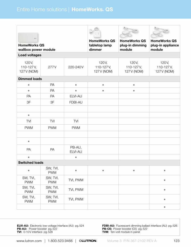
Entire Home solutions | HomeWorks® QS
122 123 | 1.800.523.9466 | www.lutron.com www.lutron.com | 1.800.523.9466 | Volume 3 P/N 367-2102 REV A
HomeWorks QS primary control summary
HomeWorks QS dimmer
HomeWorks QS switch
HomeWorks QS hybrid keypad
HomeWorks QS wallbox power module
HomeWorks QS tabletop lamp dimmer
HomeWorks QS plug-in dimming module
HomeWorks QS plug-in appliance module
Load voltages Load voltages
120 V, 110-127 V,
127 V (NOM)277 V
120 V, 110-127 V,
127 V (NOM), 277 V
120 V, 110-127 V,
127 V (NOM)
120 V, 110-127 V,
127 V (NOM)277 V 220-240 V
120 V, 110-127 V,
127 V (NOM)
120 V, 110-127 V,
127 V (NOM)
120 V, 110-127 V,
127 V (NOM)
Dimmed loads Dimmed loads
Incandescent/halogen WBX PA
Magnetic low-voltage WBX PA
Electronic low-voltage WBX PA PA PA ELVI-AU
Fluorescent and LED (3-wire) 3F 3F 3F FDBI-AU
Fluorescent and LED (EcoSystem®)
Tu-wire® fluorescent
Fluorescent and LED (0-10 V) TVI TVI TVI TVI TVI TVI
Fluorescent and LED (PWM) PWM PWM PWM PWM PWM PWM
Fluorescent and LED (DALI)
LED (2-wire phase adaptive)
CFL/LED (screw-base) * WBX PA PA PAPB-AU, ELVI-AU
Neon/cold cathode PA
Switched loads Switched loads
Non-dim lighting (loads above) SW, TVI, PWMSW, TVI,
PWM
HID SW, TVI, PWMSW, TVI,
PWMSW, TVI,
PWMTVI, PWM
Motor loads SW, TVI, PWMSW, TVI,
PWMSW, TVI,
PWMTVI, PWM
Fan loads SW, TVI, PWMSW, TVI,
PWMSW, TVI,
PWMTVI, PWM
Appliance loads
Power interfaces Compatible load control (no interfaces) 3F: 3-wire fluorescent power module pg. 516 ELVI-AU: Electronic low-voltage interface (AU) pg. 524 FDBI-AU: Fluorescent dimming ballast interface (AU) pg. 526
WBX: Phase adaptive power module with 3-wire input PA: Phase adaptive power module pg. 514 PB-AU: Power booster pg. 522 PB-CE: Power booster (CE) pg. 522 PWM: Pulse width modulation interface pg. 530 SW: Switching power module pg. 520 TVI: 0-10 V interface pg. 528 TVM: Ten-volt module in panel

Entire home solutions | HomeWorks® QS
124 125 | 1.800.523.9466 | www.lutron.com www.lutron.com | 1.800.523.9466 |Volume 3 P/N 367-2102 REV A

Entire Home solutions | HomeWorks® QS
124 125 | 1.800.523.9466 | www.lutron.com www.lutron.com | 1.800.523.9466 | Volume 3 P/N 367-2102 REV A
POWERED BY
120 V110-127 V127 V NOM220-240 V230 V CE
FREQUENCY
434 MHz434 limited
channel MHz865 MHz868 MHz
868 limited channel MHz
BACKBOX
U.S. style
Primary controls (continued)The main devices in a lighting control system that distribute commands to sub-controls, control interfaces and lighting loads.
GRAFIK Eye® QS main unit
• Preset control of 3, 4, or 6 lighting zones
• Wireless units communicate via radio frequency to Pico® wireless controls, Radio Powr SavrTM sensors and Sivoia® QS Wireless shades (wired only models available)
• Available in 41 finishes• W: 9.38 in (239 mm)
H: 4.69 in (119 mm) D: 2.00 in (51 mm) Profile: 0.38 in (10 mm)

Entire home solutions | HomeWorks® QS
126 127 | 1.800.523.9466 | www.lutron.com www.lutron.com | 1.800.523.9466 |Volume 3 P/N 367-2102 REV A
HomeWorks QS primary control summary (cont.)
GRAFIK Eye® QS main units GRAFIK Eye® QS main units
Load voltages Load voltages
120 V, 110-127 V,
127 V (NOM)277 V 220-240 V 230 V (CE) 220-240 V
Dimmed loads Dimmed loads
Incandescent/halogen PA
Magnetic low-voltage PA
Electronic low-voltage PA PA ELVI-AU ELVI-CE ELVI-AU
Fluorescent and LED (3-wire) 3F 3F FDBI-AU FDBI-AU
Fluorescent and LED (EcoSystem®)
Tu-wire® fluorescent
Fluorescent and LED (0-10 V) TVI TVI TVI TVI TVI
Fluorescent and LED (PWM) PWM PWM PWM PWM
Fluorescent and LED (DALI)
LED (2-wire forward adaptive)
CFL/LED (screw-base) PA PA PB-AU, ELVI-AU PB-CE, ELVI-CE PB-AU, ELVI-AU
Neon/cold cathode
Switched loads Switched loads
Non-dim lighting (loads above) SW, TVI, PWM
HID SW, TVI, PWM SW, TVI, PWM TVI, PWM TVI TVI, PWM
Motor loads SW, TVI, PWM SW, TVI, PWM TVI, PWM TVI TVI, PWM
Fan loads SW, TVI, PWM SW, TVI, PWM TVI, PWM TVI TVI, PWM
Main unit voltage120-127 V/ 220-240 V
120-127 V/ 220-240 V
120-127 V/ 220-240 V
230 V (CE) 230 V (CE)
Frequency 50/60 Hz 50/60 Hz 50/60 Hz 50/60 Hz 50/60 Hz
Minimum capacity per zone 25 25 40 40 40
Maximum capacity per zone 800 W, 600 W (MLV) 800 W, 600 W (MLV) 1200 W, 960 W (MLV) 500 W, 400 W (MLV) 500 W, 400 W (MLV)
Unit capacity 2000 W, 1600 W (MLV) 2000 W, 1600 W (MLV) 3000 W, 2400 W (MLV)3-zone: 1500 W, 1200 W (MLV) 4-zone: 2000 W, 1600 W (MLV)
6-zone: 2300 W
3-zone: 1500 W, 1200 W (MLV) 4-zone: 2000 W, 1600 W (MLV)
6-zone: 2300 W
Power interfaces Compatible load control (no interfaces) 3F: 3-wire fluorescent power module pg. 516 ELVI-AU: Electronic low-voltage interface (AU) pg. 524 ELVI-CE: Electronic low-voltage interface (CE) pg. 524
FDBI-AU: Fluorescent dimming ballast interface (AU) pg. 526 PA: Phase adaptive power module pg. 514 PB-AU: Power booster pg. 522 PB-CE: Power booster (CE) pg. 522PWM: Pulse width modulation interface pg. 530 SW: Switching power module pg. 520 TVI: 0-10 V interface pg. 528
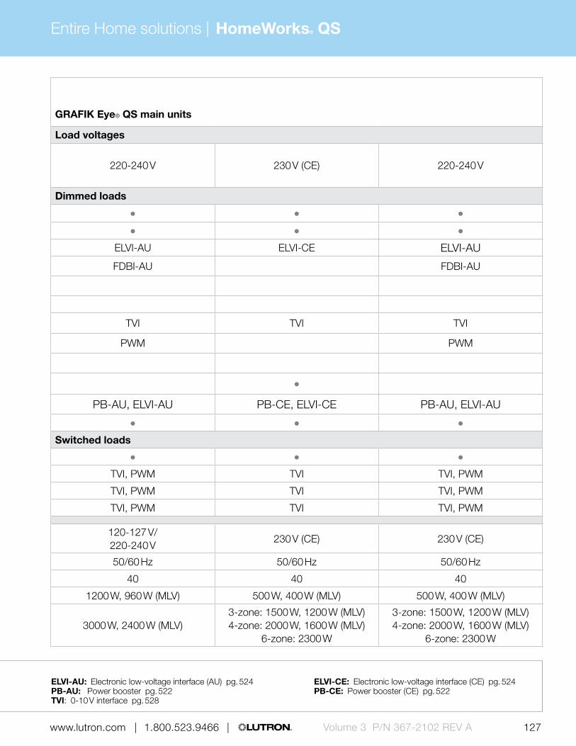
Entire Home solutions | HomeWorks® QS
126 127 | 1.800.523.9466 | www.lutron.com www.lutron.com | 1.800.523.9466 | Volume 3 P/N 367-2102 REV A
HomeWorks QS primary control summary (cont.)
GRAFIK Eye® QS main units GRAFIK Eye® QS main units
Load voltages Load voltages
120 V, 110-127 V,
127 V (NOM)277 V 220-240 V 230 V (CE) 220-240 V
Dimmed loads Dimmed loads
Incandescent/halogen PA
Magnetic low-voltage PA
Electronic low-voltage PA PA ELVI-AU ELVI-CE ELVI-AU
Fluorescent and LED (3-wire) 3F 3F FDBI-AU FDBI-AU
Fluorescent and LED (EcoSystem®)
Tu-wire® fluorescent
Fluorescent and LED (0-10 V) TVI TVI TVI TVI TVI
Fluorescent and LED (PWM) PWM PWM PWM PWM
Fluorescent and LED (DALI)
LED (2-wire forward adaptive)
CFL/LED (screw-base) PA PA PB-AU, ELVI-AU PB-CE, ELVI-CE PB-AU, ELVI-AU
Neon/cold cathode
Switched loads Switched loads
Non-dim lighting (loads above) SW, TVI, PWM
HID SW, TVI, PWM SW, TVI, PWM TVI, PWM TVI TVI, PWM
Motor loads SW, TVI, PWM SW, TVI, PWM TVI, PWM TVI TVI, PWM
Fan loads SW, TVI, PWM SW, TVI, PWM TVI, PWM TVI TVI, PWM
Main unit voltage120-127 V/ 220-240 V
120-127 V/ 220-240 V
120-127 V/ 220-240 V
230 V (CE) 230 V (CE)
Frequency 50/60 Hz 50/60 Hz 50/60 Hz 50/60 Hz 50/60 Hz
Minimum capacity per zone 25 25 40 40 40
Maximum capacity per zone 800 W, 600 W (MLV) 800 W, 600 W (MLV) 1200 W, 960 W (MLV) 500 W, 400 W (MLV) 500 W, 400 W (MLV)
Unit capacity 2000 W, 1600 W (MLV) 2000 W, 1600 W (MLV) 3000 W, 2400 W (MLV)3-zone: 1500 W, 1200 W (MLV) 4-zone: 2000 W, 1600 W (MLV)
6-zone: 2300 W
3-zone: 1500 W, 1200 W (MLV) 4-zone: 2000 W, 1600 W (MLV)
6-zone: 2300 W
Power interfaces Compatible load control (no interfaces) 3F: 3-wire fluorescent power module pg. 516 ELVI-AU: Electronic low-voltage interface (AU) pg. 524 ELVI-CE: Electronic low-voltage interface (CE) pg. 524
FDBI-AU: Fluorescent dimming ballast interface (AU) pg. 526 PA: Phase adaptive power module pg. 514 PB-AU: Power booster pg. 522 PB-CE: Power booster (CE) pg. 522PWM: Pulse width modulation interface pg. 530 SW: Switching power module pg. 520 TVI: 0-10 V interface pg. 528

Entire home solutions | HomeWorks® QS
128 129 | 1.800.523.9466 | www.lutron.com www.lutron.com | 1.800.523.9466 |Volume 3 P/N 367-2102 REV A
POWERED BY
220-240 V
POWERED BY
220-240 V230 V CE
POWERED BY
220-240 V230 V CE
POWERED BY
220-240 V230 V CE
Primary controls (continued)The main devices in a lighting control system that distribute commands to sub-controls, control interfaces and lighting loads.
DALI power module (DIN-rail)
• Provides control of two buses of DALI compliant digital addressable loads, up to 128 DALI compatible devices
• Each DALI loop can control a maximum of 16 zones
• DIN-rail mounted• W: 6.36 in (162 mm)
H: 3.53 in (90 mm) D: 2.39 in (61 mm)
Power module with EcoSystem® (DIN-rail)
• Provides control of two EcoSystem loops, up to 128 EcoSystem compatible devices
• EcoSystem technology available in fluorescent dimming ballasts, LED drivers and fixture modules
• DIN-rail mount• W: 6.36 in (162 mm)
H: 3.53 in (90 mm) D: 2.39 in (61 mm)
Switching/0-10 V power module (DIN-rail)
• Controls up to 4 16 A zones of lighting fixtures (switched relay or 0-10 V dimming)
• DIN-rail mounted• W: 6.36 in (162 mm)
H: 3.53 in (90 mm) D: 2.39 in (61 mm)
Phase adaptive power module (DIN-rail)
• Provides control of dimmable CFL/LED loads in addition to incandescent/halogen, electronic low-voltage, magnetic low-voltage, and neon cold cathode light sources
• DIN-rail mounted• W: 8.50 in (216 mm)
H: 3.54 in (90 mm) D: 2.99 in (76 mm)
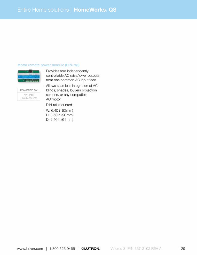
Entire Home solutions | HomeWorks® QS
128 129 | 1.800.523.9466 | www.lutron.com www.lutron.com | 1.800.523.9466 | Volume 3 P/N 367-2102 REV A
POWERED BY
120-240120-240 V (CE)
Motor remote power module (DIN-rail)
• Provides four independently controllable AC raise/lower outputs from one common AC input feed
• Allows seamless integration of AC blinds, shades, louvers projection screens, or any compatible AC motor
• DIN-rail mounted• W: 6.40 (162 mm)
H: 3.50 in (90 mm) D: 2.40 in (61 mm)

Entire home solutions | HomeWorks® QS
130 131 | 1.800.523.9466 | www.lutron.com www.lutron.com | 1.800.523.9466 |Volume 3 P/N 367-2102 REV A
HomeWorks QS primary control summary (cont.)
HomeWorks QS power module with EcoSystem (DIN-rail)
HomeWorks QS switching power module (DIN-rail)
HomeWorks QS Switching/0-10 V power module (DIN-rail)
HomeWorks QS phase adaptive power module (DIN-rail)
HomeWorks QS DALI power module (DIN-rail)
HomeWorks QS motor control power module (DIN-rail)
Load voltages Load voltages
220-240 V, 230 V (CE)
220-240 V, 230 V (CE)
220-240 V, 230 V (CE)
230 V (CE) 220-240 V220-240 V, 230 V (CE)
220-240 V, 230 V (CE)
Dimmed loads Dimmed loads
Incandescent/halogen
Magnetic low-voltage
Electronic low-voltage
Fluorescent and LED (3-wire) FDBI-AU
Fluorescent and LED (EcoSystem®)
Tu-wire® fluorescent
Fluorescent and LED (0-10 V) TVI TVI
Fluorescent and LED (PWM) PWM
Fluorescent and LED (DALI)
LED (2-wire phase adaptive)
CFL/LED (screw-base) * *
Neon/cold cathode*
Switched loads Switched loads
Non-dim lighting (loads above) TVI TVI, PWM
HID TVI TVI, PWM
Motor loads TVI TVI, PWM
(AC loads only)
Fan loads TVI TVI, PWM
Power module voltage 220-240 V (CE) 220-240 V (CE) 220-240 V (CE) 220-240 V (CE) 220-240 V (CE) 220-240 V (CE) 220-240 V (CE)
Frequency 50/60 Hz 50/60 Hz 50/60 Hz 50/60 Hz 50/60 Hz 50/60 Hz 50/60 Hz
Maximum capacity per loop/zone64 EcoSystem
devices16 A;
1.5 HP
16 A; 50 mA (0-10 V)
1.5 HP
Zone 1: 800 W, 600 W (MLV/NCC),
Zone 2-4: 500 W, 375 W (MLV/NCC)
Zone 1: 800 W, 600 W (MLV/NCC),
Zone 2-4: 500 W, 375 W (MLV/NCC)
64 DALI devices 1.5 A
Power interfaces Compatible load control (no interfaces) PWM: Pulse width modulation interface pg. 530 TVI: 0-10 V interface pg. 528 FDBI-AU: Fluorescent dimming ballast interface (AU) pg. 526
* Visit www.lutron.com/LEDtool for a complete list of LEDs compatible with this module.

Entire Home solutions | HomeWorks® QS
130 131 | 1.800.523.9466 | www.lutron.com www.lutron.com | 1.800.523.9466 | Volume 3 P/N 367-2102 REV A
HomeWorks QS primary control summary (cont.)
HomeWorks QS power module with EcoSystem (DIN-rail)
HomeWorks QS switching power module (DIN-rail)
HomeWorks QS Switching/0-10 V power module (DIN-rail)
HomeWorks QS phase adaptive power module (DIN-rail)
HomeWorks QS DALI power module (DIN-rail)
HomeWorks QS motor control power module (DIN-rail)
Load voltages Load voltages
220-240 V, 230 V (CE)
220-240 V, 230 V (CE)
220-240 V, 230 V (CE)
230 V (CE) 220-240 V220-240 V, 230 V (CE)
220-240 V, 230 V (CE)
Dimmed loads Dimmed loads
Incandescent/halogen
Magnetic low-voltage
Electronic low-voltage
Fluorescent and LED (3-wire) FDBI-AU
Fluorescent and LED (EcoSystem®)
Tu-wire® fluorescent
Fluorescent and LED (0-10 V) TVI TVI
Fluorescent and LED (PWM) PWM
Fluorescent and LED (DALI)
LED (2-wire phase adaptive)
CFL/LED (screw-base) * *
Neon/cold cathode*
Switched loads Switched loads
Non-dim lighting (loads above) TVI TVI, PWM
HID TVI TVI, PWM
Motor loads TVI TVI, PWM
(AC loads only)
Fan loads TVI TVI, PWM
Power module voltage 220-240 V (CE) 220-240 V (CE) 220-240 V (CE) 220-240 V (CE) 220-240 V (CE) 220-240 V (CE) 220-240 V (CE)
Frequency 50/60 Hz 50/60 Hz 50/60 Hz 50/60 Hz 50/60 Hz 50/60 Hz 50/60 Hz
Maximum capacity per loop/zone64 EcoSystem
devices16 A;
1.5 HP
16 A; 50 mA (0-10 V)
1.5 HP
Zone 1: 800 W, 600 W (MLV/NCC),
Zone 2-4: 500 W, 375 W (MLV/NCC)
Zone 1: 800 W, 600 W (MLV/NCC),
Zone 2-4: 500 W, 375 W (MLV/NCC)
64 DALI devices 1.5 A
Power interfaces Compatible load control (no interfaces) PWM: Pulse width modulation interface pg. 530 TVI: 0-10 V interface pg. 528 FDBI-AU: Fluorescent dimming ballast interface (AU) pg. 526

Entire home solutions | HomeWorks® QS
132 133 | 1.800.523.9466 | www.lutron.com www.lutron.com | 1.800.523.9466 |Volume 3 P/N 367-2102 REV A
Pico´® wireless control
• Controls scenes or zones of light • Four button configurations
available with options for preset and raise/lower
• Available in 5 finishes• Can be a wall-mount, tabletop,
car visor or hand-held control• W: 1.30 in (33 mm)
H: 2.60 in (66 mm) D: 0.31 in (8 mm)
Architectural-style seeTouch keypad
• Models available with 1-7 programmable buttons
• Available in insert or non-insert style
• Select models available with raise/lower buttons and infrared receiver
• Backlit buttons or text make it easy to find and operate keypad in low-light conditions
• Available in 19 finishes• W: 2.75 in (70 mm)
H: 4.56 in (116 mm) D: 1.06 in (28 mm) Profile: 0.31 in (8 mm)
Sub-controlsSub-controls are accessory components that provide additional control locations for increased convenience.
International seeTouch keypad
• Models available with 2-10 programmable buttons
• Select models available with raise/lower buttons and infrared receiver
• Backlit buttons or text make it easy to find and operate keypad in low-light conditions
• Available in 12 finishes• W: 3.38 in (86 mm)
H: 3.38 in (86 mm) D: 1.00 in (25 mm) Profile: 0.25 in (6 mm)
POWERED BY
Battery
POWERED BY
QS link, 1 PDU
BACKBOX
U.S. style
POWERED BY
QS link, 1 PDU
BACKBOX
Round or square
POWERED BY
Battery
FREQUENCY
434 MHz434 limited
channel MHz865 MHz868 MHz
868 limited channel MHz
Infrared (IR) remote control
• Models available with 4 or 8 scene control
• Offers master raise/lower and all off buttons
• Available in White and Black• W: 1.50 in (38 mm)
H: 5.69 in (145 mm) D: 0.88 in (22 mm)

Entire Home solutions | HomeWorks® QS
132 133 | 1.800.523.9466 | www.lutron.com www.lutron.com | 1.800.523.9466 | Volume 3 P/N 367-2102 REV A
Designer-style seeTouch wired keypad
• Models available with 1-7 programmable buttons
• Select models available with raise/lower buttons and infrared receiver
• Backlit buttons or text make it easy to find and operate keypad in low-light conditions
• Available in 27 finishes• W: 2.94 in (75 mm)
H: 4.69 in (119 mm) D: 1.31 in (33 mm) Profile: 0.31 in (8 mm)
POWERED BY
120 V110-127 V127 V NOM
FREQUENCY
434 MHz
POWERED BY
Battery or external
transformer (9 V DC)
FREQUENCY
434 MHz
POWERED BY
120 V 110-127 V 127 V NOM
277 V
FREQUENCY
434 MHz
BACKBOX
U.S. style
POWERED BY
QS link 6 PDUs or
external transformer (20-24 V DC)
Designer-style seeTouch wireless keypad
• Models available with 1-7 programmable buttons
• Select models available with raise/lower buttons
• Backlit buttons or text make it easy to find and operate keypad in low-light conditions
• Available in 27 finishes• W: 2.94 in (75 mm)
H: 4.69 in (119 mm) D: 1.31 in (33 mm) Profile: 0.31 in (8 mm)
Wireless tabletop keypad
• Models available with 5,10 or 15 programmable buttons with raise/lower
• Select models available master on/off buttons
• Backlit buttons or text make it easy to find and operate keypad in low-light conditions
• Available in Snow and Midnight• W: 3.56 in (90 mm)
H: 3.25 in (83 mm) Top Depth: 1.00 in (25 mm) Bottom Depth: 0.75 in (19 mm)
Dynamic keypad
• Provides the functionality of multiple keypads in an easy to navigate, intuitive arrangement
• Includes a capacitive touch interface and three hard buttons
• Available in White and Black• Mounts on wall using
mounting frame• W: 2.38 in (60 mm)
H: 5.13 in (130 mm) Profile: 0.50 in (13 mm)

Entire home solutions | HomeWorks® QS
134 135 | 1.800.523.9466 | www.lutron.com www.lutron.com | 1.800.523.9466 |Volume 3 P/N 367-2102 REV A
POWERED BY
24 V AC low-voltage
or 120 V 110-127 V 127 V NOM
POWERED BY
24 V AC low-voltage
FREQUENCY
434 MHz
Sub-controls (continued)Sub-controls are accessory components that provide additional control locations for increased convenience.
POWERED BY
Battery
FREQUENCY
390 MHz
seeTemp® wall control
• Provides control and monitoring of a single HVAC zone
• Can be placed at preferred control locations
• Celsius and Fahrenheit models available
• Available in 26 finishes• W: 2.94 in (75 mm)
H: 4.69 in (119 mm) D: 1.21 in (31 mm) Profile: 0.31 in (8 mm)
Visor control transmitter
• Allows lights , shades, HVAC and other equipment to be controlled from the car at a touch of a button
• Visor clip included• Homelink compatible• W: 3.25 in (83 mm)
H: 1.25 in (32 mm) Profile: 0.75 in (19 mm)
TouchPRO Wireless thermostat
• Designed by Honeywell and utilizes Lutron reliable Clear Connect radio frequency (RF) technology to allow seamless HVAC integration
• Installs like a conventional thermostat
• Available in White• W: 6.56 in (167 mm)
H: 4.94 in (125 mm) Profile: 1.44 in (37 mm)
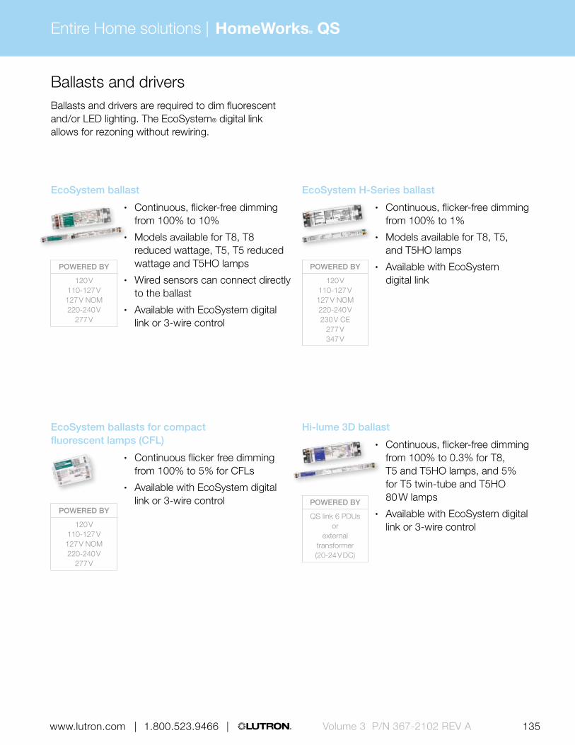
Entire Home solutions | HomeWorks® QS
134 135 | 1.800.523.9466 | www.lutron.com www.lutron.com | 1.800.523.9466 | Volume 3 P/N 367-2102 REV A
Ballasts and driversBallasts and drivers are required to dim fluorescent and/or LED lighting. The EcoSystem® digital link allows for rezoning without rewiring.
POWERED BY
120 V110-127 V127 V NOM220-240 V
277 V
POWERED BY
120 V110-127 V 127 V NOM220-240 V
277 V
POWERED BY
120 V110-127 V 127 V NOM220-240 V230 V CE
277 V347 V
POWERED BY
QS link 6 PDUs or
external transformer (20-24 V DC)
EcoSystem ballast
• Continuous, flicker-free dimming from 100% to 10%
• Models available for T8, T8 reduced wattage, T5, T5 reduced wattage and T5HO lamps
• Wired sensors can connect directly to the ballast
• Available with EcoSystem digital link or 3-wire control
EcoSystem H-Series ballast
• Continuous, flicker-free dimming from 100% to 1%
• Models available for T8, T5, and T5HO lamps
• Available with EcoSystem digital link
EcoSystem ballasts for compact fluorescent lamps (CFL)
• Continuous flicker free dimming from 100% to 5% for CFLs
• Available with EcoSystem digital link or 3-wire control
Hi-lume 3D ballast
• Continuous, flicker-free dimming from 100% to 0.3% for T8, T5 and T5HO lamps, and 5% for T5 twin-tube and T5HO 80 W lamps
• Available with EcoSystem digital link or 3-wire control

Entire home solutions | HomeWorks® QS
136 137 | 1.800.523.9466 | www.lutron.com www.lutron.com | 1.800.523.9466 |Volume 3 P/N 367-2102 REV A
POWERED BY
120 V277 V
POWERED BY
120 V110-127 V 127 V NOM220-240 V
277 V
POWERED BY
120 V
POWERED BY
220-240 V230 V CE
Ballasts and drivers (continued)Ballasts and drivers are required to dim fluorescent and/or LED lighting. The EcoSystem® digital link allows for rezoning without rewiring.
Hi-lume ballast
• Continuous flicker free dimming from 100% to 1%
• Models available for T5HO lamps and T4 CFLs
• Available with 3-wire control
Tu-wire ballast
• Continuous, flicker-free dimming from 100% to 5%
• Models available for T8 lamps and T4 CFLs
• Available with Tu-wire control
Hi-lume A-Series LED driver
• Continuous, flicker-free dimming from 100% to 1%
• Models available for LED light engines up to 40 W, constant current or constant voltage
• Available with EcoSystem digital link, 3-wire or 2-wire forward phase control
EcoSystem LED driver
• Continuous, flicker-free dimming from 100% to 1%
• Models available for LED light engines up to 25 W, constant current or constant voltage
• Available with EcoSystem digital link

Entire Home solutions | HomeWorks® QS
136 137 | 1.800.523.9466 | www.lutron.com www.lutron.com | 1.800.523.9466 | Volume 3 P/N 367-2102 REV A
POWERED BY
Battery
FREQUENCY
434 MHz434 limited
channel MHz865 MHz
(ceiling-mount only)868 MHz
(ceiling-mount only)868 limited
channel MHz(ceiling-mount only)
POWERED BY
Battery
FREQUENCY
434 MHz434 limited
channel MHz865 MHz868 MHz
868 limited channel MHz
POWERED BY
Battery
FREQUENCY
434 MHz
SensorsWired and wireless sensors add convenience by detecting occupancy/vacancy, daylight, and partitioning and adjust the light accordingly.
Wireless
Radio Powr SavrTM wireless occupancy/vacancy sensors
• Sensor automatically turns lighting on and/or off based on space occupancy
• Models available as occupancy/vacancy or vacancy only
• Passive infrared (PIR) with Lutron® exclusive XCT technology
• 10-year battery life• Available in White• Ceiling-mount:
Diameter: 3.57 in (91 mm) Depth: 1.13 in (29 mm)
Wall-mount: W: 1.80 in (46 mm) H: 4.35 in (110 mm) D: 1.35 in (34 mm)
Radio Powr Savr wireless daylight sensor
• Sensor automatically adjusts lighting zones based on amount of daylight entering a space
• Ability to disable on a scene-by-scene basis
• Ceiling-mounted• 10-year battery life• Available in White• Diameter: 1.60 in (41 mm)
Depth: 0.70 in (17 mm)
Wireless wall-mount temperature sensor
• Detects temperature and transmits information to HVAC controller
• Use up to four wireless temperature sensors to average temperature readings
• 5-year battery life• Available in Snow and Midnight• Diameter: 1.63 in (41 mm)
Depth: 0.75 in (17 mm)

Entire home solutions | HomeWorks® QS
138 139 | 1.800.523.9466 | www.lutron.com www.lutron.com | 1.800.523.9466 |Volume 3 P/N 367-2102 REV A
POWERED BY
20 V DC from ESN, GRAFIK
Eye QS main unit, power pack, or ballast/module
with input or
QS link, 2 PDUs
Wired
Sensors (continued)Wired and wireless sensors add convenience by detecting occupancy/vacancy, daylight, and partitioning and adjust the light accordingly.
Wired LOS-C and LOS-W series occupancy sensors
• Sensor automatically turns lighting scenes/zones on and/or off based on space occupancy
• Sensor technology options include passive infrared, ultrasonic and dual technology
• Wall-mount and ceiling-mount models available
• Available in White• Ceiling-mount:
Diameter: 4.50 in (114 mm) Depth: 1.40 in (38 mm)
Wall-mount: W: 2.70 in (69 mm) H: 5.25 in (133 mm) D: 3.90 in (99 mm)

Entire Home solutions | HomeWorks® QS
138 139 | 1.800.523.9466 | www.lutron.com www.lutron.com | 1.800.523.9466 | Volume 3 P/N 367-2102 REV A
POWERED BY
QS link 3 PDUs or
external transformer
(12–24 V DC)
POWERED BY
QS link 2 PDUs or
external transformer
(12–24 V DC)
POWERED BY
QS link 2 PDUs or
external transformer
(12–24 V DC)
POWERED BY
24 V AC low-voltage
FREQUENCY
434 MHz
Control interfacesUse control interfaces to combine Lutron lighting controls with other third-party devices and systems for advanced integration. Interfaces may also provide connections points for other Lutron® devices.
QS contact closure interface
• Provides five contact closure inputs and five contact closure outputs
• Allows integration with third-party equipment, such as motion/occupancy sensors, time clocks and movable walls
• W: 4.26 in (108 mm) H: 5.26 in (134 mm) D: 1.06 in (27 mm)
QS RS232/Ethernet interface
• Allows integration with a touchscreen, PC, A/V systems, or other digital equipment that supports RS232 communication, or TCP/IP communication over Ethernet
• Monitor lighting scenes, levels and shade positions
• W: 4.26 in (108 mm) H: 5.26 in (134 mm) D: 1.06 in (27 mm)
HVAC controller
• Connects to and controls mechanical HVAC equipment
• Can utilize either a wireless or wired temperature sensor
• Provides the ability to adjust heating and cooling systems any time of the day
• W: 4.25 in (108 mm) H: 5.25 in (133 mm) Depth: 1.06 in (27 mm)
QS DMX512 output interface
• Allows control DMX512- controlled devices
• Zones can be mapped to either a single DMX512 channel or to three separate DMX512 channels
• W: 4.26 in (108 mm) H: 5.26 in (134 mm) D: 1.06 in (27 mm)

Entire home solutions | HomeWorks® QS
140 141 | 1.800.523.9466 | www.lutron.com www.lutron.com | 1.800.523.9466 |Volume 3 P/N 367-2102 REV A
Control interfaces (continued)Use control interfaces to combine Lutron lighting controls with other third-party devices and systems for advanced integration. Interfaces may also provide connections points for other Lutron® devices.
POWERED BY
External transformer
(9 V DC)
FREQUENCY
434 MHz
Visor control receiver
• Allows the control of lights, shades, HVAC and other equipment from the visor control transmitter
• Includes 2 contact closure inputs and four contact closure outputs
• W: 4.25 in (108 mm) H: 5.25 in (133 mm) D: 1.06 in (27 mm)

Entire Home solutions | HomeWorks® QS
140 141 | 1.800.523.9466 | www.lutron.com www.lutron.com | 1.800.523.9466 | Volume 3 P/N 367-2102 REV A
ShadesSivoia® QS wired and wireless shading systems offer convenient control of daylight at the touch of a button.
FREQUENCY
434 MHz434 limited
channel MHz865 MHz868 MHz
868 limited channel MHz
POWERED BY
120 V110–127 V
110–127 V NOM220-240 V230 V CE
POWERED BY
120 V110–127 V
110–127 V NOM220-240 V230 V CE
Sivoia QS power supply individual and smart panel)
• 12-24 V supply that provides power to shade and drapery drive units
• Various form factors available
Insulating Honeycomb shade power
• Universal input voltage 120-240 V @ 50/60 Hz
• Electronic over-current and over-temperature protection
• Class 2 12 V supply that can power up to 10 insulating honeycomb shades
• Simple wiring scheme uses 2-conductor low voltage link to provide power
• Energy efficient – International Efficiency Level V, Energy Star 2.0 & CeC compliant
Sivoia QS wired/wireless shades
• Shades offer ultra-quiet precision control of daylight
• Styles include:– Roller shades– Tensioned shades– Roman shades with CERUS®
safety technology– Drapery tracks– Kirbé® vertical drapery systems– Venetian blinds– Insulating honeycomb shades
• Includes a wide variety of fabric offerings to meet every need
• Wired shades communicate via the QS link; wireless shades communicate via Lutron® reliable Clear Connect® RF technology

142 143 | 1.800.523.9466 | www.lutron.com www.lutron.com | 1.800.523.9466 |
Entire home solutions | HomeWorks® QS
142 143 | 1.800.523.9466 | www.lutron.com www.lutron.com | 1.800.523.9466 |Volume 3 P/N 367-2102 REV A
Software and programmingHomeWorks QS is programmed through PC-based software.
HomeWorks QS software
• Design and program the system through this PC-based software
• Provides commissioning support through communication diagnostics
• Create customized report packages—bill of material, load schedule, wiring and engraving
Home Control +
• Provides the ability to control and monitor your HomeWorks QS system right from your mobile device—at home or while away
• Use the app to control and monitor lights, shades and HVAC
• Full two-way functionality allows the app to update in real time as you change the lights in the space.
142 143 | 1.800.523.9466 | www.lutron.com www.lutron.com | 1.800.523.9466 | P/N 367-2102 REV A142 143 | 1.800.523.9466 | www.lutron.com www.lutron.com | 1.800.523.9466 |

144 145 | 1.800.523.9466 | www.lutron.com www.lutron.com | 1.800.523.9466 |144 145 | 1.800.523.9466 | www.lutron.com www.lutron.com | 1.800.523.9466 |Volume 3 P/N 367-2102 REV A
The processor is the heart of the lighting control system providing intelligence and offering a centralized connection point for control and communication. The processor communicates with all components of the system, including the primary controls, power panels and control interfaces
Quantum® light management hub (QP2)pg. 146
Quantum® light management hub (QP3)pg. 150
Whole building
Processors
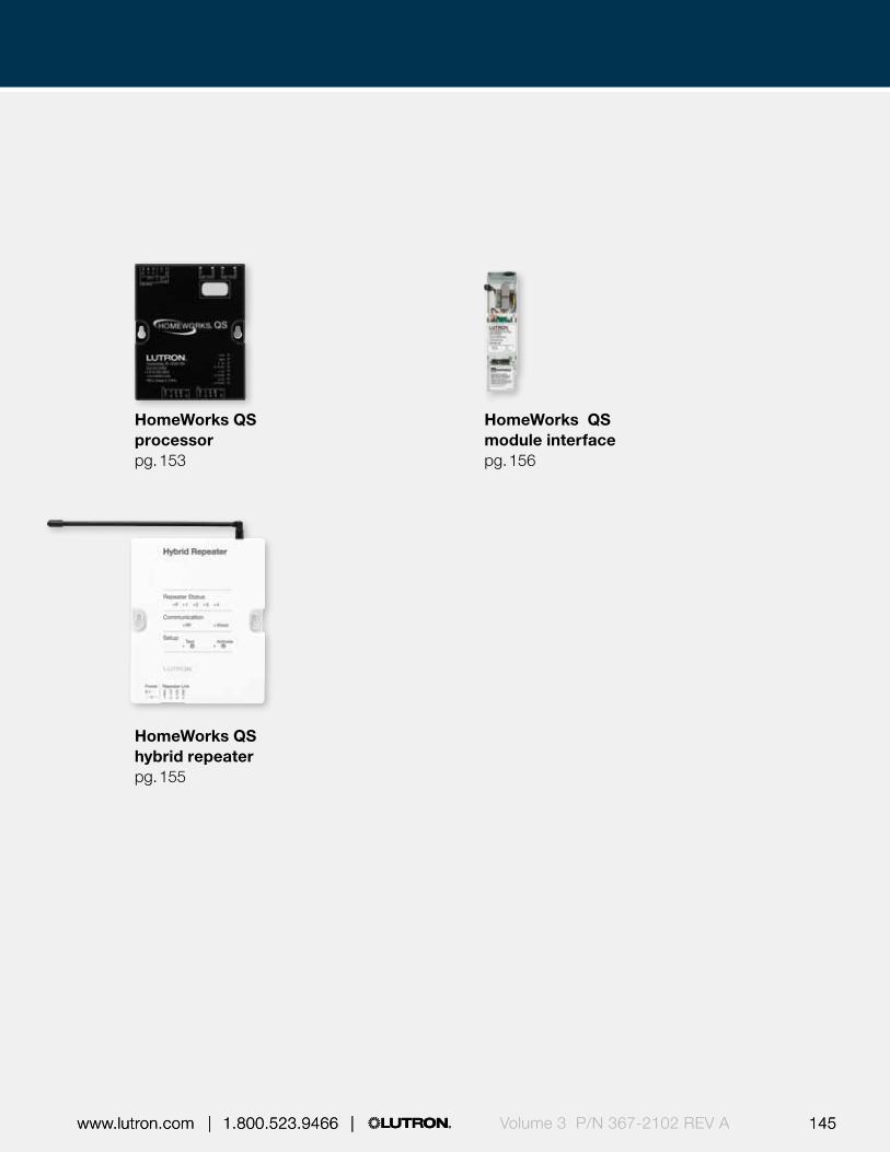
144 145 | 1.800.523.9466 | www.lutron.com www.lutron.com | 1.800.523.9466 |144 145 | 1.800.523.9466 | www.lutron.com www.lutron.com | 1.800.523.9466 | Volume 3 P/N 367-2102 REV A
HomeWorks QS processorpg. 153
HomeWorks QS module interfacepg. 156
HomeWorks QS hybrid repeaterpg. 155

Processors |
146 | 1.800.523.9466 | www.lutron.comVolume 3 P/N 367-2102 REV A
Shown above: Quantum light management hub (QP2) (QP2-2P8CSE-120)
15.75 in (400 mm)
31.50 in (800 mm
)
Features and capacities• Provides a centralized connection point for
EcoSystem ballasts / drivers / modules,* dimming and switching panels and Lutron QS devices, including Energi Savr Node™ modules, GRAFIK Eye® QS main units, and Sivoia® QS shades
• Models available for 120 V, 230 V (CE) and 220- 240 V (non-CE)
• Contains up to two Quantum processors with two links each that can be individually configured to communicate with:– Quantum bus supply*
(limited to one link per hub—Link A)– Lutron power panels– Lutron QS devices
• Each hub supports up to eight internal EcoSystem loops, (two per Quantum bus supply*); each loop can have a combination of 64 EcoSystem ballasts, drivers, and modules, plus a maximum of 16 daylight sensors, 32 occupancy sensors, and 64 infrared (IR) devices
• Designed to control, manage and monitor lighting and shade systems in a building or a whole campus
• Supports both astronomic and time-of-day events to automatically control the lights and shades in the system
• Allows for simple reconfiguration of a space without rewiring
Dimensions and mounting• Width: 15.75 in (400 mm)
Height: 31.50 in (800 mm) Depth: 5.81 in (148 mm)
• Surface mount
Communication and wiring• Ability to connect to additional Quantum light
management hubs (QP2 or QP3)• Light management hubs communicate via Ethernet• EcoSystem loop* may be wired NEC Class 1 or
IEC PELV / NEC Class 2• QS and power panel links are wired low-voltage
IEC PELV / NEC Class 2• Link B, C, and D each supply 32 power draw units
to the QS link
5.81 in (148 mm) depth
Direct lighting loads*
Fluorescent (EcoSystem®) LED (EcoSystem)
Quantum® light management hub (QP2)
* Quantum bus supply / EcoSystem loops available in 120 V and 220-240 V (non-CE) models only, not available in 230 V (CE) models.

Processors |
146 | 1.800.523.9466 | www.lutron.com 147 www.lutron.com | 1.800.523.9466 | Volume 3 P/N 367-2102 REV A
Quantum light management hub (QP2) with cover removed
3
4
5
7
6
2
1 Features
1 Line voltage input • 120 V, 230 V (CE) or 220 -240 V (non-CE)
• Normal / emergency feed
2 Power panel switch
• Disconnects power to all components in the hub
3 Quantum bus supplies
• Up to four modules, two EcoSystem loops per module maximum
4 Factory configured Quantum bus supply link
• Link A• If no Quantum bus supply
link can be configured in field to power panel or Lutron QS
• Supplies no power draw units (PDUs)
5 Configurable links • Power panel or Lutron QS
6 Accessory device • 5-port unmanaged Ethernet port
7 Quantum processor
• Two maximum
Explanation of features
Quantum® light management hub (QP2)
Download specification submittal – 120 VDownload specification submittal – 240 VDownload specification submittal – 230 V (CE)Download high resolution product image
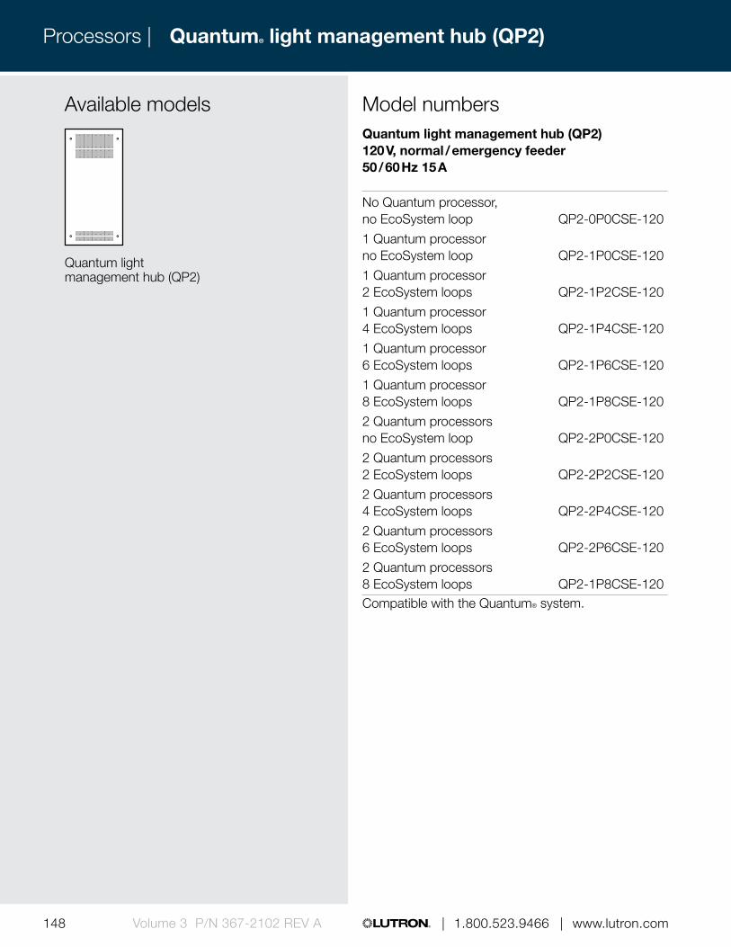
Processors |
148 | 1.800.523.9466 | www.lutron.comVolume 3 P/N 367-2102 REV A
Available models
Quantum light management hub (QP2)
Quantum® light management hub (QP2)
Quantum light management hub (QP2) 120 V, normal / emergency feeder 50 / 60 Hz 15 A
No Quantum processor, no EcoSystem loop QP2-0P0CSE-120
1 Quantum processor no EcoSystem loop QP2-1P0CSE-120
1 Quantum processor 2 EcoSystem loops QP2-1P2CSE-120
1 Quantum processor 4 EcoSystem loops QP2-1P4CSE-120
1 Quantum processor 6 EcoSystem loops QP2-1P6CSE-120
1 Quantum processor 8 EcoSystem loops QP2-1P8CSE-120
2 Quantum processors no EcoSystem loop QP2-2P0CSE-120
2 Quantum processors 2 EcoSystem loops QP2-2P2CSE-120
2 Quantum processors 4 EcoSystem loops QP2-2P4CSE-120
2 Quantum processors 6 EcoSystem loops QP2-2P6CSE-120
2 Quantum processors 8 EcoSystem loops QP2-1P8CSE-120Compatible with the Quantum® system.
Model numbers

Processors |
148 | 1.800.523.9466 | www.lutron.com 149 www.lutron.com | 1.800.523.9466 | Volume 3 P/N 367-2102 REV A
Quantum light management hub (QP2) 230 V (CE), normal / emergency feeder 50 / 60 Hz 10 A
1 Quantum processor, no EcoSystem loop QP2-1P0CSE-230
2 Quantum processors no EcoSystem loop QP2-2P0CSE-230Compatible with the Quantum® system.
Quantum light management hub (QP2) 220-240 V (non-CE), normal / emergency feeder 50 / 60 Hz 10 A
No Quantum processor, no EcoSystem loop QP2-0P0CSE-240
1 Quantum processor no EcoSystem loop QP2-1P0CSE-240
1 Quantum processor 2 EcoSystem loops QP2-1P2CSE-240
1 Quantum processor 4 EcoSystem loops QP2-1P4CSE-240
1 Quantum processor 6 EcoSystem loops QP2-1P6CSE-240
1 Quantum processor 8 EcoSystem loops QP2-1P8CSE-240
2 Quantum processors no EcoSystem loop QP2-2P0CSE-240
2 Quantum processor 2 EcoSystem loops QP2-2P2CSE-240
2 Quantum processor 4 EcoSystem loops QP2-2P4CSE-240
2 Quantum processor 6 EcoSystem loops QP2-2P6CSE-240
2 Quantum processor 8 EcoSystem loops QP2-1P8CSE-240Compatible with the Quantum® system.
Model numbers
Quantum® light management hub (QP2)

Processors |
150 | 1.800.523.9466 | www.lutron.comVolume 3 P/N 367-2102 REV A
Shown above: Quantum light management hub (QP3) (QP3-1PL-100-240)
9.25 in (235 mm)
13.25 in (337 mm
)
Features and capacities• Provides a centralized connection point for dimming
and switching panels, and Lutron QS devices, including Energi Savr Node™ modules, GRAFIK Eye® QS main units, and Sivoia® QS shades
• Model available for 100 -240 V; CE rated• Contains one Quantum processor with two links that
can be individually configured to communicate with:– Lutron power panels– Lutron QS devices
• Designed to control, manage, and monitor lighting and shade systems in a building or a whole campus
• Enables a Quantum system to cost-effectively scale from a single-floor to a whole campus
• Supports both astronomic and time-of-day events to automatically control the lights and shades in the system
• Allows for simple reconfiguration of a space without rewiring
Dimensions and mounting• Width: 9.25 in (235 mm)
Height: 13.25 in (337 mm) Depth: 3.16 in (80 mm)
• Surface mount
Communication and wiring• Ability to connect to additional Quantum light
management hubs (QP2 or QP3)• Light management hubs communicate via Ethernet• QS and power panel links are wired low-voltage
IEC PELV/NEC Class 2• Link A and B each supply 32 power draw units
to the QS link
3.16 in (80 mm) depth
Quantum® light management hub (QP3)
Download specification submittalDownload high resolution product image

500-
1056
1 Re
v. B
H H N N N G GN N N
Processors |
150 | 1.800.523.9466 | www.lutron.com 151 www.lutron.com | 1.800.523.9466 | Volume 3 P/N 367-2102 REV A
Quantum light management hub (QP3) with cover removed
3
4
5
2
1 Features
1 Line voltage input • 100 – 240 V• Normal / emergency feed
2 Configurable links • Link 1 and 2 • Power panel or Lutron QS
3 Ethernet port • 10/100 full duplex for connection to Quantum server
4 Quantum processor
• One processor per hub, two configurable links per processor
5 Power supply • 24 V DC, 2 A low voltage• IEC PELV/ NEC
Class 2 wiring
Explanation of features
Quantum® light management hub (QP3)

Processors |
152 | 1.800.523.9466 | www.lutron.comVolume 3 P/N 367-2102 REV A
Available models
Quantum light management hub (QP3)
Quantum® light management hub (QP3)
Quantum light management hub (QP3) 100 – 240 V, normal / emergency feeder 50 / 60 Hz 1 A
1 Quantum processor QP3-1PL-100-240Compatible with the Quantum system.
Model numbers
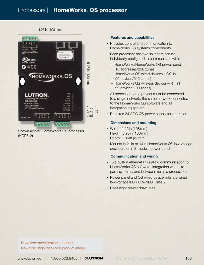
HomeWorks® QS processorProcessors |
152 | 1.800.523.9466 | www.lutron.com 153 www.lutron.com | 1.800.523.9466 | Volume 3 P/N 367-2102 REV A
Features and capabilities• Provides control and communication to
HomeWorks QS systems components• Each processor has two links that can be
individually configured to communicate with:
– HomeWorks/HomeWorks QS power panels (16 addresses/256 zones)
– HomeWorks QS wired devices—QS link (99 devices/512 zones)
– HomeWorks QS wireless devices—RF link (99 devices/100 zones)
• All processors on a project must be connected to a single network; the same network connected to the HomeWorks QS software and all integration equipment
• Requires 24 V DC QS power supply for operation
Dimensions and mounting• Width: 4.25 in (108 mm)
Height: 5.25 in (133 mm) Depth: 1.06 in (27 mm)
• Mounts in 21 in or 14 in HomeWorks QS low-voltage enclosure or in 8-module power panel
Communication and wiring• Two built-in ethernet links allow communication to
HomeWorks QS software, integration with third-party systems, and between multiple processors
• Power panel and QS wired device links are wired low-voltage IEC PELV/NEC Class 2
• Uses eight power draw units
Shown above: HomeWorks QS processor (HQP6-2)
4.25 in (108 mm)
5.25 in (133 mm
)
1.06 in (27 mm) depth
Download specification submittalDownload high resolution product image
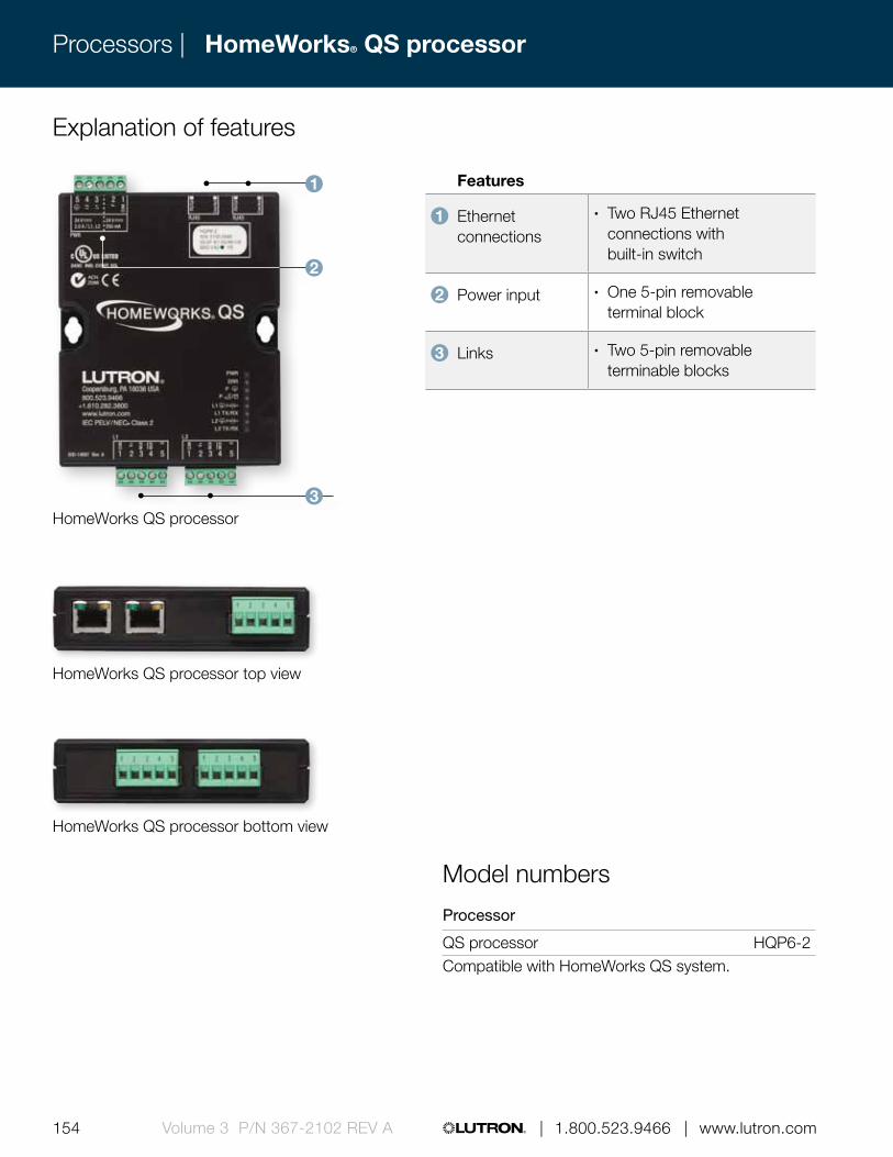
HomeWorks® QS processorProcessors |
154 | 1.800.523.9466 | www.lutron.comVolume 3 P/N 367-2102 REV A
Features
1 Ethernet connections
• Two RJ45 Ethernet connections with built-in switch
2 Power input • One 5-pin removable terminal block
3 Links • Two 5-pin removable terminable blocks
Explanation of features
HomeWorks QS processor
HomeWorks QS processor top view
HomeWorks QS processor bottom view
Model numbers
Processor
QS processor HQP6-2Compatible with HomeWorks QS system.
1
3
2
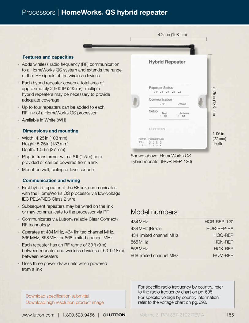
Processors |
154 | 1.800.523.9466 | www.lutron.com 155 www.lutron.com | 1.800.523.9466 | Volume 3 P/N 367-2102 REV A
4.25 in (108 mm)5.25 in (133 m
m)
1.06 in (27 mm) depth
Shown above: HomeWorks QS hybrid repeater (HQR-REP-120)
Features and capacities• Adds wireless radio frequency (RF) communication
to a HomeWorks QS system and extends the range of the RF signals of the wireless devices
• Each hybrid repeater covers a total area of approximately 2,500 ft2 (232 m2); multiple hybrid repeaters may be necessary to provide adequate coverage
• Up to four repeaters can be added to each RF link of a HomeWorks QS processor
• Available in White (WH)
Dimensions and mounting• Width: 4.25 in (108 mm)
Height: 5.25 in (133 mm) Depth: 1.06 in (27 mm)
• Plug-in transformer with a 5 ft (1.5 m) cord provided or can be powered from a link
• Mount on wall, ceiling or level surface
Communication and wiring• First hybrid repeater of the RF link communicates
with the HomeWorks QS processor via low-voltage IEC PELV/NEC Class 2 wire
• Subsequent repeaters may be wired on the link or may communicate to the processor via RF
• Communicates via Lutron® reliable Clear Connect® RF technology
• Operates at 434 MHz, 434 limited channel MHz, 865 MHz, 868 MHz or 868 limited channel MHz
• Each repeater has an RF range of 30 ft (9 m) between repeater and wireless devices or 60 ft (18 m) between repeaters
• Uses three power draw units when powered from a link
Model numbers434 MHz HQR-REP-120
434 MHz (Brazil) HQR-REP-BA
434 limited channel MHz HQQ-REP
865 MHz HQN-REP
868 MHz HQK-REP
868 limited channel MHz HQM-REP
HomeWorks® QS hybrid repeater
Download specification submittalDownload high resolution product image
For specific radio frequency by country, refer to the radio frequency chart on pg. 695. For specific voltage by country information refer to the voltage chart on pg. 692.
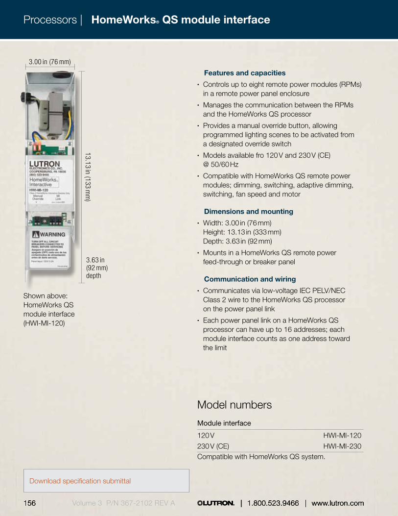
HomeWorks® QS module interface
156 157 | 1.800.523.9466 | www.lutron.com www.lutron.com | 1.800.523.9466 |156 157 | 1.800.523.9466 | www.lutron.com www.lutron.com | 1.800.523.9466 |
Processors |
156 | 1.800.523.9466 | www.lutron.comVolume 3 P/N 367-2102 REV A
Features and capacities• Controls up to eight remote power modules (RPMs)
in a remote power panel enclosure• Manages the communication between the RPMs
and the HomeWorks QS processor• Provides a manual override button, allowing
programmed lighting scenes to be activated from a designated override switch
• Models available fro 120 V and 230 V (CE) @ 50/60 Hz
• Compatible with HomeWorks QS remote power modules; dimming, switching, adaptive dimming, switching, fan speed and motor
Dimensions and mounting• Width: 3.00 in (76 mm)
Height: 13.13 in (333 mm) Depth: 3.63 in (92 mm)
• Mounts in a HomeWorks QS remote power feed-through or breaker panel
Communication and wiring• Communicates via low-voltage IEC PELV/NEC
Class 2 wire to the HomeWorks QS processor on the power panel link
• Each power panel link on a HomeWorks QS processor can have up to 16 addresses; each module interface counts as one address toward the limit
Download specification submittal
Shown above: HomeWorks QS module interface (HWI-MI-120)
Model numbers
Module interface
120 V HWI-MI-120
230 V (CE) HWI-MI-230Compatible with HomeWorks QS system.
3.00 in (76 mm)
13.13 in (133 mm
)
3.63 in (92 mm) depth

156 157 | 1.800.523.9466 | www.lutron.com www.lutron.com | 1.800.523.9466 |156 157 | 1.800.523.9466 | www.lutron.com www.lutron.com | 1.800.523.9466 | Volume 3 P/N 367-2102 REV A156 | 1.800.523.9466 | www.lutron.com

158 159 | 1.800.523.9466 | www.lutron.com www.lutron.com | 1.800.523.9466 |Volume 3 P/N 367-2102 REV A
Power panels are available as dimming and switching panels to provide architectural lighting control of premiere spaces, buildings, and campus environments.
Power panels
LCP128™ dimming panelpg. 170
Softswitch128® switching panelpg. 166

158 159 | 1.800.523.9466 | www.lutron.com www.lutron.com | 1.800.523.9466 | Volume 3 P/N 367-2102 REV A
XP switching panelpg. 178
GP dimming panelpg. 185
LP dimming panelpg. 182
LCP128 spec-grade dimming panelpg. 175

160 161 | 1.800.523.9466 | www.lutron.com www.lutron.com | 1.800.523.9466 |Volume 3 P/N 367-2102 REV A
Power panels |Power panels
DCI dimming panelpg. 194
Custom combination panel (CCP)pg. 189
HomeWorks QS remote power feed-through panelpg. 197
HomeWorks QS remote power panel with breakers pg. 199

160 161 | 1.800.523.9466 | www.lutron.com www.lutron.com | 1.800.523.9466 | Volume 3 P/N 367-2102 REV A
Power panels |Power interfaces |
HomeWorks QS relay remote module pg. 203
HomeWorks QS adaptive dimming modulepg. 201
HomeWorks QS motor remote power modulepg. 204
HomeWorks QS spec grade panelpg. 206
HomeWorks QS dimming remote power module pg. 202
HomeWorks QS fan remote power module pg. 205

162 163 | 1.800.523.9466 | www.lutron.com www.lutron.com | 1.800.523.9466 |Volume 3 P/N 367-2102 REV A162 163 | 1.800.523.9466 | www.lutron.com www.lutron.com | 1.800.523.9466 |
Power panels |
Panel type Voltage Panel feed type Number of circuitsThermal magnetic circuit breaker Load rating Load type*
Lamp noise suppression
Compatible system
Softswitch128® switching pg. 166
120 V/277 V, 230 V (CE), 220-240 V, 347 V
50/60 Hz
Feed-through Main lugs Main breaker
4-48 (feed-through)
4-42 (panels with breakers)
1 per circuit (main lug panels only)
16 A continuous/circuit
INC, MLV, ELV, NCC, FL, LED, HID, Motor
No choke required
Softswitch128
LCP128TM dimming pg. 170
120 V, 230 V (CE), 220-240 V
50/60 Hz
Feed-through Main lugs Main breaker Isolation switch
4-36 (1-9 modules)
1 per module 1 per circuit (switching modules only)
Load rating based on module, see pg. 171 for more details
INC, MLV, ELV, NCC, FL, LED, CFL, Non-dim, HID, Motor, Fan
High-grade choke LCP128
LCP128 spec grade dimming pg. 175
120 V, 277 V
50/60 Hz
Feed-through Main lugs Main breaker Dual tap main lugs
8-24 1 per circuit 16 A continuous/circuit
INC, MLV, ELV, NCC, FL, LED, CFL, Non-dim, HID, Motor
Highest-grade choke
LCP128
XP switching pg. 178
120 V, 230 V (CE), 220-240 V, 277 V, 347 V
50/60 Hz
Feed-through Main lugs Main breaker
4-48 (feed-through)
4-42 (panels with breakers)
1 per circuit (main lug panels only)
16 A continuous/circuit
INC, MLV, ELV, NCC, FL, LED, HID, Motor
No choke required
GRAFIK Eye® 4000
Quantum®
LP dimming pg. 182
120 V, 230 V (CE), 220-240 V
50/60 Hz
Main lugs Main breaker Isolation switch
4-32 (1-8 modules)
1 per module 16 A continuous/module (120 V and 220-240 V) 13 A continuous module (230 V CE)
INC, MLV, ELV, NCC, FL, LED, CFL, Non-dim HID, Motor
High-grade choke GRAFIK Eye 4000 Quantum
Choosing a panel

162 163 | 1.800.523.9466 | www.lutron.com www.lutron.com | 1.800.523.9466 |162 163 | 1.800.523.9466 | www.lutron.com www.lutron.com | 1.800.523.9466 | Volume 3 P/N 367-2102 REV A
Panel type Voltage Panel feed type Number of circuitsThermal magnetic circuit breaker Load rating Load type*
Lamp noise suppression
Compatible system
Softswitch128® switching pg. 166
120 V/277 V, 230 V (CE), 220-240 V, 347 V
50/60 Hz
Feed-through Main lugs Main breaker
4-48 (feed-through)
4-42 (panels with breakers)
1 per circuit (main lug panels only)
16 A continuous/circuit
INC, MLV, ELV, NCC, FL, LED, HID, Motor
No choke required
Softswitch128
LCP128TM dimming pg. 170
120 V, 230 V (CE), 220-240 V
50/60 Hz
Feed-through Main lugs Main breaker Isolation switch
4-36 (1-9 modules)
1 per module 1 per circuit (switching modules only)
Load rating based on module, see pg. 171 for more details
INC, MLV, ELV, NCC, FL, LED, CFL, Non-dim, HID, Motor, Fan
High-grade choke LCP128
LCP128 spec grade dimming pg. 175
120 V, 277 V
50/60 Hz
Feed-through Main lugs Main breaker Dual tap main lugs
8-24 1 per circuit 16 A continuous/circuit
INC, MLV, ELV, NCC, FL, LED, CFL, Non-dim, HID, Motor
Highest-grade choke
LCP128
XP switching pg. 178
120 V, 230 V (CE), 220-240 V, 277 V, 347 V
50/60 Hz
Feed-through Main lugs Main breaker
4-48 (feed-through)
4-42 (panels with breakers)
1 per circuit (main lug panels only)
16 A continuous/circuit
INC, MLV, ELV, NCC, FL, LED, HID, Motor
No choke required
GRAFIK Eye® 4000
Quantum®
LP dimming pg. 182
120 V, 230 V (CE), 220-240 V
50/60 Hz
Main lugs Main breaker Isolation switch
4-32 (1-8 modules)
1 per module 16 A continuous/module (120 V and 220-240 V) 13 A continuous module (230 V CE)
INC, MLV, ELV, NCC, FL, LED, CFL, Non-dim HID, Motor
High-grade choke GRAFIK Eye 4000 Quantum
* Control interface may be required to control loads listedLoad type key:INC=incandescent/halogen, MLV=magnetic low-voltage, ELV=electronic low-voltage, FL=fluorescent (3-wire, Tu-wire, 0-10 V, PWM, DALI), NCC=neon/cold cathode, LED=LED (3-wire, 0-10 V, PWM, DALI, 2-wire phase adaptive), CFL=CFL/LED (screw-base), Non-dim=Non-dim lighting, HID=HID, Motor=Motor loads, Fan=Fan speed control

164 165 | 1.800.523.9466 | www.lutron.com www.lutron.com | 1.800.523.9466 |Volume 3 P/N 367-2102 REV A164 165 | 1.800.523.9466 | www.lutron.com www.lutron.com | 1.800.523.9466 |
Power panels |
Panel type VoltagePanel feed type Number of circuits
Thermal magnetic circuit breaker Load rating Load type
Lamp noise suppression
Compatible system
GP dimmingpg. 185
100 V, 120 V, 230 V (CE), 220-240 V, 277 V 50/60 Hz
Feed-throughMain lugsMain breakerDual tap main lugsIsolation switch
3-144 1 per circuit 16 A continuous/circuit
INC, MLV, ELV, NCC, FL, LED, CFL, Non-dim, HID, Motor
Highest-grade choke
GRAFIK Eye 4000Quantum
DCI dimming panelpg. 194
120 V 50/60 Hz
Main breaker 1-3 1 per circuit 1200 W continuous/circuit
INC No choke inaudible
GRAFIK Eye 4000Quantum
Custom combination dimming panelpg. 189
120 V, 277 V (CE), 220-240 V 50/60 Hz
Main lugsIsolation switch
4-36(1-9 modules)
1 per module; 1 per circuit (switching modules only)
Load rating based on module, see pg. 190 for more details
INC, MLV, ELV, NCC, FL, LED, CFL, Non-dim, HID, Motor, Fan
High-grade choke GRAFIK Eye 4000Quantum
Remote power feed-through panel with modulespg. 197
120 V, 220 V (CE), 220-240 V 50/60 Hz
Feed-through 4-32(1-8 modules)
N/A Load rating based on module, see pgs. 201-205 for more details
INC, MLV, ELV, NCC, FL, LED, CFL, Non-dim, HID, Motor, Fan
High-grade choke HomeWorks QS
Remote power panel with breakers and modulespg. 199
120 V, 230 V (CE), 220-240 V 50/60 Hz
Feed-throughMain lugs (120 V only)
4-32 (1– 8 modules)
N/A Load rating based on module, see pgs. 201-205 for more details
INC, MLV, ELV, NCC, FL, LED, CFL, Non-dim, HID, Motor, Fan
High-grade choke HomeWorks QS
HomeWorks QS spec grade dimmingpg. 206
120 V, 230 V (CE), 220-240 V 50/60 Hz
Feed-throughMain lugsMain breakerDual tap main lugsIsolation switch
8-24 1 per circuit 16 A continuous/circuit
INC, MLV, ELV, NCC, FL, LED, CFL, Non-dim, HID, Motor
Highest-grade choke
HomeWorks QS
Choosing a panel
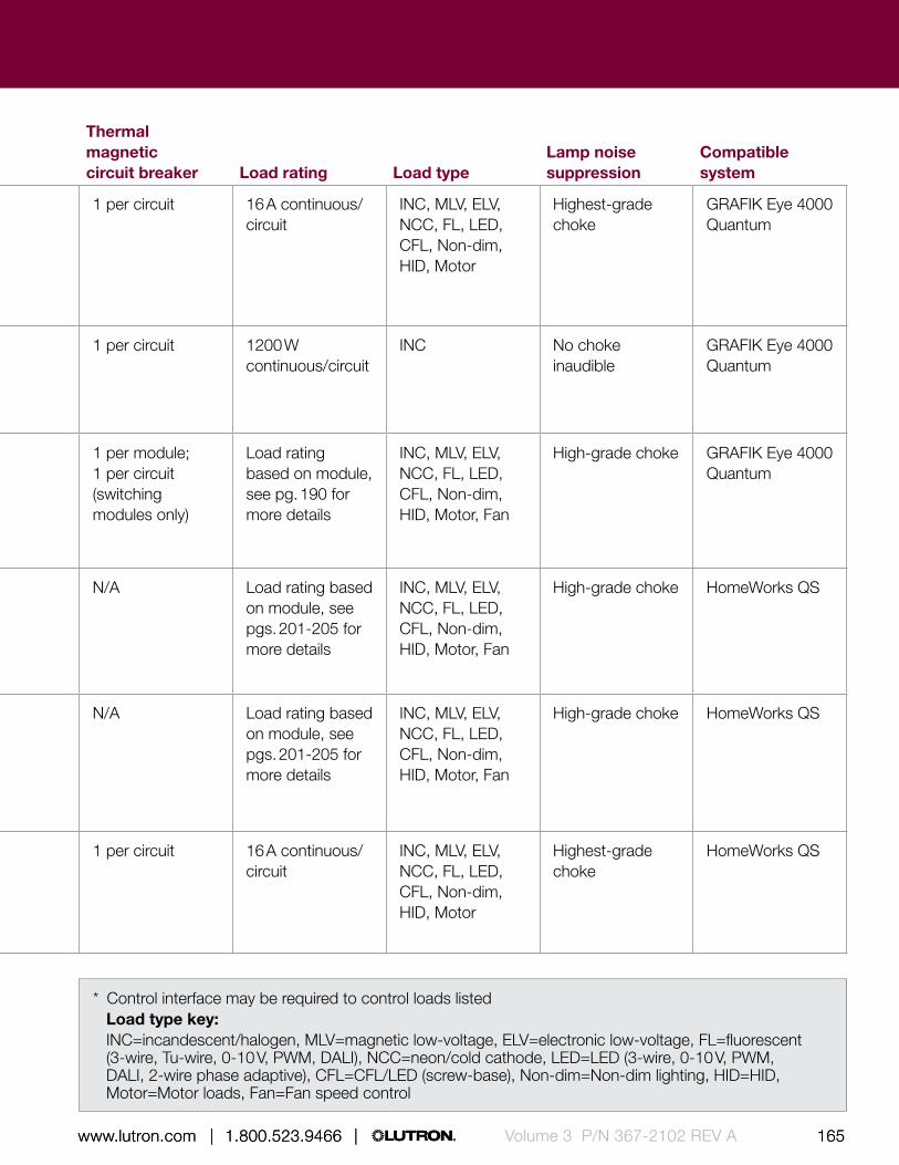
164 165 | 1.800.523.9466 | www.lutron.com www.lutron.com | 1.800.523.9466 |164 165 | 1.800.523.9466 | www.lutron.com www.lutron.com | 1.800.523.9466 | Volume 3 P/N 367-2102 REV A
Panel type VoltagePanel feed type Number of circuits
Thermal magnetic circuit breaker Load rating Load type
Lamp noise suppression
Compatible system
GP dimmingpg. 185
100 V, 120 V, 230 V (CE), 220-240 V, 277 V 50/60 Hz
Feed-throughMain lugsMain breakerDual tap main lugsIsolation switch
3-144 1 per circuit 16 A continuous/circuit
INC, MLV, ELV, NCC, FL, LED, CFL, Non-dim, HID, Motor
Highest-grade choke
GRAFIK Eye 4000Quantum
DCI dimming panelpg. 194
120 V 50/60 Hz
Main breaker 1-3 1 per circuit 1200 W continuous/circuit
INC No choke inaudible
GRAFIK Eye 4000Quantum
Custom combination dimming panelpg. 189
120 V, 277 V (CE), 220-240 V 50/60 Hz
Main lugsIsolation switch
4-36(1-9 modules)
1 per module; 1 per circuit (switching modules only)
Load rating based on module, see pg. 190 for more details
INC, MLV, ELV, NCC, FL, LED, CFL, Non-dim, HID, Motor, Fan
High-grade choke GRAFIK Eye 4000Quantum
Remote power feed-through panel with modulespg. 197
120 V, 220 V (CE), 220-240 V 50/60 Hz
Feed-through 4-32(1-8 modules)
N/A Load rating based on module, see pgs. 201-205 for more details
INC, MLV, ELV, NCC, FL, LED, CFL, Non-dim, HID, Motor, Fan
High-grade choke HomeWorks QS
Remote power panel with breakers and modulespg. 199
120 V, 230 V (CE), 220-240 V 50/60 Hz
Feed-throughMain lugs (120 V only)
4-32 (1– 8 modules)
N/A Load rating based on module, see pgs. 201-205 for more details
INC, MLV, ELV, NCC, FL, LED, CFL, Non-dim, HID, Motor, Fan
High-grade choke HomeWorks QS
HomeWorks QS spec grade dimmingpg. 206
120 V, 230 V (CE), 220-240 V 50/60 Hz
Feed-throughMain lugsMain breakerDual tap main lugsIsolation switch
8-24 1 per circuit 16 A continuous/circuit
INC, MLV, ELV, NCC, FL, LED, CFL, Non-dim, HID, Motor
Highest-grade choke
HomeWorks QS
* Control interface may be required to control loads listedLoad type key:INC=incandescent/halogen, MLV=magnetic low-voltage, ELV=electronic low-voltage, FL=fluorescent (3-wire, Tu-wire, 0-10 V, PWM, DALI), NCC=neon/cold cathode, LED=LED (3-wire, 0-10 V, PWM, DALI, 2-wire phase adaptive), CFL=CFL/LED (screw-base), Non-dim=Non-dim lighting, HID=HID, Motor=Motor loads, Fan=Fan speed control

166 167 | 1.800.523.9466 | www.lutron.com www.lutron.com | 1.800.523.9466 |Volume 3 P/N 367-2102 REV A
Power panels |
Direct lighting loads
Incandescent/halogen Magnetic low-voltage Electronic low-voltage Neon/cold cathode Fluorescent LED HID
Motor loads Fan loads
15 A receptacles
15.88 in (403 mm)
59.50 in (1511 mm
)
Shown above: Standard size Softswitch128 switching panel (XPS24-1204ML-20)
4.21 in (107 mm) depth
Softswitch128® switching panel
Model numbers
Rough-in panels-feed-through*
Empty tub
Mini-size, 8-16 circuits TUB16
Standard size, 20-48 circuits TUB48
Base plate, 120/277 V
8 circuits SINT8-FT
12 circuits SINT12-FT
16 circuits SINT16-FT
20 circuits SINT20-FT
24 circuits SINT24-FT
28 circuits SINT28-FT
32 circuits SINT32-FT
36 circuits SINT36-FT
40 circuits SINT40-FT
44 circuits SINT44-FT
48 circuits SINT48-FT
Compatible with the Softswitch128 (XPS) system
* Rough-in panels are ordered and delivered as two parts: empty tub and pre-wired base plate.
Download specification submittal for 120 VDownload specification submittal for 230 VDownload specification submittal for 220-240 V

166 167 | 1.800.523.9466 | www.lutron.com www.lutron.com | 1.800.523.9466 | Volume 3 P/N 367-2102 REV A
Power panels |
Dimensions and mounting• Mini:
Width: 15.88 in (403 mm) Height: 24.50 in (622 mm) Depth: 4.21 in (107 mm)
• Standard: Width: 15.88 in (403 mm) Height: 59.50 in (1511 mm) Depth: 4.21 in (107 mm)
• Large: Width: 23.50 in (597 mm) Height: 63.50 in (1613 mm) Depth: 6.30 in (160 mm)
• Extra large: Width: 23.50 in (597 mm) Height: 82.50 in (2096 mm) Depth: 6.30 in (160 mm)
• Mini XP and standard size panels can be surface or recess mounted
• Large and extra large panels can be surface mounted only
Communication and wiring• Low-voltage IEC PELV/NEC Class 2 standard
wired communication connects panel to other system components
• Line (mains) voltage: feed and load wiring only, no other wiring or assembly required
• Connect up to 16 Softswitch128 panels for up to 512 switched outputs
Features and capacities• Switching panel for up to 48 circuits with
integrated astronomical time clock and Liquid Crystal Display (LCD) controller for programming
• Switching circuits rated for 16 A• Models available for 120 V/277 V, 230 V (CE),
220-240 V, and 347 V at 50/60 Hz1
• All voltages indicated are phase-to-neutral• LCD controller mounted in the panel, provides
easy-to-use, menu-based control and configuration of the entire system
• Two user-configurable contact closure inputs built into the controller provide for easy interface with occupancy sensors
• Patented Softswitch® technology eliminates arcing at mechanical contacts when loads are switched, extending relay life to an average of 1,000,000 cycles
• Astronomical time clock provides automated selection of lighting scenes
• Feed-through (120 V/277 V only), branch circuit breaker, and rough-in panels are available
• Rough-in panels are ordered and delivered as two parts: an empty tub and a pre-wired baseplate that includes switching modules, terminal blocks, LCD controller/time clock, power supply and panel cover
• Normal or emergency panel capability2
Softswitch128® switching panel
1 Please contact Lutron for details on 480 V, phase-to-phase switching
2 Standard size feed-through panels are available with internal separation allowing emergency circuits to be wired into the same enclosure, please contact Lutron for more details

168 169 | 1.800.523.9466 | www.lutron.com www.lutron.com | 1.800.523.9466 |Volume 3 P/N 367-2102 REV A
Power panels |
Feature
1 Terminal blocks • For Lighting load circuit connections
2 Switching modules
• Patented Softswitch® circuit eliminates arcing at mechanical contacts when loads are switched, extending relay life to an average of 1,000,000 cycles
3 Low-voltage IEC PELV/NEC Class 2 wiring
• Connection for communication to other system components
4 LCD controller • Menu based control and configuration of the entire system
• Two integrated user-configurable contact closure inputs
• Integrated astronomical time clock
5 Branch circuit breakers
• Each circuit is protected by thermal magnetic breakers
6 Power feed wiring • 120 V, 277 V, 230 V (CE), 220-240 V, or 347 V
• Main breaker feeds (120 V only) or standard main lug
1
Standard size Softswitch128 switching panel with cover removed
Softswitch128® switching panel
Explanation of features
4
3
5
6
2

168 169 | 1.800.523.9466 | www.lutron.com www.lutron.com | 1.800.523.9466 | Volume 3 P/N 367-2102 REV A
Power panels |
Available models How to build a standard model number1
Mini panel Standard panel Number of circuits:
8 for 8 circuits12 for 12 circuits16 for 16 circuits20 for 20 circuits24 for 24 circuits28 for 28 circuits
Voltage:Omit for 120/277 V dual-voltage 120 for 120 V 277 for 277 V
Feed type2:FT for feed-through (120/277 V dual-voltage only) 4 for 3-phase, 4-wire (120 V or 277 V only)
Panel feed3:Omit for feed-through. ML for main lugs
Branch circuit breaker rating:Omit for feed-through. 20 for 20 A branch circuit breakers4
Compatible with the Softswitch128 system
X P S 2 4 - 1 2 0 4 M L - 2 0
Voltage
Feed type
Branch circuit breaker rating
Panel type
Number of circuits
Softswitch128® switching panel
Large panel Extra large panel
32 for 32 circuits36 for 36 circuits40 for 40 circuits42 for 42 circuits44 for 44 circuits (feed-through only)48 for 48 circuits (feed-through only)
1 Please contact Lutron for availability and assistance specifying appropriate model numbers for 230 V (CE), 220-240 V, 347 V, and 480 V panels.
2 1-phase 3-wire (split phase) panel feed option available, please contact Lutron for information.
3 Main breaker panel feed option available for 120 V, please contact Lutron for more information
4 20 A branch circuit breakers have a 16 A continuous load rating.

170 171 | 1.800.523.9466 | www.lutron.com www.lutron.com | 1.800.523.9466 |Volume 3 P/N 367-2102 REV A
Power panels |
15.88 in (403 mm)
59.50 in (1511 mm
)
Shown above: Standard size LCP128 dimming panel
4.21 in (107 mm) depth
Direct lighting loads (requires modules to control loads,
see pg. 171 for module information)
Incandescent/halogen Magnetic low-voltage Electronic low-voltage Neon/cold cathode Tu-wire fluorescent LED (2-wire forward phase) / CFL/LED (screw-base)1
Non-dim lighting AC motors loads Motor loads Fan loads
Lighting loads requiring an interface
/ Fluorescent/LED (3-wire) / Fluorescent/LED (0-10 V)2
/ Fluorescent/LED (PWM)2
Features and capacities• Combination dimming and switching panel for up
to 36 circuits with integrated astronomical time clock and Liquid Crystal Display (LCD) controller for programming
• Models available for 120 V, 230 V (CE) or 220-240 V at 50/60 Hz
• All voltages indicated are phase-to-neutral • LCD controller mounted in the panel provides
easy-to-use, menu-based control and configuration of the entire system
• Two user-configurable contact closure inputs built into the controller provide for easy interface with occupancy sensors
LCP128™ dimming panel
1 Visit www.lutron.com/LEDtool for a complete list of LEDs compatible with the adaptive dimming module.
2 0-10 V and PWM ballasts and drivers may also be controlled by adding 10-volt module (TVM) to panel. TVM will also allow control of DALI ballasts and drivers with broadcast commands only. Please contact Lutron for more information if control of these loads are required.
Download specification submittal for all modelsDownload specification submittal for 220-240 V
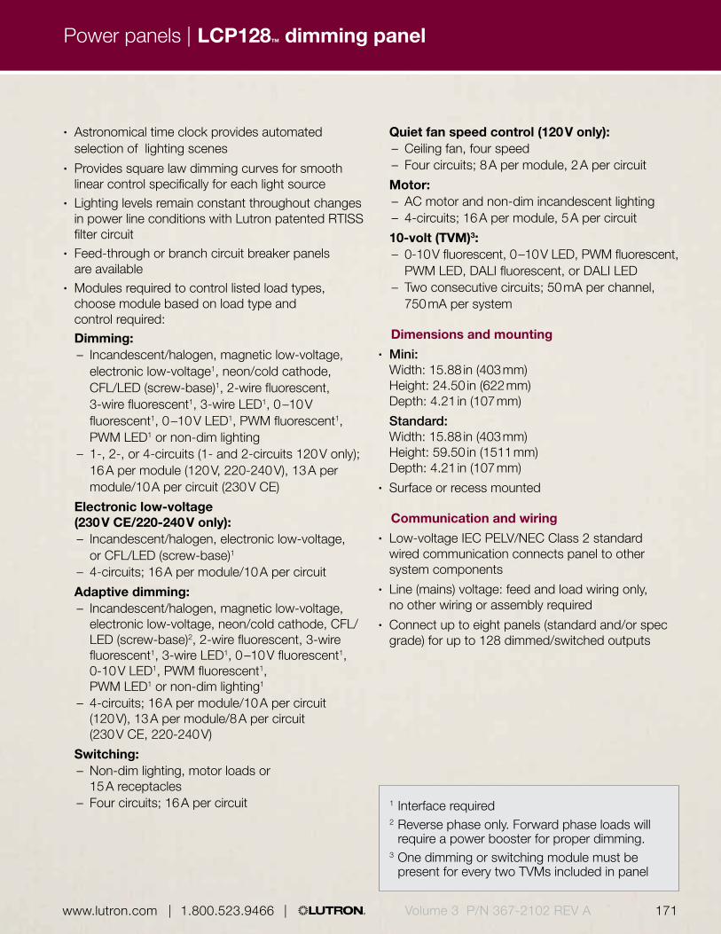
170 171 | 1.800.523.9466 | www.lutron.com www.lutron.com | 1.800.523.9466 | Volume 3 P/N 367-2102 REV A
Power panels |
• Astronomical time clock provides automated selection of lighting scenes
• Provides square law dimming curves for smooth linear control specifically for each light source
• Lighting levels remain constant throughout changes in power line conditions with Lutron patented RTISS filter circuit
• Feed-through or branch circuit breaker panels are available
• Modules required to control listed load types, choose module based on load type and control required:
Dimming:– Incandescent/halogen, magnetic low-voltage,
electronic low-voltage1, neon/cold cathode, CFL/LED (screw-base)1, 2-wire fluorescent, 3-wire fluorescent1, 3-wire LED1, 0 –10 V fluorescent1, 0 –10 V LED1, PWM fluorescent1, PWM LED1 or non-dim lighting
– 1-, 2-, or 4-circuits (1- and 2-circuits 120 V only); 16 A per module (120 V, 220-240 V), 13 A per module/10 A per circuit (230 V CE)
Electronic low-voltage (230 V CE/220-240 V only):– Incandescent/halogen, electronic low-voltage,
or CFL/LED (screw-base)1
– 4-circuits; 16 A per module/10 A per circuit Adaptive dimming:
– Incandescent/halogen, magnetic low-voltage, electronic low-voltage, neon/cold cathode, CFL/LED (screw-base)2, 2-wire fluorescent, 3-wire fluorescent1, 3-wire LED1, 0 –10 V fluorescent1, 0-10 V LED1, PWM fluorescent1, PWM LED1 or non-dim lighting1
– 4-circuits; 16 A per module/10 A per circuit (120 V), 13 A per module/8 A per circuit (230 V CE, 220-240 V)
Switching:– Non-dim lighting, motor loads or
15 A receptacles– Four circuits; 16 A per circuit
Quiet fan speed control (120 V only):– Ceiling fan, four speed– Four circuits; 8 A per module, 2 A per circuit
Motor:– AC motor and non-dim incandescent lighting– 4-circuits; 16 A per module, 5 A per circuit
10-volt (TVM)3:– 0-10 V fluorescent, 0 –10 V LED, PWM fluorescent,
PWM LED, DALI fluorescent, or DALI LED– Two consecutive circuits; 50 mA per channel,
750 mA per system
Dimensions and mounting• Mini:
Width: 15.88 in (403 mm) Height: 24.50 in (622 mm) Depth: 4.21 in (107 mm)
Standard: Width: 15.88 in (403 mm) Height: 59.50 in (1511 mm) Depth: 4.21 in (107 mm)
• Surface or recess mounted
Communication and wiring• Low-voltage IEC PELV/NEC Class 2 standard
wired communication connects panel to other system components
• Line (mains) voltage: feed and load wiring only, no other wiring or assembly required
• Connect up to eight panels (standard and/or spec grade) for up to 128 dimmed/switched outputs
LCP128™ dimming panel
1 Interface required2 Reverse phase only. Forward phase loads will
require a power booster for proper dimming.3 One dimming or switching module must be
present for every two TVMs included in panel

172 173 | 1.800.523.9466 | www.lutron.com www.lutron.com | 1.800.523.9466 |Volume 3 P/N 367-2102 REV A
Power panels |
Standard size LCP128 dimming panel with cover removed
Feature
1 Terminal blocks • Lighting load circuit connections
2 Modules • Choose module based on load type and control required
3 Low-voltage IEC PELV/NEC Class 2 wiring
• Connection for communication to other system components
4 LCD controller • Menu based control and configuration of the entire system
• Two integrated user-configurable contact closure inputs
• Integrated astronomical time clock
5 Branch circuit breakers
• Each input circuit is protected by thermal magnetic breakers
6 Power feed wiring • 120 V, 230 V (CE), or 220-240 V
• Main breaker feeds (120 V only) or standard main lug
Explanation of features
Available models
1
6
2
5
4
3
LCP128™ dimming panel
Standard panelMini panel

172 173 | 1.800.523.9466 | www.lutron.com www.lutron.com | 1.800.523.9466 | Volume 3 P/N 367-2102 REV A
Power panels |
How to build a 120 V model number1
Module (quantity and type):_ X _ S _ D _ Q _ A _ M _ F _ TList modules in the order shown above. Insert the quantity before each module code. Omit codes for modules not used in panel. See Note at right for limits on numbers of modules per panel.X for 4-circuit switching (relay) (XP)S for 1-circuit dimmingD for 2-circuit dimmingQ for 4-circuit dimmingA for 4-circuit adaptive dimmingM for 4-circuit motorF for 4-circuit quiet fan speedT for 0-10 V (TVM)
Voltage:120 for 120 V
Feed type:FT for feed-through3 for 1-phase, 3-wire (split phase)4 for 3-phase, 4-wire
Panel feed2:Omit for feed throughML for main lugs
Branch circuit breaker rating:Omit for feed-through20 for 20 A branch circuit breakers
Compatible with the LCP128 system
L C P - 2 X 2 D 1 A 8 T - 1 2 0 4 M L - 2 0
Module (quantity and type)
Voltage Panel feed
Feed type
Branch circuit breaker rating
Note:Module quantities are limited as follows (TVMs do not count toward maximum quantity):
Standard-Size Branch Circuit Breaker panels:Max. # in panel—9Max. # with TVMs—8Max. # with XP modules —7Max. # with XP modules and TVMs—5Max. # of TVMs—12
Standard-Size Feed-Through panels:Max. # in panel—9Max. # with TVMs—8Max. # of TVMs—12
Mini-Size Branch Circuit Breaker panels (no XP modules):Max. # in panel—3
Mini-Size Feed-Through panels:Max. # in panel (with XP modules)—3Max. # in panel (all XP modules)—4
LCP128™ dimming panel
1 Model number information provided for general use only. Please contact Lutron for availability and assistance specifying appropriate model numbers.
2 Main breaker panel feed option available for 120 V, please contact Lutron for more information
3 20 A branch circuit breakers have a 16 A continuous load rating

174 175 | 1.800.523.9466 | www.lutron.com www.lutron.com | 1.800.523.9466 |Volume 3 P/N 367-2102 REV A
Power panels |
How to build a 230 V (CE) or 220-240 V model number*
Module (quantity and type):_ X _ U _ E _ A _ M _ TList modules in the order shown above. Insert the quantity before each module code. Omit codes for modules not used in panel. See Note at right for limits on numbers of modules per panel.X for 4-circuit switching (relay) (XP)U for 4-circuit dimmingE for 4-circuit electronic low-voltage dimmingA for 4-circuit adaptive dimmingM for 4-circuit motorT for 0 -10 V (TVM)
Voltage:230 for 230 V (CE)240 for 220-240 V
Feed type:FT for feed-through4 for 3-phase, 4-wire
Panel feed:Omit for feed throughIS for isolation switch
Suffix:CE for 230 V (CE) AU for 220-240 V
Compatible with the LCP128 system
C C P - 2 X 1 U 1 E 1 A 6 T - 2 3 0 4 I S - C E - L C P
Module (quantity and type)
Voltage Panel feed
Feed type
Suffix
* Model number information provided for general use only. Please contact Lutron for availability and assistance specifying appropriate model numbers.
LCP128™ dimming panel

174 175 | 1.800.523.9466 | www.lutron.com www.lutron.com | 1.800.523.9466 | Volume 3 P/N 367-2102 REV A
Power panels |
28.00 in (711 mm)
37.00 in (940 mm
)
Shown above: LCP128 spec grade dimming panel (LCP24-1204ML-20)
Direct lighting loads
Incandescent/halogen Magnetic low-voltage Electronic low-voltage1
Neon/cold cathode Tu-wire fluorescent Fluorescent/LED (3-wire) LED (2-wire forward phase)/ CFL/LED (screw-base)1
Non-dim lighting
Lighting loads that require an interface
/ Fluorescent/LED (0-10 V)2
/ Fluorescent/LED (PWM)2
Motor loads Fan loads
12.00 in (304 mm) depth
1 Forward phase only. Not all electronic low-voltage transformers and dimmable CFL/LEDs dim properly with forward phase control dimmers. Contact Lutron for compatibility; may require phase-adaptive power module for proper dimming. For reverse phase, a phase adaptive power module will be required.
2 0-10 V and PWM ballasts and drivers may also be controlled by adding 10-volt module (TVM) to panel. TVM will also allow control of DALI ballasts and drivers with broadcast commands only. Please contact Lutron for more information if control of these loads is required.
LCP128™ spec grade dimming panel
Features and capacities• Combination dimming and switching panel for up
to 24 circuits with integrated astronomical time clock and Liquid Crystal Display (LCD) controller for programming
• Circuits rated for 16 A• Models available for 120 V or 277 V input power
at 50/60 Hz power• All voltages indicated are phase-to-neutral• LCD controller mounted in the panel, provides
easy-to-use, menu-based control and configuration of the entire system
• Two user-configurable contact closure inputs built into the controller provide for easy interface with occupancy sensors and daylight sensors
• Astronomical time clock provides automated selection of lighting scenes
• Provides square law dimming curves for smooth linear control, specifically for each light source
• Lighting levels remain constant throughout changes in power line conditions with Lutron patented RTISS filter circuit
• Feed-through or branch circuit breaker panels are available
Dimensions and mounting• Width: 28.00 in (711 mm); Height: 37.00 in (940 mm);
Depth: 12.00 in (304 mm)• Surface mounted
Communication and wiring• Low voltage IEC PELV/NEC Class 2 standard
wired communication connects panel to other system components
• Line (mains) voltage: feed and load wiring only, no other wiring or assembly required
• Connect up to eight panels (standard and/or spec grade) for up to 128 dimmed/switched outputs
Download specification submittal
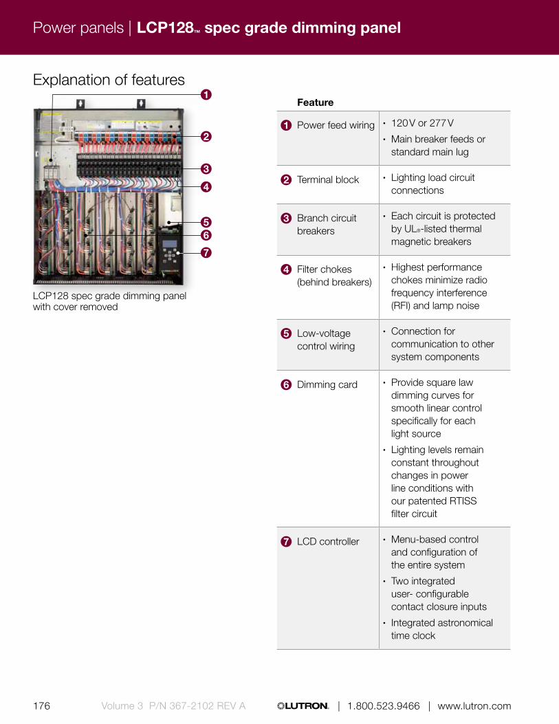
176 177 | 1.800.523.9466 | www.lutron.com www.lutron.com | 1.800.523.9466 |Volume 3 P/N 367-2102 REV A
Power panels |
Feature
1 Power feed wiring • 120 V or 277 V• Main breaker feeds or
standard main lug
2 Terminal block • Lighting load circuit connections
3 Branch circuit breakers
• Each circuit is protected by UL®-listed thermal magnetic breakers
4 Filter chokes (behind breakers)
• Highest performance chokes minimize radio frequency interference (RFI) and lamp noise
5 Low-voltage control wiring
• Connection for communication to other system components
6 Dimming card • Provide square law dimming curves for smooth linear control specifically for each light source
• Lighting levels remain constant throughout changes in power line conditions with our patented RTISS filter circuit
7 LCD controller • Menu-based control and configuration of the entire system
• Two integrated user- configurable contact closure inputs
• Integrated astronomical time clock
Explanation of features
LCP128 spec grade dimming panel with cover removed
3
2
4
56
7
LCP128™ spec grade dimming panel
1

176 177 | 1.800.523.9466 | www.lutron.com www.lutron.com | 1.800.523.9466 | Volume 3 P/N 367-2102 REV A
Power panels |
How to build a standard model numberAvailable models
L C P 2 4 - 1 2 0 4 M L - 2 0
Voltage Panel feed
Feed type
Branch circuit breaker rating
Number of circuits
Number of circuits:8 for 8 circuits12 for 12 circuits16 for 16 circuits20 for 20 circuits24 for 24 circuits
Voltage:120 for 120 V277 for 277 V
Feed type:2 for 1-phase, 2-wire3 for 1-phase, 3-wire (split phase)4 for 3-phase, 4-wire
Feed type:ML for main lugsDTML for dual tap main lugsMxxx for main breaker (xxx = breaker size in amps)
Branch circuit breaker rating:20 for 20 A branch circuit breakers
Compatible with the LCP128 system
Branch Circuit Breaker Model Numbers
Available models
Spec grade panel
LCP128™ spec grade dimming panel
1 Feed-through panels available, please contact Lutron for more information
2 20 A branch circuit breakers have a 16 A continuous load rating

178 179 | 1.800.523.9466 | www.lutron.com www.lutron.com | 1.800.523.9466 |Volume 3 P/N 367-2102 REV A
Power panels |
15.88 in (403 mm)
59.50 in (1511 mm
)
Shown above: Standard size XP switching panel (XP12-1204ML-15)
Features and capacities• Panel that provides power and switching for up to
48 switching circuits• Switching circuits rated for 16 A• Models are available with 120 V, 230 V (CE),
220-240 V, 277 V, or 347 V input power at 50/60 Hz• All voltages indicated are phase-to-neutral• Patented Softswitch® technology eliminates
arcing at mechanical contacts when loads are switched, extending relay life to an average of 1,000,000 cycles
• Feed-through or branch circuit breakers are available• Normal or emergency panel capability*• Available with 2Link circuit selector, which allows
both theatrical and architectural lighting controls in one system
Dimensions and mounting• Mini: Width: 15.88 in (403 mm);
Height: 24.50 in (622 mm); Depth: 4.21 in (107 mm) • Standard: Width: 15.88 in (403 mm);
Height: 59.50 in (1511 mm); Depth: 4.21 in (107 mm) • Large: Width: 23.50 in (597 mm);
Height: 63.50 in (1613 mm); Depth: 6.30 in (160 mm)• Extra large: Width: 23.50 in (597 mm);
Height: 82.50 in (2096 mm); Depth: 6.30 in (160 mm)• Mini and standard size panels can be surface or
recess mounted• Large and extra large panels can be surface
mounted only
Communication and wiring• Low-voltage IEC PELV/NEC Class 2 standard
wired communication connects panel to other system components
• Line (mains) voltage: feed and load wiring only, no other wiring or assembly required
• Panels work with GP dimming panels, DCI dimming panels, LP dimming panels, and CCP panels
Direct lighting loads
Incandescent/halogen Magnetic low-voltage Electronic low-voltage Neon/cold cathode Fluorescent LED HID
Motor loads Fan loads
15 A receptacles
4.21 in (107 mm) depth
XP switching panel
Download specification submittal for 120 VDownload specification submittal for 230 VDownload specification submittal for 220-240 V
* Standard size feed-through panels are available with internal separation allowing emergency circuits to be wired into the same enclosure, please contact Lutron for more details

178 179 | 1.800.523.9466 | www.lutron.com www.lutron.com | 1.800.523.9466 | Volume 3 P/N 367-2102 REV A
Power panels |
Standard size XP switching panel with cover removed
Explanation of features
5
1
2
3
4
Features
1 Terminal blocks • Lighting load circuit connections
2 Switching modules • Patented Softswitch® circuit eliminates arcing at mechanical contacts when loads are switched, extending relay life to an average of 1,000,000 cycles
3 Low-voltage IEC PELV/NEC Class 2 wiring
• Connection for communication to other system components
4 Branch circuit breakers
• Each circuit is protected by thermal magnetic breakers
5 Power feed wiring • 120 V, 230 V (CE), 220-240 V, 277 V, or 347 V
• Main breaker feeds (120 V only) or standard main lug
XP switching panel

180 181 | 1.800.523.9466 | www.lutron.com www.lutron.com | 1.800.523.9466 |Volume 3 P/N 367-2102 REV A
Power panels |
Available models How to build a standard feed-through panel model number*
Mini panel Standard panel
Large panel Extra large panel
Number of circuits:4 for 4 circuits 8 for 8 circuits12 for 12 circuits16 for 16 circuits20 for 20 circuits24 for 24 circuits28 for 28 circuits
Voltage:Omit for 120/277 V dual-voltage230 for 230 V (CE)
Feed type:FT for feed through
Panel feed:Omit for 120/277 V dual-voltageML for main lugs
Compatible with GRAFIK Eye® 4000 and Quantum® systems.
X P 1 2 - 2 3 0 F T M L
Voltage
Feed type
Panel feed
Number of circuits
* Please contact Lutron for availability and assistance with specifying model numbers for 220-240 V and 347 V feed-through panels
XP switching panel
32 for 32 circuits36 for 36 circuits40 for 40 circuits42 for 42 circuits44 for 44 circuits48 for 48 circuits
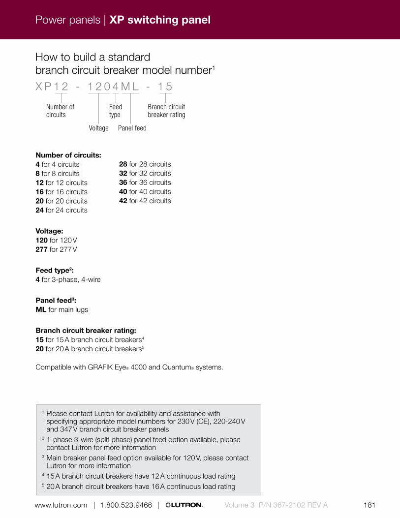
180 181 | 1.800.523.9466 | www.lutron.com www.lutron.com | 1.800.523.9466 | Volume 3 P/N 367-2102 REV A
Power panels | XP switching panel
How to build a standard branch circuit breaker model number1
Number of circuits:4 for 4 circuits 8 for 8 circuits12 for 12 circuits16 for 16 circuits20 for 20 circuits24 for 24 circuits
Voltage:120 for 120 V277 for 277 V
Feed type2:4 for 3-phase, 4-wire
Panel feed3:ML for main lugs
Branch circuit breaker rating:15 for 15 A branch circuit breakers4
20 for 20 A branch circuit breakers5
Compatible with GRAFIK Eye® 4000 and Quantum® systems.
X P 1 2 - 1 2 0 4 M L - 1 5
Voltage
Feed type
Branch circuit breaker rating
Panel feed
Number of circuits
1 Please contact Lutron for availability and assistance with specifying appropriate model numbers for 230 V (CE), 220-240 V and 347 V branch circuit breaker panels
2 1-phase 3-wire (split phase) panel feed option available, please contact Lutron for more information
3 Main breaker panel feed option available for 120 V, please contact Lutron for more information
4 15 A branch circuit breakers have 12 A continuous load rating5 20 A branch circuit breakers have 16 A continuous load rating
28 for 28 circuits32 for 32 circuits36 for 36 circuits40 for 40 circuits42 for 42 circuits

182 183 | 1.800.523.9466 | www.lutron.com www.lutron.com | 1.800.523.9466 |Volume 3 P/N 367-2102 REV A
Power panels |
15.88 in (403 mm)
59.50 in (1511 mm
)
Shown above: Standard LP dimming panel (LP7/28-1204ML-20)
Features and capacities• Panel that provides power and dimming for up to
32 dimming legs (up to eight dimming modules; four outputs per module)
• Models available for 120 V, 230 V (CE), or 220-240 V input power at 50/60 Hz
• All voltages indicated are phase-to-neutral• 120 V and 220-240 V: 16 A per module; 230 V (CE):
13 A per module, 10 A per leg• Panels include branch circuit breakers• Available with 2Link circuit selector, which allows
both theatrical and architectural lighting controls in one system
Dimensions and mounting• Mini:
Width: 15.88 in (403 mm) Height: 24.50 in (622 mm) Depth: 4.21 in (107 mm)
Standard: Width: 15.88 in (403 mm) Height: 59.50 in (1511 mm) Depth: 4.21 in (107 mm)
• Surface or recess mounted
Communication and wiring• Low-voltage IEC PELV/NEC Class 2 standard
wired communication connects panel to other system components
• Line (mains) voltage: feed and load wiring only, no other wiring or assembly required
• Panels work with GP dimming panels, DCI dimming panels, XP switching panels and CCP panels
Direct lighting loads
Incandescent/halogen Magnetic low-voltage Tu-wire fluorescent LED (2-wire forward phase) Neon/cold cathode Non-dim lighting
Lighting loads requiring an interface
Electronic low-voltage/ Fluorescent/LED (3-wire)/ Fluorescent/LED (0-10 V)*/ Fluorescent/LED (PWM)*
/ CFL/LED (screw-base) Motor loads Fan loads
4.21 in (107 mm) depth
LP dimming panel
* 0-10 V and PWM ballasts and drivers may also be controlled by adding 10-volt module (TVM) to panel. TVM will also allow control of DALI ballasts and drivers with broadcast commands only. Please contact Lutron for more information if control of these loads are required.
Download specification submittal for 120 VDownload specification submittal for 230 VDownload specification submittal for 220-240 V
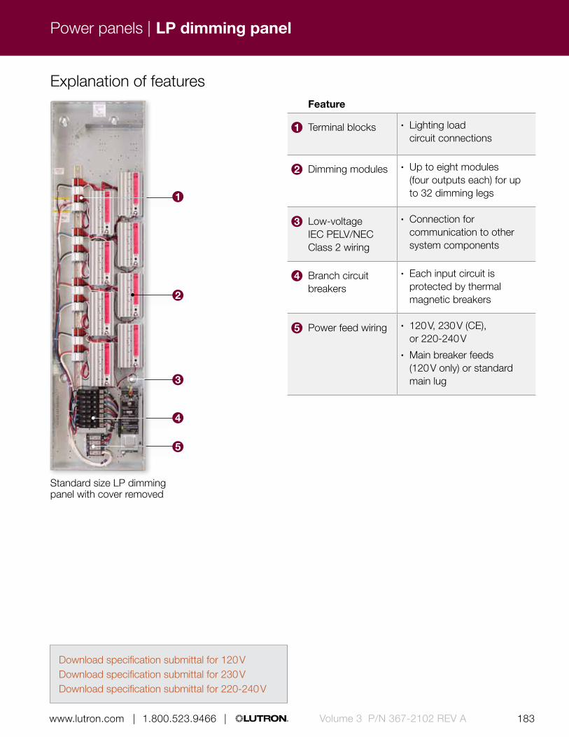
182 183 | 1.800.523.9466 | www.lutron.com www.lutron.com | 1.800.523.9466 | Volume 3 P/N 367-2102 REV A
Power panels |
Explanation of features
Standard size LP dimming panel with cover removed
Feature
1 Terminal blocks • Lighting load circuit connections
2 Dimming modules • Up to eight modules (four outputs each) for up to 32 dimming legs
3 Low-voltage IEC PELV/NEC Class 2 wiring
• Connection for communication to other system components
4 Branch circuit breakers
• Each input circuit is protected by thermal magnetic breakers
5 Power feed wiring • 120 V, 230 V (CE), or 220-240 V
• Main breaker feeds (120 V only) or standard main lug
1
2
3
4
5
LP dimming panel
Download specification submittal for 120 VDownload specification submittal for 230 VDownload specification submittal for 220-240 V

184 185 | 1.800.523.9466 | www.lutron.com www.lutron.com | 1.800.523.9466 |Volume 3 P/N 367-2102 REV A
Power panels |
Available models
Number of dimming modules/dimming legs:1/4 for 1 module, 4 legs2/8 for 2 modules, 8 legs3/12 for 3 modules, 12 legs4/16 for 4 modules, 16 legs5/20 for 5 modules, 20 legs6/24 for 6 modules, 24 legs7/28 for 7 modules, 28 legs8/32 for 8 modules, 32 legs
Voltage:120 for 120 V230 for 230 V (CE)240 for 220-240 V
Feed type:2 for 1-phase, 2-wire3 for 1-phase, 3-wire (split phase)4 for 3-phase, 4-wire
Panel feed:1
ML for main lugsIS for isolation switch (230 V CE/220-240 V only)
Branch circuit breaker rating:15 for 15 A branch circuit breakers (120 V only)2
20 for 20 A branch circuit breakers (120 V only)3
13 for 13 A branch circuit breakers (230 V CE only)16 for 16 A branch circuit breakers (220-240 V only)
Compatible with GRAFIK Eye® 4000 and Quantum® systems.
How to build a standard model number
L P 7 / 2 8 - 1 2 0 4 M L - 2 0
VoltageFeed type
Panel feed
Branch circuit breaker rating
Number of dimming modules /dimming legs
Mini panel Standard panel
LP dimming panel
1 Main breaker panel feed option available for 120 V, please contact Lutron for more information
2 15 A branch circuit breakers have a 12 A continuous load rating3 20 A branch circuit breakers have a 16 A continuous load rating
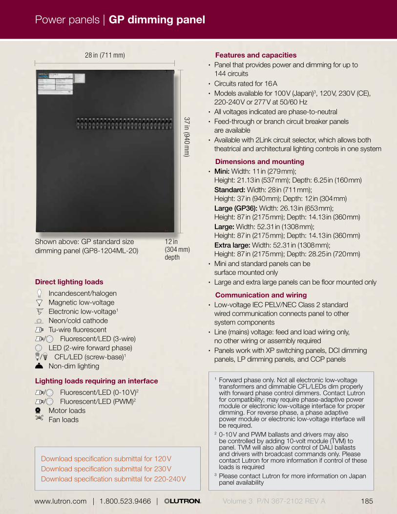
184 185 | 1.800.523.9466 | www.lutron.com www.lutron.com | 1.800.523.9466 | Volume 3 P/N 367-2102 REV A
Power panels |
Shown above: GP standard size dimming panel (GP8-1204ML-20)
28 in (711 mm)
37 in (940 mm
)
Direct lighting loads
Incandescent/halogen Magnetic low-voltage Electronic low-voltage1
Neon/cold cathode Tu-wire fluorescent/ Fluorescent/LED (3-wire) LED (2-wire forward phase)/ CFL/LED (screw-base)1
Non-dim lighting
Lighting loads requiring an interface
/ Fluorescent/LED (0-10 V)2
/ Fluorescent/LED (PWM)2 Motor loads
Fan loads
12 in (304 mm) depth
1 Forward phase only. Not all electronic low-voltage transformers and dimmable CFL/LEDs dim properly with forward phase control dimmers. Contact Lutron for compatibility; may require phase-adaptive power module or electronic low-voltage interface for proper dimming. For reverse phase, a phase adaptive power module or electronic low-voltage interface will be required.
2 0-10 V and PWM ballasts and drivers may also be controlled by adding 10-volt module (TVM) to panel. TVM will also allow control of DALI ballasts and drivers with broadcast commands only. Please contact Lutron for more information if control of these loads is required
3 Please contact Lutron for more information on Japan panel availability
Features and capacities• Panel that provides power and dimming for up to
144 circuits• Circuits rated for 16 A• Models available for 100 V (Japan)3, 120 V, 230 V (CE),
220-240 V or 277 V at 50/60 Hz• All voltages indicated are phase-to-neutral• Feed-through or branch circuit breaker panels
are available• Available with 2Link circuit selector, which allows both
theatrical and architectural lighting controls in one system
Dimensions and mounting• Mini: Width: 11 in (279 mm);
Height: 21.13 in (537 mm); Depth: 6.25 in (160 mm) Standard: Width: 28 in (711 mm);
Height: 37 in (940 mm); Depth: 12 in (304 mm) Large (GP36): Width: 26.13 in (653 mm);
Height: 87 in (2175 mm); Depth: 14.13 in (360 mm) Large: Width: 52.31 in (1308 mm);
Height: 87 in (2175 mm); Depth: 14.13 in (360 mm) Extra large: Width: 52.31 in (1308 mm);
Height: 87 in (2175 mm); Depth: 28.25 in (720 mm)• Mini and standard panels can be
surface mounted only• Large and extra large panels can be floor mounted only
Communication and wiring• Low-voltage IEC PELV/NEC Class 2 standard
wired communication connects panel to other system components
• Line (mains) voltage: feed and load wiring only, no other wiring or assembly required
• Panels work with XP switching panels, DCI dimming panels, LP dimming panels, and CCP panels
GP dimming panel
Download specification submittal for 120 VDownload specification submittal for 230 VDownload specification submittal for 220-240 V

186 187 | 1.800.523.9466 | www.lutron.com www.lutron.com | 1.800.523.9466 |Volume 3 P/N 367-2102 REV A
Power panels |
Explanation of features
1
3
2
4
5
Standard size GP dimming panel with cover removed
6
Feature
1 Terminal block • Lighting load circuit connections
2 Filter chokes (behind breakers)
• Highest performance chokes minimize radio frequency interference (RFI) and lamp noise
3 Branch circuit breakers
• Each circuit is protected by thermal magnetic breakers
4 Power feed wiring • 100 V (Japan), 120 V, 230 V (CE), 220-240 V or 277 V
• Main breaker feeds (120 or 277 V) or standard main lug
5 Low-voltage IEC PELV/NEC Class 2 wiring
• Connection for communication to other system components
6 Dimming card • Provides square law dimming curves for smooth linear control specifically for each light source.
• Lighting levels remain constant throughout changes in power line conditions with our patented RTISS® filter circuit
GP dimming panel
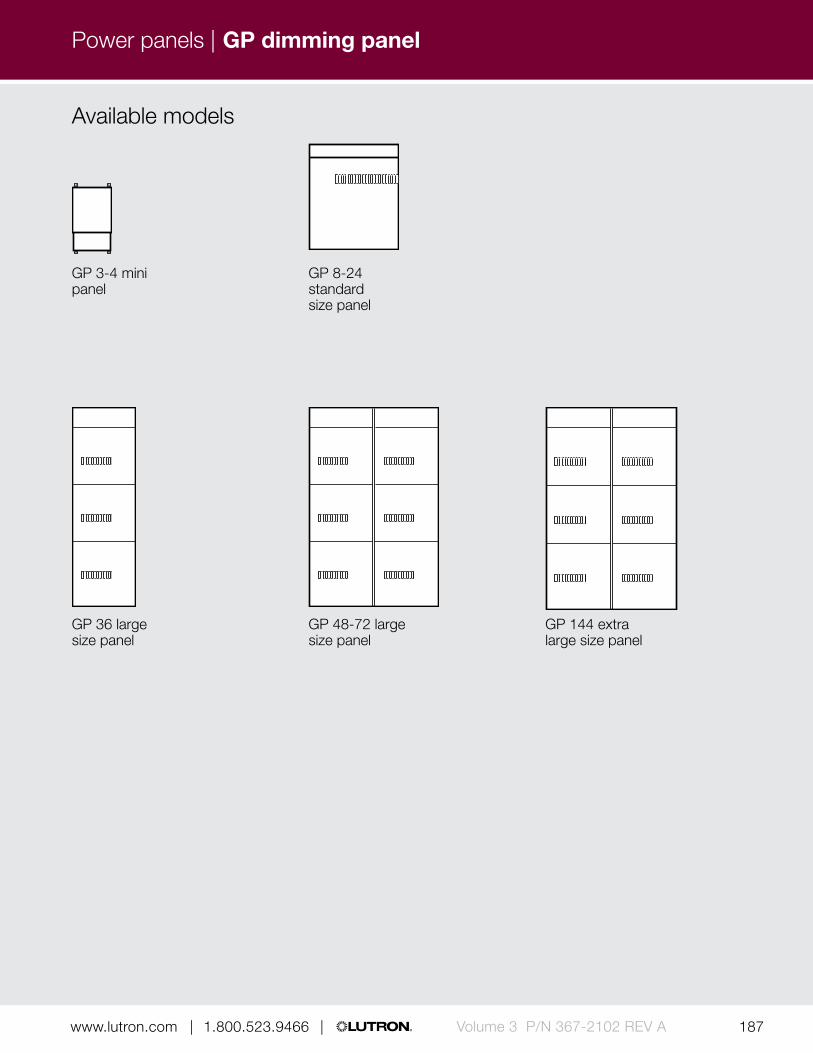
186 187 | 1.800.523.9466 | www.lutron.com www.lutron.com | 1.800.523.9466 | Volume 3 P/N 367-2102 REV A
Power panels |
Available models
GP 3-4 mini panel
GP 36 large size panel
GP 8-24 standard size panel
GP 48-72 large size panel
GP 144 extra large size panel
GP dimming panel

188 189 | 1.800.523.9466 | www.lutron.com www.lutron.com | 1.800.523.9466 |Volume 3 P/N 367-2102 REV A
Power panels |
Number of load circuits: 3 for 3 circuits4 for 4 circuits8 for 8 circuits12 for 12 circuits16 for 16 circuits20 for 20 circuits
Voltage:120 for 120 V277 for 277 V
Feed type:FT for feed-through2 for 1-phase, 2-wire3 for 1-phase, 3-wire (split phase)4 for 3-phase, 4-wire
Panel feed:ML for main lugs onlyDTML for dual tap main lugsMxx for main breaker with xx = breaker size in Amps
Branch circuit breakers:15 for 15 A branch circuit breakers1
20 for 20 A branch circuit breakers2
Number of load circuits: 3 for 3 circuits4 for 4 circuits8 for 8 circuits12 for 12 circuits16 for 16 circuits20 for 20 circuits24 for 24 circuits
Voltage:230 for 230 V (CE)240 for 220-240 V
Feed type:FT for feed-through2 for 1-phase, 2-wire (split phase)4 for 3-phase, 4-wire
Panel feed:IS for isolation switch
Branch circuit breakers:10 for 10 A branch circuit breakers16 for 16 A branch circuit breakers (220-240 V only)
Suffix:CE for 230 V (CE)AU for 220-240 V
How to build a standard 120 V or 277 V model number
How to build a standard 230 V (CE) or 220-240 V model number
G P 1 2 - 1 2 0 4 M L - 2 0 G P 1 2 - 2 3 0 4 I S - 1 0 C E
Voltage Voltage
Feed type
Feed type
Panel feed Panel feed Suffix
Branch circuit breaker rating
Branch circuit breaker rating
Number of switch legs
Number of switch legs
24 for 24 circuits36 for 36 circuits48 for 48 circuits60 for 60 circuits72 for 72 circuits144 for 144 circuits
GP dimming panel
1 15 A branch circuit breakers have a 12 A continuous load rating
2 20 A branch circuit breakers have a 16 A continuous load rating
Compatible with GRAFIK Eye® 4000 and Quantum® systems.

188 189 | 1.800.523.9466 | www.lutron.com www.lutron.com | 1.800.523.9466 | Volume 3 P/N 367-2102 REV A
Power panels |
15.88 in (403 mm)
59.50 in (1511 mm
)Shown above: Standard size custom combination panel
Direct lighting loads
(Requires modules to control loads; see pg. 190 for module information)
Incandescent/halogen Magnetic low-voltage Electronic low-voltage Neon/cold cathode Tu-wire fluorescent LED (2-wire forward phase)/ CFL/LED (screw-base)1
Non-dim lighting AC motors loads Motor loads Fan loads
Lighting loads requiring an interface
/ Fluorescent/LED (3-wire)/ Fluorescent/LED (0-10 V)2
/ Fluorescent/LED (PWM)2
4.21 in (107 mm) depth
Custom combination panel (CCP)
1 Visit www.lutron.com/LEDtool for a complete list of LEDs compatible with the adaptive dimming module.
2 0-10 V and PWM ballasts and drivers may also be controlled by adding 10-volt module (TVM) to panel. TVM will also allow control of DALI ballasts and drivers with broadcast commands only. Please contact Lutron for more information if control of these loads is required
Download specification submittal for 120 VDownload specification submittal for 230 VDownload specification submittal for 220-240 V

190 191 | 1.800.523.9466 | www.lutron.com www.lutron.com | 1.800.523.9466 |Volume 3 P/N 367-2102 REV A
Power panels |
Features and capacities• Combination dimming and switching panel that
provides power and dimming /switching for up to 32 dimming/switching legs
• Models available for 120 V, 230 V (CE) or 220-240 V at 50/60 Hz
• All voltages indicated are phase-to-neutral • Provides square law dimming curves for smooth
linear control specifically for each light source• Lighting levels remain constant throughout changes
in power line conditions with Lutron patented RTISS filter circuit
• Panels include input branch circuit breakers • Available with a 2Link circuit selector, which allows
both theatrical and architectural lighting controls in one system
• Modules required to control listed load types, choose module based on load type and control required:
Dimming:– Incandescent/halogen, magnetic low-voltage,
electronic low-voltage1, neon/cold cathode, CFL/LED (screw-base)1, Tu-wire fluorescent, 2-wire forward phase LED, 3-wire fluorescent1, 3-wire LED1, 0 -10 V fluorescent1, 0 -10 V LED1, PWM fluorescent1, PWM LED1 or non-dim lighting
– 4-circuits;16 A per module Electronic low-voltage (230 V CE/220-240 V
non-CE only):– Incandescent/halogen, electronic low-voltage
or CFL/LED (screw-base)2 – 4-circuits; 16 A per module, 10 A per circuit
Adaptive dimming:– Incandescent/halogen, magnetic low-voltage,
electronic low-voltage, neon/cold cathode, CFL/LED (screw-base), Tu-wire fluorescent, 2-wire forward phase LED, 3-wire fluorescent1, 3-wire LED1, 0 –10 V fluorescent1, 0 -10 V LED1, PWM fluorescent1, PWM LED1 or non-dim lighting1
– 4-circuits; 16 A per module, 10 A per circuit
Custom combination panel (CCP)
1 Interface required2 Reverse phase only. Forward phase loads will
require a power booster for proper dimming3 One dimming or switching module must be
present for every two TVMs included in panel
Switching:– Non-dim lighting, motor loads or
15 A receptacles– 4-circuits; 16 A per circuit
Quiet fan speed control (120 V only):– Ceiling fan, four speed– 4-circuits; 8 A per module, 2 A per circuit
Motor:– AC motor and non-dim incandescent lighting– 4-circuits; 16 A per module, 5 A per circuit
10-volt (TVM)3:– 0 -10 V fluorescent, 0 –10 V LED, PWM
fluorescent, PWM LED, DALI fluorescent, or DALI LED
– Two consecutive circuits; 50 mA per channel, 750 mA per system
Dimensions and mounting• Width: 15.88 in (403 mm)
Height: 59.50 in (1511 mm) Depth: 4.21 in (107 mm)
• Surface or recess mounted
Communication and wiring• Low-voltage IEC PELV/NEC Class 2 standard
wired communication connects panel to other system components
• Line (mains) voltage: feed and load wiring only, no other wiring or assembly required
• Panels work with GP dimming panels, DCI dimming panels, LP dimming panels, and XP switching panels

190 191 | 1.800.523.9466 | www.lutron.com www.lutron.com | 1.800.523.9466 | Volume 3 P/N 367-2102 REV A
2
1
3
4
5
6
Power panels |
Explanation of features
CCP panel with cover removed
Custom combination panel (CCP)
Feature
1 Low-voltage control wiring for TVM loads
• Allows for proper voltage spacing
2 Terminal blocks • For lighting load circuit connections
3 Modules • Have different modules for different load types
4 Low-voltage IEC PELV/NEC Class 2 wiring
• Connection for communication to other system components
5 Branch circuit breakers
• Each input circuit is protected breakers by thermal magnetic breakers
6 Feedwiring • Standard main lug or main breaker feeds (120 V only)
Available models
Standard panel

192 193 | 1.800.523.9466 | www.lutron.com www.lutron.com | 1.800.523.9466 |Volume 3 P/N 367-2102 REV A
Power panels | Custom combination panel (CCP)
Module (quantity and type): _ X _ L _ A _ M _ F _ TList modules in order shown above. Insert the quantity before each module code. Omit codes for modules not used in panel. See note at right for limits on numbers of modules per panelX for 4-circuit switching (relay) (XP)L for 4-circuit dimmingA for 4-circuit adaptive dimmingM for 4-circuit motorF for 4-circuit quiet fan speedT for 10 V (TVM)
Voltage:120 for 120 V
Feed type:3 for 1-phase, 3-wire (split phase)4 for 3-phase, 4-wire
Panel feed:ML for main lugs
Branch circuit breakers:15 for 15 A branch circuit breakers2
20 for 20 A branch circuit breakers3
How to build a 120 V model number1
C C P - 2 X 2 L 1 A 8 T - 1 2 0 4 M L - 2 0
Voltage
Feed type
Panel feed
Branch circuit breaker rating
Module (quantity and type)
Note:Module quantities are limited as follows (TVMs do not count toward maximum quantity):Max. # in panel—9Max. # with TVMs—8Max. # with XP modules—7Max. # with XP modules and TVMs—5Max. # of TVM—12
1 Model number information provided for general use only. Please contact Lutron for availability and assistance specifying appropriate model numbers.
2 15 A branch circuit breakers have a 12 A continuous load rating
3 20 A branch circuit breakers have a 16 A continuous load rating
Compatible with GRAFIK Eye® 4000 and Quantum® systems.

192 193 | 1.800.523.9466 | www.lutron.com www.lutron.com | 1.800.523.9466 | Volume 3 P/N 367-2102 REV A
Power panels |
Module (quantity and type): _ X _ L _ E _ A _ M _ TList modules in order shown above. Insert the quantity before each module code. Omit codes for modules not used in panel. See note at right for limits on numbers of modules per panelX for 4-circuit switching (relay) (XP)L for 4-circuit dimmingE for 4-circuit electronic low-voltage dimmingA for 4-circuit adaptive dimmingM for 4-circuit motorT for 10 V (TVM)
Voltage:230 for 230 V (CE)240 for 220-240 V
Feed type:4 for 3-phase, 4-wire
Panel feed:IS for isolation switch
Branch circuit breakers:CE for 13 A branch circuit breakers (230 V CE only)AU for 16 A branch circuit breakers (220-240 V only)
How to build a 230 V (CE) or 220-240 V model number*
C C P - 2 X 2 L 1 E 8 T - 2 3 0 4 I S - C E
Voltage
Feed type
Panel feed
Branch circuit breaker rating
Module (quantity and type)
* Model number information provided for general use only. Please contact Lutron for availability and assistance specifying appropriate model numbers.
Custom combination panel (CCP)
Compatible with GRAFIK Eye® 4000 and Quantum® systems.

194 195 | 1.800.523.9466 | www.lutron.com www.lutron.com | 1.800.523.9466 |Volume 3 P/N 367-2102 REV A
Power panels |
27.63 in (700 mm)
37.25 in (946 mm
)
Features and capacities• Dimming panel featuring direct current, thus
not producing radio frequency interference (RFI) that is normally associated with standard phase-control incandescent dimming
• Models available for 120 V at 60 Hz with up to three dimming modules
• Each module rated for 1200 W• Voltage indicated is phase-to-neutral• Ideal for Magnetic Resonance Imaging (MRI)
facilities* and sound studios• Meets recommended electrical noise levels of
MRI system manufacturers• Lamps are free of flicker and audible noise
throughout the entire dimming range• Available with 2Link circuit selector, which
allows both theatrical and architectural lighting controls in one system
Dimensions and mounting• Width: 27.63 in (700 mm)
Height: 37.25 in (946 mm) Depth: 12 in (304 mm)
• Surface mount only
Communication and wiring• Low-voltage IEC PELV/NEC Class 2 standard
wired communication connects panel to other system components
• Line (mains) Voltage: feed and load wiring only, no other wiring or assembly required
• Panels work with GP dimming panels, LP dimming panels, XP switching panels and CCP panels
Shown above: DCI dimming panel (DC12-1202M-20)
Direct lighting loads
Incandescent/halogen
12 in (304 mm) depth
DCI dimming panel
* Special facility filters are required for MRI applications, consult factory for specific informationDownload specification submittal

194 195 | 1.800.523.9466 | www.lutron.com www.lutron.com | 1.800.523.9466 | Volume 3 P/N 367-2102 REV A
Power panels |
Feature
1 Input feed • Terminal blocks provided to land feed wires
2 Terminal blocks • Lighting load circuit connections
3 Low-voltage IEC PELV/NEC Class 2 wiring
• Connection for communication to other system components
4 Branch breakers • Each circuit is protected by UL®-listed thermal magnetic breakers
5 Output fuse • In series with both the output load wires, over current for the DC load to protect dimming module
Explanation of features
3
DCI dimming panel with cover removed
12
4 5
DCI dimming panel

196 197 | 1.800.523.9466 | www.lutron.com www.lutron.com | 1.800.523.9466 |Volume 3 P/N 367-2102 REV A
Power panels |
Available models
Dimming panel
How to build a model number
Number of modules:1 for 1 module2 for 2 modules3 for 3 modules
Voltage:120 for 120 V
Feed type:2 for 1-phase, 2-wire
Panel feed:M for main breaker1
Branch circuit breaker rating:20 for 20 A branch circuit breakers2
D C I 2 - 1 2 0 2 M - 2 0
Voltage
Feed type
Panel feed
Branch circuit breaker rating
Number of modules
DCI dimming panel
1 One 20 A main breaker per module2 20 A branch circuit breakers have a 16 A
continuous local rating
Compatible with GRAFIK Eye® 4000 and Quantum® systems.

196 197 | 1.800.523.9466 | www.lutron.com www.lutron.com | 1.800.523.9466 | Volume 3 P/N 367-2102 REV A
Power panels | HomeWorks® QS remote power feed-through panel
Features and capacities• Models available for 120 V or 220-240 V (CE)
@ 50/60 Hz• Available in two sizes: 5-module or 8-module• May be distributed throughout the home for added
flexibility during installation of the line-voltage wiring• Can house up to eight remote power modules (only
seven if using TVM modules1) in any combination, one module interface, up to two processors or interfaces, and two power supplies
• Allows for passive cooling, mount in a place where the vented cover will not be blocked
• DIN-rail mounted terminal blocks are provided with bypass jumpers installed
• Includes 24 ground termination points• Enclosure is manufactured from 16-gauge
galvanized sheet metal
Dimensions and mounting• 5-module:
Width: 14.38 in (365 mm) Height: 32.00 in (810 mm) Depth: 4.25 in (105 mm)
• 8-module: Width: 14.38 in (365 mm) Height: 59.00 in (1500 mm) Depth: 4.25 in (105 mm)
• May be surface- or recess-mounted
Shown above: HomeWorks QS 8-module remote power feed-through panel (HWI-PNL-8)
14.38 in (365 cm)
59.00 in (1500 cm)
4.25 in (105 cm) depth
Download specification submittal
1 0-10 V and PWM ballasts and drivers may also be controlled by adding 10-volt module (TVM) to panel. TVM will also allow control of DALI ballasts and drivers. Please contact Lutron for more information if control of these loads is required.

198 199 | 1.800.523.9466 | www.lutron.com www.lutron.com | 1.800.523.9466 |Volume 3 P/N 367-2102 REV A
Power panels | HomeWorks® QS remote power feed-through panel
Model numbers
Remote power feed-through panel
5-module, 120 V HWI-PNL-5
5-module, 230 V (CE)/220-240 V HWI-PNL-5-CE
8-module, 120 V HWI-PNL-8
8-module, 230 V (CE)/220-240 V HWI-PNL-8-CECompatible with HomeWorks QS system.
Feature
1 Remote power modules
• Used to control lighting, motor and fan loads (sold separately)
2 Terminal blocks • For feed and lighting load circuit connections
3 Module interface • Manages communication between remote power modules and the processor (sold separately)
4 Processor • Provides control and communication system components (sold separately)
Explanation of features
1
2
3
HomeWorks QS remote power feed-through panel with cover removed
4
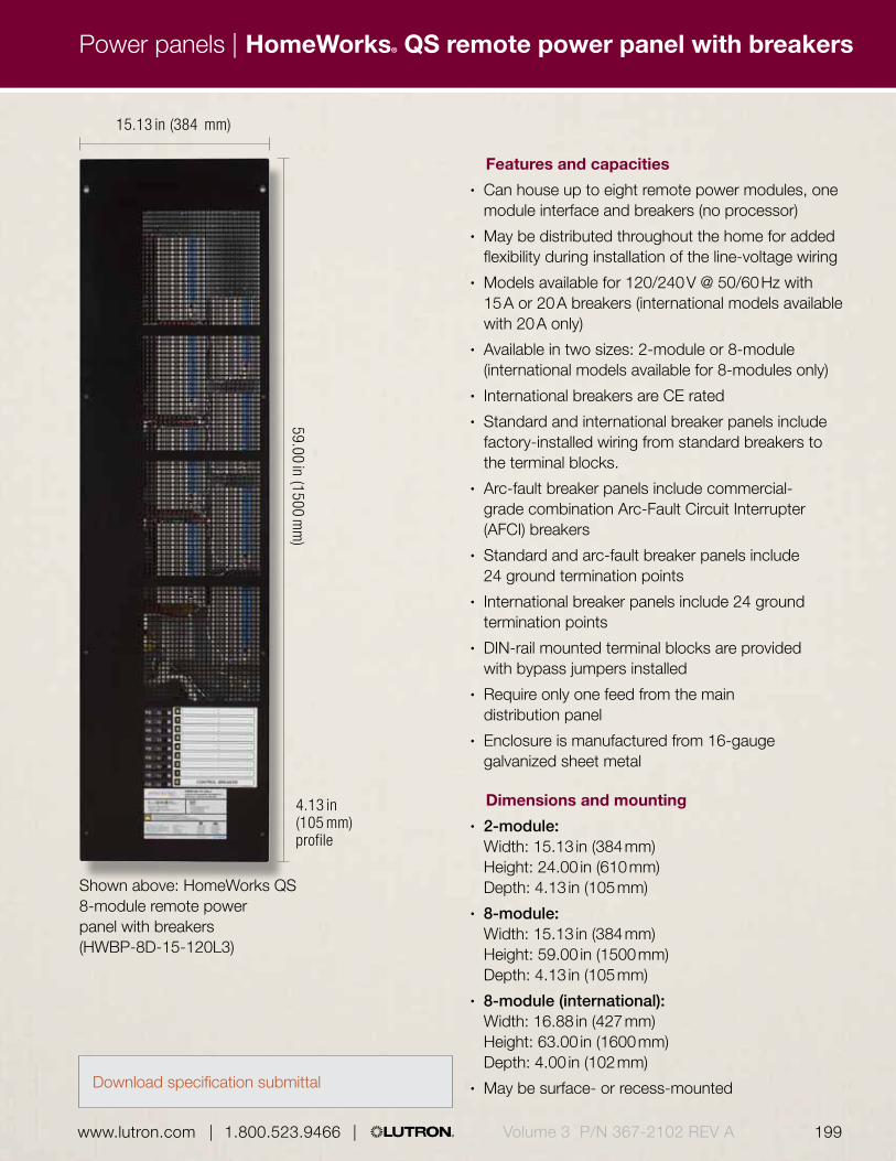
198 199 | 1.800.523.9466 | www.lutron.com www.lutron.com | 1.800.523.9466 | Volume 3 P/N 367-2102 REV A
Power panels | HomeWorks® QS remote power panel with breakers
Features and capacities• Can house up to eight remote power modules, one
module interface and breakers (no processor)• May be distributed throughout the home for added
flexibility during installation of the line-voltage wiring• Models available for 120/240 V @ 50/60 Hz with
15 A or 20 A breakers (international models available with 20 A only)
• Available in two sizes: 2-module or 8-module (international models available for 8-modules only)
• International breakers are CE rated• Standard and international breaker panels include
factory-installed wiring from standard breakers to the terminal blocks.
• Arc-fault breaker panels include commercial-grade combination Arc-Fault Circuit Interrupter (AFCI) breakers
• Standard and arc-fault breaker panels include 24 ground termination points
• International breaker panels include 24 ground termination points
• DIN-rail mounted terminal blocks are provided with bypass jumpers installed
• Require only one feed from the main distribution panel
• Enclosure is manufactured from 16-gauge galvanized sheet metal
Dimensions and mounting• 2-module:
Width: 15.13 in (384 mm) Height: 24.00 in (610 mm) Depth: 4.13 in (105 mm)
• 8-module: Width: 15.13 in (384 mm) Height: 59.00 in (1500 mm) Depth: 4.13 in (105 mm)
• 8-module (international): Width: 16.88 in (427 mm) Height: 63.00 in (1600 mm) Depth: 4.00 in (102 mm)
• May be surface- or recess-mounted
15.13 in (384 mm)
59.00 in (1500 mm
)
Shown above: HomeWorks QS 8-module remote power panel with breakers (HWBP-8D-15-120L3)
4.13 in (105 mm) profile
Download specification submittal

200 201 | 1.800.523.9466 | www.lutron.com www.lutron.com | 1.800.523.9466 |Volume 3 P/N 367-2102 REV A
Power panels | HomeWorks® QS remote power panel with breakers
Explanation of features
HomeWorks QS 8-module remote power panel with breakers with cover removed
Model numbers
2-module, standard breakers
1-phase, 3-wire, 15 A HWBP-2S-15-120L3 120/240 V
1-phase, 3-wire , 20 A HWBP-8D-15-120L3 120/240 V
3-phase, 4-wire, 15 A HWBP-2S-15-120L4 120/208 V
3-phase, 4-wire, 20 A HWBP-2S-20-120L4 120/208 V
8-module, standard breakers
1-phase, 3-wire, 15 A HWBP-8D-15-120L3 120/240 V
1-phase, 3-wire, 20 A HWBP-8D-20-120L3 120/240 V
3-phase, 4-wire, 15 A HWBP-8D-15-120L4 120/208 V
3-phase, 4-wire, 20 A HWBP-8D-20-120L4 120/208 V
Feature
1 Remote power modules
• Used to control lighting, motor and fan loads (sold separately)
2 Terminal blocks • For feed and lighting load circuit connections
3 Breakers • 15 or 20 A• Standard, arc-fault or
international (CE)
4 Module interface • Manages communication between remote power modules and processor (sold separately)
1
2
4
8-module, arc-fault breakers
1-phase, 3-wire, 15 A HWAP-8D-15-120L3 120/240 V
1-phase, 3-wire, 20 A HWAP-8D-20-120L3 120/240 V
3-phase, 4-wire, 15 A HWAP-8D-15-120L4 120/208 V
3-phase, 4-wire, 20 A HWAP-8D-20-120L4 120/208 V
International breakers
1-phase, 3-wire, 20 A PBK8-40-13-CE input breakers 120/240 V
1-phase, 3-wire, 20 A PBK8-40-13-10-CE input and output breakers 120/240 VCompatible with HomeWorks QS system
3

For specific voltage by country information refer to the voltage chart on pg. 692.
* Visit www.lutron.com/LEDtool for a complete list of LEDs compatible with this module
200 201 | 1.800.523.9466 | www.lutron.com www.lutron.com | 1.800.523.9466 | Volume 3 P/N 367-2102 REV A
3.50 in (89 mm) profile
Power panels | HomeWorks® QS adaptive dimming module
Features and capacities• Controls up to four circuits of incandescent/
halogen, magnetic low-voltage, neon/cold cathode, and Tu-wire® fluorescent lighting
• Automatically selects leading edge or trail edge dimming
• Maximum load per 120 V module is 16 A, 10 A per circuit
• Maximum load per 220-240 V (CE) module is 13 A, 8 A per circuit
Operating voltages• Models available for 120 V or 220-240 V (CE)
@ 50 / 60 Hz
Dimensions and mounting• Width: 3.88 in (98 mm)
Height: 7.00 in (178 mm) Depth: 3.50 in (89 mm)
Direct lighting loads
Incandescent/halogen Electronic low-voltage Magnetic low-voltage Neon/cold cathode LED (2-wire forward phase) Tu-Wire fluorescent / CFL/LED (screw-base)*
Shown above: Adaptive dimming module (HW-RPM-4A-120)
3.88 in (98 mm)
7.00 in (178 mm
)
Model numbers
Adaptive remote power dimming modules
120 V HW-RPM-4A-120
230 V (CE), 220-240 V HW-RPM-4A-230
Compatible with HomeWorks QS system
Download specification submittal

For specific voltage by country information refer to the voltage chart on pg. 692.
202 203 | 1.800.523.9466 | www.lutron.com www.lutron.com | 1.800.523.9466 |Volume 3 P/N 367-2102 REV A
3.50 in (89 mm) profile
Power panels | HomeWorks® QS dimming remote power module
Features and capacities• Controls up to four circuits of incandescent/
halogen, magnetic low-voltage, neon/cold cathode, Tu-wire® fluorescent, and non-dim lighting
• Maximum load per 120 V/220-240 V module is 16 A• Maximum load per 230 V (CE) module is 13 A,
10 A per circuit
Operating voltages• Models available for 120 V, 230 V (CE), or 220-240 V
@ 50 / 60 Hz
Dimensions and mounting• Width: 3.88 in (98 mm)
Height: 7.00 in (178 mm) Depth: 3.50 in (89 mm)
• Mounts in a HomeWorks QS remote power feed-through or breaker panel
Direct lighting loads
Incandescent/halogen Magnetic low-voltage Neon/cold cathode Tu-Wire fluorescent LED (2-wire forward phase) Non-dim lighting
Shown above: Dimming module (HW-RPM-4U-120)
3.88 in (98 mm)
7.00 in (178 mm
)
Model numbers
Dimming remote power modules
120 V HW-RPM-4U-120
230 V (CE) HW-RPM-4U-230-CE
220-240 V HW-RPM-4U-240
Compatible with HomeWorks QS system
Download specification submittal

3.50 in (88.90 mm) profile
Features and capacities• Controls up to four circuits of switched lighting,
fans, or motor loads• Maximum load per circuit is 16 A
Operating voltages• Available for 100-277 V (CE) @ 50/60 Hz
Dimensions and mounting• Width: 3.88 in (98 mm)
Height: 7.00 in (178 mm) Depth: 3.50 in (89 mm)
Direct lighting loads
Non-dim lighting HID Motors loads Fan loads 15 A receptacles
Shown above: HomeWorks QS relay remote power module (HW-RPM-4R)
3.88 in (98 mm)
7.00 in (178 mm
)
Model numbers
Relay remote power module
100-277 V (CE) HW-RPM-4R
Compatible with HomeWorks QS system
HomeWorks® QS switching relay power module
For specific voltage by country information refer to the voltage chart on pg. 692.
202 203 | 1.800.523.9466 | www.lutron.com www.lutron.com | 1.800.523.9466 | Volume 3 P/N 367-2102 REV A
Power panels | HomeWorks® QS relay remote power module
Download specification submittal

For specific voltage by country information refer to the voltage chart on pg. 692.
204 205 | 1.800.523.9466 | www.lutron.com www.lutron.com | 1.800.523.9466 |Volume 3 P/N 367-2102 REV A
Power panels | HomeWorks® QS motor remote power module
Features and capacities• Controls up to four circuits of 3-wire AC motors
for applications such as shades, draperies and curtains
• Utilizes two mechanically interlocked relays for directional control that prevents simultaneous operation of both outputs
• Maximum load per module is 16 A, per circuit 5 A (0.25 HP)
Operating voltages• Models available for 120 V or 220-240 V @ 50 / 60 Hz
Dimensions and mounting• Width: 3.88 in (98 mm)
Height: 7.88 in (200 mm) Depth: 2.80 in (73 mm)
• Mounts in a HomeWorks QS remote power feed-through or breaker panel
Direct lighting loads
AC motor loads Non-dim lighting
Shown above: HomeWorks QS remote power motor module (HW-RPM-4M)
3.88 in (98 mm)
2.80 in (73 mm) depth
7.88 in (200 mm
)
Model numbers
Motor remote power modules
120 V HW-RPM-4M-120
220-240 V HW-RPM-4M-230Compatible with HomeWorks QS system
Download specification submittal
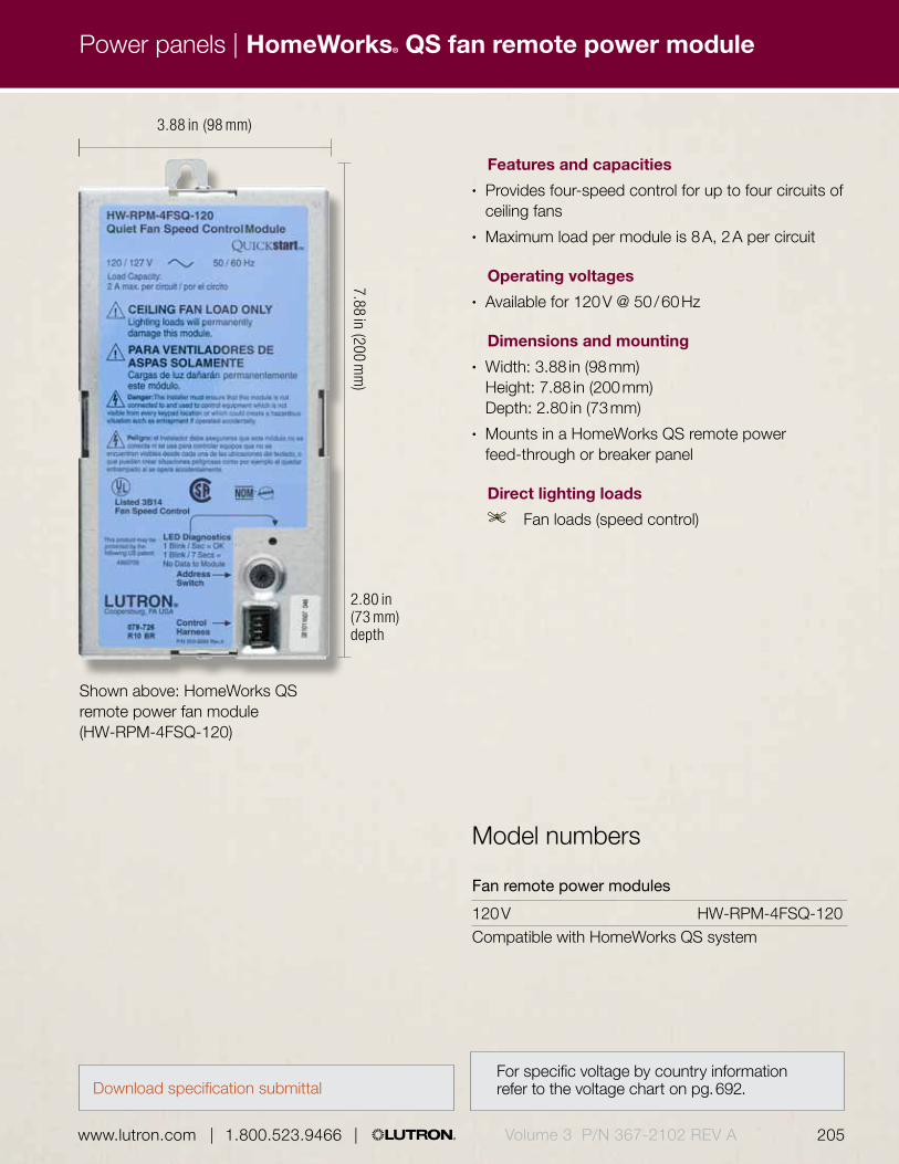
For specific voltage by country information refer to the voltage chart on pg. 692.
204 205 | 1.800.523.9466 | www.lutron.com www.lutron.com | 1.800.523.9466 | Volume 3 P/N 367-2102 REV A
Power panels | HomeWorks® QS fan remote power module
Features and capacities• Provides four-speed control for up to four circuits of
ceiling fans• Maximum load per module is 8 A, 2 A per circuit
Operating voltages• Available for 120 V @ 50 / 60 Hz
Dimensions and mounting• Width: 3.88 in (98 mm)
Height: 7.88 in (200 mm) Depth: 2.80 in (73 mm)
• Mounts in a HomeWorks QS remote power feed-through or breaker panel
Direct lighting loads
Fan loads (speed control)
Model numbers
Fan remote power modules
120 V HW-RPM-4FSQ-120Compatible with HomeWorks QS system
Shown above: HomeWorks QS remote power fan module (HW-RPM-4FSQ-120)
3.88 in (98 mm)
2.80 in (73 mm) depth
7.88 in (200 mm
)
Download specification submittal
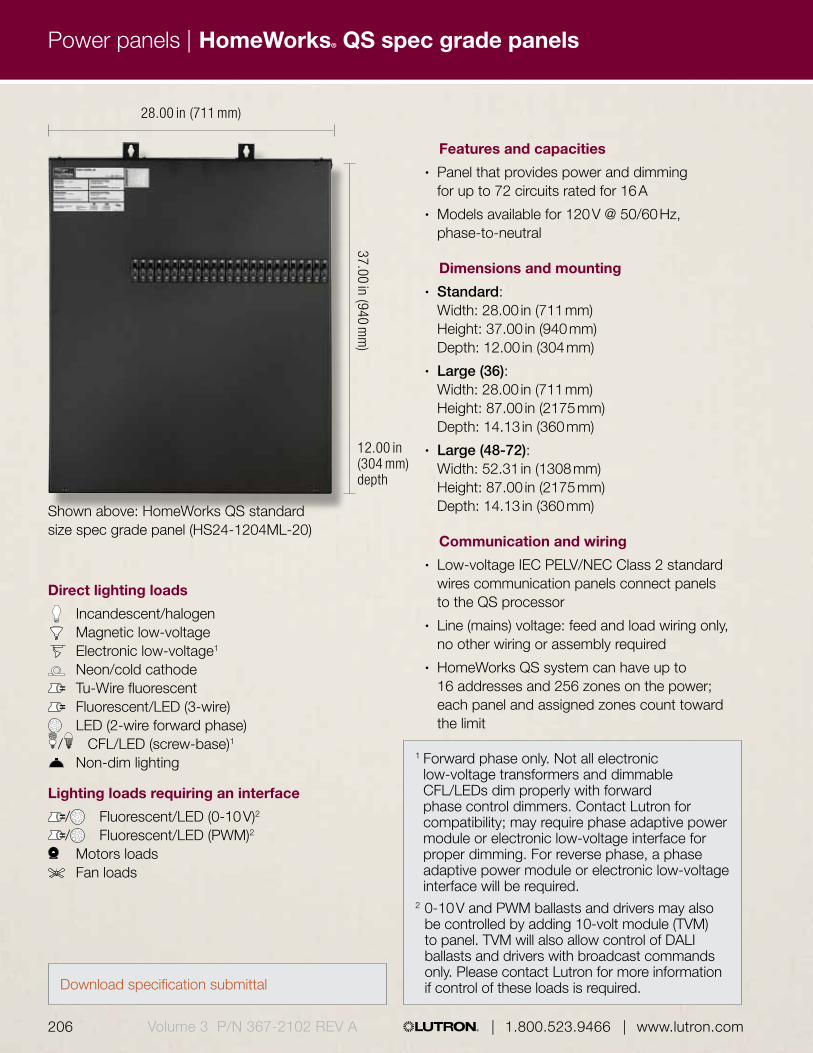
206 207 | 1.800.523.9466 | www.lutron.com www.lutron.com | 1.800.523.9466 |Volume 3 P/N 367-2102 REV A
Power panels | HomeWorks® QS spec grade panels
Direct lighting loads
Incandescent/halogen Magnetic low-voltage Electronic low-voltage1
Neon/cold cathode Tu-Wire fluorescent Fluorescent/LED (3-wire) LED (2-wire forward phase)/ CFL/LED (screw-base)1
Non-dim lighting
Lighting loads requiring an interface
/ Fluorescent/LED (0-10 V)2
/ Fluorescent/LED (PWM)2
Motors loads Fan loads
Shown above: HomeWorks QS standard size spec grade panel (HS24-1204ML-20)
28.00 in (711 mm)
37.00 in (940 mm
)12.00 in (304 mm) depth
1 Forward phase only. Not all electronic low-voltage transformers and dimmable CFL/LEDs dim properly with forward phase control dimmers. Contact Lutron for compatibility; may require phase adaptive power module or electronic low-voltage interface for proper dimming. For reverse phase, a phase adaptive power module or electronic low-voltage interface will be required.
2 0-10 V and PWM ballasts and drivers may also be controlled by adding 10-volt module (TVM) to panel. TVM will also allow control of DALI ballasts and drivers with broadcast commands only. Please contact Lutron for more information if control of these loads is required.
Features and capacities• Panel that provides power and dimming
for up to 72 circuits rated for 16 A• Models available for 120 V @ 50/60 Hz,
phase-to-neutral
Dimensions and mounting• Standard:
Width: 28.00 in (711 mm) Height: 37.00 in (940 mm) Depth: 12.00 in (304 mm)
• Large (36): Width: 28.00 in (711 mm) Height: 87.00 in (2175 mm) Depth: 14.13 in (360 mm)
• Large (48-72): Width: 52.31 in (1308 mm) Height: 87.00 in (2175 mm) Depth: 14.13 in (360 mm)
Communication and wiring• Low-voltage IEC PELV/NEC Class 2 standard
wires communication panels connect panels to the QS processor
• Line (mains) voltage: feed and load wiring only, no other wiring or assembly required
• HomeWorks QS system can have up to 16 addresses and 256 zones on the power; each panel and assigned zones count toward the limit
Download specification submittal

206 207 | 1.800.523.9466 | www.lutron.com www.lutron.com | 1.800.523.9466 | Volume 3 P/N 367-2102 REV A
Power panels | HomeWorks® QS spec grade panels
Explanation of features
1
3
2
4
5
HomeWorks spec grade panel with cover removed
6
Feature
1 Terminal block • Lighting load circuit connections
2 Filter chokes (behind breakers)
• Highest performance chokes minimize radio frequency interference (RFI) and lamp noise
3 Branch circuit breakers
• Each circuit is protected by UL®-listed thermal magnetic breakers
4 Power feed wiring • 120 V• Main breaker feeds or
standard main lug
5 Low-voltage IEC PELV/NEC Class 2 wiring
• Connection for communication to other system components
6 Dimming card • Provide square law dimming curves for smooth linear control UL listed specifically for each light source
• Lighting levels remain constant throughout changes in power line conditions with our patented RTISS™ filter circuit

208 209 | 1.800.523.9466 | www.lutron.com www.lutron.com | 1.800.523.9466 |Volume 3 P/N 367-2102 REV A208 209 | 1.800.523.9466 | www.lutron.com www.lutron.com | 1.800.523.9466 |
Power panels | HomeWorks® QS spec grade panels
Available models
HomeWorks QS spec grade standard size panel
HomeWorks QS spec grade 36 large size panel
HomeWorks QS spec grade 48-72 large size panel
Number of load circuits:3 for 3 circuits 24 for 24 circuits 4 for 4 circuits 36 for 36 circuits 8 for 8 circuits 48 for 48 circuits 12 for 12 circuits 60 for 60 circuits 16 for 16 circuits 72 for 72 circuits 20 for 20 circuitsHomeWorks QS spec grade 36 large size panel
Voltage:120 for 120 V
Feed type:2 for 1-phase, 2-wire3 for 1-phase, 3-wire (split phase)4 for 3-phase, 4-wire
Panel feed:ML for main lugs onlyDTML for dual tap main lugsMxx for main breaker with xx = breaker size in Amps
Branch circuit breakers:15 for 15 A branch circuit breakers1
20 for 20 A branch circuit breakers2
Compatible with HomeWorks QS system
How to build a model number
H S 1 2 - 1 2 0 4 M L - 2 0
Voltage
Feed type
Panel feed
Branch circuit breaker rating
Number of load circuits
1 15 A branch circuit breakers have a 12 A continuous load rating
2 20 A branch circuit breakers have a 16 A continuous load rating

208 209 | 1.800.523.9466 | www.lutron.com www.lutron.com | 1.800.523.9466 |208 209 | 1.800.523.9466 | www.lutron.com www.lutron.com | 1.800.523.9466 | Volume 3 P/N 367-2102 REV A

210 211 | 1.800.523.9466 | www.lutron.com www.lutron.com | 1.800.523.9466 |210 211 | 1.800.523.9466 | www.lutron.com www.lutron.com | 1.800.523.9466 |Volume 3 P/N 367-2102 REV A
Primary controls |
A primary control is the main device in a lighting control system that coordinates communication and distributes commands such as preset scene levels to sub-controls, sensors and shades.
Primary control options include:
• GRAFIK Eye® main units• Energi Savr Node™ modules• Dimmers• Plug-in modules• Lamp dimmers
Whole building
Wireless Radio Frequency (RF) communication
Infrared (IR) communication
GRAFIK Eye 4000 Series slider control unitpg. 220
GRAFIK Eye QS main unitpg. 225
GRAFIK Eye® 4000 series control unitpg. 213
Primary controls

210 211 | 1.800.523.9466 | www.lutron.com www.lutron.com | 1.800.523.9466 |210 211 | 1.800.523.9466 | www.lutron.com www.lutron.com | 1.800.523.9466 | Volume 3 P/N 367-2102 REV A
Energi Savr NodeTM with EcoSystem®
pg. 237
Energi Savr Node for 0-10 V/with Energi Savr Node Softswitch®
pg. 240
Energi Savr Node with EcoSystem (DIN-rail)pg. 243
Energi Savr Node for DALI (DIN-rail)pg. 246
Energi Savr Node™ for 0-10 V/Energi Savr Node for Switching (DIN-rail) pg. 249
Energi Savr Node phase adaptive (DIN-rail)pg. 252
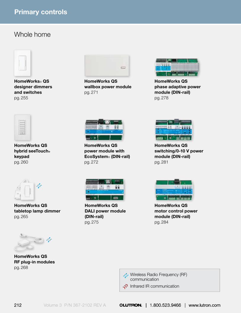
212 | 1.800.523.9466 | www.lutron.com212 213 | 1.800.523.9466 | www.lutron.com www.lutron.com | 1.800.523.9466 |212 213 | 1.800.523.9466 | www.lutron.com www.lutron.com | 1.800.523.9466 |Volume 3 P/N 367-2102 REV A
Primary controls |
HomeWorks QS tabletop lamp dimmerpg. 265
HomeWorks QS RF plug-in modulespg. 268
HomeWorks QS hybrid seeTouch® keypadpg. 260
Whole home
Wireless Radio Frequency (RF) communication
Infrared IR communication
HomeWorks QS wallbox power modulepg. 271
HomeWorks QS power module with EcoSystem® (DIN-rail)pg. 272
HomeWorks QS motor control power module (DIN-rail)pg. 284
HomeWorks QS DALI power module (DIN-rail)pg. 275
HomeWorks QS phase adaptive power module (DIN-rail)pg. 278
HomeWorks QS switching/0-10 V power module (DIN-rail)pg. 281
Primary controls
HomeWorks® QS designer dimmers and switchespg. 255

Primary controls |
212 | 1.800.523.9466 | www.lutron.com 213 www.lutron.com | 1.800.523.9466 | Volume 3 P/N 367-2102 REV A212 213 | 1.800.523.9466 | www.lutron.com www.lutron.com | 1.800.523.9466 |212 213 | 1.800.523.9466 | www.lutron.com www.lutron.com | 1.800.523.9466 |
0.31 in (8 mm) profile
1.94 in (49 mm) depth
8.94 in (227 mm)
4.56 in (116 mm
)
Shown above: GRAFIK Eye 4100 control unit in White with translucent top (GRX-4108-T-WH)
Download specification submittal
GRAFIK Eye® 4000 series control unit

Primary controls |
214 | 1.800.523.9466 | www.lutron.comVolume 3 P/N 367-2102 REV A
Features and capacities• Serves as a control unit for up to 24 zones
of lighting• Loads are controlled through GP, XP, LP, DCI and/or
CCP power panels (see pgs. 158-209)• Allows set up of lighting scenes using buttons on
the control unit• Provides push-button recall of four preset lighting
scenes plus off on control unit• Stores up to 12 additional user-programmable scenes• Scenes can be recalled via a keypad/wallstation
and/or control interface• Light levels fade smoothly between scenes• Fade time can be set differently for each scene,
between 0-59 second or 1-60 minute• Provides lockout options to prevent
accidental changes• Includes built-in infrared (IR) receiver for control with
an IR remote control (sold separately) (see pg. 290)• 4500 model allows PC-based programming through
GRAFIK Eye Liaison software and control of Sivoia QED and 3-wire AC motorized window treatments (control interface required)
• Operates at 24 V DC off the link• Engraving available
Dimensions and mounting• 2-zone:
Width: 5.56 in (141 mm) Height: 4.56 in (116 mm) Depth: 1.94 in (49 mm) Profile: 0.31 in (8 mm)
• 3-zone: Width: 7.25 in (184 mm) Height: 4.56 in (116 mm) Depth: 1.94 in (49 mm) Profile: 0.31 in (8 mm)
• 4-, 6-, 8-, 16- and 24-zone: Width: 8.94 in (227 mm) Height: 4.56 in (116 mm) Depth: 1.94 in (49 mm) Profile: 0.31 in (8 mm)
• 2-zone control unit mounts into a 2-gang U.S. backbox, 3.50 in (89 mm) deep
• 3-zone control unit mounts into a 3-gang U.S. backbox, 3.50 in (89 mm) deep
• 4-, 6-, 8-, 16- and 24-zone control units mount into a 4-gang U.S. backbox, 3.50 in (89 mm) deep
Communication and wiring• Operates via low-voltage IEC PELV/NEC Class 2
standard wired communication to panels and other system components
• Counts as one of the eight control units allowed in a GRAFIK Eye 4000 system; up to 64 zones per system
GRAFIK Eye® 4000 series control unit

Primary controls |
214 | 1.800.523.9466 | www.lutron.com 215 www.lutron.com | 1.800.523.9466 | Volume 3 P/N 367-2102 REV A
Available finishes
Use BOLD color code in model number (Example: GRX-4108-T- WH)
Architectural matte finishes
Color code indicates faceplate color.
* Finishes available with matching top only
** Finishes available with translucent top only.
IVIvory FBlack B
WHWhite FBlack B
LALight Almond FBlack B
ALAlmond FBlack B
GRGray FBlack B
BEBeige FBlack B
BRBrown FBlack B
BLBlack FBlack B
Faceplate F
Buttons B
GRAFIK Eye® 4000 series control unit
Designer gloss finishes†
GWHWhite FBlack B
GIVIvory FBlack B
GLALight Almond FBlack B
GALAlmond FBlack B

Primary controls |
216 | 1.800.523.9466 | www.lutron.comVolume 3 P/N 367-2102 REV A
Available finishes
Satin finishes *
MRMerlot FBlack B
MNMidnight FBlack B
PDPalladium FBlack B
GSGoldstone FBlack B
TPTaupe FBlack B
SWSnow FBlack B
LSLimestone FBlack B
BGBluestone FBlack B
TCTerracotta FBlack B
SISienna FBlack B
GBGreenbriar FBlack B
STStone FBlack B
BIBiscuit FBlack B
PLPlum FBlack B
DSDesert Stone FBlack B
HTHot FBlack B
MSMocha Stone FBlack B
ESEggshell FBlack B
TQTurquoise FBlack B
GRAFIK Eye® 4000 series control unit
QBAntique Brass FBlack B
BLABlack Anodized Aluminum FBlack B
BBBright Brass FBlack B
BRABrass Anodized Aluminum FBlack B
SBSatin Brass FBlack B
Architectural metal finishes†
SNSatin Nickel FBlack B
BNBright Nickel FBlack B
QZAntique Bronze FBlack B
BCBright Chrome FBlack B
CLAClear Anodized Aluminum FBlack B
SCSatin Chrome FBlack B

Primary controls |
216 | 1.800.523.9466 | www.lutron.com 217 www.lutron.com | 1.800.523.9466 | Volume 3 P/N 367-2102 REV A
47
1
2
6 3
Explanation of features
Features
1 Multiple lighting zones
• Controls 2, 3, 4, 6, 8, 16 or 24 zones of lighting
2 Master override buttons
• Temporarily raise/lower light levels of an entire scene
3 Scene control buttons
• 1-4 scenes and off
4 Infrared (IR)receiver
• Allows IR connectivity to handheld IR remotes (50 ft range, line-of-sight); IR input located on front of control unit
5 Zone control scene buttons
• Raise/lower each zone of lights• LEDs indicate light level
GRAFIK Eye 4500 series 24-zone control unit with top open
0.31 in (8 mm)
1.94 in (49 mm)5
GRAFIK Eye® 4000 series control unit

Primary controls |
218 | 1.800.523.9466 | www.lutron.comVolume 3 P/N 367-2102 REV A
Available models
2-zone
3-zone
4-zone
6-zone
8-zone
16-zone
24-zone
Model numbersGRAFIK Eye 4100 series control unit—through button-press programming
2-zone GRX-4102-A-XX1-E1
2-zone (Japan) GRX-4102-A-JA-XX1-E1
2-zone, translucent top GRX-4102-T-XX1-E1
2-zone, translucent top (Japan) GRX-4102-T-JA-XX1-E1
3-zone GRX-4103-A-XX1-E1
3-zone (Japan) GRX-4103-A-JA-XX1-E1
3-zone, translucent top GRX-4103-T-XX1-E1
3-zone, translucent top (Japan) GRX-4103-T-JA-XX1-E1
4-zone GRX-4104-A-XX1-E1
4-zone (Japan) GRX-4104-A-JA-XX1-E1
4-zone, translucent top GRX-4104-T-XX1-E1
4-zone, translucent top (Japan) GRX-4104-T-JA-XX1-E1
6-zone GRX-4106-A-XX1-E1
6-zone (Japan) GRX-4106-A-JA-XX1-E1
6-zone, translucent top GRX-4106-T-XX1-E1
6-zone, translucent top (Japan) GRX-4106-T-JA-XX1-E1
8-zone GRX-4108-A-XX1 -E1
8-zone (Japan) GRX-4108-A-JA-XX1 -E1
8-zone, translucent top GRX-4108-T-XX1-E1
8-zone, translucent top (Japan) GRX-4108-T-JA-XX1-E1
16-zone GRX-4116-A-XX1-E1
16-zone (Japan) GRX-4116-A-JA-XX1-E1
16-zone, translucent top GRX-4116-T-XX1-E1
16-zone, translucent top (Japan) GRX-4116-T-JA-XX1-E1
24-zone GRX-4124-A-XX1-E1
24-zone (Japan) GRX-4124-A-JA-XX1-E1
24-zone, translucent top GRX-4124-T-XX1-E1
24-zone, translucent top (Japan) GRX-4124-T-JA-XX1-E1
Compatible with the GRAFIK Eye 4000 system
XX1: Gloss, Architectural matte, metal and Satin Color codes, see pg. 216
E1: Engraving form required with order. If engraving not desired, omit “E”
GRAFIK Eye® 4000 series control unit

Primary controls |
218 | 1.800.523.9466 | www.lutron.com 219 www.lutron.com | 1.800.523.9466 | Volume 3 P/N 367-2102 REV A
GRAFIK Eye® 4000 series control unit
GRAFIK Eye 4500 series control unit—PC-based programming and motorized window treatment control*
2-zone GRX-4502-A-XX1-E1
2-zone (Japan) GRX-4502-A-JA-XX1-E1
2-zone, translucent top GRX-4502-T-XX1-E1
2-zone, translucent top (Japan) GRX-4502-T-JA-XX1-E1
3-zone GRX-4503-A-XX1-E1
3-zone (Japan) GRX-4503-A-JA-XX1-E1
3-zone, translucent top GRX-4503-T-XX1-E1
3-zone, translucent top (Japan) GRX-4503-T-JA-XX1-E1
4-zone GRX-4504-A-XX1-E1
4-zone (Japan) GRX-4504-A-JA-XX1-E1
4-zone, translucent top GRX-4504-T-XX1-E1
4-zone, translucent top (Japan) GRX-4504-T-JA-XX1-E1
6-zone GRX-4506-A-XX1-E1
6-zone (Japan) GRX-4506-A-JA-XX1-E1
6-zone, translucent top GRX-4506-T-XX1-E1
6-zone, translucent top (Japan) GRX-4506-T-JA-XX1-E1
8-zone GRX-4508-A-XX1--E1
8-zone (Japan) GRX-4508-A-JA-XX1--E1
8-zone, translucent top GRX-4508-T-XX1-E1
8-zone, translucent top(Japan) GRX-4508-T-JA-XX1-E1
16-zone GRX-4516-A-XX1-E1
16-zone(Japan) GRX-4516-A-JA-XX1-E1
16-zone, translucent top GRX-4516-T-XX1-E1
16-zone, translucent top (Japan) GRX-4516-T-JA-XX1-E1
24-zone GRX-4524-A-XX1-E1
24-zone (Japan) GRX-4524-A-JA-XX1-E1
24-zone, translucent top GRX-4524-T-XX1-E1
24-zone, translucent top (Japan) GRX-4524-T-JA-XX1-E1
Compatible with the GRAFIK Eye 4000 system
XX1: Gloss, Architectural matte, metal and Satin Color codes, see pg. 216
E1: Engraving form required with order. If engraving not desired, omit “E”
* Control interface required for motorized window treatment control

Primary controls |
220 | 1.800.523.9466 | www.lutron.comVolume 3 P/N 367-2102 REV A
0.31 in (8 mm) profile
1.94 in (49 mm) depth
8.31 in (208 mm)
4.56 in (116 mm
)
Shown above: GRAFIK Eye 4100 8-zone slider control unit in White (GRXSLD-4108-WH)
Download specification submittal
GRAFIK Eye® 4000 series slider control unit

Primary controls |
220 | 1.800.523.9466 | www.lutron.com 221 www.lutron.com | 1.800.523.9466 | Volume 3 P/N 367-2102 REV A
Features and capacities• Serves as a control unit for up to eight zones
of lighting• Loads are controlled through GP, XP, LP, DCI
and/or CCP power panels (see pg. 158-209)• Allows set up of lighting scenes using buttons on
the control unit• Provides push-button recall of a single lighting
scene plus off on control unit• Stores up to 11 additional user-programmable
scenes plus two panic scenes• Scenes can also be recalled via a keypad/
wallstation and/or control interface• Allows full range dimming plus slide-to-off utilizing
zone sliders• Provides a user-selective master slider• Light levels fade smoothly between scenes• Fade time can be set differently for each scene,
between 0-59 second or 1-60 minute• Operates at 24 V DC off the link• Engraving available
Dimensions and mounting• 3- and 4-zone:
Width: 6.69 in (168 mm) Height: 4.56 in (116 mm) Depth: 1.94 in (49 mm) Profile: 0.31 in (8 mm)
• 6- and 8-zone: Width: 8.31 in (208 mm) Height: 4.56 in (116 mm) Depth: 1.94 in (49 mm) Profile: 0.31 in (8 mm)
• 3- and 4-zone control unit mounts into a 3-gang U.S. wallbox, 3.50 in (90 mm) deep
• 6- and 8-zone control units mount into a 4-gang U.S. wallbox, 3.50 in (90 mm) deep
Communication and wiring• Operates via low-voltage IEC PELV/NEC Class 2
wired communication to panels and other system components
• Counts as one of the eight control units allowed in a GRAFIK Eye 4000 system; up to 64 zones per system
GRAFIK Eye® 4000 series slider control unit

Primary controls |
222 | 1.800.523.9466 | www.lutron.comVolume 3 P/N 367-2102 REV A
Architectural metal finishes
BCBright Chrome FBlack S, B
BBBright Brass FBlack S, B
SBSatin Brass FBlack S, B
WHWhite F, S, B
Architectural matte finishes
BRBrown F, BBlack S
BLBlack F, S, B
GRGray F. BBlack S
BEBeige F, BBlack S
IVIvory F, BBlack S
Use BOLD color code in model number (Example: GRXSLD-4108-WH)
Available finishes
Faceplate F
Slider buttons SButtons B
GRAFIK Eye® 4000 series slider control unit

Primary controls |
222 | 1.800.523.9466 | www.lutron.com 223 www.lutron.com | 1.800.523.9466 | Volume 3 P/N 367-2102 REV A
Explanation of features
Features
1 Multiple lighting zones
• Controls 3, 4, 6, or 8 zones of lighting
2 Scene 1 and Off buttons
• Ability to recall a favorite lighting scene and turn all lights off
3 Zone control sliders
• Raise or lower each group of lights
1
2
3
0.31 in (8 mm)
1.94 in (49 mm)
Shown above: GRAFIK Eye 4100 8-zone slider control unit in White
GRAFIK Eye® 4000 series slider control unit

Primary controls |
224 | 1.800.523.9466 | www.lutron.comVolume 3 P/N 367-2102 REV A
Available models Model numbers
GRAFIK Eye 4000 series slider control units
3-zone GRXSLD-4103-XX1
3-zone, (Japan) GRXSLD-4103-JAXX1
4-zone GRXSLD-4104-XX1
4-zone, (Japan) GRXSLD-4104-JAXX1
6-zone GRXSLD-4106-XX1
6-zone, (Japan) GRXSLD-4106-JAXX1
8-zone GRXSLD-4108-XX1
8-zone, (Japan) GRXSLD-4108-JAXX1
Compatible with the GRAFIK Eye® 4000 system
3-zone
4-zone
6-zone
8-zone
XX1: Architectural matte and metal finish color codes, see pg. 222
GRAFIK Eye® 4000 series slider control unit

Primary controls |
224 | 1.800.523.9466 | www.lutron.com 225 www.lutron.com | 1.800.523.9466 | Volume 3 P/N 367-2102 REV A
GRAFIK Eye® QS main unit
* For 230 V applications, Lutron ELV transformers may be used without an interface, see pg. 656.
GRAFIK Eye QS GRAFIK Eye QS with EcoSystem® GRAFIK Eye QS for DALI
Direct lighting loads Direct lighting loads Direct lighting loads
Incandescent/halogen Magnetic low-voltage Tu-Wire® fluorescent LED (2-wire forward phase) Neon/cold cathode Non-dim lighting Cree® LR4/LR6 LED
Incandescent/halogen Magnetic low-voltage / Fluorescent/LED
(EcoSystem) Tu-Wire® fluorescent LED (2-wire forward phase) Neon/cold cathode Non-dim lighting
Lutron electronic low-voltage transformer (240 V only)
Cree® LR4/LR6 LED
Fluorescent/LED (DALI)
Download specification submittal for GRAFIK Eye QS main unit
Download specification submittal for GRAFIK Eye QS main unit with EcoSystem/DALI
Download high resolution product image
Shown above: GRAFIK Eye QS main unit with two shade columns in White with Gray stripe. Models with 2-3 shade columns require base unit and faceplate kit to be ordered separately Base unit (QSGRJ-3P) and faceplate kit (QSGFP-2-WH) shown above.
9.38 in (239 mm)
4.69 in (119 mm
)
0.38 in (10 mm) profile
Load summary
2.00 in (51 mm) depth

Primary controls |
226 | 1.800.523.9466 | www.lutron.comVolume 3 P/N 367-2102 REV A
GRAFIK Eye® QS main unit
Features and capacities• Models available for 120 V, 230 V (CE) and
220-240 V (non-CE) @ 50/60 Hz• Connect wired occupancy sensors directly to
the GRAFIK Eye QS main unit or to the QS sensor module
• GRAFIK Eye QS with EcoSystem® models provide direct connections to EcoSystem ballasts, drivers, and modules without the need for interfaces
• GRAFIK Eye QS with DALI models provide direct connections to DALI ballasts and drivers without the need for interfaces
• Large, rounded buttons are easy to use• Backlit buttons or text make it easy to find and
operate control in low-light conditions• High-end trim adjustment sets maximum
light/energy level for each zone• Built-in astronomic time clock with
after hours mode• Preset light and shade control allows you to adjust
the total light level for any task or activity• Controls available with up to three columns
of shade buttons; each column can operate one shade group
• Shade operations can be linked to scenes• For information on engraving, text symbols,
or backlit buttons/backlit text, see pgs. 667-668
Dimensions and mounting• Width: 9.38 in (239 mm)
Height: 4.69 in (119 mm) Depth: 2.00 in (51 mm) Profile: 0.38 in (10 mm)
• Mounts in a 4-gang U.S. backbox, 3.50 in (89 mm) deep
Communication and wiring• GRAFIK Eye QS wireless main unit can
communicate with up to 30 wireless devices via Lutron® reliable Clear Connect RF technology
• Wireless devices must be located within a 30 ft range of the main unit; add a QS sensor module to extend RF range
• Wireless models available for operation at 434 MHz, 434 limited channel MHz, 865 MHz, 868 MHz, or 868 limited channel MHz band
• Communicates to ballasts, modules, and LED drivers on the EcoSystem digital link, and via low-voltage IEC PELV/NEC Class 2 wire to QS components on the QS link
• Each QS link on a Quantum or HomeWorks® QS processor can have up to 99 devices and 512 switch legs; each GRAFIK Eye QS unit and each assigned zone count toward the limit
• Supplies three power draw units on the QS link in Quantum system
Line-voltage load capacity Total unit maximum capacity:• 2000 W/VA for 120-127 V @ 50/60 Hz • 3000 W/VA for 220-240 V @ 50/60 Hz • Phase control CE models:
– 3-zone 1500 W/VA– 4-zone 2000 W/VA– 6-zone 2300 W/VA
Individual triac zone maximum capacity:• 25-800 W/VA for 120-127 V @ 50/60 Hz • 40-1200 W/VA for 220-240 V @ 50/60 Hz• CE models: 40-500 W/VA for 230 V @ 50 Hz

Primary controls |
226 | 1.800.523.9466 | www.lutron.com 227 www.lutron.com | 1.800.523.9466 | Volume 3 P/N 367-2102 REV A
GRAFIK Eye® QS main unit
SNSatin Nickel FBlack S, BWhite E
QBAntique Brass FBlack S, BWhite E
BNBright Nickel FBlack S, BWhite E
BLABlack Anodized Aluminum FBlack S, BWhite E
BCBright Chrome FBlack S, BWhite E
BBBright Brass FBlack S, BWhite E
CLAClear Anodized Aluminum FBlack S, BWhite E
BRABrass AnodizedAluminum FBlack S, BWhite E
SCSatin Chrome FBlack S, BWhite E
SBSatin Brass FBlack S, BWhite E
WHWhite F, BGray S, E
Architectural matte finishes*
GRGray F, BBlack SWhite E
QZAntique Bronze FBlack S, BWhite E
BLBlack F, BGray SWhite E
BRBrown F, BBlack SWhite E
IVIvory F, BBeige SGray E
LALight Almond F, BAlmond SGray E
ALAlmond F, BLight Almond SGray E
BEBeige F, BIvory SGray E
Use BOLD color code in model number (Example: QSGRJ-3P-WH)
Available finishes
Faceplate FStripe S
Buttons BEngraving E
Architectural metal finishes*
Color code indicates faceplate color. Models include stripe and button kit in coordinating colors as shown.
* All finishes are available with translucent top. Specify “T” in model number before color code. For translucent top models, stripe color will complement the selected faceplate color. Example shown above, TWH.

GSGoldstone FIvory S, BGray E
Primary controls |
228 | 1.800.523.9466 | www.lutron.comVolume 3 P/N 367-2102 REV A
GRAFIK Eye® QS main unit
SGSea Glass FGray S, B, E
PDPalladium FGray S, B, E
MSMocha Stone FTaupe S, BWhite E
TPTaupe F, BGray S, E
SWSnow F, BGray S, E
TQTurquoise FGray S, BWhite E
TCTerracotta FTaupe S, BWhite E
STStone FGray S, B, E
LSLimestone FGray S, B, E
SISienna FBrown S, BWhite E
BGBluestone FGray S, BWhite E
BIBiscuit F, BEggshell SGray E
DSDesert Stone FTaupe S, BGray E
HTHot FTaupe S, BWhite E
PLPlum FTaupe S, BWhite E
ESEggshell F, BBeige SGray E
GBGreenbriar FGray S, BWhite E
MNMidnight FGray SBlack BWhite E
MRMerlot FTaupe S, BWhite E
Satin finishes*
TBCBright Chrome FTranslucent topBlack S, BWhite E
TWHWhite F, S, BTranslucent topGray E
TLSLimestone FTranslucent topGray S, B, E
Examples of matte, metal and satin products with translucent top specified
Color code indicates faceplate color. Models include stripe and button kit in coordinating colors as shown.
* All finishes are available with translucent top. Specify “T” in model number before color code. For translucent top models, stripe color will complement the selected faceplate color. Example shown above, TWH.
Text engraving color varies by button color. Lighter colored buttons use gray text and darker colored buttons use white text. Visit www.lutron.com/engraving or see pg. 667 for additional information.

Primary controls |
228 | 1.800.523.9466 | www.lutron.com 229 www.lutron.com | 1.800.523.9466 | Volume 3 P/N 367-2102 REV A
GRAFIK Eye® QS main unit
4 3 2 1
GRAFIK Eye QS with EcoSystem® main unit with top open
0.38 in (10 mm) 1.98 in (51 mm)
5 9876

Primary controls |
230 | 1.800.523.9466 | www.lutron.comVolume 3 P/N 367-2102 REV A
GRAFIK Eye® QS main unit
Features Quantum® HomeWorks® QS
1 Scene control buttons
• 1-4 scenes and off• Buttons available with configurable
fade times• Can be configured to control
any lights wired to devices on the QS link
• Buttons can be programmed via software and act as HomeWorks® QS keypads
• Can also be used for local scenes
2 RF transceiver • Communicates with Radio Powr SavrTM sensors, Pico® wireless controls, Sivoia® QS wireless shades and other wireless GRAFIK Eye QS main units (30 ft range)
• Able to communicate via wireless link or QS wired link with other system devices including sensors and keypads
3 Infrared (IR) receiver • Allows IR connectivity to handheld IR remotes (50 ft range line-of-sight); IR receiver located on the front of the main unit
4 Shade control buttons
• Each shade control has open, preset, close, raise/lower for one shade or a group of shades
• Models available with 0, 1, 2, or 3 shade columns
• Can also be used for local scenes main units (30 ft range)
• Buttons can be programmed via software and act as HomeWorks QS keypads for any function
• Can also be used for local scenes
5 Backlit zone buttons • Non-EcoSystem® models available with 3, 4, or 6 line voltage zones• EcoSystem/DALI models available
with 6, 8, or 16 zones • EcoSystem models also have three
line voltage zones
• Zone buttons can control lights wired to the main unit
• Zones can be programmed to function as HomeWorks QS dimmer or switch and assigned to any scene or keypad button
6 Page button • In GRAFIK Eye QS with EcoSystem/DALI, button toggles between zones 1-8 and 9-16
• EcoSystem and DALI models not available for use with HomeWorks QS
7 Astronomic time clock
• Time clock disabled in Quantum® system; time clock programmed through Quantum software
• Time clock disabled in HomeWorks QS system; use system time clock in processor
8 Information display/ user interface
• Energy savings (as % of energy used)• Lighting levels• Programming information
9 Master override backlit buttons
• Temporarily raise/lower light levels of an entire scene
Explanation of features

Primary controls |
230 | 1.800.523.9466 | www.lutron.com 231 www.lutron.com | 1.800.523.9466 | Volume 3 P/N 367-2102 REV A
GRAFIK Eye® QS main unit
GRAFIK Eye QS main units can be ordered in two ways:
1 Main unit: Order a main unit when the installation requires 0 or 1 shade group and unit finish desired is White.
2 Base unit and faceplate kit: Order a base unit and a faceplate kit individually when the installation requires two or three shade zones, or if a finish other than White is preferred.
+
Base unit Faceplate kit
How to select a model number
or
1
Main unit
2
Available models
0 shade columns 1 shade column
2 shade columns 3 shade columns
• Non-EcoSystem/DALI models are available with 3, 4, or 6 lighting zones
• EcoSystem® and DALI models are available with 6, 8, or 16 lighting zones
• All models are available with 0, 1, 2, or 3 shade columns

Primary controls |
232 | 1.800.523.9466 | www.lutron.comVolume 3 P/N 367-2102 REV A
GRAFIK Eye® QS main unit
GRAFIK Eye QS base unit120-127 V, 220-240 V @ 50/60 Hz (wireless models operate at 434 MHz)
3 lighting zones
Wireless QSGRJ-3P Wireless (Brazil) QSGRJ-3PBA
Wired QSGR-3P
4 lighting zones
Wireless QSGRJ-4P Wireless (Brazil) QSGRJ-4PBA
Wired only QSGR-4P
6 lighting zones
Wireless QSGRJ-6P Wireless (Brazil) QSGRJ-6PBA
Wired only QSGR-6PBase units require a faceplate kit for operation.120 V units are standard phase control, 800 W/channel, 2000 W total (220-240 V units are 1200 W/channel, 3000 W total).Compatible with HomeWorks QS and Quantum systems
GRAFIK Eye QS wireless main unit120-127 V, 220-240 V @ 50/60 Hz (434 MHz)
3 lighting zones
Matte white, 0 shade zones QSGRJ-3P-WH
Matte white, translucent top, QSGRJ-3P-TWH 0 shade zones
Matte white, 1 shade zone QSGRJ-3P-1WH
Matte white, translucent top, QSGRJ-3P-1TWH 1 shade zone
4 lighting zones
Matte white, 0 shade zones QSGRJ-4P-WH
Matte white, translucent top, QSGRJ-4P-TWH 0 shade zones
Matte white, 1 shade zone QSGRJ-4P-1WH
Matte white, translucent top, QSGRJ-4P-1TWH 1 shade zone
6 lighting zones
Matte white, 0 shade zones QSGRJ-6P-WH
Matte white, translucent top, QSGRJ-6P-TWH 0 shade zones
Matte white, 1 shade zone QSGRJ-6P-1WH
Matte white, translucent top, QSGRJ-6P-1TWH 1 shade zoneTWH models include translucent top; stripe color will complement base unit.120 V units are standard phase control, 800 W/channel, 2000 W total (220-240 V units are 1200 W/channel, 3000 W total).Compatible with HomeWorks® QS and Quantum® systems
Model numbers for 120-127 V, 220-240 V devices
For specific radio frequency by country, refer to the radio frequency chart on pg. 695. For specific voltage by country information refer to the voltage chart on pg. 692.

Primary controls |
232 | 1.800.523.9466 | www.lutron.com 233 www.lutron.com | 1.800.523.9466 | Volume 3 P/N 367-2102 REV A
GRAFIK Eye® QS main unit
Model numbers for 120-127 V, 220-240 V devices (continued)
GRAFIK Eye QS with EcoSystem base unit 120-127 V and 220-240 V @ 50/60 Hz (wireless models operate at 434 MHz or 434 limited channel MHz)
6 lighting zones
Wireless-434 MHz QSGRJ-6E
Wireless-434 limited channel MHz QSGRQ-6E
Wired QSGR-6E
8 lighting zones
Wireless-434 MHz QSGRJ-8E
Wireless-434 limited channel MHz QSGRQ-8E
Wired QSGR-8E
16 lighting zones
Wireless-434 MHz QSGRJ-16E
Wireless-434 limited channel MHz QSGRQ-16E
Wired QSGR-16EBase units require a faceplate kit for operation.120 V units are standard phase control, 800 W/channel, 2000 W total (220-24 V units are 1200 W/channel, 3000 W total).Compatible with the Quantum system
GRAFIK Eye QS wireless main unit with EcoSystem® 120-127 V and 220-240 V @ 50/60 Hz (434 MHz)
6 lighting zones
Matte white, 0 shade zones QSGRJ-6E-WH
Matte white, translucent top, QSGRJ-6E-TWH 0 shade zones
Matte white, 1 shade zone QSGRJ-6E-1WH
Matte white, translucent top, QSGRJ-6E-1TWH 1 shade zone
8 lighting zones
Matte white, 0 shade zones QSGRJ-8E-WH
Matte white, translucent top, QSGRJ-8E-TWH 0 shade zones
Matte white, 1 shade zone QSGRJ-8E-1WH
Matte white, translucent top, QSGRJ-8E-1TWH 1 shade zone
16 lighting zones
Matte white, 0 shade zones QSGRJ-16E-WH
Matte white, translucent top, QSGRJ-16E-TWH 0 shade zones
Matte white, 1 shade zone QSGRJ-16E-1WH
Matte white, translucent top, QSGRJ-16E-1TWH 1 shade zoneTWH models include translucent top; stripe color will complement base unit.120 V units are standard phase control, 800 W/channel, 2000 W total (220-240 V units are 1200 W/channel, 3000 W total).Compatible with the Quantum® system
For specific radio frequency by country, refer to the radio frequency chart on pg. 695. For specific voltage by country information refer to the voltage chart on pg. 692.

Primary controls |
234 | 1.800.523.9466 | www.lutron.comVolume 3 P/N 367-2102 REV A
GRAFIK Eye® QS main unit
GRAFIK Eye QS wireless main unit230 V (CE) (868 MHz)
3 lighting zones
Matte white, 0 shade zones QSGRK-3PCE-WH
Matte white, translucent top, QSGRK-3PCE-TWH 0 shade zones
Matte white, 1 shade zone QSGRK-3PCE-1WH
Matte white, translucent top, QSGRK-3PCE-1TWH 1 shade zone
4 lighting zones
Matte white, 0 shade zones QSGRK-4PCE-WH
Matte white, translucent top, QSGRK-4PCE-TWH 0 shade zones
Matte white, 1 shade zone QSGRK-4PCE-1WH
Matte white, translucent top, QSGRK-4PCE-1TWH 1 shade zone
6 lighting zones
Matte white, 0 shade zones QSGRK-6PCE-WH
Matte white, translucent top, QSGRK-6PCE-TWH 0 shade zones
Matte white, 1 shade zone QSGRK-6PCE-1WH
Matte white, translucent top, QSGRK-6PCE-1TWH 1 shade zoneTWH models include translucent top; stripe color will complement base unit.Standard phase control 500 W/channel, 1500-2300 W total based on number of zones. Compatible with HomeWorks® QS and Quantum® system
Model numbers for 230 V devices
GRAFIK Eye QS base unit 230 V @ 50 Hz (wireless models operate at 434 limited channel MHz, 865 MHz, 868 MHz, or 868 limited channel)
3 lighting zones
Wireless (CE) - 868 MHz QSGRK-3PCE
Wireless (CE) - 868 MHz QSGRM-3PCE limited channel MHz
Wired (CE) QSGR-3PCE
4 lighting zones
Wireless (CE) - 868 MHz QSGRK-4PCE
Wireless (CE) - 868 MHz QSGRM-4PCE limited channel MHz
Wired (CE) QSGR-4PCE
6 lighting zones
Wireless (CE) - 865 MHz QSGRN-6PCE
Wireless (CE) - 868 MHz QSGRK-6PCE
Wireless (CE) - 868 MHz QSGRM-6PCE limited channel MHz
Wireless (CE) - 434 MHz QSGRQ-6PCE
limited channel MHz
Wired (CE) QSGR-6PCEBase units require a faceplate kit for operation.Standard phase control 500 W/channel, 1500-2300 W total based on number of zones.Compatible with HomeWorks QS and Quantum system
For specific radio frequency by country, refer to the radio frequency chart on pg. 695. For specific voltage by country information refer to the voltage chart on pg. 692.

Primary controls |
234 | 1.800.523.9466 | www.lutron.com 235 www.lutron.com | 1.800.523.9466 | Volume 3 P/N 367-2102 REV A
GRAFIK Eye® QS main unit
Model numbers for 230 V devices
GRAFIK Eye QS wireless main unit with DALI230 V (CE) @ 50/60 Hz (868 MHz)
6 lighting zones
Matte white, 0 shade zones QSGRK-6D-WH
Matte white, translucent top, QSGRK-6D-TWH 0 shade zones
Matte white, 1 shade zone QSGRK-6D-1WH
Matte white, translucent top, QSGRK-6D-1TWH 1 shade zone
8 lighting zones
Matte white, 0 shade zones QSGRK-8D-WH
Matte white, translucent top, QSGRK-8D-TWH 0 shade zones
Matte white, 1 shade zone QSGRK-8D-1WH
Matte white, translucent top QSGRK-8D-1TWH 1 shade zone
16 lighting zones
Matte white, 0 shade zones QSGRK-16D-WH
Matte white, translucent top QSGRK-16D-TWH 0 shade zones
Matte white, 1 shade zone QSGRK-16D-1WH
Matte white, translucent top QSGRK-16D-1TWH 1 shade zoneTWH models include translucent top; stripe color will complement base unit. Compatible with the Quantum® system
GRAFIK Eye QS with DALI base unit230 V (CE) @ 50/60 Hz (wireless models operate at 868 MHz and 868 MHz limited channel MHz)
6 lighting zones
Wireless (CE) - 868 MHz QSGRM-6D limited channel MHz Wireless (CE) - 868 MHz QSGRK-6D
Wired (CE) QSGR-6D
8 lighting zones
Wireless (CE) - 868 MHz QSGRM-8D limited channel MHz Wireless (CE) - 868 MHz QSGRK-8D
Wired (CE) QSGR-8D
16 lighting zones
Wireless (CE) - 868 MHz QSGRM-16D limited channel MHz Wireless (CE) - 868 MHz QSGRK-16D
Wired (CE) QSGR-16DBase units require a faceplate kit for operation.Compatible with the Quantum system
For specific radio frequency by country, refer to the radio frequency chart on pg. 695. For specific voltage by country information refer to the voltage chart on pg. 692.

Primary controls |
236 | 1.800.523.9466 | www.lutron.comVolume 3 P/N 367-2102 REV A
GRAFIK Eye® QS main unit
Faceplate and button kit model numbers
Faceplate kit
0 shade zones
Faceplate kit QSGFP-XX1-EEE1
Faceplate kit, translucent top QSGFP-T-XX1-EEE1
1 shade zone
Faceplate kit QSGFP-1-XX1-EEE1
Faceplate kit, translucent top QSGFP-1T-XX1-EEE1
2 shade zones
Faceplate kit QSGFP-2-XX1-EEE1
Faceplate kit, translucent top QSGFP-2T-XX1-EEE1
3 shade zones
Faceplate kit QSGFP-3-XX1-EEE1
Faceplate kit, translucent top QSGFP-3T-XX1-EEE1
Faceplate kit includes coordinating stripe insert and buttons; base unit required for operation.Compatible with all GRAFIK Eye QS models
XX1: Architectural matte, metal and Satin Colors® codes, see pgs. 632
XX2: Architectural matte color codes, see pg. 632
EEE1: Engraving codes, see pgs. 667-668
f faceplate color options stripe color optionb button color option
s
GRAFIK Eye QSseeTouch® QS
b
f
Stripe and button kits
Stripe kits
Stripe kit QSGS-XX1
3-button
3-button with raise/lower QSGB-3BRL-XX2-EEE1 replacement kit (shade buttons)
5-button
5-button replacement kit QSGB-5B-XX2-EEE1 (scene buttons)
Compatible with all GRAFIK Eye QS models
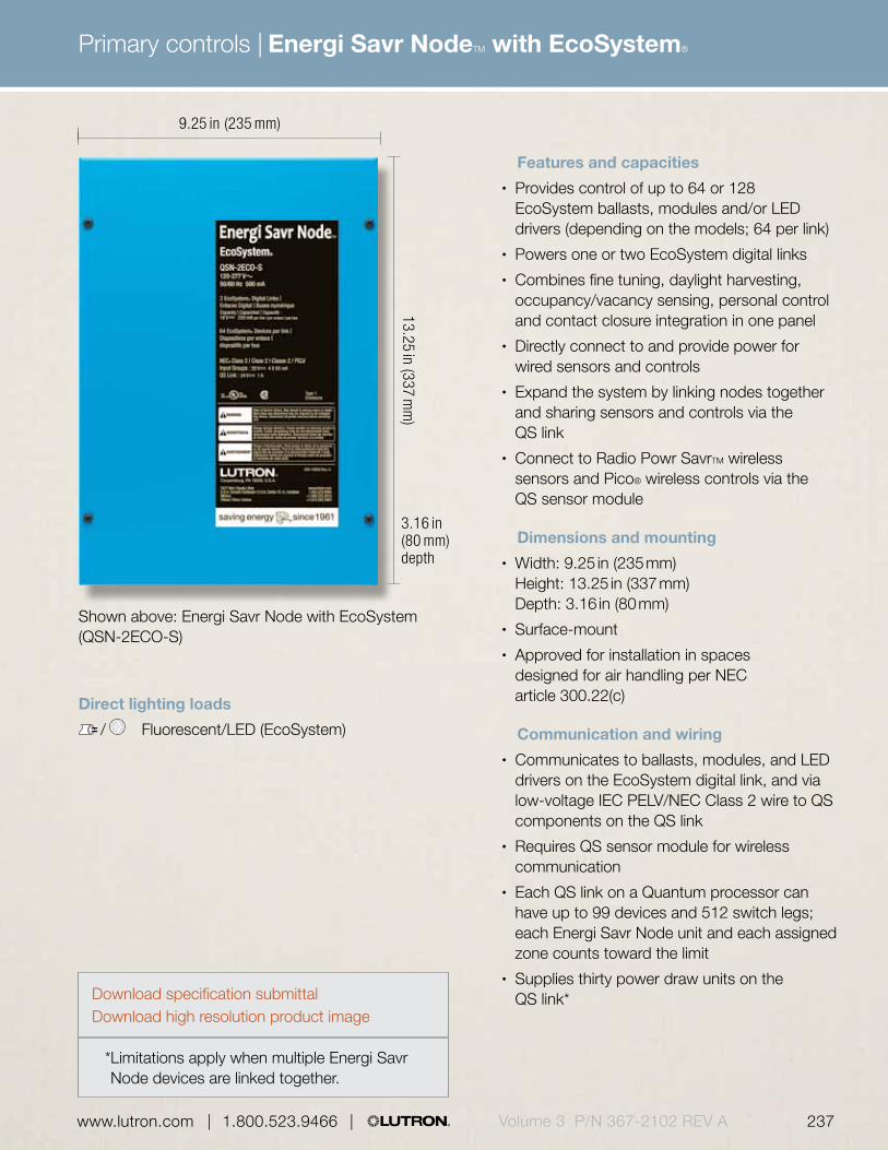
Primary controls |
236 | 1.800.523.9466 | www.lutron.com 237 www.lutron.com | 1.800.523.9466 | Volume 3 P/N 367-2102 REV A
Energi Savr NodeTM with EcoSystem®
Features and capacities• Provides control of up to 64 or 128
EcoSystem ballasts, modules and/or LED drivers (depending on the models; 64 per link)
• Powers one or two EcoSystem digital links• Combines fine tuning, daylight harvesting,
occupancy/vacancy sensing, personal control and contact closure integration in one panel
• Directly connect to and provide power for wired sensors and controls
• Expand the system by linking nodes together and sharing sensors and controls via the QS link
• Connect to Radio Powr SavrTM wireless sensors and Pico® wireless controls via the QS sensor module
Dimensions and mounting• Width: 9.25 in (235 mm)
Height: 13.25 in (337 mm) Depth: 3.16 in (80 mm)
• Surface-mount• Approved for installation in spaces
designed for air handling per NEC article 300.22(c)
Communication and wiring• Communicates to ballasts, modules, and LED
drivers on the EcoSystem digital link, and via low-voltage IEC PELV/NEC Class 2 wire to QS components on the QS link
• Requires QS sensor module for wireless communication
• Each QS link on a Quantum processor can have up to 99 devices and 512 switch legs; each Energi Savr Node unit and each assigned zone counts toward the limit
• Supplies thirty power draw units on the QS link*
Shown above: Energi Savr Node with EcoSystem (QSN-2ECO-S)
9.25 in (235 mm)
13.25 in (337 mm
)
3.16 in (80 mm) depth
* Limitations apply when multiple Energi Savr Node devices are linked together.
Direct lighting loads
/ Fluorescent/LED (EcoSystem)
Download specification submittalDownload high resolution product image

Primary controls |
238 | 1.800.523.9466 | www.lutron.comVolume 3 P/N 367-2102 REV A
Energi Savr NodeTM with EcoSystem®
seeTouch® QS keypad
QSsensormodule
Explanation of features
Features
1 Control power • 120-277 V
2 EcoSystem digital links • Up to 64 EcoSystem ballasts, modules or drivers per link
• Models available with one or two links
3 Emergency contact closure input
• Force all lights to 100% (by default)
4 Programmable contact closure input
• To select scene, enable after hours, or enable a demand response
5 Wired daylight sensors • Up to four wired sensors
Wired occupancy sensors
• Up to four wired sensors
Wired EcoSystem and Pico® wallstations or infrared (IR) receivers
• Up to four inputs
6 QS link • Link to additional wired controls, sensors, and interfaces
• Connect to Radio Powr Savr wireless sensors and Pico wireless controls via QS sensor module
4
21
5
6
3
Energi Savr Node with EcoSystem (cover removed)

Primary controls |
238 | 1.800.523.9466 | www.lutron.com 239 www.lutron.com | 1.800.523.9466 | Volume 3 P/N 367-2102 REV A
Energi Savr NodeTM with EcoSystem®
Available models
Energi Savr Node with EcoSystem
Energi Savr Node with EcoSystem 120 V, 240 V and 277 V models @ 50/60 Hz
EcoSystem with one digital link QSN-1ECO-S
EcoSystem with two digital links QSN-2ECO-SCompatible with the Quantum® system
Model numbers
For specific voltage by country information refer to voltage chart on pg. 692.
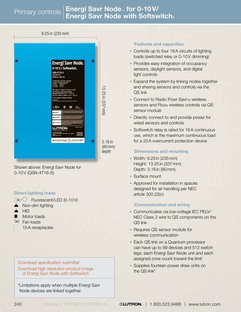
Primary controls |
240 | 1.800.523.9466 | www.lutron.comVolume 3 P/N 367-2102 REV A
Energi Savr NodeTM for 0-10 V/ Energi Savr Node with Softswitch®
Features and capacities• Controls up to four 16 A circuits of lighting
loads (switched relay or 0-10 V dimming)• Provides easy integration of occupancy
sensors, daylight sensors, and digital light controls
• Expand the system by linking nodes together and sharing sensors and controls via the QS link
• Connect to Radio Powr SavrTM wireless sensors and Pico® wireless controls via QS sensor module
• Directly connect to and provide power for wired sensors and controls
• Softswitch relay is rated for 16 A continuous use, which is the maximum continuous load for a 20 A overcurrent protection device
Dimensions and mounting• Width: 9.25 in (235 mm)
Height: 13.25 in (337 mm) Depth: 3.16 in (80 mm)
• Surface mount• Approved for installation in spaces
designed for air handling per NEC article 300.22(c)
Communication and wiring• Communicates via low-voltage IEC PELV/
NEC Class 2 wire to QS components on the QS link
• Requires QS sensor module for wireless communication
• Each QS link on a Quantum processor can have up to 99 devices and 512 switch legs; each Energi Savr Node unit and each assigned zone count toward the limit
• Supplies fourteen power draw units on the QS link*
Shown above: Energi Savr Node for 0-10 V (QSN-4T16-S)
9.25 in (235 mm)
13.25 in (337 mm
)3.16 in (80 mm) depth
Direct lighting loads
/ Fluorescent/LED (0-10 V) Non-dim lighting HID Motor loads Fan loads
15 A receptacles
* Limitations apply when multiple Energi Savr Node devices are linked together.
Download specification submittalDownload high resolution product image
of Energi Savr Node with Softswitch

Primary controls |
240 | 1.800.523.9466 | www.lutron.com 241 www.lutron.com | 1.800.523.9466 | Volume 3 P/N 367-2102 REV A
Energi Savr NodeTM for 0-10 V/ Energi Savr Node with Softswitch®
Explanation of features
Energi Savr Node programming interface
seeTouch® QS keypad
QS sensor module
Features
1 Control power • 120-277 V
2 Switched load outputs
• Four feed-through Softswitch relays
• 120-277 V, 347 V
3 QS link • Link to additional wired controls, sensors, and interfaces
• Connect to Radio Powr SavrTM wireless sensors and Pico® wireless controls via QS sensor module
4 Emergency contact closure input
• Force all lights to 100% (by default)
5 Programmable contact closure input
• To select scene, enable after-hours, or enable a demand response
6 Wired daylight sensors
• Up to four wired sensors
Wired occupancy sensors
• Up to four wired sensors
Wired EcoSystem® and Pico wallstations or IR receivers
• Up to four inputs
Wired IEC PELV/NEC Class 2 dry contact switches
• Up to four dry contact closure inputs
7 0-10 V channels • Four dimming zones (0-10 V only)
4
3
21
67 5
Energi Savr Node for 0-10 V (cover removed)

Primary controls |
242 | 1.800.523.9466 | www.lutron.comVolume 3 P/N 367-2102 REV A
Energi Savr NodeTM for 0-10 V/ Energi Savr Node with Softswitch®
Energi Savr Node for 0-10 V 120 V, 220-240 V and 277 V models @ 50/60 Hz
0-10 V control (120-277 V) QSN-4T16-S 0-10 V control (120-277 V, 347 V) QSN-4T16-S-347
Compatible with the Quantum® system
Energi Savr Node with Softswitch 120 V, 220-240 V and 277 V models @ 50/60 Hz
Softswitch (120-277 V) QSN-4S16-S Softswitch (120-277 V, 347 V) QSN-4S16-S-347Compatible with the Quantum system
Model numbersAvailable models
Energi Savr Node for 0-10 V
For specific voltage by country information refer to voltage chart on pg. 692.
Energi Savr Node with Softswitch

Primary controls |
242 | 1.800.523.9466 | www.lutron.com 243 www.lutron.com | 1.800.523.9466 | Volume 3 P/N 367-2102 REV A
Energi Savr NodeTM with EcoSystem® (DIN-rail)
6.36 in (162 mm)
3.53 in (90 mm
)
Shown above: Energi Savr Node with EcoSystem (DIN-rail) (QSNE-2ECO-D)
Direct lighting loads
/ Fluorescent/LED (EcoSystem)
Features and capacities• Provides control of up to 128 EcoSystem ballasts,
modules, and/or drivers (up to 64 per EcoSystem digital link)
• Powers two EcoSystem digital links• Combines fine tuning, daylight harvesting,
occupancy/vacancy sensing, personal control, and contact closure integration in one control
• Expand the system by linking nodes together and sharing sensors and controls via the QS link
• Directly connect to and provide power for wired sensors and controls
• Connect to wireless sensors and controls via QS sensor module
Dimensions and mounting• Width: 6.36 in (162 mm)
Height: 3.53 in (90 mm) Depth: 2.39 in (61 mm)
• Mounts to standard DIN-rail (width = 9.50 mm)• 9 DIN-wide device
Communication and wiring• Communicates to ballasts, modules, and LED
drivers on the EcoSystem digital link, and via low-voltage IEC PELV/NEC Class 2 wire to QS components on the QS link
• Requires QS sensor module for wireless communication
• Each QS link on a Quantum processor can have up to 99 devices and 512 switch legs; each Energi Savr Node unit and each assigned zone counts toward the limit
• Supplies three power draw units on the QS link*
* Limitations apply when multiple Energi Savr Node devices are linked together. Download specification submittal
2.39 in (61 mm) depth

Primary controls |
244 | 1.800.523.9466 | www.lutron.comVolume 3 P/N 367-2102 REV A
Energi Savr NodeTM with EcoSystem® (DIN-rail)
Explanation of features
4
1 3
Energi Savr Node with EcoSystem (DIN-rail)
Features
1 Wired daylight sensors
• Up to four wired sensors
Wired occupancy sensors
• Up to four wired sensors
Wired EcoSystem wallstations, IR receivers, or IEC PELV contact switches
• Up to four inputs
2 QS link • Link to additional wired controls, sensors, and interfaces
• Connect to Radio Powr SavrTM wireless sensors and Pico® wireless controls via QS sensor module
3 EcoSystem digital links
• Up to 64 EcoSystem ballasts, modules, and drivers per link
• Available with two links
4 Mains wiring • Wiring from distribution panel to module
2

Primary controls |
244 | 1.800.523.9466 | www.lutron.com 245 www.lutron.com | 1.800.523.9466 | Volume 3 P/N 367-2102 REV A
Energi Savr NodeTM with EcoSystem® (DIN-rail)
Available models
Energi Savr Node with EcoSystem (DIN-rail)
Energi Savr Node with EcoSystem (DIN-rail) 230 V (CE), 220-240 V
EcoSystem QSNE-2ECO-DCompatible with the Quantum® system
Model numbers
For specific voltage by country information refer to voltage chart on pg. 692.

Primary controls |
246 | 1.800.523.9466 | www.lutron.comVolume 3 P/N 367-2102 REV A
Energi Savr NodeTM for DALI (DIN-rail)
6.36 in (162 mm)
3.53 in (90 mm
)
Shown above: Energi Savr Node for DALI (DIN-rail) (QSNE-2DAL-D)
2.39 in (61 mm) depth
Direct lighting loads
/ Fluorescent/LED (DALI)
Features and capacities• Provides power for either one or two loops of DALI
compliant digitally addressable loads (up to 64 ballasts/LED drivers per loop)
• Each DALI loop can control a maximum of 16 zones• Expand the system by linking nodes together and
sharing sensors via the QS link• Default configuration requires no commissioning• Directly connect to and provide power for wired
sensors and controls
Dimensions and mounting• Width: 6.36 in (162 mm)
Height: 3.53 in (90 mm) Depth: 2.39 in (61 mm)
• Mounts to standard DIN-rail (width = 9.50 mm)• 9 DIN-wide device
Communication and wiring• Communicates via low-voltage IEC PELV/NEC
Class 2 wire to QS components on the QS link• Requires QS sensor module for wireless
communication• Each QS link on a Quantum processor can have
up to 99 devices and 512 switch legs; each Energi Savr Node QS unit and each assigned zone counts toward the limit
• Supplies three power draw units on the QS link*
* Limitations apply when multiple Energi Savr Node devices are linked together. Download specification submittal

Primary controls |
246 | 1.800.523.9466 | www.lutron.com 247 www.lutron.com | 1.800.523.9466 | Volume 3 P/N 367-2102 REV A
Energi Savr NodeTM for DALI (DIN-rail)
Explanation of features
Features
1 Wired daylight sensors
• Up to four wired sensors
Wired occupancy sensors
• Up to four wired sensors
Wired or IR receivers
• Up to four inputs
2 QS link • Link to additional controls, sensors, and interfaces on the QS link
• Connect to Radio Powr SavrTM sensors and Pico® wireless controls via QS sensor module on the QS link
3 DALI bus • Connect to DALI loop
4 Mains wiring • Wiring from distribution panel to module
4
1 2 3
Energi Savr Node for DALI (DIN-rail)
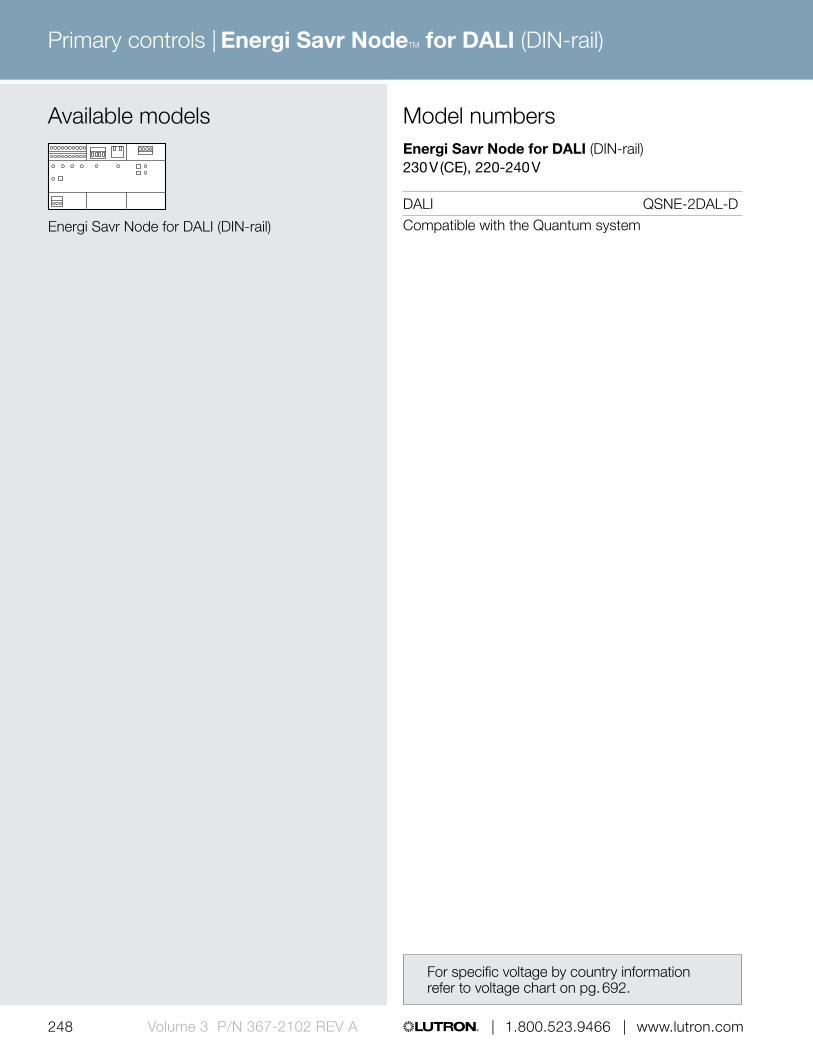
Primary controls |
248 | 1.800.523.9466 | www.lutron.comVolume 3 P/N 367-2102 REV A
Energi Savr NodeTM for DALI (DIN-rail)
Available models
Energi Savr Node for DALI (DIN-rail)
Energi Savr Node for DALI (DIN-rail) 230 V (CE), 220-240 V
DALI QSNE-2DAL-DCompatible with the Quantum system
Model numbers
For specific voltage by country information refer to voltage chart on pg. 692.
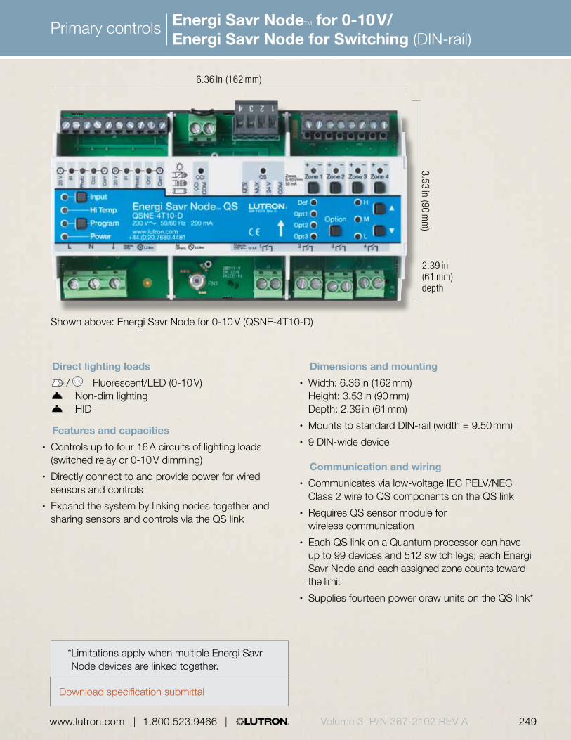
Primary controls |
248 | 1.800.523.9466 | www.lutron.com 249 www.lutron.com | 1.800.523.9466 | Volume 3 P/N 367-2102 REV A
Energi Savr NodeTM for 0-10 V/ Energi Savr Node for Switching (DIN-rail)
6.36 in (162 mm)
3.53 in (90 mm
)
Shown above: Energi Savr Node for 0-10 V (QSNE-4T10-D)
Direct lighting loads
/ Fluorescent/LED (0-10 V) Non-dim lighting HID
Features and capacities• Controls up to four 16 A circuits of lighting loads
(switched relay or 0-10 V dimming)• Directly connect to and provide power for wired
sensors and controls• Expand the system by linking nodes together and
sharing sensors and controls via the QS link
2.39 in (61 mm) depth
* Limitations apply when multiple Energi Savr Node devices are linked together.
Dimensions and mounting• Width: 6.36 in (162 mm)
Height: 3.53 in (90 mm) Depth: 2.39 in (61 mm)
• Mounts to standard DIN-rail (width = 9.50 mm)• 9 DIN-wide device
Communication and wiring• Communicates via low-voltage IEC PELV/NEC
Class 2 wire to QS components on the QS link• Requires QS sensor module for
wireless communication• Each QS link on a Quantum processor can have
up to 99 devices and 512 switch legs; each Energi Savr Node and each assigned zone counts toward the limit
• Supplies fourteen power draw units on the QS link*
Download specification submittal

Primary controls |
250 | 1.800.523.9466 | www.lutron.comVolume 3 P/N 367-2102 REV A
Energi Savr NodeTM for 0-10 V/ Energi Savr Node for Switching (DIN-rail)
Explanation of features4321
5 6
Energi Savr Node for 0-10 V
Features
1 Wired daylight sensors
• Up to two wired sensors
Wired occupancy sensors
• Up to two wired occupancy sensors
Wired IR receivers • Up to two inputs
2 Emergency contact closure input
• Forces all lights to 100% (by default)
3 QS link • Link to additional wired controls, sensors, and interfaces
• Connect to Radio Powr SavrTM sensors and Pico® wireless controls via QS sensor module
4 0-10 V channels • Four dimming zones (0-10 V)
5 Mains wiring • Wiring from distribution to bus supply
6 Switched load outputs
• Four feed-through relays• 220-240 V

Primary controls |
250 | 1.800.523.9466 | www.lutron.com 251 www.lutron.com | 1.800.523.9466 | Volume 3 P/N 367-2102 REV A
Energi Savr NodeTM for 0-10 V/ Energi Savr Node for Switching (DIN-rail)
Energi Savr Node for 0-10 V (DIN-rail) 230 V (CE), 220-240 V
0-10 V QSNE-4T10-D
Compatible with the Quantum system
Energi Savr Node for Switching (DIN-rail) 230 V (CE), 220-240 V
Switching QSNE-4S10-D
Compatible with the Quantum system
Model numbersAvailable models
Energi Savr Node for 0-10 V
For specific voltage by country information refer to voltage chart on pg. 692.
Energi Savr Node for Switching

Primary controls |
252 | 1.800.523.9466 | www.lutron.comVolume 3 P/N 367-2102 REV A
Energi Savr NodeTM phase adaptive (DIN-rail)
8.50 in (216 mm)
3.54 in (90 mm
)
Shown above: Energi Savr Node phase adaptive (DIN-rail) (QSNE-4A-D)
2.99 in (76 mm) depth
Direct lighting loads
Incandescent/halogen Electronic low-voltage Magnetic low-voltage Neon/cold cathode CFL/LED (screw-base)1
Features and capacities• Controls up to four zones of dimmable CFL/
LED loads in addition to incandescent, halogen, electronic low-voltage, magnetic low-voltage, and neon cold cathode light sources (Zone 1: 800 W, Zone 2, 3, and 4: 500 W)
• No minimum load requirement; one load type per zone
• Automatically selects leading edge or trailing edge dimming
• Four multi-functional inputs that are compatible with wired occupancy/vacancy sensors, daylight sensors, IR receivers, or IEC PELV switches
• Connect to Radio Powr SavrTM wireless sensor and Pico® wireless controls via QS sensor module
• Expand the system by linking nodes together and sharing sensors and controls via the QS link
1 Visit www.lutron.com/LEDtool for a complete list of LEDs compatible with this module*
2 Limitations apply when multiple Energi Savr Node devices are linked together. Download specification submittal
Dimensions and mounting• Width: 8.50 in (216 mm)
Height: 3.54 in (90 mm) Depth: 2.99 in (76 mm)
• Mounts to standard DIN-rail (width = 9.50 mm)• 12 DIN-wide device
Communication and wiring• Communicates via low-voltage IEC PELV/NEC
Class 2 wire to QS components on the QS link • Requires QS sensor module for wireless
communication • Each QS link on a Quantum processor can have
up to 99 devices and 512 switch legs; each Energi Savr Node and each assigned zone counts toward the limit
• Supplies four power draw units on the QS link2

Primary controls |
252 | 1.800.523.9466 | www.lutron.com 253 www.lutron.com | 1.800.523.9466 | Volume 3 P/N 367-2102 REV A
Energi Savr NodeTM phase adaptive (DIN-rail)
Explanation of features
Features
1 Multi-function inputs
• Four sensor inputs link to occupancy/vacancy or daylight sensors, IR receivers, or IEC PELV contact switches for energy savings
2 Emergency contact closure input
• Force all lights to 100% (by default)
3 QS link • Link to additional wired controls, sensors, and interfaces
• Connect to Radio Powr SavrTM wireless sensors and Pico® wireless controls via QS sensor module
4 Mains wiring • Wiring from distribution panel to module
5 Phase adaptive outputs
• Zone 1—800 W, Zones 2-4—500 W
• 220—240 V
Energi Savr Node phase adaptive (DIN-rail)
21 3
4 5

Primary controls |
254 | 1.800.523.9466 | www.lutron.comVolume 3 P/N 367-2102 REV A
Energi Savr NodeTM phase adaptive (DIN-rail)
Available models
Energi Savr Node phase adaptive (DIN-rail)
Energi Savr Node phase adaptive (DIN-rail) 230 V (CE), 220-240 V
Phase adaptive QSNE-4A-DCompatible with the Quantum® system
Model numbers
For specific voltage by country information refer to voltage chart on pg. 692.

Primary controls |
254 | 1.800.523.9466 | www.lutron.com 255 www.lutron.com | 1.800.523.9466 | Volume 3 P/N 367-2102 REV A
HomeWorks® QS designer dimmers and switches
2.94 in (75 mm)
Shown actual size: HomeWorks QS designer dimmer in White(HQRD-6D-WH) with 1-gang Claro® wallplate in White (CW-1-WH)
4.69 in (119 mm
)
Direct lighting loads
Incandescent/halogen Magnetic low-voltage Electronic low-voltage/ Fluorescent/LED (3-wire) LED (2-wire forward phase) Tu-Wire® fluorescent
/ CFL/LED (screw-base)* Neon/cold cathode
Non-dim lighting HID Motor loads Fan loads
0.31 in (8 mm) profile
Features and capacities• Functions much like standard dimmers and
switches, but can also be controlled as part of a lighting control system
• Dimmers incorporate advanced features such as fade on/fade off, long fade off, and rapid full on
• Light levels can be fine tuned by pressing and holding the dimming rocker until the desired light level is reached
• Can be installed in single-pole or multi-location applications
• Up to nine remote dimmers/switches may be connected to a single dimmer/switch for multi-location control
• Coordinating Claro, Satin Color® and Stainless Steel wallplates available separately, see pg. 640
Dimensions and mounting• Width: 2.94 in (75 mm)
Height: 4.69 in (119 mm) Depth: 1.13 in (30 mm) Profile: 0.31 in (8 mm)
• Mounts in a standard 1-gang U.S. backbox
Communication and wiring• Communicates via Lutron reliable Clear Connect®
Radio Frequency (RF) technology to other Lutron wireless devices
• Operates at 434 MHz• Must be located within 30 ft (9 m) of a
hybrid repeater• Operates at 120 V @ 50/60 Hz; dual voltage
120-277 V @ 50/60 Hz models available for fluorescent/LED dimming and non-dim lighting
• A HomeWorks QS system can have up to 99 devices per RF link
1.13 in (30 mm) depth
Download specification submittalDownload high resolution product image
* Visit www.lutron.com/LEDtool for a complete list of LEDs compatible with the adaptive dimmer.

Primary controls |
256 | 1.800.523.9466 | www.lutron.comVolume 3 P/N 367-2102 REV A
HomeWorks® QS designer dimmers and switches
Gloss finishes*
Use BOLD color code in model number (Example: HQRD-6D-WH)
WHWhite
LALight Almond
ALAlmond
IVIvory
GRGray
BRBrown
BLBlack
Satin finishes*
MSMocha Stone
TCTerracotta
SISienna
HTHot
MRMerlot
MNMidnight
SS**Stainless Steel (wallplate only)
SWSnow
LSLimestone
BIBiscuit
ESEggshell
PDPalladium
TPTaupe
STStone
BGBluestone
PLPlum
TQTurquoise
GSGoldstone
DSDesert Stone
GBGreenbriar
Available finishes
* Coordinating wallplates only available separately. For wallplate information, see pg. 642.
** Stainless Steel wallplate includes black plastic trim/adapter, visible from side. Match with separate Black (BL) or Midnight (MN) controls.

Primary controls |
256 | 1.800.523.9466 | www.lutron.com 257 www.lutron.com | 1.800.523.9466 | Volume 3 P/N 367-2102 REV A
HomeWorks® QS designer dimmers and switches
0.31 in (8 mm)
1.13 in (30 mm)
Explanation of features
Features
1 Status LEDs • Indicate light level; glow softly as night light when light is off (not available on remote dimmers/switches)
2 Dimming rocker • Press up to brighten, down to dim
3 Tapswitch • Tap on/off
4 FASS™• Front Accessible Service
Switch to disconnect power from the load for serviceHomeWorks QS designer dimmer
HomeWorks QS designer switch
4
3
2
3
4
1
1
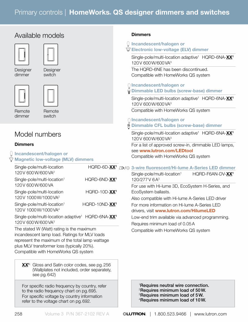
Primary controls |
258 | 1.800.523.9466 | www.lutron.comVolume 3 P/N 367-2102 REV A
HomeWorks® QS designer dimmers and switches
Dimmers
Incandescent/halogen or Electronic low-voltage (ELV) dimmer
Single-pole/multi-location adaptive1 HQRD-6NA-XX1
120 V 600 W/600 VA3
The HQRD-6NE has been discontinued. Compatible with HomeWorks QS system
Incandescent/halogen or Dimmable LED bulbs (screw-base) dimmer
Single-pole/multi-location adaptive1 HQRD-6NA-XX1
120 V 600 W/600 VA3
Compatible with HomeWorks QS system
Incandescent/halogen or Dimmable CFL bulbs (screw-base) dimmer
Single-pole/multi-location adaptive1 HQRD-6NA-XX1
120 V 600 W/600 VA3
For a list of approved screw-in, dimmable LED lamps, see www.lutron.com/LEDtoolCompatible with HomeWorks QS system 3-wire fluorescent/Hi-lume A-Series LED dimmerSingle-pole/multi-location1 HQRD-F6AN-DV-XX1 120/277 V 6 A3
For use with Hi-lume 3D, EcoSystem H-Series, and EcoSystem ballasts.Also compatible with Hi-lume A-Series LED driverFor more information on Hi-lume A-Series LED drivers, visit www.lutron.com/HilumeLEDLow-end trim available via advanced programming.Requires minimum load of 0.05 ACompatible with HomeWorks QS system
1Requires neutral wire connection. 2Requires minimum load of 50 W. 3Requires minimum load of 5 W. 4Requires minimum load of 10 W.
XX1: Gloss and Satin color codes, see pg. 256 (Wallplates not included, order separately, see pg. 642)
Available models
Designer dimmer
Designer switch
Remote dimmer
Remote switch
For specific radio frequency by country, refer to the radio frequency chart on pg. 695. For specific voltage by country information refer to the voltage chart on pg. 692.
Dimmers
Incandescent/halogen or Magnetic low-voltage (MLV) dimmers
Single-pole/multi-location HQRD-6D-XX1 120 V 600 W/600 VA2
Single-pole/multi-location1 HQRD-6ND-XX1 120 V 600 W/600 VA
Single-pole/multi-location HQRD-10D-XX1 120 V 1000 W/1000 VA2
Single-pole/multi-location1 HQRD-10ND-XX1 120 V 1000 W/1000 VA4
Single-pole/multi-location adaptive1 HQRD-6NA-XX1 120 V 600 W/600 VA3
The stated W (Watt) rating is the maximum incandescent lamp load. Ratings for MLV loads represent the maximum of the total lamp wattage plus MLV transformer loss (typically 20%). Compatible with HomeWorks QS system
Model numbers

Primary controls |
258 | 1.800.523.9466 | www.lutron.com 259 www.lutron.com | 1.800.523.9466 | Volume 3 P/N 367-2102 REV A
HomeWorks® QS designer dimmers and switches
Remote dimmers
Remote dimmer
Multi-location HQD-RD-XX1 120 V
Multi-location HQD-RD-277-XX1 277 VFor multi-location control, add up to nine remote dimmers to a single HomeWorks QS dimmer.277 V model for use with HQRD-F6AN-DV-XX.
Switches and remote switches
Switch
Multi-location/single-pole1 HQRD-8ANS-XX1 120 V 8 A light or .25 HP motor 5.8 A motor3
Dual-voltage, HQRD-8S-DV-XX1
two wire electronic switch2 120/277 V 8 A light, 0.10 HP 3 A motor1
Compatible with HomeWorks QS system
Remote switch
Multi-location HQD-RS-XX1 120 V
Multi-location HQD-RS-277-XX1 277 VFor multi-location control, add up to nine remote switches to a single HomeWorks QS switch.Compatible with HomeWorks QS system277 V model for use with HQRD-8S-DV-XX.
Model numbers
1Requires neutral wire connection. 2Requires shunt capacitor. 3Requires minimum load of 10 W / 0.08 A. 4Requires minimum load of 40 W / 0.04 A.
XX1: Gloss and Satin color codes, see pg. 256 (Wallplates not included, order separately, see pg. 642)
For specific radio frequency by country, refer to the radio frequency chart on pg. 695. For specific voltage by country information refer to the voltage chart on pg. 692.

Primary controls |
260 | 1.800.523.9466 | www.lutron.comVolume 3 P/N 367-2102 REV A
HomeWorks® QS hybrid seeTouch® keypad
Features and capacities• Hybrid keypads function as a dimmer and a keypad
combined into a single device, and eliminate the need for extra wiring
• Keypads incorporate advanced features such as fade on/fade off and rapid full on
• Scenes can be fine-tuned by pressing and holding the raise/lower buttons to adjust lights or shades
• Backlit buttons or backlit text• Available with neutral wire terminal that allows
keypads to be installed in either two-wire or neutral wire installations (neutral wire recommended)
• Coordinating Claro, Satin Color® and Stainless Steel wallplates only available separately, see pg. 640
• For information on engraving, text symbols, or backlit buttons/backlit text, see pgs. 667-668
• Operates at 120 V• Maximum load 450 W/450 VA 2-wire or
neutral wire, 120 V• Minimum load with neutral 15 W/15 VA• Minimum load without neutral 50 W/50 VA
Dimensions and mounting• Width: 2.94 in (75 mm)
Height: 4.69 in (119 mm) Depth: 1.25 in (32 mm) Profile: 0.31 in (8 mm)
• Mounts into a standard 1-gang U.S. backbox
Communication and wiring• Communicates via Lutron reliable Clear Connect® RF
technology to other Lutron wireless devices• Operates at 434 MHz• Must be located within 30 ft (9 m) of a hybrid repeater• HomeWorks QS system can have up to 99 devices
per radio frequency (RF) link
Direct lighting loads
Incandescent/halogen Magnetic low-voltage Tu-Wire® fluorescent
2.94 in (75 mm)
Shown actual size: 5-button hybrid seeTouch keypad in White (HQRD-H5BRL-WH) and 1-gang Claro® wallplate in White (CW-1-WH)
4.69 in (119 mm
)
0.31 in (8 mm) profile
1.25 in (32 mm) depth
Download specification submittalDownload high resolution product imageDownload engraving sheet for button kits

Primary controls |
260 | 1.800.523.9466 | www.lutron.com 261 www.lutron.com | 1.800.523.9466 | Volume 3 P/N 367-2102 REV A
HomeWorks® QS hybrid seeTouch® keypad
Use BOLD color code in model number (Example: HQRD-H6BRL-WH)
PLPlum FTaupe BWhite E
TQTurquoise FGray BWhite E
GBGreenbriar FGray BWhite E
BGBluestone FGray BWhite E
GSGoldstone FIvory BGray E
DSDesert Stone FTaupe BGray E
Gloss finishes*
TPTaupe F, BGray E
ESEggshell F, BGray E
BIBiscuit F, BGray E
SWSnow F, BGray E
PDPalladium FGray B
STStone FGray B, E
LSLimestone FGray BWhite E
MSMocha Stone FTaupe BWhite E
WHWhite F, BGray E
LALight Almond F, BGray E
ALAlmond F, BGray E
IVIvory F, BGray E
GRGray F, BWhite E
BRBrown F, BWhite E
BLBlack F, BWhite E
Buttons B
Faceplate F
Available finishes
Engraving E
TCTerracotta FTaupe BWhite E
SISienna FBrown BWhite E
HTHot FTaupe BWhite E
MRMerlot FTaupe BWhite E
MNMidnight F, BWhite E
SS **Stainless Steel FBlack BWhite E
* Coordinating wallplates only available separately. For wallplate information, see pg. 642.
** Stainless Steel wallplate includes black plastic trim/adapter, visible from side. Match with separate Black (BL) or Midnight (MN) controls.
Satin finishes*

Primary controls |
262 | 1.800.523.9466 | www.lutron.comVolume 3 P/N 367-2102 REV A
HomeWorks® QS hybrid seeTouch® keypad
0.31 in (8 mm)
1.25 in (32 mm)
Explanation of features
Features
1 Status LEDs • Show status of lights or shades assigned to button
2 Programmable buttons
• Five buttons• Buttons provide zone,
scene, and shade control
3 Raise/lower buttons
• Lights increase or decrease in intensity or shades/draperies move towards the open/close limit
3
1
HomeWorks QS hybrid seeTouch keypad
2

Primary controls |
262 | 1.800.523.9466 | www.lutron.com 263 www.lutron.com | 1.800.523.9466 | Volume 3 P/N 367-2102 REV A
HomeWorks® QS hybrid seeTouch® keypad
Available models
3-button and 2-button with raise/lower dual
2-button dual keypad with raise/lower
6-button with raise/lower
4-scene with raise/lower
5-button with raise/lower
3-button with raise/lower

Primary controls |
264 | 1.800.523.9466 | www.lutron.comVolume 3 P/N 367-2102 REV A
HomeWorks® QS hybrid seeTouch® keypad
Incandescent/halogen or Magnetic low-voltage (MLV) dimmers
(434 MHz)
3-button with HQRD-H3BSRL-XX1 raise/lower keypad and 120 V, 450 W/450 VA dimmer
4-button with HQRD-H4S-XX1 raise/lower keypad and 120 V, 450 W/450 VA dimmer
5-button with HQRD-H5BRL-XX1 raise/lower keypad and 120 V, 450 W/450 VA dimmer
6-button with HQRD-H6BRL-XX1 raise/lower keypad and 120 V, 450 W/450 VA dimmer
3-button, 2-button with HQRD-H1RLD-XX1 raise/lower dual group keypad and 120 V, 450 W/450 VA dimmer
2-button with raise/lower HQRD-H2RLD-XX1 dual group keypad and 120 V, 450 W/450 VA dimmer2-wire or neutral dimmer.Compatible with HomeWorks QS system
Model numbers
For specific radio frequency by country, refer to the radio frequency chart on pg. 695. For specific voltage by country information refer to the voltage chart on pg. 692.
XX1: Gloss and Satin Color® codes, see pg. 261 (Wallplates not included, order separately, see pg. 642)
E1: Complete an engraving sheet for each button kit. If no engraving is desired, remove the “-E” from the model number.
Engraved replacement kits
3-button with RKD-H3BSRL-XX1-E1 raise/lower keypad and 120 V, 450 W/450 VA dimmer
4-button with RKD-H4S-XX1-E1 raise/lower keypad and 120 V, 450 W/450 VA dimmer
5-button with RKD-H5BRL-XX1-E1 raise/lower keypad and 120 V, 450 W/450 VA dimmer
6-button with RKD-H6BRL-XX1-E1 raise/lower keypad and 120 V, 450 W/450 VA dimmer
3-button, 2-button with RKD-H1RLD-XX1-E1 raise/lower dual group keypad and 120 V, 450 W/450 VA dimmer
2-button with raise/lower RKD-H2RLD-XX1-E1 dual group keypad and 120 V, 450 W/450 VA dimmerCompatible with HomeWorks QS hybrid seeTouch keypads

Primary controls |
264 | 1.800.523.9466 | www.lutron.com 265 www.lutron.com | 1.800.523.9466 | Volume 3 P/N 367-2102 REV A
HomeWorks® QS tabletop lamp dimmer
Shown above: HomeWorks QS tabletop lamp dimmer in Snow (HQR-3LD-SW) (full cord length not shown)
Direct lighting loads
Incandescent/halogen Magnetic low-voltage Non-dim lighting
Features and capacities• Light levels can be fine-tuned to the desired level• Incorporates advanced features such as fade on/
fade off, delayed long fade off, and rapid full on• On a single-tap, lights fade on or off• On a double-tap, lights go to full on• When on, press and hold to engage the delayed
long fade to off• Cord is 6 ft (1.8 m) long• Minimum load is 10 W• Can be programmed to switch• Available in Snow (SW) and Midnight (MN)
Dimensions and mounting• Width: 2.44 in (62 mm)
Height: 3.25 in (83 mm) Top Depth: 0.94 in (24 mm) Bottom Depth: 0.69 in (18 mm)
Communication and wiring• Communicates via Lutron reliable Clear Connect®
Radio Frequency (RF) technology to other Lutron® wireless devices
• Operates at 434 MHz• Must be located within 30 ft (9 m) of a
hybrid repeater• Easy to install, no mounting required• HomeWorks QS system can have up to
99 devices per RF link
3.25 in (83 mm
)
2.44 in (62 mm)
0.69 in (18 mm) bottom depth
0.94 in (24 mm) top depth
Download specification submittalDownload high resolution product image

Primary controls |
266 | 1.800.523.9466 | www.lutron.comVolume 3 P/N 367-2102 REV A
Explanation of features
Features
1 Status LEDs
• Indicates light level; glows softly as night light when light is off
2 Dimming rocker
• Press up to brighten, down to dim
3 Tapswitch • Tap on/off
0.94 in (24 mm)0.69 in
(18 mm)
1
2
3
HomeWorks QS tabletop lamp dimmer
HomeWorks® QS tabletop lamp dimmer

Primary controls |
266 | 1.800.523.9466 | www.lutron.com 267 www.lutron.com | 1.800.523.9466 | Volume 3 P/N 367-2102 REV A
HomeWorks QS tabletop lamp dimmers (120 V @ 50/60 Hz; 434 MHz)
Dimming/switching
Plug-in lamp dimmer HQR-3LD-XX1 300 W (incandescent/halogen) 200 W/300 VA (MLV)Compatible with HomeWorks QS system
Model numbers
Available models
HomeWorks QS tabletop lamp dimmer
SWSnow
MNMidnight
Available finishesSatin finish
HomeWorks® QS tabletop lamp dimmer
XX1: Available in Snow (SW) and Midnight (MN)
For specific radio frequency by country, refer to the radio frequency chart on pg. 695. For specific voltage by country information refer to the voltage chart on pg. 692.

Primary controls |
268 | 1.800.523.9466 | www.lutron.comVolume 3 P/N 367-2102 REV A
HomeWorks® QS RF plug-in modules
Shown actual size: HomeWorks QS radio frequency (RF) plug-in dimming module (HQR-3PD-1-SW) (full cord length not shown)
Direct lighting loads
Plug-in dimming module (dimming mode)
Incandescent/halogen Magnetic low-voltage
Plug-in dimming module (switching mode)
Non-dim lighting
Plug-in appliance module
General purpose Non-dim lighting
HID Motor loads Fan loads
Features and capacities• Dimming module functions much like standard lamp
dimmers, and incorporates advanced features such as fade on/fade off, delayed long fade off, and rapid full on
• Appliance module switches up to 15 A of general purpose load; it features Lutron patented Softswitch® technology to prevent the relay contacts from arcing, extending the life of the switch
• Appliance module may be used with (but is not limited to) task lighting, monitors, printers and fans
• Male plug on 24 in (610 mm) cord• Female receptacle on 6 in (150 mm) cord• 10 W minimum load for dimming module• Use the plug-in appliance module to eliminate
energy use by products /appliances in the off position, such as vampire loads
• Available in Snow (SW) and Midnight (MN)
Dimensions and mounting• Width: 2.25 in (57 mm)
Height: 3.25 in (83 mm) Depth: 1.23 in (31 mm)
• Module can be hidden discretely behind furniture
Communication and wiring• Communicates via Lutron reliable Clear Connect®
RF technology to other Lutron wireless devices• Operates at 434 MHz• Must be located within 30 ft (9 m) of a
hybrid repeater• HomeWorks QS system can have up to
99 devices per RF link
3.25 in (83 mm
)
1.23 in (31 mm) depth
2.25 in (57 mm)
Download specification submittalDownload high resolution product image

Primary controls |
268 | 1.800.523.9466 | www.lutron.com 269 www.lutron.com | 1.800.523.9466 | Volume 3 P/N 367-2102 REV A
HomeWorks® QS RF plug-in modules
Back of HomeWorks QS RF plug-in dimming module (full cord length not shown)
Back of HomeWorks QS RF plug-in appliance module (full cord length not shown)
1.23 in (31 mm)
Explanation of features
Features
1 Status LEDs • Indicate light level; glow softly as night light when load is off
2 Raise button • Press to brighten
3 Toggle button • Press to toggle on/off; double-tap for full on; press and hold while on for delayed long fade to off
4 Lower button • Press to dim
4
3
3
2
1
Dimming module (with 2-prong plug)
Appliance module (with 3-prong plug)

Primary controls |
270 | 1.800.523.9466 | www.lutron.comVolume 3 P/N 367-2102 REV A
HomeWorks® QS RF plug-in modules
Available models
Appliance module (3-prong plug)
Dimming module (2-prong plug)
SWSnow
MNMidnight
Available finishesMatte finishes HomeWorks QS RF plug-in dimming and
appliance modules (120 V @ 50/60 Hz; 434 MHz)
Dimming/switching
300 W/300 VA HQR-3PD-1-XX1
Compatible with HomeWorks QS system
Appliance module
General purpose switching HQR-15APS-1-XX1
0.50 HP or 15 ACompatible with HomeWorks QS system
XX1: Available in Snow (SW) and Midnight (MN)
Model numbers
For specific radio frequency by country, refer to the radio frequency chart on pg. 695. For specific voltage by country information refer to the voltage chart on pg. 692.

Download specification submittalDownload high resolution product image
Primary controls |
270 | 1.800.523.9466 | www.lutron.com 271 www.lutron.com | 1.800.523.9466 | Volume 3 P/N 367-2102 REV A
HomeWorks® QS wallbox power module
Features and capacities• Controls up to six zones of lighting• Default scene button on the front of the unit that
allows a user to toggle between pre-programmed scenes
• Provides a cost-effective dimming solution to jobs with lower wattage loads and space constraints
• Reduces overall job cost by 5 -20% when less than 96 control zones are required
• Total unit maximum capacity: 2000 W / VA for 120 V @ 50 / 60 Hz; 3000 W / VA for 220-240 V @ 50 / 60 Hz
• Individual zone capacity: 25-800 W / VA for 120 V @ 50 / 60 Hz; 40-1200 W / VA for 220-240 V @ 50 / 60 Hz
Dimensions and mounting• Width: 9.44 in (240 mm)
Height: 4.69 in (119 mm) Depth: 2.00 in (51 mm) Profile: 0.38 in (10 mm)
• Mounts in a 4-gang U.S. backbox, 3.5 in (89 mm) deep
Communication and wiring• Can be configured for wired (QS link)
or wireless (RF link) communication• Radio frequency (RF) option communicates via
Lutron reliable Clear Connect® RF technology to other Lutron wireless devices, operates at 434 MHz, and must be located within 30 ft (9 m) of a hybrid keypad
• Wired option communicates via low-voltage IEC PELV/NEC Class 2-wire on the QS link
• HomeWorks QS system can have up to 99 devices per RF link and up to 99 devices and 512 zones per QS link; the HomeWorks QS wallbox power module and its zones count towards the limit
• Does not consume power draw units
9.44 in (240 mm)
Model numbersWallbox power module HQRJ-WPM-6D-120Compatible with the HomeWorks QS system
2.00 in (51 mm) depth
Shown above: 6-zone wallbox power module (HQRJ-WPM-6D-120)
4.69 in (119 mm
)
0.38 in (10 mm) profile
Direct lighting loads
Incandescent/halogen Magnetic low-voltage Tu-wire® fluorescent LED (2-wire forward phase) Neon/cold cathode Non-dim lighting

Primary controls |
272 | 1.800.523.9466 | www.lutron.comVolume 3 P/N 367-2102 REV A
6.36 in (162 mm)
3.53 in (90 mm
)
Shown above: HomeWorks QS power module with EcoSystem (DIN-rail) (LQSE-2ECO-D)
Direct lighting loads
/ Fluorescent/LED (EcoSystem)
Features and capacities• Provides power for two links of EcoSystem ballasts
or drivers (up to 64 mA per link)• Includes QS link for connection to a
HomeWorks QS system• Power module with EcoSystem unit can be used in
a HomeWorks QS system to control and manage light in an entire home or building
• Operates at 230 V (CE) @ 50 / 60 Hz
Dimensions and mounting• Width: 6.36 in (162 mm)
Height: 3.53 in (90 mm) Depth: 2.39 in (61 mm)
• Mounts to standard DIN-rail (width = 9.50 mm)• 9 DIN-wide device
Communication and wiring• Communicates to ballasts, modules, and LED
drivers on the EcoSystem digital link, and via low-voltage IEC PELV/NEC Class 2 wire to HomeWorks QS processor components on the QS link
• Each QS link on a HomeWorks QS processor can have up to 99 devices and 512 zones, the power module with EcoSystem counts as one device toward the limit and each ballast/driver/module counts as one zone unless specifically grouped into zones
• Maximum of eight fully loaded EcoSystem digital links may be connected to a single QS link
• Does not consume power draw units
Download specification submittal
2.39 in (61 mm) depth
HomeWorks® QS power module with EcoSystem® (DIN-rail)

Primary controls |
272 | 1.800.523.9466 | www.lutron.com 273 www.lutron.com | 1.800.523.9466 | Volume 3 P/N 367-2102 REV A
Explanation of features
3
2
HomeWorks QS power module with EcoSystem (DIN-rail)
Features
1 QS link • Link to additional wired controls, interfaces, and processors
2 EcoSystem digital links
• Up to 64 EcoSystem ballasts, modules, and drivers per link
• Available with two links
3 Mains wiring • Wiring from distribution panel to module
1
HomeWorks® QS power module with EcoSystem® (DIN-rail)

Primary controls |
274 | 1.800.523.9466 | www.lutron.comVolume 3 P/N 367-2102 REV A
Available models
HomeWorks QS power module with EcoSystem (DIN-rail)
HomeWorks QS power module with EcoSystem (DIN-rail) 230 V (CE), 220-240 V
EcoSystem, two links LQSE-2ECO-DCompatible with the HomeWorks QS system
Model numbers
For specific voltage by country information refer to voltage chart on pg. 692.
HomeWorks® QS power module with EcoSystem® (DIN-rail)
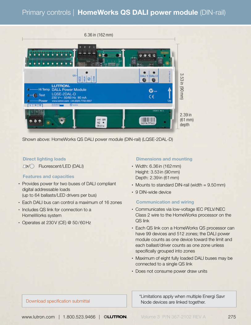
Primary controls |
274 | 1.800.523.9466 | www.lutron.com 275 www.lutron.com | 1.800.523.9466 | Volume 3 P/N 367-2102 REV A
HomeWorks QS DALI power module (DIN-rail)
6.36 in (162 mm)
3.53 in (90 mm
)
Shown above: HomeWorks QS DALI power module (DIN-rail) (LQSE-2DAL-D)
2.39 in (61 mm) depth
Direct lighting loads
/ Fluorescent/LED (DALI)
Features and capacities• Provides power for two buses of DALI compliant
digital addressable loads (up to 64 ballasts/LED drivers per bus)
• Each DALI bus can control a maximum of 16 zones• Includes QS link for connection to a
HomeWorks system• Operates at 230 V (CE) @ 50 / 60 Hz
Dimensions and mounting• Width: 6.36 in (162 mm)
Height: 3.53 in (90 mm) Depth: 2.39 in (61 mm)
• Mounts to standard DIN-rail (width = 9.50 mm)• 9 DIN-wide device
Communication and wiring• Communicates via low-voltage IEC PELV/NEC
Class 2 wire to the HomeWorks processor on the QS link
• Each QS link con a HomeWorks QS processor can have 99 devices and 512 zones; the DALI power module counts as one device toward the limit and each ballast/driver counts as one zone unless specifically grouped into zones
• Maximum of eight fully loaded DALI buses may be connected to a single QS link
• Does not consume power draw units
* Limitations apply when multiple Energi Savr Node devices are linked together. Download specification submittal

Primary controls |
276 | 1.800.523.9466 | www.lutron.comVolume 3 P/N 367-2102 REV A
HomeWorks QS DALI power module (DIN-rail)
Explanation of features
Features
1 QS link • Link to additional wired controls, interfaces, and processors
2 DALI bus • Up to 64 DALI ballasts and LED drivers per bus
• Available with two buses
3 Mains wiring • Wiring from distribution panel to module
3
1 2
HomeWorks QS DALI power module (DIN-rail)

Primary controls |
276 | 1.800.523.9466 | www.lutron.com 277 www.lutron.com | 1.800.523.9466 | Volume 3 P/N 367-2102 REV A
HomeWorks QS DALI power module (DIN-rail)
Available models
HomeWorks QS DALI power module (DIN-rail)
HomeWorks QS DALI power module (DIN-rail) 230 V (CE), 220-240 V
DALI LQSE-2DAL-DCompatible with the HomeWorks QS system
Model numbers
For specific voltage by country information refer to voltage chart on pg. 692.

Primary controls |
278 | 1.800.523.9466 | www.lutron.comVolume 3 P/N 367-2102 REV A
HomeWorks® QS phase adaptive power module (DIN-rail)
8.50 in (216 mm)
3.54 in (90 mm
)
Shown above: HomeWorks QS phase adaptive power module (DIN-rail) (LQSE-4A-D)
2.99 in (76 mm) depth
Direct lighting loads
Incandescent/halogen Electronic low-voltage Magnetic low-voltage Neon/cold cathode CFL/LED (screw-base)*
Features and capacities• Controls up to four zones of dimmable CFL/
LED loads in addition to incandescent, halogen, electronic low-voltage, magnetic low-voltage, and neon/cold cathode light sources (Zone 1: 800 W; Zone 2, 3, and 4: 500 W)
• Automatically selects leading edge or trailing edge dimming
• RTISS technology ensures that each output dims smoothly and is flicker-free
• No minimum load requirement; one load type per zone
• Includes QS link for connection to HomeWorks QS system
• Operates at 220-240 V (CE) @ 50 / 60 Hz
Download specification submittal
Dimensions and mounting• Width: 8.50 in (216 mm)
Height: 3.54 in (90 mm) Depth: 2.99 in (76 mm)
• Mounts to standard DIN-rail (width = 9.50 mm)• 12 DIN-wide device
Communication and wiring• Communicates via low-voltage IEC PELV/NEC
Class 2 wire to HomeWorks QS processor on the QS link
• Each QS link on a HomeWorks QS processor can have up to 99 devices and 512 zones; the phase adaptive power module and each assigned zone counts towards the limit
• Does not consume power draw units
* Visit www.lutron.com/LEDtool for a complete list of LEDs compatible with this module*
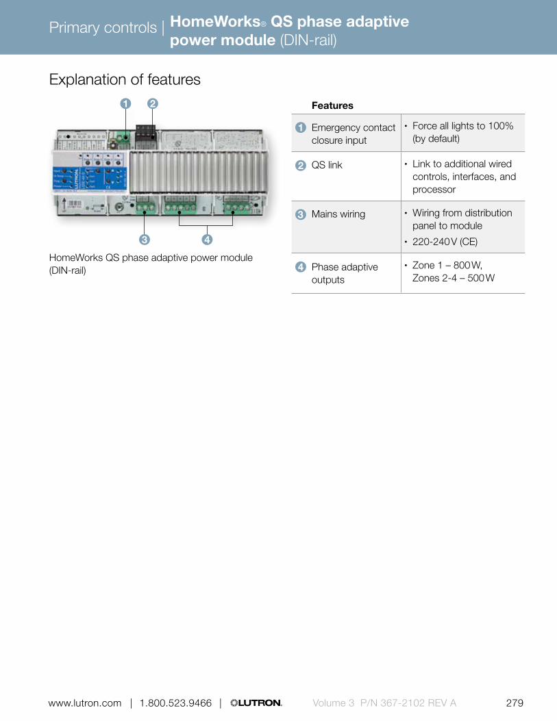
Primary controls |
278 | 1.800.523.9466 | www.lutron.com 279 www.lutron.com | 1.800.523.9466 | Volume 3 P/N 367-2102 REV A
HomeWorks® QS phase adaptive power module (DIN-rail)
Explanation of features
Features
1 Emergency contact closure input
• Force all lights to 100% (by default)
2 QS link • Link to additional wired controls, interfaces, and processor
3 Mains wiring • Wiring from distribution panel to module
• 220-240 V (CE)
4 Phase adaptive outputs
• Zone 1 – 800 W, Zones 2-4 – 500 W
HomeWorks QS phase adaptive power module (DIN-rail)
1 2
3 4
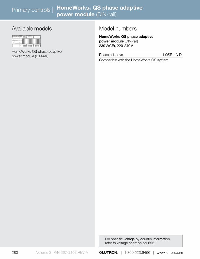
Primary controls |
280 | 1.800.523.9466 | www.lutron.comVolume 3 P/N 367-2102 REV A
HomeWorks® QS phase adaptive power module (DIN-rail)
Available models
HomeWorks QS phase adaptive power module (DIN-rail)
HomeWorks QS phase adaptive power module (DIN-rail) 230 V (CE), 220-240 V
Phase adaptive LQSE-4A-DCompatible with the HomeWorks QS system
Model numbers
For specific voltage by country information refer to voltage chart on pg. 692.

Primary controls |
280 | 1.800.523.9466 | www.lutron.com 281 www.lutron.com | 1.800.523.9466 | Volume 3 P/N 367-2102 REV A
HomeWorks® QS switching/0-10 V power module (DIN-rail)
6.36 in (162 mm)
3.53 in (90 mm
)
Shown above: HomeWorks QS switching/0-10 V power module (DIN-rail) (LQSE-4T10-D)
Direct lighting loads
/ Fluorescent/LED (0-10 V) Non-dim lighting HID
Features and capacities• Controls up to four 16 A circuits of lighting loads
(switched relay or 0-10 V dimming)• Includes QS link for connection to
HomeWorks QS system• Operates at 230 V (CE) @ 50 / 60 Hz
2.39 in (61 mm) depth
Dimensions and mounting• Width: 6.36 in (162 mm)
Height: 3.53 in (90 mm) Depth: 2.39 in (61 mm)
• Mounts to standard DIN-rail (width = 9.50 mm)• 9 DIN-wide device
Communication and wiring• Communicates via low-voltage IEC PELV/NEC
Class 2 wire to HomeWorks QS processor on the QS link
• Each QS link on a HomeWorks QS processor can have up to 99 devices and 512 zones; the switching/0-10 V power module and each assigned zone counts toward the limit
• Does not consume power draw units
Download specification submittal

Primary controls |
282 | 1.800.523.9466 | www.lutron.comVolume 3 P/N 367-2102 REV A
HomeWorks® QS switching/0-10 V power module (DIN-rail)
Explanation of features321
4 5
HomeWorks QS switching/0-10 V power module (DIN-rail)
Features
1 Emergency contact closure input
• Forces all lights to 100% (by default)
2 QS link • Link to additional wired controls, interfaces, and processor
3 0-10 V channels • Four dimming zones (0-10 V)
4 Mains wiring • Wiring from distribution to bus supply
5 Switched load outputs
• Four feed-through relays• 220-240 V

Primary controls |
282 | 1.800.523.9466 | www.lutron.com 283 www.lutron.com | 1.800.523.9466 | Volume 3 P/N 367-2102 REV A
HomeWorks QS switching/0-10 V power module (DIN-rail) 230 V (CE), 220-240 V
0-10 V LQSE-4T10-D
Compatible with the HomeWorks QS system
HomeWorks QS switching power module (DIN-rail) 230 V (CE), 220-240 V
Switching LQSE-4S10-D
Compatible with the HomeWorks QS system
Model numbersAvailable models
HomeWorks QS switching/0-10 V power module (DIN-rail)
For specific voltage by country information refer to voltage chart on pg. 692.
HomeWorks QS switching power module (DIN-rail)
HomeWorks® QS switching/0-10 V power module (DIN-rail)

Primary controls |
284 | 1.800.523.9466 | www.lutron.comVolume 3 P/N 367-2102 REV A
6.40 in (162 mm)
3.50 in (90 mm
)
2.40 in (61 mm) depth
Shown above: HomeWorks QS motor control power module (DIN-rail) (LQSE-4M-D)
Direct lighting loads
AC motor loads
Features and capacities• Provides seamless integration of HomeWorks QS
systems with AC blinds, shades, louvers, projection screens, or any compatible AC motor
• Provides four independently controllable AC raise/lower outputs from one common AC input feed; 1.50 A maximum motor load per channel, 6 A maximum total input current
• Includes QS link for connection to HomeWorks QS system
• Operates at 120-240 V (CE) @ 50/60 Hz
Download specification submittal
HomeWorks® QS motor control power module (DIN-rail)
Dimensions and mounting• Width: 6.40 in (162 mm)
Height: 3.50 in (90 mm) Depth 2.40 in (61 mm)
• Mounts to standard DIN-rail (width = 9.50 mm)• 9 DIN-wide device
Communication and wiring• Communicates via low-voltage IEC PELV/NEC
Class 2 wire to HomeWorks QS processor on the QS link
• Each QS link on a HomeWorks QS processor can have 99 devices and 512 zones; the motor control power module counts as one device and four zones toward the limits
• Does not consume power draw units

Primary controls |
284 | 1.800.523.9466 | www.lutron.com 285 www.lutron.com | 1.800.523.9466 | Volume 3 P/N 367-2102 REV A
Available modelsHomeWorks QS motor control power module (DIN-rail)110-127 V, 230 V (CE), 220-240 V
Motor control LQSE-4M-D
Compatible with HomeWorks QS International system
Model numbers
HomeWorks® QS motor control power module (DIN-rail)
Explanation of features Features
1 Mains wiring • Wiring from distribution panel to module
2 Zone select buttons
• Select desired zone• LED indicates which
zone is selected
3 Raise/lower buttons
• Raise and lower selected zones
• LEDs indicate which direction (raise/stop/lower) is active
4 QS link • Link to additional wired controls, interfaces and processors
5 Motor load outputs • 1.5 A maximum motor load per channel
• Four outputs
2
1 5
HomeWorks QS motor control power module (DIN-rail)
4 3

Sub-controls
286 | 1.800.523.9466 | www.lutron.com286 | 1.800.523.9466 | www.lutron.comVolume 3 P/N 367-2102 REV A
A sub-control is an accessory component to a system that provides additional control locations for increased convenience and functionality. The sub-controls in this guide are specific to each country’s voltage and frequency requirements. Please confirm that the products you have selected match the required voltages by country on pg. 692
Sub-control options include:• Keypads• Wallstations• Wireless Controllers• IR Remote Controls
Whole building system components
Infrared (IR) remote controlpg. 292
Ceiling-mount infrared receiverpg. 290
Wireless Radio Frequency (RF) communication
Infrared (IR) communication
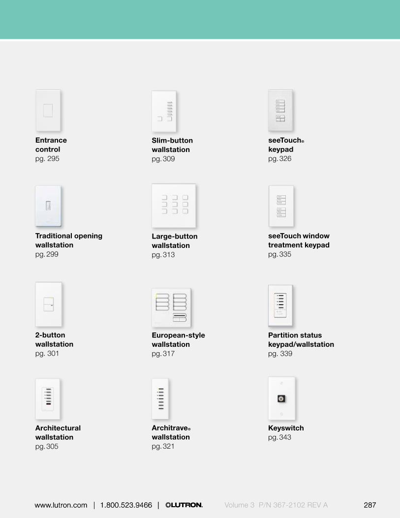
Volume 3 P/N 367-2102 REV A 287 www.lutron.com | 1.800.523.9466 | 287 www.lutron.com | 1.800.523.9466 |
seeTouch® keypadpg. 326
Entrance controlpg. 295
seeTouch window treatment keypadpg. 335
Architectural wallstationpg. 305
Slim-button wallstationpg. 309
Large-button wallstationpg. 313
Architrave® wallstationpg. 321
Traditional opening wallstationpg. 299
2-button wallstationpg. 301
European-style wallstationpg. 317
Partition status keypad/wallstationpg. 339
Keyswitchpg. 343

Sub-controls
288 289 | 1.800.523.9466 | www.lutron.com www.lutron.com | 1.800.523.9466 |288 289 | 1.800.523.9466 | www.lutron.com www.lutron.com | 1.800.523.9466 |Volume 3 P/N 367-2102 REV A
Whole building system components (continued)
Multi-channel theatrical consolespg. 346
QS Keyswitchpg. 380
QS infrared (IR) eyepg. 350
seeTouch® QS keypadpg. 366
Pico® wireless controlpg. 351
International seeTouch QS keypadpg. 374
Pico wired controlpg. 360
EcoSystem® IR remote control and IR receiverpg. 347
EcoSystem® wallstationpg. 363
Wireless Radio Frequency (RF) communication
Infrared (IR) communication

288 289 | 1.800.523.9466 | www.lutron.com www.lutron.com | 1.800.523.9466 |288 289 | 1.800.523.9466 | www.lutron.com www.lutron.com | 1.800.523.9466 | Volume 3 P/N 367-2102 REV A
Whole home system components
HomeWorks QS Architectural-style seeTouch keypadpg. 394
HomeWorks® QS dynamic keypadpg. 410
HomeWorks QS designer-style seeTouch wired keypadpg. 384
HomeWorks QS designer-style seeTouch wireless keypadpg. 389
HomeWorks QS wireless tabletop keypadpg. 406
TouchPRO Wireless® thermostatpg. 419
HomeWorks QS visor control transmitterpg. 413
HomeWorks QS International seeTouch® keypadpg. 401
seeTemp® wall controlpg. 415

Sub-controls |
290 | 1.800.523.9466 | www.lutron.comVolume 3 P/N 367-2102 REV A
Features and capacities• Provides control of lighting via IR handheld remote
controls by providing an access point• Allows scene selection, raise/lower scenes and all
off functionality via Lutron IR remote control• Works with all Lutron IR remote controls• Available in White (WH)• OMX models operate at 24 V DC;
GRX models operate at 12/24 V DC
Dimensions and mounting• Diameter: 3.50 in (89 mm)
Depth: 3.00 in (76 mm) Profile: 0.75 in (20 mm)
• Mounts in metal collar provided by Lutron; recess-mounted
Communication and wiring• Operates via low-voltage IEC PELV/ NEC Class 2
standard wired communication to main control unit and other system components
• OMX models—counts as one wallstation on OMX link; can have up to 32 keypads/wallstations and/or control interfaces
• GRX models—GRAFIK Eye 4000 system can have up to 16 total keypads/wallstations and/or control interfaces; each ceiling-mount IR receiver counts as one wallstation
• Reception range: 360º, 50 ft (15 m) line-of-sight range from wireless remote control to receiver
Shown above: OMX ceiling-mount infrared (IR) receiver (OMX-CIR-WH)
2.25 in (56 mm)
3.50 in (87 mm)
2.00 in (50 mm)
3.00 in (75 mm
)
0.75 in (20 mm)
Related components
IR remote control pg. 292
Ceiling-mount infrared receiver
Download specification submittal for OMXDownload specification submittal for GRX

Sub-controls |
291 | 1.800.523.9466 | www.lutron.com www.lutron.com | 1.800.523.9466 | Volume 3 P/N 367-2102 REV A
OMX IR receiver
Ceiling-mount IR receiver OMX-CIR-WHCompatible with LCP128™ and Softswitch128® (XPS) systems.
GRX IR receiver
Ceiling-mount IR receiver GRX-CIR-WHCompatible with the GRAFIK Eye® 4000 system.
Model numbers
Explanation of features Features
1 DIP switches (not shown)
• Utilized to address
2 IR lens • Receives signal from IR remote control
Visible portion of receiver
Ceiling-mount infrared (IR) receiver
1
2
Ceiling-mount infrared receiver

Sub-controls |
292 | 1.800.523.9466 | www.lutron.comVolume 3 P/N 367-2102 REV A
Infrared (IR) remote control
1.50 in (38 mm)
5.69 in (145 mm
)
Shown actual size: 4-scene IR remote control in White (GRX-IT-WH)
Features and capacities• Models available with 4- or 8-scene/
control buttons• Requires compatible infrared receiving device
(wallstation/keypad, QS IR Eye, GRAFIK Eye®
or GRAFIK Eye® QS main unit, or wired daylight sensor)
• Off button turns all lights off• Master raise/lower button brightens or dims
all lighting zones• Available in White (WH) and Black (BL)• Three AAA alkaline batteries included• Engraving available
Dimensions and mounting• Width: 1.50 in (38 mm)
Height: 5.69 in (145 mm) Depth: 0.88 in (22 mm)
• Handheld control
Communication and wiring• IR remote control uses IR signals to
communicate with the IR receiver• Transmits signal up to 50 ft (15 m) line-of-sight
range to receiver0.88 in (22 mm) depth
Download specification submittal for GRX-ITDownload specification submittal for GRX-8ITDownload engraving sheet for IR remote

Sub-controls |
293 | 1.800.523.9466 | www.lutron.com www.lutron.com | 1.800.523.9466 | Volume 3 P/N 367-2102 REV A
Infrared (IR) remote control
Explanation of features Features
1 Preset buttons (scenes 1-4)
• Models available with 1-4 scene buttons
2 Preset buttons (scenes 5-8)
• Models available with an additional 5-8 scene buttons
3 Off button • Turns all lights off
4 Master raise/lower buttons
• Brightens/dims all lighting zones
4
2
3
1
0.88 in (22 mm)8-scene IR remote control

| 1.800.523.9466 | www.lutron.com294 | 1.800.523.9466 | www.lutron.comVolume 3 P/N 367-2102 REV A
Sub-controls | Infrared (IR) remote control
IR remote control
4-scene GRX-IT-XX1-E1
8-scene GRX-8IT-XX1-E1
Compatible with LCP128™, Softswitch128® (XPS), GRAFIK Eye® 4000, Quantum®, and HomeWorks® QS systems.
Model numbers
4-scene 8-scene
Available models
XX1: White (WH) or Black (BL) E1: Engraving form required with order.
If engraving not desired, omit “E”.

Sub-controls |
295 | 1.800.523.9466 | www.lutron.com www.lutron.com | 1.800.523.9466 | Volume 3 P/N 367-2102 REV A | 1.800.523.9466 | www.lutron.com
Features and capacities• One button control, toggles the connected
GRAFIK Eye® control unit between Scene one and Off
• Operates one GRAFIK Eye control unit• Ideal for large projects that utilize the maximum
number of keypads/wallstations and/or control interfaces, but still require additional points of control
• Operates at 12/24 V DC• Engraving available
Dimensions and mounting• Width: 2.75 in (70 mm)
Height: 4.56 in (116 mm) Depth: 1.38 in (35 mm) Profile: 0.31 in (8 mm)
• Mounts in a standard 1-gang U.S. backbox
Communications and wiring• Wires direct to GRAFIK Eye 4000 control unit via
low-voltage IEC PELV/NEC Class 2 wiring• Up to 10 entrance controls may be wired in parallel
to a single GRAFIK Eye control unit• Does not require an address• Does not count toward maximum number of
keypads/wallstations/control interfaces in a GRAFIK Eye 4000 system
Shown above: Entrance control in White (NTGRX-1S-WH)
2.75 in (70 mm)
4.56 in (116 mm
)
0.31 in (8 mm) profile
1.38 in (35 mm) depth
Entrance control
Download specification submittalDownload engraving sheet for faceplates

296 | 1.800.523.9466 | www.lutron.comVolume 3 P/N 367-2102 REV A
Sub-controls |
Architectural matte finishes (Coordinated faceplates included)
GRGray F, B
BEBeige F, B
WHWhite F, B
TPTaupe F, B
BRBrown F, B
Available finishes
Use BOLD color code in model number (Example: NTGRX-1S-WH)
IVIvory F, B
Architectural metal finishes (Coordinated faceplates included)
CLAClear Anodized Aluminum FBlack B
BCBright Chrome FBlack B
BNBright Nickel FBlack B, I
SCSatin Chrome FBlack B
SNSatin Nickel FBlack B
QZAntique Bronze FBlack B
BBBright Brass FBlack B
BRABrass Anodized Aluminum FBlack B
SBSatin Brass FBlack B
QBAntique Brass FBlack B
BLABlack Anodized Aluminum FBlack B
Entrance control
Faceplate F
Button B

297 | 1.800.523.9466 | www.lutron.com www.lutron.com | 1.800.523.9466 | Volume 3 P/N 367-2102 REV A
Sub-controls |
1
Explanation of features Features
1 Button • Toggles between Scene 1 and Off
0.31 in (8 mm)
1.38 in (35 mm)
Entrance control
Entrance control

| 1.800.523.9466 | www.lutron.com298 | 1.800.523.9466 | www.lutron.comVolume 3 P/N 367-2102 REV A
Sub-controls |
Entrance control
1-button NTGRX-1S-XX1-E1
Compatible with the GRAFIK Eye® 4000 system.
Model numbers
Entrance control
XX1: Architectural matte and metal finishes E1: Engraving form required with order.
If engraving not desired, omit “E”.
Available models
Entrance control

Sub-controls |
299 | 1.800.523.9466 | www.lutron.com www.lutron.com | 1.800.523.9466 | Volume 3 P/N 367-2102 REV A | 1.800.523.9466 | www.lutron.com
Features and capacities• Simple wallstation with one tap button or one tap
button with status LED• Provides toggle functionality for any zone(s)
in the system• Front accessible DIP switches allow change of
address without removing the unit from the wall• Shipped with or without screwless Fassada®
traditional opening faceplate, which are screwless, seamless and have no visible hardware
• Available in white (WH)• Can be ganged with other traditional opening
wallstations and controls using a multi-gang faceplate
• Operates at 24 V DC
Dimensions and mounting• Width: 2.86 in (73 mm)
Height: 4.60 in (117 mm) Depth: 1.31 in (33 mm) Profile: 0.23 in (6 mm)
• Mounts in a standard 1-gang U.S. backbox
Communication and wiring• Operates via low-voltage IEC PELV/NEC Class 2
standard wired communication to the main control unit and other system components
• Counts as one wallstation on OMX link; can have up to 32 keypads/wallstations and/or control interfaces
Shown above: 1-button traditional opening with status LED wallstation in White (FOMX-1B-SL-WH)
2.86 in (73 mm)
4.60 in (117 mm
)
Available finishesGloss finish
WHWhite
0.23 in (6 mm) profile
1.31 in (33 mm) depth
Traditional opening wallstation
Download specification submittalDownload engraving sheet for faceplates

| 1.800.523.9466 | www.lutron.com300 | 1.800.523.9466 | www.lutron.comVolume 3 P/N 367-2102 REV A
Sub-controls |
0.23 in (6 mm)
1.31 in (33 mm)
Features
1 Status LED • Indicates status of lights assigned to button
2 Tap button • Tap to turn on/off
Explanation of features
2
1
1-button 1-button with status LED
Available modelsOMX traditional opening wallstation
1-button with faceplate FOMX-1B-WH
1-button without faceplate FOMX-1B-NW-WH
1-button with status LED FOMX-1B-SL-WH with faceplate
1-button with status LED FOMX-1B-SLNW-WH without faceplate
Compatible with LCP128™ and Softswitch128® (XPS) systems
Fassada® traditional opening screwless faceplate
1-gang faceplate FW-1-WH
2-gang faceplate FW-2-WH
3-gang faceplate FW-3-WH
4-gang faceplate FW-4-WHCompatible with all traditional opening wallstations.
Model numbers
1-button traditional opening with status LED wallstation
Traditional opening wallstation

Sub-controls |
301 | 1.800.523.9466 | www.lutron.com www.lutron.com | 1.800.523.9466 | Volume 3 P/N 367-2102 REV A | 1.800.523.9466 | www.lutron.com
Shown above: OMX 2-button wallstation in White (NTOMX-2B-SL-WH)
4.56 in (116 mm
)
Features and capacities• OMX models offer the following functionality,
dependent upon system:– Toggle– Scene selection– Raise/lower zones– All off– Delay to off– Enable/disable time clock
• GRX models offer the following functionality:– Scene selection– Entrance or panic wallstation selection– Fine tuning– Partitioning– Zone lockout– Sequencing
• Ideal for use in entryways to turn all lights off• OMX models operate at 24 V DC;
GRX models operate at 12/24 V DC• Engraving available
Dimensions and mounting• Width: 2.75 in (70 mm)
Height: 4.56 in (116 mm) Depth: 1.38 in (35 mm) Profile: 0.31 in (8 mm)
• Mounts in standard 1-gang U.S. backbox
Communications and wiring• Operates via low-voltage IEC PELV/ NEC Class 2
standard wired communication to the main control unit and other system components
• OMX models—counts as one wallstation on the OMX link; can have up to 32 keypads/wallstations and/or control interfaces
• GRX models—GRAFIK Eye® 4000 system can have up to 16 keypads/wallstations and/or control interfaces; each 2-button wallstation counts as one wallstation
2.75 in (70 mm)
0.31 in (8 mm) profile
1.38 in (35 mm) depth
2-button wallstation
Download specification submittal for OMX
Download specification submittal for GRXDownload engraving sheet for faceplates

302 | 1.800.523.9466 | www.lutron.comVolume 3 P/N 367-2102 REV A
Sub-controls |
Available finishes
Architectural matte finishes
GRGray F, B
BEBeige F, B
WHWhite F, B
BRBrown F, B
BLBlack F, B
Use BOLD color code in model number (Example: NTOMX-2B-SL-WH)
IVIvory F, B
Architectural metal finishes
CLAClear Anodized Aluminum F Black B
BCBright Chrome F Black B
BNBright Nickel F Black B
SCSatin Chrome F Black B
SNSatin Nickel F Black B
QZAntique Bronze F Black B
BRABrass Anodized Aluminum F Black B
SBSatin Brass F Black B
QBAntique Brass F Black B
BLABlack Anodized Aluminum F Black B
BBBright Brass F Black B
Faceplate F
Buttons B
2-button wallstation

303 | 1.800.523.9466 | www.lutron.com www.lutron.com | 1.800.523.9466 | Volume 3 P/N 367-2102 REV A
Sub-controls |
0.31 in (8 mm)
1.38 in (35 mm)
Feature
1 Status LEDs • Indicate which wallstation button has been activated
2 Top button • Scene select, start sequencing, or raise button and other functions
3 Bottom button • Scene select, stop sequencing, lower or off button and other functions
2
Explanation of features
3
1
2-button wallstation
2-button wallstation

| 1.800.523.9466 | www.lutron.com304 | 1.800.523.9466 | www.lutron.comVolume 3 P/N 367-2102 REV A
Sub-controls |
2-button
Model numbersAvailable modelsOMX 2-button wallstation
2-button NTOMX-2B-XX1-E1
2-button (Japan) NTOMX-2B-JA-XX1-E1
Compatible with LCP128™ and Softswitch128® (XPS) systems.
GRX 2-button wallstation
2-button NTGRX-2B-SL-XX1-E1
2-button (Japan) NTGRX-2B-SL-JA-XX1-E1
Compatible with the GRAFIK Eye® 4000 system.
2-button wallstation
XX1: Architectural matte and metal finishes E1: Engraving form required with order.
If engraving not desired, omit “E.”

Sub-controls |
305 | 1.800.523.9466 | www.lutron.com www.lutron.com | 1.800.523.9466 | Volume 3 P/N 367-2102 REV A | 1.800.523.9466 | www.lutron.com
Features and capacities• Offer the following functionality, dependant upon
button configuration and system:– Toggle– Scene selection– Raise/lower zones or scenes– All off– Delay to off– Enable/disable time clock
• Slim-button, insert-style aesthetic compliments GRAFIK Eye® main units and architectural-style dimmers
• Functionality may be selected in the field• OMX models operate at 24 V DC;
GRX models operate at 12/24 V DC• Engraving available
Dimensions and mounting• Width: 2.75 in (70 mm)
Height: 4.56 in (116 mm) Depth: 1.38 in (35 mm) Profile: 0.31 in (8 mm)
• Mounts in a standard 1-gang U.S. backbox
Communications and wiring• Operates via low-voltage IEC PELV/ NEC Class 2
standard wired communication to main control unit and other system components
• OMX models—counts as one wallstation on the OMX link; can have up to 32 keypads/wallstations and/or control interfaces
• GRX models—GRAFIK Eye 4000 system can have up to 16 total keypads/wallstations and/or control interfaces; each Architectural wallstation counts as one wallstation
Shown above: OMX Architectural 4-scene wallstation with raise/lower and off in White (NTOMX-4S-WH)
2.75 in (70 mm)
4.56 in (116 mm
)
0.31 in (8 mm) profile
1.38 in (35 mm) depth
Architectural wallstation
Download specification submittal for NTGRXDownload specification submittal for NTOMX-4BDownload specification submittal for NTOMX-4SDownload specification submittal for NTOMX-4SIRDownload engraving sheet for faceplates

306 | 1.800.523.9466 | www.lutron.comVolume 3 P/N 367-2102 REV A
Sub-controls |
Architectural matte finishes
GRGray F, IBlack B
BEBeige F, IBlack B
WHWhite F, IBlack B
BRBrown F, IBlack B
BLBlack F, IBlack B
Available finishes
Use BOLD color code in model number (Example: NTOMX-4S-WH)
IVIvory F, IBlack B
Architectural metal finishes
CLAClear Anodized Aluminum FBlack B, I
BCBright Chrome FBlack B, I
BNBright Nickel FBlack B, I
SCSatin Chrome FBlack B, I
SNSatin Nickel FBlack B, I
QZAntique Bronze FBlack B, I
BBBright Brass FBlack B, I
BRABrass Anodized Aluminum FBlack B, I
SBSatin Brass FBlack B, I
QBAntique Brass FBlack B, I
BLABlack Anodized Aluminum FBlack B, I
Architectural wallstation
Faceplate FButtons B
Insert I

307 | 1.800.523.9466 | www.lutron.com www.lutron.com | 1.800.523.9466 | Volume 3 P/N 367-2102 REV A
Sub-controls |
1
34
2
Explanation of features Features
1 Status LEDs • Indicate which wallstation button has been activated
2 Buttons • Available with four scene preset options
• Can provide toggle, scene selection, or enable/disable time clock and other functions
3 Off • Turns all lights off
4 Raise/lower buttons
• Brightens/dims all assigned lighting
5 Insert style • Insert style wallstations use standard decorator style faceplates for single and multi-gang configurations
0.31 in (8 mm)
1.38 in (35 mm)
Architectural 4-scene wallstation with raise/lower and off
Architectural wallstation
5
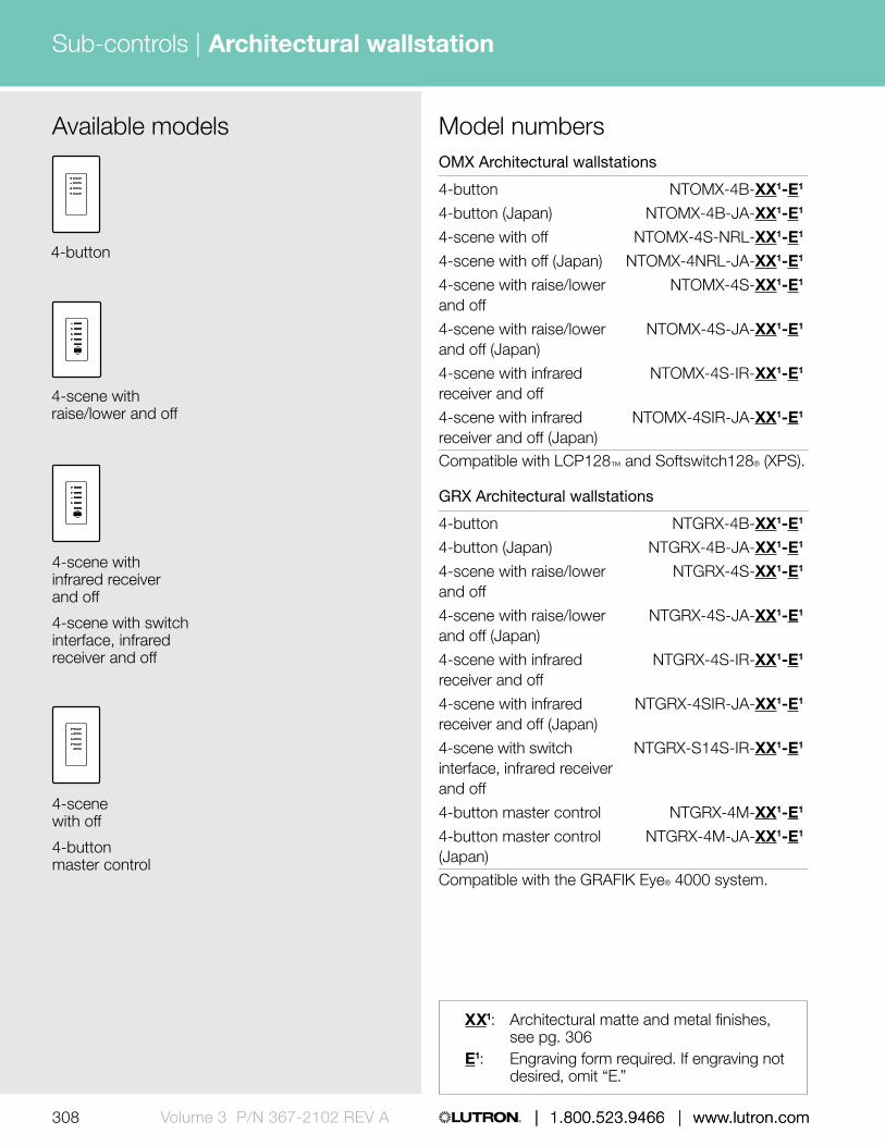
| 1.800.523.9466 | www.lutron.com308 | 1.800.523.9466 | www.lutron.comVolume 3 P/N 367-2102 REV A
Sub-controls |
OMX Architectural wallstations
4-button NTOMX-4B-XX1-E1
4-button (Japan) NTOMX-4B-JA-XX1-E1
4-scene with off NTOMX-4S-NRL-XX1-E1
4-scene with off (Japan) NTOMX-4NRL-JA-XX1-E1
4-scene with raise/lower NTOMX-4S-XX1-E1 and off
4-scene with raise/lower NTOMX-4S-JA-XX1-E1 and off (Japan)
4-scene with infrared NTOMX-4S-IR-XX1-E1 receiver and off
4-scene with infrared NTOMX-4SIR-JA-XX1-E1 receiver and off (Japan)Compatible with LCP128™ and Softswitch128® (XPS).
GRX Architectural wallstations
4-button NTGRX-4B-XX1-E1
4-button (Japan) NTGRX-4B-JA-XX1-E1
4-scene with raise/lower NTGRX-4S-XX1-E1 and off
4-scene with raise/lower NTGRX-4S-JA-XX1-E1 and off (Japan)
4-scene with infrared NTGRX-4S-IR-XX1-E1 receiver and off
4-scene with infrared NTGRX-4SIR-JA-XX1-E1 receiver and off (Japan)
4-scene with switch NTGRX-S14S-IR-XX1-E1 interface, infrared receiver and off
4-button master control NTGRX-4M-XX1-E1
4-button master control NTGRX-4M-JA-XX1-E1
(Japan)Compatible with the GRAFIK Eye® 4000 system.
Model numbers
4-scene with raise/lower and off
4-button
4-scene with infrared receiver and off
4-scene with switch interface, infrared receiver and off
4-scene with off
4-button master control
XX1: Architectural matte and metal finishes, see pg. 306
E1: Engraving form required. If engraving not desired, omit “E.”
Available models
Architectural wallstation

Sub-controls |
309 | 1.800.523.9466 | www.lutron.com www.lutron.com | 1.800.523.9466 | Volume 3 P/N 367-2102 REV A | 1.800.523.9466 | www.lutron.com
Features and capacities• Slim buttons select scenes• Two large buttons dim and brighten selected
scene or turn lights full on and off, depending on functionality selected in field
• OMX models operate at 24 V DC; GRX models operate at 12/24 V DC
• Engraving available
Dimensions and mounting 5-button and 10-button• Width: 2.75 in (70 mm)
Height: 4.56 in (116 mm) Depth: 0.88 in (21 mm) Profile: 0.31 in (8 mm)
• Mounts in a standard 1-gang U.S. backbox 15-button• Width: 4.56 in (116 mm)
Height: 4.56 in (116 mm) Depth: 0.88 in (21 mm) Profile: 0.31 in (8 mm)
• Mounts in a standard 2-gang U.S. backbox
Communication and wiring• Operates via low-voltage IEC PELV/ NEC Class 2
standard wired communication to the main control unit and other system components
• OMX models—counts as one wallstation on the OMX link; can have up to 32 keypads/wallstations and/or control interfaces
• GRX models—GRAFIK Eye® 4000 system can have up to 16 keypads/wallstations and/or control interfaces; each slim-button wallstation counts as one wallstation
Shown above: OMX Slim-button 5-button wallstation in White (NTOMX-KP5-WH)
2.75 in (70 mm)
4.56 in (116 mm
)
0.31 in (8 mm) profile
0.88 in (21 mm) profile
Slim-button wallstation
Download specification submittal for NTOMX-KP10Download specification submittal for NTOMX-KP15Download specification submittal for NTOMX-KP5Download specification submittal for NTGR-KPDownload specification submittal for NTGRX-LBDownload specification submittal for NTOMX-LB6Download specification submittal for NTOMX-LB6-RLDownload specification submittal for NTOMX-LB9Download specification submittal for NTOMX-LB9-RLDownload engraving sheet for faceplates

310 | 1.800.523.9466 | www.lutron.comVolume 3 P/N 367-2102 REV A
Sub-controls |
Architectural matte finishes
GRGray F, B, L
BEBeige F, B, L
WHWhite F, B Gray L
BRBrown F, B, L
BLBlack F, B, L
Available finishes
Use BOLD color code in model number (Example: NTOMX-KP5-WH)
IVIvory F, B, L
Architectural metal finishes
CLAClear Anodized Aluminum FBlack B, L
BCBright Chrome FBlack B, L
BNBright Nickel FBlack B, L
SCSatin Chrome FBlack B, L
SNSatin Nickel FBlack B, L
QZAntique Bronze FBlack B, L
BRABrass Anodized Aluminum FBlack B, L
SBSatin Brass FBlack B, L
QBAntique Brass FBlack B, L
BLABlack Anodized Aluminum FBlack B, L
BBBright Brass FBlack B, L
Faceplate F
Lutron button L
Buttons B
Slim-button wallstation

311 | 1.800.523.9466 | www.lutron.com www.lutron.com | 1.800.523.9466 | Volume 3 P/N 367-2102 REV A
Sub-controls |
1
Explanation of features Features
1 Status LEDs • Indicate which wallstation button has been activated
2 Buttons • Available with 5, 10, or 15 buttons
• Provide scene selection
3 Lower or full on* • Dims all lighting
4 Raise or off* • Brightens all lighting or turns all off
3
4
2
0.35 in (9 mm)
0.88 in (21 mm)
*For Softswitch128® raise/lower buttons act as additional programmable buttons.
Slim-button 5-button wallstation
Slim-button wallstation

| 1.800.523.9466 | www.lutron.com312 | 1.800.523.9466 | www.lutron.comVolume 3 P/N 367-2102 REV A
Sub-controls |
5-button 10-button 15-button
OMX slim-button wallstation
5-button NTOMX-KP5-XX1-E1
5-button (Japan) NTOMX-KP5-JA-XX1-E1
10-button NTOMX-KP10-XX1-E1
10-button (Japan) NTOMX-KP10-JA-XX1-E1
15-button NTOMX-KP15-XX1-E1
15-button (Japan) NTOMX-KP15-JA-XX1-E1
Compatible with LCP128™ and Softswitch128® (XPS) systems.
GRX slim-button wallstation
5-button NTGRX-KP5-XX1-E1
5-button (Japan) NTGRX-KP5-JA-XX1-E1
10-button NTGRX-KP10-XX1-E1
10-button (Japan) NTGRX-KP10-JA-XX1-E1
15-button NTGRX-KP15-XX1-E1
15-button (Japan) NTGRX-KP15-JA-XX1-E1
Compatible with the GRAFIK Eye® 4000 system.
Model numbersAvailable models
Slim-button wallstation
XX1: Architectural matte and metal finishes, see pg. 310
E1: Engraving form required with order. If engraving not desired, omit “E.”
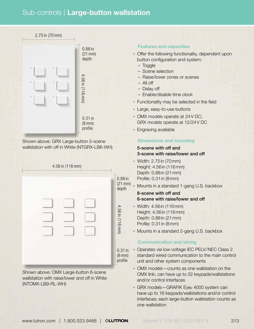
Sub-controls |
313 | 1.800.523.9466 | www.lutron.com www.lutron.com | 1.800.523.9466 | Volume 3 P/N 367-2102 REV A | 1.800.523.9466 | www.lutron.com
Features and capacities• Offer the following functionality, dependent upon
button configuration and system:– Toggle– Scene selection– Raise/lower zones or scenes– All off– Delay off– Enable/disable time clock
• Functionality may be selected in the field• Large, easy-to-use buttons• OMX models operate at 24 V DC;
GRX models operate at 12/24 V DC• Engraving available
Dimensions and mounting 5-scene with off and
3-scene with raise/lower and off• Width: 2.75 in (70 mm)
Height: 4.56 in (116 mm) Depth: 0.88 in (21 mm) Profile: 0.31 in (8 mm)
• Mounts in a standard 1-gang U.S. backbox 8-scene with off and
6-scene with raise/lower and off• Width: 4.56 in (116 mm)
Height: 4.56 in (116 mm) Depth: 0.88 in (21 mm) Profile: 0.31 in (8 mm)
• Mounts in a standard 2-gang U.S. backbox
Communication and wiring• Operates via low-voltage IEC PELV/ NEC Class 2
standard wired communication to the main control unit and other system components
• OMX models—counts as one wallstation on the OMX link; can have up to 32 keypads/wallstations and/or control interfaces
• GRX models—GRAFIK Eye® 4000 system can have up to 16 keypads/wallstations and/or control interfaces; each large-button wallstation counts as one wallstation
Shown above: GRX Large-button 5-scene wallstation with off in White (NTGRX-LB6-WH)
Shown above: OMX Large-button 6-scene wallstation with raise/lower and off in White (NTOMX-LB9-RL-WH)
2.75 in (70 mm)
4.56 in (116 mm)4.56 in (116 m
m)
4.56 in (116 mm
)
0.31 in (8 mm) profile
0.31 in (8 mm) profile
0.88 in (21 mm) depth
0.88 in (21 mm) depth
Large-button wallstation

314 | 1.800.523.9466 | www.lutron.comVolume 3 P/N 367-2102 REV A
Sub-controls |
Architectural matte finishes
GRGray F, B, L
BEBeige F, B, L
WHWhite F, BGray L
BRBrown F, B, L
BLBlack F, B, L
Available finishes
Use BOLD color code in model number (Example: NTOMX-LB9-WH)
IVIvory F, B, L
Architectural metal finishes
CLAClear Anodized Aluminum FBlack B, L
BCBright Chrome FBlack B, L
BNBright Nickel FBlack B, L
SCSatin Chrome FBlack B, L
SNSatin Nickel FBlack B, L
QZAntique Bronze FBlack B, L
BRABrass Anodized Aluminum FBlack B, L
SBSatin Brass FBlack B, L
QBAntique Brass FBlack B, L
BLABlack Anodized Aluminum FBlack B, L
BBBright Brass FBlack B, L
Large-button wallstation
Faceplate F
Lutron button L
Buttons B

315 | 1.800.523.9466 | www.lutron.com www.lutron.com | 1.800.523.9466 | Volume 3 P/N 367-2102 REV A
Sub-controls |
1
Explanation of features
4
2
0.31 in (8 mm)
0.88 in (21 mm)
Features
1 Status LEDs • Indicate which wallstation button has been activated
2 Buttons • Available with 3, 5, 6, or 8 buttons
• Can provide toggle, scene selection, or enable/disable time clock and other functions
3 Raise/lower buttons*
• Brightens/dims all assigned lighting
4 Off • Turns all lights off
*For Softswitch128® raise/lower buttons act as additional programmable buttons.
Large-button 6-scene wallstation with raise/lower and off
3
Large-button wallstation

| 1.800.523.9466 | www.lutron.com316 | 1.800.523.9466 | www.lutron.comVolume 3 P/N 367-2102 REV A
Sub-controls |
OMX large-button wallstation
5-scene with off NTOMX-LB6-XX1-E1
5-scene with off (Japan) NTOMX-LB6-JA-XX1-E1
8-scene with off NTOMX-LB9-XX1-E1
8-scene with off (Japan) NTOMX-LB9-JA-XX1-E1
3-scene with NTOMX-LB6-RL-XX1-E1 raise/lower and off
3-scene with NTOMX-LB6RLJA-XX1-E1 raise/lower and off (Japan)
6-scene with NTOMX-LB9-RL-XX1-E1 raise/lower and off
6-scene with NTOMX-LB9RLJA-XX1-E1 raise/lower and off (Japan)Compatible with LCP128™ and Softswitch128® (XPS) systems.
GRX large-button wallstation
5-scene with off NTGRX-LB6-XX1-E1
5-scene with off (Japan) NTGRX-LB6-JA-XX1-E1
8-scene with off NTGRX-LB9-XX1-E1
8-scene with off (Japan) NTGRX-LB9-JA-XX1-E1
3-scene with NTGRX-LB6-RL-XX1-E1 raise/lower and off
3-scene with NTGRX-LB6RLJA-XX1-E1 raise/lower and off (Japan)
6-scene with NTGRX-LB9-RL-XX1-E1 raise/lower and off
6-scene with NTGRX-LB9RLJA-XX1-E1 raise/lower and off (Japan)Compatible with the GRAFIK Eye® 4000 system.
Model numbersAvailable models
5-scene with off
3-scene with raise/lower and off
8-scene with off
6-scene with raise/lower and off
Large-button wallstation
XX1: Architectural matte and metal finishes, see pg. 314
E1: Engraving form required with order. If engraving not desired, omit “E.”

Sub-controls |
317 | 1.800.523.9466 | www.lutron.com www.lutron.com | 1.800.523.9466 | Volume 3 P/N 367-2102 REV A | 1.800.523.9466 | www.lutron.com
Features and capacities• Offer the following functionality:
– Toggle– Scene selection– Raise/lower zones or scenes– All off– Delay off– Enable/disable time clock
• In addition, the GRX 2-button model allows for zone lockout, partitioning, sequencing, fine-tuning and entrance and panic wallstation selection
• Functionality may be selected in the field• Large, rounded buttons allow engraving
to be displayed at an upward angle for increased readability
• OMX models operate at 24 V DC; GRX models operate at 12/24 V DC
Dimensions and mounting• Width: 3.38 in (86 mm)
Height: 3.38 in (86 mm) Depth: 1.00 in (25 mm) Profile: 0.25 in (6 mm)
• Mounts in U.K./German single-gang backbox; Lutron supplies the backbox (P/N 241-683) with the wallstation in the U.S.
Communication and wiring• Operates via low-voltage IEC PELV/ NEC Class
2 standard wired communication to the main control unit and other system components
• OMX models—counts as one wallstation on the OMX link; can have up to 32 keypads/wallstations and/or control interfaces
• GRX models—GRAFIK Eye® 4000 system can have up to 16 keypads/wallstations and/or control interfaces; each European-style wallstation counts as one wallstation
Shown above: OMX European-style 8-button wallstation with infrared receiver/off and raise/lower in White (EOMX-8S-IR-WH)
3.38 in (86 mm)
3.38 in (86 mm
)
0.25 in (6 mm) profile
1.00 in (25 mm) depth
European-style wallstation
Download specification submittal for EGRXDownload specification submittal for EOMX-2BDownload specification submittal for EOMX-4BDownload specification submittal for EOMX-4SDownload specification submittal for EOMX-4S-IRDownload specification submittal for EOMX-8S-IRDownload engraving sheet for faceplates

318 | 1.800.523.9466 | www.lutron.comVolume 3 P/N 367-2102 REV A
Sub-controls |
Architectural matte finishes
SBSatin Brass FBlack B
GRGray F, B
BCBright Chrome FBlack B
BRBrown F, B
WHWhite F, B
IVIvory F, B
BBBright Brass FBlack B
SCSatin Chrome FBlack B
Available finishes
Use BOLD color code in model number (Example: EOMX-8S-IR-WH)
BLBlack F, B
BEBeige F, B
Architectural metal finishes
BNBright Nickel FBlack B
SNSatin Nickel FBlack B
QZAntique Bronze FBlack B
CLAClear Anodized Aluminum FBlack B
BLABlack Anodized Aluminum FBlack B
BRABrass Anodized Aluminum FBlack B
QBAntique Brass FBlack B
European-style wallstation
Faceplate F
Buttons B

319 | 1.800.523.9466 | www.lutron.com www.lutron.com | 1.800.523.9466 | Volume 3 P/N 367-2102 REV A
Sub-controls |
Explanation of features Features
1 Status LEDs • Indicate which wallstation button has been activated
• Large LEDs to clearly show status
2 Programmable buttons
• Available with 2, 4, or 8 buttons
• Can provide toggle, scene selection, or enable/disable time clock, and other functions
3 IR receiver/off • Offers convenient control of lights from IR remote control, see pg. 292
• Button turns all lights off
4 Raise/lower buttons
• Brightens/dims all assigned lighting
0.25 in (6 mm)
1.00 in (25 mm)
34
1
2
European-style OMX 8-button wallstation with infrared (IR) receiver/off and raise/lower
European-style wallstation

| 1.800.523.9466 | www.lutron.com320 | 1.800.523.9466 | www.lutron.comVolume 3 P/N 367-2102 REV A
Sub-controls |
OMX European-style wallstations
2-button EOMX-2B-XX1-E1
4-button EOMX-4B-XX1-E1
4-scene with raise/lower and off EOMX-4S-XX1-E1
8-scene with raise/lower and off EOMX-8S-XX1-E1
4-scene with IR/off EOMX-4S-IR-XX1-E1 and raise/lower
8-scene with IR/off EOMX-8S-IR-XX1-E1 and raise/lowerCompatible with LCP128™ and Softswitch128® (XPS) systems.
GRX European-style wallstations
2-button EGRX-2B-SL-XX1-E1
4-button EGRX-4B-XX1-E1
4-scene with raise/lower and off EGRX-4S-XX1-E1
8-scene with raise/lower and off EGRX-8S-XX1-E1
4-scene with IR/off, EGRX-4S-IR-XX1-E1 and raise/lower
8-scene with IR/off, EGRX-8S-IR-XX1-E1 and raise/lower
4-button master control EGRX-4M-XX1-E1
Compatible with the GRAFIK Eye® 4000 system.
Model numbers
4-scene with raise/lower and off
8-scene with raise/lower and off
2-button 4-button
4-scene with IR/off and raise/lower
8-scene with IR/off and raise/lower
4-button with master
XX1: Architectural matte and metal finishes, see pg. 318
E1: Engraving form required with order. If engraving not desired, omit “E.”
Available models
European-style wallstation

Sub-controls |
321 | 1.800.523.9466 | www.lutron.com www.lutron.com | 1.800.523.9466 | Volume 3 P/N 367-2102 REV A | 1.800.523.9466 | www.lutron.com
Shown actual size: OMX Architrave slim-button 4-scene wallstation with raise/lower and off in White (OMX-7B-DW-WH)
1.75 in (44 mm)
0.13 in (3 mm) profile
1.50 in (38 mm) depth
4.50 in (144 mm
)
Shown actual size: OMX Architrave large-button 4-scene wallstation with raise/lower and off in White (OMX-4SLB-DW-WH)
1.50 in (38 mm)
0.13 in (3 mm) profile
1.88 in (48 mm) depth
5.16 in (131 mm
)
Architrave® wallstation
Download specification submittal for ArchitraveDownload specification submittal for OMX-2B-DWDownload specification submittal for OMX-4SLB-DWDownload specification submittal for OMX-7B-DWDownload engraving sheet for faceplates

| 1.800.523.9466 | www.lutron.com
Sub-controls |
322 | 1.800.523.9466 | www.lutron.comVolume 3 P/N 367-2102 REV A
Features and capacities• Offer the following functionality, dependent upon
button configuration and system:– Toggle– Scene selection– Raise/lower zones or scenes– All off– Enable/disable time clock
• Functionality may be selected in the field• Fits into door jamb, door trim or standard switch
location—occupants can adjust lighting as they enter a room
• OMX models operate at 24 V DC; GRX models operate at 12/24 V DC
• Engraving available
Dimensions and mounting OMX/GRX slim-button• Width: 1.75 in (44 mm)
Height: 4.50 in (114 mm) Depth: 1.50 in (38 mm) Profile: 0.13 in (3 mm) for GRX
0.25 in (6 mm) for OMX• Mounts in Lutron-supplied backbox (P/N 241-399) OMX/GRX large-button• Width: 1.50 in (38 mm)
Height: 5.16 in (131 mm) Depth: 1.88 in (48 mm) Profile: 0.13 in (3 mm)
• Mounts in Lutron-supplied backbox (P/N 241-663)
Communication and wiring• Operates via low-voltage IEC PELV/ NEC Class 2
standard wired communication to the main control unit and other system components
• OMX models—counts as one wallstation on the OMX link; can have up to 32 keypads/wallstations and/or control interfaces
• GRX models—GRAFIK Eye® 4000 system can have up to 16 keypads/wallstations and/or control interfaces; each Architrave wallstation counts as one wallstation
Architrave® wallstation
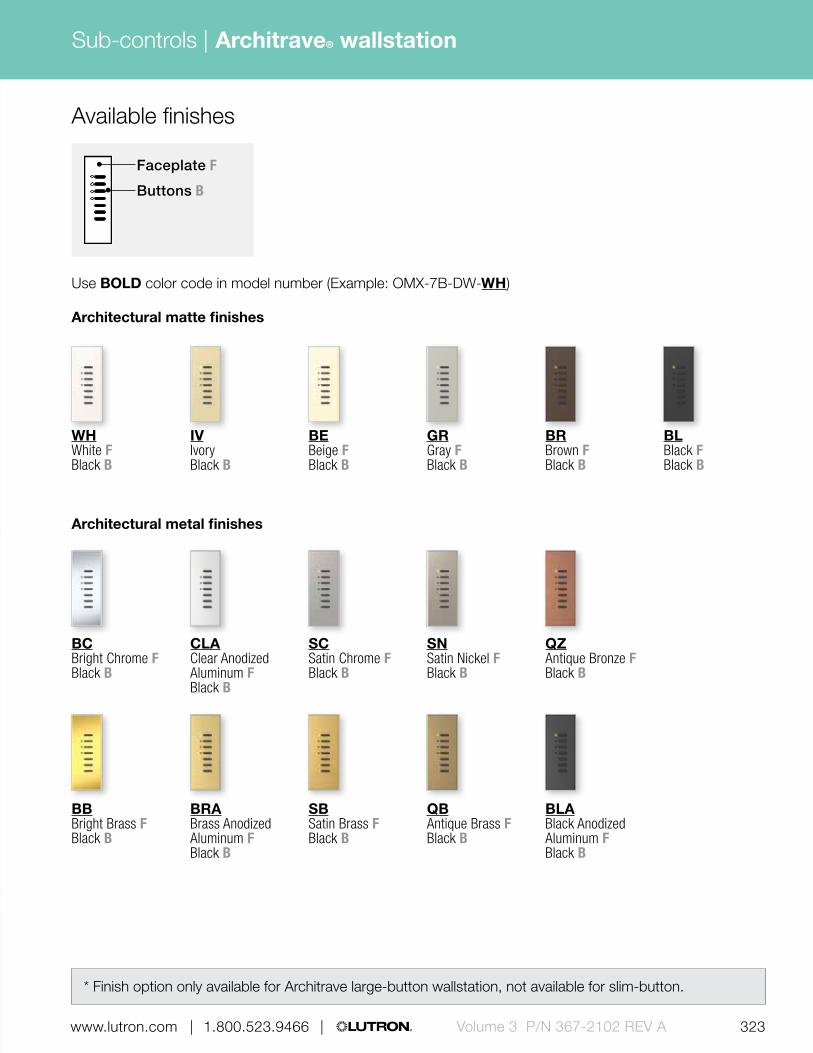
323 | 1.800.523.9466 | www.lutron.com www.lutron.com | 1.800.523.9466 | Volume 3 P/N 367-2102 REV A
Sub-controls |
| 1.800.523.9466 | www.lutron.com
* Finish option only available for Architrave large-button wallstation, not available for slim-button.
Available finishes
Architectural matte finishes
GRGray F Black B
BEBeige F Black B
WHWhite F Black B
BRBrown F Black B
BLBlack F Black B
Use BOLD color code in model number (Example: OMX-7B-DW-WH)
IVIvory Black B
Architectural metal finishes
BRABrass Anodized Aluminum FBlack B
SBSatin Brass FBlack B
QBAntique Brass FBlack B
BLABlack Anodized Aluminum FBlack B
CLAClear Anodized Aluminum FBlack B
BCBright Chrome FBlack B
SCSatin Chrome FBlack B
SNSatin Nickel FBlack B
QZAntique Bronze FBlack B
BBBright Brass FBlack B
Faceplate F
Buttons B
Architrave® wallstation

324 | 1.800.523.9466 | www.lutron.comVolume 3 P/N 367-2102 REV A
Sub-controls |
1
3
4
Explanation of features
2
2
1
3
4
Features
1 Status LEDs • Indicate which wallstation button has been activated
2 Buttons • OMX models available with two or four buttons
• GRX models available with four buttons
• Can provide toggle, scene selection, or enable/disable time clock and other functions
3 Off • Turns all lights off
4 Raise/lower buttons*
• Brightens/dims all assigned lighting
* For Softswitch128® raise/lower buttons act as additional programmable buttons.
Architrave slim-button (top) and large-button (bottom) 4-scene wallstation with raise/lower and off
Architrave® wallstation

325 | 1.800.523.9466 | www.lutron.com www.lutron.com | 1.800.523.9466 | Volume 3 P/N 367-2102 REV A
Sub-controls |
Available models Model numbersOMX Architrave wallstation
2-button slim-button OMX-2B-DW-XX1-E1
4-scene slim-button with OMX-7B-DW-XX1-E1 raise/lower and off
4-scene slim-button OMX-7B-NRL-DW-XX1-E1
with off
4-scene large-button with OMX-4SLB-DW-XX1-E1 raise/lower and offCompatible with LCP128™ and Softswitch128® (XPS) systems.
GRX Architrave wallstation
4-scene slim-button with GRX-4S-DW-XX1-E1 raise/lower and off
4-scene slim-button with GRX-4S-DW-JA-XX1-E1 raise/lower and off (Japan)
4-scene large-button with GRX-4SLB-DW-XX1-E1 raise/lower and offCompatible with the GRAFIK Eye® 4000 system.
2-button slim-button
4-scene slim-button with raise/lower and off
4-scene slim-button with off
4-scene large-button with raise/lower and off
Architrave™ wallstation
XX1: Architectural matte and metal finishes, see pg. 323
E1: Engraving form required with order. If engraving not desired, omit “E.”

| 1.800.523.9466 | www.lutron.com
Sub-controls |
326 | 1.800.523.9466 | www.lutron.comVolume 3 P/N 367-2102 REV A
Features and capacities• Offer the following functionality, dependant upon
button configuration and system:– Toggle– Scene selection– Raise/lower zones or scenes– All off– Delay to off– Enable/ disable time clock
• In addition, the GRX 2-button model allows for zone lockout, partitioning, sequencing, fine tuning and entrance and panic keypad selection
• Functionality may be selected in the field• Front accessible DIP switches allow change of
function without removing the unit from the wall• Standard OMX models include two contact closure
inputs on the back of the keypad; models also available with an occupancy sensor connection that supplies power to and receives control signals from a wired occupancy sensor
• OMX models operate at 24 V DC; GRX models operate at 12/24 V DC
• Large, rounded buttons are easy to use• Backlit buttons or text make it easy to find and
operate keypad in low-light conditions
Dimensions and mounting• Width: 2.75 in (70 mm)
Height: 4.56 in (116 mm) Depth: 1.06 in (27 mm) Profile: 0.31 in (8 mm)
• Mounts in a standard 1-gang U.S. backbox
Communication and wiring• Operates via low-voltage IEC PELV/NEC Class 2
standard wired communication to the main control unit and other system components
• OMX models—counts as one keypad on the OMX link; can have up to 32 keypads/wallstations and/or control interfaces
• GRX models—GRAFIK Eye® 4000 system can have up to 16 total keypads/wallstations and/or control interfaces; each seeTouch keypad counts as one keypad
Shown actual size: OMX seeTouch non-insert style 4-scene keypad with raise/lower and off in White (SO-4SN-WH-EGN)
2.75 in (70 mm)
4.56 in (116 mm
)
0.31 in (8 mm) profile
1.06 in (27 mm) depth
seeTouch® keypad
Download specification submittalsDownload engraving sheet for faceplates

327 | 1.800.523.9466 | www.lutron.com www.lutron.com | 1.800.523.9466 | Volume 3 P/N 367-2102 REV A
Sub-controls |
| 1.800.523.9466 | www.lutron.com
Gloss finishes (Available for insert style keypads only; coordinating faceplates included)
GLALight Almond F, I, BGray E
GWHWhite F, I, BGray E
Available finishes
Use BOLD color code in model number (Example: SO-4SI-WH)
Faceplate F
Insert I
Buttons BEngraving E
seeTouch® keypad
Satin finishes (Available for insert style keypads; coordinating faceplates ordered separately)
BGBluestone F, IGray BWhite E
SGSea Glass F, IGray BWhite E
TQTurquoise F, IGray BWhite E
GSGoldstone F, IIvory BGray E
DSDesert Stone F, ITaupe BGray E
GBGreenbriar F, IGray BWhite E
SWSnow F, I, BGray E
LSLimestone F, IGray BWhite E
ESEggshell F, I, BGray E
PDPalladium F, IGray B White E
TPTaupe F, I, BGray E
STStone F, IGray BWhite E
BIBiscuit F, I BGray E
MSMocha Stone F, ITaupe BGray E
TCTerracotta F, ITaupe BGray E
SISienna F, IBrown BWhite E
HTHot F, ITaupe BGray E
MRMerlot F, ITaupe BGray E
MNMidnight F, I, BGray E
PLPlum F, ITaupe BGray E

328 | 1.800.523.9466 | www.lutron.comVolume 3 P/N 367-2102 REV A
Sub-controls |
Architectural metal finishes (available for insert and non-insert style keypads; coordinating faceplates included)
CLAClear Anodized Aluminum FBlack B, IWhite E
BCBright Chrome FBlack B, IWhite E
BNBright Nickel FBlack B, IWhite E
SCSatin Chrome FBlack B, IWhite E
SNSatin Nickel FBlack B, IWhite E
QZAntique Bronze FBlack B, IWhite E
BRABrass Anodized Aluminum FBlack B, IWhite E
SBSatin Brass FBlack B, IWhite E
QBAntique Brass FBlack B, IWhite E
BLABlack Anodized Aluminum FBlack B, IWhite E
BBBright Brass FBlack B, IWhite E
Available finishes
seeTouch® keypad
Architectural matte finishes (Available for insert and non-insert style keypads; coordinating faceplates included)
GRGray F, I, BWhite E
BRBrown F, I, BWhite E
BLBlack F, I, BWhite E
BEBeige F, I, BGray E
IVIvory F, I, BGray E
WHWhite F, I, BGray E
TPTaupe F, I, BGray E

329 | 1.800.523.9466 | www.lutron.com www.lutron.com | 1.800.523.9466 | Volume 3 P/N 367-2102 REV A
Sub-controls |
Explanation of features
1
54
6
2 3
Features
1 Status LEDs• Indicate which keypad
button has been activated
2 Buttons• OMX models available
with 1-7 buttons• GRX models available
with two or four buttons• Can provide toggle, scene
selection, or enable/disable time clock and other functions
3 Backlit buttons or text
• Easy to read and use in low-light conditions
4 Infrared receiver (IR)/off
• Offers convenient control of lights from IR remote control, see pg. 292
• Button turns all lights off
5 Raise/lower buttons
• Brightens/dims all assigned lighting
0.31 in (8 mm)
1.06 in (27 mm)
Non-insert style seeTouch 4-scene keypads with infrared receiver/off and raise/lower
seeTouch® keypad

330 | 1.800.523.9466 | www.lutron.comVolume 3 P/N 367-2102 REV A
Sub-controls |
5-button 6-button 7-button
1-button
(Available in insert and non-insert styles, non-insert style shown)
2-button 3-button 4-button
4-scene with off
4-button with master
4-scene with raise/lower and off
4-scene with infrared receiver/off and raise/lower
4-scene with infrared receiver programming/off and raise/lower
Available models OMX seeTouch keypad model numbersKeypads
1-button
Non-insert style SO-1BN-XX1-EEE1
Non-insert style with occupancy sensor connection SO-1BON-XX1-EEE1
Insert style SO-1BI-XX2-EEE1
Insert style with occupancy sensor connection SO-1BOI-XX2-EEE1
2-button
Non-insert style SO-2BN-XX1-EEE1
Non-insert style with occupancy sensor connection SO-2BON-XX1-EEE1
Insert style SO-2BI-XX2-EEE1
Insert style with occupancy sensor connection SO-2BOI-XX2-EEE1
3-button
Non-insert style SO-3BN-XX1-EEE1
Non-insert style with occupancy sensor connection SO-3BON-XX1-EEE1
Insert style SO-3BI-XX2-EEE1
Insert style with occupancy sensor connection SO-3BOI-XX2-EEE1
4-button
Non-insert style SO-4BN-XX1-EEE1
Non-insert style with occupancy sensor connection SO-4BON-XX1-EEE1
Insert style SO-4BI-XX2-EEE1
Insert style with occupancy sensor connection SO-4BOI-XX2-EEE1
XX1: Architectural matte and metal color codes, see pg. 328
XX2: Gloss, architectural matte, metal and Satin color codes, see pgs. 327-328 (Coordinating faceplates not included with Satin Colors®, order separately, see pg. 641)
EEE1: Engraving codes, see pgs. 667-668
seeTouch® keypad

331 | 1.800.523.9466 | www.lutron.com www.lutron.com | 1.800.523.9466 | Volume 3 P/N 367-2102 REV A
Sub-controls |
OMX seeTouch keypad model numbers
XX1: Architectural matte and metal color codes, see pg. 328
XX2: Gloss, architectural matte, metal and Satin color codes, see pgs. 327-328 (Coordinating faceplates not included with Satin Colors®, order separately, see pg. 641)
EEE1: Engraving codes, see pgs. 667-668
Keypads with raise/lower and off
4-scene with raise/lower and off
Non-insert style SO-4SN-XX1-EEE1
Non-insert style with occupancy sensor connection SO-4SON-XX1-EEE1
Insert style SO-4SI-XX2-EEE1
Insert style with occupancy sensor connection SO-4SOI-XX2-EEE1
Compatible with LCP128 and Softswitch128 (XPS).
Keypads with infrared receiver/off and raise/lower
4-scene with infrared receiver/off and raise/lower
Non-insert style SO-4SIRN-XX1-EEE1
Non-insert style with occupancy sensor connection SO-4SIRON-XX1-EEE1
Insert style SO-4SIRI-XX2-EEE1
Insert style with occupancy sensor connection SO-4SIROI-XX2-EEE1
Compatible with LCP128 and Softswitch128 (XPS).
Keypads (continued)
5-button
Non-insert style SO-5BN-XX1-EEE1
Non-insert style with occupancy sensor connection SO-5BON-XX1-EEE1
Insert style SO-5BI-XX2-EEE1
Insert style with occupancy sensor connection SO-5BOI-XX2-EEE1
6-button
Non-insert style SO-6BN-XX1-EEE1
Non-insert style with occupancy sensor connection SO-6BON-XX1-EEE1
Insert style SO-6BI-XX2-EEE1
Insert style with occupancy sensor connection SO-6BOI-XX2-EEE1
7-button
Non-insert style SO-7BN-XX1-EEE1
Non-insert style with occupancy sensor connection SO-7BON-XX1-EEE1
Insert style SO-7BI-XX2-EEE1
Insert style with occupancy sensor connection SO-7BOI-XX2-EEE1
Compatible with LCP128™ and Softswitch128® (XPS).
Keypads with off
4-scene with off
Non-insert style SO-4NRLN-XX1-EEE1
Non-insert style with occupancy sensor connection SO-4NRLON-XX1-EEE1
Insert style SO-4NRLI-XX2-EEE1
Insert style with occupancy sensor connection SO-4NRLOI-XX2-EEE1
Compatible with LCP128 and Softswitch128 (XPS).
seeTouch® keypad

332 | 1.800.523.9466 | www.lutron.comVolume 3 P/N 367-2102 REV A
Sub-controls |
Keypads
2-button
Non-insert style SG-2BN-XX1-EEE1
Insert style SG-2BI-XX2-EEE1
4-button
Non-insert style SG-4BN-XX1-EEE1
Insert style SG-4BI-XX2-EEE1
Compatible with the GRAFIK Eye® 4000 system.
Keypad with master
4-button with master
Non-insert style SG-4MN-XX1-EEE1
Insert style SG-4MI-XX2-EEE1
Compatible with the GRAFIK Eye 4000 system.
Keypad with off
4-scene with off
Non-insert style SG-4NRLN-XX1-EEE1
Insert style SG-4NRLI-XX2-EEE1
Compatible with the GRAFIK Eye 4000 system.
Keypads with raise/lower and off
4-scene with raise/lower and off
Non-insert style SG-4SN-XX1-EEE1
Insert style SG-4SI-XX2-EEE1
Compatible with the GRAFIK Eye 4000 system.
Keypads with infrared receiver/off and raise/lower
4-scene with infrared receiver/off and raise/lower
Non-insert style SG-4SIRN-XX1-EEE1
Insert style SG-4SIRI-XX2-EEE1
Compatible with the GRAFIK Eye 4000 system.
XX1: Architectural matte and metal color codes, see pg. 328
XX2: Gloss, architectural matte, metal and Satin color codes, see pgs. 327-328 (Coordinating faceplates not included with Satin Colors®, order separately, see pg.641)
EEE1: Engraving codes, see pgs. 667-668
GRX seeTouch keypad model numbers
seeTouch® keypad

333 | 1.800.523.9466 | www.lutron.com www.lutron.com | 1.800.523.9466 | Volume 3 P/N 367-2102 REV A
Sub-controls |
seeTouch keypad faceplate kit model numbersFaceplate kits
1-button
Non-insert style SR-1BN-XX1-EEE1
Insert style SR-1BI-XX2-EEE1
2-button
Non-insert style SR-2BN-XX1-EEE1
Insert style SR-2BI-XX2-EEE1
3-button
Non-insert style SR-3BN-XX1-EEE1
Insert style SR-3BI-XX2-EEE1
4-button
Non-insert style SR-4BN-XX1-EEE1
Insert style SR-4BI-XX2-EEE1
5-button
Non-insert style SR-5BN-XX1-EEE1
Insert style SR-5BI-XX2-EEE1
6-button
Non-insert style SR-6BN-XX1-EEE1
Insert style SR-6BI-XX2-EEE1
7-button
Non-insert style SR-7BN-XX1-EEE1
Insert style SR-7BI-XX2-EEE1
Includes faceplate, buttons, and insert (when applicable).Compatible with seeTouch keypads.
Faceplate kits with master
4-button with master
Non-insert style SR-4MN-XX1-EEE1
Insert style SR-4MI-XX2-EEE1
Includes faceplate, buttons, and insert (when applicable).Compatible with seeTouch keypads.
XX1: Architectural matte and metal color codes, see pg. 328
XX2: Gloss, architectural matte, metal and Satin color codes, see pgs. 327-328 (Coordinating faceplates not included with Satin Colors®, order separately, see pg. 642)
EEE1: Engraving codes, see pgs. 667-668
Faceplate kits with off
4-scene with off
Non-insert style SR-4NRLN-XX1-EEE1
Insert style SR-4NRLI-XX2-EEE1
Includes faceplate, buttons, and insert (when applicable).Compatible with seeTouch keypads.
Faceplate kits with raise/lower and off
4-scene with raise/lower and off
Non-insert style SR-4SN-XX1-EEE1
Insert style SR-4SI-XX2-EEE1
Includes faceplate, buttons, and insert (when applicable).Compatible with seeTouch keypads.
Faceplate kits with infrared (IR) receiver/off and raise/lower
4-scene with IR receiver/off and raise/lower
Non-insert style SR-4SIRN-XX1-EEE1
Insert style SR-4SIRI-XX2-EEE1
Includes faceplate, buttons, and insert (when applicable).Compatible with seeTouch keypads.IR faceplate kits require IR seeTouch keypads with IR functionality.
seeTouch® keypad

| 1.800.523.9466 | www.lutron.com334 | 1.800.523.9466 | www.lutron.comVolume 3 P/N 367-2102 REV A
Sub-controls |
seeTouch keypad button kit model numbersButton kits
1-button
Non-insert style SB-1BN-XX1-EEE1
Insert style SB-1BI-XX2-EEE1
2-button
Non-insert style SB-2BN-XX1-EEE1
Insert style SB-2BI-XX2-EEE1
3-button
Non-insert style SB-3BN-XX1-EEE1
Insert style SB-3BI-XX2-EEE1
4-button
Non-insert style SB-4BN-XX1-EEE1
Insert style SB-4BI-XX2-EEE1
5-button
Non-insert style SB-5BN-XX1-EEE1
Insert style SB-5BI-XX2-EEE1
6-button
Non-insert style SB-6BN-XX1-EEE1
Insert style SB-6BI-XX2-EEE1
7-button
Non-insert style SB-7BN-XX1-EEE1
Insert style SB-7BI-XX2-EEE1
Compatible with seeTouch keypads.
XX1: Limited architectural matte color codes, see pg. 328 for corresponding button colors
XX2: Limited gloss, architectural matte, and Satin Colors® codes, see pgs. 327-328 for corresponding button colors
EEE1: Engraving codes, see pgs. 667-668
Button kits with master
4-button with master
Non-insert style SB-4MN-XX1-EEE1
Insert style SB-4MI-XX2-EEE1
Compatible with seeTouch keypads.
Button kits with off
4-scene with off
Non-insert style SB-4NRLN-XX1-EEE1
Insert style SB-4NRLI-XX2-EEE1
Compatible with seeTouch keypads.
Button kits with raise/lower and off
4-scene with raise/lower and off
Non-insert style SB-4SN-XX1-EEE1
Insert style SB-4SI-XX2-EEE1
Compatible with seeTouch keypads.
Button kits with infrared (IR) receiver/off and raise/lower
4-scene with IR receiver/off and raise/lower
Non-insert style SB-4SIRN-XX1-EEE1
Insert style SB-4SIRI-XX2-EEE1
Compatible with seeTouch keypads.IR button kits require IR seeTouch keypads with IR functionality.
seeTouch® keypad
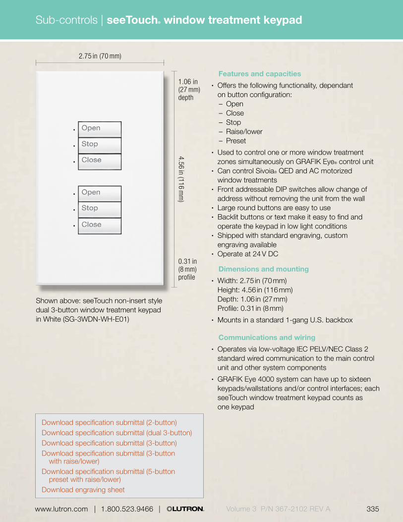
Sub-controls |
335 | 1.800.523.9466 | www.lutron.com www.lutron.com | 1.800.523.9466 | Volume 3 P/N 367-2102 REV A | 1.800.523.9466 | www.lutron.com
Features and capacities• Offers the following functionality, dependant
on button configuration:– Open– Close– Stop– Raise/lower– Preset
• Used to control one or more window treatment zones simultaneously on GRAFIK Eye® control unit
• Can control Sivoia® QED and AC motorized window treatments
• Front addressable DIP switches allow change of address without removing the unit from the wall
• Large round buttons are easy to use• Backlit buttons or text make it easy to find and
operate the keypad in low light conditions• Shipped with standard engraving, custom
engraving available• Operate at 24 V DC
Dimensions and mounting• Width: 2.75 in (70 mm)
Height: 4.56 in (116 mm) Depth: 1.06 in (27 mm) Profile: 0.31 in (8 mm)
• Mounts in a standard 1-gang U.S. backbox
Communications and wiring• Operates via low-voltage IEC PELV/NEC Class 2
standard wired communication to the main control unit and other system components
• GRAFIK Eye 4000 system can have up to sixteen keypads/wallstations and/or control interfaces; each seeTouch window treatment keypad counts as one keypad
Shown above: seeTouch non-insert style dual 3-button window treatment keypad in White (SG-3WDN-WH-E01)
2.75 in (70 mm)
4.56 in (116 mm
)
0.31 in (8 mm) profile
1.06 in (27 mm) depth
seeTouch® window treatment keypad
Download specification submittal (2-button)Download specification submittal (dual 3-button)Download specification submittal (3-button)Download specification submittal (3-button
with raise/lower)Download specification submittal (5-button
preset with raise/lower)Download engraving sheet
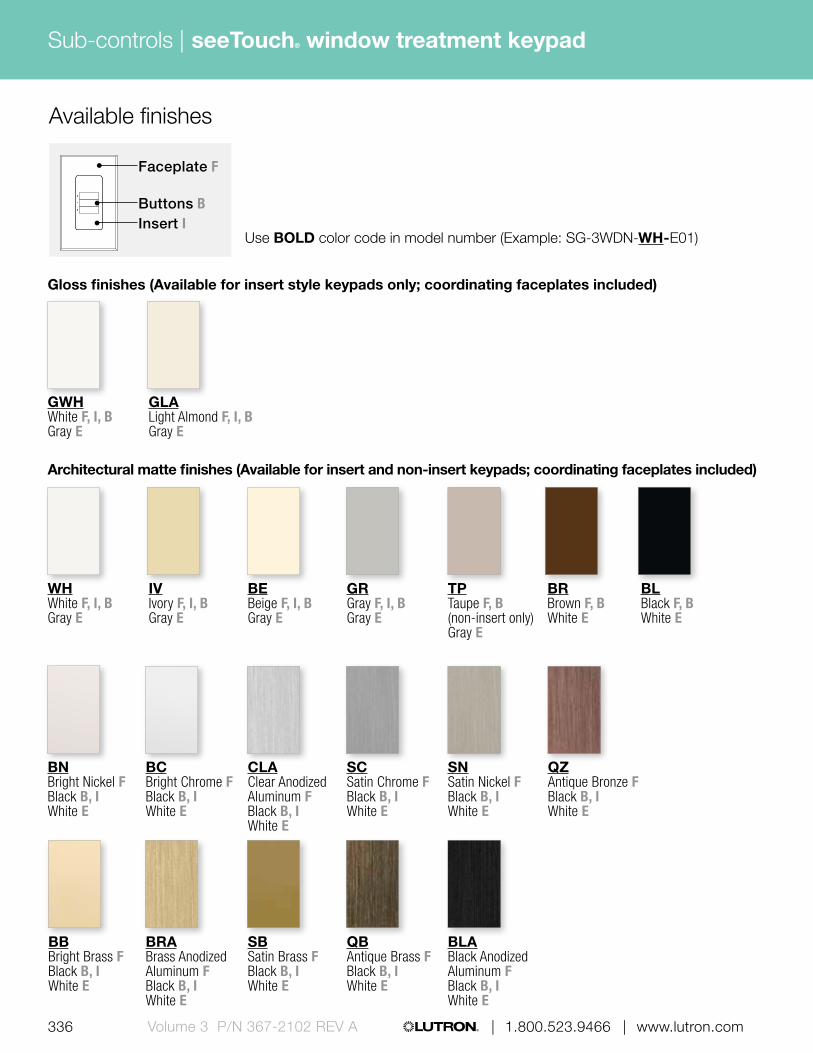
336 | 1.800.523.9466 | www.lutron.comVolume 3 P/N 367-2102 REV A
Sub-controls |
Architectural matte finishes (Available for insert and non-insert keypads; coordinating faceplates included)
Gloss finishes (Available for insert style keypads only; coordinating faceplates included)
GRGray F, I, BGray E
BEBeige F, I, BGray E
WHWhite F, I, BGray E
GWHWhite F, I, BGray E
TPTaupe F, B(non-insert only)Gray E
BRBrown F, BWhite E
BLBlack F, BWhite E
Use BOLD color code in model number (Example: SG-3WDN-WH-E01)
IVIvory F, I, BGray E
GLALight Almond F, I, BGray E
CLAClear Anodized Aluminum FBlack B, IWhite E
BCBright Chrome FBlack B, IWhite E
BNBright Nickel FBlack B, IWhite E
SCSatin Chrome FBlack B, IWhite E
SNSatin Nickel FBlack B, IWhite E
QZAntique Bronze FBlack B, IWhite E
BBBright Brass FBlack B, IWhite E
BRABrass Anodized Aluminum FBlack B, IWhite E
SBSatin Brass FBlack B, IWhite E
QBAntique Brass FBlack B, IWhite E
BLABlack Anodized Aluminum FBlack B, IWhite E
seeTouch® window treatment keypad
Available finishes
Faceplate F
Buttons BInsert I
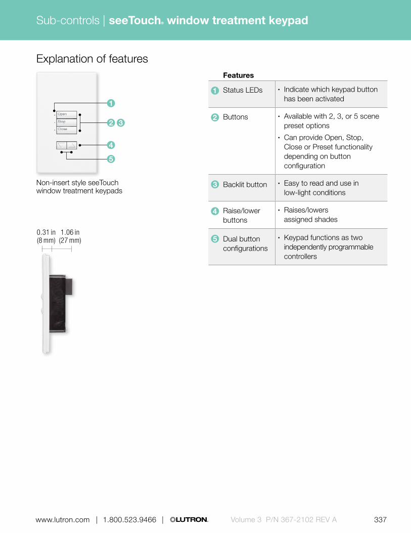
4
5
337 | 1.800.523.9466 | www.lutron.com www.lutron.com | 1.800.523.9466 | Volume 3 P/N 367-2102 REV A
Sub-controls |
1
2 3
Explanation of features
0.31 in (8 mm)
1.06 in (27 mm)
Non-insert style seeTouch window treatment keypads
Features
1 Status LEDs • Indicate which keypad button has been activated
2 Buttons • Available with 2, 3, or 5 scene preset options
• Can provide Open, Stop, Close or Preset functionality depending on button configuration
3 Backlit button • Easy to read and use in low-light conditions
4 Raise/lower buttons
• Raises/lowers assigned shades
5 Dual button configurations
• Keypad functions as two independently programmable controllers
seeTouch® window treatment keypad

| 1.800.523.9466 | www.lutron.com338 | 1.800.523.9466 | www.lutron.comVolume 3 P/N 367-2102 REV A
Sub-controls |
seeTouch window treatment keypads
2-button, non-insert style SG-2WN-XX1-E01 2-button, insert style SG-2WI-XX1-E01 3-button, non-insert style SG-3WN-XX1-E01 3-button, insert style SG-3WI-XX1-E01 Dual 3-button, non-insert style SG-3WDN-XX1-E01 Dual 3-button, insert style SG-3WDI-XX1-E01 3-button with raise/lower, SG-3WRLN-XX1-E01 non-insert style 3-button with raise/lower, SG-3WRLI-XX1-E01 insert style 5-button preset with SG-5WRLN-XX1-E01 raise/lower, non-insert style 5-button preset with SG-5WRLI-XX1-E01 raise/lower, insert style Compatible with the GRAFIK Eye® 4000 system.
Model numbers
2-button
Dual 3-button
5-button preset with raise/lower
3-button
3-button with raise/lower
XX1: Gloss, architectural matte and metal finishes, see pg. 336
E01: Standard engraving, no engraving form required. If custom engraving required replace “E01” with “EGN” and include engraving form with order.
Available models
seeTouch® window treatment keypad
(Available in insert and non-insert styles, insert style shown)

Sub-controls |
339 | 1.800.523.9466 | www.lutron.com www.lutron.com | 1.800.523.9466 | Volume 3 P/N 367-2102 REV A | 1.800.523.9466 | www.lutron.com
6.32 in (161 mm)
2.75 in (70 mm)
3.38 in (86 mm)
4.56 in (116 mm
)
4.56 in (116 mm
)
3.38 in (86 mm
)
0.31 in (8 mm) profile
1.06 in (27 mm) depth
0.31 in (8 mm) profile
0.25 in (6 mm) profile
1.38 in (35 mm) depth 1.00 in
(25 mm) depth
Shown above: seeTouch® partition status keypad with custom-engraved faceplate in White (SG-4PS-CF-WH-E)
Shown above: Architectural partition status wallstation in White (NTGRX-4PS-WH)
Shown above: European-style partition status wallstation in White (EGRX-4PS-WH)
Partition status keypad/wallstation
Download specification submittalDownload engraving sheet for faceplates

| 1.800.523.9466 | www.lutron.com
Sub-controls |
340 | 1.800.523.9466 | www.lutron.comVolume 3 P/N 367-2102 REV A
Partition status keypad/wallstation
Features and capacities• Coordinates lighting for up to four movable walls
(five rooms)• Each toggle button is set-up to operate the main
control unit associated with a moveable wall• When the wall is open to make one large space,
the user presses the toggle button associated to the wall to turn on the LED; the main control units assigned to that button will then work in combination
• When the wall is closed to make several smaller spaces, the user presses the toggle button associated to the wall to turn off the LED; the main control unit assigned to that button will then work independently
• The bottom button resets all main control units• Available in three wallstation/keypad styles—
seeTouch®, Architectural and European-style; seeTouch keypads and Architectural wallstations are available with custom-engraved faceplate with floor plan to match project
• Operates at 12/24 V DC
Dimensions and mounting seeTouch• Without custom-engraved faceplate:
Width: 2.75 in (70 mm) Height: 4.56 in (116 mm) Depth: 1.06 in (27 mm) Profile: 0.31 in (8 mm)
• With custom-engraved faceplate: Width: 6.32 in (161 mm) Height: 4.56 in (116 mm) Depth: 1.06 in (27 mm) Profile: 0.31 in (8 mm)
• Mounts in standard 1-gang U.S. backbox Architectural• Without custom-engraved faceplate:
Width: 2.75 in (70 mm) Height: 4.56 in (116 mm) Depth: 1.38 in (35 mm) Profile: 0.31 in (8 mm)
• With custom-engraved faceplate: Width: 6.32 in (161 mm) Height: 4.56 in (116 mm) Depth: 1.38 in (35 mm) Profile: 0.31 in (8 mm)
• Mounts in standard 1-gang U.S. backbox European-style• Width: 3.38 in (86 mm)
Height: 3.38 in (86 mm) Depth: 1.00 in (25 mm) Profile: 0.25 in (6 mm)
• Mounts in U.K./German 1-gang backbox (P/N 241-683)
Communication and wiring• Operates via low-voltage IEC PELV/NEC Class 2
standard wired communication to the main control unit and other system components
• GRAFIK Eye® 4000 system can have up to 16 total keypads/wallstations and/or control interfaces; each partition control counts as one keypad/wallstation
Download specification submittalDownload engraving sheet for faceplates
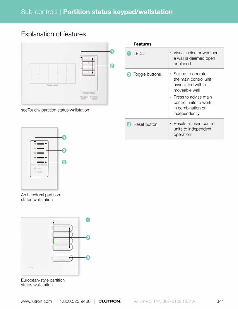
341 | 1.800.523.9466 | www.lutron.com www.lutron.com | 1.800.523.9466 | Volume 3 P/N 367-2102 REV A
Sub-controls |
| 1.800.523.9466 | www.lutron.com
Partition status keypad/wallstation
Explanation of features Features
1 LEDs • Visual indicator whether a wall is deemed open or closed
2 Toggle buttons • Set-up to operate the main control unit associated with a moveable wall
• Press to advise main control units to work in combination or independently
3 Reset button • Resets all main control units to independent operation
1
Architectural partition status wallstation
European-style partition status wallstation
seeTouch® partition status wallstation
1
1
2
2
2
3
3

| 1.800.523.9466 | www.lutron.com342 | 1.800.523.9466 | www.lutron.comVolume 3 P/N 367-2102 REV A
Sub-controls |
seeTouch partition status keypad
Insert version without SG-4PSI-XX1-EEE1 custom-engraved faceplate
Non-insert version without SG-4PSN-XX1-EEE1 custom-engraved faceplate
Insert version with SG-4PS-CF-XX2-E1 custom-engraved faceplate
Compatible with the GRAFIK Eye® 4000 system.
Architectural partition status wallstation
Without custom-engraved NTGRX-4PS-XX2-E2 faceplate
With custom-engraved NTGRX-4PS-CF-XX2-E2 faceplate
Compatible with the GRAFIK Eye 4000 system.
European-style partition status wallstation
Partition wallstation EGRX-4PS-XX3-E2
Compatible with the GRAFIK Eye 4000 system.
Model numbers
XX1: Gloss, architectural matte, metal, and Satin color codes, see pgs. 327-328 (Coordinating faceplates not included with Satin colors, order separately, see pg.642)
XX2: Architectural matte and metal color codes, see pg. 306
XX3: Architectural matte and metal color codes, see pg. 318
EEE1: Engraving code required, see pg. 667-668E1: Engraving form required with orderE2: Engraving form required with order.
If engraving not desired, omit “E”.
seeTouch® partition status keypad
Architectural partition status wallstation
European-style partition status wallstation
Available models(Available in insert and non-insert styles, non-insert style shown)
Partition status keypad/wallstation

Sub-controls |
343 | 1.800.523.9466 | www.lutron.com www.lutron.com | 1.800.523.9466 | Volume 3 P/N 367-2102 REV A | 1.800.523.9466 | www.lutron.com
Features and capacities• Limits access to lighting control system, requires
authorized personnel to use a key• OMX models provide scene selection or enable/
disable time clock functionality• GRX models allow the following functionality:
– Scene selection– Entrance or panic wallstation selection– Fine-tuning– Partitioning– Zone lockout– Sequencing
• Functionality may be selected in the field• Ideal for use in public spaces• Available in two wallstation styles: Architectural
(non-insert or insert) and European-style
Dimensions and mounting Architectural• Width: 2.75 in (70 mm)
Height: 4.56 in (116 mm) Depth: 1.38 in (35 mm) Profile: 0.31 in (8 mm)
• Mounts in a standard 1-gang U.S. backbox European-style• Width: 3.38 in (86 mm)
Height: 3.38 in (86 mm) Depth: 1.00 in (25 mm) Profile: 0.25 in (6 mm)
• Mounts in a U.K./German 1-gang backbox (P/N 241-683)
Communication and wiring• Operates via low-voltage IEC PELV/NEC Class 2
standard wired communication to the main control unit and other system components
• OMX models—counts as one wallstation on the OMX link; can have up to 32 keypads/wallstations and/or control interfaces
• GRX models—GRAFIK Eye® 4000 system can have up to 16 keypads/wallstations and/or control interfaces; each keyswitch counts as one wallstation
Shown above: OMX Architectural keyswitch in 1-gang matte finish faceplate in White (NTOMX-KS-WH)
2.75 in (70 mm)
4.56 in (116 mm
)
Keyswitch
0.31 in (8 mm) profile
1.38 in (35 mm) depth
Download specification submittal
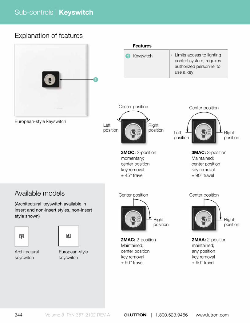
344 | 1.800.523.9466 | www.lutron.comVolume 3 P/N 367-2102 REV A
Sub-controls |
Explanation of features Features
1 Keyswitch • Limits access to lighting control system, requires authorized personnel to use a key
1
European-style keyswitch
Keyswitch
Architectural keyswitch
Available models(Architectural keyswitch available in insert and non-insert styles, non-insert style shown)
European-style keyswitch
2MAA: 2-position maintained;any position key removal± 90° travel
3MOC: 3-position momentary;center position key removal± 45° travel
2MAC: 2-position Maintained;center position key removal± 90° travel
3MAC: 3-position Maintained;center position key removal± 90° travel
Center position
Left position
Right position
Center position
Right position
Center position
Right position
Left position
Center position
Right position

345 | 1.800.523.9466 | www.lutron.com www.lutron.com | 1.800.523.9466 | Volume 3 P/N 367-2102 REV A
Sub-controls | Keyswitch
OMX Keyswitches
Architectural non-insert style, 3-position momentary, NTOMX-KSN3MOC-XX1-CPN5313-E1 center position key removal
Architectural insert style, 3-position momentary, NTOMX-KSI3MOC-XX1-CPN5313-E1 center position key removal
Architectural non-insert style, 3-position maintained, NTOMX-KSN3MAC-XX1-CPN5313-E1 center position key removal
Architectural insert style, 3-position maintained, NTOMX-KSI3MAC-XX1-CPN5313-E1 center position key removal
Architectural non-insert style, 2-position maintained, NTOMX-KSN2MAC-XX1-CPN5313-E1 center position key removal
Architectural insert style, 2-position maintained, NTOMX-KSI2MAC-XX1-CPN5313-E1 center position key removal
Architectural non-insert style, 2-position maintained, NTOMX-KSN2MAA-XX1-CPN5313-E1 any position key removal
Architectural insert style, 2-position maintained, NTOMX-KSI2MAA-XX1-CPN5313-E1 any position key removal
European-style, 3-position momentary, EOMX-KS-XX2-CPN2783-E1 center position key removal
European-style, 2-position maintained, EOMX-KS-XX2-CPN3951-E1 center position key removalCompatible with LCP128™ and Softswitch128® (XPS) systems.
GRX Keyswitches
Architectural non-insert style, 3-position momentary, NTGRX-KSN-XX1-CPN0731-E1 center position key removal
Architectural insert style, 3-position momentary, NTGRX-KSI-XX1-CPN0731-E1 center position key removal
Architectural non-insert style, 2-position maintained, NTGRX-KSN-CENTURY-XX1-CPN1115-E1 center position key removal
Architectural insert style, 2-position maintained, NTGRX-KSI-CENTURY-XX1-CPN1115-E1 center position key removal
European-style, 3-position momentary, EGRX-KS-XX2-CPN2782-E1 center position key removalCompatible with the GRAFIK Eye® 4000 system.
Model numbers
XX1: Architectural matte and metal color codes, see pg. 306XX2: Architectural matte and metal color codes, see pg. 318
E1: Engraving form required with order. If engraving not desired, omit “E”.

| 1.800.523.9466 | www.lutron.com
Sub-controls |
346 | 1.800.523.9466 | www.lutron.comVolume 3 P/N 367-2102 REV A
Features and capacities• Fully featured and simple to operate these consoles
were designed and built for professional use with full-size knobs, quick-action bump buttons and large bright LEDs
• Available with 12 or 24 channels• Two scene preset mode allows manual control
of lighting• Chase memory provides easy-to-program chases,
and makes lights run a continuous pattern• Cue stack and go button allows playback of a show
using one button to advance from scene to scene• Simultaneous DMX, microplex, and analog output• Four pages of playback memories provide 48 or
96 locations to store presets
Dimensions and mounting 12-channel• Width: 15.41 in (391 mm)
Height: 10.13 in (257 mm) Depth: 2.87 in (73 mm)
24-channel• Width: 25.38 in (645 mm)
Height: 10.13 in (257 mm) Depth: 2.87 in (73 mm)
Shown above: 24-channel theatrical console (LTC-24)
Communication and wiring• Low-voltage IEC PELV/NEC Class 2 wiring
for communication• Requires 120 V external power supply• DMX512 input interface (LCP128) or 2Link
(12-15 V AC, 1 A) circuit selector panel (GRAFIK Eye® 4000/Quantum®) required to integrate with Lutron® lighting control system
• Does not count toward any device limits on a Lutron system
Related components
DMX512 input interface(sold separately, see pg. 482)
Multi-channel theatrical consoles
12-channel LTC-12
24-channel LTC-24Compatible with LCP128™, GRAFIK Eye® 4000, and Quantum® systems.
Model numbers
Multi-channel theatrical console
25.38 in (645 mm)
10.13 in (257 mm
)
2.87 in (73 mm) depth

Sub-controls |
347 | 1.800.523.9466 | www.lutron.com www.lutron.com | 1.800.523.9466 | Volume 3 P/N 367-2102 REV A | 1.800.523.9466 | www.lutron.com
EcoSystem® IR remote control and IR receiver
Features and capacities• Remote control includes on/off, raise/lower and
a favorite level button• Using IR technology, the remote control can adjust
lights from minimum to maximum and set and recall a favorite light level
• Aim remote at IR receiver and press desired button• Available in White (WH)
1.51 in (38 mm)
4.61 in (117 mm
)
Shown actual size: EcoSystem infrared (IR) remote control in White (C-FLRC-WH)
0.55 in (14 mm) depth
Download specification submittal for IR receiver
Download specification submittal for IR remote control
Dimensions and mounting• IR remote control:
Width: 1.51 in (38 mm) Height: 4.61 in (117 mm) Depth: 0.55 in (14 mm)
• IR receiver: Diameter: 1.18 in (30 mm) Depth: 1.25 in (32 mm) Profile: 0.69 in (17 mm)
• IR receiver mounts easily to ceiling tiles or fixtures with 0.38 in (10 mm) diameter hole; IR remote is handheld device
Communication and wiring• IR remote control uses IR signals to communicate
with the IR receiver• IR receiver responds to IR signals from up
to 8 ft (2.5 m) away when mounted on a 10 ft (3 m) ceiling
• Total wire length from IR receiver to device must not exceed 100 ft (30 m)
• IR receiver—20 V DC; IR remote control - battery (two AAA batteries included)
• IR receiver is designed to connect directly to an EcoSystem ballast or module (with sensor inputs), QS sensor module, or Energi Savr Node™ module via low-voltage IEC PELV/NEC Class 2 wiring
• IR receiver does not connect directly to QS link• Each QS link on a Quantum® processor can have
up to 100 keypads; each IR receiver counts as one keypad toward the limit when connected to a QS sensor module or Energi Savr Node module
• Uses one-half power draw unit on the QS link when connected to the QS sensor module; power draw calculations are not needed for inputs connected directly to the Energi Savr Node or EcoSystem ballast/module

348 | 1.800.523.9466 | www.lutron.comVolume 3 P/N 367-2102 REV A
Sub-controls |
1.18 in (30 mm)
Shown actual size: EcoSystem ceiling-mount IR receiver in White (EC-IR-WH)
0.69 in (17 mm) profile
1.25 in (32 mm) depth
EcoSystem® IR remote control and IR receiver
Explanation of features Features
1 On button • Lights brighten smoothly to full intensity
2 Off button • Tap once—lights dim smoothly to off
3 Dimming rocker
• Raise/lower lights
4 Favorite level button
• Tap once to recall your favorite light level
5 IR transmitter • Transmits signal line-of-sight to receiver
6 IR receiver • Requires line-of-sight from IR remote control
7 Status indicator
• Flashes when IR signal is being received
8 Threaded mounting
• Use 3/8-16 nut (provided) for mounting
0.55 in (14 mm)
0.69 in (17 mm)
4
32
1
6
5
EcoSystem infrared (IR) remote control
7 8
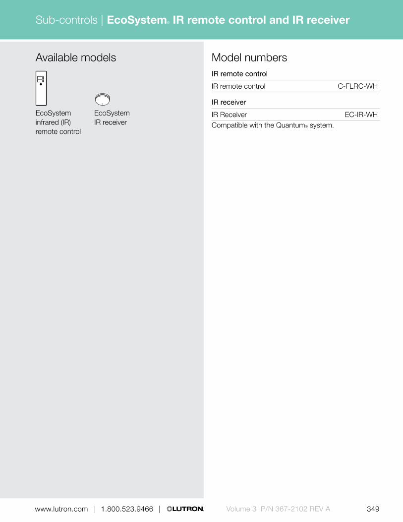
349 | 1.800.523.9466 | www.lutron.com www.lutron.com | 1.800.523.9466 | Volume 3 P/N 367-2102 REV A
Sub-controls | EcoSystem® IR remote control and IR receiver
Available models
EcoSystem infrared (IR) remote control
EcoSystem IR receiver
IR remote control
IR remote control C-FLRC-WH
IR receiver
IR Receiver EC-IR-WHCompatible with the Quantum® system.
Model numbers

| 1.800.523.9466 | www.lutron.com
Sub-controls |
350 | 1.800.523.9466 | www.lutron.comVolume 3 P/N 367-2102 REV A
QS infrared (IR) eye
7.25 in (184 mm)
1.19 in (30 mm
)
0.75 in (19 mm) depth
Download specification submittal
Features and capacities• Provides control of shades/drapes and lighting via
IR handheld remote controls by providing an access point
• Provides access to 16 scenes (plus off) or 16 areas• Works with all Lutron handheld IR remote controls• Allows IR integration via third-party IR remotes• Integrates shading and lighting devices via a single
IR device• Simple to program and reconfigure as the needs of
the space change• LED provides feedback during programming and
troubleshooting• Available in White (WH)
Dimensions and mounting• Cord length: 7.25 in (184 mm)
IR receiver diameter: 1.19 in (30 mm) IR receiver depth: 0.75 in (19 mm)
• Wiring harness can easily be configured to exit the side or out the back to accommodate a variety of mounting options
• Self adhesive mounting disc allows for secure mounting to any surface
Communication and wiring• Operating range: 30 ft (9 m) line of sight• Wiring flexibility allows the IR eye to plug directly
into shading devices or wire into the QS link via the included harness adapter
• Uses one power draw unit on the QS link• Each QS link on the Quantum® processor can have
up to 99 QS devices and 100 keypads; each QS IR eye counts as one QS device and one keypad toward the limits
Related components
IR remote control (available separately, see pg. 292)
Model numbers
QS IR eye
IR eye QSE-IR-WHCompatible with the Quantum® system.

Sub-controls |
351 | 1.800.523.9466 | www.lutron.com www.lutron.com | 1.800.523.9466 | Volume 3 P/N 367-2102 REV A | 1.800.523.9466 | www.lutron.com
Pico® wireless control
Features and capacities• Allows master control from any location
without wires• Available in a variety of colors and button
configurations with predetermined button labeling• Buttons can control a single light or shade, or zone
of lights or group of shades• Models available to control lighting and non-lighting
loads, as well as shade group• Simple to install in single-gang or multi-gang
applications with Lutron Claro® or international faceplates
• Battery included• Add wireless controls to a system for increased
convenience and energy savings
1.30 in (33 mm)
2.60 in (66 mm
)
Shown actual size: 3-button with raise/lower Pico wireless control in White (PJ-3BRL-GWH-T01)
0.31 in (8 mm) depth
Download specification submittal
Dimensions and mounting• Width: 1.30 in (33 mm)
Height: 2.60 in (66 mm) Depth: 0.31 in (8 mm)
• Can be handheld, mounted to wall using Pico faceplate adapter kit, mounted on a tabletop pedestal, or kept on a car visor clip
Communication and wiring• Communicates via Lutron reliable Clear Connect®
Radio Frequency (RF) technology to the HomeWorks® QS repeater, a GRAFIK Eye® QS wireless main unit or QS sensor module
• Models available for operation at 434 MHz, 434 limited channel MHz, 865 MHz, 868 MHz, and 868 limited channel MHz
• RF range is 30 ft (9 m) to compatible RF devices
• Each RF link in a HomeWorks QS system can have up to 99 wireless devices; each Pico wireless control counts as one wireless device toward the limit
• Each QS sensor module can communicate with up to ten Pico wireless controls
• Each GRAFIK Eye QS main unit can communicate with up to 30 wireless devices; each Pico wireless control counts as one wireless device toward the limit
• Each QS link on the Quantum processor can have up to 100 keypads; each Pico wireless control counts as one keypad toward the limit

352 | 1.800.523.9466 | www.lutron.comVolume 3 P/N 367-2102 REV A
Sub-controls | Pico® wireless control
For engraving information see pg. 356 (434 MHz models), or pg. 359 (868 MHz, 868 limited channel MHz, 865 MHz, and 434 limited channel MHz models).
WHWhite
BLBlack
Pedestal finishes
Gloss finishes
Available finishes
Gloss finishes Matte finishes
Use BOLD color code in model number (Example: PJ-3BRL-GWH-T01)
White color palette in all models
White/Gray color palette in all models
WGWhite/Gray
WHWhite
TAWArctic White
IVIvory
LALight Almond
BLBlack
TBLBlack
3-button with raise/lower
3-button2-button 2-button with raise/lower
3-button with raise/lower
3-button2-button 2-button with raise/lower

353 | 1.800.523.9466 | www.lutron.com www.lutron.com | 1.800.523.9466 | Volume 3 P/N 367-2102 REV A
Sub-controls | Pico® wireless control
Mounting optionsSingle pedestal for tabletops
(L-PED1-)
Triple pedestal for tabletops
(L-PED3-)
Wall-mount (no wallbox required)
Car visor clip (PICO-CARVISOR-CL)
Pico mounted inside a 1-gang Claro® faceplate in White (CW-1-WH), see pg. 640 (adapter plate required PICO-FP-ADAPT)
Left: Pico mounted inside a 1-gang International faceplate in Arctic White (PFP-1-B-FAW-M)
Right: Two Picos mounted inside a 2-gang International faceplate in Arctic White (PFP-2-B-FAW-M)
4.59 in (117 mm)
Quad pedestal for tabletops
(L-PED4-)
6.00 in (152 mm)
Dual pedestal for tabletops
(L-PED2-)
3.18 in (81 mm)1.78 in (45 mm)
2.95 in(75 mm)
1.45 in(37 mm)
2.94 in (75 mm)
3.39 in (86 mm) 3.39 in (86 mm)
4.69 in (118 mm
)
3.39 in (86 mm
)
3.39 in (86 mm
)

354 | 1.800.523.9466 | www.lutron.comVolume 3 P/N 367-2102 REV A
Sub-controls | Pico® wireless control
0.31 in (8 mm)
Features
1 On/Open • Press once and lighting device(s) brighten to full intensity or shades move to open
2 Raise button/ tilt up
• Press and hold for lights to increase in intensity, for shades to open, or for venetian blinds to tilt
3 Lower button/ tilt down
• Press and hold for lights to decrease in intensity, for shades to close, or for venetian blinds to tilt
4 Preset button • Tap once to recall a favorite lighting or shade level
5 Off/Close • Tap once and lighting device(s) will dim to off or shades will close
Explanation of features
5
3
2
1
4
3-button Pico (with raise/lower)

355 | 1.800.523.9466 | www.lutron.com www.lutron.com | 1.800.523.9466 | Volume 3 P/N 367-2102 REV A
Sub-controls | Pico® wireless control
Model numbers (434 MHz)2-button Pico (434 MHz)
Light icon PJ-2B-GXX1-I01
Light text PJ-2B-GXX1-T01
Power icon PJ-2B-GXX1-I14
3-button Pico (434 MHz)
Light icon PJ-3B-GXX1-I01
Light text PJ-3B-GXX1-T01
2-button with raise/lower Pico (434 MHz)
Light icon PJ-2BRL-GXX1-I01
Light text PJ-2BRL-GXX1-T01
Shade icon PJ-2BRL-GXX1-I02
Shade text PJ-2BRL-GXX1-T02
Drapery icon PJ-2BRL-GXX1-I08
Drapery text PJ-2BRL-GXX1-T08
3-button with raise/lower Pico (434 MHz)
Light icon PJ-3BRL-GXX1-I01
Light text PJ-3BRL-GXX1-T01
Shade icon PJ-3BRL-GXX1-I02
Shade text PJ-3BRL-GXX1-T02
Shade 1 text PJ-3BRL-GXX1-T05
Shade 2 text PJ-3BRL-GXX1-T06
Screen text PJ-3BRL-GXX1-T07
Drape icon PJ-3BRL-GXX1-I08
Drape text PJ-3BRL-GXX1-T08
Blackout text PJ-3BRL-GXX1-T09
Sheer text PJ-3BRL-GXX1-T10
Blind text PJ-3BRL-GXX1-T13Compatible with the Quantum® and HomeWorks® QS systems.
XX1: Available in Gloss finishes: White (WH), White/Gray (WG), Light Almond (LA), Ivory (IV), and Black (BL), see pg. 352
3-button with raise/lower
2-button with raise/lower
3-button
2-button
Available models (434 MHz)
For specific radio frequency by country, refer to the radio frequency chart on pg. 695.

On
Off
Light
On
Light
Off
Preset
On
Light
Off
On
Light
Off
Open
Shade 1
Close
Open
Shade 2
Close
Open
Shade
Close
Open
Screen
Close
Open
Blackout
Close
Open
Sheer
Close
Open
Drape
Close
Open
Blind
Close
Open
Drape
Close
Open
Shade
Close
356 | 1.800.523.9466 | www.lutron.comVolume 3 P/N 367-2102 REV A
Sub-controls | Pico® wireless control
Engraving options and model number engraving codes for 434 MHz models
2-button (T01) 3-button (T01) 2-button with raise/lower (T01)
3-button with raise/lower (T01)
Light — Text
Light and Power — Icons
3-button (I01) 2-button with raise/lower (I01)
2-button (I01) 3-button with raise/lower (I01)
2-button (I14)
Automated Window Treatments — Text
3-button with raise/lower— Shade 1 (T05)
3-button with raise/lower— Shade 2 (T06)
3-button with raise/lower—Shade (T02)
2-button with raise/lower—Shade (T02)
3-button with raise/lower— Screen (T07)
3-button with raise/lower— Blackout (T09)
3-button with raise/lower— Sheer (T10)
3-button with raise/lower—Drape (T08)
3-button with raise/lower— Blind (T13)
3-button with raise/lower— Shade (I02)
2-button with raise/lower— Shade (I02)
3-button with raise/lower— Drape (I08)
2-button with raise/lower— Drape (I08)
2-button with raise/lower— Drape (T08)
Automated Window Treatments — Icons

Preset
357 | 1.800.523.9466 | www.lutron.com www.lutron.com | 1.800.523.9466 | Volume 3 P/N 367-2102 REV A
Sub-controls | Pico® wireless control
3-button with raise/lower
2-button with raise/lower
2-button
Available models (865 MHz, 868 MHz, 868 limited channel MHz, and 434 limited channel MHz)
3-button
Model numbers (865 MHz)2-button Pico (865 MHz)
Light QSRNP-2-TXX1-I03Roller blind QSRNP-2-TXX1-I04
Curtain QSRNP-2-TXX1-I13
3-button Pico (865 MHz)
Light QSRNP-3-TXX1-I03Roller blind QSRNP-3-TXX1-I04
Curtain QSRNP-3-TXX1-I13
2-button Pico with raise/lower (865 MHz)
Light QSRNP-2R-TXX1-I03Roller blind QSRNP-2R-TXX1-I04
Curtain QSRNP-2R-TXX1-I13
3-button Pico with raise/lower (865 MHz)
Light QSRNP-3R-TXX1-I03Roller blind QSRNP-3R-TXX1-I04
Curtain QSRNP-3R-TXX1-I13Compatible with the Quantum® and HomeWorks® QS systems.
XX1: Available in matte Arctic White (TAW) or matte Black (TBL), see pg. 352
For specific radio frequency by country, refer to the radio frequency chart on pg. 695.

358 | 1.800.523.9466 | www.lutron.comVolume 3 P/N 367-2102 REV A
Sub-controls | Pico® wireless control
2-button Pico (868 MHz)
Light QSRKP-2-TXX1-I03Roller blind QSRKP-2-TXX1-I04
Curtain QSRKP-2-TXX1-I13
3-button Pico (868 MHz)
Light QSRKP-3-TXX1-I03Roller blind QSRKP-3-TXX1-I04
Curtain QSRKP-3-TXX1-I13
2-button Pico with raise/lower (868 MHz)
Light QSRKP-2R-TXX1-I03Roller blind QSRKP-2R-TXX1-I04
Curtain QSRKP-2R-TXX1-I13
3-button Pico with raise/lower (868 MHz)
Light QSRKP-3R-TXX1-I03Roller blind QSRKP-3R-TXX1-I04
Curtain QSRKP-3R-TXX1-I13Compatible with the Quantum® and HomeWorks® QS systems.
2-button Pico (868 limited channel MHz)
Light QSRMP-2-TXX1-I03Roller blind QSRMP-2-TXX1-I04Curtain QSRMP-2-TXX1-I13
2-button Pico with raise/lower (868 limited channel MHz)
Light QSRMP-2R-TXX1-I03Roller blind QSRMP-2R-TXX1-I04
Curtain QSRMP-2R-TXX1-I13
3-button Pico with raise/lower (868 limited channel MHz)
Light QSRMP-3R-TXX1-I03Roller blind QSRMP-3R-TXX1-I04Curtain QSRMP-3R-TXX1-I13Compatible with the Quantum and HomeWorks QS systems.
Model numbers (868 MHz)
Model numbers (868 limited channel MHz)
XX1: Available in gloss White (WH), gloss Black (BL), matte Arctic White (TAW) or matte Black (TBL), see pg. 352
Pedestal and adapter kit (for all Pico models)
Pico tabletop pedestals
Single pedestal L-PED1-XX1
Dual pedestal L-PED2-XX1
Triple pedestal L-PED3-XX1
Quadruple pedestal L-PED4-XX1
Pico wireless control not included with pedestal, order separately.
Adapters
Wallplate adapter PICO-FP-ADAPTFor international wallplate and adapter, call Lutron customer service for details.
Car visor clip
Car visor clip PICO-CARVISOR-CL
For specific radio frequency by country, refer to the radio frequency chart on pg. 695.

359 | 1.800.523.9466 | www.lutron.com www.lutron.com | 1.800.523.9466 | Volume 3 P/N 367-2102 REV A
Sub-controls | Pico® wireless control
Engraving options and model number engraving codes for 865 MHz, 868 MHz, 868 limited channel MHz, and 434 limited channel MHz models
3-button— Roller blind (I04)*
Preset
3-button (I03)
Preset
3-button— Curtain (I13)*
Preset
3-button with raise/lower (I03)
3-button with raise/lower—Roller blind (I04)
3-button with raise/lower—Curtain (I13)
2-button with raise/lower (I03)
3-button with raise/lower— Roller blind (I04)
3-button with raise/lower— Curtain (I13)
2-button—Roller blind (I04)
2-button (I03)
2-button—Curtain (I13)
Light — Icons
Automated Window Treatments — Icons
2-button Pico (434 limited channel MHz)
Light QSRQP-2-TXX1-I03
Roller blind QSRQP-2-TXX1-I04
Curtain QSRQP-2-TXX1-I13
3-button Pico (434 limited channel MHz)
Light QSRQP-3-TXX1-I03
Roller blind QSRQP-3-TXX1-I04
Curtain QSRQP-3-TXX1-I13
2-button Pico with raise/lower (434 limited channel MHz)
Light QSRQP-2R-TXX1-I03
Roller blind QSRQP-2R-TXX1-I04
Curtain QSRQP-2R-TXX1-I13
3-button Pico with raise/lower (434 limited channel MHz)
Light QSRQP-3R-TXX1-I03
Roller blind QSRQP-3R-TXX1-I04
Curtain QSRQP-3R-TXX1-I13Compatible with the Quantum® and HomeWorks® QS systems.
Model numbers (434 limited channel MHz)
XX1: Available in gloss White (WH), gloss Black (BL), matte Arctic White (TAW) or matte Black (TBL), see pg. 352
* 3-button not available in QSRMP- (868 limited channel MHz) models.
For specific radio frequency by country, refer to the radio frequency chart on pg. 695.
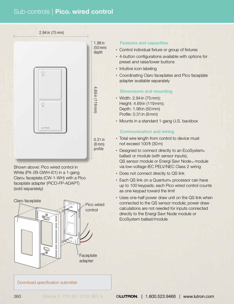
| 1.800.523.9466 | www.lutron.com
Sub-controls |
360 | 1.800.523.9466 | www.lutron.comVolume 3 P/N 367-2102 REV A
2.94 in (75 mm)
4.69 in (119 mm
)
Shown above: Pico wired control in White (PX-2B-GWH-I01) in a 1-gang Claro® faceplate (CW-1-WH) with a Pico faceplate adapter (PICO-FP-ADAPT) (sold separately)
0.31 in (8 mm) profile
1.98 in (50 mm) depth
Features and capacities• Control individual fixture or group of fixtures• 4-button configurations available with options for
preset and raise/lower buttons• Intuitive icon labeling• Coordinating Claro faceplates and Pico faceplate
adapter available separately
Dimensions and mounting• Width: 2.94 in (75 mm);
Height: 4.69 in (119 mm); Depth: 1.98 in (50 mm) Profile: 0.31 in (8 mm)
• Mounts in a standard 1-gang U.S. backbox
Communication and wiring• Total wire length from control to device must
not exceed 100 ft (30 m)• Designed to connect directly to an EcoSystem®
ballast or module (with sensor inputs), QS sensor module or Energi Savr Node™ module via low-voltage IEC PELV/NEC Class 2 wiring
• Does not connect directly to QS link• Each QS link on a Quantum® processor can have
up to 100 keypads; each Pico wired control counts as one keypad toward the limit
• Uses one-half power draw unit on the QS link when connected to the QS sensor module; power draw calculations are not needed for inputs connected directly to the Energi Savr Node module or EcoSystem ballast/module
Claro faceplate
Faceplate adapter
Pico wired control
Download specification submittal
Pico® wired control
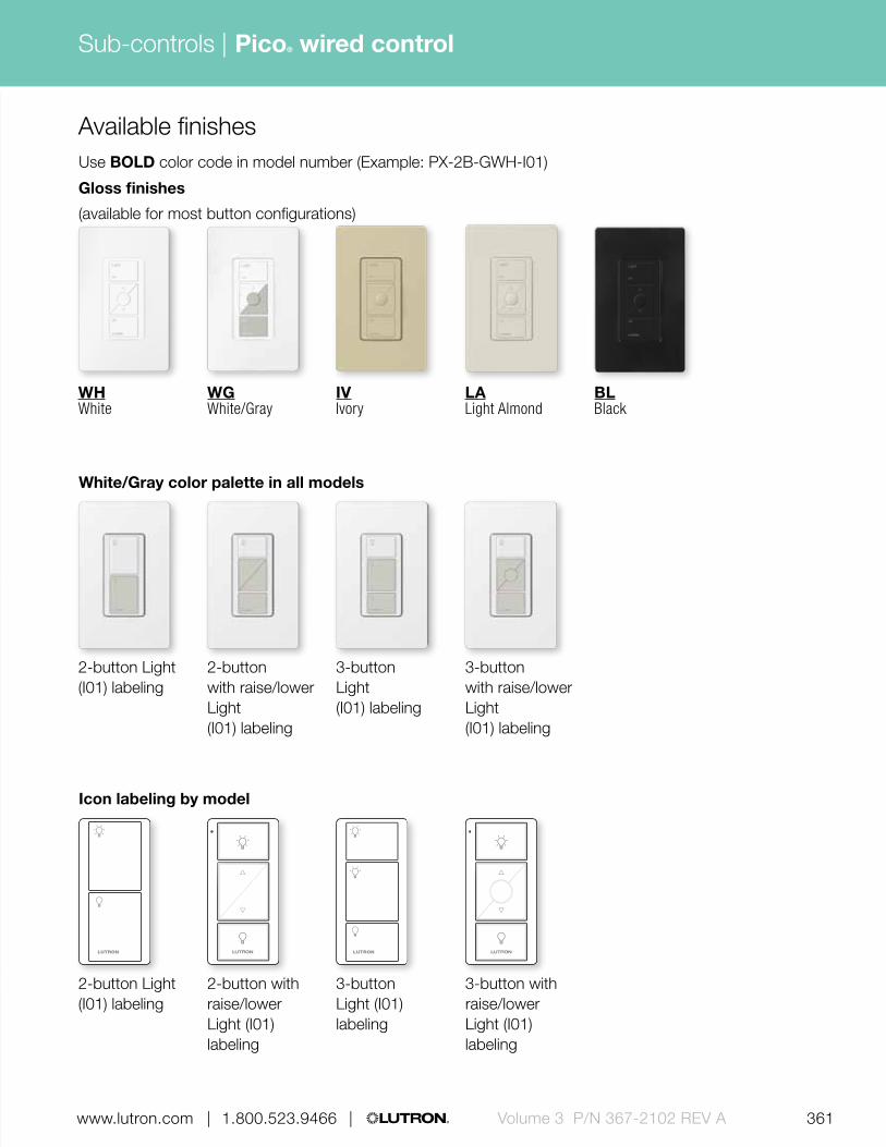
361 | 1.800.523.9466 | www.lutron.com www.lutron.com | 1.800.523.9466 | Volume 3 P/N 367-2102 REV A
Sub-controls |
| 1.800.523.9466 | www.lutron.com
Pico® wired control
WGWhite/Gray
WHWhite
IVIvory
LALight Almond
BLBlack
Available finishes
Gloss finishes
(available for most button configurations)
Use BOLD color code in model number (Example: PX-2B-GWH-I01)
3-button with raise/lower Light (I01) labeling
3-button Light (I01) labeling
White/Gray color palette in all models
2-button Light (I01) labeling
2-button with raise/lower Light (I01) labeling
3-button with raise/lower Light (I01) labeling
3-button Light (I01) labeling
Icon labeling by model
2-button Light (I01) labeling
2-button with raise/lower Light (I01) labeling

| 1.800.523.9466 | www.lutron.com362 | 1.800.523.9466 | www.lutron.comVolume 3 P/N 367-2102 REV A
Sub-controls | Pico® wired control
Available models Model numbersPico wired control
2-button PX-2B-GXX1-I012-button with raise/lower PX-2BRL-GXX1-I013-button PX-3B-GXX1-I01
3-button with raise/lower PX-3BRL-GXX1-I01Compatible with the Quantum® system.
XX1: Available in gloss finishes: White/Gray (WG), White (WH), Light Almond (LA), Ivory (IV), and Black (BL), see pg. 361
3-button with preset and raise/lower
2-button with raise/lower
2-button
3-button with preset

Sub-controls |
363 | 1.800.523.9466 | www.lutron.com www.lutron.com | 1.800.523.9466 | Volume 3 P/N 367-2102 REV A | 1.800.523.9466 | www.lutron.com
EcoSystem® wallstation
Shown actual size: 4-button EcoSystem® wallstation in White (CC-4BRL-WH) in a 1-gang Claro® faceplate (CW-1-WH) (Order separately)
2.94 in (75 mm)
4.69 in (119 mm
)
Features and capacities• 4-button control with raise/lower rocker• Four presets in addition to All On and All Off• Built-in infrared (IR) receiver• Multi-color LED to indicate button presses and
reception of IR signals• Engraving on faceplate available• Coordinating Claro faceplates
available separately
Dimensions and mounting• Width: 2.94 in (75 mm)
Height: 4.69 in (119 mm) Depth: 1.45 in (37 mm) Profile: 0.31 in (8 mm)
• Mounts in a standard 1-gang U.S. backbox
Communication and wiring• Total wire length from control to device must not
exceed 100 ft (30 m)• Designed to connect directly to an EcoSystem
ballast or module (with sensor inputs), QS sensor module or Energi Savr Node™ module via low-voltage IEC PELV/ NEC Class 2 wiring
• Does not connect to QS link directly• Each QS link on a Quantum® processor can have
up to 100 keypads; each EcoSystem wallstation counts as one keypad toward the limit
• Uses one power draw unit on the QS link when connected to the QS sensor module; power draw calculations are not needed for inputs connected directly to the Energi Savr Node module or EcoSystem ballast/module
Related components
0.31 in (8 mm) profile
1.45 in (37 mm) depth
IR remote control (available separately, see pg. 292)
Download specification submittalDownload engraving sheet for faceplates

364 | 1.800.523.9466 | www.lutron.comVolume 3 P/N 367-2102 REV A
Sub-controls | EcoSystem® wallstation
Features
1 On button • All On button (programmable)
2 Preset buttons • Four buttons each recall lighting presets
3 Status LEDs • Indicate control is functioning
4 Dimming rocker
• Raise/lower lights
5 Infrared receiver
• Allows wireless connectivity to handheld infrared remotes (maximum 10 ft)
6 Off button • All Off button (programmable)
7 Faceplate • Lutron Claro® faceplate (sold separately)
Explanation of features
0.31 in (8 mm)
1.25 in (32 mm)
23
1
4
5
7
4-button EcoSystem wallstation
6
Available finishesGloss finishes
BLBlack
IVIvory
WHWhite
LALight Almond

365 | 1.800.523.9466 | www.lutron.com www.lutron.com | 1.800.523.9466 | Volume 3 P/N 367-2102 REV A
Sub-controls | EcoSystem® wallstation
Available model
4-button
Wallstation
4-button with raise/lower CC-4BRL-XX1
Compatible with the Quantum® system.
Model numbers
Faceplate not included. Order separately, see pg. 642.
XX1: Available in limited gloss finishes, White (WH), Light Almond (LA), Ivory (IV) and Black (BL)
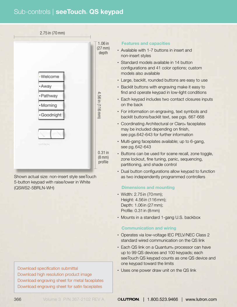
| 1.800.523.9466 | www.lutron.com
Sub-controls |
366 | 1.800.523.9466 | www.lutron.comVolume 3 P/N 367-2102 REV A
seeTouch® QS keypad
Features and capacities• Available with 1-7 buttons in insert and
non-insert styles• Standard models available in 14 button
configurations and 41 color options; custom models also available
• Large, backlit, rounded buttons are easy to use• Backlit buttons with engraving make it easy to
find and operate keypad in low-light conditions• Each keypad includes two contact closures inputs
on the back• For information on engraving, text symbols and
backlit buttons/backlit text, see pgs. 667-668• Coordinating Architectural or Claro® faceplates
may be included depending on finish, see pgs.642-643 for further information
• Multi-gang faceplates available; up to 6-gang, see pg. 642-643
• Buttons can be used for scene recall, zone toggle, zone lockout, fine tuning, panic, sequencing, partitioning, and shade control
• Dual button configurations allow keypad to function as two independently programmed controllers
Dimensions and mounting• Width: 2.75 in (70 mm);
Height: 4.56 in (116 mm); Depth: 1.06 in (27 mm); Profile: 0.31 in (8 mm)
• Mounts in a standard 1-gang U.S. backbox
Communication and wiring• Operates via low-voltage IEC PELV/NEC Class 2
standard wired communication on the QS link• Each QS link on a Quantum® processor can have
up to 99 QS devices and 100 keypads; each seeTouch QS keypad counts as one QS device and one keypad toward the limits
• Uses one power draw unit on the QS link
Shown actual size: non-insert style seeTouch 5-button keypad with raise/lower in White (QSWS2-5BRLN-WH)
2.75 in (70 mm)
4.56 in (116 mm
)
0.31 in (8 mm) profile
1.06 in (27 mm) depth
Download specification submittalDownload high resolution product imageDownload engraving sheet for metal faceplatesDownload engraving sheet for satin faceplates

367 | 1.800.523.9466 | www.lutron.com www.lutron.com | 1.800.523.9466 | Volume 3 P/N 367-2102 REV A
Sub-controls |
| 1.800.523.9466 | www.lutron.com
seeTouch® QS keypad
Available finishes
Use BOLD color code in model number (Example: QSWS2-2BN-SW)
Satin finishes (Available for insert style keypads; coordinating faceplates ordered separately)
BGBluestone FGray BWhite E
SGSea Glass FGray BWhite E
TQTurquoise FGray BWhite E
GSGoldstone FIvory BGray E
DSDesert Stone FTaupe BGray E
GBGreenbriar FGray BWhite E
SWSnow F, BGray E
LSLimestone FGray BWhite E
ESEggshell F, BGray E
PDPalladium FGray B White E
TPTaupe F, BGray E
STStone FGray BWhite E
BIBiscuit F, BGray E
MSMocha Stone FTaupe BGray E
TCTerracotta FTaupe BGray E
SISienna FBrown BWhite E
HTHot FTaupe BGray E
MRMerlot FTaupe BGray E
MNMidnight F, BGray E
Faceplate F
Buttons BEngraving E
PLPlum FTaupe BGray E
Bold color code indicates faceplate color. Models include button kit in coordinating colors as shown.
Text engraving color varies by button color. Lighter colored buttons use gray text and darker colored buttons use white text. Visit www.lutron.com/engraving for further information.

368 | 1.800.523.9466 | www.lutron.comVolume 3 P/N 367-2102 REV A
Sub-controls | seeTouch® QS keypad
Architectural matte finishes (Available for insert and non-insert style keypads; coordinating faceplates included)
GRGray F, BWhite E
BRBrown F, BWhite E
BLBlack F, BWhite E
BEBeige F, BGray E
IVIvory F, BGray E
TPTaupe F, B(non-insert only)Gray E
LALight Almond F, BGray E
WHWhite F, BGray E
ALAlmond F, BGray E
Architectural metal finishes (Available for insert and non-insert style keypads; coordinating faceplates included)
CLAClear Anodized Aluminum FBlack BWhite E
BCBright Chrome FBlack BWhite E
BNBright Nickel FBlack BWhite E
SCSatin Chrome FBlack BWhite E
SNSatin Nickel FBlack BWhite E
QZAntique Bronze FBlack BWhite E
BRABrass Anodized Aluminum FBlack BWhite E
SBSatin Brass FBlack BWhite E
QBAntique Brass FBlack BWhite E
BLABlack Anodized Aluminum FBlack BWhite E
BBBright Brass FBlack BWhite E

369 | 1.800.523.9466 | www.lutron.com www.lutron.com | 1.800.523.9466 | Volume 3 P/N 367-2102 REV A
Sub-controls | seeTouch® QS keypad
Explanation of features Features
1 Buttons • Available with 1-7 scene preset options
• Can also provide zone, partitioning, sequencing, or shade control, and other features
2 Status LEDs • Show which keypad button has been activated
3 Backlit buttons • Easy to read and use in low-light conditions, can be disabled on a button by button basis
4 Infrared (IR) receiver (optional)
• Offers convenient control of lights/shades from an IR remote control, see pg. 292
5 Raise/lower buttons
• Brightens/dims assigned lighting or raises/lowers assigned shades
6 Dual contact closure inputs
• Dual contact closure inputs (CCI) programmable
0.31 in (8 mm)
1.09 in (28 mm)
Insert style 5-button seeTouch QS keypad with infrared receiver and raise/lower
5
4
1
23
6

370 | 1.800.523.9466 | www.lutron.comVolume 3 P/N 367-2102 REV A
Sub-controls | seeTouch® QS keypad
1, 2, 3, 5, 7-button
2, 3, 5-button with infrared receiver and raise/lower (model numbers on following page)
2, 3, 5-button with raise/lower (model numbers on following page)
Dual configurations (model numbers on following page)
Available models(Available in insert and non-insert styles, non-insert style shown)
Model numbersKeypads
1-button
Non-insert style QSWS2-1BN-XX1-EEE1
Insert style QSWS2-1BI-XX2-EEE1
2-button
Non-insert style QSWS2-2BN-XX1-EEE1
Insert style QSWS2-2BI-XX2-EEE1
3-button
Non-insert style QSWS2-3BN-XX1-EEE1
Insert style QSWS2-3BI-XX2-EEE1
5-button
Non-insert style QSWS2-5BN-XX1-EEE1
Insert style QSWS2-5BI-XX2-EEE1
7-button
Non-insert style QSWS2-7BN-XX1-EEE1
Insert style QSWS2-7BI-XX2-EEE1
Compatible with the Quantum® system.
XX1: Architectural matte and metal color codes, see pg. 368
XX2: Architectural matte, metal and Satin Colors® codes, see pgs. 367-368 (Coordinating faceplates not included with Satin Colors, order separately, see pg. 642
EEE1: Engraving codes, see pgs. 667-668

371 | 1.800.523.9466 | www.lutron.com www.lutron.com | 1.800.523.9466 | Volume 3 P/N 367-2102 REV A
Sub-controls | seeTouch® QS keypad
Model numbersDual configuration keypads
Dual 2-button with raise/lower
Non-insert style QSWS2-2RLDN-XX1-EEE1
Insert style QSWS2-2RLDI-XX2-EEE1
Dual 3-button and 2-button with raise/lower
Non-insert style QSWS2-1RLDN-XX1-EEE1
Insert style QSWS2-1RLDI-XX2-EEE1
Dual 3-button
Non-insert style QSWS2-3BDN-XX1-EEE1
Insert style QSWS2-3BDI-XX2-EEE1
Compatible with the Quantum system.
Faceplate kits
1-button
Non-insert style QSWS2R-1BN-XX1-EEE1
Insert style QSWS2R-1BI-XX2-EEE1
2-button
Non-insert style QSWS2R-2BN-XX1-EEE1
Insert style QSWS2R-2BI-XX2-EEE1
3-button
Non-insert style QSWS2R-3BN-XX1-EEE1
Insert style QSWS2R-3BI-XX2-EEE1
5-button
Non-insert style QSWS2R-5BN-XX1-EEE1
Insert style QSWS2R-5BI-XX2-EEE1
7-button
Non-insert style QSWS2R-7BN-XX1-EEE1
Insert style QSWS2R-7BI-XX2-EEE1
Includes faceplate, buttons and insert (when applicable).Compatible with seeTouch QS keypads.
Keypads with raise/lower
2-button with raise/lower
Non-insert style QSWS2-2BRLN-XX1-EEE1
Insert style QSWS2-2BRLI-XX2-EEE1
3-button with raise/lower
Non-insert style QSWS2-3BRLN-XX1-EEE1
Insert style QSWS2-3BRLI-XX2-EEE1
5-button with raise/lower
Non-insert style QSWS2-5BRLN-XX1-EEE1
Insert style QSWS2-5BRLI-XX2-EEE1
Compatible with the Quantum® system.
Keypads with infrared (IR) receiver and raise/lower
2-button with IR receiver and raise/lower
Non-insert style QSWS2-2BRLIRN-XX1-EEE1
Insert style QSWS2-2BRLIRI-XX2-EEE1
3-button with IR receiver and raise/lower
Non-insert style QSWS2-3BRLIRN-XX1-EEE1
Insert style QSWS2-3BRLIRI-XX2-EEE1
5-button with IR receiver and raise/lower
Non-insert style QSWS2-5BRLIRN-XX1-EEE1
Insert style QSWS2-5BRLIRI-XX2-EEE1
Compatible with the Quantum system.
XX1: Architectural matte and metal color codes, see pg. 368
XX2: Architectural matte, metal and Satin color codes, see pgs. 367-368
EEE1: Engraving codes, see pgs. 667-668 (Faceplates ship with matte and metal
finishes, but should be ordered separately for satin finish keypads)

372 | 1.800.523.9466 | www.lutron.comVolume 3 P/N 367-2102 REV A
Sub-controls | seeTouch® QS keypad
Insert style keypads may ship with architectural or designer style faceplates depending on finish; non-insert style keypads ship with architectural faceplates.
Faceplate kits with raise/lower
2-button with raise/lower
Non-insert style QSWS2R-2BRLN-XX1-EEE1
Insert style QSWS2R-2BRLI-XX2-EEE1
3-button with raise/lower
Non-insert style QSWS2R-3BRLN-XX1-EEE1
Insert style QSWS2R-3BRLI-XX2-EEE1
5-button with raise/lower
Non-insert style QSWS2R-5BRLN-XX1-EEE1
Insert style QSWS2R-5BRLI-XX2-EEE1
Includes faceplate, buttons and insert (when applicable).Compatible with seeTouch QS keypads.
Faceplate kits with infrared (IR) receiver and raise/lower
2-button with IR receiver and raise/lower
Non-insert style QSWS2R-2BRLIRN-XX1-EEE1
Insert style QSWS2R-2BRLIRI-XX2-EEE1
3-button with IR receiver and raise/lower
Non-insert style QSWS2R-3BRLIRN-XX1-EEE1
Insert style QSWS2R-3BRLIRI-XX2-EEE1
5-button with IR receiver and raise/lower
Non-insert style QSWS2R-5BRLIRN-XX1-EEE1
Insert style QSWS2R-5BRLIRI-XX2-EEE1
Includes faceplate, buttons and insert (when applicable).Compatible with seeTouch QS keypads.IR faceplate kits require IR keypad with IR functionality.
Dual faceplate kits
Dual 2-button with raise/lower
Non-insert style QSWS2R-2RLDN-XX1-EEE1
Insert style QSWS2R-2RLDI-XX2-EEE1
Dual 3-button and 2-button with raise/lower
Non-insert style QSWS2R-1RLDN-XX1-EEE1
Insert style QSWS2R-1RLDI-XX2-EEE1
Dual 3-button
Non-insert style QSWS2R-3BDN-XX1-EEE1
Insert style QSWS2R-3BDI-XX2-EEE1
Includes faceplate, buttons and insert (when applicable).Compatible with seeTouch QS keypads.
XX1: Architectural matte and metal color codes, see pg. 368
XX2: Architectural matte, metal and Satin color codes, see pgs. 367-368
EEE1: Engraving codes, see pgs. 667-668
Model numbers

373 | 1.800.523.9466 | www.lutron.com www.lutron.com | 1.800.523.9466 | Volume 3 P/N 367-2102 REV A
Sub-controls | seeTouch® QS keypad
Button kits
1-button
Non-insert style QSWS2B-1BN-XX1-EEE1
Insert style QSWS2B-1BI-XX2-EEE1
2-button
Non-insert style QSWS2B-2BN-XX1-EEE1
Insert style QSWS2B-2BI-XX2-EEE1
3-button
Non-insert style QSWS2B-3BN-XX1-EEE1
Insert style QSWS2B-3BI-XX2-EEE1
5-button
Non-insert style QSWS2B-5BN-XX1-EEE1
Insert style QSWS2B-5BI-XX2-EEE1
7-button
Non-insert style QSWS2B-7BN-XX1-EEE1
Insert style QSWS2B-7BI-XX2-EEE1
Compatible with seeTouch QS keypads.
Button kits with raise/lower
2-button with raise/lower
Non-insert style QSWS2B-2BRLN-XX1-EEE1
Insert style QSWS2B-2BRLI-XX2-EEE1
3-button with raise/lower
Non-insert style QSWS2B-3BRLN-XX1-EEE1
Insert style QSWS2B-3BRLI-XX2-EEE1
5-button with raise/lower
Non-insert style QSWS2B-5BRLN-XX1-EEE1
Insert style QSWS2B-5BRLI-XX2-EEE1
Compatible with seeTouch QS keypads.
Button kits with infrared (IR) receiver and raise/lower
2-button with IR receiver and raise/lower
Non-insert style QSWS2B-2BRLIRN-XX1-EEE1
Insert style QSWS2B-2BRLIRI-XX2-EEE1
3-button with IR receiver and raise/lower
Non-insert style QSWS2B-3BRLIRN-XX1-EEE1
Insert style QSWS2B-3BRLIRI-XX2-EEE1
5-button with IR receiver and raise/lower
Non-insert style QSWS2B-5BRLIRN-XX1-EEE1
Insert style QSWS2B-5BRLIRI-XX2-EEE1
Compatible with seeTouch QS keypads.IR button kits require IR keypad with IR functionality.
Dual configuration button kits
Dual 3-button and 2-button with raise/lower
Non-insert style QSWS2B-1RLDN-XX1-EEE1
Insert style QSWS2B-1RLDI-XX2-EEE1
Dual 2-button with raise/lower
Non-insert style QSWS2B-2RLDN-XX1-EEE1
Insert style QSWS2B-2RLDI-XX2-EEE1
Dual 3-button
Non-insert style QSWS2B-3BDN-XX1-EEE1
Insert style QSWS2B-3BDI-XX2-EEE1
Compatible with seeTouch QS keypads.
Model numbers
XX1: Limited architectural matte color codes, see pg. 368 for corresponding button colors
XX2: Limited gloss, architectural matte, and Satin Colors® finishes, see pgs. 367-368 for corresponding button colors
EEE1: Engraving codes, see pgs. 667-668

| 1.800.523.9466 | www.lutron.com
Sub-controls |
374 | 1.800.523.9466 | www.lutron.comVolume 3 P/N 367-2102 REV A
International seeTouch® QS wallstation
Shown actual size: Non-insert style International seeTouch 8-button keypad with IR and raise/lower in White (QSWE-8BRLIRN-AW)
3.38 in (86 mm)
3.38 in (86 mm
)
Features and capacities• Available with 2-10 buttons in insert and
non-insert styles• Standard models available in 10-button
configurations and 12 color options; custom models available
• Large rounded buttons are easy to use• Each keypad includes two built-in
contact closures inputs on the back• Backlit buttons with optional engraving make
it easy to find and operate wallstation in low light conditions
0.31 in (8 mm) profile
1.06 in (27 mm) depth
Download specification submittalDownload high resolution product imageDownload engraving sheet for faceplates
• For information on engraving, symbols and backlit buttons/backlit text, see pgs. 667-668
• Buttons can be used for scene recall, zone toggle, zone lockout, fine tuning, panic, sequencing, partitioning, and shade control
• Coordinating faceplate included• Models available with group control settings
for a single shade or multiple shades
Dimensions and mounting• Product dimensions:
Width: 3.38 in (86 mm) Height: 3.38 in (86 mm) Depth: 1.06 in (27 mm) Profile: 0.31 in (8 mm)
• Typical backbox dimensions: Width: 3.00 in (75 mm) Height: 3.00 in (75 mm) Depth: 1.40 in (35.6 mm)
• May be mounted in a 1.40 in round backbox, used in Europe
Communication and wiring• Operates via low-voltage IEC PELV/NEC
Class 2 standard wired communication on the QS link
• Each QS link on a Quantum® processor can have up to 99 QS devices and 100 keypads; each International seeTouch QS wallstation counts as one QS device and one keypad toward the limits
• Uses one power draw unit on the QS link

375 | 1.800.523.9466 | www.lutron.com www.lutron.com | 1.800.523.9466 | Volume 3 P/N 367-2102 REV A
Sub-controls |
| 1.800.523.9466 | www.lutron.com
International seeTouch® QS wallstation
Buttons B
Faceplate F
Matte finishes Metallic finishes
AWArctic White F, BGray E
ARArgentum F Black BWhite E
MCMica F Black BWhite E
Metal finishes
SNSatin Nickel F Black BWhite E
BNBright Nickel F Black BWhite E
SBSatin Brass F Black BWhite E
BBBright Brass F Black BWhite E
BCBright Chrome F Black B White E
SCSatin Chrome F Black BWhite E
QZAntique Bronze F Black BWhite E
AUGold Plated F Black BWhite E
QBAntique Brass F Black BWhite E
Use BOLD color code in model number (Example: QWS2B-2BN-AW)
Available finishes
Bold color code indicates faceplate color. Models include button kit in coordinating colors as shown.
Text engraving color varies by button color. Lighter colored buttons use gray text and darker colored buttons use white text. Visit www.lutron.com/engraving for further information.
Engraving E

376 | 1.800.523.9466 | www.lutron.comVolume 3 P/N 367-2102 REV A
Sub-controls | International seeTouch® QS wallstation
Explanation of features Features
1 Preset buttons for shades*
• Enable user to control one shade or group of shades
2 Status LEDs • Show which keypad button has been activated
3 Preset buttons for lights*
• Enable user to control a light or group of lights
4 Backlit buttons • Easy to read and use in low-light conditions; can optionally be disabled on a button-by-button basis
5 Raise/lower buttons
• Brighten/dim all assigned lighting or raise/lower all assigned shades
6 Dual contact closure inputs
• Dual contact closure inputs (CCI) programmable
0.31 in (8 mm)
1.09 in (28 mm)
5
1 2 3
Insert style 8-button International seeTouch QS wallstation with raise/lower
4
6
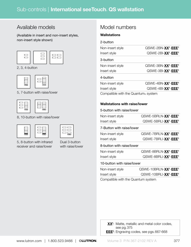
377 | 1.800.523.9466 | www.lutron.com www.lutron.com | 1.800.523.9466 | Volume 3 P/N 367-2102 REV A
Sub-controls | International seeTouch® QS wallstation
Model numbers
2, 3, 4-button
5, 8-button with infrared receiver and raise/lower
8, 10-button with raise/lower
5, 7-button with raise/lower
Dual 3-button with raise/lower
Available models(Available in insert and non-insert styles, non-insert style shown)
Wallstations
2-button
Non-insert style QSWE-2BN-XX1-EEE1
Insert style QSWE-2BI-XX1-EEE1
3-button
Non-insert style QSWE-3BN-XX1-EEE1
Insert style QSWE-3BI-XX1-EEE1
4-button
Non-insert style QSWE-4BN-XX1-EEE1
Insert style QSWE-4BI-XX1-EEE1
Compatible with the Quantum® system.
Wallstations with raise/lower
5-button with raise/lower
Non-insert style QSWE-5BRLN-XX1-EEE1
Insert style QSWE-5BRLI-XX1-EEE1
7-Button with raise/lower
Non-insert style QSWE-7BRLN-XX1-EEE1
Insert style QSWE-7BRLI-XX1-EEE1
8-button with raise/lower
Non-insert style QSWE-8BRLN-XX1-EEE1
Insert style QSWE-8BRLI-XX1-EEE1
10-button with raise/lower
Non-insert style QSWE-10BRLN-XX1-EEE1
Insert style QSWE-10BRLI-XX1-EEE1
Compatible with the Quantum system.
XX1: Matte, metallic and metal color codes, see pg. 375
EEE1: Engraving codes, see pgs. 667-668

378 | 1.800.523.9466 | www.lutron.comVolume 3 P/N 367-2102 REV A
Sub-controls | International seeTouch® QS wallstation
Wallstations with infrared (IR) receiver and raise/lower
5-button with IR receiver and raise/lower
Non-insert style QSWE-5BRLIRN-XX1-EEE1
Insert style QSWE-5BRLIRI-XX1-EEE1
8-button with IR receiver and raise/lower
Non-insert style QSWE-8BRLIRN-XX1-EEE1
Insert style QSWE-8BRLIRI-XX1-EEE1
Compatible with the Quantum® system.
Dual wallstations with raise/lower
Dual wallstation with 3-button and raise/lower
Non-insert style QSWE-6BRLN-XX1-EEE1
Insert style QSWE-6BRLI-XX1-EEE1
Compatible with the Quantum system.
Faceplate kits
2-button
Non-insert style QSWER-2BN-XX1-EEE1
Insert style QSWER-2BI-XX1-EEE1
3-button
Non-insert style QSWER-3BN-XX1-EEE1
Insert style QSWER-3BI-XX1-EEE1
4-button
Non-insert style QSWER-4BN-XX1-EEE1
Insert style QSWER-4BI-XX1-EEE1
Includes faceplate, buttons and insert (when applicable).Compatible with International seeTouch QS wallstations.
Model numbersFaceplate kits with raise/lower
5-button with raise/lower
Non-insert style QSWER-5BRLN-XX1-EEE1
Insert style QSWER-5BRLI-XX1-EEE1
7-button with raise/lower
Non-insert style QSWER-7BRLN-XX1-EEE1
Insert style QSWER-7BRLI-XX1-EEE1
8-button with raise/lower
Non-insert style QSWER-8BRLN-XX1-EEE1
Insert style QSWER-8BRLI-XX1-EEE1
10-button with raise/lower
Non-insert style QSWER-10BRLN-XX1-EEE1
Insert style QSWER-10BRLI-XX1-EEE1
Includes faceplate, buttons and insert (when applicable).Compatible with International seeTouch QS wallstations.
Faceplate kits with IR receiver and raise/lower
5-button with IR receiver and raise/lower
Non-insert style QSWER-5BRLIRN-XX1-EEE1
Insert style QSWER-5BRLIRI-XX1-EEE1
8-button with IR receiver and raise/lower
Non-insert style QSWER-8BRLIRN-XX1-EEE1
Insert style QSWER-8BRLIRI-XX1-EEE1
Includes faceplate, buttons and insert (when applicable).Compatible with International seeTouch QS wallstations. IR faceplate kits require IR keypads with IR functionality.
Dual faceplate kits
Dual 3-button with raise/lower
Non-insert style QSWER-6BRLN-XX1-EEE1
Insert style QSWER-6BRLI-XX1-EEE1
Includes faceplate, buttons and insert (when applicable).Compatible with International seeTouch QS wallstations.
XX1: Matte, metallic and metal color codes, see pg. 375
EEE1: Engraving codes, see pgs. 667-668

379 | 1.800.523.9466 | www.lutron.com www.lutron.com | 1.800.523.9466 | Volume 3 P/N 367-2102 REV A
Sub-controls | International seeTouch® QS wallstation
Button kits
2-button
Non-insert style QSWEB-2BN-XX1-EEE1
Insert style QSWEB-2BI-XX1-EEE1
3-button
Non-insert style QSWEB-3BN-XX1-EEE1
Insert style QSWEB-3BI-XX1-EEE1
4-button
Non-insert style QSWEB-4BN-XX1-EEE1
Insert style QSWEB-4BI-XX1-EEE1
Compatible with International seeTouch QS wallstations.
Button kits with raise/lower
5-button with raise/lower
Non-insert style QSWEB-5BRLN-XX1-EEE1
Insert style QSWEB-5BRLI-XX1-EEE1
7-button with raise/lower
Non-insert style QSWEB-7BRLN-XX1-EEE1
Insert style QSWEB-7BRLI-XX1-EEE1
8-button with raise/lower
Non-insert style QSWEB-8BRLN-XX1-EEE1
Insert style QSWEB-8BRLI-XX1-EEE1
10-button with raise/lower
Non-insert style QSWEB-10BRLN-XX1-EEE1
Insert style QSWEB-10BRLI-XX1-EEE1
Compatible with International seeTouch QS wallstations.
Model numbersButton kits with infrared (IR) receiver and raise/lower
5-button with IR receiver and raise/lower
Non-insert style QSWEB-5BRLIRN-XX1-EEE1
Insert style QSWEB-5BRLIRI-XX1-EEE1
8-button with IR receiver and raise/lower
Non-insert style QSWEB-8BRLIRN-XX1-EEE1
Insert style QSWEB-8BRLIRI-XX1-EEE1
Compatible with International seeTouch QS wallstations.IR button kits require IR keypads with IR functionality.
Button kits for dual configurations
Dual wallstation with 3-button and 3-button with raise/lower
Non-insert style QSWEB-6BRLN-XX1-EEE1
Insert style QSWEB-6BRLI-XX1-EEE1
Compatible with International seeTouch QS wallstations.
XX1: Available in Arctic White (AW) and Black (BL), see pg. 375
EEE1: Engraving codes, see pgs. 667-668
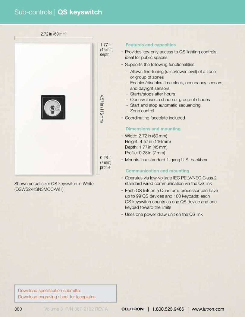
| 1.800.523.9466 | www.lutron.com
Sub-controls |
380 | 1.800.523.9466 | www.lutron.comVolume 3 P/N 367-2102 REV A
QS keyswitch
2.72 in (69 mm)
Shown actual size: QS keyswitch in White (QSWS2-KSN3MOC-WH)
4.57 in (116 mm
)
0.28 in (7 mm) profile
1.77 in (45 mm) depth
Features and capacities• Provides key-only access to QS lighting controls,
ideal for public spaces• Supports the following functionalities:
— Allows fine-tuning (raise/lower level) of a zone or group of zones
— Enables/disables time clock, occupancy sensors, and daylight sensors
— Starts/stops after hours— Opens/closes a shade or group of shades— Start and stop automatic sequencing— Zone control
• Coordinating faceplate included
Dimensions and mounting• Width: 2.72 in (69 mm)
Height: 4.57 in (116 mm) Depth: 1.77 in (45 mm) Profile: 0.28 in (7 mm)
• Mounts in a standard 1-gang U.S. backbox
Communication and mounting• Operates via low-voltage IEC PELV/NEC Class 2
standard wired communication via the QS link• Each QS link on a Quantum® processor can have
up to 99 QS devices and 100 keypads; each QS keyswitch counts as one QS device and one keypad toward the limits
• Uses one power draw unit on the QS link
Download specification submittalDownload engraving sheet for faceplates

381 | 1.800.523.9466 | www.lutron.com www.lutron.com | 1.800.523.9466 | Volume 3 P/N 367-2102 REV A
Sub-controls |
| 1.800.523.9466 | www.lutron.com
QS keyswitch
Features
1 Keyswitch • Provides key-only access to systems
Explanation of features
1
QS keyswitch
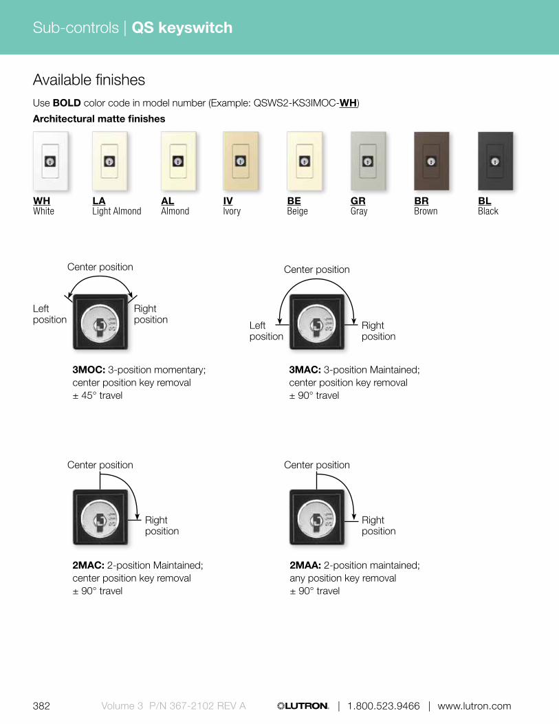
382 | 1.800.523.9466 | www.lutron.comVolume 3 P/N 367-2102 REV A
Sub-controls | QS keyswitch
2MAA: 2-position maintained;any position key removal± 90° travel
3MOC: 3-position momentary;center position key removal± 45° travel
2MAC: 2-position Maintained;center position key removal± 90° travel
3MAC: 3-position Maintained;center position key removal± 90° travel
Center position
Left position
Right position
Center position
Right position
Center position
Right position
Left position
Center position
Right position
Architectural matte finishes
Use BOLD color code in model number (Example: QSWS2-KS3IMOC-WH)
LALight Almond
ALAlmond
IVIvory
GRGray
BRBrown
BLBlack
WHWhite
Available finishes
BEBeige

383 | 1.800.523.9466 | www.lutron.com www.lutron.com | 1.800.523.9466 | Volume 3 P/N 367-2102 REV A
Sub-controls | QS keyswitch
Keyswitch
Model numbersAvailable models(Available in insert and non-insert styles, non-insert style shown)
Keyswitch
3-position momentary; center position key removal
Non-insert style QSWS2-KS3NMOC-XX1-E1 Insert style QSWS2-KS3IMOC-XX1-E1
3-position maintained; center position key removal
Non-insert style QSWS2-KS3NMAC-XX1-E1 Insert style QSWS2-KS3IMAC-XX1-E1
2-position maintained; center position key removal
Non-insert style QSWS2-KS2NMAC-XX1-E1 Insert style QSWS2-KS2IMAC-XX1-E1
2-position maintained; any position key removal
Non-insert style QSWS2-KS2NMAA-XX1-E1 Insert style QSWS2-KS2IMAA-XX1-E1
Compatible with the Quantum® system.
XX1: Architectural matte color codes, see pg. 382
E1: Engraving form required with order. If engraving not desired, omit “E”.

| 1.800.523.9466 | www.lutron.com
Sub-controls |
384 | 1.800.523.9466 | www.lutron.comVolume 3 P/N 367-2102 REV A
Features and capacities• Available with 1-7 buttons• Models available in 14 button configurations with
options for raise/lower and infrared receiver• Large, backlit button are easy to see• Backlit buttons make it easy to find and operate
the keypad in low-light conditions• Each keypad includes two contact closure
inputs on the back• Functionality determined in the field and
programmed via HomeWorks QS software• Operates at 24 V DC• Coordinating Claro®, Satin Colors® and Stainless
Steel faceplates available separately, see pg. 640• Multi-gang faceplates also available;
up to 6-gang, see pgs. 642-643• For information on engraving, text symbols and
backlit buttons/backlit texts, see pgs. 667-668
Dimensions and mounting• Width: 2.94 in (75 mm)
Height: 4.69 in (119 mm) Depth: 1.31 in (33 mm) Profile: 0.31 in (8 mm)
• Mounts in a standard 1-gang U.S. backbox
Communication and wiring• Communicates via low-voltage IEC PELV/NEC
Class 2 wire to HomeWorks QS processor on the QS link
• Each QS link on a HomeWorks QS processor can have up to 99 devices; the HomeWorks QS seeTouch keypad counts as one device toward the limit
• Uses one power draw unit on the QS link
2.94 in (75 mm)
4.69 in (119 mm
)
0.31 in (8 mm) profile
1.31 in (33 mm) depth
Shown above: HomeWorks QS designer-style seeTouch wired 5-button keypad with raise/lower in White (HQWD-W5BRL-WH) and 1-gang Claro® faceplate in White (CW-1-WH)
HomeWorks® QS designer-style seeTouch® wired keypad
Download specification submittalDownload high resolution product imageDownload engraving sheet for button kits

385 | 1.800.523.9466 | www.lutron.com www.lutron.com | 1.800.523.9466 | Volume 3 P/N 367-2102 REV A
Sub-controls |
| 1.800.523.9466 | www.lutron.com
HomeWorks® QS designer-style seeTouch® wired keypad
Available finishes
Buttons B
Faceplate FEngraving E
Gloss finishes*
Use BOLD color code in model number (Example: HQWD-W2RLD-WH)
Satin finishes*
Coordinating faceplates only available separately. For faceplate information, see pg. 642.
WHWhite F, BGray E
LALight Almond F, BGray E
ALAlmond F, BGray E
IVIvory F, BGray E
GRGray F, B White E
BRBrown F, BWhite E
BLBlack F, BWhite E
PLPlum FTaupe BGray E
BGBluestone FGray BWhite E
TQTurquoise FGray BWhite E
GBGreenbriar FGray BWhite E
GSGoldstone FIvory BGray E
DSDesert Stone FTaupe BGray E
TPTaupe F, BGray E
ESEggshell F, BGray E
BIBiscuit F, BGray E
SWSnow F, BGray E
PDPalladium FGray BWhite E
STStone FGray BWhite E
LSLimestone FGray BWhite E
TCTerracotta FTaupe BGray E
SISienna FBrown BWhite E
HTHot FTaupe BGray E
MRMerlot FTaupe BGray E
MNMidnight F, BWhite E
SSStainless Steel FBlack B (default)White E
MSMocha Stone FTaupe BGray E

386 | 1.800.523.9466 | www.lutron.comVolume 3 P/N 367-2102 REV A
Sub-controls | HomeWorks® QS designer-style seeTouch® wired keypad
Explanation of features
HomeWorks QS designer-style seeTouch wired keypad
0.31 in (8 mm)
1.31 in (33 mm)
43
2
1
Features
1 Programmable buttons
• Available with 1-7 buttons• Buttons provide control of
lights, shades and HVAC
2 Status LEDs • Show which keypad buttons have been activated
3 Infrared (IR) receiver
• Accepts infrared (IR) commands from a Lutron® IR remote or third-party universal remote
4 Raise/lower buttons
• Lights increase or decrease in intensity or shades/draperies move towards the open/close limit

387 | 1.800.523.9466 | www.lutron.com www.lutron.com | 1.800.523.9466 | Volume 3 P/N 367-2102 REV A
Sub-controls | HomeWorks® QS designer-style seeTouch® wired keypad
Available models
5-button with raise/lower and infrared receiver
Dual group with raise/lower dual
Dual groupDual group with raise/lower
6-button with raise/lower
2-button 4-button
5-button
3-button1-button
6-button 7-button
4-scene with raise/lower
5-button with raise/lower
3-button spaced with raise/lower

| 1.800.523.9466 | www.lutron.com388 | 1.800.523.9466 | www.lutron.comVolume 3 P/N 367-2102 REV A
Sub-controls | HomeWorks® QS designer-style seeTouch® wired keypad
Keypads
1-button HQWD-W1B-XX1
2-button HQWD-W2BS-XX1
3-button HQWD-W3BS-XX1
4-button HQWD-W4BS-XX1
5-button HQWD-W5B-XX1
6-button HQWD-W6B-XX1
7-button HQWD-W7B-XX1
Compatible with HomeWorks QS system.
Keypads with raise/lower
3-button with raise/lower HQWD-W3BSRL-XX1
4-scene with raise/lower HQWD-W4S-XX1
5-button with raise/lower HQWD-W5BRL-XX1
6-button with raise/lower HQWD-W6BRL-XX1
Compatible with HomeWorks QS system.
Keypads with raise/lower and infrared (IR) receiver
5-button with raise/lower HQWD-W5BIR-XX1 and IR receiverCompatible with HomeWorks QS system.
Dual group keypads
Dual group HQWD-W2RLD-XX1 with raise/lower
Dual group HQWD-W1RLD-XX1 with dual raise/lower
Dual group HQWD-W3BD-XX1
Compatible with HomeWorks QS system.
Model numbers
XX1: Gloss and Satin Color® codes, see pg. 385E1: Engraving form required with order.
If engraving not desired, omit “E”.
Engraved replacement kits
1-button RKD-W1B-XX1-E1
2-button RKD-W2BS-XX1-E1
3-button RKD-W3BS-XX1-E1
4-button RKD-W4BS-XX1-E1
5-button RKD-W5B-XX1-E1
6-button RKD-W6B-XX1-E1
7-button RKD-W7B-XX1-E1
3-button with raise/lower RKD-W3BSRL-XX1-E1
4-scene with raise/lower RKD-W4S-XX1-E1
5-button with raise/lower RKD-W5BRL-XX1-E1
5-button with raise/lower RKD-W5BIR-XX1-E1 and IR receiver
6-button with raise/lower RKD-W6BRL-XX1-E1
Dual group with raise/lower RKD-W2RLD-XX1-E1
Dual group with RKD-W1RLD-XX1-E1 dual raise/lower
Dual group RKD-W3BD-XX1-E1
Includes buttons and insert.IR replacement kit requires IR keypad with IR functionality.Compatible with HomeWorks QS designer-style seeTouch wired keypads.

Sub-controls |
389 | 1.800.523.9466 | www.lutron.com www.lutron.com | 1.800.523.9466 | Volume 3 P/N 367-2102 REV A | 1.800.523.9466 | www.lutron.com
HomeWorks® QS designer-style seeTouch® wireless keypad
2.94 in (75 mm)
4.69 in (119 mm
)
0.31 in (8 mm) profile
1.40 in (36 mm) depth
Features and capacities• Available with 1-7 buttons• Models available in 14 button configurations with
options for raise/lower• Large, backlit button are easy to use• Backlit buttons or text make it easy to find and
operate the keypad in low-light conditions• Each keypad includes two contact closure inputs
on the back• Functionality determined in the field and
programmed via HomeWorks QS software• Operates at 120 V• Coordinating Claro®, Satin Colors® and Stainless
Steel faceplates available separately, see pg. 640• Multi-gang faceplates also available; up to
6-gang, see pgs. 642-643• For information on engraving, text symbols and
backlit buttons/backlit text, see pgs. 667-668
Dimensions and mounting• Width: 2.94 in (75 mm)
Height: 4.69 in (119 mm) Depth: 1.40 in (36 mm) Profile: 0.31 in (8 mm)
• Mounts in a standard 1-gang U.S. backbox
Communication and wiring• Communicates via Lutron reliable Clear Connect®
radio frequency (RF) technology to other Lutron wireless devices
• Operates at 434 MHz• Requires a neutral wire• Must be located within 30 ft (9 m) of a hybrid
repeater• HomeWorks QS system can have up to
99 devices per RF link
Shown actual size: HomeWorks QS designer-style seeTouch wireless 5-button with raise/lower keypad n White (HQRD-W5BRL-WH) and 1-gang Claro® faceplate in White (CW-1-WH)
Download specification submittalDownload high resolution product imageDownload engraving sheet for button kits
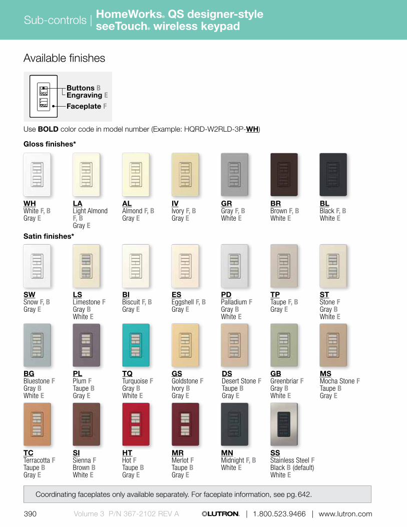
390 | 1.800.523.9466 | www.lutron.comVolume 3 P/N 367-2102 REV A
Sub-controls | HomeWorks® QS designer-style seeTouch® wireless keypad
Available finishes
Buttons B
Faceplate F
Engraving E
Gloss finishes*
Use BOLD color code in model number (Example: HQRD-W2RLD-3P-WH)
Satin finishes*
Coordinating faceplates only available separately. For faceplate information, see pg. 642.
WHWhite F, BGray E
LALight Almond F, BGray E
ALAlmond F, BGray E
IVIvory F, BGray E
GRGray F, B White E
BRBrown F, BWhite E
BLBlack F, BWhite E
PLPlum FTaupe BGray E
BGBluestone FGray BWhite E
TQTurquoise FGray BWhite E
GBGreenbriar FGray BWhite E
GSGoldstone FIvory BGray E
DSDesert Stone FTaupe BGray E
TPTaupe F, BGray E
ESEggshell F, BGray E
BIBiscuit F, BGray E
SWSnow F, BGray E
PDPalladium FGray BWhite E
STStone FGray BWhite E
LSLimestone FGray BWhite E
TCTerracotta FTaupe BGray E
SISienna FBrown BWhite E
HTHot FTaupe BGray E
MRMerlot FTaupe BGray E
MNMidnight F, BWhite E
SSStainless Steel FBlack B (default)White E
MSMocha Stone FTaupe BGray E

391 | 1.800.523.9466 | www.lutron.com www.lutron.com | 1.800.523.9466 | Volume 3 P/N 367-2102 REV A
Sub-controls | HomeWorks® QS designer-style seeTouch® wireless keypad
Explanation of features
2
1
HomeWorks QS designer-style seeTouch wireless keypad
0.31 in (8 mm)
1.09 in (28 mm)
Features
1 Programmable buttons
• Available with 1-7 buttons• Buttons provide control of
lights, shades and HVAC
2 Status LEDs • Show which keypad buttons have been activated

392 | 1.800.523.9466 | www.lutron.comVolume 3 P/N 367-2102 REV A
Sub-controls | HomeWorks® QS designer-style seeTouch® wireless keypad
Available models
Dual group with raise/lower
Dual groupDual group with dual raise/lower
6-button with raise/lower
2-button 4-button
5-button
3-button1-button
6-button 7-button
4-scene with raise/lower
5-button with raise/lower
3-button with raise/lower

393 | 1.800.523.9466 | www.lutron.com www.lutron.com | 1.800.523.9466 | Volume 3 P/N 367-2102 REV A
Sub-controls |
Keypads
1-button HQRD-W1B-XX1
2-button HQRD-W2BS-XX1
3-button HQRD-W3BS-XX1
4-button HQRD-W4BS-XX1
5-button HQRD-W5B-XX1
6-button HQRD-W6B-XX1
7-button HQRD-W7B-XX1
Compatible with HomeWorks QS system.
Keypads with raise/lower
3-button with raise/lower HQRD-W3BSRL-XX1
4-scene with raise/lower HQRD-W4S-XX1
5-button with raise/lower HQRD-W5BRL-XX1
6-button with raise/lower HQRD-W6BRL-XX1
Compatible with HomeWorks QS system.
Dual group keypads
Dual group with raise/lower HQRD-W1RLD-XX1
Dual group HQRD-W2RLD-XX1 with dual raise/lower
Dual group HQRD-W3BD-XX1
Compatible with HomeWorks QS system.
Model numbers
XX1: Gloss and Satin Color® codes, see pg. 390E1: Engraving form required with order.
If engraving not desired, omit “E”.
HomeWorks® QS designer-style seeTouch® wireless keypad
Engraved replacement kit
1-button RKD-W1B-XX1-E1
2-button RKD-W2BS-XX1-E1
3-button RKD-W3BS-XX1-E1
4-button RKD-W4BS-XX1-E1
5-button RKD-W5B-XX1-E1
6-button RKD-W6B-XX1-E1
7-button RKD-W7B-XX1-E1
3-button with raise/lower RKD-W3BSRL-XX1-E1
4-scene with raise/lower RKD-W4S-XX1-E1
5-button with raise/lower RKD-W5BRL-XX1-E1
6-button with raise/lower RKD-W6BRL-XX1-E1
Dual group with raise/lower RKD-W1RLD-XX1-E1
Dual group RKD-W2RLD-XX1-E1 with dual raise/lower
Dual group RKD-W3BD-XX1-E1
Includes buttons and insert.Compatible with HomeWorks QS designer-style seeTouch keypads.
For specific radio frequency by country, refer to the radio frequency chart on pg. 695. For specific voltage by country information refer to the voltage chart on pg. 692.

| 1.800.523.9466 | www.lutron.com
Sub-controls |
394 | 1.800.523.9466 | www.lutron.comVolume 3 P/N 367-2102 REV A
Features and capacities• Available with 1-7 buttons in insert and
non-insert style• Models available in 15 button configurations with
options for raise/lower and infrared receiver• Large, backlit buttons are easy to use• Backlit buttons or text make it easy to find and
operate the keypad in low light conditions• Each keypad includes two contact closure inputs
on the back• Functionality determined in the field and
programmed via HomeWrks QS software• Operates at 24 V DC• For information on engraving, text symbols and
backlit buttons/backlit text, see pgs. 667-668• Multi-gang faceplates available
Dimensions and mounting• Width: 2.75 in (70 mm)
Height: 4.56 in (116 mm) Depth: 1.06 in (28 mm) Profile: 0.31 in (8 mm)
• Mounts in a standard 1-gang U.S. backbox
Communication and wiring• Communicates via low-voltage IEC PELV/NEC
Class 2 to HomeWorks QS processor on the QS link
• Each QS link on a HomeWorks QS processor can have up to 99 devices; the HomeWorks QS seeTouch keypad counts as one device toward the limit
• Uses one power draw unit on the QS link
2.75 in (70 mm)
4.56 in (116 mm
)
0.31 in (8 mm) profile
1.06 in (28 mm) depth
Shown above: Non-insert HomeWorks QS Architectural-style seeTouch 5-button keypad with raise/lower in White (HQWA-W5BRLN-WH)
Download specification submittalDownload high resolution product imageDownload engraving sheet for button kits
HomeWorks® QS Architectural-style seeTouch® keypad

395 | 1.800.523.9466 | www.lutron.com www.lutron.com | 1.800.523.9466 | Volume 3 P/N 367-2102 REV A
Sub-controls |
| 1.800.523.9466 | www.lutron.com
Architectural matte finishes (Available for insert and non-insert style keypads; coordinating faceplates included)
GRGray F, BWhite E
BRBrown F, BWhite E
BLBlack F, BWhite E
BEBeige F, BGray E
IVIvory F, BGray E
LALight Almond F, BGray E
WHWhite F, BGray E
ALAlmond F, BGray E
Architectural metal finishes (Available for insert and non-insert style keypads; coordinating faceplates included)
CLAClear Anodized Aluminum FBlack BWhite E
BCBright Chrome FBlack BWhite E
BNBright Nickel FBlack BWhite E
SCSatin Chrome FBlack BWhite E
SNSatin Nickel FBlack BWhite E
QZAntique Bronze FBlack BWhite E
BRABrass Anodized Aluminum FBlack BWhite E
SBSatin Brass FBlack BWhite E
QBAntique Brass FBlack BWhite E
BLABlack Anodized Aluminum FBlack BWhite E
BBBright Brass FBlack BWhite E
Available finishesAvailable finishes
Use BOLD color code in model number (Example: HQWA-W5BRLI-WH)
Faceplate F
Buttons BEngraving E
HomeWorks® QS Architectural-style seeTouch® keypad

396 | 1.800.523.9466 | www.lutron.comVolume 3 P/N 367-2102 REV A
Sub-controls |
Explanation of features Features
1 Status LEDs• Show which keypad buttons have
been activated
2 Programmable buttons
• Available with 1-7 buttons• Buttons provide control of lights,
shades and HVAC
3 Raise/lower buttons
• Lights increase or decrease in intensity or shades/drapes move toward the open/close limit
0.31 in (8 mm)
1.06 in (28 mm)
1
3
2
Non-insert HomeWorks QS Architectural-style seeTouch keypad
HomeWorks® QS Architectural-style seeTouch® keypad

397 | 1.800.523.9466 | www.lutron.com www.lutron.com | 1.800.523.9466 | Volume 3 P/N 367-2102 REV A
Sub-controls |
1-button
5-button
3-button with raise/lower
5-button with raise/lower
6-button with raise/lower
4-scene with raise/lower
5-button with infrared receiver and raise/lower
2-button
6-button
Dual group with dual raise/lower
Dual groupDual group with raise/lower
3-button
7-button
4-button
Available models(Available in insert and non-insert styles, non-insert style shown)
HomeWorks® QS Architectural-style seeTouch® keypad

398 | 1.800.523.9466 | www.lutron.comVolume 3 P/N 367-2102 REV A
Sub-controls | HomeWorks® QS Architectural-style seeTouch® keypad
Keypads with raise/lower
3-button with raise/lower
Non-insert style HQWA-W3BSRLN-XX1
Insert style HQWA-W3BSRLI-XX1
4-scene with raise/lower
Non-insert style HQWA-W4SN-XX1
Insert style HQWA-W4SI-XX1
5-button with raise/lower
Non-insert style HQWA-W5BRLN-XX1
Insert style HQWA-W5BRLI-XX1
6-button with raise/lower
Non-insert style HQWA-W6BRLN-XX1
Insert style HQWA-W6BRLI-XX1
Compatible with HomeWorks QS system.
Keypads with raise/lower and infrared (IR) receiver
5-button with raise/lower and IR receiver
Non-insert style HQWA-W5BIRN-XX1
Insert style HQWA-W5BIRI-XX1
Compatible with HomeWorks QS system.
Dual group keypads
Dual group with raise/lower
Non-insert style HQWA-W1RLDN-XX1
Insert style HQWA-W1RLDI-XX1
Dual group with dual raise/lower
Non-insert style HQWA-W2RLDN-XX1
Insert style HQWA-W2RLDI-XX1
Dual group
Non-insert style HQWA-W3BDN-XX1
Insert style HQWA-W3BDI-XX1
Compatible with HomeWorks QS system.
Model numbersKeypads
1-button
Non-insert style HQWA-W1BN-XX1
Insert style HQWA-W1BI-XX1
2-button
Non-insert style HQWA-W2BSN-XX1
Insert style HQWA-W2BSI-XX1
3-button
Non-insert style HQWA-W3BSN-XX1
Insert style HQWA-W3BSI-XX1
4-button
Non-insert style HQWA-W4BSN-XX1
Insert style HQWA-W4BSI-XX1
5-button
Non-insert style HQWA-W5BN-XX1
Insert style HQWA-W5BI-XX1
6-button
Non-insert style HQWA-W6BN-XX1
Insert style HQWA-W6BI-XX1
7-button
Non-insert style HQWA-W7BN-XX1
Insert style HQWA-W7BI-XX1
Compatible with HomeWorks QS system.
XX1: Architectural matte and metal finish codes, see pg. 395

399 | 1.800.523.9466 | www.lutron.com www.lutron.com | 1.800.523.9466 | Volume 3 P/N 367-2102 REV A
Sub-controls | HomeWorks® QS Architectural-style seeTouch® keypad
Engraved replacement kits with raise/lower
3-button with raise/lower
Non-insert style RKA-W3BSRLN-XX1-E1
Insert style RKA-W3BSRLI-XX1-E1
4-scene with raise/lower
Non-insert style RKA-W4SN-XX1-E1
Insert style RKA-W4SI-XX1-E1
5-button with raise/lower
Non-insert style RKA-W5BRLN-XX1-E1
Insert style RKA-W5BRLI-XX1-E1
6-button with raise/lower
Non-insert style RKA-W6BRLN-XX1-E1
Insert style RKA-W6BRLI-XX1-E1
Includes faceplate, buttons and insert (when applicable)Compatible with HomeWorks QS seeTouch keypads.
Engraved replacement kits with raise/lower and infrared (IR) receiver
5-button with raise/lower and IR receiver
Non-insert style RKA-W5BIRN-XX1-E1
Insert style RKA-W5BIRI-XX1-E1
Includes faceplate, buttons and insert (when applicable)Compatible with HomeWorks QS seeTouch keypads.IR replacement kits require IR keypads with IR functionality
Model numbersEngraved replacement kits
1-button
Non-insert style RKA-W1BN-XX1-E1
Insert style RKA-W1BI-XX1-E1
2-button
Non-insert style RKA-W2BSN-XX1-E1
Insert style RKA-W2BSI-XX1-E1
3-button
Non-insert style RKA-W3BSN-XX1-E1
Insert style RKA-W3BSI-XX1-E1
4-button
Non-insert style RKA-W4BSN-XX1-E1
Insert style RKA-W4BSI-XX1-E1
5-button
Non-insert style RKA-W5BN-XX1-E1
Insert style RKA-W5BI-XX1-E1
6-button
Non-insert style RKA-W6BN-XX1-E1
Insert style RKA-W6BI-XX1-E1
7-button
Non-insert style RKA-W7BN-XX1-E1
Insert style RKA-W7BI-XX1-E1
Includes faceplate, buttons and insert (when applicable)Compatible with HomeWorks QS seeTouch keypads.
Insert style faceplate kits include faceplate, buttons, and insert.Non-insert style faceplate kits include faceplate and buttons only.Replacement kits ordered separately.
XX1: Architectural matte and metal finish codes, see pg. 395
E1: Engraving form required with order. If engraving not desired, omit “E”.

| 1.800.523.9466 | www.lutron.com400 | 1.800.523.9466 | www.lutron.comVolume 3 P/N 367-2102 REV A
Sub-controls |
Insert style faceplate kits include faceplate, buttons, and insert.Non-insert style faceplate kits include faceplate and buttons only.Replacement kits ordered separately.
XX1: Architectural matte and metal finish codes, see pg. 395
E1: Engraving form required with order. If engraving not desired, omit “E”.
Engraved Dual group replacement kits
Dual group with raise/lower
Non-insert style RKA-W1RLDN-XX1-E1
Insert style RKA-W1RLDI-XX1-E1
Dual group with dual raise/lower
Non-insert style RKA-W2RLDN-XX1-E1
Insert style RKA-W2RLDI-XX1-E1
Dual group
Non-insert style RKA-W3BDN-XX1-E1
Insert style RKA-W3BDI-XX1-E1
Includes faceplate, buttons and insert (when applicable)Compatible with HomeWorks QS seeTouch keypads.
HomeWorks® QS Architectural-style seeTouch® keypad

Sub-controls |
401 | 1.800.523.9466 | www.lutron.com www.lutron.com | 1.800.523.9466 | Volume 3 P/N 367-2102 REV A | 1.800.523.9466 | www.lutron.com
Features and capacities• Available with 2-10 buttons in insert and
non-insert style• Models available in 10 button
configurations with options for raise/lower and IR receiver
• Large, rounded buttons are easy to use• Backlit buttons or text make it easy
to find and operate the keypad in low light conditions
• Each keypad includes two contact closure inputs on the back of the keypad
• Operates at 24 V DC• Complete keypad created by ordering
base unit (with or without IR receiver) and button/faceplate kit
• For information on engraving, text symbols, and backlit buttons/backlit text, see pgs. 667-668
Dimensions and mounting• Width: 3.38 in (86 mm)
Height: 3.38 in (86 mm) Depth: 1.00 in (25 mm) Profile: 0.25 in (6 mm)
• Mounts in either a round plastic backbox (EBB-15-RD, order separately) or a square metal backbox (EBB-15-SQ, order separately)
Communication and wiring• Communicates via low-voltage IEC PELV/
NEC Class 2 wire to HomeWorks QS processor on the QS link
• Each QS link on a HomeWorks QS processor can have 99 devices; the HomeWorks QS seeTouch keypad counts as one device toward the limit
• Uses one power draw unit on QS link
Shown above: Non-insert style HomeWorks QS International seeTouch 8-button keypad with infrared (IR) receiver and raise/lower in White (HWIS-8BRLIR-F-WH)
3.38 in (86 mm)
3.38 in (86 mm
)
0.25 in (6 mm) profile
1.00 in (25 mm) depth
HomeWorks® QS International seeTouch® keypad
Download specification submittal

402 | 1.800.523.9466 | www.lutron.comVolume 3 P/N 367-2102 REV A
Sub-controls |
Buttons B
Faceplate F
Matte finishes Metallic finishes
Special metal finishes
AWArctic White F, BGray E
ARArgentum F Black BWhite E
MCMica F Black BWhite E
Metal finishes
SNSatin Nickel F Black BWhite E
BNBright Nickel F Black BWhite E
SBSatin Brass F Black BWhite E
BBBright Brass F Black BWhite E
BCBright Chrome F Black B
SCSatin Chrome F Black BWhite E
QZAntique Bronze F Black BWhite E
AUGold Plated F Black BWhite E
QBAntique Brass F Black BWhite E
Use BOLD color code in model number (Example: HWIS-8BRL-I-AW)
Available finishes
Color code indicates faceplate color. Models include button kit in coordinating colors as shown.
Text engraving color varies by button color. Lighter colored buttons use gray text and darker colored buttons use white text. Visit www.lutron.com/engraving for further information.
Engraving E
HomeWorks® QS International seeTouch® keypad

403 | 1.800.523.9466 | www.lutron.com www.lutron.com | 1.800.523.9466 | Volume 3 P/N 367-2102 REV A
Sub-controls |
Explanation of features Features
1 Status LEDs • Show which keypad buttons have been activated
2 Programmable buttons
• Available with 2-10 button options
• Buttons provide control of lights, shades and HVAC
3 Infrared (IR)receiver
• Accepts IR commands from a Lutron® remote or third-party universal remote
4 Raise/lower buttons
• Lights increase or decrease in intensity or shades/draperies move toward the open/close limit
0.25 in (6 mm)
1.00 in (25 mm)
3
21
4
Non-insert style HomeWorks QS International seeTouch keypad
HomeWorks® QS International seeTouch® keypad

404 | 1.800.523.9466 | www.lutron.comVolume 3 P/N 367-2102 REV A
Sub-controls |
2-button
5-button with raise/lower
8-button with raise/lower
5-button with raise/lower and infrared (IR) receiver
3-button
6-button with raise/lower
10-button with raise/lower
8-button with raise/lower and IR receiver
4-button
7-button with raise/lower
Available models(Insert and non-insert styles, non-insert style shown) Base units
Keypad without faceplate HQWIS-NB-NONE or button kit
Keypad with IR receiver HQWIS-NBIR-NONE without faceplate or button kitCompatible with HomeWorks QS system.
Button/faceplate kit
2-button
Non-insert style HWIS-2B-F-XX1
Insert style HWIS-2B-I-XX1
3-button
Non-insert style HWIS-3B-F-XX1
Insert style HWIS-3B-I-XX1
4-button
Non-insert style HWIS-4B-F-XX1
Insert style HWIS-5B-I-XX1
Includes faceplate, buttons and insert (when applicable)Compatible with HomeWorks QS International seeTouch keypad base units.
Model numbers
HomeWorks® QS International seeTouch® keypad
XX1: Matte, metallic and metal finish codes, see pg. 402

405 | 1.800.523.9466 | www.lutron.com www.lutron.com | 1.800.523.9466 | Volume 3 P/N 367-2102 REV A
Sub-controls | HomeWorks® QS International seeTouch® keypad
Button/faceplate kit with raise/lower
5-button with raise/lower
Non-insert style HWIS-5BRL-F-XX1
Insert style HWIS-5BRL-I-XX1
6-button with raise/lower
Non-insert style HWIS-6BRL-F-XX1
Insert style HWIS-6BRL-I-XX1
7-button with raise/lower
Non-insert style HWIS-7BRL-F-XX1
Insert style HWIS-7BRL-I-XX1
8-button with raise/lower
Non-insert style HWIS-8BRL-F-XX1
Insert style HWIS-8BRL-I-XX1
10-button with raise/lower
Non-insert style HWIS-10BRL-F-XX1
Insert style HWIS-10BRL-I-XX1
Includes faceplate, buttons and insert (when applicable)Compatible with HomeWorks QS International seeTouch keypad base units.
Button/faceplate kit with raise/lower and infrared (IR) receiver
5-button with raise/lower and IR receiver
Non-insert style HWIS-5BIR-F-XX1
Insert style HWIS-5BIR-I-XX1
8-button with raise/lower and IR receiver
Non-insert style HWIS-8BIR-F-XX1
Insert style HWIS-8BIR-I-XX1
Includes faceplate, buttons and insert (when applicable)IR button/faceplate kits require IR keypad base unit with IR functionalityCompatible with HomeWorks QS International seeTouch keypad base units.
Engraved replacement button kits
2-button SIB-2B-XX1-E1
3-button SIB-3B-XX1-E1
4-button SIB-4B-XX1-E1
5-button with raise/lower SIB-5BRL-XX1-E1
5-button with raise/lower SIB-5BIR-XX1-E1 and IR receiver
6-button with raise/lower SIB-6BRL-XX1-E1
7-button with raise/lower SIB-7BRL-XX1-E1
8-button with raise/lower SIB-8BRL-XX1-E1
8-button with raise/lower SIB-8BIR-XX1-E1 and IR receiver
10-button with raise/lower SIB-10BRL-XX1-E1
IR button/faceplate kits require IR keypad base unit with IR functionalityCompatible with HomeWorks QS International seeTouch keypad base units.
XX1: Matte, metallic and metal finish codes, see pg. 402
E1: Engraving form required with order. If engraving not desired, omit “E”.

| 1.800.523.9466 | www.lutron.com
Sub-controls |
406 | 1.800.523.9466 | www.lutron.comVolume 3 P/N 367-2102 REV A
HomeWorks® QS wireless tabletop keypad
Features and capacities• Available with 5-15 buttons with
raise/lower and options for master on/off buttons
• Programmable to select whole-home, single-room preset levels or single zones of lights, shades or HVAC
• Functionality determined in the field and programmed via HomeWorks QS software
• Large, backlit buttons are easy to use• Backlit buttons or text make it easy to
find and operate the keypad in low-light condition
• For information on engraving, text symbols and backlit buttons/backlit text, see pgs. 667-668
• Keypads can be powered by DC adapter (included) or with two AAA batteries
• Adjustable keypad backlighting
Dimensions and mounting• Width: 3.56 in (90 mm);
Height: 3.25 in (83 mm); Top depth: 1.00 in (25 mm); Bottom depth: 0.75 in (19 mm)
• Mounting bracket included for optional wall-mounting
Communication and wiring• Communicates via Lutron® reliable
Clear Connect® RF technology to other Lutron wireless devices
• Operates at 434 MHz• Must be located within 30 ft (9 m)
of a hybrid repeater• HomeWorks QS system can have
up to 99 devices per radio frequency (RF) link
Shown actual size: HomeWorks QS 10-button with master on/off and raise/lower tabletop keypad in Snow (HQR-T10RL-SW)
3.56 in (90 mm)
3.25 in (83 mm
)0.75 in (19 mm) bottom depth
1.00 in (25 mm) top depth
Download specification submittalDownload high resolution product imageDownload engraving sheet for button kits

407 | 1.800.523.9466 | www.lutron.com www.lutron.com | 1.800.523.9466 | Volume 3 P/N 367-2102 REV A
Sub-controls |
| 1.800.523.9466 | www.lutron.com
HomeWorks® QS wireless tabletop keypad
Features
1 Status LEDs • Show status of devices being controlled
2 Backlit buttons or text
• Easy to read and use in low-light conditions
3 Programmable buttons
• Press to activate desired light levels, shade positions, or HVAC settings
• Available in three columns for 5, 10 or 15 buttons
4 Raise/lower buttons
• Lights increase or decrease in intensity or shades/draperies move towards the open/close limit
Explanation of features
1.00 in (25 mm)
0.75 in (19 mm)
1
2
4
HomeWorks QS wireless tabletop keypad
3

408 | 1.800.523.9466 | www.lutron.comVolume 3 P/N 367-2102 REV A
Sub-controls |
Tabletop keypad (434 MHz)
5-button with master on/off HQR-T5RL-XX1 and raise/lower10-button with master on/off HQR-T10RL-XX1 and raise/lower15-button with master on/off HQR-T15RL-XX1 and raise/lower5-button with column raise/lower HQR-T5CRL-XX1
10-button with column raise/lower HQR-T10CRL-XX1
15-button with column raise/lower HQR-T15CRL-XX1
Compatible with HomeWorks QS system.
Tabletop keypads (434 MHz - Brazil)
5-button with master on/off HQR-T5RL-XX1 -BA and raise/lower10-button with master on/off HQR-T10RL-XX1-BA and raise/lower15-button with master on/off HQR-T15RL-XX1-BA and raise/lower5-button with master on/off HQR-T5CRL-XX1-BA10-button with master on/off HQR-T10CRL-XX1-BA15-button with master on/off HQR-T15CRL-XX1-BACompatible with HomeWorks QS system.
Tabletop keypads (868 MHz)
5-button with master on/off HQK-T5RL-XX1 and raise/lower10-button with master on/off HQK-T10RL-XX1 and raise/lower15-button with master on/off HQK-T15RL-XX1 and raise/lower5-button with master on/off HQK-T5CRL-XX1
10-button with master on/off HQK-T10CRL-XX1
15-button with master on/off HQK-T15CRL-XX1
Compatible with HomeWorks QS system.
HomeWorks® QS wireless tabletop keypad
5-button with master on/off and raise/lower
5-button with column raise/lower
10-button with master on/off and raise/lower
10-button with column raise/lower
15-button with master on/off and raise/lower
15-button with column raise/lower
Available models
Model numbers
XX1: Available in Snow (SW) and Midnight (MN)
SWSnow
MNMidnight
Available finishesSatin finishes
For specific radio frequency by country, refer to the radio frequency chart on pg. 695.

409 | 1.800.523.9466 | www.lutron.com www.lutron.com | 1.800.523.9466 | Volume 3 P/N 367-2102 REV A
Sub-controls |
Engraved button kits
5-button with master on/off LBK-T5RL-XX1-E1 and raise/lower10-button with master on/off LBK-T10RL-XX1-E1 and raise/lower15-button with master on/off LBK-T15RL-XX1-E1 and raise/lower5-button with LBK-T5CRL-XX1-E1 column raise/lower10-button with LBK-T10CRL-XX1-E1 column raise/lower15-button with LBK-T15CRL-XX1-E1 column raise/lowerCompatible with HomeWorks QS wireless tabletop keypads.
Engraved faceplate kits
5-button with master on/off LFK-T5RL-XX2-E1 and raise/lower10-button with master on/off LFK-T10RL-XX2-E1 and raise/lower15-button with master on/off LFK-T15RL-XX2-E1 and raise/lower5-button with LFK-T5CRL-XX2-E1 column raise/lower10-button with LFK-T10CRL-XX2-E1 column raise/lower15-button with LFK-T15CRL-XX2-E1 column raise/lowerIncludes faceplates and buttons.Compatible with HomeWorks QS wireless tabletop keypads.
XX1: Available in Snow (SW) and Midnight (MN)XX2: Architectural matte and metal finishes,
see pg. 395E1: Engraving form required with order.
If engraving not desired, omit “E”.
For specific radio frequency by country, refer to the radio frequency chart on pg. 695.
Tabletop keypads (868 limited channel MHz)
5-button with master on/off HQM-T5RL-XX1 and raise/lower10-button with master on/off HQM-T10RL-XX1 and raise/lower15-button with master on/off HQM-T15RL-XX1 and raise/lower5-button with master on/off HQM-T5CRL-XX1
10-button with master on/off HQM-T10CRL-XX1
15-button with master on/off HQM-T15CRL-XX1
Compatible with HomeWorks QS system.
Tabletop keypads (434 limited channel MHz)
5-button with master on/off HQQ-T5RL-XX1 and raise/lower10-button with master on/off HQQ-T10RL-XX1 and raise/lower15-button with master on/off HQQ-T15RL-XX1 and raise/lower5-button with master on/off HQQ-T5CRL-XX1
10-button with master on/off HQQ-T10CRL-XX1
15-button with master on/off HQQ-T15CRL-XX1
Compatible with HomeWorks QS system.
Tabletop keypads (865 MHz)
5-button with master on/off HQN-T5RL-XX1 and raise/lower10-button with master on/off HQN-T10RL-XX1 and raise/lower15-button with master on/off HQN-T15RL-XX1 and raise/lower5-button with master on/off HQN-T5CRL-XX1
10-button with master on/off HQN-T10CRL-XX1
15-button with master on/off HQN-T15CRL-XX1
Compatible with HomeWorks QS system.
HomeWorks® QS wireless tabletop keypad

| 1.800.523.9466 | www.lutron.com
Sub-controls |
410 | 1.800.523.9466 | www.lutron.comVolume 3 P/N 367-2102 REV A
Features and capacities• Provides the functionality of multiple keypads in an
easy-to-navigate, intuitive arrangement• Control and monitor lighting scenes, individual
lights, or groups of shades in multiple areas of the home
• Capacitive touch interface provides a rich user experience and flexible control for a single room or an entire home
• Three hard buttons provide instant access to frequently used lighting functions
• Create or modify on-screen buttons easily through HomeWorks QS software
• Available for wired or wireless installation• Operates at 24 V DC• Simple, intuitive control of lights, shades/draperies,
compatible HVAC and A/V equipment from a single location
Dimensions and mounting• Width: 2.38 in (60 mm)
Height: 5.13 in (130 mm) Depth: 2.25 in (57 mm) Profile: 0.50 in (13 mm)
• Mounts on the wall using included custom mounting frame
Communication and wiring• Wired dynamic keypad communicates via low-
voltage IEC PELV/NEC Class 2 wire to HomeWorks QS processor on the QS link
• Wireless dynamic keypad communicates via Lutron® reliable Clear Connect® radio frequency (RF) technology to other Lutron wireless devices
• Wireless model operates at 434 MHz• Wireless dynamic keypad must be located within
30 ft (9 m) of a hybrid repeater• HomeWorks QS system can have up to 99 devices
per RF link and QS link• Consumes six power draw units on the QS link
2.38 in (60 mm)
Shown above: HomeWorks QS dynamic keypad in White (HQ-J-DK420-WH)
5.13 in (130 mm
)
0.50 in (13 mm) profile
2.25 in (57 mm) depth
HomeWorks® QS dynamic keypad
Download specification submittalDownload high resolution product image
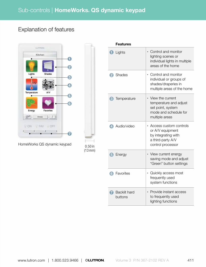
411 | 1.800.523.9466 | www.lutron.com www.lutron.com | 1.800.523.9466 | Volume 3 P/N 367-2102 REV A
Sub-controls |
| 1.800.523.9466 | www.lutron.com
HomeWorks QS dynamic keypad 0.50 in (13 mm)
Features
1 Lights • Control and monitor lighting scenes or individual lights in multiple areas of the home
2 Shades • Control and monitor individual or groups of shades/draperies in multiple areas of the home
3 Temperature • View the current temperature and adjust set point, system mode and schedule for multiple areas
4 Audio/video • Access custom controls or A/V equipment by integrating with a third-party A/V control processor
5 Energy • View current energy saving mode and adjust “Green” button settings
6 Favorites • Quickly access most frequently used system functions
7 Backlit hard buttons
• Provide instant access to frequently used lighting functions
Explanation of features
7
1
2
4
6
3
5
HomeWorks® QS dynamic keypad
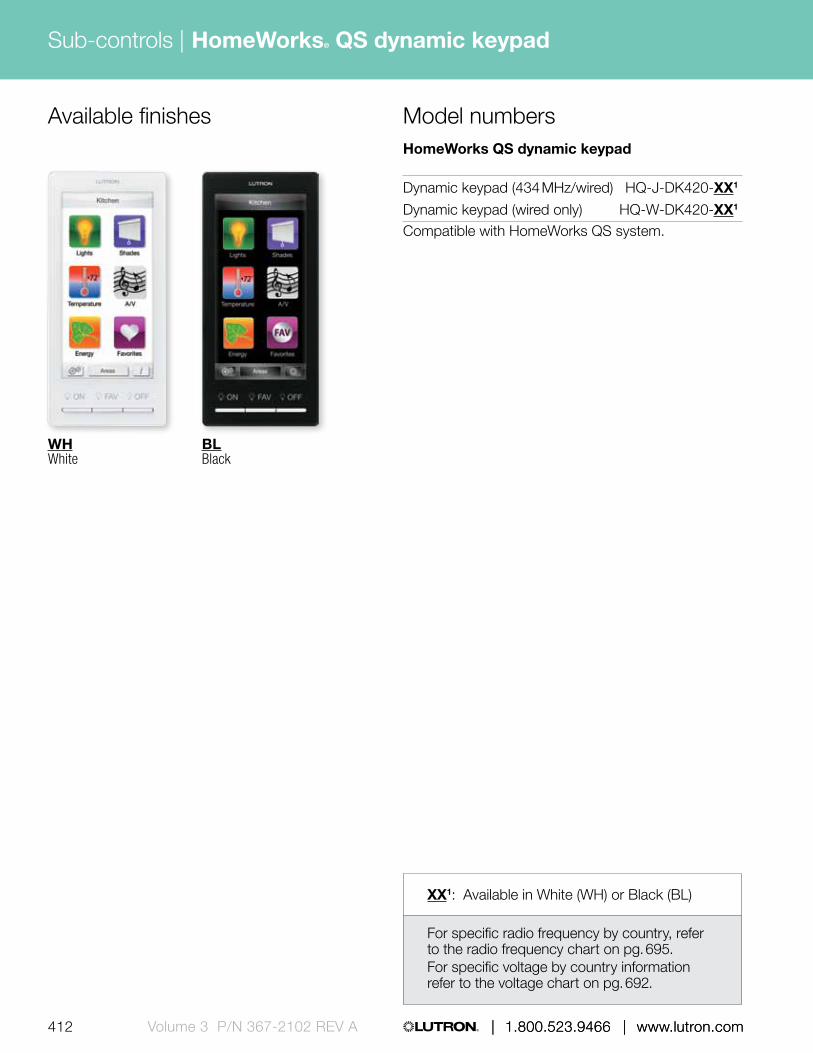
| 1.800.523.9466 | www.lutron.com412 | 1.800.523.9466 | www.lutron.comVolume 3 P/N 367-2102 REV A
Sub-controls |
Available finishesHomeWorks QS dynamic keypad
Dynamic keypad (434 MHz/wired) HQ-J-DK420-XX1
Dynamic keypad (wired only) HQ-W-DK420-XX1
Compatible with HomeWorks QS system.
Model numbers
HomeWorks® QS dynamic keypad
WHWhite
BLBlack
XX1: Available in White (WH) or Black (BL)
For specific radio frequency by country, refer to the radio frequency chart on pg. 695. For specific voltage by country information refer to the voltage chart on pg. 692.

Sub-controls |
413 | 1.800.523.9466 | www.lutron.com www.lutron.com | 1.800.523.9466 | Volume 3 P/N 367-2102 REV A | 1.800.523.9466 | www.lutron.com
HomeWorks® QS visor control transmitter
3.25 in (83 mm)
Shown actual size: HomeWorks QS visor control transmitter in Snow (LR-3B-H-SW)
1.25 in (32 mm
)
0.75 in (19 mm) profile
Features and capacities• Allows lights, shades, HVAC and other
equipment to be controlled from the car with just the touch of a button
• Can activate up to seven different options for lights, shades and HVAC
• Visor control receiver required (available separately), see pg. 509
• Can remotely control the “keypad”, “security input” and “output” buttons on the receiver
• HomeLink® compatible• Battery included; 10-year battery life• Preprinted and blank labels are included
for naming scenes or buttons• Available in Snow (SW)
Dimensions and mounting• Width: 3.25 in (83 mm)
Height: 1.25 in (32 mm) Profile: 0.75 in (19 mm)
• Visor clip included
Communication and wiring• Utilizes HomeLink to communicate with
the receiver• Operates at 390 MHz• Typical operating distance between a receiver
and transmitter is 150 ft (46 m)• Up to ten transmitters can be used
with a single receiver
HomeWorks QS visor control receiver, power cord not shown (available separately, see pg. 509)
Related component
Download specification submittalDownload high resolution product image

| 1.800.523.9466 | www.lutron.com414 | 1.800.523.9466 | www.lutron.comVolume 3 P/N 367-2102 REV A
Sub-controls | HomeWorks® QS visor control transmitter
Explanation of features
Features
1 Labels • Place pre-printed labels in depression to name buttons
2 Visor control transmitter buttons
• Press to activate functions remotely
• Combo presses provide up to seven actions
3 Visor clip • Removable clip0.75 in (19 mm)
Transmitter (390 MHz)
Car visor transmitter LR-3B-H-SWCompatible with HomeWorks QS systems.
Model numbers
HomeWorks QS visor control transmitter
2
1
3

Sub-controls |
415 | 1.800.523.9466 | www.lutron.com www.lutron.com | 1.800.523.9466 | Volume 3 P/N 367-2102 REV A | 1.800.523.9466 | www.lutron.com
seeTemp® wall control
Features and capacities• Provides control and monitoring of a single
HVAC zone• Can be placed at a preferred control location,
without regard for the local temperature, while the wireless temperature sensor is placed where readings will be most accurate
• Celsius and Fahrenheit models available• eco button saves energy by adjusting set points
by a programmed amount• Features flush-mounting and an elegant, slim design• Insert-style allows control to be ganged with other
devices such as dimmers and keypads• Can be used as accessory control for TouchPRO
Wireless® thermostat• Coordinating Claro®, Satin Color® and Stainless
Steel faceplates available separately, see pg. 640
Dimensions and mounting• Width: 2.94 in (75 mm)
Height: 4.69 in (119 mm) Depth: 1.21 in (31 mm) Profile: 0.31 in (8 mm)
• Mounts into a standard 1-gang U.S. backbox
Communication and wiring• Communicates via Lutron reliable Clear Connect®
radio frequency (RF) technology to other Lutron wireless devices
• Operates at 434 MHz• Must be located within 30 ft (9 m) of a
hybrid repeater• HomeWorks QS system can have up to
99 devices per radio frequency (RF) link• Operates at 24 V or 120 V AC• Wires via line-voltage (requires neutral) or
low-voltage IEC PELV/NEC Class 2
2.94 in (75 mm)
Shown actual size: seeTemp wall control (LRD-WST-F-WH) in Fahrenheit configuration and 1-gang Claro faceplate in White (CW-1-WH)
4.69 in (119 mm
)
0.31 in (8 mm) profile
1.21 in (31 mm) depth
Wireless wall-mount temperature sensor(available separately, see pg. 438)
HVAC controller(available separately, see pg. 506)
Related components
Download specification submittalDownload high resolution product image

416 | 1.800.523.9466 | www.lutron.comVolume 3 P/N 367-2102 REV A
Sub-controls | seeTemp® wall control
Gloss finishes*
Use BOLD color code in model number (Example: LRD-WST-F-WH)
WHWhite
LALight Almond
ALAlmond
IVIvory
GRGray
BRBrown
BLBlack
Satin finishes*
MSMocha Stone
TCTerracotta
SISienna
HTHot
MRMerlot
MNMidnight
SS **Stainless Steel (faceplate only)
SWSnow
LSLimestone
BIBiscuit
ESEggshell
PDPalladium
TPTaupe
STStone
BGBluestone
PLPlum
TQTurquoise
GSGoldstone
DSDesert Stone
GBGreenbriar
Available finishes
* Coordinating faceplates only available separately. For faceplate information, see pg. 642.
** Stainless Steel faceplate includes black plastic trim/adapter, visible from side. Match with separate Black (BL) or Midnight (MN) controls.

417 | 1.800.523.9466 | www.lutron.com www.lutron.com | 1.800.523.9466 | Volume 3 P/N 367-2102 REV A
Sub-controls |
0.31 in (8 mm)
1.21 in (31 mm)
Explanation of features
Features
1 Room temperature LEDs
• Column of red LEDs that display the current room temperature
2 Set temperature LEDs
• Column of green LEDs that display the current temperature set point
• Set LED turns off when system is turned off
3 Raise/lower rocker
• Press to raise/lower the set temperature point
4 eco button • Press to toggle eco mode on/off
5 Fan buttons • Indicates current fan setting—button will light up orange when selected
6 Flip-down door • Covers the system and fan buttons
7 System mode buttons
• Buttons will light up according to the following: Heat–red, Cool–blue, Auto–orange, Off–orange
4
3
2
1
5
7
6
seeTemp wall control with lid open
seeTemp® wall control

XX1: Gloss and Satin Color® codes, see pg. 416 (Faceplates not included, order separately, see pg. 416)
| 1.800.523.9466 | www.lutron.com418 | 1.800.523.9466 | www.lutron.comVolume 3 P/N 367-2102 REV A
Sub-controls |
For specific radio frequency by country, refer to the radio frequency chart on pg. 695. For specific voltage by country information refer to the voltage chart on pg. 692.
seeTemp wall control 120 V @ 50/60 Hz 24 V~ Class 2
Fahrenheit model (°F) LRD-WST-F-XX1
Celsius model (°C) LRD-WST-C-XX1
Compatible with HomeWorks QS systems.
Model numbersAvailable models
seeTemp wall control
seeTemp® wall control

Sub-controls |
419 | 1.800.523.9466 | www.lutron.com www.lutron.com | 1.800.523.9466 | Volume 3 P/N 367-2102 REV A | 1.800.523.9466 | www.lutron.com
TouchPRO Wireless® thermostat
Shown above: TouchPRO Wireless thermostat (LR-HWLV-HVAC)
6.56 in (167 mm)
4.94 in (125 mm
)
Features and capacities• TouchPRO Wireless thermostat is designed
by Honeywell® and utilizes Lutron reliable Clear Connect® radio frequency (RF) technology to allow heating and cooling systems to integrate seamlessly with the HomeWorks QS system
• Installs like a conventional thermostat• Allows the ability to adjust heating and
cooling systems any time of the day from keypads, sensors, mobile devices and third-party control systems
• Create energy-saving schedules using Home Control+ app or HomeWorks® QS software
• Features an intuitive touch screen interface• Compatible with seeTemp® wall controls,
making it easy to add additional points of control
• Operates at 24 V• Available in White
Dimensions and mounting• Width: 6.56 in (167 mm);
Height: 4.94 in (125 mm); Profile: 1.44 in (37 mm);
• Mounts to wall (wall bracket included)
Communication and wiring• Communicates via Lutron reliable
Clear Connect RF technology to other Lutron® wireless devices
• Must be located within 30 ft (9 m) of a hybrid repeater
• Requires 24 V AC low-voltage common connection from the HVAC equipment or use the included wiring module for retrofit applications where no common wire is available
• Operates at 434 MHz• HomeWorks QS system can have up to 99
devices per RF link
1.44 in (37 mm) profile
Download specification submittalDownload high resolution product image

420 | 1.800.523.9466 | www.lutron.comVolume 3 P/N 367-2102 REV A
Sub-controls |
Explanation of features Features
1 Temperature adjustments
• Press to adjust temperature settings
2 Current set point • Displays temperature set point
3 Current time • Displays current time
4 More button
• Before addressing to a Lutron system—press the MORE button to view the wireless connection screen
• Also, the MORE button can be programmed to cycle through the replacement schedules for the filter pad, UV lamp, and humidity pad
5 Screen cleaning button
• Press to lock thermostat keypad for 30 seconds to clean screen
6 Current inside temperature
• Displays current inside temperature
7 Fan setting button
• Press to select fan operation• On—fan is always on• Auto—fan runs only when the heating
or cooling system is on
8 System setting button
• Press to select system type• Heat—thermostat only controls
the heating system• Cool—thermostat only controls
the cooling system• Off—heating and cooling
systems are off• Auto—thermostat automatically
selects heating or cooling depending on indoor temperature.
• Em Heat—thermostat controls emergency and auxiliary heat (only for heat pumps with auxiliary heat.
57 8
6 2
1
34
TouchPRO Wireless® thermostat

421 | 1.800.523.9466 | www.lutron.com www.lutron.com | 1.800.523.9466 | Volume 3 P/N 367-2102 REV A
Sub-controls |
Model numbersAvailable modelsTouchPRO Wireless thermostat
TouchPRO Wireless thermostat LR-HWLV-HVACCompatible with HomeWorks QS systems.
TouchPRO Wireless thermostat
TouchPRO Wireless® thermostat

422 Volume 3 P/N 367-2102 | 1.800.523.9466 | www.lutron.com/specificationguide
Energy-saving sensors
Sensors detect motion, daylight and temperature to provide automatic, energy-saving control of lighting, window shading and other building systems.
The sensors addressed in this guide are specific to each country’s voltage and frequency requirements. Please confirm that the products you have selected match the required voltages (pg. 692) and radio frequency (pg. 695) listed by country.
Sensor options include:
• Occupancy/vacancy sensors
• Vacancy only sensors
• Daylight sensors
• Temperature sensors
Wireless
Radio Powr Savr™ ceiling-mount occupancy/vacancy sensors pg. 424
Radio Powr Savr corner, hallway and wall-mount occupancy/vacancy sensors pg. 428
Radio Powr Savr ceiling-mount daylight sensorspg. 435
Wall-mount temperature sensorpg. 438
Radio shadow sensorpg. 440

www.lutron.com/specificationguide | 1.800.523.9466 | Volume 3 P/N 367-2102 423
For detailed component information, visit www.lutron.com/specificationguide
Wired
Additional components
Daylight sensorpg. 458
Daylight sensor packagespg. 461
Photosensor pg. 456
LOS-C series ceiling-mount occupancy sensor pg. 443
LOS-W series wall-mount occupancy sensorpg. 449
Power packspg. 466
For information on Maestro® wallbox occupancy/vacancy sensors with dimmers and switches, as well as LOS-S series wallbox sensors, refer to the Volume 1: Basic devices and single-space systems catalog (P/N 367-1746 REV A)
Infrared partition status sensor pg. 464
Wireless Radio Frequency (RF) communication
Infrared (IR) communication
High-bay occupancy sensorpg. 452

424 Volume 3 P/N 367-2102 | 1.800.523.9466 | www.lutron.com/specificationguide
Wireless sensors
Radio Powr SavrTM ceiling-mount occupancy/vacancy sensor
Features and capacities• Simple installation with no wiring• Passive Infrared (PIR) with exclusive Lutron
XCTTM technology for fine motion detection• 360º coverage• Occupancy/vacancy has auto-on/auto-off,
manual-on/auto-off or auto-on low light/ auto-off control (low light not supported when connected to system via QS sensor module)
• Vacancy model has manual-on/auto-off control to meet California Title 24 section 119 (j) requirements
• Time-out options include 1 minute, 5 minutes, 15 minutes, and 30 minutes
• Ability to add additional time out options through software programming
3.57 in (91 mm)
Shown above: Radio Powr Savr ceiling-mount wireless occupancy/vacancy sensor—434 MHz in White (LRF2-OCR2B-P-WH)
1.13 in (29 mm) depth
Download specification submittalDownload high resolution product image
• Recommended for 8-12 ft (2.4-3.7 m) ceilings• Multiple sensors can be added for extended
coverage—refer to product specification submittals of receiving device to determine system limits
• For indoor use only, temperature: 32° F-104° F (0° C-40° C)
• Battery included; 10-year battery life design• Available in White (WH)
Dimensions and mounting• Diameter: 3.57 in (91 mm)
Depth: 1.13 in (29 mm)• Mount within 60 ft (18 m) line-of-sight
or 30 ft (9.1 m) through walls of the receiving devices
• Can be recess or surface mounted to solid or drop ceilings (recess mounting bracket P/N L-CMDPIRKIT, sold separately)
Communication• Communicates via Lutron reliable Clear
Connect® Radio Frequency (RF) technology to the HomeWorks QS repeater, a GRAFIK Eye® QS wireless main unit or QS sensor module
• Models available for operation at 434 MHz, 434 limited channel MHz, 865 MHz, 868 MHz or 868 limited channel MHz
• Each RF link in a HomeWorks QS system can have up to 99 wireless devices; each Radio Powr Savr occupancy vacancy sensor counts as one wireless device toward the limit
• Each QS sensor module can communicate with up to ten Radio Powr Savr occupancy sensors
• Each GRAFIK Eye QS main unit can communicate with up to thirty wireless devices; each Radio Powr Savr occupancy sensor counts as one wireless device toward the limit
• Each QS link on a Quantum processor can have up to 100 occupancy sensors; each Radio Powr Savr occupancy sensor counts as one occupancy sensor toward the limit

www.lutron.com/specificationguide | 1.800.523.9466 | Volume 3 P/N 367-2102 425
Wireless sensors
Radio Powr SavrTM ceiling-mount occupancy/vacancy sensor
0.51 in (13 mm)
0.62 in (16 mm)
Explanation of features
Features
1 Sensor lens • Lens will illuminate orange in response to test mode
2 Sensor test button
• Lens will illuminate in response to motion; tests placement and coverage
3 Lights on/off button
• Signals load control to turn on/off; tests RF range
4 Service opening • Used by service personnel for remote system configuration
1
2
3
4
Radio Powr Savr ceiling-mount wireless occupancy/vacancy sensor

426 Volume 3 P/N 367-2102 | 1.800.523.9466 | www.lutron.com/specificationguide
Wireless sensors
Radio Powr SavrTM ceiling-mount occupancy/vacancy sensor
Model numbers
Occupancy/vacancy
Vacancy only
Available modelsWireless occupancy/vacancy sensors
Ceiling-mount (434 MHz)
Occupancy/vacancy LRF2-OCR2B-P-WH
Vacancy only LRF2-VCR2B-P-WH
Ceiling-mount (868 MHz)
Occupancy/vacancy LRF3-OCRB-P-WH
Ceiling-mount (868 limited channel MHz)
Occupancy/vacancy LRF4-OCRB-P-WH
Ceiling-mount (865 MHz)
Occupancy/vacancy LRF5-OCR2B-P-WH
Ceiling-mount (434 limited channel MHz)
Occupancy/vacancy LRF7-OCR2B-P-WH
Compatible with the Quantum® and HomeWorks QS systems
For specific radio frequency information by country, refer to radio frequency chart on pg. 695.

15 ft(4.6 m)
12 ft(3.7 m)
9 ft(2.7 m)
6 ft(1.8 m)
3 ft(0.9 m)
0 ft(0 m)
3 ft(0.9 m)
6 ft(1.8 m)
9 ft(2.7 m)
12 ft(3.7 m)
15 ft(4.6 m)
Sensor
18 x 18 ft (5.5 x 5.5 m)Maximum room dimension
for complete coverage whenmounted on an 8 ft (2.4 m) ceiling
Ceiling
Floor
8 ft(2.4 m)ceilin g height
13 ft (4.0 m) Radius of coverage at floor whenmounted on an 8 ft (2.4 m) ceiling
Occupant
Radius of coverage at floor
www.lutron.com/specificationguide | 1.800.523.9466 | Volume 3 P/N 367-2102 427
Wireless sensors
Radio Powr SavrTM ceiling-mount occupancy/vacancy sensor
Sensor coverage pattern* 8 ft (2.4 m) ceiling shown
Coverage
Detection range for fine motion
Ceiling height
Maximum room dimensions
for complete floor coverage Square feet
8 ft (2.4 m) 18 × 18 ft (5.5 × 5.5 m) 324 ft2 (30.2 m2)
9 ft (2.7 m) 20 × 20 ft (6.1 × 6.1 m) 400 ft2 (37.2 m2)
10 ft (3.0 m) 22 × 22 ft (6.7 × 6.7 m) 484 ft2 (44.9 m2)
12 ft (3.7 m) 26 × 26 ft (7.9 × 7.9 m) 676 ft2 (62.4 m2)
* Gray shaded areas in the above illustration represent sensor detection areas.

428 Volume 3 P/N 367-2102 | 1.800.523.9466 | www.lutron.com/specificationguide
Wireless sensors Radio Powr SavrTM wall-mount occupancy/vacancy sensor
Shown actual size: Radio Powr Savr wall-mount wireless occupancy/vacancy sensor —434 MHz in White (LRF2-OWLB-P-WH)
1.80 in (46 mm)
4.35 in (110 mm
)
Features and capacities• Simple installation with no wiring• Passive Infrared (PIR) with exclusive Lutron XCTTM
technology for fine motion detection• Occupancy/vacancy has auto-on/auto-off and
manual on/auto-off• Vacancy model has manual on/auto-off control to
meet California Title 24 Section 119 (j) requirements• Three models available:
– Wall-mount: 180° field-of-view– Corner-mount: 90° field-of-view– Hallway: Long, narrow field-of-view
1.35 in (34 mm) depth
Download specification submittalDownload high resolution product image
• Time-out options include: 1 minute, 5 minutes, 15 minutes and 30 minutes
• Ability to add additional time out options through software programming
• Recommended mounting height 6-8 ft (1.8-2.4 m)from floor
• Multiple sensors can be added for extended coverage—refer to product specification submittals of receiving device to determine system limits
• For indoor use only temperature: 32° F-104° F (0° C-40° C)
• Battery included; 10-year battery life design• Available in White (WH)
Dimensions and mounting• Width: 1.80 in (46 mm); Height: 4.35 in (110 mm);
Depth: 1.35 in (34 mm)• Mount within 60 ft (18 m) line-of-sight or 30 ft
(9 m) through walls, of the receiving devices• Temporary mounting hardware (included) allows
for optimum sensor placement and coverage
Communication• Communicates via Lutron reliable Clear
Connect® Radio Frequency (RF) technology to the HomeWorks QS repeater, a GRAFIK Eye® QS wireless main unit or QS sensor module
• Models available for operation at 434 MHz or 434 limited channel MHz
• Each RF link in a HomeWorks QS system can have up to 99 wireless devices; each Radio Powr Savr occupancy vacancy sensor counts as one wireless device toward the limit
• Each QS sensor module can communicate with up to ten Radio Powr Savr occupancy sensors
• Each GRAFIK Eye QS main unit can communicate with up to thirty wireless devices; each Radio Powr Savr occupancy sensor counts as one wireless device toward the limit
• Each QS link on a Quantum processor can have up to 100 occupancy sensors; each Radio Powr Savr occupancy sensor counts as one occupancy sensor toward the limit

www.lutron.com/specificationguide | 1.800.523.9466 | Volume 3 P/N 367-2102 429
Wireless sensors Radio Powr SavrTM wall-mount occupancy/vacancy sensor
Explanation of features
Features
1 Sensor lens • Lens varies internally based on model• Lens will illuminate orange in response to
test mode
2 Model options • 180° field-of-view, 90° field-of-view for corner mounting, and hallway sensor for long, narrow field-of-view
3 Sensor test button • Lens will illuminate in response to motion; tests placement and coverage
4 Lights on/off button • Signals load control to turn on/off; tests RF range
1.35 in (34 mm)
4
3
2
1
Radio Powr Savr wall-mount wireless occupancy/vacancy sensor

430 Volume 3 P/N 367-2102 | 1.800.523.9466 | www.lutron.com/specificationguide
Wireless sensors Radio Powr SavrTM wall-mount occupancy/vacancy sensor
Model numbersAvailable models
Corner (90°)
occupancy/ vacancy
Corner (90°)
vacancy only
Hallway
occupancy/ vacancy
Hallway
vacancy only
Wall (180°)
occupancy/ vacancy
Wall (180°)
vacancy only
Wireless occupancy/vacancy sensors
180° wall mount (434 MHz)
Occupancy/vacancy LRF2-OWLB-P-WH
Vacancy only LRF2-VWLB-P-WH
180° wall mount (434 limited channel MHz)
Occupancy/vacancy LRF7-OWLB-P-WH
90° corner mount (434 MHz)
Occupancy/vacancy LRF2-OKLB-P-WH
Vacancy only LRF2-VKLB-P-WH
90° corner mount (434 limited channel MHz)
Occupancy/vacancy LRF7-OKLB-P-WH
Hallway (434 MHz)
Occupancy/vacancy LRF2-OHLB-P-WH
Vacancy only LRF2-VHLB-P-WH
Hallway (434 limited channel MHz)
Occupancy/vacancy LRF7-OHLB-P-WH
Compatible with the Quantum® and HomeWorks QS systems
For specific radio frequency information by country, refer to radio frequency chart on pg. 695.

www.lutron.com/specificationguide | 1.800.523.9466 | Volume 3 P/N 367-2102 431
Wireless sensors Radio Powr SavrTM wall-mount occupancy/vacancy sensor
Typical mounting illustrations
90° field-of-view corner-mount sensor
Hallway long, narrow field-of-view sensor
150 ft (45.7 m)
10 ft (3 m) or more
180° field-of-view wall-mount sensor
50 ft (15.2 m)
up to 25 ft (7.6 m)
up to 25 ft (7.6 m)
50 ft (15.2 m)
up to 60 ft (18.3 m)
For illustration purposes only. Consult specific coverage pattern (pgs. 432-434) to determine appropriate location.
Sensor
Sensor
Sensor

0 ft
(0 m
)
0 ft (0 m)
5 ft
(1.5
m)
5 ft (1.5 m)
5 ft (1.5 m)
10 ft
(3.0
m)
10 ft (3.0 m)
10 ft (3.0 m)
15 ft
(4.6
m)
15 ft (4.6 m)
15 ft (4.6 m)
20 ft
(6.1
m)
20 ft (6.1 m)
20 ft (6.1 m)
25 ft
(7.6
m)
25 ft (7.6 m)
25 ft (7.6 m)
30 ft
(9.1
m)
35 ft
(10.
7 m
)
40 ft
(12.
2 m
)
45 ft
(13.
7 m
)
50 ft
(15.
2 m
)
55 ft
(16.
8 m
)
60 ft
(18.
3 m
)
432 Volume 3 P/N 367-2102 | 1.800.523.9466 | www.lutron.com/specificationguide
Wireless sensors Radio Powr SavrTM wall-mount occupancy/vacancy sensor
Top view/plan view
180° field-of-view wall-mount sensor coverage
Minor Motion
Coverage Area
1500 ft2 (139.4 m2)
Major Motion
Coverage Area
3000 ft2 (278.7 m2)
Side view/section
7 ft* (2.1 m)
0 ft
(0 m
)
5 ft
(1.5
m)
10 ft
(3.0
m)
15 ft
(4.6
m)
20 ft
(6.1
m)
25 ft
(7.6
m)
30 ft
(9.1
m)
35 ft
(10.
7 m
)
40 ft
(12.
2 m
)
45 ft
(13.
7 m
)
50 ft
(15.
2 m
)
55 ft
(16.
8 m
)
60 ft
(18.
3 m
)
* Sensor mounting shown at 7 ft (2.1 m), mounting height should be between 6 ft and 8 ft (1.6 - 2.4 m).

Side view/section
0 ft
(0 m
)
5 ft
(1.5
m)
10 ft
(3.0
m)
15 ft
(4.6
m)
20 ft
(6.1
m)
25 ft
(7.6
m)
30 ft
(9.1
m)
35 ft
(10.
7 m
)
40 ft
(12.
2 m
)
45 ft
(13.
7 m
)
50 ft
(15.
2 m
)
55 ft
(16.
8 m
)
60 ft
(18.
3 m
)
65 ft
(19.
8 m
)
70 ft
(21.
3 m
)
7 ft* (2.1 m)
www.lutron.com/specificationguide | 1.800.523.9466 | Volume 3 P/N 367-2102 433
Wireless sensors Radio Powr SavrTM wall-mount occupancy/vacancy sensor
Top view/plan view
90° field-of-view corner-mount sensor coverage
* Sensor mounting shown at 7 ft (2.1 m), mounting height should be between 6 ft and 8 ft (1.6 - 2.4 m).
Minor Motion
Coverage Area
1225 ft2 (113.8 m2)
Major Motion
Coverage Area
2500 ft2 (232.3 m2)
50 ft
(15.2
m)
35 ft (10.7 m)

0 ft(0 m)
150 ft(45.7 m)
10 ft(3.0 m)
5 ft(1.5 m)
0 ft(0 m)
5 ft(1.5 m)
10 ft(3.0 m)
434 Volume 3 P/N 367-2102 | 1.800.523.9466 | www.lutron.com/specificationguide
Wireless sensors Radio Powr SavrTM wall-mount occupancy/vacancy sensor
Side view/section
Hallway version with coverage of up to 150 ft (45.7 m)
Hallway sensor coverage
* Sensor mounting shown at 7 ft (2.1 m), mounting height should be between 6 ft and 8 ft (1.6 - 2.4 m). Designed for mounting at the end of hallway with view down the length of hall, detection at longer distance is best for motion occurring at right angles to the sensor.
Maximum recommended hallway lengthWidth of Hall Length of Hall6 ft (1.6 m) or less 50 ft (15.2 m)8 ft (2.4 m) 100 ft (30.5 m)10 ft (3.06 m) or more 150 ft (45.7 m)
7 ft* (2.1 m)
0 ft
(0 m
)
25 ft
(7.6
m)
50 ft
(15.
2 m
)
75 ft
(22.
9 m
)
100
ft (3
0.5
m)
125
ft (3
8.1
m)
150
ft (4
5.7
m)
Top view/plan view0
ft (0
m)
25 ft
(7.6
m)
50 ft
(15.
2 m
)
75 ft
(22.
9 m
)
100
ft (3
0.5
m)
125
ft (3
8.1
m)
150
ft (4
5.7
m)
0 ft (0 m)
5 ft (1.5 m)
5 ft (1.5 m)
10 ft (3.0 m)
10 ft (3.0 m)

www.lutron.com/specificationguide | 1.800.523.9466 | Volume 3 P/N 367-2102 435
Wireless sensors Radio Powr SavrTM ceiling-mount daylight sensor
Features and capacities• Simple installation with no wiring• Detects light level and relays information back to
compatible wireless device• Daylight harvesting automatically dims/switches off
the lights when sufficient daylight is available and brightens/turns on the lights when the available daylight is low
• Proportional open loop system allows the signal to vary during the course of the day
• Suitable for use with light levels up to 10,000 foot-candles (fc)
• A maximum of one sensor may be assigned to each preset lighting zone
• Available in White (WH)• For indoor use, temperature: 32 ° F-104 ° F
(0 ° C-40 ° C)
• Battery included; 10-year battery life design
Shown actual size: Radio Powr Savr wireless daylight sensor —434 MHz in White (LRF2-DCRB-WH)
1.60 in (41 mm)
0.70 in (17 mm) depth
Download specification submittalDownload high resolution product image
Dimensions and mounting• Diameter: 1.60 in (41 mm);
Depth: 0.70 in (17 mm)• Mount within 60 ft (18 m) line-of-sight or 30 ft
(9.1 m) through walls of the receiving devices• Built-in test-mode and temporary mounting
hardware (included) allows for optimum sensor placement and coverage
Communication• Communicates via Lutron reliable Clear Connect®
Radio Frequency (RF) technology to a GRAFIK Eye® QS wireless main unit or QS sensor module in a Quantum® system
• Operates at 434 MHz, 434 limited channel MHz, 865 MHz, 868 MHz or 868 limited channel MHz band
• Each QS sensor module can communicate with up to ten wireless daylight sensors; each Radio Powr Savr daylight sensor counts as one wireless daylight sensor toward the limit
• Each GRAFIK Eye QS main unit can communicate with up to thirty wireless devices; each RadioPowr Savr daylight sensor counts as one wireless device toward the limit
• Each QS link on a Quantum processor can have up to 100 daylight sensors; each Radio Powr SavrTM daylight sensor counts as one daylight sensor toward the limit

436 Volume 3 P/N 367-2102 | 1.800.523.9466 | www.lutron.com/specificationguide
Wireless sensors Radio Powr SavrTM ceiling-mount daylight sensor
Explanation of features
Features
1 Sensor lens • Arrow points toward the area viewed by the sensor
2 Link button • Association and programming
3 Sensor test button
• Tests system functionality
4 Calibration button • Press to calibrate system automatically
Wireless daylight sensors
Ceiling-mount (434 MHz)
Daylight LRF2-DCRB-WH
Ceiling-mount (868 MHz)
Daylight LRF3-DCRB-WH
Ceiling-mount (868 limited channel MHz)
Daylight LRF4-DCRB-WH
Ceiling-mount (865 MHz)
Daylight LRF5-DCRB-WH
Ceiling-mount (434 limited channel MHz)
Daylight LRF7-DCRB-WH
Compatible with the Quantum® system.
Model numbers
432
1
0.7 in (17 mm)
Radio Powr Savr wireless daylight sensor
For specific radio frequency information by country, refer to radio frequency chart on pg. 695.

www.lutron.com/specificationguide | 1.800.523.9466 | Volume 3 P/N 367-2102 437
Wireless sensors Radio Powr SavrTM ceiling-mount daylight sensor
Location for narrow areas (corridors, private offices)
Arrow points towards the area viewed by the sensor (away from window)
Location for average size areas
Arrow points towards the area viewed by the sensor (toward windows)
Bottom of sensor
Area viewed by sensor
1 H-2 H
H
3 ft
H = Effective Window Height
Sensor placement Determine the daylight sensor mounting location using the diagram below:
• Place the daylight sensor so the viewing area is centered on the nearest window at a distance from the window of one to two times the effective window height (H)
• The effective window height (H) starts at the window sill or 3 ft (1 m) up from the floor, whichever is higher, and ends at the top of the window
• Do not position the daylight sensor in the well of a skylight or above indirect lighting fixtures• For narrow areas where the daylight sensor cannot be placed 1 H-2 H from windows, place sensor near
windows facing into space

438 Volume 3 P/N 367-2102 | 1.800.523.9466 | www.lutron.com/specificationguide
Wireless sensors Wall-mount temperature sensor
Features and capacities• Detects temperature and transmits information to
HVAC controller (required)• Simple installation with no wiring• Use up to four wireless temperature sensors per
HVAC controller (temperatures are averaged)• Battery included; 5-year battery life• Available in Snow (SW) or Midnight (MN)
Dimensions and mounting• Width: 1.63 in (41 mm)
Profile: 0.75 in (17 mm)• Temporary attachment method: 3M® command strip• Permanent attachment: wall anchor and screw• Surface mount to wall in space to be conditioned
Communication and wiring• Communicates via Lutron reliable Clear Connect®
Radio Frequency (RF) technology to other Lutron wireless devices
• Wireless temperature sensor must be located within 30 ft (9 m) of a hybrid repeater
• Operates at 434 MHz• Up to four wireless temperature sensors can be
used with a single HVAC controller and up to five temperature sensors per QS link
• HomeWorks QS system can have up to 99 devices per RF link Related components
Shown actual size: Wireless wall-mount temperature sensor in Snow (LRF2-TWRB-SW)
1.63 in (41 mm)
0.75 in (17 mm) profile
seeTemp® wall control (available separately, see pg. 415)
HVAC controller (available separately, see pg. 506)
Download specification submittalDownload high resolution product image
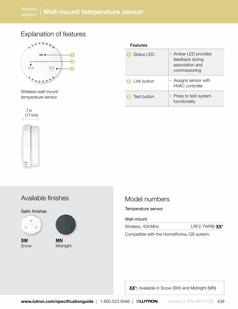
XX1: Available in Snow (SW) and Midnight (MN)
SWSnow
MNMidnight
Available finishes
Satin finishes
Explanation of features
Features
1 Status LED • Amber LED provides feedback during association and commissioning
2 Link button • Assigns sensor with HVAC controller
3 Test button • Press to test system functionality
Temperature sensor
Wall-mount
Wireless, 434 MHz LRF2-TWRB-XX1
Compatible with the HomeWorks® QS system.
Model numbers
XX1: Available in Snow (SW) and Midnight (MN)
3
2
1
.7 in (17 mm)
Wireless wall-mount temperature sensor
www.lutron.com/specificationguide | 1.800.523.9466 | Volume 3 P/N 367-2102 439
Wireless sensors Wall-mount temperature sensor

Wired sensors
440 Volume 3 P/N 367-2102 | 1.800.523.9466 | www.lutron.com/specificationguide
Radio Shadow sensor
Dimensions and mounting• Diameter: 1.60 in (41 mm)
Depth: 0.70 in (17 mm);• Mount on window within 60 ft (18 m) line-of-sight or
30 ft (9.1 m) through walls of the QS sensor module
Communication• Communicates via Lutron® reliable Clear
Connect® Radio Frequency (RF) technology to a QS sensor module
• Operates at 434 MHz• QS sensor module can communicate with up to
10 daylight sensors; each Radio Shadow sensor counts as one daylight sensor toward the limit
• Each QS link on a Quantum processor can have up to 100 daylight sensors; each Radio Shadow sensor counts as one daylight sensor toward the limit
Shown actual size: Radio Shadow sensor (LRF2-SSW-WH)
1.60 in (41 mm)
0.70 in (17 mm) depth
Features and capacities• Enhances the performance of Hyperion solar-
adaptive shading systems by maximizing available views and occupant comfort when shadows are cast on buildings, or when cloudy conditions prevail
• Works at the window level to communicate current exterior conditions to the Quantum system, enabling Hyperion to respond appropriately
• Simple installation with no wiring required• Suitable for use with light levels up to 10,000
foot-candles (fc)• Available in White (WH)• For indoor use, temperature: 32° F-122° F
(0° C-50° C)• Battery included; 10-year battery life design
Download specification submittal

Wired sensors
www.lutron.com/specificationguide | 1.800.523.9466 | Volume 3 P/N 367-2102 441
Radio Shadow sensor
Explanation of features
Feature
1 Programming buttons
• Front accessible buttons make set-up easy
2 Arrow • When mounting ensure that the arrow points up
Radio Shadow sensor
434 MHz LRF2-SSW-WH
Compatible with the Quantum® system.
Model numbers
1
0.7 in (17 mm)
2
Radio Shadow Sensor
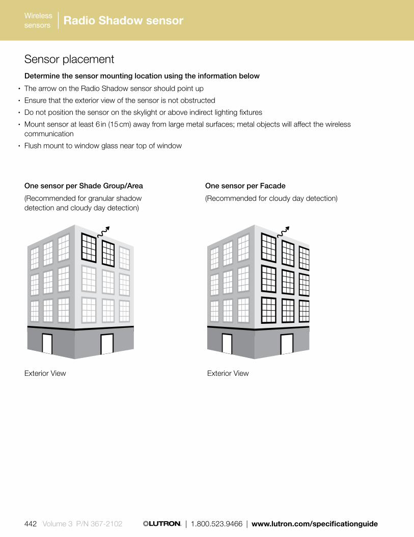
442 Volume 3 P/N 367-2102 | 1.800.523.9466 | www.lutron.com/specificationguide
Wireless sensors Radio Shadow sensor
Sensor placement Determine the sensor mounting location using the information below
• The arrow on the Radio Shadow sensor should point up• Ensure that the exterior view of the sensor is not obstructed• Do not position the sensor on the skylight or above indirect lighting fixtures• Mount sensor at least 6 in (15 cm) away from large metal surfaces; metal objects will affect the wireless
communication• Flush mount to window glass near top of window
One sensor per Facade
(Recommended for cloudy day detection)
One sensor per Shade Group/Area
(Recommended for granular shadow detection and cloudy day detection)
Exterior View Exterior View

4.50 in (114 mm)
Shown above: Ceiling-mount dual technology sensor in White (LOS-CDT-2000-WH)
1.40 in (38 mm) depth
Download specification submittal for Ceiling-mount passive infrared occupancy sensor
Download specification submittal for Ceiling-mount dual technology occupancy sensor
Download specification submittal for Ceiling-mount ultrasonic occupancy sensor
Features and capacities• Sensors can integrate into Lutron system or
function as stand-alone control using wired power pack
• Affords choice of turning lights off or dimming to preset level in unoccupied state when integrated into Lutron system
• Models available in ultrasonic, passive infrared, or dual technology
• Dual technology sensors are self-adaptive to automatically adjust sensitivity and timing
• Coverages available from 450 ft2 - 2000 ft2 (137 m2 - 610 m2) mounted at 8 -12 ft (2.4 m - 3.6 m) from floor
• 360° and 180° field-of-view models available• Models available with an additional dry
contact closure output• Available in White (WH)• For indoor use only, temperature:
32 ° F -104 ° F (0 ° C -40 ° C)
Dimensions and mounting• Width: 4.50 in (114 mm)
Depth: 1.40 in (38 mm)• Snap-locks to ceiling-mounted cover plate
Communication and wiring• 20-24 V DC• Connects to system via low-voltage IEC PELV/NEC
Class 2 wiring through contact closure inputs or directly to an EcoSystem® ballast or module (with sensor inputs), QS sensor module, Energi Savr NodeTM module, or GRAFIK Eye® QS main unit
• Uses two power draw units on the QS link when connected to the QS sensor module; power draw calculations are not needed for inputs connected directly to the Energi Savr Node module, GRAFIK Eye QS main unit, or EcoSystem ballast/module
• Each QS link on a Quantum processor can have up to 100 occupancy sensors; each LOS-C series occupancy sensor counts as one occupancy sensor toward the limit
• Power pack required for stand-alone control, when more than one sensor is connected to an occupancy sensor input or when sensor is connected to the system via contact closure interface
Wired sensors
www.lutron.com/specificationguide | 1.800.523.9466 | Volume 3 P/N 367-2102 443
LOS-C series ceiling-mount occupancy sensor

Wired sensors
444 Volume 3 P/N 367-2102 | 1.800.523.9466 | www.lutron.com/specificationguide
LOS-C series ceiling-mount occupancy sensor
Explanation of features
Features
1 Green LED • Indicates when ultrasonic motion is detected
2 Red LED • Indicates when infrared (IR) is detected
1.4 in (38 mm
)
1
2
Ceiling-mount dual technology sensor

Wired sensors
www.lutron.com/specificationguide | 1.800.523.9466 | Volume 3 P/N 367-2102 445
LOS-C series ceiling-mount occupancy sensor
Wired ceiling-mount occupancy sensors
Dual technology
2,000 ft2 (610 m2), 360º LOS-CDT-2000-WH Additional contact closure LOS-CDT-2000R-WH
1,000 ft2 (305 m2), 180º LOS-CDT-1000-WH Additional contact closure LOS-CDT-1000R-WH
500 ft2 (152 m2) 180º LOS-CDT-500-WH Additional contact closure LOS-CDT-500R-WH
Ultrasonic
2,000 ft2 (610 m2), 360º LOS-CUS-2000-WH
1,000 ft2 (305 m2), 180º LOS-CUS-1000-WH
500 ft2 (152 m2), 180º LOS-CUS-500-WH
Passive infrared
1,500 ft2 (457 m2), 360º LOS-CIR-1500-WH
450 ft2 (137 m2), 360º LOS-CIR-450-WH
Compatible with LCP128TM, Softswitch® 128 (XPS), GRAFIK Eye® 4000, Quantum® and HomeWorks QS systems
Model numbersAvailable models
Dual technology occupancy
Passive infrared occupancy
Ultrasonic occupancy
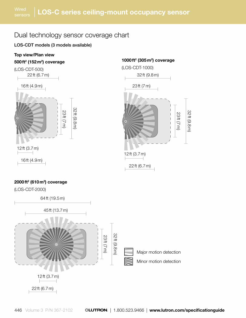
Wired sensors
446 Volume 3 P/N 367-2102 | 1.800.523.9466 | www.lutron.com/specificationguide
LOS-C series ceiling-mount occupancy sensor
Top view/Plan view
500 ft2 (152 m2) coverage
(LOS-CDT-500)
2000 ft2 (610 m2) coverage
(LOS-CDT-2000)
1000 ft2 (305 m2) coverage
(LOS-CDT-1000)
32 ft (9.8 m)
23 ft (7 m)
64 ft (19.5 m)
12 ft (3.7 m)
45 ft (13.7 m)
22 ft (6.7 m)
32 ft (9.8 m)
23 ft (7 m)
22 ft (6.7 m)
16 ft (4.9 m)
12 ft (3.7 m)
16 ft (4.9 m)
32 ft (9.8 m)
23 ft (7 m)
32 ft (9.8 m)
23 ft (7 m)
12 ft (3.7 m)
22 ft (6.7 m)
Dual technology sensor coverage chartLOS-CDT models (3 models available)
Major motion detection
Minor motion detection

Wired sensors
www.lutron.com/specificationguide | 1.800.523.9466 | Volume 3 P/N 367-2102 447
LOS-C series ceiling-mount occupancy sensor
Top view/Plan view
450 ft2 (137 m2) coverage
(LOS-CIR-450)
1500 ft2 (457 m2) coverage(LOS-CIR-1500)
Major motion detection
Minor motion detection
6.5 ft (1.9 m) 12 ft (3.7 m)
12 ft (3.7 m) 22 ft (6.7 m)
Passive infrared sensor coverage chartLOS-CIR models (2 models available)

Wired sensors
448 Volume 3 P/N 367-2102 | 1.800.523.9466 | www.lutron.com/specificationguide
LOS-C series ceiling-mount occupancy sensor
Top view/Plan view
500 ft2 (152 m2) coverage
(LOS-CUS-500)
1000 ft2 (305 m2) coverage
(LOS-CUS-1000)
2000 ft2 (610 m2) coverage
(LOS-CUS-2000)
32 ft (9.8 m)
23 ft (7 m)
64 ft (19.5 m)
45 ft (13.7 m)
Major motion detection
Minor motion detection
22 ft (6.7 m)
32 ft (9.8 m)
16 ft (4.9 m)
23 ft (7 m)
22 ft (6.7 m) 32 ft (9.8 m)
16 ft (4.9 m) 23 ft (7 m)
Ultrasonic sensor coverage chartLOS-CUS models (3 models available)

Wired sensors
www.lutron.com/specificationguide | 1.800.523.9466 | Volume 3 P/N 367-2102 449
LOS-W series wall-mount occupancy sensor
Features and capacities• Sensors can integrate into Lutron system or
by using a wired power pack can function as a stand-alone control
• Affords choice of turning lights off or dimming to preset level in unoccupied state when integrated to Lutron system
• Models available with an additional dry contact closure output
2.70 in (69 mm)
Shown above: Wall-mount dual technology sensor in White (LOS-WDT-R-WH)
5.25 in (133 mm
)
3.90 in (99 mm) depth
Download specification submittal for Wall-mount passive infrared occupancy sensor
Download specification submittal for Wall-mount dual technology occupancy sensor
• Dual-technology sensors are self-adaptive to automatically adjust sensitivity and timing
• Coverage of 1600 ft2 (488 m2) mounted at 8 ft to 12 ft (2.4-3.7 m) from floor
• 110° field-of-view• Models available with additional
dry contact closures• Available in White (WH)• For indoor use only, temperature: 32 ° F-104 ° F
(0 ° C-40 ° C)
Dimensions and mounting• Width: 2.70 in (69 mm)
Height: 5.25 in (133 mm) Depth: 3.90 in (99 mm)
• Flexible base allows mounting on wall or ceiling
Communication and wiring• 20-24 V DC• Connects to system via low-voltage IEC PELV/NEC
Class 2 wiring through contact closure inputs or directly to an EcoSystem® ballast or module (with sensor inputs), QS sensor module, Energi Savr NodeTM module, or GRAFIK Eye® QS main unit
• Uses two power draw units on the QS link when connected to the QS sensor module; power draw calculations are not needed for inputs connected directly to the Energi Savr Node module, GRAFIK Eye QS main unit, or EcoSystem ballast/module
• Each QS link on a Quantum processor can have up to 100 occupancy sensors; each LOS-W series occupancy sensor counts as one occupancy sensor toward the limit
• Power pack required for stand-alone control, when more than one sensor is connected to an occupancy sensor input or when sensor is connected to the system via contact closure interface

Wired sensors
450 Volume 3 P/N 367-2102 | 1.800.523.9466 | www.lutron.com/specificationguide
LOS-W series wall-mount occupancy sensor
Explanation of features3.90 in (99 mm) Features
1 Green LED • Indicates when ultrasonic motion is detected
2 Red LED • Indicates when infrared (IR) is detected
Wired wall-mount occupancy sensor
Dual technology
1,600 ft2 (488 m2), 110˚ LOS-WDT-WH Additional contact closure LOS-WDT-R-WH
Passive infrared
1,600 ft2 (488 m2) LOS-WIR-WH
Compatible with LCP128TM, Softswitch® 128 (XPS), GRAFIK Eye® 4000, Quantum®, and HomeWorks QS systems
Model numbersAvailable models
Dual technology, self-adaptive occupancy
Passive infrared occupancy
2
1
Wall-mount dual technology sensor

Major motion detection
Minor motion detection
Wired sensors
www.lutron.com/specificationguide | 1.800.523.9466 | Volume 3 P/N 367-2102 451
LOS-W series wall-mount occupancy sensor
Top view/Plan view
(LOS-WDT)
Top view/Plan view
(LOS-WIR)
6.5 ft (1.9 m)
20 ft (6.1 m)
12 ft (3.7 m)
40 ft (12.2 m)
22 ft (6.7 m)
16 ft (4.9 m)
Dual technology sensor coverage chart
Passive infrared sensor coverage chart
Major motion detection
Minor motion detection
Major motion detection
Minor motion detection

452 Volume 3 P/N 367-2102 | 1.800.523.9466 | www.lutron.com/specificationguide
Wireless sensors High-bay occupancy sensor
Features and capacities• Passive infrared sensor designed for use in high-
bay applications, such as warehouses, distribution centers and gymnasiums
• Sensors can integrate into Lutron system or by using a wired power pack can function as a stand-alone control
• Surface-mount and end-mount models available with either 180° or 360° area lens
• Mounted at 45 ft (14 m) from floor the 180° models feature 50 ft (15 m) coverage radius and the 360° models feature 1,450 ft2 (135 m2) coverage
• Time-out options include 4, 8, 16 and 30 minutes• Available in White (WH)• For indoor use, temperature: 32° F-149° F
(0° C-65° C)
4.00 in (102 mm)
Shown above: 360° surface-mount high-bay occupancy sensor (LUT-WSPSM24V-180-CPN6112)
1.50 in (38 mm) depth
Download specification submittal
Dimensions and mounting• 180° and 360° surface-mount:
Diameter: 4.00 in (102 mm) Depth: 1.50 in (38 mm)
• 180° end-mount: Width 4.00 in (102 mm) Height: 4.50 in (114 mm) Depth: 1.50 in (38 mm)
• 360° end-mount: Width 3.60 in (91 mm) Height: 4.40 in (112 mm) Depth: 2.00 in (51 mm)
• Surface-mount models mount directly to fixture or to a standard 4.00 in (102 mm) x 4.00 in (102 mm) junction box via two 1.25 in (32 mm) stainless steel screws and locking nuts
• End-mount models mount directly to end of fixture through extended 0.5 in (13 mm) chase nipple
• Maximum mounting height is 45 ft (14 m)
Communication• 20-24 V DC• Connects to system via low-voltage IEC PELV/
NEC Class 2 wiring through contact closure inputs or directly to an Ecosystem ballast/module (with sensor inputs), QS sensors module, Energi Savr Node module, or GRAFIK Eye QS main unit
• Uses two power draw units on the QS link when connected to the QS sensor module; power draw calculations are not needed for inputs connected directly to the Energi Savr Node module, GRAFIK Eye QS main unit or EcoSystem ballast/module
• Each QS link on a Quantum processor can have up to 100 occupancy sensors; each high-bay occupancy sensor counts as one occupancy sensor toward the limit
• Power pack required for stand-alone control, when more than one sensor is connected to an occupancy sensor input, or when sensor is connected to the system via contact closure interface

www.lutron.com/specificationguide | 1.800.523.9466 | Volume 3 P/N 367-2102 453
Wireless sensors High-bay occupancy sensor
Explanation of features
Features
1 Lens • Models available with 180° or 360° area lens
2 Technology • Passive infrared, designed to detect major motion
1
360° end-mount high-bay occupancy sensor

454 Volume 3 P/N 367-2102 | 1.800.523.9466 | www.lutron.com/specificationguide
Wireless sensors High-bay occupancy sensor
Model numbers
180° and 360° surface-mount
360° end-mount
180° end-mount
Available modelsWireless occupancy/vacancy sensors
Wired high-bay occupancy sensor
180° surface-mount LUT-WSPSM24V-180-CPN6111 360° surface-mount LUT-WSPSM24V-360-CPN6111 180° end-mount LUT-WSPEM24V-180-CPN6112 360° surface-mount FHB140NP24V-CPN5190
Compatible with LCP128, Softswitch 128 (XPS), GRAFIK Eye 4000 and Quantum systems

www.lutron.com/specificationguide | 1.800.523.9466 | Volume 3 P/N 367-2102 455
Wireless sensors
Top view/Plan view
Side view
180º high-bay sensor coverage chart
360º high-bay sensor coverage chart
30 ft (9 m) mounting height 45 ft (14 m)
mounting height
42 ft (13 m) radius at 30 ft (9 m) mounting height
50 ft (15 m) radius at 45 ft (14 m) mounting height
42 ft (13 m) at 30 ft (9 m) mounting height
50 ft (15 m) at 45 ft (14 m) mounting height
29 ft (9 m)
21 ft (6 m)
Notes: Sensor is designed to detect major motion (i.e., walking person) only. A delay of 1 to 2 seconds from occupancy detection to turn-on may be experienced
High-bay occupancy sensor

1.18 in (30 mm)
0.69 in (17 mm) profile
1.25 in (32 mm) depth
Wired sensors
456 Volume 3 P/N 367-2102 | 1.800.523.9466 | www.lutron.com/specificationguide
Shown actual size: Wired photosensor (MW-FPS-WH)
Wired photosensor
Ceiling/fixture-mount MW-FPS-WH
Compatible with the GRAFIK Eye® 4000 system.
Model numbers
Photosensor
Dimensions and mounting• Diameter: 1.18 in (30 mm)
Depth: 1.25 in (32 mm); Profile: 0.69 in (17 mm)
• Optional sensor post allows sensor to be extended from any ceiling for a length up to 36 in
• Mount to ceiling or fixture with 0.375 in (10 mm) diameter hole
Communication and wiring• Designed to connect to daylight controller via
IEC PELV/NEC Class 2 low-voltage wire• Total wire length from sensor to device must not
exceed 100 ft (30 m)• 15 V DC
Related Component
Daylight controller (sold separately, see pg. 484)
Features and capacities• Monitors ambient daylight levels and communicates
information to daylight controller (required)• Allows controller to automatically select scenes
based on the amount of daylight available• Phototopic response matches human eye• For indoor use, temperature:
32° F-113° F (0° C-45° C)• Available in White (WH)
Download specification submittal

Bottom of sensor
H = Effective Window Height
Area viewed by sensor
1 H-2 H
H
3 ft
Location for narrow areas (corridors, private offices)
Arrow points toward the area viewed by the sensor (away from window)
Location for average size areas
Arrow points toward the area viewed by the sensor (toward windows)
Sensor placement Determine the photosensor mounting location using the diagram below
• Place the photosensor so the viewing area is centered on the nearest window at a distance from the window of one to two times the effective window height (H)
• The effective window height (H) starts at the window sill or 3 ft (1 m) up from the floor, whichever is higher, and ends at the top of the window
• Do not position the photosensor in the well of a skylight or above indirect lighting fixtures• For narrow areas where the daylight sensor cannot be placed 1 H-2 H from windows, place photosensor
near windows facing into space
Wired sensors
www.lutron.com/specificationguide | 1.800.523.9466 | Volume 3 P/N 367-2102 457
Wired sensors Photosensor
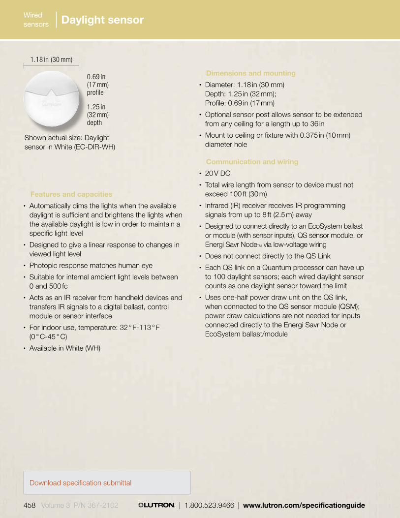
Wired sensors
458 Volume 3 P/N 367-2102 | 1.800.523.9466 | www.lutron.com/specificationguide
Daylight sensor
Dimensions and mounting• Diameter: 1.18 in (30 mm)
Depth: 1.25 in (32 mm); Profile: 0.69 in (17 mm)
• Optional sensor post allows sensor to be extended from any ceiling for a length up to 36 in
• Mount to ceiling or fixture with 0.375 in (10 mm) diameter hole
Communication and wiring• 20 V DC• Total wire length from sensor to device must not
exceed 100 ft (30 m)• Infrared (IR) receiver receives IR programming
signals from up to 8 ft (2.5 m) away• Designed to connect directly to an EcoSystem ballast
or module (with sensor inputs), QS sensor module, or Energi Savr NodeTM via low-voltage wiring
• Does not connect directly to the QS Link• Each QS link on a Quantum processor can have up
to 100 daylight sensors; each wired daylight sensor counts as one daylight sensor toward the limit
• Uses one-half power draw unit on the QS link, when connected to the QS sensor module (QSM); power draw calculations are not needed for inputs connected directly to the Energi Savr Node or EcoSystem ballast/module
Shown actual size: Daylight sensor in White (EC-DIR-WH)
1.18 in (30 mm)
0.69 in (17 mm) profile
1.25 in (32 mm) depth
Features and capacities• Automatically dims the lights when the available
daylight is sufficient and brightens the lights when the available daylight is low in order to maintain a specific light level
• Designed to give a linear response to changes in viewed light level
• Photopic response matches human eye• Suitable for internal ambient light levels between
0 and 500 fc• Acts as an IR receiver from handheld devices and
transfers IR signals to a digital ballast, control module or sensor interface
• For indoor use, temperature: 32 ° F-113 ° F (0 ° C-45 ° C)
• Available in White (WH)
Download specification submittal
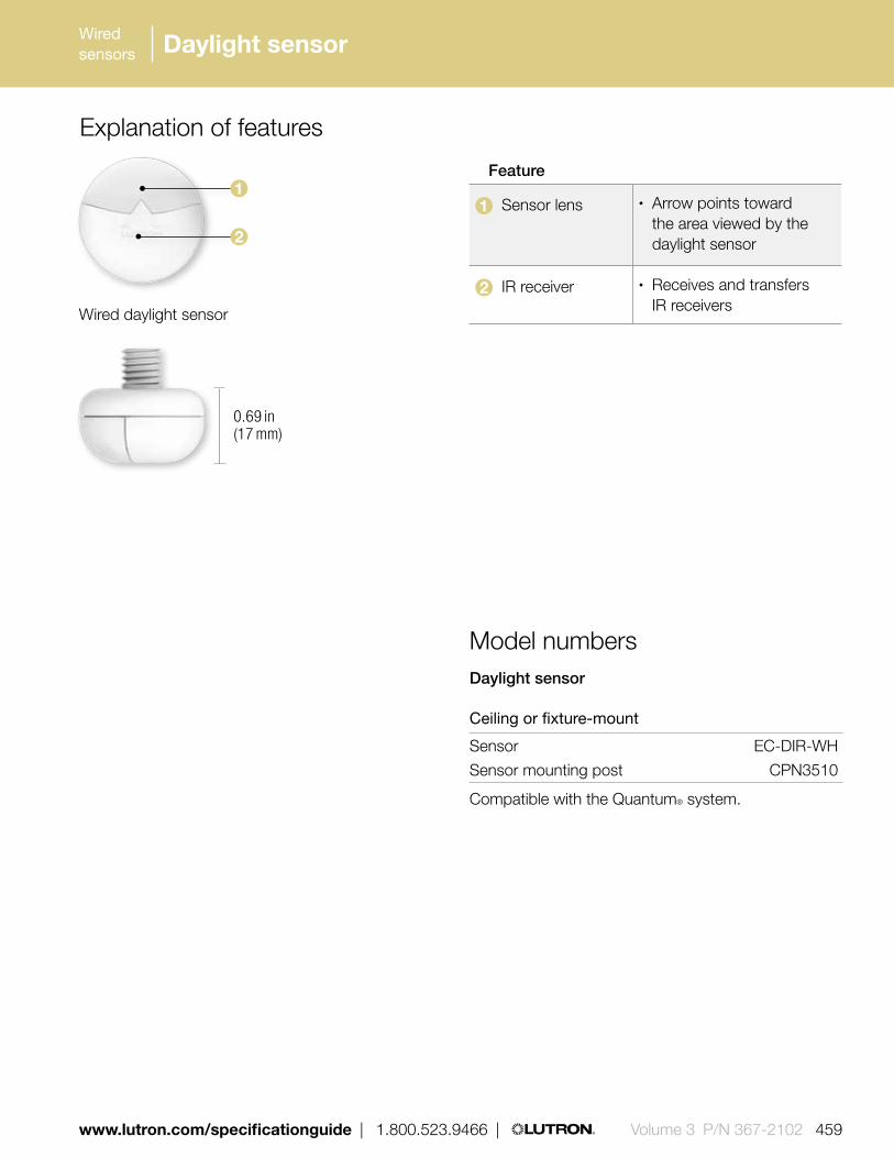
Wired sensors
www.lutron.com/specificationguide | 1.800.523.9466 | Volume 3 P/N 367-2102 459
Daylight sensor
Explanation of features
Feature
1 Sensor lens • Arrow points toward the area viewed by the daylight sensor
2 IR receiver • Receives and transfers IR receivers
Daylight sensor
Ceiling or fixture-mount
Sensor EC-DIR-WH
Sensor mounting post CPN3510
Compatible with the Quantum® system.
Model numbers
1
0.69 in (17 mm)
2
Wired daylight sensor

460 | 1.800.523.9466 | www.lutron.comVolume 3 P/N 367-2102 REV A
Wired sensors Daylight sensor
Bottom of sensor
H = Effective Window Height
Area viewed by sensor
1 H-2 H
H
3 ft
Location for narrow areas (corridors, private offices)
Arrow points toward the area viewed by the sensor (away from window)
Location for average size areas
Arrow points toward the area viewed by the sensor (toward windows)
Sensor placement Determine the daylight sensor mounting location using the diagram below
• Place the daylight sensor so the viewing area is centered on the nearest window at a distance from the window of one to two times the effective window height (H)
• The effective window height (H) starts at the window sill or 3 ft (1 m) up from the floor, whichever is higher, and ends at the top of the window
• Do not position the daylight sensor in the well of a skylight or above indirect lighting fixtures• For narrow areas where the daylight sensor cannot be placed 1 H-2 H from windows, place sensor near
windows facing into space

461 | 1.800.523.9466 | www.lutron.com www.lutron.com | 1.800.523.9466 | Volume 3 P/N 367-2102 REV A
Wired sensors
1.85 in (47 mm)
Shown above: Outdoor sensor (GRX-CESO)
1.35 in (34 m
m)
1.28 in (33 mm)
Shown above: Indoor sensor (GRX-CESI)
1.15 in (29 m
m)
1.28 in (33 m
m)
Shown above: Atrium or skylight sensor (GRX-CESA/GRX-CESS)
2.25 in (57 mm)
Features and capacities• Daylight sensor packages that allow Lutron lighting
control systems to switch lights on/off in response to ambient daylight level settings in the controller
• Packages include a wired power pack, daylight sensor, and daylight controller
• Daylight controller features adjustable On and Off setpoints
• A variety of sensor packages are available to fit virtually any application:– indoor– outdoor– atrium– skylight
• Each sensor is calibrated during manufacturing to the light levels in its intended environment
• Operating temperature: 13° F-140° F (-11° C- 60° C).
• All sensors are water-resistant and designed to withstand UV radiation
• Daylight controller and wired power packs for indoor use only
• Available in white (WH)
Communication and wiring• Daylight controller connects to system through
contact closure inputs and to sensors directly via low-voltage IEC PELV/NEC Class 2 wiring
• When interfacing to a Lutron system, the normal close contact will turn lights on (contact closure close) when daylight levels are low, and turn lights off (contact closure open) when daylight levels are high
• Each QS link on a Quantum processor can have up to 100 daylight sensors; each sensor in a package counts as one daylight sensor toward the limit
Daylight sensor packages
Download specification submittal

6 – 8 ft1.8 – 2.4 m
Light fixture
Light fixture
Sensor
Win
dow
Ceiling Mount
18 in (457 mm)Sensor
Reflecting Wall Mount
60˚Sensor
Sconce Wall Mount
Sconce
Sensor Snow line
1/2 in (13 mm) conduit
North
Sensor
Win
dow
Sensor
1/2 in (13 mm) conduit
462 | 1.800.523.9466 | www.lutron.comVolume 3 P/N 367-2102 REV A
Wired sensorsWired sensorsWired sensors
Outdoor • Width: 1.85 in (47 mm)
Height: 1.35 in (34 mm)
• Mount in standard .50 in (13 mm) conduit or knockout
• Mount horizontally, facing north, with the hooded portion on top
Indoor• Width: 1.28 in (33 mm)
Height: 1.15 in (29 mm)
• Mount in .38 in (10 mm) hole using the adhesive backing (included)
• Ceiling mount: 6 to 8 ft (2 m) from window, centrally located
• Reflected wall mount: Facing the reflecting wall, not in line with any indoor lighting
• Wall mount with sconces: Mount at same height as sconce, but not directly in line
Atrium • Width: 2.25 in (57 mm)
Height: 1.28 in (33 mm)
• Mount in standard 0.50 in (13 mm) conduit or knockout, opposite the atrium window
Skylight • Width: 2.25 in (57 mm)
Height: 1.28 in (33 mm)
• Mount in standard 0.50 in (13 mm) conduit or knockout, near the center of the skylight well, at least 12 in (305 mm) from the sides
• Mount vertically, facing up, with top of sensor level with top of skylight curb
Dimensions and mounting
Daylight sensor packages

* All packages include a wired power pack, daylight sensor and daylight controller.
** Daylight sensors, daylight controller and wired power pack are also available as individual items, please contact Lutron for more information.
| 1.800.523.9466 | www.lutron.com www.lutron.com/specificationguide | 1.800.523.9466 | Volume 3 P/N 367-2102 463
Wireless sensorsWireless sensors
Daylight sensor packages
Indoor package**
120 V GRX-CESI-120 PKG
277 V GRX-CESI-277 PKG
Outdoor package**
120 V GRX-CESO-120 PKG
277 V GRX-CESO-277 PKG
Atrium package**
120 V GRX-CESA-120 PKG
277 V GRX-CESA-277 PKG
Skylight package**
120 V GRX-CESS-120 PKG
277 V GRX-CESS-277 PKGCompatible with LCP 128TM, Softswitch128® (XPS), GRAFIK Eye® 4000 and Quantum® systems
Available models
For specific voltage by country information refer to voltage chart on pg. 695.
Outdoor sensor
Indoor sensor
Atrium sensor
Skylight sensor
Daylight sensor packages
Model numbers

Wired sensors
464 Volume 3 P/N 367-2102 | 1.800.523.9466 | www.lutron.com/specificationguide
Infrared partition status sensor
Features and capacities• Infrared transmitter/receiver pair detects partition
movement and coordinates lighting preset functions• Automatically combines lighting preset functions
when partition is open creating one large space• Lighting preset functions become independent as
partition is closed creating several smaller spaces• Requires contact closure input/output interface or
QS seeTouch® keypad for operation
Dimensions and mounting• Width: 4.56 in (159 mm)
Height: 2.69 in (68 mm) Depth: 1.50 in (38 mm)
• Receiver and transmitter surface-mount in standard 1-gang U.S. wallboxes, 3.50 in (89 mm) deep, mounted face down from the ceiling
• The sensors must be mounted in a position where the partition separates the transmitter and receiver when the partition is closed
• Transmitter and receiver may be located no more than 8 ft (243 mm) apart
• Adjustable mounting brackets allow easy alignment during installation
Communication and wiring• 12-24 V DC from plug-in supply
(P/N GRX-12 V DC, sold separately)• Connects to system via IEC PELV/NEC Class 2
low-voltage wiring through contact closure inputs
Shown above: Infrared partition status sensor (one of a pair) (GRX-IRPS-WH)
4.56 in (159 mm)
2.69 in (68 mm
)
1.50 in (38 mm)
Download specification submittal

Wired sensors
www.lutron.com/specificationguide | 1.800.523.9466 | Volume 3 P/N 367-2102 465
Partition
Black boxes represent standard 1-gang U.S. wallbox mounted facedown and flush with ceiling surface (typical of two)
8 ft (2.43 m) maximum
GRX-IRPS-WH (pair of sensors)
Transmitter Receiver
1.50 in (38 mm)
Ceiling
Model numbers
Infrared partition status sensor
Sensor GRX-IRPS-WH
Compatible with GRAFIK Eye® 4000 and Quantum® systems
Infrared partition status sensor

466 Volume 3 P/N 367-2102 | 1.800.523.9466 | www.lutron.com/specificationguide
Wireless sensors Power packs
Features and capacities• Provide both the 24 V power supply to
operate Lutron® sensors as well as the 20 A line voltage relay to control the load in one compact housing
• Models available for 120 V AC, 230 V AC (CE), 277 V AC, and 347 V AC
• Relay contact rating: 20 A: 120/230/277 V ballast 15 A: 347 V ballast 15 A: 120 V incandescent
• Auxiliary relay allows for direct control of multiple lighting circuits or load types; draws power from another power pack and takes its control signal from the occupancy sensors
• Supports up to three Lutron LOS-C or LOS-W series wired sensors and/or auxiliary relay
Dimensions and mounting• Width: 3.69 in (94 mm)
Height: 2.33 in (59 mm) Depth: 1.36 in (35 mm)
• Unit can be placed outside or inside the junction box with a simple nut-twist
Communication and wiring• Approved for installation in spaces
designed for air handling per NEC article 300.22(c)
• 24 V DC, 100 mA power output
3.69 in (94 mm)
2.33 in (59 mm
)Shown above: Wired power pack (PP-120H) 1.36 in
(35 mm) depth
Model numbers
Power packs
120 V AC @ 60 Hz PP-120H
230 V AC @ 50/60 Hz PP-230H
277 V AC @ 60 Hz PP-277H
347 V AC @ 60 Hz PP-347H
Auxiliary relay PP-SH
Compatible with LCP128TM, Softswitch® 128 (XPS), GRAFIK Eye® 4000 and Quantum® systems
Download specification submittal


468 469 | 1.800.523.9466 | www.lutron.com www.lutron.com | 1.800.523.9466 |468 469 | 1.800.523.9466 | www.lutron.com www.lutron.com | 1.800.523.9466 |Volume 3 P/N 367-2102 REV A
Control interfaces typically provide integration between Lutron lighting systems and other home and building systems.
The control interfaces addressed in this guide are specific to each country’s voltage and frequency requirements. Please confirm that the products you have selected match the required voltages by country on page 692.
Control interfaces allow integration with:
• Touch screens• Projection screens• Time clocks• Emergency lighting interfaces• HVAC Equipment
Whole building control interfaces
Ethernet interfacepg. 475
Time clock/programming interfacepg. 479
Wired communication
RS232 interfacepg. 477
DMX512 input interfacepg. 482
Wallbox contact closure input interfacepg. 471
Contact closure output interfacepg. 472
DMX512 output interfacepg. 481
Control interfaces
Contact closure input/output interfacepg. 473

468 469 | 1.800.523.9466 | www.lutron.com www.lutron.com | 1.800.523.9466 |468 469 | 1.800.523.9466 | www.lutron.com www.lutron.com | 1.800.523.9466 | Volume 3 P/N 367-2102 REV A
QS contact closure input/output interfacepg. 492
QS RS232/Ethernet interfacepg. 494
Emergency lighting interfacepg. 502
Data link repeaterpg. 504
Daylight controller pg. 484
QS DMX512 output control interfacepg. 496
QS sensor module (QSM)pg. 498
AC motor group controllerpg. 487
Sivoia QED® controllerpg. 488
QS motor group controllerpg. 500
Energy meterpg. 501
Infrared interfacepg. 483

470 471 | 1.800.523.9466 | www.lutron.com www.lutron.com | 1.800.523.9466 |470 471 | 1.800.523.9466 | www.lutron.com www.lutron.com | 1.800.523.9466 |470 471 | 1.800.523.9466 | www.lutron.com www.lutron.com | 1.800.523.9466 |Volume 3 P/N 367-2102 REV A
Whole home control interfaces
HVAC controllerpg. 505
HomeWorks QS visor control receiverpg. 508
Control interfaces
Wireless communication
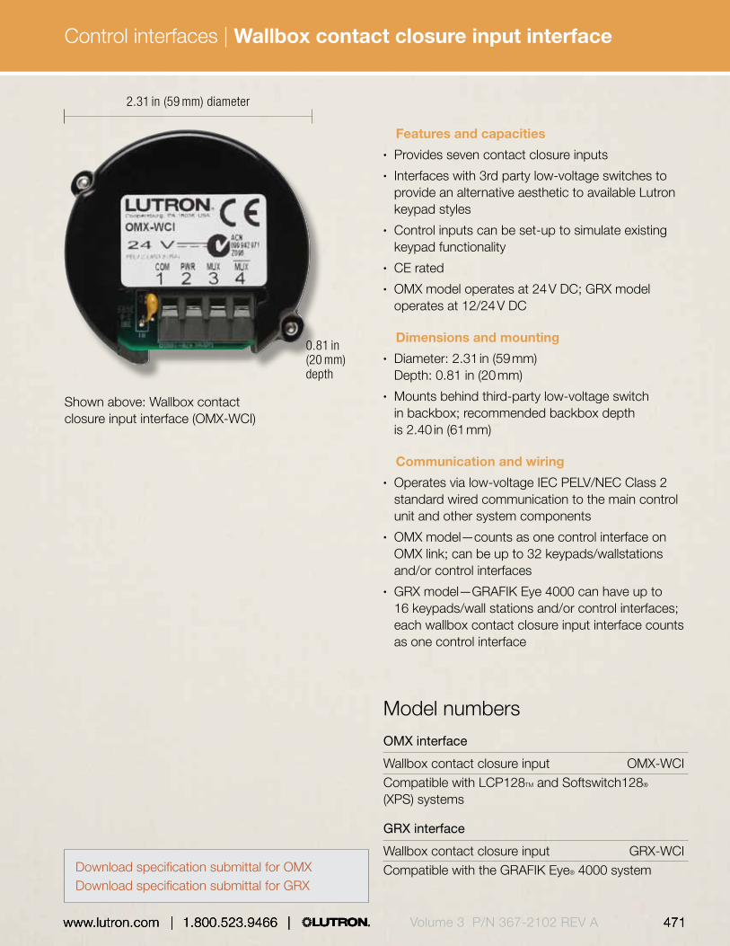
470 471 | 1.800.523.9466 | www.lutron.com www.lutron.com | 1.800.523.9466 |470 471 | 1.800.523.9466 | www.lutron.com www.lutron.com | 1.800.523.9466 | Volume 3 P/N 367-2102 REV A
Control interfaces |
470 471 | 1.800.523.9466 | www.lutron.com www.lutron.com | 1.800.523.9466 |
Features and capacities• Provides seven contact closure inputs• Interfaces with 3rd party low-voltage switches to
provide an alternative aesthetic to available Lutron keypad styles
• Control inputs can be set-up to simulate existing keypad functionality
• CE rated• OMX model operates at 24 V DC; GRX model
operates at 12/24 V DC
Dimensions and mounting• Diameter: 2.31 in (59 mm)
Depth: 0.81 in (20 mm)• Mounts behind third-party low-voltage switch
in backbox; recommended backbox depth is 2.40 in (61 mm)
Communication and wiring• Operates via low-voltage IEC PELV/NEC Class 2
standard wired communication to the main control unit and other system components
• OMX model—counts as one control interface on OMX link; can be up to 32 keypads/wallstations and/or control interfaces
• GRX model—GRAFIK Eye 4000 can have up to 16 keypads/wall stations and/or control interfaces; each wallbox contact closure input interface counts as one control interface
Shown above: Wallbox contact closure input interface (OMX-WCI)
2.31 in (59 mm) diameter
0.81 in (20 mm) depth
OMX interface
Wallbox contact closure input OMX-WCICompatible with LCP128TM and Softswitch128® (XPS) systems
GRX interface
Wallbox contact closure input GRX-WCICompatible with the GRAFIK Eye® 4000 system
Model numbers
Wallbox contact closure input interface
Download specification submittal for OMXDownload specification submittal for GRX

472 473 | 1.800.523.9466 | www.lutron.com www.lutron.com | 1.800.523.9466 |Volume 3 P/N 367-2102 REV A
Control interfaces |
Shown above: GRX contact closure output interface (GRX-CCO-8)
5.75 in (146 mm)
Features and capacities• Provides eight dry contact closure outputs• Compatible with motorized projection screens,
window treatments, and A/V equipment that have contact closure output
• Provides both normally open (NO) and normally closed (NC) contacts
• May be set to momentary or maintained outputs• Manual override buttons allow the testing of
the system• OMX models operate at 24 V DC; GRX models
operate at 12/24 V DC
Dimensions and mounting• Width: 5.75 in (146 mm)
Height: 10.75 in (273 mm) Depth: 2.00 in (50 mm)
• Surface mounted
Communication and wiring• Operates via low-voltage IEC PELV/NEC Class 2
wired communication to the main control unit and other system components
• OMX models - counts as one control interface on OMX link; can have up to 32 keypads/wall stations and/or control interfaces
• GRX models - GRAFIK Eye 4000 system can have up to 16 keypads/wallstations and/or control interfaces; each contact closure output interface counts as one control interface
10.75 in (273 mm
)2.00 in (50 mm) depth
GRX interfaces
Contact closure output GRX-CCO-8 Contact closure output (Japan) GRX-CCO-8-JA
Compatible with the GRAFIK Eye 4000 system
OMX interfaces
Contact closure output interface OMX-CCO-8 Contact closure output (Japan) OMX-CCO-8-JA
Compatible with LCP128 and Softswitch128 (XPS) systems
Model numbers
Contact closure output interface
Download specification submittal
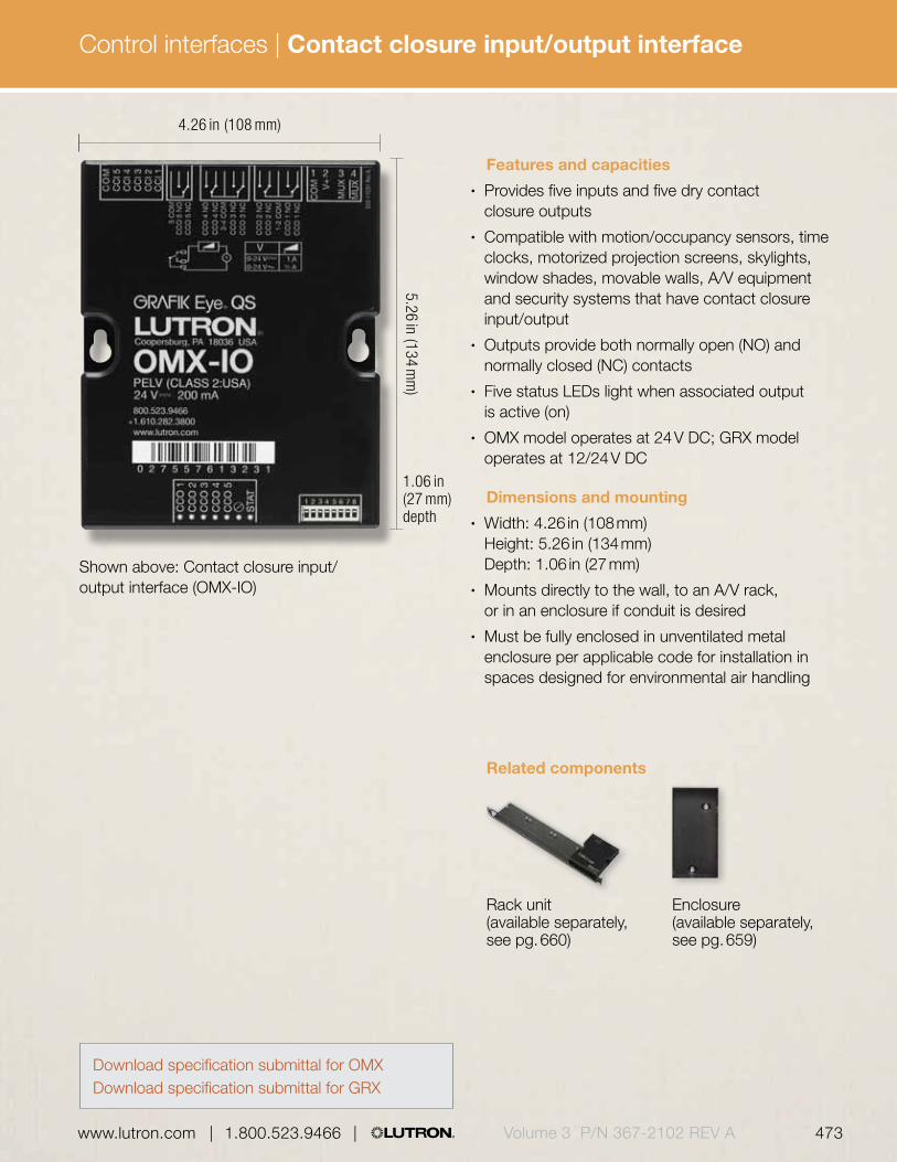
472 473 | 1.800.523.9466 | www.lutron.com www.lutron.com | 1.800.523.9466 | Volume 3 P/N 367-2102 REV A
Control interfaces |
Shown above: Contact closure input/output interface (OMX-IO)
4.26 in (108 mm)
5.26 in (134 mm
)1.06 in (27 mm) depth
Features and capacities• Provides five inputs and five dry contact
closure outputs• Compatible with motion/occupancy sensors, time
clocks, motorized projection screens, skylights, window shades, movable walls, A/V equipment and security systems that have contact closure input/output
• Outputs provide both normally open (NO) and normally closed (NC) contacts
• Five status LEDs light when associated output is active (on)
• OMX model operates at 24 V DC; GRX model operates at 12/24 V DC
Dimensions and mounting• Width: 4.26 in (108 mm)
Height: 5.26 in (134 mm) Depth: 1.06 in (27 mm)
• Mounts directly to the wall, to an A/V rack, or in an enclosure if conduit is desired
• Must be fully enclosed in unventilated metal enclosure per applicable code for installation in spaces designed for environmental air handling
Related components
Rack unit (available separately,see pg. 660)
Enclosure (available separately,see pg. 659)
Contact closure input/output interface
Download specification submittal for OMXDownload specification submittal for GRX
474 475 | 1.800.523.9466 | www.lutron.com www.lutron.com | 1.800.523.9466 |Volume 3 P/N 367-2102 REV A
Control interfaces |
Communication and wiring• Operates via low-voltage IEC PELV/NEC Class 2
standard wired communication to main control unit and other system components
• OMX model - counts as one control interface on the OMX link; can have up to 32 keypads/wallstations and/or control interfaces
• GRX model - GRAFIK Eye 4000 system can have up to 16 keypads/wallstations and/or control interfaces; each contact closure input/output interface counts as control interface
Functionality and operating modes• Using the inputs, contact closures in other
equipment can operate compatible primary controls to (dependent on system):
– Select scenes– Adjust scenes to reflect status of movable
walls (partitioning)– Turn lights on or off based on room occupancy– Perform special functions such as panic, control
lockout and scene lock-out• Using the outputs, scene and/or zone changes in
control units can:
– Trigger outputs to control other equipment– Provide status feedback to other equipment
OMX interface
Contact closure OMX-IO input/output interfaceCompatible with LCP128 and Softswitch128 (XPS) systems
GRX interface
Contact closure GRX-IO input/output interfaceCompatible with the GRAFIK Eye® 4000 system
Model numbers
Contact closure input/output interface

474 475 | 1.800.523.9466 | www.lutron.com www.lutron.com | 1.800.523.9466 | Volume 3 P/N 367-2102 REV A
Control interfaces |
Features and capacities• Allows integration with a touchscreen, PC, A/V
system or other digital equipment that supports TCP/IP communication over Ethernet
• Control and monitor dimming and switching panels and GRAFIK Eye control units
• Monitor lighting scenes and levels• OMX model operates at 24 V DC; GRX model
operates at 12/24 V DC
Dimensions and mounting• Width: 4.26 in (108 mm)
Height: 5.26 in (134 mm) Depth: 1.06 in (27 mm)
• Mounts directly to the wall, to an A/V rack or in an enclosure if conduit is desired
• Must be fully enclosed in unventilated metal enclosure per applicable code for installation in spaces designed for environmental air handling
4.26 in (108 mm)
5.26 in (134 mm
)1.06 in (27 mm) profile
Shown above: Ethernet interface (OMX-CI-NWK-E)
Related components
Rack unit (available separately,see pg. 660)
Enclosure(available separately,see pg. 659)
Ethernet interface
Download specification submittal for OMXDownload specification submittal for GRX

476 477 | 1.800.523.9466 | www.lutron.com www.lutron.com | 1.800.523.9466 |Volume 3 P/N 367-2102 REV A
Control interfaces |
OMX interface
RS232/Ethernet interface OMX-CI-NWK-E
Compatible with LCP128™ and Softswitch128® (XPS) systems
GRX interface
RS232/Ethernet interface GRX-CI-NWK-ECompatible with the GRAFIK Eye® 4000 system
Model numbers Communication and wiring• Operates via low-voltage IEC PELV/NEC Class 2
standard wired communication to main control unit and other system components
• Standard CAT5 cable (328 ft (100 m) maximum length) connects interface to Ethernet source
• Multiple control interfaces may be used in a single system
• OMX model - counts as one control interface on the OMX link; can have up to 32 keypads/wallstations and/or control interfaces
• GRX model - GRAFIK Eye 4000 system can have up to 16 keypads/wallstations and/or control interfaces; each Ethernet interface counts as one control interface
Functionality and operating modes• Control
– Softswitch 128: scene selection, scene lockout, zone lockout, enable/disable time clock
– LCP 128: scene selection, scene lockout, zone lockout, zone raise/lower, enable/disable time clock
– GRAFIK Eye 4000: scene selection, scene lockout, sequencing zone, lockout, zone raise/lower, set zone intensity
• Monitor: current scene, button presses, zone level
Ethernet interface

476 477 | 1.800.523.9466 | www.lutron.com www.lutron.com | 1.800.523.9466 | Volume 3 P/N 367-2102 REV A
Control interfaces |
Features and capacities• Allows integration with a touchscreen, PC, A/V
system or other digital equipment that supports RS232 communication
• Control and monitor dimming and switching panels and GRAFIK Eye control units
• Monitor lighting scenes and levels• OMX model operates at 24 V DC; GRX model
operates at 12/24 V DC
Dimensions and mounting• Width: 4.26 in (108 mm)
Height: 5.26 in (134 mm) Depth: 1.06 in (27 mm)
• Mounts directly to the wall, to an A/V rack or in an enclosure if conduit is desired
• Must be fully enclosed in unventilated metal enclosure per applicable code for installation in spaces designed for environmental air handling
4.26 in (108 mm)
5.26 in (134 mm
)1.06 in (27 mm) profile
Shown above: RS232 interface (GRX-CI-RS232)
Related components
Rack unit (available separately,see pg. 660)
Enclosure (available separately,see pg. 659)
RS232 interface
Download specification submittal for OMXDownload specification submittal for GRX

478 479 | 1.800.523.9466 | www.lutron.com www.lutron.com | 1.800.523.9466 |Volume 3 P/N 367-2102 REV A
Control interfaces |
OMX interfaces
RS232 interface OMX-CI-RS232 RS232 interface (Japan) OMX-CI-RS232-JACompatible with LCP128 and Softswitch128 (XPS) systems
GRX interfaces
RS232 interface GRX-CI-RS232 RS232 interface (Japan) GRX-CI-RS232-JACompatible with the GRAFIK Eye 4000 system
Model numbers Communication and wiring• Operates via low-voltage IEC PELV/NEC Class 2
standard wired communication to main control unit and other system components
• Standard 9-pin serial connector plugs into interface and RS232 equipment
• Distance between interface and RS232 source not to exceed 50 ft (15 m)
• Multiple control interfaces may be used in a single system
• OMX model-counts as one control interface on OMX link; can have up to 32 keypads/wallstations and/or control interfaces
• GRX model-GRAFIK Eye 4000 system can have up to 16 keypads/wallstations and/or control interfaces; each RS232 interface counts as one control interface
RS232 interface

Download specification submittal
478 479 | 1.800.523.9466 | www.lutron.com www.lutron.com | 1.800.523.9466 | Volume 3 P/N 367-2102 REV A
Control interfaces |
Features and capacities• Integrates the GRAFIK Eye® 4000 control system
with a PC or other digital equipment that supports RS232 or TCP/IP communication
• Provides a basic serial string command set that allows a PC to monitor and control lighting; functionality is selected in the field using dip switches
• Built-in astronomic time clock provides ability to schedule lighting events
• Acts as a programming interface, enables use of a PC to set up GRAFIK Eye 4500 control units
• Comes with easy-to-use, LIAISON™ software for scheduling the astronomic time clock and utilizing the programmer Interface
• May be programmed to control up to eight GRAFIK Eye 4000 series control units
• Operates at 12/24 V DC
Dimensions and mounting• Width: 4.26 in (108 mm)
Height: 5.26 in (134 mm) Depth: 1.06 in (27 mm)
• Mounts directly to the wall, to an A/V rack or in an enclosure if conduit is desired
• Must be fully enclosed in unventilated metal enclosure per applicable code for installation in spaces designed for environmental air handling
Shown above: Time clock/programming interface (GRX-CI-PRG)
4.26 in (108 mm)
5.26 in (134 mm
)1.06 in (27 mm) profile
Related components
Rack unit (available separately,see pg. 660)
Enclosure (available separately,see pg. 659)
Time clock/programming interface
480 481 | 1.800.523.9466 | www.lutron.com www.lutron.com | 1.800.523.9466 |Volume 3 P/N 367-2102 REV A
Control interfaces |
Communication and wiring• Operates via low-voltage IEC PELV/NEC Class 2
standard wired communication to main control and other system components
• Standard CAT5 cable (328 ft (100 m) maximum length) connects interface to PC or other Ethernet Source
• Standard 9-pin serial connector plugs into interface and RS232 equipment
• Distance between interface and RS232 source not to exceed 50 ft (15 m)
• One interface per GRAFIK Eye® 4000 system, automatically occupies wallstation address 16
Functionality and operating models• Control: scene selection, scene lockout, zone
lockout, zone raise/lower, enable/disable time clock• Monitor: current scene, button presses• Programmer interface:
– Scenes, including light levels in 1% increments and fade times
– Load type settings– Tamper-proof protection of scenes– Assignment of communication between control
units and wallstations– Panel zone and load assignment
Interface
Time clock/programming interface GRX-CI-PRG Time clock/programming interface (Japan) GRX-CI-PRG-JACompatible with the GRAFIK Eye 4000 system
Model numbers
Time clock/programming interface

Download specification submittal
480 481 | 1.800.523.9466 | www.lutron.com www.lutron.com | 1.800.523.9466 | Volume 3 P/N 367-2102 REV A
Control interfaces |
Features and capacities• Allows GRAFIK Eye® control unit to operate lighting
and other equipment that uses the DMX512 protocol, including:– Strobes, fiber optic lighting, and LED-
based lamps– Fog machines– Animated characters and motorized fixtures
• Converts GRAFIK Eye zone intensities into DMX512 channel settings—each zone is assigned to a DMX512 channel
• One DMX512 output interface per system, does not require an address
• Up to 64 GRAFIK Eye lighting zones and/or DMX512 channels per GRAFIK Eye 4000 system
• Operates at 12/24 V DC
Dimensions and mounting• Width: 5.00 in (127 mm)
Height: 7.75 in (197 mm) Depth: 2.50 in (84 mm)
• Mounts to a standard 4 in (102 mm) x 4 in (102 mm) junction box or surface mount directly to wall
Communication and wiring• Operates via low-voltage IEC PELV/NEC class 2
standard wired communication to the main control unit and other system components
• Does not count toward maximum number of keypads/wallstations/control interfaces in a GRAFIK Eye 4000 system
• Connects to theatrical equipment via DMX cable (P/N GRX-CBL-DMX-250 or GRX-CBL-DMX-500, sold separately)
Shown above: DMX512 output interface (LUT-DMX)
5.00 in (127 mm)
7.75 in (197 mm
)
2.50 in (84 mm) depth
Interfaces
DMX512 output interface LUT-DMX
Compatible with the GRAFIK Eye® 4000 system
Model numbers
DMX512 output interface

Multiple channel theatrical consoles (sold separately, see pg. 346)
Download specification submittal
482 483 | 1.800.523.9466 | www.lutron.com www.lutron.com | 1.800.523.9466 |Volume 3 P/N 367-2102 REV A
Control interfaces |
Features and capacities• Provides an interface between a DMX512/1990
compatible stage lighting console and a Lutron lighting control system
• Supports up to 32 consecutive channel levels from the entire range of 512 channels
• Each channel can be mapped to one or more circuits on the system
• Control can be shared between systems• Operates at 24 V DC
Shown above: DMX512 input interface (ODMX-512)
5.00 in (127 mm)
7.75 in (197 mm
)
2.50 in (84 mm) depth
Interface
DMX512 input interface ODMX-512
Compatible with the LCP128 system
Model numbers
DMX512 input interface
Dimensions and mounting• Width: 5.00 in (127 mm)
Height: 7.75 in (197 mm) Depth: 2.50 in (84 mm)
• Mounts to a standard 4 in. (102 mm) x 4 in (102 mm) junction box or surface mount directly to wall
Communication and wiring• Operates via low-voltage IEC PELV/NEC Class 2
standard wired communication to the main control unit and other system components
• Connects to theatrical equipment via DMX cable (P/N GRX-CBL-DMX-250 or GRX-CBL-DMX-500, sold separately)
• OMX link length not to exceed 2000 ft (610 m), can be extended with the Lutron data link repeater (pg. 505)
• LCP 128 system can have up to 32 keypads/wallstations and/or control interfaces; each DMX512 input interface counts as one control interface
Related components

4.1 in (105 mm
) height
482 483 | 1.800.523.9466 | www.lutron.com www.lutron.com | 1.800.523.9466 | Volume 3 P/N 367-2102 REV A
Control interfaces |
Shown above: Infrared interface (GRX-IRI)
1.75 in (45 mm) width
0.90 in (23 mm) depth
Interface
Infrared GRX-IRI
Compatible with the GRAFIK Eye 4000 system
Model numbers
Infrared interface
Features and capacities• Allows auxiliary systems equipped with an infrared
(IR) emitter to control the Lutron lighting control system by accessing functions using IR codes
• Address the GRAFIK Eye main units to the IR interface in the field via DIP switches
• Standard Lutron IR codes allow control of the GRAFIK Eye main units as a group:
– Select 16 scenes plus Off– Raise/lower all zones
• Lutron PRO IR codes can be used for ultimate flexibility, providing individual control of any of the GRAFIK Eye main units assigned to the group:
– Select 16 scenes plus Off– Raise/lower any one or all zones– Save current setting as a scene (GRAFIK Eye
4500 series only)• Operates at 12/24 V DC
Dimensions and mounting• Width: 1.75 in (45 mm)
Height: 4.1 in (105 mm) Depth: 0.90 in (23 mm)
• Mount in a standard 1-gang U.S. backbox or directly to the wall
Communication and wiring• Operates via low-voltage IEC PELV/NEC Class 2
standard wired communication to the main control unit and other system components
• GRAFIK Eye 4000 system can have up to sixteen keypads/wallstations and/or control interfaces; each infrared interface counts as one control interface
• Up to eight GRAFIK Eye main units can communicate with the IR interface

484 485 | 1.800.523.9466 | www.lutron.com www.lutron.com | 1.800.523.9466 |Volume 3 P/N 367-2102 REV A
Control interfaces |
8.94 in (227 mm)
4.56 in (116 mm
)
Shown above: Daylight controller (GRX-DACPI-A-WH)
0.31 in (8 mm) profile
1.94 in (49 mm) depth
Features and capacities• Automatically selects preset scenes in response
to ambient daylight levels• Features range qualification time which eliminates
lighting level fluctuations by waiting two minutes before an automatic scene change
• Monitors ambient light, automatically selecting scenes as daylight levels set cross thresholds
• Device lets you set up four banks of thresholds and scenes; three different thresholds can be set-up for each bank
• Works with up to three Lutron wired photosensors wired in parallel or one 0 -10 V photosensor by others
• Operates at 32 V DC• Available in White (WH) with matching opaque top
Dimensions and mounting• Width: 8.94 in (227 mm)
Height: 4.56 in (116 mm) Depth: 1.94 in (49 mm) Profile 0.31 (8 mm)
• Mounts in a 4-gang U.S. backbox, 3.50 in (89 mm) deep
Communication and wiring• Operates via low-voltage IEC PELV/NEC Class 2
standard wired communication to the main control unit and photosensor
• GRAFIK 4000 system can have up to 16 keypads/wallstations and/or control interfaces; each daylight controller counts as one control interface
Related components
Wired photosensor (available separately, see pg. 456)
Daylight controller

484 485 | 1.800.523.9466 | www.lutron.com www.lutron.com | 1.800.523.9466 | Volume 3 P/N 367-2102 REV A
Control interfaces |
1 2 3 4
5
Daylight controller with top open
Explanation of features
Feature
1 Photocell calibrate
• Calibrates the photocell connected to the daylight controller
2 Threshold raiser/lower
• Used to set-up 3 thresholds for each bank • Each threshold must be equal to or lower than the next threshold
3 Bank selection • Select which bank of scenes the daylight controller utilizes• LED 1 lights for bank 1, LED 2 for bank 2, LED 2 for bank 3, LED 4 for bank 4
4 Scene selection buttons
• Select scenes – 1 to 4 with bank 1 – 9 to 12 with bank 3 – 5 to 8 with bank 2 – 13 to 16 with bank 4
5 Enforce toggle button and LED
• Forces the daylight controller to re-select the appropriate scene every 5 minutes— even if daylight levels stay the same.
• LED lights when enforce mode is on
Daylight controller
0.31 in (8 mm)
1.94 in (49 mm)

Interface
Daylight controller GRX-DACPI-A-WH
Compatible with the GRAFIK Eye 4000 system
Model number
486 487 | 1.800.523.9466 | www.lutron.com www.lutron.com | 1.800.523.9466 |Volume 3 P/N 367-2102 REV A
Control interfaces |
Available models
Daylight controller
Daylight controller

486 487 | 1.800.523.9466 | www.lutron.com www.lutron.com | 1.800.523.9466 | Volume 3 P/N 367-2102 REV A
Control interfaces |
Features and capacities• 4-channel AC motor controller that provides
capability to seamlessly integrate AC motorized window treatments (or projection screens) into a Lutron lighting control system
• Models available for 120 V and 220-240 V (CE) @ 50/60 Hz
• Requires a dedicated zone on GRAFIK Eye control unit for each channel in group controller
• Allows AC motorized window treatments to be controlled independently or to be incorporated into lighting scenes
• Provides dry contact closure inputs for control by low-voltage, dry contact closure devices
• Provides open, close, and stop terminals for contact closure input
• Provides LED indication of last position of AC window treatments (Open, Close, Stop)
Shown above: AC motor group controller (GRX-4M-GC)
12.00 in (305 mm)
2.75 in (70 mm) depth
7.90 in (200 mm
)
Model numbersAC motor group controllers
120 V GRX-4M-GC 220-240 V (CE) GRX-4M-GC-CE
Compatible with the GRAFIK Eye® 4000 system
AC motor group controller
Dimensions and mounting• Width: 12.00 in (305 mm)
Height: 7.90 in (200 mm) Depth: 2.75 in (70 mm)
• Surface mounted
Communication and wiring• Operates via low-voltage IEC PELV/NEC
Class 2 standard wired communicated to GRAFIK Eye 4000 series control unit
• Metal enclosure separates line voltage and low-voltage wiring for ease of installation
• Up to 8 AC motor group controllers per GRAFIK Eye 4000 system, does not require an address
• Does not count toward maximum number of keypads/wallstations/control interfaces in a GRAFIK Eye 4000 system
Related components
seeTouch window treatment keypad (sold separately, see pg. 335)
Download specification submittal

488 489 | 1.800.523.9466 | www.lutron.com www.lutron.com | 1.800.523.9466 |Volume 3 P/N 367-2102 REV A
Control interfaces |
Features and capacities• Provides programming and control of one group
of Sivoia QED window treatments• Allows Sivoia QED window treatments to be
controlled independently or to be incorporated into lighting scenes
• Window treatment may be set to Open, Close, or Unaffected in each and every lighting scene, including the Off scene
• Front accessible DIP switches allow change of address without removing the unit from the wall
• Large, rounded buttons are easy to use• Backlit buttons or text make it easy to find and
operate the keypad in low light conditions• One Sivoia QED needed per group of Sivoia QED
window treatment (up to 96 electronic drive units)• Requires a dedicated zone on GRAFIK Eye® control
unit for each Sivoia QED controller• Operates at 12/24 V DC
Dimensions and mounting• Width: 2.75 in (70 mm)
Height: 4.56 in (116 mm) Depth: 1.06 in (27 mm) Profile: 0.31 in (8 mm)
• Mounts into a standard 1-gang U.S. backbox
Communication and wiring• Operates via low-voltage IEC PELV/NEC Class 2
wiring standard wired communication to the main control unit and other system components
• GRAFIK Eye 4000 system can have up to sixteen keypads/wallstations and/or control interfaces; each Sivoia QED controller counts as one control interface
Related components
seeTouch® window treatment keypad (available separately, see pg. 335)
Shown above: Sivoia QED controller non-insert style in White (SG-SVCN-WH)
2.75 in (70 mm)
4.56 in (116 mm
)
0.31 in (8 mm) profile
1.06 in (27 mm) depth
Sivoia QED® controller
Download specification submittal

488 489 | 1.800.523.9466 | www.lutron.com www.lutron.com | 1.800.523.9466 | Volume 3 P/N 367-2102 REV A
Control interfaces |
Architectural matte finishes (Available for insert and non-insert style keypads; coordinating faceplates included)
WHWhite F,I,BGray E
Available finishes
Architectural metal finishes (Available for insert and non-insert style keypads; coordinating faceplates included)
CLAClear Anodized Aluminum FBlack B,IWhite E
BCBright Chrome FBlack B,IWhite E
BNBright Nickel FBlack B,IWhite E
SCSatin Chrome FBlack B,IWhite E
SNSatin Nickel FBlack B,IWhite E
QZAntique Bronze FBlack B,IWhite E
BRABrass Anodized Aluminum F Black B,IWhite E
BBBright Brass FBlack B,IWhite E
SBSatin Brass F Black B,IWhite E
QBAntique Brass F Black B,IWhite E
BLABlack Anodized Aluminum F Black B,IWhite E
BEBeige F,I,BGray E
IVIvory F,I,BGray E
GRGray F,I,BWhite E
TPTaupe F,I,B(non-insert only)Gray E
BRBrown F,I,BWhite E
BLBlack F,I,BWhite E
Use BOLD color code in model number (Example: SG-SVCN-WH)
Sivoia QED® controller
Buttons BFaceplate F
Insert IEngraving E

490 491 | 1.800.523.9466 | www.lutron.com www.lutron.com | 1.800.523.9466 |Volume 3 P/N 367-2102 REV A
Control interfaces |
0.31 in (8 mm)
1.06 in (27 mm)
Explanation of features
Feature
1 Status LEDs • Utilized during programming• Indicate which controller button
has been activated
2 Open button • Pressing the Open button once will cause the window treatment(s) to move to fully open position; pressing the Open button again while the window treatment(s) is opening will stop movement
3 Preset buttons • Pressing the Preset 1, Preset 2, or Preset 3 button once will cause the window treatment(s) to move to the first, second, and third preset level, respectively
• If the Preset 1, Preset 2, or Preset 3 button is pressed while the window treatment(s) is moving, the window treatments will stop
4 Close button • Pressing the Close button once will cause the window treatment(s) to move to the fully closed position; pressing the Close button again while the window treatment(s) is closing stop movement
5 Raise/lower buttons
• Pressing the raise/lower buttons will cause the window treatment(s) to open/close while the button is pressed
1
2
4
5
3
Sivoia QED controller
Sivoia QED® controller

490 491 | 1.800.523.9466 | www.lutron.com www.lutron.com | 1.800.523.9466 | Volume 3 P/N 367-2102 REV A
Control interfaces | Sivoia QED® controller
Compatible with GRAFIK Eye 4000 system
Model numbersSivoia QED controller
Non-insert style SO-SVCN-XX-EEE
Insert style SO-SVCI-XX-EEE
XX: Architectural matte and metal color codes, see pg. 489)
EEE: Engraving codes, see pg. 668)
Available models
Sivoia QED controller
(Available in insert and non-insert styles, non-insert style shown)
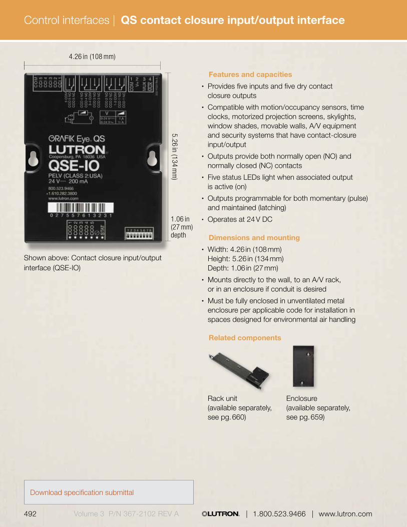
492 493 | 1.800.523.9466 | www.lutron.com www.lutron.com | 1.800.523.9466 |Volume 3 P/N 367-2102 REV A
Control interfaces |
Shown above: Contact closure input/output interface (QSE-IO)
4.26 in (108 mm)
5.26 in (134 mm
)
1.06 in (27 mm) depth
Features and capacities• Provides five inputs and five dry contact
closure outputs• Compatible with motion/occupancy sensors, time
clocks, motorized projection screens, skylights, window shades, movable walls, A/V equipment and security systems that have contact-closure input/output
• Outputs provide both normally open (NO) and normally closed (NC) contacts
• Five status LEDs light when associated output is active (on)
• Outputs programmable for both momentary (pulse) and maintained (latching)
• Operates at 24 V DC
Dimensions and mounting• Width: 4.26 in (108 mm)
Height: 5.26 in (134 mm) Depth: 1.06 in (27 mm)
• Mounts directly to the wall, to an A/V rack, or in an enclosure if conduit is desired
• Must be fully enclosed in unventilated metal enclosure per applicable code for installation in spaces designed for environmental air handling
Related components
Rack unit Enclosure (available separately, (available separately, see pg. 660) see pg. 659)
Download specification submittal
QS contact closure input/output interface

492 493 | 1.800.523.9466 | www.lutron.com www.lutron.com | 1.800.523.9466 | Volume 3 P/N 367-2102 REV A
Control interfaces |
InterfaceQS Contact closure interface QSE-IO
Compatible with Quantum® and HomeWorks® QS systems
Model numbers Communication and wiring• Low-voltage IEC PELV/NEC Class 2 wired
communication via the QS link• Uses three power draw units on the QS link• Each QS link on a Quantum or HomeWorks QS
processor can have up to 99 QS devices; each QS contact closure input/output interface counts as one device toward the limit
Functionality and operating modes• Contact closure inputs and outputs are
fully programmable using the Quantum and HomeWorks QS software
• Using the inputs, contact closures in other equipment can operate compatible primary controls to:
– Select scenes– Adjust scenes to reflect status of movable
walls (partitioning)– Toggle any combination of zones in the system
between Off and a configurable preset value – Turn lights on or off and/or move shades based
on room occupancy – Perform special functions such as sequencing,
control lockout, and time clock disable• Using the outputs, scene and/or zone changes
in control units can:
– Trigger outputs to control other equipment– Provide status feedback to other equipment
• Using the inputs, contact closures in other equipment can operate Sivoia® QS window treatments to:
– Open or close – Raise/lower or stop– Select adjustable presets
• Using the outputs, key presses on QS window treatment keypads or GRAFIK Eye QS window treatment buttons can:
– Trigger outputs to other motorized window treatment equipment
QS Contact closure input/output interface

494 495 | 1.800.523.9466 | www.lutron.com www.lutron.com | 1.800.523.9466 |Volume 3 P/N 367-2102 REV A
Control interfaces |
Features and capacities• Interface allows integration with a touch screen,
PC, A/V systems, or other digital equipment that supports RS232, or TCP/IP communication over Ethernet
• Control and monitor GRAFIK Eye QS main units, Sivoia® QS shades and draperies, Energi Savr Node modules and other products on the wired QS link
• Monitor lighting scenes, levels, and shade positions
• Operates at 24 V DC
Dimensions and mounting• Width: 4.26 in (108 mm)
Height: 5.26 in (134 mm) Depth: 1.06 in (27 mm)
• Mounts directly to the wall, to an A/V rack or in an enclosure if conduit is desired
• Must be fully enclosed in unventilated metal enclosure per applicable code for installation in spaces designed for environmental air handling
Related components
Rack unit Enclosure (available separately, (available separately, see pg. 660) see pg. 659)
Shown above: RS232/Ethernet interface (QSE-CI-NWK-E)
4.26 in (108 mm)
5.26 in (134 mm
)
1.06 in (27 mm) depth
Download specification submittal
QS RS232/Ethernet interface
494 495 | 1.800.523.9466 | www.lutron.com www.lutron.com | 1.800.523.9466 | Volume 3 P/N 367-2102 REV A
Control interfaces |
Interfaces and mounting units
Interfaces
QS RS232/Ethernet interface QSE-CI-NWK-E
Compatible with Quantum® and HomeWorks® QS systems
Model numbers Communication and wiring• Low-voltage IEC PELV/NEC Class 2 wired
communication via the QS link• Up to ten QS RS232/Ethernet interfaces are
allowed per QS link• Each QS link on a Quantum or HomeWorks QS
processor can have up to 99 QS devices; the QS RS232/Ethernet interface counts as one device toward the limit
• Uses two power draw units on the QS link
Functionality and operating modes• Control: scene selection, sequencing, zone raise/
lower, master raise/lower, set shade group level, simulate button press/release
• Monitoring: current scene, zone level, button presses, shade group levels
• For a full list of features refer to the Lutron Integration Protocol Guide (P/N 040-249)
QS RS232/Ethernet interface

496 497 | 1.800.523.9466 | www.lutron.com www.lutron.com | 1.800.523.9466 |Volume 3 P/N 367-2102 REV A
Control interfaces |
Features and capacities• Allows control of DMX512-controlled devices• Zones can be mapped to either a single DMX512
channel or to three separate DMX512 channels, for RGB/CMYK color-control applications
• Integral RGB/CMYK lookup table that maps zone intensities to RGB/CMYK values (colors)
• DMX512 link terminators as needed at both ends of the DMX512 link (available from Lutron®, part number LT-1)
• Each interface can control a maximum of 32 DMX512 channels
• Operates at 24 V DC
Dimensions and mounting• Width: 4.26 in (108 mm)
Height: 5.26 in (134 mm) Depth: 1.06 in (27 mm)
• Mounts directly to the wall, to an AV rack or in an enclosure
• Must be fully enclosed in unventilated metal enclosure per applicable code for installation in spaces designed for environmental air handling
Related components
Rack unit Enclosure (available separately, (available separately, see pg. 660) see pg. 659)
Shown above: DMX control interface (QSE-CI-DMX)
4.26 in (108 mm)
5.26 in (134 mm
)
1.06 in (27 mm) depth
Download specification submittal
QS DMX512 output control interface

496 497 | 1.800.523.9466 | www.lutron.com www.lutron.com | 1.800.523.9466 | Volume 3 P/N 367-2102 REV A
Control interfaces |
Interfaces and mounting units
Interfaces
QS DMX interface QSE-CI-DMX
Compatible with Quantum and HomeWorks QS systems
Model numbers Communication and wiring• Low-voltage IEC PELV/NEC Class 2 wired
communication via the QS link• Connects to theatrical equipment via DMX cable
(P/N GRX-CBL-DMX-250 or GRX-CBL-DMX-500, sold separately)
• One DMX512 output control interface per QS link; counts toward the 99 QS device limit on each of the QS links on a Quantum or HomeWorks QS processor
• Each channel counts as a single zone; each QS link on a Quantum or HomeWorks QS processor has a 512 zone limit
• Uses two power draw units on the QS link
QS DMX512 output control interface

498 499 | 1.800.523.9466 | www.lutron.com www.lutron.com | 1.800.523.9466 |Volume 3 P/N 367-2102 REV A
Control interfaces |
Features and capacities• Integrates Lutron® wireless and wired
sensors and controls through the QS communication link to Energi Savr NodeTM modules, GRAFIK Eye® QS main units, and Sivoia® QS shades and draperies
• Connects to up to four Lutron wired sensors or controls—occupancy sensors, daylight sensors, EcoSystem® infrared (IR) receivers, EcoSystem wallstations or Pico® wired controls (does not apply to wireless only models)
• Connects to up to ten of each type of wireless device—occupancy/vacancy sensors, daylight sensors, Radio shadow sensor, or Pico® wireless controls
• Operates at 24 V DC
Dimensions and mounting• Diameter: 4.04 in (103 mm)
Depth: 0.74 in (19 mm) Profile: 0.43 in (11 mm)
• Ceiling-mount where visible from inside the space to guarantee wireless range
Communication and wiring• Communicates via Lutron reliable Clear
Connect® Radio Frequency (RF) technology to other Lutron wireless devices
• Radio Frequency (RF) range: 60 ft (18 m) line of sight, or 30 ft (9 m) through walls
• Low-voltage IEC PELV/NEC Class 2 wired communication via the QS link
• Each QS link on a Quantum processor can have up to 99 QS devices; each QS sensor module counts as one device toward the limit
• Uses three power draw units on the QS link, not including wired inputs
• Models available for 434 MHz, 434 limited channel MHz, 865 MHz, 868 MHz and 868 limited channel MHz
Shown above: QS sensor module–434 MHz (QSM2-4W-C)
4.04 in (103 mm)
0.74 in(19 mm) depth
0.43 in(11 mm) profile
0.43 in(11 mm) profile
0.74 in (19 mm)depth
Download specification submittal
QS sensor module

498 499 | 1.800.523.9466 | www.lutron.com www.lutron.com | 1.800.523.9466 | Volume 3 P/N 367-2102 REV A
Control interfaces |
Wired and wireless inputs
North America (434 MHz) QSM2-4W-C For J-box mounting QSM2-4W-J
European Union and QSM3-4W-C U.A.E.(868 MHz)
China and Singapore QSM4-4W-C (868 MHz limited channel) Hong Kong QSM7-4W-C (434 MHz limited channel)
Wireless inputs only
North America (434 MHz) QSM2-XW-C For J-box mounting QSM2-XW-J
European Union and QSM3-XW-C U.A.E.(868 MHz)
China and Singapore QSM4-XW-C (868 MHz limited channel)
India (865 MHz) QSM5-XW-C Hong Kong QSM7-CW-C (434 MHz limited channel)
Wired input only
Wired input only, non-RF QSMX-4W-C
Compatible with the Quantum® system
Model numbers
For specific radio frequency information by country, refer to radio frequency chart on pg. 695.
QS sensor module

500 501 | 1.800.523.9466 | www.lutron.com www.lutron.com | 1.800.523.9466 |Volume 3 P/N 367-2102 REV A
Control interfaces |
6.4 in (162 mm)
3.5 in (90 mm
)
2.4 in (61 mm) depth
Shown above: QS motor group controller (QSE-CI-4M-D)
Features and capacities• Provides seamless integration of QS
stand-alone systems with AC blinds, shades, louvers, projection screens, or any compatible AC motor
• Can be controlled by the GRAFIK Eye® QS main unit, seeTouch® QS keypad, or Pico® wireless control
• Provides four independently controllable AC raise/lower outputs from one common AC input feed; 1.5 A maximum motor load per channel, 6 A maximum total input current
• Operating voltage: 120-240 V (CE) @ 50/60 Hz
Dimensions and mounting• Width: 6.40 in (162 mm)
Height: 3.50 in (90 mm) Depth 2.40 in (61 mm)
• Mounts to standard DIN-rail (width = 9.5 mm)• 9 DIN-wide device
Communication and wiring• Low-voltage IEC PELV/NEC Class 2 wired
communication via the QS link• Requires QS sensor module for
wireless communication• Each QS link on a Quantum processor can
have up to 99 QS devices and 512 zones; each QS motor group controller counts as four zones and one device toward the limit
• Does not provide nor consume power draw units on QS link
Download specification submittal
QS motor group controller (DIN-rail)
QS motor group controller (DIN-rail) QSE-CI-4M-D
120-240 V (CE)
Compatible with the Quantum system
Model numbers
QS motor group controller

Download specification submittal
7.50 in (191 mm
)
500 501 | 1.800.523.9466 | www.lutron.com www.lutron.com | 1.800.523.9466 | Volume 3 P/N 367-2102 REV A
Control interfaces |
Features and capacities• Provides accurate, real-time energy measurement
of lighting, HVAC, and/or plug loads coupled with verification capability via Quantum GreenGlance® and Q-AdminTM software
• Metered data contributes to LEED certification and helps meet requirements for industry regulation and/or regional rebates and incentives
• Models available for 120/208 V, 277/480 V or 347/600 V
• Each meter includes one set of three split-core current sensors; connect up to three sets of current sensors (all same amperage) to monitor up to three loads of the same voltage with one meter
• Current sensors available for 100 A, 200 A, 400 A, 800 A, 1600 A or 3200 A
• Battery back-up in event of power failure, 8-year battery life expectancy
• Q-Manager server is required
Shown above: Energy meter LUT-SUBM208-100C-CPN5898
7.00 in 178 mm) 3.25 in (83 mm) depth
Energy meter
Dimensions and mounting• Width: 7.00 in (178 mm)
Height: 7.50 in (191 mm) Depth: 3.25 in (83 mm)
• Current Sensor
– 100 A or 200 A: Width: 3.75 in (95 mm); Height: 2.75 in (70 mm); Depth: 1.3 in (33 mm)
– 400 A; Width: 3.75 in (95 mm); Height: 4.25 in (108 mm); Depth: 1.3 in (108 mm)
– 800 A/1600 A: Width: 6.09 in (155 mm); Height: 5.75 in (146 mm); Depth: 1.25 in (32 mm)
– 3200 A: Width: 7.75 in (197 mm); Height: 9.28 in (231 mm); 1.25 in (32 mm)
• Energy meter is surface mounted
Communication and wiring• Connects to the Q-Manager server via Ethernet• Each meter requires an Ethernet connection and
a static IP address• May be installed in a fixed electrical system on the
load side of the branch circuit distribution panel• Quantum system can have up to 500 meters
Voltage
208 for 120/208 V480 for 277/480 V600 for 347/600 V
Amperage100 for 100 A200 for 200 A300 for 300 A400 for 400 A800 for 800 A1600 for 1600 A3200 for 3200 A
Compatible with the Quantum system
Voltage Amperage
Amperage
Energy meter
LUT-SUBMGL480-400C-CPN5898
Addition set of three current sensors
LUT-SUB-CS400-CPN5899
How to build a model number

502 503 | 1.800.523.9466 | www.lutron.com www.lutron.com | 1.800.523.9466 |Volume 3 P/N 367-2102 REV A
Control interfaces |
Features and capacities• Turns all or designated lighting loads to “full on”
output or other programmed emergency lighting level (interface does not provide emergency power)
• UL924 Listed as “Emergency Lighting and Power Equipment”
• Senses the normal (non-essential) line voltage on all phases of normal power. When one or more phases of power are lost, the interface will send a signal to the panel circuit selector/controller, GRAFIK Eye® QS main unit or Energi Savr NodeTM module with emergency (essential) power, causing it to enter the emergency lighting mode.
• Sense voltage range: 100-347 V @ 50/60 Hz, 30 mA, 1 Phase or 3 Phase
• Status indicator indicates the phase status; indicator ON is normal mode, OFF is emergency mode
• A test switch is provided to perform a functional test of the system by simulating an emergency situation
• Provides inputs for a Fire Alarm Control Panel (FACP); a maintained dry contact closure received between the FACP inputs will actuate the emergency mode
• For more information on the emergency lighting interface see application note #106 at www.lutron.com/applicationnotes
Shown above: Emergency lighting interface (LUT-ELI-3PH)
5.00 in (127 mm)
2.50 in (64 mm) depth
7.75 in (197 mm
)
Download specification submittal
Emergency lighting interface

502 503 | 1.800.523.9466 | www.lutron.com www.lutron.com | 1.800.523.9466 | Volume 3 P/N 367-2102 REV A
Control interfaces |
Interfaces
Emergency lighting interface LUT-ELI-3PH
Compatible with LCP128, Softswitch 128 (XPS), GRAFIK Eye 4000 and Quantum systems
Model numbers Dimensions and mounting• Width: 5.00 in (127 mm)
Height: 7.75 in (197 mm) Depth: 2.50 in (64 mm)
• Mounts to a standard 4 in (102 mm) x 4 in (102 mm) junction box
• Approved for installation in spaces designed for environmental air handling per 2011 NEC® article 300.22(C)
Communication and wiring• Low-voltage IEC PELV/NEC Class 2 wiring• Sense voltage input to the emergency lighting
interface must be from the normal (non-essential) power source
• Separate 24 V DC power supply must be used with an Energi Savr Node unit
• One emergency lighting interface may be used with up to 32 circuit selectors, Energi Savr Node modules, GRAFIK Eye QS main units or Quantum bus supplies
• Only one Quantum bus supply per Quantum light management hub needs to be connected per emergency lighting interface; up to eight Quantum hubs can be connected to one interface
Emergency lighting interface
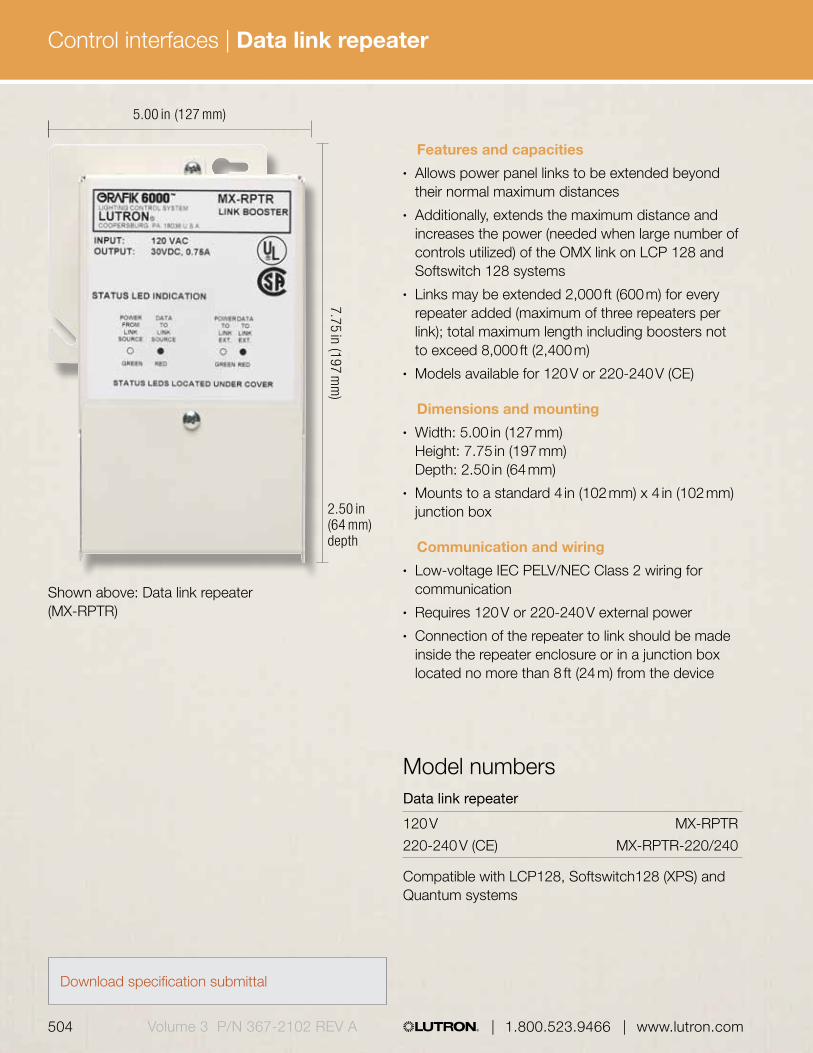
Compatible with LCP128, Softswitch128 (XPS) and Quantum systems
504 505 | 1.800.523.9466 | www.lutron.com www.lutron.com | 1.800.523.9466 |Volume 3 P/N 367-2102 REV A
Control interfaces |
Shown above: Data link repeater (MX-RPTR)
5.00 in (127 mm)
7.75 in (197 mm
)
Features and capacities• Allows power panel links to be extended beyond
their normal maximum distances• Additionally, extends the maximum distance and
increases the power (needed when large number of controls utilized) of the OMX link on LCP 128 and Softswitch 128 systems
• Links may be extended 2,000 ft (600 m) for every repeater added (maximum of three repeaters per link); total maximum length including boosters not to exceed 8,000 ft (2,400 m)
• Models available for 120 V or 220-240 V (CE)
Dimensions and mounting• Width: 5.00 in (127 mm)
Height: 7.75 in (197 mm) Depth: 2.50 in (64 mm)
• Mounts to a standard 4 in (102 mm) x 4 in (102 mm) junction box
Communication and wiring• Low-voltage IEC PELV/NEC Class 2 wiring for
communication• Requires 120 V or 220-240 V external power • Connection of the repeater to link should be made
inside the repeater enclosure or in a junction box located no more than 8 ft (24 m) from the device
2.50 in (64 mm) depth
Data link repeater
120 V MX-RPTR
220-240 V (CE) MX-RPTR-220/240
Model numbers
Data link repeater
Download specification submittal

504 505 | 1.800.523.9466 | www.lutron.com www.lutron.com | 1.800.523.9466 | Volume 3 P/N 367-2102 REV A
Control interfaces | HVAC controller
4.25 in (108 mm)
Shown above: HVAC controller (available only in a package)
Features and capacities• Connects to and controls mechanical
HVAC equipment• Provides the ability to adjust heating and cooling
systems any time of day with manual button press or time clock input
• Can utilize either a wireless or wired temperature sensor
• Available exclusively in White (WH)• Operates at 24 VAC
Dimensions and mounting• Width: 4.25 in (108 mm)
Height: 5.25 in (133 mm) Depth: 1.06 in (27 mm)
• Mount on a wall, ceiling or flat surface
Communication and wiring• Communicates via Lutron reliable Clear Connect®
radio frequency (RF) technology to other Lutron wireless devices
• Operates at 434 MHz• HVAC controller must be located within 30 ft (9 m)
of a hybrid repeater• Wires to and is powered by HVAC equipment
using standard 24 V AC thermostat wiring• HomeWorks QS system can have up to
99 devices per RF link• Requires one wired sensor (air duct or flush-
mount); when using wireless sensor, wired sensor ignored until battery loss
• Up to four wireless temperature sensors can be used with a single HVAC controller
5.25 in (133 mm
)
1.06 in (27 mm) depth
Download specification submittal
Related components
Wireless wall-mount seeTemp® wall control temperature sensor (available separately, (available separately, see pg. 415) see pg. 438)

506 507 | 1.800.523.9466 | www.lutron.com www.lutron.com | 1.800.523.9466 |Volume 3 P/N 367-2102 REV A
Control interfaces | HVAC controller
Explanation of features
Features
1 HVAC System Status LEDs
• Indicate the status of the control outputs— when an LED is lit the corresponding relay is closed
2 Wireless temperature sensor status LEDs
• Active—LED is lit when at least 1 sensor is active
• Battery Low—indicates low battery for at least 1 sensor
3 Test and link buttons
• Used to set up and troubleshoot the RF connection
4 Test and link LEDs
• Flashes green to indicate that the system is in Test mode or Link mode
HVAC controller
6
7
5
5 HVAC equipment connections
• 24 V HVAC relays to control HVAC equipment
6 Wired sensor input
• Connection for wired backup temperature sensor
7 System type DIP switches
• Must be configured to correctly control attached HVAC equipment
43
2
1
Air duct sensor Flush mount sensor

506 507 | 1.800.523.9466 | www.lutron.com www.lutron.com | 1.800.523.9466 | Volume 3 P/N 367-2102 REV A
Control interfaces | HVAC controller
Model numbersHVAC controller packages
System package includes: LR-HVAC-PKG-WH 1 HVAC controller** 1 seeTemp® wall control (°F) (WH) 1 wireless wall-mount temperature sensor (SW) 1 wired return air duct sensor
System package includes: LR-HVAC-PKG-C-WH 1 HVAC controller** 1 seeTemp wall control (°C) (WH) 1 wireless wall-mount temperature sensor (SW) 1 wired return air duct sensor
System package includes: LR-HVAC-INT-XX* 1 HVAC controller** 1 wireless wall-mount temperature sensor* 1 wired return air duct sensor
System package includes: LR-HVAC-INT-FLSH 1 HVAC controller** 1 wired flush mount sensor**Compatible with HomeWorks QS system * Available in Snow (SW) and Midnight (MN) ** Only available in White (WH)
HVAC controller
Available models
For specific radio frequency information by country, refer to radio frequency chart on pg. 695.
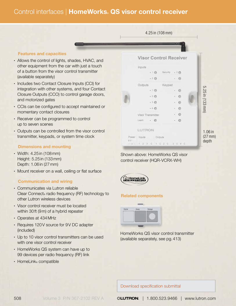
508 509 | 1.800.523.9466 | www.lutron.com www.lutron.com | 1.800.523.9466 |Volume 3 P/N 367-2102 REV A
Control interfaces | HomeWorks® QS visor control receiver
4.25 in (108 mm)5.25 in (133 m
m)
Features and capacities• Allows the control of lights, shades, HVAC, and
other equipment from the car with just a touch of a button from the visor control transmitter (available separately)
• Includes two Contact Closure Inputs (CCI) for integration with other systems, and four Contact Closure Outputs (CCO) to control garage doors, and motorized gates
• CCIs can be configured to accept maintained or momentary contact closures
• Receiver can be programmed to control up to seven scenes
• Outputs can be controlled from the visor control transmitter, keypads, or system time clock
Dimensions and mounting• Width: 4.25 in (108 mm)
Height: 5.25 in (133 mm) Depth: 1.06 in (27 mm)
• Mount receiver on a wall, ceiling or flat surface
Communication and wiring• Communicates via Lutron reliable
Clear Connect® radio frequency (RF) technology to other Lutron wireless devices
• Visor control receiver must be located within 30 ft (9 m) of a hybrid repeater
• Operates at 434 MHz• Requires 120 V source for 9 V DC adapter
(included)• Up to 10 visor control transmitters can be used
with one visor control receiver• HomeWorks QS system can have up to
99 devices per radio frequency (RF) link• HomeLink® compatible
1.06 in (27 mm) depth
Shown above: HomeWorks QS visor control receiver (HQR-VCRX-WH)
Download specification submittal
Related components
HomeWorks QS visor control transmitter (available separately, see pg. 413)

508 509 | 1.800.523.9466 | www.lutron.com www.lutron.com | 1.800.523.9466 | Volume 3 P/N 367-2102 REV A
Control interfaces | HomeWorks® QS visor control receiver
Explanation of features
1
2
3
6
Features
1 Input buttons • Press to test contact closure input programming
2 Output buttons • Press to test contact closure output programming
3 Keypad buttons • Press to test keypad programming
4 Labels • Place pre-printed or custom labels in depression to identify keypads/inputs/outputs
4
5
7
HomeWorks QS visor control receiver
5 Learn button • Press and hold for 3 seconds to enter learn mode — learn any button from transmitter to receiver
6 Contact closure terminal blocks
• Maximum 50 ft (15 m) to equipment
7 Power jack • Powered by 9 V DC adapter (supplied)

510 511 | 1.800.523.9466 | www.lutron.com www.lutron.com | 1.800.523.9466 |Volume 3 P/N 367-2102 REV A
Control interfaces | HomeWorks® QS visor control receiver
Visor control receiver
Receiver HQR-VCRX-WH
Compatible with the Quantum system
Model numbers
HomeWorks QS visor control receiver
For specific radio frequency information by country, refer to radio frequency chart on pg. 695.
Available modelsVisor Control Receiver
Learn
Visor Transmitter
KeypadOutputs
Security1
1
3
2
2
3
4
Inputs
1 2 3
Power9V
Inputs
C 1 C 2 C
Outputs
3 C 4 C

510 511 | 1.800.523.9466 | www.lutron.com www.lutron.com | 1.800.523.9466 | Volume 3 P/N 367-2102 REV A
Control interfaces |

512 Volume 3 P/N 367-2102 | 1.800.523.9466 | www.lutron.com/specificationguide
A power interface is a device wired between a dimmer and a lighting load. An interface provides additional control, increases power/wattage capacity above the dimmer capacity, and it provides voltage and control signals.
The power interfaces addressed in this guide are specific to each country's voltage requirements. Please confirm that the products you have selected match the required voltages by country on pg. 692.
Phase-adaptive power module pg. 514
Phase-adaptive power module with 3-wire fluorescent input pg. 518
3-wire fluorescent power module pg. 516
Switching power module pg. 520
Power interfaces

www.lutron.com/specificationguide | 1.800.523.9466 | Volume 3 P/N 367-2102 513
EcoSystem® dimming power module pg. 534
EcoSystem switching power module pg. 536
EcoSystem fixture module pg. 538
Power booster pg. 522
0-10 V interface pg. 528
Pulse width modulation interface pg. 530
Electronic low-voltage interface pg. 524
Fluorescent dimming ballast interface pg. 526
Synthetic minimum load interface pg. 532
EcoSystem to 0-10 V interface pg. 540

Power interfaces |
514 Volume 3 P/N 367-2102 | 1.800.523.9466 | www.lutron.com/specificationguide
Shown above: Phase-adaptive power module (PHPM-PA-120-WH)
Direct lighting loads
Incandescent/halogen Electronic low-voltage Magnetic low-voltage Neon/cold cathode Tu-Wire® fluorescent CFL/LED (screw-base)1
Operating voltages2
• Models available to accept 120 V or 100 V (Japan) control power
• Models available for 120 V, 120-277 V or 100 -200 V load power
6.30 in (160 mm)
5.10 in (130 mm
)
1.40 in (36 mm) profile
Features and capacities• Provides 16 A capability for a zone on
a compatible control unit to dim a fully loaded circuit of lighting
• Automatically detects load types and selects leading-edge or trailing-edge dimming for low-voltage transformers (electronic/magnetic)
• Provides power and dimming for one zone• Up to three power modules may be
wired on a single zone• Not for use with non-dimmable loads• Minimum load requirement is 10 W
Dimensions and mounting• Width: 6.30 in (160 mm)
Height: 5.10 in (130 mm) Depth: 1.20 in (31 mm) Profile: 1.40 in (36 mm)
• Can be surface or recess mounted• Mount in a 2-gang U.S. wallbox
3.50 in (89 mm) deep or in a 4.00 in (102 mm) x 4.00 in (102 mm) junction box, 2.10 in (53 mm) deep
• Requires incoming power feed wires, incoming control wires and outgoing load wires
• Approved and listed for installation in spaces designed for environmental air handling per 2011 National Electrical Code® (NEC) article 300.22 (c)
Related components:
Power booster for 220-240 V applications
(available separately, see pg. 522)
1.20 in (31 mm) depth
Download specification submittal
1 Visit www.lutron.com/LEDtool for a complete list of LEDs compatible with this module.
2 Contact Lutron for model availability for 277 V load power
Phase-adaptive power module
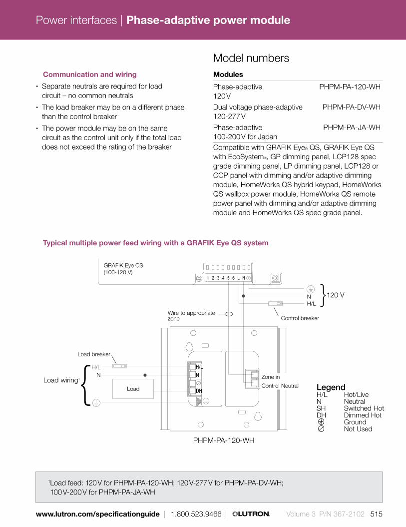
Power interfaces |
www.lutron.com/specificationguide | 1.800.523.9466 | Volume 3 P/N 367-2102 515
1 2 3 4 5 6 L N
H/L
N
DH
H/LN
NH/L
Load
GRAFIK Eye QS (100-120 V)
Zone in
Control Neutral
Wire to appropriate zone
LegendH/L Hot/LiveN NeutralSH Switched HotDH Dimmed Hot Ground
Not Used
Load breaker
Control breaker
}
Load wiring1{
120 V
Modules
Phase-adaptive PHPM-PA-120-WH 120 V
Dual voltage phase-adaptive PHPM-PA-DV-WH 120-277 V
Phase-adaptive PHPM-PA-JA-WH 100-200 V for JapanCompatible with GRAFIK Eye® QS, GRAFIK Eye QS with EcoSystem®, GP dimming panel, LCP128 spec grade dimming panel, LP dimming panel, LCP128 or CCP panel with dimming and/or adaptive dimming module, HomeWorks QS hybrid keypad, HomeWorks QS wallbox power module, HomeWorks QS remote power panel with dimming and/or adaptive dimming module and HomeWorks QS spec grade panel.
Model numbers Communication and wiring• Separate neutrals are required for load
circuit – no common neutrals• The load breaker may be on a different phase
than the control breaker• The power module may be on the same
circuit as the control unit only if the total load does not exceed the rating of the breaker
1 2 3 4 5 6 L N
H/L
N
DH
H/LN
NH/L
Load
GRAFIK Eye QS (100-120 V)
Zone in
Control Neutral
Wire to appropriate zone
LegendH/L Hot/LiveN NeutralSH Switched HotDH Dimmed Hot Ground
Not Used
Load breaker
Control breaker
}
Load wiring1{
120 V
Typical multiple power feed wiring with a GRAFIK Eye QS system
1 Load feed: 120 V for PHPM-PA-120-WH; 120 V-277 V for PHPM-PA-DV-WH; 100 V-200 V for PHPM-PA-JA-WH
PHPM-PA-120-WH
Phase-adaptive power module

Power interfaces |
516 Volume 3 P/N 367-2102 | 1.800.523.9466 | www.lutron.com/specificationguide
Shown above: 3-wire fluorescent power module (PHPM-3F-120-WH)
Features and capacities• Provides 16 A capability for a zone on a
compatible control unit to dim fluorescent and LED lights that have Lutron 3-wire line-voltage control electronic dimming ballasts (Hi-lume, Hi-lume 3D, EcoSystem) or LED drivers (Hi-lume A-Series)
• Provides power and dimming for one zone
• Utilizes Softswitch® arcless switching technology
• Up to three power modules may be wired on a single zone
Dimensions and mounting• Width: 6.30 in (160 mm)
Height: 5.10 in (130 mm) Depth: 1.20 in (31 mm) Profile: 1.00 in (25 mm)
• Can be surface or recess mounted• Mount in a 2-gang U.S. wallbox
3.50 in (89 mm) deep or in a 4.00 in (102 mm) x 4.00 in (102 mm) junction box, 2.10 in (53 mm) deep
• Requires incoming power feed wires, incoming control wires and outgoing load wires
• Approved and listed for installation in spaces designed for environmental air handling per 2011 NEC® article 300.22 (c)
6.30 in (160 mm)
5.10 in (130 mm
)
1.00 in (25 mm) profile
Direct lighting loads
/ Fluorescent/LED (3-wire)
Operating voltages1
• Models accept 120 V control power only• Models available for 120 V or 120-277 V
load power
1.20 in (31 mm) depth
3-wire fluorescent power module
Download specification submittal
1 Contact Lutron for model availability for 277 V load power

Power interfaces |
www.lutron.com/specificationguide | 1.800.523.9466 | Volume 3 P/N 367-2102 517
1 2 3 4 5 6 L N
H/L
N
DHSH
H/LN
NH/L
Lutronballast/driver
GRAFIK Eye QS (120 V)
Zone in
Control Neutral
Wire to appropriate zone
LegendH/L Hot/LiveN NeutralSH Switched HotDH Dimmed Hot Ground
Load breaker
Control breaker
}
Load wiring1{
120 V
Modules
3-wire fluorescent PHPM-3F-120-WH 120 V
Dual voltage 3-wire fluorescent PHPM-3F-DV-WH 120-277 V Compatible with GRAFIK Eye® QS, GRAFIK Eye QS with EcoSystem®, GP dimming panel, LCP128 spec grade dimming panel, LP dimming panel, LCP128 or CCP panel with dimming and/or adaptive dimming module, HomeWorks QS dimmer/hybrid keypad, HomeWorks QS wallbox power module, HomeWorks QS remote power panel with dimming and/or adaptive dimming module and HomeWorks QS spec grade panel.
Model numbers Communication and wiring• Separate neutrals are required for load
circuit – no common neutrals• The load breaker may be on a different phase
than the control breaker• The power module may be on the same
circuit as the control unit only if the total load does not exceed the rating of the breaker
1 2 3 4 5 6 L N
H/L
N
DH
H/LN
NH/L
Load
GRAFIK Eye QS (100-120 V)
Zone in
Control Neutral
Wire to appropriate zone
LegendH/L Hot/LiveN NeutralSH Switched HotDH Dimmed Hot Ground
Not Used
Load breaker
Control breaker
}
Load wiring1{
120 V
Typical multiple power feed wiring with a GRAFIK Eye QS system
1Load feed: 120 V for PHPM-3F-120-WH; 120 V-277 V for PHPM-3F-DV-WH
PHPM-3F-120-WH
3-wire fluorescent power module

Power interfaces |
518 Volume 3 P/N 367-2102 | 1.800.523.9466 | www.lutron.com/specificationguide
Shown above: Phase-adaptive power module with 3-wire fluorescent input (PHPM-WBX-120-WH)
Direct lighting loads
Incandescent/halogen Electronic low-voltage Magnetic low-voltage Neon/cold cathode Tu-Wire® fluorescent CFL/LED (screw-base)*
Operating voltages• Models accept 120 V control power only• Models available for 120 V or 120-277 V
load power
6.30 in (160 mm)
5.10 in (130 mm
)
1.40 in (36 mm) profile
Features and capacities• When connected to a 20 A circuit
breaker, provides capacity on a compatible control unit for full 16 A load of lighting
• Automatically detects load types and selects leading-edge or trailing-edge dimming for low-voltage transformers (electronic/magnetic)
• Provides power and dimming for one zone• Up to three power modules may be
wired on a single zone• Not for use with non-dimmable loads• Minimum load on power module is 10 W
Dimensions and mounting• Width: 6.30 in (160 mm)
Height: 5.10 in (130 mm) Depth: 1.20 in (31 mm) Profile: 1.40 in (36 mm)
• Can be surface or recess mounted• Mount in a 2-gang U.S. wallbox
3.50 in (89 mm) deep or in a 4.00 in (102 mm) x 4.00 in (102 mm) junction box, 2.10 in (53 mm) deep
• Requires incoming power feed wires, incoming control wires and outgoing load wires
• Approved and listed for installation in spaces designed for environmental air handling per 2011 NEC® article 300.22 (c)
1.20 in (31 mm) depth
Download specification submittal
* Visit www.lutron.com/LEDtool for a complete list of LEDs compatible with this module.
Phase-adaptive power module with 3-wire fluorescent input

Power interfaces |
www.lutron.com/specificationguide | 1.800.523.9466 | Volume 3 P/N 367-2102 519
H/L
N
DH
H/LN
Load* 120 V
Zone in
Control Neutral
Circuit breaker
120 V
3-wire fluorescent dimmer 120 V
DH (yellow or orange wire)
SH (red wire)Cap off
H/LN
Modules
Phase-adaptive with PHPM-WBX-120-WH 3-wire fluorescent input 120 V
Dual voltage phase-adaptive PHPM-WBX-DV-WH with 3-wire fluorescent input 120-277 VCompatible with HomeWorks QS dimmer and EcoSystem dimming power module.
Model numbers Communication and wiring• Separate neutrals are required for load
circuit – no common neutrals• The load breaker may be on a different phase
than the control breaker• The power module may be on the same
circuit as the control unit only if the total load does not exceed the rating of the breaker
1 2 3 4 5 6 L N
H/L
N
DH
H/LN
NH/L
Load
GRAFIK Eye QS (100-120 V)
Zone in
Control Neutral
Wire to appropriate zone
LegendH/L Hot/LiveN NeutralSH Switched HotDH Dimmed Hot Ground
Not Used
Load breaker
Control breaker
}
Load wiring1{
120 V
Typical single power feed wiring with a 3-wire fluorescent dimmer
For additional wiring diagrams, see the specification submittal on www.lutron.com
* Load feed: 120 V for PHPM-WBX-120-WH; 120 V-277 V for PHPM-WBX-DV-WH
{
Phase-adaptive power module with 3-wire fluorescent input

Power interfaces |
520 Volume 3 P/N 367-2102 | 1.800.523.9466 | www.lutron.com/specificationguide
Shown above: Switching power module (PHPM-SW-DV-WH)
Features and capacities
• Provides 16 A capability for a zone on a compatible control to switch a fully loaded circuit of lighting
• May be used to switch incandescent/halogen, electronic low-voltage, magnetic low-voltage, HID, fluorescent ballasts and neon/cold cathode lighting sources, and LED non-dimmable drivers/sources
• Utilizes Softswitch® arcless switching technology
• Provides power and switching for one zone
• Up to three power modules may be wired on a single zone
Dimensions and mounting• Width: 6.30 in (160 mm)
Height: 5.10 in (130 mm) Depth: 1.20 in (31 mm) Profile depth: 1.00 in (25 mm)
• Can be surface or recess mounted• Mount in a 2-gang U.S. wallbox
3.50 in (89 mm) deep or in a 4.00 in (102 mm) x 4.00 in (102 mm) junction box, 2.10 in (53 mm) deep
• Requires incoming power feed wires, incoming and outgoing load wires
• Approved and listed for installation in spaces designed for environmental air handling per 2011 NEC® article 300.22 (c)
6.30 in (160 mm)
Direct lighting loads
Non-dim lighting HID Motor loads:
0.50 HP at 120 V 1.00 HP at 277 V
Fan loads
Operating voltages• Models available to accept 120 V or 100 V
(Japan) control power• Model available for 120-277 V or 100 V-200 V
load power
5.10 in (130 mm
)
1.00 in (25 mm) profile
1.20 in (31 mm) depth
Download specification submittal
Switching power module

Power interfaces |
www.lutron.com/specificationguide | 1.800.523.9466 | Volume 3 P/N 367-2102 521
Modules
Dual voltage-switching PHPM-SW-DV-WH 120-277 V
Switching PHPM-SW-JA-WH 100 V-200 V for Japan Compatible with GRAFIK Eye® QS, GRAFIK Eye QS with EcoSystem®, GP dimming panel, LCP128 spec grade dimming panel, LP dimming panel, Softswich128 switching panel, XP switching panel, LCP128 or CCP with dimming, adaptive dimming, and/or relay module, HomeWorks QS switch/hybrid keypad, HomeWorks QS wallbox power module, HomeWorks QS remote power panel with dimming, adaptive dimming, and/or relay module, HomeWorks QS spec grade panel, and EcoSystem switching power module.
Model numbers Communication and wiring• Separate neutrals are required for load
circuit – no common neutrals• The load breaker may be on a different phase
than the control breaker• The power module may be on the same
circuit as the control unit only if the total load does not exceed the rating of the breaker
For additional wiring diagrams, see the specification submittal on www.lutron.com
1Load feed: 120-277 V for PHPM-SW-DV-WH; 100 V or 100-200 V for PHPM-SW-JA-WH
1 2 3 4 5 6 L N
H/L
N
SH
H/LN
NH/L
Load
GRAFIK Eye QS (100-120 V)
Zone in
Control Neutral
Wire to appropriate zone
LegendH/L Hot/LiveN NeutralSH Switched HotDH Dimmed Hot Ground
Not Used
Load breaker
Control breaker
}
Load wiring1{
120 V
1 2 3 4 5 6 L N
H/L
N
DH
H/LN
NH/L
Load
GRAFIK Eye QS (100-120 V)
Zone in
Control Neutral
Wire to appropriate zone
LegendH/L Hot/LiveN NeutralSH Switched HotDH Dimmed Hot Ground
Not Used
Load breaker
Control breaker
}
Load wiring1{
120 V
Typical multiple power feed wiring with GRAFIK Eye QS system
PHPM-SW-DV-WH
Switching power module

Power interfaces |
522 Volume 3 P/N 367-2102 | 1.800.523.9466 | www.lutron.com/specificationguide
Features and capacities• Provides capability for a zone on a control unit to
control a larger load• Allows the zone to dim or switch a fully-loaded
circuit of lighting• Dims most popular lighting sources and load types• For 120 V application, phase-adaptive power
module is recommended, see pg. 514• Two power boosters may be used on a zone to
double the capacity• For indoor use only
Dimensions and mounting• Width: 4.57 in (116 mm)
Height: 4.57 in (116 mm) Depth: 1.88 in (48 mm) Profile: 0.69 in (17 mm)
• Can be surface or recess-mounted• Mount in 2-gang U.S. wallbox
3.50 in (89 mm) deep• Requires incoming power feed wires
and outgoing load wires• Approved and listed for installation
in spaces designed for environmental air handling per 2011 NEC® article 300.22 (c)
Shown above: Power booster (NGRX-PB-CE-WH)
4.57 in (116 mm)
4.57 in (116 mm
)
Direct lighting loads
Incandescent/halogen Magnetic low-voltage Tu-Wire® Fluorescent Neon/cold cathode CFL/LED (screw-base)*
Operating voltages• Models available for 220-240 V,
230 V (CE) or 100 V @ 50/60 Hz input power
0.69 in (17 mm) profile
1.88 in (48 mm) depth
Download specification submittal
* Visit www.lutron.com/LEDtool for a complete list of LEDs compatible with this booster.
Power booster

Power interfaces |
www.lutron.com/specificationguide | 1.800.523.9466 | Volume 3 P/N 367-2102 523
Boosters
Power Booster NGRX-PB-AU-WH 220-240 V 2400 W/VA
Power Booster NGRX-PB-CE-WH 230 V (CE) 1200 W/VA flush mount with faceplate
Power Booster NGRX-PB-CE-WH 230 V (CE) 1840 W/VA surface mount without faceplate
Power Booster NGRX-PB-JA-WH 100 V 1600 W/VA for JapanCompatible with GRAFIK Eye® QS, GRAFIK Eye QS with EcoSystem®, Energi Savr NodeTM phase adaptive (DIN-rail), GP dimming panel, LP dimming panel, LCP128 or CCP panel with dimming, adaptive dimming and/or electronic low-voltage module, HomeWorks QS wallbox power module, HomeWorks QS remote power panel with dimming and/or adaptive dimming module, HomeWorks QS spec grade panel and HomeWorks QS phase adaptive power module (DIN-rail).
Model numbers
TO HOT/LIVE
TO APPLICABLE ZONE
TO NEUTRAL
DO N
OT U
SE H/L
N
HOT/
LIVE
EAR
TH/G
ROUN
D
ZONE
INNE
UTRA
L N
H/LN
ZONE
OUT
GRAFIK Eye QSControl Unit
Feed 1 fromDistributionPanel
Feed 2 fromDistributionPanel
LoadLoad Neutral
Rear View of PB
Dual-feed wiring diagram for NGRX-PB 100 V, 120 V and 220–240 V
NGRX-PB-WH
Communication and wiring• Separate neutrals are required for load circuit—
no common neutrals• The load breaker/MCB may be on a different phase
than the control breaker/MCB• The power module may be on the same circuit
as the control unit only if the total load does not exceed the rating of the breaker
For 230 V wiring and single-feed wiring, see the specification submittal on www.lutron.com
Power booster

Power interfaces |
524 Volume 3 P/N 367-2102 | 1.800.523.9466 | www.lutron.com/specificationguide
Features and capacities• Provides power and up to 1200 watts dimming
capacity for one electronic low-voltage zone• Operates electronic low-voltage lighting; works only
with electronic (solid state) low-voltage transformers that are manufacturer approved for reverse phase control dimming
• Incandescent and electronic low-voltage sources may be controlled on same zone; up to 30% of the electronic low-voltage interfaces capacity may be used for incandescent lighting
• For 120 V application, phase-adaptive power module is recommended, see pg. 514
• Two electronic low-voltage interfaces may be used on a zone to double capacity (up to 2400 watts)
• For indoor use only
Dimensions and mounting• Width: 4.57 in (116 mm)
Height: 4.57 in (116 mm) Depth: 1.88 in (48 mm) Profile: 0.69 in (17 mm)
• Can be surface or recess mounted• Mount in a 2-gang U.S. wallbox 3.50 in (89 m) deep• Requires incoming power feed wires, incoming
control wires and outgoing load wires• Approved and listed for installation in spaces
designed for environmental air handling per 2011 NEC® article 300.22 (c)
4.57 in (116 mm)
4.57 in (116 mm
)
Shown above: Electronic low-voltage interface (NGRX-ELVI-CE-WH)
Direct lighting loads
Electronic low-voltage CFL/LED (screw-base)*
Operating voltages• Models available for 220-240 V,
or 230 V (CE)
0.69 in (17 mm) profile
1.88 in (48 mm) depth
Download specification submittal
* Visit www.lutron.com/LEDtool for a complete list of LEDs compatible with this interface.
Electronic low-voltage interface

Power interfaces |
www.lutron.com/specificationguide | 1.800.523.9466 | Volume 3 P/N 367-2102 525
Interfaces
Electronic low-voltage interface NGRX-ELVI-AU-WH 220-240 V 1200 W/VA
Electronic low-voltage interface NGRX-ELVI-CE-WH 230 V (CE) 1200 W/VACompatible with GRAFIK Eye® QS, GRAFIK Eye QS with EcoSystem®, Energi Savr NodeTM phase adaptive (DIN-rail), GP dimming panel, LP dimming panel, LCP128 or CCP panel with dimming, adaptive dimming and/or electronic low-voltage module, HomeWorks QS wallbox power module, HomeWorks QS remote power panel with dimming and/or adaptive dimming module, HomeWorks QS spec grade panel and HomeWorks QS phase adaptive power module (DIN-rail).
Model numbers Communication and wiring• Separate neutrals are required for load circuit—
no common neutrals• The load breaker/MCB may be on a different
phase than the control breaker/MCB• The power module may be on the same circuit
as the control unit only if the total load does not exceed the rating of the breaker
TO HOT/LIVE
TO APPLICABLE ZONE
TO NEUTRAL
DO N
OT U
SE H/L
N
HOT/
LIVE
EAR
TH/G
ROUN
D
ZONE
INNE
UTRA
L N
H/LN
ZONE
OUT
GRAFIK Eye QSControl Unit
Feed 1 fromDistributionPanel
Feed 2 fromDistributionPanel
LoadLoad Neutral
Rear View of PBNGRX-ELVI-CE-WH
Dual-feed wiring diagram for 230 V (CE)
For 230 V wiring and single-feed wiring, see the specification submittal on www.lutron.com
Electronic low-voltage interface

Power interfaces |
526 Volume 3 P/N 367-2102 | 1.800.523.9466 | www.lutron.com/specificationguide
Features and capacities• Dim fluorescent lights that have Lutron 3-wire
line-voltage control electronic dimming ballasts (Hi-lume®, EcoSystem®, and Hi-lume® 3D)
• For 120 V application, 3-wire fluorescent power module is recommended, see pg. 516
• Two fluorescent dimming ballast interfaces can be connected to one zone
• For indoor use only
Dimensions and mounting• Width: 4.57 in (116 mm)
Height: 4.57 in (116 mm) Depth: 1.88 in (48 mm) Profile: 0.69 in (17 mm)
• Can be surface or recess mounted• Mount in a 2-gang U.S. wallbox 3.50 in
(89 m) deep• Requires incoming power feed wires, incoming
control wires and outgoing load wires• Approved and listed for installation in spaces
designed for environmental air handling per 2011 NEC® article 300.22 (c)
Shown above: Fluorescent dimming ballast interface (NGRX-FDBI-AU-WH)
Direct lighting loads
Fluorescent (3-wire)
Operating voltages• Models available for 220-240 V
4.57 in (116 mm)
4.57 in (116 mm
)
0.69 in (17 mm) profile
1.88 in (48 mm) depth
Download specification submittal
Fluorescent dimming ballast interface
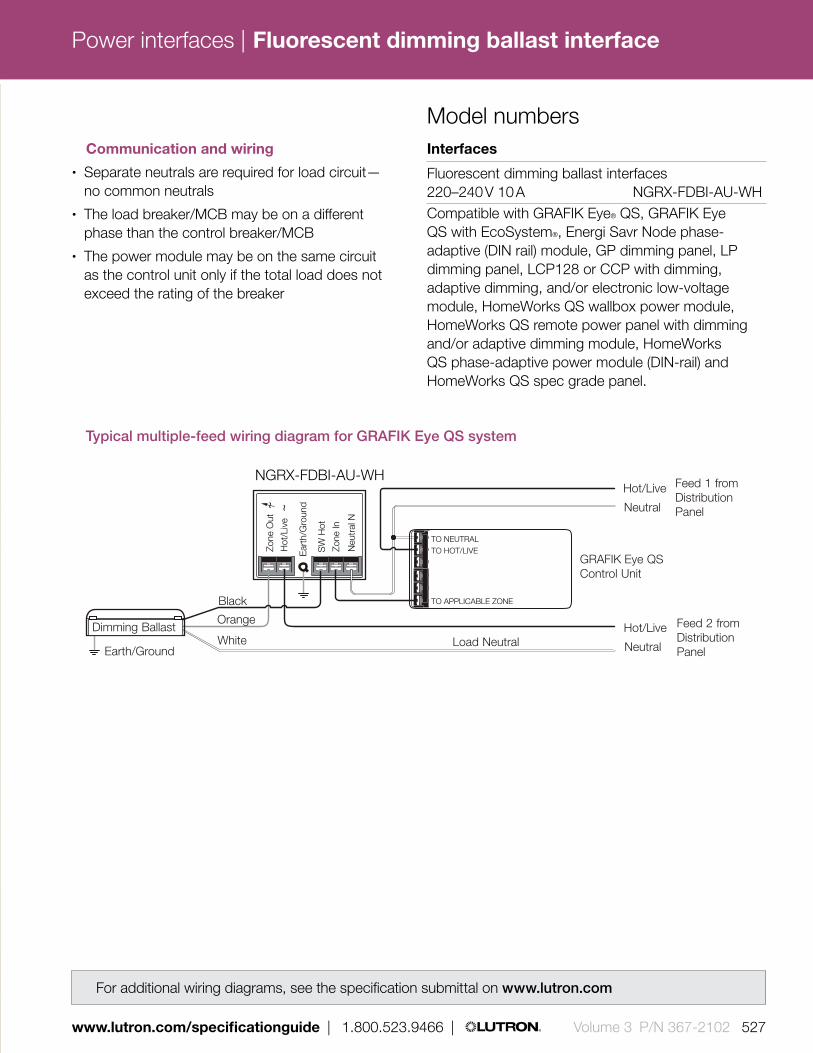
Power interfaces |
www.lutron.com/specificationguide | 1.800.523.9466 | Volume 3 P/N 367-2102 527
Neu
tral
N
Zone
In
Zone
Out
Ear
th/G
roun
d
Hot
/Liv
e
SW
Hot
TO NEUTRAL
TO APPLICABLE ZONE
TO HOT/LIVE
Orange
Black
WhiteDimming Ballast
Earth/GroundLoad Neutral
GRAFIK Eye QSControl Unit
Neutral
Hot/Live
Neutral
Hot/Live
Feed 1 fromDistributionPanel
Feed 2 fromDistributionPanel
Interfaces
Fluorescent dimming ballast interfaces 220–240 V 10 A NGRX-FDBI-AU-WHCompatible with GRAFIK Eye® QS, GRAFIK Eye QS with EcoSystem®, Energi Savr Node phase-adaptive (DIN rail) module, GP dimming panel, LP dimming panel, LCP128 or CCP with dimming, adaptive dimming, and/or electronic low-voltage module, HomeWorks QS wallbox power module, HomeWorks QS remote power panel with dimming and/or adaptive dimming module, HomeWorks QS phase-adaptive power module (DIN-rail) and HomeWorks QS spec grade panel.
Model numbers
Typical multiple-feed wiring diagram for GRAFIK Eye QS system
NGRX-FDBI-AU-WH
Communication and wiring• Separate neutrals are required for load circuit—
no common neutrals• The load breaker/MCB may be on a different
phase than the control breaker/MCB• The power module may be on the same circuit
as the control unit only if the total load does not exceed the rating of the breaker
For additional wiring diagrams, see the specification submittal on www.lutron.com
Fluorescent dimming ballast interface

Power interfaces |
528 Volume 3 P/N 367-2102 | 1.800.523.9466 | www.lutron.com/specificationguide
Operating voltages2
• Provides 100-127 V or 200-240 V (CE) power to loads
• Requires 100-127 V or 200-240 V power for internal operations
Features and capacities• Dims 0-10 V LED drivers powered by 100-277 V
(driver must provide 0-10 V source); consult Lutron® for LED performance
• Dims 0-10 V electronic fluorescent or 0-10 V dimming ballast powered by 100-277 V (ballast must provide 0-10 V source)
• Switches up to 16 A of electronic capacitive fluorescent ballasts/other loads
• Switches motors up to 0.25 HP @ 100-127 V, 0.50 HP @ 200-277 V
• 0-10 V control output current rating:10µA-127mA (sink only)
• Up to five 0-10 V Interfaces may be connected to one control unit zone; this allows one zone to control up to five 16 A circuits of 0-10 V electronic dimming ballasts, or LED drivers or five motors
• Indoor use only
Dimensions and mounting• Width: 6.10 in (155 mm)
Height: 12.50 in (318 mm) Depth: 3.30 in (84 mm)
• Wall-mount• Requires incoming power feed wires, incoming
control wires and outgoing load wires• Approved for installation in spaces
designed for environmental air handling per 2011 NEC® article 300.22 (c)
Shown above: 0-10 V interface (GRX-TVI)
6.10 in (155 mm)
12.50 in (318 mm
)
3.30 in (84 mm) depth
Direct lighting loads
/ Fluorescent/LED (0-10 V)1 Non-dim lighting Motor loads Fan loads
0-10 V interface
Download specification submittal
1 Visit www.lutron.com/ledtool for compatibility information.2 Contact Lutron for model availability
for 277 V load power

Power interfaces |
www.lutron.com/specificationguide | 1.800.523.9466 | Volume 3 P/N 367-2102 529
GRX-TVI
L2/H2 is the Hot/Live feed that powers the internal circuitry of the GRX-TVI. Use L2/H2 220-240V/CE only if your line/mains voltage is 220-240 V.Use L2/H2 100-127V only if your line/mains voltage is 100-127V.
To additional ballasts*
EARTH/GROUND CONNECTIONS
GRAFIK Eye QS Control Unit
Dimmed Hot/Live
Switched Hot/Live
Hot/Live
Hot/Live
Hot/Live
0-10 V Ballast
0-10 V Ballast
Earth/Ground
Earth/Ground
NOTICE: 0-10 V Control Signal Wires — DO NOT CONNECT TO LINE VOLTAGE. Lutron is not liable for damage due to miswiring.
Use 20 A (16 A CE) maxi-mum circuit breaker/MCB
Neutral
Neutral
Neutral
Distribution Panel A
Distribution Panel B
Neutral
Earth/Ground
Earth/Ground
Interfaces
0-10 V interface GRX-TVI
0-10 V interface for Japan GRX-TVI-JACompatible with, GRAFIK Eye® QS, GRAFIK Eye QS with EcoSystem®, Energi Savr Node phase-adaptive (DIN-rail) module, GP dimming panel, LP dimming panel, LCP128 spec grade panel, LCP128 or CCP panel with dimming, adaptive dimming, relay and/or electronic low-voltage module, XP switching panel, Softswitch128 switching panel, HomeWorks QS dimmer/switch/hybrid keypad, HomeWorks QS wallbox power module, HomeWorks QS remote power panel with dimming, adaptive dimming, and/or relay module, HomeWorks QS spec grade panel, HomeWorks QS phase-adaptive power module (DIN-rail), EcoSystem dimming power module and EcoSystem fixture module amd EcoSystem switching power module.
Model numbers
Typical multiple feed wiring diagram for GRAFIK Eye QS system
GRX-TVI
Communication and wiring• Separate neutrals are required for
load circuit—no common neutrals • Each terminal can accept up to two
12 AWG (2.50 mm2) conductors
For additional wiring diagrams, see the specification submittal on www.lutron.com
*Ballast must provide 0–10 V source only.
0-10 V interface

Power interfaces |
530 Volume 3 P/N 367-2102 | 1.800.523.9466 | www.lutron.com/specificationguide
Operating voltages• Provides 100-277 V @ 50/60 Hz power to loads• Requires 100-127 V @ 50/60 Hz power
for internal operations
Feature and capacities• Switches and dims any pulse width modulation
fluorescent dimming ballast or LED driver powered by 100-277 V that conforms to JISC 8120-2
• Switches up to 16 A of electronic capacitive fluorescent ballasts/other loads
• Switches motors up to 0.25 HP @ 100-127 V, 0.50 HP @ 200-277 V
• Up to five pulse width modulation interfaces may be connected to one control unit zone. This allows one zone to control up to five 16 A circuits of electronic dimming ballasts or five motors
Dimensions and mounting• Width: 6.10 in (155 mm)
Height: 12.50 in (318 mm) Depth: 3.30 in (84 mm)
• Wall-mount • Requires incoming power feed wires, incoming
control wires and outgoing load wires• Approved for installation in spaces
designed for environmental air handling per 2011 NEC® article 300.22 (c)
Direct lighting loads
/ Fluorescent/LED* (PWM) Non-dim lighting Motor loads Fan loads
Shown above: Pulse width modulation interface (GRX-PWM)
6.10 in (155 mm)
12.50 in (318 mm
)
3.30 in (84 mm) depth
Download specification submittal
* Visit www.lutron.com/ledtool for compatibility information.
Pulse width modulation interface

Power interfaces |
www.lutron.com/specificationguide | 1.800.523.9466 | Volume 3 P/N 367-2102 531
Interfaces
PWM interface GRX-PWM PWM interface for Japan GRX-PWM-JACompatible with GRAFIK® Eye QS, GRAFIK Eye QS with EcoSystem, Energi Savr Node phase-adaptive (DIN-rail) module, GP dimming panel, LP dimming panel, LCP128 spec grade panel, LCP128 or CCP panel with dimming, adaptive dimming, relay, and/or electronic low-voltage module, XP switching panel, Softswitch128 switching panel, HomeWorks QS dimmer/switch/hybrid keypad, HomeWorks QS wallbox power module, HomeWorks QS remote panel with dimming, adaptive dimming, and/or relay module, HomeWorks QS spec grade panel, HomeWorks QS phase-adaptive power module (DIN-rail), EcoSystem dimming power module and EcoSystem fixture module and EcoSystem switching power module.
Model numbers
For additional wiring diagrams, see the specification submittal on www.lutron.com
100-127V
220-240V
N2 DL2/DH2 L1/H1 N1 N1 SL1/SH 1 + –
Max 0.3A0-10V
Control Inputs Load SwitchedL2/H 2
100-277V
EAR TH/GROUNDCONNECTIONS
L2/H
2 10
0-12
0VN
2
DL2/
DH
2
L1/H
1
N1
N1
SL1/
SH1
0-10
Vol
t
NEUTRA L
L2/H
2 22
0-24
0V
N
N
Earth/Ground
DistributionPanel
PWM Ballast
PWM Ballast
Dimmed Hot
Neutral
Neutral
Neutral
Hot
Switched Hot
HotUse 20 Amaximum circuit
breaker/MCB
To additional ballasts (50 max.)
PWM Control Signal Wires - DO NOTCONNECT TO LINE VOLTAGE.Lutron is not liable for damage due tomiswiring.
Earth/Ground
Earth/Ground
Earth/Groundconnections
Earth/Ground
DistributionPanel
Neutral
Hot
100/120 V
100-277 V
H2 is the Hot feed that powers the internal
circuitry of the GRX-PWM. UseH2 only if your line voltage is
100/120 V H2 N2 DH2
12 VPWM
H1 N1 N1 SH1
-+SH1N1
-+SH1N1
GRAFIK Eye® QSControl Unit
Typical wiring diagram for 100/120 V GRX-PWM with multiple distribution panels
GRX-PWM
Communication and wiring• Separate neutrals are required for load
circuit—no common neutrals • Each terminal can accept up to two
12 AWG (2.50 mm2) conductors
Pulse width modulation interface

Power interfaces |
532 Volume 3 P/N 367-2102 | 1.800.523.9466 | www.lutron.com/specificationguide
Features and capacities• Presents a simulated load to the dimmer to meet
the minimum load requirements even when the actual load is smaller
• Single circuit input: 120 V 100 mA• Provides capability for certain control units to
control low-wattage loads from 0 W up to the minimum rating
• Works with forward-phase or leading-edge dimmers and reverse-phase or trailing-edge dimmers
• This “load-side” equipment installs on the zone wiring in parallel with the lighting load
• Dissipates a maximum of 10 W when the controlling dimmer is near high-end
• Does not change the approved load types of control unit, only the minimum load requirement
Dimensions and mounting• Width: 4.57 in (116 mm)
Height: 4.57 in (116 mm) Depth: 1.87 in (48 mm) Profile: 0.68 in (17 mm)
• Recess or surface-mount in 2-gang U.S. wallbox 3.50 in (89 mm) deep or in a 4.00 in (102 mm) x 4.00 in (102 mm) junction box, 2.10 in (53 mm) deep
Shown above: Synthetic minimum load interface (LUT-LBX-WH)
4.57 in (116 mm)
4.57 in (116 mm
)
0.68 in (17 mm) profile
Direct lighting loads
Incandescent/halogen Electronic low-voltage Magnetic low-voltage Neon/cold cathode / Fluorescent/LED (3-wire)
Operating voltages• Models available for 120 V 100 mA and 220–240 V
65 mA (CE), and 100 V input power @ 50/60 Hz
1.87 in (48 mm) depth
Download specification submittal
Synthetic minimum load interface

Power interfaces |
www.lutron.com/specificationguide | 1.800.523.9466 | Volume 3 P/N 367-2102 533
NEUTRAL
EARTH/GROUND
DIMMED HOT/LIVE
Interfaces
Synthetic minimum load interface LUT-LBX-WH 120 V
Synthetic minimum load interface LUT-LBX-CE-WH 220-240 V (CE)
Synthetic minimum load interface LUT-LBX-JA-WH 100 V for JapanCompatible with GRAFIK Eye® QS, GRAFIK Eye QS with EcoSystem, GP dimming panel, LCP128 spec grade dimming panel, LCP128 or CCP panel with dimming, adaptive dimming and/or electronic low-voltage module, HomeWorks QS dimmer/hybrid keypad HomeWorks QS wallbox power module, HomeWorks QS remote power panel with dimming and/or adaptive dimming module and HomeWorks QS spec grade panel.
Model numbers
Typical single-zone wiring
Communication and wiring• Accepts up to two #12 AWG (2.50 mm2) wires• Single and dual-zone wiring
Hot/Live Dimmed Hot/Live
Low-Wattage Load
Neutral (if necessary)
120 V~ LUT-LBX
220-240 V~ LUT-LBX-CE
100 V~ LUT-LBX-JA
Dimmer Circuit
Neutral
LUT-LBX (-CE-JA)
Synthetic minimum load interface

Power interfaces |
534 Volume 3 P/N 367-2102 | 1.800.523.9466 | www.lutron.com/specificationguide
Shown above: EcoSystem dimming module (BMJ) (C5-BMJ-16A)
5.00 in (130 mm)
7.80 in (200 mm
)
Features and capacities• Allows integration of Lutron 3-wire dimming ballasts
or LED drivers into EcoSystem digital link• Continuous, flicker-free dimming from 100% to
minimum ballast level (10% for EcoSystem, 1% for Hi-lume®, 5% for Hi-lume 3D) relative light output
• Dim additional loads when the appropriate Lutron phase-adaptive power module is used Load types (120 V ONLY):– Lutron® Tu-Wire® fluorescent dimming ballasts– Incandescent (tungsten/halogen)– Magnetic low-voltage transformer– Neon/cold cathode
• Provides power to one wired occupant sensor, one wired daylight sensor, and one wired personal control input (infrared receiver or wallstation)
Dimensions and mounting• Width: 5.00 in (130 mm);
Height: 7.80 in (200 mm); Depth: 2.50 in (64 mm)
• Mount the EcoSystem Power Module onto a 4.00 in (102 mm) x 4.00 in (102 mm) standard (1900) junction box
• Mount on a vertical or horizontal surface• Approved for installation in spaces designed
for environmental air handling per 2011 NEC® article 300.22 (c)
2.50 in (64 mm) depth
Direct lighting loads
/ Fluorescent/LED (3-wire)
Operating voltages• Universal voltage input: 100–277 V @ 50/60 Hz• Output rating: 16 A Softswitch® relay maximum
non-dimmable load
Download specification submittal
EcoSystem® dimming power module

Power interfaces |
www.lutron.com/specificationguide | 1.800.523.9466 | Volume 3 P/N 367-2102 535
DistributionPanel
Lutron 3-wire phase control
dimming ballast
Fixture Ground
Fixture GroundGreen*
White*
Black*
Orange*
Green (ground)*
White (neutral)*
Red (switched hot)*
Orange (dimmed hot)*
Green*
White*
Black*
GroundNeutralHot Green*
White*
Black*
Orange*
Lutron 3-wire phase control
dimming ballastE1 E2
Modules
EcoSystem dimming power module C5-BMJ-16ACompatible with GRAFIK Eye® QS with EcoSystem, Energi Savr NodeTM with EcoSystem and Quantum light management hub (QP2).
Model numbers
C5-BMJ-16A
Communication and wiring• Wiring between module and ballast shall not
exceed 500 ft (150 m)• Maximum distance from module to
sensor/keypad is 100 ft (30 m)• Communicates status and sensor levels over
the EcoSystem digital link• E1 and E2 wires are not polarity sensitive• Digital link length is limited by the wire gauge
used for E1 and E2
For additional wiring diagrams, see the specification submittal on www.lutron.com
*Colors indicate the module and ballast wire colors and/or ballast terminal colors.
Typical load wiring diagram to a Lutron 3-wire dimming ballast
EcoSystem® dimming power module

Power interfaces |
536 Volume 3 P/N 367-2102 | 1.800.523.9466 | www.lutron.com/specificationguide
Shown above: EcoSystem switching module (XPJ) (C5-XPJ-16A)
5.00 in (130 mm)
7.80 in (200 mm
)
Features and capacities• Allows integration of non-dim loads into
EcoSystem digital link• Capable of switching 16 A of lighting (magnetic
fluorescent ballast, electronic fluorescent ballast, incandescent/halogen, magnetic low-voltage, neon/cold cathode) and motor loads
• Provides power to one wired occupant sensor, one wired daylight sensor, and one personal control input (infrared receiver or wallstation)
• Do not use to switch receptacles or HID loads
Dimensions and mounting• Width: 5.00 in (130 mm);
Height: 7.80 in (200 mm); Depth: 2.50 in (64 mm)
• Mount the EcoSystem Power Module onto a 4.00 in (102 mm) x 4.00 in (102 mm) standard (1900) junction box
• Mount on a vertical or horizontal surface• Approved for installation in spaces
designed for environmental air handling per 2011 NEC® article 300.22 (c)
2.50 in (64 mm) depth
Direct lighting loads
Non-dim lighting Motor loads:
0.25 HP at 100-120 V 0.50 HP at 200-277 V
Fan loads
Operating voltages• Universal voltage input: 100-277 V @ 50/60 Hz• Output Rating: 16 A Softswitch® relay maximum
non-dimmable load
Download specification submittal
EcoSystem® switching power module

Power interfaces |
www.lutron.com/specificationguide | 1.800.523.9466 | Volume 3 P/N 367-2102 537
DistributionPanel
Non-Dim Loads
Non-Dim Loads
Green*
Fixture Ground
Fixture Ground
White*
Black*
Green*
White*
Black*
Green (ground)*
White (neutral)*
Red (switched hot)*
Green*
White*
Black*
Ground
Neutral
Hot
E1 E2
Communication and wiring• Wiring between module and ballast shall not
exceed 500 ft (150 m)• Maximum distance from module to
sensor/keypad is 100 ft (30 m)• E1 and E2 wires are not polarity sensitive• Digital link length is limited by the wire gauge
used for E1 and E2• Communicates status and sensor levels over
the EcoSystem digital link
Module
EcoSystem switching power module C5-XPJ-16ACompatible with GRAFIK Eye® QS with EcoSystem®, Energi Savr NodeTM with EcoSystem, and Quantum light management hub (QP2).
Model numbers
Typical load wiring diagram to a Lutron 3-wire dimming ballast
C5-XPJ-16A
For additional wiring diagrams, see the specification submittal on www.lutron.com
*Colors indicate the module and ballast wire colors and/or ballast terminal colors.
EcoSystem® switching power module

Power interfaces |
538 Volume 3 P/N 367-2102 | 1.800.523.9466 | www.lutron.com/specificationguide
9.30 in (236 mm)
1.18 in (30 mm)
Shown above: EcoSystem fixture module (BMF)—fixture mounted (C5-BMF-2A)
1.00 in (25 mm) depth
Features and capacities• Allows integration of Lutron 3-wire dimming ballasts
into EcoSystem digital link• Provides power to one wired occupant sensor,
one wired daylight sensor, and one wired personal control input (infrared receiver or wallstation)
• Continuous, flicker-free dimming from 100% to minimum ballast level (10% for EcoSystem, 1% for Hi-lume®/Hi-lume 3D) relative light output
Dimensions and mounting• Width: 9.30 in (236 mm)
Height: 1.18 in (30 mm) Depth: 1.00 in (25 mm)
• Mounts using two screws within a fluorescent fixture
Direct lighting loads
Fluorescent (3-wire)
Operating voltages• Universal voltage input:
120/240/277 V @ 50/60 Hz
Download specification submittal
EcoSystem® fixture module

Power interfaces |
www.lutron.com/specificationguide | 1.800.523.9466 | Volume 3 P/N 367-2102 539
SHDHNEUB
ALL
AS
T
NEUHOTP
OW
ER
Hi-lume® 3D, EcoSystemor Hi-lume ballast
Hi-lume 3D, EcoSystemor Hi-lume ballast
Main Voltage
Modules
EcoSystem fixture module C5-BMF-2ACompatible with, GRAFIK Eye® QS with EcoSystem, Energi Savr NodeTM with EcoSystem and Quantum light management hub (QP2).
Model numbers
C5-BMF-2A
Communication and wiring• Wiring between module to ballast shall not
exceed 50 ft (15 m)• Maximum distance from module to
sensor/keypad is 100 ft (30 m)• Do not exceed 2 A of ballast current per
fixture module output, consult 3-wire ballast specification for ballast current draw
• Communicates status and sensor levels over the EcoSystem digital link
• E1 and E2 wires are not polarity sensitive• Digital link length is limited by the wire gauge
used for E1 and E2
For additional wiring diagrams, see the specification submittal on www.lutron.com
Typical wiring diagram to multiple ballasts
EcoSystem® fixture module

Power interfaces |
540 Volume 3 P/N 367-2102 | 1.800.523.9466 | www.lutron.com/specificationguide
Shown actual size: EcoSystem® to 0-10 V interface (TVI-LMF-2A)
3.00 in (76 mm
)
4.90 in (124 mm)
1.00 in (25 mm) depth
• Occupies one EcoSystem unit address• 0-10 V control output current rating:
25 mA max (sink only)
Dimensions and mounting• Width: 3.00 in (76 mm); Height: 4.90 in (124 mm)
Depth: 1.00 in (25 mm)• Mounts via studs or tabs to outside of an LED
fixture or on a junction box• Complies with requirements for use in a
compartment handling environmental air (plenum) per NEC® 2011 300.22(C)
Communication and wiring• Provides one 0-10 V low-voltage IEC PELV/NEC
Class 2 control output for devices compliant with IEC 60929 Annex E2 (control by DC voltage)
• EcoSystem digital link wiring connects the interface together with Lutron compatible controls with EcoSystem
• EcoSystem digital link can be wired Class 1 or IEC PELV/NEC Class 2
• Sensors cannot directly connect to the EcoSystem to 0-10 V interfaceDownload specification submittal
Direct lighting loads
/ Fluorescent/LED (0-10 V)
Operating voltages• 120 V, 220/240 V, or 277 V @ 50/60 Hz input • Provides one 120 V, 220/240 V, or
277 V @ 50/60 Hz 2 A relay output
Features and capacities• Provides a control gateway from an EcoSystem®
link to a 0-10 V compatible lighting device, typically an LED driver
• Allows for individual addressability of the 0-10 V device, but only provides one-way communication from the controls to the 0-10 V device
• For fixtures that have multiple drivers installed (such as two or three drivers being needed to reach certain output wattages), only one interface may be necessary
• This interface is not intended for control of multiple fixtures
• Incorporates Lutron® Softswitch® technology, allowing a minimum of 1,000,000 relay cycles
EcoSystem® to 0-10 V interface

Power interfaces |
www.lutron.com/specificationguide | 1.800.523.9466 | Volume 3 P/N 367-2102 541
Typical wiring diagram to multiple ballasts
EcoSystem® to 0-10 V Interface
To LEDs
0-10 V LED Driver
(By Others)
Neutral
Hot
Ground
Switched HotLine
InNeutral
EcoSystem® Link (E1, E2)
0-10 V
Wiring within fixture
E1E2
To b
reak
er p
anel
(uns
witc
hed
)
Interfaces
EcoSystem to 0-10 V interface
EcoSystem to 0-10 V interface TVI-LMF-2A
Compatible with GRAFIK Eye® QS with EcoSystem, Energi Savr NodeTM with EcoSystem, and Quantum® light management hub (QP2).
Model numbers
EcoSystem® to 0-10 V interface

542 Volume 2 P/N 367-2066 | 1.800.523.9466 | www.lutron.com/specificationguide
Ballasts and drivers
Fluorescent and LED lighting is used widely in educational, institutional and commercial buildings. These sources meet energy-conscious design criteria such as ASHRAE/IESNA 90.1 standards and LEED® guidelines. Fluorescent and LED lighting is also increasingly found in residential spaces, especially in recessed downlights and coves.
Dimming fluorescent lighting instead of repeated switching helps maintain lamp life and saves energy. All Lutron® fluorescent dimming ballasts and LED drivers are 100% performance-tested at the factory and come with a 5-year limited warranty with Lutron field service commissioning (3-year standard warranty) from date of purchase. Lutron Quality Systems are registered to ISO 9001.2008.
The ballasts and drivers addressed in this guide are specific to each country’s voltage requirements. Please confirm that the products you have selected match the required voltages by country shown on pg. 692.
Hi-lume® 3D ballasts EcoSystem digital control 3-wire control pg. 554
EcoSystem ballasts EcoSystem digital control 3-wire control pg. 556
EcoSystem® H-Series ballasts EcoSystem digital control pg. 552
CE, CSA, CCC AND INMETRO MODELS AVAILABLE
Fluorescent ballasts

www.lutron.com/specificationguide | 1.800.523.9466 | Volume 3 P/N 367-2102 543
EcoSystem ballasts for compact fluorescent lamps (CFL) EcoSystem digital control 3-wire control pg. 558
Tu-Wire® ballasts Tu-Wire control pg. 562
Hi-lume ballasts 3-wire control pg. 560
Hi-lume A-Series LED drivers EcoSystem digital control 3-wire control 2-wire forward phase control pg. 564
For additional information on ballasts, please visit www.lutron.com/ballast
For additional information on LEDs, please visit www.lutron.com/LED
EcoSystem LED drivers EcoSystem digital control pg. 566
CE MODELS ONLY
LED drivers

Ballasts and drivers |
544 Volume 2 P/N 367-2066 | 1.800.523.9466 | www.lutron.com/specificationguide
EcoSystem® compatible ballasts and drivers
Family Compatible Lamp Types and Wattages Input Voltage Control Options Available Case Types (pgs. 548-551)Low-end dimming level
Integral Sensor Connections
Fluorescent ballastsEcoSystem H-Series ballasts pg. 552 • T8 linear and U-bent: 17 W, 25 W, 32 W
• T5 HO linear: 24 W, 39 W, 54 W• T5 linear: 14 W, 21 W, 28 W
• UNV: 120 V, 220/240 V, 277 V @ 50/60 Hz
• EcoSystem digital link0.70% for T8
1% for T% and T5HO
No
EcoSystem H-Series ballasts pg. 552 Global models
• T8 linear: 32 W• T5 HO linear: 24 W, 39 W, 54 W • T5 linear: 14 W, 21 W, 28 W NOTE: For model availability, please refer to
page 316.
• 127-220 V INMETRO @ 50/60 Hz
• 220-240 V CE @ 50/60 Hz
• 220-240 V CCC @ 50/60 Hz
• 347 V CSA @ 60 Hz
• EcoSystem digital link 1% No
Hi-lume® 3D ballasts pg. 554 • T8 linear and U-bent: 17 W, 25 W, 32 W, 40 W• T5 HO linear: 24 W, 39 W, 54 W, 80 W• T5 linear: 14 W, 21 W, 28 W• T5 twin-tube: 36 W, 40 W, 50 W
• UNV: 120 V, 220/240 V, 277 V @ 50/60 Hz
• EcoSystem digital link
• 3-wire
0.70% for T8
1% for T5 and T5 HO
5% for T5 twin-tube and T5 HO 80 W
No
EcoSystem ballasts pg. 556• T8 linear and U-bent: 17 W, 25 W 32 W• T8 linear Reduced Wattage: 25 W, 28 W, 30 W• T5 HO linear: 24 W, 39 W, 54 W• T5 linear: 14 W, 21 W, 28 W, 35 W• T5 twin-tube: 36 W, 39 W, 40 W, 50 W, 55 W• T5 twin-tube Reduced Wattage: 25 W
• UNV: 120 V, 220/240 V, 277 V @ 50/60 Hz
• EcoSystem digital link
• 3-wire control
• Low-voltage wallbox controls, occupancy and daylight sensors
10% Yes
EcoSystem compact ballasts pg. 558
• T4 4-pin quad-tube CFL: 18 W, 26 W• T4 4-pin triple-tube CFL: 26 W, 32 W, 42 W
• UNV: 120 V, 220/240 V, 277 V @ 50/60 Hz
• EcoSystem digital link
• 3-wire5% No
LED drivers
Hi-lume® A-Series LED drivers
pg. 564• LED light engines, up to 40 W
• UNV: 120 V, 220/240 V, 277 V @ 50/60 Hz
• 120 V only for forward phase control models
• EcoSystem digital link
• 3-wire
• 2-wire forward phase control (neutral required)
1% No
EcoSystem LED drivers pg. 566 CE model • LED light engines, up to 25 W • 220-240 V CE @ 50/60 Hz • EcoSystem digital link 1% No
Quick reference guide

Ballasts and drivers |
www.lutron.com/specificationguide | 1.800.523.9466 | Volume 2 P/N 367-2066 545
Family Compatible Lamp Types and Wattages Input Voltage Control Options Available Case Types (pgs. 548-551)Low-end dimming level
Integral Sensor Connections
Fluorescent ballastsEcoSystem H-Series ballasts pg. 552 • T8 linear and U-bent: 17 W, 25 W, 32 W
• T5 HO linear: 24 W, 39 W, 54 W• T5 linear: 14 W, 21 W, 28 W
• UNV: 120 V, 220/240 V, 277 V @ 50/60 Hz
• EcoSystem digital link0.70% for T8
1% for T% and T5HO
No
EcoSystem H-Series ballasts pg. 552 Global models
• T8 linear: 32 W• T5 HO linear: 24 W, 39 W, 54 W • T5 linear: 14 W, 21 W, 28 W NOTE: For model availability, please refer to
page 316.
• 127-220 V INMETRO @ 50/60 Hz
• 220-240 V CE @ 50/60 Hz
• 220-240 V CCC @ 50/60 Hz
• 347 V CSA @ 60 Hz
• EcoSystem digital link 1% No
Hi-lume® 3D ballasts pg. 554 • T8 linear and U-bent: 17 W, 25 W, 32 W, 40 W• T5 HO linear: 24 W, 39 W, 54 W, 80 W• T5 linear: 14 W, 21 W, 28 W• T5 twin-tube: 36 W, 40 W, 50 W
• UNV: 120 V, 220/240 V, 277 V @ 50/60 Hz
• EcoSystem digital link
• 3-wire
0.70% for T8
1% for T5 and T5 HO
5% for T5 twin-tube and T5 HO 80 W
No
EcoSystem ballasts pg. 556• T8 linear and U-bent: 17 W, 25 W 32 W• T8 linear Reduced Wattage: 25 W, 28 W, 30 W• T5 HO linear: 24 W, 39 W, 54 W• T5 linear: 14 W, 21 W, 28 W, 35 W• T5 twin-tube: 36 W, 39 W, 40 W, 50 W, 55 W• T5 twin-tube Reduced Wattage: 25 W
• UNV: 120 V, 220/240 V, 277 V @ 50/60 Hz
• EcoSystem digital link
• 3-wire control
• Low-voltage wallbox controls, occupancy and daylight sensors
10% Yes
EcoSystem compact ballasts pg. 558
• T4 4-pin quad-tube CFL: 18 W, 26 W• T4 4-pin triple-tube CFL: 26 W, 32 W, 42 W
• UNV: 120 V, 220/240 V, 277 V @ 50/60 Hz
• EcoSystem digital link
• 3-wire5% No
LED drivers
Hi-lume® A-Series LED drivers
pg. 564• LED light engines, up to 40 W
• UNV: 120 V, 220/240 V, 277 V @ 50/60 Hz
• 120 V only for forward phase control models
• EcoSystem digital link
• 3-wire
• 2-wire forward phase control (neutral required)
1% No
EcoSystem LED drivers pg. 566 CE model • LED light engines, up to 25 W • 220-240 V CE @ 50/60 Hz • EcoSystem digital link 1% No
K-case
P-case
K-case
M-case
M-case
M-case
C-case G-case
G-caseJ-case
G-case
C-case (for 347 V only)
Quick reference guide

Ballasts and drivers |
546 Volume 2 P/N 367-2066 | 1.800.523.9466 | www.lutron.com/specificationguide
Family Compatible Lamp Types and Wattages Input Voltage Control Options Available Case Types (pgs. 548-551)Low-end dimming level
Integral Sensor Connections
Fluorescent ballastsHi-lume® ballasts pg. 560
• T5 HO linear: 24 W, 39 W, 54 W• T4 4-pin triple-tube CFL: 26 W, 32 W
• 120 V, 277 V @ 60 Hz • 3-wire 1% No
Tu-Wire ballasts pg. 562• T8 linear and U-bent: 25 W, 32 W• T4 4-pin quad-tube CFL: 18 W, 26 W• T4 4-pin triple-tube CFL: 18 W, 26 W, 32 W
• 120 V @ 60 Hz • Tu-Wire (fluorescent) 5% No
3-Wire and Tu-Wire® compatible ballasts(For other 3-wire compatible ballasts, see pgs. 554, 556)
Quick reference guide

Ballasts and drivers |
www.lutron.com/specificationguide | 1.800.523.9466 | Volume 2 P/N 367-2066 547
Family Compatible Lamp Types and Wattages Input Voltage Control Options Available Case Types (pgs. 548-551)Low-end dimming level
Integral Sensor Connections
Fluorescent ballastsHi-lume® ballasts pg. 560
• T5 HO linear: 24 W, 39 W, 54 W• T4 4-pin triple-tube CFL: 26 W, 32 W
• 120 V, 277 V @ 60 Hz • 3-wire 1% No
Tu-Wire ballasts pg. 562• T8 linear and U-bent: 25 W, 32 W• T4 4-pin quad-tube CFL: 18 W, 26 W• T4 4-pin triple-tube CFL: 18 W, 26 W, 32 W
• 120 V @ 60 Hz • Tu-Wire (fluorescent) 5% No
C-caseA-case
C-caseA-case B-case
Quick reference guide

Ballasts and drivers |
548 Volume 2 P/N 367-2066 | 1.800.523.9466 | www.lutron.com/specificationguide
A
GC
F
H
E D
8-32 Threaded stud0.29 in (7.37 mm) long
I
B
I
H
B
A
E D
C
8-32 Threaded stud0.29 in (7.37 mm) long
FG
Case dimensionsA 4.20 in (107 mm)B 1.00 in (25 mm)C 3.00 in (76 mm)D 4.90 in (124 mm)E 4.60 in (117 mm) (mounting centers)F 2.00 in (51 mm)G 1.08 in (27 mm)H 1.60 in (41 mm)I 1.39 in (35 mm)
A 6.00 in (152 mm)B 1.00 in (25 mm)C 3.00 in (76 mm)D 6.75 in (171 mm)E 6.50 in (165 mm) (mounting centers)F 2.00 in (51 mm)G 1.16 in (29 mm)H 1.60 in (41 mm)I 1.39 in (35 mm)
A-case
B-case
Quick reference guide

Ballasts and drivers |
www.lutron.com/specificationguide | 1.800.523.9466 | Volume 2 P/N 367-2066 549
A
EB
C
D
F G
Case dimensionsA 16.12 in (409 mm)B 1.00 in (25 mm)C 1.18 in (30 mm)D 18.00 in (457 mm) E 17.70 in (450 mm) (mounting centers)F 6.82 in (173 mm)
(J only)G 0.394 in (10 mm)
(J only)Note: Dotted area for sensor attachment applies
to EcoSystem® J-case only.
C
A 7.13 in (181 mm) B 1.00 in (25 mm)C 2.38 in (60 mm)
(slot mounting centers)D 9.50 in (241 mm)E 8.91 in (226 mm)
If using 4-hole mount, mounting centers are 9.00 in (229 mm) x 1.06 in (27 mm).
D
BA
E
Lamp wires are 36 in (0.90 m) for leaded models
Power and control wires are 18 in (457 mm) for leaded models
C- or J-case
G-case
Quick reference guide

Ballasts and drivers |
550 Volume 2 P/N 367-2066 | 1.800.523.9466 | www.lutron.com/specificationguide
A C
ED
BF
G
HI
J
A C
ED
B F
G
Case dimensionsA 4.20 in (107 mm)B 1.00 in (25 mm)C 3.00 in (76 mm)D 4.90 in (124 mm)E 4.60 in (117 mm) (mounting centers)F 1.42 in (36 mm)G 1.99 in (51 mm)
For studded models only:H 1.09 in (28 mm)I 2.00 in (51 mm)J 1.60 in (41 mm)
K-case (Ballast)
K-case (LED Driver) A 4.20 in (107 mm)B 1.00 in (25 mm)C 3.00 in (76 mm)D 4.90 in (124 mm)E 4.60 in (117 mm)
(mounting centers)F 1.42 in (36 mm)G 1.99 in (51 mm)
For studded models only:H 1.09 in (28 mm)I 2.00 in (51 mm)J 1.60 in (41 mm)
For non-studded models only:S 1.38 in (35 mm)T 0.64 in (16 mm)U 0.88 in (22 mm)V 1.53 in (39 mm)
AI
H
C
FG
E
D
J
B
8-32 Threaded stud0.29 in (7.37 mm) long
ST
UV
8-32 Threaded stud0.29 in (7.37 mm) long
Studded:
Non-studded:
Non-studded:
Studded:
Quick reference guide

Ballasts and drivers |
www.lutron.com/specificationguide | 1.800.523.9466 | Volume 2 P/N 367-2066 551
A
CB
A 31.8 mmB 90.0 mmC 154.7 mmD 134.6 mmE 13.6 mmF 6.95 mmG 76.05 mm
D
G
E
F
Case dimensions
A 31.80 mmB 90 mmC 154.70 mmD 134.60 mmE 13.60 mmF 6.95 mmG 76.05 mm
Mounting centers
M-case
P-case (International models only)
A 14.13 in (359 mm)B 13.78 in (350 mm)
(mounting centers)C 1.18 in (30 mm)D 0.98 in (25 mm)
Quick reference guide

Ballasts and drivers |
552 Volume 2 P/N 367-2066 | 1.800.523.9466 | www.lutron.com/specificationguide
Shown above: EcoSystem H-Series, M-case
Model numbers are organized by lamp type, refer to pg. 568 for additional information.
EcoSystem H-Series digitally addressable ballasts offer a low-cost, flexible solution for any space in an application. Providing industry-leading dimming to 1% or less, they meet the needs of the most demanding applications. The EcoSystem digital link also provides individual control, which eliminates the need to rewire, reduces design time, and provides a scalable solution from a small area to an entire building.
Highest performance dimming to 1% at a low cost EcoSystem digital link controlled
Operating voltage
• Universal input (120 V, 220/240 V and 277 V @ 50/60 Hz) and 347 V @ 60 Hz
Lamp types and wattages UL Listed (for North America):
• T8 linear and U-bent: 17 W, 25 W, 32 W
• T5 HO linear: 24 W, 39 W, 54 W
• T5 linear: 14 W, 21 W, 28 W Global models:
• T8 linear: 32 W
• T5 HO linear: 24 W, 39 W, 54 W
• T5 linear: 14 W, 21 W, 28 W
Control option
• EcoSystem digital link
Available case types
• G-case
• M-case
• C-case (347 V only)
Key standards
• California Energy Commission Listed
• UL Listed (evaluated to the requirements of UL 935)
• CSA Certified (evaluated to the requirements of C22.2 No. 74)
• Meets FCC Part 18 Non-Consumer requirements for EMI/RFI emissions
• Select models are NOM listed
• Models are also available to meet global country-specific standards. See pg. 588 for a listing of global model numbers
CE, CSA, CCC AND INMETRO MODELS AVAILABLE
EcoSystem® H-Series ballast
Download specification submittal for 120 V-220 V-277 VDownload specification submittal for 347 VDownload specification submittal for 220 V-240 VDownload high resolution product image

Ballasts and drivers |
www.lutron.com/specificationguide | 1.800.523.9466 | Volume 2 P/N 367-2066 553
Features
• Continuous, flicker-free dimming down to 0.70% or 1% of full light output for T8 lamps, 1% for T5 and T5 HO lamps
• The EcoSystem digital link allows for re-zoning without rewiring, and can be wired as Class 1 or Class 2—perfect for retrofit and new construction
• The EcoSystem® digital link supports up to 64 digital ballasts, 64 occupancy sensors, 16 daylight sensors, and 64 wall stations or infrared (IR) receivers
• The PowPak® dimming module with EcoSystem supports 32 EcoSystem ballasts or drivers, nine Pico® wireless controls, six occupancy/vacancy sensors and one daylight sensor
• Low-voltage, 2-conductor EcoSystem digital link provides individual, reconfigurable fixture control
• Sensors cannot connect directly to EcoSystem H-Series ballasts
• Communicates with wired or wireless sensors and controls via compatible device
• Line-voltage miswire protection of EcoSystem link
• Slim-profile design
• Ballasts maintain consistent light output for different lamp lengths, ensuring fixture-to-fixture uniformity
• Lamps turn on at any dimmed level without going to full brightness
• 100% performance-tested, including burn-in at the factory
Mounting
• Ballast mounts using two screws (or sheet metal feature and one screw) within a fluorescent fixture
• Ballast is grounded via a mounting screw to the fixture
• Lutron and NEMA® recommend sockets complying with IEC 60400. Sockets must have a UL mark as well. Use rapid start sockets, not instant start sockets.
• Terminals accept 16-18 AWG (0.75 to 1.50 mm2) solid copper or tinned stranded wire
Specifications
• Total Harmonic Distortion (THD): less than 10%
• Power factor greater than 0.95
• Ballast factor equal to 1.00 or 1.17 for T8 lamps
• Ballast factor equal to 1.00 for T5 and T5 HO lamps and all international models
• Non-volatile memory restores all ballast settings after power failure
• Frequency of operation greater than 42 kHz
• Built-in inrush-current limiting circuitry (maximum of 7 amps at 120 V and 3 amps at 277 V)
• Factory-tuned ballast factors available to customize the ballast for different applications (not available for models outside the US)
Environment
• Sound rating: Class A
• Minimum lamp starting temperature 10º C (50º F)
• Maximum ballast case temperature 75º C (167º F)
Wiring
• EcoSystem H-Series ballasts require four wires plus Ground (E1, E2, Constant Hot and Neutral); one 16-18 AWG solid copper Class 1 or Class 2 wire per terminal
• The 16 AWG control wire must not exceed 900 ft, and the 18 AWG must not exceed 550 ft; maximum ballast-to-lamp-socket lead length is 7 ft (2 m) for T8, T5 and T5 HO linear lamps
EcoSystem® H-Series ballast
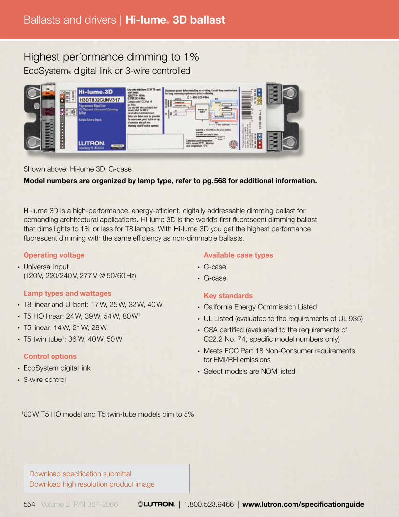
Ballasts and drivers |
554 Volume 2 P/N 367-2066 | 1.800.523.9466 | www.lutron.com/specificationguide
Available case types
• C-case
• G-case
Key standards
• California Energy Commission Listed
• UL Listed (evaluated to the requirements of UL 935)
• CSA certified (evaluated to the requirements of C22.2 No. 74, specific model numbers only)
• Meets FCC Part 18 Non-Consumer requirements for EMI/RFI emissions
• Select models are NOM listed
Shown above: Hi-lume 3D, G-case
Model numbers are organized by lamp type, refer to pg. 568 for additional information.
Operating voltage
• Universal input (120 V, 220/240 V, 277 V @ 50/60 Hz)
Lamp types and wattages
• T8 linear and U-bent: 17 W, 25 W, 32 W, 40 W
• T5 HO linear: 24 W, 39 W, 54 W, 80 W1
• T5 linear: 14 W, 21 W, 28 W
• T5 twin tube1: 36 W, 40 W, 50 W
Control options
• EcoSystem digital link
• 3-wire control
Hi-lume 3D is a high-performance, energy-efficient, digitally addressable dimming ballast for demanding architectural applications. Hi-lume 3D is the world’s first fluorescent dimming ballast that dims lights to 1% or less for T8 lamps. With Hi-lume 3D you get the highest performance fluorescent dimming with the same efficiency as non-dimmable ballasts.
Highest performance dimming to 1% EcoSystem® digital link or 3-wire controlled
1 80 W T5 HO model and T5 twin-tube models dim to 5%
Hi-lume® 3D ballast
Download specification submittalDownload high resolution product image

Ballasts and drivers |
www.lutron.com/specificationguide | 1.800.523.9466 | Volume 2 P/N 367-2066 555
Environment
• Sound rating: Class A
• Minimum lamp starting temperature 10º C (50º F)
• Maximum ballast case temperature 75º C (167º F)
Mounting
• Ballast mounts using two screws (or sheet metal feature and one screw) within a fluorescent fixture
• Ballast is grounded via a mounting screw to the fixture
• Lutron and NEMA® recommend sockets complying with IEC 60400. Sockets must have a UL mark as well. Use rapid start sockets, not instant start sockets.
• Terminals accept 16-18 AWG (0.75 to 1.50 mm2) solid copper or tinned stranded wire
Wiring
• EcoSystem digital link: Hi-lume 3D ballasts require 4 wires plus Ground (E1, E2, Constant Hot and Neutral); one 16-18 AWG solid copper Class 1 or Class 2 wire per terminal
3-Wire: Hi-lume 3D ballasts require three wires plus Ground (Dimmed Hot, Switched Hot and Neutral); one 16-18 AWG solid copper Class 1 wire per terminal
• The 16 AWG control wire must not exceed 900 ft, and the 18 AWG must not exceed 550 ft; maximum ballast-to-lamp-socket lead length is 7 ft (2 m) for T8, T5 and T5 HO linear lamps, and 3 ft (1 m) for T5 twin-tube lamps
• Ballast is grounded via case
Features
• Industry-leading ballast efficacy of up to 100 lumens per watt
• Broadest dimming range: continuous, flicker-free dimming down to 0.70% of full light output for T8 lamps, 1% for T5 and T5 HO lamps, and 5% for T5 twin-tube and T5 HO 80 W lamps
• The EcoSystem® digital link supports up to 64 digital ballasts, 64 occupancy sensors, 16 daylight sensors, and 64 wallstations or infrared (IR) receivers
• The PowPak® dimming module with EcoSystem supports 32 EcoSystem ballasts or drivers, nine Pico® wireless controls, six occupancy/vacancy sensors and one daylight sensor
• EcoSystem digital link allows for rezoning without rewiring, and can be wired as Class 1 or Class 2— perfect for retrofit and new construction
• Sensors cannot connect directly to the Hi-lume 3D ballasts
• Communicates with wired or wireless sensors and controls via compatible device
• Line-voltage miswire protection of EcoSystem link
• Slim-profile design
• Ballasts maintain consistent light output for different lamp lengths, ensuring fixture-to-fixture uniformity
• Lamps turn on at any dimmed level without going to full brightness
• 100% performance-tested, including burn-in at the factory
Specifications
• Total Harmonic Distortion (THD): less than 10%
• Power factor greater than .95
• Ballast factor equal to 1.00 or 1.17 for T8 lamps
• Ballast factor equal to 1.00 for T5 lamps
• Frequency of operation greater than 42 kHz
• Factory-tuned ballast factors available to customize the ballast for different applications
Hi-lume® 3D ballast

Ballasts and drivers |
556 Volume 2 P/N 367-2066 | 1.800.523.9466 | www.lutron.com/specificationguide
Shown above: EcoSystem ballast, G-case
Model numbers are organized by lamp type, refer to pg. 568 for additional information.
Available case types
• G-case
• J-case
Key standards
• California Energy Commission Listed
• UL Listed (evaluated to the requirements of UL 935)
• CSA Certified (evaluated to the requirements of C22.2 No. 74)
• Select models are NOM listed
• Meets FCC Part 18 Non-Consumer requirements for EMI/RFI emissions
Operating voltage
• Universal input (120 V, 220/240 V, 277 V @ 50/60 Hz)
Lamp types and wattages
• T8 linear and U-bent: 17 W, 25 W, 32 W
• T8 linear Reduced Wattage: 25 W, 28 W, 30 W
• T5 HO linear: 24 W, 39 W, 54 W
• T5 linear: 14 W, 21 W, 28 W, 35 W
• T5 twin-tube: 36 W, 39 W, 40 W, 50 W, 55 W
• T5 twin-tube reduced wattage: 25 W
Control options
• EcoSystem digital link
• 3-Wire control
EcoSystem digitally addressable dimming ballasts employ revolutionary technology allowing each device to listen, think, decide, remember, and react to its environment. EcoSystem fluorescent lighting control solutions are built on a simple building block architecture of fluorescent dimming ballasts, sensors, and controls, free from interfaces and power packs. EcoSystem redefines fluorescent lighting control as easy to design, easy to install, easy to maintain, and cost effective.
Light management performance dimming to 10% EcoSystem digital link or 3-wire controlled
EcoSystem® ballast
Download specification submittal for T4Download specification submittal for T5 LinearDownload high resolution product image

Ballasts and drivers |
www.lutron.com/specificationguide | 1.800.523.9466 | Volume 2 P/N 367-2066 557
Features
• Continuous, flicker-free dimming from 100% to 10%
• EcoSystem digital link allows for re-zoning without rewiring, and can be wired as Class 1 or Class 2— perfect for retrofit and new construction
• The EcoSystem digital link supports up to 64 digital ballasts, 64 occupancy sensors, 16 daylight sensors, and 64 wallstations or infrared (IR) receivers
• The PowPak® dimming module with EcoSystem supports 32 EcoSystem ballasts or drivers, nine Pico® wireless controls, six occupancy/vacancy sensors and one daylight sensor
• Low-voltage, 2-conductor EcoSystem digital link provides individual, reconfigurable fixture control
• Supports digital control and standard 3-wire line-voltage phase control technology
• Sensors can connect directly to EcoSystem ballasts; all sensor and wall station wiring is Class 2
• Communicates with wired or wireless sensors and controls via local wired sensor connections or compatible device
• Line-voltage miswire protection of EcoSystem link
• Slim-profile design
• Ballasts maintain consistent light output for different lamp lengths, ensuring fixture-to-fixture uniformity
• Lamps turn on at any dimmed level without going to full brightness
• 100% performance-tested, including burn-in at the factory
Specifications
• Total Harmonic Distortion (THD): less than 10% (select models are less than 15%)
• Power factor greater than 0.95
• Ballast factor equal to 0.85 for T8 lamps
• Ballast factor equal to 1.00 for T5 and T5 HO lamps
• Non-volatile memory restores all ballast settings after power failure
• Frequency of operation ensures that ballast does not interfere with infrared devices
• Factory-tuned ballast factors available to customize the ballast for different applications
Environment
• Sound rating: Class A
• Minimum lamp starting temperature 10º C (50º F)
• Maximum ballast case temperature 75º C (167º F)
Mounting
• Ballast mounts using two screws (or sheet metal feature and one screw) within a fluorescent fixture
• Ballast is grounded via a mounting screw to the fixture
• Lutron® and NEMA® recommend sockets complying with IEC 60400. Sockets must have a UL mark as well. Use rapid start sockets, not instant start sockets.
• Terminals accept 16-18 AWG (0.75 to 1.50 mm2) solid copper or tinned stranded wire
Wiring
• EcoSystem digital link: EcoSystem ballasts require four wires plus Ground (E1, E2, Constant Hot and Neutral); one 16-18 AWG solid copper Class 1 or Class 2 wire per terminal
3-Wire: EcoSystem ballasts require three wires plus Ground (Dimmed Hot, Switched Hot and Neutral); one 16-18 AWG solid copper Class 1 wire per terminal
• The 16 AWG control wire must not exceed 900 ft, and the 18 AWG must not exceed 550 ft; maximum ballast-to-lamp-socket lead length is 7 ft (2 m) for T8, T5 and T5 HO linear lamps, and 3 ft (1 m) for T5 twin-tube lamps
• Ballast is grounded via case
EcoSystem® ballast

Ballasts and drivers |
558 Volume 2 P/N 367-2066 | 1.800.523.9466 | www.lutron.com/specificationguide
Operating voltage
• Universal input (120 V, 220/240 V, 277 V @ 50/60 Hz)
Lamp types and wattages
• T4 4-pin quad-tube CFL: 18 W, 26 W
• T4 4-pin triple-tube CFL: 26 W, 32 W, 42 W
Key standards
• UL Listed (evaluated to the requirements of UL 935)
• UL Type 1 Outdoor for damp locations
• CSA Certified (evaluated to the requirements of C22.2 No. 74)
• Select models are NOM listed
• Meets FCC Part 18 Non-Consumer requirements for EMI/RFI emissions
Control options
• EcoSystem digital link
• 3-Wire control
EcoSystem compact ballasts provide high-performance dimming for any compact fluorescent application, completing the EcoSystem solution. With a 100% to 5% dimming range for T4 CFL lamps, EcoSystem compact ballasts provide both energy savings and flexibility.
Shown above: EcoSystem compact ballast, K-case
Model numbers are organized by lamp type, refer to pg. 568 for additional information.
High performance dimming to 5% EcoSystem digital link or 3-wire controlled
Feature EcoSystem Compact
EcoSystem pg. 363
Dimming Level 5% 10%
Integral sensor
connection
No Yes
Maximum number of lamps per ballast
2 3
Maximum ballast to lamp socket lead length
3 ft (1 m) 7 ft (2 m)
Available case type
• K-case
Quick comparison
EcoSystem® compact ballast
Download high resolution product image

Ballasts and drivers |
www.lutron.com/specificationguide | 1.800.523.9466 | Volume 2 P/N 367-2066 559
Environment
• Sound rating: Class A
• Minimum lamp starting temperature 10º C (50º F)
• Maximum ballast case temperature 75º C (167º F)
Mounting
• Ballast mounts using two mounting tabs or studs within a fluorescent fixture
• “No studs” case option available
• Ballast is grounded via a mounting screw to the fixture
• Lutron and NEMA® recommend sockets complying with IEC 60400. Sockets must have a UL mark as well. Use rapid start sockets, not instant start sockets.
• Terminals accept 16-18 AWG (0.75 to 1.50 mm2) solid copper or tinned stranded wire
Wiring
• EcoSystem digital link: EcoSystem compact ballasts require four wires plus Ground (E1, E2, Constant Hot and Neutral); one 16-18 AWG solid copper Class 1 or Class 2 wire per terminal
3-Wire: EcoSystem compact ballasts require three wires plus Ground (Dimmed Hot, Switched Hot and Neutral); one 16-18 AWG solid copper Class 1 wire per terminal
• The 16 AWG control wire must not exceed 900 ft, and the 18 AWG must not exceed 550 ft; maximum ballast-to-lamp-socket lead length is 3 ft (1 m) for T4 compact lamps
• Ballast is grounded via case
Features
• Continuous, flicker-free dimming from 100% to 5% for T4 CFL lamps
• EcoSystem digital link allows for re-zoning without rewiring, and can be wired as Class 1 or Class 2— perfect for retrofit and new construction
• The EcoSystem digital link supports up to 64 digital ballasts, 64 occupancy sensors, 16 daylight sensors, and 64 wallstations or infrared (IR) receivers
• The PowPak® dimming module with EcoSystem supports 32 EcoSystem ballasts or drivers, nine Pico® wireless controls, six occupancy/vacancy sensors and one daylight sensor
• Low-voltage, 2-conductor EcoSystem digital link provides individual fixture control
• Communicates with wired or wireless sensors and controls via compatible device
• Sensors cannot connect directly to EcoSystem compact ballasts
• Line-voltage miswire protection of EcoSystem link
• One model can control both 26 W and 32 W T4 lamps
• Ultra-low standby power (<1 W) when lamps are off
• Ballasts maintain consistent light output for different lamp lengths, ensuring fixture-to-fixture uniformity
• 100% performance-tested, including burn-in at the factory
Specifications
• Total Harmonic Distortion (THD): less than 10%
• Power factor greater than 0.95
• Ballast factor equal to 0.95 for T4 lamps
• Non-volatile memory restores all ballast settings after power failure
• Factory-tuned ballast factors available to customize the ballast for different applications
EcoSystem® compact ballast
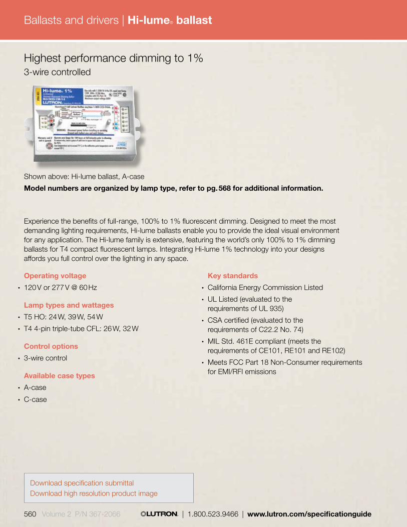
Ballasts and drivers |
560 Volume 2 P/N 367-2066 | 1.800.523.9466 | www.lutron.com/specificationguide
Operating voltage
• 120 V or 277 V @ 60 Hz
Lamp types and wattages
• T5 HO: 24 W, 39 W, 54 W
• T4 4-pin triple-tube CFL: 26 W, 32 W
Control options
• 3-wire control
Available case types
• A-case
• C-case
Experience the benefits of full-range, 100% to 1% fluorescent dimming. Designed to meet the most demanding lighting requirements, Hi-lume ballasts enable you to provide the ideal visual environment for any application. The Hi-lume family is extensive, featuring the world’s only 100% to 1% dimming ballasts for T4 compact fluorescent lamps. Integrating Hi-lume 1% technology into your designs affords you full control over the lighting in any space.
Key standards
• California Energy Commission Listed
• UL Listed (evaluated to the requirements of UL 935)
• CSA certified (evaluated to the requirements of C22.2 No. 74)
• MIL Std. 461E compliant (meets the requirements of CE101, RE101 and RE102)
• Meets FCC Part 18 Non-Consumer requirements for EMI/RFI emissions
Shown above: Hi-lume ballast, A-case
Model numbers are organized by lamp type, refer to pg. 568 for additional information.
Highest performance dimming to 1% 3-wire controlled
Hi-lume® ballast
Download specification submittalDownload high resolution product image

Ballasts and drivers |
www.lutron.com/specificationguide | 1.800.523.9466 | Volume 2 P/N 367-2066 561
Mounting
• Ballast mounts using two screws (or sheet metal feature and one screw) within a fluorescent fixture
• Ballast is grounded via a mounting screw to the fixture
• Lutron® and NEMA® recommend sockets complying with IEC 60400. Sockets must have a UL mark as well. Use rapid start sockets, not instant start sockets.
• Terminals accept 16-18 AWG (0.75 to 1.50 mm2) solid copper or tinned stranded wire
Wiring
• Hi-lume ballasts require three wires plus Ground (Dimmed Hot, Switched Hot and Neutral); one 16-18 AWG solid copper Class 1 wire per terminal
• Maximum ballast-to-lamp-socket lead length is 7 ft (2 m) for T5 HO linear lamps, and 3 ft (1 m) for T4 compact lamps
• Ballast is grounded via case
Features
• Continuous, flicker-free dimming from 100% to 1%
• Ballasts maintain consistent light output for different lamp lengths, ensuring fixture-to-fixture uniformity
• 3-wire line voltage control for consistent fixture-to-fixture dimming
• Sensors cannot connect directly to Hi-lume ballasts
• Line-voltage miswire protection
• Slim-profile design
• Lamps turn on at any dimmed level without going to full brightness
• 100% performance-tested, including burn-in at the factory
Specifications
• Total Harmonic Distortion (THD): less than 10%
• Power factor greater than 0.95
• Ballast factor equal to 0.95 for T4 lamps
• Ballast factor equal to 1.00 for T5 HO lamps
Environment
• Sound rating: Class A
• Minimum lamp starting temperature 10º C (50º F)
• Maximum ballast case temperature 75º C (167º F)
Hi-lume® ballast

Ballasts and drivers |
562 Volume 2 P/N 367-2066 | 1.800.523.9466 | www.lutron.com/specificationguide
Available case types
• A-case
• B-case
• C-case
Key standards
• California Energy Commission (CEC) Listed
• UL Listed (evaluated to the requirements of UL 935)
• CSA certified (evaluated to the requirements of C22.2 No. 74)—all models except T8 25 W
• 1-lamp ballasts for T4 CFL meet FCC Part 18 requirements for residential use
• Meets FCC Part 18 Non-Consumer requirements for EMI/RFI emissions
Shown above: Tu-Wire ballast, B-case
Model numbers are organized by lamp type, refer to pg. 568 for additional information.
Operating voltage
• 120 V @ 60 Hz
Lamp types and wattages
• T8 linear and U-bent: 25 W, 32 W
• T4 4-pin quad-tube CFL: 18 W, 26 W
• T4 4-pin triple-tube CFL: 18 W, 26 W, 32 W
Control option
• Tu-Wire control
Tu-Wire ballasts offer high performance 100% to 5% dimming for linear and compact fluorescent lamps. Retrofit applications can benefit from the ease of installation offered by Lutron Tu-Wire dimming ballasts. Tu-Wire ballasts require only two wires (dimmed hot and neutral) for power and control. Lutron offers a wide range of compatible Tu-Wire controls, making Tu-Wire ballasts the perfect choice for many applications. Additionally, one-lamp T4 models have been designed to meet FCC Part 18 consumer requirements for residential applications.
High performance dimming to 5% Tu-Wire controlled
Tu-Wire® ballast
Download specification submittalDownload high resolution product image

Ballasts and drivers |
www.lutron.com/specificationguide | 1.800.523.9466 | Volume 2 P/N 367-2066 563
Mounting
• Ballast mounts using two mounting tabs or studs within a fluorescent fixture
• Lutron and NEMA® recommend sockets complying with IEC 60400. Sockets must have a UL mark as well. Use rapid start sockets, not instant start sockets.
• Terminals accept 16-18 AWG (0.75 to 1.50 mm2) solid copper or tinned stranded wire
Wiring
• Tu-Wire ballasts require two wires plus Ground (Dimmed Hot and Neutral); one 16-18 AWG solid copper Class 1 wire per terminal
• Maximum ballast-to-lamp-socket lead length is 7 ft (2 m) for T8 lamps and 3 ft (1 m) for T4 compact lamps
• Ballast is grounded via case
Features
• Continuous, flicker-free dimming from 100% to 5%
• Works with all Lutron Tu-Wire fluorescent controls for consistent dimming performance
• Sensors cannot connect directly to Tu-Wire ballasts
• 2-Wire line voltage control ideal for retrofit
• Line-voltage miswire protection
• Slim-profile design
• Low-line voltage protection circuitry prevents damage to the ballast or lamps if the ballast is connected to an incompatible dimmer
• Lamps turn on at any dimmed level without going to full brightness
• 100% performance-tested, including burn-in at the factory
Specifications
• Total Harmonic Distortion (THD) less than 20%
• Power factor greater than 0.95
• Ballast factor greater than 0.95 for T4 lamps
• Ballast factor equal to 1.00 for T8 lamps
Environment
• Sound rating: Class A
• Minimum lamp starting temperature 10º C (50º F)
• Maximum ballast case temperature 75º C (167º F)
Tu-Wire® ballast
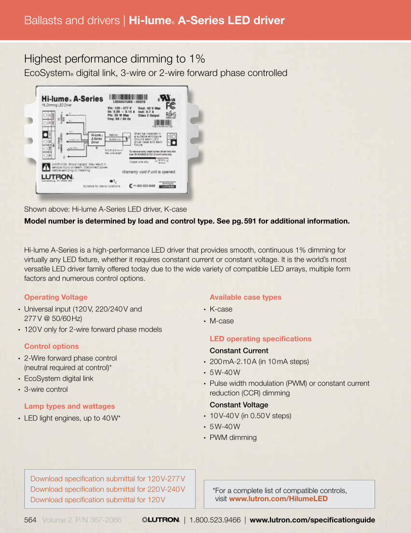
Ballasts and drivers |
564 Volume 2 P/N 367-2066 | 1.800.523.9466 | www.lutron.com/specificationguide
Operating Voltage
• Universal input (120 V, 220/240 V and 277 V @ 50/60 Hz)
• 120 V only for 2-wire forward phase models
Control options
• 2-Wire forward phase control (neutral required at control)*
• EcoSystem digital link• 3-wire control
Lamp types and wattages
• LED light engines, up to 40 W*
Shown above: Hi-lume A-Series LED driver, K-case
Model number is determined by load and control type. See pg. 591 for additional information.
Hi-lume A-Series is a high-performance LED driver that provides smooth, continuous 1% dimming for virtually any LED fixture, whether it requires constant current or constant voltage. It is the world’s most versatile LED driver family offered today due to the wide variety of compatible LED arrays, multiple form factors and numerous control options.
Available case types
• K-case
• M-case
LED operating specifications Constant Current• 200 mA-2.10 A (in 10 mA steps)• 5 W-40 W• Pulse width modulation (PWM) or constant current
reduction (CCR) dimming Constant Voltage• 10 V-40 V (in 0.50 V steps)• 5 W-40 W• PWM dimming
Highest performance dimming to 1% EcoSystem® digital link, 3-wire or 2-wire forward phase controlled
* For a complete list of compatible controls, visit www.lutron.com/HilumeLED
Hi-lume® A-Series LED driver
Download specification submittal for 120 V-277 VDownload specification submittal for 220 V-240 VDownload specification submittal for 120 V

Ballasts and drivers |
www.lutron.com/specificationguide | 1.800.523.9466 | Volume 2 P/N 367-2066 565
Environment
• Sound rating: Class A
• Maximum case temperature is 65º C (149º F)
Mounting
• K-case driver typically mounts via studs or tabs to the outside of an LED fixture or on a junction box
• “No studs” case option available
• Any fixture type (downlight, cove light, sconce, under-cabinet, etc.) will work with the Hi-lume A-Series driver family, if the LED light engine operates at either the constant current or constant voltage levels specified
Wiring
• EcoSystem digital link: Hi-lume A-Series LED drivers require 4 wires plus Ground (E1, E2, Constant Hot and Neutral); one 16-18 AWG solid copper Class 1 or Class 2 wire per terminal
3-Wire: Requires three wires plus Ground (Dimmed Hot, Switched Hot and Neutral); one 16-18 AWG solid copper Class 1 wire per terminal
2-Wire forward phase: Requires two wires plus Ground (Dimmed Hot and Neutral); one 16-18 AWG solid copper Class 1 or Class 2 wire per terminal
• The 16 AWG control wire must not exceed 900 ft, and the 18 AWG must not exceed 550 ft; maximum driver-to-LED light engine wire length is 10 ft (3 m)
• Driver is grounded by a mounting screw to the grounded fixture (or by terminal connection on the K-case)
Key standards
• UL 8750 Recognized
• FCC Part 15 compliant for commercial applications at 120 V or 277 V and for residential applications at 120 V
• Meets ANSI C62.41 category A surge protection standards up to and including 4 kV
• Models available to meet LED Driver requirements for Energy Star 1.10
Features
• Continuous, flicker-free dimming from 100% to 1%• Efficiency greater than 80% at 40 W• A rated lifetime of 50,000 hours• EcoSystem digital link allows for re-zoning without
rewiring, and can be wired as Class 1 or Class 2— perfect for retrofit and new construction
• Standard 3-wire line-voltage phase-control technology for consistent dimming performance and compatibility with all Lutron 3-wire fluorescent dimmers
• CCR and PWM dimming available for constant current light engines; constant voltage light engines operate with pulse width modulation (PWM) dimming only
• Sensors cannot connect directly to the driver
• Line-voltage miswire protection• Instant light output at any level when turned on,
without flashing to full on
Specifications
• Power factor greater than 0.90 at 40 W
• Inrush current less than 2 A
Hi-lume® A-Series LED driver
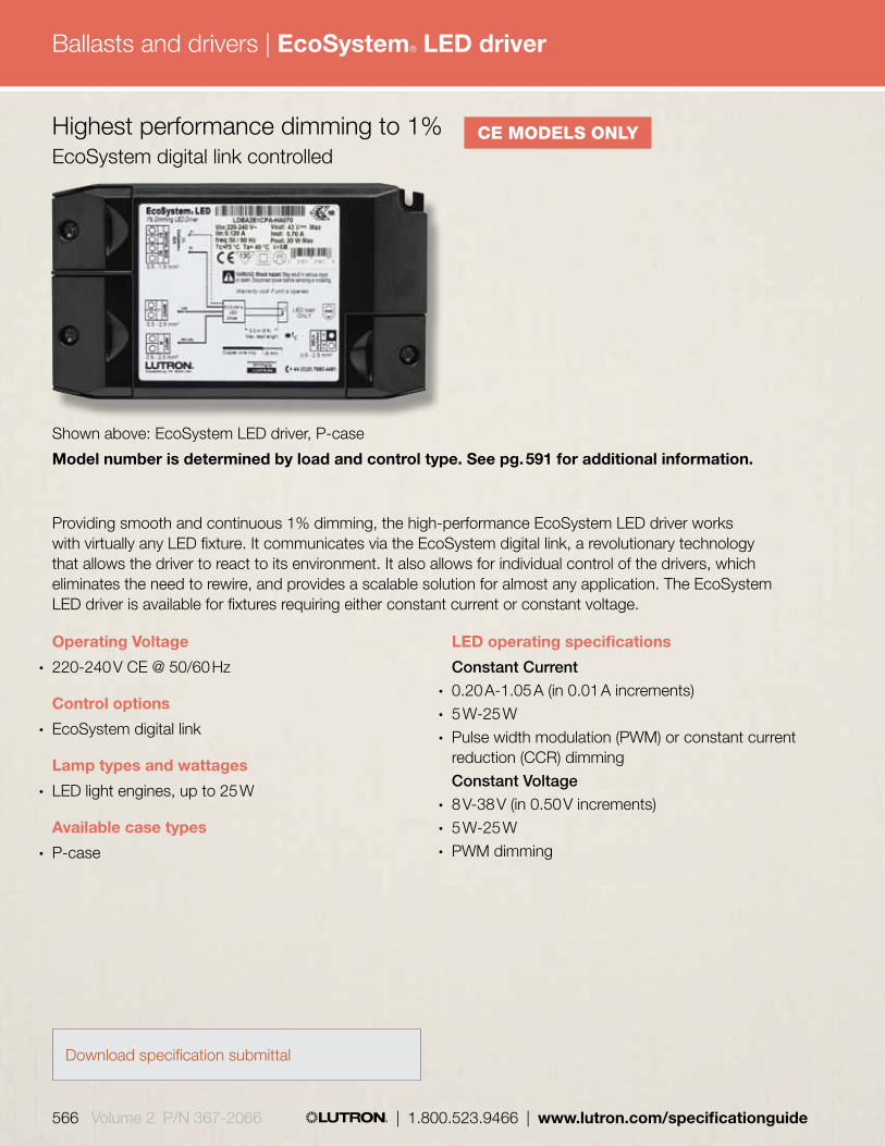
Ballasts and drivers |
566 Volume 2 P/N 367-2066 | 1.800.523.9466 | www.lutron.com/specificationguide
Operating Voltage
• 220-240 V CE @ 50/60 Hz
Control options
• EcoSystem digital link
Lamp types and wattages
• LED light engines, up to 25 W
Available case types
• P-case
Shown above: EcoSystem LED driver, P-case
Model number is determined by load and control type. See pg. 591 for additional information.
Providing smooth and continuous 1% dimming, the high-performance EcoSystem LED driver works with virtually any LED fixture. It communicates via the EcoSystem digital link, a revolutionary technology that allows the driver to react to its environment. It also allows for individual control of the drivers, which eliminates the need to rewire, and provides a scalable solution for almost any application. The EcoSystem LED driver is available for fixtures requiring either constant current or constant voltage.
LED operating specifications Constant Current• 0.20 A-1.05 A (in 0.01 A increments)• 5 W-25 W• Pulse width modulation (PWM) or constant current
reduction (CCR) dimming Constant Voltage• 8 V-38 V (in 0.50 V increments)• 5 W-25 W• PWM dimming
Highest performance dimming to 1% EcoSystem digital link controlled
CE MODELS ONLY
EcoSystem® LED driver
Download specification submittal

Ballasts and drivers |
www.lutron.com/specificationguide | 1.800.523.9466 | Volume 2 P/N 367-2066 567
Key standards
• CE and ENEC Mark
• RoHS 2006 Compliant
• IEC Rated
Features
• Continuous, flicker-free dimming from 100% to 1%
• Efficiency of 80% at 25 W
• Protected from miswires of input power to EcoSystem control inputs
• CCR and PWM dimming available for constant current light engines; constant voltage light engines operate with pulse width modulation (PWM) dimming only
• A rated lifetime of 50,000 hours
• Independent control gear with integral strain relief
• LEDs turn on to any dimmed level without flashing to full brightness
• Sensors cannot connect directly to the driver
Specifications
• Power factor greater than 0.95 at 25 W
• Low harmonic distortion
• Inrush current less than 2 A
Environment
• Sound rating: inaudible in a 27 dB ambient environment
Mounting
• Independent control gear, driver requires no particular mounting means
Wiring
• EcoSystem LED drivers require four wires plus Ground (E1, E2, Live and Neutral); one 0.75 mm2 to 1.50 mm2 solid copper Class 1 or Class 2 wire per terminal
• The 1.50 mm2 control wire must not exceed 310 m, and the 0.75 mm2 must not exceed 50 m; maximum driver-to-LED light engine wire length is 3 m for any output type
EcoSystem® LED driver

Ballasts and drivers |
568 Volume 2 P/N 367-2066 | 1.800.523.9466 | www.lutron.com/specificationguide
Lutron ballast model numbers are designed to illustrate basic information about the ballast. For example:
Understanding ballast model numbers
EHD T8 32 M U 1 10
Family
Universal voltage
Lamp quantity
Ballast factor
Lamp type
Case size
Lamp wattage
EcoSystem® H-Series ballasts
EC5 T5 36 J UNV 1
Family
Universal voltage
Lamp quantity
Lamp type
Case sizeLamp wattage
EcoSystem ballasts
Generate part numbers, confirm ballast performance specifications (input power, system lumens, ballast factor) and select the proper ballast by utilizing the Ballast Selection Tool.
This tool also enables users to choose a Custom Ballast Factor (percentage of light output for a given lamp ballast combination). Reduced ballast factors achieve greater energy savings and are available for all Lutron ballasts with EcoSystem control.
Updated Ballast Selection Tool with Custom Ballast Factor. Find and configure the ballast that best fits your project: www.lutron.com/BallastTool
NEW
Fluorescent ballast model numbers

Ballasts and drivers |
www.lutron.com/specificationguide | 1.800.523.9466 | Volume 2 P/N 367-2066 569
Refer to the online ballast selection tool for additional information, www.lutron.com/BallastTool *For case type information see pgs. 548-551. * *Factory-tuned ballast factors available. To customize, visit www.lutron.com/BallastTool † Actual number may vary with lamp model. Please consult the lamp manufacturer for lamp-specific data.
T8 and U-bent
EcoSystem® H-Series (1% or less dimming) universal voltage digital dimming ballasts
• Dimming to 1% or less• Compatible with Lutron EcoSystem digital controls• Energy saving and cost effective
LampWatts
(Length)
Lamps per
Ballast Model NumberCaseType*
InputVoltage
(VAC)
InputCurrent
(A)
Input Power
(W)
Ballast Factor (BF)**
System Lumens
(lm)†
System Efficacy (lm/W)†
Ballast Efficacy
Factor (BEF)
Relative System Efficacy
(RSE)
17 W(24 in)
1 EHD T817 M U 1 10 M277 0.08 22.20 1.00 1,300 90 4.51 0.77240 0.09 21.60 1.00 1,300 93 4.63 0.79120 0.18 21.60 1.00 1,300 93 4.63 0.79
2 EHD T817 M U 2 10 M277 0.15 41.60 1.00 2,600 96 2.41 0.82240 0.18 43.20 1.00 2,600 93 2.31 0.79120 0.35 42.00 1.00 2,600 95 2.38 0.81
25 W(36 in)
1 EHD T825 M U 1 10 M277 0.11 30.50 1.00 1,900 62 3.28 0.82240 0.11 26.40 1.00 1,900 72 3.79 0.95120 0.26 31.20 1.00 1,900 61 3.21 0.80
2 EHD T825 M U 2 10 M277 0.20 55.40 1.00 3,800 69 1.81 0.90240 0.23 55.20 1.00 3,800 69 1.81 0.91120 0.47 56.40 1.00 3,800 67 1.77 0.89
32 W(48 in)
1
EHD T832 M U 1 10 M277 0.12 33.20 1.00 3,000 90 3.01 0.96240 0.14 33.60 1.00 3,000 89 2.98 0.95120 0.29 34.80 1.00 3,000 86 3.01 0.92
EHD T832 M U 1 17 M277 0.15 41.60 1.17 3,510 84 2.82 0.92240 0.17 40.80 1.17 3,510 86 2.87 0.92120 0.34 40.80 1.17 3,510 86 2.87 0.90
2
EHD T832 M U 2 10 M277 0.24 66.50 1.00 6,000 90 1.50 0.96240 0.28 67.20 1.00 6,000 89 1.49 0.95120 0.57 68.40 1.00 6,000 88 1.46 0.94
EHD T832 M U 2 17 M277 0.28 77.60 1.17 7,020 91 1.51 0.97240 0.32 76.80 1.17 7,020 91 1.52 0.98120 0.65 78.00 1.17 7,020 90 1.50 0.96
3
EHD T832 G U 3 10 G277 0.37 93.50 1.00 9,000 96 1.07 1.03240 0.40 94.90 1.00 9,000 95 1.05 1.01120 0.83 95.40 1.00 9,000 94 1.05 1.01
EHD T832 G U 3 17 G277 0.41 105.70 1.17 10,530 100 1.11 1.06240 0.47 106.50 1.17 10,530 99 1.10 1.05120 0.95 106.80 1.17 10,530 99 1.10 1.05
Fluorescent ballast model numbers

Ballasts and drivers |
570 Volume 2 P/N 367-2066 | 1.800.523.9466 | www.lutron.com/specificationguide
Refer to the online ballast selection tool for additional information, www.lutron.com/BallastTool *For case type information see pgs. 548-551. * *Factory-tuned ballast factors available. To customize, visit www.lutron.com/BallastTool † Actual number may vary with lamp model. Please consult the lamp manufacturer for lamp-specific data.
T8 and U-bent (continued)
Hi-lume® 3D (1% or less dimming) universal voltage digital dimming ballasts
• Dimming to 1% or less• Compatible with Lutron 3-wire fluorescent controls and EcoSystem® digital controls• Energy saving
LampWatts
(Length)
Lamps per
Ballast Model NumberCaseType*
InputVoltage
(VAC)
InputCurrent
(A)
Input Power
(W)
Ballast Factor (BF)**
System Lumens
(lm)†
System Efficacy (lm/W)†
Ballast Efficacy
Factor (BEF)
Relative System Efficacy
(RSE)
17 W(24 in)
1
H3D T817 C U 1 10H3D T817 G U 1 10
CG
277 0.08 22.20 1.00 1,300 59 4.51 0.77240 0.09 21.60 1.00 1,300 60 4.63 0.79120 0.18 21.60 1.00 1,300 60 4.63 0.79
H3D T817 C U 1 17H3D T817 G U 1 17
CG
277 0.08 22.20 1.17 1,521 69 5.28 0.90240 0.10 24.00 1.17 1,521 63 4.88 0.83120 0.19 22.80 1.17 1,521 67 5.13 0.87
2
H3D T817 C U 2 10H3D T817 G U 2 10
CG
277 0.15 41.60 1.00 2,600 63 2.41 0.82240 0.18 43.20 1.00 2,600 60 2.31 0.79120 0.35 42.00 1.00 2,600 62 2.38 0.81
H3D T817 C U 2 17H3D T817 G U 2 17
CG
277 0.15 41.60 1.17 3,042 73 2.82 0.96240 0.17 40.80 1.17 3,042 75 2.87 0.98120 0.35 42.00 1.17 3,042 72 2.79 0.95
3
H3D T817 G U 3 10 G277 0.21 58.20 1.00 3,900 67 1.72 0.88240 0.25 60.00 1.00 3,900 65 1.67 0.85120 0.48 57.60 1.00 3,900 68 1.74 0.89
H3D T817 G U 3 17 G277 0.23 63.70 1.17 4,563 72 1.84 0.94240 0.27 64.80 1.17 4,563 70 1.81 0.92120 0.55 66.00 1.17 4,563 69 1.77 0.90
25 W(36 in)
1
H3D T825 C U 1 10 C277 0.11 30.50 1.00 1,900 62 3.28 0.82240 0.11 26.40 1.00 1,900 72 3.79 0.95120 0.26 31.20 1.00 1,900 61 3.21 0.80
H3D T825 C U 1 17 C277 0.12 33.20 1.17 2,223 67 3.52 0.88240 0.14 33.60 1.17 2,223 66 3.48 0.87120 0.28 33.60 1.17 2,223 66 3.48 0.87
2
H3D T825 C U 2 10 C277 0.20 55.40 1.00 3,800 69 1.81 0.90240 0.23 55.20 1.00 3,800 69 1.81 0.91120 0.47 56.40 1.00 3,800 67 1.77 0.89
H3D T825 C U 2 17 C277 0.22 60.90 1.17 4,446 73 1.92 0.96240 0.25 60.00 1.17 4,446 74 1.95 0.98120 0.51 61.20 1.17 4,446 73 1.91 0.96
Fluorescent ballast model numbers

Ballasts and drivers |
www.lutron.com/specificationguide | 1.800.523.9466 | Volume 2 P/N 367-2066 571
Refer to the online ballast selection tool for additional information, www.lutron.com/BallastTool *For case type information see pgs. 548-551. * *Factory-tuned ballast factors available. To customize, visit www.lutron.com/BallastTool † Actual number may vary with lamp model. Please consult the lamp manufacturer for lamp-specific data.
T8 and U-bent (continued)
Hi-lume 3D (1% or less dimming) universal voltage digital dimming ballasts
LampWatts
(Length)
Lamps per
Ballast Model NumberCaseType*
InputVoltage
(VAC)
InputCurrent
(A)
Input Power
(W)
Ballast Factor (BF)**
System Lumens
(lm)†
System Efficacy (lm/W)†
Ballast Efficacy
Factor (BEF)
Relative System Efficacy
(RSE)
32 W(48 in)
1
H3D T832 C U 1 10H3D T832 G U 1 10
CG
277 0.12 33.20 1.00 3,000 90 3.01 0.96240 0.14 33.60 1.00 3,000 89 2.98 0.95120 0.29 34.80 1.00 3,000 86 2.87 0.92
H3D T832 C U 1 17H3D T832 G U 1 17
CG
277 0.15 41.60 1.17 3,510 84 2.82 0.90240 0.17 40.80 1.17 3,510 86 2.87 0.92120 0.34 40.80 1.17 3,510 86 2.87 0.92
2
H3D T832 C U 2 10H3D T832 G U 2 10
CG
277 0.24 66.50 1.00 6,000 90 1.50 0.96240 0.28 67.20 1.00 6,000 89 1.49 0.95120 0.57 68.40 1.00 6,000 88 1.46 0.94
H3D T832 C U 2 17H3D T832 G U 2 17
CG
277 0.28 77.60 1.17 7,020 91 1.51 0.97240 0.32 76.80 1.17 7,020 91 1.52 0.98120 0.65 78.00 1.17 7,020 90 1.50 0.96
3
H3D T832 G U 3 10 G277 0.37 102.50 1.00 9,000 88 0.98 0.94240 0.40 96.00 1.00 9,000 94 1.04 1.00120 0.83 99.60 1.00 9,000 90 1.00 0.96
H3D T832 G U 3 17 G277 0.41 113.60 1.17 10,530 93 1.03 0.99240 0.47 112.80 1.17 10,530 93 1.04 1.00120 0.95 114.00 1.17 10,530 92 1.03 0.99
40 W(60 in)
1
H3D T840 C U 1 10 C277 0.16 42.80 1.00 3,800 89 2.34 0.94240 0.18 43.00 1.00 3,800 88 2.33 0.93120 0.37 43.80 1.00 3,800 87 2.28 0.91
H3D T840 C U 1 17 C277 0.18 49.60 1.17 4,446 90 2.36 0.94240 0.21 49.40 1.17 4,446 90 2.37 0.95120 0.43 50.60 1.17 4,446 88 2.31 0.92
2
H3D T840 C U 2 10 C277 0.32 88.90 1.00 7,600 86 1.13 0.90240 0.37 88.40 1.00 7,600 86 1.13 0.91120 0.77 90.90 1.00 7,600 84 1.10 0.88
H3D T840 C U 2 17 C277 0.36 98.20 1.17 8,892 91 1.19 0.95240 0.41 97.20 1.17 8,892 92 1.20 0.96120 0.84 100.30 1.17 8,892 89 1.17 0.93
Fluorescent ballast model numbers

Ballasts and drivers |
572 Volume 2 P/N 367-2066 | 1.800.523.9466 | www.lutron.com/specificationguide
Fluorescent ballast model numbers
Refer to the online ballast selection tool for additional information, www.lutron.com/BallastTool
*For case type information see pgs. 548-551. † Actual number may vary with lamp model. Please consult the lamp manufacturer for lamp-specific data.
T8 and U-bent (continued)
Tu-Wire® (5% dimming) 120 V dimming ballasts
• Dimming to 5%• Compatible with Lutron Tu-Wire fluorescent controls• Energy saving
LampWatts
(Length)
Lamps per
Ballast Model NumberCaseType*
InputVoltage
(VAC)
InputCurrent
(A)
Input Power
(W)
Ballast Factor
(BF)
System Lumens
(lm)†
System Efficacy (lm/W)†
Ballast Efficacy
Factor (BEF)
Relative System Efficacy
(RSE)25 W
(36 in)1 2W-T825-120-1 C 120 0.30 36.00 0.85 1,828 51 2.36 0.762 2W-T825-120-2 C 120 0.50 60.00 0.85 3,655 61 1.42 0.91
32 W(48 in)
1 2W-T832-120-1 C 120 0.37 44.40 0.85 2,550 57 1.91 0.612 2W-T832-120-2 C 120 0.70 84.00 0.85 5,100 61 1.01 0.65
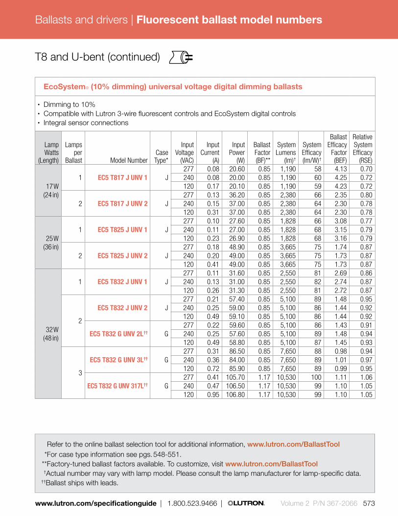
Ballasts and drivers |
www.lutron.com/specificationguide | 1.800.523.9466 | Volume 2 P/N 367-2066 573
Fluorescent ballast model numbers
Refer to the online ballast selection tool for additional information, www.lutron.com/BallastTool *For case type information see pgs. 548-551.* *Factory-tuned ballast factors available. To customize, visit www.lutron.com/BallastTool † Actual number may vary with lamp model. Please consult the lamp manufacturer for lamp-specific data.††Ballast ships with leads.
T8 and U-bent (continued)
EcoSystem® (10% dimming) universal voltage digital dimming ballasts
• Dimming to 10%• Compatible with Lutron 3-wire fluorescent controls and EcoSystem digital controls • Integral sensor connections
LampWatts
(Length)
Lamps per
Ballast Model NumberCaseType*
InputVoltage
(VAC)
InputCurrent
(A)
Input Power
(W)
Ballast Factor (BF)**
System Lumens
(lm)†
System Efficacy (lm/W)†
Ballast Efficacy
Factor (BEF)
Relative System Efficacy
(RSE)
17 W(24 in)
1 EC5 T817 J UNV 1 J277 0.08 20.60 0.85 1,190 58 4.13 0.70240 0.08 20.00 0.85 1,190 60 4.25 0.72120 0.17 20.10 0.85 1,190 59 4.23 0.72
2 EC5 T817 J UNV 2 J277 0.13 36.20 0.85 2,380 66 2.35 0.80240 0.15 37.00 0.85 2,380 64 2.30 0.78120 0.31 37.00 0.85 2,380 64 2.30 0.78
25 W(36 in)
1 EC5 T825 J UNV 1 J277 0.10 27.60 0.85 1,828 66 3.08 0.77240 0.11 27.00 0.85 1,828 68 3.15 0.79120 0.23 26.90 0.85 1,828 68 3.16 0.79
2 EC5 T825 J UNV 2 J277 0.18 48.90 0.85 3,665 75 1.74 0.87240 0.20 49.00 0.85 3,665 75 1.73 0.87120 0.41 49.00 0.85 3,665 75 1.73 0.87
32 W(48 in)
1 EC5 T832 J UNV 1 J277 0.11 31.60 0.85 2,550 81 2.69 0.86240 0.13 31.00 0.85 2,550 82 2.74 0.87120 0.26 31.30 0.85 2,550 81 2.72 0.87
2
EC5 T832 J UNV 2 J277 0.21 57.40 0.85 5,100 89 1.48 0.95240 0.25 59.00 0.85 5,100 86 1.44 0.92120 0.49 59.10 0.85 5,100 86 1.44 0.92
EC5 T832 G UNV 2L†† G277 0.22 59.60 0.85 5,100 86 1.43 0.91240 0.25 57.60 0.85 5,100 89 1.48 0.94120 0.49 58.80 0.85 5,100 87 1.45 0.93
3
EC5 T832 G UNV 3L†† G277 0.31 86.50 0.85 7,650 88 0.98 0.94240 0.36 84.00 0.85 7,650 89 1.01 0.97120 0.72 85.90 0.85 7,650 89 0.99 0.95
EC5 T832 G UNV 317L†† G277 0.41 105.70 1.17 10,530 100 1.11 1.06240 0.47 106.50 1.17 10,530 99 1.10 1.05120 0.95 106.80 1.17 10,530 99 1.10 1.05

Ballasts and drivers |
574 Volume 2 P/N 367-2066 | 1.800.523.9466 | www.lutron.com/specificationguide
Refer to the online ballast selection tool for additional information, www.lutron.com/BallastTool *For case type information see pgs. 548-551. * *Factory-tuned ballast factors available. To customize, visit www.lutron.com/BallastTool † Actual number may vary with lamp model. Please consult the lamp manufacturer for lamp-specific data.
Reduced Wattage T8 and U-bent
EcoSystem® (10% dimming) universal voltage digital dimming ballasts
• Dimming to 10% for reduced wattage (energy saving) lamps• Compatible with Lutron 3-wire fluorescent controls and EcoSystem digital controls • Integral sensor connections
LampWatts
(Length)
Lamps per
Ballast Model NumberCaseType*
InputVoltage
(VAC)
InputCurrent
(A)
Input Power
(W)
Ballast Factor (BF)**
System Lumens
(lm)†
System Efficacy (lm/W)†
Ballast Efficacy
Factor (BEF)
Relative System Efficacy
(RSE)
25 W(48 in)
1 EC5 T8RW J UNV 1 J277 0.09 24.80 0.85 2,061 83 3.43 0.86240 0.10 24.50 0.85 2,061 84 3.47 0.87120 0.21 24.90 0.85 2,061 83 3.41 0.85
2 EC5 T8RW J UNV 2 J277 0.17 46.60 0.85 4,123 88 1.82 0.91240 0.19 45.90 0.85 4,123 90 1.85 0.93120 0.38 46.50 0.85 4,123 89 1.83 0.91
3 EC5 T8RW G UNV 3L†† G277 0.25 67.90 0.85 6,184 91 1.25 0.94240 0.28 67.40 0.85 6,184 92 1.26 0.95120 0.58 69.00 0.85 6,184 90 1.23 0.92
28 W(48 in)
1 EC5 T8RW J UNV 1 J277 0.10 26.30 0.85 2,202 84 3.23 0.90240 0.11 26.20 0.85 2,202 84 3.24 0.91120 0.22 26.50 0.85 2,202 83 3.21 0.90
2 EC5 T8RW J UNV 2 J277 0.18 48.90 0.85 4,403 90 1.74 0.97240 0.20 48.60 0.85 4,403 91 1.75 0.98120 0.42 50.00 0.85 4,403 88 1.70 0.95
3 EC5 T8RW G UNV 3L†† G277 0.26 71.10 0.85 6,605 93 1.20 1.00240 0.30 70.40 0.85 6,605 94 1.21 1.01120 0.60 71.60 0.85 6,605 92 1.19 1.00
30 W(48 in)
1 EC5 T8RW J UNV 1 J277 0.11 28.90 0.85 2,350 81 2.94 0.88240 0.12 28.70 0.85 2,350 82 2.96 0.89120 0.24 29.20 0.85 2,350 80 2.91 0.87
2 EC5 T8RW J UNV 2 J277 0.19 52.50 0.85 4,701 90 1.62 0.97240 0.22 52.50 0.85 4,701 90 1.62 0.97120 0.44 53.40 0.85 4,701 88 1.59 0.96
3 EC5 T8RW G UNV 3L G277 0.28 76.30 0.85 7,051 92 1.11 1.00240 0.32 76.30 0.85 7,051 92 1.11 1.00120 0.65 78.10 0.85 7,051 90 1.09 0.98
Please consult lamp manufacturer’s specification to determine the dimmability of the reduced wattage lamp.
Fluorescent ballast model numbers
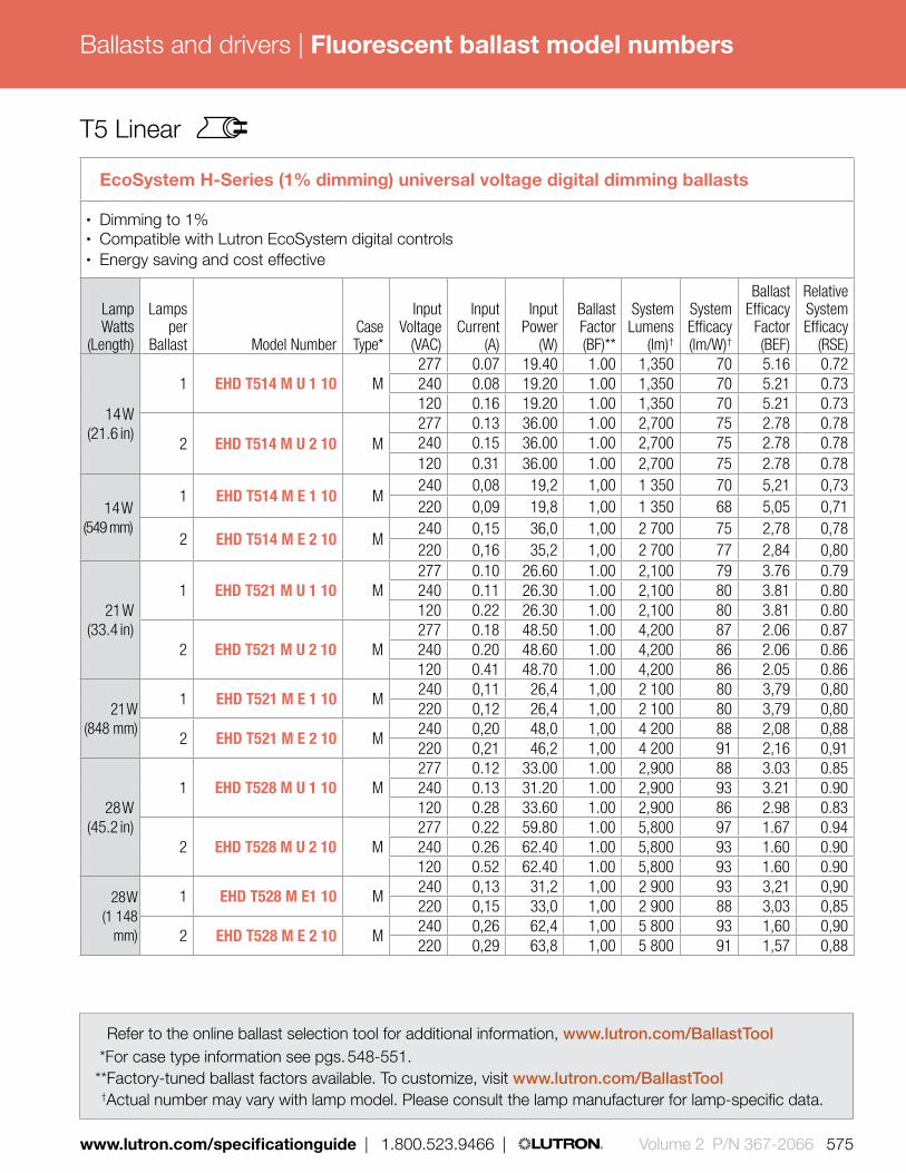
Ballasts and drivers |
www.lutron.com/specificationguide | 1.800.523.9466 | Volume 2 P/N 367-2066 575
Refer to the online ballast selection tool for additional information, www.lutron.com/BallastTool *For case type information see pgs. 548-551. * *Factory-tuned ballast factors available. To customize, visit www.lutron.com/BallastTool † Actual number may vary with lamp model. Please consult the lamp manufacturer for lamp-specific data.
T5 Linear
EcoSystem H-Series (1% dimming) universal voltage digital dimming ballasts
• Dimming to 1%• Compatible with Lutron EcoSystem digital controls• Energy saving and cost effective
LampWatts
(Length)
Lamps per
Ballast Model NumberCaseType*
InputVoltage
(VAC)
InputCurrent
(A)
Input Power
(W)
Ballast Factor (BF)**
System Lumens
(lm)†
System Efficacy (lm/W)†
Ballast Efficacy
Factor (BEF)
Relative System Efficacy
(RSE)
14 W(21.6 in)
1 EHD T514 M U 1 10 M277 0.07 19.40 1.00 1,350 70 5.16 0.72240 0.08 19.20 1.00 1,350 70 5.21 0.73120 0.16 19.20 1.00 1,350 70 5.21 0.73
2 EHD T514 M U 2 10 M277 0.13 36.00 1.00 2,700 75 2.78 0.78240 0.15 36.00 1.00 2,700 75 2.78 0.78120 0.31 36.00 1.00 2,700 75 2.78 0.78
14 W(549 mm)
1 EHD T514 M E 1 10 M240 0,08 19,2 1,00 1 350 70 5,21 0,73220 0,09 19,8 1,00 1 350 68 5,05 0,71
2 EHD T514 M E 2 10 M240 0,15 36,0 1,00 2 700 75 2,78 0,78220 0,16 35,2 1,00 2 700 77 2,84 0,80
21 W(33.4 in)
1 EHD T521 M U 1 10 M277 0.10 26.60 1.00 2,100 79 3.76 0.79240 0.11 26.30 1.00 2,100 80 3.81 0.80120 0.22 26.30 1.00 2,100 80 3.81 0.80
2 EHD T521 M U 2 10 M277 0.18 48.50 1.00 4,200 87 2.06 0.87240 0.20 48.60 1.00 4,200 86 2.06 0.86120 0.41 48.70 1.00 4,200 86 2.05 0.86
21 W(848 mm)
1 EHD T521 M E 1 10 M240 0,11 26,4 1,00 2 100 80 3,79 0,80220 0,12 26,4 1,00 2 100 80 3,79 0,80
2 EHD T521 M E 2 10 M240 0,20 48,0 1,00 4 200 88 2,08 0,88220 0,21 46,2 1,00 4 200 91 2,16 0,91
28 W(45.2 in)
1 EHD T528 M U 1 10 M277 0.12 33.00 1.00 2,900 88 3.03 0.85240 0.13 31.20 1.00 2,900 93 3.21 0.90120 0.28 33.60 1.00 2,900 86 2.98 0.83
2 EHD T528 M U 2 10 M277 0.22 59.80 1.00 5,800 97 1.67 0.94240 0.26 62.40 1.00 5,800 93 1.60 0.90120 0.52 62.40 1.00 5,800 93 1.60 0.90
28 W(1 148
mm)
1 EHD T528 M E1 10 M240 0,13 31,2 1,00 2 900 93 3,21 0,90220 0,15 33,0 1,00 2 900 88 3,03 0,85
2 EHD T528 M E 2 10 M240 0,26 62,4 1,00 5 800 93 1,60 0,90220 0,29 63,8 1,00 5 800 91 1,57 0,88
Fluorescent ballast model numbers

Ballasts and drivers |
576 Volume 2 P/N 367-2066 | 1.800.523.9466 | www.lutron.com/specificationguide
Refer to the online ballast selection tool for additional information, www.lutron.com/BallastTool *For case type information see pgs. 548-551. * *Factory-tuned ballast factors available. To customize, visit www.lutron.com/BallastTool † Actual number may vary with lamp model. Please consult the lamp manufacturer for lamp-specific data.
T5 Linear (continued)
Hi-lume® 3D (1% dimming) universal voltage digital dimming ballasts
• Dimming to 1%• Compatible with Lutron 3-wire fluorescent controls and EcoSystem® digital controls• Energy saving
LampWatts
(Length)
Lamps per
Ballast Model NumberCaseType*
InputVoltage
(VAC)
InputCurrent
(A)
Input Power
(W)
Ballast Factor (BF)**
System Lumens
(lm)†
System Efficacy (lm/W)†
Ballast Efficacy
Factor (BEF)
Relative System Efficacy
(RSE)
14 W (21.6 in)
1 H3D T514 C U 1 10 C277 0.07 19.40 1.00 1,350 70 5.16 0.72240 0.08 19.20 1.00 1,350 70 5.21 0.73120 0.16 19.20 1.00 1,350 70 5.21 0.73
2 H3D T514 C U 2 10 C277 0.13 36.00 1.00 2,700 75 2.78 0.78240 0.15 36.00 1.00 2,700 75 2.78 0.78120 0.30 36.00 1.00 2,700 75 2.78 0.78
21 W(33.4 in)
1 H3D T521 C U 1 10 C277 0.10 26.60 1.00 2,100 79 3.76 0.79240 0.11 26.30 1.00 2,100 80 3.81 0.80120 0.22 26.30 1.00 2,100 80 3.81 0.80
2 H3D T521 C U 2 10 C277 0.18 48.50 1.00 4,200 87 2.06 0.87240 0.20 48.60 1.00 4,200 86 2.06 0.86120 0.41 48.70 1.00 4,200 86 2.05 0.86
28 W(45.2 in)
1 H3D T528 C U 1 10 C277 0.12 33.00 1.00 2,900 88 3.63 0.85240 0.13 31.20 1.00 2,900 93 3.21 0.90120 0.28 33.60 1.00 2,900 86 2.98 0.83
2 H3D T528 C U 2 10 C277 0.22 59.80 1.00 5,800 97 1.67 0.94240 0.26 62.40 1.00 5,800 93 1.60 0.90120 0.52 62.40 1.00 5,800 93 1.60 0.90
Fluorescent ballast model numbers

Ballasts and drivers |
www.lutron.com/specificationguide | 1.800.523.9466 | Volume 2 P/N 367-2066 577
Refer to the online ballast selection tool for additional information, www.lutron.com/BallastTool *For case type information see pgs. 548-551. * *Factory-tuned ballast factors available. To customize, visit www.lutron.com/BallastTool † Actual number may vary with lamp model. Please consult the lamp manufacturer for lamp-specific data.
T5 Linear (continued)
EcoSystem (10% dimming) universal voltage digital dimming ballasts
• Dimming to 10%• Compatible with Lutron 3-wire fluorescent controls and EcoSystem digital controls• Integral sensor connections
LampWatts
(Length)
Lamps per
Ballast Model NumberCaseType*
InputVoltage
(VAC)
InputCurrent
(A)
Input Power
(W)
Ballast Factor (BF)**
System Lumens
(lm)†
System Efficacy (lm/W)†
Ballast Efficacy
Factor (BEF)
Relative System Efficacy
(RSE)
14 W(21.6 in)
1 EC5 T514 J UNV 1 J277 0.07 19.00 1.00 1,350 71 5.26 0.74240 0.08 19.20 1.00 1,350 70 5.21 0.74120 0.16 19.20 1.00 1,350 70 5.21 0.74
2 EC5 T514 J UNV 2 J277 0.12 32.80 1.00 2,700 82 3.05 0.85240 0.14 33.30 1.00 2,700 81 3.00 0.85120 0.28 33.30 1.00 2,700 81 3.00 0.85
21 W(33.4 in)
1 EC5 T521 J UNV 1 J277 0.09 24.90 1.00 2,100 84 4.01 0.84240 0.12 28.80 1.00 2,100 73 3.47 0.73120 0.22 26.40 1.00 2,100 80 3.79 0.80
2 EC5 T521 J UNV 2 J277 0.17 46.00 1.00 4,200 91 2.17 0.91240 0.20 47.20 1.00 4,200 89 2.12 0.89120 0.39 47.20 1.00 4,200 89 2.12 0.89
28 W(45.2 in)
1 EC5 T528 J UNV 1 J277 0.12 32.60 1.00 2,900 89 3.07 0.86240 0.14 32.90 1.00 2,900 88 3.04 0.85120 0.27 32.90 1.00 2,900 88 3.04 0.85
2 EC5 T528 J UNV 2 J277 0.23 64.50 1.00 5,800 90 1.55 0.87240 0.27 65.00 1.00 5,800 89 1.54 0.86120 0.54 65.20 1.00 5,800 89 1.53 0.86
35 W(57.1 in)
1 EC5 T535 J UNV 1 J277 0.15 42.00 1.00 3,650 87 2.38 0.83240 0.18 42.30 1.00 3,650 87 2.38 0.83120 0.35 42.20 1.00 3,650 87 2.38 0.83
Fluorescent ballast model numbers

Ballasts and drivers |
578 Volume 2 P/N 367-2066 | 1.800.523.9466 | www.lutron.com/specificationguide
Refer to the online ballast selection tool for additional information, www.lutron.com/BallastTool *For case type information see pgs. 548-551. * *Factory-tuned ballast factors available. To customize, visit www.lutron.com/BallastTool † Actual number may vary with lamp model. Please consult the lamp manufacturer for lamp-specific data.
T5 HO Linear
EcoSystem® H-Series (1% dimming) universal voltage digital dimming ballasts
• Dimming to 1%• Compatible with Lutron EcoSystem digital controls• Energy saving and cost effective
LampWatts
(Length)
Lamps per
Ballast Model NumberCaseType*
InputVoltage
(VAC)
InputCurrent
(A)
Input Power
(W)
Ballast Factor (BF)**
System Lumens
(lm)†
System Efficacy (lm/W)†
Ballast Efficacy
Factor (BEF)
Relative System Efficacy
(RSE)
24 W(21.6 in)
1 EHD T524 M U 1 10 M277 0.10 27.70 1.00 2,000 72 3.61 0.87240 0.12 28.80 1.00 2,000 69 3.47 0.83120 0.25 30.00 1.00 2,000 67 3.33 0.80
2 EHD T524 M U 2 10 M277 0.20 55.40 1.00 4,000 72 1.81 0.87240 0.23 55.20 1.00 4,000 72 1.81 0.87120 0.46 54.60 1.00 4,000 73 1.83 0.88
24 W(549 mm)
1 EHD T524 M E 1 10 M240 0,12 28,8 1,00 2 000 69 3,47 0,83220 0,13 28,6 1,00 2 000 70 3,50 0,84
2 EHD T524 M E 2 10 M240 0,22 52,8 1,00 4 000 76 1,89 0,91220 0,25 55,0 1,00 4 000 73 1,82 0,87
39 W(33.4 in)
1 EHD T539 M U 1 10 M277 0.17 46.00 1.00 3,500 76 2.17 0.85240 0.19 44.90 1.00 3,500 78 2.23 0.87120 0.37 44.40 1.00 3,500 79 2.25 0.88
2 EHD T539 M U 2 10 M277 0.29 81.40 1.00 7,000 86 1.23 0.96240 0.35 84.00 1.00 7,000 83 1.19 0.93120 0.70 84.00 1.00 7,000 83 1.19 0.93
39 W(848 mm)
1 EHD T539 M E 1 10 M240 0,18 43,2 1,00 3 500 81 2,31 0,90220 0,19 41,8 1,00 3 500 84 2,39 0,93
2 EHD T539 M E 2 10 M240 0,34 81,6 1,00 7 000 86 1.23 0,96220 0,39 85,8 1,00 7 000 82 1,17 0,91
54 W(45.2 in)
1 EHD T554 M U 1 10 M277 0.23 63.70 1.00 5,000 78 1.57 0.85240 0.26 62.40 1.00 5,000 80 1.60 0.87120 0.54 64.80 1.00 5,000 77 1.54 0.83
2 EHD T554 M U 2 10 M277 0.42 116.30 1.00 10,000 86 0.86 0.93240 0.48 115.20 1.00 10,000 87 0.87 0.94120 0.95 114.00 1.00 10,000 88 0.88 0.95
54 W(1148
mm)
1 EHD T554 M E 1 10 M240 0,26 62,4 1,00 5 000 80 1,60 0,87220 0,29 63,8 1,00 5 000 78 1,57 0,85
2 EHD T554 M E 2 10 M240 0,48 115,2 1,00 10 000 87 0,87 0,94220 0,51 112,2 1,00 10 000 89 0,89 0,96
Fluorescent ballast model numbers

Ballasts and drivers |
www.lutron.com/specificationguide | 1.800.523.9466 | Volume 2 P/N 367-2066 579
Refer to the online ballast selection tool for additional information, www.lutron.com/BallastTool *For case type information see pgs. 548-551. * *Factory-tuned ballast factors available. To customize, visit www.lutron.com/BallastTool † Actual number may vary with lamp model. Please consult the lamp manufacturer for lamp-specific data.
T5 HO Linear (continued)
Hi-lume® 3D (1% dimming) universal voltage digital dimming ballasts
• Dimming to 1%• Compatible with Lutron 3-wire fluorescent controls and EcoSystem digital controls• Energy saving
LampWatts
(Length)
Lamps per
Ballast Model NumberCaseType*
InputVoltage
(VAC)
InputCurrent
(A)
Input Power
(W)
Ballast Factor (BF)**
System Lumens
(lm)†
System Efficacy (lm/W)†
Ballast Efficacy
Factor (BEF)
Relative System Efficacy
(RSE)
24 W(21.6 in)
1 H3D T524 C U 1 10 C277 0.10 27.70 1.00 2,000 72 3.61 0.87240 0.12 28.80 1.00 2,000 69 3.47 0.83120 0.25 30.00 1.00 2,000 67 3.33 0.80
2 H3D T524 C U 2 10 C277 0.20 55.40 1.00 4,000 72 1.81 0.87240 0.23 55.20 1.00 4,000 72 1.81 0.87120 0.46 54.60 1.00 4,000 73 1.83 0.88
39 W(33.4 in)
1 H3D T539 C U 1 10 C277 0.17 46.00 1.00 3,500 76 2.17 0.85240 0.19 44.90 1.00 3,500 78 2.23 0.87120 0.37 44.40 1.00 3,500 79 2.25 0.88
2 H3D T539 C U 2 10 C277 0.29 81.40 1.00 7,000 86 1.23 0.96240 0.35 84.00 1.00 7,000 83 1.19 0.93120 0.70 84.00 1.00 7,000 83 1.19 0.93
54 W(45.2 in)
1 H3D T554 C U 1 10 C277 0.23 63.70 1.00 5,000 78 1.57 0.85240 0.26 62.40 1.00 5,000 80 1.60 0.87120 0.54 64.80 1.00 5,000 77 1.54 0.83
2 H3D T554 C U 2 10 C277 0.42 116.30 1.00 10,000 86 0.86 0.93240 0.48 115.20 1.00 10,000 87 0.87 0.94120 0.95 114.00 1.00 10,000 88 0.88 0.95
Hi-lume® 3D (5% dimming) universal voltage digital dimming ballasts
• Dimming to 5%• Compatible with Lutron 3-wire fluorescent controls and EcoSystem digital controls• Energy saving
LampWatts
(Length)
Lamps per
Ballast Model NumberCaseType*
InputVoltage
(VAC)
InputCurrent
(A)
Input Power
(W)
Ballast Factor (BF)**
System Lumens
(lm)†
System Efficacy (lm/W)†
Ballast Efficacy
Factor (BEF)
Relative System Efficacy
(RSE)
80 W(57.1 in)
277 0.32 1.00 88.60 7000 79 1.13 0.901 H3D T580 C U 1 10 C 240 0.37 1.00 88.80 7000 79 1.13 0.90
120 0.73 1.00 87.60 7000 80 1.14 0.91
Fluorescent ballast model numbers

Ballasts and drivers |
580 Volume 2 P/N 367-2066 | 1.800.523.9466 | www.lutron.com/specificationguide
Refer to the online ballast selection tool for additional information, www.lutron.com/BallastTool
*For case type information see pgs. 548-551. † Actual number may vary with lamp model. Please consult the lamp manufacturer for lamp-specific data.
T5 HO Linear (continued)
Hi-lume® (1% dimming) 120 V and 277 V dimming ballasts
• Dimming to 1%• Compatible with Lutron 3-wire fluorescent controls• Energy saving
LampWatts
(Length)
Lamps per
Ballast Model NumberCaseType*
InputVoltage
(VAC)
InputCurrent
(A)
Input Power
(W)
Ballast Factor
(BF)
System Lumens
(lm)†
System Efficacy (lm/W)†
Ballast Efficacy
Factor (BEF)
Relative System Efficacy
(RSE)
24 W(21.6 in)
1FDB-T524-277-1
C277 0.15 36.00 1.00 2,000 56 2.78 0.67
FDB-T524-120-1 120 0.31 31.20 1.00 2,000 64 3.21 0.77
2FDB-T524-277-2
C277 0.24 55.40 1.00 4,000 72 1.81 0.87
FDB-T524-120-2 120 0.62 54.00 1.00 4,000 74 1.85 0.89
39 W(33.4 in)
1FDB-T539-277-1
C277 0.19 47.10 1.00 3,500 74 2.12 0.83
FDB-T539-120-1 120 0.38 45.60 1.00 3,500 77 2.19 0.86
2FDB-T539-277-2
C277 0.32 85.90 1.00 7,000 82 1.16 0.91
FDB-T539-120-2 120 0.76 91.20 1.00 7,000 77 1.10 0.86
54 W(45.2 in)
1FDB-T554-277-1
C277 0.25 69.3 1.00 5,000 72 1.44 0.78
FDB-T554-120-1 120 0.58 69.6 1.00 5,000 72 1.44 0.78
2FDB-T554-277-2
C277 0.45 124.7 1.00 10,000 80 0.80 0.87
FDB-T554-120-2 120 1.10 132.0 1.00 10,000 76 0.76 0.82
Select Hi-lume ballasts have been discontinued. Please refer to The Fluorescent ballast and LED driver selection guide (367-2248) for discontinued ballasts and drivers.
Fluorescent ballast model numbers

Ballasts and drivers |
www.lutron.com/specificationguide | 1.800.523.9466 | Volume 2 P/N 367-2066 581
Refer to the online ballast selection tool for additional information, www.lutron.com/BallastTool *For case type information see pgs. 548-551. * *Factory-tuned ballast factors available. To customize, visit www.lutron.com/BallastTool † Actual number may vary with lamp model. Please consult the lamp manufacturer for lamp-specific data.
T5 HO Linear (continued)
EcoSystem® (10% dimming) universal voltage digital dimming ballasts
• Dimming to 10%• Compatible with Lutron 3-wire fluorescent controls and EcoSystem digital controls • Integral sensor connections
LampWatts
(Length)
Lamps per
Ballast Model NumberCaseType*
InputVoltage
(VAC)
InputCurrent
(A)
Input Power
(W)
Ballast Factor (BF)**
System Lumens
(lm)†
System Efficacy (lm/W)†
Ballast Efficacy
Factor (BEF)
Relative System Efficacy
(RSE)
24 W(21.6 in)
1 EC5 T524 J UNV 1 J277 0.11 30.00 1.00 2,000 67 3.33 0.80240 0.13 28.80 1.00 2,000 69 3.47 0.83120 0.24 28.80 1.00 2,000 69 3.47 0.83
2 EC5 T524 J UNV 2 J 277 0.20 54.80 1.00 4,000 73 1.82 0.89240 0.23 54.00 1.00 4,000 74 1.85 0.89120 0.45 53.90 1.00 4,000 74 1.86 0.89
39 W(33.4 in)
1 EC5 T539 J UNV 1 J277 0.16 43.30 1.00 3,500 81 2.31 0.90240 0.18 44.00 1.00 3,500 80 2.27 0.89120 0.37 44.00 1.00 3,500 80 2.27 0.89
2 EC5 T539 J UNV 2 J277 0.30 83.00 1.00 7,000 84 1.20 0.94240 0.35 84.00 1.00 7,000 83 1.19 0.93120 0.70 84.30 1.00 7,000 83 1.19 0.93
54 W(45.2 in)
1 EC5 T554 J UNV 1 J277 0.21 56.50 1.00 5,000 88 1.77 0.96240 0.24 58.00 1.00 5,000 86 1.73 0.93120 0.48 57.90 1.00 5,000 86 1.73 0.93
2 EC5 T554 J UNV 2 J277 0.40 110.10 1.00 10,000 91 0.91 0.98240 0.52 119.00 1.00 10,000 84 0.84 0.91120 0.99 119.30 1.00 10,000 84 0.84 0.91
Fluorescent ballast model numbers

Ballasts and drivers |
582 Volume 2 P/N 367-2066 | 1.800.523.9466 | www.lutron.com/specificationguide
Refer to the online ballast selection tool for additional information, www.lutron.com/BallastTool *For case type information see pgs. 548-551. * *Factory-tuned ballast factors available. To customize, visit www.lutron.com/BallastTool † Actual number may vary with lamp model. Please consult the lamp manufacturer for lamp-specific data.
T5 Twin-Tube
Hi-lume® 3D (5% dimming) universal voltage digital dimming ballasts
• Dimming to 5%• Compatible with Lutron 3-wire fluorescent controls and EcoSystem® digital controls• Energy saving
LampWatts
(Length)
Lamps per
Ballast Model NumberCaseType*
InputVoltage
(VAC)
InputCurrent
(A)
Input Power
(W)
Ballast Factor (BF)**
System Lumens
(lm)†
System Efficacy (lm/W)†
Ballast Efficacy
Factor (BEF)
Relative System Efficacy
(RSE)
36 W (15.5 in)
1 H3D T536 G U 1 10 G277 0.14 38.40 1.00 2,850 74 2.60 1.04240 0.17 40.40 1.00 2,850 71 2.48 0.99120 0.33 39.20 1.00 2,850 73 2.55 1.02
2 H3D T536 G U 2 10 G277 0.26 71.30 1.00 5,700 80 1.40 1.12240 0.31 73.70 1.00 5,700 77 1.36 1.09120 0.61 72.50 1.00 5,700 79 1.38 1.10
40 W (22.5 in)
1 H3D T540 G U 1 10 G277 0.16 43.90 1.00 3,100 71 2.28 0.91240 0.18 42.80 1.00 3,100 72 2.34 0.93120 0.36 42.80 1.00 3,100 72 2.34 0.93
2 H3D T540 G U 2 10 G277 0.27 74.00 1.00 6,200 84 1.35 1.08240 0.32 76.00 1.00 6,200 82 1.32 1.05120 0.64 76.00 1.00 6,200 82 1.32 1.05
3 H3D T540 G U 3 10 G277 0.40 109.70 1.00 9,300 85 0.91 1.09240 0.47 111.70 1.00 9,300 83 0.90 1.07120 0.95 112.90 1.00 9,300 82 0.89 1.06
50 W (22.5 in)
1 H3D T550 G U 1 10 G277 0.20 54.80 1.00 4,000 73 1.82 0.91240 0.23 54.60 1.00 4,000 73 1.83 0.92120 0.45 53.50 1.00 4,000 75 1.87 0.93
2 H3D T550 G U 2 10 G277 0.36 98.70 1.00 8,000 81 1.01 1.01240 0.42 99.80 1.00 8,000 80 1.00 1.00120 0.84 99.80 1.00 8,000 80 1.00 1.00
Fluorescent ballast model numbers

Ballasts and drivers |
www.lutron.com/specificationguide | 1.800.523.9466 | Volume 2 P/N 367-2066 583
T5 Twin-Tube (continued)
EcoSystem (10% dimming) universal voltage digital dimming ballasts
• Dimming to 10%• Compatible with Lutron 3-wire fluorescent controls and EcoSystem digital controls• Integral sensor connections
LampWatts
(Length)
Lamps per
Ballast Model NumberCaseType*
InputVoltage
(VAC)
InputCurrent
(A)
Input Power
(W)
Ballast Factor (BF)**
System Lumens
(lm)†
System Efficacy (lm/W)†
Ballast Efficacy
Factor (BEF)
Relative System Efficacy
(RSE)
36/39 W(15.5 in)
1 EC5 T536 J UNV 1 J277 0.14 38.80 1.00 2,850 73 2.57 0.93240 0.17 39.60 1.00 2,850 72 2.53 0.91120 0.33 39.60 1.00 2,850 72 2.53 0.91
2 EC5 T536 J UNV 2 J277 0.26 72.00 1.00 5,700 79 1.39 1.00240 0.31 73.20 1.00 5,700 78 1.37 0.98120 0.61 73.20 1.00 5,700 78 1.37 0.98
40 W(22.5 in)
1 EC5 T540 J UNV 1 J277 0.16 44.30 1.00 3,100 70 2.26 0.90240 0.18 43.20 1.00 3,100 72 2.31 0.93120 0.36 43.20 1.00 3,100 72 2.31 0.93
2 EC5 T540 J UNV 2 J277 0.27 74.80 1.00 6,200 83 1.34 1.07240 0.32 76.80 1.00 6,200 81 1.30 1.04120 0.64 76.80 1.00 6,200 81 1.30 1.04
3 EC5 T540 G UNV 3L†† G277 0.40 111.30 1.00 9,300 84 0.90 1.08240 0.47 112.40 1.00 9,300 83 0.89 1.07120 0.95 113.20 1.00 9,300 82 0.88 1.06
50 W(22.5 in)
1 EC5 T550 J UNV 1 J277 0.20 55.40 1.00 4,000 72 1.81 0.90240 0.23 54.00 1.00 4,000 72 1.85 0.93120 0.45 54.00 1.00 4,000 74 1.85 0.93
2 EC5 T550 J UNV 2 J277 0.36 99.70 1.00 8,000 80 1.00 1.00240 0.42 100.80 1.00 8,000 79 0.99 0.99120 0.84 100.80 1.00 8,000 79 0.99 0.99
55 W(20.7 in)
1 EC5 T555 J UNV 1 J277 0.20 55.40 0.90 4,320 78 1.62 0.89240 0.23 55.20 0.90 4,320 78 1.63 0.90120 0.46 55.20 0.90 4,320 78 1.63 0.90
2 EC5 T555 J UNV 2 J277 0.40 110.80 0.90 8,640 78 0.81 0.90240 0.46 110.40 0.90 8,640 78 0.82 0.90120 0.92 110.40 0.90 8,640 78 0.82 0.90
Refer to the online ballast selection tool for additional information, www.lutron.com/BallastTool *For case type information see pgs. 548-551. * *Factory-tuned ballast factors available. To customize, visit www.lutron.com/BallastTool † Actual number may vary with lamp model. Please consult the lamp manufacturer for lamp-specific data.†† Ballast ships with leads.
Fluorescent ballast model numbers

Ballasts and drivers |
584 Volume 2 P/N 367-2066 | 1.800.523.9466 | www.lutron.com/specificationguide
Refer to the online ballast selection tool for additional information, www.lutron.com/BallastTool
*For case type information see pgs. 548-551.
* *Factory-tuned ballast factors available. To customize, visit www.lutron.com/BallastTool † Actual number may vary with lamp model. Please consult the lamp manufacturer for lamp-specific data.
Please consult lamp manufacturer’s specification to determine the dimmability of the reduced wattage lamp.
Reduced Wattage T5 Twin-Tube
EcoSystem® (10% dimming) universal voltage digital dimming ballasts
• Dimming to 10% for reduced wattage (energy saving) lamps• Compatible with Lutron 3-wire fluorescent controls and EcoSystem digital controls • Integral sensor connections
LampWatts
(Length)
Lamps per
Ballast Model NumberCaseType*
InputVoltage
(VAC)
InputCurrent
(A)
Input Power
(W)
Ballast Factor (BF)**
System Lumens
(lm)†
System Efficacy (lm/W)†
Ballast Efficacy
Factor (BEF)
Relative System Efficacy
(RSE)
25 W(22.5 in)
1 EC5 T540 RW J UNV 1 J277 0.12 34.30 1.00 2,600 76 2.91 0.73240 0.14 34.50 1.00 2,600 75 2.89 0.72120 0.28 34.10 1.00 2,600 76 2.93 0.73
2 EC5 T540 RW J UNV 2 J277 0.21 59.30 1.00 5,200 88 1.68 0.84240 0.25 61.00 1.00 5,200 85 1.64 0.82120 0.49 59.30 1.00 5,200 88 1.68 0.84
Fluorescent ballast model numbers

Ballasts and drivers |
www.lutron.com/specificationguide | 1.800.523.9466 | Volume 2 P/N 367-2066 585
Refer to the online ballast selection tool for additional information, www.lutron.com/BallastTool
*For case type information see pgs. 548-551. †Actual number may vary with lamp model. Please consult the lamp manufacturer for lamp-specific data.‡Mounting studs standard. Delete -S suffix in the model number if mounting studs are not needed.
T4 Compact
Hi-lume® (1% dimming) 120 V and 277 V dimming ballasts
• Dimming to 1%• Compatible with Lutron 3-wire fluorescent controls• Energy saving
LampWatts
Lamps per
Ballast Model NumberCaseType*
InputVoltage
(VAC)
InputCurrent
(A)
Input Power
(W)
Ballast Factor
(BF)
System Lumens
(lm)†
System Efficacy (lm/W)†
Ballast Efficacy
Factor (BEF)
Relative System Efficacy
(RSE)26 W
(Triple Tube)
1HL3-T426-277-1-S‡
A277 0.12 33.20 0.95 1,710 51 2.86 0.74
HL3-T426-120-1-S‡ 120 0.26 31.20 0.95 1,710 55 3.04 0.79
32 W(Triple Tube)
1HL3-T432-277-1-S‡
A277 0.13 36.00 0.95 2,280 63 2.64 0.84
HL3-T432-120-1-S‡ 120 0.35 37.20 0.95 2,280 61 2.55 0.82
Fluorescent ballast model numbers

Ballasts and drivers |
586 Volume 2 P/N 367-2066 | 1.800.523.9466 | www.lutron.com/specificationguide
*For case type information see pgs. 548-551. * *Factory-tuned ballast factors available. To customize, visit www.lutron.com/BallastTool † Actual number may vary with lamp model. Please consult the lamp manufacturer for lamp-specific data.‡Mounting studs standard. Delete -S suffix in the model number if mounting studs are not needed.
T4 Compact (continued)
EcoSystem® (5% dimming) universal voltage digital dimming ballasts
• Dimming to 5%• Compatible with Lutron 3-wire fluorescent controls and EcoSystem digital controls • Energy saving
LampWatts
Lamps per
Ballast Model NumberCaseType*
InputVoltage
(VAC)
InputCurrent
(A)
Input Power
(W)
Ballast Factor (BF)**
System Lumens
(lm)†
System Efficacy (lm/W)†
Ballast Efficacy
Factor (BEF)
Relative System Efficacy
(RSE)
18 W(Triple/
Quad Tube)
1 EC3D T418 K U 1 S‡ K277 0.08 20.80 0.95 1,140 55 4.57 0.82240 0.09 21.40 0.95 1,140 53 4.44 0.80120 0.18 21.30 0.95 1,140 54 4.46 0.80
2 EC3D T418 K U 2 S‡ K277 0.15 39.90 0.95 2,280 57 2.38 0.86240 0.17 39.40 0.95 2,280 58 2.41 0.87120 0.34 41.10 0.95 2,280 56 2.31 0.83
26 W(Triple/
Quad Tube)
1 EC3D T4MW K U 1 S‡ K277 0.10 27.00 0.95 1,710 63 3.52 0.92240 0.11 26.90 0.95 1,710 64 3.54 0.92120 0.22 26.40 0.95 1,710 65 3.60 0.94
2 EC3D T4MW K U 2 S‡ K277 0.19 51.40 0.95 3,420 67 1.85 0.96240 0.21 50.60 0.95 3,420 68 1.88 0.98120 0.43 51.60 0.95 3,420 66 1.84 0.96
32 W(Triple Tube)
1 EC3D T4MW K U 1 S‡ K277 0.12 33.20 0.95 2,280 69 2.86 0.91240 0.14 33.60 0.95 2,280 68 2.83 0.90120 0.29 34.80 0.95 2,280 66 2.73 0.87
2 EC3D T4MW K U 2 S‡ K277 0.24 65.50 0.95 4,560 70 1.45 0.93240 0.26 63.00 0.95 4,560 72 1.51 0.96120 0.55 66.00 0.95 4,560 69 1.44 0.92
42 W(Triple Tube)
1 EC3D T442 K U 1 S‡ K277 0.15 42.60 0.95 3,040 71 2.23 0.94240 0.18 42.70 0.95 3,040 71 2.23 0.93120 0.36 43.20 0.95 3,040 70 2.20 0.92
2 EC3D T442 K U 2 S‡ K277 0.31 85.40 0.95 6,080 71 1.11 0.93240 0.35 85.10 0.95 6,080 72 1.12 0.94120 0.73 87.60 0.95 6,080 69 1.08 0.91
Fluorescent ballast model numbers

Ballasts and drivers |
www.lutron.com/specificationguide | 1.800.523.9466 | Volume 2 P/N 367-2066 587
T4 Compact (continued)
Tu-Wire® (5% dimming) 120 V dimming ballasts
• Dimming to 5%• Designed for retrofit applications • Compatible with Lutron Tu-Wire fluorescent controls• Energy saving
LampWatts
Lamps per
Ballast Model NumberCaseType*
InputVoltage
(VAC)
InputCurrent
(A)
Input Power
(W)
Ballast Factor
(BF)
System Lumens
(lm)†
System Efficacy (lm/W)†
Ballast Efficacy
Factor (BEF)
Relative System Efficacy
(RSE)18 W
(Triple/Quad Tube)
2 2W-T418-120-2-S‡ B 120 0.41 49.20 0.95 2,280 46 1.93 0.70
26 W(Triple/
Quad Tube)
1 2W-T426-120-1-S‡ A 120 0.27 32.40 0.95 1,710 53 2.93 0.76
2 2W-T426-120-2-S‡ B 120 0.53 63.60 0.95 3,420 54 1.49 0.78
32 W(Triple Tube)
1 2W-T432-120-1-S‡ A 120 0.33 39.60 0.95 2,280 58 2.40 0.77
2 2W-T432-120-2-S‡ B 120 0.58 69.60 0.95 4,560 66 1.36 0.87
Refer to the online ballast selection tool for additional information, www.lutron.com/BallastTool
*For case type information see pgs. 548-551. †Actual number may vary with lamp model. Please consult the lamp manufacturer for lamp-specific data.‡Mounting studs standard. Delete -S suffix in the model number if mounting studs are not needed.
Fluorescent ballast model numbers

Ballasts and drivers |
588 Volume 2 P/N 367-2066 | 1.800.523.9466 | www.lutron.com/specificationguide
Europe (CE)EHD T514 M E 1 10
EHD T514 M E 2 10
EHD T521 M E 1 10
EHD T521 M E 2 10
EHD T524 M E 1 10
EHD T524 M E 2 10
EHD T528 M E 1 10
EHD T528 M E 2 10
EHD T539 M E 1 10
EHD T539 M E 2 10
EHD T554 M E 1 10
EHD T554 M E 2 10
Brazil (INMETRO)EHD T832 M E 1 10-B
EHD T832 M E 2 10-B
EHD T514 M E 1 10-B
EHD T514 M E 2 10-B
EHD T521 M E 1 10-B
EHD T521 M E 2 10-B
EHD T524 M E 1 10-B
EHD T524 M E 2 10-B
EHD T528 M E 1 10-B
EHD T528 M E 2 10-B
EHD T539 M E 1 10-B
EHD T539 M E 2 10-B
EHD T554 M E 1 10-B
EHD T554 M E 2 10-B
China (CCC)EHD T514 M E 1 10-C
EHD T514 M E 2 10-C
EHD T528 M E 1 10-C
EHD T528 M E 2 10-C
EHD T554 M E 1 10-C
EHD T554 M E 2 10-C
The following ballast model numbers have certifications specific to certain countries. For details on these ballast models, visit www.lutron.com
Canada (CSA)EHD T832 C 347 110
EHD T832 C 347 210
EHD T832 C 347 117
EHD T832 C 347 217
EHD T528 C 347 110
EHD T528 C 347 210
EHD T554 C 347 110
EHD T554 C 347 210
NOTE: For specification information, please reference page 50
Ballast models by country

Ballasts and drivers |
www.lutron.com/specificationguide | 1.800.523.9466 | Volume 2 P/N 367-2066 589
Mexico (NOM)H3D T817 G U 1 10 N
H3D T817 G U 2 10 N
H3D T825 G U 1 10 N
H3D T825 G U 2 10 N
H3D T832 G U 1 10 N
H3D T832 G U 2 10 N
H3D T832 G U 3 10 N
H3D T817 C U 1 10 N
H3D T817 C U 2 10 N
H3D T825 C U 1 10 N
H3D T825 C U 2 10 N
H3D T832 C U 1 10 N
H3D T832 C U 2 10 N
H3D T832 C U 1 17 N
H3D T832 C U 2 17 N
H3D T514 C U 1 10 N
H3D T514 C U 2 10 N
H3D T521 C U 1 10 N
H3D T521 C U 2 10 N
H3D T524 C U 1 10 N
H3D T524 C U 2 10 N
H3D T528 C U 1 10 N
H3D T528 C U 2 10 N
H3D T536 G U 1 10 N
H3D T536 G U 2 10 N
H3D T539 C U 1 10 N
H3D T539 C U 2 10 N
H3D T540 G U 1 10 N
H3D T540 G U 2 10 N
H3D T540 G U 3 10 N
H3D T550 G U 1 10 N
H3D T550 G U 2 10 N
H3D T554 C U 1 10 N
H3D T554 C U 2 10 N
EC5 T514 J UNV 1 N
EC5 T514 J UNV 2 N
EC5 T521 J UNV 1 N
EC5 T521 J UNV 2 N
EC5 T524 J UNV 1 N
EC5 T524 J UNV 2 N
EC5 T528 J UNV 1 N
EC5 T528 J UNV 2 N
EC5 T535 J UNV 1 N
EC5 T536 J UNV 1 N
EC5 T536 J UNV 2 N
EC5 T539 J UNV 1 N
EC5 T539 J UNV 2 N
EC5 T540 J UNV 1 N
EC5 T540 J UNV 2 N
EC5 T550 J UNV 1 N
EC5 T550 J UNV 2 N
EC5 T554 J UNV 1 N
EC5 T554 J UNV 2 N
EC5 T555 J UNV 1 N
EC5 T555 J UNV 2 N
EC5 T817 J UNV 1 N
EC5 T817 J UNV 2 N
EC5 T825 J UNV 1 N
EC5 T825 J UNV 2 N
EC5 T832 J UNV 1 N
EC5 T832 J UNV 2 N
EC3D T418 K U 1 N
EC3D T418 K U 1 S N
EC3D T418 K U 2 N
EC3D T418 K U 2 S N
EC3D T4MW K U 1 N
EC3D T4MW K U 1 S N
EC3D T4MW K U 2 N
EC3D T4MW K U 2 S N
EC3D T442 K U 1 N
EC3D T442 K U 1 S N
EC3D T442 K U 2 N
EC3D T442 K U 2 S N
EHD T514 M U 1 10 N
EHD T514 M U 2 10 N
EHD T521 M U 1 10 N
EHD T521 M U 2 10 N
EHD T524 M U 1 10 N
EHD T524 M U 2 10 N
EHD T528 M U 1 10 N
EHD T528 M U 2 10 N
EHD T539 M U 1 10 N
EHD T539 M U 2 10 N
EHD T554 M U 1 10 N
EHD T554 M U 2 10 N
EHD T817 M U 1 10 N
EHD T817 M U 2 10 N
EHD T825 M U 1 10 N
EHD T825 M U 2 10 N
EHD T832 M U 1 10 N
EHD T832 M U 2 10 N
EHD T832 M U 1 17 N
EHD T832 M U 2 17 N
Japan (PSE)H3 T432 K 100 1 J
H3 T832 G UNV 1 J
H3 T832 G UNV 2 J
Ballast models by countryBallast models by country

Ballasts and drivers |
590 Volume 2 P/N 367-2066 | 1.800.523.9466 | www.lutron.com/specificationguide
Argentina (S)H3D T817 C 220 1 10
H3D T817 C 220 2 10
H3D T817 C 220 1 17
H3D T817 C 220 2 17
H3D T817 G 220 1 10
H3D T817 G 220 2 10
H3D T817 G 220 1 17
H3D T817 G 220 2 17
H3D T817 G 220 3 10
H3D T817 G 220 3 17
H3D T825 C 220 1 10
H3D T825 C 220 2 10
H3D T825 C 220 1 17
H3D T825 C 220 2 17
H3D T832 C 220 1 10
H3D T832 C 220 2 10
H3D T832 C 220 1 17
H3D T832 C 220 2 17
H3D T832 G 220 1 10
H3D T832 G 220 2 10
H3D T832 G 220 1 17
H3D T832 G 220 2 17
H3D T832 G 220 3 10
H3D T832 G 220 3 17
H3D T840 C 220 1 10
H3D T840 C 220 2 10
H3D T840 C 220 1 17
H3D T840 C 220 2 17
H3D T514 C 220 1 10
H3D T514 C 220 2 10
H3D T521 C 220 1 10
H3D T521 C 220 2 10
H3D T528 C 220 1 10
H3D T528 C 220 2 10
H3D T536 G 220 1 10
H3D T536 G 220 2 10
H3D T540 G 220 1 10
H3D T540 G 220 2 10
H3D T540 G 220 3 10
H3D T550 G 220 1 10
H3D T550 G 220 2 10
HL3 T426 220 1 S
HL3 T426 220 1
HL3 T432 220 1 S
HL3 T432 220 1
EC3D T418 K 220 1
EC3D T418 K 220 1 S
EC3D T418 K 220 2
EC3D T418 K 220 2 S
EC3D T442 K 220 1
EC3D T442 K 220 1 S
EC3D T442 K 220 2
EC3D T442 K 220 2 S
EC3D T4MW K 220 1
EC3D T4MW K 220 1 S
EC3D T4MW K 220 2
EC3D T4MW K 220 2 S
EC5 T536 J 220 1
EC5 T536 J 220 2
EC5 T540 J 220 1
EC5 T540 J 220 2
EC5 T540 G 220 3L
EC5 T550 J 220 1
EC5 T550 J 220 2
EC5 T555 J 220 1
EC5 T555 J 220 2
EC5 T524 J 220 1
EC5 T524 J 220 2
EC5 T539 J 220 1
EC5 T539 J 220 2
EC5 T554 J 220 1
EC5 T554 J 220 2
EC5 T514 J 220 1
EC5 T514 J 220 2
EC5 T521 J 220 1
EC5 T521 J 220 2
EC5 T528 J 220 1
EC5 T528 J 220 2
EC5 T535 J 220 1
EC5 T817 J 220 1
EC5 T817 J 220 2
EC5 T825 J 220 1
EC5 T825 J 220 2
EC5 T832 G 220 2L
EC5 T832 G 220 3L
EC5 T832 G 220 3 17L
EC5 T832 J 220 1
EC5 T832 J 220 2
Ballast models by country

Ballasts and drivers |
www.lutron.com/specificationguide | 1.800.523.9466 | Volume 2 P/N 367-2066 591
LED
How to build a Hi-lume® A-Series LED model number:
L__ __A4U1U__ __ – __ __ __ __ __
Control type:*
3D= EcoSystem® or 3-wire control
TE= 2-Wire forward phase control (neutral required)
Case style:
S= Studded (K-case only)
N=Non-studded
Case size:
K=Compact
M=Stick
Class 2 constant voltage
A= 10.00 V-12.00 V 3.30 A maximum
B=12.50 V-20.00 V
C=20.50 V-24.00 V
D=24.50 V-38.00 V
Isolated Non-class 2 constant voltage
X=38.50 V-60.00 V
Class 2 constant current
E=0.20 A-0.50 A 30 V-54 V
F=0.51 A-1.00 A 30 V-54 V
G=0.20 A-0.70 A 8 V-20 V
H=0.20 A-0.70 A 15 V-38 V
I=0.71 A-1.05 A 8 V-20 V
J=0.71 A-1.05 A 15 V-38 V
K=1.06 A-1.50 A 8 V-20 V
L=1.06 A-1.50 A 15 V-38 V
M= 1.51 A-2.10 A 8 V-20 V (30 W maximum)
Isolated Non-class 2 constant current
Y=0.20 A-0.50 A 30 V-60 V
Z=0.51 A-1.00 A 30 V-60 V
LED load output range (contact fixture manufacturer for specifications)
* For details on control types, see pg. 593.
1
Driver output:*
C= Constant current driver with pulse width modulation (PWM) dimming
A= Constant current driver with constant current reduction (CCR) dimming
V= Constant voltage driver with pulse width modulation (PWM) dimming
Current level (for constant current):*
020=0.20 A; 021=0.21 A…210=2.10 A
Voltage level (for constant voltage):*
100=10.00 V; 105=10.50 V…600=60.00 V
2
Example: L3DA4U1UKS-HC070
For assistance, contact our LED Center of Excellence at 1.877.346.5338 or [email protected], or use the online model number tool at www.lutron.com/LEDBuildAModel
LED driver model numbers

Ballasts and drivers |
592 Volume 2 P/N 367-2066 | 1.800.523.9466 | www.lutron.com/specificationguide
How to build an EcoSystem® LED model number (CE models):
L DE A2E1C PA – __ __ __ __ __
Control type:*
DE= Digital Only EcoSystem
Constant voltage
A=8.00 V-12.00 V
B=12.50 V-20.00 V
C=20.50 V-24.00 V
D=24.50 V-40.00 V
1.05 A and 25 W maximum
Constant current
G=0.20 A-0.70 A 8 V-20 V
H=0.20 A-0.70 A 15 V-40 V
I=0.71 A-1.05 A 8 V-20 V
J=0.71 A-1.05 A 15 V-40 V
40 V and 25 W maximum
LED load output range (see following pages for explanation and examples):
1
Driver output:*
C= Constant current driver with pulse width modulation (PWM) dimming
A= Constant current driver with constant current reduction (CCR) dimming
V= Constant voltage driver with pulse width modulation (PWM) dimming
Current level (for constant current):*
020=0.20 A; 021=0.21 A … 105=1.05 A
Voltage level (for constant voltage):*
100=10.00 V; 105=10.50 V … 400=40.00 V
2
LED
LED driver model numbers
* For details on control types, see pg. 593.

Ballasts and drivers |
www.lutron.com/specificationguide | 1.800.523.9466 | Volume 2 P/N 367-2066 593
Details for building a Lutron® LED driver model number
For more information, please use the following resources: • LED Driver Selection Tool (www.lutron.com/LEDBuildAModel) • Lutron LED Control Center of Excellence (1.877.DIM.LED8 or email [email protected])
Control type Features Ideal applications
2-Wire forward phase control
• Typically used for incandescent and MLV light sources
• Generally the only control used for LED retrofit lamps
• Most common method of dimming control
• Retrofit projects• Residential and
commercial system applications
• Applications that have a neutral wire in the backbox
EcoSystem digital link control
• Digitally addressable and allows LED drivers to communicate and react to environmental changes
• Allows for rezoning without rewiring, and all links are miswire protected
• Projects requiring digital control for individual fixture addressability
• Upgrade from analog 0-10 V control
• Multi-zone applications
• Small, retrofit applications using Lutron Energi TriPak®
3-Wire control • Requires a third line voltage control wire, resulting in more precise performance and less electrical noise
• Stable over long wire runs
• Easily wired
• LED dimming applications requiring precise control
1 2
Choosing a control type input The following control technologies refer to the signal and wiring between the control on the wall and the
LED driver. The compatibility of a dimmer with a particular LED fixture begins with making sure they both use the same control method. These control technologies are used in stand-alone applications and control systems as well as in wired and wireless lighting controls.
Selection of a control is typically driven by the requirements of the project.
1
LED driver model numbers

Ballasts and drivers |
594 Volume 2 P/N 367-2066 | 1.800.523.9466 | www.lutron.com/specificationguide
Details for building a Lutron® LED driver model number
Typical applications Details
Constant current
• Down light or sconce • One light source per driver (much like a fluorescent lamp with its associated ballast)
• For a pre-made LED array designed to operate at or below a set current level
Constant voltage
• Cove, under-cabinet light or an area with a variable number of fixtures
• For one or more LED arrays connected in parallel
• Similar to electronic or magnetic low-voltage power supplies that often have 12 V and 24 V outputs
1 2
Choosing an LED driver output Lutron LED drivers offer models for both constant current and constant voltage applications. These two
types of drivers are not interchangeable, and the design of the LED array, decided upon by the fixture manufacturer, determines which driver is appropriate.
The driver’s output is determined by the design of the fixture’s LED array, and must therefore be selected by the fixture manufacturer.
2
For more information, please use the following resources: • LED Driver Selection Tool (www.lutron.com/LEDBuildAModel) • Lutron LED Control Center of Excellence (1.877.DIM.LED8 or email [email protected])
LED driver model numbers

Ballasts and drivers |
www.lutron.com/specificationguide | 1.800.523.9466 | Volume 2 P/N 367-2066 595
Driver output Suitable applications
Pulse width
modulation
(PWM)
• Fixtures that must be dimmed very low and still maintain consistent color• Color mixing applications that require precise levels for each color
• Most commonly used driver output
Constant
current reduction
(CCR)
• Fixtures requiring a UL Class 2 rated output with an output voltage higher than the UL Class 2 PWM voltage level
• Applications where long wire runs may exist between the driver and the light engines and high performance dimming is required
• Applications that have strict EMI requirements, such as medical suites• Applications with high motion activity or rotating machinery
For more information, please use the following resources: • LED Driver Selection Tool (www.lutron.com/LEDBuildAModel) • Lutron LED Control Center of Excellence (1.877.DIM.LED8 or email [email protected]) • Controlling LEDs whitepaper P/N 367-2035 REV B
Details for building a Lutron LED driver model number
1 2
Choosing an LED dimming method For constant current LED drivers, there are two mechanisms for dimming: pulse width modulation (PWM)
and constant current reduction (CCR). Constant voltage LED drivers always use PWM. In a PWM driver, the current is switched at a high frequency between zero and the rated output current. The ratio of on time to off time determines the perceived light level. In a CCR supply, the current flows continuously at a set amount to achieve a given light level.
Certain applications may favor a particular dimming method for best results. In most cases, either approach is suitable.
2
LED driver model numbers

596 597 | 1.800.523.9466 | www.lutron.com www.lutron.com | 1.800.523.9466 |Volume 3 P/N 367-2102 REV A
Programming methods range from button-press (manual) programming at the wallstation, to software based programming from a touch screen. Methods vary by system, consult the following pages for more information.
Software applications and system programming
GRAFIK Eye LiasonTM softwarepg. 598
Q-adminTM software for lightspg. 599
Q-admin software for shadespg. 600
Custom floor plan softwarepg. 601
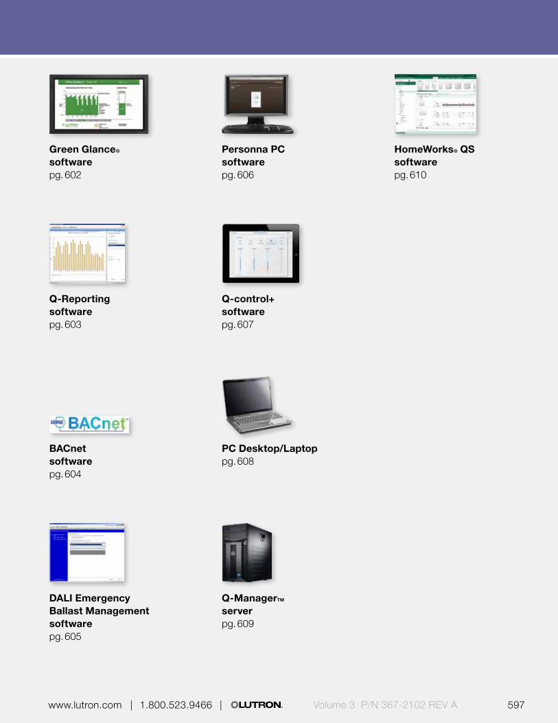
596 597 | 1.800.523.9466 | www.lutron.com www.lutron.com | 1.800.523.9466 | Volume 3 P/N 367-2102 REV A
Green Glance® softwarepg. 602
Q-Reporting softwarepg. 603
BACnet softwarepg. 604
DALI Emergency Ballast Management softwarepg. 605
Personna PC softwarepg. 606
Q-control+ softwarepg. 607
PC Desktop/Laptoppg. 608
Q-ManagerTM serverpg. 609
HomeWorks® QS softwarepg. 610
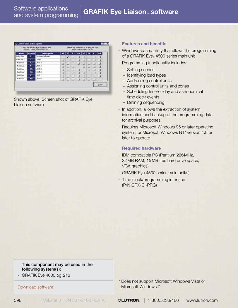
Download software
Software applications and system programming
598 599 | 1.800.523.9466 | www.lutron.com www.lutron.com | 1.800.523.9466 |Volume 3 P/N 367-2102 REV A
Features and benefits• Windows-based utility that allows the programming
of a GRAFIK Eye® 4500 series main unit• Programming functionality includes:
– Setting scenes– Identifying load types– Addressing control units– Assigning control units and zones– Scheduling time-of-day and astronomical
time clock events– Defining sequencing
• In addition, allows the extraction of system information and backup of the programming data for archival purposes
• Requires Microsoft Windows 95 or later operating system, or Microsoft Windows NT* version 4.0 or later to operate
Required hardware• IBM compatible PC (Pentium 266 MHz,
32 MB RAM, 15 MB free hard drive space, VGA graphics)
• GRAFIK Eye 4500 series main unit(s)• Time clock/programming interface
(P/N GRX-CI-PRG)
* Does not support Microsoft Windows Vista or Microsoft Windows 7
This component may be used in the following system(s):
• GRAFIK Eye 4000 pg. 213
Shown above: Screen shot of GRAFIK Eye Liaison software
GRAFIK Eye Liaison™ software
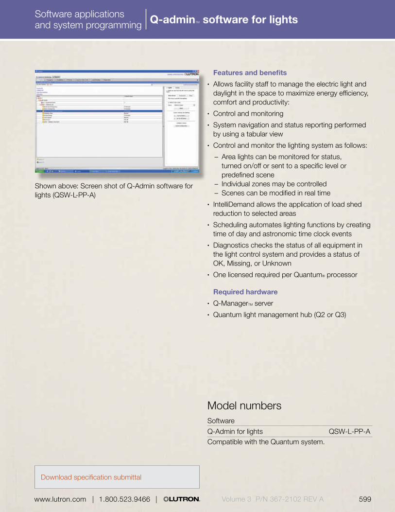
Download specification submittal
Software applications and system programming
598 599 | 1.800.523.9466 | www.lutron.com www.lutron.com | 1.800.523.9466 | Volume 3 P/N 367-2102 REV A
Features and benefits• Allows facility staff to manage the electric light and
daylight in the space to maximize energy efficiency, comfort and productivity:
• Control and monitoring• System navigation and status reporting performed
by using a tabular view• Control and monitor the lighting system as follows:
– Area lights can be monitored for status, turned on/off or sent to a specific level or predefined scene
– Individual zones may be controlled– Scenes can be modified in real time
• IntelliDemand allows the application of load shed reduction to selected areas
• Scheduling automates lighting functions by creating time of day and astronomic time clock events
• Diagnostics checks the status of all equipment in the light control system and provides a status of OK, Missing, or Unknown
• One licensed required per Quantum® processor
Required hardware• Q-ManagerTM server• Quantum light management hub (Q2 or Q3)
Shown above: Screen shot of Q-Admin software for lights (QSW-L-PP-A)
Software
Q-Admin for lights QSW-L-PP-ACompatible with the Quantum system.
Model numbers
Q-admin™ software for lights

Download specification submittal
Software applications and system programming
600 601 | 1.800.523.9466 | www.lutron.com www.lutron.com | 1.800.523.9466 |Volume 3 P/N 367-2102 REV A
Features and benefits• Allows facility staff to manage the motorized
window treatments in the space to maximize energy efficiency, comfort and productivity:
• Control and Monitoring
– System navigation and status reporting performed by using a tabular view
– Area shade groups can be opened/closed, sent to a preset or sent to a specific position
– Monitor groups for current preset or position status
• Hyperion® solar adaptive algorithm
– Calculates the sun’s position in the sky relative to the building and creates a unique shade adjustment schedule for each facade
– Automatically positions the shade to limit direct sunlight penetration, which can cause glare and heat gain
• Scheduling automates shade functions (for shades not operating as part of Hyperion) by creating time of day and astronomic time clock events
• Diagnostics checks the status of all equipment in the light control system and provides a status of OK, Missing, or Unknown
• One licensed required per Quantum processor
Required hardware• Q-Manager server• Quantum light management hub (Q2 or Q3)
Shown above: Screen shot of Q-Admin software for shades (QSW-L-PP-A)
Software
Q-Admin for shades QSW-S-PP-ACompatible with the Quantum system.
Model numbers
Q-admin™ software for shades

Software applications and system programming
600 601 | 1.800.523.9466 | www.lutron.com www.lutron.com | 1.800.523.9466 | Volume 3 P/N 367-2102 REV A
Custom floorplan software
Features and benefits• Simple, intuitive graphical user interface that
provides control of lighting and shades via the Q-AdminTM software
• Enhances the basic tabular view navigation and reporting offered in Q-Admin
• Utilizes reflected ceiling plans of the projects to provide a visual representation for real-time monitoring and control that is easily understood by any user
• Provides color-coded feedback of the current light and window treatment status in each area, in addition to supplying the current occupied and daylighting conditions
• Offers pan and zoom functionality• Q-Admin software for lights and/or shades required
Software
Custom floorplan CUST-FPS-ACompatible with the Quantum® system.
Model numbers
Download specification submittal
Shown above: Screen shot of custom floorplan software (CUST-FPS-A)
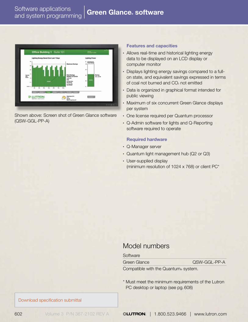
Download specification submittal
Software applications and system programming
602 603 | 1.800.523.9466 | www.lutron.com www.lutron.com | 1.800.523.9466 |Volume 3 P/N 367-2102 REV A
Software
Green Glance QSW-GGL-PP-ACompatible with the Quantum® system.
* Must meet the minimum requirements of the Lutron PC desktop or laptop (see pg. 608)
Model numbers
Features and capacities• Allows real-time and historical lighting energy
data to be displayed on an LCD display or computer monitor
• Displays lighting energy savings compared to a full-on state, and equivalent savings expressed in terms of coal not burned and CO2 not emitted
• Data is organized in graphical format intended for public viewing
• Maximum of six concurrent Green Glance displays per system
• One license required per Quantum processor• Q-Admin software for lights and Q-Reporting
software required to operate
Required hardware• Q-Manager server• Quantum light management hub (Q2 or Q3)• User-supplied display
(minimum resolution of 1024 x 768) or client PC*
Shown above: Screen shot of Green Glance software (QSW-GGL-PP-A)
Green Glance® software

Software applications and system programming
602 603 | 1.800.523.9466 | www.lutron.com www.lutron.com | 1.800.523.9466 | Volume 3 P/N 367-2102 REV A
Q-Reporting software
Features and benefits Creates the following detailed reports to
simplify operations:• Lighting power and energy usage
– Gathers historical information about the buildings usage
– Provides a comparison of cumulative energy used over period of time
– Shows power usage over a period of time• Lamp maintenance report supplies a list of all
failed fluorescent lamps connected to Ecosystem or DALI ballasts
• System activity reports are detailed reports of all events that occurred in the system, such as occupant activity, ballast replacement and time clock activity
• IntelliDemand monitors and displays real-time building power usage for the current day, assisting staff in the load shed reduction decision
• One license required per Quantum processor• Q-Admin software for lights required to operate
Required hardware• Q-Manager server• Quantum light management hub (Q2 or Q3)
Shown above: Screen shot of Q-Reporting software (QSW-RPT-PP-A)
Software
Q-Reporting QSW-RPT-PP-ACompatible with the Quantum system.
Model numbers
Download specification submittal

Download specification submittal
Software applications and system programming
604 605 | 1.800.523.9466 | www.lutron.com www.lutron.com | 1.800.523.9466 |Volume 3 P/N 367-2102 REV A
Features and benefits• Enables a third-party building management systems
to control, monitor and manage lights and shades within the Quantum system
• Share information, such as occupancy, power usage, and lighting level status with other control systems
• One license required per Quantum® processor
Required hardware• Quantum light management hub (Q2 or Q3)
Optional software• Q-Admin software for lighting —required for each
processor in the system if controlling lights• Q-Admin software for shades—required for each
processor in system if controlling motorized window treatments
• Q-Reporting—required for each processor if power data via BACnet is required
Shown above: Screen shot of BACnet software (QSW-BAC-PP-A)
BACnet software
Software
BACnet QSW-BAC-PP-ACompatible with the Quantum® system.
Model numbers

Software applications and system programming
604 605 | 1.800.523.9466 | www.lutron.com www.lutron.com | 1.800.523.9466 | Volume 3 P/N 367-2102 REV A
DALI emergency ballast management software
Features and benefits• Provides the ability to monitor, manage and test
DALI emergency devices that are connected to the Quantum® system
• Allows the user to schedule and perform functional and duration tests for all DALI emergency ballasts in system
– Functional—verifies proper communication with system, checks for lamp failures and confirms that the batter circuit is functional
– Duration—verifies that the batteries attached to the devices operate within their limits
• Permits user to group the ballasts into one of seven emergency groups and to define the day of the week that each group will be tested
• Allows the user to configure the amount of time the devices will stay at the emergency light level after an event has ended and normal power has been restored
• One license required per Quantum® processor• Q-AdminTM software for lights required to operate
Required hardware• Q-ManagerTM server• Quantum light management hub (Q2 or Q3)• DALI Emergency ballasts must be connected to
Quantum system via a Lutron® Energi Savr NodeTM with DALI main unit (see pg. 605)
Shown above: Screen shot of DALI Emergency Ballast Management software (QSW-DEM-PP-A)
Software
DALI Emergency Ballast Management QSW-DEM-PP-ACompatible with the Quantum system.
Model numbers
Download specification submittal

Download specification submittal
Software applications and system programming
606 607 | 1.800.523.9466 | www.lutron.com www.lutron.com | 1.800.523.9466 |Volume 3 P/N 367-2102 REV A
Personna® PC software
Features and benefits• Allows the occupants of the building personal
control of their lighting and window treatments from any device that can run a web browser, further enhancing comfort and productivity
• Supported web browsers include:
– Microsoft Internet Explorer (Version 7 or higher)– Mozilla Firefox (Version 3 or higher)– Apple Safari (Version 4 or higher)– Google Chrome (Version 8 or higher)
• Grants control of the lighting* (from individual fixture to entire area) and window treatments (individual shade to group of shades) by individual users
• User can save their favorite light level and shade position so that it’s easily recalled by clicking the Preset button
• One license required per seat; maximum of 10,000 users
• Requires connection to corporate network and Q-Manager server and access to email server
Required hardware• Q-Manager server• Quantum light management hub (Q2 or Q3)• Separate server (Microsoft Internet Information
Services) to host Personna PC website for 500 users or more
Shown above: Screen shot of Personna PC software (QSW-PPC-PS-A)
Software
Personna PC QSW-PPC-PS-ACompatible with the Quantum® system.
* Daylight harvesting, high-end tuning and IntelliDemand load shed will limit the maximum light levels and energy usage
Model numbers

Download specification submittal
Software applications and system programming
606 607 | 1.800.523.9466 | www.lutron.com www.lutron.com | 1.800.523.9466 | Volume 3 P/N 367-2102 REV A
Q-Control+ software
Features and benefits• Allows control and programming of the Quantum®
system via an Apple® iPad® mobile digital device on a local area network (LAN) or corporate intranet
• Provides mobile control and monitoring of area lighting and window treatments
• Offers editing functionality*:
– Adjust area scene lighting levels and shade presets
– Change area scene fade and delay times– Make zones unaffected in scenes
• Provides area access control to restrict access to specific areas
• Utilize as a hand-held device or a wall-mounted touchscreen
• Supports English, Spanish, French, German, Simplified Chinese and Brazilian Portuguese languages
• One license required per iPad mobile device• Requires Quantum version 2.6 or later, Lutron®
Q-Control+ app downloaded from the iTunes® Store and a standard wireless network to operate
Required hardware• Q-ManagerTM server or PC desktop/laptop• Quantum light management hub (Q2 or Q3)• iPad mobile digital device
Shown above: Screen shot of Q-Control+ iPad app
Software
Q-Control+ QSW-MC-PS-ACompatible with the Quantum® system.
* When utilizing GRAFIK Eye QS as load controller within system, reconfiguration of scenes is done from the GRAFIK Eye QS main unit not the mobile app; app cannot control contact closure output zones
Model numbers
iPad and iTunes are trademarks of Apple Inc., registered in the U.S. and other countries.

Download specification submittal
Software applications and system programming
608 609 | 1.800.523.9466 | www.lutron.com www.lutron.com | 1.800.523.9466 |Volume 3 P/N 367-2102 REV A
Software applications and system programming
PC
Desktop QS-A-CMP-D-0
Laptop QS-A-CMP-L-0
Compatible with the Quantum system.
* PC desktop or laptop may be supplied by customer (P/N QS-A-CMP-DBO-0 or QS-A-CMP-LBO-0, must meet all minimum requirements listed.
Model numbers*
Features and capacities• Desktop or laptop PC used to run the Quantum®
light management software application Q-AdminTM or the Green Glance® energy savings display software (one PC needed per Green Glance terminal)
• Dedicated for Lutron® Quantum software only• Intended for periodic use only; a server-based
machine is required for 24/7 operation
Minimum hardware configuration required• Single Intel CPU with minimum speed of 2.0 GHz• 512 MB RAM• 36 GB hard drive• One 10/100/1000 Ethernet network interface for
communication to Quantum® light management hub(s) or Q-Manager™ server
• 17 in. (43 cm) monitor/LCD screen of 1024 x 768 resolution
• 48X CD/DVD-ROM drive• 3 USB 2.0 port (desktop) or 1 USB 2.0 port (laptop)
Software required• Licensed installation of U.S. English Microsoft®
Windows® 7 Professional
This component may be used in the following system(s):
• Quantum® pg. 612
PC desktop
PC laptop
PC desktop/laptop

Software applications and system programming
608 609 | 1.800.523.9466 | www.lutron.com www.lutron.com | 1.800.523.9466 | Volume 3 P/N 367-2102 REV A
Software applications and system programming
Features and capacities• Dedicated server used to collect and record data
from the Quantum® system• Server is dedicated for Lutron® Quantum
software only• All Lutron rack mount servers come with rails for
a standard 4-post rack only• Two versions available: standard or high-reliability
Minimum hardware configuration required• Single Intel Xenon processor with minimum speed
of 2.0 GHz or Dual Core Intel processor with minimum speed of 1.86 GHz
• 2 GB RAM minimum• 80 GB hard drive (hot-swappable RAID 5 hard drive
—3 hard drives—included with high reliability only)• Two 10/100/1000 Ethernet ports*—one for
communication to Quantum panels and one for communication to corporate intranet
• 17 in. (43 cm) monitor with 1024 x 768 resolution and graphics card capable of same resolution
• 48X CD/DVD-ROM driver• 4 USB 2.0 ports• Dual hot-swappable power supplies
Software required• Licensed installation of U.S. English Microsoft
Windows Server 2008 Pack 1
* Server may be supplied by customer (P/N QS-A-CMP-SBO-0), must meet all minimum requirements listed
** Only one Ethernet port required if all Quantum panels and client PCs are on same network
Server (QS-A-CMP-S-0)
Q-Manager™—server
Standard Server
Tower server with keyboard, QS-A-CMP-S-0 mouse, monitor and UPS
Rack Mount server with UPS QS-A-CMP-S-K
Rack mount server with a rack QS-A-CMP-S-C mount console with a keyboard, mouse, slide-out monitor and UPSCompatible with the Quantum® system.
High Reliability Server
Tower server with keyboard, QS-A-CMP-R-0 mouse, monitor and UPS
Rack Mount server with UPS QS-A-CMP-R-K
Rack mount server with a rack QS-A-CMP-R-C mount console with a keyboard, mouse, slide-out monitor and UPSCompatible with the Quantum® system.
Model numbers*
Download specification submittal
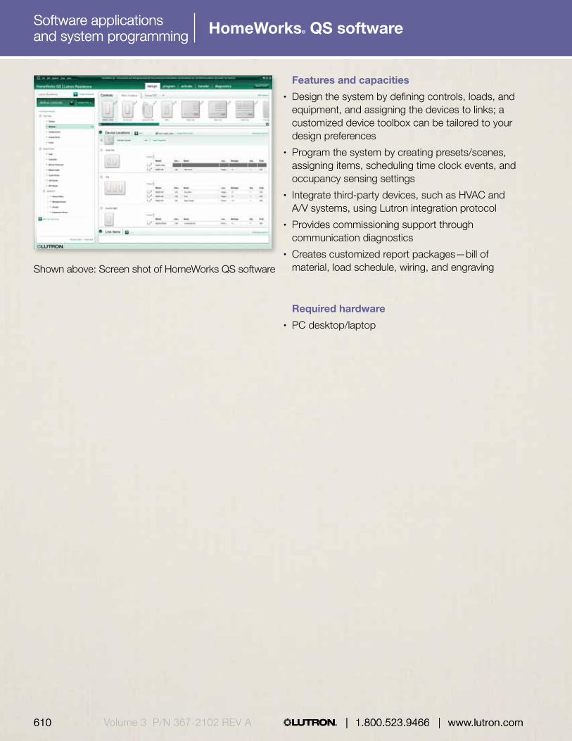
Software applications and system programming |
610 611 | 1.800.523.9466 | www.lutron.com www.lutron.com | 1.800.523.9466 |
Software applications and system programming
610 | 1.800.523.9466 | www.lutron.comVolume 3 P/N 367-2102 REV A
Software applications and system programming HomeWorks® QS software
Features and capacities• Design the system by defining controls, loads, and
equipment, and assigning the devices to links; a customized device toolbox can be tailored to your design preferences
• Program the system by creating presets/scenes, assigning items, scheduling time clock events, and occupancy sensing settings
• Integrate third-party devices, such as HVAC and A/V systems, using Lutron integration protocol
• Provides commissioning support through communication diagnostics
• Creates customized report packages—bill of material, load schedule, wiring, and engraving
Required hardware• PC desktop/laptop
Shown above: Screen shot of HomeWorks QS software

610 611 | 1.800.523.9466 | www.lutron.com www.lutron.com | 1.800.523.9466 | Volume 3 P/N 367-2102 REV A | 1.800.523.9466 | www.lutron.com

Quantum Select packages are simple, cost-effective options for adding select capabilities of larger, centralized lighting and energy management systems to smaller, more specialized applications
Ideal for standalone or panel-based projects that desire only select Quantum functionality, Quantum Select packaged solutions include a light management hub and the appropriate software licenses.
Available functionality
• Time clock• Building integration• Solar-adaptive shade control• Energy display and reporting• Central control of lights• Central control of shades
All Quantum Select packages come ready to add occupancy/vacancy sensing, daylight harvesting, high-end trim and personal control; additional components required.
Quantum® Select |
612 Volume 3 P/N 367-2102 | 1.800.523.9466 | www.lutron.com/specificationguide
Quantum® Select

Quantum® Select |
www.lutron.com/specificationguide | 1.800.523.9466 | Volume 3 P/N 367-2102 613

Central time clock package
Designed for projects that require a simple, cost-effective and scalable system, the Central Control package provides the ability to adjust and monitor your lighting control system easily from a computer. Package includes light management hub (QP3) and Q-Admin for lights software.
Features and benefits• Provide automatic control of a Lutron system
with an astronomic time clock• Manage and monitor electric light and daylight
for maximum energy efficiency, comfort and productivity
• Meet automatic shutoff requirements (for all major codes and standards)
Building systems integration package
Ideal for integrating a Lutron light control system with a third-party building management system, the Building System Integration package provides the necessary software licenses to manage your building from a single point of control. Package includes light management hub (QP3), Q-Admin for lights and BACnet software licenses.
Features and benefits• Provide automatic control of a Lutron system
with an astronomic time clock• Easily integrate with other building systems for a
single point of control• Native BACnet eliminates the need for additional
interfaces or gateways• Manage and monitor electric light and daylight
for maximum energy efficiency, comfort and productivity
• Share sensor information between systems to reduce material costs and energy bills
Quantum Select package
Central control QSL-BAS-PKGCompatible with the Quantum system.
Quantum Select package
Building system integration QSL-BMS-PKGCompatible with the Quantum system.
Model numbers Model numbers
Shades Lights
BACnet
HVAC
Download specification submittal Download specification submittal
Quantum® Select |
614 Volume 3 P/N 367-2102 | 1.800.523.9466 | www.lutron.com/specificationguide
Packages

Hyperion package
Designed for buildings that have direct exposure to daylight, the Hyperion package is ideal for applications that will utilize automatic shading systems to control the amount of daylight entering a space based on the position of the sun. Package includes light management hub (QP3) and Q-Admin for shades software license.
Features and benefits• Automatically adjust shades based on time of
day and position of the sun (solar-adaptive)• Provide centralized control and monitoring
capability for shades• Increase employee productivity and comfort by
reducing glare• Reduce HVAC costs by minimizing solar
heat gain• Save money by minimizing maintenance
requirements
Green Glance package
Intended for organizations focused on monitoring and promoting energy use to facilitate effective energy management, the Green Glance package features display software that provides real-time and historical data on lighting energy savings. Package includes light management hub (QP3) and Q-Admin for shades, Q-Reporting and Green Glance software licenses.
Features and benefits• Provide automatic control of a Lutron system
with an astronomic time clock• Use the GreenGlance display to help promote
your energy saving efforts to visitors and employees
• Evaluate energy usage and identify opportunities for increased efficiency
• Adjust and refine light control strategies based on system data
• Manage and monitor electric light and daylight for maximum energy efficiency, comfort and productivity
Quantum Select package
Hyperion QSL-HYP-PKGCompatible with the Quantum system.
Quantum Select package
GreenGlance QSL-GG-PKGCompatible with the Quantum system.
Model numbers Model numbers
Download specification submittal Download specification submittal
Quantum® Select |
www.lutron.com/specificationguide | 1.800.523.9466 | Volume 3 P/N 367-2102 615
Packages Packages
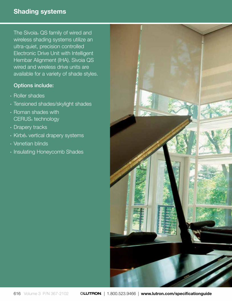
The Sivoia® QS family of wired and wireless shading systems utilize an ultra-quiet, precision controlled Electronic Drive Unit with Intelligent Hembar Alignment (IHA). Sivoia QS wired and wireless drive units are available for a variety of shade styles.
Options include:
• Roller shades• Tensioned shades/skylight shades• Roman shades with
CERUS® technology • Drapery tracks• Kirbé® vertical drapery systems• Venetian blinds• Insulating Honeycomb Shades
616 Volume 3 P/N 367-2102 | 1.800.523.9466 | www.lutron.com/specificationguide
Shading systems

www.lutron.com/specificationguide | 1.800.523.9466 | Volume 3 P/N 367-2102 617

Controllable roller shades
Roller shades are designed for ultra-quiet, precision control of daylight.
• Available models: roller 20TM, roller 64TM, roller 100TM, roller 150TM, roller 225TM, roller 200CW, and roller 300TM
• Provides maximum window coverage with the smallest possible light gaps, .75 in (19 mm) between the shade fabric and the window frame
• Light gaps are symmetrical on both sides of shade
• Uniform, precision movement of multiple shades
• Convenient one-touch control from elegant keypads and intuitive handheld remotes
• Wired and/or wireless controls• Manual shades also available• Ability to group multiple shades together on
a drive with angled and in-line couplers• Available with all Lutron roller shade fabrics.
Commercial options are also available
Tensioned shades
The tensioned shade combines Lutron® technology with a new patent-pending tension system. Fabric is kept taut and parallel to window or skylight regardless of slope.
• Available models: roller 100, 150, and 300
• Unique tension-absorbing frame eliminates stress on the surrounding ceiling structure
• Angle of installation between - 135° and + 135° for bottom up, angles, and skylight installations
• Meet-in-the-middle module uses two tension shades in one frame to cover openings up to 24 ft
• Inside, recessed, and outside surface mounting options
• Light blocking fascia eliminates gaps around fabric when closed
• Pre-assembled shipping available to make installation more convenient
• Available with all Lutron roller shade fabrics. Commercial options are also available
Shading systems |
618 619 | 1.800.523.9466 | www.lutron.com www.lutron.com | 1.800.523.9466 |Volume 3 P/N 367-2102 REV A
Styles

* Shown without cornice
For further information on Lutron shading systems please see Lutron Shading Solutions Product Guide P/N 367-1455, visit our website, www.lutron.com/shadingsolutions, or contact shades customer service at 1.800.446.1503.
Drapery systems and finished draperies *
Provide privacy with elegant draperies of any fabric and color.
• Available models: D105, D145, and D175• Available in pinch pleat and ripple
fold styles• Operates up to 175 lb (79.40 kg) draperies• Left, right, and center-draw drapery• Single or dual drapery tracks available• Straight and custom-curved tracks• Custom sized cornices are available in
multiple shapes and fabric options• Can be used with a Lutron finished
drapery or other standard draperies
Kirbé® vertical drapery system *
An entirely new type of window treatment that smoothly pulls the drapery up and out of the way, eliminating stackback.
• Available model: roller 100™
• Exclusive to Lutron®—an industry first• Custom sized cornices are available in
multiple shapes and fabric options• Offered in several sheer colors
and styles• Pair with a blackout roller shade for
room-darkening capability
Shading systems |
618 619 | 1.800.523.9466 | www.lutron.com www.lutron.com | 1.800.523.9466 | Volume 3 P/N 367-2102 REV A
Styles
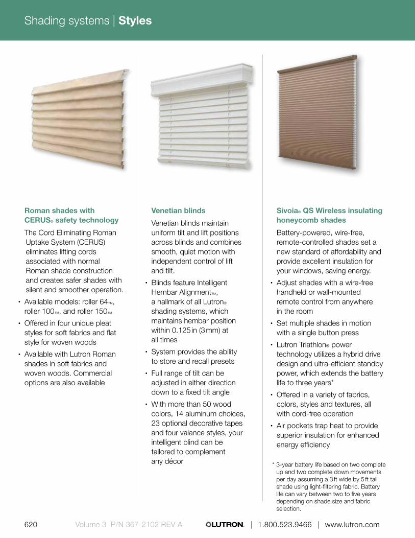
Venetian blinds
Venetian blinds maintain uniform tilt and lift positions across blinds and combines smooth, quiet motion with independent control of lift and tilt.
• Blinds feature Intelligent Hembar Alignment™, a hallmark of all Lutron® shading systems, which maintains hembar position within 0.125 in (3 mm) at all times
• System provides the ability to store and recall presets
• Full range of tilt can be adjusted in either direction down to a fixed tilt angle
• With more than 50 wood colors, 14 aluminum choices, 23 optional decorative tapes and four valance styles, your intelligent blind can be tailored to complement any décor
Sivoia® QS Wireless insulating honeycomb shades
Battery-powered, wire-free, remote-controlled shades set a new standard of affordability and provide excellent insulation for your windows, saving energy.
• Adjust shades with a wire-free handheld or wall-mounted remote control from anywhere in the room
• Set multiple shades in motion with a single button press
• Lutron Triathlon® power technology utilizes a hybrid drive design and ultra-efficient standby power, which extends the battery life to three years*
• Offered in a variety of fabrics, colors, styles and textures, all with cord-free operation
• Air pockets trap heat to provide superior insulation for enhanced energy efficiency
Roman shades with CERUS® safety technology
The Cord Eliminating Roman Uptake System (CERUS) eliminates lifting cords associated with normal Roman shade construction and creates safer shades with silent and smoother operation.
• Available models: roller 64™, roller 100™, and roller 150™
• Offered in four unique pleat styles for soft fabrics and flat style for woven woods
• Available with Lutron Roman shades in soft fabrics and woven woods. Commercial options are also available
* 3-year battery life based on two complete up and two complete down movements per day assuming a 3 ft wide by 5 ft tall shade using light-filtering fabric. Battery life can vary between two to five years depending on shade size and fabric selection.
Shading systems |
620 621 | 1.800.523.9466 | www.lutron.com www.lutron.com | 1.800.523.9466 |Volume 3 P/N 367-2102 REV A
Styles

Customer’s Own Material (COM) is an option when designing roller shades, Romans shades with CERUS technology, finished drapery panels and cornices. Please contact shades customer service for more information at 1.800.446.1503.
Product type Fabric collection Fabric options Additional options
Roller shades
Classico™ collection
Sheer Bottom bar style No
Dim-out Bottom bar style No
Blackout Bottom bar styleSill angle
Side channel
Gallery™ collection SheerBottom bar style (ABB style required)
No
COM (see below) Dim-outBottom bar style (ABB style required)
No
Tensioned shades Classico collection
Sheer Frame color No
Dim-out Frame color No
Blackout Frame color No
Drapery trackAvant™ collection
Soft fabricsPinch pleats Liner options
COM (see below) Ripplefold Liner options
Kirbé® verticaldrapery system
Avant collectionSheer fabrics and privacy
Optional roller 64™ blackout shade
Cornice styles
Roman shades with CERUS® safety technology
Avant collectionSoft fabrics
Hobbled style Liner options
Knife style Liner options
Flat style Liner options
Casual style Liner options
COM (see below)Woven woods Flat style
Liner options
Edge binding
Cornice Avant collection Soft fabrics Shape No
Venetian blinds Venetian collectionWood slats Valance style
(optional)
Decorative tape
Aluminum slats No
Insulating honeycomb shades
Insulating honeycomb collection
Light filtering
Headrail materials variability
NoRoom darkening
Sheer
Shading systems |
620 621 | 1.800.523.9466 | www.lutron.com www.lutron.com | 1.800.523.9466 | Volume 3 P/N 367-2102 REV A
Fabrics

Choosing the right fabric is critical to a successful shading project. Select from sheer, dim-out, or blackout fabrics to find a solution that’s right for your project.
The Classico™ Collection
For larger roller shade applications, durable and long-lasting fabrics are a necessity. The Classico Collection by Lutron® includes wide roll widths, fire-rated materials, and an array of sustainable options.
The Gallery Collection
The Gallery Collection by Lutron offers a variety of colors, textures, and patterns to accent any residential décor. Add beauty to traditional roller shades with interesting patterns, intricate weaves, sophisticated suedes, or colorful linens.
The Avant™ Collection
Featuring woven woods, sheers, and soft fabrics, the Avant Collection offers over 100 contemporary and traditional materials for Kirbé® vertical drapery systems, cornices, finished drapery systems, and Roman shades with CERUS® safety technology.
Insulating Honeycomb Fabric Collection
Insulating honeycomb shades come in a variety of colors and textures to complement any style. Available in single-cell and double-cell options and with light-filtering, room darkening, and sheer fabrics.
Lutron Venetian Blinds
Options include an extensive line of genuine hardwoods, available in designer paints or rich wood stains, painted or brushes aluminum choices, decorative tapes, and four valance styles. All slats come with finished ends for the finest quality.
Sustainability
Often fabrics are manufactured with chemicals to make them durable. Lutron sustainable fabrics reduce or remove many of these chemicals in order to improve indoor air quality. Others are made from recycled content in order to protect the environment. GreenScreen® Revive fabric is comprised of 89% REPREVE® polyester (pre- and post-consumer waste) recycled content, which is sourced primarily from plastic water bottles. Visit www.lutron.com/greenscreen to find out more about Lutron’s green fabric offering.
Shading systems |
622 623 | 1.800.523.9466 | www.lutron.com www.lutron.com | 1.800.523.9466 |Volume 3 P/N 367-2102 REV A
Fabrics

QS link individual power supply
Features• Works with Sivoia® QS wired and wireless shades• 24 V DC supply that provides power to shades,
drapery drive units, keypads, and accessories• Simple wiring scheme uses 4-conductor,
low-voltage link to provide power and communication for QS electronic drive units (EDUs), seeTouch® QS keypads and QS integration interfaces
• Mounting tabs and small size allow for discrete installation
• Universal input voltage (100-240 V AC) enables global specification
Sivoia QS Wireless 120 V power supply panel (10 output)
Features• Works with Sivoia QS Wireless shades• 24 V DC supply that provides power to shades
and drapery drive units• 10 output panel provides power for 10-30 shades
based on shade dimensions• Up to two power panels on a 120 V x 20 A feed.
Also available in other voltages
0.31 in (8 mm) profile
2.75 in (70 mm
)
4.00 in (102 mm)
3.90 in (99 mm) profile
9.50 in (241 mm)17.50 in (444 m
m)
Power supplies
QS link power supply
Sivoia QS wireless 120 V power supply panel with lid removed
Shading systems |
622 623 | 1.800.523.9466 | www.lutron.com www.lutron.com | 1.800.523.9466 | Volume 3 P/N 367-2102 REV A
Power options

Sivoia® QS wired power supply panel (10 output)
Features• Works with Sivoia QS wired shades• 24 V DC supply that provides power to shades,
drapery drive units, keypads, and accessories• Simple wiring scheme uses 4-conductor low-voltage
link to provide power and communication for both QS electronic drive units (EDUs) and seeTouch® QS keypads
• Flexible wiring topology for easy installation and integration
• 10 output panel provides power for 10 to 30 shades based on shade dimensions
• Smart diagnostics reduce installation time and system verification
• Confirms system communication and facilitates system installation
• Provides easy system testing with manual override buttons for shades
• Up to two power panels on a 120 V x 20 A feed. Also available in other voltages
3.90 in (99 mm) profile
9.50 in (241 mm)
17.50 in (444 mm
)
Sivoia QS wired power supply panel with cover removed
Shading systems |
624 625 | 1.800.523.9466 | www.lutron.com www.lutron.com | 1.800.523.9466 |Volume 3 P/N 367-2102 REV A
QS J-box Power Supply
Features• Works with Sivoia QS wired and wireless shades• 24 V supply that provides power to shades,
keypads (wired only), and accessories (wired only)• Simple wiring scheme uses 4-conductor,
low-voltage link to provide power and communication for both QS electronic drive units (EDUs) and seeTouch QS keypads
• Flexible wiring topology for easy installation and integration
• Form factor allows the power supply to be hidden in utility spaces
• The J-box power supply is mounted on a four inch square junction box
• The power supply os protected electronically in the event of a miswire, and will automatically reset when wiring is correct
0.31 in (8 mm) profile
4.10 in (104 mm
)
4.31 in (109 mm)
Power supplies
QS J-box Power Supply
Power options
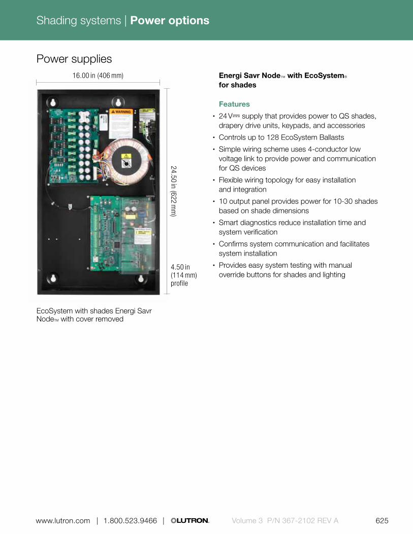
Shading systems |
624 625 | 1.800.523.9466 | www.lutron.com www.lutron.com | 1.800.523.9466 | Volume 3 P/N 367-2102 REV A
Energi Savr Node™ with EcoSystem® for shades
Features• 24 V- supply that provides power to QS shades,
drapery drive units, keypads, and accessories• Controls up to 128 EcoSystem Ballasts• Simple wiring scheme uses 4-conductor low
voltage link to provide power and communication for QS devices
• Flexible wiring topology for easy installation and integration
• 10 output panel provides power for 10-30 shades based on shade dimensions
• Smart diagnostics reduce installation time and system verification
• Confirms system communication and facilitates system installation
• Provides easy system testing with manual override buttons for shades and lighting
4.50 in (114 mm) profile
16.00 in (406 mm)
24.50 in (622 mm
)
EcoSystem with shades Energi Savr NodeTM with cover removed
Power supplies
Power options

Insulating Honeycomb Shade plug-in supply
Features• Electronic over current and over
temperature protection• Class 2 12 V DC power supply for Insulating
Honeycomb Shades• Simple installation—supply output plug
can be connected directly to a Insulating Honeycomb Shade
• Unobtrusive—same form factor as a typical cell phone charger
• Energy efficient—International Efficiency Level V
1.30 in (33 mm) profile
1.50 in (39 mm)
3.40 in (86 mm
)
Insulating Honeycomb Shade plug-in supply
Shading systems |
626 627 | 1.800.523.9466 | www.lutron.com www.lutron.com | 1.800.523.9466 |Volume 3 P/N 367-2102 REV A
Insulating Honeycomb Shade power panel power supply
Features• Universal input voltage 120-240 V~ 50/60 Hz• Electronic over current and over
temperature protection• Class 2 12 V DC supply that can power up to
10 Insulating Honeycomb Shades• Simple wiring scheme uses 2-conductor low
voltage link to provide power• Energy efficient—International Efficiency Level V,
Energy Star 2.0 & CeC compliant3.16 in (80 mm) profile
13.25 in (337 mm
)9.25 in (234,95 mm)
Power supplies
Insulating Honeycomb Shade panel power supply
Power options

For further information on Lutron shading systems please see Lutron Shading Solutions Product Guide P/N: 367-1455, visit our website, www.lutron.com/shadingsolutions, or contact shades customer service at 1.800.446.1503
seeTouch® QS keypads
Sivoia® QS wireless keypads
GRAFIK Eye® QS main units
Sivoia QS wireless tabletop keypads
Pico® wireless controls
IR remote controls
Wired controls
Wireless controls
Compatible controls via other Lutron systems
Shading systems |
626 627 | 1.800.523.9466 | www.lutron.com www.lutron.com | 1.800.523.9466 | Volume 3 P/N 367-2102 REV A
Control options

Mobile devices
If you have a residential Lutron system, you can control your shades from your mobile device with a Lutron® app—as well as lights, temperature, and small appliances—even when you’re away from home.
Time clocks (Time of day control)
A time clock works in conjunction with a home or commercial building control system to automatically raise or lower your shades based on programmed times. For example, shades can be set to lower automatically every day at noon to block harsh sunlight and protect interiors and furnishings.
Third-party integration
Shade control (as well as lights) can be integrated with other manufacturer’s systems, such as security, for another level of control. If the security system is triggered, shades can open and interior and/or exterior lights can flash.
Shading systems |
628 629 | 1.800.523.9466 | www.lutron.com www.lutron.com | 1.800.523.9466 |Volume 3 P/N 367-2102 REV A
Control options

Shading systems |
628 629 | 1.800.523.9466 | www.lutron.com www.lutron.com | 1.800.523.9466 | Volume 3 P/N 367-2102 REV A

Architectural wallplates and accessories pg. 632
Designer Claro®/ Satin Colors® wallplates and accessories pg. 640
International square wallplate for Pico® pg. 653
Wallplates come in a variety of colors, opening styles and grouping configurations. Combine these with accessories such as receptacles, cables, enclosures and other devices to finalize your project.
Wallplates and accessories include:
• Single and multi-gang wallplates
• Custom control options
• Engraving options
• Cable and wiring
International accessories pg. 647
630 Volume 3 P/N 367-2102 | 1.800.523.9466 | www.lutron.com/specificationguide
Wallplates and accessories

Mounting pg. 664
Ganging and derating pg. 665
Custom control options pg. 669
Cable/wiring pg. 661
Lockable cover pg. 658
Mounting rack for QS control interfaces pg. 660
Enclosure for QS control interfaces pg. 659
Electronic low-voltage transformer pg. 656
Lamp socket wiring tester pg. 657
Engraving pg. 667
www.lutron.com/specificationguide | 1.800.523.9466 | Volume 3 P/N 367-2102 631
QS link power supplies pg. 655

4.56 in (116 mm)
4.56 in (116 mm
)
Product family features• Product comes with crisp beveled edge• Architectural wallplates can be used with
insert style seeTouch® QS keypads, QS keyswitches and accessories
• All Lutron wallplates are screwless, seamless, and have no visible hardware; the front plate securely snaps into the alignment adapter plate
0.30 in (8 mm)
Shown actual size: 2-gang Architectural matte wallplate in White (VWP-2R-WH)
• Customize your Architectural wallplate with engraving or by adding a corporate logo, contact customer service to get started at 1.888.LUTRON1
• Matte finish wallplates can be custom colored to perfectly match a paint color number, swatch, or sample
Download high resolution product imageDownload engraving sheet for faceplates
Wallplates and accessories |
632 Volume 3 P/N 367-2102 | 1.800.523.9466 | www.lutron.com/specificationguide
Architectural

Color options
WHWhite
IVIvory
LALight Almond
TPTaupe
ALAlmond
GRGray
BEBeige
SISienna
BRBrown
BLBlack
BNBright Nickel
AUGold Plated
BCBright Chrome
BBBright Brass
CLAClear Anodized Aluminum
BRABrass Anodized Aluminum
SCSatin Chrome
SBSatin Brass
SNSatin Nickel
QBAntique Brass
QZAntique Bronze
BLABlack Anodized Aluminum
Architectural matte finishes
Architectural metal finishes*
Use BOLD color code in model number (Example: VWP-R-SI)
* Metal finish wallplates include black plastic trim/adapter, visible from side. Match with separate Black (BL) or Midnight (MN) controls.
Wallplates and accessories |
www.lutron.com/specificationguide | 1.800.523.9466 | Volume 3 P/N 367-2102 633
Architectural
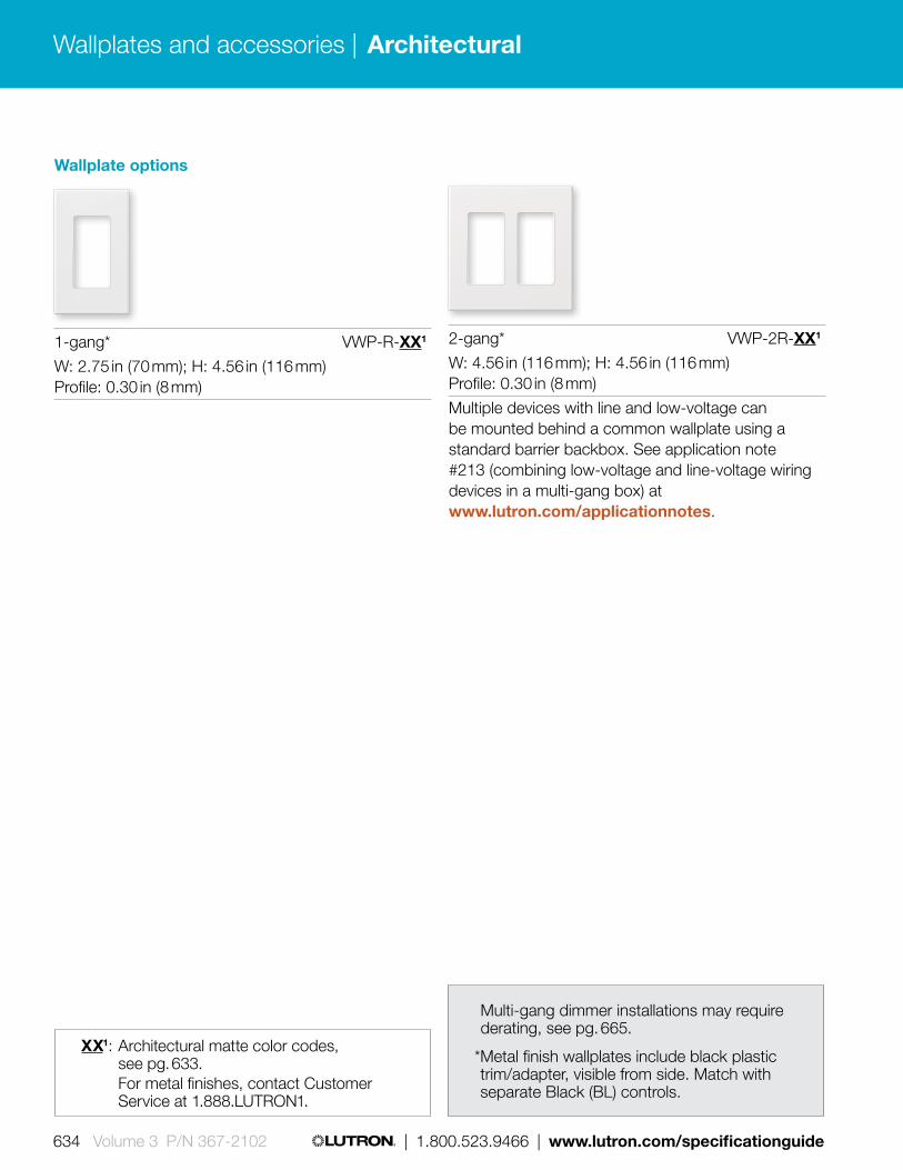
Wallplate options
1-gang* VWP-R-XX1
W: 2.75 in (70 mm); H: 4.56 in (116 mm) Profile: 0.30 in (8 mm)
2-gang* VWP-2R-XX1
W: 4.56 in (116 mm); H: 4.56 in (116 mm) Profile: 0.30 in (8 mm)
Multiple devices with line and low-voltage can be mounted behind a common wallplate using a standard barrier backbox. See application note #213 (combining low-voltage and line-voltage wiring devices in a multi-gang box) at www.lutron.com/applicationnotes.
XX1: Architectural matte color codes, see pg. 633.
For metal finishes, contact Customer Service at 1.888.LUTRON1.
Multi-gang dimmer installations may require derating, see pg. 665.
* Metal finish wallplates include black plastic trim/adapter, visible from side. Match with separate Black (BL) controls.
Wallplates and accessories |
634 Volume 3 P/N 367-2102 | 1.800.523.9466 | www.lutron.com/specificationguide
Architectural

Custom Architectural wallplates
Custom coloring available for all Architectural matte finish wallplates. Contact Customer Service at 1.888.LUTRON1.
Custom configurations, colors, engraving and silkscreenings available. Contact customer service 1.888.LUTRON1.
Custom multi-gang wallplates required for the following cases:
• Multi-gang metal finishes• Full-capacity ganging ("No Fins Broken")• Large Nova Tb controls (1500/2000 W)• Nova controls
For further information, go to www.lutron.com/customganging
Custom engraving available for all Traditional, Designer, Architectural and New Architectural style wallplates (except Stainless Steel). For wallplate engraving schedules, go to www.lutron.com/engraving
Mauve
02564-5
Majestic Purple 02564-4
Lily Glow
02564-3
Wallplates and accessories |
www.lutron.com/specificationguide | 1.800.523.9466 | Volume 3 P/N 367-2102 635
Architectural

Single cable jack* NT-CJ-XX1
Single telephone jack* NT-PJ-XX1
Multiple devices with line and low-voltage can be mounted behind a common wallplate using a standard barrier backbox, see Application Note #213 (Combining Low-Voltage and Line- Voltage Wiring Devices in a Multi-Gang Box) at www.lutron.com/applicationnotes.
Cable jack• F-style, 75-Ohm
coaxial cable• Includes 1-gang wallplate
Telephone jack• 6-conductor jack, RJ11• Includes 1-gang wallplate
XX1: Architectural matte color codes, see pg. 633 (1-gang wallplate included)
* Metal finishes are only available as separate wallplates. Match with separate Black (BL) controls and accessories.
Wallplates and accessories |
636 Volume 3 P/N 367-2102 | 1.800.523.9466 | www.lutron.com/specificationguide
Architectural

GFCI/GFTR receptacles• Press test button to confirm
LED indicator status• Press reset button to reset
GFCI after circuit interruption• Includes 1-gang wallplate• Tamper resistant shutter
mechanism (shutters are white)
Isolated ground receptacles*
15 A 125 V NTR-15-IG-OR-XX1
20 A 125 V NTR-20-IG-OR-XX1
Tamper resistant GFCI receptacles*
15 A 125 V GFCI NTR-15-GFTR-XX1
20 A 125 V GFCI NTR-20-GFTR-XX1
Receptacles• Includes 1-gang wallplate• Tamper resistant receptacles
include tamper resistant shutter mechanism (shutters are white)
Isolated ground receptacles• Receptacle is orange
for easy ID and circuit delineation• Model number color code is for
wallplate only• Includes 1-gang wallplate
XX1: Architectural matte color codes, see pg. 633 (1-gang wallplate included)
* Metal finishes are only available as separate wallplates. Match with separate Black (BL) controls and accessories.
Tamper resistant receptacles*
15 A 125 V NTR-15-TR-XX1
20 A 125 V NTR-20-TR-XX1
Receptacles
15 A 125 V NTR-15-XX1
20 A 125 V NTR-20-XX1
Wallplates and accessories |
www.lutron.com/specificationguide | 1.800.523.9466 | Volume 3 P/N 367-2102 637
Architectural

XX1: Architectural matte color codes, see pg. 633 (1-gang wallplate included)
Receptacles for dual dimming use• Duplex for dimming
both connected loads• Projecting nubs prevent standard
plugs from being used• Requires replacement plugs for
dimming use, see next page• Includes 1-gang wallplate• Tamper resistant
shutter mechanism (shutters are white)
Half dimming, tamper resistant
15 A 120/125 V* NTR-15-HDTR-XX1
20 A 120/125 V* NTR-20-HDTR-XX1
Dual dimming, tamper resistant
15 A 120/125 V* NTR-15-DDTR-XX1
20 A 120/125 V* NTR-20-DDTR-XX1
Receptacles for half dimming use• Top half for dimming• Projecting nub prevents standard
plug from being used• Requires replacement plugs for
dimming use• Bottom half is a general use
receptacle and will fit standard duplex plugs
• Includes 1-gang wallplate• Tamper resistant
shutter mechanism (shutters are white)
Important application notes:• Receptacles and plugs for dimming use are UL
listed for use with Lutron controls included in this catalog
• If there is only one electrical feed to the receptacle, then the duplex DDTR must be used
• If the hot and dimmed hot feeds to the split duplex HDTR are supplied from different circuits or split-wired, with separate switch-legs, a means to simultaneously disconnect these circuits must be provided at the panel board where they originate (NEC 210.7(C) 2002 Edition). A 2-pole circuit breaker or two single-pole circuit breakers with an approved handle tie can be used to accomplish this simultaneous disconnect. Feed-through dimming panels, which are those without breakers, are recommended when using the HDTR.
• For detailed information, see Application Notes #91 (Guide to Dimming Table Lamps) and #109 (Guide to Dimming Portable Lamps via Receptacles) at www.lutron.com/applicationnotes.
120/125 V RP-FDU-10-WH White
120/125 V RP-FDU-10-BR BrownUL/CSA/NOM regulatory approvals
Replacement plugs for dimming (use with receptacles for dimming use)
• This plug required for use with Lutron receptacles for dimming use—plug will work in standard receptacle
• Easily replaces the existing plugs on lamps
* Metal finishes are only available as separate wallplates. Match with separate Black (BL) controls and accessories.
Wallplates and accessories |
638 Volume 3 P/N 367-2102 | 1.800.523.9466 | www.lutron.com/specificationguide
Architectural

6-port frame* NT-6PF-XX1 Male jack, stageboard NT-DMXJ-IN-WH Female jack, fixture equipment NT-DMXJ-OUT-WH
Field customizable 6-port frame• Shipped with six blanks in
matching colors• Connectors sold separately• Connectors snap in
(no tools required)• Includes 1-gang wallplate
Theatrical receptacles• Provide standard pinout for
DMX512 theatrical protocol• Five-pin XLR-style jack• Includes 1-gang wallplate
Connectors for 6-port frame
Telephone/network jacks
8-conductor, CON-1P-C3-XX2 RJ45 category 3
8-conductor, CON-1P-C5E-XX2 RJ45 category 5e
8-conductor, CON-1P-C6-XX2 RJ45 category 6
Fiber jacks
MT-RJ feed through CON-1F-MTRJ-WH
SC simplex CON-1F-SC-WH
LC non-flush mount CON-1F-LC-WH
ST style CON-1F-ST-WH
Cable jack
F-style, CON-1C-XX2 75-Ohm coaxial cable
BNC jack
BNC connector, 50-Ohm CON-1B-WH
Connectors only for use with 6-port frame.
Multiple devices with line and low-voltage can be mounted behind a common wallplate using a standard barrier backbox, see Application Note #213 (Combining Low-Voltage and Line Voltage Wiring Devices in a Multi-Gang Box) at www.lutron.com/applicationnotes.
XX1: Architectural matte color codes, see pg. 633 XX2: Only available in White (WH) and Black (BL)
* Metal finishes are only available as separate wallplates. Match with separate Black (BL) controls and accessories.
Wallplates and accessories |
www.lutron.com/specificationguide | 1.800.523.9466 | Volume 3 P/N 367-2102 639
Architectural
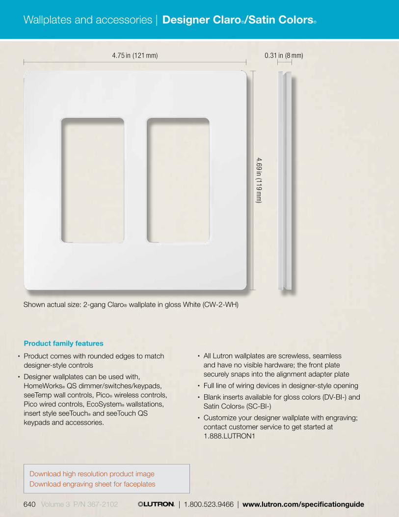
4.75 in (121 mm)
4.69 in (119 mm
)
Product family features
• Product comes with rounded edges to match designer-style controls
• Designer wallplates can be used with, HomeWorks® QS dimmer/switches/keypads, seeTemp wall controls, Pico® wireless controls, Pico wired controls, EcoSystem® wallstations, insert style seeTouch® and seeTouch QS keypads and accessories.
0.31 in (8 mm)
Shown actual size: 2-gang Claro® wallplate in gloss White (CW-2-WH)
• All Lutron wallplates are screwless, seamless and have no visible hardware; the front plate securely snaps into the alignment adapter plate
• Full line of wiring devices in designer-style opening• Blank inserts available for gloss colors (DV-BI-) and
Satin Colors® (SC-BI-)• Customize your designer wallplate with engraving;
contact customer service to get started at 1.888.LUTRON1
Download high resolution product imageDownload engraving sheet for faceplates
Wallplates and accessories |
640 Volume 3 P/N 367-2102 | 1.800.523.9466 | www.lutron.com/specificationguide
Designer Claro®/Satin Colors®

Color options
WHWhite
LALight Almond
ALAlmond
IVIvory
GRGray
BRBrown
BLBlack
SWSnow
LSLimestone
BIBiscuit
ESEggshell
PDPalladium
TPTaupe
STStone
BGBluestone
PLPlum
SGSea Glass
TQTurquoise
GSGoldstone
DSDesert Stone
GBGreenbriar
MSMocha Stone
TCTerracotta
SISienna
HTHot
MRMerlot
MNMidnight
SSStainless Steel
Gloss finishes
Satin finishes
Use BOLD color code in model number (Example: SC-1-PL)
* Stainless Steel finish only available as separate wallplate. Match with separate Black (BL) or Midnight (MN) controls and accessories.
Wallplates and accessories |
www.lutron.com/specificationguide | 1.800.523.9466 | Volume 3 P/N 367-2102 641
Designer Claro®/Satin Colors®

Designer wallplates
1-gang* CW-1-XX1 SC-1-XX2
W: 2.94 in (75 mm); H: 4.69 in (119 mm) Profile: 0.31 in (8 mm)
2-gang* CW-2-XX1 SC-2-XX2
W: 4.75 in (121 mm); H: 4.69 in (119 mm) Profile: 0.31 in (8 mm)
5-gang* CW-5-XX1 SC-5-XX2
W: 10.18 in (259 mm); H: 4.69 in (119 mm) Profile: 0.31 in (8 mm)Multiple devices with line and low-voltage can be mounted behind a common wallplate using a standard barrier backbox, see Application Note #213 (Combining Low-Voltage and Line- Voltage Wiring Devices in a Multi-Gang Box) at www.lutron.com/applicationnotes.
3-gang* CW-3-XX1 SC-3-XX2
W: 6.56 in (167 mm); H: 4.69 in (119 mm) Profile: 0.31 in (8 mm)
4-gang* CW-4-XX1 SC-4-XX2
W: 8.37 in (213 mm); H: 4.69 in (119 mm) Profile: 0.31 in (8 mm)
XX1: Gloss and Stainless Steel color codes, see pg. 641.
XX2: Satin color codes, see pg. 641.
Multi-gang dimmer installations may require derating, see pg. 665.
* Stainless Steel finish wallplates include black plastic trim/adapter, visible from side. Match with separate Black (BL) or Midnight (MN) controls and accessories.
Wallplates and accessories |
642 Volume 3 P/N 367-2102 | 1.800.523.9466 | www.lutron.com/specificationguide
Designer Claro®/Satin Colors®

Designer wallplates
Single cable jack* CA-CJ-XX3 SC-CJ-XX2
Tamper resistant receptacles*
15 A 125 V CARS-15-TR-XX3 15 A 125 V SCRS-15-TR-XX2
20 A 125 V SCRS-20-TR-XX2
Receptacles*
15 A 125 V CAR-15 -XX3 15 A 125 V SCR-15-XX2
20 A 125 V SCR-20-XX2
Tamper resistant GFCI receptacles*
15 A 125 V GFCI CAR-15-GFTR-XX3 15 A 125 V SCR-15-GFTR-XX2
20 A 125 V GFCI SCR-20-GFTR-XX2
Cable jacks• F-style, 75-Ohm coaxial cable• Wallplate sold separately
GFCI Receptacles• Press test button to confirm LED
indicator status• Press reset button to reset GFCI
after circuit interruption• Wallplate sold separately• Tamper resistant shutter
mechanism (shutters are white)
Single telephone jack* CA-PJ-XX3 SC-PJ-XX2
Telephone jacks• 6-conductor telephone jack, RJ11• Wallplate sold separately
Receptacles• Wallplate sold separately
indicator status• Tamper resistant receptacles
include tamper resistant shutter mechanism (shutters are white)
6-gang* CW-6-XX1 SC-6-XX2
W: 12.00 in (305 mm); H: 4.69 in (119 mm) Profile: 0.31 in (8 mm)
XX1: Gloss and Stainless Steel color codes, see pg. 641.
XX2: Satin color codes, see pg. 641. XX3: Gloss color codes, see pg. 641.
* Stainless Steel finish only available as separate wallplate. Match with separate Black (BL) or Midnight (MN) controls and accessories.
Wallplates and accessories |
www.lutron.com/specificationguide | 1.800.523.9466 | Volume 3 P/N 367-2102 643
Designer Claro®/Satin Colors®

XX1: Gloss color code and Stainless Steel, see pg. 641.
XX2: Satin color codes, see pg. 641.
Dual dimming, tamper resistant
15 A 120/125 V* CAR-15-DDTR-XX1
SCR-15-DDTR-XX2
20 A 120/125 V* CAR-20-DDTR-XX1
SCR-20-DDTR-XX2
Half dimming, tamper resistant
15 A 120/125 V* CAR-15-HDTR-XX1
SCR-15-HDTR-XX2
20 A 120/125 V* CAR-20-HDTR-XX1
SCR-20-HDTR-XX2
Receptacles for dual dimming use• Duplex for dimming
both connected loads• Projecting nubs prevent standard
plugs from being used• Requires replacement plugs for
dimming use, see next page• Tamper resistant
shutter mechanism• Wallplate sold separately
Receptacles for half dimming use• Top half for dimming• Projecting nub prevents
standard plug from being used• Requires replacement plugs for
dimming use, see next page• Bottom half is a general use
receptacle and will fit standard duplex plugs
• Tamper resistant shutter mechanism
• Wallplate sold separately
* Stainless Steel finish only available as separate wallplate. Match with separate Black (BL) or Midnight (MN) controls and accessories.
Wallplates and accessories |
644 Volume 3 P/N 367-2102 | 1.800.523.9466 | www.lutron.com/specificationguide
Designer Claro®/Satin Colors®

Important notes• Receptacles and plugs for dimming use are
UL listed for use with Lutron controls included in this catalog.
• If there is only one electrical feed to the receptacle, then the duplex DDTR must be used.
• If the hot and dimmed hot feeds to the split duplex HDTR are supplied from different circuits or split-wired with separate switch-legs, a means to simultaneously disconnect these circuits must be provided at the panel board where they originate (NEC 210.7(C) 2002 Edition). A 2-pole circuit breaker or two single-pole circuit breakers with an approved handle tie can be used to accomplish this simultaneous disconnect. Feed-through dimming panels, which are those without breakers, are recommended when using the HDTR.
• For detailed information, see Application Notes #91 (Guide to Dimming Table Lamps) and #109 (Guide to Dimming Portable Lamps via Receptacles) at www.lutron.com/applicationnotes.
120/125 V RP-FDU-10-WH White
120/125 V RP-FDU-10-BR BrownUL/CSA/NOM regulatory approvals.
Replacement plug for dimming (use with receptacles for dimming use)
• This plug required for use with Lutron® receptacles for dimming use—plug will work in standard receptacle
• Easily replaces the existing plugs on lamps
Wallplates and accessories |
www.lutron.com/specificationguide | 1.800.523.9466 | Volume 3 P/N 367-2102 645
Designer Claro®/Satin Colors®

6-port frame* CA-6PF-XX1
SC-6PF-XX2
Field customizable 6-port frame• Shipped with six blanks in
matching colors• Connectors and wallplate
sold separately• Connectors snap in
(no tools required)
General purpose switches (120/277 V)
Single-pole 15 A* CA-1PS-XX1 SC-1PS-XX2
3-way 15 A* CA-3PS-XX1 SC-3PS-XX2
4-way 15 A* CA-4PS-XX1 SC-4PS-XX2
General purpose switch with locator light (120 V only)
Single-pole 15 A* CA-1PSNL-XX4 SC-1PSNL-XX5
3-way 15 A* CA-3PSNL-XX4 SC-3PSNL-XX5
4-way 15 A* CA-4PSNL-XX4 SC-4PSNL-XX5
Switches• Paddle turns on/off• Use with any 15 A load• General purpose switching of
all sources and motor loads• No derating if ganged• Wallplate available separately,
see pg. 642-643.
XX1: Gloss color codes, see pg. 641. XX2: Satin color codes, see pg. 641. XX3: Only available in White (WH) and Black (BL) XX4: Only available in Almond (AL), Ivory (IV),
Light Almond (LA), and White (WH) XX5: Only available in Biscuit (BI), Eggshell (ES),
Goldstone (GS), Limestone (LS), Sea Glass (SG), and Snow (SW)
Connectors for 6-port frame
Telephone/network jacks
8-conductor, CON-1P-C3-XX3 RJ45 category 3
8-conductor, CON-1P-C5E-XX3 RJ45 category 5e
8-conductor, CON-1P-C6-XX3 RJ45 category 6
Fiber jacks
MT-RJ feed through CON-1F-MTRJ-WH
SC simplex CON-1F-SC-WH
LC non-flush mount CON-1F-LC-WH
ST style CON-1F-ST-WH
Cable jack
F-style, CON-1C-XX3 75-Ohm coaxial cable
BNC jack
BNC connector, 50-Ohm CON-1B-WH
Connectors only for use with 6-port frame.
* Stainless Steel finish only available as separate wallplate. Match with separate Black (BL) or Midnight (MN) controls and accessories.
Wallplates and accessories |
646 Volume 3 P/N 367-2102 | 1.800.523.9466 | www.lutron.com/specificationguide
Designer Claro®/Satin Colors®

Product Family Features• Full line of wiring devices• Matte, metallic and metal finishes available to
coordinate with Lutron controls• CE and IEC rated• All Lutron wallplates are screwless, seamless, and
have no visible hardware; the front plate securely snaps into the alignment adapter plate
3.39 in (86.10 mm)
3.39 in (86.10 mm
)
Shown actual size: 1-gang switch with unframed wallplate in Arctic White (RN-SS10-B-FAW-M)
Wallplates and accessories |
www.lutron.com/specificationguide | 1.800.523.9466 | Volume 3 P/N 367-2102 647
International

Color optionsUse BOLD color code in model number (Example: RN-SS10-B-FAW-M)
AWArctic White
MCMica
ARArgentum
SNSatin Nickel
SCSatin Chrome
BNBright Nickel
BCBright Chrome
AUGold Plated
QBAntique Brass
QZAntique Bronze
BBBright Brass
SBSatin Brass
Matte finishes Metallic finishes
Metal finishes*
Unframed RN-SS10-B-FXX1-M Framed RN-SS10-B-IXX1-M (matching frame and insert) Framed RN-SS10-B-BXX2-M (black frame/metal insert) W: 3.39 in (86.10 mm); H: 3.39 in (86.10 mm) D: .81 in (20.50 mm)
Unframed RN-DS10-B-FXX1-M Framed RN-DS10-B-IXX1-M (matching frame and insert) Framed RN-DS10-B-BXX2-M (black frame/metal insert) W: 3.39 in (86.10 mm); H: 3.39 in (86.10 mm) D: .81 in (20.50 mm)
Single switch, 2-way• 10 AX, 250 V~
Dual Switch, 2-way• 2 x 10 AX, 250 V~
Model numbers
Wallplates and accessories |
648 Volume 3 P/N 367-2102 | 1.800.523.9466 | www.lutron.com/specificationguide
International

XX1: Matte, metallic and metal color codes, see pg. 648
XX2: Metal color codes, see pg. 648
Unframed RN-SM10-B-FXX1-M Framed RN-SM10-B-IXX1-M (matching frame and insert) Framed RN-SM10-B-BXX2-M (black frame/metal insert) W: 3.39 in (86.10 mm); H: 3.39 in (86.10 mm) D: 0.87 in (22 mm)
Unframed RN-IS10-B-FXX1-M Framed RN-IS10-B-IXX1-M (matching frame and insert) Framed RN-IS10-B-BXX2-M (black frame/metal insert) W: 3.39 in (86.10 mm); H: 3.39 in (86.10 mm) D: 0.93 in (23.60 mm)
Unframed RN-DM10-B-FXX1-M Framed RN-DM10-B-IXX1-M (matching frame and insert) Framed RN-DM10-B-BXX2-M (black frame/metal insert) W: 3.39 in (86.10 mm); H: 3.39 in (86.10 mm) D: .87 in (22 mm)
Unframed CPW0732-FXX1-M Framed CPW0732-IXX1-M (matching frame and insert) Framed CPW0732-BXX2-M (black frame/metal insert) W: 3.39 in (86.10 mm); H: 3.39 in (86.10 mm) D: 0.93 in (23.60 mm)
Unframed CPW0856-FXX1-M Framed CPW0856-IXX1-M (matching frame and insert) Framed CPW0856-BXX2-M (black frame/metal insert) W: 3.39 in (86.10 mm); H: 3.39 in (86.10 mm) D: 0.81 in (20.50 mm)
Single momentary switch• 10 AX, 250 V~• For use with step/
impulse relay
Intermediate switch• 10 AX, 250 V~
Dual momentary switch• 2 x 10 AX, 250 V~
• For use with step/impulse relay
Dual Intermediate switch• 2 x 10 AX, 250 V~
Shutter R/L switch• 2 x 10 AX, 250 V~
Model numbers
Wallplates and accessories |
www.lutron.com/specificationguide | 1.800.523.9466 | Volume 3 P/N 367-2102 649
International

Framed RN-RS16-B-IXX1-M (matching frame and insert) Framed RN-RS16-B-BXX2-M (black frame/metal insert) W: 3.39 in (86.10 mm); H: 3.39 in (86.10 mm) D: 1.21 in (30.70 mm)
Unframed RN-RJ11-B-FXX1-M Framed RN-RJ11-B-IXX1-M (matching frame and insert) Framed RN-RJ11-B-BXX2-M (black frame/metal insert) W: 3.39 in (86.10 mm); H: 3.39 in (86.10 mm) D: 1.02 in (26 mm)
Unframed RN-RJ45-B-FXX1-M Framed RN-RJ45-B-IXX1-M (matching frame and insert) Framed RN-RJ45-B-BXX2-M (black frame/metal insert) W: 3.39 in (86.10 mm); H: 3.39 in (86.10 mm) D: 1.02 in (26 mm)
Unframed RN-TF75-B-FXX1-M Framed RN-TF75-B-IXX1-M (matching frame and insert) Framed RN-TF75-B-BXX2-M (black frame/metal insert) W: 3.39 in (86.10 mm); H: 3.39 in (86.10 mm) D: 0.43 in (11 mm)
Framed RN-RE16-B-IXX1-M (matching frame and insert) Framed RN-RE16-B-BXX2-M (black frame/metal insert) W: 3.39 in (86.10 mm); H: 3.39 in (86.10 mm) D: 1.21 in (30.70 mm)
Framed RN-FRPJ-B-IXX1-M (matching frame and insert) Framed RN-FRPJ-B-BXX2-M (black frame/metal insert) W: 3.39 in (86.10 mm); H: 3.39 in (86.10 mm) D: 0.68 in (17.20 mm)
Schuko socket• 16 A, 250 V
RJ11 phone jack• 6-conductor jack• Cat 3
RJ45 network jack• 8-conductor jack• Cat 5
Sat jack• F-style• 75-Ohm• Coaxial cable jack
French socket• 16 A, 250 V• With earthing pin (type E)
French phone jack
XX1: Matte, metallic and metal color codes, see pg. 648.
XX2: Metal color codes, see pg. 648.
Wallplates and accessories |
650 Volume 3 P/N 367-2102 | 1.800.523.9466 | www.lutron.com/specificationguide
International

Framed RN-TRI1-B-IXX1-M (matching frame and insert) Framed RN-TRI1-B-BXX2-M (black frame/metal insert) W: 3.39 in (86.10 mm); H: 3.39 in (86.10 mm) D: 0.83 in (21 mm)
Framed RN-TRI2-B-IXX1-M (matching frame and insert) Framed RN-TRI2-B-BXX2-M (black frame/metal insert) W: 3.39 in (86.10 mm); H: 3.39 in (86.10 mm) D: 0.83 in (21 mm)
1-gang RN-1GANG-B-IXX1-M W: 3.39 in (86.10 mm); H: 3.39 in (86.10 mm)
2-gang RN-2GANG-B-IXX1-M W: 6.19 in (157.10 mm); H: 3.39 in (86.10 mm)
3-gang RN-3GANG-B-IXX1-M W: 8.98 in (228.10 mm); H: 3.39 in (86.10 mm)
Trim ring RN-TRRG-B-XX3-M W: 3.39 in (86.10 mm); H: 3.39 in (86.10 mm) D: 0.52 in (13.10 mm)
Triplexer-terminated• 5-2300 MHz• Loss ≤ 4 dB
Triplexer-intermediate• 5-2300 MHz• Loss ≤ 7 dB
Frames
Trim ring• For use when retrofitting
dimmers in shallow backboxes
XX1: Matte, metallic and metal color codes, see pg. 648.
XX2: Metal color codes, see pg. 648. XX3: Available in Arctic White (AW), Mica (MC),
Argentum (AR), and Black (BL)
Wallplates and accessories |
www.lutron.com/specificationguide | 1.800.523.9466 | Volume 3 P/N 367-2102 651
International
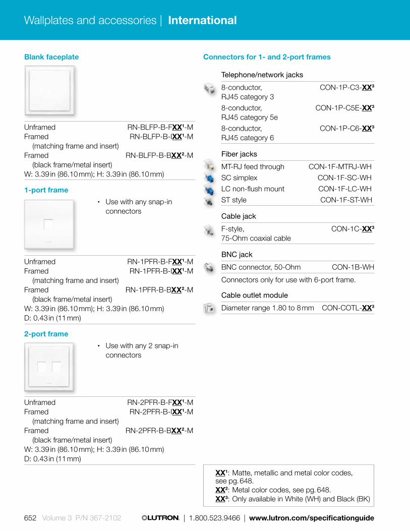
Unframed RN-BLFP-B-FXX1-M Framed RN-BLFP-B-IXX1-M (matching frame and insert) Framed RN-BLFP-B-BXX2-M (black frame/metal insert) W: 3.39 in (86.10 mm); H: 3.39 in (86.10 mm)
Unframed RN-1PFR-B-FXX1-M Framed RN-1PFR-B-IXX1-M (matching frame and insert) Framed RN-1PFR-B-BXX2-M (black frame/metal insert) W: 3.39 in (86.10 mm); H: 3.39 in (86.10 mm) D: 0.43 in (11 mm)
Unframed RN-2PFR-B-FXX1-M Framed RN-2PFR-B-IXX1-M (matching frame and insert) Framed RN-2PFR-B-BXX2-M (black frame/metal insert) W: 3.39 in (86.10 mm); H: 3.39 in (86.10 mm) D: 0.43 in (11 mm)
Blank faceplate
1-port frame• Use with any snap-in
connectors
2-port frame• Use with any 2 snap-in
connectors
XX1: Matte, metallic and metal color codes, see pg. 648.
XX2: Metal color codes, see pg. 648. XX3: Only available in White (WH) and Black (BK)
Connectors for 1- and 2-port frames
Telephone/network jacks
8-conductor, CON-1P-C3-XX3 RJ45 category 3
8-conductor, CON-1P-C5E-XX3 RJ45 category 5e
8-conductor, CON-1P-C6-XX3 RJ45 category 6
Fiber jacks
MT-RJ feed through CON-1F-MTRJ-WH
SC simplex CON-1F-SC-WH
LC non-flush mount CON-1F-LC-WH
ST style CON-1F-ST-WH
Cable jack
F-style, CON-1C-XX3 75-Ohm coaxial cable
BNC jack
BNC connector, 50-Ohm CON-1B-WH
Connectors only for use with 6-port frame.
Cable outlet module
Diameter range 1.80 to 8 mm CON-COTL-XX3
Wallplates and accessories |
652 Volume 3 P/N 367-2102 | 1.800.523.9466 | www.lutron.com/specificationguide
International

3.39 in (86 mm)
3.39 in (86 mm
)
0.31 in (8 mm)
Shown actual size: 1-gang International square wallplate for Pico in Arctic White (PFP-1-B-FAW-CPN5692)
Product family features• Intended to mount flush to the wall,
no backbox required• Use with Pico wireless controls• All Lutron® wallplates are screwless, seamless
and have no visible hardware; the front plate securely snaps into the alignment adapter plate
• Available for one or two Pico controls• Adapter plate included with the wallplate as a kit
Pico mounted inside a one Pico control opening international square wallplate in Arctic White (PFP-1-B-FAW-CPN5692)
Wallplates and accessories |
www.lutron.com/specificationguide | 1.800.523.9466 | Volume 3 P/N 367-2102 653
International square wallplate for Pico®

Color options
* Metal finish wallplates include black plastic trim/adapter, visible from side. Match with separate Black (BL) Pico controls.
AWArctic White
MNMidnight
SNSatin Nickel
Two Pico wireless controls in a two Pico control openings international square wallplate
BNBright Nickel
BBBright Brass
SBSatin Brass
Matte finishes
Metal finishes*
Use BOLD color code in model number (Example: PFP-1-B-FSN-CPN5692)
Model numbersSquare wallplate
1 Pico control opening PFP-1-B-FXX1-CPN5692
2 Pico control openings PFP-2-B-FXX1-CPN5692
XX1: Limited matte and metal color codes, see above.
Wallplates and accessories |
654 Volume 3 P/N 367-2102 | 1.800.523.9466 | www.lutron.com/specificationguide
International square wallplate for Pico®

Dimensions and mounting• Plug-in:
Width: 2.57 in (70 mm) Height: 4.00 in (102 mm) Depth: 1.20 in (31 mm) Surface mount
• J-box: Width: 4.10 in (104 mm) Height: 4.30 in (109 mm) Depth: 1.40 in (36 mm) Mount in 4.00 in (102 mm) x 4.00 in (102 mm) junction box
• DIN-rail: Width: 3.50 in (90 mm) Height: 5.90 in (150 mm) Depth: 2.40 in (61 mm) Surface mount or mount on DIN-rail
• HomeWorks QS DIN-Rail: Width: 3.50 in (90 mm) Height: 3.50 in (90 mm) Depth: 2.40 in (61 mm) Surface mount or mount on DIN-Rail
• Panel: Width: 9.50 in (241 mm) Height: 17.50 in (444 mm) Depth: 3.90 in (99 mm) Surface mount
Model numbersQS link power supply
Plug-in, 100-240 V AC, NEMA 5-15 plug QSPS-P1-10-50
Plug-in, 100-240 V AC, CEE 7/7 plug QSPS-P2-10-50
Plug-in, 100-240 V AC, BS 1363 plug QSPS-P3-10-50
J-box, 120 V AC QSPS-J1-1-50
DIN-rail, 100-240 V AC STEP-PS/1AC/24DC/3.8/C2LPS-CPN5550
DIN-rail, HomeWorks QS, 100-240 V AC QSPS-DH-1-60
Panel, 120 V AC QSPS-P1-10-60
Panel, 230 V AC (CE) QSPS-P2-10-60
Panel, 100 V AC (CE) QSPS-P4-10-60
Features and capacities• Supplies power to processors, keypads, shades,
and accessories• Output voltage: 24 V DC• Simple wiring scheme utilizing 4-conductor
low-voltage link• Available in plug-in and hard-wired models
(junction box mounted, DIN-rail mounted or panel)
4.00in (102 mm) 2.57 in (70 mm)
1.20 in (31 mm) depth
Download specification submittal
Wallplates and accessories |
www.lutron.com/specificationguide | 1.800.523.9466 | Volume 3 P/N 367-2102 655
QS link power supplies
Shown above: QS link plug-in power supply (QSPS-P1-1-50)

Features and capacities• SELV-equivalent step-down converter for
halogen lamps • Compatible with Lutron leading or
trailing edge 230 V (CE) products• Incorporates short-circuit, thermal, and overload
protection with self-resetting capabilities• Input power: 230-240 V AC 50/60 Hz• Available in 60 W or 105 W rated models
Dimensions and mounting• Length: 5.90 in (150 mm)
Height: 1.65 in (42 mm) Depth: 1.26 in (32 mm)
• Screw fixing located under each terminal cover/strain relief for mounting
Model numbers60 W electronic low-voltage transformer
Terminals only ELVXF-60-T20-CE on primary and secondary
Lead wires ELVXF-60-L21-CE one pair on secondary
Lead wires ELVXF-60-L22-CE one pair on primary and secondary
105 W electronic low-voltage transformer
Terminals only ELVXF-105-T20-CE on primary and secondary
5.90 in (150 mm)
1.65 in (42 mm
)
1.26 in (32 mm) diameter
Download specification submittal
Wallplates and accessories |
656 Volume 3 P/N 367-2102 | 1.800.523.9466 | www.lutron.com/specificationguide
Electronic low-voltage transformer

Shown actual size: Lamp socket wiring tester (FDB-LSWT-T5/T8)
5.76 in (146 mm)
0.76 in (19 mm
)
Features and capacities• Enables installers to easily verify proper pin
wiring for fluorescent lamp sockets• Aids in identifying: lamps wired in series, instant
start sockets, wires not connected to the socket or ballast, and shorted socket wires
• Assist in avoiding common problems associated with ballast retrofits
• Test wires without having to open fixtures• It is not designed to diagnose incorrect input
wiring to the ballast or controls
• 600 V, 100 kHz, 0.125 A maximum, CAT III
Dimensions• Product dimensions:
Width: 5.76 in (146 mm) Height: 0.76 in (19 mm) Diameter: 0.75 in (19mm)
0.75 in (19 mm) diameter
Model numberTester
Lamp socket wiring tester FDB-LSWT-T5/T8
Wallplates and accessories |
www.lutron.com/specificationguide | 1.800.523.9466 | Volume 3 P/N 367-2102 657
Lamp socket wiring tester

Features and capacities• Prevents tampering with GRAFIK Eye/GRAFIK Eye®
QS main units and system keypads/wallstations• Permits infrared operation• Models available for 1-, 2-, 3-, and 4-gang devices• Available in translucent smoked gray• Cover slides left or right
Model numbersLockable covers
1-gang GRX-1GLC
2-gang GRX-2GLC
3-gang GRX-3GLC
4-gang GRX-4GLC
Wallplates and accessories |
658 Volume 3 P/N 367-2102 | 1.800.523.9466 | www.lutron.com/specificationguide
Lockable cover
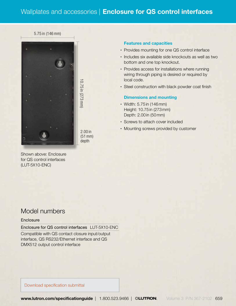
Features and capacities• Provides mounting for one QS control interface• Includes six available side knockouts as well as two
bottom and one top knockout.• Provides access for installations where running
wiring through piping is desired or required by local code.
• Steel construction with black powder coat finish
Dimensions and mounting• Width: 5.75 in (146 mm)
Height: 10.75 in (273 mm) Depth: 2.00 in (50 mm)
• Screws to attach cover included• Mounting screws provided by customer
Shown above: Enclosure for QS control interfaces (LUT-5X10-ENC)
Model numbersEnclosure
Enclosure for QS control interfaces LUT-5X10-ENC
Compatible with QS contact closure input/output interface, QS RS232/Ethernet interface and QS DMX512 output control interface
5.75 in (146 mm)
10.75 in (273 mm
)
2.00 in (51 mm) depth
Download specification submittal
Wallplates and accessories |
www.lutron.com/specificationguide | 1.800.523.9466 | Volume 3 P/N 367-2102 659
Enclosure for QS control interfaces

Features and capacities• Audiovisual rack that will hold up to four QS control
interfaces• When mounting, provide sufficient space for
connecting cables• The unit can also be placed in the LUT-19AV-1U AV
rack using the screws provided with the unit.
Dimensions and mounting• Width: 18.94 in (481 mm)
Height: 1.75 in (44 mm) Depth: 5.19 in (132 mm)
• Mounts in standard 19 in AV-1U racks• Unit mounting screws included with QS control
interface units• Mounting screws provided by customer• Steel construction with black powder coat finish
Shown above: Mounting rack for QS control interfaces (LUT-19AV-1U)
Model numbersMounting rack
Mounting rack for LUT-19AV-1U QS control interfaces
Compatible with QS contact closure input/output interface, QS RS232/Ethernet interface and QS DMX512 output control interface
Download specification submittal
Wallplates and accessories |
660 Volume 3 P/N 367-2102 | 1.800.523.9466 | www.lutron.com/specificationguide
Mounting rack for QS control interfaces

#24 AWG (0.20 mm2) drain
#22 AWG (0.25 mm2)
#22 AWG (0.25 mm2)
#18 AWG (0.75 mm2)
#18 AWG (0.75 mm2)
TWP*
Features• Available in 500 ft (150 m) spool• Five conductors:
Common—#18 AWG (0.75 mm2) Power—#18 AWG (0.75 mm2) MUX data—#22 AWG (0.25 mm2) MUX data—#22 AWG (0.25 mm2) Drain wire—#24 AWG (0.20 mm2)
• 300 V rated• UL/CSA listed• Capacitance of 22 AWG (0.25 mm2) twisted wire pair:
– conductor to shield: 48 pf/ft max– conductor to conductor: 25 pf/ft max
Plenum rated• Plenum rated for use in ceilings and enclosures
that are also used by the building air distribution system to transport environmental air
• Listed as cable type CL3P or CMP • Total outer jacket diameter: 0.17 in (4.37 mm)• Plenum sheath, 75° C rated• Rated FT6
Non-plenum rated• Listed as cable type CL3R or CMR• Total outer jacket diameter: 0.21 in (5.30 mm)• PVC sheath, 75° C rated• Rated FT4
* TWP = twisted wire pair
4-conductor cable
Model numbers4-conductor cable
Plenum rated cable GRX-PCBL-346S
Non-plenum rated cable GRX-CBL-346S
Compatible with LCP128, Softswitch 128 (XPS), GRAFIK Eye 4000, Quantum and HomeWorks QS systems
Wallplates and accessories |
www.lutron.com/specificationguide | 1.800.523.9466 | Volume 3 P/N 367-2102 661
Cable/wiring

#24 AWG (0.20 mm2) drain
#22 AWG (0.25 mm2)
#22 AWG (0.25 mm2)
#12 AWG (4.0 mm2)
#18 AWG (0.75 mm2)
#12 AWG (4.0 mm2)
TWP*
Features• Available in 250 ft (75 m) or 500 ft (150 m) spools• Six conductors:
Common—#12 AWG (4.0 mm2) Power—#12 AWG (4.0 mm2) MUX data—#22 AWG (0.25 mm2) MUX data—#22 AWG (0.25 mm2) Sense line—#18 AWG (0.75 mm2) Drain wire—#24 AWG (0.20 mm2)
• 300 V rated• UL/CSA listed• Capacitance of 22 AWG (0.25 mm2) twisted wire pair:
– conductor to shield: 48 pf/ft max– conductor to conductor: 25 pf/ft max
Plenum rated• Plenum rated for use in ceilings and enclosures
that are also used by the building air distribution system to transport environmental air
• Listed as cable type CL3P or CMP• Total outer jacket diameter: 0.17 in (4.37 mm)• Plenum sheath, 75 ° C rated• Rated FT6
Non-plenum rated• Listed as cable type CL3R or CMG• Total outer jacket diameter: 0.325 in (8.25 mm)• PVC sheath, 75 ° C rated• Rated FT4
5-conductor cable
Model numbers5-conductor cable
Plenum rated cable—250 ft GRX-PCBL-46L-250
Plenum rated cable—500 ft GRX-PCBL-46L-500
Non-plenum rated cable—250 ft GRX-CBL-46L-250
Non-plenum rated cable—500 ft GRX-CBL-46L-500
Compatible with GRAFIK Eye 4000 and Quantum systems.
* TWP = twisted wire pair
Wallplates and accessories |
662 Volume 3 P/N 367-2102 | 1.800.523.9466 | www.lutron.com/specificationguide
Cable/wiring

Features• Internal conductors match EcoSystem® device
terminal and lead color scheme• Each conductor sized for direct connection to
EcoSystem ballast and module terminals• Three types of EcoSystem digital link cable: non-
plenum cable (CL3R) for Class 2 applications, non-plenum cable (TC) for Class 1 applications and plenum cable for plenum Class 2 applications
• Two types of EcoSystem Class 2 sensor cable: plenum sensor cable (CL2P), non-plenum sensor cable (CL2R)
• Available in 1000 ft (305 m) +/- 10% spool
Plenum rated• Rated to a maximum of 300 V
Non-plenum rated• Dual rated to a maximum of 300 V or 600 V
dependant upon application
EcoSystem® cable
Model numbersEcoSystem cable
Plenum rated digital link cable, C-PCBL-216-CL-1 Class 2
Non-plenum rated digital link C-CBL-216-WH-1 cable, Class 1
Non-plenum rated digital link C-CBL-216-GR-1 sensor cable, Class 2
Plenum rated sensor cable C-PCBL-522S-CL-1
Non-plenum rated sensor cable C-CBL-522S-WH-1
Compatible with Quantum and HomeWorks QS systems.
EcoSystem sensor cable
EcoSystem digital link cable
Wallplates and accessories |
www.lutron.com/specificationguide | 1.800.523.9466 | Volume 3 P/N 367-2102 663
Cable/wiring
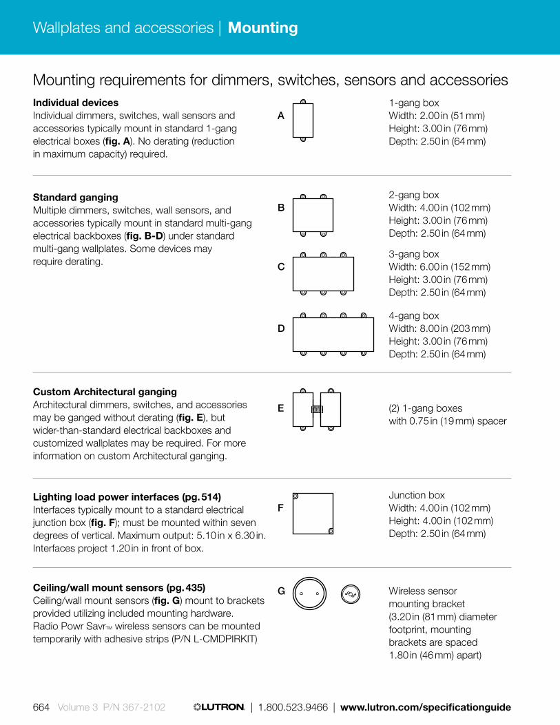
G Wireless sensor mounting bracket (3.20 in (81 mm) diameter footprint, mounting brackets are spaced 1.80 in (46 mm) apart)
Individual devicesIndividual dimmers, switches, wall sensors and accessories typically mount in standard 1-gang electrical boxes (fig. A). No derating (reduction in maximum capacity) required.
Standard gangingMultiple dimmers, switches, wall sensors, and accessories typically mount in standard multi-gang electrical backboxes (fig. B-D) under standard multi-gang wallplates. Some devices may require derating.
Custom Architectural gangingArchitectural dimmers, switches, and accessories may be ganged without derating (fig. E), but wider-than-standard electrical backboxes and customized wallplates may be required. For more information on custom Architectural ganging.
Lighting load power interfaces (pg. 514)Interfaces typically mount to a standard electrical junction box (fig. F); must be mounted within seven degrees of vertical. Maximum output: 5.10 in x 6.30 in. Interfaces project 1.20 in in front of box.
Ceiling/wall mount sensors (pg. 435)Ceiling/wall mount sensors (fig. G) mount to brackets provided utilizing included mounting hardware. Radio Powr SavrTM wireless sensors can be mounted temporarily with adhesive strips (P/N L-CMDPIRKIT)
1-gang box A Width: 2.00 in (51 mm) Height: 3.00 in (76 mm) Depth: 2.50 in (64 mm)
3-gang box C Width: 6.00 in (152 mm) Height: 3.00 in (76 mm) Depth: 2.50 in (64 mm)
2-gang box B Width: 4.00 in (102 mm) Height: 3.00 in (76 mm) Depth: 2.50 in (64 mm)
4-gang box D Width: 8.00 in (203 mm) Height: 3.00 in (76 mm) Depth: 2.50 in (64 mm)
E (2) 1-gang boxes with 0.75 in (19 mm) spacer
Junction box F Width: 4.00 in (102 mm) Height: 4.00 in (102 mm) Depth: 2.50 in (64 mm)
Mounting requirements for dimmers, switches, sensors and accessories
Wallplates and accessories |
664 Volume 3 P/N 367-2102 | 1.800.523.9466 | www.lutron.com/specificationguide
Mounting

Standard ganging and fins broken derating examples:
No fins broken Full capacity
Standard 1-gang backbox
1-gang Claro® wallplate
Standard 2-gang backbox
2-gang Claro wallplate
Standard 3-gang backbox
3-gang Claro wallplate
One HomeWorks® QS dimmer
Two HomeWorks® QS dimmers “Fins Broken” ganging
Three HomeWorks® QS dimmers “Fins Broken” ganging
One fin broken* Partial derating
Inside: Two fins broken* Full derating
Outside: One fin broken* Partial derating
= + +
= + +
= + +
For further information on ganging and derating, visit www.lutron.com/multigang.
*The fins are scored and designed to be removed easily.
Wallplates and accessories |
www.lutron.com/specificationguide | 1.800.523.9466 | Volume 3 P/N 367-2102 665
Ganging and derating

Derating table
No fins broken 1 fin broken 2 fins broken
Incandescent
Dimmers600 W 500 W 400 W
1000 W 800 W 650 W
Magnetic low-voltage
Dimmers600 VA/ 450 W 500 VA/400 W 400 VA/300 W
1000 VA/800 W 800 VA/600 W 650 VA/500 W
Electronic low-voltage
Dimmers 600 W 500 W 400 W
Fluorescent/LED
Hi-lume®/EcoSystem®/Hi-lume 3D/Hi-lume A-series LED Driver
Dimmer 60 ballasts or 6 A 50 ballasts or 5 A 35 ballasts or 3.5 A
Lighting
Switch 8 A 6.5 A 5 A
Dual-voltage switch 8 A 8 A 7 A
Motor
Switch 3 A or 0.10 HP 3 A or 0.10 HP 3 A or 0.10 HP
Dual-voltage switch 3 A or 0.10 HP 3 A or 0.10 HP 3 A or 0.10 HP
HomeWorks® QS
Wallplates and accessories |
666 Volume 3 P/N 367-2102 | 1.800.523.9466 | www.lutron.com/specificationguide
Derating

Engraving, backlit buttons/text, and icon table overview
Backlit buttons/text
Depending on color of buttons, engraving is eitherdisplayed as backlit text or on backlit buttons.
Backlit buttons, typically on lighter colored buttons
Backlit text, typically on darker colored buttons (BR, BL, SI, MN)
seeTouch® QS and international QS keypads and GRAFIK Eye® QS main unit engraving codes
Omit Unengraved Ships with engraving certificate that customer can redeem at no charge
EGN Standard Engraving
SGN Symbol-based Engraving
NST Non-standard Text Engraving
When ordering product with non-standard text engraving (NST) a completed engraving form must be submitted. Product will ship engraved as specified by customer.
1
2
3
4
Off
Open
Preset
Close
Lighting keypad
1
2
3
4
Off
Open
Preset
Close
Shade column
Engraving• 10 characters maximum
(including spaces)• Seven characters maximum
(including spaces) when using ALL CAPS (see next page for icon codes)
• Seven characters maximum (including spaces) when using an icon
• Text engraving color varies by button color. Lighter colored buttons use gray text and darker colored buttons use white text. Visit www.lutron.com/engraving for further information.
Example
Open
For open icon window #1:
Text Icon code
O p e n 0 1
Seven characters maximum when using icon
Download engraving sheets:
GRAFIK Eye QS main unit (button kit)
GRAFIK Eye QS main unit (faceplate)
seeTouch QS keypad (Architectural matte and metal finishes)
seeTouch QS keypad (Satin finishes)
International seeTouch QS keypad
Wallplates and accessories |
www.lutron.com/specificationguide | 1.800.523.9466 | Volume 3 P/N 367-2102 667
Engraving

Lutron character symbols - icon table
* Light button colors include: ** Dark button colors include:Black (BL)Brown (BR)
Beige (BE)Gray (GR)
Almond (AL)Light Almond (LA)Ivory (IV)
White (WH) Biscuit (BI)Eggshell (ES)
Snow (SW)Taupe (TP)
APPEARANCE ON:LIGHT*BUTTON COLOR
DARK**BUTTON COLORCODE CODE
LIGHT*BUTTON COLOR
DARK**BUTTON COLOR CODE
LIGHT*BUTTON COLOR
DARK**BUTTON COLOR CODE
LIGHT*BUTTON COLOR
DARK**BUTTON COLOR
64.
Wallplates and accessories |
668 Volume 3 P/N 367-2102 | 1.800.523.9466 | www.lutron.com/specificationguide
Engraving

Customized examples
Two unique custom controls with customized button placements and engraving
Two-gang International seeTouch® QS control with custom button configuration
Tabletop control to match seeTouch wall controls
As a finishing touch, add custom engraving, such as text, icons, and images
For more information on custom controls visit www.lutron.com/customcontrols.
Wallplates and accessories |
www.lutron.com/specificationguide | 1.800.523.9466 | Volume 3 P/N 367-2102 669
Custom controls

Smart design marries creative vision with progressive technology. Guided by this principle, Ivalo products aim to be functional, high-quality aesthetic solutions for every type of inhabitable space.
Ivalo fixtures are designed as architectural elements that are solutions to design problems. Each dimension and aspect of the form—including the canopy— is carefully considered.
Ivalo products are assembled in America with exceptional attention to detail and with our new available quick-ship program, select models can be delivered in two weeks.
670 671 | 1.800.523.9466 | www.lutron.com www.lutron.com | 1.800.523.9466 |670 671 | 1.800.523.9466 | www.lutron.com www.lutron.com | 1.800.523.9466 |Volume 3 P/N 367-2102 REV A
Ivalo®
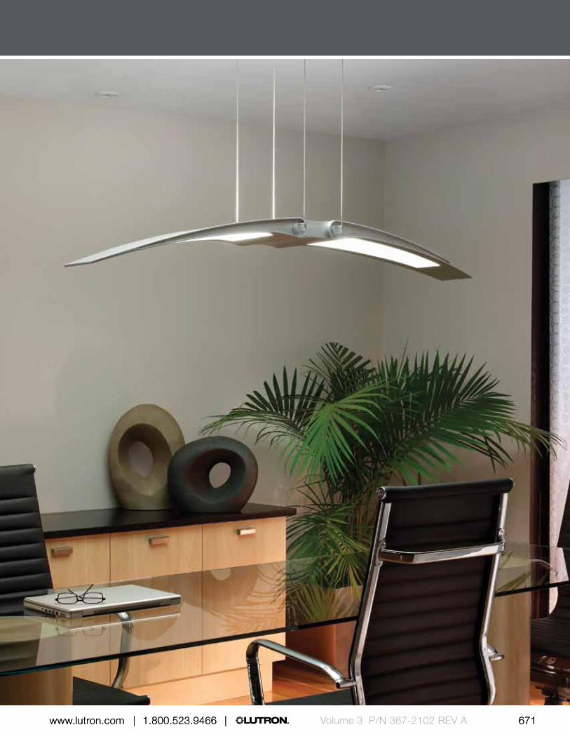
670 671 | 1.800.523.9466 | www.lutron.com www.lutron.com | 1.800.523.9466 |670 671 | 1.800.523.9466 | www.lutron.com www.lutron.com | 1.800.523.9466 | Volume 3 P/N 367-2102 REV A

*Lamps are not included.
Overview—Pendants
Aliante®
Aliante is designed for ballrooms and private offices, or over conference room tables, reception desks, dining tables, and kitchen islands.
• Length: 4 ft or 5 ft (adjustable)• Light Orientation: direct/indirect or indirect only• Lamp: dimmable and non-dimmable 1- or
2-lamp linear fluorescent T5 HO and T5 HE*• Interior use
Interior Interior
Rotare®
Rotare is designed for lobbies, atriums and private offices, or over conference room tables, reception desks, dining tables, and kitchen islands.
• Length: 4 ft 4 in (adjustable)• Light Orientation: direct/indirect• Lamp: dimmable and non-dimmable 1- or
2-lamp linear fluorescent T5 HO or T5 HE*• Interior use
Ivalo®
672 673 | 1.800.523.9466 | www.lutron.com www.lutron.com | 1.800.523.9466 |Volume 3 P/N 367-2102 REV A
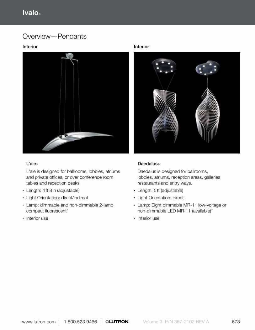
Overview—PendantsInterior Interior
L’ale®
L'ale is designed for ballrooms, lobbies, atriums and private offices, or over conference room tables and reception desks.
• Length: 4 ft 8 in (adjustable)• Light Orientation: direct/indirect• Lamp: dimmable and non-dimmable 2-lamp
compact fluorescent*• Interior use
Daedalus®
Daedalus is designed for ballrooms, lobbies, atriums, reception areas, galleries restaurants and entry ways.
• Length: 5 ft (adjustable)• Light Orientation: direct• Lamp: Eight dimmable MR-11 low-voltage or
non-dimmable LED MR-11 (available)*• Interior use
Ivalo®
672 673 | 1.800.523.9466 | www.lutron.com www.lutron.com | 1.800.523.9466 | Volume 3 P/N 367-2102 REV A

Aliante®
Aliante is designed for flanking doors, on columns, on building facades, and between windows/elevators.
• Length: 4 ft or 5 ft• Light Orientation: direct/indirect or indirect only• Lamp: dimmable and non-dimmable linear
fluorescent T5 HO and T5 HE*• Exterior/interior use
Rotare®
Rotare is designed for cove lighting in lobbies, conference rooms, reception areas and private offices.
• Length: 4 ft 4 in• Light Orientation: indirect• Lamp: dimmable and non-dimmable linear
fluorescent T5 HO and T5 HE*• Exterior/interior use
Overview—SconcesExterior/interior Exterior/interior
*Lamps are not included.
Ivalo®
674 675 | 1.800.523.9466 | www.lutron.com www.lutron.com | 1.800.523.9466 |Volume 3 P/N 367-2102 REV A

Aliante® demi
Aliante demi is designed for flanking doors, TVs and fireplaces, and between windows/elevators.
• Length: 21 in or 27 in (27 in mount available for exterior models)
• Light Orientation: direct/indirect or indirect only
• Lamp: (interior) incandescent, dimmable and non-dimmable CFL, dimmable white LED (exterior) non-dimmable CFL, HID
• Exterior/interior use• Energy Star® qualified
with Tu-Wire® control option
Inflection®
Inflection is designed for ballrooms, lobbies, atriums, foyers, conference rooms, and reception areas.
• Length: 23 in• Light Orientation:
indirect• Lamp: dimmable
and non-dimmable compact fluorescent white, green and blue LED
• Interior use
L’ale®
L'ale is designed for flanking doors, TVs and fireplaces or between windows/elevators.
• Length: 27 in• Light Orientation:
direct/indirect• Lamp: dimmable
and non-dimmable white LED
• Interior use
Silvus®
Silvus is designed for flanking doors and elevators, or mounted on columns; use singly, in a column, or in a field.
• Length: 24 in or 30 in• Light Orientation:
direct/indirect• Lamp: white, amber,
red, green, blue or dynamic color-changing RGB LED
• Exterior/interior use
Overview—SconcesExterior/interior Exterior/interior Interior Interior
Ivalo®
674 675 | 1.800.523.9466 | www.lutron.com www.lutron.com | 1.800.523.9466 | Volume 3 P/N 367-2102 REV A
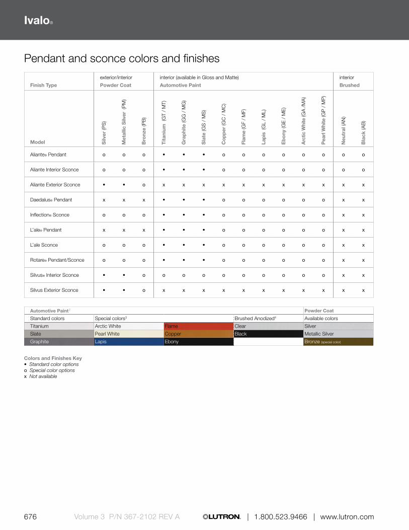
Pendant and sconce colors and finishes
Finish Type
exterior/interior
Powder Coat
interior (available in Gloss and Matte)
Automotive Paint
interior
Brushed
Model Silv
er (P
S)
Met
allic
Silv
er (
PM
)
Bro
nze
(PB
)
Tit
aniu
m (
GT
/ M
T)
Gra
phi
te (G
G /
MG
)
Sla
te (G
S /
MS
)
Co
pp
er (G
C /
MC
)
Flam
e (G
F /
MF)
Lapi
s (G
L /
ML)
Eb
ony
(GE
/ M
E)
Arc
tic W
hite
(GA
/M
A)
Pea
rl W
hite
(GP
/ M
P)
Neu
tral
(AN
)
Bla
ck (A
B)
Aliante® Pendant o o o • • • o o o o o o o o
Aliante Interior Sconce o o o • • • o o o o o o o o
Aliante Exterior Sconce • • o x x x x x x x x x x x
Daedalus® Pendant x x x • • • o o o o o o x x
Inflection® Sconce o o o • • • o o o o o o x x
L’ale® Pendant x x x • • • o o o o o o x x
L’ale Sconce o o o • • • o o o o o o x x
Rotare® Pendant/Sconce o o o • • • o o o o o o x x
Silvus® Interior Sconce • • o o o o o o o o o o x x
Silvus Exterior Sconce • • o x x x x x x x x x x x
Colors and Finishes Key• Standard color optionso Special color optionsx Not available
Automotive Paint2 Powder Coat
Standard colors Special colors3 Brushed Anodized4 Available colors
Titanium Arctic White Flame Clear Silver
Slate Pearl White Copper Black Metallic Silver
Graphite Lapis Ebony Bronze (special color)
Ivalo®
676 677 | 1.800.523.9466 | www.lutron.com www.lutron.com | 1.800.523.9466 |Volume 3 P/N 367-2102 REV A
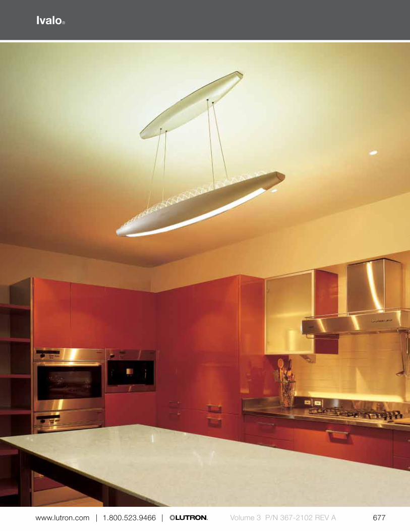
Ivalo®
676 677 | 1.800.523.9466 | www.lutron.com www.lutron.com | 1.800.523.9466 | Volume 3 P/N 367-2102 REV A

Overview—Recessed Lighting
Finiré®
Finiré LED recessed lighting is designed for kitchens, great rooms, master bathrooms and theater rooms.
• Opening: 4 in• 15 W/22 W• Light orientation: downlight, wallwash,
and adjustable• Lamp: dimmable LED standard with Lutron®
Hi-lume® A-Series LED driver• Interior use• Energy Star® qualified• Title 24 compliant
Project Versatility
• Insulation contact (IC) (15 W only) and non-insulation contact (Non-IC) options are available.
• Easy maintenance• Field-replaceable LED light module and driver.
Change the color temperature and wattage after Finiré is installed without removing the fixture housing from the ceiling.
• Extended LED lamp and driver life• Finiré contains a high-performance heat-sink for
maximum LED life and the Lutron Hi-lume LED driver—both rated for 50,000 hours.
• Color Temperature• Ranges from cool to warm, equivalent to the light
output of 60-75 W incandescent lighting.
Interior
Ivalo®
678 679 | 1.800.523.9466 | www.lutron.com www.lutron.com | 1.800.523.9466 |Volume 3 P/N 367-2102 REV A

Micro Prism Solite™*
Frosted Glass
None
Round • • •
Square • • •
Clear GlassFrosted Glass
RingTier Center
Frosted GlassStainless Steel
Bezel
Round • • • •
Square • •
Matte
White*Matte Black
Soft Glow Metal
Clear Bright Alzak
Wheat
AlzakOil-Rubbed
Bronze
Round* • • • • • •
Round Trimless • • • • • •
Round Pinhole •Round Slotted
Pinhole•
Square • • •
Square Trimless • •
Square Pinhole •
Trim Finish and Color Options
Lens Options
Decorative Trim Options
Round Clear Glass
Round Frosted
Glass Ring
Round Tier Center Frosted
Glass
Round Stainless
Steel Bezel
Square Clear Glass
Square Frosted
Glass Ring
Round* Round Trimless
Round Pinhole
Round Slotted Pinhole
Square Square Trimless
Square Pinhole
*standard option
Ivalo®
678 679 | 1.800.523.9466 | www.lutron.com www.lutron.com | 1.800.523.9466 | Volume 3 P/N 367-2102 REV A

0 -10 V ControlAn analog lighting control protocol. A 0-10 V control modifies a voltage between 0-10 V DC to produce a varying intensity level. There are two existing 0-10 V standards and they are not compatible with each other. The two 0-10 V control types are 1) current source (theatrical dimming standard ESTA E1.3 and 2) current sink (dimming ballast standard IEC Standard 90626).
Advanced control functionAdditional product capabilities that provide users with features beyond the normal operation.
After-hours modeAn energy saving mode that is used to turn lights off at the end of normal hours until the beginning of the next day.
Air-Gap SwitchA safety feature in all Lutron controls that provides true “off” function by disconnecting power to a lighting load. The switch physically separates two contacts, resulting in an air gap between the contacts. The switch is visible and front accessible. Styles vary for each dimmer type.
ANSIAmerican National Standards Institute.
Amperes/Amps (A)Electrical current unit of measurement.
Architectural lighting The general/ambient lighting that illuminates the interior ceiling, walls and architectural features.
ASHRAEASHRAE stands for American Society of Heating, Refrigerating and Air-Conditioning Engineers.
Astronomic time clockA time scheduling device that is programmed for a specific geographic location to provide automatic timed event control of lights and/or shades. The programmed time is coordinated with seasonal variations of sunrise and sunset times that change throughout the year.
Audiovisual integration (AV)Interconnection of the lighting control, window shading and other systems with an AV control system. Provides for the operation from the AV control panels or touch screens the other connected systems. Common connection methods are contact closures, RS232 and Ethernet TCP/IP.
Automatic shut offAbility of the lighting or other equipment in a building to be turned off without manual intervention. The common methods to provide shut-off are time switches and occupancy sensors. Automatic shut-off of all lighting in commercial buildings is a requirement in most energy codes.
Auxiliary repeaterIn RF control systems (RadioRA® or RadioRA 2) an additional device that extends the communication range of the system.
BackboxA metal or plastic enclosure housing one or more electrical devices. Standard USA 1 gang size is used for Lutron® domestic controls (H: 3.00 in x D: 2.75 in). Also known as switchbox or wallbox.
BacklightInternal illumination of a control device, panel or dimmer that creates a glow of the device. Allows for easy location of the device in a dark space and provide improved identification of elements of the control.
Backlit engravingIllumination of engraved lettering or symbols from behind. Allows improve visibility of the engraved elements in low light conditions.
BACnet/LonWorks BMS integrationConnection of a Building Management System (BMS) to a lighting, shading or other system using industry standard communication protocols. BACnet and LonWorks are two of the commonly used protocols.
For more detailed glossary of terms, go to www.lutron.com/glossaryofterms.
Appendix | Glossary
680 Volume 3 P/N 367-2102 | 1.800.523.9466 | www.lutron.com/specificationguide
Glossary

Ballast An electrical device required to operate all fluorescent and high intensity discharge (HID) lamps. Ballasts furnish the necessary voltage and current, for starting and operating the lamp(s). Internationally it is sometimes referred to as control gear.
Ballast current (A)The total electrical current in Amperes (A) that is drawn by a ballast.
Ballast factorA ballast’s light output with respect to “reference ballast” light output. The reference ballast is a ballast that produces full light output as defined by the ANSI.
Basic control functionsThe normal operation of a control used on a regular basis.
Blackout fabric Shade systems material that completely blocks light. Combined with side channels, they provide a 100% complete light seal used in AV rooms, home theaters, and bedrooms.
Lutron® blackout fabrics offer versatility with standard or dual-sided options.
BMSBuilding Management System.
Burn-inA term used when dimming fluorescent lamps; refers to running them at full output for 100 hours. Also known as seasoning.
Bus 1) Denotes the power source
2) A control link
California Energy Commission (CEC Title 24)California’s primary energy policy and planning agency. The Commission responsibilities include: Forecasting future energy needs, promoting energy efficiency by setting the state’s appliance and building efficiency standards and working with local government to enforce those standards, Supporting public interest energy research.
CCC markA mark that is placed on products that are certified to meet the required product safety standards in China.
CE markA mark placed on products that are declared to meet the applicable EU directives for a given product type. A CE marked product often meets the requirements of other countries that adhere to the IEC standards.
Central processorFor a large lighting control system, the major control and intelligence that is located within one processor that communicates to other system components located remotely.
Circuit An electrical term that refers to one closed loop of subsystem of the building electrical system—individually protected and dedicated to a specific use: lighting, data processing, power, etc. It usually refers to a 20 Amp circuit, which offers different wattage capacity at 120 V, 220 V or 277 V operation.
Clear Connect® RF TechnologyLutron’s advanced wireless RF communication protocol. Provides reliable communication between all Lutron® wireless products. It operates on a dedicated quiet frequency band, essentially free of interference. Using Lutron’s own dedicated network ensures communication between system devices is reliably delivered, while the command structure ensures smooth, rapid system response.
COM (Customer’s own material)A shade systems acronym that stands for “Customer’s Own Material” when motorized drapes are supplied. Customers occasionally submit a material for testing for a shade to ensure it performs properly and wears well.
For more detailed glossary of terms, go to www.lutron.com/glossaryofterms.
Appendix | Glossary
www.lutron.com/specificationguide | 1.800.523.9466 | Volume 3 P/N 367-2102 681
Glossary

Compact Fluorescent Lamp (CFL) A high efficiency lamp type that can be dimmed using a matching dimming ballast and dimmer. Standard lamp types are Twin Tube, Quad Tube, and Triple Tube. They are available in 2-pin and 4-pin versions. To operate, both require an external ballast located in the fixture; 2-pin versions are not dimmable, and 4-pin versions are dimmable when used with a dimming ballast. Screw-base CFLs are designed to replace incandescent lamps in existing fixtures, but most are not dimmable.
Companion dimmerAllows for dimming from two or more wall locations when used with a compatible multi-location dimmer.
Companion switchAllows for switching from two or more wall locations when used with a compatible multi-location switch.
Contact closureA manual switch, relay, or transistor used as means to interface Lutron control systems to/from other control systems.
Control interfaceA general term for devices that allow the interconnection of various system components. Typically provides the connection of third party systems to Lutron systems. Usually operate on the input/low-voltage side of the device and connect to the digital (QS) bus.
Control zoneA lighting fixture or group of fixtures that are controlled simultaneously. For example: two wall sconces wired together and controlled with one dimmer is a control zone. Window shades can also be grouped together as zones.
CorniceA top treatment option that offers flexibility and permits outside mount for shading systems without the need for recess pockets. Works with roller shades, roman shades and drapery systems.
Coupled shadesShades systems’ term for one electronic drive unit mechanically connected to control one or more adjacent roller shade panels.
Current The electrical rate of flow, expressed in Amperes, similar to the water flow rate in a pipe (gal/min).
Daylighting Lighting strategies that use the sun and sky as a diffuse light source, while shielding direct sunlight. Modern “Sustainable/Green” designs use Daylighting PhotoSensors that control dimmers/dimming ballasts to reduce electric lighting loads.
Daylight sensorA device that senses daylight providing feedback for automatic dimming or switching of electrical lights, based upon changes of available daylight.
DerateTo reduce the current or power capacity (lighting load) that a control can reliably handle. Lutron controls must be derated when side sections of the yoke or fin have been removed from the unit (control) for ganging. The industry also derates other items such as circuit breakers.
Digital fade dimmersA Lutron dimmer that has a gradual fade-to-off/fade-to-on feature when the switch is pressed, as compared to the more traditional slide-to-off or rotary dimmers with a knob that turns on/off. They include LED indicator lights show the relative light level in the room. Only available in certain styles.
Dimmed hotUsed in reference to the wiring connection of Lutron 3-wire dimming ballasts. It is the wire connection that provides a variable line voltage signal to the ballast. This signal adjusts the output level of the ballast. The other connections to the ballast are Neutral (N) and Switched Hot (SH).
For more detailed glossary of terms, go to www.lutron.com/glossaryofterms.
Appendix | Glossary
682 Volume 3 P/N 367-2102 | 1.800.523.9466 | www.lutron.com/specificationguide
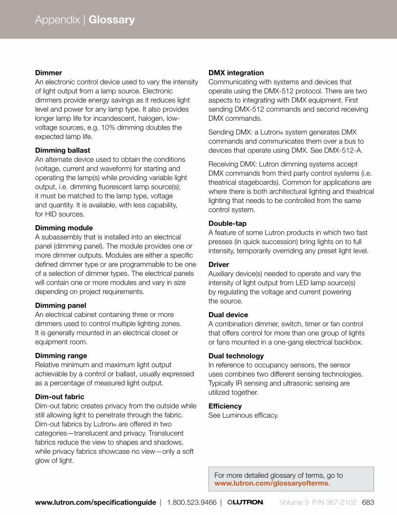
Dimmer An electronic control device used to vary the intensity of light output from a lamp source. Electronic dimmers provide energy savings as it reduces light level and power for any lamp type. It also provides longer lamp life for incandescent, halogen, low-voltage sources, e.g. 10% dimming doubles the expected lamp life.
Dimming ballast An alternate device used to obtain the conditions (voltage, current and waveform) for starting and operating the lamp(s) while providing variable light output, i.e. dimming fluorescent lamp source(s); it must be matched to the lamp type, voltage and quantity. It is available, with less capability, for HID sources.
Dimming moduleA subassembly that is installed into an electrical panel (dimming panel). The module provides one or more dimmer outputs. Modules are either a specific defined dimmer type or are programmable to be one of a selection of dimmer types. The electrical panels will contain one or more modules and vary in size depending on project requirements.
Dimming panelAn electrical cabinet containing three or more dimmers used to control multiple lighting zones. It is generally mounted in an electrical closet or equipment room.
Dimming rangeRelative minimum and maximum light output achievable by a control or ballast, usually expressed as a percentage of measured light output.
Dim-out fabricDim-out fabric creates privacy from the outside while still allowing light to penetrate through the fabric. Dim-out fabrics by Lutron® are offered in two categories—translucent and privacy. Translucent fabrics reduce the view to shapes and shadows, while privacy fabrics showcase no view—only a soft glow of light.
DMX integrationCommunicating with systems and devices that operate using the DMX-512 protocol. There are two aspects to integrating with DMX equipment. First sending DMX-512 commands and second receiving DMX commands.
Sending DMX: a Lutron® system generates DMX commands and communicates them over a bus to devices that operate using DMX. See DMX-512-A.
Receiving DMX: Lutron dimming systems accept DMX commands from third party control systems (i.e. theatrical stageboards). Common for applications are where there is both architectural lighting and theatrical lighting that needs to be controlled from the same control system.
Double-tapA feature of some Lutron products in which two fast presses (in quick succession) bring lights on to full intensity, temporarily overriding any preset light level.
DriverAuxiliary device(s) needed to operate and vary the intensity of light output from LED lamp source(s) by regulating the voltage and current powering the source.
Dual deviceA combination dimmer, switch, timer or fan control that offers control for more than one group of lights or fans mounted in a one-gang electrical backbox.
Dual technologyIn reference to occupancy sensors, the sensor uses combines two different sensing technologies. Typically IR sensing and ultrasonic sensing are utilized together.
EfficiencySee Luminous efficacy.
For more detailed glossary of terms, go to www.lutron.com/glossaryofterms.
Appendix | Glossary
www.lutron.com/specificationguide | 1.800.523.9466 | Volume 3 P/N 367-2102 683

Electronic low-voltage (ELV)A low-voltage lighting source that uses a solid-state electronic transformer to step down the incoming line voltage to the voltage required by the lamp (typically 12 V). Some ELV transformers are not dimmable and some are dimmable using reverse phase control.
Track and recessed down lights can be electronic low-voltage or magnetic low-voltage. Dimmable ELV transformers should be used with an electronic low-voltage dimmer only.
Electronic SwitchUses semiconductor device(s) to turn on and off the current flow into the load. These switches also include a mechanical disconnect (air-gap switch) to manually disconnect power for safety when replacing lamps. They typically need to be derated when ganged. Electronic switches can only be used with the load type they are approved to operate and are listed under UL1472 or UL508.
Electrostatic Discharge ProtectionProtects Lutron products from static discharges (static shocks) common in dry climates, up to 16 kiloVolts, without damage or loss of memory.
ELVI (Electronic low-voltage interface)An interface unit that allows standard phase control dimmers to control electronic low-voltage (ELV) transformers.
Emergency lighting When the normal power supply fails, emergency lighting is the illumination that automatically lights the path towards the exit location(s). It may also serve to satisfy life safety and security lighting requirements.
Fade delayThe time interval between the selection of a new light intensity for a particular lighting zone and the beginning of that zone’s change to the new level.
Fade overrideThe ability to temporarily or permanently disable fade times or delays.
Fade timeThe total time it takes a dimmer to change the lighting from one preset level to another. The time can vary from 0 seconds to 60 minutes.
Fan-motor HumThe noise made by a fan motor at lower speeds when controlling the fan using fully variable technology. Lutron has quiet 3-speed and 7-speed controls that do not cause the fan motor to hum.
FASSTM (Front Accessible Service Switch)An air-gap switch that can be activated without removing the wallplate of a control. Power is completely removed from the device’s load circuit by the air-gap switch.
FinThe raised vertical metal dividers or side sections on certain Lutron dimmers—these serve as a “heat sink” to dissipate heat.
Fins broken (FB)Removing a portion of the fins (heat sink) to fit dimmers into a standard backbox, using standard size wallplates. The dimmer's wattage capacity must be derated. Also see Ganging and Derating, page 665 when ganging dimmers.
Fixture Common term for a luminaire.
Flap and hangerShading Systems’ two-piece structure designed to conceal the roller system in a recessed ceiling installation.
For more detailed glossary of terms, go to www.lutron.com/glossaryofterms.
Appendix | Glossary
684 Volume 3 P/N 367-2102 | 1.800.523.9466 | www.lutron.com/specificationguide

Fluorescent lamp A low intensity “discharge” lamp that produces light when electric current passes through low-pressure mercury gas. The resulting arc produces ultraviolet energy, which causes the phosphor coating on the inside of the glass envelope and produce light. Fluorescent lamps require a ballast to start the lamp and maintain the light output. Fluorescent dimming ballasts are available for most fluorescent lamps to be dimmed down to as low as 1% of the lamps maximum, measured light output. The dimming ballast reduces the current through the lamp.
GangingThe act of mounting one or more dimmers, switches, receptacles or controls side-by-side in a series of connected (ganged) back boxes.
Ground Fault Circuit Interrupter (GFCI)A safety device that monitors current flow, and quickly turns off a circuit when the current returning on the neutral wire is less than what is going out on the hot wire (difference ≥ 6 mA). It is intended to provide protection from potentially dangerous ground-fault currents.
Halogen lampA higher efficiency type of incandescent lamp in which halogen is added to the filling gas and has a quartz glass inner envelope. These additions allow the lamp to operate more efficiently at a higher color temperature. (Also called quartz halogen or tungsten halogen).
Hand-held programmerHand-held device used to assist in programming a lighting control system.
HVACHeating, Ventilating, and Air-Conditioning systems designed by mechanical engineers.
IECCInternational Energy Conservation Code— a U.S. cross national energy codes standard.
IEEEInstitute of Electrical and Electronics Engineers.
IES/NAIlluminating Engineering Society of North America.
Incandescent lamp An electric lamp in which a filament gives off light when heated by an electric current. Standard light bulbs are incandescent line voltage (120 Volt). They offer excellent color rendering and are simple to replace. Newer types of incandescent bulbs include halogen and tungsten-halogen (quartz).
Infrared (IR)Signals in the frequency range just below visible light. IR signals are often used for remote controls for televisions and other audio video products. Many products use Lutron® IR signals for hand-held remote control of lighting and/or shades.
Infrared (IR) receiverA component that receives signals from an IR transmitter. Requires line-of-sight for functionality. Lutron products with IR receivers include dimmers, control units and shading products.
Infrared (IR) transmitterA component that transmits signals to an IR receiver. Requires line-of-sight for functionality. Often referred to as a “hand-held” remote control device.
Inmetro markA mark that is placed on products that are certified to meet required product safety standards in Brazil.
Interface A) A power-handling device that allows a control to dim or switch additional lighting load types.
B) A low-voltage device that allows equipment such as telephone interfaces, astronomical time clocks, car visor controls, photocells, shades, screens, security systems, and other types of controls to work in conjunction with various Lutron controls and systems.
For more detailed glossary of terms, go to www.lutron.com/glossaryofterms.
Appendix | Glossary
www.lutron.com/specificationguide | 1.800.523.9466 | Volume 3 P/N 367-2102 685

Lamp debuzzing coilAn inductor connected between the control and the load to minimize lamp or transformer buzz and radio frequency interference.
Lamp lifeAverage rated time period of the operation of a lamp before it fails to produce light. For incandescent and fluorescent lamps, manufacturers define this as the point in time when 50% of the lamps have failed. LED lamp life is defined as when the light output from the LED falls below 70% of its maximum lumen output.
LED (Light emitting diode) A solid-state light source that is used in multiple arrays of “white” or RGB “red/green/blue.” LED arrays operate with a driver, in a fixture, and a control. These components must all be compatible in order to ensure that their proper system operation is maintained.
LEDs are a long-life light source. They also produce very little heat on the object being illuminated, but require heat sinks to keep the LEDs at proper operating temperature. More detailed information is available at www.lutron.com/led.
LED driver Auxiliary device(s) needed to operate LED lamps. They operate by regulating the voltage and current powering the LED source. There are both dimming and non-dimming types.
LED lamp A collection of LEDs in a single housing used as an alternative to an incandescent lamp.
Line voltage The voltage between the lines of a supplying power system. Usually 120 V AC in U.S., 240 V AC in the U.K. 100 V in Japan. Also see Low-voltage.
Load type An industrial term for a category of lighting used in the selection of dimming devices that must “match” the load type.
Load type optimizationEach dimmer is designed for the specific load type it is meant to control. This optimizes performance and reliability in the most demanding applications.
Locator light A small indicator light on some dimmers and accessory controls that remains illuminated to help a user locate the control in a dark space.
Low-voltage (LV) Lighting fixtures that require a transformer for operation to step voltage down from line supply (120, 220, or 277 V) to 6, 12, or 24 V. The bulbs contain a smaller filament than incandescent bulbs for higher efficiency and more precise beam control. These bulbs have a long life expectancy and bright white light. Low-voltage lighting may use magnetic or electronic transformers. Also see Line voltage.
Luminous efficacyThe ratio of light emitted to the power required for a light source or luminaire. Commonly used to measure energy efficiency, it is the lumens per watt from a light source (amount of light per watt of power).
Magnetic low-voltage (MLV)A lighting source that uses a magnetic transformer to step down the incoming line voltage to that required by the lamp (typically 12 V). Recessed lights are most often magnetic low-voltage. Magnetic low-voltage lights tend to be larger and heavier than electronic low-voltage.
Mechanical (general purpose) switchAn on/off device that uses a set of metal contacts, which open or spread apart to turn off a load and make contact or come together to turn the load on. These devices sometimes have a locator light circuit across these contacts. These locator lights may either be LED or neon indicator. Mechanical switches typically do not need to be derated when ganged. This product is listed under UL20, which is the standard for general-purpose snap switches.
For more detailed glossary of terms, go to www.lutron.com/glossaryofterms.
Appendix | Glossary
686 Volume 3 P/N 367-2102 | 1.800.523.9466 | www.lutron.com/specificationguide
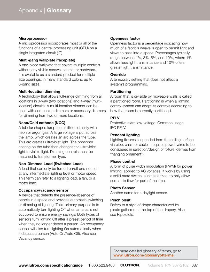
MicroprocessorA microprocessor incorporates most or all of the functions of a central processing unit (CPU) on a single integrated circuit (IC).
Multi-gang wallplate (faceplate)A one-piece wallplate that covers multiple controls without any visible screws, seams, or hardware. It is available as a standard product for multiple size openings, in many standard colors, up to 6-gang sizes.
Multi-location dimming A technology that allows full-range dimming from all locations in 3-way (two locations) and 4-way (multi-location) circuits. A multi-location dimmer can be used with companion dimmers or accessory dimmers for dimming from two or more locations.
Neon/Cold cathode (NCC)A tubular shaped lamp that is filled primarily with neon or argon gas. A large voltage is put across the lamp, which creates an arc across the tube. This arc creates ultraviolet light. The phosphor coating on the tube then changes the ultraviolet light to visible light. Dimming controls must be matched to transformer type.
Non-Dimmed Load (Switched Load)A load that can only be turned on/off and not set at any intermediate lighting level or motor speed. This term can refer to a lighting load, a fan, or a motor load.
Occupancy/vacancy sensor A device that detects the presence/absence of people in a space and provides automatic switching or dimming of lighting. Their primary purpose is to automatically turn lighting Off when an area is not occupied to ensure energy savings. Both types of sensors turn lighting Off after a preset period of time when they no longer detect a person. An occupancy sensor will also turn lighting On automatically when it detects a person (Auto On/Auto Off). Also see Vacancy sensor.
Openness factorOpenness factor is a percentage indicating how much of a fabric’s weave is open to permit light and views to pass into a space. Percentages typically range between 1%, 3%, 5%, and 10%, where 1% allows less light transmittance and 10% offers greater light transmittance.
OverrideA temporary setting that does not affect a system’s programming.
PartitioningA room that is divisible by moveable walls is called a partitioned room. Partitioning is when a lighting control system can adapt its controls according to how that room is currently partitioned.
PELVProtective extra low-voltage. Common usage IEC PELV.
Pendant lighting Lighting fixtures suspended from the ceiling surface via pipe, chain or cable—requires power wires to be considered in selection/design of fixture (derives from “hanging ornament”).
Phase controlA form of pulse width modulation (PWM) for power limiting, applied to AC voltages. It works by using a solid-state switch, such as a triac, to only allow current to flow for part of the time.
Photo SensorAnother name for a daylight sensor.
Pinch pleatRefers to a style of drape characterized by pleats gathered at the top of the drapery. Also see Ripplefold.
For more detailed glossary of terms, go to www.lutron.com/glossaryofterms.
Appendix | Glossary
www.lutron.com/specificationguide | 1.800.523.9466 | Volume 3 P/N 367-2102 687

PocketA) Ceiling recess in which a shade is installed.
Hardware is hidden above the ceiling, providing a clean look.
B) Metal casing provided by Lutron® used when shades are installed in a ceiling recess.
Power failure memoryAfter a power failure, lighting and shading is restored to the same levels set prior to the power-failure. This minimizes the inconvenience of power service interruptions. Lighting and shading does not shut off or go to a preprogrammed level.
Preset Predetermined light intensity or shading level for one or more lighting zones that can be recalled by pressing a single button.
Preset dimmersDimmers that have a separate On/Off switch that allows the user to turn lights On to a preset light level.
Primary controlsThe main dimming control required for any dimmer or system to handle the lighting load. The primary control(s) can be used with companion dimmers, accessory dimmers or accessory controls, however, these are not required for the primary controls to function properly.
Privacy fabricRefers to a type of fabric that allows for light transmission, but no view. Privacy fabric is often used in residential applications.
Programming modeAn operating state that allows the user to set up or modify a system configuration (also called setup mode).
QEDAcronym that stands for the Lutron® “Quiet Electronic Drive” used with Lutron shades and drapes. This Lutron drive technology is rated at less than 44 dBA. 44 decibels is comparable to rustling leaves.
Repeater Communication backbone for a Lutron Wireless system; it ensures robust communication.
Radio frequency (RF)The emission of electromagnetic waves, at a specific frequency that are able to pass through most materials. This provides a method of sending and receiving wireless communication signals between system components.
Radio frequency interference (RFI)Potentially disruptive set of radio frequency emissions caused by electronic devices.
RFI FilterAn electrical circuit that is part of all Lutron dimmers. It is intended to reduce radio frequency interference (RFI) and lamp buzz.
Ripplefold Refers to a style of drape characterized by an “S” shaped wave of fabric at the drapery track. Ripplefold does not gather with a pleat, see pinch pleat for further information.
Roller shades Shades that operate by rolling fabric around a tube. Roller shades may utilize sheer, dim-out, or blackout fabrics.
SceneThe lighting effect achieved by adjusting one or more zones of lighting to the desired intensity. Also see Preset.
Screw-base Compact Fluorescent Lighting (CFL)Screw-in CFLs that are rated for dimming will typically only dim down to about 10% to 30% of the lamp’s light output. For more information on dimming these lamps please visit www.lutron.com/dimcflled.
Screw-base LED Lighting Screw-in LEDs that are rated for dimming will typically only dim down to about 5% to 15% of the lamp’s light output. For more information on dimming these bulbs please visit www.lutron.com/dimcflled.
For more detailed glossary of terms, go to www.lutron.com/glossaryofterms.
Appendix | Glossary
688 Volume 3 P/N 367-2102 | 1.800.523.9466 | www.lutron.com/specificationguide

Sensor A device that detects motion, heat, partition status, etc. that allows for automatic control of dimming and switching systems. (See Occupancy, Vacancy, and Daylight sensors).
Sequencing The mode during which preset lighting scenes change in a designated order using fade times that have been programmed.
Sheer fabricSheer fabrics reduce solar heat gain and UV penetration while maintaining views to the outside. Lutron® sheer fabrics are offered in SheerShade®, designer, and dual-sided sheer fabric options to accommodate the needs of any space. SheerShade fabrics are measured by “openness factor” which describes the ration of open space to fabric yarn in a weave.
Sill angleA two-sided piece of metal designed to work with shades in order to complete a blackout design by stopping light leaks below the shade.
Single-pole switch/dimmerA switch or dimmer that controls a lighting zone from one location only.
Single-gang backboxA device installed in a wall intended to house a single switch or dimmer.
Slider The linear actuator on the front of a dimmer that adjusts the light level.
Softswitch A Lutron patented one million cycle switching solution, which limits in-rush current at turn-on.
Solar radiation Radiant energy emitted by the sun. Solar shades work to reduce this energy.
Solar reflectancePercentage of solar radiation reflected back out by the fabric.
Solar transmittancePercentage of solar radiation that passes through the fabric.
Solid-state A product or system that utilizes a semiconductor.
Specification series A class of products specifically designed to meet or exceed the rigorous demands of heavy-use/commercial applications. Dimmer(s) that meet this specification are comprised of heavy-duty components for surge protection and long product life, electrostatic discharge protection and voltage compensation. They include features such as power failure memory, Square Law Dimming, Superior RFI suppression, and are Listed.
Specifications Specifications define the qualitative requirement for products, materials, workmanship, and administrative requirements upon which the project is based. Specifications provide detailed requirement for the physical properties, chemical constituents, performance requirements, and standards of workmanship associated with the manufacture and installation of materials, equipment, and components.
Square law dimmingA dimmer is calibrated so that the linear slider position or LED indicator column provides a representation of the light level perceived by the user. For example, if the slider is set at the halfway point or one-half or the column of LEDs is lit the light level appears to be at 50%. Dimmers adjusted in this way will also use the full range of the slider or LED indicators without any “dead” travel at the top or bottom slide position or indicator LED.
For more detailed glossary of terms, go to www.lutron.com/glossaryofterms.
Appendix | Glossary
www.lutron.com/specificationguide | 1.800.523.9466 | Volume 3 P/N 367-2102 689

Surge Protection Circuitry that protects Lutron products against a near lightning strike surge of 6000 V, 3000 A, as recommended by the ANSI/IEEE standard c62.41.
perceived lig
ht leve
l
% Slider Travel
% L
ight
25
25
50
50
75
75
100
100
dimming power cu
rve
Square law dimming
Surge suppressionCircuitry that reduces the potential for damage caused by lightning strikes and other power spikes.
Switching system A switching system is designed for a facility to turn lighting zones on and off on a schedule or by responding to multiple control devices or input locations.
Tap switchA style of Lutron dimmer with a flat mechanical button that, when pressed, allows the lights to turn on to a desired preset level and to off. Some models are available with a small slider or rocker that allows the user to adjust the lights to suit any activity.
Time clockAllows various Lutron® systems to control lights based on time of day. Also see Astronomical time clock.
Toggle (On/Off)A switch or keypad that alternates between two states (typically on/off) with each touch.
Transformer A device that changes line voltage (120 V or 277 V) to 24 V, 12 V, or 6 V needed for low voltage lighting sources. It can be integral to the lighting fixture for low voltage lamps (e.g., MR-16 or Par 36). Standalone (remote) transformers can supply multiple lamps or luminaires (e.g., for a low voltage lighting strip in a ceiling cove). Transformers can be electronic or magnetic, and dimmers must be matched to either type.
TriacThe electronic component responsible for the dimming function in many Lutron dimmers. This component reduces the power to a light by switching on/off very rapidly (120 times per second). Lutron products use heavy-duty-rated triacs that are tested to last over 10 years.
Tungsten-Halogen Lamp See halogen lamp.
UL label (UL Listed)A product adhering to the standards of Underwriters Laboratories, a company nationally recognized for product safety testing (the product is not “approved” nor tested for performance). Underwriters Laboratories was initially created by insurance companies to reduce fire risks. In Canada, CSA is the listing required; in other countries, other listings are required. All Lutron products are UL listed.
UL standardA document published by UL which details the requirements that must be met by a specific product type in order to be listed or recognized.
Vacancy sensorA device that detects the absence of people in a space and provides automatic switching or dimming of lighting. The primary purpose is to automatically turn lighting Off when an area is not occupied to ensure energy savings. A vacancy sensor relies on a person operating a manual switch to turn lighting On (Manual On/Auto Off). Also see Occupancy sensor.
Appendix | Glossary
690 Volume 3 P/N 367-2102 | 1.800.523.9466 | www.lutron.com/specificationguide

VoltageThe electrical potential, measured in Volts (V), supplied by an electrical system. In the U.S. the standard voltage systems operate at a 60 Hz frequency. In residential applications the standard service is referred to as 120/240 V, commonly known as a single-phase system. Commercial buildings have two common service types; in smaller buildings it is 120/208 V known as a 3-phase service. The interior lighting in these applications generally uses 120 V feeds. In larger buildings the primary service can be 277/480 V, which also known as 3-phase service. The interior lighting in these applications generally uses 277 V feeds. To learn more about voltage supply go to www.lutron.com.
Voltage Compensation Special circuitry that maintains consistent power delivered to the lamp, in the event of incoming line-voltage variations.
WallboxA Lutron term that refers to a metal or plastic enclosure housing one or more electrical devices. Standard USA size is used for Lutron® domestic controls (H: 3.00 in x D: 2.75 in).
WallplateA decorative component that covers a lighting control by attaching to the front of the unit. Lutron multi-gang wallplates have no visible screws or seams, and are available in up to gangs of 6 for certain wallplate styles.
WallstationTypically, a Class 2 (low-voltage) control that selects scenes, raises/lowers zones, or actuates other functions such as partitions, sequences, etc. Also known as Keypad.
Watt (W)Basic unit of measurement for electrical power.
Wire connectorCapping device that provides and insulated mechanical and electrical connection for electrical wiring. Do not use wire nuts.
Zone A lighting fixture or group of fixtures that are controlled simultaneously. An example would be two wall sconces wired together with one dimmer. Lutron window shades can also be grouped together as zones.
Zone capacityThe maximum capacity limit of watts/VA per zone for an individual control, e.g. GRAFIK Eye® 3000 product line has a limit of 800 watts per zone.
Zone captureA programming shortcut that adds a particular circuit to a specific zone.
Zone lightingIn dimming, lights that are operated together. See Control Zone.
Appendix | Glossary
www.lutron.com/specificationguide | 1.800.523.9466 | Volume 3 P/N 367-2102 691

AfricaAlgeria 230 V (CE)
Angola 220 V
Benin 220 V
Botswana 230 V
Burkina Faso 220 V
Burundi 220 V
Cameroon 220 V
Canary Islands 220 V
Cape Verde 220 V
Central African Republic 220 V
Chad 220 V
Comoros 220 V
Congo, Dem. Rep. of (former Zaire) 220 V
Congo, People’s Republic of 230 V
Cote d’Ivoire 220 V
Djibouti 220 V
Egypt 220 V
Equatorial Guinea 220 V
Eritrea 230 V
Ethiopia 220 V
Gabon 220 V
Gambia 230 V
Ghana 230 V
Guinea 220 V
Guinea-Bissau 220 V
Ivory Coast (see Cote d’Ivoire)
Kenya 240 V
Lesotho 220 V
Liberia 120 V
Libya 127 V
Madagascar 220 V
* Currently available, but soon to be phased out.1 Scheduled to require products with CE marking in the future.
Malawi 230 V
Mali 220 V
Mauritania 220 V
Mauritius 230 V
Morocco 127/220 V
Mozambique 220 V
Namibia 220 V
Niger 220 V
Nigeria 240 V
Rwanda 230 V
Réunion Island 220 V
São Tomé and Principe 220 V
Senegal 230 V
Seychelles 240 V
Sierra Leone 230 V
Somalia 220 V
South Africa 220/230 V
Swaziland 230 V
Tanzania 230 V
Togo 220 V
Tunisia 230 V
Uganda 240 V
Zambia 230 V
Zimbabwe 220 V
AsiaAfghanistan 220 V
Bahrain 230 V
Bangladesh 220 V
Bhutan 230 V
Brunei 240 V
Cambodia 230 V
China, People’s Republic of 220 V
East Timor 220 V
Hong Kong 220 V
India 230 V
Indonesia 127/230 V
Iraq 230 V
Israel 220 V
Japan 100/200 V
Jordan 230 V
Kazakhstan 220 V
Kuwait 240 V
Kyrgyzstan 220 V
Laos 230 V
Lebanon 110/220 V
Macau 220 V
Malaysia 240 V
Maldives 230 V
Mongolia 220 V
Myanmar (formerly Burma) 230 V
Nepal 230 V
Oman 240 V
Pakistan 220 V
Philippines 220 V
Qatar1 240 V
Russia 220 V
Saudi Arabia1 127*/220 V
Singapore 230 V (CE)
South Korea 220 V
Sri Lanka 230 V
Syria 220 V
Tajikistan 220 V
Taiwan 110 V
692 Volume 3 P/N 367-2102 | 1.800.523.9466 | www.lutron.com/specificationguide
Appendix | Voltages by country

Thailand 220 V (CE)
Turkey 230 V (CE)
Turkmenistan 220 V
United Arab Emirates 220 V
Uzbekistan 220 V
Vietnam 127/220 V
Yemen, Rep. of 220/230 V
EuropeAlbania 220 V
Andorra 230 V
Armenia 220 V
Austria 230 V (CE)
Azerbaijan 220 V
Azores 220 V
Balearic Islands 220 V
Belarus 220 V
Belgium 230 V (CE)
Bosnia 220 V
Bulgaria 230 V (CE)
Channel Islands 230 V
Croatia 230 V (CE)
Cyprus 240 V (CE)
Czech Republic 230 V (CE)
Denmark 230 V (CE)
England (see United Kingdom)
Estonia 230 V (CE)
Faroe Islands 220 V
Finland 230 V (CE)
France 230 V (CE)
Georgia 220 V
Germany 230 V (CE)
Gibraltar 240 V
Great Britain (see United Kingdom)
Greece 240 V (CE)
Hungary 230 V (CE)
Iceland 230 V (CE)
Ireland (Eire) 230 V (CE)
Isle of Man 240 V
Italy 230 V (CE)
Latvia 220 V (CE)
Liechtenstein 230 V (CE)
Lithuania 230 V (CE)
Luxembourg 240 V (CE)
Macedonia (FYROM) 230 V (CE)
Madeira 220 V
Malta 240 V (CE)
Moldova 220/240 V
Monaco 127/220 V
Montenegro 220 V
Netherlands 230 V (CE)
Netherlands Antilles 127/220 V
Norway 230 V (CE)
Northern Ireland (see United Kingdom)
Poland 230 V (CE)
Portugal 230 V (CE)
Romania 230 V (CE)
San Marino 230 V
Scotland (see United Kingdom)
Serbia 220 V
Slovak Republic 230 V (CE)
Slovenia 230 V (CE)
Spain 230 V (CE)
Sweden 230 V (CE)
Switzerland 230 V (CE)
Ukraine 220 V
United Kingdom 230 V (CE)
Vatican City 230 V (CE)
Wales (see United Kingdom)
North America/ Central America/ CaribbeanAnguilla 110 V
Antigua 230 V
Aruba 127 V
Bahamas 120 V
Barbados 115 V
Belize 110/220 V
Bermuda 120 V
Canada 120/347 V
Cayman Islands 120 V
Costa Rica 120 V
Dominica 230 V
Dominican Republic 120 /240 V
El Salvador 115 V
Greenland 220 V
Grenada (Windward Is.) 230 V
Guadeloupe 230 V
Guatemala 120 V
Haiti 110 V
Honduras 110 V
Jamaica 110 V
Martinique 220 V
www.lutron.com/specificationguide | 1.800.523.9466 | Volume 3 P/N 367-2102 693
Voltages by country
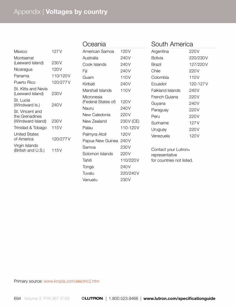
Mexico 127 V
Montserrat (Leeward Island) 230 V
Nicaragua 120 V
Panama 110/120 V
Puerto Rico 120/277 V
St. Kitts and Nevis (Leeward Island) 230 V
St. Lucia (Windward Is.) 240 V
St. Vincent and the Grenadines (Windward Island) 230 V
Trinidad & Tobago 115 V
United States of America 120/277 V
Virgin Islands (British and U.S.) 115 V
OceaniaAmerican Samoa 120 V
Australia 240 V
Cook Islands 240 V
Fiji 240 V
Guam 110 V
Kiribati 240 V
Marshall Islands 110 V
Micronesia (Federal States of) 120 V
Nauru 240 V
New Caledonia 220 V
New Zealand 230 V (CE)
Palau 110-120 V
Palmyra Atoll 120 V
Papua New Guinea 240 V
Samoa 230 V
Solomon Islands 220 V
Tahiti 110/220 V
Tonga 240 V
Tuvalu 220/240 V
Vanuatu 230 V
South AmericaArgentina 220 V
Bolivia 220/230 V
Brazil 127/220 V
Chile 220 V
Colombia 110 V
Ecuador 120-127 V
Falkland Islands 240 V
French Guiana 220 V
Guyana 240 V
Paraguay 220 V
Peru 220 V
Suriname 127 V
Uruguay 220 V
Venezuela 120 V
Contact your Lutron® representative for countries not listed.
Primary source: www.kropla.com/electric2.htm
Appendix | Voltages by country
694 Volume 3 P/N 367-2102 | 1.800.523.9466 | www.lutron.com/specificationguide
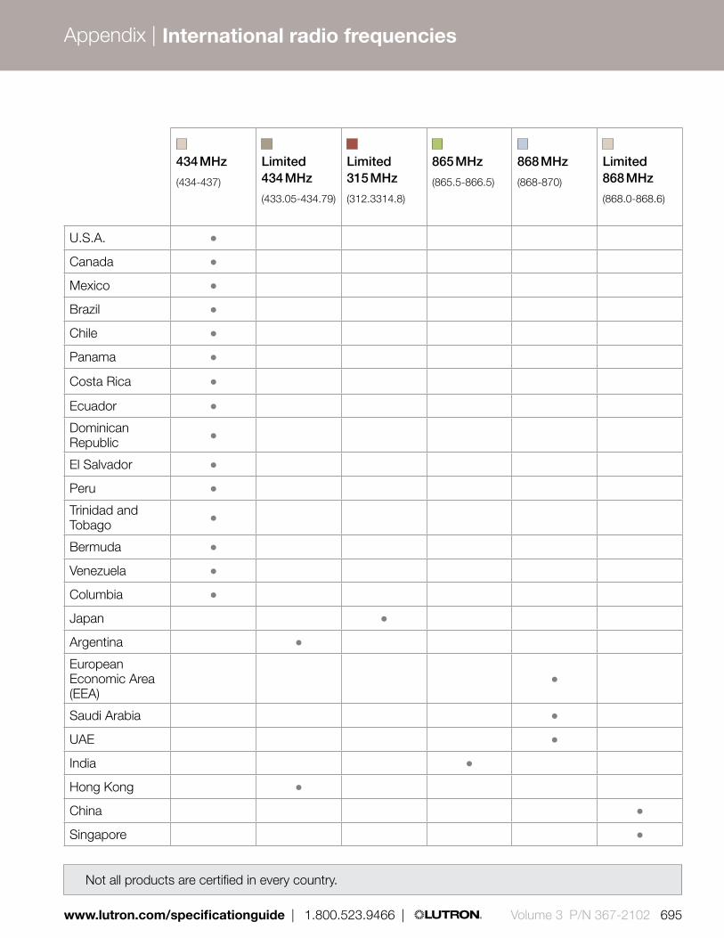
434 MHz
(434-437)
Limited 434 MHz
(433.05-434.79)
Limited 315 MHz
(312.3314.8)
865 MHz
(865.5-866.5)
868 MHz
(868-870)
Limited 868 MHz
(868.0-868.6)
U.S.A.
Canada
Mexico
Brazil
Chile
Panama
Costa Rica
Ecuador
Dominican Republic
El Salvador
Peru
Trinidad and Tobago
Bermuda
Venezuela
Columbia
Japan
Argentina
European Economic Area (EEA)
Saudi Arabia
UAE
India
Hong Kong
China
Singapore
Not all products are certified in every country.
www.lutron.com/specificationguide | 1.800.523.9466 | Volume 3 P/N 367-2102 695
Appendix | International radio frequencies

RF frequencies
434MHz
434MHz Limited Channel
865MHz
868MHz
868MHz Limited Channel
No RF product approvals
Singapore
Hong Kong
Macau
RF frequencies
434 MHz
434 MHz Limited Channel
315 MHz
865 MHz
868 MHz
868 MHz Limited Channel
No RF product approvals
696 Volume 3 P/N 367-2102 | 1.800.523.9466 | www.lutron.com/specificationguide
Appendix | International radio frequencies

RF frequencies
434MHz
434MHz Limited Channel
865MHz
868MHz
868MHz Limited Channel
No RF product approvals
Singapore
Hong Kong
Macau
www.lutron.com/specificationguide | 1.800.523.9466 | Volume 3 P/N 367-2102 697

Backbox styles
US style
Round backbox (EBB-15-RD)
Square backbox(EBB-15-SQ)
Italian style Backbox styles
U.S. style backbox
Round backbox (EBB-15-RD)
Square backbox (EBB-15-SQ)
Italian style backbox
698 Volume 3 P/N 367-2102 | 1.800.523.9466 | www.lutron.com/specificationguide
Appendix | International backbox styles

Backbox styles
US style
Round backbox (EBB-15-RD)
Square backbox(EBB-15-SQ)
Italian style
www.lutron.com/specificationguide | 1.800.523.9466 | Volume 3 P/N 367-2102 699
International backbox styles

Backbox dimensions
Square backbox (EBB-15-SQ)
1-gang box Width: 2.38 in (60 mm) Height: 2.38 in (60 mm) Depth: 1.88 in (47 mm)
2.38 in (60 mm) 1.88 in (47 mm)
U.S. style backbox
1-gang box Width: 2.00 in (51 mm) Height: 3.00 in (76 mm) Depth: 2.50 in (64 mm)
2.00 in (51 mm)
2.50 in (64 mm)
3.00 in (76 mm
)
Italian style backbox
1-gang box Width: 3.00 in (76 mm) Height: 2.00 in (51 mm) Depth: 2.50 in (64 mm)
2.00 in (51 m
m)
2.50 in (64 m
m)
3.00 in (76 mm)
Round backbox (EBB-15-RD)
1-gang box Width: 2.81 in (71 mm) Height: 2.81 in (71 mm) Depth: 2.38 in (60 mm)
2.81 in (71 mm)
2.38 in (60 mm)
700 Volume 3 P/N 367-2102 | 1.800.523.9466 | www.lutron.com/specificationguide
Appendix | International backbox styles

Power Draw Units (PDUs) on the QS LinkOn the QS link, there are devices that supply power and devices that consume power. Each device has a specific number of Power Draw Units (PDUs) it either supplies or consumes.
A Power Group consists of one device that supplies power and one or more devices that consume power; each Power Group may have only one power-supplying device.
Within Power Groups on the QS link, connect all four terminals (1, 2, 3, and 4), shown by the letter A in the diagram. Between devices on the QS link that supply power, connect only terminals 1, 3, and 4 (NOT terminal 2), shown by the letter B on the diagram.
Wiring can be T-tapped or daisy-chained.
LUTRON
LUTRON LUTRON
LUTRON
LUTRON
LUTRON
GRAFIK Eye® QScontrol unitSupplies PDUs
Energi Savr NodeTM QS unitSupplies PDUs
QS power supplySupplies PDUs
A
A
B
B
B
A
Control interfacesConsume PDUs
WallstationsConsume PDUs
WallstationsConsume PDUs
WallstationsConsume PDUs
Quantum® processor
Power group 1
Power group 2
Power group 3
Control interfacesConsume PDUs
QS sensor module with wired occupancy sensorConsumes PDUs
(Do not connect terminal 2: 24 V)
(Do not connect terminal 2: 24 V)
(Do not connect terminal 2: 24 V)
Wireless occupancy sensor does not consume PDUs
Note: Each QS link has a limit of 100 total devices; device count can vary depending on your system and your connected devices.
Connect only 3 terminals between power groups:
1: Common3 and 4: DataDo not connect Terminal 2: 24 V -
Connect all four terminals within a power group:
1: Common2: 24 V -3 and 4: Data
A
B
Power Group Wiring Example
www.lutron.com/specificationguide | 1.800.523.9466 | Volume 3 P/N 367-2102 701
Appendix | Power Draw Units (PDUs)

QS Power Draw Unit (PDU) information*On the QS link, there are devices that supply power and devices that consume power. Each device has a specific number of Power Draw Units (PDUs) it either supplies or consumes.
QS deviceProduct description
Model number
Zone count
Device count
PDUs supplied
PDUs consumed
GRAFIK Eye® QS
3-Zone phase control QSGRJ-3P 3
1
3
0
4-Zone phase control QSGRJ-4P 4
6-Zone phase control QSGRJ-6P 6
6-Zone EcoSystem® QSGRJ-6E 6
8-Zone EcoSystem QSGRJ-8E 8
16-Zone EcoSystem QSGRJ-16E 16
6-Zone DALI QSGRK-6D 6
38-Zone DALI QSGRK-8D 8
16-Zone DALI QSGRK-16D 16
Energi Savr NodeTM
Softswitch® QSN-4S16-S
4
1
14
0
0-10 V QSN-4T16-S
0-10 V/Switching (DIN-rail) QSNE-4T10-D
Switching (DIN-rail) QSNE-4S10-D
DALI (DIN-rail) QSNE-2DAL-D 16 3
EcoSystem Single-Link QSN-1ECO-S
Up to 100
30EcoSystem Dual-Link QSN-2ECO-S
3EcoSystem Dual-Link (DIN-rail) QSNE-2ECO-D
Phase-adaptive (DIN-rail) QSNE-4A-D 4 4
QS link power supply
Plug-in power supply QSPS-P1-1-500
0 80
10-Output shade panel QSPS-P1-10-60 1 8 per output
J-box power supply QSPS-J-1-50 0 0 8 0
DIN-rail power supply QSPS-DH-1-60 0 0 75 0
702 Volume 3 P/N 367-2102 | 1.800.523.9466 | www.lutron.com/specificationguide
Appendix | Power Draw Units (PDUs)

*Specification of Lutron® products subject to change. Review of current specification documents recommended.
QS deviceProduct description
Model number
Zone count
Device count
PDUs supplied
PDUs consumed
Quantum light management hub
QP2 QP2-0
1 or 2based on # of
processors
Link A:0
Link B, C, D:
32 each0
QP3 QP3-1PL-100-240 1 Link A, B: 32 each
QS sensor module
QS sensor module QSM2-4W-C
0
1
0
3
Added wired occ/vac sensor LOS-…
0
2
Added wired daylight sensor EC-DIR-WH 0.5
Added wired IR receiver EC-IR-WH 0.5
Added 4-button EcoSystem wallstation CC-4BRL-WH 1
Added Pico® Wired control PX-… 0.5
Other QS accessories
seeTouch® QS keypad QSWS2- 0
1 0
1
International QS keypad wallstation QSWE- 0 1
QS contact closure interface QSE-IO Up to
5 3
QS network interface QSE-CI-NWK-E 0 2
QS DMX interface QSE-CI-DMX 0 2
QS keyswitch QSWS2-KS... 0 1
QS infrared Eye QSE-IR-WH 0 1
Shades
Electronic Drive Unit — 1 1 0 See Spec. Submittal
QS Smart Panel Power Supply
— 1 1See
Spec. Submittal
0
www.lutron.com/specificationguide | 1.800.523.9466 | Volume 3 P/N 367-2102 703

QS deviceProduct description
Model number
Zone count
Device count
PDUs supplied
PDUs consumed
HomeWorks® QS
Processor HQP6-2-120 0 1 0 8
Hybrid repeater (without plug-in) HQR-REP-120 0 1 0 3
Hybrid repeater (with plug-in) HQR-REP-120 0 1 0 0
Wallbox power module HQRJ-WPM-6D-120 6 1 0 0
seeTouch keypad Various 0 1 0 1
Dynamic keypad HQ-J-DK420- 0 1 0 6
704 Volume 3 P/N 367-2102 | 1.800.523.9466 | www.lutron.com/specificationguide

www.lutron.com/specificationguide | 1.800.523.9466 | Volume 3 P/N 367-2102 705
Appendix |
The following are registered trademarks of Lutron Electronics Co., Inc.:
Abella; Aliante; Ariadni; Attaché; Aurora; Aviena; C•L; Ceana; Centurion; CERUS; Chronos; Claro; Clear Connect; Credenza; Daedalus; Dalia; Dimming by Lutron; Diva; Earn & Learn; Eco-10; eco-dim; eco-minder; EcoSystem; EcoSystem H-Series ballast; Energi Savr Node with EcoSystem; Energi Savr Node with Softswitch; Energi TriPak; Faedra; Fandial; Fassada; Finiré; Glyder; GRAFIK 6000; GRAFIK Eye; GRAFIK Eye 3600; GRAFIK Eye 4000; GRAFIK Eye 4100/4500; GRAFIK Eye QS; GRAFIK Eye QS with EcoSystem/DALI; GreenGlance; Greenovation; Hi-lume A-Series LED driver; Hi-lume ballast; Hi-lume 3D ballast; HomeWorks; HomeWorks Illumination; HomeWorks QS; Hyperion; Inflection; Ivalo; Kirbé; L’ale; Light Greener, Light Better; Lumea; Lutron; Lutron Dimmers Save Energy; Lyneo; Lyneo Lx; Maestro; Maestro IR; Maestro Wireless; microWATT; Milenyia; Nova; Nova TA; Orion; Osprey; Personna PC; Pico wireless control; Pico wired control; PowPak; Qoto; Quantum; Quantum Select; RadioRA; RadioRA 2; RadioTouch; Ranax; Rania; Rotare; RTISS Equipped; Satin Colors; Save Energy; See As You Save; seeTouch; seeTouch QS; Serena; SheerShade; Silvus; Sivoia; Sivoia QED; Sivoia QS; Skylark; Skylark Contour; Softswitch; Softswitch128; Solaris; Spacer; Spacer System; Stanza; TA; The Ultimate Home Theater Experience; Toggler; Triathlon; Tu-Wire; Vareo; Versaplex; Vierti; Viseo.
The following are trademarks of Lutron Electronics Co., Inc.:
2Link; Architrave; Athena; Athlite; Balance LC; Classico; ControlIT; DesignIT; Digital Micronet; Digital MicroWATT; Dim-N-Glo; Diva Duo; Earn & Learn Express; eLumen; Energi Savr Node; Energi Savr Node for 0-10 V/Switching; Energi Savr Node for DALI (DIN-rail); Energi Savr Node for 0-10 V/Switching (DIN-rail); FASS; Favorite Scene; GRAFIK 5000; GRAFIK 7000; GRAFIK Eye Designer; GRAFIK Eye Liaison; GRAFIK Integrale; GRAFIK RA; GRAFIK Systems; hand; Harmony; Hi-Power 2•4•6; HomeServe; HomeWorks Interactive; Individual lift and tilt control; LCP128; LuMasterTM Lumea2; Lustra; Lutron Controls Your Light; Maestro Duo; MeadowLark; microPS; micros; Millennium; Omnislide; One Spec; PictureIT; Piedra; Pre-Pack; Q-Admin; Q-Manage; Radio Powr Savr wireless occupancy/vacancy sensor; Radio Powr Savr wireless daylight sensor; Roller 100; Roller 20; Roller 225; Roller 64; Save Energy Beautifully; ScheduleIT; SecureIT; seeTemp; Signature Series; Simplicity. Convenience. Control; SmartDimmer; Softswitch 512; SOLos; Spec Editor; Sonata; Symphony; TapSwitch; Telume; The Avant Collection; Versaplex QS; Vibrato; Zone Capture.
Product approvals:
The products in this catalog are UL listed as required; most are CSA certified; many are NOM certified. Not all products carry all certifications.
Lutron trademarks

A history of sustainability, innovation and quality
SustainabilityAt Lutron, sustainability is not a new concept. Since 1961, we have been designing industry-leading technology that saves energy and reduces greenhouse gas emissions, and are a proud member of the U.S. Green Building Council.
Our philosophyLutron is a company built on a belief in taking care of the people: customers, employees, and the community. We innovate in advance of emerging market needs and continually improve our quality, our delivery, and our value.
InnovationLutron owns over 1,700 patents and manufactures more than 15,000 products. For over 45 years, we have met and exceeded the highest standards of quality and service. Every one of our products is quality-tested before it leaves the factory.
Global service and support
You can count on a level of support unequaled anywhere in the industry and anywhere in the world. Lutron provides 24/7 technical phone support. Lutron Field Service, made up of a global network of customer-focused field service engineers, provides world-class services that begin before your building is commissioned and continue throughout the life of your building.
SM
www.lutron.com
World Headquarters 1.610.282.3800Technical Support 1.800.523.9466 (Available 24/7)Customer Service 1.888.LUTRON1 (1.888.588.7661)
© 11/2012 Lutron Electronics Co., Inc. I P/N 367-2102 REV A