Mountlake Terrace Civic Campus
464
PROJECT SPECIFICATIONS FOR Mountlake Terrace Civic Campus VOLUME 2 (DIV 02-14) Prepared for: City of Mountlake Terrace 6100 219th St SW #200 Mountlake Terrace, WA 98043 Prepared by:
-
Upload
khangminh22 -
Category
Documents
-
view
2 -
download
0
Transcript of Mountlake Terrace Civic Campus

PROJECT SPECIFICATIONS FOR
Mountlake Terrace Civic Campus
VOLUME 2 (DIV 02-14)
Prepared for:
City of Mountlake Terrace 6100 219th St SW #200
Mountlake Terrace, WA 98043
Prepared by:

Mountlake Terrace Civic Campus
Prepared by ARC Architects
September 13, 2019
SECTION 00 00 00‐
TABLE OF CONTENTS
00 00 00 - 1
VOLUME 1 – DIVISIONS 00‐01 DIVISION 00 ‐ PROCUREMENT AND CONTRACTING REQUIREMENTS 00 00 00 CITY OF MOUNTLAKE TERRACE (MLT) CONTRACT PROVISIONS MLT INVITATION TO BID MLT INSTRUCTIONS TO BIDDERS BIDDER’S CHECKLIST BID PROPOSAL STATEMENT OF BIDDER’S QUALIFICATIONS STATEMENT OF PROPOSED SUBCONTRACTORS FOR HVAC, PLUMBING AND ELEC CERTIFICATION OF NON‐SEGREGATED FACILITIES NON‐COLLUSION AFFIDAVIT CERTIFICATION OF COMPLIANCE WITH WAGE PAYMENT STATUTES 00 11 16 INVITATION TO BID 00 21 13 INSTRUCTIONS TO BIDDERS 00 25 13 PREBID MEETINGS 00 26 00 PROCUREMENT SUBSTITUTION PROCEDURES 00 31 19 EXISTING CONDITION INFORMATION 00 31 32 GEOTECHNICAL DATA 00 31 43 PERMIT APPLICATION 00 43 73 PROPOSED SCHEDULE OF VALUES FORM 00 60 00 PROJECT FORMS
DIVISION 01 ‐ GENERAL REQUIREMENTS 01 10 00 SUMMARY 01 23 00 ALTERNATES 01 25 00 SUBSTITUTION PROCEDURES 01 26 00 CONTRACT MODIFICATION PROCEDURES 01 29 00 PAYMENT PROCEDURES 01 31 00 PROJECT MANAGEMENT AND COORDINATION 01 32 00 CONSTRUCTION PROGRESS DOCUMENTATION 01 32 33 PHOTOGRAPHIC DOCUMENTATION 01 33 00 SUBMITTAL PROCEDURES 01 35 16 ALTERATION PROJECT PROCEDURES 01 40 00 QUALITY REQUIREMENTS 01 42 00 REFERENCES 01 50 00 TEMPORARY FACILITIES AND CONTROLS 01 60 00 PRODUCT REQUIREMENTS 01 73 00 EXECUTION 01 74 19 CONSTRUCTION WASTE MANAGEMENT AND DISPOSAL 01 77 00 CLOSEOUT PROCEDURES 01 78 23 OPERATION AND MAINTENANCE DATA 01 78 39 PROJECT RECORD DOCUMENTS 01 79 00 DEMONSTRATION AND TRAINING 01 91 00 COMMISSIONING

Mountlake Terrace Civic Campus
Prepared by ARC Architects
September 13, 2019
SECTION 00 00 00‐
TABLE OF CONTENTS
00 00 00 - 2
VOLUME 1 APPENDIX AIA Document A701 "Instructions to Bidders" w/ City of Mountlake Terrace Amendments CSI Substitution Request Form 1.5C 1989.05.02 Geotechnical Report (Cascade Geotechnical, 1991 Police Station) 1989.10.20 Geotechnical Report (Cascade Geotechnical, 1991 Police Station) 2018.06.29 Geotechnical Report (Associated Earth Sciences, Police Addition & City Hall) 2018.08.15 Geotechnical Report (Associated Earth Sciences, Police Addition Drilled Piers) 2019.09.19 Geotechnical Sketch (Associated Earth Sciences, Geologic Cross Section A‐A) AIA Document G703S‐2017 “Schedule of Values Continuation Sheet” AIA Document A312‐2010 “Performance Bond” with City of Mountlake Terrace Amendments AIA Document A312‐2010 “Payment Bond” with City of Mountlake Terrace Amendments AIA Document G716‐2004 "Request for Information (RFI)" AIA Document G709‐2018 "Work Changes Proposal Request" AIA Document G701‐2017 "Change Order" AIA Document G710‐1992 "Architect's Supplemental Instructions" AIA Document G714‐2007 "Construction Change Directive" AIA Document G702‐1992/G703‐1992 "Application and Certificate for Payment & Continuation Sheet" AIA Document G706‐1994 "Contractor's Affidavit of Payment of Debts and Claims" AIA Document G706A‐1994 "Contractor's Affidavit of Payment of Release of Liens" AIA Document G707‐1994 "Consent of Surety to Final Payment" AIA Document A101‐2017 "Standard Form of Agreement between Owner and Contractor Where the Basis of Payment is a Stipulated Sum" with City of Mountlake Terrace Amendments AIA Document A101‐2017 Exhibit A “Insurance and Bonds” with City of Mountlake Terrace Amendments AIA Document A201‐2017 "General Conditions of the Contract for Construction" with City of Mountlake Terrace Amendments AIA Document G715‐2017 “Supplemental Attachment for ACORD Certificate of Insurance 25 ACORD Certificate of Liability Insurance Arborist Report (Symbiosis Tree Care, dated 4/11/2019) AIA Document A310‐2010 “Bid Bond” Department of Ecology, Cover Under the Construction Stormwater General Permit memo (October 08, 2019)
VOLUME 2 – DIVISIONS 02‐14 DIVISION 02 ‐ EXISTING CONDITIONS 02 41 19 SELECTIVE DEMOLITION
DIVISION 03 ‐ CONCRETE 03 10 00 CONCRETE FORMING 03 30 00 CAST‐IN‐PLACE CONCRETE 03 53 43 POLISHING CONCRETE FINISHING
DIVISION 04 ‐ MASONRY 04 22 00 CONCRETE UNIT MASONRY

Mountlake Terrace Civic Campus
Prepared by ARC Architects
September 13, 2019
SECTION 00 00 00‐
TABLE OF CONTENTS
00 00 00 - 3
DIVISION 05 ‐ METALS 05 12 00 STRUCTURAL STEEL FRAMING 05 50 00 METAL FABRICATIONS
DIVISION 06 ‐ WOOD, PLASTICS, AND COMPOSITES 06 10 00 ROUGH CARPENTRY 06 16 00 SHEATHING 06 17 53 SHOP‐FABRICATED WOOD TRUSSES 06 18 00 GLUED‐LAMINATED CONSTRUCTION 06 20 13 EXTERIOR FINISH CARPENTRY 06 20 23 INTERIOR FINISH CARPENTRY 06 41 16 PLASTIC‐LAMINATE‐CLAD ARCHITECTURAL CABINETS
DIVISION 07 ‐ THERMAL AND MOISTURE PROTECTION 07 11 13 BITUMINOUS DAMPPROOFING 07 17 16 BENTONITE WATERPROOFING 07 21 00 THERMAL INSULATION 07 25 00 WEATHER BARRIERS 07 31 13 ASPHALT SHINGLES 07 42 13.13 FORMED METAL WALL PANELS 07 52 16 STYRENE‐BUTADIENE‐STYRENE MODIFIED BITUMINOUS MEMBRANE ROOFING 07 62 00 SHEET METAL FLASHING AND TRIM 07 72 00 ROOF ACCESSORIES 07 84 13 PENETRATION FIRESTOPPING 07 92 00 JOINT SEALANTS
DIVISION 08 ‐ OPENINGS 08 11 13 HOLLOW METAL DOORS AND FRAMES 08 12 16 INTERIOR ALUMINUM FRAMES 08 14 16 FLUSH WOOD DOORS 08 14 23 ALUMINUM‐CLAD WOOD COMMERCIAL OUT SWING FRENCH HINGED DOORS 08 31 13 ACCESS DOORS AND FRAMES 08 33 26 OVERHEAD COILING GRILLES 08 33 36 SPRINGLESS ROLLING SERVICE DOORS 08 35 13 FOLDING WOOD‐FRAMED GLASS DOORS 08 53 13 VINYL WINDOWS 08 54 13 FIBERGLASS WINDOWS 08 71 00 DOOR HARDWARE 08 71 13 AUTOMATIC DOOR OPERATORS 08 80 00 GLAZING 08 91 19 FIXED LOUVERS
DIVISION 09 ‐ FINISHES 09 22 16 NON‐STRUCTURAL METAL FRAMING

Mountlake Terrace Civic Campus
Prepared by ARC Architects
September 13, 2019
SECTION 00 00 00‐
TABLE OF CONTENTS
00 00 00 - 4
09 29 00 GYPSUM BOARD 09 30 13 CERAMIC TILING 09 51 23 ACOUSTICAL TILE CEILINGS 09 51 26 ACOUSTICAL WOOD CEILINGS 09 54 43 STRETCHED‐FABRIC CEILING SYSTEMS 09 65 13 RESILIENT BASE AND ACCESSORIES 09 65 19 RESILIENT TILE FLOORING 09 68 13 TILE CARPETING 09 91 13 EXTERIOR PAINTING 09 91 23 INTERIOR PAINTING 09 93 00 STAINING AND TRANSPARENT FINISHING 09 96 00 HIGH‐PERFORMANCE COATINGS
DIVISION 10 ‐ SPECIALTIES 10 11 00 VISUAL DISPLAY UNITS 10 14 23 BUILDING SIGNAGE 10 21 13.17 PHENOLIC‐CORE TOILET COMPARTMENTS 10 26 00 WALL AND DOOR PROTECTION 10 28 00 TOILET, BATH, AND LAUNDRY ACCESSORIES 10 44 13 FIRE PROTECTION CABINETS 10 50 00 LOCKERS
DIVISION 11 ‐ EQUIPMENT 11 30 13 RESIDENTIAL APPLIANCES
DIVISION 12 ‐ FURNISHINGS 12 24 13 ROLLER WINDOW SHADES 12 36 61.16 SOLID SURFACING COUNTERTOPS
DIVISION 13 ‐ SPECIAL CONSTRUCTION NOT APPLICABLE
DIVISION 14 ‐ CONVEYING EQUIPMENT 14 24 00 HYDRAULIC PASSENGER ELEVATORS
VOLUME 3 – DIVISIONS 21‐33 DIVISION 21 – FIRE SUPPRESSION 21 05 00 COMMON WORK RESULTS FOR FIRE SUPPRESSION 21 10 00 AUTOMATIC FIRE PROTECTION SYSTEMS DIVISION 22 – PLUMBING 22 05 00 COMMON WORK RESULTS FOR PLUMBING 22 05 29 HANGERS AND SUPPORTS FOR PLUMBING PIPING AND EQUIPMENT 22 05 53 PAINTING AND IDENTIFICATION FOR PLUMBING PIPING AND EQUIPMENT

Mountlake Terrace Civic Campus
Prepared by ARC Architects
September 13, 2019
SECTION 00 00 00‐
TABLE OF CONTENTS
00 00 00 - 5
22 05 93 TESTING, ADJUSTING, AND BALANCING FOR PLUMBING 22 07 00 PLUMBING INSULATION 22 10 00 PLUMBING PIPING AND PUMPS 22 33 00 DOMESTIC WATER HEATERS 22 40 00 PLUMBING FIXTURES DIVISION 23 – HEATING, VENTILATING, AND AIR‐CONDITIONING (HVAC) 23 05 00 COMMON WORK RESULTS FOR HVAC 23 05 23 GENERAL‐DUTY VALVES FOR HVAC PIPING 23 05 29 HANGERS AND SUPPORTS FOR HVAC PIPING AND EQUIPMENT 23 05 48 VIBRATION AND SEISMIC CONTROLS FOR HVAC PIPING AND EQUIPMENT 23 05 53 PAINTING AND IDENTIFICATION FOR HVAC PIPING, DUCTS, AND EQUIPMENT 23 05 93 TESTING, ADJUSTING, AND BALANCING FOR HVAC 23 08 00 COMMISSIONING OF HVAC 23 09 00 INSTRUMENTATION AND CONTROL FOR HVAC 23 11 00 FACILITY FUEL PIPING 23 20 00 HVAC PIPING AND PUMPS 23 25 00 HVAC WATER TREATMENT 23 30 00 HVAC AIR DISTRIBUTION 23 34 00 HVAC FANS 23 50 00 CENTRAL HEATING EQUIPMENT 23 60 00 CENTRAL COOLING EQUIPMENT 23 80 00 DECENTRALIZED HVAC EQUIPMENT DIVISION 25 ‐ INTEGRATED AUTOMATION NOT APPLICABLE
DIVISION 26 ‐ ELECTRICAL 26 01 26 ACCEPTANCE TESTING OF ELECTRICAL SYSTEMS 26 05 00 COMMON WORK RESULTS FOR ELECTRICAL 26 05 10 EXISTING SYSTEMS 26 05 19 LOW‐VOLTAGE ELECTRICAL POWER CONDUCTORS AND CABLES 26 05 26 GROUNDING AND BONDING FOR ELECTRICAL SYSTEMS 26 05 29 HANGERS AND SUPPORTS FOR ELECTRICAL SYSTEMS 26 05 33 RACEWAYS AND BOXES FOR ELECTRICAL SYSTEMS 26 05 33.10 FLUSH FLOOR OUTLETS 26 05 40 ELECTRICAL SITE WORK 26 05 53 IDENTIFICATION FOR ELECTRICAL SYSTEMS 26 05 73 OVERCURRENT PROTECTIVE DEVICE COORDINATION STUDY 26 05 75 ELECTRIC SERVICE 26 09 23 LIGHTING CONTROL DEVICES 26 09 43 NETWORK LIGHTING CONTROLS 26 24 16 PANELBOARDS 26 27 26 WIRING DEVICES 26 28 13 FUSES

Mountlake Terrace Civic Campus
Prepared by ARC Architects
September 13, 2019
SECTION 00 00 00‐
TABLE OF CONTENTS
00 00 00 - 6
26 28 16 ENCLOSED SWITCHES AND CIRCUIT BREAKERS 26 32 13 ENGINE GENERATORS 26 36 00 TRANSFER SWITCHES 26 43 13 SURGE PROTECTIVE DEVICES 26 51 00 INTERIOR LIGHTING 26 56 00 EXTERIOR LIGHTING DIVISION 27 ‐ COMMUNICATIONS 27 05 00 COMMON WORK RESULTS FOR COMMUNICATIONS 27 05 26 GROUNDING AND BONDING FOR COMMUNICATIONS SYSTEMS 27 05 28 PATHWAYS FOR COMMUNICATION SYSTEMS 27 05 29 HANGERS AND SUPPORTS FOR COMMUNICATIONS SYSTEMS 27 05 33 CONDUITS AND BACKBOXES FOR COMMUNICATIONS SYSTEMS 27 05 36 CABLE TRAYS FOR COMMUNICATIONS SYSTEMS 27 05 43 UNDERGROUND DUCTS AND RACEWAYS FOR COMMUNICATIONS SYSTEMS 27 05 44 SLEEVES AND SLEEVE SEALS FOR COMMUNICATIONS PATHWAYS AND CABLING 27 11 00 COMMUNICATIONS EQUIPMENT ROOM FITTINGS 27 13 00 COMMUNICATION BACKBONE CABLING 27 15 00 COMMUNICATIONS HORIZONTAL CABLING 27 41 16 INTEGRATED AUDIOVISUAL SYSTEMS AND EQUIPMENT DIVISION 28 ‐ ELECTRONIC SAFETY AND SECURITY 28 05 00 COMMON WORK RESULTS FOR ELECTRONIC SAFETY AND SECURITY 28 05 13 CONDUCTORS AND CABLES FOR ELECTRONIC SAFETY AND SECURITY 28 13 00 ACCESS CONTROL 28 13 10 DOOR CONTROL PROVISIONS 28 23 00 VIDEO SURVEILLANCE 28 31 11 DIGITAL, ADDRESSABLE FIRE ALARM SYSTEM DIVISION 31 ‐ EARTHWORK 31 00 00 SITE EARTHWORK 31 25 00 TEMPORARY EROSION AND SEDIMENTATION CONTROL 31 62 17 DRIVEN STEEL PILES
DIVISION 32 ‐ EXTERIOR IMPROVEMENTS 32 10 00 BASE AND PAVING 32 12 16 ASPHALT PAVING 32 13 13 CAST‐IN‐PLACE CONCRETE PAVEMENT 32 17 23 PAVEMENT MARKINGS 32 30 00 SITE IMPROVEMENTS 32 31 00 FENCES AND GATES 32 84 00 IRRIGATION 32 90 00 PLANTING PREPARATION 32 93 00 PLANTING DIVISION 33 ‐ UTILITIES

Mountlake Terrace Civic Campus
Prepared by ARC Architects
September 13, 2019
SECTION 00 00 00‐
TABLE OF CONTENTS
00 00 00 - 7
33 10 00 WATER UTILITIES 33 13 00 DISINFECTING OF WATER UTILITY DISTRIBUTION 33 30 00 SANITARY SEWER UTILITIES 33 40 00 STORM DRAINAGE UTILITIES VOLUME 3 APPENDIX City of Mountlake Terrace Standard Details (35pgs)
END OF TABLE OF CONTENTS

Mountlake Terrace Civic CampusPrepared by ARC ArchitectsSeptember 13, 2019
SECTION 02 41 19 - SELECTIVE DEMOLITION
02 41 19 - 1
SECTION 02 41 19 - SELECTIVE DEMOLITION
PART 1 - GENERAL
1.1 RELATED DOCUMENTS
A. Drawings and general provisions of the Contract, including General and Supplementary Conditions and Division 01 Specification Sections, apply to this Section.
1.2 SUMMARY
A. Section Includes:
1. Demolition and removal of selected portions of building or structure.2. Demolition and removal of selected site elements.3. Salvage of existing items to be reused or recycled.
B. Related Requirements:
1. Section 01 10 00 "Summary" for restrictions on use of the premises, Owner-occupancy requirements, and phasing requirements.
2. Section 01 73 00 "Execution" for cutting and patching procedures.3. Section 01 35 16 "Alteration Project Procedures" for general protection and work
procedures for alteration projects.4. Section 31 10 00 "Site Clearing" for site clearing and removal of above- and below-grade
improvements not part of selective demolition.
1.3 DEFINITIONS
A. Remove: Detach items from existing construction and dispose of them off-site unless indicated to be salvaged or reinstalled.
B. Remove and Salvage: Detach items from existing construction, in a manner to prevent damage, and deliver to Owner ready for store.
C. Remove and Reinstall: Detach items from existing construction, in a manner to prevent damage, prepare for reuse, and reinstall where indicated.
D. Existing to Remain: Leave existing items that are not to be removed and that are not otherwise indicated to be salvaged or reinstalled.

Mountlake Terrace Civic CampusPrepared by ARC ArchitectsSeptember 13, 2019
SECTION 02 41 19 - SELECTIVE DEMOLITION
02 41 19 - 2
E. Dismantle: To remove by disassembling or detaching an item from a surface, using gentle methods and equipment to prevent damage to the item and surfaces; disposing of items unless indicated to be salvaged or reinstalled.
1.4 MATERIALS OWNERSHIP
A. Unless otherwise indicated, demolition waste becomes property of Contractor.
B. Historic items, relics, antiques, and similar objects including, but not limited to, cornerstones and their contents, commemorative plaques and tablets, and other items of interest or value to Owner that may be uncovered during demolition remain the property of Owner.
1. Carefully salvage in a manner to prevent damage and promptly return to Owner.
1.5 PREINSTALLATION MEETINGS
A. Pre-demolition Conference: Conduct conference at Project site.
1. Inspect and discuss condition of construction to be selectively demolished.2. Review structural load limitations of existing structure.3. Review and finalize selective demolition schedule and verify availability of materials,
demolition personnel, equipment, and facilities needed to make progress and avoid delays.
4. Review requirements of work performed by other trades that rely on substrates exposed by selective demolition operations.
5. Review areas where existing construction is to remain and requires protection.
1.6 INFORMATIONAL SUBMITTALS
A. Qualification Data: For refrigerant recovery technician.
B. Engineering Survey: Submit engineering survey of condition of building.
C. Proposed Protection Measures: Submit report, including Drawings, that indicates the measures proposed for protecting individuals and property for dust control. Indicate proposed locations and construction of barriers.
D. Schedule of Selective Demolition Activities: Indicate the following:
1. Detailed sequence of selective demolition and removal work, with starting and ending dates for each activity. Ensure Owner's on-site operations are uninterrupted.
2. Interruption of utility services. Indicate how long utility services will be interrupted.3. Coordination for shutoff, capping, and continuation of utility services.4. Use of elevator and stairs.

Mountlake Terrace Civic CampusPrepared by ARC ArchitectsSeptember 13, 2019
SECTION 02 41 19 - SELECTIVE DEMOLITION
02 41 19 - 3
5. Coordination of Owner's continuing occupancy of portions of existing building and of Owner's partial occupancy of completed Work.
E. Pre-demolition Photographs or Video: Show existing conditions of adjoining construction, including finish surfaces, that might be misconstrued as damage caused by demolition operations. Comply with Section 01 32 33 "Photographic Documentation." Submit before Work begins.
F. Statement of Refrigerant Recovery: Signed by refrigerant recovery technician responsible for recovering refrigerant, stating that all refrigerant that was present was recovered and that recovery was performed according to EPA regulations. Include name and address of technician and date refrigerant was recovered.
G. Warranties: Documentation indicating that existing warranties are still in effect after completion of selective demolition.
1.7 QUALITY ASSURANCE
A. Refrigerant Recovery Technician Qualifications: Certified by an EPA-approved certification program.
1.8 FIELD CONDITIONS
A. Owner will occupy portions of building immediately adjacent to selective demolition area. Conduct selective demolition so Owner's operations will not be disrupted.
B. Conditions existing at time of inspection for bidding purpose will be maintained by Owner as far as practical.
1. Before selective demolition, Owner will remove the following items:a. Bronze Sculpture (Police Entry)
C. Notify Architect of discrepancies between existing conditions and Drawings before proceeding with selective demolition.
D. Hazardous Materials: It is not expected that hazardous materials will be encountered in the Work.
1. Hazardous materials will be removed by Owner before start of the Work.2. If suspected hazardous materials are encountered, do not disturb; immediately notify
Architect and Owner. Hazardous materials will be removed by Owner under a separate contract.
E. Storage or sale of removed items or materials on-site is not permitted.

Mountlake Terrace Civic CampusPrepared by ARC ArchitectsSeptember 13, 2019
SECTION 02 41 19 - SELECTIVE DEMOLITION
02 41 19 - 4
F. Utility Service: Maintain existing utilities indicated to remain in service and protect them against damage during selective demolition operations.
1. Maintain fire-protection facilities in service during selective demolition operations.
1.9 WARRANTY
A. Existing Warranties: Remove, replace, patch, and repair materials and surfaces cut or damaged during selective demolition, by methods and with materials and using approved contractors so as not to void existing warranties. Notify warrantor before proceeding.
B. Notify warrantor on completion of selective demolition, and obtain documentation verifying that existing system has been inspected and warranty remains in effect. Submit documentation at Project closeout.
1.10 COORDINATION
A. Arrange selective demolition schedule so as not to interfere with Owner's operations.
PART 2 - PRODUCTS
2.1 PERFORMANCE REQUIREMENTS
A. Regulatory Requirements: Comply with governing EPA notification regulations before beginning selective demolition. Comply with hauling and disposal regulations of authorities having jurisdiction.
B. Standards: Comply with ASSE A10.6 and NFPA 241.
EXECUTION
2.2 EXAMINATION
A. Verify that utilities have been disconnected and capped before starting selective demolition operations.
B. Review Project Record Documents of existing construction or other existing condition and hazardous material information provided by Owner. Owner does not guarantee that existing conditions are same as those indicated in Project Record Documents.
C. Engage a professional engineer to perform an engineering survey of condition of building to determine whether removing any element might result in structural deficiency or unplanned

Mountlake Terrace Civic CampusPrepared by ARC ArchitectsSeptember 13, 2019
SECTION 02 41 19 - SELECTIVE DEMOLITION
02 41 19 - 5
collapse of any portion of structure or adjacent structures during selective building demolition operations.
1. Perform surveys as the Work progresses to detect hazards resulting from selective demolition activities.
D. Verify that hazardous materials have been remediated before proceeding with building demolition operations.
E. Survey of Existing Conditions: Record existing conditions by use of preconstruction photographs and measured drawings.
1. Comply with requirements specified in Section 01 32 33 "Photographic Documentation."2. Inventory and record the condition of items to be removed and salvaged. Provide
photographs or video of conditions that might be misconstrued as damage caused by salvage operations.
3. Before selective demolition or removal of existing building elements that will be reproduced or duplicated in final Work, make permanent record of measurements, materials, and construction details required to make exact reproduction.
2.3 PREPARATION
A. Refrigerant: Before starting demolition, remove refrigerant from mechanical equipment according to 40 CFR 82 and regulations of authorities having jurisdiction.
2.4 UTILITY SERVICES AND MECHANICAL/ELECTRICAL SYSTEMS
A. Existing Services/Systems to Remain: Maintain services/systems indicated to remain and protect them against damage.
B. Existing Services/Systems to Be Removed, Relocated, or Abandoned: Locate, identify, disconnect, and seal or cap off utility services and mechanical/electrical systems serving areas to be selectively demolished.
1. Owner will arrange to shut off indicated services/systems when requested by Contractor.
2. Arrange to shut off utilities with utility companies.3. If services/systems are required to be removed, relocated, or abandoned, provide
temporary services/systems that bypass area of selective demolition and that maintain continuity of services/systems to other parts of building.
4. Disconnect, demolish, and remove fire-suppression systems, plumbing, and HVAC systems, equipment, and components indicated on Drawings to be removed.
a. Piping to Be Removed: Remove portion of piping indicated to be removed and cap or plug remaining piping with same or compatible piping material.

Mountlake Terrace Civic CampusPrepared by ARC ArchitectsSeptember 13, 2019
SECTION 02 41 19 - SELECTIVE DEMOLITION
02 41 19 - 6
b. Piping to Be Abandoned in Place: Drain piping and cap or plug piping with same or compatible piping material and leave in place.
c. Equipment to Be Removed: Disconnect and cap services and remove equipment.d. Equipment to Be Removed and Reinstalled: Disconnect and cap services and
remove, clean, and store equipment; when appropriate, reinstall, reconnect, and make equipment operational.
e. Equipment to Be Removed and Salvaged: Disconnect and cap services and remove equipment and deliver to Owner.
f. Ducts to Be Removed: Remove portion of ducts indicated to be removed and plug remaining ducts with same or compatible ductwork material.
g. Ducts to Be Abandoned in Place: Cap or plug ducts with same or compatible ductwork material and leave in place.
2.5 PROTECTION
A. Temporary Protection: Provide temporary barricades and other protection required to prevent injury to people and damage to adjacent buildings and facilities to remain.
1. Provide protection to ensure safe passage of people around selective demolition area and to and from occupied portions of building.
2. Provide temporary weather protection, during interval between selective demolition of existing construction on exterior surfaces and new construction, to prevent water leakage and damage to structure and interior areas.
3. Protect walls, ceilings, floors, and other existing finish work that are to remain or that are exposed during selective demolition operations.
4. Cover and protect furniture, furnishings, and equipment that have not been removed.5. Comply with requirements for temporary enclosures, dust control, heating, and cooling
specified in Section 01 50 00 "Temporary Facilities and Controls."
B. Temporary Shoring: Design, provide, and maintain shoring, bracing, and structural supports as required to preserve stability and prevent movement, settlement, or collapse of construction and finishes to remain, and to prevent unexpected or uncontrolled movement or collapse of construction being demolished.
1. Strengthen or add new supports when required during progress of selective demolition.
C. Remove temporary barricades and protections where hazards no longer exist.
2.6 SELECTIVE DEMOLITION, GENERAL
A. General: Demolish and remove existing construction only to the extent required by new construction and as indicated. Use methods required to complete the Work within limitations of governing regulations and as follows:

Mountlake Terrace Civic CampusPrepared by ARC ArchitectsSeptember 13, 2019
SECTION 02 41 19 - SELECTIVE DEMOLITION
02 41 19 - 7
1. Proceed with selective demolition systematically, from higher to lower level. Complete selective demolition operations above each floor or tier before disturbing supporting members on the next lower level.
2. Neatly cut openings and holes plumb, square, and true to dimensions required. Use cutting methods least likely to damage construction to remain or adjoining construction. Use hand tools or small power tools designed for sawing or grinding, not hammering and chopping. Temporarily cover openings to remain.
3. Cut or drill from the exposed or finished side into concealed surfaces to avoid marring existing finished surfaces.
4. Do not use cutting torches until work area is cleared of flammable materials. At concealed spaces, such as duct and pipe interiors, verify condition and contents of hidden space before starting flame-cutting operations. Maintain portable fire-suppression devices during flame-cutting operations.
5. Maintain fire watch during and for at least 1hr hours after flame-cutting operations.6. Maintain adequate ventilation when using cutting torches.7. Remove decayed, vermin-infested, or otherwise dangerous or unsuitable materials and
promptly dispose of off-site.8. Remove structural framing members and lower to ground by method suitable to avoid
free fall and to prevent ground impact or dust generation.9. Locate selective demolition equipment and remove debris and materials so as not to
impose excessive loads on supporting walls, floors, or framing.10. Dispose of demolished items and materials promptly. Comply with requirements in
Section 01 74 19 "Construction Waste Management and Disposal."
B. Site Access and Temporary Controls: Conduct selective demolition and debris-removal operations to ensure minimum interference with roads, streets, walks, walkways, and other adjacent occupied and used facilities.
C. Removed and Salvaged Items:
1. Clean salvaged items.2. Pack or crate items after cleaning. Identify contents of containers.3. Store items in a secure area until delivery to Owner.4. Transport items to Owner's storage area designated by Owner.5. Protect items from damage during transport and storage.
D. Removed and Reinstalled Items:
1. Clean and repair items to functional condition adequate for intended reuse.2. Pack or crate items after cleaning and repairing. Identify contents of containers.3. Protect items from damage during transport and storage.4. Reinstall items in locations indicated. Comply with installation requirements for new
materials and equipment. Provide connections, supports, and miscellaneous materials necessary to make item functional for use indicated.
E. Existing Items to Remain: Protect construction indicated to remain against damage and soiling during selective demolition. When permitted by Architect, items may be removed to a

Mountlake Terrace Civic CampusPrepared by ARC ArchitectsSeptember 13, 2019
SECTION 02 41 19 - SELECTIVE DEMOLITION
02 41 19 - 8
suitable, protected storage location during selective demolition and reinstalled in their original locations after selective demolition operations are complete.
2.7 SELECTIVE DEMOLITION PROCEDURES FOR SPECIFIC MATERIALS
A. Concrete: Demolish in small sections. Using power-driven saw, cut concrete to a depth of at least 3/4 inch at junctures with construction to remain. Dislodge concrete from reinforcement at perimeter of areas being demolished, cut reinforcement, and then remove remainder of concrete. Neatly trim openings to dimensions indicated.
B. Concrete: Demolish in sections. Cut concrete full depth at junctures with construction to remain and at regular intervals using power-driven saw, and then remove concrete between saw cuts.
C. Masonry: Demolish in small sections. Cut masonry at junctures with construction to remain, using power-driven saw, and then remove masonry between saw cuts.
D. Concrete Slabs-on-Grade: Saw-cut perimeter of area to be demolished, and then break up and remove.
E. Resilient Floor Coverings: Remove floor coverings and adhesive according to recommendations in RFCI's "Recommended Work Practices for the Removal of Resilient Floor Coverings."
2.8 DISPOSAL OF DEMOLISHED MATERIALS
A. Remove demolition waste materials from Project site and recycle or dispose of them according to Section 01 74 19 "Construction Waste Management and Disposal."
1. Do not allow demolished materials to accumulate on-site.2. Remove and transport debris in a manner that will prevent spillage on adjacent surfaces
and areas.3. Remove debris from elevated portions of building by chute, hoist, or other device that
will convey debris to grade level in a controlled descent.4. Comply with requirements specified in Section 01 74 19 "Construction Waste
Management and Disposal."
B. Burning: Do not burn demolished materials.
2.9 CLEANING
A. Clean adjacent structures and improvements of dust, dirt, and debris caused by selective demolition operations. Return adjacent areas to condition existing before selective demolition operations began.
END OF SECTION 02 41 19
Mountlake Terrace Civic CampusPrepared by ARC ArchitectsSeptember 13, 2019
SECTION 03 10 00 – CONCRETE FORMING
03 10 00 - 1
SECTION 03 10 00 – CONCRETE FORMING
PART 1 - GENERAL
1.1 RELATED DOCUMENTS
A. Drawings and general provisions of the Contract, including General and Supplementary Conditions and Division 01 Specification Sections, apply to this Section.
1.2 SUMMARY
A. Section Includes:
1. Form-facing material for cast-in-place concrete.2. Form liners.
B. Related Requirements:
1. Section 321313 "Concrete Paving" for formwork related to concrete pavement and walks.
2. Section 321316 "Decorative Concrete Paving" for formwork related to decorative concrete pavement and walks.
1.3 DEFINITIONS
A. Form-Facing Material: Temporary structure or mold for the support of concrete while the concrete is setting and gaining sufficient strength to be self-supporting.
B. Formwork: The total system of support of freshly placed concrete, including the mold or sheathing that contacts the concrete, as well as supporting members, hardware, and necessary bracing.
1.4 PREINSTALLATION MEETINGS
A. Preinstallation Conference: Conduct conference at Project site.
1. Review the following:
a. Special inspection and testing and inspecting agency procedures for field quality control.
b. Construction, movement, contraction, and isolation jointsc. Forms and form-removal limitations.d. Anchor rod and anchorage device installation tolerances.

Mountlake Terrace Civic CampusPrepared by ARC ArchitectsSeptember 13, 2019
SECTION 03 10 00 – CONCRETE FORMING
03 10 00 - 2
1.5 ACTION SUBMITTALS
A. Product Data: For each of the following:
1. Exposed surface form-facing material.2. Concealed surface form-facing material.3. Forms for cylindrical columns.4. Form liners.5. Form ties.6. Waterstops.7. Form-release agent.
B. Shop Drawings: Prepared by, and signed and sealed by, a qualified professional engineer responsible for their preparation, detailing fabrication, assembly, and support of forms.
1. For exposed vertical concrete walls, indicate dimensions and form tie locations.2. Indicate dimension and locations of construction and movement joints required to
construct the structure in accordance with ACI 301 (ACI 301M).
a. Location of construction joints is subject to approval of the Architect.3. Indicate form liner layout and form line termination details.
C. Samples:
1. For waterstops.2. For Form Liners: 12-inch by 12-inch (305-mm by 305-mm) sample, indicating texture.
1.6 INFORMATIONAL SUBMITTALS
A. Research Reports: For insulating concrete forms indicating compliance with International Code Council Acceptance Criteria AC353.
B. Minutes of preinstallation conference.
1.7 QUALITY ASSURANCE
A. Mockups: Formed surfaces to demonstrate typical joints, surface finish, texture, tolerances, and standard of workmanship.
1. Build panel approximately 20 sq. ft. (9.3 sq. m) in the location indicated or, if not indicated, as directed by Architect.
2. Subject to compliance with requirements, approved mockups may become part of the completed Work.

Mountlake Terrace Civic CampusPrepared by ARC ArchitectsSeptember 13, 2019
SECTION 03 10 00 – CONCRETE FORMING
03 10 00 - 3
1.8 DELIVERY, STORAGE, AND HANDLING
A. Form Liners: Store form liners under cover to protect from sunlight.
B. Waterstops: Store waterstops under cover to protect from moisture, sunlight, dirt, oil, and other contaminants.
PART 2 - PRODUCTS
2.1 PERFORMANCE REQUIREMENTS
A. Concrete Formwork: Design, engineer, erect, shore, brace, and maintain formwork in accordance with ACI 301 (ACI 301M), to support vertical, lateral, static, and dynamic loads, and construction loads that might be applied, until structure can support such loads, so that resulting concrete conforms to the required shapes, lines, and dimensions.
1. Design wood panel forms in accordance with APA's "Concrete Forming Design/Construction Guide."
2. Design formwork to limit deflection of form-facing material to 1/240 of center-to-center spacing of supports.
2.2 FORM-FACING MATERIALS
A. Concealed Surface Form-Facing Material: Lumber, plywood, metal, plastic, or another approved material.
1. Provide lumber dressed on at least two edges and one side for tight fit.
B. Forms for Cylindrical Columns, Pedestals, and Supports: Metal, glass-fiber-reinforced plastic, paper, or fiber tubes that produce surfaces without spiral or vertical seams.
1. Provide forms with sufficient wall thickness to resist plastic concrete loads without detrimental deformation.
C. Form Liners, all visible and non-cylindrical vertical surfaces:
1. Manufacturers: Subject to compliance with requirements, provide products by one of the following:
a. Architectural Polymers, Inc.b. Fitzgerald Formliners.c. Sika Corporation.d. Spec Formliners, Inc.e. <or as approved by Architect>
Mountlake Terrace Civic CampusPrepared by ARC ArchitectsSeptember 13, 2019
SECTION 03 10 00 – CONCRETE FORMING
03 10 00 - 4
2. Basis of Design Product:
a. Manufacturer: Spec Formliners, Inc.
b. Product: ThermoSpec, Single / Multi-use Plastic Formliner
c. Pattern: #1731 Random 3/16” Striation
d. Pattern Orientation: Linear pattern oriented vertically
WATERSTOPS
D. Flexible Rubber Waterstops: U.S. Army Corps of Engineers CRD-C 513, for embedding in concrete to prevent passage of fluids through joints. Factory fabricate corners, intersections, and directional changes.
1. Manufacturers: Subject to compliance with requirements, provide products by one of the following:
a. Williams Products, Inc.b. <or as approved by Architect>.
2. Profile: Flat dumbbell with center bulb3. Dimensions: 4 inches by 3/16 inch thick (100 mm by 4.8 mm thick), nontapered.
2.3 RELATED MATERIALS
A. Reglets: Fabricate reglets of not less than 0.022-inch- (0.55-mm-) thick, galvanized-steel sheet. Temporarily fill or cover face opening of reglet to prevent intrusion of concrete or debris.
B. Dovetail Anchor Slots: Hot-dip galvanized-steel sheet, not less than 0.034 inch (0.85 mm) thick, with bent tab anchors. Temporarily fill or cover face opening of slots to prevent intrusion of concrete or debris.
C. Chamfer Strips: Wood, metal, PVC, or rubber strips, 3/4 by 3/4 inch (19 by 19 mm), minimum.
D. Rustication Strips: Wood, metal, PVC, or rubber strips, kerfed for ease of form removal.
E. Form-Release Agent: Commercially formulated form-release agent that does not bond with, stain, or adversely affect concrete surfaces and does not impair subsequent treatments of concrete surfaces.
1. Basis-of-Design Product: Subject to compliance with requirements, provide Kaufman Products, Inc.; FormKote OTC or a comparable product from manufacturers listed.
a. Cresset Chemical Company.

Mountlake Terrace Civic CampusPrepared by ARC ArchitectsSeptember 13, 2019
SECTION 03 10 00 – CONCRETE FORMING
03 10 00 - 5
b. Euclid Chemical Company.c. <or as approved by Architect>.
2. Volatile Organic Compounds (VOC): 250 g/L or less per EPA Test Method 24; with a test report demonstrating compliance dated within the past 12 months.
3. Formulate form-release agent with rust inhibitor for steel form-facing materials.4. Form release agent for form liners shall be acceptable to form liner manufacturer.
F. Form Ties: Factory-fabricated, removable or snap-off, glass-fiber-reinforced plastic or metal form ties designed to resist lateral pressure of fresh concrete on forms and to prevent spalling of concrete on removal.
1. Furnish units that leave no corrodible metal closer than 1 inch (25 mm) to the plane of exposed concrete surface.
2. Furnish ties that, when removed, leave holes no larger than 1 inch (25 mm) in diameter in concrete surface.
3. Furnish ties with integral water-barrier plates to walls indicated to receive dampproofing or waterproofing.
PART 3 - EXECUTION
3.1 INSTALLATION OF FORMWORK
A. Comply with ACI 301 (ACI 301M).
B. Construct formwork, so concrete members and structures are of size, shape, alignment, elevation, and position indicated, within tolerance limits of ACI 117 (ACI 117M) and to comply with the Surface Finish designations specified in Section 033000 "Cast-In-Place Concrete" for as-cast finishes
C. Limit concrete surface irregularities as follows:
1. Surface Finish-1.0: ACI 117 Class D, 1 inch (25 mm).2. Surface Finish-2.0: ACI 117 Class B, 1/4 inch (6 mm).3. Surface Finish-3.0: ACI 117 Class A, 1/8 inch (3.0 mm).
D. Construct forms tight enough to prevent loss of concrete mortar.
1. Minimize joints.2. Exposed Concrete: Symmetrically align joints in forms.
E. Construct removable forms for easy removal without hammering or prying against concrete surfaces.
1. Provide crush or wrecking plates where stripping may damage cast-concrete surfaces.2. Provide top forms for inclined surfaces steeper than 1.5 horizontal to 1 vertical.

Mountlake Terrace Civic CampusPrepared by ARC ArchitectsSeptember 13, 2019
SECTION 03 10 00 – CONCRETE FORMING
03 10 00 - 6
3. Install keyways, reglets, recesses, and other accessories, for easy removal.
F. Do not use rust-stained, steel, form-facing material.
G. Set edge forms, bulkheads, and intermediate screed strips for slabs to achieve required elevations and slopes in finished concrete surfaces.
1. Provide and secure units to support screed strips2. Use strike-off templates or compacting-type screeds.
H. Provide temporary openings for cleanouts and inspection ports where interior area of formwork is inaccessible.
1. Close openings with panels tightly fitted to forms and securely braced to prevent loss of concrete mortar.
2. Locate temporary openings in forms at inconspicuous locations.
I. Chamfer exterior corners and edges of permanently exposed concrete.
J. At construction joints, overlap forms onto previously placed concrete not less than 12 inches (305 mm).
K. Form openings, chases, offsets, sinkages, keyways, reglets, blocking, screeds, and bulkheads required in the Work.
1. Determine sizes and locations from trades providing such items.2. Obtain written approval of Architect prior to forming openings not indicated on
Drawings.
L. Construction Joints:
1. Construct joints true to line with faces perpendicular to surface plane of concrete.2. Install so strength and appearance of concrete are not impaired, at locations indicated
or as approved by Architect.3. Place joints perpendicular to main reinforcement.4. Space vertical joints in walls as indicated on Drawings.
a. Locate joints near corners and in concealed locations where possible.
M. Provide temporary ports or openings in formwork where required to facilitate cleaning and inspection.
1. Locate ports and openings in bottom of vertical forms, in inconspicuous location, to allow flushing water to drain.
2. Close temporary ports and openings with tight-fitting panels, flush with inside face of form, and neatly fitted, so joints will not be apparent in exposed concrete surfaces.

Mountlake Terrace Civic CampusPrepared by ARC ArchitectsSeptember 13, 2019
SECTION 03 10 00 – CONCRETE FORMING
03 10 00 - 7
N. Clean forms and adjacent surfaces to receive concrete. Remove chips, wood, sawdust, dirt, and other debris just before placing concrete.
O. Retighten forms and bracing before placing concrete, as required, to prevent mortar leaks and maintain proper alignment.
P. Coat contact surfaces of forms with form-release agent, in accordance with manufacturer's written instructions, before placing reinforcement.
3.2 INSTALLATION OF EMBEDDED ITEMS
A. Place and secure anchorage devices and other embedded items required for adjoining work that is attached to or supported by cast-in-place concrete.
1. Use setting drawings, templates, diagrams, instructions, and directions furnished with items to be embedded.
2. Install anchor rods, accurately located, to elevations required and complying with tolerances in Section 7.5 of AISC 303.
3. Install reglets to receive waterproofing and to receive through-wall flashings in outer face of concrete frame at exterior walls, where flashing is shown at lintels, shelf angles, and other conditions.
4. Install dovetail anchor slots in concrete structures, as indicated on Drawings.5. Clean embedded items immediate prior to concrete placement.
3.3 INSTALLATION OF WATERSTOPS
A. Flexible Waterstops: Install in construction joints and at other joints indicated to form a continuous diaphragm.
1. Install in longest lengths practicable.2. Locate waterstops in center of joint unless otherwise indicated on Drawings.3. Allow clearance between waterstop and reinforcing steel of not less than 2 times the
largest concrete aggregate size specified in Section 033000 "Cast-In-Place Concrete."4. Secure waterstops in correct position at 12 inches (305 mm) on center.5. Field fabricate joints in accordance with manufacturer's instructions using heat welding.
a. Miter corners, intersections, and directional changes in waterstops.b. Align center bulbs.
6. Clean waterstops immediately prior to placement of concrete.7. Support and protect exposed waterstops during progress of the Work.

Mountlake Terrace Civic CampusPrepared by ARC ArchitectsSeptember 13, 2019
SECTION 03 10 00 – CONCRETE FORMING
03 10 00 - 8
3.4 REMOVING AND REUSING FORMS
A. Formwork for sides of walls, columns, and similar parts of the Work that does not support weight of concrete may be removed after cumulatively curing at not less than 50 deg F (10 deg C) for 24 hours after placing concrete. Concrete has to be hard enough to not be damaged by form-removal operations, and curing and protection operations need to be maintained.
B. Clean and repair surfaces of forms to be reused in the Work.
1. Split, frayed, delaminated, or otherwise damaged form-facing material are unacceptable for exposed surfaces.
2. Apply new form-release agent.
C. When forms are reused, clean surfaces, remove fins and laitance, and tighten to close joints.
1. Align and secure joints to avoid offsets.2. Do not use patched forms for exposed concrete surfaces unless approved by Architect.
3.5 FIELD QUALITY CONTROL
A. Special Inspections: Owner will engage a qualified testing and inspecting agency to perform field tests and inspections and prepare test reports.
B. Inspections:
1. Inspect formwork for shape, location, and dimensions of the concrete member being formed.
2. Inspect insulating concrete forms for shape, location, and dimensions of the concrete member being formed.
END OF SECTION 03 10 00

Mountlake Terrace Civic Campus Prepared by ARC Architects September 13, 2019
SECTION 03 30 00 – CAST-IN-PLACE CONCRETE
03 30 00 - 1
SECTION 033000 - CAST-IN-PLACE CONCRETE
PART 1 - GENERAL
1.1 RELATED DOCUMENTS
A. Drawings and general provisions of the Contract, including General and Supplementary Conditions and Division 01 Specification Sections, apply to this Section.
1.2 SUMMARY
A. Section includes cast-in-place concrete, including formwork, reinforcement, concrete materials, mixture design, placement procedures, and finishes.
B. Scope: Furnish all labor, equipment and materials necessary for all architectural concrete work and exterior retaining walls, cheek walls, seatwalls, terraced seating, and anti-graffiti coatings.
C. Related Sections:
1. Division 03 “Concrete Forming.” 2. Division 31 "Earthwork" for drainage fill under slabs-on-grade. 3. Division 32 "Site cast-in-Place Concrete Paving" for concrete pavement and walks.
1.3 DEFINITIONS
A. Cementitious Materials: Portland cement alone or in combination with one or more of the following: blended hydraulic cement, fly ash and other pozzolans, ground granulated blast-furnace slag, and silica fume; subject to compliance with requirements.
1.4 ACTION SUBMITTALS
A. Product Data: For each type of product indicated.
B. Design Mixtures: For each concrete mixture. Submit alternate design mixtures when characteristics of materials, Project conditions, weather, test results, or other circumstances warrant adjustments.
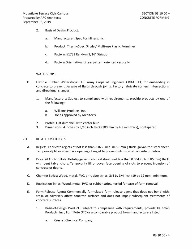
1. Submitted mix designs shall include either the “Field Experience Method Form” or the “Trial Batch Method Form”, included in this specification. Fill out the forms in their entirety.
2. Indicate amounts of mixing water to be withheld for later addition at Project site.

Mountlake Terrace Civic Campus Prepared by ARC Architects September 13, 2019
SECTION 03 30 00 – CAST-IN-PLACE CONCRETE
03 30 00 - 2
C. Steel Reinforcement Shop Drawings: Placing drawings that detail fabrication, bending, and placement. Include bar sizes, lengths, material, grade, bar schedules, stirrup spacing, bent bar diagrams, bar arrangement, splices and laps, mechanical connections, tie spacing, hoop spacing, and supports for concrete reinforcement.
D. Contraction Joint Layout: Indicate proposed location of contraction joints not shown on the drawings.
1.5 INFORMATIONAL SUBMITTALS
A. Qualification Data: For manufacturer.
B. Material Certificates: For each of the following, signed by manufacturers:
1. Cementitious materials. 2. Admixtures. 3. Steel reinforcement and accessories. 4. Curing compounds. 5. Vapor retarders. 6. Joint-filler strips. 7. Semirigid joint filler. 8. Waterstops.
C. Material Test Reports: For the following, from a qualified testing agency, indicating compliance with requirements:
1. Aggregates.
D. Minutes of preinstallation conference.
1.6 QUALITY ASSURANCE
A. Manufacturer Qualifications: A firm experienced in manufacturing ready-mixed concrete products and that complies with ASTM C 94/C 94M requirements for production facilities and equipment.
1. Manufacturer certified according to NRMCA's "Certification of Ready Mixed Concrete Production Facilities."
B. ACI Publications: Comply with the following unless modified by requirements in the Contract Documents:
1. ACI 301, "Specifications for Structural Concrete," Sections 1 through 5. 2. ACI 117, "Specifications for Tolerances for Concrete Construction and Materials."
C. Preinstallation Conference: Conduct conference at Project site.

Mountlake Terrace Civic Campus Prepared by ARC Architects September 13, 2019
SECTION 03 30 00 – CAST-IN-PLACE CONCRETE
03 30 00 - 3
1.7 DELIVERY, STORAGE, AND HANDLING
A. Steel Reinforcement: Deliver, store, and handle steel reinforcement to prevent bending and damage. Keep reinforcement off ground by using pallets, dunnage, or other supports.
B. Waterstops: Store waterstops under cover to protect from moisture, sunlight, dirt, oil, and other contaminants
PART 2 - PRODUCTS
2.1 Materials
A. Formwork: Furnish formwork and form accessories according to ACI 301 and Section 03 10 00.
B. Steel Reinforcement
1. Reinforcing Bars: ASTM A 615/A 615M, Grade 60, deformed. 2. Plain Steel Wire: ASTM A 82, as drawn. 3. Deformed Bar Anchors: ASTM A 496. 4. Plain Steel Welded Wire Fabric: ASTM A 185, fabricated from as-drawn steel wire into
flat sheets.
C. Concrete Materials
1. Portland Cement: ASTM C 150, Type I or II or I/II. Supplement with the following: a. Fly Ash: ASTM C618, Class F or C. b. Ground Granulated Blast Furnace Slag: ASTM C989, Grade 100 or 120.
2. Normal Weight Aggregate: ASTM C 33, uniformly graded, with the following maximum nominal size: a. Foundations: 1 1/2-inch b. Slabs-on-Grade: 1 inch
3. Water: Complying with ASTM C 94.
D. Admixtures
1. Air-Entraining Admixture: ASTM C 260. 2. Water-Reducing Admixture: ASTM C 494, Type A. 3. High Range, Water-Reducing Admixture: ASTM C 494, Type F. 4. Water-Reducing and Retarding Admixture: ASTM C 494, Type D.
E. Vapor Retarder: Multi-ply reinforced polyethylene sheet, ASTM E 1745, Class C, not less than 10 mils thick; or polyethylene sheet, ASTM D 4397, not less than 10 mils thick.
F. Joint Filler Strips:

Mountlake Terrace Civic Campus Prepared by ARC Architects September 13, 2019
SECTION 03 30 00 – CAST-IN-PLACE CONCRETE
03 30 00 - 4
1. Architectural Concrete Work: ASTM D 1751, asphalt-saturated cellulosic fiber. 2. Site Retaining Walls, Cheekwalls, Seatwalls and Terraced Seating:
a. Premolded Joint: Pre-molded non-extruded resilient material maximum 3/8” thick, with strip off top to allow for joint caulking.
b. Joint caulking: Self-leveling polyurethane, Sikaflex 1 CSL by Sika, or approved equal, color to match concrete.
G. Curing Materials
1. Evaporation Retarder: Waterborne, monomolecular film forming, manufactured for application to fresh concrete.
2. Absorptive Cover: AASHTO M 182, Class 2, burlap cloth made from jute or kenaf. 3. Moisture-Retaining Cover: ASTM C 171, polyethylene film or white burlap polyethylene
sheet. 4. Water: Potable. 5. Clear, Waterborne, Membrane-Forming Curing Compound: ASTM C 309, Type 1, Class B,
dissipating. 6. Clear, Waterborne, Membrane-Forming Curing and Sealing Compound: ASTM C 1315,
Type 1, Class A.
H. Liquid Floor Treatments
1. Sealer and Hardener: A Water-based, reactive siliconate solution, surface applied, deep penetrating, VOC compliant, USDA accepted, liquid sealer densifier hardener that reacts with concrete surfaces to produce a dense, hydrophobic, insoluble, moisture barrier to seal out contaminants, while hardening and densifying the concrete surface.
2. Do not use material containing fluorine, fluosilicate-base materials, or material that dries to a film on the concrete surface.
3. Use one of the following Sealer and Hardener products: a. “Sure Hard Densifier J17” siliconate hardener manufactured by Dayton Superior
Corporation. b. "Shur-Seal (HD)" siliconate hardener manufactured by Paul M. Wolff Co., Inc. c. “Pentra-Sil” siliconate hardener manufactured by Convergent Concrete
Technologies. d. “EUCO Diamond Hard” siliconate hardener manufactured by Euclid Chemical
Company.
2.2 CONCRETE MIXTURES
A. Prepare design mixtures for each type and strength of concrete, proportioned on the basis of laboratory trial mixture or field test data, or both, according to ACI 301. Mixture designs shall comply with the requirements of the structural drawings.
B. Cementitious Materials: Limit percentage, by weight, of cementitious materials other than Portland cement in concrete as follows:

Mountlake Terrace Civic Campus Prepared by ARC Architects September 13, 2019
SECTION 03 30 00 – CAST-IN-PLACE CONCRETE
03 30 00 - 5
1. Fly Ash: 25 percent. 2. Slag Cement: 50 percent.
C. Admixtures: Use admixtures according to manufacturer's written instructions.
1. Use water-reducing or high-range water-reducing admixture in concrete, as required, for placement and workability.
2. Use water-reducing and retarding admixture when required by high temperatures, low humidity, or other adverse placement conditions.
3. Use water-reducing admixture in pumped concrete and concrete with a water-cementitious materials ratio below 0.50.
2.3 CONCRETE MIXING
A. Ready-Mixed Concrete: Measure, batch, mix, and deliver concrete according to ASTM C 94/C 94M, and furnish batch ticket information.
1. When air temperature is between 85 and 90 deg F (30 and 32 deg C), reduce mixing and delivery time from 1-1/2 hours to 75 minutes; when air temperature is above 90 deg F (32 deg C), reduce mixing and delivery time to 60 minutes.
2. Provide batch ticket for each batch discharged and used in the work, indicating project identification name and number, date, mix type, mix time, quantity, and amount of water in the batch from the plant and the remaining water that may be added at the site, if any. Record approximate location of final deposit in structure.
2.4 FABRICATING REINFORCEMENT
A. Fabricate steel reinforcement according to CRSI's "Manual of Standard Practice."
PART 3 - EXECUTION
3.1 Installation, General
A. Formwork: Design, erect, shore, brace, and maintain formwork, according to ACI 301 and Section 03 10 00.
B. Embedded Items: Place and secure anchorage devices and other embedded items required for adjoining work that is attached to or supported by cast-in-place concrete. Use setting drawings, templates, diagrams, instructions, and directions furnished with items to be embedded.
1. Install anchor rods, accurately located, to elevations required and complying with tolerances in Section 7.5 of AISC's "Code of Standard Practice for Steel Buildings and Bridges."

Mountlake Terrace Civic Campus Prepared by ARC Architects September 13, 2019
SECTION 03 30 00 – CAST-IN-PLACE CONCRETE
03 30 00 - 6
C. Vapor Retarder: Place, protect, and repair sheet vapor retarder according to ASTM E 1643 and manufacturer's written instructions.
1. Lap joints 6 inches (150 mm) and seal with manufacturer's recommended tape. 2. Cover vapor retarder with fine-graded granular material, moisten, and compact with
mechanical equipment to elevation tolerances of plus 0 inch (0 mm) or minus 3/4 inch (19 mm).
D. Steel Reinforcement: Comply with CRSI's "Manual of Standard Practice" for placing reinforcement.
1. Do not cut or puncture vapor retarder. Repair damage and reseal vapor retarder before placing concrete.
E. Joints in structural concrete work and building walls: Construct joints true to line with faces perpendicular to surface plane of concrete.
1. Construction Joints: Install so strength and appearance of concrete are not impaired, at locations indicated or as approved by Architect. a. Place joints perpendicular to main reinforcement. Continue reinforcement across
construction joints unless otherwise indicated. b. Space vertical joints in walls as indicated. Locate joints beside piers integral with
walls, near corners, and in concealed locations where possible. 2. Contraction Joints in Slabs-on-Grade: Form weakened-plane contraction joints,
sectioning concrete into areas as indicated. Construct contraction joints for a depth as indicated and equal to at least one-fourth of concrete thickness as follows: a. Grooved Joints: Form contraction joints after initial floating by grooving and
finishing each edge of joint to a radius of 1/8 inch (3.2 mm). Repeat grooving of contraction joints after applying surface finishes. Eliminate groover tool marks on concrete surfaces.
b. Sawed Joints: Form contraction joints with power saws equipped with shatterproof abrasive or diamond-rimmed blades. Cut 1/8-inch- (3.2-mm-) wide joints into concrete when cutting action will not tear, abrade, or otherwise damage surface and before concrete develops random contraction cracks.
3. Isolation Joints in Slabs-on-Grade: After removing formwork, install joint-filler strips at slab junctions with vertical surfaces, such as column pedestals, foundation walls, grade beams, and other locations, as indicated.
F. Joint in site Retaining Walls, Entrance Sign, Cheekwalls, Seatwalls and Terraced Seating:
1. General: Where a construction joint is to be made, the surface of concrete shall be thoroughly cleaned and all laitance removed. Vertical joints shall be thoroughly wetted and slushed with a neat cement grout immediately before placing of new concrete. Joint locations shall be as shown on the plan and details with the following specifics and minimums. a. Site Retaining Walls, Entrance Sign, Cheekwalls, Seatwalls and Terraced Seating:
Locate control joints at 10’ o.c. max., expansion joints approximately 30’ o.c. max.,

Mountlake Terrace Civic Campus Prepared by ARC Architects September 13, 2019
SECTION 03 30 00 – CAST-IN-PLACE CONCRETE
03 30 00 - 7
horizontally and vertically. All joints shall align with joint pattern in adjacent pavement.
2. Expansion Joints: a. Pre-molded expansion joints shall be max 3/8” wide and filled to full cross section
with caulking. b. Place expansion joints at right angles to the finish surface.
3. Control Joints: a. Tooled control joints to depth and dimensions as indicated on drawings.
4. Construction Joints: a. Form with a keyed joint per drawings. b. Grade and finish shall match across joint.
5. Keys: Longitudinal keys at least 1 1/2 inches deep shall be provided in all wall joints.
G. Tolerances: Comply with ACI 117, “Specifications for Tolerances for Concrete Construction and Materials.”
3.2 CONCRETE PLACEMENT
A. Comply with ACI 304R for measuring, mixing, transporting, and placing concrete.
B. Do not add water to concrete during delivery or during placement.
1. Subject to Architect’s approval, water may be added at Project site before test sampling and placing concrete, only to the amount listed on the batch ticket, subject to limitations of ACI 301.
C. Where new concrete abuts existing, bond shall be obtained by roughening the surface of the concrete to ¼-inch amplitude in an approved manner which will expose the aggregate uniformly and will not leave laitance, loosened particles or aggregate or damaged concrete at the surface. Apply bonding agent.
D. Deposit concrete continuously in one layer or in horizontal layers of such thickness that no new concrete will be placed on concrete that has hardened enough to cause seams or planes of weakness. If a section cannot be placed continuously, provide construction joints. Deposit concrete to avoid segregation.
1. Consolidate placed concrete with mechanical vibrating equipment according to ACI 301. 2. Do not use vibrators to transport concrete inside forms.
E. Deposit and consolidate concrete for floors and slabs in a continuous operation, within limits of construction joints, until placement of a panel or section is complete.
F. Excavation:

Mountlake Terrace Civic Campus Prepared by ARC Architects September 13, 2019
SECTION 03 30 00 – CAST-IN-PLACE CONCRETE
03 30 00 - 8
1. Footing excavations are to be to the depth and widths shown on the drawings. Over-excavations shall be filled with concrete.
G. Cold-Weather Placement: Comply with ACI 306.1.
H. Hot-Weather Placement: Comply with ACI 301.
3.3 FINISHING FORMED SURFACES
A. Rough-Formed Finish: As-cast concrete texture imparted by form-facing material with tie holes and defects repaired and patched. Remove fins and other projections that exceed specified limits on formed-surface irregularities.
1. Apply to concrete surfaces not exposed to public view.
B. Smooth-Formed Finish: As-cast concrete texture imparted by form-facing material, arranged in an orderly and symmetrical manner with a minimum of seams. Repair and patch tie holes and defects. Remove fins and other projections that exceed specified limits on formed-surface irregularities.
1. Apply to concrete surfaces exposed to public view, or to be covered with a coating or covering material applied directly to concrete.
C. Sack/Trowel Finish: Provide Float finish as described below. Begin the first trowel finish operation using a power-driven trowel. Begin the final troweling when the surface produces a ringing sound when as the trowel is moved over the surface. Consolidate the concrete surface by the final hand troweling operation, free from trowel marks, uniform in texture and appearance, and with Class A surface finish throughout.
1. Apply to site Retaining Walls, Entrance Sign, Cheekwalls, Seatwalls and Terraced Seating.
D. Related Unformed Surfaces: At tops of walls, horizontal offsets, and similar unformed surfaces adjacent to formed surfaces, strike off smooth and finish with a texture matching adjacent formed surfaces. Continue final surface treatment of formed surfaces uniformly across adjacent unformed surfaces unless otherwise indicated.
3.4 FINISHING Unformed Surfaces
A. General: Comply with ACI 302.1R recommendations for screeding, restraightening, and finishing operations for concrete surfaces. Do not wet concrete surfaces.
B. Screed surfaces with a straightedge and strike off. Begin initial floating using bull floats or darbies to form a uniform and open textured surface plane before excess moisture or bleedwater appears on the surface.
1. Do not further disturb surfaces before starting finishing operations.

Mountlake Terrace Civic Campus Prepared by ARC Architects September 13, 2019
SECTION 03 30 00 – CAST-IN-PLACE CONCRETE
03 30 00 - 9
C. Scratch Finish: Apply scratch finish to surfaces to receive concrete floor topping or mortar setting beds for ceramic or quarry tile, Portland cement terrazzo, and other bonded cementitious floor finish, unless otherwise indicated.
D. Float Finish: Apply float finish to surfaces indicated, to surfaces to receive trowel finish, and to floor and slab surfaces to be covered with fluid-applied or sheet waterproofing, built-up or membrane roofing, or sand-bed terrazzo.
E. Trowel finish: Apply a hard trowel finish to surfaces indicated and to floor and slab surfaces exposed to view or to be covered with resilient flooring, carpet, ceramic or quarry tile set over a cleavage membrane, paint, or another thin film-finish coating system.
1. Finish surfaces to the following tolerances, according to ASTM E 1155 (ASTM E 1155M), for a randomly trafficked floor surface: a. Specified overall values of flatness, F(F) 30; and of levelness, F(L) 20; with minimum
local values of flatness, F(F) 24; and of levelness, F(L) 15; for elevated slabs.
F. Trowel and Fine Broom Finish: Apply a partial trowel finish, stopping after second troweling, to surfaces indicated and to surfaces where ceramic or quarry tile is to be installed by either thickset or thin-set methods. Immediately after second troweling, and when concrete is still plastic, slightly scarify surface with a fine broom.
G. Nonslip Broom Finish: Apply a nonslip broom finish to surfaces indicated, and to exterior concrete platforms, steps, and ramps. Immediately after float finishing, slightly roughen trafficked surface by brooming with fiber bristle broom perpendicular to main traffic route.
3.5 MISCELLANEOUS CONCRETE ITEMS
A. Filling In: Fill in holes and openings left in concrete structures after work of other trades is in place unless otherwise indicated. Mix, place, and cure concrete, as specified, to blend with in-place construction. Provide other miscellaneous concrete filling indicated or required to complete the Work.
B. Curbs: Provide monolithic finish to interior curbs by stripping forms while concrete is still green and by steel-troweling surfaces to a hard, dense finish with corners, intersections, and terminations slightly rounded.
C. Equipment Bases and Foundations: Provide machine and equipment bases and foundations as shown on Drawings. Set anchor bolts for machines and equipment at correct elevations, complying with diagrams or templates from manufacturer furnishing machines and equipment.
D. Steel Pan Stairs: Provide concrete fill for steel pan stair treads, landings, and associated items. Cast-in inserts and accessories as shown on Drawings. Screed, tamp, and trowel finish concrete surfaces.

Mountlake Terrace Civic Campus Prepared by ARC Architects September 13, 2019
SECTION 03 30 00 – CAST-IN-PLACE CONCRETE
03 30 00 - 10
3.6 CONCRETE PROTECTING AND CURING
A. General: Protect freshly placed concrete from premature drying and excessive cold or hot temperatures. Comply with ACI 306.1 for cold-weather protection and ACI 301 for hot-weather protection during curing.
B. Evaporation Retarder: Apply evaporation retarder to unformed concrete surfaces if hot, dry, or windy conditions cause moisture loss approaching 0.2 lb/sq. ft. x h (1 kg/sq. m x h) before and during finishing operations. Apply according to manufacturer's written instructions after placing, screeding, and bull floating or darbying concrete, but before float finishing.
C. Formed Surfaces: Cure formed concrete surfaces. If forms remain during curing period, moist cure after loosening forms. If removing forms before end of curing period, continue curing for the remainder of the curing period.
D. Unformed Surfaces: Begin curing immediately after finishing concrete. Cure unformed surfaces, including floors and slabs, concrete floor toppings, and other surfaces.
E. Cure concrete according to ACI 308.1, by one or a combination of the following methods:
1. Moisture Curing: Keep surfaces continuously moist for not less than seven days with water, continuous water-fog spray, or absorptive cover, water saturated, and kept continuously wet. Cover concrete surfaces and edges with 12-inch (300-mm) lap over adjacent absorptive covers.
2. Moisture-Retaining-Cover Curing: Cover concrete surfaces with moisture-retaining cover for curing concrete, placed in widest practicable width, with sides and ends lapped at least 12 inches (300 mm), and sealed by waterproof tape or adhesive. Cure for not less than seven days. Immediately repair any holes or tears during curing period using cover material and waterproof tape.
3. Curing Compound: Apply uniformly in continuous operation by power spray or roller according to manufacturer's written instructions. Recoat areas subjected to heavy rainfall within three hours after initial application. Maintain continuity of coating and repair damage during curing period. a. Removal: After curing period has elapsed, remove curing compound without
damaging concrete surfaces by method recommended by curing compound manufacturer unless manufacturer certifies curing compound will not interfere with bonding of floor covering used on Project.
4. Curing and Sealing Compound: Apply uniformly to floors and slabs indicated in a continuous operation by power spray or roller according to manufacturer's written instructions. Recoat areas subjected to heavy rainfall within three hours after initial application. Repeat process 24 hours later and apply a second coat. Maintain continuity of coating and repair damage during curing period.
F. Anti-Graffiti Coating for site Retaining Walls, Entrance Sign, Cheekwalls, Seatwalls and Terraced Seating:

Mountlake Terrace Civic Campus Prepared by ARC Architects September 13, 2019
SECTION 03 30 00 – CAST-IN-PLACE CONCRETE
03 30 00 - 11
1. Sherwin Williams Anti-Graffiti Coating, semi-gloss, clear. One coat application; 8.0 to 12.0 mills wet, 6.0 to 9.0 mills dry. Coverage typical 128 to 192 SF/Gal.
3.7 LIQUID FLOOR TREATMENTS
A. Sealer and Hardener: Prepare, apply, and finish penetrating liquid floor treatment according to manufacturer's written instructions.
1. Remove curing compounds, sealers, oil, dirt, laitance, and other contaminants and complete surface repairs.
2. Apply to concrete per manufacturer’s written instructions. 3. Apply liquid until surface is saturated, scrubbing into surface until a gel forms; rewet; and
repeat brooming or scrubbing. Rinse with water; remove excess material until surface is dry. Apply a second coat in a similar manner if surface is rough or porous.
B. Polished Concrete Floor Treatment: Apply polished concrete finish system to cured and prepared slabs to match accepted mockup.
1. Machine grind floor surfaces to receive polished finishes level and smooth and to depth required to reveal aggregate to match approved mockup.
2. Apply penetrating liquid floor treatment for polished concrete in polishing sequence and according to manufacturer's written instructions, allowing recommended drying time between successive coats.
3. Continue polishing with progressively finer grit diamond polishing pads to gloss level to match approved mockup.
4. Control and dispose of waste products produced by grinding and polishing operations. 5. Neutralize and clean polished floor surfaces.
C. Sealing Coat: Uniformly apply a continuous sealing coat of curing and sealing compound to hardened concrete by power spray or roller according to manufacturer's written instructions.
3.8 JOINT FILLING
A. Prepare, clean, and install joint filler according to manufacturer's written instructions.
1. Defer joint filling until concrete has aged at least one month. Do not fill joints until construction traffic has permanently ceased.
B. Remove dirt, debris, saw cuttings, curing compounds, and sealers from joints; leave contact faces of joint clean and dry.
C. Install semirigid joint filler full depth in saw-cut joints and at least 2 inches (50 mm) deep in formed joints. Overfill joint and trim joint filler flush with top of joint after hardening.

Mountlake Terrace Civic Campus Prepared by ARC Architects September 13, 2019
SECTION 03 30 00 – CAST-IN-PLACE CONCRETE
03 30 00 - 12
3.9 CONCRETE SURFACE REPAIRS
A. Defective Concrete: Repair and patch defective areas when approved by Architect. Remove and replace concrete that cannot be repaired and patched to Architect's approval.
B. Patching Mortar: Mix dry-pack patching mortar, consisting of one part Portland cement to two and one-half parts fine aggregate passing a No. 16 (1.18-mm) sieve, using only enough water for handling and placing.
C. Repairing Formed Surfaces: Surface defects include color and texture irregularities, cracks, spalls, air bubbles, honeycombs, rock pockets, fins and other projections on the surface, and stains and other discolorations that cannot be removed by cleaning.
1. Immediately after form removal, cut out honeycombs, rock pockets, and voids more than 1/2 inch (13 mm) in any dimension to solid concrete. Limit cut depth to 3/4 inch (19 mm). Make edges of cuts perpendicular to concrete surface. Clean, dampen with water, and brush-coat holes and voids with bonding agent. Fill and compact with patching mortar before bonding agent has dried. Fill form-tie voids with patching mortar or cone plugs secured in place with bonding agent.
2. Repair defects on surfaces exposed to view by blending white Portland cement and standard Portland cement so that, when dry, patching mortar will match surrounding color. Patch a test area at inconspicuous locations to verify mixture and color match before proceeding with patching. Compact mortar in place and strike off slightly higher than surrounding surface.
3. Repair defects on concealed formed surfaces that affect concrete's durability and structural performance as determined by Architect.
D. Repairing Unformed Surfaces: Test unformed surfaces, such as floors and slabs, for finish and verify surface tolerances specified for each surface. Correct low and high areas. Test surfaces sloped to drain for trueness of slope and smoothness; use a sloped template.
1. Repair finished surfaces containing defects. Surface defects include spalls, popouts, honeycombs, rock pockets, crazing and cracks in excess of 0.01 inch (0.25 mm) wide or that penetrate to reinforcement or completely through unreinforced sections regardless of width, and other objectionable conditions.
2. After concrete has cured at least 14 days, correct high areas by grinding. 3. Correct localized low areas during or immediately after completing surface finishing
operations by cutting out low areas and replacing with patching mortar. Finish repaired areas to blend into adjacent concrete.
4. Correct other low areas scheduled to receive floor coverings with a repair underlayment. Prepare, mix, and apply repair underlayment and primer according to manufacturer's written instructions to produce a smooth, uniform, plane, and level surface. Feather edges to match adjacent floor elevations.
5. Correct other low areas scheduled to remain exposed with a repair topping. Cut out low areas to ensure a minimum repair topping depth of 1/4 inch (6 mm) to match adjacent floor elevations. Prepare, mix, and apply repair topping and primer according to

Mountlake Terrace Civic Campus Prepared by ARC Architects September 13, 2019
SECTION 03 30 00 – CAST-IN-PLACE CONCRETE
03 30 00 - 13
manufacturer's written instructions to produce a smooth, uniform, plane, and level surface.
6. Repair defective areas, except random cracks and single holes 1 inch (25 mm) or less in diameter, by cutting out and replacing with fresh concrete. Remove defective areas with clean, square cuts and expose steel reinforcement with at least a 3/4-inch (19-mm) clearance all around. Dampen concrete surfaces in contact with patching concrete and apply bonding agent. Mix patching concrete of same materials and mixture as original concrete except without coarse aggregate. Place, compact, and finish to blend with adjacent finished concrete. Cure in same manner as adjacent concrete.
7. Repair random cracks and single holes 1 inch (25 mm) or less in diameter with patching mortar. Groove top of cracks and cut out holes to sound concrete and clean off dust, dirt, and loose particles. Dampen cleaned concrete surfaces and apply bonding agent. Place patching mortar before bonding agent has dried. Compact patching mortar and finish to match adjacent concrete. Keep patched area continuously moist for at least 72 hours.
E. Perform structural repairs of concrete, subject to Architect's approval, using epoxy adhesive and patching mortar.
F. Repair materials and installation not specified above may be used, subject to Architect's approval.
3.10 FIELD QUALITY CONTROL
A. Testing and Inspecting: Owner will engage a qualified testing and inspecting agency to perform field tests and inspections and prepare test reports.
B. Testing and Inspecting: Engage a qualified testing and inspecting agency to perform tests and inspections and to submit reports.
C. Tests and Inspections: As indicated on the structural drawings.
D. When strength of field-cured cylinders is less than 85 percent of companion laboratory-cured cylinders, Contractor shall evaluate operations and provide corrective procedures for protecting and curing in-place concrete.
E. Nondestructive Testing: Impact hammer, sonoscope, or other nondestructive device may be permitted by Architect but will not be used as sole basis for approval or rejection of concrete.
F. Additional Tests: Testing and inspecting agency shall make additional tests of concrete when test results indicate that slump, air entrainment, compressive strengths, or other requirements have not been met, as directed by Architect. Testing and inspecting agency may conduct tests to determine adequacy of concrete by cored cylinders complying with ASTM C 42/C 42M or by other methods as directed by Architect.
G. Additional testing and inspecting, at Contractor's expense, will be performed to determine compliance of replaced or additional work with specified requirements.

Mountlake Terrace Civic Campus Prepared by ARC Architects September 13, 2019
SECTION 03 30 00 – CAST-IN-PLACE CONCRETE
03 30 00 - 14
H. Correct deficiencies in the Work that test reports and inspections indicate do not comply with the Contract Documents.
3.11 PROTECTION OF LIQUID FLOOR TREATMENTS
A. Protect liquid floor treatment from damage and wear during the remainder of construction period. Use protective methods and materials, including temporary covering, recommended in writing by liquid floor treatments installer.
END OF SECTION 03 30 00

OVER
CONCRETE MIX DESIGN SUBMITTAL – TRIAL BATCH METHOD
Project
General Contractor
Ready Mix Supplier
Plant Supplying Concrete
Mix Design No
Concrete Class
Proposed Use
MIX CONSTITUENTS
Description Specific Gravity
Weight (lb) or Dosage (oz)
Absolute Volume (cubic foot)
Cement
Fly Ash
Silica Fume
Coarse Aggregate
Fine Aggregate
Water
Admixtures
Water Reducer
Air Entrainer
High Range Water Reducer
Other
Total
MIX CHARACTERISTICS
Water/Cementitious Ratio
Air (%)
Density (pcf)
Slump (in) Before High Range Water Reducer
After High Range Water Reducer

CONCRETE MIX DESIGN SUBMITTAL – TRIAL BATCH METHOD (continued)
DOCUMENTATION OF AVERAGE STRENGTH
REQUIRED BACK –UP DATA NOTE: THE SUBMITTED DATA SHALL COMPLY WITH THE FOLLOWING:
Yes No
At least three trial mixtures are included
At least three different cement contents are included.
At least three different water / cementitious materials ratios are included.
The trial batches are no more than 12 months old.
REQUIRED STATISTICAL ANALYSIS
METHOD FOR DETERMINING REQUIRED AVERAGE COMPRESSIVE STRENGTH (PICK ONE)
ACI 301 Section 4.2.3.3.a – Standard Deviation 15 tests minimum required from the plant supplying the concrete Specified compressive strength (psi)
Calculated standard deviation of submitted data, ss (psi)
Factor from Table 4.2.3.3.a.1, k
Required average compressive strength from Table 4.2.3.3.a, f’cr (psi)
Average strength of proposed mix, obtained from plot of submitted trial batch date (psi)
ACI 301 Section 4.2.3.3.b – Standard Deviation Not Required
Specified compressive strength (psi)
Required Average Strength from Table 4.2.3.3.b, f’cr (psi)
Average strength of proposed mix, obtained from plot of submitted trial batch date (psi)
Plot of compressive strength versus water / cementitious materials ratio
If standard deviation is calculated:
Field test data
Statistical Analysis
REQUIRED ATTACHMENTS (Please Check)
Certification that all ingredients are compatible.
Coarse aggregate gradation
Fine aggregate gradation
OVER
CONCRETE MIX DESIGN SUBMITTAL – FIELD EXPERIENCE METHOD
Project
General Contractor
Ready Mix Supplier
Plant Supplying Concrete
Mix Design No
Concrete Class
Proposed Use
MIX CONSTITUENTS
Description Specific Gravity
Weight (lb) or Dosage (oz)
Absolute Volume (cubic foot)
Cement
Fly Ash
Silica Fume
Coarse Aggregate
Fine Aggregate
Water
Admixtures
Water Reducer
Air Entrainer
High Range Water Reducer
Other
Total
MIX CHARACTERISTICS
Water / Cementitious Ratio
Air (%)
Density (pcf)
Slump (in)
Before High Range Water Reducer
After High Range Water Reducer

CONCRETE MIX DESIGN SUBMITTAL – FIELD EXPERIENCE METHOD (continued)
DOCUMENTATION OF AVERAGE STRENGTH
REQUIRED BACK –UP DATA NOTE: THE SUBMITTED DATA SHALL COMPLY WITH THE FOLLOWING:
Yes No
Ten test reports (minimum) provided.
The reports encompass a period of not less than 60 days.
The reports are no more than 12 months old.
The reports are for concrete supplied from the same plant that will be
supplying this project.
Submitted test data is supported by reports from an independent
testing agency, and the independent agency’s reports are available
at the Engineer’s request.
REQUIRED STATISTICAL ANALYSIS
METHOD FOR DETERMINING REQUIRED AVERAGE COMPRESSIVE STRENGTH (PICK ONE)
ACI 301 Section 4.2.3.3.a – Standard Deviation
15 tests minimum required Specified compressive strength (psi)
Calculated standard deviation of submitted data, ss (psi)
Factor from Table 4.2.3.3.a.1, k
Required average compressive strength from Table 4.2.3.3.a, f’cr (psi)
Calculated average strength of submitted data (psi)
ACI 301 Section 4.2.3.3.b – Standard Deviation Not Required
Specified compressive strength (psi)
Required Average Strength from Table 4.2.3.3.b, f’cr (psi)
Calculated average strength of submitted data (psi)
Field Test Data
Statistical Analysis
Certification that all ingredients are compatible.
REQUIRED ATTACHMENTS (Please Check)
Coarse Aggregate Gradation
Fine Aggregate Gradation

Mountlake Terrace Civic CampusPrepared by ARC ArchitectsSeptember 13, 2019
SECTION 03 35 43 – POLISHED CONCRETE FINISHING
03 35 43 - 1
SECTION 033543 – POLISHED CONCRETE FINISHING
PART 1 - GENERAL
1.1 RELATED DOCUMENTS
A. Drawings and general provisions of the Contract, including General and Supplementary Conditions and Division 01 Specification Sections, apply to this Section.
1.2 SUMMARY
A. Section includes grinding and polished concrete finishing and scoring.
B. Related Requirements:
1. Section 033000 "Cast-in-Place Concrete." for concrete, including formwork, reinforcement, concrete materials, mixture design, placement procedures, initial finishing, and curing.
1.3 DEFINITIONS
A. Design Reference Sample: Sample designated by Architect in the Contract Documents that reflects acceptable surface quality and appearance of polished concrete.
B. Grinding standards as identified by ConcreteNetwork .com
1.4 ACTION SUBMITTALS
A. Samples for Verification: Mockup for each type of exposed finish.
1.5 QUALITY ASSURANCE
A. Mockups: Before casting concrete, build mockups to verify selections made under Sample submittals and to demonstrate typical joints, surface finish, tolerances, and standard of workmanship. Build mockups to comply with the following requirements, using materials indicated for the completed Work:
1. Build mockups in the location and of the size indicated or, if not indicated, as directed by Architect.
2. Demonstrate curing, finishing, and protecting of concrete.

Mountlake Terrace Civic CampusPrepared by ARC ArchitectsSeptember 13, 2019
SECTION 03 35 43 – POLISHED CONCRETE FINISHING
03 35 43 - 2
1.6 FIELD CONDITIONS
A. Traffic Control: Maintain access for vehicular and pedestrian traffic as required for other construction activities.
PART 2 - PRODUCTS
2.1 GRINDING AND POLISHING
A. Gloss level1. Level 2 (satin)2. 400-grit resin bond – medium sheen
B. Aggregate Exposure1. Class B (salt and pepper)
2.2 LIQUID FLOOR TREATMENTS
A. Penetrating Liquid Floor Treatments for Polished Concrete Finish: Clear, waterborne solution of inorganic silicate or siliconate materials and proprietary components; odorless; that penetrates, hardens, and is suitable for polished concrete surfaces.
1. Products: Subject to compliance with requirements and as approved by Architect, available products that may be incorporated into the Work include, but are not limited to, the following:
a. Vexcon Chemicals: Certi-Shine Clear1-888-VEXCON-17240 State Road, Philadelphia, PA 10135www.vexcon.com
Penetrating Liquid Floor Treatment for Polished Concrete Finishes: Clear, chemically reactive, water borne solution of silicate material and proprietary components, odorless, that penetrates, hardens and is suitable for Polished Concrete surfaces leaving no surface film.
2. Unreacted Silicate Rinse: Liquid rinse solution, increases stain resistance.a. Acceptable Material: Vexcon Chemicals, Certi-Shine Fixative.
3. Stain Repellent (non-film forming): Ready to use, food (oil and acid), hydraulic fluid and motor oil stain and water repellent, Silane and Silane polymer blend.
a. Acceptable Material: Vexcon Chemicals, Certi-Shine Finish Coat Ultra.

Mountlake Terrace Civic CampusPrepared by ARC ArchitectsSeptember 13, 2019
SECTION 03 35 43 – POLISHED CONCRETE FINISHING
03 35 43 - 3
4. Silicate floor repair material: Liquid silicate material which fills and repairs concrete surface imperfections.
a. Acceptable Material: Vexcon Chemical, Certi-Shine Fusion.
5. Cleaning Solution: Eco-friendly degreaser and cleaner, concentrate pH must be slightly alkaline.
a. Acceptable Material: Vexcon Chemicals, StarSeal EF Degreaser and Cleaner.
6. Finishing Gloss Level Standard:
a. Medium shine Gold, equivalent to 60° film gloss of 60 when viewed at an angle
B. Locations of Polished Concrete Finish: As indicated on Drawings.
PART 3 - EXECUTION
3.01 EXAMINATION
A. Site Verification of Concrete Conditions
1. Installer and manufacturer's representative will examine surfaces receiving concrete finish and polishing system.
a.Verify that surfaces conform to product manufacturer's requirements for substrate conditions.
b.Verify floor is free of curing membrane, bond-breaker, concrete laitance, and will absorb water per water absorbency test.
B. Concrete slab performance requirements
1. Verify that all the concrete complies with finishing requirements as specified in Cast In Place Section 03 30 00.
3.02 CONCRETE PREPARATION
A. Complete surface preparation per manufacturers written instructions.
B. Power sweep floor area, blow out corners and column footings.
C. Initial grind should clean the concrete surface, removing all coatings, dirt, oil and latiance.
Mountlake Terrace Civic CampusPrepared by ARC ArchitectsSeptember 13, 2019
SECTION 03 35 43 – POLISHED CONCRETE FINISHING
03 35 43 - 4
D. If grinding does not remove oil spots, treat oil spots with emulsifier and oil absorber materials. Detail scrub with high pH detergent.
1. Acceptable Material: Vexcon Chemicals, StarSeal EF Stripper
E. Double scrub floor with automatic scrubber capable minimum of 80 to 120 pounds of head pressure, equipped with black stripping pads. Use proper dilution of high pH detergent. Scrub floor once without squeegee or vacuum. On second pass, remove water solution.
F. Power rinse surface removing all traces of soap residue.
G. Inspect the concrete surface.
H. Complete surface preparation per manufacturers written instructions.
I. Perform water absorbency test.
1. Repeat any steps as necessary to prepare for polishing.
3.03 CONCRETE FINISH APPLICATION AND POLISHING
A. Immediately following cleaning operation, install concrete polishing material(s) per manufacturer's instructions.
B. Perform polishing operation to the specified polish level.
1. Polishing Levels for Certi-Shine products
a. Clear, Medium Shine - Equivalent to 60° film gloss of 60 when viewed on an angle.
3.04 JOINT FILLER
A. Prime and fill with manufacturer's approved epoxy joint sealant those joints that require the application of joint sealant after the application of the finishing system or as directed by the manufacturer.
1. Powercoat Primer
2. Powercoat Flexible Epoxy Joint Sealant
3.05 PROTECTION
A. Protect finished surfaces from damage and soiling and other construction activities.
B. Without damaging completed work, provide protective cover.

Mountlake Terrace Civic CampusPrepared by ARC ArchitectsSeptember 13, 2019
SECTION 03 35 43 – POLISHED CONCRETE FINISHING
03 35 43 - 5
END OF SECTION 033543

Mountlake Terrace Civic CampusPrepared by ARC ArchitectsSeptember 13, 2019
SECTION 04 22 00 - CONCRETE UNIT MASONRY
04 22 00 - 1
SECTION 04 22 00 - CONCRETE UNIT MASONRY
PART 1 - GENERAL
1.1 RELATED DOCUMENTS
A. Drawings and general provisions of the Contract, including General and Supplementary Conditions and Division 01 Specification Sections, apply to this Section.
1.2 SUMMARY
A. Section Includes:
1. Concrete masonry units.2. Mortar and grout.3. Steel reinforcing bars.4. Masonry-joint reinforcement.5. Miscellaneous masonry accessories.6. Masonry-cell fill.
1.3 DEFINITIONS
A. CMU(s): Concrete masonry unit(s).
B. Reinforced Masonry: Masonry containing reinforcing steel in grouted cells.
1.4 ACTION SUBMITTALS
A. Product Data: For each type of product.
B. Shop Drawings: For the following:
1. Masonry Units: Show sizes, profiles, coursing, and locations of special shapes.2. Reinforcing Steel: Detail bending, lap lengths, and placement of unit masonry
reinforcing bars. Comply with ACI 315.3. Fabricated Flashing: Detail corner units, end-dam units, and other special applications.
1.5 INFORMATIONAL SUBMITTALS
A. Material Certificates: For each type and size of the following:
1. Masonry units.

Mountlake Terrace Civic CampusPrepared by ARC ArchitectsSeptember 13, 2019
SECTION 04 22 00 - CONCRETE UNIT MASONRY
04 22 00 - 2
a. Include data on material properties.
2. Integral water repellant used in CMUs.3. Cementitious materials. Include name of manufacturer, brand name, and type.4. Mortar admixtures.5. Preblended, dry mortar mixes. Include description of type and proportions of
ingredients.6. Grout mixes. Include description of type and proportions of ingredients.7. Reinforcing bars.8. Joint reinforcement.9. Anchors, ties, and metal accessories.
B. Mix Designs: For each type of mortar. Include description of type and proportions of ingredients.
1. Include test reports for mortar mixes required to comply with property specification. Test according to ASTM C109/C109M for compressive strength, ASTM C1506 for water retention, and ASTM C91/C91M for air content.
2. Include test reports, according to ASTM C1019, for grout mixes required to comply with compressive strength requirement.
C. Statement of Compressive Strength of Masonry: For each combination of masonry unit type and mortar type, provide statement of average net-area compressive strength of masonry units, mortar type, and resulting net-area compressive strength of masonry determined according to TMS 602/ACI 530.1/ASCE 6.
D. Cold-Weather Procedures: Detailed description of methods, materials, and equipment to be used to comply with requirements.
1.6 QUALITY ASSURANCE
A. Testing Agency Qualifications: Qualified according to ASTM C1093 for testing indicated.
1.7 DELIVERY, STORAGE, AND HANDLING
A. Store masonry units on elevated platforms in a dry location. If units are not stored in an enclosed location, cover tops and sides of stacks with waterproof sheeting, securely tied. If units become wet, do not install until they are dry.
B. Store cementitious materials on elevated platforms, under cover, and in a dry location. Do not use cementitious materials that have become damp.
C. Store aggregates where grading and other required characteristics can be maintained and contamination avoided.

Mountlake Terrace Civic CampusPrepared by ARC ArchitectsSeptember 13, 2019
SECTION 04 22 00 - CONCRETE UNIT MASONRY
04 22 00 - 3
D. Deliver preblended, dry mortar mix in moisture-resistant containers. Store preblended, dry mortar mix in delivery containers on elevated platforms in a dry location or in covered weatherproof dispensing silos.
E. Store masonry accessories, including metal items, to prevent corrosion and accumulation of dirt and oil.
1.8 FIELD CONDITIONS
A. Protection of Masonry: During construction, cover tops of walls, projections, and sills with waterproof sheeting at end of each day's work. Cover partially completed masonry when construction is not in progress.
1. Extend cover a minimum of 24 inches down both sides of walls, and hold cover securely in place.
B. Do not apply uniform floor or roof loads for at least 12 hours and concentrated loads for at least three days after building masonry walls or columns.
C. Stain Prevention: Prevent grout, mortar, and soil from staining the face of masonry to be left exposed or painted. Immediately remove grout, mortar, and soil that come in contact with such masonry.
1. Protect base of walls from rain-splashed mud and from mortar splatter by spreading coverings on ground and over wall surface.
2. Protect sills, ledges, and projections from mortar droppings.3. Protect surfaces of window and door frames, as well as similar products with painted
and integral finishes, from mortar droppings.4. Turn scaffold boards near the wall on edge at the end of each day to prevent rain from
splashing mortar and dirt onto completed masonry.
D. Cold-Weather Requirements: Do not use frozen materials or materials mixed or coated with ice or frost. Do not build on frozen substrates. Remove and replace unit masonry damaged by frost or by freezing conditions. Comply with cold-weather construction requirements contained in TMS 602/ACI 530.1/ASCE 6.
1. Cold-Weather Cleaning: Use liquid cleaning methods only when air temperature is 40 deg F and higher and will remain so until masonry has dried, but not less than seven days after completing cleaning.
Mountlake Terrace Civic CampusPrepared by ARC ArchitectsSeptember 13, 2019
SECTION 04 22 00 - CONCRETE UNIT MASONRY
04 22 00 - 4
PART 2 - PRODUCTS
2.1 MANUFACTURERS
A. Source Limitations for Masonry Units: Obtain exposed masonry units of a uniform texture and color, or a uniform blend within the ranges accepted for these characteristics, from single source from single manufacturer for each product required.
B. Source Limitations for Mortar Materials: Obtain mortar ingredients of a uniform quality, including color for exposed masonry, from single manufacturer for each cementitious component and from single source or producer for each aggregate.
2.2 PERFORMANCE REQUIREMENTS
A. Provide unit masonry that develops indicated net-area compressive strengths at 28 days.
1. Determine net-area compressive strength of masonry from average net-area compressive strengths of masonry units and mortar types (unit-strength method) according to TMS 602/ACI 530.1/ASCE 6.
2. Determine net-area compressive strength of masonry by testing masonry prisms according to ASTM C1314.
2.3 UNIT MASONRY, GENERAL
A. Masonry Standard: Comply with TMS 602/ACI 530.1/ASCE 6 except as modified by requirements in the Contract Documents.
B. Defective Units: Referenced masonry unit standards may allow a certain percentage of units to contain chips, cracks, or other defects exceeding limits stated. Do not use units where such defects are exposed in the completed Work.
C. Fire-Resistance Ratings: Comply with requirements for fire-resistance-rated assembly designs indicated.
1. Where fire-resistance-rated construction is indicated, units shall be listed and labeled by a qualified testing agency acceptable to authorities having jurisdiction.
2.4 CONCRETE MASONRY UNITS
A. Shapes: Provide shapes indicated and as follows, with exposed surfaces matching exposed faces of adjacent units unless otherwise indicated.
1. Provide special shapes for lintels, corners, jambs, sashes, movement joints, headers, bonding, and other special conditions.

Mountlake Terrace Civic CampusPrepared by ARC ArchitectsSeptember 13, 2019
SECTION 04 22 00 - CONCRETE UNIT MASONRY
04 22 00 - 5
2. Provide square-edged units for outside corners unless otherwise indicated.
B. CMUs: ASTM C90.
1. Unit Compressive Strength: Provide units with minimum average net-area compressive strength as indicated.
2. Density Classification: Medium weight unless otherwise indicated.3. Size (Width): Manufactured to dimensions 3/8 inch less-than-nominal dimensions.4. Exposed Faces: Natural concrete (to be field painted).
2.5 MASONRY LINTELS
A. General: Provide one of the following:
B. Masonry Lintels: Prefabricated or built-in-place masonry lintels made from bond beam CMUs matching adjacent CMUs in color, texture, and density classification, with reinforcing bars placed as indicated and filled with coarse grout. Cure precast lintels before handling and installing. Temporarily support built-in-place lintels until cured.
2.6 MORTAR AND GROUT MATERIALS
A. Portland Cement: ASTM C150/C150M, Type I or II, except Type III may be used for cold-weather construction. Provide natural color or white cement as required to produce mortar color indicated.
1. Alkali content shall not be more than 0.1 percent when tested according to ASTM C114.
B. Hydrated Lime: ASTM C207, Type S.
C. Portland Cement-Lime Mix: Packaged blend of portland cement and hydrated lime containing no other ingredients.
D. Masonry Cement: ASTM C91/C91M.
E. Mortar Cement: ASTM C1329/C1329M.
F. Aggregate for Mortar: ASTM C144.
1. For mortar that is exposed to view, use washed aggregate consisting of natural sand or crushed stone.
2. For joints less than 1/4 inch thick, use aggregate graded with 100 percent passing the No. 16 sieve.
3. White-Mortar Aggregates: Natural white sand or crushed white stone.4. Colored-Mortar Aggregates: Natural sand or crushed stone of color necessary to
produce required mortar color.

Mountlake Terrace Civic CampusPrepared by ARC ArchitectsSeptember 13, 2019
SECTION 04 22 00 - CONCRETE UNIT MASONRY
04 22 00 - 6
G. Aggregate for Grout: ASTM C404.
H. Water: Potable.
2.7 REINFORCEMENT
A. Uncoated Steel Reinforcing Bars: ASTM A615/A615M or ASTM A996/A996M, Grade 60.
B. Reinforcing Bar Positioners: Wire units designed to fit into mortar bed joints spanning masonry unit cells and to hold reinforcing bars in center of cells. Units are formed from 0.148-inch steel wire, hot-dip galvanized after fabrication. Provide units designed for number of bars indicated.
2.8 TIES AND ANCHORS
A. General: Ties and anchors shall extend at least 1-1/2 inches into masonry but with at least a 5/8-inch cover on outside face.
B. Materials: Provide ties and anchors specified in this article that are made from materials that comply with the following unless otherwise indicated:
1. Mill-Galvanized, Carbon-Steel Wire: ASTM A82/A82M, with ASTM A641/A641M, Class 1 coating.
2. Hot-Dip Galvanized, Carbon-Steel Wire: ASTM A82/A82M, with ASTM A153/A153M, Class B-2 coating.
3. Stainless Steel Wire: ASTM A580/A580M, Type 304.4. Galvanized-Steel Sheet: ASTM A653/A653M, Commercial Steel, G60 zinc coating.5. Steel Sheet, Galvanized after Fabrication: ASTM A1008/A1008M, Commercial Steel, with
ASTM A153/A153M, Class B coating.6. Stainless Steel Sheet: ASTM A240/A240M or ASTM A666, Type 304.7. Steel Plates, Shapes, and Bars: ASTM A36/A36M.
2.9 MISCELLANEOUS MASONRY ACCESSORIES
A. Compressible Filler: Premolded filler strips complying with ASTM D1056, Grade 2A1; compressible up to 35 percent; of width and thickness indicated; formulated from neoprene.
B. Preformed Control-Joint Gaskets: Made from styrene-butadiene-rubber compound, complying with ASTM D2000, Designation M2AA-805 or PVC, complying with ASTM D2287, Type PVC-65406 and designed to fit standard sash block and to maintain lateral stability in masonry wall; size and configuration as indicated.
C. Bond-Breaker Strips: Asphalt-saturated felt complying with ASTM D226/D226M, Type I (No. 15 asphalt felt).

Mountlake Terrace Civic CampusPrepared by ARC ArchitectsSeptember 13, 2019
SECTION 04 22 00 - CONCRETE UNIT MASONRY
04 22 00 - 7
2.10 MORTAR AND GROUT MIXES
A. General: Do not use admixtures, including pigments, air-entraining agents, accelerators, retarders, water-repellent agents, antifreeze compounds, or other admixtures unless otherwise indicated.
1. Do not use calcium chloride in mortar or grout.2. Use mortar as indicated, unless otherwise indicated.3. Add cold-weather admixture (if used) at same rate for all mortar that will be exposed to
view, regardless of weather conditions, to ensure that mortar color is consistent.
B. Mortar for Unit Masonry: As indicated.
C. Grout for Unit Masonry: As indicated.
PART 3 - EXECUTION
3.1 EXAMINATION
A. Examine conditions, with Installer present, for compliance with requirements for installation tolerances and other conditions affecting performance of the Work.
1. For the record, prepare written report, endorsed by Installer, listing conditions detrimental to performance of the Work.
2. Verify that foundations are within tolerances specified.3. Verify that reinforcing dowels are properly placed.4. Verify that substrates are free of substances that would impair mortar bond.
B. Before installation, examine rough-in and built-in construction for piping systems to verify actual locations of piping.
C. Proceed with installation only after unsatisfactory conditions have been corrected.
3.2 INSTALLATION, GENERAL
A. Build chases and recesses to accommodate items specified in this and other Sections.
B. Leave openings for equipment to be installed before completing masonry. After installing equipment, complete masonry to match construction immediately adjacent to opening.
C. Use full-size units without cutting if possible. If cutting is required to provide a continuous pattern or to fit adjoining construction, cut units with motor-driven saws; provide clean, sharp, unchipped edges. Allow units to dry before laying unless wetting of units is specified. Install cut units with cut surfaces and, where possible, cut edges concealed.

Mountlake Terrace Civic CampusPrepared by ARC ArchitectsSeptember 13, 2019
SECTION 04 22 00 - CONCRETE UNIT MASONRY
04 22 00 - 8
3.3 TOLERANCES
A. Dimensions and Locations of Elements:
1. For dimensions in cross section or elevation, do not vary by more than plus 1/2 inch or minus 1/4 inch.
2. For location of elements in plan, do not vary from that indicated by more than plus or minus 1/2 inch.
3. For location of elements in elevation, do not vary from that indicated by more than plus or minus 1/4 inch in a story height or 1/2 inch total.
B. Lines and Levels:
1. For bed joints and top surfaces of bearing walls, do not vary from level by more than 1/4 inch in 10 feet, or 1/2-inch maximum.
2. For conspicuous horizontal lines, such as lintels, sills, parapets, and reveals, do not vary from level by more than 1/8 inch in 10 feet, 1/4 inch in 20 feet, or 1/2-inch maximum.
3. For vertical lines and surfaces do not vary from plumb by more than 1/4 inch in 10 feet, 3/8 inch in 20 feet, or 1/2-inch maximum.
4. For conspicuous vertical lines, such as external corners, door jambs, reveals, and expansion and control joints, do not vary from plumb by more than 1/8 inch in 10 feet, 1/4 inch in 20 feet, or 1/2-inch maximum.
5. For lines and surfaces, do not vary from straight by more than 1/4 inch in 10 feet, 3/8 inch in 20 feet, or 1/2-inch maximum.
6. For vertical alignment of exposed head joints, do not vary from plumb by more than 1/4 inch in 10 feet, or 1/2-inch maximum.
7. For faces of adjacent exposed masonry units, do not vary from flush alignment by more than 1/16 inch.
C. Joints:
1. For bed joints, do not vary from thickness indicated by more than plus or minus 1/8 inch, with a maximum thickness limited to 1/2 inch.
2. For exposed bed joints, do not vary from bed-joint thickness of adjacent courses by more than 1/8 inch.
3. For head and collar joints, do not vary from thickness indicated by more than plus 3/8 inch or minus 1/4 inch.
4. For exposed head joints, do not vary from thickness indicated by more than plus or minus 1/8 inch.
3.4 LAYING MASONRY WALLS
A. Lay out walls in advance for accurate spacing of surface bond patterns with uniform joint thicknesses and for accurate location of openings, movement-type joints, returns, and offsets. Avoid using less-than-half-size units, particularly at corners, jambs, and, where possible, at other locations.

Mountlake Terrace Civic CampusPrepared by ARC ArchitectsSeptember 13, 2019
SECTION 04 22 00 - CONCRETE UNIT MASONRY
04 22 00 - 9
B. Bond Pattern for Exposed Masonry: Unless otherwise indicated, lay exposed masonry in running bond, do not use units with less-than-nominal 4-inch horizontal face dimensions at corners or jambs.
C. Stopping and Resuming Work: Stop work by stepping back units in each course from those in course below; do not tooth. When resuming work, clean masonry surfaces that are to receive mortar, remove loose masonry units and mortar, and wet brick if required before laying fresh masonry.
D. Built-in Work: As construction progresses, build in items specified in this and other Sections. Fill in solidly with masonry around built-in items.
E. Where built-in items are to be embedded in cores of hollow masonry units, place a layer of metal lath, wire mesh, or plastic mesh in the joint below, and rod mortar or grout into core.
F. Fill all cores in hollow CMUs with grout.
G. Build nonload-bearing interior partitions full height of story to underside of solid floor or roof structure above unless otherwise indicated.
1. Install compressible filler in joint between top of partition and underside of structure above.
2. At fire-rated partitions, treat joint between top of partition and underside of structure above to comply with Section 07 84 43 "Joint Firestopping."
3.5 MORTAR BEDDING AND JOINTING
A. Lay hollow CMUs as follows:
1. Bed face shells in mortar and make head joints of depth equal to bed joints.2. Bed webs in mortar in all courses of piers, columns, and pilasters.3. Bed webs in mortar in grouted masonry, including starting course on footings.4. Fully bed entire units, including areas under cells, at starting course on footings where
cells are not grouted.
B. Lay solid CMUs with completely filled bed and head joints; butter ends with sufficient mortar to fill head joints and shove into place. Do not deeply furrow bed joints or slush head joints.
C. Tool exposed joints slightly concave when thumbprint hard, using a jointer larger than joint thickness unless otherwise indicated.
D. Cut joints flush for masonry walls to receive plaster or other direct-applied finishes (other than paint) unless otherwise indicated.
E. Cut joints flush where indicated to receive waterproofing unless otherwise indicated.

Mountlake Terrace Civic CampusPrepared by ARC ArchitectsSeptember 13, 2019
SECTION 04 22 00 - CONCRETE UNIT MASONRY
04 22 00 - 10
3.6 LINTELS
A. Provide masonry lintels where shown and where openings of more than 12 inches for brick-size units and 24 inches for block-size units are shown without structural steel or other supporting lintels.
B. Provide minimum bearing of 8 inches at each jamb unless otherwise indicated.
3.7 REINFORCED UNIT MASONRY
A. Temporary Formwork and Shores: Construct formwork and shores as needed to support reinforced masonry elements during construction.
1. Construct formwork to provide shape, line, and dimensions of completed masonry as indicated. Make forms sufficiently tight to prevent leakage of mortar and grout. Brace, tie, and support forms to maintain position and shape during construction and curing of reinforced masonry.
2. Do not remove forms and shores until reinforced masonry members have hardened sufficiently to carry their own weight and other loads that may be placed on them during construction.
B. Placing Reinforcement: Comply with requirements in TMS 602/ACI 530.1/ASCE 6.
C. Grouting: Do not place grout until entire height of masonry to be grouted has attained enough strength to resist grout pressure.
1. Comply with requirements in TMS 602/ACI 530.1/ASCE 6 for cleanouts and for grout placement, including minimum grout space and maximum pour height.
3.8 FIELD QUALITY CONTROL
A. Testing and Inspecting: Owner will engage special inspectors to perform tests and inspections and prepare reports. Allow inspectors access to scaffolding and work areas as needed to perform tests and inspections. Retesting of materials that fail to comply with specified requirements shall be done at Contractor's expense.
B. Tests and Inspections: As indicated on Structural Drawings.
3.9 REPAIRING, POINTING, AND CLEANING
A. Remove and replace masonry units that are loose, chipped, broken, stained, or otherwise damaged or that do not match adjoining units. Install new units to match adjoining units; install in fresh mortar, pointed to eliminate evidence of replacement.

Mountlake Terrace Civic CampusPrepared by ARC ArchitectsSeptember 13, 2019
SECTION 04 22 00 - CONCRETE UNIT MASONRY
04 22 00 - 11
B. Pointing: During the tooling of joints, enlarge voids and holes, except weep holes, and completely fill with mortar. Point up joints, including corners, openings, and adjacent construction, to provide a neat, uniform appearance. Prepare joints for sealant application, where indicated.
C. In-Progress Cleaning: Clean unit masonry as work progresses by dry brushing to remove mortar fins and smears before tooling joints.
D. Final Cleaning: After mortar is thoroughly set and cured, clean exposed masonry as follows:
1. Remove large mortar particles by hand with wooden paddles and nonmetallic scrape hoes or chisels.
2. Test cleaning methods on sample wall panel; leave one-half of panel uncleaned for comparison purposes. Obtain Architect's approval of sample cleaning before proceeding with cleaning of masonry.
3. Protect adjacent stone and non-masonry surfaces from contact with cleaner by covering them with liquid strippable masking agent or polyethylene film and waterproof masking tape.
4. Wet wall surfaces with water before applying cleaners; remove cleaners promptly by rinsing surfaces thoroughly with clear water.
5. Clean concrete masonry by applicable cleaning methods indicated in NCMA TEK 8-4A.
3.10 MASONRY WASTE DISPOSAL
A. Salvageable Materials: Unless otherwise indicated, excess masonry materials are Contractor's property. At completion of unit masonry work, remove from Project site.
B. Waste Disposal as Fill Material: Dispose of clean masonry waste, including excess or soil-contaminated sand, waste mortar, and broken masonry units, by crushing and mixing with fill material as fill is placed.
1. Crush masonry waste to less than 4 inches in each dimension.2. Mix masonry waste with at least two parts of specified fill material for each part of
masonry waste. Fill material is specified in Section 31 20 00 "Earth Moving."3. Do not dispose of masonry waste as fill within 18 inches of finished grade.
C. Masonry Waste Recycling: Return broken CMUs not used as fill to manufacturer for recycling.
D. Excess Masonry Waste: Remove excess clean masonry waste that cannot be used as fill, as described above or recycled, and other masonry waste, and legally dispose of off Owner's property.
END OF SECTION 04 22 00

Mountlake Terrace Civic Campus Prepared by ARC Architects September 13, 2019
SECTION 05 12 00 – STRUCTURAL STEEL FRAMING
051200 - 1
SECTION 051200 - STRUCTURAL STEEL FRAMING
PART 1 - GENERAL
1.1 SUMMARY
A. Section Includes:
1. Structural steel. 2. Shrinkage-resistant grout.
1.2 DEFINITIONS
A. Structural Steel: Elements of the structural frame indicated on Drawings and as described in ANSI/AISC 303.
1.3 PREINSTALLATION MEETINGS
A. Preinstallation Conference: Conduct conference at Project site.
1.4 ACTION SUBMITTALS
A. Product Data:
1. Structural-steel materials. 2. High-strength, bolt-nut-washer assemblies. 3. Shear stud connectors. 4. Anchor rods. 5. Threaded rods. 6. Shop primer. 7. Galvanized-steel primer. 8. Galvanized repair paint. 9. Shrinkage-resistant grout. 10.
B. Shop Drawings: Show fabrication of structural-steel components.
1.5 INFORMATIONAL SUBMITTALS
A. Welding certificates.
B. Mill test reports for structural-steel materials, including chemical and physical properties.

Mountlake Terrace Civic Campus Prepared by ARC Architects September 13, 2019
SECTION 05 12 00 – STRUCTURAL STEEL FRAMING
051200 - 2
C. Source quality-control reports.
D. Field quality-control reports.
1.6 QUALITY ASSURANCE
A. Fabricator Qualifications: A qualified fabricator that participates in the AISC Quality Certification Program and is designated an AISC-Certified Plant, Category BU or is accredited by the IAS Fabricator Inspection Program for Structural Steel (Acceptance Criteria 172).
B. Installer Qualifications: A qualified Installer who participates in the AISC Quality Certification Program and is designated an AISC-Certified Erector.
C. Welding Qualifications: Qualify procedures and personnel in accordance with AWS D1.1/D1.1M.
PART 2 - PRODUCTS
2.1 PERFORMANCE REQUIREMENTS
A. Comply with applicable provisions of the following specifications and documents:
1. ANSI/AISC 303. 2. ANSI/AISC 360. 3. RCSC's "Specification for Structural Joints Using High-Strength Bolts."
B. Construction: Braced frame.
2.2 STRUCTURAL-STEEL MATERIALS
A. W-Shapes: ASTM A992/A992M.
B. Channels, Angles: ASTM A36/A36M.
C. Plate and Bar: ASTM A36/A36M, unless noted otherwise.
D. Cold-Formed Hollow Structural Sections: ASTM A500/A500M, Grade C structural tubing.
E. Steel Pipe: ASTM A53/A53M, Type E or Type S, Grade B.
F. Welding Electrodes: Comply with AWS and WABO requirements.

Mountlake Terrace Civic Campus Prepared by ARC Architects September 13, 2019
SECTION 05 12 00 – STRUCTURAL STEEL FRAMING
051200 - 3
2.3 BOLTS AND CONNECTORS
A. High-Strength A325 Bolts, Nuts, and Washers: ASTM F3125/F3125M, Grade A325, Type 1, heavy-hex steel structural bolts; ASTM A563, Grade DH, heavy-hex carbon-steel nuts; and ASTM F436/F436M, Type 1, hardened carbon-steel washers; all with plain finish.
1. Direct-Tension Indicators: ASTM F959/F959M, Type 325-1, compressible-washer type with plain finish.
B. Tension-Control, High-Strength Bolt-Nut-Washer Assemblies: ASTM F3125/F3125M, Grade F1852, Type 1, round head assemblies, consisting of steel structural bolts with splined ends; ASTM A563, Grade DH (ASTM A563M, Class 10S), heavy-hex carbon-steel nuts; and ASTM F436/F436M, Type 1, hardened carbon-steel washers.
1. Finish: Plain.
2.4 RODS
A. Unheaded Anchor Rods: ASTM F1554, Grade 36.
1. Configuration: Straight. 2. Finish: Plain.
B. Headed Anchor Rods: ASTM F1554, Grade 36, straight.
1. Finish: Plain.
C. Threaded Rods: ASTM A36/A36M.
1. Finish: Plain.
2.5 PRIMER
A. Steel Primer:
1. Comply with Section 099113 "Exterior Painting" and Section 099123 "Interior Painting." 2. SSPC-Paint 23, latex primer. 3. Fabricator's standard lead- and chromate-free, nonasphaltic, rust-inhibiting primer
complying with MPI#79 and compatible with topcoat.
2.6 SHRINKAGE-RESISTANT GROUT
A. Metallic, Shrinkage-Resistant Grout: ASTM C1107/C1107M, factory-packaged, metallic aggregate grout, mixed with water to consistency suitable for application and a 30-minute working time.

Mountlake Terrace Civic Campus Prepared by ARC Architects September 13, 2019
SECTION 05 12 00 – STRUCTURAL STEEL FRAMING
051200 - 4
B. Nonmetallic, Shrinkage-Resistant Grout: ASTM C1107/C1107M, factory-packaged, nonmetallic aggregate grout, noncorrosive and nonstaining, mixed with water to consistency suitable for application and a 30-minute working time.
2.7 FABRICATION
A. Structural Steel: Fabricate and assemble in shop to greatest extent possible. Fabricate in accordance with ANSI/AISC 303 and to ANSI/AISC 360.
2.8 SHOP CONNECTIONS
A. High-Strength Bolts: Shop install high-strength bolts in accordance with RCSC's "Specification for Structural Joints Using High-Strength Bolts" for type of bolt and type of joint specified.
1. Joint Type: Pretensioned.
B. Weld Connections: Comply with AWS D1.1/D1.1M for tolerances, appearances, welding procedure specifications, weld quality, and methods used in correcting welding work.
2.9 GALVANIZING
A. Hot-Dip Galvanized Finish: Apply zinc coating by the hot-dip process to structural steel in accordance with ASTM A123/A123M.
1. Fill vent and drain holes that are exposed in the finished Work unless they function as weep holes, by plugging with zinc solder and filing off smooth.
2.10 SHOP PRIMING
A. Shop prime steel surfaces, except the following:
1. Surfaces embedded in concrete or mortar. Extend priming of partially embedded members to a depth of 2 inches (50 mm).
2. Surfaces to be field welded. 3. Surfaces of high-strength bolted, slip-critical connections. 4. Surfaces to receive sprayed fire-resistive materials (applied fireproofing). 5. Surfaces enclosed in interior construction.
B. Surface Preparation of Steel: Clean surfaces to be painted. Remove loose rust and mill scale and spatter, slag, or flux deposits. Prepare surfaces in accordance with the following specifications and standards:
1. SSPC-SP 2. 2. SSPC-SP 3.

Mountlake Terrace Civic Campus Prepared by ARC Architects September 13, 2019
SECTION 05 12 00 – STRUCTURAL STEEL FRAMING
051200 - 5
3. SSPC-SP 7 (WAB)/NACE WAB-4. 4. SSPC-SP 6 (WAB)/NACE WAB-3.
C. Priming: Immediately after surface preparation, apply primer in accordance with manufacturer's written instructions and at rate recommended by SSPC to provide a minimum dry film thickness of 1.5 mils (0.038 mm). Use priming methods that result in full coverage of joints, corners, edges, and exposed surfaces.
2.11 SOURCE QUALITY CONTROL
A. Testing Agency: Owner will engage a qualified testing agency to perform shop tests and inspections.
1. Allow testing agency access to places where structural-steel work is being fabricated or produced to perform tests and inspections.
2. Bolted Connections: Inspect shop-bolted connections in accordance with RCSC's "Specification for Structural Joints Using High-Strength Bolts."
3. Welded Connections: Visually inspect shop-welded connections in accordance with AWS D1.1/D1.1M and the following inspection procedures, at testing agency's option: a. Liquid Penetrant Inspection: ASTM E165/E165M. b. Magnetic Particle Inspection: ASTM E709; performed on root pass and on finished
weld. Cracks or zones of incomplete fusion or penetration are not accepted. c. Ultrasonic Inspection: ASTM E164. d. Radiographic Inspection: ASTM E94/E94M.
4. In addition to visual inspection, test and inspect shop-welded shear stud connectors in accordance with requirements in AWS D1.1/D1.1M.
5. Prepare test and inspection reports.
PART 3 - EXECUTION
3.1 EXAMINATION
A. Verify, with certified steel erector present, elevations of concrete- and masonry-bearing surfaces and locations of anchor rods, bearing plates, and other embedments for compliance with requirements.
B. Proceed with installation only after unsatisfactory conditions have been corrected.
3.2 ERECTION
A. Set structural steel accurately in locations and to elevations indicated and in accordance with ANSI/AISC 303 and ANSI/AISC 360.

Mountlake Terrace Civic Campus Prepared by ARC Architects September 13, 2019
SECTION 05 12 00 – STRUCTURAL STEEL FRAMING
051200 - 6
B. Baseplates Bearing Plates and Leveling Plates: Clean concrete- and masonry-bearing surfaces of bond-reducing materials, and roughen surfaces prior to setting plates. Clean bottom surface of plates.
1. Set plates for structural members on wedges, shims, or setting nuts as required. 2. Weld plate washers to top of baseplate. 3. Snug-tighten anchor rods after supported members have been positioned and plumbed.
Do not remove wedges or shims but, if protruding, cut off flush with edge of plate before packing with grout.
4. Promptly pack shrinkage-resistant grout solidly between bearing surfaces and plates, so no voids remain. Neatly finish exposed surfaces; protect grout and allow to cure. Comply with manufacturer's written installation instructions for grouting.
C. Maintain erection tolerances of structural steel within ANSI/AISC 303.
3.3 FIELD CONNECTIONS
A. High-Strength Bolts: Install high-strength bolts in accordance with RCSC's "Specification for Structural Joints Using High-Strength Bolts" for bolt and joint type specified.
1. Joint Type: Pretensioned.
B. Weld Connections: Comply with AWS D1.1/D1.1M for tolerances, appearances, welding procedure specifications, weld quality, and methods used in correcting welding work.
1. Comply with ANSI/AISC 303 and ANSI/AISC 360 for bearing, alignment, adequacy of temporary connections, and removal of paint on surfaces adjacent to field welds.
3.4 FIELD QUALITY CONTROL
A. Special Inspections: Owner will engage a special inspector to perform the following special inspections:
1. Verify structural-steel materials and inspect steel frame joint details. 2. Verify weld materials and inspect welds. 3. Verify connection materials and inspect high-strength bolted connections.
B. Testing Agency: Owner will engage a qualified testing agency to perform tests and inspections.
1. Bolted Connections: Inspect and test bolted connections in accordance with RCSC's "Specification for Structural Joints Using High-Strength Bolts."
2. Welded Connections: Visually inspect field welds in accordance with AWS D1.1/D1.1M. a. In addition to visual inspection, test and inspect field welds in accordance with
AWS D1.1/D1.1M and the following inspection procedures, at testing agency's option: 1) Liquid Penetrant Inspection: ASTM E165/E165M.

Mountlake Terrace Civic Campus Prepared by ARC Architects September 13, 2019
SECTION 05 12 00 – STRUCTURAL STEEL FRAMING
051200 - 7
2) Magnetic Particle Inspection: ASTM E709; performed on root pass and on finished weld. Cracks or zones of incomplete fusion or penetration are not accepted.
3) Ultrasonic Inspection: ASTM E164. 4) Radiographic Inspection: ASTM E94/E94M.
END OF SECTION 051200

Mountlake Terrace Civic CampusPrepared by ARC ArchitectsSeptember 13, 2019
SECTION 05 50 00 - METAL FABRICATIONS
05 50 00 - 1
SECTION 05 50 00 - METAL FABRICATIONS
PART 1 - GENERAL
1.1 RELATED DOCUMENTS
A. Drawings and general provisions of the Contract, including General and Supplementary Conditions and Division 01 Specification Sections, apply to this Section.
1.2 SUMMARY
A. Section Includes:
1. Steel framing and supports for overhead doors and grilles.2. Steel tube reinforcement for low partitions.3. Steel framing and supports for mechanical and electrical equipment.4. Steel framing and supports for applications where framing and supports are not
specified in other Sections.5. Metal stair nosings6. Metal flooring transition strips7. Metal downspout boots.8. Loose bearing and leveling plates for applications where they are not specified in other
Sections.9. Knox Box Key Box (Recessed)10. Steel Plate for Exterior Wall Head/Jamb Trim11. Steel Angles for interior cabinetry
B. Products furnished, but not installed, under this Section include the following:
1. Anchor bolts, steel pipe sleeves, slotted-channel inserts, and wedge-type inserts indicated to be cast into concrete or built into unit masonry.
2. Steel weld plates and angles for casting into concrete for applications where they are not specified in other Sections.
C. Related Requirements:
1. Section 04 20 00 "Unit Masonry" for installing, anchor bolts, and other items built into unit masonry.
2. Section 05 12 00 "Structural Steel Framing" for steel framing, supports, elevator machine beams, hoist beams, divider beams, door frames, and other steel items attached to the structural-steel framing.
3. Section 07 72 00 "Roof Accessories" for manufactured metal roof walkways and metal roof stairs.
4. Section 32 93 00 "Plants" for tree grates.
Mountlake Terrace Civic CampusPrepared by ARC ArchitectsSeptember 13, 2019
SECTION 05 50 00 - METAL FABRICATIONS
05 50 00 - 2
1.3 COORDINATION
A. Coordinate selection of shop primers with topcoats to be applied over them. Comply with paint and coating manufacturers' written instructions to ensure that shop primers and topcoats are compatible with one another.
B. Coordinate installation of metal fabrications that are anchored to or that receive other work. Furnish setting drawings, templates, and directions for installing anchorages, including sleeves, concrete inserts, anchor bolts, and items with integral anchors, that are to be embedded in concrete or masonry. Deliver such items to Project site in time for installation.
1.4 ACTION SUBMITTALS
A. Product Data: For the following:
1. Fasteners.2. Shop primers.3. Shrinkage-resisting grout.4. Abrasive metal nosings.5. Metal downspout boots.
B. Shop Drawings: Show fabrication and installation details. Provide Shop Drawings for the following:
1. Steel framing and supports for overhead doors and grilles.2. Steel tube reinforcement for low partitions.3. Steel framing and supports for mechanical and electrical equipment.4. Steel framing and supports for applications where framing and supports are not
specified in other Sections.
C. Samples for Verification: For each type and finish of extruded nosing.
1.5 INFORMATIONAL SUBMITTALS
A. Qualification Data: For professional engineer's experience with providing delegated-design engineering services of the kind indicated, including documentation that engineer is licensed in the jurisdiction in which Project is located.
B. Mill Certificates: Signed by stainless steel manufacturers, certifying that products furnished comply with requirements.
C. Welding certificates.
D. Paint Compatibility Certificates: From manufacturers of topcoats applied over shop primers, certifying that shop primers are compatible with topcoats.
Mountlake Terrace Civic CampusPrepared by ARC ArchitectsSeptember 13, 2019
SECTION 05 50 00 - METAL FABRICATIONS
05 50 00 - 3
E. Research Reports: For post-installed anchors.
1.6 QUALITY ASSURANCE
A. Welding Qualifications: Qualify procedures and personnel in accordance with the following:
1. AWS D1.1/D1.1M, "Structural Welding Code - Steel."2. AWS D1.2/D1.2M, "Structural Welding Code - Aluminum."3. AWS D1.6/D1.6M, "Structural Welding Code - Stainless Steel."
1.7 FIELD CONDITIONS
A. Field Measurements: Verify actual locations of walls, floor slabs, decks, and other construction contiguous with metal fabrications by field measurements before fabrication.
PART 2 - PRODUCTS
2.1 PERFORMANCE REQUIREMENTS
A. Thermal Movements: Allow for thermal movements from ambient and surface temperature changes acting on exterior metal fabrications by preventing buckling, opening of joints, overstressing of components, failure of connections, and other detrimental effects.
1. Temperature Change: 120 deg F, ambient; 180 deg F, material surfaces.
2.2 METALS
A. Metal Surfaces, General: Provide materials with smooth, flat surfaces unless otherwise indicated. For metal fabrications exposed to view in the completed Work, provide materials without seam marks, roller marks, rolled trade names, or blemishes.
B. Steel Plates, Shapes, and Bars: ASTM A36/A36M.
C. Stainless Steel Sheet, Strip, and Plate: ASTM A240/A240M or ASTM A666, Type 304.
D. Stainless Steel Bars and Shapes: ASTM A276/A276M, Type 304.
E. Steel Tubing: ASTM A500/A500M, cold-formed steel tubing.
F. Steel Pipe: ASTM A53/A53M, Standard Weight (Schedule 40) unless otherwise indicated.
G. Aluminum Plate and Sheet: ASTM B209, Alloy 6061-T6.
H. Aluminum Extrusions: ASTM B221, Alloy 6063-T6.

Mountlake Terrace Civic CampusPrepared by ARC ArchitectsSeptember 13, 2019
SECTION 05 50 00 - METAL FABRICATIONS
05 50 00 - 4
I. Aluminum Castings: ASTM B26/B26M, Alloy 443.0-F.
J. Bronze Extrusions: ASTM B455, Alloy UNS No. C38500 (extruded architectural bronze).
K. Bronze Castings: ASTM B584, Alloy UNS No. C83600 (leaded red brass) or UNS No. C84400 (leaded semired brass).
L. Nickel Silver Extrusions: ASTM B151/B151M, Alloy UNS No. C74500.
M. Nickel Silver Castings: ASTM B584, Alloy UNS No. C97600 (20 percent leaded nickel bronze).
2.3 FASTENERS
A. General: Unless otherwise indicated, provide Type 304 stainless steel fasteners for exterior use and zinc-plated fasteners with coating complying with ASTM B633 or ASTM F1941/F1941M, Class Fe/Zn 5, at exterior walls. Select fasteners for type, grade, and class required.
1. Provide stainless steel fasteners for fastening aluminum, stainless steel, or nickel silver.2. Provide bronze fasteners for fastening bronze.
B. Steel Bolts and Nuts: Regular hexagon-head bolts, ASTM A307, Grade A; with hex nuts, ASTM A563; and, where indicated, flat washers.
C. High-Strength Bolts, Nuts, and Washers: ASTM F3125/F3125M, Grade A325, Type 3, heavy-hex steel structural bolts; ASTM A563, Grade DH3, heavy-hex carbon-steel nuts; and where indicated, flat washers.
D. Stainless Steel Bolts and Nuts: Regular hexagon-head annealed stainless steel bolts, ASTM F593; with hex nuts, ASTM F594; and, where indicated, flat washers; Alloy Group 1.
E. Anchor Bolts: ASTM F1554, Grade 36, of dimensions indicated; with nuts, ASTM A563; and, where indicated, flat washers.
1. Hot-dip galvanize or provide mechanically deposited, zinc coating where item being fastened is indicated to be galvanized.
F. Anchors, General: Capable of sustaining, without failure, a load equal to six times the load imposed when installed in unit masonry and four times the load imposed when installed in concrete, as determined by testing in accordance with ASTM E488/E488M, conducted by a qualified independent testing agency.
G. Cast-in-Place Anchors in Concrete: Either threaded or wedge type unless otherwise indicated; galvanized ferrous castings, either ASTM A47/A47M malleable iron or ASTM A27/A27M cast steel. Provide bolts, washers, and shims as needed, all hot-dip galvanized per ASTM F2329/F2329M.
H. Post-Installed Anchors: Torque-controlled expansion anchors or chemical anchors.

Mountlake Terrace Civic CampusPrepared by ARC ArchitectsSeptember 13, 2019
SECTION 05 50 00 - METAL FABRICATIONS
05 50 00 - 5
1. Material for Interior Locations: Carbon-steel components zinc plated to comply with ASTM B633 or ASTM F1941/F1941M, Class Fe/Zn 5, unless otherwise indicated.
2. Material for Exterior Locations and Where Stainless Steel Is Indicated: Alloy Group 1 stainless steel bolts, ASTM F593, and nuts, ASTM F594.
2.4 MISCELLANEOUS MATERIALS
A. Universal Shop Primer: Fast-curing, lead- and chromate-free, universal modified-alkyd primer complying with MPI#79 and compatible with topcoat.
1. Use primer containing pigments that make it easily distinguishable from zinc-rich primer.
B. Shop Primer for Galvanized Steel: Primer formulated for exterior use over zinc-coated metal and compatible with finish paint systems indicated.
C. Galvanizing Repair Paint: High-zinc-dust-content paint complying with SSPC-Paint 20 and compatible with paints specified to be used over it.
D. Bituminous Paint: Cold-applied asphalt emulsion complying with ASTM D1187/D1187M.
E. Shrinkage-Resistant Grout: Factory-packaged, nonmetallic, nonstaining, noncorrosive, nongaseous grout complying with ASTM C1107/C1107M. Provide grout specifically recommended by manufacturer for interior and exterior applications.
F. Concrete: Comply with requirements in Section 03 30 00 "Cast-in-Place Concrete" for normal-weight, air-entrained concrete with a minimum 28-day compressive strength of 3000 psi.
2.5 FABRICATION, GENERAL
A. Shop Assembly: Preassemble items in the shop to greatest extent possible. Disassemble units only as necessary for shipping and handling limitations. Use connections that maintain structural value of joined pieces. Clearly mark units for reassembly and coordinated installation.
B. Cut, drill, and punch metals cleanly and accurately. Remove burrs and ease edges to a radius of approximately 1/32 inch unless otherwise indicated. Remove sharp or rough areas on exposed surfaces.
C. Form bent-metal corners to smallest radius possible without causing grain separation or otherwise impairing work.
D. Form exposed work with accurate angles and surfaces and straight edges.
E. Weld corners and seams continuously to comply with the following:

Mountlake Terrace Civic CampusPrepared by ARC ArchitectsSeptember 13, 2019
SECTION 05 50 00 - METAL FABRICATIONS
05 50 00 - 6
1. Use materials and methods that minimize distortion and develop strength and corrosion resistance of base metals.
2. Obtain fusion without undercut or overlap.3. Remove welding flux immediately.4. At exposed connections, finish exposed welds and surfaces smooth and blended so no
roughness shows after finishing.
F. Form exposed connections with hairline joints, flush and smooth, using concealed fasteners or welds where possible. Where exposed fasteners are required, use Phillips flat-head (countersunk) fasteners unless otherwise indicated. Locate joints where least conspicuous.
G. Fabricate seams and other connections that are exposed to weather in a manner to exclude water. Provide weep holes where water may accumulate.
H. Cut, reinforce, drill, and tap metal fabrications as indicated to receive finish hardware, screws, and similar items.
I. Provide for anchorage of type indicated; coordinate with supporting structure. Space anchoring devices to secure metal fabrications rigidly in place and to support indicated loads.
J. Where units are indicated to be cast into concrete or built into masonry, equip with integrally welded steel strap anchors, 1/8 by 1-1/2 inches, with a minimum 6-inch embedment and 2-inch hook, not less than 8 inches from ends and corners of units and 24 inches o.c., unless otherwise indicated.
2.6 MISCELLANEOUS FRAMING AND SUPPORTS
A. General: Provide steel framing and supports not specified in other Sections as needed to complete the Work.
B. Fabricate units from steel shapes, plates, and bars of welded construction unless otherwise indicated. Fabricate to sizes, shapes, and profiles indicated and as necessary to receive adjacent construction.
1. Fabricate units from slotted channel framing where indicated.2. Furnish inserts for units installed after concrete is placed.
C. Galvanize miscellaneous framing and supports where indicated.
D. Prime miscellaneous framing and supports with primer specified in Section 09 96 00 "High-Performance Coatings" where indicated.

Mountlake Terrace Civic CampusPrepared by ARC ArchitectsSeptember 13, 2019
SECTION 05 50 00 - METAL FABRICATIONS
05 50 00 - 7
2.7 MISCELLANEOUS STEEL TRIM
A. Unless otherwise indicated, fabricate units from steel shapes, plates, and bars of profiles shown with continuously welded joints and smooth exposed edges. Miter corners and use concealed field splices where possible.
B. Provide cutouts, fittings, and anchorages as needed to coordinate assembly and installation with other work.
1. Provide with integrally welded steel strap anchors for embedding in concrete or masonry construction.
C. Prime miscellaneous steel trim with primer specified in Section 09 96 00 "High-Performance Coatings."
2.8 METAL STAIR NOSINGS
a. Extruded Units: Aluminum
1) Manufacturers: Subject to compliance with requirements, available manufacturers offering products that may be incorporated into the Work include, but are not limited to, the following:a) Schluter Systems L.P.
194 Pleasant Ridge Road, Plattsburgh, NY 129011-800-472-4588
2) Product: Trep-S w/ Trep-Tap.a) Height: 5/16”b) Length 8’-2-1/2”c) Color: GS Blackd) Accessories: End caps
3) Locations: All interior stairs, excluding stair B124.
2.9 METAL TRANSITION STRIPS
A. Manufacturer: Schluter Systems, L.P., 194 Pleasant Ridge Road, Plattsburgh, NY 12901-5841. Tel.: (800) 472-4588. Fax: (800) 477-9783. E-mail: [email protected]. Internet: www.schluter.com.
a. Products:1) Transition strip from Carpeting to Resilient Tile Flooring: Schluter Schiene in
brushed stainless steel (EB).a) Locations: see finish plans.
2) Transition strip from Carpet/Resilient flooring to Ceramic Tile: Schluter Renu-U in brushed stainless steel (EB).a) Locations: see finish plans.

Mountlake Terrace Civic CampusPrepared by ARC ArchitectsSeptember 13, 2019
SECTION 05 50 00 - METAL FABRICATIONS
05 50 00 - 8
2.10 METAL DOWNSPOUT BOOTS
a. Stainless Steel Downspout Boot (Shoe)
1) Manufacturers: Subject to compliance with requirements, available manufacturers offering products that may be incorporated into the Work include, but are not limited to, the following:a) Piedmont Pipe, 7907 Commerce Drive, Denver, NC 28037, 1-877-
489-0911
2) Product: Piedmont Pipe Downspout – Model SAa) Inlet Size: per downspout diameter (on drawings)b) Outlet Size: per Civilc) Body Length: 36”d) Finish: Brushed Stainless Steel
2.11 LOOSE BEARING AND LEVELING PLATES
A. Provide loose bearing and leveling plates for steel items bearing on masonry or concrete construction. Drill plates to receive anchor bolts and for grouting.
B. Galvanize bearing and leveling plates.
C. Prime plates with primer specified in Section 09 96 00 "High-Performance Coatings."
2.12 STEEL WELD PLATES AND ANGLES
A. Provide steel weld plates and angles not specified in other Sections, for items supported from concrete construction as needed to complete the Work. Provide each unit with no fewer than two integrally welded steel strap anchors for embedding in concrete.
2.13 GENERAL FINISH REQUIREMENTS
A. Finish metal fabrications after assembly.
B. Finish exposed surfaces to remove tool and die marks and stretch lines, and to blend into surrounding surface.
2.14 STEEL AND IRON FINISHES
A. Galvanizing: Hot-dip galvanize items as indicated to comply with ASTM A153/A153M for steel and iron hardware and with ASTM A123/A123M for other steel and iron products.

Mountlake Terrace Civic CampusPrepared by ARC ArchitectsSeptember 13, 2019
SECTION 05 50 00 - METAL FABRICATIONS
05 50 00 - 9
1. Do not quench or apply post galvanizing treatments that might interfere with paint adhesion.
B. Preparation for Shop Priming Galvanized Items: After galvanizing, thoroughly clean galvanized surfaces of grease, dirt, oil, flux, and other foreign matter, and treat with metallic phosphate process.
C. Shop prime iron and steel items unless they are to be embedded in concrete, sprayed-on fireproofing, or masonry, or unless otherwise indicated.
1. Shop prime with primers specified in Section 09 96 00 "High-Performance Coatings.”
D. Shop Priming: Apply shop primer to comply with SSPC-PA 1, "Paint Application Specification No. 1: Shop, Field, and Maintenance Painting of Steel," for shop painting.
1. Stripe paint corners, crevices, bolts, welds, and sharp edges.
2.15 ALUMINUM FINISHES
A. As-Fabricated Finish: AA-M12.
B. Clear Anodic Finish: AAMA 611, Class I, AA-M12C22A41.
2.16 KNOX-BOX KEY BOX (RECESSED)
A. Basis-of-Design Manufacturer: KNOX COMPANY • 1601 W. Deer Valley Road, Phoenix, AZ 85027 • (800) 552-5669 • (623) 687-2300 • Fax (623) 687-2299 • Web: www.knoxbox.com • E-mail: [email protected]
B. Product: Knox-Box 3200 Series Hinged Door Model
C. Mount: Recessed w/ face flange
D. Finish: Black
E. Locations: Per floor plans
2.17 STEEL PLATE FOR EXTERIOR WALL HEAD/JAMB TRIM
1. ASTM A36 Steel, 3/16” Hot Rolled Steel Plate; finished: field painted per 099113 Exterior Painting
2.18 STEEL ANGLES FOR INTERIOR CABINETRY
1. ASTM A36 Steel, ½”x1/2”x1/8” Hot Rolled Steel Angle; finished: field painted per 099123 Interior Painting

Mountlake Terrace Civic CampusPrepared by ARC ArchitectsSeptember 13, 2019
SECTION 05 50 00 - METAL FABRICATIONS
05 50 00 - 10
PART 3 - EXECUTION
3.1 INSTALLATION, GENERAL
A. Cutting, Fitting, and Placement: Perform cutting, drilling, and fitting required for installing metal fabrications. Set metal fabrications accurately in location, alignment, and elevation; with edges and surfaces level, plumb, true, and free of rack; and measured from established lines and levels.
B. Fit exposed connections accurately together to form hairline joints. Weld connections that are not to be left as exposed joints but cannot be shop welded because of shipping size limitations. Do not weld, cut, or abrade surfaces of exterior units that have been hot-dip galvanized after fabrication and are for bolted or screwed field connections.
C. Field Welding: Comply with the following requirements:
1. Use materials and methods that minimize distortion and develop strength and corrosion resistance of base metals.
2. Obtain fusion without undercut or overlap.3. Remove welding flux immediately.4. At exposed connections, finish exposed welds and surfaces smooth and blended so no
roughness shows after finishing and contour of welded surface matches that of adjacent surface.
D. Fastening to In-Place Construction: Provide anchorage devices and fasteners where metal fabrications are required to be fastened to in-place construction. Provide threaded fasteners for use with concrete and masonry inserts, toggle bolts, through bolts, lag screws, wood screws, and other connectors.
E. Provide temporary bracing or anchors in formwork for items that are to be built into concrete, masonry, or similar construction.
F. Corrosion Protection: Coat concealed surfaces of aluminum that come into contact with grout, concrete, masonry, wood, or dissimilar metals with the following:
1. Cast Aluminum: Heavy coat of bituminous paint.2. Extruded Aluminum: Two coats of clear lacquer.
3.2 INSTALLATION OF MISCELLANEOUS FRAMING AND SUPPORTS
A. General: Install framing and supports to comply with requirements of items being supported, including manufacturers' written instructions and requirements indicated on Shop Drawings.

Mountlake Terrace Civic CampusPrepared by ARC ArchitectsSeptember 13, 2019
SECTION 05 50 00 - METAL FABRICATIONS
05 50 00 - 11
B. Anchor supports for overhead doors and overhead grilles securely to, and rigidly brace from, building structure.
3.3 INSTALLATION OF NOSINGS
A. Center nosings on tread widths unless otherwise indicated.
B. For nosings embedded in concrete steps or curbs, align nosings flush with riser faces and level with tread surfaces.
3.4 INSTALLATION OF BEARING AND LEVELING PLATES
A. Clean concrete and masonry bearing surfaces of bond-reducing materials, and roughen to improve bond to surfaces. Clean bottom surface of plates.
B. Set bearing and leveling plates on wedges, shims, or leveling nuts. After bearing members have been positioned and plumbed, tighten anchor bolts. Do not remove wedges or shims but, if protruding, cut off flush with edge of bearing plate before packing with shrinkage-resistant grout. Pack grout solidly between bearing surfaces and plates to ensure that no voids remain.
3.5 REPAIRS
A. Touchup Painting:
1. Immediately after erection, clean field welds, bolted connections, and abraded areas. Paint uncoated and abraded areas with same material as used for shop painting to comply with SSPC-PA 1 for touching up shop-painted surfaces.
a. Apply by brush or spray to provide a minimum 2.0-mil dry film thickness.2. Cleaning and touchup painting of field welds, bolted connections, and abraded areas of
shop paint are specified in Section 09 91 13 "Exterior Painting and Section 09 91 23 "Interior Painting."
B. Galvanized Surfaces: Clean field welds, bolted connections, and abraded areas and repair galvanizing to comply with ASTM A780/A780M.
END OF SECTION 05 50 00

Mountlake Terrace Civic Campus Prepared by ARC Architects September 13, 2019
SECTION 06 10 00 – ROUGH CARPENTRY
06 10 00 - 1
SECTION 061000 - ROUGH CARPENTRY
PART 1 - GENERAL
1.1 RELATED DOCUMENTS
A. Drawings and general provisions of the Contract, including General and Supplementary Conditions and Division 01 Specification Sections, apply to this Section.
1.2 SUMMARY
A. Section Includes: 1. Framing with dimension lumber. 2. Framing with timber. 3. Framing with engineered wood products. 4. Shear wall panels. 5. Rooftop equipment bases and support curbs. 6. Wood blocking, cants, and nailers. 7. Wood furring. 8. Wood sleepers. 9. Plywood backing panels.
B. Related Requirements: 1. Division 06 "Glued-Laminated Construction.”
1.3 DEFINITIONS
A. Exposed Framing: Framing not concealed by other construction.
B. Dimension Lumber: Lumber of 2 inches nominal (38 mm actual) or greater but less than 5 inches nominal (114 mm actual) in least dimension.
C. Timber: Lumber of 5 inches nominal (114 mm actual) or greater in least dimension.
D. Lumber grading agencies, and the abbreviations used to reference them, include the following: 1. NLGA: National Lumber Grades Authority. 2. WCLIB: West Coast Lumber Inspection Bureau. 3. WWPA: Western Wood Products Association.
1.4 Preinstallation Conference
A. Conduct conference at Project site.

Mountlake Terrace Civic Campus Prepared by ARC Architects September 13, 2019
SECTION 06 10 00 – ROUGH CARPENTRY
06 10 00 - 2
B. Coordinate attendance of representatives of each entity directly concerned with rough carpentry, including the following: 1. General Contractor's Superintendent. 2. Wood framing subcontractor. 3. Owner or Owner’s Representative 4. Architect. 5. Structural Engineer. 6. Special Inspector. 7. Building Official, when required.
C. Review the following: 1. Special inspection and testing procedures. 2. Protocol for field corrections and nonconformance issues. 3. Allowable penetration sizes in walls and framing. 4. Shear wall sill bolts and plate washer details. 5. Diaphragm and drag strut nailing requirements.
1.5 ACTION SUBMITTALS
A. Product Data: For each type of process and factory-fabricated product. Indicate component materials and dimensions and include construction and application details. 1. Include data for wood-preservative treatment from chemical treatment manufacturer
and certification by treating plant that treated materials comply with requirements. Indicate type of preservative used and net amount of preservative retained.
2. Include data for fire-retardant treatment from chemical treatment manufacturer and certification by treating plant that treated materials comply with requirements. Include physical properties of treated materials based on testing by a qualified independent testing agency.
3. For fire-retardant treatments, include physical properties of treated lumber both before and after exposure to elevated temperatures, based on testing by a qualified independent testing agency according to ASTM D 5664.
4. For products receiving a waterborne treatment, include statement that moisture content of treated materials was reduced to levels specified before shipment to Project site.
5. Include copies of warranties from chemical treatment manufacturers for each type of treatment.
B. Nailing Submittal: Include each nail size and type to be used on the project. Indicate the nail diameter, length, and coating. Indicate where each submitted nail size and type will be used on the project.

Mountlake Terrace Civic Campus Prepared by ARC Architects September 13, 2019
SECTION 06 10 00 – ROUGH CARPENTRY
06 10 00 - 3
1.6 INFORMATIONAL SUBMITTALS
A. Material Certificates: For dimension lumber specified to comply with minimum allowable unit stresses. Indicate species and grade selected for each use and design values approved by the ALSC Board of Review.
B. Evaluation Reports: For the following, from ICC-ES: 1. Wood-preservative-treated wood. 2. Fire-retardant-treated wood. 3. Engineered wood products. 4. Shear panels. 5. Power-driven fasteners. 6. Powder-actuated fasteners. 7. Expansion anchors. 8. Metal framing anchors.
C. Minutes of preinstallation conference.
1.7 QUALITY ASSURANCE
A. Testing Agency Qualifications: For testing agency providing classification marking for fire-retardant treated material, an inspection agency acceptable to authorities having jurisdiction that periodically performs inspections to verify that the material bearing the classification marking is representative of the material tested.
1.8 DELIVERY, STORAGE, AND HANDLING
A. Stack lumber flat with spacers beneath and between each bundle to provide air circulation. Protect lumber from weather by covering with waterproof sheeting, securely anchored. Provide for air circulation around stacks and under coverings.
1.9 REDESIGN
A. Redesign or Departures from Requirements of the Contract Documents Initiated by Contractor: 1. Obtain written acceptance from the Architect and Architect’s consultants. 2. Bear costs for Contractor-initiated or construction error-caused changes to type, form,
system, or details of construction from those indicated by the contract documents. 3. Pay fees required by Architect and Architect’s consultants for review of such changes.

Mountlake Terrace Civic Campus Prepared by ARC Architects September 13, 2019
SECTION 06 10 00 – ROUGH CARPENTRY
06 10 00 - 4
PART 2 - PRODUCTS
2.1 WOOD PRODUCTS, GENERAL
A. Lumber: DOC PS 20 and applicable rules of grading agencies indicated. If no grading agency is indicated, provide lumber that complies with the applicable rules of any rules-writing agency certified by the ALSC Board of Review. Provide lumber graded by an agency certified by the ALSC Board of Review to inspect and grade lumber under the rules indicated. 1. Factory mark each piece of lumber with grade stamp of grading agency. 2. For exposed lumber indicated to receive a stained or natural finish, mark grade stamp
on end or back of each piece or omit grade stamp and provide certificates of grade compliance issued by grading agency.
3. Where nominal sizes are indicated, provide actual sizes required by DOC PS 20 for moisture content specified. Where actual sizes are indicated, they are minimum dressed sizes for dry lumber.
4. Provide dressed lumber, S4S, unless otherwise indicated.
B. Maximum Moisture Content of Lumber: 19 percent unless otherwise indicated.
C. Engineered Wood Products: Provide engineered wood products acceptable to authorities having jurisdiction and for which current model code research or evaluation reports exist that show compliance with building code in effect for Project. 1. Allowable Design Stresses: Provide engineered wood products with allowable design
stresses, as published by manufacturer, that meet or exceed those indicated. Manufacturer's published values shall be determined from empirical data or by rational engineering analysis and demonstrated by comprehensive testing performed by a qualified independent testing agency.
2.2 WOOD-PRESERVATIVE-TREATED LUMBER
A. Preservative Treatment by Pressure Process: AWPA U1; Use Category UC2. 1. Preservative Chemicals: Acceptable to authorities having jurisdiction and containing no
arsenic or chromium. 2. For exposed items indicated to receive a stained or natural finish, use chemical
formulations that do not require incising, contain colorants, bleed through, or otherwise adversely affect finishes.
B. Kiln-dry lumber after treatment to a maximum moisture content of 19 percent. Do not use material that is warped or that does not comply with requirements for untreated material.
C. Mark lumber with treatment quality mark of an inspection agency approved by the ALSC Board of Review. 1. For exposed lumber indicated to receive a stained or natural finish, mark end or back of
each piece or omit marking and provide certificates of treatment compliance issued by inspection agency.

Mountlake Terrace Civic Campus Prepared by ARC Architects September 13, 2019
SECTION 06 10 00 – ROUGH CARPENTRY
06 10 00 - 5
D. Application: Treat items indicated on Drawings, and the following: 1. Wood cants, nailers, curbs, equipment support bases, blocking, stripping, and similar
members in connection with roofing, flashing, vapor barriers, and waterproofing. 2. Wood sills, sleepers, blocking, furring, stripping, and similar concealed members in
contact with masonry or concrete. 3. Wood framing and furring attached directly to the interior of below-grade exterior
masonry or concrete walls. 4. Wood floor plates that are installed over concrete slabs-on-grade. 5. Wood framing not naturally resistant to decay and left permanently exposed to
weather.
2.3 FIRE-RETARDANT-TREATED MATERIALS
A. General: Where fire-retardant-treated materials are indicated, use materials complying with requirements in this article, that are acceptable to authorities having jurisdiction, and with fire-test-response characteristics specified as determined by testing identical products per test method indicated by a qualified testing agency.
B. Fire-Retardant-Treated Lumber and Plywood by Pressure Process: Products with a flame spread index of 25 or less when tested according to ASTM E 84, and with no evidence of significant progressive combustion when the test is extended an additional 20 minutes, and with the flame front not extending more than 10.5 feet (3.2 m) beyond the centerline of the burners at any time during the test. 1. Use treatment that does not promote corrosion of metal fasteners. 2. Interior Type A: Treated materials shall have a moisture content of 28 percent or less
when tested according to ASTM D 3201 at 92 percent relative humidity. Use where exterior type is not indicated.
3. Design Value Adjustment Factors: Treated lumber shall be tested according ASTM D 5664 and design value adjustment factors shall be calculated according to ASTM D 6841.
C. Kiln-dry lumber after treatment to a maximum moisture content of 19 percent.
D. Identify fire-retardant-treated wood with appropriate classification marking of qualified testing agency.
E. Application: Treat items indicated on Drawings, and the following: 1. Framing for raised platforms. 2. Plywood backing panels.
2.4 ENGINEERED WOOD PRODUCTS
A. Source Limitations: Obtain each type of engineered wood product from single source from a single manufacturer.

Mountlake Terrace Civic Campus Prepared by ARC Architects September 13, 2019
SECTION 06 10 00 – ROUGH CARPENTRY
06 10 00 - 6
B. Laminated-Veneer Lumber: Structural composite lumber made from wood veneers with grain primarily parallel to member lengths, evaluated and monitored according to ASTM D 5456 and manufactured with an exterior-type adhesive complying with ASTM D 2559. 1. Extreme Fiber Stress in Bending, Edgewise: as indicated. 2. Modulus of Elasticity, Edgewise: as indicated.
C. Parallel-Strand Lumber: Structural composite lumber made from wood strand elements with grain primarily parallel to member lengths, evaluated and monitored according to ASTM D 5456 and manufactured with an exterior-type adhesive complying with ASTM D 2559. 1. Extreme Fiber Stress in Bending, Edgewise: as indicated. 2. Modulus of Elasticity, Edgewise: as indicated.
D. Rim Boards: Product designed to be used as a load-bearing member and to brace joists at bearing ends. 1. Material: Laminated Strand Lumber (LSL). 2. Thickness: As indicated. 3. Provide performance-rated product complying with APA PRR-401, rim board grade,
factory marked with APA trademark indicating thickness, grade, and compliance with APA standard.
2.5 SHEAR WALL PANELS
A. Wood-Framed Shear Wall Panels: Prefabricated assembly consisting of wood perimeter framing, tie downs, and Exposure I, Structural I plywood or OSB sheathing.
B. Allowable Design Loads: Provide products with allowable design loads, as published by manufacturer, that meet or exceed those indicated. Manufacturer's published values shall be determined from empirical data or by rational engineering analysis and demonstrated by comprehensive testing performed by a qualified independent testing agency.
2.6 MISCELLANEOUS LUMBER
A. General: Provide miscellaneous lumber indicated and lumber for support or attachment of other construction, including the following: 1. Blocking. 2. Nailers. 3. Rooftop equipment bases and support curbs. 4. Cants. 5. Furring. 6. Grounds.
B. For items of dimension lumber size, provide Construction or No. 2 Stud, or No. 3 grade lumber and the following species: 1. Hem-fir; WCLIB or WWPA.

Mountlake Terrace Civic Campus Prepared by ARC Architects September 13, 2019
SECTION 06 10 00 – ROUGH CARPENTRY
06 10 00 - 7
C. For concealed boards, provide lumber with 19 percent maximum moisture content and the following species and grades: 1. Hem-fir or hem-fir (north); Construction or No. 2 Common grade; NLGA, WCLIB, or
WWPA.
D. For blocking not used for attachment of other construction, Utility, Stud, or No. 3 grade lumber of any species may be used provided that it is cut and selected to eliminate defects that will interfere with its attachment and purpose.
E. For blocking and nailers used for attachment of other construction, select and cut lumber to eliminate knots and other defects that will interfere with attachment of other work.
F. For furring strips for installing plywood or hardboard paneling, select boards with no knots capable of producing bent-over nails and damage to paneling.
2.7 PLYWOOD BACKING PANELS
A. Equipment Backing Panels: DOC PS 1, Exterior, AC in thickness indicated or, if not indicated, not less than 1/2-inch (13-mm) nominal thickness.
2.8 FASTENERS
A. General: Provide fasteners of size and type indicated that comply with requirements as indicated on the drawings. 1. Where rough carpentry is exposed to weather, in ground contact, pressure-preservative
treated, or in area of high relative humidity, provide fasteners with hot-dip zinc coating as indicated on the drawings.
B. Nails, Brads, and Staples: ASTM F 1667.
C. Power-Driven Fasteners: NES NER-272.
D. Wood Screws: ASME B18.6.1.
E. Lag Bolts: ASME B18.2.1 (ASME B18.2.3.8M).
F. Bolts: Steel bolts complying with ASTM A 307, Grade A (ASTM F 568M, Property Class 4.6); with ASTM A 563 (ASTM A 563M) hex nuts and, where indicated, flat washers.
G. Expansion Anchors: As indicated.
2.9 METAL FRAMING ANCHORS
A. Basis-of-Design Product: Subject to compliance with requirements, provide product indicated on Drawings or approved equal by substitution request

Mountlake Terrace Civic Campus Prepared by ARC Architects September 13, 2019
SECTION 06 10 00 – ROUGH CARPENTRY
06 10 00 - 8
B. Galvanized-Steel Sheet: Hot-dip, zinc-coated steel sheet complying with ASTM A 653/A 653M, G60 (Z180) coating designation. 1. Use for interior locations unless otherwise indicated.
C. Hot-Dip, Heavy-Galvanized Steel Sheet: ASTM A 653/A 653M; structural steel (SS), high-strength low-alloy steel Type A (HSLAS Type A), or high-strength low-alloy steel Type B (HSLAS Type B); G185 (Z550) coating designation; and not less than 0.036 inch (0.9 mm) thick. 1. Use for wood-preservative-treated lumber and where indicated.
D. Joist Hangers: U-shaped joist hangers with 2-inch- (50-mm-) long seat and 1-1/4-inch- (32-mm-) wide nailing flanges at least 85 percent of joist depth. 1. Thickness: per manufacturer, as indicated.
E. Top Flange Hangers: U-shaped joist hangers, full depth of joist, formed from metal strap with tabs bent to extend over and be fastened to supporting member. 1. Strap Width and Thickness: per manufacturer, as indicated.
F. Bridging: Rigid, V-section, nailless type, 0.050 inch (1.3 mm) thick, length to suit joist size and spacing.
G. Post Bases: Adjustable-socket type for bolting in place with standoff plate to raise post 1 inch (25 mm) above base and with 2-inch- (50-mm-) minimum side cover, socket 0.062 inch (1.6 mm) thick, and standoff and adjustment plates 0.108 inch (2.8 mm) thick.
H. Joist Ties: Flat straps, with holes for fasteners, for tying joists together over supports. 1. Width, Thickness, and Length: per manufacturer, as indicated.
I. Rafter Tie-Downs: Bent strap tie for fastening rafters or roof trusses to wall studs below, 1-1/2 inches (38 mm) wide by 0.050 inch (1.3 mm) thick. Tie fastens to side of rafter or truss, face of top plates, and side of stud below.
J. Rafter Tie-Downs (Hurricane or Seismic Ties): Bent strap tie for fastening rafters or roof trusses to wall studs below, 2-1/4 inches (57 mm) wide by 0.062 inch (1.6 mm) thick. Tie fits over top of rafter or truss and fastens to both sides of rafter or truss, face of top plates, and side of stud below.
K. Floor-to-Floor Ties: Flat straps, with holes for fasteners, for tying upper floor wall studs to band joists and lower floor studs, 1-1/4 inches (32 mm) wide by 0.050 inch (1.3 mm) thick by 36 inches (914 mm) long.
L. Hold-Downs: Brackets for fastening to wall studs and securing to foundation walls with anchor bolts or to other hold-downs with threaded rods, as indicated. Place the first of two bolts seven bolt diameters from reinforced base. 1. Bolt Diameter, Width, Body Thickness, and Base Reinforcement Thickness: per
manufacturer, as indicated.

Mountlake Terrace Civic Campus Prepared by ARC Architects September 13, 2019
SECTION 06 10 00 – ROUGH CARPENTRY
06 10 00 - 9
M. Wall Bracing: T-shaped bracing made for letting into studs in saw kerf, 1-1/8 inches (29 mm) wide by 9/16 inch (14 mm) deep by 0.034 inch (0.85 mm) thick with hemmed edges.
N. Wall Bracing: Angle bracing made for letting into studs in saw kerf, 15/16 by 15/16 by 0.040 inch (24 by 24 by 1 mm) thick with hemmed edges.
2.10 MISCELLANEOUS MATERIALS
A. Sill-Sealer Gaskets: Glass-fiber-resilient insulation, fabricated in strip form, for use as a sill sealer; 1-inch (25-mm) nominal thickness, compressible to 1/32 inch (0.8 mm); selected from manufacturer's standard widths to suit width of sill members indicated.
B. Adhesives for Gluing Furring and Sleepers to Concrete or Masonry: Formulation complying with ASTM D 3498 that is approved for use indicated by adhesive manufacturer.
PART 3 - EXECUTION
3.1 INSTALLATION, GENERAL
A. Set rough carpentry to required levels and lines, with members plumb, true to line, cut, and fitted. Fit rough carpentry to other construction; scribe and cope as needed for accurate fit. Locate furring, nailers, blocking, grounds, and similar supports to comply with requirements for attaching other construction.
B. Framing Standard: Comply with AF&PA's WCD 1, "Details for Conventional Wood Frame Construction," unless otherwise indicated.
C. Framing with Engineered Wood Products: Install engineered wood products to comply with manufacturer's written instructions.
D. Install plywood backing panels by fastening to studs; coordinate locations with utilities requiring backing panels. Install fire-retardant treated plywood backing panels with classification marking of testing agency exposed to view.
E. Shear Wall Panels: Install shear wall panels to comply with manufacturer's written instructions.
F. Metal Framing Anchors: Install metal framing anchors to comply with manufacturer's written instructions. Install fasteners through each fastener hole.
G. Install sill sealer gasket to form continuous seal between sill plates and foundation walls.
H. Do not splice structural members between supports unless otherwise indicated.
I. Provide blocking and framing as indicated and as required to support facing materials, fixtures, specialty items, and trim.

Mountlake Terrace Civic Campus Prepared by ARC Architects September 13, 2019
SECTION 06 10 00 – ROUGH CARPENTRY
06 10 00 - 10
1. Provide metal clips for fastening gypsum board or lath at corners and intersections where framing or blocking does not provide a surface for fastening edges of panels. Space clips not more than 16 inches (406 mm) o.c.
J. Provide fire blocking in furred spaces, stud spaces, and other concealed cavities as indicated and as follows: 1. Fire block furred spaces of walls, at each floor level, at ceiling, and at not more than 96
inches (2438 mm) o.c. with solid wood blocking or noncombustible materials accurately fitted to close furred spaces.
2. Fire block concealed spaces of wood-framed walls and partitions at each floor level, at ceiling line of top story, and at not more than 96 inches (2438 mm) o.c. Where fire blocking is not inherent in framing system used, provide closely fitted solid wood blocks of same width as framing members and 2-inch nominal- (38-mm actual-) thickness.
3. Fire block concealed spaces between floor sleepers with same material as sleepers to limit concealed spaces to not more than 100 sq. ft. (9.3 sq. m) and to solidly fill space below partitions.
4. Fire block concealed spaces behind combustible cornices and exterior trim at not more than 20 feet (6 m) o.c.
K. Sort and select lumber so that natural characteristics will not interfere with installation or with fastening other materials to lumber. Do not use materials with defects that interfere with function of member or pieces that are too small to use with minimum number of joints or optimum joint arrangement.
L. Comply with AWPA M4 for applying field treatment to cut surfaces of preservative-treated lumber. 1. Use inorganic boron for items that are continuously protected from liquid water. 2. Use copper naphthenate for items not continuously protected from liquid water.
M. Securely attach rough carpentry work to substrate by anchoring and fastening as indicated, complying with the following: 1. Table 2304.9.1, "Fastening Schedule," in ICC's International Building Code.
3.2 WOOD GROUND, SLEEPER, BLOCKING, AND NAILER INSTALLATION
A. Install where indicated and where required for attaching other work. Form to shapes indicated and cut as required for true line and level of attached work. Coordinate locations with other work involved.
B. Attach items to substrates to support applied loading. Recess bolts and nuts flush with surfaces unless otherwise indicated.

Mountlake Terrace Civic Campus Prepared by ARC Architects September 13, 2019
SECTION 06 10 00 – ROUGH CARPENTRY
06 10 00 - 11
3.3 WOOD FURRING INSTALLATION
A. Install level and plumb with closure strips at edges and openings. Shim with wood as required for tolerance of finish work.
B. Furring to Receive Plywood or Hardboard Paneling: Install 1-by-3-inch nominal- (19-by-63-mm actual-) size furring horizontally and vertically at 24 inches (610 mm) o.c.
C. Furring to Receive Gypsum Board: Install 1-by-2-inch nominal- (19-by-38-mm actual-) size furring vertically at [16 inches (406 mm)] [400 mm] o.c.
3.4 WALL AND PARTITION FRAMING INSTALLATION
A. General: Provide single bottom plate and double top plates using members of 2-inch nominal (38-mm actual) thickness unless noted otherwise whose widths equal that of studs, except single top plate may be used for non-load-bearing partitions unless noted otherwise. Fasten plates to supporting construction unless otherwise indicated. 1. For structural walls, provide wood stud size and spacing as indicated. 2. Provide continuous horizontal blocking where indicated.
B. Construct corners and intersections with three or more studs.
C. Frame openings with multiple studs and headers. Provide nailed header members of thickness equal to width of studs. Support headers on jamb studs. 1. For non-load-bearing partitions, provide jamb studs and headers as indicated. 2. For load-bearing walls, provide jamb studs and headers as indicated.
3.5 ROOF JOIST FRAMING INSTALLATION
A. General: Install roof joists with crown edge up and support ends of each member with not less than 1-1/2 inches (38 mm) of bearing on wood or metal, or 3 inches (76 mm) on masonry. Attach floor joists as follows: 1. Where supported on wood members, by toe nailing or by using metal framing anchors
as indicated. 2. Where framed into wood supporting members, by using wood ledgers as indicated or, if
not indicated, by using metal joist hangers as indicated.
B. Fire Cuts: At joists built into masonry, bevel cut ends 3 inches (76 mm) and do not embed more than 4 inches (102 mm).
C. Frame openings with headers and trimmers supported by metal joist hangers; double headers and trimmers where span of header exceeds 48 inches (1200 mm) unless noted otherwise.
D. Reference the drawings for allowable notches and bored hole sizes and locations in joists.

Mountlake Terrace Civic Campus Prepared by ARC Architects September 13, 2019
SECTION 06 10 00 – ROUGH CARPENTRY
06 10 00 - 12
E. Provide solid blocking of 2-inch nominal (38-mm actual) thickness by depth of joist at ends of joists unless nailed to header or band.
F. Lap members framing from opposite sides of beams, girders, or partitions not less than 4 inches (102 mm) or securely tie opposing members together. Provide solid blocking of 2-inch nominal (38-mm actual) thickness by depth of joist over supports.
G. Anchor members paralleling masonry with 1/4-by-1-1/4-inch (6.4-by-32-mm) metal strap anchors spaced not more than 96 inches (2438 mm) o.c., extending over and fastening to three joists. Embed anchors at least 4 inches (102 mm) into grouted masonry with ends bent at right angles and extending 4 inches (102 mm) beyond bend.
H. Provide solid blocking between joists under jamb studs for openings.
I. Provide bridging of type indicated below, at intervals of 96 inches (2438 mm) o.c., between joists. 1. Diagonal wood bridging formed from bevel-cut, 1-by-3-inch nominal- (19-by-64-mm
actual-) size lumber, double-crossed and nailed at both ends to joists. 2. Steel bridging installed to comply with bridging manufacturer's written instructions.
J. Provide special framing as indicated for eaves, overhangs, and similar conditions if any.
3.6 CEILING JOIST FRAMING INSTALLATION
A. Ceiling Joists: Install ceiling joists with crown edge up and complying with requirements specified above for floor joists. Face nail to ends of parallel rafters. 1. Where ceiling joists are at right angles to rafters, provide additional short joists parallel
to rafters from wall plate to first joist; nail to ends of rafters and to top plate and nail to first joist or anchor with framing anchors or metal straps. Provide 1-by-8-inch nominal- (19-by-184-mm actual-) size or 2-by-4-inch nominal- (38-by-89-mm actual-) size stringers spaced 48 inches (1200 mm) o.c. crosswise over main ceiling joists.
3.7 STAIR FRAMING INSTALLATION
A. Provide stair framing members of size, space, and configuration indicated.
B. Provide stair framing with no more than 3/16-inch (4.7-mm) variation between adjacent treads and risers and no more than 3/8-inch (9.5-mm) variation between largest and smallest treads and risers within each flight.
3.8 PROTECTION
A. Protect wood that has been treated with inorganic boron (SBX) from weather. If, despite protection, inorganic boron-treated wood becomes wet, apply EPA-registered borate treatment. Apply borate solution by spraying to comply with EPA-registered label.

Mountlake Terrace Civic Campus Prepared by ARC Architects September 13, 2019
SECTION 06 10 00 – ROUGH CARPENTRY
06 10 00 - 13
END OF SECTION 06 10 00

Mountlake Terrace Civic CampusPrepared by ARC ArchitectsSeptember 13, 2019
SECTION 06 16 00 - SHEATHING
06 16 00 - 1
SECTION 06 16 00 - SHEATHING
PART 1 - GENERAL
1.1 RELATED DOCUMENTS
A. Drawings and general provisions of the Contract, including General and Supplementary Conditions and Division 01 Specification Sections, apply to this Section.
1.2 SUMMARY
A. Section Includes:
1. Wall sheathing.2. Roof sheathing.3. Parapet sheathing.4. Composite nail base insulated roof sheathing.5. Subflooring.6. Underlayment.7. Sheathing joint and penetration treatment.
B. Related Requirements:
1. Section 06 10 00 "Rough Carpentry" for shear walls and plywood backing panels.2. Section 07 25 00 "Weather Barriers" for water-resistive barrier applied over wall
sheathing.
1.3 ACTION SUBMITTALS
A. Product Data: For each type of process and factory-fabricated product. Indicate component materials and dimensions and include construction and application details.
1. Include data for wood-preservative treatment from chemical treatment manufacturer and certification by treating plant that treated plywood complies with requirements. Indicate type of preservative used and net amount of preservative retained.
2. Include data for fire-retardant treatment from chemical treatment manufacturer and certification by treating plant that treated plywood complies with requirements. Include physical properties of treated materials.
3. For fire-retardant treatments, include physical properties of treated plywood both before and after exposure to elevated temperatures, based on testing by a qualified independent testing agency according to ASTM D5516.
4. For products receiving waterborne treatment, include statement that moisture content of treated materials was reduced to levels specified before shipment to Project site.

Mountlake Terrace Civic CampusPrepared by ARC ArchitectsSeptember 13, 2019
SECTION 06 16 00 - SHEATHING
06 16 00 - 2
1.4 INFORMATIONAL SUBMITTALS
A. Qualification Data: For Installer. including list of ABAA-certified installers and supervisors employed by Installer, who work on Project.
B. Evaluation Reports: For the following, from ICC-ES:
1. Wood-preservative-treated plywood.2. Fire-retardant-treated plywood.3. Foam-plastic sheathing.
C. Field quality-control reports.
1.5 QUALITY ASSURANCE
A. Testing Agency Qualifications:
1. For testing agency providing classification marking for fire-retardant-treated material, an inspection agency acceptable to authorities having jurisdiction that periodically performs inspections to verify that the material bearing the classification marking is representative of the material tested.
1.6 PRECONSTRUCTION TESTING
A. Preconstruction Testing Service: Owner will engage a qualified testing agency to perform preconstruction testing on field mockups.
1.7 DELIVERY, STORAGE, AND HANDLING
A. Stack panels flat with spacers beneath and between each bundle to provide air circulation. Protect sheathing from weather by covering with waterproof sheeting, securely anchored. Provide for air circulation around stacks and under coverings.
PART 2 - PRODUCTS
2.1 PERFORMANCE REQUIREMENTS
A. Fire-Resistance Ratings: As tested according to ASTM E119; testing by a qualified testing agency. Identify products with appropriate markings of applicable testing agency.
1. Fire-Resistance Ratings: Indicated by design designations from UL's "Fire Resistance Directory" or from the listings of another qualified testing agency.

Mountlake Terrace Civic CampusPrepared by ARC ArchitectsSeptember 13, 2019
SECTION 06 16 00 - SHEATHING
06 16 00 - 3
2.2 WOOD PANEL PRODUCTS
A. Emissions: Products shall meet the testing and product requirements of the California Department of Public Health's "Standard Method for the Testing and Evaluation of Volatile Organic Chemical Emissions from Indoor Sources Using Environmental Chambers."
B. Thickness: As needed to comply with requirements specified, but not less than thickness indicated.
C. Factory mark panels to indicate compliance with applicable standard.
2.3 PRESERVATIVE-TREATED PLYWOOD
A. Preservative Treatment by Pressure Process: AWPA U1; Use Category UC2 for interior construction not in contact with ground, Use Category UC3b for exterior construction not in contact with ground, and Use Category UC4a for items in contact with ground.
1. Preservative Chemicals: Acceptable to authorities having jurisdiction and containing no arsenic or chromium.
B. Mark plywood with appropriate classification marking of an inspection agency acceptable to authorities having jurisdiction.
C. Application: Treat items indicated on Drawings and plywood in contact with masonry or concrete or used with roofing, flashing, vapor barriers, and waterproofing.
2.4 FIRE-RETARDANT-TREATED PLYWOOD
A. General: Where fire-retardant-treated materials are indicated, use materials complying with requirements in this article that are acceptable to authorities having jurisdiction and with fire-test-response characteristics specified as determined by testing identical products per test method indicated by a qualified testing agency.
B. Fire-Retardant-Treated Plywood by Pressure Process: Products with a flame-spread index of 25 or less when tested according to ASTM E84, and with no evidence of significant progressive combustion when the test is extended an additional 20 minutes, and with the flame front not extending more than 10.5 feet beyond the centerline of the burners at any time during the test.
1. Use treatment that does not promote corrosion of metal fasteners.2. Exterior Type: Treated materials shall comply with requirements specified above for fire-
retardant-treated plywood by pressure process after being subjected to accelerated weathering according to ASTM D2898. Use for exterior locations and where indicated.
3. Interior Type A: Treated materials shall have a moisture content of 28 percent or less when tested according to ASTM D3201/D3201M at 92 percent relative humidity. Use where exterior type is not indicated.
Mountlake Terrace Civic CampusPrepared by ARC ArchitectsSeptember 13, 2019
SECTION 06 16 00 - SHEATHING
06 16 00 - 4
C. Kiln-dry material after treatment to a maximum moisture content of 15 percent. Do not use material that is warped or does not comply with requirements for untreated material.
D. Identify fire-retardant-treated plywood with appropriate classification marking of qualified testing agency.
E. Application: Treat plywood indicated on Drawings, and the following:
1. Subflooring and underlayment for raised platforms.
2.5 WALL SHEATHING
A. Plywood Sheathing: As indicated.
B. Oriented-Strand-Board Sheathing: As indicated.
2.6 ROOF SHEATHING
A. Plywood Sheathing: As indicated.
2.7 PARAPET SHEATHING
A. Plywood Sheathing: As indicated.
2.8 SUBFLOORING AND UNDERLAYMENT
A. Plywood Combination Subfloor-Underlayment: As indicated.
B. Plywood Subflooring: As indicated.
2.9 FASTENERS
A. General: Provide fasteners of size and type indicated that comply with requirements specified in this article for material and manufacture.
1. For fire treated plywood sheathing, provide fasteners with hot-dip zinc coating complying with ASTM A153/A153M of Type 304 stainless steel.
B. Nails, Brads, and Staples: ASTM F1667.
C. Power-Driven Fasteners: Fastener systems with an evaluation report acceptable to authorities having jurisdiction, based on ICC-ES AC70.
D. Screws for Fastening Sheathing to Wood Framing: ASTM C1002.

Mountlake Terrace Civic CampusPrepared by ARC ArchitectsSeptember 13, 2019
SECTION 06 16 00 - SHEATHING
06 16 00 - 5
E. Screws for Fastening Wood Structural Panels to Cold-Formed Metal Framing: ASTM C954, except with wafer heads and reamer wings, length as recommended by screw manufacturer for material being fastened.
F. Screws for Fastening Composite Nail Base Insulated Roof Sheathing to Metal Roof Deck: Steel drill screws, in type and length recommended by sheathing manufacturer for thickness of sheathing to be attached, with organic-polymer or other corrosion-protective coating having a salt-spray resistance of more than 800 hours according to ASTM B117. Provide washers or plates if recommended by sheathing manufacturer.
2.10 MISCELLANEOUS MATERIALS
A. Adhesives for Field Gluing Panels to Wood Framing: As indicated.
PART 3 - EXECUTION
3.1 INSTALLATION, GENERAL
A. Do not use materials with defects that impair quality of sheathing or pieces that are too small to use with minimum number of joints or optimum joint arrangement. Arrange joints so that pieces do not span between fewer than three support members.
B. Cut panels at penetrations, edges, and other obstructions of work; fit tightly against abutting construction unless otherwise indicated.
C. Securely attach to substrate by fastening as indicated, complying with the following:
1. As indicated on drawings.2. Table 2304.9.1, "Fastening Schedule," in the ICC's International Building Code.3. Table R602.3(1), "Fastener Schedule for Structural Members," and Table R602.3(2),
"Alternate Attachments," in the ICC's International Residential Code for One- and Two-Family Dwellings.
4. ICC-ES evaluation report for fastener.
D. Use common wire nails unless otherwise indicated. Select fasteners of size that will not fully penetrate members where opposite side will be exposed to view or will receive finish materials. Make tight connections. Install fasteners without splitting wood.
E. Coordinate wall, parapet, and roof sheathing installation with flashing and joint-sealant installation so these materials are installed in sequence and manner that prevent exterior moisture from passing through completed assembly.
F. Do not bridge building expansion joints; cut and space edges of panels to match spacing of structural support elements.

Mountlake Terrace Civic CampusPrepared by ARC ArchitectsSeptember 13, 2019
SECTION 06 16 00 - SHEATHING
06 16 00 - 6
G. Coordinate sheathing installation with installation of materials installed over sheathing so sheathing is not exposed to precipitation or left exposed at end of the workday when rain is forecast.
3.2 WOOD STRUCTURAL PANEL INSTALLATION
A. General: Comply with applicable recommendations in APA Form No. E30, "Engineered Wood Construction Guide," for types of structural-use panels and applications indicated.
B. Fastening Methods: Fasten panels as indicated below:
1. Combination Subfloor-Underlayment:a. Glue and nail to wood framing.b. Space panels 1/8 inch apart at edges and ends.
2. Wall and Roof Sheathing:a. Nail to wood framing.b. Space panels 1/8 inch apart at edges and ends.
3.3 FIBERBOARD SHEATHING INSTALLATION
A. Comply with ASTM C846 and with manufacturer's written instructions.
B. Fasten fiberboard sheathing panels to intermediate supports and then at edges and ends. Use galvanized roofing nails; comply with manufacturer's recommended spacing and referenced fastening schedule. Drive fasteners flush with surface of sheathing and locate perimeter fasteners at least 3/8 inch from edges and ends.
C. Install sheathing vertically with long edges parallel to, and centered over, studs. Install solid wood blocking where end joints do not occur over framing. Allow 1/8-inch open space between edges and ends of adjacent units. Stagger horizontal joints if any.
D. Cover sheathing as soon as practical after installation to prevent deterioration from wetting.
3.4 HARDBOARD UNDERLAYMENT INSTALLATION
A. Comply with CPA's recommendations and hardboard manufacturer's written instructions for preparing and applying hardboard underlayment.
1. Fastening Method: Nail underlayment to subflooring.
3.5 FIELD QUALITY CONTROL
A. ABAA Quality Assurance Program: Perform examinations, preparation, installation, testing, and inspections under ABAA's Quality Assurance Program.

Mountlake Terrace Civic CampusPrepared by ARC ArchitectsSeptember 13, 2019
SECTION 06 16 00 - SHEATHING
06 16 00 - 7
B. Testing and Inspecting Agency: Owner will engage a qualified testing agency to perform tests and inspections.
C. Tests: As determined by testing agency from among the following tests:
1. Air-Leakage-Location Testing: Air-barrier sheathing assemblies will be tested for evidence of air leakage according to ASTM E1186, chamber pressurization or depressurization with smoke tracers.
D. Air barriers will be considered defective if they do not pass tests and inspections.
E. Repair damage to air barriers caused by testing; follow manufacturer's written instructions.
F. Prepare test and inspection reports.
END OF SECTION 06 16 00

Mountlake Terrace Civic Campus Prepared by ARC Architects September 13, 2019
SECTION 06 17 53 - SHOP-FABRICATED WOOD TRUSSES
06 17 53 - 1
SECTION 06 17 53 - SHOP-FABRICATED WOOD TRUSSES
PART 1 - GENERAL
1.1 RELATED DOCUMENTS
A. Drawings and general provisions of the Contract, including General and Supplementary Conditions and Division 01 Specification Sections, apply to this Section.
1.2 SUMMARY
A. Section Includes:
1. Wood roof trusses. 2. Wood girder trusses.
1.3 ALLOWANCES
A. Provide wood truss bracing under the Metal-Plate-Connected Truss Bracing Allowance as specified in Section 01 21 00 "Allowances."
1.4 DEFINITIONS
A. Metal-Plate-Connected Wood Trusses: Planar structural units consisting of metal-plate-connected members fabricated from dimension lumber and cut and assembled before delivery to Project site.
1.5 ACTION SUBMITTALS
A. Shop Drawings: Show fabrication and installation details for trusses.
1. Show location, pitch, span, camber, configuration, and spacing for each type of truss required.
2. Indicate sizes, stress grades, and species of lumber. 3. Indicate locations of permanent bracing required to prevent buckling of individual truss
members due to design loads. 4. Indicate locations, sizes, and materials for permanent bracing required to prevent
buckling of individual truss members due to design loads. 5. Indicate type, size, material, finish, design values, orientation, and location of metal
connector plates. 6. Show splice details and bearing details.

Mountlake Terrace Civic Campus Prepared by ARC Architects September 13, 2019
SECTION 06 17 53 - SHOP-FABRICATED WOOD TRUSSES
06 17 53 - 2
B. Delegated-Design Submittal: For metal-plate-connected wood trusses indicated to comply with performance requirements and design criteria, including analysis data signed and sealed by the qualified professional engineer responsible for their preparation.
1.6 INFORMATIONAL SUBMITTALS
A. Qualification Data: For metal connector-plate manufacturer and fabricator.
B. Material Certificates: For dimension lumber specified to comply with minimum specific gravity. Indicate species and grade selected for each use and specific gravity.
C. Product Certificates: For metal-plate-connected wood trusses, signed by officer of truss-fabricating firm.
D. Evaluation Reports: For the following, from ICC-ES:
1. Metal-plate connectors. 2. Metal truss accessories.
1.7 QUALITY ASSURANCE
A. Metal Connector-Plate Manufacturer Qualifications: A manufacturer that is a member of TPI and that complies with quality-control procedures in TPI 1 for manufacture of connector plates.
1. Manufacturer's responsibilities include providing professional engineering services needed to assume engineering responsibility.
2. Engineering Responsibility: Preparation of Shop Drawings and comprehensive engineering analysis by a qualified professional engineer.
B. Fabricator Qualifications: Shop that participates in a recognized quality-assurance program, complies with quality-control procedures in TPI 1, and involves third-party inspection by an independent testing and inspecting agency acceptable to Architect and authorities having jurisdiction.
1.8 DELIVERY, STORAGE, AND HANDLING
A. Handle and store trusses to comply with recommendations in SBCA BCSI, "Building Component Safety Information: Guide to Good Practice for Handling, Installing, Restraining, & Bracing Metal Plate Connected Wood Trusses."
1. Store trusses flat, off of ground, and adequately supported to prevent lateral bending. 2. Protect trusses from weather by covering with waterproof sheeting, securely anchored. 3. Provide for air circulation around stacks and under coverings.

Mountlake Terrace Civic Campus Prepared by ARC Architects September 13, 2019
SECTION 06 17 53 - SHOP-FABRICATED WOOD TRUSSES
06 17 53 - 3
B. Inspect trusses showing discoloration, corrosion, or other evidence of deterioration. Discard and replace trusses that are damaged or defective.
PART 2 - PRODUCTS
2.1 PERFORMANCE REQUIREMENTS
A. Delegated Design: Engage a qualified professional engineer, as defined in Section 01 40 00 "Quality Requirements," to design metal-plate-connected wood trusses.
B. Structural Performance: Metal-plate-connected wood trusses shall be capable of withstanding design loads within limits and under conditions indicated. Comply with requirements in TPI 1 unless more stringent requirements are specified below.
1. Design Loads: As indicated on drawings. 2. Maximum Deflection under Design Loads:
a. Roof Trusses: Vertical deflection as indicated on drawings.
C. Comply with applicable requirements and recommendations of TPI 1, TPI DSB, and SBCA BCSI.
D. Wood Structural Design Standard: Comply with applicable requirements in AF&PA's "National Design Specifications for Wood Construction" and its "Supplement."
2.2 DIMENSION LUMBER
A. Lumber: DOC PS 20 and applicable rules of any rules-writing agency certified by the American Lumber Standard Committee (ALSC) Board of Review. Provide lumber graded by an agency certified by the ALSC Board of Review to inspect and grade lumber under the rules indicated.
1. Factory mark each piece of lumber with grade stamp of grading agency. 2. Provide dressed lumber, S4S. 3. Provide dry lumber with 19 percent maximum moisture content at time of dressing.
B. Minimum Chord Size for Roof Trusses: 2 by 6 inches nominal for both top and bottom chords.
C. Minimum Specific Gravity for Top Chords: 0.50.
D. Permanent Bracing: Provide wood bracing that complies with requirements for miscellaneous lumber in Section 06 10 00 "Rough Carpentry."
2.3 METAL CONNECTOR PLATES
A. Manufacturers: Subject to compliance with requirements, provide products by one of the following:

Mountlake Terrace Civic Campus Prepared by ARC Architects September 13, 2019
SECTION 06 17 53 - SHOP-FABRICATED WOOD TRUSSES
06 17 53 - 4
1. Alpine Engineered Products, Inc.; a division of ITW Building Components Group, Inc. 2. Cherokee Metal Products, Inc.; Masengill Machinery Company. 3. CompuTrus, Inc. 4. Eagle Metal Products. 5. Jager Building Systems, Inc. 6. MiTek Industries, Inc. 7. Robbins Engineering, Inc. 8. Truswal Systems Corporation.
A. Fabricate connector plates to comply with TPI 1.
B. Hot-Dip Galvanized-Steel Sheet: ASTM A653/A653M; Structural Steel (SS), high-strength low-alloy steel Type A (HSLAS Type A), or high-strength low-alloy steel Type B (HSLAS Type B); G60 coating designation; and not less than 0.036 inch thick.
1. Use for interior locations unless otherwise indicated.
2.4 FASTENERS
A. Provide fasteners of size and type indicated that comply with requirements specified in this article for material and manufacture.
1. Provide fasteners for use with metal framing anchors that comply with written recommendations of metal framing manufacturer.
B. Nails, Brads, and Staples: ASTM F1667.
2.5 METAL FRAMING ANCHORS AND ACCESSORIES
B. Manufacturers: Subject to compliance with requirements, provide products by the following:
1. Simpson Strong-Tie Co., Inc.
A. Allowable design loads, as published by manufacturer, shall comply with or exceed those indicated. Manufacturer's published values shall be determined from empirical data or by rational engineering analysis and demonstrated by comprehensive testing performed by a qualified independent testing agency. Framing anchors shall be punched for fasteners adequate to withstand same loads as framing anchors.
B. Galvanized-Steel Sheet: Hot-dip, zinc-coated steel sheet complying with ASTM A653/A653M, G60 coating designation.
1. Use for interior locations unless otherwise indicated.
C. Truss Tie-Downs: Bent strap tie for fastening roof trusses to wall studs below, 1-1/2 inches wide by 0.050 inch thick. Tie fastens to one side of truss, top plates, and side of stud below.

Mountlake Terrace Civic Campus Prepared by ARC Architects September 13, 2019
SECTION 06 17 53 - SHOP-FABRICATED WOOD TRUSSES
06 17 53 - 5
D. Truss Tie-Downs (Hurricane or Seismic Ties): Bent strap tie for fastening roof trusses to wall studs below, 2-1/4 inches wide by 0.062 inch thick. Tie fits over top of truss and fastens to both sides of truss, top plates, and one side of stud below.
E. Roof Truss Clips: Angle clips for bracing bottom chord of roof trusses at non-load-bearing walls, 1-1/4 inches wide by 0.050 inch thick. Clip is fastened to truss through slotted holes to allow for truss deflection.
F. Roof Truss Bracing/Spacers: U-shaped channels, 1-1/2 inches wide by 1 inch deep by 0.040 inch thick, made to fit between two adjacent trusses and accurately space them apart, and with tabs having metal teeth for fastening to trusses.
G. Drag Strut Connectors: Angle clip with one leg extended for fastening to the side of girder truss.
1. Angle clip is 3 by 3 by 0.239 by 10-1/2 inches with extended leg 10-1/2 inches long. Connector has painted finish.
2.6 MISCELLANEOUS MATERIALS
A. Galvanizing Repair Paint: SSPC-Paint 20, with dry film containing a minimum of 92 percent zinc dust by weight.
2.7 FABRICATION
A. Cut truss members to accurate lengths, angles, and sizes to produce close-fitting joints.
B. Fabricate metal connector plates to sizes, configurations, thicknesses, and anchorage details required to withstand design loads for types of joint designs indicated.
C. Assemble truss members in design configuration indicated; use jigs or other means to ensure uniformity and accuracy of assembly, with joints closely fitted to comply with tolerances in TPI 1. Position members to produce design camber indicated.
1. Fabricate wood trusses within manufacturing tolerances in TPI 1.
D. Connect truss members by metal connector plates located and securely embedded simultaneously in both sides of wood members by air or hydraulic press.
2.8 SOURCE QUALITY CONTROL
A. Special Inspections: Owner will engage a qualified special inspector to perform special inspections.
Mountlake Terrace Civic Campus Prepared by ARC Architects September 13, 2019
SECTION 06 17 53 - SHOP-FABRICATED WOOD TRUSSES
06 17 53 - 6
1. Provide special inspector with access to fabricator's documentation of detailed fabrication and quality-control procedures that provide a basis for inspection control of the workmanship and the fabricator's ability to conform to approved construction documents and referenced standards.
2. Provide special inspector with access to places where wood trusses are being fabricated to perform inspections.
B. Correct deficiencies in Work that special inspections indicate do not comply with the Contract Documents.
PART 3 - EXECUTION
3.1 INSTALLATION
A. Install wood trusses only after supporting construction is in place and is braced and secured.
B. If trusses are delivered to Project site in more than one piece, assemble trusses before installing.
C. Hoist trusses in place by lifting equipment suited to sizes and types of trusses required, exercising care not to damage truss members or joints by out-of-plane bending or other causes.
D. Install and brace trusses according to TPI recommendations and as indicated.
E. Install trusses plumb, square, and true to line and securely fasten to supporting construction.
F. Space trusses as indicated; adjust and align trusses in location before permanently fastening.
G. Anchor trusses securely at bearing points; use metal truss tie-downs or floor truss hangers as applicable. Install fasteners through each fastener hole in metal framing anchors according to manufacturer's fastening schedules and written instructions.
H. Securely connect each truss ply required for forming built-up girder trusses.
1. Anchor trusses to girder trusses as indicated.
I. Install and fasten permanent bracing during truss erection and before construction loads are applied. Anchor ends of permanent bracing where terminating at walls or beams.
1. Install bracing to comply with Section 06 10 00 "Rough Carpentry." 2. Install and fasten strongback bracing vertically against vertical web of parallel-chord
floor trusses at centers indicated.
J. Install wood trusses within installation tolerances in TPI 1.

Mountlake Terrace Civic Campus Prepared by ARC Architects September 13, 2019
SECTION 06 17 53 - SHOP-FABRICATED WOOD TRUSSES
06 17 53 - 7
K. Do not alter trusses in field. Do not cut, drill, notch, or remove truss members.
L. Replace wood trusses that are damaged or do not comply with requirements.
1. Damaged trusses may be repaired according to truss repair details signed and sealed by the qualified professional engineer responsible for truss design, when approved by Architect.
3.2 REPAIRS AND PROTECTION
A. Protect wood trusses from weather. If, despite protection, wood trusses become wet, apply EPA-registered borate treatment. Apply borate solution by spraying to comply with EPA-registered label.
B. Repair damaged galvanized coatings on exposed surfaces according to ASTM A780/A780M and manufacturer's written instructions.
3.3 FIELD QUALITY CONTROL
A. Special Inspections: Owner will engage a qualified special inspector to perform special inspections to verify that temporary installation restraint/bracing and the permanent individual truss member restraint/bracing are installed in accordance with the approved truss submittal package.
END OF SECTION 06 17 53

Mountlake Terrace Civic Campus Prepared by ARC Architects September 13, 2019
SECTION 06 18 00 – GLUED-LAMINATED CONSTRUCTION
06 18 00 - 1
SECTION 061800 - GLUED-LAMINATED CONSTRUCTION
PART 1 - GENERAL
1.1 RELATED DOCUMENTS
A. Drawings and general provisions of the Contract, including General and Supplementary Conditions and Division 01 Specification Sections, apply to this Section.
1.2 SUMMARY
A. Section includes framing using structural glued-laminated timber.
B. Related Requirements:
1. Division 06 "Rough Carpentry" for dimension lumber items associated with structural glued-laminated timber.
1.3 DEFINITIONS
A. Structural Glued-Laminated (Glulam) Timber: An engineered, stress-rated timber product assembled from selected and prepared wood laminations bonded together with adhesives and with the grain of the laminations approximately parallel longitudinally.
1.4 ACTION SUBMITTALS
A. Product Data: For each type of product.
1. Include data on lumber, adhesives, fabrication, and protection. 2. For connectors. Include installation instructions.
1.5 INFORMATIONAL SUBMITTALS
A. Certificates of Conformance: Issued by a qualified testing and inspecting agency indicating that structural glued-laminated timber complies with requirements in AITC A190.1.
B. Material Certificates: For preservative-treated wood products, from manufacturer. Indicate type of preservative used and net amount of preservative retained.
C. Research/Evaluation Reports: For structural glued-laminated timber, from ICC-ES.

Mountlake Terrace Civic Campus Prepared by ARC Architects September 13, 2019
SECTION 06 18 00 – GLUED-LAMINATED CONSTRUCTION
06 18 00 - 2
1.6 QUALITY ASSURANCE
A. Installer Qualifications: Engage an experienced installer who has completed structural glulam timber construction similar in material, design, and extent to that indicated for this project and with a positive record of successful in-service performance and a minimum of 10 years’ experience.
B. Manufacturer Qualifications: Provide factory-glued structural units produced by an AITC-or APA-EWS-licensed firm, with a minimum of 10 years’ experience.
C. Manufacturer Qualifications: An AITC- or APA-EWS-licensed firm.
1.7 DELIVERY, STORAGE, AND HANDLING
A. General: Comply with provisions in AITC 111.
B. Individually wrap members using plastic-coated paper covering with water-resistant seams.
C. Store on level surface. Members shall be supported with blocking so spaced as to provide uniform and adequate support. Members shall be blocked well off the ground and at a well-drained location.
PART 2 - PRODUCTS
2.1 STRUCTURAL GLUED-LAMINATED TIMBER
A. General: Provide structural glued-laminated timber that complies with AITC A190.1 and AITC 117 or research/evaluation reports acceptable to authorities having jurisdiction.
1. Factory mark each piece of structural glued-laminated timber with AITC Quality Mark or APA-EWS trademark. Place mark on surfaces that are not exposed in the completed Work.
2. Provide structural glued-laminated timber made from single species. 3. Provide structural glued-laminated timber made from solid lumber laminations; do not
use laminated veneer lumber. 4. Provide structural glued-laminated timber made with wet-use adhesive complying with
AITC A190.1.
B. Species and Grades for Structural Glued-Laminated Timber: As indicated on drawings.
C. Species and Grades for Beams:
1. Species and Combination Symbol: As indicated on drawings.
D. Species and Grades for Columns:

Mountlake Terrace Civic Campus Prepared by ARC Architects September 13, 2019
SECTION 06 18 00 – GLUED-LAMINATED CONSTRUCTION
06 18 00 - 3
1. Species and Combination Symbol: As indicated on drawings.
E. Appearance Grade: Architectural, complying with AITC 110.
1. For Premium and Architectural appearance grades, fill voids as required by AITC 110.
2.2 TIMBER CONNECTORS
A. Provide bolts with diameters as indicated, complying with ASTM A 307, Grade A (ASTM F 568M, Property Class 4.6); nuts complying with ASTM A 563 (ASTM A 563M); and, where indicated, flat washers.
B. Materials: Unless otherwise indicated, fabricate from the following materials:
1. Structural-steel shapes, plates, and flat bars complying with ASTM A 36/A 36M. 2. Round steel bars complying with ASTM A 575, Grade M 1020.
C. Finish steel assemblies and fasteners with rust-inhibitive primer, 2-mil (0.05-mm) dry film thickness.
D. Hot-dip galvanize steel assemblies and fasteners after fabrication to comply with ASTM A 123/A 123M or ASTM A 153/A 153M.
2.3 MISCELLANEOUS MATERIALS
A. End Sealer: Manufacturer's standard, transparent, colorless wood sealer that is effective in retarding the transmission of moisture at cross-grain cuts and is compatible with indicated finish.
B. Penetrating Sealer: Manufacturer's standard, transparent, penetrating wood sealer that is compatible with indicated finish.
2.4 FABRICATION
A. Shop fabricate for connections to greatest extent possible, including cutting to length and drilling bolt holes.
1. Dress exposed surfaces as needed to remove planing and surfacing marks.
B. Camber: Fabricate horizontal and inclined members of less than 1:1 slope with either circular or parabolic camber equal to 1/500 of span, unless indicated otherwise on plans.
C. End-Cut Sealing: Immediately after end cutting each member to final length, apply a saturation coat of end sealer to ends and other cross-cut surfaces, keeping surfaces flood coated for not less than 10 minutes.

Mountlake Terrace Civic Campus Prepared by ARC Architects September 13, 2019
SECTION 06 18 00 – GLUED-LAMINATED CONSTRUCTION
06 18 00 - 4
D. Seal Coat: After fabricating, sanding, and end-coat sealing, apply a heavy saturation coat of penetrating sealer on surfaces of each unit.
2.5 FACTORY FINISHING
A. Wiped Stain Finish: Manufacturer's standard, dry-appearance, penetrating acrylic stain and sealer; oven dried and resistant to mildew and fungus.
1. Color: As selected by Architect from manufacturer's full range.
B. Clear Finish: Manufacturer's standard, two-coat, clear varnish finish; resistant to mildew and fungus.
PART 3 - EXECUTION
3.1 EXAMINATION
A. Examine substrates in areas to receive structural glued-laminated timber, with Installer present, for compliance with requirements, installation tolerances, and other conditions affecting performance of the Work.
B. Proceed with installation only after unsatisfactory conditions have been corrected.
3.2 INSTALLATION
A. General: Erect structural glued-laminated timber true and plumb and with uniform, close-fitting joints. Provide temporary bracing to maintain lines and levels until permanent supporting members are in place.
1. Handle and temporarily support glued-laminated timber to prevent surface damage, compression, and other effects that might interfere with indicated finish.
B. Framing Built into Masonry: Provide 1/2-inch (13-mm) clearance at tops, sides, and ends of members built into masonry; bevel cut ends 3 inches (76 mm); and do not embed more than 4 inches (102 mm) unless otherwise indicated.
C. Cutting: Avoid extra cutting after fabrication. Where field fitting is unavoidable, comply with requirements for shop fabrication.
D. Fit structural glued-laminated timber by cutting and restoring exposed surfaces to match specified surfacing and finishing.
1. Predrill for fasteners using timber connectors as templates.

Mountlake Terrace Civic Campus Prepared by ARC Architects September 13, 2019
SECTION 06 18 00 – GLUED-LAMINATED CONSTRUCTION
06 18 00 - 5
2. Finish exposed surfaces to remove planing or surfacing marks and to provide a finish equivalent to that produced by machine sanding with No. 120 grit sandpaper.
3. Coat cross cuts with end sealer.
E. Install timber connectors as indicated.
1. Unless otherwise indicated, install bolts with same orientation within each connection and in similar connections.
2. Install bolts with orientation as indicated or, if not indicated, as directed by Architect.
3.3 ADJUSTING
A. Repair damaged surfaces and finishes after completing erection. Replace damaged structural glued-laminated timber if repairs are not approved by Architect.
3.4 PROTECTION
A. Do not remove wrappings on individually wrapped members until they no longer serve a useful purpose, including protection from weather, sunlight, soiling, and damage from work of other trades.
1. Coordinate wrapping removal with finishing work. Retain wrapping where it can serve as a painting shield.
2. Slit underside of wrapping to prevent accumulation of moisture inside the wrapping.
END OF SECTION 06 18 00

Mountlake Terrace Civic CampusPrepared by ARC ArchitectsSeptember 13, 2019
SECTION 06 20 13 - EXTERIOR FINISH CARPENTRY
06 20 13 - 1
SECTION 06 20 13 - EXTERIOR FINISH CARPENTRY
PART 1 - GENERAL
1.1 RELATED DOCUMENTS
A. Drawings and general provisions of the Contract, including General and Supplementary Conditions and Division 01 Specification Sections, apply to this Section.
1.2 SUMMARY
A. Section Includes:
A. Exterior wood trim for semi-transparent finishB. Exterior wood siding for semi-transparent finishC. Exterior burnt timber (Yakisugi) cladding and trim for factory finishD. Pre-formed metal trims and corners for wood siding.
B. Related Requirements:
A. Section 06 10 00 "Rough Carpentry" for furring, blocking, and other carpentry work not exposed to view.
1.3 DEFINITIONS
A. MDO: Plywood with a medium-density overlay on the face.
B. PVC: Polyvinyl chloride.
1.4 ACTION SUBMITTALS
A. Product Data: For each type of process and factory-fabricated product. Indicate component materials, dimensions, profiles, textures, and colors and include construction and application details.
B. Samples: For each exposed product and for each color and texture specified.
1.5 DELIVERY, STORAGE, AND HANDLING
A. Stack lumber, plywood, and other panels flat with spacers between each bundle to provide air circulation.

Mountlake Terrace Civic CampusPrepared by ARC ArchitectsSeptember 13, 2019
SECTION 06 20 13 - EXTERIOR FINISH CARPENTRY
06 20 13 - 2
A. Protect materials from weather by covering with waterproof sheeting, securely anchored.
B. Provide for air circulation around stacks and under coverings.
1.6 FIELD CONDITIONS
A. Weather Limitations: Proceed with installation only when existing and forecast weather conditions permit work to be performed and at least one coat of specified finish can be applied without exposure to rain, snow, or dampness.
B. Do not install finish carpentry materials that are wet, moisture damaged, or mold damaged.
A. Indications that materials are wet or moisture damaged include, but are not limited to, discoloration, sagging, or irregular shape.
B. Indications that materials are mold damaged include, but are not limited to, fuzzy or splotchy surface contamination and discoloration.
1.7 WARRANTY
A. Manufacturer's Warranty for Engineered Wood Siding and Trim: Manufacturer agrees to repair or replace components that fail in materials or workmanship within specified warranty period.
A. Failures include, but are not limited to, deformation or deterioration beyond normal weathering.
PART 2 - PRODUCTS
2.1 EXTERIOR WOOD TRIM FOR SEMI-TRANSPARENT FINISH
A. Species and Grade: Western Red Cedar, NLGA Grade A, NLGA 200bB. Moisture Content: Kiln-DriedC. Finger Jointing: Allowed if made with wet-use adhesive complying with ASTM D5572.D. Surface to be exposed: S4S (Surfaced four sides)E. Sizes: per drawingsF. Factory staining: All 6-surfaces w/ stain product identified in Section 09 93 00 Staining
and Transparent Finishing
2.2 EXTERIOR WOOD SIDING FOR SEMI-TRANSPARENT FINISH
A. Species: WRCLA Western Red Cedar
B. Siding Profile: Shiplap Siding, Nickle (Shadow) Gap Profile

Mountlake Terrace Civic CampusPrepared by ARC ArchitectsSeptember 13, 2019
SECTION 06 20 13 - EXTERIOR FINISH CARPENTRY
06 20 13 - 3
C. Nominal sizes: alternating 1”x6” and 1”x8”, gap “G” dimension = 3/8” typical
D. Grade: Select Knotty, NLGA para. 204a
E. Moisture Content: Kiln-Dried
F. Surface to be exposed: Sawn face
G. Factory staining: All 6-surfaces w/ stain product identified in Section 09 93 00 Staining and Transparent Finishing
2.3 EXTERIOR BURNT TIMBER CLADDING AND TRIM (YAKISUGI) FOR FACTORY FINISH
A. Basis-of-design supplier: Nakamoto Forestry, 6400 SE 101st Ave Unit 2CPortland OR 97266, (503) 512-6780
B. Basis-of-design cladding product and finish: Select grade nominal 1x6 Gendai shiplap, 12’ lengths. Finish: Hybrid Ebony Finish
C. Basis-of-design trim product and finish: Select grade nominal 1×8 Gendai S3S boards 12′ lengths. Finish: Hybrid Ebony finish.
D. Species: Cryptomeria Japonica (Japanese Cypress)
2.4 PRE-FORMED METAL TRIMS AND CORNERS FOR WOOD SIDING
A. Basis-of-design supplier: Tamlyn, www.tamlyn.com
B. Basis-of-design products:
1. Outside Corner: XtremeTrim Bold X Outside Corner, XOCX782. Inside Corner: XtremeTrim Basic Inside Corner, XIC
C. Finish: primed finish for field paint; see section 099600 HIGH-PERFORMANCE COATINGS
2.5 MISCELLANEOUS MATERIALS
A. Fasteners for Exterior Finish Carpentry: Provide nails or screws, in sufficient length to penetrate not less than 1-1/2 inches into wood substrate.

Mountlake Terrace Civic CampusPrepared by ARC ArchitectsSeptember 13, 2019
SECTION 06 20 13 - EXTERIOR FINISH CARPENTRY
06 20 13 - 4
A. For face-fastening siding, provide ringed-shank siding nails, or as required by manufacturer.
B. Wood Glue: Waterproof resorcinol glue recommended by manufacturer for exterior carpentry use.
C. Flashing: Comply with requirements in Section 07 62 00 "Sheet Metal Flashing and Trim" for flashing materials installed in exterior finish carpentry.
D. Sealants: Latex, complying with ASTM C834 Type OP, Grade NF and applicable requirements in Section 07 92 00 "Joint Sealants," and recommended by sealant and substrate manufacturers for intended application.
PART 3 - EXECUTION
3.1 EXAMINATION
A. Examine substrates, with Installer present, for compliance with requirements for installation tolerances and other conditions affecting performance of the Work.
B. Examine finish carpentry materials before installation. Reject materials that are wet, moisture damaged, and mold damaged.
C. Proceed with installation only after unsatisfactory conditions have been corrected.
3.2 PREPARATION
A. Clean substrates of projections and substances detrimental to application.
3.3 INSTALLATION, GENERAL
A. Do not use materials that are unsound, warped, improperly treated or finished, inadequately seasoned, or too small to fabricate with proper jointing arrangements.
A. Do not use manufactured units with defective surfaces, sizes, or patterns.
B. Install exterior finish carpentry level, plumb, true, and aligned with adjacent materials.
A. Use concealed shims where necessary for alignment.B. Scribe and cut exterior finish carpentry to fit adjoining work.C. Refinish and seal cuts as recommended by manufacturer.D. Install to tolerance of 1/8 inch in 96 inches for level and plumb. Install adjoining exterior
finish carpentry with 1/32-inch maximum offset for flush installation and 1/16-inch maximum offset for reveal installation.

Mountlake Terrace Civic CampusPrepared by ARC ArchitectsSeptember 13, 2019
SECTION 06 20 13 - EXTERIOR FINISH CARPENTRY
06 20 13 - 5
E. Coordinate exterior finish carpentry with materials and systems in or adjacent to it.F. Provide cutouts for mechanical and electrical items that penetrate exterior finish
carpentry.
3.4 INSTALLATION OF STANDING AND RUNNING TRIM
A. Install flat-grain lumber with bark side exposed to weather.
B. Install cellular PVC trim to comply with manufacturer's written instructions.
C. Install trim with minimum number of joints as is practical, using full-length pieces from maximum lengths of lumber available. Do not use pieces less than 24 inches long, except where necessary.
A. Use scarf joints for end-to-end joints.B. Stagger end joints in adjacent and related members.
D. Fit exterior joints to exclude water.
A. Cope at returns and miter at corners to produce tight-fitting joints, with full-surface contact throughout length of joint.
B. Plane backs of casings to provide uniform thickness across joints, where necessary for alignment.
E. Where face fastening is unavoidable, countersink fasteners, fill surface flush, and sand unless otherwise indicated.
3.5 INSTALLATION OF SIDING
A. Install siding to comply with manufacturer's written instructions and warranty requirements.
B. Horizontal Lumber Siding:
A. Apply starter strip along bottom edge of sheathing or sill.B. Install first course of siding, with lower edge at least 1/8 inch below starter strip and
subsequent courses lapped 1 inch over course below.
a. Nail at each stud.b. Do not allow nails to penetrate more than one thickness of siding.
C. Leave 1/8-inch gap at trim and corners unless otherwise recommended by manufacturer, and apply sealant.
D. Butt joints only over framing or blocking, nailing top and bottom on each side and staggering joints in subsequent courses.
E. Install prefabricated outside corners as recommended by manufacturer of siding materials.

Mountlake Terrace Civic CampusPrepared by ARC ArchitectsSeptember 13, 2019
SECTION 06 20 13 - EXTERIOR FINISH CARPENTRY
06 20 13 - 6
C. Flashing: Install metal flashing as indicated on Drawings and as recommended by siding manufacturer.
D. Finish: Factory Finish
3.6 ADJUSTING
A. Replace exterior finish carpentry that is damaged or does not comply with requirements.
A. Exterior finish carpentry may be repaired or refinished if work complies with requirements and shows no evidence of repair or refinishing.
B. Adjust joinery for uniform appearance.
3.7 CLEANING
A. Clean exterior finish carpentry on exposed and semi-exposed surfaces.
B. Touch up factory-applied finishes to restore damaged or soiled areas.
3.8 PROTECTION
A. Protect installed products from damage from weather and other causes during construction.
B. Remove and replace finish carpentry materials that are wet, moisture damaged, and mold damaged.
A. Indications that materials are wet or moisture damaged include, but are not limited to, discoloration, sagging, or irregular shape.
B. Indications that materials are mold damaged include, but are not limited to, fuzzy or splotchy surface contamination and discoloration.
END OF SECTION 06 20 13

Mountlake Terrace Civic CampusPrepared by ARC ArchitectsSeptember 13, 2019
SECTION 06 20 23 - INTERIOR FINISH CARPENTRY
06 20 23 - 1
SECTION 06 20 23 - INTERIOR FINISH CARPENTRY
PART 1 - GENERAL
1.1 RELATED DOCUMENTS
A. Drawings and general provisions of the Contract, including General and Supplementary Conditions and Division 01 Specification Sections, apply to this Section.
1.2 SUMMARY
A. Section Includes:
1. Interior wood trim, caps, window sills.2. Interior wood handrails and wall-mounted metal support brackets.3. Base & stringer molding at interior stair.4. Plywood Studs
B. Related Requirements:
1. Section 06 10 00 "Rough Carpentry" for furring, blocking, and other carpentry work not exposed to view.
2. Section 09 11 30 “Interior Painting” for field painting of factory finish metal support brackets.
3. Section 09 93 00 "Staining and Transparent Finishing" for wood finishing.
1.3 ACTION SUBMITTALS
A. Product Data: For each type of process and factory-fabricated product. Indicate component materials, dimensions, profiles, textures, and colors and include construction and application details.
1. Include data for wood-preservative treatment from chemical-treatment manufacturer and certification by treating plant that treated materials comply with requirements. Indicate type of preservative used and net amount of preservative retained. Include chemical-treatment manufacturer's written instructions for finishing treated material.
2. For products receiving a waterborne treatment, include statement that moisture content of treated materials was reduced before shipment to Project site to levels specified.
B. Samples: For each exposed product and for each color and texture specified.

Mountlake Terrace Civic CampusPrepared by ARC ArchitectsSeptember 13, 2019
SECTION 06 20 23 - INTERIOR FINISH CARPENTRY
06 20 23 - 2
1.4 DELIVERY, STORAGE, AND HANDLING
A. Stack lumber, plywood, and other panels flat with spacers between each bundle to provide air circulation.
1. Protect materials from weather by covering with waterproof sheeting, securely anchored.
2. Provide for air circulation around stacks and under coverings.
B. Deliver interior finish carpentry materials only when environmental conditions comply with requirements specified for installation areas. If interior finish carpentry materials must be stored in other than installation areas, store only where environmental conditions comply with requirements specified for installation areas.
1.5 FIELD CONDITIONS
A. Environmental Limitations: Do not deliver or install interior finish carpentry materials until building is enclosed and weatherproof, wet-work in space is completed and nominally dry, and HVAC system is operating and maintaining temperature and relative humidity at occupancy levels during the remainder of the construction period.
B. Do not install finish carpentry materials that are wet, moisture damaged, or mold damaged.
1. Indications that materials are wet or moisture damaged include, but are not limited to, discoloration, sagging, or irregular shape.
2. Indications that materials are mold damaged include, but are not limited to, fuzzy or splotchy surface contamination and discoloration.
PART 2 - PRODUCTS
2.1 INTERIOR TRIM, HANDRAILS, WINDOW SILLS, RECEPTION CASEWORK TRIM
A. Hardwood Lumber Trim for Transparent Finish (aka Wood):
1. Species and Grade: White maple, NHLA Clear.2. Maximum Moisture Content: 9 percent.3. Finger Jointing: allowed.4. Gluing for Width: Not allowed5. Veneered Material: Not allowed6. Face Surface: Surfaced (smooth).7. Matching: Selected for compatible grain and color.8. Profiles/Sizes: per drawings

Mountlake Terrace Civic CampusPrepared by ARC ArchitectsSeptember 13, 2019
SECTION 06 20 23 - INTERIOR FINISH CARPENTRY
06 20 23 - 3
2.2 MISCELLANEOUS MATERIALS
A. Fasteners for Interior Finish Carpentry: Nails, screws, and other anchoring devices of type, size, material, and finish required for application indicated to provide secure attachment, concealed where possible.
B. Low-Emitting Materials: Adhesives shall comply with testing and product requirements of the California Department of Public Health's "Standard Method for the Testing and Evaluation of Volatile Organic Chemical Emissions from Indoor Sources Using Environmental Chambers."
C. Glue: Aliphatic-resin, polyurethane, or resorcinol wood glue recommended by manufacturer for general carpentry use.
2.3 METAL WALL-MOUNTED HANDRAIL BRACKETS FOR WOOD RAILS
A. Manufacturer: Inline Design, 1420 Terry Ave, Unit 1601, Seattle, WA 98101 (425) 405-5505
B. Product: Stainless Steel Handrail Wall Bracket, Quasar Series. Model HBWA.013 w/ Round Saddle Adapter and wall bracket screw/hanger bolt for mounting through drywall into wood blocking.
C. Finish: Field paint black, see section 091130 Interior Painting (Ferrous Metal)
D. Locations: All interior handrail locations. Maximum 4’ spacing.
2.4 MDF BASE MOLDING & STRINGERS
A. 1x MDF material for base molding at landings and stair stringers, see drawings for height
1. Face Surface: Smooth
2. Finish: Primed for field paint
3. Edges: Square
2.5 PLYWOOD STUDS FOR CASEWORK BUILT IN FIELD
A. 1” plywood studs for casework infill, slotted for cable routing where required
2.6 FABRICATION
A. Back out or kerf backs of the following members, except those with ends exposed in finished work:
1. Interior standing and running trim.

Mountlake Terrace Civic CampusPrepared by ARC ArchitectsSeptember 13, 2019
SECTION 06 20 23 - INTERIOR FINISH CARPENTRY
06 20 23 - 4
B. Ease edges of lumber less than 1 inch in nominal thickness to 1/16-inch radius and edges of lumber 1 inch or more in nominal thickness to 1/8-inch radius.
PART 3 - EXECUTION
3.1 EXAMINATION
A. Examine substrates, with Installer present, for compliance with requirements for installation tolerances and other conditions affecting performance of the Work.
B. Examine finish carpentry materials before installation. Reject materials that are wet, moisture damaged, and mold damaged.
C. Proceed with installation only after unsatisfactory conditions have been corrected.
3.2 PREPARATION
A. Clean substrates of projections and substances detrimental to application.
B. Before installing interior finish carpentry, condition materials to average prevailing humidity in installation areas for a minimum of 24 hours.
3.3 INSTALLATION, GENERAL
A. Do not use materials that are unsound; warped; improperly treated or finished; inadequately seasoned; too small to fabricate with proper jointing arrangements; or with defective surfaces, sizes, or patterns.
B. Install interior finish carpentry level, plumb, true, and aligned with adjacent materials.
1. Use concealed shims where necessary for alignment.2. Scribe and cut interior finish carpentry to fit adjoining work. Refinish and seal cuts as
recommended by manufacturer.3. Where face fastening is unavoidable, countersink fasteners, fill surface flush, and sand
unless otherwise indicated.4. Install to tolerance of 1/8 inch in 96 inches for level and plumb. Install adjoining interior
finish carpentry with 1/32-inch maximum offset for flush installation and 1/16-inch maximum offset for reveal installation.
5. Coordinate interior finish carpentry with materials and systems in or adjacent to it. Provide cutouts for mechanical and electrical items that penetrate interior finish carpentry.

Mountlake Terrace Civic CampusPrepared by ARC ArchitectsSeptember 13, 2019
SECTION 06 20 23 - INTERIOR FINISH CARPENTRY
06 20 23 - 5
3.4 STANDING AND RUNNING TRIM INSTALLATION
A. Install trim with minimum number of joints as is practical, using full-length pieces from maximum lengths of lumber available.
1. Do not use pieces less than 24 inches long, except where necessary.2. Stagger joints in adjacent and related standing and running trim.3. Miter at returns, miter at outside corners, and cope at inside corners to produce tight-
fitting joints with full-surface contact throughout length of joint.4. Use scarf joints for end-to-end joints.5. Plane backs of casings to provide uniform thickness across joints where necessary for
alignment.6. Match color and grain pattern of trim for transparent finish (stain or clear finish) across
joints.7. Install trim after gypsum-board joint finishing operations are completed.8. Install without splitting; drill pilot holes before fastening where necessary to prevent
splitting.9. Fasten to prevent movement or warping.10. Countersink fastener heads on exposed carpentry work and fill holes.
3.5 ADJUSTING
A. Replace interior finish carpentry that is damaged or does not comply with requirements.
1. Interior finish carpentry may be repaired or refinished if work complies with requirements and shows no evidence of repair or refinishing.
B. Adjust joinery for uniform appearance.
3.6 CLEANING
A. Clean interior finish carpentry on exposed and semi-exposed surfaces.
B. Restore damaged or soiled areas and touch up factory-applied finishes if any.
3.7 PROTECTION
A. Protect installed products from damage from weather and other causes during construction.
B. Remove and replace finish carpentry materials that are wet, moisture damaged, and mold damaged.
1. Indications that materials are wet or moisture damaged include, but are not limited to, discoloration, sagging, or irregular shape.

Mountlake Terrace Civic CampusPrepared by ARC ArchitectsSeptember 13, 2019
SECTION 06 20 23 - INTERIOR FINISH CARPENTRY
06 20 23 - 6
2. Indications that materials are mold damaged include, but are not limited to, fuzzy or splotchy surface contamination and discoloration.
END OF SECTION 06 20 23

Mountlake Terrace Civic CampusPrepared by ARC ArchitectsSeptember 13, 2019
SECTION 06 41 16 – PLASTIC-LAMINATE-CLAD
ARCHITECTURAL CABINETS
064116 - 1
SECTION 06 41 16 - PLASTIC-LAMINATE-CLAD ARCHITECTURAL CABINETS
PART 1 - GENERAL
1.1 RELATED DOCUMENTS
A. Drawings and general provisions of the Contract, including General and Supplementary Conditions and Division 01 Specification Sections, apply to this Section.
1.2 SUMMARY
A. Section Includes:
1. Plastic-laminate-faced architectural cabinets, countertops and accessories.2. Factory finished steel knee braces.3. Wood furring, blocking, shims, and hanging strips for installing plastic-laminate-faced
architectural cabinets that are not concealed within other construction.4. Electronic Table Lift Assist Set
B. Related Requirements:
1. Section 06 10 00 "Rough Carpentry" for wood furring, blocking, shims, and hanging strips required for installing cabinets that are concealed within other construction before cabinet installation.
1.3 COORDINATION
A. Coordinate sizes and locations of framing, blocking, furring, reinforcements, and other related units of Work specified in other Sections to support loads imposed by installed and fully loaded cabinets.
1.4 ACTION SUBMITTALS
A. Product Data: For each type of product.
1. Include data for fire-retardant treatment from chemical-treatment manufacturer and certification by treating plant that treated materials comply with requirements.
B. Shop Drawings: For plastic-laminate-faced architectural cabinets.
1. Include plans, elevations, sections, and attachment details.2. Show large-scale details.

Mountlake Terrace Civic CampusPrepared by ARC ArchitectsSeptember 13, 2019
SECTION 06 41 16 – PLASTIC-LAMINATE-CLAD
ARCHITECTURAL CABINETS
064116 - 2
3. Show locations and sizes of furring, blocking, and hanging strips, including concealed blocking and reinforcement specified in other Sections.
4. Show locations and sizes of cutouts and holes for items installed in plastic-laminate architectural cabinets.
5. Apply AWI Quality Certification Program label to Shop Drawings.
C. Samples: For each exposed product and for each color and texture specified, in manufacturer's or fabricator's standard size.
1.5 QUALITY ASSURANCE
A. Fabricator Qualifications: Shop that employs skilled workers who custom fabricate products similar to those required for this Project and whose products have a record of successful in-service performance.
1. Shop Certification: AWI's Quality Certification Program accredited participant.
B. Installer Qualifications: Fabricator of products.
1.6 DELIVERY, STORAGE, AND HANDLING
A. Do not deliver cabinets until painting and similar finish operations that might damage architectural cabinets have been completed in installation areas. Store cabinets in installation areas or in areas where environmental conditions comply with requirements specified in "Field Conditions" Article.
1.7 FIELD CONDITIONS
A. Environmental Limitations: Do not deliver or install cabinets until building is enclosed, wet-work is complete, and HVAC system is operating and maintaining temperature and relative humidity at levels planned for building occupants during the remainder of the construction period.
B. Field Measurements: Where cabinets are indicated to fit to other construction, verify dimensions of other construction by field measurements before fabrication, and indicate measurements on Shop Drawings. Coordinate fabrication schedule with construction progress to avoid delaying the Work.
1. Locate concealed framing, blocking, and reinforcements that support cabinets by field measurements before being enclosed/concealed by construction, and indicate measurements on Shop Drawings.
C. Established Dimensions: Where cabinets are indicated to fit to other construction, establish dimensions for areas where cabinets are to fit. Provide allowance for trimming at site, and

Mountlake Terrace Civic CampusPrepared by ARC ArchitectsSeptember 13, 2019
SECTION 06 41 16 – PLASTIC-LAMINATE-CLAD
ARCHITECTURAL CABINETS
064116 - 3
coordinate construction to ensure that actual dimensions correspond to established dimensions.
PART 2 - PRODUCTS
2.1 ARCHITECTURAL CABINET FABRICATORS
A. Fabricators: Subject to compliance with requirements, available fabricators offering products that may be incorporated into the Work include, but are not limited to, the following:
1. Baye Enterprises, 10749 A St S, Suite F, Tacoma, WA 98444 (253)-536-22772. ML Fox Construction, 2210 37th St, Everett, WA 98201 (425) 397-69653. Genothen, LLC, 2948 29th Ave. SW, Tumwater, WA 98512 (360) 352-36364. As approved via substitution request process during bidding
2.2 PLASTIC-LAMINATE-FACED ARCHITECTURAL CABINETS
A. Quality Standard: Unless otherwise indicated, comply with the "Architectural Woodwork Standards" for grades of cabinets indicated for construction, finishes, installation, and other requirements.
1. Provide inspections of fabrication and installation together with labels and certificates from AWI certification program indicating that woodwork complies with requirements of grades specified.
2. The Contract Documents contain requirements that are more stringent than the referenced quality standard. Comply with requirements of Contract Documents in addition to those of the referenced quality standard.
B. Grade: Premium.
C. Type of Construction: Frameless.
D. Door and Drawer-Front Style: Flush overlay.
1. Reveal Dimension: 1/2 inch
E. High-Pressure Decorative Laminate: NEMA LD 3, grades as indicated or if not indicated, as required by quality standard.
F. Laminate Cladding for Exposed Surfaces:
1. Horizontal Surfaces: Grade HGS.2. Vertical Surfaces: Grade VGS.3. Edges: Grade HGS, Grade VGS4. Pattern Direction: Horizontally for drawer fronts, doors, and fixed panels.

Mountlake Terrace Civic CampusPrepared by ARC ArchitectsSeptember 13, 2019
SECTION 06 41 16 – PLASTIC-LAMINATE-CLAD
ARCHITECTURAL CABINETS
064116 - 4
G. Materials for Semiexposed Surfaces:
1. Surfaces Other Than Drawer Bodies: High-pressure decorative laminate, NEMA LD 3, Grade VGSa. Edges of Plastic-Laminate Shelves: PVC tape, 0.018-inch minimum thickness,
matching laminate in color, pattern, and finishb. Edges of Thermoset Decorative Panel Shelves: PVC or polyester edge banding.c. For semiexposed backs of panels with exposed plastic-laminate surfaces, provide
surface of high-pressure decorative laminate, NEMA LD 3, Grade VGS2. Drawer Sides and Backs: Thermoset decorative panels with PVC or polyester edge
banding.3. Drawer Bottoms: Thermoset decorative panels.
H. Dust Panels: 1/4-inch plywood or tempered hardboard above compartments and drawers unless located directly under tops.
I. Concealed Backs of Panels with Exposed Plastic-Laminate Surfaces: High-pressure decorative laminate, NEMA LD 3, Grade BKL.
J. Drawer Construction: Fabricate with exposed fronts fastened to subfront with mounting screws from interior of body.
1. Join subfronts, backs, and sides with glued rabbeted joints supplemented by mechanical fasteners.
K. Colors, Patterns, and Finishes: Provide materials and products that result in colors and textures of exposed laminate surfaces complying with the following requirements:
1. As indicated by laminate manufacturer's designations.
2.3 HIGH-PRESSURE DECORATIVE LAMINATE COUNTERTOPS AND SPLASHES
a. Performance Requirements: Meet performance requirements of the following, unless noted otherwise:1) ANSI/KCMA A161.22) AWI/AWMAC/WI Architectural Woodwork Standards, Section 11 –
Countertops.
b. Grade: Premium
c. Substrate: Particleboard: ANSI A208.1, 45-pound density, ¾” thickness. Marine Plywood at wet locations.
d. Adhesives: Water-based polyvinyl acetate (PVA)

Mountlake Terrace Civic CampusPrepared by ARC ArchitectsSeptember 13, 2019
SECTION 06 41 16 – PLASTIC-LAMINATE-CLAD
ARCHITECTURAL CABINETS
064116 - 5
2.4 LAMINATE SCHEDULE
A. PL-1: Formica Laminate: Natural Maple Matte Finish 756-58, grain pattern runs vertical
B. PL-2: Formica Laminate: Folkstone Sculpted 927-SP, pattern runs horizontal
C. PL-3: Formica Laminate: Storm 912-58 (alternate: Terril 2297-58)
2.5 WOOD MATERIALS
A. Wood Products: Provide materials that comply with requirements of referenced quality standard for each type of architectural cabinet and quality grade specified unless otherwise indicated.
1. Wood Moisture Content: 5 to 10 percent.
B. Composite Wood and Agrifiber Products: Provide materials that comply with requirements of referenced quality standard for each type of architectural cabinet and quality grade specified unless otherwise indicated.
1. Medium-Density Fiberboard (MDF): ANSI A208.2, Grade 130.2. Particleboard: ANSI A208.1, Grade M-2.3. Straw-Based Particleboard: ANSI A208.1, Grade M-2, except for density.4. Softwood Plywood: DOC PS 1.5. Thermoset Decorative Panels: Particleboard or MDF finished with thermally fused,
melamine-impregnated decorative paper and complying with requirements of NEMA LD 3, Grade VGL, for Test Methods 3.3, 3.4, 3.6, 3.8, and 3.10.
2.6 CABINET HARDWARE AND ACCESSORIES
A. General: Provide cabinet hardware and accessory materials associated with architectural cabinets except for items specified in Section 08 71 00 "Door Hardware."
B. Frameless Concealed Hinges (European Type): BHMA A156.9, B01602, 100 degrees of opening, self-closing.
C. Wire Pulls: Back mounted, solid metal, 4 inches long, 5/16 inch in diameter
D. Catches: Magnetic catches, BHMA A156.9, B03141
E. Adjustable Shelf Standards and Supports: BHMA A156.9, B04071; with shelf rests, B04081
F. Shelf Rests: BHMA A156.9, B04013; metal.
G. Drawer Slides: BHMA A156.9.

Mountlake Terrace Civic CampusPrepared by ARC ArchitectsSeptember 13, 2019
SECTION 06 41 16 – PLASTIC-LAMINATE-CLAD
ARCHITECTURAL CABINETS
064116 - 6
1. Grade 1 and Grade 2: Side mounted
a. Type: Full extension.b. Material: Zinc-plated steel with polymer rollers.
2. Grade 1HD-100 and Grade 1HD-200: Side mounted; full-extension type; zinc-plated-steel ball-bearing slides.
3. For drawers not more than 3 inches high and not more than 24 inches wide, provide Grade 2.
4. For drawers more than 3 inches high, but not more than 6 inches high and not more than 24 inches wide, provide Grade 1.
5. For drawers more than 6 inches high or more than 24 inches wide, provide Grade 1HD-100
6. For computer keyboard shelves, provide Grade 1]
H. Door Locks: BHMA A156.11, E07121.
I. Drawer Locks: BHMA A156.11, E07041.
J. Casters: 3” polyurethane heavy duty swivel caster with brake, swivel plate mount. Basis-of-Design: Rockler Item #38865
K. Door and Drawer Silencers: BHMA A156.16, L03011.
L. Grommets for Cable Passage: 2-inch OD, molded-plastic grommets and matching plastic caps with slot for wire passage.
1. Color: Black.
M. Exposed Hardware Finishes: For exposed hardware, provide finish that complies with BHMA A156.18 for BHMA finish number indicated.
1. Dark, Oxidized, Satin Bronze, Oil Rubbed: BHMA 613 for bronze base; BHMA 640 for steel base; match Architect's sample.
2. Bright Brass, Clear Coated: BHMA 605 for brass base; BHMA 632 for steel base.3. Bright Brass, Vacuum Coated: BHMA 723 for brass base; BHMA 729 for zinc-coated-steel
base.4. Satin Brass, Blackened, Bright Relieved, Clear Coated: BHMA 610 for brass base;
BHMA 636 for steel base.5. Satin Chromium Plated: BHMA 626 for brass or bronze base; BHMA 652 for steel base.6. Bright Chromium Plated: BHMA 625 for brass or bronze base; BHMA 651 for steel base.7. Satin Stainless Steel: BHMA 630.
N. For concealed hardware, provide manufacturer's standard finish that complies with product class requirements in BHMA A156.9.

Mountlake Terrace Civic CampusPrepared by ARC ArchitectsSeptember 13, 2019
SECTION 06 41 16 – PLASTIC-LAMINATE-CLAD
ARCHITECTURAL CABINETS
064116 - 7
2.7 MISCELLANEOUS MATERIALS
A. Furring, Blocking, Shims, and Hanging Strips: Softwood or hardwood lumber kiln-dried to less than 15 percent moisture content.
B. Anchors: Select material, type, size, and finish required for each substrate for secure anchorage. Provide metal expansion sleeves or expansion bolts for post-installed anchors. Use nonferrous-metal or hot-dip galvanized anchors and inserts at inside face of exterior walls and at floors.
C. Adhesive for Bonding Plastic Laminate: Unpigmented contact cement
1. Adhesive for Bonding Edges: Hot-melt adhesive
2.8 FABRICATION
A. Fabricate architectural cabinets to dimensions, profiles, and details indicated.
B. Complete fabrication, including assembly and hardware application, to maximum extent possible before shipment to Project site. Disassemble components only as necessary for shipment and installation. Where necessary for fitting at site, provide ample allowance for scribing, trimming, and fitting.
1. Notify Architect seven days in advance of the dates and times architectural cabinet fabrication will be complete.
2. Trial fit assemblies at fabrication shop that cannot be shipped completely assembled. Install dowels, screws, bolted connectors, and other fastening devices that can be removed after trial fitting. Verify that various parts fit as intended and check measurements of assemblies against field measurements before disassembling for shipment.
C. Shop-cut openings to maximum extent possible to receive hardware, appliances, electrical work, and similar items. Locate openings accurately and use templates or roughing-in diagrams to produce accurately sized and shaped openings. Sand edges of cutouts to remove splinters and burrs.
D. Install glass to comply with applicable requirements in Section 08 80 00 "Glazing" and in GANA's "Glazing Manual."
1. For glass in frames, secure glass with removable stops.2. For exposed glass edges, polish and grind smooth.
2.9 FACTORY FINISH KNEE BRACE (KNEE BRACKET)
A. Basis-of-Design Manufacturer: Centerline Brackets; Centerline Steel, LLC, 208 W Davis Industrial Dr., St. Augustine, FL 32084.

Mountlake Terrace Civic CampusPrepared by ARC ArchitectsSeptember 13, 2019
SECTION 06 41 16 – PLASTIC-LAMINATE-CLAD
ARCHITECTURAL CABINETS
064116 - 8
1. Substitutions: As approved by Architect.
B. Product: Front Mounting PLUS Bracket – Hidden
C. Size: 24”x16” (unless noted otherwise)
D. Finish: Black
E. Locations: Per drawings
2.10 ELECTRONIC LIFT ASSIST PEDESTAL (@ COUNCIL CHAMBERS PODIUM)
a. Manufacturer: Progressive Automations
b. Product: FLT-06 Table Lift Set
PART 3 - EXECUTION
3.1 PREPARATION
A. Before installation, condition cabinets to humidity conditions in installation areas for not less than 72 hours.
3.2 INSTALLATION
A. Grade: Install cabinets to comply with quality standard grade of item to be installed.
B. Assemble cabinets and complete fabrication at Project site to extent that it was not completed in the shop.
C. Anchor cabinets to anchors or blocking built in or directly attached to substrates. Secure with wafer-head cabinet installation screws.
D. Install cabinets level, plumb, and true in line to a tolerance of 1/8 inch in 96 inches using concealed shims.
1. Scribe and cut cabinets to fit adjoining work, refinish cut surfaces, and repair damaged finish at cuts.
2. Install cabinets without distortion so doors and drawers fit openings and are accurately aligned. Adjust hardware to center doors and drawers in openings and to provide unencumbered operation. Complete installation of hardware and accessory items as indicated.
3. Fasten wall cabinets through back, near top and bottom, and at ends not more than 16 inches o.c. with No. 10 wafer-head screws sized for not less than 1-1/2-inch penetration into wood framing, blocking, or hanging strips

Mountlake Terrace Civic CampusPrepared by ARC ArchitectsSeptember 13, 2019
SECTION 06 41 16 – PLASTIC-LAMINATE-CLAD
ARCHITECTURAL CABINETS
064116 - 9
3.3 ADJUSTING AND CLEANING
A. Repair damaged and defective cabinets, where possible, to eliminate functional and visual defects. Where not possible to repair, replace architectural cabinets. Adjust joinery for uniform appearance.
B. Clean, lubricate, and adjust hardware.
C. Clean cabinets on exposed and semiexposed surfaces.
END OF SECTION 06 41 16
Mountlake Terrace Civic CampusPrepared by ARC ArchitectsSeptember 13, 2019
SECTION 07 11 13 - BITUMINOUS DAMPPROOFING
07 11 13 - 1
SECTION 07 11 13 - BITUMINOUS DAMPPROOFING
PART 1 - GENERAL
1.1 RELATED DOCUMENTS
A. Drawings and general provisions of the Contract, including General and Supplementary Conditions and Division 01 Specification Sections, apply to this Section.
1.2 SUMMARY
A. Section Includes:
1. Cold-applied, cut-back-asphalt dampproofing.
B. Related Requirements:
1. Section 03 30 00 "Cast-in-Place Concrete" for bituminous vapor retarders under slabs-on-grade.
1.3 ACTION SUBMITTALS
A. Product Data: For each type of product.
1.4 FIELD CONDITIONS
A. Weather Limitations: Proceed with application only when existing and forecasted weather conditions permit dampproofing to be performed according to manufacturers' written instructions.
B. Ventilation: Provide adequate ventilation during application of dampproofing in enclosed spaces. Maintain ventilation until dampproofing has cured.
PART 2 - PRODUCTS
2.1 MANUFACTURERS
A. Source Limitations: Obtain primary dampproofing materials and primers from single source from single manufacturer. Provide auxiliary materials recommended in writing by manufacturer of primary materials.

Mountlake Terrace Civic CampusPrepared by ARC ArchitectsSeptember 13, 2019
SECTION 07 11 13 - BITUMINOUS DAMPPROOFING
07 11 13 - 2
2.2 PERFORMANCE REQUIREMENTS
A. VOC Content: Products shall comply with VOC content limits of authorities having jurisdiction unless otherwise indicated.
2.3 COLD-APPLIED, CUT-BACK-ASPHALT DAMPPROOFING
A. Trowel Coats: ASTM D 4586/D 4586M, Type I, Class 1, fibered.
B. Brush and Spray Coats: ASTM D 4479/D 4479M, Type I, fibered or non-fibered.
2.4 AUXILIARY MATERIALS
A. Furnish auxiliary materials recommended in writing by dampproofing manufacturer for intended use and compatible with bituminous dampproofing.
B. Cut-Back-Asphalt Primer: ASTM D 41/D 41M.
C. Asphalt-Coated Glass Fabric: ASTM D 1668/D 1668M, Type I.
D. Patching Compound: Epoxy or latex-modified repair mortar of type recommended in writing by dampproofing manufacturer.
E. Protection Course: Smooth-surfaced roll roofing complying with ASTM D 6380/D 6380M, Class S, Type III.
2.5 MOLDED-SHEET DRAINAGE PANELS
A. Nonwoven-Geotextile-Faced, Molded-Sheet Drainage Panel: Composite subsurface drainage panel acceptable to dampproofing manufacturer and consisting of a studded, nonbiodegradable, molded-plastic-sheet drainage core; with a nonwoven, needle-punched geotextile facing with an apparent opening size not exceeding No. 70 sieve laminated to one side of the core, with or without a polymeric film bonded to the other side; and with a vertical flow rate through the core of 9 to 21 gpm per ft.
2.6 INSULATION DRAINAGE PANELS
A. Insulation Drainage Panels: Comply with Section 07 21 00 "Thermal Insulation" for insulation drainage panels.
B. Insulation Drainage Panels: Unfaced or geotextile-faced, extruded-polystyrene board insulation according to ASTM C 578, Type IV, 25-psi, or Type VI, 40-psi, minimum compressive strength; fabricated with shiplap or channel edges and with one side having grooved drainage channels.

Mountlake Terrace Civic CampusPrepared by ARC ArchitectsSeptember 13, 2019
SECTION 07 11 13 - BITUMINOUS DAMPPROOFING
07 11 13 - 3
PART 3 - EXECUTION
3.1 EXAMINATION
A. Examine substrates, areas, and conditions, with Applicator present, for compliance with requirements for surface smoothness, maximum surface moisture content, and other conditions affecting performance of the Work.
B. Proceed with application only after substrate construction and penetrating work have been completed and unsatisfactory conditions have been corrected.
3.2 PREPARATION
A. Clean, prepare, and treat substrates according to manufacturer's written instructions. Provide clean, dust-free, and dry substrates for dampproofing application.
B. Mask or otherwise protect adjoining exposed surfaces from being stained, spotted, or coated with dampproofing. Prevent dampproofing materials from entering and clogging weep holes and drains.
C. Clean substrates of projections and substances detrimental to dampproofing work; fill voids, seal joints, and remove bond breakers if any.
D. Apply patching compound to patch and fill tie holes, honeycombs, reveals, and other imperfections
3.3 APPLICATION, GENERAL
A. Comply with manufacturer's written instructions for dampproofing application, cure time between coats, and drying time before backfilling unless otherwise indicated.
1. Apply dampproofing to provide continuous plane of protection.2. Apply additional coats if recommended in writing by manufacturer or to achieve a
smooth surface and uninterrupted coverage.
B. Where dampproofing footings and foundation walls, apply from finished-grade line to top of footing; extend over top of footing and down a minimum of 6 inches over outside face of footing.
1. Extend dampproofing 12 inches onto intersecting walls and footings, but do not extend onto surfaces exposed to view when Project is completed.
2. Install flashings and corner protection stripping at internal and external corners, changes in plane, construction joints, cracks, and where indicated as "reinforced," by embedding an 8-inch- wide strip of asphalt-coated glass fabric in a heavy coat of

Mountlake Terrace Civic CampusPrepared by ARC ArchitectsSeptember 13, 2019
SECTION 07 11 13 - BITUMINOUS DAMPPROOFING
07 11 13 - 4
dampproofing. Dampproofing coat for embedding fabric is in addition to other coats required.
C. Where dampproofing exterior face of inner wythe of exterior masonry cavity walls, lap dampproofing at least 1/4 inch onto flashing, masonry reinforcement, veneer ties, and other items that penetrate inner wythe.
1. Extend dampproofing over outer face of structural members and concrete slabs that interrupt inner wythe.
2. Lap dampproofing at least 1/4 inch onto shelf angles supporting veneer.
D. Where dampproofing interior face of above-grade, exterior walls, continue dampproofing through intersecting walls by keeping vertical mortar joints at intersection temporarily open or by dampproofing wall before constructing intersecting walls.
3.4 COLD-APPLIED, CUT-BACK-ASPHALT DAMPPROOFING
A. Concrete Foundations and Parged Masonry Foundation Walls: Apply two brush or spray coats at not less than 1.25 gal./100 sq. ft. for first coat and 1 gal./100 sq. ft. for second coat.
B. Unparged Masonry Foundation Walls: Apply primer and two brush or spray coats at not less than 1.25 gal./100 sq. ft. for first coat and 1 gal./100 sq. ft. for second coat.
C. Unexposed Face of Concrete Retaining Walls: Apply one brush or spray coat at not less than 1.25 gal./100 sq. ft..
D. Unexposed Face of Masonry Retaining Walls: Apply primer and one brush or spray coat at not less than 1.25 gal./100 sq. ft..
3.5 PROTECTION COURSE INSTALLATION
A. Install protection course over completed-and-cured dampproofing. Comply with dampproofing-material and protection-course manufacturers' written instructions for attaching protection course.
1. Support protection course over cured coating with spot application of adhesive type recommended in writing by protection-board manufacturer.
2. Install protection course on same day of dampproofing installation (while coating is tacky) to ensure adhesion.
3.6 DRAINAGE PANEL INSTALLATION
A. Molded- Sheet Drainage Panels: Install panels, with geotextile facing away from wall substrate, according to manufacturer's written instructions. Use adhesive or another method that does

Mountlake Terrace Civic CampusPrepared by ARC ArchitectsSeptember 13, 2019
SECTION 07 11 13 - BITUMINOUS DAMPPROOFING
07 11 13 - 5
not penetrate dampproofing. Lap edges and ends of geotextile to maintain continuity. Protect installed molded-sheet drainage panels during subsequent construction.
1. Install before installing drainage panels.
B. Insulation Drainage Panels: Install panels over dampproofed surfaces. Use adhesive or another method that does not penetrate dampproofing. Cut and fit panels to within 3/4 inch of projections and penetrations.
1. Ensure that drainage channels are aligned and free of obstructions.
3.7 PROTECTION
A. Protect installed insulation drainage panels from damage due to UV light, harmful weather exposures, physical abuse, and other causes. Provide temporary coverings where panels are subject to abuse and cannot be concealed and protected by permanent construction immediately after installation.
B. Correct dampproofing that does not comply with requirements; repair substrates, and reapply dampproofing.
END OF SECTION 07 11 13

Mountlake Terrace Civic CampusPrepared by ARC ArchitectsSeptember 13, 2019
SECTION 07 17 16 – BENTONITE WATERPROOFING
07 17 16 - 1
SECTION 07 17 00 – BENTONITE WATERPROOFING
PART 1 - GENERAL
1.1 SUMMARY
A. Section Includes:
1. Bentonite waterproofing.2. Molded sheet drainage panels
1.2 RELATED REQUIREMENTS
1. Section 03 10 00 "Cast-in-Place Concrete" for forms, waterstops, and concrete placement.
2. Division 07 waterproofing and air barrier Sections for flexible flashing that may be part of adjoining waterproofing and air barrier work.
3. Section 07 20 00 "Thermal Insulation" for foundation insulation.4. Section 31 20 00 "Earth Moving" for excavating and backfilling.
1.3 REFERENCES
A. References, General: Versions of the following standards current as of the date of issue of the project apply to the Work of this Section.
B. ASTM International (ASTM): www.astm.org:
1. ASTM C 920 - Standard Specification for Elastomeric Joint Sealants 2. ASTM D 412 - Standard Test Methods for Vulcanized Rubber and Thermoplastic
Elastomers - Tension3. ASTM D 1621 - Standard Test Method for Compressive Properties Of Rigid Cellular
Plastics4. ASTM D 4397 - Standard Specification for Polyethylene Sheeting for Construction,
Industrial, and Agricultural Applications5. ASTM D 4491 - Standard Test Methods for Water Permeability of Geotextiles by
Permittivity6. ASTM D 4716 - Standard Test Method for Determining the (In-plane) Flow Rate per Unit
Width and Hydraulic Transmissivity of a Geosynthetic Using a Constant Head7. ASTM D 4833 - Standard Test Method for Index Puncture Resistance of Geomembranes
and Related Products8. ASTM D 5385 - Standard Test Method for Hydrostatic Pressure Resistance of
Waterproofing Membranes9. ASTM E 96/E 96M - Standard Test Methods for Water Vapor Transmission of Materials10. ASTM E 154 - Standard Test Methods for Water Vapor Retarders Used in Contact with
Earth Under Concrete Slabs, on Walls, or as Ground Cover
C. U. S. Environmental Protection Agency (EPA): www.epa.gov:
Mountlake Terrace Civic CampusPrepared by ARC ArchitectsSeptember 13, 2019
SECTION 07 17 16 – BENTONITE WATERPROOFING
07 17 16 - 2
1. 40 CFR 59, Subpart D - National Volatile Organic Compound Emission Standards for Architectural Coatings
1.4 ADMINISTRATIVE REQUIREMENTS
A. Preinstallation Conference: Conduct conference at Project Site.
1. Review requirements for waterproofing products and installation, including surface preparation, substrate conditions, project and manufacturer's details, installation procedures, mockups, testing and inspection requirements, protection and repairs, and coordination and sequencing of waterproofing work with work of other Sections.
1.5 ACTION SUBMITTALS
A. Product Data: For each type of waterproofing product specified, including:
1. Technical data indicating compliance with requirements.2. Substrate preparation instructions and recommendations.
B. Shop Drawings: Show locations for waterproofing system components. Show details for each type of substrate, joints, corners, and edge conditions, including flashings, counterflashings, penetrations, transitions, and terminations.
1.6 INFORMATIONAL SUBMITTALS
A. Warranty: Sample of unexecuted manufacturer and installer special warranties.
1.7 QUALITY ASSURANCE
A. Installer Qualifications: A manufacturer-approved firm with minimum three years' experience in installation of specified products in successful use on similar projects, employing workers trained by manufacturer, including a full-time on-site supervisor with a minimum of three years' experience installing similar work, and able to communicate verbally with Contractor and employees.
B. Manufacturer Qualifications: A qualified manufacturer with minimum five years experience in manufacture of waterproofing as one of its principal products.
1. Manufacturer's product submitted has been in satisfactory operation on five similar installations for at least five years.
1.8 DELIVERY, STORAGE AND HANDLING
A. Accept materials on site in manufacturer's unopened original packaging.
B. Store products in weather protected environment, clear of ground and moisture, within temperature ranges recommended by waterproofing manufacturer.

Mountlake Terrace Civic CampusPrepared by ARC ArchitectsSeptember 13, 2019
SECTION 07 17 16 – BENTONITE WATERPROOFING
07 17 16 - 3
1.9 ENVIRONMENTAL REQUIREMENTS
A. Weather Limitations: Proceed with installation only when existing and forecasted weather conditions permit bentonite waterproofing to be installed according to manufacturers' written instructions and warranty requirements.
1. Do not install waterproofing during rain, mist or heavy fog. If rain, mist or snow is anticipated before the membrane is compacted below-grade, cover any exposed bentonite or seams with min. 6 mil polyethylene sheet.
2. Placing bentonite clay products in panel or composite form on damp surfaces is allowed if approved in writing by manufacturer.
1.10 SCHEDULING
A. Coordinate installation of waterproofing with completion of roofing and other work requiring interface with waterproofing.
B. Schedule work so waterproofing applications may be inspected prior to concealment.
C. Ensure waterproofing materials are cured before covering with other materials.
1.11 WARRANTY
A. Special Manufacturer's Warranty: Manufacturer's standard form in which waterproofing manufacturer agrees to furnish waterproofing material to repair or replace those materials installed according to manufacturer's written instructions that exhibit material defects or otherwise fail to perform as specified under normal use within warranty period specified.
1. Access for Repair: Owner shall provide unimpeded access to the Project and the waterproofing system for purposes of testing, leak investigation, and repair, and shall reinstall removed cladding and overburden materials upon completion of repair.
2. Cost Limitation: Manufacturer's obligation for repair or replacement shall be limited to the original installed cost of the work.
3. Warranty Period: Five years date of Substantial Completion.
B. Special warranties specified in this article exclude deterioration or failure of waterproofing materials from the following:
1. Movement of the structure caused by structural settlement or stresses on the waterproofing exceeding manufacturer's written specifications for elongation.
2. Mechanical damage caused by outside agents.
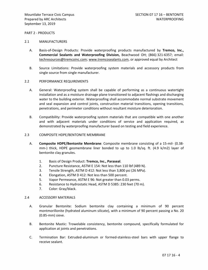
Mountlake Terrace Civic CampusPrepared by ARC ArchitectsSeptember 13, 2019
SECTION 07 17 16 – BENTONITE WATERPROOFING
07 17 16 - 4
PART 2 - PRODUCTS
2.1 MANUFACTURERS
A. Basis-of-Design Products: Provide waterproofing products manufactured by Tremco, Inc., Commercial Sealants and Waterproofing Division, Beachwood OH; (866) 321-6357; email: [email protected]; www.tremcosealants.com, or approved equal by Architect
B. Source Limitations: Provide waterproofing system materials and accessory products from single source from single manufacturer.
2.2 PERFORMANCE REQUIREMENTS
A. General: Waterproofing system shall be capable of performing as a continuous watertight installation and as a moisture drainage plane transitioned to adjacent flashings and discharging water to the building exterior. Waterproofing shall accommodate normal substrate movement and seal expansion and control joints, construction material transitions, opening transitions, penetrations, and perimeter conditions without resultant moisture deterioration.
B. Compatibility: Provide waterproofing system materials that are compatible with one another and with adjacent materials under conditions of service and application required, as demonstrated by waterproofing manufacturer based on testing and field experience.
2.3 COMPOSITE HDPE/BENTONITE MEMBRANE
A. Composite HDPE/Bentonite Membrane: Composite membrane consisting of a 15-mil- (0.38-mm-) thick, HDPE geomembrane liner bonded to up to 1.0 lb/sq. ft. (4.9 k/m2) layer of bentonite clay granules.
1. Basis of Design Product: Tremco, Inc., Paraseal.2. Puncture Resistance, ASTM E 154: Not less than 110 lbf (489 N).3. Tensile Strength, ASTM D 412: Not less than 3,800 psi (26 MPa).4. Elongation, ASTM D 412: Not less than 500 percent.5. Vapor Permeance, ASTM E 96: Not greater than 0.03 perms.6. Resistance to Hydrostatic Head, ASTM D 5385: 230 feet (70 m).7. Color: Gray/black.
2.4 ACCESSORY MATERIALS
A. Granular Bentonite: Sodium bentonite clay containing a minimum of 90 percent montmorillonite (hydrated aluminum silicate), with a minimum of 90 percent passing a No. 20 (0.85-mm) sieve.
B. Bentonite Mastic: Trowelable consistency, bentonite compound, specifically formulated for application at joints and penetrations.
C. Termination Bar: Extruded-aluminum or formed-stainless-steel bars with upper flange to receive sealant.

Mountlake Terrace Civic CampusPrepared by ARC ArchitectsSeptember 13, 2019
SECTION 07 17 16 – BENTONITE WATERPROOFING
07 17 16 - 5
D. Plastic Protection Sheet: Polyethylene sheeting complying with ASTM D 4397; thickness recommended by waterproofing manufacturer to suit application but at least 6 mils (0.15 mm) thick.
E. Cement Grout Patching Material: Manufacturer's recommended grout mix compatible with substrate being patched.
F. Masonry Fasteners: Case-hardened nails or hardened-steel, powder-actuated fasteners. Depending on manufacturer's written requirements, provide 1/2- or 1-inch- (13- or 25-mm-) diameter washers under fastener heads.
G. Tapes: Waterproofing manufacturer's recommended tape for joints between sheets, membranes, or panels. Use with recommended adhesive bonding primer.1. Reinforced Overlap Seam Tape: Reinforced, rubberized-asphaltic waterproofing seam
tape 4-inch (102 mm) wide by 60 mils (1.5 mm) thick for sealing membrane overlaps where flood-testing is required.
2. Non-Reinforced Overlap Tape: Non-reinforced, adhesive tape of partially cross-linked polymeric elastomers 2 by 1/8 inch (50 by 3.2 mm) for molding form-fit seals around contours and for taping seams within overlaps.
3. Double-Sided Bentonite Laminate Tape: Pressure sensitive, double-sided tape laminate of bentonite sandwiched between a netting and non-woven fabric for wrapping through-concrete imbeds and other detailing.
H. Waterstops: Flexible, reinforced, bentonite-laminate waterstop strips 1/2 by 1 inch (12 by 25 mm) with pressure-sensitive adhesive backing for sealing static cold joints in concrete.
I. Joint Sealants: Termination Seals:
1. Single component, high performance, medium-modulus, low-VOC, UV-stable, non-sag polyurethane sealant.
a. Basis of Design Product: Tremco Inc.; Dymonic 100.
2.5 WATERPROOFING PROTECTION AND DRAINAGE
A. Protection Course: Not required.
B. Nonwoven-Geotextile-Faced, Molded-Sheet Drainage Panel: Manufactured composite subsurface drainage panels consisting of a nonwoven, spun-bonded polypropylene facing laminated to one side of a studded, non-biodegradable, polystyrene drainage core.
1. Basis of Design: Tremco, TREMDrain.2. Flow Capacity, per unit width, ASTM D 4716: 9 gpm/ft. (112 lpm/m).3. Flow Rate, ASTM D 4491: 165 gpm/ft2 (6,724 lpm/m2).4. Apparent Opening Size: No. 70 sieve (210 micron).5. Puncture Strength, ASTM D 4833: 65 lb (289 N).6. Core Compressive Strength, ASTM D 1621: 10,800 lb/ft2 (527 kN/m2).7. Thickness: 0.25 inch (6.35 mm).

Mountlake Terrace Civic CampusPrepared by ARC ArchitectsSeptember 13, 2019
SECTION 07 17 16 – BENTONITE WATERPROOFING
07 17 16 - 6
PART 3 - EXECUTION
3.1 EXAMINATION
A. Surface Condition: Before applying waterproofing materials, examine substrate and conditions to ensure substrates and conditions comply with manufacturer's written recommendations.
B. Proceed with installation once unsatisfactory conditions have been corrected.
3.2 INTERFACE WITH OTHER WORK
A. Sequencing of Work: Coordinate sequencing of waterproofing work with work of other sections that form portions of building envelope moisture control to ensure that flashings and transition materials can be properly installed and inspected.
B. Subsequent Work: Coordinate waterproofing work with work of other sections installed subsequent to waterproofing to ensure complete inspection of installed waterproofing and sealing of waterproofing penetrations necessitated by subsequent work.
3.3 PREPARATION
A. Clean, prepare, and treat substrates in accordance with waterproofing manufacturer's written instructions. Fill voids with cement grout or bentonite mastic as recommended by manufacturer.
B. Formed Concrete Surfaces: Remove fins and projections. Fill voids, form-tie holes, and other defects greater than 1/4 inch (6 mm) in depth.
C. Horizontal Concrete Surfaces: Remove standing water, debris, and substances that may impair bonding of patching materials or effectiveness of waterproofing. Fill voids and other defects greater than 1/4 inch (6 mm) in depth.
D. Excavation Support and Protection System: Fill minor gaps and spaces 1/2 inch (12 mm) wide or wider with appropriate filling material. Cover or fill large voids and crevices.
3.4 INSTALLATION, GENERAL
A. Install waterproofing and accessories according to manufacturer's written instructions. Protect bentonite material from wetting prior to permanent placement.
1. Install a continuous layer of waterproofing membrane with ends and edges lapped a minimum of 5 inches (127 mm). Stagger end joints between membranes. Seal joints with seam tape. Treat fastener penetrations.
2. Apply granular bentonite around penetrations in horizontal surfaces and changes in plane according to manufacturer's details.
3. Apply bentonite mastic at changes of plane, construction joints in substrate, projections, and penetrations.

Mountlake Terrace Civic CampusPrepared by ARC ArchitectsSeptember 13, 2019
SECTION 07 17 16 – BENTONITE WATERPROOFING
07 17 16 - 7
B. Protect waterproofing from damage and wetting during construction. Repair punctures, tears, and cuts according to manufacturer's written instructions.
3.5 VERTICAL WALL WATERPROOFING
A. Vertical Concrete Walls: Apply mastic around penetrations and form continuous 2-inch- (50-mm-) wide cant at intersection of footings and walls with mastic.
1. Starting at lowest point, install a layer of waterproofing membrane horizontally, extending a minimum of 6 inches (150 mm) onto the footing. Lap membrane ends and edges a minimum of 4 inches (127 mm).
2. Secure membrane with washer headed fasteners.3. Extend membrane to within 6 inches (150 mm) of finished grade and terminate with
termination bar and sealant.
B. Excavation Support and Protection: Cut, clean, and treat tiebacks and similar projections. Encase tieback rods, nuts, and plates. If water is present, cover shoring and lagging with plastic protection sheets.
1. Starting at lowest point, install a layer of waterproofing membrane, with ends and edges lapped and nailed to shoring.
3.6 HORIZONTAL WATERPROOFING
A. Horizontal Roofs, Plazas, and between Slabs: Install waterproofing membrane starting at lowest point, with ends and edges overlapped a minimum of 4 inches (127 mm) and tape sealed.
1. Prime concrete substrates. Primer may be omitted on concrete surfaces that comply with requirements for dryness, surface texture, and freedom from imperfections.
2. Install bentonite side of membrane against the material to be waterproofed.3. Terminations at Vertical Surfaces: Provide a fillet or cant at intersection of horizontal
and vertical substrates. Extend waterproofing membrane to top of curb or to a minimum of 6 inches (150 mm) above plane of waterproofing; secure with manufacturer's recommended tape.
4. Cover waterproofing with a plastic slip-sheet.
3.7 BELOW-SLAB WATERPROOFING
A. Below Structural Slabs-on-Grade: Apply waterproofing membrane with HDPE side down.
1. Install membrane sheets bentonite-side up. Staple ends and edges where subject to displacement during concrete placement.
2. Install under footings, grade beams, and pile caps; or continue waterproofing through key joints between footings and foundation walls, and extend a minimum of 8 inches (200 mm) up or beyond perimeter slab forms. Stagger end joints minimum 12 inches (305 mm).
Mountlake Terrace Civic CampusPrepared by ARC ArchitectsSeptember 13, 2019
SECTION 07 17 16 – BENTONITE WATERPROOFING
07 17 16 - 8
3. Install under slabs starting at lowest point, install a continuous layer of waterproofing membrane, with ends and edges lapped a minimum of 4 inches (127 mm).
4. Protect waterproofing from damage caused by reinforcing bar supports with sharp edges.
3.8 DRAINAGE PANEL INSTALLATION
A. Place and secure drainage panels, with geotextile facing away from wall or deck substrate. Use adhesives that do not penetrate waterproofing. Lap edges and ends of geotextile to maintain continuity. Protect installed molded-sheet drainage panels during subsequent construction.
1. For vertical applications, install board insulation before installing drainage panels.
B. Insulation: Refer to Section 07 20 00 "Thermal Insulation."
3.9 FIELD QUALITY CONTROL
A. Testing Agency: Owner will engage a qualified testing agency to inspect substrate conditions, surface preparation, waterproofing application, protection, and drainage components, and to furnish reports to Architect.
B. Coordination of Testing: Cooperate with testing agency. Allow access to work areas and staging. Notify testing agency in writing of schedule for Work of this Section to allow sufficient time for testing and inspection.
1. Do not cover Work until testing and inspection is completed and accepted.
C. Reporting: Forward written inspection reports to the Architect within 10 working days of the inspection and test being performed.
D. Correction: Correct deficient applications not passing tests and inspections, make necessary repairs, and retest as required to demonstrate compliance with requirements.
3.10 CLEANING AND PROTECTING
A. Clean spills, stains, and overspray resulting application utilizing cleaning agents recommended by manufacturers of affected construction. Remove masking materials.
B. Protect waterproofing from damage from subsequent work. Protect waterproofing materials from exposure to UV light for period in excess of that acceptable to waterproofing manufacturer; replace overexposed materials and retest.
END OF SECTION

Mountlake Terrace Civic CampusPrepared by ARC ArchitectsSeptember 13, 2019
SECTION 07 21 00 - THERMAL INSULATION
07 21 00 - 1
SECTION 07 21 00 - THERMAL INSULATION
PART 1 - GENERAL
1.1 RELATED DOCUMENTS
A. Drawings and general provisions of the Contract, including General and Supplementary Conditions and Division 01 Specification Sections, apply to this Section.
1.2 SUMMARY
A. Section Includes:
1. Extruded polystyrene foam-plastic board.2. Polyisocyanurate foam-plastic board.3. Glass-fiber blanket.4. Mineral-wool blanket.5. Mineral-wool board.6. Spray-applied cellulosic insulation.
B. Related Requirements:
1. Section 04 20 00 "Unit Masonry" for insulation installed in masonry cells.
1.3 ACTION SUBMITTALS
A. Product Data: For each type of product.
1.4 DELIVERY, STORAGE, AND HANDLING
A. Protect insulation materials from physical damage and from deterioration due to moisture, soiling, and other sources. Store inside and in a dry location. Comply with manufacturer's written instructions for handling, storing, and protecting during installation.
B. Protect foam-plastic board insulation as follows:
1. Do not expose to sunlight except to necessary extent for period of installation and concealment.
2. Protect against ignition at all times. Do not deliver foam-plastic board materials to Project site until just before installation time.
3. Quickly complete installation and concealment of foam-plastic board insulation in each area of construction.

Mountlake Terrace Civic CampusPrepared by ARC ArchitectsSeptember 13, 2019
SECTION 07 21 00 - THERMAL INSULATION
07 21 00 - 2
PART 2 - PRODUCTS
2.1 EXTRUDED POLYSTYRENE FOAM-PLASTIC BOARD (XPS, RIGID INSULATION)
A. Extruded Polystyrene Board: ASTM C578, Type X, 15-psi minimum compressive strength; unfaced; maximum flame-spread and smoke-developed indexes of 25 and 450, respectively, per ASTM E84.
1. Fire Propagation Characteristics: Passes NFPA 285 testing as part of an approved assembly.
2.2 POLYISOCYANURATE FOAM-PLASTIC BOARD (RIGID INSULATION)
A. Polyisocyanurate Board, Foil Faced: ASTM C1289, foil faced, Type I, Class 1 or 2.
1. Fire Propagation Characteristics: Passes NFPA 285 testing as part of an approved assembly.
2.3 GLASS-FIBER BLANKET (BATT INSULATION)
A. Glass-Fiber Blanket, Unfaced: ASTM C665, Type I; with maximum flame-spread and smoke-developed indexes of 25 and 50, respectively, per ASTM E84; passing ASTM E136 for combustion characteristics.
B. Glass-Fiber Blanket, Kraft Faced: ASTM C665, Type II (nonreflective faced), Class C (faced surface not rated for flame propagation); Category 1 (membrane is a vapor barrier).
2.4 MINERAL-WOOL BLANKETS (MINERAL FIBER INSULATION)
A. Mineral-Wool Blanket, Unfaced: ASTM C665, Type I (blankets without membrane facing); consisting of fibers; with maximum flame-spread and smoke-developed indexes of 25 and 50, respectively, per ASTM E84; passing ASTM E136 for combustion characteristics.
1. Basis-of-Design Products: a. Exterior Wall, Batt: Rockwool Comfortbatt
MINERAL-WOOL BOARD (CONTINUOUS EXERIOR WALL INSULATION)
B. Mineral-Wool Board, Types IA and IB, Unfaced: ASTM C612, Types IA and IB; with maximum flame-spread and smoke-developed indexes of 15 and zero, respectively, per ASTM E84; passing ASTM E136 for combustion characteristics. Nominal density of 4 lb/cu. ft..
1. Basis-of-Design Product: Rockwool Comfortboard 110

Mountlake Terrace Civic CampusPrepared by ARC ArchitectsSeptember 13, 2019
SECTION 07 21 00 - THERMAL INSULATION
07 21 00 - 3
a. Insulated Sheathing for Continuous Insulation: Rockwool Comfortboard 80
2.5 SPRAY-APPLIED CELLULOSIC INSULATION
Self-Supported, Spray-Applied Cellulosic Insulation: ASTM C1149, Type I (materials applied with liquid adhesive; suitable for either exposed or enclosed applications), chemically treated for flame-resistance, processing, and handling characteristics.
2.6 INSULATION FASTENERS
A. Adhesively Attached, Spindle-Type Anchors: Plate welded to projecting spindle; capable of holding insulation of specified thickness securely in position with self-locking washer in place.
1. Plate: Perforated, galvanized carbon-steel sheet, 0.030 inch thick by 2 inches square.2. Spindle: Copper-coated, low-carbon steel; fully annealed; 0.105 inch in diameter; length
to suit depth of insulation.
B. Insulation-Retaining Washers: Self-locking washers formed from 0.016-inch- thick galvanized-steel sheet, with beveled edge for increased stiffness, sized as required to hold insulation securely in place, but not less than 1-1/2 inches square or in diameter.
1. Protect ends with capped self-locking washers incorporating a spring steel insert to ensure permanent retention of cap in the following locations:a. Attic spaces.
C. Insulation Standoff: Spacer fabricated from galvanized mild-steel sheet for fitting over spindle of insulation anchor to maintain air space between face of insulation and substrate to which anchor is attached.
D. Anchor Adhesive: Product with demonstrated capability to bond insulation anchors securely to substrates without damaging insulation, fasteners, or substrates.
2.7 ACCESSORIES
A. Insulation for Miscellaneous Voids:
1. Glass-Fiber Insulation: ASTM C764, Type II, loose fill; with maximum flame-spread and smoke-developed indexes of 5, per ASTM E84.
2. Spray Polyurethane Foam Insulation: ASTM C1029, Type II, closed cell, with maximum flame-spread and smoke-developed indexes of 75 and 450, respectively, per ASTM E84.
B. Adhesive for Bonding Insulation: Product compatible with insulation and air and water barrier materials, and with demonstrated capability to bond insulation securely to substrates without damaging insulation and substrates.

Mountlake Terrace Civic CampusPrepared by ARC ArchitectsSeptember 13, 2019
SECTION 07 21 00 - THERMAL INSULATION
07 21 00 - 4
C. Eave Ventilation Troughs: Preformed, rigid fiberboard or plastic sheets designed and sized to fit between roof framing members and to provide ventilation between insulated attic spaces and vented eaves.
PART 3 - EXECUTION
3.1 PREPARATION
A. Clean substrates of substances that are harmful to insulation, including removing projections capable of puncturing insulation or vapor retarders, or that interfere with insulation attachment.
3.2 INSTALLATION, GENERAL
A. Comply with insulation manufacturer's written instructions applicable to products and applications.
B. Install insulation that is undamaged, dry, and unsoiled and that has not been left exposed to ice, rain, or snow at any time.
C. Extend insulation to envelop entire area to be insulated. Fit tightly around obstructions and fill voids with insulation. Remove projections that interfere with placement.
D. Provide sizes to fit applications and selected from manufacturer's standard thicknesses, widths, and lengths. Apply single layer of insulation units unless multiple layers are otherwise shown or required to make up total thickness or to achieve R-value.
3.3 INSTALLATION OF SLAB INSULATION
A. On vertical slab edge and foundation surfaces, set insulation units using manufacturer's recommended adhesive according to manufacturer's written instructions.
1. If not otherwise indicated, extend insulation a minimum of 24 inches below exterior grade line.
B. On horizontal surfaces, loosely lay insulation units according to manufacturer's written instructions. Stagger end joints and tightly abut insulation units.
1. If not otherwise indicated, extend insulation a minimum of 24 inches in from exterior walls.
3.4 INSTALLATION OF FOUNDATION WALL INSULATION
A. Butt panels together for tight fit.

Mountlake Terrace Civic CampusPrepared by ARC ArchitectsSeptember 13, 2019
SECTION 07 21 00 - THERMAL INSULATION
07 21 00 - 5
B. Anchor Installation: Install board insulation on concrete substrates by adhesively attached, spindle-type insulation anchors as follows:
1. Fasten insulation anchors to concrete substrates with insulation anchor adhesive according to anchor manufacturer's written instructions. Space anchors according to insulation manufacturer's written instructions for insulation type, thickness, and application.
2. Apply insulation standoffs to each spindle to create cavity width indicated on Drawings between concrete substrate and insulation.
3. After adhesive has dried, install board insulation by pressing insulation into position over spindles and securing it tightly in place with insulation-retaining washers, taking care not to compress insulation.
4. Where insulation will not be covered by other building materials, apply capped washers to tips of spindles.
C. Adhesive Installation: Install with adhesive or press into tacky waterproofing or dampproofing according to manufacturer's written instructions.
3.5 INSTALLATION OF CAVITY-WALL INSULATION
A. Foam-Plastic Board Insulation: Install pads of adhesive spaced approximately 24 inches o.c. both ways on inside face and as recommended by manufacturer.
1. Fit courses of insulation between obstructions, with edges butted tightly in both directions, and with faces flush.
2. Press units firmly against inside substrates.3. Supplement adhesive attachment of insulation by securing boards with two-piece wall
ties designed for this purpose and specified in Section 04 20 00 "Unit Masonry."
B. Cellular-Glass Board Insulation: Install with closely fitting joints using attachment method according to manufacturer's written instructions.
C. Mineral-Wool Board Insulation: Install insulation fasteners 4 inches from each corner of board insulation, at center of board, and as recommended by manufacturer.
1. Fit courses of insulation between obstructions, with edges butted tightly in both directions, and with faces flush.
2. Press units firmly against inside substrates.
3.6 INSTALLATION OF INSULATION IN FRAMED CONSTRUCTION
A. Blanket Insulation: Install in cavities formed by framing members according to the following requirements:

Mountlake Terrace Civic CampusPrepared by ARC ArchitectsSeptember 13, 2019
SECTION 07 21 00 - THERMAL INSULATION
07 21 00 - 6
1. Use insulation widths and lengths that fill the cavities formed by framing members. If more than one length is required to fill the cavities, provide lengths that will produce a snug fit between ends.
2. Place insulation in cavities formed by framing members to produce a friction fit between edges of insulation and adjoining framing members.
3. Maintain 3-inch clearance of insulation around recessed lighting fixtures not rated for or protected from contact with insulation.
4. Attics: Install eave ventilation troughs between roof framing members in insulated attic spaces at vented eaves.
5. For wood-framed construction, install blankets according to ASTM C1320 and as follows:
a. With faced blankets having stapling flanges, lap blanket flange over flange of adjacent blanket to maintain continuity of vapor retarder once finish material is installed over it.
6. Vapor-Retarder-Faced Blankets: Tape joints and ruptures in vapor-retarder facings, and seal each continuous area of insulation to ensure airtight installation.a. Exterior Walls: Set units with facing placed toward as indicated on Drawings.b. Interior Walls: Set units with facing placed as indicated on Drawings.
B. Miscellaneous Voids: Install insulation in miscellaneous voids and cavity spaces where required to prevent gaps in insulation using the following materials:
1. Glass-Fiber Insulation: Compact to approximately 40 percent of normal maximum volume equaling a density of approximately 2.5 lb/cu. ft..
2. Spray Polyurethane Insulation: Apply according to manufacturer's written instructions.
C. Loose-Fill Insulation: Apply according to ASTM C1015 and manufacturer's written instructions. Level horizontal applications to uniform thickness as indicated, lightly settle to uniform density, but do not compact excessively.
1. For cellulosic-fiber loose-fill insulation, comply with CIMA's Bulletin #2, "Standard Practice for Installing Cellulose Insulation."
D. Spray-Applied Cellulosic Insulation: Apply spray-applied insulation according to manufacturer's written instructions. Do not apply insulation until installation of pipes, ducts, conduits, wiring, and electrical outlets in walls is completed and windows, electrical boxes, and other items not indicated to receive insulation are masked. After insulation is applied, make flush with face of studs by using method recommended by insulation manufacturer.
3.7 PROTECTION
A. Protect installed insulation from damage due to harmful weather exposures, physical abuse, and other causes. Provide temporary coverings or enclosures where insulation is subject to abuse and cannot be concealed and protected by permanent construction immediately after installation.

Mountlake Terrace Civic CampusPrepared by ARC ArchitectsSeptember 13, 2019
SECTION 07 21 00 - THERMAL INSULATION
07 21 00 - 7
END OF SECTION 07 21 00

Mountlake Terrace Civic CampusPrepared by ARC ArchitectsSeptember 13, 2019
SECTION 07 25 00 - WEATHER BARRIERS
07 25 00 - 1
SECTION 07 25 00 - WEATHER BARRIERS
PART 1 - GENERAL
1.1 RELATED DOCUMENTS
A. Drawings and general provisions of the Contract, including General and Supplementary Conditions and Division 01 Specification Sections, apply to this Section.
1.2 SUMMARY
A. Unless noted otherwise, this Section Includes:1. Weather Resistant Barrier (WRB)2. Self-Adhering Membrane (SAM)3. Self-Adhering Sill Plate Barrier4. Liquid-Applied Flashing (LAF)5. Window Sill Pan6. Aluminum back dam angle7. Flashing Panels
B. Related Requirements:1. Division 06 Section “Rough Carpentry”2. Division 07 Section "Sheet Metal Flashing and Trim”3. Division 07 Section “Styrene-butadiene-styrene (SBS) modified bituminous membrane
roofing”4. Division 08 Section “Vinyl Windows”5. Division 08 Section “Fiberglass Windows”
C. System Description:
1. Supply labor, materials and equipment for a mechanically attached water-resistive weather barrier membrane system.
2. Complete Work as shown on the Drawings and specified herein to bridge gaps and seal the water-resistive vapor permeable air barrier membrane against air leakage and water intrusion, including:
Connections of the walls to the roof membraneConnections of the walls to the foundations Seismic and expansion jointsOpenings and penetrations of window and door frames, store front, curtain wallPiping, conduit, duct and similar penetrationsMasonry ties, screws, bolts and similar penetrationsAll other air leakage pathways in the building envelope
3. Install primary water-resistive vapor permeable air barrier, flashing, and accessories.

Mountlake Terrace Civic CampusPrepared by ARC ArchitectsSeptember 13, 2019
SECTION 07 25 00 - WEATHER BARRIERS
07 25 00 - 2
1.3 ACTION SUBMITTALS
A. Product Data: For each type of product.
B. Submit manufacturers’ current details and installation instructions for the water-resistive vapor permeable air barrier membrane components and accessories.
C. Submit samples of the following: 1. Manufacturer's sample warranty
1.4 WARRANTYA. Provide manufacturer’s standard material warranty in which manufacturer agrees to provide replacement material for the mechanically attached water-resistive vapor permeable air barrier sheets installed in accordance with manufacturer's instructions that fail due to material defects within 20 years of the date of Purchase.
PART 2 - PRODUCTS
2.1 MANUFACTURER
A. Manufacturer: The manufacturer listed below is the basis-of-design product, equivalent products by other manufacturers, provided they comply with requirements of the contract documents, will be considered (if applicable).
2.2 WEATHER RESISTANT BARRIER (WRB)
A. At Walls: Vapro-Shield Wrapshield IT (integrated tape), or equal
2.3 FLASHING ASSEMBLY (SELF ADHERING MEMBRANE (SAM) AND LIQUID-APPLIED FLASHING (LAF)):
A. Self-Adhered Membrane (SAM): VaproFlashing SA™ Self-Adhered Orange
B. Liquid-Applied Flashing (LAF): Prosoco Fast Flash, a liquid-applied vapor permeable air barrier flashing material with vapor permeance and resistance to air leakage properties compatible with the primary air barrier membrane.
2.4 WINDOW SILL PANS (Aluminum angle installed inboard of window at sill, coated with liquid flashing)
A. Back Angle: 1.5”x1.5”x0.050 Aluminum. Cut to fit full width of opening and installed behind window frame at sill. Set in sealant and make watertight with VaproLiqui-Flash.

Mountlake Terrace Civic CampusPrepared by ARC ArchitectsSeptember 13, 2019
SECTION 07 25 00 - WEATHER BARRIERS
07 25 00 - 3
2.5 SEALANT
A. VaproBond, Dow 758, or VaproLiqui-Flash. For use at vertical joints in Wrapshield IT, penetrations, base of wall to adhere Wrapshield to foundation, and where shown in drawings and details.
2.6 SELF ADHESIVE SILL PLATE BARRIER
A. Protecto Premium Energy Sill Sealer by Protecto-Wrap, or equal – 5-1/2” wide x 3/8” thick
1. Closed Cell Polyethylene Foam with Self Adhering Waterproof Membrane
2.7 FLASHING PANELS
A. Flashing Panels: Quickflash Weatherproofing Products INC.
B. Mechanical / Plumbing Flashing Panels:1. Materials:
a. Panel: Combination of high-density polyethylene (HDPE) and low-density polyethylene (LDPE).1) HDPE, Specific Gravity, ASTM D 1505: 0.953 g/cm3.2) HDPE, Tensile Strength at Yield, ASTM D 638: 3,100 psi.3) LDPE, Specific Gravity, ASTM D 792: 0.917 g/cm3.4) LDPE, Tensile Strength at Yield, ASTM D 638: 1,300 psi.
b. Weatherproof Seal: Thermoplastic elastomer.1) Hardness, ASTM D 2240, Shore A, 10 Seconds: 46.2) Specific Gravity, ASTM D 792: 1.05 g/cm3.3) Tensile Strength, ASTM D 412: 490 psi.
C. Electrical Flashing Panels:1. Material: Thermoplastic elastomer.
a. Hardness, ASTM D 2240, Shore A, 10 Seconds: 93.b. Specific Gravity, ASTM D 792: 1.05 g/cm3.c. Tensile Strength, ASTM D 412: 1,300 psi.
D. Flashing Panel Model Numbers: As required for all Mechanical, Plumbing and Electrical penetrations identified in the drawings at exterior wall locations.
2.8 MISCELLANEOUS MATERIALS
A. Flexible Flashing: Composite, self-adhesive, flashing product consisting of a pliable, butyl rubber compound, bonded to a high-density polyethylene film, aluminum foil, or spun-bonded polyolefin to produce an overall thickness of not less than 0.025 inch (0.6 mm) 0.030 inch (0.8 mm) 0.040 inch (1.0 mm).

Mountlake Terrace Civic CampusPrepared by ARC ArchitectsSeptember 13, 2019
SECTION 07 25 00 - WEATHER BARRIERS
07 25 00 - 4
a. Products: Provide product compatible to the Weather Barrier products.
B. Primer for Flexible Flashing: Product recommended by manufacturer of flexible flashing for substrate.
C. Nails and Fasteners: ASTM F 1667.1. Mechanical fasteners used to secure sheathing surfaces or penetrate sheathing surfaces
shall be set flush with sheathing, fastened into solid backing and covered with the upper overlapping membrane. If exposed fasteners are present on the surface of the membrane, cover and seal with Vapro-LiquiFlash or VaproBond™.
2. If exposed fasteners are required, use Vaproshield VaproCaps to insure water/air tight seal.
D. Bi-Cellular Backer Rods: Provide cylindrical, flexible sealant backings composed bi-cellular material per Type B, ASTM C 1330 and ASTM C 717 for use as gasket or sealing material, for use with cold-applied sealants.
PART 3 - EXECUTION
3.1 WEATHER RESISTANT BARRIER INSTALLATION
A. Refer to detail drawings
B. Install in strict accordance with manufacturer’s instructions for wrap, self-adhered flashing, liquid flashing and integrated tape.
1. Seal seams, edges, fasteners, and penetrations with integrated tape or sealant.
3.2 WINDOW FLASHING INSTALLATION
A. Apply self-adhered flashing where indicated to comply with manufacturer's written instructions.
1. Clean and or Prime substrates as recommended by flashing manufacturer.2. Lap seams and junctures with other materials at least 4 inches (100 mm) except that at
flashing flanges of other construction, laps need not exceed flange width.3. Lap flashing over water-resistive barrier at bottom of openings.4. Lap water-resistive barrier over flashing at heads and jambs of openings.5. After flashing has been applied, roll surfaces with a hard rubber or metal roller to ensure
that flashing is completely adhered to substrates.
B. Apply sill angle at back of opening, set in sealant. Seal over angle with liquid flashing and seal ends of angle to jambs to form a sill pan. Position so ~1/4” inboard of window frame to allow installation of interior sealant between angle and window frame.

Mountlake Terrace Civic CampusPrepared by ARC ArchitectsSeptember 13, 2019
SECTION 07 25 00 - WEATHER BARRIERS
07 25 00 - 5
C. Apply liquid flashing at all sides of opening over the self-adhered membrane. Extend to back of opening, inboard of window frame by a minimum of 1”. Return liquid flashing up back angle to form a sill pan. Return out onto face of wall a minimum of 1” on all sides of opening.
3.3 SELF ADHESIVE SILL BARRIER INSTALLATION
A. Apply sill barrier along the foundation perimeter to comply with manufacturer’s written instructions.1. Prime the top of the foundation with Protecto #100 Primer and allow primer to tack up.
3.4 FLASHING PANELS
A. Install flashing panels in accordance with manufacturer’s instructions.
END OF SECTION 072500

Mountlake Terrace Civic CampusPrepared by ARC ArchitectsSeptember 13, 2019
SECTION 07 31 13 - ASPHALT SHINGLES
07 31 13 - 1
SECTION 07 31 13 - ASPHALT SHINGLES
PART 1 - GENERAL
1.1 RELATED DOCUMENTS
A. Drawings and general provisions of the Contract, including General and Supplementary Conditions and Division 01 Specification Sections, apply to this Section.
1.2 SUMMARY
A. Section Includes:
1. Asphalt shingles.2. Underlayment.3. Ridge vents.4. Metal flashing and trim.5. Air & Vapor Barrier (Temporary Roof)
B. Related Requirements:
1. Section 07 62 00 "Sheet Metal Flashings and Trim.”
1.3 DEFINITION
A. Roofing Terminology: See ASTM D 1079 and glossary of NRCA's "The NRCA Roofing and Waterproofing Manual" for definitions of terms related to roofing work in this Section.
1.4 ACTION SUBMITTALS
A. Product Data: For each type of product.
B. Samples: For each exposed product and for each color and texture specified.
1. Asphalt Shingles: Full size.2. Ridge and Hip Cap Shingles: Full size.3. Ridge Vent: 12-inch- long Sample.4. Exposed Valley Lining: 12 inches square.
1.5 INFORMATIONAL SUBMITTALS
A. Sample Warranty: For manufacturer's warranty.

Mountlake Terrace Civic CampusPrepared by ARC ArchitectsSeptember 13, 2019
SECTION 07 31 13 - ASPHALT SHINGLES
07 31 13 - 2
1.6 CLOSEOUT SUBMITTALS
A. Maintenance Data: For asphalt shingles to include in maintenance manuals.
1.7 MAINTENANCE MATERIAL SUBMITTALS
A. Furnish extra materials that match products installed and that are packaged with protective covering for storage and identified with labels describing contents.
1. Asphalt Shingles: 100 sq. ft. of each type, in unbroken bundles.
1.8 QUALITY ASSURANCE
A. Installer Qualifications: An authorized representative who is trained and approved by manufacturer.
1.9 DELIVERY, STORAGE, AND HANDLING
A. Store roofing materials in a dry, well-ventilated location protected from weather, sunlight, and moisture according to manufacturer's written instructions.
B. Store underlayment rolls on end on pallets or other raised surfaces. Do not double stack rolls.
C. Protect unused roofing materials from weather, sunlight, and moisture when left overnight or when roofing work is not in progress.
D. Handle, store, and place roofing materials in a manner to prevent damage to roof deck or structural supporting members.
1.10 FIELD CONDITIONS
A. Environmental Limitations: Install self-adhering sheet underlayment within the range of ambient and substrate temperatures recommended in writing by manufacturer.
1.11 WARRANTY
A. Manufacturer's Warranty: Manufacturer agrees to repair or replace asphalt shingles that fail within specified warranty period.
1. Failures include, but are not limited to, the following:
a. Manufacturing defects.2. Material Warranty Period: 40 years from date of Substantial Completion, prorated, with
first 10 years nonprorated.

Mountlake Terrace Civic CampusPrepared by ARC ArchitectsSeptember 13, 2019
SECTION 07 31 13 - ASPHALT SHINGLES
07 31 13 - 3
3. Wind-Speed Warranty Period: Asphalt shingles will resist blow-off or damage caused by wind speeds of up to 80 mph for five years from date of Substantial Completion.
4. Algae-Resistance Warranty Period: Asphalt shingles will not discolor for 20 years from date of Substantial Completion.
5. Workmanship Warranty Period: Two years from date of Substantial Completion.
B. Roofing Installer's Warranty: On warranty form at end of this Section, signed by Installer, in which Installer agrees to repair or replace components of asphalt-shingle roofing that fail in materials or workmanship within specified warranty period.
1. Warranty Period: Two years from date of Substantial Completion.
PART 2 - PRODUCTS
2.1 MANUFACTURER
A. Basis-of-Design Manufacturer: GAF, 1 Campus Drive, Parsippany, NJ 07054 Tel: 1-973-628-3000. Requests for substitutions will be considered in accordance with provisions of specifications.
2.2 VENTILATED ROOF INSULATION PANELS (NAIL BASE ROOF INSULATION PANEL)
A. Preassembled panel consisting of a oriented strand board top surface a wood spacer block separating a layer of Isocyanurate insulation on the bottom, ThermaCal® 1 Ventilating Roof Insulation Panel by GAF-Cornell.
1. 7/16 plywood
2. 1” wood spacers blocks
3. Insulation Thickness: 6.5” (R-38)
2.3 GLASS-FIBER-REINFORCED ASPHALT SHINGLES
A. UL 2218, Class 4, granule surfaced, self-sealing asphalt shingle with a strong fiberglass reinforced Micro Weave core and mineral granule surfacing. Special cut tabs and bold profile provide a rugged hand-split shake appearance with an 8 in. exposure. UL 790 Class A rated with UL 997 Wind Resistance Label; ASTM D 7158, Class H; ASTM D 3161, Type 1; ASTM D 3018, Type 1; ASTM D 3462; Passes UL 2218, Class 4 Impact Test ; AC438 compliant; CSA 123.5-98; Dade County Approved, Florida Building Code Approved, Texas Dept of Insurance Approved, ICC Report Approval. Grand Sequoia® ArmorShield™ II Lifetime Designer Shingles, by GAF®.
B.
1. Color: As selected from manufacturers’ full range.
Mountlake Terrace Civic CampusPrepared by ARC ArchitectsSeptember 13, 2019
SECTION 07 31 13 - ASPHALT SHINGLES
07 31 13 - 4
2.4 HIP AND RIDGE SHINGLES
A. High profile self sealing hip and ridge cap shingle matching the color of selected roof shingle. Each bundle covers approx. 20 lineal feet (6.10m). Timbertex® Premium Ridge Cap Shingles, by GAF®.
2.5 STARTER STRIP
A. Self sealing starter shingle designed for premium roof shingles. Each bundle covers approx. 100 lineal feet (30.48m) for English and metric shingles or 50 lineal feet (15.24m) for oversized shingles. WeatherBlocker™ Eave/Rake Starter Strip by GAF®.
2.6 LEAK (ICE MEMBRANE) BARRIER
A. Self-adhering, self-sealing, bituminous leak barrier surfaced with fine, skid-resistant granules. Approved by UL, Dade County, ICC, State of Florida and Texas Department of Insurance. Each roll contains approx. 150 sq ft (13.9 sq.m.), 36” X 50’ (0.9m x 20.3m) or 200 sq ft (18.6 sq.m.), 36” X 66.7’ (0.9m x 20.3m). WeatherWatch® Leak Barrier, by GAF®.
2.7 UNDERLAYMENT MATERIALS
A. Synthetic, non-asphaltic, non-woven, anti-skid back coated, polypropylene constructed non breathable underlayment. Meets or exceeds ASTM D226 and D4869 approved by UL, Florida Building Code, ICC and CSA A220.1. Each roll contains approximately 10 squares (1000 gross sq. ft.) of material and is 48 in. x 250 ft. (14.6 m x 76.2 m), Tiger-Paw™ Roof Deck Protection by GAF®.
B. Number of layers: 2
2.8 RIDGE VENTS
A. Flexible rigid plastic ridge ventilator designed to allow the passage of hot air from attics, while resisting snow infiltration. For use in conjunction with eave/soffit ventilation products. Provides 12.5 sq inches Net Free Ventilation Area per lineal foot (26460 sq.mm/m). Each package contains 20 lineal feet (6.10m) of vent. Cobra® Ridge Runner™ Ridge Vent by GAF®.
2.9 FASCIA AND SOFFIT/UNDER EAVE VENTS
A. Flexible rigid plastic ridge ventilator designed to allow the passage of hot air out of attics at the roof top along the eaves. For use in conjunction with ridge ventilation products. Provides 9.0 sq inches (11613 sq.mm/m) in NFVA per lineal foot. Each package contains 40 lineal feet (12.19m) of vent, Cobra® IntakePro™ Rooftop Intake Vent (includes 1-3/4” (44.5 mm) coil nails), by GAF®
2.10 ACCESSORIES
A. Asphalt Roofing Cement: ASTM D 4586, Type II, asbestos free.

Mountlake Terrace Civic CampusPrepared by ARC ArchitectsSeptember 13, 2019
SECTION 07 31 13 - ASPHALT SHINGLES
07 31 13 - 5
B. Roofing Nails: ASTM F 1667; aluminum, stainless-steel, copper, or hot-dip galvanized-steel wire shingle nails, minimum 0.120-inch- diameter, sharp-pointed, with a minimum 3/8-inch- diameter flat head and of sufficient length to penetrate 3/4 inch into solid wood decking or extend at least 1/8 inch through OSB or plywood sheathing.
1. Shank: Barbed or Smooth.2. Where nails are in contact with metal flashing, use nails made from same metal as
flashing.
2.11 AIR & VAPOR BARRIER (TEMPORARY ROOF)
a. Basis-of-Design Manufacturer and Product: Versico 725TR Air & Vapor Barrier / Temporary Roof: 725TR is a 40-mil composite consisting of 35-mils of self-adhering rubberized asphalt factory laminated to a 5-mil polyethylene film with an adhesion textured surface. 725TR roll dimensions are 39” x 75’ and the product is applied after priming an acceptable substrate with substrate primer.
b. Temporary Roof Substrate Primer: CCW 702, 702-LV or Cav-Grip primer.
2.12 METAL FLASHING AND TRIM
C. General: Comply with requirements in Section 07 62 00 "Sheet Metal Flashing and Trim."
D. Fabricate sheet metal flashing and trim to comply with recommendations in SMACNA's "Architectural Sheet Metal Manual" that apply to design, dimensions, metal, and other characteristics of the item.
1. Apron Flashings: Fabricate with lower flange a minimum of 4 inches over and 4 inches beyond each side of downslope asphalt shingles and 6 inches up the vertical surface.
2. Step Flashings: Fabricate with a headlap of 2 inches and a minimum extension of 4 inches over the underlying asphalt shingle and up the vertical surface.
3. Cricket or Backer Flashings: Fabricate with concealed flange extending a minimum of 18 inches beneath upslope asphalt shingles.
4. Open-Valley Flashings: Fabricate in lengths not exceeding 10 feet with 1-inch- high, inverted-V profile at center of valley and equal flange widths of 10 inches.
5. Drip Edges: Fabricate in lengths not exceeding 10 feet with 2-inch roof-deck flange and 1-1/2-inch fascia flange with 3/8-inch drip at lower edge.
E. Vent Pipe Flashings: ASTM B 749, Type L51121, at least 1/16 inch thick. Provide lead sleeve sized to slip over and turn down into pipe, soldered to skirt at slope of roof, and extending at least 4 inches from pipe onto roof.

Mountlake Terrace Civic CampusPrepared by ARC ArchitectsSeptember 13, 2019
SECTION 07 31 13 - ASPHALT SHINGLES
07 31 13 - 6
PART 3 - EXECUTION
3.1 EXAMINATION
A. Examine substrates, areas, and conditions, with Installer present, for compliance with requirements for installation tolerances and other conditions affecting performance of the Work.
1. Examine roof sheathing to verify that sheathing joints are supported by framing and blocking or metal clips and that installation is within flatness tolerances.
2. Verify that substrate is sound, dry, smooth, clean, sloped for drainage, and completely anchored; and that provisions have been made for flashings and penetrations through asphalt shingles.
B. Prepare written report, endorsed by Installer, listing conditions detrimental to performance of the Work.
C. Proceed with installation only after unsatisfactory conditions have been corrected.
3.2 UNDERLAYMENT INSTALLATION
A. General: Comply with underlayment manufacturer's written installation instructions applicable to products and applications indicated unless more stringent requirements apply.
B. Double-Layer Underlayment: Install on roof deck parallel with and starting at the eaves. Install a 19-inch- wide starter course at eaves and completely cover with full-width second course. Install succeeding courses lapping previous courses 19 inches in shingle fashion. Lap ends a minimum of 6 inches. Stagger end laps between succeeding courses at least 72 inches. Fasten with felt-underlayment nails.
1. Apply a continuous layer of asphalt roofing cement over starter course and on felt-underlayment surface to be concealed by succeeding courses as each felt course is installed. Apply over entire roof.
2. Install felt underlayment on roof sheathing not covered by self-adhering sheet underlayment. Lap edges over self-adhering sheet underlayment not less than 3 inches in direction that sheds water.
3. Terminate felt underlayment flush against sidewalls, curbs, chimneys, and other roof projections.
4. Install fasteners at no more than 36 inch o.c.
C. Synthetic Underlayment: Install on roof deck parallel with and starting at the eaves. Lap sides and ends and treat laps as recommended in writing by manufacturer. Stagger end laps between succeeding courses at interval recommended in writing by manufacturer. Fasten according to manufacturer's written instructions. Cover underlayment within period recommended in writing by manufacturer.

Mountlake Terrace Civic CampusPrepared by ARC ArchitectsSeptember 13, 2019
SECTION 07 31 13 - ASPHALT SHINGLES
07 31 13 - 7
1. Install in single layer on roofs sloped at 4:12 and greater.2. Install in double layer on roofs sloped at less than 4:12.
D. Metal-Flashed, Open-Valley Underlayment: Install two layers of minimum 36-inch- wide underlayment centered in valley. Stagger end laps between layers at least 72 inches. Lap ends of each layer at least 12 inches in direction to shed water, and seal with asphalt roofing cement. Fasten each layer to roof deck.
1. Lap roof-deck underlayment over first layer of valley underlayment at least 6 inches.
3.3 TEMPORARY ROOF (AIR AND VAPOR BARRIERS)
A. Air and Vapor Barriers noted in this section, and related roofing sections are to be installed per manufacturer’s requirements to act as a temporary, weatherproof roof immediately after the barrier substrate is installed to avoid potential water damage during installation of roofing components that occur after the air and vapor barrier.
3.4 METAL FLASHING INSTALLATION
A. General: Install metal flashings and other sheet metal to comply with requirements in Section 07 62 00 "Sheet Metal Flashing and Trim."
1. Install metal flashings according to recommendations in ARMA's "Residential Asphalt Roofing Manual" and NRCA's "NRCA Guidelines for Asphalt Shingle Roof Systems."
B. Apron Flashings: Extend lower flange over and beyond each side of downslope asphalt shingles and up the vertical surface.
C. Step Flashings: Install with a headlap of 2 inches and extend over the underlying asphalt shingle and up the vertical surface. Fasten to roof deck only.
D. Cricket or Backer Flashings: Install against the roof-penetrating element extending concealed flange beneath upslope asphalt shingles and beyond each side.
E. Open-Valley Flashings: Install centered in valleys, lapping ends at least 8 inches in direction to shed water. Fasten upper end of each length to roof deck beneath overlap.
1. Secure hemmed flange edges into metal cleats spaced 12 inchesapart and fastened to roof deck.
2. Adhere 9-inch wide strip of self-adhering sheet to metal flanges and to self-adhering sheet underlayment.
F. Rake Drip Edges: Install rake drip-edge flashings over underlayment and fasten to roof deck.
G. Eave Drip Edges: Install eave drip-edge flashings below underlayment and fasten to roof sheathing.

Mountlake Terrace Civic CampusPrepared by ARC ArchitectsSeptember 13, 2019
SECTION 07 31 13 - ASPHALT SHINGLES
07 31 13 - 8
H. Pipe Flashings: Form flashing around pipe penetrations and asphalt shingles. Fasten and seal to asphalt shingles as recommended by manufacturer.
3.5 ASPHALT-SHINGLE INSTALLATION
A. General: Install asphalt shingles according to manufacturer's written instructions, recommendations in ARMA's "Residential Asphalt Roofing Manual," and recommendations in NRCA's "NRCA Guidelines for Asphalt Shingle Roof Systems."
B. Install starter strip along lowest roof edge, consisting of an asphalt-shingle strip with tabs removed with self-sealing strip face up at roof edge.
1. Extend asphalt shingles 1/2 inch over fasciae at eaves and rakes.2. Install starter strip along rake edge.
C. Install first and remaining courses of asphalt shingles stair-stepping diagonally across roof deck with manufacturer's recommended offset pattern at succeeding courses, maintaining uniform exposure.
D. Install first and remaining courses of asphalt shingles stair-stepping diagonally across roof deck with manufacturer's recommended offset pattern at succeeding courses, maintaining uniform exposure.
E. Install asphalt shingles by single-strip column or racking method, maintaining uniform exposure. Install full-length first course followed by cut second course, repeating alternating pattern in succeeding courses.
F. Fasten asphalt-shingle strips with a minimum of four roofing nails located according to manufacturer's written instructions.
1. Where roof slope is less than 4:12, seal asphalt shingles with asphalt roofing cement spots.
2. When ambient temperature during installation is below 50 deg F, seal asphalt shingles with asphalt roofing cement spots.
G. Open Valleys: Cut and fit asphalt shingles at open valleys, trimming upper concealed corners of shingle strips. Maintain uniform width of exposed open valley from highest to lowest point.
1. Set valley edge of asphalt shingles in a 3-inch- wide bed of asphalt roofing cement.2. Do not nail asphalt shingles to metal open-valley flashings.
H. Ridge Vents: Install continuous ridge vents over asphalt shingles according to manufacturer's written instructions. Fasten with roofing nails of sufficient length to penetrate sheathing.
I. Hip and Ridge Shingles: Maintain same exposure of cap shingles as roofing shingle exposure. Lap cap shingles at ridges to shed water away from direction of prevailing winds. Fasten with roofing nails of sufficient length to penetrate sheathing.

Mountlake Terrace Civic CampusPrepared by ARC ArchitectsSeptember 13, 2019
SECTION 07 31 13 - ASPHALT SHINGLES
07 31 13 - 9
1. Fasten ridge cap asphalt shingles to cover ridge vent without obstructing airflow.
END OF SECTION 07 31 13
Mountlake Terrace Civic CampusPrepared by ARC ArchitectsSeptember 13, 2019
SECTION 07 42 13.13 - FORMED METAL WALL PANELS
07 42 13.13 - 1
SECTION 074213.13 – FORMED METAL WALL PANELS
PART 1 - GENERAL
1.1 SUMMARY
A. Section includes complete system of concealed-fastener, lap-seam metal panels, and accessories in the following applications:1. Metal wall panels (siding).
1.2 REFERENCES
A. Reference Standards:1. ASCE 7: Minimum Design Loads for Buildings and Other Structures.2. ASTM A653: Steel Sheet, Zinc Coated (Galvanized) or Zinc Iron Alloy Coated
(Galvannealed) by the Hot Dip Process.3. ASTM A792: Steel Sheet, 55 % Aluminum Zinc Alloy Coated by the Hot Dip Process.4. ASTM C1371: Determination of Emittance of Materials Near Room Temperature Using
Portable Emissometers.5. ASTM C1549: Determination of Solar Reflectance Near Ambient Temperature Using a
Portable Solar Reflectometer.6. ASTM D523: Specular Gloss.7. ASTM E283: Rate of Air Leakage Through Exterior Windows, Curtain Walls, and Doors
Under Specified Pressure Differences Across the Specimen.8. ASTM E331: Water Penetration of Exterior Windows, Skylights, Doors, and Curtain Walls
by Uniform Static Air Pressure Difference.9. ASTM E1592: Structural Performance of Sheet Metal Roof and Siding Systems by
Uniform Static Air Pressure Difference.10. ASTM E1918: Measuring Solar Reflectance of Horizontal and Low Sloped Surfaces in the
Field.11. ASTM E1980: Calculating Solar Reflectance Index of Horizontal and Low Sloped Opaque
Surfaces.12. CRRC-1 Method #1: Measuring Solar Reflectance of a Flat, Opaque, and Heterogeneous
Surface Using a Portable Solar Reflectometer.13. SMACNA Architectural Sheet Metal Manual.
1.3 SUBMITTALS
A. Product Data.
B. Shop Drawings:1. Indicate thickness and dimensions of parts, fastenings and anchoring methods, details
and locations of joints, transitions, flashings, corners, and other provisions necessary for thermal expansion and contraction.

Mountlake Terrace Civic CampusPrepared by ARC ArchitectsSeptember 13, 2019
SECTION 07 42 13.13 - FORMED METAL WALL PANELS
07 42 13.13 - 2
2. Indicate locations of field- and factory-applied sealant.
C. Samples:1. Submit one sample, 12 inches long by full panel width, showing proposed metal
thickness and seam profile in color selected.
1.4 QUALITY ASSURANCE
A. Installer Qualifications: 1. Three years' experience, minimum, in application of metal roof or wall panels.
B. Product Testing Agency Qualifications: Agency compliant with ISO/IEC Standard 17025, or an accredited independent agency recognized by the International Laboratory Accreditation Cooperation Mutual Recognition Arrangement or ANSI.
1.5 DELIVERY, STORAGE, AND HANDLING
A. Storage and Handling Requirements:1. Keep panels and accessory items dry.2. Protect against damage and discoloration.3. Handle panels with non-marring slings.4. Support panels to prevent permanent deformation.5. Store panels above ground, with one end elevated for drainage.6. Protect panels against standing water and condensation between adjacent surfaces.7. If panels become wet, immediately separate sheets, wipe dry with clean cloth, and keep
sheets separate for air-drying.8. Painted panels shall be shipped with protective plastic sheeting or a strippable film
coating between panels. Remove strippable film coating prior to installation. Do not allow strippable film coating to remain on panels in extreme heat, cold, or direct sunlight or other UV source.
1.6 WARRANTY
A. Manufacturer's Warranty: Manufacturer’s standard 25-year performance warranty, stating the following:1. Architectural fluorocarbon finish:
a. Will be free of fading or color change in excess of 5 Hunter delta-E units as determined by ASTM D2244-02.
b. Will not chalk in excess of numerical rating of 8 when measured in accordance with standard procedures specified in ASTM D4214-98 method D659.
c. Will not peel, crack, chip, or delaminae.2. Metal substrate will not rupture, fail structurally, or perforate.
B. Installer's Warranty: Warrant panels, flashings, sealants, fasteners and accessories against defective materials and/or workmanship, covering repairs required to maintain wall panels watertight and weatherproof with normal usage for two years following Project Substantial Completion date.

Mountlake Terrace Civic CampusPrepared by ARC ArchitectsSeptember 13, 2019
SECTION 07 42 13.13 - FORMED METAL WALL PANELS
07 42 13.13 - 3
1. Furnish written warranty, signed by installer.
PART 2 - PRODUCTS
2.1 SYSTEM DESCRIPTION
A. Products: Provide the following:1. AEP Span, a Division of ASC Profiles LLC.; Perception Collection™.2. The Bryer Company; TBC Symmetry C223. The Bryer Company; TBC 7/8” Corrugated4. Metal Sales Mfg. Corp.
B. Substitution Limitations: Substitutions will be considered in accordance with Section 012500 "Substitution Procedures" as approved by Architect.
2.2 METAL WALL PANELS
A. Panel: AEP Span, a Division of ASC Profiles LLC; Perception Collection™1. Material: Steel conforming to ASTM A792.
a. 22 Gauge: Yield strength 50,000 psi; with aluminum-zinc alloy coating conforming to ASTM A792, Class AZ50.
b. Thickness and yield strength as required for performance indicated; with aluminum-zinc alloy coating conforming to ASTM A792, Class AZ50 or with zinc coating conforming to ASTM A653, Class G 90.
2. Profile and Pattern:
a. Perception Collection™, #PC20-12, 12” coverage, 1-1/2 + 5-1/2” rib profile, 7/8” rib height
b. Panel to substrate attachment: Clip Attached
3. Finishes:a. Exterior Panel Finish: Provide primer and finish coat on exposed faces; provide
primer on concealed faces of panels.1) DuraTech® 5000: Polyvinylidine Fluoride, full 70 percent Kynar 500/Hylar 5000,
consisting of a baked-on 0.15-0.20 mil corrosion resistant primer and a baked-on 0.70-0.80 mil finish coat with a specular gloss of 8 to 15 when tested in accordance with ASTM D523 at 60 degrees.
2) Color: Timeless Bronze (Classic Brushed Series)

Mountlake Terrace Civic CampusPrepared by ARC ArchitectsSeptember 13, 2019
SECTION 07 42 13.13 - FORMED METAL WALL PANELS
07 42 13.13 - 4
4. Panel Orientation: Vertical.
2.3 SUB-FRAMING THERMAL SPACER
A. Sub-framing Thermal Spacer: 100 % Pultruded glass fibre and thermoset polyester resin insulation clip. For all exterior rainscreen cladding applications.1. Thermal Spacer thickness for top, base and web: 3/16 inches nominal.2. Thermal spacer depth: equal to thickness of insulation board3. Basis of Design: Cascadia Windows Inc., Cascadia Clip®, www.cascadiaclip.com, or
approved equal as determined by Architect. Orientation as indicated on drawings.
B. Spacer Fasteners: High hex head washer head with sharp twin lead threaded design of heat treated corrosion resistant coated steel.1. Fastener for wood framing: 1/4 w/ hex head.
a. Acceptable material: Leland Industries Inc., Master Gripper™ with DT2000 coating.
2.4 ACCESSORIES
A. Clip: Panel clip with pre-drilled holes attachment holes at one end and panel hook at other end, sized to fit panels.1. Product: AEP Span; Perception Collection™ Flush Mount Clip.2. Material: 18 gauge (.0438 Min.), 40ksi yield min., G90 galvanized, material in
conformance with ASTM A-653 Class G90. 3. Panel clips to be of proper design to resist uplift forces and reduce permanent
deflection of panel assembly under design loads. Panel system manufacturer to provide proof that this has been addressed through use of clip strengthening ribs, short clip reach, or similar.
B. Trims and Flashings: Material, metal thickness, and finish to match panels. Profiles illustrated on Drawings are all fabricated by metal wall panel manufacturer in matching finish.
C. Panel Penetration Flashings: As recommended by panel manufacturer.
D. Fasteners: Per manufacturer recommendation.
E. Profile Closures: Polyethylene foam, die-cut or formed to panel configuration.
F. Sealant for Field Application: See Section 079200 "Joint Sealants".
G. Insulation: See Section 072100 "Thermal Insulation".
2.5 FABRICATION
A. Fabrication, General: 1. Fabricate panels in continuous lengths. Panel lengths exceed standard 20 foot lengths
and are to be assumed to be custom fabricated lengths to avoid breaks. Fabricate flashings and accessories in longest practical lengths.
Mountlake Terrace Civic CampusPrepared by ARC ArchitectsSeptember 13, 2019
SECTION 07 42 13.13 - FORMED METAL WALL PANELS
07 42 13.13 - 5
2. Panels shall be factory correctively-leveled.
B. Fabrication Tolerances:1. Flat metal surfaces will display waviness commonly referred to as “oil canning”. This is
caused by steel mill tolerances and is a characteristic, not a defect, of panels manufactured from light gauge metal. Panels are factory correctively-leveled to minimize the occurrence of “oil canning”. As such, “oil canning” will not be accepted as cause for rejection.
PART 3 - EXECUTION
3.1 EXAMINATION
A. Verification of Conditions: With Installer present.1. Examine conditions and substrates on which metal panels are to be installed. Structural
support or substrate shall be flat and plumb to avoid panel stresses and distortion.2. Verify that weather barrier work is complete and inspected.3. Prior to starting work, correct defects.
B. Field Measurements:1. Coordinate field measurements and fabrication schedule with construction progress.2. Field measure prior to fabrication. Show recorded dimensions on shop drawings,
including locations of shop-fabricated openings.3. If field measurements differ from drawing dimensions, notify Architect prior to
fabrication.
C. Framing Tolerances: Deviations from flat plane shall not exceed the following.1. 1/4 inch in 20 feet vertically or horizontally.2. 1/8 inch in 5 feet.
3.2 PREPARATION
A. Protection: 1. Treat contacting surfaces of dissimilar materials to prevent electrolytic corrosion. 2. Where panels or trim may come in contact with dissimilar materials or treated lumber,
fabricate transitions to facilitate drainage and minimize possibility of galvanic corrosion.3. At points of contact with dissimilar metal or treated lumber, coat panel or trim with
protective paint or separate materials with a weatherproof underlayment.4. Direct contact or run-off from CCA, ACQ, AC, or other treated lumber (outdoor wood) or
fire retardant impregnated or treated wood shakes or siding can cause panels and trim to fail prematurely. Avoid contact with these materials.
3.3 INSTALLATION
A. Substrate and Weather Barrier: Install according to approved shop drawings and metal panel manufacturer's recommendations.

Mountlake Terrace Civic CampusPrepared by ARC ArchitectsSeptember 13, 2019
SECTION 07 42 13.13 - FORMED METAL WALL PANELS
07 42 13.13 - 6
B. Panels and Flashing:1. Install according to approved shop drawings.2. Comply with methods and recommendations of SMACNA Architectural Sheet Metal
Manual for flashing configurations required.3. Overlap flashing at least 6 inches.4. Discrepancies between job site conditions and shop drawings shall be brought to the
attention of the Architect for resolution.5. Cutting and Fitting:
a. Cut panels neat, square, and true with shearing action cutters. Torch or power saw cutting is prohibited.
b. Openings 6 inches and larger: Shop fabricate and reinforce to maintain original load capacity.
c. Openings less than 6 inches: Field cutting is acceptable.
C. Accessories: Install trims, panel closures, flashings according to Drawings and manufacturer's recommended details.
D. Sealant Installation: Apply according to approved shop drawings and SMACNA Architectural Sheet Metal Manual recommendations.
3.4 CLEANING
A. Repairs:1. Touch up paint is not required for panels with scratches that do not expose metal.2. Panels or flashings with finish damage exposing metal or with substrate damage shall be
replaced.
B. Cleaning and Waste Management: See Division 01 Section "Construction Waste Management and Disposal" for recycling requirements. At completion of each day’s work and at work completion, sweep panels, flashings, and gutters clean. Do not allow fasteners, cuttings, filings, or scraps to accumulate.
END OF SECTION 074213.13

Mountlake Terrace Civic CampusPrepared by ARC ArchitectsSeptember 13, 2019
SECTION 07 52 16 - STYRENE-BUTADIENE-STYRENE (SBS)
MODIFIED BITUMINOUS MEMBRANE ROOFING
07 52 16 - 1
SECTION 075216 – STYRENE-BUTADIENE-STYRENE (SBS) MODIFIED BITUMINOUS MEMBRANE ROOFING
PART 1 - GENERAL
1.1 RELATED DOCUMENTS
A. Drawings and general provisions of the Contract, including General and Supplementary Conditions and Division 1 Specification Sections, apply to this Section.
1.2 SUMMARY
A. This Section includes the following:
1. Three ply modified bitumen roof membrane with mineral surface.
B. This Section also includes the following roofing related work:
1. Vapor retarder at areas identified.2. Roof insulation at areas identified.3. Coverboard.4. Wood blocking, curbs, nailers, etc.
C. Related Sections: The following Sections contain requirements that relate to this Sections:
1. Section 076200: “Sheet Metal Flashing and Trim”.
2. Section 072500: “Weather Barriers”
1.3 DEFINITIONS
A. Roofing Terminology: Refer to ASTM D 1079 for definitions of terms related to roofing work not otherwise defined in this Section.
B. Thermal Resistance: Where thermal resistance properties of insulating materials are designated by "R-values," they represent the reciprocal of thermal conductance (C-value). Thermal conductance is the rate of heat flow through a material of thickness indicated. Thermal resistances (R-values) are expressed by the temperature difference in degrees F between the two exposed faces required to cause one (1) BTU to flow through one square foot per hour at mean temperatures indicated.
C. SEI/ASCE (Structural Engineering Institute/ American Society of Civil Engineers): SEI/ASCE – 7: Minimum Design Loads for Buildings and Other Structures.

Mountlake Terrace Civic CampusPrepared by ARC ArchitectsSeptember 13, 2019
SECTION 07 52 16 - STYRENE-BUTADIENE-STYRENE (SBS)
MODIFIED BITUMINOUS MEMBRANE ROOFING
07 52 16 - 2
D. The term "Contractor" herein shall in all cases mean the Roofing Contractor, unless otherwise stated.
1.4 SUBMITTALS
A. Product Data, including manufacturer's technical product data, installation instructions, and recommendations for each type of roofing product (including roofing, insulation, coverboard, fasteners and equipment) required. Include data substantiating that materials comply with requirements.
B. Roofing Assembly: Provide diagrams identifying all proposed layers for each roof assembly on the project. Identify each layer and how it is attached. Provide fastening patterns that comply with the specification for mechanically fastened or ribbon-adhered layers.
C. Installer Certification: Written certification from manufacturer of roofing system certifying that Installer is trained and approved by manufacturer for installation of specified roofing system. Provide two (2) copies of certification to Architect prior to award of roofing work.
D. Letter of Compatibility: Written statement from the manufacturer of the roofing membrane stating that all proposed materials used are compatible with the specified product and do not invalidate or in any way lessen the required warranties. The letter shall also state that all Contract Drawing details and specifications meet the manufacturer's requirements for the required warranties. Provide two (2) copies of letter to Architect prior to award of roofing work.
E. Manufacturer's certification indicating that bulk bituminous materials (if any) delivered to Project comply with required standards. Include quantity and statistical and descriptive data for each product. Submit certificate with each load before it is used.
1.5 QUALITY ASSURANCE
A. Single Installer Responsibility: A single installer (contractor) shall perform the work, including sheet metal work, as required by this specification; and shall be a firm specializing in roofing system work who has been in business under the same name and ownership for at least 5 years, capable of showing successful installations similar to the work required for this project.
B. Installer Qualifications: Engage an experienced Installer ("Roofer") to perform roofing work who has specialized in the installation of roofing systems similar to that required for this project. The roofing contractor shall be certified as an approved applicator by the manufacturer of the roofing system. EVIDENCE OF SAID CERTIFICATION SHALL BE WRITTEN TO THE OWNER AND SIGNED BY THE MANUFACTURER AND FORWARDED TO THE OWNER ALONG WITH THE BID.
C. Contractor's Field Supervision: Require Contractor to maintain a full-time supervisor/foreman who is on the jobsite during times that roofing work is in progress and who is experienced in installation of roofing systems similar to type and scope required for this Project.
D. Manufacturer Qualifications: Obtain primary products, including each type of roofing sheet (felt), bitumen, flashings, and vapor retarder, from a single manufacturer. Provide secondary

Mountlake Terrace Civic CampusPrepared by ARC ArchitectsSeptember 13, 2019
SECTION 07 52 16 - STYRENE-BUTADIENE-STYRENE (SBS)
MODIFIED BITUMINOUS MEMBRANE ROOFING
07 52 16 - 3
products as recommended by manufacturer of primary products for use with roofing system specified.
E. Insurance Certification: Assist Owner in preparation and submittal of roof installation acceptance certification as may be necessary in connection with fire and extended coverage insurance on roofing and associated work.
F. UL Listing: Provide roofing system and component materials that have been tested for application and slopes indicated and are listed by UL in "Building Materials Directory", or by other nationally recognized testing laboratory, for Class A external fire exposure.
1. Provide roof-covering materials bearing UL Classification Marking (or corresponding marking from other nationally recognized testing laboratory) on bundle, package, or container indicating that materials have been produced under UL's Classification and Follow-up Service, or corresponding system.
G. Wind Uplift: Provide manufacturer designed roofing system which will resist wind up-lift loads indicated on the Structural Drawings. When not indicated meet the requirements of SEI/ASCE 7.
H. Fire Performance Characteristics: Provide insulation materials that are identical to materials whose fire performance characteristics, per requirements listed in Part 2 of this Section, have been determined by testing by UL or other nationally recognized testing and inspecting agency acceptable to authorities having jurisdiction, when tested for the assemblies of which the insulation materials are a part and in accordance with approved test methods.
I. Pre-Construction Conference: Contractor will meet at project site with installer of each component of associated work, installers of deck or substrate construction to receive roofing work, installers of mechanical work and other work in and around roofing that must precede or follow roofing work (including rooftop units if any), Architect, Owner, roofing system manufacturer's representative, and other representatives directly concerned with performance of the work, including (where applicable) Owner's insurers, test agencies, and governing authorities.
1. Review foreseeable methods and procedures related to roofing work, including but not necessarily limited to the following:
a. Tour representative areas of roofing substrates (decks), inspect and discuss condition of substrate, roof drains, curbs, penetrations, and other preparatory work performed by other trades.
b. Review structural loading limitations of steel deck and inspect deck for loss of flatness and for required mechanical fastening.
c. Review roofing system requirements (drawings, specifications, and other contract documents).
d. Review required submittals, both completed and yet to be completed.e. Review and finalize construction schedule related to roofing work and verify
availability of materials, Installer's personnel, equipment, and facilities needed to make progress and avoid delays.
f. Review required inspection, testing, certifying, and material usage accounting procedures.

Mountlake Terrace Civic CampusPrepared by ARC ArchitectsSeptember 13, 2019
SECTION 07 52 16 - STYRENE-BUTADIENE-STYRENE (SBS)
MODIFIED BITUMINOUS MEMBRANE ROOFING
07 52 16 - 4
g. Review weather and forecasted weather conditions and procedures for coping with unfavorable conditions, including possibility of temporary roofing.
h. Architect will record discussions of conference and furnish copy of record to each party attending.
1.6 PROJECT CONDITIONS
A. The Contractor is responsible for maintaining the building in a watertight condition. Coordinate all work to ensure, on a daily basis, that the building, its finishes and furnishings, and all new work is protected from damage or moisture and that the roof system remains watertight.1. Do not assume weighted or nailed visqueen sheets to be watertight.2. Do not assume that an exposed roof surface will be watertight.
B. Dust inside the building created by construction operations including vibration, drilling and concrete coring can be detrimental to the Owner's electrical and electronic equipment. The Contractor is responsible for maintaining the building interior in a dust and dirt free condition. Survey the building interior prior to commencement of demolition work and make all necessary protections to prevent dust and debris from entering the building.
1. During the construction period, filters approved by the Owner must be placed over all outside air intakes.
C. Weather Condition Limitations: Proceed with roofing work only when existing and forecasted weather conditions will permit work to be performed in accordance with manufacturers' recommendations and warranty requirements.
D. In the event weather conditions force the rapid closure of exposed roof deck or roof insulation, the following temporary closures shall be made:
1. Exposed Roof Deck: Do not expose any roof deck that cannot be made weathertight prior to the end of the work day or inclement weather.
2. Exposed Roof Insulation/Coverboard: The insulation/coverboard shall be covered with the specified base sheet and mid ply by the end of the work day to prevent water from coming in contact with the insulation/coverboard.
3. Should the Work be required to be shut down for extended periods of time, adequate closures shall be provided for all installations in place. Provide closures listed above with cut offs to cover exposed edges of felts and insulation with joints and edges sealed with roofing cement. Remove cut offs immediately before resuming work.
1.7 DELIVERY, STORAGE, AND HANDLING
A. Store and handle roofing materials in a manner that will ensure that there is no possibility of significant moisture pickup. Store in a dry, well ventilated, weather-tight place. Unless protected from weather or other moisture sources, do not leave unused roofing materials on the roof overnight or when roofing work is not in progress. Store rolls of felt and other sheet materials on end on pallets or other raised surface. Handle and store materials or equipment in a manner to avoid significant or permanent deflection of deck.

Mountlake Terrace Civic CampusPrepared by ARC ArchitectsSeptember 13, 2019
SECTION 07 52 16 - STYRENE-BUTADIENE-STYRENE (SBS)
MODIFIED BITUMINOUS MEMBRANE ROOFING
07 52 16 - 5
1. All materials shall be delivered directly to the job site from the manufacturer's warehouse facilities. All materials shall be delivered in the manufacturer's labeled containers.
2. Store materials on site in the location designated by the Owner.3. Do not store materials on the roof in a manner that will damage the roof structure or the
roof membrane.4. Use canvas rather than polyethylene for the protection of roofing materials.
1.8 WARRANTIES
A. Special Project Warranty: Submit two (2) executed copies of a two (2) year watertight and weatherproof guarantee on the "Standard Roofing Guarantee" form included at end of this section, covering work of this section including roofing membrane, flashing, roof insulation, vapor retarder, and roofing accessories, signed by roofing Contractor.
B. Manufacturer's Warranty: Submit executed roofing membrane manufacturer's "System Warranty" agreement, signed by an authorized representative of the manufacturer. The warranty shall protect the Owner against the costs of repairing leakage resulting from defects in all components of the system supplied by the roofing membrane manufacturer, to include membrane, flashing, fasteners, and insulation, as well as from their installation. Provide form that was published with product literature as of date of Contract Documents, for the following period of time:
1. Twenty (20) years after date of Substantial Completion.
PART 2 - PRODUCTS
2.1 LUMBER & PLYWOOD
A. General: Provide lumber for support or attachment of other construction including rooftop equipment curbs and support bases, cant strips, bucks, nailers, blocking, furring, grounds, stripping, and similar members. Fabricate miscellaneous lumber from dimension lumber of sizes indicated and into shapes shown.
B. For curbs, blocking, top plates, cants, etc., (2" through 4" thick and less than 6" wide), provide the following grade and species:
1. Species: Douglas Fir, Fb = 1450 p.s.i..2. Grade: No. 2.3. Moisture Content: 19 percent maximum for lumber items not specified to receive wood
preservative treatment.
C. All wood curbs, blocking, top plates, cants, etc., shall be pressure treated with wood preservatives and bear the AWPB LP-2 stamp with preservative retention of 0.25 #/c.f. Any cuts shall be coated with a brush application of preservative.
D. Plywood: Provide APA Performance-Rated Panels complying with the following requirements:

Mountlake Terrace Civic CampusPrepared by ARC ArchitectsSeptember 13, 2019
SECTION 07 52 16 - STYRENE-BUTADIENE-STYRENE (SBS)
MODIFIED BITUMINOUS MEMBRANE ROOFING
07 52 16 - 6
1. Thickness: ¾”, or as indicated on structural drawings.2. Exposure Durability Classification: EXPOSURE 1.3. Span Rating: 24/164. Finish: C-D
2.2 WOOD RELATED FASTENERS
A. General: Metal plates, caps, battens, accessory components, fastening devices and adhesives to suit substrate and as recommended by membrane manufacturer unless specifically mentioned below.
B. Sealing Washers: Rawlplug Company, Inc., "Rawl EPDM Sealing Washer," 5/8" diameter.
C. Wood Curbs to Wood Decking: Rawlplug Company, Inc., "Rawl Deck Screw #2618," or approved equal.
D. Wood Curbs & Nailers to Concrete: Rawlplug Company, Inc., "Rawl-Drive," or approved equal. Length as required. Use with 1 inch diameter washer.

Mountlake Terrace Civic CampusPrepared by ARC ArchitectsSeptember 13, 2019
SECTION 07 52 16 - STYRENE-BUTADIENE-STYRENE (SBS)
MODIFIED BITUMINOUS MEMBRANE ROOFING
07 52 16 - 7
2.3 ROOFING ASSEMBLY
A. Manufacturers: Subject to compliance with requirements, provide products by one of the following.
Option #1: Derbigum Option #2: Siplast Option #3: SopremaAir and vapor barrier/temp roof
Sopravap’R – self adhered membrane composed of SBS modified bitumen and woven polyethylene top surface
Sopravap’R – self adhered membrane composed of SBS modified bitumen and woven polyethylene top surface
Sopravap’R – self adhered membrane composed of SBS modified bitumen and woven polyethylene top surface
Insulation Polyisocyanurate, tapered as indicated on drawings, thickness as indicated on drawings. Flat stock layers mechanically attached and tapered layers adhesively attached.
Polyisocyanurate, tapered as indicated on drawings, thickness as indicated on drawings. Flat stock layers mechanically attached and tapered layers adhesively attached.
Polyisocyanurate, tapered as indicated on drawings, thickness as indicated on drawings. Flat stock layers mechanically attached and tapered layers adhesively attached.
Coverboard Georgia-Pacific "Dens-Deck Prime", 1/4 inch thick,. Adhesively attached.
Georgia-Pacific "Dens-Deck Prime", 1/4 inch thick. Adhesively attached.
Georgia-Pacific "Dens-Deck Prime", 1/4 inch thick, Adhesively attached.
Base Sheet (over coverboard)
PRS SA Base Sheet, SBS modified, self-adhered fiberglass base sheet.
Siplast Paradiene 20 SA, SBS modified, self adhered fiberglass base sheet.
Sopralene Flam Stick, SBS modified, self-adhered polyester reinforced base sheet.
Interply Derbibase Ultra, APP ply sheet, glass reinforced, torch adhered.
Paradiene 20 TG, torch adhered fiberglass reinforced plysheet.
Sopralene Flam 180, SBS ply sheet torch applied to the base sheet.
Surface Sheet Derbicolor GP FR, APP modified capsheet with granule surfacing. Torch adhered. Color white or gray.
Paradiene 30 FR TG, SBS granulated capsheet, glass reinforced, torch adhered. Color white or gray.
Sopralene Flam 180 FR GR, SBS asphalt sheet with mineral surfacing, torch applied, color white or gray.
Flashing Ply Sheet PRS SA Base Sheet, SBS modified basesheet, self-adhered to a primed substrate.
Paradiene 20 SA, SBS ply sheet, glass reinforced, self-adhered to primed substrates.
Sopralene Flam Stick, polyester reinforced base sheet, self-adhered to primed substrates.
Flashing Surface Sheet Derbicolor GP FR, APP modified capsheet with granule surfacing. Torch
Parafor 30 TG, SBS granulated capsheet with polyester reinforcing,
Sopralene Flam 250 FR GR, polyester reinforced granulatd

Mountlake Terrace Civic CampusPrepared by ARC ArchitectsSeptember 13, 2019
SECTION 07 52 16 - STYRENE-BUTADIENE-STYRENE (SBS)
MODIFIED BITUMINOUS MEMBRANE ROOFING
07 52 16 - 8
adhered. Color white or gray.
torch-applied. capsheet, torch-applied to flashing ply.
2.4 INSULATION
A. Roof Insulation: Rigid closed cell polyisocyanurate foam insulation with asphalt saturated organic facers, size as necessary. Compressive Strength: 20 psi (ASTM D-1621). Foam Core Density: 2 pounds per cubic foot (ASTM D-1622):
1. Verify insulation required by membrane manufacturer for system warranty applications. See Paragraph 1.04, C, Letter of Compatibility; Section 075200: "Roofing Membrane".
B. Tapered Insulation: Tapered rigid closed cell polyisocyanurate foam insulation with asphalt saturated organic facers, tapered as necessary to meet existing slopes. Compressive Strength: 20 psi (ASTM D-1621). Foam Core Density: 2 pounds per cubic foot (ASTM D-1622). Verify insulation required by manufacturer for system warranty applications.
C. Approved manufacturers:
1. Apache Products, "Pyrox" and "Apache Tapered".2. Atlas, "AC Foam-II" and "Tapered AC Foam".3. Johns-Manville, "E'NRG"Y 3" and "Tapered E'NRG"Y 3".4. R Max, Inc., "Multi-Max FA" and "Tapered Thermaroof".
2.5 COVERBOARD
A. Georgia-Pacific "Dens-Deck Prime", 1/4 inch thick, fiberglass-faced siliconized gypsum board. Adhesively attached.
2.6 TAPERED EDGE STRIPS
A. Johns-Manville, "Tapered Fesco Board", "US Intec Inc., "Tapered Permalite", or approved equal. Slope as required.
2.7 CANT MATERIAL
A. Johns-Manville, "FesCant Plus", "US Intec Inc., "Permalite Cant Strip", or approved equal, cant strip, 1 1/2'' x 48" with 4" face (3" high) and corner cut-outs.
2.8 INSULATION FASTENERS
A. Corrosion resistant screws and 3" disks as approved by insulation materials manufacturer, Buildex Roof Grip #14 size, or comparable.

Mountlake Terrace Civic CampusPrepared by ARC ArchitectsSeptember 13, 2019
SECTION 07 52 16 - STYRENE-BUTADIENE-STYRENE (SBS)
MODIFIED BITUMINOUS MEMBRANE ROOFING
07 52 16 - 9
2.9 TAPERED INSULATION AND COVERBOARD ADHESIVE
A. OMG, Olybond 500 Spot Shot Adhesive, or equal, as approved by manufacturer.
2.10 PRIMERS
B. Asphalt Primer:
1. Siplast, "PA-917 LS Primer ", or equivalent.
C. Primer for Self-adhered sheets:
1. Siplast, “TA-119 Primer”, or equivalent.
2.11 PLASTIC CEMENT
D. Approved products:
1. Siplast, "PA-1021 Plastic Cement", or equivalent.
2.12 SEALANT
E. Moisture curing elastomeric sealant designed for roofing applications:
1. Siplast, “PS-209”, or equivalent.
2.13 CERAMIC GRANULES
F. No. 11 grade specification ceramic granules of color scheme matching the granule surfacing of the finish ply.
1. Siplast, "PA-1021 Plastic Cement", or equivalent.
2.14 FLUID APPLIED POLYESTER REINFORCED FLASHING MEMBRANE
G. Catalyzed Acrylic Resin Flashing System: A specialty flashing system consisting of a liquid-applied, fully reinforced, multi-component acrylic membrane installed over a prepared or primed substrate. The flashing system consists of a catalyzed acrylic resin primer, basecoat and topcoat, combined with a non-woven polyester fleece. The resin and catalyst are pre-mixed immediately prior to installation. The use of the specialty flashing system shall be specifically approved in advance by the membrane manufacturer for each application.
1. Parapro 123 Flashing System by Siplast; Irving, TX, or equivalent. Equivalent products must be guaranteed by the roofing manufacturer.

Mountlake Terrace Civic CampusPrepared by ARC ArchitectsSeptember 13, 2019
SECTION 07 52 16 - STYRENE-BUTADIENE-STYRENE (SBS)
MODIFIED BITUMINOUS MEMBRANE ROOFING
07 52 16 - 10
2.15 MISCELLANEOUS ACCESSORIES
H. Provide 3#/sf lead flashing and caps for soil stacks and conduit penetrations. Pre-prime with asphalt primer and set in cold adhesive as detailed in manufacturer's instructions. Where soil stacks exceed height of lead flashing, provide Uncured EPDM boot.
I. Provide 4# lead for drain sumps, 30 inch square. Pre-prime with asphalt primer and set in cold adhesive as detailed in manufacturer's instructions.
J. Provide new cast iron clamping rings, clamp brackets, fasteners, and cast iron dome strainers where existing are damaged, missing, or broken.
PART 3 - EXECUTION
3.1 INSPECTION OF SUBSTRATES
A. Examine substrate surfaces to receive roofing system and associated work and conditions under which roofing will be installed. Do not proceed with roofing until unsatisfactory conditions have been corrected in a manner acceptable to Installer.
1. Verify that deck is secure with no projecting surfaces in excess of 1/8" out of plane.
3.2 GENERAL INSTALLATION REQUIREMENTS
A. Review the drawings and other sections of the specifications for items occurring prior to installation of new roof membrane.
1. Remove all debris from roof, prepare roof drains, and broom clean all surfaces before commencing installation.
2. Protect other work from spillage of roofing materials, and prevent liquid materials from entering or clogging drains and conductors. Replace/restore other work damaged by installation of roofing system work.
B. Coordinate the installation of insulation, roofing, flashings, coatings, and surfacings so that insulation and felts are not exposed to precipitation or exposed overnight. Provide cut offs as described in Paragraph 1.8 at end of each day's work, to cover exposed felts and insulation. Remove cut offs immediately before resuming work.
C. Substrate Joint Penetrations: Do not allow bitumen to penetrate substrate joints and enter building or damage insulation, vapor barriers (retarders), or other construction.
3.3 WOOD NAILERS AND BLOCKING
A. Coordinate the replacement and/or installation of the following items:

Mountlake Terrace Civic CampusPrepared by ARC ArchitectsSeptember 13, 2019
SECTION 07 52 16 - STYRENE-BUTADIENE-STYRENE (SBS)
MODIFIED BITUMINOUS MEMBRANE ROOFING
07 52 16 - 11
1. Install new treated wood nailers and blocking at roof parapets and all other projections and penetrations shown, specified on project documents or required by manufacturer. Thickness of nailers shall match substrate or insulation height.
2. Nailers shall be anchored to the roof deck to resist a minimum force of 175 pounds per lineal foot in any direction. Fastener spacing shall be a maximum of three (3) feet on center. Fasteners shall be installed within six (6) inches of each end. Spacing and fastener embedment shall conform to FM Loss Prevention Data Sheet 1-49.
3.4 VAPOR RETARDERS
A. Install the specified vapor retarder as indicated on drawings.
1. The membrane shall be laid free of wrinkles, creases, or fishmouths and shall be laid at right angles to the slope of the deck.
2. Flash-in at all obstructions and penetrations through vapor retarder.3. Seal vapor retarder to perimeter walls and curbs so that it extends above the thickness of
the insulation, coverboard, and cant strip and will be in contact with the roofing membrane
3.5 INSULATION INSTALLATION
A. General: Comply with insulation manufacturer's instructions and recommendations for the handling, installation, and bonding or anchorage of insulation to substrate.
B. Install specified insulation over the vapor retarder at locations where existing insulation is removed, as shown in the drawings. Install such that surface of new “infill” insulation is level with the surface of the existing roofing membrane. Install with long joints in continuous straight lines, perpendicular to roof slopes with end joints staggered between rows. Tightly butt boards together. Install tapered insulation to match existing slopes. Insulation boards to be tightly butted with no more than 1/8 inch gap. Attach flat stock layers of insulation with fasteners/disks, and attach tapered insulation with low rise foam adhesive. Fasteners and insulation adhesive rate shall be increased at roof edges and corners as specified by the manufacturer. Butt panels together and tight to vertical surfaces. Cut out around projections. Provide tapered edge strip at roof drain sump. Offset joints between layers.
3.6 COVERBOARD INSTALLATION
A. Install Dens Deck Prime over the roofing membrane with beads of low rise foam adhesive to meet SEI/ASCE 7.
3.7 CANT INSTALLATION
A. Install cants and tapered edge strips in adhesive around equipment curbs, roof sidewalls, insulation perimeter and all other locations shown on drawings.

Mountlake Terrace Civic CampusPrepared by ARC ArchitectsSeptember 13, 2019
SECTION 07 52 16 - STYRENE-BUTADIENE-STYRENE (SBS)
MODIFIED BITUMINOUS MEMBRANE ROOFING
07 52 16 - 12
3.8 ROOF MEMBRANE INSTALLATION
A. General: The following information shows the basic installation sequence. The Installer shall resolve any discrepancies between this information and the manufacturer's specification prior to the commencement of the Work.
B. Base Sheet & Midply: Fully adhere to cover board so the flow of water is perpendicular to the laps. Lap each sheet 3 inches on sides and ends. Extend over the top of curb at perimeter and at all equipment curbs. Self-adhered the base sheet to primed substrate, as recommended by the manufacturer. Heat weld seams as necessary. Torch adhere the ply sheet to the underlying surface.
C. Install reinforcing strips. Torch apply to base sheet with 3 inch end laps onto itself, and extend 4 inches onto the horizontal base ply surface and to the top of the curb or vertical surface as shown in the details. Exert sufficient pressure to ensure full bonding to the base sheet with no air pockets.
D. Install lead flashing on all vent pipe and conduit penetrations through roof, unless otherwise noted on plans. Prime flange and set in roofing cement. Install reinforcing target in hot asphalt. Trim top of lead flashing to top of vent pipe and install lead cap. Install stainless steel clamp around lead flashing on all pipes and conduits. Apply sealant around base.
E. Roof Drains: Prime both sides of a 30" square, 4 lb. lead flashing sheet. Allow to dry, and set in a bed of roofing cement. Install reinforcing target ply over lead (option to install reinforcing ply under lead and field plysheet over lead). Extend capsheet into drain opening and clamp completed assembly including lead sheet with the drain ring.
F. Cap Sheet: The cap sheet shall be bonded to the mid-ply sheet by torch application. Apply with 3" side laps and 6" end laps. The laps shall be applied so the flow of water is perpendicular to the laps. Adjoining end laps should be offset 3' apart. Stagger side laps between plies. The sheets shall be cut into 12 foot lengths and allowed to flatten before application. Extend to top of cant at perimeter and at all equipment curbs. Apply each sheet directly behind the torch applicator, exerting sufficient pressure on the cap sheet to ensure full bonding to the base sheet with no air pockets. Probe laps using a clean, heated roofing trowel and heat fuse any dry laps to ensure a complete seal. Dress all bleed lines of asphalt with granules or reflective emulsion.
G. Base Flashing: Install at all roof drains, parapets, sidewalls and equipment curbs as shown on drawings (and at all penetrations and conditions requiring flashing not shown on drawings). Base flashings shall be installed with a minimum 3" end lap to itself and shall extend a minimum of 6" onto the roofing membrane surface beyond the cant and a minimum of 8" up the curb, parapet or sidewall, or to the extent shown in the details. All flashing sheets shall be cut off the end of the roll and be applied vertically, always lapping the selvage edge. Self-adhered baseflashing plysheet to primed substrates, using heat as necessary to promote adhesion. Fully torch adhere baseflashing capsheet, taking special precautions to provide continuous seal at exposed edges of flashing. Exert sufficient pressure to ensure full bonding to the cap sheet with no air pockets. Probe laps using a clean, heated roofing trowel and heat fuse any dry laps to ensure a complete seal. Dress all bleed lines of asphalt with granules to match.

Mountlake Terrace Civic CampusPrepared by ARC ArchitectsSeptember 13, 2019
SECTION 07 52 16 - STYRENE-BUTADIENE-STYRENE (SBS)
MODIFIED BITUMINOUS MEMBRANE ROOFING
07 52 16 - 13
H. Install new sheet metal copings, reglets, curb covers and counterflashings as noted on drawings and as specified in Section 07600: "Flashing and Sheet Metal".
I. Clean, prime and install clamping rings on roof drains while membrane is still warm. Clean and install strainers.
J. Following clamping ring installation, all roof drain lines and leaders shall be cleaned to the storm drain line by a professional drain cleaning service. All obstructions shall be removed and all roof drain lines and leaders shall be free flowing. Any broken or cracked roof drains or drain leaders shall be reported to the Owner.
3.9 FLUID APPLIED POLYESTER REINFORCED MEMBRANE
A. Install the fluid applied flashing membrane per manufacturer’s recommendations adhering to the granulated capsheet surface of the roofing membrane and steel substrate, or as shown in the details and drawings.
3.10 CLEAN-UP
A. Remove all equipment, unused materials, and debris from the roof and job site. Broom clean the roof surface.
3.11 PROTECTION OF ROOFING
A. Upon completion of roofing and associated work, institute appropriate procedures for protection of roofing during clean-up period. At end of clean-up period, inspect roofing and prepare a written report, with copies to Architect and Owner, describing nature and extent of any damage found.
B. Repair or replace (as required) defective work found at time of above inspection to a condition free of damage at time of Substantial Completion and in accordance with requirements of specified warranty.
END OF SECTION 075216

Mountlake Terrace Civic CampusPrepared by ARC ArchitectsSeptember 13, 2019
SECTION 07 62 00 - SHEET METAL FLASHING AND TRIM
07 62 00 - 1
SECTION 076200 - SHEET METAL FLASHING AND TRIM
PART 1 - GENERAL
1.1 RELATED DOCUMENTS
A. Drawings and general provisions of the Contract, including General and Supplementary Conditions and Division 01 Specification Sections, apply to this Section.
1.2 SUMMARY
A. Section Includes:
1. Formed vertical and horizontal exterior sheet metal fabrications.
B. Related Requirements:
1. Section 074213.13 “Formed Metal Wall Panels.”
1.3 COORDINATION
A. Coordinate sheet metal flashing and trim layout and seams with sizes and locations of penetrations to be flashed, and joints and seams in adjacent materials.
B. Coordinate sheet metal flashing and trim installation with adjoining roofing and wall materials, joints, and seams to provide leak-proof, secure, and noncorrosive installation.
1.4 ACTION SUBMITTALS
A. Product Data: For each type of product.
1. Include construction details, material descriptions, dimensions of individual components and profiles, and finishes for each manufactured product and accessory.
B. Shop Drawings: For sheet metal flashing and trim.
1. Include plans, elevations, sections, and attachment details.2. Detail fabrication and installation layouts, expansion-joint locations, and keyed details.
Distinguish between shop- and field-assembled work.3. Include identification of material, thickness, weight, and finish for each item and
location in Project.4. Include details for forming, including profiles, shapes, seams, and dimensions.

Mountlake Terrace Civic CampusPrepared by ARC ArchitectsSeptember 13, 2019
SECTION 07 62 00 - SHEET METAL FLASHING AND TRIM
07 62 00 - 2
5. Include details for joining, supporting, and securing, including layout and spacing of fasteners, cleats, clips, and other attachments. Include pattern of seams.
6. Include details of termination points and assemblies.7. Include details of expansion joints and expansion-joint covers, including showing
direction of expansion and contraction from fixed points.8. Include details of roof-penetration flashing.9. Include details of edge conditions, including eaves, ridges, valleys, rakes, crickets, and
counterflashings as applicable.10. Include details of special conditions.11. Include details of connections to adjoining work.
C. Samples for Verification: For each type of exposed finish.
1. Sheet Metal Flashing: 12 inches (300 mm) long by actual width of unit, including finished seam and in required profile.
2. Trim, Metal Closures, Expansion Joints, Joint Intersections, and Miscellaneous Fabrications: 12 inches (300 mm) long required finishes.
1.5 QUALITY ASSURANCE
A. Fabricator Qualifications: Employs skilled workers who custom fabricate sheet metal flashing and trim similar to that required for this Project and whose products have a record of successful in-service performance.
1.6 DELIVERY, STORAGE, AND HANDLING
A. Do not store sheet metal flashing and trim materials in contact with other materials that might cause staining, denting, or other surface damage. Store sheet metal flashing and trim materials away from uncured concrete and masonry.
B. Protect strippable protective covering on sheet metal flashing and trim from exposure to sunlight and high humidity, except to extent necessary for period of sheet metal flashing and trim installation.
1.7 WARRANTY
A. Special Warranty on Finishes: Manufacturer agrees to repair finish or replace sheet metal flashing and trim that shows evidence of deterioration of factory-applied finishes within specified warranty period.
1. Exposed Panel Finish: Deterioration includes, but is not limited to, the following:
a. Color fading more than 5 Hunter units when tested according to ASTM D 2244.b. Chalking in excess of a No. 8 rating when tested according to ASTM D 4214.c. Cracking, checking, peeling, or failure of paint to adhere to bare metal.

Mountlake Terrace Civic CampusPrepared by ARC ArchitectsSeptember 13, 2019
SECTION 07 62 00 - SHEET METAL FLASHING AND TRIM
07 62 00 - 3
2. Finish Warranty Period: 20 years from date of Substantial Completion.
PART 2 - PRODUCTS
2.1 PERFORMANCE REQUIREMENTS
A. General: Sheet metal flashing and trim assemblies shall withstand wind loads, structural movement, thermally induced movement, and exposure to weather without failure due to defective manufacture, fabrication, installation, or other defects in construction. Completed sheet metal flashing and trim shall not rattle, leak, or loosen, and shall remain watertight.
B. Sheet Metal Standard for Flashing and Trim: Comply with NRCA's "The NRCA Roofing Manual" and SMACNA's "Architectural Sheet Metal Manual" requirements for dimensions and profiles shown unless more stringent requirements are indicated.
C. Thermal Movements: Allow for thermal movements from ambient and surface temperature changes to prevent buckling, opening of joints, overstressing of components, failure of joint sealants, failure of connections, and other detrimental effects. Base calculations on surface temperatures of materials due to both solar heat gain and nighttime-sky heat loss.
2.2 SHEET METALS
A. General: Protect mechanical and other finishes on exposed surfaces from damage by applying strippable, temporary protective film before shipping.
1. Exposed Coil-Coated Finish:a. Three-Coat Fluoropolymer: AAMA 620. Fluoropolymer finish containing not less
than 70 percent PVDF resin by weight in both color coat and clear topcoat. Prepare, pretreat, and apply coating to exposed metal surfaces to comply with coating and resin manufacturers' written instructions.
2. Color: Black.3. Concealed Finish: Pretreat with manufacturer's standard white or light-colored acrylic or
polyester backer finish, consisting of prime coat and wash coat with minimum total dry film thickness of 0.5 mil (0.013 mm).
2.3 MISCELLANEOUS MATERIALS
A. General: Provide materials and types of fasteners, protective coatings, sealants, and other miscellaneous items as required for complete sheet metal flashing and trim installation and as recommended by manufacturer of primary sheet metal unless otherwise indicated.
B. Fasteners: Wood screws, annular threaded nails, self-tapping screws, self-locking rivets and bolts, and other suitable fasteners designed to withstand design loads and recommended by manufacturer of primary sheet metal.
1. General: Blind fasteners or self-drilling screws, gasketed, with hex-washer head.
Mountlake Terrace Civic CampusPrepared by ARC ArchitectsSeptember 13, 2019
SECTION 07 62 00 - SHEET METAL FLASHING AND TRIM
07 62 00 - 4
a. Exposed Fasteners: Heads matching color of sheet metal using plastic caps or factory-applied coating. Provide metal-backed EPDM or PVC sealing washers under heads of exposed fasteners bearing on weather side of metal.
b. Blind Fasteners: High-strength aluminum or stainless-steel rivets suitable for metal being fastened.
C. Elastomeric Sealant: ASTM C 920, elastomeric polyurethane polymer sealant; of type, grade, class, and use classifications required to seal joints in sheet metal flashing and trim and remain watertight.
D. Butyl Sealant: ASTM C 1311, single-component, solvent-release butyl rubber sealant; polyisobutylene plasticized; heavy bodied for hooked-type expansion joints with limited movement.
E. Epoxy Seam Sealer: Two-part, noncorrosive, aluminum seam-cementing compound, recommended by aluminum manufacturer for exterior nonmoving joints, including riveted joints.
F. Bituminous Coating: Cold-applied asphalt emulsion according to ASTM D 1187.
G. Asphalt Roofing Cement: ASTM D 4586, asbestos free, of consistency required for application.
2.4 FABRICATION, GENERAL
A. General: Custom fabricate sheet metal flashing and trim to comply with details shown and recommendations in cited sheet metal standard that apply to design, dimensions, geometry, metal thickness, and other characteristics of item required. Fabricate sheet metal flashing and trim in shop to greatest extent possible.
1. Fabricate sheet metal flashing and trim in thickness or weight needed to comply with performance requirements, but not less than that specified for each application and metal.
2. Obtain field measurements for accurate fit before shop fabrication.3. Form sheet metal flashing and trim to fit substrates without excessive oil canning,
buckling, and tool marks; true to line, levels, and slopes; and with exposed edges folded back to form hems.
4. Conceal fasteners and expansion provisions where possible. Do not use exposed fasteners on faces exposed to view.
B. Fabrication Tolerances: Fabricate sheet metal flashing and trim that is capable of installation to a tolerance of 1/4 inch in 20 feet (6 mm in 6 m) on slope and location lines indicated on Drawings and within 1/8-inch (3-mm) offset of adjoining faces and of alignment of matching profiles.
C. Expansion Provisions: Form metal for thermal expansion of exposed flashing and trim.

Mountlake Terrace Civic CampusPrepared by ARC ArchitectsSeptember 13, 2019
SECTION 07 62 00 - SHEET METAL FLASHING AND TRIM
07 62 00 - 5
1. Form expansion joints of intermeshing hooked flanges, not less than 1 inch (25 mm) deep, filled with butyl sealant concealed within joints.
D. Sealant Joints: Where movable, nonexpansion-type joints are required, form metal to provide for proper installation of elastomeric sealant according to cited sheet metal standard.
E. Fabricate cleats and attachment devices from same material as accessory being anchored or from compatible, noncorrosive metal.
F. Fabricate cleats and attachment devices of sizes as recommended by cited sheet metal standard for application, but not less than thickness of metal being secured.
G. Do not use graphite pencils to mark metal surfaces.
2.5 LOW-SLOPE ROOF SHEET METAL FABRICATIONS
A. Roof Edge Flashing (Gravel Stop) and Fascia Cap: Fabricate in minimum 96-inch-(2400-mm-)long, but not exceeding 12-foot-(3.6-m-)long sections. Furnish with 6-inch-(150-mm-) wide, joint cover plates. Shop-fabricate interior and exterior corners.
a. Aluminum-Zinc Alloy-Coated Steel: 0.028 inch (0.71 mm) thick.
B. Copings: Fabricate in minimum 96-inch-(2400-mm-)long, but not exceeding 12-foot-(3.6-m-) long, sections. Fabricate joint plates of same thickness as copings. Furnish with continuous cleats to support edge of external leg and drill elongated holes for fasteners on interior leg. Miter corners, fasten and seal watertight. Shop-fabricate interior and exterior corners.
1. Coping Profile: Per Drawings.2. Joint Style: Lapped Seam3. Fabricate from the Following Materials:
a. Aluminum-Zinc Alloy-Coated Steel: 0.040 inch (1.02 mm) thick.
C. Roof Expansion-Joint Cover: Fabricate from the following materials: Shop fabricate interior and exterior corners.1. Aluminum-Zinc Alloy-Coated Steel: 0.034 inch (0.86 mm) thick.
D. Base Flashing: Fabricate from the following materials:1. Aluminum-Zinc Alloy-Coated Steel: 0.028 inch (0.71 mm) thick.
E. Counterflashing: Fabricate from the following materials:1. Aluminum-Zinc Alloy-Coated Steel: 0.022 inch (0.56 mm) thick.
F. Roof-Penetration Flashing: Fabricate from the following materials:1. Aluminum-Zinc Alloy-Coated Steel: 0.028 inch (0.71 mm) thick.
G. Roof-Drain Flashing: Fabricate from the following materials:1. Stainless Steel: 0.016 inch (0.40 mm) thick.

Mountlake Terrace Civic CampusPrepared by ARC ArchitectsSeptember 13, 2019
SECTION 07 62 00 - SHEET METAL FLASHING AND TRIM
07 62 00 - 6
2.6 MISCELLANEOUS SHEET METAL FABRICATIONS
A. Equipment Support Flashing: Fabricate from the following materials:1. Aluminum-Zinc Alloy-Coated Steel: 0.028 inch (0.71 mm) thick.
PART 3 - EXECUTION
3.1 EXAMINATION
A. Examine substrates, areas, and conditions, with Installer present, for compliance with requirements for installation tolerances, substrate, and other conditions affecting performance of the Work.
1. Verify compliance with requirements for installation tolerances of substrates.2. Verify that substrate is sound, dry, smooth, clean, sloped for drainage, and securely
anchored.
B. Proceed with installation only after unsatisfactory conditions have been corrected.
3.2 INSTALLATION, GENERAL
A. General: Anchor sheet metal flashing and trim and other components of the Work securely in place, with provisions for thermal and structural movement. Use fasteners, protective coatings, separators, sealants, and other miscellaneous items as required to complete sheet metal flashing and trim system.
1. Install sheet metal flashing and trim true to line, levels, and slopes. Provide uniform, neat seams with minimum exposure of solder, welds, and sealant.
2. Install sheet metal flashing and trim to fit substrates and to result in watertight performance. Verify shapes and dimensions of surfaces to be covered before fabricating sheet metal.
3. Space cleats not more than 12 inches (300 mm) apart. Attach each cleat with at least two fasteners. Bend tabs over fasteners.
4. Install exposed sheet metal flashing and trim with limited oil canning, and free of buckling and tool marks.
5. Torch cutting of sheet metal flashing and trim is not permitted.
B. Metal Protection: Where dissimilar metals contact each other, or where metal contacts pressure-treated wood or other corrosive substrates, protect against galvanic action or corrosion by painting contact surfaces with bituminous coating or by other permanent separation as recommended by sheet metal manufacturer or cited sheet metal standard.
1. Coat concealed side of uncoated-aluminum and stainless-steel sheet metal flashing and trim with bituminous coating where flashing and trim contact wood, ferrous metal, or cementitious construction.

Mountlake Terrace Civic CampusPrepared by ARC ArchitectsSeptember 13, 2019
SECTION 07 62 00 - SHEET METAL FLASHING AND TRIM
07 62 00 - 7
C. Expansion Provisions: Provide for thermal expansion of exposed flashing and trim. Space movement joints at maximum of 10 feet (3 m) with no joints within 24 inches (600 mm) of corner or intersection.
1. Form expansion joints of intermeshing hooked flanges, not less than 1 inch (25 mm) deep, filled with sealant concealed within joints.
D. Fasteners: Use fastener sizes that penetrate wood blocking or sheathing not less than 1-1/4 inches (32 mm) for nails and not less than 3/4 inch (19 mm) for wood screws.
E. Conceal fasteners and expansion provisions where possible in exposed work and locate to minimize possibility of leakage. Cover and seal fasteners and anchors as required for a tight installation.
F. Seal joints as required for watertight construction.
1. Use sealant-filled joints unless otherwise indicated. Embed hooked flanges of joint members not less than 1 inch (25 mm) into sealant. Form joints to completely conceal sealant. When ambient temperature at time of installation is between 40 and 70 deg F (4 and 21 deg C), set joint members for 50 percent movement each way. Adjust setting proportionately for installation at higher ambient temperatures. Do not install sealant-type joints at temperatures below 40 deg F (4 deg C).
3.3 ROOF FLASHING INSTALLATION
A. General: Install sheet metal flashing and trim to comply with performance requirements and cited sheet metal standard. Provide concealed fasteners where possible, and set units true to line, levels, and slopes. Install work with laps, joints, and seams that are permanently watertight and weather resistant.
B. Pipe or Post Counterflashing: Install counterflashing umbrella with close-fitting collar with top edge flared for elastomeric sealant, extending minimum of 4 inches (100 mm) over base flashing. Install stainless-steel draw band and tighten.
C. Counterflashing: Coordinate installation of counterflashing with installation of base flashing. Insert counterflashing in reglets or receivers and fit tightly to base flashing. Extend counterflashing 4 inches (100 mm) over base flashing. Lap counterflashing joints minimum of 4 inches (100 mm). Secure in waterproof manner by means of interlocking folded seam or blind rivets and sealant unless otherwise indicated.
D. Roof-Penetration Flashing: Coordinate installation of roof-penetration flashing with installation of roofing and other items penetrating roof. Seal with butyl sealant and clamp flashing to pipes that penetrate roof.

Mountlake Terrace Civic CampusPrepared by ARC ArchitectsSeptember 13, 2019
SECTION 07 62 00 - SHEET METAL FLASHING AND TRIM
07 62 00 - 8
3.4 MISCELLANEOUS FLASHING INSTALLATION
A. Equipment Support Flashing: Coordinate installation of equipment support flashing with installation of roofing and equipment. Weld or seal flashing with elastomeric sealant to equipment support member.
3.5 ERECTION TOLERANCES
A. Installation Tolerances: Shim and align sheet metal flashing and trim within installed tolerance of 1/4 inch in 20 feet (6 mm in 6 m) on slope and location lines indicated on Drawings and within 1/8-inch (3-mm) offset of adjoining faces and of alignment of matching profiles.
END OF SECTION 076200

Mountlake Terrace Civic CampusPrepared by ARC ArchitectsSeptember 13, 2019
SECTION 07 72 00 – ROOF ACCESSORIES
07 72 00 - 1
SECTION 077200 - ROOF ACCESSORIES
PART 1 - GENERAL
1.1 RELATED DOCUMENTS
A. Drawings and general provisions of the Contract, including General and Supplementary Conditions and Division 01 Specification Sections, apply to this Section.
1.2 SUMMARY
A. Section Includes:
A. Pre-finished metal gutters, downspouts and accessories
B. Stainless Steel Roof Scuppers
B. Related Sections:A. Section 055000 “Metal Fabrications.”B. Section 076200 "Sheet Metal Flashing and Trim" for shop- and field-formed metal
flashing, roof-drainage systems, roof expansion-joint covers, and miscellaneous sheet metal trim and accessories.
1.3 COORDINATION
A. Coordinate layout and installation of roof accessories with interfacing and adjoining construction to provide a leakproof, weathertight, secure, and noncorrosive installation.
B. Coordinate dimensions with rough-in information or Shop Drawings of equipment to be supported.
1.4 ACTION SUBMITTALS
A. Product Data: For each type of roof accessory.
A. Include construction details, material descriptions, dimensions of individual components and profiles, and finishes.
B. Shop Drawings: For roof accessories.
A. Include plans, elevations, keyed details, and attachments to other work. Indicate dimensions, loadings, and special conditions.
Mountlake Terrace Civic CampusPrepared by ARC ArchitectsSeptember 13, 2019
SECTION 07 72 00 – ROOF ACCESSORIES
07 72 00 - 2
C. Samples: Submit manufacturer’s color samples of materials, consisting of complete color chart representing manufacturer’s full range of available colors
PART 2 - PRODUCTS
2.1 PERFORMANCE REQUIREMENTS
A. General Performance: Roof accessories shall withstand exposure to weather and resist thermally induced movement without failure, rattling, leaking, or fastener disengagement due to defective manufacture, fabrication, installation, or other defects in construction.
2.2 GUTTERS & DOWNSPOUTS
A. Basis-of-Design Manufacturer: CertainTeed Roofing, 750 E Swedesford Rd, Valley Forge, PA 19482, or approved alternate by Architect.
B. Basis-of-Design Product: FlintEdge Edge Metal Systems
C. Hanging Gutters: Fabricate to cross section indicated, complete with end pieces, outlet tubes, hidden gutter hangers, downspout hangers and other accessories as required. Fabricate in minimum 96-inch- 2400-mm- long sections. Furnish flat-stock gutter spacers and gutter brackets fabricated from same metal as gutters, of size recommended by SMACNA but not less than twice the gutter thickness. Fabricate expansion joints, expansion-joint covers and gutter accessories from same metal as gutters.
A. Gutter Style: A Style B. Accessories: Continuous removable leaf screen with sheet metal frame and hardware
cloth screen. Basis-of-design product: E-Z Gutter Guard Protection’s E-Z Micro Mesh, color: black.
C. Fabricate from the following materials:
a. Aluminum-Zinc Coil-Coated Steel: 24 gaugeb. Color: Kynar 500 coating, color as selected from Manufacturer’s standardsc. Size: per drawings
D. Downspouts: Fabricate downspouts complete with mitered elbows. Furnish with metal hangers and straps from same material as downspouts, and anchors.
a. Aluminum-Zinc Coil-Coated - Steel:24 GA b. Color: To match guttersc. Size: 4”x4”
2.3 STAINLESS STEEL SCUPPER
A. Basis-of-Design Manufacturer: Majestic Water Spouts, LLC. 940 S Park Lane, Suite 2, Tempe, A 85281, or approved alternate by Architect.
B. Basis-of-Design Product: Rossi 6” Open Top Roof Drainage Scupper – Stainless Steel

Mountlake Terrace Civic CampusPrepared by ARC ArchitectsSeptember 13, 2019
SECTION 07 72 00 – ROOF ACCESSORIES
07 72 00 - 3
PART 3 - EXECUTION
3.1 EXAMINATION
A. Examine substrates, areas, and conditions, with Installer present, to verify actual locations, dimensions, and other conditions affecting performance of the Work.
B. Verify that substrate is sound, dry, smooth, clean, sloped for drainage, and securely anchored.
C. Verify dimensions of roof openings for roof accessories.
D. Proceed with installation only after unsatisfactory conditions have been corrected.
3.2 INSTALLATION
A. General: Install roof accessories according to manufacturer's written instructions.
A. Install roof accessories level; plumb; true to line and elevation; and without warping, jogs in alignment, buckling, or tool marks.
B. Anchor roof accessories securely in place so they are capable of resisting indicated loads.
C. Use fasteners, separators, sealants, and other miscellaneous items as required to complete installation of roof accessories and fit them to substrates.
D. Install roof accessories to resist exposure to weather without failing, rattling, leaking, or loosening of fasteners and seals.
B. Metal Protection: Protect metals against galvanic action by separating dissimilar metals from contact with each other or with corrosive substrates by painting contact surfaces with bituminous coating or by other permanent separation as recommended by manufacturer.
A. Coat concealed side of roof accessories with bituminous coating where in contact with wood, ferrous metal, or cementitious construction.
B. Underlayment: Where installing roof accessories directly on cementitious or wood substrates, install a course of underlayment and cover with manufacturer's recommended slip sheet.
C. Bed flanges in thick coat of asphalt roofing cement where required by manufacturers of roof accessories for waterproof performance.
3.3 REPAIR AND CLEANING
A. Galvanized Surfaces: Clean field welds, bolted connections, and abraded areas and repair galvanizing according to ASTM A 780/A 780M.
B. Touch up factory-primed surfaces with compatible primer ready for field painting according to Section 099113 "Exterior Painting."

Mountlake Terrace Civic CampusPrepared by ARC ArchitectsSeptember 13, 2019
SECTION 07 72 00 – ROOF ACCESSORIES
07 72 00 - 4
C. Clean exposed surfaces according to manufacturer's written instructions.
D. Clean off excess sealants.
E. Replace roof accessories that have been damaged or that cannot be successfully repaired by finish touchup or similar minor repair procedures.
END OF SECTION 077200

Mountlake Terrace Civic CampusPrepared by ARC ArchitectsSeptember 13, 2019
SECTION 07 84 13 – PENETRATION FIRESTOPPING
07 84 13 - 1
SECTION 078413 - PENETRATION FIRESTOPPING
PART 1 - GENERAL
1.1 RELATED DOCUMENTS
A. Drawings and general provisions of the Contract, including General and Supplementary Conditions and Division 01 Specification Sections, apply to this Section.
1.2 SUMMARY
A. Section Includes:
1. Penetrations in fire-resistance-rated walls.2. Penetrations in rated horizontal assemblies.
1.3 ACTION SUBMITTALS
A. Product Data: For each type of product indicated.
1.4 QUALITY ASSURANCE
A. Installer Qualifications: A firm experienced in installing penetration firestopping similar in material, design, and extent to that indicated for this Project, whose work has resulted in construction with a record of successful performance. Qualifications include having the necessary experience, staff, and training to install manufacturer's products per specified requirements. Manufacturer's willingness to sell its penetration firestopping products to Contractor or to Installer engaged by Contractor does not in itself confer qualification on buyer.
B. Fire-Test-Response Characteristics: Penetration firestopping shall comply with the following requirements:
1. Penetration firestopping is identical to those tested per testing standard referenced in "Penetration Firestopping" Article. Provide rated systems complying with the following requirements:
a. Penetration firestopping products bear classification marking of qualified testing and inspecting agency.
b. Classification markings on penetration firestopping correspond to designations listed by the following:

Mountlake Terrace Civic CampusPrepared by ARC ArchitectsSeptember 13, 2019
SECTION 07 84 13 – PENETRATION FIRESTOPPING
07 84 13 - 2
1) UL in its "Fire Resistance Directory."
1.5 PROJECT CONDITIONS
A. Environmental Limitations: Do not install penetration firestopping when ambient or substrate temperatures are outside limits permitted by penetration firestopping manufacturers or when substrates are wet because of rain, frost, condensation, or other causes.
B. Install and cure penetration firestopping per manufacturer's written instructions using natural means of ventilations or, where this is inadequate, forced-air circulation.
1.6 COORDINATION
A. Coordinate construction of openings and penetrating items to ensure that penetration firestopping is installed according to specified requirements.
B. Coordinate sizing of sleeves, openings, core-drilled holes, or cut openings to accommodate penetration firestopping.
C. Notify Owner's testing agency at least seven days in advance of penetration firestopping installations; confirm dates and times on day preceding each series of installations.
PART 2 - PRODUCTS
2.1 PENETRATION FIRESTOPPING
A. Provide penetration firestopping that is produced and installed to resist spread of fire according to requirements indicated, resist passage of smoke and other gases, and maintain original fire-resistance rating of construction penetrated. Penetration firestopping systems shall be compatible with one another, with the substrates forming openings, and with penetrating items if any.
B. Penetrations in Fire-Resistance-Rated Walls: Provide penetration firestopping with ratings determined per ASTM E 814 or UL 1479, based on testing at a positive pressure differential of 0.01-inch wg (2.49 Pa).
1. Fire-resistance-rated walls include fire walls, fire-barrier walls, smoke-barrier walls, and fire partitions.
2. F-Rating: Not less than the fire-resistance rating of constructions penetrated.
C. Penetrations in Horizontal Assemblies: Provide penetration firestopping with ratings determined per ASTM E 814 or UL 1479, based on testing at a positive pressure differential of 0.01-inch wg (2.49 Pa).

Mountlake Terrace Civic CampusPrepared by ARC ArchitectsSeptember 13, 2019
SECTION 07 84 13 – PENETRATION FIRESTOPPING
07 84 13 - 3
1. Horizontal assemblies include floor/ceiling assemblies, and ceiling membranes of roof/ceiling assemblies.
2. F-Rating: At least 1 hour, but not less than the fire-resistance rating of constructions penetrated.
D. Exposed Penetration Firestopping: Provide products with flame-spread and smoke-developed indexes of less than 25 and 450, respectively, as determined per ASTM E 84.
E. Accessories: Provide components for each penetration firestopping system that are needed to install fill materials and to maintain ratings required. Use only those components specified by penetration firestopping manufacturer and approved by qualified testing and inspecting agency for firestopping indicated.
1. Permanent forming/damming/backing materials, including the following:
a. Slag-wool-fiber or rock-wool-fiber insulation.b. Sealants used in combination with other forming/damming/backing materials to
prevent leakage of fill materials in liquid state.c. Fire-rated form board.d. Fillers for sealants.
2. Temporary forming materials.3. Substrate primers.4. Collars.
2.2 FILL MATERIALS
A. Cast-in-Place Firestop Devices: Factory-assembled devices for use in cast-in-place concrete floors and consisting of an outer metallic sleeve lined with an intumescent strip, a radial extended flange attached to one end of the sleeve for fastening to concrete formwork, and a neoprene gasket.
B. Latex Sealants: Single-component latex formulations that do not re-emulsify after cure during exposure to moisture.
C. Intumescent Composite Sheets: Rigid panels consisting of aluminum-foil-faced elastomeric sheet bonded to galvanized-steel sheet.
D. Intumescent Putties: Nonhardening dielectric, water-resistant putties containing no solvents, inorganic fibers, or silicone compounds.
E. Intumescent Wrap Strips: Single-component intumescent elastomeric sheets with aluminum foil on one side.

Mountlake Terrace Civic CampusPrepared by ARC ArchitectsSeptember 13, 2019
SECTION 07 84 13 – PENETRATION FIRESTOPPING
07 84 13 - 4
PART 3 - EXECUTION
3.1 EXAMINATION
A. Examine substrates and conditions, with Installer present, for compliance with requirements for opening configurations, penetrating items, substrates, and other conditions affecting performance of the Work.
B. Proceed with installation only after unsatisfactory conditions have been corrected.
3.2 PREPARATION
A. Surface Cleaning: Clean out openings immediately before installing penetration firestopping to comply with manufacturer's written instructions and with the following requirements:
1. Remove from surfaces of opening substrates and from penetrating items foreign materials that could interfere with adhesion of penetration firestopping.
2. Clean opening substrates and penetrating items to produce clean, sound surfaces capable of developing optimum bond with penetration firestopping. Remove loose particles remaining from cleaning operation.
3. Remove laitance and form-release agents from concrete.
B. Priming: Prime substrates where recommended in writing by manufacturer using that manufacturer's recommended products and methods. Confine primers to areas of bond; do not allow spillage and migration onto exposed surfaces.
3.3 INSTALLATION
A. General: Install penetration firestopping to comply with manufacturer's written installation instructions and published drawings for products and applications indicated.
B. Install forming materials and other accessories of types required to support fill materials during their application and in the position needed to produce cross-sectional shapes and depths required to achieve fire ratings indicated.
1. After installing fill materials and allowing them to fully cure, remove combustible forming materials and other accessories not indicated as permanent components of firestopping.
C. Install fill materials for firestopping by proven techniques to produce the following results:
1. Fill voids and cavities formed by openings, forming materials, accessories, and penetrating items as required to achieve fire-resistance ratings indicated.

Mountlake Terrace Civic CampusPrepared by ARC ArchitectsSeptember 13, 2019
SECTION 07 84 13 – PENETRATION FIRESTOPPING
07 84 13 - 5
2. Apply materials so they contact and adhere to substrates formed by openings and penetrating items.
3. For fill materials that will remain exposed after completing the Work, finish to produce smooth, uniform surfaces that are flush with adjoining finishes.
3.4 CLEANING AND PROTECTION
A. Clean off excess fill materials adjacent to openings as the Work progresses by methods and with cleaning materials that are approved in writing by penetration firestopping manufacturers and that do not damage materials in which openings occur.
B. Provide final protection and maintain conditions during and after installation that ensure that penetration firestopping is without damage or deterioration at time of Substantial Completion. If, despite such protection, damage or deterioration occurs, immediately cut out and remove damaged or deteriorated penetration firestopping and install new materials to produce systems complying with specified requirements.
END OF SECTION 078413

Mountlake Terrace Civic CampusPrepared by ARC ArchitectsSeptember 13, 2019
SECTION 07 92 00 – JOINT SEALANTS
07 92 00 - 1
SECTION 079200 - JOINT SEALANTS
PART 1 - GENERAL
1.1 RELATED DOCUMENTS
A. Drawings and general provisions of the Contract, including General and Supplementary Conditions and Division 01 Specification Sections, apply to this Section.
1.2 SUMMARY
A. Section Includes:
1. Silicone joint sealants.2. Latex joint sealants.3. Acoustical joint sealants.
B. Related Sections:
1. Section 042000 "Unit Masonry" for masonry control and expansion joint fillers and gaskets.
2. Section 088000 "Glazing" for glazing sealants.3. Section 092900 "Gypsum Board" for sealing perimeter joints.4. Section 093000 "Tiling" for sealing tile joints.
1.3 ACTION SUBMITTALS
A. Product Data: For each joint-sealant product indicated.
1.4 QUALITY ASSURANCE
A. Installer Qualifications: Manufacturer's authorized representative who is trained and approved for installation of units required for this Project.
B. Source Limitations: Obtain each kind of joint sealant from single source from single manufacturer.
1.5 PROJECT CONDITIONS
A. Do not proceed with installation of joint sealants under the following conditions:

Mountlake Terrace Civic CampusPrepared by ARC ArchitectsSeptember 13, 2019
SECTION 07 92 00 – JOINT SEALANTS
07 92 00 - 2
1. When ambient and substrate temperature conditions are outside limits permitted by joint-sealant manufacturer.
2. When joint substrates are wet.3. Where joint widths are less than those allowed by joint-sealant manufacturer for
applications indicated.4. Where contaminants capable of interfering with adhesion have not yet been removed
from joint substrates.
1.6 WARRANTY
A. Special warranties specified in this article exclude deterioration or failure of joint sealants from the following:
1. Movement of the structure caused by structural settlement or errors attributable to design or construction resulting in stresses on the sealant exceeding sealant manufacturer's written specifications for sealant elongation and compression.
2. Disintegration of joint substrates from natural causes exceeding design specifications.3. Mechanical damage caused by individuals, tools, or other outside agents.4. Changes in sealant appearance caused by accumulation of dirt or other atmospheric
contaminants.
PART 2 - PRODUCTS
2.1 MATERIALS, GENERAL
A. Compatibility: Provide joint sealants, backings, and other related materials that are compatible with one another and with joint substrates under conditions of service and application, as demonstrated by joint-sealant manufacturer, based on testing and field experience.
B. Liquid-Applied Joint Sealants: Comply with ASTM C 920 and other requirements indicated for each liquid-applied joint sealant specified, including those referencing ASTM C 920 classifications for type, grade, class, and uses related to exposure and joint substrates.
1. Suitability for Immersion in Liquids. Where sealants are indicated for Use I for joints that will be continuously immersed in liquids, provide products that have undergone testing according to ASTM C 1247. Liquid used for testing sealants is deionized water, unless otherwise indicated.
C. Stain-Test-Response Characteristics: Where sealants are specified to be nonstaining to porous substrates, provide products that have undergone testing according to ASTM C 1248 and have not stained porous joint substrates indicated for Project.
D. Suitability for Contact with Food: Where sealants are indicated for joints that will come in repeated contact with food, provide products that comply with 21 CFR 177.2600.

Mountlake Terrace Civic CampusPrepared by ARC ArchitectsSeptember 13, 2019
SECTION 07 92 00 – JOINT SEALANTS
07 92 00 - 3
E. Colors of non-paintable, exposed Joint Sealants: As selected by Architect from manufacturer's full range.
2.2 SILICONE JOINT SEALANTS
A. Single-Component, Nonsag, Neutral-Curing Silicone Joint Sealant: ASTM C 920, Type S, Grade NS, Class 100/50, for Use NT.
2.3 LATEX JOINT SEALANTS
A. Latex Joint Sealant: Acrylic latex or siliconized acrylic latex, ASTM C 834, Type OP, Grade NF.
2.4 ACOUSTICAL JOINT SEALANTS
A. Acoustical Joint Sealant: Manufacturer's standard nonsag, paintable, nonstaining latex sealant complying with ASTM C 834. Product effectively reduces airborne sound transmission through perimeter joints and openings in building construction as demonstrated by testing representative assemblies according to ASTM E 90.
2.5 JOINT SEALANT BACKING
A. General: Provide sealant backings of material that are nonstaining; are compatible with joint substrates, sealants, primers, and other joint fillers; and are approved for applications indicated by sealant manufacturer based on field experience and laboratory testing.
B. Cylindrical Sealant Backings (Backer Rod): ASTM C 1330, Type C (closed-cell material with a surface skin), Type B (bicellular material with a surface skin) or any of the preceding types, as approved in writing by joint-sealant manufacturer for joint application indicated, and of size and density to control sealant depth and otherwise contribute to producing optimum sealant performance.
2.6 MISCELLANEOUS MATERIALS
A. Cleaners for Nonporous Surfaces: Chemical cleaners acceptable to manufacturers of sealants and sealant backing materials, free of oily residues or other substances capable of staining or harming joint substrates and adjacent nonporous surfaces in any way, and formulated to promote optimum adhesion of sealants to joint substrates.
B. Masking Tape: Nonstaining, nonabsorbent material compatible with joint sealants and surfaces adjacent to joints.

Mountlake Terrace Civic CampusPrepared by ARC ArchitectsSeptember 13, 2019
SECTION 07 92 00 – JOINT SEALANTS
07 92 00 - 4
PART 3 - EXECUTION
3.1 EXAMINATION
A. Examine joints indicated to receive joint sealants, with Installer present, for compliance with requirements for joint configuration, installation tolerances, and other conditions affecting joint-sealant performance.
B. Proceed with installation only after unsatisfactory conditions have been corrected.
3.2 PREPARATION
A. Surface Cleaning of Joints: Clean out joints immediately before installing joint sealants to comply with joint-sealant manufacturer's written instructions and the following requirements:
1. Remove all foreign material from joint substrates that could interfere with adhesion of joint sealant, including dust, paints (except for permanent, protective coatings tested and approved for sealant adhesion and compatibility by sealant manufacturer), old joint sealants, oil, grease, waterproofing, water repellents, water, surface dirt, and frost.
2. Clean porous joint substrate surfaces by brushing, grinding, mechanical abrading, or a combination of these methods to produce a clean, sound substrate capable of developing optimum bond with joint sealants. Remove loose particles remaining after cleaning operations above by vacuuming or blowing out joints with oil-free compressed air. Porous joint substrates include the following:
a. Concrete.b. Masonry.c. Unglazed surfaces of ceramic tile.d. Exterior insulation and finish systems.
3. Remove laitance and form-release agents from concrete.4. Clean nonporous joint substrate surfaces with chemical cleaners or other means that do
not stain, harm substrates, or leave residues capable of interfering with adhesion of joint sealants. Nonporous joint substrates include the following:
a. Metal.b. Glass.c. Porcelain enamel.d. Glazed surfaces of ceramic tile.
B. Masking Tape: Use masking tape where required to prevent contact of sealant or primer with adjoining surfaces that otherwise would be permanently stained or damaged by such contact or by cleaning methods required to remove sealant smears. Remove tape immediately after tooling without disturbing joint seal.

Mountlake Terrace Civic CampusPrepared by ARC ArchitectsSeptember 13, 2019
SECTION 07 92 00 – JOINT SEALANTS
07 92 00 - 5
3.3 INSTALLATION OF JOINT SEALANTS
A. General: Comply with joint-sealant manufacturer's written installation instructions for products and applications indicated, unless more stringent requirements apply.
B. Sealant Installation Standard: Comply with recommendations in ASTM C 1193 for use of joint sealants as applicable to materials, applications, and conditions indicated.
C. Install sealant backings of kind indicated to support sealants during application and at position required to produce cross-sectional shapes and depths of installed sealants relative to joint widths that allow optimum sealant movement capability.
1. Do not leave gaps between ends of sealant backings.2. Do not stretch, twist, puncture, or tear sealant backings.3. Remove absorbent sealant backings that have become wet before sealant application
and replace them with dry materials.
D. Install bond-breaker tape behind sealants where sealant backings are not used between sealants and backs of joints.
E. Install sealants using proven techniques that comply with the following and at the same time backings are installed:
1. Place sealants so they directly contact and fully wet joint substrates.2. Completely fill recesses in each joint configuration.3. Produce uniform, cross-sectional shapes and depths relative to joint widths that allow
optimum sealant movement capability.
F. Tooling of Nonsag Sealants: Immediately after sealant application and before skinning or curing begins, tool sealants according to requirements specified in subparagraphs below to form smooth, uniform beads of configuration indicated; to eliminate air pockets; and to ensure contact and adhesion of sealant with sides of joint.
1. Remove excess sealant from surfaces adjacent to joints.2. Use tooling agents that are approved in writing by sealant manufacturer and that do not
discolor sealants or adjacent surfaces.3. Provide concave joint profile per Figure 8A in ASTM C 1193, unless otherwise indicated.4. Provide flush joint profile where indicated per Figure 8B in ASTM C 1193.5. Provide recessed joint configuration of recess depth and at locations indicated per
Figure 8C in ASTM C 1193.
a. Use masking tape to protect surfaces adjacent to recessed tooled joints.
G. Acoustical Sealant Installation: At sound-rated assemblies and elsewhere as indicated, seal construction at perimeters, behind control joints, and at openings and penetrations with a continuous bead of acoustical sealant. Install acoustical sealant at both faces of partitions at

Mountlake Terrace Civic CampusPrepared by ARC ArchitectsSeptember 13, 2019
SECTION 07 92 00 – JOINT SEALANTS
07 92 00 - 6
perimeters and through penetrations. Comply with ASTM C 919 and with manufacturer's written recommendations.
3.4 FIELD QUALITY CONTROL
A. Evaluation of Field-Adhesion Test Results: Sealants not evidencing adhesive failure from testing or noncompliance with other indicated requirements will be considered satisfactory. Remove sealants that fail to adhere to joint substrates during testing or to comply with other requirements. Retest failed applications until test results prove sealants comply with indicated requirements.
3.5 CLEANING
A. Clean off excess sealant or sealant smears adjacent to joints as the Work progresses by methods and with cleaning materials approved in writing by manufacturers of joint sealants and of products in which joints occur.
3.6 PROTECTION
A. Protect joint sealants during and after curing period from contact with contaminating substances and from damage resulting from construction operations or other causes so sealants are without deterioration or damage at time of Substantial Completion. If, despite such protection, damage or deterioration occurs, cut out and remove damaged or deteriorated joint sealants immediately so installations with repaired areas are indistinguishable from original work.
END OF SECTION 079200

Mountlake Terrace Civic CampusPrepared by ARC ArchitectsSeptember 13, 2019
SECTION 08 11 13 - HOLLOW METAL DOORS AND FRAMES
08 11 13 - 1
SECTION 081113 - HOLLOW METAL DOORS AND FRAMES
PART 1 - GENERAL
1.1 RELATED DOCUMENTS
A. Drawings and general provisions of the Contract, including General and Supplementary Conditions and Division 01 Specification Sections, apply to this Section.
1.2 SUMMARY
A. Section Includes:
1. Standard and custom hollow metal doors and frames.2. Louvers installed in hollow metal doors.3. Light frames and glazing installed in hollow metal doors.
B. Related Sections:
1. Division 04 Section "Unit Masonry" for embedding anchors for hollow metal work into masonry construction.
2. Division 08 Section “Flush Wood Doors”.3. Division 08 Section "Door Hardware".4. Division 09 Sections for field painting hollow metal doors and frames.
C. Codes and References: Comply with the version year adopted by the Authority Having Jurisdiction.
1. ANSI/SDI A250.8 - Recommended Specifications for Standard Steel Doors and Frames.2. ANSI/SDI A250.4 - Test Procedure and Acceptance Criteria for Physical Endurance for Steel
Doors, Frames, Frames Anchors and Hardware Reinforcing.3. ANSI/SDI A250.6 - Recommended Practice for Hardware Reinforcing on Standard Steel
Doors and Frames.4. ANSI/SDI A250.10 - Test Procedure and Acceptance Criteria for Prime Painted Steel
Surfaces for Steel Doors and Frames. 5. ANSI/SDI A250.11 - Recommended Erection Instructions for Steel Frames.6. ASTM A1008 - Standard Specification for Steel Sheet, Cold-Rolled, Carbon, Structural,
High-Strength Low-Alloy and High-Strength Low-Alloy with Improved Formability.7. ASTM A653 - Standard Specification for Steel Sheet, Zinc-Coated (Galvanized) or Zinc-Iron
Alloy-Coated (Galvannealed) by the Hot-Dip Process.8. ASTM A924 - Standard Specification for General Requirements for Steel Sheet, Metallic-
Coated by the Hot-Dip Process.9. ASTM C 1363 - Standard Test Method for Thermal Performance of Building Assemblies by
Means of a Hot Box Apparatus.10. ANSI/BHMA A156.115 - Hardware Preparation in Steel Doors and Frames.

Mountlake Terrace Civic CampusPrepared by ARC ArchitectsSeptember 13, 2019
SECTION 08 11 13 - HOLLOW METAL DOORS AND FRAMES
08 11 13 - 2
11. ANSI/SDI 122 - Installation and Troubleshooting Guide for Standard Steel Doors and Frames.
12. ANSI/NFPA 80 - Standard for Fire Doors and Fire Windows; National Fire Protection Association.
13. ANSI/NFPA 105: Standard for the Installation of Smoke Door Assemblies.14. NFPA 252 - Standard Methods of Fire Tests of Door Assemblies; National Fire Protection
Association.15. UL 10C - Positive Pressure Fire Tests of Door Assemblies.16. UL 1784 - Standard for Air Leakage Tests of Door Assemblies.
1.3 SUBMITTALS
A. Product Data: For each type of product indicated. Include construction details, material descriptions, core descriptions, hardware reinforcements, profiles, anchors, fire-resistance rating, and finishes.
B. Door hardware supplier is to furnish templates, template reference number and/or physical hardware to the steel door and frame supplier in order to prepare the doors and frames to receive the finish hardware items.
C. Shop Drawings: Include the following:
1. Elevations of each door design.2. Details of doors, including vertical and horizontal edge details and metal thicknesses.3. Frame details for each frame type, including dimensioned profiles and metal
thicknesses.4. Locations of reinforcement and preparations for hardware.5. Details of anchorages, joints, field splices, and connections.6. Details of accessories.7. Details of moldings, removable stops, and glazing.8. Details of conduit and preparations for power, signal, and control systems.
1.4 QUALITY ASSURANCE
A. Source Limitations: Obtain hollow metal doors and frames through one source from a single manufacturer wherever possible.
B. Quality Standard: In addition to requirements specified, furnish SDI-Certified manufacturer products that comply with ANSI/SDI A250.8, latest edition, "Recommended Specifications for Standard Steel Doors and Frames".
C. Fire-Rated Door Assemblies: Assemblies complying with NFPA 80 that are listed and labeled by a qualified testing agency, for fire-protection ratings indicated, based on testing at positive pressure according to UL10C (neutral pressure at 40” above sill) or UL 10C.

Mountlake Terrace Civic CampusPrepared by ARC ArchitectsSeptember 13, 2019
SECTION 08 11 13 - HOLLOW METAL DOORS AND FRAMES
08 11 13 - 3
1. Oversize Fire-Rated Door Assemblies Construction: For units exceeding sizes of tested assemblies, attach construction label certifying doors are built to standard construction requirements for tested and labeled fire rated door assemblies except for size.
2. Temperature-Rise Limit: Where indicated and at vertical exit enclosures (stairwell openings) and exit passageways, provide doors that have a maximum transmitted temperature end point of not more than 450 deg F (250 deg C) above ambient after 30 minutes of standard fire-test exposure.
3. Smoke Control Door Assemblies: Comply with NFPA 105.
a. Smoke "S" Label: Doors to bear “S” label, and include smoke and draft control gasketing applied to frame and on meeting stiles of pair doors.
D. Fire-Rated, Borrowed-Light Frame Assemblies: Assemblies complying with NFPA 80 that are listed and labeled, by a testing and inspecting agency acceptable to authorities having jurisdiction, for fire-protection ratings indicated, based on testing according to NFPA 257. Provide labeled glazing material.
E. Pre-Submittal Conference: Conduct conference in compliance with requirements in Division 01 Section "Project Meetings" with attendance by representatives of Supplier, Installer, and Contractor to review proper methods and procedures for installing hollow metal doors and frames and to verify installation of electrical knockout boxes and conduit at frames with electrified or access control hardware.
1.5 DELIVERY, STORAGE, AND HANDLING
A. Deliver hollow metal work palletized, wrapped, or crated to provide protection during transit and Project site storage. Do not use non-vented plastic.
B. Deliver welded frames with two removable spreader bars across bottom of frames, tack welded to jambs and mullions.
C. Store hollow metal work under cover at Project site. Place in stacks of five units maximum in a vertical position with heads up, spaced by blocking, on minimum 4-inch high wood blocking. Do not store in a manner that traps excess humidity.
1. Provide minimum 1/4-inch space between each stacked door to permit air circulation. Door and frames to be stacked in a vertical upright position.
1.6 PROJECT CONDITIONS
A. Field Measurements: Verify actual dimensions of openings by field measurements before fabrication.

Mountlake Terrace Civic CampusPrepared by ARC ArchitectsSeptember 13, 2019
SECTION 08 11 13 - HOLLOW METAL DOORS AND FRAMES
08 11 13 - 4
1.7 COORDINATION
A. Coordinate installation of anchorages for hollow metal frames. Furnish setting drawings, templates, and directions for installing anchorages, including sleeves, concrete inserts, anchor bolts, and items with integral anchors. Deliver such items to Project site in time for installation.
1.8 WARRANTY
A. Special Warranty: Manufacturer's standard form in which manufacturer agrees to repair or replace doors that fail in materials or workmanship within specified warranty period.
B. Warranty includes installation and finishing that may be required due to repair or replacement of defective doors.
PART 2 - PRODUCTS
2.1 MANUFACTURERS
A. Manufacturers: Subject to compliance with requirements, provide steel doors and frames from a SDI Certified manufacturer:
1. CECO Door Products (C).2. Curries Company (CU).3. Pioneer Industries (PI).4. Security Metal Products (SMP).
2.2 MATERIALS
A. Cold-Rolled Steel Sheet: ASTM A 1008/A 1008M, Commercial Steel (CS), Type B; suitable for exposed applications.
B. Metallic-Coated Steel Sheet: ASTM A 653/A 653M, Commercial Steel (CS), Type B; with minimum G60 (Z180) or A60 (ZF180) metallic coating.
C. Recycled Content of Steel Products: Postconsumer recycled content plus one-half of preconsumer recycled content not less than 38 percent.
D. Frame Anchors: ASTM A 653/A 653M, Commercial Steel (CS), Commercial Steel (CS), Type B; with minimum G60 (Z180) or A60 (ZF180) metallic coating.
2.3 HOLLOW METAL DOORS
A. General: Provide 1-3/4 inch doors of design indicated, not less than thickness indicated; fabricated with smooth surfaces, without visible joints or seams on exposed faces unless otherwise indicated. Comply with ANSI/SDI A250.8 and ANSI/NAAMM HMMA 867.

Mountlake Terrace Civic CampusPrepared by ARC ArchitectsSeptember 13, 2019
SECTION 08 11 13 - HOLLOW METAL DOORS AND FRAMES
08 11 13 - 5
B. Exterior Doors (Energy Efficient): Face sheets fabricated of commercial quality hot-dipped zinc coated steel that complies with ASTM A924 A60. Provide doors complying with requirements indicated below by referencing ANSI/SDI A250.8 for level and model, and ANSI/SDI A250.4 for physical performance level.
1. Design: Flush panel.2. Core Construction: Foamed in place polyurethane and steel reinforced core with no
stiffener face welds.
a. Provide 18 gauge steel vertical reinforcements 6 inches apart and welded in place. Foamed in place polyurethane core is chemically bonded to all interior surfaces. No face welding is permitted.
b. Thermal properties to rate at a fully operable minimum U-Factor 0.374 and R-Value 2.53, including insulated door, Mercury thermal-break frame and threshold.
c. Kerf Type Frames: Thermal properties to rate at a fully operable minimum U-Factor 0.378 and R-Value 2.5, including insulated door, kerf type frame, and threshold.
3. Level/Model: Level 3 and Physical Performance Level A (Extra Heavy Duty), Minimum 16 gauge (0.053-inch - 1.3-mm) thick steel, Model 2.
4. Vertical Edges: Vertical edges to be mechanically interlocked with hairline seam. Beveled Lock Edge, 1/8 inch in 2 inches (3 mm in 50 mm).
5. Top and Bottom Edges: Reinforce tops and bottoms of doors with a continuous steel channel not less than 16 gauge, extending the full width of the door and welded to the face sheet. Doors with an inverted top channel to include a steel closure channel, screw attached, with the web of the channel flush with the face sheets of the door. Plastic or composite channel fillers are not acceptable.
6. Hinge Reinforcement: Minimum 7 gauge (3/16") plate 1-1/4" x 9".7. Hardware Reinforcements: Fabricate according to ANSI/SDI A250.6 with reinforcing
plates from same material as door face sheets.
C. Interior Doors: Face sheets fabricated of commercial quality cold rolled steel that complies with ASTM A 1008/A 1008M. Provide doors complying with requirements indicated below by referencing ANSI/SDI A250.8 for level and model and ANSI/SDI A250.4 for physical performance level:
1. Design: Flush panel.2. Core Construction: Manufacturer's standard vertical steel-stiffener core. Minimum 22
gauge steel-stiffeners at 6 inches on-center construction attached by spot welds spaced not more than 5" on centers. Spaces between stiffeners filled with fiberglass insulation (minimum density 0.8#/cubic ft.).
a. Fire Door Core: As required to provide fire-protection and temperature-rise ratings indicated.
3. Level/Model: Level 3 and Physical Performance Level A (Extra Heavy Duty), minimum 16 gauge (0.053-inch - 1.3-mm) thick steel, Model 2.

Mountlake Terrace Civic CampusPrepared by ARC ArchitectsSeptember 13, 2019
SECTION 08 11 13 - HOLLOW METAL DOORS AND FRAMES
08 11 13 - 6
4. Vertical Edges: Vertical edges to have the face sheets joined by a continuous weld extending the full height of the door. Welds are to be ground, filled and dressed smooth. Beveled Lock Edge, 1/8 inch in 2 inches (3 mm in 50 mm).
5. Top and Bottom Edges: Reinforce tops and bottoms of doors with a continuous steel channel not less than 16 gauge, extending the full width of the door and welded to the face sheet.
6. Hinge Reinforcement: Minimum 7 gauge (3/16") plate 1-1/4" x 9" or minimum 14 gauge continuous channel with pierced holes, drilled and tapped.
7. Hardware Reinforcements: Fabricate according to ANSI/SDI A250.6 with reinforcing plates from same material as door face sheets.
D. Manufacturers Basis of Design:
1. Curries Company (CU) - Steel-Stiffened - 747 Series.
2.4 SPECIAL FUNCTION HOLLOW METAL DOORS (DETENTION GRADE)
A. Security Door Assemblies: Subject to the same compliance standards and requirements as standard hollow metal doors, provide manufacturer's security door system tested in accordance with ANSI/NAAMM/HMMA 862-87 or 863-98 commercial and detention hollow metal standards. Fabricate with minimum 14 gauge construction, 2" thickness, reinforced with 18 gauge steel stiffeners welded to the face sheets every 4" on center with spot welds 4" on center the full height of the door and minimum 10 gauge inverted steel end channels welded to both face sheets. Furnish as a complete unit with factory welded frame.
1. Manufacturers Basis of Design:a. Curries Company (CU) - 857 Series.
2.5 HOLLOW METAL FRAMES
A. General: Comply with ANSI/SDI A250.8 and with details indicated for type and profile.
B. Exterior Frames: Fabricated of hot-dipped zinc coated steel that complies with ASTM A 653/A 653M, Coating Designation A60.
1. Fabricate frames with mitered or coped corners. Profile as indicated on drawings.2. Frames: Minimum 16 gauge (0.053-inch -1.3-mm) thick steel sheet.3. Manufacturers Basis of Design:
a. Curries Company (CU) – M CM Series.
C. Interior Frames: Fabricated from cold-rolled steel sheet that complies with ASTM A 1008/A 1008M.
1. Fabricate frames with mitered or coped corners. Profile as indicated on drawings.2. Frames: Minimum 16 gauge (0.053-inch -1.3-mm) thick steel sheet.

Mountlake Terrace Civic CampusPrepared by ARC ArchitectsSeptember 13, 2019
SECTION 08 11 13 - HOLLOW METAL DOORS AND FRAMES
08 11 13 - 7
3. Frames: Minimum 12 gauge (0.081-inch -2.7-mm) thick steel sheet.
4. Manufacturers Basis of Design:
a. Curries Company (CU) - M Series.
D. Fire rated frames: Fabricate frames in accordance with NFPA 80, listed and labeled by a qualified testing agency, for fire-protection ratings indicated.
E. Hardware Reinforcement: Fabricate according to ANSI/SDI A250.6 Table 4 with reinforcement plates from same material as frames.
2.6 FRAME ANCHORS
A. Jamb Anchors:
1. Stud Wall Type: Designed to engage stud and not less than 0.042 inch thick.
B. Floor Anchors: Floor anchors to be provided at each jamb, formed from A60 metallic coated material, not less than 0.042 inches thick.
C. Mortar Guards: Formed from same material as frames, not less than 0.016 inches thick.
2.7 LIGHT OPENINGS AND GLAZING
A. Moldings for Glazed Lites in Doors and Loose Stops for Glazed Lites in Frames: Minimum 20 gauge thick, fabricated from same material as door face sheet in which they are installed.
2.8 ACCESSORIES
A. Mullions and Transom Bars: Join to adjacent members by welding or rigid mechanical anchors.
B. Grout Guards: Formed from same material as frames, not less than 0.016 inches thick.
2.9 FABRICATION
A. Fabricate hollow metal work to be rigid and free of defects, warp, or buckle. Accurately form metal to required sizes and profiles, with minimum radius for thickness of metal. Where practical, fit and assemble units in manufacturer's plant. When shipping limitations so dictate, frames for large openings are to be fabricated in sections for splicing or splining in the field by others.
B. Tolerances: Fabricate hollow metal work to tolerances indicated in ANSI/SDI A250.8.
C. Hollow Metal Doors:

Mountlake Terrace Civic CampusPrepared by ARC ArchitectsSeptember 13, 2019
SECTION 08 11 13 - HOLLOW METAL DOORS AND FRAMES
08 11 13 - 8
1. Exterior Doors: Provide optional weep-hole openings in bottom of exterior doors to permit moisture to escape where specified.
2. Glazed Lites: Factory cut openings in doors with applied trim or kits to fit. Factory install glazing where indicated.
3. Astragals: Provide overlapping astragals as noted in door hardware sets in Division 08 Section "Door Hardware" on one leaf of pairs of doors where required by NFPA 80 for fire-performance rating or where indicated. Extend minimum 3/4 inch beyond edge of door on which astragal is mounted.
4. Electrical Raceways: Provide hollow metal doors to receive electrified hardware with concealed wiring harness and standardized Molex™ plug connectors on both ends to accommodate up to twelve wires. Coordinate connectors on end of the wiring harness to plug directly into the electrified hardware and the through-wire transfer hardware or wiring harness specified in hardware sets in Division 08 Sections "Door Hardware" and "Access Control Hardware". Wire nut connections are not acceptable.
D. Hollow Metal Frames:
1. Shipping Limitations: Where frames are fabricated in sections due to shipping or handling limitations, provide alignment plates or angles at each joint, fabricated of same thickness metal as frames.
2. Welded Frames: Weld flush face joints continuously; grind, fill, dress, and make smooth, flush, and invisible.
a. Welded frames are to be provided with two steel spreaders temporarily attached to the bottom of both jambs to serve as a brace during shipping and handling. Spreader bars are for bracing only and are not to be used to size the frame opening.
3. High Frequency Hinge Reinforcement: Provide high frequency hinge reinforcements at door openings 48-inches and wider with mortise butt type hinges at top hinge locations.
4. Continuous Hinge Reinforcement: Provide welded continuous 12 gauge straps for continuous hinges specified in hardware sets in Division 08 Section "Door Hardware".
5. Provide countersunk, flat- or oval-head exposed screws and bolts for exposed fasteners unless otherwise indicated for removable stops, provide security screws at exterior locations.
6. Mortar Guards: Provide guard boxes at back of hardware mortises in frames at all hinges and strike preps regardless of grouting requirements.
7. Floor Anchors: Weld anchors to bottom of jambs and mullions with at least four spot welds per anchor.
8. Jamb Anchors: Provide number and spacing of anchors as follows:
a. Masonry Type: Locate anchors not more than 18 inches from top and bottom of frame. Space anchors not more than 32 inches o.c. and as follows:
1) Two anchors per jamb up to 60 inches high.2) Three anchors per jamb from 60 to 90 inches high.3) Four anchors per jamb from 90 to 120 inches high.

Mountlake Terrace Civic CampusPrepared by ARC ArchitectsSeptember 13, 2019
SECTION 08 11 13 - HOLLOW METAL DOORS AND FRAMES
08 11 13 - 9
4) Four anchors per jamb plus 1 additional anchor per jamb for each 24 inches or fraction thereof above 120 inches high.
b. Stud Wall Type: Locate anchors not more than 18 inches from top and bottom of frame. Space anchors not more than 32 inches o.c. and as follows:
1) Three anchors per jamb up to 60 inches high.2) Four anchors per jamb from 60 to 90 inches high.3) Five anchors per jamb from 90 to 96 inches high.4) Five anchors per jamb plus 1 additional anchor per jamb for each 24 inches
or fraction thereof above 96 inches high.5) Two anchors per head for frames above 42 inches wide and mounted in
metal stud partitions.9. Door Silencers: Except on weatherstripped or gasketed doors, drill stops to receive door
silencers. Silencers to be supplied by frame manufacturer regardless if specified in Division 08 Section "Door Hardware".
E. Hardware Preparation: Factory prepare hollow metal work to receive template mortised hardware; include cutouts, reinforcement, mortising, drilling, and tapping according to the Door Hardware Schedule and templates furnished as specified in Division 08 Section "Door Hardware."
1. Locate hardware as indicated, or if not indicated, according to ANSI/SDI A250.8.2. Reinforce doors and frames to receive non-template, mortised and surface mounted
door hardware.3. Comply with applicable requirements in ANSI/SDI A250.6 and ANSI/DHI A115 Series
specifications for preparation of hollow metal work for hardware.4. Coordinate locations of conduit and wiring boxes for electrical connections with
Division 26 Sections.
2.10 STEEL FINISHES
A. Prime Finishes: Doors and frames to be cleaned, and chemically treated to insure maximum finish paint adhesion. Surfaces of the door and frame exposed to view to receive a factory applied coat of rust inhibiting shop primer.
1. Shop Primer: Manufacturer's standard, fast-curing, lead and chromate free primer complying with ANSI/SDI A250.10 acceptance criteria; recommended by primer manufacturer for substrate; and compatible with substrate and field-applied coatings.

Mountlake Terrace Civic CampusPrepared by ARC ArchitectsSeptember 13, 2019
SECTION 08 11 13 - HOLLOW METAL DOORS AND FRAMES
08 11 13 - 10
PART 3 - EXECUTION
3.1 EXAMINATION
A. Examine substrates, areas, and conditions, with Installer present, for compliance with requirements for installation tolerances and other conditions affecting performance of the Work.
B. General Contractor to verify the accuracy of dimensions given to the steel door and frame manufacturer for existing openings or existing frames (strike height, hinge spacing, hinge back set, etc.).
C. Proceed with installation only after unsatisfactory conditions have been corrected.
3.2 PREPARATION
A. Remove welded in shipping spreaders installed at factory. Restore exposed finish by grinding, filling, and dressing, as required to make repaired area smooth, flush, and invisible on exposed faces.
B. Prior to installation, adjust and securely brace welded hollow metal frames for square, level, twist, and plumb condition.
C. Tolerances shall comply with SDI-117 "Manufacturing Tolerances Standard Steel Doors and Frames."
D. Drill and tap doors and frames to receive non-template, mortised, and surface-mounted door hardware.
3.3 INSTALLATION
A. General: Install hollow metal work plumb, rigid, properly aligned, and securely fastened in place; comply with Drawings and manufacturer's written instructions.
B. Hollow Metal Frames: Install hollow metal frames of size and profile indicated. Comply with ANSI/SDI A250.11 and NFPA 80 at fire rated openings.
1. Set frames accurately in position, plumbed, leveled, aligned, and braced securely until permanent anchors are set. After wall construction is complete and frames properly set and secured, remove temporary braces, leaving surfaces smooth and undamaged. Shim as necessary to comply with installation tolerances.
2. Floor Anchors: Provide floor anchors for each jamb and mullion that extends to floor, and secure with post-installed expansion anchors.
3. Masonry Walls: Coordinate installation of frames to allow for solidly filling space between frames and masonry with mortar.

Mountlake Terrace Civic CampusPrepared by ARC ArchitectsSeptember 13, 2019
SECTION 08 11 13 - HOLLOW METAL DOORS AND FRAMES
08 11 13 - 11
4. Grout Requirements: Do not grout head of frames unless reinforcing has been installed in head of frame. Do not grout vertical or horizontal closed mullion members.
C. Hollow Metal Doors: Fit hollow metal doors accurately in frames, within clearances specified below. Shim as necessary.
1. Non-Fire-Rated Standard Steel Doors:
a. Jambs and Head: 1/8 inch plus or minus 1/16 inch.b. Between Edges of Pairs of Doors: 1/8 inch plus or minus 1/16 inch.c. Between Bottom of Door and Top of Threshold: Maximum 3/8 inch.d. Between Bottom of Door and Top of Finish Floor (No Threshold): Maximum 3/4
inch.
2. Fire-Rated Doors: Install doors with clearances according to NFPA 80.
D. Field Glazing: Comply with installation requirements in Division 08 Section "Glazing" and with hollow metal manufacturer's written instructions.
3.4 ADJUSTING AND CLEANING
A. Final Adjustments: Check and readjust operating hardware items immediately before final inspection. Leave work in complete and proper operating condition. Remove and replace defective work, including hollow metal work that is warped, bowed, or otherwise unacceptable.
B. Remove grout and other bonding material from hollow metal work immediately after installation.
C. Prime-Coat and Painted Finish Touchup: Immediately after erection, sand smooth rusted or damaged areas of prime coat, or painted finishes, and apply touchup of compatible air drying, rust-inhibitive primer, zinc rich primer (exterior and galvanized openings) or finish paint.
END OF SECTION 081113

Mountlake Terrace Civic CampusPrepared by ARC ArchitectsSeptember 13, 2019
SECTION 08 12 16INTERIOR ALUMINUM FRAMES
081216 - 1
SECTION 081216 – INTERIOR ALUMINUM FRAMES
PART 1 - GENERAL
1.1 RELATED DOCUMENTS
A. Drawings and general provisions of the Contract, including General and Supplementary Conditions and Division 01 Specification Sections, apply to this Section.
1.2 SUMMARY
A. Section includes interior aluminum frames and accessories for doors, glazing and cased openings installed in framed partitions.
B. Related Sections:
1. Section 081416 "Flush Wood Doors" for wood doors installed in interior aluminum frames.
1.3 ACTION SUBMITTALS
A. Product Data: For each type of product indicated. Include construction details, material descriptions, dimensions of individual components and profiles, and finishes.
B. Shop Drawings: Include the following:
1. Frame details for each frame type, including dimensioned profiles and metal thicknesses.
2. Locations of reinforcements and preparations for hardware.3. Details of each different wall-opening condition.4. Details of anchorages, joints, field splices, and connections.5. Details of accessories.6. Details of moldings, removable stops, and glazing.7. Details of conduits and preparations for power, signal, and control systems.
C. Samples for Verification: For interior aluminum frames, prepared on Samples of size indicated below:
1. Framing Member: 12 inches (300 mm) long.2. Corner Fabrication: 12-by-12-inch-(300-by-300-mm-) long, full-size window corner,
including full-size sections of extrusions with factory-applied color finish.

Mountlake Terrace Civic CampusPrepared by ARC ArchitectsSeptember 13, 2019
SECTION 08 12 16INTERIOR ALUMINUM FRAMES
081216 - 2
D. Schedule: For interior aluminum frames. Use same designations indicated on Drawings. Coordinate with door hardware schedule and glazing.
1.4 QUALITY ASSURANCE
A. Source Limitations: Obtain interior aluminum frames from single source from single manufacturer.
1.5 DELIVERY, STORAGE, AND HANDLING
A. Deliver interior aluminum frames palletized, wrapped, or crated to provide protection during transit and Project-site storage. Do not use non-vented plastic. Store interior aluminum frames under cover at Project site.
PART 2 - PRODUCTS
2.1 MANUFACTURER
A. Basis-of-Design Product: Subject to compliance with requirements, provide product listed or acceptable substitution by Architect:1. Alpha Aluminum Products, Inc. Anaheim, CA 92801
2.2 PRODUCTS
A. Frames (AL): Aluminum alloy 6063-T7 extruded and fabricated to shapes as required for each application, knock down for field assembly1. Nominal wall thickness of frame members: 0.070 inches2. Hinge and strike backing plates to be drilled, tapped and installed by frame
manufacturer. Backing plates to be aluminum alloy 6063-T6 with a nominal thickness of 0.125 inches
3. Fasteners and hardware: aluminum compatible with aluminum and acceptable to frame manufacturer. Snap on casing to cover fasteners; exposed not permitted.
4. Provide continuous PVC vinyl smoke seal around perimeter of door stop. Color: black5. Frame design must permit installation over finished walls.
B. Casings:1. Aluminum casing to be 1” standard
C. Finish:1. Thermal-setting polyester to meet or exceed AAMA specifications 603.8 or higher.
a. Application: Finish must be factory applied to ensure controlled film thickness and smooth surface. Surface imperfections not to be visible from a distance of five feet.
b. Color: Class II Black Anodized

Mountlake Terrace Civic CampusPrepared by ARC ArchitectsSeptember 13, 2019
SECTION 08 12 16INTERIOR ALUMINUM FRAMES
081216 - 3
2.3 ACCESSORIES
A. Fasteners: Aluminum, nonmagnetic, stainless-steel or other noncorrosive metal fasteners compatible with frames, stops, panels, reinforcement plates, hardware, anchors, and other items being fastened.
B. Door Silencers: Manufacturer's standard continuous mohair, wool pile, or vinyl seals; color: black
C. Glazing Gaskets: Manufacturer's standard extruded or molded plastic, to accommodate glazing thickness indicate, color: black.
D. Glazing: Per Section 088000 "Glazing."
E. Hardware: Comply with requirements in Section 087100 "Door Hardware."
F. Break Metal Mullion Covers:1. Custom sized break metal mullion covers.2. Material: 0.050" Aluminum3. Finish: To Match Interior Aluminum Window Frames4. Locations: Per Drawings
2.4 FABRICATION
A. Provide concealed corner reinforcements and alignment clips for accurately fitted hairline joints at butted or mitered connections.
B. Factory prepare interior aluminum frames to receive templated mortised hardware; include cutouts, reinforcements, mortising, drilling, and tapping, according to the Door Hardware Schedule as specified in Section 087100 "Door Hardware."
C. Fabricate frames for glazing with removable stops to allow glazing replacement without dismantling frame.
1. Locate removable stops on the inside of spaces accessed by keyed doors.
D. Fabricate components to allow secure installation without exposed fasteners.
2.5 GENERAL FINISH REQUIREMENTS
A. Comply with NAAMM's "Metal Finishes Manual for Architectural and Metal Products" for recommendations for applying and designating finishes.
B. Appearance of Finished Work: Noticeable variations in same piece are not acceptable. Variations in appearance of adjoining components are acceptable if they are within the range of approved Samples and are assembled or installed to minimize contrast.

Mountlake Terrace Civic CampusPrepared by ARC ArchitectsSeptember 13, 2019
SECTION 08 12 16INTERIOR ALUMINUM FRAMES
081216 - 4
PART 3 - EXECUTION
3.1 EXAMINATION
A. Examine walls, floors, and ceilings, with Installer present, for conditions affecting performance of the Work.
B. Verify that wall thickness does not exceed standard tolerances allowed by throat size indicated.
C. Proceed with installation only after unsatisfactory conditions have been corrected.
3.2 INSTALLATION
A. General: Install interior aluminum frames plumb, rigid, properly aligned, and securely fastened in place; comply with manufacturer's written instructions.
B. Set frames accurately in position and plumbed, aligned, and securely anchored to substrates.
C. Install frame components in the longest possible lengths; components up to 96 inches (2450 mm) long must be one piece.
1. Use concealed installation clips to produce tightly fitted and aligned splices and connections.
2. Secure clips to extruded main-frame components and not to snap-in or trim members.3. Do not leave screws or other fasteners exposed to view when installation is complete.
3.3 CLEANING
A. Clean exposed frame surfaces promptly after installation, using cleaning methods recommended by frame manufacturer and according to AAMA 609 & 610.
B. Touch up marred frame surfaces. Remove and replace frames with damaged finish that cannot be satisfactorily repaired.
END OF SECTION 081216

Mountlake Terrace Civic CampusPrepared by ARC ArchitectsSeptember 13, 2019
SECTION 08 14 16 - FLUSH WOOD DOORS
08 14 16 - 1
SECTION 081416 - FLUSH WOOD DOORS
PART 1 - GENERAL
1.1 RELATED DOCUMENTS
A. Drawings and general provisions of the Contract, including General and Supplementary Conditions and Division 1 Specification Sections, apply to this Section.
1.2 SUMMARY
A. Section Includes:
1. Solid core doors with wood veneer faces.2. Factory finishing wood doors.3. Factory fitting wood doors to frames and factory machining for hardware.4. Louvers installed in flush wood doors.5. Light frames and glazing installed in wood doors.
B. Related Sections:1. Division 08 Section “Door Schedule”.2. Division 08 Section "Hollow Metal Doors and Frames".3. Division 08 Section "Glazing".4. Division 08 Section "Door Hardware".5. Division 08 Section "Access Control Hardware".
C. Standards and References: Comply with the version year adopted by the Authority Having Jurisdiction.
1. ANSI A117.1 - Accessible and Usable Buildings and Facilities.2. ANSI A208.1 – Wood Particleboard.3. Intertek Testing Service (ITS Warnock Hersey) - Certification Listings for Fire Doors.4. NFPA 80 - Standard for Fire Doors and Fire Windows; National Fire Protection
Association.5. NFPA 252 - Standard Methods of Fire Tests of Door Assemblies; National Fire Protection
Association.6. UL 10C - Positive Pressure Fire Tests of Door Assemblies; UL 1784 - Standard for Air
Leakage Tests of Door Assemblies.7. Window and Door Manufacturers Association - WDMA I.S.1-A Architectural Wood Flush
Doors.

Mountlake Terrace Civic CampusPrepared by ARC ArchitectsSeptember 13, 2019
SECTION 08 14 16 - FLUSH WOOD DOORS
08 14 16 - 2
1.3 SUBMITTALS
A. Product Data: For each type of door indicated. Include details of core and edge construction, louvers, trim for openings, and WDMA I.S.1-A classifications. Include factory finishing specifications.
B. Shop Drawings shall include:
1. Indicate location, size, and hand of each door.2. Indicate dimensions and locations of mortises and holes for hardware.3. Indicate dimensions and locations of cutouts.4. Indicate requirements for veneer matching.5. Indicate location and extent of hardware blocking.6. Indicate construction details not covered in Product Data.7. Indicate doors to be factory finished and finish requirements.8. Indicate fire protection ratings for fire rated doors.
C. Samples for Initial Selection: For factory finished doors.
1. Factory finishes applied to actual door face materials, approximately 8 by 10 inches, for each material and finish. For each wood species and transparent finish, provide set of three samples showing typical range of color and grain to be expected in the finished work.
2. Corner sections of doors, 8 by 10 inches, with door faces and edges representing actual materials to be used.
a. Provide samples for each species of veneer and core material.b. Finish veneer faced door samples with same materials proposed for factory
finished doors.
3. Frames for light openings, 6 inches long, for each material, type, and finish required.
D. Warranty: Provide sample of manufacturer’s warranty.
1.4 QUALITY ASSURANCE
A. Source Limitations: Obtain flush wood doors through one source from a single manufacturer wherever possible.
B. Quality Standard: In addition to requirements specified, comply with WDMA I.S.1-A, latest edition, "Industry Standard for Architectural Wood Flush Doors’.
C. Fire Rated Wood Doors: Doors complying with NFPA 80 that are listed and labeled by a testing and inspecting agency acceptable to authorities having jurisdiction, for fire ratings indicated, based on testing at positive pressure according to NFPA 252 (neutral pressure at 40” above sill) or UL10C.

Mountlake Terrace Civic CampusPrepared by ARC ArchitectsSeptember 13, 2019
SECTION 08 14 16 - FLUSH WOOD DOORS
08 14 16 - 3
1. Oversize Fire Rated Door Assemblies: For units exceeding sizes of tested assemblies provide manufacturer’s construction label, indicating compliance to independent 3rd party certification agency’s procedure, except for size.
2. Temperature Rise Limit: Where required and at vertical exit enclosures (stairwell openings) and exit passageways, provide doors that have a maximum transmitted temperature end point of not more than 450 deg F (250 deg C) above ambient after 30 minutes of standard fire test exposure.
3. Smoke Control Door Assemblies: Comply with NFPA 105.
1) Smoke "S" Label: Doors to bear “S” label, and include smoke and draft control gasketing applied to frame and on meeting stiles of pair doors.
D. Pre-Submittal Conference: Conduct conference in compliance with requirements in Division 01 Section "Project Meetings" with attendance by representatives of Supplier, Installer, and Contractor to review proper methods and procedures for receiving, handling, and installing flush wood doors.
1.5 DELIVERY, STORAGE, AND HANDLING
A. Comply with requirements of referenced standard and manufacturer's written instructions.
B. Package pre-finished doors individually in plastic bags and wrap bundles of doors in plastic sheeting.
C. Mark each door on top rail with opening number used on Shop Drawings.
1.6 PROJECT CONDITIONS
A. Environmental Limitations: Do not deliver or install doors until spaces are enclosed and weather tight, wet work in spaces is complete and dry, and HVAC system is operating and maintaining ambient temperature and humidity conditions at occupancy levels during the remainder of the construction period.
1.7 WARRANTY
A. Warranty: Manufacturer's standard form in which manufacturer agrees to repair or replace doors that fail in materials or workmanship within specified warranty period.
1. Failures include, but are not limited to, the following:
a. Warping (bow, cup, or twist) more than 1/4 inch in a 42-by-84-inch section.b. Telegraphing of core construction in wood face veneers exceeding 0.01 inch in a
3-inch span.

Mountlake Terrace Civic CampusPrepared by ARC ArchitectsSeptember 13, 2019
SECTION 08 14 16 - FLUSH WOOD DOORS
08 14 16 - 4
2. Warranty includes installation and finishing that may be required due to repair or replacement of defective doors.
3. Warranty Period for Solid Core Interior Doors: Life of installation.
PART 2 - PRODUCTS
2.1 DOOR CONSTRUCTION – GENERAL
A. WDMA I.S.1-A Performance Grade: Extra Heavy Duty; Aesthetic Grade: Premium.
B. Fire Rated Doors: Provide construction and core as needed to provide fire ratings indicated.
1. Category A Edge Construction: Provide fire rated door edge construction with intumescent seals concealed by outer stile (Category A) at 45, 60, and 90 minute rated doors. Comply with specified requirements for exposed edges.
2.2 CORE CONSTRUCTION
A. Particleboard Core Doors:
1. Particleboard: Wood fiber based materials complying with ANSI A208.1 Particleboard standard. Grade LD-2.
2. Adhesive: Fully bonded construction using Polyurethane (PUR) glue.
3. Blocking: As indicated under article “Blocking”.
B. Fire Resistant Composite Core Doors:
1. Core: Non-combustible mineral product complying with requirements of referenced quality standard and testing and inspecting agency for fire protection rating indicated.
2. Blocking: As indicated under article “Blocking”.
3. Edge Construction: At hinge stiles, provide laminated edge construction with improved screw holding capability and split resistance. Comply with specified requirements for exposed edges.
2.3 BLOCKING
A. Fire Rated Doors:
1. Provide blocking as indicated below:

Mountlake Terrace Civic CampusPrepared by ARC ArchitectsSeptember 13, 2019
SECTION 08 14 16 - FLUSH WOOD DOORS
08 14 16 - 5
a. HB1: 5 inch in doors indicated to have closers and overhead stops.
2.4 VENEERED DOORS FOR TRANSPARENT FINISH
A. Manufacturers: Subject to compliance with requirements, provide products by one of the following:
1. Eggers Industries: Premium Series.2. Graham: GPD Series.3. Marshfield-Algoma: Signature Series.4. Mohawk: Cendura Series.5. VT Industries: Artistry Series.
B. Interior Solid Core Doors:
1. Grade: Premium.
2. Faces: Veneer grades as noted below; veneer minimum 1/50-inch (0.5mm) thickness at moisture content of 12% or less.
a. Match Existing.
3. Match between Veneer Leaves: Book match.
4. Assembly of Veneer Leaves on Door Faces:
a. Running Match.
5. Pair and Set Match: Provide for doors hung in same opening or separated only by mullions.
6. Transom Match: Continuous match.
7. Vertical Edges: Matching same species as faces. Wood or composite material, one piece, laminated, or veneered. Minimum requirements per WDMA section P-1, Performance Standards for Architectural Wood Flush Doors.
8. Horizontal Edges: Solid wood or structural composite material meeting the minimum requirements per WDMA section P-1, Performance Standards for Architectural Wood Flush Doors
9. Construction: Five plies. Stiles and rails are bonded to core, then entire unit sanded before applying face veneers.
10. At doors over 40% of the face cut-out for lights and or louvers, furnish engineered composite lumber core.

Mountlake Terrace Civic CampusPrepared by ARC ArchitectsSeptember 13, 2019
SECTION 08 14 16 - FLUSH WOOD DOORS
08 14 16 - 6
2.5 LIGHT FRAMES AND LOUVERS
A. Wood Beads for Light Openings in Wood Doors: Provide manufacturer's standard wood beads unless otherwise indicated.
1. Wood Species: Same species as door faces2. Profile: Flush rectangular beads
B. Glazing: Comply with installation requirements in Division 08 Section "Glazing" and with the flush wood door manufacturer's written instructions.
2.6 FABRICATION
A. Factory fit doors to suit frame opening sizes indicated. 1. Comply with requirements in NFPA 80 for fire rated doors.2. Undercut: As required per manufacturer’s templates and sill condition.
B. Factory machine doors for hardware that is not surface applied. Comply with final hardware schedules, door frame Shop Drawings, DHI A115-W series standards, and hardware templates.
1. Coordinate with hardware mortises in metal frames to verify dimensions and alignment before factory machining.
2. Metal Astragals: Factory machine astragals and formed steel edges for hardware for pairs of fire rated doors.
C. Openings: Cut and trim openings through doors in factory.
1. Light Openings: Trim openings with moldings of material and profile indicated.2. Glazing: Comply with applicable requirements in Division 08 Section "Glazing."3. Louvers: Factory install louvers in prepared openings.
D. Electrical Raceways: Provide flush wood doors receiving electrified hardware with concealed wiring harness and standardized Molex™ plug connectors on both ends to accommodate up to twelve wires. Coordinate connectors on end of the wiring harness to plug directly into the electrified hardware and the through wire transfer hardware or wiring harness specified in hardware sets in Division 08 "Door Hardware". Wire nut connections are not acceptable.
2.7 FACTORY FINISHING
A. General: Comply with referenced quality standard for factory finishing. Complete fabrication, including fitting doors for openings and machining for hardware that is not surface applied, before finishing.
1. Finish faces, all four edges, edges of cutouts, and mortises. Stains and fillers may be omitted on top and bottom edges, edges of cutouts, and mortises.

Mountlake Terrace Civic CampusPrepared by ARC ArchitectsSeptember 13, 2019
SECTION 08 14 16 - FLUSH WOOD DOORS
08 14 16 - 7
B. Transparent Finish: Provide a clear protective coating over the wood veneer allowing the natural color and grain of the selected wood species to provide the appearance specified. Stain is applied to the wood surface underneath the transparent finish to add color and design flexibility.
1. Finish: Meet or exceed WDMA I.S. 1A TR8 UV Cured Acrylated Polyester finish performance requirements.
2. Staining:
a. Custom stain to match architect’s sample.
3. Sheen: Satin.
PART 3 - EXECUTION
3.1 EXAMINATION
A. Examine doors and installed door frames before hanging doors.
1. Verify that frames comply with indicated requirements for type, size, location, and swing characteristics and have been installed with level heads and plumb jambs.
2. Reject doors with defects.
B. Proceed with installation only after unsatisfactory conditions have been corrected.
3.2 INSTALLATION
A. Hardware: For installation, see Division 8 Section "Door Hardware."
B. Installation Instructions: Install doors and frames to comply with manufacturer's written instructions and the referenced quality standard, and as indicated.
1. Install fire rated doors in corresponding fire rated frames according to NFPA 80.
C. Factory Fitted Doors: Align in frames for uniform clearance at each edge.
D. Factory Finished Doors: Restore finish before installation if fitting or machining is required at Project site.
E. Field modifications to doors shall not be permitted, except those specifically allowed by manufacturer or fire rating requirements.
3.3 ADJUSTING
A. Operation: Re-hang or replace doors that do not swing or operate freely.

Mountlake Terrace Civic CampusPrepared by ARC ArchitectsSeptember 13, 2019
SECTION 08 14 16 - FLUSH WOOD DOORS
08 14 16 - 8
B. Finished Doors: Replace doors that do not comply with requirements. Doors may be repaired or refinished if work complies with requirements and shows no evidence of repair or refinishing.
END OF SECTION 081416

Mountlake Terrace Civic CampusPrepared by ARC ArchitectsSeptember 13, 2019
SECTION 08 14 23 - ALUMINUM-CLAD WOOD
COMMERCIAL OUT-SWING FRENCH HINGED DOORS
08 14 23 - 1
SECTION 08 14 23 - ALUMINUM-CLAD WOOD COMMERCIAL OUT-SWING FRENCH HINGED DOORS
PART 1 GENERAL
1.1 SECTION INCLUDES
A. Aluminum-clad wood commercial out-swing French hinged doors and frames.
1.2 RELATED SECTIONS
A. Section 07 25 00 - Weather Barriers
B. Section 07 92 00 - Joint Sealants: Sealants and caulking.
C. Section 08 71 00 - Door Hardware.
D. Section 08 54 13 – Fiberglass Windows (and Door Frames).
1.3 REFERENCES
A. American Architectural Manufacturers Association (AAMA):1. AAMA 502 - Voluntary Specification for Field Testing of Windows and Sliding Doors.2. AAMA 2603 - Voluntary Specification, Performance Requirements and Test Procedures for
Pigmented Organic Coatings on Aluminum Extrusions and Panels.3. AAMA 2605 - Voluntary Specification, Performance Requirements and Test Procedures for
Superior Performing Organic Coatings on Aluminum Extrusions and Panels.
B. American Society for Testing and Materials (ASTM):1. ASTM B 117 - Operating Salt Spray (Fog) Apparatus.2. ASTM C 1036 - Flat Glass.3. ASTM C 1048 - Heat-Treated Flat Glass – Kind HS, Kind FT Coated and Uncoated Glass.4. ASTM D 1149 - Rubber Deterioration – Surface Ozone Cracking in a Chamber.5. ASTM D 2803 - Filiform Corrosion Resistance of Organic Coatings on Metal.6. ASTM D 3656 - Insect Screening and Louver Cloth Woven from Vinyl-Coated Glass Yarns.7. ASTM D 4060 - Abrasion Resistance of Organic Coatings by the Taber Abraser.8. ASTM E 283 - Rate of Air Leakage Through Exterior Windows, Curtain Walls and Doors
Under Specified Pressure Difference Across the Specimen.9. ASTM E 330 - Structural Performance of Exterior Windows, Curtain Walls and Doors by
Uniform Static Air Pressure Difference.10. ASTM E 547 - Water Penetration of Exterior Windows, Curtain Walls and Doors by Cyclic
Static Air Pressure Differential.11. ASTM E 1105 – Standard Test Method for Field Determination of Water Penetration of
Exterior Windows, Doors, Skylights and Curtain Walls by Uniform Static Air Pressure Difference

Mountlake Terrace Civic CampusPrepared by ARC ArchitectsSeptember 13, 2019
SECTION 08 14 23 - ALUMINUM-CLAD WOOD
COMMERCIAL OUT-SWING FRENCH HINGED DOORS
08 14 23 - 2
12. ASTM G 85 - Modified Salt Spray (Fog) Testing.
C. Window and Door Manufacturers Association (WDMA):1. AAMA/WDMA/CSA 101/I.S.2/A440 – North American Fenestration Standard/Specification
for windows, doors and skylights2. WDMA I.S.4 - Industry Specification for Preservative Treatment for Millwork.
1.4 PERFORMANCE REQUIREMENTS
A. Doors not rated due to 0 psf water performance with low profile sill.
B. Door Unit Air Leakage, ASTM E 283, 1.57 psf (25 mph): 0.15 cfm per square foot of frame or less.
1.5 SUBMITTALS
A. Comply with Division 1 requirements.
B. Product Data: Submit manufacturer's product data, including installation instructions.
C. Shop Drawings: Submit manufacturer's shop drawings, indicating dimensions, construction, component connections and locations, anchorage methods and locations, hardware locations, and installation details.
D. Samples: Submit full-size or partial full-size sample of door illustrating glazing system, quality of construction, and color of finish.
E. Warranty: Submit manufacturer’s standard warranty.
1.6 DELIVERY, STORAGE, AND HANDLING
A. Delivery: Deliver materials to site undamaged in manufacturer's or sales branch's original, unopened containers and packaging, with labels clearly identifying manufacturer and product name. Include installation instructions.
B. Storage: Store materials in an upright position, off ground, under cover, and protected from weather, direct sunlight, and construction activities.
C. Handling: Protect materials and finish during handling and installation to prevent damage.
PART 2 PRODUCTS
2.1 MANUFACTURER

Mountlake Terrace Civic CampusPrepared by ARC ArchitectsSeptember 13, 2019
SECTION 08 14 23 - ALUMINUM-CLAD WOOD
COMMERCIAL OUT-SWING FRENCH HINGED DOORS
08 14 23 - 3
A. Basis-of-Design Manufacturer: Pella Corporation, 102 Main Street, Pella, Iowa 50219. Toll Free (800) 54-PELLA. Phone (641) 621-1000. Website www.pella.com.
2.2 ALUMINUM-CLAD WOOD COMMERCIAL OUT-SWING FRENCH HINGED DOORS & FRAMES
A. Aluminum-Clad Wood Commercial Out-Swing French Hinged Doors: Architect Series factory-assembled aluminum-clad wood doors with outward-swing door panels installed in frame.
B. Frame:1. Select woods, water-repellent, preservative-treated with EnduraGuard® in accordance
with WDMA I.S.-4. EnduraGuard includes water-repellency, three active fungicides and an insecticide applied to the frame.
2. Interior Exposed Surfaces: Douglas Fir veneered and edge-banded with no visible fastener holes.
3. Exterior Surfaces: Clad with aluminum at head and jambs.4. Metal Sill: Solid aluminum, ADA approved, low profile.
a. Finish: Black
5. Overall Frame Depth: 5-7/8 inches (149 mm).
C. Door Panel:1. Select woods, water-repellent, preservative-treated with EnduraGuard in accordance with
WDMA I.S.-4. EnduraGuard includes water-repellency, three active fungicides and an insecticide applied to the panel.
2. Panels: Three-ply construction. Randomly finger-jointed blocks laminated with water-resistant glue.
3. Interior Exposed Surfaces: Pine core veneered with douglas fir, with glass stops.4. Exterior Surfaces: Clad with aluminum.5. Corners: Urethane-sealed and secured with metal fasteners.6. Sash Thickness: 2-1/16 inches (52 mm).
D. Weather Strip:1. Dual-durometer extruded polymer along jambs, head and sill.2. Dual-durometer extruded polymer rainscreen along top and sides of panel.3. Bristle rainscreen along bottom of panel.
2.3 GLAZING
A. Glazing: Match Insulated Glazing Units in Fiberglass Windows per section 088000 Glazing.
2.5 HARDWAREA. Hinges:

Mountlake Terrace Civic CampusPrepared by ARC ArchitectsSeptember 13, 2019
SECTION 08 14 23 - ALUMINUM-CLAD WOOD
COMMERCIAL OUT-SWING FRENCH HINGED DOORS
08 14 23 - 4
1. Doors over 6' 10" frame height up to and including 8' 0" frame height will have four (4) ball bearing hinges.
2. Finish: compliments the finish of the sill.3. All other hardware per 087100 Door Hardware and division 28.
2.6 TOLERANCES
A. Doors shall accommodate the following opening tolerances:1. Vertical Dimensions Between High and Low Points: Plus 1/8 inch, minus 0 inch.2. Width Dimensions: Plus 1/8 inch, minus 0 inch.3. Building Columns or Masonry Openings: Plus or minus 1/8 inch from plumb.
2.7 FINISH
A. Exterior Finish System: Pella EnduraClad.1. Exterior aluminum surfaces shall be finished with the following multi-stage system:
a. Clean and etch aluminum surface of oxides.b. Pre-treat with conversion coating.c. Top coat with baked-on polyester enamel.
2. Color: Black3. Performance Requirements: Exterior aluminum finishes shall meet or exceed all
performance requirements of AAMA 2603 and the following performance requirements of AAMA 2605:a. Dry Film Hardness: Eagle Turquoise Pencil, H minimum.b. Film Adhesion: 1/16-inch crosshatch, dry, wet, boiling water.c. Impact Resistance: 1/10-inch distortion, no film removal.d. Chemical Resistance: 10 percent Muriatic acid, 15 minutes. Mortar pat test, 24
hours.e. Detergent Resistance: 3 percent at 100 degrees F, 72 hours.f. Corrosion Resistance (ASTM G85-A5): Humidity, 3,000 hours. Salt spray exceeds
3,000 hours.
C. Interior Finish: Factory finished stain. Color: Black
2.8 INSTALLATION ACCESSORIES
A. Flashing/Sealant Tape: Pella SmartFlash.1. Aluminum-foil-backed butyl window and door flashing tape.2. Maximum Total Thickness: 0.013 inch.3. UV resistant.4. Verify sealant compatibility with sealant manufacturer.
B. Interior Insulating-Foam Sealant: Low-expansion, low-pressure polyurethane insulating window and door foam sealant.

Mountlake Terrace Civic CampusPrepared by ARC ArchitectsSeptember 13, 2019
SECTION 08 14 23 - ALUMINUM-CLAD WOOD
COMMERCIAL OUT-SWING FRENCH HINGED DOORS
08 14 23 - 5
C. Exterior Perimeter Sealant: “Pella Window and Door Installation Sealant” or equivalent high quality, multi-purpose sealant as specified in the joints sealant section.
PART 3 EXECUTION
3.1 EXAMINATION
A. Examine areas to receive doors. Notify Architect of conditions that would adversely affect installation or subsequent use. Do not proceed with installation until unsatisfactory conditions are corrected.
3.2 INSTALLATION
A. Install doors in accordance with manufacturer's instructions and approved shop drawings.
B. Install doors to be weather-tight and freely operating.
C. Maintain alignment with adjacent work.
D. Secure assembly to framed openings, plumb and square, without distortion.
E. Integrate door system installation with exterior weather-resistant barrier using flashing/sealant tape. Apply and integrate flashing/sealant tape with weather-resistant barrier using watershed principles in accordance with door manufacturer's instructions.
F. Place interior seal around door perimeter to maintain continuity of building thermal and air barrier using backer rod and sealant.
G. Seal door to exterior wall cladding with sealant and related backing materials at perimeter of assembly.
H. Leave doors closed.
3.3 FIELD QUALITY CONTROL
A. Field Testing: Field water testing shall be conducted in accordance with ASTM E1105 Test Procedure B. The test pressure shall be based on the maximum positive components and cladding design pressure. Utilizing the AAMA 502 field test reduction, the water test pressure is 10% of the maximum positive design pressure.
3.4 CLEANING
A. Clean door frames and glass in accordance with Division 1 requirements.

Mountlake Terrace Civic CampusPrepared by ARC ArchitectsSeptember 13, 2019
SECTION 08 14 23 - ALUMINUM-CLAD WOOD
COMMERCIAL OUT-SWING FRENCH HINGED DOORS
08 14 23 - 6
B. Do not use harsh cleaning materials or methods that would damage finish.
C. Remove labels and visible markings.
3.5 PROTECTION
A. Protect installed doors to ensure that, except for normal weathering, doors will be without damage or deterioration at time of substantial completion.
3.6 ALUMINUM-CLAD WOOD DOOR SCHEDULEA. All doors listed as ‘ACW/GL (Aluminum Clad Wood w/ Glazing)’ on Door Schedule drawing sheet
A3.2.
END OF SECTION 08 14 23

Mountlake Terrace Civic Campus Prepared by ARC Architects September 13, 2019
SECTION 08 31 13 - ACCESS DOORS AND FRAMES
08 31 13 - 1
SECTION 083113 - ACCESS DOORS AND FRAMES
PART 1 - GENERAL
1.1 RELATED DOCUMENTS
A. Drawings and general provisions of the Contract, including General and Supplementary Conditions and Division 01 Specification Sections, apply to this Section.
1.2 SUMMARY
A. Section Includes:
1. Access doors and frames for walls.
1.3 ACTION SUBMITTALS
A. Product Data: For each type of product.
1. Include construction details materials, individual components and profiles, and finishes.
B. Shop Drawings:
1. Include plans, elevations, sections, details, and attachments to other work. 2. Detail fabrication and installation of access doors and frames for each type of substrate.
C. Product Schedule: Provide complete access door and frame schedule, including types, locations, sizes, latching or locking provisions, and other data pertinent to installation.
PART 2 - PRODUCTS
2.1 ACCESS DOORS AND FRAMES FOR WALLS
A. Source Limitations: Obtain each type of access door and frame from single source from single manufacturer.
B. Flush Access Doors with Exposed Flanges:
1. Assembly Description: Fabricate door to fit flush to frame. Provide manufacturer's standard-width exposed flange, proportional to door size.
2. Locations: Wall

Mountlake Terrace Civic Campus Prepared by ARC Architects September 13, 2019
SECTION 08 31 13 - ACCESS DOORS AND FRAMES
08 31 13 - 2
3. Door Size: Varies (2’x 3’ max) 4. Uncoated Steel Sheet for Door: Nominal 0.060 inch (1.52 mm), 16 gauge
a. Finish: Factory prime for field paint.
5. Frame Material: Same material, thickness, and finish as door 6. Hinges: Manufacturer's standard 7. Hardware: Lock, cylinder 8. Quantity: 10, verify locations w/ Architect
2.2 MATERIALS
A. Steel Plates, Shapes, and Bars: ASTM A 36/A 36M.
B. Steel Sheet: Uncoated or electrolytic zinc coated, ASTM A 879/A 879M, with cold-rolled steel sheet substrate complying with ASTM A 1008/A 1008M, Commercial Steel (CS), exposed.
C. Frame Anchors: Same type as door face.
D. Inserts, Bolts, and Anchor Fasteners: Hot-dip galvanized steel according to ASTM A 153/A 153M or ASTM F 2329.
2.3 FABRICATION
A. General: Provide access door and frame assemblies manufactured as integral units ready for installation.
B. Metal Surfaces: For metal surfaces exposed to view in the completed Work, provide materials with smooth, flat surfaces without blemishes. Do not use materials with exposed pitting, seam marks, roller marks, rolled trade names, or roughness.
C. Doors and Frames: Grind exposed welds smooth and flush with adjacent surfaces. Furnish attachment devices and fasteners of type required to secure access doors to types of supports indicated.
2.4 FINISHES
A. Comply with NAAMM's "Metal Finishes Manual for Architectural and Metal Products" for recommendations for applying and designating finishes.
B. Protect mechanical finishes on exposed surfaces from damage by applying a strippable, temporary protective covering before shipping.
C. Appearance of Finished Work: Noticeable variations in same piece are not acceptable. Variations in appearance of adjoining components are acceptable if they are within the range of approved Samples and are assembled or installed to minimize contrast.
D. Steel and Metallic-Coated-Steel Finishes:
Mountlake Terrace Civic Campus Prepared by ARC Architects September 13, 2019
SECTION 08 31 13 - ACCESS DOORS AND FRAMES
08 31 13 - 3
1. Factory Prime: Apply manufacturer's standard, fast-curing, lead- and chromate-free, universal primer immediately after surface preparation and pretreatment.
PART 3 - EXECUTION
3.1 EXAMINATION
A. Examine substrates for compliance with requirements for installation tolerances and other conditions affecting performance of the Work.
B. Proceed with installation only after unsatisfactory conditions have been corrected.
3.2 INSTALLATION
A. Comply with manufacturer's written instructions for installing access doors and frames.
B. Install doors flush with adjacent finish surfaces or recessed to receive finish material.
3.3 ADJUSTING
A. Adjust doors and hardware, after installation, for proper operation.
B. Remove and replace doors and frames that are warped, bowed, or otherwise damaged.
END OF SECTION 083113

Mountlake Terrace Civic CampusPrepared by ARC ArchitectsSeptember 13, 2019
SECTION 08 33 26 - OVERHEAD COILING GRILLES
08 33 26 - 1
SECTION 08 33 26 – ROLLING SECURITY GRILLES
PART 1 - GENERAL
1.1 SUMMARY
A. Section Includes: 1. Electric operated overhead rolling security grilles.
B. Related Sections:1. Division 26. Electrical wiring and conduit, fuses, disconnect switches, connection of
operator to power supply, and installation of control station and wiring.
1.2 SYSTEM DESCRIPTION
A. Design Requirements:1. Cycle Life:
a. Design grilles of standard construction for normal use of up to 20 cycles per day maximum.
1.3 SUBMITTALS
A. Submit the following items:1. Product Data for all components and accessories.2. Shop Drawings: Include special conditions not detailed in Product Data. Show interface
with adjacent work, including but not limited to the self-supporting tube steel elevations and details.
3. Quality Assurance/Control Submittals:a. Provide proof of manufacturer ISO 9001:2008 registration.b. Provide proof of manufacturer and installer qualifications - see 1.4 below.c. Provide manufacturer's installation instructions.
4. Closeout Submittals:a. Operation and Maintenance Manual.b. Certificate stating that installed materials comply with this specification.
1.4 QUALITY ASSURANCE
A. Qualifications:1. Manufacturer Qualifications: ISO 9001:2008 registered and a minimum of five years
experience in producing grilles of the type specified.2. Installer Qualifications: Manufacturer's approval.
1.5 DELIVERY STORAGE AND HANDLING

Mountlake Terrace Civic CampusPrepared by ARC ArchitectsSeptember 13, 2019
SECTION 08 33 26 - OVERHEAD COILING GRILLES
08 33 26 - 2
A. Follow manufacturer's instructions.
1.6 WARRANTY
A. Standard Warranty: Two years from date of shipment against defects in material and workmanship.
B. Maintenance: Submit for owner's consideration and acceptance of a maintenance service agreement for installed products.
PART 2 - PRODUCTS
2.1 MANUFACTURER
A. Manufacturers: Subject to compliance with requirements, available manufacturers offering products that may be incorporated into the Work include, but are not limited to, the following:
1. Cornell Iron Works, Inc.2. The Cookson Company, Inc.3. Amarr4. Clopay5. < or approved equal by Architect >
B. Basis-of-Design Product: Cornell Iron Works, Visionaire Model ESG12 Motorized Rolling Security Grille
2.2 MATERIALS
A. Curtain:1. ESG12 Brick Pattern
a. Horizontal Rods: Solid 5/16 inch (8 mm) diameter, 5056 H32 aluminum alloy sleeved with horizontal aluminum tube spacers to separate vertical links.
1. Vertical Spacing 2 inches (50.8 mm)b. Vertical Links: Heavy duty aluminum links, ¾ inch (19mm) wide, positioned by tube
spacers on 9 inch (228.6 mm) staggered centers. End links to be held in place by self-locking retaining rings.
2. Bottom Bar: 2 x 3-1/2 inch (50.8 x 88.9 mm) extruded aluminum tubular section.
3. Finish:a. Aluminum Curtain and Bottom Bar:
1. Curtain: Mill finish.2. Bottom Bar: Mill finish
Mountlake Terrace Civic CampusPrepared by ARC ArchitectsSeptember 13, 2019
SECTION 08 33 26 - OVERHEAD COILING GRILLES
08 33 26 - 3
B. Guides, Tube Mounted: Heavy duty extruded aluminum sections with snap-on cover to conceal fasteners and polypropylene pile runners on both sides of curtain. Provide aluminum tubes, floor saddles and hardware as recommended by manufacturer to support grille.
1. Finish, Aluminum Guide Components: Mill finish
C. Counterbalance Shaft Assembly:1. Barrel: Steel pipe capable of supporting curtain load with maximum deflection of 0.03
inches per foot (2.5 mm per meter) of width.2. Spring Balance: Oil-tempered, heat-treated steel helical torsion spring assembly designed
for proper balance of grille to ensure that maximum effort to operate will not exceed 25lbs (110 N). Provide wheel for applying and adjusting spring torque.
D. Brackets: Fabricate from minimum 3/16 inch (4.76 mm) steel plate with permanently lubricated ball or roller bearings at rotating support points to support counterbalance shaft assembly and form end closures.
1. Finish: Phosphate treatment followed by a light gray baked-on polyester powder coat; minimum 2.5 mils (0.065 mm) cured film thickness.
E. Self-Supporting Tube Steel Assembly1. Factory prepared tube steel for the attachment of all grille components. 2. Attach tubes to the floor slab below and the joists above, thereby becoming self-
supporting, per manufacturer’s installation instructions.3. Finish: primed for interior painting, all steel, brackets and fasteners. See Division 09.
2.3 ACCESSORIES
A. Locking:1. Motor Operated: Keyed cylinder locking into both jambs operable from both sides of
curtain with motor interlock cutout switches.
2.4 OPERATION
A. Supply Cornell Model MG Electric Motor Operator, industrial duty - rated for a maximum of 20 cycles per hour, cULus listed, Totally Enclosed Non Ventilated gear head operators rated HP as recommended by door manufacture for size and type of door. Volt and phase power requirements per electrical and as recommended by door manufacture. Provide complete with electric motor and factory pre-wired motor control terminals, maintenance free solenoid actuated brake and control station. Motor shall be high starting torque, industrial type, protected against overload with an auto-reset thermal sensing device. Primary speed reduction shall be heavy-duty, lubricated gears with mechanical braking to hold the door in any position. A disconnect chain shall not be required to engage or release the manual chain hoist. Operator drive and door driven sprockets shall be provided with #50 roller chain. Provide an integral Motor Mounted Interlock system to prevent damage to door and operator when mechanical door locking devices are provided. Operator shall be capable of driving the door at a speed of 6 to 9 inches per second (15 to 23 cm/sec). Fully adjustable, driven linear screw type cam limit
Mountlake Terrace Civic CampusPrepared by ARC ArchitectsSeptember 13, 2019
SECTION 08 33 26 - OVERHEAD COILING GRILLES
08 33 26 - 4
switch mechanism shall synchronize the operator with the door. The electrical contractor shall mount the control station and supply the appropriate disconnect switch, all conduit and wiring per the overhead door wiring instructions and as noted in the bid documents.
1. Control Station: Flush mounted, "Open/Close" key switch with "Stop" push button; NEMA 1B.
B. Provide operator to function with constant pressure close operation to meet UL325-2010 listing standard requirements.
1. Provide a continuously monitored, concealed, wireless sensing/weather edge seal extending full width of door bottom bar. Contact before door fully closes shall cause door to immediately stop downward travel and reverse direction to the fully opened position.
C. Sensing/Weather Edge: Provide automatic reversing control by an automatic sensing switch within neoprene or rubber astragal extending full width of grille bottom bar.
1. Provide an electric sensing edge device. Contact before grille fully closes shall cause door to immediately stop downward travel and reverse direction to the fully opened position. Provide a wireless sensing edge connection to motor operator eliminating the need for a physical traveling electric cord connection between bottom bar sensing edge device and motor operator.
PART 3 - EXECUTION
3.1 EXAMINATION
A. Examine substrates upon which work will be installed and verify conditions are in accordance with approved shop drawings.
B. Coordinate with responsible entity to perform corrective work on unsatisfactory substrates.
C. Commencement of work by installer is acceptance of substrate.
3.2 INSTALLATION
A. General: Install grille and operating equipment with necessary hardware, anchors, inserts, hangers and supports.
B. Follow manufacturer's installation instructions.
3.3 ADJUSTING
A. Following completion of installation, including related work by others, lubricate, test, and adjust grilles for ease of operation, free from warp, twist, or distortion.
3.4 CLEANING

Mountlake Terrace Civic CampusPrepared by ARC ArchitectsSeptember 13, 2019
SECTION 08 33 26 - OVERHEAD COILING GRILLES
08 33 26 - 5
A. Clean surfaces soiled by work as recommended by manufacturer.
B. Remove surplus materials and debris from the site.
3.5 DEMONSTRATION
A. Demonstrate proper operation to Owner's Representative.
B. Instruct Owner's Representative in maintenance procedures.
Revise this Section by deleting and inserting text to meet Project-specific requirements.
This Section uses the term "Architect." Change this term to match that used to identify the design professional as defined in the General and Supplementary Conditions.
Verify that Section titles referenced in this Section are correct for this Project's Specifications; Section titles may have changed.
END OF SECTION 083326

Mountlake Terrace Civic CampusPrepared by ARC ArchitectsSeptember 13, 2019
SECTION 08 33 36 – SPRINGLESS ROLLING SERVICE DOORS
08 33 36 - 1
SECTION 08 33 36 – SPRINGLESS ROLLING SERVICE DOORS
PART 1 GENERAL
1.1 SECTION INCLUDES
A. Springless rolling service doors
1.2 RELATED SECTIONS
A. Section 055000 - Metal Fabrications: Support framing and framed opening.
B. Section 083326 - Security Grilles.
C. Division 26 – Electrical and access control requirements.
1.3 REFERENCES
A. ANSI/DASMA 108 - American National Standards Institute Standard Method For Testing Sectional Garage Doors And Rolling Doors: Determination Of Structural Performance Under Uniform Static Air Pressure Difference.
B. NFRC 102 - Test Procedure for Measuring the Steady-State Thermal Transmittance of Fenestration Systems.
C. ASTM E 90 - Standard Test Method for Laboratory Measurement of Airborne Sound Transmission Loss of Building Partitions and Element.
D. ASTM E 330 - Standard Test Method for Structural Performance of Exterior Windows, Doors, Skylights and Curtain Walls by Uniform Static Air Pressure Difference.
E. ASTM A 653 - Standard Specification for Steel Sheet, Zinc-Coated (Galvanized) or Zinc-Iron Alloy-Coated (Galvannealed) by the Hot-Dip Process.
F. ASTM A 666 - Standard Specification for Austenitic Stainless Steel Sheet, Strip, Plate, and Flat Bar.
G. ASTM A 924 - Standard Specification for General Requirements for Steel Sheet, Metallic-Coated by the Hot-Dip Process.
H. ASTM B 221 - Standard Specification for Aluminum and Aluminum-Alloy Extruded Bars, Rods, Wire, Profiles, and Tubes.
I. NEMA 250 - Enclosures for Electrical Equipment (1000 Volts Maximum).

Mountlake Terrace Civic CampusPrepared by ARC ArchitectsSeptember 13, 2019
SECTION 08 33 36 – SPRINGLESS ROLLING SERVICE DOORS
08 33 36 - 2
J. NEMA MG 1 - Motors and Generators.
1.4 DESIGN / PERFORMANCE REQUIREMENTS
A. Overhead coiling service doors: 1. Wind Loads: Design door assembly to withstand wind/suction load of 20 psf (958 Pa)
without damage to door or assembly components in conformance with ASTM E 330. 2. Operation: Design door assembly, including operator, to operate for not less than
500,000 cycles.
B. Single-Source Responsibility: Provide doors, tracks, motors, and accessories from one manufacturer for each type of door. Provide secondary components from source acceptable to manufacturer of primary components.
C. Products Requiring Electrical Connection: Listed and classified by Underwriters Laboratories, Inc. acceptable to authority having jurisdiction as suitable for purpose specified.
1.5 SUBMITTALS
A. Submit under provisions of Section 013000.
B. Product Data: Manufacturer's data sheets on each product to be used, including:1. Preparation instructions and recommendations.2. Storage and handling requirements and recommendations.3. Details of construction and fabrication.4. Installation instructions.
C. Shop Drawings: Include detailed plans, elevations, details of framing members, anchoring methods, required clearances, hardware, and accessories. Include relationship with adjacent construction.
D. Selection Samples: For each finish product specified, two complete sets of color chips representing manufacturer's full range of available colors and patterns.
E. Operation and Maintenance Data: Submit lubrication requirements and frequency, and periodic adjustments required.
1.6 QUALITY ASSURANCE
A. Manufacturer Qualifications: Company specializing in performing Work of this section with a minimum of five years’ experience in the fabrication and installation of security closures.
B. Installer Qualifications: Installer Qualifications: Company specializing in performing Work of this section with minimum three years and approved by manufacturer.

Mountlake Terrace Civic CampusPrepared by ARC ArchitectsSeptember 13, 2019
SECTION 08 33 36 – SPRINGLESS ROLLING SERVICE DOORS
08 33 36 - 3
1.7 DELIVERY, STORAGE, AND HANDLING
A. Store products in manufacturer's unopened packaging until ready for installation.
B. Protect materials from exposure to moisture. Do not deliver until after wet work is complete and dry.
C. Store materials in a dry, warm, ventilated weathertight location.
1.8 PROJECT CONDITIONS
A. Maintain environmental conditions (temperature, humidity, and ventilation) within limits recommended by manufacturer for optimum results. Do not install products under environmental conditions outside manufacturer's absolute limits.
1.9 COORDINATION
A. Coordinate Work with other operations and installation of adjacent materials to avoid damage to installed materials.
1.10 WARRANTY
A. Warranty: Manufacturer’s limited door and operator system, to be free from defects in materials and workmanship for 3 years or 500,000 cycles, whichever occurs first.
PART 2 PRODUCTS
2.1 MANUFACTURERS
A. Basis-of-Design Manufacturer: Overhead Door Corp., 2501 S. State Hwy. 121, Suite 200, Lewisville, TX 75067. ASD. Tel. Toll Free: (800) 275-3290. Phone: (469) 549-7100. Fax: (972) 906-1499. Web Site: www.overheaddoor.com. E-mail: [email protected].
B. Substitutions: As approved by Architect.
C. Requests for substitutions will be considered in accordance with provisions of Division 01.
2.2 SPRINGLESS ROLLING SERVICE DOORS
A. EverServe Model 625S Insulated Springless Rolling Service Doors with Stormtite perimeter seals by Overhead Door Corporation.

Mountlake Terrace Civic CampusPrepared by ARC ArchitectsSeptember 13, 2019
SECTION 08 33 36 – SPRINGLESS ROLLING SERVICE DOORS
08 33 36 - 4
1. Curtain: Interlocking roll-formed metal slats with endlocks attached to each end of alternate slats to prevent lateral movement.a. Flat Profile insulated type F-265i with 24 gauge back stainless steel; .024 inch
(.06 mm) aluminum, for doors up to 20 feet wide fabricated of:1) 20 gauge stainless steel.
b. Insulation: Slat cavity shall be filled with CFC-free, foamed-in-place, polyurethane insulation.
c. Insulated Vision Lites: n/a2. Performance:
a. R-Value: 7.7, U-Value: 0.13.b. Through Curtain Sound Rating: Sound Rating: STC-28 (STC-30+ with HZ noise
generator) as per ASTM E 90.c. Installed System Sound Rating: STC-21 as per ASTM E 90.d. U-factor: 0.91 NFRC test report, maximum U-factor of no higher than 1.00.e. Air Infiltration: Meets ASHRAE 90.1 & IECC 2012/2015 C402.4.3 Air leakage <
1.00 cfm/ft2.3. Curtain and Hood Finish:
a. Stainless Steel: Slats shall be stainless steel finished as follows. Hoods are only available in No. 4 satin finish.1) Finish: 2B mill finish.2) Finish: No. 4 satin finish.
4. Weatherseals:a. Vinyl bottom seal, exterior guide and internal hood seals.b. Interior guide weatherseal.c. Lintel weatherseal.
5. Bottom Bar: Two metal angles, minimum thickness 3/16 inch, bolted back to back to reinforce curtain in the guides.a. Material:
1) Stainless steel with brushed finish.6. Guides: Three Structural steel angles provided with high usage guide wear strip to
minimize wear and reduce sound.a. Material:
1) Steel.2) High usage guide wear strips.
7. Brackets: a. Hot rolled prime painted steel to support counterbalance, curtain and hood.
8. Finish; Bottom Bar, Guides, Headplate and Brackets:a. Finish: Black powdercoat finish.
9. Motor: Direct drive, integrated gear motor/brake assembly sized for openings. Provide with a manual hand chain for operation during power outages. Operator and drive assembly is factory pre-assembled and provided with all wiring harnesses needed direct from the factory.a. Electrical Characteristics: 220V AC, three phase per motor/drive.b. Hand Mount: per drawings
10. Control Panel: Electronic controller with microprocessor self-diagnostics. Digital readout indicates door action, alarm conditions and fault conditions. Time delay self-

Mountlake Terrace Civic CampusPrepared by ARC ArchitectsSeptember 13, 2019
SECTION 08 33 36 – SPRINGLESS ROLLING SERVICE DOORS
08 33 36 - 5
close timer and non-resettable cycle counter are included. Enclosure is IP54 rated (NEMA 3 equivalent).
11. Door Roll: Directly driven, springless roll shall be steel tube with integral shafts, keyed on the Drive End and supported by self-aligning greaseable sealed bearings. Door shall not require any counterbalance device.
12. Hood: Protecting drive motor, barrel, chain, and sprocket from dirt and debris and extending between the support brackets. Provide with internal hood baffle weatherseal. Fabricated of:a. Stainless steel, 24 gauge hood with intermediate supports as required.
13. Safety Devices: Provide door with following safety devices:a. Photoelectric sensors that cast an invisible beam across the door opening and
reverses the downward motion of the door when an object enters the path of the beam.
b. Built-in (to motor assembly) brake mechanism eliminates uncontrolled curtain travel independent of other safeties.
c. Sensing Edge Protection (option; not standard)1) Electric sensing edge.
14. Actuators:a. One Open/Close/Stop push button station incorporated into Control Panel.b. Radio control.c. Interior Push buttons.d. Exterior Push buttons.e. Interior Key switch.f. Exterior Key switch.g. Loop detectors.h. Motion detectors.i. Warning light.
15. Windload Design:a. Standard windload shall be 20 PSF.
PART 3 EXECUTION
3.1 EXAMINATION
A. Verify opening sizes, tolerances and conditions are acceptable.
B. Examine conditions of substrates, supports, and other conditions under which this work is to be performed.
C. If substrate preparation is the responsibility of another installer, notify Architect of unsatisfactory preparation before proceeding.
3.2 PREPARATION
A. Clean surfaces thoroughly prior to installation.

Mountlake Terrace Civic CampusPrepared by ARC ArchitectsSeptember 13, 2019
SECTION 08 33 36 – SPRINGLESS ROLLING SERVICE DOORS
08 33 36 - 6
B. Prepare surfaces using the methods recommended by the manufacturer for achieving the best result for the substrate under the project conditions.
3.3 INSTALLATION
A. Install in accordance with manufacturer's instructions.
B. Use anchorage devices to securely fasten assembly to wall construction and building framing without distortion or stress.
C. Securely and rigidly brace components suspended from structure. Secure guides to structural members only.
D. Fit and align assembly including hardware; level and plumb, to provide smooth operation.
E. Coordinate installation of electrical service with Section 16150. Complete wiring from disconnect to unit components.
F. Coordinate installation of sealants and backing materials at frame perimeter as specified in Section 07900.
G. Install perimeter trim and closures.
H. Instruct Owner’s personnel in proper operating procedures and maintenance schedule.
3.4 ADJUSTING
A. Test for proper operation and adjust as necessary to provide proper operation without binding or distortion.
B. Adjust hardware and operating assemblies for smooth and noiseless operation.
3.5 CLEANING
A. Clean components using non-abrasive materials recommended by manufacturer.
B. Remove labels and visible markings.
C. Touch-up, repair or replace damaged products before Substantial Completion.
3.6 PROTECTION
A. Protect installed products until completion of project.
END OF SECTION 083336

Mountlake Terrace Civic CampusPrepared by ARC ArchitectsSeptember 13, 2019
SECTION 08 35 13 – FOLDING WOOD-FRAMED GLASS DOORS
08 35 13 - 1
SECTION 08 35 13 - FOLDING WOOD-FRAMED GLASS DOORS
PART 1 GENERAL
1.01 SUMMARY
A. Section includes furnishing and installing a top-hung, folding / paired-panel, wood framed glass panel system that includes:
1. Wood frame
2. Threshold
3. Panels
4. Sliding-folding and locking hardware
5. Weather stripping
6. Glass and glazing
7. Accessories as required for a complete working installation.
B. Related Documents and Sections: Contractor to examine Contract Documents for requirements that directly affect or are affected by Work of this Section. A list of those Documents and Sections include, but is not limited to, the following:
1. Drawings and general provisions of the Contract, including General and Supplementary Conditions and Division 01 General Requirements, Specification Sections, apply to this Section.
2. Section 06 10 00, Rough Carpentry: Wood framing R.O. and blocking.
1.02 REFERENCES
A. Reference Standards in accordance with Division 01 and current editions from the following:
1. AAMA. American Architectural Manufacturers Association; www.aamanet.org
a. AAMA 502, Voluntary Specification for Field Testing of Newly Installed Fenestration Products
b. AAMA 611, Voluntary Specification for Anodized Architectural Aluminum
c. AAMA CAWM 300, Forced Entry Resistance Tests for Sliding Glass Doors
d. AAMA/WDMA/CSA 101/I.S.2/A440, NAFS, North American Fenestration Standard - Specification for Windows, Doors and Skylights
e. AAMA 1303.5, Voluntary Specifications for Forced-Entry Resistant Aluminum Sliding Glass Doors
f. AAMA 1304, Voluntary Specification for Forced Entry Resistance of Side-Hinged Door Systems
2. ANSI. American National Standards Institute; www.ansi.org
a. ANSI Z97.1, Safety Performance Specifications and Methods of Test for Safety Glazing Material Used In Buildings
3. ASTM. ASTM International; www.astm.org

Mountlake Terrace Civic CampusPrepared by ARC ArchitectsSeptember 13, 2019
SECTION 08 35 13 – FOLDING WOOD-FRAMED GLASS DOORS
08 35 13 - 2
a. ASTM C1036, Standard Specification for Flat Glass
b. ASTM C1048, Standard Specification for Heat-Strengthened and Fully Tempered Flat Glass
c. ASTM E283, Test Method for Rate of Air Leakage through Exterior Windows, Curtain Walls, and Doors by Uniform Static Air Pressure Difference.
d. ASTM E330, Test Method for Structural Performance of Exterior Windows, Curtain Walls, and Doors by Uniform Static Air Pressure Difference.
e. ASTM E331, Standard Test Method for Water Penetration of Exterior Windows, Skylights, Doors, and Curtain Walls by Uniform Static Air Pressure Difference
f. ASTM E413, Classification for Rating Sound Insulation
g. ASTM E547, Test Method for Water Penetration of Exterior Windows, Curtain Walls, and Doors by Cyclic Static Air Pressure Differential.
h. ASTM E1332, Standard Classification for Rating Outdoor-Indoor Sound Attenuation
4. CPSC. Consumer Product Safety Commission; www.cpsc.gov
a. CPSC 16CFR-1201, Safety Standard for Architectural Glazing Materials
5. CSA Group (Canadian Standards Association); www.csagroup.org/global/en/home
a. CSA A440S1 - The Canadian supplement to North American (NAFS) standards
6. Energy Star, U.S. Environmental Protection Agency (EPA) Program; www.energystar.gov
7. NFRC. National Fenestration Rating Council; www.nfrc.org
a. NFRC 100, Procedure for Determining Fenestration Product U-factors
b. NFRC 200, Procedure for Determining Fenestration Product Solar Heat Gain Coefficient and Visible Transmittance at Normal Incidence
c. NFRC 400, Procedure for Determining Fenestration Product Air Leakage
d. NFRC 500, Procedure for Determining Fenestration Product Condensation Resistance Rating Values
1.03 ADMINISTRATIVE REQUIREMENTS
A. Coordination: Coordinate Folding Glass Storefront system and framing R.O.
B. Pre-installation Meetings: See Section 01 30 00.
1.04 SUBMITTALS
A. For Contractor submittal procedures see Section 01 30 00.
B. Product Data: Submit manufacturer’s printed product literature for each Folding Glass Storefront system to be incorporated into the Work. Show performance test results and details of construction relative to materials, dimensions of individual components, profiles and colors.
C. Product Drawings: Indicate Folding Glass Storefront system component sizes, dimensions and framing R.O., configuration, swing panels, direction of swing, stacking layout, typical head jamb, side jambs and sill details, type of glazing material, handle height and field measurements.
D. Manufacturers' Instructions: Submit manufacturer's installation instructions.
E. Installation, Operation and Maintenance Data: Submit Owner’s Manual from manufacturer.

Mountlake Terrace Civic CampusPrepared by ARC ArchitectsSeptember 13, 2019
SECTION 08 35 13 – FOLDING WOOD-FRAMED GLASS DOORS
08 35 13 - 3
Identify with project name, location and completion date, and type and size of unit installed.
1.05 QUALITY ASSURANCE
A. Manufacturer Qualifications: Manufacturer capable of providing complete, precision built, engineered, pre-fitted units with a minimum twenty-five (25) years’ experience in the sale of folding-sliding door systems for large openings in the North American market.
1. Manufacturer to have ISO 9001: 2015 quality management system registration.
2. Manufacturer to have ISO 14001: 2015 environmental management system registration.
B. Installer Qualifications: Installer experienced in the installation of manufacturer’s products or other similar products for large openings. Installer to provide reference list of at least three (3) projects of similar scale and complexity successfully completed in the last three (3) years.
1. Installer to be trained and certified by manufacturer.
C. Single Source Responsibility: Furnish Folding Glass Storefront system materials from one manufacturer for entire Project.
1.06 DELIVERY, STORAGE, AND HANDLING
A. Comply with manufacturer’s instructions and recommendations, Section 01 60 00 requirements, and as follows:
1. Deliver materials to job site in sealed, unopened cartons or crates.
a. Upon receipt, inspect the shipment to ensure it is complete, in good condition and meets project requirements.
2. Condition wood components to average prevailing relative humidity before installation. Do not subject wood components to extreme nor rapid changes in heat or humidity.
3. Do not use forced heat to dry out building.
4. Store flat in a well-ventilated area out of direct sunlight under cover in a clean and dry location, protecting units against weather and defacement or damage from construction activities, especially to the edges of panels.
1.07 FIELD CONDITIONS
A. Field Measurements: Contractor to field verify dimensions of rough openings (R.O.) and threshold depressions to receive sill. Mark field measurements on product drawing submittal.
1.08 WARRANTY
A. Manufacturer Warranty: Provide Folding Glass Storefront manufacturer’s standard limited warranty as per manufacturer’s published warranty document in force at time of purchase, subject to change, against defects in materials and workmanship.
1. Warranty Period beginning with the earliest of 120 days from Date of Delivery or Date of Substantial Completion:
a. Rollers and Glass Seal Failure: Ten (10) years
b. All Other Components Except Screens: Ten (10) years
1). Exception: Five (5) years if NOT installed by manufacturer's certified trained installer.

Mountlake Terrace Civic CampusPrepared by ARC ArchitectsSeptember 13, 2019
SECTION 08 35 13 – FOLDING WOOD-FRAMED GLASS DOORS
08 35 13 - 4
PART 2 PRODUCTS
2.01 MANUFACTURERS
A. Basis-of-Design Product by Manufacturer: NanaWall WD65 by NANA WALL SYSTEMS, INC. (www.nanawall.com)
1. Substitution Procedures AS A
2.02 PERFORMANCE / DESIGN CRITERIA
A. Performance Criteria (Lab Tested): Flush Sill - Inward Opening
1. Air Infiltration (ASTM E283):
a. 0.10 cfm/ft2 (0.50 L/s/m2) at a static air pressure difference of 1.57 psf (75 Pa)
b. 0.25 cfm/ft2 (1.27 L/s/m2) at a static air pressure difference of 6.24 psf (300 Pa)
2. Structural Load Deflection (ASTM E330): Pass
a. Design Pressure - Positive: 25 psf (1200 Pa)
b. Design Pressure - Negative: 25 psf (1200 Pa)
B. Performance Criteria (Lab Tested):
1. Forced Entry (AAMA CAWM 300): Pass
2. Folding Glass Storefront Units tested to AAMA/WDMA/CSA 101/I.S.2/A440
3. Glass Acoustical Performance (ASTM E413 and ASTM E1332): STC (Rw)
a. 36 (36); double IGU, air filled, 8 mm + 4 mm tempered glass
4. Thermal Performance (U-factor): NFRC 100 rated, certified, and labeled.
5. Solar Heat Gain Coefficient (SHGC) + Visible Light Transmission (VT): NFRC 200 rated, certified, and labeled
6. Air Leakage: NFRC 400 rated, certified, and labeled.
7. Condensation Resistance Factor (CRF): NFRC 500 rated, certified, and labeled.
8. EPA Energy Star: Meets requirements
C. Design Criteria:
1. Sizes and Configurations: As indicated by the Drawings for selected number and size of panels, location of swing panels, and location of tracks and stacking bays.
2. Unit Operation: Sliding and folding hardware with top and bottom tracks;
3. Panel Configuration:
a. Straight
4. Stack Storage Configuration:
a. FoldFlat® against Wall
5. Mounting Type:
a. Top-hung
6. Paired Panel Type: Hinged
a. Primary swing panel of paired swing panels, looking from inside, to be on the right.

Mountlake Terrace Civic CampusPrepared by ARC ArchitectsSeptember 13, 2019
SECTION 08 35 13 – FOLDING WOOD-FRAMED GLASS DOORS
08 35 13 - 5
7. Panel Pairing Configuration: See drawings.
2.03 MATERIALS
A. Solid Wood Framed Folding Glass Storefront Description: 2-5/8 inch (66 mm) thick for single, double and triple glazed frame profiles, top-hung system designed for straight runs, segmented and angle changes, center pivot or capable of folding flat against adjacent walls. Manufacturer’s standard frame and panel profiles, with head and floor track, side jambs and panels with dimensions as shown on Drawings.
1. Panels and Frame:
a. Panels
1) Single lite.
2) Panel Size (W x H): As indicated on drawings
3) Rail Depth: 2-5/8 inch (66 mm)
4) Top Rail and Stile Width:
a). 3-1/16 inch (78 mm)
7). Bottom Rail Width:
a). Match top rail and stile width
b. Frame:
1). Matching top track and side jambs
a). Top Track Width: 2-1/2 inch (64 mm)
b). Side Jambs Width: 2-5/8 inch (66 mm)
c). Top Track Depth: 2-5/8 inch (66 mm)
d). Side Jambs Depth: 2-5/8 inch (66 mm)
2. Sill - Extruded Aluminum:
a. Flush sill
b. Finish:
1). Dark bronze anodized
c. For ADA Compliance: Provide gasket to cover the channel in the sill at swing doors.
3. Wood: Cross-grained, triple laminated solid wood with mortise and tenon, and glued and pinned corners. Veneered wood not acceptable.
a. Species:
1). Maple
b. Wood Finish: Provide factory water-based, open pore with one additional clear coat; See Section 09 93 00 for field finish for dressed lumber.
4. Aluminum Extrusion: Attached to interior wood with thermal isolating polyamide connectors.
a. Alloy: AIMgSi0.5; 6063-T5 (F-22 - European standard)
b. Thickness: 0.078 inch (2.0 mm) nominal

Mountlake Terrace Civic CampusPrepared by ARC ArchitectsSeptember 13, 2019
SECTION 08 35 13 – FOLDING WOOD-FRAMED GLASS DOORS
08 35 13 - 6
c. Finish (AAMA 611): Clear, anodized
B. Glass and Glazing:
1. Safety Glazing: In compliance with ASTM C1036, ASTM C1048, ANSI Z97.1 and CPSC 16CFR 1201.
2. Manufacturer’s tempered and laminated glass lites, dry glazed with glass stops on the inside.
a. Glass Lite:
1). Single: 1/4 inch (6 mm) thick.
b. Glass Spacers: Manufacturer’s standard
1). dark bronze finish with capillary tubes
c. Surface:
1). Clear
C. Locking Hardware and Handles:
1. Main Entry Pair of Panels on Inswing Models WITHOUT a Swing Panel: Provide manufacturer’s standard L-shaped handle on the inside, flat handle on the outside and lockset with profile cylinder. Operation of lockset is by turn of key from the outside and with a thumb-turn from the inside with two-point locking hardware operated by 180º turn of the handle.
a. L-Shaped Handles - Finish:
1). Titanium black stainless steel
2. Secondary Panels and Pairs of Folding Panels: Provide manufacturer’s standard flat handles and concealed one or two-point locking hardware operated by 180º turn of handle between each pair.
a. Face applied flush bolt locking not acceptable (except for units with paired panels).
3. Flat Handle - Finish:
a. Titanium black stainless steel
4. Handle Height: 41-3/8 inch (105 cm) centered from bottom of panel or as otherwise indicated.
5. Aluminum locking rods with fiberglass reinforced polyamide end caps at the top and bottom. Rods to have a stroke of 15/16 inch (24 mm).
6. Additional profile cylinders to be keyed alike.
D. Sliding-Folding Hardware: Provide manufacturer’s standard combination sliding and folding hardware with top and bottom tracks and threshold. All running carriages to be with sealed, self-lubricating, ball bearing multi-rollers. Surface mounted hinges and running carriages NOT acceptable.
1. For Each Pair of Folding Panels: Provide independent cardanic suspension for four (4) wheeled rollers coated with fiberglass reinforced polyamide upper running carriage and lower guide carriage.
2. For ADA Compliance: Provide gasket to cover the channel in the sill at swing doors.

Mountlake Terrace Civic CampusPrepared by ARC ArchitectsSeptember 13, 2019
SECTION 08 35 13 – FOLDING WOOD-FRAMED GLASS DOORS
08 35 13 - 7
3. Panel Hinges: Dark bronze anodized aluminum hinges with stainless steel hinge pins.
4. Adjustment: Provide hardware capable of compensation and adjustments without removing panels from tracks.
E. Weather stripping: Manufacturer’s double layer EPDM between panels and EPDM gasket, or brush seal between panel and frame, or brush seals with a two-layer fiberglass reinforced polyamide fin attached at both inner and outer edge of bottom of door panels with a recessed sill or on frame for sealing between panels and between panel and frame.
2.04 FABRICATION
A. Folding Glass Wall: Use solid, three layer, cross grained, solid wood frame and panel profiles with male-female interlocking, hinges, sliding and folding hardware, locking hardware and handles, threshold and track, glass and glazing and weather stripping.
1. Each unit factory pre-assembled and shipped with complete system components and installation instructions.
2. Exposed work to be carefully matched to produce continuity of line and design with all joints.
3. No raw edges visible at joints.
4. Wood frame and panel components to be sealed with a clear sand sealer or primer.
PART 3 EXECUTION
3.01 EXAMINATION
A. Examination and Acceptance of Conditions per Section 01 70 00 and as follows:
1. Carefully examine rough openings with Installer present, for compliance with requirements affecting Work performance.
a. Examine surfaces of openings and verify dimensions; verify rough openings are level, plumb, and square with no unevenness, bowing, or bumps on the floor; and other conditions as required by the manufacturer for readiness to receive Work.
b. Verify structural integrity of the header for deflection with live and dead loads limited to the lesser of L/720 of the span or 1/4 inch (6 mm). Provide structural support for lateral loads, and both wind load and eccentric load when the panels are stacked open.
2. Proceed with installation only after unsatisfactory conditions have been corrected.
3.02 INSTALLATION
A. General: Install Folding Glass Storefront system in accordance with the Drawings, approved submittals, manufacturer’s recommendations and installation instructions, and as follows:
1. Properly flash, waterproof and seal around opening perimeter.
2. Securely attach anchorage devices to rigidly fit frame in place, level, straight, plumb and square. Install frame in proper elevation, plane and location, and in proper alignment with other work
3. When lower track is designed to drain, provide connections to allow for drainage.
4. Wood Finishing: Field finish wood under Section 09 90 00, Painting and Coating; seal and finish promptly after installation and prior to exposure to weather.

Mountlake Terrace Civic CampusPrepared by ARC ArchitectsSeptember 13, 2019
SECTION 08 35 13 – FOLDING WOOD-FRAMED GLASS DOORS
08 35 13 - 8
5. Install panels, handles, lockset, screens, weather stripping and other accessories in accordance with manufacturer’s recommendations and instructions.
3.03 FIELD QUALITY CONTROL
A. Field Tests and Inspections per Section 01 40 00 of the following:
1. Verify the Folding Glass Storefront system operates and functions properly. Adjust hardware for proper operation.
B. Non-Conforming Work: Repair or replace non-conforming work as directed by the Architect; see General and Supplementary Conditions, and Division 01, General Requirements.
3.04 CLEANING AND PROTECTION
A. Keep units closed and protect Folding Glass Storefront installation against damage from construction activities.
B. Remove protective coatings and use manufacturer recommended methods to clean exposed surfaces.
END OF SECTION 08 35 13

Mountlake Terrace Civic CampusPrepared by ARC ArchitectsSeptember 13, 2019
SECTION 08 53 13 - VINYL WINDOWS
08 53 13 - 1
08 53 13 - VINYL WINDOWS
PART 1 GENERAL
1.1 SECTION INCLUDES
A. Vinyl fixed windows.
1.2 RELATED REQUIREMENTS
A. Section 07 92 00 – Joint Sealants: Sealants.
1.3 REFERENCE STANDARDS
A. American Architectural Manufacturers Association (AAMA):1. AAMA 303 - Voluntary Specification for Poly (Vinyl Chloride) (PVC) Exterior Profile
Extrusions; American Architectural Manufacturers Association.2. AAMA 502 – Voluntary Specification for Field Testing of Newly Installed Fenestration
Products.3. AAMA 613 – Voluntary Performance Requirements and Test Procedures For Organic
Coatings On Plastic Profiles.
B. ASTM International (ASTM):1. ASTM C 1036 – Standard Specification for Flat Glass.2. ASTM C 1048 – Standard Specification for Heat-Treated Flat Glass—Kind HS, Kind FT Coated
and Uncoated Glass.3. ASTM D 1929 – Standard Test Method for Determining Ignition Temperature of Plastics.4. ASTM E 330 – Standard Test Method for Structural Performance of Exterior Windows,
Doors, Skylights and Curtain Walls by Uniform Static Air Pressure Difference.5. ASTM E 1105 – Standard Test Method for Field Determination of Water Penetration of
Exterior Windows, Doors, Skylights and Curtain Walls by Uniform Static Air Pressure Difference.
6. ASTM F 588 – Standard Test Methods for Measuring the Forced Entry Resistance of Window Assemblies, Excluding Glazing Impact.
C. Window and Door Manufacturers Association (WDMA):1. AAMA/WDMA/CSA 101/I.S.2/A440 – North American Fenestration Standard/Specification
for Windows, Doors, and Skylights.
1.4 SUBMITTALS
A. Comply with Section 01 33 00 – Submittal Procedures.
B. Product Data: Submit manufacturer's product data, including installation instructions.

Mountlake Terrace Civic CampusPrepared by ARC ArchitectsSeptember 13, 2019
SECTION 08 53 13 - VINYL WINDOWS
08 53 13 - 2
C. Shop Drawings: Submit manufacturer's shop drawings, indicating dimensions, construction, component connections and locations, anchorage methods and locations, hardware locations, and installation details.
D. Samples: Submit full-size or partial full-size sample of vinyl fixed windows illustrating glazing system, quality of construction, and color of finish.
1.5 QUALITY ASSURANCE
A. Installer's Qualifications:1. Installer regularly engaged, for past 5 years, in installation of vinyl fixed windows of similar
type to that specified.2. Employ persons trained for installation of vinyl fixed windows.
B. Mock-ups:1. Provide sample installation for field testing window performance requirements and to
determine acceptability of window installation methods.2. Approved mock-ups shall represent minimum quality required for the Work.3. Approved mock-ups shall remain in place within the Work.
1.6 DELIVERY, STORAGE, AND HANDLING
A. Delivery:1. Deliver windows to site undamaged in manufacturer's or sales branch's original, unopened
containers and packaging, with labels clearly identifying manufacturer and product name.2. Include installation instructions.
B. Storage and Handling:1. Store and handle windows in accordance with manufacturer's instructions.2. Store windows off ground and under cover.3. Provide full support under framework when storing, handling, and installing windows.4. Allow sufficient spacing between windows during storage for ventilation.5. Do not lift windows by head member only.6. Protect windows from weather, direct sunlight, and construction activities.7. Protect windows and finish during handling and installation to prevent damage.
PART 2 PRODUCTS
2.1 MANUFACTURER
A. Pella Corporation, 102 Main Street, Pella, Iowa 50219. Toll Free 800-54-PELLA. Phone 641-621-1000. Website www.pella.com.
B. <or as approved by Architect>

Mountlake Terrace Civic CampusPrepared by ARC ArchitectsSeptember 13, 2019
SECTION 08 53 13 - VINYL WINDOWS
08 53 13 - 3
2.2 PERFORMANCE REQUIREMENTS
A. Standard Performance:1. Meets or exceeds AAMA/WDMA/CSA 101/I.S.2/A440 Ratings: R-PG30 to CW-PG60, WDMA
Hallmark Certified.2. Unit assembly shall withstand both positive and negative uniform static air pressure
difference without damage when tested according to ASTM E 330.3. Air Infiltration, 1.57 psf wind pressure: 0.05 cfm/ft2 of frame.4. Design Pressure: 30 to 60 psf.5. Water Penetration Resistance: 4.5 to 9.0 psf.
B. Performance Upgrade:1. Meets or exceeds AAMA/WDMA/CSA 101/I.S.2/A440 Ratings: R-PG30 to CW-PG60, WDMA
Hallmark Certified.2. Unit assembly shall withstand both positive and negative uniform static air pressure
difference without damage when tested according to ASTM E 330.3. Air Infiltration, 1.57 psf wind pressure: 0.05 cfm/ft2 of frame.4. Design Pressure: 30 to 60 psf.5. Water Penetration Resistance: 4.5 to 9.0 psf.
C. Forced Entry Resistance, ASTM F 588, Minimum Security Grade: 40.
D. Meets U.S. ENERGY STAR guidelines.
2.3 VINYL FIXED WINDOWS
A. Vinyl Fixed Windows: Pella “350 Series”.
B. Frame:1. Interior and Exterior Frame Surfaces: Extruded, rigid, polyvinyl chloride (uPVC) complying
with AAMA 303, having minimum ignition temperature 824 degrees F. when tested in accordance with ASTM D 1929.
2. Overall Frame Depth: 4-1/2 inches.3. Frame Members: Mitered and heat fused to provide fully welded corner assembly with
“SmoothSeam” virtually invisible interior corner welds.4. Sill: Fitted with weeps.5. Frame Type: Standard nail fin
C. Glazing:1. Per section 0880000 Glazing
2.4 TOLERANCES
A. Windows shall accommodate the following opening tolerances:1. Horizontal Dimensions Between High and Low Points: Plus 1/4 inch, minus 0 inch.2. Width Dimensions: Plus 1/4 inch, minus 0 inch.3. Building Columns or Masonry Openings: Plus or minus 1/4 inch from plumb.

Mountlake Terrace Civic CampusPrepared by ARC ArchitectsSeptember 13, 2019
SECTION 08 53 13 - VINYL WINDOWS
08 53 13 - 4
2.5 FINISH
A. Exposed uPVC Surfaces: Smooth, glossy, and uniform in appearance.
B. Frame Colors:1. Exterior/Interior:
a. Black exterior, consisting of a solar reflective coating exceeding AAMA 613 test requirements, with White integral color extruded throughout the profiles on the interior.
2.6 INSTALLATION ACCESSORIES
A. Flashing/Sealant Tape: Pella “SmartFlash”.1. Aluminum-foil-backed butyl window and door flashing tape.2. Maximum Total Thickness: 0.013 inch.3. UV resistant.4. Verify sealant compatibility with sealant manufacturer.
B. Interior Insulating-Foam Sealant: Low-expansion, low-pressure polyurethane insulating window and door foam sealant.
C. Exterior Perimeter Sealant: “Pella Window and Door Installation Sealant” or equivalent high quality, multi-purpose sealant as specified in the joints sealant section.
PART 3 EXECUTION
3.1 EXAMINATION
A. Examine rough opening to receive vinyl fixed windows.1. Verify rough opening is plumb, level, square, and of proper dimensions.2. Verify a minimum of 1-1/2 inches of solid wood blocking is installed around perimeter of
rough opening.
B. Notify Architect of conditions that would adversely affect installation or subsequent use.
C. Do not proceed with installation until unsatisfactory conditions are corrected.
3.2 INSTALLATION
A. Install vinyl fixed windows in accordance with manufacturer's instructions.
B. Install windows plumb, level, square, and without distortion.
C. Maintain alignment with adjacent work.
D. Install windows to be weathertight.

Mountlake Terrace Civic CampusPrepared by ARC ArchitectsSeptember 13, 2019
SECTION 08 53 13 - VINYL WINDOWS
08 53 13 - 5
E. Install windows to be freely operating.
F. Verify proper operation of operating hardware.
G. Integrate window installation with exterior weather-resistant barrier using flashing/sealant tape.
1. Apply and integrate flashing/sealant tape with weather-resistant barrier using watershed principles in accordance with window manufacturer's instructions.
H. Seal windows to exterior wall cladding with sealant and related backing materials at perimeter of assembly.
I. Place interior seal around vinyl window perimeter to maintain continuity of building thermal and air barrier using backer rod and sealant.
3.3 FIELD QUALITY CONTROL
A. Field Testing: Field water testing shall be conducted in accordance with ASTM E1105 Test Procedure B. The test pressure shall be based on the maximum positive components and cladding design pressure. Utilizing the AAMA 502 field test reduction, the water test pressure is 10% of the maximum positive design pressure.
3.4 CLEANING
A. Clean vinyl fixed windows in accordance with manufacturer's instructions.
B. Do not use harsh cleaning materials or methods that could damage finish, vinyl, or glass.
C. Remove labels and visible markings.
D. Keep weep holes open and clear of obstructions.
3.5 PROTECTION
A. Protect installed vinyl fixed windows to ensure that, except for normal weathering, windows will be without damage or deterioration at time of substantial completion.
END OF SECTION 08 53 13
Mountlake Terrace Civic CampusPrepared by ARC ArchitectsSeptember 13, 2019
SECTION 08 54 13 - FIBERGLASS WINDOWS
08 54 13 - 1
SECTION 08 54 13 - FIBERGLASS WINDOWS
PART 1 GENERAL
1.1 SECTION INCLUDES
A. Fiberglass fixed frame windows.B. Custom Break Metal Mullion Covers
1.2 RELATED SECTIONS
A. Section 07920 (07 92 00) - Joint Sealants: Sealants and caulking.
1.3 REFERENCES
A. American Architectural Manufacturers Association (AAMA):1. AAMA 502 - Voluntary Specification for Field Testing of Windows and Sliding Doors.2. AAMA 623 - Voluntary Performance Requirements and Test Procedures for Organic
Coatings on Fiber Reinforced Thermoset Profiles.
B. American Society for Testing and Materials (ASTM):1. ASTM C 1036 - Flat Glass.2. ASTM C 1048 - Heat-Treated Flat Glass--Kind HS, Kind FT Coated and Uncoated Glass.3. ASTM E 283 - Rate of Air Leakage Through Exterior Windows, Curtain Walls and Doors
Under Specified Pressure Difference Across the Specimen.4. ASTM E 547 - Water Penetration of Exterior Windows, Curtain Walls and Doors by Cyclic
Static Air Pressure Differential.5. ASTM E 1105 – Standard Test Method for Field Determination of Water Penetration of
Exterior Windows, Doors, Skylights and Curtain Walls by Uniform Static Air Pressure Difference.
C. Window and Door Manufacturers Association (WDMA):1. ANSI/AAMA/NWWDA 101/I.S.2 - Voluntary Specifications for Aluminum, Vinyl (PVC) and
Wood Windows and Glass Doors.
1.4 PERFORMANCE REQUIREMENTS
A. Windows shall meet Rating FW-CW-PG specifications in accordance with ANSI/AAMA/NWWDA 101/I.S.2/A440-08.
B. Window Air Leakage, ASTM E 283: Window air leakage when tested at 1.57 psf (25 mph) shall be 0.25 cfm/ft2 of frame or less.

Mountlake Terrace Civic CampusPrepared by ARC ArchitectsSeptember 13, 2019
SECTION 08 54 13 - FIBERGLASS WINDOWS
08 54 13 - 2
C. Window Water Penetration, ASTM E 547: No water penetration through window when tested under static pressure of 7.5 psf (54 mph) after 4 cycles of 5 minutes each, with water being applied at a rate of 5 gallons per hour per square foot.
1.5 SUBMITTALS
A. Product Data: Submit manufacturer's product data, including installation instructions.
B. Shop Drawings: Submit manufacturer's shop drawings, indicating dimensions, construction, component connections and locations, anchorage methods and locations, hardware locations, and installation details.
C. Samples: Submit full-size or partial full-size sample of window illustrating glazing system, quality of construction, and color of finish.
1.6 QUALITY ASSURANCE
A. Mockup:1. Provide sample installation for field testing window performance requirements and to
determine acceptability of window installation methods.2. Approved mockup shall represent minimum quality required for the Work.
3. Approved mockup shall remain in place within the Work.
1.7 DELIVERY, STORAGE, AND HANDLING
A. Delivery: Deliver materials to site undamaged in manufacturer's or sales branch's original, unopened containers and packaging, with labels clearly identifying manufacturer and product name. Include installation instructions.
B. Storage:1. Store materials in accordance with manufacturer's instructions.2. Store materials off ground and under cover.3. Protect materials from weather, direct sunlight, and construction activities.
C. Handling: Protect materials and finish during handling and installation to prevent damage.
PART 2 PRODUCTS
2.1 MANUFACTURER
A. Pella Corporation, 102 Main Street, Pella, Iowa 50219. Toll Free (800) 54-PELLA. Phone (641) 621-1000. Website www.pella.com.
B. <or approved equal by Archtiect>

Mountlake Terrace Civic CampusPrepared by ARC ArchitectsSeptember 13, 2019
SECTION 08 54 13 - FIBERGLASS WINDOWS
08 54 13 - 3
2.2 FIBERGLASS FIXED FRAME WINDOWS
A. Fixed Frame Windows: Pella Impervia.1. Factory-assembled fixed frame window.2. Frame Material: Duracast. 5-layer, pultruded-fiberglass material, reinforced with
interlocking mat.B. Frame:
1. Type: Block frame.2. Interior and Exterior Frame: Pultruded, fiberglass composite with foam inserts.3. Overall Frame Depth: 3 inches.4. Nominal Wall Thickness of Fiberglass Members: 0.050 inch to 0.080 inch.5. Frame Corners:
a. Mitered.b. Joined and bonded with thermoset polyurethane adhesive, nylon corner lock, and
mechanically fastened.6. Frame installed with glazing stop on interior or exterior (unit can be flipped to install in
either direction).7. Jambs: Contain optional factory-drilled, counter-bored, installation screw holes.8. Head and Sill: Contain optional factory-drilled, counter-bored, installation screw holes.
C. Glazing:1. See Section 088000 Glazing.
2.3 TOLERANCES
A. Windows shall accommodate the following opening tolerances:1. Vertical Dimensions Between High and Low Points: Plus 1/4-inch, minus 0 inch.2. Width Dimensions: Plus 1/4-inch, minus 0 inch.3. Building Columns or Masonry Openings: Plus or minus 1/4-inch from plumb.
2.4 FINISH
A. Exterior and Interior Duracast Finish: Factory-applied powder-coat paint, comply with AAMA 623.1. Single-color: Black.
2.5 INSTALLATION ACCESSORIES
A. Flashing/Sealant Tape: Pella SmartFlash.1. Aluminum-foil-backed butyl window and door flashing tape.2. Maximum Total Thickness: 0.013 inch.3. UV resistant.4. Verify sealant compatibility with sealant manufacturer.
B. Interior Insulating-Foam Sealant: Low-expansion, low-pressure polyurethane insulating
Mountlake Terrace Civic CampusPrepared by ARC ArchitectsSeptember 13, 2019
SECTION 08 54 13 - FIBERGLASS WINDOWS
08 54 13 - 4
window and door foam sealant.
C. Exterior Perimeter Sealant: “Pella Window and Door Installation Sealant” or equivalent high quality, multi-purpose sealant as specified in the joints sealant section.
C. Block Frame Installation Accessories: Vinyl installation fin with head drip flashing at new construction openings.
2.6 CUSTOM BREAK METAL MULLION COVERS
A. Mullion Covers: Standard and custom sized break metal mullion covers by fiberglass fixed frame manufacturer.
B. Material: 0.050" AluminumC. Finish: To Match Fiberglass Window FramesD. Location: Per Drawings
PART 3 EXECUTION
3.1 EXAMINATION
A. Examine areas to receive windows. Notify Architect of conditions that would adversely affect installation or subsequent use. Do not proceed with installation until unsatisfactory conditions are corrected.
3.2 INSTALLATION
A. Install windows in accordance with manufacturer's instructions.
B. Install windows to be weather-tight.
C. Maintain alignment with adjacent work.
D. Secure assembly to framed openings, plumb and square, without distortion.
E. Integrate window system installation with exterior water-resistant barrier using flashing/sealant tape. Apply and integrate flashing/sealant tape with water-resistant barrier using watershed principles in accordance with window manufacturer's instructions.
F. Place interior seal around window perimeter to maintain continuity of building thermal and air barrier using insulating foam sealant.
G. Seal window to exterior wall cladding with sealant and related backing materials at perimeter of assembly.
3.3 FIELD QUALITY CONTROL

Mountlake Terrace Civic CampusPrepared by ARC ArchitectsSeptember 13, 2019
SECTION 08 54 13 - FIBERGLASS WINDOWS
08 54 13 - 5
A. Field Testing: Field water testing shall be conducted in accordance with ASTM E1105 Test Procedure B. The test pressure shall be based on the maximum positive components and cladding design pressure. Utilizing the AAMA 502 field test reduction, the water test pressure is 10% of the maximum positive design pressure.
3.4 CLEANING
A. Clean window frames and glass in accordance with Division 1 requirements.
B. Do not use harsh cleaning materials or methods that would damage finish or glass.
C. Remove labels and visible markings.
3.5 PROTECTION
A. Protect installed windows to ensure that, except for normal weathering, windows will be without damage or deterioration at time of substantial completion.
END OF SECTION 08 54 13

Mountlake Terrace Civic CampusPrepared by ARC ArchitectsSeptember 13, 2019
SECTION 08 71 00 – DOOR HARDWARE
08 71 00 - 1
SECTION 087100 – DOOR HARDWARE
PART 1 - GENERAL
1.1 RELATED DOCUMENTS
A. Drawings and general provisions of the Contract, including General and Supplementary Conditions and Division 1 Specification Sections, apply to this Section.
1.2 SUMMARY
A. This Section includes commercial door hardware for the following:
1. Swinging doors.2. Sliding doors.3. Other doors to the extent indicated.
B. Door hardware includes, but is not necessarily limited to, the following:
1. Mechanical door hardware.2. Electromechanical door hardware.3. Automatic operators.4. Cylinders specified for doors in other sections.
C. Related Sections:
1. Division 08 Section “Door Hardware Schedule”.2. Division 08 Section “Hollow Metal Doors and Frames”.3. Division 08 Section “Flush Wood Doors”.4. Division 08 Section “Automatic Door Operators”.5. Division 08 Section “Access Control Hardware”.6. Division 08 Section “Overhead Coiling Grilles”7. Division 08 Section “Springless Rolling Service Doors”8. Division 08 Section “Folding Wood-Framed Glass Doors”
D. Codes and References: Comply with the version year adopted by the Authority Having Jurisdiction.
1. ANSI A117.1 - Accessible and Usable Buildings and Facilities.2. ICC/IBC - International Building Code.3. NFPA 70 - National Electrical Code.

Mountlake Terrace Civic CampusPrepared by ARC ArchitectsSeptember 13, 2019
SECTION 08 71 00 – DOOR HARDWARE
08 71 00 - 2
4. NFPA 80 - Fire Doors and Windows.5. NFPA 101 - Life Safety Code.6. NFPA 105 - Installation of Smoke Door Assemblies.7. UL/ULC and CSA C22.2 – Standards for Automatic Door Operators Used on Fire and Smoke
Barrier Doors and Systems of Doors.8. State Building Codes, Local Amendments.
E. Standards: All hardware specified herein shall comply with the following industry standards:
1. ANSI/BHMA Certified Product Standards - A156 Series2. UL10C – Positive Pressure Fire Tests of Door Assemblies
1.3 SUBMITTALS
A. Product Data: Manufacturer's product data sheets including installation details, material descriptions, dimensions of individual components and profiles, operational descriptions and finishes.
B. Door Hardware Schedule: Prepared by or under the supervision of supplier, detailing fabrication and assembly of door hardware, as well as procedures and diagrams. Coordinate the final Door Hardware Schedule with doors, frames, and related work to ensure proper size, thickness, hand, function, and finish of door hardware.
1. Format: Comply with scheduling sequence and vertical format in DHI's "Sequence and Format for the Hardware Schedule."
2. Organization: Organize the Door Hardware Schedule into door hardware sets indicating complete designations of every item required for each door or opening. Organize door hardware sets in same order as in the Door Hardware Sets at the end of Part 3. Submittals that do not follow the same format and order as the Door Hardware Sets will be rejected and subject to resubmission.
3. Content: Include the following information:
a. Type, style, function, size, label, hand, and finish of each door hardware item.
b. Manufacturer of each item.c. Fastenings and other pertinent information.d. Location of door hardware set, cross-referenced to Drawings, both on floor
plans and in door and frame schedule.e. Explanation of abbreviations, symbols, and codes contained in schedule.f. Mounting locations for door hardware.g. Door and frame sizes and materials.h. Warranty information for each product.

Mountlake Terrace Civic CampusPrepared by ARC ArchitectsSeptember 13, 2019
SECTION 08 71 00 – DOOR HARDWARE
08 71 00 - 3
4. Submittal Sequence: Submit the final Door Hardware Schedule at earliest possible date, particularly where approval of the Door Hardware Schedule must precede fabrication of other work that is critical in the Project construction schedule. Include Product Data, Samples, Shop Drawings of other work affected by door hardware, and other information essential to the coordinated review of the Door Hardware Schedule.
C. Shop Drawings: Details of electrified access control hardware indicating the following:
1. Wiring Diagrams: Upon receipt of approved schedules, submit detailed system wiring diagrams for power, signaling, monitoring, communication, and control of the access control system electrified hardware. Differentiate between manufacturer-installed and field-installed wiring. Include the following:
a. Elevation diagram of each unique access controlled opening showing location and interconnection of major system components with respect to their placement in the respective door openings.
b. Complete (risers, point-to-point) access control system block wiring diagrams.
c. Wiring instructions for each electronic component scheduled herein.
2. Electrical Coordination: Coordinate with related sections the voltages and wiring details required at electrically controlled and operated hardware openings.
D. Keying Schedule: After a keying meeting with the owner has taken place prepare a separate keying schedule detailing final instructions. Submit the keying schedule in electronic format. Include keying system explanation, door numbers, key set symbols, hardware set numbers and special instructions. Owner must approve submitted keying schedule prior to the ordering of permanent cylinders/cores.
E. Informational Submittals:
1. Product Test Reports: Indicating compliance with cycle testing requirements, based on evaluation of comprehensive tests performed by manufacturer and witnessed by a qualified independent testing agency.
F. Operating and Maintenance Manuals: Provide manufacturers operating and maintenance manuals for each item comprising the complete door hardware installation in quantity as required in Division 01, Closeout Submittals.
1.4 QUALITY ASSURANCE
A. Manufacturers Qualifications: Engage qualified manufacturers with a minimum 5 years of documented experience in producing hardware and equipment similar to that indicated for this Project and that have a proven record of successful in-service performance.

Mountlake Terrace Civic CampusPrepared by ARC ArchitectsSeptember 13, 2019
SECTION 08 71 00 – DOOR HARDWARE
08 71 00 - 4
B. Installer Qualifications: A minimum 3 years documented experience installing both standard and electrified door hardware similar in material, design, and extent to that indicated for this Project and whose work has resulted in construction with a record of successful in-service performance.
C. Door Hardware Supplier Qualifications: Experienced commercial door hardware distributors with a minimum 5 years documented experience supplying both mechanical and electromechanical hardware installations comparable in material, design, and extent to that indicated for this Project. Supplier recognized as a factory direct distributor by the manufacturers of the primary materials with a warehousing facility in Project's vicinity. Supplier to have on staff a certified Architectural Hardware Consultant (AHC) available during the course of the Work to consult with Contractor, Architect, and Owner concerning both standard and electromechanical door hardware and keying.
D. Source Limitations: Obtain each type and variety of door hardware specified in this section from a single source unless otherwise indicated.
1. Electrified modifications or enhancements made to a source manufacturer's product line by a secondary or third party source will not be accepted.
2. Provide electromechanical door hardware from the same manufacturer as mechanical door hardware, unless otherwise indicated.
E. Each unit to bear third party permanent label demonstrating compliance with the referenced standards.
F. Keying Conference: Conduct conference to comply with requirements in Division 01 Section "Project Meetings." Keying conference to incorporate the following criteria into the final keying schedule document:
1. Function of building, purpose of each area and degree of security required.2. Plans for existing and future key system expansion.3. Requirements for key control storage and software.4. Installation of permanent keys, cylinder cores and software.5. Address and requirements for delivery of keys.
G. Pre-Submittal Conference: Conduct coordination conference in compliance with requirements in Division 01 Section "Project Meetings" with attendance by representatives of Supplier(s), Installer(s), and Contractor(s) to review proper methods and the procedures for receiving, handling, and installing door hardware.
1. Prior to installation of door hardware, conduct a project specific training meeting to instruct the installing contractors' personnel on the proper installation and adjustment of their respective products. Product training to be attended by installers of door hardware (including electromechanical hardware) for aluminum, hollow metal and

Mountlake Terrace Civic CampusPrepared by ARC ArchitectsSeptember 13, 2019
SECTION 08 71 00 – DOOR HARDWARE
08 71 00 - 5
wood doors. Training will include the use of installation manuals, hardware schedules, templates and physical product samples as required.
2. Inspect and discuss electrical roughing-in, power supply connections, and other preparatory work performed by other trades.
3. Review sequence of operation narratives for each unique access controlled opening.4. Review and finalize construction schedule and verify availability of materials.5. Review the required inspecting, testing, commissioning, and demonstration procedures
H. At completion of installation, provide written documentation that components were applied to manufacturer's instructions and recommendations and according to approved schedule.
1.5 DELIVERY, STORAGE, AND HANDLING
A. Inventory door hardware on receipt and provide secure lock-up and shelving for door hardware delivered to Project site. Do not store electronic access control hardware, software or accessories at Project site without prior authorization.
B. Tag each item or package separately with identification related to the final Door Hardware Schedule, and include basic installation instructions with each item or package.
C. Deliver, as applicable, permanent keys, cylinders, cores, access control credentials, software and related accessories directly to Owner via registered mail or overnight package service. Instructions for delivery to the Owner shall be established at the "Keying Conference".
1.6 COORDINATION
A. Templates: Obtain and distribute to the parties involved templates for doors, frames, and other work specified to be factory prepared for installing standard and electrified hardware. Check Shop Drawings of other work to confirm that adequate provisions are made for locating and installing hardware to comply with indicated requirements.
B. Door Hardware and Electrical Connections: Coordinate the layout and installation of scheduled electrified door hardware and related access control equipment with required connections to source power junction boxes, low voltage power supplies, detection and monitoring hardware, and fire and detection alarm systems.
C. Door and Frame Preparation: Doors and corresponding frames are to be prepared, reinforced and pre-wired (if applicable) to receive the installation of the specified electrified, monitoring, signaling and access control system hardware without additional in-field modifications.
1.7 WARRANTY
A. General Warranty: Reference Division 01, General Requirements. Special warranties specified in this Article shall not deprive Owner of other rights Owner may have under other provisions

Mountlake Terrace Civic CampusPrepared by ARC ArchitectsSeptember 13, 2019
SECTION 08 71 00 – DOOR HARDWARE
08 71 00 - 6
of the Contract Documents and shall be in addition to, and run concurrent with, other warranties made by Contractor under requirements of the Contract Documents.
B. Warranty Period: Written warranty, executed by manufacturer(s), agreeing to repair or replace components of standard and electrified door hardware that fails in materials or workmanship within specified warranty period after final acceptance by the Owner. Failures include, but are not limited to, the following:
1. Structural failures including excessive deflection, cracking, or breakage.2. Faulty operation of the hardware.3. Deterioration of metals, metal finishes, and other materials beyond normal weathering.4. Electrical component defects and failures within the systems operation.
C. Standard Warranty Period: One year from date of Substantial Completion, unless otherwise indicated.
D. Special Warranty Periods:
1. Ten years for mortise locks and latches.2. Five years for exit hardware.3. Five years for motorized electric latch retraction exit devices.4. Two years for electromechanical door hardware.
1.8 MAINTENANCE SERVICE
A. Maintenance Tools and Instructions: Furnish a complete set of specialized tools and maintenance instructions as needed for Owner's continued adjustment, maintenance, and removal and replacement of door hardware.
PART 2 - PRODUCTS
2.1 SCHEDULED DOOR HARDWARE
A. General: Provide door hardware for each door to comply with requirements in Door Hardware Sets and each referenced section that products are to be supplied under.
B. Designations: Requirements for quantity, item, size, finish or color, grade, function, and other distinctive qualities of each type of door hardware are indicated in the Door Hardware Sets at the end of Part 3. Products are identified by using door hardware designations, as follows:
1. Named Manufacturer's Products: Product designation and manufacturer are listed for each door hardware type required for the purpose of establishing requirements. Manufacturers' names are abbreviated in the Door Hardware Schedule.
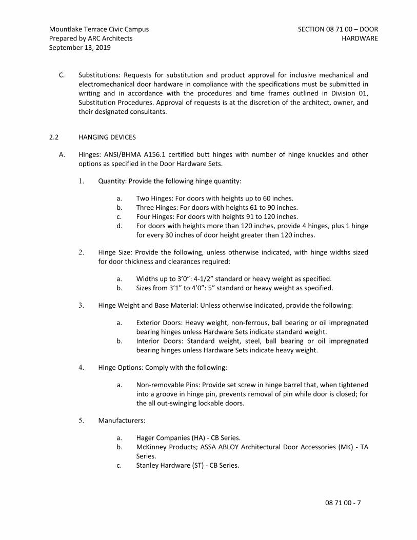
Mountlake Terrace Civic CampusPrepared by ARC ArchitectsSeptember 13, 2019
SECTION 08 71 00 – DOOR HARDWARE
08 71 00 - 7
C. Substitutions: Requests for substitution and product approval for inclusive mechanical and electromechanical door hardware in compliance with the specifications must be submitted in writing and in accordance with the procedures and time frames outlined in Division 01, Substitution Procedures. Approval of requests is at the discretion of the architect, owner, and their designated consultants.
2.2 HANGING DEVICES
A. Hinges: ANSI/BHMA A156.1 certified butt hinges with number of hinge knuckles and other options as specified in the Door Hardware Sets.
1. Quantity: Provide the following hinge quantity:
a. Two Hinges: For doors with heights up to 60 inches.b. Three Hinges: For doors with heights 61 to 90 inches.c. Four Hinges: For doors with heights 91 to 120 inches.d. For doors with heights more than 120 inches, provide 4 hinges, plus 1 hinge
for every 30 inches of door height greater than 120 inches.
2. Hinge Size: Provide the following, unless otherwise indicated, with hinge widths sized for door thickness and clearances required:
a. Widths up to 3’0”: 4-1/2” standard or heavy weight as specified.b. Sizes from 3’1” to 4’0”: 5” standard or heavy weight as specified.
3. Hinge Weight and Base Material: Unless otherwise indicated, provide the following:
a. Exterior Doors: Heavy weight, non-ferrous, ball bearing or oil impregnated bearing hinges unless Hardware Sets indicate standard weight.
b. Interior Doors: Standard weight, steel, ball bearing or oil impregnated bearing hinges unless Hardware Sets indicate heavy weight.
4. Hinge Options: Comply with the following:
a. Non-removable Pins: Provide set screw in hinge barrel that, when tightened into a groove in hinge pin, prevents removal of pin while door is closed; for the all out-swinging lockable doors.
5. Manufacturers:
a. Hager Companies (HA) - CB Series.b. McKinney Products; ASSA ABLOY Architectural Door Accessories (MK) - TA
Series.c. Stanley Hardware (ST) - CB Series.

Mountlake Terrace Civic CampusPrepared by ARC ArchitectsSeptember 13, 2019
SECTION 08 71 00 – DOOR HARDWARE
08 71 00 - 8
B. Pivots: ANSI/BHMA A156.4, Grade 1, certified. Space intermediate pivots equally not less than 25 inches on center apart or not more than 35 inches on center for doors over 121 inches high. Pivot hinges to have oil impregnated bronze bearing in the top pivot and a radial roller and thrust bearing in the bottom pivot with the bottom pivot designed to carry the full weight of the door. Pivots to be UL listed for windstorm where applicable.
1. Manufacturers:
a. Architectural Builders Hardware (AH).b. Rixson Door Controls (RF).
2.3 POWER TRANSFER DEVICES
A. Concealed Quick Connect Electric Power Transfers: Provide concealed wiring pathway housing mortised into the door and frame for low voltage electrified door hardware. Furnish with Molex™ standardized plug connectors and sufficient number of concealed wires (up to 12) to accommodate the electrified functions specified in the Door Hardware Sets. Connectors plug directly to through-door wiring harnesses for connection to electric locking devices and power supplies. Wire nut connections are not acceptable.
1. Manufacturers:
a. Pemko Products; ASSA ABLOY Architectural Door Accessories (PE) – EL-CEPT Series.
b. Securitron (SU) - EL-CEPT Series.c. Von Duprin (VD) - EPT-10 Series.
B. Electric Door Wire Harnesses: Provide electric/data transfer wiring harnesses with standardized plug connectors to accommodate up to twelve (12) wires. Connectors plug directly to through-door wiring harnesses for connection to electric locking devices and power supplies. Provide sufficient number and type of concealed wires to accommodate electric function of specified hardware. Provide a connector for through-door electronic locking devices and from hinge to junction box above the opening. Wire nut connections are not acceptable. Determine the length required for each electrified hardware component for the door type, size and construction, minimum of two per electrified opening.
1. Provide one each of the following tools as part of the base bid contract:a. McKinney Products; ASSA ABLOY Architectural Door Accessories (MK) -
Electrical Connecting Kit: QC-R001.b. McKinney Products; ASSA ABLOY Architectural Door Accessories (MK) -
Connector Hand Tool: QC-R003.
2. Manufacturers:
a. Hager Companies (HA) - Quick Connect.

Mountlake Terrace Civic CampusPrepared by ARC ArchitectsSeptember 13, 2019
SECTION 08 71 00 – DOOR HARDWARE
08 71 00 - 9
b. McKinney Products; ASSA ABLOY Architectural Door Accessories (MK) – QC-C Series.
c. Stanley Hardware (ST) – WH Series.
2.4 DOOR OPERATING TRIM
A. Flush Bolts and Surface Bolts: ANSI/BHMA A156.3 and A156.16, Grade 1, certified.
1. Flush bolts to be furnished with top rod of sufficient length to allow bolt retraction device location approximately six feet from the floor.
2. Furnish dust proof strikes for bottom bolts. 3. Surface bolts to be minimum 8” in length and U.L. listed for labeled fire doors and U.L.
listed for windstorm components where applicable.4. Provide related accessories (mounting brackets, strikes, coordinators, etc.) as required
for appropriate installation and operation.
5. Manufacturers:
a. Door Controls International (DC).b. Rockwood Products; ASSA ABLOY Architectural Door Accessories (RO).c. Trimco (TC).
2.5 CYLINDERS AND KEYING
A. General: Cylinder manufacturer to have minimum (10) years experience designing secured master key systems and have on record a published security keying system policy.
B. Source Limitations: Obtain each type of keyed cylinder and keys from the same source manufacturer as locksets and exit devices, unless otherwise indicated.
C. Cylinders: Original manufacturer cylinders complying with the following:
1. Mortise Type: Threaded cylinders with rings and cams to suit hardware application.2. Rim Type: Cylinders with back plate, flat-type vertical or horizontal tailpiece, and raised
trim ring.3. Bored-Lock Type: Cylinders with tailpieces to suit locks.4. Mortise and rim cylinder collars to be solid and recessed to allow the cylinder face to be
flush and be free spinning with matching finishes.5. Keyway: Match Facility Restricted Keyway.
D. Permanent Cores: Manufacturer's standard; finish face to match lockset; complying with the following:1. Removable Cores: Core insert, removable by use of a special key, and for use with only
the core manufacturer's cylinder and door hardware. Provide removable core (small or large format) as specified in Hardware Sets.

Mountlake Terrace Civic CampusPrepared by ARC ArchitectsSeptember 13, 2019
SECTION 08 71 00 – DOOR HARDWARE
08 71 00 - 10
E. Patented Cylinders: ANSI/BHMA A156.5, Grade 1, certified cylinders employing a utility patented and restricted keyway requiring the use of patented controlled keys. Provide bump resistant, fixed core cylinders as standard with solid recessed cylinder collars. Cylinders are to be factory keyed where permanent keying records will be established and maintained.
1. Provide a 6 pin multi-level master key system comprised of patented controlled keys and security and high security cylinders operated by one (1) key of the highest level. Geographical exclusivity to be provided for all security and high security cylinders and UL437 certification where specified.
a. Level 1 Cylinders: Provide utility patented controlled keyway cylinders that are furnished with patented keys available only from authorized distribution.
b. Level 2 Cylinders: Provide utility patented controlled keyway and side bar locking incorporating unique angled bottom pins for geographical exclusivity. Cylinders constructed to provide protection against bumping and picking.
c. Level 3 Cylinders: Provide utility patented controlled keyway and side bar locking incorporating unique angled bottom pins for geographical exclusivity. Cylinders to be UL437 certified and constructed to provide protection against bumping, picking, and drilling.
d. Refer to hardware sets for specified levels.
2. Manufacturers:a. Sargent Manufacturing (SA) - Degree Series.b. Corbin Russwin (RU) – Access 3 Series.
F. Keying System: Each type of lock and cylinders to be factory keyed.
1. Conduct specified "Keying Conference" to define and document keying system instructions and requirements.
2. Furnish factory cut, nickel-silver large bow permanently inscribed with a visual key control number as directed by Owner.
3. Existing System: Key locks to Owner's existing system.
G. Key Quantity: Provide the following minimum number of keys:
1. Change Keys per Cylinder: Two (2) 2. Master Keys (per Master Key Level/Group): Five (5).3. Construction Keys (where required): Ten (10).
H. Construction Keying: Provide construction master keyed cylinders.
I. Key Registration List (Bitting List):
1. Provide keying transcript list to Owner's representative in the proper format for importing into key control software.
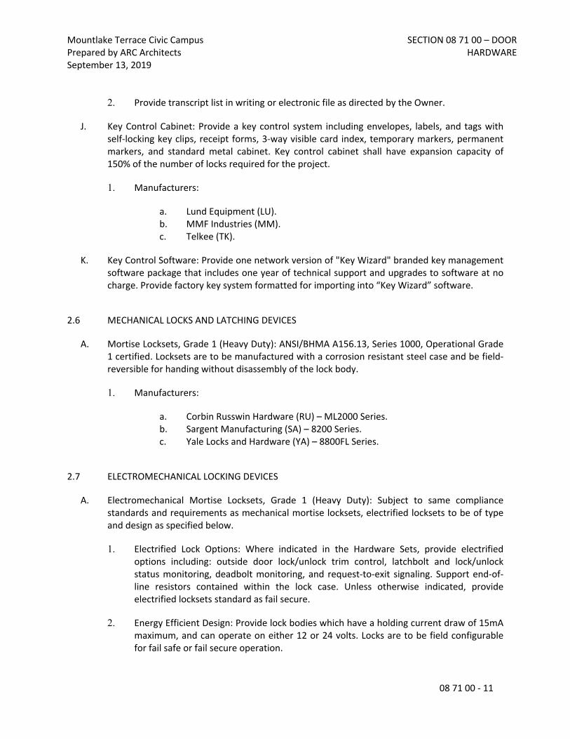
Mountlake Terrace Civic CampusPrepared by ARC ArchitectsSeptember 13, 2019
SECTION 08 71 00 – DOOR HARDWARE
08 71 00 - 11
2. Provide transcript list in writing or electronic file as directed by the Owner.
J. Key Control Cabinet: Provide a key control system including envelopes, labels, and tags with self-locking key clips, receipt forms, 3-way visible card index, temporary markers, permanent markers, and standard metal cabinet. Key control cabinet shall have expansion capacity of 150% of the number of locks required for the project.
1. Manufacturers:
a. Lund Equipment (LU).b. MMF Industries (MM).c. Telkee (TK).
K. Key Control Software: Provide one network version of "Key Wizard" branded key management software package that includes one year of technical support and upgrades to software at no charge. Provide factory key system formatted for importing into “Key Wizard” software.
2.6 MECHANICAL LOCKS AND LATCHING DEVICES
A. Mortise Locksets, Grade 1 (Heavy Duty): ANSI/BHMA A156.13, Series 1000, Operational Grade 1 certified. Locksets are to be manufactured with a corrosion resistant steel case and be field-reversible for handing without disassembly of the lock body.
1. Manufacturers:
a. Corbin Russwin Hardware (RU) – ML2000 Series.b. Sargent Manufacturing (SA) – 8200 Series.c. Yale Locks and Hardware (YA) – 8800FL Series.
2.7 ELECTROMECHANICAL LOCKING DEVICES
A. Electromechanical Mortise Locksets, Grade 1 (Heavy Duty): Subject to same compliance standards and requirements as mechanical mortise locksets, electrified locksets to be of type and design as specified below.
1. Electrified Lock Options: Where indicated in the Hardware Sets, provide electrified options including: outside door lock/unlock trim control, latchbolt and lock/unlock status monitoring, deadbolt monitoring, and request-to-exit signaling. Support end-of-line resistors contained within the lock case. Unless otherwise indicated, provide electrified locksets standard as fail secure.
2. Energy Efficient Design: Provide lock bodies which have a holding current draw of 15mA maximum, and can operate on either 12 or 24 volts. Locks are to be field configurable for fail safe or fail secure operation.

Mountlake Terrace Civic CampusPrepared by ARC ArchitectsSeptember 13, 2019
SECTION 08 71 00 – DOOR HARDWARE
08 71 00 - 12
3. High Security Monitoring: Provide lock bodies which have built-in request to exit monitoring and are provided with accompanying door position switches. Provide a resistor configuration which is compatible with the access control system.
4. Manufacturers:
a. Corbin Russwin Hardware (RU) - ML20900 Series.b. Sargent Manufacturing (SA) - 8200 Series.c. Yale Locks and Hardware (YA) – 8800FL Series.
B. Electromechanical Multi-Point Locks: Vertical rod locking devices designed for openings requiring multiple latching points within one locking mechanism. Rods are retracted by dual mounted outside lever trim controls available in a variety of ANSI/BHMA operational functions. Option for single top latching only eliminates the need for bottom strikes. Electromechanical options include solenoid activated trim, electric latch retraction, and inside and outside lever monitoring.
1. Energy Efficient Design: Provide lock bodies which have a holding current draw of 15mA maximum, and can operate on either 12 or 24 volts. Locks are to be field configurable for fail safe or fail secure operation.
2. Manufacturers:
a. Corbin Russwin Hardware (RU) MP9800 Series.b. Sargent Manufacturing (SA) – 7000 Series.
2.8 AUXILIARY LOCKS
A. Mortise Deadlocks, Small Case: ANSI/BHMA A156.36, Grade 1, small case mortise type deadlocks constructed of heavy gauge wrought corrosion resistant steel. Steel or stainless steel bolts with a 1" throw and hardened steel roller pins. Deadlocks to be products of the same source manufacturer and keyway as other specified locksets.
1. Manufacturers:
a. Corbin Russwin Hardware (RU) - DL4100 Series.b. Sargent Manufacturing (SA) - 4870 Series.c. Yale Locks and Hardware (YA) - 350 Series.
2.9 LOCK AND LATCH STRIKES
A. Strikes: Provide manufacturer's standard strike with strike box for each latch or lock bolt, with curved lip extended to protect frame, finished to match door hardware set, unless otherwise indicated, and as follows:

Mountlake Terrace Civic CampusPrepared by ARC ArchitectsSeptember 13, 2019
SECTION 08 71 00 – DOOR HARDWARE
08 71 00 - 13
1. Flat-Lip Strikes: For locks with three-piece antifriction latchbolts, as recommended by manufacturer.
2. Extra-Long-Lip Strikes: For locks used on frames with applied wood casing trim.3. Aluminum-Frame Strike Box: Provide manufacturer's special strike box fabricated for
aluminum framing.4. Double-lipped strikes: For locks at double acting doors. Furnish with retractable stop for
rescue hardware applications.
B. Standards: Comply with the following:
1. Strikes for Mortise Locks and Latches: BHMA A156.13.2. Strikes for Bored Locks and Latches: BHMA A156.2.3. Strikes for Auxiliary Deadlocks: BHMA A156.36.4. Dustproof Strikes: BHMA A156.16.
2.10 CONVENTIONAL EXIT DEVICES
A. General Requirements: All exit devices specified herein shall meet or exceed the following criteria:
1. At doors not requiring a fire rating, provide devices complying with NFPA 101 and listed and labeled for "Panic Hardware" according to UL305. Provide proper fasteners as required by manufacturer including sex nuts and bolts at openings specified in the Hardware Sets.
2. Where exit devices are required on fire rated doors, provide devices complying with NFPA 80 and with UL labeling indicating "Fire Exit Hardware". Provide devices with the proper fasteners for installation as tested and listed by UL. Consult manufacturer’s catalog and template book for specific requirements.
3. Except on fire rated doors, provide exit devices with hex key dogging device to hold the pushbar and latch in a retracted position. Provide optional keyed cylinder dogging on devices where specified in Hardware Sets.
4. Devices must fit flat against the door face with no gap that permits unauthorized dogging of the push bar. The addition of filler strips is required in any case where the door light extends behind the device as in a full glass configuration.
5. Energy Efficient Design: Provide lock bodies which have a holding current draw of 15mA maximum, and can operate on either 12 or 24 volts. Locks are to be field configurable for fail safe or fail secure operation.
6. Electromechanical Options: Subject to same compliance standards and requirements as mechanical exit devices, electrified devices to be of type and design as specified in hardware sets. Include any specific controllers when conventional power supplies are not sufficient to provide the proper inrush current.

Mountlake Terrace Civic CampusPrepared by ARC ArchitectsSeptember 13, 2019
SECTION 08 71 00 – DOOR HARDWARE
08 71 00 - 14
7. Lever Operating Trim: Where exit devices require lever trim, furnish manufacturer's heavy duty escutcheon trim with threaded studs for thru-bolts.
a. Lock Trim Design: As indicated in Hardware Sets, provide finishes and designs to match that of the specified locksets.
b. Where function of exit device requires a cylinder, provide a cylinder (Rim or Mortise) as specified in Hardware Sets.
8. Vertical Rod Exit Devices: Where surface or concealed vertical rod exit devices are used at interior openings, provide as less bottom rod (LBR) unless otherwise indicated. Provide dust proof strikes where thermal pins are required to project into the floor.
9. Narrow Stile Applications: At doors constructed with narrow stiles, or as specified in Hardware Sets, provide devices designed for maximum 2” wide stiles.
10. Dummy Push Bar: Nonfunctioning push bar matching functional push bar.
11. Rail Sizing: Provide exit device rails factory sized for proper door width application.
12. Through Bolt Installation: For exit devices and trim as indicated in Door Hardware Sets.
B. Conventional Push Rail Exit Devices (Heavy Duty): ANSI/BHMA A156.3, Grade 1 certified panic and fire exit hardware devices furnished in the functions specified in the Hardware Sets. Exit device latch to be stainless steel, pullman type, with deadlock feature.
1. Manufacturers:
a. Corbin Russwin Hardware (RU) - ED4000 / ED5000 Series.b. Sargent Manufacturing (SA) - 80 Series.
2.11 DOOR CLOSERS
A. All door closers specified herein shall meet or exceed the following criteria:
1. General: Door closers to be from one manufacturer, matching in design and style, with the same type door preparations and templates regardless of application or spring size. Closers to be non-handed with full sized covers including installation and adjusting information on inside of cover.
2. Standards: Closers to comply with UL-10C for Positive Pressure Fire Test and be U.L. listed for use of fire rated doors.
3. Cycle Testing: Provide closers which have surpassed 15 million cycles in a test witnessed and verified by UL.

Mountlake Terrace Civic CampusPrepared by ARC ArchitectsSeptember 13, 2019
SECTION 08 71 00 – DOOR HARDWARE
08 71 00 - 15
4. Size of Units: Comply with manufacturer's written recommendations for sizing of door closers depending on size of door, exposure to weather, and anticipated frequency of use. Where closers are indicated for doors required to be accessible to the physically handicapped, provide units complying with ANSI ICC/A117.1.
5. Closer Arms: Provide heavy duty, forged steel closer arms unless otherwise indicated in Hardware Sets.
6. Closers shall not be installed on exterior or corridor side of doors; where possible install closers on door for optimum aesthetics.
7. Closer Accessories: Provide door closer accessories including custom templates, special mounting brackets, spacers and drop plates as required for proper installation. Provide through-bolt and security type fasteners as specified in the hardware sets.
B. Door Closers, Surface Mounted (Heavy Duty): ANSI/BHMA A156.4, Grade 1 surface mounted, heavy duty door closers with complete spring power adjustment, sizes 1 thru 6; and fully operational adjustable according to door size, frequency of use, and opening force. Closers to be rack and pinion type, one piece cast iron or aluminum alloy body construction, with adjustable backcheck and separate non-critical valves for closing sweep and latch speed control. Provide non-handed units standard.
1. Manufacturers:
a. Corbin Russwin Hardware (RU) - DC6000 Series.b. Sargent Manufacturing (SA) - 351 Series.c. Norton Door Controls (NO) - 7500 Series.d. Yale Locks and Hardware (YA) - 4400 Series.
C. Door Closers, Overhead Concealed (Narrow Profile): ANSI/BHMA 156.4 certified Grade 1 door closers designed for narrow profile frames and doors. Closers to have fully concealed body in the frame head for offset hung applications, with separate and independent valves for closing speed and backcheck adjustments.
1. Manufacturers:
a. Rixson Door Controls (RF) - 91 Series.
2.12 ELECTROMECHANICAL DOOR OPERATORS
A. General: Provide low energy operators of size recommended by manufacturer for door size, weight, and movement; for condition of exposure; and for compliance with UL 325. Coordinate operator mechanisms with door operation, hinges, and activation devices.

Mountlake Terrace Civic CampusPrepared by ARC ArchitectsSeptember 13, 2019
SECTION 08 71 00 – DOOR HARDWARE
08 71 00 - 16
1. Fire-Rated Doors: Provide door operators for fire-rated door assemblies that comply with NFPA 80 for fire-rated door components and are listed and labeled by a qualified testing agency.
B. Standard: Certified ANSI/BHMA A156.19.
C. Performance Requirements:
1. Opening Force if Power Fails: Not more than 15 lbf required to release a latch if provided, not more than 30 lbf required to manually set door in motion, and not more than 15 lbf required to fully open door.
2. Entrapment Protection: Not more than 15 lbf required to prevent stopped door from closing or opening.
D. Configuration: Surface mounted or in-ground as required. Door operators to control single swinging and pair of swinging doors.
E. Operation: Power opening and spring closing operation capable of meeting ANSI A117.1 accessibility guideline. Provide time delay for door to remain open before initiating closing cycle as required by ANSI/BHMA A156.19.
F. Features: Operator units to have full feature adjustments for door opening and closing force and speed, backcheck, motor assist acceleration from 0 to 30 seconds, time delay, vestibule interface delay, obstruction recycle, and hold open time from 0 up to 30 seconds.
G. Provide outputs and relays on board the operator to allow for coordination of exit device latch retraction, electric strikes, magnetic locks, card readers, safety and motion sensors and specified auxiliary contacts.
H. Brackets and Reinforcements: Manufacturer's standard, fabricated from aluminum with nonferrous shims for aligning system components.
I. Manufacturers: Subject to compliance with requirements, provide products by one of the following:
1. Besam Automated Entrance Systems (BE) – SW200i Series.2. Horton Automatics (HO) - 4100 Series.3. Stanley Security Solutions (ST) - Magic Force Series.
2.13 ARCHITECTURAL TRIM
A. Door Protective Trim
1. General: Door protective trim units to be of type and design as specified below or in the Hardware Sets.

Mountlake Terrace Civic CampusPrepared by ARC ArchitectsSeptember 13, 2019
SECTION 08 71 00 – DOOR HARDWARE
08 71 00 - 17
2. Size: Fabricate protection plates (kick, armor, or mop) not more than 2" less than door width (LDW) on stop side of single doors and 1” LDW on stop side of pairs of doors, and not more than 1" less than door width on pull side. Coordinate and provide proper width and height as required where conflicting hardware dictates. Height to be as specified in the Hardware Sets.
3. Where plates are applied to fire rated doors with the top of the plate more than 16” above the bottom of the door, provide plates complying with NFPA 80. Consult manufacturer’s catalog and template book for specific requirements for size and applications.
4. Protection Plates: ANSI/BHMA A156.6 certified protection plates (kick, armor, or mop), fabricated from the following:
a. Stainless Steel: 300 grade, 050-inch thick.
5. Options and fasteners: Provide manufacturer's designated fastener type as specified in the Hardware Sets. Provide countersunk screw holes.
6. Manufacturers:
a. Hiawatha, Inc. (HI).b. Rockwood Products; ASSA ABLOY Architectural Door Accessories (RO).c. Trimco (TC).
2.14 DOOR STOPS AND HOLDERS
A. General: Door stops and holders to be of type and design as specified below or in the Hardware Sets.
B. Door Stops and Bumpers: ANSI/BHMA A156.16, Grade 1 certified door stops and wall bumpers. Provide wall bumpers, either convex or concave types with anchorage as indicated, unless floor or other types of door stops are specified in Hardware Sets. Do not mount floor stops where they will impede traffic. Where floor or wall bumpers are not appropriate, provide overhead type stops and holders.
1. Manufacturers:
a. Hiawatha, Inc. (HI).b. Rockwood Products; ASSA ABLOY Architectural Door Accessories (RO).c. Trimco (TC).
C. Overhead Door Stops and Holders: ANSI/BHMA A156.6, Grade 1 certified overhead stops and holders to be surface or concealed types as indicated in Hardware Sets. Track, slide, arm and jamb bracket to be constructed of extruded bronze and shock absorber spring of heavy

Mountlake Terrace Civic CampusPrepared by ARC ArchitectsSeptember 13, 2019
SECTION 08 71 00 – DOOR HARDWARE
08 71 00 - 18
tempered steel. Provide non-handed design with mounting brackets as required for proper operation and function.
1. Manufacturers:
a. Rixson Door Controls (RF).b. Rockwood Products; ASSA ABLOY Architectural Door Accessories (RO).c. Sargent Manufacturing (SA).
2.15 ARCHITECTURAL SEALS
A. General: Thresholds, weatherstripping, and gasket seals to be of type and design as specified below or in the Hardware Sets. Provide continuous weatherstrip gasketing on exterior doors and provide smoke, light, or sound gasketing on interior doors where indicated. At exterior applications provide non-corrosive fasteners and elsewhere where indicated.
B. Smoke Labeled Gasketing: Assemblies complying with NFPA 105 that are listed and labeled by a testing and inspecting agency acceptable to authorities having jurisdiction, for smoke control ratings indicated, based on testing according to UL 1784.
1. Provide smoke labeled perimeter gasketing at all smoke labeled openings.
C. Fire Labeled Gasketing: Assemblies complying with NFPA 80 that are listed and labeled by a testing and inspecting agency acceptable to authorities having jurisdiction, for fire ratings indicated, based on testing according to UL-10C.
1. Provide intumescent seals as indicated to meet UL10C Standard for Positive Pressure Fire Tests of Door Assemblies, and NPFA 252, Standard Methods of Fire Tests of Door Assemblies.
D. Sound-Rated Gasketing: Assemblies that are listed and labeled by a testing and inspecting agency, for sound ratings indicated.
E. Replaceable Seal Strips: Provide only those units where resilient or flexible seal strips are easily replaceable and readily available from stocks maintained by manufacturer.
F. Manufacturers:
1. National Guard Products (NG).2. Pemko Products; ASSA ABLOY Architectural Door Accessories (PE).3. Reese Enterprises, Inc. (RE).

Mountlake Terrace Civic CampusPrepared by ARC ArchitectsSeptember 13, 2019
SECTION 08 71 00 – DOOR HARDWARE
08 71 00 - 19
2.16 FABRICATION
A. Fasteners: Provide door hardware manufactured to comply with published templates generally prepared for machine, wood, and sheet metal screws. Provide screws according to manufacturers recognized installation standards for application intended.
2.17 FINISHES
A. Standard: Designations used in the Hardware Sets and elsewhere indicate hardware finishes complying with ANSI/BHMA A156.18, including coordination with traditional U.S. finishes indicated by certain manufacturers for their products.
B. Provide quality of finish, including thickness of plating or coating (if any), composition, hardness, and other qualities complying with manufacturer's standards, but in no case less than specified by referenced standards for the applicable units of hardware
C. Protect mechanical finishes on exposed surfaces from damage by applying a strippable, temporary protective covering before shipping.
PART 3 - EXECUTION
3.1 EXAMINATION
A. Examine scheduled openings, with Installer present, for compliance with requirements for installation tolerances, labeled fire door assembly construction, wall and floor construction, and other conditions affecting performance.
B. Notify architect of any discrepancies or conflicts between the door schedule, door types, drawings and scheduled hardware. Proceed only after such discrepancies or conflicts have been resolved in writing.
3.2 PREPARATION
A. Hollow Metal Doors and Frames: Comply with ANSI/DHI A115 series.
B. Wood Doors: Comply with ANSI/DHI A115-W series.
3.3 INSTALLATION
A. Install each item of mechanical and electromechanical hardware and access control equipment to comply with manufacturer's written instructions and according to specifications.

Mountlake Terrace Civic CampusPrepared by ARC ArchitectsSeptember 13, 2019
SECTION 08 71 00 – DOOR HARDWARE
08 71 00 - 20
1. Installers are to be trained and certified by the manufacturer on the proper installation and adjustment of fire, life safety, and security products including: hanging devices; locking devices; closing devices; and seals.
B. Mounting Heights: Mount door hardware units at heights indicated in following applicable publications, unless specifically indicated or required to comply with governing regulations:
1. Standard Steel Doors and Frames: DHI's "Recommended Locations for Architectural Hardware for Standard Steel Doors and Frames."
2. Wood Doors: DHI WDHS.3, "Recommended Locations for Architectural Hardware for Wood Flush Doors."
3. Where indicated to comply with accessibility requirements, comply with ANSI A117.1 "Accessibility Guidelines for Buildings and Facilities."
4. Provide blocking in drywall partitions where wall stops or other wall mounted hardware is located.
C. Retrofitting: Install door hardware to comply with manufacturer's published templates and written instructions. Where cutting and fitting are required to install door hardware onto or into surfaces that are later to be painted or finished in another way, coordinate removal, storage, and reinstallation of surface protective trim units with finishing work specified in Division 9 Sections. Do not install surface-mounted items until finishes have been completed on substrates involved.
D. Thresholds: Set thresholds for exterior and acoustical doors in full bed of sealant complying with requirements specified in Division 7 Section "Joint Sealants."
E. Storage: Provide a secure lock up for hardware delivered to the project but not yet installed. Control the handling and installation of hardware items so that the completion of the work will not be delayed by hardware losses before and after installation.
3.4 FIELD QUALITY CONTROL
A. Field Inspection: Supplier will perform a final inspection of installed door hardware and state in report whether work complies with or deviates from requirements, including whether door hardware is properly installed, operating and adjusted.
3.5 ADJUSTING
A. Initial Adjustment: Adjust and check each operating item of door hardware and each door to ensure proper operation or function of every unit. Replace units that cannot be adjusted to operate as intended. Adjust door control devices to compensate for final operation of heating and ventilating equipment and to comply with referenced accessibility requirements.

Mountlake Terrace Civic CampusPrepared by ARC ArchitectsSeptember 13, 2019
SECTION 08 71 00 – DOOR HARDWARE
08 71 00 - 21
3.6 CLEANING AND PROTECTION
A. Protect all hardware stored on construction site in a covered and dry place. Protect exposed hardware installed on doors during the construction phase. Install any and all hardware at the latest possible time frame.
B. Clean adjacent surfaces soiled by door hardware installation.
C. Clean operating items as necessary to restore proper finish. Provide final protection and maintain conditions that ensure door hardware is without damage or deterioration at time of owner occupancy.
3.7 DEMONSTRATION
A. Instruct Owner's maintenance personnel to adjust, operate, and maintain mechanical and electromechanical door hardware.
3.8 DOOR HARDWARE SETS
A. The hardware sets represent the design intent and direction of the owner and architect. They are a guideline only and should not be considered a detailed hardware schedule. Discrepancies, conflicting hardware and missing items should be brought to the attention of the architect with corrections made prior to the bidding process. Omitted items not included in a hardware set should be scheduled with the appropriate additional hardware required for proper application and functionality.
B. The supplier is responsible for handing and sizing all products and providing the correct option for the appropriate door type and material where more than one is presented in the hardware sets. Quantities listed are for each pair of doors, or for each single door.
C. Manufacturer’s Abbreviations:
1. MK - McKinney 2. PE - Pemko 3. RF - Rixson 4. RO - Rockwood 5. SA - SARGENT 6. GS - ASSA ABLOY Glass Solutions 7. NO - Norton 8. BM - Besam 9. SU - Securitron

Mountlake Terrace Civic CampusPrepared by ARC ArchitectsSeptember 13, 2019
SECTION 08 71 00 – DOOR HARDWARE
08 71 00 - 22
Hardware Sets
Set: 1.0
Doors: A100 1 Pivot Set 195 622/BSP RF 0871001 Pivot M19 622/BSP RF 0871001 Exit Device (nightlatch) DG163 19 55 56 AD8410 106 622/BSP SA 087100 ⚡1 Door Pull TB RM3311-24 Mtg-Type 12HD 622/BSP RO 0871001 Single Door Operator SW200i (concealed single) 622/BSP BM 087113 ⚡1 Door Stop 463-RKW 622/BSP RO 0871001 Threshold 2__A FHSL14 as detailed PE 0871001 Electric Power Transfer EL-CEPT SU 087100 ⚡1 Frame Harness QC-C1500 (as required) MK 087100 ⚡1 Door Harness QC-C__ (as required) MK 087100 ⚡1 Power Supply AQD4 SU 087100 ⚡1 Card Reader provided by access control.
Set: 2.0Doors: A101 1 Pivot Set 195 622/BSP RF 0871001 Pivot M19 622/BSP RF 0871002 Door Pull BTB RM3311-24 Mtg-Type 16 622/BSP RO 0871001 Single Door Operator SW200i (concealed single) 622/BSP BM 087113 ⚡1 Door Stop 463-RKW 622/BSP RO 0871001 Threshold 2__A FHSL14 as detailed PE 087100
Set: 3.0Doors: A102, A103, A108, A114, B103, B103-B, B104, B107, B109-B, B111, B206, B210 3 Hinge (heavy weight) T4A3786 4.5 x 4.5 622/BSP MK 087100
1 Electrified Mortise Lock DG163 R01 IDP NAC-82271-24v LNMW 622/BSP SA 087100 ⚡
1 Door Closer PR7500 622/BSP NO 0871001 Door Stop 441CU/409 as required 622/BSP RO 0871001 Gasketing S773GR PE 0871001 Electric Power Transfer EL-CEPT SU 087100 ⚡1 Frame Harness QC-C1500 (as required) MK 087100 ⚡

Mountlake Terrace Civic CampusPrepared by ARC ArchitectsSeptember 13, 2019
SECTION 08 71 00 – DOOR HARDWARE
08 71 00 - 23
1 Door Harness QC-C__ (as required) MK 087100 ⚡1 Card Reader provided by access control.
Set: 4.0Doors: A109 3 Hinge (heavy weight) T4A3786 4.5 x 4.5 622/BSP MK 0871001 Office Lock DG163 8205 LNMW 622/BSP SA 0871001 Door Closer PR7500 622/BSP NO 0871001 Kick Plate K1050 10X1.5LDW CSK BEV 622/BSP RO 0871001 Door Stop 441CU/409 as required 622/BSP RO 0871001 Gasketing S773GR PE 087100
Set: 5.0Doors: A111 3 Hinge (heavy weight) T4A3786 4.5 x 4.5 622/BSP MK 0871001 Classroom Lock DG163 8237 LNMW 622/BSP SA 0871001 Door Closer PR7500 622/BSP NO 0871001 Kick Plate K1050 10X1.5LDW CSK BEV 622/BSP RO 0871001 Door Stop 441CU/409 as required 622/BSP RO 0871001 Gasketing S773GR PE 087100
Set: 6.0Doors: A112, A113 3 Hinge (heavy weight) HTA386xPSF 4-1/2" x 4-1/2" 622/BSP MK 0871001 Balance of Hardware by door mfg.
Set: 7.0Doors: A114-B 3 Hinge (heavy weight) T4A3386 x NRP 4.5 x 4.5 622/BSP MK 0871001 Asylum/Institutional Lock DG163 8217 LNMW 622/BSP SA 0871001 Door Closer PR7500 622/BSP NO 0871001 Kick Plate K1050 10X1.5LDW CSK BEV 622/BSP RO 0871001 Door Stop 463-RKW 622/BSP RO 0871001 Threshold 2__A FHSL14 as detailed PE 0871001 Gasketing S773GR PE 0871001 Sweep 315CN PE 087100

Mountlake Terrace Civic CampusPrepared by ARC ArchitectsSeptember 13, 2019
SECTION 08 71 00 – DOOR HARDWARE
08 71 00 - 24
Set: 8.0Doors: A114-C, B101-B, B111-B, B111-C: See related sections for hardware. 1 Hardware by door mfg.
Set: 9.0Doors: B100 2 Pivot Set 195 622/BSP RF 0871002 Pivot M19 622/BSP RF 0871001 Exit Device (nightlatch) DG163 19 55 56 AD8410 106 622/BSP SA 087100 ⚡1 Exit Device (exit only) 19 55 56 AD8410 622/BSP SA 087100 ⚡2 Door Pull TB RM3311-24 Mtg-Type 12HD 622/BSP RO 0871001 Pair Door Operators SW200i (concealed pair) 622/BSP BM 087113 ⚡2 Door Stop 463-RKW 622/BSP RO 0871001 Threshold 2__A FHSL14 as detailed PE 0871002 Electric Power Transfer EL-CEPT SU 087100 ⚡2 Frame Harness QC-C1500 (as required) MK 087100 ⚡2 Door Harness QC-C__ (as required) MK 087100 ⚡1 Power Supply AQD4 SU 087100 ⚡1 Card Reader provided by access control.
Set: 10.0Doors: B101 4 Hinge (heavy weight) T4A3786 4.5 x 4.5 622/BSP MK 0871001 Exit Device (classroom) DG163 19 8813 ETMW 622/BSP SA 0871001 Door Closer PR7500 622/BSP NO 0871001 Kick Plate K1050 10X1.5LDW CSK BEV 622/BSP RO 0871001 Door Stop 441CU/409 as required 622/BSP RO 0871001 Gasketing S773GR PE 087100
Set: 11.0Doors: B101-C 2 Pivot Set 195 622/BSP RF 0871002 Pivot M19 622/BSP RF 0871002 Exit Device (exit only) 19 AD8410 622/BSP SA 0871002 Concealed Closer 91N 622/BSP RF 0871002 Door Stop 463-RKW 622/BSP RO 087100

Mountlake Terrace Civic CampusPrepared by ARC ArchitectsSeptember 13, 2019
SECTION 08 71 00 – DOOR HARDWARE
08 71 00 - 25
Set: 12.0
Doors: B102 2 Pivot Set 195 622/BSP RF 0871002 Pivot M19 622/BSP RF 0871002 Door Pull BTB RM3311-24 Mtg-Type 16 622/BSP RO 0871001 Pair Door Operators SW200i (concealed pair) 622/BSP BM 087113 ⚡2 Door Stop 463-RKW 622/BSP RO 0871001 Threshold 2__A FHSL14 as detailed PE 087100
Set: 13.0Doors: B105, B106 3 Hinge (heavy weight) T4A3786 4.5 x 4.5 622/BSP MK 0871001 Mortise Deadlock DG163 4877 622/BSP SA 0871001 Door Pull BTB RM3311-24 Mtg-Type 16 622/BSP RO 0871001 Door Closer 7500 622/BSP NO 0871001 Kick Plate K1050 10X1.5LDW CSK BEV 622/BSP RO 0871001 Door Stop 441CU/409 as required 622/BSP RO 0871001 Gasketing S773GR PE 087100
Set: 14.0Doors: B107-B 3 Hinge TA2714 4.5 x 4.5 622/BSP MK 0871001 Passage Latch 8215 LNMW 622/BSP SA 0871001 Door Stop 441CU/409 as required 622/BSP RO 0871001 Gasketing S773GR PE 087100
Set: 15.0Doors: B108, B119, B122, B123, B207, B208 3 Hinge TA2714 4.5 x 4.5 622/BSP MK 087100
1 Privacy Lock w/Occupancy Indicator 49 8265 LNMW 622/BSP SA 087100
1 Door Closer 7500 622/BSP NO 0871001 Kick Plate K1050 10X1.5LDW CSK BEV 622/BSP RO 0871001 Door Stop 441CU/409 as required 622/BSP RO 0871001 Gasketing S773GR PE 087100

Mountlake Terrace Civic CampusPrepared by ARC ArchitectsSeptember 13, 2019
SECTION 08 71 00 – DOOR HARDWARE
08 71 00 - 26
Set: 16.0Doors: B109 3 Hinge TA2714 4.5 x 4.5 622/BSP MK 0871001 Passage Latch 8215 LNMW 622/BSP SA 0871001 Door Closer 7500 622/BSP NO 0871001 Kick Plate K1050 10X1.5LDW CSK BEV 622/BSP RO 0871001 Door Stop 441CU/409 as required 622/BSP RO 0871001 Gasketing S773GR PE 087100
Set: 17.0Doors: B110, B113, B113-B, B205 1 Track System CS-W100/8 PE 0871001 Cylinder DG1 63 34 622/BSP SA 0871001 Locking Pull LP3301DBD ADA Code 05 622/BSP GS 0841261 Dust Proof Strike 570 622/BSP GS 084126
Set: 18.0Doors: B112, B120, B121 3 Hinge TA2714 4.5 x 4.5 622/BSP MK 0871001 Storeroom Lock DG163 8204 LNMW 622/BSP SA 0871001 Kick Plate K1050 10X1.5LDW CSK BEV 622/BSP RO 0871001 Door Stop 441CU/409 as required 622/BSP RO 0871001 Gasketing S773GR PE 087100
Set: 19.0Doors: B114, B115, B125, B126, B127, B201, B202, B203, B204, B211, B212, B213, B214, B215, B216 3 Hinge TA2714 4.5 x 4.5 622/BSP MK 0871001 Office Lock DG163 8205 LNMW 622/BSP SA 0871001 Door Stop 441CU/409 as required 622/BSP RO 0871001 Gasketing S773GR PE 087100
Set: 20.0Doors: B116, B118-B, B128 3 Hinge TA2714 4.5 x 4.5 622/BSP MK 0871001 Storeroom Lock DG163 8204 LNMW 622/BSP SA 0871001 Door Closer 7500 622/BSP NO 087100

Mountlake Terrace Civic CampusPrepared by ARC ArchitectsSeptember 13, 2019
SECTION 08 71 00 – DOOR HARDWARE
08 71 00 - 27
1 Kick Plate K1050 10X1.5LDW CSK BEV 622/BSP RO 0871001 Door Stop 441CU/409 as required 622/BSP RO 0871001 Gasketing S773GR PE 087100
Set: 21.0Doors: B116-B 3 Hinge TA2314 x NRP 4.5 x 4.5 622/BSP MK 0871001 Storeroom Lock DG163 8204 LNMW 622/BSP SA 0871001 Door Closer 7500 622/BSP NO 0871001 Kick Plate K1050 10X1.5LDW CSK BEV 622/BSP RO 0871001 Door Stop 441CU/409 as required 622/BSP RO 0871001 Threshold 2__A FHSL14 as detailed PE 0871001 Gasketing S773GR PE 0871001 Door Bottom 2221APK PE 087100
Set: 22.0Doors: B117 3 Hinge (heavy weight) T4A3786 4.5 x 4.5 622/BSP MK 0871001 Rim Exit Device DG163 12 19 8806 ETMW 622/BSP SA 0871001 Door Closer CPS7500 622/BSP NO 0871001 Kick Plate K1050 10X1.5LDW CSK BEV 622/BSP RO 0871001 Gasketing S773GR PE 087100
Set: 23.0Doors: B117-B 3 Hinge (heavy weight) T4A3386 x NRP 4.5 x 4.5 622/BSP MK 0871001 Rim Exit Device DG163 12 19 8806 ETMW 622/BSP SA 0871001 Door Closer PR7500 622/BSP NO 0871001 Kick Plate K1050 10X1.5LDW CSK BEV 622/BSP RO 0871001 Door Stop 463-RKW 622/BSP RO 0871001 Threshold 2__A FHSL14 as detailed PE 0871001 Gasketing S773GR PE 0871001 Sweep 315CN PE 087100
Set: 24.0Doors: B118 3 Hinge TA2314 x NRP 4.5 x 4.5 622/BSP MK 087100

Mountlake Terrace Civic CampusPrepared by ARC ArchitectsSeptember 13, 2019
SECTION 08 71 00 – DOOR HARDWARE
08 71 00 - 28
1 Electrified Mortise Lock DG163 R01 IDP NAC-82271-24v LNMW 622/BSP SA 087100 ⚡
1 Door Closer 7500 622/BSP NO 0871001 Kick Plate K1050 10X1.5LDW CSK BEV 622/BSP RO 0871001 Door Stop 441CU/409 as required 622/BSP RO 0871001 Threshold 2__A FHSL14 as detailed PE 0871001 Gasketing S773GR PE 0871001 Door Bottom 2221APK PE 0871001 Electric Power Transfer EL-CEPT SU 087100 ⚡1 Frame Harness QC-C1500 (as required) MK 087100 ⚡1 Door Harness QC-C__ (as required) MK 087100 ⚡1 Card Reader provided by access control.
Set: 25.0Doors: B124, B124-C 3 Hinge (heavy weight) T4A3786 4.5 x 4.5 622/BSP MK 0871001 Exit Device (passage) 12 19 8815 ETMW 622/BSP SA 0871001 Door Closer 7500 622/BSP NO 0871001 Kick Plate K1050 10X1.5LDW CSK BEV 622/BSP RO 0871001 Door Stop 441CU/409 as required 622/BSP RO 0871001 Gasketing S773GR PE 087100
Set: 26.0Doors: B124-B 3 Hinge (heavy weight) T4A3386 x NRP 4.5 x 4.5 622/BSP MK 0871001 Electrified Rim Exit DG163 19 55 8876-24v ETMW 622/BSP SA 087100 ⚡1 Door Closer PR7500 622/BSP NO 0871001 Kick Plate K1050 10X1.5LDW CSK BEV 622/BSP RO 0871001 Door Stop 463-RKW 622/BSP RO 0871001 Threshold 2__A FHSL14 as detailed PE 0871001 Gasketing S773GR PE 0871001 Sweep 315CN PE 0871001 Electric Power Transfer EL-CEPT SU 087100 ⚡1 Frame Harness QC-C1500 (as required) MK 087100 ⚡1 Door Harness QC-C__ (as required) MK 087100 ⚡1 Card Reader provided by access control.
Set: 27.0

Mountlake Terrace Civic CampusPrepared by ARC ArchitectsSeptember 13, 2019
SECTION 08 71 00 – DOOR HARDWARE
08 71 00 - 29
Doors: B209 6 Hinge TA2714 4.5 x 4.5 622/BSP MK 0871001 Flush Bolt 2805 622/BSP RO 0871001 Storeroom Lock DG163 8204 LNMW 622/BSP SA 0871002 Surface OH Stop 55-X36 622/BSP RF 0871001 Astragal 355CV PE 087100
Set: 28.0Doors: B129 1 Rim Exit Device DG163 19 8806 ETMW 622/BSP SA 0871001 Balance of Hardware by door mfg.
END OF SECTION 087100

Mountlake Terrace Civic CampusPrepared by ARC ArchitectsSeptember 13, 2019
SECTION 08 71 13 – AUTOMATIC DOOR OPERATORS
08 71 13 - 1
SECTION 087113 - AUTOMATIC DOOR OPERATORS
PART 1 - GENERAL
1.1 RELATED DOCUMENTS
A. Drawings and general provisions of the Contract, including General and Supplementary Conditions and Division 01 Specification Sections, apply to this Section.
1.2 SUMMARY
A. Section Includes:
1. Low energy automatic door operators for swinging doors.
B. Related Sections:
1. Division 08 Section “Door Schedule”.2. Division 08 Section “Hollow Metal Doors and Frames”.3. Division 08 Section “Flush Wood Doors”.4. Division 08 Section “Door Hardware”.5. Division 08 Section “Access Control Hardware”.6. Division 26 Section “Electrical”.
A. Codes and Standards: Comply with the version year adopted by the Authority Having Jurisdiction.
1. ANSI A117.1 - Accessible and Usable Buildings and Facilities.2. ANSI/BHMA A156.4 - Door Controls, Door Closers.3. ANSI/BHMA A156.19 - Power Assist and Low-Energy Power Operated Doors.4. ICC/IBC - International Building Code.5. NFPA 70 - National Electrical Code.6. NFPA 80 - Fire Doors and Windows.7. NFPA 101 - Life Safety Code.8. NFPA 105 - Installation of Smoke Door Assemblies.9. UL/ULC and CSA C22.2 – Standards for Automatic Door Operators Used on Fire and
Smoke Barrier Doors and Systems of Doors.10. UL 325 - Door, Drapery, Gate, Louver, and Window Operators and Systems.11. State Building Codes, Local Amendments.

Mountlake Terrace Civic CampusPrepared by ARC ArchitectsSeptember 13, 2019
SECTION 08 71 13 – AUTOMATIC DOOR OPERATORS
08 71 13 - 2
1.3 PERFORMANCE REQUIREMENTS
A. Automatic door operators to be used on interior or exterior doors; up to 200 pounds (91 kg) weight and maximum door width of 48" (1219 mm).
1. Auto door operator capable of operating within temperature ranges of -22°F (-30°C) and 122°F (50°C).
1.4 SUBMITTALS
A. Product Data: Manufacturer's product data sheets including installation details, material descriptions, dimensions of individual components and profiles, and finishes for automatic door operators, including activation devices. Include operating characteristics, electrical characteristics, and furnished accessories.
B. Shop Drawings: Include details and attachments to other work.
1. Include locations and elevations of each unique entrance showing activation devices.2. Indicate required clearances, components, and location and size of field connections.3. Wiring Diagrams: For power, signal, and activation wiring.
C. Qualification Data: Provide copy of manufacturer's official certification or accreditation document indicating proof of status as a qualified and authorized installer of automatic door operators and accessories.
D. Operating and Maintenance Manuals: Provide manufacturer's operating and maintenance manual for each item comprising the automatic door operator installation in quantity as required in Division 01, Closeout Submittals. The manual to include the name, address, and contact information of the manufacturer and Installer providing the operators and installation. The final copies delivered after completion of the installation test to include "as built" modifications made during installation, checkout, and acceptance.
E. Warranties and Maintenance: Special warranties and maintenance agreements specified in this Section.
1.5 QUALITY ASSURANCE
A. Installer Qualifications: Manufacturer's authorized representative who is trained and approved for installation and maintenance of units required for this Project.
B. Certified Installer Qualifications: Locally certified ASSA ABLOY Power Operator Preferred Installer required for the installation and maintenance of the automatic door operator units and accessories indicated for the Project.
C. Source Limitations: Obtain automatic door operators, including activation devices, from single source, qualified supplier unless otherwise indicated.

Mountlake Terrace Civic CampusPrepared by ARC ArchitectsSeptember 13, 2019
SECTION 08 71 13 – AUTOMATIC DOOR OPERATORS
08 71 13 - 3
D. Electrical Components, Devices, and Accessories: Listed and labeled as defined in NFPA 70, by a testing agency, and marked for intended location and application.
E. Exit Door Requirements: Comply with requirements of authorities having jurisdiction for doors with automatic door operators serving as a component of a required means of egress.
F. Fire Rated Door Assemblies: Provide operators for fire rated door assemblies that are listed and labeled by a testing and inspecting agency acceptable to authorities having jurisdiction for use on types and sizes of labeled fire doors required.
G. Pre-Submittal Conference: Conduct coordination conference in compliance with requirements in Division 01 Section "Project Meetings" with attendance by representatives of Supplier, Installer, and Contractor to review proper methods and the procedures for receiving, handling, and installing automatic door operators.
1. Prior to installation of automatic door operators, arrange for certified Installer's representative to conduct a project specific meeting to review the installation and maintenance of their respective products. Project meeting to be attended by representatives of related trades furnishing and installing the aluminum, hollow metal and wood doors sections.
2. Review and finalize construction schedule and verify availability of materials.
1.6 COORDINATION
A. Electrical Systems Coordination: Coordinate the layout and installation of scheduled automatic door operators and related activation devices, with required connections to source power junction boxes, remote power supplies, access control equipment, detection and monitoring hardware, and fire alarm system.
B. Templates: Obtain and distribute to the parties involved, templates for doors, frames, operators, and other work specified to be factory prepared and reinforced for installing automatic door operators. Check Shop Drawings of other work to confirm that adequate provisions are made for locating and installing automatic door operators to comply with indicated requirements.
C. Door and Frame Preparation: Related Division 08 Sections (Steel, Aluminum and Wood) doors and corresponding frames are to be prepared, reinforced and pre-wired (if applicable) to receive the installation of the specified automatic door operators without additional in-field modifications.
1.7 WARRANTY
A. General Warranty: Reference Division 01, General Requirements. Special warranties specified in this Article shall not deprive Owner of other rights Owner may have under other provisions of the Contract Documents and shall be in addition to, and run concurrent with, other warranties made by Contractor under requirements of the Contract Documents.

Mountlake Terrace Civic CampusPrepared by ARC ArchitectsSeptember 13, 2019
SECTION 08 71 13 – AUTOMATIC DOOR OPERATORS
08 71 13 - 4
B. Special Warranty: Written warranty, executed by manufacturer, agreeing to repair or replace components of automatic door operators that fail in materials or workmanship within specified warranty period after final acceptance by Owner. Failures include, but are not limited to, the following:
1. Faulty or sporadic operation of automatic door operator, including activation and safety devices.
2. Deterioration of metals, metal finishes, and other materials beyond normal weathering or use.
C. Special Warranty Period: Two years from date of Substantial Completion.
D. Provide extended warranty from defects in material or workmanship under normal use for a period of 3 years from the date of substantial completion for units installed by a certified ASSA ABLOY Power Operator Preferred Installer in accordance with the manufacturer's written warranty certificate.
1.8 MAINTENANCE SERVICE
A. Maintenance Service: Beginning at Substantial Completion, and running concurrent with the specified warranty period, provide continuous (6) months full maintenance by skilled employees of automatic door operator Installer. Include planned and preventive maintenance, repair or replacement of worn or defective components, lubrication, cleaning, and adjusting as required for proper door operation. Provide parts and supplies the same as those used in the manufacture and installation of original equipment.
B. Extended Maintenance Support and Service Agreement: Submit for Owner’s consideration an optional extended Service Agreement for the installed automatic door operator system. The extended Service Agreement is considered elective and is without manufacturer's requirement stipulating mandatory coverage for owner and/or vendor system support.
1. A published copy of this agreement to be included with the submittal package2. Support for the installed automatic door operator system is provided through the
vendor under a specified, limited 24 hour support program.3. Automatic door operators and components are to be available on a one-day turn
around time frame from the vendor.
PART 2 - PRODUCTS
2.1 ELECTROMECHANICAL DOOR OPERATORS
A. General: Provide low energy operators of size recommended by manufacturer for door size, weight, and movement; for condition of exposure; and for compliance with UL 325. Coordinate operator mechanisms with door operation, hinges, and activation devices.

Mountlake Terrace Civic CampusPrepared by ARC ArchitectsSeptember 13, 2019
SECTION 08 71 13 – AUTOMATIC DOOR OPERATORS
08 71 13 - 5
1. Fire-Rated Doors: Provide door operators for fire-rated door assemblies that comply with NFPA 80 for fire-rated door components and are listed and labeled by a qualified testing agency.
B. Standard: Certified ANSI/BHMA A156.19.
C. Performance Requirements:
1. Opening Force if Power Fails: Not more than 15 lbf required to release a latch if provided, not more than 30 lbf required to manually set door in motion, and not more than 15 lbf required to fully open door.
2. Entrapment Protection: Not more than 15 lbf required to prevent stopped door from closing or opening.
D. Configuration: Surface mounted or in-ground as required. Door operators to control single swinging and pair of swinging doors.
E. Operation: Power opening and spring closing operation capable of meeting ANSI A117.1 accessibility guideline. Provide time delay for door to remain open before initiating closing cycle as required by ANSI/BHMA A156.19.
F. Features: Operator units to have full feature adjustments for door opening and closing force and speed, backcheck, motor assist acceleration from 0 to 30 seconds, time delay, vestibule interface delay, obstruction recycle, and hold open time from 0 up to 30 seconds.
G. Provide outputs and relays on board the operator to allow for coordination of exit device latch retraction, electric strikes, magnetic locks, card readers, safety and motion sensors and specified auxiliary contacts.
H. Brackets and Reinforcements: Manufacturer's standard, fabricated from aluminum with nonferrous shims for aligning system components.
I. Manufacturers: Subject to compliance with requirements, provide products by one of the following:
1. Besam Automated Entrance Systems (BE) – SW200i Series.2. Horton Automatics (HO) - 4100 Series.3. Stanley Security Solutions (ST) - Magic Force Series.
2.2 ACTIVATION DEVICES
A. General: Provide activation devices in accordance with ANSI/BHMA A156.19 standard, for condition of exposure indicated and for long term, maintenance free operation under normal traffic load operation. Coordinate activation control with electrified hardware and access control interfaces. Activation switches are standard SPST, with optional DPDT availability.
B. Key Switch: Key controlled actuator device enclosed in single or double gang junction box.

Mountlake Terrace Civic CampusPrepared by ARC ArchitectsSeptember 13, 2019
SECTION 08 71 13 – AUTOMATIC DOOR OPERATORS
08 71 13 - 6
1. Faceplate Material: Stainless steel.2. Functions: On-off, maintained contact. 3. Two-way Mounting: Recess or surface mounting as indicated on Drawings.4. Manufacturers:
a. Alarm Controls (AK) – MCK Series.b. Securitron (SU) – MKA Series.c. Wikk Industries (WI) – KS Series.
2.3 ACCESSORIES
A. Signage: As required by cited ANSI/BHMA A156.19 standard for the type of operator.
2.4 FINISHES
A. Standard: Designations used to indicate hardware finishes complying with ANSI/BHMA A156.18, including coordination with traditional U.S. finishes indicated by certain manufacturers for their products.
B. Provide quality of finish, including thickness of plating or coating (if any), composition, hardness, and other qualities complying with manufacturer's standards, but in no case less than specified by referenced standards for the applicable units of hardware. Units will be sprayed with a combination of waterborne acrylic and polyester powder coat.
C. Protect mechanical finishes on exposed surfaces from damage by applying a strippable, temporary protective covering before shipping.
PART 3 - EXECUTION
3.1 EXAMINATION
A. Examine conditions, with Installer present, for compliance with requirements for installation tolerances, door and frame preparation and reinforcements, power connections, electrical systems interfaces, and other conditions affecting performance of automatic door operators.
B. Notify architect of any discrepancies or conflicts between the door schedule, door types, drawings and scheduled hardware. Proceed only after such discrepancies or conflicts have been resolved in writing.
3.2 INSTALLATION
A. General: Install complete automatic door operators according to manufacturer's written instructions and ANSI/BHMA A156;19 standard, including activation devices, control wiring,

Mountlake Terrace Civic CampusPrepared by ARC ArchitectsSeptember 13, 2019
SECTION 08 71 13 – AUTOMATIC DOOR OPERATORS
08 71 13 - 7
remote power units if any, connection to the building's fire alarm system, and required signage.
B. Power Connection: Reference Division 26 "Electrical" Sections for connection to electrical power distribution system.
C. Access Control System: Coordinate connections and operation with access control system
D. Signage: Apply signage as required by ANSI/BHMA A156.19 standard for type of door operator and direction of pedestrian travel.
3.3 FIELD QUALITY CONTROL
A. Inspection: Certified Installer' representative to inspect and test automatic door operators to determine compliance of installed systems with specifications and ANSI/BHMA A146.19 standard. Report discrepancies in writing to Architect and Contractor within 24 hours after inspection.
3.4 ADJUSTING
A. Comply with requirements of ANSI/BHMA A156.19 standard. Adjust automatic door operators to function smoothly, and lubricate as recommended by manufacturer.
3.5 DEMONSTRATION
A. Certified Installer's representative to provide eight (8) hours of training to Owner's maintenance personnel in the proper adjustment, operation, and maintenance of automatic door operators.
END OF SECTION 087113

Mountlake Terrace Civic CampusPrepared by ARC ArchitectsSeptember 13, 2019
SECTION 08 80 00 - GLAZING
08 80 00 - 1
SECTION 088000 - GLAZING
PART 1 - GENERAL
1.1 RELATED DOCUMENTS
A. Drawings and general provisions of the Contract, including General and Supplementary Conditions and Division 01 Specification Sections, apply to this Section.
1.2 SUMMARY
A. Section includes glazing for the following products and applications, including those specified in other Sections where glazing requirements are specified by reference to this Section:
1. Windows.2. Doors.3. Interior borrowed lites (relites).4. Mall Clamps
B. Related Sections:
1. Section 101423 “Panel Signage” for glass panel signs.
2. Section 101100 “Visual Display Units” for glass markerboards.
1.3 DEFINITIONS
A. Glass Manufacturers: Firms that produce primary glass, fabricated glass, or both, as defined in referenced glazing publications.
B. Glass Thicknesses: Indicated by thickness designations in millimeters according to ASTM C 1036.
C. Interspace: Space between lites of an insulating-glass unit.
1.4 PERFORMANCE REQUIREMENTS
A. General: Installed glazing systems shall withstand normal thermal movement and wind and impact loads (where applicable) without failure, including loss or glass breakage attributable to the following: defective manufacture, fabrication, or installation; failure of sealants or gaskets to remain watertight and airtight; deterioration of glazing materials; or other defects in construction.

Mountlake Terrace Civic CampusPrepared by ARC ArchitectsSeptember 13, 2019
SECTION 08 80 00 - GLAZING
08 80 00 - 2
B. Thermal Movements: Allow for thermal movements from ambient and surface temperature changes acting on glass framing members and glazing components.
1. Temperature Change: 120 deg F (67 deg C), ambient; 180 deg F (100 deg C), material surfaces.
1.5 ACTION SUBMITTALS
A. Product Data: For each glass product and glazing material indicated.
B. Glass Samples: For each type of the following products; 12 inches (300 mm) square.1. Clear glass2. Tinted glass.3. Laminated glass with colored interlayer.4. Insulating glass.
C. Glazing Schedule: List glass types and thicknesses for each size opening and location. Use same designations indicated on Drawings.
1.6 INFORMATIONAL SUBMITTALS
A. Product Certificates: For glass and glazing products, from manufacturer.
B. Warranties: Sample of special warranties.
1.7 QUALITY ASSURANCE
A. Manufacturer Qualifications for Insulating-Glass Units with Sputter-Coated, Low-E Coatings: A qualified insulating-glass manufacturer who is approved and certified by coated-glass manufacturer.
B. Installer Qualifications: A qualified installer who employs glass installers for this Project who are certified under the National Glass Association's Certified Glass Installer Program.
C. Source Limitations for Glass: Obtain glass from single source from single manufacturer for each glass type.
D. Source Limitations for Glazing Accessories: Obtain from single source from single manufacturer for each product and installation method.
E. Glazing Publications: Comply with published recommendations of glass product manufacturers and organizations below, unless more stringent requirements are indicated. Refer to these publications for glazing terms not otherwise defined in this Section or in referenced standards.
1. GANA Publications: GANA's "Glazing Manual."

Mountlake Terrace Civic CampusPrepared by ARC ArchitectsSeptember 13, 2019
SECTION 08 80 00 - GLAZING
08 80 00 - 3
2. AAMA Publications: AAMA GDSG-1, "Glass Design for Sloped Glazing," and AAMA TIR-A7, "Sloped Glazing Guidelines."
3. IGMA Publication for Sloped Glazing: IGMA TB-3001, "Guidelines for Sloped Glazing."4. IGMA Publication for Insulating Glass: SIGMA TM-3000, "North American Glazing
Guidelines for Sealed Insulating Glass Units for Commercial and Residential Use."
F. Safety Glazing Labeling: Where safety glazing labeling is indicated, permanently mark glazing with certification label of the SGCC or another certification agency acceptable to authorities having jurisdiction. Label shall indicate manufacturer's name, type of glass, thickness, and safety glazing standard with which glass complies.
G. Fire-Protection-Rated Glazing Labeling: Permanently mark fire-protection-rated glazing with certification label of a testing agency acceptable to authorities having jurisdiction. Label shall indicate manufacturer's name, test standard, whether glazing is for use in fire doors or other openings, whether or not glazing passes hose-stream test, whether or not glazing has a temperature rise rating of 450 deg F (250 deg C), and the fire-resistance rating in minutes.
H. Insulating-Glass Certification Program: Permanently marked either on spacers or on at least one component lite of units with appropriate certification label of IGCC.
1.8 DELIVERY, STORAGE, AND HANDLING
A. Protect glazing materials according to manufacturer's written instructions. Prevent damage to glass and glazing materials from condensation, temperature changes, direct exposure to sun, or other causes.
B. Comply with insulating-glass manufacturer's written recommendations for venting and sealing units to avoid hermetic seal ruptures due to altitude change.
1.9 PROJECT CONDITIONS
A. Environmental Limitations: Do not proceed with glazing when ambient and substrate temperature conditions are outside limits permitted by glazing material manufacturers and when glazing channel substrates are wet from rain, frost, condensation, or other causes.
1. Do not install glazing sealants when ambient and substrate temperature conditions are outside limits permitted by sealant manufacturer or below 40 deg F (4.4 deg C).
1.10 WARRANTY
A. Manufacturer's Special Warranty for Coated-Glass Products: Manufacturer's standard form in which coated-glass manufacturer agrees to replace coated-glass units that deteriorate within specified warranty period. Deterioration of coated glass is defined as defects developed from normal use that are not attributed to glass breakage or to maintaining and cleaning coated glass contrary to manufacturer's written instructions. Defects include peeling, cracking, and other indications of deterioration in coating.

Mountlake Terrace Civic CampusPrepared by ARC ArchitectsSeptember 13, 2019
SECTION 08 80 00 - GLAZING
08 80 00 - 4
1. Warranty Period: 10 years from date of Substantial Completion.
B. Manufacturer's Special Warranty on Laminated Glass: Manufacturer's standard form in which laminated-glass manufacturer agrees to replace laminated-glass units that deteriorate within specified warranty period. Deterioration of laminated glass is defined as defects developed from normal use that are not attributed to glass breakage or to maintaining and cleaning laminated glass contrary to manufacturer's written instructions. Defects include edge separation, delamination materially obstructing vision through glass, and blemishes exceeding those allowed by referenced laminated-glass standard.
1. Warranty Period: 10 years from date of Substantial Completion.
C. Manufacturer's Special Warranty on Insulating Glass: Manufacturer's standard form in which insulating-glass manufacturer agrees to replace insulating-glass units that deteriorate within specified warranty period. Deterioration of insulating glass is defined as failure of hermetic seal under normal use that is not attributed to glass breakage or to maintaining and cleaning insulating glass contrary to manufacturer's written instructions. Evidence of failure is the obstruction of vision by dust, moisture, or film on interior surfaces of glass.
1. Warranty Period: 10 years from date of Substantial Completion.
PART 2 - PRODUCTS
2.1 GLASS PRODUCTS, GENERAL
A. Thickness: Where glass thickness is indicated, it is a minimum. Provide glass lites in thicknesses as needed to comply with requirements indicated.
1. Minimum Glass Thickness for Exterior Lites: Not less than 6.0mm.2. Thickness of Tinted Glass: Provide same thickness for each tint color indicated
throughout Project.
B. Strength: Where float glass is indicated, provide annealed float glass, Kind HS heat-treated float glass, or Kind FT heat-treated float glass. Where fully tempered glass is indicated, provide Kind FT heat-treated float glass.
C. Thermal and Optical Performance Properties: Provide glass with performance properties specified, as indicated in manufacturer's published test data, based on procedures indicated below:
1. For monolithic-glass lites, properties are based on units with lites 6.0 mm thick.2. For laminated-glass lites, properties are based on products of construction indicated.3. For insulating-glass units, properties are based on units of thickness indicated for overall
unit and for each lite.4. U-Factors: Center-of-glazing values, according to NFRC 100 and based on LBL's WINDOW
5.2 computer program, expressed as Btu/sq. ft. x h x deg F (W/sq. m x K).5. Solar Heat-Gain Coefficient and Visible Transmittance: Center-of-glazing values,
according to NFRC 200 and based on LBL's WINDOW 5.2 computer program.

Mountlake Terrace Civic CampusPrepared by ARC ArchitectsSeptember 13, 2019
SECTION 08 80 00 - GLAZING
08 80 00 - 5
6. Visible Reflectance: Center-of-glazing values, according to NFRC 300.
2.2 FLOAT GLASS PRODUCTS
A. Float Glass: ASTM C 1036, Type I, Quality-Q3, Class I (clear) unless otherwise indicated.
B. Uncoated Tinted Float Glass: Class 2, complying with other requirements specified, colors per types noted within this section.
2.3 LAMINATED GLASS
A. Laminated Glass: ASTM C 1172, and complying with testing requirements in 16 CFR 1201 for Category II materials, and with other requirements specified. Use materials that have a proven record of no tendency to bubble, discolor, or lose physical and mechanical properties after fabrication and installation.
1. Construction: Laminate glass with polyvinyl butyral interlayer to comply with interlayer manufacturer's written recommendations.
2. Interlayer Thickness: Provide thickness not less than that indicated and as needed to comply with requirements.
3. Interlayer Color: Clear unless otherwise indicated.
B. Glass: Comply with applicable requirements in "Glass Products" Article as indicated by designations in "Laminated-Glass Types" Article.
2.4 INSULATING GLASS
A. Insulating-Glass Units: Factory-assembled units consisting of sealed lites of glass separated by a dehydrated interspace, qualified according to ASTM E 2190, and complying with other requirements specified.
1. Sealing System: Dual seal, with manufacturer's standard primary and secondary.2. Spacer: Manufacturer's standard spacer material and construction.3. Desiccant: Molecular sieve or silica gel, or blend of both.
B. Glass: Comply with applicable requirements in "Glass Products" Article as indicated by designations in "Insulating-Glass Types" Article.
2.5 MALL CLAMPS
A. Basis-of-Design Manufacturer: CR Laurence Company, Inc.
B. Product: 2” CRL Brushed Stainless 180 Degree Mall Front Clamp, model #MFC31

Mountlake Terrace Civic CampusPrepared by ARC ArchitectsSeptember 13, 2019
SECTION 08 80 00 - GLAZING
08 80 00 - 6
2.6 GLAZING GASKETS
A. Dense Compression Gaskets: Molded or extruded gaskets of profile and hardness required to maintain watertight seal, made from one of the following:
1. Neoprene complying with ASTM C 864.2. EPDM complying with ASTM C 864.3. Silicone complying with ASTM C 1115.4. Thermoplastic polyolefin rubber complying with ASTM C 1115.
2.7 GLAZING SEALANTS
A. General:
1. Compatibility: Provide glazing sealants that are compatible with one another and with other materials they will contact, including glass products, seals of insulating-glass units, and glazing channel substrates, under conditions of service and application, as demonstrated by sealant manufacturer based on testing and field experience.
2. Suitability: Comply with sealant and glass manufacturers' written instructions for selecting glazing sealants suitable for applications indicated and for conditions existing at time of installation.
3. Colors of Exposed Glazing Sealants: As selected by Architect from manufacturer's full range.
B. Glazing Sealant: Neutral-curing silicone glazing sealant complying with ASTM C 920, Type S, Grade NS, Class 100/50, Use NT.
2.8 GLAZING TAPES
A. Back-Bedding Mastic Glazing Tapes: Preformed, butyl-based, 100 percent solids elastomeric tape; nonstaining and nonmigrating in contact with nonporous surfaces; with or without spacer rod as recommended in writing by tape and glass manufacturers for application indicated; and complying with ASTM C 1281 and AAMA 800 for products indicated below:
1. AAMA 804.3 tape, where indicated.2. AAMA 806.3 tape, for glazing applications in which tape is subject to continuous
pressure.3. AAMA 807.3 tape, for glazing applications in which tape is not subject to continuous
pressure.
2.9 MISCELLANEOUS GLAZING MATERIALS
A. General: Provide products of material, size, and shape complying with referenced glazing standard, requirements of manufacturers of glass and other glazing materials for application indicated, and with a proven record of compatibility with surfaces contacted in installation.

Mountlake Terrace Civic CampusPrepared by ARC ArchitectsSeptember 13, 2019
SECTION 08 80 00 - GLAZING
08 80 00 - 7
B. Cleaners, Primers, and Sealers: Types recommended by sealant or gasket manufacturer.
C. Setting Blocks: Elastomeric material with a Shore, Type A durometer hardness of 85, plus or minus 5.
D. Spacers: Elastomeric blocks or continuous extrusions of hardness required by glass manufacturer to maintain glass lites in place for installation indicated.
E. Edge Blocks: Elastomeric material of hardness needed to limit glass lateral movement (side walking).
F. Cylindrical Glazing Sealant Backing: ASTM C 1330, Type O (open-cell material), of size and density to control glazing sealant depth and otherwise produce optimum glazing sealant performance.
G. Perimeter Insulation for Fire-Resistive Glazing: Product that is approved by testing agency that listed and labeled fire-resistant glazing product with which it is used for application and fire-protection rating indicated.
2.10 FABRICATION OF GLAZING UNITS
A. Fabricate glazing units in sizes required to fit openings indicated for Project, with edge and face clearances, edge and surface conditions, and bite complying with written instructions of product manufacturer and referenced glazing publications, to comply with system performance requirements.
B. Clean-cut or flat-grind vertical edges of butt-glazed monolithic lites to produce square edges with slight chamfers at junctions of edges and faces.
C. Grind smooth and polish exposed glass edges and corners.
2.11 MONOLITHIC-GLASS TYPES
A. Glass Type 1: Clear float glass.
1. Thickness: per selected frame manufacturer, 6.0mm minimum2. Provide safety glazing labeling.3. Locations: Interior glazing not marked with a tempered notation, per drawings.
B. Glass Type 2: Clear fully tempered float glass.
1. Thickness: per selected frame manufacturer, 6.0mm minimum2. Provide safety glazing labeling.3. Locations: Interior glazing marked with a tempered notation, per drawings.

Mountlake Terrace Civic CampusPrepared by ARC ArchitectsSeptember 13, 2019
SECTION 08 80 00 - GLAZING
08 80 00 - 8
2.12 INSULATING-GLASS TYPES
A. Glass Type 3: Low-e-coated, insulating glass tinted unit
1. Overall Unit Thickness: 1 inch (25 mm).2. Thickness of Each Glass Lite: 6.0 mm.3. Outdoor Lite: Clear float glass and fully tempered float glass (where indicated to be
tempered on drawings) 4. Interspace Content: Argon.5. Indoor Lite: Clear float glass and fully tempered float glass (where indicated to be
tempered on drawings)6. Provide safety glazing labeling at tempered glass.7. Locations: All exterior glazing not indicated as ‘TRANSLUCENT’
B. Glass Type 4: Low-e-coated, insulating glass tinted unit
1. Overall Unit Thickness: 1 inch (25 mm).2. Thickness of Each Glass Lite: 6.0 mm.3. Outdoor Lite: Tinted float glass and fully tempered float glass (where indicated to be
tempered on drawings)4. Outdoor Lite Tint: Greylite II Annealed5. Interspace Content: Argon.6. Indoor Lite: Tinted float glass and fully tempered float glass (where indicated to be
tempered on drawings)7. Indoor Lite Tint: Greylite II Annealed8. Provide safety glazing labeling at tempered glass.9. Locations: All exterior glazing indicated as ‘TRANSLUCENT.’
PART 3 - EXECUTION
3.1 EXAMINATION
A. Examine framing, glazing channels, and stops, with Installer present, for compliance with the following:
1. Manufacturing and installation tolerances, including those for size, squareness, and offsets at corners.
2. Presence and functioning of weep systems.3. Minimum required face and edge clearances.4. Effective sealing between joints of glass-framing members.
B. Proceed with installation only after unsatisfactory conditions have been corrected.

Mountlake Terrace Civic CampusPrepared by ARC ArchitectsSeptember 13, 2019
SECTION 08 80 00 - GLAZING
08 80 00 - 9
3.2 PREPARATION
A. Clean glazing channels and other framing members receiving glass immediately before glazing. Remove coatings not firmly bonded to substrates.
B. Examine glazing units to locate exterior and interior surfaces. Label or mark units as needed so that exterior and interior surfaces are readily identifiable. Do not use materials that will leave visible marks in the completed work.
3.3 GLAZING, GENERAL
A. Comply with combined written instructions of manufacturers of glass, sealants, gaskets, and other glazing materials, unless more stringent requirements are indicated, including those in referenced glazing publications.
B. Adjust glazing channel dimensions as required by Project conditions during installation to provide necessary bite on glass, minimum edge and face clearances, and adequate sealant thicknesses, with reasonable tolerances.
C. Protect glass edges from damage during handling and installation. Remove damaged glass from Project site and legally dispose of off Project site. Damaged glass is glass with edge damage or other imperfections that, when installed, could weaken glass and impair performance and appearance.
D. Apply primers to joint surfaces where required for adhesion of sealants, as determined by preconstruction testing.
E. Install setting blocks in sill rabbets, sized and located to comply with referenced glazing publications, unless otherwise required by glass manufacturer. Set blocks in thin course of compatible sealant suitable for heel bead.
F. Do not exceed edge pressures stipulated by glass manufacturers for installing glass lites.
G. Provide spacers for glass lites where length plus width is larger than 50 inches (1270 mm).
1. Locate spacers directly opposite each other on both inside and outside faces of glass. Install correct size and spacing to preserve required face clearances, unless gaskets and glazing tapes are used that have demonstrated ability to maintain required face clearances and to comply with system performance requirements.
2. Provide 1/8-inch (3-mm) minimum bite of spacers on glass and use thickness equal to sealant width. With glazing tape, use thickness slightly less than final compressed thickness of tape.
H. Provide edge blocking where indicated or needed to prevent glass lites from moving sideways in glazing channel, as recommended in writing by glass manufacturer and according to requirements in referenced glazing publications.

Mountlake Terrace Civic CampusPrepared by ARC ArchitectsSeptember 13, 2019
SECTION 08 80 00 - GLAZING
08 80 00 - 10
I. Set glass lites in each series with uniform pattern, draw, bow, and similar characteristics.
J. Set glass lites with proper orientation so that coatings face exterior or interior as specified.
K. Where wedge-shaped gaskets are driven into one side of channel to pressurize sealant or gasket on opposite side, provide adequate anchorage so gasket cannot walk out when installation is subjected to movement.
L. Square cut wedge-shaped gaskets at corners and install gaskets in a manner recommended by gasket manufacturer to prevent corners from pulling away; seal corner joints and butt joints with sealant recommended by gasket manufacturer.
3.4 TAPE GLAZING
A. Position tapes on fixed stops so that, when compressed by glass, their exposed edges are flush with or protrude slightly above sightline of stops.
B. Install tapes continuously, but not necessarily in one continuous length. Do not stretch tapes to make them fit opening.
C. Cover vertical framing joints by applying tapes to heads and sills first and then to jambs. Cover horizontal framing joints by applying tapes to jambs and then to heads and sills.
D. Place joints in tapes at corners of opening with adjoining lengths butted together, not lapped. Seal joints in tapes with compatible sealant approved by tape manufacturer.
E. Do not remove release paper from tape until right before each glazing unit is installed.
F. Apply heel bead of elastomeric sealant.
G. Center glass lites in openings on setting blocks and press firmly against tape by inserting dense compression gaskets formed and installed to lock in place against faces of removable stops. Start gasket applications at corners and work toward centers of openings.
H. Apply cap bead of elastomeric sealant over exposed edge of tape.
3.5 GASKET GLAZING (DRY)
A. Cut compression gaskets to lengths recommended by gasket manufacturer to fit openings exactly, with allowance for stretch during installation.
B. Installation with Drive-in Wedge Gaskets: Center glass lites in openings on setting blocks and press firmly against soft compression gasket by inserting dense compression gaskets formed and installed to lock in place against faces of removable stops. Start gasket applications at corners and work toward centers of openings. Compress gaskets to produce a weathertight

Mountlake Terrace Civic CampusPrepared by ARC ArchitectsSeptember 13, 2019
SECTION 08 80 00 - GLAZING
08 80 00 - 11
seal without developing bending stresses in glass. Seal gasket joints with sealant recommended by gasket manufacturer.
C. Installation with Pressure-Glazing Stops: Center glass lites in openings on setting blocks and press firmly against soft compression gasket. Install dense compression gaskets and pressure-glazing stops, applying pressure uniformly to compression gaskets. Compress gaskets to produce a weathertight seal without developing bending stresses in glass. Seal gasket joints with sealant recommended by gasket manufacturer.
D. Install gaskets so they protrude past face of glazing stops.
3.6 SEALANT GLAZING (WET)
A. Install continuous spacers, or spacers combined with cylindrical sealant backing, between glass lites and glazing stops to maintain glass face clearances and to prevent sealant from extruding into glass channel and blocking weep systems until sealants cure. Secure spacers or spacers and backings in place and in position to control depth of installed sealant relative to edge clearance for optimum sealant performance.
B. Force sealants into glazing channels to eliminate voids and to ensure complete wetting or bond of sealant to glass and channel surfaces.
C. Tool exposed surfaces of sealants to provide a substantial wash away from glass.
3.7 CLEANING AND PROTECTION
A. Protect exterior glass from damage immediately after installation by attaching crossed streamers to framing held away from glass. Do not apply markers to glass surface. Remove nonpermanent labels and clean surfaces.
B. Protect glass from contact with contaminating substances resulting from construction operations. If, despite such protection, contaminating substances do come into contact with glass, remove substances immediately as recommended in writing by glass manufacturer.
C. Examine glass surfaces adjacent to or below exterior concrete and other masonry surfaces at frequent intervals during construction, but not less than once a month, for buildup of dirt, scum, alkaline deposits, or stains; remove as recommended in writing by glass manufacturer.
D. Remove and replace glass that is broken, chipped, cracked, or abraded or that is damaged from natural causes, accidents, and vandalism, during construction period.
E. Wash glass on both exposed surfaces in each area of Project not more than four days before date scheduled for inspections that establish date of Substantial Completion. Wash glass as recommended in writing by glass manufacturer.

Mountlake Terrace Civic CampusPrepared by ARC ArchitectsSeptember 13, 2019
SECTION 08 80 00 - GLAZING
08 80 00 - 12
END OF SECTION 088000

Mountlake Terrace Civic CampusPrepared by ARC ArchitectsSeptember 13, 2019
SECTION 08 91 19 – FIXED LOUVERS
08 91 19 - 1
SECTION 089119 - FIXED LOUVERS
PART 1 - GENERAL
1.1 RELATED DOCUMENTS
A. Drawings and general provisions of the Contract, including General and Supplementary Conditions and Division 01 Specification Sections, apply to this Section.
1.2 SUMMARY
A. Section Includes:
1. Fixed, extruded-aluminum louvers.
B. Related Requirements:
1. Drawings for louver sizes and locations.
1.3 DEFINITIONS
A. Louver Terminology: Definitions of terms for metal louvers contained in AMCA 501 apply to this Section unless otherwise defined in this Section or in referenced standards.
B. Horizontal Louver: Louver with horizontal blades (i.e., the axes of the blades are horizontal).
C. Vertical Louver: Louver with vertical blades (i.e., the axes of the blades are vertical).
D. Wind-Driven-Rain-Resistant Louver: Louver that provides specified wind-driven rain performance, as determined by testing according to AMCA 500-L.
1.4 ACTION SUBMITTALS
A. Product Data: For each type of product.
1. For louvers specified to bear AMCA seal, include printed catalog pages showing specified models with appropriate AMCA Certified Ratings Seals.
B. Shop Drawings: For louvers and accessories. Include plans, elevations, sections, details, and attachments to other work. Show frame profiles and blade profiles, angles, and spacing.

Mountlake Terrace Civic CampusPrepared by ARC ArchitectsSeptember 13, 2019
SECTION 08 91 19 – FIXED LOUVERS
08 91 19 - 2
1. Show weep paths, gaskets, flashing, sealant, and other means of preventing water intrusion.
2. Show mullion profiles and locations.
1.5 QUALITY ASSURANCE
A. Welding Qualifications: Qualify procedures and personnel according to the following:
1. AWS D1.2/D1.2M, "Structural Welding Code - Aluminum."
1.6 FIELD CONDITIONS
A. Field Measurements: Verify actual dimensions of openings by field measurements before fabrication.
PART 2 - PRODUCTS
2.1 MANUFACTURERS
A. Source Limitations: Obtain louvers from single source from a single manufacturer where indicated to be of same type, design, or factory-applied color finish.
2.2 PERFORMANCE REQUIREMENTS
A. Structural Performance: Louvers shall withstand the effects of gravity loads and the following loads and stresses within limits and under conditions indicated without permanent deformation of louver components, noise or metal fatigue caused by louver-blade rattle or flutter, or permanent damage to fasteners and anchors. Wind pressures shall be considered to act normal to the face of the building.
B. SMACNA Standard: Comply with recommendations in SMACNA's "Architectural Sheet Metal Manual" for fabrication, construction details, and installation procedures.
2.3 FIXED, EXTRUDED-ALUMINUM LOUVERS
A. Vertical, Wind-Driven-Rain-Resistant Louver:
1. Manufacturers: Subject to compliance with requirements, available manufacturers offering products that may be incorporated into the Work include, but are not limited to, the following:
2. Louver Depth: 4 inches (100 mm)3. Frame and Blade Nominal Thickness: Not less than 0.060 inch (1.52 mm) for blades and
0.080 inch (2.03 mm) for frames.4. AMCA Seal: Mark units with AMCA Certified Ratings Seal.
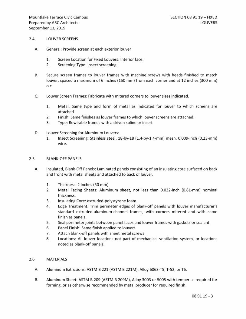
Mountlake Terrace Civic CampusPrepared by ARC ArchitectsSeptember 13, 2019
SECTION 08 91 19 – FIXED LOUVERS
08 91 19 - 3
2.4 LOUVER SCREENS
A. General: Provide screen at each exterior louver
1. Screen Location for Fixed Louvers: Interior face.2. Screening Type: Insect screening.
B. Secure screen frames to louver frames with machine screws with heads finished to match louver, spaced a maximum of 6 inches (150 mm) from each corner and at 12 inches (300 mm) o.c.
C. Louver Screen Frames: Fabricate with mitered corners to louver sizes indicated.
1. Metal: Same type and form of metal as indicated for louver to which screens are attached.
2. Finish: Same finishes as louver frames to which louver screens are attached.3. Type: Rewirable frames with a driven spline or insert
D. Louver Screening for Aluminum Louvers:1. Insect Screening: Stainless steel, 18-by-18 (1.4-by-1.4-mm) mesh, 0.009-inch (0.23-mm)
wire.
2.5 BLANK-OFF PANELS
A. Insulated, Blank-Off Panels: Laminated panels consisting of an insulating core surfaced on back and front with metal sheets and attached to back of louver.
1. Thickness: 2 inches (50 mm)2. Metal Facing Sheets: Aluminum sheet, not less than 0.032-inch (0.81-mm) nominal
thickness.3. Insulating Core: extruded-polystyrene foam4. Edge Treatment: Trim perimeter edges of blank-off panels with louver manufacturer's
standard extruded-aluminum-channel frames, with corners mitered and with same finish as panels.
5. Seal perimeter joints between panel faces and louver frames with gaskets or sealant.6. Panel Finish: Same finish applied to louvers7. Attach blank-off panels with sheet metal screws8. Locations: All louver locations not part of mechanical ventilation system, or locations
noted as blank-off panels.
2.6 MATERIALS
A. Aluminum Extrusions: ASTM B 221 (ASTM B 221M), Alloy 6063-T5, T-52, or T6.
B. Aluminum Sheet: ASTM B 209 (ASTM B 209M), Alloy 3003 or 5005 with temper as required for forming, or as otherwise recommended by metal producer for required finish.

Mountlake Terrace Civic CampusPrepared by ARC ArchitectsSeptember 13, 2019
SECTION 08 91 19 – FIXED LOUVERS
08 91 19 - 4
C. Fasteners: Use types and sizes to suit unit installation conditions.1. For color-finished louvers, use fasteners with heads that match color of louvers.
2.7 FABRICATION
A. Factory assemble louvers to minimize field splicing and assembly. Disassemble units as necessary for shipping and handling limitations. Clearly mark units for reassembly and coordinated installation.
B. Maintain equal louver blade spacing, including separation between blades and frames at head and sill, to produce uniform appearance.
C. Fabricate frames, including integral sills, to fit in openings of sizes indicated, with allowances made for fabrication and installation tolerances, adjoining material tolerances, and perimeter sealant joints.
1. Frame Type: Channel unless otherwise indicated.
D. Include supports, anchorages, and accessories required for complete assembly.
E. Provide vertical mullions of type and at spacings indicated, but not more than is recommended by manufacturer, or 72 inches (1830 mm) o.c., whichever is less.
1. Fully Recessed Mullions: Where indicated, provide mullions fully recessed behind louver blades. Where length of louver exceeds fabrication and handling limitations, fabricate with close-fitting blade splices designed to permit expansion and contraction.
2. Exterior Corners: Prefabricated corner units with mitered and with fully recessed mullions at corners.
F. Provide subsills made of same material as louvers or extended sills for recessed louvers.
G. Join frame members to each other and to fixed louver blades with fillet welds concealed from view unless otherwise indicated or size of louver assembly makes bolted connections between frame members necessary.
2.8 ALUMINUM FINISHES
A. Finish louvers after assembly.
B. Color Anodic Finish: AAMA 611, AA-M12C22A42/A44, Class I, 0.018 mm or thicker.
1. Colors: To match adjacent, non-louver material finish per Drawings.

Mountlake Terrace Civic CampusPrepared by ARC ArchitectsSeptember 13, 2019
SECTION 08 91 19 – FIXED LOUVERS
08 91 19 - 5
PART 3 - EXECUTION
3.1 EXAMINATION
A. Examine substrates and openings, with Installer present, for compliance with requirements for installation tolerances and other conditions affecting performance of the Work.
B. Proceed with installation only after unsatisfactory conditions have been corrected.
3.2 PREPARATION
A. Coordinate setting drawings, diagrams, templates, instructions, and directions for installation of anchorages that are to be embedded in concrete or masonry construction. Coordinate delivery of such items to Project site.
3.3 INSTALLATION
A. Locate and place louvers level, plumb, and at indicated alignment with adjacent work.
B. Use concealed anchorages where possible. Provide brass or lead washers fitted to screws where required to protect metal surfaces and to make a weathertight connection.
C. Form closely fitted joints with exposed connections accurately located and secured.
D. Provide perimeter reveals and openings of uniform width for sealants and joint fillers, as indicated.
E. Protect unpainted galvanized and nonferrous-metal surfaces that are in contact with concrete, masonry, or dissimilar metals from corrosion and galvanic action by applying a heavy coating of bituminous paint or by separating surfaces with waterproof gaskets or nonmetallic flashing.
F. Install concealed gaskets, flashings, joint fillers, and insulation as louver installation progresses, where weathertight louver joints are required. Comply with Section 079200 "Joint Sealants" for sealants applied during louver installation.
3.4 ADJUSTING AND CLEANING
A. Clean exposed louver surfaces that are not protected by temporary covering, to remove fingerprints and soil during construction period. Do not let soil accumulate during construction period.
B. Before final inspection, clean exposed surfaces with water and a mild soap or detergent not harmful to finishes. Thoroughly rinse surfaces and dry.
C. Restore louvers damaged during installation and construction so no evidence remains of corrective work. If results of restoration are unsuccessful, as determined by Architect, remove damaged units and replace with new units.

Mountlake Terrace Civic CampusPrepared by ARC ArchitectsSeptember 13, 2019
SECTION 08 91 19 – FIXED LOUVERS
08 91 19 - 6
1. Touch up minor abrasions in finishes with air-dried coating that matches color and gloss of, and is compatible with, factory-applied finish coating.
END OF SECTION 089119

Mountlake Terrace Civic CampusPrepared by ARC ArchitectsSeptember 13, 2019
SECTION 09 22 16 - NON-STRUCTURAL METAL FRAMING
09 22 16 - 1
SECTION 092216 - NON-STRUCTURAL METAL FRAMING
PART 1 - GENERAL
1.1 SUMMARY
A. Section Includes:
1. C-H Studs for elevator shaft walls
1.2 RELATED SECTIONSA. 092000 – Gypsum Wallboard for metal furring, resilient hat channels.B. 061000 – Rough CarpentryC. 055000 – Metal Fabrications
1.3 ACTION SUBMITTALS
A. Product Data: For each type of product.
1.4 QUALITY ASSURANCE
A. Contractor shall provide effective, full time quality control over all fabrication and erection complying with the pertinent codes and regulations of government agencies having jurisdiction. Conduct pre-installation meeting to verify project requirements, substrate conditions, and manufacturer’s installation instructions.
1.5 DELIVERY, STORAGE, AND HANDLING
A. Notify manufacturer of damaged materials received prior to installation.
B. Deliver materials in manufacturer's original, unopened, undamaged containers with identification labels intact.
C. Protect cold-formed metal framing from corrosion, deformation, and other damage during delivery, storage, and handling as required by AISI's "Code of Standard Practice".

Mountlake Terrace Civic CampusPrepared by ARC ArchitectsSeptember 13, 2019
SECTION 09 22 16 - NON-STRUCTURAL METAL FRAMING
09 22 16 - 2
PART 2 - PRODUCTS
2.1 PERFORMANCE / DESIGN CRITERIA
A. Fire-Test-Response Characteristics: For fire-resistance-rated assemblies that incorporate non-load-bearing steel framing, provide materials and construction identical to those tested in assembly indicated, according to ASTM E 119 by, and displaying a classification label from, an independent testing agency acceptable to the authority having jurisdiction.
1. Construct fire-resistance rated partitions in compliance with tested assembly requirements as indicated on drawings.
B. STC-Rated Assemblies: For STC-rated assemblies, provide materials and construction identical to those tested in assembly indicated, according to ASTM E 90 and classified according to ASTM E 413 by an independent testing agency.
C. Design framing systems in accordance with American Iron and Steel Institute Publication “North American Specification for the Design of Cold-Formed Steel Framing – NonStructural Members”, except as otherwise shown or specified.
D. Design loads: 5 PSF minimum as required by the International Building Code.
2.2 FRAMING SYSTEMS
A. Framing Members, General: Comply with ASTM C 645 for conditions indicated.
1. Steel Sheet Components: Comply with ASTM C 645 requirements for metal unless otherwise indicated.
2. Protective Coating: Comply with ASTM C 645; roll-formed from hot-dipped galvanized steel; complying with ASTM A 1003/A 1003M and ASTM A 653/A 653M G40 (Z120) or having a coating that provides equivalent corrosion resistance. A40 galvannealed products are not acceptable.
3. Basis-of-Design Product: Subject to compliance with requirements, provide ClarkDietrich Building Systems products listed or comparable products from the manufacturer’s list below:
1. SCAFCO Corporation2. Super Stud Building Products, Inc.3. < or approved equal by Architect >
B. CT Stud Profile – Elevator shaftwall studs, ASTM C 645.
1. Guage: 18ga2. Depth: As indicated on Drawings

Mountlake Terrace Civic CampusPrepared by ARC ArchitectsSeptember 13, 2019
SECTION 09 22 16 - NON-STRUCTURAL METAL FRAMING
09 22 16 - 3
2.3 AUXILIARY MATERIALS
A. General: Provide auxiliary materials that comply with referenced installation standards.
1. Fasteners for Metal Framing: Of type, material, size, corrosion resistance, holding power, and other properties required to fasten steel members to substrates.
PART 3 - EXECUTION
3.1 EXAMINATION
A. Examine areas and substrates, with Installer present, and including welded hollow-metal frames, cast-in anchors, and structural framing, for compliance with requirements and other conditions affecting performance of the Work. Proceed with installation only after unsatisfactory conditions have been corrected.
B. Installation of non-structural metal framing shall be coordinated with remediation and removal of regulated materials. Refer to “Related Requirements” of this specification section.
3.2 PREPARATION
A. Suspended Assemblies: Coordinate installation of suspension systems with installation of overhead structure to ensure that inserts and other provisions for anchorages to building structure have been installed to receive hangers at spacing required to support the Work and that hangers will develop their full strength.
1. Furnish concrete inserts and other devices indicated to other trades for installation in advance of time needed for coordination and construction.
3.3 INSTALLATION, GENERAL
A. Installation Standard: ASTM C 754.
1. Gypsum Plaster Assemblies: Also comply with requirements in ASTM C 841 that apply to framing installation.
2. Portland Cement Plaster Assemblies: Also comply with requirements in ASTM C 1063 that apply to framing installation.
3. Gypsum Veneer Plaster Assemblies: Also comply with requirements in ASTM C 844 that apply to framing installation.
4. Gypsum Board Assemblies: Also comply with requirements in ASTM C 840 that apply to framing installation.
B. Install supplementary framing, and blocking to support fixtures, equipment services, heavy trim, grab bars, toilet accessories, furnishings, or similar construction.

Mountlake Terrace Civic CampusPrepared by ARC ArchitectsSeptember 13, 2019
SECTION 09 22 16 - NON-STRUCTURAL METAL FRAMING
09 22 16 - 4
C. Install bracing at terminations in assemblies.
D. Do not bridge building control and expansion joints with non-load-bearing steel framing members. Frame both sides of joints independently.
3.4 INSTALLING FRAMED ASSEMBLIES
A. Install framing system components according to spacings indicated, but not greater than spacings required by referenced installation standards for assembly types.
1. Single-Layer Application: 16 inches (406 mm) o.c. unless otherwise indicated.2. Multilayer Application: 16 inches (406 mm) o.c. unless otherwise indicated.
B. Where studs are installed directly against exterior masonry walls or dissimilar metals at exterior walls, install isolation strip between studs and exterior wall.
C. Install studs so flanges within framing system point in same direction.
D. Install tracks (runners) at floors and overhead supports. Extend framing full height to structural supports or substrates above suspended ceilings except where partitions are indicated to terminate at suspended ceilings. Continue framing around ducts penetrating partitions above ceiling.
1. Slip-Type Head Joints: Where framing extends to overhead structural supports, install to produce joints at tops of framing systems that prevent axial loading of finished assemblies.
2. Door Openings: Screw vertical studs at jambs to jamb anchor clips on door frames; install runner track section (for cripple studs) at head and secure to jamb studs.
1. Install two studs at each jamb unless otherwise indicated.2. Install cripple studs at head adjacent to each jamb stud, with a minimum 1/2-inch
(13-mm) clearance from jamb stud to allow for installation of control joint in finished assembly.
3. Extend jamb studs through suspended ceilings and attach to underside of overhead structure.
3. Other Framed Openings: Frame openings other than door openings the same as required for door openings unless otherwise indicated. Install framing below sills of openings to match framing required above door heads.
4. Fire-Resistance-Rated Partitions: Install framing to comply with fire-resistance-rated assembly indicated and support closures and to make partitions continuous from floor to underside of solid structure.
1. Install fire-resistant partitions using manufacturer's proprietary equivalent gauge studs in compliance with requirements of UL V450.
2. Firestop Track: Where indicated, install to maintain continuity of fire-resistance-rated assembly indicated.

Mountlake Terrace Civic CampusPrepared by ARC ArchitectsSeptember 13, 2019
SECTION 09 22 16 - NON-STRUCTURAL METAL FRAMING
09 22 16 - 5
5. Sound-Rated Partitions: Install framing to comply with sound-rated assembly indicated.
E. Installation Tolerance: Install each framing member so fastening surfaces vary not more than 1/8 inch (3 mm) from the plane formed by faces of adjacent framing.
END OF SECTION 092216

Mountlake Terrace Civic CampusPrepared by ARC ArchitectsSeptember 13, 2019
SECTION 09 29 00 - GYPSUM BOARD
09 29 00 - 1
SECTION 092900 - GYPSUM BOARD
PART 1 - GENERAL
1.1 SUMMARY
A. Section Includes:1. Exterior soffit gypsum board2. Interior gypsum board.3. Interior trims.4. Joint treatment materials5. Auxiliary materials6. Security mesh7. Resilient furring channel
B. Related Requirements:
1. Section 092216 "Non-Structural Metal Framing" for non-structural framing.
1.2 ACTION SUBMITTALS
A. Product Data: For each type of product.
1.3 DELIVERY, STORAGE AND HANDLING
A. Store materials inside under cover and keep them dry and protected against weather, condensation, direct sunlight, construction traffic, and other potential causes of damage. Stack panels flat and supported on risers on a flat platform to prevent sagging.
1.4 FIELD CONDITIONS
A. Environmental Limitations: Comply with ASTM C 840 requirements or gypsum board manufacturer's written recommendations, whichever are more stringent.
B. Do not install paper-faced gypsum panels until installation areas are enclosed and conditioned.
C. Do not install panels that are wet, those that are moisture damaged, and those that are mold damaged.

Mountlake Terrace Civic CampusPrepared by ARC ArchitectsSeptember 13, 2019
SECTION 09 29 00 - GYPSUM BOARD
09 29 00 - 2
PART 2 - PRODUCTS
2.1 PERFORMANCE REQUIREMENTS
A. Fire-Resistance-Rated Assemblies: For fire-resistance-rated assemblies, provide materials and construction identical to those tested in assembly indicated according to ASTM E 119 by an independent testing agency.
B. STC-Rated Assemblies: For STC-rated assemblies, provide materials and construction identical to those tested in assembly indicated according to ASTM E 90 and classified according to ASTM E 413 by an independent testing agency.
2.2 GYPSUM BOARD, GENERAL
A. Size: Provide maximum lengths and widths available that will minimize joints in each area and that correspond with support system indicated.
2.3 EXTERIOR SOFFIT GYPSUM BOARD
A. Exterior Soffit Gypsum Wallboard, Type X: ASTM C 1396 section 8 (C 931)1. Thickness: 5/8 inch2. Long Edges: Tapered.
2.4 INTERIOR GYPSUM BOARD
A. Gypsum Board, Type X: ASTM C 1396/C 1396M.
1. Thickness: 5/8 inch (15.9 mm).2. Long Edges: Tapered.
2.5 RESILIENT FURRING CHANNELS
A. Resilient Furring Channel: 1/2-inch- (13-mm-) deep, steel sheet members designed to reduce sound transmission.
1.Basis-of-Design Product: Subject to compliance with requirements, provide ClarkDietrich; RC Deluxe (RCSD) Resilient Channel or comparable product as approved by architect
2.5 TRIM ACCESSORIES
A. Interior Trim: ASTM C 1047.1. Material: Galvanized or aluminum-coated steel sheet, rolled zinc, plastic, or paper-
faced galvanized steel sheet.2. Shapes:
a. Cornerbead.

Mountlake Terrace Civic CampusPrepared by ARC ArchitectsSeptember 13, 2019
SECTION 09 29 00 - GYPSUM BOARD
09 29 00 - 3
b. Bullnose bead.c. Z-reveald. F-reveale. J-Trimf. LC-Bead: J-shaped; exposed long flange receives joint compound.g. L-Bead: L-shaped; exposed long flange receives joint compound.h. U-Bead: J-shaped; exposed short flange does not receive joint compound.i. Expansion (control) joint.
B. Exterior Trim: ASTM C 1047.1. Material: Hot-dip galvanized steel sheet, plastic, or rolled zinc.2. Shapes:
a. Cornerbead.b. LC-Bead: J-shaped; exposed long flange receives joint compound.c. Expansion (Control) Joint: One-piece, rolled zinc with V-shaped slot and
removable strip covering slot opening.
2.6 JOINT TREATMENT MATERIALS
A. General: Comply with ASTM C 475/C 475M.
B. Joint Tape:
1. Interior Gypsum Board: Paper.
C. Joint Compound for Interior Gypsum Board: For each coat use formulation that is compatible with other compounds applied on previous or for successive coats.
1. Prefilling: At open joints and damaged surface areas, use setting-type taping compound.
2. Embedding and First Coat: For embedding tape and first coat on joints, fasteners, and trim flanges, use setting-type taping compound.
a. Use setting-type compound for installing paper-faced metal trim accessories.
3. Fill Coat: For second coat, use setting-type, sandable topping compound.4. Finish Coat: For third coat, use setting-type, sandable topping compound.
2.7 AUXILIARY MATERIALS
A. General: Provide auxiliary materials that comply with referenced installation standards and manufacturer's written recommendations.
B. Steel Drill Screws: ASTM C 1002, unless otherwise indicated.

Mountlake Terrace Civic CampusPrepared by ARC ArchitectsSeptember 13, 2019
SECTION 09 29 00 - GYPSUM BOARD
09 29 00 - 4
1. Use screws complying with ASTM C 954 for fastening panels to steel members from 0.033 to 0.112 inch (0.84 to 2.84 mm) thick.
2. For fastening cementitious backer units, use screws of type and size recommended by panel manufacturer.
C. Acoustical Latex Joint Sealant: Meets ASTM C834 Standard Specification for Latex-Based Sealing Compounds tested in accordance with ASTM C731, ASTM C732, ASTM C733, ASTM C734, ASTM C736, ASTM D217, ASTM D2202, ASTM D2203 and ASTM D2377. Also tested in accordance with ASTM E84 (surface-burning characteristics), ASTM E90 (sound tests) and ASTM E1966 (fire-resistant joint systems). ASTM E814 (through-penetration firestop systems).1. Surface-Burning Characteristics: 0/0 (flame spread/smoke developed)2. Color: Off-white3. Solids: 73% ± 3%4. Weight:12.0–12.8 lbs./gal. (in container)
D. Adhesive: Provide one of the following:1. SikaBond® Construction Adhesive2. Loctite® Power Grab® Heavy Duty Clear Exterior Construction Adhesive3. Liquid Nails Drywall Adhesive (DWF-24)4. < or approved equal by Architect >
2.8 SECURITY MESH
A. Manufacturer: Bailey Metal Products Limited or approved equal by architect1. Style: C3/4 – 9F2. Weigh – 1763. Opening area 63-69
PART 3 - EXECUTION
3.1 EXAMINATION
A. Examine areas and substrates including welded hollow-metal frames and framing, with Installer present, for compliance with requirements and other conditions affecting performance.
B. Examine panels before installation. Reject panels that are wet, moisture damaged, and mold damaged.
C. Proceed with installation only after unsatisfactory conditions have been corrected.
3.2 APPLYING AND FINISHING PANELS, GENERAL
A. Comply with ASTM C 840.

Mountlake Terrace Civic CampusPrepared by ARC ArchitectsSeptember 13, 2019
SECTION 09 29 00 - GYPSUM BOARD
09 29 00 - 5
B. Install ceiling panels across framing to minimize the number of abutting end joints and to avoid abutting end joints in central area of each ceiling. Stagger abutting end joints of adjacent panels not less than one framing member.
C. Install panels with face side out. Butt panels together for a light contact at edges and ends with not more than 1/16 inch (1.5 mm) of open space between panels. Do not force into place.
D. Locate edge and end joints over supports, except in ceiling applications where intermediate supports or gypsum board back-blocking is provided behind end joints. Do not place tapered edges against cut edges or ends. Stagger vertical joints on opposite sides of partitions. Do not make joints other than control joints at corners of framed openings.
E. Form control and expansion joints with space between edges of adjoining gypsum panels.
F. Cover both faces of support framing with gypsum panels in concealed spaces (above ceilings, etc.), except in chases braced internally.
1. Unless concealed application is indicated or required for sound, fire, air, or smoke ratings, coverage may be accomplished with scraps of not less than 8 sq. ft. (0.7 sq. m) in area.
2. Fit gypsum panels around ducts, pipes, and conduits.3. Where partitions intersect structural members projecting below underside of floor/roof
slabs and decks, cut gypsum panels to fit profile formed by structural members; allow 1/4- to 3/8-inch-(6.4- to 9.5-mm-)wide joints to install sealant.
G. Isolate perimeter of gypsum board applied to non-load-bearing partitions at structural abutments, except floors. Provide 1/4- to 1/2-inch-(6.4- to 12.7-mm-)wide spaces at these locations and trim edges with edge trim where edges of panels are exposed. Seal joints between edges and abutting structural surfaces with acoustical sealant.
H. Attachment to Steel Framing: Attach panels so leading edge or end of each panel is attached to open (unsupported) edges of stud flanges first.
I. STC-Rated Assemblies: Seal construction at perimeters, behind control joints, and at openings and penetrations with a continuous bead of acoustical sealant. Install acoustical sealant at both faces of partitions at perimeters and through penetrations. Comply with ASTM C 919 and with manufacturer's written recommendations for locating edge trim and closing off sound-flanking paths around or through assemblies, including sealing partitions above acoustical ceilings.
J. Install sound attenuation blankets before installing gypsum panels unless blankets are readily installed after panels have been installed on one side.
3.3 APPLYING INTERIOR GYPSUM BOARD
A. Install interior gypsum board in the following locations:

Mountlake Terrace Civic CampusPrepared by ARC ArchitectsSeptember 13, 2019
SECTION 09 29 00 - GYPSUM BOARD
09 29 00 - 6
1. Type X: At ceilings and walls per drawings
B. Single-Layer Application:
1. On ceilings, apply gypsum panels before wall/partition board application to greatest extent possible and at right angles to framing unless otherwise indicated.
2. On partitions/walls, apply gypsum panels horizontally (perpendicular to framing)] unless otherwise indicated or required by fire-resistance-rated assembly, and minimize end joints.
a. Stagger abutting end joints not less than one framing member in alternate courses of panels.
3. On Z-furring members, apply gypsum panels vertically (parallel to framing) with no end joints. Locate edge joints over furring members.
4. Fastening Methods: Apply gypsum panels to supports with steel drill screws.
3.4 INSTALLING TRIM ACCESSORIES
A. General: For trim with back flanges intended for fasteners, attach to framing with same fasteners used for panels. Otherwise, attach trim according to manufacturer's written instructions.
B. Interior Trim: Install in the following locations:
1. Cornerbead: Use at outside corners unless otherwise indicated].2. F-Reveal Molding: Use Where gypsum board abuts adjacent wood, masonry or concrete
construction as indicated on drawings.3. Control Joints: as indicated on drawings.
3.5 FINISHING GYPSUM BOARD
A. General: Treat gypsum board joints, interior angles, edge trim, control joints, penetrations, fastener heads, surface defects, and elsewhere as required to prepare gypsum board surfaces for decoration. Promptly remove residual joint compound from adjacent surfaces.
B. Prefill open joints and damaged surface areas.
C. Apply joint tape over gypsum board joints, except for trim products specifically indicated as not intended to receive tape.
D. Gypsum Board Finish Levels: Finish panels to levels indicated below and according to ASTM C 840:
1. Level 4: At panel surfaces that will be exposed to view unless otherwise indicated.

Mountlake Terrace Civic CampusPrepared by ARC ArchitectsSeptember 13, 2019
SECTION 09 29 00 - GYPSUM BOARD
09 29 00 - 7
a. Primer and its application to surfaces are specified in Section 099123 "Interior Painting."
3.6 SECURITY MESH
A. Installation1. Self-Drilling screws. Use pan head type. Screws need to be long enough to penetrate
through steel studs and joists at least ¼”.2. Alternative installation: Welding to steel studs and joists. Security mesh may be fillet
welded maximum 8” on center; edge welds must be within 2” of the edge.
3.7 PROTECTION
A. Protect adjacent surfaces from drywall compound and promptly remove from floors and other non-drywall surfaces. Repair surfaces stained, marred, or otherwise damaged during drywall application.
B. Remove and replace panels that are wet, moisture damaged, and mold damaged.
END OF SECTION 092900
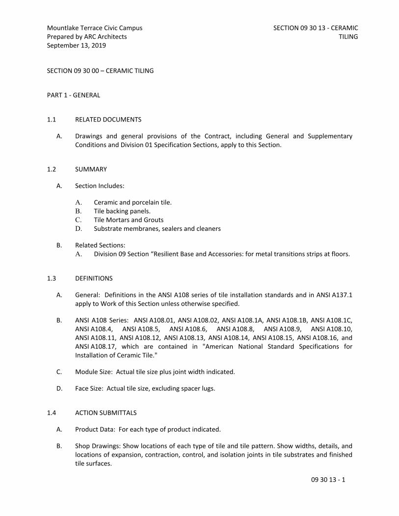
Mountlake Terrace Civic CampusPrepared by ARC ArchitectsSeptember 13, 2019
SECTION 09 30 13 - CERAMIC TILING
09 30 13 - 1
SECTION 09 30 00 – CERAMIC TILING
PART 1 - GENERAL
1.1 RELATED DOCUMENTS
A. Drawings and general provisions of the Contract, including General and Supplementary Conditions and Division 01 Specification Sections, apply to this Section.
1.2 SUMMARY
A. Section Includes:
A. Ceramic and porcelain tile.B. Tile backing panels.C. Tile Mortars and GroutsD. Substrate membranes, sealers and cleaners
B. Related Sections:A. Division 09 Section “Resilient Base and Accessories: for metal transitions strips at floors.
1.3 DEFINITIONS
A. General: Definitions in the ANSI A108 series of tile installation standards and in ANSI A137.1 apply to Work of this Section unless otherwise specified.
B. ANSI A108 Series: ANSI A108.01, ANSI A108.02, ANSI A108.1A, ANSI A108.1B, ANSI A108.1C, ANSI A108.4, ANSI A108.5, ANSI A108.6, ANSI A108.8, ANSI A108.9, ANSI A108.10, ANSI A108.11, ANSI A108.12, ANSI A108.13, ANSI A108.14, ANSI A108.15, ANSI A108.16, and ANSI A108.17, which are contained in "American National Standard Specifications for Installation of Ceramic Tile."
C. Module Size: Actual tile size plus joint width indicated.
D. Face Size: Actual tile size, excluding spacer lugs.
1.4 ACTION SUBMITTALS
A. Product Data: For each type of product indicated.
B. Shop Drawings: Show locations of each type of tile and tile pattern. Show widths, details, and locations of expansion, contraction, control, and isolation joints in tile substrates and finished tile surfaces.

Mountlake Terrace Civic CampusPrepared by ARC ArchitectsSeptember 13, 2019
SECTION 09 30 13 - CERAMIC TILING
09 30 13 - 2
C. Samples for Verification:A. Full-size units of each type of trim and accessory for each color and finish required.
1.5 MATERIALS MAINTENANCE SUBMITTALS
A. Furnish extra materials that match and are from same production runs as products installed and that are packaged with protective covering for storage and identified with labels describing contents.
A. Tile: Furnish quantity of full-size units equal to 5 percent of amount installed for each type, composition, color, pattern, and size indicated.
1.6 QUALITY ASSURANCE
A. Source Limitations for Tile: Obtain tile of each color or finish tile from one source or producer.
A. Obtain tile of each type and color or finish from same production run and of consistent quality in appearance and physical properties for each contiguous area.
B. Source Limitations for Setting and Grouting Materials: Obtain ingredients of a uniform quality for each mortar, adhesive, and grout component from one manufacturer and each aggregate from one source or producer.
C. Source Limitations for Other Products: Obtain each of the following products specified in this Section from a single manufacturer for each product:
A. Joint sealants.
D. Preinstallation Conference: Conduct conference at Project site.
A. Review requirements in ANSI A108.01 for substrates and for preparation by other trades.
1.7 DELIVERY, STORAGE, AND HANDLING
A. Deliver and store packaged materials in original containers with seals unbroken and labels intact until time of use. Comply with requirements in ANSI A137.1 for labeling tile packages.
B. Store tile and cementitious materials on elevated platforms, under cover, and in a dry location.
C. Store aggregates where grading and other required characteristics can be maintained and contamination can be avoided.
D. Store liquid materials in unopened containers and protected from freezing.

Mountlake Terrace Civic CampusPrepared by ARC ArchitectsSeptember 13, 2019
SECTION 09 30 13 - CERAMIC TILING
09 30 13 - 3
E. Handle tile that has temporary protective coating on exposed surfaces to prevent coated surfaces from contacting backs or edges of other units. If coating does contact bonding surfaces of tile, remove coating from bonding surfaces before setting tile.
1.8 PROJECT CONDITIONS
A. Environmental Limitations: Do not install tile until construction in spaces is complete and ambient temperature and humidity conditions are maintained at the levels indicated in referenced standards and manufacturer's written instructions.
PART 2 - PRODUCTS
2.1 PRODUCTS, GENERAL
A. ANSI Ceramic Tile Standard: Provide tile that complies with ANSI A137.1 for types, compositions, and other characteristics indicated.
A. Provide tile complying with Standard grade requirements unless otherwise indicated.
B. ANSI Standards for Tile Installation Materials: Provide materials complying with ANSI A108.02, ANSI standards referenced in other Part 2 articles, ANSI standards referenced by TCA installation methods specified in tile installation schedules, and other requirements specified.
C. Factory Blending: For tile exhibiting color variations within ranges, blend tile in factory and package so tile units taken from one package show same range in colors as those taken from other packages and match approved Samples.
D. Mounting: For factory-mounted tile, provide back- or edge-mounted tile assemblies as standard with manufacturer unless otherwise indicated.
E. Factory-Applied Temporary Protective Coating: Where indicated under tile type, protect exposed surfaces of tile against adherence of mortar and grout by precoating with continuous film of petroleum paraffin wax, applied hot. Do not coat unexposed tile surfaces.
F. Provide manufactures full line of tile shapes.A. Coved floor tile bases B. Bullnosed at outside corners and returns to GWB
2.2 TILE SCHEDULE
T-1 CERAMIC FLOOR TILE AND WALL BASEManufacture: Landmark CeramicsItem: Trek

Mountlake Terrace Civic CampusPrepared by ARC ArchitectsSeptember 13, 2019
SECTION 09 30 13 - CERAMIC TILING
09 30 13 - 4
Color: LeadSize: 12” x 24” floor tileSize: 6” x 12” cove trimLocation / Orientation / Pattern: per drawingsSetting material: thicksetInstallation: tile council of North America (TCNA)# f114 and ANSI a108.1c; cement mortar bed with cleavage membrane; epoxy grout.
T-2 CERAMIC TILE WALLManufacture: United TileItem: Color by NumbersColor: WT18 1812 OvertureSize: 4” x 8” wall tileLocation / Orientation / Pattern: per drawingsSetting material: thinsetInstallation: TCNA# w243, thinset mortar on backer boards, with waterproof membrane over backer board.
T-3 CERAMIC TILE WALLManufacture: United TileItem: Color by NumbersColor: WT06 Sixth SenseSize: 4” x 8” wall tileLocation / Orientation / Pattern: per drawingsSetting material: thinsetInstallation: TCNA# w243, thinset mortar on backer boards, with waterproof membrane over backer board.
2.3 TILE BACKING PANELS (aka Cement Backer Panel, Backer Panel)
A. Products: Subject to compliance with requirements, available products that may be incorporated into the Work include, but are not limited to, the following:
a. CertainTeed; Diamondback Tile Backer Type Xb. Georgia-Pacific Building Products: Denshield Tile Backer.
B. Core: 5/8 inch, Type X.C. Mold Resistance: ASTM D 3273, score of 10 as rated according to ASTM D 3274.
2.4 SETTING MATERIALS
A. Portland Cement Mortar (Thickset) Installation Materials: ANSI A108.02.
Mountlake Terrace Civic CampusPrepared by ARC ArchitectsSeptember 13, 2019
SECTION 09 30 13 - CERAMIC TILING
09 30 13 - 5
A. Cleavage Membrane: Asphalt felt, ASTM D 226/D 226M, Type I (No. 15); or polyethylene sheeting, ASTM D 4397, 4.0 mils thick.
B. Reinforcing Wire Fabric: Galvanized, welded-wire fabric, 2 by 2 inches by 0.062-inch diameter; comply with ASTM A 185/A 185M and ASTM A 82/A 82M, except for minimum wire size.
C. Latex Additive: Manufacturer's standard water emulsion, serving as replacement for part or all of gaging water, of type specifically recommended by latex-additive manufacturer for use with field-mixed portland cement and aggregate mortar bed.
B. Latex-Portland Cement Mortar (Thinset): ANSI A118.4.
A. Provide prepackaged, dry-mortar mix containing dry, redispersible, vinyl acetate or acrylic additive to which only water must be added at Project site.
B. Provide prepackaged, dry-mortar mix combined with acrylic resin or styrene-butadiene-rubber liquid-latex additive at Project site.
C. For wall applications, provide mortar that complies with requirements for nonsagging mortar in addition to the other requirements in ANSI A118.4.
C. Water-Cleanable, Tile-Setting Epoxy: ANSI A118.3.
A. Provide product capable of withstanding continuous and intermittent exposure to temperatures of up to 140 and 212 deg F , respectively, and certified by manufacturer for intended use.
2.5 GROUT MATERIALS
A. Water-Cleanable Epoxy Grout: ANSI A118.3.
A. Provide product capable of withstanding continuous and intermittent exposure to temperatures of up to 140 and 212 deg F , respectively, and certified by manufacturer for intended use.
B. Color: As selected from manufacturer’s full range of standard options.
2.6 MISCELLANEOUS MATERIALS
A. Trowelable Underlayments and Patching Compounds: Latex-modified, portland cement-based formulation provided or approved by manufacturer of tile-setting materials for installations indicated.
B. Waterproofing / Crack Isolation Membrane: RedGard by Custom Building Products or equal
C. Vapor-Retarder / Cleavage Membrane: Polyethylene sheeting, ASTM D 4397, 4.0 mils thick.
D. Tile Cleaner: A neutral cleaner capable of removing soil and residue without harming tile and grout surfaces, specifically approved for materials and installations indicated by tile and grout manufacturers.
Mountlake Terrace Civic CampusPrepared by ARC ArchitectsSeptember 13, 2019
SECTION 09 30 13 - CERAMIC TILING
09 30 13 - 6
E. Grout Sealer: Manufacturer's standard product for sealing grout joints and that does not change color or appearance of grout.
A. Products: Subject to compliance with requirements, available products that may be incorporated into the Work include, but are not limited to, the following:
a. Bonsal American, an Oldcastle companyb. Custom Building Productsc. Jamo Incd. Southern Grouts & Mortars, Inc.e. Summitville Tiles, Inc
B. Grout sealers shall comply with requirements of FloorScore certification.
2.7 MIXING MORTARS AND GROUT
A. Mix mortars and grouts to comply with referenced standards and mortar and grout manufacturers' written instructions.
B. Add materials, water, and additives in accurate proportions.
C. Obtain and use type of mixing equipment, mixer speeds, mixing containers, mixing time, and other procedures to produce mortars and grouts of uniform quality with optimum performance characteristics for installations indicated.
PART 3 - EXECUTION
3.1 EXAMINATION
A. Examine substrates, areas, and conditions where tile will be installed, with Installer present, for compliance with requirements for installation tolerances and other conditions affecting performance of the Work.
A. Verify that substrates for setting tile are firm; dry; clean; free of coatings that are incompatible with tile-setting materials, including curing compounds and other substances that contain soap, wax, oil, or silicone; and comply with flatness tolerances required by ANSI A108.01 for installations indicated.
B. Verify that concrete substrates for tile floors installed with thinset mortar comply with surface finish requirements in ANSI A108.01 for installations indicated.
a. Verify that surfaces that received a steel trowel finish have been mechanically scarified.
b. Verify that protrusions, bumps, and ridges have been removed by sanding or grinding.
C. Verify that installation of grounds, anchors, recessed frames, electrical and mechanical units of work, and similar items located in or behind tile has been completed.

Mountlake Terrace Civic CampusPrepared by ARC ArchitectsSeptember 13, 2019
SECTION 09 30 13 - CERAMIC TILING
09 30 13 - 7
D. Verify that joints and cracks in tile substrates are coordinated with tile joint locations; if not coordinated, adjust joint locations in consultation with Architect.
B. Proceed with installation only after unsatisfactory conditions have been corrected.
3.2 PREPARATION
A. Fill cracks, holes, and depressions in concrete substrates for tile floors installed with thinset mortar with trowelable leveling and patching compound specifically recommended by tile-setting material manufacturer.
B. Where indicated, prepare substrates to receive waterproofing by applying a reinforced mortar bed that complies with ANSI A108.1A and is sloped toward drains. Refer to drawings for slope direction and inches / foot.
C. Blending: For tile exhibiting color variations, verify that tile has been factory blended and packaged so tile units taken from one package show same range of colors as those taken from other packages and match approved Samples. If not factory blended, either return to manufacturer or blend tiles at Project site before installing.
3.3 CERAMIC TILE INSTALLATION
A. Comply with TCNA's "Handbook for Ceramic, Glass, and Stone Tile Installation" for TCNA installation methods specified in tile installation schedules. Comply with parts of the ANSI A108 series "Specifications for Installation of Ceramic Tile" that are referenced in TCNA installation methods, specified in tile installation schedules, and apply to types of setting and grouting materials used.
B. Extend tile work into recesses and under or behind equipment and fixtures to form complete covering without interruptions unless otherwise indicated. Terminate work neatly at obstructions, edges, and corners without disrupting pattern or joint alignments.
C. Accurately form intersections and returns. Perform cutting and drilling of tile without marring visible surfaces. Carefully grind cut edges of tile abutting trim, finish, or built-in items for straight aligned joints. Fit tile closely to electrical outlets, piping, fixtures, and other penetrations so plates, collars, or covers overlap tile.
D. Provide manufacturer's standard trim shapes where necessary to eliminate exposed tile edges.
E. Jointing Pattern: Lay tile in grid pattern unless otherwise indicated. Lay out tile work and center tile fields in both directions in each space or on each wall area. Lay out tile work to minimize the use of pieces that are less than half of a tile. Provide uniform joint widths unless otherwise indicated.
A. For tile mounted in sheets, make joints between tile sheets same width as joints within tile sheets so joints between sheets are not apparent in finished work.

Mountlake Terrace Civic CampusPrepared by ARC ArchitectsSeptember 13, 2019
SECTION 09 30 13 - CERAMIC TILING
09 30 13 - 8
B. Where adjoining tiles on floor, base, walls, or trim are specified or indicated to be same size, align joints.
C. Where tiles are specified or indicated to be whole integer multiples of adjoining tiles on floor, base, walls, or trim, align joints unless otherwise indicated.
F. Joint Widths: As recommended by tile manufacturer.
G. Lay out tile wainscots to dimensions indicated or to next full tile beyond dimensions indicated.
H. Expansion Joints: Provide expansion joints and other sealant-filled joints, including control, contraction, and isolation joints, where indicated or, if not indicated, above joints in concrete substrates. Form joints during installation of setting materials, mortar beds, and tile. Do not saw-cut joints after installing tiles.
I. Grout Sealer: Apply grout sealer to grout joints according to grout-sealer manufacturer's written instructions. As soon as grout sealer has penetrated grout joints, remove excess sealer and sealer from tile faces by wiping with soft cloth.
3.4 ADJUSTING AND CLEANING
A. Remove and replace tile that is damaged or that does not match adjoining tile. Provide new matching units, installed as specified and in a manner to eliminate evidence of replacement.
B. Cleaning: On completion of placement and grouting, clean all ceramic tile surfaces so they are free of foreign matter.
A. Remove grout residue from tile as soon as possible.B. Clean grout smears and haze from tile according to tile and grout manufacturer's
written instructions but no sooner than 10 days after installation. Use only cleaners recommended by tile and grout manufacturers and only after determining that cleaners are safe to use by testing on samples of tile and other surfaces to be cleaned. Protect metal surfaces and plumbing fixtures from effects of cleaning. Flush surfaces with clean water before and after cleaning.
3.5 PROTECTION
A. Protect installed tile work with kraft paper or other heavy covering during construction period to prevent staining, damage, and wear. If recommended by tile manufacturer, apply coat of neutral protective cleaner to completed tile walls and floors.
B. Prohibit foot and wheel traffic from tiled floors for at least seven days after grouting is completed.
C. Before final inspection, remove protective coverings and rinse neutral protective cleaner from tile surfaces

Mountlake Terrace Civic CampusPrepared by ARC ArchitectsSeptember 13, 2019
SECTION 09 30 13 - CERAMIC TILING
09 30 13 - 9
END OF SECTION 093000

Mountlake Terrace Civic CampusPrepared by ARC ArchitectsSeptember 13, 2019
SECTION 09 51 23 - ACOUSTICAL TILE CEILINGS
09 51 23 - 1
SECTION 095123 - ACOUSTICAL TILE CEILINGS
PART 1 - GENERAL
1.1 SUMMARY
A. Section Includes:
1. Acoustical tiles for ceilings.2. Concealed suspension systems for acoustical tile.
B. Products furnished, but not installed under this Section, include anchors, clips, and other ceiling attachment devices to be cast in concrete to concealed clips and fasteners for attachment to hardwood veneer plywood paneling.
1.2 ACTION SUBMITTALS
A. Product Data: For each type of product.
B. Samples for Verification: For each component indicated and for each exposed finish required, prepared on Samples of size indicated below.
1. Acoustical Tile: Set of full-size Samples of each type, color, pattern, and texture.2. Concealed Suspension-System Members: 6-inch-(150-mm-)long Sample of each type.3. Exposed Moldings and Trim: Set of 6-inch-(150-mm-)long Samples of each type and
color.
1.3 QUALITY ASSURANCE
A. Testing Agency Qualifications: Qualified according to the National Voluntary Laboratory Accreditation Program (NVLAP) for testing indicated.
1.4 DELIVERY, STORAGE, AND HANDLING
A. Deliver acoustical tiles, suspension-system components, and accessories to Project site in original, unopened packages and store them in a fully enclosed, conditioned space where they will be protected against damage from moisture, humidity, temperature extremes, direct sunlight, surface contamination, and other causes.
B. Before installing acoustical tiles, permit them to reach room temperature and a stabilized moisture content.

Mountlake Terrace Civic CampusPrepared by ARC ArchitectsSeptember 13, 2019
SECTION 09 51 23 - ACOUSTICAL TILE CEILINGS
09 51 23 - 2
C. Handle acoustical tiles carefully to avoid chipping edges or damaging units in any way.
PART 2 - PRODUCTS
2.1 PERFORMANCE REQUIREMENTS
A. Seismic Performance: Acoustical ceiling shall withstand the effects of earthquake motions determined according to ASCE/SEI 7.
B. Surface-Burning Characteristics: Comply with ASTM E 84; testing by a qualified testing agency. Identify products with appropriate markings of applicable testing agency.
1. Flame-Spread Index: Comply with ASTM E 1264 for Class A materials.
2.2 ACOUSTICAL TILES, GENERAL
A. Source Limitations:
1. Acoustical Ceiling Tile: Obtain each type from single source from single manufacturer.2. Suspension System: Obtain each type from single source from single manufacturer.
B. Source Limitations: Obtain each type of acoustical ceiling tile and supporting suspension system from single source from single manufacturer.
C. Acoustical Tile Standard: Provide manufacturer's standard tiles of configuration indicated that comply with ASTM E 1264 classifications as designated by types, patterns, acoustical ratings, and light reflectances unless otherwise indicated.
1. Mounting Method for Measuring NRC: Type E-400; plenum mounting in which face of test specimen is 15-3/4 inches (400 mm) away from test surface according to ASTM E 795.
2.3 ACOUSTICAL TILES (ACT or ACT TILE)
A. Classification: Provide tiles complying with ASTM E 1264 for type, form, and pattern as follows:
1. Type and Form: Type III, mineral base with painted finish; Form 4, cast or molded.2. Pattern: Armstrong Ultima High NRC beveled tegular, or equal manufacturer approved
by Architect.
B. Color: White.
C. LR: Not less than.87.
D. NRC: Not less than 0.80.

Mountlake Terrace Civic CampusPrepared by ARC ArchitectsSeptember 13, 2019
SECTION 09 51 23 - ACOUSTICAL TILE CEILINGS
09 51 23 - 3
E. CAC: Not less than 35.
F. AC: Not less than 170.
G. Thickness: 15/16".
H. Tile Size: 24"x24"
I. Broad Spectrum Antimicrobial Fungicide and Bactericide Treatment: Provide acoustical tiles treated with manufacturer's standard antimicrobial formulation that inhibits fungus, mold, mildew, and gram-positive and gram-negative bacteria and showing no mold, mildew, or bacterial growth when tested according to ASTM D 3273 and evaluated according to ASTM D 3274 or ASTM G 21.
2.4 METAL SUSPENSION SYSTEMS, GENERAL
A. Metal Suspension-System Standard: Provide manufacturer's standard metal suspension systems of types, structural classifications, and finishes indicated that comply with applicable requirements in ASTM C 635/C 635M.
B. Attachment Devices: Size for five times the design load indicated in ASTM C 635/C 635M, Table 1, "Direct Hung," unless otherwise indicated. Comply with seismic design requirements.
C. Wire Hangers, Braces, and Ties: Provide wires complying with the following requirements:
1. Zinc-Coated, Carbon-Steel Wire: ASTM A 641/A 641M, Class 1 zinc coating, soft temper.2. Size: Select wire diameter so its stress at three times hanger design load (ASTM C 635/C
635M, Table 1, "Direct Hung") will be less than yield stress of wire, but provide not less than as required to meet all applicable codes.
D. Seismic Struts: Manufacturer's standard compression struts designed to accommodate lateral forces.
E. Seismic Clips: Manufacturer's standard seismic clips designed and spaced to secure acoustical tiles in-place.
2.5 METAL SUSPENSION SYSTEM ACT GRID (ACT GRID)
A. Direct-Hung, Double-Web Suspension System: Main and cross runners roll formed from and capped with cold-rolled steel sheet, prepainted, electrolytically zinc coated, or hot-dip galvanized according to ASTM A 653/A 653M, G30 (Z90) coating designation.
1. Structural Classification: Intermediate-duty system.
2. Armstrong Suprafine XL 9/16”, white; or equal

Mountlake Terrace Civic CampusPrepared by ARC ArchitectsSeptember 13, 2019
SECTION 09 51 23 - ACOUSTICAL TILE CEILINGS
09 51 23 - 4
2.6 METAL EDGE MOLDINGS AND TRIM (EDGE MOLDING)
A. Extruded-Aluminum Edge Moldings and Trim: Where indicated, provide manufacturer's extruded-aluminum edge moldings and trim of profile indicated or referenced by manufacturer's designations, including splice plates, corner pieces, and attachment and other clips and complying with seismic design requirements and the following:
1. Aluminum Alloy: Alloy and temper recommended by aluminum producer and finisher for type of use and finish indicated and with not less than the strength and durability properties of aluminum extrusions complying with ASTM B 221 (ASTM B 221M) for Alloy and Temper 6063-T5.
2. Baked-Enamel or Powder-Coat Finish: Minimum dry film thickness of 1.5 mils (0.04 mm). Comply with ASTM C 635/C 635M and coating manufacturer's written instructions for cleaning, conversion coating, and applying and baking finish.
B. Edge/Joint Detail where ceilings do not touch walls (clouds): Armstrong Classic, 2” high, white; or equal.
C. Edge/Joint Detail ceilings do touch walls: Armstrong Straight Shadow Molding ¾” x ¾”, white; or equal
2.7 ACOUSTICAL SEALANT
A. Acoustical Latex Sealant: See section 079200 “Joint Sealants.”
2.8 MISCELLANEOUS MATERIALS
A. Acoustical Tile Adhesive: Type recommended by acoustical tile manufacturer, bearing UL label for Class 0-25 flame spread.
1. Adhesive shall have a VOC content of 50 g/L or less when calculated according to 40 CFR 59, Subpart D (EPA Method 24).
B. Staples: 5/16-inch-(8-mm-)long, divergent-point staples.
PART 3 - EXECUTION
3.1 EXAMINATION
A. Examine substrates, areas, and conditions, including structural framing and substrates to which acoustical tile ceilings attach or abut, with Installer present, for compliance with requirements specified in this and other Sections that affect ceiling installation and anchorage and for compliance with requirements for installation tolerances and other conditions affecting performance of the Work.
B. Examine acoustical tiles before installation. Reject acoustical tiles that are wet, moisture damaged, or mold damaged.

Mountlake Terrace Civic CampusPrepared by ARC ArchitectsSeptember 13, 2019
SECTION 09 51 23 - ACOUSTICAL TILE CEILINGS
09 51 23 - 5
C. Proceed with installation only after unsatisfactory conditions have been corrected.
D. Installation of acoustical tile ceilings shall be coordinated with remediation and removal of regulated materials. Refer to “Related Requirements” of this specification section.
3.2 PREPARATION
A. Measure each ceiling area and establish layout of acoustical tiles to balance border widths at opposite edges of each ceiling. Avoid using less-than-half-width tiles at borders, and comply with layout shown on reflected ceiling plans.
3.3 INSTALLATION OF SUSPENDED ACOUSTICAL TILE CEILINGS
A. General: Install acoustical panel ceilings to comply with ASTM C 636/C 636M and seismic design requirements indicated, according to manufacturer's written instructions and CISCA's "Ceiling Systems Handbook."
B. Suspend ceiling hangers from building's structural members and as follows:
1. Install hangers plumb and free from contact with insulation or other objects within ceiling plenum that are not part of supporting structure or of ceiling suspension system.
2. Splay hangers only where required to miss obstructions; offset resulting horizontal forces by bracing, countersplaying, or other equally effective means.
3. Where width of ducts and other construction within ceiling plenum produces hanger spacings that interfere with location of hangers at spacings required to support standard suspension-system members, install supplemental suspension members and hangers in form of trapezes or equivalent devices.
4. Secure wire hangers to ceiling suspension members and to supports above with a minimum of three tight turns. Connect hangers directly either to structures or to inserts, eye screws, or other devices that are secure and appropriate for substrate and that will not deteriorate or otherwise fail due to age, corrosion, or elevated temperatures.
5. Secure flat, angle, channel, and rod hangers to structure, including intermediate framing members, by attaching to inserts, eye screws, or other devices that are secure and appropriate for both the structure to which hangers are attached and the type of hanger involved. Install hangers in a manner that will not cause them to deteriorate or fail due to age, corrosion, or elevated temperatures.
6. Do not support ceilings directly from permanent metal forms or floor deck. Fasten hangers to cast-in-place hanger inserts, postinstalled mechanical or adhesive anchors, or power-actuated fasteners that extend through forms into concrete.
7. When steel framing does not permit installation of hanger wires at spacing required, install carrying channels or other supplemental support for attachment of hanger wires.
8. Do not attach hangers to steel deck tabs.9. Space hangers not more than 48 inches (1200 mm) o.c. along each member supported
directly from hangers unless otherwise indicated; provide hangers not more than 8 inches (200 mm) from ends of each member.
10. Size supplemental suspension members and hangers to support ceiling loads within performance limits established by referenced standards and publications.

Mountlake Terrace Civic CampusPrepared by ARC ArchitectsSeptember 13, 2019
SECTION 09 51 23 - ACOUSTICAL TILE CEILINGS
09 51 23 - 6
C. Secure bracing wires to ceiling suspension members and to supports with a minimum of four tight turns. Suspend bracing from building's structural members as required for hangers without attaching to permanent metal forms, steel deck, or steel deck tabs. Fasten bracing wires into concrete with cast-in-place or postinstalled anchors.
D. Install edge moldings and trim of type indicated at perimeter of acoustical tile ceiling area and where necessary to conceal edges of acoustical tiles.
1. Apply acoustical sealant in a continuous ribbon concealed on back of vertical legs of moldings before they are installed.
2. Screw attach moldings to substrate at intervals not more than 16 inches (400 mm) o.c. and not more than 3 inches (75 mm) from ends, leveling with ceiling suspension system to a tolerance of 1/8 inch in 12 feet (3.2 mm in 3.6 m). Miter corners accurately and connect securely.
3. Do not use exposed fasteners, including pop rivets, on moldings and trim.
E. Install suspension-system runners so they are square and securely interlocked with one another. Remove and replace dented, bent, or kinked members.
F. Arrange directionally patterned acoustical tiles as follows:
1. As indicated on reflected ceiling plans.
G. Install acoustical tiles in coordination with suspension system and exposed moldings and trim. Place splines or suspension-system flanges into kerfed edges so tile-to-tile joints are closed by double lap of material.
1. Fit adjoining tile to form flush, tight joints. Scribe and cut tile for accurate fit at borders and around penetrations through tile.
2. Hold tile field in compression by inserting leaf-type, spring-steel spacers between tile and moldings, spaced 12 inches (305 mm) o.c.
3.4 CLEANING
A. Clean exposed surfaces of acoustical tile ceilings, including trim and edge moldings. Comply with manufacturer's written instructions for cleaning and touchup of minor finish damage. Remove and replace tiles and other ceiling components that cannot be successfully cleaned and repaired to permanently eliminate evidence of damage.
END OF SECTION 09 51 23

Mountlake Terrace Civic CampusPrepared by ARC ArchitectsSeptember 13, 2019
SECTION 09 51 26 - ACOUSTICAL WOOD CEILINGS
09 51 26 - 1
SECTION 09 51 26 - ACOUSTICAL WOOD CEILINGS
PART 1 - GENERAL
1.1 RELATED DOCUMENTS
A. Drawings and general provisions of the Contract, including General and Supplementary Conditions and Division 01 Specification Sections, apply to this Section.
1.2 SUMMARY
A. Section includes acoustical wood panels and exposed suspension systems for interior ceilings.
B. Related Requirements:
1. Section 09 51 23 "Acoustical Tile Ceilings" for ceilings consisting of mineral-base acoustical tiles used with fully concealed suspension systems, stapling, or adhesive bonding.
C. Products furnished, but not installed under this Section, include anchors, clips, and other ceiling attachment devices to be cast in concrete.
1.3 PREINSTALLATION MEETINGS
A. Preinstallation Conference: Conduct conference at Project site.
1.4 ACTION SUBMITTALS
A. Product Data: For each type of product.
B. Samples for Verification: For each component indicated and for each exposed finish required, prepared on Samples of sizes indicated below:
1. Acoustical Panels: Set of full-size Samples of each type, color, pattern, and texture.2. Exposed Suspension-System Members, Moldings, and Trim: Set of 6-inch long Samples
of each type, finish, and color.3. Clips: Full-size hold-down, impact and seismic clips.
1.5 INFORMATIONAL SUBMITTALS
A. Coordination Drawings: Reflected ceiling plans, drawn to scale, on which the following items are shown and coordinated with each other, using input from installers of the items involved:

Mountlake Terrace Civic CampusPrepared by ARC ArchitectsSeptember 13, 2019
SECTION 09 51 26 - ACOUSTICAL WOOD CEILINGS
09 51 26 - 2
1. Ceiling suspension-system members.2. Structural members to which suspension systems will be attached.3. Method of attaching hangers to building structure.
a. Furnish layouts for cast-in-place anchors, clips, and other ceiling attachment devices whose installation is specified in other Sections.
4. Carrying channels or other supplemental support for hanger-wire attachment where conditions do not permit installation of hanger wires at required spacing.
5. Size and location of initial access modules for acoustical panels.6. Items penetrating finished ceiling and ceiling-mounted items including the following:
a. Lighting fixtures.b. Diffusers.c. Grilles.d. Speakers.e. Sprinklers.f. Access panels.g. Perimeter moldings.
7. Show operation of hinged and sliding components covered by or adjacent to acoustical panels.
8. Minimum Drawing Scale: 1/8 inch = 1 foot
B. Qualification Data: For testing agency.
1.6 QUALITY ASSURANCE
A. Manufacturer Qualifications: A qualified manufacturer that is certified for chain of custody by an FSC-accredited certification body.
1.7 DELIVERY, STORAGE, AND HANDLING
A. Deliver acoustical panels, suspension-system components, and accessories to Project site and store them in a fully enclosed, conditioned space where they will be protected against damage from moisture, humidity, temperature extremes, direct sunlight, surface contamination, and other causes.
B. Before installing acoustical panels, permit them to reach room temperature and a stabilized moisture content.
1.8 FIELD CONDITIONS
A. Environmental Limitations: Do not install acoustical panel ceilings until spaces are enclosed and weathertight, wet-work in spaces is complete and dry, work above ceilings is complete, and ambient temperature and humidity conditions are maintained at the levels indicated for Project when occupied for its intended use.

Mountlake Terrace Civic CampusPrepared by ARC ArchitectsSeptember 13, 2019
SECTION 09 51 26 - ACOUSTICAL WOOD CEILINGS
09 51 26 - 3
1. Pressurized Plenums: Operate ventilation system for not less than 48 hours before beginning acoustical panel ceiling installation.
PART 2 - PRODUCTS
2.1 MANUFACTURERS
A. Source Limitations: Obtain each type of acoustical wood ceiling panel and its supporting suspension system from single source from single manufacturer.
2.2 PERFORMANCE REQUIREMENTS
A. Seismic Performance: Suspended ceilings shall withstand the effects of earthquake motions determined according to ASCE/SEI 7.
B. Surface-Burning Characteristics: Comply with ASTM E 84; testing by a qualified testing agency. Identify products with appropriate markings of applicable testing agency.
1. Flame-Spread Index: Class A according to ASTM E 1264.2. Smoke-Developed Index: 50 or less.
2.3 ACOUSTICAL WOOD PANELS (SLATTED WOOD SUSPENDED CEILING, LINEAR WOOD CEILING)
A. Basis-of-Design Manufacturer: Subject to compliance with requirements, provide 9Wood or a comparable product by one of the following:
1. Acoustigreen2. American Gypsum.3. Armstrong World Industries, Inc.4. CertainTeed Corporation.5. Decoustics Saint Gobain.6. RPG Diffusor Systems, Inc.7. Rulon International Inc.8. Linea Ceiling and Wall System9. <or as approved by Architect>.
B. Basis-of-Design Product: 2100 Panelized Linear SKU 2114-3.
1. Species: White Maple (solid wood)
C. Classification: Class 1(A) Fire Rating
D. Member size: 5/8” x 3-1/4” (solid wood)

Mountlake Terrace Civic CampusPrepared by ARC ArchitectsSeptember 13, 2019
SECTION 09 51 26 - ACOUSTICAL WOOD CEILINGS
09 51 26 - 4
E. Edge Profile: Square
F. Reveal: 3/4”
G. Members per LF: 3
H. Assembly Style: Cross Piece Backer, Black
I. Panel Sizes: 1’x10’ (Nominal)
J. Finish: Clear sealer, factory finish
K. Perimeter Trims: 9wood matching wood trim
L. Reveal Scrim: Premium Black Scrim (Acoustone 345 FR)
2.4 METAL SUSPENSION SYSTEM
A. Metal T-Grid Suspension System: Provide standard interior Metal Heavy Duty 15/16” suspension T-Grid system using Main Runners, Cross-tees, Wall Angle or Shadow Moldings of types, structural classifications, and black finishes indicated and that comply with applicable ASTM C636 and ASTM E580 requirements. Comply with all applicable seismic codes and ordinances
B. Attachment Devices: Size for 3 times the design load indicated in ASTM C636 and ASTM E580, Direct Hung unless otherwise indicated
C. Wire, Braces, Ties, Hanger Rods, Flat Hangers and Angle Hangers: Provide wires, rods and hangers that comply with applicable ASTM specifications.
2.5 ACCESSORIES
A. Attachment Devices: Size for five times the design load indicated in ASTM C 635/C 635M, Table 1, "Direct Hung," unless otherwise indicated. Comply with seismic design requirements.
B. Wire Hangers, Braces, and Ties: Provide wires as follows:
1. Zinc-Coated, Carbon-Steel Wire: ASTM A 641/A 641M, Class 1 zinc coating, soft temper.2. Stainless-Steel Wire: ASTM A 580/A 580M, Type 304, nonmagnetic.3. Nickel-Copper-Alloy Wire: ASTM B 164, nickel-copper-alloy UNS No. N04400.4. Size: Wire diameter sufficient for its stress at three times hanger design load
(ASTM C 635/C 635M, Table 1, "Direct Hung") will be less than yield stress of wire, but not less than 0.106-inch diameter wire.
C. Hanger Rods: Mild steel, zinc coated or protected with rust-inhibitive paint.
D. Flat Hangers: Mild steel, zinc coated or protected with rust-inhibitive paint.

Mountlake Terrace Civic CampusPrepared by ARC ArchitectsSeptember 13, 2019
SECTION 09 51 26 - ACOUSTICAL WOOD CEILINGS
09 51 26 - 5
E. Angle Hangers: Angles with legs not less than 7/8-inch wide; formed with 0.04-inch thick, galvanized-steel sheet complying with ASTM A 653/A 653M, G90 coating designation; with bolted connections and 5/16-inch diameter bolts.
F. Hold-Down Clips: Manufacturer's standard hold-down.
G. Impact Clips: Manufacturer's standard impact-clip system designed to absorb impact forces against acoustical panels.
H. Seismic Clips: Manufacturer's standard seismic clips designed to secure acoustical panels in place during a seismic event.
I. Seismic Stabilizer Bars: Manufacturer's standard perimeter stabilizers designed to accommodate seismic forces.
J. Seismic Struts: Manufacturer's standard compression struts designed to accommodate seismic forces.
K. Stabilizer Bars: Manufacturer's standard perimeter stabilizers designed to accommodate seismic forces and to provide rigid support for ceiling suspension system installations of ceiling tiles greater than 30 by 60 inches in size. Refer to manufacturer’s instructions for quantities per wood ceiling panel size.
2.6 INSULATION
A. Manufacturer: Owens Corning, One Owens Corning Parkway, Toledo, Ohio 43659, Tel: 1-800-GET-PINK, www.owenscorning.com.
B. Product: SelectSound® Black Acoustic BoardC. NRC - .70D. Thickness / Finish: 1” / Mat Faced.E. Locations: All linear wood ceilings.
2.7 ACOUSTICAL SEALANT
A. Acoustical Sealant: As specified in Section 07 92 19 "Acoustical Joint Sealants."
PART 3 - EXECUTION
3.1 EXAMINATION
A. Examine substrates, areas, and conditions, including structural framing to which acoustical panel ceilings attach or abut, with Installer present, for compliance with requirements specified in this and other Sections that affect ceiling installation and anchorage and with

Mountlake Terrace Civic CampusPrepared by ARC ArchitectsSeptember 13, 2019
SECTION 09 51 26 - ACOUSTICAL WOOD CEILINGS
09 51 26 - 6
requirements for installation tolerances and other conditions affecting performance of acoustical panel ceilings.
B. Examine acoustical panels before installation. Reject acoustical panels that are wet, moisture damaged, or mold damaged.
C. Proceed with installation only after unsatisfactory conditions have been corrected.
3.2 PREPARATION
A. Measure each ceiling area and establish layout of acoustical panels to balance border widths at opposite edges of each ceiling. Avoid using less-than-half-width panels at borders unless otherwise indicated, and comply with layout shown on reflected ceiling plans.
B. Layout openings for penetrations centered on the penetrating items.
3.3 INSTALLATION
A. Install acoustical panel ceilings according to ASTM C 636/C 636M, seismic design requirements, and manufacturer's written instructions.
1. Fire-Rated Assembly: Install fire-rated ceiling systems according to tested fire-rated design.
B. Suspend ceiling hangers from building's structural members and as follows:
1. Install hangers plumb and free from contact with insulation or other objects within ceiling plenum that are not part of supporting structure or of ceiling suspension system.
2. Splay hangers only where required to miss obstructions; offset resulting horizontal forces by bracing, counters playing, or other equally effective means.
3. Where width of ducts and other construction within ceiling plenum produces hanger spacings that interfere with location of hangers at spacings required to support standard suspension-system members, install supplemental suspension members and hangers in form of trapezes or equivalent devices.
4. Secure wire hangers to ceiling-suspension members and to supports above with a minimum of three tight turns. Connect hangers directly to structure or to inserts, eye screws, or other devices that are secure and appropriate for substrate and that will not deteriorate or otherwise fail due to age, corrosion, or elevated temperatures.
5. Secure flat, angle, channel, and rod hangers to structure, including intermediate framing members, by attaching to inserts, eye screws, or other devices that are secure and appropriate for both the structure to which hangers are attached and the type of hanger involved. Install hangers in a manner that will not cause them to deteriorate or fail due to age, corrosion, or elevated temperatures.
6. Do not support ceilings directly from permanent metal forms or floor deck. Fasten hangers to cast-in-place hanger inserts, post installed mechanical or adhesive anchors, or power-actuated fasteners that extend through forms into concrete.

Mountlake Terrace Civic CampusPrepared by ARC ArchitectsSeptember 13, 2019
SECTION 09 51 26 - ACOUSTICAL WOOD CEILINGS
09 51 26 - 7
7. When steel framing does not permit installation of hanger wires at spacing required, install carrying channels or other supplemental support for attachment of hanger wires.
8. Do not attach hangers to steel deck tabs.9. Do not attach hangers to steel roof deck. Attach hangers to structural members.10. Space hangers not more than 48 inches o.c. along each member supported directly from
hangers unless otherwise indicated; provide hangers not more than 8 inches from ends of each member.
11. Size supplemental suspension members and hangers to support ceiling loads within performance limits established by referenced standards.
C. Secure bracing wires to ceiling suspension members and to supports with a minimum of four tight turns. Suspend bracing from building's structural members as required for hangers, without attaching to permanent metal forms, steel deck, or steel deck tabs. Fasten bracing wires into concrete with cast-in-place or postinstalled anchors.
D. Install edge moldings and trim of type indicated at perimeter of acoustical ceiling area and where necessary to conceal edges of acoustical panels.
1. Apply acoustical sealant in a continuous ribbon concealed on back of vertical legs of moldings before they are installed.
2. Screw attach moldings to substrate at intervals not more than 16 inches o.c. and not more than 3 inches from ends. Miter corners accurately and connect securely.
3. Do not use exposed fasteners, including pop rivets, on moldings and trim.
E. Install suspension-system runners so they are square and securely interlocked with one another. Remove and replace dented, bent, or kinked members.
F. Install acoustical wood panels with undamaged edges and fit accurately into suspension-system runners and edge moldings. Scribe and cut panels at borders and penetrations to provide precise fit.
1. Arrange directionally patterned acoustical panels as follows:a. As indicated on reflected ceiling plans.
2. Stain cut edges of panel remaining exposed after installation; match color of exposed panel surfaces using coating recommended in writing for this purpose by acoustical panel manufacturer.
3. Install hold-down, impact and seismic clips in areas indicated; space according to panel manufacturer's written instructions unless otherwise indicated.
a. Hold-Down Clips: Space 24 inches o.c. on all cross runners.4. Protect lighting fixtures and air ducts according to requirements indicated for fire-
resistance-rated assembly.
3.4 ERECTION TOLERANCES
A. Suspended Ceilings: Install main and cross runners level to a tolerance of 1/8 inch in 12 feet non-cumulative.

Mountlake Terrace Civic CampusPrepared by ARC ArchitectsSeptember 13, 2019
SECTION 09 51 26 - ACOUSTICAL WOOD CEILINGS
09 51 26 - 8
B. Moldings and Trim: Install moldings and trim to substrate and level with ceiling suspension system to a tolerance of 1/8 inch in 12 feet non-cumulative.
3.5 CLEANING
A. Clean exposed surfaces of acoustical panel ceilings, including trim, edge moldings, and suspension-system members. Comply with manufacturer's written instructions for cleaning and touchup of minor finish damage.
B. Remove and replace ceiling components that cannot be successfully cleaned and repaired to permanently eliminate evidence of damage.
END OF SECTION 09 51 26

Mountlake Terrace Civic CampusPrepared by ARC ArchitectsSeptember 13, 2019
SECTION 09 54 43 - STRETCHED-FABRIC CEILING SYSTEMS
09 54 43 - 1
SECTION 09 54 43 - STRETCHED-FABRIC WALL SYSTEM
PART 1 - GENERAL
1.01 RELATED DOCUMENTS
A. Drawings and general provisions of the Contract, including General and Supplementary Conditions and Division 01 Specification Sections, apply to this Section.
1.02 SUMMARY
A. Section Includes: Stretched-fabric wall system including, but not limited to, track, insulation backing, wall fabrics and accessories.
1.03 REFERENCESA. ASTM E84 – Surface Burning Characteristics of Building Materials.B. ASTM C208 – Cellulosic Fiber Insulating Board.C. ASTM C423 – Sound Absorption and Sound Absorption Coefficients by the Reverberation
Room Method.D. ASTM C612 – Mineral Fiber Block and Board Thermal Insulation.E. NFPA 255 – Surface Burning Characteristics of Building Materials.F. NFPA 701 – Fire Tests for Flame Propagation of Textiles and Films.
1.04 SYSTEM DESCRIPTION
A. System shall consist of track, core materials, and fabric that are site-fabricated to permit the installation of continuous, unbroken lengths (and widths) beyond those available in pre-assembled panels. System shall allow for removal and replacement of fabric without the removal and replacement of any other components.
1.05 SUBMITTALS
A. Product Data: 1. Manufacturer’s Technical Data: Submit for track, core, and fabric showing compliance
with Specifications.2. Installation Instructions: Submit track manufacturer’s installation instructions. 3. Cleaning Instructions: Submit fabric manufacturer’s cleaning and instructions for
fabric.4. Fabric Replacement Agreement: Submit sample copy.
B. Shop Drawings: 1. Show types and locations of track , cores, fabrics; fabric direction; pattern matching or
repeats; and how each type of track transitions into adjacent track.2. Show special installation instructions not included in product data.
C. Samples:1. Track: 4” long sample

Mountlake Terrace Civic CampusPrepared by ARC ArchitectsSeptember 13, 2019
SECTION 09 54 43 - STRETCHED-FABRIC CEILING SYSTEMS
09 54 43 - 2
2. Core: 8-1/2" X 11" sample.3. Fabric Submittal for verifications: 1 square yd.
D. Installer Qualification Statement: Submit certification of installer qualifications.
E. QUALITY ASSURANCE1. Installer Qualifications: Firm approved by track manufacturer.
1.06 DELIVERIES, STORAGE, AND HANDLING
A. Comply with instructions of manufacturer. Protect from moisture in shipment, storage, and handling. Deliver in unopened bundles and store in a dry place with adequate air circulation. Do not deliver cores or fabrics until wet work such as concrete and plaster has been completed.
1.07 PROJECT CONDITIONS
A. Do not install core or fabric until building is enclosed and temperature and humidity are maintained at approximate conditions planned for occupancy and in accordance with instructions of manufacturer.
B. Install fabric under lighting conditions similar to permanent lighting. If permanent lighting is not operable when fabric is installed, provide not less than 50 foot candles of illumination on surfaces to be covered.
1.08 WARRANTY
A. Provide track manufacturer’s five-year limited warranty against defects and workmanship in wall system.
1.09 NO-COST FABRIC REPLACEMENT PROGRAM
A. Provide fabric replacement agreement signed by installer. Owner will not be liable for additional payments for work performed under agreement.
B. Agreement shall have a 3-year term and include replacement of up to ten percent of fabric on Project.
C. Provide materials and labor to replace fabric damaged for any reason. Replacement fabric may not exceed cost of original fabric.
D. If fabric in excess of specified percent requires replacement during term of agreement, installer shall replace fabric for the cost of the fabric plus prevailing labor rate at owner’s expense.
E. Installer shall make reasonable efforts to respond to Owner’s service requests within 48 hours.
F. Agreement will not cover removal or replacement of items not specified in this section.

Mountlake Terrace Civic CampusPrepared by ARC ArchitectsSeptember 13, 2019
SECTION 09 54 43 - STRETCHED-FABRIC CEILING SYSTEMS
09 54 43 - 3
PART 2 - PRODUCTS
2.01 TRACKA. Manufacturers: Subject to compliance with requirements, available manufacturers offering
products that may be incorporated into the Work include, but are not limited to, the following:
a. Fabricmate Systems Inc. (www.fabricmate.com)
B. Fabrication: One-piece extruded polymer track with 0.062" minimum wall thickness. Hinged, self-locking, snap-lock, and 2-piece extrusions do not satisfy design intent and are not acceptable.
C. Performance: Track shall be able to securely hold fabric without sagging, allow fabric to be easily removed, and permit repeated cycles of fabric attachment and removal.
A. Depth: 1/2”
B. Track color: Natural
C. Track Profiles:1. Front-Load Edge Track (when terminating at perpendicular surfaces); Beveled, FS2002. Side-Load Edge Track (when terminating 8” from perpendicular surfaces); Beveled,
FS2103. Front-Load Seam Track: Beveled, FS230
D. Tracks for electrical and data outlet cutouts: Square butt joint, FS110
E. Fasteners: Provide screws, staples, or other fasteners suitable for use on different surfaces as recommended by track manufacturer.
2.02 BACKING MATERIALSA. Manufacturers: Subject to compliance with requirements, available manufacturers offering
products that may be incorporated into the Work include, but are not limited to, the following:1. Fabricmate Systems Inc. (www.fabricmate.com)
B. Acoustical Backing Material:1. Types: Fabricmate ReCore® Single-Solution Substrate – 65% post consumer product
content, lightweight, tackable, high-impact. 2. Thickness: 1/2”
B. Fasteners: Provide types suitable for conditions of use.
C. Tape: Self-adhesive tape in color similar to color of core.
2.03 FABRIC

Mountlake Terrace Civic CampusPrepared by ARC ArchitectsSeptember 13, 2019
SECTION 09 54 43 - STRETCHED-FABRIC CEILING SYSTEMS
09 54 43 - 4
A. Wall Fabric (AP-1)Manufacture: Maharam Style: messenger 458640Color: To be selected from the following: 061 Capri, 059 Fennel, 092 Dipper, 080 PensiveWidth: 54" (max), panel spacing per drawingsLocation / Dimensions: per drawings (AP-1)
B. Supergraphic Wall Fabric (AP-2)Manufacture: FabricmateProduct: Graphic Panels (Fabric Photographic Mural)Print Image(s): Image file(s) to be provided by ArchitectLocation / Dimensions: per drawings
C. Ceiling Fabric (AP-3)Manufacture: Maharam Style: messenger 458640Color: 079 OysterWidth: 54" (max), panel spacing per drawingsLocation / Dimensions: per drawings (AP-3)
PART 3 - EXECUTION
3.01 EXAMINATION
A. Examine substrates and conditions under which the wall system is to be applied and notify Architect in writing of conditions detrimental to proper and timely completion. Do not proceed until unsatisfactory conditions have been corrected.
B. Where practical, do not install track until stationary objects abutting top and sides of wall system, such as casework, door jams, chair rails and ceiling grids have been installed and work that will be concealed by wall system has been installed and accepted. If stationary objects are installed after wall system, protect wall system against damage.
3.02 INSTALLATION
A. Install wall system in accordance with track manufacturer's instructions.
B. Layout: Fabric shall be installed to avoid horizontal fabric seams.
C. Track:1. Install around perimeter of and openings within wall system and where required at
intermediate locations.2. Fasten with screws, anchors, staples or adhesives in accordance with manufacturers
instructions and as required to prevent track from separating from substrate under tension applied by stretched fabric.
3. Install plumb and level and in proper relation to building lines. Follow contours of wall and scribe to adjoining work at borders and penetrations,

Mountlake Terrace Civic CampusPrepared by ARC ArchitectsSeptember 13, 2019
SECTION 09 54 43 - STRETCHED-FABRIC CEILING SYSTEMS
09 54 43 - 5
4. Abut adjacent pieces of track. Trim or sand joints to remove visible surface irregularities.
D. Core:1. Prepare substrates; remove wall plates and other obstacles. 2. Cut core material to accurately fit inside tracked perimeter, maintaining the same
plane.3. Fix in place with adhesive. Mechanically fasten if necessary to prevent gaps between
abutting core pieces and track and to assure proper adhesion.4. Gap between core and track shall not exceed 1/4”. 5. If necessary for a uniform looking appearance, tape joints, if required by architect.
E. Fabric:1. Install fabric plumb, level, and in proper relation to building lines. 2. Direction of fabric shall be consistent on a wall and on adjacent walls. Install fabric
with consideration for pattern matching and repeats.3. Stretch over core and tucked into the track's locking jaws using track manufacturer’s
heavy-duty roller with roller bearings. 4. Fabric shall “float” above core; do not fix in place with adhesives, fasteners, sewn
seams or tape.5. Fabric shall be sufficiently taut to avoid sagging under seasonal temperature and
humidity variations; shall maintain its shape after being touched or leaned against without leaving any indentations or blisters; and shall be free from ripples, waviness or "hourglass" effects.
3.03 CLEANING AND PROTECTION
A. Clean exposed surfaces and repair minor damage in accordance with track manufacturer's instructions. Remove and replace work that cannot be cleaned and repaired to permanently eliminate evidence of damage.
B. Protect finished installation against damage by other Work.
END OF SECTION 09 54 43

Mountlake Terrace Civic CampusPrepared by ARC ArchitectsSeptember 13, 2019
SECTION 09 65 13 - RESILIENT BASE AND ACCESSORIES
09 65 13 - 1
SECTION 096513 - RESILIENT BASE AND ACCESSORIES
PART 1 - GENERAL
1.1 RELATED DOCUMENTS
A. Drawings and general provisions of the Contract, including General and Supplementary Conditions and Division 01 Specification Sections, apply to this Section.
1.2 SUMMARY
A. Section Includes:
1. Resilient base and accessories.
2. Resilient stair nosings.
1.3 RELATED SECTIONS
A. See 055000 Metal Fabrications for metal stair nosings
1.4 ACTION SUBMITTALS
A. Product Data: For each type of product.
B. Samples for Verification: For each type of product indicated and for each color, texture, and pattern required in manufacturer's standard-size Samples, but not less than 3” inches long.
1.5 DELIVERY, STORAGE, AND HANDLING
A. Store resilient products and installation materials in dry spaces protected from the weather, with ambient temperatures maintained within range recommended by manufacturer, but not less than 50 deg F (10 deg C) or more than 90 deg F (32 deg C).
1.6 FIELD CONDITIONS
A. Maintain ambient temperatures within range recommended by manufacturer, but not less than 70 deg F (21 deg C) or more than 95 deg F (35 deg C, in spaces to receive resilient products during the following time periods:
1. 48 hours before installation.2. During installation.

Mountlake Terrace Civic CampusPrepared by ARC ArchitectsSeptember 13, 2019
SECTION 09 65 13 - RESILIENT BASE AND ACCESSORIES
09 65 13 - 2
3. 48 hours after installation.
B. After installation and until Substantial Completion, maintain ambient temperatures within range recommended by manufacturer, but not less than 55 deg F (13 deg C)or more than 95 deg F (35 deg C).
C. Install resilient products after other finishing operations, including painting, have been completed.
PART 2 - PRODUCTS
2.1 RUBBER BASE (noted as Rubber Base, Base or Wall Base on drawings)
A. Manufacturers: Subject to compliance with requirements, available manufacturers offering products that may be incorporated into the Work include:
1. Johnsonite
2. Roppe
3. < or approved equal by Architect >
B. Product Standard: ASTM F 1861, Type TS (rubber, vulcanized thermoset), Group I (solid, homogeneous).
1. Style: Standard Toe
C. Thickness: 0.125 inch (3.2 mm).
D. Height: 4” typical
E. Lengths: Coils in manufacturer's standard length.
F. Outside Corners: Preformed.
G. Inside Corners: Preformed.
H. Basis-of-Design & Color: As selected from manufacturer’s full range
2.2 RUBBER STAIR NOSINGS
A. Manufacturers: Subject to compliance with requirements, available manufacturers offering products that may be incorporated into the Work include, but are not limited to, the following:
1. Johnsonite
2. Roppe

Mountlake Terrace Civic CampusPrepared by ARC ArchitectsSeptember 13, 2019
SECTION 09 65 13 - RESILIENT BASE AND ACCESSORIES
09 65 13 - 3
3. < or approved equal by Architect >
B. Description: Glue-down, rubber nosing.
C. Basis-of-Design & Color: Roppe #9 underlap stair nosing, Color: TBD
D. Locations: All stair nosing not noted as stainless steel.
2.3 INSTALLATION MATERIALS
A. Adhesives: Water-resistant type recommended by resilient-product manufacturer for resilient products and substrate conditions indicated.
PART 3 - EXECUTION
3.1 EXAMINATION
A. Examine substrates, with Installer present, for compliance with requirements for maximum moisture content and other conditions affecting performance of the Work.
1. Verify that finishes of substrates comply with tolerances and other requirements specified in other Sections and that substrates are free of cracks, ridges, depressions, scale, and foreign deposits that might interfere with adhesion of resilient products.
B. Proceed with installation only after unsatisfactory conditions have been corrected.
1. Installation of resilient products indicates acceptance of surfaces and conditions.
3.2 PREPARATION
A. Prepare substrates according to manufacturer's written instructions to ensure adhesion of resilient products.
B. Do not install resilient products until they are the same temperature as the space where they are to be installed.
1. At least 48 hours in advance of installation, move resilient products and installation materials into spaces where they will be installed.
C. Immediately before installation, sweep and vacuum clean substrates to be covered by resilient products.
3.3 INSTALLATION
A. Comply with manufacturer's written instructions for installing resilient base.

Mountlake Terrace Civic CampusPrepared by ARC ArchitectsSeptember 13, 2019
SECTION 09 65 13 - RESILIENT BASE AND ACCESSORIES
09 65 13 - 4
B. Apply to walls, columns, pilasters, casework and cabinets in toe spaces, and other permanent fixtures in rooms and areas where base is required.
C. Install in lengths as long as practical without gaps at seams and with tops of adjacent pieces aligned.
D. Tightly adhere to substrate throughout length of each piece, with base in continuous contact with horizontal and vertical substrates.
E. Do not stretch resilient base during installation.
F. On masonry surfaces or other similar irregular substrates, fill voids along top edge of resilient base with manufacturer's recommended adhesive filler material.
G. Preformed Corners: Install preformed corners before installing straight pieces.
3.4 RESILIENT ACCESSORY INSTALLATION
A. Comply with manufacturer's written instructions for installing resilient accessories.
B. Resilient Molding Accessories: Butt to adjacent materials and tightly adhere to substrates throughout length of each piece. Install reducer strips at edges of floor covering that would otherwise be exposed.
3.5 CLEANING AND PROTECTION
A. Comply with manufacturer's written instructions for cleaning and protecting resilient products.
B. Perform the following operations immediately after completing resilient-product installation:
1. Remove adhesive and other blemishes from exposed surfaces.
C. Protect resilient products from mars, marks, indentations, and other damage from construction operations and placement of equipment and fixtures during remainder of construction period.
D. Cover products subject to wear and foot traffic until Substantial Completion.
END OF SECTION 096513

Mountlake Terrace Civic CampusPrepared by ARC ArchitectsSeptember 13, 2019
SECTION 09 65 19 - RESILIENT TILE FLOORING
09 65 19 - 1
SECTION 096519 - RESILIENT TILE FLOORING
PART 1 - GENERAL
1.1 SUMMARY
A. Section Includes:
1. Vinyl composition plank flooring (a.k.a. resilient tile flooring, luxury vinyl tile).
B. Related Sections:1. 096513 Resilient Base and Accessories
1.2 ACTION SUBMITTALS
A. Product Data: For each type of product.
B. Samples for Verification: Full-size units of each color and pattern of floor tile required.
1.3 CLOSEOUT SUBMITTALS
A. Maintenance Data: For each type of floor tile to include in maintenance manuals.
1.4 MAINTENANCE MATERIAL SUBMITTALS
A. Furnish extra materials that match products installed and that are packaged with protective covering for storage and identified with labels describing contents.
1. Floor Tile: Furnish one box for every boxes or fraction thereof, of each type, color, and pattern of floor tile installed.
1.5 QUALITY ASSURANCE
A. Installer Qualifications: A qualified installer who employs workers for this Project who are competent in techniques required by manufacturer for floor tile installation and seaming method indicated.
1. Engage an installer who employs workers for this Project who are trained or certified by floor tile manufacturer for installation techniques required.
1.6 DELIVERY, STORAGE, AND HANDLING
A. Store floor tile and installation materials in dry spaces protected from the weather, with ambient temperatures maintained within range recommended by manufacturer, but not less than 50 deg F (10 deg C) or more than 90 deg F (32 deg C). Store floor tiles on flat surfaces.

Mountlake Terrace Civic CampusPrepared by ARC ArchitectsSeptember 13, 2019
SECTION 09 65 19 - RESILIENT TILE FLOORING
09 65 19 - 2
1.7 FIELD CONDITIONS
A. Maintain ambient temperatures within range recommended by manufacturer, but not less than 70 deg F (21 deg C) or more than 95 deg F (35 deg C), in spaces to receive floor tile during the following time periods:
1. 48 hours before installation.2. During installation.3. 48 hours after installation.
B. After installation and until Substantial Completion, maintain ambient temperatures within range recommended by manufacturer, but not less than 55 deg F (13 deg C) or more than 95 deg F (35 deg C).
C. Close spaces to traffic during floor tile installation.
D. Close spaces to traffic for 48 hours after floor tile installation.
E. Install floor tile after other finishing operations, including painting, have been completed.
PART 2 - PRODUCTS
2.1 PERFORMANCE REQUIREMENTS
A. Fire-Test-Response Characteristics: For resilient tile flooring, as determined by testing identical products according to ASTM E 648 or NFPA 253 by a qualified testing agency.
1. Critical Radiant Flux Classification: Class I, not less than 0.45 W/sq. cm.
2.2 RESILIENT TILE FLOORING
A. LVT-1: Subject to compliance with requirements, provide the following:1. Manufacturer: Shaw Contract2. Style: Inspire LVT 0884V3. Color: Nuance 845154. Size: 12”x24” Tile (Plank)5. Locations: per drawings
B. LVT-2: Subject to compliance with requirements, provide the following:1. Manufacturer: Patcraft2. Style: Mixed Materials Converge3. Color 1: 00750 Bronze4. Color 2: 00570 Pewter5. Size: 9”x36” Tile (Plank), field cut pattern per drawings6. Locations: per drawings

Mountlake Terrace Civic CampusPrepared by ARC ArchitectsSeptember 13, 2019
SECTION 09 65 19 - RESILIENT TILE FLOORING
09 65 19 - 3
2.3 INSTALLATION MATERIALS
A. Trowelable Leveling and Patching Compounds: Latex-modified, portland cement based or blended hydraulic-cement-based formulation provided or approved by floor tile manufacturer for applications indicated.
B. Adhesives: Water-resistant type recommended by floor tile and adhesive manufacturers to suit floor tile and substrate conditions indicated.
1. Adhesives shall comply with the following limits for VOC content:
a. Vinyl Composition Tile Adhesives: 50 g/L or less.
C. Floor Polish: Provide protective, liquid floor-polish products recommended by floor tile manufacturer.
PART 3 - EXECUTION
3.1 EXAMINATION
A. Examine substrates, with Installer present, for compliance with requirements for maximum moisture content and other conditions affecting performance of the Work.
1. Verify that finishes of substrates comply with tolerances and other requirements specified in other Sections and that substrates are free of cracks, ridges, depressions, scale, and foreign deposits that might interfere with adhesion of floor tile.
B. Proceed with installation only after unsatisfactory conditions have been corrected.
3.2 PREPARATION
A. Prepare substrates according to floor tile manufacturer's written instructions to ensure adhesion of resilient products.
B. Concrete Substrates: Prepare according to ASTM F 710 and section 035416 Gypsum Cement Underlayment.
1. Verify that substrates are dry and free of curing compounds, sealers, and hardeners.2. Remove substrate coatings and other substances that are incompatible with adhesives
and that contain soap, wax, oil, or silicone, using mechanical methods recommended by floor tile manufacturer. Do not use solvents.
3. Alkalinity and Adhesion Testing: Perform tests recommended by floor tile manufacturer. Proceed with installation only after substrate alkalinity falls within range on pH scale recommended by manufacturer in writing, but not less than 5 or more than 9 pH.

Mountlake Terrace Civic CampusPrepared by ARC ArchitectsSeptember 13, 2019
SECTION 09 65 19 - RESILIENT TILE FLOORING
09 65 19 - 4
4. Moisture Testing: Proceed with installation only after substrates pass testing according to floor tile manufacturer's written recommendations, but not less stringent than the following:
a. Perform anhydrous calcium chloride test according to ASTM F 1869. Proceed with installation only after substrates have maximum moisture-vapor-emission rate of lbs/1000 sq. ft (as required by manufacturer's written instructions) in 24 hours.
b. Perform relative humidity test using in situ probes according to ASTM F 2170. Proceed with installation only after substrates have a maximum, per manufacturer's written instructions, percent relative humidity level.
C. Fill cracks, holes, and depressions in substrates with trowelable leveling and patching compound; remove bumps and ridges to produce a uniform and smooth substrate.
D. Do not install floor tiles until they are the same temperature as the space where they are to be installed.
1. At least 48 hours in advance of installation, move resilient floor tile and installation materials into spaces where they will be installed.
E. Immediately before installation, sweep and vacuum clean substrates to be covered by resilient floor tile.
3.3 FLOOR TILE INSTALLATION
A. Comply with manufacturer's written instructions for installing floor tile.
B. Lay out floor tiles from center marks established with principal walls, discounting minor offsets, so tiles at opposite edges of room are of equal width. Adjust as necessary to avoid using cut widths that equal less than one-half tile at perimeter.
1. Lay tiles in pattern indicated on drawings
C. Scribe, cut, and fit floor tiles to butt neatly and tightly to vertical surfaces and permanent fixtures including built-in furniture, cabinets, pipes, outlets, and door frames.
D. Extend floor tiles into toe spaces, door reveals, closets, and similar openings. Extend floor tiles to center of door openings.
E. Adhere floor tiles to flooring substrates using a full spread of adhesive applied to substrate to produce a completed installation without open cracks, voids, raising and puckering at joints, telegraphing of adhesive spreader marks, and other surface imperfections.
3.4 CLEANING AND PROTECTION
A. Comply with manufacturer's written instructions for cleaning and protecting floor tile.
B. Perform the following operations immediately after completing floor tile installation:

Mountlake Terrace Civic CampusPrepared by ARC ArchitectsSeptember 13, 2019
SECTION 09 65 19 - RESILIENT TILE FLOORING
09 65 19 - 5
1. Remove adhesive and other blemishes from exposed surfaces.2. Sweep and vacuum surfaces thoroughly.3. Damp-mop surfaces to remove marks and soil.
C. Protect floor tile from mars, marks, indentations, and other damage from construction operations and placement of equipment and fixtures during remainder of construction period.
D. Cover floor tile until Substantial Completion.
END OF SECTION 096520
Mountlake Terrace Civic CampusPrepared by ARC ArchitectsSeptember 13, 2019
SECTION 09 68 13 - TILE CARPETING
09 68 13 - 1
SECTION 09 68 13 – TILE CARPETING
PART 1 - GENERAL
1.1 SUMMARY
A. Section includes modular carpet tile and accessories
B. Related Requirements:
1. 096513 Resilient Base and Accessories2. 055000 Metal Fabrications (Floor Transition and Stair Nosings)
1.2 ACTION SUBMITTALS
A. Product Data: For each type of product.
1. Include manufacturer's written data on physical characteristics, durability, and fade resistance.
2. Include installation recommendations for each type of substrate.
B. Samples: For each of the following products and for each color and texture required. Label each Sample with manufacturer's name, material description, color, pattern, and designation indicated on Drawings and in schedules.
1. Carpet Tile: Full-size Sample.
1.3 INFORMATIONAL SUBMITTALS
A. Sample Warranty: For special warranty.
1.4 CLOSEOUT SUBMITTALS
A. Maintenance Data: For carpet to include in maintenance manuals. Include the following:
1. Methods for maintaining carpet, including cleaning and stain-removal products and procedures and manufacturer's recommended maintenance schedule.
2. Precautions for cleaning materials and methods that could be detrimental to carpet.

Mountlake Terrace Civic CampusPrepared by ARC ArchitectsSeptember 13, 2019
SECTION 09 68 13 - TILE CARPETING
09 68 13 - 2
1.5 MAINTENANCE MATERIAL SUBMITTALS
A. Furnish extra materials, from the same product run, that match products installed and that are packaged with protective covering for storage and identified with labels describing contents.
1. Carpet: Full-size units equal to 5 percent of amount installed for each type indicated, but not less than 10 sq. yd. (8.3 sq. m).
1.6 QUALITY ASSURANCE
A. Installer Qualifications: An experienced installer who is certified by the International Certified Floorcovering Installers Association at the Commercial II certification level.
1.7 DELIVERY, STORAGE, AND HANDLING
A. Comply with CRI (Carpet and Rug Institute – current edition) 104.
1.8 FIELD CONDITIONS
A. Comply with CRI 104 for temperature, humidity, and ventilation limitations.
B. Environmental Limitations: Do not deliver or install carpet until spaces are enclosed and weathertight, wet work in spaces is complete and dry, and ambient temperature and humidity conditions are maintained at occupancy levels during the remainder of the construction period.
C. Do not install carpet over concrete slabs until slabs have cured and are sufficiently dry to bond with adhesive and concrete slabs have pH range recommended by carpet manufacturer.
D. Where demountable partitions or other items are indicated for installation on top of carpet, install carpet before installing these items.
1.9 WARRANTY
A. Special Warranty for Carpet: Manufacturer agrees to repair or replace components of carpet installation that fail in materials or workmanship within specified warranty period.
1. Warranty does not include deterioration or failure of carpet due to unusual traffic, failure of substrate, vandalism, or abuse.
2. Failures include, but are not limited to, more than 10 percent edge raveling, snags, runs, dimensional stability, loss of face fiber, and delamination.
3. Warranty Period: 10 years from date of Substantial Completion.

Mountlake Terrace Civic CampusPrepared by ARC ArchitectsSeptember 13, 2019
SECTION 09 68 13 - TILE CARPETING
09 68 13 - 3
PART 2 - PRODUCTS
2.1 CARPET SCHEDULE
CPT-1 CARPET
A. CARP-11. Manufacturer: Bentley Mills2. Product: After Dark 4AFT63. Color: 400454 Blur4. Tile Size: 18”x36”5. Pattern: Basket Weave
B. CARP-21. Manufacturer: Bentley Mills2. Product: Discord 4DCT53. Color: 402250 Clamor4. Tile Size: 18”x36”5. Pattern: Basket Weave
C. WOM (Walk-Off Mat Carpet)1. Manufacturer: Bentley Mills2. Product: Rough Idea 8RU263. Color: 800657 Framework4. Tile Size: 24”x24”5. Pattern: Quarter Turn

Mountlake Terrace Civic CampusPrepared by ARC ArchitectsSeptember 13, 2019
SECTION 09 68 13 - TILE CARPETING
09 68 13 - 4
2.2 INSTALLATION ACCESSORIES
A. pH Blocker / liquid latex floor primer: As approved by selected carpeting manufacturer. Basis-of-Design product: Shaw 9050
B. Solvent-free, polymer-based sealer for existing floor adhesives: As approved by selected carpeting manufacturer. Basis-of-Design product: Shaw 6200.
C. Floorsheild adhesive sealer: As approved by selected carpeting manufacturer. Basis-of-design product: Shaw 9000.
D. Premium grade pressure sensitive adhesive: As approved by selected carpeting manufacturer. Basis-of-design product: Shaw 5000/5100.
E. Trowelable Leveling and Patching Compounds: cement-based, repair mortar, allowing thin or feather edged cross sections. Subject to compliance with requirements, available products that may be incorporated into the Work include, but are not limited to, the following: “DURATHIN PATCH” by L&M Construction Chemicals, Inc. Prepare concrete in accordance with ICRI 03732.
PART 3 - EXECUTION
3.1 EXAMINATION
A. Examine substrates, areas, and conditions, with Installer present, for compliance with requirements for maximum moisture content, alkalinity range, installation tolerances, and other conditions affecting carpet performance. Examine carpet for type, color, pattern, and potential defects.
B. Subfloors: Verify that concrete slabs comply with ASTM F 710 and the following:
1. Slab substrates are dry and free of curing compounds, sealers, hardeners, and other materials that may interfere with adhesive bond. Determine adhesion and dryness characteristics by performing bond and moisture tests recommended by carpet manufacturer.
2. Subfloors are free of cracks, ridges, abandoned penetrations, depressions, scale, and foreign deposits.
3. Prep existing concrete subfloors with manufacturer recommended installation accessories as noted in section 2.2.
C. Proceed with installation only after unsatisfactory conditions have been corrected.

Mountlake Terrace Civic CampusPrepared by ARC ArchitectsSeptember 13, 2019
SECTION 09 68 13 - TILE CARPETING
09 68 13 - 5
3.2 PREPARATION
A. General: Comply with CRI 104, Section 6.2, "Site Conditions; Floor Preparation," and with carpet manufacturer's written installation instructions for preparing substrates indicated to receive carpet installation.
B. Use trowelable leveling and patching compounds, to fill cracks, holes, depressions, and protrusions in substrates. Fill or level cracks, holes and depressions 1/8 inch (3 mm) wide or wider and protrusions more than 1/32 inch (0.8 mm) unless more stringent requirements are required by manufacturer's written instructions.
C. Remove coatings, including curing compounds, and other substances that are incompatible with adhesives and that contain soap, wax, oil, or silicone, without using solvents. Use methods recommended in writing by carpet manufacturer.
D. Clean substrates of grease, oil and soil and prime if directed by adhesive manufacturer. Rough sand painted surfaces and remove loose paint.
E. Broom and vacuum clean substrates to be covered immediately before installing carpet.
3.3 INSTALLATION
A. General: Comply with CRI 104, Section 14, "Carpet Modules," and with carpet tile manufacturer's written installation instructions.
B. Installation Method: Glue down; install with full-spread, releasable, pressure-sensitive adhesive.
C. Maintain dye lot integrity. Do not mix dye lots in same area.
D. Cut and fit carpet to butt tightly to vertical surfaces, permanent fixtures, and built-in furniture including cabinets, pipes, outlets, edgings, thresholds, and nosings. Bind or seal cut edges as recommended by carpet manufacturer.
E. Extend carpet into toe spaces, door reveals, closets, open-bottomed obstructions, removable flanges, alcoves, and similar openings.
F. Maintain reference markers, holes, and openings that are in place or marked for future cutting by repeating on finish flooring as marked on subfloor. Use nonpermanent, nonstaining marking device.
3.4 CLEANING AND PROTECTION
A. Perform the following operations immediately after installing carpet:
1. Remove yarns that protrude from carpet surface.

Mountlake Terrace Civic CampusPrepared by ARC ArchitectsSeptember 13, 2019
SECTION 09 68 13 - TILE CARPETING
09 68 13 - 6
2. Vacuum carpet using commercial machine with face-beater element.
B. Protect installed carpet to comply with CRI 104, Section 16, "Protecting Indoor Installations."
C. Protect carpet against damage from construction operations and placement of equipment and fixtures during the remainder of construction period. Use protection methods indicated or recommended in writing by carpet manufacturer.
END OF SECTION 096813

Mountlake Terrace Civic CampusPrepared by ARC ArchitectsSeptember 13, 2019
SECTION 09 91 13 - EXTERIOR PAINTING
09 91 13 - 1
SECTION 09 91 13 - EXTERIOR PAINTING
PART 1 - GENERAL
1.1 RELATED DOCUMENTS
A. Drawings and general provisions of the Contract, including General and Supplementary Conditions and Division 01 Specification Sections, apply to this Section.
1.2 SUMMARY
A. Section includes surface preparation and the application of paint systems on the following exterior substrates:
1. Concrete.
2. Portland cement plaster (stucco).
3. Gypsum board.
4. Fire Suppression, Plumbing, HVAC, Electrical, Communication, and Electronic Safety and Security Work
B. Related Requirements:
1. Section 09 91 23 “Interior Painting” for interior painted finishes
2. Section 09 93 00 "Staining and Transparent Finishing" for surface preparation and the application of wood stains and transparent finishes on exterior wood substrates.
3. Section 09 96 00 "High-Performance Coatings" for painted exterior metal.
1.3 DEFINITIONS
A. MPI Gloss Level 1: Not more than five units at 60 degrees and 10 units at 85 degrees, according to ASTM D 523.
B. MPI Gloss Level 3: 10 to 25 units at 60 degrees and 10 to 35 units at 85 degrees, according to ASTM D 523.
C. MPI Gloss Level 4: 20 to 35 units at 60 degrees and not less than 35 units at 85 degrees, according to ASTM D 523.
D. MPI Gloss Level 5: 35 to 70 units at 60 degrees, according to ASTM D 523.
E. MPI Gloss Level 6: 70 to 85 units at 60 degrees, according to ASTM D 523.
F. MPI Gloss Level 7: More than 85 units at 60 degrees, according to ASTM D 523.

Mountlake Terrace Civic CampusPrepared by ARC ArchitectsSeptember 13, 2019
SECTION 09 91 13 - EXTERIOR PAINTING
09 91 13 - 2
1.4 ACTION SUBMITTALS
A. Product Data: For each type of product. Include preparation requirements and application instructions.
1. Include printout of current "MPI Approved Products List" for each product category specified, with the proposed product highlighted.
2. Indicate VOC content.
B. Samples for Verification: For each type of paint system and each color and gloss of topcoat.
1. Submit Samples on rigid backing, 8 inches square.
2. Apply coats on Samples in steps to show each coat required for system.
3. Label each coat of each Sample.
4. Label each Sample for location and application area.
C. Product List: Cross-reference to paint system and locations of application areas. Use same designations indicated on Drawings and in schedules. Include color designations.
1.5 MAINTENANCE MATERIAL SUBMITTALS
A. Furnish extra materials, from the same product run, that match products installed and that are packaged with protective covering for storage and identified with labels describing contents.
1. Paint: 5 percent, but not less than 1 gal. of each material and color applied.
1.6 DELIVERY, STORAGE, AND HANDLING
A. Store materials not in use in tightly covered containers in well-ventilated areas with ambient temperatures continuously maintained at not less than 45 deg F.
1. Maintain containers in clean condition, free of foreign materials and residue.
2. Remove rags and waste from storage areas daily.
1.7 FIELD CONDITIONS
A. Apply paints only when temperature of surfaces to be painted and ambient air temperatures are between 50 and 95 deg F.
B. Do not apply paints in snow, rain, fog, or mist; when relative humidity exceeds 85 percent; at temperatures less than 5 deg F above the dew point; or to damp or wet surfaces.
PART 2 - PRODUCTS
2.1 MANUFACTURERS
A. Acceptable Manufacturers:

Mountlake Terrace Civic CampusPrepared by ARC ArchitectsSeptember 13, 2019
SECTION 09 91 13 - EXTERIOR PAINTING
09 91 13 - 3
1. Benjamin Moore & Co.2. Kelly-Moore Paint Company3. Sherwin-Williams4. Rodda Paint Co5. <or approved equal by Architect>
B. Products: Subject to compliance with requirements, available products that may be incorporated into the Work include, but are not limited to products listed in the Exterior Painting Schedule for the paint category indicated.
2.2 PAINT, GENERAL
A. MPI Standards: Products shall comply with MPI standards indicated and shall be listed in its "MPI Approved Products Lists."
B. Material Compatibility:
1. Materials for use within each paint system shall be compatible with one another and substrates indicated, under conditions of service and application as demonstrated by manufacturer, based on testing and field experience.
2. For each coat in a paint system, products shall be recommended in writing by topcoat manufacturers for use in paint system and on substrate indicated.
C. Colors:
1. PT-2: Benjamin Moore HC-163 Duxbury Gray
2. PT-6: Custom Color: Color to match Existing Police metal parapet coping
2.3 SOURCE QUALITY CONTROL
A. Testing of Paint Materials: Owner reserves the right to invoke the following procedure:
1. Owner will engage the services of a qualified testing agency to sample paint materials. Contractor will be notified in advance and may be present when samples are taken. If paint materials have already been delivered to Project site, samples may be taken at Project site. Samples will be identified, sealed, and certified by testing agency.
2. Testing agency will perform tests for compliance with product requirements.
3. Owner may direct Contractor to stop applying paints if test results show materials being used do not comply with product requirements. Contractor shall remove noncomplying paint materials from Project site, pay for testing, and repaint surfaces painted with rejected materials. Contractor will be required to remove rejected materials from previously painted surfaces if, on repainting with complying materials, the two paints are incompatible.

Mountlake Terrace Civic CampusPrepared by ARC ArchitectsSeptember 13, 2019
SECTION 09 91 13 - EXTERIOR PAINTING
09 91 13 - 4
PART 3 - EXECUTION
3.1 EXAMINATION
A. Examine substrates and conditions, with Applicator present, for compliance with requirements for maximum moisture content and other conditions affecting performance of the Work.
B. Maximum Moisture Content of Substrates: When measured with an electronic moisture meter as follows:
1. Concrete: 12 percent.
2. Portland Cement Plaster: 12 percent.
3. Gypsum Board: 12 percent.
C. Portland Cement Plaster Substrates: Verify that plaster is cleaned and fully cured.
D. Exterior Gypsum Board Substrates: Verify that finishing compound is sanded smooth.
E. Verify suitability of substrates, including surface conditions and compatibility, with existing finishes and primers.
F. Proceed with coating application only after unsatisfactory conditions have been corrected.
1. Application of coating indicates acceptance of surfaces and conditions.
3.2 PREPARATION
A. Comply with manufacturer's written instructions and recommendations in "MPI Architectural Painting Specification Manual" applicable to substrates and paint systems indicated.
B. Remove hardware, covers, plates, and similar items already in place that are removable and are not to be painted. If removal is impractical or impossible because of size or weight of item, provide surface-applied protection before surface preparation and painting.
1. After completing painting operations, use workers skilled in the trades involved to reinstall items that were removed. Remove surface-applied protection.
C. Clean substrates of substances that could impair bond of paints, including dust, dirt, oil, grease, and incompatible paints and encapsulants.
1. Remove incompatible primers and reprime substrate with compatible primers or apply tie coat as required to produce paint systems indicated.
D. Concrete Substrates: Remove release agents, curing compounds, efflorescence, and chalk. Do not paint surfaces if moisture content or alkalinity of surfaces to be painted exceeds that permitted in manufacturer's written instructions.

Mountlake Terrace Civic CampusPrepared by ARC ArchitectsSeptember 13, 2019
SECTION 09 91 13 - EXTERIOR PAINTING
09 91 13 - 5
3.3 APPLICATION
A. Apply paints according to manufacturer's written instructions and recommendations in "MPI Architectural Painting Specification Manual."
1. Use applicators and techniques suited for paint and substrate indicated.
2. Paint surfaces behind movable items same as similar exposed surfaces. Before final installation, paint surfaces behind permanently fixed items with prime coat only.
3. Paint both sides and edges of exterior doors and entire exposed surface of exterior door frames.
4. Paint entire exposed surface of window frames and sashes.
5. Do not paint over labels of independent testing agencies or equipment name, identification, performance rating, or nomenclature plates.
6. Primers specified in painting schedules may be omitted on items that are factory primed or factory finished if acceptable to topcoat manufacturers.
B. Tint undercoats same color as topcoat, but tint each undercoat a lighter shade to facilitate identification of each coat if multiple coats of same material are to be applied. Provide sufficient difference in shade of undercoats to distinguish each separate coat.
C. If undercoats or other conditions show through topcoat, apply additional coats until cured film has a uniform paint finish, color, and appearance.
D. Apply paints to produce surface films without cloudiness, spotting, holidays, laps, brush marks, roller tracking, runs, sags, ropiness, or other surface imperfections. Cut in sharp lines and color breaks.
E. Painting Fire Suppression, Plumbing, HVAC, Electrical, Communication, and Electronic Safety and Security Work:
1. Paint the following work where exposed to view:
a. Equipment, including panelboards and switch gear.
b. Uninsulated metal piping.
c. Uninsulated plastic piping.
d. Pipe hangers and supports.
e. Metal conduit.
f. Plastic conduit.
g. Tanks that do not have factory-applied final finishes.

Mountlake Terrace Civic CampusPrepared by ARC ArchitectsSeptember 13, 2019
SECTION 09 91 13 - EXTERIOR PAINTING
09 91 13 - 6
3.4 FIELD QUALITY CONTROL
A. Dry Film Thickness Testing: Owner may engage the services of a qualified testing and inspecting agency to inspect and test paint for dry film thickness.
1. Contractor shall touch up and restore painted surfaces damaged by testing.
2. If test results show that dry film thickness of applied paint does not comply with paint manufacturer's written recommendations, Contractor shall pay for testing and apply additional coats as needed to provide dry film thickness that complies with paint manufacturer's written recommendations.
3.5 CLEANING AND PROTECTION
A. At end of each workday, remove rubbish, empty cans, rags, and other discarded materials from Project site.
B. After completing paint application, clean spattered surfaces. Remove spattered paints by washing, scraping, or other methods. Do not scratch or damage adjacent finished surfaces.
C. Protect work of other trades against damage from paint application. Correct damage to work of other trades by cleaning, repairing, replacing, and refinishing, as approved by Architect, and leave in an undamaged condition.
D. At completion of construction activities of other trades, touch up and restore damaged or defaced painted surfaces.
3.6 EXTERIOR PAINTING SCHEDULEA. Concrete Substrates, Nontraffic Surfaces:
1. Latex System MPI EXT 3.1A:a. Prime Coat: Primer, alkali resistant, water based, MPI #3.b. Intermediate Coat: Latex, exterior, matching topcoat.c. Topcoat: Latex, exterior, low sheen (MPI Gloss Level 3-4), MPI #15.
B. Portland Cement Plaster Substrates:1. Latex System MPI EXT 9.1A:
a. Prime Coat: Primer, alkali resistant, water based, MPI #3.b. Intermediate Coat: Latex, exterior, matching topcoat.c. Topcoat: Latex, exterior, flat (MPI Gloss Level 1), MPI #10.
C. Exterior Gypsum Board Substrates:1. Latex System MPI EXT 9.2A:
a. Prime Coat: Primer, latex for exterior wood (reduced), MPI #6.b. Intermediate Coat: Latex, exterior, matching topcoat.c. Topcoat: Latex, exterior, flat (MPI Gloss Level 1), MPI #10.
END OF SECTION 09 91 13

Mountlake Terrace Civic CampusPrepared by ARC ArchitectsSeptember 13, 2019
SECTION 09 91 23 - INTERIOR PAINTING
09 91 23 - 1
SECTION 09 91 23 - INTERIOR PAINTING
PART 1 - GENERAL
1.1 RELATED DOCUMENTS
A. Drawings and general provisions of the Contract, including General and Supplementary Conditions and Division 01 Specification Sections, apply to this Section.
1.2 SUMMARY
A. Section includes surface preparation and the application of paint systems on the following interior substrates:
1. Concrete Masonry Units2. Steel and iron.3. Galvanized metal.4. Aluminum (not anodized or otherwise coated).5. Gypsum board and MDF.6. Insulation covering.
B. Related Requirements:
1. Section 09 96 00 "High-Performance Coatings" for exterior metal coatings.2. Section 09 91 13 “Exterior Painting” for exterior painted surfaces3. Section 09 93 00 "Staining and Transparent Finishing" for surface preparation and the
application of wood stains and transparent finishes on interior wood substrates.
1.3 DEFINITIONS
A. MPI Gloss Level 1: Not more than five units at 60 degrees and 10 units at 85 degrees, according to ASTM D 523.
B. MPI Gloss Level 2: Not more than 10 units at 60 degrees and 10 to 35 units at 85 degrees, according to ASTM D 523.
C. MPI Gloss Level 3: 10 to 25 units at 60 degrees and 10 to 35 units at 85 degrees, according to ASTM D 523.
D. MPI Gloss Level 4: 20 to 35 units at 60 degrees and not less than 35 units at 85 degrees, according to ASTM D 523.
E. MPI Gloss Level 5: 35 to 70 units at 60 degrees, according to ASTM D 523.

Mountlake Terrace Civic CampusPrepared by ARC ArchitectsSeptember 13, 2019
SECTION 09 91 23 - INTERIOR PAINTING
09 91 23 - 2
F. MPI Gloss Level 6: 70 to 85 units at 60 degrees, according to ASTM D 523.
G. MPI Gloss Level 7: More than 85 units at 60 degrees, according to ASTM D 523.
1.4 ACTION SUBMITTALS
A. Product Data: For each type of product. Include preparation requirements and application instructions.
1. Include Printout of current "MPI Approved Products List" for each product category specified, with the proposed product highlighted.
2. Indicate VOC content.
B. Samples for Verification: For each type of paint system and in each color and gloss of topcoat.
1. Submit Samples on rigid backing, 8 inches square.2. Apply coats on Samples in steps to show each coat required for system.3. Label each coat of each Sample.4. Label each Sample for location and application area.
C. Product List: Cross-reference to paint system and locations of application areas. Use same designations indicated on Drawings and in schedules. Include color designations.
1.5 MAINTENANCE MATERIAL SUBMITTALS
A. Furnish extra materials, from the same product run, that match products installed and that are packaged with protective covering for storage and identified with labels describing contents.
1. Paint: 5 percent, but not less than 1 gal. of each material and color applied.
1.6 DELIVERY, STORAGE, AND HANDLING
A. Store materials not in use in tightly covered containers in well-ventilated areas with ambient temperatures continuously maintained at not less than 45 deg F.
1. Maintain containers in clean condition, free of foreign materials and residue.2. Remove rags and waste from storage areas daily.
1.7 FIELD CONDITIONS
A. Apply paints only when temperature of surfaces to be painted and ambient air temperatures are between 50 and 95 deg F.
B. Do not apply paints when relative humidity exceeds 85 percent; at temperatures less than 5 deg F above the dew point; or to damp or wet surfaces.

Mountlake Terrace Civic CampusPrepared by ARC ArchitectsSeptember 13, 2019
SECTION 09 91 23 - INTERIOR PAINTING
09 91 23 - 3
PART 2 - PRODUCTS
2.1 MANUFACTURERS
A. Acceptable Manufacturers:1. Benjamin Moore & Co.2. Kelly-Moore Paint Company3. Sherwin-Williams4. Rodda Paint Co5. <or approved equal by Architect>
B. Products: Subject to compliance with requirements, available products that may be incorporated into the Work include, but are not limited to products listed in the Interior Painting Schedule for the paint category indicated.
2.2 PAINT, GENERAL
A. MPI Standards: Products shall comply with MPI standards indicated and shall be listed in its "MPI Approved Products Lists."
B. Material Compatibility:
1. Materials for use within each paint system shall be compatible with one another and substrates indicated, under conditions of service and application as demonstrated by manufacturer, based on testing and field experience.
2. For each coat in a paint system, products shall be recommended in writing by topcoat manufacturers for use in paint system and on substrate indicated.
C. Colors:
1. PT-1: Benjamin Moore OC-46 Halo2. PT-2: Benjamin Moore HC-163 Duxbury Gray3. PT-3: Benjamin Moore HC-114 Saybrook Sage4. PT-4: Benjamin Moore HC-162 Brewster Gray5. PT-5: Benjamin Moore 2135-10 Blacktop
2.3 SOURCE QUALITY CONTROL
A. Testing of Paint Materials: Owner reserves the right to invoke the following procedure:
1. Owner will engage the services of a qualified testing agency to sample paint materials. Contractor will be notified in advance and may be present when samples are taken. If paint materials have already been delivered to Project site, samples may be taken at Project site. Samples will be identified, sealed, and certified by testing agency.
2. Testing agency will perform tests for compliance with product requirements.

Mountlake Terrace Civic CampusPrepared by ARC ArchitectsSeptember 13, 2019
SECTION 09 91 23 - INTERIOR PAINTING
09 91 23 - 4
3. Owner may direct Contractor to stop applying paints if test results show materials being used do not comply with product requirements. Contractor shall remove noncomplying paint materials from Project site, pay for testing, and repaint surfaces painted with rejected materials. Contractor will be required to remove rejected materials from previously painted surfaces if, on repainting with complying materials, the two paints are incompatible.
PART 3 - EXECUTION
3.1 EXAMINATION
A. Examine substrates and conditions, with Applicator present, for compliance with requirements for maximum moisture content and other conditions affecting performance of the Work.
B. Maximum Moisture Content of Substrates: When measured with an electronic moisture meter as follows:
1. Gypsum Board: 12 percent.
C. Gypsum Board Substrates: Verify that finishing compound is sanded smooth.
D. Verify suitability of substrates, including surface conditions and compatibility, with existing finishes and primers.
E. Proceed with coating application only after unsatisfactory conditions have been corrected.
1. Application of coating indicates acceptance of surfaces and conditions.
3.2 PREPARATION
A. Comply with manufacturer's written instructions and recommendations in "MPI Architectural Painting Specification Manual" applicable to substrates and paint systems indicated.
B. Remove hardware, covers, plates, and similar items already in place that are removable and are not to be painted. If removal is impractical or impossible because of size or weight of item, provide surface-applied protection before surface preparation and painting.
1. After completing painting operations, use workers skilled in the trades involved to reinstall items that were removed. Remove surface-applied protection if any.
C. Clean substrates of substances that could impair bond of paints, including dust, dirt, oil, grease, and incompatible paints and encapsulants.
1. Remove incompatible primers and reprime substrate with compatible primers or apply tie coat as required to produce paint systems indicated.

Mountlake Terrace Civic CampusPrepared by ARC ArchitectsSeptember 13, 2019
SECTION 09 91 23 - INTERIOR PAINTING
09 91 23 - 5
D. Steel Substrates: Remove rust, loose mill scale, and shop primer, if any. Clean using methods recommended in writing by paint manufacturer but not less than the following:
1. SSPC-SP 2.2. SSPC-SP 3.3. SSPC-SP 7/NACE No. 4.4. SSPC-SP 11.
E. Shop-Primed Steel Substrates: Clean field welds, bolted connections, and areas where shop paint is abraded. Paint exposed areas with the same material as used for shop priming to comply with SSPC-PA 1 for touching up shop-primed surfaces.
F. Galvanized-Metal Substrates: Remove grease and oil residue from galvanized sheet metal by mechanical methods to produce clean, lightly etched surfaces that promote adhesion of subsequently applied paints.
G. Aluminum Substrates: Remove loose surface oxidation.
3.3 APPLICATION
A. Apply paints according to manufacturer's written instructions and to recommendations in "MPI Manual."
1. Use applicators and techniques suited for paint and substrate indicated.2. Paint surfaces behind movable equipment and furniture same as similar exposed
surfaces. Before final installation, paint surfaces behind permanently fixed equipment or furniture with prime coat only.
3. Paint front and backsides of access panels, removable or hinged covers, and similar hinged items to match exposed surfaces.
4. Do not paint over labels of independent testing agencies or equipment name, identification, performance rating, or nomenclature plates.
5. Primers specified in painting schedules may be omitted on items that are factory primed or factory finished if acceptable to topcoat manufacturers.
B. Tint each undercoat a lighter shade to facilitate identification of each coat if multiple coats of same material are to be applied. Tint undercoats to match color of topcoat, but provide sufficient difference in shade of undercoats to distinguish each separate coat.
C. If undercoats or other conditions show through topcoat, apply additional coats until cured film has a uniform paint finish, color, and appearance.
D. Apply paints to produce surface films without cloudiness, spotting, holidays, laps, brush marks, roller tracking, runs, sags, ropiness, or other surface imperfections. Cut in sharp lines and color breaks.
E. Painting Fire Suppression, Plumbing, HVAC, Electrical, Communication, and Electronic Safety and Security Work:

Mountlake Terrace Civic CampusPrepared by ARC ArchitectsSeptember 13, 2019
SECTION 09 91 23 - INTERIOR PAINTING
09 91 23 - 6
1. Paint the following work where exposed in equipment rooms:a. Equipment, including panelboards and switch gear.b. Uninsulated metal piping.c. Uninsulated plastic piping.d. Pipe hangers and supports.e. Metal conduit.f. Plastic conduit.g. Tanks that do not have factory-applied final finishes.h. Duct, equipment, and pipe insulation having cotton or canvas insulation covering
or other paintable jacket material.2. Paint the following work where exposed in occupied spaces:
a. Equipment, including panelboards.b. Uninsulated metal piping.c. Uninsulated plastic piping.d. Pipe hangers and supports.e. Metal conduit.f. Plastic conduit.g. Duct, equipment, and pipe insulation having cotton or canvas insulation covering
or other paintable jacket material.h. Other items as directed by Architect.
3. Paint portions of internal surfaces of metal ducts, without liner, behind air inlets and outlets that are visible from occupied spaces.
3.4 FIELD QUALITY CONTROL
A. Dry Film Thickness Testing: Owner may engage the services of a qualified testing and inspecting agency to inspect and test paint for dry film thickness.
1. Contractor shall touch up and restore painted surfaces damaged by testing.2. If test results show that dry film thickness of applied paint does not comply with paint
manufacturer's written recommendations, Contractor shall pay for testing and apply additional coats as needed to provide dry film thickness that complies with paint manufacturer's written recommendations.
3.5 CLEANING AND PROTECTION
A. At end of each workday, remove rubbish, empty cans, rags, and other discarded materials from Project site.
B. After completing paint application, clean spattered surfaces. Remove spattered paints by washing, scraping, or other methods. Do not scratch or damage adjacent finished surfaces.
C. Protect work of other trades against damage from paint application. Correct damage to work of other trades by cleaning, repairing, replacing, and refinishing, as approved by Architect, and leave in an undamaged condition.

Mountlake Terrace Civic CampusPrepared by ARC ArchitectsSeptember 13, 2019
SECTION 09 91 23 - INTERIOR PAINTING
09 91 23 - 7
D. At completion of construction activities of other trades, touch up and restore damaged or defaced painted surfaces.
3.6 INTERIOR PAINTING SCHEDULE
A. CMU Substrates:
1. Latex System MPI INT 4.2A:
a. Block Filler: Block filler, latex, interior/exterior, MPI #61.b. Intermediate Coat: Latex, interior, matching topcoat.c. Topcoat: Latex, interior (MPI Gloss Level 2), MPI #44.
B. Steel Substrates:
1. Latex System, Alkyd Primer MPI INT 5.1Q:a. Prime Coat: Primer, alkyd, quick dry, for metal, MPI #76.b. Prime Coat: Shop primer specified in Section where substrate is specified.c. Intermediate Coat: Latex, interior, matching topcoat.d. Topcoat: Latex, interior (MPI Gloss Level 2), MPI #44.
C. Galvanized-Metal Substrates:
1. Latex System MPI INT 5.3:a. Prime Coat: Primer, galvanized, cementitious, MPI #26.b. Intermediate Coat: Latex, interior, matching topcoat.c. Topcoat: Latex, interior (MPI Gloss Level 2), MPI #44.
D. Aluminum (Not Anodized or Otherwise Coated) Substrates:
1. Latex System MPI INT 5.4H:
a. Prime Coat: Primer, quick dry, for aluminum, MPI #95.b. Intermediate Coat: Latex, interior, matching topcoat.c. Topcoat: Latex, interior (MPI Gloss Level 2), MPI #44
E. Gypsum Board and MDF Substrates:
1. Latex over Latex Sealer System MPI INT 9.2A:a. Prime Coat: Primer sealer, latex, interior, MPI #50.
b. Intermediate Coat: Latex, interior, matching topcoat.c. Topcoat: Latex, interior (MPI Gloss Level 2) , MPI #44.
F. Insulation-Covering Substrates: Including pipe and duct coverings
1. Latex System MPI INT 10.1A:

Mountlake Terrace Civic CampusPrepared by ARC ArchitectsSeptember 13, 2019
SECTION 09 91 23 - INTERIOR PAINTING
09 91 23 - 8
a. Prime Coat: Primer sealer, latex, interior, MPI #50.b. Intermediate Coat: Latex, interior, matching topcoat.c. Topcoat: Latex, interior (MPI Gloss Level 2), MPI #44.
END OF SECTION 09 91 23

Mountlake Terrace Civic CampusPrepared by ARC ArchitectsSeptember 13, 2019
SECTION 09 93 00 - STAINING AND TRANSPARENT FINISHING
09 93 00 - 1
SECTION 09 93 00 - STAINING AND TRANSPARENT FINISHING
PART 1 - GENERAL
1.1 RELATED DOCUMENTS
A. Drawings and general provisions of the Contract, including General and Supplementary Conditions and Division 01 Specification Sections, apply to this Section.
1.2 SUMMARY
A. Section includes surface preparation and application of wood stains and transparent finishes on the following substrates:
1. Exterior Substrates:
a. Exposed glued-laminated beams and columns.b. Exposed framing.c. Dressed lumber (exterior finish carpentry or woodwork).
2. Interior Substrates:
a. Exposed glued-laminated beams and columns.b. Exposed framing.c. Dressed lumber (interior finish carpentry or woodwork).
B. Related Requirements:
1. Section 08 14 16 “Interior Wood Doors” for factory finish on interior doors.2. Section 08 32 19 “Sliding Wood-Framed Glass Doors” for factory finish on sliding doors.3. Section 09 51 26 “Acoustical Wood Ceilings” for factory finish on wood ceilings. 4. Section 06 20 13 “Exterior Finish Carpentry” for factory finish Gendai wood siding and
trim.
1.3 DEFINITIONS
A. MPI Gloss Level 1: Not more than 5 units at 60 degrees and 10 units at 85 degrees, according to ASTM D 523.
B. MPI Gloss Level 4: 20 to 35 units at 60 degrees and not less than 35 units at 85 degrees, according to ASTM D 523.
C. MPI Gloss Level 5: 35 to 70 units at 60 degrees, according to ASTM D 523.

Mountlake Terrace Civic CampusPrepared by ARC ArchitectsSeptember 13, 2019
SECTION 09 93 00 - STAINING AND TRANSPARENT FINISHING
09 93 00 - 2
D. MPI Gloss Level 6: 70 to 85 units at 60 degrees, according to ASTM D 523.
E. MPI Gloss Level 7: More than 85 units at 60 degrees, according to ASTM D 523.
1.4 ACTION SUBMITTALS
A. Product Data: For each type of product. Include preparation requirements and application instructions.
1. Include printout of current "MPI Approved Products List" for each product category specified, with the proposed product highlighted.
2. Indicate VOC content.
B. Samples for Verification: For each type of finish system and in each color and gloss of finish required.
1. Submit Samples on representative samples of actual wood substrates, 8 inches long.2. Apply coats on Samples in steps to show each coat required for system.3. Label each coat of each Sample.4. Label each Sample for location and application area.
C. Product List: Cross-reference to finish system and locations of application areas. Use same designations indicated on Drawings and in schedules. Include color designations.
1.5 MAINTENANCE MATERIAL SUBMITTALS
A. Furnish extra materials, from the same product run, that match products installed and that are packaged with protective covering for storage and identified with labels describing contents.
1. Stains and Transparent Finishes: 5 percent, but not less than 1 gal. of each material and color applied.
1.6 DELIVERY, STORAGE, AND HANDLING
A. Store materials not in use in tightly covered containers in well-ventilated areas with ambient temperatures continuously maintained at not less than 45 deg F.
1. Maintain containers in clean condition, free of foreign materials and residue.2. Remove rags and waste from storage areas daily.
1.7 FIELD CONDITIONS
A. Apply finishes only when temperature of surfaces to be finished and ambient air temperatures are between 50 and 95 deg F.

Mountlake Terrace Civic CampusPrepared by ARC ArchitectsSeptember 13, 2019
SECTION 09 93 00 - STAINING AND TRANSPARENT FINISHING
09 93 00 - 3
B. Do not apply finishes when relative humidity exceeds 85 percent, at temperatures less than 5 deg F above the dew point, or to damp or wet surfaces.
C. Do not apply exterior finishes in snow, rain, fog, or mist.
PART 2 - PRODUCTS
2.1 MANUFACTURERS
A. Acceptable Manufacturers:1. Benjamin Moore & Co.2. Kelly-Moore Paint Company3. Sherwin-Williams4. Rodda Paint Co5. <or approved equal by Architect>
B. Products: Subject to compliance with requirements, available products that may be incorporated into the Work include, but are not limited to products listed in wood finish systems schedules for the product category indicated.
2.2 MATERIALS, GENERAL
A. MPI Standards: Products shall comply with MPI standards indicated and shall be listed in its "MPI Approved Products List."
B. Material Compatibility:
1. Materials for use within each paint system shall be compatible with one another and substrates indicated, under conditions of service and application as demonstrated by manufacturer, based on testing and field experience.
2. For each coat in a paint system, products shall be recommended in writing by manufacturers of topcoat for use in paint system and on substrate indicated.
C. Stain Colors:
1. Semi-Transparent Stain: Benjamin Moore ARBORCOAT Seim-Transparent Classic Oil Finish, Flat (328), Color: Natural Cedartone
2.3 SOURCE QUALITY CONTROL
A. Testing of Materials: Owner reserves the right to invoke the following procedure:
1. Owner will engage the services of a qualified testing agency to sample wood finishing materials. Contractor will be notified in advance and may be present when samples are

Mountlake Terrace Civic CampusPrepared by ARC ArchitectsSeptember 13, 2019
SECTION 09 93 00 - STAINING AND TRANSPARENT FINISHING
09 93 00 - 4
taken. If materials have already been delivered to Project site, samples may be taken at Project site. Samples will be identified, sealed, and certified by testing agency.
2. Testing agency will perform tests for compliance with product requirements.3. Owner may direct Contractor to stop applying wood finishes if test results show
materials being used do not comply with product requirements. Contractor shall remove noncomplying materials from Project site, pay for testing, and refinish surfaces finished with rejected materials. Contractor will be required to remove rejected materials from previously finished surfaces before refinishing with complying materials if the two finishes are incompatible or produce results that, in the opinion of the Architect, are aesthetically unacceptable.
PART 3 - EXECUTION
3.1 EXAMINATION
A. Examine substrates and conditions, with Applicator present, for compliance with requirements for maximum moisture content and other conditions affecting performance of the Work.
B. Maximum Moisture Content of Exterior Wood Substrates: 15 percent, when measured with an electronic moisture meter.
C. Maximum Moisture Content of Interior Wood Substrates: 15 percent, when measured with an electronic moisture meter.
D. Verify suitability of substrates, including surface conditions and compatibility with existing finishes and primers.
E. Proceed with finish application only after unsatisfactory conditions have been corrected.
1. Beginning finish application constitutes Contractor's acceptance of substrates and conditions.
3.2 PREPARATION
A. Comply with manufacturer's written instructions and recommendations in "MPI Architectural Painting Specification Manual" applicable to substrates indicated.
B. Remove hardware, covers, plates, and similar items already in place that are removable. If removal is impractical or impossible because of size or weight of item, provide surface-applied protection before surface preparation and finishing.
1. After completing finishing operations, use workers skilled in the trades involved to reinstall items that were removed. Remove surface-applied protection if any.

Mountlake Terrace Civic CampusPrepared by ARC ArchitectsSeptember 13, 2019
SECTION 09 93 00 - STAINING AND TRANSPARENT FINISHING
09 93 00 - 5
C. Clean and prepare surfaces to be finished according to manufacturer's written instructions for each substrate condition and as specified.
1. Remove dust, dirt, oil, and grease by washing with a detergent solution; rinse thoroughly with clean water and allow to dry. Remove grade stamps and pencil marks by sanding lightly. Remove loose wood fibers by brushing.
2. Remove mildew by scrubbing with a commercial wash formulated for mildew removal and as recommended by stain manufacturer.
D. Exterior Wood Substrates:
1. Scrape and clean knots, and apply coat of knot sealer before applying primer.2. Prime edges, ends, faces, undersides, and backsides of wood.
a. For solid hide stained wood, stain edges and ends after priming.b. For varnish-coated stained wood, stain edges and ends and prime with varnish.
Prime undersides and backsides with varnish.3. Countersink steel nails, if used, and fill with putty or plastic wood filler tinted to final
color. Sand smooth when dried.
E. Interior Wood Substrates:
1. Scrape and clean knots, and apply coat of knot sealer before applying primer.2. Apply wood filler paste to open-grain woods, as defined in "MPI Architectural Painting
Specification Manual," to produce smooth, glasslike finish.3. Sand surfaces exposed to view and dust off.4. After priming, fill holes and imperfections in the finish surfaces with putty or plastic
wood filler. Sand smooth when dry.
3.3 APPLICATION
A. Apply finishes according to manufacturer's written instructions and recommendations in "MPI Architectural Painting Specification Manual."
1. Use applicators and techniques suited for finish and substrate indicated.2. Finish surfaces behind movable equipment and furniture same as similar exposed
surfaces.3. Do not apply finishes over labels of independent testing agencies or equipment name,
identification, performance rating, or nomenclature plates.
B. Apply finishes to produce surface films without cloudiness, holidays, lap marks, brush marks, runs, ropiness, or other surface imperfections.

Mountlake Terrace Civic CampusPrepared by ARC ArchitectsSeptember 13, 2019
SECTION 09 93 00 - STAINING AND TRANSPARENT FINISHING
09 93 00 - 6
3.4 CLEANING AND PROTECTION
A. At end of each workday, remove rubbish, empty cans, rags, and other discarded materials from Project site.
B. After completing finish application, clean spattered surfaces. Remove spattered materials by washing, scraping, or other methods. Do not scratch or damage adjacent finished surfaces.
C. Protect work of other trades against damage from finish application. Correct damage by cleaning, repairing, replacing, and refinishing, as approved by Architect, and leave in an undamaged condition.
D. At completion of construction activities of other trades, touch up and restore damaged or defaced finished wood surfaces.
3.5 EXTERIOR WOOD-FINISH-SYSTEM SCHEDULE
A. Wood Substrates: Glued-laminated construction, exposed framing, exterior finish carpentry.
1. Varnish over Semitransparent Stain System MPI EXT 6.1D:
a. Stain Coat: Stain, exterior, solvent based, semitransparent, MPI #13.b. First Intermediate Coat: Varnish matching topcoat.c. Second Intermediate Coat: Varnish matching topcoat.d. Topcoat: Varnish, with UV inhibitor, exterior, flat (MPI Gloss Level 1), MPI #71.
3.6 INTERIOR WOOD -FINISH-SYSTEM SCHEDULE
A. Wood Substrates: Glued-laminated construction, exposed framing.
1. Semitransparent Stain System - MPI INT 6.1G:
a. Prime Coat: Stain, semitransparent, matching topcoat.b. Topcoat: Stain, semitransparent, for interior wood, MPI #13 (natural cedar color).
B. Wood Substrates: Wood trim and architectural woodwork
1. Danish Oil System - MPI INT 6.3M:
a. Prime Coat: Danish oil matching topcoat.b. Topcoat: Danish oil, MPI #92 (clear)
END OF SECTION 09 93 00
Mountlake Terrace Civic CampusPrepared by ARC ArchitectsSeptember 13, 2019
SECTION 09 96 00 - HIGH-PERFORMANCE COATINGS
09 96 00 - 1
SECTION 09 96 00 - HIGH-PERFORMANCE COATINGS
PART 1 - GENERAL
1.1 RELATED DOCUMENTS
A. Drawings and general provisions of the Contract, including General and Supplementary Conditions and Division 01 Specification Sections, apply to this Section.
1.2 SUMMARY
A. Section includes surface preparation and the application of high-performance coating systems on the following substrates:
1. Exterior Substrates:a. Steel.
B. Related Requirements:
1. Section 09 91 13 "Exterior Painting" for general field painting.2. Section 09 91 23 "Interior Painting" for general field painting.
1.3 DEFINITIONS
A. MPI Gloss Level 5: 35 to 70 units at 60 degrees, according to ASTM D 523.
B. MPI Gloss Level 6: 70 to 85 units at 60 degrees, according to ASTM D 523.
C. MPI Gloss Level 7: More than 85 units at 60 degrees, according to ASTM D 523.
1.4 ACTION SUBMITTALS
A. Product Data: For each type of product. Include preparation requirements and application instructions.
1. Include printout of current "MPI Approved Products List" for each product category specified, with the proposed product highlighted.
2. Indicate VOC content.
B. Samples for Verification: For each type of coating system and each color and gloss of topcoat indicated.
1. Submit Samples on rigid backing, 8 inches square.

Mountlake Terrace Civic CampusPrepared by ARC ArchitectsSeptember 13, 2019
SECTION 09 96 00 - HIGH-PERFORMANCE COATINGS
09 96 00 - 2
2. Apply coats on Samples in steps to show each coat required for system.3. Label each coat of each Sample.4. Label each Sample for location and application area.
C. Product List: Cross-reference to coating system and locations of application areas. Use same designations indicated on Drawings and in schedules. Include color designations.
1.5 MAINTENANCE MATERIAL SUBMITTALS
A. Furnish extra materials, from the same product run, that match products installed and that are packaged with protective covering for storage and identified with labels describing contents.
1. Coatings: 5 percent, but not less than 1 gal. of each material and color applied.
1.6 DELIVERY, STORAGE, AND HANDLING
A. Store materials not in use in tightly covered containers in well-ventilated areas with ambient temperatures continuously maintained at not less than 45 deg F.
1. Maintain containers in clean condition, free of foreign materials and residue.2. Remove rags and waste from storage areas daily.
1.7 FIELD CONDITIONS
A. Apply coatings only when temperature of surfaces to be coated and ambient air temperatures are between 50 and 95 deg F.
B. Do not apply coatings when relative humidity exceeds 85 percent; at temperatures less than 5 deg F above the dew point; or to damp or wet surfaces.
C. Do not apply exterior coatings in snow, rain, fog, or mist.
PART 2 - PRODUCTS
2.1 MANUFACTURERS
A. Acceptable Manufacturers:1. Benjamin Moore & Co.2. Kelly-Moore Paint Company3. Sherwin-Williams4. Rodda Paint Co5. <or approved equal by Architect>

Mountlake Terrace Civic CampusPrepared by ARC ArchitectsSeptember 13, 2019
SECTION 09 96 00 - HIGH-PERFORMANCE COATINGS
09 96 00 - 3
B. Products: Subject to compliance with requirements, available products that may be incorporated into the Work include, but are not limited to products listed in the Exterior High-Performance Coating Schedule or Interior High-Performance Coating Schedule for the coating category indicated.
2.2 HIGH-PERFORMANCE COATINGS, GENERAL
A. MPI Standards: Products shall comply with MPI standards indicated and shall be listed in its "MPI Approved Products Lists."
B. Material Compatibility:
1. Materials for use within each paint system shall be compatible with one another and substrates indicated, under conditions of service and application as demonstrated by manufacturer, based on testing and field experience.
2. For each coat in a paint system, products shall be recommended in writing by topcoat manufacturers for use in paint system and on substrate indicated.
3. Products shall be of same manufacturer for each coat in a coating system.4. Color: PT-5 -Benjamin Moore 2135-10 Blacktop
2.3 SOURCE QUALITY CONTROL
A. Testing of Coating Materials: Owner reserves the right to invoke the following procedure:
1. Owner will engage the services of a qualified testing agency to sample coating materials. Contractor will be notified in advance and may be present when samples are taken. If coating materials have already been delivered to Project site, samples may be taken at Project site. Samples will be identified, sealed, and certified by testing agency.
2. Testing agency will perform tests for compliance with product requirements.3. Owner may direct Contractor to stop applying coatings if test results show materials
being used do not comply with product requirements. Contractor shall remove noncomplying coating materials from Project site, pay for testing, and recoat surfaces coated with rejected materials. Contractor will be required to remove rejected materials from previously coated surfaces if, on recoating with complying materials, the two coatings are incompatible.
PART 3 - EXECUTION
3.1 EXAMINATION
A. Examine substrates and conditions, with Applicator present, for compliance with requirements for maximum moisture content and other conditions affecting performance of the Work.
B. Verify suitability of substrates, including surface conditions and compatibility, with existing finishes and primers.

Mountlake Terrace Civic CampusPrepared by ARC ArchitectsSeptember 13, 2019
SECTION 09 96 00 - HIGH-PERFORMANCE COATINGS
09 96 00 - 4
C. Proceed with coating application only after unsatisfactory conditions have been corrected.
1. Application of coating indicates acceptance of surfaces and conditions.
3.2 PREPARATION
A. Comply with manufacturer's written instructions and recommendations in "MPI Architectural Painting Specification Manual" applicable to substrates and coating systems indicated.
B. Remove hardware, covers, plates, and similar items already in place that are removable and are not to be painted. If removal is impractical or impossible because of size or weight of item, provide surface-applied protection before surface preparation and painting.
1. After completing painting operations, use workers skilled in the trades involved to reinstall items that were removed. Remove surface-applied protection if any.
C. Clean substrates of substances that could impair bond of coatings, including dust, dirt, oil, grease, and incompatible paints and encapsulants.
1. Remove incompatible primers and reprime substrate with compatible primers or apply tie coat as required to produce coating systems indicated.
D. Steel Substrates: Remove rust, loose mill scale, and shop primer if any. Clean using methods recommended in writing by paint manufacturer but not less than the following:
1. SSPC-SP 7/NACE No. 4.2. SSPC-SP 11.3. SSPC-SP 6/NACE No. 3.4. SSPC-SP 10/NACE No. 2.5. SSPC-SP 5/NACE No. 1.
E. Shop-Primed Steel Substrates: Clean field welds, bolted connections, and areas where shop paint is abraded. Paint exposed areas with the same material as used for shop priming to comply with SSPC-PA 1 for touching up shop-primed surfaces.
F. Galvanized-Metal Substrates: Remove grease and oil residue from galvanized sheet metal by mechanical methods to produce clean, lightly etched surfaces that promote adhesion of subsequently applied coatings.
G. Aluminum Substrates: Remove loose surface oxidation.
3.3 APPLICATION
A. Apply high-performance coatings according to manufacturer's written instructions and recommendations in "MPI Architectural Painting Specification Manual."

Mountlake Terrace Civic CampusPrepared by ARC ArchitectsSeptember 13, 2019
SECTION 09 96 00 - HIGH-PERFORMANCE COATINGS
09 96 00 - 5
1. Use applicators and techniques suited for coating and substrate indicated.2. Coat surfaces behind movable equipment and furniture same as similar exposed
surfaces. Before final installation, coat surfaces behind permanently fixed equipment or furniture with prime coat only.
3. Coat backsides of access panels, removable or hinged covers, and similar hinged items to match exposed surfaces.
4. Do not apply coatings over labels of independent testing agencies or equipment name, identification, performance rating, or nomenclature plates.
B. Tint each undercoat a lighter shade to facilitate identification of each coat if multiple coats of the same material are to be applied. Tint undercoats to match color of finish coat, but provide sufficient difference in shade of undercoats to distinguish each separate coat.
C. If undercoats or other conditions show through final coat, apply additional coats until cured film has a uniform coating finish, color, and appearance.
D. Apply coatings to produce surface films without cloudiness, spotting, holidays, laps, brush marks, runs, sags, ropiness, or other surface imperfections. Produce sharp glass lines and color breaks.
3.4 FIELD QUALITY CONTROL
A. Dry Film Thickness Testing: Owner may engage the services of a qualified testing and inspecting agency to inspect and test coatings for dry film thickness.
1. Contractor shall touch up and restore coated surfaces damaged by testing.2. If test results show that dry film thickness of applied coating does not comply with
coating manufacturer's written recommendations, Contractor shall pay for testing and apply additional coats as needed to provide dry film thickness that complies with coating manufacturer's written recommendations.
3.5 CLEANING AND PROTECTION
A. At end of each workday, remove rubbish, empty cans, rags, and other discarded materials from Project site.
B. After completing coating application, clean spattered surfaces. Remove spattered coatings by washing, scraping, or other methods. Do not scratch or damage adjacent finished surfaces.
C. Protect work of other trades against damage from coating operation. Correct damage to work of other trades by cleaning, repairing, replacing, and recoating, as approved by Architect, and leave in an undamaged condition.
D. At completion of construction activities of other trades, touch up and restore damaged or defaced coated surfaces.

Mountlake Terrace Civic CampusPrepared by ARC ArchitectsSeptember 13, 2019
SECTION 09 96 00 - HIGH-PERFORMANCE COATINGS
09 96 00 - 6
3.6 EXTERIOR HIGH-PERFORMANCE COATING SCHEDULE
A. Steel Substrates:
1. Epoxy System MPI EXT 5.1F:
a. Prime Coat: Primer, epoxy, anti-corrosive, for metal, MPI #101.b. Intermediate Coat: Epoxy, high build, low gloss, MPI #108.c. Topcoat: Epoxy, gloss, MPI #77.
END OF SECTION 09 96 00

Mountlake Terrace Civic CampusPrepared by ARC ArchitectsSeptember 13, 2019
SECTION 10 11 00 - VISUAL DISPLAY UNITS
10 11 00 - 1
SECTION 101100 - VISUAL DISPLAY UNITS
PART 1 - GENERAL
1.1 SUMMARY
A. This section includes Glass magnetic markerboards and accessories.
1.2 ACTION SUBMITTALS
A. Product Data: For each type of product indicated. Include construction details, material descriptions, dimensions of individual components and profiles, and finishes for visual display surfaces.
B. Shop Drawings: For visual display surfaces. Include plans, elevations, sections, details, and attachments to other work.
C. Samples for Verification: For each type of visual display surface indicated.
1. Visual Display Surface: Not less than 8-1/2 by 11 inches (215 by 280 mm). Include one panel for each type, color, and texture required.
1.3 QUALITY ASSURANCE
A. Source Limitations: Obtain visual display surfaces from single source from single manufacturer.
1.4 DELIVERY, STORAGE, AND HANDLING
A. Deliver factory-built visual display surfaces completely assembled in one piece without joints, where possible. If dimensions exceed maximum manufactured panel size, provide panel joints at approved locations by Engineer on shop drawings. When overall dimensions require delivery in separate units, prefit components at the factory, disassemble for delivery, and make final joints at the site.
B. Store visual display surfaces vertically with packing materials between each unit.
1.5 PROJECT CONDITIONS
A. Environmental Limitations: Do not deliver or install visual display surfaces until spaces are enclosed and weathertight, wet work in spaces is complete and dry, work above ceilings is

Mountlake Terrace Civic CampusPrepared by ARC ArchitectsSeptember 13, 2019
SECTION 10 11 00 - VISUAL DISPLAY UNITS
10 11 00 - 2
complete, and temporary HVAC system is operating and maintaining ambient temperature and humidity conditions at occupancy levels during the remainder of the construction period.
B. Field Measurements: Verify actual dimensions of construction contiguous with visual display surfaces by field measurements before fabrication.
PART 2 - PRODUCTS
2.1 GLASS MAGNETIC MARKERBOARDS (WB)
A. Manufacturers and Product: Subject to compliance with requirements, provide products by the following, or approved equal by Engineer:
1. Manufacturer: Clarus Glassboarda. Product: The Glassboard Float, ¼” tempered magnetic glassboardb. Finish: Magnetic Pure White C100c. Mounting hardware: Clarus Float™ concealed mounting hardwared. Sizes: Per Drawingse. Quantity: See drawings for quantity and locations.f. Accessories:
1. Clarus Curve Tray™, marker/eraser holder @ each location2. 10 rare earth magnets f@ each location
2.2 GENERAL FINISH REQUIREMENTS
A. Protect mechanical finishes on exposed surfaces from damage by applying a strippable, temporary protective covering before shipping, where applicable.
B. Appearance of Finished Work: Noticeable variations in same or abutting pieces are not acceptable and are to be replaced.
PART 3 - EXECUTION
3.1 EXAMINATION
A. Examine substrates and conditions, with Installer present, for compliance with requirements for installation tolerances, surface conditions of wall, and other conditions affecting performance of the Work.
B. Examine walls and partitions for proper preparation and backing for visual display surfaces.
C. Proceed with installation only after unsatisfactory conditions have been corrected.

Mountlake Terrace Civic CampusPrepared by ARC ArchitectsSeptember 13, 2019
SECTION 10 11 00 - VISUAL DISPLAY UNITS
10 11 00 - 3
3.2 PREPARATION
A. Comply with manufacturer's written instructions for surface preparation.
B. Clean substrates of substances that could impair the performance of and affect the smooth, finished surfaces of visual display boards, including dirt, mold, and mildew.
C. Prepare surfaces to achieve a smooth, dry, clean surface free of flaking, unsound coatings, cracks, defects, projections, depressions, and substances that will impair connection between visual display surfaces and wall surfaces.
3.3 INSTALLATION, GENERAL
A. General: Install visual display surfaces in locations and at mounting heights indicated on Drawings. Keep perimeter lines straight, level, and plumb and aligned with adjacent finishes. Provide grounds, clips, backing materials, adhesives, brackets, anchors, trim, and accessories necessary for complete installation.
3.4 CLEANING AND PROTECTION
A. Clean visual display surfaces according to manufacturer's written instructions. Attach one cleaning label to visual display surface in each room.
B. Cover and protect visual display surfaces after installation and cleaning.
END OF SECTION 10 11 00

Mountlake Terrace Civic CampusPrepared by ARC ArchitectsSeptember 13, 2019
SECTION 10 14 23 - BUILDING SIGNAGE
10 14 23 - 1
SECTION 101423 – BUILDING SIGNAGE
PART 1 - GENERAL
1.1 RELATED DOCUMENTS
A. Drawings and general provisions of the Contract, including General and Supplementary Conditions and Division 01 Specification Sections, apply to this Section.
1.2 SUMMARY
A. Section Includes:a. Room-identification, maximum occupancy and accessibility panel signsb. Changeable Window Insert Signagec. Formed Aluminum Signaged. Building Evacuation Signagee. Aluminum Dias Insert Signage on metal stand-offs.f. Post-mounted exterior directional signageg. Vinyl Lettering Signage
1.3 DEFINITIONS
A. Accessible: In accordance with the accessibility standard.
1.4 COORDINATION
A. Furnish templates for placement of sign-anchorage devices embedded in permanent construction by other installers.
1.5 ACTION SUBMITTALS
A. Product Data: For each type of product.
B. Shop Drawings: For signs.
a. Include fabrication and installation details and attachments to other work.b. Show sign mounting heights, locations of supplementary supports to be provided by
others, and accessories.c. Show message list, typestyles, graphic elements, including raised characters and Braille,
and layout for each sign at least half size.

Mountlake Terrace Civic CampusPrepared by ARC ArchitectsSeptember 13, 2019
SECTION 10 14 23 - BUILDING SIGNAGE
10 14 23 - 2
C. Samples for Initial Selection: For each type of sign assembly, exposed component, and exposed finish.
a. Include representative Samples of available typestyles and graphic symbols.
D. Samples for Verification: For each type of sign assembly showing all components and with the required finish(es), in manufacturer's standard size unless otherwise indicated and as follows:
a. Room-Identification Signs: Full-size Sample.
E. Sign Schedule: Use same designations for rooms and doors and indicated in a sign schedule at end of this section. Room names note in schedule below to be verified with Architect and Owner prior to submitting shop drawings
1.6 QUALITY ASSURANCE
A. Installer Qualifications: An entity that employs installers and supervisors who are trained and approved by manufacturer.
1.7 FIELD CONDITIONS
A. Field Measurements: Verify locations of anchorage devices and electrical service embedded in permanent construction by other installers by field measurements before fabrication, and indicate measurements on Shop Drawings.
1.8 WARRANTY
A. Special Warranty: Manufacturer agrees to repair or replace components of signs that fail in materials or workmanship within specified warranty period.
a. Failures include, but are not limited to, the following:
1. Deterioration of finishes beyond normal weathering.2. Deterioration of embedded graphic image.3. Separation or delamination of sheet materials and components.
b. Warranty Period: Five years from date of Substantial Completion.

Mountlake Terrace Civic CampusPrepared by ARC ArchitectsSeptember 13, 2019
SECTION 10 14 23 - BUILDING SIGNAGE
10 14 23 - 3
PART 2 - PRODUCTS
2.1 PERFORMANCE REQUIREMENTS
A. Accessibility Standard: Comply with applicable provisions in the U.S. Architectural & Transportation Barriers Compliance Board's ADA-ABA Accessibility Guidelines for Buildings and Facilities and ICC A117.1 for signs.
2.2 SIGNS
A. Room Identification, Maximum Occupancy and Accessibility Panel Signs (refer to schedule at end of this section): Sign with smooth, uniform surfaces; with message and characters having uniform faces, sharp corners, and precisely formed lines and profiles; and as follows:
a. Laminated-Sheet Sign: Photopolymer face sheet with raised graphics laminated to Insert material backing sheet to produce composite sheet.
1. Composite-Sheet Thickness: ¼”2. Panel Color: Black3. Panel Size: Per Drawings 4. Text / Pictogram Color: White5. Text Height: Per Drawings
b. Sign Perimeter: Finish edges smooth.
1. Edge Condition, Vertical Edges, Horizontal Edges: Square cut.2. Corner Condition in Elevation: Square.
c. Mounting: Manufacturer's standard method for substrates indicated with two-face tape.
d. Text and Typeface: Accessible raised characters and Braille, typeface is Arial unless otherwise noted. Finish raised characters to contrast with background color, and finish Braille to match background color.
e. Provide blank panel for mounting at room side where signs are mounted on glass.
B. Changeable Window Insert Signage (refer to schedule at end of this section):a. Flat interior signs with header panel, paper insert window and base panel. Paper to have
two “feet” which slip into slots on the profile to assure that insert cannot be removed. b. Size: 5.75” (H) x 5.75” (W) window panel holds 2.25” (H) x 5.75” (W) perforated paper
insertc. Panel Materials for header and base panel:
1. Standard body frame: White2. Header and Base Panels: Black
d. Window Lens: Clear Acrylice. Content: See Drawingsf. Mounting: Manufacturer's standard method for substrates indicated with two-face
tape.

Mountlake Terrace Civic CampusPrepared by ARC ArchitectsSeptember 13, 2019
SECTION 10 14 23 - BUILDING SIGNAGE
10 14 23 - 4
g. Text and Typeface: Accessible raised characters and Braille, typeface is Arial Narrow unless otherwise noted. Finish raised characters to contrast with background color, and finish Braille to match background color.
h. Provide blank panel for mounting at room side where signs are mounted on glass.i. Content: Per Drawings
C. Formed Aluminum Signage (refer to schedule at end of this section):a. Material: Aluminumb. Sizes: As indicated on drawingsc. Mounting: As indicated on drawingsd. Finish: Smoothe. Color: As indicated on drawingsf. Font: As indicated on drawings
D. Building Evacuation Signage (refer to schedule at end of this section):
a. Sign Panel
1. Material: Clear Acrylic2. Thickness: ¼”3. Image: Sub-surface high resolution digital print, full bleed to outside edges of sign
panel. images provide by Architect
b. Mounting: Manufacturer's standard method for substrates indicated with two-face tape.
c. Content: Per Drawings
E. Aluminum Dias Insert Signage on metal stand-offs (refer to schedule at end of this section):a. Aluminum Panel Backer (1/4”) and Face (.025”): 12” x 24” (Aluma Steel)b. Alumna Steel Slider Face: 4”x24” (.025”)c. Polycarb Slider Backer: 4”x24” (.031”)d. Standoffs: Manufacturer: Gyford Standoff Systems, or approved equal as determined by
Architect. Product: ¾”dia stainless steel standoff (1”long) barrel and cap to accommodate glass panel(s)
e. Uniqueness: each slider panel with unique vinyl lettering (individual name and title), to be provided by owner.
f. Content: Per Drawings
F. Vinyl Lettering Signage:a. Type: Vinyl Lettering b. Material: Cut Vinyl, colored (not printed)c. Thickness: 2-mil cast filmd. Size: 12” Highe. Mount: Vinyl surface on inside glass
Mountlake Terrace Civic CampusPrepared by ARC ArchitectsSeptember 13, 2019
SECTION 10 14 23 - BUILDING SIGNAGE
10 14 23 - 5
2.3 ACCESSORIES
A. Two-Face Tape: Manufacturer's standard high-bond, foam-core tape, 0.045 inch (1.14 mm) thick, with adhesive on both sides.
B. Fasteners and Anchors: Manufacturer's standard as required for secure anchorage of signage, noncorrosive and compatible with each material joined, and complying with the following:a. Sign Mounting Fasteners:
1. Projecting Studs: Threaded studs with sleeve spacer, welded or brazed to back of sign material or screwed into back of sign assembly, unless otherwise indicated.
2. Standoffs: Manufacturer aluminum round standoff cap, standoff and threaded rod fastener(s) as required to mount to required substrate.
2.4 FABRICATION
A. General: Provide manufacturer's standard sign assemblies according to requirements indicated.
a. Preassemble signs and assemblies in the shop to greatest extent possible. Disassemble signs and assemblies only as necessary for shipping and handling limitations. Clearly mark units for reassembly and installation; apply markings in locations concealed from view after final assembly.
b. Mill joints to a tight, hairline fit. Form assemblies and joints exposed to weather to resist water penetration and retention.
c. Comply with AWS for recommended practices in welding and brazing. Provide welds and brazes behind finished surfaces without distorting or discoloring exposed side. Clean exposed welded and brazed connections of flux, and dress exposed and contact surfaces.
d. Conceal connections if possible; otherwise, locate connections where they are inconspicuous.
e. Internally brace signs for stability and for securing fasteners.f. Provide rebates, lugs, and brackets necessary to assemble components and to attach to
existing work. Drill and tap for required fasteners. Use concealed fasteners where possible; use exposed fasteners that match sign finish.
2.5 GENERAL FINISH REQUIREMENTS
A. Protect mechanical finishes on exposed surfaces from damage by applying a strippable, temporary protective covering before shipping.
B. Appearance of Finished Work: Noticeable variations in same piece are not acceptable. Variations in appearance of adjoining components are acceptable if they are within the range of approved Samples and are assembled or installed to minimize contrast.

Mountlake Terrace Civic CampusPrepared by ARC ArchitectsSeptember 13, 2019
SECTION 10 14 23 - BUILDING SIGNAGE
10 14 23 - 6
C. Directional Finishes: Run grain with long dimension of each piece and perpendicular to long dimension of finished trim or border surface unless otherwise indicated.
PART 3 - EXECUTION
3.1 EXAMINATION
A. Examine substrates, areas, and conditions, with Installer present, for compliance with requirements for installation tolerances and other conditions affecting performance of signage work.
B. Verify that sign-support surfaces are within tolerances to accommodate signs without gaps or irregularities between backs of signs and support surfaces unless otherwise indicated.
C. Verify that anchor inserts are correctly sized and located to accommodate signs.
D. Proceed with installation only after unsatisfactory conditions have been corrected.
3.2 INSTALLATION
A. General: Install signs using mounting methods indicated and according to manufacturer's written instructions.
a. Install signs level, plumb, true to line, and at locations and heights indicated, with sign surfaces free of distortion and other defects in appearance.
b. Install signs so they do not protrude or obstruct according to the accessibility standard.c. Before installation, verify that sign surfaces are clean and free of materials or debris that
would impair installation.
B. Room-Identification Signs and Other Accessible Signage: Install in locations on walls as indicated.
C. Mounting Methods:
a. Two-Face Tape: Clean bond-breaking materials from substrate surface and remove loose debris. Apply tape strips symmetrically to back of sign and of suitable quantity to support weight of sign without slippage. Keep strips away from edges to prevent visibility at sign edges. Place sign in position, and push to engage tape adhesive.
3.3 ADJUSTING AND CLEANING
A. Remove and replace damaged or deformed signs and signs that do not comply with specified requirements. Replace signs with damaged or deteriorated finishes or components that cannot be successfully repaired by finish touchup or similar minor repair procedures.

Mountlake Terrace Civic CampusPrepared by ARC ArchitectsSeptember 13, 2019
SECTION 10 14 23 - BUILDING SIGNAGE
10 14 23 - 7
B. Remove temporary protective coverings and strippable films as signs are installed.
C. On completion of installation, clean exposed surfaces of signs according to manufacturer's written instructions, and touch up minor nicks and abrasions in finish. Maintain signs in a clean condition during construction and protect from damage until acceptance by Owner.
3.4 SCHEDULE
A. Generala. Room names noted in schedule below to be verified with Architect and Owner prior to
submitting shop drawings.
B. Maximum Occupancy Signs:a. Locations: All Assembly use classification rooms, noted with an ‘A-3,’ per Life Safety
Occupant Load Calculations on drawings.
C. Room Identification Signs (unless noted otherwise):a. Locations: All Rooms assigned a number on the Architectural Floor Plans, unless
otherwise noted.
D. Restroom room Signs:a. Locations: All Restroom and Shower Rooms
E. Changeable Window Insert Signagea. Office Locations: B114, B115, B125-127, B201, B202, B211-216
F. Formed Aluminum Signage:a. CITY HALL w/ Mountlake Terrace Logo.b. POLICE w/ Mountlake Terrace Logo.
G. Building Evacuation Signage:a. Quantity: 10, Verify locations with Architectb. Images: 10 Individual images to be provided by Architect
H. Dias Signage on metal stand-offsa. Location: Council Chambersb. Quantity: 8
I. Vinyl Letteringa. Building Address Locations: on glazing lite of entry door B100 and A100, color: white
letter, no film background, font: Arial
1. Police Building Address Number: 59062. City Hall Building Address Number: 23204

Mountlake Terrace Civic CampusPrepared by ARC ArchitectsSeptember 13, 2019
SECTION 10 14 23 - BUILDING SIGNAGE
10 14 23 - 8
b. Hours of Operation: on glazing lite beside entry door B100 and A100 color: white letter, no film background, font: Arial1. Size: 11”x17”2. Content: To be provided by Architect.
END OF SECTION 101423

Mountlake Terrace Civic CampusPrepared by ARC ArchitectsSeptember 13, 2019
SECTION 10 21 13.17 - PHENOLIC-CORE TOILET
COMPARTMENTS
10 21 13.17 - 1
SECTION 10 21 13.17 – PHENOLIC-CORE TOILET COMPARTMENTS
PART 1 - GENERAL
1.1 RELATED DOCUMENTS
A. Drawings and general provisions of the Contract, including General and Supplementary Conditions and Division 01 Specification Sections, apply to this Section.
1.2 SUMMARY
A. Section Includes:
1. Solid-polymer toilet compartments configured as toilet enclosures and urinal screens, and accessories.
B. Related Sections:
1. Section 102800 "Toilet and Bath Accessories" for toilet tissue dispensers, grab bars, purse shelves, and similar accessories.
1.3 ACTION SUBMITTALS
A. Product Data: For each type of product indicated. Include construction details, material descriptions, dimensions of individual components and profiles, and finishes.
B. Shop Drawings: For toilet compartments. Include plans, elevations, sections, details, and attachments to other work.
1. Show locations of cutouts for compartment-mounted toilet accessories.2. Show locations of reinforcements for compartment-mounted grab bars.3. Show locations of centerlines of toilet fixtures.
C. Samples for Verification: For the following products, in manufacturer's standard sizes unless otherwise indicated:
1. Each type of material, color, and finish required for units, prepared on 4-inch square Samples of same thickness and material indicated for Work.
2. Each type of hardware and accessory.
1.4 CLOSEOUT SUBMITTALS
A. Maintenance Data: For toilet compartments to include in maintenance manuals.

Mountlake Terrace Civic CampusPrepared by ARC ArchitectsSeptember 13, 2019
SECTION 10 21 13.17 - PHENOLIC-CORE TOILET
COMPARTMENTS
10 21 13.17 - 2
1.5 QUALITY ASSURANCE
A. Comply with requirements in GSA's CID-A-A-60003, "Partitions, Toilets, Complete."
B. Regulatory Requirements: Comply with applicable provisions in the U.S. Architectural & Transportation Barriers Compliance Board's "Americans with Disabilities Act (ADA) and Architectural Barriers Act (ABA) Accessibility Guidelines for Buildings and Facilities" and ICC/ANSI A117.1 for toilet compartments designated as accessible.
1.6 PROJECT CONDITIONS
A. Field Measurements: Verify actual locations of toilet fixtures, walls, columns, ceilings, and other construction contiguous with toilet compartments by field measurements before fabrication.
PART 2 - PRODUCTS
2.1 MATERIALS
A. Aluminum Castings: ASTM B 26/B 26M.
B. Aluminum Extrusions: ASTM B 221 (ASTM B 221M).
C. Stainless-Steel Sheet: ASTM A 666, Type 304, stretcher-leveled standard of flatness.
D. Stainless-Steel Castings: ASTM A 743/A 743M.
2.2 SOLID-POLYMER UNITS
A. Manufacturers: Subject to compliance with requirements, available manufacturers offering products that may be incorporated into the Work include, but are not limited to, the following:
B. Basis-of-Design Product: Subject to compliance with requirements, provide Eclipse Partitions by Scranton Products.
C. Toilet-Enclosure Style: Floor Mounted, Overhead braced, Standard 55” High
D. Urinal-Screen Style: Eclipse Partition Standard wall T-bracket.
1. Integral Hinges: Configure doors and stanchions to receive integral hinges.2. Color and Pattern: Shale, Orange Peel.
E. Hinges: Eclipse Partition standard inswing pivot hinges, and outswing hinges
F. Stanchions: Eclipse Partition standard metal post, stanchion cap, corner caps, stanchion posts.
Mountlake Terrace Civic CampusPrepared by ARC ArchitectsSeptember 13, 2019
SECTION 10 21 13.17 - PHENOLIC-CORE TOILET
COMPARTMENTS
10 21 13.17 - 3
G. Head Rail: Eclipse Partition standard aluminum head rail
H. Latch: Eclipse Partition standard aluminum privacy latch.
2.3 ACCESSORIES
A. Hardware and Accessories: Manufacturer's standard design, heavy-duty operating hardware and accessories.
1. Material: Clear-anodized aluminum.2. Coat Hook: Eclipse Partition standard combination hook and rubber-tipped bumper,
sized to prevent in-swinging door from hitting compartment-mounted accessories. 3. Door Bumper: Eclipse Partition standard rubber-tipped bumper at doors and entrance-
screen doors.4. Door Push/Pulls: Eclipse Partition standard unit at doors that complies with regulatory
requirements for accessibility. Provide units on both sides of doors at compartments designated as accessible.
B. Anchorages and Fasteners: Manufacturer's standard fasteners of stainless steel or chrome-plated steel or brass, finished to match the items they are securing, with theft-resistant-type heads. Provide sex-type bolts for through-bolt applications. For concealed anchors, use stainless steel, hot-dip galvanized steel, or other rust-resistant, protective-coated steel.
2.4 FABRICATION
A. Overhead-Braced Units: Provide manufacturer's standard corrosion-resistant supports, leveling mechanism, and anchors at stanchions to suit floor conditions. Provide shoes at stanchions to conceal supports and leveling mechanism.
B. Urinal-Screen Posts: Provide manufacturer's standard corrosion-resistant anchoring assemblies with leveling adjustment at bottoms of posts. Provide shoes and sleeves (caps) at posts to conceal anchorage.
C. Door Size and Swings: Unless otherwise indicated, provide 24-inch-(610-mm-)wide, in-swinging doors for standard toilet compartments and 36-inch-(914-mm-)wide, out-swinging doors with a minimum 32-inch-(813-mm-)wide, clear opening for compartments designated as accessible.
PART 3 - EXECUTION
3.1 INSTALLATION
A. General: Comply with manufacturer's written installation instructions. Install units rigid, straight, level, and plumb. Secure units in position with manufacturer's recommended anchoring devices.

Mountlake Terrace Civic CampusPrepared by ARC ArchitectsSeptember 13, 2019
SECTION 10 21 13.17 - PHENOLIC-CORE TOILET
COMPARTMENTS
10 21 13.17 - 4
B. Overhead-Braced Units: Secure stanchions to floor and level, plumb, and tighten. Set stanchions with anchors penetrating not less than 1-3/4 inches (44 mm) into structural floor unless otherwise indicated in manufacturer's written instructions. Secure continuous head rail to each stanchion with no fewer than two fasteners. Hang doors to align tops of doors with tops of panels, and adjust so tops of doors are parallel with overhead brace when doors are in closed position.
C. Urinal Screens: Attach with anchoring devices to suit supporting structure. Set units level and plumb, rigid, and secured to resist lateral impact.
3.2 ADJUSTING
A. Hardware Adjustment: Adjust and lubricate hardware according to hardware manufacturer's written instructions for proper operation. Set hinges on in-swinging doors to hold doors open approximately 30 degrees from closed position when unlatched. Set hinges on out-swinging doors and doors in entrance screens to return doors to fully closed position.
END OF SECTION 10 21 13.17

Mountlake Terrace Civic CampusPrepared by ARC ArchitectsSeptember 13, 2019
SECTION 10 26 00 - WALL AND DOOR PROTECTION
10 26 00 - 1
SECTION 102600 - WALL AND DOOR PROTECTION
PART 1 - GENERAL
1.1 SUMMARY
A. Section Includes:
1. Corner guards (CG).
2. Impact-resistant wall covering (FRP)
1.2 ACTION SUBMITTALS
A. Product Data: Include construction details, material descriptions, impact strength, dimensions of individual components and profiles, and finishes for each impact-resistant wall protection unit.
B. Shop Drawings: For each impact-resistant wall protection unit showing locations.
C. Samples for Verification: For each type of exposed finish required, prepared on Samples of size indicated below.
1. Corner Guards: 12 inches (300 mm) long.
1.3 CLOSEOUT SUBMITTALS
A. Maintenance Data: For each impact-resistant wall protection unit to include in maintenance manuals.
1.4 QUALITY ASSURANCE
A. Source Limitations: Obtain impact-resistant wall protection units from single source from single manufacturer.
1.5 DELIVERY, STORAGE, AND HANDLING
A. Store impact-resistant wall protection units in original undamaged packages and containers inside well-ventilated area protected from weather, moisture, soiling, extreme temperatures, and humidity.

Mountlake Terrace Civic CampusPrepared by ARC ArchitectsSeptember 13, 2019
SECTION 10 26 00 - WALL AND DOOR PROTECTION
10 26 00 - 2
PART 2 - PRODUCTS
2.1 CORNER GUARDS
A. Surface-Mounted, Metal Corner Guards (Corner Guards, CG): Fabricated from one-piece, formed or extruded metal with formed edges; with turn to match wall condition.
1. Manufacturers: Subject to compliance with requirements, available manufacturers offering products that may be incorporated into the Work include the following:
a. KoroGard or approved equivalent
2. Material: 16ga Stainless Steel
3. Finish: #4 satin4. Wing Size: Nominal 1-1/2” by 1-1/2”inches 5. Height: 48”6. Corner Radius: 1/8 inch (3 mm).7. Mounting: Manufacturer’s Heavy Duty Adhesive. Bottom of corner guard to be
mounted at top of rubber wall base, where occurs, otherwise install to finish floor.8. Locations: per drawings
2.2 IMPACT-RESISTANT WALL COVERING
A. Basis-of-Design Manufacturer: Marlite, or Architect approved equal.
B.. Product:
1. Marlite® Standard FRP. 2. Color/Texture: P145 Silver, Pebbled Surface
C. Trim: Harmonizing Aluminum Line, including:
1. A560 Outside Corner2. A551 Inside Corner3. A570 Edge4. A565 Division
D. Base Moldings:1. M660 Outside Corner2. M651 Inside Corner3. Butt Joint connector
E. Adhesives and Sealants
9. As required by Manufacturer.

Mountlake Terrace Civic CampusPrepared by ARC ArchitectsSeptember 13, 2019
SECTION 10 26 00 - WALL AND DOOR PROTECTION
10 26 00 - 3
2.2 FABRICATION
A. Fabricate impact-resistant wall protection units to comply with requirements indicated for design, dimensions, and member sizes, including thicknesses of components.
2.3 METAL FINISHES
A. Comply with NAAMM's "Metal Finishes Manual for Architectural and Metal Products" for recommendations for applying and designating finishes.1. Run grain of directional finishes with long dimension of each piece.
B. Protect finishes on exposed surfaces from damage by applying a strippable, temporary protective covering before shipping.
PART 3 - EXECUTION
3.1 EXAMINATION
A. Examine substrates and wall areas, with Installer present, for compliance with requirements for installation tolerances and other conditions affecting performance of work.
B. Proceed with installation only after unsatisfactory conditions have been corrected.
3.2 PREPARATION
A. Complete finishing operations, including painting, before installing impact-resistant wall protection system components.
B. Before installation, clean substrate to remove dust, debris, and loose particles.
3.3 INSTALLATION
A. General: Install impact-resistant wall protection units level, plumb, and true to line without distortions. Do not use materials with chips, cracks, voids, stains, scratches or other defects that might be visible in the finished Work.
B. Apply a bead of manufacturer’s Heavy Duty Adhesive in a zigzag pattern over the back of each wing of the corner guard. Position corner guard on the wall and apply pressure until a tight fit is achieved.
C. Remove the protective plastic covering from the exposed surface of the corner guard.

Mountlake Terrace Civic CampusPrepared by ARC ArchitectsSeptember 13, 2019
SECTION 10 26 00 - WALL AND DOOR PROTECTION
10 26 00 - 4
3.4 CLEANING
A. Immediately after completion of installation, clean plastic covers and accessories using a standard, ammonia-based, household cleaning agent.
END OF SECTION 10 26 00

Mountlake Terrace Civic Campus Prepared by ARC Architects September 13, 2019
SECTION 10 28 00 - TOILET, BATH, AND LAUNDRY
ACCESSORIES
10 28 00 - 1
10 28 00 - TOILET, BATH AND LAUNDRY ACCESSORIES
PART 1 - GENERAL
1.1 RELATED DOCUMENTS
A. Drawings and general provisions of the Contract, including General and Supplementary Conditions and Division 1 Specification Sections, apply to this Section.
1.2 SUMMARY
A. This Section includes the following: 1. Public-use washroom (restroom) accessories. 2. Mirrors 3. Childcare accessories.
B. Related sections include the following: 1. Section 102113.17 PHENOLIC-CORE TOILET COMPARTMENTS
1.3 SUBMITTALS
A. Product Data: For each type of product indicated. Include the following:
1. Construction details and dimensions. 2. Anchoring and mounting requirements, including requirements for cutouts in other work
and substrate preparation. 3. Material and finish descriptions. 4. Features that will be included for Project. 5. Manufacturer's warranty.
B. Product Schedule: Indicating types, quantities, sizes, and installation locations by room of each accessory required.
1. Identify locations using room designations indicated on Drawings. 2. Identify products using designations indicated on Drawings.
1.4 QUALITY ASSURANCE
A. Electrical Components, Devices, and Accessories: Listed and labeled as defined in NFPA 70, Article 100, by a testing agency acceptable to authorities having jurisdiction, and marked for intended use.

Mountlake Terrace Civic Campus Prepared by ARC Architects September 13, 2019
SECTION 10 28 00 - TOILET, BATH, AND LAUNDRY
ACCESSORIES
10 28 00 - 2
1.5 COORDINATION
A. Coordinate accessory locations with other work to prevent interference with clearances required for access by people with disabilities, and for proper installation, adjustment, operation, cleaning, and servicing of accessories.
B. Deliver inserts and anchoring devices set into concrete or masonry as required to prevent delaying the Work.
PART 2 - PRODUCTS
2.1 MATERIALS
A. Stainless Steel: ASTM A 666, Type 304, 0.0312-inch (0.8-mm) minimum nominal thickness, unless otherwise indicated.
B. Steel Sheet: ASTM A 1008/A 1008M, Designation CS (cold rolled, commercial steel), 0.0359-inch (0.9-mm) minimum nominal thickness.
C. Galvanized Steel Sheet: ASTM A 653/A 653M, with G60 (Z180) hot-dip zinc coating.
D. Galvanized Steel Mounting Devices: ASTM A 153/A 153M, hot-dip galvanized after fabrication.
E. Fasteners: Screws, bolts, and other devices of same material as accessory unit and tamper-and-theft resistant where exposed, and of galvanized steel where concealed.
F. ABS Plastic: Acrylonitrile-butadiene-styrene resin formulation.
2.2 PUBLIC-USE WASHROOM ACCESSORIES
A. Manufacturers: All Public-Use Washroom Accessories listed below are based on model number selections from Bobrick Washroom Equipment, Inc. Alternate Public-Use Washroom Accessories from the following companies may be substituted pending Architect approval:
1. American Specialties, Inc. 2. Bradley Corporation. 3. (or approved equal by Archtiect)
B. Accessory ‘A:’ QuietDry Series, TrimDry ADA Surface-Mounted Hand Dryer 1. Model B-7120 of Bobrick Washroom Equipment, Inc.
C. Accessory ‘B:’ Recessed Convertible Paper Towel Dispenser / Waste Receptacle 1. Model B-3944 of Bobrick Washroom Equipment, Inc.

Mountlake Terrace Civic Campus Prepared by ARC Architects September 13, 2019
SECTION 10 28 00 - TOILET, BATH, AND LAUNDRY
ACCESSORIES
10 28 00 - 3
D. Accessory ‘C:’ Acorn (Penal Ware) Stainless Steel Recessed Toilet Paper Roll Holder for Rear Mount (chase) Application. 1. Model: 1840 of Penal Ware
E. Accessory ‘D:’ Classic™ Series Surface-Mounted Seat-Cover Dispenser 1. Model B-221 of Bobrick Washroom Equipment, Inc.
F. Accessory ‘E:’ Surface-Mounted Diaper Changing Station:
1. Model KB110-SSWM of Bobrick Washroom Equipment, Inc.
G. Accessory ‘F:’ Classic™ Automatic Wall-mounted Soap Dispenser 1. Model B-2012 of Bobrick Washroom Equipment, Inc.
H. Accessory ‘G:’ Shelf with Mop and Broom Holders and Hooks 1. Model B-239x34 of Borbrick Washroom Equipment, Inc.
I. Accessory ‘I:’ Surface-Mounted Multi-Roll Toilet Tissue Dispenser:
1. Model B-2888 of Bobrick Washroom Equipment, Inc.
J. Accessory ‘K:’ Surface-Mounted Sanitary Napkin Disposal: 1. Model B-254 of Bobrick Washroom Equipment, Inc.
K. Accessory ‘N:’ See Section 102113.17 PHENOLIC-CORE TOILET COMPARTMENTS
L. Accessory ‘P:’ Mirror with Stainless Steel Channel Frame 1. Model B-165 Series 2. Size(s): Custom, per Drawings (96”x72”max)
M. Accessory ‘Q:’ Grab Bar (w/ peened gripping surface, lengths as required to meet ADA and IBC code requirements, installed at each hc accessible toilet stall (2 stalls total)): 1. Model B-6806.99 of Bobrick Washroom Equipment, Inc. 2. Size(s): Per drawings.
N. Accessory ‘R:’ Reversible Folding Shower Seat 1. Model B-5181 of Bobrick Washroom Equipment, Inc.
O. Accessory ‘S:’ Shower Rod and Curtain 1. Model 204-2 (curtain) of Bobrick Washroom Equipment, Inc. 2. Model 204-1 (curtain hooks) of Bobrick Washroom Equipment, Inc. 3. Model B207 (rod) of Bobrick Washroom Equipment, Inc.
P. Accessory ‘T:’ Extra-Heavy-Duty Surface-Mounted Towel Bar : 1. Model B-530 of Bobrick Washroom Equipment, Inc.
Q. Accessory ‘V:’ Automatic Soap dispenser, Liquid : 1. Model B-826 of Bobrick Washroom Equipment, Inc.

Mountlake Terrace Civic Campus Prepared by ARC Architects September 13, 2019
SECTION 10 28 00 - TOILET, BATH, AND LAUNDRY
ACCESSORIES
10 28 00 - 4
2.3 UNDERLAVATORY GUARDS
A. Basis-of-Design Product: The design for accessories is based on products indicated. Subject to compliance with requirements, provide the named product or a comparable product by one of the following:
1. Plumberex Specialty Products, Inc.
B. Underlavatory Guard: Handy Shield Safety Cover 1. Color: White 2. Locations: all sinks w/o integral ceramic shroud.
2.4 FABRICATION
A. General: Fabricate units with tight seams and joints, and exposed edges rolled. Hang doors and access panels with full-length, continuous hinges. Equip units for concealed anchorage and with corrosion-resistant backing plates.
B. Keys: Provide universal keys for internal access to accessories for servicing and resupplying. Provide minimum of six keys to Owner's representative.
PART 3 - EXECUTION
3.1 INSTALLATION
A. Do not proceed with installation until blocking has been verified for all accessories.
B. Install accessories according to manufacturers' written instructions, using fasteners appropriate to substrate indicated and recommended by unit manufacturer. Install units level, plumb, and firmly anchored in locations and at heights indicated.
C. Grab Bars: Install to withstand a downward load of at least 250lbf (1112 N), when tested according to method in ASTM F 446.
3.2 ADJUSTING AND CLEANING
A. Adjust accessories for unencumbered, smooth operation. Replace damaged or defective items.
B. Remove temporary labels and protective coatings.
C. Clean and polish exposed surfaces according to manufacturer's written recommendations.
END OF SECTION 10 28 00

Mountlake Terrace Civic CampusPrepared by ARC ArchitectsSeptember 13, 2019
SECTION 10 44 13 - FIRE PROTECTION CABINETS &
EXTINGUISHERS
10 44 13 - 1
SECTION 10 44 13 - FIRE EXTINGUISHERS, CABINETS AND ACCESSORIES
PART 1 - GENERAL
1.1 SUMMARY
A. Section Includes:
1. Semi-recessed fire-extinguisher cabinets.
2. Portable fire extinguishers.
1.2 ACTION SUBMITTALS
A. Product Data: For each type of product. Show door hardware, cabinet type, trim style, and panel style. Include roughing-in dimensions and details showing semi-recessed mounting method and relationships of box and trim to surrounding construction.
1.3 CLOSEOUT SUBMITTALS
A. Maintenance Data: For fire-protection cabinets to include in maintenance manuals.
1.4 COORDINATION
A. Coordinate size of fire-protection cabinets to ensure that type and capacity of fire extinguishers indicated are accommodated.
B. Coordinate sizes and locations of fire-protection cabinets with wall depths.
PART 2 - PRODUCTS
2.1 FIRE-PROTECTION CABINET (FEC)
A. Manufacturers: Subject to compliance with requirements, available manufacturers and products that may be incorporated into the Work include the following:
1. Larsen’s Manufacturing Companya. Series: Architectural Seriesb. Model Number: 2409-5Rc. Trim Style and Projection: Semi-recessed, 1-1/2”, square trimd. Door Style: Vertical Duo Clear Tempered Glass Safety Door (#4 Stainless Steel)

Mountlake Terrace Civic CampusPrepared by ARC ArchitectsSeptember 13, 2019
SECTION 10 44 13 - FIRE PROTECTION CABINETS &
EXTINGUISHERS
10 44 13 - 2
e. Door Hardware: Manufacturer's standard door-operating hardware of proper type for cabinet type, trim style, and door material and style indicated.
f. Mounting Bracket: Manufacturer's standard steel, designed to secure fire extinguisher to fire-protection cabinet, of sizes required for types and capacities of fire extinguishers indicated, with plated or baked-enamel finish.
2. J. L. Industries, Inc., a division of Activar Construction Products Groupa. Series: Cosmopolitan Seriesb. Cabinet Style: Semi-recessedc. Tub: Stainless steel; #4 directional satin finish.d. Door and Trim Construction: Stainless steel; flush doors with 5/8 inch (15.88 mm)
door stop attached by continuous hinge and equipped with zinc-plated handle with roller catch.
e. Trim Style and Projection: Semi-recessed, 1-1/2”, square trimf. Door Style: V - Vertical duo with pull
3. < or approved equal by Architect >
2.2 FIRE EXTINGUISHER
A. Multi-Purpose Chemical Type: Extinguisher unit containing a fluidized and siliconized mono ammonium phosphate powder; nonconductive and nontoxic.
1. Construction: Heavy duty steel cylinder with metal valve and siphon tube, O-ring seal, replaceable valve stem seal, visual pressure gage, pull pin and upright squeeze grip.
2. Finish: Factory powder-coated; Red.3. Effectiveness (Rating): Class A, B, and C fires.4. Manufacturer: Same as fire extinguisher cabinet manufacturer5. Model: as recommend by fire extinguisher cabinet manufacturer
PART 3 - EXECUTION
3.1 EXAMINATION
A. Examine walls and partitions for suitable framing depth and blocking where semi-recessed cabinets will be installed.
B. Proceed with installation only after unsatisfactory conditions have been corrected.
C. Examine fire extinguishers for proper charging and tagging.

Mountlake Terrace Civic CampusPrepared by ARC ArchitectsSeptember 13, 2019
SECTION 10 44 13 - FIRE PROTECTION CABINETS &
EXTINGUISHERS
10 44 13 - 3
3.2 PREPARATION
A. Prepare recesses for semi-recessed fire-protection cabinets as required by type and size of cabinet and trim style.
3.3 INSTALLATION
A. General: Install fire-protection cabinets in locations and at mounting heights per manufacturer’s guidelines to meet requirements of the International Building Code:
B. Fire-Protection Cabinets: Fasten cabinets to structure, square and plumb.
1. Fasten mounting brackets to inside surface of fire-protection cabinets, square and plumb.
C. General: Install fire extinguishers in locations indicated and in compliance with requirements of authorities having jurisdiction.
3.4 ADJUSTING AND CLEANING
A. Remove temporary protective coverings and strippable films, if any, as fire-protection cabinets are installed unless otherwise indicated in manufacturer's written installation instructions.
B. Adjust fire-protection cabinet doors to operate easily without binding. Verify that integral locking devices operate properly.
C. On completion of fire-protection cabinet installation, clean interior and exterior surfaces as recommended by manufacturer.
D. Touch up marred finishes, or replace fire-protection cabinets that cannot be restored to factory-finished appearance. Use only materials and procedures recommended or furnished by fire-protection cabinet and mounting bracket manufacturers.
E. Replace fire-protection cabinets that have been damaged or have deteriorated beyond successful repair by finish touchup or similar minor repair procedures.
END OF SECTION 104400
Mountlake Terrace Civic CampusPrepared by ARC ArchitectsSeptember 13, 2019
SECTION 10 50 00 - LOCKERS
10 50 00 - 1
SECTION 10 50 00 - LOCKERS
PART 1 GENERAL
1.1 SECTION INCLUDES
A. Extra Wide Designer Wood Lockers.
B. Locker Benches
C. Detention Benches w/ handcuff bar
1.2 REFERENCES
A. ADAAG - Americans with Disabilities Act, Accessibility Guidelines.
B. IBC - International Building Code.
1.4 SUBMITTALS
A. Product Data: Manufacturer's data sheets on each product to be used, including:1. Preparation instructions and recommendations.2. Storage and handling requirements and recommendations.3. Installation methods.
B. Shop Drawings: Prepared specifically for this project; show dimensions of lockers and interface with other products.
C. Selection Samples: For each finish product specified, two complete sets of color chips representing manufacturer's full range of available colors and patterns.
1.5 QUALITY ASSURANCE
A. Manufacturer Qualifications: Manufacturer shall have a Quality System in place to ensure and be able to substantiate that manufactured units conform to requirements and match the approved design and must be ISO 9001:2008 certified.
1.6 DELIVERY, STORAGE, AND HANDLING
A. Store products in manufacturer's unopened packaging, in a dry, ventilated area until ready for installation.
B. Locker components shall be stored flat, if shipped unassembled, until assembly. All finishes shall be protected from soiling and damage during handling.

Mountlake Terrace Civic CampusPrepared by ARC ArchitectsSeptember 13, 2019
SECTION 10 50 00 - LOCKERS
10 50 00 - 2
C. Store and dispose of solvent-based materials, and materials used with solvent-based materials, in accordance with requirements of local authorities having jurisdiction.
1.7 WARRANTY
A. Manufacturer's standard warranty to repair or replace components of locker products that fail in materials or workmanship within 3 years from date of Substantial Completion.
PART 2 PRODUCTS
2.1 MANUFACTURERS
A. Basis of Design Manufacturer: Salsbury Industries, 1010 East 62nd Street; Los Angeles, CA 90001-1598; Toll Free Tel: 800-LOCKERS (800-562-5377); Fax: 800-562-5399; Email: [email protected]; Website: www.lockers.com.
B. Substitutions: As approved by Architect.
2.2 LOCKERS
Double-tier, extra wide designer wood lockers: Constructed of industrial grade particleboard and covered with durable plastic laminate; includes a lift up handle and recessed hasp for added security; includes built-in key locks.
A. Extra Wide Designer Wood Locker Series:
1. 22000 series: Double-tier.
B. Unit Width: 15 inches (381 mm).
C. Unit Height:1. 76 inches (1,930 mm) with bases.
D. Unit Depth:1. 21 inches (533 mm).
E. Unit Assembly: Requires minor assembly.
F. Laminate Color: 1. Color: as selected from Manufactures standards
2.3 INTERIOR EQUIPMENT

Mountlake Terrace Civic CampusPrepared by ARC ArchitectsSeptember 13, 2019
SECTION 10 50 00 - LOCKERS
10 50 00 - 3
A. ADA Compliant Lockers with Recessed Handles and Multi-Point Latch:1. Additional shelf at maximum 48 inches (1,219 mm) off the floor for
unobstructed forward and side reach. 2. Handicapped Locker Compartment Bottom: Minimum of 15 inches (381 mm) off
the floor or an extra shelf placed 15 inches (381 mm) off the floor for unobstructed forward and side reach.
3. Handicapped symbol attached to door.4. Hooks and rods as specified.5. Quantity: 1 per section of grouped lockers
B. Standard Hardware Features: 1. Double Tier Designer Wood Lockers:
a. Padlock hasp.b. One top-mounted, two-pronged stainless steel coat hook.c. One 5 inch (127 mm) deep shelf.d. Two heavy duty concealed door hinges.
2.4 ACCESSORIES
A. Sloping hoods:1. 15 inches (381 mm) for 1-wide units.2. 45 inches (1,143 mm) for 3-wide units.
B. Bases: 4 inches (102 mm) high. Color: Black
.C Engraved number plates.
2.6 CONSTRUCTION
A. Locker Body – Tops, bottoms, sides, backs and shelves are precision machined:1. Locker shall be fabricated using doweled and glued assembly process.2. Tops and bottoms with three sides formed to 90 degrees, the front offset
formed to be flush with horizontal frame member.3. Shelves with four sides formed to 90 degrees.
B. Locker Doors – Doors are precision machined: 1. Door:
a. Doors have four radial edges.b. Routed inset to insert and attach number plates.
2. Ventilation – 1/2 inch (12.7 mm) opening between door and frame on locker top and bottom provide unrestricted airflow.
3. Single-point latching:

Mountlake Terrace Civic CampusPrepared by ARC ArchitectsSeptember 13, 2019
SECTION 10 50 00 - LOCKERS
10 50 00 - 4
a. Recessed handle in door.
C. Fabricate locker parts square, rigid and without warp, with the finished faces flat and free of scratches and chips.
D. Fabricate corners and fillers as required for installation.
2.7 LOCKER BENCHA. Manufacturer: SalisburyB. Size: 48" W x 18" H x 9.5" D C. Weight: 25 lbs D. Color: Light (Maple wood)E. Model: # 77784LGT
2.8 DETENTION BENCH W/ HANDCUFF BARA. Manufacturer: Secure Lock upB. Size: 48" W x 13" HC. Weight: 100 lbs
D. Model: #SB-4-HCR
PART 3 EXECUTION
3.1 EXAMINATION
A. Do not begin installation until substrates have been properly prepared.
B. If substrate preparation is the responsibility of another installer, notify Architect of unsatisfactory preparation before proceeding.
3.2 PREPARATION
A. Clean surfaces thoroughly prior to installation.
B. Prepare surfaces using the methods recommended by the manufacturer for achieving the best result for the substrate under the project conditions.
3.3 INSTALLATION
A. Install in accordance with Salsbury Industry's installation instructions.
B. Anchor the units to the wall studs through the locker back and to the floor.
C. Lockers can be either floor-mounted or installed on concrete or wood bases as scheduled or indicated. Floor or base shall be level for proper installation.
3.4 PROTECTION

Mountlake Terrace Civic CampusPrepared by ARC ArchitectsSeptember 13, 2019
SECTION 10 50 00 - LOCKERS
10 50 00 - 5
A. Protect installed products until completion of project.
B. Touch-up, repair or replace damaged products before Substantial Completion.
END OF SECTION

Mountlake Terrace Civic CampusPrepared by ARC ArchitectsSeptember 13, 2019
SECTION 11 30 13 - RESIDENTIAL APPLIANCES
11 30 13 - 1
SECTION 11 31 13 - RESIDENTIAL APPLIANCES
PART 1 - GENERAL
1.1 RELATED DOCUMENTS
A. Drawings and general provisions of the Contract, including General and Supplementary Conditions and Division 01 Specification Sections, apply to this Section.
1.2 SUMMARY
A. Section Includes:
1. Refrigeration appliances.2. Dishwashers3. Microwaves
1.3 ACTION SUBMITTALS
A. Product Data: For each type of product indicated. Include rated capacities, operating characteristics, dimensions, furnished accessories, and finishes for each appliance.
1.4 INFORMATIONAL SUBMITTALS
A. Warranties: Sample of manufacturer’s special warranty.
1.5 QUALITY ASSURANCE
A. Manufacturer Qualifications: Maintains, within 25 miles of Project site, a service center capable of providing training, parts, and emergency maintenance repairs.
B. Installer Qualifications: An employer of workers trained and approved by manufacturer for installation and maintenance of units required for this Project.
C. Regulatory Requirements: Comply with the following:
1. NFPA: Provide electrical appliances listed and labeled as defined in NFPA 70, by a qualified testing agency, and marked for intended location and application.

Mountlake Terrace Civic CampusPrepared by ARC ArchitectsSeptember 13, 2019
SECTION 11 30 13 - RESIDENTIAL APPLIANCES
11 30 13 - 2
D. Accessibility: Where residential appliances are indicated to comply with accessibility requirements, comply with ICC/ANSI A117.1.
1.6 WARRANTY
A. Special Warranties: Manufacturer's standard form in which manufacturer agrees to repair or replace residential appliances or components that fail in materials or workmanship within specified warranty period except as qualified below:
1. Warranty Period: Two years from date of Substantial Completion.
B. Refrigerator/Freezer, Sealed System: Full warranty including parts and labor for on-site service on the product.
1. Warranty Period: Five years from date of Substantial Completion.
PART 2 - PRODUCTS
2.0 MANUFACTURERS
Basis-of-Design Product: Appliance selections are based on the manufacturer and products indicated. See drawings for locations and quantities. Subject to compliance with requirements, provide the named product or approved equal as determined by Architect.
2.1 APPLIANCE SCHEUDLE
A. Refrigerator (REF)1. Manufacturer: GE Energy Star 23.7 Cu. Ft. French-Door Refrigerator2. Model: GFE24JGKBB3. Include ice maker / water dispenser, GE SmartConnect Refrigerator Tubing Kit
WX08X100254. Color: Black
B. Dishwasher (DW)1. Manufacturer: General Electric (GE®) ADA Built-in Dishwasher2. Model: GDT225SGLBB3. Color: Black
C. Microwave (M/W)1. Manufacturer: General Electric (GE®) 0.7 Cu. Ft. Countertop Microwave Oven2. Product: JES1072DMBB3. Color: Black

Mountlake Terrace Civic CampusPrepared by ARC ArchitectsSeptember 13, 2019
SECTION 11 30 13 - RESIDENTIAL APPLIANCES
11 30 13 - 3
2.6 GENERAL FINISH REQUIREMENTS
A. Protect mechanical finishes on exposed surfaces from damage by applying a strippable, temporary protective covering before shipping.
B. Appearance of Finished Work: Noticeable variations in same piece are not acceptable. Variations in appearance of adjoining components are acceptable if they are assembled or installed to minimize contrast.
PART 3 - EXECUTION
3.1 EXAMINATION
A. Examine substrates and conditions, with Installer present, for compliance with requirements for installation tolerances, power connections, and other conditions affecting installation and performance of residential appliances.
B. Examine roughing-in for piping systems to verify actual locations of piping connections before appliance installation.
C. Examine walls, ceilings, and roofs for suitable conditions where overhead exhaust hoods will be installed.
D. Prepare written report, endorsed by Installer, listing conditions detrimental to performance of the Work.
E. Proceed with installation only after unsatisfactory conditions have been corrected.
3.2 INSTALLATION, GENERAL
A. General: Comply with manufacturer's written instructions.
B. Freestanding Equipment: Place units in final locations after finishes have been completed in each area. Verify that clearances are adequate to properly operate equipment.
C. Utilities: Comply with plumbing and electrical requirements.
3.3 FIELD QUALITY CONTROL
A. Perform tests and inspections.

Mountlake Terrace Civic CampusPrepared by ARC ArchitectsSeptember 13, 2019
SECTION 11 30 13 - RESIDENTIAL APPLIANCES
11 30 13 - 4
1. Manufacturer's Field Service: Engage a factory-authorized service representative to inspect components, assemblies, and equipment installations, including connections, and to assist in testing.
B. Tests and Inspections:
1. Perform visual, mechanical, and electrical inspection and testing for each appliance according to manufacturers' written recommendations. Certify compliance with each manufacturer's appliance-performance parameters.
2. Leak Test: After installation, test for leaks. Repair leaks and retest until no leaks exist.3. Operational Test: After installation, start units to confirm proper operation.4. Test and adjust controls and safeties. Replace damaged and malfunctioning controls
and components.
C. An appliance will be considered defective if it does not pass tests and inspections.
D. Prepare test and inspection reports.
3.4 DEMONSTRATION
A. Engage a factory-authorized service representative to train Owner's maintenance personnel to adjust, operate, and maintain residential appliances.
END OF SECTION 11 31 13

Mountlake Terrace Civic CampusPrepared by ARC ArchitectsSeptember 13, 2019
SECTION 12 24 13 - ROLLER WINDOW SHADES
12 24 13 - 1
122413 – ROLLER WINDOW SHADES
GENERAL
1.1 SECTION INCLUDES
A. Manual sunscreen roller shades.
B. Motorized sunscreen roller shades.
1.2 RELATED SECTIONS
A. Section 061000 - Rough Carpentry: Wood blocking and grounds for mounting roller shades and accessories.
B. Section 092600 - Gypsum Board Assemblies: Coordination with gypsum board assemblies for installation of shade pockets, closures and related accessories.
C. Division 26 - Electrical: Electric service for motor controls.
1.3 REFERENCES
A. ASTM G 21 - Standard Practice for Determining Resistance of Synthetic Polymeric Materials to Fungi.
B. NFPA 70 - National Electrical Code.
C. NFPA 701 - Fire Tests for Flame-Resistant Textiles and Films.
1.4 SUBMITTALS
A. Submit under provisions of Section 013000.
B. Product Data: Manufacturer's data sheets on each product to be used, including:1. Preparation instructions and recommendations.2. Styles, material descriptions, dimensions of individual components, profiles,
features, finishes and operating instructions.3. Storage and handling requirements and recommendations.4. Mounting details and installation methods.5. Typical wiring diagrams including integration of motor controllers with building
management system, audiovisual and lighting control systems as applicable.
C. Shop Drawings: Plans, elevations, sections, product details, installation details, operational clearances, wiring diagrams and relationship to adjacent work.
D. Window Treatment Schedule: For all roller shades. Use same room designations as indicated on the Drawings and include opening sizes and key to typical mounting details.
E. Selection Samples: For each finish product specified, one set of shade cloth options and

Mountlake Terrace Civic CampusPrepared by ARC ArchitectsSeptember 13, 2019
SECTION 12 24 13 - ROLLER WINDOW SHADES
12 24 13 - 2
aluminum finish color samples representing manufacturer's full range of available colors and patterns.
F. Verification Samples: For each finish product specified, one complete set of shade components, unassembled, demonstrating compliance with specified requirements. Shadecloth sample and aluminum finish sample as selected. Mark face of material to indicate interior faces.
G. Maintenance Data: Methods for maintaining roller shades, precautions regarding cleaning materials and methods, instructions for operating hardware and controls.
1.5 QUALITY ASSURANCE
A. Manufacturer Qualifications: Obtain roller shades through one source from a single manufacturer with a minimum of twenty years’ experience in manufacturing products comparable to those specified in this section.
B. Installer Qualifications: Installer trained and certified by the manufacturer with a minimum of ten years’ experience in installing products comparable to those specified in this section.
C. Fire-Test-Response Characteristics: Passes NFPA 701 small and large-scale vertical burn. Materials tested shall be identical to products proposed for use.
D. Electrical Components: NFPA Article 100 listed and labeled by either UL or ETL or other testing agency acceptable to authorities having jurisdiction, marked for intended use, and tested as a system. Individual testing of components will not be acceptable in lieu of system testing.
E. Anti-Microbial Characteristics: 'No Growth' per ASTM G 21 results for fungi ATCC9642, ATCC 9644, ATCC9645.
1.6 DELIVERY, STORAGE, AND HANDLING
A. Deliver shades in factory-labeled packages, marked with manufacturer and product name, fire-test-response characteristics, and location of installation using same room designations indicated on Drawings and in the Window Treatment Schedule.
1.7 PROJECT CONDITIONS
A. Environmental Limitations: Install roller shades after finish work including painting is complete and ambient temperature and humidity conditions are maintained at the levels indicated for Project when occupied for its intended use.
1.8 WARRANTY
A. Roller Shade Hardware and Chain Warranty: Manufacturer's standard non-depreciating twenty-five year limited warranty.
B. Standard Shadecloth: Manufacturer's standard twenty-five year warranty.
Mountlake Terrace Civic CampusPrepared by ARC ArchitectsSeptember 13, 2019
SECTION 12 24 13 - ROLLER WINDOW SHADES
12 24 13 - 3
C. Roller Shade Motors and Motor Control Systems: Manufacturer's standard non-depreciating five year warranty.
D. Roller Shade Installation: One year from date of Substantial Completion, not including scaffolding, lifts or other means to reach inaccessible areas.
PART 2 PRODUCTS
2.1 MANUFACTURERS
A. Basis of Design Manufacturer: MechoShade Systems, Inc., which is located at: 4203 35th St.; Long Island City, NY 11101; Tel: 718-729-2020; Fax: 718-729-2941; Email:[email protected]; Web:www.mechoshade.com
B. Substitutions: As approved by Architect
C. Requests for substitutions will be considered in accordance with provisions of Section 012500 Substitution Procedures.
2.2 ROLLER SHADE TYPE AND SHADECLOTH
A. Manually Operated Shades:1. Mounting: Surface mounted with fascia.2. Configuration: Single solar shadecloth.3. Solar Shadecloths:
a. Fabric: ThermoVeil Dense Basket Weave 1500 Series, 3 percent openb. 126 inch wide.c. Color: 1524 Taupe
B. Motorized Shades:1. Mounting: Surface mounted with fascia.2. Model: Electro2 Extended Bracket w/ Fascia.3. Configuration: Single solar shadecloth.4. Solar Shadecloths:
a. Fabric: ThermoVeil Dense Basket Weave 1500 Series, 3 percent openb. 126 inch wide.c. Color: 1524 Taupe
5. Controls: Electrically operated, Quiet Intelligent Encoded Motor System.
2.3 SHADE BAND
A. Shade Bands: Construction of shade band includes the fabric, the hem weight, hem-pocket, shade roller tube, and the attachment of the shade band to the roller tube. Sewn hems and open hem pockets are not acceptable.1. Hem Pockets and Hem Weights: Fabric hem pocket with RF-welded seams (including
welded ends) and concealed hem weights. Hem weights shall be of appropriate size and weight for shade band. Hem weight shall be continuous inside a sealed hem pocket. Hem pocket construction and hem weights shall be similar, for all shades

Mountlake Terrace Civic CampusPrepared by ARC ArchitectsSeptember 13, 2019
SECTION 12 24 13 - ROLLER WINDOW SHADES
12 24 13 - 4
within one room.2. Shade Band and Shade Roller Attachment:
a. Use extruded aluminum shade roller tube of a diameter and wall thickness required to support shade fabric without excessive deflection. Roller tubes less than 1.55 inch (39.37 mm) in diameter for manual shades, and less than 2.55 inches (64.77 mm) for motorize shades are not acceptable.
b. Provide for positive mechanical engagement with drive / brake mechanism.c. Provide for positive mechanical attachment of shade band to roller tube;
shade band shall be made removable / replaceable with a "snap-on" "snap-off" spline mounting, without having to remove shade roller from shade brackets.
d. Mounting spline shall not require use of adhesives, adhesive tapes, staples, and/or rivets.
e. Any method of attaching shade band to roller tube that requires the use of: adhesive, adhesive tapes, staples, and/or rivets are not acceptable.
2.4 SHADE FABRICATION
A. Fabricate units to completely fill existing openings from head to sill and jamb-to-jamb, no railroaded shadebands.
2.5 COMPONENTS
A. Access and Material Requirements:1. Provide shade hardware allowing for the removal of shade roller tube from brackets
without removing hardware from opening and without requiring end or center supports to be removed.
2. Provide shade hardware that allows for removal and re-mounting of the shade bands without having to remove the shade tube, drive or operating support brackets.
3. Use only Delrin engineered plastics by DuPont for all plastic components of shade hardware. Styrene based plastics, and /or polyester, or reinforced polyester will not be acceptable.
B. Motorized Shade Hardware and Shade Brackets:1. Provide shade hardware constructed of minimum 1/8-inch (3.18 mm) thick plated
steel, or heavier, thicker, as required to support 150 percent of the full weight of each shade.
2. Provide shade hardware system that allows for field adjustment of motor or replacement of any operable hardware component without requiring removal of brackets, regardless of mounting position (inside, or outside mount).
3. Provide shade hardware system that allows for operation of multiple shade bands offset by a maximum of 8-45 degrees from the motor axis between shade bands (4-22.5 degrees) on each side of the radial line, by a single shade motor (multi-banded shade, subject to manufacturer's design criteria).
C. Manual Operated Chain Drive Hardware and Brackets:

Mountlake Terrace Civic CampusPrepared by ARC ArchitectsSeptember 13, 2019
SECTION 12 24 13 - ROLLER WINDOW SHADES
12 24 13 - 5
1. Provide for universal, regular and offset drive capacity, allowing drive chain to fall at front, rear or non-offset for all shade drive end brackets. Universal offset shall be adjustable for future change.
2. Provide hardware capable for installation of a removable fascia, for both regular and/or reverse roll, which shall be installed without exposed fastening devices of any kind.
3. Provide shade hardware system that allows for removable regular and/or reverse roll fascias to be mounted continuously across two or more shade bands without requiring exposed fasteners of any kind.
4. Provide shade hardware system that allows for operation of multiple shade bands (multi-banded shades) by a single chain operator, subject to manufacturer's design criteria. Connectors shall be offset to assure alignment from the first to the last shade band.
5. Provide shade hardware system that allows multi-banded manually operated shades to be capable of smooth operation when the axis is offset a maximum of 6 degrees on each side of the plane perpendicular to the radial line of the curve, for a 12 degrees total offset.
6. Provide positive mechanical engagement of drive mechanism to shade roller tube. Friction fit connectors for drive mechanism connection to shade roller tube are not acceptable
7. Provide shade hardware constructed of minimum 1/8-inch (3.18 mm) thick plated steel or heavier as required to support 150 percent of the full weight of each shade.
8. Drive Bracket / Brake Assembly:a. MechoShade Drive Bracket model M5 shall be fully integrated with all
MechoShade accessories, including, but not limited to: SnapLoc fascia, room darkening side / sill channels, center supports and connectors for multi-banded shades.
b. M5 drive sprocket and brake assembly shall rotate and be supported on a welded 3/8 inch (9.525 mm) steel pin.
c. The brake shall be an over-running clutch design which disengages to 90 percent during the raising and lowering of a shade. The brake shall withstand a pull force of 50 lbs. (22 kg) in the stopped position.
d. The braking mechanism shall be applied to an oil-impregnated hub on to which the brake system is mounted. The oil impregnated hub design includes an articulated brake assembly, which assures a smooth, non-jerky operation in raising and lowering the shades. The assembly shall be permanently lubricated. Products that require externally applied lubrication and or not permanently lubricated are not acceptable.
e. The entire M5 assembly shall be fully mounted on the steel support bracket, and fully independent of the shade tube assembly, which may be removed and reinstalled without effecting the roller shade limit adjustments.
f. Drive Chain: #10 qualified stainless steel chain rated to 90 lb. (41 kg) minimum breaking strength. Nickel plate chain shall not be accepted.
2.6 SHADE MOTOR DRIVE SYSTEM

Mountlake Terrace Civic CampusPrepared by ARC ArchitectsSeptember 13, 2019
SECTION 12 24 13 - ROLLER WINDOW SHADES
12 24 13 - 6
A. Shade Motors:1. Tubular, asynchronous (non-synchronous) motors, with built-in reversible capacitor
operating at 110v AC (60hz), single phase, temperature Class A, thermally protected, totally enclosed, maintenance free with line voltage power supply equipped with locking disconnect plug assembly furnished with each motor.
2. Conceal motors inside shade roller tube.3. Maximum current draw for each shade motor of 2.3 amps.4. Use motors rated at the same nominal speed for all shades in the same room.
B. Total hanging weight of shade band shall not exceed 80 percent of the rated lifting capacity of the shade motor and tube assembly.
2.7 MOTOR CONTROL SYSTEMS
A. Quiet Intelligent Encoded Motor System (software, two-way communication): Specifications and design are based on the Intelligent Motor Control System / WhisperShade-IQ(TM) Motor System) as manufactured by MechoShade Systems, Inc. Other systems may be acceptable providing all of the following performance capabilities are provided. Motor control systems not in complete compliance with these performance criteria shall not be accepted as equal systems.1. Quiet operation of up to 46dBa within 3 feet (1 m), open air.2. Upper and lower stopping points (operating limits) of shade bands shall be
programmed into motors via a hand held removable program module / configurator.3. Intermediate stopping positions for shades shall allow for up to three repeatable and
precise aligned positions.4. Up to 103 available alignment points including 3-user programmable predefined
intermediate positions, for a total of 5-defined and aligned positions. All shades on the same switch circuit with the same opening height shall align at each intermediate stopping position.
5. Two inherent methods of control:a. Cost effective, low voltage, hardwired dry-contact for local switch or 3rd party
control operation.b. Expandable to 2-way communication network with IQ/485-NI to support
whole building low-voltage control and integration.6. Mecho-RF(TM) via Zigby(TM) wireless mesh, network communication available to
reduce low voltage wiring and field labor associated costs.7. Uniform or Regular Modes of Operation:
a. Uniform mode shall allow for shades to only move to intermediate stop positions.
b. Regular mode shall allow for shades to move to both intermediate stop positions, plus any position desired between the upper and lower limits as set by the installer.
8. Provide Wall Switches:a. Shades shall be operated by a 4 and 8 button low voltage standard switches or
programmable intelligent switches (IS). Standard switch shall be wired to a bus

Mountlake Terrace Civic CampusPrepared by ARC ArchitectsSeptember 13, 2019
SECTION 12 24 13 - ROLLER WINDOW SHADES
12 24 13 - 7
interface and the bus interface will be programmed to transmit an address for the local switch.
b. Intelligent switches may be installed anywhere on the busline. Each IS shall be capable of storing one control level address to be broadcast along the busline.
c. An address that is transmitted by either a switch or central controller shall be responded to by those motors with the same address in their control table.
d. IS shall provide for interface with other low voltage input devices via a set of dry contact terminals located on the switch.
e. Standard switch or IS may control an individual, sub-group or group of motors in accordance with the address in each motor.
2.8 ACCESSORlES
A. Fascia:1. Continuous removable extruded aluminum fascia that attaches to shade mounting
brackets without the use of adhesives, magnetic strips, or exposed fasteners.2. Fascia shall be able to be installed across two or more shade bands in one piece.3. Fascia shall fully conceal brackets, shade roller and fabric on the tube.4. Provide bracket / fascia end caps where mounting conditions expose outside of roller
shade brackets.5. Notching of Fascia for manual chain shall not be acceptable.
B. Tension Guide Cable Kit: Manufacturers standard cable guide kit including eyepad, continuous uncoated cable with double nicopress, tension stop, single nicopress and mounting plate for I.D. mount.
PART 3 EXECUTION
3.1 EXAMINATION
A. Do not begin installation until substrates have been properly prepared.
B. If substrate preparation is the responsibility of another installer, notify Architect of unsatisfactory preparation before proceeding.
3.2 PREPARATION
A. Clean surfaces thoroughly prior to installation.
B. Prepare surfaces using the methods recommended by the manufacturer for achieving the best result for the substrate under the project conditions.
3.3 INSTALLATION
A. Install roller shades level, plumb, square, and true according to manufacturer's written instructions, and located so shade band is not closer than 2 inches (50 mm) to interior face of glass. Allow proper clearances for window operation hardware.

Mountlake Terrace Civic CampusPrepared by ARC ArchitectsSeptember 13, 2019
SECTION 12 24 13 - ROLLER WINDOW SHADES
12 24 13 - 8
B. Turn-Key Single-Source Responsibility for Motorized Interior Roller Shades: To control the responsibility for performance of motorized roller shade systems, assign the design, engineering, and installation of motorized roller shade systems, motors, controls, and low voltage electrical control wiring specified in this Section to a single manufacturer and their authorized installer/dealer. The Architect will not produce a set of electrical drawings for the installation of control wiring for the motors, or motor controllers of the motorized roller shades. Power wiring (line voltage), shall be provided by the roller shade installer/dealer, in accordance with the requirements provided by the manufacturer. Coordinate the following with the roller shade installer/dealer:1. Contractor shall provide power panels and circuits of sufficient size to accommodate
roller shade manufacturer's requirements, as indicated on the mechanical and electrical drawings.
2. Contractor shall coordinate with requirements of roller shade installer/dealer, before inaccessible areas are constructed.
3. Roller shade installer/dealer shall run line voltage as dedicated home runs (of sufficient quantity, in sufficient capacity as required) terminating in junction boxes in locations designated by roller shade dealer.
4. Roller shade installer/dealer shall provide and run all line voltage (from the terminating points) to the motor controllers, wire all roller shade motors to the motor controllers, and provide and run low voltage control wiring from motor controllers to switch/ control locations designated by the Architect. All above-ceiling and concealed wiring shall be plenum-rated, or installed in conduit, as required by the electrical code having jurisdiction.
5. Contractor shall provide conduit with pull wire in all areas, which might not be accessible to roller shade contractor due to building design, equipment location or schedule.
C. Adjust and balance roller shades to operate smoothly, easily, safely, and free from binding or malfunction throughout entire operational range.
D. Clean roller shade surfaces after installation, according to manufacturer's written instructions.
E. Engage Installer to train Owner's maintenance personnel to adjust, operate and maintain roller shade systems.
3.4 PROTECTION
A. Protect installed products until completion of project.
B. Touch-up, repair or replace damaged products before Substantial Completion.
END OF SECTION

Mountlake Terrace Civic CampusPrepared by ARC ArchitectsSeptember 13, 2019
SECTION 12 36 61.16 - SOLID SURFACING COUNTERTOPS
12 36 61.16 - 1
SECTION 12 36 61.16 - SOLID SURFACING COUNTERTOPS
PART 1 - GENERAL
1.1 RELATED DOCUMENTS
A. Drawings and general provisions of the Contract, including General and Supplementary Conditions and Division 01 Specification Sections, apply to this Section.
1.2 SUMMARY
A. Section Includes:
1. Solid surface material countertops.2. Solid surface material backsplashes.3. Solid surface material end splashes.4. Solid surface material apron fronts.
B. Related Requirements:
1. Section 22 41 00 "Residential Plumbing Fixtures" for sinks and plumbing fittings.2. Section 10 28 00 “Toilet, bath, and laundry accessories” for counter mounted
accessories.
1.3 ACTION SUBMITTALS
A. Product Data: For countertop materials.
B. Shop Drawings: For countertops. Show materials, finishes, edge and backsplash profiles, methods of joining, and cutouts for plumbing fixtures.
1. Show locations and details of joints.2. Show direction of directional pattern, if any.
C. Samples for Verification: For the following products:
1. Countertop material, 6 inches square.2. Wood trim, 8 inches long.3. One full-size solid surface material countertop, with front edge, 8 by 10 inches, of
construction and in configuration specified.

Mountlake Terrace Civic CampusPrepared by ARC ArchitectsSeptember 13, 2019
SECTION 12 36 61.16 - SOLID SURFACING COUNTERTOPS
12 36 61.16 - 2
1.4 INFORMATIONAL SUBMITTALS
A. Qualification Data: For fabricator.
1.5 CLOSEOUT SUBMITTALS
A. Maintenance Data: For solid surface material countertops to include in maintenance manuals. Include Product Data for care products used or recommended by Installer and names, addresses, and telephone numbers of local sources for products.
1.6 QUALITY ASSURANCE
A. Fabricator Qualifications: Shop that employs skilled workers who custom-fabricate countertops similar to that required for this Project, and whose products have a record of successful in-service performance.
B. Installer Qualifications: Fabricator of countertops.
1.7 FIELD CONDITIONS
A. Field Measurements: Verify dimensions of countertops by field measurements before countertop fabrication is complete.
1.8 COORDINATION
A. Coordinate locations of utilities that will penetrate countertops or backsplashes.
PART 2 - PRODUCTS
2.1 SOLID SURFACE COUNTERTOP MATERIALS
A. Solid Surface Material (SS-1) : Homogeneous-filled plastic resin complying with ICPA SS-1.
1. Basis-of-Design Manufacturer: Dupont Corian2. Colors and Patterns: Witch Hazel
B. Particleboard: ANSI A208.1, Grade M-2-Exterior Glue.
C. Plywood: Exterior softwood plywood complying with DOC PS 1, Grade C-C Plugged, touch sanded.
Mountlake Terrace Civic CampusPrepared by ARC ArchitectsSeptember 13, 2019
SECTION 12 36 61.16 - SOLID SURFACING COUNTERTOPS
12 36 61.16 - 3
2.2 COUNTERTOP FABRICATION
A. Fabricate countertops according to solid surface material manufacturer's written instructions and to the AWI/AWMAC/WI's "Architectural Woodwork Standards."
1. Grade: Premium
B. Configuration:
1. Front: Straight, slightly eased at top2. Backsplash: Straight, slightly eased at corner3. End Splash: Matching backsplash
C. Counter Perimeter Frame: Ensure ½” thick, moisture resistant cores for counter tops in wet areas having sinks or lavatories are 3/4" thick exterior grade plywood with waterproof adhesive, Fir or Poplar plywood, veneer core only.
D. Adhesive: Product recommended by solid surface material manufacturer.
E. Sealant for Countertops: Comply with applicable requirements in Section 07 92 00 "Joint Sealants."
PART 3 - EXECUTION
3.1 EXAMINATION
A. Examine substrates to receive solid surface material countertops and conditions under which countertops will be installed, with Installer present, for compliance with requirements for installation tolerances and other conditions affecting performance of countertops.
B. Proceed with installation only after unsatisfactory conditions have been corrected.
3.2 INSTALLATION
A. Install countertops level to a tolerance of 1/8 inch in 8 feet, 1/4 inch maximum. Do not exceed 1/64-inch difference between planes of adjacent units.
B. Fasten countertops by screwing through corner blocks of base units into underside of countertop. Predrill holes for screws as recommended by manufacturer. Align adjacent surfaces and, using adhesive in color to match countertop, form seams to comply with manufacturer's written instructions. Carefully dress joints smooth, remove surface scratches, and clean entire surface.
C. Fasten subtops to cabinets by screwing through subtops into cornerblocks of base cabinets. Shim as needed to align subtops in a level plane.

Mountlake Terrace Civic CampusPrepared by ARC ArchitectsSeptember 13, 2019
SECTION 12 36 61.16 - SOLID SURFACING COUNTERTOPS
12 36 61.16 - 4
D. Secure countertops to subtops with adhesive according to solid surface material manufacturer's written instructions. Align adjacent surfaces and, using adhesive in color to match countertop, form seams to comply with manufacturer's written instructions. Carefully dress joints smooth, remove surface scratches, and clean entire surface.
E. Bond joints with adhesive and draw tight as countertops are set. Mask areas of countertops adjacent to joints to prevent adhesive smears.
1. Install metal splines in kerfs in countertop edges at joints. Fill kerfs with adhesive before inserting splines and remove excess immediately after adjoining units are drawn into position.
2. Clamp units to temporary bracing, supports, or each other to ensure that countertops are properly aligned and joints are of specified width.
F. Install backsplashes and end splashes by adhering to wall and countertops with adhesive. Mask areas of countertops and splashes adjacent to joints to prevent adhesive smears.
G. Install aprons to backing and countertops with adhesive. Mask areas of countertops and splashes adjacent to joints to prevent adhesive smears. Fasten by screwing through backing. Predrill holes for screws as recommended by manufacturer.
H. Complete cutouts not finished in shop. Mask areas of countertops adjacent to cutouts to prevent damage while cutting. Make cutouts to accurately fit items to be installed, and at right angles to finished surfaces unless beveling is required for clearance. Ease edges slightly to prevent snipping.
1. Seal edges of cutouts in particleboard subtops by saturating with varnish.
I. Apply sealant to gaps at walls; comply with Section 07 92 00 "Joint Sealants."
END OF SECTION 12 36 61.16

Mountlake Terrace Civic CampusPrepared by ARC ArchitectsSeptember 13, 2019
SECTION 14 24 00 HYDRAULIC PASSENGER ELEVATORS
14 24 00 - 1
SECTION 14 24 00 - HYDRAULIC PASSENGER ELEVATORS
PART 1 GENERAL
1.01 SUMMARY
A. Section includes: Hydraulic passenger elevators as shown and specified. Elevator work includes:1. Standard pre-engineered hydraulic passenger elevators.2. Elevator car enclosures, hoistway entrances and signal equipment.3. Operation and control systems.4. Jack(s).5. Accessibility provisions for physically disabled persons.6. Equipment, machines, controls, systems and devices as required for safely operating the
specified elevators at their rated speed and capacity.7. Materials and accessories as required to complete the elevator installation.
B. Related Sections:1. Division 1 General Requirements: Meet or exceed all referenced sustainability
requirements.2. Division 3 Concrete: Installing inserts, sleeves and anchors in concrete.3. Division 5 Metals:
a. Providing hoist beams, pit ladders, steel framing, auxiliary support steel and divider beams for supporting guide-rail brackets.
b. Providing steel angle sill supports and grouting hoistway entrance sills and frames.4. Division 9 Finishes: Providing elevator car finish flooring and field painting unfinished
and shop primed ferrous materials.5. Division 26 Sections:
a. Providing electrical service to elevators, including fused disconnect switches. b. Emergency power supply, transfer switch and auxiliary contacts.c. Heat and smoke sensing devices.d. Convenience outlets and illumination in control room, hoistway and pit.
6. Division 22 Plumbinga. Sump pit and oil interceptor.
7. Division 23 Heating, Ventilation and Air Conditioninga. Heating and ventilating hoistways and/or control room.
C. General contractor shall provide the following in accordance with the requirements of the Model Building Code and ANSI A17.1 Code. For specific rules, refer to ANSI A17.1, Part 3 for hydraulic elevators. State or local requirements must be used if more stringent. The cost of this work is not included in the thyssenkrupp Elevator’s proposal, since it is a part of the building construction.

Mountlake Terrace Civic CampusPrepared by ARC ArchitectsSeptember 13, 2019
SECTION 14 24 00 HYDRAULIC PASSENGER ELEVATORS
14 24 00 - 2
1. Elevator hoist beam to be provided at top of elevator shaft. Beam must be able to accommodate proper loads and clearances for elevator installation and operation.
2. Supply in ample time for installation by other trades, inserts, anchors, bearing plates, brackets, supports and bracing including all setting templates and diagrams for placement.
3. Hatch walls require a minimum two hours of fire rating. Hoistway should be clear and plumb with variations not to exceed 1/2'' at any point.
4. Elevator hoistways shall have barricades, as required.5. Install bevel guards at 75° on all recesses, projections or setbacks over 2'' (4'' for A17.1
2000 areas) except for loading or unloading.6. Provide rail bracket supports at pit, each floor and roof. For guide rail bracket supports,
provide divider beams between hoistway at each floor and roof. 7. Pit floor shall be level and free of debris. Reinforce dry pit to sustain normal vertical
forces from rails and buffers.8. Where pit access is by means of the lowest hoistway entrance, a vertical ladder of non-
combustible material extending 42'' minimum, (48'' minimum for A17.1-2000 areas) shall be provided at the same height, above sill of access door or handgrips.
9. Machine room to be enclosed and protected.10. Machine Room temperature must be maintained between 55º and 90º F.11. If machine room is remote from the elevator hoistway, clear access must be available
above the ceiling or metal/concrete raceways in floor for oil line and wiring duct from machine room.
12. Access to the machinery space and machine room must be in accordance with the governing authority or code.
13. Provide an 8” x 16” cutout through machine room wall, for oil line and wiring duct, coordinated with elevator contractor at the building site.
14. All wire and conduit should run remote from the hoistways.15. When heat, smoke or combustion sensing devices are required, connect to elevator
control cabinet terminals. Contacts on the sensors should be sided for 12 volt D.C.16. Install and furnish finished flooring in elevator cab.17. Finished floors and entrance walls are not to be constructed until after sills and door
frames are in place. Consult elevator contractor for rough opening size. The general contractor shall supply the drywall framing so that the wall fire resistance rating is maintained, when drywall construction is used.
18. Where sheet rock or drywall construction is used for front walls, it shall be of sufficient strength to maintain the doors in true lateral alignment. Drywall contractor to coordinate with elevator contractor.
19. Before erection of rough walls and doors; erect hoistway sills, headers, and frames. After rough walls are finished; erect fascias and toe guards. Set sill level and slightly above finished floor at landings.

Mountlake Terrace Civic CampusPrepared by ARC ArchitectsSeptember 13, 2019
SECTION 14 24 00 HYDRAULIC PASSENGER ELEVATORS
14 24 00 - 3
20. To maintain legal fire rating (masonry construction), door frames are to be anchored to walls and properly grouted in place.
21. The elevator wall shall interface with the hoistway entrance assembly and be in strict compliance with the elevator contractor's requirements.
22. General Contractor shall fill and grout around entrances, as required.23. Elevator sill supports shall be provided at each opening.24. All walls and sill supports must be plumb where openings occur.25. For applications with jack hole, free and clear access to the elevator pit area for the jack
hole-drilling rig is required. 26. Where jack hole is required, remove all spoils from jack hole drilling.27. When not provided by Elevator Contractor, jack hole shall accommodate the jack unit. If
required the jack hole is to be provided in strict accordance with the elevator contractor's shop drawings.
28. Locate a light fixture (200 lx / 19 fc) and convenience outlet in pit with switch located adjacent to the access door.
29. A light switch and fused disconnect switch for each elevator should be located inside the machine room adjacent to the door, where practical, per the National Electrical Code (NFPA No. 70).
30. For signal systems and power operated door: provide ground and branch wiring circuits, including main line switch.
31. For car light and fan: provide a feeder and branch wiring circuits, including main line switch.
32. Wall thickness may increase when fixtures are mounted in drywall. These requirements must be coordinated between the general contractor and the elevator contractor.
33. Provide supports, patching and recesses to accommodate hall button boxes, signal fixtures, etc..
34. Locate telephone and convenience outlet on control panel.
1.02 SUBMITTALS
A. Product data: When requested, the elevator contractor shall provide standard cab, entrance and signal fixture data to describe product for approval.
B. Shop drawings:1. Show equipment arrangement in the corridor, pit, and hoistway and/or optional control
room. Provide plans, elevations, sections and details of assembly, erection, anchorage, and equipment location.
2. Indicate elevator system capacities, sizes, performances, safety features, finishes and other pertinent information.
3. Show floors served, travel distances, maximum loads imposed on the building structure at points of support and all similar considerations of the elevator work.

Mountlake Terrace Civic CampusPrepared by ARC ArchitectsSeptember 13, 2019
SECTION 14 24 00 HYDRAULIC PASSENGER ELEVATORS
14 24 00 - 4
4. Indicate electrical power requirements and branch circuit protection device recommendations.
C. Powder Coat paint selection: Submit manufacturer’s standard selection charts for exposed finishes and materials.
D. Finishes: Submit manufacturer’s standard selection charts for exposed finishes and materials.
E. Operation and maintenance data. Include the following:1. Owner’s manuals and wiring diagrams.2. Parts list, with recommended parts inventory.
1.03 QUALITY ASSURANCE
A. Manufacturer Qualifications: An approved manufacturer with minimum 15 years of experience in manufacturing, installing, and servicing elevators of the type required for the project.
1. The manufacturer of machines, controllers, signal fixtures, door operators cabs, entrances, and all other major parts of elevator operating equipment.a. The major parts of the elevator equipment shall be manufactured by the installing
company, and not be an assembled system.2. The manufacturer shall have a documented, on-going quality assurance program.3. ISO-9001:2000 Manufacturer Certified4. ISO-14001:2004 Environmental Management System Certified5. LEED Gold certified elevator manufacturing facility.
B. Installer Qualifications: The manufacturer or an authorized agent of the manufacturer with not less than 15 years of satisfactory experience installing elevators equal in character and performance to the project elevators.
C. Regulatory Requirements:1. ASME A17.1 Safety Code for Elevators and Escalators, latest edition or as required by
the local building code.2. Building Code: National. 3. NFPA 70 National Electrical Code.4. NFPA 80 Fire Doors and Windows.5. Americans with Disabilities Act - Accessibility Guidelines (ADAAG)6. Section 407 in ICC A117.1, when required by local authorities7. CAN/CSA C22.1 Canadian Electrical Code8. CAN/CSA B44 Safety Code for Elevators and Escalators.9. California Department of Public Health Standard Method V1.1–2010, CA Section 01350

Mountlake Terrace Civic CampusPrepared by ARC ArchitectsSeptember 13, 2019
SECTION 14 24 00 HYDRAULIC PASSENGER ELEVATORS
14 24 00 - 5
D. Fire-rated entrance assemblies: Opening protective assemblies including frames, hardware, and operation shall comply with ASTM E2074, CAN4-S104 (ULC-S104), UL10(b), and NFPA Standard 80. Provide entrance assembly units bearing Class B or 1 1/2 hour label by a Nationally Recognized Testing Laboratory (2 hour label in Canada).
E. Inspection and testing:1. Elevator Installer shall obtain and pay for all required inspections, tests, permits and
fees for elevator installation.2. Arrange for inspections and make required tests.3. Deliver to the Owner upon completion and acceptance of elevator work.
1.04 DELIVERY, STORAGE AND HANDLING
A. Manufacturing shall deliver elevator materials, components and equipment and the contractor is responsible to provide secure and safe storage on job site.
1.05 PROJECT CONDITIONS
A. Temporary Use: Elevators shall not be used for temporary service or for any other purpose during the construction period before Substantial Completion and acceptance by the purchaser unless agreed upon by Elevator Contractor and General Contractor with signed temporary agreement.
B. Provide the hole for the jack unit (if required by the type of jack provided), based on excavation through normal soil or clay which can be removed by manual digging or by standard truck-mounted regular drilling unit. Provide a casing if required to retain the walls of the hole. General contractor shall remove excavation spoils deposited in the elevator pit.
1. If a physical obstruction or hindrance is encountered below the ground surface, including boulders, rock, gravel, wood, metal, pilings, sand, water, quick sand, caves, public utilities or any other foreign material, obtain written authorization to proceed with excavating using special excavation equipment.
2. Maintain a daily log of time and material costs involved.3. Elevator contractor will be compensated on a time and material basis for additional costs
incurred after encountering the physical obstruction or hindrance, including the cost of the special excavation equipment.
1.06 WARRANTY
A. Warranty: Submit elevator manufacturer's standard written warranty agreeing to repair, restore or replace defects in elevator work materials and workmanship not due to ordinary wear and tear or improper use or care for 12 months after final acceptance.

Mountlake Terrace Civic CampusPrepared by ARC ArchitectsSeptember 13, 2019
SECTION 14 24 00 HYDRAULIC PASSENGER ELEVATORS
14 24 00 - 6
1.07 MAINTENANCE
A. Furnish maintenance and call back service for a period of 3 months for each elevator after completion of installation or acceptance thereof by beneficial use, whichever is earlier, during normal working hours excluding callbacks.
1. Service shall consist of periodic examination of the equipment, adjustment, lubrication, cleaning, supplies and parts to keep the elevators in proper operation. Maintenance work, including emergency call back repair service, shall be performed by trained employees of the elevator contractor during regular working hours.
2. Submit parts catalog and show evidence of local parts inventory with complete list of recommended spare parts. Parts shall be produced by manufacturer of original equipment.
3. Manufacturer shall have a service office and full time service personnel within a 100 mile radius of the project site.
PART 2 PRODUCTS
2.01 MANUFACTURERS
A. Basis-of-Design Manufacturer: Design based around thyssenkrupp Elevator’s endura hydraulic elevator.
2.02 MATERIALS, GENERAL
A. All Elevator Cab materials including frame, buttons, lighting, wall and ceiling assembly, laminates and carpet shall have an EPD and an HPD, and shall meet the California Department of Public Health Standard Method V1.1–2010, CA Section 01350 as mentioned in 1.03.9 of this specification.
B. Colors, patterns, and finishes: As selected by the Architect from manufacturer's full range of standard colors, patterns, and finishes.
C. Steel:1. Shapes and bars: Carbon.2. Sheet: Cold-rolled steel sheet, commercial quality, Class 1, matte finish.3. Finish: Factory-applied baked enamel for structural parts, powder coat for architectural parts.
Color selection must be based on elevator manufacture’s standard selections.
D. Finish floor: See finish plans and Section 096831 Tile Carpeting
2.03 HOISTWAY EQUIPMENT

Mountlake Terrace Civic CampusPrepared by ARC ArchitectsSeptember 13, 2019
SECTION 14 24 00 HYDRAULIC PASSENGER ELEVATORS
14 24 00 - 7
A. Platform: Fabricated frame of formed or structural steel shapes, gusseted and rigidly welded with a wood sub-floor. Underside of the platform shall be fireproofed. The car platform shall be designed and fabricated to support one-piece loads weighing up to 25% of the rated capacity.
B. Sling: Steel stiles bolted or welded to a steel crosshead and bolstered with bracing members to remove strain from the car enclosure.
C. Guide Rails: Steel, omega shaped, fastened to the building structure with steel brackets.
D. Guides: Slide guides shall be mounted on top and bottom of the car.
E. Buffers: Provide substantial buffers in the elevator pit. Mount buffers on continuous channels fastened to the elevator guide rail or securely anchored to the pit floor. Provide extensions if required by project conditions.
F. Jack: A jack unit shall be of sufficient size to lift the gross load the height specified. Factory test jack to ensure adequate strength and freedom from leakage. Brittle material, such as gray cast iron, is prohibited in the jack construction. Provide the following jack type: Twin post holeless. Two jacks piped together, mounted one on each side of the car with a polished steel hydraulic plunger housed in a sealed steel casing having sufficient clearance space to allow for alignment during installation. Each plunger shall have a high pressure sealing system which will not allow for seal movement or displacement during the course of operation. Each Jack Assembly shall have a check valve built into the assembly to allow for automatically re-syncing the two plunger sections by moving the jack to its fully contracted position. The jack shall be designed to be mounted on the pit floor or in a recess in the pit floor. Each jack section shall have a bleeder valve to discharge any air trapped in the section..
G. Automatic Self-Leveling: Provide each elevator car with a self-leveling feature to automatically bring the car to the floor landings and correct for over travel or under travel. Self-leveling shall, within its zone, be automatic and independent of the operating device. The car shall be maintained approximately level with the landing irrespective of its load.
H. Wiring, Piping, and Oil: Provide all necessary hoistway wiring in accordance with the National Electrical Code. All necessary code compliant pipe and fittings shall be provided to connect the power unit to the jack unit. theoiltype
2.04 POWER UNIT
A. Power Unit (Oil Pumping and Control Mechanism): A self-contained unit consisting of the following items:

Mountlake Terrace Civic CampusPrepared by ARC ArchitectsSeptember 13, 2019
SECTION 14 24 00 HYDRAULIC PASSENGER ELEVATORS
14 24 00 - 8
1. An oil reservoir with tank cover.2. An oil hydraulic pump.3. An electric motor.4. An oil control valve with the following components built into single housing; high
pressure relief valve, check valve, automatic unloading up start valve, lowering and leveling valve, and electro-magnetic controlling solenoids.
B. Pump: Positive displacement type pump specifically manufactured for oil-hydraulic elevator service. Pump shall be designed for steady discharge with minimum pulsation to give smooth and quiet operation. Output of pump shall not vary more than 10 percent between no load and full load on the elevator car.
C. Motor: Standard manufacture motor specifically designed for oil-hydraulic elevator service. Duty rating shall be selected for specified speed and load.
D. Oil Control Unit: The following components shall be built into a single housing. Welded manifolds with separate valves to accomplish each function are not acceptable. Adjustments shall be accessible and be made without removing the assembly from the oil line.
1. Relief valve shall be adjustable and be capable of bypassing the total oil flow without increasing back pressure more than 10 percent above that required to barely open the valve.
2. Up start and stop valve shall be adjustable and designed to bypass oil flow during start and stop of motor pump assembly. Valve shall close slowly, gradually diverting oil to or from the jack unit, ensuring smooth up starts and up stops.
3. Check valve shall be designed to close quietly without permitting any perceptible reverse flow.4. Lowering valve and leveling valve shall be adjustable for down start speed, lowering speed,
leveling speed and stopping speed to ensure smooth "down" starts and stops. The leveling valve shall be designed to level the car to the floor in the direction the car is traveling after slowdown is initiated.
5. Provided with constant speed regulation in both up and down direction. Feature to compensate for load changes, oil temperature, and viscosity changes.
6. Solid State Starting: Provide an electronic starter featuring adjustable starting currents.7. Oil Type: Provide a zinc free, inherently biodegradable lubricant formulated with premium base
stocks to provide outstanding protection for demanding hydraulic systems, especially those operating in environmentally sensitive areas.
2.05 HOISTWAY ENTRANCES
A. Doors and Frames: Provide complete hollow metal type hoistway entrances at each hoistway opening bolted\knock down construction.

Mountlake Terrace Civic CampusPrepared by ARC ArchitectsSeptember 13, 2019
SECTION 14 24 00 HYDRAULIC PASSENGER ELEVATORS
14 24 00 - 9
1. Manufacturer's standard entrance design consisting of hangers, doors, hanger supports, hanger covers, fascia plates (where required), sight guards, and necessary hardware.
2. Main landing door & frame finish: ASTM A1008 steel panels, factory applied powder coat finish.
3. Typical door & frame finish: ASTM A 366 steel panels, factory applied powder coat finish.
B. Interlocks: Equip each hoistway entrance with an approved type interlock tested as required by code. Provide door restriction devices as required by code.
C. Door Hanger and Tracks: Provide sheave type two point suspension hangers and tracks for each hoistway horizontal sliding door.
1. Sheaves: Polyurethane tires with ball bearings properly sealed to retain grease.2. Hangers: Provide an adjustable device beneath the track to limit the up-thrust of the
doors during operation.3. Tracks: Drawn steel shapes, smooth surface and shaped to conform to the hanger
sheaves.
D. Hoistway Sills: Extruded metal, with groove(s) in top surface. Provide mill finish on aluminum.
2.06 PASSENGER ELEVATOR CAR ENCLOSURE
A. Car Enclosure:1. Walls: Cab type a steel shell design, reinforced cold-rolled steel with an applied panel
design. The applied panels design, shall be arranged vertically on wood core panels covered on both sides with stainless steel: ASTM A 167, No. 4 brushed finish.
2. Reveals and frieze: Stainless steel, No. 4 brushed finish3. Canopy: Cold-rolled steel with hinged exit.4. Ceiling: Suspended type, LED lighting with translucent diffuser mounted in a metal
frame. Framework shall be finished with a stainless steel, no. 4 brushed finish.5. Cab Fronts, Return, Transom, Soffit and Strike: Provide panels faced with No. 4 brushed
stainless steel6. Doors: Horizontal sliding car doors reinforced with steel for panel rigidity. Hang doors on
sheave type hangers with polyurethane tires that roll on a polished steel track and are guided at the bottom by non-metallic sliding guides.a. Door Finish: Stainless steel panels: No. 4 brushed finish.b. Cab Sills: Extruded aluminum, mill finish.
7. Handrail: Provide 1.5'' diameter cylindrical metal on side and rear walls on front opening cars and side walls only on front and rear opening cars. Handrails shall have a stainless steel, No. 4 brushed finish.
8. Ventilation: Manufacturer’s standard exhaust fan, mounted on the car top.

Mountlake Terrace Civic CampusPrepared by ARC ArchitectsSeptember 13, 2019
SECTION 14 24 00 HYDRAULIC PASSENGER ELEVATORS
14 24 00 - 10
9. Protection pads and buttons: Not required
B. Car Top Inspection: Provide a car top inspection station with an “Auto-Inspection” switch, an "emergency stop" switch, and constant pressure "up and down" direction and safety buttons to make the normal operating devices inoperative. The station shall give the inspector complete control of the elevator. The car top inspection station shall be mounted in the door operator assembly.
2.07 DOOR OPERATION
A. Door Operation: Provide a direct or alternating current motor driven heavy duty operator designed to operate the car and hoistway doors simultaneously. The door control system shall be digital closed loop and the closed loop circuit shall give constant feedback on the position and velocity of the elevator door. The motor torque shall be constantly adjusted to maintain the correct door speed based on its position and load. All adjustments and setup shall be through the computer based service tool. Door movements shall follow a field programmable speed pattern with smooth acceleration and deceleration at the ends of travel. The mechanical door operating mechanism shall be arranged for manual operation in event of power failure. Doors shall automatically open when the car arrives at the landing and automatically close after an adjustable time interval or when the car is dispatched to another landing. AC controlled units with oil checks, or other deviations are not acceptable.
1. No Un-Necessary Door Operation: The car door shall open only if the car is stopping for a car or hall call, answering a car or hall call at the present position or selected as a dispatch car.
2. Door Open Time Saver: If a car is stopping in response to a car call assignment only (no coincident hall call), the current door hold open time is changed to a shorter field programmable time when the electronic door protection device is activated.
3. Double Door Operation: When a car stops at a landing with concurrent up and down hall calls, no car calls, and no other hall call assignments, the car door opens to answer the hall call in the direction of the car's current travel. If an onward car call is not registered before the door closes to within 6 inches of fully closed, the travel shall reverse and the door shall reopen to answer the other call.
4. Nudging Operation: The doors shall remain open as long as the electronic detector senses the presence of a passenger or object in the door opening. If door closing is prevented for a field programmable time, a buzzer shall sound. When the obstruction is removed, the door shall begin to close at reduced speed. If the infra-red door protection system detects a person or object while closing on nudging, the doors shall stop and resume closing only after the obstruction has been removed.

Mountlake Terrace Civic CampusPrepared by ARC ArchitectsSeptember 13, 2019
SECTION 14 24 00 HYDRAULIC PASSENGER ELEVATORS
14 24 00 - 11
5. Door Reversal: If the doors are closing and the infra-red beam(s) is interrupted, the doors shall reverse and reopen. After the obstruction is cleared, the doors shall begin to close.
6. Door Open Watchdog: If the doors are opening, but do not fully open after a field adjustable time, the doors shall recycle closed then attempt to open six times to try and correct the fault.
7. Door Close Watchdog: If the doors are closing, but do not fully close after a field adjustable time, the doors shall recycle open then attempt to close six times to try and correct the fault.
8. Door Close Assist: When the doors have failed to fully close and are in the recycle mode, the door drive motor shall have increased torque applied to possibly overcome mechanical resistance or differential air pressure and allow the door to close.
B. Door Protection Device: Provide a door protection system using microprocessor controlled infra-red light beams. The beams shall project across the car opening detecting the presence of a passenger or object. If door movement is obstructed, the doors shall immediately reopen.
2.08 CAR OPERATING STATION
A. Car Operating Station, General: The main car control in each car shall contain the devices required for specific operation mounted in an integral swing return panel requiring no applied faceplate. Wrap return shall have a No. 4 brushed stainless steel finish. The main car operating panel shall be mounted in the return and comply with handicap requirements. Pushbuttons that illuminate using long lasting LED’s shall be included for each floor served, and emergency buttons and switches shall be provided per code. Switches for car light and accessories shall be provided.
B. Emergency Communications System: Integral phone system provided.
C. Auxiliary Operating Panel: Not Required
D. Column Mounted Car Riding Lantern: A car riding lantern shall be installed in the elevator cab and located in the entrance. The lantern, when illuminated, will indicate the intended direction of travel. The lantern will illuminate and a signal will sound when the car arrives at a floor where it will stop. The lantern shall remain illuminated until the door(s) begin to close.
E. Special Equipment: Not Applicable
2.09 CONTROL SYSTEMS

Mountlake Terrace Civic CampusPrepared by ARC ArchitectsSeptember 13, 2019
SECTION 14 24 00 HYDRAULIC PASSENGER ELEVATORS
14 24 00 - 12
A. Controller: The elevator control system shall be microprocessor based and software oriented. Control of the elevator shall be automatic in operation by means of push buttons in the car numbered to correspond to floors served, for registering car stops, and by "up-down" push buttons at each intermediate landing and "call" push buttons at terminal landings.
B. Automatic Light and Fan shut down: The control system shall evaluate the system activity and automatically turn off the cab lighting and ventilation fan during periods of inactivity. The settings shall be field programmable.
C. Emergency Power Operation: (10-DOA) Upon loss of the normal power supply, building-supplied standby power is available on the same wires as the normal power supply. Once the loss of normal power is detected and standby power is available, the elevator is lowered to a pre-designated landing and the doors are opened. After passengers have exited the elevator, the doors are closed and the car is shut down. When normal power is restored, the elevator automatically resumes operation.
D. Special Operation: Not Applicable
2.10 HALL STATIONS
A. Hall Stations, General: Provide buttons with white-illuminating or blue-illuminating LED halos to indicate that a call has been registered at that floor for the indicated direction. Provide 1 set of pushbutton risers.
1. Provide one pushbutton riser with faceplates having a No. 4 brushed stainless steel finish.a. Phase 1 firefighter’s service key switch, with instructions, shall be incorporated into
the hall station at the designated level.B. Floor Identification Pads: Provide door jamb pads at each floor. Jamb pads shall comply with
Americans with Disabilities Act (ADA) requirements.
C. Hall Position Indicator: Not Applicable
D. Hall lanterns: Not Applicable
E. Special Equipment: Not Applicable
2.11 MISCELLANEOUS ELEVATOR COMPONENTS

Mountlake Terrace Civic CampusPrepared by ARC ArchitectsSeptember 13, 2019
SECTION 14 24 00 HYDRAULIC PASSENGER ELEVATORS
14 24 00 - 13
A. Oil Hydraulic Silencer: Install multiple oil hydraulic silencers (muffler device) at the power unit location. The silencers shall contain pulsation absorbing material inserted in a blowout proof housing.
PART 3 EXECUTION
3.01 EXAMINATION
A. Before starting elevator installation, inspect hoistway, hoistway openings, pits and/or control room, as constructed, verify all critical dimensions, and examine supporting structures and all other conditions under which elevator work is to be installed. Do not proceed with elevator installation until unsatisfactory conditions have been corrected in a manner acceptable to the installer.
B. Installation constitutes acceptance of existing conditions and responsibility for satisfactory performance.
3.02 INSTALLATION
A. Install elevator systems components and coordinate installation of hoistway wall construction.1. Work shall be performed by competent elevator installation personnel in accordance
with ASME A17.1, manufacturer's installation instructions and approved shop drawings.2. Comply with the National Electrical Code for electrical work required during installation.
B. Jack unit excavation (if required by the type of jack provided): Drill or otherwise excavate below elevator pit construction as required to install the jack unit.
1. Install casing for jack unit.2. Provide HDPE jack protection system for all in ground jacks.3. Set casing for jack unit assembly plumb, and partially fill with water set¬tled sand, eliminating
voids. Back fill depth shall be sufficient to hold the bottom of the jack in place over time.
C. Perform work with competent, skilled workmen under the direct control and supervision of the elevator manufacturer's experienced foreman.
D. Supply in ample time for installation by other trades, inserts, anchors, bearing plates, brackets, supports, and bracing including all setting templates and diagrams for placement.
E. Welded construction: Provide welded connections for installation of elevator work where bolted connections are not required for subsequent removal or for normal operation, adjustment,

Mountlake Terrace Civic CampusPrepared by ARC ArchitectsSeptember 13, 2019
SECTION 14 24 00 HYDRAULIC PASSENGER ELEVATORS
14 24 00 - 14
inspection, maintenance, and replacement of worn parts. Comply with AWS standards for workmanship and for qualification of welding operators.
F. Coordination: Coordinate elevator work with the work of other trades, for proper time and sequence to avoid construction delays. Use benchmarks, lines, and levels designated by the Contractor, to ensure dimensional coordination of the work.
G. Install machinery, guides, controls, car and all equipment and accessories to provide a quiet, smoothly operating installation, free from side sway, oscillation or vibration.
H. Alignment: Coordinate installation of hoistway entrances with installation of elevator guide rails for accurate alignment of entrances with cars. Where possible, delay final adjustment of sills and doors until car is operable in shaft. Reduce clearances to minimum safe, workable dimensions at each landing.
I. Erect hoistway sills, headers, and frames before erection of rough walls and doors; erect fascia and toe guards after rough walls finished. Set sill units accurately aligned and slightly above finish floor at landings.
J. Lubricate operating parts of system, where recommended by manufacturer.
3.03 FIELD QUALITY CONTROL
A. Acceptance testing: Upon completion of the elevator installation and before permitting use of elevator, perform acceptance tests as required and recommended by Code and governing regulations or agencies. Perform other tests, if any, as required by governing regulations or agencies.
B. Advise Owner, Contractor, Architect, and governing authorities in advance of dates and times tests are to be performed on the elevator.
3.04 ADJUSTING
A. Make necessary adjustments of operating devices and equipment to ensure elevator operates smoothly and accurately.
3.05 CLEANING

Mountlake Terrace Civic CampusPrepared by ARC ArchitectsSeptember 13, 2019
SECTION 14 24 00 HYDRAULIC PASSENGER ELEVATORS
14 24 00 - 15
A. Before final acceptance, remove protection from finished surfaces and clean and polish surfaces in accordance with manufacturer's recommendations for type of material and finish provided. Stainless steel shall be cleaned with soap and water and dried with a non-abrasive surface; it shall not be cleaned with bleach-based cleansers.
B. At completion of elevator work, remove tools, equipment, and surplus materials from site. Clean equipment rooms and hoistway. Remove trash and debris.
1. Use environmentally preferable and low VOC emitting cleaners for each application type. Cleaners that contain solvents, pine and/or citrus oils are not permitted.
3.06 PROTECTION
A. At time of Substantial Completion of elevator work, or portion thereof, provide suitable protective coverings, barriers, devices, signs, or other such methods or procedures to protect elevator work from damage or deterioration. Maintain protective measures throughout remainder of construction period.
3.07 DEMONSTRATION
A. Instruct Owner's personnel in proper use, operations, and daily maintenance of elevators. Review emergency provisions, including emergency access and procedures to be followed at time of failure in operation and other building emergencies. Train Owner's personnel in normal procedures to be followed in checking for sources of operational failures or malfunctions.
B. Make a final check of each elevator operation, with Owner's personnel present, immediately before date of substantial completion. Determine that control systems and operating devices are functioning properly.
3.08 ELEVATOR SCHEDULE
A. Elevator Qty. 11. Elevator Model: endura Above-Ground (1-Stage)2. Elevator Type: Hydraulic Passenger 3. Rated Capacity: 2500 lbs.4. Rated Speed: 80 ft./min.5. Operation System: TAC32H6. Travel: 13'-0''7. Landings: 2 total8. Openings:

Mountlake Terrace Civic CampusPrepared by ARC ArchitectsSeptember 13, 2019
SECTION 14 24 00 HYDRAULIC PASSENGER ELEVATORS
14 24 00 - 16
a. Front: 1b. Rear: 0
9. Clear Car Inside: 6' - 8'' wide x 4' - 3'' deep10. Cab Height: 8'-0'' standard11. Hoistway Entrance Size: 3' - 6'' wide x 7'-0'' high 12. Door Type: Single Speed13. Power Characteristics: 208 volts, 3 Phase.14. Seismic Requirements: Zone 115. Hoistway Dimensions: 8' - 4'' wide x 5' - 9'' deep16. Pit Depth: 4' - 4''17. Button & Fixture Style: Signa4 Signal Fixtures18. Special Operations: None
3.09 SPECIAL CONDITIONS (Note: Add Special Conditions as Needed)
END OF SECTION