Legal Fortnight February 2021 Edition, Volume – II - National ...
Upload
khangminh22Category
view
0download
0
Volume 1: Form Assessment Study Report
(February 2011)
Additional Waitemata Harbour Crossing


Additional Waitemata Harbour Crossing
Status Final Page i February 2011
Document Reference No. NZ1-4074756 Form Assessment Study Report
This report has been prepared by Beca Infrastructure Ltd (Beca) and AECOM (NZ) Ltd for the benefit of the
NZ Transport Agency (NZTA). No liability is accepted by this company or any employee or sub-consultant of
this company with respect to its use by any other person.
This disclaimer shall apply notwithstanding that the report may be made available to other persons for an
application for permission or approval or to fulfil a legal requirement.
Quality Assurance Statement
Prepared by: Lesley Hopkins and Rupert Hodson (Beca)
Reviewed by: Bryce Julyan (Beca)
Approved for Release: Bryce Julyan (Beca)
Project Manager (NZTA): Patrick Kelly
Revision Schedule
Rev.
No.
Date Description Prepared by Reviewed by Approved by
1 26/10/10 Final (Client Draft)
RH, LH, NW, YM,
JD
BJ BJ
2 15/02/2011 Final
RH, LH, NW, YM,
JD
BJ BJ

Additional Waitemata Harbour Crossing
Status Final Page i February 2011
Document Reference No. NZ1-4074756 Form Assessment Study Report
Contents
Volume 1: Form Assessment Study Report
EXECUTIVE SUMMARY ...................................................................................................................................... 1
PART A – PROJECT CONTEXT ............................................................................................................................ 6
1. Introduction .......................................................................................................................................... 8
1.1 Project Background ...................................................................................................................... 9
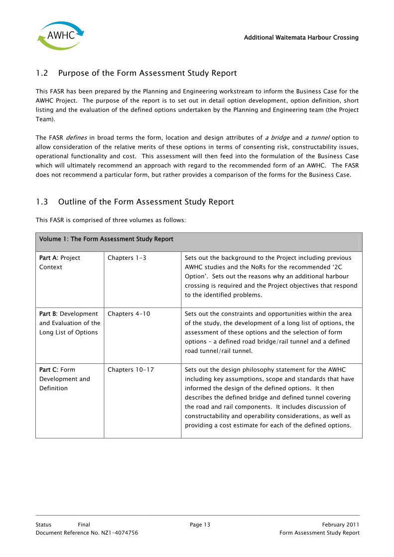
1.2 Purpose of the Form Assessment Study Report ........................................................................... 13
1.3 Outline of the Form Assessment Study Report ............................................................................ 13
2. Defining the Problem ........................................................................................................................... 15
2.1 Population and Economic Growth ............................................................................................... 15
2.2 Cross Harbour Capacity ............................................................................................................. 16
2.3 Northern Busway ....................................................................................................................... 17
2.4 Rail ............................................................................................................................................ 19
2.5 Freight ...................................................................................................................................... 20
2.6 Network Resilience .................................................................................................................... 22
2.7 Walking and Cycling................................................................................................................... 23
2.8 Summary of the Factors Contributing to the Problem within the Corridor .................................... 24
3. Defining the Solution ........................................................................................................................... 25
3.1 Replacing the Existing Harbour Bridge with a New Single Crossing ............................................. 25
3.2 Supplementing the AHB with an Additional Crossing .................................................................. 28
3.3 Preferred Solution ...................................................................................................................... 29
3.4 Project Objectives ...................................................................................................................... 29
3.5 National and Regional Transport Documents .............................................................................. 30
PART B – DEVELOPMENT AND EVALUATION OF THE LONG LIST OF OPTIONS ............................................. 32
4. Introduction to the Development and Evaluation of the Long List of Options ......................................... 34
5. The Study Area .................................................................................................................................... 35
5.1 Sector Descriptions .................................................................................................................... 35
Additional Waitemata Harbour Crossing
Status Final Page ii February 2011
Document Reference No. NZ1-4074756 Form Assessment Study Report
5.2 Study Area Constraints and Opportunities .................................................................................. 37
5.3 Guiding Project Principles .......................................................................................................... 41
6. Methodology for Development and Evaluation ...................................................................................... 44
6.1 Stage 1: Development of Long List Options and Assessment Criteria .......................................... 46
6.2 Stage 2: Evaluation of the Road Component of Options .............................................................. 50
6.3 Stage 3: Evaluation of Combined Road and Rail Options ............................................................. 51
7. Outcomes of Long List Option Development......................................................................................... 52
7.1 Optioneering ............................................................................................................................. 52
7.2 Long List Options ...................................................................................................................... 57
8. Results of Options Evaluation Process .................................................................................................. 63
8.1 Option T1 .................................................................................................................................. 63
8.2 Option T2 .................................................................................................................................. 64
8.3 Option T3 .................................................................................................................................. 64
8.4 Option T4 .................................................................................................................................. 65
8.5 Option B1 .................................................................................................................................. 65
8.6 Option B2 .................................................................................................................................. 66
8.7 Option B3 .................................................................................................................................. 66
8.8 Option B4 .................................................................................................................................. 67
8.9 Summary ................................................................................................................................... 67
9. Analysis of Options Evaluation Results ................................................................................................. 71
9.1 Option Alignment ...................................................................................................................... 71
9.2 Option Form .............................................................................................................................. 73
10. Defined Options .................................................................................................................................. 78
10.1 Defined Tunnel .......................................................................................................................... 79
10.2 Defined Bridge ........................................................................................................................... 80
PART C - FORM DEVELOPMENT AND DEFINITION ............................................................................................ 81
11. Introduction to Form Development and Definition ................................................................................ 83
12. Design Philosophy and Status .............................................................................................................. 84

Additional Waitemata Harbour Crossing
Status Final Page iii February 2011
Document Reference No. NZ1-4074756 Form Assessment Study Report
13. Defined Tunnel Option ........................................................................................................................ 85
13.1 Motorway .................................................................................................................................. 85
13.2 Geotechnical .............................................................................................................................. 97
13.3 Tunnel Design ........................................................................................................................... 98
13.4 Fire Life Safety ......................................................................................................................... 103
13.5 Reclamation ............................................................................................................................. 105
13.6 Coastal Engineering Design...................................................................................................... 106
13.7 Constructability ....................................................................................................................... 108
13.8 Outline Programme .................................................................................................................. 119
13.9 Operability............................................................................................................................... 120
14. Defined Bridge Option ....................................................................................................................... 125
14.1 Motorway ................................................................................................................................ 125
14.2 Bridge Architectural Design ...................................................................................................... 133
14.3 Geotechnical ............................................................................................................................ 143
14.4 Tunnels ................................................................................................................................... 144
14.5 Fire Life Safety ......................................................................................................................... 145
14.6 Reclamation ............................................................................................................................. 146
14.7 Coastal Engineering ................................................................................................................. 146
14.8 Constructability ....................................................................................................................... 147
14.9 Outline Programme .................................................................................................................. 154
14.10 Operability............................................................................................................................... 155
15. Rail ................................................................................................................................................... 158
15.1 Rail Geometrics........................................................................................................................ 158
15.2 Geotechnical ............................................................................................................................ 159
15.3 Tunnel ..................................................................................................................................... 159
15.4 Fire Life Safety ......................................................................................................................... 161
15.5 Reclamation ............................................................................................................................. 162
15.6 Coastal Engineering ................................................................................................................. 163
15.7 Constructability ....................................................................................................................... 163

Additional Waitemata Harbour Crossing
Status Final Page iv February 2011
Document Reference No. NZ1-4074756 Form Assessment Study Report
15.8 Outline Programme .................................................................................................................. 164
15.9 Operability............................................................................................................................... 164
16. Form Description ............................................................................................................................... 166
17. Cost Estimates ................................................................................................................................... 170
17.1 Business Case .......................................................................................................................... 172
17.2 Key Aspects of the Estimates.................................................................................................... 172
PART D – FORM ASSESSMENT ....................................................................................................................... 175
18. Introduction to Form Assessment ...................................................................................................... 177
18.1 Framework for Assessment ...................................................................................................... 177
19. Coastal Processes and Ecology ........................................................................................................... 185
19.1 Context for Assessment of Effects ............................................................................................ 185
19.2 Assessment of Northern Sector ................................................................................................ 186
19.3 Assessment of Central Sector ................................................................................................... 190
19.4 Assessment of Southern Sector ................................................................................................ 191
19.5 Mitigation ................................................................................................................................ 192
19.6 Further work required if option recommended ......................................................................... 195
19.7 Summary of Assessment .......................................................................................................... 195
20. Landscape and Visual ........................................................................................................................ 197
20.1 Context for Assessment of Effects ............................................................................................ 197
20.2 Assessment of Northern Sector ................................................................................................ 198
20.3 Assessment of Southern Sector ................................................................................................ 205
20.4 Mitigation ................................................................................................................................ 210
20.5 Further Work Required if Option Recommended ....................................................................... 211
20.6 Summary of Assessment .......................................................................................................... 212
21. Historic Heritage................................................................................................................................ 215
21.1 Context for Assessment of Effects ............................................................................................ 215
21.2 Assessment of Northern Sector ................................................................................................ 215
21.3 Assessment of Central Sector ................................................................................................... 216

Additional Waitemata Harbour Crossing
Status Final Page v February 2011
Document Reference No. NZ1-4074756 Form Assessment Study Report
21.4 Assessment of Southern Sector ................................................................................................ 216
21.5 Mitigation ................................................................................................................................ 219
21.6 Further Work Required ............................................................................................................. 220
21.7 Summary of Assessment .......................................................................................................... 220
22. Air Quality ......................................................................................................................................... 222
22.1 Context for Assessment of Effects ............................................................................................ 222
22.2 Assessment of Northern Sector ................................................................................................ 222
22.3 Assessment of Central Sector ................................................................................................... 223
22.4 Assessment of Southern Sector ................................................................................................ 223
22.5 Mitigation ................................................................................................................................ 223
22.6 Further work required .............................................................................................................. 224
22.7 Summary ................................................................................................................................. 224
23. Noise and Vibration ........................................................................................................................... 225
23.1 Context for Assessment of Effects ............................................................................................ 225
23.2 Assessment of Northern Sector ................................................................................................ 225
23.3 Assessment of Central Sector ................................................................................................... 226
23.4 Assessment of Southern Sector ................................................................................................ 227
23.5 Mitigation ................................................................................................................................ 228
23.6 Further work required .............................................................................................................. 229
23.7 Summary of Assessment .......................................................................................................... 229
24. Groundwater and Settlement .............................................................................................................. 230
24.1 Cut and Cover Tunnel and Trench ............................................................................................ 230
24.2 Bored Tunnel ........................................................................................................................... 231
24.3 Mitigation ................................................................................................................................ 232
24.4 Further Work Required ............................................................................................................. 232
24.5 Summary of Assessment .......................................................................................................... 232
25. Contamination ................................................................................................................................... 233
25.1 Northern Sector Assessment .................................................................................................... 233
25.2 Southern Sector Assessment .................................................................................................... 233
Additional Waitemata Harbour Crossing
Status Final Page vi February 2011
Document Reference No. NZ1-4074756 Form Assessment Study Report
25.3 Summary of Assessment .......................................................................................................... 234
26. Land Use and Community .................................................................................................................. 235
26.1 Assessment of Northern Sector ................................................................................................ 235
26.2 Assessment of Central Sector ................................................................................................... 236
26.3 Assessment of Southern Sector ................................................................................................ 240
26.4 Mitigation ................................................................................................................................ 242
26.5 Further Work Required ............................................................................................................. 243
26.6 Summary of Assessment .......................................................................................................... 243
27. Impacts on the Future Vision for the Waterfront ................................................................................. 245
27.1 Wynyard Quarter ...................................................................................................................... 246
27.2 Fishing and Marine Industries .................................................................................................. 247
27.3 Westhaven Marina and Surrounds ............................................................................................. 248
27.4 Public Access ........................................................................................................................... 249
27.5 Open Space ............................................................................................................................. 251
27.6 Summary of Assessment .......................................................................................................... 252
28. Analysis against National, Regional and Local Policy ........................................................................... 254
28.1 Hauraki Gulf Marine Parks Act 2000 ......................................................................................... 254
28.2 New Zealand Coastal Policy Statement 2000 ............................................................................. 255
28.3 Auckland Regional Policy Statement ......................................................................................... 257
28.4 Assessment of Relevant Provisions from Regional and District Plans ......................................... 258
PART E - COMPARISON OF TUNNEL AND BRIDGE ..................................................................................... 261
29. Introduction ...................................................................................................................................... 263
30. Consentability ................................................................................................................................... 264
30.1 Comparative Analysis against Statutory and Policy Framework .................................................. 275
30.2 Consentability Discussion ........................................................................................................ 280
31. Constructability ................................................................................................................................. 282
31.1 Introduction ............................................................................................................................. 282
31.2 Constructability Discussion ...................................................................................................... 286

Additional Waitemata Harbour Crossing
Status Final Page vii February 2011
Document Reference No. NZ1-4074756 Form Assessment Study Report
32. Operability ........................................................................................................................................ 287
32.1 Introduction ............................................................................................................................ 287
32.2 Operability Conclusion ............................................................................................................. 292
33. Overall Conclusion ............................................................................................................................. 293
REFERENCES ................................................................................................................................................ 295
Volume 2: Design Drawings
Location Plan
Long List Options Design Drawings - Location Plan
Long List Options Design Drawings – General Alignment Plans and Long Sections
Confirmed Form Option Design Drawings
Volume 3: Supporting Assessments
Appendix A: Existing Environment Report
Appendix B: Engineering Design Methodology
Appendix C: Options Short Listing Workshop Results (including assessment criteria)
Appendix D: Technical Papers: Parallel Bridge and Wynyard Quarter Impacts
Appendix E: Preliminary Geotechnical Appraisal Report
Appendix F: Road and Rail Safety Audits
Appendix G: Construction Programmes
Appendix H: Confirmed Form Option Cost Estimates
Appendix I: Assessment of the Auckland Regional Plan: Coastal
Appendix J: Coastal and Ecological Assessment
Appendix K: Landscape and Visual Assessment
Appendix L: Historic Heritage Assessment
Appendix M: Air Quality Assessment
Appendix N: Noise and Vibration Assessment

Additional Waitemata Harbour Crossing
Status Final Page viii February 2011
Document Reference No. NZ1-4074756 Form Assessment Study Report
List of Tables
Table 2.1: Daily Flows across Harbour (in vehicles per day (VPD)) 17
Table 2.2: Total Vehicle and Freight Figures from the AHB WIM Station for the Month of March 2010 20
Table 5.1: Existing Opportunities 39
Table 5.2: Existing Constraints 39
Table 5.3: Guiding Project Principles 42
Table 6.1: Refined Consentability Criteria 47
Table 6.2: Refined Constructability Criteria 48
Table 6.3: Refined Operability Criteria 48
Table 6.4: Economic and Funding Drivers 49
Table 7.1: Attributes of Long List Options 62
Table 8.1: Comparative Summary of Options Evaluation Results – Tunnels 68
Table 8.2: Comparative Summary of Option Evaluation Results – Bridge 69
Table 10.1: Attributes of Defined Options 78
Table 13.1: CMJ 5% Vertical Gradient Tie-in Effects and Mitigation 94
Table 13.2: Rock Armour Requirements 107
Table 13.3: Northern Sector Construction Sequence: Defined Tunnel 108
Table 13.4: Southern Sector Construction Sequence: Defined Tunnel 114
Table 13.5: Tunnel Option Road Safety Audit 124
Table 14.1: CMJ Vertical Gradient Tie-In Effects and Mitigation 131
Table 14.2: Northern Sector Construction Sequence: Defined Bridge 148
Table 14.3: Southern Sector Construction Sequence: Defined Tunnel 151
Table 14.4: Bridge Option Road Safety Audit 157
Table 16.1: Attributes of Developed Options 166
Table 17.1: Estimates – Tunnel Option including Rail 171
Table 17.2: Estimates – Bridge Option including Rail 171
Table 17.3: Sector Comparison 173
Table 18.1: Purpose of the RMA and key Considerations for the Form Assessment 178
Table 18.2: Matters of National Significance and key Considerations for the Form Assessment 179
Table 18.3: Relevant National and Local Policy Documents 181
Table 18.4: Relevant Matters for Assessment of Effects on the Environment 183
Table 19.1: Relevant Matters for the Assessment of Effects on Coastal Processes and Ecology 185
Table 19.2: Comparative Summary of Coastal Processes and Ecological Effects Associated with the Defined
Tunnel and Defined Bridge (excluding mitigation) 196
Table 20.1: Comparative Summary of Visual Effects 213
Table 28.1: Assessment of the options in accordance with the HGMPA 255
Table 28.2: Assessment of the options in accordance with the NZCPS 256
Table 28.3: Assessment of the options in accordance with the ARPS 257
Table 30.1: Consentability Comparison 265
Table 30.2: Assessment of Matters of National Importance 275
Table 30.3: Assessment of Other Matters 277
Table 31.1: Constructability Comparison 283
Table 30.1: Operability Comparison 288

Additional Waitemata Harbour Crossing
Status Final Page ix February 2011
Document Reference No. NZ1-4074756 Form Assessment Study Report
List of Figures
Figure 1.1: Alignment of Option 2C 11
Figure 5.1: Study Area Map 36
Figure 6.1: AWHC Short Listing Process 45
Figure 6.2: Consentability Ranking System 50
Figure 6.3: Constructability and Operability Ranking System 51
Figure 7.1: Long List Options 61
Figure 16.1: Defined Tunnel Option Connections 169
Figure 16.2: Defined Bridge Option Connections 170
Figure 20.1: Existing view from the Onewa Road Interchange looking north towards Takapuna 199
Figure 20.2: Existing view from the Onewa Road Interchange looking south towards the AHB 199
Figure 20.3: View of the AHB taken from the Waitemata Harbour 203
Figure 20.4: The Bridges of Hong Kong Harbour 204
Figure 20.5: View from Z Pier looking South towards the St Marys Bay Cliffline 205
Figure 20.6: Existing view from Mt Eden looking towards the AHB. 206
Figure 20.7: View from Boylan Street Reserve, St Marys Bay looking south towards the CBD 208
Figure 20.8: Existing view from Wynyard Wharf looking northwest 209
Figure 26.1: Westhaven Marina: Defined Bridge Option 237
Figure 26.2: Westhaven Marina: Defined Tunnel Option 238
Figure 27.1: Key Elements of the Waterfront Vision 246

Additional Waitemata Harbour Crossing
Status Final Page x February 2011
Document Reference No. NZ1-4074756 Form Assessment Study Report
Glossary of Abbreviations
Abbreviation Definition
ACC Auckland City Council
ACCDP Isthmus Section Auckland City Council District Plan (Isthmus Section) 1999
AEE Assessment of Environmental Effects
AHB The Auckland Harbour Bridge
AQMA Air Quality Management Area
ARC Auckland Regional Council
ARGS Auckland Regional Growth Strategy
ARLTS Auckland Regional Land Transport Strategy
ARP:C Auckland Regional Plan: Coastal
ARPS Auckland Regional Policy Statement
ASHS Auckland State Highway Strategy
AWHC Additional Waitemata Harbour Crossing
CBD Auckland Central Business District
Ch Chainage
CMA Coastal Marine Area
CMJ Central Motorway Junction
CPA 1 Coastal Protection Area 1
CPA 2 Coastal Protection Area 2
dBA Decibels
ECBF East Coast Bays Formation
EPBM Earth Pressure Balance Machine
FASR Form Assessment Study Report
FBS Freemans Bay Stormwater

Additional Waitemata Harbour Crossing
Status Final Page xi February 2011
Document Reference No. NZ1-4074756 Form Assessment Study Report
Abbreviation Definition
GPS Government Policy Statement on Land Transport Funding
ha Hectares
HGMPA Hauraki Gulf Marine Park Act 2000
HPA Historic Places Act 1993
ITC International Telecommunications Cables
LTMA Land Transport Management Act 2003
MfE Ministry for the Environment
MHWS Mean High Water Springs
MUZ Mixed Use Zone
NoRs Notice of Requirement(s)
NSCCDP North Shore City Council District Plan 2002
NSHS National State highway Strategy
NZCPS New Zealand Coastal Policy Statement
NZHPT New Zealand Historic Places Trust
NZTA NZ Transport Agency
NZTS New Zealand Transport Strategy 2008
OMS Orakei Main Sewer
RL Reduced Level
RMA Resource Management Act 1991
SH State Highway
TBM Tunnel Boring Machine
TGA Tauranga Group Alluvium
VPT Victoria Park Tunnel
VPV Victoria Park Viaduct

Additional Waitemata Harbour Crossing
Status Final Page xii February 2011
Document Reference No. NZ1-4074756 Form Assessment Study Report
Glossary of Terms
Term Definition
Alignment The route or position of an existing or proposed motorway
Ambient Air The air outside buildings and structures. It does not refer to indoor air, air in the
workplace, or to contaminated air as it is discharged from a source.
Ambient Sound
The total sound existing at a specified point and time associated with a given
environment. The ambient sound is usually a composite of sounds from several
sources, near and far.
Amenity
Defined in Section 2 of the RMA as those natural or physical qualities and
characteristics that contribute to people‘s appreciation of its pleasantness,
aesthetic coherence, and cultural and recreational attributes.
Archaeological Site
Defined in Part 2 of the HPA as any place in New Zealand that –
Either-
Was associated with human activity that occurred before 1990; or
Is the site of the wreck of any vessel where that wreck occurred before 1990; and
Is or may be able through investigation by archaeological methods to provide
evidence relating to the history of New Zealand.
Anzac Bridge Concept A concept developed by the ANZAC Centenary Bridge Group for a new two-tier,
multi-modal harbour bridge linking Wynyard Pt to Onewa Rd.
Rob Roy Hotel Also known as the Birdcage Tavern, Hotel or Birdcage Public House. The original
Rob Roy Hotel was built in 1885-1886.
Coastal Marine Area
Defined in Section 2 of the RMA. The foreshore, seabed, and coastal water, and the
airspace above the water –
a) of which the seaward boundary is the outer limits of the territorial sea; and
b) of which the landward boundary is the line of MHWS, except that where that
line crosses a river, the landward boundary at that point shall be whichever is
the lesser of-
i.) 1 kilometre upstream from the mouth of a river; or
ii.) The point upstream that is calculated by multiplying the width of the river
mouth by 5.
Cut and Cover
Tunnelling A method of construction for tunnels where a trench is excavated and roofed over.
dBA
A measurement of sound level which has its frequency characteristics modified by
a filter (A-weighted) so as to more closely approximate the frequency bias of the
human ear.
Designation Defined in Section 2 and Section 166 of the RMA.

Additional Waitemata Harbour Crossing
Status Final Page xiii February 2011
Document Reference No. NZ1-4074756 Form Assessment Study Report
Term Definition
Effect Defined in Section 3 of the RMA.
Extension bridges The two outer lanes on either side of the AHB which were added to the structure in
1969. Also commonly referred to as the extension bridges.
Gasworks Site
The block of MUZ land located at 90 Beaumont Street and comprising medium
density residential apartments and a heritage building. Also known as Auckland
Gas Company Administration Buildings, Beaumont Quarter or the Beaumont
Quarter Apartments.
Groundwater Natural water contained within soil and rock formations below the surface of the
ground.
Heritage Site
A site that contributes to an understanding and appreciation of New Zealand‘s
history and cultures. A heritage site can be derived from archaeological,
architectural, cultural, historic, scientific and technological fields.
Immersed Tube An underwater tunnel composed of segments, constructed elsewhere and floated
to the tunnel site to be sunk into place and then linked together.
Mainline The principal route of transportation. For the purposes of this Project the mainline
is the Additional Waitemata Harbour Crossing.
Motorway
Motorway means a motorway declared as such by the Governor-General in Council
under section 138 of the Public Works Act or under section 71 of the Government
Roading Powers Act 1989.
Network Resilience
Network resilience encompasses:
Redundancy: the degree to which the transport system provides for functionally
similar components which can serve the same purpose to ensure the system does
not fail when one of the component fail (i.e. a number of similar routes are
available with spare capacity).
Diversity: the degree to which the transport system provides for a range of
functionally different components to protect the system against various threats
(i.e. alternative modes of transport are available).
Autonomy (or security): the ability of the transport system to operate
independently so that the failure of one component does not cause the others to
fail.
Strength: the ability of the transport systems to withstand an incident.
Mobility: the level of service provided by the transport system in delivering
travellers to their chosen destination(s).
Safety: the degree to which the transport system protects users from harm or does
not unduly expose them, to hazards.
Recovery: the ability of the transport system to recover quickly to an acceptable
level of service with minimal outside assistance after an incident occurs.

Additional Waitemata Harbour Crossing
Status Final Page xiv February 2011
Document Reference No. NZ1-4074756 Form Assessment Study Report
Term Definition
Orams Marine
A boat building and servicing business located on the western edge of Wynyard
Quarter at 144 Beaumont Street, Auckland Central. Also known as Orams Marine
Village.
Pier Refers to piers associated with the bridge structure through the central sector.
Portal Entrance way to bored and cut and cover tunnel sections.
Reclamation
As defined in the ARP: C, any permanent filling of an area previously inundated by
coastal water either at or above MHWS mark, whether or not it is contiguous with
the land, so that the filled surface is raised above the natural level of MHWS, and
thus creates dry land, removed from the ebb and flow of the tide.
Sectors
North Sector: located on the North Shore, extending from the SH1 / Esmonde Road
Interchange in the north to Stokes Point / Northcote Point in the south.
Central Sector: encompasses the Waitemata Harbour, extending from end of
Northcote Point, on the North Shore to the coastal edge of Auckland City between
Point Erin and Wynyard Quarter.
South Sector: encompasses the areas above MHWS extending from Westhaven
Drive and Wynyard Quarter in the North to the locality of the Cook
Street/Wellington Street ramps on SH1 and the SH16 links in Auckland City.
Settlement The gradual sinking of the ground surface as a result of the compression of
underlying material.
Study Area
The area to which the project relates, extending from the SH1 Esmonde Road
Interchange on the North Shore to the locality of the Cook Street/ Wellington Street
interchanges on SH1, and the SH16 links in Auckland City (i.e. the Central
Motorway Junction (CMJ)).
Study Corridor A corridor through the central sector of the study area within which all long list
options are located.
Swing Mooring
Consists of a buoy which is attached by chains to a heavy sinker which lies on the
sea bed. Boats attached to the buoys will swing around in the water according to
the direction of the tide.
Westhaven Marina
The predominantly Coastal Marina Area bound by the Waitemata Harbour to the
north, Wynyard Quarter to the east, Point Erin to the west, and comprising
Westhaven Drive and Z-Pier at the southernmost extent. Also known as Westhaven.
Wynyard Quarter
The area of reclaimed land and wharfs bound by the Waitemata Harbour to the
north, Halsey Street and the Viaduct Harbour to the east, Fanshawe Street to the
south and Westhaven Marina to the west. Also known as the Western Reclamation
or Tank Farm.
Z-Pier
The area of land west of Wynyard Quarter extending north from Westhaven Drive in
the southeast corner of Westhaven Marina and comprising the charter berths,
public boat ramp, and associated car park.. Also referred to as Pier Z or Area Z.
Additional Waitemata Harbour Crossing
Status Final Page xv February 2011
Document Reference No. NZ1-4074756 Form Assessment Study Report

Additional Waitemata Harbour Crossing
Status Final Page xvi February 2011
Document Reference No. NZ1-4074756 Form Assessment Study Report

Additional Waitemata Harbour Crossing
Status Final Page 1 February 2011
Document Reference No. NZ1-4074756 Form Assessment Study Report
EXECUTIVE SUMMARY
Introduction
An additional Waitemata Harbour crossing (AWHC) operated in conjunction with the Auckland Harbour Bridge
(AHB) has been identified by the NZ Transport Agency (NZTA) as the most appropriate solution to provide
flexibility, resilience, and sustainability for the provision of future access across the Harbour.
A 2008 AWHC Study recommended a preferred route for an AWHC to be operated in conjunction with the AHB.
The recommended option consisted of two bored tunnels with three lanes in each direction for road traffic and
two separate single track bored tunnels for rail passenger transport. The NZTA and KiwiRail subsequently
served a number of Notice of Requirements (NoRs) for designations within both Auckland City and North Shore
City District Plans for the protection of land to allow the construction of the preferred crossing.
The NZTA is developing a Business Case for an AWHC, building on previous studies (including the 2008 study)
and existing information to help confirm or revise the nature and appropriate form of a crossing taking into
account the transport, economic, social and environmental setting. The Business Case will provide a greater
level of robustness to enable decisions that lead up to the construction of an AWHC.
The Form Assessment Study
The Form Assessment Study (which is the subject of this report) has been undertaken to inform the Business
Case as to the most appropriate form of an additional crossing from a planning, engineering, and cost
perspective. It comprises a summary and documentation of the planning and engineering investigations of
tunnel and bridge options (that extend from the Esmonde Road Interchange in the north to the Central
Motorway Junction in the south). These investigations build on earlier studies to confirm:
detailed engineering investigation of tunnel and bridge options, including constructability and both
capital and operational costs based on an option estimate (OE) level design;
operability, including connectivity and functionality; and
consentability, including planning and consenting risk.
The initial phase of the Study involved the development of a long list of possible bridge and tunnel options and
the evaluation of these options. This process resulted in a tunnel option and a bridge option being ‗defined‘
as follows:
Defined Tunnel: Bored tunnels for road and rail generally following the alignment of the recommended
option from the 2008 AWHC Study (and adopted for the NoRs); and
Defined Bridge: Road bridge landing in vicinity of Northcote Point in the north and Z-pier in the south
and rail bored tunnel generally following the alignment of the rail component of the recommended
option from the 2008 AWHC Study.

Additional Waitemata Harbour Crossing
Status Final Page 2 February 2011
Document Reference No. NZ1-4074756 Form Assessment Study Report
The FASR does not exclude a particular tunnel or bridge but defines in broad terms the form, location and
design attributes of a bridge and a tunnel option to allow consideration of the relative merits of these options
in terms of consenting risk, constructability issues, operational functionality and cost. The attributes of the
options reflect the guiding project principles (defined by the project scope and objectives) and provide for
further design and refinement to a level adequate for the purpose of cost estimation and evaluation.
In regards to rail, the Study indicates that a rail crossing can be provided separately and on a different
timeframe, as required, under both options - however the route of such a crossing may need further
consideration in line with the policy direction to connect to areas of intensification.
Cost
The cost of the defined tunnel has always been acknowledged as being greater than that of a bridge.
The analysis and cost estimates confirm the Option Estimate P50 cost differential between the options of
approximately NZ$1,247,000,000.
Constructability
To determine constructability, the defined options were assessed in terms of the ease or difficulty of
construction.
The assessment indicates that both the tunnel and bridge options have complex staging and sequencing in the
northern sections and complex civil works to construct the southern connections. The shorter construction
duration for the bridge option (with a construction programme duration of 5 years, compared with 6 years and
9 months for the tunnel) offers reduced construction impacts and increased project cost benefit.
Other differences between the options relate to greater importation and removal of earthworks material and
increased building settlement risk associated with the tunnel option. These matters equate to only a nominal
difference in construction complexity and cost and are not significant differentiators in determining the form
of any additional crossing.
Overall, both options have similar complexity and cost with respect to constructability and provide similar
opportunities for further design refinement or investigation to improve these constructability matters.
Operability
To determine operability, the defined options were assessed in terms of network resilience and operational
and maintenance costs.
The assessment indicates that compared to the defined bridge, the defined tunnel has greater operational and
maintenance costs (an estimated average difference of $15 million per annum over the life of the
infrastructure).
The defined bridge offers a slightly greater degree of network resilience with fewer impacts on the road
network due to planned or unplanned closures (e.g. fire) as full carriageway closures can likely be avoided

Additional Waitemata Harbour Crossing
Status Final Page 3 February 2011
Document Reference No. NZ1-4074756 Form Assessment Study Report
given the effective carriageway width of four lanes. The bridge has greater recovery resilience in the event of
unplanned closures.
The Road Safety Audit has identified the vertical gradient tie-in to the CMJ as serious and significant concerns
for tunnel and bridge options respectively. The tunnel gradient is considered a particular design challenge
due to the resulting likelihood of crashes. This will require revisiting to address safety within the network.
Further design and refinement may assist to address some of the safety concerns associated with the tunnel
option however, given the confined nature of the study area it is unlikely that any such refinement could be
undertaken without resulting in significant additional effects and cost implications.
Consentability
To determine consentability (or consenting risk), the defined options were assessed based on their respective
environmental effects and an overall judgement made of their ability to meet the purpose and principles of the
Resource Management Act 1991 (RMA)and the wider national and regional statutory and policy framework.
The relevant planning framework under the RMA includes the ARP:C and the national and regional policy
documents (including the HGMPA which has the effect of a NPS). The policy framework provides clear direction
to protect the natural character and values of the harbour. Consequently any works within the harbour will
face challenges in obtaining consents. Acknowledging the importance of State highway network and in
particular the objectives of this project, substantial changes in the planning framework are unlikely to be
undertaken without a substantial shift in direction requiring the support of stakeholders including the
Auckland Council and Iwi.
The assessment indicates both options generate impacts on Shoal Bay (from the degree of reclamation) which
are significant and present consenting risks. Although opportunities exist with both options to mitigate
effects, an additional crossing of any form will require modifications to the planning provisions of the ARP:C to
better enable work in this area.
As well as the above effects in the northern sector, the defined bridge has additional effects on the natural
character and amenity values of the wider harbour and significant effects associated with the bridge
approaches at both ends (with less opportunities to mitigate these effects when compared to a tunnel). The
defined bridge in combination with the AHB will have a significant adverse cumulative effect on the natural
character of the inner harbour environment. This means that the consenting risk associated with a bridge
option is significantly higher than a tunnel. A tunnel in comparison, by its nature being below ground, largely
avoids effects on the harbour.
A bridge option is likely to be inconsistent with key matters inherent in the National and Regional Policy
framework, and there is little or no opportunity for any redesign or improvements to the bridge concept to
provide better for consistency with these matters. Any further design refinement or substantive changes to the
bridge design (or landing points or approach arrangements) is unlikely to provide any significant opportunity
to reduce consenting risk as bridge option definition sought to optimise a design in terms of impacts within
the bounds of the scope and objectives of this study. Improvements to the quality of the design of the overall
bridge structure through the main harbour area will not significantly avoid remedy or mitigate the effects on
the natural character or amenity values or provide for consistency with the statutory and policy framework as it
will not avoid the cumulative effects of an additional structure on the natural character of the inner harbour
environment.

Additional Waitemata Harbour Crossing
Status Final Page 4 February 2011
Document Reference No. NZ1-4074756 Form Assessment Study Report
In concluding, it is recognised that under the current planning framework, the likelihood of not obtaining
consent for an additional bridge is significantly greater than for a tunnel. This represents a significant risk to
an additional bridge achieving consent.

Additional Waitemata Harbour Crossing
Status Final Page 5 February 2011
Document Reference No. NZ1-4074756 Form Assessment Study Report

Additional Waitemata Harbour Crossing
Status Final Page 6 February 2011
Document Reference No. NZ1-4074756 Form Assessment Study Report
PART A – PROJECT CONTEXT

Additional Waitemata Harbour Crossing
Status Final Page 7 February 2011
Document Reference No. NZ1-4074756 Form Assessment Study Report

Additional Waitemata Harbour Crossing
Status Final Page 8 February 2011
Document Reference No. NZ1-4074756 Form Assessment Study Report
1. Introduction
The Additional Waitemata Harbour Crossing (AWHC) Project (the Project) progresses the outcomes of previous
studies undertaken for an AWHC. In 2008 a study recommended a preferred route for a further Waitemata
Harbour crossing to be operated in conjunction with the Auckland Harbour Bridge (AHB). This consisted of two
bored tunnels with three lanes in each direction for road traffic and two separate single track tunnels for rail
passenger transport. National and regional policy documents direct policy and decision makers to plan and
provide for an AWHC (see further discussion in Section 3.5). In December 2009, the NZ Transport Agency
(NZTA) and KiwiRail served a number of Notices of Requirement (NoRs) to seek designations within both
Auckland City and North Shore City District Plans for the protection of land to allow the construction of the
preferred crossing.
Following the outcome of the 2008 Study and serving of the NoRs, and following publication of the New
Zealand National Infrastructure Plan in March 20101, the NZTA sought to take forward the outcomes of
previous studies (refer Section 1.1.1) and develop an agreed and targeted Business Case for an AWHC. This
Business Case was to support the progression of an AWHC through subsequent development, consent, design
and construction phases. The Business Case will:
Examine the national, regional and local economic impacts of an AWHC;
Summarise the full spectrum of benefits including transport and toll modelling analysis; and
Consider mechanisms for funding including the development of a debt funding model.
The Business Case will be based on a planning and engineering study encompassing:
A more detailed engineering investigation of bridge and tunnel options, including both capital and
operational costs;
Connectivity; and
Planning and consentability considerations, constructability and functionality.
The Business Case aims to provide the NZTA with a clear understanding of the costs associated with each form
of crossing and whether this represents the best value for money in the transport, economic, social and
environmental setting. The Business Case will provide a greater level of robustness in the decisions that lead
up to the construction of an AWHC.
1 The National Infrastructure Plan identifies the AWHC as part of the Government‘s infrastructure priorities for investment
beyond 2010 in order to increase in the capacity of the transport network, respond to the pressure on the state highway
network and remove these constraints on economic growth. Source: New Zealand Government, National Infrastructure Plan,
March 2010.

Additional Waitemata Harbour Crossing
Status Final Page 9 February 2011
Document Reference No. NZ1-4074756 Form Assessment Study Report
In order to develop a Business Case for an AWHC, the Project has been split into three separate, concurrent
workstreams being:
Planning and Engineering;
Transport and Toll Modelling; and
Economic Advisory.
A Network Plan providing for connectivity of the network to and from the harbour crossing is also being
developed in parallel with the three project workstreams. The overall Business Case will be delivered by the
Economic Advisory workstream and will recommend the form of the crossing (i.e. whether an AWHC should be
―under the water‖ (tunnel), ―over the water‖ (bridge) or a combination of both).
This Form Assessment Study Report (FASR) is the key deliverable of the Engineering and Planning workstream
and will help inform the Business Case on the difference between a bridge and a tunnel from a planning and
engineering perspective.
1.1 Project Background
The AWHC Project builds on the outcomes of previous studies undertaken, which have examined the need for,
nature and form of an additional transport crossing of Auckland‘s Waitemata Harbour. These studies have
been undertaken in recognition of the contribution that an additional crossing would make in improving the
accessibility and resilience of Auckland‘s transport network, in a manner that will facilitate the predicted future
growth of the Auckland Region.
At the same time, strategies for Auckland‘s transport network have sought ways to increase cross-harbour
capacity including passenger transport links between the North Shore and the Auckland Central Business
District (CBD). These strategies identify the need for an additional harbour crossing and the need to identify
and protect a route. These documents are discussed in Section 3.5.
1.1.1 Past Studies and Historic Options
Information from the following studies has informed the option development and evaluation for this FASR:
1988 Waitemata Harbour Crossing Study: This study considered a range of alternative options for an
additional crossing of the Waitemata Harbour. It recommended that priority be given to increasing the capacity
of the AHB.
1997 Waitemata Harbour Crossing Study: This study built on the 1988 study, identifying a range of road and
public transport options for an additional crossing of the Waitemata Harbour. A crossing design in the vicinity
of the AHB was recommended. A Technical Advisory Committee group (TAC) oversaw the conduct and outcome
of the Project. The TAC group included Auckland Regional Council (ARC), Auckland City Council (ACC), North
Shore City Council, Waitakere City Council and Transit New Zealand (now NZTA).

Additional Waitemata Harbour Crossing
Status Final Page 10 February 2011
Document Reference No. NZ1-4074756 Form Assessment Study Report
2002 Construction Feasibility Study: This study considered in detail eight alternative crossing alignments. A
new bridge 500m west of AHB and an immersed tube tunnel across the harbour to Wynyard Wharf were
identified as options for further investigation.
2007 Screening of Possible Options: This study considered eight options identified by the 1997 and 2002
studies. A tunnel from Esmonde Road to the Western Reclamation was recommended as the preferred option.
2008 Additional Waitemata Harbour Crossing: This study considered options for both rail and road crossings
of the Waitemata Harbour in two phases. A long list of 159 crossing optis was developed in Phase 1 of the
study. Phase 2 of the study involved a detailed investigation of three of the identified options. It
recommended a harbour crossing west of Wynyard Quarter, comprising two bored tunnels of three lanes each
for road traffic, and two single track rail tunnels.
1.1.2 The 2008 Waitemata Harbour Crossing Study Recommended Option
The 2008 Waitemata Harbour Crossing Study considered a wide range of options for developing a new harbour
crossing to be operated in conjunction with the AHB. Assessments were made of economic, social and
environmental effects at a strategic level of detail. From a short list of three broad options, the study
recommended ‗Option 2C‘ as the preferred route for an AWHC (hereafter referred to as the NoRs alignment or
Option 2C). Option 2C consisted of two bored tunnels with three lanes in each direction for road traffic and
two separate single track tunnels for rail passenger transport. The alignment for Option 2C is shown in
Figure 1.1.

Additional Waitemata Harbour Crossing
Status Final Page 11 February 2011
Document Reference No. NZ1-4074756 Form Assessment Study Report
Figure 1.1: Alignment of Option 2C

Additional Waitemata Harbour Crossing
Status Final Page 12 February 2011
Document Reference No. NZ1-4074756 Form Assessment Study Report
Following the 2008 study, in December 2009, the NZTA and KiwiRail served a number of NoRs to seek
designations within both Auckland City and North Shore City District Plans for the protection of land to allow
the construction of both a bored twin tunnel road crossing and a bored twin tunnel rail crossing (as per the
2008 recommended option). The primary purpose of the designations would be to protect the AWHC
alignment from any development in the short-term that might compromise the ultimate construction of a
crossing, while at the same time providing planning certainty for any medium term development in and around
the Auckland CBD, such as the Wynyard Quarter. Documentation was later provided to support the NoRs,
including an Assessment of Environmental Effects (AEE) and a number of Specialist Technical Reports.
Around the same time as the NoRs were served, a National Infrastructure Plan (dated March 2010) was
published by the New Zealand Government. The National Infrastructure Plan identified AWHC as a Project to be
further investigated and considered for inclusion in the relevant Regional and National Land Transport
Programmes beyond 2012. As a result, the NZTA is now developing the Business Case for an AWHC, building
on previous studies and existing information to help confirm or revise the nature and appropriate form of a
crossing.
To produce a Business Case for an AWHC the Project involves:
Identifying and evaluating a short list of crossing options (i.e. tunnels, bridges or combinations) in
terms of consentability, constructability and operability;
Investigating the wider economic and transportation benefits of the crossing forms; and
Understanding the capital and operational costs of the crossing options.
1.1.3 Particular Objective for the Form Assessment Study Report
To guide this FASR, the following objective has been identified for the Project:
―To establish the form of an additional Waitemata Harbour Crossing (as a tunnel or a bridge or a
combination) to allow certainty over the future development of the Wynyard Quarter and
surrounding areas. A bridge or tunnel option must be able to be operated in a way that provides
flexibility within the transport network and system as well as providing a safe and responsive
environment for all users of the public facilities.‖
The overall purpose of the Project is to produce an agreed and targeted Business Case to support the
progression of the AWHC through subsequent development, consent, design and construction phases. The
central question for this Study is whether a crossing in the form of a ‗bridge‘ or ‗tunnel‘ is likely to be the best
use of resources for an AWHC. To respond to this, the Project needs to provide a more rigorous evaluation of
both the wider economic and transportation benefits of alternative crossing forms through more detailed
engineering and modelling including an assessment of capital and operational costs, connectivity,
environmental and social impacts, constructability and functionality.
Additional Waitemata Harbour Crossing
Status Final Page 13 February 2011
Document Reference No. NZ1-4074756 Form Assessment Study Report
1.2 Purpose of the Form Assessment Study Report
This FASR has been prepared by the Planning and Engineering workstream to inform the Business Case for the
AWHC Project. The purpose of the report is to set out in detail option development, option definition, short
listing and the evaluation of the defined options undertaken by the Planning and Engineering team (the Project
Team).
The FASR defines in broad terms the form, location and design attributes of a bridge and a tunnel option to
allow consideration of the relative merits of these options in terms of consenting risk, constructability issues,
operational functionality and cost. This assessment will then feed into the formulation of the Business Case
which will ultimately recommend an approach with regard to the recommended form of an AWHC. The FASR
does not recommend a particular form, but rather provides a comparison of the forms for the Business Case.
1.3 Outline of the Form Assessment Study Report
This FASR is comprised of three volumes as follows:
Volume 1: The Form Assessment Study Report
Part A: Project
Context
Chapters 1-3 Sets out the background to the Project including previous
AWHC studies and the NoRs for the recommended ‗2C
Option‘. Sets out the reasons why an additional harbour
crossing is required and the Project objectives that respond
to the identified problems.
Part B: Development
and Evaluation of the
Long List of Options
Chapters 4-10 Sets out the constraints and opportunities within the area
of the study, the development of a long list of options, the
assessment of these options and the selection of form
options – a defined road bridge/rail tunnel and a defined
road tunnel/rail tunnel.
Part C: Form
Development and
Definition
Chapters 10-17 Sets out the design philosophy statement for the AWHC
including key assumptions, scope and standards that have
informed the design of the defined options. It then
describes the defined bridge and defined tunnel covering
the road and rail components. It includes discussion of
constructability and operability considerations, as well as
providing a cost estimate for each of the defined options.

Additional Waitemata Harbour Crossing
Status Final Page 14 February 2011
Document Reference No. NZ1-4074756 Form Assessment Study Report
Volume 1: The Form Assessment Study Report
Part D: Form
Assessment
Chapters 18-29 Provides an assessment of options against the framework
set down by planning legislation and policy. It
concentrates on the consentability considerations for the
defined bridge and defined tunnel including socio-cultural,
physical, ecological, and natural environment effects, and
the impact of emissions.
Part E: Comparison
of Bridge and
Tunnel.
Chapters 30-34 Summarises the assessments in regards to consentability,
constructability , operability and cost for the defined bridge
and defined tunnel.
Volume 2: Design Drawings. Drawings of the long list options and the defined bridge and defined tunnel
options.
Volume 3: Supporting Information. Supporting documents and specialist assessments that have informed the
FASR.

Additional Waitemata Harbour Crossing
Status Final Page 15 February 2011
Document Reference No. NZ1-4074756 Form Assessment Study Report
2. Defining the Problem
This Chapter defines the issues underpinning the need for an AWHC. It also sets out the features of the study
area (between Esmonde Road and the Central Motorway Junction (CMJ)) that present opportunities for, or will
constrain, the design, construction and operation of an AWHC in this area.
Auckland‘s transport network is becoming increasingly constrained, impacting on the potential for economic
growth and inhibiting inter-regional connectivity between Northland, the Auckland CBD and the regions to the
south (particularly Waikato and Bay of Plenty). The predicted future growth of the Auckland Region will
increase the demand for transport, placing further pressure on the already congested transport network. In
addition, population growth in the adjacent regions also places increasing demand on inter-regional transport
networks, including State highways.2
The transport corridor between the Auckland CBD and the North Shore is a section of the transport network
that will become increasingly constrained in comparison to other sections of the network. The following
Sections set out the factors contributing to congestion within this corridor.
2.1 Population and Economic Growth
In 2006 (the latest census), the Auckland Region3 was home to 1,303,068 people (comprising 32.4 percent of
New Zealand's population4). This was an increase of 144,177 people, or 12.4 percent, since the 2001 Census.
Recent projections indicate a likely future population of 2.3 million people living in the Region by 20515.
In recognition of the need to carefully manage Auckland‘s growth, the Auckland Regional Growth Strategy
(ARGS)6 was adopted in 1999 by all of Auckland‘s Councils. The ARGS sets a vision for how the Region‘s
growth can be managed over the 50 years and has been reviewed and updated in 2007.
The ARGS seeks a shift in land use patterns towards a more compact urban form which focuses growth in more
intensive mixed-use centres along the northern, western and southern passenger transit corridors, as well as
near main arterial roads. Coupled with this is the identification of specific new areas (greenfield development)
for growth. Those located to the north of the AHB include Albany/ Greenhithe, Long Bay and Orewa/ Silverdale.
The strategy seeks to achieve greater mixed use and ensure sufficient business land is available in specific
employment zones for larger industrial and commercial development. The Land Use Report prepared as part
of the Network Plan for the AWHC summarises the current land use strategy for the North Shore and the CBD
2 Between 2001 and 2006 the population of the Waikato Region increased by 7% and the population of the Northland Region
increased by 5.9%. This is against a national average of 7.8% for the same period.
3 Which is the same area as governed by the Auckland Council.
4 Statistics New Zealand, 2006 Census data.
5 Statistics New Zealand Population Projections, medium projection (2006 base)
6 Auckland Regional Growth Strategy, November 1999.

Additional Waitemata Harbour Crossing
Status Final Page 16 February 2011
Document Reference No. NZ1-4074756 Form Assessment Study Report
and analyses the possible future land use scenarios. The ARGS acknowledges the constraint of the AHB and
consequently allocates less growth to areas north of the bridge in comparison to the rest of the Region. These
scenarios have been used to inform the traffic modelling undertaken by the Transport and Toll Modelling
workstream.
A vital component to realising the vision of the ARGS is an efficient transport system, as transport and land use
are closely interrelated. The Auckland Regional Land Transport Strategy (ARLTS), released at the same time as
the ARGS, is a key mechanism in the implementation of the ARGS. The ARLTS identifies that economic growth
and activity in the Auckland Region is affected by the efficient movement of people, goods and services both
within the Region and by trips that cross regional boundaries by the provision of a resilient and reliable
network. Maintaining and increasing the level of regional economic productivity in the near and long-term is
affected by transport factors including travel distances, increasing number of cars on the road, limited access
to reliable and affordable public transport, as well as other viable alternatives.7
2.2 Cross Harbour Capacity
A key area of Auckland‘s transport network that will become increasingly constrained with regional population
growth is the section of SH1 between the CBD and the North Shore. In order to manage the transport demands
of current and predicted future growth there is a need for improvements in the capacity of the transport
network within this corridor.
The AHB currently provides the only direct, cross-harbour vehicle link between the Auckland CBD (and areas to
the south) and the North Shore. It provides eight lanes of general traffic, with the north bound and south
bound capacity managed between the am and pm peak through ‗tidal‘ lane arrangements. The tidal flow
provides for five lanes in the priority direction each peak period (and three in the other direction, contra-peak).
The AHB presently accommodates on average 165,000 vehicle trips per day.
Traffic modelling forecasts have been undertaken for cross-harbour travel8 based on figures from 2008, for
2026 and 2041. This indicates that person trips across the Waitemata Harbour will continue to increase.
Demands across the AHB are predicted to increase by 18% between 2008 and 2026. Modest growth is
predicted between 2026 and 2041, with 2041 flows predicted to be around 22% above the 2008 flows. For
example, modelling indicates that a journey from Onewa Road to Cook Street during the 2008 am peak took
approximately 32.50 minutes. In 2026 the same journey will take 40.50 minutes and in 2041 it will reduce
slightly to 40 minutes.
The growth will occur in both directions, but more so in the contra-peak direction, which will face increasing
restrictions on trip times and reliability.
The daily traffic flows for 2008, and those predicted for 2026 and 2041 are shown in Table 2.1.
7 Page37, Auckland Regional Land Transport Strategy 2010-2040, April 2010.
8 Additional Waitemata Harbour Crossing: Do Minimum Saturn Models, 15 September 2010

Additional Waitemata Harbour Crossing
Status Final Page 17 February 2011
Document Reference No. NZ1-4074756 Form Assessment Study Report
Table 2.1: Daily Flows across Harbour9 (in Vehicles per day (Vpd))
2008 (Vpd) 2026 (Vpd) 2041 (Vpd) Total
increase
(vpd)
AHB Northbound 82,890 99,530 101,210 18,320
Southbound 85,260 98,300 103,990 18,730
Total 168,150 197,830 205,200 37,050
Capacity constraints on the approaches to and from the AHB can be partially addressed by increasing capacity
within other parts of the transport network. The main existing or proposed upgrades affecting this are:
Construction of the Victoria Park Tunnel (VPT), will provide three lanes northbound (within the new
tunnel) which will connect with the St Marys Bay section of SH1 where it will become five lanes
northbound.
Proposed improved access to Wynyard Quarter involving the reconfiguration of Beaumont Street.
Proposed upgrades to Onewa Road including creating a new transit lane as a continuation of the
existing one along Onewa Road and a shared cycle and footpath along the northern side of Onewa
Road.
A number of other local network changes have been planned and programmed, while others are yet to be
programmed, but are highly likely to occur. These local network changes have been identified as part of the
AWHC Network Plan10.
The effect of the VPT changes (due in 2012) will relieve congestion in this approach to the AHB which will then
make the AHB an area of capacity constraint during the contra-peak. The changes from VPT have been
included within the modelling undertaken as part of the AWHC Network Plan.
2.3 Northern Busway
The Northern Busway currently provides a dedicated, high capacity, passenger transport facility on the North
Shore (between Albany and Onewa Road) and uses general traffic lanes over the AHB and bus lanes/shoulders
into the Auckland CBD (with VPT).
9 Additional Waitemata Harbour Crossing: Do Minimum Saturn Models, 15 September
10 Draft Additional Waitemata Harbour Crossing Network Plan: Local Roads, September 2010.

Additional Waitemata Harbour Crossing
Status Final Page 18 February 2011
Document Reference No. NZ1-4074756 Form Assessment Study Report
The Northern Busway includes five stations on the North Shore plus the physical Busway. The Busway is located
east of the Northern Motorway on a separate and dedicated carriageway from Constellation Station (just south
of Constellation Drive) to just north of the AHB operates in both directions with the exception of the section
south of Akoranga Station which operates in the southbound direction only. The NZTA is currently
investigating an extension of the Northern Busway from its current terminus at Constellation Station to
Silverdale.
Recent analysis undertaken for the NZTA indicates that the Northern Busway has experienced strong growth in
demand over the last five years with a corresponding significant increase in bus services during the peak
hours11. In 2009 a total of 185 buses operated daily along Fanshawe Street citybound in the 7:00 to 9:00 am
period – this corresponds to a peak hour flow of about 105 buses per hour. The Northern Busway is currently
carrying about 5,000 passengers per hour in the peak periods.12
An analysis of future demand for the Northern Busway indicates that the AM peak hour bus flows into the CBD
could increase to 250 buses per hour in 2041. This figure has been recommended as the target capacity for
the Northern Busway system. Based on this target capacity, the Northern Busway corridor could carry over
12,000 passengers per hour13. One of the advantages of a new crossing would be the ability to have dedicated
bus lanes across the AHB which would maintain a high level of trip reliability for passenger transport users.
Realising the full potential of the Busway system is hindered by capacity constraints close to the CBD where the
provision of dedicated facilities is more costly and bus volumes are at their highest. The appropriate response
in these circumstances is to identify and implement measures to overcome localised constraints to ensure that
the full potential of the overall system is achieved. The NZTA has investigated possible measures and these
are discussed in detail in the Northern Busway Corridor Capacity Study 2010 Update14. The report identifies
that of all the measures identified, the development of additional bus infrastructure between the Northern
Motorway and the CBD is the most important to enable an extended life of the Northern Busway. The report
recommends that planning for increased capacity be targeted for a 2020 commencement.
Within the CBD, bus corridors have limited capacity to increase bus volumes particularly on narrow streets. For
example, Fanshawe Street will have capacity to carry about 180 busses per hour in the peak flow direction15.
As the CBD grows, there will be an associated sustained growth in pedestrian activity with a resulting need to
improve pedestrian priority in the CBD. Bus movements will impact on the ability to provide these facilities as
bus numbers increase. It is likely that there will be a strong emphasis placed on improving pedestrian amenity
in the CBD. The potential future conflict between passenger transport and urban amenity could be alleviated
by shifting to passenger transport systems that support higher densities and higher transit mode share (such
as rail).
11 Source: Northern Busway Corridor Capacity Study, August 2010.
12 Page 2, Draft Northern Busway Corridor Capacity Study 2010 Update, August 2010.
13 Page 2, Draft Northern Busway Corridor Capacity Study 2010 Update, August 2010.
14 Draft Northern Busway Corridor Capacity Study 2010 Update, August 2010.
15 Draft Northern Busway Corridor Capacity Study 2010 Update, August 2010.

Additional Waitemata Harbour Crossing
Status Final Page 19 February 2011
Document Reference No. NZ1-4074756 Form Assessment Study Report
2.4 Rail
There is currently no provision for rail between the CBD and the North Shore and no passenger rail service on
the North Shore.
During the period of the current ARLTS (2010-2040), the Northern Busway is best positioned to provide rapid
transit connections from the North Shore to the CBD, service growth areas around Albany and support growth
in the sub-regional centres of Albany and Takapuna. After this time, rail may be more suitable to support
regional employment growth in centres outside the CBD. A North Shore passenger rail line could be part of
such an expansion to provide stronger connections between the key centres of Albany and Takapuna and the
rest of the Auckland Region. Rail corridors can typically achieve higher transit usage than bus corridors (due
to the frequency and reliability of service) but only within a 1 to 2 km distance of stations. Rail systems
perform best in corridors of moderate to high density and in connecting strong, mixed use centres.
The provision of rail to the North Shore therefore needs to be discussed within the context of wider regional
rail network development and land use intensification. A decision about the provision of rail to/from the North
Shore should be made on the basis of aspects other that just corridor capacity including:
The potential for rail to connect with the rest of the Auckland rail network and provide significant
improvements in cross regional travel opportunities; and
Rail‘s role in shaping land use patterns within the Region.
Given the above, the AWHC Network Plan16 suggests that there are three main stages to the development of
the Auckland regional rail network.
Stage 1 - The current network upgrade programme delivering major improvements in service
frequency and reliability across the Western, Eastern and Southern lines.
Stage 2 - Completion of the CBD Rail Link which will deliver services to the heart of the CBD, unlock
capacity constraints at Britomart, and support strong planned employment growth in the CBD.
Completion of the CBD Rail Link will provide the impetus for improving urban amenity through a
moderation in the growth of buses in the CBD that would otherwise have occurred.
Stage 3 - Rail network development beyond the timeframe of the current ARLTS involving expansion of
the rail network to support regional employment growth in centres outside the CBD. A North Shore rail
line could be part of such an expansion to provide stronger connections between the key centres of
Albany and Takapuna and the rest of the Auckland Region.
Two main options exist for the North Shore rail alignment - using the existing Busway corridor or developing a
new alignment. These options have been investigated as part of the AWHC Network Plan17. This work
suggests that there appears to be limited opportunity to develop a heavy rail alignment within the existing
16 Draft Northern Busway Corridor Capacity Study 2010 Update, August 2010.
17 Draft Northern Busway Corridor Capacity Study 2010 Update, August 2010.

Additional Waitemata Harbour Crossing
Status Final Page 20 February 2011
Document Reference No. NZ1-4074756 Form Assessment Study Report
motorway / Busway corridor due to constrained widths, incompatible vertical alignment and lack of available
catchment areas along the Busway corridor. Therefore the current concept for North Shore rail is an
underground alignment through the North Shore linking key centres and aligning land use opportunities.
For this study an AWHC rail connection has been considered within the context of the above discussion.
2.5 Freight
Around 25 percent of all freight traffic in New Zealand occurs within the Auckland Region and therefore freight
efficiency in Auckland has national implications18. The freight industry accounts for 6 percent of the regional
GDP and 5 percent of employment. Almost all freight within the Region is transported by road (around
250 million tonnes in 2002)19. Road freight also dominates movements between Auckland and other regions,
accounting for about 60 percent of total traffic (around 10 million tonnes in 2002). An efficient freight system
is therefore vital for the economic health of both the Region and the nation.
The Port of Auckland is New Zealand‘s busiest port, handling around 43 percent of the country‘s container
trade20. Currently any overweight vehicles utilising the Port of Auckland to travel north inter regionally
(between regions) are required to cross the Waitemata Harbour either utilising the AHB or the Upper Harbour
Bridge. The AHB corridor (bounded by Onewa Road ramps to the north and Fanshawe Street on/off-ramps to
the south) is therefore a key cross harbour route for inter and intra (within the Region) regional freight. The
corridor is required to serve normal freight use as well as acting as an overweight and over dimension route.
Table 2.2 provides the freight use figures for the AHB sourced from the Weigh-In-Motion site at the northern
end of the AHB.21.
Table 2.2: Total Vehicle and Freight figures from the AHB WIM station for the month of March 2010
Direction Total for the month Heavies for the month % Heavy for the month
Northbound 2,539,077 109,259 4.3
Southbound 2,595,014 107,305 4.1
In 2006, the ARC prepared the Auckland Regional Freight Strategy to respond to the changing demands for
freight as the Region grows. This strategy provides a detailed discussion of the current situation and trends
for freight in the Region and key actions and priorities to address current issues and, over the longer term,
deal with the evolving pattern of development across the Region.
18 Auckland Regional Freight Strategy, Auckland Regional Council, 2006.
19 Auckland Regional Freight Strategy, Auckland Regional Council, 2006.
20 Draft Auckland Harbour Bridge Freight Management Strategy, NZTA, September 2010.
21 Draft Auckland Harbour Bridge Freight Management Strategy, NZTA, September 2010. WIM figures for March 2010.

Additional Waitemata Harbour Crossing
Status Final Page 21 February 2011
Document Reference No. NZ1-4074756 Form Assessment Study Report
The Strategy identifies congestion as the key issue for the regional freight transport industry along with the
significant costs on the industry. The direct financial impact of road congestion on the profitability of regional
manufacturing and distribution sectors has been estimated at around NZ$100 million per annum due to delays
and inefficiencies in the delivery of good and services, resulting in a $185 million impact on the wider local
economy22.
The SH1 corridor between the CBD and the North Shore is a key part of the freight network and currently
serves as the main connecting route between Northland and Waikato. In 2002, intra-regional freight accounted
for 500,000 vehicles trips per day for the Auckland Region23. 30% of these vehicles were heavy vehicles with
the remainder being light vehicles (e.g light trucks vans and utilities). The role of the AHB for inter-regional
freight may change when the Waterview Connection becomes operational and there is an alternative route
north via the Western Ring Route. This will not diminish the role of the AHB corridor (particularly for intra-
regional freight) but place more emphasis on the need to be able to deliver network reliability.
The volume of inter-regional freight is not a high percentage of the total freight volumes. In 2002, inter-
regional freight accounted for 6,500 vehicle trips per day for the Auckland Region24.
Historic records of heavy vehicle counts for the AHB indicate a 4 percent average compound growth, with
short-term fluctuations related to economic conditions and construction activity. Thus heavy traffic numbers
have grown more rapidly than light vehicles. The growth in freight transport bears a close relationship to
regional economic and population growth and therefore, as the Region continues to grow, heavy vehicle
numbers will also continue to increase. Furthermore, heavy vehicles are increasing in size and load capacity.
In recognition of the important role that the AHB plays in cross-harbour freight movement, the NZTA has
prepared a Freight Management Strategy for the AHB25. The strategy sets out future management strategies for
freight on the AHB and will assist, in the short-term, to manage, in part, the pressures facing the AHB. One of
these pressures is the impact of heavy vehicles on the fatigue life and load capacity of the bridge decks.
Fatigue life is directly related to the total numbers of heavy vehicles and their weights. In contrast, the impact
of future live load capacity is related to lane usage and the percentage of heavy vehicles in the lanes for
specific time periods, and is not directly related to total numbers of heavy vehicles26. These issues mean that
the AHB is currently managed within a constrained environment including:
Restrictions on use of the extension bridges (also referred to as the extension bridges) by overloaded
and high productivity vehicles if the AHB is identified as part of the High Productivity Vehicle network;
and
Restrictions on times of travel for over dimension vehicles.
22 Page 2, Auckland Regional Freight Strategy: Summary, Auckland Regional Council, 2006.
23 Auckland Regional Freight Strategy 2006, Page 21.
24 Auckland Regional Freight Strategy 2006, Page 21.
25 Auckland Harbour Bridge Freight Management Strategy, April 2010.
26 Page 13, Auckland Harbour Bridge Freight Management Strategy, April 2010.

Additional Waitemata Harbour Crossing
Status Final Page 22 February 2011
Document Reference No. NZ1-4074756 Form Assessment Study Report
In addition, heavy vehicles also elect not to use the single narrow lane on the truss bridge (created by ‗tidal‘
lane arrangements) which redistributes heavy vehicles to other lanes on the AHB.
As freight vehicle numbers increase, compounded by increases in light vehicle numbers, these constraints will
continue to affect freight on the AHB into the foreseeable future.
2.6 Network Resilience
The Waitemata Harbour as part of the wider Hauraki Gulf is of national significance and a beautiful asset to the
Region. However, it also represents a significant barrier to urban mobility as it reduces options for north-
south regional traffic, as well as access between the CBD and the North. As noted, the AHB provides the only
―cross-harbour‖ road link between the Auckland CBD and the North Shore. The Region is therefore heavily
reliant on the AHB for the transport of goods and people and this reliance will only increase as vehicle numbers
increase. The current alternative route is longer and travels around the western edge of the harbour via SH16.
Therefore, the SH1 corridor plays a critical role in linking the areas to the south of the AHB with those to the
north. Within the AHB corridor, the CBD commuter traffic and through traffic connections are not separated,
therefore concentrating all traffic into the same corridor. For this reason, the resilience of the network is a
significant issue.
A resilient network is one that is:
Able to deliver more reliable journey times through improved connectivity, traffic separation and
increased capacity (Capacity);
Able to provide components which can change function to ensure the system does not fail if a
component(s) fail (Redundancy);
Able to deliver business as usual demand in a more diverse way (Diversity);
Subject to a lower risk of ―catastrophic failure‖ (Safety);
Able to limit the impacts of any network problems or failures (Safety); and
Able to recover from any problems more quickly (Recovery).
The above resilience terms are defined in the Glossary.
The NZTA‘s long-term aspirations for the AHB focus on managing the main structure and extension bridges so
that they will continue to provide the connectivity needed to cater for all vehicles crossing the harbour. In
200627 the NZTA completed a structural assessment of the AHB extension lanes. Since then, the NZTA has
completed structural strengthening of the extension bridges. Further structural strengthening of the trusses
and traffic loading restrictions on the extension bridges would enable the bridge to be maintained as part of
27 Source: Auckland Harbour Bridge Extension Bridge Strengthening Design Report, April 2009.

Additional Waitemata Harbour Crossing
Status Final Page 23 February 2011
Document Reference No. NZ1-4074756 Form Assessment Study Report
the State highway network. A programme of monitoring, maintenance, upgrades and load management for the
AHB means the bridge is able to carry reduced loads indefinitely. While the NZTA's careful and ongoing
strategic management of the AHB will ensure its prolonged life as a critical link, it is clear there will have to be
some loading restrictions in the future which will impact on its efficiency and its ability to provide for demand.
Any reduction in the capacity of the network due to; major structural repairs or upgrading; incidents on the
bridge; or damage to the structure from natural hazards; could cause significant disruption to cross-harbour
accessibility. In those situations, the bridge may operate at reduced capacity for a period and/or an alternative
route would need to be used.
The AHB is also a critical service corridor, with a high pressure gas pipeline, telecommunication and high
voltage electricity transmission cables (among other services) all located within the bridge structure. These are
significant lifeline utilities for the Region. Any incident on the bridge or failure would therefore not only affect
the transport route but may also impact on these utilities.
2.7 Walking and Cycling
Cyclist and pedestrian access across the Waitemata Harbour (between the Auckland CBD and the North Shore)
is currently provided through ferry services. There is no facility for either pedestrians or cyclists to travel
across the AHB. The alternative for cyclists is a route west via SH16 and SH18.
National and regional strategies support the encouragement and promotion of walking and cycling as a
transport choice because of the environmental, health and economic benefits to New Zealand as a whole. The
New Zealand Transport Strategy 2008 (NZTS), Government Policy Statement on Land Transport Funding (GPS),
ARGS and the ARLTS all seek to facilitate increased walking and cycling.
At the national level, the NZTS targets an increase in walking and cycling and other active modes to 30% of
total trips in urban areas by 204028. It also seeks an increase in the number of walking and cycling trips by 1%
per year through to 2015. Within the Auckland Region, the ARLTS has a target of increasing walking and
cycling mode share to 15.3% by 2040. There is also a target to improving residents‘ perceptions of walking
and cycling accessibility. A comprehensive summary of the national and regional strategies that are relevant to
walking and cycling is provided in the Additional Waitemata Harbour Crossing Network Plan: Walking and
Cycling (September 2010).
The NZTA has undertaken an investigation of the main cycle routes which will be in demand if a cycling facility
is implemented across the harbour29. The results for the northern side of the bridge indicate that (aside from
the bridge itself) the main demand will be along SH1 and Esmonde Road to Takapuna and other suburbs on the
eastern side of the motorway. Significant demand is also evident for access to suburbs on the western side of
the motorway such as Northcote Point, Birkenhead and Glenfield. The results for the southern side of the
bridge indicate that significant demand is evident from the AHB to destinations around Beaumont Street and
Halsey Street, various locations within the CBD, Anzac Avenue and the University area and Ponsonby Road.
28 Source: New Zealand Transport Strategy, Ministry of Transport, 2008.
29 Additional Waitemata Harbour Crossing Network Plan: Walking and Cycling, September 2010.

Additional Waitemata Harbour Crossing
Status Final Page 24 February 2011
Document Reference No. NZ1-4074756 Form Assessment Study Report
Some of the trips will access these areas while others will continue onto Wellington Street to access the
southern side of the CBD or Newmarket. There is also evidence of demand from the AHB to areas such as
Point Chevalier and the Northwestern Cycleway.
2.8 Summary of the Factors Contributing to the Problem within the Corridor
Based on the matters set out above, the key factors contributing to the current and future problems within this
part of Auckland‘s transport network are:
Population growth and land use intensification in the Region resulting in increases in total daily flows
across the Harbour for light and heavy vehicle movements;
The subsequent increase in demand for the use of the corridor which adversely impacts on the length
and reliability of travel times.
An increase in demand for the Northern Busway and a desire to create a passenger transport system
that increases mode share (including rail);
Reliance on a single structure (the AHB) as the only ―cross-harbour‖ vehicle link between the CBD and
the North Shore;
Constraints in the long-term management of freight on the AHB; and
An aspiration to provide cyclist and pedestrian access across the Waitemata Harbour.

Additional Waitemata Harbour Crossing
Status Final Page 25 February 2011
Document Reference No. NZ1-4074756 Form Assessment Study Report
3. Defining the Solution
In defining a solution to the problems described above, the NZTA has two possible solutions:
Replace the AHB with a new crossing with increased capacity (ie. a single crossing e.g. the Anzac Bridge
concept or similar); or
Supplement the AHB with an additional crossing.
Both of the above solutions would have the benefit of increasing the capacity of the road network. This would
enable additional vehicles to cross the harbour in the peak hour, thereby reducing the duration of the peak
period. They would also provide increased cross-harbour accessibility for all modes, including freight and
general road traffic, rapid transit, cycling and walking. This would enable predicted future travel demands to
be accommodated within the network. Improving the capacity and reliability of the transport network would
encourage economic development and facilitate growth.
Providing a dedicated harbour crossing for rail would allow a significant improvement in passenger transport
across the harbour, providing benefits to the regional economy and the transport network. It is therefore
necessary to continue investigation of rail and to protect the ability for the future introduction of rail between
the North Shore and the Auckland Isthmus. The timing for a harbour rail crossing is linked to the ability to
connect to the rest of the Auckland rail network. The design of rail is constrained differently to road (having
different geometric and gradient requirements). These constraints limit the ability to provide road and rail on
the same structure. Any decision on the preferred cross-harbour alignment for rail should be undertaken in
conjunction with decisions on the appropriate form for a road crossing so as to allow flexibility in the timing
for provision of a rail crossing. For this reason, an AWHC which allows for the separation of the road and rail
components best provides this flexibility and addresses the different design constraints. This is discussed
further in Section 6 and Section 7.1.2.2.
The sections below set out the potential opportunities and disadvantages of the two possible solutions.
3.1 Replacing the Existing Harbour Bridge with a New Single Crossing
This solution would involve removing the AHB and providing a new single crossing which incorporates the
capacity of the AHB and additional capacity to meet the demand for general traffic, passenger transport,
walking and cycling. The discussion below outlines the potential opportunities and disadvantages this solution
presents.

Additional Waitemata Harbour Crossing
Status Final Page 26 February 2011
Document Reference No. NZ1-4074756 Form Assessment Study Report
The potential opportunities created by this as a solution are:
Possible redevelopment of land associated with the motorway corridor along St Marys Bay/Northcote.
Removal of the AHB potentially creates an opportunity for possible redevelopment of land associated with the
motorway corridor. It could release 14 ha30 of foreshore land along St Marys Bay and Northcote. It is noted
that this is largely reclaimed land and is constrained by a number of heritage and natural features as well as
amenity aspirations (identified by Auckland City). If the AHB was removed, then parts of the former Highway
along St Marys Bay and Northcote Point would likely become surplus. In accordance with the Public Works
Act 1981 (PWA) and the Crown‘s land disposal processes, a legal process exists for determining who can
acquire such land.
In summary, the PWA Crown Land disposal processes provide for the land to be offered to (in order of PWA
priority):
1. other public entities (e.g. councils, government departments, etc) if any of those parties can
demonstrate a requirement for the land;
2. any landowner to whom the Crown owes compensation under the PWA;
3. any former private owner; and
4. the Office of Treaty Settlements for use in Treaty of Waitangi claims settlements, through the Maori
Protection Mechanism and Sites of Significance regimes.
If the former State highway was not disposed of under any of these processes, then the Crown could dispose of
the land on the open market. It is likely that the land would be required by a public entity under this process
(e.g. by Auckland Council given its aspiration for the waterfront). Therefore, while some development
potential of this area may be possible (for the likes of commercial or high density residential development) it is
likely to be limited and probably constrained (e.g. by public space, heritage and amenity requirements).
Potential for a new ―landmark‖
Removing the AHB and replacing it with a new single crossing, creates the opportunity for the new crossing to
become a ―landmark‖ structure much in the way that the existing bridge is part of the existing fabric of
Auckland.
Providing a purpose built pedestrian and cycle facility
30 This includes land at St Mary's Bay and Northcote Point is 14ha which includes St Mary's Bay and a small part of Northcote
Point within the existing motorway designation. This area does not include the motorway between Northcote Point and
Onewa Rd as this area would be needed to land a bridge and achieve required Onewa Road Interchange connectivity.

Additional Waitemata Harbour Crossing
Status Final Page 27 February 2011
Document Reference No. NZ1-4074756 Form Assessment Study Report
A new single crossing has the advantage of providing purpose built facilities for pedestrian and cyclist on the
structure. An additional crossing also has this ability but only if the crossing is in the form of a bridge as
pedestrians and cyclist would not be provided in a tunnel.
The key disadvantages with this as a solution are:
The cost of removing the AHB and providing capacity in a new crossing
In the event that the AHB was altered or removed as part of any AWHC Project, any reduced lane capacity and
capacity for meeting future demand would need to be accommodated within the new single crossing. The cost
of demolishing and removing the AHB and the cost of removal of the motorway and remediation following
construction of the new crossing would need to be factored into the overall Project cost.
As part of this Study, high level indicative costs were prepared for a single crossing to inform the comparison
between the two solutions. This indicates that the cost of the single crossing31 is similar to providing an
additional crossing as a tunnel. For the purpose of comparing costs, the rail components have been removed
(as per discussion in Section 7.1.2.2) because of the significant geometric and constructability constraints
associated with locating rail on the same structure as a road.
Foregoing the remaining life of the fully functional AHB
The AHB is continually monitored, maintained and improved to suit changing demands. As set out in
Section 2.6, the AHB is an asset which, with appropriate management, can operate indefinitely. Given its value,
the NZTA would not remove the AHB until it has reached the end of its useful life. Therefore, removal of the
AHB would require the removal of a fully operational and functioning asset; and consequential loss of value in
the remaining life of the AHB.
Reducing the opportunity to increase network resilience
If the AHB was removed and replaced with a new structure, this would still maintain only a single harbour
crossing from the North Shore to the CBD and the CMJ. Network resilience would therefore not be improved.
Removing an existing Auckland landmark.
With the AHB now being 50 years old, it not only has visual significance, but is also part of what makes
Auckland distinctive. Therefore removal of the bridge would likely generate considerable public interest.
Considering the ‗value‘ of the bridge as part of the functioning State highway system, it would be difficult to
justify its removal on the grounds of network improvement.
31 The high level estimate includes bridge construction cost, contingency, net bridge property cost and cost to remove AHB
and de-construct available land. There are several costs not included, including the remaining life value of the existing
Auckland Harbour Bridge.

Additional Waitemata Harbour Crossing
Status Final Page 28 February 2011
Document Reference No. NZ1-4074756 Form Assessment Study Report
3.2 Supplementing the AHB with an Additional Crossing
This solution would involve constructing an additional crossing (which could be either a tunnel or a bridge) to
be operated in conjunction with the AHB. In addition to delivering increased capacity and reliability within this
corridor, the discussion below outlines the potential opportunities and disadvantages this solution presents.
The potential opportunities created by this as a solution are:
Utilising the AHB in conjunction with an additional crossing to provide an integrated network solution
Constructing an additional crossing will allow the NZTA to separate CBD and through traffic (motorway North-
south), with each provided on a separate crossing. This allows greater flexibility within the network with
separate CBD connections.
An additional crossing provides the opportunity to develop dedicated passenger transport capacity within the
network making use of the AHB. This would provide additional direct bus access to and from the Northern
Motorway either alongside current access arrangements at Fanshawe Street or a new point further south (for
example Cook Street).
Providing the opportunity to increase network resilience
An additional crossing would reduce the reliance on the AHB as the only direct connection between the CBD
and the North Shore and the concentration of a high proportion of cross-harbour capacity on a single route. A
separate crossing provides an alternative route which would reduce the risk of a partial or full closure of the
corridor for planned or unplanned events. Together, the additional crossing and the AHB would improve
transport security for Aucklanders. Therefore resilience and route security in the network can be improved by
the addition of another crossing of the harbour. A replacement single crossing would not achieve this.
The key disadvantages with this as a solution are:
Restrictions providing purpose built pedestrian and cycle facilities
An addition crossing in the form of a bridge has the advantage of providing purpose built facilities for
pedestrian and cyclists on the structure. However, if the chosen form is a tunnel, then pedestrians and cyclist
facilities would need to be provided on the AHB. This means that the facilities would not be purpose built.
Adding another structure to the harbour
An addition crossing in the form of a bridge has the disadvantage of creating an additional structure within the
harbour (with the other being the AHB). This may conflict with the architectural form of the AHB (depending on
design), and result in cumulative impacts on the character of the harbour. An additional crossing as a tunnel
would not have these disadvantages.

Additional Waitemata Harbour Crossing
Status Final Page 29 February 2011
Document Reference No. NZ1-4074756 Form Assessment Study Report
3.3 Preferred Solution
Based on the above, both replacing the AHB with a new single crossing or supplementing the AHB with an
additional crossing will increase the capacity of the road network and provide increased cross-harbour
accessibility for all modes. This will encourage economic development and facilitate growth in line with the
strategic land use objective of the ARGS.
There are opportunities and disadvantages with each solution. For the new single bridge crossing the
advantages (purpose built walking and cycling facilities, the potential for redevelopment of land, and the
opportunity to create a ―landmark‖) come at a cost similar to providing an additional crossing as a tunnel.
Therefore, construction of a new crossing with sufficient future capacity and demolition of the AHB, removal of
the motorway and remediation could be more expensive than retention of the AHB and construction of an
additional crossing.
In contrast, an additional crossing (whether a tunnel or a bridge) has a number of opportunities that cannot be
delivered by replacing the AHB with a new single bridge crossing. These include the ability to provide an
integrated network solution and the opportunity to increase network resilience. It also has the advantage of
not precluding the replacement of the AHB in the future (if such a replacement was required). Therefore, the
NZTA has chosen to supplement the AHB with an additional crossing as its preferred solution. The opportunity
the AWHC presents is flexibility, resilience, and sustainability in terms of long term provision of the crossing.
The additional crossing could be in the form of a tunnel or a bridge.
Notwithstanding that replacing the AHB with a new crossing would deliver increased capacity and reliability
within this corridor, there are several disadvantages with this as a solution which mean that it is not the
solution preferred by the NZTA. In contrast, an additional crossing has a number of opportunities that cannot
be delivered by replacing the AHB with a new crossing. Therefore, the NZTA has chosen to supplement the
AHB with an additional crossing as its preferred solution.
3.4 Project Objectives
As part of the 2008 AWHC Study, the NZTA and KiwiRail developed objectives for an AWHC. In response to the
problem defined in Section 2 and an additional crossing as the preferred solution to this problem, the NZTA
determined that the objectives are still relevant for this Project.
The NZTA‘s objectives for the AWHC Project are:
‗To contribute to an affordable, integrated, safe, responsive, and sustainable land transport system within the
Auckland Region by providing a cross-harbour motorway route between the CMJ and Esmonde Road that will:
Encourage economic development and facilitate growth in line with the strategic land use objectives of the
ARGS;
Improve cross-harbour accessibility and reduce the barrier effect of the Waitemata Harbour;

Additional Waitemata Harbour Crossing
Status Final Page 30 February 2011
Document Reference No. NZ1-4074756 Form Assessment Study Report
Provide an additional transport route to the existing AHB to provide a more resilient network and reduce
risks associated with concentrating a high proportion of cross-harbour capacity on a single route;
In conjunction with other harbour crossings, improve opportunities for cross-harbour accessibility for all
modes, including commercial and general road traffic, passenger and rapid transport, walking and
cycling‘.
KiwiRail‘s particular objectives for the AWHC Project are:
‗To establish and maintain safe and efficient rail passenger transport services within the Auckland Region by
providing a cross-harbour rail route between Gaunt Street and Akoranga Station that will:
Encourage economic development and facilitate growth in line with the strategic land use objectives of the
ARGS;
Provide for improved cross-harbour accessibility and reduce the barrier effect of the Waitemata Harbour;
Provide greater opportunity for the development of a rail network on the North Shore connecting with the
Auckland Isthmus;
Allow for stations which are easily accessible and serve the needs for existing and future communities;
Contribute to providing a more resilient cross-harbour transport network and reduce risks associated with
concentrating a high proportion of cross-harbour capacity on a single route‘.
3.5 National and Regional Transport Documents
NZTA‘s objectives align with national and Regional policy documents. The key documents are discussed
below.
3.5.1 Government Policy Statement on Land Transport Funding 2009/10 – 2018/19
The GPS sets out the government‘s priorities for expenditure from the National Land Transport Fund over the
next 10 years. It is the main guiding document by which the Government can ensure that the land transport
funding system focuses on the priority of generating economic growth and productivity. The GPS will ensure
the use of land transport funding does so by directing investment into high quality infrastructure projects and
transport services that encourage the efficient movement of freight and people.
The GPS identifies that the Government wishes to see the following specific outcomes that contribute to
economic growth and productivity:
Improvements in the provision of infrastructure and services that enhance transport efficiency and
lower the cost of transportation;

Additional Waitemata Harbour Crossing
Status Final Page 31 February 2011
Document Reference No. NZ1-4074756 Form Assessment Study Report
Better access to markets, employment and areas that contribute to economic growth; and
A secure and resilient transport network.
As set out in Section 2, without an AWHC, the Auckland transport network will place increasing constraints on
growth and productivity of the Region and adjoining regions that rely on the transport of goods to and from
Auckland. Therefore, an AWHC would specifically address the outcomes sought by the GPS.
3.5.2 National Infrastructure Plan, March 2010
The National Infrastructure Plan outlines the infrastructure challenges facing New Zealand, outlines the
Government's infrastructure priorities and describes the planned investment to address these. The plan
contributes to the Government‘s commitment to build better infrastructure to ensure that New Zealand can
achieve higher levels of economic growth. It identifies the AWHC as a large transport investment that will be
investigated and (if acceptable) considered for inclusion in the Regional and National Transport programmes
beyond 201232.
3.5.3 Auckland Regional Land Transport Strategy 2010-2040
The ARLTS is a statutory document prepared under the LTMA. The ARLTS sets the direction for the Region‘s
transport system for the next 30 years. The strategy identifies the actions, policies, priorities and funding
needed to achieve a land transport system that enhances the Auckland Region. The ARLTS was released at the
same time as the ARGS and is a key mechanism in the implementation of the ARGS.
The ARLTS notes that concentrating growth and high trip generating activity in centres and corridors, linked by
high frequency public transport corridors and good walking and cycling connections where appropriate, allows
people to access opportunities with less need for travel, and improves the feasibility of public transport.
The RLTS recognises that an important element in planning for the future of Auckland‘s transport network is
the protection of the route for an additional crossing of the Waitemata Harbour. The ARLTS identifies the
AWHC as an activity of high regional significance.33
3.5.4 National State Highway Strategy, June 2007
The National State highway Strategy (NZSHS) takes a 30-year view and provides a link between the NZTS, the
Land Transport Management Act 2003 (LTMA) (and other legislation) and NZTA's (formerly Transit) plans and
policies and the State highway Forecast. It also addresses the need for integration between State highway
planning and local land use and multi-modal transport planning. It recognises that highways must respond to
differing and sometimes conflicting expectations. The NZSHS sets out the strategy for managing the capacity
and levels of service on State highways in areas experiencing substantial population growth (such as
Auckland).
32 Page 33, National Infrastructure Plan, March 2010
33 Page9, Land Use Report, Network Plan, Date.

Additional Waitemata Harbour Crossing
Status Final Page 32 February 2011
Document Reference No. NZ1-4074756 Form Assessment Study Report
PART B – DEVELOPMENT AND EVALUATION OF
THE LONG LIST OF OPTIONS

Additional Waitemata Harbour Crossing
Status Final Page 33 February 2011
Document Reference No. NZ1-4074756 Form Assessment Study Report

Additional Waitemata Harbour Crossing
Status Final Page 34 February 2011
Document Reference No. NZ1-4074756 Form Assessment Study Report
4. Introduction to the Development and Evaluation of the Long List
of Options
This section of the FASR describes the study area (including the constraints and opportunities within this) and
outlines Guiding Project Principles that directed the Form Assessment Study. A description of the methodology
used to shortlist options is provided followed by a discussion and analysis of the results and decisions made
during option development and evaluation. The section should be read alongside the Options Short Listing
Workshop Results (including the long list of assessment criteria) attached as Appendix C.

Additional Waitemata Harbour Crossing
Status Final Page 35 February 2011
Document Reference No. NZ1-4074756 Form Assessment Study Report
5. The Study Area
The study area as defined by the NZTA and KiwiRail‘s AWHC objectives extends from the SH1 / Esmonde Road
Interchange on the North Shore to the locality of the Cook Street/ Wellington Street interchanges on SH1, and
the SH16 links in Auckland City (i.e. the CMJ). The indicative extent of this study area is shown in Figure 5.1.
5.1 Sector Descriptions
For the purpose of this FASR, the study area is divided into a Northern Sector, Central Sector and Southern
Sector as follows:
Northern Sector: Located on the North Shore, extending from the SH1 / Esmonde Road Interchange in the
north to Stokes Point / Northcote Point in the south;
Central Sector: Encompasses the Waitemata Harbour, extending from the end of Northcote Point, on the
North Shore to the coastal edge of Auckland City;
Southern Sector: Encompasses the areas above Mean High Water Springs (MHWS) extending from Westhaven
Drive and Wynyard Quarter in the north to the locality of the CMJ in Auckland City.

Additional Waitemata Harbour Crossing
Status Final Page 36 February 2011
Document Reference No. NZ1- 4074756 Form Assessment Study Report
Figure 5.1: Study Area Map

Additional Waitemata Harbour Crossing
Status Final Page 37 February 2011
Document Reference No. NZ1-4074756 Form Assessment Study Report
5.2 Study Area Constraints and Opportunities
There are a number of existing constraints and opportunities within the area that direct the way in which an
AWHC can achieve the NZTA‘s objectives along with the relevant objectives and policies of national and
regional documents. The existing constraints and opportunities within the study area are set out in detail in
Appendix A and summarised in Tables 5.1 and 5.1. Appendix A should be referred to for a detailed
discussion.
The existing constraints and opportunities that have the greatest influence on the construction and operation
of an AWHC in this area have been identified as:
Westhaven Marina/Westhaven
The marina is one of the largest marinas in the southern hemisphere with a total of 1,814 pile and swing
moorings. It supports significant marina based activity including charter businesses, commercial and retail,
and public facilities (e.g. boat ramp). The marina is synonymous with Auckland‘s identity as the City of Sails.
Westhaven Marina/Westhaven presents a constraint within the area.
Auckland Harbour Bridge
The AHB, which opened in 1959, is the only crossing of the Waitemata Harbour near the CBD. The AHB
currently accommodates eight lanes of traffic. The AHB does not have any formal heritage protection (under
the NZHTP schedules or District Plans) it has engineering heritage significance. The NZTA‘s long-term
aspirations for the AHB focus on managing the main structure and extension bridges so that they will continue
to provide the connectivity needed to cater for all vehicles crossing the harbour.
The AHB represents both a constraint (dictates bridge clearances and has value as a landmark) and an
opportunity (with the ability to use AHB capacity for walking/cycling, general traffic and passenger transport).
Wynyard Quarter
Wynyard Quarter is a 35ha area of land which forms a strategic part of the City‘s vision for the Waterfront. A
Council led plan change will allow significant development in the area, involving office, residential
accommodation, retail and marine uses, and open space. The proposed plan change seeks to implement up to
approximately 700,000m2 gross floor area of development. The western edge of the Wynyard Quarter has been
allocated for the superyacht industry and construction of the first berths is currently underway. Wynyard
Quarter and the superyacht berths represent a constraint.
Navigation Clearances
Navigation clearances for any over water structures are dictated by the existing clearance of the AHB (which at
its highest level is 41m above MHWS) and, for any structures to the east of Wynyard Wharf, the clearance
required for superyachts that use the existing and proposed facilities around Wynyard Quarter. Navigation
clearances represent a constraint and are reflected as a design parameter.

Additional Waitemata Harbour Crossing
Status Final Page 38 February 2011
Document Reference No. NZ1-4074756 Form Assessment Study Report
St Marys Bay and Northcote Residential areas and other residential areas
Within the study area, the residential areas of St Marys Bay and Northcote are the main residential areas. There
are several areas of residential development associated with mixed use development. These include the
Beaumont residential apartments and the future residential apartments within Wynyard Quarter. The
residential areas represent a constraint.
Victoria Park and surrounding areas
There are several areas of open space within the northern and southern sectors. The most significant of these
is Victoria Park which is one of the few large areas of open space in this part of the city. The Park and its
surrounds contain a number of heritage features and buildings including the Victoria Park Markets, the Rob
Roy Hotel, scheduled trees, Campbell Free Kindergarten. Victoria Park and the heritage features in the
surrounding area represent a constraint.
Existing transport network
The existing transport network includes Victoria Park tunnel (currently under construction), the Victoria Park
Viaduct, State highway corridor and its connections, and local roads. These represent both constraints (e.g.
CMJ), opportunities (e.g. Victoria Park Viaduct) and set the design parameters for connectivity.
Landscapes and Viewshafts
Protected volcanic viewshafts are located in each of the three sectors. Along Shoal Bay an area of outstanding
landscape value is identified and an area of regionally significant landscape is associated with Northcote Point.
These represent constraints.
The above opportunities and constraints and other features of the area are summarised in the tables below.

Additional Waitemata Harbour Crossing
Status Final Page 39 February 2011
Document Reference No. NZ1-4074756 Form Assessment Study Report
Table 5.1: Existing Opportunities
Category # Feature Opportunity Project Response
Transport O1 AHB Existing capacity available for
reallocation as part of
Project.
Ability to use AHB capacity
for walking/cycling, general
traffic and passenger
transport.
O2 VPT Existing structure can provide
northbound capacity.
Incorporate into design.
O3 Rail alignment Ability to protect and future
proof the rail network as part
of AWHC Project
Identify rail alignment as
part of Project.
O4 Provide separate
structure for road
traffic.
Opportunity to provide
increased resilience.
Identify an alignment for a
separate harbour crossing.
O5 Connections Enhance connections for
freight and travellers between
the north and south.
Design of connections in
northern and southern
sector to provide full
connectivity.
Land use O6 Land use
intensification and
agglomeration
Ability for land use
intensification around
improved access.
Facilitate economic growth.
Table 5.2: Existing Constraints
Category # Feature Constraint Key effects
Land Use C1 Residential areas of
Northcote, St Marys
Bay, Freeman‘s Bay,
Beaumont Quarter
residential apartments.
Areas of community
assembly.
Residential areas. Beaumont
Quarter façade also
protected.
Proximity of alignment
(noise, air quality, visual),
construction.
C2 Sulphur Beach Reserve,
Stokes Point Reserve,
Victoria Park
Active and passive recreation
and community focal areas.
Alignment location,
mitigation/replacement of
open space.

Additional Waitemata Harbour Crossing
Status Final Page 40 February 2011
Document Reference No. NZ1-4074756 Form Assessment Study Report
Category # Feature Constraint Key effects
C4 Wynyard Quarter Area identified for strategic
redevelopment – open space,
residential/commercial and
marine.
Proximity of alignment
(noise, air quality, visual),
Marine C5 Northcote Mooring
area, Westhaven
mooring area.
Boat mooring area. Alignment, continued use.
C6 Boat ramps - Sulphur
Beach, Z-Pier.
Access for recreational
boating
Loss of public facilities,
mitigation/replacement of
access
C7 AHB navigation
channel
Access to upper Waitemata
Harbour
Ensure bridge clearance
heights and fairway channel
are maintained.
C8 Westhaven Marina Navigation channel,
breakwater, boat berths,
piers, charter facilities,
marine industries and
associated land based
commercial facilities.
Maintain navigation
clearance for boats.
Bridge clearance, alignment,
construction methods,
mitigation.
C9 Super Yacht Berths Area under construction for
super yacht berthage.
Bridge clearance, alignment,
construction methods,
mitigation.
Transport C10 Victoria Park Tunnel ,
Victoria Park Viaduct,
Victoria Park West and
Central Motorway
Junction
Existing transport
infrastructure.
Capacity, alignment,
construction methods.
C11 Shelly Beach Road,
Curran Street,
Fanshawe Street, Cook
Street and Wellington
Street
Existing CBD connections
from the AHB
Constrains PT connections
to the CBD
C12 Westhaven Drive Access to Westhaven. Reinstatement following
construction.
Soils C13 Tauranga Group
Alluvium deposits
Soft marine sediments Alignment location,
construction methods.
C14 Construction fill or
historic reclamation
Unspecified material. Construction methods,
potential contamination.

Additional Waitemata Harbour Crossing
Status Final Page 41 February 2011
Document Reference No. NZ1-4074756 Form Assessment Study Report
Category # Feature Constraint Key effects
Contaminate
d land and
groundwater
C15 Barry‘s Point historic
landfill, Freemans Bay
reclamation area.
Contaminated soil also
resulting in contaminated
groundwater.
Construction cost and
methodology.
Geological
heritage
C16 Volcanic features -
Onepoto Crater and
Tuff Farm Crater
Geological significance –
District and Regional
protection
Alignment.
Heritage C17 Victoria Park, Rob Roy
Hotel Campbell Free
Kindergarten, Victoria
Park Market
Heritage and archaeological
sites (District, New Zealand
Archaeological Association
and NZHPT protection)
Alignment, construction
methods, remediation
Landscape
and visual
C18 Volcanic viewshafts
landscapes of
outstanding and
regional significance –
Shoal Bay and
Northcote Point.
Protection of key views of
volcanic cones (including Mt
Eden, North Head and
Rangitoto)
Location of structures
relative to viewshafts and
landscapes.
Ecology C19 Shoal Bay (marine and
land areas), Sulphur
Beach, Tank Farm
Crater.
Sites of ecological
significance and habitat to
nationally vulnerable species.
Alignment, construction
methods.
Air quality C20 Air quality
management area
(AQMA) – seaward
environments of the
northern sector and
landward extent of the
northern and southern
sectors.
Management of vehicle
emissions.
Identify air quality
management measures and
any mitigation required.
5.3 Guiding Project Principles
For an AWHC to meet the objectives set out in Section 3.3 above, it is important that the development and
evaluation of options is informed by the particular constraints and opportunities within the area of study.
Therefore, Guiding Project Principles have been developed to inform this process. These include the scope and

Additional Waitemata Harbour Crossing
Status Final Page 42 February 2011
Document Reference No. NZ1-4074756 Form Assessment Study Report
design assumptions in Appendix B and are set out in Table 5.3. The discussion of how these Principles have
informed the option development and evaluation process is set out in Chapter 6.
Table 5.3: Guiding Project Principles
Guiding
Principle
Description Constraints and
opportunities the
principle addresses
GP1 Rail is to be included within the options, but it is recognised that rail
is not the primary driver in determining option form because of the
need to provide for flexibility in the timing of the provision for rail.
O3
GP2 Maximising connectivity in the north to provide connections to the
CBD and south.
O1, O5, O6
GP3 Bridge or tunnel options must be able to be constructed and operated
in a way that provides flexibility within the transport network.
O1, O2, O3, O4
GP4 New capacity is to be achieved by utilisation of the AHB for a
combination of bus rapid transit, walking, cycling and general traffic.
O1, O3, C10, C11
GP5 Significant adverse land use effects within the study area must be
minimised, particularly in relation to: Westhaven Marina and
associated marina industry activity (i.e. super yacht industry); and
Wynyard Quarter.
C1, C2, C3, C4, C5, C6,
C7, C8, C9, C10, C11,
C12, C13, C14, C15,
C16, C17, C18, C19,
C20
GP6 Consideration should be given to optimising design and construction
methodologies through the northern sector of the study area by:
minimising the extent and potential impacts of reclamation on
the harbour; and
minimising or avoiding effects on Shoal Bay and the
surrounding ecological area including the NZ Dotterel
shorebird nesting and breeding areas.
C4, C5, C6, C8, C9, C16,
C19
GP7 Minimising, avoiding or mitigating environmental effects on sensitive
receivers (i.e. residential properties) is an important Project driver.
C1, C4, C8
GP8 Maximising potential economic benefits (including agglomeration
benefits associated with potential options) is an important Project
driver.
O6

Additional Waitemata Harbour Crossing
Status Final Page 43 February 2011
Document Reference No. NZ1-4074756 Form Assessment Study Report
Guiding
Principle
Description Constraints and
opportunities the
principle addresses
GP9 The development of options must maximise the ability to give effect
to the objectives of the principles of the LTMA, including:
assisting economic development;
assisting safety and personal security;
improving access and mobility;
protecting and promoting public health; and
ensuring environmental sustainability.
O1-O6

Additional Waitemata Harbour Crossing
Status Final Page 44 February 2011
Document Reference No. NZ1-4074756 Form Assessment Study Report
6. Methodology for Development and Evaluation
As demonstrated by Figure 6.1 the AWHC short listing process was undertaken in three stages:
Stage 1: Development of Long List Options and Assessment Criteria;
Stage 2: Evaluation of the Road Component of Options; and
Stage 3: Evaluation of Combined Road and Rail Options.
During the short listing process tunnel options were evaluated separately to bridge options (i.e. they were not
assessed against each other) to enable at least one tunnel and one bridge to be carried through to the
shortlist. This allowed for a robust Business Case to be developed that could compare different crossing forms.
The Project Team recognised that rail was a relatively static component of a crossing form. In accordance with
guiding principle GP1 it was recognised that rail is not the primary driver in determining option form because
of the need to provide for flexibility in the timing of the provision for rail. On this basis options were initially
evaluated without the rail component.
The methodology followed during each stage of the short listing process is described below. The conclusion of
this process resulted in two options being ‗defined‘ to reflect a tunnel option and a bridge option, each with
various attributes that reflect guiding project principles, but do not preclude further redesign and refinement.
The defined options do not exclude a particular tunnel or bridge, but uses defined attributes to reflect an
optimal bridge and an optimal tunnel with elements that help distinguish between the two forms.
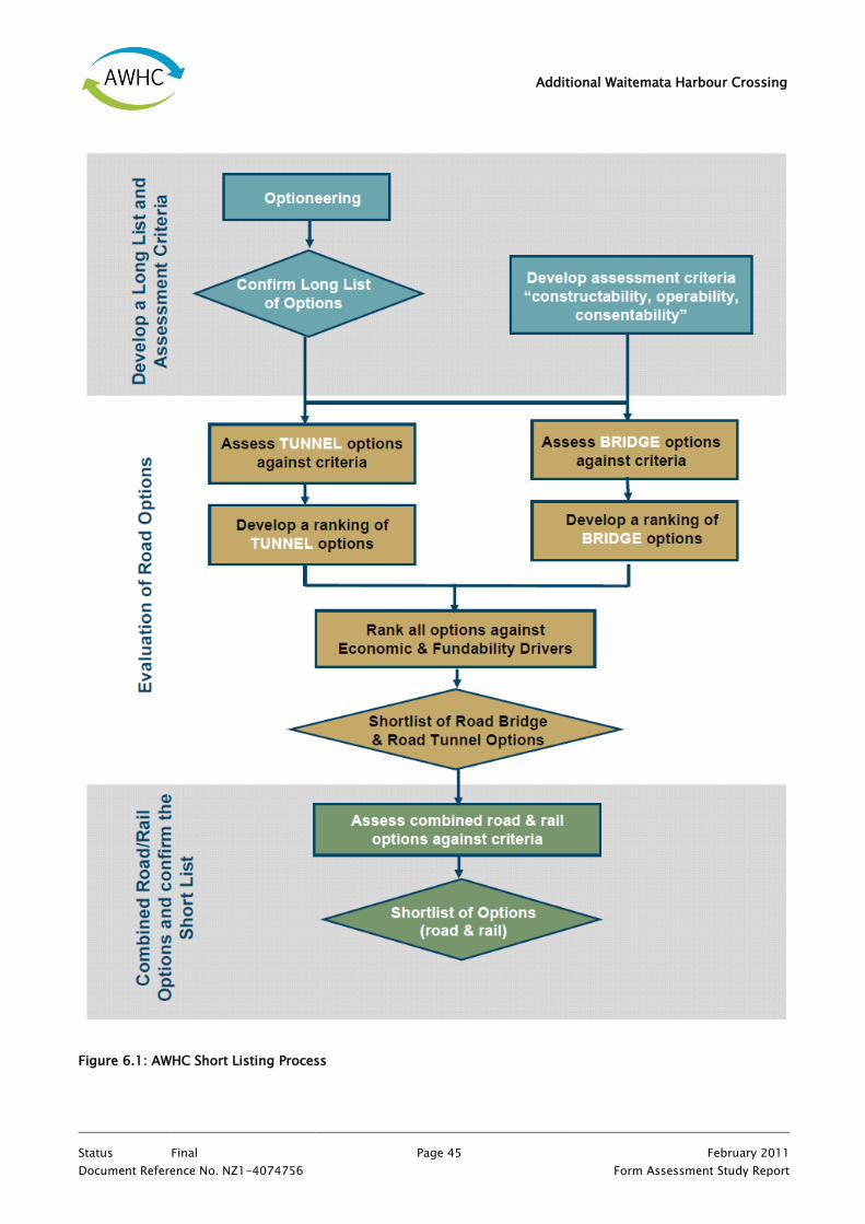
Additional Waitemata Harbour Crossing
Status Final Page 45 February 2011
Document Reference No. NZ1-4074756 Form Assessment Study Report
Figure 6.1: AWHC Short Listing Process

Additional Waitemata Harbour Crossing
Status Final Page 46 February 2011
Document Reference No. NZ1-4074756 Form Assessment Study Report
6.1 Stage 1: Development of Long List Options and Assessment Criteria
Stage 1 of the short listing process involved the development of options and assessment criteria as two parallel
processes. The details of these processes are outlined below.
6.1.1 Development of Long List Options
The option development process involved ‗optioneering‘ to enable the identification of a long list of options.
This process entailed:
A review of previous available studies;
Identification of different forms of tunnel and bridge harbour crossings, potential mainline alignments
(including bridge landing locations) and rail and road combinations that would be consistent with the
guiding Project principles, as well as identification of some key design aspects such as tunnel vent
stacks, mainline and AHB connections and reclamation;
A high level assessment of mainline geometrics using standards adopted for the NoRs concept design;
and
A high level constructability assessment to identify constraints that could preclude construction.
Design and scope assumptions formulated at a prior workshop (see Appendix C for workshop details) were
adopted for the purposes of focusing decision making during this process.
6.1.2 Development of Assessment Criteria
In parallel with development of options, Stage 1 of the short listing process also involved the development of
assessment criteria as part of a multi-criteria evaluation system.
6.1.2.1 Categories of Assessment Criteria
In considering guiding Project principles, constraints, operational and engineering requirements and previous
AWHC studies a long list of assessment criteria were initially developed that encompassed three categories of
criteria: (1) consentability; (2) constructability; and (3) operability (see Appendix C). This long list of criteria
were then refined for the purposes of evaluating long list options. The categories of criteria that developed
during this process are discussed below.
6.1.2.1.1 Consentability
The consentability criteria relate to the consenting risk associated with an option or the actual and potential
effects of an option. They encompass land use, visual/ landscape, social/ community and environmental
matters. The specific consentability criteria adopted for the purpose of the AWHC Short Listing Process
(through the refinement of the long list of assessment criteria attached within Appendix C) are set out in
Table 6.1 below:

Additional Waitemata Harbour Crossing
Status Final Page 47 February 2011
Document Reference No. NZ1-4074756 Form Assessment Study Report
Table 6.1: Refined Consentability Criteria
Consentability Criteria
Degree of long-term impacts on the function and viability of business areas
Degree of long-term impact on social and community infrastructure
Amount of land acquisition required
Degree of disruption to residential and business areas during construction
Degree of long-term impact on access to and along the coast
Degree of seabed disturbance associated with excavation and the marine disposal of sediments
Degree of impact on marine ecology
Degree of reclamation required for construction and operation
Degree of long-term impact from noise and vibration
Degree of impact on archaeological and cultural sites, scheduled buildings and scheduled trees
Degree to which the option results in increased air contaminant loads in proximity to sensitive land uses
Degree of impacts on views
Degree to which the option contributes to sense of place and/or identity/ impacts on amenity values
6.1.2.1.2 Constructability
The constructability criteria relate to the ease or difficulty of construction of an option. They encompass
construction feasibility and complexity, traffic management, and infrastructure services protection and
relocation. The specific constructability criteria adopted for the purpose of the AWHC Short Listing Process
(through the refinement of the long list of assessment criteria attached within Appendix C) are set out in
Table 6.2.

Additional Waitemata Harbour Crossing
Status Final Page 48 February 2011
Document Reference No. NZ1-4074756 Form Assessment Study Report
Table 6.2: Refined Constructability Criteria
Constructability Criteria
Degree to which the option minimises impacts on existing structures
Degree to which the option minimises removal of excavated material from site and disposal
Degree to which the option reduces vulnerability to geotechnical risk
Degree to which the option minimises extensive ground improvement
Degree to which the option minimises complexity of construction (central sector)
Degree to which the option minimises complexity of construction (southern sector)
Relative robustness of construction plant methodologies
Degree to which the option minimises programme cost and risk
Degree to which the option minimises construction cost
6.1.2.1.3 Operability
The operability criteria relate to the operational aspects of the options. They encompass all components of
network resilience, being diversity, redundancy, safety and security. The specific operability criteria adopted
for the purpose of the AWHC Short Listing Process (through the refinement of the long list of assessment
criteria attached within Appendix C) are set out in Table 6.3 below:
Table 6.3: Refined Operability Criteria
Operability Criteria
Which option has a shorter recovery time after incident
Degree to which the option reduces the potential for vehicle accidents between SH1/ Northcote Road
Interchange and CBD/ CMJ and has lower vulnerability to incidents
Degree to which the option provides for hazardous goods vehicles
Which option has a shorter average outage duration for maintenance over operational life
Degree of travel time savings between SH1/ Northcote Road Interchange and CMJ

Additional Waitemata Harbour Crossing
Status Final Page 49 February 2011
Document Reference No. NZ1-4074756 Form Assessment Study Report
Operability Criteria
Degree of travel time savings between SH1/ Northcote Road Interchange and CBD
Degree to which the option improves separation of CBD local traffic and new motorway crossing through traffic
Degree to which the option improves efficiency and reliability of freight/ commercial traffic movements to Port
and business zones
Degree to which the option provides ability to maintain CBD/ motorway connections in event of incident/
maintenance on the AHB and approaches
Degree to which the option provides for utility services
Degree to which the option provides flexibility for changes in passenger transport routes and future proofs the
network considering future changes to transport network
6.1.2.1.4 Economic and Funding
A set of economic and funding drivers were also identified. These are set out in Table 6.4 below:
Table 6.4: Economic and Funding Drivers
Economic and Funding Drivers
Degree to which the option impact on local development
Relative cost difference of Land Purchase and reclamation
Relative cost difference for capital cost (qualitative)
Relative cost difference for operational cost (qualitative)
Difference in risk rating (for financing purposes)
6.1.2.2 Lists of Assessment Criteria
Two separate lists of different criteria were formed using the consentability, constructability and operability
criteria listed above (see the Option Short Listing Workshop Results attached as Appendix C). One list was
developed for the purposes of evaluating (and differentiating) bridge options. The other list was developed for
the purpose of evaluating (and differentiating) tunnel options. Each list incorporated a combination of
consentability, constructability and operability criteria, but only included criteria from each of these categories
that assisted to differentiate the options (i.e. some criteria assisted to differentiate tunnel options, but did not

Additional Waitemata Harbour Crossing
Status Final Page 50 February 2011
Document Reference No. NZ1-4074756 Form Assessment Study Report
assist to differentiate bridge options and vice versa). The Economic and Funding Drivers were retained as a
separate standalone list of criteria for the purposes of testing long listed options comparatively in terms of
cost and wider economics.
6.2 Stage 2: Evaluation of the Road Component of Options
The second stage of the short listing process involved the evaluation or comparative ranking of the road
component of each option using a multi-criteria evaluation system. The road component of the options was
also ranked comparatively against the economic and funding drivers as part of this process.
6.2.1 Ranking System
In assessing the options against the consentability criteria, options were ranked in terms of the degree of
effects using the ranking system shown in Figure 6.2.
Significant Positive Effect: The option offers significant opportunities to improve the environment
or results in a significant positive effect on the environment.
Potential Positive Effect: The option offers an opportunity to improve the environment or results in
a positive effect on the environment.
O No more than minor adverse effect: The option has a no more than minor adverse effect on the
environment without mitigation.
X Adverse environmental effect: The option has adverse effects on the environment, but these
effects may be mitigated.
XX Significant adverse environmental effect: The option has a significant adverse effect on the
environment and there is limited ability to mitigate these effects.
F Fatal Flaw: The option has a significant adverse effect on the environment that cannot be avoided
or mitigated.
Figure 6.2: Consentability Ranking System
Options were ranked either positively or negatively against the constructability and operability criteria using
the ranking system shown in Figure 6.3.

Additional Waitemata Harbour Crossing
Status Final Page 51 February 2011
Document Reference No. NZ1-4074756 Form Assessment Study Report
Strongly supports criteria: The option fully supports the criteria.
Supports criteria: The option supports the criteria however there is an opportunity for measures
to be introduced that would enable the option to better meet the criteria.
O Partially supports criteria: The option neither supports nor does not support the criteria.
X Does not support criteria: The option does not support the criteria but there is an ability to
manage or overcome the issue.
XX Strongly does not support criteria: The option does not support the criteria and there is limited
ability to manage or overcome the issue.
F Fatal Flaw: The option does not support the criteria and there is no ability to manage the risk or
any engineering solution that would enable the option to overcome the issue.
Figure 6.3: Constructability and Operability Ranking
6.3 Stage 3: Evaluation of Combined Road and Rail Options
The final phase of the AWHC short listing process involved an assessment of combined road and rail options
against assessment criteria. To facilitate this evaluation process, all the consentability, constructability and
operability assessment criteria outlined in Section 6.1.2.1 were combined. This provided a robust set of criteria
from which to assess combined road and rail options with both bridge and tunnel components. The same
ranking system outlined above was used to assess the combined road and rail options against each category of
criteria.

Additional Waitemata Harbour Crossing
Status Final Page 52 February 2011
Document Reference No. NZ1-4074756 Form Assessment Study Report
7. Outcomes of Long List Option Development
The decisions and outcomes of the long list options development process undertaken by the Project Team
during Stage 1 of the short listing process are outlined below.
7.1 Optioneering
During the optioneering phase (as described in Section 6.1.1 above), the Project Team identified a long list of
options, each of which had road and rail components. These options were identified in considering possible
route alignments as well as road and rail forms. The critical thinking undertaken during optioneering is
outlined below.
7.1.1 Option Alignment
The Project Team identified possible road and rail route alignments for an AWHC that could be constructed
within the constraints of the study area (study area constraints are set out in Table 5.2). Key considerations
leading to the identification of possible alignments were motorway geometrics and constructability.
7.1.1.1 Road Alignment
The Study Scope Assumptions (see the Engineering Design Methodology attached as Appendix B) required a
route through the study area for the road component of options that connected the Northcote Road
Interchange in the north and the CMJ in the south. A mainline connection at the Onewa Road Interchange was
also included as part of the options because this would maximise connectivity between the north, the CBD and
the south (in accordance with guiding principle GP2).
7.1.1.1.1 Tunnel Options
It was not necessary to consider option alignments through the northern sector as part of the optioneering
process, as this route resulted in a relatively fixed alignment through the northern sector of the study area.
That is, all options maximised mainline and AHB connections in accordance with guiding project principle GP2
and were aligned to a common design north of the Onewa Road Interchange.
In considering route alignments through the central sector of the study area, the Project Team determined that
tunnels should follow the most direct route because this would reduce the length of tunnel infrastructure
required. These routes were identified as routes through the centre of the central sector, either on, or west of
the NoRs alignment.
In considering route alignments for options through the southern sector, the Project Team identified two
possible alignments: one through Victoria Park to the CMJ; and the other to the west of Victoria Park (through
the Gasworks site) to the CMJ. These alignments were identified as they largely avoided the geometric and / or
constructability constraints associated with placing mainline routes under Victoria Park.

Additional Waitemata Harbour Crossing
Status Final Page 53 February 2011
Document Reference No. NZ1-4074756 Form Assessment Study Report
7.1.1.1.2 Bridge Options
For the same reason as outlined for the tunnel options in Section 7.1.1.1.1 above it was not necessary to
consider option alignments through the northern sector as part of the optioneering process.
Key considerations in identifying route alignments through the central sector of the study area included:
Navigation clearance, which governed the height of the bridge;
Where a route would or could land within the northern and southern sectors;
The amount of reclamation (that is impacts on the harbour and access to the coast); and
Impacts on existing and proposed facilities at Westhaven Marina and Wynyard Quarter in terms of
marine and boating activities (including marina and super yacht berths) and land development.
The NoRs alignment from the 2008 study identified bridge options landing in the southwest corner of Wynyard
Quarter (i.e. in accordance with Option 2B from the 2008 study). Option 2B did not provide the AHB/ CBD
connectivity required for this study, such that in considering bridges within this general alignment the Project
Team investigated the merit of refining this landing location. The Project Team determined that a landing point
further to the west in the vicinity of Z-Pier would optimise the degree of clearance from Wynyard Quarter
whilst still remaining clear of the main body of finger berths within Westhaven Marina. In maintaining these
clearances adverse effects on both Westhaven Marina and Wynyard Quarter (including the marine industry
precinct and proposed super yacht facilities) could best be avoided. This approach was consistent with the
guiding principle of minimising land use impacts (GP5). In addition, the Z-Pier landing location allowed VPT to
be used for the mainline northbound. Alignments closer to Wynyard Quarter required a significant part of the
VPT floor and the trench eastern wall to be removed which had constructability issues. The Z-Pier landing
location enabled the use VPT and ensured only minimal changes to the VPT structure would be required.
Consequently, the Z-Pier landing location influenced the alignment of bridge options through the central
sector that were carried through as long list options.
The Project Team also considered bridge route alignments at the extremities of the central sector of the study
area. These included a route alignment parallel to the AHB (at the western edge of the study area) and a route
alignment to the east of the NoRs alignment (landing within Wynyard Quarter). The Project Team decided
alignments at the extreme edges of the study area would be inconsistent with guiding principle GP5, which
sought to minimise land use impacts. Such alignments were not optimal in terms of reducing route length and
would likely generate significant land use effects in relation to impacts on Wynyard Quarter and Westhaven
Marina (including the yacht clubs, car parking, restaurant and other facilities) as well as consequential effects
on the harbor as a result of the reclamation required to replace lost facilities, with no corresponding benefits
identified. Consequentially, bridge options at the extremities of the study area where not carried forward to
the long list.
Notwithstanding this, an analysis of an option with a route alignment at the western edge of the study area
(i.e. parallel to the AHB) was undertaken (upon request by the NZTA) in parallel to the options short listing

Additional Waitemata Harbour Crossing
Status Final Page 54 February 2011
Document Reference No. NZ1-4074756 Form Assessment Study Report
process (see the Parallel Bridge Technical Paper attached as Appendix D). In summary, such an option was
identified as resulting in:
Significant adverse effects on the long-term functionality and viability of the Westhaven Marina where
the options alignment traverses the area of finger berths and marina facilities within the main body of
the marina;
Significant consequential adverse coastal and ecological effects on the harbour itself where the marina
needed to be substantially re-built elsewhere within the harbour; and
The loss of the opportunity to design a bridge option that has the potential to contribute ‗sense of
place‘ and develop ‗landmark‘ status, given the proximity to the AHB.
An analysis of route alignments at the eastern edge of the study area (i.e. through Wynyard Quarter) was also
undertaken (upon request by the NZTA) in parallel to the options short listing process (see the Wynyard
Quarter Impacts Technical Paper attached as Appendix D). In summary alignments along the eastern edge of
the study are identified as having:
Opportunity costs associated with bridge or tunnel footprints;
Potentially significant adverse effects on the ability to realise the vision and master plan for
Auckland‘s waterfront;
Potentially significant adverse effects on the marine industry;
Significant adverse severance effects on Wynyard Quarter and the wider waterfront; and
Significant adverse effects on commercial value of Wynyard Quarter, including reduced prices for
residential and commercial property and reductions in the amount of available recreational space.
In considering route alignments for options through the southern sector, the Project Team identified two
possible alignments: one through Victoria Park to the CMJ; and the other to the west of Victoria Park (through
the Gasworks site) to the CMJ. These alignments were identified as they largely avoided the geometric and / or
constructability constraints associated with placing mainline routes under Victoria Park.
7.1.1.2 Rail Alignment
The Study Scope Assumptions (see the Engineering Design Methodology attached as Appendix B) required a
rail crossing to connect to Akoranga Station (in the north) and a potential station at Gaunt Street (in the south).
The NoRs concept design provided an optimum alignment for rail tunnels as it was a direct route across the
harbour between these two stations. The optimum alignment for rail bridges was identified to follow that of
the road bridge because this would minimise visual impacts and disruption to harbour navigation.

Additional Waitemata Harbour Crossing
Status Final Page 55 February 2011
Document Reference No. NZ1-4074756 Form Assessment Study Report
7.1.2 Option Form
The Project Team identified possible road and rail forms for an AWHC that could be constructed within the
constraints of the study area (study area constraints are set out in Table 5.2).
7.1.2.1.1 Road Form
In accordance with the Study Scope Assumptions set out in the Engineering Design Methodology attached as
Appendix B) tunnel and bridge forms were identified that could accommodate six lanes of road (three in each
direction) through the central sector of the Study area. In addition different road forms for the land based
sections of the route alignment were also considered.
7.1.2.1.2 Tunnel Options
Bored and immersed tube tunnels were identified as two tunnel forms that could be constructed through the
central sector of the study area (i.e. across the harbour). Both tunnel forms were carried through to the long
list of options.
A single bored tunnel was considered as an option, but dismissed by the Project Team because current TBM
technology does not provide for a tunnel size sufficient to accommodate the requirement for six lanes of
traffic.
Three two lane bored tunnels were also considered as they would provide for a contra-flow arrangement in the
peak period. Such an option was identified as being more costly than two bored tunnels with three lanes in
each direction given the additional costs associated with constructing and operating a third tunnel. The option
was discounted because of the additional cost and because the Project Team saw no real benefit in a contra-
flow provision for the mainline.
Double deck bored tunnels were considered as a possible tunnel option. The Project Team discounted the
double deck bored tunnel because current TBM technology does not provide for a tunnel size sufficient to
accommodate the requirement for six lanes of traffic within this tunnel form. In addition, there are also
difficulties connecting double deck tunnels back into the roading network.
On this basis all tunnel options carried forward to the long list comprised either: two separate bored tunnels
(with three lanes each); or a single immersed tube (with three lanes in each direction) through the central
sector.
The Project Team identified bored and cut and cover tunnels as well as trenching and at-grade section of road
as possible options to accommodate the road component of tunnel options within the northern and southern
sectors of the study area. One or a combination of these forms was included as part of the tunnel options that
were carried through to the long list.

Additional Waitemata Harbour Crossing
Status Final Page 56 February 2011
Document Reference No. NZ1-4074756 Form Assessment Study Report
7.1.2.1.3 Bridge Options
Varied bridge forms through the central sector were not considered during the long list option stage of the
process because it was recognised that this needed to be shaped by design constraints (i.e. navigational
clearances) and would be controlled by the design process.
The Project Team identified cut and cover tunnels, trenches and bridge structures, as well as at-grade sections
of road as possible options to accommodate the road component of bridge options within the northern and
southern sectors of the study area. One or a combination of these forms was included as part of the bridge
options that were carried through to the long list.
7.1.2.2 Rail Form
In accordance with the Study Scope Assumptions set out in the Engineering Design Methodology attached as
Appendix B) tunnel and bridge forms were identified that could accommodate two rail tracks (one in each
direction) through the Study area.
The Project Team considered a single deck combined road and rail bridge structure. However, this was
dismissed because in order to provide for a symmetrical road configuration rail needed to be positioned in the
centre of the bridge deck, making it both structurally and geometrically difficult to separate road and rail at
their respective northern and southern sector landings. In addition, a single deck structure would not provide
for the same level of construction flexibility as two separate structures in the instance that the road component
of the option was required ahead of the rail component. A double deck bridge structure, with road on the
upper deck and rail on the lower deck was also considered, but dismissed by the Project Team for similar
geometric and construction timing related reasons.
The Project Team considered incorporating rail in a double deck bored tunnel beneath the deck of the road or
alongside the road in a single immersed tube. The bored tunnel option was discounted as current TBM
technology does not provide for a tunnel size sufficient to accommodate the required number of traffic lanes
and rail tracks. The immersed tube tunnel option was discounted as it was constrained by difficulties in
separating rail from road and would require a substantial casting dock. In addition both options (similar to the
combined road and rail bridge option) offered less flexibility in the timing for construction to options with
separate road and rail structures.
Whilst the Project Team recognised that separate structures for road and rail also posed some geometric
difficulties, they provided greater construction flexibility (in accordance with guiding principle GP3) than a
single combined structure (i.e. rail could easily be constructed later without having to future proof the road
crossing infrastructure for rail at the time of construction). Consequently, all options that were carried forward
to the long list included rail as a separate bridge or tunnel structure.

Additional Waitemata Harbour Crossing
Status Final Page 57 February 2011
Document Reference No. NZ1-4074756 Form Assessment Study Report
7.1.3 Summary
Eight options were identified for the long list, including four tunnel options and four bridge (or combined
options). Each option followed one of the identified route alignments and included various combinations of the
road and rail form described above.
7.2 Long List Options
Each of the eight options that were carried forward to the long list are described below and depicted in Figure
7.1 and the drawings attached as Volume 2 (Drawings 60157303–TR- 003 to 60157303 –TR–013). Thereafter,
the attributes of each option are set out in Table 7.1.
7.2.1 Option T1
Option T1 comprises bored tunnels for road and rail (refer to Volume 2, Drawing No. 60157303–TR- 006).
The road follows the NoRs alignment along the eastern side of the existing motorway from Esmonde Road
Interchange in the northern sector of the study area to Northcote Point. At Northcote Point the road enters two
bored tunnels (three lanes in each tunnel) and crosses under the harbour on the NoRs alignment to Wynyard
Quarter. The bored tunnels traverse the southwest corner of Wynyard Quarter to Victoria Park before
continuing in cut and cover tunnels and trenches to the CMJ,
Rail is separated from road and follows the NoRs horizontal alignment between the Akoranga Busway Station
and Wynyard Quarter. It is at grade from a future Akoranga Station (Esmonde) to Sulphur Beach and then
crosses under the harbour via two bored tunnels (one track in each direction) to a future train station at Gaunt
Street in the Wynyard Quarter.
7.2.2 Option T2
Option T2 comprises an immersed tube tunnel for road and rail (refer to Volume 2, Drawing No. 60157303–
TR- 007).
The road follows the NoRs alignment along the eastern side of the existing motorway from Esmonde Road
Interchange in the northern sector of the study area to Northcote Point. At Northcote Point the road enters one
immersed tube tunnel (three lanes in each direction) and crosses the harbour on the NoRs alignment to
Wynyard Quarter. The route traverses the southwest corner of Wynyard Quarter and Victoria Park in a cut and
cover tunnels and trenches to the CMJ.
Rail is separated from road and follows the NoRs horizontal alignment between the Akoranga Busway Station
into Wynyard Quarter. It is at grade from a future Akoranga Station (Esmonde) to Sulphur Beach and then
crosses under the harbour via one immersed tube tunnel (one track in each direction) to a future train station
at Gaunt Street in the Wynyard Quarter.

Additional Waitemata Harbour Crossing
Status Final Page 58 February 2011
Document Reference No. NZ1-4074756 Form Assessment Study Report
7.2.3 Option T3
Option T3 comprises an immersed tube tunnel for road and rail (refer to Volume 2, Drawing No. 60157303–
TR- 008).
The road follows the NoRs alignment along the eastern side of the existing motorway from Esmonde Road
Interchange in the northern sector of the study area to Northcote Point. At Northcote Point the road enters one
immersed tube tunnel (three lanes in each direction) and crosses the harbour west of the NoRs alignment to
the vicinity of Z-Pier. The road alignment joins the existing motorway at this point before traversing Victoria
Park in cut and cover tunnels and trenches to the CMJ.
Rail is separated from road and follows the NoRs horizontal alignment between the Akoranga Busway Station
into Wynyard Quarter. It is at grade from a future Akoranga Station (Esmonde) to Sulphur Beach and then
crosses under the harbour via one immersed tube tunnel (one track in each direction) to a future train station
at Gaunt Street in the Wynyard Quarter.
7.2.4 Option T4
Option T4 comprises bored tunnels for road and rail (refer to Volume 2, Drawing No. 60157303–TR- 009).
The road follows the NoRs alignment along the eastern side of the existing motorway from Esmonde Road
Interchange in the northern sector of the study area to Northcote Point. At Northcote Point the road enters two
bored tunnels (three lanes in each tunnel) and crosses under the harbour west of the NoRs alignment to the
vicinity of Z-Pier. The road alignment crosses under the existing motorway at this point before traversing the
Gasworks site west of Victoria Park in cut and cover tunnels and trenches to the CMJ.
Rail is separate from road and follows the NoRs alignment between the Akoranga Busway Station and Wynyard
Quarter. It is at grade from a future Akoranga Station (Esmonde) to Sulphur Beach and then crosses under the
harbour via two bored tunnels (one track in each tunnel) to a future train station at Gaunt Street in the Wynyard
Quarter.
7.2.5 Option B1
Option B1comprises a road bridge and immersed tube or bored tunnel for rail (refer to Volume 2, Drawing No.
60157303–TR-010).
The road follows the NoRs alignment along the eastern side of the existing motorway from Esmonde Road
Interchange in the northern sector of the study area to Northcote Point. At Northcote Point the road crosses
the harbour on a bridge structure (1 track in each direction) generally following the NoRs alignment to the
vicinity of Z-Pier. The bridge crosses the existing motorway at this point before traversing the Gasworks site
west of Victoria Park to the CMJ.
Rail is separated from road and follows the NoRs alignment between the Akoranga Busway Station and Wynyard
Quarter. It is at grade from Akoranga Station (Esmonde) to Sulphur Beach and then crosses under the harbour

Additional Waitemata Harbour Crossing
Status Final Page 59 February 2011
Document Reference No. NZ1-4074756 Form Assessment Study Report
via two bored tunnels or one immersed tube tunnel (one track in each direction) to a future train station at
Gaunt Street in the Wynyard Quarter.
7.2.6 Option B2
Option B2 comprises duplicate bridges for road and rail (refer to Volume 2, Drawing No. 60157303–TR- 011).
The road follows the NoRs alignment along the eastern side of the existing motorway from Esmonde Road
Interchange in the northern sector of the study area to Northcote Point. At Northcote Point the road crosses
the harbour on a bridge structure (3 lanes in each direction) generally following the NoRs alignment to the
vicinity of Z-Pier. The bridge crosses the existing motorway at this point before traversing the Gasworks site
west of Victoria Park to the CMJ.
Rail is separated from the road crossing and follows the NoRs alignment in the northern sector. It crosses the
harbour on a bridge structure (1 track in each direction) adjacent to the road bridge before diverging and
descending to a future Gaunt Street Station in the Wynyard Quarter.
7.2.7 Option B3
Option B3 comprises a road bridge and immersed tube or bored tunnel for rail (refer to Volume 2, Drawing No.
60157303–TR- 012).
The road follows the NoRs alignment along the eastern side of the existing motorway from Esmonde Road
Interchange in the northern sector of the study area to Northcote Point. At Northcote Point the road crosses
the harbour on a bridge structure (3 lanes in each direction) west of the NoRs alignment to the vicinity of Z-
Pier. The road alignment joins the existing motorway at this point before traversing Victoria Park in cut and
cover tunnels and trenches to the CMJ.
Rail is separated from road and follows the NoRs alignment between the Akoranga Busway Station and Wynyard
Quarter. It is at grade from Akoranga Station (Esmonde) to Sulphur Beach and then crosses under the harbour
via two bored tunnels or one immersed tube tunnel (one track in each direction) to a future train station at
Gaunt Street in the Wynyard Quarter.
7.2.8 Option B4
Option B4 comprises duplicate bridges for road and rail (refer to Volume 2, Drawing No. 60157303–TR- 013).
The road follows the NoRs alignment along the eastern side of the existing motorway from Esmonde Road
Interchange in the northern sector of the study area to Northcote Point. At Northcote Point the road crosses
the harbour on a bridge structure (3 lanes in each direction) west of the NoRs alignment to the vicinity of Z-
Pier. The road alignment joins the existing motorway at this point before traversing Victoria Park in cut and
cover tunnels and trenches to the CMJ.

Additional Waitemata Harbour Crossing
Status Final Page 60 February 2011
Document Reference No. NZ1-4074756 Form Assessment Study Report
Rail is separated from the road crossing and follows the NoRs alignment in the northern sector. It crosses the
harbour on a bridge structure (1 track in each direction) adjacent to the road bridge before diverging and
descending to a future Gaunt Street Station in the Wynyard Quarter.

Additional Waitemata Harbour Crossing
Status Final Page 61 February 2011
Document Reference No. NZ1-4074756 Form Assessment Study Report
Figure 7.1: Long List Options34
Table 7.1: Attributes of Long List Options
34 This Figure has been developed from Drawings 60157303–TR- 003 to 60157303 –TR–05). For detail and the relevant key, refer to the Drawings in Volume 2.

Additional Waitemata Harbour Crossing
Status Final Page 62 February 2011
Document Reference No. NZ1-4074756 Form Assessment Study Report
OPTION T1 T2 T3 T4 B1 B2 B3 B4
Northern Sector
Road and Rail Alignment
Generally follows NoRs alignment
Road Connections
Esmonde Road Interchange to/from mainline and AHB
Onewa Road Interchange to/from mainline and AHB
Central Sector
Road Alignment
Generally follows NoRs alignment
West of NoRs alignment
Road Form
Bored tunnel
Immersed tube tunnel
Bridge
Length 2.7km 2.1km 2.1km 2.6km 3.5km 3.5km 2.8km 2.8km
Dimension 15.5m dia. 32x11m box 32x11m box 15.5m dia. N/A N/A N/A N/A
Rail Alignment
Generally follows NoRs alignment
Generally follows bridge alignment
Rail Form
Tunnel
Bridge
Bored tunnel
Immersed tube tunnel
Length 4.2km 3.1km 3.1km 4.2km 4.2km 2.9km 4.2km 2.9km
Dimension 6.9m dia. 13x11m box 13x11m box 6.9m dia. 6.9m dia. N/A 6.9m dia. N/A
Southern Sector
Road Alignment
Traverses Victoria Park
Traverses Gasworks site west of Victoria Park
Road Compatibility with VPT
North bound to AHB
Mainline north bound
AHB south bound to Cook Street
Road Connections
Fanshawe Street (Exit & Entry to & from AHB)
Wellington Street (entry to AHB)
Wellington Street (entry to mainline)
Cook Street (exit from AHB)
Cook Street (entry to AHB)
Rail Alignment
NoRs alignment to future Gaunt Street Station
Rail Form
Bored tunnel
Cut and cover tunnel

Additional Waitemata Harbour Crossing
Status Final Page 63 February 2011
Document Reference No. NZ1-4074756 Form Assessment Study Report
8. Results of Options Evaluation Process
The results of Stage 2 and Stage 3 of the short listing process described in Section 6 and 7 above are
discussed by option below. The discussion provides a summary of three options evaluation workshops
undertaken during the short listing process. The details of each of these workshops, including full results from
each separate workshop are attached as Appendix C, and should be read with this Chapter.
It is important to note that the evaluation sought to optimise a tunnel and a bridge for comparative purposes.
Fully investigated and designed schemes may develop innovative and efficient methods that may alter such
conclusions in the future. However, for the purposes of comparing a bridge and a tunnel the Project Team
elected to optimise the design based on the information available, the expertise and judgements of the team
and other factors known to the Project Team. Due to the limited information available during the short listing
phase judgements were generally qualitative.
8.1 Option T1
Option T1 ranked best against the consentability criteria. As a bored tunnel with the cut and cover section only
temporarily impacting on Victoria Park (rather than business/ residential areas) it was ranked as the option
with the least land use impacts and requiring the least land acquisition. It was also one of the best ranked in
terms of impacts on the seabed and marine ecology as the bored tunnel through the central sector would have
substantially less seabed disturbance than an immersed tube tunnel.
In terms of constructability option T1 is marginally one of the least well ranked options overall. This is largely
due to the risks associated with bored tunnel technologies compared to immersed tube technologies. The
option is however identified as one of options that will minimise impacts on existing structures and is
relatively easy to construct through the central sector (given that it is a bored tunnel option rather than an
immersed tube tunnel).
For operability the option is well ranked against all the criteria. As the option does not provide for Wellington
Street connections to the mainline it is one of the better ranked options in terms of separating CBD traffic from
motorway traffic and providing for the efficient and reliable movement of freight along the motorway.
All tunnel options ranked relatively the same against the economic and funding drivers. This option ranked
marginally better than all other options in terms of land acquisition costs (qualitative assessment only) because
it was assumed that a bored tunnel option would require only substrata lease, which would be less expensive
than the acquisition of land. However, the option was ranked as having a greater risk rating (for financing
purposes) as the bored tunnel construction methodology was assumed to be more risky compared to the
immersed tunnel.

Additional Waitemata Harbour Crossing
Status Final Page 64 February 2011
Document Reference No. NZ1-4074756 Form Assessment Study Report
8.2 Option T2
Option T2 is one of the least well ranked against consentability criteria. It is identified as having significant
construction impacts and impacts on the seabed and marine ecology, because of the invasive and disruptive
nature of the construction methodology required to construct an immersed tube tunnel compared with a bored
tunnel.
In terms of constructability the option was overall one of the marginally better ranked options. As an immersed
tube tunnel option, it is one of the most complex options to build through the central sector. It is however
recognised that the option has less vulnerability to geotechnical risk compared to bored tunnel options.
For operability the option ranked well against all criteria. As it does not provide for Wellington Street
connections to the mainline it is one of the options that ranked better in terms of separating CBD traffic from
motorway traffic and providing for the efficient and reliable movement of freight along the motorway.
All tunnel options ranked relatively the same against the economic and funding drivers. Option T2 (as an
immersed tube tunnel option) was ranked as having relatively higher land acquisition costs (associated with
the need for reclamation and cut and cover tunnel sections through the southern sector) than a bored tunnel
option. However, it was ranked as having a lower risk rating (for financing purposes) compared to bored tunnel
options which were considered to involve a more risky construction methodology.
8.3 Option T3
This option ranked relatively poorly against all consentability criteria. It is identified as having significant
construction impacts and impacts on the seabed and marine ecology, because of the invasive and disruptive
nature of the construction methodology required to construct an immersed tube tunnel compared with a bored
tunnel.
In terms of constructability the option was one of the marginally better ranked options overall. As an immersed
tube tunnel option, it is one of the most complex options to build through the central sector. It is however
recognised that the option has less vulnerability to geotechnical risk compared to bored tunnel options.
For operability the option ranked well against the majority of criteria. It is marginally less well ranked because,
in providing for Wellington Street connections to the mainline, it does not separate CBD traffic from motorway
through traffic and provides for less efficient and reliable freight movement compared to some of the other
options.
All tunnel options ranked relatively the same against the economic and funding drivers. Option T3 (as an
immersed tube tunnel option) was ranked as having relatively higher land acquisition costs (associated with
the need for reclamation and cut and cover tunnel sections through the southern sector) compared to a bored
tunnel. However it was ranked as having a lower risk rating (for financing purposes) compared to bored tunnel
options which were considered to involve a more risky construction methodology.

Additional Waitemata Harbour Crossing
Status Final Page 65 February 2011
Document Reference No. NZ1-4074756 Form Assessment Study Report
8.4 Option T4
This option is one of the less well ranked in consentability terms. Given that it is aligned through built up areas
in the vicinity of the Gasworks site it is identified as having significant land use impacts. However as a bored
tunnel option (rather than an immersed tube tunnel) it avoids impacts on the seabed and marine ecology.
Overall, option T4 is marginally one of the less well ranked options in terms of constructability. This is largely
due to the risks associated with bored tunnel technologies compared to immersed tube technologies. The
option is however identified as one of options that is relatively easy to construct through the central sector
(because it is a bored tunnel option rather than an immersed tube tunnel).
For operability the option ranked well against the majority of criteria. It is marginally less well ranked because
in providing for Wellington Street connections to the mainline, it does not separate CBD traffic from motorway
through traffic and provides for less efficient and reliable freight movement compared to some of the other
options.
All tunnel options ranked relatively the same against the economic and funding drivers. The option ranked
marginally less well than all other options in terms of land acquisition costs (based on a qualitative
assessment) because it incorporates a long section of cut and cover tunnel through MUZ land. However, the
option was ranked as having a greater risk rating (for financing purposes) as the bored tunnel construction
methodology was assumed to be more risky compared to the immersed tunnel.
8.5 Option B1
Option B1 is one of the worst ranked options against the consentability criteria. The option is identified as
having significant adverse land use and visual effects as it is an elevated bridge structure (rather than tunnel)
through the southern sector to the CMJ. The rail component of this option (as either an immersed tube or a
bored tunnel) was also identified as having a marginal difference in terms of effects. The immersed tube rail
component would have greater impacts on the seabed and marine ecology than a bored tube rail component.
The option is one of the less well ranked options against the constructability criteria. As an elevated structure
through the southern sector (rather than a tunnel) it is simpler to construct through the southern sector and
requires the removal of less material than those options that include cut and cover tunnel sections through the
southern sector. The option does however have a relatively high degree of construction complexity through the
central sector as it includes a rail tunnel (rather than a rail bridge). This complexity was identified as being
greater in the case of an immersed tube rail tunnel, compared with a bored rail tunnel.
For operability the option ranks well against all the criteria. The option is one of the marginally better ranked
options against these criteria because it comprises an elevated structure for road though the southern sector
(rather than a tunnel) meaning that it has better geometry, a shorter recovery time following an incident and
shorter outage time for maintenance.
Option B1 was one of the less well ranked options against the economic and funding drivers. As the option is
aligned through Mixed Use zoned land in the southern sector rather than Open Space it was assumed to have a

Additional Waitemata Harbour Crossing
Status Final Page 66 February 2011
Document Reference No. NZ1-4074756 Form Assessment Study Report
higher land purchase cost and greater impact on local development because less land could be returned to the
current use following construction than is possible for options traversing Open Space zoned land.
8.6 Option B2
Option B2 is one of the worst ranked options against the consentability criteria. The option is identified as
having significant adverse land use and visual effects as it is an elevated bridge structure (rather than tunnel)
through the southern sector to the CMJ. The visual impacts are identified as particularly significant because the
rail component is in the form of a rail bridge.
The option is the best ranked option in terms of constructability. As an all bridge option (for road and rail), it
minimises the need for disposal of material and requires the least complex construction methodologies in both
the central and southern sectors (it does not require the specialist construction methodologies that the tunnels
do).
For operability the option ranks well against all the criteria. It is marginally the best ranked option against
these criteria because as an all bridge option (for road and rail) it has, better geometry, a shorter recovery time
following an incident and shorter outage time for maintenance. Additionally, the rail gometric alignment at the
southern end is relatively steep and on a tight horizontal radius making it less favourable compared to other
rail alignments.
Option B2 was one of the less well ranked options against the economic and funding drivers. As the option is
aligned through Mixed Use zoned land in the southern sector rather than Open Space it was assumed to have a
higher land purchase cost and greater impacts on local development because less land could be returned to
the current use following construction than is possible for options traversing Open Space zoned land.
8.7 Option B3
This option ranked best against the consentability criteria. It is identified as having the least significant degree
of adverse land use effects because its alignment traverses Victoria Park in a tunnel rather than the Gasworks
site as an elevated structure. The option is also identified as having the greatest potential to contribute
positively to amenity and achieve a sense of place/ identity because of its alignment clear of the Gasworks site
and the fact that rail is in the form of a tunnel rather than on a bridge. The rail component of this option (as
either an immersed tube or a bored tunnel) was also identified as having a marginal difference in terms of
effects. The immersed tube rail component would have greater impacts on the seabed and marine ecology
than a bored tube rail component.
In terms of constructability the option is marginally the least well ranked option. The option comprising a cut
and cover tunnel through the southern sector and a tunnel for rail (rather than elevated bridge structures) is
relatively more complex to construct through the central and southern sectors and requires greater disposal of
material. Central sector complexity was identified as being greater in the case of an immersed tube rail tunnel,
compared with a bored rail tunnel.

Additional Waitemata Harbour Crossing
Status Final Page 67 February 2011
Document Reference No. NZ1-4074756 Form Assessment Study Report
For operability Option B3 ranks well against all criteria. It ranks marginally less well than all other options
against these criteria because of the tunnel components of the option which result in longer recovery times
following an incident and longer outage time for maintenance.
Option B3 was one of the better ranked options against the economic and funding drivers. As the option is
aligned through Open Space rather than Mixed Use zoned land in the southern sector it was assumed to have a
lower land purchase cost and a lesser impact on local development because more land could be returned to
current use following construction than is possible for bridge options traversing Mixed Use zoned land.
8.8 Option B4
Option B4 is poorly ranked against the consentability criteria. Whilst it minimises land use impacts (because of
its alignment in a tunnel through Victoria Park), it is identified as having significant impacts on visual amenity
as it comprises a duplicate bridge structure for road and rail through the central sector.
The option is one of the less well ranked options against the constructability criteria. The option comprising a
cut and cover tunnel through the southern sector requires more complex construction methodologies through
the southern sector and has a greater requirement for disposal of material compared to options with elevated
structures through the southern sector. However, as the rail component of the option is a bridge structure
construction complexity through the central sector is less complex than options with rail tunnels.
For operability the option ranks well against all the criteria. It is one of the marginally less well ranked options
against these criteria because it has a tunnel component (through the southern sector), meaning longer
recovery times following an incident and longer outage time for maintenance. Additionally, the rail geometric
alignment at the southern end is relatively steep and on a tight horizontal radius making it less favourable
compared to other rail alignments.
Option B4 was one of the better ranked options against the economic and funding drivers. As the option is
aligned through Open Space rather than Mixed Use zoned land in the southern sector it was assumed to have a
lower land purchase cost and a lesser impact on local development because more land could be returned to
current use following construction than is possible for bridge options traversing Mixed Use zoned land.
8.9 Summary
A comparative summary of the results of the options evaluation process is provided in Table 8.1 and Table 8.2
below. The assessment provides a comparison of all tunnel options followed by a comparison of all bridge
options. The summary does not compare tunnel options with bridge options.
The overall ranking in Tables 8.1 and 8.2 is provided to visually depict how one option compares to another in
terms of the category of criteria assessed (i.e. for the consentability of option B3 the ‗X‘ acknowledges there
are potential adverse effects but demonstrates that the effects of this bridge option are likely to be less than
the other options).

Additional Waitemata Harbour Crossing
Status Final Page 68 February 2011
Document Reference No. NZ1-4074756 Form Assessment Study Report
Table 8.1: Comparative Summary of Option Evaluation Results - Tunnels
OPTION T1 T2 T3 T4 Comment
Consentability X XX XX XX Option T1 is best ranked against the
consentability criteria. As a bored
tunnel with the cut and cover
section only temporarily impacting
on Victoria Park (rather than
business/ residential areas) it was
ranked as the option with the least
land use impacts and requiring the
least land acquisition. It was also
one of the best ranked in terms of
impacts on the seabed and marine
ecology as the bored tunnel through
the central sector would have
substantially less seabed
disturbance than an immersed tube
tunnel. Whilst there were marginal
differences between the rankings of
the other options, on balance the
consenting risk is the same.
Constructability X X X X As discussed above only marginal
differences were identified between
the options in terms of
constructability. On balance the
degree of construction complexity is
the same.
Operability
As discussed above all options were
ranked favourably against the
majority of operability criteria with
only marginal differences being
identified. On balance the network
functionality and resilience is the
same.
Economic &
Funding
Similar Similar Similar Similar As discussed above there are
marginal differences between the
ranking of the options against
economic and funding drivers. On
balance the options are the similar.

Additional Waitemata Harbour Crossing
Status Final Page 69 February 2011
Document Reference No. NZ1-4074756 Form Assessment Study Report
Table 8.2: Comparative Summary of Option Evaluation Results - Bridges
OPTION B1 B2 B3 B4 Comment
Consentability XX XX X XX Option B3 ranked best against the consentability
criteria. It is identified as having the least significant
degree of adverse land use effects because its
alignment traverses Victoria Park in a tunnel rather
than the Gasworks site as an elevated structure. The
option is also identified as having the greatest
potential to contribute positively to amenity and
achieve a sense of place/ identity because of its
alignment clear of the Gasworks site and the fact that
rail is in the form of a tunnel rather than on a
duplicate bridge. The option ranked most favourably
with a bored tunnel for rail rather than an immersed
tube given the less degree of impacts on the seabed
and marine ecology associated with bored tunnel
construction methodologies. Whilst there were
marginal differences between the rankings of the
other options, on balance the consenting risk is the
same.
Constructability X 0 X X Option B2 ranked best against the constructability
criteria. As an all bridge option (for road and rail), it
minimises the need for disposal of material and
requires the least complex construction
methodologies in both the central and southern
sectors (it does not require the specialist construction
methodologies that the tunnels do). Whilst there were
marginal differences between the rankings of the
other options, on balance the degree of construction
complexity is the same.
Operability As discussed above all options were ranked favourably
against the majority of operability criteria with only
marginal differences being identified. On balance the
network functionality and resilience is the same.
Economic &
Funding
Worst Worst Best Best Options B3 and B4 were ranked better against the
economic and funding drivers. As the options are
aligned through Open Space rather than Mixed Use
zoned land in the southern sector they have
significantly lower land purchase cost and a lesser
impact on local development.

Additional Waitemata Harbour Crossing
Status Final Page 70 February 2011
Document Reference No. NZ1-4074756 Form Assessment Study Report
For the tunnels, option T1 was identified as the top ranking option. The option ranked significantly better than
all other options in terms of consentability, and for operability ranked well against all criteria. Whilst this
option ranked marginally less well against the constructability criteria the Project Team did not consider the
differences in construction complexity substantial enough to rule out the option. The alternative options were
also seen as less favourable because they have a greater degree of consenting risk. There was little difference
between the options in economic and funding terms.
For the bridges, option B3 was identified as the top road bridge option. The option is best ranked in terms of
consentability and ranks relatively the same as all other options in terms of operability. Whilst the option is the
least well ranked in terms of constructability the Project Team did not consider the differences in construction
complexity substantial enough to rule out the option. The alternative options were also seen as less favourable
because they have a greater degree of consenting risk. In economic and funding terms option B3 was identified
as one of the better ranked options as it reduces the cost of land acquisition and impacts on local
development.

Additional Waitemata Harbour Crossing
Status Final Page 71 February 2011
Document Reference No. NZ1-4074756 Form Assessment Study Report
9. Analysis of Options Evaluation Results
This Chapter provides an analysis of the results of the options short listing process set out in Section 8 above.
Key attributes of the alignment and form of the long listed tunnel and bridge options that differentiated the
options and resulted in options being ranked more or less favourably against the various assessment criteria
during this process are discussed below.
9.1 Option Alignment
The different alignments of the long list options were identified to differentiate between the options during the
short listing process. These differences are set out within the previous Chapter (and within the results of the
options short listing workshop attached as Appendix C) and the key differentiating factors are discussed in
more detail below.
9.1.1 Road Alignment
The road alignment through the northern and central sectors was similar for all the long listed tunnel and
bridge options and as such did not differentiate between the options or result in options being ranked more or
less favourable against assessment criteria. However, the alignment of the road component of both the tunnel
and bridge options through the southern sector was a key factor that differentiated between options for the
reasons discussed below.
9.1.1.1 Construction Methodologies
At the time of long listing, the Project Team proposed that cut and cover construction methods would be
required for tunnels west of Victoria Park (through the southern sector) because geotechnical information that
demonstrated the existence of sufficient rock to enable a bored tunnel construction method was not available
at this time. Whilst cut and cover construction methods involve substantial above ground works (i.e.
earthworks to form trenches and the laying of concrete tunnel sections) with potentially significant resulting
adverse effects, alignments to the west were favoured from a construction perspective as the majority of
construction works could be undertaken offline (and clear of VPT) easing the degree of complexity associated
with construction. The construction of a bridge structure west of Victoria Park was identified as being similar in
this regard.
9.1.1.2 Consenting Risk
From a land use perspective, the construction of a bridge or tunnel west of Victoria Park was identified as
generating a greater degree of adverse effects than construction through Victoria Park. This was because
Victoria Park is currently zoned Open Space and used for recreational purposes (being largely devoid of
buildings) whilst the land west of Victoria Park is currently zoned for business Mixed Use and occupied by
commercial buildings and residential apartments. The Open Space alignment, although acknowledged to have
temporary impact on Victoria Park, was favoured over an alignment through business Mixed Use land because

Additional Waitemata Harbour Crossing
Status Final Page 72 February 2011
Document Reference No. NZ1-4074756 Form Assessment Study Report
it minimised direct impacts on established business areas and was further away from large residential
catchments, thereby reducing land use impacts.
The options that were aligned west of Victoria Park were subsequently ranked less favourably against the
consentability criteria (see the options sort listing workshop results attached as Appendix C) that related to the
following effects:
Short term impacts on the function and viability of business areas in the vicinity of the Gasworks site
during construction (tunnel criteria E.3 and bridge criteria E.4);
Long term impacts on the function and viability of business areas where land could not be returned to
business uses following construction, particularly where land is beneath a bridge structure and to a
lesser extent where land is above a cut and covseverance effects, particularly in terms of a road bridge
structure (bridge criteria E.2);
The loss of amenity values as a result of a bridge structure traversing a built up area (bridge criteria
E.11); and
The potential destruction of the Auckland Gas Company Administration Building (a Category B listed
building under the Auckland City District Plan), resulting in the loss of heritage values (tunnel criteria
E.7 and bridge criteria E.8).
9.1.1.3 Land Acquisition
Additionally, the cost of land acquisition (tunnel criteria E.2 and bridge criteria E.3) was assumed to be
substantially higher for alignments west of Victoria Park. This was largely because land within Victoria Park
could be returned to its current use following construction, whilst much of the land to the west of Victoria Park
could not be returned to business and residential use given issues around building over cut and cover tunnels
or under bridge structures.
9.1.1.4 Operability
Options with alignments west of Victoria Park through the southern sector were identified as having the best
geometric design. These options have a better geometric alignment as they connect the CMJ and the Onewa
Road Interchange in a more direct alignment at an improved vertical gradient compared to options that
traverse Victoria Park underground.
9.1.1.5 Summary
Notwithstanding the benefits in geometric design and constructability terms associated with options that were
aligned west of Victoria Park through the southern sector, options aligned west of Victoria Park through the
southern sector of the study area were not progressed to the short list given the substantially higher degree of
consenting risk (in relation to land use effects) and the land acquisition costs associated with these options.
Consequently, the two options taken forward to the short list were aligned through Victoria Park

Additional Waitemata Harbour Crossing
Status Final Page 73 February 2011
Document Reference No. NZ1-4074756 Form Assessment Study Report
9.1.2 Rail Alignment
The rail alignment was similar for all the long listed tunnel and bridge options, such that it did not differentiate
between the options or result in options being ranked substantially more or less favourable against
assessment criteria.
9.2 Option Form
Attributes of the form of the long list options were identified to differentiate between the options during the
short listing process. These differences are discussed in Chapter 7 (and set out within the results of the
options short listing workshops attached as Appendix C). The key differentiating factors are discussed in more
detail below.
9.2.1 Road Form
As described in the long list option descriptions 7.2 the tunnel and bridge options comprised various different
elements of form along there alignment through the study area.
9.2.1.1 Tunnel Options
The form of the tunnel options in the northern sector was not a differentiator because the long listed tunnel
options all emerge in relatively the same location and follow relatively the same alignment given the lack of
route flexibility through this sector (as discussed in Section 7.1.1.1). The form of tunnel options was however
a differentiator (in combination with the route alignment) in the southern sector for the reasons outlined in
Section 9.2 above. In addition tunnel form through the central sector was a key differentiator and resulted in
options being ranked more or less favourable against the assessment criteria during the short listing process
for the reasons set out below.
9.2.1.1.1 Construction Methodology
The bored tunnel construction methodology through the central sector is relatively straightforward compared
to immersed tube construction methodologies. For this reason options that included an immersed tube tunnel
component were ranked less favourably against tunnel constructability criteria C.4 (minimises complexity of
option construction in central sector). Costs were expected to be similar for either methodology.
Bored Tunnels
The bored tunnel construction methodology involves the use of a tunnel boring machine (TBM) to construct a
tunnel beneath the harbour. Once the TBM is set up and operational the process to form the tunnel is relatively
simple and non-invasive in terms of impacts on the harbour. On harbour activities required to construct the
bored tunnel are limited to activities associated with reclamation (which is also required for the immersed tube
tunnel options).
Immersed Tube Tunnels

Additional Waitemata Harbour Crossing
Status Final Page 74 February 2011
Document Reference No. NZ1-4074756 Form Assessment Study Report
For the immersed tube the extent of permanent and/or temporary reclamation is greater than that required for
a bored tunnel. The immersed tube needs additional reclamation to bring the tunnel back to grade via trench
or cut and cover structures before it meets land, whereas the bored tunnel emerges on land and does not
require reclamation to achieve this.
The immersed tube requires a relatively complex construction methodology. Concrete tunnel sections need to
be caste in a purpose built facility and floated from this facility to their final location in the harbour. Extensive
harbour dredging is also required to enable sections of the tunnel to be immersed within seabed. There is a
high degree of on harbour activity required to facilitate these construction activities. Barges would need to be
mobilised within the harbour channel and across Westhaven Marina to enable tunnel sections to be floated into
place. The harbour essentially would take on the form of a construction site.
9.2.1.1.2 Consenting Risk
Immersed tube tunnels were identified as having a higher degree of consenting risk than bored tunnels given
the comparatively invasive and disruptive nature of the construction methodology and the consequential effect
on the harbour environment (see the results of the options short listing workshops attached as Appendix C).
Bored tunnels being constructed beneath the seabed involved a less invasive construction methodology and
therefore have a comparatively lower consenting risk.
9.2.1.1.3 Significant Adverse Effects
Options involving immersed tube tunnels were identified as having greater adverse environmental effects
compared with bored tunnels and were subsequently ranked less favourably against the consentability criteria
that related to the following effects:
Impacts on seabed and marine ecology associated with harbour dredging and the disposal of marine
sediments (tunnel criteria E.5 and E.6);
Impacts on the function and viability of Westhaven Marina as a result of construction (tunnel criteria
E.1 and E.3);
Short term disruption to on-harbour activities as a result of construction (tunnel criteria E.3); and
Short term visual impacts on amenity values associated with the harbour environment as a result of
construction (tunnel criteria E.3).
A bored tunnel also creates an ability (if required) to extend the tunnel in the northern sector, thereby reducing
adverse effects on this area of the alignment. In contrast, an immersed tube would not have this ability as its
construction method requires dredging of a trench for placement of the tube.
9.2.1.1.4 Disposal of Marine Sediments
For the immersed tube tunnel options there are uncertainties around having the ability to dispose of marine
sediments dredged from the harbour at the time of construction. An estimated 960,000 cubic metres of
marine sediment would need to be excavated to create a trench for each immersed tube. The majority of

Additional Waitemata Harbour Crossing
Status Final Page 75 February 2011
Document Reference No. NZ1-4074756 Form Assessment Study Report
dredged material would need to be disposed of because it would largely comprise soft marine sediments that
are unsuitable for fill material. At the time of long listing this issue was not deemed to be common to the
bored tunnel as rock removed from beneath the seabed to form the bored tunnel would be appropriate as fill
material.
The disposal of dredged material is an issue that has historically raised considerable public concern within the
Auckland Region. Options for disposal include the creation of reclamation (typically for port activities), disposal
onto land, to marine sites within the CMA and to deep sea disposal sites beyond the 12 nautical mile territorial
waters. There is a strong direction, in both regional and national policy documents, to take a precautionary
approach and to avoid, as far as practicable, disposal of dredged material within the CMA (given the potential
for significant adverse environmental effects). The assessment criteria within planning documents created
under the RMA are further elevated within the Hauraki Gulf by the provisions of the HGMPA which recognise
the national significance of the Hauraki Gulf and promote the protection and enhancement of its ecological
values. Similarly, disposal to marine sites beyond the territorial waters also require approvals through a public
process which experience suggests can be costly, time consuming and uncertain.
9.2.1.1.5 Summary
Throughout the short listing process immersed tube tunnel options ranked less favourably in terms of
constructability through the central sector and were identified as having a significant degree of adverse effects
compared with bored tunnel options. The immerse tube tunnels have a relatively greater degree of consenting
risk and do not achieve the degree of environmental benefit that a bored tunnel option offers because of the
additional seabed disturbance required to construct an immersed tube tunnel. As such, an immersed tube
tunnel was not carried forward to the short list of options.
9.2.1.2 Bridge Options
The form of the bridge options in the northern sector was not a differentiator because the long listed bridge
options all land in relatively the same location and follow relatively the same alignment given the lack of route
flexibility through this sector (as discussed in Section 7.1.1.1). As discussed in Section 7.1.2.1.2 above varied
bridge forms through the central sector were not considered during the long listing stage. For this reason the
form of the bridge options through the central sector was not a differentiator. The form of bridge options was
however a differentiator (in combination with the route alignment) in the southern sector for the reasons
outlined in Section 9.2 above.
9.2.2 Rail Form
The form of the rail crossing was also an attribute that differentiated between the options during the options
short listing process. This was largely because of the environmental impacts associated with a bridge structure
for rail, compared to impacts associated with a rail tunnel.
9.2.2.1 Rail Bridge
The duplicate bridge option for road and rail is constrained by four factors which make the geometric design
challenging, as follows:

Additional Waitemata Harbour Crossing
Status Final Page 76 February 2011
Document Reference No. NZ1-4074756 Form Assessment Study Report
The rail bridge needs to connect below ground at Gaunt Street Station;
The rail bridge needs to be below ground and in a cut and cover tunnel prior to Beaumont Street so
that it does not affect the operation of this main access road into the Wynyard Quarter;
The rail bridge to be operationally functional and meet safety requirements needs to be designed to a
maximum vertical gradient of 3.5% anminimum horizontal curve of 180m; and
The rail bridge is required to maintain navigational clearances across the harbour (41m above MHWS).
9.2.2.1.1 Design Requirements
In order to engineer a rail bridge within these constraints reclamation is required in the vicinity of Orams
Marine as well as a cut and cover tunnel through Wynyard Quarter to enable access to a potential station at
Gaunt Street (below ground). Additionally, for the rail bridge to connect a Gaunt Street Station with the rail
reclamation near Onewa Road Interchange, the rail needs to diverge from the road bridge where the bridges
descend into the southern and northern sectors, resulting in bridge structures of differing levels.
9.2.2.1.2 Consenting Risk
Bridge options incorporating a duplicate rail bridge were identified as having a significantly greater degree of
consenting risk than options incorporating rail tunnels during the options short listing process (refer to the
results of the options short listing workshops attached as Appendix C). The design requirements noted above
were identified to generate a number of significant adverse effects and resulted in the options that
incorporated a rail bridge component being ranked less favourably against the consentability criteria. These
effects included:
Long and short-term impacts on the function and viability of business areas (particularly Wynyard
Quarter and Westhaven Marina) associated with the visual effect of the duplicate bridge structures,
reclamation in the vicinity of Orams Marine and the cut and cover tunnel through Wynyard Quarter
(bridge criteria E.1 and E.4);
Long term impacts on amenity values, particularly in terms of the visual impact of bridge structures
diverging and descending at different gradients as the rail bridge diverges from the road bridge into
two landing points in both the southern sector and the northern sector (bridge criteria E.10 and E.11);
and
Long term noise and vibration impacts associated with an above-ground rail bridge in combination
with an above ground road bridge (bridge criteria E.7).
It is important to note that whilst a road bridge also results in adverse effects of a similar nature, the degree of
adverse effects is more significant when considering the adverse effects of the rail bridge in combination with
the adverse effects of a road bridge. In the instance that a rail bridge crossing was consented and constructed

Additional Waitemata Harbour Crossing
Status Final Page 77 February 2011
Document Reference No. NZ1-4074756 Form Assessment Study Report
separate to the road crossing (and at later date) there would still be significant adverse effects. These would
however be of a cumulative nature as a result of providing for a rail bridge structure in addition to the bridge
crossing and AHB.
9.2.2.1.3 Summary
Given the identifiable degree of adverse effects and the geometric design challenges associated with a rail
bridge, duplicate road and rail bridge options were not carried forward to the shortlist. Consequently, the
tunnel option offered the best form of crossing for rail.
9.2.2.2 Rail Tunnel
In respect of the rail tunnel options, the immersed tube rail tunnel ranked less favourably than the bored
tunnel for the reasons discussed in Section 9.3.1.1. The immersed tube tunnel for rail also required
reclamation in the vicinity of Orams Marine and a cut and cover tunnel through Wynyard Quarter (to enable the
rail connect below ground at Gaunt Street Station). This resulted in impacts on the function and viability of
business areas including Westhaven and Wynyard Quarter (bridge criteria E.1). Consequently, the bored tunnel
for rail ranked more favourably in combination with the top ranked road bridge than the immersed tube tunnel
for rail. The Project Team determined that the most appropriate form of the rail component of all options was
a bored tunnel.

Additional Waitemata Harbour Crossing
Status Final Page 78 February 2011
Document Reference No. NZ1-4074756 Form Assessment Study Report
10. Defined Options
As a result of the short listing process, two options were identified as ‗defined‘ options to be carried forward
for further design development as follows:
Option T1: Bored tunnels for road and rail generally on NoRs alignment; and
Option B3: Road bridge west of NoRs alignment through central sector (landing in vicinity of Z-pier
and traversing Victoria Park in southern sector) and rail tunnel generally on NoRs alignment.
Table 10.1 below provides a comparison of the attributes of the defined options at the conclusion of the short
listing phase and a full description of each option is provided thereafter.
Table 10.1: Attributes of Defined Options
ATTRIBUTE TUNNEL BRIDGE
Northern Sector
Road Alignment
Follows NoRs alignment
Road Form
Cut and cover tunnels x
Tunnel trenches x
Road Connections
Esmonde Road Interchange full connectivity to mainline and AHB
Onewa Road Interchange full connectivity to mainline and AHB
Esmonde Road Interchange to Onewa Road Interchange connection
Rail Alignment and Form
Same as NoRs
Central Sector
Road Alignment
Follows NoRs alignment x
West of NoRs alignment x
Road Form
Two bored tunnels, 3 traffic lanes in each direction x
Single bridge, 3 traffic lanes each direction, shared pedestrian and cycle way x
Rail Alignment & Form

Additional Waitemata Harbour Crossing
Status Final Page 79 February 2011
Document Reference No. NZ1-4074756 Form Assessment Study Report
ATTRIBUTE TUNNEL BRIDGE
Same as NoRs
Southern Sector
Road Alignment
Traverses Victoria Park
Road Form
Cut and cover tunnels
Tunnel trenches
Road Connections
Fanshawe Street on and off-ramps, AHB to the CBD
Cook Street off-ramp, AHB to the CBD
Wellington Street35 on-ramp to mainline northbound x
Wellington Street on-ramp to the AHB northbound x
SH16/Ports off-ramp southbound
Road Compatibility with VPT
Wellington Street on-ramp to the AHB northbound x
Mainline northbound x
Rail Alignment and Form
Same as NoRs
10.1 Defined Tunnel
The road component of the defined tunnel follows the NoRs alignment along the eastern side of the existing
motorway from Esmonde Road Interchange in the northern sector of the study area to Northcote Point. At
Northcote Point the road enters two bored tunnels (three lanes in each tunnel) and crosses under the harbour
on the NoRs alignment to Wynyard Quarter. The bored tunnels traverse the southwest corner of Wynyard
Quarter to Victoria Park before continuing in cut and cover tunnels and trenches to the CMJ,
The rail component is separated from road and follows the NoRs horizontal alignment between the Akoranga
Busway Station and Wynyard Quarter. It is at grade from a future Akoranga Station (Esmonde) to Sulphur Beach
and then crosses under the harbour via two bored tunnels (one track in each direction) to a future train station
at Gaunt Street in the Wynyard Quarter.
35 During the option development phase the Wellington St on-ramp was removed. This is discussed in Section 13.2.3.1.

Additional Waitemata Harbour Crossing
Status Final Page 80 February 2011
Document Reference No. NZ1-4074756 Form Assessment Study Report
10.2 Defined Bridge
The road component of the defined bridge follows the NoRs alignment along the eastern side of the existing
motorway from Esmonde Road Interchange in the northern sector of the study area to Northcote Point. At
Northcote Point the road crosses the harbour on a bridge structure (3 lanes in each direction) west of the NoRs
alignment to the vicinity of Z-Pier. The road alignment joins the existing motorway at this point before
traversing Victoria Park in cut and cover tunnels and trenches to the CMJ.
The rail component is separated from road and follows the NoRs alignment between the Akoranga Busway
Station and Wynyard Quarter. It is at grade from Akoranga Station (Esmonde) to Sulphur Beach and then
crosses under the harbour via two bored tunnels (one track in each direction) to a future train station at Gaunt
Street in the Wynyard Quarter.

Additional Waitemata Harbour Crossing
Status Final Page 81 February 2011
Document Reference No. NZ1-4074756 Form Assessment Study Report
PART C - FORM DEVELOPMENT AND DEFINITION

Additional Waitemata Harbour Crossing
Status Final Page 82 February 2011
Document Reference No. NZ1-4074756 Form Assessment Study Report

Additional Waitemata Harbour Crossing
Status Final Page 83 February 2011
Document Reference No. NZ1-4074756 Form Assessment Study Report
11. Introduction to Form Development and Definition
This section sets out the design philosophy and design status used to develop the form of the defined options
following the short listing process, discusses the design development undertaken for each of the defined
options and details key aspects of the design. The design of the road component of the defined tunnel and
defined bridge options is discussed, separately to the design of the rail component of the options. The
discussion encompasses all aspects of the design work breakdown structure as follows:
Motorway (including discussion around required changes to utilities);
Rail;
Geotechnical;
Tunnel design;
Bridge design (applicable to defined bridge option only);
Fire life safety;
Reclamation;
Coastal engineering;
Constructability;
Programme; and
Operability.
This Part of the FASR concludes with a cost estimate for each of the defined options (including cost associated
with the rail component).
.

Additional Waitemata Harbour Crossing
Status Final Page 84 February 2011
Document Reference No. NZ1-4074756 Form Assessment Study Report
12. Design Philosophy and Status
The design philosophy used to develop the form of the defined options responded to the NZTA‘s objective to
complete a more rigorous evaluation of the transportation and economic benefits of harbour crossing forms
through more detailed engineering and modelling (than provided in previous studies).
The design status for the development of defined options was Option Estimate (OE) status (NZTA Cost
Estimation Manual SM014, 2007). The work breakdown structure adopted during the design of the defined
options was appropriate for OE status. Appendix B details the engineering design methodology and work
breakdown structure followed during this design phase.
The design work breakdown structure provided for:
Confirmation of road geometric standard compliance and construction feasibility for mainline and CBD
connections;
A review of defined option attributes, e.g. tunnel diameter, use of VPT and bridge length and span
arrangements;
Identification of key component requirements, e.g. tunnel Fire Life Safety, cut and cover tunnels for the
bridge option and temporary and permanent reclamations for both options;
Quantum measure for estimating construction costs of major elements;
Risk assessment; and
Cost estimates.
Minor elements and elements that were readily quantified and costed were not designed (e.g. carriageway
drainage, pavement markings, traffic signals, lighting, ITS, non-critical utility services, control centre and
tolling facility). Cost estimates for these elements were based on like items from similar projects.
The design of the defined options was guided by the developed project scope, key design assumptions and
design standards due set out in Appendix B.
No specific geotechnical investigations were carried out for this FASR. Interpretation of existing available
geological information was applied to defined option design. The Preliminary Geotechnical Appraisal Report is
attached as Appendix E.
Refer to the drawings within Volume 2 for defined option developed design details. Drawing No. 60157303-
TR-003 shows the project northern, central and southern sectors referenced to in the following sections.

Additional Waitemata Harbour Crossing
Status Final Page 85 February 2011
Document Reference No. NZ1-4074756 Form Assessment Study Report
13. Defined Tunnel Option
This Section describes the development of the road component of the defined tunnel option. The developed
design provides a possible solution for an AWHC in the form of a twin tunnel (refer to Volume 2, Drawings
60157303-TR-021 to 047). The design proposed is a possible design solution and does not preclude
opportunities to improve upon or alter the design in future design development stages. The solution
maintains the guiding project principals and defined option attributes except that southern sector connectivity
was changed to remove the Wellington Street ramp, add a Cook Street on-ramp and increase the capacity of
the Cook Street off-ramp.
13.1 Motorway
The road component of the defined tunnel option has the following fixed attributes which shape the motorway
design:
An alignment between Northcote Road and the CMJ, generally following the NoRs alignment;
Mainline and AHB alignments to have connections to Onewa Road and Esmonde Road in the northern
sector;
AHB alignment connection to Stafford Road;
Mainline connections to SH16/ Port and AHB connections to Shelly Beach Road, Fanshawe Street and
Cook Street in the southern sector;
The VPT is utilised as a northbound Cook Street on-ramp to the AHB;
The posted speed similar to the current posted speed (100kph north of the Onepoto Stream Bridge
and 80kph south of the Onepoto Stream Bridge including the tunnel, AHB and through the CMJ);
Minimum design speed 110kph north of the Onepoto Stream Bridge and 90kph south of the Onepoto
Stream Bridge including the tunnel, except at the tie-in at the CMJ where the design speed is 80kph;
Dedicated Busway/bus lanes from Akoranga Bus Station to Fanshawe Street using the AHB;
Pedestrian/cycle facility on the eastern side of AHB;
Pedestrian/cycle facility along the eastern side of the Busway alignment from the AHB to Esmonde
Road with connections to western side at Northcote Point, and Exmouth Street in the northern sector;
Pedestrian/cycle facility along Westhaven Drive in the southern sector; and

Additional Waitemata Harbour Crossing
Status Final Page 86 February 2011
Document Reference No. NZ1-4074756 Form Assessment Study Report
A 40 year design life pavement design has been provided.
The proposed alignments for both the mainline and the AHB impact on the major existing utilities that run
along and across the motorway corridor. New stormwater treatment will be required for the impervious
pavement placed during the works. Diversion routes are proposed for affected major utilities (including
sewerage and waterpipes), along with new stormwater treatment options. The motorway and utilities design is
discussed by sector below.
13.1.1 Northern Sector
In the NoRs concept, the proposed alignment included a motorway to motorway diverge/merge located
between the Onewa Road Interchange and the north portal of the road bored tunnel which was moved in the
design to a location immediately south of Onewa Road Interchange to allow the majority of the existing Onewa
Road Interchange structure to be retained. The southbound direction governed the design due to the required
time for motorists to make decisions on their exiting off-ramp. Therefore the southbound traffic from
Esmonde Road was kept on a separate alignment and not merged on to the main motorway alignments until
after the motorway to motorway diverge. This allowed the first and second advanced direction signs for the
motorway to motorway diverge to be placed at 2km and 1km respectively from the diverge point (refer to lane
layout, Drawing 60157303-TR-035 within Volume 2).
13.1.1.1 Northcote Road Interchange to Esmonde Road Interchange
In the northbound direction the current motorway layout has an auxiliary lane between Esmonde Road and
Northcote Road. The northbound auxiliary lane is a lane gain from one of the northbound Esmonde Road on-
ramps and a lane drop at Northcote Road. In the southbound direction, the current motorway has three
through lanes and standard southbound on-ramp and off-ramp at Northcote Road and Esmonde Road
respectively. The median is grassed and there is approximately 6m between edge line to edge line with a wire
rope median barrier. On the eastern side of the motorway, the southbound shoulder adjoins the Busway
retaining wall therefore it is difficult to widen on this side. On the western side there is a step cut batter with
the Awataha Marae on top.
The study scope required four lanes in each direction between Northcote Road and Esmonde Road. To achieve
the fourth lane southbound, the existing Northcote Road southbound on-ramp can be converted from a
standard entrance to a lane gain. Extra pavement area required for this fourth lane can be generated by
replacing the wire rope median barrier in the 6m grassed median (between the north and south carriageways)
with a TL4 concrete barrier with 1.5m wide median shoulders. This approach provides 2.4m. The extra 1.1m
required for the fourth lane can be generated on the western side. This would require retaining walls and
barriers.
The section between Esmonde Road and Northcote Road was not fully developed in the design model as
limited survey was available and the design team deemed the widening required would be a relatively simple
part of the design. The motorway layout is the same for both the defined options in this location.

Additional Waitemata Harbour Crossing
Status Final Page 87 February 2011
Document Reference No. NZ1-4074756 Form Assessment Study Report
13.1.1.2 Esmonde Road Interchange
The existing Esmonde Road Bridge would need to be replaced as there is insufficient span to accommodate the
required extra lane.
The study scope required a full movement interchange at the Esmonde Road Interchange. To achieve this, an
additional signal movement (to the existing layout) is required to allow Akoranga Road traffic to access the
motorway southbound. The 2041 traffic model indicates that three lanes would be required westbound on
Esmonde Road toward the looped northbound on-ramp and Akoranga Drive. This requirement results from
the additional signal movement which will take capacity away from other (existing) movements. Widening of
one approach will benefit all, as a result of signal optimization.
The northbound loop ramp will be changed to a lane merge at the four lane northbound carriageway (refer to
lane layout drawing 60157303-TR-035 within Volume 2). Esmonde Road/ Akoranga Road southbound traffic
will run parallel to the main alignment and then split into CBD and SH1 southbound traffic, before merging
with their respective alignments after the mainline motorway to motorway diverge south of Onewa Road.
13.1.1.3 Esmonde Road Interchange to Onewa Road Interchange
The four southbound lanes are maintained from Esmonde Road through to Onewa Road Interchange. The
existing three lane carriageway is widened to four lanes by converting the existing southbound bus lane into a
general traffic lane. This is possible because the proposed layout provides a dedicated Busway east of the
existing bus lane.
Four northbound lanes pass through the Esmonde Road Interchange. A two lane northbound off-ramp to
Esmonde Road requires that five lanes be provided from the motorway to motorway merge to Esmonde Road.
Five lanes can be provided by widening the existing four lane carriageway to the west.
This section of motorway currently has W-Section and concrete median barrier. The median barrier could be
upgraded to a concrete TL4 barrier to provide route consistency and reduce maintenance costs.
The Esmonde Road to Onewa Road traffic movement is not a desirable movement for a motorway. However, it
is an existing link and is included in the proposed layout. There is a future opportunity to remove this link as
the 2010 traffic model indicates a low demand to this motorway link.
The existing motorway centre line has a reduced level (RL) of approximately 5m at Esmonde Road, reducing
down to a minimum of 2.1m and rising again to approximately 3.5m at Onewa Road. The NoRs concept raised
the motorway to RL 5.0m. It is understood that this provides for sea level rise, wave run-up and tie-in to the
Esmonde Road Interchange. The defined options provide for the same level between Esmonde Road and
Onewa Road.

Additional Waitemata Harbour Crossing
Status Final Page 88 February 2011
Document Reference No. NZ1-4074756 Form Assessment Study Report
13.1.1.4 Onewa Road Interchange
The newly constructed Onewa Road Interchange allows up to five lanes (including shoulders) to pass
underneath. The design team considered it beneficial to retain as much of the existing interchange
infrastructure as possible because it reduced costs and minimised impacts. However, this meant that in parts
the existing interchange alignment has tight horizontal geometry that is close to the absolute minimum in
Austroads36.
With the motorway to motorway merge/diverge immediately south of the Onewa Road Interchange, in order to
allow for all movements to the CBD and south, it is necessary to have multiple south facing ramps. Refer to
lane layout drawing 60157303-TR-035 within Volume 2.
Utilisation of the existing structures at Onewa Road Interchange precludes raising the motorway RL for sea
level rise and wave run-up. Therefore earth bunding is provided to protect this section of motorway.
13.1.1.4.1 Onewa Road Interchange to Harbour Crossings
The motorway to motorway merge/diverge south of Onewa Road Interchange, requires multiple levels to allow
the various alignments to cross.
On the mainline southbound, four lanes are split to provide two lanes to the AHB/ CBD and two lanes to the
harbour crossing tunnel.
Traffic from Esmonde Road and Onewa Road travelling to the CBD are merged to a single lane, and then
merged as a lane gain with the mainline AHB/CBD. This provides three southbound lanes to the AHB/ CBD. As
there are only five general traffic lanes on the AHB, the AHB will continue to operate a tidal flow via a movable
central median barrier. Therefore in the PM peak, a right hand lane drop similar to existing will be required.
Traffic movements from Esmonde Road and Onewa Road that are southbound on the mainline are merged to a
single lane, and then merged as a lane gain with the harbour crossing tunnel. This provides three southbound
lanes through the tunnel.
On the mainline northbound under Onewa Road Bridge there are five lanes. These five lanes are achieved by
the merging of the three lanes from the tunnel and two lanes from the AHB.
In peak traffic flows there are three northbound lanes on the AHB. The standard off-ramp for Stafford Road
and lane drop for Onewa Road provides two through lanes to merge with the three northbound tunnel lanes.
The Onewa Road northbound off-ramp from the tunnel is a standard single lane exit.
Southbound buses travel in a dedicated Busway parallel with Esmonde Road and Onewa Road traffic to the
AHB/CBD. Northbound buses come from the western side of the AHB and cross over all carriageways on an
elevated structure to access the Busway on the eastern side.
36 Austroads, 2009, Guide to Road Design

Additional Waitemata Harbour Crossing
Status Final Page 89 February 2011
Document Reference No. NZ1-4074756 Form Assessment Study Report
The earth bunding provided at the Onewa Road Interchange for climate change and wave run-up is extended
to protect this section. Trenches are protected by extending trench wall heights.
13.1.1.5 Utilities
The motorway alignment traverses a number of utilities which will need to be relocated. The required utility
diversions are discussed below.
13.1.1.5.1 Transpower Linking Project Power Cables
The Transpower Linking Projects (TPLP) have installed ducts for proposed 220kV power cables from Penrose to
Albany and these run through the proposed tunnel alignment. The power cables will be pulled through these
ducts in the next two years and will complete the main Auckland power supply loop to provide power security
north of Auckland. The existing TPLP cables cross the AHB and run along the seaward edge of the motorway to
Esmonde Road Interchange.
The TPLP cables require relocation where they are crossed by the mainline cut and cover tunnels and ramps.
The proposed TPLP alignment will cross above the main cut and cover tunnels and follow the eastern edge of
reclamation below the proposed Busway to the Esmonde Road Interchange.
13.1.1.5.2 International Telecommunications Cables
The Telecom International Telecommunication Cables (ITC) connect New Zealand‘s Telecommunications
network to the rest of the world.
The mainline cut and cover tunnel crosses an armoured ITC cable that extends from Stafford Road into Shoal
Bay. It is proposed to directionally drill a new cable duct under the live motorway under cut and cover section.
The new cable must be pulled from the closest jointing pits on either side of this location which are in Mayoral
Drive, Auckland CBD and Takapuna.
A bank of approximately twenty ITC cables cross under the existing northern motorway in the vicinity of
Northcote Road Interchange and must be protected (in place) during the construction works.
13.1.2 Central Sector
Motorway design matters relating to the central sector are discussed below.
13.1.2.1 Tunnel
To maintain harbour tidal flows to the Onepoto Crater (via the Onepoto Stream) the road alignment cannot
descend into the tunnels until south of the Onepoto Stream. Once beyond the Onepoto Stream the mainline
descends into the tunnels on a 4.5% vertical grade (note: this requires reclamation discussed below in
Section 13.6). There is approximately 300m of open trench, followed by 300m of cut and cover tunnel before
the alignment is at a sufficient depth for the bored tunnel to commence. Each bored tunnel accommodates
three 3.5m lanes with 1.0m wide shoulders and a 5.4m minimum vertical clearance. The tunnel from a health

Additional Waitemata Harbour Crossing
Status Final Page 90 February 2011
Document Reference No. NZ1-4074756 Form Assessment Study Report
and safety perspective cannot provide for pedestrians and cyclists, instead they could be accommodated on a
reconfiguration of the lanes on the AHB.
Once the bored tunnel reaches the low point in rock head (being the deepest point) beneath the harbour the
alignment ascends at a 1.4% vertical grade. This shallow grade is proposed in order to maintain sufficient rock
cover.
13.1.2.2 Auckland Harbour Bridge
The AHB currently has 8 general traffic lanes. The extension bridges are approximately 9.76m wide (including
barriers) with two 3.65m lanes, 1.15m wide left hand shoulder and 0.71m wide right hand shoulder. The
central truss structure is approximately 12.8m wide and has four 3.0-3.1m wide lanes with a moveable median
barrier.
It is proposed to provide for pedestrian/cyclist, bus and general traffic on the AHB. For this study it was
determined that:
The AHB eastern lane (Lane 1) would be provided for pedestrians/cyclists;
Lane 2 would provide for southbound buses (and potentially Shelly Beach off-ramp traffic);
Lanes 3 to 7 would be general traffic lanes; and
Lane 8 would provide for northbound buses.
This configuration was based on the outcomes of the traffic modelling that indicates three general traffic lanes
in the peak direction were required (i.e. southbound in the AM peak and northbound in the PM peak). In the
contra peak direction only two lanes are sufficient.
The AHB/CBD connections were developed on this basis, however, there could be other solutions that may be
investigated in more detail in future studies.
The proposed AHB lane configuration has a number of operational issues which are discussed in detail below.
13.1.2.2.1 Pedestrians and Cyclists
A new ramp or lift structure would be required at Northcote Point and Westhaven Drive to provide access to the
AHB. At the southern end in order to maximise the sight distance to the exit nose of Shelly Beach Road off-
ramp it is important that pedestrians/cyclists leave the bridge a safe distance from the exit.
In order to safely provide for the southbound bus lane the maximum available width of a pedestrian/cycle path
(without widening the extension bridges) is 4.45m excluding barrier protection. The path‘s gradient is the
same as the bridge (i.e. 5%). More detailed design would need to address safety issues including
pedestrian/cyclist separation and separation from the adjacent bus lane.

Additional Waitemata Harbour Crossing
Status Final Page 91 February 2011
Document Reference No. NZ1-4074756 Form Assessment Study Report
13.1.2.2.2 Shelly Beach Road Off-Ramp
Where the exit nose of the existing Shelly Beach Road off-ramp is located, the eastern extension bridge and
the central truss bridge are separate structures. Without substantially altering the off-ramp design Shelly
Beach Road traffic must travel on the eastern extension bridge (in lane 2 assuming that Lane 1 provides for
pedestrians/cyclists). The bus lane (lane 2) needs to allow both buses and Shelly Beach Road general traffic if
the off-ramp is to remain. At this stage a combined bus and general traffic lane is considered practicable.
More detailed traffic modelling is required to confirm this.
A lesser issue is sight distance to the nose of the Shelly Beach Road off-ramp. With pedestrian/cyclist in Lane
1 and buses passenger transport and Shelly Beach Road general traffic in Lane 2, the sight distance to the nose
is restricted by the barrier between traffic lanes and the Pedestrian/Cycleway. This issue will need to be
investigated further in future design as it is dependent on how pedestrians/cyclist access to the bridge from
the southern abutment is provided.
13.1.2.2.3 Curran Street On-Ramp
Curran Street on-ramp traffic will need to merge with the northbound bus lane then move across to the
general traffic lane. This raises minor operational issues to be addressed in future design.
13.1.3 Southern Sector
Motorway design considerations in the southern sector are discussed below.
13.1.3.1 AHB connections to Cook Street and Fanshawe Street
Some of the scope and key design assumptions established for the development of the draft option long list
(see Appendix B) were amended during defined option development.
The Buses in City Centres Report37, identified the need to either increase the capacity of Fanshawe Street for
buses or to create a second entrance into the CBD for North Shore buses (such as Cook Street). The
connectivity provided by the defined options was subsequently altered to provide Fanshawe Street and Cook
Street on and off-ramps that catered for buses. Initially the ramps were developed as parallel cut and cover
tunnels east of the mainline tunnels which further encroached into Victoria Market.
The Cook Street off-ramp design has provided for one bus lane and two general traffic lanes. The on-ramp
has one bus lane and one general traffic lane (refer to lane layout drawing 60157303-TR-035 within
Volume 2). The NoRs vertical gradient for the Cook Street off-ramp is 6.5% by providing a tunnel through the
crest and ties into the sag east of Morton Street. The Cook Street vertical gradient is 12% from the sag to
Nelson Street. It is not possible to further reduce the gradient of the off-ramp because the alignment needed
to be kept below Victoria Park Markets to allow the affected area of the market to be rebuilt over the
completed cut and cover tunnel.
37 Buses in City Centres, September 2010, prepared by Parsons Brinkerhoff for NZTA

Additional Waitemata Harbour Crossing
Status Final Page 92 February 2011
Document Reference No. NZ1-4074756 Form Assessment Study Report
The 12% gradient and location of the Cook Street and Nelson Street intersection are not suitable for bus
operations. Future design will need to consider alternative bus routes from the Cook Street sag point or
develop a connection at a different location.
The Fanshawe Street off-ramp generally follows the existing alignment. The two lanes split to form three
through lanes and a right turn lane. The left turn lane into Beaumont Street has not been developed as there is
a conflict with the dedicated bus lane to Fanshawe Street. This can be resolved in future design.
The traffic modelling indicated that the increased capacity provided by the Cook Street ramps allowed the
Wellington Street on-ramp to the AHB via VPT to be discontinued. This change enabled realignment of the
Cook Street on-ramp to utilise an otherwise redundant VPT and reduce the encroachment into Victoria Park
Markets.
Southern sector construction sequencing and temporary traffic management required to maintain SH1
functionality had a major influence on geometric design particularly the construction in Victoria Park (refer
Section 13.8) which involves the use of major temporary road deck structures. Future designs may need to
consider reducing the gradient by lengthening the elevated structure northward. When VPT is completed, the
VPV will carry four southbound lanes. This traffic must be managed when the viaduct is removed to allow the
retrieval of the TBM and the construction of the mainline tunnels.
To achieve the retrieval of the TBM and the construction of the mainline tunnels, Cook Street off-ramp would
be a cut and cover tunnel under the Fanshawe Street and Beaumont Street intersection and through Victoria
Park to the east of the VPV. This allows the off-ramp to be constructed off line and be used as a three lane
temporary diversion for southbound traffic.
The diversion will comprise a temporary elevated structure from the floor of the Cook Street cut and cover
tunnel in Victoria Park, over Victoria Street West to CMJ. It will be in place for approximately three years and
has a vertical gradient of 6.5% over a distance of approximately 300m.
13.1.3.2 Main alignment tie-in with the CMJ with 6.5% Vertical Gradient
The proposed bored tunnel south portal is in Victoria Park as this is where rock head cover reduces. Cut and
cover tunnels continue across Victoria Park, under Victoria Street West and into trenches that tie-into the CMJ.
The northbound tunnel passes under the Rob Roy Hotel building (assuming it is relocated to its permanent
position after the completion of VPT) which would need to be temporarily moved (again) for construction.
In the northbound direction, there are two lanes through the CMJ with a lane gain from SH16 providing three
lanes into the northbound tunnel. In the southbound direction, there are three lanes in the tunnel. At the
SH16/Port diverge there are two lanes on SH16 and two lanes on the mainline. This lane configuration can be
developed using a typical multi-lane diverge or a two lane exit. Ideally the typical multi-lane diverge should
be used for a motorway to motorway connection. However there is insufficient length to develop the multi-
lane diverge, such that a two lane exit has been adopted.
Refinements to the NoRs concept alignment resulted in encroachment of the Cook Street off-ramp cut and
cover tunnel beyond the NoRs designation to accommodate tunnel structural width, and a 6.5% vertical grade
Additional Waitemata Harbour Crossing
Status Final Page 93 February 2011
Document Reference No. NZ1-4074756 Form Assessment Study Report
to tie in with the CMJ north of the Wellington Street motorway underpass bridge. The 6.5% tie-in gradient met
the NoRs design standards (Working Note 2: Option Design Standards, 9 April 2008). The constraints
governing the tie-in vertical gradient were:
Proximity of the Air New Zealand building foundations to the top of the bored tunnel (the building is
located on the corner of Beaumont and Fanshawe Streets and partly overlies mainline southbound
tunnel);
Vertical clearance of the Cook Street off-ramp cut and cover tunnel with the Beaumont Street and
Fanshawe Street intersection;
Proximity of the Cook Street off-ramp cut and cover tunnel to the underlying mainline southbound
tunnel;
Vertical clearance of the Cook Street off-ramp cut and cover tunnel with Victoria Street West;
Maintaining a positive fall on the Orakei Main Sewer (OMS) and Freemans Bay Stormwater (FBS) lines
over the cut and cover tunnels;
Tie-in to the CMJ north of Wellington Street motorway underpass bridge so that the SH16/Port diverge
grades were achievable and to avoid the major CMJ structures further south; and
SH16 diverge vertical gradient (the current gradient south of the VPV climbs at approximately 3% for
350m, and then it steepens to approximately 7% over the next 120m before cresting (SH1 over this
length continues at the 3% grade).
The internal Road Safety Audit Report for this study rated the 6.5% gradient southbound as a serious concern
because of the considerable length of sustained vertical gradient in this section. The mainline vertical gradient
southbound commenced with a 1.4% grade for approximately 1.4km , followed by 350m with an average grade
of approximately 4.5% and then 550m with a 6.5% to tie in with the CMJ (in the vicinity of the SH16/Port
diverge). However, after this point the vertical gradient continues to climb for another 2km to a high point
south of CMJ near Khyber Pass Overpass. The 6.5% vertical gradient on SH16 continues for approximately
200m past the diverge. Refer to Section 13.10 for discussion of the effects of gradient on traffic speed and
operation.
13.1.3.3 Main alignment tie in with CMJ with a 5% Grade
Given the serious concern associated with the 6.5% gradient, the feasibility of a mainline southbound 5%
vertical gradient tie-in to the CMJ was investigated.
Initially the constraints on the 6.5% vertical gradient tie-in were retained except for the tie-in location to CMJ.
Changing the gradient from 6.5% to 5% moved the tie-in location approximately 800m south of the Wellington
Street motorway underpass bridge and resulted in the need for significant excavation (up to 9m deep) in a very
constrained location (i.e. there are major retaining walls on each side of the carriageway and the SH16

Additional Waitemata Harbour Crossing
Status Final Page 94 February 2011
Document Reference No. NZ1-4074756 Form Assessment Study Report
motorway underpass bridge in this location). For this reason it was concluded that the tie-in should not be
located any further south than under the Wellington Street motorway underpass bridge.
The tie-in location constraint was therefore retained and the Victoria Street West, OMS, FBS and SH16 diverge
gradient constraints were removed. The resulting vertical alignment affected several areas of the southern
sector. The main effect was a reduction in clearance between proposed tunnels and existing infrastructure.
Key effects resulting from this design change and mitigation measures are summarised in
Table13.1.
Table 13.1: CMJ 5% Vertical Gradient Tie-in Effects and Mitigation
Feature Effect Mitigation
Victoria Street West Reduced vertical clearance to mainline
southbound cut and cover tunnel.
Move Victoria Street West by
approximately 12m north and raise the
level of the street by 1.5m.
Relocate all services in this section of
Victoria Street West, including the ITC.
OMS and FBS Lines Not possible to maintain positive fall with
OMS and FBS lines over the tunnel.
Relocate OMS and FBS.
Air New Zealand
Building
Mainline southbound tunnel raised 7m
under building. Reduced clearance
between base of building foundations and
top of tunnel. Cook Street off-ramp cut
and cover tunnel 3m from building
Realigned mainline tunnels west to
increase clearance.
Building foundation treatment to manage
effect of potential settlement.
Cook Street off-
ramp cut and cover
tunnel
Raising the mainline southbound tunnel
lifted the top of the overlying Cook Street
off-ramp cut to Fanshawe Street
pavement level.
Relay minor services. Sewer lines to be
pumped. Relocate Transpower 220kV
cables.
Cook Street off-
ramp cut and cover
tunnel
Raising the mainline southbound tunnel
also reduced clearance between the top of
the bored tunnel and the overlying Cook
Street cut and cover tunnel.
Design Cook Street cut and cover tunnel
to span this section of the southbound
mainline bored tunnel.
Mainline
southbound tunnel
portal
Raising the mainline southbound tunnel
reduced the rock head cover over the
southern bored tunnel portal.
Move the bored road tunnel portal
northward to increase rockhead cover.
Increase length of cut and cover south of
portal.

Additional Waitemata Harbour Crossing
Status Final Page 95 February 2011
Document Reference No. NZ1-4074756 Form Assessment Study Report
Feature Effect Mitigation
SH16/Port diverge The existing SH16 diverge vertical
gradient goes from 3% to a max of 7%
over 120m past the diverge nose. For the
6.5% gradient mainline southbound tie-in
to the CMJ SH16 gradient remains at 6.5%
for an additional 200m pass the diverge
nose. The 5% CMJ tie-in, increases the
diverge vertical gradient of SH16 to 8% for
over 200m past the diverge nose.
No mitigation. Will need to investigate
further in future design.
Tunnel Fire Life
Safety
The different vertical alignments between
mainline tunnels and Cook Street Tunnels
make the provision of emergency cross
passages between tunnels difficult.
Match mainline tunnel and Cook Street
tunnel vertical alignment as far as
practicable. Provide in tunnel emergency
egress if needed.
Design work indicated that matching the mainline northbound tunnel vertical gradient to that of the
southbound tunnel was feasible. Future design will need to refine the above mitigation measures and should
consider shifting the mainline tunnels further west. This would however need to be considered against
impacts on constructability and construction programme due to the location of VPV.
The internal Road Safety Audit Report (carried out on the 5% design) noted that the mainline southbound
vertical gradient tie-in to the CMJ still rated a serious concern because of the length of sustained gradient.
The SH16 diverge 8% vertical gradient was also considered a serious concern as this is a motorway to
motorway link and not an off-ramp. Refer to Section 13.10 for discussion of the effects of gradient on traffic
speed and operation.
13.1.3.4 Utilities
The motorway alignment traverses a number of utilities which will need to be relocated. The required utility
diversions are discussed below.
13.1.3.4.1 Freemans Bay Stormwater Culvert
The existing FBS culvert passes over VPT and crosses the proposed motorway corridor through Victoria Park at
a depth of approximately 5m. The mainline southbound 6.5% vertical alignment gradient tie-in to the CMJ
allowed the FBS to cross the top of the new cut and cover tunnels. The 5% vertical gradient tie-in raises the
mainline southbound cut and cover tunnel. These final levels prevent the FBS maintaining a positive fall across
the top of the tunnel. A diversion route is therefore required.
The FBS diversion is approximately 800m in length and begins at the existing concrete FBS on the western side
of VPT and ends at Z-Pier with a new outfall. The diversion alignment passes below Victoria Park, Fisher-Point
Drive, the Fuji Xerox complex, St Marys College Playground, and New Street. The system will be gravity
operated with the outfall below sea level.

Additional Waitemata Harbour Crossing
Status Final Page 96 February 2011
Document Reference No. NZ1-4074756 Form Assessment Study Report
A deep siphon type structure under the new motorway out into the harbour was considered for the FBS but
deemed unacceptable due to the risk of blockage from sedimentation as well as the discharge of untreated
stormwater into the harbour. Instead, an outfall into one of the sheltered bays is preferred as this encourages
the settling of contaminated sediments and enables these to be removed by dredging. At Z-Pier there is a
natural channel in the seabed, deep enough that the outlet will not become blocked by shifting sediment,
making this an ideal location for the proposed outfall. This also enables the outlet to be hidden and protected
below a wharf.
13.1.3.4.2 Eastern (CMJ) Stormwater
All stormwater on the eastern side of VPT, including the CMJ stormwater, is conveyed in a 1.8m dia. reticulated
system down Union Street to the FBS. This system will need to be diverted as it is currently inside the
motorway corridor under the VPV.
The Eastern Stormwater can be diverted to follow an alignment that crosses below the Cook Street Ramps and
runs parallel east of the Cook Street Of-ramp beyond the extent of tunnel works. This system would passes
through Victoria Park Market and Victoria Park to a new FBS connection just south of Fanshawe Street.
13.1.3.4.3 Orakei Main Sewer
The existing OMS, owned and managed by Watercare, crosses the motorway corridor from Weld Street to Drake
Street. The OMS diversion must cross the motorway corridor to reach the main collection at the Orakei pump
station. The mainline southbound 6.5% vertical gradient tie-in to the CMJ allowed the OMS to cross the top of
the cut and cover tunnels. The 5% vertical gradient tie-in has raised the mainline southbound cut and cover
tunnel such that the OMS cannot maintain a positive fall over the top of the tunnel.
The OMS can however be diverted from the corner of Wilkins Street/Weld Street, downstream of the closest
incoming branch sewer to the motorway. The OMS alignment would run south below the existing VPT water
storage tanks, then west below SH1 and the Cook Street ramps. East of the Cook Street ramps the route has
been designed to run below Adelaide Street until rejoining the existing OMS in Drake Street.
13.1.3.4.4 Transpower Linking Project Power Cables
The TPLP cables are part of the same cables described in the Section 13.2.1.5.1 above. The TPLP cables in the
southern sector will be affected by the alignment of the defined tunnel option between Fanshawe Street and
Westhaven Drive.
These can be diverted north (avoiding the Air New Zealand Building) and then west across two private car parks
to Beaumont Street. The TPLP cables can then continue west below a realigned Westhaven Drive to the existing
TPLP cables.
13.1.3.4.5 International Telecommunications Cables
The ITC cables discussed in Section 13.2.1.5.2 also pass through the southern sector tunnel alignment at
Victoria Street West and in Victoria Park. The existing ITC cables in Victoria Park will need to be relocated east
beyond the extent of tunnel works.

Additional Waitemata Harbour Crossing
Status Final Page 97 February 2011
Document Reference No. NZ1-4074756 Form Assessment Study Report
The ITC ducts below Victoria Street West will need to be relocated approximately 50m north to pass through
the roof structure of the cut and cover tunnels. The new cables will need to be pulled from the nearest jointing
pits which are in Mayoral Drive, the CBD, and Northcote on the North Shore.
13.2 Geotechnical
The NoRs alignment considered in this study traverses a range of geotechnical terrains, each with implications
for design and construction of the tunnels. Variable thicknesses of fill, marine mud and alluvium overlie East
Coast Bays Formation (ECBF) rock, as described in the Preliminary Geotechnical Appraisal Report attached as
Appendix E.
The motorway section south of Esmonde Road to Onewa Road Interchange is to be raised and ground
treatment will be required. The trench structures and cut and cover tunnels can be designed to accommodate
any combination of ground conditions. As a minimum these structures will have walls and tension piles that
found in the ECBF. However, it is expected that much of the excavation will also be in ECBF. Section 24
considers the effect of groundwater drawdown and settlements. This issue will need to be analysed further in
subsequent design stages.
For the purposes of this Study, the bored tunnels are expected to be developed within ECBF rock of nominal
strength 0.5 to 20MPa. The terminal chainages at the end of the bored tunnel section have been influenced by
this criterion and a minimum rock cover of 5m above the crown of the tunnel is assumed at the portals and
under structures. A nominal rock cover of one tunnel diameter (15m) was initially assumed for the low point
under the harbour but this has been reduced to about 10m at a number of points under the harbour where
rockhead data suggests lower cover.
13.2.1 Geotechnical Hazards
Tunnel development is expected to be undertaken using a TBM as alternative excavation methods are
considered to have unacceptable risks associated with groundwater ingress beneath the harbour. A number of
geotechnical hazards exist that could affect TBM performance, including encountering:
A deeper palaeo-channel within the Waitemata Harbour than the existing data indicates;
A previously un-identified volcano;
Significant faulting; and
Parnell Grit and uncemented granular material.
Encountering a palaeo-channel would result in: mixed face tunnelling conditions which increases the
possibility of impaired machine performance; deviation from design alignment; and possible water ingress
risking flooding of the machine. Encountering basaltic material associated with the vent of a volcano could
result in the TBM becoming stuck if the cutter face had not been designed to deal with that condition. Faulting
in the ECBF tends to be narrow and relatively tight, however the 2002 Opus study investigations identified a

Additional Waitemata Harbour Crossing
Status Final Page 98 February 2011
Document Reference No. NZ1-4074756 Form Assessment Study Report
zone of complex folded and faulted material that appears to affect the majority of the proposed bored tunnel
alignment. The faulting may provide a hydraulic connection to the sea floor which results in flooding or
squeezing conditions that could result in a TBM becoming stuck. The presence of Parnell Grit beds within the
ECBF is expected to be manageable. Past experience with EPBMs in this material has indicated that water
pressures and potential for inflow are the major concern although lenses of weakly cemented cobbles and
boulders can cause problems for spoil handling through the screw feed.
13.2.2 Mitigation of Hazards
The principal mitigation for the above hazards is completion of additional site investigation for preliminary and
detail design stages. A comprehensive investigation comprising over-water geophysics (reflection survey for
strengths and stratigraphy, magnetometer survey for volcanic vents), boreholes and CPTs will give greater
confidence that these issues can be managed in design or construction. Tunnel alignment could be adjusted
and methods modified to mitigate the risk from identified hazards. Further mitigation measures would include
the requirement for the EPBM to operate in closed mode when tunnelling beneath the harbour so that
groundwater pressures and inflows could be managed. Where poor ground conditions are identified and
cannot be avoided, these could be grouted in advance of tunnelling either from the TBM or ground surface.
Conditioning agents will be required to optimise excavation and handling of the spoil.
13.2.3 Alternative Methods
Alternative methods of excavation including open face roadheader and open face TBM methods were
considered but discounted due to the high safety risk. These methods would be at much greater risk of tunnel
collapse or rapid water inflow, which would pose a serious hazard to tunnel workers and project completion.
Difficult rock conditions could also be very problematic for these tunnelling methods resulting in significant
delays and cost overruns.
13.3 Tunnel Design
The road tunnels described below include the trench structures from grade, cut and cover tunnel approaches
to the portals and the bored tunnels. All tunnel sections have been space proofed to accommodate the
following:
Working width requirements based on the sum of the static clearance envelope and vehicle roll
allowance comprising:
(a) 3 x 3.5m traffic lanes;
(b) 1.0m shoulders on each side of the carriageway;
(c) 3% crossfall;
(d) Vehicle roll allowance of 0.70m at 4.25m height on low side and 0.50m on high side for
80km/h traffic speed;

Additional Waitemata Harbour Crossing
Status Final Page 99 February 2011
Document Reference No. NZ1-4074756 Form Assessment Study Report
(e) Vertical clearance of 5.4m which accommodates nominal maximum vehicle height of 4.3m
above pavement;
(f) Concrete pavement in the bored tunnels and concrete with asphalt overlay in cut and cover
sections;
(g) Concrete barriers; and
(h) The envelope is located approximately centrally within the profile.
Smoke duct above carriageway providing an area of 18m2;
Minimum 700mm space between traffic envelope and smoke duct for lights, signs and deluge; and
Architectural panels along barriers.
The NoRs alignment assumed that the two mainline tunnel vertical gradients were the same at any point thus
allowing for horizontal cross passage connections. Re-design of the southbound connection to the CMJ
(incorporating a maximum gradient of 5%) has resulted in vertical separation of the carriageways from Ch 6200
to the final tie-in at Ch 7000. This has implications for cross passage layout between Ch 6200 and Ch 6500.
13.3.1 Northern Sector
The design of tunnel and trench structures through the northern sector are described below. Cut and cover
tunnels and trenches provide a transition from the bored tunnels to ground surface sections of the motorway.
13.3.1.1 Trenches
Existing ground level is generally +3.5mRL over the area of the trench at the northern landfall. The base of the
excavation will extend to approximately -4.6mRL at Ch 2950. A perimeter bund has been designed for the
reclamation and Onepoto Stream to protect the tunnel portal from inundation due to wave run-up, tsunami
and sea level rise. An open trench will be constructed by top-down construction from Ch 2800 to 2950 with
diaphragm walls embedded into ECBF rock and the road slab acting as a prop. The permanent structure has
been assumed to be tanked (i.e. fully sealed against groundwater ingress).
From Ch 2950 to 3100 excavation is required to approximately -10mRL. One row of temporary ground
anchors will be required to support the diaphragm walls each side. The road slab will provide continuous
propping to the walls while the tops of the walls will be propped by horizontal beams at nominal 5m centres,
supported by a central row of columns.
The maximum depth of excavation from ground level occurs at the portal to the bored tunnel and is governed
by provision for TBM access bored tunnel construction. This results in a deeper temporary excavation than is
required for the permanent condition. Backfilling with cement stabilised material is required to re-instate the
level to the underside of the finished base slab. Tension piles are required to resist the hydrostatic uplift on
the completed base slab.

Additional Waitemata Harbour Crossing
Status Final Page 100 February 2011
Document Reference No. NZ1-4074756 Form Assessment Study Report
13.3.1.2 Cut and Cover Tunnels
From Ch 3100 to the bored tunnel portal at Ch 3415 there will be a full roof slab of double hollowcore units or
similar with insitu topping. This section will be constructed within the temporary reclamation area. Temporary
rock anchors will be installed as top-down excavation proceeds. Drainage sumps will be positioned under the
finished base slab with intermediate columns and beams to support the roof slabs; these will be located at the
interface with the cut and cover tunnels to capture surface runoff before it enters the tunnels. The runoff
water will be pumped to surface for treatment and discharge. The vent equipment plant room and substation
will be housed within the cut and cover structure above the carriageway. Cables from the main tunnels will be
brought to surface in this section.
13.3.2 Central Sector
The bored tunnels commence at Ch 3400 and continue through to Ch 6180 (i.e. through the central sector and
Wynyard Quarter in the southern sector) giving a total bored tunnel length of some 2.8km. The tunnels
descend from Ch 3400 at a maximum gradient of 4.5% to a low point about Ch 4350 then rise at 1.4% to Ch
5750 before increasing to a maximum gradient of 5% from Ch 5850 to the TBM retrieval shaft at Ch 6200.
13.3.2.1 Tunnel Profile
The profile of the tunnel has been developed by considering the following:
Working width requirements detailed above;
Pre-cast concrete smoke duct;
Concrete road slab;
Pre-cast concrete cable tunnel located centrally along the invert; and
Drainage services on low side below road slab.
The tunnel profile that accommodates these components has an internal diameter of 13.8m. With tunnel
lining, over-cut and construction tolerances, this results in a nominal 15.5m diameter TBM cutter head. While
a number of tunnels of this size have been developed around the world in recent years, this is still a very large
machine and near the limit of current technology which must be considered when assessing the risk to the
Project.
13.3.2.2 Smoke Duct and Southern Vent Facility
The smoke duct is expected to comprise a pre-cast slab supported on corbels fixed to the face of the tunnel
lining and suspended by stainless steel hangers. Space is available between the traffic envelope and the
smoke duct for signs, lighting and deluge facilities. Space for jet fans is marginal and if it is decided at a
future stage of design to install fans through the bored tunnel section, then re-assessment of the layout will
be required.

Additional Waitemata Harbour Crossing
Status Final Page 101 February 2011
Document Reference No. NZ1-4074756 Form Assessment Study Report
The vent stack and plant rooms at the southern end of the tunnels could be built about Ch 6050 or over 100-
110 Beaumont Street at about Ch 6050. A shaft will be excavated to the crown of the tunnels to provide a
connection and cross-over for the smoke ducts. The main vent fans are to be housed vertically in the shaft. A
vent stack is required above the shaft; the height of which is a function of the existing and future surrounding
buildings.
13.3.2.3 Lining
Preliminary analysis indicates that 600mm thick pre-cast concrete tunnel lining segments are expected to be
adequate for the ground, grout and water pressures anticipated. The tunnel lining is assumed to be un-
drained. Segments will incorporate a full perimeter gasket and will be watertight. The adjacent rock mass will
be grouted where misalignment of segments result in seepage.
13.3.2.4 Cross Passages, Sub-Stations and Sumps
Cross passages are proposed at 120m intervals along the tunnel. They are primarily used to provide
emergency egress from the incident tunnel to the non-incident tunnel however they are also used to house
mechanical and electrical equipment such as deluge control valves, electrical plant and distribution to local
equipment/lighting.
Cross passages will be mined between the bored tunnels after completion of the main bores. A nominal 5m
diameter excavated profile is allowed to provide a clear envelope of 1.5m wide by 2.4m high within the
completed passages. The cross passages are to be made fully watertight by incorporating a water proof
membrane.
Sub-stations are required underground to step high voltage electricity down to voltages suitable for operating
in-tunnel equipment such as fans, lighting and pumps. Sub-stations can be formed in a series of over-size
cross passage openings between the main tunnels, as described above. The nominal dimensions would be 6m
diameter to provide a clear space of 3.5m wide by 3.5m high and typically four cross passages would be
required for each sub-station. However, it may also be possible to house the sub-stations below the road deck
within each tube with a local realignment of the cable tunnel. This would have significant benefits including
reduced construction risk and reduced costs although access for inspection and maintenance of equipment
may be disadvantaged.
Sumps are required to collect seepage, maintenance wash-down, deluge and spills within the tunnel. A single
sump is proposed at the low point in each tunnel. It is proposed to place the sump within the profile of the
TBM tunnel rather than mining a void below a cross passage as this reduces construction difficulty and risk.
The floor of the cable tunnel will need to be re-profiled to form a small sump that can collect any water
inflows. The sumps should be sized to contain deluge water from two zones (60m length) and two hydrants
activated for 30 minutes without overtopping. The deluge water is likely to be contaminated and will be
pumped to surface for disposal to sewer. Pumps and rising mains are required in each tunnel.
13.3.3 Southern Sector
The tunnel and trench structures within the southern sector of the study area are described below.

Additional Waitemata Harbour Crossing
Status Final Page 102 February 2011
Document Reference No. NZ1-4074756 Form Assessment Study Report
13.3.3.1 Trenches
From Ch 6520 to 6600 the diaphragm walls of the open trench require propping at the top at nominal 5m
centres. From Ch 6600 to 6800 the diaphragm walls are expected to cantilever vertically without propping. The
base slab will require tension piles to resist the hydrostatic uplift.
13.3.3.2 Cut and Cover Tunnels
The southern sector cut and cover tunnels commence at the TBM retrieval shaft between Ch 6180 and 6200.
The shaft will be some 25m deep and constructed top-down with diaphragm walls supported laterally by
temporary rock anchors. The Cook Street off-ramp will be constructed prior to the TBM shaft and they will
share a common wall. The invert of the shaft extends to below TBM invert level so that the TBM can be driven
through, dismantled and removed. A floor slab secured with tension piles will be cast in the base of the shaft.
Once the TBM has been removed the invert area will be filled with cement stabilised material and the
permanent road slab constructed. Cables will connect the sub-station housed in the cut and cover box above
the roadway to the tunnel and adjacent jet fans.
From Ch 6200 to Ch 6520 construction will be top down excavation (cut and cover). To avoid the need for
temporary rock anchors (to stabilise the diaphragm walls) intermediate props will be installed. Hydrostatic
uplift on the completed base slab is resisted by tension piles. To accommodate the 5% gradient into CMJ, the
floor levels between the adjacent tubes vary by up to 8m. Emergency egress will need to be via longer
passages incorporating stairs.
13.3.3.3 Cook Street Ramps
The Cook Street off-ramp from the AHB will have cantilever diaphragm walls from Ch 230 to 450 and from Ch
1300 to 1400. For Ch 450 to 540 the tops of the walls require propping between, and from Ch 540 to 1300
there will be a full roof slab of double hollow core units or similar. Tension piles are not required to resist
hydrostatic uplift on the base slabs, as the lesser width of the trench/tunnel enables the floor slab to span
horizontally between the diaphragm walls. These are embedded sufficiently deep into the ECBF rock to resist
the total uplift.
The raising of the bored tunnel alignment to meet a 5% grade into CMJ has resulted in minimal cover between
the crown of the bored tunnels and the soffit of the Cook Street off-ramp cut and cover tunnel. It has been
assumed that the ramp tunnel will be designed as a rigid box that can span across the bored tunnel, supported
on ‗abutment‘ piles. This will require rows of bored piles beside the tunnels and locally thicker walls, roof and
floor slabs for Cook Street off-ramp.
Similarly the Cook Street on-ramp to the AHB commences as an open trench that continues into a short section
of bored tunnel (where it is too deep to build a cut and cover tunnel) then cut and cover construction under the
SH1 trenches before rising to join into the VPT. Construction will involve removal of part of the roof of the VPT
and temporary support of the west wall.

Additional Waitemata Harbour Crossing
Status Final Page 103 February 2011
Document Reference No. NZ1-4074756 Form Assessment Study Report
13.4 Fire Life Safety
Safe and efficient operation of a road tunnel requires consideration of a number of ventilation and fire life
safety issues including:
Emergency egress;
Fire suppression;
Ventilation for smoke control in an emergency;
Ventilation plant for management of internal and external air pollution; and
Building space requirements for the ventilation plant.
13.4.1 Main Line Tunnels
Fire life safety matters relating to the mainline tunnel are out below.
13.4.1.1 Emergency Egress and Monitoring
Emergency egress within the tunnels is to be via cross passages that connect the incident and non-incident
tunnels. The two bored tunnels crossing the harbour have similar vertical alignments and will have short
horizontal cross passages at nominally 120m centres. The southern cut and cover tunnels diverge significantly
in vertical alignment due to the 5% grade requirement on the south bound tunnel. Emergency egress between
Ch 6250 and 6500 will be via longer passages that include stairs. The cross passages will have fire rated
doors at each end and can provide refuge in the event of fire.
The tunnels will require: CCTV cameras at 60 m centres, with video incident detection; 24/7 manned control
room, with operators trained in emergency response procedures; and road patrollers with breakdown response
vehicles.
13.4.1.2 Fire Suppression
Given that dangerous goods vehicles (which have a higher rate of combustibility) will not be permitted to travel
through the tunnels the design fire has been assumed at a lower level of combustibility of 50MW. The road
tunnels will include a fixed water based fire suppression system which could be either deluge or water mist.
Emergency equipment cabinets with hydrants, hose reels, extinguisher and communications at 50 m centres
along each tunnel bore. These will be supplied by a hydrant main in each tunnel, cross connected at intervals
and valved to allow isolation of sections.
The VPT is currently providing very large storage tanks to feed a 10 mm/min deluge system. It could also
supply the new tunnel. At this stage the scheme should allow for 30 m long deluge zones delivering
10 mm/min. It should be assumed that two deluge zones are activated in an incident. Then, with a 30 minute
deluge duration and 15 minutes of two hydrants each 15 L/s, a water supply volume of 250 kL will be required

Additional Waitemata Harbour Crossing
Status Final Page 104 February 2011
Document Reference No. NZ1-4074756 Form Assessment Study Report
from the north end. A similarly sized sump will be required at the tunnel low point, with additional allowance
of 30 kL for spill from a vehicle.
13.4.1.3 Smoke Control
An overhead smoke duct is proposed for the full length of the tunnels. This is based on the relatively long
length of the mainline tunnels and the likelihood of congestion in the southbound tunnel due to traffic on the
CMJ outside the portals. Stopped traffic ahead of a fire makes it desirable to capture smoke near the source
rather than ventilating over stationary vehicles to the portals. The smoke duct will extend to within 60m of the
daylight portals, to address smoke control in such stopped traffic scenarios. Remotely activated dampers will
be provided at 60m centres within the smoke duct to collect smoke from the immediate vicinity of a fire.
Future detailed analysis may demonstrate that risk from smoke can be kept appropriately low without the need
for a duct, in which case there will be savings in cost.
13.4.1.4 Ventilation
Longitudinal ventilation will be used for normal operation, powered by jet fans housed in the cut and cover
sections at each end of the mainline tunnels. Removing jet fans from the bored tunnel section reduces the
space required and may allow a reduced tunnel diameter.
It has been assumed that for normal operation, all exhaust fumes would be captured for stationary and slow
moving traffic (<40 km/h) but that there will be portal emissions for free moving traffic. Ventilation buildings
are required at the northern and southern portals to capture tunnel air at the portals at the rate of 400m3/s.
This represents all tunnel air from congested traffic and around 60% of the highest flows from free flowing
traffic. Each ventilation building will have three fans of nominal capacity 133m3/s. Total installed fan power
may be around 1200 kW. Higher capacity portal emission capture may be required if there are sensitive
receivers very close to the portal.
The northern ventilation stack is proposed at the bored tunnel portal about Ch 3400. Exhaust from north
bound vehicles travelling between Ch 3400 and the cut and cover portal at Ch 3100 will be drawn back to the
stack via the smoke duct. A similar arrangement will apply at the south end where the vent stack is envisaged
to be located over 100 to 110 Beaumont Street about Ch 6050. The capture rate and the height of any stacks
are matters for assessment during the next stage of the Project.
13.4.2 Cook Street Ramps
On and off-ramps between Cook Street and the existing AHB involve relatively short cut and cover tunnels. For
the bored tunnel option, the ramps are discrete tunnels; the off-ramp is 900m long and the on-ramp is 620m
long connecting into the existing VPT.
Incident detection, emergency egress and fire suppression provisions in these shorter tunnels will be
comparable to those in the main tunnel. Longitudinal passages are to be provided, with fire doors at
maximum 120m intervals along the roadway. The longitudinal passages would lead to a place of safety
beyond the portals.

Additional Waitemata Harbour Crossing
Status Final Page 105 February 2011
Document Reference No. NZ1-4074756 Form Assessment Study Report
A smoke duct is not considered justified for Cook Street. Given the vertical constraints for the Cook Street
ramps where they pass over the bored tunnels, a duct may be very difficult to provide. It is proposed that
longitudinal ventilation with jet fans mounted from the ceiling will be sufficient. Jet fans are to be distributed
throughout the tunnels.
Portal emissions are expected to be acceptable given the short length of tunnels (600 – 900m). As a result, it
is unlikely that Cook Street would need ventilation plant for portal flow control, or a stack for dispersion.
13.5 Reclamation
Refer to Volume 2, Drawings Nos. 60157303-TR-036 and 037.
The nature and extent of proposed reclamations and ground improvement were determined by the following
considerations:
Road alignment geometry;
Temporary construction requirements, working areas and traffic management;
Temporary reclamation to minimise permanent reclamation encroachment into the harbour;
Permanent reclamation versus bridge structure and earthfill approaches, in areas of difficult ground
conditions and coastal environment;
Permanent reclamation versus retaining walls in areas of visual amenity and coastal environment; and
Opportunities provided by permanent reclamation for landscaping and separation of motorway from
the coastal environment.
Reclamation and ground improvement design provides reliable construction performance, reduces
construction duration by minimising settlement durations, and effectively manages the risk of longer term
settlement on motorway serviceability.
Temporary and permanent reclamation in the northern sector and permanent reclamation in the southern
sector are proposed for the tunnel option.
13.5.1 Temporary Reclamation
In the northern sector, 3.1ha of temporary reclamation is required. Reclamation bunds protecting temporary
work areas will be constructed from mudcrete (natural marine muds mixed with cement) and/or imported fill.
The harbour side slopes of the bunds will be either overlaid with rock armour or, the mudcrete surface
roughened to control wave run-up. Soft marine sediments underlying the bunds will be treated by
replacement in areas where the sediment layer is thin and deep soil mixing in areas of thicker layers.

Additional Waitemata Harbour Crossing
Status Final Page 106 February 2011
Document Reference No. NZ1-4074756 Form Assessment Study Report
The temporary reclamation adjacent to the north portal of the bored road tunnels is required to create a
construction working area for launching the TBM. The cut and cover tunnel structures will be located below
the existing sea bed and the area backfilled to existing sea bed level. The temporary reclamation would be
removed at the completion of construction and the area reinstated to a marine environment.
13.5.2 Permanent Reclamation
Permanent reclamation is required in the northern and central sectors of the study area. Permanent
reclamation bund design is similar to temporary bunds except that harbour side surface will be permanently
protected with rock armour and landscaped above the extent of armouring. Platform fills beyond the bunds
will be either mudcrete or suitable imported fill. Bund and platform foundation treatment would be the same
as temporary reclamations. Earthfill areas within the existing motorway area (e.g. bridge abutment earthfill
approaches) and climate change fill will be constructed from suitable imported fill with foundation treatment
as for temporary reclamations.
13.5.2.1 Northern Sector
In the northern sector, 10.5ha of permanent reclamation is required to accommodate tunnel portals and
additional motorway lanes. Less reclamation may be possible in the vicinity of the Onewa Road Interchange,
but this would require demolition of most of the existing structures, and substantially re-building the
Interchange. This would result in a longer and more complex construction programme, with more significant
impacts on the road network and disruption to road users, as the majority of this work could only be
constructed in the existing motorway corridor.
13.5.2.2 Southern Sector
In the southern sector, 1.7ha of permanent reclamation is required to accommodate the Fanshawe Street and
Cook Street ramps. Less reclamation may be possible to the east of Z-pier, but this would require demolition
of part or all of existing road structures (e.g. VPT) and significantly more complex temporary construction
works and traffic management.
13.6 Coastal Engineering Design
The defined tunnel option traverses the CMA. Coastal engineering measures have been built into the design to
address the following issues:
Levels of temporary reclamation bunds adjacent to the coast, including allowance for wave run-up;
Levels of permanent reclamation bunds and platforms adjacent to the coast, including allowance for
wave run-up; and
Sizing of rock armour for temporary and permanent reclamation bunds.

Additional Waitemata Harbour Crossing
Status Final Page 107 February 2011
Document Reference No. NZ1-4074756 Form Assessment Study Report
13.6.1 Temporary Reclamation Levels
Temporary reclamation bunds are put in place to protect facilities such as TBM launching and spoil recovery
areas. These bunds will be required for a period of about 4-5 years. Results of a combined wave/tidal analysis
for Shoal Bay indicate that the platform level should be about RL 3.5m. A level of RL 3.5m has been adopted
for the Project design. In general temporary platforms are not required in the Westhaven area.
13.6.2 Permanent Reclamation Levels
Permanent reclamation bunds and platform fill are put in place to protect the completed project works.
Results of a combined wave/tidal analysis for Shoal Bay indicate that the platform level should be at least RL
4.5m. A level of RL 5.0m has been adopted for the Project design, as required by NZTA.
Results of a combined wave/tidal analysis for the Westhaven area indicate that the platform level should be at
least RL 4.0m. A level of RL 3.5m has been adopted for the Project design, as the finished platforms need to fit
into the surrounding area and maintain functionality. Most of downtown Auckland is at RL 3.5m. If issues
develop with wave run-up and sea level rise then a wave return wall could be installed at the crest of the
reclamation bund.
13.6.3 Rock Armour
Based on the Rock Manua38l (CIRIA, 2008) and the 100 year return period wave event, the rock sizes and
thicknesses for permanent reclamation are given in Table 13.2.
Table 13.2: Rock Armour Requirements
Rock Component Shoal Bay Westhaven
Armour
D50 (m) 0.6 0.4
W50 (kg) 300 75
Thickness (m) 1.0 0.7
Underlayer
D50 (m) 0.2 0.15
W50 (kg) 15 4
Thickness (m) 0.35 0.25
Toe length (for wave breaking conditions) For berm toe (m) or 4.5 3.0
For buried toe (m) 3.0 2.0
38 Construction Industry Research and Information Association (CIRIA), 2008, Rock Manual.

Additional Waitemata Harbour Crossing
Status Final Page 108 February 2011
Document Reference No. NZ1-4074756 Form Assessment Study Report
13.7 Constructability
This Section sets out the construction sequence and addresses the key constructability issues associated with
the road component of the defined tunnel option (refer to Volume 2, Drawings Nos. 60157303-TR-041 to
047).
For this discussion the northern sector comprises all works north of the northern road tunnel portals, the
central sector is the bored road tunnels between the portals and the southern sector all works on the south
side of the Waitemata Harbour.
The construction sequence has been developed on the basis that the bored tunnels will be driven from the
North Shore rather the Victoria Park, because this offers sufficient space to support the TBM operation (on
reclamation), and allows work on the southern reception areas to progress and be ready to receive the TBM.
13.7.1 Northern Sector
Works in the northern sector comprise reclamation (both temporary and permanent) along the coast to
facilitate motorway widening and additional lane construction between Esmonde Road Interchange and the
AHB. In addition the road level will be raised to allow for predicted sea level increases due to climate change.
Reclamation for the approach structures to, and portals of, the harbour crossing is also required.
The proposed construction sequence for the purposes of this Study relating to the northern alignment is
shown in Volume 2 on drawings 60157303-TR-041 to 044. A summary of the construction sequence is
provided in Table 13.3 below, followed by a more detailed explanation of key aspects of the construction
works.
Table 13.3: Northern Sector Construction Sequence: Defined Tunnel
Stage Construction Sequence
1 Construct site access and reclamation for tunnel construction site and motorway links
Construct temporary access roads and establish work site facilities
Deliver TBM to site and launch TBM to bore the southbound tunnel
On-going mucking out and materials
Construct cut and cover box for tunnel approaches
Upgrade Esmonde Road Interchange bridges
Retrieve TBM from Victoria Park and re-launch to construct northbound tunnel bore
Commence fit out of the southbound tunnel.
2 Demobilise TBM supporting equipment from the construction site
Commence northbound tunnel fit out
Remove the temporary reclamation

Additional Waitemata Harbour Crossing
Status Final Page 109 February 2011
Document Reference No. NZ1-4074756 Form Assessment Study Report
Construct roads from the Esmonde Road Interchange and the Onewa Road Interchange to AHB (which
includes the construction of a number of elevated cast in situ concrete structures and installation of
ducts for TPLP)
Construct a temporary diversion at Onewa Road Interchange
Extend the Exmouth footbridge (at Ch 1700)
3 Construct a temporary diversion at the Esmonde Road Interchange and divert SH1 southbound traffic
onto the new links to the AHB;
Construct the remainder of the mainline cut and cover tunnels and trenches from Onewa Road
Interchange
Commence ground improvement works and raise road levels on southbound lanes of SH1
Commence staged replacement of existing motorway culverts with elevated structures
Construct Onewa Interchange links and demolish the existing Busway bridge
Divert AHB northbound traffic between the AHB and the Onewa Road Interchange and construct new
northbound lanes
4 Divert northbound traffic to southbound lanes between the Onewa Road Interchange and the Esmonde
Road interchanges, including temporary connection to Esmonde Road off-ramp (it is envisaged that
the mainline southbound lanes would be completed by this stage to enable VPT traffic to be
transferred to these)
Commence ground improvement works and raise road levels on northbound lanes of SH1
Complete the replacement of motorway culverts with cast in situ elevated structures
Complete all remaining northbound lanes and move traffic to final mainline and AHB lanes
Remove all temporary diversions and demobilise construction site
13.7.1.1 Esmonde Road Interchange
To facilitate reconstruction of the Esmonde Road Interchange and motorway construction works, two work site
areas have been identified adjacent to the interchange for site office and materials storage purposes.
Replacement of the existing bridge structures at Esmonde Road Interchange, in conjunction with additional
road, is a relatively isolated element of works. This should be carried out early in the project prior to diversion
of mainline southbound traffic onto the proposed new lanes.
Due to the required increase in bridge span, the two existing bridges and abutments will require replacement
one at a time, in sequence with construction of the new abutments and bridge spans. A temporary bridge will
be required to facilitate this and maintain traffic capacity over the interchange in conjunction with carefully
planned traffic management sequences.
It is envisaged that the construction of an additional lane between Fred Thomas Drive and the northbound
loop. on-ramp at the Esmonde Road Interchange will be on lightweight polystyrene block fill similar to the
existing lanes.

Additional Waitemata Harbour Crossing
Status Final Page 110 February 2011
Document Reference No. NZ1-4074756 Form Assessment Study Report
13.7.1.2 Additional Motorway Carriageway
Due to poor ground conditions the new southbound motorway lanes associated with the defined tunnel option
will be partially constructed on an elevated viaduct in the north (just to the east of the Esmonde Road
Interchange) and on reclamation in the south. The elevated viaduct will be piled to approximately 30m depth.
Temporary fill or a temporary piled trestle structure would be required to provide a construction access track
to the viaduct.
13.7.1.3 Motorway Reclamation
Mudcrete and/or imported fill will be required to form the reclamation for the motorway lanes as spoil from
the bored tunnel will not be available until later in the construction phasing. Spoil from excavation of the north
tunnel portal could be used for reclamation purposes if the construction timing is suitable.
Most of the identified northern sector construction sites require site access and egress to and from the SH1
southbound carriageway. To accommodate this, and to minimise construction traffic passing through Auckland
from the south and over the AHB, a source of weathered or other rock could be identified north of the harbour
for transport by truck to site. Currently there are suitable quarries in Wainui, Whangaripo (Wellsford), Omaha
Flats and Waimauku. There are several sources of suitable armour rock in the Auckland area, all of which would
require to be trucked into the site.
Construction of reclamation areas from land would require progressive work constrained by tidal cycles to
build up to the required levels. These works would be undertaken over a period of approximately one year.
13.7.1.4 Motorway Works and Culvert replacement
A requirement of the Study is to provide for the predicted increases in sea level as a result of climate change.
Consequently the design raises the level of the northbound and southbound carriageways of the motorway and
replaces the culverts with bridges at Onepoto Stream and Tank Farm Tuff Crater. In order to maintain SH1
traffic flows during these works, it will be necessary to construct the additional motorway lanes first to allow
diversion of SH1 traffic off the existing carriageways, in sequence. Ground improvement works, new bridge
abutments and spans could then be constructed in the occupied carriageways and the culverts broken out in
sections.
The bridge abutments would be constructed from within the motorway area prior to exposure and removal of
the culvert, thereby providing stable working platforms for piling rigs and cranage. On completion of a
carriageway, the next traffic management sequence would transfer diverted traffic to the completed
carriageway and make the remaining carriageway available for construction.
13.7.1.5 Affected Utilities
There are two major utilities affected by the works required to construct the defined tunnel option: the ITC;
and the TPLP power cables.

Additional Waitemata Harbour Crossing
Status Final Page 111 February 2011
Document Reference No. NZ1-4074756 Form Assessment Study Report
The ITC passes under the existing SH1 from Stafford Road into the CMA. The cable will have to be diverted as
it is positioned on the seabed in the area to be reclaimed for construction of the tunnel portal. This can be
achieved by directional drilling a duct from an existing chamber in Stafford Road, under SH1 to the reclamation
site. After the reclamation area has been drained and prior to it being filled, the duct can then be extended to
a new watertight chamber, within the site and at the edge of the permanent reclamation. A replacement cable
section can then be installed through the new ducts and chamber to the next existing connection point.
The TPLP is a bundle of cables in ducts surrounded in thermal concrete which currently runs along the eastern
edge of the existing motorway. It will need to be relocated at the north end due to the ground improvement
works, and at the south end to facilitate construction of the cut and cover structures, which cut across its
alignment.
The cable must remain live at all times. To achieve this, new ducting will need to be built into the new
motorway lanes as they are constructed. However, in the vicinity of the northern portal the new ducts will have
to be laid after the TBM drives have been completed and before existing cables are removed for construction of
the cut and cover approach structures and over bridges.
13.7.1.6 Northern Tunnel Portal Work Site and Reclamation
The TBM launch site (and main construction site) is to be located on 60,000m2 of reclamation to the north of
the northern AHB abutment. The TBM launch site is proposed to be located on the seaward side of the existing
motorway so will need a temporary construction access off the SH1 southbound to Onewa slip road for delivery
of materials and TBM infrastructure.
13.7.1.6.1 Reclamation
Reclamation construction is described in Section 13.6. Part of the reclamation will be temporary. Bunds will be
constructed to protect the reclaimed areas from the sea. The soft sediment enclosed by the bund will be
removed and hardstand and drainage installed. Following the completion of tunnel construction works
temporary reclamation will be removed and the foreshore reinstated.
13.7.1.6.2 Site Access
Egress from this work site could either be provided direct to SH1 southbound, or SH1 northbound via a
temporary over bridge across SH1. The overbridge could link to either the central reservation currently used
for the barrier relocation facility, or to the west side of SH1. The central reservation option would probably
require relocation of a motorway sign gantry and would be subject to acceptability of trucks merging into the
right hand lane of SH1 northbound. If this was unacceptable from a safety perspective the over bridge would
have to extend across SH1 to a slip road exiting to Onewa Road and/or SH1 northbound.
There is a minor access track under SH1 at Northcote Point which passes residential properties to merge with
SH1 northbound. It may be feasible to use this track for light site traffic.
13.7.1.6.3 Tunnel Portal Construction

Additional Waitemata Harbour Crossing
Status Final Page 112 February 2011
Document Reference No. NZ1-4074756 Form Assessment Study Report
The northern tunnel portal will be formed within a cut which will become the permanent approach cutting to
the tunnels. This deep excavation will require watertight contiguous bored piles or diaphragm retaining walls
through reclamation and weak upper layers of the ECBF. Intermediate level propping between these walls will
also be required. Rock head will likely be encountered at shallow depth making the bulk of the cutting
excavation in relatively stable ECBF rock.
The location of the tunnel portals (Ch 3400) are such that the cutting forming the portal and new motorway
approaches encroach into the existing SH1 footprint. To avoid disruption to traffic flows the tunnel portals will
need to be constructed in two stages.
The portal approach cut structure can be accessed via the new gain lane from the Onewa Road Interchange
allowing for an uninterrupted alignment for the TBM spoil conveyors.
The portal work site area provides sufficient space for stockpiling tunnel lining segments for only about two
day‘s production with one TBM. A gantry crane will be required to handle segments and deliver them to the
tunnel portal. As the rate of segment manufacture will not be able to match construction progress, large offsite
storage yard will be required, this would preferably be located at the segment casting yard to reduce multiple
handling of the large and easily damaged segments. This storage site could be as large as 2.5ha.
13.7.1.6.4 Tunnel Spoil Management and Disposal
If the tunnels are excavated with one TBM, the maximum bulk spoil disposal requirement would be around
6500m3/day or around 300 truck per day. As the TBM will run 24 hours, 6 days a week the spoil handing
facility will need to be enclosed in an acoustic shed and muck stockpiled overnight to avoid out of hours
transportation.
Options considered for spoil handling from portal to offsite area are:
Option (a): By conveyor, to barge for off shore disposal;
Option (b): By conveyor, over SH1 to a muck holding area in Stafford Park and then by truck
northwards on SH1 for onshore disposal; and
Option (c): By conveyor to muck holding area within the reclamation area and then by truck via a
temporary overbridge onto SH1 northbound for onshore disposal.
An overbridge will already be required to enable trucks accessing the work site to return northbound without a
protracted journey over the AHB and back. Option (c) would therefore be the most viable, and avoids the use of
further land at Stafford Park. Disposal by barge is environmentally unattractive, would be weather and tide
dependant and would involve long shipping distances to reach acceptable tipping sites outside the Waitemata
Harbour.
13.7.1.6.5 Tunnel Materials and Plant Transportation

Additional Waitemata Harbour Crossing
Status Final Page 113 February 2011
Document Reference No. NZ1-4074756 Form Assessment Study Report
Materials and segment delivery to the TBM in the tunnel is assumed to be via trucks. The TBM diameter is
15.5m and delivery of the larger TBM components may require a short-term closure of some SH1 south bound
lanes. Assuming the tunnel lining segments are 550mm thick only two 12.5 tonne segments could be
delivered on each truck. Allowing for one TBM progressing at 6 rings per day suggests 36 segment delivery
trucks to site per day. A segment storage and delivery facility will be located at the tunnel portal and covered
with a noise enclosure.
The only existing segment manufacturing facility is located in South Auckland, but a new facility on the North
Shore would ease delivery issues. Suitable sites for these purposes exist in Silverdale.
As the TBM drive progresses the invert will be backfilled with the permanent road sub-base material and a
temporary surfacing applied for construction access.
The spoil from the tunnel excavations will require the application of conditioners to control its plasticity and
enhance handling. Where wet ground conditions are experienced the spoil will need to be treated to facilitate
its effective transportation by conveyor. Transportation of spoil by open truck from the on-site storage facility
on public highways will require the material to be either treated or well drained to avoid spillage.
13.7.2 Central Sector
The new crossing road tunnels will be excavated by 15.5m diameter TBM designed specifically for the Project
to ensure it is appropriate to the ground conditions and can bore to the required alignment tolerances. It will
have an automated system for handling and installing the tunnel lining segments behind the TBM.
There are no manufacturers of this type of machine in New Zealand or Australia so it will require procurement
from international sources (which is normal practise for such specialised equipment). This size of machine is at
the leading edge of TBM technology. However there is international experience in the construction of similar
sized tunnels (for example Madrid in Spain and Chevy Ming in China).
The use of a single TBM for both the northbound and southbound lanes is proposed. Due to the physical
constraint presented by the connections to SH1 and the removal of the existing VPV it will only be possible to
construct one TBM recovery shaft prior to the removal of the viaduct. The design team considered using two
TBM‘s but it was unlikely that this would result in any time or cost saving. The infrastructure and costs for
power, materials supply and disposal of spoil associated with operating two TBM‘s are significant issues which
informed the decision.
The two road tunnel bores are connected by cross passages at intervals to facilitate fire life safety egress. It
has been assumed that cross passage construction will be commenced from tunnel drive 1 and partially
completed to a safe distance from drive 2 in advance of the arrival of the second tunnel drive. Cross passages
would then be completed after tunnel drive 2 has passed each location.
Typical cross passage construction would require a break out from the main tunnel lining through special
segments at the cross passage locations. Probe drilling would be carried out to determine if ground water at
pressure is present. Ground treatment by grouting and possibly costly ground freezing will be required prior to

Additional Waitemata Harbour Crossing
Status Final Page 114 February 2011
Document Reference No. NZ1-4074756 Form Assessment Study Report
excavation. Excavation of the cross passage would be carried out by small road header followed by the
installation of a waterproof membrane and permanent concrete lining.
13.7.3 Southern Sector
The southern sector works along Westhaven Drive and around Victoria Park will require a series of work areas
to accommodate the permanent works. The southern sector works are made very complex by the density of
the existing busy roads and the presence of significant utilities. In addition a number of buildings are required
to be demolished adjacent to public roads and precautions will need to be taken for the careful dismantling of
the buildings and protection of the public. Access and egress to and from demolition sites will need to be
carefully managed to minimise disruption to traffic flows.
The construction of the southern sector works is complex and is generally as shown in Volume 2, drawings
60157303-TR 045 to 047. A summary of the construction sequence is provided in Table 13.4 below, followed
by a more detailed explanation of key aspects of the construction works.
Table 13.4: Southern Sector Construction Sequence: Tunnel
Stage Construction Sequence
1 Construct the site access and reclamation along Westhaven Drive
Establish construction site at Victoria Park
Construct new road to connect Westhaven Drive to Wynyard Quarter
Construct Cook Street off-ramp including a temporary viaduct over Victoria Street West to the
southbound lanes of SH1
Construct the southbound off-ramp to Fanshawe Street and extend the existing pedestrian footbridge
to Westhaven Drive
2 Divert AHB southbound traffic to Cook Street and Fanshawe Street off-ramps and remove the VPV
Construct TBM retrieval shaft and cut and cover tunnel
Retrieve TBM and return it to the northern sector construction site to commence the northbound tunnel
drive
Commence fit out of southbound tunnel
Construct southbound trenched section to complete the southbound tunnel
Retrieve the TBM after the northbound drive and commence fit out of northbound tunnel
Construct Cook Street ramp to the VPT
3 Close the VPT and temporarily divert SH1 northbound traffic into the completed AWHC southbound
tunnel
Construct Cook Street on-ramp and AWHC northbound cut and cover tunnel merge into the VPT
Construct the AWHC tunnels, northbound trench section and backfill the redundant section of the VPT
Construct the Fanshawe Street bus lane on-ramp and new road linking Sale Street to Union Street
Move the final lanes to the AWHC and AHB and remove all temporary diversions

Additional Waitemata Harbour Crossing
Status Final Page 115 February 2011
Document Reference No. NZ1-4074756 Form Assessment Study Report
Stage Construction Sequence
Remove temporary viaduct from Cook Street off-ramp and complete the roof structure
Open Cook Street off-ramp and demobilise construction site
13.7.3.1 Z-Pier
The existing Z-Pier reclamation will be used to service the reclamation works along Westhaven Drive,
construction of the Cook Street off-ramp from SH1 to beneath the Fanshawe Street / Beaumont Street junction
and to support the construction of the Fanshawe Street off-ramp and Busway lanes. The area will provide for a
site area of about 1.5ha.
Z-Pier represents the only practicable area of land to the north of the existing SH1 which gives access to the
western end of the Cook Street ramp tunnels and the works in this area. Alternatively, new working space
could be provided by additional reclamation within Westhaven Marina.
13.7.3.2 Westhaven Drive
The reclamation required along Westhaven Drive will need to be carried out early in the Project. This will enable
Westhaven Drive to be moved north to facilitate diversion of the TPLP cables and construction of the Cook
Street off-ramp structure. Reclamation construction is described in Section 13.6.
13.7.3.3 Victoria Park
The area of Victoria Park east of the existing VPV is required temporarily as the main construction support area
for all works in Victoria Park. Mainline bored and cut and cover tunnel construction including TBM retrieval pits
will require more than one third of the Park area. The Park offers a significant area centrally located in the
southern sector and relatively unencumbered by existing buildings. It is acknowledged however that tree
protection measures will be required as there are a number of scheduled trees within the Park (refer to
Chapter 21).
This site will be required for the duration of construction work and will allow the TBM reception shaft and Cook
Street off-ramp to be built. Access and egress will be from Fanshawe Street and Victoria Street West. This site
includes the foot print of the Cook Street off-ramp tunnel, and will be occupied by a 500m long temporary
viaduct emerging from the Cook Street off-ramp, crossing over Victoria Street West, to connect to SH1.
The use of Victoria Park as a construction site will necessitate the relocation of the existing Campbell Free
Kindergarten building. Victoria Park is also a flood detention area. This will need to be taken into
consideration in the design of the temporary works to avoid flooding of excavations.
The part of Victoria Park currently under the existing VPV cannot be utilised as a construction site until the
existing viaduct is removed and after the Cook Street off-ramp tunnel is complete. The area of this site is
around 0.7ha. Once the existing viaduct is removed, the Victoria Park (Central) work site will provide the space

Additional Waitemata Harbour Crossing
Status Final Page 116 February 2011
Document Reference No. NZ1-4074756 Form Assessment Study Report
to construct the TBM (north bound) reception pit and the southern approach cutting. The mitigation and
protection of trees within Victoria Park is discussed in Section 21.
The cut and cover tunnels are proposed to be constructed using diaphragm perimeter and central walls, with
top down excavation in lifts using waling beams and central props as appropriate. The base slabs will be tied
to tension piles to resist ground water uplift. The roof will comprise precast concrete units with insitu concrete
topping. Availability of concrete supply by the local industry should be adequate assuming that no other
projects of a similar scale are in progress concurrently.
Demolition of the existing SH1 viaducts will need to be carried out with consideration to noise and dust
control. The elevated nature of the structure will also require a planned sequence of de-construction to ensure
its stability is not adversely affected and that safety is not compromised. The demolished structure will
comprise of a significant volume of waste concrete and steel for disposal offsite, or it may be crushed and
sorted off-site for recycling purposes.
In order to divert SH1 southbound traffic off of the existing SH1 viaduct to allow its demolition, a 500m long
temporary viaduct will be required following the alignment of the new Cook Street off-ramp. The temporary
viaduct will rise at a 6.5% grade over Victoira Street Westand link into SH1 southbound near the Wellington
Street Bridge.
If a 5% grade is required, this would increase the length of the temporary viaduct by another 500m,
commencing near Z-Pier. This may have consenting issues as it would pass very close to the Air NZ building,
but would avoid the need for an opening in the off-ramp roof and facilitating its completion at an earlier date.
The south end of the temporary viaduct will merge with ground level at Union Street and continue in two cuts,
one to merge into SH16 and the other with SH1. These cuts will pass through approximately 100m length of
the existing concrete retaining wall on the east side of SH1 just north of the Wellington Street Bridge. Subject
to available space, the ground adjacent to the cuts may be retained by sloped embankment or piled retaining
wall.
13.7.3.4 Cook Street and Union Street
The majority of these streets will be closed to traffic and used as construction sites to provide room to
construct the Cook Street on and off-ramps. The Eastern Storm Water Sewer and other utilities also require
construction or diversion within this area. The site area is around 1.5 hectares.
13.7.3.5 State Highway 1
Work will be required within the current footprint of SH1 and just north of Wellington Street Bridge, to make
the carriageway connections from SH1 to the AWHC tunnels.
13.7.3.6 Rob Roy Hotel
The Rob Roy Hotel will need to be temporarily relocated to facilitate the construction of the northbound cut
and cover tunnel. The area around the Rob Roy Hotel will be required to facilitate its temporary relocation. The

Additional Waitemata Harbour Crossing
Status Final Page 117 February 2011
Document Reference No. NZ1-4074756 Form Assessment Study Report
Hotel can be relocated along a straight route to a location west of its current position, as it was during the
construction of VPT. A system of rails on reinforced concrete runway beams will be required for this purpose.
13.7.3.7 Victoria Park Tunnel
Traffic within the VPT will be required to be diverted to the AWHC southbound tunnel to facilitate partial
demolition of VPT and merging of the AWHC northbound tunnel into it. The new Cook Street on-ramp
commences in a cut within Cook Street, becoming a cut and cover box under the AWHC tunnels, to merge into
the VPT structure through its floor slab. The Cook Street on-ramp merge with the VPT is coincident with part
of the AWHC merge. The tunnel for the on-ramp will be constructed as cut and cover up to the eastern wall of
the VPT, with spoil disposal, site access and material deliveries all from Cook Street. Prior to the removal of
any part of VPT for the merging, the western retaining wall of the VPT will require strengthening. Prior to the
installation of these the VPT traffic will need to be diverted into the AWHC southbound tunnel.
13.7.3.8 Diversion of OMS
The envisaged location of major utility diversions is shown on Drawing 60157303-TR-025.
The diversion of these utilities is a major undertaking requiring complex sequencing. The OMS is required to
be diverted as it cannot cross over (without a pump facility). The proposed diversion route is approximately
500m in length passing under the motorway corridor from the entry point behind the Nelson Street
apartments, to Drake Street. Open trench excavation will be required to make the connection to the remainder
of the existing OMS. A deep drive pit and reception pit will be required for the 340m long TBM micro-tunnelled
section of the diversion.
The OMS diversion must be completed and live before the Cook Street off-ramp construction removes part of
the existing OMS. Precautions will be taken to support the OMS excavations and control ground water to
minimise potential settlement impacts. Vibration from sheetpiling could be minimised by using hydraulically
driven sheetpiles.
13.7.3.9 Diversion of Freemans Bay Stormwater Culvert
The FBS is required to be diverted as it intersects the new AWHC tunnels. The proposed route is approximately
800m in length and three deep shafts are required. The proposed open trench section of the diversion passes
through Beaumont Quarter which is a residential area containing apartment blocks. The area was once an old
gasworks site and it is anticipated that contaminated land and gas release may be encountered.
Where the FBS will pass under the existing SH1 carriageways to Z-Pier the risk of poor ground and obstructions
in the fill material is such that open trench excavation is proposed. This will required a staged construction
with traffic management as the excavation progresses across the motorway.
13.7.3.10 Air New Zealand Building
The cover between the top of the new AWHC tunnels and the piled foundations of the Air NZ building is
limited. To minimise the risk of the structure being adversely affected by the tunnel excavations, it is proposed

Additional Waitemata Harbour Crossing
Status Final Page 118 February 2011
Document Reference No. NZ1-4074756 Form Assessment Study Report
to carry out ground stabilisation using grouting to stiffen the rock mass. This work will need to be completed
prior to the TBM arriving at this point on the southbound tunnel drive. During driving of the tunnel in the
vicinity of the building, compensation grouting will be required to control settlement along with settlement
monitoring.
13.7.3.11 Vertical Separation of Cook Street Off-Ramp and AWHC tunnels
Where the Cook Street off-ramp passes over the AWHC SH1 tunnels there will only be 1m nominal rock cover
between them and careful assessment of this area will be needed, as will strengthening work to ensure that the
rock remains stable during the TBM drives.
13.7.3.12 Transpower Linking Project Power Cables
The Transpower Linking Project (TPLP) power cables passing along SH1 will be affected by the tunnel works
from the eastern side of the Fanshawe Street/ Beaumont Street through to Westhaven Drive. It is proposed to
divert the TPLP cables at the Fanshawe Street/Daley Street intersection, around the eastern side of the Air NZ
building and reconnecting with the existing TPLP cables at the north end of the reclaimed area along
Westhaven Drive.
13.7.3.13 Victoria Street West
Victoria Street West needs to be realigned some 10m to the north (towards and into Victoria Park) and be
raised by approximately 1.5m. This will need to be completed through sequenced traffic diversions during the
construction of the southbound cut and cover tunnel but cannot be completed until the VPV is removed. Trees
within Victoria Park may need to be either relocated or felled to facilitate the realignment of Victoria Street
West and access for construction.
13.7.3.14 Campbell Free Kindergarten
The Kindergarten building will obstruct access to Victoria Park (Central) work site and is in the vicinity of the
southbound tunnel trench. It is also on the path of the proposed realignment of Victoria Street West. The
existing VPT operation plant will need to be relocated into a new structure prior to disassembly of the
Kindergarten building. The building could be rebuilt at a new location; however it cannot be reconstructed on
its original position due to the realignment and raising of Victoria Street West.
13.7.3.15 Diversion of the Eastern Stormwater Sewer
The Eastern Stormwater Sewer construction in the verge of Union Street will impact on the existing Victoria
Park Market. The walls and paving will need to be dismantled and stored for reconstruction on completion of
the works. Sheet piled trench excavations 2.5m wide by up to 8m deep will be required. Where vibration or
noise is unacceptable silent hydraulic piling may be necessary. Equipment for this purpose may have to be
imported.

Additional Waitemata Harbour Crossing
Status Final Page 119 February 2011
Document Reference No. NZ1-4074756 Form Assessment Study Report
13.8 Outline Programme
An outline construction programme has been prepared and is attached as Appendix L. Key details relating to
the indicative construction programme are set out below.
13.8.1 Programme Matters
The key programme related matters for the defined tunnel option are as follows:
The preconstruction period is five years, which has largely been determined by land issues and
property purchases;
Refinement of the scheme, resource consents and award of construction contract could take up to 3-5
years (concurrent with the land issues); and
Construction of the twin tunnels is expected to take 6 years and 9 months in accordance with the
Construction Programme attached as Appendix G (including final tie-ins at the north and south ends).
13.8.2 Programme Assumptions
In developing the programme a number of assumptions have been made. The key assumptions that have
shaped the programme are:
A TBM can be purchased and delivered within 18 months of ordering;
Tunnels will be constructed from north to south as the larger site area available in this location will be
more able to cope with the support equipment, spoil stockpile and removal;
A TBM will be used for each tunnel in turn;
Major service relocations in the southern sector can be performed off the critical path;
Major road crossings of Victoria and Fanshawe Streets can be managed off the critical path;
Cook Street off-ramp will need to remain closed for 4 years 6 months while the temporary viaduct for
southbound traffic is in operation; and
Reclamation fill, spoil removal and material supply will be removed/ delivered by truck (some 300 truck
and trailer movements per day are required at the peak of construction).
13.8.3 Critical Path
The critical path for the defined tunnel option runs through the following activities:
Land purchases and associated issues, and design;

Additional Waitemata Harbour Crossing
Status Final Page 120 February 2011
Document Reference No. NZ1-4074756 Form Assessment Study Report
Procurement and delivery of the TBM, assembly and boring of the southbound tunnel;
TBM removal from southbound tunnel exit and assembly and boring of the northbound tunnel;
Removal of the spoil handling area and completion of the new southbound link to the AHB;
Northbound traffic switched into the southbound tunnel, Cook Street on-ramp into the VPT tunnel is
completed and the northbound tie-ins to the northbound tunnel and open northbound tunnel are
completed; and
Final tie-ins to the southbound tunnel and open southbound tunnel, removal of the temporary viaduct
and opening of the Cook Street off-ramp tunnel.
13.9 Operability
The following Section sets out aspects of the defined tunnel option operability.
13.9.1 Connectivity
The alignment, connections and lane layout of the defined tunnel option are detailed in the drawings within
Volume 2 of the FASR. The connections within the northern and southern sectors are as follows:
Northern Sector: Esmonde and Onewa Road interchanges provide full connectivity to the mainline
crossing and the AHB for north and southbound traffic.
Southern Sector: The mainline southbound connection to the CBD is via the SH16/ Port off-ramp. The
North Shore/ Whangarei (Exit 3) from SH16 provide CBD access to the mainline northbound. The AHB
southbound provides connections to the CBD only, via Shelly Beach Road, Fanshawe Street and Cook
Street. Northbound connections from the CBD to the AHB are at Curran Street, Fanshawe Street and
Cook Street.
Mainline connectivity to the CBD is reduced compared to existing SH1 connectivity by the removal of the
Wellington Street ramp and connection of Cook Street to the AHB. Although this reduces mainline to CBD
connectivity, it improves regional network connectivity as most mainline general traffic is north or southbound
with some east to the Port and to the west. CBD connectivity is maintained by the AHB to CBD connections.
13.9.2 Capacity
The Additional Waitemata Harbour Crossing Network Plan, Local Roads: Draft Report, September 2010
presents traffic modelling analysis for the existing network and defined options in terms of present and future
demand and capacity.

Additional Waitemata Harbour Crossing
Status Final Page 121 February 2011
Document Reference No. NZ1-4074756 Form Assessment Study Report
The additional capacity provided by the defined tunnel option will reduce demand on the AHB and allow the
AHB lane reallocation for dedicated bus lanes and a cycle/ pedestrian lanes. The AHB lane reallocation will
require retention of the existing moveable lane barrier to manage peak contra flows.
13.9.3 Resilience
Network resilience provided by the tunnel option is described below.
13.9.3.1 Redundancy
Passenger transport redundancy is provided by the rail connection to the North Shore and retention of the AHB
for dedicated bus lanes. This is subject to the retention of both public transport modes.
The Esmonde and Onewa Road interchanges provide full connectivity to and from both the mainline crossing
and the AHB in the event that either crossing is closed. The interchanges also offer some flexibility for the
local North Shore network by providing more direct routes to and from the mainline and the AHB.
Southern sector redundancy is limited because in the event that the mainline is closed; there is no direct
connection available from the AHB to the mainline southbound. Traffic may need to enter the CBD to access a
SH1 southbound on-ramp, e.g. the Hobson Street on-ramp or SH16 Exit 2 to SH1 southbound. Mainline
northbound traffic would need to exit SH1 to the CBD via an off-ramp, e.g. Nelson Street Exit 427, and access
the AHB crossing via the CBD. This issue may be able to be addressed by future design.
In the event that the AHB is closed; the first CBD connection from the mainline southbound is the SH16/Port
off-ramp. The last mainline northbound connection from the CBD is the North Shore/Whangarei Exit 3 from
SH16.
The mainline and AHB routes south of the Onewa Road Interchange (Ch 2500) to the CMJ are able to operate
independently. South of the Onewa Road Interchange where mainline and AHB routes diverge there are no
shared sections of carriageway where an incident could occur that would impair the operation of both routes.
Fire Life Safety, Intelligent Transport Systems and power supply for both the mainline and the AHB cut and
cover tunnels and trenches would need to be independent.
13.9.3.2 Diversity
Passenger transport and general traffic connectivity to the CBD are improved by:
Connection of rail to the North Shore;
Retention of the AHB for CBD access only; and
Provision of continuous bus lanes, each way, from Esmonde Road, over the AHB to Fanshawe Street
and Cook Street.

Additional Waitemata Harbour Crossing
Status Final Page 122 February 2011
Document Reference No. NZ1-4074756 Form Assessment Study Report
The cycle/pedestrian mode is improved by a shared cycle/pedestrian path from Esmonde Road, over the AHB
to the CBD.
13.9.3.3 Autonomy and Strength
The approaches to the mainline tunnels in the northern sector are protected from harbour waves, storm
surges, tsunami and climate change by a combination of raised carriageways and bunding to RL+5m. Analysis
indicates that a minimum protection RL of +4.5m is required for the northern sector.
A similar level of protection is not provided for the southern sector. The harbour side edge of the existing
motorway between the AHB and Fanshawe Street varies between RL+3.5m and RL+5m depending on
horizontal alignment and pavement crossfall. Westhaven Drive is about RL+3.5m and this level extends along
the existing waterfront. The VPT Project will not significantly change existing levels. Analysis indicates that a
minimum protection RL of +4m is required for the southern sector. The level of protection provided for both
sectors will be considered further in future design.
Operation of the tunnels, in particular the 2.8km long bored road tunnels, relies on functioning mechanical
and electrical services and uninterrupted power supply. Power supply redundancy is normally provided by 2
independent circuits in each tunnel. Operational security protection requirements are reflected in tunnel
operation and maintenance costs.
Inclusion or otherwise of dangerous goods vehicles in tunnels is a "risk management issue" and requires
detailed analysis specific to the harbour crossing tunnel. At this stage dangerous goods vehicles are excluded
from the tunnels. Inclusion would likely require an increase in jet fans and review of tunnel services fire rating
and permanent structural lining fire resistance. Operational mitigation options include restricting tunnel
access to periods of low traffic volume and piloting dangerous goods vehicles by police or fire service.
13.9.3.4 Recovery
Planned maintenance closure of each road tunnel for maintenance and cleaning is expected to be 3 monthly,
(i.e. northbound tunnel closure, followed 6 weeks later by southbound tunnel closure). Closures would be at
night time (9pm to 5am) when traffic volumes are low. No resulting traffic congestion is expected. Tunnel
closures would require an alternative route with a longer time.
Unplanned closure recovery depends on access to the tunnel and incident management provisions. The
northern and southern sector connections closest to the tunnel are Onewa Road Interchange southbound and
North Shore/Whangarei Exit 3 from SH16 northbound. Incident management provisions include: 24/7 manned
control room, CCTV with automatic incident detection, road patrollers and incident response vehicles,
including a standby heavy tow vehicle. Fire Life Safety provisions are described in detail in Section 13.5.
Typically, single lane closure durations would be 30 minutes or so (stopped vehicle or minor accident such as
removal of debris, possibly 2-5 times a week). Resulting traffic congestion is expected to be minor if
occurring at off-peak or inter-peak times, but more significant if occurring during peak flows. Full closure for
fire or major incident may be expected up to 8 times a year and vary in duration from 30 minutes (car fire once
a year or less), to several hours (fatal accident once in many years) or several days (structural damage to lining

Additional Waitemata Harbour Crossing
Status Final Page 123 February 2011
Document Reference No. NZ1-4074756 Form Assessment Study Report
perhaps never within the design life of the tunnel). Resulting traffic congestion is expected to be moderate to
major depending on incident time and duration.
Tunnel closures, planned or otherwise, would require an alternate route. Alternatively contra flow in the
operational carriageway under comprehensive traffic management may be acceptable during a long closure
when traffic flow is low.
13.9.3.5 Mobility
Initial traffic modelling identified a number of congestion points at connections and on the mainline. These
were addressed by ramp signal control and amending lane layouts such that congestion was limited to levels
similar to existing or less.
Under normal operation the mainline and AHB routes provide an acceptable level of service to users. The level
of service would diminish in the event of planned and unplanned closure of either route.
13.9.3.6 Safety
Geometric design and signage are appropriate for a tunnel environment. The tunnel design speed is 90kph.
Bored tunnel carriageway shoulder widths are 1.0m left and right. Cut and cover tunnel and trench shoulder
widths vary from 1m to 2.5m.
The internal Road Safety Audit and Designer‘s Response for the tunnel option are presented in Appendix F.
The audit raised a number of minor, significant and serious concerns. It is considered that all minor and
significant concerns (apart from the SH16/Port diverge gradient) can be readily addressed in future design.
Serious concerns are summarised in Table 13.5
Table 13.5: Tunnel Option Road Safety Audit
No. Serious Concern Discussion
1 Esmonde and Onewa
southbound merge to the
AHB – insufficient merge
area
Traffic modelling identified the merge area as a potential congestion point
that could be controlled by interchange signals and ramp metering. The
proposed lane layout reduces from 4 to 3 lanes (AHB peak) and 2 lanes (AHB
off-peak). This requires a right hand lane drop off peak and is expected to
be achievable over the 900m available (Ch 2700 to 3600)
2 Shelly Beach Road off-
ramp bus lane and
pedestrian/cycle lane -
conflict
The conflict may be removed by moving the pedestrian/cycle lane from the
east to the west side of the AHB
3 Mainline southbound
from tunnel – excessive
gradient (6.5%)
The effect of gradient on traffic speed was assessed using the deceleration
curves from Austroads 2009, Guide to Road Design, Part 3: Geometric
Design. The analysis indicates that truck speeds will be less than 40kph

Additional Waitemata Harbour Crossing
Status Final Page 124 February 2011
Document Reference No. NZ1-4074756 Form Assessment Study Report
The critical items are the vertical gradient of the mainline southbound tie-in to the CMJ. Both the 6.5% and 5%
gradients rated a serious concern because of their sustained lengths, although the 5% gradient is preferred
because it offers a slightly higher speed through the SH16/Port diverge area. However, the gradient remains a
potential design flaw as the speed differential between slower moving trucks and other vehicles in the cut and
cover tunnel and at the SH16/Port diverge area is likely to result in ―nose to tail‖ and lane change crashes.
The opportunity to further lower the tie-in gradient and widen the mainline southbound is limited by corridor
constraints (e.g. Victoria Street West and the CMJ) and the placement of the mainline route in cut and cover
tunnels under Victoria Park.
A consequence of reducing the CMJ tie-in gradient to 5% is an increase in the level difference between the
mainline and the SH16/Port diverge. This increases the gradient along the diverge to 8%. This issue was rated
a significant concern by the Road Safety Audit and is similarly difficult to address given the study corridor and
mainline cut and cover tunnels.
between Ch 6400 and the CMJ tie-in. Adequate sight distance is required
for other vehicles to adjust speed and pass slower moving trucks safely.
Potential conflict between slower moving trucks and other vehicles arises if
vehicles in lane 1 wish to continue south rather than exit at the SH16/Port
diverge, or vehicles attempt to access SH1/Port from lane 3, or vehicles
attempt to pass slower moving trucks that occupy lanes 1 and 2
4 Cook Street on-ramp to
the VPT – low radius
horizontal curve
The ramp accesses the AHB from Cook Street via the VPT. The ramp radius
is considered acceptable provided a posted speed of 50kph is maintained
from the Cook Street entrance to the VPT
5 Cyclist access to the AHB The audit was completed before pedestrian and cyclist routes were
identified by the FAS. Proposed routes provide access at north and south
ends of the AHB and points beyond
6 Mainline southbound
from tunnel – excessive
gradient (5%)
Analysis indicates that truck speeds will be 40 to 50kph between Ch 6500
approximately and the CMJ tie-in. Discussion is as for item 3 above.

Additional Waitemata Harbour Crossing
Status Final Page 125 February 2011
Document Reference No. NZ1-4074756 Form Assessment Study Report
14. Defined Bridge Option
This Section describes the development of the road component of the defined bridge option. The developed
design provides a possible solution for an AWHC in the form of a bridge (refer to Volume 2, Drawings Nos.
60157303-TR-051 to 083). The design proposed is one of a number of possible design solutions and does
not preclude opportunities to improve upon or alter the design in future design development stages. The
solution maintains the guiding project principles and defined option attributes except that southern sector
connectivity was changed to be consistent with the tunnel option.
It is important to note that the development of a defined bridge has been undertaken to enable assessment of
form and therefore has attributes and characteristics that allow such assessment. However, the defined bridge
attributes and characteristics do not necessarily determine the exact architecture of a bridge.
14.1 Motorway
The road component of the defined bridge has the following fixed attributes which shaped motorway design:
An alignment between Northcote Road and the CMJ, generally following the NoRs alignment;
Mainline and AHB alignments have connections to Onewa Road and Esmonde Road in the northern
sector;
AHB alignment connection to Stafford Road
Mainline connections to SH16/ Port and the AHB connections to Fanshawe Street and Cook Street in
the southern sector;
VPT is utilised as a northbound main alignment;
Posted speed similar to the current posted speed (north of the Onepoto Stream Bridge posted speed of
100kph and south of the Onepoto Stream Bridge including the bridge, AHB and through the CMJ is
80kph;
Minimum design speed 110kph north of the Onepoto Stream Bridge and 100kph south of the Onepoto
Stream Bridge including the bridge, except at the tie in at the CMJ where the design speed is 80kph;
Dedicated Busway/bus lanes from Akoranga Bus Station to Fanshawe Street using the AHB;
Pedestrian facility on the eastern side of the new bridge;
Cycle facility on the western side of the new bridge;

Additional Waitemata Harbour Crossing
Status Final Page 126 February 2011
Document Reference No. NZ1-4074756 Form Assessment Study Report
pedestrian/cycle facility along the eastern side of the Busway alignment from the AHB to Esmonde
Road with connections to western side at Northcote Point, and Exmouth Street in the northern sector;
Pedestrian/cycle facility along Westhaven Drive in the southern sector; and
A 40 year design life pavement design has been provided in accordance with the Project scope.
The proposed alignments for the mainline and AHB impact on the major existing utilities that run along and
across the motorway corridor. New stormwater treatment will be required for the impervious pavement placed
during the works. Diversion routes are proposed for affected major utilities, as are new stormwater treatment
options. The motorway and utilities design is discussed by sector below. Refer to drawing 60157303-TR-073
within Volume 2 of the FASR for the lane layout.
14.1.1 Northern Sector
The design of the motorway for the defined bridge option through the northern sector is set out below.
14.1.1.1 Northcote Road Interchange to Esmonde Road Interchange
Motorway design between Northcote Road Interchange and Esmonde Road Interchange is similar to that
described for the defined tunnel option in Section 13.2.1.1.
14.1.1.2 Esmonde Road Interchange
The design for the Esmonde Road Interchange is similar to that described for the defined tunnel option in
Section 13.2.1.2.
14.1.1.3 Esmonde Road Interchange to Onewa Road Interchange
Motorway design between Esmonde Road Interchange and Onewa Road Interchange is similar to that described
for the defined tunnel option in Section 13.2.1.3.
14.1.1.4 Onewa Road Interchange
Motorway design for Onewa Road Interchange is to that described for the defined tunnel option in Section
13.2.1.4.
14.1.1.5 Onewa Road Interchange to Harbour Crossings
The motorway to motorway merge/diverge south of Onewa Road Interchange, requires multiple levels to allow
the various alignments to cross.
On the mainline southbound, four lanes are split to provide two lanes to the AHB/CBD and two lanes to the
harbour crossing tunnel.

Additional Waitemata Harbour Crossing
Status Final Page 127 February 2011
Document Reference No. NZ1-4074756 Form Assessment Study Report
Traffic from Esmonde Road and Onewa Road interchanges that are travelling to the CBD are merged to a single
lane, and then merged as a lane gain with the mainline AHB/CBD. This provides three southbound lanes to the
AHB/ CBD.
Traffic movements from the Esmonde Road Interchange and Onewa Road Interchange that are mainline
southbound are merged to a single lane, and then merged as a lane gain with the harbour crossing bridge.
This provides for three southbound lanes across the new bridge.
On the mainline northbound carriageway under Onewa Road Interchange Bridge there are five lanes. These 5
lanes are achieved by merging of the three lanes from the tunnel and two lanes from the AHB.
There are three northbound lanes on the AHB. The standard off-ramp for Stafford Road and a lane drop from
Onewa Road, provide two through lanes to merge with the three northbound bridge lanes. The Onewa Road
Interchange northbound off-ramp from the bridge is a standard single lane exit.
Southbound buses travel in a dedicated Busway parallel with Esmonde Road and Onewa Road traffic to the
AHB/CBD. Northbound buses from the western side of the AHB cross over all carriageways on an elevated
structure to access the Busway on the eastern side.
In this sector any areas of motorway below RL +5m will be protected by earth bunding for sea level rise and
wave run-up as proposed in the NoRs (refer Section 13.7 ).
14.1.1.6 Utilities
The motorway alignment traverses a number of utilities which will need to be relocated. The required utility
diversions are discussed below.
14.1.1.6.1 Transpower Linking Project Power Cables
Treatment of the TPLP cables is similar to that described for the defined tunnel option in Section 13.2.1.5.
14.1.1.6.2 International Telecommunications Cables
Treatment of the ITC is similar to that described for the defined tunnel option in Section 13.2.1.5.
14.1.2 Central Sector
Motorway design through the central sector is described below.
14.1.2.1 Bridge Crossing
The vertical alignment of the bridge crossing was governed by required navigation channel clearances, ideal
traffic gradients of no greater than 5%, and where rail was considered a maximum gradient of 3.5%. Vertical
gradients on the defined bridge provide for the following clearances to MHWS over Westhaven Marina:

Additional Waitemata Harbour Crossing
Status Final Page 128 February 2011
Document Reference No. NZ1-4074756 Form Assessment Study Report
42m at the entrance through the Westhaven breakwater (Ch 5050);
32m in the main east/west access channel to the berths (Ch 5300); and
23m at the land end of piers ―T‖ and ―U‖ (Ch 5500).
The bridge northern abutment is generally fixed in a similar location to the AHB northern abutment. This
reduces the bridge length and harbour reclamation area.
The southern abutment location is generally aligned to Z-Pier and uses VPT as a northbound mainline. The Z-
Pier location doesn‘t address all impacts on Westhaven Marina but generally avoids land impacts on the
Wynyard Quarter. Alternatives examined alignments to the east (closer to Wynyard Quarter similar to the 2008
Study) and using VPT as a CBD on-ramp.
Given the form and location of the bridge a 3m wide pedestrian facility is provided on the eastern side of the
new bridge and a 3m wide cycle facility on the western side (refer Section 13.2.2.2). Facilities are provided on
either side of the bridge for structural reasons (i.e. this provides for bridge symmetry).
14.1.2.2 Auckland Harbour Bridge
The AHB currently has eight general traffic lanes. The extension bridges are approximately 10m wide
(including barriers) with two 3.65m lanes, 1.15m wide left hand shoulder and 0.71m wide right hand shoulder.
The central truss structure is approximately 12.8m wide and has four 3.0 to 3.1m wide lanes with a moveable
median barrier.
It is proposed to provide for bus and general traffic only. Pedestrian/cyclist provision will be provided on the
new bridge structure. For this study it was assumed that;
The AHB eastern lane (Lane 1) would provide for southbound buses;
Lanes 2 to 7 would be general traffic lanes; and
Lane 8 would provide for northbound buses.
This configuration was based on traffic modelling that indicated three general traffic lanes in the peak
direction and allows the existing moveable lane barrier separation to be discontinued.
The AHB/CBD connections were developed on this basis, however, there could be other solutions that may be
investigated in more detail in future studies.
The AHB lane configuration raises the following minor operational issues that will need to be addressed in
future design.
Shelly Beach Road off-ramp traffic will need to merge into the bus lanes prior to the exit nose; and

Additional Waitemata Harbour Crossing
Status Final Page 129 February 2011
Document Reference No. NZ1-4074756 Form Assessment Study Report
Curran Street on-ramp traffic will need to merge with the northbound bus lane then move across to
the general traffic lane.
14.1.3 Southern Sector
Motorway alignment through the southern sector is described below.
14.1.3.1 Cook Street and Fanshawe Street Connections
Some of the scope and key design assumptions established during the short listing process (see Appendix B)
were amended during defined option development.
The Buses in City Centres Report39 identified the need to either increase the capacity of Fanshawe Street for
buses or to create a second entrance into the CBD for North Shore buses (such as Cook Street). The
connectivity provided by the defined options was subsequently altered to provide Fanshawe Street and Cook
Street on and off-ramps that catered for buses. Initially the ramps were developed as parallel cut and cover
tunnels east of the mainline tunnels which further encroached into Victoria Park Market.
The Cook Street off-ramp design has provided for one bus lane and two general traffic lanes. The on-ramp
has one bus lane and one general traffic lane. Refer to the lane layout drawing 60157303-TR-073 within
Volume 2 of the FASR. The NoRs vertical gradient for the Cook Street off-ramp was reduced to 6.5% by
providing a tunnel through the crest and ties into the sag east of Morton Street. The Cook Street vertical
gradient is 12% from the sag to Nelson Street. It was not readily achievable to further reduce the gradient of
the off-ramp because the alignment needed to be kept below the Victoria Park Market to allow the affected
area of the market to be rebuilt over the completed cut and cover tunnel.
The 12% gradient and location of the Cook Street and Nelson Street intersection are not ideal for bus
operations. Future design may need to consider alternative bus routes from the Cook Street sag point or
develop a connection at a different location.
The Fanshawe Street off-ramp generally follows the existing alignment, and the two lanes split to form three
through lanes and a right turn lane. The left turn lane in to Beaumont Street has not been developed as there
is a conflict with the dedicated bus lane to Fanshawe Street. This will be resolved in future design.
The traffic model indicated that the increase capacity provided by the Cook Street ramps allowed the
Wellington Street on-ramp to the AHB via the VPT to be discontinued. This change required realignment of the
Cook Street on-ramp to utilise an otherwise redundant VPT and reduce the encroachment into Victoria
Markets.
Southern sector construction sequencing and temporary traffic management had a major influence on
geometric design. When the VPT is completed the VPV will carry four southbound lanes. This traffic must be
managed when the Viaduct is removed to allow the construction of the southbound mainline tunnel.
39 Buses in City Centres, September 2010, prepared by Parsons Brinkerhoff for NZTA

Additional Waitemata Harbour Crossing
Status Final Page 130 February 2011
Document Reference No. NZ1-4074756 Form Assessment Study Report
To achieve the construction of the mainline tunnels, Cook Street off-ramp would be a cut and cover tunnel
under the Fanshawe Street and Beaumont Street intersection and through Victoria Park to the east of the VPV.
This allowed the off-ramp to be constructed off line and be used as a three lane temporary diversion for
southbound traffic. The diversion comprises a temporary elevated structure from the floor of the Cook Street
cut and cover tunnel in Victoria Park, over Victoria Street West to the CMJ. The diversion will be in place for
approximately three years and has a vertical gradient of 6.5% over a distance of approximately 300m. Future
designs may need to consider reducing the gradient by lengthening the elevated structure northward although
this will be difficult through the Fanshawe Street/ Beaumont Street intersection.
14.1.3.2 Main alignment tie-in with the CMJ with 6.5% vertical gradient
With the northbound alignment using the VPT, initial design proposed to construct the southbound tunnel
adjacent to VPT with an opportunity to use VPT‘s eastern wall as a common wall. This approach had some
constructability issues. Service relocations dictated that the north and southbound mainline tunnels required a
separation of approximately 6m to allow the temporary relocation of the FBS culvert while a pipe bridge could
be constructed over the southbound tunnel.
In the northbound direction, there are two lanes through the CMJ with a lane gain from SH16 providing three
lanes into the northbound tunnel. In the southbound direction, there are three lanes in the tunnel. At the
SH16/Port diverge there are two lanes on SH16 and two lanes on the mainline. This 3 into 2+2 lane
configuration can be developed using a typical multi-lane diverge or a two lane exit. Ideally the typical multi-
lane diverge should for a motorway to motorway connection. However there is insufficient length to develop
the multi-lane diverge, such that a two lane exit has been adopted.
The southbound vertical alignment is governed by the same constraints that governed the VPT design (e.g.
OMS, FBS) therefore the 6.5% vertical grade southbound is similar to that being used for VPT. The 6.5% tie-in
gradient to the CMJ met the NoR design standards (Working Note 2: Option Design Standards, 9 April 2008).
The constraints governing the tie-in vertical gradient were:
The vertical clearance between the Cook Street off-ramp cut and cover tunnel and Victoria Street West;
Maintaining a positive fall on the OMS and FBS lines over the cut and cover tunnels;
Tie-in to the CMJ north of Wellington Street motorway underpass bridge so that the SH16/Port diverge
grades were achievable and to avoid the major CMJ structures further south; and
SH16 diverge vertical gradient (the current gradient south of the VPV climbs at approximately 3% for
350m, and then it steepens to approximately 7% over the next 120m before cresting (SH1 over this
length continues at the 3% grade)).
The internal Road Safety Audit report for this study rated the 6.5% gradient southbound as a significant
concern. The mainline vertical gradient southbound commenced with a 4.5% down grade which flattened to a
1% down grade for approximately 150m, followed by a 6.5% grade for approximately 290m to the proposed
tie-in with the CMJ at approximately the SH16/Port Diverge. However the vertical gradient continues to climb
for another 2km to a high point south of the CMJ at approximately Khyber Pass Overpass. The 6.5% vertical

Additional Waitemata Harbour Crossing
Status Final Page 131 February 2011
Document Reference No. NZ1-4074756 Form Assessment Study Report
gradient on SH16 continues for approximately 200m past the diverge. Refer to Section 14.11 for discussion of
the effects of gradient on traffic speed and operation.
14.1.3.3 Main alignment tie in with CMJ with a 5% Grade
The feasibility of a mainline southbound 5% vertical gradient tie-in to the CMJ was investigated.
Initially the constraints on the 6.5% vertical gradient tie-in were retained except for the tie-in location to CMJ.
Changing the gradient from 6.5% to 5% moved the tie-in location approximately 800m south of the Wellington
Street motorway underpass bridge and resulted in the need for significant excavation (up to 9m deep) in a very
constrained location (i.e. there are major retaining walls on each side of the carriageway and the SH16
motorway underpass bridge in this location). For this reason it was concluded that the tie-in should not be
located any further south than under the Wellington Street motorway underpass bridge.
The tie-in location constraint was retained and the Victoria Street West, OMS, FBS and SH16 diverge gradient
constraints were removed. The resulting vertical alignment affected several areas of the southern sector. The
main effect was a reduction in clearance between proposed tunnels and existing infrastructure. The main
effects and mitigations are in Table 14.1.
Table 14.1: CMJ 5% Vertical Gradient Tie-in Effects and Mitigation
Feature Effect Mitigation
Rob Roy Hotel Southbound tunnel that was being raised
was directly under the Rob Roy Hotel
which would require permanent
relocation.
Relocating the southbound tunnel so that
its western wall was 3m from the Rob Roy
Hotel. This will allow the Rob Roy Hotel
to be relocated back to its current
position after construction.
Victoria Street West Reduced vertical clearance to mainline
southbound cut and cover tunnel.
Move Victoria Street West by
approximately 12m north and raise the
level of the street by 1.5m. Relocate all
services in this section of Victoria Street
West, including the ITC.
OMS and FBS Lines Not possible to maintain positive fall with
OMS and FBS lines over the tunnel.
Relocate OMS and FBS.
SH16 diverge The existing SH16/ Port diverge vertical
gradient goes from 3% to a max of 7%
over 120m pass the diverge nose. For the
6.5% gradient mainline southbound tie-in
to the CMJ SH16/ Port gradient remains at
6.5% for an additional 200m pass the
diverge nose. The 5% CMJ tie-in, increase
the diverge vertical gradient of SH16 to
8% for over 200m pass the diverge nose.
No mitigation. Will need to investigate
further in future design.

Additional Waitemata Harbour Crossing
Status Final Page 132 February 2011
Document Reference No. NZ1-4074756 Form Assessment Study Report
Feature Effect Mitigation
Tunnel Fire Life
Safety
The different vertical alignments between
mainline tunnels and Cook Street Tunnels
make the provision of emergency egress
cross passages between tunnels difficult.
Match mainline tunnel and Cook Street
tunnel vertical alignment as far as
practicable. Provide in tunnel emergency
egress.
Design work indicated that matching the mainline northbound tunnel vertical gradient to that of the
southbound tunnel was feasible. Future design will need to refine the above mitigation measures and should
consider shifting the mainline tunnels further west. This would however need to be considered against
impacts on constructability and construction programme due to the location of VPV.
The internal Road Safety Audit (carried out for the 5% gradient) noted that the mainline southbound vertical
gradient tie-in to the CMJ rated a serious concern because of the length of sustained gradient. This is worse
than the 6.5% grade. The SH16 diverge 8% vertical gradient was considered a significant concern as this is a
motorway to motorway link and not an off-ramp. Refer to Section 14.11 for discussion of the effects of
gradient on traffic speed and operation.
14.1.3.4 Utilities
The motorway alignment traverses a number of utilities which will need to be relocated. The required utility
diversions are discussed below.
14.1.3.4.1 Freemans Bay Stormwater Culvert
Treatment of the existing FBS culvert is similar to that described for the defined tunnel option in Section
13.2.3.4.
14.1.3.4.2 Eastern (CMJ) Stormwater
Treatment of all stormwater on the eastern side of VPT, including the existing CMJ stormwater is similar to that
described for the defined tunnel option in Section 13.2.3.4.
14.1.3.4.3 Orakei Main Sewer
The existing OMS, owned and managed by Watercare, crosses the motorway corridor from Weld Street to Drake
Street. The proposed OMS diversion needs to cross the motorway corridor to reach the main collection at the
Orakei pump station. The mainline southbound 6.5% vertical gradient tie-in to the CMJ allowed the OMS to
cross the top of the cut and cover tunnels. The 5% vertical gradient tie-in raised the Mainline southbound cut
and cover tunnel such that the OMS could not maintain a positive fall over the top of the tunnel.
The OMS can be diverted from the corner of Wilkins Street/Weld Street, downstream of the closest incoming
branch sewer to the motorway. The OMS alignment can then runs south below the existing VPT water storage

Additional Waitemata Harbour Crossing
Status Final Page 133 February 2011
Document Reference No. NZ1-4074756 Form Assessment Study Report
tanks, then west below SH1 and the Cook Street ramps. East of the Cook Street ramps the route has been
designed to run below Centre Street until rejoining the existing OMS in Drake Street.
14.1.3.4.4 Transpower Linking Project Power Cables
The TPLP cables are part of the same TPLP cables described in Section 13.2.3.4. The TPLP cables will be
affected by the alignment of the defined bridge option between Fanshawe Street and Westhaven Drive.
The proposed relocation route for the TPLP cables diverts them from Fanshawe Street to the new Westhaven
Drive. The TPLP cables will continue under Westhaven Drive along the edge of the proposed reclamation until
they can connect into the existing TPLP cables.
14.1.3.4.5 International Telecommunications Cables
Treatment of the ITC is similar to that described for the defined tunnel option in Section 13.2.3.4.
14.2 Bridge Architectural Design
The form of the bridge solution for the AWHC has been determined with reference to a number of key
constraints including location, geometry, traffic requirements and impacts on surrounding land use. As with
all bridges, a design has been developed in relation to the context of its setting in the harbour close to the
Auckland CBD. The engineering constraints, route alignment, critical loadings and construction methods and
architectural considerations for the proposed bridge solution are described below.
An assessment of the visual effects and the impacts on the surrounding area are described in Chapter 5.
14.2.1 Context and Design Constraints
Any bridge in Auckland‘s harbour will by its nature adopt landmark status. The defined bridge alignment from
Northcote Point to the VPT portal was selected for a number of reasons including minimisation of impacts on
land use in Wynyard Quarter, St Marys Bay and Westhaven Marina, for transport network route security and
resilience and for differentiating sufficiently between a new and the existing harbour bridges. Some key
constraints are imposed on the route for the bridge and contribute to the definition of its form and
functionality which are described below.
14.2.1.1 Harbour Navigation
The existing AHB navigation channel constrains the maximum size of vessel passing west of the SH1 route and
the new bridge should not further restrict the size of ships that can navigate to western area of the harbour.
The proposed new bridge has a clear span which aligns with the 244m long main navigation span of the AHB.
The height of the bridge soffit is higher than the maximum air draft of the existing bridge which is 41m above
MHWS. As well as allowing the passage of commercial and naval vessels, the harbour is used by private boats
particularly yachts in the vicinity of Westhaven Marina. The bridge design has been developed to allow access
for private vessels by maintaining an air draft of 42m (MHWS) over the western entrance to marina and

Additional Waitemata Harbour Crossing
Status Final Page 134 February 2011
Document Reference No. NZ1-4074756 Form Assessment Study Report
maintaining a minimum clearance of 32m (MHWS) over the east/west access channel to berths within the
marina.
14.2.1.2 Existing AHB
The relationship of a new bridge to the AHB is important for visual effects and is described in Appendix K. The
location and alignment of the new bridge, however, is sufficiently separate that the new crossing will have an
identity of its own and will not be constrained by the form of the AHB bridge extension and truss structures.
The form of structure for a new bridge for the purpose of this assessment has a minimum span of 250m and
has been chosen from a range of several potential types to suit architectural considerations, structural
efficiency, cost effectiveness and consentability criteria.
14.2.1.3 Harbour Bathymetry and Geology
Within the central spans of the bridge the harbour is up to 22m deep, while the depth on the northern
approaches and in the marina ranges from 1-4m. An arrangement of longer spans in the deeper water
minimises risks associated with pier construction as well as adverse effects on vessels using the harbour. A
variable depth layer of marine sediment overlies Waitemata Series sandstone/siltstone (ECBF), as described in
the Preliminary Geotechnical Appraisal Report (attached as Appendix E), and this is a suitable substratum for
founding the bridge piers.
14.2.2 Bridge Cross Section
Based on the traffic modelling, capacity and network planning information informing this study the new bridge
has been designed with three 3.5m wide traffic lanes in each direction plus 2.5m left-hand side and 2.0m
right-hand side shoulders. Edge protection is provided by Test-Level 5 traffic barriers in accordance with NZTA
standards as defined in Appendix B.
A pedestrian footway and cycle way will be provided on opposite sides of the crossing: pedestrians on the
eastern side (to take advantage of harbor views to city); and cyclists on the western side. It is anticipated that a
new bridge connected into the CBD will attract many people including tourists and visitors. A cycle route
across the harbour is expected to attract commuting cyclists and the two different uses are separated on the
new bridge for safety reasons. Connections for the pedestrian/cycle routes are made at the southern landing
point of the bridge linking to Victoria Park and also at Westhaven Drive to provide access from waterfront
walking and cycling networks. At the north abutment pedestrian and cycle routes will connect to proposed
walking and cycling paths on the North Shore.
14.2.3 Design Loadings
The new harbour bridge will cater for design loadings in accordance with NZTA standards as defined in
Appendix B.

Additional Waitemata Harbour Crossing
Status Final Page 135 February 2011
Document Reference No. NZ1-4074756 Form Assessment Study Report
The overall width of each three lane carriageway between barriers is 15m to allow for Austroads40 standard
shoulder widths to be continued onto the bridge. As bridge design loadings must also cater for vehicle loads
on the shoulders, the bridge width offers an opportunity to increase the number of lanes in each carriageway
from 3 to 4 in the future without the need for structural strengthening. A change to 4 lanes would require
appropriate operational and incident management.
14.2.4 Structural Form
In developing a bridge form for assessment it is important to identify a design that reflects the attributes
required, bearing in mind that a bridge of a different design could be constructed. The importance and the
visibility of the new bridge calls for an elegant design that reflects the uniqueness of the location and responds
to the values attached to Auckland‘s harbour.
The location of the navigation span of the AHB close to the north shore presents a challenge of aligning a new
bridge with the channel while visually linking a gateway structure to the city on the south side of the harbour.
A single span structure with long approach viaducts may be the lowest cost solution, however, the asymmetric
location over the harbour and a line of approach span piers in the navigable water south of the channel would
have negative environmental and visual impacts. A long-span bridge with for example 500m main span and
250m side spans would bridge the whole central harbour sector alongside the AHB, but would be a high cost
solution with potentially very tall vertical towers affecting harbour views.
For spans similar to the current navigation channel a cable-stayed bridge solution is a cost-effective (lower
third range) structural type which can be an aesthetically-pleasing form given the length and elevation of the
crossing. Images of a range of international cable-stayed bridges illustrating visual benefits and disadvantages
of the different potential arrangement options are shown below.
Photo 1: Cable-stayed navigation span separated from land by long viaducts (Incheon Bridge, Korea, 2009)
40 Austroads, 2003, Part 3

Additional Waitemata Harbour Crossing
Status Final Page 136 February 2011
Document Reference No. NZ1-4074756 Form Assessment Study Report
Photo 2: Long-span cable-stayed bridge with very tall towers (Sutong Bridge, China, 2008)
Photo 3: Multi-span cable-stayed spans over waterway (Rion Anitrion Bridge, Greece, 2004)
In the harbour setting a multi-span cable-stayed bridge is proposed to provide the desired channel clearances
while presenting a fitting landmark structure in the Waitemata Harbour.
The cable-stayed bridge options shown in photos above have two planes of stays supporting the deck. This
arrangement can present a confusing array of criss-crossed cables when viewed from some angles. An
alternative array is a single plane of stays which appears as a simpler form when viewed from afar - as
demonstrated in the images below. The suspended deck structure must be designed to carry asymmetric
carriageway loading when a single plane is used with marginally higher cost implications compared with the
more traditional double plane. Given the high visibility and the range of view angles a new harbour crossing
will be seen from a single plane of stays is proposed as it is simpler and less cluttered visually.

Additional Waitemata Harbour Crossing
Status Final Page 137 February 2011
Document Reference No. NZ1-4074756 Form Assessment Study Report
Photo 4: Two planes of stay cables (Ed Hendler Bridge, 1978)
Photo 5: Single plane of stay cables (Sunshine Skyway Bridge, USA, 1987)
The defined bridge option for an AWHC comprises a four pylon cable-stayed bridge with three 250m spans
and 125m side spans linked by approach viaducts with regular 75m spans and 60m end spans. The northern
approach viaduct flanks the eastern side of Northcote Point for approximately 600m as it descends to
converge with the AHB approaches close to the north abutment. The southern approach passes at high level
over Westhaven marina before crossing over Westhaven Drive and Fanshawe Street with an abutment close to
the VPT portal and is approximately 800m in length.

Additional Waitemata Harbour Crossing
Status Final Page 138 February 2011
Document Reference No. NZ1-4074756 Form Assessment Study Report
Photo 6: Photomontage showing an AWHC bridge option (viewed from Bayswater Marina)
14.2.5 Bridge Design
A key issue in the design of multi-span cable-stayed bridges is the limitation of deflections due to asymmetric
traffic loading on alternate spans. This problem has been solved by designing stiff pylon structures in the form
of inverted V-shaped masts above deck level. A governing design loadcase for bridges in New Zealand arises
from seismic loading. Earthquake loads on the bridge determined the size of bored pile foundations for the
main pylons and approach span piers. The foundation structures located in the deep water of the harbour are
capable of withstanding the ship impact loads defined above.
A twin match-cast segmental, post-tensioned box girder deck structure is proposed to support the
carriageways. A range of alternative deck structures would be feasible but concrete box girders have been
chosen for both cost reasons and to minimise maintenance requirements. The box girders are similar on the
approach spans and the cable-stayed spans offering economic construction methods and economies of scale.
A steel bridge solution may be comparative in cost terms depending on market pricing at the time of tender.
The use of twin decks allows separate north and south-bound motorway carriageways to pass clear of the
central pylons with a void between the two maintained along the full length of the bridge. The intention of the
voided deck is to reduce the visual mass of the structure and allow light through the suspended deck. This
separation also suits the road alignment at the entrance into the VPT at the southern landing of the bridge.
The cable-stayed bridge section is separated by expansion joints from the approach spans allowing thermal
expansion and contraction to be controlled. The deck is supported on bearings from cantilevered beams built
into the pylons. Lock-up devices are used to distribute longitudinal seismic loads evenly to each of the main
pylon structures while allowing thermal movement. The approach spans have expansion joints at each end and
at the connection with cable-stayed back spans. The superstructure is made integral with the piers to minimise
maintenance except at the end spans which are shortened to maintain economic box dimensions and
supported on bearings at the abutments.
14.2.6 Architectural Considerations
Motorway, bridges and viaducts are key components of the built environment and have a significant visual and
social impact in addition to their mere utility. The generic high-profile nature of long-span bridges is manifest
in the fact they so often attain landmark status or even become the defining symbol of a place. The AWHC will
be highly visible, both because of its scale and because of its proximity to the centre of Auckland. The bridge

Additional Waitemata Harbour Crossing
Status Final Page 139 February 2011
Document Reference No. NZ1-4074756 Form Assessment Study Report
will be a visual gateway to the city and a significant event on any journey between the North Shore and the
south. As such, it is important that this structure is appropriate and fitting for its context. The Planning and
Engineering team for the AWHC study includes international bridge architects who have designed landmark
crossings for world class cities around the globe to combine essential architectural considerations with
engineering design enabling reliable assessment of effects for consenting purposes.
It is important to consider where the structure will be viewed from in order to design a successful composition
which is responsive to its unique context. Although distinctive in form, Auckland‘s existing harbour bridge is
utilitarian. The dimensions of the bridge are modest on a world scale and yet the bridge dominates its
surroundings due to its location in open water close to the city centre. Like the AHB, any new structure will be
clearly visible in long views in and around the harbour, from public spaces at the waterfront and from high rise
buildings in the CBD. For the driver, the bridge will additionally be experienced as a destination which grows
ever closer or as a dramatic moment on their journey across the Harbour.
These view-points have informed the design of the bridge and its approaches. While the study is in an early
stage in the development of a new crossing, the bridge design team has been working with the
macro-elements of the design, manipulating the spatial experience for the driver and addressing the
perception of the bridge from its surrounding context. This description explains how a wide range of issues
have been considered from form, structural arrangement, profiling of members, the visual effects of sunlight
on the structure, to those details which will be encountered only at close quarters such as materials and
lighting.
14.2.6.1 Vertical Alignment and Span Configuration
Although all bridges must be designed as objects in their own right, it is the elevation of the AWHC which will
become its defining feature. Situated to the north west of Auckland‘s city centre the composition of structural
elements on the skyline will form a distinctive and enduring silhouette.
The height of the bridge above the water is governed by the requirement to provide navigation clearance to
large vessels accessing the inner harbour past Northcote Point. The main span of the existing bridge is
situated towards the north of the crossing as a whole. Although the proposals for the new bridge align a
navigation span with the existing bridge, this span is not the key visual feature of the crossing. Instead, the
bridge has been conceived as a string of similar elements which reach from Westhaven to Northcote Point.
From the east, views towards West Harbour are flanked by Auckland city centre to the left and by the dark
silhouette of Northcote Point to the right. By adopting multiple main spans, in long views across the harbour,
the whole crossing will be understood as a homogenous entity which has a more symmetrical relationship with
the water being crossed.
The provision of multiple navigation spans also makes the bridge more open for boats and yachts exiting
Westhaven Marina by providing minimal obstructions in the water and by maximising headroom beneath the
bridge soffit.

Additional Waitemata Harbour Crossing
Status Final Page 140 February 2011
Document Reference No. NZ1-4074756 Form Assessment Study Report
14.2.6.2 Driver Experience and Stay Array
The mode of transport dictates the experience of the user. The principle users of the Waitemata Harbour
Crossing will be road users travelling at speed. Assuming an average speed of 80kph, the experience of the
whole crossing is limited to approximately 2 minutes. The design engenders this interval with drama to
underline the significance of the bridge crossing as a key moment on any journey. The drive across the
Harbour should be a delightful visual experience, from the moment the bridge is glimpsed in the distance, to
the instant of release on the bridge itself where the driver is momentarily passed from one cable plane to the
support of the adjacent structure.
An enduring quality of many bridges is their sense of arrested movement – the impression that the various
elements are juxtaposed in a dynamic counterpoise where balance is only just maintained. This dynamism is
achieved through the careful composition of surfaces and lines and the resulting forms can bestow an
engaging gracefulness and elegance upon a bridge structure.
Photo 7: Photomontage showing user experience on an AWHC Bridge Option (looking towards CBD)
For the driver, the lattice of cables from which the bridge is suspended gives clear visual clues about the
spanning capacity of the structure. The presence of the cables, visibly taught from the load that they support,
remind the driver of the void that is being crossed and of the water beneath the bridge. The stays are also seen
as a device to manipulate views. By locating the cables at the centre of the deck between carriageways they
define a dramatic linear plane which is expressive of the bridge‘s trajectory across the water. For drivers
travelling south, the arrangement also enables unimpeded views of Auckland‘s skyline.

Additional Waitemata Harbour Crossing
Status Final Page 141 February 2011
Document Reference No. NZ1-4074756 Form Assessment Study Report
14.2.6.3 Piers and Pylons
Structures which clearly express the flow of forces from deck to ground have an aesthetic appeal. The gravity-
defying character of long spans that challenge our sense of what is possible falls outside the normal range of
human experience. Consequently, long-span bridges can be a source of great wonder. Bridges are remarkable
because of the volumes of unimpeded space that they can span without landing. Where a bridge does touch
the ground at an abutment or pier the interface is both structurally and visually significant. It is at these
locations where the structure will be directly tangible and where the grand scale of the span itself is suddenly
given a human context and scale.
Although the cable-stayed bridge and approach viaducts are macro-scale structures there are locations where
these large forms interact with the ground at the abutments and are accessible to pedestrians. It is therefore
important to design large structural components with a consistent care and sensitive attention to detail to
prevent their scale and mass from overpowering the human scale of their context.
The key dimensions of the four pylons are primarily driven by their structural requirements. These forms are
re-addressed with a desire to break down their visually massive appearance. The use of inclined surfaces and
shadow gaps on the surface of the pylon creates relief that catches the light in places and creates shadow in
others. The angled planes will catch the light in different ways at different times of day and night enlivening
the surface of the pylon with blocks of radiance and shadow. Throughout the day the structure will become
animated, adding an additional layer of implied movement to the crossing.
The geometry of the pylon is intentionally kept simple and constant and is therefore relatively easy to
construct using standard jump-form shuttering methods. In addition to the four main pylons, careful attention
has been paid to the piers that support the approach viaducts. Their form is derived such that they are clearly
read as smaller members of the same family as the main cable stay pylons.
14.2.6.4 Shaping to Soffit
Because the bridge is elevated above the water, its underside is highly visible to boat users in the harbour and
to pedestrians at Westhaven Marina. The treatment of the soffit is therefore critical in maintaining the
perception of continuity between abutments and spans. The underside of the structure must be treated with
care because its effect on its local environment is as critical as the impacts of the pylons and cables on the
skyline.
The box girder structures are deliberately separated by an open void to minimise shading effects on the water,
footpaths and roads below. Glimpses of sky between the elongated deck elements brighten the views from
below distracting the eye from the deck elements cast in shadows. The soffits of the bridge are shaped with
narrow flanges and inclined webs which break up the width of the motorway carriageway supported overhead.

Additional Waitemata Harbour Crossing
Status Final Page 142 February 2011
Document Reference No. NZ1-4074756 Form Assessment Study Report
Photo 8: Photomontage showing potential bridge lighting for an AWHC bridge option (viewed from Northcote)
The void between the two decks enables daylight to flood down between the carriageways, to create a less
imposing structure that over-sails the water traffic and carriageways below the southern approach structures.
Lighting is incorporated into the bridge to pick out the main vertical elements and to accentuate the
slenderness of the deck.
14.2.6.5 Noise Barriers and Safety Screen
The introduction of a new bridge has the potential to impact on noise levels in the immediate area. This has
been mitigated against by the installation of screens both at the deck edge and also in the horizontal plane
between the two decks. The visual significance of these cannot be under-estimated. These barriers will be
highly visible for the driver and will also be evident to a much wider audience.
There is also a requirement for a safety fence at the outer edge of the deck. The defined bridge seeks to
rationalise the design of these two elements such that they have a visual consistency between them. When the
screen is require to perform effective acoustic protection to control noise levels in the environment, for
example over Westhaven Marina, transparent perspex or glass is used as the infill material. However, once over
the open water, in order to minimise the effects of wind loading on the cable-stayed structure, a more
perforate material such as an architectural mesh that maintains transparency as much as possible is used.
14.2.6.6 Abutments and Landing Points
The treatment of the interface with the ground and the interaction with the surrounding environment at the
landing points are critical factors for a new bridge which must be handled extremely sensitively with attention
to the human scale of contact. The landing points and bridge approaches could be handled in a number of

Additional Waitemata Harbour Crossing
Status Final Page 143 February 2011
Document Reference No. NZ1-4074756 Form Assessment Study Report
ways from an architectural, urban design and structural perspective. The defined bridge option presents a
solution for costing and assessment of effects purposes.
At the South end the bridge approach viaduct crosses Westhaven Drive with approximately 10m clearance.
Relatively long spans for a bridge over the motorway are maintained to minimise the number of piers in the
road reserve between Fanshawe Street and the Cook Street off-ramps. The twin bridge deck structures come
down to ground at the south abutment located on the southern side of the reclaimed land close to where the
VPT emerges from below ground level. The separation between the decks allows planting to be introduced
along a short length of embankment as the motorway descends to the tunnel entrance. The pedestrian
footpath and cycleway connect to Victoria Park and to a new footbridge at the location of the current Jacob‘s
Ladder bridge, which is extended over the widened motorway corridor. Ramps or lifts connect the footpath and
cycleway to the pedestrian routes alongside Westhaven Drive.
At the North end of the bridge the twin deck structure lands on an abutment beside the existing AHB abutment
with an approach embankment continuing northwards alongside the existing motorway.
The defined bridge solution continues at a level (RL +13) sufficient to allow southbound AHB lanes to pass
under the new route. This is one option of treatment of the interaction between traffic lanes and landscape,
however, there are a number of potential solutions including elevated structures and cut and cover tunnels that
would have a range of costs and effects. The effects and impacts of the landing points are discussed in more
detail in Part D.
14.3 Geotechnical
The corridor that has been considered as a part of this study traverses a range of geotechnical terrains, each
with implications for design and construction of the bridge and its approach structures. Variable thicknesses
of fill, marine mud and alluvium overlie ECBF rock, as described in the Preliminary Geotechnical Appraisal
Report.
The bridge option requires: reclamations in the northern sector with an approach embankment to 11m in
height; pier foundations across the harbour, Westhaven and landing west of at Z-Pier; and cut and cover tunnel
sections in the southern sector to connect to CMJ.
Ground treatment is proposed for the reclamations and motorway construction where these overlie weak
materials. The embankment underpass structures lie over a combination of shallow rock and variable depth
alluvium which will require treatment prior to construction. An embankment up to 14m in height will be easily
achieved with well compacted granular fill (refer to drawings 60157303-TR-074 and 075 within Volume 2.
14.3.1 Geotechnical Hazards
The bored piles for the bridge foundations are expected to be developed within ECBF rock of nominal strength
0.5 to 20MPa. However, the rock is covered by a variable thickness of marine mud and alluvium and casing
will be required to rockhead when drilling the piles. A number of geotechnical hazards exist that could affect
piling, including:

Additional Waitemata Harbour Crossing
Status Final Page 144 February 2011
Document Reference No. NZ1-4074756 Form Assessment Study Report
Encountering a deeper palaeo-channel within the Waitemata Harbour than the existing data indicates;
Encountering previously un-identified volcanic material;
Encountering significant faulting; and
Parnell Grit and uncemented granular material.
Bored piles will be able to accommodate all of the above issues. Groundwater inflow from the Parnell Grit
could be managed by maintaining water within the casing or by drilling under bentonite. Significant faulting
and uncemented sands are likely to result in reduced bond strength for the sockets. These issues can be
overcome by evaluating ground conditions during pile construction and varying socket length as required. Cut
and cover tunnels for the southern connections can be designed to accommodate any reasonable combination
of ground conditions. As a minimum these structures will have walls and tension piles that found in the ECBF
however it is expected that much of the excavation will also be in ECBF. Part D considers the effect of
groundwater drawdown and settlements during construction. This will need to be analysed further in
subsequent design stages.
14.3.2 Mitigation of Hazards
The principal mitigation for the above hazards is site investigations for preliminary and detail design stages. A
comprehensive investigation comprising over-water geophysics (reflection survey for strengths and
stratigraphy, magnetometer survey for volcanic vents), boreholes with pressure meter testing and CPTs will
give greater confidence that these issues have been delineated.
14.4 Tunnels
The defined bridge option includes cut and cover tunnel sections. The development of the design of these
tunnels is described below.
14.4.1 Northern Sector
The proposed alignment requires three box tunnel underpasses to carry:
southbound Busway under the mainline to the AHB about Ch 3300;
southbound connection to the AHB under the mainline about Ch 3200; and
northbound from the AHB under the off-ramp from the new bridge to the Onewa Road Interchange
about Ch 2950.
The box tunnels are constructed with reinforced or prestressed concrete portal frames at 5.0m centres
perpendicular to the underpassing carriageways. Hollow-core units (or similar) with insitu topping span onto

Additional Waitemata Harbour Crossing
Status Final Page 145 February 2011
Document Reference No. NZ1-4074756 Form Assessment Study Report
the portals. Because of the highly skew alignment roof slabs are not required over the entire underpass area.
Each portal column is supported on piles and the water table has been assumed at RL+1m.
The construction sequence will need to be coordinated with geotechnical ground treatment requirements.
14.4.2 Southern Sector
The mainline transitions from elevated structure to open trench are at about Ch 5980. At Ch 6130 the
northbound lanes enter the VPT and the southbound lanes transition into a cut and cover tunnel similar to VPT.
At Ch 6630 both carriageways daylight to open trenches and at Ch 6600 they become surface roads.
The off-ramp from the AHB to Cook Street transitions from open trench to a portal structure at Ch 1200
(approximate mainline Ch 6090) are similar to the northern sector box tunnels. This structure supports the
bus lane off-ramp and Fanshawe Street on-ramp and off-ramp.
The Cook Street on-ramp cut and cover tunnel to the AHB will be a diaphragm wall structure with hollow-core
units or similar forming the roof. From mainline Ch 6400 south, the on and off-ramps converge to share a
common central diaphragm wall. Base slabs resist hydrostatic uplift by spanning horizontally between
diaphragm walls.
14.5 Fire Life Safety
Safe and efficient operation of the cut and cover tunnel approaches to the bridge crossing require similar
considerations to the cut and cover tunnels for the defined tunnel option.
On and off-ramps between Cook Street and the AHB involve short lengths of cut and cover tunnels. The ramp
tunnels are variously discrete and share a common wall. The off-ramp is 750m long and the on-ramp is
1,250m long.
Incident detection, emergency egress and fire suppression provisions in these shorter tunnels are to be
comparable to those in the tunnel option mainline bored road tunnel. Where there is a parallel tunnel, as is
the case for the Cook Street end of the ramps, doors in the dividing wall or short cross passages at 120m
centres will be sufficient for egress. For the on-ramp, with no parallel tunnel for the western third, a
longitudinal passage would need to be provided with fire doors at intervals along the roadway. The
longitudinal passage would lead to a place of safety beyond the western portal and connect to a cross passage
at its eastern end.
A smoke duct is not considered necessary for Cook Street ramps. It is expected that longitudinal ventilation
with jet fans mounted from the ceiling will be sufficient. Jet fans are to be distributed throughout the tunnels.
Portal emissions are expected to be acceptable given the short length of tunnels (750 – 1,250m). As a result,
Cook Street will not need ventilation plant for portal flow control, or a stack for dispersion.

Additional Waitemata Harbour Crossing
Status Final Page 146 February 2011
Document Reference No. NZ1-4074756 Form Assessment Study Report
14.6 Reclamation
Refer to Volume 2, Drawings Nos. 60157303-TR-074 and 075.
The road component of the defined bridge option includes permanent reclamation in the northern and central
sectors of the study area. Reclamation in the northern sector is required to accommodate the northern
approach to the bridge and additional motorway lanes. In the central sector the reclamation is required to
accommodate additional motorway infrastructure.
14.6.1 Northern Sector
In the northern sector a total of 0.7ha of permanent reclamation is required. An earthfill solution is preferred
to a retaining wall to support the east side of the north abutment approach to the new bridge crossing.
Although requiring permanent reclamation, a landscaped earthfill slope was preferred from a visual
perspective to a ―hard‖ vertical surface some 600m long and up to 14m high at the bridge abutment.
Less reclamation may be possible in the vicinity of the Onewa Road Interchange, in the northern sector, but
this would require demolition of most of the existing structures, and substantial re-building the interchange.
This would result in a longer and more complex construction programme, with more significant impacts on the
road network and disruption to road users, as the majority of this work could only be constructed in the
existing motorway corridor.
14.6.2 Central Sector
In the central sector a total of 2.8ha of permanent reclamation is required. The design of the permanent
reclamation in the central sector is the same as that for the defined tunnel option described in Section 13.6.2.
14.7 Coastal Engineering
The defined bridge option traverses the CMA. The following coastal engineering matters have been considered
in the design:
levels of permanent reclamation bunds and platforms adjacent to the coast, including allowance for
wave run-up;
sizing of rock armour for temporary and permanent reclamation bunds; and
scour around bridge piers.
Permanent reclamation bund, platform and rock armour matters are similar to that for the defined tunnel
option discussed in Section 13.7. Scour around bridge piers is discussed below.

Additional Waitemata Harbour Crossing
Status Final Page 147 February 2011
Document Reference No. NZ1-4074756 Form Assessment Study Report
14.7.1 Bridge Scour
Bridge scour can be due to a general erosional state, channel constriction, and vortex shedding around a pier.
The best indication of scour is from existing bridge structures in a similar environment.
Review of bathymetric data indicates that there has been little change in seabed level around the existing
bridge over the past 30 years, although since the beginning of the 20th century the bed may have lowered in
response to the constriction of the existing bridge structure. In general the harbour is in a slight depositional
state.
The alignment of the proposed bridge structure should not cause any channel constriction.
Some local scour around piers could be expected. Current surveys of the existing bridge piers are too coarse
to identify any local scour holes. Uninhibited pier scour could be up to 2.4 times the pier width. Due to flow
and velocity fluctuations under extreme events not being high and the oscillating tidal flows, deep scour holes
are unlikely to develop. Recent experience with estimating scour depths, based on detailed surveys, on the
Manukau and Tauranga Harbour Crossing projects indicate that scour in tidal applications is relatively mild.
For the purpose of design, it is recommended that an allowance be made for local pier scour of 1.0 times the
pier width (at seabed level) or to rock level whichever is the lesser.
If the bridge option were to be advanced, then pier scour should be based on a more detailed survey of the
existing bridge piers and also to consider the effects of high velocities associated with tsunami.
14.8 Constructability
The section sets out the construction sequence and addresses key constructability issues associated with a
bridge option (refer to Volume 2, Drawings Nos. 60157303-TR-076 to 083). For this purpose the northern
sector comprises all works north of the northern bridge abutment, the central sector is the bridge between the
abutments and the southern sector all works on the south side of the Waitemata Harbour.
14.8.1 Northern Sector
Works in the northern sector comprise reclamation along the coast to facilitate motorway widening and
additional lane construction between Esmonde Road Interchange and the AHB. In addition the road level will be
raised to allow for predicted sea level increases due to climate change. Reclamation for the approach structure
to the bridge is also required.
The envisaged construction sequence for the northern sector works is shown in Volume 2, drawings
60157303-TR-076 to 079. A summary of the construction sequence is provided in Table 14.2, followed by a
more detailed explanation of key aspects of the construction works.

Additional Waitemata Harbour Crossing
Status Final Page 148 February 2011
Document Reference No. NZ1-4074756 Form Assessment Study Report
Table 14.2: Northern Sector Construction Sequence: Defined Bridge
Stage Construction Sequence
1 Construct site accesses at Esmonde Road Interchange and reclamation site, with temporary over
bridge as egress to SH1 northbound
Commence reclamation areas
Undertake ground improvement to manage reclamation consolidation settlement
Establish construction work site facilities
Replace Esmonde Road Interchange bridges systematically using a temporary bridge to facilitate initial
diversion of traffic from one of the bridge decks
2 Construct a temporary trestle for access to construct the northern bridge approach piers and
abutment
Construct the in-situ road tunnels southbound to AHB;
Construct a temporary connection between the new southbound roads south of Onewa Road ready for
the diversion of SH1 southbound traffic; and
Extend the existing Exmouth Street footbridge to connect to the new pedestrian walkway
3 Remove the temporary trestle
Construct a temporary connection at Esmonde Road Interchange between the SH1 southbound
carriageway and the new southbound roads and divert SH1 southbound traffic
Construct the Onewa Road Interchange links and demolish the existing Busway bridge
Divert AHB northbound traffic to SH1 southbound carriageway to enable the construction of AHB
northbound lanes to be constructed up to Onewa Road
Commence ground improvement works in SH1 northbound carriageway, including the first stage
replacement of the existing culverts with bridge structures and raise road levels
Divert traffic onto the new AHB northbound lanes and construct AWHC north and southbound lanes to
Onewa Road
4 Divert SH1 northbound traffic onto the southbound lanes between Onewa and Esmonde interchanges
including a temporary connection to service the Esmonde Road off-ramp (it is envisaged that the
AWHC southbound lanes would be completed by this stage to enable VPT traffic to be transferred to
the AWHC and allow connection of the AWHC northbound lanes to the VPT);
Complete ground improvement works of the SH1 existing carriageways, (including the second stage
replacement of the existing culverts with bridge structures) and raise the road levels;
Move traffic to final lanes for the AWHC and AHB, and remove all temporary diversions; and
Decommission construction work site facilities.

Additional Waitemata Harbour Crossing
Status Final Page 149 February 2011
Document Reference No. NZ1-4074756 Form Assessment Study Report
14.8.1.1 Esmonde Road Interchange
The works required at the Esmonde Road Interchange are the same as those required for the defined tunnel
option (refer Section 13.8.1.1).
14.8.1.2 Additional Motorway Carriageways
The works required to form additional motorway carriageways are the same as those required for the defined
tunnel option (refer Section 13.8.1.2).
14.8.1.3 Motorway Reclamation
The works required to form motorway reclamation is the same as those required for the defined tunnel option
(refer Section 13.8.1.3).
14.8.1.4 Highway Works and Culvert Replacement
The highway and culvert replacement works are the same as those required for the defined tunnel option (refer
Section 13.8.1.4).
14.8.1.5 Affected Utilities
The work required for the diversion of utilities is similar to that required for the defined tunnel option (refer
Section 13.8.1.5).
14.8.1.6 Northern Bridge Construction Site
The northern bridge construction site is located on the permanent reclamation just north of the AHB north
abutment. Reclamation construction is described in Section 14.7. The approximate available working area is
initially 4.0ha. This will be reduced significantly once traffic is diverted off the SH1 southbound carriageways at
Esmonde Road Interchange. The available space at both construction stages should be adequate for the
activities.
The site is seaward of the existing SH1 so will need a temporary construction vehicle access off the SH1
southbound to Onewa slip road for delivery of materials and precast concrete bridge deck units. The options
for a temporary construction vehicle access are the same to those outlined in Section 13.8.1.6 for the defined
tunnel option.
The northern approach spans of the bridge are located in shallow waters of 3-10m depth. The use of a 600m
long temporary trestle structure would facilitate the construction of the approach span piles and piers and
would negate the need for barge operations for their construction. The trestle could also be used to deliver
materials to barges being used for construction of the main span piles and pylons.

Additional Waitemata Harbour Crossing
Status Final Page 150 February 2011
Document Reference No. NZ1-4074756 Form Assessment Study Report
Most of the new carriageways within the reclamation area for the defined bridge option are either at-grade or
elevated structures. The underpasses connecting to the AHB southbound lanes will be constructed as culverts
at-grade and covered by the fill material forming the highway embankment.
14.8.2 Central Sector
The proposed bridge comprises four main cable stayed spans with balanced cantilever approach spans at each
end.
Due to the shallow depth of water over the length of the northern approach spans (which precludes large
floating plant) a temporary access trestle will be constructed to facilitate the construction of the piles and pile
caps within the northern part of the central sector. To minimise disruption to Westhaven Marina (resulting from
a temporary trestle in this location) barges will be used for construction of the southern approach piles, pile
caps and piers. The piles and pile caps in the deeper water (over the length of the main spans) will be
constructed from a barge platform.
The piles will be bored using conventional drilling equipment and sleeved with a steel liner. The reinforcing will
be added prior to the concrete being poured. The pile caps will be constructed by utilising a precast form to
create a caisson for casting of the caps in a watertight environment.
The piers of the approach spans and the pylons of the main spans could be constructed insitu utilising an
adjustable form system which will climb the piers/pylons as construction progresses. This system is a tried
and tested method of constructing vertical concrete structures for many applications.
The construction method for the placement of the precast concrete deck units of the approach spans would be
by overhead launching gantry. This will be similar to the method adopted for the recent replacement of the
Newmarket viaduct. The units will be delivered along the approach spans as they progress before being lifted
into place.
The construction method for the placement of the precast concrete deck units of the main spans will require
the units to be delivered by barge from Z-Pier or another facility, or from the trestle structure to the north. The
barge will then be moored below the bridge and the deck units lifted to final height and aligned with the
previously erected deck unit by deck erection gantries.
The reinforced concrete pylon structures are to be constructed before cable-stayed deck segments are
installed incrementally progressing stage-by-stage by balanced cantilever methods north and south from each
pylon.
The precast concrete deck units for the bridge will be cast offsite and delivered as required. The casting yard
would likely be constructed specifically for the Project and be demobilised at the end. Each unit is
approximately 19m long x 3m wide x 3.5m deep and will weigh approximately 100 tonnes. The location may
be in East Tamaki (as was done for the Newmarket Viaduct project) however, a facility for bridge deck unit
casting in a closer location would ease delivery issues if available at the time of construction.

Additional Waitemata Harbour Crossing
Status Final Page 151 February 2011
Document Reference No. NZ1-4074756 Form Assessment Study Report
As the AWHC Project will have two work fronts erecting bridge deck units it is likely that the production facility
will need to produce in the order of 16 units per week.
A significant time constraint for the Project will be the final connection of the AWHC northbound approach to
the VPT. This will require temporary diversion of VPT traffic onto the AWHC southbound carriageway when it
has been commissioned.
14.8.3 Southern Sector
The southern sector works along Westhaven Drive and around Victoria Park will require a series of work areas
to accommodate permanent works as outlined below. In addition a number of buildings are required to be
demolished adjacent to public road because of the cut and cover tunnel requiring top down excavation.
Precautions will need to be taken for the careful dismantling of the buildings and protection of the public.
Access and egress to and from demolition sites will need to be carefully managed to minimise disruption to
traffic flows.
The construction of the southern sector works is envisaged to be generally as shown in Volume 2, drawings
60157303-TR-080 to 083. A summary of the construction sequence is provided in Table 14.3 below, followed
by a more detailed explanation of key aspects of the construction works.
Table 14.3: Northern Sector Construction Sequence: Defined Bridge
Stage Construction Sequence
1 Construct reclamation areas along Westhaven Drive
Establish construction work site facilities at Victoria Park
Construct new road to connect Westhaven Drive to Wynyard Quarter
Construct Cook Street off-ramp cut-and-cover tunnel
Construct piers for bridge southern approach spans
Construct temporary viaduct from Cook Street off-ramp tunnel over Victoira Street Westto the
southbound lanes of SH1
Construct SH1 southbound off-ramp and Busway to Fanshawe Street and extend the footbridge to
Westhaven Drive
2 Divert AHB southbound traffic onto Cook Street and Fanshawe Street off-ramps (which will release the
area required to demolish VPV)
Construct Cook Street and Fanshawe Street on-ramps
Construct cut and cover tunnel through Victoria Park and southbound connection to AWHC bridge
Construct new road linking Sale Street to Union Street
3 Close the VPT and divert northbound traffic to new Victoria Park cut and cover tunnel and the AWHC
bridge via a temporary diversion
Construct AWHC bridge northbound connection to the VPT and Fanshawe Street Busway on-ramp
4 Move traffic to final lanes to the AWHC and AHB, and remove all temporary works

Additional Waitemata Harbour Crossing
Status Final Page 152 February 2011
Document Reference No. NZ1-4074756 Form Assessment Study Report
Remove the temporary viaduct from Cook Street off-ramp
Complete the roof structure and open the off-ramp
Decommission construction work site facilities
14.8.3.1 Z-Pier
Z-Pier is required to provide mooring facilities for the bridge pier marine works in addition to servicing the
reclamation works. It will also support the construction of the Cook Street off-ramp (from SH1 to beneath the
Fanshawe/Beaumont junction), and the construction of the Fanshawe Street general and Busway lanes. The
removal of existing beths at Z-Pier will be needed to enable the construction of moorings suitable for barges.
The Z- Pier site area is approximately 1.5ha.
14.8.3.2 Westhaven Drive
Construction works along Westhaven Drive are the same as those for the defined tunnel option, although they
include a greater extent of reclamation (refer Section 14.7).
14.8.3.3 Victoria Park
The area of Victoria Park east of the existing VPV is envisaged as the main construction support area for all
works in Victoria Park associated with construction of the defined bridge option (as with the defined tunnel
option). The total area of this site is around 6.3ha however the extent which can be utilised for construction
purposes will depend on the requirements to protect and preserve scheduled trees within the park.
This site will be required for the duration of construction work. Access and egress will be from Fanshawe Street
and Victoria Street West. This site includes the foot print of the Cook Street off-ramp tunnel, and will be
occupied by a 500m long temporary viaduct emerging from the Cook Street off-ramp, crossing over Victoria
Street West, to connect to SH1.
The construction of tunnels will necessitate the relocation of the Campbell Free Kindergarten building as
discussed in detail in Section 21. Victoria Park is also a flood detention area. This will need to be taken into
consideration in the design of the temporary works to avoid flooding of excavations.
The part of Victoria Park currently under the existing SH1 viaduct does not become available as a construction
site until the existing viaduct is removed and after the Cook Street off-ramp tunnel is complete. The area of
this site is around 0.7ha. Once the existing viaduct is removed, the Victoria Park (Central) work site will provide
the space to construct the Cook Street on-ramp and the cut and cover tunnel connecting the defined bridge
southbound carriageway to SH1.
Cut and cover tunnel construction and the demolition of the existing SH1 viaducts will be undertaken in
accordance with the methodologies outlined for the defined tunnel option in Section 13.8.3.3.

Additional Waitemata Harbour Crossing
Status Final Page 153 February 2011
Document Reference No. NZ1-4074756 Form Assessment Study Report
In order to divert SH1 southbound traffic off of the existing SH1 viaduct to allow its demolition, a 500m long
temporary viaduct will be required following the alignment of the new Cook Street off-ramp. The details and
issues associated with the temporary viaduct are set out in Section 13.8.3.3.
14.8.3.4 Cook Street and Union Street
The Cook Street and Union Street works are the same as those for the defined tunnel option (refer
Section 13.8.3.4.
14.8.3.5 State Highway 1
Work will be required within the current foot print of SH1, at the south end of the cut and cover tunnel through
Victoria Park and just north of Wellington Street, to enable the carriageway connections from SH1 to the
southbound carriageways of the defined bridge.
14.8.3.6 Rob Roy Hotel
It may be necessary to temporarily relocate the Rob Roy Tavern to facilitate the construction of cut and cover
tunnels. Should this be required relocation of the Tavern will follow the methodology outlined for the defined
tunnel option in Section 13.8.3.6.
14.8.3.7 VPT connection to AWHC Northbound
This site will be very constrained as it is bounded on the east side by the AWHC southbound carriageway and
on the west by high ground. Access for material delivery will be only from SH1 northbound into VPT or from
Fanshawe Street. Site egress will only be possible on the SH1 northbound across AHB or, if temporary works
are installed, on the AWHC northbound carriageway. This will be inefficient and result in considerable
transportation costs for this element of the Works.
14.8.3.8 Diversion of OMS
The diversion works for the OMS are the same as those for the defined tunnel option (refer Section 13.8.3.8).
14.8.3.9 Diversion of Freemans Bay Stormwater Culvert
The diversion works for the FBS are the same as those for the defined tunnel option (refer Section 13.8.3.9).
14.8.3.10 Diversion of Transpower Cables
The TPLP cables will be affected by the bridge works. In the southern sector they are affected from the eastern
side of the Fanshawe Street/ Beaumont Street junction through to Westhaven Drive. It is proposed to divert the
TPLP cables at the Fanshawe Street along the alignment of Cook Street off-ramp onto Westhaven Drive and
reconnecting with the existing TPLP cables at the north end of the reclaimed area.

Additional Waitemata Harbour Crossing
Status Final Page 154 February 2011
Document Reference No. NZ1-4074756 Form Assessment Study Report
14.8.3.11 Victoria Street West
Victoria Street West needs to be realigned some 10m to the north and be raised by approximately 1.5m. The
works required (and associated construction issues) are the same as those for the defined tunnel option (refer
Section 13.8.3.13).
14.8.3.12 Campbell Free Kindergarten
The construction issues associated with the Campbell Free Kindergarten are the same as those for the defined
tunnel option (refer Section 13.8.3.14).
14.8.3.13 Diversion of the Eastern Stormwater Sewer
The Eastern Stormwater Sewer construction in the verge of Union Street will impact on the existing Victoria
Park Market. The works required in this location are the same as those required for the defined tunnel option
(refer Section 13.8.3.15).
14.9 Outline Programme
An outline construction programme has been prepared and is attached as Appendix G. Key details relating to
the construction programme are set out below.
14.9.1 Programme Matters
The key programme related matters for the defined bridge option are as follows:
The preconstruction period is five years, which has largely been determined by land issues and
property purchases;
Refinement of the scheme, resource consents and award of construction contract could take up to 3-5
years (concurrent with the land issues); and
Construction of the cable stay bridge is expected to take 4 years and 9 months in accordance with the
Construction Programme attached as Appendix G (including final tie-ins at the north and south ends).
14.9.2 Programme Assumptions
In developing the programme a number of assumptions have been made. The key assumptions that have
shaped the programme are:
Temporary staging will be necessary for access to the bridge approach spans for piling and pier
construction and the temporary staging for the main span pylons will around each pier cap with supply
by barge;

Additional Waitemata Harbour Crossing
Status Final Page 155 February 2011
Document Reference No. NZ1-4074756 Form Assessment Study Report
Balanced cantilevered approach spans are constructed in parallel with the cable stayed main spans;
Four launching gantries will be required for the approach spans to supply eight precast 3m segments
per day;
For the main spans, two pylons will need to be constructed concurrently with jump form construction
using 4m lifts;
Main span bridge segment supply will be by barge with peak production advancing each span by one
segment per week (eight precast segments supplied per week);
Major services relocations in the southern sector can be performed off the critical path;
Major road crossings of Victoria Street West and Fanshawe Street can be managed off the critical path;
Cook Street off-ramp will need to remain closed for three years while the temporary viaduct for
southbound traffic is in operation.
14.9.3 Critical Path
The critical path for the defined bridge option runs through the following activities:
Land purchases and associated issues, and design;
Piling and construction of pier cap and Pylon 12;
Erection of segments for deck for Pylon 10;
Bridge finishes (barriers, drainage, lighting pavement);
Shift northbound traffic onto southbound lanes of new bridge and complete last span of south
abutment for northbound lane (tie-in to the VPT);
Open bridge to all traffic; and
Remove temporary viaduct, open Cook Street off-ramp.
14.10 Operability
The following Section sets out aspects of the defined bridge option operability.

Additional Waitemata Harbour Crossing
Status Final Page 156 February 2011
Document Reference No. NZ1-4074756 Form Assessment Study Report
14.10.1 Connectivity
The alignment, connections and lane layout of the defined bridge option is detailed in the drawings within
Volume 2. Connectivity and related resilience issues of redundancy and diversity are the same or similar to
those associated with the defined tunnel option.
14.10.2 Resilience
Some aspects of resilience for the bridge option differ from that of the tunnel option and are discussed below.
14.10.2.1 Autonomy and Strength
The northern sector is protected from harbour inundation by a combination of raised carriageways and
bunding to RL+5m. Analysis indicates that a minimum protection RL of +4.5m is required for the northern
sector. The bridge crossing northern and southern sector approaches are elevated and not susceptible to
inundation.
In the southern sector, the harbour side edge of the existing motorway between the AHB and Fanshawe Street
varies between RL+3.5m and RL+5m depending on horizontal alignment and pavement crossfall. Westhaven
Drive is about RL+3.5m and this level extends along the existing waterfront. VPT will not significantly change
existing levels. Analysis indicates that a minimum protection RL of +4m is required for the southern sector.
The level of protection provided for both sectors will be considered further in future design.
14.10.2.2 Recovery
Planned closures are not expected to require closure of a full carriageway as there is sufficient width to
maintain at least one lane of traffic. Access to the harbour crossing and incident management provisions are
similar for both tunnel and bridge options.
Typically, single lane unplanned closure durations would be 30 minutes or so (stopped vehicle or minor
accident, e.g removal of debris, possibly 2-5 times a week). Resulting traffic congestion is expected to be
minor if occurring at off-peak or inter-peak times, but more significant if occurring during peak flows. A 2 to
3 lane closure for fire or major incident may be expected up to eight times a year and vary in duration from 30
minutes (car fire once a year or less), to several hours (fatal accident once in many years) or several days
(structural damage to bridge perhaps never within the design life of the bridge). North and southbound 3 lane
carriageways each have 2.5m left-hand side and 2.0m right-hand side shoulders (i.e. effectively 4 lanes), and
are separated by 3 to 8.5m. Given this configuration, it is expected that full closure of a carriageway would
not be required. Should full closure of a carriageway be required, an alternate route would be needed.
Resulting traffic congestion is expected to be moderate to major depending on the number of lanes closed and
incident time and duration. Alternatively contra flow in the operational carriageway under comprehensive
traffic management may be acceptable during a long closure when traffic flow is low.

Additional Waitemata Harbour Crossing
Status Final Page 157 February 2011
Document Reference No. NZ1-4074756 Form Assessment Study Report
14.10.2.3 Safety
The bridge crossing design speed is 100kph. Carriageway shoulder widths of 2.5m left and 2.0m right provide
flexibility for traffic management during planned and unplanned lane closures. Cut and cover tunnel and
trench shoulder widths vary from 1m to 2.5m.
The internal Road Safety Audit and Designer‘s Response for the bridge option are presented in Appendix K.
The audit raised a number of minor, significant and serious concerns. It is considered that all minor and
significant concerns (apart from the SH16/Port diverge gradient) can be readily addressed in future design.
Serious concerns are summarised below.
Table 14.4– Bridge Option Road Safety Audit
No. Serious Concern Discussion
1 Cook Street on-ramp –
low radius horizontal
curve
The ramp accesses the AHB from Cook Street. The ramp radius is considered
acceptable provided a posted speed of 50kph is maintained from the Cook
Street to the on-ramp cut and cover tunnel northern portal
2 Mainline southbound
from tunnel – excessive
gradient (5%)
The effect of gradient on traffic speed was assessed using the deceleration
curves from Austroads 2009, Guide to Road Design, Part 3: Geometric Design.
The analysis indicates that truck speeds will be 60 to 80kph between Ch 6400
and 6850 approx. Adequate sight distance is required for other vehicles to
adjust speed and pass slower moving trucks safely. Potential traffic conflicts
are as described for the tunnel option.
The critical item is the 5% vertical gradient of the mainline southbound tie-in to the CMJ. The 6.5% gradient
rated a significant concern only because although the gradient was steeper, the length was less, allowing
higher truck speeds to be maintained longer before decelerating compared to the tunnel option. Accordingly,
the likelihood of crashes due to traffic speed differential in the cut and cover tunnel and SH16/Port diverge
area is significantly reduced.
The opportunity to further lower the tie-in gradient and address the SH16/Port diverge gradient issue is
similarly limited as for the tunnel option.

Additional Waitemata Harbour Crossing
Status Final Page 158 February 2011
Document Reference No. NZ1-4074756 Form Assessment Study Report
15. Rail
This Section describes the development of the rail component of the tunnel and bridge options. The developed
design provides a possible solution for the rail component of an AWHC (refer to Volume 2, Drawings Nos.
60157303-TR-085 to 091). The design proposed is one of a number of possible design solutions and does
not preclude opportunities to improve upon or alter the design in future design development stages. The
solution maintains the guiding project principles and defined option attributes.
The rail infrastructure considered in this report comprises:
at grade single track each way on reclamation and structures south of Esmonde Road: Drawings within
Volume 2 show an interim bus lane layout pending future rail implementation and bus transport
operations. Future rail and bus lane alignments crossing Esmonde Road to Akoranga Station are not
included in this study;
trench and cut and cover tunnel transitions to the northern portal for twin bored tunnels, one track in
each tunnel; and
twin bored tunnels crossing the harbour to the west end of a proposed Gaunt Street Station. Gaunt
Street Station and a cross over west of the station are not included in the study. The Gaunt Street
Station Report41 prepared as part of the 2008 Study proposed cross-overs at the east or west end of
the station so that trains can change tracks if the station is operating as an interim terminus prior to
completion of the AWHC. This study assumes that the southern station terminus for the rail harbour
crossing will be built either before or concurrent with the harbour crossing.
15.1 Rail Geometrics
The geometric design of the rail alignment is based on the NoR alignment and the NoR design standards.42
This included both vertical and horizontal alignments, the location of the cut and cover portal in the northern
sector and location of the bored tunnel portal.
The NoR alignment was refined to accommodate reduced rockhead cover over the northern portal area. This
required the portal to be moved southward to maintain adequate cover, reducing the tunnel length by
approximately 400m and increasing adjacent cut and cover tunnel length by the same amount. As a result, the
form of tunnel under the Onewa Road Interchange structures changed from a bored tunnel to a cut and cover
tunnel. This required a small eastward shift of the horizontal alignment to avoid a clash between cut and cover
tunnels and the Onewa Road Interchange structures.
The internal Rail Safety Audit report is appended as Appendix F.
41 Waitemata Harbor Crossing Study 2008: Protection Measures for Gaunt Street Station, June 2008
42 Working Note 2: Option Design Standards, 9 April 2008

Additional Waitemata Harbour Crossing
Status Final Page 159 February 2011
Document Reference No. NZ1-4074756 Form Assessment Study Report
15.2 Geotechnical
The rail corridor that has been considered as a part of this study traverses a range of geotechnical terrains,
each with implications for design and construction of the tunnels. Variable thicknesses of fill, marine mud and
alluvium overlie ECBF rock, as described in the Preliminary Geotechnical Appraisal Report attached as
Appendix E.
The trench structures and cut and cover tunnels can be designed to accommodate any combination of ground
conditions. As a minimum these structures will have walls and tension piles that found in the ECBF however it
is expected that much of the excavation will also be in ECBF.
The bored tunnels are expected to be developed within ECBF rock of nominal strength 0.5 to 20MPa. The
terminal chainages have been influenced by this criterion and a minimum rock cover of 5m is assumed at the
portals and under structures. A nominal rock cover of one tunnel diameter (7m) has been assumed for the low
point under the harbour. The earlier NoR alignment for the rail tunnels continued further to the north than
proposed in this FASR, however investigation of existing data indicates that ECBF rock dives away at the north
end and that the rail tunnels there would be developed in Tauranga Group Alluvium (TGA), as a result the
portal was brought south.
Geotechnical hazards for the rail bored tunnels are similar to the hazards for the bored tunnels for the defined
tunnel option (refer Section 13.3).
15.3 Tunnel
The development of the tunnel design through is described below.
15.3.1 Northern Sector
Through the northern sector the rail form includes trench and cut and cover tunnel structures.
15.3.1.1 Trench
Top down construction is proposed for the open trench from Ch 1500 to 1700, with diaphragm walls
transmitting the gravity loads down to rock level as well as providing resistance against hydrostatic uplift.
The open trench is propped at the top from Ch 1700 to 1900 and is constructed top down with diaphragm
walls embedded into the ECBF rock. The base slab spans horizontally between the walls and is sealed against
the walls to prevent groundwater ingress and associated impacts on the external groundwater levels.

Additional Waitemata Harbour Crossing
Status Final Page 160 February 2011
Document Reference No. NZ1-4074756 Form Assessment Study Report
15.3.1.2 Cut and Cover Tunnel
The cut and cover tunnel from Ch 1900 to 2150 is similarly constructed with diaphragm walls embedded into
the ECBF rock and base slab spanning horizontally between the walls. From Ch 2150 to the bored tunnel portal
at Ch 2500 the tunnel widens from 10m to 20m, and tension piles are required to hold down the tunnel floor
slab against hydrostatic uplift.
15.3.2 Central and Southern Sectors
Bored tunnels commence at Ch 2500 and continue to Ch 6000 giving a total bored tunnel length of 3500m.
The tunnels descend from Ch 2500 at a maximum gradient of 2.25% to a low point about Ch 3975, rise at
1.35% to Ch 5550 then continue level to Gaunt Street Station at Ch 5980. The tunnel crown is around -21m RL
at Gaunt Street or about 24m below the existing surface level.
15.3.2.1 Tunnel Profile
The profile of the tunnel has been developed by considering the following:
Structure gauge (from Kiwirail);
Fireman access and emergency walkway down each side of the tunnel; and
Clearance for catenary overhead wiring.
The tunnel profile that accommodates these components has an internal diameter of 6.0m. With tunnel lining,
over-cut and construction tolerances, this results in a nominal 6.9m diameter TBM cutter head.
15.3.2.2 Lining
Preliminary analysis indicates that 300mm thick pre-cast concrete segments will be adequate for the ground,
grout and water pressures anticipated. The tunnel lining is assumed to be undrained. Segments will
incorporate full perimeter sealing gaskets resulting in a fully watertight concrete lining. Where misalignment
results in seepage, the adjacent rock mass will be grouted.
15.3.2.3 Cross Passages, Sub- Stations and Sumps
Cross passages are proposed at 240m intervals along the tunnel. They are primarily used to provide
emergency egress from the incident tunnel to the non-incident tunnel however they can also contain
mechanical and electrical equipment such as fire fighting equipment, electrical plant and distribution to local
equipment/lighting
Cross passages will be mined between the bored tunnels after completion of the main bores. A nominal 5m
diameter excavated profile is allowed to provide a clear envelope of 1.5m width x 2.4m height within the

Additional Waitemata Harbour Crossing
Status Final Page 161 February 2011
Document Reference No. NZ1-4074756 Form Assessment Study Report
completed passages. The cross passages are to be made fully watertight by incorporating a full perimeter
water proof membrane.
Sub-stations are not expected to be required underground for the rail tunnels. It is expected that the trains
can operate with sub stations at each end of the tunnel, either within the cut and cover structures or on
surface.
Sumps are required to collect seepage, portal run-off, fire fighting water and spills within the tunnel. A single
sump is proposed beneath the low point cross passage as there is insufficient space within the tunnel profile
to accommodate a sump below the permanent way.
15.4 Fire Life Safety
Safe and efficient operation of a rail tunnel requires similar considerations to the defined road tunnel option
(refer Section 13.5).
It has been assumed that only one train will be present in a ventilation zone at one time. To allow for the
possibility of a train breaking down at Gaunt Street Station, a separate ventilation zone is proposed
immediately to the west of the station with provision for de-training to the station.
15.4.1 Emergency Egress and Monitoring
Emergency egress within the tunnels is to be via cross passages that connect the incident and non-incident
tunnels. The bored tunnels have the same vertical alignment and will be provided short horizontal passages at
nominal 240m centres. The cross passages will have fire rated doors at each end and can provide refuge in
the event of fire. Walkways are also provided inside the tunnels and these will allow de-training to either the
north portal or Gaunt Street Station.
The tunnels will require a manned control room, with operators trained in emergency response procedures.
Such a control room could be combined as part of the underground rail operation centre for the CBD rail.
15.4.2 Fire Suppression
The design fire that has been assumed is 15MW. 15MW has been specified as the maximum interior fire power
for each of the new KiwiRail vehicles currently being procured. The rail tunnels will not have a fixed water
based fire suppression system however double hydrants and communications will be installed at 60m centres
along each tunnel bore. The hydrants will be supplied by a main in each tunnel, cross connected through the
cross passages with appropriate isolations to form a series of ring mains along the tunnel.
At this stage the scheme should allow for a sump capable of holding water from two hydrants each operating
for 15 minutes at a flow rate of 15 L/s, nominally 30m3.

Additional Waitemata Harbour Crossing
Status Final Page 162 February 2011
Document Reference No. NZ1-4074756 Form Assessment Study Report
15.4.3 Smoke Control
Smoke generated by a fire will be controlled by means of Saccardo nozzles installed at both the north portal
and Gaunt Street Station. Smoke is to be blown in one direction to allow evacuation of passengers in tenable
air conditions and access by emergency services from the opposite direction. Depending on the location of the
fire, smoke would be blown out of the north portal without the use of a stack or blown to the south where it
would be captured and vented by the station-end equipment. The design of the station facilities is outside the
scope of this study.
A Saccardo nozzle fan room might occupy a 6m high space in the cut and cover section above both tunnels,
for a length of about 20m. A surface structure will be required for the inlet, of about 6m high and 14m2 in
plan.
Creation of a separate ventilation zone for a train delayed in the tunnel approaching Gaunt Street requires an
emergency walkway 'platform' of one train length adjacent to the station with three additional cross passages
and a duct running one train length from the station end along the tunnel to the north. The duct will have
remotely activated dampers to enable capture of smoke in the event of a fire in that zone and to be able to
isolate the zone from the adjacent rail tunnel and Gaunt Street Station zones.
Each fan plantroom will contain three 150kW fans with appropriate dampers, attenuators, electrical power and
controls.
15.4.4 Ventilation
The objectives of rail tunnel ventilation are threefold: to control heat in normal operations; to control heat for a
train disabled in a tunnel; and to control smoke movement in the event of a fire, to allow for safe evacuation
for passengers and access for responders. Because the trains are to be electric (Working Note 2, 9 April
2009), there is no need to ventilate for the pollutants associated with diesel engines in regular service. The
plant and geometric requirements for these three functions described below will also deal with fumes and dust
from diesel work trains and maintenance activities.
Longitudinal ventilation for normal operation will be provided by piston effect due to passage of the trains. The
Saccardo nozzles will not be used in normal operation. Jet fans are not proposed due to the conflicts with the
catenary in an electrified rail tunnel.
15.5 Reclamation
Refer to Volume 2, Drawings Nos. 60157303-TR-036 and 074.
The considerations and design for proposed reclamations are the same as the road tunnel component of the
tunnel option.

Additional Waitemata Harbour Crossing
Status Final Page 163 February 2011
Document Reference No. NZ1-4074756 Form Assessment Study Report
Temporary and permanent reclamations in the northern sector are proposed for the rail option. For the
purposes of this study it is assumed that this reclamation will be undertaken at the time of construction of the
rail.
15.5.1 Temporary Reclamation
In total 3.5ha of temporary reclamation is required for the rail alignment. Temporary reclamation bunds are
required to enable construction of the cut and cover tunnel south of the trench section, and the working area
for TBM assembly and launch. Cut and cover tunnel structures will be located below the existing sea bed and
the area between the bunds and landside backfilled to existing sea bed level. The construction working area
and temporary bunds would be removed at the completion of construction and the area reinstated to a marine
environment.
15.5.2 Permanent Reclamation
In total 1.7ha of permanent reclamation is required for the rail alignment. The area of permanent reclamation
for rail is predominantly dictated by the form of structure used to support the railway. The permanent
reclamation south of the Tank Farm is required to incorporate a trench structure allowing transfer between the
rail bridge to the north and the cut and cover tunnel to the south.
15.6 Coastal Engineering
The rail alignment traverses the CMA. The following coastal engineering matters have been considered in the
design:
Levels of temporary reclamation bunds adjacent to the coast, including allowance for wave run-up;
Levels of permanent reclamation bunds and platforms adjacent to the coast, including allowance for
wave run-up; and
Sizing of rock armour for temporary and permanent reclamation bunds.
Temporary and permanent platform and rock armour design are is similar to that of the defined options
discussed in Section 13.7.
15.7 Constructability
Key constructability issues associated with the rail component of the defined options are presented below
addressing those in the northern sector first, followed by the central sector and southern sector. For this
purpose the northern sector comprises all works north of the northern tunnel portal for rail, the central sector
is the between the northern tunnel portal and Wynyard Quarter and the southern sector landward of the
southern extent of the Waitemata Harbour.

Additional Waitemata Harbour Crossing
Status Final Page 164 February 2011
Document Reference No. NZ1-4074756 Form Assessment Study Report
15.7.1 Northern Sector
At the northern end of the rail alignment permanent and temporary reclamation will be required (additional to
that required for the road alignment). The temporary reclamation will form the work site for construction of
the rail TBM portal and cut and cover approach structure. Construction methodology will be similar to that for
the road tunnel structure for the defined tunnel option as outlined in Section 13.8.
No significant utility diversions would be required to facilitate these works. However a reliable power source
and water supply will need to be provided to the site for operation of the TBM from this location. There is
limited space for storage of tunnel lining segments or spoil, therefore an offsite segment manufacture and
storage facility will be required. As outlined in Section 13.8 for the road tunnel associated with the defined
tunnel option, spoil will need to be conditioned for transport on public highways if wet ground conditions are
experienced to avoid spillage.
Site access and egress would be at Esmonde Road Interchange. This provides direct connections to both the
northbound and southbound carriageways of SH1.
Future design work will need to be undertaken in relation to the connection of the rail to Akoranga Station.
15.7.2 Central Sector
The rail tunnels will be bored with cross passages as indicated on drawing 60157303-TR-85 to 87, within
Volume 2 of the FASR. The works required to construct the bored tunnel will generally follow the methodology
set out in Section 13.8 for the road component of the defined tunnel option.
15.7.3 Southern Sector
At the southern end of the rail tunnel the TBM will be recovered from a cut and cover structure. It is expected
that this will be constructed as part of the construction works associated with Gaunt Street Station (which is
outside the scope of the AWHC study).
15.8 Outline Programme
A programme for rail has not been prepared. However it is expected that the programme for the rail
component of the options will comprise approximately 3 years for approvals and procurement and 5 years for
construction. It is assumed that Gaunt Street Station will be constructed in parallel with the rail tunnels.
15.9 Operability
Climate change and wave run-up protection has not been provided for rail in the northern sector. The at
grade track levels in this sector are RL+2m at Ch 1500 and RL+2.85m at Ch 700 in the existing cut and cover
tunnel under Esmonde Road. Protection to RL+5m would require a wall up to 3m high. Design to a maximum
vertical gradient of 3.5% may achieve a short length of track at RL+5m.

Additional Waitemata Harbour Crossing
Status Final Page 165 February 2011
Document Reference No. NZ1-4074756 Form Assessment Study Report
Rail mainline geometrics and tunnel clearances comply with design assumptions and standards within
Appendix B. Accordingly these factors do not constrain rail operations for the rolling stock currently
envisaged, (i.e. heavy passenger rai)l.
Section 13.5 describes ventilation and fire life safety provisions for the tunnels. These are largely determined
by rolling stock type, tunnel length, track vertical gradients and train operation. Train operation allows for one
train in a tunnel at a time and no restriction on having a clear station platform before entering the tunnel. This
applies to southbound trains only and Gaunt Street Station. A train delayed by the train ahead failing to clear
Gaunt Street station would stop in the tunnel section at the station entrance. An in-tunnel walkway with cross
passage connection and ventilation over a train-length zone within this section of tunnel will provide for this
event. Ventilation would be provided from the Gaunt Street Station ventilation plant. Failure to clear Akoranga
Station is not an issue for northbound trains as there is a section of surface track between the tunnel northern
portal and Akoranga Station.
The Rail Safety Audit Report is attached as Appendix F. The report is high level only as the rail design is
limited primarily to the central sector. Fire Life Safety has been addressed in design development. The links to
other rail networks and track and signals will need to be addressed in future design.

Additional Waitemata Harbour Crossing
Status Final Page 166 February 2011
Document Reference No. NZ1-4074756 Form Assessment Study Report
16. Form Description
The key attributes of the road and rail forms resulting from design development of the defined options are
summarised in Table 16.1 .
Table 16.1: Attributes of Developed Options
ATTRIBUTE TUNNEL BRIDGE
Northern Sector
Road Alignment
Generally follows NoRs alignment
Northcote Road Interchange to north extent of harbour crossing mainline 4.1km 4.3km
Permanent reclamation 10.5ha 12.1ha
Climate change provision
Road Form
Cut and cover tunnels 0.8km 0km
Tunnel trenches 1.2km 0km
Road Connections (refer Figure 4.1 and Figure 4.2 below)
Esmonde Road Interchange full connectivity to mainline & AHB
Onewa Road Interchange full connectivity to mainline & AHB
Esmonde Road Interchange to Onewa Road Interchange connection
Shared pedestrian/cycle path
Rail Alignment
Generally follows NoRs alignment
Esmonde Road Interchange to north extent of harbour crossing mainline 3.5km 3.5km
Permanent reclamation 1.7ha 1.7ha
Climate change provision x x
Rail Form
Cut & cover tunnels 0.6km 0.6km
Tunnel trenches 0.4km 0.4km
Central Sector
Road Alignment
Generally follows NoRs alignment x
West of NoRs alignment x
Harbour crossing 2.8km 2.4km
Road Form
Two bored tunnels, 1 northbound and 1 southbound, 3 traffic lanes in each tunnel x
Single bridge, separated carriageways, 1 northbound and 1 southbound, 3 traffic lanes x

Additional Waitemata Harbour Crossing
Status Final Page 167 February 2011
Document Reference No. NZ1-4074756 Form Assessment Study Report
ATTRIBUTE TUNNEL BRIDGE
each carriageway, separate pedestrian and cycle paths
Dimension (carriageway width, shoulders and barriers, plus separate pedestrian and
cycle paths for the bridge option) 2x13.8m 2x19.5m
AHB, 1 cycle/pedestrian lane, 1 bus lane each way, five general traffic lanes (2 one way
3 the other way). Moveable lane barrier required.
x
AHB, 1 bus lane and 3 general traffic lanes each way. No moveable lane barrier. x
Rail Alignment
Follows NoRs alignment
Harbour crossing 3.5km 3.5km
Rail Form
Two bored tunnels, 1 northbound and 1 southbound, 1 track in each tunnel
Internal Dimension 6m 6m
Southern Sector
Road Alignment
Traverses Victoria Park
South extent of harbour crossing to the CMJ tie-in 0.8km 1.2km
Permanent reclamation 0.7ha 3.5ha
Climate change provision x x
Road Form
Cut & cover tunnels 1.6km 2.7km
Tunnel trenches 1.1km 1.7km
Road Connections (refer Figure 4.1 and Figure 4.2 below)
Fanshawe Street on and off-ramps, AHB to the CBD
Cook Street on and off-ramps, AHB to the CBD
Wellington Street on-ramp to mainline northbound discontinued
SH16/Port off-ramp mainline southbound
Road Compatibility with VPT
Cook Street on-ramp to the AHB x
Mainline northbound x
Rail Alignment
Follows NoRs alignment to Gaunt Street station
Rail Form
Two bored tunnels, 1 northbound and 1 southbound, 1 track in each tunnel
The developed design of the defined tunnel option and defined bridge option are possible design solution that
do not preclude opportunities to improve upon or alter the design in future design development stages. With
the exception of the southern sector connectivity (which was changed to remove the Wellington Street ramp,
add a Cook Street on-ramp and increase the capacity of the Cook Street off-ramp) the developed design for
each of the defined options accord with guiding project principals and are consistent with the defined option
attributes carried forward at the completion of the short listing process. The connectivity associated with
developed form of the defined options is depicted in Figure 16.1 and Figure 16.2.

Additional Waitemata Harbour Crossing
Status Final Page 168 February 2011
Document Reference No. NZ1-4074756 Form Assessment Study Report
Figure 16.1: Defined Tunnel Option Connections

Additional Waitemata Harbour Crossing
Status Final Page 169 February 2011
Document Reference No. NZ1-4074756 Form Assessment Study Report
Figure 16.2: Defined Bridge Option Connections

Additional Waitemata Harbour Crossing
Status Final Page 170 February 2011
Document Reference No. NZ1-4074756 Form Assessment Study Report
17. Cost Estimates
This section presents the project cost estimates for the defined tunnel and bridge options and discusses key
aspects of the estimates.
Cost estimates have been prepared in accordance with the NZTA Cost Estimation Manual (SM014). Based on
the level of design undertaken for the FASR; the estimates are deemed to be Option Estimate (OE) status.
Estimates are expressed in NZ dollars. The cost estimate methodology is described further in Appendix A.
The cost estimates are based on the defined options as described in Part C. This includes all at grade road and
tunnel work from Northcote Road Interchange in the north to the CMJ tie-in at Wellington Street in the south
and the Fanshawe Street and Cook Street connections.
The tunnel and bridge options each include a rail component which is common to both options. The rail cost
estimate includes all rail at grade and tunnel works from Akoranga Station in the north to Gaunt Street Station
in the south but excludes the stations.
Estimates for the road and rail components of the tunnel and bridge options are presented in Appendix M.
Presentation format is in terms of SM014 Project Estimate – Form B. Separate Base Estimates prepared
independently by Bond Construction Management were within 10% of each project component Base Estimates
prepared for this study. This result provides confidence in estimate reliability.
A risk assessment of the Base Estimate, in conjunction with the Economic Services Advisory Team, provided the
P50 Contingency and P95 Funding Risk amounts. The risks considered were design and construction risks
associated with the Property, Investigation and Reporting (I&R), Design and Project Documentation (D&PD),
Management Supervision and Quality Assurance (MSQA) and Construction items in the Base Estimate.
Estimates for the tunnel and bridge options are summarised in Tables 17.1 and 17.243.
43 High level indicative costs have been prepared for a single bridge crossing (such as the Anzac Bridge concept or similar).
This indicates that the costs for a single bridge with separate rail is similar to the cost for the defined tunnel with separate
rail. Compared to the defined bridge it is likely to cost in the order of $1.3 Billion more.

Additional Waitemata Harbour Crossing
Status Final Page 171 February 2011
Document Reference No. NZ1-4074756 Form Assessment Study Report
Table 17.1: Estimates - Tunnel Option including Rail
Item Description Base Estimate (P0)
$000
P50 Estimate
$000
P95 Estimate
$000
1 Net Property Cost (road component) $201,000 $233,000 316,000
2 Tunnel (road component) $3,858,000 $4,618,000 $4,978,000
3 Total Tunnel $4,059,000 $4,851,000 $5,294,000
4 Net Property Cost (rail component) $5,000 $6,000 $7,000
5 Rail $1,258,000 $1,506,000 $1,628,000
6 Total Rail $1,263,000 $1,512,000 $1,635,000
7 Total Tunnel and Rail $5,322,000 $6,363,000 $6,929,000
Table 17.2: Estimates – Bridge Option including Rail
Item Description Base Estimate (P0)
$000
P50 Estimate
$000
P95 Estimate
$000
1 Net Property Cost (road component) $200,000 $232,000 $255,000
2 Bridge (road component) $2,816,000 $3,372,000 $3,634,000
3 Total Bridge $3,016,000 $3,604,000 $3,889,000
4 Net Property Cost (rail component) $5,000 $6,000 $7,000
5 Rail $1,258,000 $1,506,000 $1,628,000
6 Total Rail $1,263,000 $1,512,000 $1,635,000
7 Total Bridge and Rail $4,279,000 $5,116,000 $5,524,000
The following items are excluded from the estimates:
Goods and Services Tax (GST);
Escalation;
Ramp metering; and
Duplication of AHB utility services on the AWHC (structural capacity and space are provided but not
duplication of the services).

Additional Waitemata Harbour Crossing
Status Final Page 172 February 2011
Document Reference No. NZ1-4074756 Form Assessment Study Report
17.1 Business Case
The purpose of the cost estimates is to enable the development of a Business Case by the Economic Advisory
Services Team for selection of a preferred option for the AWHC. In addition to the cost estimates in
Appendix H, the following Expected Estimate (P50) information was provided for the Business Case:
Cashflows for I&R, D&PD, MSQA and Construction estimates for each component over the project pre-
construction and construction programme durations. Detailed programmes for the road component of
the tunnel and bridge options are presented in Appendix G. A duration of 8 years, comprising a 3 year
pre-construction period followed by 5 years construction was assumed for rail.
Cashflows for property acquisition and disposal estimates for each component. The period allowed for
property acquisition was concurrent with the tunnel and bridge option pre-construction durations, i.e.
5 years for both options. A 3 year period following construction completion was allowed for property
disposal.
Cashflows for operation and maintenance estimates for each component over a 30 year period
following construction completion. Maintenance costs provided for routine annual maintenance and
periodic replacement.
Cost escalation indices were provided by the Economic Advisory Services Team.
An assessment of risks external to the Property, I&R, D&PD, MSQA and Construction items of the Base Estimate
(e.g. force majeure events during construction and operation) was undertaken for the Business Case in
conjunction with the Economic Advisory Services Team.
17.2 Key Aspects of the Estimates
The key aspects of the cost estimate are discussed below.
17.2.1 Sector Comparison
Table 17.3 indicates the relative portions of the Base Estimate for works in the northern, central and southern
sectors. Inferences drawn are:
The northern sector layout between Northcote Road Interchange and Onewa Road Interchange are
similar for both tunnel and bridge options. The tunnel option indicates the higher cost of bringing the
road tunnels to ground surface and separating AHB and tunnel traffic at the tunnel northern portal and
the AHB northern approach.
The southern sector layouts are different for each option. The main differences are the larger
permanent reclamation in St Marys Bay and the longer Cook Street on-ramp for the bridge option.
The tunnel option southern alignment and AHB connections to the CBD require a smaller reclamation,
and the Cook Street on-ramp is considerably shorter as it uses the VPT. This issue raises the
opportunity to investigate an alternate CBD connection layout for the bridge .

Additional Waitemata Harbour Crossing
Status Final Page 173 February 2011
Document Reference No. NZ1-4074756 Form Assessment Study Report
Table 17.3: Sector Comparison
Sector Base Estimate (P0)
$000
Portion of Total Base
Estimate
Tunnel Option excluding Rail
Northern $1,014,750 25%
Central $2,029,500 50%
Southern $1,014,750 25%
Total Tunnel (road component) $4,059,000 100%
Bridge Option excluding Rail
Northern $693,700 23%
Central $904,800 30%
Southern $1,417,500 47%
Total Bridge (road component) $3,016,000 100%
17.2.2 Climate Change
Route protection from the effects of climate change is discussed in Sections 13 and 14. Protection is provided
only in the northern sector for the road component of each option. The cost estimate provision is $40M for
each option.
17.2.3 Central Motorway Junction Tie-In
Sections 13.2.3 and 14.2.3 indicate mainline southbound vertical gradients for the CMJ tie-in of 5% and 6.5%
for the tunnel and bridge options respectively. A specific provision of $114M was made in the tunnel option
Base Estimate to provide for a 5% gradient. A risk provision of $103M was made in the bridge option for
further improving the CMJ tie-in. The opportunity to improve the gradient for both options is limited by
corridor constraints and placements of the mainline routes in cut and cover tunnels under Victoria Park.
17.2.4 Operation and Maintenance
Operation and maintenance cost estimates for the road component of the tunnel and bridge options differ.
Average costs per annum over 30 years at 3rd Quarter 2010 rates are compared below.
Tunnel (road component) – $36M per annum, excluding the AHB at $5M per annum; and
Bridge (road component) – $21M per annum, excluding the AHB at $5M per annum.

Additional Waitemata Harbour Crossing
Status Final Page 174 February 2011
Document Reference No. NZ1-4074756 Form Assessment Study Report
The higher tunnel cost estimate is primarily due to the more extensive Fire Life Safety provisions and electrical
power requirements and consumption for the tunnel option.
17.2.5 Risks
The Base Estimate Construction items contributing the greatest costs to the P50 Contingency and P95 Funding
Risk are earthworks, utility services and traffic management. The Base Estimate risk assessment for these
items provided the following input to the @Risk simulation used to produce the P50 Contingency and P95
Funding Risk amounts:
Earthworks including reclamation: 100% likelihood of 100% increase in construction cost estimate
schedule items;
Utility services: 50% likelihood of 100% cost increase in construction cost estimate schedule items; and
Traffic management including temporary works: 70% likelihood of 60% cost increase in construction
cost estimate schedule items ate risks.
The likelihoods and costs reflect risks to I&R, D&PD and MSQA fees and Construction quantities and rates.
17.2.6 Environmental Mitigation
Specific provision was made in the Base Estimate for managing and minimising the permanent effects of
construction and operation. The following items were specifically addressed:
Noise;
Air quality;
Westhaven Marina;
NZ dotterel;
Urban design and landscaping;
Heritage buildings (Rob Roy Hotel, Victoria Park Market and Campbell Free Kindergarten);
Removal of temporary reclamation bunds and construction areas returned to the marine environment;
and
Stormwater treatment.
The above mitigation measures are discussed in further detail in Part D and considered in the assessment of
consentability (consenting risk) for the options.

Additional Waitemata Harbour Crossing
Status Final Page 175 February 2011
Document Reference No. NZ1-4074756 Form Assessment Study Report
PART D – FORM ASSESSMENT

Additional Waitemata Harbour Crossing
Status Final Page 176 February 2011
Document Reference No. NZ1-4074756 Form Assessment Study Report

Additional Waitemata Harbour Crossing
Status Final Page 177 February 2011
Document Reference No. NZ1-4074756 Form Assessment Study Report
18. Introduction to Form Assessment
This Part of the FASR provides an assessment of the consentability of the defined options. It sets out the
identified potential effects in relation to the construction and operation of the defined bridge and the defined
tunnel. The effects assessed include socio-cultural, physical, ecological and natural environment effects. The
purpose of this FASR is to provide a comparative assessment of the defined options based on the option
estimate design (see discussion in Part C) and therefore, the assessment of effects is not of the level required
for an Assessment of Effects on the Environment (AEE) prepared to support planning approvals for a project
under a traditional investigation and reporting process. For this assessment the focus is on those identified
effects that differentiate between the defined bridge and the defined tunnel, those identified effects that
present a significant consenting risk and those that represent a significant departure from the effects
identified as part of the NoRs for Option 2C (Refer Section 1.1.2 for a description of Option 2C). In addition,
there are some effects that cannot yet be quantified or fully understood due to the present level of design.
18.1 Framework for Assessment
For the purpose of this Study, consentability is defined as the relative ability to gain the necessary statutory
planning or RMA approvals to construct and operate a tunnel or a bridge. The qualitative degree of risk
associated with consenting an option is an indicator of consentability. That is, based on the appropriate
statutory provisions and relevant policy framework, the risk of consenting an option is determined to be higher
or lower relative to each other.
Any route alignment options that were considered to have identified fatal flaws in regards to consentability (i.e.
consenting risks considered so significant that consent is very unlikely to be obtained) were eliminated during
option identification and any options with significant consenting risk were identified and evaluated during the
optioneering phase. These decisions were made based on the level of design available at the time.
The RMA sets the framework for assessing effects associated with the use and development of natural and
physical resources. Within the RMA framework, the key elements that inform the consentability of a project
are:
Assessment against Part 2 of the RMA including the purpose of the Act (Section 5), the Matters of
National Importance (Section 6), Other Matters (Section 7), and the Treaty of Waitangi (Section 8);
Assessment against the relevant national, regional and district policy documents; and
Actual and potential effects on the environment.
These key elements of the framework are discussed below.

Additional Waitemata Harbour Crossing
Status Final Page 178 February 2011
Document Reference No. NZ1-4074756 Form Assessment Study Report
18.1.1 Part 2 of the RMA
18.1.1.1 Section 5 – Purpose of the RMA
The purpose of the RMA as set out in Section 5 of the Act is ―…to promote the sustainable management of
natural and physical resources‖. Sustainable management is therefore the overarching consideration for
decisions concerning the use, development, and protection of natural and physical resources. The table below
sets out the key considerations for the Form Assessment Study in regards to the purpose of the Act.
Table 18.1: Purpose of the RMA and key considerations for the Form Assessment
Provisions Key Considerations for the Form Assessment
(2) In this Act, sustainable management
means managing the use, development,
and protection of natural and physical
resources in a way, or at a rate, which
enables people and communities to
provide for their social, economic, and
cultural well-being and for their health
and safety while—
Does a bridge or tunnel best provide for social well-being (eg.
deliver the outcomes that we want for our city)?
Does a bridge or tunnel best provide for economic well-being
(e.g. cost of the project , encouraging economic growth in the
Region, economic impacts on affected areas)?
Does a bridge or tunnel best provide for cultural well-being
(e.g. relationship with the harbour)?
Does a bridge or tunnel best provide for the health of people
and communities (eg. encourage active communities, impacts
on health of individuals)?
Does a bridge or tunnel best provide for the safety of people
and communities (eg. meet design/safety standards, create
spaces where people feel safe)?
(a) sustaining the potential of natural and
physical resources (excluding minerals) to
meet the reasonably foreseeable needs of
future generations; and
Does a bridge or tunnel sustain the potential of existing physical
resources (e.g. the AHB, Westhaven Marina etc)
Does a bridge or tunnel sustain the potential of existing natural
resources (e.g. the harbour)
(b) safeguarding the life-supporting
capacity of air, water, soil, and
ecosystems; and
Does a bridge or a tunnel have significant effects on air, water,
soil or ecosystems (e.g. from physical changes)?
(c) avoiding, remedying, or mitigating any
adverse effects of activities on the
environment.
Can the effects of a bridge or tunnel be avoided (eg. is there an
alternative that would avoid an effect)?
If not, can the effects of a bridge or a tunnel be remedied or
mitigated (eg. are there measures that can reduce the effects)?
In considering actual or potential effect on the environment of the defined bridge and defined tunnel,
consideration has been given to positive and adverse effects, temporary and permanent effects, as well as
cumulative effects (as directed by the definition of effect provided in section 3 of the RMA).

Additional Waitemata Harbour Crossing
Status Final Page 179 February 2011
Document Reference No. NZ1-4074756 Form Assessment Study Report
A high level analysis of which defined option (the bridge or the tunnel) best meets the purpose of the Act is
provided in Section 31.2.4.
18.1.1.2 Section 6 - Matters of National Importance
Section 6 of the RMA provides direction to project proponents and decision makers on matters that are of
national importance. The Matters of National importance need to be recognised and provided for. Table 18.2
below sets out the key considerations in regards to Matters of National Importance.
Table 18.2: Matter of National Significance and key considerations for the Form Assessment
Section 6 Matter Key Considerations for the Form
Assessment
Relevant Section of FASR
(a) the preservation of the natural
character of the coastal environment
(including the CMA), wetlands, and
lakes and rivers and their margins,
and the protection of them from
inappropriate subdivision, use, and
development:
Assessment of impacts on the
natural character of the coast (the
coastal environment in the
northern and southern sectors and
the Waitemata Harbour).
Assessed in Section 20.
(b) the protection of outstanding
natural features and landscapes from
inappropriate subdivision, use, and
development:
Assessment of impacts on
outstanding natural features and
landscapes
Assessed in Section 20.
(c) the protection of areas of
significant indigenous vegetation and
significant habitats of indigenous
fauna:
Assessment of impacts on
significant ecological areas in the
northern sector.
Assessed in Section 19.
(d) the maintenance and enhancement
of public access to and along the
CMA, lakes, and rivers:
Assessment of impacts on existing
coastal access in the northern and
southern sectors.
Opportunities to maintain or
improve access to the coast.
Assessed in Section 26 and
27.
(e) the relationship of Maori and their
culture and traditions with their
ancestral lands, water, sites, waahi
tapu, and other taonga:
Assessment of impacts on
ancestral lands, water, sites, waahi
tapu, and other taonga.
This assessment requires
consultation with tangata
whenua and has not been
undertaken for the FASR. This
would be required to be
undertaken in a subsequent
stage of this project following
confirmation of a preferred
form.

Additional Waitemata Harbour Crossing
Status Final Page 180 February 2011
Document Reference No. NZ1-4074756 Form Assessment Study Report
Section 6 Matter Key Considerations for the Form
Assessment
Relevant Section of FASR
(f) the protection of historic heritage
from inappropriate subdivision, use,
and development:
Assessment of impacts on historic
heritage, particularly in the
southern sector.
Assessed in Section 21.
(g) the protection of recognised
customary activities.
Assessment of impacts on
recognised customary activities.
This assessment requires
consultation with tangata
whenua and has not been
undertaken for the FASR.
The sections noted above provide a detailed discussion of the relevant effects to differentiate between a bridge
and a tunnel. An analysis of which defined option (the bridge or the tunnel) best provides for the matters in
section 6 of the Act is discussed in Section 31.2.2.
18.1.1.3 Section 7 (Other Matters) and Section 8 (Treaty of Waitangi)
Section 7 of the RMA sets out the Other Matters that need to be given particular regard. Those of relevance to
this FASR are:
―(b) the efficient use and development of natural and physical resources:
(c) the maintenance and enhancement of amenity values:
(d) intrinsic values of ecosystems:
(f) maintenance and enhancement of the quality of the environment:
(g) any finite characteristics of natural and physical resources.‖
These RMA Section 7 matters are analysed in Section 31.2.3 of this report.
In addition to the above, ss 7(a) - kaitiakitanga and ss 7(aa) – the ethic of stewardship, are relevant to an
AWHC, however, analysis of these matters requires engagement/consultation with tangata whenua, and
therefore does not fall within the scope of this FASR. The same applies to assessment under Section 8 of the
RMA which requires that the principles of the Treaty of Waitangi are taken into account. Assessment of these
matters will be required during subsequent phases of the AWHC.
18.1.1.4 Relevant Provisions of National and Local Policy Documents
When considering planning approvals for a project, consent authorities need to have regard to the relevant
provisions of the following:
a national environmental standard;
other regulations;

Additional Waitemata Harbour Crossing
Status Final Page 181 February 2011
Document Reference No. NZ1-4074756 Form Assessment Study Report
a national policy statement;
a New Zealand coastal policy statement;
a regional policy statement or proposed regional policy statement; and
a plan or proposed plan.
The provisions which are considered relevant for a comparative assessment of consentability for the defined
tunnel and defined bridge are set out in Table 18.3 below. For the purpose of this FASR, the assessment of
these provisions is concerned with identifying where either of the defined options is not consistent with the
outcomes sought in these documents such that it presents a risk that statutory and planning approvals may
not be obtained. Therefore, while all of the provisions in the table are relevant for the consideration of
statutory and planning approvals for either option, there are several key provisions which assist in
differentiating between the defined bridge and the defined tunnel (as highlighted in the final column of the
table). Therefore, these form the focus of the assessment provided. Once a preferred option is selected, a
more detailed assessment of all these provisions will be required.
Table 18.3: Relevant National and Local Policy Documents
Provisions Document Comment
National
environmental
standards
National Environmental Standards for Air
Quality.
For this FASR the options have been
assessed in Section 22 in
accordance with the Ministry for the
Environment (MfE) Good Practice
Guide for Assessing Discharges to
Air from Transport.
Other regulations Historic Places Act 1993 (HPA) Discussed in relation to impacts on
historic and archaeological sites.
Section 21.
Land Transport Management Act 2003. Discussed in Section 3.5.
Foreshore and Sea Bed Act 2004 (with
the Marine and Coastal Area Bill 2010
currently before the House).
No assessment undertaken for FASR
as assessment will need to be
informed by consultation during
subsequent phases of the Project..
Hauraki Gulf Marine Parks Act 2000
(HGMPA).
Discussed in Section 28.1.
National Policy
Statements
New Zealand Costal Policy Statement
(NZCPS)1994.
Section 7 & 8 of the HGMPA (which have
the effect of a NPS).
Discussed in Section 28.2.

Additional Waitemata Harbour Crossing
Status Final Page 182 February 2011
Document Reference No. NZ1-4074756 Form Assessment Study Report
Provisions Document Comment
Regional Policy
Statement
Auckland Regional Policy Statement
1999.
Discussed in Section 28.3.
Plan or Proposed Plan Proposed Regional Plan: Air Land and
Water 2001
No assessment undertaken for FASR.
Auckland Regional Plan: Coastal 2004 Discussed in Section 28.4.1.
Auckland Regional Plan: Sediment
Control 2001
No assessment undertaken for FASR
as the level of design need to be
further developed to provide
detailed assessment.
Auckland City District Plan – Isthmus
Section 1999
Auckland City District Plan – Central Area
Section 2005.
No assessment undertaken for FASR
as the level of design need to be
further developed to provide
detailed assessment.
North Shore City District Plan No assessment undertaken for FASR
as the level of design need to be
further developed to provide
detailed assessment.
In addition to these statutory documents, there are a range of non-statutory strategies, policies and plans (e.g.
the ARGS). The defined options have not been specifically assessed in relation to these documents. However,
the selection of the defined options has been guided by the outcomes sought in these documents.
18.1.1.5 Assessment of Effects
Due to the scale of the project, the effects associated with either the defined bridge or the defined tunnel will
likely be significant and there are a number of key consenting risks that will need to be addressed in greater
detail during design and consenting of the AWHC. Schedule 4 of the RMA sets out the matters that should be
considered when preparing an assessment of effects. Table 18.4 below sets out the matters from Schedule 4
that are considered most relevant to this FASR.

Additional Waitemata Harbour Crossing
Status Final Page 183 February 2011
Document Reference No. NZ1-4074756 Form Assessment Study Report
Table 18.4: Relevant Matters for the Assessment of Effects on the Environment
Schedule 4 Matter Matters to consider Relevant matters for this project (not exhaustive)
Human
environment (s2(a))
Includes effects on
neighbourhood and wider
community including socio-
economic and cultural effects.
Impacts on land use, including business,
residential and open space.
Impacts on use and access to the CMA including
recreational use.
Transport including local road, State highway
network, passenger transport, walking and
cycling.
Impacts of ground settlement on built resources
and the neighbourhood resulting from
construction.
Social impacts on communities and
neighbourhoods.
Impacts on cultural values.
Physical locality
effects (s2(b))
Including effects on the locality
including landscape and visual.
Landscape and visual impacts.
Ecosystem effects
(s2(c))
Effects on plants, animals and
habitats.
Impacts on avifauna and habitats.
Impacts on fauna and habitats in the CMA.
Impacts on terrestrial fauna and habitats.
Impacts on significant vegetation and habitats.
Natural and
physical resources
(s2(d))
Effects on natural and physical
resources of special value.
Impacts on heritage and archaeology including
sites and areas of heritage and historic value.
Impacts and changes to the physical processes of
the coastal marine environment.
Effects on groundwater.
Effects of the
discharge of
contaminants into
the environment
(s2(e))
Includes the effects of
discharge of noise, air, light
and vibration.
Air emissions.
Noise emissions.
Vibration emissions.
Discharge of contaminants from stormwater.
The effects of construction works on
contaminated land.
Other effects (s2(f)) Other effects on the
neighbourhood and community
through natural hazards or the
use of hazardous substances.
Effects of hazardous substances.

Additional Waitemata Harbour Crossing
Status Final Page 184 February 2011
Document Reference No. NZ1-4074756 Form Assessment Study Report
This assessment of effects draws on information provided in specialist assessments commissioned as part of
the project. These assessments relate to;
Coastal and Ecology (See Appendix J),
Landscape and Visual (See Appendix K),
Heritage and Archaeology (See Appendix L),
Air Quality (See Appendix M),
Noise and Vibration (See Appendix N),
The specialist assessment reports describe the potential effects and mitigation measures with respect to
specific natural and physical resources (or emissions). The following sections identify the key aspects from the
specialist assessments and reference should be made to the specialist reports for further information.

Additional Waitemata Harbour Crossing
Status Final Page 185 February 2011
Document Reference No. NZ1-4074756 Form Assessment Study Report
19. Coastal Processes and Ecology
An assessment of coastal processes and ecology has been undertaken by Golder Associates (NZ) Ltd to provide
a comparative assessment of the defined bridge and the defined tunnel in relation to impacts on ecological
resources and coastal processes. This comparative assessment examines the key elements of the two defined
options and examines the environmental issues and concerns that might arise from their construction and
subsequent operation. The Coastal Processes and Ecology Assessment report is located in Appendix J.
19.1 Context for Assessment of Effects
As stated in Section 18.1.1.2 of this Chapter (Part 2 of the RMA), the matters of national significance that need
to be recognised and provided for include (emphasis added):
(a) the preservation of the natural character of the coastal environment (including the CMA), wetlands,
and lakes and rivers and their margins, and the protection of them from inappropriate subdivision,
use, and development;;
(b) the protection of outstanding natural features and landscapes from inappropriate subdivision, use,
and development; and
(c) the protection of areas of significant indigenous vegetation and significant habitats of indigenous
fauna.
Matters that were considered in assessing the defined bridge and the defined tunnel from a coastal processes
and ecology perspective are outlined in Table 19.1:
Table 19.1: Relevant Matters for the Assessment of Effects on Coastal Processes and Ecology
Matters that were considered during assessment
Coastal
Processes
The effects of structures such as piers and piles on local seabed scour.
The effects of reclamations on tidal cross-sections in the Waitemata Harbour and Shoal
Bay.
The effects of new structures on local tidal flow, freshwater inflows and physical processes
(e.g. wave reflection, tidal currents, sediment sorting, changes to local sediment supply
within reclaimed inter-tidal areas).

Additional Waitemata Harbour Crossing
Status Final Page 186 February 2011
Document Reference No. NZ1-4074756 Form Assessment Study Report
Matters that were considered during assessment
Terrestrial
Ecology
Presence of native plant communities.
Presence of rare or threatened plant species.
Presence of specific amenity trees.
The presence of habitat utilised by reptiles
Intertidal
Ecology
Presence of inter-tidal plant communities especially communities (e.g. salt marsh)
Presence of rare or threatened plant species.
Presence of unusual or rare habitat in Shoal Bay or the Region.
Areas of habitat used as a resource by bird species.
Subtidal
Ecology
Subtidal habitat to be lost by the options.
Effects of works on subtidal habitats along the option routes.
Effects on specific biota such as marine mammals.
Coastal
Ornithology
The utilisation of habitat in Shoal Bay by coastal bird species (e.g. roosting) and in
particular by bird species of conservation significance.
The presence of nesting, breeding bird species in particular by species of conservation
significance.
The level of disturbance that might occur during construction.
The level of disturbance that might occur during operation of new roads and structures.
Water
Quality
Disturbance with local water clarity changes during piling.
Materials and fuel and oil management during construction.
Effects of reclamation construction / removal on suspended sediment
19.2 Assessment of Northern Sector
19.2.1 Coastal Processes
Both options will permanently remove a portion of the upper inter-tidal zone of Shoal Bay. Both the defined
bridge and the defined tunnel require reclamation along Sulphur Beach. The reclamations extend into Shoal
Bay resulting in a decrease in the width of the mouth of Shoal Bay. This may have implications for sediment

Additional Waitemata Harbour Crossing
Status Final Page 187 February 2011
Document Reference No. NZ1-4074756 Form Assessment Study Report
supply (sand and shell hash) to landward areas and the interchange and impacts on equilibrium of sediments
on the upper intertidal flats located both seaward and to the north (if net transport is to the north this will cut
off some supply). The defined tunnel has a larger reclamation footprint than the defined bridge. However, it is
proposed to declaim a major portion of the seaward part of the tunnel reclamation. This would reduce the
amount of reclamation to less than what is required for the defined bridge. The Coastal Processes and Ecology
Assessment report notes that Shoal Bay is a complex area of sediment depositional and erosional areas and
these vary depending upon tidal height.
Reclamation as a result of either option may result in the following effects common to both options:
Losses to the tidal prism in areas which are currently backed by rip-rap;
Overall loss of beaches in this area (as the presence of deeper water at edge of rip-rap introduces the
possibility of larger waves/stronger currents at new shoreline);
Enhanced scour / reduced stability of existing seabed;
Displacement of stream deltas seaward into deeper water;
Some detectable changes to wave climate and tidal hydraulics; and
Disturbance and reshaping of shell banks.
Sea level rise projections will expose reclaimed areas to higher risk of flooding and overtopping. Sea level rise
projections will encourage migration and dynamic response of shorelines and will increase the tidal prism.
Fixed structures will not allow a dynamic shift in shoreline position, likely resulting in more intense migration
response at other locations which are not fixed. This puts pressure on the remaining ―natural‖ areas of
shoreline. Reclamation effectively diminishes the ability of the system to accommodate increases in sea level to
any extent.
19.2.2 Terrestrial Ecology
In the northern sector, neither of the defined options has significant adverse effects on significant terrestrial
vegetation resources. There is a lack of significant natural and native habitat associated with the areas along
the Shoal Bay shoreline. The nature of what remains is constrained by its scale and its quality. Overall, it is
considered that there are no significant differences between the defined options in relation to their effects on
terrestrial-vegetation resources above the high tide mark and true terrestrial resources (plants and reptiles).
19.2.3 Intertidal Ecology
Both the defined bridge and the defined tunnel require reclamations which will result in the loss or disturbance
of similar types of habitat. The key differences between the options relate to the amount of habitat lost
through reclamation in Shoal Bay south of Onepoto Stream. The bridge involves construction of permanent
reclamation covering 49,211 square metres. The tunnel involves construction of permanent reclamation
covering 22,223 square metres and temporary reclamation totalling 44,784 square metres.

Additional Waitemata Harbour Crossing
Status Final Page 188 February 2011
Document Reference No. NZ1-4074756 Form Assessment Study Report
The key matters arising in relation to intertidal habitat loss and disturbance as a result of reclamation works
are as follows:
Loss of the shell bank at Sulphur Beach;
Burial of part of the hard habitat associated with Sulphur Beach reef;
The loss of Heath Road reef;
There is potential for restriction of the Onepoto Stream outlet, resulting in the outlet affecting the
southern tip of the shell banks habitat; and
The change in shoreline (from permanent reclamation) and introduction of new physical structures on
tidal water movement could potentially have adverse effects on nearby shell banks.
19.2.4 Subtidal Ecology
The Coastal Processes and Ecology Assessment report notes that neither of the defined options will result in
disturbance of the subtidal area in the northern sector.
19.2.5 Coastal Ornithology Resources
The greatest effects on coastal birds (which within the study area relate to the northern sector only) are the
loss of NZ dotterel nesting site at Sulphur Beach44 and potential disturbance or loss of foraging and roosting
areas in Shoal Bay (particularly in the vicinity of Sulphur Beach).
Construction related disturbance is likely to be more than minor for both of the defined options (though more
significant for the bridge option due to the larger amount of permanent reclamation). For both options, the
effects can be avoided or managed in a similar manner as for the Northern Busway project (refer to the
mitigation discussion in Section 19.7).
Construction effects for both of the options relate to:
The loss of habitat for nesting and roosting shorebirds as a result of reclamation construction;
Abandonment of existing habitat for nesting and roosting shorebirds or reduced productivity of
shorebirds as a result of construction disturbance; and
Sulphur Beach is one of the most important beaches in Shoal Bay and is the habitat for the only pair of
year round resident NZ dotterels in Shoal Bay. The loss of this habitat represents a significant adverse
effect on NZ dotterel and other birds nesting on the beach. The estimated area of Sulphur Beach reef
lost as a result of either of the defined options is a relatively small proportion of the available foraging
habitat associated with the reef and the wider Shoal Bay area and is not expected to have a significant
44 Up to 3 pairs of NZ dotterel have nested in the wider area of the Esmonde Road Interchange but the habit of shifting the
location of nests each year makes it difficult to accurately assess potential effects in terms of their explicit spatial context.

Additional Waitemata Harbour Crossing
Status Final Page 189 February 2011
Document Reference No. NZ1-4074756 Form Assessment Study Report
effect. There will be a permanent loss of some intertidal foraging habitat for shorebirds within the
intertidal area between City of Cork shell banks and Onewa Road Interchange. The magnitude of this
loss is minor given the availability of the substantial area of intertidal habitat available in Shoal Bay and
the wider area. The loss of the Tuff Crater shell banks and associated beach will be a minor effect
because there are no records of shorebirds nesting there and it is only infrequently used as a high tide
roost, possibly due to its elevated position being on a similar plane to the motorway. The loss of Heath
Road Reef as a source of food resources for shorebirds is a minor effect when compared to the
abundance of food within the intertidal area forming the primary foraging habitat.
Possible operational effects on coastal ornithology resources are common to both options and are as follows
Traffic related disturbance; and
Presence of elevated structures.
For either option, the effects during the operational phase of the project are likely to be minor given the
distance between the likely location of created habitat and traffic and other sources of disturbance.
Disturbance associated with the operational phase is likely to be of little consequence given the ability of the
species present to withstand existing levels of disturbance associated with the high traffic volumes of the
motorway and the Northern Busway. NZ dotterel currently nest successfully in close proximity to high volumes
of traffic and appear habituated to this type of disturbance.
Potential operational effects relate to the presence of an elevated structure (bridge) over the south western
portion of the shell banks. The effects of the elevated structures during the operational phase are unclear and
it is possible that the birds may discontinue nesting in the area.
19.2.6 Water Quality
Both the defined bridge and the defined tunnel require reclamations, new structures and construction methods
resulting in adverse effects on water quality which are likely to be more than minor.
For both options tunnel portals of the rail (both options) and road (bridge option only) tunnels in Shoal Bay
require a cut and cover section to link the surface with the bored tunnels. Overall, the environmental issues
associated with the tunnel component of the options are similar between the Options. The assessment
undertaken in the Coastal Processes and Ecology Assessment report assumes that all materials excavated from
the tunnels will be transported to an approved disposal site. As such, materials management/storm water
management will only require assessment if material excavated from the tunnels require temporary
stockpiling.
Both defined options require similar construction works for the viaduct section between the rail tunnel portal
and Esmonde Road and the Busway viaduct. If the viaduct is constructed end to end in sequence without the
need for local reclamation, then the scale of impacts will be minor in relation to potential water quality
disturbance. The issues to be considered will be essentially the same for both options and will include:
Disturbance with local water clarity changes during piling.

Additional Waitemata Harbour Crossing
Status Final Page 190 February 2011
Document Reference No. NZ1-4074756 Form Assessment Study Report
Materials and fuel and oil management during construction.
Works will result in local ground disturbance but the Coastal Processes and Ecology Assessment report notes
that the works footprint associated with pile construction is expected to be relatively small.
Both options require significant reclamation works. The key issues associated with the various areas of works
related principally to off-site loss of sediment both in terms of changes in water clarity and smothering of
adjacent off site sediments.
19.3 Assessment of Central Sector
19.3.1 Coastal Processes
The tunnel results in no changes to coastal processes in the central section of the study area because as a
bored tunnel beneath the seabed it will not alter the movement of water or sediment within the harbour.
The bridge requires construction of bridge piers (and associated piles) from Westhaven Marina across to the
northern approach of the bridge at Sulphur Beach. The construction of the piers will result in a small change in
the harbour cross section between Northcote Point and Westhaven Marina. The cross section of the piers is
expected to be about 5m, resulting in a cross-sectional change of about 75m. This change will result in a
small change in tidal current velocity in the bridge vicinity but this change will be localised as the cross section
change occurs for a very narrow section of harbour. Bridge piles may result in some scour in the immediate
vicinity of each pier. These impacts are likely to be no worse than what occurs around the base of the piers of
the AHB. Changes to the movement of water and sediment within the channel will not result in sny adverse
effects of significance.
19.3.2 Subtidal Ecology
The defined tunnel results in no disturbance or effects on subtidal ecology as the tunnels pass under the
harbour and result in no disturbance to this part of the harbour.
The defined bridge requires a sequence of bridge piers to be constructed. This will involve drilling and removal
of sand and shell from the seabed along with underlying Waitemata series sandstone. Habitat loss is expected
to be relatively minor and no subtidal habitats of note are known in the area based on seabed sampling and
habitat mapping undertaken in the lower Waitemata Harbour.
19.3.3 Coastal Ornithology Resources
The defined tunnel option results in no disturbance or effects on coastal ornithology because as it is a bored
tunnel beneath the seabed it will have no above ground effects of significance during construction or
operation.
It is recognised that the central sector of the project study area is utilised by a variety of seabirds. However,
this use is not considered to be significantly constrained by construction (e.g. from construction noise and
vibration) or operation (e.g. traffic noise or road lighting) of the bridge as most bird utilisation of the area is

Additional Waitemata Harbour Crossing
Status Final Page 191 February 2011
Document Reference No. NZ1-4074756 Form Assessment Study Report
for individual bird roosting or feeding. The effects of the defined bridge option on coastal ornithology would
be minor in the central sector.
19.3.4 Water Quality
The defined tunnel option results in no disturbance or effects on water quality because as it is a bored tunnel
beneath the seabed it will have no above ground effects of significance during construction or operation.
The defined bridge requires significant construction works in the Central Sector of the study area. The key
over water construction issues that have the potential to influence water quality are:
Construction of bridge piers and material management from drilling.
Overhead works associated with deck construction; and
Stormwater management during construction.
As bridge piles are typically built in sequence, effects are local and the scale managed. The effects of the
defined bridge option on water quality would be minor in the central sector.
19.4 Assessment of Southern Sector
19.4.1 Coastal Processes
Both options result in reclamation within Westhaven Marina, changing the position of the existing shoreline.
Reclamation will result in minor additional losses of tidal cross section within the lower Waitemata Harbour.
The extent of reclamation required for the bridge option is larger than for the tunnel option. However, the
resulting effect is not expected to be substantially more significant in terms of adverse effects on coastal
processes. As the marina is only a small part of the harbour tidal cross-section the potential changes as a
result of either of the defined options are small. Both the reclamation and bridge piles will result in a small
decrease in the total volume of water within Westhaven Marina. It is not expected that the changes will result in
any substantial changes in marina flushing characteristics.
The bridge has an additional impact from the location of bridge piers in the CMA. The total footprint from the
bridge pier construction is expected to be small and not likely to result in significant effects to either
hydrodynamics or sediment dynamics. However, some local disturbance to tidal circulation patterns may occur
around piers.
19.4.2 Terrestrial Ecology
The effects on terrestrial ecology associated with the works required to construct the defined tunnel and
defined bridge are minor. There is a range of natural and planted terrestrial vegetation resources in the
landward southern sector. These include amenity trees (including scheduled trees in Victoria Park) and the
coastal escarpment vegetation in St Marys Bay alongside the SH1 approaches to the AHB.

Additional Waitemata Harbour Crossing
Status Final Page 192 February 2011
Document Reference No. NZ1-4074756 Form Assessment Study Report
19.4.3 Intertidal Ecology
Both the defined options result in modifications to the Westhaven shoreline. The level of disturbance will be
significant but the habitat, fauna and flora is not considered to be of any significant ecological value and the
area has been modified in the past during the construction of SH1. Therefore, neither option will have an
adverse effect of significance on ecology within this area.
19.4.4 Subtidal Ecology
The defined tunnel results in no disturbance or effects in the subtidal area as it is a bored tunnel beneath the
seabed in this location.
The defined bridge has a minor effect on the subtidal area in the southern sector. Construction of the bridge
piers from the approaches in St Marys Bay into Westhaven Marina will result in some disturbance.
19.4.5 Coastal Ornithology Resources
There are no aspects of the defined bridge or tunnel options that result in adverse effects on the utilisation of
the southern sector by birds.
19.4.6 Water Quality
The defined tunnel option results in no disturbance or effects on water quality because as it is a bored tunnel
beneath the seabed it will have no above ground effects of significance during construction or operation.
The defined bridge requires significant construction works in the Southern Sector of the study area. The key
over water construction issues that have the potential to influence water quality are:
Construction of bridge piers and material management from drilling.
Overhead works associated with deck construction; and
Stormwater management during construction.
As bridge piles are typically built in sequence, effects are local and the scale managed. The effects of the
defined bridge option on water quality would be minor in the southern sector.
19.5 Mitigation
The following measures are recommended to mitigate adverse effects on ecological resources and coastal
processes resulting from the construction and operation of the defined tunnel or the defined bridge:

Additional Waitemata Harbour Crossing
Status Final Page 193 February 2011
Document Reference No. NZ1-4074756 Form Assessment Study Report
19.5.1 Coastal Processes
There are opportunities to mitigate the adverse effects resulting from new structures and reclamation impacts
from both options (including enhanced local scour losses of tidal prism and reduced sediment supply, loss of
intertidal area). Potential mitigation could include the following:
Prior to works in any area with shell/shell hash resources, harvest existing beach and shell sediments
for re-use in bank re-nourishment and artificial beach placements;
Assess potential for new beaches to be constructed as a part of new reclamation frontage;
Ensure that in locations where reclamation impinges on deeper water reclamation edge design shape
can be smoothed to minimise scour and reflection effects and through use of rip-rap revetment which
is non-reflective;
Mitigate the impact of bridge piers occupying additional channel area (resulting in locally enhanced
scour) by alignment with existing AHB piers and implementation of scour protection at piers (e.g.
localised scour around piers can be managed by rip-rap scour protection);
Compensate for losses in sediment supply with nourishment; and
Proposed mitigation of sediment supply is recommended (taking into consideration modified depth
regimes).
19.5.2 Terrestrial Vegetation
Given the patchy nature of coastal vegetation in the study area, the history of disturbance and development of
introduced vegetation, particularly on the North Shore, there are opportunities to provide or enhance coastal
vegetation in the study area as part of a wider mitigation package to offset adverse effects on ecological
resources and coastal processes. Two key areas where mitigation is considered to be of value are:
The marginal corridor around Tuff Crater lagoon that forms part of the Tuff Crater Lagoon; and
The coastal escarpment between Onewa Road and the Exmouth Road pedestrian bridge.
19.5.3 Intertidal and Coastal Vegetation
For intertidal and coastal vegetation, consideration should be given to re-establishing natural features that
have been progressively encroached upon due to coastal development in the Waitemata Harbour (e.g. shell
banks, salt marsh and coastal scrub).
If reclaimed land can be modified or partially declaimed after construction to re-create shallow shorelines, and
an appropriate substrate is established (as recommended for consideration in the Coastal Processes and
Ecology Assessment report), mangroves and salt marsh/meadow communities are likely to colonise such areas.
Alternatively, vegetation can be actively restored. Intertidal coastal vegetation mitigation options could include:

Additional Waitemata Harbour Crossing
Status Final Page 194 February 2011
Document Reference No. NZ1-4074756 Form Assessment Study Report
Provision of coastal beach habitat in conjunction with development of bird roosts and NZ Dotterel
breeding sites; and
Development of pockets of intertidal and high tide coastal vegetation.
19.5.4 Coastal Ornithology
Any mitigation concept for shorebirds will need to be developed in conjunction with coastal processes
mitigation and intertidal and coastal habitat/vegetation mitigation relating in particular to reclamation
redevelopment. The key elements of the mitigation are:
Identification of locations suitable for intertidal roosts; and
Identification of suitable locations and construction needs for NZ dotterel shell bank nesting sites.
Mitigation opportunities for adverse effects occurring from reclamation as part of both of the defined options
include creation of significant areas of new nesting habitat and predator control to increase nest success and
over all shorebird productivity. The loss of Sulphur Beach presents a mitigation opportunity to significantly
replace and add beyond the existing level, to the availability of nesting habitat in Shoal Bay. Preferably, this
should occur as close to the current location of the beach while taking into consideration potential
disturbance. Because the magnitude of effect is considered high, the quanta of habitat created should be
greater than that currently available to the extent that the area can support more than a single pair of NZ
dotterel.
19.5.5 Intertidal Ecology
Potential mitigation could include the following:
Declamation where reclamation has been built over Sulphur Beach reef with an aim to return the
surface to the underlying reef profile with minimal disturbance; and
Declamation where the reclamation has been built on soft sediment, where the sediment was
strengthened by re-working (creating mudcrete), requiring over dredging to allow the sediment
surface to reform with sufficient depth to allow infaunal communities to re-establish.
19.5.6 Environmental (Water) Quality
Potential mitigation could include the following:
Preparation of storm water and construction management plans which include techniques to manage
storm water runoff from construction areas and intertidal and subtidal sediment and seabed
disturbance (e.g. use of silt fences between works and intertidal areas, managing timing of inter-tidal
work and vehicle movement in inter-tidal areas).

Additional Waitemata Harbour Crossing
Status Final Page 195 February 2011
Document Reference No. NZ1-4074756 Form Assessment Study Report
19.6 Further work required if option recommended
Should one of the defined options be carried forward, the following further work is required:
Further definition of changes in tidal prism and tidal flows in Shoal Bay;
Evaluation of potential changes in Shoal Bay sediment budgets arising from reclamations;
Modelling of local sediment budgets and calculation of the sediment flux in the areas being reclaimed;
A site specific assessment of potential effects on trees;
Further collation of information regarding terrestrial ecology resources, confirming whether they
contain any faunal resources of note;
Identification of any subtidal Waitemata Series outcrops within the study area, between the outside of
Westhaven Marina and Sulphur Beach (should the defined bridge option be selected); and
Investigation of potential locations for coastal bird habitat replacement. Consideration should be given
to undertaking this investigation as part of a separate feasibility study with recommendations made in
a shorebird mitigation plan to a shorebird technical working group similar to that adopted for the
Northern Busway project.
19.7 Summary of Assessment
The following table has been adapted from the Coastal Processes and Ecology Assessment. This table provides
a summary of the key coastal processes and ecological effects associated with the defined options.
There are no significant ecological environmental differences for works associated with either of the defined
options on the southern side of the Waitemata Harbour (the Southern and Central Sectors). Although
significant works are required for the bridge option (in particular construction of bridge piers) the
environmental differences between the two options are not considered to be significant. Overall, the coastal
processes and ecological effects associated with the southern and central sectors of the project are considered
minor and manageable. As such, the summary table (Table 19.2) relates to the northern sector of the study
area from Sulphur Beach to Esmonde Road where the more substantial effects occur and where there are
differences in the options. The table does not include consideration of mitigation which would reduce the
degree of effects stated.

Additional Waitemata Harbour Crossing
Status Final Page 196 February 2011
Document Reference No. NZ1-4074756 Form Assessment Study Report
Table 19.2: Comparative summary of coastal processes and ecological effects associated with the defined
tunnel and the defined bridge (excluding mitigation)
Defined tunnel option – effects /risks Defined bridge option – effects /risks
Coastal processes Moderate (with declamation) Moderate-major
Moderate-major (without declamation)
Terrestrial ecology None None
Intertidal ecology Moderate-major Moderate-major
Subtidal ecology None None
Ornithology resources Moderate-major Moderate-major
Environmental (water)
quality
Moderate-major Moderate-major
In the northern sector, both of the defined options result in significant changes to the physical nature of the
western shore of Shoal Bay. Both options will potentially result in significant cumulative effects on ecology and
coastal processes as a result of reclamation. The principal changes arise from the construction of temporary
and permanent reclamations. Potential mitigation measures, as outlined in Section 19.7 above, will provide for
adequate mitigation of these adverse effects.
Both of the defined options result in significant impacts on coastal ornithological resources from the loss of
foraging and roosting areas in Shoal Bay (as a result of reclamation and construction associated with
reclamation and bridges). Given the magnitude of loss and the high quality of foraging habitat, the effect is
considered to be more than minor in magnitude. For both defined options, effects can be avoided or managed
in a similar manner as for the Northern Busway project (refer Section 19.7).
Both of the defined options result in significant impacts on water quality from storm water and sediment
discharge, disturbance and disposal (as a result of reclamation and construction associated with reclamation
and bridges). For both defined options, effects can be avoided or managed though management techniques
(such as storm water and construction management plans).
The comparative assessment indicates that the majority of the coastal processes and ecological concerns
arising from the implementation of either the defined bridge or the defined tunnel will occur in Shoal Bay. The
most significant effects will occur between Sulphur Beach and the Onewa Road Interchange. These effects can
be mitigated through a suitable environmental enhancement mitigation package. Overall, and taking into
account the mitigation options available, the degree of adverse effects to the physical and ecological character
of Shoal Bay is relatively the same for both the defined tunnel option and defined bridge option.

Additional Waitemata Harbour Crossing
Status Final Page 197 February 2011
Document Reference No. NZ1-4074756 Form Assessment Study Report
20. Landscape and Visual
An assessment of landscape and visual effects has been undertaken by Thresher Associates to provide a
comparative assessment of the defined bridge and the defined tunnel in relation to landscape and visual
impacts. The Landscape and Visual Assessment is contained as Appendix K.
Within the landscape and visual assessment, the defined bridge has been used to assist in determining likely
landscape and visual effects for the bridge, however, the assessment and proposed mitigation measures could
equally apply to other bridge designs. Other possible bridge designs are discussed in Section 4.4.2.4 of this
FASR.
20.1 Context for Assessment of Effects
As discussed in Section 18.1.1.2, Section 6 of the RMA identifies the following as matters of national
importance (emphasis added):
(d) the preservation of the natural character of the coastal environment (including the CMA), wetlands,
and lakes and rivers and their margins, and the protection of them from inappropriate subdivision,
use, and development:
(e) the protection of outstanding natural features and landscapes from inappropriate subdivision, use,
and development:
In addition, the NZCPS identifies the importance of the preservation and protection of landscapes and natural
character of the coast. The HGMPA and regional and district policy documents identify the specific importance
of the Waitemata Harbour and its coastal edge to the Region. The policy framework provides strong direction
that adverse effects of the use or development of the harbour resource and impacts on these values should, as
far as practicable, be avoided. Where avoidance is not practicable, the adverse effects should be mitigated and
provisions made for remedying those effects.
The degree to which effects are positive, neutral or negative for the viewing audience is based on the following
factors:
The degree to which the proposal contrasts or is compatible with the qualities of the surrounding
landscape and visual environment;
The visibility of the proposal from the viewpoint, relative to the position of the viewer and the
development components;
Whether that view is static/moving and the type or number of viewers;
The distance from the proposal and the foreground content/context of the view;

Additional Waitemata Harbour Crossing
Status Final Page 198 February 2011
Document Reference No. NZ1-4074756 Form Assessment Study Report
The area or extent of visual catchment from which the proposal is visible; and
The quality of the resultant landscape (with the proposal), its aesthetic value and contribution to the
wider landscape character.
For the purpose of this assessment, the different viewing audiences within the study area have been
categorised as; city visitors, recreational users – water, recreational users – land, commuters, and residents.
As part of the assessment, a number of viewpoints were selected to best represent key and common views
from where the transport corridor would be readily visible by viewing audiences and/or effects needed to be
tested. These viewpoints are:
Tamaki Drive (Orakei Wharf)
Birkenhead Ferry
Wynyard Wharf
Westhaven Marina
Bayswater Marina/Ferry
Harbourview
St Marys Bay
Devonport
Northcote
20.2 Assessment of Northern Sector
20.2.1 Existing Natural Character
This sector covers the longest length of corridor affected by the works and the most sensitive in terms of
ecological (as they contribute to natural character) and landscape value. Whilst there has been a large amount
of development around the shoreline of Shoal Bay, including works associated with the motorway, the
Landscape and Visual Assessment identifies the natural values of the bay as high. The bay forms an important
foreground landscape to the surrounding built and natural areas. From a landscape character perspective, the
area is one of contrasts, including dominant natural character features associated with the marine area.
Figure 20.1 and 20.2 show the existing views from the Onewa Road Interchange looking north toward
Takapuna and south toward the AHB.

Additional Waitemata Harbour Crossing
Status Final Page 199 February 2011
Document Reference No. NZ1-4074756 Form Assessment Study Report
Figure 20.1: Existing view from the Onewa Road Interchange looking north towards Takapuna.
Figure 20.2: Existing view from the Onewa Road Interchange looking south towards the AHB.
These landscape features (and their attributes) contribute to a pleasant experiential journey while travelling
through the northern sector both into and out of North Shore City. There is a physical and perceptual
separation of the North Shore and Auckland CBD, which emphasises the importance of the experiential quality
of the route.
Based on the existing natural character of the Northern Sector, the key landscape issues that need to be
assessed for the defined options are:
The degree to which any option would change the appreciation of the natural landscape character and
features;
The amount of change to valued ecological and landscape features; and
The degree and nature of the change to the experiential journey

Additional Waitemata Harbour Crossing
Status Final Page 200 February 2011
Document Reference No. NZ1-4074756 Form Assessment Study Report
20.2.2 Northern Sector Tunnel Assessment
The greatest landscape and visual effects in the northern sector with regard to a tunnel occur from the
following works and structures:
Extending the motorway corridor into Shoal Bay and the Waitemata Harbour;
Impacts on shoreline features including mudflats, shell terraces, stream mouths and open
space/vegetation;
Areas of dead water or reclaimed land between areas of road/rail;
Height of reclamation and road/rail above adjoining land (including existing road) and water;
Effects on visual amenity, particularly for/from motorists travelling north and south, and Northcote
residents; and
Loss of shoreline identity where the road and rail lines (and their interchange/service areas) create a
new coastal edge divorced from the natural line and cliffs.
The most notable effects from the tunnel are discussed below.
20.2.2.1 Views from the Waitemata Harbour
The proposed works between Esmonde Road and the tunnel portals, when viewed from the Waitemata Harbour
will form a thin horizontal line on the edge of the corridor close to the water‘s edge. The exceptions to this
are the vent buildings and vent stacks. These structures could be of substantial size (e.g. the proposed vent
stack could be between 25-35m in height) and therefore form a visual focus. For close views from the harbour
(eg. for boats/ferries), the visual effects of these elements will increase and the overall extent of the expanded
motorway corridor is expected to diminish the character and quality of the natural landscape and its amenity.
In these locations, the existing cliffs will be more distant from the water/shoreline and the modified edge of
the motorway system will be more noticeable due to the additional extent of reclamation, expanded motorway
pavement surface and additional structures located along the coastal edge.
Overall, the visual effects of the proposed works when viewed at some distance from the harbour will be
minor, although from closer views the works will be more prominent.
20.2.2.2 Views from Northcote
The views for residents at Northcote will vary, depending on their location, elevation and orientation of views.
From less elevated locations (such as close to the Sulphur Beach), views of the widened motorway corridor and
various structures will be prominent for some residents. All of these elements are expected to have significant
visual impacts. For more elevated residents, it is expected that the wider harbour will be the focus of views so
that the motorway and its elements will be less important. For some residents close to, or at the same levels
as taller structures (e.g. vent infrastructure), their views would be blocked in addition to the visual impacts of
the elements, resulting in significant adverse effects. The proposed works will have the general effect of

Additional Waitemata Harbour Crossing
Status Final Page 201 February 2011
Document Reference No. NZ1-4074756 Form Assessment Study Report
diminishing natural character and landscape quality and amenity, and the visual change to the shoreline will be
particularly apparent.
Overall, the visual effects on some residents at Northcote will be particularly significant with little opportunity
to remedy or mitigate these effects. This conclusion is based on the worst case design scenario with a highly
visible vent stack and other vent infrastructure, tall bunds and riprap associated with the tunnel.
20.2.2.3 Views for Motorists
For motorists on the northern side of the AHB travelling north, views of Shoal Bay, its reef outcrops, shell
banks and vegetation are important components which form a natural foreground to the residential areas of
Bayswater, Devonport and Takapuna, and the commercial buildings in Takapuna town centre. In addition,
views inland to Onepoto Crater and Stream and the Tank Farm Tuff Crater add to the natural landscape quality
and give the impression of driving on a causeway ‗through‘ the Bay. The proposed tunnel works threaten this
driver experience and these views because of the following:
The loss of natural features (vegetation removal, shellbanks etc);
The additional width of the motorway corridor meaning visual change with more views of
infrastructure/traffic and increased separation from the natural environment;
The levels of new roads and reclamation, including bunds, which will block views;
Mitigation planting blocking views;
Views of tunnel portals, vent building and stack will have adverse visual effects;
Potential crash barriers obstruct views and ‗insulate‘ drivers – reinforce infrastructure/transport
character and reduce visual connection with the natural environment;
Disassociation from the coastal edge and loss of ‗causeway‘ as corridor is widened and leaves the
coastal edge; and
Potential visual effects of infrastructure for electrification of rail corridor and lighting (both the
infrastructure and the impact) of the road corridor.
Overall, the visual effects for motorists in the northern sector will be significant with little opportunity to
remedy or mitigate these effects. This effect, while significant, is transient and therefore not as significant as
effects on residents, which is permanent.
20.2.3 Northern Sector Bridge Assessment
In the northern sector, the defined bridge connects to the existing motorway network in the vicinity of Onewa
Road Interchange and lands adjacent to the AHB at Northcote Point. The proposed works for the bridge are
identical to the tunnel until approximate chainage 2700, when the tunnel goes into a trench for 300m, then
cut and cover tunnel for approximately 300m and then bored tunnel across the harbour. In contrast, at

Additional Waitemata Harbour Crossing
Status Final Page 202 February 2011
Document Reference No. NZ1-4074756 Form Assessment Study Report
chainage 2700 the bridge continues on reclamation for a further 900m before continuing across the harbour
on piers. The bridge involves a number of additional elevated on-ramp and off-ramp structures between
Northcote and Onewa Road. The assessment of potential visual effects for the defined bridge is therefore
restricted to those areas where the options differ.
The greatest landscape and visual effects in the northern sector with regard to a bridge occur from the
following works and structures:
The overall quality of the bridge design;
Visual obstructions on the bridge and approaches (crash barriers, side walls, safety fences);
Height of reclamation and approach ramps; and
Location of the bridge and associated structures relative to residential properties.
20.2.3.1 Views from Northcote and Birkenhead Ferries
From Northcote and Birkenhead Ferry terminals the bridge would be visible behind the AHB with the potential
for duplicated piers to obstruct views of the CBD and create a view with additional structures. In addition, the
ferry journey would now pass under two bridge structures and therefore the journey experience would be
altered. Overall these visual impacts are likely to be moderate.
20.2.3.2 Views for Northcote Residents
The visual effects for residents at Northcote will be affected more by the roadworks and approaches to the
bridge than the bridge structure itself. Earthworks and roads start rising at approximately chainage 2600,
rising to more than 11m above existing ground at chainage 3400 and continuing at this level until the bridge
takes off at chainage 3600. Some residents will have views of the bridge approaches, elevated structures
associated with the Onewa Road Interchange and the new bridge deck depending on their location, elevation
and orientation of views. The bridge keeps rising, (above the level of the AHB) so those residents currently to
the north of the AHB (at Northcote Point) will have views under the new bridge. A greater number of residents
will have views of the bridge when compared to the tunnel because of the length of the bridge.
Overall, the visual effects on residents at Northcote will be significant with little opportunity to remedy or
mitigate these effects. These effects are more significant than the tunnel due to the additional structures
between Onewa Road and Northcote. The most significant being the large reclamation/ embankment on which
the bridge lands combined with the various on and off-ramps for Onewa Road (which are similarly required for
a tunnel).
20.2.3.3 Views for Motorists
As for the tunnel, the driver experience for motorists on the northern side of the AHB travelling north are
changed and the visual effects for motorists in the northern sector will be significant with little opportunity to
remedy or mitigate these effects.

Additional Waitemata Harbour Crossing
Status Final Page 203 February 2011
Document Reference No. NZ1-4074756 Form Assessment Study Report
The new bridge does however have the opportunity to offer motorists a different view of the city and the
harbour as well as views of the AHB. This is a potential positive visual effect for the bridge. Realising this
opportunity is influenced by the design of the bridge, and notably the crash barriers and side walls/fences. It is
noted that crash barriers and side walls are generally of a height that just cuts off views from cars and the
proposed safety fences will also add another visual barrier preventing views.
Overall, the visual effects for motorists in the northern sector are considered to be significant with little
opportunity to remedy or mitigate these effects, however there is opportunity for some positive effects as
motorists cross the harbour (depending on the design of the bridge). It is however noted that these effects
(adverse and potentially positive) are transient and therefore not as significant as the effects on residents,
which are permanent.
20.2.4 Assessment of Central Sector
20.2.4.1 Existing Natural Character
This sector covers the open water of the harbour, offering views to both the northern sector and the southern
sector, and beyond. Figure 20.3 is a view of the AHB from the Bayswater Ferry.
Figure 20.3: View of the AHB taken from the Waitemata Harbour
The AHB connects the two land edges over the shortest distance between the North Shore and the Auckland
Isthmus and therefore it minimises changes to and effects on the landscape. It also defines the western edge
of the middle part of the harbour (the foreshore of the CBD), separating this part from the upper harbour. The
landscape or seascape character of this sector is influenced by available views from and of the AHB and, when
travelling over the bridge, the experience of being ‗suspended‘ between places for a short length of time.
20.2.4.2 Central Sector Tunnel Assessment
The defined tunnel has netral landscape and visual effects through the central sector. In being located below
the seabed none of the tunnel infrastructure is visible and therefore it can avoid effects on landscape and
views through this sector. This therefore preserves and protects the natural character of the harbour.

Additional Waitemata Harbour Crossing
Status Final Page 204 February 2011
Document Reference No. NZ1-4074756 Form Assessment Study Report
20.2.5 Central Sector Bridge Assessment
In the central sector, the physical changes to the landscape/seascape will be limited to bridge piers within the
harbour. The introduction of a second bridge will influence the character of the harbour and wider landscape
so the key issues in relation to landscape character for this sector are:
The form and design of a bridge including the height of bridge and masts and the number and
location of bridge piers;
The degree to which any option changes the landscape character of the harbour; and
The type of journey experience offered.
20.2.5.1 Views from the Waitemata Harbour
For long distance views from the Waitemata Harbour, including the views represented by the
Waiheke/Devonport Ferry, the bridge would largely eclipse the AHB and be a dominant feature of the harbour.
It is anticipated that a bridge with this length and form could become a symbol of the city if well designed
although, equally, if poorly designed it could have significant adverse effects on views and the perception of
the city. Any bridge design will need to work visually with the AHB. There are international examples of where
this has been successful including San Francisco Bay Bridges and Hong Kong Harbour. Figure 20.4 shows the
bridges of the Hong Kong Harbour.
Figure 20.4: The Bridges of Hong Kong Harbour45
From closer views (such as for boats/ferries), the large bridge piers would not be attractive, and the proposed
safety fencing either side of the bridge could also detract from the bridge‘s elegance. Generally, the scale of
the bridge, including the height of the pylons and the number and size of the piers, means there is the
potential for adverse and cumulative effects from some viewpoints.
45 Sourced from Jeffery Photography at www.pbase.co/specialteam

Additional Waitemata Harbour Crossing
Status Final Page 205 February 2011
Document Reference No. NZ1-4074756 Form Assessment Study Report
20.2.5.2 Views from Devonport and Stanley Point
From Devonport there will be limited impact on views as a result of the new bridge due to distance between
the bridge and Devonport and orientation of the area (predominately looking across to the CBD). The new
bridge will be a slightly longer element in front of the AHB and will therefore partially obscure views of the hills
behind, but will not be prominent within the view.
From Stanley Point the bridge will be more visible as the views are closer and some properties are oriented
towards the bridge. It is anticipated, however, that the new bridge will have similar effects as the existing
bridge and will create an additional element of interest rather than resulting in an adverse effect.
20.3 Assessment of Southern Sector
This sector covers the most diverse area of land, and the most built-up. It also covers areas planned for future
development, including Westhaven Marina and Z-Pier, Sea+City (Wynyard Quarter), and the waterfront.
The Waterfront Vision 2040 (See Appendix A for further discussion) identifies the importance of the views from
the waterfront. A key part of the Vision is to identify and protect public visual links and views into and outside
the waterfront area, including outstanding public viewing points. It identifies the importance of the interface
between the open water and land edge. There are some key natural and landscape features along the north
western edge of the sector, notably the Pohutukawa trees and cliffs above St Marys Bay, Point Erin Park, and
Harbour Park.
The only residential area in this sector is St Marys Bay located above the existing motorway and on-ramps.
Figure 20.5 shows the houses located along the cliff edge at St Marys Bay.
Figure 20.5: View from Z Pier looking South towards the St Marys Bay Cliffline
The existing motorway corridor connects with the CBD at Fanshawe Street and Cook Street. Between these
junctions are the existing VPV and the VPT, which is currently under construction. The Viaduct currently
negatively impacts on Victoria Park and removal of this feature would be a landscape benefit allowing this area
to be returned to open space and improving the overall amenity of the area. The removal of the Viaduct is
proposed for both the tunnel and the bridge options and is therefore a positive effect for the overall project.
South of the viaduct, once past the Victoria Park Markets, landscape values are low due to the impact of the
motorway and infrastructure corridor. Apart from older buildings in Victoria Park Market and on Sale Street,
and the new residential area on Beaumont Street (the former gas works site), the area is characterised by

Additional Waitemata Harbour Crossing
Status Final Page 206 February 2011
Document Reference No. NZ1-4074756 Form Assessment Study Report
typical commercial development, with Cook Street and Union Street providing major connections to/from the
motorway system. The existing motorway corridor physically and perceptually divides Freemans Bay from the
CBD.
Based on the existing natural character of the Southern Sector, the key landscape issues that need to be
assessed for the defined options are:
The degree to which any option would change the appreciation of the existing character and features
of the waterfront.
20.3.1 Southern Sector Tunnel Assessment
The greatest landscape and visual effects in the Southern Sector for a tunnel occur from the following works
and structures:
Extending the motorway corridor into the Westhaven Marina; and
Effects on visual amenity, particularly for St Marys residents.
20.3.1.1 View from AHB to Mt Eden
The general visibility and landscape prominence of the volcanic cones throughout Auckland is recognised as
regionally important, with protection of viewshafts in the ARPS and Auckland City District Plan: Isthmus. Views
of Rangitoto and Mt Eden are available from the motorway corridor although only one protected volcanic
viewshaft (E10/16) is affected within the study area. The viewshaft extends along a wide area from the AHB to
Mt Eden and includes part of Westhaven Marina and Z-Pier. The existing view from Mt Eden towards the AHB
is shown in Figure 20.6
Figure 20.6: Existing view from Mt Eden looking towards the AHB.
The area of new tunnel works within the viewshaft includes all the motorway from the CMJ to the corner below
St Marys Bay. Within this view, the boats in the marina are prominent as a foreground element. The southern

Additional Waitemata Harbour Crossing
Status Final Page 207 February 2011
Document Reference No. NZ1-4074756 Form Assessment Study Report
landing for the tunnel will not be apparent within this context and therefore the visual effects on the viewshaft
for a tunnel are considered to be minor.
20.3.1.2 Views from Wynyard Wharf
From the end of Wynyard Wharf there are panoramic views of the harbour, while views of the inner harbour and
Shoal Bay are framed and encircled by the AHB, Northcote cliffs, and boat masts. This view is representative of
a number of views from existing and future waterfront locations and the view will become increasingly
important as the Waterfront Vision and Wynyard Quarter developments are implemented.
For buildings and other viewing points along Wynyard Quarter orientated south or closer to the tunnel landing,
trenching and vent stacks could be noticeable, depending on size and materials/colour, but other structures,
including the AHB, will remain more visually prominent.
Overall it is considered that there are moderate visual effects for Wynyard Wharf and Wynyard Quarter, however
there are opportunities to remedy or mitigate these effects. For example by treatment of tunnel portals.
20.3.1.3 Westhaven Marina
Westhaven Marina is currently used as a destination and retreat from the CBD despite its proximity to the
motorway and AHB. Plans for the area include developing Harbour Bridge Park and improving connections
between Point Erin and a new marina village, pedestrian overbridges from St Marys Bay, and a wide pedestrian
promenade with integrated cycleway and grade separated carriageway. Views from this area will vary, but the
greatest effects will result from encroachment into the area north of Z-Pier, the detailed treatment of the
motorway edge/buffer, and pedestrian and vehicular access to the area from the north and west.
Given the changes that have occurred in this area, it is considered unlikely that the proposed tunnel works will
be particularly noticeable, although there will be effects on the future vision of the area, which will need to be
modified to accommodate the works (for further discussion refer Section 6.10). Overall it is considered that
there are moderate visual effects for Westhaven Marina, however there are opportunities to remedy or mitigate
these effects.
20.3.1.4 St Marys Bay
Views for residents of St Marys Bay are represented by views of Rangitoto, Wynyard Wharf and the CBD. Similar
views are also available from other public locations (streets). Jacobs Ladder affords views of Westhaven Marina
and Wynyard Wharf and provides access to open space. Figure 20.7 shows the existing view from Boylan Street
Reserve looking east towards the CBD. More extensive views would be available for residents along the top of
the cliff who currently look on to and over the southern sector motorway. For these residents, views would be
similar to that shown below although the motorway corridor would be wider.

Additional Waitemata Harbour Crossing
Status Final Page 208 February 2011
Document Reference No. NZ1-4074756 Form Assessment Study Report
Figure 20.7: View from Boylan Street Reserve, St Marys Bay looking south towards the CBD.
The future development of the waterfront, Westhaven Marina and Wynyard Wharf are likely to result in a better
outlook and visual enhancement for these residents, which would offset some of the proposed works
associated with the tunnel.
Overall it is considered that there are adverse visual effects for some residents in St Marys Bay for the tunnel,
however there are opportunities to remedy or mitigate some of these effects.
20.3.1.5 Views for motorists
On the south side of the AHB, the driver experience for motorists will be similar to existing experience, as this
is a visually contained corridor and motorists are generally focused on lane manoeuvres. The proposed tunnel
could result in beneficial visual effects at ground level where there will be opportunities for improved visual
connections and landscape enhancement. However, the location of the vent building and stack on the edge of
Victoria Park (based on current design) would have adverse visual effects given their height and bulk.
20.3.2 Southern Sector Bridge Assessment
The bridge lands on reclamation at Z-Pier where it continues through cut and cover tunnels to the CMJ. At the
southern end the bridge would ramp more steeply (than at the northern end), so as to minimise impacts on
navigation in Westhaven Marina.
The greatest landscape and visual effects in the Southern Sector from a bridge occur from the following works
and structures:
Overall quality of the bridge design including height of bridge and masts and number and location of
bridge piers;
Visual obstructions on the bridge and approaches (crash barriers, side walls, safety fences); and
Location of the bridge and associated structures relative to residential and commercial properties,
marine activities/access and open space.

Additional Waitemata Harbour Crossing
Status Final Page 209 February 2011
Document Reference No. NZ1-4074756 Form Assessment Study Report
View from AHB to Mt Eden
The bridge would occupy a very small part of the protected volcanic viewshaft (E10/16) but would partially
screen the AHB. The angle of view would also foreshorten the bridge so that it would block an area of the
water currently visible. It would be expected to become a focal element within the view, while the marina would
become a less prominent feature. The scale of the pylons also results in some diminution of the background
features including the area of harbour below Birkenhead and Northcote Point. Overall the adverse effects on
the volcanic viewshaft will be significant. This is due to the regional significance of the viewshaft being
focussed on the AHB which could arguably change if a new bridge structure was added to the landscape.
Wynyard Wharf
From Wynyard Wharf, the AHB is prominent and the new bridge will be substantially closer and larger. Views of
vehicles are also expected to be noticeable although the bridge could also be an attraction from this viewpoint.
Figure 20.8 shows the existing view from Wynyard Wharf, with the AHB, Northcote and Shoal Bay visible.
Figure 20.8: Existing view from Wynyard Wharf looking northwest
The visual effects of a bridge are therefore likely to be influenced by the design of the bridge and people‘s
perceptions relative to the importance of the viewpoint as a recreation destination for the city.
Westhaven Marina
The southern landing of the bridge at Pier Z will visually and physically divide the marina, and separate the
western part further from the CBD from some viewpoints. It is also anticipated that the scale of the bridge
beam structure and piers will result in effects of visual dominance and affect the way the marina and
surrounding open spaces are designed and used.
The adverse visual effects on Westhaven Marina and surrounding areas are significant with limited opportunity
to mitigate these effects. The introduction of such a substantial structure and the approaches will permanently
change the visual and general amenity experience at Westhaven.
St Marys Bay
Views for residents of St Marys Bay will vary, depending on their location, elevation and orientation of each
dwelling. From some locations the bridge will divide and contain the marina, separating it from the wider

Additional Waitemata Harbour Crossing
Status Final Page 210 February 2011
Document Reference No. NZ1-4074756 Form Assessment Study Report
harbour and waterfront to the east. The size and number of piers are particularly disruptive, and, depending
on their colour, they could be visually prominent. In addition, the bridge will block views from dwellings at a
similar elevation as the approach ramp, and for those residents directly facing it.
Existing views and glimpses from streets will also vary with the bridge filling or dominating many aspects. For
example the current view of Rangitoto from the intersection of Ring Terrace and Ameria Street would be
adversely impacted by the new bridge.
Overall the visual effects for some residents in St Marys Bay will be significant with limited opportunities to
mitigate these effects. Over time this effect may dissipate as a bridge obtains prominence, however, the effects
are permanent.
Views for motorists
The new bridge has the opportunity to offer motorists a different view of the city and the harbour as well as
views of the AHB. This is a potential positive visual effect for the bridge. Realising this opportunity is
influenced by the design of the bridge, and notably the crash barriers and side walls/fences. It is noted that
crash barriers and side walls are generally of a height that just cuts off views from cars and the proposed
safety fences will also add another visual barrier preventing views.
20.4 Mitigation
The landscape and visual assessment has identified a number of adverse effects of the defined bridge and
defined tunnel, some of which can be reduced through visual mitigation. The following measures are
recommended to mitigate adverse visual effects of the works required to construct and operate the defined
tunnel and defined bridge options.
20.4.1 Restoration/Replanting for the Tunnel
In the northern and southern sectors there are opportunities for restoration planting and planting to integrate
the tunnel works including:
Restoration/replanting of existing bus lane link from Esmonde Road to the motorway;
Planting/restoration on reclaimed land next to City of Cork shell banks in Shoal Bay and other
reclaimed land associated with the tunnel;
Planting any banks required for trenches;
Planting areas located between road/rail including under the Onewa Road Interchange area;
Screen planting around tunnel portal/vent building/stacks in both sectors.
Planting along the interface with Westhaven Marina; and around the end of Westhaven Drive including
screening of tunnel portal and structures; and

Additional Waitemata Harbour Crossing
Status Final Page 211 February 2011
Document Reference No. NZ1-4074756 Form Assessment Study Report
Planting associated with redevelopment/restoration of Victoria Park, the Rob Roy Hotel, and Victoria
Street West planting around the CMJ and the end of Sale Street including planting over cut and cover
tunnels.
20.4.2 Restoration/Replanting for the Bridge
In the northern and southern sectors there are opportunities for restoration planting and planting to integrate
the bridge works including:
Planting/restoration on reclaimed land next to City of Cork shell banks in Shoal Bay;
Planting/restoration along coastal edge of reclaimed land, including the bridge embankment between
Onewa Road and Northcote and planting areas between the road and rail including under Onewa Road
Interchange area;
Planting along the interface with Westhaven Marina and planting associated with redevelopment of
Westhaven Marina and Westhaven Drive including under and around the bridge;
Planting/restoration of Victoria Park and planting associated with redevelopment around Victoria Park
Markets, the Rob Roy Hotel, and Victoria Street West; and
Planting associated with redevelopment around the CMJ and end of Sale Street, including planting over
cut and cover tunnels.
20.5 Further Work Required if Option Recommended
Should one of the defined options be carried forward, there are opportunities to refine the current design to
reduce greatest adverse visual effects.
For the tunnel, this would include:
Further refinement of the tunnel vents and portals to reduce their height and bulk and provide
treatment for these facilities;
Investigating opportunities to locate new roads and rail lines parallel to and tight against the existing
road, tracing the line of the existing shoreline as close to the cliffs as possible in the northern and
southern sectors;
Locating new roads and rail lines as low to the ground (and existing road) as possible;
Avoiding structures in areas of estuarine wetland and/or constructing bridges over sensitive areas in
the northern sector;
Identifying restoration and/or revegetation of corridor open spaces and edges.

Additional Waitemata Harbour Crossing
Status Final Page 212 February 2011
Document Reference No. NZ1-4074756 Form Assessment Study Report
Redevelopment (buildings and open spaces) to reconnect places (or create new places) disrupted by
infrastructure works in the southern sector.
Creation of new open spaces and pedestrian access close to residential areas and the CBD.
For the bridge, this work includes:
Ensuring a world class standard of design for the bridge;
Maintaining the height of bridge and central piers so that they are predominant over the AHB and
avoid obstructing views from residential properties and key visitor destinations;
Minimising reclamation/earthworks for ramps;
Avoiding locating piers where they impact on use of the harbour (including marina areas);
Restoring and/or creating of public open space around and under structures;
Investigating restoration/revegetation opportunities in the northern and southern sectors; and
Connecting any pedestrian/cycleway routes to the existing network.
20.6 Summary of Assessment
The visual assessment has identified that a major new crossing, whether a bridge or a tunnel, will result in
significant landscape and visual effects. Both the defined bridge and the defined tunnel result in significant
adverse visual effects for both motorists and residents. This is notwithstanding that the environment in the
northern and southern sectors has been modified over the years to provide a transport corridor. Both the
defined tunnel and the defined bridge result in very high adverse effects on landscape and natural character
due to the considerable extension of infrastructure and reclamation associated with each option. In the
northern sector this includes significant effects on the coastal edge and intertidal areas, with consequential
effects on landscape quality, character and amenity. In the southern sector this includes additional
reclamation along the interface between Westhaven and the motorway corridor and for the bridge, impacts on
the existing character of Westhaven Marina. Table 20.1 provides a summary of the landscape and visual effects
associated with the defined options.

Additional Waitemata Harbour Crossing
Status Final Page 213 February 2011
Document Reference No. NZ1-4074756 Form Assessment Study Report
Table 20.1: Comparative Summary of Visual Effects
Viewpoint: Defined Tunnel Defined Bridge
Mt Eden Viewshaft Minor adverse effect Significant (with limited opportunity to
mitigate)
Wynyard Wharf Moderate (with opportunities to
remedy or mitigate)
Minor adverse effect
Westhaven Marina Moderate (with opportunities to
remedy or mitigate)
Adverse (with opportunities to remedy or
mitigate)
St Marys Bay
residents
Adverse (with opportunities to remedy
or mitigate)
Severe with no opportunity to mitigate and
limited opportunity for redesign to reduce
effects.
Northcote Severe, however refining the design of
vent infrastructure could reduce this to
Significant.
Severe with no opportunity to mitigate and
limited opportunity for redesign to reduce
effects.
Motorists Significant (with limited opportunity to
mitigate) in the northern Sector.
Significant (with limited opportunity to
mitigate) (for the landings)
Potential Positive Effect (from bridge)
The bridge is a large structure and will therefore have high visual impact. The magnitude of impact will
depend on the relative size of the bridge within the view and the sensitivity of the view. The
landings/approaches at both ends of the bridge (Northcote and St Marys Bay), will have landscape and visual
effects of a degree of significance such that they present a potential fatal flaw. That is, because the effects are
so significant and there is little opportunity to reduce these effects through either mitigation or refinement of
the design. These effects are combined with significant effects on the statutory protected viewshaft from Mt
Eden and effects on Westhaven Marina. The effects identified for the bridge are likely to apply to any form of
bridge in this location as there are critical elements associated with a bridge which are common to any design
(i.e. the landings, piers, embankments at the northern sector, and bulk). In addition, the location of the
defined bridge has been selected through iteration to minimise adverse effects (for all effects) in the southern
sector. Therefore, any changes in the alignment of the bridge may reduce the adverse visual effects for some
viewing audiences, only to increase them for others. A bridge on any alignment will still present significant
effects for the residents at St Marys Bay and Northcote.
A potential positive attribute of the bridge includes the scale and length (compared with the AHB) and the
opportunity for the bridge to provide a different view of the city and the harbour while minimising/distracting
from the motorway transport corridor. Given the subjective nature of visual effects however, it is accepted that
not everyone will appreciate the new bridge and for some people a second bridge will be regarded
unfavourably regardless of the design. This positive attribute would not outweigh the significant adverse
effects associated with the bridge.
The adverse visual effects associated with the tunnel are more localised than the bridge. The adverse effects
of the tunnel within the northern sector are, like the bridge, identified as a potential fatal flaw, however, the

Additional Waitemata Harbour Crossing
Status Final Page 214 February 2011
Document Reference No. NZ1-4074756 Form Assessment Study Report
key difference between the bridge and the tunnel in this location is that adverse visual effects from the tunnel
relate to the works between where the tunnel emerges into trench and the Esmonde Road Interchange.
Through the remainder of the northern sector the tunnel is not visible. In contrast, the bridge works occur
along the entire length of this sector. The most significant effects for the tunnel are associated with vent stack
and related infrastructure. The current design of these elements is based on a worst case and therefore the
vent stack is between 25- 35 m in height and likely to be a dominant element in views. Further air quality
modelling is likely to enable the stack to be reduced in height and there is also the ability to treat tunnel
portals. Therefore, there are opportunities to refine the design and reduce the consenting risk associated with
landscape and visual effects for the tunnel.

Additional Waitemata Harbour Crossing
Status Final Page 215 February 2011
Document Reference No. NZ1-4074756 Form Assessment Study Report
21. Historic Heritage
The defined tunnel and defined bridge are discussed comparatively in terms of impacts on archaeological sites.
An historic heritage has been undertaken by Clough and Associates to provide a comparative assessment of
the defined bridge and the defined tunnel in relation to impacts on archaeological and heritage sites and
features. The Historic Heritage Assessment report is located in Appendix L.
21.1 Context for Assessment of Effects
As outlined in Section 18.1.1.2 ―the protection of historic heritage from inappropriate subdivision, use, and
development‖ is a matter of national importance under section 6 of the RMA.
In addition, the HPA protects all archaeological sites whether recorded or not. An archaeological site is defined
under the HPA as:
‗any place in New Zealand that – (a) Either – (i) Was associated with human activity that occurred before 1900;
or (ii) Is the site of the wreck of any vessel where that wreck occurred before 1900; and (b) Is or may be able
though investigation by archaeological methods to provide evidence relating to the history of New Zealand.‘
Under the HPA no archaeological site may be damaged or destroyed unless an Authority to modify an
archaeological site has been issued by the NZHPT in accordance with the provisions of sections 11 and 12 of
the Act.
The registration of historic places, historic areas, wahi tapu, and wahi tapu areas with the NZHPT is also
provided for by the HPA. Within the study area there are two such registered items: the Campbell Free
Kindergarten (Category I, Item 7537); and Victoria Park Markets (Category I, Item 7664). There are also a
number of other recorded heritage items within the study area that are not registered with the NZHPT but are
listed in District Plan and/ or ARPC heritage schedules/ inventories. These are identified in the Historic
Heritage Assessment.
The assessment that follows considers impacts on archaeological sites, historic places and areas, wahi tapu,
and other items of heritage significance or interest.
21.2 Assessment of Northern Sector
There are a number of recorded archaeological sites within the northern sector. These include: Te Onewa Pa
(R11/54) at Stokes Point; a midden site (R11/1799) on Northcote Peninsula; a midden site (R11/2365) just
south of the Onepoto Domain; a well and early homestead site (R11/1798) on the Northcote Peninsular. There
are also several maritime heritage sites recorded in the ARC Coastal Heritage Inventory (ARC CHI). These
include former shipyards, shipwrecks, wharves and jetties, and a sulphur works which have either been
destroyed by the existing motorway or have no known surviving remains, as well as a slipway and posts

Additional Waitemata Harbour Crossing
Status Final Page 216 February 2011
Document Reference No. NZ1-4074756 Form Assessment Study Report
(CHI 15124) in the intertidal area near the Esmonde Road Interchange which remain. Appendix H contains the
full details.
As the impacts of the construction works on these heritage items are common to both the defined options the
impacts are discussed together in the following sections.
21.2.1 Works to the East of the Motorway
The construction of the defined bridge and defined tunnel will largely occur within the CMA (east of the
existing motorway). These works will involve reclamation for the northern tunnel portal/ northern approach to
the bridge and associated traffic lanes. The recorded slipway and posts that remain in the intertidal area in the
vicinity of Esmonde Road will potentially be impacted by the works, with resulting effects on the heritage
values associated with this item.
21.2.2 Works to the West of the Motorway
The proposed works to the west of the motorway (for both the defined tunnel and defined bridge) are limited
to minor motorway widening in the far north of the study area and the formation of connections to the Onewa
Road Interchange in the vicinity of Onepoto Stream. No archaeological sites will be affected by these works
because Te Onewa Pa is positioned to the south of these works, the works are east of the midden and the well
and early homestead sites on Northcote Peninsula, and the midden site to the south of the Onepoto Domain is
north of the proposed works.
21.3 Assessment of Central Sector
There are no recorded heritage items within the central sector.
21.4 Assessment of Southern Sector
There are a number of recorded archaeological sites, four scheduled Maori Heritage sites, several heritage
buildings, other heritage items and items of historical interest within the southern sector (see Appendix H for
full details). The impacts on these heritage items from the proposed works required to construct the defined
tunnel and defined bridge are discussed below.
21.4.1 Mainline Route
The works required within the southern sector for the mainline component of the defined bridge and defined
tunnel traverse the area of land between Z-Pier and the CMJ. This corridor is extremely constrained given the
location of the VPT, the presence of main line stormwater and sewer infrastructure, and the extent of existing
development, including a number of heritage buildings in various positions within the corridor.
Substantial works enabling the formation of tunnels will be undertaken within Victoria Park (immediately
adjacent to VPT) and north of Victoria Park (between Victoria Park Market and Franklin Road). The section of
Victoria Street West that fronts the southern side of Victoria Park will be realigned to the north (into Victoria

Additional Waitemata Harbour Crossing
Status Final Page 217 February 2011
Document Reference No. NZ1-4074756 Form Assessment Study Report
Park) to enable the tunnels to be constructed with a 5% carriageway gradient. The VPV will be removed as part
of the AWHC project.
Given the constrained nature of the corridor in this sector there is no ability to avoid all historic buildings. The
works for both options will therefore impact on the Rob Roy Hotel, the Victoria Park Markets, the Campbell
Free Kindergarten and Victoria Park. There is potential for redesign but this is likely to simply reduce impacts
in one location and increase them in another.
21.4.2 Rob Roy Hotel
The site (i.e. the land) of the Rob Roy Hotel is in the NZHPT heritage register. The site itself has been modified
by the construction of VPT. For the defined tunnel, works will be undertaken within the site. It is likely that
works for the defined bridge (cut and cover tunnels and trenching) can be managed such that they are entirely
clear of the site. In either case, works required for both of the defined options will further detract from the site
because in both cases the tunnel portal (for the cut and cover tunnel) is located immediately adjacent to the
site, thereby removing any possibility of creating appropriate/attractive surrounds for the hotel building.
The Rob Roy Hotel (i.e. the building) is in the NZHPT heritage register. The hotel has recently been moved to a
temporary site as part of the works for VPT. The hotel is to be returned to its original site following
construction of VPT. The defined tunnel will impact directly on the hotel (in its returned location) as the
alignment traverses the site of the hotel. For the defined bridge, there is a possibility that the hotel could
remain in place during the construction as the alignment is located just clear of the hotel site, however due to
the age and materials used in the construction of the hotel, the structure would be at risk of damage from
vibrations associated with construction of the bridge tunnels and trenches.
As outlined within the Historic Heritage Assessment attached as Appendix H, if the Rob Roy Hotel is returned
to its original site following the completion of VPT (as is currently proposed), and then relocated again to
provide for the construction of either option, there is potential for significant impacts on the structure from
sever building stress. At worst, this could result in the destruction of the building. A potential measure to
address this issue is discussed in Section 21.6.1.
The VPV currently overshadows the Rob Roy Hotel and impacts on views to, and public appreciation of, the
building, as well as views between the heritage buildings in the southern sector. The removal of the VPV as
part of the AWHC will improve views to and between the heritage buildings in the southern sector. Assuming
the impacts on the Rob Roy Hotel discussed above can be overcome, this would result in a positive effect on
the heritage values within this sector.
21.4.3 Victoria Park Markets
The works to construct tunnels for both the defined bridge option and defined tunnel option will encroach
approximately 20m into the Victoria Park Market site. Part of the Western Depot building, the Weighbridge
Office, and the western brick wall of the historic Refuse Destructor complex will be directly impacted on by the
works. There is potential for impacts on archaeological features within the markets including an early seawall
that runs through the southern part of the block. Vibration impacts on other buildings within the markets (and
in particular the chimney) are also a potential risk given the proximity of the construction works to these
buildings.

Additional Waitemata Harbour Crossing
Status Final Page 218 February 2011
Document Reference No. NZ1-4074756 Form Assessment Study Report
21.4.4 Campbell Free Kindergarten
The required works in Victoria Park for both the defined tunnel and defined bridge will impact directly on the
Campbell Free Kindergarten because it is located in the vicinity of the cut and cover sections of tunnel. Whilst
the building is not directly above the tunnel sections of either option, it would not be feasible to keep the
building in its current location during construction as it would be in the middle of a construction site. The
realignment of Victoria Street West to the north would also impact on the surrounds of the building.
The VPV currently overshadows the Campbell Free Kindergarten and impacts on views to, and public
appreciation of, the building, as well as views between the heritage buildings in the southern sector. The
removal of the viaduct as part of the AWHC project will improve views to and between the heritage buildings in
the southern sector. Assuming the Campbell Free Kindergarten is relocated elsewhere within the Park this
would result in a positive effect on the heritage value within the southern sector.
21.4.5 Victoria Park
The works to form tunnels through Victoria Park and realign Victoria Street West (for either the defined tunnel
or the defined bridge) will likely impact on seawalls and other structures (along the former foreshore) which
are known to exist within Victoria Park, as well as material deposited (or lost on the original seabed) and the
reclamation deposits within the Park.
There are a number of scheduled trees within Victoria Park that may be affected by the proposed works for
either option. The works associated with the tunnels (for each option) and the realignment of Victoria Street
West may require works within the dripline or removal of scheduled trees. This depends on the final alignment
and construction methods chosen, and the degree of impacts on these trees would be similar for the defined
tunnel and the defined bridge because they have a similar construction footprint. The impact on these trees is
a matter for further investigation as the design of the preferred option is progressed.
The Maori heritage values of the Victoria Park/ Beaumont Street/ Fanshawe Street area may also be impacted
by the works required to construct either the defined tunnel or defined bridge. The extent of these impacts can
only be determined through consultation with appropriate iwi groups.
21.4.6 AHB Route
The defined tunnel and the defined bridge both require works in the vicinity of St Marys Bay and Fanshawe
Street to enable a widening of the motorway. This area has been reclaimed and is heavily modified, such that
archaeological remains relating to a former Pa site at Point Erin are not expected to be present in this location.
Maritime heritage sites (including hulks, a wharf and the former Shelly Beach Baths) recorded in this location
have either been destroyed, are buried under the existing motorway, or have no known remains such that the
potential for these to be impacted by the works is limited.
The Maori heritage sites within this area may be impacted by the works required to construct either the
defined tunnel or the defined bridge. The extent of these impacts can only be determined through consultation
with appropriate iwi groups.

Additional Waitemata Harbour Crossing
Status Final Page 219 February 2011
Document Reference No. NZ1-4074756 Form Assessment Study Report
21.4.7 Rail Route
The rail component of both the defined tunnel and defined bridge traverses Wynyard Quarter. The character
buildings and maritime sites recorded in the ARC Cultural Heritage Inventory will not be directly affected by the
rail tunnel because it is some 30m below ground in this location. There is however potential for vibration
associated with construction to impact on the buildings (due to their age and construction materials) during
the construction phase.
21.4.8 Sewer and Stormwater Works
Both the defined tunnel option and defined bridge option result in the need to relocate the Orakei Sewer Main
and FBS Main. The Orakei Sewer Main is an item of historical interest. There is potential for impacts on
recorded archaeological remains to the south of Victoria Park because of the realignment of the Orakei Sewer
main through this area. The works involve deep open trenching adjacent to the Gas Company Buildings,
putting these buildings at risk from vibration.
21.5 Mitigation
Given the degree of adverse effects on heritage values associated with the defined bridge and defined tunnel,
mitigation of these effects is discussed below. As noted above, there are limited opportunities for the
avoidance of these effects without more substantial impacts on heritage items.
21.5.1 Rob Roy Hotel
In response to the potential risks to the Rob Roy Hotel from multiple relocations of the building (for VPT and
the AWHC works), the Historic Heritage Assessment recommends that the NZTA consider permanently
retaining the hotel in its ‗temporary location‘ (i.e. where it has been moved to enable construction of VPT) with
appropriate open space created around the building. This would avoid impacts on the building associated with
the defined options identified by this study, but is a departure from the approach agreed as part of the VPT
project. In addition, any change to the alignment of the defined tunnel could affect the temporary site of the
hotel and therefore require relocation of the hotel.
It is therefore recommended that that NZTA develop a longer term strategy to manage impacts on the Rob Roy
Hotel and future proof the AWHC alignment. To inform this strategy, the likely impacts of moving the Rob Roy
Hotel a subsequent time to that associated with the VPT Project need to be fully understood. It is
recommended that work around understanding this issue be undertaken ahead of the completion of the VPT
project, as there is a high likelihood that moving the Rob Roy Hotel for an AWHC will not be possible (without
sever impacts on the building). With this being the case, an alternative location for the Rob Roy Hotel would
need to be considered rather than returning the building to its original site as is currently proposed. Any
alternative location would need to future proof an AWHC corridor, allowing for design flexibility in the defined
options and also provide appropriate building surrounds both now and following the completion of an AWHC.

Additional Waitemata Harbour Crossing
Status Final Page 220 February 2011
Document Reference No. NZ1-4074756 Form Assessment Study Report
21.5.2 Other Heritage Items
The following measures are recommended to mitigate adverse effects on other heritage items associated with
construction of the defined tunnel and defined bridge:
the Campbell Free Kindergarten building should be preserved by moving it to another location within
Victoria Park;
the Victoria Park Markets should be preserved by:
(a) where possible using construction methodologies for the tunnel sections that would not require
the buildings within Victoria Park Markets to be dismantled; and/or
(b) reconstructing those parts of the markets that need to be removed to facilitate the construction of
tunnel sections following construction.
archaeological remains should be recorded during excavation within and around Victoria Park and
Victoria Park Markets to add to knowledge of early Auckland and occupation along the former
foreshore in the Freemans Bay Area;
Arboricultural best practice should be adopted for works affecting scheduled and other significant
trees; and
the Orakei Sewer Main should be archaeologically recorded during its removal to add to the knowledge
of this infrastructure as an item of historical interest.
21.6 Further Work Required
Should one of the defined options be carried forward, the following further work is required:
consultation with the NZHPT regarding effects on the Campbell Free Kindergarten and Victoria Park
Markets;
investigation into suitable locations for the Campbell Free Kindergarten within Victoria Park;
discussions with iwi in relation to the impacts on Maori heritage sites; and
investigation into impacts on scheduled trees, including whether these can be avoided or mitigated.
21.7 Summary of Assessment
The degree of adverse effects on heritage values is relatively the same for both the defined tunnel and the
defined bridge. These effects can largely be mitigated (i.e. through relocation of heritage buildings) however
some works may result in permanent effects (i.e. loss of scheduled trees).

Additional Waitemata Harbour Crossing
Status Final Page 221 February 2011
Document Reference No. NZ1-4074756 Form Assessment Study Report
In the northern sector there is potential for the proposed works to impact on the slipway and posts in the
intertidal area near Esmonde Road. Given the construction footprint is relatively the same for both options in
this location, the degree of resulting effects on heritage values will be similar. It is possible that these effects
could be avoided in refining the design of the options.
Within the southern sector, both the defined tunnel and defined bridge will impact on Victoria Park (a historic
reclamation site, Maori heritage site and location of scheduled trees) and the adjoining streets (which are listed
Maori Heritage sites). The degree of resulting adverse effects on heritage values are expected to be similar for
both options as the construction footprint through this area is relatively the same.
For both options there is potential for impacts on recorded archaeological remains to the south of Victoria Park
because of the realignment of the Orakei Sewer Main through this area. Vibration associated with the
realignment of the FBS Main has the potential to impact on the Gas Company Buildings. The degree of adverse
effects will be similar for both the defined tunnel and defined bridge because the realignment of services is
similar under both options.
There is little opportunity to avoid effects on heritage buildings through the southern sector given the
constrained nature of the motorway corridor (i.e. heritage buildings are positioned directly to the east and to
the west of the current motorway alignment). As such, both the defined tunnel and defined bridge will have
significant adverse effects on the heritage values associated with the Rob Roy Hotel, Campbell Free
Kindergarten and Victoria Park Markets. If the Rob Roy Hotel cannot be successfully protected and positioned,
this would pose a significant consenting risk as the protection of historic heritage is a matter of National
Significance under section 6 of the RMA. However, if the effects on the heritage buildings in the southern
sector can be adequately mitigated, the removal of the VPV as part of the AWHC project will have a positive
effect on heritage values. This positive effect will form part of the assessment undertaken for statutory and
planning approvals.

Additional Waitemata Harbour Crossing
Status Final Page 222 February 2011
Document Reference No. NZ1-4074756 Form Assessment Study Report
22. Air Quality
An assessment of air quality has been undertaken by Beca Infrastructure Ltd to provide a comparative
assessment of the defined bridge and the defined tunnel in relation to impacts on human health associated
with vehicle exhaust emissions. The Air Quality Assessment is attached as Appendix M.
22.1 Context for Assessment of Effects
The assessment of air quality for each option has been carried out in accordance with the MfE Good Practice
Guide for Assessing Discharges to Air from Transport (MfE, 2008). This guideline recommends assessing the
air quality effects of a proposed road on identified sensitive receptors which include residential areas,
recreational areas, childcare and early learning facilities, schools, hospitals and residential care homes. For the
purposes of comparing the human health effects of the defined options, only sensitive receptors within 200m
of the proposed surface sections of road have been considered as potentially affected.
No attempt has been made to quantify the effects of vehicle exhaust emissions associated with tunnel vent
stacks because ventilation stacks of greater than 25m high (as proposed in the northern and southern sectors)
are recognised as an efficient means of dispersing vehicle related contaminants. The highest concentrations
from ventilation stacks will thus be much less than concentrations associated with nearby surface roads.
The effects of vehicle exhaust emissions from Cook Street and between the Esmonde Road Interchange and the
Onewa Road Interchange (including impacts at these interchanges) have not been considered as part of this
assessment as they do not differentiate between the options in terms of health effects.
The rail component of the defined options has also been excluded from the air quality assessment as
discharges of contaminants into air from rail will be minimal because rail is proposed to be operated by
electric trains (with diesel power only being used for maintenance). Rail will have negligible effects on air
quality, the environment or human health.
22.2 Assessment of Northern Sector
Within the northern sector there are a number of sensitive receptors located within 200m of the surface
sections of both the defined tunnel and defined bridge as residential properties are located immediately
adjacent to the road alignment (see Appendix M). For the defined tunnel, the surface section of road within
the northern sector is slightly shorter than that associated with the defined bridge, because the defined tunnel
goes below ground in the vicinity of Shoal Bay, whereas the defined bridge is above ground for its full length
within this sector.
For the defined bridge, vehicle exhaust emissions on surface sections of road in the northern sector will impact
on a wider catchment of properties, compared with the defined tunnel option (see Figure 6.1 and Figure
6.4a-6.4b in Appendix M). There are no properties identified as significantly affected by vehicle exhaust
emissions associated with either option. Whilst the defined options impact on residential catchments to
Additional Waitemata Harbour Crossing
Status Final Page 223 February 2011
Document Reference No. NZ1-4074756 Form Assessment Study Report
differing degrees, these impacts do not correlate to a difference in the degree of adverse effects on human
health because population densities within the affected residential catchment are low.
22.3 Assessment of Central Sector
Through the central sector, the defined tunnel will not impact on sensitive receptors as it is located below the
seabed.
The defined bridge option is positioned more than 200m from sensitive receptors, such that it will not impact
on human health.
22.4 Assessment of Southern Sector
Within the southern sector there are a number of sensitive receptors located within 200m of the surface
sections of both the defined options as they traverse built up areas. Both options have a section of surface
road between the southernmost tunnel portal and the CMJ and the defined bridge also has a surface road
section between the cut and cover tunnel portal at Victoria Park and the southern bridge approach.
For the defined bridge, vehicle exhaust emissions on surface sections of road will impact on a wider catchment
of properties, compared with the defined tunnel, because of the greater length of surface road (see Figure 6.2,
6.3, 6.5a, 6.4b, 6.6a and 6.7b in Appendix M). Vehicle exhaust emissions for the defined bridge will have a
significant impact on approximately 10 residential properties located immediately adjacent to the surface
section of road between the northern portal of the cut and cover tunnel and the southern bridge approach.
This is due to the combination of tunnel portal emissions with surface road emissions in this location. For the
same reason, the defined bridge will also have a significant impact on a residential apartment building (located
immediately west of the Rob Roy Hotel, on Franklin Road,) which is adjacent to the surface section of road
between the southern tunnel portal and the CMJ. Despite the defined tunnel also having the same section of
surface road through this section the defined bridge will have a lesser impact on the residential apartment
building because of the vent stack associated with the tunnel (meaning vehicle emissions will be minimised
because there are dispersed).
Whilst the defined bridge has a significant impact on a limited number of properties, these impacts do not
correlate to a significant degree of adverse effects on human health because the population densities within
the affected residential catchments are low. On this basis, the human health effects of the defined options do
not differentiate the options in terms of human health effects.
22.5 Mitigation
For the defined bridge, consideration should be given to mitigating the identified significant impacts on
residential properties adjacent to the surface section of road in the southern sector. This could be achieved
through one or a combination of the following measures:

Additional Waitemata Harbour Crossing
Status Final Page 224 February 2011
Document Reference No. NZ1-4074756 Form Assessment Study Report
increase the separation of sensitive receptors from the motorway alignment by purchasing and
changing the use of properties immediately adjacent to the motorway alignment from residential to
business use; and/ or
install a vent stack to remove the portal emissions thereby reducing vehicle exhaust emissions to only
those associated with the surface road.
22.6 Further work required
Should one of the defined options be carried forward, the option should be modelled against the ‗do minimum‘
to determine the requirements for vent stacks, including the most appropriate location and height for stacks.
22.7 Summary
The degree of adverse effects on human health is similar for both options. The longest section of surface road
associated with the defined bridge (through the central sector) is more than 200m away from sensitive
receptors. Vehicle exhaust emissions on surface roads associated with the defined bridge thus only impact on
a nominally larger residential catchment than the defined tunnel. Whilst the defined bridge will have a
significant impact on a limited number of properties within the southern sector (because of the combination of
tunnel portal emissions with surface road emissions in this location) this does not equate to a difference in the
degree of adverse health effects associated with the options as the population densities within the affected
residential properties is low and these impacts can be adequately mitigated.

Additional Waitemata Harbour Crossing
Status Final Page 225 February 2011
Document Reference No. NZ1-4074756 Form Assessment Study Report
23. Noise and Vibration
An assessment of noise and vibration has been undertaken by AECOM to provide a comparative assessment of
the defined bridge and the defined tunnel in relation to impacts on potentially affected receivers (e.g.
residences). The Noise and Vibration Assessment report is located in Appendix N.
23.1 Context for Assessment of Effects
The assessment of noise and vibration has been carried out with reference to design goals for construction
noise and vibration based on local (city/district level), national and international standards and guidelines.
These are set out in Section 5 of the Noise and Vibration Assessment report. For the purpose of comparing the
noise and vibration effects of the defined options, only potentially affected receivers (or noise sensitive
premises) (defined in Section 5.2.1.4 of Appendix N) within 100m of the alignments have been considered as
potentially affected.
The defined options are assessed against the relevant NZS 6806:2010 traffic noise design targets, and also
against the relative change in received noise levels at premises in the vicinity of each of the defined options
and the situation that might exist in the absence of an AWHC (i.e. the ―do minimum‖). Therefore, three
scenarios have been modelled for the Noise and Vibration Assessment report; the ―do minimum‖, the bridge
option and the tunnel option.
NZS 6806:2010 (Clause 1.2.3 (c)) indicates that the Standard applies to relevant receivers near a new road
where the noise from the new road increases the noise level at any affected receiver by 3 dB LAe,(24hr). In
accordance with the provisions of that Clause, (due to the predicted reduction in noise levels discussed below)
the Standard would not apply to this section of the road. That is, the new road will not increase the noise levels
by more than 3 dB LAe,(24hr). In terms of the comparison of environmental noise and vibration effects associated
with the rail component of each of the defined options, there is no significant benefit or disadvantage
attributable to either defined option. Therefore, the sections below relate to the construction and operation of
the road component of each of the defined options. It is noted that the proposed rail alignment does have an
impact on the adjoining areas and a discussion of these effects is given in Section 7 of the Noise and Vibration
Assessment report (Appendix J).
23.2 Assessment of Northern Sector
Within the northern sector there are a number of potentially affected receivers located within 200m of both the
defined tunnel and the defined bridge as residential properties are located immediately adjacent to the
alignment (see Appendix N).
23.2.1 Construction Impacts
For both defined options, effects in the vicinity of the Esmonde Road Interchange will be minor and the
relevant daytime noise criteria are unlikely to be breached. Between Esmonde and Onewa Roads the closest

Additional Waitemata Harbour Crossing
Status Final Page 226 February 2011
Document Reference No. NZ1-4074756 Form Assessment Study Report
residences to the proposed works are located on Heath and Sylvan Avenues (approximately 100m to 120m
from the works). These works will generally comply with the daytime construction noise criteria, but may
exceed the recommended limits during the evening and night time periods. Vibration from construction is also
expected to be within the recommended levels for structural and tactile vibration.
South of Onewa Road, for both defined options, noise and vibration effects have been considered for the
nearest residential properties on Waimana Avenue and Stafford Road. The new off-ramp to Onewa Road is in
the order of 70m from the nearest Waimana Avenue residences. The defined tunnel is considered to have
marginally less impact on these residences because it has the benefit of shielding from the trench walls and
the cover installed over the cut-and-cover sections. Whereas the defined bridge becomes more prominent as
the works become elevated above the local natural landform.
Along the southern end of Northcote Point, for the defined bridge particularly, the construction of the
proposed northbound busway is extensive and close to the residential properties. Approximately 25 properties
on Sulphur Beach Road and Princes Street are within 40m of the proposed works (of which approximately 18
are within 25m of the proposed works). For these residences, compliance with the daytime construction noise
criteria is expected to be marginal for most of the earthworks operations.
23.2.2 Operational Impacts
Both of the defined options result in reductions in traffic noise levels at relevant residential receivers within
100m of the roadway (Figure 8.1 Appendix N). This is due to the effect of relocating a percentage of that
traffic from the existing motorway corridor onto to a new road located further from the residential area than
the existing motorway, thereby countering the expected increase in noise levels due to increased traffic flow.
As outlined above, due to the reduction in noise levels NZS 6806:2010 would not apply to this section of the
road. Therefore, no traffic noise mitigation is required for either option.
The predicted noise levels and number of affected residences in the vicinity of the defined options were
considered. In terms of numbers of (potentially) affected residences alone, the defined bridge shows more
affected properties than the defined tunnel in the northern sector. Although actual noise levels may not be
significantly different, the increasingly elevated roadway of the defined bridge means that more residents have
a direct line-of-sight to the road network and the perception of affected residents could possibly change as a
result.
23.3 Assessment of Central Sector
Within the central sector there are no noise sensitive receivers located within 200m of the defined bridge (see
Figures 8.4, 8.5, 8.8 and 8.9 of Appendix N).
23.3.1 Construction Impacts
The defined bridge requires piling for the support piers as it crosses the harbour. While no properties are
immediately affected by construction noise and vibration, it is a highly visible activity and is likely to result in
public opinion regarding noise and vibration issues.

Additional Waitemata Harbour Crossing
Status Final Page 227 February 2011
Document Reference No. NZ1-4074756 Form Assessment Study Report
Activities related to the structure once the piers are in place will be highly visible. Mitigation measures will be
of limited effectiveness due to the distances between the source and receiver locations, the elevation of the
bridge in relation to affected residents adjacent to St Marys Bay and Northcote Point, and the
acoustically-reflective nature of the surface of the water in the harbour.
Construction noise for the defined bridge is expected to be high at the Westhaven Marina itself. The
construction noise and vibration guidelines are not directly applicable to the watercraft berthed at the marina.
However, the impact of the construction in terms of the change to the acoustic amenity of the environment is
significant. For the defined bridge the daytime construction noise limits in relation to commercial buildings are
likely to be exceeded for a portion of the works.
The construction noise and vibration effects of the defined tunnel on nearby sensitive receivers is negligible, as
all noise is effectively contained within the tunnel as it progresses, and vibration levels at the indicated depths
are expected to be well below the guideline criteria at the land-based receivers.
23.3.2 Operational Impacts
Both defined options result in an increase in traffic noise levels at the water level of the harbour (Figure 8.6
Appendix J). For the defined tunnel this is due to the increased traffic volumes crossing the AHB with the traffic
segregation. For the defined bridge this is compounded by an additional environmental noise source across
the harbour. There are no residential or educational facilities in the vicinity of the defined bridge, therefore no
comparison is made against either Category A or Category B of the NZS 6806:2010 (see Figure 8.2-8.5 of
Appendix J).
Road traffic noise from the defined bridge is predicted to increase at Westhaven Marina by up to 14dB at
locations close to the bridge at the point on its span furthest from the existing AHB. The actual predicted noise
levels are still well below any NZS 6806 criteria for noise-sensitive receivers, and are still within ambient noise
levels at which comfortable conversation can be held without the need for raised voices.
The Noise and Vibration Assessment report considers that traffic noise mitigation measures are not warranted
for the central sector for either of the defined options.
23.4 Assessment of Southern Sector
Within the southern sector there are a number of potentially affected receivers located within 200m of the
surface sections of both the defined options as they traverse built up areas. Both options have a section of
surface road between the southernmost tunnel portal and the CMJ and the defined bridge also has a surface
road section between the cut and cover tunnel portal at Victoria Park and the southern bridge approach (see
Figure 8.8 and Figure 8.9 of Appendix J).
23.4.1 Construction Impacts
For both of the defined options, it is likely that daytime construction noise limits will be exceeded at
residences on London and Harbour Streets during reclamation construction works. Evening and night time
construction works are expected to significantly exceed the relevant noise limits.

Additional Waitemata Harbour Crossing
Status Final Page 228 February 2011
Document Reference No. NZ1-4074756 Form Assessment Study Report
The defined bridge is expected to generate higher construction noise levels at affected receivers than the
defined tunnel due the greater amount of reclamation works required and trenching activities proposed in St
Marys Bay and the greater extent of cut-and-cover works through Victoria Park. At approximately 80 meters to
the nearest residence at Fisher Point Drive, evening and night works are expected to exceed the relevant
criteria. As the construction process progresses southwards away from the residential area, the likelihood of
compliance with the construction noise limits increases at the Fisher Point Drive residences, but the likelihood
of exceedance of the noise limits at commercial and retail properties in the vicinity of the Cook Street
connection point increases.
Vibration from construction activities for each of the defined options is expected to fall within the guidelines.
Although, for the start of the cut-and-cover works there is a chance that the vibration may be felt for a short
period of time until construction progresses away from the residences. In the vicinity of the Cook Street
connection, there are several buildings which are located within close proximity to the construction works.
Both construction noise and vibration limits will be exceeded at this location.
For the defined tunnel, the TBM will pass directly beneath some commercial and hospitality buildings on
Westhaven Drive / Beaumont Street. Regenerated noise within those buildings is likely to reach audible levels
within the occupied spaces. Vibration levels generated by the final stages of boring are not expected to reach
levels at which structural damage may occur.
23.4.2 Operational Impacts
Both of the defined options result in reductions in traffic noise levels at relevant residential receivers within
100m of the roadway (Figure 8.7 Appendix J). This is due to the effect of relocating a percentage of that traffic
from the existing motorway corridor onto to a new road located further from the residential area than the
existing motorway, thereby countering the expected increase in noise levels due to increased traffic flow.
As for the northern sector, under NZS 6806:2010 (Clause 1.2.3 (c)) the Standard would not apply to this
section of the road. Therefore, no traffic noise mitigation is required for either option.
To enable a comparison between the potential effects for the two defined options, the predicted noise levels
and number of affected residences in the vicinity of the defined options are also considered. In terms of
numbers of (potentially) affected residences alone, the defined bridge shows more affected properties than the
defined tunnel for the southern sector.
23.5 Mitigation
In recognition of the actual and potential adverse noise and vibration effects associated with the construction
of either of the defined options, mitigation of those effects could involve the following:
Avoiding evening or night construction works; and
Consider the specification of equipment which is quieter (for example, operating at lower speeds) or
localised equipment enclosures or barriers for noisier construction equipment.

Additional Waitemata Harbour Crossing
Status Final Page 229 February 2011
Document Reference No. NZ1-4074756 Form Assessment Study Report
In recognition of the mitigation of actual and potential adverse noise and vibration effects associated with the
construction of the defined bridge option, mitigation of those effects could involve the following:
Semi-permanent property boundary acoustic barriers;
Temporary relocation of residences during construction periods involving evening or night-works;
Temporary relocation of watercraft to another marina or berthing location (a minimum of 200m distant
to allow for night time construction works) for the duration of the construction works affecting that
craft‘s normal berthing arrangements.
23.6 Further work required
Should one of the defined options be carried forward, further work to calibrate the acoustic modelling against
existing traffic noise levels should be undertaken.
23.7 Summary of Assessment
The construction and operation of the defined tunnel generally has less impact on potentially affected
premises when compared to the defined bridge, in terms operational and construction noise and vibration.
Although the construction noise and vibration effects of the defined bridge option may be more significant
than the defined tunnel option, the operational effects of the defined bridge option are still less than the ‗do
minimum‘ scenario.
For the northern sector of the works, there is little to distinguish between the two defined options for either
construction or operational noise and vibration. However, for the central sector, the enclosure of construction
equipment (the TBM) and operational traffic within the defined tunnel means that there is no emission of noise
from either construction or operation to affected properties from the actual crossing of the harbour. For the
southern sector, both options require significant earthworks to provide the proposed cut-and-cover tunnels
and trenches, and both are likely to result in exceedances of construction noise and vibration criteria.
The Noise and Vibration Assessment report (Appendix N) considers that there is no significant differences
between the rail alignments proposed for the defined bridge and defined tunnel. Therefore, in terms of the
comparison of effects, there is no significant benefit or disadvantage attributable to either of the options.

Additional Waitemata Harbour Crossing
Status Final Page 230 February 2011
Document Reference No. NZ1-4074756 Form Assessment Study Report
24. Groundwater and Settlement
Both the defined options involve tunnel sections in the southern sector as described in Part C. A comparison of
the groundwater and settlement effects associated with these tunnels is discussed below.
24.1 Cut and Cover Tunnel and Trench
24.1.1 Construction Phase Impacts
Any excavation for cut and cover structures and trenches will require de-watering. Hydrogeological modelling
was undertaken in the southern sectot as part of VPT investigations. This indicated the potential for up to
3.0m of groundwater drawdown immediately adjacent to cut and cover structures, decreasing to approximately
0.5m at a distance of 100m from the excavation. Given the proximity of both options to VPT, it is likely that
this magnitude of groundwater drawdown will be applicable to both options, as each have cut and cover tunnel
sections through Victoria Park. Potential groundwater inflows into the excavations could range from between
5 and 50 m3/ day (based on analysis from VPT). It is likely that drawdown effects may occur for up to 200m
either side of cut and cover and open trench structures.
Within the southern sector, drawdown induced settlements are estimated to be of the order of 30 to 70 mm
adjacent to the cut and cover tunnels, reducing to 30mm along Beaumont and Victoria Street West. Limited
settlements of up to about 15 mm may occur south of Wynyard Quarter. The majority of the cut and cover
tunnel structures for both of the defined options are located within Victoria Park, meaning that any settlement
in these areas will not impact on buildings. That said, the defined options both have cut and cover sections
adjacent to Victoria Park Markets which have the potential to adversely affect buildings within that precinct.
Assuming that buildings along Cook Street are removed to enable construction of the cut and cover and trench
structures in this area, no buildings will be affected by potential settlement in this location.
In the northern sector, the effect of settlement due to lateral movement of the structure walls for the defined
tunnel and rail components of both options are likely to be insignificant because of the separation from
sensitive structures. If long-term seepage occurs, then settlement of the adjacent road formations is possible.
New sections of motorway and those that are to be raised over compressible materials will require ground
treatment to reduce settlement.
24.1.2 Operational Impacts
In the long-term, un-drained cut and cover or trench structures associated with the defined options
intercepting the groundwater flow could result in some elevation of the groundwater on the up-gradient side
and some lowering on the down-gradient side of the structure. Elevation of up-gradient groundwater levels
could potentially result in one of a number of the following adverse effects:
flooding of basement structures;
the upward movement of services that were designed for a lower ground water level;

Additional Waitemata Harbour Crossing
Status Final Page 231 February 2011
Document Reference No. NZ1-4074756 Form Assessment Study Report
flooding of tree root systems;
migration of contaminants towards the ground surface; and
concentration of contaminants where the groundwater is ―dammed‖ by the tunnel.
Any such effects would however be common to both of the defined options since the footprint of the cut and
cover and trench structures in the southern sector is relatively the same. Whilst the tunnel option has a greater
extent of cut and cover and trench structures in the northern sector (than the bridge option) these structures
are well clear of buildings and services and there is no record of groundwater contamination in this area,
meaning that the potential for resulting adverse effects is low.
24.2 Bored Tunnel
The bored tunnel sections of the defined tunnel will result in some ground movement, both vertically and
horizontally. The amount of movement is a function of several variables, including:
tunnel size and depth;
ground conditions and strength of material in which the tunnel is being developed;
method of construction and equipment – face support, radial support, permanent support;
workmanship;
groundwater drawdown and induced settlements in adjacent soils; and
mitigation measures such as compensation grouting or underpinning.
Where the defined tunnel alignment passes directly beneath buildings in the Wynyard Quarter, there is
potential for impacts as a result of settlement. In particular:
11 Westhaven Drive: This building is assumed to be piled. The bored tunnels pass directly beneath the
structure with approximately 15m of rock between the inferred pile toe and tunnel crown. The entire
building will lie within the settlement trough and there is expected to be less settlement towards the
edges compared to the centre and therefore differential settlement is anticipated. Settlements of less
than 20 mm are expected at pile toe level and differential settlements should be less than 10 mm.
185 Fanshawe Street (Air NZ Building): This building is supported on driven piles that terminate circa
RL 3m over the tunnel alignment. Rock thickness between the toes of the piles and the crown of the
tunnel is approximately 7m. The southbound tunnel passes directly beneath this building and is skew
to the building outline. The settlement trough is estimated to be approximately 15m wide and thus
parts of the building will not be affected by direct settlement. Settlements of up to 30 mm are likely
directly above the tunnel.

Additional Waitemata Harbour Crossing
Status Final Page 232 February 2011
Document Reference No. NZ1-4074756 Form Assessment Study Report
The rail tunnel alignment also passes directly beneath a number of buildings in the Wynyard Quarter. There is
unlikely to be any effect on existing or future buildings given the tunnel depth (approximately 30m below
ground) in this location.
24.3 Mitigation
In recognition of the actual and potential adverse groundwater and settlement effects associated with both
defined options, mitigation of those effects could involve the following:
grouting of the rock mass below the tunnels to limit groundwater inflow during construction;
groundwater recharging; and
settlement monitoring of the buildings in Wynyard Quarter.
24.4 Further Work Required
Should one of the defined options be carried forward, the following further work is recommended:
an assessment of differential and total settlements in relation to the buildings potentially affected by
the defined tunnel option; and
further assessment of the likely settlement impacts associated with rail tunnel for both of the defined
options.
24.5 Summary of Assessment
Both defined options will have similar groundwater and settlement effects in the northern and southern sectors
as a result of the construction of cut and cover tunnels and trenches in these areas. The defined tunnel (unlike
the defined bridge) may affect some buildings in Wynyard Quarter as a result of settlement from the bored
tunnels, these effects will be localised and can likely be mitigated.

Additional Waitemata Harbour Crossing
Status Final Page 233 February 2011
Document Reference No. NZ1-4074756 Form Assessment Study Report
25. Contamination
Both the defined options involve the disturbance of land that is potentially contaminated. A comparison of the
effects associated with contamination for the options is discussed below.
25.1 Northern Sector Assessment
The motorway corridor within the northern sector has been constructed on land reclaimed for this purpose.
No investigations have been undertaken as part of this study, or previous studies to determine whether there
are elevated levels of contaminants within soils immediately adjacent to the corridor. However, it is likely that
there are elevated levels of hydrocarbons and heavy metals due to stormwater runoff from the motorway. Both
the defined tunnel and the defined bridge involve disturbing land through this sector. Therefore, the effects
from contamination in this sector will be similar for both options.
25.2 Southern Sector Assessment
Much of the land in the southern sector (including Victoria Park, Beaumont and Victoria Streets and Wynyard
Quarter) has been reclaimed from the original Auckland harbour foreshore. This, combined with historic land
uses in the area (see Appendix B – Existing Environment) have resulted in contaminated land and groundwater
issues. The risks and potential mitigation measures associated with construction through this area are well
understood as VPT is currently under construction in this area and has had to respond to these issues. No
further work has been undertaken in relation to this known area of contamination as part of the AWHC study
because:
the risks associated with contamination within Victoria Park and surrounds are well understood; and
both defined options traverse Victoria Park in cut in cover tunnels, meaning that this matter does not
differentiate between the options.
Based on experience from VPT, soil excavated from the cut and cover sections of both defined options is likely
to be contaminated. As such, this material will require appropriate treatment or disposal to an approved
landfill. Similarly, contaminated ground water collected during construction and operation will also require
treatment or off-site disposal. The daily volumes of ground water collected through this section of cut and
cover tunnels has been estimated to be between 5m3/ day and 50m3/ day (based on analysis from VPT). This
volume could either be removed from site by tanker for appropriate disposal or, subject to approval, be
discharged to the public sewer system.
The risk of impacts from contaminated land and groundwater for both the defined options are similar and,
based on experience from the construction of VPT, these risks can be managed during construction and
operation.

Additional Waitemata Harbour Crossing
Status Final Page 234 February 2011
Document Reference No. NZ1-4074756 Form Assessment Study Report
25.3 Summary of Assessment
The motorway corridor within the northern sector has been constructed on land reclaimed for this purpose.
Both the defined tunnel and the defined bridge involve disturbing land through this sector and therefore the
effects from contamination will be similar for both options.
In the southern sector, the risk of impacts from contaminated land and groundwater for both the defined
options are similar and, based on experience from the construction of VPT, these risks can be managed during
construction and operation.

Additional Waitemata Harbour Crossing
Status Final Page 235 February 2011
Document Reference No. NZ1-4074756 Form Assessment Study Report
26. Land Use and Community
The defined tunnel and defined bridge are discussed comparatively in terms of long-term and short-term land
use and community impacts below. The discussion considers the degree of adverse effects arising from land
use impacts, including impacts on social and community infrastructure and the ability for activities and
facilities to be relocated or reinstated following construction of the defined tunnel or defined bridge.
26.1 Assessment of Northern Sector
The defined options both involve widening of the motorway east of its current alignment (i.e. into the CMA)
and minor works to the west of the motorway. These works will impact on community infrastructure, coastal
facilities and land within the northern sector during construction and operation phases.
26.1.1 Construction Phase Impacts
Widening of the motorway east of the current motorway will directly impact on access to the CMA during
construction. Both options will impact on the following access:
access to a short section of the coastal edge along Shoal Bay via the Exmouth Street footbridge;
access to the CMA at Sulphur Beach with its public boat ramp, parking and dingy lockers; and
slipway and boat storage facilities at Northcote (accessed from Princes Street).
During construction of both options, access to these areas will be unavailable given their proximity to the
works.
Both defined options traverse the Northcote mooring area and therefore access to this area is likely to be
restricted during construction. Once construction of the tunnel is underway, some access to the mooring area
could be restored, as along this section, bored tunnels will be constructed under the seabed and therefore are
less affected by on harbour activities.
26.1.2 Operational Impacts
Both the defined options will increase the existing degree of severance between the residential properties to
the west of the motorway and Shoal Bay as a result of the widening of the existing motorway. That said, the
existing access along this section is already dominated by its proximity to the motorway.
Both defined options provide for cycle and pedestrian facility along the coastal edge. The Exmouth Street
footbridge will be lengthened and reinstated following completion of construction and will be connected to the
cycle and pedestrian facility. This will provide access to and along the CMA via these facilities.

Additional Waitemata Harbour Crossing
Status Final Page 236 February 2011
Document Reference No. NZ1-4074756 Form Assessment Study Report
The defined bridge will result in the permanent loss of all the access discussed in Section 26.2.1 as they are
located within the bridge footprint. For the defined tunnel, access to the slipway and boat storage facility at
Northcote is not within the permanent footprint of the tunnel and could be reinstated following construction.
Both defined options traverse the Northcote mooring area. The bridge alignment will result in the permanent
loss of some of these moorings as bridge piles are located within the area. Therefore, the moorings area may
need to be relocated or reconfigured. Notwithstanding that the mooring area would remain functional, access
to the moorings will be affected by the removal of the facilities at Sulphur Beach which are currently used to
access the area. Unless these facilities can be reinstated in an alternative location in the immediate vicinity,
this will impact on the ability to easily access boats moored within the area.
26.2 Assessment of Central Sector
Both defined options require an extension of motorway infrastructure northwards (on reclamation of the CMA)
into Westhaven Marina. In addition, the alignment of the defined bridge option traverses finger berths within
the marina. These works will impact on community infrastructure and coastal facilities within the central sector
during both the construction phase and operational phases.
26.2.1 Construction Phase Impacts
The defined bridge will have significant impacts on the functioning of Westhaven Marina. Westhaven Marina is
a key part of Auckland‘s identity and is one of the largest marinas in the southern hemisphere, comprising
1,814 boat berths and pile/ swing moorings (see Appendix A for further details). Berths would need to be
removed and/or relocated to enable the construction of bridge piers. It is likely that pedestrian access to some
marina berths (using the existing walkways) would need to be restricted during the construction phase. The
location of bridge piers has the potential to create a navigational barrier and manoeuvring challenge for
vessels attempting to access or leave berths (see Figures 26.1 and 26.2 below). In addition there is the
potential for marina entrances to be temporarily blocked during construction.

Additional Waitemata Harbour Crossing
Status Final Page 237 February 2011
Document Reference No. NZ1-4074756 Form Assessment Study Report
Figure 26.1: Westhaven Marina: Defined Bridge Option

Additional Waitemata Harbour Crossing
Status Final Page 238 February 2011
Document Reference No. NZ1-4074756 Form Assessment Study Report
Figure 26.2: Westhaven Marina: Defined Tunnel Option

Additional Waitemata Harbour Crossing
Status Final Page 239 February 2011
Document Reference No. NZ1-4074756 Form Assessment Study Report
Should barges be used to construct the defined bridge46, there is potential for conflict to arise during
construction between vessels moving within Westhaven Marina, the proposed superyacht berthage and the
harbour, with resulting adverse effects on navigational safety. Construction of the bridge piers could involve
up to two barges (10-12m in length) per bridge pier, each serviced by tugs and smaller vessels ferrying
equipment between the barges and Z-Pier (where the construction site will be located). It is likely that barges
(and associated vessels) will use the eastern entrance of Westhaven Marina to reach bridge piers in the main
harbour channel.
The defined tunnel will not affect the central sector during construction as it comprises a bored tunnel beneath
the seabed in this location, with no water based construction activities.
26.2.2 Operational Impacts
The operational impacts of the defined options are discusses below.
26.2.2.1 Viability of Westhaven Marina
To accommodate bridge piers within Westhaven Marina, the defined bridge will likely result in the permanent
loss of some berths, and at the very least the reconfiguration of some berthing and mooring facilities within
the marina. There is no certainty that these can be replaced within the remaining water space areas of the
marina. The loss of berth space and the positioning of a bridge structure through the marina have the
potential to adversely affect the viability of the marina in the long-term.
26.2.2.2 Navigation
The defined bridge option has been designed to provide an air draught appropriate to maintain the same
navigational clearance in the harbour channel as the AHB and maintain access to Westhaven Marina by boats of
a height currently berthed in the marina. The navigational clearance within the marina precludes access by
super yachts such that they would be restricted to marina water space east of the bridge. The current marina
configuration west of the defined bridge does not provide for the manoeuvring space required to
accommodate larger boats than those currently berthed. Without reconfiguration of the entire marina, it is
unlikely that the air draught of the defined bridge would adversely affect navigation of the marina as the
current marina configuration does not provide for boats larger than those presently using the facilities.
26.2.2.3 Access to the CMA
Both defined options will result in the loss of St Marys Bay beach (located west of Z-Pier) due to the
reclamation required to accommodate widened motorway infrastructure in this location. The all tide pontoon
(which is used to launch small boats from this location) will be retained, providing for continued access to the
CMA.
46 Use of barges to construct the bridge piers within Westhaven Marina lessens the impact on navigational access through
the marina (as opposed to using a trestle structure to construct the bridge within the marina).

Additional Waitemata Harbour Crossing
Status Final Page 240 February 2011
Document Reference No. NZ1-4074756 Form Assessment Study Report
26.3 Assessment of Southern Sector
Both defined options will impact on community infrastructure, coastal facilities and land during construction
and operation of the options.
26.3.1 Construction Phase Impacts
The effects of the construction phase of the defined bridge and defined tunnel options are discussed below.
26.3.1.1 Viability of Business Areas
The existing Z-Pier reclamation will likely be used as a base for site operations for the construction of the
defined options. It could be used for a period of up to five years. Z-Pier is located in proximity to the
proposed reclamation works, Cook Street connections, Fanshawe Street and busway lanes making it a good
construction site. As such, the existing commercial enterprises (charter boat services and Bill Fish Café) will not
be able to operate from Z-Pier during construction. The temporary loss of use of Z-Pier is common to both
options. Should barges be used to construct the defined bridge, Z-Pier may also be required to provide
mooring facilities for the vessels47. The existing berths currently used by charter boats operating from Z-Pier
would need to be removed to provide for the construction of stronger moorings suitable for barges. Given the
length of the construction phase, this would potentially have a significant effect on the viability of these
businesses during construction.
Construction impacts on other business areas within the southern sector will be relatively the same for both of
the defined options. Both options will impact on the same businesses in the southwestern area of Wynyard
Quarter as the construction footprint associated with the Fanshawe Street general traffic and bus lanes is
relatively the same for both options. Similarly, the construction footprint of the Cook Street connection is
relatively the same for both options. Whilst the alignment of the tunnel traverses Wynyard Quarter it would not
impact on the ability for businesses to operate during the construction as it is a bored tunnel. There is the
potential for the defined tunnel option to result in ground settlement, meaning that some buildings may need
to be temporarily vacated during construction.
26.3.1.2 Access to the CMA
Site operations on Z-Pier will restrict public access to the CMA during construction of both defined options,
particularly as access to the public boat ramp on the western side of the Z-Pier the existing reclamation will
need to be removed (including the public car and boat trailer parking). The boat ramp is one of the only public
all tide boat ramps within the CBD.
The proposed northward shift of motorway infrastructure and reclamation into the CMA will restrict pedestrian
access between St Marys Bay / Jacob‘s Ladder (on the southern side of the motorway) and Westhaven.
47 For the purposes of this report Pier Z has been identified as the base for site operations and the mooring location for
barges and tugs. While there are alternative locations (including basing barges and tugs on the North Shore or on the
western edge of Wynyard Quarter), for the purposes of this assessment basing the barges and tugs at Pier Z enables a ‗worst
case‘ effects assessment of Westhaven Marina.

Additional Waitemata Harbour Crossing
Status Final Page 241 February 2011
Document Reference No. NZ1-4074756 Form Assessment Study Report
The Jacob‘s Ladder pedestrian bridge over the motorway (proposed as part of the VPT Project) will not be
available for use during construction and access along Westhaven Drive (from Wynyard Quarter) will likely be
restricted. The Jacob‘s Ladder pedestrian bridge as designed is around 100m long with an internal dimension
of 3.5m width. Any further extension of the bridge would not only result in a very long travel distance within a
contained space, but also in that space feeling more constrained for users (because of the reduced width in
proportion to length), thereby compromising pedestrian amenity.
These impacts may have adverse effects on public access to and along the CMA.
26.3.1.3 Access to Open Space
It is likely that a large area of Victoria Park will be used as a construction site area for both of the defined
options given that the alignment of cut and cover tunnels for both options traverse this area. This will result in
temporary adverse community impacts given the importance of the site as a recreational space for people who
live and work in the CBD.
26.3.2 Operational Phase Impacts
The long-term effects of the defined bridge and defined tunnel options are discussed below.
26.3.2.1 Viability of Business Areas
Both the defined bridge and the tunnel option will have a permanent impact on Z-Pier, with some of the Z-Pier
reclamation permanently accommodating new road infrastructure. While part of Z-Pier will be available for
reuse after construction, it is unlikely that the charter boat services will relocate back as this would involve
further disruption to this business.
26.3.2.2 Access to the CMA
The defined bridge option will likely result in the permanent loss of the boat ramp facilities on Z-Pier as the
location of the boat ramp conflicts with the indicative extent of reclamation required to accommodate
additional motorway infrastructure. Whilst there is potential for the boat ramp to be reinstated in a different
position on Z-Pier the usability of the ramp would likely be compromised. For the defined tunnel option it is
more likely that the boat ramp can remain in a similar location to its current position on Z-Pier as the
reclamation required through St Marys Bay does not conflict directly with the position of the boat ramp.
Both the defined options will increase the existing degree of severance between the residential properties to
the south of the motorway and St Marys Bay as a result of the widening of the existing motorway northwards.
That said, this environment is not particularly pristine or useable given its proximity to the motorway.
Both defined options involve reinstatement of Westhaven Drive following construction. This will provide the
opportunity to improve, or at least maintain, pedestrian and cycling linkages along this route. Such
improvements would offer a corresponding benefit in terms of access to the CMA. Public access between
Jacob‘s Ladder and Westhaven will also be reinstated after construction by extending the pedestrian bridge,
thereby maintaining public access between St Marys Bay and Westhaven.

Additional Waitemata Harbour Crossing
Status Final Page 242 February 2011
Document Reference No. NZ1-4074756 Form Assessment Study Report
26.3.2.3 Access to Open Space
The defined options both result in the removal of the VPV. This will provide for improved opportunities for
recreation within the park (e.g. longer playing fields) and improve the amenity and usability of the entire Park
space.
26.4 Mitigation
In recognition of the actual and potential adverse land use and community effects associated with both defined
options, mitigation of those effects identified above are discussed below.
26.4.1 Sulphur Beach Dinghy and Slipway Facilities
For the defined bridge option the dinghy and slipway facilities at Sulphur Beach will need to be reinstated in an
alternative location within the vicinity of the Northcote mooring area because these facilities provide for access
to boats moored within the Northcote mooring area. For the same reason consideration should be given to a
temporary location for these facilities during construction of either option.
26.4.2 Northcote Mooring Area
For the defined bridge option any moorings within the Northcote mooring area that are lost as a result of the
construction of bridge piers should be reinstated following construction. Temporary mooring locations should
be provided (if required) during the construction phase of the defined bridge option.
26.4.3 Westhaven Marina
In order to adequately mitigate the effects on Westhaven Marina resulting from the defined bridge option an
important aspect of mitigation will be to work with Auckland Council, Sea+City, the Waterfront Development
Agency, Westhaven Marina and the Harbour Master to develop a comprehensive plan that:
minimises impacts on the function of Westhaven Marina during the construction phase;
provides for the reconfiguration of Westhaven in a manner that best utilises the water space upon
completion of the works; and
integrates with the wider waterfront development master plans and ACC aspirations for the waterfront
area (as outlined in Appendix A).
Alternative bridge alignments through Westhaven could be investigated as a means of reducing impacts on the
marina. Generally the alignment has been iterated to minimise the impacts on the marina and facilities.
However, further design may identify some modifications. Any such changes need to be tempered such that
they do not result in other significant effects that the current alignment avoids.

Additional Waitemata Harbour Crossing
Status Final Page 243 February 2011
Document Reference No. NZ1-4074756 Form Assessment Study Report
26.4.4 Public Boat Ramp
For both of the defined options a suitable alternative location for the public boat ramp at Z-Pier should be
provided either as a temporary or long-term solution to mitigate the effects on recreation and access to the
CMA that would result from the loss of this facility. Should a temporary boat ramp and associated facilities be
provided, a permanent facility should be reinstated on Z-Pier following the completion of construction
(assuming a functional facility can be reinstated).
26.5 Further Work Required
Should one of the defined options be carried forward, the following further work is recommended:
an investigation into an alternative site (temporary or permanent) in the vicinity of the Northcote
mooring area for dinghy lockers and slipway;
an investigation into alternative sites in the vicinity of the CBD for a temporary or permanent boat
ramp;
a full investigation of the opportunities and issues associated with reconfiguration of Westhaven
Marina to accommodate the bridge option; and
engagement with land owners/stakeholders including the Waterfront Development Agency, Auckland
Council, Westhaven Marina and Sea+City (particularly for the bridge option).
26.6 Summary of Assessment
The defined options both result in impacts on public access to and along the CMA (including access to marine
facilities in coastal locations) during construction (short to medium term) and land operation (long-term).
Assuming that alternative temporary locations can be found for marine facilities during construction, these
effects can largely be mitigated. Solutions to accommodate facilities in the long-term will also be necessary to
ensure access to recreation and the CMA is retained. Both options will provide access along coastal edges
through the provision of a cycle and pedestrian way between the northern and southern sectors of the study
area, providing for long-term accessibility to and along the CMA.
Both defined options will have adverse effects on the existing business areas. These effects will be limited to
the construction phase, such that the degree of effects on the viability of business within the study area will be
minimal. During construction, business will relocate. Whilst some of these businesses may not return to the
area on completion of the Project, other marine related business is likely to move into the area.
During construction, the defined tunnel and defined bridge options will adversely affect access to Open Space
given that both options traverse Victoria Park. However, there will be significant benefits associated with either
option in the long-term as a result of the removal of the VPV which will increase opportunities for the use of
the Park for recreational purposes.
Additional Waitemata Harbour Crossing
Status Final Page 244 February 2011
Document Reference No. NZ1-4074756 Form Assessment Study Report
The effects of the defined bridge option on Westhaven Marina (which is a key part of Auckland‘s identity and
one of the largest marinas in the Southern Hemisphere) is a key factor differentiating between the options.
There is potential for these impacts to have significant adverse effects on the function, amenity and social
long-term effects of Westhaven Marina during the construction phase and in the long-term. Construction
works within the marina can however be carefully managed to minimise the degree of disruption. In order to
effectively mitigate effects on Westhaven there is a need to engage with key stakeholders. The development of
a comprehensive plan that provides for the reconfiguration of Westhaven in a manner than best utilises the
available water space and integrates with the master plan and wider development plans for the waterfront
would assist to mitigate any such effects in the long-term.

Additional Waitemata Harbour Crossing
Status Final Page 245 February 2011
Document Reference No. NZ1-4074756 Form Assessment Study Report
27. Impacts on the Future Vision for the Waterfront
Section 26 of this report identifies the short-term and long-term land use and community impacts of the
defined tunnel and defined bridge. In addition to these impacts, there are visions for the future development
of the central, and southern sectors which may be affected by the options.
Auckland is strongly defined by its harbours. Aucklanders and visitors to the city value the coastal
environment for its scenery and are drawn to the harbour for recreation. However, Auckland‘s city centre
waterfront has few locations where people can connect to the water‘s edge, due to the operational needs of the
port and industry and the nature of the area as a traffic-dominated environment. The relocation and
consolidation of these activities over the next 30 years provides opportunities to create a waterfront that is
open and accessible to the public.
The use of the waterfront has changed over the years in response to the city‘s growth, prosperity and
activities. This is an ongoing process and future plans for the waterfront are focussed on allowing this
evolution to continue, while protecting the features that give Auckland‘s waterfront its identity.
The vision for the future of the waterfront is set out in the Auckland Waterfront Vision 2040, and the statutory
and non-statutory documents (e.g. the Wynyard Quarter Plan Changes and the Waterfront Master Plan) that
seek to implement this vision. The Vision is discussed in detail in Section 2.3.4 of the Existing Environment
Report (Appendix A). In summary, the key elements of the Vision which are particularly relevant to this Study
are:
Redeveloping Wynyard Quarter and integrating the area with the wider waterfront and city centre;
Enabling the fishing and marine industries to operate and prosper;
Creating a world-class marina facility that attracts boaties and visitors to Westhaven; and
Provision of public access along the waterfront edge and the creation of a variety of new public open
spaces.
Figure 27.1 below shows the key elements of the Vision for the area between the AHB and Wynyard Quarter.

Additional Waitemata Harbour Crossing
Status Final Page 246 February 2011
Document Reference No. NZ1-4074756 Form Assessment Study Report
Figure 27.1: Key Elements of the Waterfront Vision
27.1 Wynyard Quarter
The existing Wynyard Quarter accommodates a range of marine industries and the former Tank Farm. More
recently it has become a destination for visitors and is used for recreation, including fishing. As part of the
Wynyard Quarter redevelopment proposals, an urban design framework has been developed for the area. Part
of the framework is the establishment of a network of parks, linking the area and the waterfront and creating
precincts, areas of distinct character.
27.1.1 Tunnel
The defined tunnel option affects the south western edge of Wynyard Quarter, requiring the reconfiguration of
existing roads (Westhaven Drive and Fanshawe Street) and the placement of a vent building at the intersection
of Beaumont Street and Fanshawe Street. These works will require the removal of some existing facilities.
However, these facilities represent a small part of Wynyard Quarter and the reconfigured roads can be
integrated into the proposed vision for the area.
Increased traffic on Fanshawe Street may present a barrier for pedestrians. However, this effect occurs under
either option and can be mitigated through pedestrian facilities.
Harbourside Park Harbourside Park
Marina Village
Marine Industry
Wynyard Quarter Park
Pedestrian and cycle promenade
Victoria Park
Openspace

Additional Waitemata Harbour Crossing
Status Final Page 247 February 2011
Document Reference No. NZ1-4074756 Form Assessment Study Report
27.1.2 Bridge
The defined bridge may affect the proposed linkages between Wynyard Quarter and Westhaven by creating a
physical separation between the two areas. Whilst Westhaven Drive will be reinstated following construction
and will provide for pedestrian, cycle and vehicle connections, the experience will be greatly reduced from that
anticipated under the Vision. Increased noise, reduced air quality, shading, a widened motorway corridor and
the presence of structures will all contribute to a potentially unpleasant journey between the areas.
27.1.3 Summary
The tunnel will have impacts on the Wynyard Quarter during construction, however in the long-term, the
tunnel will not impact on the vision for this area. The bridge alignment is located west of Wynyard Quarter and
therefore does not have physical impacts on the Quarter. The impacts in access are discussed later in this
section.
27.2 Fishing and Marine Industries
The Auckland waterfront is a working area with its role as a port and transport hub and the regional centre for
marine and fishing industries. These elements contribute to Auckland‘s distinctive and unique waterfront
environment and the economic importance of this area. The vision for the future of these industries is to
provide the fishing industry land and water operations within Wynyard Quarter and for marine industry activity
to be located at Wynyard Quarter and Westhaven.
27.2.1 Tunnel
The tunnels for the defined tunnel option (rail and road) are located beneath the western edge of Wynyard
Quarter. Following construction, the defined tunnel option would not impact on the future development or
expansion of the marine industry in this area as the tunnels are at least 20m (at their shallowest point) below
ground level.
27.2.2 Bridge
At its southern landing, the defined bridge is approximately 300m from the western edge of Wynyard Quarter
and this distance extends to 450m where the bridge crosses over the Westhaven breakwater. This is clear of
the proposed super yacht manoeuvring area. Following construction, the defined bridge would not impact on
the future development or expansion of the marine industry in this area.
27.2.3 Summary
Neither the tunnel nor the bridge on the alignment identified in the defined options will impact on the ability
to realise the future vision for the fishing and marine industries at Wynyard Quarter and Westhaven.

Additional Waitemata Harbour Crossing
Status Final Page 248 February 2011
Document Reference No. NZ1-4074756 Form Assessment Study Report
27.3 Westhaven Marina and Surrounds
The Westhaven area (which incorporates Westhaven Marina, Z-Pier and Harbour Park) is a key component in
the Council's wider plan to enhance the CBD waterfront. As part of the Waterfront Plan, a number of features
are relevant including:
Improvements to access including the creation of a wide promenade on the water‘s edge; further
reclamation along the north-eastern breakwater and multiple access points for pedestrians and
cyclists to connect Westhaven to Wynyard Point, the city centre and residential neighbourhoods.
Retaining the boat ramps and associated trailer parking and the charter depot on Z-Pier for the
foreseeable future. Consolidating marina berths onto pontoons and piers throughout the marina.
Providing improved public facilities including; lookouts and promontories to view the marina and
harbour; a marina village at the north western area of the marina, relocating the adjacent section of
Westhaven Drive inland to create Harbour Bridge Park; and creating a beachside park and playground
for sailing spectators.
27.3.1 Tunnel
The defined tunnel would require reclamation along Westhaven Drive, from the edge of Wynyard Quarter to St
Marys Bay beach. This is to provide for bus lanes within the AHB corridor and a reconfigured Westhaven Drive.
The reclamation includes additional width to provide walking and cycling facilities and the reinstatement of
grassed/vegetated areas.
The defined tunnel would not affect the vision for a harbour park alongside the AHB as no changes are
proposed to the motorway corridor through this section. For the defined tunnel, pedestrians and cyclists
would be located on the AHB and this creates an opportunity to provide linkages along Westhaven Drive. The
public boat ramp and associate car parking on Z Pier would be retained.
27.3.2 Bridge
The defined bridge would require a large area of reclamation along Westhaven Drive, from the edge of Wynyard
Quarter to just west of the building which currently houses Sails Restaurant. The reclamation is required to
reconfigure the motorway lanes for the AHB, provide dedicated bus lanes to the CBD and accommodate the
piers for the defined bridge. This creates space between lanes which varies from 2-10m in width. These
spaces can be planted for landscape treatment but cannot be used for other facilities (e.g. cycle facilities). The
outer edge of the reclamation allows for the reinstatement of Westhaven Drive and a 10 metre width for
creation of cycle/walking facilities and landscape planting/grassed space.
The defined bridge would require the removal and relocation of charter boat facilities and public boat ramp
(and associated facilities i.e. car parking) on Z Pier. Part of the vision for the waterfront is the retention of this
area. Therefore, in order to realise this vision, suitable new locations would need to be found for these
facilities which improved (or at the least maintained) their current functionality and accessibility for users.

Additional Waitemata Harbour Crossing
Status Final Page 249 February 2011
Document Reference No. NZ1-4074756 Form Assessment Study Report
The defined bridge will have piers located within the figure berth area of Westhaven Marina. Section 26
discusses the function and viability of Westhaven Marina in the long-term. This identifies that the
development of a comprehensive plan is required for the reconfiguration of Westhaven in a manner that best
utilises the available water space and integrates with the master plan and wider development plans for the
waterfront. Notwithstanding this, the defined bridge will permanently alter the amenity of the Westhaven area
through increased noise levels and changes to the character of the marina.
27.3.3 Summary
Both the defined tunnel and the defined bridge options provide for continued access along Westhaven Drive.
However the bridge structure cuts across Westhaven Marina separating the marina from the rest of the
waterfront.
The defined bridge option requires the removal and relocation of the charter boat facilities and public boat
ramp at Z-Pier and the reconfiguration of Westhaven Marina. The ability to successfully relocate/reconfigure
these facilities in consultation with those who operate and use them will determine whether the future vision
for these facilities can be realised.
Notwithstanding that the marina will remain functioning and viable as part of the defined bridge design, the
defined bridge option will permanently alter the amenity of the Westhaven area and therefore affect the ability
to realise the long-term vision for this area.
27.4 Public Access
A key theme of the vision for the waterfront is to create good transport links between the wider city and the
waterfront and better access to the water‘s edge from the city centre. Improving access for pedestrians,
cyclists and ferry, bus and rail users is a priority. To achieve this, the Masterplan seeks that:
Design considerations for pedestrian access should create a convenient, attractive and safe walking
environment;
In areas of high pedestrian activity such as on the waterfront, cyclists should have a dedicated lane or
share road space;
Efficient commuter cycle routes be provided along the waterfront, which expand the current network;
Traffic on Quay Street and Fanshawe Street be reduced by completing the motorway network; and
The network of passenger transport services that serve the area be expanded to support better access
to the waterfront and the city centre from around Auckland.
The designs for the defined tunnel and the bridge options have the same connectivity for passenger transport
and general traffic into the CBD. Both options will have the same volume of traffic on the AHB connections. In
summary, both options divide non-CBD traffic away from the CBD, and provide dedicated bus lanes into

Additional Waitemata Harbour Crossing
Status Final Page 250 February 2011
Document Reference No. NZ1-4074756 Form Assessment Study Report
Fanshawe Street and improved access at Cook Street. The rail component of each option is identical,
delivering passenger rail services from the North Shore into the CBD. This would assist in delivering an
integrated transport network which is part of the vision for the area. Both options provide for a pedestrian and
cycleway between the CBD and Esmonde Road Interchange.
Both defined options involve the reinstatement of Westhaven Drive following construction. This will, at the
least, maintain a pedestrian and cycling link and access to the CMA. However, the overall experience of users
will vary and is discussed below.
27.4.1 Tunnel
The design of the defined tunnel has cyclists and pedestrians using a shared facility on the AHB. This facility
utilises lanes currently for general traffic on the bridge. The shared nature of the facility has the potential to
create conflict between the two modes. In addition, the width of the pedestrian facility is not as wide as that
proposed for the defined bridge. Therefore, although the length of the AHB is shorter, the overall experience
for cyclists and pedestrians would be defined by traffic noise and safety issues.
The defined tunnel will not result in any other significant change to public access along the waterfront and,
due to its undergrounding, will not affect opportunities to expand public access through this area.
27.4.2 Bridge
The defined bridge has dedicated cycle and pedestrian facilities incorporated into its design. These are
separate facilities, with cyclists located on the western side of the bridge and pedestrians on the eastern side.
This ensures that there are no conflicts between these two modes. This is off-set somewhat by the longer
distance that cyclists and pedestrians need to travel (when compared to the AHB) before they can disembark
from the bridge.
The height of the defined bridge over Westhaven Drive is approximately 10m. The proximity to Westhaven
Drive means that the bridge will be highly visible to users of this area of the waterfront. The noise of traffic
will also be prominent. These effects can be partially mitigated through design and noise attenuation.
However, the journey along Westhaven Drive will be dominated by the motorway corridor, bridge structure and
residual traffic noise. This runs counter to the urban and landscape design principle developed as part of the
VPT project that "the design shall enrich the experience of travelling through the area, in particular the arrival
to Auckland from the north". This principle is fundamental to the design of the Jacob's ladder pedestrian
bridge which is intended as a sculptural gateway element for motorway users. Additional overhead structures
will compromise this gateway experience.
The defined bridge will affect linkages between the proposed Harbour Park and Westhaven and the remainder
of the CBD by creating a physical separation between the two areas. Whilst Westhaven Drive will be reinstated
following construction and will provide for pedestrian, cycle and vehicle connections, the experience will be
greatly reduced from that anticipated under the waterfront vision. Increased noise, reduced air quality,
shading, a widened motorway corridor and the presence of structures will all contribute to a potentially
unpleasant journey along this section of the waterfront. These effects can only be partially mitigated (e.g.
through noise attenuation).

Additional Waitemata Harbour Crossing
Status Final Page 251 February 2011
Document Reference No. NZ1-4074756 Form Assessment Study Report
Access from St Marys Bay to Westhaven over the motorway would also be less inviting because of the reduced
amenity associated with a very long, narrow pedestrian / cycle bridge.
Overall, the defined bridge will discourage people from accessing the area by foot and cycle.
27.4.3 Summary
The defined tunnel will not result in any other significant change to public access along the waterfront and,
due to its undergrounding, will not affect opportunities to expand public access through this area.
The defined bridge will affect linkages between the proposed Harbour Park and Westhaven and the remainder
of the CBD by creating a physical separation between the two areas. Effects associated with the defined bridge
will create a potentially unpleasant journey and discourage people from accessing the area by foot and cycle.
27.5 Open Space
A key element of the Waterfront Vision is the creation of a variety of public open spaces in the form of water
spaces, parks and plazas linked by waterfront promenades. Within the study area this includes public space
along Westhaven Drive, a Harbour Park alongside the AHB, public spaces within Wynyard Quarter and Victoria
Park.
Victoria Park is the major public space in the western CBD area and is a key destination for both passive and
active recreation. In the future, it will be connected to the Wynyard Quarter and Daldy Street via a pedestrian
bridge link across Fanshawe Street. The removal of the VPV as part of the project will allow the
redevelopment/restoration of the Park and greatly improve the amenity of the area, encouraging increased use
of the park and becoming an important linkage between the proposed open space within Wynyard Quarter and
the remainder of the CBD. This is a positive effect of the project and supports the outcomes sought by the
Waterfront Vision.
Under both options, the public will be temporarily excluded from the Park as it will be used as a construction
site for the duration of the work. Whilst this disruption will be significant for the period of construction, it is
temporary and will be off-set by the improved amenity for the area following completion of the work.
The key difference between a bridge and tunnel with regards realising the vision for open space are discussed
below.
27.5.1 Tunnel
Through Victoria Park the defined tunnel is in cut and cover and therefore, once constructed, it will not detract
from the park.
The defined tunnel does not require extensive reclamation along the coastal edge between Wynyard Quarter
and the AHB and therefore the area can be developed for open space without being constrained by an
expanded transport corridor.

Additional Waitemata Harbour Crossing
Status Final Page 252 February 2011
Document Reference No. NZ1-4074756 Form Assessment Study Report
27.5.2 Bridge
Through Victoria Park the defined bridge is in cut and cover and therefore, once constructed, it will not detract
from the park.
By straightening out the current curve in the motorway corridor along St Marys Bay, the defined bridge option
creates an additional area of land at the base of the St Marys Bay cliffline. This area would be available to be
developed for open space. However, the expansion of the motorway corridor onto reclamation on the northern
side of the corridor would create a space dominated by the transport corridor (including noise, visual and other
resultant effects) and would therefore not be an attractive area. This would discourage people from using this
space.
The construction of the defined bridge will limit the opportunities to create additional open space along the
coastal edge in the future without further reclamation of the harbour.
27.5.3 Summary
Both defined options provide for the removal of the VPV which will allow the redevelopment/restoration of the
Park and greatly improve the amenity of the area. This is a positive effect of the project and supports the
outcomes sought by the Waterfront Vision.
The defined tunnel does not require extensive reclamation along the coastal edge and therefore the area can
be developed for open space without being constrained by an expanded transport corridor. In contrast, the
defined bridge will limit the opportunities to create additional open space along the coastal edge in the future
without further reclamation (with associated effects) of the harbour.
27.6 Summary of Assessment
A long-term vision has been prepared for the Auckland Waterfront to create an area that is open and
accessible to the public, while still providing for the needs of the port and marine industry. The key elements
of this vision (within the study area) provide for:
Redevelopment of Wynyard Quarter;
Dedicated areas for the fishing and marine industries;
Recreational and commercial marine activities at Westhaven Marina;
Public access to and along the waterfront; and
Open space linked by waterfront promenades.
The defined tunnel mostly avoids adverse effects on these elements and where there are effects (e.g. to access
in the south western corner of Wynyard Quarter or vent stacks which are visible from public space), these can

Additional Waitemata Harbour Crossing
Status Final Page 253 February 2011
Document Reference No. NZ1-4074756 Form Assessment Study Report
be mitigated through reinstatement and design incorporating the principles of good urban design. Therefore,
the defined tunnel will not reduce the ability to realise the Region‘s aspirations for its waterfront and the ability
to realise those ambitions.
The design of the defined bridge has sought to minimise potential adverse effects on the surrounding area.
However, the defined bridge will result in increased noise, reduced air quality, shading, a widened motorway
corridor and the presence of structures which combine to permanently alter the amenity of the waterfront.
This will significantly affect the ability to realise Region‘s aspirations for its waterfront and will impact on the
Region‘s ability to realise those ambitions.

Additional Waitemata Harbour Crossing
Status Final Page 254 February 2011
Document Reference No. NZ1-4074756 Form Assessment Study Report
28. Analysis against National, Regional and Local Policy
The following section provides a comparative analysis of the defined tunnel and the defined bridge against the
relevant statutory provisions and national, regional and local policy as discussed in Section 18.1. The section
concludes with an analysis of the options against the relevant matters set out in Part 2 of the RMA. Within this
assessment it is recognised that these policy directives are not absolute, and their requirements must be
carefully weighed particularly where significant benefit as well as significant effects exist for a project.
Within this section the colours in the tables indicate the degree to which the options achieve the relevant
provisions. The colour scale ranges from green (signalling that the option fully achieves the intent of the
provision) to red (signalling that it does not meet the intent of the provision). The colours are as follows
Fully achieves the intent of the provision
Meets the intent of the provision
Partially meets the intent of the provision.
Does not meet the intent of the provision
This assessment is high level in its focus and is intended to highlight areas of significant consenting risk. Only
those provisions that would differentiate the consenting risk associated with the defined tunnel and defined
bridge are analysed. For this reason a number of provisions could be considered ‗neutral‘ and consequently
have been excluded from the analysis - that is both options would be the same (i.e. both could fully achieve
the intent of the provisions or would not meet the intent of the provisions). The analysis is informed by the
assessment of effects set out in the preceding sections.
28.1 Hauraki Gulf Marine Parks Act 2000
The provisions of the Hauraki Gulf Marine Parks Act 2000 (HGMPA) are reflective of the wider provisions of
Part 2 of the RMA, and of the NZCPS, but are specific to the catchments, waters and islands of the Hauraki Gulf.
The HGMPA provides for integrated management of the Gulf across 21 statutes including the RMA,
Conservation Act and Fisheries Act. The HGMPA defines the Hauraki Gulf as being CMA on the east coast of the
Auckland and Waikato Regions and includes estuaries and the tidal parts of rivers and creeks. The HGMPA
recognises the national significance of the Hauraki Gulf, including the interrelationship between the Hauraki
Gulf, its islands and catchments, and the ability of the interrelationship to sustain the life-supporting capacity
of the environment. The Act identifies the Hauraki Gulf as a nationally significant resource. Section 7 and 8 of
the HGMPA have the effect of a National Policy Statement. The objectives for the management of the Hauraki
Gulf (Section 8 of the Act) that are relevant for this FASR are set out in Table 28.1 below.

Additional Waitemata Harbour Crossing
Status Final Page 255 February 2011
Document Reference No. NZ1-4074756 Form Assessment Study Report
Table 28.1: Assessment of the options in accordance with the HGMPA
Provisions Relevant considerations for this FASR Tunnel Bridge
Impacts on the natural, historic, and
physical resources of the Hauraki Gulf
Impacts on coastal features (eg. clifflines,
rock outcrops, shellbanks).
Impacts on coastal habitats.
Impacts on heritage and archaeology.
Impacts on natural character of the
Hauraki Gulf.
Impacts on cultural and historic
associations of people and communities
in and around the Hauraki Gulf:
Impacts on relationship with the
waterfront.
Impact on economic well-being of the
people and communities of the Hauraki
Gulf and New Zealand:
Impacts on businesses that rely on the
Gulf (e.g. Westhaven, super yacht
facilities)
Impact on recreation and enjoyment of
the Hauraki Gulf
Impacts on public access to the Gulf.
Impacts on recreation features (eg.
coastal reserves, marinas, boat ramps)
Both the defined bridge and the defined tunnel do not fully meet some of the assessed objectives of the
HGMPA. Overall an additional bridge is less able to meet the objectives of the HGMPA compared to a tunnel
because:
the bridge will result in significant adverse effects on the natural character of part of the Hauraki Gulf
(i.e. the Waitemata Harbour), with less opportunity to remedy or mitigate these effects compared to
the tunnel which avoids a number of significant effects by being located below the seabed;
the Gulf is a limited physical resource and the bridge has greater potential to impact on the amenity,
recreation and enjoyment provided by it including public access to and along the waterfront as it
spans the waterfront area, compared to a tunnel which generally avoids significant effects by being
located below the seabed ; and
compared to the tunnel the bridge has greater potential to impact on activities and businesses that
rely on the Gulf, including marine and tourism activities.
28.2 New Zealand Coastal Policy Statement 2000
The New Zealand Coastal Policy Statement 2000 (NZCPS) sets out policies for the preservation of the natural
character of the coastal environment. The policies of the NZCPS that are relevant for this FASR are set out and
assessed in Table 28.2 below.

Additional Waitemata Harbour Crossing
Status Final Page 256 February 2011
Document Reference No. NZ1-4074756 Form Assessment Study Report
Table 28.2: Assessment of the options in accordance with the NZCPS
Provisions Relevant considerations for this FASR Tunnel Bridge
In relation to the coastal environment
consider how adverse visual impacts of
development can be avoided in areas
sensitive to such effects, such as
headlands and prominent ridgelines, and
as far as practicable and reasonable
apply controls or conditions to avoid
those effects (Policy 6(h)).
Effects on visual amenity.
To preserve the natural character of the
coastal environment and to protect it
from inappropriate subdivision, use, and
development (Policy 13.1).
Effects on natural character.
Impact of cumulative effects.
To protect the natural features and
natural landscapes (including seascapes)
of the coastal environment from
inappropriate subdivision, use, and
development. (Policy 15)
Impacts on landscape of significance (e.g.
viewshafts, regional landscapes), Mt Eden,
Northcote Point, Shoal Bay.
Impacts on the seascape of the harbour.
Impacts on geological features (e.g. Tuff
rings).
Both the defined bridge and the defined tunnel have difficulty meeting the assessed policies of the NZCPS. In
this regard:
As discussed in Chapter 20 at the northern end both of the defined options will have an adverse effect
on visual amenity, some of which cannot be avoided.
Both of the defined options will result in unavoidable cumulative effects on natural character from
additional reclamation and structures in the coastal environment (northern end).
Both the defined options will impact on natural features (i.e. Shoal Bay and Northcote Point) however
the bridge will also impact on the seascape of the harbour channel.
Overall the bridge is less able to meet the assessed policies of the NZCPS because unlike the tunnel it cannot
avoid adverse effects associated with the crossing of the harbour channel (through the central sector of the
study area).

Additional Waitemata Harbour Crossing
Status Final Page 257 February 2011
Document Reference No. NZ1-4074756 Form Assessment Study Report
28.3 Auckland Regional Policy Statement
The ARPS is the strategic document which sets out the direction of management for the use, development and
protection of natural and physical resources in the Auckland Region. The ARPS contains objectives and policies
for the use, development, and protection of natural and physical resources. There are numerous objectives and
policies within the ARPS that are relevant to an AWHC. Therefore the strategic policies for the Region (as set
out in Chapter 2 of the ARPS) have been assessed in Table 28.3.
Table 28.3: Assessment of the options in accordance with the ARPS
Provisions Relevant considerations for this FASR Tunnel Bridge
Provision is to be made to enable the safe and
efficient operation of existing regional
infrastructure which is necessary for the social,
and economic wellbeing of the Region‘s people,
and for the development of regional infrastructure
(including transport and energy facilities and
services) in a manner which is consistent with this
strategic direction and which avoids, remedies or
mitigates any adverse effects of those activities on
the environment (Policy 2.5.2(6)).
Ability to avoid adverse effects
on the environment from
regional infrastructure.
Ability to remedy or mitigate
effects of regional
infrastructure.
Cumulative effects on the
coastal environment (including
coastal processes, habitats,
natural character).
The safe and efficient operation of existing
Regional infrastructure and the provision of
necessary new Regional infrastructure is to be
enabled, planned and undertaken in ways that:
give effect to Part 2 of the RMA;
consider and make appropriate provision for
the following matters:
(i) The avoidance of significant adverse
effects (including cumulative adverse
effects) on:
(b) amenity values throughout the whole
of the Region and the rural character of
rural areas in the Region.
Where significant adverse effects cannot be
avoided they shall be remedied or mitigated.
(iv) Environmental enhancement and/or
remediation opportunities (Policy 2.6.7)
Gives effect to Part 2 of the Act
(ie. sustainable management).
Ability to avoid significant
adverse effects on amenity
values.
Ability to remedy or mitigate
significant adverse effects that
cannot be avoided.
Opportunities for environmental
enhancement and/or
remediation.

Additional Waitemata Harbour Crossing
Status Final Page 258 February 2011
Document Reference No. NZ1-4074756 Form Assessment Study Report
Both the defined bridge and the defined tunnel do not fully meet the assessed strategic policies of the ARPS
however the bridge is less able to meet these provisions than the tunnel. The defined options will both result
in cumulative effects on natural character from additional reclamation and structures in the coastal
environment. However, a second bridge structure across the harbour will have additional cumulative effects on
natural character.
The bridge provides little opportunity to avoid, remedy or mitigate cumulative effects on natural character,
whereas the tunnel can avoid significant effects through most of the study area by being located below the
seabed. Therefore the additional bridge has more difficulty than a tunnel in meeting Policy 2.6.7.
The ARPS recognises the importance of regionally significant infrastructure, however the policies provide that
such infrastructure needs to be weighed against the effects of its construction and operation. Compared to
the defined bridge the defined tunnel, whilst having some adverse effects, better meets the policies by
avoiding effects and, where significant effects cannot be avoided, providing mitigation.
Policy 2.6.7 includes reference to ―giving effect to Part 2 of the Act‖. An assessment of options against the
purpose and principles of the RMA (i.e. Part 2) is provided in Section 30.2.1.
28.4 Assessment of Relevant Provisions from Regional and District Plans
The documentation prepared in support of the NoRs for Option 2c provided a comprehensive assessment of
objectives and policies of the relevant regional and district plans. This assessment was provided in accordance
with section 171 of the RMA which provides that when considering a requirement (for a designation), a
territorial authority must have regard to any relevant provisions of a plan or proposed plan. These provisions
assessed in the NoRs apply to landward components of the tunnel, but would equally apply to the landward
components of a bridge.
The NoRs assessment does not provide an assessment of the relevant objectives and policies for the Auckland
Regional Plan: Coastal (ARP:C) as the NoRs only apply to land. Although the NZTA is a Requiring Authority, in
terms of the RMA this is not relevant to gaining the statutory approvals to undertake the construction of a
roading corridor within the CMA. Rather, resource consents will be required. Therefore, as part of the FASR, an
assessment has been undertaken of the tunnel and bridge against the key objectives, policies and rules of the
ARP:C to compare the options and determine any consenting risks or opportunities. This assessment is
provided in Appendix I and is discussed below.
28.4.1 Auckland Regional Plan: Coastal
28.4.1.1 Objectives and Policies
Table 1.1 of Appendix N provides an assessment of the defined options against key objectives and policies
from the ARP: C. This indicates that both the defined tunnel and the defined bridge are inconsistent with a
number of objectives and policies of the ARP: C. In particular, the reclamation associated with both options is
contrary to the objectives and policies for reclamation as it does not meet the tests of ‗appropriate‘
reclamation set out in Policy 13.4.1 of the Plan.

Additional Waitemata Harbour Crossing
Status Final Page 259 February 2011
Document Reference No. NZ1-4074756 Form Assessment Study Report
The defined tunnel is however more consistent with objectives and policies relating to natural character,
amenity and landscape values than the defined bridge because it largely avoids adverse effects on the natural
character of the harbour associated with structures and provides a greater opportunity for avoidance of effects
on natural character and landscape values associated with permanent reclamation. The defined bridge in
combination with the AHB, will have adverse cumulative effects on the natural character, amenity and
landscape values of the harbour and is therefore a less appropriate use of the harbour.
28.4.1.2 Rules
Whilst it is likely that the rules of the ARP:C may change within the timeframes of the AWHC (to align with new
legislation, national policy and regional strategy), the assessment of rules within the ARP:C provides a gauge as
to the current consentability for the activities within the CMA. Table 1.2 of Appendix N provides an assessment
of the defined options against rules from the ARP:C.
For the purpose of the assessment, the road and rail components of the Project have been assessed separately
on the basis that consent for rail crossing would most likely be sought separately to that for the road crossing
(given that the timing for rail is different to that of the road).
The road component of either option is overall a non-complying activity. There is little opportunity for either
option to be refined to avoid non-complying activity status, given that the area of Shoal Bay adjacent to the
existing SH1 motorway corridor is within Coastal Protection Area 1 (CPA 1) and Coastal Protection Area 2
(CPA2) areas. Even if the alignment of the defined options could be refined to avoid reclamation and/or
extraction in the CPA1 area they would still require non-complying activity consent for reclamation and/or
extraction in the CPA2 area. This assessment relies on an AWHC falling within the scope of Rule 13.5.6
(i.e. required for the safe and efficient operation of SH1). If not, then the reclamation would be a prohibited
activity and resource consent cannot be sought. In that case, the NZTA would need to seek a Plan Change to
provide for the activity.
The rail crossing is overall a prohibited activity because parts of the crossing traverse CPA1. Therefore,
resource consent cannot be sought. Therefore, either the NZTA will need to seek a Plan Change to provide for
the activity or, given the localised nature of the CPA1, the alignment of the rail may be able to be refined to
avoid CPA1. Should this be possible rail would be a non-complying activity. For the same reasons stated for
the road crossing, there is little opportunity for the alignment of the rail crossing to be refined to avoid the
non-complying activity status.
Section 104D of the RMA, sets out the following test for non-complying activities:
(1) Despite any decision made for the purpose of section 95A(2)(a) in relation to adverse effects, a
consent authority may grant a resource consent for a non-complying activity only if it is satisfied
that either—
(a) the adverse effects of the activity on the environment (other than any effect to which section
104(3)(a)(ii) applies) will be minor; or
(b) the application is for an activity that will not be contrary to the objectives and policies of—

Additional Waitemata Harbour Crossing
Status Final Page 260 February 2011
Document Reference No. NZ1-4074756 Form Assessment Study Report
(i) the relevant plan, if there is a plan but no proposed plan in respect of the activity; or
(ii) the relevant proposed plan, if there is a proposed plan but no relevant plan in respect of the
activity; or
(iii) both the relevant plan and the relevant proposed plan, if there is both a plan and a
proposed plan in respect of the activity.
In summary, a consent authority may only grant a resource consent for a non-complying activity if it is
satisfied that either the adverse effects of the activity are minor, or the application is for an activity that will
not be contrary to the objectives and policies of the relevant plan. Such an assessment would be challenging
under the existing policy framework. As outlined in Section 28.5.1.1 above, both the defined bridge and
defined tunnel are inconsistent with a number of relevant objectives and policies of the ARP: C, however the
defined bridge is more inconsistent than the tunnel. Changes to the policy framework (and particularly the
ARP:C) would assist to identify the appropriateness of the bridge and tunnel activities in the coastal
environment.
The assessment of the effects of both options demonstrates that the adverse effects associated with both
options could not currently be considered minor, however the opportunities to avoid or mitigate adverse
effects are greater for the defined tunnel than the defined bridge. Design refinement and mitigation measures
could provide opportunities to further reduce the adverse effects of the defined tunnel option. Given that it is
difficult to mitigate the cumulative effect of a second bridge structure on the natural character of the harbour,
there are less opportunities to further reduce the effects of the defined bridge.
Whilst both the defined options cannot meet the second test of section 104D of the Act, the defined tunnel
option is more able to meet the first test of section104D than the defined bridge option. On this basis the
defined tunnel is has less consenting risk (although the risks are still significant) than the defined bridge
option.

Additional Waitemata Harbour Crossing
Status Final Page 261 February 2011
Document Reference No. NZ1-4074756 Form Assessment Study Report
PART E - COMPARISON OF TUNNEL AND BRIDGE

Additional Waitemata Harbour Crossing
Status Final Page 262 February 2011
Document Reference No. NZ1-4074756 Form Assessment Study Report

Additional Waitemata Harbour Crossing
Status Final Page 263 February 2011
Document Reference No. NZ1-4074756 Form Assessment Study Report
29. Introduction
This Section provides a summary of the evaluation of the defined options undertaken following the AWHC
short listing process. The discussion is informed by Part C and Part D of this FASR and is shaped by the three
evaluation categories developed as part of the short listing process: (1) consentability; (2) constructability;
(3) operability.
The summary focuses only on the key factors that differentiate the defined options in terms of environmental
effects, construction complexity and operational matters. In addition, matters, issues or effects that are
common to both options are noted where it is recommended that further investigation and refinement of the
design be undertaken to provide for improved design and/or environmental outcomes. For a full discussion of
matters relating to consentability, constructability and operability reference should be made to Part C and
Part D of this FASR.

Additional Waitemata Harbour Crossing
Status Final Page 264 February 2011
Document Reference No. NZ1-4074756 Form Assessment Study Report
30. Consentability
Table 30.1 below provides a comparative summary of the consenting risk with regard to the effects associated
with a specific environment or area along the alignment, that differentiate between the defined options.
In addition to identifying the key effects that differentiate between the options, the table also identifies the
significant effects that are common to both options that pose significant consenting risk to the project. Further
investigation is recommended where it is required to determine whether these effects can be further avoided,
remedied, or mitigated.
The table that follows provides a comparative analysis of the defined options‘ consistency with the National
and Regional statutory and policy framework. This section concludes with a discussion on the overall relative
consenting risks of both defined options.

Additional Waitemata Harbour Crossing
Status Final Page 265 February 2011
Document Reference No. NZ1-4074756 Form Assessment Study Report
Table 30.1: Consentability Comparison
TUNNEL BRIDGE
Significant Effects Ability to avoid or mitigate effects Significant Effects Ability to avoid or mitigate effects
Shoal Bay ( CMA )
Permanent reclamation is required to
accommodate additional motorway width and
road and rail tunnel portals, trenches and vent
stack buildings. Temporary reclamation is
required to form worksites (from which to
operate the TBM and stockpile spoil associated
with the road and rail tunnels) and to enable
construction of cut and cover sections of road
and rail tunnels. Both the temporary and
permanent reclamation will have: will have:
adverse cumulative effects on the
environment;
significant adverse effects on natural
character of Shoal Bay (an outstanding
landscape);
adverse effects on marine ecology within
Shoal Bay (a coastal protection area);
potential adverse effects on the
environment as a result of changes to
coastal processes;
adverse effects on access to and along
the CMA (including access to marine
facilities) during the construction phase;
and
benefits for communities in the long-
term as a result of the provision for a
cycle and pedestrian way along the
coastal edge of Shoal Bay.
The removal of temporary reclamation associated
with both the road and rail tunnel worksites will
also have additional adverse effects on marine
ecology in the medium term.
Note: staging of works for road and rail
construction would mean that reclamation would
occur at different times (i.e. rail would occur at a
Once the degree of cumulative effects on Shoal Bay is more
fully understood the following mitigation measures should
be considered to reduce the amount of permanent and
temporary reclamation and the resulting degree of
identified adverse effects:
bridging structures as an alternative to
reclamation;
detailed design refinement to reduce reclamation
such as rebuilding Onewa Road Interchange or
moving the motorway alignment landward;
contouring of reclamation foreshore to reduce
changes to coastal processes and natural
character;
reinstatement of habitats lost by permanent
reclamation or impacted on by temporary
reclamation; and
temporary or permanent relocation of marine
facilities within Shoal Bay to provide for on-going
access to the coast.
Design refinements such as the removal of the mainline
connection to the Onewa Road Interchange or redesign of
the interchange itself, may avoid some of the identified
adverse effects by potentially reducing the extent of
reclamation required.
Permanent reclamation (is required to
accommodate additional motorway width, the
northern bridge approach and embankment, and
the rail tunnel portals, and trenches. Temporary
reclamation is required to form a worksite (from
which to operate the TBM and plant and stockpile
spoil associated with the rail tunnels) and to enable
construction of cut and cover sections of the rail
tunnels. The temporary and permanent reclamation
will have:
adverse cumulative effects on the
environment;
significant adverse effects on natural
character of Shoal Bay (an outstanding
landscape) and Northcote Point (a
regionally significant landscape);
adverse effects on marine ecology within
Shoal Bay (a coastal protection area);
potential adverse effects on the
environment as a result of changes to
coastal processes;
adverse effects on access to and along the
CMA (including access to marine facilities)
during the construction phase;
and benefits for communities in the long-
term as a result of the provision for a cycle
and pedestrian way along the coastal edge
of Shoal Bay.
The removal of temporary reclamation associated
with the rail tunnel worksite will also have
additional adverse effects on marine ecology in the
medium term.
Note: staging of works for road and rail
construction would mean that reclamation would
occur at different times (i.e. rail would occur at a
Once the degree of cumulative effects on Shoal Bay is more
fully understood the following mitigation measures should
be considered to reduce the amount of permanent and
temporary reclamation and the resulting degree of
identified adverse effects:
bridging structures as an alternative to
reclamation;
detailed design refinement to reduce reclamation
such as rebuilding Onewa Road Interchange or
moving the motorway alignment landward;
contouring of reclamation foreshore to reduce
changes to coastal processes and natural
character;
reinstatement of habitats lost by permanent
reclamation or impacted on by temporary
reclamation; and
temporary or permanent relocation of marine
facilities within Shoal Bay to provide for on-going
access to the coast.
Design refinements such as the removal of the mainline
connection to the Onewa Road Interchange, redesign of the
interchange itself, or replacing reclamation with bridge
structures may avoid some of the identified adverse effects
of reclamation.

Additional Waitemata Harbour Crossing
Status Final Page 266 February 2011
Document Reference No. NZ1-4074756 Form Assessment Study Report
TUNNEL BRIDGE
Significant Effects Ability to avoid or mitigate effects Significant Effects Ability to avoid or mitigate effects
later stage), potentially resulting in a more
sustained adverse effect on marine ecology where
the time between the construction phases was
insufficient to enable marine habitats to recover,
ahead of the second phase of works.
later stage), potentially resulting in a more
sustained adverse effect on marine ecology where
the time between the construction phases was
insufficient to enable marine habitats to recover,
ahead of the second phase of works.
Overall Assessment:
The defined bridge option has a greater extent of permanent reclamation associated with the road component of the option to that associated with the road component of the defined tunnel option. There is no temporary
reclamation associated with the road component of the defined bridge option. The rail component of both the defined options has the same extent of permanent and temporary reclamation (and would likely follow at a later
stage). Whilst there are differences in extent and nature (permanent and temporary) of reclamation between the defined options this does not equate to a difference in the extent of effects on ecology and coastal processes
because the:
additional effects on marine ecology associated with a greater extent of permanent reclamation for the road component of the bridge option are similar to the additional effects on the marine ecology associated with the
removal of a greater extent of temporary reclamation associated with the defined tunnel option;
differences in the extent and nature of reclamation between the defined options are not significant enough to equate to a difference in degree of adverse effects on the environment as a result of changes to coastal
processes and in any case these effects can (for both options) be adequately mitigated by contouring the reclamation foreshore; and
the differences in the extent of reclamation do not equate to a difference in the degree of adverse effects on access to and along the coast as access will be restricted to relatively the same extent during construction
phase of either option and in the long-term access (including access to marine facilities) can be reinstated.
The greater extent of permanent reclamation for the defined bridge option does however result in a more significant adverse effect on the natural character of the coastline as it extends further to the north, further compromising
the remaining natural character and landscape values of Northcote Point in addition to altering the natural character of Shoal Bay (which both options will alter). There is also an identified need to better understand the actual
cumulative effects of reclamation. It is therefore recommended that further investigation is undertaken to understand this matter.
Overall the reclamation required for both options poses a consenting risk. Under the ARP: C reclamation within Shoal Bay is at very least a non-complying activity for reclamation associated with the road component of the
defined options, and is a prohibited activity for reclamation associated with the rail component of the options (see Appendix N). A plan change may be required due to the degree of adverse effects associated with this
reclamation and the inconsistency of the reclamation with the policy framework. There are significant actual and potential adverse effects resulting from reclamation to accommodate the road component of the options which
cannot be avoided or mitigated (i.e. adverse effects on natural character). These adverse effects in combination with the lack of consistency with the National and Regional policy framework for coastal environments (see
Section 28.5.1 and Appendix N) would make the reclamation for the road component of either option difficult to consent. The prohibited status of reclamation required for the rail component of the options (which may also apply
to the road if the reclamation for the road component is not deemed to be for the safe and efficient operation of SH1) means that the reclamation for rail (on the alignment proposed) cannot be consented under the existing rules
of the ARP: C and as such a Plan Change would need to be progressed.
A reduction in reclamation and consequential avoidance of some effects may be achievable with further design refinements, such as, where it can be demonstrated (and a decision made) that the mainline connection to Onewa
Road is not required to meet future travel demand by private motor vehicle. This analysis is recommended to determine whether this connectivity is necessary as if it is not necessary and then if a redesign would allow for the
area of reclamation could be reduced or moved further north to avoid encroaching into the CPA 1 area. Other design refinements that would potential reduce the extent of reclamation should also be investigated to reduce
consenting risk that amount and location of reclamation within this northern sector presents.

Additional Waitemata Harbour Crossing
Status Final Page 267 February 2011
Document Reference No. NZ1-4074756 Form Assessment Study Report
TUNNEL BRIDGE
Significant Effects Ability to avoid or mitigate effects Significant Effects Ability to avoid or mitigate effects
Northcote Point (land)
The additional motorway lane structures for a
mainline connection from Onewa Road
Interchange and busway connections to the AHB,
associated reclamation, and vent stacks will have:
adverse effects on the remaining natural
and landscape character and amenity
values associated with the Northcote
Point area;
adverse effects on visual amenity for
residents and drivers associated with
reduced amenity values; and
adverse effects on the Northcote Point
community as a result of increased
severance.
Mitigation of the effects associated with tunnel vent stacks
may be achieved by:
sensitive design of vent stacks;
reducing the height of the vent stacks (should a
more detailed air quality analysis demonstrate that
this is possible); and
locating vent stack plant below the surface of cut
and cover tunnels).
Mitigation of the visual effects of reclamation may be
achievable if the extent of reclamation can be reduced.
(See previous discussion).
The additional northern bridge approach structures
including the embankment, additional motorway
lanes, structures required to accommodate a
mainline connection from Onewa Road Interchange
and busway connections to the AHB, and associated
reclamation will have:
significant adverse effects on the landform
of Northcote Point (a regionally significant
landscape under the ARP: C);
adverse effects on remaining natural
character and amenity values associated
with the Northcote Point area;
adverse effects on visual amenity for
residents and drivers associated with
impacts on protected views (i.e. to Mt
Eden);
potential adverse effects on aural amenity;
and
adverse effects on the Northcote Point
community as a result of increased
severance.
Mitigation of the visual effects of reclamation may be
achievable if the extent of reclamation can be reduced.
(See previous discussion) There is little opportunity to
avoid the adverse effects of an additional northern bridge
approach on the landform of Northcote Point.
Overall Assessment:
The defined bridge option will result in significant actual and potential adverse effects on the landform and residential areas of Northcote Point. There is potential for avoidance and mitigation of some of these effects. It is
however unlikely that the adverse effects of the bridge approach and embankment on the remaining natural character and landscape values of the landform of Northcote Point and amenity values of the harbour can be avoided or
mitigated because:
opportunities for mitigation through redesign will only be of limited benefit as it is the requirement to locate the northern bridge approach and embankment within a constrained motorway corridor (i.e. between the CMA
to the east and residential properties to the west) that results in the extent of identified adverse effect; and
the location of the motorway corridor offers little opportunity to relocate the northern bridge approach and embankment to a position that would avoid the identified adverse effects.
The defined tunnel option will also have adverse effects on Northcote Point. Whilst there are adverse effects associated with tunnel vent stacks (which are not common to the defined bridge option) the degree of adverse effects
associated with the stacks are less than those associated with the northern bridge approach and embankment because they do not directly impact on the landform associated with Northcote Point and have a lesser impact on
amenity values as they do not impact on protected views. Furthermore there is a greater ability for mitigation of the effects associated with the vent stacks (by way of design) than there is for mitigation of the effects associated
with the northern bridge approach and embankment.

Additional Waitemata Harbour Crossing
Status Final Page 268 February 2011
Document Reference No. NZ1-4074756 Form Assessment Study Report
TUNNEL BRIDGE
Significant Effects Ability to avoid or mitigate effects Significant Effects Ability to avoid or mitigate effects
Waitemata Harbour
No adverse effects of significance on the inner
area of the Waitemata Harbour.
Positive effects associated with providing the
transport benefits of an additional crossing whilst
protecting and preserving the natural character of
the harbour.
The tunnel avoids all actual and potential adverse effects
on the inner area of the Waitemata Harbour identified for
the defined bridge option by locating the motorway
infrastructure under the seabed.
An additional bridge structure within the study
corridor crossing the inner harbour will have:
a cumulative adverse effect on the natural
character of the harbour (in combination
with the AHB);
potential adverse effects on amenity values
associated with the harbour (including the
publicly accessible areas around
Westhaven);
potential adverse effects on coastal
processes where bridge piers result in
changes to the movement of silt and
sediment within the harbour;
localised adverse effects on marine ecology
during the construction of bridge piers;
potential adverse effects on harbour
navigation as a result of the placement of
additional bridge piers within the harbour;
and
potential adverse effects on harbour
navigation associated with on-harbour
activities required to construct the bridge..
A bride design that integrates positively with the
surrounding environment may mitigate some adverse
effects on amenity values. However, the adverse effects of
an additional bridge structure crossing the harbour on the
natural character of the harbour cannot be avoided or
mitigated.
Adverse effects on coastal processes can be mitigated by
reducing the potential for harbour scour through the
installation of scour protection at the bridge piers.
There is potential to mitigate effects on harbour navigation
by:
placing bridge piers where they will limit conflict
with vessel navigation; and
minimising the use of on-harbour construction
methodologies.
Overall Assessment:
The defined bridge option will have significant actual and potential adverse effects on the Waitemata Harbour. Whilst there is an ability to mitigate some of the identified effects, the defined bridge in combination with the AHB
will have a significant adverse cumulative effect on the natural character of the inner harbour environment that is difficult to avoid or mitigate. The natural character values of the inner harbour environment provide a significant
contribute to the amenity of the inner city urban area.
The defined tunnel option being beneath the Waitemata Harbour largely avoids all adverse effects on the Waitemata harbour. It provides for the transport benefits associated with an additional harbour crossing whilst protecting
and preserving the natural character of the harbour and not precluding opportunities for enhancement of the harbour

Additional Waitemata Harbour Crossing
Status Final Page 269 February 2011
Document Reference No. NZ1-4074756 Form Assessment Study Report
TUNNEL BRIDGE
Significant Effects Ability to avoid or mitigate effects Significant Effects Ability to avoid or mitigate effects
Westhaven Marina
Construction
Occupation of Z-pier as a construction yard
(through the construction period of up to 7 years)
will have:
adverse effects on access to and along
the CMA (including access to marine
facilities) during the construction phase;
adverse effects on the general amenity of
the marina during the construction
phase;
Long Term
Permanent reclamation associated encroaching
into Westhaven Drive to accommodate additional
CBD connections.
The defined tunnel option provides for transport
benefits whilst having positive effects on the
public realm of Westhaven Marina in the long-
term as a result of the removal of traffic (and its
associated noise) from the existing motorway.
The defined tunnel option avoids long-term adverse
effects on Westhaven Marina by locating all motorway
infrastructure under the seabed. Mitigation of some of the
construction phase effects may be achievable by:
providing a temporary location for boat ramp
facilities affected by works; and
providing for temporary access along Westhaven
Drive.
The defined tunnel option provides better opportunities to
better reconfigure the marina and wider Westhaven area in
partnership with Auckland Council to enhance the amenity
and quality of the public realm in a manner that provides
for access and connectivity along the waterfront through
Westhaven and Wynyard and integrates with the Council‘s
waterfront development aspirations.
Construction
Occupation of Z-Pier as a construction yard
(through the construction period of up to 5 years)
will have:
adverse effects on access to and along the
coast (including access to marine facilities)
during the construction phase ;
adverse effects on the general amenity of
the marina during the construction phase;
displacement of a number of berths and
boat ramp facility and the charter boat
commercial activities operating from Z Pier
The construction of the bridge approaches will have
adverse effects on the wider marina functionality
and access during the construction phase
Long Term
Permanent reclamation associated encroaching into
Westhaven Drive to accommodate additional CBD
connections and the bridge approach piers.
While the alignment of the bridge has been selected
to maximise the degree to which effects on
Westhaven Marina can be avoided, (whilst
minimising effects on Wynyard Quarter) the 14
metre wide elevated bridge approaches (providing
for 6 lanes of motorway traffic) will have:
potential adverse effects on marina
functionality during in the long-term;
adverse effects on the visual amenity
associated with Westhaven Marina;
adverse effects on the general amenity of
the marina environment from additional
nuisance effects including noise (14db
increase in the vicinity of the marina) and
air quality;
adverse effects on amenity values
associated with marina as a result of
There is a limited ability to mitigate the effects on the
marina during the construction phase. Mitigation of some
of the construction phase effects may be achievable by:
providing a temporary location for boat ramp
facilities affected by works;
providing for temporary access along Westhaven
Drive; and
temporarily reconfiguring marina water space.
Due to the scale of the bridge approaches and the effects it
generates (an elevated 14 metre wide structure providing
for 6 lanes of traffic), through this environment (with
numerous environmental and landuse constraints) there is
limited ability to mitigate the adverse effects on amenity
value of the Marina environmental and the wider waterfront
public realm.
Adverse effects on the public realm (associated with the
bridge approaches) are difficult to mitigate and the
mitigation itself is likely to impose additional impacts. For
example mitigation for noise (i.e. bridge shrouding) will
create additional bulk potentially resulting on additional
adverse visual impacts on Westhaven.
Due to the scale of the bridge structure there are limited
opportunities to reconfigure the marina and wider
Westhaven area in partnership with Auckland Council to
enhance the amenity and quality of the public realm in a
manner that provides for access and connectivity along the
waterfront through Westhaven and Wynyard and integrates
with the Council‘s waterfront development aspirations.

Additional Waitemata Harbour Crossing
Status Final Page 270 February 2011
Document Reference No. NZ1-4074756 Form Assessment Study Report
TUNNEL BRIDGE
Significant Effects Ability to avoid or mitigate effects Significant Effects Ability to avoid or mitigate effects
changes to views to the marina, and
through the marina to the CBD or the St
Marys Bay cliffline; and
adverse effects on the public realm;
potential effects on the ability for ACCs‘
vision for its Waterfront to be realised.
Overall Assessment:
The actual and potential adverse effects of the defined bridge option on Westhaven Marina are significant and will change the current identity of Westhaven (a key part of what makes up the identity of Auckland). This section of
the alignment has already sought to minimise effects on Westhaven Marina. Consequently, there is a limited opportunity to avoid these effects, without consequential adverse effects on Wynyard Quarter or other parts of
Westhaven Marina given the constrained nature of the study area in this location (i.e. Wynyard Quarter to the east and Westhaven Marina to the west). The defined bridge option may not maintain and will not enhance the public
realm areas of Westhaven Marina in the long-term and may not enable ACC‘s visions for the waterfront to be fully realised. Whilst a number of the construction phase impacts may be able to be mitigated, there is very little
opportunity to mitigate long-term effects on the generally amenity of the marina and the surrounding environment. As there has not yet been full stakeholder engagement in relation to impacts on Westhaven there is a need to
consult will stakeholders in order to understand how the marina water space can best be reconfigured in a manner that provides for the long-term function and viability of the marina and the realisation of current ACC
aspirations for the waterfront. The lack of certainty in relation to this matter poses a consenting risk.
Whilst the defined tunnel option will also have adverse effects on Westhaven Marina the degree of these effects are comparatively minor because they are largely temporary in nature. The defined tunnel being under the seabed
avoids long-term effects on Westhaven Marina and will deliver an environment that is better able to integrate with ACC‘s wider aspirations for the waterfront than the defined bridge option.
Wynyard Quarter
Construction
The use of Z-pier as a worksite during the
construction phase of up to 7 years and the
construction of a connection to Fanshawe Street
from the AHB will have:
adverse effects on general amenity of Wynyard
Quarter; and
adverse effects on the function and viability of
businesses in Wynyard Quarter.
Long Term
The defined tunnel option provides for the
transport benefits associated with an additional
crossing whilst minimising the adverse effects on
the Wynyard environment.
There is little opportunity to mitigate adverse effects
during the construction phase. However, in the long-term
the defined tunnel option avoids all actual and potential
adverse effects on Wynyard Quarter by putting the mainline
motorway and rail infrastructure underground. This has
significant benefits for Wynyard Quarter, enabling the
visions for the future development of this area of land to
be realised without significant compromise.
While the alignment of the bridge has been selected
to maximise the degree to which effects on
Wynyard Quarter can be avoided, (whilst also
minimising effects on Westhaven Marina), the
bridge alignment as well as the use of Z-pier as a
worksite and the provision of a connection to
Fanshawe Street from the AHB will have:
effects on amenity values associated with
Wynyard Quarter as a result of changes to views
of the harbour and Westhaven Marina from
Wynyard Quarter (perceived as positive and
negative effects);
adverse effects on aural amenity associated with
noise generated by traffic crossing the bridge;
adverse effects on general amenity during the
construction phase;
adverse effects on the function and access of
There is little opportunity to mitigate adverse effects
during the construction phase or in the long-term.
Mitigation of some amenity effects may be achievable by:
shrouding the bridge to reduce noise (this may however
have a resulting adverse effect on visual amenity as a
result of increased bridge bulk);
designing a bridge that can achieve ‗landmark‘ status or
contribute positively to the amenity values associated
with Wynyard Quarter; and
designing the waterfront public realm areas in a manner
that contributes positively to the amenity values of
Wynyard Quarter.

Additional Waitemata Harbour Crossing
Status Final Page 271 February 2011
Document Reference No. NZ1-4074756 Form Assessment Study Report
TUNNEL BRIDGE
Significant Effects Ability to avoid or mitigate effects Significant Effects Ability to avoid or mitigate effects
businesses in Wynyard Quarter during the
construction phase;
potential adverse effects on amenity values
associated with waterfront public realm areas;
and
potential effects on the ability for ACCs‘
Waterfront Vision for its Waterfront to be
realised.
Overall Assessment:
The defined bridge option is likely to have significant actual and potential adverse effects on Wynyard Quarter. This section of the bridge alignment has already sought to minimise effects on Wynyard Quarter. Consequently, there
is a limited ability to avoid the identified effects, without consequential significant adverse effects on other areas of parts of the study area because of the constrained nature of the study area in this location (i.e. Wynyard Quarter
to the east and Westhaven to the west). Whilst some of the identified effects may be able to be mitigated, the defined bridge option may not be able to maintain or enhance the amenity values associated with Wynyard Quarter
and may not enable the ACC‘s visions for the waterfront to be fully realised.
Whilst the defined tunnel option will also have adverse effects on Wynyard Quarter the degree of these effects are comparatively minor because they are largely temporary in nature. The tunnel option being under the seabed
avoids long-term effects on Wynyard Quarter and has greater potential to enhance the public realm of Wynyard Quarter and assist to deliver an environment that enables the visions for the future development of this area of land
to be realised without compromise.
St Marys Bay Residential Area
Construction
The use of Z-pier as a worksite and the
construction of the additional motorway expanse
(and associated reclamation) to provide
additional CBD connections, through the St Marys
Bay will have:
adverse effects on general amenity of St
Marys Bay and surrounding areas during
the construction phase
Long Term
The increase in additional motorway expanse
(and associated reclamation) to provide
additional CBD connections, through the St Marys
Bay CMA will have adverse effects on the St Marys
Bay community as a result of increased severance
The defined tunnel option, in putting the AWHC motorway
infrastructure under the seabed avoids long-term adverse
effects on amenity values of the St Marys Bay residential
area associated with the natural character of the harbour.
Mitigation of the effects of increased severance may be
achieved by:
further optimising the use of the existing available
motorway space to reduce the requirement for
additional motorway expanse (and reclamation)
through St Marys Bay; and
Maintaining/reinstating the pedestrian (Jacobs
Ladder) footbridge between the St Marys Bay and
Westhaven.
Enhancement of the open space/public realm areas
Construction
The use of Z-pier as a worksite and the
construction of the additional motorway expanse
(and associated reclamation) to provide additional
CBD connections, through the St Marys Bay will
have:
adverse effects on general amenity of St
Marys Bay and surrounding areas during
the construction phase
Long Term
The elevated 14 metre wide bridge providing for 6
lanes of traffic approaches across Westhaven
Marina and the additional motorway expanse (and
associated reclamation) through St Marys Bay will
There is little opportunity to mitigate adverse effects on
the amenity value of St Marys Bay and surrounding public
realm areas to an acceptable level.
Mitigation of some of the identified effects may be
achievable by:
further optimising the use of the existing available
motorway space to reduce the requirement for
additional motorway expanse (and reclamation)
through St Marys Bay; and
purchasing and changing the use (from residential
to business) of properties significantly affected by
a reduction in air quality; or
installing a vent stack on cut and cover tunnel
through Victoria Park;

Additional Waitemata Harbour Crossing
Status Final Page 272 February 2011
Document Reference No. NZ1-4074756 Form Assessment Study Report
TUNNEL BRIDGE
Significant Effects Ability to avoid or mitigate effects Significant Effects Ability to avoid or mitigate effects
from the CMA.
The defined tunnel option will have positive
effects on aural amenity in the long-term as a
result of the removal of traffic (and its associated
noise) from the existing motorway onto a new
State highway through route.
in the surrounding area. have:
potential significant adverse effects on
amenity value of St Marys Bay residential
area associated with changes to the natural
character of the harbour;
adverse effects on the St Marys Bay
community as a result of increased
severance from the CMA (this severance will
be greater than the tunnel due to the
increased spacing between the motorways
lanes to accommodate the bridge approach
piers)..;
adverse effects on aural amenity within part
of the St Marys Bay residential area (and
positive effects on other parts) associated
with the relocation and removal of traffic
(and its associated noise) from the AHB to
the AWHC; and
adverse human health effects on part of the
St Marys Bay residential area as a resulted
of degraded air quality.
shrouding the bridge to reduce noise (this may
however have a resulting adverse effect on visual
amenity); and
Maintaining/reinstating the pedestrian (Jacobs
Ladder) footbridge between the St Marys Bay and
Westhaven. However it is noted that additional
length required for this bridge to cross the
motorway it is predicated that this would become a
less desirable and therefore utilised pedestrian
connection.
Overall Assessment:
The degree of actual and potential adverse effects on St Marys Bay residential area associated with the defined bridge option (specifically the 14 metre wide approaches providing for 6 lanes of motorway traffic) is likely to be
significant. It is important to note that the existing motorway corridor through this area and incremental upgrade projects (VPT) has created an amenity that is at present seriously compromised. Any incremental additional effects
(even of a minor nature), including additional nuisance effects on amenity (air quality, noise) and other effects such as severance and the further compromise of natural character is likely to result in an environment that is beyond
acceptable level for the St Marys Bay residential catchment. Whilst there is an ability to mitigate some of these effects, there is little opportunity to avoid potential adverse effects on amenity values of the St Marys Bay residential
area associated with changes to the natural character of the harbour given the constrained nature of the Motorway corridor in this location (i.e. between Westhaven Marina to the north and St Marys Bay residential area (on top of
an identified cliffline amenity area) to the south, and Wynyard Quarter to the east).
Furthermore, whilst the defined tunnel option will also generate adverse amenity effects on the St Marys Bay residential area, the degree of these effects will be substantially less than those associated with the defined bridge
option. The defined tunnel option will avoid long-term adverse effects on amenity values of the St Marys Bay residential area associated with the natural character of the harbour. Both options will create adverse effects
associated with increased severance with the harbour environment as a result of the additional motorway width through this corridor; however for the bridge option this is much worse due to the additional width required to
locate the piers.

Additional Waitemata Harbour Crossing
Status Final Page 273 February 2011
Document Reference No. NZ1-4074756 Form Assessment Study Report
TUNNEL BRIDGE
Significant Effects Ability to avoid or mitigate effects Significant Effects Ability to avoid or mitigate effects
Victoria Park and Surrounds
Construction Effects
The construction of a tunnel through Victoria
Park (including the use of the Victoria Park as a
construction site) will have:
adverse effects on heritage values
associated with a number of
archaeological sites, buildings, and
scheduled trees;
adverse effects on general amenity of the
surrounding area during the construction
phase; and
adverse effects on the community as a
result of the temporary loss of open
space to utilise the park as a construction
yard for up to 7 years.
Long Term
The removal of the VPV as part of the AWHC
project will have:
positive effects for the community as a
improved quality of public open space;
positive effects on heritage values as a
result of improved visibility to and
between heritage buildings from public
spaces; and
positive effects on amenity values
associated with the public realm of
Victoria Park.
Mitigation of the identified adverse effects may be
achievable by:
temporary or permanent relocation of heritage
buildings directly impacted on by construction
works; and/or
use of construction methodologies that enable
buildings to remain in place whilst works are being
undertaken;
recording of archaeological sites and items of
historic interest that are unearthed during
excavations to add to our knowledge of early
Auckland;
minimisation of the area of Victoria Park used as a
construction worksite;
use of best practise arboriculture methodologies
where works are required to be undertaken in the
vicinity of scheduled trees; and
relocation of scheduled trees that need to be
removed to facilitate works (or replacement
planting where relocation is not practical).
Construction Effects
The construction of a tunnel through Victoria Park
(including the use of the Victoria Park as a
construction site) will have:
adverse effects on heritage values
associated with a number of archaeological
sites, buildings, and scheduled trees;
adverse effects on general amenity of the
surrounding area during the construction
phase; and
adverse effects on the community as a
result of the temporary loss of open space
to utilise the park as a construction yard for
up to 7 years.
Long Term
The removal of the VPV as part of the AWHC project
will have:
positive effects for the community as a
improved quality of public open space;
positive effects on heritage values as a
result of improved visibility to and between
heritage buildings from public spaces; and
positive effects on amenity values
associated with the public realm of Victoria
Park.
Mitigation of the identified adverse effects may be
achievable by:
temporary or permanent relocation of heritage
buildings directly impacted on by construction
works; and/or
use of construction methodologies that enable
buildings to remain in place whilst works are being
undertaken;
recording of archaeological sites and items of
historic interest that are unearthed during
excavations to add to our knowledge of early
Auckland;
minimisation of the area of Victoria Park used as a
construction worksite;
use of best practise arboriculture methodologies
where works are required to be undertaken in the
vicinity of scheduled trees; and
relocation of scheduled trees that need to be
removed to facilitate works (or replacement
planting where relocation is not practical).
Overall Assessment:
Both the defined tunnel and bridge options will have a significant adverse effect on Victoria Park and its immediate surrounds during the construction period of up to 7 years. The constrained nature of the existing corridor
connecting through to CMJ means that there is limited opportunity to avoid impacts on a number of listed heritage buildings and items including the Rob Roy Hotel, The Campbell Free Kindergarden, the Victoria Park Market and

Additional Waitemata Harbour Crossing
Status Final Page 274 February 2011
Document Reference No. NZ1-4074756 Form Assessment Study Report
TUNNEL BRIDGE
Significant Effects Ability to avoid or mitigate effects Significant Effects Ability to avoid or mitigate effects
listed Plane Trees that are situated within this area. Furthermore the extensive stormwater and wastewater infrastructure (and the fact that there are heritage items east and west of the motorway corridor including those noted
above and the Gas Works building to the West of the Park) means that opportunities to consider alternative alignments, and therefore avoid adverse effects on heritage values are limited. Whilst there is likely some ability to
mitigate these effects, through methods such as relocating or reconstructing heritage buildings within and alternative locations through the site, and relocating scheduled trees, there is a need to further investigate the ability to
relocate the Rob Roy Hotel as further moving (to that proposed as part of the VPT project) may result in significant adverse effects that at worst case could result in the destruction of the building. However, assuming effects on
heritage can be mitigated to an acceptable level the AWHC project will in the long-term overall improve the Victoria Park area through removal of the VPV.

Additional Waitemata Harbour Crossing
Status Final Page 275 February 2011
Document Reference No. NZ1-4074756 Form Assessment Study Report
30.1 Comparative Analysis against Statutory and Policy Framework
30.1.1 Assessment against Part 2 of the RMA
As discussed in Section 18 of this report, the consentability is determined by an assessment of the effects of
the defined option and the relative degree to which each option achieves the purpose and principles of the Act
as set out in Part 2 and consistency with the policy framework.
An assessment against Part 2of the Act which is undertaken for planning approvals as part of the traditional
Investigation and Reporting phase of a project would be informed by the project objectives, assessment of
effects, assessment against relevant statutory and policy provisions, and consultation with key stakeholders
(including potentially affected parties). For this FASR, the level of assessment is commensurate with the level
of design required to differentiate between the options for the purpose of the Business Case. Significantly
consultation with stakeholders has been limited and has not informed this assessment, other than that
undertaken by NZTA or recorded in earlier documentation. Therefore, the evaluation of consenting risk is
focussed on the key matters that may differentiate between the options (as identified by key policy and the
assessment of effects) and has not involved consultation with key stakeholders.
A hierarchy is created within Part 2 of the RMA where the matters of National Importance in section 6 have
greater weight than those in section 7 and then section 8. Section 5 is then overarching, being the purpose of
the Act. The defined options are assessed below in accordance with this hierarchy.
30.1.2 Section 6 – Matter of National Importance
Table 30.2 provides an assessment of the defined bridge and defined tunnel against the matters of National
Importance in section 6 of the RMA that need to be recognised and provided for.
Table 30.2: Assessment of Matters of National Importance
Section 6 Matter Assessment Tunnel Bridge
(a) the preservation
of the natural
character of the
coastal environment
(including the CMA),
wetlands, and lakes
and rivers and their
margins, and the
protection of them
from inappropriate
subdivision, use, and
development:
Within the northern sector, neither option preserves the natural
character of the coastal environment, as both options require
reclamation of the CMA. The tunnel has additional temporary
reclamation (for construction). However, the bridge requires more
permanent reclamation than the tunnel.
In the central sector the tunnel preserves the natural character of
the harbour and in the south (being underground) avoids any
impacts on the modified coastal character.
The bridge introduces an additional significant structure into the
inner harbour, altering its natural state and physical character.

Additional Waitemata Harbour Crossing
Status Final Page 276 February 2011
Document Reference No. NZ1-4074756 Form Assessment Study Report
Section 6 Matter Assessment Tunnel Bridge
(b) the protection of
outstanding natural
features and
landscapes from
inappropriate
subdivision, use, and
development:
Within the study area, the outstanding natural features and
landscapes affected by the works include the protected volcanic
viewshaft and the outstanding landscape along Shoal Bay. Both
the tunnel and the bridge have significant impacts on the
outstanding landscape in Shoal Bay. The protected volcanic
viewshaft is affected by only the bridge. The remaining natural
and landscape character of the Northcote Point landform is
affected by the bridge and is recognised as a regionally significant
landscape by the ARP:C.
(c) the protection of
areas of significant
indigenous
vegetation and
significant habitats of
indigenous fauna:
Within the study area, the only area of significant indigenous fauna
habitat is the Shoal Bay Shell banks (CPA1). Both the tunnel and
the bridge require reclamation within this area, with the degree of
associated effects on the habitat being similar for both options.
(d) the maintenance
and enhancement of
public access to and
along the CMA, lakes,
and rivers:
Both the tunnel and bridge will alter public access to the CMA
during construction in the northern sector (the Exmouth Street
Footbridge, Sulphur Beach Boat Ramp, and Northcote slipway).
However, access can be reinstated/relocated following
construction.
The central area will generally maintain access but will restrict
access in some areas for sailing and commercial vessels where the
bridge piers are located.
The southern landing of the bridge will affect access along the
Waterfront, which can be reinstated, albeit with some likely
reduced amenity resulting from the presence of the bridge.
A pedestrian and cycle accessway is provided along the coastal
fringe between Esmonde Road and the CBD as part of both
options. The tunnel provides the best opportunity to facilitate
access to and improve the amenity of the waterfront.
(e) the relationship of
Maori and their
culture and traditions
with their ancestral
lands, water, sites,
waahi tapu, and other
taonga:
This matter has not been specifically assessed as part of this FASR.
However, consideration has been given to known sites and values
based on previous investigations and documentation (including Vic
Park Tunnel). It is acknowledged that the harbour is likely to be of
significance to iwi and consultation would be encouraged to
inform any decisions on the form of an AWHC.
N/A N/A

Additional Waitemata Harbour Crossing
Status Final Page 277 February 2011
Document Reference No. NZ1-4074756 Form Assessment Study Report
Section 6 Matter Assessment Tunnel Bridge
(f) the protection of
historic heritage from
inappropriate
subdivision, use, and
development:
The southern sector includes a number of sites of historic
heritage. While both the tunnel and the bridge affect these sites (to
a similar degree), the effects on these sites have the potential to
be managed and appropriate mitigation provided, although this
involves reconstruction and/or relocation of some heritage
buildings.
30.1.3 Section 7 – Other Matters
Table 30.3 provides an assessment of the defined bridge and defined tunnel against the Other Matters in
section 7 of the RMA that particular regard need to be given to.
Table 30.3: Assessment of Other Matters
Section 7 Matter Assessment Tunnel Bridge
The efficient use and
development of natural
and physical resources:
Both options make efficient use of an existing physical resource
being the AHB and the SH1 Corridor.
Within the study area, Westhaven Marina and Wynyard Quarter
also present significant existing physical resources. Allowing the
ongoing use and development of these areas is therefore
important. The defined bridge will require the reconfiguration of
Westhaven and may, in the longer term, affect/restrict the
development opportunities for the marina.
The harbour is a significant natural resource for the Region. Many
people/businesses use the harbour and it is important that it is
developed efficiently so that it can continue to provide for the
social, cultural and economic well-being of the community. A
tunnel can make more efficient use of the harbour (than a bridge)
by reducing the effects on this physical resource and the impact
on people and businesses reliant on this part of the harbour.
The maintenance and
enhancement of
amenity values:
At its southern landing through Westhaven, the bridge will
permanently alter the amenity of the area through a combination
of increased noise, reduced air quality, the presence of large
structures and adverse effects on amenity values associated with
the harbour.
The tunnel and the bridge both affect amenity values in the
northern sector.

Additional Waitemata Harbour Crossing
Status Final Page 278 February 2011
Document Reference No. NZ1-4074756 Form Assessment Study Report
Section 7 Matter Assessment Tunnel Bridge
The intrinsic values of
ecosystems:
Significant ecosystems exist through Shoal Bay. These are
affected by the defined bridge and the defined tunnel. The effects
of the bridge and tunnel on these values are similar as discussed
in Table 6.1 above.
In addition, the entire harbour has intrinsic value as an ecosystem.
The bridge has a greater permanent physical impact on the
harbour. The tunnel avoids impacts on the harbour (other than as
discussed above) by being located below the seabed.
The maintenance and
enhancement of the
quality of the
environment:
Both the options allow for the removal of the VPV and
maintenance of the Park as open space, however they will reduce
the heritage values of the surrounding area though the
damage/alteration of heritage sites/feature. There is an ability to
mitigate effects on heritage values through
reconstruction/relocation although, in the long-term, there will be
an overall reduction in heritage values.
When considered in its entirety, the tunnel maintains the quality of
the environment by avoiding or mitigating significant effects. That
said the tunnel vent stacks and portals will have a visual effect on
the quality of the environment.
When considered in its entirety, the bridge reduces the quality of
the environment as it has a number of significant effects that
cannot be avoided or mitigated.
Any finite
characteristics of
natural and physical
resources.
Both the defined tunnel and the defined bridge will contribute to
the incremental reclamation of the harbour resulting in cumulative
effects. The area of permanent reclamation for both options is
significant although the bridge is greater than that required for
the tunnel, and a bridge alters to some degree the access to and
use of the harbour through the introduction of a substantial
structure (with piers etc).
30.1.4 Section 5 – Purpose and Principles
The RMA has a single overarching purpose to promote the sustainable management of natural and physical
resources.
An AWHC in principle will promote the sustainable management and development of existing physical
resources (namely the State highway network and the Auckland rail network) in a manner that will enable the
community to provide for their social, economic, and cultural well-being. The benefits to be derived from an
AWHC are discussed in Section 2 and 3 of this FASR and include:

Additional Waitemata Harbour Crossing
Status Final Page 279 February 2011
Document Reference No. NZ1-4074756 Form Assessment Study Report
Providing safe and efficient cross harbour connections;
Providing an efficient public transport network (bus rapid transit and rail);
Improving network resilience and route security;
Better efficiency in the network and greater accessibility.
These positive effects of an AWHC need to be weighed against potential adverse effects (including cumulative
effects). An AWHC through the study area (whether a tunnel or a bridge) will have the following impacts;
Impacts from construction (traffic, noise and vibration, temporary loss of open space, restriction on
access and use of parts of the CMA etc.),
Impacts from operation (air quality, noise, visual etc.)
Impacts from physical changes to the environment (both land and CMA) from structures, including
reclamation, roading and rail infrastructure resulting in loss of CMA, changes to coastal processes,
loss/displacement of habitat, reduced access, impact on amenity, and impacts on use of areas of the
harbour.
The adverse effects which result from the above, will (to varying degrees) affect the life-supporting capacity of
air, water, soil, and ecosystems (as set out in section 5(b) of the RMA). Section 5 of the RMA directs that, in
achieving the purpose and principles, adverse effects of activities on the environment (such as those identified
above) are to be avoided, remedied or mitigated. The option selection and design process for the AWHC has
responded to potentially significant effects by, firstly, avoiding the effect, and then, identifying opportunities
to mitigate the effects that cannot be avoided. For example, the construction of an immersed tunnel was
identified as potentially having significant adverse effects on the CMA through the dredging and disposal of
material. This effect was avoided by selecting bored tunnels as the preferred construction methodology.
The selection of alignments and the design for the defined tunnel and defined bridge have sought to minimise
the most significant effects associated with locating in this severely constrained corridor. In doing so, there
are a number of trade-offs that need to be made and, changes to the design to avoid one effect, are likely to
only result in another effect. Therefore, the test for the tunnel or bridge is whether, taking into account the
constraints of the corridor, the form can better avoid, remedy or mitigate effects. This then needs to be
weighed against the positive effects and benefits of the project to determine the consenting risks associated
with the option. A comparative assessment of effects for the tunnel and the bridge is provided in Part D and
summarised in Table 31.1. This assessment confirms that while both options deliver an increased level of
transport benefits, tunnel provides significantly better opportunities to avoid, remedy or mitigate adverse
effects associated with an AWHC and is determined to be more consistent with the purpose of the RMA.

Additional Waitemata Harbour Crossing
Status Final Page 280 February 2011
Document Reference No. NZ1-4074756 Form Assessment Study Report
30.2 Consentability Discussion
The relevant planning framework under the RMA includes the ARP:C and the national and regional policy
documents (including the HGMPA which has the effect of a NPS). This framework provides the means by which
an assessment can be made of the relative consentability of an additional bridge or a tunnel. The policy
framework provides clear direction to protect the natural character and values of the harbour. Consequently
any works within the harbour will face challenges in obtaining consents.
Even though much of the surrounding land use is urbanised, the harbour retains a strong natural character,
providing an important marine environment and a physical resource open and accessible to many users (e.g.
commerce and marine industries, tourism and recreation, cultural and social activities). Along with the volcanic
cones in the landscape this character is distinctive to Auckland. The setting of the City on the harbour itself
and within the Gulf gives it a unique identity and provides a major centrepiece for Auckland‘s economic,
recreational, cultural and social needs. It is for these reasons that the planning framework seeks to protect
this character. Substantial changes in the planning framework are therefore unlikely to be undertaken without
a substantial shift in direction requiring the support of stakeholders including the Auckland Council and Iwi.
The main elements of consenting risk relate to the actual and potential effects on the environment (particularly
the coastal environment). The NZTA‘s Requiring Authority status is not relevant to gaining the statutory
approval to undertake the construction of a roading corridor through this sector of the corridor (the Coastal
Marine Area). The RMA provides for a streamlined process for Projects of National Significance (under the
EPA), However, while this mechanism expedites timeframes, it does not change the tests required to gain
statutory approval and therefore the risks remain the same.
Both options generate impacts on Shoal Bay (from the degree of reclamation) which are significant and present
consenting risks in terms of their consistency with the National and Regional policy framework. Although
opportunities exist with both options to mitigate effects, a Plan Change to the ARP:C would better enable work
in this area to be undertaken.
As well as the above effects, the defined bridge has additional effects on the natural character of the wider
harbour and significant effects associated with the bridge approaches at both ends (with less opportunities to
mitigate these effects when compared to a tunnel). This means that the consenting risk associated with a
bridge option is significantly higher than a tunnel.
This is likely to be the case for other possible design alternatives due to the constrained nature and
environmental characteristics of the corridor. Furthermore any improvements to the quality of the design of
the overall bridge structure through the main harbour area will not significantly avoid, remedy or mitigate the
effects on the natural character or amenity values of the nationally significant harbour resource due to the
cumulative nature of an additional structure. A bridge option is likely to be inconsistent with key matters
inherent in the National and Regional Policy framework, and there is little or no opportunity for any redesign or
improvements to the bridge concept to provide better for consistency with these matters. A tunnel in
comparison, by its nature, largely avoids effects on the harbour.
In concluding, it is recognised that the defined bridge option has significantly greater areas of consenting risk
than the defined tunnel with respect to the following matters:

Additional Waitemata Harbour Crossing
Status Final Page 281 February 2011
Document Reference No. NZ1-4074756 Form Assessment Study Report
The effect of an additional bridge within this study corridor, situated in the Waitemata Harbour which
is a nationally significant resource
The effects of an additional bridge on the natural character, landscape and amenity values of the
harbour (including recreation)
The ability to integrate the bridge approaches with Northcote Point and the constrained environment
within the southern sector
The consistency of the bridge option with the national and regional policy framework, including Part 2
of the RMA (s 6 matters of National importance), The NZCPS, and also the HGMPA and the objectives
and policies of the ARC Coastal Plan.
The ability to reduce reclamation (temporary and permanent) and associated severance within the
southern sector
The consistency of the bridge option with the Region‘s aspirations for its waterfront and the impacts
on Regions ability to realise those ambitions
The effect the bridge and bridge approaches on the amenity values of the public realm and residential
environments particularly within the southern sector.
Any consideration of potential options to reduce the effects on the environment by alternative design or
alignments (and therefore reduce consenting risk) needs to be cognisant that that design and alignment of the
defined bridge has been optimised within the bounds of the scope and objectives of this study. This has
sought to avoid remedy or mitigate effects on the environment and to best provide for consistency with the
National and Regional Policy Framework. Further design refinement or even substantive changes to the bridge
design or landing points or approach arrangements is unlikely to provide any significant opportunity for
reducing the consenting risk. For example, any redesign of the bridge approaches within the southern sector,
such as landing the bridge outside of the marina area on reclamation to avoid effects on Westhaven, Wynyard
Quarter and the St Marys Bay area will generate ancillary significant environmental effects which would pose a
similar level of consenting risk.

Additional Waitemata Harbour Crossing
Status Final Page 282 February 2011
Document Reference No. NZ1-4074756 Form Assessment Study Report
31. Constructability
31.1 Introduction
Table 31.1 below identifies the significant constructability matters that differentiate between the defined
tunnel and defined bridge. It also identifies any opportunities that further design investigation and refinement
may provide to further develop these areas. In addition significant constructability issues that are common to
both options which require further investigation and refinement of the design to provide for improved
constructability outcomes are noted.

Additional Waitemata Harbour Crossing
Status Final Page 283 February 2011
Document Reference No. NZ1-4075756 Form Assessment Study Report
Table 31.1: Constructability Comparison
Tunnel Bridge
Significant Matters/Further Investigation & Refinement Significant Matters/Further Investigation & Refinement
Reclamation
Significant Matter:
1. Northern sector - temporary reclamation area for the northern tunnel portal
and road works (TBM operation area) is approximately 3.1ha (excludes rail).
Significant Matter:
1. Northern sector- temporary reclamation is not required for the road bridge works (excludes rail).
Further investigation & refinement:
1. Investigate the opportunity to reduce the area of temporary reclamation.
Further investigation & refinement:
1. As temporary reclamation is not required for the road bridge no further design investigation or refinement in this area is
necessary.
Overall comments:
The tunnel option requires 3.1ha of temporary reclamation which increases construction complexity and impacts through the additional steps of constructing the reclamation and removing it and reinstating the
environment. The bridge option does not require temporary reclamation. The need for temporary reclamation for rail is common to both options.
Significant Matter:
1. Volume of imported fill is approximately 570,000m3
Significant Matter:
1. Volume of imported fill is approximately 908,000m3.
Further investigation & refinement:
No identified opportunities for further investigation & refinement.
Further investigation & refinement:
No identified opportunities for further investigation & refinement.
Overall comments:
The bridge option requires over 300,000m³ more (60%) of imported fill due to the embankments required for the bridge approaches. This requirement creates additional construction complexity and cost through the
need to source fill material, and the associated additional truck movements and associated traffic management and impacts on the roading network.
Spoil disposal and contaminated ground
Significant Matters:
1. Volume of spoil to be disposed of approximately 2,300,000m3
2. Southern sector - contaminated ground in the vicinity of Victoria Park and
Esmonde Junction will require excavation and disposal to appropriate
landfills.
Significant Matters:
1. Volume of spoil to be disposed of approximately 1,275,000m3
2. As for the tunnel option.
Further investigation & refinement:
1. Investigate spoil reuse for reclamation purposes to reduce road
transportation and disposal requirements.
2. Investigate construction timing of embankments to reuse southern sector
spoil.
Further investigation & refinement:
1. As for the tunnel option.
2. As for the tunnel option.

Additional Waitemata Harbour Crossing
Status Final Page 284 February 2011
Document Reference No. NZ1-4075756 Form Assessment Study Report
Tunnel Bridge
Significant Matters/Further Investigation & Refinement Significant Matters/Further Investigation & Refinement
Overall comments:
The tunnel option requires over 1,000,000m³ more (80%) of spoil to be disposed off site. This requirement creates additional construction complexity and cost through the need to arrange for disposal of spoil and the
associated additional truck movements and associated traffic management and impacts on the roading network. With respect to construction complexity associated with the both the importation of fill and removal of
spoil the tunnel has 30% more earth movements on and off the site than the bridge option.
The complexity and costs of dealing with the contaminated ground in the vicinity of Victoria Park and Esmonde Junction is common to both options and is recommended for further investigation.
Settlement
Significant Matters:
1. Southern sector – building settlement risk due to limited cover between the
top of the bored road tunnels and the piled foundations of the Air NZ
building. Cook Street off-ramp cut-and-cover tunnel is close to the
building
2. Potential settlement in the vicinity of Victoria Park Markets and Cook Street
due to the cut and cover tunnels and trenches.
Significant Matters:
1. Southern sector - no Air NZ Building not affected by potential settlement.
2. Potential settlement in the vicinity of Victoria Park Markets and Cook Street due to the cut and cover tunnels and trenches.
Further investigation & refinement:
1. Ground stabilisation and compensation grouting to mitigate ground
settlement
2. Settlement monitoring
3. Building purchase is a cost estimate risk item.
Further investigation & refinement:
1. Ground stabilisation and compensation grouting to mitigate ground settlement
2. Settlement monitoring
3. Building purchase is a cost estimate risk item.
Overall comments:
The tunnel option has additional building settlement risks (Air NZ Building) that has been priced as a risk item, which requires additional investigation to manage the potential issue. The bridge and tunnel option have
the same settlement issues with respect to the cut and cover and trench sections through the Cook street, Victoria Park Market areas.
Traffic Management
Significant Matters:
1. Southern sector - major temporary traffic diversion of SH1 southbound,
duration approximately 3 years
2. Southern sector - major tie-in of mainline to CMJ. Need to accommodate up
to 2m level difference between new mainline and existing SH1.
Significant Matters:
1. As for the tunnel option.
2. As for the tunnel option.
Further investigation & refinement:
1. Refine design and construction methodology to minimise temporary
diversion works and disruption.
Further investigation & refinement:
1. As for the tunnel option
Overall comments:
The traffic management issues outlined above that are recommended for further investigation and refinement are common to both options

Additional Waitemata Harbour Crossing
Status Final Page 285 February 2011
Document Reference No. NZ1-4075756 Form Assessment Study Report
Tunnel Bridge
Significant Matters/Further Investigation & Refinement Significant Matters/Further Investigation & Refinement
Programme
Significant Matter:
1. The tunnel construction programme duration is 6 years 9 months.
Significant Matter:
1. The bridge option construction programme duration is 5 years.
Further investigation & refinement:
1. Review design and constructability to reduce duration.
Further investigation & refinement:
1. As for the tunnel option
Overall comments:
The bridge option construction period is almost 2 years shorter (25%), reducing the duration of construction impacts, e.g. temporary traffic diversions and earthworks, and realising potential tolling revenues earlier.

Additional Waitemata Harbour Crossing
Status Final Page 286 February 2011
Document Reference No. NZ1 - 4074756 Form Assessment Study Report
31.2 Constructability Discussion
Both the tunnel and bridge options have complex staging and sequencing in the northern sections. The shorter
construction duration for the bridge option offers reduced construction impacts and increased project cost
benefit. Other differences between the options are minor in terms of a comparative constructability
assessment apart from a greater earthworks volume and increased building settlement risk associated with the
tunnel option. However, these areas are not significant differentiators in determining the form of any
additional crossing.
Both options provide similar opportunities for future refinement or investigation to improve constructability
matters.

Additional Waitemata Harbour Crossing
Status Final Page 287 February 2011
Document Reference No. NZ1 - 4074756 Form Assessment Study Report
32. Operability
32.1 Introduction
Table 32.1 identifies the significant operability matters that differentiate between the defined tunnel and
defined bridge options. In addition, significant matters that are common to both options are noted, and also
where opportunities for further investigation and refinement of the design to provide for improved operability
outcomes are present.

Additional Waitemata Harbour Crossing
Status Final Page 288 February 2011
Document Reference No. NZ1-4074756 Form Assessment Study Report
Table 32.1: Operability Comparison
Tunnel Bridge
Significant Matters/Further Investigation & Refinement Significant Matters/Further Investigation & Refinement
Motorway alignment
Significant Matter:
1. The design proposed, including the motorway alignment is one of a possible number of design
solutions and does not preclude opportunities to improve upon or alter the design in future
design development stages.
Significant Matter:
1. As for tunnel option.
Further investigation & refinement:
1. Southern sector – the consideration of a mainline north and southbound tunnel alignment west
of VPT is worthy of further investigation for the following reasons. Improved understanding of
rock head location may allow a bored tunnel under most of the Gasworks Site, reducing the
impacts of cut and cover tunnels. The geometric alignment may be improved as a result of this
amendment. It is noted that impacts on Victoria Park and Victoria Market are reduced but may
be offset by impacts on the Gasworks Site and other residential and commercial properties west
of VPT. A further benefit is that most construction is off-line allowing VPV to be removed at the
end of construction. This alternative was considered in the short listing process and discarded
because of potential land impacts. However, design development for the tunnel option indicates
a possible opportunity to reduce construction cost with this alternative.
Further investigation & refinement:
1. Southern sector – consider two mainline north and southbound cut and cover tunnels east of VPT, similar to the
tunnel option, and use VPT for northbound Cook Street on-ramp to the AHB. This approach will address the
Road Safety Audit‘s significant concern with sight distance in the mainline cut and cover tunnel southbound, but
would move the bridge eastward towards the Wynyard Quarter with increasing impacts on the Wynyard Quarter
and reducing impacts on Westhaven Marina. This alternative was considered in the short listing process and
discarded because of potential land impact on the Wynyard Quarter. However, design development for the
bridge option indicates a possible opportunity to reduce construction cost with this alternative and address A
Road Safety Audit concern.
Overall comments:
Both options offer potentially better opportunities for further refinement of the design. The relative benefits offered by the alternatives cannot be quantified without further investigation and design.
Connectivity
Significant Matter:
1. Connectivity is the same for both the tunnel and bridge options, however there are opportunities
refine the design or investigate alternative improved options to achieving this connectivity.
Significant Matter:
1. As for the tunnel option.
Further investigation & refinement:
1. Northern sector - review Esmonde Road and Onewa Road Interchange layouts for further
optimisation.
2. Northern sector - remove Esmonde Road Interchange to Onewa Road Interchange southbound
link. The 2041 traffic model indicates low demand for this route.
3. Southern sector - review the AHB lane layout. The layout influences how contraflows are
managed and how the Fanshawe Street and Cook Street bus and general traffic connections are
provided. This could involve undergrounding the Fanshawe Street ramps and changing the Cook
Street ramp layout and location.
4. Southern sector – review AHB and mainline connections to the CBD.
Further investigation & refinement:
1 to 4. As for the tunnel option.

Additional Waitemata Harbour Crossing
Status Final Page 289 February 2011
Document Reference No. NZ1-4074756 Form Assessment Study Report
Tunnel Bridge
Significant Matters/Further Investigation & Refinement Significant Matters/Further Investigation & Refinement
Overall comments:
The connectivity for both options is the same and both options offer similar potential to deliver opportunities to refine the design or investigate alternative improved options to achieve this connectivity.
Resilience (Autonomy and Strength)
Significant Matter:
1. Tunnel and Fire Life Safety design do not permit dangerous goods vehicles in the bored and cut
and cover tunnels. The tunnel option cost estimate includes provision for dangerous goods
vehicles in bored and cut and cover tunnels as a risk item.
Significant Matter:
1. Dangerous goods vehicles are permitted on the bridge crossing but not in cut and cover tunnels. The bridge
option cost estimate includes provision for dangerous goods vehicles in cut and cover tunnels as a risk item.
Further Investigation & refinement:
1. Complete risk assessment and design for provision of dangerous goods vehicles in bored and
cut and cover tunnels.
Further Investigation & refinement:
1. Complete risk assessment and design for provision of dangerous goods vehicles cut and cover tunnels.
Overall comments:
Future design is expected to provide for dangerous goods for both bored and cut and cover tunnels. Therefore both options will provide for dangerous goods. The provision for dangerous good vehicles within the bored tunnel
for the tunnel option results in an incremental cost of $35 million and an increased risk to life in the event of a fire.
Resilience (Recovery)
Significant Matter:
1. Planned and unplanned lane and carriageway closures. Some types of planned and unplanned
closures will require full closure of the north and south bound bored tunnels. Cut and cover
tunnels may also require full closure although carriageway widths allow more flexibility in terms
of managing events to avoid full closure.
Significant Matter:
1. Planned and unplanned lane and carriageway closures. It is expected that full carriageway closures will not be
required for the bridge (due to an effective carriageway width of 4 lanes). Cut and cover tunnels may require
full closure although carriageway widths allow flexibility in terms of managing events to avoid full closure.
Further Investigation & Refinement:
1. Review bored tunnel section space proofing. Review future changes in TBM technology that
provide for larger diameter tunnels.
Further Investigation & Refinement:
1. No identified opportunities for further investigation & refinement.
Overall comments:
The bridge option provides greater recovery resilience than the tunnel in the event of planned maintenance and unplanned incidents.
Resilience (Safety)
Significant Matter:
1. The internal Road Safety Audit (Appendix K) identified six serious concerns with the tunnel
option. One of these has been addressed in design development. Proposed investigation and
refinement of remaining serious concerns and some significant concerns are summarised below:
Significant Matter:
1. The internal Road Safety Audit (Appendix K) identified 2 serious concerns with the bridge option. Serious
concerns and some significant concerns are summarised below:

Additional Waitemata Harbour Crossing
Status Final Page 290 February 2011
Document Reference No. NZ1-4074756 Form Assessment Study Report
Tunnel Bridge
Significant Matters/Further Investigation & Refinement Significant Matters/Further Investigation & Refinement
Further Investigation & Refinement:
1a.Northern sector (serious concern) – review merge area for the Esmonde and Onewa southbound
merge to the AHB for off-peak lane requirements.
1b.Southern sector (serious concern) – address AHB lane configuration issue. The allocation of AHB
Lane 1 to pedestrians and cyclists and Lane 2 to buses southbound, affects general traffic using
the Shelly Beach Road off-ramp.
1c. Southern sector (serious concern x 2) - review the permanent mainline southbound vertical
gradient to the CMJ tie-in and mitigate impacts. The steep gradient impacts on traffic speed and
safety. The internal Road Safety Audit rated both the 5% and 6.5% vertical gradient tie-in to the
CMJ as serious concerns and the impact on the SH16/Port diverge a significant concern.
Gradients are considered a potential design flaw due to the resulting traffic speed differential and
consequent likelihood of crashes in the cut and cover tunnel and SH16/Port diverge area. The
constraints in this sector limit opportunities to mitigate these concerns.
1d. Southern sector - reduce Cook Street 12% vertical gradient to Nelson Street. Consider
alternative bus routes from the Cook Street sag point or develop a connection at a different
location.
1e. Southern sector (significant concern) - reduce temporary diversion mainline southbound vertical
gradient to the CMJ tie-in and mitigate impacts. Currently the diversion vertical gradient is 6.5%
over 300m and will be in place for approximately 3 years. Consider reducing the gradient by
lengthening the elevated structure northward.
1f. Southern sector (serious concern) – review the Cook Street on-ramp tunnel southern radius on
steep vertical gradient.
Further Investigation & Refinement:
1a. This is not a concern with the bridge option as the AHB lane layout for the bridge option provides 3 lanes in each
direction.
1b. This is not a concern with the bridge option as the pedestrian/cycle path is on the new bridge, not the AHB.
1c. Southern sector (serious and significant concerns) – review permanent mainline southbound vertical gradient to
the CMJ tie-in and mitigate impacts. The steep gradient impacts on traffic speed and safety. The internal Road
Safety Audit rated the 5% vertical gradient tie-in to the CMJ a serious concern and the impact on the SH16/Port
diverge a significant concern. The Road Safety Audit rated a 6.5% tie-in a significant concern. Accordingly, the
likelihood of crashes due to speed differential in the cut and cover tunnel and SH16/Port diverge area is
significantly less. The constraints in this sector limit opportunities to mitigate these concerns.
This was because the lengths of the 5% and 6.5% gradients are 450m and 298m respectively; the 6.5% section being
the shorter of the two and consequently a lesser concern. The constraints in this sector limit opportunities to
mitigate these concerns. Elevated structures rather than cut and cover tunnels offer a solution to these issues
however, this type of alternative was considered in the short listing process and discarded because of potential
visual and land impacts including land acquisition.
1d,1e and 1f. As for the tunnel option.
Overall comments:
The bridge option has fewer serious concerns requiring resolution. With respect to the southbound vertical gradient to the CMJ tie-in (issue 1c described above) the tunnel gradient is considered a potential design challenge. The
bridge is rated less of a concern from a Road Safety Audit perspective and therefore providing a better safety outcome.
Significant Matter:
2. Proposed AHB lane configuration requires retention of moveable lane barrier – pedestrian/cycle lane, 2 x bus lanes and
5 general traffic lanes.
Significant Matter:
2. Proposed AHB lane configuration does not require a moveable lane barrier - 2 x (bus lane
and 3 general traffic lanes). The new bridge provides for separate pedestrian and cycle
path on each side of the bridge.
Further Investigation / Refinement:
2. Central sector – confirm ability to provide a shared pedestrian/cycle path on the AHB.
Further Investigation / Refinement:
2. No identified opportunities for further investigation & refinement.

Additional Waitemata Harbour Crossing
Status Final Page 291 February 2011
Document Reference No. NZ1-4074756 Form Assessment Study Report
Tunnel Bridge
Significant Matters/Further Investigation & Refinement Significant Matters/Further Investigation & Refinement
Overall comments:
As the bridge option does not require a moveable lane barrier (as a pedestrian and cycle path can be provided on each side of the new bridge), the bridge option therefore provides greater safety and capacity than the tunnel
option in addition to reducing the AHB operation costs and complexity.
Operation and Maintenance
Significant Matter:
1. The estimated operation and maintenance cost for the tunnel option averaged over 30 years after tunnel completion is
$36M per annum, excluding the AHB at $5M per annum.
2. The frequency of full carriageway closures for the tunnel option, in particular the bored tunnel section, will be higher
than for the bridge option (refer also Resilience (Recovery) above).
Significant Matter:
1. The estimated operation and maintenance cost for the bridge option averaged over 20
years after bridge completion is $21M per annum, excluding the AHB at $5M per annum.
2. The frequency of full carriageway closure for the bridge option will be lower than for the
tunnel option. Carriageway closures are expected to be limited to the cut and cover
tunnels only (refer also Resilience (Recovery) above).
Further Investigation & Refinement:
1. Review design provisions for minimising operation and maintenance costs.
2. Develop operation and management strategies to minimise closure durations.
Further Investigation & Refinement:
1. and 2. As for the tunnel option.
Overall comments:
The bridge option offers lower operation and maintenance costs and reduces potential impact on the network due to lower frequency of carriageway closure.

Additional Waitemata Harbour Crossing
Status Final Page 292 February 2011
Document Reference No. NZ1-4074756 Form Assessment Study Report
32.2 Operability Conclusion
There are three significant differences between the defined tunnel and bridge options in terms of operability:
1. The bridge option provides reduced risk in the event of a major incident (e.g. fire) and greater recovery
resilience in the event of unplanned closures.
2. The Road Safety Audit has identified the vertical gradient tie-in to the CMJ as serious and significant
concerns for tunnel and bridge options respectively. The tunnel gradient is considered a potential
design challenge due to the resulting likelihood of crashes, whereas the likelihood is significantly
reduced for the bridge option.
3. The tunnel option operation and maintenance cost is $15M per annum more than the bridge option.

Additional Waitemata Harbour Crossing
Status Final Page 293 February 2011
Document Reference No. NZ1-4074756 Form Assessment Study Report
33. Overall Conclusion
This FASR comprises a summary and documentation of the planning and engineering investigations
undertaken to inform the business case for the AWHC. These investigations build on earlier studies to confirm:
detailed engineering investigation of tunnel and bridge options, including constructability and both
capital and operational costs;
operability, including connectivity and functionality;
consentability, including planning and consenting risk.
The FASR defines in broad terms the form, location and design attributes of a tunnel and a bridge option and
considers the relative merits of these options in terms of consenting risk, constructability issues, operational
functionality and cost. The report has detailed the option development, option definition, and evaluation of
the defined options undertaken by the team.
For the purposes of informing the Business Case, the study concludes:
1. In terms of constructability, both options are substantially the same or similar apart from the shorter
construction duration for the defined bridge option. Other differences are marginal or minor and they
cannot reasonably be differentiated at this stage.
2. In terms of operability assessment concludes that:,
a. Compared to the defined bridge, the defined tunnel has greater operational and maintenance
costs (an estimated average difference of $15 million per annum over the life of the
infrastructure) and more impacts on the network due to unplanned closures.
b. The CMJ connection (for both options) creates some design challenges that will require
revisiting to address safety within the network. A safety audit identified these as significant
for the defined bridge and serious for the defined tunnel.
3. A rail crossing can be provided separately and on a different timeframe, as required, under both
options - however the route of such a crossing may need further consideration in line with the
policy direction to connect to areas of intensification.
4. The cost of the tunnel has always been acknowledged as being greater than that of a bridge. The
analysis and cost estimates confirm the OE P50 cost differential between the options of
approximately NZ$1,247,000,000.
5. In terms of consentability, the options have been assessed on their respective environmental
impacts and an overall judgement made of their ability to meet the purpose and principles of the
RMA and the wider national and regional policy framework. The assessment concludes that:

Additional Waitemata Harbour Crossing
Status Final Page 294 February 2011
Document Reference No. NZ1-4074756 Form Assessment Study Report
a. In an overall assessment, the bridge has more significant adverse effects (than the tunnel)
which are less able to be mitigated and
b. Having regard to the relevant legislation, national and regional policy framework, including
and Auckland City waterfront strategy, the bridge is likely to attract a significantly greater
degree of risk of achieving consents than the tunnel.
It is important to note that the defined bridge option sought to reduce impacts of an additional crossing within
the bounds of the scope and objectives of this Study. Therefore any further design refinement or substantive
changes are unlikely to reduce the consenting risk.
There are a number of further actions that will better inform these investigations and preliminary conclusions
in particular further consultation with stakeholders particularly the Auckland Council and iwi.

Additional Waitemata Harbour Crossing
Status Final Page 295 February 2011
Document Reference No. NZ1-4074756 Form Assessment Study Report
REFERENCES
Auckland Regional Council, Auckland Regional Freight Strategy, 2006.
Auckland Regional Council, Auckland Regional Land Transport Strategy 2010-2040, April 2010.
Auckland Regional Growth Forum, Auckland Regional Growth Strategy, Nov 1999.
Beca Infrastructure Ltd, Auckland Harbour Bridge Extension Bridge Strengthening Design Report, April 2009.
Flow Transportation Specialists, Additional Waitemata Harbour Crossing: Do Minimum Saturn Models, 15
September 2010
Flow Transportation Specialists, Draft Additional Waitemata Harbour Crossing Network Plan: Local Roads,
September 2010.
Flow Transportation Specialists, Additional Waitemata Harbour Crossing Network Plan: Walking and Cycling,
September 2010.
New Zealand Government, National Infrastructure Plan, March 2010.
New Zealand Transport Agency, Draft Auckland Harbour Bridge Freight Management Strategy, September
2010.
Ministry of Transport, New Zealand Transport Strategy, 2008.
New Zealand Transport Agency, Auckland Waitemata Harbour Cyclist and Pedestrian Access Study, September
2008.
Parsons Brinckerhoff, Draft Northern Busway Corridor Capacity Study 2010 Update, August 2010.
PriceWaterhouseCoopers Ltd, Technical note dated 26 August 2010.
Sinclair Knight Merz, Waitemata Harbour Crossing Study 2008 – Transportation Assessment, July 2008.
Statistics New Zealand, 2006 Census data.
Statistics New Zealand, Population Projections, medium projection (2006 base).
Copyright © 2022 FDOKUMEN