VMware Cloud Director Availability 4.3 - Replication Flow
40
Replication Flow DEC 2021 VMware Cloud Director Availability 4.3
-
Upload
khangminh22 -
Category
Documents
-
view
1 -
download
0
Transcript of VMware Cloud Director Availability 4.3 - Replication Flow

Replication Flow
DEC 2021VMware Cloud Director Availability 4.3

You can find the most up-to-date technical documentation on the VMware website at:
https://docs.vmware.com/
VMware, Inc.3401 Hillview Ave.Palo Alto, CA 94304www.vmware.com
Copyright ©
2018-2021 VMware, Inc. All rights reserved. Copyright and trademark information.
Replication Flow
VMware, Inc. 2

Contents
1 About the Issue 4
2 Replication Process Overview 6
3 Replication Data Path 13
4 Connectivity 26
5 Monitoring 32
VMware, Inc. 3

About the Issue 1Replications experiencing Recovery Point Objective (RPO) violations while the replication traffic is not using all of the available network bandwidth require optimizing the components configuration in the disaster recovery infrastructure. Shorter target RPO, specially 1-minute, requires that all replication operations be complete in a shorter time window, raising the chance for RPO violations.
When using VMware Cloud Director Availability™ the replication traffic might only use a small part of the available bandwidth while a replication might experience RPO violations. The resolution is not simple as it is a combination of the way VMware Cloud Director Availability operates and the design and configuration of the virtual infrastructure components. While all replications are free of RPO violations even when VMware Cloud Director Availability does not use most of the available bandwidth is not an issue. However, when RPO violations are present, the VMware Cloud Director Availability design and configuration requires investigation. Between the source of a replication and its destination, there are multiple components. The configuration of each component in this long chain might impact the replication flow. When the configuration of some components does not deliver optimal performance, might show issues in the VMware Cloud Director Availability Dashboard page.
1-minute RPO
VMware Cloud Director Availability 4.3 and later allow configuring replications with RPO as short as 1-minute. When configuring replications with 1-minute RPO, the chances for multiple concurrent operations sharply increase and require additional attention to the configuration details. As the same principles apply for all replications, the information in this document does not limit to 1-minute RPO replications only.
About the Replication Flow Document
In addition to showing each component that participates in the replication flow, this document also explores the various configurations of a single component and whether specific setting values are optimal or suboptimal. This document provides information for correctly sizing VMware Cloud Director Availability and for optimizing disaster recovery virtual infrastructures. Following correct design decisions helps prevent or reduce the support requests.
VMware, Inc. 4
Intended Audience
The Replication Flow document is intended for cloud architects, infrastructure administrators, cloud administrators, and cloud operators using VMware Cloud Director Availability in a disaster recovery environment that complies with the requirements for capacity, scalability, business continuity, and disaster recovery.
VMware software familiarity is required.
Replication Flow
VMware, Inc. 5

Replication Process Overview 2VMware Cloud Director Availability replicates workloads to and from on-premises sites and to and from cloud sites. Learn more about the incoming and outgoing replication data paths, the way the replication works, and the replication operations performed in the sites for ensuring the replications are free from Recovery Point Objective (RPO) violations.
Replication Path Overview
Depending on the source and the destination of a replication, for replicating virtual machines and vApps VMware Cloud Director Availability supports the following replications.
Cloud-to-cloud
Replications between two cloud sites, managed by VMware Cloud Director™. In each VMware Cloud Director site, VMware Cloud Director Availability consists of:
n a single Cloud Replication Management Appliance running the Manager Service and the Cloud Service providing the VMware Cloud Director Availability Portal for service providers and for tenants,
n a single Cloud Tunnel Appliance running the Tunnel Service providing the Service Endpoint in the cloud site,
n and one or more Cloud Replicator Appliance instances running the Replicator Service, the Lightweight Delta Protocol Service (LWD Proxy) and vSphere® Replication™ Service with vSphere Replication filter.
Replicating between two cloud sites first requires establishing a pairing between the two Cloud Tunnel Appliance instances in the sites. This allows configuring and performing replications in both directions.
On-premises-to-cloud
Replications between VMware vCenter Server®-managed infrastructure and a cloud site managed by VMware Cloud Director. These replications require deploying a single VMware Cloud Director Availability On-Premises Appliance in the vSphere infrastructure, potentially scalable with multiple on-premises appliance instances for a single vCenter Server instance.
VMware, Inc. 6
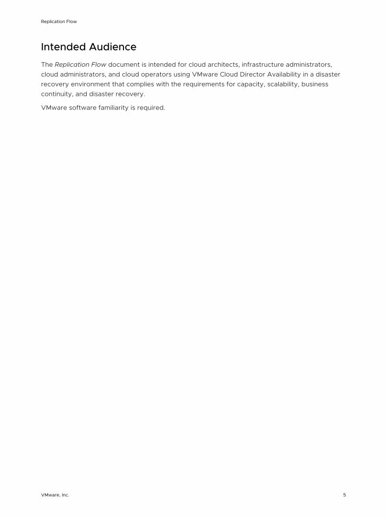
The on-premises appliance establishes pairing to the Cloud Tunnel Appliance in the cloud site. This allows configuring and performing replications in both directions.
Figure 2-1. Replication path between two cloud sites and an on-premises site
Cloud site A
Cloud Tunnel Appliance
Cloud Replicator Appliance
VMkernel
VMkernel/HBA
ESXi Host
Data store
Cloud site B
Cloud Tunnel Appliance
Cloud Replicator Appliance
VMkernel
VMkernel/HBA
ESXi Host
Data store
PrivateNetwork
On-Premises site
VMware Cloud Director Availability On-Premises Appliance
VMkernel
VMkernel/HBA
ESXi Host
Data store
PublicNetwork
Replication Flow
VMware, Inc. 7

n This example shows the network connectivity and pairing between the two cloud sites over a private network. Alternatively, the cloud-to-cloud site pairing allows establishing over the public Internet.
n This example also shows the connectivity between the cloud site B and the on-premises site over Internet. Alternatively, while not frequently used, the on-premises sites also allow pairing with a cloud site by using a private network.
The entire replication data path between two cloud sites consists of multiple components of the virtual infrastructure, together with Cloud Replicator Appliance instances and the two Cloud Tunnel Appliance instances in each site.
Note Cloud Replication Management Appliance is not shown in the diagram as it is not part of replication data path. Replication data passes through this appliance only for test environments when configured as a Combined Appliance. The Combined Appliance can be deployed as a proof-of-concept for evaluating the functionality and for testing the configurations but not for performance metrics. Never deploy Combined Appliance instances in production environments expecting substantial number of replications.
Replication in VMware vSphere®For low level data moving, the Cloud Replicator Appliance uses host-based replication provided by the vSphere Replication Service and the two VMware Cloud Director Availability services running in the Cloud Replicator Appliance – LWD Proxy and the Replicator Service. When configuring a replication, different services from both the source Cloud Replicator Appliance and the destination Cloud Replicator Appliance instances prepare the virtual machine for replication and move its contents from the source site to the destination recovery site.
Every virtual machine has multiple I/O filters. The I/O filter managing the disk activities of a virtual machine is the vSCSI filter. In the source site, this filter also manages the outgoing replication data traffic. When adding a virtual machine in a replication, the Replicator Service running in the source Cloud Replicator Appliance configures the vSCSI filter by using vCenter Server APIs. This filter configuration includes information about the source Cloud Replicator Appliance instance, the network port on which it listens for replication traffic, the replication RPO, and several other parameters. For information about the vSCSI filter, see Chapter 3 Replication Data Path.
Replication Flow
VMware, Inc. 8

Figure 2-2. Outgoing Replication Path from the Source Cloud Site
source Cloud Tunnel Appliance
TunnelService
sourceCloud Replicator Appliance
Lightweight DeltaProtocol Service
ESXi Host
Data store
vmdk file vmdk file
vSCSIfilter
vSCSIfilter
1 For outgoing replications, in the source cloud site first the vSCSI filter uses the ESXi host VMkernel adapter network interface activated for replication for sending the replication data to the LWD Proxy in the source Cloud Replicator Appliance.
Note If no interface is activated for replication, the vSCSI filter attempts using the management VMkernel interface.
VMware strongly recommends activating vSphere Replication and vSphere Replication NFC on the VMkernel interface that transfers the replication data traffic, even when this is the management VMkernel interface. For more information, see Setting Up VMkernel Networking in the vSphere documentation.
2 Then, the source Cloud Replicator Appliance sends the replication data to the source Cloud Tunnel Appliance for transferring to the destination recovery site.
Replication Flow
VMware, Inc. 9

Figure 2-3. Incoming Replication Path to the Destination Recovery Cloud Site
destination Cloud Tunnel Appliance
TunnelService
vSphere Replication Service
destinationCloud Replicator Appliance
Lightweight DeltaProtocol Service
NFC Service
ESXi Host
Data store
Base disk Instancesand delta
images
Base disk Instancesand delta
images
1 For incoming replications, in the destination cloud site the Cloud Tunnel Appliance receives the replication data traffic and sends it to the LWD Proxy in the Cloud Replicator Appliance in the destination recovery site.
2 Then the vSphere Replication Service in the same Cloud Replicator Appliance sends this replication data to the Network File Copy (NFC) Service in the ESXi host in the destination recovery site. The NFC Service handles large amounts of data transfers like replications and backups.
Note For replication incoming traffic, one of the VMkernel interfaces of the ESXi host must be activated for vSphere Replication NFC. This instructs the NFC Service for receiving replication traffic over this VMkernel interface.
Replication Flow
VMware, Inc. 10

3 Finally, the ESXi host in the destination recovery site writes the replication data to a replica file on one of its data stores.
For on-premises-to-cloud replications, the replication data path is similar. The VMware Cloud Director Availability On-Premises Appliance embeds all services, including the Tunnel Service.
Replication Operations
1 When configuring a replication for a virtual machine, the first operation is a full synchronization of the disks of the virtual machine.
a First, the Cloud Replicator Appliance instance in the destination recovery site allocates an empty vmdk file for storing the replicated blocks from the source virtual machine.
b Then the vSCSI filter in the source site starts reading blocks from the source disk and calculates checksums for each source block.
c Finally, the vSphere Replication Service in the destination site calculates checksums for each destination block in the recovery site.
n When not using a seed virtual machine, the checksums for the same source and destination block differ, causing the contents of this block to transfer over the network from the source site to the recovery site.
n When using a seed virtual machine, only the blocks with different checksums transfer between the source and the destination replicator instances.
2 When the full synchronization completes, the vSCSI filter in the source site tracks which blocks change, and stores the addresses of the changed blocks, also known as dirty blocks in a .psf file in the directory of the virtual machine.
3 Later, when the RPO window expires, the vSCSI filter in the source site reads all blocks that changed during the last RPO window and the VMware Cloud Director Availability appliances send these dirty blocks to the recovery site. When overwriting a single block multiple times during the RPO window, only the last state of the block is replicated.
This replication data transferred on each RPO window represents the delta image.
4 If the replication keeps multiple instances, the recovery site stores the instances together with the base image. Retention rules distribute* the instances across a period of time.
For example, a replication keeping four instances for a day creates an instance on every sixth hour.
Usually, the RPO window is shorter than the time window between instances. As a result, in the recovery site multiple delta images are created after creating the last instance and before creating the next instance. At the time for creating a new instance the following two operations take place.
1 The oldest instance merges in the base image for releasing a slot for the next instance.
Replication Flow
VMware, Inc. 11

2 All delta images created after the latest instance merge in a new instance, and this becomes the latest instance.
In the recovery site, these consolidation operations of the replication data cause increased read/write storage operations.
n Bigger instances need longer time for consolidation.
n The same is valid for new instance creation – with more and bigger delta images the time for consolidation in a single instance takes longer and generates more storage operations.
In the recovery site, the vmdk files store the data of the base image, of the instances, and of
the delta images. When performing a recovery or a migration, VMware Cloud Director Availability uses these vmdk files and creates a virtual machine, registers it in the vSphere inventory, and
imports it in the VMware Cloud Director inventory.
In summary, this represents the simplified form of the replication process. However, the vSphere Replication Service has other functionalities, not part of this document.
* VMware Cloud Director Availability 4.3 and later allow keeping instances with different periods of time between them. For more information, see Advanced Retention Rules in the User Guide.
Replication Flow
VMware, Inc. 12

Replication Data Path 3Learn more about the replication I/O operations in the source and in the destination storage subsystems and the storage recommendations for 1-minute Recovery Point Objective (RPO). Also, learn about the vSCSI filter operations and approaches for improving the network traffic. In geographically separated data centers, see the benefits of deploying multiple VMware Cloud Director Availability instances. Learn about optimizing the Cloud Replicator Appliance instances and the Cloud Tunnel Appliance.
Storage
In the vmdk files, the vSCSI filter creates a list of blocks modified at least once during the last RPO
window, for these dirty blocks must replicate when the RPO window expires. The ESXi host reads these blocks before sending them over a TCP connection to the vSphere Replication Service in the Cloud Replicator Appliance. For more information, see Chapter 2 Replication Process Overview.
Source site storage
In the source site storage subsystem, replicating a virtual machine adds operations over what the virtual machine already generates. After the RPO window expires, there is a period with additional read operations. For differing workloads, this period starts and stops at various times for a variable duration.
As a result, the read/write profile of the datastores changes randomly at random intervals.
This inherent variability requires monitoring for correctly sizing and configuring the source storage subsystem for meeting all requirements and recommendations from both the storage vendor and from VMware.
Destination recovery site storage
In the recovery site, the storage subsystem also receives additional operations triggered by the replication data traffic. The replication data is written in replica files.
Consolidating the delta images in the instances generates another stream of read/write operations.
VMware, Inc. 13

The merging of instances in the base disk also generates read/write disk operations. The deeper the hierarchy of the instance, the longer this consolidation lasts due to the increase in read/write operations. For information about the hierarchy of the instances, see Using Instances in the User Guide.
The number of write operations also depends on the way the protected application stores its data. For example, when an application frequently overwrites the same set of blocks, the write operations for instances consolidation are less than when an application randomly writes in new blocks.
Note n To meet an RPO as short as 1-minute and ensure that the replications are free of RPO
violations, in the recovery site VMware strongly recommends using flash storage backed by NVMe or by other high-performance enterprise-grade SSD devices. Using consumer-grade SSD might cause issues.
n VMware also strongly recommends using vSphere 7.0.2 or later. By using VMware Cloud Director Availability 4.3 with vSphere 7.0.2 allows for the latest improvements in the replication data processing. The increased level of read/write operations handling reduces the chances for RPO violations.
n VMware performs all internal product testing by using VMware vSAN™ datastores. However, not only vSAN can fulfill the increased demand for replications, protected by a 1-minute RPO. Other all-flash storage solutions might also provide the necessary read/write operations handling.
n For providing capacity to non-vSphere workloads, do not use physical disk pools that are home of vSphere datastores. For example, NFS or SMB exports or LUNs directly attached to servers not running ESXi. vSphere might mistake background storage operations, like auto-tiering and disk rebalancing as unmanaged I/O traffic, resulting in a negative impact on storage operations managed by vCenter Server.
VMware recommends using vSAN as it prevents this unmanaged I/O traffic. As completely dedicated for virtual infrastructures, the vSAN datastores allow for granular observability and for control over the vSAN operations. VMware actively develops the vSAN technology and improves its performance, monitoring, recoverability, and manageability features. The vSAN policy-driven configuration allows the storage administrators discovery and flexible assignment of the best combination of rules for any type of data stored on vSAN, including replication data. For more information, see the Troubleshooting vSAN Performance, Understanding vSAN Performance Bottlenecks, and Write Buffer Sizing in vSAN blog posts.
The following example shows the impact of dynamic utilization of the recovery site datastore, for replications configured with a target RPO of 1-minute.
n The example contains five operational virtual machines, running applications that store data in binary format.
n Each virtual machine generates from 880 to 900 MB of binary data per minute.
Replication Flow
VMware, Inc. 14

n Some of the blocks are overwritten once or more within this minute.
n In the recovery site, a vSAN datastore receives all the replication data. This vSAN datastore also contains other virtual machines which dynamically change the I/O pattern over the storage subsystem, resembling a production system.
In the following diagram for this example, each color represents a single replication. The bar size increases with each additional minute in RPO violation.
Figure 3-1. Dynamic I/O in destination site and RPO violations
1 First, during “Phase One”, all virtual machines residing in the recovery vSAN datastore have the same I/O profile and only a few replications experience an RPO violation for a minute or two.
2 Later, during “Phase Two” the production workload I/O pattern increases, causing the replications to accumulate RPO violations for extended periods of time. All replications are in RPO violations for 10 to 25 minutes.
3 Finally, during “Phase Three” the I/O operations in virtual machines running in the destination site reduces to its typical values and replications begin reducing their delays and shortly after they are free of RPO violations for the remaining time.
During “Phase Two”, the following diagram from vRealize Operations Manager helps explain the reason for the RPO violations.
Figure 3-2. vSAN write buffer dynamics in vRealize Operations Manager
Replication Flow
VMware, Inc. 15

Increasing the write operations to the vSAN datastore, begins saturating its write buffer. This increased write rate obstructs de-staging to the capacity drives and the vSAN datastore begins experiencing performance degradation. Reducing the I/O streams from the virtual machines allows for re-obtaining the high-performance levels for write operations.
Alternatively, instead of reducing the I/O stream to vSAN datastore disk groups, add more caching drives to the vSAN cluster. Adding more caching drives is more common, and it underlines the importance of correctly sizing the storage infrastructure and especially vSAN, as higher cache-to-capacity ratio lowers the chances for reduced performance.
vSCSI Filter
The vSCSI filter sends the replication data traffic over one of the VMkernel interfaces of the ESXi host to the vSphere Replication Service in the source Cloud Replicator Appliance instance. The vSphere Replication Service manages the operation of the vSCSI filter.
The vSphere Replication Service does not complete the synchronization of the delta image in the shortest time possible as the service keeps the following information.
n The size of the delta image.
n The maximum time to complete the previous delta images synchronization.
n The bandwidth used by the previous delta images synchronization.
Based on this information, the vSphere Replication Service precisely calculates the required bandwidth and uses as low bandwidth as necessary for moving the delta images to the recovery site within the RPO window. This process prevents the high utilization of the resources by the replications. By modifying the advanced parameters of the hypervisor allows controlling this process to a limited level.
Note VMware recommends modifying these advanced parameters only under the guidance of VMware support.
When an RPO window expires, the vSphere Replication Service requests the ESXi host to read and send dirty blocks. Reading the dirty blocks occurs through the vSCSI filter, that is through the virtual SCSI interface of the virtual machine. The storage I/O limits for a virtual machine apply on the virtual SCSI adapter. When a virtual machine has a limit on the storage I/O operations, the reading of dirty blocks requested by the vSphere Replication Service respects this limit.
Note Setting a low I/O storage limit might cause RPO violations and reduced performance of the services provided by the virtual machine. Obtain the correct numbers when such limits must apply. This includes determining the repeatability of periods with low and high utilization and collecting and analyzing I/O operations per second (IOPS) data for at least one full cycle and adding a portion for replication traffic.
Replication Flow
VMware, Inc. 16

Another key factor is the CPU processing of replicated virtual machines. The following three items sum the total demand for CPU cycles from a replicated virtual machine.
n CPU cycles requested by the guest operating system.
n CPU cycles used by the hypervisor for maintaining the virtual machine.
n CPU cycles requested by the vSphere Replication Service.
Based on the ESXi host resource utilization, the CPU scheduler of the ESXi host provides access to the physical CPUs. When the ESXi host is over-utilized, the virtual machine receives its share of CPU resources based on the number of virtual CPUs. For example, a virtual machine with eight virtual CPUs receives twice more CPU cycles for replication processing, compared to a virtual machine with four virtual CPUs. Instead of simply increasing the number of virtual processors in replicated virtual machines, avoid virtual CPU over-provisioning by configuring each workload with the correct number of virtual CPUs.
In the source site, the network traffic from the vSCSI filter to the LWDProxy is in a raw data format. The vSCSI filter performs no processing of the data block content.
Similarly, in the recovery site, the network traffic from the vSphere Replication Service to the ESXi host is in raw data format. An ESXi host in a cloud environment can run tens or hundreds of virtual machines that might be replicated or might be used as a destination for tens or hundreds of replications. This way, the network traffic for replication data between the ESXi hosts and the Cloud Replicator Appliance instances can reach a significant volume.
The architecture allows the following two approaches for improvements.
1 The first approach is by creating a dedicated replication network - VLAN with a dedicated ESXi host VMkernel interface. Then the Cloud Replicator Appliance instances directly connect to this network. This approach allows for the following benefits.
n For outgoing replications, the vSCSI filter in the source ESXi host sends the raw replication data traffic directly to the LWDProxy Service in the source Cloud Replicator Appliance instance over a single Layer 2 broadcast domain. This prevents routing this large traffic volume over the routed networks and avoids the detrimental impact on the entire network infrastructure and services.
n For incoming replications, the LWDProxy Service in the destination Cloud Replicator Appliance instance sends raw replication data traffic to the VMkernel interface of the destination ESXi host again over a single Layer 2 network. This prevents the routing of large volumes of replication data traffic and reduces the risk of impacting other types of traffic and services.
n By using the vSphere Network I/O Control (NetIOC) allows for granular control over allocating shares to each type of network traffic and bandwidth priorities, preventing bandwidth saturation.
n This approach comes with no additional costs when the cloud provider uses vSphere Enterprise Plus and above product licenses.
Replication Flow
VMware, Inc. 17

This first approach requires correct planning and implementation of the following network configuration changes.
n Create a VLAN network dedicated to replication data traffic.
n Dedicate an IP subnet for replication data traffic.
n Create a virtual port group dedicated to replication and tag it with the replication VLAN ID.
n Create a VMkernel adapter interface dedicated for replication, configure it with an IP address from the replication IP subnet and connect it to the replication virtual port group.
n Configure the network interface of each Cloud Replicator Appliance instance with an IP address from the replication IP subnet and connect it to the replication virtual port group.
Figure 3-3. VMkernel interface with active vSphere Replication and vSphere Replication NFC
Figure 3-4. Cloud Replicator Appliance and replication VMkernel interfaces connected to a port group dedicated for replication
2 The second approach is by using dedicated physical ESXi host uplinks for the replication data traffic. Less frequently used, this approach comes with additional expenses like additional physical switch ports, additional used space in racks, and additional costs for power and cooling.
When the replication VMkernel interface of the ESXi host and the Cloud Replicator Appliance instances reside in different subnets and routing the replication data traffic between the subnets, account for the performance capabilities of the involved routing devices. For each replicated virtual machine, the vSCSI filter opens a single TCP session to the Cloud Replicator Appliance instance. If the routing device performs IDS/IPS of the replication data traffic, that might cause issues.
Replication Flow
VMware, Inc. 18

VMware strongly recommends, when possible, excluding the replication data traffic from such inspection.
The performance of the routing devices might have a negative impact on the usable network bandwidth passing through it and might limit the number of replications or amount of replicated data.
Geographically Separated Data Centers
Only vSCSI filter and Cloud Replicator Appliance optimizations might not suffice when the cloud providers manage a single VMware Cloud Director instance with multiple vCenter Server clusters located in data centers separated by a long distance.
With a single VMware Cloud Director Availability instance associated with all provider VDCs, raw replication data traffic between the vSCSI filter and the Cloud Replicator Appliance instances travels over inter-site links once or multiple times. Also, the network traffic between the Cloud Replicator Appliance instance and the Cloud Tunnel Appliance might need to travel over the inter-site link when deploying the Cloud Replicator Appliance instance and the Cloud Tunnel Appliance in different data centers.
The following example shows such an unoptimized replication flow between, for example, the London and the Berlin data centers.
Replication Flow
VMware, Inc. 19

Figure 3-5. Unoptimized replication data flow
London provider VDC
Cloud Tunnel Appliance
Cloud ReplicatorAppliance instance 1
Cloud Replication Management Appliance
ESXi Host
Berlin provider VDC
3
4 Cloud ReplicatorAppliance instance 2
ESXi Host
2
1
Replication Flow
VMware, Inc. 20

In the London data center, a single VMware Cloud Director Availability instance is deployed withCloud Replication Management Appliance and Cloud Tunnel Appliance, with two Cloud Replicator Appliance instances deployed in the London and in the Berlin data centers.
Then, replicate a virtual machine hosted in the London provider VDC to the Berlin provider VDC.
The Cloud Replication Management Appliance cannot know the location of each Cloud Replicator Appliance instance and chooses one of the Cloud Replicator Appliance instances for communicating with the source ESXi host in London and another Cloud Replicator Appliance instance for sending the replication data traffic to the destination ESXi host in Berlin.
With such a topology, nothing prevents the Cloud Replication Management Appliance from selecting a Cloud Replicator Appliance instance from Berlin as a source and a Cloud Replicator Appliance instance in London as a destination.
As a result, the replication data traffic flows in the order shown in the diagram. For a single replication, the replication data traffic passes through the inter-site link three times, two of which as raw uncompressed data.
With such a topology, the chances for RPO violations occurrence are extremely high. VMware recommends deploying one VMware Cloud Director Availability instance per data center.
Cloud Replicator Appliance Instances
The Cloud Replicator Appliance instances perform the heavy lifting of the replication data traffic. Multiple factors impact the operations of the Cloud Replicator Appliance. Combinations of these factors determine whether the Cloud Replicator Appliance instance can meet a replication RPO or not.
The initial factor is the format of how the protected virtual machine stores its data. Some applications store data in a binary format that is not subjectable to compression. Other applications store their data in a format that could significantly reduce by compressing, for example, text data. Knowing the applications that run in a replicated virtual machine helps decide whether to activate compression for this replication at the expense of higher CPU utilization of the Cloud Replicator Appliance instances.
The following example illustrates replications using 1-minute RPO with active compression resulting in RPO violations.
Replication Flow
VMware, Inc. 21

Figure 3-6. Replications with activated compression in RPO violations
In this example, all the replications cannot keep up with the RPO setting and are in RPO violation between 1 and 10 minutes.
The following monitoring diagram shows a historic view of the same situation. Each replication has its own color and shows that for most of the time, all the replications are in violation of their RPO. Several replications manage catching up but soon after that they again experience RPO violations.
Figure 3-7. Monitoring replications health with RPO violations
In the following example, the Last changed column shows that all replications are reconfigured at 7:47 PM with deactivated compression, resulting in meeting the 1-minute RPO.
Replication Flow
VMware, Inc. 22

Figure 3-8. RPO violations resolved by deactivating replication compression
The same monitoring also shows the number of RPO violations goes down to zero a few minutes after 07:47 PM when the replications are reconfigured with deactivated compression. All replications manage catching up and several minutes later none of them is in RPO violation anymore.
Figure 3-9. Monitoring replications health after reconfiguring them with deactivated compression
The change in replications configuration directly relates to the way the Cloud Replicator Appliance instances process the replication data traffic. The above example shows that offloading the Cloud Replicator Appliance instance from intensive CPU compression operations improves its throughput, which effectively resolves the RPO violations.
Replication Flow
VMware, Inc. 23

In production deployments, the number of Cloud Replicator Appliance instances is another key factor. While not recommended, VMware Cloud Director Availability can safely operate with only a single Cloud Replicator Appliance instance. However, VMware recommends initially deploying at least two Cloud Replicator Appliance instances. For maintenance, having two Cloud Replicator Appliance instances allows the second instance to keep the replication data flowing while placing the first instance in maintenance mode, for example, for upgrade or for certificates replacement.
From a resource utilization perspective, a deployment with multiple Cloud Replicator Appliance instances hosted in different hypervisors delivers the following benefits.
n Distributing the CPU utilization generated by handling the replication data traffic over multiple ESXi hosts.
n Distributing the replication data traffic over multiple uplinks.
VMware strongly recommends creating a Separate Virtual Machines distributed resource schedule (DRS) rule for the Cloud Replicator Appliance virtual machines. This ensures the Cloud Replicator Appliance instances run on different ESXi hosts.
VMware also recommends the following optimizations from placement and from a network connectivity perspective.
n Place the Cloud Replicator Appliance instances on VMware Cloud Director resource clusters, not on management clusters. This is due to typically VMware Cloud Director resource clusters having more ESXi hosts allowing for easy DRS application of the Separate Virtual Machines rule.
n Connect the Cloud Replicator Appliance instances together with the replication VMkernel interfaces of the ESXi hosts in a common port group. Alternatively, when they connect with routed networks, ensure having the least number of routers between the Cloud Replicator Appliance network and the replication VMkernel interfaces network of the ESXi hosts. For information about replication VMkernel interfaces in the local site, see Chapter 4 Connectivity.
When investigating RPO violations, both the source and the destination Cloud Replicator Appliance instances might be the cause. Check for CPU contention in ESXi hosts running the Cloud Replicator Appliance instances. The Cloud Replicator Appliance operations suffer a negative impact when the ESXi host experiences any kind of CPU contention, either high CPU utilization or high CPU ready times.
n As short-term mitigation, deactivate compression for some replications.
n As more permanent resolutions, add more CPUs, upgrade the existing ESXi hosts, or add new ESXi hosts to the cluster.
In summary, when observing the following issues.
n A constant 100% CPU utilization for all Cloud Replicator Appliance instances.
n Data transmission rates to the Cloud Tunnel Appliance above 2Gbps.
n RPO violations present.
Replication Flow
VMware, Inc. 24

For resolving these issues, deploy an additional one or two Cloud Replicator Appliance instances. Shortly after that, the RPO violations should start disappearing when the number of Cloud Replicator Appliance instances caused the issue. If the issue persists, the cause might be something else. For example, the connectivity to the Cloud Tunnel Appliance, or a bandwidth limit on a network link to the remote site.
Cloud Tunnel Appliance
The Cloud Tunnel Appliance performs no processing of the replication data traffic, causing high network throughput but low CPU and memory utilization for the Cloud Tunnel Appliance. The underlying virtualization environment might impact the performance of the Cloud Tunnel Appliance. As long as the Cloud Tunnel Appliance virtual machine is not in resource contention, it should continue performing well. When suspecting that the Cloud Tunnel Appliance is the bottleneck causing RPO violations, investigate the hosting infrastructure. Check for high CPU ready times, uplink utilization, and other generic vSphere troubleshooting steps. Perform the following possible resolutions.
n vMotion the Cloud Tunnel Appliance to an ESXi host with lower resource utilization.
n Create a Separate Virtual Machines DRS rule for the Cloud Replicator Appliance virtual machine for handling a large amount of network traffic.
To prevent the saturation of the network interfaces of the Cloud Tunnel Appliance, activate replication compression. As mentioned, some workloads store their data in a format that benefits from compressing. The Cloud Tunnel Appliance receives replication streams from multiple Cloud Replicator Appliance instances. By activating compression, even for some workloads, lowers the total replication data traffic at the Cloud Tunnel Appliance at the expense of higher CPU utilization of the Cloud Replicator Appliance instances. The compression reduces the total replication data traffic and reduces the chances for the Cloud Tunnel Appliance to be a bottleneck, causing RPO violations. That is why VMware recommends when configuring a new replication, always activate compression, except when knowing the data does not significantly reduce by compressing.
Another configuration reason for RPO violation is the utilization of the bandwidth throttling feature introduced with VMware Cloud Director Availability 4.0. For cloud-to-cloud replications, bandwidth throttling sets a limit on the interface the Cloud Tunnel Appliance uses for communication with the remaining VMware Cloud Director Availability appliances in the local site. When observing RPO violations while using bandwidth throttling, increase the throttling limit, or completely deactivate bandwidth throttling.
For on-premises-to-cloud replications, bandwidth throttling applies to the interface of the VMware Cloud Director Availability On-Premises Appliance. The limit controls the traffic the VMware Cloud Director Availability On-Premises Appliance sends to the Cloud Tunnel Appliance in the cloud site.
Note Do not use bandwidth throttling when configuring replications with a 1-minute RPO.
Replication Flow
VMware, Inc. 25

Connectivity 4The connectivity between the local VMware Cloud Director Availability cloud appliances and the connectivity between sites can have a significant impact on the replication data traffic.
Connectivity in the Local Site
Inside data centers, while the cloud providers typically use links with 10 Gbps or more between the components, the routing of replication data traffic might still benefit from optimizing. The way the Cloud Tunnel Appliance and the Cloud Replicator Appliance instances connect in the local cloud site is important. This connectivity can be routed or switched. Routed connectivity is easier for deployment and configuration. However, the routers might bottleneck replications. The intensive replication traffic might impact the operations of the routers, causing issues for other types of traffic.
To optimize the replication data traffic, use multiple network interfaces for the cloud appliances and connect the Cloud Replicator Appliance instances with the Cloud Tunnel Appliance at a common Layer 2 port group, bypassing routing devices. By using such optimization, only the connectivity with the Cloud Replication Management Appliance and with the management infrastructure remains over routed networks. However, the management traffic is negligible compared to the replication data traffic. As a result, the management traffic over routed networks is not a challenge for the routing devices.
The following network diagram shows this topology.
VMware, Inc. 26

Figure 4-1. Cloud Tunnel Appliance and Cloud Replicator Appliance with multiple network interfaces
CloudTunnel
Appliance
vCenterServer
VMwareCloud
Director
CloudReplication
ManagementAppliance
NSXManager
CloudReplicatorApplianceinstance
Management network
Compressedreplicationdata traffic
Raw Replication data trafficnot-routed network segment
ESXi Host
Traffic type:
Pairing overpublic networks
Pairing overprivate networks
Edgerouter
Managementrouter
ManagementVMkernel interface
ReplicationVMkernel interface
Service management traffic
Replication data traffic
Replication Flow
VMware, Inc. 27

n This network diagram shows two network interfaces for the Cloud Replicator Appliance instance.
n The downstream interface connects with the replication VMkernel interface of the ESXi host to a common port group. For information about this configuration, see Chapter 2 Replication Process Overview.
n The upstream network interface of the Cloud Replicator Appliance and the downstream interface of the Cloud Tunnel Appliance connect to a common port group, routed to the Management network. By using this configuration, the Cloud Replicator Appliance instance and the Cloud Tunnel Appliance communicate directly and the replication data traffic does not pass through any router.
n The Cloud Tunnel Appliance and the Cloud Replicator Appliance instances communicate with the Cloud Replication Management Appliance through routed networks. The bandwidth required for this service management traffic does not have a significant impact on the Management router.
n The diagram shows the replication data traffic as an orange arrow that does not pass through any router and the service management traffic as green arrows routed to the Management network passing through the Management router.
n In this example, the Cloud Tunnel Appliance uses three network interfaces.
n The downstream interface communicates with the local cloud appliances – the Cloud Replication Management Appliance and the Cloud Replicator Appliance instances.
n The remaining two network interfaces of the Cloud Tunnel Appliance are for pairing with remote cloud sites and with on-premises sites.
n The network interface connected with the blue network is for pairing over public networks. Edge firewall DNAT rule forwards the network traffic destined to VMware Cloud Director Availability to the IP address of the Cloud Tunnel Appliance, on port 8048/TCP.
n The network interface connected with the red network is for pairing sites over a private network. Over such a private network, remote cloud sites or on-premises appliances pair directly to the IP address of this network interface of the Cloud Tunnel Appliance, on port 8048/TCP.
VMware Cloud Director Availability 4.3 and later allow using the management interface for configuring the cloud appliances with multiple network interfaces, also called multi-homed. In previous VMware Cloud Director Availability versions, configuring multiple network interfaces requires using the command-line interface and might require assistance from VMware support. For information about configuring multi-homed cloud appliances, see Network Settings Configuration in the Administration Guide and VMware Cloud Director Availability Configuration with Multiple NICs.
Replication Flow
VMware, Inc. 28

Improving the network traffic by using jumbo frames of more than 1500 bytes might not drastically improve the throughput of the network.
Important When using jumbo frames, ensure the correct configuration of each component in both the physical and the virtual network infrastructure. A single miss in the entire network infrastructure might result in reducing the network throughput.
To verify the network configuration and see the throughput, use typical Linux troubleshooting tools.
Test whether the network infrastructure supports jumbo frames by using Internet Control Message Protocol (ICMP) with large frames with “do not fragment” bit set. VMware Cloud Director Availability 4.0 and later appliances have ICMP echo traffic activated on their internal firewall.
In the appliances command-line interface, test the network bandwidth by using iperf for active
measurement of the maximum achievable bandwidth on IP networks. However, the VMware Cloud Director Availability appliances do not have iperf installed and the repositories in all
VMware Cloud Director Availability appliances are by default deactivated.
Note Do not enable any repository on the VMware Cloud Director Availability appliances.
To install the iperf package by temporary allowing the repository run the following command.
tdnf --enablerepo=photon install iperf -y
To start a server session run the following command.
iperf3 -s -p 25201
By default, the iperf server listens on port 5201. Ensure that a firewall does not block this port
between the server and the client. The server can listen on a different port by using “-p” followed by a port number. In this example, the server listens on port 25201.
To start a client session run the following command.
iperf3 -c server_ip -P 100 -t 60 -p 25201
Replication Flow
VMware, Inc. 29

In this example, “-c” runs iperf in client mode, “server_ip” is the server IP address, “-P”
configures the number of parallel sessions, “-t” determines for how long the client runs and generates traffic to the server, and “-p” instructs the client that the server listens on that port.
Note n Consider the duration for running these tests as iperf uses as much as possible network
bandwidth between the server and the client.
n When testing with iperf, attempt simulating as closely as possible the replication
connectivity by using multiple TCP sessions and monitor all the network devices in the path.
n Prevent the network saturation by performing the tests for short periods of time, out of business hours.
Connectivity Between Paired Sites
Inside their data centers, the cloud providers have full control over the architecture and the configurations. However, for inter-site network links, there is little control. Usually, the cloud providers are in a better position than smaller companies as they have network links with multiple pre-determined parameters and SLAs. However, physics mandates that long-distance links have higher Round-Trip Time (RTT) latency. This latency might impact the efficiency of the bandwidth utilization together with retransmit packets and the replication data traffic. Replications over high-latency links require careful planning and optimization of the RPO settings for ensuring no RPO violations occur.
Edge devices between internal networks and public networks can also impact the replication data traffic. Usually, these devices perform traffic inspection, check packets against long firewall rules lists, some of them might perform SSL processing and other CPU-intensive operations, resulting in reduced network throughput.
VMware strongly recommends excluding the replication data traffic from such inspection.
Note Excluding the replication data traffic from inspection does not affect security, as any SSL manipulation of the replication data traffic invalidates it, not resulting in RPO violations but in completely failing replications.
The cloud providers should perform intensive testing of which replication configurations are possible and what are the shortest RPO values that do not cause RPO violations. A single replication generates the same background operations when using a 1-minute RPO or 8 hours, for example. The difference is in concurrent and overlapping operations. With a shorter RPO value, all operations must be able to complete in a shorter time window.
For on-premises-to-cloud replications, the connectivity between the cloud provider and the on-premises data center is critical. Most on-premises sites have to pair with their cloud provider over public networks. Tenants cannot rely on constant optimal connectivity and extreme configurations like replications with 1-minute RPO might cause RPO violations. Tenants with a
Replication Flow
VMware, Inc. 30

high-bandwidth connection to their cloud provider might perform a higher number of replications. Such tenants can also deploy additional VMware Cloud Director Availability On-Premises Appliance instances for increasing the replication data traffic flow to the cloud site for testing whether replications with 1-minute RPO are successful and without RPO violations.
Verifying the inter-site network link capabilities is the same as for local connectivity. However, configuring the connectivity through any firewall devices might require additional steps.
VMware recommends testing the 1-minute RPO replications for ensuring that the environment and the configuration can support such a short RPO value. However, as explained, there are multiple configurations, where achieving a 1-minute RPO might not be possible.
Replication Flow
VMware, Inc. 31

Monitoring 5To discover possible replication bottlenecks, monitor the disaster recovery infrastructure.
The primary point for monitoring is the VMware Cloud Director Availability Portal. After logging in, the Dashboard page reports the most obvious issues. The overview in System health reports of any connectivity issues between the components.
Alternatively, by using the API allows retrieving this health information. First, authenticate to the Cloud Replication Management Appliance.
curl -i -k -H 'Content-Type: application/json' -H 'Accept: application/vnd.vmware.h4-v4.3+json;charset=UTF-8' -d '{"type": "localUser", "localUser": "root", "localPassword": "T0pSecret!"}' -X POST https://vcdam01.ca.cloud.local:8046/sessionsHTTP/1.1 200Vary: OriginVary: Access-Control-Request-MethodVary: Access-Control-Request-HeadersX-VCAV-Auth: U/7KA56oxQaQXEgUy4jVP4HLPIY=X-Content-Type-Options: nosniffX-XSS-Protection: 1; mode=blockCache-Control: no-cache, no-store, max-age=0, must-revalidatePragma: no-cacheExpires: 0Strict-Transport-Security: max-age=31536000 ; includeSubDomainsX-Frame-Options: DENYContent-Type: application/vnd.vmware.h4-v4.3+json;charset=UTF-8Content-Length: 135Date: Wed, 24 Nov 2021 16:17:28 GMT
{"user":"root","roles":["EVERYONE","ADMINISTRATORS","VRADMINISTRATORS"],"authenticatedSites":[{"site":"CA-DR-Site-01","org":"System"}]}
This example established a session with administrative privileges. The next API calls use authentication token stored in X-VCAV-Auth for requesting health information.
curl -k -H 'Accept: application/vnd.vmware.h4-v4.3+json;charset=UTF-8' -H 'X-VCAV-Auth: U/7KA56oxQaQXEgUy4jVP4HLPIY=' -X GET https://vcdam01.ca.cloud.local:8046/diagnostics/health | python -m json.tool % Total % Received % Xferd Average Speed Time Time Time Current Dload Upload Total Spent Left Speed100 333 0 333 0 0 15167 0 --:--:-- --:--:-- --:--:-- 15857{ "id": "e80073e0-a399-4bc4-b919-e655acf9b708",
VMware, Inc. 32

"user": "root", "workflowInfo": { "type": "health", "resourceType": "CLOUD", "resourceId": null, "resourceName": null }, "progress": 0, "state": "RUNNING", "lastUpdated": 1637770698480, "startTime": 1637770698477, "endTime": -1, "resultType": null, "result": null, "error": null, "warnings": [], "site": "CA-DR-Site-01"}
VMware Cloud Director Availability versions earlier than 4.2 return a long JSON-formatted output with information about the health state. VMware Cloud Director Availability 4.2 and later improve the task management. The “State” key informs the health checking task is still in progress. This requires an additional API call for getting the final health information. The ID value in the previous output is the ID of the task that collects and provides the health information and requires checking whether the task has completed.
curl -k -H 'Accept: application/vnd.vmware.h4-v4.3+json;charset=UTF-8' -H 'X-VCAV-Auth: U/7KA56oxQaQXEgUy4jVP4HLPIY=' -X GET https://vcdam01.ca.cloud.local:8046/tasks/e80073e0-a399-4bc4-b919-e655acf9b708 | python -m json.tool % Total % Received % Xferd Average Speed Time Time Time Current Dload Upload Total Spent Left Speed100 6053 0 6053 0 0 236k 0 --:--:-- --:--:-- --:--:-- 246k{ "id": "e80073e0-a399-4bc4-b919-e655acf9b708", "user": "root", "workflowInfo": { "type": "health", "resourceType": "CLOUD", "resourceId": null, "resourceName": null }, "progress": 100, "state": "SUCCEEDED", "lastUpdated": -1, "startTime": 1637770698477, "endTime": 1637770698932, "resultType": "CloudHealthInfo", "result": { "productName": "VMware Cloud Director Availability Cloud Service", "buildVersion": "4.3.0.3095245-9308521ec0", "buildDate": 1637066189629, "instanceId": "6d2f0f94-5769-4b67-8edb-5d4b98f48893", "runtimeId": "c30cd2e9-d056-4a80-ae68-84175ccd4a6b", "currentTime": 1637770698931,
Replication Flow
VMware, Inc. 33

"address": "192.168.12.81", "tunnelError": null, "vcdError": null, "managerError": null, "managerHealth": { "productName": "VMware Cloud Director Availability Manager Service", "buildVersion": "4.3.0.3095245-9308521ec0", "buildDate": 1637066189629, "instanceId": "1225c20a-1b86-410a-85d3-daf58cfa2936", "runtimeId": "e9e87106-46de-4d6b-b423-fea35d209b10", "currentTime": 1637770698901, "address": "192.168.12.81", "offlineReplicators": [], "onlineReplicators": [ { "id": "3df8708a-b353-4b8b-b9c7-1e573ed14125", "owner": "*", "site": "CA-DR-Site-01", "description": "", "apiUrl": "https://192.168.13.1:8043", "certThumbprint": "SHA-256:42:D6:0C:A2:03:02:25:5E:A6:42:82:4C:FC:B7:4B:A3:2E:53:82:79:54:19:D9:7F:35:B3:02:E5:EE:C2:FC:7C", "pairingCookie": null, "state": { "incomingCommError": null, "outgoingCommError": null }, "isInMaintenanceMode": false, "apiVersion": "4.3", "dataAddress": "lwd://192.168.13.1:44045/" }, { "id": "167217ca-4a6e-4926-ae14-fcb4c493944a", "owner": "*", "site": "CA-DR-Site-01", "description": "", "apiUrl": "https://192.168.13.2:8043", "certThumbprint": "SHA-256:89:49:1C:53:94:14:D6:92:D7:33:53:58:FA:B8:41:D2:AD:19:C2:8B:0A:D8:7E:A9:EE:E6:98:3B:0A:59:B1:09", "pairingCookie": null, "state": { "incomingCommError": null, "outgoingCommError": null }, "isInMaintenanceMode": false, "apiVersion": "4.3", "dataAddress": "lwd://192.168.13.2:44045/" }, { "id": "239b2681-ff45-4560-b1e7-90505f94c1ff", "owner": "*", "site": "NY-DR-Site-01", "description": "",
Replication Flow
VMware, Inc. 34

"apiUrl": "https://tn-239b2681-ff45-4560-b1e7-90505f94c1ff.tnexus.io:8048", "certThumbprint": "SHA-256:E7:47:30:0D:FD:B9:30:F0:9F:EF:12:AA:E8:A4:52:70:B2:1E:A6:38:96:D6:9C:FD:10:65:B7:E2:E1:26:22:F2", "pairingCookie": null, "state": { "incomingCommError": null, "outgoingCommError": null }, "isInMaintenanceMode": false, "apiVersion": "4.3", "dataAddress": "lwd://192.168.23.1:44045/" }, { "id": "484fcb26-2b92-44d0-bff6-838321458dc2", "owner": "*", "site": "NY-DR-Site-01", "description": "", "apiUrl": "https://tn-484fcb26-2b92-44d0-bff6-838321458dc2.tnexus.io:8048", "certThumbprint": "SHA-256:AD:1A:62:B9:79:9C:11:FC:6B:C1:68:64:71:39:02:4C:69:56:69:3F:5C:85:FB:81:55:F1:D8:DC:6F:08:B2:08", "pairingCookie": null, "state": { "incomingCommError": null, "outgoingCommError": null }, "isInMaintenanceMode": false, "apiVersion": "4.3", "dataAddress": "lwd://192.168.23.2:44045/" } ], "localReplicatorsHealth": [ { "productName": "VMware Cloud Director Availability Replicator Service", "buildVersion": "4.3.0.3095245-9308521ec0", "buildDate": 1637066189629, "instanceId": "3df8708a-b353-4b8b-b9c7-1e573ed14125", "runtimeId": "863bcf17-5827-411d-a353-3c034e78724a", "currentTime": 1637770698822, "address": "192.168.13.1", "offlineManagers": [], "onlineManagers": [ { "id": "1225c20a-1b86-410a-85d3-daf58cfa2936", "description": "", "certThumbprint": "SHA-256:47:75:7E:A3:81:CE:3E:E9:83:81:98:D1:EF:FF:A2:C6:AD:AE:BD:D2:AC:2E:6E:83:CD:DF:1A:DA:58:5C:65:77", "owner": "*", "apiUrl": "https://192.168.12.81:8044", "localUser": "[email protected]", "localPassword": "<censored>",
Replication Flow
VMware, Inc. 35

"apiVersion": "4.3" }, { "id": "eeb2be0c-9603-4767-8047-95d8957000bf", "description": "", "certThumbprint": "SHA-256:1C:90:9A:E5:50:4C:12:6F:F6:17:BB:AF:77:D1:09:D9:2C:8F:EE:6B:2E:71:0F:3B:09:AD:4D:DB:B2:72:44:EB", "owner": "*", "apiUrl": "https://tn-eeb2be0c-9603-4767-8047-95d8957000bf.tnexus.io:8048", "localUser": "[email protected]", "localPassword": "<censored>", "apiVersion": "4.3" } ], "lsError": null, "dbError": null, "vcError": { "eeb2be0c-9603-4767-8047-95d8957000bf": { "d22a2ad0-3c1e-4840-a0b8-eb2d3451bea0": null, "9de71d86-9df4-49aa-92ab-34595e45d171": null }, "1225c20a-1b86-410a-85d3-daf58cfa2936": { "d22a2ad0-3c1e-4840-a0b8-eb2d3451bea0": null, "9de71d86-9df4-49aa-92ab-34595e45d171": null } }, "lwdError": null, "hbrError": null, "h4dmError": null, "ntpError": null, "diskUsage": { "total": 10486022144, "usable": 9015365632, "free": 9568223232 } }, { "productName": "VMware Cloud Director Availability Replicator Service", "buildVersion": "4.3.0.3095245-9308521ec0", "buildDate": 1637066189629, "instanceId": "167217ca-4a6e-4926-ae14-fcb4c493944a", "runtimeId": "76a39c6a-db7b-4bff-b7c9-cf34981766de", "currentTime": 1637770698895, "address": "192.168.13.2", "offlineManagers": [], "onlineManagers": [ { "id": "1225c20a-1b86-410a-85d3-daf58cfa2936", "description": "", "certThumbprint": "SHA-256:47:75:7E:A3:81:CE:3E:E9:83:81:98:D1:EF:FF:A2:C6:AD:AE:BD:D2:AC:2E:6E:83:CD:DF:1A:DA:58:5C:65:77", "owner": "*",
Replication Flow
VMware, Inc. 36

"apiUrl": "https://192.168.12.81:8044", "localUser": "[email protected]", "localPassword": "<censored>", "apiVersion": "4.3" }, { "id": "eeb2be0c-9603-4767-8047-95d8957000bf", "description": "", "certThumbprint": "SHA-256:1C:90:9A:E5:50:4C:12:6F:F6:17:BB:AF:77:D1:09:D9:2C:8F:EE:6B:2E:71:0F:3B:09:AD:4D:DB:B2:72:44:EB", "owner": "*", "apiUrl": "https://tn-eeb2be0c-9603-4767-8047-95d8957000bf.tnexus.io:8048", "localUser": "[email protected]", "localPassword": "<censored>", "apiVersion": "4.3" } ], "lsError": null, "dbError": null, "vcError": { "eeb2be0c-9603-4767-8047-95d8957000bf": { "d22a2ad0-3c1e-4840-a0b8-eb2d3451bea0": null, "9de71d86-9df4-49aa-92ab-34595e45d171": null }, "1225c20a-1b86-410a-85d3-daf58cfa2936": { "d22a2ad0-3c1e-4840-a0b8-eb2d3451bea0": null, "9de71d86-9df4-49aa-92ab-34595e45d171": null } }, "lwdError": null, "hbrError": null, "h4dmError": null, "ntpError": null, "diskUsage": { "total": 10486022144, "usable": 9023971328, "free": 9576828928 } } ], "lsError": null, "dbError": null, "ntpError": null, "localReplicatorsLsMismatch": null, "diskUsage": { "total": 10486022144, "usable": 9033674752, "free": 9586532352 } }, "lsError": null, "dbError": null, "ntpError": null,
Replication Flow
VMware, Inc. 37

"diskUsage": { "total": 10486022144, "usable": 9033670656, "free": 9586528256 } }, "error": null, "warnings": [], "site": "CA-DR-Site-01"}
Now the “State” key informs that the task successfully completed. This example shows no error and all the keys containing “Error” in their names have “null” values.
The following example shows an NTP issue.
"ntpError": { "code": "FailedToConnectToNtpServer", "msg": "Time is not synchronized with the NTP server.", "args": [], "stacktrace": "com.vmware.h4.exceptions.common.FailedToConnectToNtpServerException: Time is not synchronized with the NTP server.\n\tat com.vmware.h4.common.diagnostics.BaseDiagnosticsService.checkNtpConnectivity(BaseDiagnosticsService.java:93)\n\tat com.vmware.h4.manager.replication.ManagerHealthInfoJob.execute(ManagerHealthInfoJob.java:58)\n\tat com.vmware.h4.manager.replication.ManagerHealthInfoJob.execute(ManagerHealthInfoJob.java:38)\n\tat com.vmware.h4.jobengine.JobEngine.execute(JobEngine.java:202)\n\tat com.vmware.h4.jobengine.JobEngine.lambda$resume$0(JobEngine.java:142)\n\tat com.vmware.h4.jobengine.ThrottledExecutorService$1.run(ThrottledExecutorService.java:132)\n\tat com.vmware.h4.common.mdc.MDCRunnableWrapper.run(MDCRunnableWrapper.java:30)\n\tat java.base/java.util.concurrent.ThreadPoolExecutor.runWorker(ThreadPoolExecutor.java:1128)\n\tat java.base/java.util.concurrent.ThreadPoolExecutor$Worker.run(ThreadPoolExecutor.java:628)\n\tat java.base/java.lang.Thread.run(Thread.java:829)\n" }, "localReplicatorsLsMismatch": null, "diskUsage": { "total": 10486022144, "usable": 9033555968, "free": 9586413568 } }, "lsError": null, "dbError": null, "ntpError": { "code": "FailedToConnectToNtpServer", "msg": "Time is not synchronized with the NTP server.", "args": [], "stacktrace": "com.vmware.h4.exceptions.common.FailedToConnectToNtpServerException: Time is not synchronized with the NTP server.\n\tat com.vmware.h4.common.diagnostics.BaseDiagnosticsService.checkNtpConnectivity(BaseDiagnosticsService.java:93)\n\tat
Replication Flow
VMware, Inc. 38

com.vmware.h4.cloud.job.CloudHealthInfoJob.execute(CloudHealthInfoJob.java:78)\n\tat com.vmware.h4.cloud.job.CloudHealthInfoJob.execute(CloudHealthInfoJob.java:34)\n\tat com.vmware.h4.jobengine.JobEngine.execute(JobEngine.java:202)\n\tat com.vmware.h4.jobengine.JobEngine.lambda$resume$0(JobEngine.java:142)\n\tat com.vmware.h4.jobengine.ThrottledExecutorService$1.run(ThrottledExecutorService.java:132)\n\tat com.vmware.h4.common.mdc.MDCRunnableWrapper.run(MDCRunnableWrapper.java:30)\n\tat java.base/java.util.concurrent.ThreadPoolExecutor.runWorker(ThreadPoolExecutor.java:1128)\n\tat java.base/java.util.concurrent.ThreadPoolExecutor$Worker.run(ThreadPoolExecutor.java:628)\n\tat java.base/java.lang.Thread.run(Thread.java:829)\n" }, "diskUsage": { "total": 10486022144, "usable": 9033555968, "free": 9586413568 } }, "error": null, "warnings": [], "site": "CA-DR-Site-01"}
APIs allow programmatically setting and retrieving information about replications, resources, policies and other VMware Cloud Director Availability configurations. For information about the APIs, see the VMware Cloud Director Availability API Guide.
VMware Cloud Director Availability Management Pack for VMware vRealize® Operations™vRealize Operations monitors and helps with analyzing VMware environments. In vRealize Operations, by adding a management pack provides coverage for the VMware product that the management pack targets. In vRealize Operations, monitor VMware Cloud Director Availability by using the vRealize Operations Management Pack for Cloud Director Availability.
Once installed, the vRealize Operations Management Pack for Cloud Director Availability requires registering with the Cloud Replication Management Appliance. This registration allows monitoring in vRealize Operations of the incoming virtual machine and vApp replications to VMware Cloud Director. The management pack collects the following metrics for all incoming replications:
n Replication type
n Replication state and recovery state
n Replication health
n Recovery Point Objective (RPO)
n Service Level Agreement (SLA) profile
n Storage policy
n Consumed storage
Replication Flow
VMware, Inc. 39

n Topology - the source and the destination:
n Organization
n Site
n Virtual data center (VDC)
n Recovery statistics, aggregated on the organization VDC level
vRealize Operations Management Pack for Cloud Director Availability provides different views for the tenant and the service provider.
n Tenants see only replications with the tenant OrgVDC as a recovery location.
n Service providers see all replications with the provider VDCs as a recovery destination.
For information about the vRealize Operations Management Pack for Cloud Director Availability, see the Install, Upgrade, and Use Guide.
Replication Flow
VMware, Inc. 40