VMA1615 and VMA1630 Variable Air Volume Controllers ...
21
VMA1615 and VMA1630 Variable Air Volume Controllers Installation Instructions MS-VMA1615-0U, MS-VMA1615-1U, MS-VMA1630-0U, MS-VMA1630-1U Part No. 24-10143-01604, Rev. — Software Release 8.1 Issued March 2018 Refer to the QuickLIT website for the most up-to-date version of this document. Applications The VMA1615/1630 programmable digital controllers are designed for VAV applications that communicate through the MSTP or N2 protocol. These VMA controllers feature combinations of an integral digital pressure sensor (DPT), a damper actuator, and a 32-bit microprocessor. The controllers' small package size facilitates quick field installation and efficient use of space without compromising high-tech control performance. These VMA controllers connect easily to the wired network sensors for zone and discharge air temperature sensing. Important: The MS-VMA1615-xU and MS-VMA1630-xU models are used in Metasys Release 8.1 smoke control applications and are UL 864 UUKL/UUKLC 10th Edition Smoke Control Listed. You must refer to the Metasys® System UL 864 10th Edition UUKL/ORD-C100-13 UUKLC Smoke Control System Technical Bulletin (LIT-12012487) for detailed requirements and procedures for installing, commissioning, and operating UL 864 UUKL/UUKLC Listed Metasys system devices. The UL 864 UUKL/UUKLC listing for Smoke Control Equipment is voided if (1) you do not use the required software tools at the required versions; or (2) you do not meet the requirements or do not follow the procedures as documented in the Metasys® System UL 864 10th Edition UUKL/ORD-C100-13 UUKLC Smoke Control System Technical Bulletin (LIT-12012487). Switchable Communications Protocols By default, the Metasys® system FEC Family Controllers and network sensors communicate using either the standard BACnet protocol, based on the ANSI/ASHRAE 135-2004, or the BACnet/IP protocol. The BACnet protocol is a standard for ANSI, ASHRAE, and the International Standards Organization (ISO) for building controls. FEC, VMA, and most IOM field controllers are BTL-listed as BACnet Application Specific Controllers (B-ASCs). FAC field controllers and the VMA1930 Field Controller are BTL-listed as BACnet Advanced Application Controllers (B-AACs). Release 10.3 with Release Module (RM) 10.2 of the Controller Configuration Tool (CCT) can be used to switch the Field Bus communications protocol in supported FEC, FAC and VMA controllers to be either the standard BACnet MSTP or the N2 protocol. All new controllers use BACnet MSTP as the default communications protocol. Switchable communications protocols in the MSTP models provide a cost-effective upgrade and modernization path for customers with existing N2 controllers. The N2-capable FEC Family Controllers can be used as functional replacements for legacy N2 controllers. The N2-capable FEC Family Controllers: • have the input and output (I/O) quantities and characteristics of the FEC Family Controllers • must be programmed with CCT, which has similar, but not identical programming capabilities as HVACPro, GX9100, GPL, and other legacy tools • support SA Bus devices • are available in Buy American versions (most models) • are listed for UL864 UUKL/UUKLC (some models). N2 is supported as part of the Metasys® 10th Edition listing for Smoke Control System Equipment. The N2-capable FEC family controllers: • do not support Zone Bus (for example, TMZ sensors and M100 actuators) or XT-Bus (System 91) devices (for example, XT, XTM, and XP modules) • do not support a wireless connection to the N2 bus • do not support NxE passthrough 1 VMA1615 and VMA1630 Variable Air Volume Controllers Installation Instructions
-
Upload
khangminh22 -
Category
Documents
-
view
0 -
download
0
Transcript of VMA1615 and VMA1630 Variable Air Volume Controllers ...

VMA1615 and VMA1630 Variable Air Volume ControllersInstallation InstructionsMS-VMA1615-0U, MS-VMA1615-1U, MS-VMA1630-0U,MS-VMA1630-1U
Part No. 24-10143-01604, Rev. —Software Release 8.1Issued March 2018
Refer to the QuickLIT website for the most up-to-date version of this document.
ApplicationsThe VMA1615/1630 programmable digital controllers aredesigned for VAV applications that communicate throughthe MSTP or N2 protocol. These VMA controllers featurecombinations of an integral digital pressure sensor (DPT),a damper actuator, and a 32-bit microprocessor. Thecontrollers' small package size facilitates quick fieldinstallation and efficient use of space withoutcompromising high-tech control performance. These VMAcontrollers connect easily to the wired network sensorsfor zone and discharge air temperature sensing.
Important: The MS-VMA1615-xU andMS-VMA1630-xU models are used inMetasys Release 8.1 smoke controlapplications and are UL 864 UUKL/UUKLC10th Edition Smoke Control Listed. Youmust refer to theMetasys® System UL 86410th Edition UUKL/ORD-C100-13 UUKLCSmoke Control System Technical Bulletin(LIT-12012487) for detailed requirementsand procedures for installing,commissioning, and operating UL 864UUKL/UUKLC Listed Metasys systemdevices. The UL 864 UUKL/UUKLC listingfor Smoke Control Equipment is voided if(1) you do not use the required softwaretools at the required versions; or (2) you donot meet the requirements or do not followthe procedures as documented in theMetasys® System UL 864 10th EditionUUKL/ORD-C100-13 UUKLC SmokeControl System Technical Bulletin(LIT-12012487).
Switchable CommunicationsProtocolsBy default, theMetasys® system FEC Family Controllersand network sensors communicate using either thestandard BACnet protocol, based on the ANSI/ASHRAE135-2004, or the BACnet/IP protocol. The BACnetprotocol is a standard for ANSI, ASHRAE, and theInternational Standards Organization (ISO) for buildingcontrols.
FEC, VMA, and most IOM field controllers are BTL-listedas BACnet Application Specific Controllers (B-ASCs).FAC field controllers and the VMA1930 Field Controllerare BTL-listed as BACnet Advanced ApplicationControllers (B-AACs).
Release 10.3 with Release Module (RM) 10.2 of theController Configuration Tool (CCT) can be used to switchthe Field Bus communications protocol in supported FEC,FAC and VMA controllers to be either the standardBACnet MSTP or the N2 protocol. All new controllers useBACnet MSTP as the default communications protocol.Switchable communications protocols in the MSTPmodels provide a cost-effective upgrade andmodernization path for customers with existing N2controllers.
The N2-capable FEC Family Controllers can be used asfunctional replacements for legacy N2 controllers. TheN2-capable FEC Family Controllers:• have the input and output (I/O) quantities and
characteristics of the FEC Family Controllers• must be programmed with CCT, which has similar,
but not identical programming capabilities asHVACPro, GX9100, GPL, and other legacy tools
• support SA Bus devices• are available in Buy American versions (most models)• are listed for UL864 UUKL/UUKLC (some models).
N2 is supported as part of theMetasys® 10th Editionlisting for Smoke Control System Equipment.
The N2-capable FEC family controllers:• do not support Zone Bus (for example, TMZ sensors
and M100 actuators) or XT-Bus (System 91) devices(for example, XT, XTM, and XP modules)
• do not support a wireless connection to the N2 bus• do not support NxE passthrough
1VMA1615 and VMA1630 Variable Air Volume Controllers Installation Instructions

North American EmissionsCompliance
United StatesThis equipment has been tested and found to complywith the limits for a Class A digital device pursuant toPart 15 of the FCC Rules. These limits are designed toprovide reasonable protection against harmfulinterference when this equipment is operated in acommercial environment. This equipment generates,uses, and can radiate radio frequency energy and, if notinstalled and used in accordance with the instructionmanual, may cause harmful interference to radiocommunications. Operation of this equipment in aresidential areamay cause harmful interference, in whichcase the users will be required to correct the interferenceat their own expense.
CanadaThis Class (A) digital apparatus meets all therequirements of the Canadian Interference-CausingEquipment Regulations.
Cet appareil numérique de la Classe (A) respecte toutesles exigences du Règlement sur le matériel brouilleurdu Canada.
InstallationObserve these guidelines when installing aVMA1615/1630 controller:
• Transport the VMA controller in the original containerto minimize vibration and shock damage to the VMAcontroller.
• Do not drop the VMA controller or subject it to physicalshock.
Parts Included• one VMA1615/1630 controller with removable FC and
SA buses and power terminal blocks• one installation instructions sheet• one self-drilling No. 10 x 25 mm (1 in.) screw
Materials and Special Tools Needed• several 6 mm (1/4 in.) female spade terminals for
input and output wiring, and crimping tool for spademounted terminal blocks
• small, straight-blade screwdriver for securing wiresin the terminal blocks
• 8 mm (5/16 in.) wrench or 10 mm (3/8 in.) 12-pointsocket to tighten the square coupler bolt
• several shims or washers to mount the VMA• power screwdriver, 100 mm (4 in.) extension socket,
punch, drill, and 3.5 mm (9/64 in.) drill bits to mountthe VMA
• pliers to open and close the damper• required length of 3.97 mm (5/32 in.) ID pneumatic
tubing and barbed fittings
MountingObserve these guidelines when mounting a VMA:
Important: When the air supply to the VAV box is below10°C (50°F), make sure that anycondensation on the VAV box, particularlyon the damper shaft, does not enter theVMA electronics. Mount the VMA verticallyabove the damper shaft to allow any shaftcondensation to fall away from the VMA.Additional measures may be required insome installations.
• Ensure that the mounting surface can support theVMA and any user-supplied enclosure.
• Mount the VMA on a hard, even surface wheneverpossible.
• Use shims or washers to mount the VMA securelyand evenly on the mounting surface.
• Mount the VMA in an area free of corrosive vaporsthat matches the ambient conditions specified in theTechnical Specifications section.
• Provide sufficient space around the VMA for cableand wire connections and adequate ventilationthrough the controller (at least 50 mm [2 in.] on thetop, bottom, sides, and front of the controllers).
• Do not mount the VMA in areas whereelectromagnetic emissions from other devices orwiring can interfere with controller communication.
• Avoid mounting the VMA on surfaces with excessivevibration.
To mount the VMA1615/1630 controllers:
1. Set all the switches on the field controller to theirknown settings.
2. Place the VMA controller in the proper mountingposition on the damper shaft so that the wiringconnections are easily accessible. Make sure theVMA controller base is parallel to the VAV box(perpendicular to the damper shaft). If needed, use
2VMA1615 and VMA1630 Variable Air Volume Controllers Installation Instructions
a spacer to offset tipping of the VMA controllercaused by the shaft bushings.Note: Use the alignment marks to center the captive
spacer to ensure sufficient VMA movementin either direction.
3. Secure the self-drilling No.10 screw through thecaptive spacer (Figure 2) with a power screwdriverand 100mm (4in.) extension socket. Otherwise, usea punch to mark the position of the shoulder washer,and then drill a hole into the VAV box using a 3.5mm(9/64in.) drill bit. Insert the mounting screw andtighten against the spacer.
Important: Do not overtighten the screw, or thethreads may strip. If mounting to theVAV box, make sure the screws do notinterfere with damper blademovement.
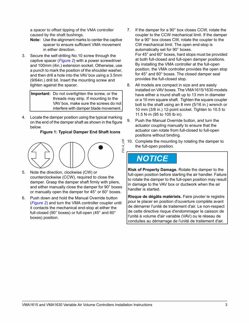
4. Locate the damper position using the typical markingon the end of the damper shaft as shown in the figurebelow.
Figure 1: Typical Damper End Shaft Icons
5. Note the direction, clockwise (CW) orcounterclockwise (CCW), required to close thedamper. Grasp the damper shaft firmly with pliers,and either manually close the damper for 90° boxesor manually open the damper for 45° or 60° boxes.
6. Push down and hold the Manual Override button(Figure 2) and turn the VMA controller coupler untilit contacts the mechanical end-stop at either thefull-closed (90° boxes) or full-open (45° and 60°boxes) position.
7. If the damper for a 90° box closes CCW, rotate thecoupler to the CCW mechanical limit. If the damperfor a 90° box closes CW, rotate the coupler to theCW mechanical limit. The open end-stop isautomatically set for 90° boxes.For 45° and 60° boxes, hard stops must be providedat both full-closed and full-open damper positions.By installing the VMA controller at the full-openposition, the VMA controller provides the open stopfor 45° and 60° boxes. The closed damper sealprovides the full-closed stop.
8. All models are compact in size and are easilyinstalled on VAV boxes. The VMA1615/1630modelshave either a round shaft up to 13 mm in diameteror a 10 mm square shaft. Tighten the square couplerbolt to the shaft using an 8 mm (5/16 in.) wrench or10 mm (3/8 in.) 12-point socket. Tighten to 10.5 to11.5 N·m (95 to 105 lb·in).
9. Push the Manual Override button, and turn theactuator coupling manually to ensure that theactuator can rotate from full-closed to full-openpositions without binding.
10. Complete the mounting by rotating the damper tothe full-open position.
Risk of Property Damage. Rotate the damper to thefull-open position before starting the air handler. Failureto rotate the damper to the full-open position may resultin damage to the VAV box or ductwork when the airhandler is started.
Risque de dégâts matériels. Faire pivoter le registrepour le placer en position d'ouverture complète avantde démarrer l'unité de traitement d'air. Le non-respectde cette directive risque d'endommager le caisson del'unité à volume d'air variable (VAV) ou le réseau deconduites au démarrage de l'unité de traitement d'air.
3VMA1615 and VMA1630 Variable Air Volume Controllers Installation Instructions

Figure 2: VMA1615/1630 Controller Wiring Terminations and Physical Features (VMA1630 Shown)
4VMA1615 and VMA1630 Variable Air Volume Controllers Installation Instructions

Table 1: VMA1615/1630 Feature Callout Numbers and DescriptionsPhysical Features: Description and ReferencesCallout24 VAC, Class 2 Supply Power Terminal Block (see Supply Power Terminal Block)1
Device Address DIP Switch Block (see Setting the Device Address)2
Binary Outputs, 24 VAC Triacs (see Table 3)3
Configurable Outputs: Voltage Analog Output (0–10 VDC) and Binary Output (24 VAC Triac) (VMA1630,see Table 3)
4
Dual Port Fitting (see Figure 2)5
Manual Override Button (see Mounting)6
Controller Coupler (see Mounting)7
Coupler Bolt (see Mounting)8
Universal Input: Voltage Analog Input (0–10 VDC)
Resistive Analog Inputs (0–600k ohm) (see Table 3):
0–2k Potentiometer
RTD: 1k Nickel, 1k Platinum, or A99B SI
NTC: 10K Type L (10K Johnson Controls Type II is equivalent to Type L) or 2.252K Type II
Dry Contact Binary Input
9
FC Bus Terminal Block. May also be used for N2 connections. See FC Bus Terminal Block (Or N2 ProtocolAs Required).
10
EOL (End-of-Line) Switch (see Setting the EOL Switch)11
SA Bus Terminal Block12
Modular Port (FC Bus) RJ-12 6-Pin Modular Jack (see Modular Ports)13
Modular Port (SA Bus) RJ-12 6-Pin Modular Jack (see Modular Ports)14
Captive Spacer and Screw (see Figure 2)15
LED Status Indicators (see Table 8)16
5VMA1615 and VMA1630 Variable Air Volume Controllers Installation Instructions

Wiring
Risk of Electric Shock. Disconnect the power supplybefore making electrical connections to avoid electricshock.
Risque de décharge électrique. Débrancherl'alimentation avant de réaliser tout raccordementélectrique afin d'éviter tout risque de décharge électrique.
Important: Do not connect supply power to thecontroller before finishing wiring andchecking all wiring connections. Shortcircuits or improperly connected wires canresult in damage to the controller and voidany warranty.
Important: Do not exceed the controller electricalratings. Exceeding controller electricalratings can result in permanent damage tothe controller and void any warranty.
Important: Use copper conductors only. Make all wiringin accordance with local, national, andregional regulations.
Important: Electrostatic discharge can damagecontroller components. Use properelectrostatic discharge precautions duringinstallation, setup, and servicing to avoiddamaging the controller.
For detailed information on configuring and wiring anMSTP Bus, Field Controller (FC), or Sensor/Actuator (SA)Bus, refer to the MSTP Communications Bus TechnicalBulletin (LIT-12011034).
VMA Terminals and Bus PortsSee Figure 2 for input and output terminal and bus portlocations on the VMA1615/1630 controllers. Observe thefollowing guidelines when wiring a VMA controller.
Input and Output TerminalsThe input spade terminals are located on the side of theVMA near the FC Bus terminal block. The output spadeterminals are located on the opposite side of the controllernear the power supply terminal block. See Table 3 formore information.
FC Bus Terminal Block (Or N2 Protocol AsRequired)The FC Bus terminal block is a blue, removable,4-terminal plug that fits into a board-mounted jack.
Wire the removable FC Bus terminal block plugs on theVMA and other controllers in a daisy-chain configurationusing 3-wire twisted, shielded cable as shown in Figure3. See Table 5 for more information.
Figure 3: FC Bus Terminal Block Wiring
Note: The Shield terminal (SHLD) on the FC Busterminal block is isolated and can be used toconnect the cable shields on the bus (Figure 3).
SA Bus Terminal BlockThe SA Bus terminal block is a brown, removable,4-terminal plug with +15 VDC that fits into aboard-mounted jack.
Wire the removable SA Bus terminal block plugs on theVMA and other SA Bus devices in a daisy-chainconfiguration using 4-wire twisted, shielded cable asshown in Figure 4. See Table 5 for more information.
Figure 4: SA Bus Terminal Block Wiring
6VMA1615 and VMA1630 Variable Air Volume Controllers Installation Instructions

Modular PortsThe modular and FC Bus ports on the face of the VMA(Figure 2) are RJ-12 (6-position) modular jacks as shownin Figure 5.
The modular SA Bus port provides a connection for theVAV Balancing Tool and NS Series sensors.
Figure 5: Pin Number Assignments for Sensor (SABus and FCBus) Ports on VMA1615/1630 Controllers
Note: Do not use the modular SA Bus port and theterminal block SA Bus simultaneously. Only useone of these connections at a time.
Supply Power Terminal BlockThe 24 VAC supply power terminal block is a gray,removable, 2-terminal plug that fits into a board-mountedjack on the upper left of the VMA controller.
Wire the 24 VAC supply power wires from the transformerto the HOT and COM terminals on the terminal plug asshown in Figure 6. See Table 5 for more information.
Figure 6: 24 VACSupply Power Terminal BlockWiring
Important: Connect 24 VAC supply power to the VMAand all other network devices so thattransformer phasing is uniform across thenetwork devices. Powering network deviceswith uniform 24 VAC supply power phasingreduces noise, interference, and groundloop problems. The VMA does not requirean earth ground connection. However, whengrounding the secondary of the 24 VACtransformer is required, only one connectionto ground should be made near thetransformer. See the following figure.
Figure 7: Transformer Grounding
Risk of Property Damage: Do not apply power to thesystem before checking all wiring connections. Improperwiring of this terminal may cause a short circuit acrossthe 24 VAC power supply on VMAmodels. A short circuitmay result in a tripped circuit breaker or blown fuse. Ifusing a transformer with a built-in fuse, the transformermay need to be replaced.
Risque de dommages matériels: Ne mettez pasl’appareil sous tension avant d’avoir vérifié toutes lesconnexions du câblage. Le câblage inadéquat de cetteborne peut causer un court-circuit sur l’alimentationélectrique de 24 V c.a. des -1 VMA modèles. Uncourt-circuit peut causer le déclenchement du disjoncteurou le grillage d’un fusible. Si vous utilisez untransformateur avec un fusible intégré, vous pourriezdevoir remplacer le transformateur.
To wire the VMA1615/1630 controller:
1. Terminate wiring according the appropriate figure inTermination Diagrams.
2. Wire network sensors and other devices to the VMA'sSA Bus.
3. Wire the FC Bus in a daisy chain.4. Ensure that the VMA’s device address DIP switches
are set to the appropriate device address. (See
7VMA1615 and VMA1630 Variable Air Volume Controllers Installation Instructions
Setting the Device Address.) Also, activate theend-of-line (EOL) switch if necessary.
5. Connect the VMA controller to 24 VAC, Class 2power.
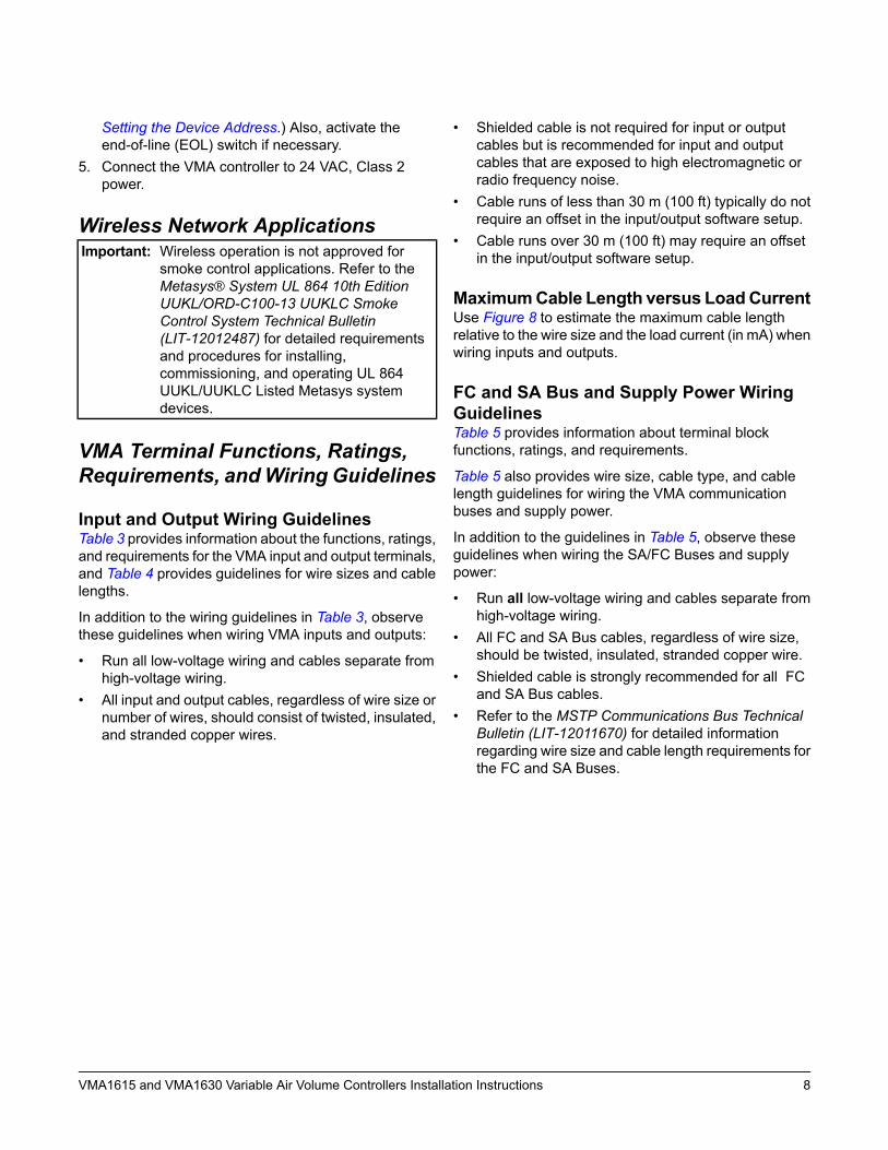
Wireless Network ApplicationsImportant: Wireless operation is not approved for
smoke control applications. Refer to theMetasys® System UL 864 10th EditionUUKL/ORD-C100-13 UUKLC SmokeControl System Technical Bulletin(LIT-12012487) for detailed requirementsand procedures for installing,commissioning, and operating UL 864UUKL/UUKLC Listed Metasys systemdevices.
VMA Terminal Functions, Ratings,Requirements, andWiring Guidelines
Input and Output Wiring GuidelinesTable 3 provides information about the functions, ratings,and requirements for the VMA input and output terminals,and Table 4 provides guidelines for wire sizes and cablelengths.
In addition to the wiring guidelines in Table 3, observethese guidelines when wiring VMA inputs and outputs:
• Run all low-voltage wiring and cables separate fromhigh-voltage wiring.
• All input and output cables, regardless of wire size ornumber of wires, should consist of twisted, insulated,and stranded copper wires.
• Shielded cable is not required for input or outputcables but is recommended for input and outputcables that are exposed to high electromagnetic orradio frequency noise.
• Cable runs of less than 30 m (100 ft) typically do notrequire an offset in the input/output software setup.
• Cable runs over 30 m (100 ft) may require an offsetin the input/output software setup.
MaximumCable Length versus LoadCurrentUse Figure 8 to estimate the maximum cable lengthrelative to the wire size and the load current (in mA) whenwiring inputs and outputs.
FC and SA Bus and Supply Power WiringGuidelinesTable 5 provides information about terminal blockfunctions, ratings, and requirements.
Table 5 also provides wire size, cable type, and cablelength guidelines for wiring the VMA communicationbuses and supply power.
In addition to the guidelines in Table 5, observe theseguidelines when wiring the SA/FC Buses and supplypower:
• Run all low-voltage wiring and cables separate fromhigh-voltage wiring.
• All FC and SA Bus cables, regardless of wire size,should be twisted, insulated, stranded copper wire.
• Shielded cable is strongly recommended for all FCand SA Bus cables.
• Refer to the MSTP Communications Bus TechnicalBulletin (LIT-12011670) for detailed informationregarding wire size and cable length requirements forthe FC and SA Buses.
8VMA1615 and VMA1630 Variable Air Volume Controllers Installation Instructions

Termination DiagramsA set of Johnson Controls® termination diagrams provides details for wiring inputs and outputs to the controllers.See the figures in this section for the applicable termination diagrams.Table 2: Termination Details
Termination DiagramsType ofInput/Output
Type of FieldDevice
UIVoltage Input -External Source
UIVoltage Input -Internal Source
UIVoltage Input(Self-Powered)
UITemperatureSensor
UIDry Contact
CO0–10 VDCOutput toActuator (ExternalSource)
9VMA1615 and VMA1630 Variable Air Volume Controllers Installation Instructions

Table 2: Termination DetailsTermination DiagramsType of
Input/OutputType of FieldDevice
CO0–10 VDCOutput toActuator (InternalSource)
Note: Applies to CO4 and CO5.
CO24 VAC TriacOutput (SwitchLow, ExternalSource)
Note: Applies to CO4 and CO5.
COIncremental Controlto Actuator (SwitchLow, ExternalSource)
COAnalog Output(Voltage)
Note: Applies to BO3 (for VMA 1630 only), BO1, and BO2.
BOIncremental Controlto Actuator (SwitchLow, InternallySourced)
BO24 VAC BinaryOutput (SwitchLow, InternallySourced)
10VMA1615 and VMA1630 Variable Air Volume Controllers Installation Instructions

Table 2: Termination DetailsTermination DiagramsType of
Input/OutputType of FieldDevice
SA BusNetwork Stat withPhone Jack (FixedAddress = 199)
SA BusNetwork Stat withTerminalsAddressable
SA BusNetwork Stat withTerminals (FixedAddress = 199)
11VMA1615 and VMA1630 Variable Air Volume Controllers Installation Instructions

Table 3: I/O Terminal Blocks, Functions, Ratings, Requirements, and CablesTo Determine Wire Sizeand Maximum CableLength1
Function, Ratings, and RequirementsTerminalLabels
Terminal Block Label
Same as (Universal) INn.
Note: Use 3-wire cable fordevices that sourcepower from the +15 Vterminal.
15 VDC Power Source for active (3-wire) inputdevices connected to the Universal INn terminals.
Provides 35 mA total current.
+15 VUNIVERSAL
(Inputs)
See Guideline A in Table 4.Analog Input - Voltage Mode (0–10 VDC)
10 VDC maximum input voltage
Internal 75k ohm Pulldown
INn
See Guideline A in Table 4.Analog Input - Resistive Mode (0–600k ohm)
Internal 12 V, 15k ohm pull up
Qualified Sensors: 0–2k potentiometer,
RTD (1k Nickel [Johnson Controls sensor],
1k Platinum, and A99B Silicon TemperatureSensor)
Negative Temperature Coefficient (NTC) Sensor
10K Type L (10K Johnson Controls Type II isequivalent to Type L) or 2.252K Type II
See Guideline A in Table 4.Binary Input - Dry Contact Maintained Mode
1 second minimum pulse width
Internal 12 V, 15k ohm pull up
Same as (Universal) INn.Universal Input Common for all Universal INterminals
Note: All Universal ICOMn terminals areisolated from all other commons on the-0 models. The -1 model ICOMnterminals are isolated from FC BUSCOM terminals only.
ICOMn
See Guideline C in Table 4.Binary Output - 24 VAC Triac (Internal Power)
Sources internal 24 VAC power (24~ HOT)
OUTnBINARY
(Outputs)
See Guideline C in Table 4.Binary Output - 24 VAC Triac (Internal Power)
Connects OCOMn to 24~ COM when activated.
Internal Power Source:
30 VAC maximum voltage to load
0.5 A maximum output current
1.3 A at 25% duty cycle
40 mA minimum load current
OCOMn
12VMA1615 and VMA1630 Variable Air Volume Controllers Installation Instructions

Table 3: I/O Terminal Blocks, Functions, Ratings, Requirements, and CablesTo Determine Wire Sizeand Maximum CableLength1
Function, Ratings, and RequirementsTerminalLabels
Terminal Block Label
See Guideline A in Table 4.Analog Output - Voltage Mode (0–10 VDC)
10 VDC maximum output voltage
10 mA maximum output current
External 1k to 50k ohm load required
OUTnCONFIGURABLE
(Outputs)
See Guideline C in Table 4.Binary Output 24 VAC Triac
Connects OUT to OCOM when activated.
External Power Source:
30 VAC maximum voltage to load
0.5 A maximum output current
1.3 A at 25% duty cycle
40 mA minimum load current
Same as (Configurable)OUTn.Analog Output Signal Common: AllConfigurable Outputs defined as Analog Outputsshare a common, which is isolated from all othercommons except the Binary Input common.
OCOMn
Binary Output Signal Common: AllConfigurable Outputs defined as Binary Outputsare isolated from all other commons, includingother Configurable Output commons.
1 Table 4 defines cable length guidelines for the various wire sizes that may be used for input and output wiring.
Table 4: Cable Length Guidelines for Recommended Wire SizesAssumptionsMaximum Cable Length
and TypeWire Size/Gauge and TypeGuideline
100mVmaximum voltage drop
Depending on the cable lengthand the connected input oroutput device, you may have todefine an offset in the setupsoftware for the input or outputpoint.
457 m (1,500 ft) twisted wire1.0mm (18 AWG) stranded copperA
297 m (975 ft) twisted wire0.8mm (20 AWG) stranded copper297 m (975 ft) twisted wire
183 m (600 ft) twisted wire0.6mm (22 AWG) stranded copper183 m (600 ft) twisted wire
107 m (350 ft) twisted wire0.5mm (24 AWG) stranded copper107 m (350 ft) twisted wire
100mVmaximum voltage drop
Depending on the cable lengthand the connected input oroutput device, you may have todefine an offset in the setupsoftware for the input or outputpoint.
229 m (750 ft) twisted wire1.0mm (18 AWG) stranded copperB
137 m (450 ft) twisted wire0.8mm (20 AWG) stranded copper297 m (975 ft) twisted wire
91 m (300 ft) twisted wire0.6mm (22 AWG) stranded copper183 m (600 ft) twisted wire
61 m (200 ft) twisted wire0.5mm (24 AWG) stranded copper107 m (350 ft) twisted wire
N/ASee Figure 8 to determinecable length.
Use twisted wire cable.
See Figure 8 to select wiresize/gauge.
Use stranded copper wire.
C
13VMA1615 and VMA1630 Variable Air Volume Controllers Installation Instructions
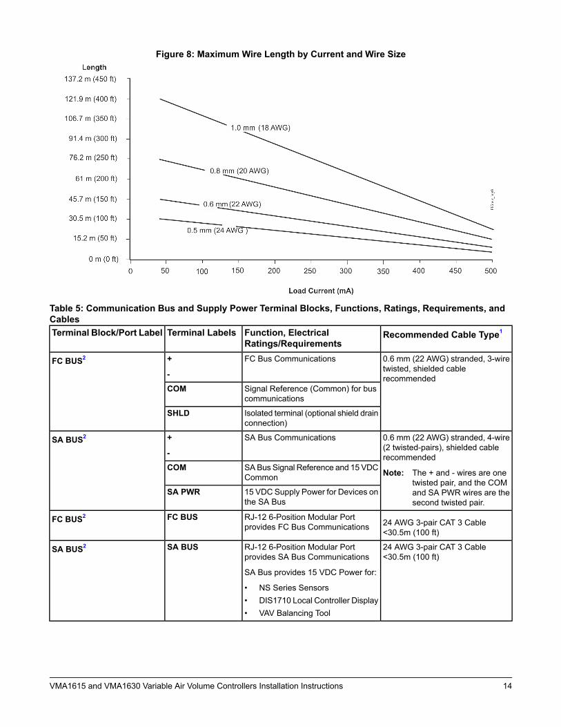
Figure 8: Maximum Wire Length by Current and Wire Size
Table 5: Communication Bus and Supply Power Terminal Blocks, Functions, Ratings, Requirements, andCables
Recommended Cable Type1Function, ElectricalRatings/Requirements
Terminal LabelsTerminal Block/Port Label
0.6 mm (22 AWG) stranded, 3-wiretwisted, shielded cablerecommended
FC Bus Communications+
-FC BUS2
Signal Reference (Common) for buscommunications
COM
Isolated terminal (optional shield drainconnection)
SHLD
0.6 mm (22 AWG) stranded, 4-wire(2 twisted-pairs), shielded cablerecommended
Note: The + and - wires are onetwisted pair, and the COMand SA PWR wires are thesecond twisted pair.
SA Bus Communications+
-SA BUS2
SABus Signal Reference and 15 VDCCommon
COM
15 VDC Supply Power for Devices onthe SA Bus
SA PWR
24 AWG 3-pair CAT 3 Cable<30.5m (100 ft)
RJ-12 6-Position Modular Portprovides FC Bus Communications
FC BUSFC BUS2
24 AWG 3-pair CAT 3 Cable<30.5m (100 ft)
RJ-12 6-Position Modular Portprovides SA Bus Communications
SA Bus provides 15 VDC Power for:
• NS Series Sensors• DIS1710 Local Controller Display• VAV Balancing Tool
SA BUSSA BUS2
14VMA1615 and VMA1630 Variable Air Volume Controllers Installation Instructions

Table 5: Communication Bus and Supply Power Terminal Blocks, Functions, Ratings, Requirements, andCables
Recommended Cable Type1Function, ElectricalRatings/Requirements
Terminal LabelsTerminal Block/Port Label
0.8 mm to 1.0 mm
(20 to 18 AWG) 2-wire
24 VAC Power Supply - Hot
Supplies 20–30 VAC (Nominal24VAC)
HOT24~
24 VAC Power Supply Common
The -0 models isolate this terminalfrom all other commons.
The -1 models only isolate thisterminal from the FC bus common.
COM
1 See Table 4 to determine wire size and cable lengths for cables other than the recommended cables.2 The SA Bus and FC Bus wiring recommendations in this table are for MS/TP Bus communications at 38.4k baud. For more
information, refer to the ,MS/TP Communications Bus Technical Bulletin (LIT-12011034).
Setup and AdjustmentsImportant: Electrostatic discharge can damage
controller components. Use properelectrostatic discharge precautions duringinstallation, setup, and servicing to avoiddamaging the controller.
Setting the Device AddressMetasys® field controllers are master devices onBACnet®MSTP (SA or FC) Buses. Before operating fieldcontrollers on a bus, you must set a valid and uniquedevice address for each controller on the bus.
Set a field controller’s device address by setting thepositions of the switches on the Device Address DIPswitch block at the top of the controller (Figure 2). Deviceaddresses 4 through 127 are the valid addresses forthese controllers.
The DIP switch block (Figure 9) has eight switchesnumbered 128, 64, 32, 16, 8, 4, 2, and 1. Switches 64through 1 are device address switches. Switch 128 is amode switch that enables a field controller to operate ona ZFR /ZFR Pro Series Wireless Field Bus. Set switch128 to OFF for all hard-wired SA and FC Bus applications.
Figure 9: Device Address Switches Set to 21
Note: Metasys field controllers ship with Switch 128 ONand the remaining address switches OFF. Thisrenders the controllers wired slave devices, whichdo not interfere on MSTP Buses and do notinterfere with bus operation. Set a valid andunique device address on the controller beforeapplying power to the controller on the bus.
To set the device addresses on aMetasys field controller:
1. Set all of the switches on the field controller’s deviceaddress DIP switch block (128 through 1) to OFF.
2. Set one or more of the seven address switches (64through 1) to ON, so that the sum of the switchnumbers set to ON equals the intended deviceaddress. See Table 6 for valid field controlleraddresses.
Set the highest number switch that is less than orequal to the intended device address to ON. Thencontinue setting lower numbered switches until thetotal equals the intended address. For example, if theintended device address is 21, set Switch 16 to ONfirst, then set Switch 4 ON, followed by Switch 1(16+4+1=21). See Figure 9.
3. Set Switch 128 to OFF for all hard-wired SA and FCBus applications.
4. Set a unique and sequential device address for eachof the field controllers connected on the SA or FCBus, starting with device address 4.
To ensure the best bus performance, set sequentialdevice addresses with no gaps in the device addressrange (4, 5, 6, 7, 8, 9, and so on). The field controllers
15VMA1615 and VMA1630 Variable Air Volume Controllers Installation Instructions

do not need to be physically connected on the bus intheir numerical device address order.
5. Write each field controller’s device address on thewhite label below the DIP switch block on thecontroller’s cover.
Refer to the MSTP Communications Bus TechnicalBulletin (LIT-12011034) for more information on fieldcontroller device addresses and how to set them onMSTP Buses.
Table 6 show and describe the valid FC Bus and SA Busdevice addresses for Johnson Controls MSTPcommunications bus applications.
Table 6: FC Bus Device Address DescriptionsAddress DescriptionDevice
AddressReserved for FC Bus Supervisory Controller(not valid for field controllers).
0
(Switch 128OFF)
Reserved for peripheral devices (not valid forfield controllers).
1 to 3
(Switch 128OFF)
Valid for MSTP Master field controllers on ahard-wired SA Bus or FC Bus.
4 to 127
(Switch 128OFF)
Setting the N2 Controller Address tobe Greater than 127N2-configured controllers support the full range ofpossible N2 device addresses provided by the N2 protocolstandard (1-255). However, these controllers requirespecial configuration for addresses above 127.
Use the following instructions for controller addressesgreater than 127. Prior to performing this procedure, besure the controller has been converted from BACnet toN2 protocol first. Refer to the Modernization Guide forLegacy N2 Controllers (LIT-12012005) for moreinformation.
1. Disconnect the 24 VAC supply from the controller.2. Remove the FC Bus connector from the controller.3. Set the address switch set to the desired N2 address.4. Set the address switch segment labeled 128 to OFF.5. Reconnect the 24 VAC supply to the controller.6. Using an SA bus connection, download the firmware
and controller application file. The download processasks to confirm switching the communication protocolto N2.
7. Click OK.8. After the download is finished, disconnect the 24
VAC supply to the controller.9. Set the address switch segment labeled 128 to ON.10. Reattach the FC Bus connector to the controller.11. Reconnect the 24 VAC supply to the controller.
Setting the EOL SwitchEach field controller has an EOL switch, which, when setto ON (up), sets the field controller as a terminating deviceon the bus. See (Figure 2) for the EOL switch locationon the field controller. The default EOL switch position isOFF (down). The amber EOL LED illuminates to showthe EOL is active.
Figure 10: EOL Switch Positions
To set the EOL switch on a field controller:1. Determine the physical location of the controller on
the SA or FC Bus.2. Determine if the controller must be set as a
terminating device on the bus.Note: The EOL termination rules for SA Buses and
FC Buses are different. Refer to the MSTPCommunications Bus Technical Bulletin(LIT-12011034) for detailed informationregarding EOL termination rules and EOLswitch settings on SA and FC Buses.
3. If the controller is a terminating device on the FC Bus,set the EOL switch to ON. If the controller is not aterminating device on the bus, set the EOL switch toOFF.Note: When the EOL switch is set to ON, the LED
light on the face of the controller is illuminated.
16VMA1615 and VMA1630 Variable Air Volume Controllers Installation Instructions

CommissioningUse the following procedure to commission theVMA1615/1630 controller:1. Download the control application to the VMA controller
using the Controller Configuration Tool (CCT). Referto the Controller Tool Help (LIT-12011147).
2. Commission the VAV Box. Refer to the ControllerTool Help (LIT-12011147).
3. Perform airflow balancing on the VAV box. Refer tothe VAV Balancing Tool Technical Bulletin(LIT-12011087).
4. Perform commissioning checkout procedures. Referto the Controller Tool Help (LIT-12011147).
Repair InformationTheMS-VMA1615-xU andMS-VMA1630-xUmodels areUL 864 10th Edition UUKL/ORD-C100-13 UUKLC listedfor smoke control. If the VMA1615/1630 controller failsto operate within its specifications, contact the JohnsonControls Repair Center in Louisville, Kentucky, at1-502-671-7312.
TroubleshootingTable 8 provides LED status indicator information fortroubleshooting the VMA1615/1630 controller. Table 7provides some additional troubleshooting information forpossible problems.Note: If you experience short circuits in the 24 VAC
power supply causing protective devices such asbreakers or fuses to trip, make sure that the powerconnections on the VMA are not reversed. Themost common cause of this problem is when the24 VAC power supply on the VMA is reversed butnot reversed on a connected secondary device.Improper wiring of this power terminal may causea short circuit across the 24 VAC power supplyon -1 models.
17VMA1615 and VMA1630 Variable Air Volume Controllers Installation Instructions

Table 7: TroubleshootingVerificationCorrectionPossible CauseProblem
Transformer has trippedPower at Primary ofTransformer, 0V atSecondary
Controller is Off 1.1.1. Disconnect thesecondary of the 24VAC transformer
Ensure polarity of ~24 V COM /ICOM / + 15VCOM/SA BUSCOM on the controller, auxiliarydevices and I/O is the same.
Transformer is shorted2. 24VAC powered sensor is not
wired with the same polarity asthe controllerBreaker/Fuse has tripped.Power at Primary of
Transformer, 24 V atSecondary, 0V atFuse/Breaker.
2. Use an ohm-meter tomeasure between ~24 VHOT and COM; thereshould be no shortcircuit.
2. Ensure OUT1-OUT3 terminalsof binary outputs are notconnected to ~24 VAC COM,verify that OCOM1-OCOM3 arenot connected to ~24 VAC HOT(these terminals are internallysourced).
3. SA bus device is not wired withthe same polarity as thecontroller
Note: Note that someinstallations requirethe secondary of theTransformer to beEarth Grounded. Ifthis is the case,verify that the EarthGround connectionis valid and notshared betweenmultiple pieces ofequipment.
3. Verify the short circuit has beenresolved with an ohm-meter.
4. Reset the breaker/fuse orreplace the transformer.
Note: When replacing thetransformer, it isrecommended to replacewith a model that utilizes aresettable circuit breaker. Acircuit breaker makessolving wiring problemseasier.
Ensure polarities of ~24 VCOM/OCOM match and that theconnected end device uses thesame polarity.
Power polarity mismatch betweenconnected device and configurableoutput
Output is in protectionmode - a state the analogportion of the configurableoutput goes into when itdetects a wiring problem.The analog output is setto 0% regardless of thecommand whenever awiring fault is detected.
0–10 V output is setto 10–100%, but 0 Vis at output terminals
Configurable output- analog mode isinvalid.
1. Measure the output andverify that it matches thecommand.
2. Disconnect theconnected device andverify the commandedvalue is present.
Connect OCOM terminal of theconfigurable output to the commonof the connected end device.
OCOM terminal is not connectedCommon Reference isincorrect
0–10V output has anundesirable offset ofup to 1 V
18VMA1615 and VMA1630 Variable Air Volume Controllers Installation Instructions
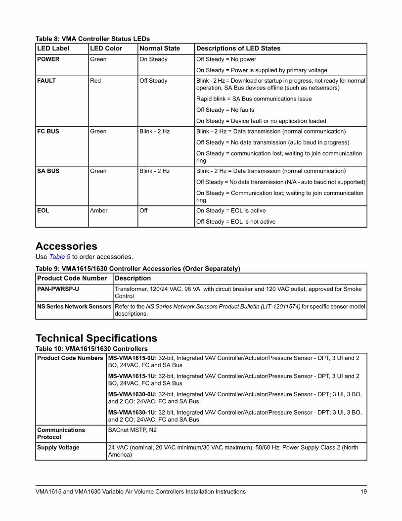
Table 8: VMA Controller Status LEDsDescriptions of LED StatesNormal StateLED ColorLED LabelOff Steady = No power
On Steady = Power is supplied by primary voltage
On SteadyGreenPOWER
Blink - 2 Hz = Download or startup in progress, not ready for normaloperation, SA Bus devices offline (such as netsensors)
Rapid blink = SA Bus communications issue
Off Steady = No faults
On Steady = Device fault or no application loaded
Off SteadyRedFAULT
Blink - 2 Hz = Data transmission (normal communication)
Off Steady = No data transmission (auto baud in progress)
On Steady = communication lost, waiting to join communicationring
Blink - 2 HzGreenFC BUS
Blink - 2 Hz = Data transmission (normal communication)
Off Steady = No data transmission (N/A - auto baud not supported)
On Steady = Communication lost; waiting to join communicationring
Blink - 2 HzGreenSA BUS
On Steady = EOL is active
Off Steady = EOL is not active
OffAmberEOL
AccessoriesUse Table 9 to order accessories.
Table 9: VMA1615/1630 Controller Accessories (Order Separately)DescriptionProduct Code NumberTransformer, 120/24 VAC, 96 VA, with circuit breaker and 120 VAC outlet, approved for SmokeControl
PAN-PWRSP-U
Refer to theNS Series Network Sensors Product Bulletin (LIT-12011574) for specific sensor modeldescriptions.
NSSeriesNetwork Sensors
Technical SpecificationsTable 10: VMA1615/1630 Controllers
MS-VMA1615-0U: 32-bit, Integrated VAV Controller/Actuator/Pressure Sensor - DPT, 3 UI and 2BO, 24VAC, FC and SA Bus
MS-VMA1615-1U: 32-bit, Integrated VAV Controller/Actuator/Pressure Sensor - DPT, 3 UI and 2BO, 24VAC, FC and SA Bus
MS-VMA1630-0U: 32-bit, Integrated VAV Controller/Actuator/Pressure Sensor - DPT; 3 UI, 3 BO,and 2 CO; 24VAC; FC and SA Bus
MS-VMA1630-1U: 32-bit, Integrated VAV Controller/Actuator/Pressure Sensor - DPT; 3 UI, 3 BO,and 2 CO; 24VAC; FC and SA Bus
Product Code Numbers
BACnet MSTP, N2CommunicationsProtocol
24 VAC (nominal, 20 VAC minimum/30 VAC maximum), 50/60 Hz, Power Supply Class 2 (NorthAmerica)
Supply Voltage
19VMA1615 and VMA1630 Variable Air Volume Controllers Installation Instructions

Table 10: VMA1615/1630 Controllers10 VA typical, 14 VA maximum
Note: The VA rating does not include any power supplied to the peripheral devices connected toBinary Outputs (BOs) or Configurable Outputs (COs), which can consume up to 12 VA foreach BO or CO, for a possible total consumption of an additional 60 VA (maximum).
Power Consumption
Operating: 0 to 50°C (32 to 122°F)
Storage: -40 to 70°C (-40 to 158°F)
Ambient Conditions
Inputs/Outputs: 6.3 mm (1/4 in.) Spade Lugs
FC Bus, Pluggable Screw Terminal Block
FC and SA Bus Modular Ports: RJ-12 6-Pin Modular Jacks
Terminations
DIP switch set; valid field controller device addresses 4–127
(Device addresses 0–3 and 128–255 are reserved and not valid field controller addresses.)
Controller Addressingfor BACnet MSTP
DIP switch set; valid field controller device addresses 1–255Controller Addressingfor N2
RS-485: selectable between BACnet MSTP or N2
FC Bus: 0.6 mm (22 AWG) standard 3-wire, twisted, shielded cable recommended between thesupervisory controller and field controller
SA Bus: 0.6 mm (22 AWG) stranded, 4-wire (2-twisted pairs) shielded cable recommended fromthe VMA controller for network sensors and other sensor/actuator devices; includes a terminal tosource 15 VDC supply power from VMA to SA Bus devices1
Communications Bus1
RX630 32-bit Renesas microcontrollerProcessor
1 MB flash memory and 512 KB RAMMemory
UI Analog Input Mode: 15-bit resolution on UIs
CO Analog Output Mode (VMA1630 only): 0–10 VDC ± 200 mV
Universal InputMode/ConfigurableOutput Mode Accuracy
Range: -1.5 in. to 1.5 in. W.C.
Performance Characteristics:
Accuracy: ±1.3% Full Span Maximum2 (±0.039 in. W.C.)
Typical accuracy at zero (null) pressure is ±0.02 in. W.C.3 (if provided)
Air Pressure DifferentialSensor
4 N·m (35 lb·in) minimum shaft length = 44 mm (1-3/4 in.) (if provided)Actuator Rating
Mounts to damper shaft using single set screw and to duct with single mounting screwMounting
165 x 125 x 73 mm (6.5 x 4.92 x 2.9 in.)
Center of Output Hub to Center of Captive Spacer: 135 mm (5-5/16 in.)
Dimensions
(Height x Width x Depth)
0.65 kg (1.45 lb)Weight
20VMA1615 and VMA1630 Variable Air Volume Controllers Installation Instructions
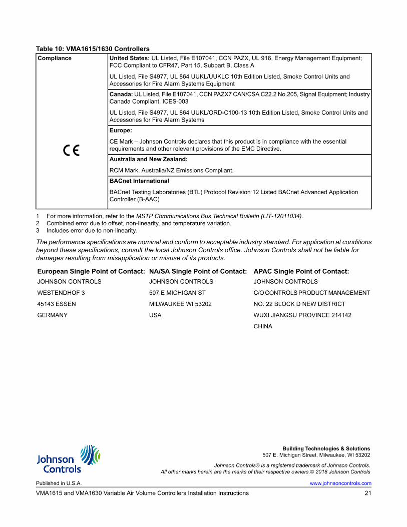
Table 10: VMA1615/1630 ControllersUnited States: UL Listed, File E107041, CCN PAZX, UL 916, Energy Management Equipment;FCC Compliant to CFR47, Part 15, Subpart B, Class A
UL Listed, File S4977, UL 864 UUKL/UUKLC 10th Edition Listed, Smoke Control Units andAccessories for Fire Alarm Systems Equipment
Compliance
Canada:UL Listed, File E107041, CCN PAZX7 CAN/CSAC22.2 No.205, Signal Equipment; IndustryCanada Compliant, ICES-003
UL Listed, File S4977, UL 864 UUKL/ORD-C100-13 10th Edition Listed, Smoke Control Units andAccessories for Fire Alarm Systems
Europe:
CE Mark – Johnson Controls declares that this product is in compliance with the essentialrequirements and other relevant provisions of the EMC Directive.
Australia and New Zealand:
RCM Mark, Australia/NZ Emissions Compliant.
BACnet International
BACnet Testing Laboratories (BTL) Protocol Revision 12 Listed BACnet Advanced ApplicationController (B-AAC)
1 For more information, refer to the MSTP Communications Bus Technical Bulletin (LIT-12011034).2 Combined error due to offset, non-linearity, and temperature variation.3 Includes error due to non-linearity.
The performance specifications are nominal and conform to acceptable industry standard. For application at conditionsbeyond these specifications, consult the local Johnson Controls office. Johnson Controls shall not be liable fordamages resulting from misapplication or misuse of its products.
APAC Single Point of Contact:NA/SA Single Point of Contact:European Single Point of Contact:JOHNSON CONTROLS
C/OCONTROLSPRODUCTMANAGEMENT
NO. 22 BLOCK D NEW DISTRICT
WUXI JIANGSU PROVINCE 214142
CHINA
JOHNSON CONTROLS
507 E MICHIGAN ST
MILWAUKEE WI 53202
USA
JOHNSON CONTROLS
WESTENDHOF 3
45143 ESSEN
GERMANY
Building Technologies & Solutions507 E. Michigan Street, Milwaukee, WI 53202
Johnson Controls® is a registered trademark of Johnson Controls.All other marks herein are the marks of their respective owners.© 2018 Johnson Controls
www.johnsoncontrols.comPublished in U.S.A.
21VMA1615 and VMA1630 Variable Air Volume Controllers Installation Instructions