45J,M,K,N,Q,R Fan Powered Variable Air Volume Terminals
52
Manufacturer reserves the right to discontinue, or change at any time, specifications or designs without notice and without incurring obligations. Catalog No. 04-53450002-01 Printed in U.S.A. Form 45-3SI Pg 1 12-08 Replaces: 45-1SI Installation, Start-Up and Service Instructions CONTENTS SAFETY CONSIDERATIONS . . . . . . . . . . . . . . . . . . . . . . 1 PRE-INSTALLATION . . . . . . . . . . . . . . . . . . . . . . . . . . . . 1-3 General . . . . . . . . . . . . . . . . . . . . . . . . . . . . . . . . . . . . . . . . . . 1 Unit Identification . . . . . . . . . . . . . . . . . . . . . . . . . . . . . . . . 2 Warranty . . . . . . . . . . . . . . . . . . . . . . . . . . . . . . . . . . . . . . . . . 2 CONTROL OPTIONS . . . . . . . . . . . . . . . . . . . . . . . . . . . 4-6 ComfortID™ VAV Controls . . . . . . . . . . . . . . . . . . . . . . . 4 3V™ VVT® Controls . . . . . . . . . . . . . . . . . . . . . . . . . . . . . . 4 Analog Electric Controls . . . . . . . . . . . . . . . . . . . . . . . . . 4 Pneumatic Controls . . . . . . . . . . . . . . . . . . . . . . . . . . . . . . 5 No Controls or Direct Digital Controls (By Others) . . . . . . . . . . . . . . . . . . . . . . . . . . . . . . . . . . . . . . 5 INSTALLATION . . . . . . . . . . . . . . . . . . . . . . . . . . . . . . . . . 6-9 Step 1 — Install Fan Powered Box . . . . . . . . . . . . . . . . 6 Step 2 — Make Duct Connections . . . . . . . . . . . . . . . . 6 Step 3 — Connect Power Wiring. . . . . . . . . . . . . . . . . . 6 Step 4 — Set Up System and Calibrate . . . . . . . . . . . 8 START-UP . . . . . . . . . . . . . . . . . . . . . . . . . . . . . . . . . . . . . 9-16 General . . . . . . . . . . . . . . . . . . . . . . . . . . . . . . . . . . . . . . . . . . 9 Initial Start-Up Procedures . . . . . . . . . . . . . . . . . . . . . . . 9 Balancing Carrier Fan Terminals . . . . . . . . . . . . . . . . 10 Speed Controller . . . . . . . . . . . . . . . . . . . . . . . . . . . . . . . . 16 ComfortID VAV CONTROLS . . . . . . . . . . . . . . . . . . 16-23 Install Sensors and Make Field Wiring Connections . . . . . . . . . . . . . . . . . . . . . . . . . . . . . . . . . . 16 Connect the CCN Communication Bus . . . . . . . . . . 22 Water Valve Installation . . . . . . . . . . . . . . . . . . . . . . . . . 22 ComfortID Start-Up. . . . . . . . . . . . . . . . . . . . . . . . . . . . . . 22 CCN System Start-Up . . . . . . . . . . . . . . . . . . . . . . . . . . . 23 3V VVT CONTROLS . . . . . . . . . . . . . . . . . . . . . . . . . . 24-43 General . . . . . . . . . . . . . . . . . . . . . . . . . . . . . . . . . . . . . . . . . 24 Installation . . . . . . . . . . . . . . . . . . . . . . . . . . . . . . . . . . . . . . 24 Start-Up . . . . . . . . . . . . . . . . . . . . . . . . . . . . . . . . . . . . . . . . . 39 Initial Operation and Test. . . . . . . . . . . . . . . . . . . . . . . . 42 Fan and Heat Configuration and Test. . . . . . . . . . . . 43 System Balancing . . . . . . . . . . . . . . . . . . . . . . . . . . . . . . . 43 PNEUMATIC CONTROLS . . . . . . . . . . . . . . . . . . . . . 43-46 General — Single Function Pneumatic Controller Control Sequences (1300-1305, 1400-1401). . . . 43 Units with Single-Function Controllers . . . . . . . . . . 43 Units with Multi-Function Controllers (Sequences 1306-1317 and 1402-1405) . . . . . . . . 45 Operation Sequences . . . . . . . . . . . . . . . . . . . . . . . . . . . 45 ANALOG CONTROLS . . . . . . . . . . . . . . . . . . . . . . . . 46-48 General . . . . . . . . . . . . . . . . . . . . . . . . . . . . . . . . . . . . . . . . . 46 System Check . . . . . . . . . . . . . . . . . . . . . . . . . . . . . . . . . . . 46 Thermostat Check. . . . . . . . . . . . . . . . . . . . . . . . . . . . . . . 46 Controller Check . . . . . . . . . . . . . . . . . . . . . . . . . . . . . . . . 47 SERVICE . . . . . . . . . . . . . . . . . . . . . . . . . . . . . . . . . . . . . .48,49 Controls. . . . . . . . . . . . . . . . . . . . . . . . . . . . . . . . . . . . . . . . . 48 Fan Motor and Wheel. . . . . . . . . . . . . . . . . . . . . . . . . . . . 48 Fan Motor Wiring. . . . . . . . . . . . . . . . . . . . . . . . . . . . . . . . 48 Fan Motor Maintenance . . . . . . . . . . . . . . . . . . . . . . . . . 48 SAFETY CONSIDERATIONS PRE-INSTALLATION General — The 45J,K,Q constant volume (series) and 45M,N,R variable volume (parallel) fan powered boxes (see Fig. 1 and 2) can be equipped to provide pressure independent, variable volume (VAV). All units can also be equipped with factory-installed analog electronic, pneumatic, or ComfortID™ variable air volume (VAV) controls. The 45M,N,R units can be equipped with 3V™ variable volume and temperature (VVT) controls. Units are available with factory-installed electric or hot water heat. SAFETY NOTE Air-handling equipment will provide safe and reliable service when operated within design specifications. The equipment should be operated and serviced only by authorized personnel who have a thorough knowledge of system operation, safety devices, and emergency procedures. Good judgement should be used in applying any manu- facturer’s instructions to avoid injury to personnel or damage to equipment and property. WARNING Disconnect all power to the unit before performing mainte- nance or service. Unit may automatically start if power is not disconnected. Electrical shock and personal injury could result. WARNING If it is necessary to remove and dispose of mercury contac- tors in electric heat section, follow all local, state, and fed- eral laws regarding disposal of equipment containing hazardous materials. 45J,M,K,N,Q,R Fan Powered Variable Air Volume Terminals Fig. 1 — Series Flow Unit (45K Shown)
-
Upload
khangminh22 -
Category
Documents
-
view
1 -
download
0
Transcript of 45J,M,K,N,Q,R Fan Powered Variable Air Volume Terminals

Manufacturer reserves the right to discontinue, or change at any time, specifications or designs without notice and without incurring obligations.Catalog No. 04-53450002-01 Printed in U.S.A. Form 45-3SI Pg 1 12-08 Replaces: 45-1SI
Installation, Start-Up andService Instructions
CONTENTSSAFETY CONSIDERATIONS . . . . . . . . . . . . . . . . . . . . . . 1PRE-INSTALLATION . . . . . . . . . . . . . . . . . . . . . . . . . . . . 1-3General . . . . . . . . . . . . . . . . . . . . . . . . . . . . . . . . . . . . . . . . . . 1Unit Identification . . . . . . . . . . . . . . . . . . . . . . . . . . . . . . . . 2Warranty . . . . . . . . . . . . . . . . . . . . . . . . . . . . . . . . . . . . . . . . . 2CONTROL OPTIONS . . . . . . . . . . . . . . . . . . . . . . . . . . . 4-6ComfortID™ VAV Controls . . . . . . . . . . . . . . . . . . . . . . . 43V™ VVT® Controls . . . . . . . . . . . . . . . . . . . . . . . . . . . . . . 4Analog Electric Controls . . . . . . . . . . . . . . . . . . . . . . . . . 4Pneumatic Controls . . . . . . . . . . . . . . . . . . . . . . . . . . . . . . 5No Controls or Direct Digital Controls (By Others) . . . . . . . . . . . . . . . . . . . . . . . . . . . . . . . . . . . . . . 5INSTALLATION . . . . . . . . . . . . . . . . . . . . . . . . . . . . . . . . . 6-9Step 1 — Install Fan Powered Box. . . . . . . . . . . . . . . . 6Step 2 — Make Duct Connections . . . . . . . . . . . . . . . . 6Step 3 — Connect Power Wiring. . . . . . . . . . . . . . . . . . 6Step 4 — Set Up System and Calibrate . . . . . . . . . . . 8START-UP . . . . . . . . . . . . . . . . . . . . . . . . . . . . . . . . . . . . . 9-16General . . . . . . . . . . . . . . . . . . . . . . . . . . . . . . . . . . . . . . . . . . 9Initial Start-Up Procedures . . . . . . . . . . . . . . . . . . . . . . . 9Balancing Carrier Fan Terminals . . . . . . . . . . . . . . . . 10Speed Controller . . . . . . . . . . . . . . . . . . . . . . . . . . . . . . . . 16ComfortID VAV CONTROLS . . . . . . . . . . . . . . . . . . 16-23Install Sensors and Make Field Wiring
Connections . . . . . . . . . . . . . . . . . . . . . . . . . . . . . . . . . . 16Connect the CCN Communication Bus . . . . . . . . . . 22Water Valve Installation . . . . . . . . . . . . . . . . . . . . . . . . . 22ComfortID Start-Up. . . . . . . . . . . . . . . . . . . . . . . . . . . . . . 22CCN System Start-Up . . . . . . . . . . . . . . . . . . . . . . . . . . . 233V VVT CONTROLS . . . . . . . . . . . . . . . . . . . . . . . . . . 24-43General . . . . . . . . . . . . . . . . . . . . . . . . . . . . . . . . . . . . . . . . . 24Installation . . . . . . . . . . . . . . . . . . . . . . . . . . . . . . . . . . . . . . 24Start-Up . . . . . . . . . . . . . . . . . . . . . . . . . . . . . . . . . . . . . . . . . 39Initial Operation and Test. . . . . . . . . . . . . . . . . . . . . . . . 42Fan and Heat Configuration and Test. . . . . . . . . . . . 43System Balancing . . . . . . . . . . . . . . . . . . . . . . . . . . . . . . . 43PNEUMATIC CONTROLS . . . . . . . . . . . . . . . . . . . . . 43-46General — Single Function Pneumatic Controller
Control Sequences (1300-1305, 1400-1401). . . . 43Units with Single-Function Controllers . . . . . . . . . . 43Units with Multi-Function Controllers
(Sequences 1306-1317 and 1402-1405) . . . . . . . . 45Operation Sequences . . . . . . . . . . . . . . . . . . . . . . . . . . . 45ANALOG CONTROLS . . . . . . . . . . . . . . . . . . . . . . . . 46-48General . . . . . . . . . . . . . . . . . . . . . . . . . . . . . . . . . . . . . . . . . 46System Check. . . . . . . . . . . . . . . . . . . . . . . . . . . . . . . . . . . 46Thermostat Check. . . . . . . . . . . . . . . . . . . . . . . . . . . . . . . 46Controller Check . . . . . . . . . . . . . . . . . . . . . . . . . . . . . . . . 47SERVICE . . . . . . . . . . . . . . . . . . . . . . . . . . . . . . . . . . . . . .48,49Controls. . . . . . . . . . . . . . . . . . . . . . . . . . . . . . . . . . . . . . . . . 48Fan Motor and Wheel. . . . . . . . . . . . . . . . . . . . . . . . . . . . 48Fan Motor Wiring. . . . . . . . . . . . . . . . . . . . . . . . . . . . . . . . 48Fan Motor Maintenance . . . . . . . . . . . . . . . . . . . . . . . . . 48
SAFETY CONSIDERATIONS
PRE-INSTALLATION
General — The 45J,K,Q constant volume (series) and45M,N,R variable volume (parallel) fan powered boxes (seeFig. 1 and 2) can be equipped to provide pressure independent,variable volume (VAV). All units can also be equipped withfactory-installed analog electronic, pneumatic, or ComfortID™variable air volume (VAV) controls. The 45M,N,R units can beequipped with 3V™ variable volume and temperature (VVT)controls. Units are available with factory-installed electric orhot water heat.
SAFETY NOTEAir-handling equipment will provide safe and reliableservice when operated within design specifications. Theequipment should be operated and serviced only byauthorized personnel who have a thorough knowledgeof system operation, safety devices, and emergencyprocedures.Good judgement should be used in applying any manu-facturer’s instructions to avoid injury to personnel ordamage to equipment and property.
WARNING
Disconnect all power to the unit before performing mainte-nance or service. Unit may automatically start if power isnot disconnected. Electrical shock and personal injurycould result.
WARNING
If it is necessary to remove and dispose of mercury contac-tors in electric heat section, follow all local, state, and fed-eral laws regarding disposal of equipment containinghazardous materials.
45J,M,K,N,Q,RFan Powered
Variable Air Volume Terminals
Fig. 1 — Series Flow Unit (45K Shown)

2
The 45J,M units are standard fan powered terminal units.The 45K,N units are quiet fan powered terminal units. The45Q,R units are low profile fan powered terminal units.CONTROL OFFERINGS — Each 45J, 45K, 45M, 45N, 45Q,45R unit is supplied with a linear averaging flow probe as astandard feature. This probe offers a flow averaging capabilityand results in flow sensing capacity equal to any competitiveunit.
Control options include ComfortID™ VAV, 3V variablevolume and temperature (VVT®), analog electronic and pres-sure-independent pneumatic. Both 3V and ComfortID controlsare communicating controls that are compatible with the Carri-er Comfort Network® (CCN) network. The 3V VVT controlsare for 45M,N,R units only.
Pneumatic controls are available with linear actuators andsingle-function or multi-function controller. The multi-functioncontroller provides a simple switchover from normally open tonormally closed applications.
Electronic control units feature a factory-installed enclosurethat provides easy access for field connections.STORAGE AND HANDLING — Inspect for damage uponreceipt. Shipping damage claims should be filed with shipper attime of delivery. Store in a clean, dry, and covered location. Donot stack units. When unpacking units, care should be takenthat the inlet collars and externally mounted components do notbecome damaged. Do not lift units using collars, sensors, or ex-ternally mounted components as handles. If a unit is suppliedwith electric or hot water heat, care should be taken to preventdamage to these devices. Do not lay uncrated units on end orsides. Do not stack uncrated units over 6 ft high. Do not man-handle. Do not handle control boxes by tubing connections orother external attachments. Table 1 shows component weights.INITIAL INSPECTION — Once items have been removedfrom packing, check carefully for damage to duct connections,coils, or controls. File damage claim immediately with trans-portation agency and notify Carrier.NOTE: Remove all packaging material and foreign materialfrom unit and ensure the blower wheel moves freely beforeinstallation. Units are shipped with cardboard in both sides ofthe fan inlet that MUST be removed.
Unit Identification — Each unit has 2 main labels at-tached to the casing. The FAN UNIT label (Fig. 3) lists themodel number, supply voltage requirements, motor horsepow-er and overcurrent protection requirements. The AIRFLOWlabel (Fig. 4) lists the model number, unit size, factory ordernumber and location. The location “tag” indicates where theunit is intended for installation. There may be other labels at-tached to the unit, as options or codes may require. Read alllabels on a typical unit before attempting installation. Controlboxes are assembled as indicated on the identification label.
Contact your local Carrier representative for moreinformation.INSTALLATION PRECAUTION — Check that constructiondebris does not enter unit or ductwork. Do not operate thecentral-station air-handling fan without final or constructionfilters in place. Accumulated dust and construction debrisdistributed through the ductwork can adversely affect unitoperation.SERVICE ACCESS — Provide service clearance for unitaccess (see Installation section for details).CODES — Install units in compliance with all applicable coderequirements.UNIT SUSPENSION — See Installation section for unit sus-pension details.
Warranty — All Carrier-furnished items carry the standardCarrier warranty.
Fig. 2 — Parallel Fan Unit (45J Shown)
Fig. 3 — Fan Unit Label
Fig. 4 — Airflow Label

3
Table 1 — Unit Weights
45J UNIT WEIGHTS (lb)
45M UNIT WEIGHTS (lb)
45K UNIT WEIGHTS (lb)
45N UNIT WEIGHTS (lb)
45Q UNIT WEIGHTS (lb)
45R UNIT WEIGHTS (lb)
LEGENDDDC — Direct Digital Controls
SIZE UNIT WT WITH PNEUMATIC CONTROLS
WITH DDC OR ANALOG CONTROLS WITH ELECTRIC HEATER
WITH HOT WATER1-Row 2-Row
2 70 74 79 100 89 913 70 74 79 100 90 924 85 89 94 117 107 1105 85 89 94 117 109 1136 100 104 109 135 125 1307 140 144 109 180 175 183
SIZE UNIT WT WITH PNEUMATIC CONTROLS
WITH DDC OR ANALOG CONTROLS WITH ELECTRIC HEATER
WITH HOT WATER1-Row 2-Row
2 114 118 123 144 133 1353 114 118 123 144 133 1354 115 119 124 147 134 1365 122 126 131 154 134 1366 123 127 132 155 135 1377 127 131 136 167 139 141
SIZE UNIT WT WITH PNEUMATIC CONTROLS
WITH DDC OR ANALOG CONTROLS WITH ELECTRIC HEATER
WITH HOT WATER1-Row 2-Row
2 185 189 194 278 194 1973 200 204 209 280 209 2124 200 204 209 232 209 2125 225 229 234 257 237 2426 250 254 259 285 262 2677 260 264 269 300 272 277
SIZE UNIT WT WITH PNEUMATIC CONTROLS
WITH DDC OR ANALOG CONTROLS WITH ELECTRIC HEATER
WITH HOT WATER1-Row 2-Row
2 185 189 194 219 197 1973 200 204 209 230 209 2124 200 204 209 237 209 2125 225 229 234 257 237 2426 250 254 259 284 262 2677 260 264 269 304 272 277
SIZE UNIT WT WITH PNEUMATIC CONTROLS
WITH DDC OR ANALOG CONTROLS WITH ELECTRIC HEATER
WITH HOT WATER1-Row 2-Row
2 60 64 69 75 70 723 70 74 79 85 80 824 110 114 119 132 122 124
SIZE UNIT WT WITH PNEUMATIC CONTROLS
WITH DDC OR ANALOG CONTROLS WITH ELECTRIC HEATER
WITH HOT WATER1-Row 2-Row
2 80 84 89 95 88 904 90 94 99 110 98 100

4
CONTROL OPTIONSThe units are offered with a wide variety of factory-
mounted controls that regulate the volume of air delivery fromthe unit and respond to cooling and heating load requirementsof the conditioned space. All control packages can operatestand-alone and will fulfill the thermal requirements of a givencontrol space. These devices are available in both pneumaticand electronic arrangements. The 3V™ and ComfortID™ con-trol types are communicating controls which can be integratedinto a CCN building system. A number of DDC (direct digitalcontrol) control packages by others are available for consign-ment mounting as indicated.Control offerings are:
A: Analog ElectronicC: ComfortID™, VAVP: PneumaticV: 3V™, VVT® (45M,N,R units only)N: None or DDC by othersEach control approach offers a variety of operating func-
tions; a control package number identifies combinations ofcontrol functions. Because of the variety of functions available,circuit diagrams, operating sequences, and function descrip-tions are contained in separate Application Data publications.Refer to the specific control publication for details.
ComfortID™ VAV Controls — Pressure independentcontrol packages are available with or without heat. These con-trols provide occupied and unoccupied heating and cooling, de-mand controlled ventilation (DCV), and zone humidity control.They can be networked together via the CCN network to pro-vide integrated system operation of all components, includingthe operation of air source equipment. These controls may beused in a stand-alone terminal, or as part of the Carrier DDCcontrol system. All control arrangements include a standardlinear inlet flow sensor, control enclosure, SCR (silicone con-trol rectifier) fan speed controller, class II 24-volt power trans-former, and fan contactor. Several types of room sensors maybe ordered, with and without set point adjustment, and with in-tegral CO2 sensors.CONTROL ARRANGEMENTS — ComfortID control pack-ages must be used in combination with a thermostat. Thermo-stats are not included in the package and are ordered separately.See Tables 2A and 2B.Table 2A — ComfortID VAV Control Arrangements
— 45JC,KC,QC Series Terminals
SSR — Solid-State Relay
Table 2B — ComfortID VAV Control Arrangements — 45MC,NC,RC Parallel Terminals
SSR — Solid-State Relay
ACCESSORY THERMOSTATS:Thermostat: 33ZCT55SPT: RT (room temperature) sensor,with override only.Thermostat: 33ZCT56SPT: RT (room temperature) sensor,with set point adjust and override.Thermostat: 33ZCT58SPT: Communicating room tempera-ture sensor with LCD, set point adjust, fan control, and over-ride.Inlet Air Temperature Sensor: 33ZCSENPAT (required only iflinkage unavailable)NOTE: The 33ZCSENSAT supply air temperature sensor isincluded with the controls package. Field-installed VVT com-ponents such as thermostats and bypass controllers must stillbe ordered separately and shipped to the job site.
3V™ VVT® Controls — Pressure dependent controlpackages are available with or without hot water (on-off con-trol), electric heat (up to 2 stages), or SSR (solid-state relay)electric heat. They are designed to be an integral part of theCarrier 3V, VVT control system, for parallel flow units only.All control arrangements include a standard linear inlet flowsensor, control enclosure, SCR fan speed controller, 24-volttransformer and fan relay. The 3V, VVT terminals are notavailable on series terminal units.
The 3V, VVT packages must be used in conjunction with aVVT compatible thermostat. Field-installed thermostats arenot included and must be ordered separately. See Table 3.
Table 3 — 3V, VVT Control Arrangements — 45MV,NV,RV Parallel Terminals
Analog Electronic Controls — Pressure independentcontrol packages are available with or without hot water orelectric heat, automatic or remote night shutdown, and auto-matic night setback. All control arrangements include astandard linear inlet flow sensor, control enclosure, SCR fanspeed controller, 24-volt transformer, fan relay, and wall ther-mostat to match the control type. See Tables 4A and 4B.
PACKAGENO. DESCRIPTION
4440 No heat (or field supplied baseboard heat)4442 Cooling with up to 3 stage electric heat4443 Cooling with On-Off hot water4444 Cooling with proportional (floating) hot water4452 Cooling with 1 to 3 stage field-installed electric heat4454 Cooling with Proportional SSR electric heat
PACKAGENO. DESCRIPTION
4740 No heat (or field supplied baseboard heat)4742 Cooling with up to 3 stage electric heat4743 Cooling with On-Off hot water4744 Cooling with proportional (floating) hot water4752 Cooling with 1 to 3 stage field-installed electric heat4754 Cooling with Proportional SSR electric heat
PACKAGENO. DESCRIPTION
8815 Pressure dependent, cooling only
8818 Pressure dependent, cooling with on-off hot water reheat
8819 Pressure dependent, cooling with 3-stage electric heat
8820 Pressure dependent, cooling with modulating hot water reheat
8825 Pressure dependent, cooling with combination baseboard and ducted reheat
8829 Pressure dependent, cooling with 1 to 3 stage field-installed electric heat
8830 Pressure dependent, cooling with Proportional SSR electric heat

5
Table 4A — Analog Electronic Control Arrangements — 45JA,KA,QA Series Terminals
Table 4B — Analog Electronic Control Arrangements — 45MA,NA,RA Parallel Terminals
Pneumatic Controls — Pressure independent controlpackages are available with or without hot water or electricheat, night shutdown and/or unoccupied heating. All control ar-rangements include a standard linear inlet flow sensor and SCRfan speed controller. See Tables 5A and 5B.Single function controller: Provides single function,i.e., DA-NO.Multi-function controller: Capable of providing DA-NO,DA-NC, RA-NC or RA-NO functions.
Table 5A — Pneumatic Control Arrangements —45JP,KP,QP Series Terminals
Table 5B — Pneumatic Control Arrangements —45MP,NP,RP Parallel Terminals
LEGEND
No Controls or Direct Digital Controls (By Oth-ers) — Control sequences are available for factory installa-tion of numerous field-supplied controls from various manu-facturers including: Andover, Automated Logic, Invensys (Sie-be), Siemans (Landis), Johnson, and others. All packages in-clude a standard liner inlet flow sensor, control enclosure, SCRfan speed controller, 24-v transformer, and fan relay.
Contact Carrier for information on mounting field-suppliedcontrols.
PACKAGENO. DESCRIPTION
2200 Cooling only2201 Cooling only with automatic night shutdown2202 Cooling only with remote night shutdown2203 Cooling only with automatic night setback2204 Cooling with on/off hot water heat2205 Cooling with on/off hot water heat and automatic night
shutdown2206 Cooling with on/off hot water heat and remote night
shutdown2207 Cooling with on/off hot water heat and automatic night
setback2208 Cooling with proportional hot water heat2209 Cooling with proportional hot water heat and automatic
night shutdown2210 Cooling with proportional hot water heat and remote
night shutdown2211 Cooling with proportional hot water heat and automatic
night setback2212 Cooling with up to 2 stages of electric heat2213 Cooling with up to 2 stages of electric heat and auto-
matic night shutdown2214 Cooling with up to 2 stages of electric heat and remote
night shutdown2215 Cooling with up to 2 stages of electric heat and auto-
matic night setback a variety of pressures2216 Cooling with up to 2 stages of electric heat, cooling/
heating automatic change over control (morning warm-up) and automatic night setback
2218 Cooling with proportional electric heat
PACKAGENO. DESCRIPTION
2300 Cooling with sequenced fan2301 Cooling with sequenced fan and auto. night shutdown2302 Cooling with sequenced fan and auto. night setback2303 Cooling with sequenced fan and on/off hot water heat2304 Cooling with sequenced fan and on/off hot water heat
and auto. night shutdown2305 Cooling with sequenced fan and on/off hot water heat
and auto. night setback2306 Cooling with sequenced fan and proportional hot water
heat2307 Cooling with sequenced fan proportional hot water heat
and auto. night shutdown2308 Cooling with sequenced fan proportional hot water heat
and auto. night setback2309 Cooling with sequenced fan and up to 2 stages of elec-
tric heat2310 Cooling with sequenced fan up to 2 stages of electric
heat and auto. night shutdown2311 Cooling with sequenced fan up to 2 stages of electric
heat and auto. night setback2313 Cooling with sequenced fan and proportional electric
heat
PACKAGENO. DESCRIPTION
1300 Single function controller; DA-NO with or without hot water or electric heat
1301 Single function controller; DA-NO with or without hot water or electric heat and with night shutdown
1302 Single function controller; DA-NO with or without hot water or electric heat, with night shutdown and unoc-cupied heating
1303 Single function controller; RA-NC with or without hot water or electric heat
1304 Single function controller; RA-NC with or without hot water or electric heat and with night shutdown
1305 Single function controller; RA-NC with or without hot water or electric heat, with night shutdown and unoc-cupied heating
1306 Multi-function controller; DA-NO with or without hot water or electric heat
1307 Multi-function controller; DA-NO with or without hot water or electric heat and with night shutdown
1308 Multi-function controller; DA-NO with or without hot water or electric heat, with night shutdown and unoc-cupied heating
1309 Multi-function controller; DA-NC with or without hot water or electric heat
1310 Multi-function controller; DA-NC with or without hot water or electric heat and with night shutdown
1311 Multi-function controller; DA-NC with or without hot water or electric heat, with night shutdown and unoc-cupied heating
1312 Multi-function controller; RA-NC with or without hot water or electric heat
1313 Multi-function controller; RA-NC with or without hot water or electric heat and with night shutdown
1314 Multi-function controller; RA-NC with or without hot water or electric heat, with night shutdown and unoc-cupied heating
1315 Multi-function controller; RA-NO with or without hot water or electric heat
1316 Multi-function controller; RA-NO with or without hot water or electric heat and with night shutdown
1317 Multi-function controller; RA-NO with or without hot water or electric heat, with night shutdown and unoc-cupied heating
PACKAGENO. DESCRIPTION
1400 1 function DA-NO with or without optional heat1401 1 function RA-NC with or without optional heat1402 4 function DA-NO with or without optional heat1403 4 function RA-NO with or without optional heat1404 4 function DA-NC with or without optional heat 1405 4 function RA-NC with or without optional heat
DA — Direct Acting ThermostatRA — Reverse Acting ThermostatNO — Normally Open Damper PositionNC — Normally Closed Damper Position

6
NO CONTROL UNITS — Control sequences are also avail-able to provide a control box on units supplied with no factory-installed controls. These arrangements include a standardlinear inlet flow sensor, control enclosure, SCR fan speed con-trol, 24-v transformer, and fan relay. See Table 6.
Table 6 — No Control Arrangements —45JN,MN,KN,NN,QN,RN Terminals
INSTALLATION
Step 1 — Install Fan-Powered BoxSELECT LOCATION
1. Units should be installed so that they do not come in con-tact with obstacles such as rigid conduit, sprinkler piping,Greenfield flexible metal covering, or rigid pneumatictubing; such contact can transmit vibration to the buildingstructure, causing objectionable low frequency noise.
2. Units should never be installed tight against concreteslabs or columns, as vibration transmission is amplified inthis condition.
3. Fan powered terminals require sufficient clearance forservicing the blower/motor assembly from the bottom ofthe unit, low voltage controls from the side and line volt-age motor controls or electric heat (if equipped) from therear (discharge end) of the unit.Bottom access panel removal requires a minimum of 3 in.minimum clearance, plus substantial horizontal clearanceto slide the access panel out of the way for service. Actualhorizontal dimensions will vary due to varying accesspanels for different sized units. See your particular unit’ssubmittal drawings for more detail.NOTE: Be certain appropriate accommodations for panelremoval of most unit casings are large enough to allowadequate internal service room once the panels areremoved.A clearance of 18 in. is recommended for control enclo-sure access. Unit control enclosure will vary dependingon which control package is used. Control enclosure loca-tion is specified on unit submittals. Low voltage enclo-sure covers are removable, not hinged.A clearance of 36 in. is recommended for line voltagemotor controls and electric heat control access. High-voltage motor controls or electric heat control access issupplied with hinged access doors for units with fuseddisconnect. Specific location is indicated on the unitsubmittal.NOTE: These recommendations do not supersede NEC(National Electrical Code) or local codes that may beapplicable, which are the responsibility of the installingcontractor.
4. Whenever possible, fan-powered boxes should beinstalled over halls or passageways (rather than overoccupied spaces) in order to limit the sound reachingoccupants.
POSITION UNIT1. When moving boxes, use appropriate material handling
equipment and avoid contact with shaft extensions, con-trols, wiring, piping, heaters, and control boxes.
2. Raise unit to position using safe mechanical equipmentand support until hanging means are attached and box islevel.
INSTALL UNIT1. Install field-supplied eye bolts, strap hangers or bolt rod
supports as desired. Figure 5 illustrates possible unit sus-pension methods. A typical installation is shown in Fig. 6.
2. Care should be taken to use hanging materials of suffi-cient stiffness and strength, rigidly attached to the unit.Straps should not be located on coil flanges, electric heatsections, or control boxes. When using trapeze supports,avoid areas where access is required to side mounted con-trols, or side or bottom access doors. For best installationwith trapeze supports, provide elastomeric material be-tween unit and supports.
3. Hangers should be securely attached to bar joist ormounting anchors properly secured to building structurewith lugs or poured-in-place hangers. Percussion nails arenot considered adequate anchors.
Step 2 — Make Duct Connections1. Check that the pressure pick-up in primary air collar is
located properly and that air supply duct connections areairtight. Install supply ductwork on unit inlet collar, fol-lowing all accepted medium-pressure duct installationprocedures. Seal joints against leakage.NOTE: For maximum efficiency in controlling radiatednoise in critical applications, inlet ducts should be fabri-cated of 24-gage minimum sheet metal in place of flexconnections. Flex duct is extremely transparent to radiat-ed sound; consequently high inlet statics (Ps) or sharpbends with excessive pressure drop can cause a radiatednoise problem in the space. If flex duct is used, it shouldbe limited to the connection between the distribution ductand the boot diffuser.
2. Install the discharge duct, being careful not to reduce theface area of any electric heat section until several diame-ters away from the unit. It is strongly recommended thatlined discharge duct be used downstream of the unit. In-sulate duct as required.
3. Fan boxes should not be attached to octopus sections im-mediately downstream of the unit.
4. Install optional return-air filters before operating the unit.5. Where construction filters were supplied with the box,
leave filters in place until installation is complete andbuilding is cleaned for occupancy.
Step 3 — Connect Power Wiring — See Fig. 7.1. All power wiring must comply with local codes and with
the NEC (National Electrical Code) ANSI/NFPA (Ameri-can National Standards Institute/National Fire ProtectionAssociation) 70-1981. Disconnect switches are optionalequipment. Electrical, control and piping diagrams areshown on the exterior labeling or on a diagram inside thecontrol and high-voltage enclosure covers, unless other-wise specified in the order write-up. All units are wiredfor a single point electrical connection to the fan and elec-tric heater (if equipped). Electric heaters provided by Car-rier are balanced by kW per stage. The installing electri-cian should rotate incoming electric service by phase tohelp balance overall building load.
PACKAGENO. DESCRIPTION
D000 Field supplied and mounted controls by others. (For units without electric heat, includes Class II for 24-volt power transformer.)
D001 Field supplied and mounted controls by others. (For units with electric heat that already include a trans-former.)

7
FIELD-SUPPLIEDHANGERBRACKETOPTIONAL
ACCESSORYHANGER
FIELD-SUPPLIEDHANGING STRAPS
DO NOT suspend unit by trapeze hangers that interfere with the unit access panel.
Fig. 5 — Typical Unit Suspension Methods (45K Shown)
Fig. 6 — Typical Perimeter Installation — Constant Volume Fan-Powered Box

8
2. All field wiring must be provided with a safety discon-nect per NEC 424-19, 20, and 21.
3. Disconnect all incoming power before wiring or servicingunit. All disconnect switches on the terminal (ifequipped) should be in the OFF position while makingpower connections.
4. Units with electric heat should use copper wires rated atleast 125% of rating plate amperage. Refer to the unit’srating label and minimum supply circuit amps.
5. Observe wiring diagram and instructions attached to theunit. The 480-v, 3-phase units require a Wye powersource with a fourth (neutral) wire in addition to the fullsized ground wire. All units must be grounded as requiredby NEC 424-14 and 250.
Step 4 — Set Up System and CalibrateGENERAL — The parallel fan powered terminals (45K and45N) are designed to provide varying quantities of coldprimary air to a space in response to a thermostat demand forcooling. For a heating demand, the fan will operate to supplyceiling plenum air to the space. For units equipped with a heat-ing coil, the heater will operate as required to meet a heatingdemand.
The series fan powered terminals (45J and 45M) are de-signed to provide a constant airflow to the space. The airsupplied to the space is a mixture of primary air and ceilingplenum air. The fan speed is adjusted to provide the requiredairflow to the space. In response to a cooling demand from athermostat, the damper will increase the amount of cold prima-ry air while reducing the amount of ceiling plenum air todecrease the temperature of the air being delivered to the space.
Most terminal control packages provide pressure compen-sation to allow pressure independent operation of the primaryair damper, regardless of changes to the available static pres-sure in the supply ductwork. To balance the unit it is necessaryto set both the minimum and maximum airflow set points ofthe controller. The many types of control options available eachhave specific procedures required for balancing. Refer to thesubmittal information for these requirements.SET POINTS — Maximum and minimum airflow set pointsare normally specified for the job and specific for each unit onthe job. Default set point values are provided by the factory andcan be reset to the specific requirements in the field. The fanspeed must be field adjusted after all discharge ductwork anddiffusers have been installed.Field Adjustment of the Maximum and Minimum AirflowSet Points — Each fan powered terminals unit is equippedwith a flow probe installed in the primary air inlet which mea-sures a differential pressure. The relationship between theairflow probe pressure and the corresponding airflow is shownin the Flow Probe Graph. See Fig. 8. This chart is attached toeach unit.SYSTEM CALIBRATION OF THE LINEAR AVERAGINGFLOW PROBE — To achieve efficient pressure independentoperation, the velocity sensor and linear averaging flow probemust be calibrated to the controller. This will ensure that air-flow will be accurate for all terminals at system start-up.
System calibration is accomplished by calculating a flowcoefficient that adjusts the pressure fpm characteristics. Theflow coefficient is determined by dividing the flow for a givenunit (design air volume in cfm), at a different velocity pressureof 1.0 in. wg, by the standard pitot tube coefficient of 4005.This ratio is the same for all sizes, if the standard averagingprobe is used.
Fig. 7 — Typical Power Connections for Fan Powered Units with 3-Stage Electric Heat
LEGENDAFS — Airflow SwitchCAP — CapacitorSCR — Silicone Control Rectifier

9
Determine the design air velocity by dividing the design airvolume (the flow at 1.0 in. wg) by the nominal inlet area (sq ft).This factor is the K factor.
Carrier inlet areas are shown in Table 7. The design airvolume is shown. It can be determined from Table 7 that theaverage design air velocity for units is equal to 0.2656 fpm at1.0-in. wg.
Table 7 — Inlet Areas — 45J,K,M,N,Q,R
NOTE: For ComfortID™ terminals, all flow sizes are normalizedusing a single probe multiplier (PMF) for all sizes equal to 2.273.
START-UP
General — Before balancing the system, the air handlersmust be operating in accordance with the specifications for aircapacity, static pressure, and temperature. Record data on a unitperformance sheet (Fig. 9). The following items must bechecked:
1. All fans must be running at calculated and specified rpm.2. Permanent or temporary filters must be clean and in-
stalled where required.3. All central station dampers must be adjusted and operat-
ing properly.4. All thermostats must be calibrated and at the desired
settings.
5. All ductwork must be tight.6. All dirt or loose lining must be removed from inside
ductwork.7. Pumps and sprays, when used, must be in operation.8. Connections to the coil, when used, must be checked.9. Water control valve, if used, must be checked.
NOTE: All 45 Series terminal units are shipped with cardboardpackaging restraints placed inside both sides of the blowerhousing internal to the blower/motor. These restraints are pro-vided to prevent damage to the motor during shipment. Therestraints MUST BE REMOVED prior to operation.
Remove the bottom access panel to remove the cardboardpacking material.
Carrier Corporation will not accept responsibility for anyadditional costs for removal of this packaging material.
Initial Start-Up ProceduresNOTE: The following steps MUST be followed in order toproperly operate and service this unit.
1. Disconnect all electrical power to the unit. Failure to dis-connect the power to the fan box prior to checking and/orservicing the fan box could result in a serious injury.
2. Verify that the fan box is installed level, and that adequatemounting support has been provided.
3. Remove motor access panel from the bottom of the fanbox, and also remove the control panel cover.
10000
8000
6000
4000
2000
1000
800
600
400
200
10080
60
40
20
100.01 .03 .05 0.1 0.3 0.5 1
522
2086
1449
927
3709
2840
FLOW PROBE PRESSURE DIFFERENTIAL IN. WG
CF
M
CF
M @
ON
E IN
CH
SIG
NA
L
INLET SIZE 06INLET SIZE 08INLET SIZE 10INLET SIZE 12INLET SIZE 14INLET SIZE 16
Fig. 8 — Linear Probe CFM vs Signal Chart
INLET DIAMETER (in.) 6.0 8.0 10.0 12.0 14.0 16.0
Cfm at1 in. wg 522 927 1449 2086 2840 3709
Inlet Area(sq ft) 0.196 0.349 0.545 0.785 1.069 1.396
IMPORTANT: Before proceeding with start-up, be cer-tain that voltage, frequency, and phase correspond tounit specifications. Unless noted, all fan motors are60 Hz, 115, 208/230, or 277 v, single-phase ac.

10
4. Test the fan motor setscrew. The setscrew should fittightly, but it may have come loose during shipment orinstallation.
5. Rotate the blower by hand to ensure proper clearance be-tween the blower and the blower housing.
6. Check the fan box for loose fiberglass insulation, espe-cially on the electric heater elements or the hot water coils(if these accessories are installed).
7. Check the control enclosure and remove any debris.8. Check the induction inlet filter (if provided) for obstruc-
tions, and verify the filter is securely in place.9. Verify the main power supply to the connection to the fan
box for proper voltage. If the fan box is installed withelectric heat, the electric heat voltage may exceed theblower motor voltage requirement. Excessive voltage tothe fan box may seriously damage it. Verify that the DDC(if equipped) are receiving 24-v ac, –15%, +20%.
10. Identify the control system supplied.11. Check all control connections (and/or electric) for proper
installation.12. Connect electrical power.
Balancing Carrier Fan Terminals — Carrier fanterminal units contain primary air dampers which, under thecontrol of a volume controller, regulate the amount of cold airdistributed to the space.45J,K,Q SERIES FLOW UNITS — The 45J,K,Q series flowterminals direct all primary air through the unit fan. The termi-nal is designed to operate with the fan supplying airflow equalto or greater than the airflow supplied by the VAV damper. Tobalance the unit, therefore, it is necessary to first set the fanflow, and then the VAV damper (primary) flow.
Each control option has specific procedures required forbalancing the unit, but some steps are common to all 45J,K,Qunits. The fan box adjustments described below must be madein conjunction with the adjustments described in the SpeedController section.
The VAV damper airflow may be set at the factory, but thefan airflow must be set in the field as described below.Setting Fan AirflowNOTE: If the unit has electric heat or hot water heat, tempo-rarily disable these functions before balancing the fan.
If unit has optional electric heat disconnect downstream offan motor connections to power, open disconnect.
If unit does not have optional electric heat disconnect, re-move one electric heat power line connection. Be sure toinsulate loose line from ground wire or other wires.
1. Set the controller to provide heating airflow demand only.Typically, this is accomplished by setting the thermostatto the highest possible temperature setting.
2. Determine that the VAV valve is fully closed and that thefan is rotating in the proper direction. (If the VAV damperis open when the fan is started and there is primary air inthe system, the fan may start and run backward.)
3. Using a flow hood or duct traverse, determine the deliv-ered fan airflow (cfm).NOTE: Both flow hood and duct traverse are subject tomeasurement errors. Be sure that all applicable measure-ment precautions are taken.
4. Compare the actual cfm in heating mode to the designedairflow. If there is a minimum setting for the VAV damperin heating mode (as recommended by ASHRAE [Ameri-can Society of Heating, Refrigeration, and Air
Conditioning Engineers] Standard 62), this quantity is in-cluded in the total measured heating airflow to determineif the desired induction airflow level has been met.
5. Adjust the fan SCR at unit control box to achieve thedesired airflow rate. Refer to the performance data tables(Tables 8-10) to ensure airflow through electric heatersmeets the requirements before operating the heater.
Setting of VAV (Primary) AirflowAdjustment of Set Points — Each 45J, 45K, and 45Q suppliedwith controls is equipped with a pneumatic or electronic vol-ume controller which regulates the quantity of cold primary airentering the terminal and the conditioned space. If required air-flow levels are specified with the job order, the minimum andmaximum cfm levels will be set at the factory where applica-ble. If minimum and maximum levels are not specified, adefault value of 0 is used for minimum setting at the factory.Other settings of minimum and maximum primary airflowmust be set in the field. Airflow (cfm) ranges for the primaryair damper are shown in Tables 8-10. The minimum primaryairflow (other than zero) is the minimum flow rate controllableby the unit volume controller. The primary air damper can beset at zero for shutoff or at the minimum cfm listed.Field Adjustment of Minimum and Maximum Airflow SetPoints — Each 45J, 45K, and 45Q unit is equipped with a lin-ear averaging flow probe which provides an amplified differ-ential pressure that is proportional to the unit airflow. Outputfrom this probe is used to provide a flow signal to both pneu-matic and electronic controls. Unit airflow (cfm) can be readdirectly from the flow probe on the unit (refer to Fig. 8).
1. With the unit airflow from the fan set, turn on primary(VAV) air supply.
2. To set cfm in the field, connect a gage to the flow probe atthe provided ‘T’ taps, and check the differential pressure.(Alternately, the total flow may be measured, and the pre-viously determined fan induction flow rate may be sub-tracted from the total flow to determine VAV flow.However, for low primary settings, this may not be asaccurate as the flow tap method.)
3. If a minimum VAV flow is required in heating mode, ad-just the volume until the differential pressure correspondsto the cfm required.
4. Set the controller to provide maximum cooling demand.This is typically accomplished by first setting the thermo-stat to the lowest possible temperature setting.a. In most series fan boxes, the primary airflow rate is
equal to the fan induction flow; in these cases,adjust the volume controller until a balance isachieved between fan induced airflow and primaryairflow. When a balance exists, a strip of paperhung at the induction port should hang straightdown, and neither be blown in or out of the unit.
b. If the VAV airflow desired is less than the faninduction flow, adjust the volume controller untilthe differential pressure (measured through theflow probe as described above) corresponds to thecfm required. Verify that induction exists throughthe inlet ports, using the paper strips as describedabove. When induction exists, the paper stripshould be pulled into the unit.
5. Return all reheat options to normal connections.6. Cap the ‘T’ taps.7. Reset the thermostat to a normal setting.
NOTE: It is normal for the total airflow to the room to in-crease slightly in full cooling mode.

11
AIR TERMINAL PERFORMANCE SHEETJOB NAME ________________________________________
JOB LOCATION ____________________________________
CUSTOMER ________________________________________
ENGINEER ________________________________________
BUILDING LOCATION/FLOOR ________________________
BUS NUMBER ______________________________________
Fig. 9 — Air Terminal Performance Sheet
CONTROL SET POINTS
TagNumber
ZoneAddress #
BoxSize
(in./cfm)
Cooling(Cfm) Fan
cfm
Heating(Cfm) Heat kW Occupied Unoccupied Calibration
Gainmin max min max Type Btu min max min max mult.

12
Table 8 — 45J Series Fan Powered Terminal Unit Performance
LEGEND
*45J unit size 7 is not available with 120 v motor option.
NOTES:1. 45J maximum primary airflow (cfm) is set by the maximum
induced airflow, which may vary as a function of downstreampressure. Maximum airflow shown is based on the maximuminduced airflow (fan airflow) or 1.00 in. wg velocity pressure atinlet probe, whichever is less.
2. Minimum recommended primary airflow (cfm) is based on0.03 in. wg differential pressure of the linear inlet flow sensor,or 0 airflow. 0.03 in. wg is equal to 15% to 20% of the nominal
flow rating of the terminal. Less than 15% to 20% may result ingreater than +5% control of box flow.
3. 45J maximum fan airflow is based on 0.10 in. wg downstreamstatic pressure.
4. 45J minimum fan airflow (cfm) is based on maximum external(downstream) static pressure 0.60 in. wg.
5. Minimum primary airflow (cfm) listed is for all controls exceptComfortID controls which is shown separately with lower avail-able minimum cfm. Some DDC controls supplied by others mayhave different limitations.
6. Do not select discharge temperature exceeding 120 F. In addi-tion, ASHRAE recommends a maximum discharge tempera-ture of 90 F to avoid room air stratification when heating fromthe ceiling (2001 Fundamentals, Chapter 32).
Table 9A — 45K Quiet Series Fan Powered Terminal Unit Performance (PSC Motor)
LEGEND *Max based on 0.1 in. wg downstream Ps for PSC motors. See Catalog forcomplete fan curves. Min based on 0.6 in. wg downstream Ps for PSCmotors.
†For all controls except ComfortID controls. Some DDC controls supplied byothers may have differing limitations.
NOTES:1. Data is based on tests conducted in accordance with ARI Standard 880-
98.2. Minimum airflow for cooling or cooling with hot water heat is the mini-
mum flow rate controllable by the unit volume controller; shutoff or zerois also acceptable.
UNITSIZE45J
INLETSIZE(in.)
MOTORHP
MOTORAMPS FAN AIRFLOW (cfm) PRIMARY AIRFLOW (cfm)
120V 208/240V 277V Max Min Max Min Min ComfortID
2 6 1/10 1.8 1.0 0.7 560 100 515 90 or 0 52 or 0
36 1/4 3.6 2.0 1.5
990 300 515 90 or 0 52 or 08 990 300 920 170 or 0 93 or 0
48 1/4 5.0 2.8 2.1
1440 550 920 170 or 0 93 or 010 1440 550 1430 250 or 0 145 or 0
510 1/2 8.3 4.6 3.5
2100 1100 1430 250 or 0 145 or 012 2100 1100 2060 360 or 0 210 or 0
612 3/4 9.5 5.8 4.4
2530 1200 2060 360 or 0 210 or 014 2530 1200 2530 500 or 0 285 or 0
7* 16 (2) 3/4 N/A 13.2 9.9 3900 2100 3660 650 or 0 370 or 0
ASHRAE— American Society of Heating, Refrigeration and Air Conditioning Engineers
DDC — Direct Digital Controls
UNITSIZE45K
INLETSIZE (in.)
PSC MOTORHP
MOTOR AMPS PRIMARY AIRFLOW FAN AIRFLOW*120 VFLA
208 VFLA
240 VFLA
277 VFLA
Max with PSC Min† Min
ComfortIDMaxPSC
MinPSC
26 1/10 1.4 0.8 0.8 0.6
500 90 or 0 52 or 0530 50
8 530 170 or 0 93 or 0
36
1/4 4.3 2.4 2.4 1.8500 90 or 0 52 or 0
1150 1858 900 170 or 0 93 or 010 1150 250 or 0 145 or 0
4
6
1/4 4.3 2.4 2.4 1.8
500 90 or 0 52 or 0
1425 5008 900 170 or 0 93 or 0
10 1400 250 or 0 145 or 012 1425 360 or 0 210 or 0
510
1/2 8.3 4.4 4.4 3.51400 250 or 0 145 or 0
1900 80012 1900 360 or 0 210 or 014 1900 500 or 0 285 or 0
6
10
3/4 9.5 5.0 5.0 4.4
1400 250 or 0 145 or 0
2600 120012 2100 360 or 0 210 or 014 2500 500 or 0 285 or 016 2600 650 or 0 370 or 0
7
10
1 12.8 7.1 7.1 5.3
1400 250 or 0 145 or 0
3000 125012 2100 360 or 0 210 or 014 2500 500 or 0 285 or 016 3000 650 or 0 370 or 0
ARI — Air Conditioning and Refrigeration InstituteDDC — Direct Digital ControlsFLA — Full Load AmpsPSC — Permanent Split Capacitor MotorPs — Static Pressure

13
Table 9B — 45K Quiet Series Fan Powered Terminal Unit Performance (ECM Motor)
LEGEND
*Special order.†This value is based on signal of 0.03 in. wg differential pressure of the linear
averaging probe.
NOTES:1. Data is based on tests conducted in accordance with ARI Standard 880-
98.2. Minimum airflow for cooling or cooling with hot water heat is the minimum
flow rate controllable by the unit volume controller; shutoff or zero is alsoacceptable.
Table 10 — 45Q Low Profile Series Fan Powered Terminal Unit Performance
LEGEND
NOTES:1. 45Q maximum primary airflow (cfm) is set by the maximum induced
airflow, which may vary as a function of downstream pressure.Maximum airflow shown is based on the maximum induced airflow(fan airflow) or 1.00 in. wg velocity pressure at inlet probe, which-ever is less.
2. Minimum recommended primary airflow (cfm) is based on 0.03 in.wg differential pressure of the linear inlet flow sensor, or 0 airflow.0.03 in. wg is equal to 15% to 20% of the nominal flow rating of theterminal. Less than 15% to 20% may result in greater than +5%control of box flow.
3. 45Q maximum fan airflow is based on 0.10 in. wg downstreamstatic pressure.
4. 45Q minimum fan airflow (cfm) is based on maximum external(downstream) static pressure 0.60 in. wg.
5. Minimum primary airflow (cfm) listed is for all controls except Com-fortID control which is shown separately with lower available mini-mum CFMs. Some DDC controls supplied by others may havedifferent limitations.
6. Do not select discharge temperature exceeding 120 F. In addition,ASHRAE (American Society of Heating, Refrigeration, and Air Con-ditioning Engineers) recommends a maximum discharge tempera-ture of 90 F to avoid room air stratification when heating from theceiling (2001 Fundamentals, Chapter 32).
BALANCING 45M,N,R PARALLEL FLOW UNITS — Aparallel fan terminal is designed to operate with the fan supply-ing air equal to 40 to 60% of the VAV damper maximum set-ting. Adjustments to the parallel units fan should be made withthe primary air closed off. Refer to unit capacity tables toensure airflow through the electric heater meets the minimumrequirements before operating heater.
Each control option has specific procedures required forbalancing the unit, but some steps are common to all parallelfan units, as described below.To balance parallel fan unit:Setting Fan AirflowNOTE: If the unit has electric heat or hot water heat, tempo-rarily disable these functions before balancing the fan.
If unit has optional electric heat disconnect downstream offan motor connections to power, open disconnect.
If unit does not have optional electric heat disconnect, re-move one electric heat power line connection. Be sure to insu-late loose line from ground wire or other wires.
1. Set the controller to provide heating airflow demand only.Typically, this is accomplished by setting the thermostatto the highest possible temperature setting.
2. Determine that the VAV damper is fully closed. This mayrequire a temporary override of the VAV controller. Donot adjust minimum and maximum cfm set points at thistime.
3. Using a flow hood or duct traverse, determine the deliv-ered fan airflow (cfm).NOTE: Both flow hood and duct traverse are subject tomeasurement errors. Be sure that all applicable measure-ment precautions are taken.
4. Compare the required design cfm in heating mode to theactual delivered airflow. If there is a minimum setting forthe VAV damper in heating mode (as recommended byASHRAE [American Society of Heating, Refrigeration,and Air Conditioning Engineers] Standard 62), this quan-tity is included in the total measured airflow.
5. Adjust the fan SCR at unit control box to achieve the de-sired airflow rate.
Setting of VAV (Primary) AirflowAdjustment of Set Points — Each parallel fan unit is equippedwith a pneumatic or electronic volume controller which regu-lates the quantity of cold primary air entering the terminal andthe conditioned space. If required airflow levels are specified
UNITSIZE45K
INLETSIZE (in.)
ECM MOTORHP
ECM MOTOR AMPS PRIMARY AIRFLOW FAN AIRFLOW
120 V FLA* 240 V FLA* 277 V FLA Max with ECM Min† Min ComfortID Max ECM Min ECM
3
6
1/2 7.7 5.0 4.1
500 90 or 0 52 or 0
1030 2508 900 170 or 0 93 or 0
10 1400 250 or 0 145 or 012 1400 360 or 0 209 or 0
6
10
1 12.8 9.4 6.9
1400 250 or 0 145 or 0
2000 50012 2000 360 or 0 209 or 014 2000 500 or 0 284 or 016 2000 650 or 0 370 or 0
7
10 1400 250 or 0 145 or 0
2500 60012 2100 360 or 0 209 or 014 2500 500 or 0 284 or 016 2500 650 or 0 370 or 0
ARI — Air Conditioning and Refrigeration InstituteECM — Electronically Commutated MotorFLA — Full Load Amps
UNITSIZE45Q
INLETSIZE (in.)
MOTORHP
MOTOR AMPS FAN AIRFLOW (cfm) PRIMARY AIRFLOW (cfm)MINIMUM
Ps. (in. wg)120V 208/230V 277V Max Min Max Min MinComfortID
26 1/6 2.8 1.5 1.1 840 310 522 90 52 0.04
8 1/6 2.8 1.5 1.1 840 310 840 160 93 0.06
3 8 1/4 4.1 2.2 1.6 1090 520 927 160 93 0.07
4 8 x 14 (2) 1/6 6.9 3.7 2.7 1650 800 1650 358 207 0.10
DDC — Direct Digital ControlsPs — Static Pressure
14
with the job order, the minimum and maximum cfm levels willbe set at the factory. If minimum and maximum levels are notspecified, a default value is used. Other settings of minimumand maximum primary airflow must be set in the field. Airflow(cfm) ranges for the primary air damper are shown inTables 11-13 for 45M,N,R units. The minimum primary air-flow (other than zero) is the minimum flow rate controllable bythe unit volume controller. The primary air damper can be setat zero for shutoff or at the minimum cfm listed.Field Adjustment of Minimum and Maximum Airflow SetPoints — Each parallel fan unit is equipped with a linear aver-aging flow probe which provides an amplified differentialpressure that is proportional to the unit airflow. Output fromthis probe is used to provide a flow signal to both pneumaticand electronic controls. Unit airflow (cfm) can be read directlyfrom the flow probe on the unit.
1. After the unit airflow from the fan has been set, turn onprimary (VAV) air supply and turn off the fan.
2. To set cfm in the field, connect a gage to the flow probeand check the differential pressure.
3. If a minimum VAV flow is required in heating mode, ad-just the volume controller until the differential pressurecorresponds to the cfm required.
4. Some control sequences allow the fan to start before theVAV damper reaches minimum setting, for an overlap-ping of fan and VAV flow. For these sequences, after con-troller min airflow has been adjusted, the total airflowwith both fan and primary airflow should be checked. Forsequences that call for the fan to start as the first stageof heat, the cooling minimum cfm can be verified at thediffuser.Setting the minimum control point will typically requirecareful adjustment of the thermostat to create a minimumcooling demand signal.
5. a. Set the controller to provide maximum cooling de-mand. This is typically accomplished by setting thethermostat to the lowest possible temperature set-ting. For most control sequences, this will causethe fan to shut off.
b. Adjust the volume controller until the differentialpressure (measured through the flow probe asdescribed above) corresponds to the cfm required.
6. Return all reheat options to normal connections.7. Cap the ends of the inlet flow sensors.8. Reset the thermostat to a normal setting.
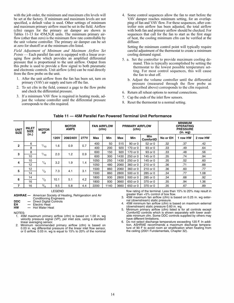
Table 11 — 45M Parallel Fan Powered Terminal Unit Performance
LEGEND
NOTES:1. 45M maximum primary airflow (cfm) is based on 1.00 in. wg
velocity pressure signal (VP), per inlet size, using a standardlinear averaging sensor.
2. Minimum recommended primary airflow (cfm) is based on0.03 in. wg differential pressure of the linear inlet flow sensor,or 0 airflow. 0.03 in. wg is equal to 15% to 20% of the nominal
flow rating of the terminal. Less than 15% to 20% may result ingreater than +5% control of box flow.
3. 45M maximum fan airflow (cfm) is based on 0.25 in. wg exter-nal (downstream) static pressure.
4. 45M minimum fan airflow (cfm) is based on maximum external(downstream) static pressure 0.60 in. wg.
5. Minimum primary airflow (cfm) listed is for all controls exceptComfortID controls which is shown separately with lower avail-able minimum cfm. Some DDC controls supplied by others mayhave different limitations.
6. Do not select discharge temperature exceeding 120 F. In addi-tion, ASHRAE recommends a maximum discharge tempera-ture of 90 F to avoid room air stratification when heating fromthe ceiling (2001 Fundamentals, Chapter 32).
UNITSIZE
INLETSIZE(in.)
MOTORHP
MOTORAMPS
FAN AIRFLOW(cfm)
PRIMARY AIRFLOW(cfm)
MINIMUMOPERATINGPRESSURE
(in. wg)
120V 208/240V 277V Max Min Max Min MinComfortID No or EH 1 row HW 2 row HW
26 1/10 1.6 0.9 0.7
400 50 515 90 or 0 52 or 0 .32 .37 .428 400 200 920 170 or 0 93 or 0 .33 .49 .64
38 1/10 2.0 1.2 0.9
600 150 920 170 or 0 93 or 0 .33 .48 .5610 600 300 1430 250 or 0 145 or 0 .35 .74 .94
410 1/4 3.2 1.9 1.4
1050 250 1430 250 or 0 145 or 0 .35 .52 .6012 1050 480 2060 360 or 0 210 or 0 .36 .71 .88
512 1/2 7.3 4.1 3.1
1500 860 2060 360 or 0 210 or 0 .36 .60 .7714 1500 860 2800 500 or 0 285 or 0 .34 .77 1.08
614 1/2 10.1 5.1 4.2
1800 930 2800 500 or 0 285 or 0 .34 .68 .9216 1800 930 3660 650 or 0 370 or 0 .35 .94 1.36
7 16 3/4 9.5 5.8 4.4 2200 1140 3660 650 or 0 370 or 0 .35 .67 .89
ASHRAE — American Society of Heating, Refrigeration and Air Conditioning Engineers
DDC — Direct Digital ControlsEH — Electric HeatHW — Hot Water Heat

15
Table 12A — 45N Quiet Parallel Fan Powered Terminal Unit Performance (PSC Motor)
LEGEND *Max based on 0.25 in. wg downstream Ps for PSC motors. See Catalog forcomplete fan curves. Min based on 0.6 in. wg downstream Ps for PSCmotors.
†For all controls except ComfortID controls. Some DDC controls supplied byothers may have differing limitations.
NOTE: Data is based on tests conducted in accordance with ARI (Air Condi-tioning and Refrigeration Institute) Standard 880-98.
Table 12B — 45N Quiet Parallel Fan Powered Terminal Unit Performance (ECM Motor)
LEGEND
*Special order.
†For all controls except ComfortID controls. Some DDC controls supplied byothers may have differing limitations. This value is based on a signal of0.03 in. wg differential pressure of the linear averaging flow probe.
NOTE: Data is based on tests conducted in accordance with ARI (Air Condi-tioning and Refrigeration Institute) Standard 880-98.
Table 13 — 45R Low Profile Parallel Fan Powered Terminal Unit Performance
LEGEND
NOTES:1. 45R maximum primary airflow (cfm) is based on 1.00 in. wg velocity
pressure signal (VP), per inlet size, using a standard linear averag-ing sensor.
2. Minimum recommended primary airflow (cfm) is based on 0.03 in.wg differential pressure of the linear inlet flow sensor, or 0 airflow.0.03 in. wg is equal to 15% to 20% of the nominal flow rating of theterminal. Less than 15% to 20% may result in greater than +5%control of box flow.
3. 45R maximum fan airflow (cfm) is based on 0.25 in. wg external(downstream) static pressure.
4. 45R minimum fan airflow (cfm) is based on maximum external(downstream) static pressure 0.60 in. wg.
5. Minimum primary airflow (cfm) listed is for all controls except Com-fortID controls which is shown separately with lower available mini-mum CFMs. Some DDC controls supplied by others may havedifferent limitations.
6. Minimum pressure, Ps (in. wg) on 45R water coil units is based oncoil located on induction port.
7. Do not select discharge temperature exceeding 120 F. In addition,ASHRAE recommends a maximum discharge temperature of 90 Fto avoid room air stratification when heating from the ceiling (2001Fundamentals, Chapter 32).
UNITSIZE
INLETSIZE (in.)
MOTORHp
MOTOR AMPS FAN AIRFLOW* PRIMARY AIRFLOW MINIMUM PRESSURES, Ps in. wg
120 V 208/240 V 277 V Max Min Max Min† Min ComfortID No or EH 1 Row HW 2 Row HW
26 1/4 2.6 1.5 1.1 500 50
515 90 or 0 52 or 0 0.31 0.34 0.368 920 160 or 0 93 or 0 0.33 0.42 0.50
36
1/4 3.1 1.7 1.3 800 50515 90 or 0 52 or 0 0.31 0.34 0.35
8 920 160 or 0 93 or 0 0.33 0.41 0.4410 1430 250 or 0 145 or 0 0.32 0.52 0.58
4
6
1/4 3.4 1.9 1.4 900 50
515 90 or 0 52 or 0 0.31 0.34 0.348 920 160 or 0 93 or 0 0.33 0.41 0.43
10 1430 250 or 0 145 or 0 0.32 0.51 0.5812 2060 360 or 0 210 or 0 0.34 0.77 0.91
510
1/2 7.3 4.1 3.1 1700 3751430 250 or 0 145 or 0 0.32 0.39 0.58
12 2060 360 or 0 210 or 0 0.34 0.48 0.9114 2800 480 or 0 285 or 0 0.28 0.48 1.08
6
10
1/2 7.3 4.1 3.1 1800 400
1430 250 or 0 145 or 0 0.32 0.39 0.4312 2060 360 or 0 210 or 0 0.34 0.49 0.5814 2800 480 or 0 285 or 0 0.28 0.49 0.6116 3660 630 or 0 370 or 0 0.28 0.63 0.85
7
10
3/4 9.5 5.8 4.4 2000 625
1430 250 or 0 145 or 0 0.32 0.39 0.4312 2060 360 or 0 210 or 0 0.34 0.48 0.5814 2800 480 or 0 285 or 0 0.28 0.48 0.6116 3660 630 or 0 370 or 0 0.28 0.62 0.85
DDC — Direct Digital ControlsEH — Electric HeatHW — Hot WaterPs — Static PressurePSC — Permanent Split Capacitor Motor
UNITSIZE
INLETSIZE (in.)
MOTORHp
ECM MOTOR AMPS PRIMRY AIRFLOW ECM FAN AIRFLOW
120 V FLA* 240 V FLA* 277 V FLA Max Min† Min ComfortID Max Min
4
6
1/2 7.7 5.0 4.1
500 90 or 0 52 or 0
1000 2508 900 170 or 0 93 or 0
10 1400 250 or 0 145 or 012 2100 360 or 0 210 or 0
7
10
1 12.8 9.4 6.9
1400 250 or 0 145 or 0
1600 40012 2100 360 or 0 210 or 014 2500 500 or 0 285 or 016 3300 650 or 0 370 or 0
DDC — Direct Digital ControlsECM — Electronically Commutated MotorFLA — Full Load Amps
UNITSIZE45R
INLETSIZE (in.)
MOTORHP
MOTOR AMPS FAN AIRFLOW (cfm) PRIMARY AIRFLOW (cfm) MINIMUM Ps (in. wg)
120V 208/230V 277V Max Min Max Min Min ComfortID
None orElec. Heat
1 RowHot Water
2 RowsHot Water
26 1/6 2.8 1.5 1.0 620 250 522 90 52 0.10 0.10 0.10
8 1/6 2.8 1.5 1.0 620 250 927 160 93 0.18 0.18 0.18
4 8 x 14 1/4 3.9 2.1 1.4 830 450 2066 358 207 0.17 0.17 0.17
ASHRAE— American Society of Heating, Refrigeration and Air Conditioning Engineers
DDC — Direct Digital ControlsPs — Static Pressure

16
Speed Controller — Each Carrier fan powered air ter-minal unit is equipped with a fan SCR speed controller, locatedon the bottom of the control box. The SCR can be adjusted inthe field.NOTE: The 45J size 7 unit and 45Q size 4 unit have 2 SCRspeed controllers, one for each fan. One SCR is located in thestandard position at the bottom of the control box; the other isat the top of the control box.
The fan airflow output is dependent on the setting of thecontroller and the downstream static resistance.
TO INCREASE THE FAN SPEED (RPM), turn the slottedadjustment on the controller clockwise toward the “HI” mark-ing printed on the controller face plate. (Refer to Fig. 10.)TO DECREASE THE FAN SPEED (RPM), turn the adjust-ment counterclockwise toward the “LO” marking. (SeeFig. 10.)
ComfortID™ VAV CONTROLS
Install Sensors and Make Field WiringConnectionsGENERAL — All field wiring must comply with NationalElectrical Code and local requirements.
Wire the control as shown on the control package diagramfor the specific installation. Control wiring diagrams can befound inside the control box.SUPPLY-AIR TEMPERATURE (SAT) SENSOR INSTAL-LATION — On terminals with heat, the SAT sensor is pro-vided. The sensor is factory wired to the controller and shippedin the control box. The SAT must be field-installed in the ductdownstream from the air terminal. See Fig. 11. The SAT sensorpart number is 33ZCSENSAT. See Table 14 for resistanceinformation.To install the sensor, proceed as follows:
1. Remove the plug from one of the 7/8-in. openings in thecontrol box and pass the sensor probe through the hole.
2. Drill or punch a 1/2-in. hole in the duct downstream ofthe unit, at a location meeting the requirements shown inFig. 11.
3. Using 2 self-drilling screws (supplied), secure the sensorprobe to the duct.
The SAT sensor probe is 6 inches in length. The tip of theprobe must not touch the inside of the duct. Use field-suppliedbushings as spacers when mounting the probe in a duct that is6 in. or less in diameter.
If the unit is not equipped with heat, the SAT sensor is notprovided and is not required.
For units equipped with electric heat, locate the sensor as fardownstream as possible. This ensures the sensor will not beaffected by excessive radiant heat from the heater coil. Installthe sensor a minimum of 2 ft downstream of the coil for unitswith hot water heat.
Perform the following steps if state or local code requiresthe use of conduit, or if your installation requires a cable lengthof more than 8 ft:
1. Disconnect the sensor cable from the ComfortID zonecontroller, at the terminals labeled SAT and GND.
2. Mount the sensor to the duct (see Steps 2 and 3 above).3. Mount a field-supplied 4 in. x 4 in. x 2 in. extension box
over the duct sensor.4. Connect a conduit (1/2-in. nominal) to the zone controller
enclosure and extension box.
CAUTION
The minimum stop on the speed controller is factory set atan internal minimum stop to prevent damage to the motor.Do not attempt to override this minimum stop or electricaldamage to the fan motor may result.
WARNING
Disconnect electrical power before wiring inside the con-troller. Electrical shock, personal injury, or damage to thezone controller can result.
CAUTIONDO NOT run sensor or relay wires in the same conduit orraceway with Class 1 service wiring.DO NOT abrade or nick the outer jacket of cable.DO NOT pull or draw cable with a force that may harm thephysical or electrical properties.DO NOT bend a cable through a radius sharper than thatrecommended by its manufacturer.AVOID splices in any control wiring.
LO HIUR
RANCOMXF-544002-001
100533-01
277 V 12L 5 FLA
50 6 Z
ZC
AIRTERMINAL
UNIT
HEAT SAT
2 FT. MIN.
PRIMARYAIR INLET
Fig. 10 — Fan Speed Controller
UNIT WITH HEAT
LEGEND
Fig. 11 — Supply Air Temperature Probe(Part No. 33ZCSENSAT) Location
SAT — Supply Air Temperature SensorZC — Zone Controller

17
5. Pass the sensor probe through the extension box openingand into the conduit.
6. Reconnect the sensor leads to the zone controller labeledSAT and GND.
SPACE TEMPERATURE (SPT) SENSOR INSTALLATIONAND WIRING — The SPT sensor accessory is ordered sepa-rately for field installation. It is installed on interior walls tomeasure room space air temperature. See Fig. 12-16 andTable 14.
The wall plate accommodates both the NEMA (NationalElectrical Manufacturing Association) standard and theEuropean 1/4 DIN standard. The use of a junction box to ac-commodate the wiring is recommended for installation. Thesensor may be mounted directly on the wall, if acceptable bylocal codes.
DO NOT mount the sensor in drafty areas such as near heat-ing or air-conditioning ducts, open windows, fans, or over heatsources such as baseboard heaters or radiators. Sensors mount-ed in those areas will produce inaccurate readings.
Avoid corner locations. Allow at least 3 ft between thesensor and any corner. Air in corners tends to be stagnantresulting in inaccurate sensor readings.
Sensor should be mounted approximately 5 ft up from thefloor, in an area that best represents the average temperaturefound in the space (zone).
The space temperature sensor cover includes a service jackconnector. If wiring connection is made to the service jack, theconnector can then be used to connect a network service toolwith the Carrier Comfort Network® system.
Before installing the space temperature sensor, decidewhether or not the service jack wiring connection will be made.If connection is desired, the CCN communication cable shouldbe available at time of sensor installation, for convenientwiring connections. The cable selected must meet the require-ments for the entire network. See Table 15 for CCN communi-cation cable specifications.
Install and wire the space temperature sensor as follows:NOTE: Space temperature sensor will be identified as T55 orT56. Refer to Control Package Drawings to determine whichSPT is part of the particular control package being installed.(The difference between T55 and T56 is that T56 includes setpoint adjustment capability.)
1. Locate the two Allen type screws at the bottom of thesensor.
2. Turn the two screws clockwise to release the cover fromthe sensor wall mounting plate.
3. Lift the cover from the bottom and then release it fromthe top fasteners.
4. Feed the wires from the electrical box through the open-ing in the center of the sensor mounting plate.
5. Using two no. 6-32 x 1 mounting screws (provided withthe sensor), secure the sensor to the electrical box.
6. Use 20 gage wire to connect the sensor to the controller.The wire is suitable for distances of up to 500 ft. Use athree-conductor shielded cable for the sensor and setpoint adjustment connections. The standard CCN com-munication cable may be used. If the set point adjustment(slide-bar) is not required, then an unshielded, 18 or 20gage, two-conductor, twisted pair cable may be used. Re-fer to Table 15.The CCN network service jack requires a separate,shielded CCN communication cable. Always use sepa-rate cables for CCN communication and sensor wiring.(Refer to Fig. 15 and 16 for wire terminations.)
7. Replace the cover by inserting the cover at the top of themounting plate first, then swing the cover down over thelower portion. Rotate the two Allen head screws counter-clockwise until the cover is secured to the mounting plateand locked in position.
8. For more sensor information, see Table 14 for thermistorresistance vs temperature values.
NOTE: Clean sensor with damp cloth only. Do not usesolvents.
Table 15 — Recommended Sensor andDevice Wiring
NOTE: Wiring is 20 gage, 2 conductor twisted cable.
Table 14 — Thermistor Resistance vs Temperature Values forSupply-Air Temperature Sensor, Primary Air Temperature Sensor and Space Temperature Sensor
MANUFACTURERPART NUMBER
Regular PlenumBelden 8205 88442Columbia D6451 —American A21501 A48301Quabik 6130 —Alpha 1895 —Manhattan M13402 M64430
RESISTANCE(Ohms)
TEMP(F)
RESISTANCE(Ohms)
TEMP(F)
RESISTANCE(Ohms)
TEMP(F)
RESISTANCE(Ohms)
TEMP(F)
RESISTANCE(Ohms)
TEMP(F)
29,481 32 17,050 54 10,227 76 6340 98 4051 12028,732 33 16,646 55 10,000 77 6209 99 3972 12128,005 34 16,253 56 9,779 78 6080 100 3895 12227,298 35 15,870 57 9,563 79 5954 101 3819 12326,611 36 15,497 58 9,353 80 5832 102 3745 12425,943 37 15,134 59 9,148 81 5712 103 3673 12525,295 38 14,780 60 8,948 82 5595 104 3603 12624,664 39 14,436 61 8,754 83 5481 105 3533 12724,051 40 14,101 62 8,563 84 5369 106 3466 12823,456 41 13,775 63 8,378 85 5260 107 3400 12922,877 42 13,457 64 8,197 86 5154 108 3335 13022,313 43 13,148 65 8,021 87 5050 109 3272 13121,766 44 12,846 66 7,849 88 4948 110 3210 13221,234 45 12,553 67 7,681 89 4849 111 3150 13320,716 46 12,267 68 7,517 90 4752 112 3090 13420,212 47 11,988 69 7,357 91 4657 113 3033 13519,722 48 11,717 70 7,201 92 4564 114 2976 13619,246 49 11,452 71 7,049 93 4474 115 2920 13718,782 50 11,194 72 6,900 94 4385 116 2866 13818,332 51 10,943 73 6,755 95 4299 117 2813 13917,893 52 10,698 74 6,613 96 4214 118 2761 14017,466 53 10,459 75 6,475 97 4132 119

18
D
5’
3’ (MIN)
OR2/3 OF WALL HEIGHT
Fig. 12 — Typical Space Temperature Sensor Room Location
WarmCool
Fig. 13 — Space Temperature Sensor(P/N 33ZCT56SPT Shown)
NOTE: Dimensions are in inches.
Fig. 14 — Space Temperature Sensor and WallMounted Humidity Sensor Mounting
2 3 4 5 61
SW1
SEN
BLK (GND)RED (SPT)
RED(+)WHT(GND)
BLK(-) CCN COM
SENSOR WIRING
Fig. 15 — Space Temperature Sensor Wiring(33ZCT55SPT)
2 3 4 5 61
SW1
SEN SET
Cool Warm
WHT(T56)
BLK (GND)RED (SPT)
RED(+)WHT(GND)
BLK(-) CCN COM
SENSOR WIRING
JUMPERTERMINALSAS SHOWN
Fig. 16 — Space Temperature Sensor Wiring(33ZCT56SPT)

19
WIRING THE SPACE TEMPERATURE SENSOR ANDSET POINT ADJUSTMENT SLIDEBAR — To wire the sen-sor and slidebar, perform the following (see Fig. 16):
1. Identify which cable is for the sensor wiring.2. Strip back the jacket from the cables for at least 3-inches.
Strip 1/4-in. of insulation from each conductor. Cut theshield and drain wire from the sensor end of the cable.
3. Connect the sensor cable as follows:a. Connect one wire from the cable (RED) to the SPT
terminal on the controller. Connect the other end ofthe wire to the left terminal on the SEN terminalblock of the sensor.
b. Connect another wire from the cable (BLACK) tothe ground terminal on the controller. Connect theother end of the wire to the remaining open termi-nal on the SEN terminal block.
c. For T56 sensors, connect the remaining wire(WHITE/CLR) to the T56 terminal on the control-ler. Connect the other end of the wire to the rightmost terminal on the SET terminal block.
d. In the control box, connect the cable shield toJ1-3, equipment ground.
e. Install a jumper between the two center terminals(right SEN and left SET).
WIRING THE CCN NETWORK COMMUNICATIONSERVICE JACK — To wire the service jack, perform thefollowing:
1. Strip back the jacket from the CCN communicationcable(s) for at least 3 inches. Strip 1/4-in. of insulationfrom each conductor. Remove the shield and separate thedrain wire from the cable. Twist together all the shielddrain wires and fasten them together using an closed endcrimp lug or a wire nut. Tape off any exposed bare wire toprevent shorting.
2. Connect the CCN + signal wire(s) (RED) to Terminal 5.3. Connect the CCN – signal wire(s) (BLACK) to Terminal 2.4. Connect the CCN GND signal wire(s) (WHITE/CLR) to
Terminal 4.PRIMARY AIR TEMPERATURE SENSOR INSTALLA-TION — A primary air temperature (PAT) sensor is used on azone controller which is functioning as a Linkage Coordinatorfor a non CCN (Carrier Comfort Network)/Linkage compatibleair source. The part number is 33ZCSENPAT. See Fig. 17. Thesensor is available as field-supplied accessory.
When used on a zone controller, try to select a zone control-ler which will allow installation of the PAT sensor in the maintrunk, as close to the air source as possible. See Fig. 18.To mount the PAT sensor, remove sensor cover.
1. Drill a 1/2-in. hole in supply duct.2. Using field-supplied drill tap screw, secure sensor to duct.3. Connect sensor to zone controller using field-supplied
2-conductor cable. Refer to Table 15.4. Use field-supplied wire nuts to connect cable to sensor.5. At zone controller, connect sensor wires to PAT and GND
terminals.INDOOR-AIR QUALITY SENSOR INSTALLATION —The indoor-air quality (IAQ) sensor accessory monitors carbondioxide levels. This information is used to increase the airflowto the zone and may also modify the position of the outdoor-airdampers to admit more outdoor air as required to provide thedesired ventilation rate. The wall sensor is used to monitor theconditioned space. The sensor uses infrared technology tomeasure the levels of CO2 present in the air. The wall sensor isavailable with or without an LCD readout to display the CO2level in ppm and is also available in a combination modelwhich senses both temperature and CO2 level.
The CO2 sensors are factory set for a range of 0 to2000 ppm and a linear voltage output of 0 to 10 vdc. Refer tothe instructions supplied with the CO2 sensor for electrical re-quirements and terminal locations. The sensor requires a sepa-rate field-supplied 24 vac 25 va transformer to provide powerto the sensor. The transformer may be mounted in the controlbox if space is provided.
For factory configuration changes to some models of thesensor, the User Interface Program (UIP) or sensor calibrationservice kit is required.
To accurately monitor the quality of the air in the condi-tioned air space, locate the sensor near the return air grille so itsenses the concentration of CO2 leaving the space. The sensorshould be mounted in a location to avoid direct breath contact.
Do not mount the space sensor in drafty areas such as nearsupply diffusers, open window, fans, or over heat sources. Al-low at least 3 ft between the sensor and any corner. Avoidmounting the sensor where it is influenced by the supply air;the sensor gives inaccurate readings if the supply air is blowndirectly onto the sensor.
To mount the sensor, refer to the installation instructionsshipped with the accessory kit.
Fig. 17 — Primary Air Temperature Sensor(Part Number 33ZCSENPAT)
Fig. 18 — Primary Air TemperatureSensor Installation
(Air-Handling Unit Discharge Locations)

20
INDOOR AIR QUALITY SENSOR WIRING — To wire thesensor after it is mounted in the conditioned air space, seeFig. 19-21 and the instructions shipped with the sensor. Usetwo 2-conductor 20 AWG (American Wire Gage) twisted-paircables (see Table 15) to connect the field-supplied separate iso-lated 24 vac power source to the sensor and to connect the sen-sor to the control terminals. To connect the sensor to thecontrol, identify the positive (+) and ground (GND) terminalson the sensor and connect the positive terminal to the RH/IAQterminal on the control and connect the ground terminal to ter-minal GND.HUMIDITY SENSOR (WALL-MOUNTED) INSTALLA-TION — The accessory space humidity sensor is field sup-plied and installed on an interior wall to measure the relativehumidity of the air within the occupied space. See Fig. 22.
The use of a standard 2 x 4-in. electrical box to accommo-date the wiring is recommended for installation. The sensor canbe mounted directly on the wall, if acceptable by local codes.
If the sensor is installed directly on a wall surface, install thehumidity sensor using 2 screws and 2 hollow wall anchors(field-supplied); do not overtighten screws.
The sensor must be mounted vertically on the wall. TheCarrier logo should be oriented correctly when the sensor isproperly mounted.
DO NOT mount the sensor in drafty areas such as near heat-ing or air-conditioning ducts, open windows, fans, or over heatsources such as baseboard heaters, radiators, or wall-mountedlight dimmers. Sensors mounted in those areas will produceinaccurate readings.
Avoid corner locations. Allow at least 4 ft between the sen-sor and any corner. Airflow near corners tends to be reduced,resulting in erratic sensor readings.
Sensor should be vertically mounted approximately 5 ft upfrom the floor, beside the space temperature sensor.
For distances up to 500 feet, use a 3-conductor, 18 or20 AWG cable. A CCN communication cable can be used,although the shield is not required. The shield must be removedfrom both ends of the cable if this cable is used.
The power for the sensor is provided by the control board.The board provides 24 vdc for the sensor. No additional powersource is required.
CAUTION
Do NOT clean or touch the sensing element with chemicalsolvents; they can permanently damage the sensor.
Fig. 19 — Indoor Air Quality Sensor(Wall-Mounted Version Shown) 33ZCSENCO2
Fig. 20 — Ventilation Rated Based onCO2 Set Point
LINE VOLTAGE24VAC
SEPARATEPOWERSUPPLY
REQUIRED
IAQ
GND
21 87
NOTE: Do not connect to the same transformer that supplies power to the zone controller.
Fig. 21 — Indoor Air Quality Sensor Wiring

21
To wire the sensor, perform the following (see Fig. 23):1. At the sensor, remove 4-in. of jacket from the cable. Strip
1/4-in. of insulation from each conductor. Route the cablethrough the wire clearance opening in the center of thesensor.
2. Connect the RED wire to the sensor screw terminalmarked (+).
3. Install one lead from the resistor (supplied with the sen-sor) and the WHITE wire, into the sensor screw terminalmarked (–). After tightening the screw terminal, test theconnection by pulling gently on the resistor lead.
4. Connect the remaining lead from the resistor to theBLACK wire and secure using a field-supplied closedend type crimp connector or wire nut.
5. Using electrical tape, insulate any exposed resistor lead toprevent shorting.
6. At the control box, remove the jacket from the cable.7. Strip 1/4-in. of insulation from each conductor.8. Connect the RED wire to terminal +24v on the control
board.9. Connect the BLACK wire to terminal GND on the con-
trol board.10. Connect the WHITE/CLEAR wire to terminal RH/IAQ
on the control board. Fig. 22 — Wall Mounted Relative Humidity Sensor(P/N 33AMSENRHS000)
HF23BJ042Made in Switzerlandby Belimo Automation
LR 92800
NEMA 2
Class 2 Supply
LISTED94D5TENP IND ®. EQUIP.
24VAC/DC50/60 Hz3VA 2W
5K
WIP
yel blu ora blk red wht
COM
1 2 3
35 in-lb (4 Nm)80...110s
0 1
J4
RH/IAQ
GND
SECFLOW
+10V
DMPPOS
GND
TESTGND
+24VSPT
GND
SAT
T56
GND
PAT
N/A
J3J1
SR
VC
24V
AC +
G-
HIG
H
Part Number: 33ZCFANTRM
S/N:
Bus#:
Element#:
Unit#:
J6
CC
WC
OM
CW
HE
AT
124
VA
CH
EA
T2
ZONE Controller®
®
C US
LOW
1 6
31
+
G-
J2A
CC
N LEN
J2B
+
G-
11
13
3
2
15 16FAN AC
FAN
24VACN/A
HEAT3
J7J6
11
23
CWCOMCCW
J8S
EC
DM
P13
CCNCOMMUNICATIONCONNECTOR
RED (+)
WHITE (GND)
BLACK (–)
CCN
Fig. 23 — CCN Terminations at Zone Controller

22
Connect the CCN Communication Bus — Thezone controllers connect to the bus in a daisy chain arrange-ment. The zone controller may be installed on a primary CCNbus or on a secondary bus from the primary CCN bus. Con-necting to a secondary bus is recommended.
At 9,600 baud, the number of controllers is limited to128 zones maximum, with a limit of 8 systems (linkage coordi-nator configured for at least 2 zones). Bus length may notexceed 4000-ft, with no more than 60 devices on any 1000-ftsection. Optically isolated RS-485 repeaters are required every1000 ft.
At 19,200 and 38,400 baud, the number of controllersis limited to 128 maximum, with no limit on the number oflinkage coordinators. Bus length may not exceed 1000 ft.
The first zone controller in a network connects directly tothe bridge and the others are wired sequentially in a daisy chainfashion.
The CCN communication bus also connects to the zonecontroller space temperature sensor. Refer to the Install theSensors section for sensor wiring instructions.COMMUNICATION BUS WIRE SPECIFICATIONS —The Carrier Comfort Network (CCN) communication bus wir-ing is field-supplied and field-installed. It consists of shieldedthree-conductor cable with drain (ground) wire. The cableselected must be identical to the CCN communication bus wireused for the entire network. See Table 16 for recommendedcable.
Table 16 — Recommended Cables
NOTE: Conductors and drain wire must be at least 20 AWG(American Wire Gage), stranded, and tinned copper. Individual con-ductors must be insulated with PVC, PVC/nylon, vinyl, Teflon, orpolyethylene. An aluminum/polyester 100% foil shield and an outerjacket of PVC, PVC/nylon, chrome vinyl, or Teflon with a minimumoperating temperature range of –20 C to 60 C is required.
CONNECTION TO THE COMMUNICATION BUS1. Strip the ends of the red, white, and black conductors
of the communication bus cable.2. Connect one end of the communication bus cable to
the bridge communication port labeled COMM2 (ifconnecting on a secondary bus).When connecting the communication bus cable, acolor code system for the entire network is recom-mended to simplify installation and checkout. SeeTable 17 for the recommended color code.Table 17 — Color Code Recommendations
3. Refer to Fig. 23. Connect the other end of the communi-cation bus cable to the terminal block labeled CCN inthe zone controller of the first air terminal. Followingthe color code in Table 17, connect the Red (+) wire toTerminal 1. Connect the White (ground) wire to Termi-nal 2. Connect the Black (–) wire to Terminal 3.
4. Connect additional zone controllers in a daisy chainfashion, following the color coded wiring scheme inTable 17.
NOTE: The communication bus drain wires (shield) mustbe tied together at each zone controller. If the communica-tion bus is entirely within one building, the resulting contin-uous shield must be connected to ground at only one singlepoint. If the communication bus cable exits from one build-ing and enters another building, connect the shields toground at a lightning suppressor in each building where thecable enters or exits (one point only).
Water Valve Installation
Water valves are field supplied. Carrier offers two differenthot water valve applications; on/off and floating point modulat-ing proportional control. See Table 18 for specifications forcompatible water valves. To connect the field-supplied watervalves to the controller, refer to the wiring labels for the controlpackage.
Table 18 — Valve Specifications
ComfortID™ Start-UpGENERAL — Air volume delivery to the conditioned spaceis controlled by the modulation of the primary air damper, thefan operation, and the sequencing of the air source supply fan.The controller positions the damper by way of an actuator andturns the fan on and off through linkage for the CCN compati-ble air source equipment control.PRIMARY SYSTEM CHECK
1. Check that all controls, control box, and ductwork havebeen properly installed and set according to installationinstructions and job requirements.
2. Check that final filters have been installed in the air-handling apparatus. Dust and debris can adversely affectsystem operation.
3. Check fan and system controls for proper operation.4. Check electrical system and connections of any optional
electric reheat coil. If hot water reheat is used, check pip-ing and valves per job drawings.
5. Check that all air duct connections are tight.6. See that all balancing dampers at box outlets are in full-
open position.ComfortID CONTROL SYSTEM CHECK
1. Check interconnections between thermostats and unitcontrols.
2. Force all dampers to control to the maximum cooling cfmusing the Building Supervisor, ComfortWORKS®, Net-work Service Tool or ComfortID Test and Balance Toolsoftware.
3. For series flow terminals, verify and adjust the fan speedto provide zero pressure in the induced air plenum.
MANUFACTURER CABLE PART NO.Alpha 2413 or 5463American A22503Belden 8772Columbia 02525
SIGNAL TYPE CCN BUS WIRECOLOR
PLUG PINNUMBER
+ Red 1Ground White 2
– Black 3
WARNING
Electric shock hazard can cause injury or death. More thanone disconnect switch may be required to deenergize thisequipment. Open all disconnects before servicing.
CAUTION
Follow the valve manufacturers recommended installationinstructions. Damage to valve may result.
TYPE ON/OFFVALVE
3 POINTSFLOATING VALVE
VoltageFrequencyPower Requirement
24 vac50/60 HzNot to exceed 15 va
24 vac (15%)50/60 HzNot to exceed 15 vamax inrush

23
4. Set supply-duct balancing dampers, if used, in maximumcool position.
5. Check that the static pressure available at each box isabove the minimum required, force all dampers to controlto the minimum cooling cfm and verify that the staticpressure is below the maximum safe operating limitswhen the damper is providing minimum cooling airflow.
6. Set air source supply fan speed and duct static pressureregulator to obtain satisfactory static pressure at designairflow.
7. While at peak system load, check system operation andpressures.
8. Check duct pressure at various points in the system. If sys-tem static pressure probe has been properly located, pres-sure at last units of all branch headers should remain essen-tially the same. If pressure has changed considerably, re-check the supply air static pressure controller or relocatethe probe to better sense system pressure changes.
9. Remove all forces and balance each control box zoneusing through the balancing procedure described onpage 10.
10. Check that each heating coil is fully operational and thatsufficient airflow is provided during heating on parallelfan units.
It is important to maintain sufficient airflow to units withelectric heating elements. Supply-air temperature should NOTEXCEED 105 F in any stage of heating operation. Check theunit to make sure that it does not cycle the heater stages on andoff during heating.
CCN System Start-Up — The i-Vu® CCN, Comfort-VIEW® software, and the Network Service Tool can aid insystem start-up and troubleshooting.
All set-up and set point configurations are factory set andfield adjustable. Changes are made by using Carrier networksoftware. The Network Service Tool can be used as a portabledevice to change system set-up and set points from a zone sen-sor or terminal control module. During start-up, the NetworkService Tool can also be used to verify communication witheach controller. See Table 19 for troubleshooting information.
Table 19 — Troubleshooting Guide for ComfortID™ Terminal Controls
PROBLEM CAUSE CORRECTIVE ACTIONMeasured airflow does not agreewith display value.
Terminal airflow not calibrated or airflowsensor not calibrated.Wrong terminal inlet size.
Perform damper/transducer and zone calibration.
Check and correct terminal inlet size if necessary.Supply Air Temperature (SAT)displays 0.0°. Terminal not equipped with heat or field installed.
No heat type configured or ducted heat notconfigured.
For terminals without heat, the SAT sensor isnot used. If required, configure Heat Type = 2and Ducted Heat = YES.
Baseboard perimeter heat doesnot work.
No heat type configured. Configure Heat Type. If modulating baseboard,then Ducted Heat must equal YES and sensorHH79NZ078 must be affixed to measure leaving watertemperature.
Modulating baseboard hot waterheat does not control properly.
Improperly configured. Readjust the following service configuration parameters:Heat Start Value = 110 FMaximum Duct Temperature = 180 FP Gain = 20I Gain = 1.3
Electric heat does not operate. No power to heater.Fan airflow too low or high temperature limittripped.
Check fuses and disconnect.Verify airflow exceeds 500 fpm. Adjust fan speed if neces-sary to operate below 120 F discharge with all stagesenergized.
Hot water reheat does not operate. No hot water available.Water valve wired wrong or not functioning.
Repair as required.Check wiring and correct if necessary. Retest watervalve operation.
Excessive air noise. Primary airflow or fan speed not setproperly.
Excessive system static pressure.Diffusers too small.
Check and readjust maximum airflow limits and fan speed.Verify ‘VAV Control Heat’ is set to NO for parallel airflow units.Check system static pressure. Reduce pressure if required.Replace with proper size.
Unit will not provide modulatingdamper control during air sourceheating/warm-up mode.
Primary air temperature sensor notinstalled and no Linkage Master is used(PAT sensor required for control package4440 and 4740, cooling only, stand-aloneoperation).
Install PAT sensor and configure as a Linkage Masterwith a system size of 1 zone.Verify ‘VAV Control Heat’ is set to YES (series airflow units only).

24
3V™ VVT® CONTROLS
General — The zone controller is a single duct, fan pow-ered, variable volume and temperature (VVT) terminal controlwith a factory-integrated controller and actuator. The VVTzone controller maintains precise temperature control in thespace by operating the terminal fan and regulating the flow ofconditioned air into the space. Buildings with diverse loadingconditions can be supported by controlling equipment heatingand cooling sources or supplemental heat.
The VVT zone controller (33ZCVVTZC-01) providesdedicated control functions for single duct terminals withmodulating heat, up to 3 stages of ducted heat, or combinationbaseboard and ducted heat. A relay board (33ZCOPTBRD-01)is required for heat or fan terminals.
Carrier’s 3V control system provides optimized equipmentand component control through airside linkage. Linkage refersto the process through which data is exchanged between the airterminals and the air source that provides the supply air to thoseterminals. The process “links” the terminals and the air sourceto form a coordinated system. Linkage allows the air source tooperate efficiently and reliably while responding to and satisfy-ing changing conditions in the zones. Linkage also allows theterminals to respond properly to changes in the air source. AVVT zone controller configured as the linkage coordinatormanages the flow of data between the air source and the VVTsystem zones.
Rooftop units, air handlers, fan coils, and water source heatpumps feature product integrated or factory-installed controlsthat are directly compatible with the 3V control system. Therooftop units, air handlers, fan coils, and water source heatpumps do not require any special hardware to be compatiblewith the Carrier linkage system. Consult your local Carrierrepresentative for the complete list of compatible air sourcecontrollers. Figure 24 shows an example of a Carrier linkagesystem. Figure 25 shows a typical 3V VVT zone controller.
Installation — The VVT zone controller is a microproces-sor-based direct digital control (DDC) controller that can be pur-chased or installed on variable volume and temperature (VVT)air terminals. It can be retrofitted on units manufactured byCarrier or other manufacturers to provide pressure dependentVVT control.
Each zone controller has the ability to function as a linkagecoordinator for systems with up to 32 zones. As a linkagecoordinator, a zone controller will retrieve and provide systeminformation to the rooftop or air-handling equipment and otherzone controllers. A zone controller can function as a standalone device by installing a duct air sensor.
The zone controller is connected to a wall-mounted, field-supplied, space temperature sensor (SPT) in order to monitorzone temperature changes and satisfy zone demand.
On stand-alone applications or applications with ducted ormodulating heat, the zone controller must be connected to afield-supplied supply air temperature (SAT) sensor to monitorthe temperature of the air delivered by the air terminal. ASystem Pilot™ device can be used to adjust set points, set oper-ating parameters, and fully configure the zone controller or anydevice on the system. A System Pilot device can also providelocal space temperature, set point adjust, time broadcast, andschedule adjustment for a single dedicated or remote device. Aservice clearance of 1 ft must be observed for access to the con-trol. See Fig. 26.
Carrier’s network software can be connected to the systemat the SPT sensor if Carrier network communication wiring isrun to the SPT sensor. The network software can be used toadjust set points, set operating parameters, and fully configurethe zone controller or any device on the system.
FIELD-SUPPLIED HARDWARE — Each zone controller re-quires the following field-supplied components to complete itsinstallation:• space temperature sensor• transformer — 24 vac, 40 va• two no. 10 x 1/2-in. sheet metal screws (to secure SAT
sensor to duct, if required)• two no. 6-32 x 5/8-in. screws (to mount SPT [space tem-
perature] sensor base to electrical box)• contactors (if required for fan or electric heat)• supply air temperature sensor (required for terminal with
ducted heat)• option board 33ZCOPTBRD-01 (required for auxiliary
heat or fan terminals)• indoor air quality sensor (if required)• relative humidity sensor (if required)• one SPST (single pole, single throw) relay• valve and actuator for hot water heat (if required)• wire• bushings (required when mounting SAT sensor in a duct
6-in. or less in diameter)• primary air temperature sensor (if required)Space Temperature Sensor — Each zone controller requires afield-supplied Carrier space temperature sensor. There are threesensors available for this application:• 33ZCT55SPT, Space Temperature Sensor with Override
Button• 33ZCT56SPT, Space Temperature Sensor with Override
Button and Set Point Adjustment• 33PILOT-01, System Pilot Space Temperature Sensor,
User Interface, and Configuration DeviceThe System Pilot device is a user interface to the zone con-
troller with a full complement of zone display features that canbe used to configure and operate the zone controller. It has anSPT sensor and can transmit its value to the zone controller.The System Pilot device communicates to the zone controllerthrough the zone controller’s dedicated Comm2 port or overthe main communication bus through Comm1.Option Board — The option board (33ZCOPTBRD-01) is re-quired for use of auxiliary heat and fan control functions. TheOption Board is field installed and provides four triac discreteoutputs, three for supplemental heat and one for the fan output.Primary Air Temperature Sensor — A field-supplied, prima-ry air temperature (PAT) sensor (part number 33ZCSENPAT) isused on a zone controller which is functioning as a linkagecoordinator for a non Carrier network/linkage compatible airsource.Supply Air Temperature (SAT) Sensor — The33ZCSENSAT supply air temperature sensor is required forreheat applications or stand-alone operation. The sensor has anoperating range of –40 to 245 F (–40 to 118 C) and includes a6-in. stainless steel probe and cable.Duct Air Temperature Sensor — The 33ZCSENDAT duct airtemperature sensor is required for cooling only applications onnon-33CS or non-Carrier dampers. The sensor is used for supplyair monitoring. The sensor has an operating range of –40 to245 F (–40 to 118 C) and includes a mounting grommet and75-in. cable.Relative Humidity Sensor — The 33AMSENRHS000 rela-tive humidity sensor is required for zone humidity control (de-humidification) when in a linked system with a rooftop unitequipped with a dehumidification device. Otherwise, the RHsensor is used for monitoring only.NOTE: The relative humidity sensor and CO2 sensor cannotbe used on the same zone controller.

25
PRIMARY BUS (BUS 0)
VVT ZONE CONTROLLEREQUIPPED AIR TERMINAL
SECONDARY BUS
DATACOLLECTION
OPTION
BRIDGE(RECOMMENDED)
SYSTEMMONITORINGSOFTWARE
ROOFTOPUNIT
ROOFTOPUNIT
SYSTEMPILOT
CARRIER COMMUNICATINGNETWORK
MAXIMUM OF 32 PER ROOFTOP/LINKAGE MASTER
MAXIMUM OF 8 LINKAGE MASTERS PER BUS
Fig. 24 — Typical Carrier Linkage System

26
Indoor Air Quality (CO2) Sensor — An indoor air qualitysensor is required for optional demand control ventilation. The33ZCSENCO2 CO2 sensor is an indoor, wall mounted sensorwith an LED display. The 33ZCT55CO2 and 33ZCT56CO2CO2 sensors are indoor, wall-mounted sensors without display.NOTE: The relative humidity sensor and CO2 sensor cannotbe used on the same zone controller.CONNECT THE POWER TRANSFORMER — An individ-ual, field-supplied, 24-vac power transformer is recommended
for each zone controller. If multiple zone controllers arepowered from one power transformer (100 va maximum forUL [Underwriters Laboratories] Class 2 conformance), main-tain polarity on the power input terminals. All transformer sec-ondaries are required to be grounded. Use only stranded copperconductors for all wiring to the zone controller. Wiring connec-tions must be made in accordance with NEC (National Electri-cal Code) and local codes. Ground the transformer at the trans-former location. Provide an 18-gage, green, chassis groundwire at the terminal.
The power supply is 24 vac ± 10% at 40 va (50/60 Hz).For VVT® zone controllers, the power requirement sizing
allows for accessory water valves and for electric heat contac-tor(s). Water valves are limited to 15 va on both two-positionand modulating hot water. The electric heat contactor(s) arelimited to 10 va (holding) each.NOTE: If a water valve or electric heat contactor exceeds theselimits, or external contactors are required for electric heat, thenit is recommended a 60 va transformer be used. The maximumrating for any output is 20 va.NOTE: Do not run sensor or communication wiring in thesame conduit with line-voltage wiring.NOTE: A conduit cover is provided and integrated with thezone controller.
Perform the following steps to connect the powertransformer:
1. Install the field-supplied transformer in an electricalenclosure that conforms to NEC and local codes.
2. Connect 24 vac from the transformer as shown in theapplicable wiring diagram (Fig. 27-30).
35 in-lb (4 Nm)80...110s
Assembled in USAby Belimo for CARRIER
10
y bl orWI
5
24VAC/DC50/60Hz3VA 2W
CO
bl re w
MECHANICALSTOP
ACTUATOR
CLAMPASSEMBLY
MANUAL OVERRIDESWITCH
MOTHERBOARDACCESS
WIRINGACCESS
WIRINGKNOCKOUTS
Manual Override
Fig. 25 — Zone Controller
END VIEW INLET
ZONECONTROLLER
ALLOW 12” CLEARANCE FOR SERVICEACCESS TO CONTROL BOX
3” REF.
Fig. 26 — Service Clearance for Zone Controller Mounting

27
SA
T
OY
BI
24 V
AC
RB
T56
SA
T
+24
V
GN
D
HE
AT
2
HE
AT
3
GN
D
24V
AC
24V
AC
24V
AC
FAN
Vol
tage
Line
com
mun
icat
ion
Ded
icat
ed S
yste
m P
ilot
com
mun
icat
ion
Tran
sfor
mer
gro
und
HE
AT
1
35 in
-lb (
4 N
m)
80...
110s
Ass
em
ble
d i
n U
SA
by
Be
limo
fo
r C
AR
RIE
R
24V
AC
/DC
50/6
0Hz
3VA
2W
yel
blu
ora
WIP
5K
CO
M 12
3bl
kre
dw
ht
Ma
nu
al
Ov
err
ide
Cha
ssis
Gro
und
Net
wor
k
Net
wor
k
AUX
24VAC
GN
D
GN
D
RH
/IAQ
PA
T
GN
D
CCW
COM
CW
+10V
DMPPOS
GND
AUX DMP
GND
HW
V
Fan
Rel
ay
Fan
Mot
or
SP
T
RE
MO
TE
SP
T
+
+
+
GN
D
GN
D
GN
D
-
-
-
J1
1 2 3
Fig
. 27
— V
VT
® Z
on
e C
on
tro
ller
Wir
ing
— F
an B
ox
Tw
o-P
osi
tio
n H
ot
Wat
er H
eat
LEG
EN
DC
CW
—C
ount
ercl
ockw
ise
PAT
—P
rimar
y A
ir Te
mpe
ratu
re S
enso
rC
OM
—C
omm
onR
H—
Rel
ativ
e H
umid
ityC
W—
Clo
ckw
ise
SA
T—
Sup
ply
Air
Tem
pera
ture
Sen
sor
DM
PP
OS
—D
ampe
r P
ositi
onS
PT
—S
pace
Tem
pera
ture
Sen
sor
GN
D—
Gro
und
Fie
ld-S
uppl
ied
Wiri
ngH
WV
—H
ot W
ater
Val
veFa
ctor
y W
iring
IAQ
—In
door
Air
Qua
lity
NO
TE
: The
SAT
may
be
relo
cate
d to
sen
se a
nd c
ontr
ol d
ucte
d he
at.

28
SA
T
OY
BI
24 V
AC
RB
T56
SA
T
+24 GN
D
HE
AT
2
HE
AT
3
GN
D
24V
AC
24V
AC
24V
AC
FAN
Vol
tage
Line
com
mun
icat
ion
Ded
icat
ed S
yste
m P
ilot
com
mun
icat
ion
Tran
sfor
mer
gro
und
HE
AT
1
35 in
-lb (
4 N
m)
80...
110s
Ass
em
ble
d i
n U
SA
by
Be
limo
fo
r C
AR
RIE
R
24V
AC
/DC
50/6
0Hz
3VA
2W
yel
blu
ora
WIP
5K
CO
M 12
3bl
kre
dw
ht
Ma
nu
al
Ov
err
ide
Cha
ssis
Gro
und
Net
wor
k
Net
wor
kAUX
24VAC
GN
D
GN
D
RH
/IAQ
PA
T
GN
D
CCW
COM
CW
+10V
DMPPOS
GND
AUX DMP
GND
Fan
Rel
ay
Fan
Mot
or
O PC L
C O M
Nor
mal
ly o
pen
or n
orm
ally
clo
sed
valv
e m
ay b
e us
ed
SP
T
HW
V
RE
MO
TE
SP
T
++
GN
DG
ND
--
J1
+ - GN
D
1 2 3
Fig
. 28
— V
VT
® Z
on
e C
on
tro
ller
Wir
ing
— F
an B
ox,
Mo
du
lati
ng
Ho
t W
ater
Hea
t
LEG
EN
DC
CW
—C
ount
ercl
ockw
ise
PAT
—P
rimar
y A
ir Te
mpe
ratu
re S
enso
rC
OM
—C
omm
onR
H—
Rel
ativ
e H
umid
ityC
W—
Clo
ckw
ise
SA
T—
Sup
ply
Air
Tem
pera
ture
Sen
sor
DM
PP
OS
—D
ampe
r P
ositi
onS
PT
—S
pace
Tem
pera
ture
Sen
sor
GN
D—
Gro
und
Fie
ld-S
uppl
ied
Wiri
ngH
WV
—H
ot W
ater
Val
veFa
ctor
y W
iring
IAQ
—In
door
Air
Qua
lity
NO
TE
: The
SAT
may
be
relo
cate
d to
sen
se a
nd c
ontr
ol d
ucte
d he
at.

29
SA
T
OY
BI
B
24 V
AC
RB
T56
SA
T
+24
GN
D
HE
AT
2
HE
AT
3
GN
D
24V
AC
24V
AC
24V
AC
FAN
Vol
tage
Line
com
mun
icat
ion
Ded
icat
ed S
yste
m P
ilot
com
mun
icat
ion
Tran
sfor
mer
gro
und
HE
AT
1
35 in
-lb (
4 N
m)
80...
110s
Ass
em
ble
d i
n U
SA
by
Be
limo
fo
r C
AR
RIE
R
24V
AC
/DC
50/6
0Hz
3VA
2W
yel
blu
ora
WIP
5K
CO
M 12
3bl
kre
dw
ht
Ma
nu
al
Ov
err
ide
Cha
ssis
Gro
und
Net
wor
k
Net
wor
k
B
AUX
24VAC
GN
D
GN
D
RH
/IAQ
PA
T
GN
D
CCW
COM
CW
+10V
DMPPOS
GND
AUX DMP
GND
Fan
Rel
ay
Fan
Mot
or
Nor
mal
ly o
pen
or n
orm
ally
clo
sed
valv
e m
ay b
e us
ed
H2
H3
HW
V
SP
T
RE
MO
TE
SP
T
++
-
-
-
GN
D
GN
D
GN
D
J1
+1 2 3
Fig
. 29
— V
VT
® Z
on
e C
on
tro
ller
Wir
ing
— F
an B
ox,
Co
mb
inat
ion
Bas
e B
oar
d, D
uct
ed H
eat
LEG
EN
DC
CW
—C
ount
ercl
ockw
ise
PAT
—P
rimar
y A
ir Te
mpe
ratu
re S
enso
rC
OM
—C
omm
onR
H—
Rel
ativ
e H
umid
ityC
W—
Clo
ckw
ise
SA
T—
Sup
ply
Air
Tem
pera
ture
Sen
sor
DM
PP
OS
—D
ampe
r P
ositi
onS
PT
—S
pace
Tem
pera
ture
Sen
sor
GN
D—
Gro
und
Fie
ld-S
uppl
ied
Wiri
ngH
WV
—H
ot W
ater
Val
veFa
ctor
y W
iring
IAQ
—In
door
Air
Qua
lity
NO
TE
: The
SAT
may
be
relo
cate
d to
sen
se a
nd c
ontr
ol d
ucte
d he
at.

30
SA
T
OY
BI
24 V
AC
RB
T56
SA
T
+24
GN
D
HE
AT
2
HE
AT
3
GN
D
24V
AC
24V
AC
24V
AC
FAN
Vol
tage
Line
com
mun
icat
ion
Ded
icat
ed S
yste
m P
ilot
com
mun
icat
ion
Tran
sfor
mer
gro
und
HE
AT
1
35 in
-lb (
4 N
m)
80...
110s
Ass
em
ble
d i
n U
SA
by
Be
limo
fo
r C
AR
RIE
R
24V
AC
/DC
50/6
0Hz
3VA
2W
yel
blu
ora
WIP
5K
CO
M 12
3bl
kre
dw
ht
Ma
nu
al
Ov
err
ide
Cha
ssis
Gro
und
Net
wor
k
Net
wor
kAUX
24VAC
GN
D
GN
D
RH
/IAQ
PA
T
GN
D
CCW
COM
CW
+10V
DMPPOS
GND
AUX DMP
GND
Fan
Rel
ay
Fan
Mot
or
H2
H1
H3
SP
T
RE
MO
TE
SP
T
+ --+
GN
DG
ND
GN
D
J1-+
1 2 3
Fig
. 30
— V
VT
® Z
on
e C
on
tro
ller
Wir
ing
— F
an B
ox,
Th
ree-
Sta
ge
Ele
ctri
c H
eat
LEG
EN
DC
CW
—C
ount
ercl
ockw
ise
PAT
—P
rimar
y A
ir Te
mpe
ratu
re S
enso
rC
OM
—C
omm
onR
H—
Rel
ativ
e H
umid
ityC
W—
Clo
ckw
ise
SA
T—
Sup
ply
Air
Tem
pera
ture
Sen
sor
DM
PP
OS
—D
ampe
r P
ositi
onS
PT
—S
pace
Tem
pera
ture
Sen
sor
GN
D—
Gro
und
Fie
ld-S
uppl
ied
Wiri
ngIA
Q—
Indo
or A
ir Q
ualit
yFa
ctor
y W
iring
NO
TE
: The
SAT
may
be
relo
cate
d to
sen
se a
nd c
ontr
ol d
ucte
d he
at.

31
INSTALL SENSORSSpace Temperature Sensor Installation — A space tempera-ture sensor must be installed for each zone controller. There aretwo types of SPT sensors available from Carrier: the33ZCT55SPT space temperature sensor with timed overridebutton and the 33ZCT56SPT space temperature sensor withtimed override button and set point adjustment. See Fig. 31.
The space temperature sensor is used to measure thebuilding interior temperature and should be located on aninterior building wall. The sensor wall plate accommodatesthe NEMA standard 2 x 4 junction box. The sensor can bemounted directly on the wall surface if acceptable by localcodes.
Do not mount the sensor in drafty locations such as near airconditioning or heating ducts, over heat sources such asbaseboard heaters, radiators, or directly above wall mountedlighting dimmers. Do not mount the sensor near a windowwhich may be opened, near a wall corner, or a door. Sensorsmounted in these areas will have inaccurate and erratic sensorreadings.
The sensor should be mounted approximately 5 ft from thefloor, in an area representing the average temperature in thespace. Allow at least 4 ft between the sensor and any cornerand mount the sensor at least 2 ft from an open doorway.
Install the sensor as follows (see Fig. 32):1. Locate the two Allen type screws at the bottom of the
sensor. 2. Turn the two screws clockwise to release the cover from
the sensor wall mounting plate.3. Lift the cover from the bottom and then release it from
the top fasteners.4. Feed the wires from the electrical box through the
opening in the center of the sensor mounting plate.5. Using two no. 6-32 x 1 mounting screws (provided with
the sensor), secure the sensor to the electrical box.6. Use 20 gage wire to connect the sensor to the controller.
The wire is suitable for distances of up to 500 ft. Use athree-conductor shielded cable for the sensor and setpoint adjustment connections. The standard Carriernetwork communication cable may be used. If the setpoint adjustment (slidebar) is not required, then anunshielded, 18 or 20 gage, two-conductor, twisted paircable may be used.The Carrier network service jack requires a separate,shielded communication cable. Always use separatecables for communication and sensor wiring. (Refer toFig. 33 for wire terminations.)
7. Replace the cover by inserting the cover at the top of themounting plate first, then swing the cover down over thelower portion. Rotate the two Allen head screws counter-clockwise until the cover is secured to the mounting plateand locked in position.
8. For more sensor information, see Table 20 for thermistorresistance vs temperature values.
NOTE: Clean sensor with damp cloth only. Do not usesolvents.Wiring the Space Temperature Sensor (33ZCT55SPT and33ZCT56SPT) — To wire the sensor, perform the following(see Fig. 33 and 34):
1. Identify which cable is for the sensor wiring. 2. Strip back the jacket from the cables for at least 3-inches.
Strip 1/4-in. of insulation from each conductor. Cut theshield and drain wire from the sensor end of the cable.
3. Connect the sensor cable as follows:a. Connect one wire from the cable (RED) to the SPT
terminal on the controller. Connect the other end ofthe wire to the left terminal on the SEN terminalblock of the sensor.
b. Connect another wire from the cable (BLACK) tothe GND terminal on the controller. Connect theother end of the wire to the remaining open termi-nal on the SEN terminal block.
WarmCool
Fig. 31 — Space Temperature Sensor(P/N 33ZCT56SPT Shown)
NOTE: Dimensions are in inches.
Fig. 32 — Space Temperature Sensor and WallMounted Humidity Sensor Mounting

32
c. On 33ZCT56SPT thermostats, connect the remain-ing wire (WHITE/CLR) to the T56 terminal on thecontroller. Connect the other end of the wire to theright most terminal on the SET terminal block.
d. In the control box, install a no. 6 ring type crimplug on the shield drain wire. Install this lug underthe mounting screw in the upper right corner of thecontroller (just above terminal T1).
e. On 33ZCT56SPT thermostats install a jumperbetween the two center terminals (right SEN andleft SET).
Wiring the Network Communication Service Jack — SeeFig. 33-35. To wire the service jack, perform the following:
1. Strip back the jacket from the communication cable(s) forat least 3 inches. Strip 1/4-in. of insulation from eachconductor. Remove the shield and separate the drain wirefrom the cable. Twist together all the shield drain wiresand fasten them together using an closed end crimp lug ora wire nut. Tape off any exposed bare wire to preventshorting.
2. Connect the CCN + signal wire(s) (RED) to Terminal 5.
3. Connect the CCN – signal wire(s) (BLACK) toTerminal 2.
4. Connect the CCN GND signal wire(s) (WHITE/CLR) toTerminal 4.
Before wiring the Carrier proprietary network connection,refer to the Connect the Carrier Communicating NetworkCommunication Bus section on page 37, for communicationbus wiring and cable selection. The cable selected must beidentical to the communication bus wire used for the entirenetwork.
The other end of the communication bus cable must beconnected to the remainder of the communication bus. If thecable is installed as a T-tap into the bus, the cable length cannotexceed 100 ft. Wire the service jack of the sensor in a daisychain arrangement with other equipment. Refer to the Connectthe Carrier Communicating Network Communication Bus sec-tion, page 37, for more details.System Pilot™ Device — Refer to System Pilot device instal-lation instructions for information on installing and using theSystem Pilot device.
2 3 4 5 61
SW1
SEN
BLKRED
RED(+)WHT(GND)
BLK(-) COM BUS
SENSOR WIRING
2 3 4 5 61
SW1
SEN SET
Cool Warm
WHTBLKRED
RED(+)WHT(GND)
BLK(-) COM BUS
SENSOR WIRING
JUMPERTERMINALSAS SHOWN
Fig. 33 — Space Temperature Sensor Wiring(33ZCT55SPT)
Fig. 34 — Space Temperature Sensor Wiring(33ZCT56SPT)

33
WarCoo
100 FT. MAXIMUM
AIR TERMINALUNIT (TYP)
ZONE CONTROLLER
2 COND TWISTEDCABLE OR 3 CONDCABLE (TEMPSENSOR WIRING) (TYP)
COMM BUS
SPACETEMPERATURE
SENSOR
3 COND COMM CABLE (TYP)
WarCoo
AIR TERMINALUNIT (TYP)
ZONE CONTROLLER
2 COND TWISTEDCABLE OR 3 CONDCABLE (TEMPSENSOR WIRING) (TYP)
SPACETEMPERATURE
SENSOR
DISTANCE GREATERTHAN 100 FT.COMM BUS
SYSTEMPILOT
SYSTEMPILOT
Fig. 35 — Communication Bus Wiring to Zone Controller
Wiring when distance between zone controller and space temperature sensor is greater than 100 feet
Wiring when distance between zone controller and space temperature sensor is 100 feet or less

34
Table 20 — Thermistor Resistance vs Temperature Values for Space Temperature Sensor, Return-Air Temperature Sensor, and Supply-Air Temperature Sensor
Primary Air Temperature Sensor Installation — A primaryair temperature (PAT) sensor is used on a zone controller whichis functioning as a linkage coordinator for a non-Carrier net-work/linkage compatible air source. The part number is33ZCSENPAT. See Fig. 36.
When used on a zone controller, try to select a zone control-ler which will allow installation of the PAT sensor in the maintrunk, as close to the air source as possible. See Fig. 37.Duct Temperature Sensor (33ZCSENDAT) Installation —The 33ZCSENDAT duct air temperature sensor is required forcooling only applications on non-Carrier dampers. The sensoris used for supply air monitoring. The sensor has an operatingrange of –40 to 245 F (–40 to 118 C) and includes a mountinggrommet and 75-in. cable. The duct temperature sensor mustbe installed in the supply air duct. See Fig. 38 for sensor details.
The duct temperature sensor should be moved to a locationwhich will provide the best sensing of the supply-air tempera-ture during heating and cooling.
For systems using a ducted supply, the duct temperaturesensor should be located in the supply duct downstream of thedischarge of the air source and before the bypass damper toallow good mixing of the supply airstream.
The 33ZCSENDAT duct sensor is a small epoxy sensor thatis 11/4-in. long. A grommet is provided for filling the holearound the sensor cable after the sensor is located in the duct.
See Fig. 39 for mounting location.
Do not run sensor or relay wires in the same conduit or race-way with Class 1 AC service wiring. Do not abrade, cut, ornick the outer jacket of the cable. Do not pull or draw cablewith a force that may harm the physical or electrical properties.Avoid splices in any control wiring.
Perform the following steps to connect the duct temperaturesensor to the bypass controller:
1. Drill or punch a 1/4-in. hole in the supply duct. SeeFig. 39. Duct sensor can be installed to hang from top ofduct or from the sides. Sensor probe can touch side ofduct.
2. Push sensor through hole in the supply duct. Snap thegrommet into the hole until it is secure. Pull on the leadsof the duct sensor until the sensor is snug against thegrommet.
3. Connect the sensor leads to the bypass controller’s termi-nal board at the terminals labeled SAT and GND. SeeFig. 27-30 for wiring. If extending cable length beyond 8ft, use plenum rated, 20 AWG (American Wire Gage),twisted pair wire. Sensor wiring does not have polarity.Either lead can be wired to either terminal.
4. Neatly bundle and secure excess wire.5. Using electrical tape, insulate any exposed lead to prevent
shorting.6. Connect shield to earth ground (if shielded wire is used).
Supply Air Temperature (33ZCSENSAT) Sensor Installa-tion — The 33ZCSENSAT supply air temperature sensor is re-quired for reheat applications or stand-alone operation. Thesensor has an operating range of –40 to 245 F (–40 to 118 C)and includes a 6-in. stainless steel probe and cable. The sensoris factory-supplied but must be relocated for ducted heat. TheSAT must be installed in the duct downstream from the air ter-minal. The SAT sensor is also sometimes called a duct air tem-perature sensor. Part number 33ZCSENSAT may be used inplace of the factory-installed sensor.
The SAT sensor probe is 6 inches in length. The tip of theprobe must not touch the inside of the duct. Use field-suppliedbushings as spacers when mounting the probe in a duct that is6 in. or less in diameter.
If the unit is a cooling only unit, the SAT is not required.If the unit is equipped with electric reheat, ensure that the
sensor is installed at least 2 ft downstream of the electric heater.See Fig. 40 for the sensor location in this application.
If the unit has an octopus connected directly at thedischarge, install the sensor in the octopus. If the unit has anelectric heater, the two-foot minimum distance between thesensor and the heater must be maintained. See Fig. 40 for thesensor location in this application.
TEMP(C)
TEMP(F)
RESISTANCE(Ohms)
–40 –40 335,651–35 –31 242,195–30 –22 176,683–25 –13 130,243–20 –4 96,974–15 5 72,895–10 14 55,298
–5 23 42,3150 32 32,6515 41 25,395
10 50 19,90315 59 15,71420 68 12,49425 77 10,00030 86 8,05635 95 6,53040 104 5,32545 113 4,36750 122 3,60155 131 2,98560 140 2,48765 149 2,08270 158 1,752
WARNING
Disconnect electrical power before wiring the bypass con-troller. Electrical shock, personal injury, or damage to thefan coil controller can result.
WARNING
Disconnect electrical power before wiring the bypass con-troller. Electrical shock, personal injury, or damage to thefan coil controller can result.

35
.225/ .245(5.72/6.22)
75.0 .5(1905)
1.00(25.4)
1.25(31.8)
0.06(1.5)
Fig. 36 — Primary Air Temperature Sensor(Part Number 33ZCSENPAT)
Fig. 37 — Primary Air Temperature SensorInstallation (Unit Discharge Location)
NOTE: Dimensions are in inches (millimeters).
Fig. 38 — 33ZCSENSDAT Duct Sensor
DRILL 1/4" HOLEIN TOP OF DUCTAND LET SENSORHANG DOWN
ALTERNATE INSTALLATIONLOCATION INSIDE OF DUCT
SUPPLY DUCT
Fig. 39 — DAT Installation Location
ZC
AIRTERMINAL
UNITOCTOPUS
HEAT SAT
2 FT. MIN.
PRIMARYAIR INLET
ZC
AIRTERMINAL
UNIT
HEAT SAT
2 FT. MIN.
PRIMARYAIR INLET
ZC — Zone Controller
Fig. 40 — Supply Air Temperature Probe (Part No. 33ZCSENSAT) Locations
UNIT WITH ELECTRIC REHEAT
UNIT WITH OCTOPUS

36
Do not run sensor or relay wires in the same conduit or race-way with Class 1 AC or DC service wiring. Do not abrade, cut,or nick the outer jacket of the cable. Do not pull or draw cablewith a force that may harm the physical or electrical properties.Avoid splices in any control wiring.
Perform the following steps to connect the SAT sensor tothe zone controller:
1. Locate the opening in the control box. Pass the sensorprobe through the hole.
2. Drill or punch a 1/4-in. hole in the duct downstream of theunit, at a location that conforms to the requirementsshown in Fig. 40.
3. Use two field-supplied, self-drilling screws to secure thesensor probe to the duct. Use field-supplied bushings asspacers when installing the sensor probe in a duct 6 in. orless in diameter.
Perform the following steps if state or local code requiresthe use of conduit, or if your installation requires a cable lengthof more than 8 ft:
1. Remove the center knockout from a field-supplied 4 x2-in. junction box and secure the junction box to the ductat the location selected for the sensor probe.
2. Drill a 1/2-in. hole in the duct through the opening in thejunction box.
3. Connect a 1/2-in. nominal field-supplied conduit betweenthe zone controller enclosure and the junction box.
4. Pass the sensor probe wires through the conduit and insertthe probe in the duct. Use field-supplied bushings asspacers when installing the sensor probe in a duct 6 in. orless in diameter.
5. Secure the probe to the duct with two field-supplied self-drilling screws.
6. If extending cable length beyond 8 ft, use plenum rated,20 AWG (American Wire Gage), twisted pair wire.
7. Connect the sensor leads to the zone controller’s wiringharness terminal board at the terminals labeled SAT andGND.
8. Neatly bundle and secure excess wire.Indoor Air Quality Sensor Installation — The indoor airquality (IAQ) sensor accessory monitors carbon dioxide levels.This information is used to modify the position of the outdoorair dampers to admit more outdoor air as required to providethe desired ventilation rate. Two types of sensors are supplied.The wall sensor can be used to monitor the conditioned airspace; the duct sensor monitors the return air duct. Both walland duct sensors use infrared technology to measure the levelsof CO2 present in the air. The wall sensor is available with orwithout an LCD (liquid crystal display) readout to display theCO2 level in ppm. See Fig. 41.
The sensor part number is 33ZCSENCO2. To mount thesensor, refer to the installation instructions shipped with theaccessory kit.
The CO2 sensors (33ZCSENCO2) factory set for a range of 0to 2000 ppm and a linear voltage output of 0 to 10 vdc. Figure 42shows ventilation rates for various CO2 set points when outsideair with a typical CO2 level of 350 ppm is used. Refer to theinstructions supplied with the CO2 sensor for electrical require-ments and terminal locations. The zone controller requires a24 vac, 25 va transformer to provide power to the sensor.
To convert the CO2 sensor into a duct-mounted CO2 sensor,the duct-mounted aspirator (33ZCASPCO2) will need to bepurchased.
To accurately monitor the quality of the air in the condi-tioned air space, locate the sensor near the return air grille so itsenses the concentration of CO2 leaving the space. The sensorshould be mounted in a location to avoid direct breath contact.
Do not mount the space sensor in drafty areas such as nearsupply ducts, open windows, fans, or over heat sources. Allowat least 3 ft between the sensor and any corner. Avoid mountingthe sensor where it is influenced by the supply air; the sensorgives inaccurate readings if the supply air is blown directly ontothe sensor or if the supply air does not have a chance to mix withthe room air before it is drawn into the return airstream.
To accurately monitor the quality of the air in the return airduct, locate the sensor at least 6 in. upstream or 15 in.downstream of a 90-degree turn in the duct. The downstreamlocation is preferred. Mount the sensor in the center of the duct.
To wire the sensors after they are mounted in the condi-tioned air space and return air duct, see Fig. 43 and the instruc-tions shipped with the sensors. For each sensor, use two 2-con-ductor 18 AWG twisted-pair cables (unshielded) to connect theseparate isolated 24 vac power source to the sensor and to con-nect the sensor to the control board terminals. To connect thesensor to the control board, identify the positive (+) PIN-8 andground (GND) PIN-7 terminals on the sensor and connect thepositive terminal to terminal RH/IAQ and connect the groundterminal to terminal GND.
IMPORTANT: If the sensor is mounted in the return-airduct, readjust the mixed-air dampers to allow a smallamount of air to flow past the return-air damper when-ever the mixing box is fully open to the outside air. If thedamper is not properly adjusted to provide this mini-mum airflow, the sensor may not detect the indoor-airquality during the economizer cycle.
3.25(8.3)
5.625(14.3)
1.125(2.9)
0.25(0.8)
5(12.7)
NOTE: Dimensions are in inches. Dimensions in ( ) are in millimeters
Fig. 41 — Indoor Air Quality (CO2) Sensor(33ZCSENCO2)
Fig. 42 — Ventilation Rated Based onCO2 Set Point

37
OY
BI
RB
0
T56
SA
T
+24 GN
D
GN
D
35 in
-lb (
4 N
m)
80...
110s
Ass
em
ble
d i
n U
SA
by
Be
limo
fo
r C
AR
RIE
R
24V
AC
/DC
50/6
0Hz
3VA
2W
yel
blu
ora
WIP
5K
CO
M 12
3bl
kre
dw
ht
Ma
nu
al
Ov
err
ide
1
GN
D
GN
D
RH
/IAQ
PA
T
GN
D
CCW
COM
CW
+10V
DMPPOS
GND
AUX DMP
GND
RH
/IAQ
GN
D
LIN
E
VO
LTA
GE
8721
24 V
AC
SE
PA
RA
TE
ISO
LAT
ED
PO
WE
RS
UP
PLY
RE
QU
IRE
D(2
4 V
AC
, 25
VA
MIN
IMU
M)*
RE
MO
TE
SP
T
+
+
-
-
-+
GN
D
GN
D
GN
D
J1
1 2 3
*Do
not c
onne
ct to
the
sam
e tr
ansf
orm
er th
at s
uppl
ies
pow
er to
the
zone
con
trol
ler.
Fig
. 43
— In
do
or
Air
Qu
alit
y S
enso
r W
irin
g

38
Humidity Sensor (Wall-Mounted) Installation — The acces-sory space humidity sensor is installed on an interior wall tomeasure the relative humidity of the air within the occupiedspace. See Fig. 44.
The use of a standard 2 x 4-in. electrical box to accommo-date the wiring is recommended for installation. The sensor canbe mounted directly on the wall, if acceptable by local codes.
If the sensor is installed directly on a wall surface, install thehumidity sensor using 2 screws and 2 hollow wall anchors(field-supplied); do not overtighten screws. See Fig. 32.
The sensor must be mounted vertically on the wall. TheCarrier logo should be oriented correctly when the sensor isproperly mounted.
DO NOT mount the sensor in drafty areas such as near heat-ing or air-conditioning ducts, open windows, fans, or over heatsources such as baseboard heaters, radiators, or wall-mountedlight dimmers. Sensors mounted in those areas will produce in-accurate readings.
Avoid corner locations. Allow at least 4 ft between the sen-sor and any corner. Airflow near corners tends to be reduced,resulting in erratic sensor readings.
Sensor should be vertically mounted approximately 5 ft upfrom the floor, beside the space temperature sensor.
For distances up to 500 feet, use a 3-conductor, 18 or 20AWG cable. A communication cable can be used, although theshield is not required. The shield must be removed from thesensor end of the cable if this cable is used. See Fig. 28 forwiring details.
The power for the sensor is provided by the control board.The board provides 24 vdc for the sensor. No additional powersource is required.
To wire the sensor, perform the following:1. At the sensor, remove 4-in. of jacket from the cable. Strip
1/4-in. of insulation from each conductor. Route the cablethrough the wire clearance opening in the center of thesensor. See Fig. 45.
2. Connect the RED wire to the sensor screw terminalmarked (+).
3. Install one lead from the resistor (supplied with the sen-sor) and the WHITE wire, into the sensor screw terminalmarked (–). After tightening the screw terminal, test theconnection by pulling gently on the resistor lead.
4. Connect the remaining lead from the resistor to theBLACK wire and secure using a closed end type crimpconnector or wire nut.
5. Using electrical tape, insulate any exposed resistor lead toprevent shorting.
6. At the control box, remove the jacket from the cable androute the RED conductor over to the left side of the con-trol board. Route the remaining conductors to the rightside of the control board.
7. Strip 1/4-in. of insulation from each conductor and equipeach with a 1/4-in. female quick connect terminal.
8. Connect the RED wire to terminal +24v on the controlboard.
9. Connect the BLACK wire to terminal GND on the con-trol board.
10. Connect the WHITE/CLEAR wire to terminal RH/IAQon the control board.
11. Connect shield to ground (if shielded wire is used).REMOTE OCCUPANCY CONTACT — The remote occu-pancy input (J4 pin 1) has the capability to be connected to anormally open or normally closed occupancy dry contact. Wirethe dry contact as show in Fig. 46 between J4 Pin 1 and24 VAC J1 Pin 1. The 24 vac necessary to supply the VVT®zone controller remote occupancy contact input is suppliedusing the zone controller.CONNECT THE OUTPUTS — Wire the zone controller’soutputs (fan, staged heat, valves) as shown in the applicablewiring diagrams in Fig. 27-30.MODULATING BASEBOARD HYDRONIC HEATING —Install the water valve on the leaving water end of the base-board heater. See Fig. 47. Observe the fluid flow directionwhen mounting the valve. Be sure to properly heat sink thevalve and direct the flame away from the actuator and valvebody when sweating the valve connections. Install the leavingwater temperature sensor (33ZCSENCHG) on the hydronicheating coil as shown. The sensor accommodates nominal cop-per pipe from 1/2 to 1-in. (OD sizes from 5/8 to 1.125 in.). Itshould be secured to the pipe with the clamp supplied. If pip-ing is larger than 1-in. nominal size, a field-supplied clampmust be used. Use fiberglass pipe insulation to insulate the sen-sor assembly.
Refer to Fig. 28 to wire the modulating water valve and thesensor to the zone controller. Connect the leaving water tem-perature sensor to the controller using the wiring connectionsshown for the SAT sensor. (NOTE: The leaving water tempera-ture sensor replaces the SAT sensor in this application.) Use 18or 20 AWG wire for all connections. The water valve actuatorhousing may be used as a junction box if the leaving watertemperature sensor cable is not long enough and the sensor ca-ble must be extended to reach the controller.
For modulating hydronic heating applications, the defaultconfiguration must be changed to properly control the valve.Refer to the service configuration table and set the HeatingLoop parameters as follows:Proportional Gain = 20.0Integral Gain = 0.5Derivative Gain = 0.0Start Value = 102.0
Also, set the Ducted Heat decision to YES and set theMaximum Duct Temperature decision equal to the design(maximum) boiler water temperature minus 20 degrees, but notgreater than 200 F.CONNECT THE CARRIER COMMUNICATING NET-WORK COMMUNICATION BUS — The zone controllersconnect to the bus in a daisy chain arrangement. The zonecontroller may be installed on a primary bus or on a secondarybus from the primary bus. Connecting to a secondary bus isrecommended.
At 9,600 baud, the number of controllers is limited to128 zones maximum, with a limit of 8 systems (Linkage Coor-dinator configured for at least 2 zones). Bus length may notexceed 4000 ft, with no more than 60 devices on any 1000-ftsection. Optically isolated RS-485 repeaters are required every1000 ft.
At 19,200 and 38,400 baud, the number of controllersis limited to 128 maximum, with no limit on the number ofLinkage Coordinators. Bus length may not exceed 1000 ft.
On larger systems with more than 8 linkage coordinators,use bridges to split the system into sections. The first zone con-troller in a network connects directly to the bridge and theothers are wired sequentially in a daisy chain fashion. Refer toFig. 48 for an illustration of communication bus wiring.
CAUTION
Do NOT clean or touch the sensing element with chemicalsolvents; they can permanently damage the sensor.

39
The communication bus also connects to the zone controllerspace temperature sensor. Refer to the Install the Sensors sec-tion for sensor wiring instructions.Communication Bus Wire Specifications — The communi-cation bus wiring is field-supplied and field-installed. It con-sists of shielded three-conductor cable with drain (ground)wire. The cable selected must be identical to the communica-tion bus wire used for the entire network. See Table 21 for rec-ommended cable.
Table 21 — Recommended Cables
NOTE: Conductors and drain wire must be at least 20 AWG(American Wire Gage), stranded, and tinned copper. Individual con-ductors must be insulated with PVC, PVC/nylon, vinyl, Teflon, orpolyethylene. An aluminum/polyester 100% foil shield and an outerjacket of PVC, PVC/nylon, chrome vinyl, or Teflon with a minimumoperating temperature range of –20 C to 60 C is required.
Connection To The Communication Bus1. Strip the ends of the red, white, and black conductors of
the communication bus cable.2. Connect one end of the communication bus cable to the
bridge communication port labeled COMM2 (if connect-ing on a secondary bus).When connecting the communication bus cable, a colorcode system for the entire network is recommended tosimplify installation and checkout. See Table 22 for therecommended color code.
3. Connect the other end of the communication bus cableto the terminal block labeled J2A in the zone controllerof the first air terminal. Following the color code inTable 22, connect the Red (+) wire to Terminal 1.Connect the White (ground) wire to Terminal 2.Connect the Black (–) wire to Terminal 3.
4. Connect additional zone controllers in a daisy chain fash-ion, following the color coded wiring scheme in Table 22.Refer to Fig. 48.
NOTE: The communication bus drain wires (shield) must betied together at each zone controller. If the communication busis entirely within one building, the resulting continuous shieldmust be connected to ground at only one single point. If thecommunication bus cable exits from one building and entersanother building, connect the shields to ground at a lightningsuppressor in each building where the cable enters or exits (onepoint only).
Table 22 — Color Code Recommendations
Start-Up — Use the Carrier network communication soft-ware to start up and configure the zone controller.
All set-up and set point configurations are factory-set andfield-adjustable.
Changes can be made using the System Pilot™ device orCarrier software. During start-up, the Carrier software can alsobe used to verify communication with each zone controller.
For specific operating instructions, refer to the literatureprovided with the software.PERFORM SYSTEM CHECKOUT
1. Check correctness and tightness of all power and commu-nication connections.
2. Check that all air terminals, ductwork, and zone control-lers are properly installed and set according to installationinstructions and job requirements.
3. Check that all air duct connections are tight.4. At the air terminals, check fan and system controls for
proper operation. Verify that actuator screws are properlytightened.
5. At the air terminals, check electrical system and connec-tions of any optional electric reheat coil. If hot water re-heat is used, check piping and valves against job draw-ings.
6. At the air terminals, make sure that all balancing dampersat box outlets are in the fully open position.
7. If using an air source with field-installed controls, makesure controls and sensors have been installed and wiredper manufacturer installation instructions.
8. At air source, verify that the motor starter and, if applica-ble, the Hand/Off/Auto (HOA) switch are installed andwired.
9. Check to be sure the area around the air source is clear ofconstruction dirt and debris.
10. Check that final filters are installed in the air handler(s).Dust and debris can adversely affect system operation.
11. Verify that the zone controller and the air source controlsare properly connected to the communication bus.
12. Remember to utilize good duct design and to providesufficient straight duct at the inlet of the box. A minimumof three times the inlet size is recommended.
MANUFACTURER CABLE PART NO.Alpha 2413 or 5463American A22503Belden 8772Columbia 02525
Fig. 44 — Wall Mounted Relative Humidity Sensor
SIGNAL TYPE COMMUNICATION BUS WIRE COLOR
PLUG PINNUMBER
+ Red 1Ground White 2– Black 3
CAUTION
Before starting the air source fan, make sure that dampersat the system’s air terminals are not fully closed. Startingthe fan with dampers closed will result in damage to thesystem ductwork.
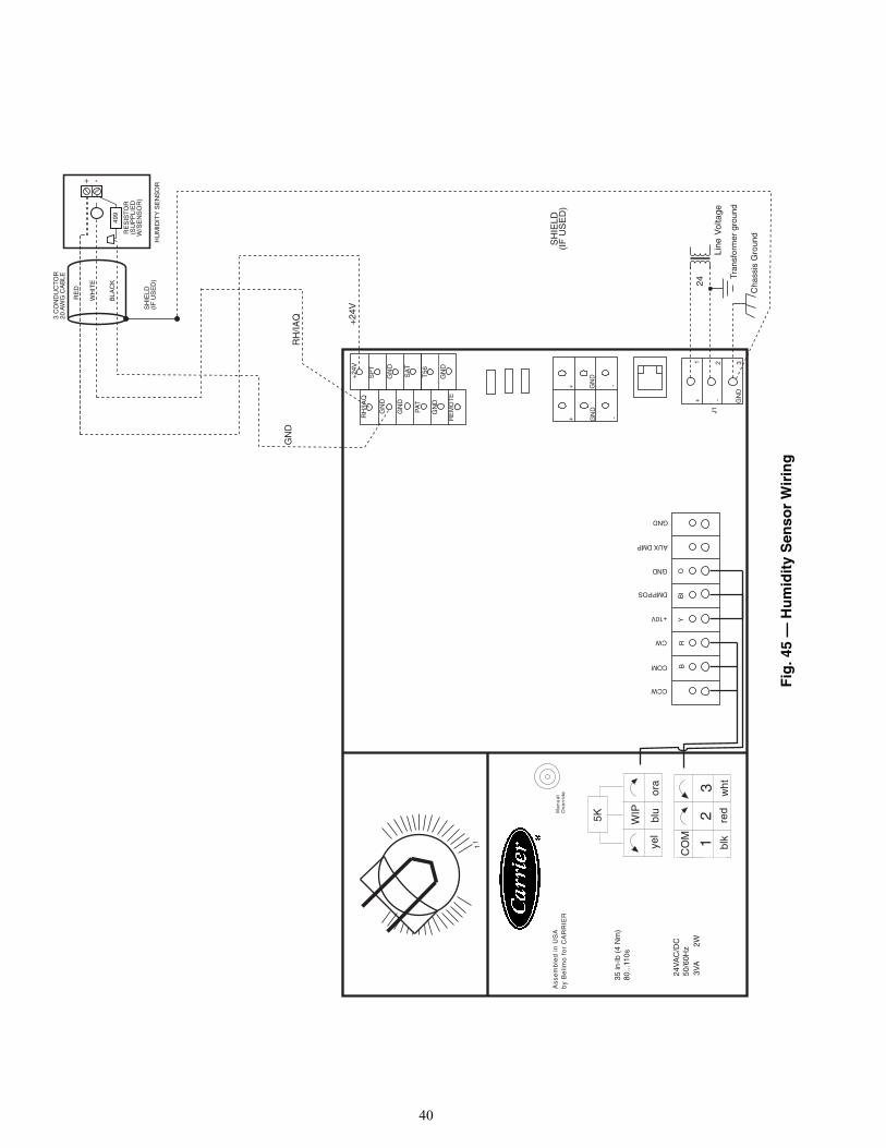
40
OY
BI
24
RB
1
T56SA
T
+24
GN
D
GN
D
Vol
tage
Line
Tran
sfor
mer
gro
und
35 in
-lb (
4 N
m)
80...
110s
Ass
em
ble
d i
n U
SA
by
Be
limo
fo
r C
AR
RIE
R
24V
AC
/DC
50/6
0Hz
3VA
2W
yel
blu
ora
WIP
5K
CO
M 12
3bl
kre
dw
ht
Ma
nu
al
Ov
err
ide
Cha
ssis
Gro
und
1
GN
D
GN
D
RH
/IAQ
PA
T
GN
D
CCW
COM
CW
+10V
DMPPOS
GND
AUX DMP
GND
GN
DR
H/IA
Q +24
VV
SH
IELD
(IF
US
ED
)
+ -
499
RE
SIS
TO
R(S
UP
PLI
ED
W/S
EN
SO
R)
HU
MID
ITY
SE
NS
OR
RE
D
WH
ITE
BLA
CK
3 C
ON
DU
CT
OR
20 A
WG
CA
BLE
SH
IELD
(IF
US
ED
)
RE
MO
TE
SP
T
++
GN
DG
ND
--
J1
+ - GN
D
1 2 3
Fig
. 45
— H
um
idit
y S
enso
r W
irin
g

41
OY
BI
24 V
AC
RB
T56
SA
T
+24
GN
D
GN
D
Vol
tage
Line
Tran
sfor
mer
gro
und
35 in
-lb (
4 N
m)
80...
110s
Ass
em
ble
d i
n U
SA
by
Be
limo
fo
r C
AR
RIE
R
24V
AC
/DC
50/6
0Hz
3VA
2W
yel
blu
ora
WIP
5K
CO
M 12
3bl
kre
dw
ht
Ma
nu
al
Ov
err
ide
Cha
ssis
Gro
und
GN
D
GN
D
RH
/IAQ
PA
T
GN
D
CCW
COM
CW
+10V
DMPPOS
GND
AUX DMP
GND
V
FIE
LD-S
UP
PLI
ED
DR
Y C
ON
TAC
TS
WIT
CH
RE
MO
TE
SP
T
++
GN
DG
ND
--
J1
+ - GN
D
1 2 3
Fig
. 46
— R
emo
te O
ccu
pan
cy W
irin
g

42
NETWORK ADDRESSING — Use the following methodwhen all the zone controllers are installed and powered, and theSPT sensors are wired and functioning properly. This methodcan be used if no addresses have been set previously. Theaddress of an individual zone controller may be set by usingthe System Pilot™ device. This is the standard method of set-ting the address.
Each zone controller will default to an address of 0, 140when its application software is initially loaded. Since multiplecontrollers will be on the same bus, a unique address must beassigned to each controller before the system can operateproperly. The assignment of controller addresses will beperformed through the System Pilot device, as follows:
1. The System Pilot device recognizes that the zone control-ler’s address, stored in the zone controller memory, hasnot been written yet (this will be true when the unit is firstpowered up on the job, or after a jumper-initiated reset).
2. Press the override button on the SPT (terminals J4-14 andJ4-12 are shorted) for 1 to 10 seconds.
3. The zone controller address changes from 0, 140 to 239,239 for a period of 15 minutes.
4. Use System Pilot device to change the address from 239,239 to a valid system address within 15 minutes.
NOTE: If the address is not changed from 239, 239 to a validsystem address within 15 minutes, the controller will revert toaddress 0, 140 and use of the override button will cause theaddress function to repeat. The operator MUST actively set theaddress even if the final desired address is 0, 140.
Initial Operation and Test — Perform the followingprocedure:
1. Apply 24 vac power to the control. 2. Using the System Pilot device, upload the controller from
address assigned in Network Addressing section above.3. From the Terminal Service Configuration screen, proper-
ly configure the damper type and inlet size. If a roundinlet is used, then enter the size directly in the InletDiameter decision. If a square, rectangular, or ellipticaldamper inlet is supplied, then enter the inlet size in squareinches in the Inlet Area decision.
4. If the terminal damper closes in the CW direction, then noadjustment is required. Otherwise, locate the damperdirection configuration decision (CW Rotation) and
33ZCSENCHG(SENSOR)
FLOW
1/2” TUBE3/4” TUBE1” TUBE
Fig. 47 — Typical Water Valve and Sensor Installation
1 2 3 1 2 3 1 2 3
AIR TERMINALUNIT (TYP)
1 2 3
COMM 2
1 2 3 4
GND
ZC(TYP)
1000 FT MAXIMUM
DRAIN WIRE (TYP)
BLK (TYP)
WHT (TYP)
RED (TYP)
BRIDGE(RECOMMENDED)
LEGEND
Fig. 48 — Communication Bus Wiring
ZC — Zone Controller
ON LARGESYSTEMS

43
toggle the value to OPEN by using the space bar. Thisconfiguration decision is also located on the TerminalService Configuration screen.
5. After entering the area and rotation direction, verify oper-ation of the damper. From the System Pilot Diagnostic,Maintenance Screen, select the Zone CommissioningTable and force the Commissioning Mode point toEnable. Then select the Damper Cal point and force thispoint to Enable. The controller automatically tests theactuator by fully closing the damper.It checks the fully closed position to determine if thecontrol was properly mounted. It then opens the damper.The control scales the actual actuator travel range used toa 0 to 100% open value. Finally the control will close thedamper, test, and zero the pressure transducer. Whencompleted, the control automatically removes the forcefrom the Damper Cal point. If a failure occurs at anypoint during the testing, the Damper Calibration Statuspoint at the bottom of the screen will indicate ALARMand the test will be aborted.
6. The actuator stroke has now been calibrated for the prop-er rotation.
Fan and Heat Configuration and Test — Per-form the following procedure to configure and test the fan andheat:
1. Display the Terminal Service Configuration screen tomake sure the proper Terminal Type and Heat Type areconfigured. See the Configuration section to answerquestions about the individual configurations.
2. From the Diagnostics Maintenance Screen select theZone Commissioning table.
3. Force the Commissioning Mode to Enable.4. If the terminal is a parallel or series powered fan box,
force the Fan Override to Enable. If the damper is open itmay have to be repositioned to the proper positiondepending on the box type. Damper percent change willbe displayed. After the damper is positioned correctly, thefan relay should energize and the fan should run for a fewseconds.
5. Make sure the fan runs and the Fan Override decisionreturns to disabled to ensure the fan is wired correctly forproper operation.
6. Force the Heating Override to Enable. If the unit is asingle duct unit, this must be done with the primary termi-nal at reheat set point. The damper will open to the reheatcfm. The heat outputs will be commanded to providemaximum heat. If the unit is a fan-powered terminal, thefan must be on.
NOTE: The damper position settings can be found underservice configuration in the table AIRFLOW.
System Balancing — To balance the system, performthe following procedure:
1. Enable the balancing process by forcing System Com-missioning to Enable.
2. Enable the All Zone Dampers to Max point.3. The zone controller will send all system zone dampers to
their configured maximum positions and display thevalues. Check the system maximum airflows to all zonesand set zone dampers while the system is at maximumflow and the bypass damper is closed. Adjust maximumdamper position set points if required. The system canalso be balanced at design conditions with some dampersclosed.
4. If the user forces any zones to a new position, the new po-sition is written to the zone’s maximum damper positionconfiguration value and the damper is repositioned.
5. Enable the All Zone Dampers to Min point.6. The zone controller will send all system zone dampers to
their configured minimum positions and display thevalues. Check the system bypass pressure and set thepressure set point. Adjust minimum damper set points ifrequired.
7. If the user forces any zones to a new position, the newposition is written to the zone’s minimum damper posi-tion configuration value and the damper is repositioned.
8. Enable the Position Single Zone point.9. The zone controller will send all system zone dampers to
their configured maximum positions and display thevalues.
10. If the user forces any zones to a new position, the new po-sition is written to the zone’s maximum damper positionconfiguration value and the damper is repositioned.
11. At this time, the user can force the Bypass Pressure setpoint. Typically, the maximum unit rated duct static isused. The zone controller will then write the forcedBypass Pressure set point to the set point table in theBypass Controller by communicating over the network.The bypass controller will then begin to control to thenew bypass pressure set point.
PNEUMATIC CONTROLS
General — Single Function Pneumatic Con-troller Control Sequences (1300-1305, 1400-1401) — To properly balance the system, all ductwork andoutlets must be installed and connected tightly. Referencepiping/wiring diagram on unit for specifics for the controlsequence selected for the unit.
Units With Single-Function Controllers1. Determine sequence of operations (reverse-acting, nor-
mally closed [RANC], direct-acting, normally open[DANO]). This can be accomplished by reading thediagram affixed to the unit. The standard RANC control-ler is gray colored; the DANO controller is beige. SeeFig. 49-51.
2. Check that main air pressure at the controller. Main airshould equal 18 to 25 psi. Main air must be clean and dry.
3. Check for primary airflow in the inlet duct, using a differ-ential pressure sensor tapped into the differential pressuresensor signal line tees.
4. Verify that the installed room thermostat is compatiblewith the unit control.
5. Close the primary air damper.a. RANC — disconnecting the actuator from the con-
troller should allow the damper to close completely.b. DANO — connecting to 20 psi air supply directly
to the actuator should close the damper completely.6. Start the blower motor by doing one of the following:
45J,K,Q Units:Both RANC and DANO — Connect electrical power tothe blower motor control.45M,N,R Units:RANC — Connect the main air line to the blower con-trol, bypassing the thermostat input.DANO — Disconnect the thermostat line from the blow-er controls.These steps should energize the fan.

44
7. Balance the supply outlets using a proportional air vol-ume method.a. With the blower discharging full volume (SCR on
max setting), measure the total air volume.b. Calculate the percentage of the design air volume
needed by each outlet.c. Multiply the total air volume by the percent-of-
design air volume for each diffuser.d. Balance each outlet according to the requirements
calculated above.8. Balance the unit fan discharge:
a. Measure the total flow discharging from the unit.b. Adjust the discharge flow from the unit using the
unit electronic speed control (SCR).9. Reconnect the damper actuator and/or the thermostat tub-
ing to the velocity controller with the fan still running.Make sure the piping is as shown on the unit piping/wiring diagram.
10. Balance the primary (cooling) air volume:NOTE: To balance the primary air side of the 45M,N,Runit only, the blower motor must be disconnected.a. Connect the Magnehelic or inclined manometer
(0 to 2.0 in. wg scale, maximum) to the differentialpressure sensor tubing.
b. Measure the volume of air flowing through the inletusing the calibration curve affixed to the unit.RANC1) With a 0 psi thermostat signal, measure the unit
maximum airflow.2) Rotate to the “HI” adjustment knob on the
velocity controller, adjust the airflow to the de-sired maximum setting.
3) With the 15 psig (or greater) thermostat signal,measure the unit minimum airflow.
DANO1) At a 0 psi stat signal, measure the unit minimum
airflow.2) Rotate the “LO” adjustment knob of the velocity
controller, adjust the minimum flow to the desiredsetting, as read from the differential pressuresensor.With a 15 psig (or greater) thermostat signal,measure the unit maximum airflow.
3) Rotate the “HI” adjustment know on the velocitycontroller, adjust the airflow to the desired maxi-mum setting.
11. Reconnect the power to the blower motor on the45M,N,R unit.
NOTES:1. The single function control system uses a Kreuter CSC
2000 series velocity controller with a rated air consump-tion of 0.0083 SCFM at 20 psi main air pressure.
2. The maximum and minimum limits are both changedwhen adjusting the CENTER knob. For this reason, thecenter knob should always be set first.
3. Refer to the Table 23 if any of the above steps do not re-sult in satisfactory performance.
HI
LO
CSC-2003
0-1” PD.A.
DMPR. N.O.
INCREASE
INCREASE
HI
LO
CSC-2004
0-1” PR.A.
DMPR. N.C.
INCREASE
INCREASE
T
H L
B
M
NO
NC
G
RESET START
LO STAT ΔP
RESET SPAN
HI STAT ΔP
D A M P E R
IN C R IN C R
Fig. 49 — Pneumatic Volume Controller(Normally Open) for Pneumatic Control Unit
(Beige Color)
Fig. 50 — Pneumatic Volume Controller(Normally Closed) for Pneumatic Control Unit
(Grey Color)
Fig. 51 — CSC 3000 SeriesReset Volume Controller

45
Table 23 — Troubleshooting Pneumatic Controls
Units With Multi-Function Controllers (Sequences1306-1317 and 1402-1405)
1. Determine sequence of operation (direct-acting, normallyclosed [DANC], reverse-acting, normally closed[RANC], direct-acting, normally open, or reverse-acting,normally open). This can be accomplished by reading thediagram affixed to the unit. All sequences above utilize afour-function controller, allowing for changeover from agiven sequence to another.
2. Check the main air pressure at the controller. Main airshould equal 18 to 25 psi. Main air must be clean and dry.
3. Check for primary airflow in the inlet duct, using a differ-ential pressure sensor tapped into the differential pressuresensor signal line tees.
4. Verify that the installed room thermostat is compatiblewith the unit control.
5. Close the primary air damper.a. DANC, RANC — Disconnecting the actuator from
the controller should allow the damper to closecompletely.
b. DANO, RANO — Connecting a 20 psi air supplydirectly to the actuator should close the dampercompletely.
6. Start the blower motor by doing one of the following:45J,K,Q Units:DANC, RANC, DANO, RANO — Connect electricalpower to the blower motor controls.45M,N,R Units:DANC, DANO — Disconnect the thermostat line fromthe blower control.RANC, RANO — Connect the main air line to the blow-er control, bypassing the thermostat input.These steps should energize the fan.
7. Balance the supply outlets using a proportional air vol-ume method:a. With the blower discharging full volume (SCR on
max setting), measure the total air volume.b. Calculate the percentage of the design air volume
needed by each outlet.c. Multiply the total air volume by the percent-of-
design air volume for each diffuser.d. Balance each outlet according to the requirements
calculated above.8. Balance the unit fan discharge:
a. Measure the total flow discharging from the unit.b. Adjust the discharge flow from the unit using the
unit electronic speed control (SCR).9. Reconnect the damper actuator to the velocity controller
with the fan still running. Make sure the piping is asshown on the unit piping/wiring diagram.
10. Balance the primary (cooling) air volumes:NOTE: To balance the primary air side of the 45M,N,Runits only, the blower motor must be disconnected.
a. Connect a Magnehelic or inclined manometer (0 to2.0 in. wg scale, maximum) to the differential pres-sure sensor tubing.
b. Measure the volume of air flowing through the inletusing the calibration curve affixed to the unit.
c. Adjust the “LO STAT” knob, with a 0 psi thermo-stat signal, to obtain the desired airflow setting.Depending on the control sequence desired, the“LO STAT” knob will vary either the minimum set-ting or the maximum setting as follows:DANC — “LO STAT” knob adjusts the minimumsetting.RANC — “LO STAT” knob adjusts the maximumsetting.DANO — “LO STAT” knob adjusts the minimumsetting.RANO — “LO STAT” knob adjusts the maximumsetting.
Operation Sequences1. During maximum thermostat cooling demand, the pri-
mary air damper will open in the maximum airflow set-ting providing cold primary air at the preset maximumvolume. Accessory coils, if supplied, are off, and the unitshould discharge primary air only.
2. When the thermostat modulates between maximum cool-ing and satisfied set point, the primary air damperresponds by proportional settings. Accessory coils, if sup-plied, are off. The 45J,K,Q units only will be inducingplenum air and mixing it with the cold primary air. The45M,N,R fan will not induce any plenum air at this point.
3. When the thermostat is modulating between maximumheating demand and satisfied setpoint, the primary airdamper will be at the minimum air volume setting. Amaximum amount of plenum air is induced at this point.In sequence, the first and second stages of electric reheatwill energize, if supplied. If hot water heating coils aresupplied, they will either open fully or modulate open.
4. During thermostat demand for maximum heating, prima-ry air will flow through the unit at the preset minimumsetting, maximum amount of plenum air will be induced,and heating coils, if supplied, are full on. See Table 23 forpneumatic control troubleshooting.
5. Adjust the “HI STAT” knob, with a 15 psi thermostatsignal, to obtain the desired airflow setting. Depending onthe control sequence desired, the “HI STAT” knob willvary either the minimum setting or the maximum settingas follows:DANC — “HI STAT” knob adjusts the maximum settingRANC — “HI STAT” knob adjusts the minimum settingDANO — “HI STAT” knob adjusts the maximum settingRANO — “HI STAT” knob adjusts the minimum setting
6. To adjust the thermostat reset start point, remove gageport (“G”) cap and attach a 0 to 30 psi pressure gage andnote the pressure reading. Adjust the thermostat pressureto the controller, “T” port to the desired start point. Adjust
PROBLEM LIKELY CAUSEController does not reset to maximum minimum set point during balancing procedure.
Thermostat signal is being used for control signal. An artificial signal must be used.
Controller does not reset to maximum or point during operation.
Thermostat is not demanding minimum set maximum or minimum air volume. Main air pressure at the controller is less than 15 psi.
Pneumatic actuator does not stroke fully. Leak in pneumatic tubing between the controller and the actuator. Main air pressure at the controller is less that 15 psi. Leak in the actuator diaphragm.
Air valve stays in wide open position. Differential pressure sensor is blocked or obstructed. Insufficient supply air pressure in the unit inlet.

46
the “RESET START” knob until the gage pressure beginsto change slightly. Remove pressure gage and replacecap.
7. To adjust the thermostat reset span from standard 5 psi,remove gage port (“G”) cap and attach a 0 to 30 psipressure gage and note the pressure reading. Adjust thethermostat pressure to the controller “T” port to thedesired start point. Adjust the “RESET SPAN” knob untilthe gage pressure equals the desired reset span. Removegage and replace cap.
8. To change logic from a given sequence to another, followthe steps below:a. To change from N.O. to N.C. or from N.C. to N.O.,
loosen the “damper” dial screw and rotate the dialuntil the desired damper position indicator isaligned with the arrow. The VAV damper must bephysically changed to desired position.
b. To change from DA to RA or from RA to DA, noconfiguration changes are required — use theappropriate calibration procedures from above.
9. Reconnect the power to the blower motor on the 45M,Nunits.
NOTES:1. The multi-function control system uses a Kreuter CSC
3000 series velocity controller with a rated air consump-tion of 1.00 SCFH at 20 psi main air pressure.
2. The maximum and minimum limits are both changedwhen adjusting the center knob. The center knob shouldalways be set first.
ANALOG CONTROLS
General — All field wiring must comply with NationalElectrical Code and local requirements. Wire the control asshown on the control package diagram for the specific installa-tion. Control wiring diagrams can be found inside the controlbox. Check the actuator clamp nut to ensure the actuator damp-er is firmly attached to the actuator shaft.
System Check — Refer to the following to ensure properunit/control operation.
1. Verify 24 vac at terminals “~” (phase) and “–” (ground).Tolerance can be –15% to +20% (20.4 to 28.8 VAC).If the transformer’s secondary voltage to the controller isnot between 20.4 and 28.8, then replace the transformerwith a 24 VAC transformer (with –15, +20% tolerance).If there is no voltage, be sure power is turned on. If poweris turned on, turn power off and find out why the trans-former was damaged before installing a new transformerand apply primary power.After the supply voltage has been verified to be between20.4 and 28.8, then proceed to the next step.
2. Verify 16vDC at terminals “(16vDC)” and “(–)”.a. Tolerance is 15.0 to 17.0 vDC power supply to
thermostat.b. If not correct, disconnect thermostat and recheck. If
still incorrect, replace controller.3. Check “Requested Flow” voltage on terminal “IN” and
“–”.a. Use the calibration curve (Fig. 52) to correlate into
cubic feet per min (cfm).b. If reading is not what is really desired, see
“Calibration” to adjust thermostat.4. Check “Actual Flow” voltage on terminal “OUT” and
“–” for (0 to 10vDC). Use the linear flow probe chart(Fig. 52) to correlate into cfm.
5. Check box movement, damper rotation, etc.a. Review “Requested Flow” and “Actual Flow”
above to determine if unit should be satisfied(within 50 fpm) or driving open or closed.
b. If damper is not moving, verify damper is not stuckor at end of travel. Check rotation jumpers forproper position.
c. Change “Requested Flow” to make unit drive oppo-site direction. This can be accomplished by movingthe set point sliders or by the following:1) To manually open the box, remove wiring from
terminal “IN” and jumper terminal “IN” to termi-nal “16vDC”. This will tell unit to control at3300 fpm/full airflow, and the green LED shouldturn on (and the box should drive open).
2) To manually close the box, remove wiring fromterminal “IN”, jumper and “IN” terminal to “–”terminal. This will tell unit to control at zero fpm/no airflow, and the red LED should be on (and thebox should drive closed).
Thermostat Check — Refer to the following to ensureproper thermostat operation.
1. The thermostat operates on a 16vDC power supply fromthe controller and outputs a 0 to 10vDC signal on theT terminals; T1 in the cooling mode (DA) and T2 in theheating mode (RA). See the unit wiring diagram fordetails on which “T” terminals are used on each modelthermostat, but in general T1 and T3 are used for the cool-ing mode, T2 and T4 for heating. T1 and T2 are adjustableto limit minimum and maximum flow. T3 and T4 have a 0to 10vDC output signal.
2. Remove thermostat cover:Thermostat cover is removed by loosening the setscrewson each side of the thermostat. Using a 1/16-in. hex/keywrench turn the setscrews clockwise until cover is loose.
3. Check voltages:a. Verify 16vDC between (+), and (–) terminals.b. Measure “T” to “–” for output voltage. Use calibra-
tion procedures below to adjust limits if desired.Adjust set point above and below current roomtemperature and observe changes in appropriate“T” voltage. Remove set point slider stops ifnecessary.
NOTE: Always adjust minimum flow limits first.NOTE: Maximum limits must always be greater thanminimum limits. If in doubt, turn maximum limit fullyclockwise (increase) before proceeding.NOTE: Dials rotate approximately 200 degrees (8:00 to4:00). DO NOT force dial beyond stop.
4. Connect voltmeter to the meter taps:a. The two holes on the right are for the minimum and
maximum reading.b. Move to the left to measure actual flow.
5. Adjust set point to request minimum flow:a. DA cooling thermostat; set point greater than room
temperature.b. RA heating thermostat; set point less than room
temperature.c. Set minimum flow as desired using the minimum
dial.NOTE: Dials should move with minimal force.
6. Adjust set point to request maximum flow:a. DA cooling thermostat: set point < room
temperature

47
b. RA heating thermostat: set point > room temperature
c. Set maximum flow as desired using the maximumdial.
NOTE: Limits may be set at the controller or the thermo-stat. If setting the minimum/maximum limits at the ther-mostat the controller’s minimum dial must be set fullycounterclockwise to “0” and the maximum dial set fullyclockwise to “100”. This will ensure that the controllerwill not have any effect on the limits.
Controller Check — Refer to the following to ensureproper controller operation.
Minimum and maximum flow limits are often set at thethermostat as detailed on the previous section. However, ifdesired the minimum and maximum limits can be defined byadjusting the appropriate set points within the controller as ex-plained below (however, do not try to set at both the controllerand the thermostat).SETTING MIN AND MAX LIMITS
1. Connect voltmeter to the meter taps using calibration testleads (part no. HSO-5001).
2. Move the jumper from the “NOR” position to the mini-mum position. Using a small flat screwdriver adjust themin. dial to the desired voltage.
NOTE: Always adjust minimum limits before adjustingmaximum limits.
3. Move the jumper to the maximum position. Adjust themax. dial to the desired voltage.
4. Return the jumper to the “NOR” position.5. Refer to the Calibration Curve chart (Fig. 52) for mini-
mum and maximum values.NOTE: If setting the minimum/maximum limits at thethermostat the controller’s minimum dial must be set ful-ly CCW to “0” and the maximum dial set fully CW to“100”. This will ensure that the controller will not haveany effect on the limits.NOTE: If minimum and maximum are set at the control-ler it is possible to use T3 on the thermostat for coolingand T4 for heating. These outputs are not affected by min-imum/maximum settings at the thermostat and eliminatesthe possibility of inadvertently setting minimum/maxi-mum at both devices!
NOMINAL VOLTAGE RANGE — The flow sensor is facto-ry calibrated with the VNOM dial centered. This gives thecontroller a range of 0 to 3300 fpm with a 0 to 10vDC resetcontrol signal. The VNOM adjustment allows matching the0 to 10vDC reset control signal to a specific fpm range and/orflow characteristics of different installations.
MIN.
MAX.
10000
8000
6000
4000
2000
1000
800
600
400
200
10080
60
40
20
10
522
2086
1449
927
3709
2840
CF
M
CF
M @
ON
E IN
CH
SIG
NA
L
INLET SIZE 06INLET SIZE 08INLET SIZE 10INLET SIZE 12INLET SIZE 14INLET SIZE 16
1.2 1.8 2.3 3.4 4.6 5.8 7.2 9.7 11DIFF. P. .02 .04 .06 0.1 0.2 0.3 0.5 0.8 1VOLTS
CARRIER LINEAR PROBE CFM vs PRESSURE SIGNAL GRAPH
Fig. 52 — Calibration Curve

48
TO RESET THE VNOM:1. Apply the desired velocity pressure to the “H” and “L”
ports.2. Adjust the VNOM potentiometer until the 0 to 10v veloc-
ity output signal indicates 10vDC, as read between termi-nals “OUT” and “–”.
3. Follow steps 1 to 5 above for setting minimum and maxi-mum flow limits.
ROTATION — The controller is factory set for counterclock-wise to close; to change rotation to clockwise direction, movethe two jumpers to CW (the two outside pins).
SERVICE
Controls — No periodic preventive maintenance isnecessary.
Fan Motor and Wheel — The fan motor and wheel areaccessible from the bottom of the unit. Remove the bottompanel to check the wiring or remove the fan wheel or motor.
The PSC motors are equipped with long life sleeve bearingswith non-detergent SAE (Society of Automotive Engineers) 20oil biannually.NOTE: The ECM motor has permanently lubricated ball bear-ings that require NO maintenance.
TO CHECK WIRING (Refer to Fig 53-55) — The PSC mo-tor is connected by quick-connect terminals to the capacitor(brown wire), the housing wire (green ground wire), and thecontrol box (black wire and white wire). Verify that the fan mo-tor wiring is correct as shown in these figures. To remove the fan motor and wheel:
1. Disconnect wiring at the quick-connector terminals locat-ed on the motor and the bell. Note connections.
2. The fan motor and wheel assembly is attached to the dis-charge panel with 4 hex nuts.
3. Remove the motor by removing the 3 screws that attachthe torsion flex mounts to the inlet ring.
4. Remove wheel by unscrewing the hub set screws that areaccessed through the open end of the wheel.
Fan Motor Wiring — Refer to the fan motor wiring de-tails shown on the wiring diagram attached to the unit. Failureto reconnect the fan properly can cause damage to the motorand/or serious personal injury.
Fan Motor Maintenance — Unit motors are equippedwith permanently lubricated bearings. Inspect fan and motorassembly for accumulation of dust and dirt as required by oper-ating environment. Clean as necessary.
WARNING
LOCK OPEN AND TAG heater electrical disconnectbefore working on this equipment. Otherwise, one leg ofthe 3-leg heater remains energized.
WARNING
Disconnect power to unit before touching fan motor wir-ing, or electrical shock or personal injury could result.
CAPACITOR
BROWN
BROWN
BLACK
WHITE
GREEN
GROUND
MO
TO
R
115 V
6
5
2
4
1
3
CAPACITOR
BROWN
BROWN
BLACK
WHITE
GREEN
GROUND
MO
TO
R
208/240 V
6
4
3
2
1
5
CAPACITOR
BROWN
BROWN
BLACK
WHITE
GREEN
GROUND
MO
TO
R
277 V
5
4
3
2
1
6
Fig. 53 — PSC Motor Wiring Terminal Block —115 V, Single Phase
Fig. 54 — PSC Motor Wiring Terminal Block —208/240 V, Single Phase
Fig. 55 — PSC Motor Wiring Terminal Block —277 V, Single Phase

49
TROUBLESHOOTING — If fan motor does not run:1. Make sure that there is free rotation of blower wheel.2. Remove fan packing.3. Verify that there is no freight or installation damage.4. Check for proper unit power.5. Disconnects should be on, and check optional fusing.6. Check for proper control signal, pie switch setting, proper
air control 24 vac at fan contactor, and that the coil isenergized.
If fan motor runs, excessive noise:1. Make sure the blower, and all components have no clear-
ance problems and are securely attached.2. Verify the integrity of ductwork, make sure there are no
leaks or loose connections rattling diffusers or balancingdampers.
3. Confirm that the maximum CFM not too high, or dis-charge static pressure is too low.
If fan motor runs, insufficient airflow:1. Check for ductwork restrictions, dirty air filters, and
clogged water coils.
2. Re-adjust fan speed control.3. Discharge static pressure too high.
If repair or replacement is required:1. Motor and fan should be removed as an assembly. Dis-
connect all power before servicing.2. Remove the four hex nuts from the mounting lugs hold-
ing the fan assembly to the discharge panel, and lower theassembly.NOTE: Do not allow assembly to hang from wiring.
3. Loosen the setscrew if removing motor from blower.4. Hold the blower wheel to the motor shaft. Remove the
three screws holding motor to the fan housing, and slidemotor and fan housing apart. Reverse the procedure forassembly.NOTE: Overtightening motor mounting screws maycrush isolation bushings, and cause excessive fan noiseand wear.


Manufacturer reserves the right to discontinue, or change at any time, specifications or designs without notice and without incurring obligations.Catalog No. 04-53450002-01 Printed in U.S.A. Form 45-3SI Pg 52 12-08 Replaces: 45-1SI
Copyright 2008 Carrier Corporation