Using basic Statechart to program industrial controllers
8
Using basic Statechart to program industrial controllers Raimundo Santos Moura a, ⁎, Luiz Affonso Guedes b a Federal University of Piaui, Brazil b Federal University of Rio Grande do Norte, Brazil abstract article info Article history: Received 1 July 2009 Accepted 12 May 2011 Available online 1 June 2011 Keywords: Industrial control Discrete event systems System modeling Programmable logic devices Finite state machines Statecharts Despite the many studies that have attempted to develop “friendly” methods for industrial controller programming, they are still programmed by conventional “trial-and-error” methods and in practice, there is little written documentation on these systems. The ideal solution is to use a computational environment that allows industrial engineers to implement the system using high-level language and that follows international standards. Accordingly, this paper proposes a methodology to model and validate control programs for manufacturing systems that include sequential, parallel and timed operations, using a formalism based on Statecharts, denominated Basic Statechart (BSC). To improve the formal aspects of the original Statecharts, we introduce the semantic of the BSC using only characteristics relevant to the industrial area. We also present an algorithm that translates the control model described in BSC into Ladder diagrams, thereby enabling tests with actual PLCs. Finally, one typical example of application in the manufacturing area is discussed as case study to illustrate the proposed methodology. © 2011 Elsevier B.V. All rights reserved. 1. Introduction Despite large PLC manufacturers provide supporting the five languages defined by IEC 61131–3 [1] standard, the great majority of medium and small PLC manufacturers do support for programming only in Ladder Diagrams. Thus, in practice, PLCs are still programmed in Ladder Diagrams by conventional trial-and-error methods and there is no written documentation on these systems. Furthermore, controllers are often reprogrammed during the plant operation life- cycle to adapt them to new requirements. As a result, “for practically no implemented controller does a formal description exist”[2]. Conse- quently, the technicians responsible for control programs have many difficulties to maintenance them. In addition, in industry there are only a few trained professionals to maintenance these legacy systems. On the other hand, in the academic field there are several proposals for the systematic synthesis of controllers, such as Supervisory Control Theory developed by Ramadge and Wonham in the 1980s [3]. This theory is based on formal aspects of the automata that automate controller synthesis. However, despite advances in this area, the scientific community has not managed to convince industrial engineers to migrate from traditional programming methods to the new approaches. Skoldstam et al. [4] indicate two main causes for the failure of Supervisory Control Theory to implement real world controllers: i) the discrepancy between reality based on the signal and the event-based automata framework, and ii) the lack of a compact representation of large models. In more general aspect, Gourcuff et al. [5] present three reasons for not adopting formal methods in industry: i) formal specification of properties in temporal logic or in the form of timed automata is an extremely difficult task for most engineers; ii) model-checkers provide, in the case of negative proof, counterexamples that are difficult to interpret; and iii) PLC manufacturers do not provide commercial software capable of automatically translating PLC programs into formal models. There- fore, the use of higher-level methodologies could be useful in developing controller programming. However, it poses a great challenge to industry. In addition, to remain focused on the formal aspect is very important for analysis, validation, and verification of the models, but it must be abstracted for the designers to fully understand the system. In the Computer Science area, several models guide the software development process, such as the Waterfall Model[6], a sequential software development model in which development is seen as a sequence of phases; the Spiral model[7], an iterative software development model that combines elements of software design and prototype stages; and agile methods, which emerged in the 1990. Examples of the latter are: Adaptive Software Development, Crystal, Dynamic Systems Development, eXtreme Programming (XP), Feature Driven Development, and Scrum. Boehm, in [8], presents an overview of the best software engineer practices used since 1950 (decade to decade) and he identifies the historical aspects of each tendency. In several software development models, the life-cycle used can be divided into three phases: Modeling–Validation–Implementation (see Fig. 1). The “Modifications” arc represents multiple iterations that Computer Standards & Interfaces 34 (2012) 60–67 ⁎ Corresponding author. E-mail addresses: [email protected] (R.S. Moura), [email protected] (L.A. Guedes). 0920-5489/$ – see front matter © 2011 Elsevier B.V. All rights reserved. doi:10.1016/j.csi.2011.05.006 Contents lists available at ScienceDirect Computer Standards & Interfaces journal homepage: www.elsevier.com/locate/csi
Transcript of Using basic Statechart to program industrial controllers

Computer Standards & Interfaces 34 (2012) 60–67
Contents lists available at ScienceDirect
Computer Standards & Interfaces
j ourna l homepage: www.e lsev ie r.com/ locate /cs i
Using basic Statechart to program industrial controllers
Raimundo Santos Moura a,⁎, Luiz Affonso Guedes b
a Federal University of Piaui, Brazilb Federal University of Rio Grande do Norte, Brazil
⁎ Corresponding author.E-mail addresses: [email protected] (R.S. Moura),
(L.A. Guedes).
0920-5489/$ – see front matter © 2011 Elsevier B.V. Adoi:10.1016/j.csi.2011.05.006
a b s t r a c t
a r t i c l e i n f oArticle history:Received 1 July 2009Accepted 12 May 2011Available online 1 June 2011
Keywords:Industrial controlDiscrete event systemsSystem modelingProgrammable logic devicesFinite state machinesStatecharts
Despite the many studies that have attempted to develop “friendly” methods for industrial controllerprogramming, they are still programmed by conventional “trial-and-error” methods and in practice, there islittle written documentation on these systems. The ideal solution is to use a computational environment thatallows industrial engineers to implement the system using high-level language and that follows internationalstandards. Accordingly, this paper proposes a methodology to model and validate control programs formanufacturing systems that include sequential, parallel and timed operations, using a formalism based onStatecharts, denominated Basic Statechart (BSC). To improve the formal aspects of the original Statecharts, weintroduce the semantic of the BSC using only characteristics relevant to the industrial area. We also present analgorithm that translates the control model described in BSC into Ladder diagrams, thereby enabling tests withactual PLCs. Finally, one typical example of application in the manufacturing area is discussed as case study toillustrate the proposed methodology.
ll rights reserved.
© 2011 Elsevier B.V. All rights reserved.
1. Introduction
Despite large PLC manufacturers provide supporting the fivelanguages defined by IEC 61131–3 [1] standard, the great majority ofmedium and small PLC manufacturers do support for programmingonly in Ladder Diagrams. Thus, in practice, PLCs are still programmedin Ladder Diagrams by conventional trial-and-error methods andthere is no written documentation on these systems. Furthermore,controllers are often reprogrammed during the plant operation life-cycle to adapt them to new requirements. As a result, “for practicallyno implemented controller does a formal description exist”[2]. Conse-quently, the technicians responsible for control programs have manydifficulties to maintenance them. In addition, in industry there areonly a few trained professionals to maintenance these legacy systems.
On the other hand, in the academic field there are severalproposals for the systematic synthesis of controllers, such asSupervisory Control Theory developed by Ramadge and Wonham inthe 1980s [3]. This theory is based on formal aspects of the automatathat automate controller synthesis. However, despite advances in thisarea, the scientific community has not managed to convince industrialengineers to migrate from traditional programming methods to thenew approaches. Skoldstam et al. [4] indicate two main causes for thefailure of Supervisory Control Theory to implement real worldcontrollers: i) the discrepancy between reality based on the signal
and the event-based automata framework, and ii) the lack of acompact representation of large models. In more general aspect,Gourcuff et al. [5] present three reasons for not adopting formalmethods in industry: i) formal specification of properties in temporallogic or in the form of timed automata is an extremely difficult task formost engineers; ii) model-checkers provide, in the case of negativeproof, counterexamples that are difficult to interpret; and iii) PLCmanufacturers do not provide commercial software capable ofautomatically translating PLC programs into formal models. There-fore, the use of higher-level methodologies could be useful indeveloping controller programming. However, it poses a greatchallenge to industry. In addition, to remain focused on the formalaspect is very important for analysis, validation, and verification of themodels, but it must be abstracted for the designers to fully understandthe system.
In the Computer Science area, several models guide the softwaredevelopment process, such as the Waterfall Model[6], a sequentialsoftware development model in which development is seen as asequence of phases; the Spiral model[7], an iterative softwaredevelopment model that combines elements of software design andprototype stages; and agile methods, which emerged in the 1990.Examples of the latter are: Adaptive Software Development, Crystal,Dynamic Systems Development, eXtreme Programming (XP), FeatureDriven Development, and Scrum. Boehm, in [8], presents an overview ofthe best software engineer practices used since 1950 (decade todecade) and he identifies the historical aspects of each tendency.
In several software developmentmodels, the life-cycle used can bedivided into three phases: Modeling–Validation–Implementation(see Fig. 1). The “Modifications” arc representsmultiple iterations that

Fig. 1. Application life-cycle: overview.
61R.S. Moura, L.A. Guedes / Computer Standards & Interfaces 34 (2012) 60–67
can occur in software modeling processes. The “Reengineering” arcrepresents the research area that investigates the generation of a modelfrom the legacy code. Our focus is on forward engineering, whichinvestigates model generation from user-specified requirements.
Owing to the aforementioned problems, the main objective of thispaper is to propose a method for programming the control software ofmanufacturing systems that involve sequential, parallel and timedoperations. For the modeling phase, we use a new formalism based onStatecharts diagram [9], denominated as Basic Statecharts (BSC). Forthe validation phase, simulations can be used through the executionenvironment developed by the Jakarta Commons SCXML Project[10].Moura and Guedes [11] describe a general schema of the industrialautomation process, using the SCXML environment. As the controlsoftware model does not represent the controller itself, a translationfrom this model into a programming language accepted by the PLCwas also carried out. In this study, Ladder diagramswere used becauseit is one of the languages defined by international IEC-61131-3standardmost widely used in industry. However, these models can betranslated into any IEC-61131-3 standard language. This work isfocused only in the modeling and implementation phases.
Although there are several formalisms for DES modeling, wepropose the Basic Statechart for three main reasons: i) to allow formalvalidation of the models; ii) to be a high-level formalism, makingcontroller design easier for industrial engineers; and iii) to useStatecharts properties to model complex systems, a task that is verydifficult in automata or Petri net-based approaches. In addition, BSCpermits to model, control, and document discrete event system in aneasy and natural way. This approach can be applied in themanufacturing area, for example, machinery on factory assemblylines. We believe that BSC can help technicians in the developmentand maintenance of PLC-based systems.
The remainder of this paper is organized as follows: Section 2defines the Basic Statecharts that will be used to model the controlsoftware. Section 3 describes a method to model control software formanufacturing systems, based on the PLC. In Section 4, we discuss analgorithm for translating the control model described in BasicStatecharts into Ladder diagrams. One typical application is presentedas case study in Section 5, which shows complete examples ofindustrial systems using actuator components with sequential,parallel and timed operations. In the last section, we conclude witha discussion about future projects.
2. Basic Statecharts
Statecharts formalism was described by David Harel in the 1980sand it extends conventional automata with notions of hierarchy,concurrency, and broadcast communication. Statecharts have acompact graphic representation that can be translated into automata,according to the description in [12]. Thus, Statecharts facilitate thespecification and design of complex DES. Hierarchy and concurrencyare represented through OR-decomposition and AND-decomposition,respectively. It is worth mentioning that Statecharts do not explicitlyenumerate all the system states. Therefore, an implicit combination ofthe parallel states must be performed to obtain the real configurationof the model; that is, the real state of the system.
The absence of a formal semantic of the original Statecharts makesthe verification of these models very complex to carry out. In anattempt to minimize this problem, several Statechart variants weredefined. Michael von der Beeck, in [13], makes a comparison between20 variants, and discusses a number of problems related to the originalStatecharts. In addition, the broadcast communication of the Statechartsallows a triggered event in one state to affect another state that has nodependent relation with the former. Another drawback of the originalStatecharts is that they allow interlevel transitions without imposingany constraints, a situation that can generate unstructured models.
To incorporate the advantages of the original Statecharts and toavoid the aforementioned problems, we propose a formalism, calledBasic Statechart (BSC), to model DES based on UML/Statechartdiagrams, but with a more limited syntax and semantic.
The BSC uses the syntax of UML/Statecharts with some variations;for example: i) absence of history connectors; ii) inclusion of input/output data channels to allow explicit communication between thecomponents and to avoid broadcast messages in the system; and iii)the transitions are represented by the expression “[condition]/action”.The conditions are composed using variables, data channels and thelogical operators AND, OR and NOT. The actions allow one to changethe value of these variables. The semantic of Basic Statecharts is morerestrictive than that of UML/Statecharts to avoid conflict andinconsistency in model evolution. We believe that this semantic ismore appropriate for modeling industrial systems.
A BSC is composed of a collection of components and a BSCcomponent is a structure used to model the behavior of a systemelement. A component can contain states, input/output channels,internal variables, and other components, which can be called sub-components. A data channel is a resource used to communicatebetween system components. The input data channels are implicitlyassociated with internal variables and thus their values are maintainedduring the entire execution cycle. They can be used to change the valueof guard condition from the component or external entity, such ascontrol softwareora simulationenvironment. Theoutputdatachannelsare also associated with internal variables; however, their values areupdated only at the end of the execution cycle. They are used to publishthe status of internal elements from one component to another.
The conceptual model describing the relationship between theelements that make up a BSC diagram is shown in Fig. 2.
It is important to note that the Basic Statecharts used tomodel thecontrol software do not have history connectors defined in theoriginal Statecharts and the tree structure with substate descendantshas a depth of 3, where: level 0 represents the controller that containsactuators and timers running in parallel; level 1 represents eachactuator and timer; and level 2 contains “BASIC” states, which specifythe dynamic behavior of each component.
The evolution of the BSC dynamic behavior is performedby sequentialsteps, called the execution cycle. One constraint that is ensured by the BSCis that a component composed of basic states can only trigger onetransition in each execution cycle (macrostep). As with originalStatecharts, eachmacrostep in BSC can be divided into severalmicrosteps;however, the actions performed when one transition is triggered only

Fig. 2. Basic Statecharts: conceptual model.
Off
On
[g1]/A=1
[g2]/A=0
Timer T
Off
Start
[g3]/Tm1=1
[Tm1.tm]
On
<datamodel>
</datamodel>
Actuator A
(c)(b)(a)
/Tm1=0
Fig. 3. Actuators: basic model.
62 R.S. Moura, L.A. Guedes / Computer Standards & Interfaces 34 (2012) 60–67
update the variables defined in the component data area. Moreover, theBSC run in accordance with definition order of the components. Thus, inan execution cycle only one component can affect the componentssubsequently defined in the model. This point represents a differencebetween the proposed approach and the Harel diagrams specified byUML. Basic Statechartsmake the definition of validation techniques morepractical, because their syntax and semantic are more constrained thanthose of the original Statecharts.
A macrostep of a BSC execution is finishedwhen all the componentshave been analyzed. The BSC communication mechanism follows apublish/subscribe pattern: the variables associated to output channelsare published in a global area, and the variables associated to inputchannels are consumers of these data. It is important to note that acomponent can be both publisher and subscriber of the same data item.However, the published value in one step is only consumed in the nextstep. It is also valid for different components. Moreover, one publishedvalue can be consumed by several components in a same step, but thevalue of all components is guaranteed to be the same.
3. Control software: modeling
In this section, we discuss themodeling of control software frombasicactuators, sensors, and timers. In the manufacturing area, actuatorcomponents are controlled through events that are triggered by devices,suchasbuttons, sensors, and timers,which are defined in the controlmodelusing temporary variables. The controller is modeled through thecomposition of components; i.e., complex models are constructed fromsimplermodels. Thebasic components are: a) actuators that aremodeledusing components with two states: OFF and ON; b) timers that aremodeled using components with three states: OFF, START and ON— thestate “START” starts the timer and the transition “Tm1.tm” from state“START” to state “ON” triggers the endof the timer event; and c) variablesthat are associatedwith sensors and temporary elements. Fig. 3 shows thebasic model for these elements. In this figure, g1, g2, and g3 are guardconditions. The datamodel area in Fig. 3-c defines two Boolean variables(s1 and s2), both with the “false” value, using the syntax of the SCXMLspecification [10].
Operational requirements of the actuators are inserted into themodelas transitions between the states, in the following general form: “[guardcondition]/action”. The guard conditions are Boolean expressionscomposed of data channel and internal variables, interconnected throughlogical connectors ¬ (negation), ∥ (disjunction) and (conjunction). The
actions can be, for example, an assignment statement to set a value in thevariable and or data channel. Therefore, operational requirements areconstraints in the model to implement dependencies and/or interactionsbetween the components. Such constraints allow us to define sequentialand parallel behavior in the model; this will be described in the nextsubsections.
3.1. Sequential operation
Consider a plant composed of two actuators (Ai and Aj) that runsequentially one after the other, i.e., Ai ;Aj. This sequence is runcontinuously in a cyclical way until user intervention. The sequentialbehavior of Ai and Aj is obtained through the execution of actions inactuator Ai, which generates internal event triggers in actuator Aj. Ingeneral, anaction inanactuator cancause state changes inotheractuators.
Fig. 4-a shows the Basic Statechart diagram for modeling thesequential behavior between actuators Ai and Aj discussed above. Inthis figure, ch1, ch2 and ch3 are input data channels; ch1, Ai and Aj areoutput data channels, and ev is an internal variable. Note that thesame channel can be both input and output channel in a model. This ispossible because the channels are associated implicitly with internalvariables. These elements are used to generate the desired modelbehavior. In this case, the “ev” variable is used as an action by actuatorAi, which indicates the end of its actuation. It is perceived by actuatorAj, which starts its operation, generating the sequential behaviorbetween them. Note that the datamodel area is not represented in thefigure. At the end of Aj actuation, data channel ch1 is updated,generating the cyclical behavior of the model. In its initial configu-ration, all the actuators of themodel are set to “OFF”. The system startsits operation when data channel ch1 is equal to 1 (Boolean value“true”), a situation that can be simulated when the operator pushes a“start” button on the Interface Human-Machine (IHM), for example.
3.2. Parallel operation
Parallelism, an inherent characteristic of original Statecharts, isaccomplished through AND-decomposition. However, the componentsynchronism demands additional mechanisms. Consider a plantcomposed of three actuators (Ai, Aj and Ak), where Ai and Aj run inparallel, but Ak can only run after the execution of the two firstcomponents, i.e., (Ai||Aj) ;Ak. This sequence is run continuously in acyclical way until operator intervention. The parallel behavior of Ai
and Aj is obtained naturally; however, internal variables must be usedto generate internal event triggers in actuator Ak to indicate the end ofexecution in other actuators. Thus, Ak must wait for these updates tostart its operation. After the Ak run, these internal variables must beupdated to allow the execution of a new cycle in the system.
Fig. 4-b shows the Basic Statechart diagram for modeling the parallelbehavior between the aforementioned actuators. In this figure, chi(i=1…5) are input data channels, Ai, Aj and Ak are output data channels,evi and evj are internal variables. These elements are used to generate thedesired application behavior. In this case, the variable evi is updated as anaction by actuator Ai, indicating the end of its actuation, and the variable

Off
On
Ai
Csequential
[ch ]/1
Ai=1[ ]/ch2
ch =0
i
1
Off
On
Aj
[ev]/Aj=1
[ ]/ch3
A =0&ch =1
j1
Off
On
Ai
Cparallel
[ ]/ch2
A =0&ev =1
ii
Off
On
Aj
[ ]/ch4
A =0&ev =1
jj
Off On
Ak
[ /i j]
A =1k
ch5
ev ev =0k
Off
On
Ai
Ctimed
[ ]/ch1
A =1i
[ ]/evA =0i
Tk
Off
Start
[ ]/ch2
Tk=1
[tk.tm
]/ev=1
On
(a)
(b)
(c)
ch1
ch2
ch3
ch1
ch2
ch1
Ai
ch3 ch1
Aj
ch1
Ai
Aj
tk.tm
ch1
ch2
ch1 Ai /Tk=0ch2
tk.tm
Tk Ai
Tk
chi(i=1..5)
ch1
ch2
Ai Ajch3
ch4
ch5 Ak
Ai
Aj
Ak
[ ]/ch &ev1 i
A =1i
[ ]/ch &ev3 j
A =1j
Fig. 4. Control model: operations.
63R.S. Moura, L.A. Guedes / Computer Standards & Interfaces 34 (2012) 60–67
evj is updated to indicate the end of Aj actuation. These updates areperceived by actuator Ak, which starts its operation, generating thesynchronism between them. At the end of Ak actuation, the evi and evjmust be “reset” to generate the cyclical behavior of themodel. In its initialconfiguration, the model must have all actuators set to “OFF”.
3.3. Timed operation
Consider a plant composed of an actuator Ai and a timer Tk, whereAi must act for t seconds before turning off. Fig. 4-c shows the BasicStatechart for modeling the temporal behavior of actuator Ai,controlled by timer Tk. In this figure, ch1 and ch2 are input datachannels used to start the operation of actuator Ai and of timer Tk,respectively, and tk. tm is an input data channel used to indicate thetimeout of Tk. The timers are updated as a global action of the model,and, the timer Tk is started when action tk=1 is executed.
The guard condition “ev” used to turn off actuator Ai becomes truewhen timer Tk reaches or surpasses the specified limit (condition tk.tm).Thus, the constraint that defines that actuator Ai must execute for aspecific time is ensured.
The approach for modeling the control software discussed in thissection maintains the description and specification aspects built into theBasic Statechartmodel. Transitions, guard conditions, and implicit actionsare used to describe system constraints. Thus, the approach allows us toanalyze some controller properties using the reachability tree of theformalmodel. Moreover, simulated environments can be used to validatethe controlmodel alongwith the plantmodel. For lack of space it was notpossible to include the algorithm to create a reachability tree for BasicStatecharts. Finally, themain advantage of this approach is that sensor andactuator characteristics become internal events of the system. Thus, theintrinsic properties of the system, such as reachability, deadlock, andreinitiability become intrinsic and extrinsic properties of the controller.
4. Control software: implementation
Given that the control model does not represent the controllersoftware itself, the translation from this model into a programminglanguage accepted by the PLC must also be performed. Ladderdiagrams were used because it is one of the languages defined byinternational IEC-61131-3 standardmost widely used in industry. Thetranslation is performed systematically by a method that analyzes onecomponent at a time, according to its type (actuator or timer).
The states (“OFF” and “ON”) in the actuators are represented in theLadder through auxiliary contacts (flip-flop Reset and flip-flop Set),respectively. Each control model transition results in a “rung” of theladder, as follows: the source state must be added to the condition,and the target state represents the action that must be executed. LetA be the generic actuator shown in Fig. 3-a, where transitions“[g1]/A=1” and “[g2]/A=0” generate lines 3 and 4, respectively, ofthe Ladder diagram, as shown in Fig. 5. In this figure, c1, c2, and c3 areauxiliary variables that are computed from the guard conditions of themodel (i.e., g1, g2, and g3, respectively).
The timers were translated as follows: one “rung” to transition fromthe “OFF” to “START” state, which allows us to start up the timing; one“rung” to specify the timer itself,withoneelement (auxiliary contact) thatindicates the end of the specified time, which can be used in other Ladderlines, according to the application; and another “rung” to reset the timer.The generic timer shown in Fig. 3-b generates lines 5 to 8 of the Ladderdiagram (see Fig. 5). In this figure, the parameters “HAB” and “T” of theblock TMR represent identifiers used to set up as follows: HAB lets itenable/disable, and T lets us define the time limit value of this block.
The variables that represent the sensors and or auxiliary contactscan be freely used in the guard conditions and actions of the Laddercode, according to the transitions of the model. However, as the guardconditions of the transitions (in each Ladder line) must be guaranteedby at least one PLC-scan cycle, all conditions must be evaluated andstored in auxiliary variables at the beginning of each PLC-scan cycle(see lines 0, 1 and 2 in Fig. 5).
Moreover, it is important to note that to avoid non-determinism inthe system, the guard conditions for the same source state must bemutually exclusive. This constraint can be established during model-building and the user can be notified by warningmessages. But, as theconditions must be mutually exclusive to a same source state, theseLadder lines specifically cannot be generated in any order, becauseinconsistencies can occur in one PLC-scan cycle; for example, turningon/turning off an actuator. To avoid such inconsistencies, thetemporary state of the actuators must be stored in auxiliary variables,and at the end of the cycle, these variables must be updated for thecorresponding outputs (see lines 9 and 10 in Fig. 5).
The complete algorithm used to translate the control model intoLadder code is presented in Algorithm 1. In this algorithm, some termshave been used to facilitate the understanding, such as:
• guard(t) is the guard condition of the t-th transition;• source(t) is the source state of the t-th transition;

...
...
...
Fig. 5. Actuators: Ladder diagram.
64 R.S. Moura, L.A. Guedes / Computer Standards & Interfaces 34 (2012) 60–67
• target(t) is the target state of the t-th transition;• T[Ai]Z is number of transitions of actuator Ai;• Ai.ONZ is a constant to represent the ‘ON’ state of actuator Ai;• enableTimer(Tmi) is the transition that allows us to start up thetiming of the i-th timer;
• Tmi.limit(bvalueN) is the time limit of the i-th timer;• Tmi.enable() is a function to indicate if the i-th timer is enabled;• Tmi.timeout() is a function to indicate when the i-th timer reachesthe end of the specified time
(a) (b)
Fig. 6. Manufacturing cell: s
5. Case study
The manufacturing cell (see Fig. 6-a) is a typical example of themanufacturing sector, where the devices can run in a simultaneousmode. This example is well explored in Supervisory Control Theory byQueiroz and Cury in [14]. The problem with these systems is the needfor synchronization points between parallel blocks.
The execution flow, with a possible operation of the devices for thissystem, is shown in Fig. 6-b. It is interesting to note that the four deviceactuators can run simultaneously and that the tablemust be runonly afterthe execution of these devices. Thus, a synchronization point betweendevices and the tablemust be created to enable proper system operation.
Consider the run scenario described below:
Algorithm 1. Translation from the control model into a ladderdiagram
{Let there be n actuators, m timers, t transitions}{Guard conditions analysis}for i=1 to t do
Compute guard(i) {Guard condition of the i-th transition}end for{Actuator's logic}for i=1 to n do
for j=1 to T[Ai] doif target(j)=Ai.ON then
AiTemp.set :=source(j) AND guard(j)else
AiTemp. reset :=source(j) AND guard(j)end if
end forend for{Timer's logic}for i=1 to m do
Tmi.set :=guard(enableTimer(Tmi))CreateTimer(Tmi, limit(Tmi)) {Function block: Timer}tmi. tm :=Tmi.enable()AND Tmi. timeout()Tmi. reset := tmi. tm
end for{Update actuators from temporary variables}for i=1 to n do
Ai.set :=AiTempAi. reset :=¬AiTemp
end for
imulation environment.

Table 1Controller: guard conditions.
g1 ¬P1 & ¬E1 & INg2 P1g3 ¬P1 & ¬E1 & ¬INg4 P2 & ¬E2g5 tm1.tmg6 ¬P2 & ¬E2g7 P3 & ¬E3g8 tm2.tmg9 ¬P3 & ¬E3g10 P4 & ¬E4g11 tm3.tmg12 ¬P4 & ¬E4g13 E1 & E2 & E3 & E4 & (P1 ∥ P2 ∥ P3)g14 S1g15 E1 & E2 & E3 & E4 & ¬P1 & ¬P2 & ¬P3
65R.S. Moura, L.A. Guedes / Computer Standards & Interfaces 34 (2012) 60–67
BELT: If there is a piece in the input buffer (initial position of thebelt) and none in position P1, the belt must be turned on;later, when the piece is at position P1 the beltmust be turnedoff. The if …then clauses of this specification are:• If inputbuffer and¬P1 then BeltOn;• If P1 then BeltOff;
DRILL: If there is a piece in position P2, the drill and a timercomponent timer T1 must be turned on; at the end oftimeout, the drillmust be turned off. The if…then clauses ofthis specification are:• If P2 then DrillOn & tm 1 On;• If tm1.tm then DrillOff;
TEST: If there is a piece in position P3, the test and a timercomponent timerT2 must be turned on; at the end oftimeout, the test must be turned off. The if …then clausesof this specification are:• If P3 then TestOn and tm2On;• If tm2.tm then TestOff;
ROBOT: The robot removes a piece from position P4, and stores it. Ifthere is a piece in position P4, the robot and a timercomponent timer T3 must be turned on; at the end oftimeout, the robot must be turned off. The if …then clausesof this specification are:• If P4 then RobotOn & tm3On;• If tm3.tm then RobotOff;
TABLE: The table rotation is controlled by the single-action cylinderand the total advance of the cylinder-arm generates a 90°turn. Thus, after the execution of the four devices, thecylinder must be activated to obtain a new system config-uration. The return of the cylinder-arm should occur whenthe sensor detects the total advance of the cylinder-arm. Theif …then clauses of this specification are:• If BeltEnd and DrillEnd and TestEnd and RobotEnd thenValveOn;
• If SensorOn then ValveOff;
Other constraints imposed on the model are:
1. Each device must execute only once before a table rotation;2. If in a configuration there is no piece in the input buffer or in
positions P2, P3, and P4, then the belt, the drill, the test, and therobot must not be turned on;
3. The table rotation must only be performed if there is at least onepiece in positions P1, P2, or P3.
The inclusion of these constraints in the controller model is carriedout by determining new transitions between states and/or changes inthe guard conditions of the existing transitions. Initially, to create the
BeltCtrl
Off
On
[ ]/g1b=1
[ ]/g2b=0&E1=1
TimerT1
Off
Start
[Tm1]
[tm1.tm
]
Actuators
[ ]/g3E1=1
DrillCtrl
Off
On
[ ]/g4d=1&
Tm1=1
[ ]/g5d=0&E2=1
[ ]/g6E2=1
ValveCtrl
Off
On
[ ]/g13v=1
[ ]/v=0g14
&Ei=0
[ ]/g15Ei=0
On
IN
Tmi(i=1..3)
IN
P1 b
P2
P3
P1 v
tm1.tm
P2
Tm1
d
/Tm1=0tm1.tm
Tm1 Tm1
tm2.tm
Tm2
tm2.tm
P3
tmi.tm(i=1..3)
S1
P1
P2
P3
P4
S1
Fig. 7. Manufacturing c
control model for this case study, extra variables must be included toensure synchronism between the devices and, therefore, the constraintimposed on table rotation, i.e., the table cannot rotate while the devicesare running. In this case, the variables E1, E2, E3, and E4 indicate the“end-of-operation” of the belt, drill, test, and robot, respectively. Thesevariables must be set to “true” for each of the devices. According to celloperation, the table must only be rotated when all of devices haveconcluded their operations, i.e., when the variables Ei= true(i=1,…,4).After the table rotates 90°, these variables must be reset to allow newoperations in the system. These variables are also used in the transitionsto turning on/turning off the actuators; for example, the drillmust onlybe turned on if the E2 control variable is equal to “false”.
Extra transitions to ensure constraints 2 and 3 must be included inthe model. For example, if there is no piece in position P2, then thedrillmust not be turned on, but the E2 variablemust be set to “true” toindicate end-of-operation of the phase. A similar idea is applied toother actuator devices. In the table model, if there is no piece inpositions P1, P2 or P3, then the table must not rotate (constraint 3);however, variables E1, E2, E3, and E4 must be set to “false” to allownew operations in the devices. Thus, if there is no piece in themanufacturing cell, the model will continually alternate the value ofE1, …, E4 between “false” and “true”. The complete BSC model of thecontrol software is shown in Fig. 7. Guard conditions g1, g2,…, g15 arepresented in Table 1, where the variable IN indicates the presence orabsence of a component in the input buffer. Note that the data area isnot represented in the figure, but the IO channels can be easilyidentified; Ei(i=1,…,4) are internal variables, and P1, …, P4, IN, S1represent sensors installed in the plant.
This example is composed of four devices with three possible stateseach and one cylinder linked to the table, which also has three states.The model with no control has 243 states, i.e., 3×3×3×3×3=243
TestCtrl
Off
On
[ ]/g7t=1&
Tm2=1
[ ]/g8t=0&E3=1
[ ]/g9E3=1
RobotCtrl
Off
On
[ ]/g10r=1&
Tm3=1
[ ]/g11r=0&E4=1
[ ]/g12E4=1
TimerT2
Off
Start
[Tm2]
[tm2.tm
]
On
/Tm2=0
Tm2
TimerT3
Off
Start
[Tm3]
[tm3.tm
]
On
/Tm3=0tm3.tm
Tm3 Tm3
Tm2
tTm3
rtm3.tm
P4
Tmi(i=1..3)
b
d
t
r
v
ell: control model.
66 R.S. Moura, L.A. Guedes / Computer Standards & Interfaces 34 (2012) 60–67
distinct configurations and the controlled model (control+plant) hasonly 227 different states. The reduced states indicate the combinationsof events (24=16) representing a piece in positions input buffer, P2, P3and P4 that cannot be generated while the table is rotating. Consideringthat only 16 configurations were avoided, we can affirm that ourapproach produces a less restrictive model. Reachability tree analysishas shown that the model ensures the properties of reinitiability,vivacity, and that there is no deadlock.
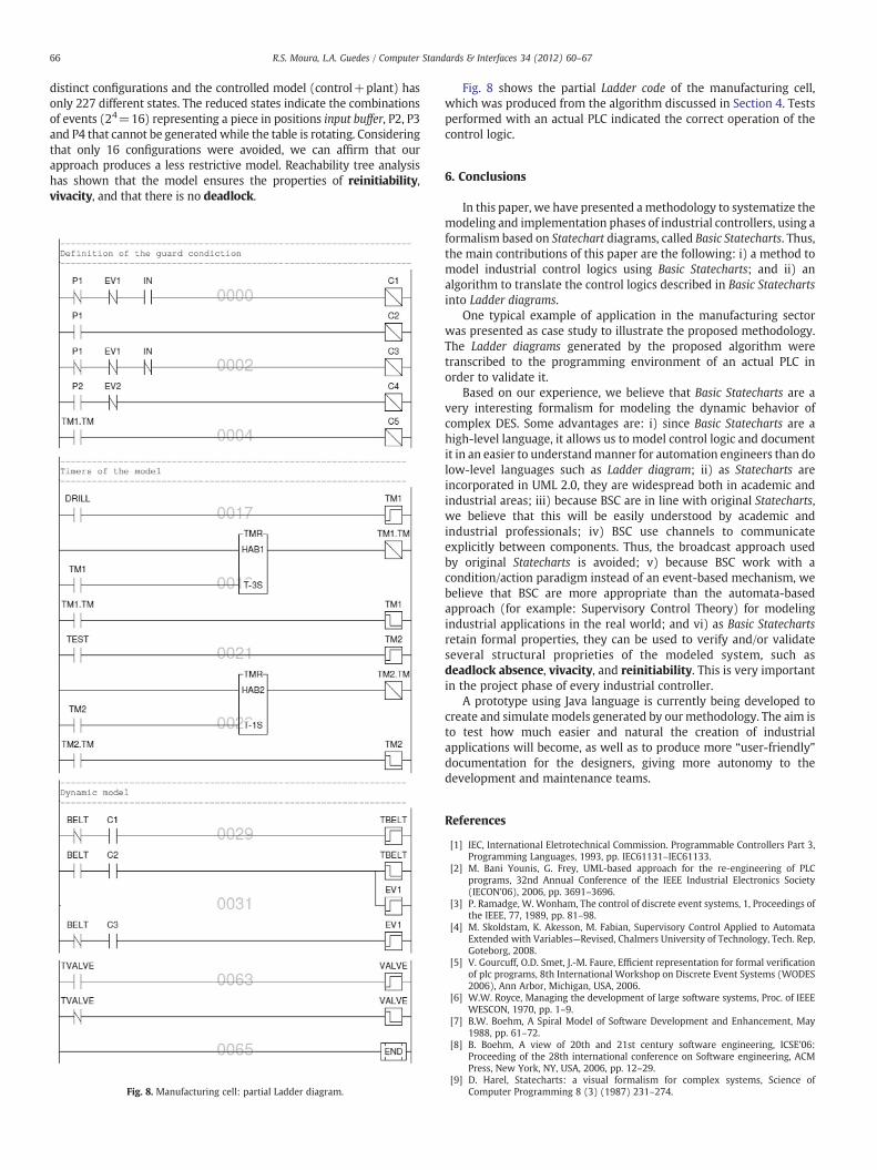
Fig. 8. Manufacturing cell: partial Ladder diagram.
Fig. 8 shows the partial Ladder code of the manufacturing cell,which was produced from the algorithm discussed in Section 4. Testsperformed with an actual PLC indicated the correct operation of thecontrol logic.
6. Conclusions
In this paper, we have presented amethodology to systematize themodeling and implementation phases of industrial controllers, using aformalism based on Statechart diagrams, called Basic Statecharts. Thus,the main contributions of this paper are the following: i) a method tomodel industrial control logics using Basic Statecharts; and ii) analgorithm to translate the control logics described in Basic Statechartsinto Ladder diagrams.
One typical example of application in the manufacturing sectorwas presented as case study to illustrate the proposed methodology.The Ladder diagrams generated by the proposed algorithm weretranscribed to the programming environment of an actual PLC inorder to validate it.
Based on our experience, we believe that Basic Statecharts are avery interesting formalism for modeling the dynamic behavior ofcomplex DES. Some advantages are: i) since Basic Statecharts are ahigh-level language, it allows us to model control logic and documentit in an easier to understandmanner for automation engineers than dolow-level languages such as Ladder diagram; ii) as Statecharts areincorporated in UML 2.0, they are widespread both in academic andindustrial areas; iii) because BSC are in line with original Statecharts,we believe that this will be easily understood by academic andindustrial professionals; iv) BSC use channels to communicateexplicitly between components. Thus, the broadcast approach usedby original Statecharts is avoided; v) because BSC work with acondition/action paradigm instead of an event-based mechanism, webelieve that BSC are more appropriate than the automata-basedapproach (for example: Supervisory Control Theory) for modelingindustrial applications in the real world; and vi) as Basic Statechartsretain formal properties, they can be used to verify and/or validateseveral structural proprieties of the modeled system, such asdeadlock absence, vivacity, and reinitiability. This is very importantin the project phase of every industrial controller.
A prototype using Java language is currently being developed tocreate and simulate models generated by ourmethodology. The aim isto test how much easier and natural the creation of industrialapplications will become, as well as to produce more “user-friendly”documentation for the designers, giving more autonomy to thedevelopment and maintenance teams.
References
[1] IEC, International Eletrotechnical Commission. Programmable Controllers Part 3,Programming Languages, 1993, pp. IEC61131–IEC61133.
[2] M. Bani Younis, G. Frey, UML-based approach for the re-engineering of PLCprograms, 32nd Annual Conference of the IEEE Industrial Electronics Society(IECON'06), 2006, pp. 3691–3696.
[3] P. Ramadge, W. Wonham, The control of discrete event systems, 1, Proceedings ofthe IEEE, 77, 1989, pp. 81–98.
[4] M. Skoldstam, K. Akesson, M. Fabian, Supervisory Control Applied to AutomataExtended with Variables—Revised, Chalmers University of Technology, Tech. Rep,Goteborg, 2008.
[5] V. Gourcuff, O.D. Smet, J.-M. Faure, Efficient representation for formal verificationof plc programs, 8th International Workshop on Discrete Event Systems (WODES2006), Ann Arbor, Michigan, USA, 2006.
[6] W.W. Royce, Managing the development of large software systems, Proc. of IEEEWESCON, 1970, pp. 1–9.
[7] B.W. Boehm, A Spiral Model of Software Development and Enhancement, May1988, pp. 61–72.
[8] B. Boehm, A view of 20th and 21st century software engineering, ICSE'06:Proceeding of the 28th international conference on Software engineering, ACMPress, New York, NY, USA, 2006, pp. 12–29.
[9] D. Harel, Statecharts: a visual formalism for complex systems, Science ofComputer Programming 8 (3) (1987) 231–274.
67R.S. Moura, L.A. Guedes / Computer Standards & Interfaces 34 (2012) 60–67
[10] SCXML, The jakarta project commons SCXML, http://jakarta.apache.org/commons/scxml/, 2006.
[11] R. Moura, L. Guedes, Simulation of industrial applications using the executionenvironment SCXML, 5th IEEE International Conference on Industrial Informatics(INDIN 2007), 2007, pp. 255–260.
[12] D. Drusinsky, D. Harel, Using statecharts for hardware description and synthesis,IEEE Transactions on Computer-Aided Design 8 (7) (1989) 798–807.
[13] M. von der Beeck, A comparison of statecharts variants, ProCoS: Proceedings ofthe Third International Symposium Organized Jointly with the Working GroupProvably Correct Systems on Formal Techniques in Real-Time and Fault-TolerantSystems, Springer-Verlag, London, UK, 1994, pp. 128–148.
[14] M. Queiroz, J. Cury, Synthesis and implementation of local modular supervisorycontrol for a manufacturing cell, 6th International Workshop on Discrete EventSystems (WODES 2002), Zaragoza, Spain, 2002.