VLT® AutomationDrive FC 301/302 - Danfoss
234
Contents 1. Introduction 3 Approvals 3 Symbols 3 Abbreviations 4 Definitions 4 2. How to Programme 11 The Graphical and Numerical Local Control Panels 11 How to Programme on the Graphical LCP 11 The LCD-Display 12 Quick Transfer of Parameter Settings between Multiple Frequency Converters 14 Display Mode 16 Display Mode - Selection of Read-Outs 16 Parameter Set-Up 17 Quick Menu Key Functions 17 Main Menu Mode 20 Parameter Selection 20 Changing Data 20 Changing a Text Value 20 Changing a Group of Numeric Data Values 21 Infinitely Variable Change of Numeric Data Value 21 Changing a Data Value,Step-by-Step 22 Read-out and Programming of Indexed Parameters 22 How to Programme on the Numerical Local Control Panel 23 Local Control Keys 24 Initialisation to Default Settings 25 Parameters: Operation and Display 27 Parameters: Load and Motor 42 Parameters: Brakes 63 Parameters: Reference/Ramps 70 Parameters: Limits/Warnings 86 Parameters: Digital In/Out 94 Parameters: Analog In/Out 112 Parameters: Controllers 121 Parameters: Communications and Options 127 Parameters: Profibus 134 Parameters: DeviceNet CAN Fieldbus 145 Parameters: Smart Logic Control 153 Parameters: Special Functions 171 FC 300 Programming Guide Contents MG.33.M2.02 - VLT ® is a registered Danfoss trademark 1
-
Upload
khangminh22 -
Category
Documents
-
view
3 -
download
0
Transcript of VLT® AutomationDrive FC 301/302 - Danfoss
Contents
1. Introduction 3
Approvals 3
Symbols 3
Abbreviations 4
Definitions 4
2. How to Programme 11
The Graphical and Numerical Local Control Panels 11
How to Programme on the Graphical LCP 11
The LCD-Display 12
Quick Transfer of Parameter Settings between Multiple Frequency Converters 14
Display Mode 16
Display Mode - Selection of Read-Outs 16
Parameter Set-Up 17
Quick Menu Key Functions 17
Main Menu Mode 20
Parameter Selection 20
Changing Data 20
Changing a Text Value 20
Changing a Group of Numeric Data Values 21
Infinitely Variable Change of Numeric Data Value 21
Changing a Data Value,Step-by-Step 22
Read-out and Programming of Indexed Parameters 22
How to Programme on the Numerical Local Control Panel 23
Local Control Keys 24
Initialisation to Default Settings 25
Parameters: Operation and Display 27
Parameters: Load and Motor 42
Parameters: Brakes 63
Parameters: Reference/Ramps 70
Parameters: Limits/Warnings 86
Parameters: Digital In/Out 94
Parameters: Analog In/Out 112
Parameters: Controllers 121
Parameters: Communications and Options 127
Parameters: Profibus 134
Parameters: DeviceNet CAN Fieldbus 145
Parameters: Smart Logic Control 153
Parameters: Special Functions 171
FC 300 Programming Guide Contents
MG.33.M2.02 - VLT ® is a registered Danfoss trademark 1

Parameters: Drive Information 181
Parameters: Data Read-outs 190
Parameters: Encoder Input 198
Parameter Lists 202
Index 229
Contents FC 300 Programming Guide
2 MG.33.M2.02 - VLT ® is a registered Danfoss trademark

1. Introduction
1.1.1. Approvals
1.1.2. Symbols
Symbols used in this guide.
NB!Indicates something to be noted by the reader.
Indicates a general warning.
Indicates a high-voltage warning.
* Indicates default setting
FC 300 Programming Guide 1. Introduction
MG.33.M2.02 - VLT ® is a registered Danfoss trademark 3
1

1.1.3. Abbreviations
Alternating current ACAmerican wire gauge AWGAmpere/AMP AAutomatic Motor Adaptation AMACurrent limit ILIM
Degrees Celsius °CDirect current DCDrive Dependent D-TYPEElectro Magnetic Compatibility EMCElectronic Thermal Relay ETRdrive FCGram gHertz HzKilohertz kHzLocal Control Panel LCPMeter mMillihenry Inductance mHMilliampere mAMillisecond msMinute minMotion Control Tool MCTNanofarad nFNewton Meters NmNominal motor current IM,N
Nominal motor frequency fM,N
Nominal motor power PM,N
Nominal motor voltage UM,N
Parameter par.Protective Extra Low Voltage PELVPrinted Circuit Board PCBRated Inverter Output Current IINV
Revolutions Per Minute RPMSecond sTorque limit TLIM
Volts V
1.1.4. Definitions
Drive:
D-TYPESize and type of the connected drive (dependencies).
IVLT,MAX
The maximum output current.
IVLT,N
The rated output current supplied by the frequency converter.
UVLT, MAX
The maximum output voltage.
Input:
Control commandYou can start and stop the connected motorby means of LCP and the digital inputs.Functions are divided into two groups.
Functions in group 1 have higher priority thanfunctions in group 2.
Group 1 Reset, Coasting stop, Resetand Coasting stop, Quick-stop,DC braking, Stop and the "Off"key.
Group 2 Start, Pulse start, Reversing,Start reversing, Jog andFreeze output
1. Introduction FC 300 Programming Guide
4 MG.33.M2.02 - VLT ® is a registered Danfoss trademark
1

Motor:
fJOG
The motor frequency when the jog function is activated (via digital terminals).
fMThe motor frequency.
fMAX
The maximum motor frequency.
fMIN
The minimum motor frequency.
fM,N
The rated motor frequency (nameplate data).
IM
The motor current.
IM,N
The rated motor current (nameplate data).
M-TYPESize and type of the connected motor (dependencies).
nM,N
The rated motor speed (nameplate data).
PM,N
The rated motor power (nameplate data).
TM,N
The rated torque (motor).
UM
The instantaneous motor voltage.
UM,N
The rated motor voltage (nameplate data).
Break-away torque
FC 300 Programming Guide 1. Introduction
MG.33.M2.02 - VLT ® is a registered Danfoss trademark 5
1

ηVLT
The efficiency of the frequency converter is defined as the ratio between the power output andthe power input.
Start-disable commandA stop command belonging to the group 1 control commands - see this group.
Stop commandSee Control commands.
References:Analog ReferenceA signal transmitted to the analog inputs 53 or 54, can be voltage or current.Binary ReferenceA signal transmitted to the serial communication port.Preset ReferenceA defined preset reference to be set from -100% to +100% of the reference range. Selection ofeight preset references via the digital terminals.
Pulse ReferenceA pulse frequency signal transmitted to the digital inputs (terminal 29 or 33).
RefMAX
Determines the relationship between the reference input at 100% full scale value (typically 10 V,20mA) and the resulting reference. The maximum reference value set in par. 3-03.
RefMIN
Determines the relationship between the reference input at 0% value (typically 0V, 0mA, 4mA)and the resulting reference. The minimum reference value set in par. 3-02.
Miscellaneous:
Analog InputsThe analog inputs are used for controlling various functions of the frequency converter.There are two types of analog inputs:Current input, 0-20 mA and 4-20 mAVoltage input, 0-10 V DC (FC 301)Voltage input, -10 - +10 V DC (FC 302).
Analog OutputsThe analog outputs can supply a signal of 0-20 mA, 4-20 mA, or a digital signal.
Automatic Motor Adaptation, AMAAMA algorithm determines the electrical parameters for the connected motor at standstill.
Brake ResistorThe brake resistor is a module capable of absorbing the brake power generated in regenerativebraking. This regenerative braking power increases the intermediate circuit voltage and a brakechopper ensures that the power is transmitted to the brake resistor.
CT CharacteristicsConstant torque characteristics used for all applications such as conveyor belts, displacementpumps and cranes.
1. Introduction FC 300 Programming Guide
6 MG.33.M2.02 - VLT ® is a registered Danfoss trademark
1

Digital InputsThe digital inputs can be used for controlling various functions of the frequency converter.
Digital OutputsThe drive features two Solid State outputs that can supply a 24 V DC (max. 40 mA) signal.
DSPDigital Signal Processor.
ETRElectronic Thermal Relay is a thermal load calculation based on present load and time. Its purposeis to estimate the motor temperature.
Hiperface®
Hiperface® is a registered trademark by Stegmann.
InitialisingIf initialising is carried out (par. 14-22), the frequency converter returns to the default setting.
Intermittent Duty C ycleAn intermittent duty rating refers to a sequence of duty cycles. Each cycle consists of an on-loadand an off-load period. The operation can be either periodic duty or non-periodic duty.
LCPThe Local Control Panel (LCP) makes up a complete interface for control and programming of theFC 300 Series. The control panel is detachable and can be installed up to 3 metres from thefrequency converter, i.e. in a front panel by means of the installation kit option.
lsbLeast significant bit.
msbMost significant bit.
MCMShort for Mille Circular Mil, an American measuring unit for cable cross-section. 1 MCM = 0.5067mm2.
On-line/Off-line ParametersChanges to on-line parameters are activated immediately after the data value is changed. Changesto off-line parameters are not activated until you enter [OK] on the LCP.
Process PIDThe PID regulator maintains the desired speed, pressure, temperature, etc. by adjusting the out-put frequency to match the varying load.
Pulse Input/Incremental EncoderAn external, digital pulse transmitter used for feeding back information on motor speed. The en-coder is used in applications where great accuracy in speed control is required.
RCDResidual Current Device.
FC 300 Programming Guide 1. Introduction
MG.33.M2.02 - VLT ® is a registered Danfoss trademark 7
1

Set-upYou can save parameter settings in four Set-ups. Change between the four parameter Set-upsand edit one Set-up, while another Set-up is active.
SFAVMSwitching pattern called Stator Flux oriented Asynchronous Vector Modulation (par. 14-00).
Slip CompensationThe frequency converter compensates for the motor slip by giving the frequency a supplementthat follows the measured motor load keeping the motor speed almost constant..
Smart Logic Control (SLC)The SLC is a sequence of user defined actions executed when the associated user defined eventsare evaluated as true by the SLC. (Parameter group 13-xx).
FC Standard BusIncludes RS 485 bus with FC protocol or MC protocol. See parameter 8-30.
Thermistor:A temperature-dependent resistor placed where the temperature is to be monitored (frequencyconverter or motor).
TripA state entered in fault situations, e.g. if the frequency converter is subject to an over-temperatureor when the frequency converter is protecting the motor, process or mechanism. Restart is pre-vented until the cause of the fault has disappeared and the trip state is cancelled by activatingreset or, in some cases, by being programmed to reset automatically. Trip may not be used forpersonal safety.
Trip LockedA state entered in fault situations when the frequency converter is protecting itself and requiringphysical intervention, e.g. if the frequency converter is subject to a short circuit on the output. Alocked trip can only be cancelled by cutting off mains, removing the cause of the fault, and re-connecting the frequency converter. Restart is prevented until the trip state is cancelled byactivating reset or, in some cases, by being programmed to reset automatically. Trip may not beused for personal safety.
VT CharacteristicsVariable torque characteristics used for pumps and fans.
VVCplusIf compared with standard voltage/frequency ratio control, Voltage Vector Control (VVCplus) im-proves the dynamics and the stability, both when the speed reference is changed and in relationto the load torque.
60° AVMSwitching pattern called 60°Asynchronous Vector Modulation (par. 14-00).
Power FactorThe power factor is the relation between I1
and IRMS.
Power factor = 3 x U x I1 x cosϕ3 x U x IRMS
The power factor for 3-phase control:= I1 x cosϕ1
IRMS=
I1IRMS
since cosϕ1 = 1
1. Introduction FC 300 Programming Guide
8 MG.33.M2.02 - VLT ® is a registered Danfoss trademark
1

The power factor indicates to which extent thefrequency converter imposes a load on themains supply.The lower the power factor, the higher theIRMS for the same kW performance.
IRMS = I12 + I5
2 + I72 + .. + In
2
In addition, a high power factor indicates that the different harmonic currents are low.The FC 300 frequency converters' built-in DC coils produce a high power factor, which minimizesthe imposed load on the mains supply.
The voltage of the frequency converter is dangerous whenever connected to mains.Incorrect installation of the motor, frequency converter or fieldbus may cause dam-age to the equipment, serious personal injury or death. Consequently, the instruc-tions in this manual, as well as national and local rules and safety regulations, mustbe complied with.
Safety Regulations1. The frequency converter must be disconnected from mains if repair work is to be carried
out. Check that the mains supply has been disconnected and that the necessary time haspassed before removing motor and mains plugs.
2. The [STOP/RESET] key on the control panel of the frequency converter does not dis-connect the equipment from mains and is thus not to be used as a safety switch.
3. Correct protective earthing of the equipment must be established, the user must be pro-tected against supply voltage, and the motor must be protected against overload inaccordance with applicable national and local regulations.
4. The earth leakage currents are higher than 3.5 mA.
5. Protection against motor overload is not included in the factory setting. If this functionis desired, set par. 1-90 to data value ETR trip or data value ETR warning.
6. Do not remove the plugs for the motor and mains supply while the frequency converteris connected to mains. Check that the mains supply has been disconnected and that thenecessary time has passed before removing motor and mains plugs.
7. Please note that the frequency converter has more voltage inputs than L1, L2 and L3,when load sharing (linking of DC intermediate circuit) and external 24 V DC have beeninstalled. Check that all voltage inputs have been disconnected and that the necessarytime has passed before commencing repair work.
FC 300 Programming Guide 1. Introduction
MG.33.M2.02 - VLT ® is a registered Danfoss trademark 9
1

2. How to Programme FC 300 Programming Guide
10 MG.33.M2.02 - VLT ® is a registered Danfoss trademark
2

2. How to Programme
2.1. The Graphical and Numerical Local Control Panels
The easiest programming of the frequency converter is performed by the Graphical Local ControlPanel (LCP 102). It is necessary to consult the frequency converter Design Guide, when using theNumeric Local Control Panel (LCP 101).
2.1.1. How to Programme on the Graphical LCP
The following instructions are valid for the graphical LCP (LCP 102):
The control panel is divided into fourfunctional groups:
1. Graphical display with Status lines.
2. Menu keys and indicator lights -changing parameters and switchingbetween display functions.
3. Navigation keys and indicator lights(LEDs).
4. Operation keys and indicator lights(LEDs).
All data is displayed in a graphical LCP display,which can show up to five items of operatingdata while displaying [Status].
Display lines:a. Status line: Status messages dis-
playing icons and graphic.1
b. Line 1-2: Operator data lines dis-playing data defined or chosen bythe user. By pressing the [Status]key, up to one extra line can be add-ed.1
c. Status line: Status messages dis-playing text.1
FC 300 Programming Guide 2. How to Programme
MG.33.M2.02 - VLT ® is a registered Danfoss trademark 11
2

2.1.2. The LCD-Display
The LCD-display has back light and a total of 6 alpha-numeric lines. The display lines show thedirection of rotation (arrow), the chosen Set-up as well as the programming Set-up. The displayis divided into 3 sections:
Top section shows up to 2 measurements innormal operating status.
The top line in the Middle section shows upto 5 measurements with related unit, regard-less of status (except in the case of alarm/warning).
Bottom section always shows the state ofthe frequency converter in Status mode.
130BP074.10
Top section
Middle section
Bottom section
The Active Set-up (selected as the Active Set-up in par. 0-10) is shown. When programming an-other Set-up than the Active Set-up, the number of the programmed Set-up appears to the right.
Display Contrast Adjustment
Press [status] and [] for darker displayPress [status] and [] for brighter display
Most FC 300 parameter set-ups can be changed immediately via the control panel, unless a pass-word has been created via par. 0-60 Main Menu Password or via par. 0-65 Quick MenuPassword.
Indicator lights (LEDs):
If certain threshold values are exceeded, the alarm and/or warning LED lights up. A status andalarm text appear on the control panel.The ON LED is activated when the frequency converter receives mains voltage or via a DC busterminal or 24 V external supply. At the same time, the back light is on.
• Green LED/On: Control section isworking.
• Yellow LED/Warn.: Indicates a warn-ing.
• Flashing Red LED/Alarm: Indicatesan alarm. 130BP040.10
LCP keys
The control keys are divided into functions.The keys below the display and indicatorlamps are used for parameter Set-up, includ-ing choice of display indication during normaloperation.
130BP045.10
2. How to Programme FC 300 Programming Guide
12 MG.33.M2.02 - VLT ® is a registered Danfoss trademark
2

[Status] indicates the status of the frequency converter and/or the motor. You can choose be-tween 3 different readouts by pressing the [Status] key:5 line readouts, 4 line readouts or Smart Logic Control.Use [Status] for selecting the mode of display or for changing back to Display mode from eitherthe Quick Menu mode, the Main Menu mode or Alarm mode. Also use the [Status] key to togglesingle or double read-out mode.
[Quick Menu] allows quick access to different Quick Menus such as:
- My Personal Menu
- Quick Set-up
- Changes Made
- Loggings
Use [Quick Menu] for programming the parameters belonging to the Quick Menu. It is possibleto switch directly between Quick Menu mode and Main Menu mode.
[Main Menu] is used for programming all parameters.It is possible to switch directly between Main Menu mode and Quick Menu mode.Parameter shortcut can be carried out by pressing down the [Main Menu] key for 3 seconds.The parameter shortcut allows direct access to any parameter.
[Alarm Log] displays an Alarm list of the five latest alarms (numbered A1-A5). To obtain addi-tional details about an alarm, use the arrow keys to manoeuvre to the alarm number and press[OK]. You will now receive information about the condition of your frequency converter right be-fore entering the alarm mode.
[Back] takes you to the previous step or layer in the navigation structure.
[Cancel] annuls your last change or command as long as the display has not been changed.
[Info] supplies information about a com-mand, parameter, or function in any displaywindow. [Info] provides detailed informationwhenever help is needed.Exit info mode by pressing either [Info],[Back], or [Cancel].
Navigation KeysThe four navigation arrows are used to navigate between the different choices available in [QuickMenu], [Main Menu] and [Alarm Log]. Use the keys to move the cursor.
[OK] is used for choosing a parameter marked by the cursor and for enabling the change of aparameter.
Local Control Key for local control are foundat the bottom of the control panel.
130BP046.10
[Hand On] enables control of the frequency converter via the LCP. [Hand on] also starts themotor, and it is now possible to enter the motor speed data by means of the arrow keys. The keycan be selected as Enable [1] or Disable [0] via par. 0-40 [Hand on] key on LCP.
FC 300 Programming Guide 2. How to Programme
MG.33.M2.02 - VLT ® is a registered Danfoss trademark 13
2

External stop signals activated by means of control signals or a serial bus will override a “start”command via the LCP.The following control signals will still be active when [Hand on] is activated:
• [Hand on] - [Off] - [Auto on]
• Reset
• Coasting stop inverse
• Reversing
• Set-up select bit 0- Set-up select bit 1
• Stop command from serial communication
• Quick stop
• DC brake
[Off] stops the connected motor. The key can be selected as Enable [1] or Disable [0] via par.0-41 [Off] key on LCP. If no external stop function is selected and the [Off] key is inactive themotor can be stopped by disconnecting the voltage.
[Auto On] enables the frequency converter to be controlled via the control terminals and/or serialcommunication. When a start signal is applied on the control terminals and/or the bus, the fre-quency converter will start. The key can be selected as Enable [1] or Disable [0] via par. 0-42[Auto on] key on LCP.
NB!An active HAND-OFF-AUTO signal via the digital inputs has higher priority than thecontrol keys [Hand on] – [Auto on].
[Reset] is used for resetting the frequency converter after an alarm (trip). It can be selected asEnable [1] or Disable [0] via par. 0-43 Reset Keys on LCP.
The parameter shortcut can be carried out by holding down the [Main Menu] key for 3 seconds.The parameter shortcut allows direct access to any parameter.
2.1.3. Quick Transfer of Parameter Settings between Multiple Fre-quency Converters
Once the set-up of a frequency converter iscomplete, we recommend that you store thedata in the LCP or on a PC via MCT 10 Set-upSoftware Tool.
Data storage in LCP:
1. Go to par. 0-50 LCP Copy
2. How to Programme FC 300 Programming Guide
14 MG.33.M2.02 - VLT ® is a registered Danfoss trademark
2
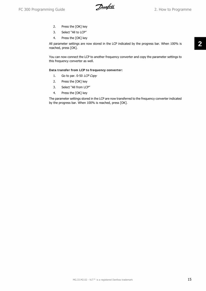
2. Press the [OK] key
3. Select “All to LCP”
4. Press the [OK] key
All parameter settings are now stored in the LCP indicated by the progress bar. When 100% isreached, press [OK].
You can now connect the LCP to another frequency converter and copy the parameter settings tothis frequency converter as well.
Data transfer from LCP to frequency converter:
1. Go to par. 0-50 LCP Copy
2. Press the [OK] key
3. Select “All from LCP”
4. Press the [OK] key
The parameter settings stored in the LCP are now transferred to the frequency converter indicatedby the progress bar. When 100% is reached, press [OK].
FC 300 Programming Guide 2. How to Programme
MG.33.M2.02 - VLT ® is a registered Danfoss trademark 15
2

2.1.4. Display Mode
In normal operation, up to 5 different operating variables can be indicated continuously in themiddle section: 1.1, 1.2, and 1.3 as well as 2 and 3.
2.1.5. Display Mode - Selection of Read-Outs
It is possible to toggle between three statusread-out screens by pressing the [Status] key.Operating variables with different formattingare shown in each status screen - see below.
The table shows the measurements you canlink to each of the operating variables. Definethe links via par. 0-20, 0-21, 0-22, 0-23, and0-24.
Each readout parameter selected in par. 0-20to par. 0-24 has its own scale and digits aftera possible decimal point. By larger numericvalue of a parameter fewer digits are dis-played after the decimal point.Ex.: Current readout5.25 A; 15.2 A 105 A.
Operating variable: Unit:Par. 16-00 Control Word hexPar. 16-01 Reference [unit]Par. 16-02 Reference %Par. 16-03 Status Word hexPar. 16-05 Main Actual Value %Par. 16-10 Power [kW]Par. 16-11 Power [HP]Par. 16-12 Motor Voltage [V]Par. 16-13 Frequency [Hz]Par. 16-14 Motor Current [A]Par. 16-16 Torque NmPar. 16-17 Speed [RPM]Par. 16-18 Motor Thermal %Par. 16-20 Motor AnglePar. 16-30 DC Link Voltage VPar. 16-32 Brake Energy / s kWPar. 16-33 Brake Energy / 2 min kWPar. 16-34 Heatsink Temp. CPar. 16-35 Inverter Thermal %Par. 16-36 Inv. Nom. Current APar. 16-37 Inv. Max. Current APar. 16-38 SL Control StatePar. 16-39 Control Card Temp. CPar. 16-40 Logging Buffer FullPar. 16-50 External Reference Par. 16-51 Pulse ReferencePar. 16-52 Feedback [Unit]Par. 16-53 Digi Pot ReferencePar. 16-60 Digital Input binPar. 16-61 Terminal 53 Switch Set-ting
V
Par. 16-62 Analog Input 53 Par. 16-63 Terminal 54 Switch Set-ting
V
Par. 16-64 Analog Input 54 Par. 16-65 Analog Output 42 [mA]Par. 16-66 Digital Output [bin]Par. 16-67 Freq. Input #29 [Hz]Par. 16-68 Freq. Input #33 [Hz]Par. 16-69 Pulse Output #27 [Hz]Par. 16-70 Pulse Output #29 [Hz]Par. 16-71 Relay OutputPar. 16-72 Counter A Par. 16-73 Counter BPar. 16-80 Fieldbus CTW hexPar. 16-82 Fieldbus REF 1 hexPar. 16-84 Comm. Option STW hexPar. 16-85 FC Port CTW 1 hexPar. 16-86 FC Port REF 1 hexPar. 16-90 Alarm WordPar. 16-92 Warning Word Par. 16-94 Ext. Status Word
Status screen I:This read-out state is standard after start-upor initialization.Use [INFO] to obtain information about themeasurement links to the displayed operatingvariables (1.1, 1.2, 1.3, 2 and 3).See the operating variables shown in thescreen in this illustration.
130BP041.10
1.1
1.3
2
1.2
3
2. How to Programme FC 300 Programming Guide
16 MG.33.M2.02 - VLT ® is a registered Danfoss trademark
2

Status screen II:See the operating variables (1.1, 1.2, 1.3 and2) shown in the screen in this illustration.In the example, Speed, Motor current, Motorpower and Frequency are selected as varia-bles in the first and second.
130BP062.10
2
1.2
1.31.1
Status screen III:This state displays the event and action of theSmart Logic Control. For further information,see section Smart Logic Control. 1
30BP063.10
2.1.6. Parameter Set-Up
The FC 300 Series can be used for practically all assignments, which is why the number of pa-rameters is quite large. The series offers a choice between two programming modes - a MainMenu and a Quick Menu mode.The former provides access to all parameters. The latter takes the user through a few parametersmaking it possible to start operating the frequency converter.Regardless of the mode of programming, you can change a parameter both in the Main Menumode and in the Quick Menu mode.
2.1.7. Quick Menu Key Functions
Pressing [Quick Menus] The list indicates thedifferent areas contained in the Quick menu.Select My Personal Menu to display the chosenpersonal parameters. These parameters areselected in par. 0-25 Personal Menu. Up to 20different parameters can be added in thismenu.
Select Quick setup to go through a limited amount of parameters to get the motor running almostoptimally. The default setting for the other parameters considers the desired control functions andthe configuration of signal inputs/outputs (control terminals).
The selection of parameter is effected by means of the arrow keys. The parameters in the followingtable are accessible.
FC 300 Programming Guide 2. How to Programme
MG.33.M2.02 - VLT ® is a registered Danfoss trademark 17
2

Parameter Designation Setting0-01 Language 1-20 Motor Power [kW]1-22 Motor Voltage [V]1-23 Motor Frequency [Hz]1-24 Motor Current [A]1-25 Motor Nominal Speed [rpm]5-12 Terminal 27 Digital Input [0] No function*1-29 Automatic Motor Adaptation (AMA) [1] Enable complete AMA3-02 Min Reference [rpm]3-03 Max Reference [rpm]3-41 Ramp 1 Ramp-up Time [sec]3-42 Ramp 1 Ramp-down Time [sec]3-13 Reference Site
* If terminal 27 is set to “no function”, no connection to +24 V on terminal 27 is necessary.
Select Changes made to get informationabout:
• the last 10 changes. Use the [] []navigation keys to scroll between thelast 10 changed parameters.
• the changes made since default set-ting.
Select Loggings to get information about thedisplay line read-outs. The information isshown as graphs.Only display parameters selected in par. 0-20and par. 0-24 can be viewed. It is possible tostore up to 120 samples in the memory forlater reference.
2. How to Programme FC 300 Programming Guide
18 MG.33.M2.02 - VLT ® is a registered Danfoss trademark
2

2.1.8. Initial Commissioning
The easiest way of carrying out the initial commissioning is by using the Quick Menu button andfollow the quick set-up procedure using LCP 102 (read table from left to right):
Press
Q2 Quick Menu
0-01 Language Set language
1-20 Motor power Set Motor nameplate power
1-22 Motor voltage Set Nameplate voltage
1-23 Motor frequency Set Nameplate frequency
1-24 Motor current Set Nameplate current
1-25 Motor nominal speed Set Nameplate speed in RPM
5-12 Terminal 27 DigitalInput
If terminal default is Coast inverse it ispossible to change this setting to Nofunction. No connection to terminal 27is then needed for running AMA
1-29 Automatic MotorAdaptation
Set desired AMA function. Enable com-plete AMA is recommended
3-02 Minimum referenceSet the minimum speed of the motorshaft
3-03 Maximum referenceSet the maximum speed of the motorshaft
3-41 Ramp1 up timeSet the ramping up time with referenceto nominal motor speed (set in par.1-25)
3-42 Ramp1 down timeSet the ramping down time with refer-ence to nominal motor speed (set in par.1-25)
3-13 Reference siteSet the site from where the referencemust work
FC 300 Programming Guide 2. How to Programme
MG.33.M2.02 - VLT ® is a registered Danfoss trademark 19
2

2.1.9. Main Menu Mode
Start the Main Menu mode by pressing the[Main Menu] key. The read-out shown to theright appears on the display.The middle and bottom sections on the displayshow a list of parameter groups which can bechosen by toggling the up and down buttons.
130BP066.10
Each parameter has a name and number which remain the same regardless of the programmingmode. In the Main Menu mode, the parameters are divided into groups. The first digit of theparameter number (from the left) indicates the parameter group number.
All parameters can be changed in the Main Menu. However, depending on the choice of configu-ration (par. 1-00), some parameters can be "missing". E.g. open loop hides all the PID parameters,and other enabled options make more parameter groups visible.
2.1.10. Parameter Selection
In the Main menu mode, the parameters aredivided into groups. You select a parametergroup by means of the navigation keys.The following parameter groups are accessi-ble:
Group no. Parameter group:0 Operation/Display1 Load/Motor2 Brakes3 References/Ramps4 Limits/Warnings5 Digital In/Out6 Analog In/Out7 Controls8 Comm. and Options9 Profibus10 CAN Fieldbus11 Reserved Com. 112 Reserved Com. 213 Smart Logic14 Special Functions15 Drive Information16 Data Readouts17 Motor Feedb. Option
After selecting a parameter group, choose aparameter by means of the navigation keys.The middle section on the display shows theparameter number and name as well as theselected parameter value.
130BP067.10
2.1.11. Changing Data
The procedure for changing data is the same whether you select a parameter in the Quick menuor the Main menu mode. Press [OK] to change the selected parameter.The procedure for changing data depends on whether the selected parameter represents a nu-merical data value or a text value.
2.1.12. Changing a Text Value
2. How to Programme FC 300 Programming Guide
20 MG.33.M2.02 - VLT ® is a registered Danfoss trademark
2

If the selected parameter is a text value,change the text value by means of the [][] navigation keys.The up key increases the value, and the downkey decreases the value. Place the cursor onthe value you want to save and press [OK].
130BP068.10
2.1.13. Changing a Group of Numeric Data Values
If the chosen parameter represents a numericdata value, change the chosen data value bymeans of the [] [] navigation keys as wellas the [] [] navigation keys. Use the [][] navigation keys to move the cursor hori-zontally.
130BP069.10
Use the [] [] navigation keys to change thedata value. The up key enlarges the data val-ue, and the down key reduces the data value.Place the cursor on the value you want to saveand press [OK].
130BP070.10
2.1.14. Infinitely Variable Change of Numeric Data Value
If the chosen parameter represents a numericdata value, select a digit by means of the [][] navigation keys.
130BP073.10
Change the selected digit infinitely variably bymeans of the [] [] navigation keys.The chosen digit is indicated by the cursor.Place the cursor on the digit you want to saveand press [OK].
130BP072.10
FC 300 Programming Guide 2. How to Programme
MG.33.M2.02 - VLT ® is a registered Danfoss trademark 21
2

2.1.15. Changing a Data Value,Step-by-Step
Certain parameters can be changed step by step or infinitely variably. This applies to Motor Pow-er (par. 1-20), Motor Voltage (par. 1-22) and Motor Frequency (par. 1-23).The parameters are changed both as a group of numeric data values and as numeric data valuesinfinitely variably.
2.1.16. Read-out and Programming of Indexed Parameters
Parameters are indexed when placed in a rolling stack.Par. 15-30 to 15-32 contain a fault log which can be read out. Choose a parameter, press [OK],and use the [] [] navigation keys to scroll through the value log.
Use par. 3-10 as another example:Choose the parameter, press [OK], and use the [] [] navigation keys to scroll through theindexed values. To change the parameter value, select the indexed value and press [OK]. Changethe value by using the [] [] keys. Press [OK] to accept the new setting. Press [CANCEL] to abort.Press [Back] to leave the parameter.
2. How to Programme FC 300 Programming Guide
22 MG.33.M2.02 - VLT ® is a registered Danfoss trademark
2

2.1.17. How to Programme on the Numerical Local Control Panel
The following instructions are valid for the Nu-merical LCP (LCP 101).The control panel is divided into four function-al groups:
1. Numerical display.
2. Menu keys and indicator lights -changing parameters and switchingbetween display functions.
3. Navigation keys and indicator lights(LEDs).
4. Operation keys and indicator lights(LEDs).
Display line:
Status line: Status messages displayingicons and numeric value.
Indicator lights (LEDs):
• Green LED/On: Indicates if controlsection is on.
• Yellow LED/Wrn.: Indicates a warn-ing.
• Flashing red LED/Alarm: Indicatesan alarm.
LCP keys[Menu] Select one of the following modes:
• Status
• Quick Setup
• Main Menu
Status Mode: Displays the status of the fre-quency converter or the motor.If an alarm occurs the NLCP automaticallyswitches to status mode.A number of alarms can be displayed.
NB!Parameter copy is not possiblewith LCP 101 Numerical LocalControl Panel.
130BP077.10
130BP078.10
FC 300 Programming Guide 2. How to Programme
MG.33.M2.02 - VLT ® is a registered Danfoss trademark 23
2

Main Menu/ Quick Setup is used for pro-gramming all parameters or only the param-eters in the Quick Meny (see also descriptionof the LCP 102 earlier in this chapter).The parameter values can be changed usingthe [] [] keys when the value is flashing.Select Main Menu by pressing [Menu] key anumber of times.Select the parameter group [xx-__] and press[OK]Select the parameter [__-xx] and press [OK]If the parameter is an array parameter selectthe array number and press [OK]Select the wanted data value and press [OK]Parameters with functional choices displayvalues such as [1], [2], etc. For a descriptionof the different choices, see the individual de-scription of the parameters in the ParameterSelection section
[Back] for stepping backwardsArrow [] [] keys are used for manoeuvringbetween commands and within parameters.
130BP079.10
2.1.18. Local Control Keys
Keys for local control are found at the bottomof the control panel.
130BP046.10
[Hand on] enables control of the frequency converter via the LCP. [Hand on] also starts the motorand it is now possible to enter the motor speed data by means of the arrow keys. The key can beselected as Enable [1] og Disable [0] via par. 0-40 [Hand on] Key on LCP.External stop signals activated by means of control signals or a serial bus will override a 'start'command via the LCP.The following control signals will still be active when [Hand on] is activated:
• [Hand on] - [Off] - [Auto on]
• Reset
• Coasting stop inverse
• Reversing
• Set-up select lsb - Set-up select msb
• Stop command from serial communication
• Quick stop
• DC brake
[Off] stops the connected motor. The key can be selected as Enable [1] or Disable [0] via par.0-41 [Off] Key on LCP.If no external stop function is selected and the [Off] key is inactive the motor can be stopped bydisconnecting the voltage.
2. How to Programme FC 300 Programming Guide
24 MG.33.M2.02 - VLT ® is a registered Danfoss trademark
2

[Auto on] enables the frequency converter to be controlled via the control terminals and/or serialcommunication. When a start signal is applied on the control terminals and/or the bus, the fre-quency converter will start. The key can be selected as Enable [1] or Disable [0] via par. 0-42[Auto on] Key on LCP.
NB!An active HAND-OFF-AUTO signal via the digital inputs has higher priority than thecontrol keys [Hand on] [Auto on].
[Reset] is used for resetting the frequency converter after an alarm (trip). It can be selected asEnable [1] or Disable [0] via par. 0-43 Reset Keys on LCP.
2.1.19. Initialisation to Default Settings
Initialise the frequency converter to default settings in two ways:
Recommended initialisation (via par. 14-22)
1. Select par. 14-22
2. Press [OK]
3. Select “Initialisation”
4. Press [OK]
5. Cut off the mains supply and waituntil the display turns off.
6. Reconnect the mains supply - thefrequency converter is now reset.
Par. 14-22 initialises all except:14-50 RFI 18-30 Protocol8-31 Address8-32 Baud Rate
8-35 Minimum Response Delay8-36 Max Response Delay8-37 Max Inter-char Delay15-00 to 15-05 Operating data15-20 to 15-22 Historic log15-30 to 15-32 Fault log
Manual initialisation
1. Disconnect from mains and wait untilthe display turns off.
2a. Press [Status] - [Main Menu] - [OK]at the same time while power up forLCP 102, Graphical Display
2b. Press [Menu] while power up for LCP101, Numerical Display
3. Release the keys after 5 s.4. The frequency converter is now pro-
grammed according to default set-tings.
This parameter initialises all except:15-00 Operating Hours15-03 Power-up's15-04 Over temp's15-05 Over volt's
NB!When you carry out manual initialisation, you also reset serial communication, RFIfilter settings (par. 14-50) and fault log settings.
FC 300 Programming Guide 2. How to Programme
MG.33.M2.02 - VLT ® is a registered Danfoss trademark 25
2

2.2. Parameter Selection
Parameters for FC 300 are grouped into various parameter groups for easy selection of the correctparameters for optimized operation of the frequency converter.0-xx Operation and Display parameters
• Basic Settings, set-up handling
• Display and Local Control Panel parameters for choosing readouts, setting up selectionsand copying functions
1-xx Load and Motor parameters includes all load and motor related parameters
2-xx Brake parameters
• DC brake
• Dynamic brake (Resistor brake)
• Mechanical brake
• Over Voltage Control
3-xx References and ramping parameters includes DigiPot function
4-xx Limits Warnings; setting of limits and warning parameters
5-xx Digital inputs and outputs includes relay controls
6-xx Analog inputs and outputs
7-xx Controls; Setting parameters for speed and process controls
8-xx Communication and option parameters for setting of FC RS485 and FC USB port parameters.
9-xx Profibus parameters
10-xx DeviceNet and CAN Fieldbus parameters
13-xx Smart Logic Control parameters
14-xx Special function parameters
15-xx Drive information parameters
16-xx Read out parameters
17-xx Encoder Option parameters
2. How to Programme FC 300 Programming Guide
26 MG.33.M2.02 - VLT ® is a registered Danfoss trademark
2

2.3. Parameters: Operation and Display
2.3.1. 0-0* Operation / Display
Parameters related to the fundamental functions of the frequency converter, function of the LCPbuttons and configuration of the LCP display.
2.3.2. 0-0* Basic Settings
Parameter group for basic frequency converter settings.
0-01 Language
Option: Function:
Defines the language to be used in the display.
The frequency converter can be delivered with 4 different lan-guage packages. English and German are included in all pack-ages. English cannot be erased or manipulated.
[0] * English Part of Language packages 1 - 4
[1] German Part of Language packages 1 - 4
[2] French Part of Language package 1
[3] Danish Part of Language package 1
[4] Spanish Part of Language package 1
[5] Italian Part of Language package 1
[6] Swedish Part of Language package 1
[7] Dutch Part of Language package 1
[10] Chinese Language package 2
[20] Finnish Part of Language package 1
[22] English US Part of Language package 4
[27] Greek Part of Language package 4
[28] Portuguese Part of Language package 4
[36] Slovenian Part of Language package 3
[39] Korean Part of Language package 2
[40] Japanese Part of Language package 2
[41] Turkish Part of Language package 4
[42] Traditional Chinese Part of Language package 2
[43] Bulgarian Part of Language package 3
[44] Serbian Part of Language package 3
[45] Romanian Part of Language package 3
[46] Hungarian Part of Language package 3
FC 300 Programming Guide 2. How to Programme
MG.33.M2.02 - VLT ® is a registered Danfoss trademark 27
2
[47] Czech Part of Language package 3
[48] Polish Part of Language package 4
[49] Russian Part of Language package 3
[50] Thai Part of Language package 2
[51] Bahasa Indonesian Part of Language package 2
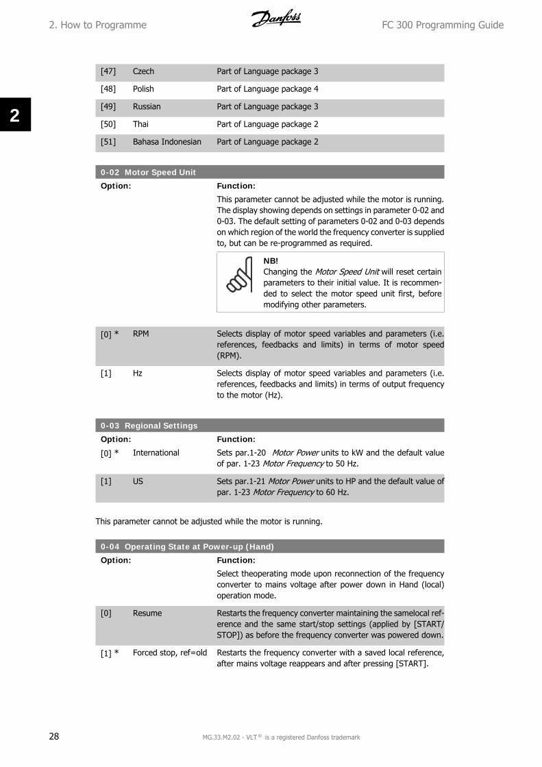
0-02 Motor Speed Unit
Option: Function:
This parameter cannot be adjusted while the motor is running.The display showing depends on settings in parameter 0-02 and0-03. The default setting of parameters 0-02 and 0-03 dependson which region of the world the frequency converter is suppliedto, but can be re-programmed as required.
NB!Changing the Motor Speed Unit will reset certainparameters to their initial value. It is recommen-ded to select the motor speed unit first, beforemodifying other parameters.
[0] * RPM Selects display of motor speed variables and parameters (i.e.references, feedbacks and limits) in terms of motor speed(RPM).
[1] Hz Selects display of motor speed variables and parameters (i.e.references, feedbacks and limits) in terms of output frequencyto the motor (Hz).
0-03 Regional Settings
Option: Function:
[0] * International Sets par.1-20 Motor Power units to kW and the default valueof par. 1-23 Motor Frequency to 50 Hz.
[1] US Sets par.1-21 Motor Power units to HP and the default value ofpar. 1-23 Motor Frequency to 60 Hz.
This parameter cannot be adjusted while the motor is running.
0-04 Operating State at Power-up (Hand)
Option: Function:
Select theoperating mode upon reconnection of the frequencyconverter to mains voltage after power down in Hand (local)operation mode.
[0] Resume Restarts the frequency converter maintaining the samelocal ref-erence and the same start/stop settings (applied by [START/STOP]) as before the frequency converter was powered down.
[1] * Forced stop, ref=old Restarts the frequency converter with a saved local reference,after mains voltage reappears and after pressing [START].
2. How to Programme FC 300 Programming Guide
28 MG.33.M2.02 - VLT ® is a registered Danfoss trademark
2

[2] Forced stop, ref = 0 Resets the local reference to 0 upon restarting the frequencyconverter.
2.3.3. 0-1* Set-up Operations
Define and control the individual parameter setups.The frequency converter has four parameter setups that can be programmed independently ofeach other. This makes the frequency converter very flexible and able to solve advanced controlfunctionality problems, often saving the cost of external control equipment. For example thesecan be used to program the frequency converter to operate according to one control scheme inone setup (e.g. motor 1 for horizontal movement) and another control scheme in another setup(e.g. motor 2 for vertical movement). Alternatively they can be used by an OEM machine builderto identically program all their factory fitted frequency converters for different machine typeswithin a range to have the same parameters and then during production/commissioning simplyselect a specific setup depending on which machine the frequency converter is installed on.The active setup (i.e. the setup in which the frequency converter is currently operating) can beselected in parameter 0-10 and is displayed in the LCP. Using Multi set-up it is possible to switchbetween setups with the frequency converter running or stopped, via digital input or serial com-munication commands. If it is necessary to change setups whilst running, ensure parameter 0-12is programmed as required. Using parameter 0-11 it is possible to edit parameters within any ofthe setups whilst continuing the frequency converter operation in its Active Setup which can be adifferent setup to that being edited. Using parameter 0-51 it is possible to copy parameter settingsbetween the setups to enable quicker commissioning if similar parameter settings are required indifferent setups.
0-10 Active Set-up
Option: Function:
Select the set-up to control the frequency converter functions.
[0] Factory setup Cannot be changed. It contains the Danfoss data set, and canbe used as a data source when returning the other set-ups to aknown state.
[1] * Set-up 1 Set-up 1 [1] to Set-up 4 [4] are the four separate parameterset-ups within which all parameters can be programmed.
[2] Set-up 2
[3] Set-up 3
[4] Set-up 4
[9] Multi set-up Remote selection of set-ups using digital inputs and the serialcommunication port. This set-up uses the settings from par.0-12 'This option linked to'. Stop the frequency converter beforemaking changes to open- and closed loop functions
Use par. 0-51 Set-up copy to copy a set-up to one or all other set-ups. Stop the frequency con-verter before switching between set-ups where parameters marked ‘not changeable duringoperation’ have different values. To avoid conflicting settings of the same parameter within twodifferent set-ups, link the set-ups together using par. 0-12 This set-up linked to. Parameters whichare ‘not changeable during operation’ are marked FALSE in the parameter lists in the sectionParameter Lists.
FC 300 Programming Guide 2. How to Programme
MG.33.M2.02 - VLT ® is a registered Danfoss trademark 29
2

0-11 Edit Set-up
Option: Function:
Select the set-up to be edited (i.e. programmed) during opera-tion; either the active set-up or one of the inactive set-ups.
[0] Factory setup Cannot be edited but it is useful as a data source to return theother set-ups to a known state.
[1] * Set-up 1 Set-up 1 [1] to Set-up 4 [4] can be edited freely during opera-tion, independently of the active set-up.
[2] Set-up 2
[3] Set-up 3
[4] Set-up 4
[9] Active Set-up Can also be edited during operation. Edit the chosen set-up froma range of sources: LCP, FC RS485, FC USB or up to five fieldbussites.
0-12 This Set-up Linked to
Option: Function:
To enable conflict-free changes from one set-up to another dur-ing operation, link set-ups containing parameters which are notchangeable during operation. The link will ensure synchronisingof the ‘not changeable during operation’ parameter values whenmoving from one set-up to another during operation. ‘Notchangeable during operation’ parameters can be identified by
2. How to Programme FC 300 Programming Guide
30 MG.33.M2.02 - VLT ® is a registered Danfoss trademark
2

the label FALSE in the parameter lists in the section ParameterLists.
The par. 0-12 link set-up feature is used by Multi set-up in par.0-10 Active Set-up. Multi set-up is used to move from one set-up to another during operation (i.e. while the motor is running).Example:Use Multi set-up to shift from Set-up 1 to Set-up 2 whilst themotor is running. Programme in Set-up 1 first, then ensure thatSet-up 1 and Set-up 2 are synchronised (or ‘linked’). Synchro-nisation can be performed in two ways:1. Change the edit set-up to Set-up 2 [2] in par. 0-11 Edit Set-up and set par. 0-12 This Set-up Linked to to Set-up 1 [1]. Thiswill start the linking (synchronising) process.
130BP075.10
OR
2. While still in Set-up 1, copy Set-up 1 to Set-up 2. Then setpar. 0-12 to Set-up 2 [2]. This will start the linking process.
130BP076.10
After the link is complete, par. 0-13 Readout: Linked Set-ups willread 1,2 to indicate that all ‘not changeable during operation’parameters are now the same in Set-up 1 and Set-up 2. If thereare changes to a ‘not changeable during operation’ parameter,e.g. par 1-30 Stator Resistance (Rs), in Set-up 2, they will alsobe changed automatically in Set-up 1. A switch between Set-up1 and Set-up 2 during operation is now possible.
[0] * Not linked
[1] Set-up 1
[2] Set-up 2
[3] Set-up 3
[4] Set-up 4
0-13 Readout: Linked Set-ups
FC 300 Programming Guide 2. How to Programme
MG.33.M2.02 - VLT ® is a registered Danfoss trademark 31
2

Array [5]
0* [0 - 255] View a list of all the set-ups linked by means of par. 0-12 ThisSet-up Linked to. The parameter has one index for each pa-rameter set-up. The parameter value displayed for each indexrepresents which setups are linked to that parameter setup.
Index LCP value0 01 1,22 1,23 34 4
Table 2.1: Example: Set-up 1 and Set-up 2 are linked
0-14 Readout: Edit Set-ups / Channe
Range: Function:
0* [0 - FFF.FFF.FFF] View the setting of par. 0-11 Edit Set-up for each of the fourdifferent communication channels. When the number is dis-played in hex, as it is in the LCP, each number represents onechannel.Numbers 1-4 represent a set-up number; ‘F’ means factory set-ting; and ‘A’ means active set-up. The channels are, from rightto left: LCP, FC-bus, USB, HPFB1-5.Example: The number AAAAAA21h means that the FC bus se-lected Set-up 2 in par. 0-11, the LCP selected Set-up 1 and allothers used the active set-up.
2.3.4. 0-2* LCP Display
Define the variables displayed in the Graphical Local Control Panel.
NB!Please refer to parameters 0-37, 0-38 and 0-39 for information on how to writedisplay texts
Select a variable for display in line 1, left position.
[0] None No display value selected.
[953] Profibus WarningWord
[1005] Readout Transmit Er-ror Counter
[1006] Readout Receive Er-ror Counter
[1007] Readout Bus OffCounter
[1013] Warning Parameter
[1501] Running Hours
2. How to Programme FC 300 Programming Guide
32 MG.33.M2.02 - VLT ® is a registered Danfoss trademark
2

[1502] kWh Counter
[1600] Control Word Present control word
[1601] Reference [Unit] Total reference (sum of digital/analog/preset/bus/freeze ref./catch up and slow-down) in selected unit.
[1602] Reference % Total reference (sum of digital/analog/preset/bus/freeze ref./catch up and slow-down) in percent.
[1603] Status Word Present status word.
[1605] Main Actual Value [%] One or more warnings in a Hex code.
[1609] Custom Readout
[1610] Power [kW] Actual power consumed by the motor in kW.
[1611] Power [hp] Actual power consumed by the motor in HP.
[1612] Motor Voltage Voltage supplied to the motor.
[1613] Frequency Motor frequency, i.e. the output frequency from the frequencyconverter in Hz
[1614] Motor Current Phase current of the motor measured as effective value.
[1615] Frequency [%] Motor frequency, i.e. the output frequency from the frequencyconverter in percent.
[1616] Torque Present motor load as a percentage of the rated motor torque.
[1617] * Speed [RPM] Speed in RPM (revolutions per minute) i.e. the motor shaftspeed in closed loop.
[1618] Motor Thermal Thermal load on the motor, calculated by the ETR function.
[1619] KTY Sensor Tempera-ture
[1620] Motor Angle
[1621] Phase Angle
[1622] Torque %
[1630] DC Link Voltage Intermediate circuit voltage in the frequency converter.
[1632] BrakeEnergy/s Present brake power transferred to an external brake resistor.Stated as an instantaneous value.
[1633] BrakeEnergy/2 min Brake power transferred to an external brake resistor. The meanpower is calculated continuously for the most recent 120 sec-onds.
[1634] Heatsink Temp. Present heat sink temperature of the frequency converter. Thecut-out limit is 95 ±5 oC; cutting back in occurs at 70 ±5° C.
[1635] Inverter Thermal Percentage load of the inverters.
[1636] Inv. Nom. Current Nominal current of the frequency converter.
[1637] Inv. Max. Current Maximum current of the frequency converter.
[1638] SL Control State State of the event executed by the control.
[1639] Control Card Temp. Temperature of the control card.
FC 300 Programming Guide 2. How to Programme
MG.33.M2.02 - VLT ® is a registered Danfoss trademark 33
2

[1650] External Reference Sum of the external reference as a percentage, i.e. the sum ofanalog/pulse/bus.
[1651] Pulse Reference Frequency in Hz connected to the digital inputs (18, 19 or 32,33).
[1652] Feedback [Unit] Reference value from programmed digital input(s).
[1653] Digi Pot Reference
[1660] Digital Input Signal states form the 6 digital terminals (18, 19, 27, 29, 32 and33). Input 18 corresponds to the bit at the far left. Signal low =0; Signal high = 1.
[1661] Terminal 53 SwitchSetting
Setting of input terminal 54. Current = 0; Voltage = 1.
[1662] Analog Input 53 Actual value at input 53 either as a reference or protection val-ue.
[1663] Terminal 54 SwitchSetting
Setting of input terminal 54. Current = 0; Voltage = 1.
[1664] Analog Input 54 Actual value at input 54 either as reference or protection value.
[1665] Analog Output 42[mA]
Actual value at output 42 in mA. Use par. 6-50 to select the valueto be shown.
[1666] Digital Output [bin] Binary value of all digital outputs.
[1667] Freq. Input #29 [Hz] Actual value of the frequency applied at terminal 29 as an im-pulse input.
[1668] Freq. Input #33 [Hz] Actual value of the frequency applied at terminal 33 as an im-pulse input.
[1669] Pulse Output #27[Hz]
Actual value of impulses applied to terminal 27 in digital outputmode.
[1670] Pulse Output #29[Hz]
Actual value of impulses applied to terminal 29 in digital outputmode.
[1671] Relay Output [bin]
[1672] Counter A
[1673] Counter B
[1674] Prec. Stop Counter
[1680] Fieldbus CTW 1 Control word (CTW) received from the Bus Master.
[1682] Fieldbus REF 1 Main reference value sent with control word from the Bus Mas-ter.
[1684] Comm. Option STW Extended fieldbus communication option status word.
[1685] FC Port CTW 1 Control word (CTW) received from the Bus Master.
[1686] FC Port REF 1 Status word (STW) sent to the Bus Master.
[1690] Alarm Word One or more alarms in a Hex code.
[1691] Alarm Word 2 One or more alarms in a Hex code.
[1692] Warning Word One or more warnings in a Hex code.
[1693] Warning Word 2 One or more warnings in a Hex code.
2. How to Programme FC 300 Programming Guide
34 MG.33.M2.02 - VLT ® is a registered Danfoss trademark
2

[1694] Ext. Status Word One or more status conditions in a Hex code.
[1695] Ext. Status Word 2 One or more status conditions in a Hex code.
[3401] PCD 1 Write to MCO
[3402] PCD 2 Write to MCO
[3403] PCD 3 Write to MCO
[3404] PCD 4 Write to MCO
[3405] PCD 5 Write to MCO
[3406] PCD 6 Write to MCO
[3407] PCD 7 Write to MCO
[3408] PCD 8 Write to MCO
[3409] PCD 9 Write to MCO
[3410] PCD 10 Write to MCO
[3421] PCD 1 Read from MCO
[3422] PCD 2 Read from MCO
[3423] PCD 3 Read from MCO
[3424] PCD 4 Read from MCO
[3425] PCD 5 Read from MCO
[3426] PCD 6 Read from MCO
[3427] PCD 7 Read from MCO
[3428] PCD 8 Read from MCO
[3429] PCD 9 Read from MCO
[3430] PCD 10 Read fromMCO
[3440] Digital Inputs
[3441] Digital Outputs
[3450] Actual Position
[3451] Commanded Position
[3452] Actual Master Position
[3453] Slave Index Position
[3454] Master Index Position
[3455] Curve Position
[3456] Track Error
[3457] Synchronizing Error
[3458] Actual Velocity
[3459] Actual Master Velocity
[3460] Synchronizing Status
[3461] Axis Status
[3462] Program Status
[9913] Idle Time
[9914] Paramdb Requests inQueue
[1675] Analog input X30/11
[1676] Analog input X30/12
[1677] Analog output X30/8mA
FC 300 Programming Guide 2. How to Programme
MG.33.M2.02 - VLT ® is a registered Danfoss trademark 35
2

0-20 Display Line 1.1 Small
Option: Function:
[1617] * Speed [RPM] Select a variable for display in line 1, middle position. The op-tions are the same as listed for par. 0-2*.
0-21 Display Line 1.2 Small
Option: Function:
[1614] *Motor Current [A] Select a variable for display in line 1, middle position. The op-tions are the same as listed for par. 0-2*.
0-22 Display Line 1.3 Small
Option: Function:
[1610] * Power [kW] Select a variable for display in line 1, right position. The optionsare the same as listed for par. 0-2*.
0-23 Display Line 2 Large
Option: Function:
[1613] * Frequency [Hz] Select a variable for display in line 2. The options are the sameas those listed for par. 0-2*.
0-24 Display Line 3 Large
Option: Function:
Select a variable for display in line 2.
[1502] *Counter [kWh]
The options are the same as those listed for par. 0-20 DisplayLine 1.1 Small.
0-25 My Personal Menu
Array [20]
[0 - 9999] Define up to 50 parameters to appear in the Q1 Personal Menu,accessible via the [Quick Menu] key on the LCP. The parameterswill be displayed in the Q1 Personal Menu in the order they areprogrammed into this array parameter. Delete parameters bysetting the value to ‘0000’.For example, this can be used to provide quick, simple accessto just one or up to 20 parameters which require changing on aregular basis (e.g. for plant maintenance reasons) or by an OEMto enable simple commissioning of their equipment.
2. How to Programme FC 300 Programming Guide
36 MG.33.M2.02 - VLT ® is a registered Danfoss trademark
2
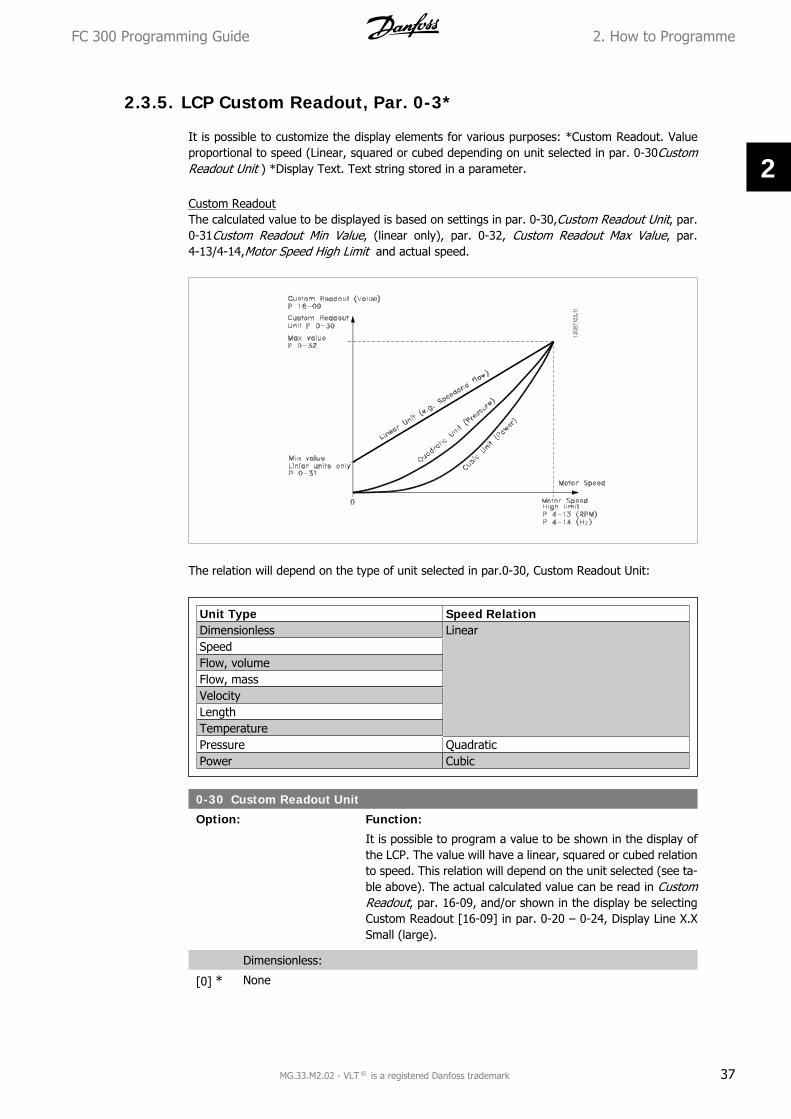
2.3.5. LCP Custom Readout, Par. 0-3*
It is possible to customize the display elements for various purposes: *Custom Readout. Valueproportional to speed (Linear, squared or cubed depending on unit selected in par. 0-30CustomReadout Unit ) *Display Text. Text string stored in a parameter.
Custom ReadoutThe calculated value to be displayed is based on settings in par. 0-30,Custom Readout Unit, par.0-31Custom Readout Min Value, (linear only), par. 0-32, Custom Readout Max Value, par.4-13/4-14,Motor Speed High Limit and actual speed.
The relation will depend on the type of unit selected in par.0-30, Custom Readout Unit:
Unit Type Speed RelationDimensionless LinearSpeedFlow, volumeFlow, massVelocityLengthTemperaturePressure QuadraticPower Cubic
0-30 Custom Readout Unit
Option: Function:
It is possible to program a value to be shown in the display ofthe LCP. The value will have a linear, squared or cubed relationto speed. This relation will depend on the unit selected (see ta-ble above). The actual calculated value can be read in CustomReadout, par. 16-09, and/or shown in the display be selectingCustom Readout [16-09] in par. 0-20 – 0-24, Display Line X.XSmall (large).
Dimensionless:
[0] * None
FC 300 Programming Guide 2. How to Programme
MG.33.M2.02 - VLT ® is a registered Danfoss trademark 37
2

[1] %
[5] PPM
Speed:
[10] 1/min
[11] RPM
[12] Pulse/s
Flow, volume:
[20] l/s
[21] l/min
[22] l/h
[23] m3/s
[24] m3/min
[25] m3/h
Flow, mass:
[30] kg/s
[31] kg/min
[32] kg/h
[33] ton/min
[34] ton/h
Velocity:
[40] m/s
[41] m/min
Length:
[45] m
Temperature:
[60] ° C
Pressure:
[70] mbar
[71] bar
[72] Pa
[73] kPa
[74] m WG
Power:
[80] kW
Flow, volume:
[120] GPM
[121] gal/s
[122] gal/min
[123] gal/h
[124] CFM
[125] ft3/s
[126] ft3/min
[127] ft3/h
Flow, mass:
[130] lb/s
2. How to Programme FC 300 Programming Guide
38 MG.33.M2.02 - VLT ® is a registered Danfoss trademark
2

[131] lb/min
[132] lb/h
Velocity:
[140] ft/s
[141] ft/min
Length:
[145] ft
Temperature:
[160] ° F
Pressure:
[170] psi
[171] lb/in2
[170] in WG
[173] ft WG
Power:
[180] HP
0-31 Custom Readout Min Value
Range: Function:
0.00 [0 - par. 0 - 32] This parameter sets the min. value of the custom defined read-out (occurs at zero speed). Only possible to set different from 0is when selecting a linear unit in Custom Readout Unit, par.0-30. For Quadratic and Cubic units the minimum value will be0.
0-32 Custom Readout Max Value
Range: Function:
100.00* [Par. 0-31 -999999.99 ]
This parameter sets the max value to be shown when the speedof the motor has reached the set value for Motor Speed HighLimit, (par.4-13/4-14).
2.3.6. LCP Keypad, 0-4*
Enable, disable and password protect individual keys on the LCP keypad.
0-40 [Hand on] Key on LCP
Option: Function:
[0] Disabled No function
[1] * Enabled [Hand on] Key enabled
[2] Password Avoid unauthorized start in Hand mode. If par. 0-40 is includedin the Quick Menu, then define the password in par. 0-65 QuickMenu Password. Otherwise define the password in par. 0-60Main Menu Password.
FC 300 Programming Guide 2. How to Programme
MG.33.M2.02 - VLT ® is a registered Danfoss trademark 39
2

0-41 [Off] Key on LCP
Option: Function:
[0] Disabled Avoids accidental stop of the frequency converter.
[1] * Enabled
[2] Password Avoids unauthorised stop. If par. 0-41 is included in the QuickMenu, then define the password in par. 0-65 Quick Menu Pass-word.
0-42 [Auto on] Key on LCP
Option: Function:
[0] Disabled avoid accidental start of the frequency converter in Auto mode.
[1] * Enabled
[2] Password Avoids unauthorised start in Auto mode. If par. 0-42 is includedin the Quick Menu, then define the password in par. 0-65 QuickMenu Password.
0-43 [Reset] Key on LCP
Option: Function:
[0] Disabled Avoids accidental alarm reset.
[1] * Enabled
[2] Password Avoids unauthorised resetting. If par. 0-43 is included in theQuick Menu, then define the password in par. 0-65 Quick MenuPassword.
2.3.7. 0-5* Copy / Save
Copy parameter settings between set-ups and to/from the LCP.
0-50 LCP Copy
Option: Function:
[0] * No copy
[1] All to LCP Copies all parameters in all set-ups from the frequency convert-er memory to the LCP memory.
[2] All from LCP Copies all parameters in all set-ups from the LCP memory to thefrequency converter memory.
[3] Size indep. from LCP copy only the parameters that are independent of the motorsize. The latter selection can be used to programme severaldrives with the same function without disturbing motor data.
[4] File from MCO to LCP
[5] File from LCP to MCO
This parameter cannot be adjusted while the motor is running.
2. How to Programme FC 300 Programming Guide
40 MG.33.M2.02 - VLT ® is a registered Danfoss trademark
2

0-51 Set-up Copy
Option: Function:
[0] * No copy No function
[1] Copy to set-up 1 Copies all parameters in the present edit set-up (defined in par.0-11 Edit Set-up) to Set-up 1.
[2] Copy to set-up 2 Copies all parameters in the present edit set-up (defined in par.0-11 Edit Set-up) to Set-up 2.
[3] Copy to set-up 3 Copies all parameters in the present edit set-up (defined in par.0-11 Edit Set-up) to Set-up 3.
[4] Copy to set-up 4 Copies all parameters in the present edit set-up (defined in par.0-11 Edit Set-up) to Set-up 4.
[9] Copy to all Copies the parameters in the present set-up over to each of theset-ups 1 to 4.
2.3.8. 0-6* Password
Define password access to menus.
0-60 Main Menu Password
Option: Function:
[100] * -9999 - 9999 Define the password for access to the Main Menu via the [MainMenu] key. If par. 0-61 Access to Main Menu w/o Password isset to Full access [0], this parameter will be ignored.
0-61 Access to Main Menu w/o Password
Option: Function:
[0] * Full access Disables password defined in par. 0-60 Main Menu Password.
[1] Read only Prevent unauthorized editing of Main Menu parameters.
[2] No access Prevent unauthorized viewing and editing of Main Menu param-eters.
[3] Bus: Read only Read only functions for parameters on fieldbus and/ or FCstandard bus.
[4] Bus: No access No access to parameters is allowed via fieldbus and/ or FCstandard bus.
[5] All: Read only Read only function for parameters on LCP, fieldbus or FC stand-ard bus.
[6] All: No access No access from LCP, fieldbus or FC standard bus is allowed.
If Full access [0] is selected then parameters0-60, 0-65 and 0-66 will be ignored.
0-65 Quick Menu Password
Range: Function:
200* [-9999 - 9999] Define the password for access to the Quick Menu via the [QuickMenu] key. If par. 0-66 Access to Quick Menu w/o Password is
FC 300 Programming Guide 2. How to Programme
MG.33.M2.02 - VLT ® is a registered Danfoss trademark 41
2

set to Full access [0], this parameter will be ignored.
0-66 Access to Quick Menu w/o Password
Option: Function:
[0] * Full access Disables the password defined in par. 0-65 Quick Menu Pass-word.
[1] Read only Prevents unauthorised editing of Quick Menu parameters.
[2] No access Prevents unauthorised viewing and editing of Quick Menu pa-rameters.
[3] Bus: Read only Read only functions for parameters on fieldbus and/ or FCstandard bus.
[4] Bus: No access No access to parameters is allowed via fieldbus and/ or FCstandard bus.
[5] All: Read only read only function for parameters on LCP, fieldbus or FC stand-ard bus.
[6] All: No access No access from LCP, fieldbus or FC standard bus is allowed.
If par. 0-61 Access to Main Menu w/o Password is set to Full access [0] then this parameter willbe ignored.
0-67 Bus Password Access
Range: Function:
0* [0 - 9999] Writing to this parameter enables users to unlock the drive frombus/ MCT10
2.4. Parameters: Load and Motor
2.4.1. 1-0* General Settings
Define whether the frequency converter operates in speed mode or torque mode; and whetherthe internal PID control should be active or not.
1-00 Configuration Mode
Option: Function:
Select the application control principle to be used when a Re-mote Reference (i.e. via analog input or fieldbus) is active. ARemote Reference can only be active when par. 3-13 ReferenceSite is set to [0] or [1].
[0] Speed open loop Enables speed control (without feedback signal from motor)with automatic slip compensation for almost constant speed atvarying loads.Compensations are active but can be disabled in the Load/Motorpar. group 1-0*.
[1] Speed closed loop Enables encoder feedback from motor. Obtain full holding tor-que at 0 RPM.
2. How to Programme FC 300 Programming Guide
42 MG.33.M2.02 - VLT ® is a registered Danfoss trademark
2

For increased speed accuracy, provide a feedback signal and setthe speed PID control.
[2] Torque Connects the encoder speed feedback signal to the encoder in-put. Only possible with “Flux with motor feedback” option, par.1-01 Motor control principle.
[3] Process Enables the use of process control in the frequency converter.The process control parameters are set in par. groups 7-2* and7-3*.
1-01 Motor Control Principle
Option: Function:
Select which motor control principle to employ.
[0] U/f special motor mode, for parallel connected motors in specialmotor applications. When U/f is selected the characteristic ofthe control principle can be edited in par. 1-55 and 1-56.
[1] VVCplus Voltage Vector Control principle suitable for most applications.The main benefit of VVCplus operation is that it uses a robustmotor model.
[2] Flux sensorless (FC302 only)
Flux Vector control without encoder feedback, for simple instal-lation and robustness against sudden load changes.
[3] Flux w/ motor feed-back(FC 302 only)
very high accuracy speed and torque control, suitable for themost demanding applications.
The best shaft performance is normally achieved using either of the two Flux Vector control modesFlux sensorless [2] and Flux with encoder feedback [3].
This parameter cannot be adjusted while themotor is running.
1-02 Flux Motor Feedback Source
Option: Function:
Select the interface at which to receive feedback from the mo-tor.
[1] * 24 V encoder A and B channel encoder, which can be connected to the digitalinput terminals 32/33 only. Terminals 32/33 must be program-med to No operation.
[2] MCB 102 Encoder module option which can be configured in par. group17-1*This parameter appears in FC 302 only.
[3] MCB 103 Optional resolver interface module which can be configured inparameter group 17-5*
[4] MCO 305 encoder 1 Encoder interface 1 of the optional programmable motion con-troller MCO 305.
[5] MCO 305 encoder 2 encoder interface 2 of the optional programmable motion con-troller MCO 305.
FC 300 Programming Guide 2. How to Programme
MG.33.M2.02 - VLT ® is a registered Danfoss trademark 43
2
This parameter cannot be adjusted while the motor is running.
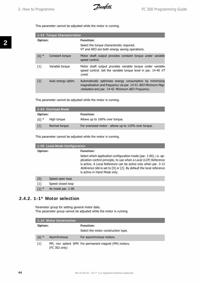
1-03 Torque Characteristics
Option: Function:
Select the torque characteristic required.VT and AEO are both energy saving operations.
[0] * Constant torque Motor shaft output provides constant torque under variablespeed control.
[1] Variable torque Motor shaft output provides variable torque under variablespeed control. Set the variable torque level in par. 14-40 VTLevel.
[2] Auto energy optim. Automatically optimises energy consumption by minimisingmagnetisation and frequency via par. 14-41 AEO Minimum Mag-netisation and par. 14-42 Minimum AEO Frequency.
This parameter cannot be adjusted while the motor is running.
1-04 Overload Mode
Option: Function:
[0] * High torque Allows up to 160% over torque.
[1] Normal torque For oversized motor - allows up to 110% over torque.
This parameter cannot be adjusted while the motor is running.
1-05 Local Mode Configuration
Option: Function:
Select which application configuration mode (par. 1-00), i.e. ap-plication control principle, to use when a Local (LCP) Referenceis active. A Local Reference can be active only when par. 3-13Reference Site is set to [0] or [2]. By default the local referenceis active in Hand Mode only.
[0] Speed open loop
[1] Speed closed loop
[2] * As mode par. 1-00
2.4.2. 1-1* Motor selection
Parameter group for setting general motor data.This parameter group cannot be adjusted while the motor is running.
1-10 Motor Construction
Option: Function:
Select the motor construction type.
[0] * Asynchronous For asynchronous motors.
[1] PM, non salient SPM(FC 302 only)
For permanent magnet (PM) motors.
2. How to Programme FC 300 Programming Guide
44 MG.33.M2.02 - VLT ® is a registered Danfoss trademark
2

Note that PM motors are divided into two groups, with eithersurface mounted (non salient) or interior (salient) magnets.
Motor construction can either be asynchronous or permanent magnet (PM) motor.
2.4.3. 1-2* Motor Data
Parameter group 1-2* comprises input data from the nameplate on the connected motor.Parameters in parameter group 1-2* cannot be adjusted while the motor is running.
NB!Changing the value of these parameters affects the setting of other parameters.
1-20 Motor Power
Range: Function:
Size re-lated*
[0.09 - 1200 kW] Enter the nominal motor power in kW according to the motornameplate data. The default value corresponds to the nominalrated output of the unit.This parameter cannot be adjusted while the motor is running.This parameter is visible in LCP if par. 0-03 is International [0].
1-21 Motor Power [HP]
Range: Function:
Size re-lated*
[0.09 - 500 HP] Enter the nominal motor power in HP according to the motornameplate data. The default value corresponds to the nominalrated output of the unit. This parameter is visible in LCP if par.0-03 is US [1]
1-22 Motor Voltage
Range: Function:
Size re-lated*
[10 - 1000 V] Enter the nominal motor voltage according to the motor name-plate data. The default value corresponds to the nominal ratedoutput of the unit.
1-23 Motor Frequency
Option: Function:
Min - Max motor frequency: 20 - 1000 Hz.Select the motor frequency value from the motor nameplatedata. If a value different from 50 Hz or 60 Hz is selected, it isnecessary to adapt the load independent settings in par. 1-50to 1-53. For 87 Hz operation with 230/400 V motors, set thenameplate data for 230 V/50 Hz. Adapt par. 4-13 Motor SpeedHigh Limit [RPM) and par. 3-03 Maximum Reference to the 87Hz application.
[50] * 50 Hz when parame-ter 0-03 = interna-tional
FC 300 Programming Guide 2. How to Programme
MG.33.M2.02 - VLT ® is a registered Danfoss trademark 45
2

[60] 60 Hz when parame-ter 0-03 = US
1-24 Motor Current
Option: Function:
[Motortype de-pend-ent.]
Enter the nominal motor current value from the motor name-plate data. The data are used for calculating torque, motorprotection etc.
1-25 Motor Nominal Speed
Range: Function:
Size re-lated*
[10 - 60000 RPM] Enter the nominal motor speed value from the motor nameplatedata. The data are used for calculating motor compensations.
1-26 Motor Cont. Rated Torque
Range: Function:
Size re-lated
[1.0 - 10000.0 Nm] Enter the value from the motor nameplate data. The defaultvalue corresponds to the nominal rated output. This parameteris available when par. 1-10Motor Construction is set to PM, nonsalient SPM [1], i.e. the parameter is valid for PM and non-sali-ent SPM motors only.
1-29 Automatic Motor Adaptation (AMA)
Option: Function:
The AMA function optimises dynamic motor performance by au-tomatically optimising the advanced motor parameters (par.1-30 to par. 1-35) at motor standstill.
Activate the AMA function by pressing [Hand on] after selecting[1] or [2]. See also the section Automatic Motor Adaptation inthe Design Guide. After a normal sequence, the display willread: "Press [OK] to finish AMA". After pressing the [OK] keythe frequency converter is ready for operation.
This parameter cannot be adjusted while the motor is running.
[0] * OFF
[1] Enable complete AMA Performs AMA of the stator resistance RS, the rotor resistanceRr, the stator leakage reactance X1, the rotor leakage reactanceX2 and the main reactance Xh. Select this option if an LC filter isused between the drive and the motor.FC 301: The Complete AMA does not include Xh measurementfor FC 301. Instead, the Xh value is determined from the motordatabase. Par. 1-35 Main Reactance (Xh ) may be adjusted toobtain optimal start performance.
[2] Enable reduced AMA Performs a reduced AMA of the stator resistance Rs in the sys-tem only.
2. How to Programme FC 300 Programming Guide
46 MG.33.M2.02 - VLT ® is a registered Danfoss trademark
2

Note:
• For the best adaptation of the frequency converter, run AMA on a cold motor.
• AMA cannot be performed while the motor is running.
• AMA cannot be performed on permanent magnet motors.
NB!It is important to set motor par. 1-2* Motor Data correctly, since these form part ofthe AMA algorithm. An AMA must be performed to achieve optimum dynamic motorperformance. It may take up to 10 min, depending on the power rating of the motor.
NB!Avoid generating external torque during AMA.
NB!If one of the settings in par. 1-2* Motor Data is changed, par. 1-30 to 1-39, theadvanced motor parameters, will return to default setting.
2.4.4. 1-3* Adv. Motor Data
Parameters for advanced motor data. The motor data in par. 1-30 - par. 1-39 must match therelevant motor in order to run the motor optimally. The default settings are figures based oncommon motor parameter values from standard motors. If the motor parameters are not setcorrectly, a malfunction of the drive system may occur. If the motor data is not known, runningan AMA (Automatic Motor Adaptation) is recommended. See the Automatic Motor Adaptation sec-tion in the Design Guide. The AMA sequence will adjust all motor parameters except the momentof inertia of the rotor and the iron loss resistance (par. 1-36).Parameters 1-3* and 1-4* cannot be adjusted while the motor is running.
Illustration 2.1: Motor equivalent diagram for anasynchronous motor
1-30 Stator Resistance (Rs)
Range: Function:
Size re-lated
[Ohm] Set the stator resistance value. Enter the value from a motordata sheet or perform an AMA on a cold motor.
FC 300 Programming Guide 2. How to Programme
MG.33.M2.02 - VLT ® is a registered Danfoss trademark 47
2

1-31 Rotor Resistance (Rr)
Range: Function:
Size re-lated
[Ohm] Fine-tuning Rr will improve shaft performance. Set the rotor re-sistance value using one of these methods:
1. Run an AMA on a cold motor. The frequency converterwill measure the value from the motor. All compensa-tions are reset to 100%.
2. Enter the Rr value manually. Obtain the value from themotor supplier.
3. Use the Rr default setting. The frequency converterestablishes the setting on the basis of the motor name-plate data.
1-33 Stator Leakage Reactance (X1)
Range: Function:
Size re-lated
[Ohm] Set the stator leakage reactance of the motor using one of thesemethods:
1. Run an AMA on a cold motor. The frequency converterwill measure the value from the motor.
2. Enter the X1 value manually. Obtain the value from themotor supplier.
3. Use the X1 default setting. The frequency converterestablishes the setting on the basis of the motor nameplate data.
1-34 Rotor Leakage Reactance (X2)
Option: Function:
[Size re-lated]
Ohm Set the rotor leakage reactance of the motor using one of thesemethods:
1. Run an AMA on a cold motor. The frequency converterwill measure the value from the motor.
2. Enter the X2 value manually. Obtain the value from themotor supplier.
3. Use the X2 default setting. The frequency converterestablishes the setting on the basis of the motor nameplate data.
1-35 Main Reactance (Xh)
Option: Function:
[Size re-lated]
Ohm Set the main reactance of the motor using one of these meth-ods:
1. Run an AMA on a cold motor. The frequency converterwill measure the value from the motor.
2. Enter the Xh value manually. Obtain the value from themotor supplier.
2. How to Programme FC 300 Programming Guide
48 MG.33.M2.02 - VLT ® is a registered Danfoss trademark
2

3. Use the Xh default setting. The frequency converterestablishes the setting on the basis of the motor nameplate data.
1-36 Iron Loss Resistance (Rfe)
Range: Function:
Size re-lated
[1 - 10.000 Ω] Enter the equivalent iron loss resistance (RFe) value to compen-sate for iron loss in the motor.The RFe value cannot be found by performing an AMA.The RFe value is especially important in torque control applica-tions. If RFe is unknown, leave par. 1-36 on default setting.
1-37 d-axis Inductance (Ld)
Range: Function:
0.0mH [0.0 - 1000.0 mH] Enter the value of the d-axis inductance. Obtain the value fromthe permanent magnet motor data sheet.This parameter is only active when par. 1-10 Motor construc-tion has the value PM, non-salient SPM [1] (Permanent MagnetMotor).This parameter is available for FC 302 only.
1-39 Motor Poles
Option: Function:
[4] * Depends on motortype
Value 2 - 100 poles
Enter the number of motor poles.
Poles ~nn@ 50 Hz ~nn@60 Hz2 2700 - 2880 3250 - 34604 1350 - 1450 1625 - 17306 700 - 960 840 - 1153
The table shows the number of poles for normal speed ranges of various motor types. Definemotors designed for other frequencies separately. The motor pole value is always an even number,because it refers to the total number of poles, not pairs of poles. The frequency converter createsthe initial setting of par. 1-39 based on par. 1-23 Motor Frequency and par. 1-25 Motor NominalSpeed.
1-40 Back EMF at 1000 RPM
Range: Function:
500 V* [10 - 9000 V] Set the nominal back EMF for the motor when running at 1000RPM. This parameter is only active when par. 1-10 Motor con-struction is set to PM motor [1] (Permanent Magnet Motor).This parameter is available for FC 302 only.
NB!When using PM motors, it is recommended to usebrake resistors.
FC 300 Programming Guide 2. How to Programme
MG.33.M2.02 - VLT ® is a registered Danfoss trademark 49
2

1-41 Motor Angle Offset
Range: Function:
0* [0 - 65535] Enter the correct offset angle between the PM motor and theindex position (single-turn) of the attached encoder or resolver.The value range of 0 – 65535 corresponds to 0 - 2 * pi (radians).To obtain the offset angle value: After drive start-up apply DC-hold and enter the value of par. 16-20 Motor Angle into thisparameter.This parameter is only active when par. 1-10 Motor construc-tion is set to PM, non-salient SPM [1] (Permanent Magnet Mo-tor).
2.4.5. 1-5* Load Indep. Setting
Parameters for setting the load-independent motor settings.
1-50 Motor Magnetisation at Zero Speed
Range: Function:
100% [0 - 300 %] Use this par. along with par. 1-51 Min Speed Normal Magnetis-ing [RPM] to obtain a different thermal load on the motor whenrunning at low speed.Enter a value which is a percentage of the rated magnetizingcurrent. If the setting is too low, the torque on the motor shaftmay be reduced.
1-51 Min Speed Normal Magnetising [RPM]
Range: Function:
15RPM*
[10 - 300 RPM] Set the required speed for normal magnetising current. If thespeed is set lower than the motor slip speed, par. 1-50 MotorMagnetisation at Zero Speed and par. 1-51 are of no signifi-cance.Use this par. along with par. 1-50. See drawing for par. 1-50.
1-52 Min Speed Normal Magnetising [Hz]
Option: Function:
[Size re-lated]
0 - 250 Hz Set the required frequency for normal magnetising current. Ifthe frequency is set lower than the motor slip frequency, par.1-50 Motor Magnetisation at Zero Speed is inactive.Use this par. along with par. 1-50. See drawing for par. 1-50.
2. How to Programme FC 300 Programming Guide
50 MG.33.M2.02 - VLT ® is a registered Danfoss trademark
2

1-53 Model Shift Frequency
Range: Function:
Size re-lated
[4.0 - 50.0 Hz] Flux Model shiftEnter the frequency value for shift between two models for de-termining motor speed. Choose the value based on settings inpar. 1-00 Configuration Mode and par. 1-01 Motor Control Prin-ciple. There are two options: shift between Flux model 1 andFlux model 2; or shift between Variable Current mode and Fluxmodel 2. This parameter is available for FC 302 only.This parameter cannot be adjusted while the motor is running.
Flux Model 1 – Flux model 2This model is used when par. 1-00 is set to Speed closed loop[1] or Torque [2] and par. 1-01 is set to Flux w/motor feed-back [3]. With this parameter it is possible to make an adjust-ment of the shifting point where FC 302 changes between Fluxmodel 1 and Flux model 2, which is useful in some sensitivespeed and torque control applications.
Illustration 2.2: Par. 1-00 = [1] Speed closed loop or [2] Torque andpar. 1-01 = [3] Flux w/motor feedback
Variable Current - Flux model - SensorlessThis model is used when par. 1-00 is set to Speed open loop [0]and par. 1-01 is set to Flux sensorless [2].In speed open loop in flux mode, the speed is determined fromthe current measurement.Below fnorm x 0.1, the drive runs on a Variable Current model.Above fnorm x 0.125 the frequency converter runs on a Fluxmodel.
FC 300 Programming Guide 2. How to Programme
MG.33.M2.02 - VLT ® is a registered Danfoss trademark 51
2

Illustration 2.3: Par. 1-00 = [0] Speed open loop, Par. 1-01 = [2] Fluxsensorless
1-55 U/f Characteristic - U
Range: Function:
Size re-lated
[0.0 - max. motorvoltage]
Enter the voltage at each frequency point to manually form a U/f characteristic matching the motor.The frequency points are defined in par. 1-56 U/f Characteristic- F.This parameter is an array parameter [0-5] and is only accessi-ble when par. 1-01 Motor Control Principle is set to U/f [0].
1-56 U/f Characteristic - F
Range: Function:
Size re-lated*
[0.0 - max. motor fre-quency]
Enter the frequency points to manually form a U/f-characteristicmatching the motor.The voltage at each point is defined in par. 1-55 U/f Character-istic - U.This parameter is an array parameter [0-5] and is only accessi-ble when par. 1-01 Motor Control Principle is set to U/f [0].
2.4.6. 1-6* Load Depend. Setting
Parameters for adjusting the load-dependent motor settings.
2. How to Programme FC 300 Programming Guide
52 MG.33.M2.02 - VLT ® is a registered Danfoss trademark
2
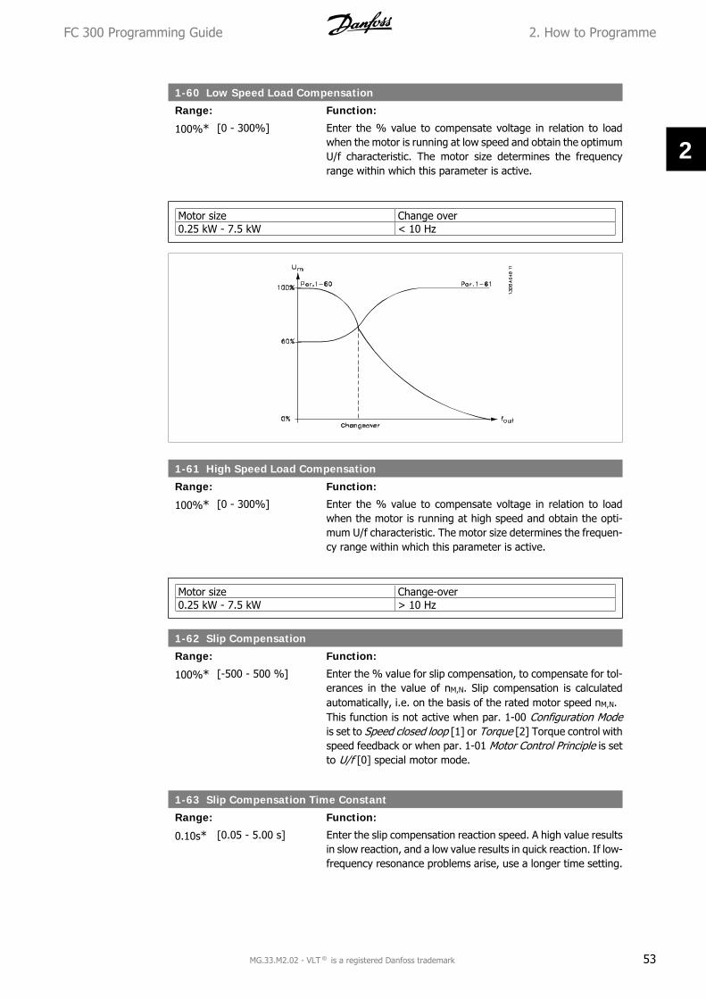
1-60 Low Speed Load Compensation
Range: Function:
100%* [0 - 300%] Enter the % value to compensate voltage in relation to loadwhen the motor is running at low speed and obtain the optimumU/f characteristic. The motor size determines the frequencyrange within which this parameter is active.
Motor size Change over0.25 kW - 7.5 kW < 10 Hz
1-61 High Speed Load Compensation
Range: Function:
100%* [0 - 300%] Enter the % value to compensate voltage in relation to loadwhen the motor is running at high speed and obtain the opti-mum U/f characteristic. The motor size determines the frequen-cy range within which this parameter is active.
Motor size Change-over0.25 kW - 7.5 kW > 10 Hz
1-62 Slip Compensation
Range: Function:
100%* [-500 - 500 %] Enter the % value for slip compensation, to compensate for tol-erances in the value of nM,N. Slip compensation is calculatedautomatically, i.e. on the basis of the rated motor speed nM,N.This function is not active when par. 1-00 Configuration Modeis set to Speed closed loop [1] or Torque [2] Torque control withspeed feedback or when par. 1-01 Motor Control Principle is setto U/f [0] special motor mode.
1-63 Slip Compensation Time Constant
Range: Function:
0.10s* [0.05 - 5.00 s] Enter the slip compensation reaction speed. A high value resultsin slow reaction, and a low value results in quick reaction. If low-frequency resonance problems arise, use a longer time setting.
FC 300 Programming Guide 2. How to Programme
MG.33.M2.02 - VLT ® is a registered Danfoss trademark 53
2

1-64 Resonance Dampening
Range: Function:
100% * [0 - 500 %] Enter the resonance dampening value. Set par. 1-64 and par.1-65 Resonance Dampening Time Constant to help eliminatehigh-frequency resonance problems. To reduce resonance os-cillation, increase the value of par. 1-64.
1-65 Resonance Dampening Time Constant
Range: Function:
5msec.*
[5 - 50 msec.] Set par. 1-64 Resonance Dampening and par. 1-65 to help elim-inate high-frequency resonance problems. Enter the time con-stant that provides the best dampening.
1-66 Min. Current at Low Speed
Range: Function:
100%* [0 - 200%] Enter the minimum motor current at low speed, see par. 1-53Model Shift Frequency. Increasing this current improves motortorque at low speed.Par. 1-66 is enabled when par. 1-00 Configuration Mode =Speed open loop [0] only. The drive runs with constant currentthrough motor for speeds below 10 Hz.For speeds above 10 Hz, the motor flux model in the drive con-trols the motor. Par. 4-16 Torque Limit Motor Mode and / or par.4-17 Torque Limit Generator Mode automatically adjust par.1-66. The parameter with the highest value adjusts par. 1-66.The current setting in par. 1-66 is composed of the torque gen-erating current and the magnetizing current.Example: Set par. 4-16 Torque Limit for Motor Mode to 100%and set par. 4-17 Torque Limit for Generating Mode to 60%.Par. 1-66 automatically adjusts to about 127%, depending onthe motor size.This parameter is available for FC 302 only.
1-67 Load Type
Option: Function:
[0] * Passive load For conveyers, fan and pump applications.
[1] Active Load For hoisting applications. When Active Load [1] is selected, setpar. 1-66 Min. Current at Low Speed to a level which corre-sponds to maximum torque.
This parameter is available for FC 302 only.
1-68 Minimum Inertia
Range: Function:
0.0048* [0.0001 - Par. 1-69] Enter the minimum moment of inertia of the mechanical system.Par. 1-68 and par. 1-69 Maximum Inertia are used for pre-ad-justment of the Proportional Gain in the speed control, see par.7-02 Speed PID Proportional Gain.This parameter is available for FC 302 only.
2. How to Programme FC 300 Programming Guide
54 MG.33.M2.02 - VLT ® is a registered Danfoss trademark
2

This parameter cannot be adjusted while motor is running.
1-69 Maximum Inertia
Range: Function:
0.0048* [0 - 0.4800] Enter the maximum moment of inertia of the mechanical sys-tem. Par. 1-68 Minimum Inertia and par. 1-69 are used for pre-adjustment of the Proportional Gain in the speed control, seepar. 7-02 Speed PID Proportional Gain.This parameter is available for FC 302 only.
This parameter cannot be adjusted while mo-tor is running.
2.4.7. 1-7* Start Adjustments
Parameters for setting special motor start features.
1-71 Start Delay
Range: Function:
0.0s* [0.0 - 10.0 s] This parameter refers to the start function selected in par. 1-72Start Function.Enter the time delay required before commencing acceleration.
1-72 Start Function
Option: Function:
Select the start function during start delay. This parameter islinked to par. 1-71 Start Delay.
[0] DC hold/ delay time Energizes motor with a DC holding current (par. 2-00) duringthe start delay time.
[1] DC Brake/delay time Energizes motor with a DC braking current (par. 2-01) duringthe start delay time.
[2] * Coast/delay time Releases shaft coasted converter during the start delay time(inverter off).
[3] Start speed/ currentclockwise operation
Only possible with VVC+.Connect the function described in par. 1-74 Start Speed (RPM)and par. 1-76 Start Current in the start delay time.Regardless of the value applied by the reference signal, theoutput speed applies the setting of the start speed in par. 1-74or par. 1-75 and the output current corresponds to the settingof the start current in par. 1-76 Start Current. This function istypically used in hoisting applications without counterweightand especially in applications with a Cone-motor, where thestart is clockwise, followed by rotation in the reference direction.
[4] Horizontal operation Only possible with VVC+.For obtaining the function described in par. 1-74 and par. 1-76during the start delay time. The motor rotates in the referencedirection. If the reference signal equals zero (0), par. 1-74 Startspeed (RPM) is ignored and the output speed equals zero (0).
FC 300 Programming Guide 2. How to Programme
MG.33.M2.02 - VLT ® is a registered Danfoss trademark 55
2

The output current corresponds to the setting of the start cur-rent in par. 1-76 Start current.
[5] VVCplus/ Flux clock-wise
for the function described in par. 1-74 only (Start speed in thestart delay time). The start current is calculated automatically.This function uses the start speed in the start delay time only.Regardless of the value set by the reference signal, the outputspeed equals the setting of the start speed in par. 1-74.Startspeed/current clockwise [3] and VVCplus/Flux clockwise [5] aretypically used in hoisting applications. Start speed/current inreference direction [4] is particularly used in applications withcounterweight and horizontal movement.
[6] Hoist Mech. Brake Rel For utilizing mechanical brake control functions, par. 2-24 to2-28. This parameter is only active when par. 1-01 is set to [3]Flux w/ motor feedback (FC 302 only).
1-73 Flying Start [RPM]
Option: Function:
This function makes it possible to catch a motor which is spin-ning freely due to a mains drop-out.
[0] * Off No function
[1] On Enables the frequency converter to “catch” and control a spin-ning motor.When par. 1-73 is enabled par. 1-71 Start Delay and 1-72 StartFunction have no function.
This parameter cannot be adjusted while motor is running.
NB!This function is not recommended for hoisting applications.
1-74 Start Speed [RPM]
Range: Function:
0 RPM* [0 - 600 RPM] Set the motor start speed. After the start signal the motor out-put speed leaps to the set value. This parameter can be usedfor hoist applications (cone rotor motors). Set the start functionin par. 1-72 Start Function to [3], [4] or [5], and set a start delaytime in par. 1-71 Start Delay. A reference signal must bepresent.
1-75 Start Speed [Hz]
Range: Function:
0 Hz* [0 - 500 Hz] Set the motor start speed. After the start signal the motor out-put speed leaps to the set value. This parameter can be usedfor hoist applications (cone rotor motors). Set the start functionin par. 1-72 Start Function to [3], [4] or [5], and set a start delaytime in par. 1-71 Start Delay. A reference signal must bepresent.
2. How to Programme FC 300 Programming Guide
56 MG.33.M2.02 - VLT ® is a registered Danfoss trademark
2

1-76 Start Current
Range: Function:
0.00 A* [0.00 - par. 1-24] Some motors, such as cone rotor motors, need extra current/starting speed (boost) to disengage the mechanical brake. Ad-just par. 1-74 Start Speed [RPM] and par. 1-76 to get this boost.Set the required current value to disengage the mechanicalbrake. Set par. 1-72 Start Function to [3] or [4], and set a startdelay time in par. 1-71 Start Delay. A reference signal must bepresent.
2.4.8. 1-8* Stop Adjustments
Parameters for setting special stop features for the motor.
1-80 Function at Stop
Option: Function:
Select the drive function after a stop command or after thespeed is ramped down to the settings in par. 1-81 Min Speedfor Function at Stop [RPM].
[0] * Coast Leaves motor in free mode.
[1] DC hold Energizes motor with a DC holding current (see par. 2-00).
[2] Motor check Checks if a motor has been connected.
[3] Pre-magnetizing Builds up a magnetic field while the motor is stopped. The motorcan now produce a quick torque build-up at start.
[4] DC Voltage U0
1-81 Min Speed for Function at Stop [RPM]
Range: Function:
3 RPM* [0 - 600 RPM] Set the speed at which to activate par. 1-80 Function at stop.
1-82 Min Speed for Function at Stop [Hz]
Range: Function:
0.0 Hz* [0.0 - 500 Hz] Set the output frequency at which to activate par. 1-80 Functionat stop.
1-83 Precise Stop Function
Option: Function:
[0] * Precise ramp stop Achieves high repetitive precision at the stopping point.
[1] Counter stop with re-set
Runs the frequency converter from receipt of a pulse start signaluntil the number of pulses programmed by the user in par. 1-84Precise Stop Counter Value has been received at input terminal29 or input terminal 33.An internal stop signal will activate the normal ramp down time(par. 3-42, 3-52, 3-62 or 3-72). The counter function is activated
FC 300 Programming Guide 2. How to Programme
MG.33.M2.02 - VLT ® is a registered Danfoss trademark 57
2
(starts timing) at the edge of the start signal (when it changesfrom stop to start). After each precise stop the number of pulsescounted during ramp down 0 rpm is reset.
[2] Counter stop withoutreset
Same as [1] but the number of pulses counted during rampdown to 0 rpm is deducted from the counter value in par. 1-84.
[3] Speed compensatedstop
Stops at precisely the same point, regardless of the presentspeed, the stop signal is delayed internally when the presentspeed is lower than the maximum speed (set in par. 4-19).
[4] Speed compensatedcounter stop with re-set
Same as [3] but after each precise stop the number of pulsescounted during ramp down 0 rpm is reset.
[5] Speed compensatedcounter stop withoutreset
Same as [3] but the number of pulses counted during rampdown to 0 rpm is deducted from the counter value in par. 1-84.
This parameter cannot be adjusted while the motor is running.
1-84 Precise Stop
Range: Function:
100000*
[0 - 999999999] Enter the counter value to be used in the integrated precise stopfunction, par. 1-83.The maximum permissible frequency at terminal 29 or 33 is 110kHz.
1-85 Precise Stop Speed Compensation Delay
Range: Function:
10 ms* [1-100 ms] Enter the delay time for sensors, PLCs, etc. for use in par. 1-83Precise Stop Function. In speed compensated stop mode, thedelay time at different frequencies has a major influence on thestop function.
2.4.9. 1-9* Motor Temperature
Parameters for setting the temperature protection features for the motor.
1-90 Motor Thermal Protection
Option: Function:
The frequency converter determines the motor temperature formotor protection in two different ways:
• Via a thermistor sensor connected to one of the analogor digital inputs (par. 1-93 Thermistor Source).
• Via calculation (ETR = Electronic Terminal Relay) ofthe thermal load, based on the actual load and time.The calculated thermal load is compared with the ratedmotor current IM,N and the rated motor frequencyfM,N. The calculations estimate the need for a lowerload at lower speed due to less cooling from the fanincorporated in the motor.
2. How to Programme FC 300 Programming Guide
58 MG.33.M2.02 - VLT ® is a registered Danfoss trademark
2

[0] * No protection Continuously overloaded motor, when no warning or trip ofdrive is required.
[1] Thermistor warning Activates a warning when the connected thermistor or KTY-sensor in the motor reacts in the event of motor over-temper-ature.
[2] Thermistor trip Stops (trips) frequency converter when connected thermistor inmotor reacts in the event of motor over-temperature.
The thermistor cut-out value must be > 3 kΩ.
Integrate a thermistor (PTC sensor) in the motor for windingprotection.
[3] ETR warning 1
[4] ETR trip 1
[5] ETR warning 2
[6] ETR trip 2
[7] ETR warning 3
[8] ETR trip 3
[9] ETR warning 4
[10] ETR trip 4
Motor protection can be implemented using a range of techniques: PTC or KTY sensor (see alsosection KTY Sensor Connection) in motor windings; mechanical thermal switch (Klixon type); orElectronic Thermal Relay (ETR).
Using a digital input and 24 V as power supply:Example: The frequency converter trips when the motor temperature is too highParameter set-up:Set Par. 1-90 Motor Thermal Protection to Thermistor Trip [2]Set Par. 1-93 Thermistor Source to Digital Input [6]
FC 300 Programming Guide 2. How to Programme
MG.33.M2.02 - VLT ® is a registered Danfoss trademark 59
2

Using a digital input and 10 V as power supply:Example: The frequency converter trips when the motor temperature is too high.Parameter set-up:Set Par. 1-90 Motor Thermal Protection to Thermistor Trip [2]Set Par. 1-93 Thermistor Source to Digital Input [6]
Using an analog input and 10 V as power supply:Example: The frequency converter trips when the motor temperature is too high.Parameter set-up:Set Par. 1-90 Motor Thermal Protection to Thermistor Trip [2]Set Par. 1-93 Thermistor Source to Analog Input 54 [2]
InputDigital/analog
Supply VoltageVolt
ThresholdCut-out Values
Digital 24 V < 6.6 kΩ - > 10.8 kΩDigital 10 V < 800Ω - > 2.7 kΩAnalog 10 V < 3.0 kΩ - > 3.0 kΩ
NB!Check that the chosen supply voltage follows the specification of the used thermistorelement.
Select ETR Warning 1-4, to activate a warning on the display when the motor is overloaded.Select ETR Trip 1-4 to trip the frequency converter when the motor is overloaded.Programme a warning signal via one of the digital outputs. The signal appears in the event of awarning and if the frequency converter trips (thermal warning).ETR (Electronic Terminal Relay) functions 1-4 will calculate the load when the set-up where theywere selected is active. For example ETR starts calculating when setup 3 is selected. For the NorthAmerican market: The ETR functions provide class 20 motor overload protection in accordancewith NEC.
2. How to Programme FC 300 Programming Guide
60 MG.33.M2.02 - VLT ® is a registered Danfoss trademark
2

1-91 Motor External Fan
Option: Function:
[0] * No No external fan is required, i.e. the motor is derated at lowspeed.
[1] Yes Applies an external motor fan (external ventilation), so no de-rating of the motor is required at low speed. The graph belowis followed if the motor current is lower than nominal motorcurrent (see par. 1-24). If the motor current exceeds nominalcurrent, the operation time still decreases as if no fan were in-stalled.
1-93 Thermistor Source
Option: Function:
Select the input to which the thermistor (PTC sensor) should beconnected. An analog input option [1] or [2] cannot be selectedif the analog input is already in use as a reference source (se-lected in par. 3-15 Reference Source 1, 3-16 Reference Source2 or 3-17 Reference Source 3).
This parameter cannot be adjusted while the motor is running.
[0] * None
[1] Analog input 53
[2] Analog input 54
[3] Digital input 18
[4] Digital input 19
[5] Digital input 32
[6] Digital input 33
FC 300 Programming Guide 2. How to Programme
MG.33.M2.02 - VLT ® is a registered Danfoss trademark 61
2

2.4.10. KTY Sensor Connection
FC 302 only)
KTY sensors are used especially in Permanent Magnet Servo Motors (PM motors) for dynamicadjusting of motor parameters as stator resistance (par. 1-30) for PM motors and also rotor re-sistance (par. 1-31) for asynchronous motors, depending on winding temperature. The calculationis:
Rs = Rs20° C x (1 + αcu x ΔT) Ω where αcu = 0.00393
KTY sensors can be used for motor protecting (par 1-97).FC 302 can handle three types of KTY sensors, defined in par 1-95. The actual sensor temperaturecan be read out from par 16-19.
NB!If the temperature of the motor is utilized through a thermistor or KTY sensor thePELV is not complied with in case of short circuits between motor windings andsensor. In order to comply with PELV the sensor must be extra isolated.
1-95 KTY Sensor Type
Option: Function:
Select the used type of KTY sensor:
KTY Sensor type 1: 1Kohm at 100 degrees CKTY Sensor type 2: 1Kohm at 25 degrees CKTY Sensor type 3: 2Kohm at 25 degrees C
This parameter only applies for FC 302.
[0] * KTY Sensor 1
[1] KTY Sensor 2
[2] KTY Sensor 3
2. How to Programme FC 300 Programming Guide
62 MG.33.M2.02 - VLT ® is a registered Danfoss trademark
2

1-96 KTY Thermistor Source
Option: Function:
Selecting analog input terminal 54 to be used as KTY sensorinput. Terminal 54 cannot be selected as KTY source if otherwiseused as reference (see par. 3-15 to 3-17).
This parameter only applies for FC 302.
NB!Connection of KTY-sensor between term. 54 and55 (GND). See picture in section KTY Sensor Con-nection.
[0] * None
[2] Analog input 54
1-97 KTY Threshold level
Range: Function:
80° C [-40 - 140° C] Select the KTY sensor threshold level for motor thermal protec-tion. This parameter only applies for FC 302.
2.5. Parameters: Brakes
2.5.1. 2-** Brakes
Parameter group for setting brake features in the frequency converter.
2.5.2. 2-0* DC-Brakes
Parameter group for configuring the DC brake and DC hold functions.
2-00 DC Hold Current
Range: Function:
50 %* [0 - 160%] Enter a value for holding current as a percentage of the ratedmotor current IM,N set in par. 1-24 Motor Current. 100% DCholding current corresponds to IM,N.This parameter holds the motor function (holding torque) orpre-heats the motor.This parameter is active if DC hold is selected in par. 1-72 StartFunction [0] or par. 1-80 Function at Stop [1].
NB!The maximum value depends on the rated motor current.NB!Avoid 100 % current for too long. It may damage the motor.
FC 300 Programming Guide 2. How to Programme
MG.33.M2.02 - VLT ® is a registered Danfoss trademark 63
2

2-01 DC Brake Current
Range: Function:
50%* [0 - 1000 %] Enter a value for current as a percentage of the rated motorcurrent IM,N, see par. 1-24 Motor Current. 100% DC brakingcurrent corresponds to IM,N.DC brake current is applied on a stop command, when the speedis lower than the limit set in par. 2-03 DC Brake Cut In Speed;when the DC Brake Inverse function is active; or via the serialcommunication port. The braking current is active during thetime period set in par. 2-02 DC Braking Time.
NB!The maximum value depends on the rated motor current.NB!Avoid 100 % current for too long. It may damage the motor.
2-02 DC Braking Time
Range: Function:
10.0s.* [0.0 - 60.0 s.] Set the duration of the DC braking current set in par. 2-01, onceactivated.
2-03 DC Brake Cut In Speed [RPM]
Range: Function:
0 RPM* [0 - par. 4 -13] Set the DC brake cut-in speed for activation of the DC brakingcurrent set in par. 2-01, upon a stop command.
2-04 DC Brake Cut In Speed [Hz]
Option: Function:
[0 RPM]*
0 - par. 4 -14 Set the DC brake cut-in speed for activation of the DC brakingcurrent set in par. 2-01, upon a stop command.
2.5.3. 2-1* Brake Energy Funct.
Parameter group for selecting dynamic braking parameters.
2-10 Brake Function
Option: Function:
[0] Off No brake resistor is installed.
[1] Resistor brake A brake resistor is incorporated in the system, for dissipation ofsurplus brake energy as heat. Connecting a brake resistor allowsa higher DC link voltage during braking (generating operation).The Resistor brake function is only active in frequency convert-ers with an integral dynamic brake.
[2] AC brake
2. How to Programme FC 300 Programming Guide
64 MG.33.M2.02 - VLT ® is a registered Danfoss trademark
2

2-11 Brake Resistor (ohm)
Range: Function:
Size re-lated
[Ohm] Set the brake resistor value in Ohms. This value is used formonitoring the power to the brake resistor in par. 2-13 BrakePower Monitoring. This parameter is only active in frequencyconverters with an integral dynamic brake.
2-12 Brake Power
Range: Function:
kW* [0.001 - Size related] Set the monitoring limit of the brake power transmitted to theresistor.The monitoring limit is a product of the maximum duty cycle(120 sec.) and the maximum power of the brake resistor at thatduty cycle. See the formula below.
For 200 - 240 V units:Presistor = 3902 × dutytime
R × 120For 380 - 480 V units
Presistor = 7782 × dutytimeR × 120
For 380 - 500 V unitsPresistor = 8102 × dutytime
R × 120For 575 - 600 V units
Presistor = 9432 × dutytimeR × 120
This parameter is only active in drives with an integral dynamic brake.
2-13 Brake Power Monitoring
Option: Function:
This parameter is only active in frequency converters with anintegral dynamic brake.This parameter enables monitoring of the power to the brakeresistor. The power is calculated on the basis of the resistance(par. 2-11 Brake Resistor (Ohm)), the DC link voltage, and theresistor duty time.
[0] * Off No brake power monitoring required.
[1] Warning Activates a warning on the display when the power transmittedover 120 s exceeds 100% of the monitoring limit (par. 2-12Brake Power Limit (kW)).The warning disappears when the transmitted power falls below80% of the monitoring limit.
[2] Trip Trips frequency converter and displays an alarm when the cal-culated power exceeds 100% of the monitoring limit.
[3] Warning and Trip Activates both of the above, including warning, trip and alarm.
If power monitoring is set to Off [0] or Warning [1], the brake function remains active, even if themonitoring limit is exceeded. This may lead to thermal overload of the resistor. It is also possibleto generate a warning via a relay/digital outputs. The measuring accuracy of the power monitoringdepends on the accuracy of the resistance of the resistor (better than ± 20%).
FC 300 Programming Guide 2. How to Programme
MG.33.M2.02 - VLT ® is a registered Danfoss trademark 65
2

2-15 Brake Check
Option: Function:
Select type of test and monitoring function to check the con-nection to the brake resistor, or whether a brake resistor ispresent, and then display a warning or an alarm in the event ofa fault.
NB!The brake resistor disconnection function is testedduring power-up. However the brake IGBT test isperformed when there is no braking. A warning ortrip disconnects the brake function.
The testing sequence is as follows:
1. The DC link ripple amplitude is measured for 300 mswithout braking.
2. The DC link ripple amplitude is measured for 300 mswith the brake turned on.
3. If the DC link ripple amplitude while braking is lowerthan the DC link ripple amplitude before braking + 1%: Brake check failed, return a warning or alarm.
4. If the DC link ripple amplitude while braking is higherthan the DC link ripple amplitude before braking + 1%: Brake check OK.
[0] * Off Monitors brake resistor and brake IGBT for a short-circuit duringoperation. If a short-circuit occurs, a warning appears.
[1] Warning Monitors brake resistor and brake IGBT for a short-circuit, andruns a test for brake resistor disconnection during power-up.
[2] Trip Monitors for a short-circuit or disconnection of the brake resis-tor, or a short-circuit of the brake IGBT. If a fault occurs, thedrive cuts out while displaying an alarm (trip locked).
[3] Stop and Trip Monitors for a short-circuit or disconnection of the brake resis-tor, or a short-circuit of the brake IGBT. If a fault occurs, thedrive ramps down to coast and then trips. A trip lock alarm isdisplayed.
[4] AC brake Monitors for a short-circuit or disconnection of the brake resis-tor, or a short-circuit of the brake IGBT. If a fault occurs, thedrive performs a controlled ramp down. This option is availablefor FC 302 only.
NB!NB!: Remove a warning arising in connection with Off [0] or Warning [1] by cyclingthe mains supply. The fault must be corrected first. For Off [0] or Warning [1], thedrive keeps running even if a fault is located.
This parameter is only active in drives with an integral dynamic brake.
2. How to Programme FC 300 Programming Guide
66 MG.33.M2.02 - VLT ® is a registered Danfoss trademark
2

2-16 AC Brake Max. Current
Range: Function:
100%* [0 - 1000%] Enter the maximum permissible current when using AC brake toavoid overheating of motor windings. The AC brake function isavailable in Flux mode only (FC 302 only).
2-17 Over-voltage Control
Option: Function:
Over-voltage control (OVC) reduces the risk of the drive trippingdue to an over voltage on the DC link caused by generativepower from the load.
[0] * Disabled No OVC required.
[1] Enabled (not at stop) Activates OVC except when using a stop signal to stop the fre-quency converter.
[2] Enabled Activates OVC.
NB!OVC must not be enabled in hoisting applications.
2.5.4. 2-2* Mechanical Brake
Parameters for controlling operation of an electro-magnetic (mechanical) brake, typically requiredin hoisting applications.To control a mechanical brake, a relay output (relay 01 or relay 02) or a programmed digital output(terminal 27 or 29) is required. Normally this output must be closed during periods when the driveis unable to ‘hold’ the motor, e.g. due to an excessive load. Select Mechanical Brake Control [32]for applications with an electro-magnetic brake in par. 5-40 Function Relay, par. 5-30 Terminal27 Digital Output, or par. 5-31 Terminal 29 Digital Output. When selecting Mechanical brake con-trol [32], the mechanical brake is closed from start up until the output current is above the levelselected in par. 2-20 Release Brake Current. During stop, the mechanical brake activates whenthe speed falls below the level specified in par. 2-21 Activate Brake Speed [RPM]. If the frequencyconverter enters an alarm condition or an over-current or over-voltage situation, the mechanicalbrake immediately cuts in. This is also the case during safe stop.
NB!Protection mode and trip delay features (par. 14-25 and 14-26) may delay the ac-tivation of the mechanical brake in an alarm condition. These features must bedisabled in hoisting applications.
FC 300 Programming Guide 2. How to Programme
MG.33.M2.02 - VLT ® is a registered Danfoss trademark 67
2
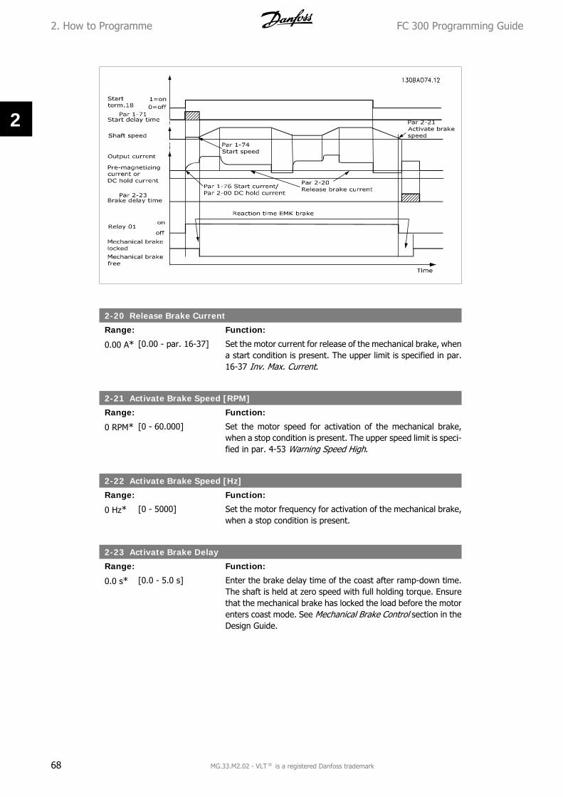
2-20 Release Brake Current
Range: Function:
0.00 A* [0.00 - par. 16-37] Set the motor current for release of the mechanical brake, whena start condition is present. The upper limit is specified in par.16-37 Inv. Max. Current.
2-21 Activate Brake Speed [RPM]
Range: Function:
0 RPM* [0 - 60.000] Set the motor speed for activation of the mechanical brake,when a stop condition is present. The upper speed limit is speci-fied in par. 4-53 Warning Speed High.
2-22 Activate Brake Speed [Hz]
Range: Function:
0 Hz* [0 - 5000] Set the motor frequency for activation of the mechanical brake,when a stop condition is present.
2-23 Activate Brake Delay
Range: Function:
0.0 s* [0.0 - 5.0 s] Enter the brake delay time of the coast after ramp-down time.The shaft is held at zero speed with full holding torque. Ensurethat the mechanical brake has locked the load before the motorenters coast mode. See Mechanical Brake Control section in theDesign Guide.
2. How to Programme FC 300 Programming Guide
68 MG.33.M2.02 - VLT ® is a registered Danfoss trademark
2

2-24 Stop delay
Range: Function:
0.0 s* [0.0 - 5.0 s] Set the time interval from the moment when the motor is stop-ped until the brake closes. This parameter is a part of thestopping function.
2-25 Brake Release Time
Range: Function:
0.20 s* [0.00 - 5.00 s] This value defines the time it takes for the mechanical brake toopen/ close. This parameter must act as a time-out when brakefeedback is activated.
2-26 Torque Ref
Range: Function:
0.00%* [-100.00 - 100.00 %] The value defines the torque applied against the closed me-chanical brake, before release
2-27 Torque Ramp Time
Range: Function:
0.2 s* [0.0 - 5.0 s] The value defines the duration of the torque ramp in clockwisedirection.
2-28 Gain Boost Factor
Range: Function:
1.00* [0.00 - 4.00] When a speed PID-control is connected to the output (fluxclosed loop) it must be possible to boost the proportional gainof the control during the Activate Brake Delay (par. 2-23). Byincreasing the gain, the bump when the motor takes over theload from the brake can be reduced. The risk of oscillation isvery small due to the relatively short duration and the low (zero)speed.
FC 300 Programming Guide 2. How to Programme
MG.33.M2.02 - VLT ® is a registered Danfoss trademark 69
2

Illustration 2.4: Brake release sequence for hoist mechanical brake control
2.6. Parameters: Reference/Ramps
2.6.1. 3-** Reference/Reference Limits/Ramps
Parameters for reference handling, definition of limitations, and configuration of the reaction ofthe frequency converter to changes.
2.6.2. 3-0* Reference Limits
Parameters for setting the reference unit, limits and ranges.
3-00 Reference Range
Option: Function:
Select the range of the reference signal and the feedback signal.Signal values can be positive only, or positive and negative. Theminimum limit may have a negative value, unless Speed closedloop [1] control or Process [3] is selected in par. 1-00 Configu-ration Mode.
[0] Min. - Max For positive values only.
[1] -Max - +Max For both positive and negative values.
3-05 Reference/Feedback Unit
Option: Function:
Select the unit to be used in Process PID Control references andfeedbacks.
[0] None
[1] %
[2] * RPM
[3] Hz
2. How to Programme FC 300 Programming Guide
70 MG.33.M2.02 - VLT ® is a registered Danfoss trademark
2
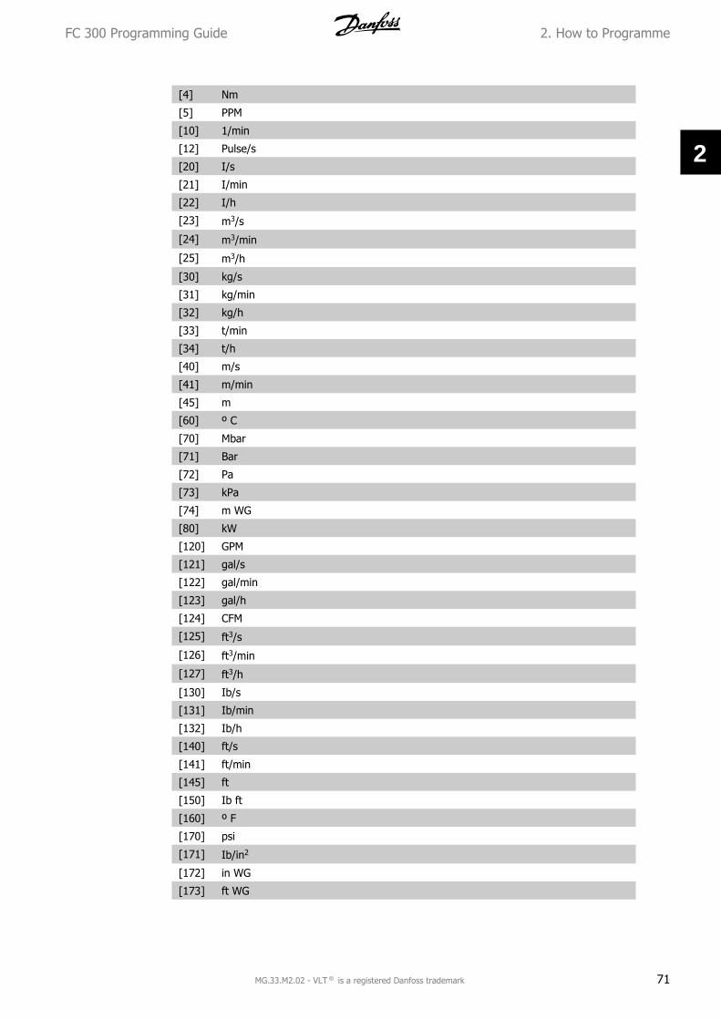
[4] Nm
[5] PPM
[10] 1/min
[12] Pulse/s
[20] I/s
[21] I/min
[22] I/h
[23] m3/s
[24] m3/min
[25] m3/h
[30] kg/s
[31] kg/min
[32] kg/h
[33] t/min
[34] t/h
[40] m/s
[41] m/min
[45] m
[60] º C
[70] Mbar
[71] Bar
[72] Pa
[73] kPa
[74] m WG
[80] kW
[120] GPM
[121] gal/s
[122] gal/min
[123] gal/h
[124] CFM
[125] ft3/s
[126] ft3/min
[127] ft3/h
[130] Ib/s
[131] Ib/min
[132] Ib/h
[140] ft/s
[141] ft/min
[145] ft
[150] Ib ft
[160] º F
[170] psi
[171] Ib/in2
[172] in WG
[173] ft WG
FC 300 Programming Guide 2. How to Programme
MG.33.M2.02 - VLT ® is a registered Danfoss trademark 71
2

[180] HP
3-02 Minimum Reference
Range: Function:
0.000 * [-100000.000 – par.3-03]
Enter the Minimum Reference. The Minimum Reference is thelowest value obtainable by summing all references.Minimum Reference is active only when par. 3-00 ReferenceRange is set to Min.- Max. [0].The Minimum Reference unit matches:
• The choice of configuration in par 1-00 ConfigurationMode: for Speed closed loop [1], RPM; for Torque [2],Nm.
• The unit selected in par. 3-01 Reference/FeedbackUnit.
3-03 Maximum Reference
Range: Function:
1500.000*
[Par. 3-02 -100000.000]
Enter the Maximum Reference. The Maximum Reference is thehighest value obtainable by summing all references.
The Maximum Reference unit matches:• The choice of configuration in par. 1-00 Configuration
Mode: for Speed closed loop [1], RPM; for Torque [2],Nm.
• The unit selected in par. 3-01 Reference/FeedbackUnit.
3-04 Reference Function
Option: Function:
[0] * Sum Sums both external and preset reference sources.
[1] External/Preset Use either the preset or the external reference source.
Shift between external and preset via a command on a digital input.
2.6.3. 3-1* References
Parameters for setting up the reference sources.Select the preset reference(s). Select Preset ref. bit 0 / 1 / 2 [16], [17] or [18] for the corre-sponding digital inputs in parameter group 5.1* Digital Inputs.
3-10 Preset Reference
Array [8]Range: 0-7
0.00%* [-100.00 - 100.00 %] Enter up to eight different preset references (0-7) in this pa-rameter, using array programming. The preset reference isstated as a percentage of the value RefMAX (par. 3-03 Maximum
2. How to Programme FC 300 Programming Guide
72 MG.33.M2.02 - VLT ® is a registered Danfoss trademark
2

Reference) If a RefMIN different from 0 (Par. 3-02 Minimum Ref-erence) is programmed, the preset reference is calculated as apercentage of the full reference range, i.e. on the basis of thedifference between RefMAX and RefMIN. Afterwards, the value isadded to RefMIN. When using preset references, select Presetref. bit 0 / 1 / 2 [16], [17] or [18] for the corresponding digitalinputs in parameter group 5.1* Digital Inputs.
Preset ref. bit 2 1 0Preset ref. 0 0 0 0Preset ref. 1 0 0 1Preset ref. 2 0 1 0Preset ref. 3 0 1 1Preset ref. 4 1 0 0Preset ref. 5 1 0 1Preset ref. 6 1 1 0Preset ref. 7 1 1 1
3-11 Jog Speed
Range: Function:
Size re-lated
[0.0 - par. 4-14] The jog speed is a fixed output speed at which the frequencyconverter is running when the jog function is activated.See also par. 3-80.
3-12 Catch up/slow Down Value
Range: Function:
0.00% [0.00 - 100.00%] Enter a percentage (relative) value to be either added to or de-ducted from the actual reference for Catch up or Slow downrespectively. If Catch up is selected via one of the digital inputs(par. 5-10 to par. 5-15), the percentage (relative) value is addedto the total reference. If Slow down is selected via one of thedigital inputs (par. 5-10 to par. 5-15), the percentage (relative)value is deducted from the total reference. Obtain extendedfunctionality with the DigiPot function. See parameter group3-9* Digital Potentiometer.
FC 300 Programming Guide 2. How to Programme
MG.33.M2.02 - VLT ® is a registered Danfoss trademark 73
2

3-13 Reference Site
Option: Function:
Select which reference site to activate.
[0] * Linked to Hand / Auto Use local reference when in Hand mode; or remote referencewhen in Auto mode.
[1] Remote Use remote reference in both Hand mode and Auto mode.
[2] Local Use local reference in both Hand mode and Auto mode.
3-14 Preset Relative Reference
Range: Function:
0.00%* [-200.00 - 200.00 %] The actual reference, X, is increased or decreased with the per-centage Y, set in par.3-14. This results in the actual referenceZ. Actual reference (X) is the sum of the inputs selected in par.3-15, Reference Source 1, par.3-16, Reference Source 2, par.3-17, Reference Source 3, and par.8-02, Control Word Source.
3-15 Reference Source 1
Option: Function:
Select the reference input to be used for the first reference sig-nal. Par. 3-15, 3-16 and 3-17 define up to three different refer-ence signals. The sum of these reference signals defines theactual reference.
[0] No function
[1] * Analog input 53
[2] Analog input 54
[7] Frequency input 29(FC 302 only)
[8] Frequency input 33
[11] Local bus reference
[20] Digital pot.meter
[21] Analog input X30-11
2. How to Programme FC 300 Programming Guide
74 MG.33.M2.02 - VLT ® is a registered Danfoss trademark
2

[22] Analog input X30-12
3-16 Reference Source 2
Option: Function:
Select the reference input to be used for the second referencesignal. Par. 3-15, 3-16 and 3-17 define up to three different ref-erence signals. The sum of these reference signals defines theactual reference.
[0] No function
[1] Analog input 53
[2] Analog input 54
[7] Frequency input 29(FC 302 only)
[8] Frequency input 33
[11] Local bus reference
[20] * Digital pot.meter
[21] Analog input X30-11
[22] Analog input X30-12
3-17 Reference Source 3
Option: Function:
Select the reference input to be used for the third referencesignal. Par. 3-15, 3-16 and 3-17 define up to three different ref-erence signals. The sum of these reference signals defines theactual reference.
[0] No function
[1] Analog input 53
[2] Analog input 54
[7] Frequency input 29(FC 302 only)
[8] Frequency input 33
[11] * Local bus reference
[20] Digital pot.meter
[21] Analog input X30-11
[22] Analog input X30-12
3-18 Relative Scaling Reference Source
Option: Function:
Select a variable value to be added to the fixed value (definedin par. 3-14 Preset Relative Reference). The sum of the fixedand variable values (labelled Y in the illustration below) is mul-tiplied with the actual reference (labelled X in the illustrationbelow). This product is then added to the actual reference (X+X*Y/100) to give the resultant actual reference.
FC 300 Programming Guide 2. How to Programme
MG.33.M2.02 - VLT ® is a registered Danfoss trademark 75
2

This parameter cannot be adjusted while the motor is running.
[0] * No function
[1] Analog input 53
[2] Analog input 54
[7] Frequency input 29(FC 302 only)
[8] Frequency input 33
[11] Local bus reference
[20] Digital pot.meter
[21] Analog input X30-11
[22] Analog input X30-12
3-19 Jog Speed
Range: Function:
150RPM*
[0 - par. 4-13 RPM] Enter a value for the jog speed nJOG, which is a fixed outputspeed. The frequency converter runs at this speed when the jogfunction is activated. The maximum limit is defined in par. 4-13Motor Speed High Limit (RPM).See also par. 3-80.
2.6.4. Ramps3-4* Ramp 1
For each of four ramps (par. 3-4*, 3-5*, 3-6* and 3-7*) configure the ramp parameters: ramptype, ramping times (duration of acceleration and deceleration) and level of jerk compensationfor S ramps.
Start by setting the linear ramping times corresponding to the figures.
2. How to Programme FC 300 Programming Guide
76 MG.33.M2.02 - VLT ® is a registered Danfoss trademark
2

If S-ramps are selected then set the level of non-linear jerk compensation required. Set jerk com-pensation by defining the proportion of ramp-up and ramp-down times where acceleration anddeceleration are variable (i.e. increasing or decreasing). The S-ramp acceleration and decelerationsettings are defined as a percentage of the actual ramp time.
3-40 Ramp 1 Type
Option: Function:
Select the ramp type, depending on requirements for accelera-tion/deceleration.A linear ramp will give constant acceleration during ramping. AnS-ramp will give non-linear acceleration, compensating for jerkin the application.
[0] * Linear
[1] S-ramp Const Jerk Acceleration with lowest possible jerk.
[2] S-ramp Const Time S-ramp based on the values set in par. 3-41 and 3-42.
NB!If S-ramp [1] is selected and the reference during ramping is changed the ramp timemay be prolonged in order to realize a jerk free movement which may result in alonger start or stop time.Additional adjustment of the S-ramp ratios or switching initiators may be necessary.
3-41 Ramp 1 Ramp up Time
Range: Function:
Size re-lated
[0.01 - 3600.00 s] Enter the ramp-up time, i.e. the acceleration time from 0 RPMto the rated motor speed nM,N (par. 1-25). Choose a ramp-uptime such that the output current does not exceed the currentlimit in par. 4-18 during ramping. The value 0.00 correspondsto 0.01 sec. in speed mode. See ramp-down time in par. 3-42.
Par. 3− 41 =tacc s x nM, N (par. 1− 25) RPM
Δ ref RPM
FC 300 Programming Guide 2. How to Programme
MG.33.M2.02 - VLT ® is a registered Danfoss trademark 77
2

3-42 Ramp 1 Ramp Down Time
Range: Function:
Size re-lated
[0.01 - 3600.00 s] Enter the ramp-down time, i.e. the deceleration time from therated motor speed nM,N (par. 1-25) to 0 RPM. Choose a ramp-down time such that no over-voltage arises in the inverter dueto regenerative operation of the motor, and such that the gen-erated current does not exceed the current limit set in par. 4-18.The value 0.00 corresponds to 0.01 s in speed mode. See ramp-up time in par. 3-41.
Par. 3− 42 =tacc s x nM, N (par. 1− 25) RPM
Δ ref RPM
3-45 Ramp 1 S-ramp Ratio at Accel. Start
Range: Function:
50%* [1 - 99%] Enter the proportion of the total ramp-up time (par. 3-41) inwhich the acceleration torque increases. The larger the per-centage value, the greater the jerk compensation achieved, andthus the lower the torque jerks occurring in the application.
3-46 Ramp 1 S-ramp Ratio at Accel. End
Range: Function:
50%* [1 - 99%] Enter the proportion of the total ramp-up time (par. 3-41) inwhich the acceleration torque decreases. The larger the per-centage value, the greater the jerk compensation achieved, andthus the lower the torque jerks in the application.
3-47 Ramp 1 S-ramp Ratio at Decel. Start
Range: Function:
50%* [1 - 99%] Enter the proportion of the total ramp-down time (par. 3-42)where the deceleration torque increases. The larger the per-centage value, the greater the jerk compensation achieved, andthus the lower the torque jerks in the application.
2. How to Programme FC 300 Programming Guide
78 MG.33.M2.02 - VLT ® is a registered Danfoss trademark
2

3-48 Ramp 1 S-ramp Ratio at Decel. End
Range: Function:
50%* [1 - 99%] Enter the proportion of the total ramp-down time (par. 3-42)where the deceleration torque decreases. The larger the per-centage value, the greater the jerk compensation achieved, andthus the lower the torque jerks in the application.
2.6.5. 3-5* Ramp 2
Choosing ramp parameters, see 3-4*.
3-50 Ramp 2 Type
Option: Function:
Select the ramp type, depending on requirements for accelera-tion/deceleration. A linear ramp will give constant accelerationduring ramping. An S-ramp will give non-linear acceleration,compensating for jerk in the application.
[0] * Linear
[1] S-ramp Const Jerk Acceleration with lowest possible jerk
[2] S-ramp Const Time S-ramp based on the values set in par. 3-51 and 3-52
NB!If S-ramp [1] is selected and the reference during ramping is changed the ramp timemay be prolonged in order to realize a jerk free movement which may result in alonger start or stop time.Additional adjustment of the S-ramp ratios or switching initiators may be necessary.
3-51 Ramp 2 Ramp up Time
Range: Function:
Size re-lated
[0.01 - 3600.00 s] Enter the ramp-up time, i.e. the acceleration time from 0 RPMto the rated motor speed nM,N (par. 1-25). Choose a ramp-uptime such that the output current does not exceed the currentlimit in par. 4-18 during ramping. The value 0.00 correspondsto 0.01 sec. in speed mode. See ramp-down time in par. 3-52.
Par. 3− 51 =tacc s x nM, N (par. 1− 25) RPM
Δ ref RPM
3-52 Ramp 2 Ramp down Time
Range: Function:
Size re-lated
[0.01 - 3600.00 s.] Enter the ramp-down time, i.e. the deceleration time from therated motor speed nM,N (par. 1-25) to 0 RPM. Choose a ramp-down time such that no over-voltage arises in the inverter dueto regenerative operation of the motor, and such that the gen-erated current does not exceed the current limit set in par. 4-18.The value 0.00 corresponds to 0.01 s in speed mode. See ramp-up time in par. 3-51.
Par. 3− 52 =tdec s x nM, N (par. 1− 25) RPM
Δ ref RPM
FC 300 Programming Guide 2. How to Programme
MG.33.M2.02 - VLT ® is a registered Danfoss trademark 79
2

3-55 Ramp 2 S-ramp Ratio at Accel. Start
Range: Function:
50%* [1 - 99%] Enter the proportion of the total ramp-up time (par. 3-51) inwhich the acceleration torque increases. The larger the per-centage value, the greater the jerk compensation achieved, andthus the lower the torque jerks in the application.
3-56 Ramp 2 S-ramp Ratio at Accel. End
Range: Function:
50%* [1 - 99%] Enter the proportion of the total ramp-up time (par. 3-51) inwhich the acceleration torque decreases. The larger the per-centage value, the greater the jerk compensation achieved, andthus the lower the torque jerks in the application.
3-57 Ramp 2 S-ramp Ratio at Decel. Start
Range: Function:
50%* [1 - 99%] Enter the proportion of the total ramp-down time (par. 3-52)where the deceleration torque increases The larger the per-centage value, the greater the jerk compensation achieved, andthus the lower the torque jerks in the application.
3-58 Ramp 2 S-ramp Ratio at Decel. End
Range: Function:
50%* [1 - 99%] Enter the proportion of the total ramp-down time (par. 3-52)where the deceleration torque decreases. The larger the per-centage value, the greater the jerk compensation achieved, andthus the lower the torque jerks in the application.
2.6.6. 3-6* Ramp 3
Configure ramp parameters, see 3-4*.
3-60 Ramp 3 Type
Option: Function:
Select the ramp type, depending on requirements for accelera-tion and deceleration. A linear ramp will give constant acceler-ation during ramping. An S-ramp will give non-linear accelera-tion, compensating for jerk in the application.
[0] * Linear
[1] S-ramp Const Jerk Accelerates with lowest possible jerk.
[2] S-ramp Const Time S-ramp based on the values set in par. 3-61 and 3-62
NB!If S-ramp [1] is selected and the reference during ramping is changed the ramp timemay be prolonged in order to realize a jerk free movement which may result in alonger start or stop time.Additional adjustment of the S-ramp ratios or switching initiators may be necessary.
2. How to Programme FC 300 Programming Guide
80 MG.33.M2.02 - VLT ® is a registered Danfoss trademark
2

3-61 Ramp 3 Ramp up Time
Range: Function:
Size re-lated
[0.01 - 3600.00 s] Enter the ramp-up time, i.e. the acceleration time from 0 RPMto the rated motor speed nM,N (par. 1-25). Choose a ramp-uptime such that the output current does not exceed the currentlimit in par. 4-18 during ramping. The value 0.00 correspondsto 0.01 sec. in speed mode. See ramp-down time in par. 3-62.
3-62 Ramp 3 Ramp down Time
Range: Function:
Size re-lated
[0.01 - 3600.00 s ] Enter the ramp-down time, i.e. the deceleration time from therated motor speed nM,N (par. 1-25) to 0 RPM. Choose a ramp-down time such that no over-voltage arises in the inverter dueto regenerative operation of the motor, and such that the gen-erated current does not exceed the current limit set in par. 4-18.The value 0.00 corresponds to 0.01 s in speed mode. See ramp-up time in par. 3-61.
Par. 3− 62 =tdec s x nM, N (par. 1− 25) RPM
Δ ref RPM
3-65 Ramp 3 S-ramp Ratio at Accel. Start
Range: Function:
50%* [1 - 99%] Enter the proportion of the total ramp-up time (par. 3-61) inwhich the acceleration torque increases. The larger the per-centage value, the greater the jerk compensation achieved, andthus the lower the torque jerks in the application.
3-66 Ramp 3 S-ramp Ratio at Accel. End
Range: Function:
50%* [1 - 99%] Enter the proportion of the total ramp-up time (par. 3-61) inwhich the acceleration torque decreases. The larger the per-centage value, the greater the jerk compensation achieved, andthus the lower the torque jerks in the application.
3-67 Ramp 3 S-ramp Ratio at Decel. Start
Range: Function:
50%* [1 - 99%] Enter the proportion of the total ramp-down time (par. 3-62)where the deceleration torque increases. The larger the per-centage value, the greater the jerk compensation achieved, andthus the lower the torque jerks in the application.
3-68 Ramp 3 S-ramp Ratio at Decel. End
Range: Function:
50%* [1 - 99%] Enter the proportion of the total ramp-down time (par. 3-62)where the deceleration torque decreases. The larger the per-centage value, the greater the jerk compensation achieved, andthus the lower the torque jerks in the application.
FC 300 Programming Guide 2. How to Programme
MG.33.M2.02 - VLT ® is a registered Danfoss trademark 81
2

2.6.7. 3-7* Ramp 4
Configure ramp parameters, see 3-4*.
3-70 Ramp 4 Type
Option: Function:
Select the ramp type, depending on requirements for accelera-tion and deceleration. A linear ramp will give constant acceler-ation during ramping. An S-ramp will give non-linear accelera-tion, compensating for jerk in the application
[0] * Linear
[1] S-ramp Const Jerk Accelerates with lowest possible jerk.
[2] S-ramp Const Time S-ramp based on the values set in par. 3-71 and 3-72.
NB!If S-ramp [1] is selected and the reference during ramping is changed the ramp timemay be prolonged in order to realize a jerk free movement which may result in alonger start or stop time.Additional adjustment of the S-ramp ratios or switching initiators may be necessary.
3-71 Ramp 4 Ramp up Time
Range: Function:
Size re-lated
[0.01 - 3600.00 s] Enter the ramp-up time, i.e. the acceleration time from 0 RPMto the rated motor speed nM,N (par. 1-25). Choose a ramp-uptime such that the output current does not exceed the currentlimit in par. 4-18 during ramping. The value 0.00 correspondsto 0.01 sec. in speed mode. See ramp-down time in par. 3-72.
Par. 3− 71 =tacc s x nM, N (par. 1− 25) RPM
Δ ref RPM
3-72 Ramp 4 Ramp Down Time
Range: Function:
Size re-lated
[0.01 - 3600.00 s] Enter the ramp-down time, i.e. the deceleration time from therated motor speed nM,N (par. 1-25) to 0 RPM. Choose a ramp-down time such that no over-voltage arises in the inverter dueto regenerative operation of the motor, and such that the gen-erated current does not exceed the current limit set in par. 4-18.The value 0.00 corresponds to 0.01 s in speed mode. See ramp-up time in par. 3-71.
Par. 3− 72 =tdec s x nM, N (par. 1− 25) RPM
Δ ref RPM
3-75 Ramp 4 S-ramp Ratio at Accel. Start
Range: Function:
50%* [1 - 99%] Enter the proportion of the total ramp-up time (par. 3-71) inwhich the acceleration torque increases. The larger the per-centage value, the greater the jerk compensation achieved, andthus the lower the torque jerks in the application.
2. How to Programme FC 300 Programming Guide
82 MG.33.M2.02 - VLT ® is a registered Danfoss trademark
2

3-76 Ramp 4 S-ramp Ratio at Accel. End
Range: Function:
50%* [1 - 99%] Enter the proportion of the total ramp-up time (par. 3-71) inwhich the acceleration torque decreases. The larger the per-centage value, the greater the jerk compensation achieved, andthus the lower the torque jerks in the application.
3-77 Ramp 4 S-ramp Ratio at Decel. Start
Range: Function:
50%* [1 - 99%] Enter the proportion of the total ramp-down time (par. 3-72)where the deceleration torque increases. The larger the per-centage value, the greater the jerk compensation achieved, andthus the lower the torque jerks in the application.
3-78 Ramp 4 S-ramp Ratio at Decel. End
Range: Function:
50%* [1 - 99%] Enter the proportion of the total ramp-down time (par. 3-72)where the deceleration torque decreases. The larger the per-centage value, the greater the jerk compensation achieved, andthus the lower the torque jerks in the application.
2.6.8. 3-8* Other Ramps
Configure parameters for special ramps e.g. Jog or Quick Stop.
3-80 Jog Ramp Time
Range: Function:
Size re-lated
[0.01 - 3600.00 s] Enter the jog ramp time, i.e. the acceleration/deceleration timebetween 0 RPM and the rated motor frequency nM,N (set in par.1-25 Motor Nominal Speed). Ensure that the resultant outputcurrent required for the given jog ramp time does not exceedthe current limit in par. 4-18. The jog ramp time starts uponactivation of a jog signal via the control panel, a selected digitalinput, or the serial communication port.
Par. 3− 80 =t jog s x nM, N (par. 1− 25) RPMΔ log speed (par. 3 − 19) RPM
FC 300 Programming Guide 2. How to Programme
MG.33.M2.02 - VLT ® is a registered Danfoss trademark 83
2

3-81 Quick Stop Ramp Time
Range: Function:
3 s* [0.01 - 3600.00 s] Enter the quick–stop ramp-down time, i.e. the deceleration timefrom the rated motor speed to 0 RPM. Ensure that no resultantover-voltage will arise in the inverter due to regenerative oper-ation of the motor required to achieve the given ramp-downtime. Ensure also that the generated current required to achievethe given ramp-down time does not exceed the current limit (setin par. 4-18). Quick-stop is activated by means of a signal on aselected digital input, or via the serial communication port.
Par. 3− 81 =tQstop s x nM, N (par. 1− 25) RPM
Δ jog ref (par. 3 − 19) RPM2.6.9. 3-9* Digital Pot.Meter
The digital potentiometer function allows the user to increase or decrease the actual reference byadjusting the set-up of the digital inputs using the functions Increase, Decrease or Clear. To ac-tivate the function, at least one digital input must be set up to Increase or Decrease.
2. How to Programme FC 300 Programming Guide
84 MG.33.M2.02 - VLT ® is a registered Danfoss trademark
2

3-90 Step Size
Range: Function:
0.10%* [0.01 - 200.00%] Enter the increment size required for INCREASE/DECREASE, asa percentage of the nominal speed set in par. 1-25. If IN-CREASE/ DECREASE is activated the resulting reference will beincreased / decreased by the amount set in this parameter.
3-91 Ramp Time
Range: Function:
1.00 s* [0.000 - 3600.00 s] Enter the ramp time, i.e. the time for adjustment of the refer-ence from 0% to 100% of the specified digital potentiometerfunction (Increase, Decrease or Clear).If Increase/ Decrease is activated for longer than the ramp delayperiod specified in par. 3-95 the actual reference will be rampedup / down according to this ramp time. The ramp time is definedas the time used to adjust the reference by the step size speci-fied in par. 3-90 Step Size.
3-92 Power Restore
Option: Function:
[0] * Off Resets the Digital Potentiometer reference to 0% after powerup.
[1] On Restores the most recent Digital Potentiometer reference atpower up.
3-93 Maximum Limit
Range: Function:
100%* [-200 - 200 %] Set the maximum permissible value for the resultant reference.This is advisable if the Digital Potentiometer is used for finetuning of the resulting reference.
3-94 Minimum Limit
Range: Function:
-100%* [-200 - 200 %] Set the minimum permissible value for the resultant reference.This is advisable if the Digital Potentiometer is used for finetuning of the resulting reference.
3-95 Ramp Delay
Range: Function:
1.000 s* [0.000 - 3600.00 s] Enter the delay required from activation of the digital potenti-ometer function until the frequency converter starts to ramp thereference. With a delay of 0 ms, the reference starts to ramp assoon as INCREASE/ DECREASE is activated. See also par. 3-91Ramp Time.
FC 300 Programming Guide 2. How to Programme
MG.33.M2.02 - VLT ® is a registered Danfoss trademark 85
2

2.7. Parameters: Limits/Warnings
2.7.1. 4-** Limits and Warnings
Parameter group for configuring limits and warnings.
2.7.2. 4-1* Motor Limits
Define torque, current and speed limits for the motor, and the reaction of the frequency converterwhen the limits are exceeded.A limit may generate a message on the display. A warning will always generate a message on thedisplay or on the fieldbus. A monitoring function may initiate a warning or a trip, upon which thefrequency converter will stop and generate an alarm message.
4-10 Motor Speed Direction
Option: Function:
Select the motor speed direction(s) required. Use this parameterto prevent unwanted reversing. When par. 1-00 ConfigurationMode is set to Process [3], par. 4-10 is set to Clockwise [0] asdefault. The setting in par. 4-10 does not limit options for settingpar.4-13.This parameter cannot be adjusted while the motor is running.
[0] * Clockwise
[1] Counter clockwise
[2] Both directions
4-11 Motor Speed Low Limit [RPM]
Range: Function:
0 RPM* [0 - par. 4-13] Enter the minimum limit for motor speed. The Motor Speed LowLimit can be set to correspond to the manufacturer’s recom-mended minimum motor speed. The Motor Speed Low Limitmust not exceed the setting in par. 4-13 Motor Speed High Limit[RPM].
4-12 Motor Speed Low Limit [Hz]
Range: Function:
0 Hz* [0 - par. 4-14] Enter the minimum limit for motor speed. The Motor Speed LowLimit can be set to correspond to the minimum output frequencyof the motor shaft. The Motor Speed Low Limit must not exceedthe setting in par. 4-14 Motor Speed High Limit [Hz].
4-13 Motor Speed High Limit [RPM]
Range: Function:
3600RPM
[Par. 4-11 - 60.000] Enter the maximum limit for motor speed. The Motor SpeedHigh Limit can be set to correspond to the manufacturer’s max-imum rated motor speed. The Motor Speed High Limit mustexceed the setting in par. 4-11 Motor Speed Low Limit [RPM].
2. How to Programme FC 300 Programming Guide
86 MG.33.M2.02 - VLT ® is a registered Danfoss trademark
2

NB!Max. output frequency cannot exceed 10% of the inverter switching frequency (par.14-01).
4-14 Motor Speed High Limit [Hz]
Range: Function:
Size re-lated*
[0 - 1000 Hz] Enter the maximum limit for motor speed. The Motor SpeedHigh Limit can be set to correspond to the manufacturer’s rec-ommended maximum frequency of the motor shaft. The MotorSpeed High Limit must exceed the setting in par. 4-12 MotorSpeed Low Limit [Hz]. Only par. 4-11 or 4-12 will be displayeddepending on other parameters set in the Main Menu and de-pending on default settings dependant on global geographicallocation.
NB!Max. output frequency cannot exceed 10% of the inverter switching frequency (par.14-01).
4-16 Torque Limit Motor Mode
Range: Function:
160.0 %*
[0.0 - Variable Limit%]
Sets the torque limit for motor operation. The torque limit isactive in the speed range up to the rated motor speed (par.1-25). To protect the motor from reaching the stalling torque,the default setting is 1.6 x the rated motor torque (calculatedvalue). If a setting in par. 1-00 to par. 1-26 is changed, par.4-16 to 4-18 are not automatically reset to the default settings.
Changing par. 4-16 Torque Limit Motor Mode when par. 1-00 is set to Speed openloop [0], par. 1-66 Min Current at Low Speed is automatically readjusted.
FC 300 Programming Guide 2. How to Programme
MG.33.M2.02 - VLT ® is a registered Danfoss trademark 87
2

4-17 Torque Limit Generator Mode
Range: Function:
100.0 %*
[0.0 - Variable Limit%]
Sets the torque limit for generator mode operation. The torquelimit is active in the speed range up to the rated motor speed(par. 1-25). See illustration for par. 4-16 as well as par. 14-25for further details.
4-18 Current Limit
Range: Function:
160.0 %*
[0.0 - Variable Limit%]
Sets the current limit for motor operation. To protect the motorfrom reaching the stalling torque, the default setting is 1.6 x therated motor torque (calculated value). If a setting in par. 1-00to par. 1-26 is changed, par. 4-16 to par. 4-18 are not auto-matically reset to the default settings.To obtain maximum output torque and prevent the motor fromstalling, it is recommendable not to set par. 4-18 lower than par.4-16 and 4-17 (Torque Limits)
4-19 Max Output Frequency
Range: Function:
132.0Hz*
[0.0 - 1000.0 Hz] Provides a final limit on the drive output frequency for improvedsafety in applications where you want to avoid accidental over-speeding. This limit is final in all configurations (independent ofthe setting in par. 1-00).
NB!Max. output frequency cannot exceed 10% of the inverter switching frequency (par.14-01).
Par. 4-19 cannot be adjusted while the motor is running.
4-20 Torque Limit Factor SourceOption
Option: Function:
Select an analog input for scaling the settings in par. 4-16 and4-17 from 0% to 100% (or inverse). The signal levels corre-sponding to 0% and 100% are defined in the analog inputscaling, e.g. par. group 6-1*. This parameter is only active whenpar. 1-00 Configuration Mode is in Speed Open Loop or SpeedClosed Loop.
[0] * No function
[2] Analog input 53
[4] Analog input 53 inv
[6] Analog input 54
[8] Analog input 54 inv
[10] Analog input X30-11
[12] Analog input X30-11inv
[14] Analog input X30-12
2. How to Programme FC 300 Programming Guide
88 MG.33.M2.02 - VLT ® is a registered Danfoss trademark
2

[16] Analog input X30-12inv
4-21 Speed Limit Factor SourceOption
Option: Function:
Select an analog input for scaling the settings in par. 4-19 from0% to 100% (or inverse). The signal levels corresponding to 0%and 100% are defined in the analog input scaling, e.g. par.group 6-1*. This parameter is only active when par. 1-00 Con-figuration Mode is in Torque Mode.
[0] * No function
[2] Analog input 53
[4] Analog input 53 inv
[6] Analog input 54
[8] Analog input 54 inv
[10] Analog input X30-11
[12] Analog input X30-11inv
[14] Analog input X30-12
[16] Analog input X30-12inv
2.7.3. 4-3* Motor Feedback Monitoring
The parameter group includes monitoring and handling of motor feedback devices as encoders,resolvers etc.
4-30 Motor Feedback Loss Function
Option: Function:
Select which reaction the frequency converter should take in thecase a feedback fault is detected. The selected action will takeplace if the feedback signal differs from the output speed withmore than specified in par. 4-31 during the time set in par. 4-32.
[0] Disabled
[1] Warning
[2] * Trip
4-31 Motor Feedback Speed Error
Range: Function:
300RPM*
[1-600 RPM] Select the max allowed tracking error in speed from the calcu-lated and the actual mechanical shaft output speed.
FC 300 Programming Guide 2. How to Programme
MG.33.M2.02 - VLT ® is a registered Danfoss trademark 89
2

4-32 Motor Feedback Loss Timeout
Range: Function:
0.05 s* [0.00 - 60.00 sec] Set the timeout value allowing the speed error set in par. 4-31to be exceeded.
2.7.4. 4-5* Adjustable Warnings
Define adjustable warning limits for current, speed, reference and feedback. Warnings are shownon the display, programmed output or serial bus.
Warnings are shown on display, programmed output or serial bus.
4-50 Warning Current Low
Range: Function:
0.00 A* [0.00 - par. 4-51] Enter the ILOW value. When the motor current falls below thislimit, the display reads Current Low. The signal outputs can beprogrammed to produce a status signal on terminal 27 or 29 andon relay output 01 or 02. Refer to the drawing in this section.
2. How to Programme FC 300 Programming Guide
90 MG.33.M2.02 - VLT ® is a registered Danfoss trademark
2

4-51 Warning Current High
Range: Function:
par.16-37A*
[Par. 4-50 - par.16-37]
Enter the IHIGH value. When the motor current exceeds this limit,the display reads Current High. The signal outputs can be pro-grammed to produce a status signal on terminal 27 or 29 andon relay output 01 or 02. Refer to the drawing in this section.
4-52 Warning Speed Low
Range: Function:
0 RPM* [0 - par. 4-13] Enter the nLOW value. When the motor speed exceeds this limit,the display reads Speed Low. The signal outputs can be pro-grammed to produce a status signal on terminal 27 or 29 (FC302 only) and on relay output 01 or 02 (FC 302 only).
4-53 Warning Speed High
Range: Function:
par.4-13RPM*
[Par. 4-52 - par. 4-13] Enter the nHIGH value. When the motor speed exceeds this limit,the display reads Speed High. The signal outputs can be pro-grammed to produce a status signal on terminal 27 or 29 andon relay output 01 or 02. Programme the upper signal limit ofthe motor speed, nHIGH, within the normal working range of thefrequency converter. Refer to the drawing in this section.
4-54 Warning Reference Low
Range: Function:
-999999.999*
[-999999.999 - par.4-55]
Enter the lower reference limit. When the actual reference fallsbelow this limit, the display indicates Ref Low. The signal out-puts can be programmed to produce a status signal on terminal27 or 29 and on relay output 01 or 02.
4-55 Warning Reference High
Range: Function:
999999.999*
[Par. 4-54 -999999.999]
Enter the upper reference limit. When the actual reference ex-ceeds this limit, the display reads Ref High. The signal outputscan be programmed to produce a status signal on terminal 27or 29 and on relay output 01 or 02.
4-56 Warning Feedback Low
Range: Function:
-999999.999*
[-999999.999 - par.4-57]
Enter the lower feedback limit. When the feedback falls belowthis limit, the display reads Feedb Low. The signal outputs canbe programmed to produce a status signal on terminal 27 or 29and on relay output 01 or 02.
FC 300 Programming Guide 2. How to Programme
MG.33.M2.02 - VLT ® is a registered Danfoss trademark 91
2

4-57 Warning Feedback High
Range: Function:
999999.999*
[Par. 4-56 -999999.999]
Enter the upper feedback limit. When the feedback exceeds thislimit, the display reads Feedb High. The signal outputs can beprogrammed to produce a status signal on terminal 27 or 29 andon relay output 01 or 02.
4-58 Missing Motor Phase Function
Option: Function:
[0] Off Displays an alarm in the event of a missing motor phase.
[1] * On No alarm displayed in the event of a missing motor phase. How-ever, if the motor runs on only two phases, it can be damagedby overheating. Retaining the On setting is therefore stronglyrecommended.
This parameter cannot be adjusted while the motor is running.
2.7.5. 4-6* Speed Bypass
Define the Speed Bypass areas for the ramps.Some systems call for avoiding certain output frequencies or speeds, due to resonance problemsin the system. A maximum of four frequency or speed ranges can be avoided.
4-60 Bypass Speed From [RPM]
Array [4]
4-60 Bypass Speed From [RPM]
Range: Function:
0 RPM* [0 - par. 4-13] Some systems call for avoiding certain output speeds due toresonance problems in the system. Enter the lower limits of thespeeds to be avoided.
4-61 Bypass Speed From [Hz]
Array [4]
0 Hz* [0 - par. 4-14 Hz] Some systems call for avoiding certain output speeds due toresonance problems in the system. Enter the lower limits of thespeeds to be avoided.
4-62 Bypass Speed To [RPM]
Array [4]
2. How to Programme FC 300 Programming Guide
92 MG.33.M2.02 - VLT ® is a registered Danfoss trademark
2

0 RPM* [0 - par. 4-13] Some systems call for avoiding certain output speeds due toresonance problems in the system. Enter the upper limits of thespeeds to be avoided.
4-63 Bypass Speed To [Hz]
Array [4]
0 Hz* [0 - par. 4-14] Some systems call for avoiding certain output speeds due toresonance problems in the system. Enter the upper limits of thespeeds to be avoided.
FC 300 Programming Guide 2. How to Programme
MG.33.M2.02 - VLT ® is a registered Danfoss trademark 93
2

2.8. Parameters: Digital In/Out
2.8.1. 5-** Digital In/Out
Parameter group for configuring the digital input and output.
2.8.2. 5-0* Digital I/O Mode
Parameters for configuring the IO mode. NPN/PNP and setting up IO to Input or Output.
5-00 Digital I/O Mode
Option: Function:
Digital inputs and programmed digital outputs are pre-program-mable for operation either in PNP or NPN systems.
[0] * PNP Action on positive directional pulses (). PNP systems are pulleddown to GND.
[1] NPN Action on negative directional pulses (). NPN systems arepulled up to + 24 V, internally in the frequency converter.
NB!When changing this parameter, a power cycle must be carried out before the pa-rameter change is active.
This parameter cannot be adjusted while the motor is running.
5-01 Terminal 27 Mode
Option: Function:
[0] * Input Defines terminal 27 as a digital input.
[1] Output Defines terminal 27 as a digital output.
This parameter cannot be adjusted while themotor is running.
5-02 Terminal 29 Mode
Option: Function:
[0] * Input Defines terminal 29 as a digital input.
[1] Output Defines terminal 29 as a digital output.
This parameter is available for FC 302 only.This parameter cannot be adjusted while the motor is running.
2.8.3. 5-1* Digital Inputs
Parameters for configuring the input functions for the input terminals.The digital inputs are used for selecting various functions in the frequency converter. All digitalinputs can be set to the following functions:
2. How to Programme FC 300 Programming Guide
94 MG.33.M2.02 - VLT ® is a registered Danfoss trademark
2

Digital input function Select TerminalNo operation [0] All *term 32, 33Reset [1] AllCoast inverse [2] All *term 27Coast and reset inverse [3] AllQuick stop inverse [4] AllDC-brake inverse [5] AllStop inverse [6] AllStart [8] All *term 18Latched start [9] AllReversing [10] All *term 19Start reversing [11] AllEnable start forward [12] AllEnable start reverse [13] AllJog [14] All *term 29Preset reference on [15] AllPreset ref bit 0 [16] AllPreset ref bit 1 [17] AllPreset ref bit 2 [18] AllFreeze reference [19] AllFreeze output [20] AllSpeed up [21] AllSpeed down [22] AllSet-up select bit 0 [23] AllSet-up select bit 1 [24] AllPrecise stop inverse [26] 18, 19Precises start, stop [27] 18, 19Catch up [28] AllSlow down [29] AllCounter input [30] 29, 33Pulse input [32] 29, 33Ramp bit 0 [34] AllRamp bit 1 [35] AllMains failure inverse [36] AllLatched precise start [40] 18, 19Latched precise stop inverse [41] 18, 19DigiPot Increase [55] AllDigiPot Decrease [56] AllDigiPot Clear [57] AllCounter A (up) [60] 29, 33Counter A (down) [61] 29, 33Reset Counter A [62] AllCounter B (up) [63] 29, 33Counter B (down) [64] 29, 33Reset Counter B [65] AllMech. Brake Feedb. [70] AllMech. Brake Feedb. Inv. [71] AllPTC Card 1 [80] All
All = Terminals 18, 19, 27, 29, 32, 33, X30/2, X30/3, X30/4. X30/ are the terminals on MCB 101.Terminal 29 is available in FC 302 only.
Functions dedicated to only one digital input are stated in the associated parameter.
All digital inputs can be programmed to these functions:
[0] No operation No reaction to signals transmitted to the terminal.
[1] Reset Resets frequency converter after a TRIP/ALARM. Not all alarmscan be reset.
[2] Coast inverse (Default Digital input 27): Coasting stop, inverted input (NC).The frequency converter leaves the motor in free mode. Logic‘0’ => coasting stop.
[3] Coast and reset in-verse
Reset and coasting stop Inverted input (NC). Leaves motor infree mode and resets drive. Logic ‘0’ => coasting stop and reset.
FC 300 Programming Guide 2. How to Programme
MG.33.M2.02 - VLT ® is a registered Danfoss trademark 95
2

[4] Quick stop inverse Inverted input (NC). Generates a stop in accordance with quick-stop ramp time set in par. 3-81. When motor stops, the shaft isin free mode. Logic ‘0’ => Quick-stop.
[5] DC-brake inverse Inverted input for DC braking (NC). Stops motor by energizingit with a DC current for a certain time period. See par. 2-01 topar. 2-03. The function is only active when the value in par. 2-02is different from 0. Logic ’0’ => DC braking.
[6] Stop inverse Stop Inverted function. Generates a stop function when the se-lected terminal goes from logical level ‘1’ to ‘0’. The stop isperformed according to the selected ramp time (par. 3-42, par.3-52, par. 3-62, par. 3-72).
NB!When the frequency converter is at the torquelimit and has received a stop command, it may notstop by itself. To ensure that the frequency con-verter stops, configure a digital output to Torquelimit & stop [27] and connect this digital output toa digital input that is configured as coast.
[8] Start (Default Digital input 18): Select start for a start/stop command.Logic ‘1’ = start, logic ‘0’ = stop.
[9] Latched start The motor starts, if a pulse is applied for min. 2 ms. The motorstops when Stop inverse is activated.
[10] Reversing (Default Digital input 19). Change the direction of motor shaftrotation. Select Logic ‘1’ to reverse. The reversing signal onlychanges the direction of rotation. It does not activate the startfunction. Select both directions in par. 4-10 Motor Speed Direc-tion. The function is not active in process closed loop.
[11] Start reversing Used for start/stop and for reversing on the same wire. Signalson start are not allowed at the same time.
[12] Enable start forward Rotates motor shaft clockwise at start.
[13] Enable start reverse Rotates motor shaft counterclockwise at start.
[14] Jog (Default Digital input 29): Use to activate jog speed. See par.3-11.
[15] Preset reference on Shifts between external reference and preset reference. It isassumed that External/preset [1] has been selected in par. 3-04.Logic '0' = external reference active; logic '1' = one of the eightpreset references is active.
[16] Preset ref bit 0 Preset ref. bit 0,1, and 2 enables a choice between one of theeight preset references according to the table below.
[17] Preset ref bit 1 Same as Preset ref bit 0 [16].
[18] Preset ref bit 2 Same as Preset ref bit 0 [16].
2. How to Programme FC 300 Programming Guide
96 MG.33.M2.02 - VLT ® is a registered Danfoss trademark
2

Preset ref. bit 2 1 0Preset ref. 0 0 0 0Preset ref. 1 0 0 1Preset ref. 2 0 1 0Preset ref. 3 0 1 1Preset ref. 4 1 0 0Preset ref. 5 1 0 1Preset ref. 6 1 1 0Preset ref. 7 1 1 1
[19] Freeze ref Freezes the actual reference, which is now the point of enable/condition for Speed up and Speed down to be used. If Speedup/down is used, the speed change always follows ramp 2 (par.3-51 and 3-52) in the range 0 - par. 3-03 Maximum Reference.
[20] Freeze output Freezes the actual motor frequency (Hz), which is now the pointof enable/condition for Speed up and Speed down to be used.If Speed up/down is used, the speed change always followsramp 2 (par. 3-51 and 3-52) in the range 0 - par. 1-23 MotorFrequency.
NB!When Freeze output is active, the frequency con-verter cannot be stopped via a low ‘start [8]’ sig-nal. Stop the frequency converter via a terminalprogrammed for Coasting inverse [2] or Coast andreset, inverse.
[21] Speed up Select Speed up and Speed down if digital control of the up/down speed is desired (motor potentiometer). Activate thisfunction by selecting either Freeze reference or Freeze output.When Speed up/ down is activated for less than 400 msec. theresulting reference will be increased/ decreased by 0.1 %. IfSpeed up/ down is activated for more than 400 msec. the re-sulting reference will follow the setting in ramping up/ downparameter 3-x1/ 3-x2.
Shut down Catch upUnchanged speed 0 0Reduced by %-value 1 0Increased by %-value 0 1Reduced by %-value 1 1
[22] Speed down Same as Speed up [21].
[23] Set-up select bit 0 Select Set-up select bit 0 or Select Set-up select bit 1 to selectone of the four set-ups. Set par. 0-10 Active Set-up to Multi Set-up.
[24] Set-up select bit 1 (Default Digital input 32): Same as Set-up select bit 0 [23].
[26] Precise stop inv. Prolongs stop signal to give a precise stop independent ofspeed.Sends an inverted stop signal when the precise stop function isactivated in par. 1-83 Precise Stop Function.Precise stop inverse function is available for terminals 18 or 19.
FC 300 Programming Guide 2. How to Programme
MG.33.M2.02 - VLT ® is a registered Danfoss trademark 97
2

[27] Precise start, stop Use when Precise ramp stop [0] is selected in par 1-83 Precisestop function.
[28] Catch up Increases or reduces reference value set in par. 3-12.
[29] Slow down Same as Catch up [28].
[30] Counter input Precise stop function in par. 1-83 acts as Counter stop or speedcompensated counter stop with or without reset. The countervalue must be set in par. 1-84.
[32] Pulse input Use pulse sequence as either reference or feedback. Scaling isdone in par. group 5-5*.
[34] Ramp bit 0 Enables a choice between one of the 4 ramps available, accord-ing to the table below.
[35] Ramp bit 1 Same as Ramp bit 0.
Preset ramp bit 1 0Ramp 1 0 0Ramp 2 0 1Ramp 3 1 0Ramp 4 1 1
[36] Mains failure inverse Activates par. 14-10 Mains Failure. Mains failure inverse is activein the Logic .0. situation.
[41] Latched Precise Stopinverse
Sends a latched stop signal when the precise stop function isactivated in par. 1-83 Precise Stop Function. The Latched Pre-cise stop inverse function is available for terminals 18 or 19.
[55] DigiPot Increase INCREASE signal to the Digital Potentiometer function describedin parameter group 3-9*
[56] DigiPot Decrease DECREASE signal to the Digital Potentiometer function descri-bed in parameter group 3-9*
[57] DigiPot Clear Clears the Digital Potentiometer reference described in param-eter group 3-9*
[60] Counter A (Terminal 29 or 33 only) Input for increment counting in the SLCcounter.
[61] Counter A (Terminal 29 or 33 only) Input for decrement counting in theSLC counter.
[62] Reset Counter A Input for reset of counter A.
[63] Counter B (Terminal 29 or 33 only) Input for increment counting in the SLCcounter.
2. How to Programme FC 300 Programming Guide
98 MG.33.M2.02 - VLT ® is a registered Danfoss trademark
2
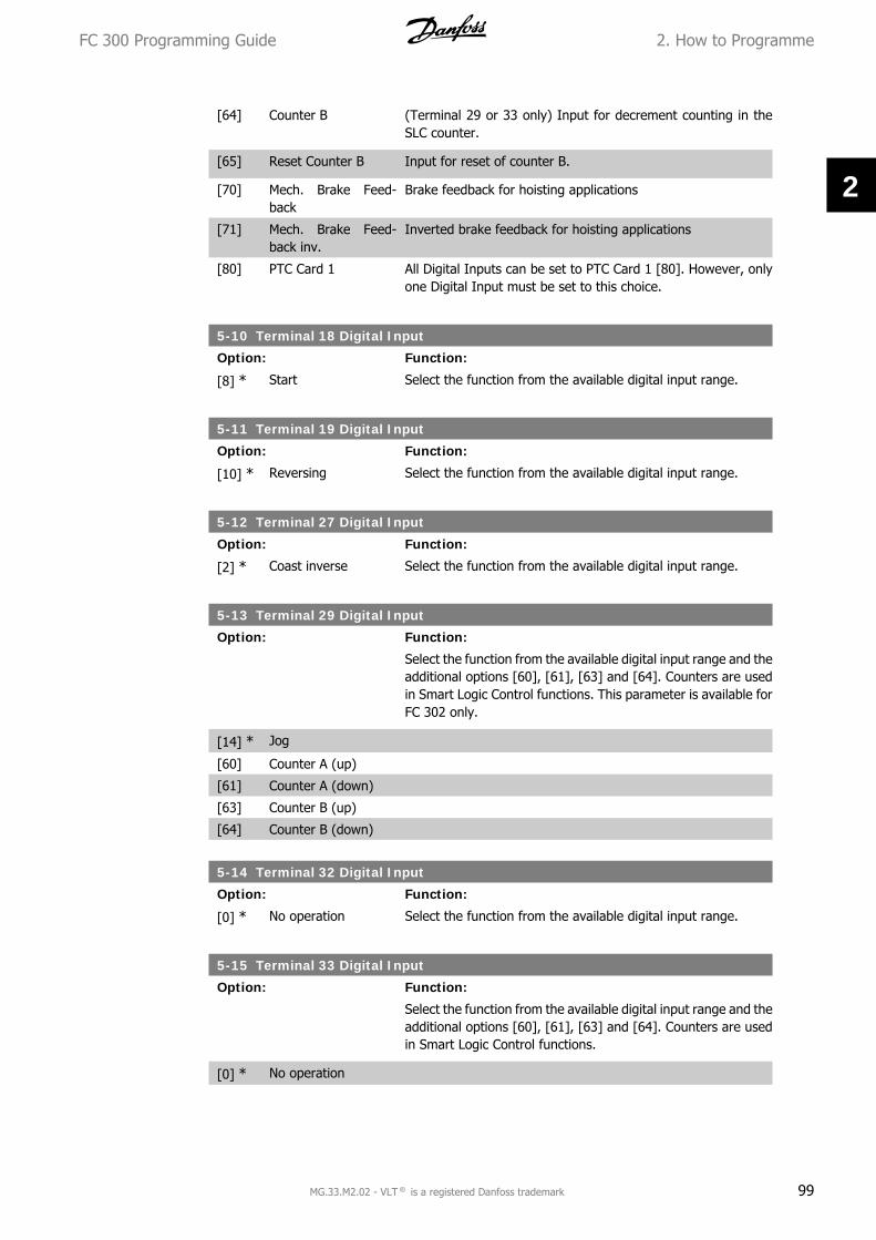
[64] Counter B (Terminal 29 or 33 only) Input for decrement counting in theSLC counter.
[65] Reset Counter B Input for reset of counter B.
[70] Mech. Brake Feed-back
Brake feedback for hoisting applications
[71] Mech. Brake Feed-back inv.
Inverted brake feedback for hoisting applications
[80] PTC Card 1 All Digital Inputs can be set to PTC Card 1 [80]. However, onlyone Digital Input must be set to this choice.
5-10 Terminal 18 Digital Input
Option: Function:
[8] * Start Select the function from the available digital input range.
5-11 Terminal 19 Digital Input
Option: Function:
[10] * Reversing Select the function from the available digital input range.
5-12 Terminal 27 Digital Input
Option: Function:
[2] * Coast inverse Select the function from the available digital input range.
5-13 Terminal 29 Digital Input
Option: Function:
Select the function from the available digital input range and theadditional options [60], [61], [63] and [64]. Counters are usedin Smart Logic Control functions. This parameter is available forFC 302 only.
[14] * Jog
[60] Counter A (up)
[61] Counter A (down)
[63] Counter B (up)
[64] Counter B (down)
5-14 Terminal 32 Digital Input
Option: Function:
[0] * No operation Select the function from the available digital input range.
5-15 Terminal 33 Digital Input
Option: Function:
Select the function from the available digital input range and theadditional options [60], [61], [63] and [64]. Counters are usedin Smart Logic Control functions.
[0] * No operation
FC 300 Programming Guide 2. How to Programme
MG.33.M2.02 - VLT ® is a registered Danfoss trademark 99
2

[60] Counter A (up)
[61] Counter A (down)
[63] Counter B (up)
[64] Counter B (down)
5-16 Terminal X30/3 Digital Input
Option: Function:
[0] * No operation This parameter is active when option module MCB 101 is instal-led in the frequency converter.Follow the function stated in 5-1*
5-17 Terminal X30/4 Digital Input
Option: Function:
[0] * No operation This parameter is active when option module MCB 101 is instal-led in the frequency converter.Follow the function stated in 5-1*
5-18 Terminal X30/4 Digital Input
Option: Function:
[0] * No operation This parameter is active when option module MCB 101 is instal-led in the frequency converter.Follow the function stated in 5-1*
5-19 Terminal 37 Safe Stop
Option: Function:
[1] * Safe Stop Alarm Coasts frequency converter when safe stop is activated. Manualreset from LCP, digital input or fieldbus.
[3] Safe Stop Auto Reset Coasts frequency converter when safe stop is activated (term37 off). When safe stop circuit is reestablished, the drive willcontinue without manual reset.
[4] PTC 1 Alarm Coasts frequency converter when safe stop is activated. Manualreset from LCP, digital input or fieldbus. Choice 4 is only avail-able when the MCB 112 PTC Thermistor Card is connected.
[5] PTC 1 Warning Coasts frequency converter when safe stop is activated (term37 off). When safe stop circuit is reestablished, the drive willcontinue without manual reset, unless a Digital Input set to PTCCard 1 [80] is still enabled. Choice 5 is only available when theMCB 112 PTC Thermistor Card is connected.
[6] PTC 1 & Relay A This choice is used when the PTC option is gated together witha Stop button through a Safety relay to T-37. Coasts frequencyconverter when safe stop is activated. Manual reset from LCP,digital input or fieldbus. Choice 6 is only available when the MCB112 PTC Thermistor Card is connected.
[7] PTC 1 & Relay W This choice is used when the PTC option is gated together witha Stop button through a Safety relay to T-37. Coasts frequencyconverter when safe stop is activated (term 37 off). When safestop circuit is reestablished, the drive will continue without man-
2. How to Programme FC 300 Programming Guide
100 MG.33.M2.02 - VLT ® is a registered Danfoss trademark
2

ual reset, unless a Digital Input set to PTC Card 1 [80] is (still)enabled. Choice 7 is only available when the MCB 112 PTC Ther-mistor Card is connected.
[8] PTC 1 & Relay A/W This choice makes it possible to use a combination of Alarm andWarning. Choice 8 is only available when the MCB 112 PTCThermistor Card is connected.
[9] PTC 1 & Relay W/A This choice makes it possible to use a combination of Alarm andWarning. Choice 9 is only available when the MCB 112 PTCThermistor Card is connected.
NB!When Auto Reset/ Warning is selected the drive opens up for automatic restart.
Overview of functions, alarms and warn-ings
Function No. PTC RelayNo Function [0] - -Safe Stop Alarm [1]* - Safe Stop [A68]Safe Stop Warning [3] - Safe Stop [W68]PTC 1 Alarm [4] PTC 1 Safe Stop [A71] -PTC 1 Warning [5] PTC 1 Safe Stop [W71] -PTC 1 & Relay A [6] PTC 1 Safe Stop [A71] Safe Stop [A68]PTC 1 & Relay W [7] PTC 1 Safe Stop [W71] Safe Stop [W68]PTC 1 & Relay A/W [8] PTC 1 Safe Stop [A71] Safe Stop [W68]PTC 1 & Relay W/A [9] PTC 1 Safe Stop [W71] Safe Stop [A68]
W means warning and A means alarm. For further information, see Alarms and Warnings in sectionTroubleshooting in the Design Guide or the Operating InstructionsA dangerous failure related to Safe Stop willgive Alarm: Dangerous Failure [A72].
2.8.4. 5-3* Digital Outputs
Parameters for configuring the output functions for the output terminals. The 2 solid-state digitaloutputs are common for terminals 27 and 29. Set the I/O function for terminal 27 in par. 5-01Terminal 27 Mode, and set the I/O function for terminal 29 in par. 5-02 Terminal 29 Mode. Theseparameters cannot be adjusted while the motor is running.
[0] No operation Default for all digital outputs and relay outputs
[1] Control ready The control board receives supply voltage.
[2] Drive ready The frequency converter is ready for operation and applies asupply signal on the control board.
[3] Drive ready / remotecontrol
The frequency converter is ready for operation and is in AutoOn mode.
[4] Enable / no warning Ready for operation. No start or stop command is been given(start/disable). There are no warnings.
[5] VLT running Motor is running.
FC 300 Programming Guide 2. How to Programme
MG.33.M2.02 - VLT ® is a registered Danfoss trademark 101
2

[6] Running / no warning Output speed is higher than the speed set in par. 1-81Min Speedfor Function at Stop [RPM]. The motor is running and there areno warnings.
[7] Run in range / nowarning
Motor is running within the programmed current and speedranges set in par. 4-50 to par. 4-53. There are no warnings.
[8] Run on reference / nowarning
Motor runs at reference speed.
[9] Alarm An alarm activates the output. There are no warnings.
[10] Alarm or warning An alarm or a warning activates the output.
[11] At torque limit The torque limit set in par. 4-16 or par. 1-17 has been exceeded.
[12] Out of current range The motor current is outside the range set in par. 4-18.
[13] Below current, low Motor current is lower than set in par. 4-50.
[14] Above current, high Motor current is higher than set in par. 4-51.
[15] Out of range Output frequency is outside the frequency range set in any limitparameter.
[16] Below speed, low Output speed is lower than the setting in par. 4-52.
[17] Above speed, high Output speed is higher than the setting in par. 4-53.
[18] Out of feedback range Feedback is outside the range set in par. 4-56 and 4-57.
[19] Below feedback low Feedback is below the limit set in par. 4-56 Warning FeedbackLow.
[20] Above feedback high Feedback is above the limit set in par. 4-57 Warning FeedbackHigh.
[21] Thermal warning The thermal warning turns on when the temperature exceedsthe limit in the motor, the frequency converter, the brake resis-tor, or the thermistor.
[22] Ready, no thermalwarning
Frequency converter is ready for operation and there is no over-temperature warning.
[23] Remote, ready, nothermal warning
Frequency converter is ready for operation and is in Auto Onmode. There is no over-temperature warning.
[24] Ready, no over-/ un-der voltage
Frequency converter is ready for operation and the mains volt-age is within the specified voltage range (see General Specifi-cations section).
[25] Reverse Reversing. Logic ‘1’ when CW rotation of the motor. Logic ‘0’when CCW rotation of the motor. If the motor is not rotating theoutput will follow the reference.
[26] Bus OK Active communication (no time-out) via the serial communica-tion port.
[27] Torque limit and stop Use in performing a coasting stop and in torque limit condition.If the frequency converter has received a stop signal and is atthe torque limit, the signal is Logic ‘0’.
[28] Brake, no brake warn-ing
Brake is active and there are no warnings.
2. How to Programme FC 300 Programming Guide
102 MG.33.M2.02 - VLT ® is a registered Danfoss trademark
2

[29] Brake ready, no fault Brake is ready for operation and there are no faults.
[30] Brake fault (IGBT) Output is Logic ‘1’ when the brake IGBT is short-circuited. Usethis function to protect the frequency converter if there is a faulton the brake modules. Use the output/relay to cut out the mainvoltage from the frequency converter.
[31] Relay 123 Relay is activated when Control Word [0] is selected in param-eter group 8-**.
[32] Mechanical brakecontrol
Enables control of an external mechanical brake, see descriptionin the section Control of Mechanical Brake, and par. group 2-2*
[33] Safe stop activated(FC 302 only)
Indicates that the safe stop on terminal 37 has been activated.
[40] Out of ref range
[41] Below reference low
[42] Above reference high
[45] Bus Ctrl
[46] Bus Ctrl On at timeout
[47] Bus Ctrl Off at timeout
[51] MCO controlled
[55] Pulse output
[60] Comparator 0 See par. group 13-1*. If Comparator 0 is evaluated as TRUE,the output will go high. Otherwise, it will be low.
[61] Comparator 1 See par. group 13-1*. If Comparator 1 is evaluated as TRUE,the output will go high. Otherwise, it will be low.
[62] Comparator 2 See par. group 13-1*. If Comparator 2 is evaluated as TRUE,the output will go high. Otherwise, it will be low.
[63] Comparator 3 See par. group 13-1*. If Comparator 3 is evaluated as TRUE,the output will go high. Otherwise, it will be low.
[64] Comparator 4 See par. group 13-1*. If Comparator 4 is evaluated as TRUE,the output will go high. Otherwise, it will be low.
[65] Comparator 5 See par. group 13-1*. If Comparator 5 is evaluated as TRUE,the output will go high. Otherwise, it will be low.
[70] Logic Rule 0 See par. group 13-4*. If Logic Rule 0 is evaluated as TRUE, theoutput will go high. Otherwise, it will be low.
[71] Logic Rule 1 See par. group 13-4*. If Logic Rule 1 is evaluated as TRUE, theoutput will go high. Otherwise, it will be low.
[72] Logic Rule 2 See par. group 13-4*. If Logic Rule 2 is evaluated as TRUE, theoutput will go high. Otherwise, it will be low.
[73] Logic Rule 3 See par. group 13-4*. If Logic Rule 3 is evaluated as TRUE, theoutput will go high. Otherwise, it will be low.
[74] Logic Rule 4 See par. group 13-4*. If Logic Rule 4 is evaluated as TRUE, theoutput will go high. Otherwise, it will be low.
[75] Logic Rule 5 See par. group 13-4*. If Logic Rule 5 is evaluated as TRUE, theoutput will go high. Otherwise, it will be low.
FC 300 Programming Guide 2. How to Programme
MG.33.M2.02 - VLT ® is a registered Danfoss trademark 103
2
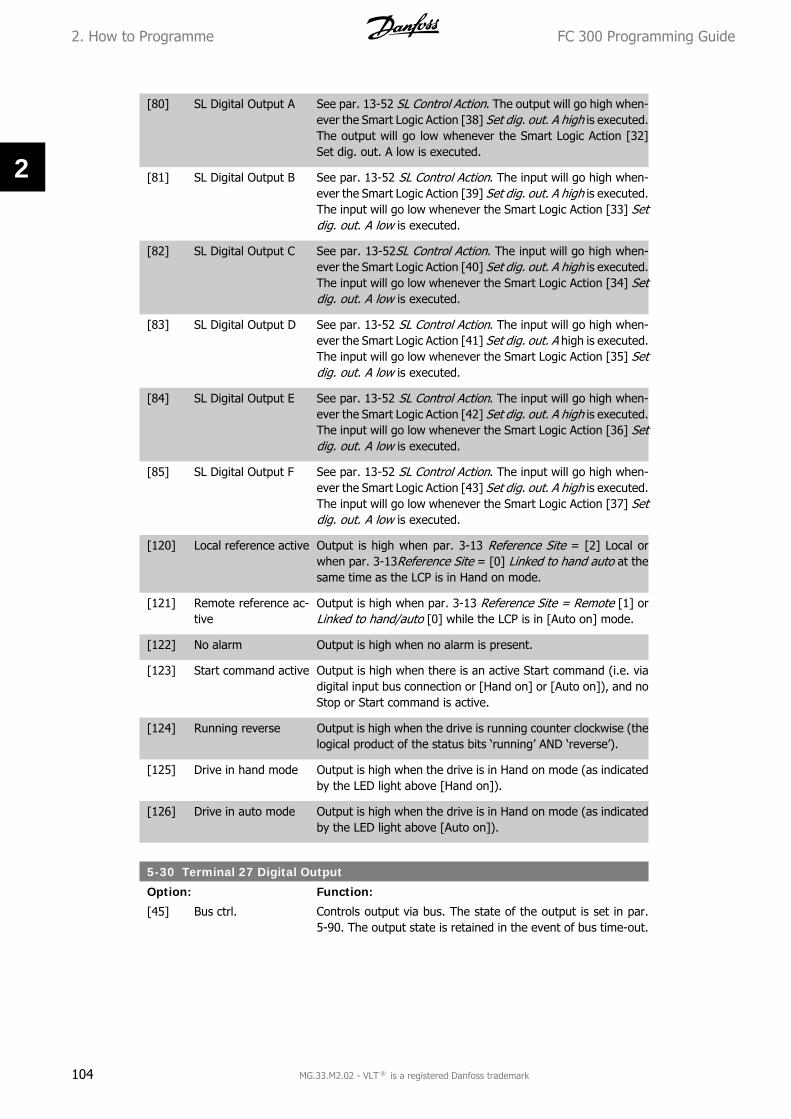
[80] SL Digital Output A See par. 13-52 SL Control Action. The output will go high when-ever the Smart Logic Action [38] Set dig. out. A high is executed.The output will go low whenever the Smart Logic Action [32]Set dig. out. A low is executed.
[81] SL Digital Output B See par. 13-52 SL Control Action. The input will go high when-ever the Smart Logic Action [39] Set dig. out. A high is executed.The input will go low whenever the Smart Logic Action [33] Setdig. out. A low is executed.
[82] SL Digital Output C See par. 13-52SL Control Action. The input will go high when-ever the Smart Logic Action [40] Set dig. out. A high is executed.The input will go low whenever the Smart Logic Action [34] Setdig. out. A low is executed.
[83] SL Digital Output D See par. 13-52 SL Control Action. The input will go high when-ever the Smart Logic Action [41] Set dig. out. A high is executed.The input will go low whenever the Smart Logic Action [35] Setdig. out. A low is executed.
[84] SL Digital Output E See par. 13-52 SL Control Action. The input will go high when-ever the Smart Logic Action [42] Set dig. out. A high is executed.The input will go low whenever the Smart Logic Action [36] Setdig. out. A low is executed.
[85] SL Digital Output F See par. 13-52 SL Control Action. The input will go high when-ever the Smart Logic Action [43] Set dig. out. A high is executed.The input will go low whenever the Smart Logic Action [37] Setdig. out. A low is executed.
[120] Local reference active Output is high when par. 3-13 Reference Site = [2] Local orwhen par. 3-13Reference Site = [0] Linked to hand auto at thesame time as the LCP is in Hand on mode.
[121] Remote reference ac-tive
Output is high when par. 3-13 Reference Site = Remote [1] orLinked to hand/auto [0] while the LCP is in [Auto on] mode.
[122] No alarm Output is high when no alarm is present.
[123] Start command active Output is high when there is an active Start command (i.e. viadigital input bus connection or [Hand on] or [Auto on]), and noStop or Start command is active.
[124] Running reverse Output is high when the drive is running counter clockwise (thelogical product of the status bits ‘running’ AND ‘reverse’).
[125] Drive in hand mode Output is high when the drive is in Hand on mode (as indicatedby the LED light above [Hand on]).
[126] Drive in auto mode Output is high when the drive is in Hand on mode (as indicatedby the LED light above [Auto on]).
5-30 Terminal 27 Digital Output
Option: Function:
[45] Bus ctrl. Controls output via bus. The state of the output is set in par.5-90. The output state is retained in the event of bus time-out.
2. How to Programme FC 300 Programming Guide
104 MG.33.M2.02 - VLT ® is a registered Danfoss trademark
2

[46] Bus ctrl. on at timeout Controls output via bus. The state of the output is set in par.5-90. In the event of bus time-out the output state is set high(On).
[47] Bus ctrl. off at timeout Controls output via bus. The state of the output is set in par.5-90. In the event of bus time-out the output state is set low(Off).
5-31 Terminal 29 Digital Output
Option: Function:
[45] Bus ctrl. Controls output via bus. The state of the output is set in par.5-90. The output state is retained in the event of bus time-out.
[46] Bus ctrl. on at timeout Controls output via bus. The state of the output is set in par.5-90. In the event of bus time-out the output state is set high(On).
[47] Bus ctrl. off at timeout Controls output via bus. The state of the output is set in par.5-90. In the event of bus time-out the output state is set low(Off).
This parameter only applies for FC 302.
5-32 Terminal X30/6 Digital Output (MCB 101)
Option: Function:
[0] * No operation This parameter is active when option module MCB 101 is moun-ted in the frequency converter.Follow the function stated in 5-3*.
5-33 Terminal X30/7 Digital Output (MCB 101)
Option: Function:
[0] * No operation This parameter is active when option module MCB 101 is moun-ted in the frequency converter.Follow the function stated in 5-3*.
2.8.5. 5-4* Relays
Parameters for configuring the timing and the output functions for the relays.
5-40 Function Relay
Option: Function:
Relay 2 is included in FC 302 only. Par. 5-40 functions are as forpar. 5-3*, including options 36 and 37.
Par. 5-40 options are as for par. 5-30, including options 36 and37. Relay 2 is included in FC 302 only. Relay 7, 8 and 9 areincluded in MCB 105 Relay option module.
[1] (Relay 1)
[2] (Relay 2)
[7] Relay 7
[8] Relay 8
FC 300 Programming Guide 2. How to Programme
MG.33.M2.02 - VLT ® is a registered Danfoss trademark 105
2

[9] Relay 9
[36] Control word bit 11
[37] Control word bit 12
5-41 On Delay, Relay
Array [8] (Relay 1 [0], Relay 2 [1], Relay 7 [6], Relay 8 [7], Relay 9[8])
0.01s* [0.01 - 600.00 s ] Enter the delay of the relay cut-in time. Select one of availablemechanical relays and MCO 105 in an array function. See par.5-40.
5-42 Off Delay, Relay
Array [8] (Relay 1 [0], Relay 2 [1], Relay 7 [6], Relay 8 [7], Relay 9[8])
0.01s* [0.01 - 600.00 s.] Enter the delay of the relay cut-out time. Select one of availablemechanical relays and MCO 105 in an array function. See par.5-40.
If the Selected Event condition changes before the on- or offdelay timer expires, the relay output is unaffected.
2. How to Programme FC 300 Programming Guide
106 MG.33.M2.02 - VLT ® is a registered Danfoss trademark
2

2.8.6. 5-5* Pulse Input
The pulse input parameters are used to define an appropriate window for the impulse referencearea by configuring the scaling and filter settings for the pulse inputs. Input terminals 29 or 33act as frequency reference inputs. Set terminal 29 (par. 5-13) or terminal 33 (par. 5-15) to Pulseinput [32]. If terminal 29 is used as an input, then set par. 5-01 to Input [0].
5-50 Term. 29 Low Frequency
Range: Function:
100 Hz* [0 - 110000 Hz] Enter the low frequency limit corresponding to the low motorshaft speed (i.e. low reference value) in par. 5-52. Refer to thediagram in this section.This parameter is available for FC 302 only.
5-51 Term. 29 High Frequency
Range: Function:
100 Hz [0 - 110000 Hz] Enter the high frequency limit corresponding to the high motorshaft speed (i.e. high reference value) in par. 5-53.This parameter is available for FC 302 only.
5-52 Term. 29 Low Ref./Feedb. Value
Range: Function:
0.000* [-1000000.000 - par.5-53]
Enter the low reference value limit for the motor shaft speed[RPM]. This is also the lowest feedback value, see also par. 5-57.Set terminal 29 to digital output (par. 5-02 =Output [1] and par.5-13 = applicable value).This parameter is available for FC 302 only.
5-53 Term. 29 High Ref./Feedb. Value
Range: Function:
1500.000*
[Par. 5-52 -1000000.000]
Enter the high reference value [RPM] for the motor shaft speedand the high feedback value, see also par.5-58. Select terminal29 as a digital output (par. 5-02 =Output [1] and par. 5-13 =applicable value).This parameter is available for FC 302 only.
FC 300 Programming Guide 2. How to Programme
MG.33.M2.02 - VLT ® is a registered Danfoss trademark 107
2

5-54 Pulse Filter Time Constant #29
Range: Function:
100 ms* [1 - 1000 ms] Enter the pulse filter time constant. The pulse filter dampensoscillations of the feedback signal, which is an advantage ifthere is a lot of noise in the system. A high time constant valueresults in better dampening but also increases the time delaythrough the filter. This parameter is available for FC 302 only.This parameter cannot be adjusted while the motor is running.
5-55 Term. 33 Low Frequency
Range: Function:
100Hz* [0 - 110000 Hz] Enter the low frequency corresponding to the low motor shaftspeed (i.e. low reference value) in par. 5-57. Refer to the dia-gram in this section.
5-56 Term. 33 High Frequency
Range: Function:
100Hz* [0 - 110000 Hz] Enter the high frequency corresponding to the high motor shaftspeed (i.e. high reference value) in par. 5-58.
5-57 Term. 33 Low Ref./Feedb. Value
Range: Function:
0.000 * [-100000.000 – par.5-58]
Enter the low reference value [RPM] for the motor shaft speed.This is also the low feedback value, see also par. 5-52.
5-58 Term. 33 High Ref./Feedb. Value
Range: Function:
1500.000*
[Par. 5-57 -100000.000]
Enter the high reference value [RPM] for the motor shaft speed.See also par. 5-53 Term. 29 High Ref./Feedb. Value.
5-59 Pulse Filter Time Constant #33
Range: Function:
100 ms [1 - 1000 ms] Enter the pulse filter time constant. The low-pass filter reducesthe influence on and dampens oscillations on the feedback sig-nal from the control.This is an advantage, e.g. if there is a great amount on noise inthe system. This parameter cannot be adjusted while the motoris running.
2.8.7. 5-6* Pulse Outputs
Parameters for configuring the scaling and output functions of pulse outputs. The pulse outputsare designated to terminals 27 or 29. Select terminal 27 output in par. 5-01 and terminal 29 outputin par. 5-02.
2. How to Programme FC 300 Programming Guide
108 MG.33.M2.02 - VLT ® is a registered Danfoss trademark
2
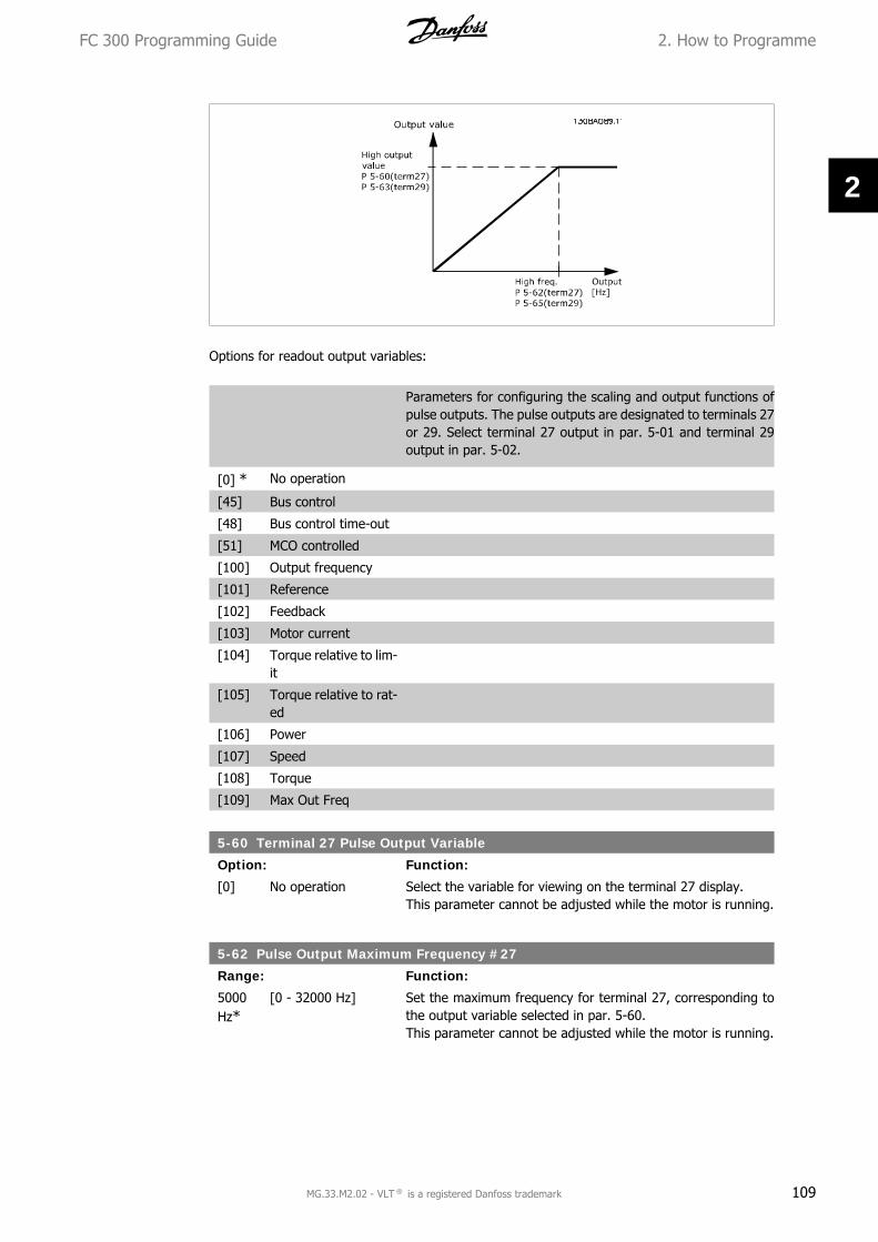
Options for readout output variables:
Parameters for configuring the scaling and output functions ofpulse outputs. The pulse outputs are designated to terminals 27or 29. Select terminal 27 output in par. 5-01 and terminal 29output in par. 5-02.
[0] * No operation
[45] Bus control
[48] Bus control time-out
[51] MCO controlled
[100] Output frequency
[101] Reference
[102] Feedback
[103] Motor current
[104] Torque relative to lim-it
[105] Torque relative to rat-ed
[106] Power
[107] Speed
[108] Torque
[109] Max Out Freq
5-60 Terminal 27 Pulse Output Variable
Option: Function:
[0] No operation Select the variable for viewing on the terminal 27 display.This parameter cannot be adjusted while the motor is running.
5-62 Pulse Output Maximum Frequency #27
Range: Function:
5000Hz*
[0 - 32000 Hz] Set the maximum frequency for terminal 27, corresponding tothe output variable selected in par. 5-60.This parameter cannot be adjusted while the motor is running.
FC 300 Programming Guide 2. How to Programme
MG.33.M2.02 - VLT ® is a registered Danfoss trademark 109
2

5-63 Terminal 29 Pulse Output Variable
Option: Function:
[0] * No operation Select the variable for viewing on the terminal 29 display. Thisparameter is available for FC 302 only.This parameter cannot be adjusted while the motor is running.
5-65 Pulse Output Maximum Frequency #29
Option: Function:
[5000Hz] *
0 - 32000 Hz Set the maximum frequency for terminal 29 corresponding tothe output variable set in par. 5-63.This parameter cannot be adjusted while the motor is running.
5-66 Terminal X30/6 Pulse Output Variable
Option: Function:
[0] * No operation Select the variable for read-out on terminal X30/6. This param-eter cannot be adjusted while the motor is running.This parameter is active when option module MCB 101 is instal-led in the frequency converter.
5-68 Pulse Output Maximum Frequency #X30/6
Range: Function:
5000Hz*
[0 - 32000 Hz] Select the maximum frequency on terminal X30/6 referring tothe output variable in par. 5-66. This parameter cannot be ad-justed while the motor is running.This parameter is active when option module MCB 101 is moun-ted in the frequency converter.
2.8.8. 5-7* 24 V Encoder Input
Parameters for configuring the 24 V encoder.Connect the 24 V encoder to terminal 12 (24 V DC supply), terminal 32 (Channel A), terminal 33(Channel B), and terminal 20 (GND). The digital inputs 32/33 are active for encoder inputs when24 V encoder is selected in par. 1-02 and par. 7-00. The encoder used is a dual channel (A andB) 24 V type. Max input frequency: 110 kHz.
2. How to Programme FC 300 Programming Guide
110 MG.33.M2.02 - VLT ® is a registered Danfoss trademark
2

5-70 Term 32/33 Pulses per Revolution
Range: Function:
1024PPR*
[128 - 4096 PPR] Set the encoder pulses per revolution on the motor shaft. Readthe correct value from the encoder.This parameter cannot be adjusted while the motor is running.
5-71 Term 32/33 Encoder Direction
Option: Function:
Change the detected encoder rotation direction without chang-ing the wiring to the encoder.
[0] * Clockwise Sets channel A 90° (electrical degrees) behind channel B uponclockwise rotation of the encoder shaft.
[1] Counter clockwise Sets channel A 90° (electrical degrees) ahead of channel B uponclockwise rotation of the encoder shaft.
This parameter cannot be adjusted while the motor is running.
2.8.9. 5-9* Bus Controlled
This parameter group selects digital and relay outputs via a fieldbus setting.
5-90 Digital & Relay Bus Control
Option: Function:
[0] * 0 - FFFFFFFF This parameter holds the state of the digital outputs and relaysthat is controlled by bus.A logical '1' indicates that the output is high or active.A logical '0' indicates that the output is low or inactive.
FC 300 Programming Guide 2. How to Programme
MG.33.M2.02 - VLT ® is a registered Danfoss trademark 111
2

Bit 0 Digital Output Terminal 27Bit 1 Digital Output Terminal 29Bit 2 Digital Output Terminal X 30/6Bit 3 Digital Output Terminal X 30/7Bit 4 Relay 1 output terminalBit 5 Relay 2 output terminalBit 6 Option B Relay 1 output terminalBit 7 Option B Relay 2 output terminalBit 8 Option B Relay 3 output terminalBit 9-15 Reserved for future terminalsBit 16 Option C Relay 1 output terminalBit 17 Option C Relay 2 output terminalBit 18 Option C Relay 3 output terminalBit 19 Option C Relay 4 output terminalBit 20 Option C Relay 5 output terminalBit 21 Option C Relay 6 output terminalBit 22 Option C Relay 7 output terminalBit 23 Option C Relay 8 output terminalBit 24-31 Reserved for future terminals
5-93 Pulse Output #27 Bus Control
Range: Function:
0%* [0.00 - 100.00%] Set the output frequency transferred to the output terminal 27when the terminal is configured as 'Bus Controlled' in par. 5-60[45].
5-94 Pulse Output #27 Time-out Preset
Range: Function:
0.00%* [0.00 - 100.00%] Set the output frequency transferred to the output terminal 27when the terminal is configured as 'Bus Ctrl Timeout' in par.5-60 [48]. And a time-out is detected.
5-95 Pulse Output #29 Bus Control
Range: Function:
0%* [0.00 - 100.00%] Set the output frequency transferred to the output terminal 29when the terminal is configured as 'Bus Controlled' in par. 5-60[45].This parameter only applies for FC 302.
5-96 Pulse Output #29 Time-out Preset
Range: Function:
0.00%* [0.00 - 100.00%] Set the output frequency transferred to the output terminal 29when the terminal is configured as 'Bus Ctrl Timeout' in par.5-60 [48]. And a time-out is detected.This parameter only applies for FC 302.
2.9. Parameters: Analog In/Out
2.9.1. 6-** Analog In/Out
Parameter group for configuration of the analog input and output.
2. How to Programme FC 300 Programming Guide
112 MG.33.M2.02 - VLT ® is a registered Danfoss trademark
2

2.9.2. 6-0* Analog I/O Mode
The analog inputs can freely be allocated to be either voltage (FC 301: 0..10 V, FC 302: 0..+/-10V) or current (FC 301/302: 0/4..20 mA) input.
NB!Thermistors may be connected to either an analog or a digital input.
6-00 Live Zero Timeout Time
Range: Function:
10s* [1 - 99 s] Enter the Live Zero Time-out time period. Live Zero Time-outTime is active for analog inputs, i.e. terminal 53 or terminal 54,allocated to current and used as reference or feedback sources.If the reference signal value associated with the selected currentinput falls below 50% of the value set in par. 6-10, par. 6-12,par. 6-20 or par. 6-22 for a time period longer than the time setin par. 6-00, the function selected in par. 6-01 will be activated.
6-01 Live Zero Timeout Function
Option: Function:
Select the time-out function. The function set in par. 6-01 willbe activated if the input signal on terminal 53 or 54 is below50% of the value in par. 6-10, par. 6-12, par. 6-20 or par. 6-22for a time period defined in par. 6-00. If several time-outs occursimultaneously, the frequency converter prioritises the time-outfunctions as follows:
1. Par. 6-01 Live Zero Time-out Function
2. Par. 5-74 Encoder Loss Function
3. Par. 8-04 Control-word Time-out FunctionThe output frequency of the frequency converter canbe:
The output frequency of the frequency converter can be:• [1] frozen at the present value
• [2] overruled to stop
• [3] overruled to jog speed
• [4] overruled to max. speed
• [5] overruled to stop with subsequent trip
[0] * Off
[1] Freeze Output
[2] Stop
[3] Jogging
[4] Max. speed
[5] Stop and trip
FC 300 Programming Guide 2. How to Programme
MG.33.M2.02 - VLT ® is a registered Danfoss trademark 113
2

2.9.3. 6-1* Analog Input 1
Parameters for configuring the scaling and limits for analog input 1 (terminal 53).
6-10 Terminal 53 Low Voltage
Range: Function:
0.07 V* [FC 301: 0V - par.6-11][FC 302: -10V - par.6-11]
Enter the low voltage value. This analog input scaling valueshould correspond to the minimum reference value, set in par.6-14. See also the section Reference Handling.
6-11 Terminal 53 High Voltage
Range: Function:
10.0V* [Par. 6-10 to 10.0 V] Enter the high voltage value. This analog input scaling valueshould correspond to the high reference/feedback value set inpar. 6-15.
6-12 Terminal 53 Low Current
Range: Function:
0.14mA*
[0.0 to par. 6-13 mA] Enter the low current value. This reference signal should corre-spond to the minimum reference value, set in par. 3-02. Thevalue must be set at >2 mA in order to activate the Live ZeroTime-out Function in par. 6-01.
6-13 Terminal 53 High Current
Range: Function:
20.0mA*
[ Par. 6-12 to - 20.0mA]
Enter the high current value corresponding to the high refer-ence/feedback set in par. 6-15.
6-14 Terminal 53 Low Ref./Feedb. Value
Range: Function:
0.000Unit*
[-1000000.000 to par.6-15]
Enter the analog input scaling value that corresponds to the lowvoltage/low current set in par. 6-10 and 6-12.
2. How to Programme FC 300 Programming Guide
114 MG.33.M2.02 - VLT ® is a registered Danfoss trademark
2

6-15 Terminal 53 High Ref./Feedb. Value
Range: Function:
1500.000 Unit*
[Par. 6-14 to1000000.000]
Enter the analog input scaling value that corresponds to themaximum reference feedback value set in par. 6-11 and 6-13.
6-16 Terminal 53 Filter Time Constant
Range: Function:
0.001s* [0.001 - 10.000 s] Enter the time constant. This is a first-order digital low pass filtertime constant for suppressing electrical noise in terminal 53. Ahigh time constant value improves dampening but also increa-ses the time delay through the filter.This parameter cannot be adjusted while the motor is running.
2.9.4. 6-2* Analog Input 2
Parameters for configuring the scaling and limits for analog input 2 (terminal 54).
6-20 Terminal 54 Low Voltage
Range: Function:
0.07 V* [FC 301: 0V - par.6-11][FC 302: -10V - par.6-11]
Enter the low voltage value. This analog input scaling valueshould correspond to the minimum reference value, set in par.3-02. See also the section Reference Handling.
6-21 Terminal 54 High Voltage
Range: Function:
10.0V* [Par. 6-20 to 10.0 V] Enter the high voltage value. This analog input scaling valueshould correspond to the high reference/feedback value set inpar. 6-25.
6-22 Terminal 54 Low Current
Range: Function:
0.14mA*
[0.0 to par. 6-23 mA] Enter the low current value. This reference signal should corre-spond to the minimum reference value, set in par. 3-02. Thevalue must be set at >2 mA in order to activate the Live ZeroTime-out Function in par. 6-01.
6-23 Terminal 54 High Current
Range: Function:
20.0mA*
[Par. 6-22 to - 20.0mA]
Enter the high current value corresponding to the high refer-ence/feedback value set in par. 6-25.
6-24 Terminal 54 Low Ref./Feedb. Value
Range: Function:
0.000Unit*
[-1000000.000 to par.6-25]
Enter the analog input scaling value that corresponds to theminimum reference feedback value set in par. 3-02.
FC 300 Programming Guide 2. How to Programme
MG.33.M2.02 - VLT ® is a registered Danfoss trademark 115
2

6-25 Terminal 54 high ref./feedb. value
Range: Function:
1500.000 Unit*
[Par. 6-24 to1000000.000]
Enter the analog input scaling value that corresponds to themaximum reference feedback value set in par. 3-03.
6-26 Terminal 54 Filter Time Constant
Range: Function:
0.001s* [0.001 - 10.000 s] Enter the time constant. This is a first-order digital low pass filtertime constant for suppressing electrical noise in terminal 54. Ahigh time constant value improves dampening but also increa-ses the time delay through the filter.This parameter cannot be adjusted while the motor is running.
2.9.5. 6-3* Analog Input 3 (MCB 101)
Parameter group for configuring the scale and limits for analog input 3 (X30/11) placed on optionmodule MCB 101.
6-30 Term. X30/11 Low Voltage
Range: Function:
0.07 V* [0 - par. 6-31] Sets the analog input scaling value to correspond to the lowreference/feedback value (set in par. 6-34).
6-31 Term. X30/11 High Voltage
Range: Function:
10.0 V* [Par. 6-30 to 10.0 V] Sets the analog input scaling value to correspond to the highreference/feedback value (set in par. 6-35).
6-34 Term. X30/11 Low Ref./Feedb. Value
Range: Function:
0.000Unit*
[1000000.000 to par.6-35]
Sets the analog input scaling value to correspond to the lowvoltage value (set in par. 6-30).
6-35 Term. X30/11 High Ref./Feedb. Value
Range: Function:
1500.000 Unit
[Par. 6-34 to1000000.000]
Sets the analog input scaling value to correspond to the highvoltage value (set in par. 6-31).
6-36 Term. X30/11 Filter Time Constant
Range: Function:
0.001s* [0.001 - 10.000 s] A 1st order digital low pass filter time constant for suppressingelectrical noise on terminal X30/11.Par. 6-36 cannot be changed while the motor is running.
2. How to Programme FC 300 Programming Guide
116 MG.33.M2.02 - VLT ® is a registered Danfoss trademark
2

2.9.6. 6-4* Analog Input 4 (MCB 101)
Parameter group for configuring the scale and limits for analog input 4 (X30/12) placed on optionmodule MCB 101.
6-40 Term. X30/12 Low Voltage
Range: Function:
0.7 V* [0 to par. 6-41] Sets the analog input scaling value to correspond to the lowreference/feedback value set in par. 6-44.
6-41 Term. X30/12 High Voltage
Range: Function:
10.0V* [Par. 6-40 to 10.0 V] Sets the analog input scaling value to correspond to the highreference/feedback value set in par. 6-45.
6-44 Term. X30/12 Low Ref./Feedb. Value
Range: Function:
0.000Unit*
[-1000000.000 to par.6-45]
Sets the analog input scaling value to correspond to the lowvoltage value set in par. 6-44.
6-45 Term. X30/12 High Ref./Feedb. Value
Range: Function:
1500.000 Unit*
[Par. 6-44 to1000000.000]
Sets the analog input scaling value to correspond to the highvoltage value set in par. 6-41.
6-46 Term. X30/12 Filter Time Constant
Range: Function:
0.001s* [0.001 - 10.000 s] A 1st order digital low pass filter time constant for suppressingelectrical noise on terminal X30/12.Par. 6-46 cannot be changed while the motor is running.
2.9.7. 6-5* Analog Output 1
Parameters for configuring the scaling and limits for analog output 1, i.e. Terminal 42. Analogoutputs are current outputs: 0/4 – 20 mA. Common terminal (terminal 39) is the same terminaland has the same electrical potential for analog common and digital common connection. Reso-lution on analog output is 12 bit.
6-50 Terminal 42 Output
Option: Function:
Select the function of Terminal 42 as an analog current output.
[0] No operation
[52] MCO 305 0-20 mA
[53] MCO 305 4-20 mA
[100] Output frequency
[101] Reference
[102] Feedback
FC 300 Programming Guide 2. How to Programme
MG.33.M2.02 - VLT ® is a registered Danfoss trademark 117
2

[103] Motor current
[104] Torque rel to lim
[105] Torque rel to rated
[106] Power
[107] Speed
[108] Torque
[109] Max Out Freq 0-20mA
[130] Output freq. 4-20 mA
[131] Reference 4-20 mA
[132] Feedback 4-20 mA
[133] Motor cur. 4-20 mA
[134] Torque % lim. 4-20mA
[135] Torque % nom 4-20mA
[136] Power 4-20 mA
[137] Speed 4-20 mA
[138] Torque 4-20 mA
[139] Bus ctrl. 0-20 mA
[140] Bus ctrl. 4-20 mA
[141] Bus ctrl. 0-20 mA,timeout
[142] Bus ctrl. 4-20 mA,timeout
[150] Max Out Freq 4-20mA
6-51 Terminal 42 Output Min Scale
Range: Function:
0%* [0 – 200%] Scale the minimum output of the selected analog signal at ter-minal 42, as a percentage of the maximum signal value. E.g. if0 mA (or 0 Hz) is desired at 25% of the maximum output value,then programme 25%. Scaling values up to 100% can never behigher than the corresponding setting in par. 6-52.
2. How to Programme FC 300 Programming Guide
118 MG.33.M2.02 - VLT ® is a registered Danfoss trademark
2

6-52 Terminal 42 Output Max Scale
Range: Function:
100 %* [000 – 200%] Scale the maximum output of the selected analog signal at ter-minal 42. Set the value to the maximum value of the currentsignal output. Scale the output to give a current lower than 20mA at full scale; or 20 mA at an output below 100% of themaximum signal value. If 20 mA is the desired output currentat a value between 0 - 100% of the full-scale output, pro-gramme the percentage value in the parameter, i.e. 50% = 20mA. If a current between 4 and 20 mA is desired at maximumoutput (100%), calculate the percentage value as follows:
20 mA / desired maximum current x 100 %i.e. 10 mA : 2010 x 100 = 200 %
6-53 Terminal 42 Output Bus Control
Range: Function:
0.00%* [0.00 – 100.00 %] Holds the level of Output 42 if controlled by bus.
6-54 Terminal 42 Output Timeout Preset
Range: Function:
0.00%* [0.00 – 100.00 %] Holds the preset level of Output 42.In case of a bus timeout and a timeout function is selected inpar. 6-50 the output will preset to this level.
2.9.8. 6-6* Analog Output 2 (MCB 101)
Analog outputs are current outputs: 0/4 - 20 mA. Common terminal (terminal X30/7) is the sameterminal and electrical potential for analog common connection. Resolution on analog output is12 bit.
6-60 Terminal X30/8 Output
Option: Function:
[0] No operation
[100] Output frequency (0 .1000 Hz), 0.20 mA
[101] Output frequency (0 .1000 Hz), 4.20 mAReference (Refmin-max),0.20 mA
FC 300 Programming Guide 2. How to Programme
MG.33.M2.02 - VLT ® is a registered Danfoss trademark 119
2

[102] Reference (Ref min-max), 4.20 mAFeedback (FB min-max)0.20 mA
[103] Feedback (FB min-max) 4.20 mAMotor current (0-Im-ax) 0.20 mA
[104] Motor current (0-Im-ax) 4.20 mATorque relative to lim-it0-Tlim,0.20 mA
[105] Torque relative to lim-it 0-Tlim, 4.20 mATorque relativetora-ted0-Tnom,0.20 mA
[106] Torque relative to rat-ed 0-Tnom, 4.20 mAPower (0-Pnom),0.20mA
[107] Power (0-Pnom), 4.20mASpeed (0-Speedmax),0.20 mA
[108] Speed (0-Speedmax),4.20 mATorque (+/-160%torque), 0-20 mA
[130] Torque (+/-160%torque), 4-20 mAOutput freq. 4-20 mA
[131] Reference 4-20 mA
[132] Feedback 4-20 mA
[133] Motor cur. 4-20 mA
[134] Torque % lim. 4-20mA
[135] Torque % nom 4-20mA
[136] Power 4-20 mA
[137] Speed 4-20 mA
[138] Torque 4-20 mA
[139] Bus Ctrl 0-20 mA
[140] Bus Ctrl 4-20 mA
[141] Bus Ctrl 0-20 mA,Timeout
[142] Bus Ctrl 4-20 mA,Timeout
[150] Max Out Freq 4-20mA
2. How to Programme FC 300 Programming Guide
120 MG.33.M2.02 - VLT ® is a registered Danfoss trademark
2

6-61 Term. X30/8 Output Min Scale
Range: Function:
0%* [0.00 - 200 %] Scales the minimum output of the selected analog signal on ter-minal X30/8. Scale the minimum value as a percentage of themaximum signal value, i.e. 0 mA (or 0 Hz) is desired at 25% ofthe maximum output value and 25% is programmed. The valuecan never be higher than the corresponding setting in par. 6-62if value is below 100%.This parameter is active when option module MCB 101 is moun-ted in the frequency converter.
6-62 Term. X30/8 Output Max Scale
Range: Function:
100%* [0.00 - 200 %] Scales the maximum output of the selected analog signal onterminal X30/8. Scale the value to the desired maximum valueof the current signal output. Scale the output to give a lowercurrent than 20 mA at full scale or 20 mA at an output below100% of the maximum signal value. If 20 mA is the desiredoutput current at a value between 0 - 100% of the ful-scaleoutput, program the percentage value in the parameter, i.e.50% = 20 mA. If a current between 4 and 20 mA is desired atmaximum output (100%), calculate the percentage value asfollows:
20 mA / desired maximum current x 100 %i.e. 10 mA : 2010 x 100 = 200 %
2.10. Parameters: Controllers
2.10.1. 7-** Controllers
Parameter group for configuring application controls.
2.10.2. 7-0* Speed PID Ctrl.
Parameters for configuring the speed PID control.
7-00 Speed PID Feedback Source
Option: Function:
Select the encoder for closed loop feedback.The feedback may come from a different encoder (typicallymounted on the application itself) than the motor mounted en-coder feedback selected in par. 1-02.This parameter cannot be adjusted while the motor is running.
[0] Motor feedb. p.1-02(FC 302 only)
[1] 24V encoder
[2] MCB 102
[3] MCB 103
[4] MCO encoder 1
FC 300 Programming Guide 2. How to Programme
MG.33.M2.02 - VLT ® is a registered Danfoss trademark 121
2

[5] MCO encoder 2
NB!If separate encoders are used (FC 302 only) the ramp settings parameters in thefollowing groups: 3-4*, 3-5*, 3-6*, 3-7* and 3-8* must be adjusted according tothe gear ratio between the two encoders.
7-02 ProportionalGain
Range: Function:
Size re-lated
[0.000 - 1.000] Enter the speed controller proportional gain. The proportionalgain amplifies the error (i.e. the deviation between the feedbacksignal and the set-point). This parameter is used with par. 1-00Speed open loop [0] and Speed closed loop [1] control. Quickcontrol is obtained at high amplification. However if the ampli-fication is too great, the process may become unstable.
7-03 Speed PID Integral Time
Range: Function:
8.0 ms* [2.0 - 20000.0 ms] Enter the speed controller integral time, which determines thetime the internal PID control takes to correct errors. The greaterthe error, the more quickly the gain increases. The integral timecauses a delay of the signal and therefore a dampening effect,and can be used to eliminate steady state speed error. Obtainquick control through a short integral time, though if the integraltime is too short, the process becomes unstable. An excessivelylong integral time disables the integral action, leading to majordeviations from the required reference, since the process reg-ulator takes too long to regulate errors. This parameter is usedwith Speed open loop [0] and Speed closed loop [1] control, setin par. 1-00 Configuration Mode.
7-04 Speed PID Differentiation Time
Range: Function:
30.0 ms [0.0 - 200.0 ms] Enter the speed controller differentiation time. The differentia-tor does not react to constant error. It provides gain propor-tional to the rate of change of the speed feedback. The quickerthe error changes, the stronger the gain from the differentiator.The gain is proportional with the speed at which errors change.Setting this parameter to zero disables the differentiator. Thisparameter is used with par. 1-00 Speed closed loop [1] control.
7-05 Speed PID Diff Gain Limit
Range: Function:
5.000* [1.0 - 20.0] Set a limit for the gain provided by the differentiator. Since thedifferential gain increases at higher frequencies, limiting thegain may be useful. For example, set up a pure D-link at lowfrequencies and a constant D-link at higher frequencies. Thisparameter is used with par. 1-00 Speed closed loop [1] control.
2. How to Programme FC 300 Programming Guide
122 MG.33.M2.02 - VLT ® is a registered Danfoss trademark
2

7-06 Speed PID Lowpass Filter Time
Range: Function:
10.0ms*
[1.0 - 100.0 ms] Set a time constant for the speed control low-pass filter. Thelow-pass filter improves steady-state performance and damp-ens oscillations on the feedback signal. This is an advantage ifthere is a great amount on noise in the system, see illustrationbelow. For example, if a time constant (τ) of 100 ms is pro-grammed, the cut-off frequency for the low-pass filter will be1/0.1= 10 RAD/sec., corresponding to (10/2 x p) = 1.6 Hz. ThePID regulator only regulates a feedback signal that varies by afrequency of less than 1.6 Hz. If the feedback signal varies bya higher frequency than 1.6 Hz, the PID regulator does not re-act.Note that severe filtering can be detrimental to dynamic per-formance.This parameter is used with par. 1-00 Speed closed loop [1] andTorque [2] control.
7-08 Speed PID Feed Forward Factor
Range: Function:
0%* [0 - 500%] The reference signal bypasses the speed controller by theamount specified. This feature increases the dynamic perform-ance of the speed control loop.
2.10.3. 7-2* Process Ctrl. Feedb.
Select the feedback sources for the Process PID Control, and how this feedback should be handled.
7-20 Process CL Feedback 1 Source
Option: Function:
The effective feedback signal is made up of the sum of up totwo different input signals.Select which frequency converter input should be treated as thesource of the first of these signals. The second input signal isdefined in par. 7-22.
FC 300 Programming Guide 2. How to Programme
MG.33.M2.02 - VLT ® is a registered Danfoss trademark 123
2

[0] * No function
[1] Analog input 53
[2] Analog input 54
[3] Frequency input 29(FC 302 only)
[4] Frequency input 33
[5] Bus feedback 1
[6] Bus feedback 2
[7] Analog input X30/11
[8] Analog input X30/12
7-22 Process CL Feedback 2 Source
Option: Function:
The effective feedback signal is made up of the sum of up totwo different input signals. Select which frequency converterinput should be treated as the source of the second of thesesignals. The first input signal is defined in par. 7-21.
[0] * No function
[1] Analog input 53
[2] Analog input 54
[3] Frequency input 29(FC 302 only)
[4] Frequency input 33
[5] Bus feedback 1
[6] Bus feedback 2
[7] Analog input X30/11
[8] Analog input X30/12
2.10.4. 7-3* Process PID Ctrl.
Parameters for configuring the Process PID control.
7-30 Process PID Normal/ Inverse Control
Option: Function:
Normal and inverse control are implemented by introducing adifference between the reference signal and the feedback sig-nal.
[0] * Normal Sets process control to increase the output frequency.
[1] Inverse Sets process control to reduce the output frequency.
7-31 Process PID Anti Windup
Option: Function:
[0] * Off Ceases regulation of an error when the output frequency can nolonger be adjusted.
[1] On Continues regulation of an error even when the output frequen-cy cannot be increased or decreased.
2. How to Programme FC 300 Programming Guide
124 MG.33.M2.02 - VLT ® is a registered Danfoss trademark
2

7-32 Process PID Start Speed
Range: Function:
0 RPM* [0 - 6000 RPM] Enter the motor speed to be attained as a start signal for com-mencement of PID control. When the power is switched on, thefrequency converter will commence ramping and then operateunder speed open loop control. Thereafter, when the ProcessPID start speed is reached, the frequency converter will changeover to Process PID control.
7-33 Process PID Proportional Gain
Range: Function:
0.01 N/A*
[0.00 - 10.00 N/A] Enter the PID proportional gain. The proportional gain multipliesthe error between the set point and the feedback signal.
7-34 Process PID Integral Time
Range: Function:
10000.00 s*
[0.01 - 10000.00] Enter the PID integral time. The integrator provides an increas-ing gain at a constant error between the set point and thefeedback signal. The integral time is the time needed by theintegrator to reach the same gain as the proportional gain.
7-35 Process PID Differentiation Time
Range: Function:
0.00 s* [0.00 - 10.00 s] Enter the PID differentiation time. The differentiator does notreact to a constant error, but provides a gain only when the errorchanges. The shorter the PID differentiation time, the strongerthe gain from the differentiator.
7-36 Process PID Diff. Gain Limit
Range: Function:
5.0 N/A*
[1.0 - 50.0 N/A] Enter a limit for the differentiator gain (DG). If there is no limit,the DG will increase when there are fast changes. Limit the DGto obtain a pure differentiator gain at slow changes and a con-stant differentiator gain where fast changes occur.
7-38 Process PID Feed Forward Factor
Range: Function:
0%* [0 - 500%] Enter the PID feed forward (FF) factor. The FF factor sends aconstant fraction of the reference signal to bypass the PID con-trol, so the PID control only affects the remaining fraction of thecontrol signal. Any change to this parameter will thus affect themotor speed. When the FF factor is activated it provides lessovershoot, and high dynamics when changing the set point. Par.7-38 is active when par. 1-00 Configuration Mode is set to [3]Process.
FC 300 Programming Guide 2. How to Programme
MG.33.M2.02 - VLT ® is a registered Danfoss trademark 125
2
7-39 On Reference Bandwidth
Range: Function:
5%* [0 - 200%] Enter the On Reference bandwidth. When the PID Control Error(the difference between the reference and the feedback) is lessthan the set value of this parameter the On Reference status bitis high, i.e. =1.
2. How to Programme FC 300 Programming Guide
126 MG.33.M2.02 - VLT ® is a registered Danfoss trademark
2

2.11. Parameters: Communications and Options
2.11.1. 8-** Comm. and Options
Parameter group for configuring communications and options.
2.11.2. 8-0* General Settings
General settings for communications and options.
8-01 Control Site
Option: Function:
[0] * Digital and ctrl. word Control by using both digital input and control word.
[1] Digital only Control by using digital inputs only.
[2] Control word only Control by using control word only.
The setting in this parameter overrides the settings in par. 8-50to 8-56.
8-02 Control Word Source
Option: Function:
[0] None
[1] FC RS485
[2] FC USB
[3] Option A
[4] Option B
[5] Option C0
[6] Option C1
[30] External Can Select the source of the control word: one of two serial interfa-ces or four installed options. During initial power-up, the fre-quency converter automatically sets this parameter to OptionA [3] if it detects a valid fieldbus option installed in slot A. If theoption is removed, the frequency converter detects a change inthe configuration, sets par. 8-02 back to default setting FCRS485, and the frequency converter then trips. If an option isinstalled after initial power-up, the setting of par. 8-02 will notchange but the frequency converter will trip and display: Alarm67 Option Changed.This parameter cannot be adjusted while the motor is running.
8-03 Control Word Timeout Time
Range: Function:
1.0s* [0.1 - 18000.0 s] Enter the maximum time expected to pass between the recep-tion of two consecutive telegrams. If this time is exceeded, itindicates that the serial communication has stopped. The func-tion selected in par. 8-04 Control Word Time-out Function will
FC 300 Programming Guide 2. How to Programme
MG.33.M2.02 - VLT ® is a registered Danfoss trademark 127
2

then be carried out. The time-out counter is triggered by a validcontrol word.
8-04 Control Word Timeout Function
Option: Function:
[0] * Off
[1] Freeze Output
[2] Stop
[3] Jogging
[4] Max. Speed
[5] Stop and trip
[7] Select set-up 1
[8] Select set-up 2
[9] Select set-up 3
[10] Select set-up 4 Select the time-out function. The time-out function activateswhen the control word fails to be updated within the time periodspecified in par. 8-03 Control Word Time-out Time.
- Off [0]: Resume control via serial bus (Fieldbus orstandard) using the most recent control word.
- Freeze output [1]: Freeze output frequency until com-munication resumes.
- Stop [2]: Stop with auto restart when communicationresumes.
- Jogging [3]: Run the motor at JOG frequency untilcommunication resumes.
- Max. freq. [4]: Run the motor at maximum frequencyuntil communication resumes.
- Stop and trip [5]: Stop the motor, then reset the fre-quency converter in order to restart: via the fieldbus,via the reset button on the LCP or via a digital input.
- Select set-up 1-4 [7] - [10]: This option changes theset-up upon reestablishment of communication follow-ing a control word time-out. If communication resumescausing the time-out situation to disappear, par. 8-05End-of-time-out Function defines whether to resumethe set-up used before the time-out or to retain theset-up endorsed by the time-out function. Note thefollowing configuration required in order to change theset-up after a time-out: Set Par. 0-10 Active set-up toMulti set-up [9], and select the relevant link in par.0-12 This Set-up Linked To.
8-05 End-of-Timeout Function
Option: Function:
[0] Hold set-up Retains the set-up selected in par. 8-04 and displays a warning,until par. 8-06 toggles. Then the frequency converter resumesits original set-up.
2. How to Programme FC 300 Programming Guide
128 MG.33.M2.02 - VLT ® is a registered Danfoss trademark
2

[1] * Resume set-up Resumes the set-up active prior to the time-out.
Select the action after receiving a valid control word following atime-out. This parameter is active only when par. 8-04 is set to[Set-up 1-4].
8-06 Reset Control Word Timeout
Option: Function:
[0] * Do not reset
[1] Do reset Select Do reset [1] to return the frequency converter to theoriginal set-up following a control word time-out. When the val-ue is set to Do reset [1], the frequency converter performs thereset and then immediately reverts to the Do not reset [0] set-ting.Select Do not reset [0] to retain the set-up specified in par. 8-04,Select setup 1-4 following a control word time-out.This parameter is active only when Hold set-up [0] has beenselected in par. 8-05 End-of-Time-out Function.
8-07 Diagnosis Trigger
Option: Function:
[0] * Disable
[1] Trigger on alarms
[2] Trigger alarms/warn. This parameter enables and controls the frequency converterdiagnosis function and permits expansion of the diagnosis datato 24 byte.
NB!It relates only to Profibus.
- Disable [0]: Do not send extended diagnosis data evenif they appear in the frequency converter.
- Trigger on alarms [1]: Send extended diagnosis datawhen one or more alarms appear in alarm par. 16-90or 9-53.
- Trigger alarms/warn. [2]: Send extended diagnosisdata if one or more alarms or warnings appear in alarmpar. 16-90, 9-53, or warning par. 16-92.
The content of the extended diagnosis frame is as follows:
Byte Content Description0 - 5 Standard DP Diagnose
DataStandard DP Diagnose Data
6 PDU length xx Header of extended diagnostic data7 Status type = 0x81 Header of extended diagnostic data8 Slot = 0 Header of extended diagnostic data9 Status info = 0 Header of extended diagnostic data10 - 13 VLT par. 16-92 VLT warning word14 - 17 VLT par. 16-03 VLT status word18 - 21 VLT par. 16-90 VLT alarm word22 - 23 VLT par. 9-53 Communication warning word (Profi-
bus)
FC 300 Programming Guide 2. How to Programme
MG.33.M2.02 - VLT ® is a registered Danfoss trademark 129
2
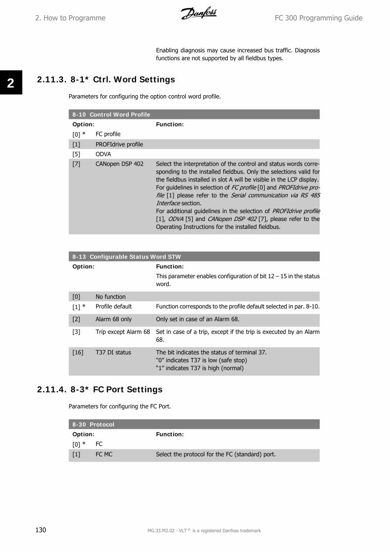
Enabling diagnosis may cause increased bus traffic. Diagnosisfunctions are not supported by all fieldbus types.
2.11.3. 8-1* Ctrl. Word Settings
Parameters for configuring the option control word profile.
8-10 Control Word Profile
Option: Function:
[0] * FC profile
[1] PROFIdrive profile
[5] ODVA
[7] CANopen DSP 402 Select the interpretation of the control and status words corre-sponding to the installed fieldbus. Only the selections valid forthe fieldbus installed in slot A will be visible in the LCP display.For guidelines in selection of FC profile [0] and PROFIdrive pro-file [1] please refer to the Serial communication via RS 485Interface section.For additional guidelines in the selection of PROFIdrive profile[1], ODVA [5] and CANopen DSP 402 [7], please refer to theOperating Instructions for the installed fieldbus.
8-13 Configurable Status Word STW
Option: Function:
This parameter enables configuration of bit 12 – 15 in the statusword.
[0] No function
[1] * Profile default Function corresponds to the profile default selected in par. 8-10.
[2] Alarm 68 only Only set in case of an Alarm 68.
[3] Trip except Alarm 68 Set in case of a trip, except if the trip is executed by an Alarm68.
[16] T37 DI status The bit indicates the status of terminal 37.“0” indicates T37 is low (safe stop)“1” indicates T37 is high (normal)
2.11.4. 8-3* FC Port Settings
Parameters for configuring the FC Port.
8-30 Protocol
Option: Function:
[0] * FC
[1] FC MC Select the protocol for the FC (standard) port.
2. How to Programme FC 300 Programming Guide
130 MG.33.M2.02 - VLT ® is a registered Danfoss trademark
2

8-31 Address
Range: Function:
1* [1 - 126 ] Enter the address for the FC (standard) port.Valid range: 1 - 126.
8-32 FC Port Baud Rate
Option: Function:
[0] 2400 Baud
[1] 4800 Baud
[2] * 9600 Baud
[3] 19200 Baud
[4] 38400 Baud
[7] 115200 Baud Baud rate selection for the FC (standard) port.
8-35 Minimum Response Delay
Range: Function:
10ms* [1 - 500 ms] Specify the minimum delay time between receiving a requestand transmitting a response. This is used for overcoming mo-dem turnaround delays.
8-36 Max Response DelayMax Response Delay
Range: Function:
5000ms*
[1 - 10000 ms] Specify the maximum permissible delay time between transmit-ting a request and receiving a response. Exceeding this delaytime will cause control word time-out.
8-37 Max Inter-Char Delay
Range: Function:
25ms* [0 - 30 ms] Specify the maximum permissible time interval between receiptof two bytes. This parameter activates time-out if transmissionis interrupted.This parameter is active only when par. 8-30 is set to FC MC [1]protocol.
8-40 FC MC Protocol Set
Option: Function:
[1] * Standard Telegram 1
[200] Custom Telegram Enables use of freely configurable telegrams or standard tele-grams for the FC port.
2.11.5. 8-5* Digital/Bus
Parameters for configuring the control word Digital/Bus merging.
FC 300 Programming Guide 2. How to Programme
MG.33.M2.02 - VLT ® is a registered Danfoss trademark 131
2

8-50 Coasting Select
Option: Function:
[0] Digital input
[1] Bus
[2] Logic AND
[3] * Logic OR
Select control of the coasting function via the terminals (digitalinput) and/or via the bus.
NB!This parameter is active only when par. 8-01 Control Site is set to [0] Digital andcontrol word.
8-51 Quick Stop Select
Option: Function:
[0] Digital input
[1] Bus
[2] Logic AND
[3] * Logic OR Select control of the Quick Stop function via the terminals (dig-ital input) and/or via the bus.
NB!This parameter is active only when par. 8-01 Con-trol Site is set to [0] Digital and control word.
8-52 DC Brake Select
Option: Function:
[0] Digital input
[1] Bus
[2] Logic AND
[3] * Logic OR
Select control of the DC brake via the terminals (digital input)and/or via the fieldbus.
NB!This parameter is active only when par. 8-01 Control Site is set to [0] Digital andcontrol word.
8-53 Start Select
Option: Function:
[0] Digital input
2. How to Programme FC 300 Programming Guide
132 MG.33.M2.02 - VLT ® is a registered Danfoss trademark
2

[1] Bus Activates Start command via the serial communication port orfieldbus option.
[2] Logic AND Activates Start command via the fieldbus/serial communicationport, AND additionally via one of the digital inputs.
[3] * Logic OR Activates Start command via the fieldbus/serial communicationport OR via one of the digital inputs.
Select control of the frequency converter start function via theterminals (digital input) and/or via the fieldbus.
NB!This parameter is active only when par. 8-01 Control Site is set to [0] Digital andcontrol word.
8-54 Reversing Select
Option: Function:
[0] Digital input
[1] Bus
[2] Logic AND
[3] * Logic OR Select control of the frequency converter reverse function viathe terminals (digital input) and/or via the fieldbus.Select Bus [1], to activate the Reverse command via the serialcommunication port or fieldbus option.Select Logic AND [2] to activate the Reverse command via thefieldbus/serial communication port, AND additionally via one ofthe digital inputs.Select Logic OR [3] to activate the Reverse command via thefieldbus/serial communication port OR via one of the digital in-puts.
NB!This parameter is active only when par. 8-01 Con-trol Site is set to [0] Digital and control word.
8-55 Set-up Select
Option: Function:
[0] Digital input
[1] Bus Activates the set-up selection via the serial communication portor fieldbus option.
[2] Logic AND Activates the set-up selection via the fieldbus/serial communi-cation port, AND additionally via one of the digital inputs.
[3] * Logic OR Activate the set-up selection via the fieldbus/serial communica-tion port OR via one of the digital inputs.
Select control of the frequency converter set-up selection viathe terminals (digital input) and/or via the fieldbus.
FC 300 Programming Guide 2. How to Programme
MG.33.M2.02 - VLT ® is a registered Danfoss trademark 133
2

NB!This parameter is active only when par. 8-01 Control Site is set to [0] Digital andcontrol word.
8-56 Preset Reference Select
Option: Function:
[0] Digital input
[1] Bus Activates Preset Reference selection via the serial communica-tion port or fieldbus option.
[2] Logic AND Activates Preset Reference selection via the fieldbus/serial com-munication port, AND additionally via one of the digital inputs.
[3] * Logic OR Activates the Preset Reference selection via the fieldbus/serialcommunication port OR via one of the digital inputs.
Select control of the frequency converter Preset Reference se-lection via the terminals (digital input) and/or via the fieldbus.
NB!This parameter is active only when par. 8-01Control Site is set to [0] Digital andcontrol word.
2.11.6. 8-9* Bus Jog
Parameters for configuring the Bus Jog.
8-90 Bus Jog 1 Speed
Range: Function:
100RPM*
[0 - par. 4-13 RPM] Enter the jog speed. This is a fixed jog speed activated via theserial port or fieldbus option.
8-91 Bus Jog 2 Speed
Range: Function:
200RPM*
[0 - par. 4-13 RPM] Enter the jog speed. This is a fixed jog speed activated via theserial port or fieldbus option.
2.12. Parameters: Profibus
2.12.1. 9-** Profibus
Parameter group for all Profibus-specific parameters.
2. How to Programme FC 300 Programming Guide
134 MG.33.M2.02 - VLT ® is a registered Danfoss trademark
2

9-00 Setpoint
Range: Function:
0* [0-65535] This parameter receives cyclical reference from a Master Class2. If the control priority is set to Master Class 2, the referencefor the frequency converter is taken from this parameter,whereas the cyclical reference will be ignored.
9-07 Actual Value
Range: Function:
0* [0-65535] This parameter delivers the MAV for a Master Class 2. The pa-rameter is valid if the control priority is set to Master Class 2.
9-15 PCD Write Configuration
Array [10]
None
3-02 Minimum Refer-ence
3-03 Maximum Refer-ence
3-12 Catch Up/SlowDown Value
3-41 Ramp 1 RampUp Time
3-42 Ramp 1 RampDown Time
3-51 Ramp 2 RampUp Time
3-52 Ramp 2 RampDown Time
3-80 Jog Ramp Time
3-81 Quick StopRamp Time
4-11 Motor SpeedLow Limit [RPM]
4-13 Motor SpeedHigh Limit [RPM]
4-16 Torque Limit Mo-tor Mode
4-17 Torque LimitGenerator Mode
7-28 Minimum Feed-back
7-29 Maximum Feed-back
8-90 Bus Jog 1 Speed
8-91 Bus Jog 2 Speed
FC 300 Programming Guide 2. How to Programme
MG.33.M2.02 - VLT ® is a registered Danfoss trademark 135
2

16-80 Fieldbus CTW 1
16-82 Fieldbus REF 1
34-01 PCD 1 Write toMCO
34-02 PCD 2 Write toMCO
34-03 PCD 3 Write toMCO
34-04 PCD 4 Write toMCO
34-05 PCD 5 Write toMCO
34-06 PCD 6 Write toMCO
34-07 PCD 7 Write toMCO
34-08 PCD 8 Write toMCO
34-09 PCD 9 Write toMCO
34-10 PCD 10 Write toMCO
Select the parameters to be assigned to PCD 3 to 10 of the tele-grams. The number of available PCDs depends on the telegramtype. The values in PCD 3 to 10 will then be written to the se-lected parameters as data values. Alternatively, specify a stand-ard Profibus telegram in par. 9-22.
9-16 PCD Read Configuration
Array [10]
None
16-00 Control Word
16-01 Reference[Unit]
16-02 Reference %
16-03 Status Word
16-04 Main ActualValue [Unit]
16-05 Main ActualValue [%]
16-09 Custom Read-out
16-10 Power [kW]
16-11 Power [hp]
16-12 Motor Voltage
16-13 Frequency
16-14 Motor Current
16-16 Torque
2. How to Programme FC 300 Programming Guide
136 MG.33.M2.02 - VLT ® is a registered Danfoss trademark
2

16-17 Speed [RPM]
16-18 Motor Thermal
16-19 KTY SensorTemperature
16-21 Phase Angle
16-30 DC Link Voltage
16-32 Brake Energy /s
16-33 Brake Energy /2 min 16-34 HeatsinkTemp.
16-35 Inverter Ther-mal
16-38 SL ControlState
16-39 Control CardTemp.
16-50 External Refer-ence
16-51 Pulse Refer-ence
16-52 Feedback[Unit]
16-53 Digi Pot Refer-ence
16-60 Digital Input
16-61 Terminal 53Switch Setting
16-62 Analog Input53
16-63 Terminal 54Switch Setting
16-64 Analog Input54
16-65 Analog Output42 [mA]
16-66 Digital Output[bin]
16-67 Freq. Input#29 [Hz]
16-68 Freq. Input#33 [Hz]
16-69 Pulse Output#27 [Hz]
16-70 Pulse Output#29 [Hz]
16-71 Pulse Output[bin]
16-84 Comm OptionSTW [Binary]
FC 300 Programming Guide 2. How to Programme
MG.33.M2.02 - VLT ® is a registered Danfoss trademark 137
2

16-85 FC port CTW 1Signal
16-90 Alarm Word
16-91 Alarm Word 2
16-92 Warning Word
16-93 Warning Word2
16-94 Extended Sta-tus Word
16-95 Extended Sta-tus Word 2
34-21 PCD 1 Readfrom MCO
34-22 PCD 2 Readfrom MCO
34-23 PCD 3 Readfrom MCO
34-24 PCD 4 Readfrom MCO
34-25 PCD 5 Readfrom MCO
34-26 PCD 6 Readfrom MCO
34-27 PCD 7 Readfrom MCO
34-28 PCD 8 Readfrom MCO
34-29 PCD 9 Readfrom MCO
34-30 PCD 10 Readfrom MCO
34-40 Digital Inputs
34-41 Digital Outputs
34-50 Actual Position
34-51 CommandedPosition
34-52 Actual MasterPosition
34-53 Slave Index Po-sition
34-54 Master IndexPosition
34-55 Curve Position
34-56 Track Error
34-57 SynchronizingError
34-58 Actual Velocity
34-59 Actual MasterVelocity
2. How to Programme FC 300 Programming Guide
138 MG.33.M2.02 - VLT ® is a registered Danfoss trademark
2

34-60 SynchronizinStatus
34-61 Axis Status
34-62 Program Status Select the parameters to be assigned to PCD 3 to 10 of the tele-grams. The number of available PCDs depends on the telegramtype. PCDs 3 to 10 contain the actual data values of the selectedparameters. For standard Profibus telegrams, see par. 9-22.
9-18 Node Address
Range: Function:
126* [0 - 126] Enter the station address in this parameter or alternatively inthe hardware switch. In order to adjust the station address inpar. 9-18, the hardware switch must be set to 126 or 127 (i.e.all switches set to ‘on’). Otherwise this parameter will displaythe actual setting of the switch.
9-22 Telegram Selection
Option: Function:
[1] Standard telegram 1
[101] PPO 1
[102] PPO 2
[103] PPO 3
[104] PPO 4
[105] PPO 5
[106] PPO 6
[107] PPO 7
[108] * PPO 8 Read only.
Displays the Profibus telegram configuration.
9-23 Parameters for Signals
Array [1000]Read only
This parameter contains a list of signals available for selectionin par. 9-15 and 9-16.
9-27 Parameter Edit
Option: Function:
Parameters can be edited via Profibus, the standard RS485 in-terface, or the LCP.
[0] Disabled Disables editing via Profibus.
[1] * Enabled Enables editing via Profibus.
FC 300 Programming Guide 2. How to Programme
MG.33.M2.02 - VLT ® is a registered Danfoss trademark 139
2

9-28 Process Control
Option: Function:
Process control (setting of Control Word, speed reference, andprocess data) is possible via either Profibus or standard fieldbusbut not both simultaneously. Local control is always possible viathe LCP. Control via process control is possible via either termi-nals or fieldbus depending on the settings in par. 8-50 to 8-56.
[0] Disable Disables process control via Profibus, and enables process con-trol via standard fieldbus or Profibus Master class 2.
[1] * Enable cyclic master Enables process control via Profibus Master Class 1, and disablesprocess control via standard fieldbus or Profibus Master class 2.
9-44 Fault Message Counter
Range: Function:
0* [0-65535] This parameter displays the number of error events stored inpar. 9-45 and 9-47. The maximum buffer capacity is eight errorevents. The buffer and counter are set to 0 upon reset or power-up.
9-45 Fault Code
Range: Function:
0* [0 - 0] This buffer contains the alarm word for all alarms and warningsthat have occurred since last reset or power-up. The maximumbuffer capacity is eight error events.
9-47 Fault Number
Range: Function:
0* [0 - 0] This buffer contains the alarm number (e.g. 2 for live zero error,4 for mains phase loss) for all alarms and warnings that haveoccurred since last reset or power-up. The maximum buffer ca-pacity is eight error events.
9-52 Fault Situation Counter
Range: Function:
0* [0 - 1000] This parameter displays the number of error events which haveoccurred since last reset of power-up.
9-53 Profibus Warning Word
Option: Function:
This parameter displays Profibus communication warnings.Please refer to the Profibus Operating Instructions for furtherinformation.
Read only
2. How to Programme FC 300 Programming Guide
140 MG.33.M2.02 - VLT ® is a registered Danfoss trademark
2

Bit: Meaning:0 Connection with DP-master is not1 Not used2 FDL (Field-bus Data link Layer) is not ok3 Clear data command received4 Actual value is not updated5 Baudrate search6 PROFIBUS ASIC is not transmitting7 Initializing of PROFIBUS is not ok8 Drive is tripped9 Internal CAN error10 Wrong configuration data from PLC11 Wrong ID sent by PLC12 Internal error occured13 Not configured14 Timeout active15 Warning 34 active
9-63 Actual Baud Rate
Option: Function:
This parameter displays the actual Profibus baud rate. The Pro-fibus Master automatically sets the baud rate.
Read only
[0] 9.6 kbit/s
[1] 19.2 kbit/s
[2] 93.75 kbit/s
[3] 187.5 kbit/s
[4] 500 kbit/s
[6] 1500 kbit/s
[7] 3000 kbit/s
[8] 6000 kbit/s
[9] 12000 kbit/s
[10] 31.25 kbit/s
[11] 45.45 kbit/s
[255] No baud rate found
9-64 Device Identification
Range: Function:
0* [0 - 0] This parameter displays the device identification. Please refer tothe Operating Instructions for Profibus, MG33CXYY for furtherexplanation.
9-65 Profile Number
Range: Function:
Read only
0* [0 - 0] This parameter contains the profile identification. Byte 1 con-tains the profile number and byte 2 the version number of theprofile.
NB!This parameter is not visible via LCP.
FC 300 Programming Guide 2. How to Programme
MG.33.M2.02 - VLT ® is a registered Danfoss trademark 141
2

9-67 Control Word 1
Range: Function:
0* [0-65535] This parameter accepts the Control Word from a Master Class 2in the same format as PCD 1.
9-68 Status Word 1
Range: Function:
0* [0-65535] This parameter delivers the Status Word for a Master Class 2 inthe same format as PCD 2.
9-70 Edit Set-up
Option: Function:
Select the set-up to be edited.
[0] Factory setup Uses default data. This option can be used as a data source toreturn the other set-ups to a known state.
[1] * Setup 1 Edits Set-up 1.
[2] Setup 2 Edits Set-up 2.
[3] Setup 3 Edits Set-up 3.
[4] Setup 4 Edits Set-up 4.
[9] Active setup Follows the active set-up selected in par. 0-10.
This parameter is unique to LCP and fieldbuses. See also par. 0-11 Edit set-up.
9-71 Save Data Values
Option: Function:
Parameter values changed via Profibus are not automaticallystored in non-volatile memory. Use this parameter to activate afunction that stores parameter values in the EEPROM non-vol-atile memory, so changed parameter values will be retained atpower-down.
[0] * Off Deactivates the non-volatile storage function.
[1] Store edit setup Stores all parameter values in the set-up selected in par. 9-70in the non-volatile memory. The selection returns to Off [0]when all values have been stored.
[2] Store all set-ups Stores all parameter values for all set-ups in the non-volatilememory. The selection returns to Off [0] when all parametervalues have been stored.
9-72 Drive Reset
Option: Function:
[0] * No action
[1] Power-on reset Resets frequency converter upon power-up, as for power-cycle.
[3] Comm. option reset Resets the Profibus option only, useful after changing certainsettings in parameter group 9-**, e.g. par. 9-18.
2. How to Programme FC 300 Programming Guide
142 MG.33.M2.02 - VLT ® is a registered Danfoss trademark
2

When reset, the frequency converter disappears from the field-bus, which may cause a communication error from the master.
9-80 Defined Parameters (1)
Array [116]
No LCP access
Read only
0* [0 - 115] This parameter displays a list of all the defined frequency con-verter parameters available for Profibus.
9-81 Defined Parameters (2)
Array [116]
No LCP access
Read only
0* [0 - 115] This parameter displays a list of all the defined frequency con-verter parameters available for Profibus.
9-82 Defined Parameters (3)
Array [116]
No LCP access
Read only
0* [0 - 115] This parameter displays a list of all the defined frequency con-verter parameters available for Profibus.
9-83 Defined Parameters (4)
Array [116]
No LCP access
Read only
0* [0 - 115] This parameter displays a list of all the defined frequency con-verter parameters available for Profibus.
FC 300 Programming Guide 2. How to Programme
MG.33.M2.02 - VLT ® is a registered Danfoss trademark 143
2

9-84 Defined Parameters (5)
Range: Function:
Array [116]
No LCP access
Read only
0* [0 - 115] This parameter displays a list of all the defined frequency con-verter parameters available for Profibus.
9-90 Changed Parameters (1)
Array [116]
No LCP access
Read only
0* [0 - 115] This parameter displays a list of all the frequency converter pa-rameters deviating from default setting.
9-91 Changed Parameters (2)
Array [116]
No LCP access
Read only
0* [0 - 115] This parameter displays a list of all the frequency converter pa-rameters deviating from default setting.
9-92 Changed Parameters (3)
Array [116]
No LCP access
Read only
0* [0 - 115] This parameter displays a list of all the frequency converter pa-rameters deviating from default setting.
9-94 Changed Parameters (5)
Array [116]
No LCP access
2. How to Programme FC 300 Programming Guide
144 MG.33.M2.02 - VLT ® is a registered Danfoss trademark
2

Read only
0* [0 - 115] This parameter displays a list of all the frequency converter pa-rameters deviating from default setting.
2.13. Parameters: DeviceNet CAN Fieldbus
2.13.1. 10-** DeviceNet and CAN Fieldbus
Parameter group for DeviceNet CAN fieldbus parameters.
2.13.2. 10-0* Common Settings
Parameter group for configuring common settings for CAN fieldbus options.
10-00 CAN Protocol
Option: Function:
[0] CANopen
[1] * DeviceNet View the active CAN protocol.
NB!The options depend on installed option.
10-01 Baud Rate Select
Option: Function:
[16] 10 Kbps
[17] 20 Kbps
[18][19]
50 Kbps100 Kbps
[20] * 125 Kbps
[21] 250 Kbps
[22] 500 Kbps Select the fieldbus transmission speed. The selection must cor-respond to the transmission speed of the master and the otherfieldbus nodes.
10-02 MAC ID
Range: Function:
63* [0 - 127] Selection of station address. Every station connected to thesame network must have an unambiguous address.
10-05 Readout Transmit Error Counter
Range: Function:
0* [0 - 255] View the number of CAN control transmission errors since thelast power-up.
FC 300 Programming Guide 2. How to Programme
MG.33.M2.02 - VLT ® is a registered Danfoss trademark 145
2

10-06 Readout Receive Error Counter
Option: Function:
[0] 0 - 255 View the number of CAN control receipt errors since the lastpower-up.
10-07 Readout Bus Off Counter
Range: Function:
0* [0 - 255] View the number of Bus Off events since the last power-up.
2.13.3. 10-1* DeviceNet
Parameters specific to the DeviceNet fieldbus.
10-10 Process Data Type Selection
Option: Function:
Select the Instance (telegram) for data transmission. The In-stances available are dependent upon the setting of par. 8-10Control Word Profile.When par. 8-10 is set to [0] FC profile, par. 10-10 options [0]and [1] are available.When par. 8-10 is set to [5] ODVA, par. 10-10 options [2] and[3] are available.Instances 100/150 and 101/151 are Danfoss-specific. Instances20/70 and 21/71 are ODVA-specific AC Drive profiles.For guidelines in telegram selection, please refer to the Device-Net Operating Instructions.Note that a change to this parameter will be executed immedi-ately.
[0] Instance 100/150
[1] Instance 101/151
[2] Instance 20/70
[3] Instance 21/71
10-11 Process Data Config Write
Option: Function:
[0 ] * None
3-02 Minimum refer-ence
3-03 Maximum refer-ence
3-12 Catch up/slowdown value
3-41 Ramp 1 ramp uptime
3-42 Ramp 1 rampdown time
3-51 Ramp 2 ramp uptime
2. How to Programme FC 300 Programming Guide
146 MG.33.M2.02 - VLT ® is a registered Danfoss trademark
2

3-52 Ramp 2 rampdown time
3-80 Jog ramp time
3-81 Quick stop ramptime
4-11 Motor speed lowlimit (RPM)
4-13 Motor speedhigh limit (RPM)
4-16 Torque limit mo-tor mode
4-17 Torque limitgenerator mode
7-28 Minimum Feed-back
7-29 Maximum Feed-back
8-90 Bus Jog 1 Speed
8-91 Bus Jog 2 Speed
16-80 Fieldbus CTW 1(Fixed)
16-82 Fieldbus REF 1(Fixed)
34-01 PCD 1 Write toMCO
34-02 PCD 2 Write toMCO
34-03 PCD 3 Write toMCO
34-04 PCD 4 Write toMCO
34-05 PCD 5 Write toMCO
34-06 PCD 6 Write toMCO
34-07 PCD 7 Write toMCO
34-08 PCD 8 Write toMCO
34-09 PCD 9 Write toMCO
34-10 PCD 10 Write toMCO
Select the process write data for I/O Assembly Instances101/151. Elements [2] and [3] of this array can be selected.Elements [0] and [1] of the array are fixed.
10-12 Process Data Config Read
Option: Function:
None
16-00 Control Word
FC 300 Programming Guide 2. How to Programme
MG.33.M2.02 - VLT ® is a registered Danfoss trademark 147
2

16-01 Reference[Unit]
16-02 Reference %
16-03 Status Word(Fixed)
16-04 Main ActualValue [Unit]
16-05 Main ActualValue (%) (Fixed)
16-10 Power [kW]
16-11 Power [hp]
16-12 Motor Voltage
16-13 Frequency
16-14 Motor Current
16-16 Torque
16-17 Speed [RPM]
16-18 Motor Thermal
16-19 KTY SensorTemperature
16-21 Phase Angle
16-30 DC Link Voltage
16-32 BrakeEnergy/s
16-33 BrakeEnergy/2min
16-34 Heatsink Temp.
16-35 Inverter Ther-mal
16-38 SL ControlState
16-39 ControlcardTemp.
16-50 External Refer-ence
16-51 Pulse Refer-ence
16-52 Feedback[Unit]
16-53 Digi Pot Refer-ence
16-60 Digital Input
16-61 Terminal 53Switch Setting
16-62 Analog Input53
16-63 Terminal 54Switch Setting
16-64 Analog Input54
2. How to Programme FC 300 Programming Guide
148 MG.33.M2.02 - VLT ® is a registered Danfoss trademark
2

16-65 Analog Output42 [mA]
16-66 Digital Output[bin]
16-67 Freq. Input#29 [Hz]
16-68 Freq. Input#33 [Hz]
16-69 Pulse Output#27 [Hz]
16-70 Pulse Output#29 [Hz]
16-71 Relay Output[bin]
16-84 Comm OptionSTW
16-85 FC Port CTW 1
16-90 Alarm Word
16-91 Alarm Word 2
16-92 Warning Word
16-93 Warning Word2
16-94 Extended Sta-tus Word
16-95 Extended Sta-tus Word 2
34-21 PCD 1 Readfrom MCO
34-22 PCD 2 Readfrom MCO
34-23 PCD 3 Readfrom MCO
34-24 PCD 4 Readfrom MCO
34-25 PCD 5 Readfrom MCO
34-26 PCD 6 Readfrom MCO
34-27 PCD 7 Readfrom MCO
34-28 PCD 8 Readfrom MCO
34-29 PCD 9 Readfrom MCO
34-30 PCD 10 Readfrom MCO
34-40 Digital Inputs
34-41 Digital Outputs
34-50 Actual Position
FC 300 Programming Guide 2. How to Programme
MG.33.M2.02 - VLT ® is a registered Danfoss trademark 149
2

34-51 CommandedPosition
34-52 Actual MasterPosition
34-53 Slave Index Po-sition
34-54 Master IndexPosition
34-55 Curve Position
34-56 Track Error
34-57 SynchronizingError
34-58 Actual Velocity
34-59 Actual MasterVelocity
34-60 SynchronizingStatus
34-61 Axis Status
34-62 Program Status Select the process read data for I/O Assembly Instances101/151. Elements [2] and [3] of this array can be selected.Elements [0] and [1] of the array are fixed.
10-13 Warning Parameter
Range: Function:
0* [0 - FFFF] View a DeviceNet-specific Warning word. One bit is assigned toevery warning. Please refer to the DeviceNet Operating Instruc-tions (MG.33.DX.YY) for further information.
Bit: Meaning:0 Bus not active1 Explicit connection timeout2 I/O connection3 Retry limit reached4 Actual is not updated5 CAN bus off6 I/O send error7 Initialization error8 No bus supply9 Bus off10 Error passive11 Error warning12 Duplicate MAC ID Error13 RX queue overrun14 TX queue overrun15 CAN overrun
10-14 Net Reference
Read only from LCP.
Select the reference source in Instance 21/71 and 20/70.
[0] * Off Enables reference via analog/digital inputs.
2. How to Programme FC 300 Programming Guide
150 MG.33.M2.02 - VLT ® is a registered Danfoss trademark
2

[1] On Enables reference via the fieldbus.
10-15 Net Control
Read only from LCP.
Select the control source in Instance 21/71 and 20-70.
[0] * Off Enables control via analog/digital inputs.
[1] On enable control via the fieldbus.
2.13.4. 10-2* COS Filters
Parameters for configuring COS filter settings.
10-20 COS Filter 1
Range: Function:
0000* [0 - FFFF] Enter the value for COS Filter 1 to set up the filter mask for theStatus Word. When operating in COS (Change-Of-State), thisfunction filters out bits in the Status Word that should not besent if they change.
10-21 COS Filter 2
Range: Function:
0000* [0 - FFFF] Enter the value for COS Filter 2, to set up the filter mask for theMain Actual Value. When operating in COS (Change-Of-State),this function filters out bits in the Main Actual Value that shouldnot be sent if they change.
10-22 COS Filter 3
Range: Function:
0000* [0 - FFFF] Enter the value for COS Filter 3, to set up the filter mask for PCD3. When operating in COS (Change-Of-State), this function fil-ters out bits in PCD 3 that should not be sent if they change.
10-23 COS Filter 4
Range: Function:
0000* [0 - FFFF] Enter the value for COS Filter 4 to set up the filter mask for PCD4. When operating in COS (Change-Of-State), this function fil-ters out bits in PCD 4 that should not be sent if they change.
2.13.5. 10-3* Parameter Access
Parameter group providing access to indexed parameters and defining programming set-up.
FC 300 Programming Guide 2. How to Programme
MG.33.M2.02 - VLT ® is a registered Danfoss trademark 151
2

10-30 Array Index
Range: Function:
0* [0 - 255]
Read only from LCP. View array parameters. This parameter is valid only when a De-viceNet fieldbus is installed.
10-31 Store Data Values
Option: Function:
Parameter values changed via DeviceNet are not automaticallystored in non-volatile memory. Use this parameter to activate afunction that stores parameter values in the EEPROM non-vol-atile memory, so changed parameter values will be retained atpower-down.
[0] * Off Deactivates the non-volatile storage function.
[1] Store edit setup Stores all parameter values from the active set-up in the non-volatile memory. The selection returns to Off [0] when all valueshave been stored.
[2] Store all setups store all parameter values for all set-ups in the non-volatilememory. The selection returns to Off [0] when all parametervalues have been stored.
10-32 Devicenet Revision
Option: Function:
Major revision
Minor revision View the DeviceNet revision number. This parameter is used forEDS file creation.
10-33 Store Always
Option: Function:
[0] * Off Deactivates non-volatile storage of data.
[1] On Stores parameter data received via DeviceNet in EEPROM non-volatile memory as default.
10-39 Devicenet F Parameters
Array [1000]
No LCP access
0* [0 - 0] This parameter is used to configure the frequency converter viaDeviceNet and build the EDS-file.
2. How to Programme FC 300 Programming Guide
152 MG.33.M2.02 - VLT ® is a registered Danfoss trademark
2

2.14. Parameters: Smart Logic Control
2.14.1. 13-** Prog. Features
Smart Logic Control (SLC) is essentially a sequence of user defined actions (see par. 13-52 [x])executed by the SLC when the associated user defined event (see par. 13-51 [x]) is evaluated asTRUE by the SLC. Events and actions are each numbered and linked together in pairs (states).This means that when event [0] is fulfilled (attains the value TRUE), action [0] is executed. Afterthis, the conditions of event [1] will be evaluated and if evaluated TRUE, action [1] will be executedand so on. Only one event will be evaluated at any time. If an event is evaluated as FALSE, nothinghappens (in the SLC) during the current scan interval and no other events will be evaluated. Thismeans that when the SLC starts, it evaluates event [0] (and only event [0]) each scan interval.Only when event [0] is evaluated TRUE, will the SLC execute action [0] and start evaluatingevent [1]. It is possible to programme from 1 to 20 events and actions.When the last event / action has been executed, the sequence starts over again from event [0] /action [0]. The illustration shows an example with three event / actions:
Starting and stopping the SLC:Starting and stopping the SLC can be done by selecting .On [1]. or .Off [0]. in par. 13-00. TheSLC always starts in state 0 (where it evaluates event [0]). The SLC starts when the Start Event(defined in par. 13-01 Start Event) is evaluated as TRUE (provided that On [1] is selected in par.13-00). The SLC stops when the Stop Event (par. 13-02) is TRUE. Par. 13-03 resets all SLC pa-rameters and start programming from scratch.
2.14.2. 13-0* SLC Settings
Use the SLC settings to activate, deactivate and reset the Smart Logic Control.
13-00 SL Controller Mode
Option: Function:
[0] * Off Disables the Smart Logic Controller.
[1] On Enables the Smart Logic Controller.
FC 300 Programming Guide 2. How to Programme
MG.33.M2.02 - VLT ® is a registered Danfoss trademark 153
2

13-01 Start Event
Option: Function:
[0] False
[1] True
[2] Running
[3] In range
[4] On reference
[5] Torque limit
[6] Current limit
[7] Out of current range
[8] Below I low
[9] Above I high
[10] Out of speed range
[11] Below speed low
[12] Above speed high
[13] Out of feedb. range
[14] Below feedb. low
[15] Above feedb. high
[16] Thermal warning
[17] Mains out of range
[18] Reversing
[19] Warning
[20] Alarm (trip)
[21] Alarm (trip lock)
[22] Comparator 0
[23] Comparator 1
[24] Comparator 2
[25] Comparator 3
[26] Logic rule 0
[27] Logic rule 1
[28] Logic rule 2
[29] Logic rule 3
[33] Digital input DI18
[34] Digital input DI19
[35] Digital input DI27
[36] Digital input DI29 (FC302 only)
[37] Digital input DI32
[38] Digital input DI33
[39] * Start command
[40] Drive stopped
[41] Reset Trip
[42] Auto-reset Trip
[43] Ok key
[44] Reset key
2. How to Programme FC 300 Programming Guide
154 MG.33.M2.02 - VLT ® is a registered Danfoss trademark
2
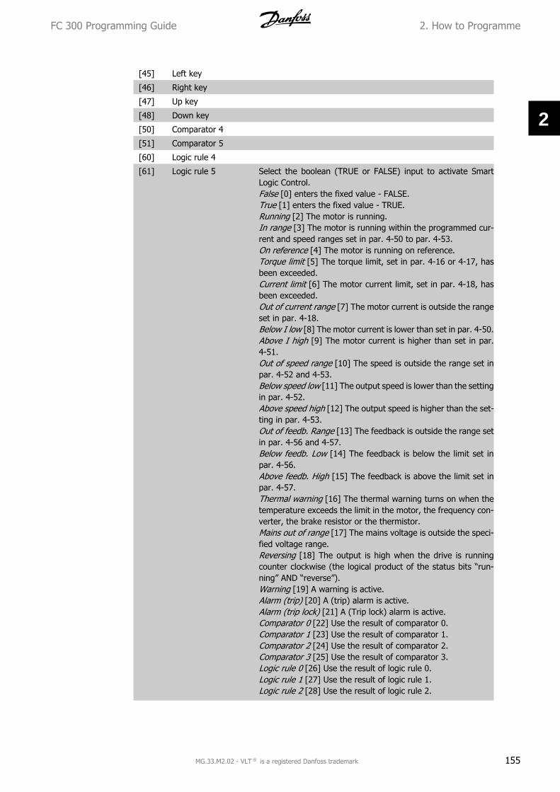
[45] Left key
[46] Right key
[47] Up key
[48] Down key
[50] Comparator 4
[51] Comparator 5
[60] Logic rule 4
[61] Logic rule 5 Select the boolean (TRUE or FALSE) input to activate SmartLogic Control.False [0] enters the fixed value - FALSE.True [1] enters the fixed value - TRUE.Running [2] The motor is running.In range [3] The motor is running within the programmed cur-rent and speed ranges set in par. 4-50 to par. 4-53.On reference [4] The motor is running on reference.Torque limit [5] The torque limit, set in par. 4-16 or 4-17, hasbeen exceeded.Current limit [6] The motor current limit, set in par. 4-18, hasbeen exceeded.Out of current range [7] The motor current is outside the rangeset in par. 4-18.Below I low [8] The motor current is lower than set in par. 4-50.Above I high [9] The motor current is higher than set in par.4-51.Out of speed range [10] The speed is outside the range set inpar. 4-52 and 4-53.Below speed low [11] The output speed is lower than the settingin par. 4-52.Above speed high [12] The output speed is higher than the set-ting in par. 4-53.Out of feedb. Range [13] The feedback is outside the range setin par. 4-56 and 4-57.Below feedb. Low [14] The feedback is below the limit set inpar. 4-56.Above feedb. High [15] The feedback is above the limit set inpar. 4-57.Thermal warning [16] The thermal warning turns on when thetemperature exceeds the limit in the motor, the frequency con-verter, the brake resistor or the thermistor.Mains out of range [17] The mains voltage is outside the speci-fied voltage range.Reversing [18] The output is high when the drive is runningcounter clockwise (the logical product of the status bits “run-ning” AND “reverse”).Warning [19] A warning is active.Alarm (trip) [20] A (trip) alarm is active.Alarm (trip lock) [21] A (Trip lock) alarm is active.Comparator 0 [22] Use the result of comparator 0.Comparator 1 [23] Use the result of comparator 1.Comparator 2 [24] Use the result of comparator 2.Comparator 3 [25] Use the result of comparator 3.Logic rule 0 [26] Use the result of logic rule 0.Logic rule 1 [27] Use the result of logic rule 1.Logic rule 2 [28] Use the result of logic rule 2.
FC 300 Programming Guide 2. How to Programme
MG.33.M2.02 - VLT ® is a registered Danfoss trademark 155
2

Logic rule 3 [29] Use the result of logic rule 3.Digital input DI18 [33] Use the result of digital input 18.Digital input DI19 [34] Use the result of digital input 19.Digital input DI27 [35] Use the result of digital input 27.Digital input DI29 FC302Only [36] Use the result of digital input29.Digital input DI32 [37] Use the result of digital input 32.Digital input DI33 [38] Use the result of digital input 33.Start command [39] A start command is issued.Drive stopped [40] A stop command ( Jog, Stop, Qstop, Coast)is issued – and not from the SLC itself.Reset Trip [41] A reset is issuedAuto-reset Trip [42] An Auto reset is performed.OK key [43] The Ok key is pressed.Reset key [44] The reset key is pressed.Left key [45] The left key is pressed.Right key [46] The right key is pressed.Up key [47] The up key is pressed.Down key [48] The down key is pressed.Comparator 4 [50] Use the result of comparator 4.Comparator 5 [51] Use the result of comparator 5.Logic rule 4 [60] Use the result of logic rule 4.Logic rule 5 [61] Use the result of logic rule 5.
13-02 Stop Event
Option: Function:
[0] False
[1] True
[2] Running
[3] In range
[4] On reference
[5] Torque limit
[6] Current limit
[7] Out of current range
[8] Below I low
[9] Above I high
[10] Out of speed range
[11] Below speed low
[12] Above speed high
[13] Out of feedb. range
[14] Below feedb. low
[15] Above feedb. high
[16] Thermal warning
[17] Mains out of range
[18] Reversing
[19] Warning
[20] Alarm (trip)
[21] Alarm (trip lock)
[22] Comparator 0
2. How to Programme FC 300 Programming Guide
156 MG.33.M2.02 - VLT ® is a registered Danfoss trademark
2

[23] Comparator 1
[24] Comparator 2
[25] Comparator 3
[26] Logic rule 0
[27] Logic rule 1
[28] Logic rule 2
[29] Logic rule 3
[30] SL Time-out 0
[31] SL Time-out 1
[32] SL Time-out 2
[33] Digital input DI18
[34] Digital input DI19
[35] Digital input DI27
[36] Digital input DI29 (FC302 only)
[37] Digital input DI32
[38] Digital input DI33
[39] Start command
[40] Drive stopped
[41] Reset Trip
[42] Auto-reset Trip
[43] Ok key
[44] Reset key
[45] Left key
[46] Right key
[47] Up key
[48] Down key
[50] Comparator 4
[51] Comparator 5
[60] Logic rule 4
[61] Logic rule 5
[70] SL Time-out 3
[71] SL Time-out 4
[72] SL Time-out 5
[73] SL Time-out 6
[74] SL Time-out 7 Select the boolean (TRUE or FALSE) input to activate SmartLogic Control.For descriptions [0] - [61], see 13-01 Start EventSL Time-out 3 [70] Smart logic controller timer 3 is timed out.SL Time-out 4 [71] Smart logic controller timer 4 is timed out.SL Time-out 5 [72] Smart logic controller timer 5 is timed out.SL- Time-out 6 [73] Smart logic controller timer 6 is timed out.SL Time-out 7 [74] Smart logic controller timer 7 is timed out.
FC 300 Programming Guide 2. How to Programme
MG.33.M2.02 - VLT ® is a registered Danfoss trademark 157
2

13-03 Reset SLC
Option: Function:
[0] * Do not reset SLC Retains programmed settings in all group 13 parameters (13-*).
[1] Reset SLC Resets all group 13 parameters (13-*) to default settings.
2.14.3. 13-1* Comparators
Comparators are used for comparing continuous variables (i.e. output frequency, output current,analog input etc.) to fixed preset values. In addition, there are digital values that will be comparedto fixed time values. See explanation in par. 13-10. Comparators are evaluated once in each scaninterval. Use the result (TRUE or FALSE) directly. All parameters in this parameter group are arrayparameters with index 0 to 5. Select index 0 to programme Comparator 0, select index 1 to pro-gramme Comparator 1, and so on.
13-10 Comparator Operand
Array [6]
Choice [1] to [31] are variables which will be compared based on their values. Choice [50] to [186]are digital values (TRUE/FALSE) where the comparison is based on the amount of time duringwhich they are set to TRUE or FALSE, respectively. See par. 13-11.Select the variable to be monitored by the comparator.
[0] * DISABLED DISABLED [0] The comparator is disabled.
[1] Reference Reference [1] The resulting remote reference (not local) as apercentage.
[2] Feedback Feedback [2] In the unit [RPM] or [Hz]
[3] Motor speed Motor speed [3] [RPM] or [Hz]
[4] Motor current Motor current [4] [A]
[5] Motor torque Motor torque [5] [Nm]
[6] Motor power Motor power [6] [kW] or [hp]
[7] Motor voltage Motor voltage [7] [V]
[8] DC-link voltage DC-link voltage [8] [V]
[9] Motor thermal Motor thermal [9] Expressed as a percentage.
[10] VLT thermal VLT thermal [10] Expressed as a percentage.
[11] Heat sink temp. Heat sink temp [11] Expressed as a percentage.
[12] Analog input AI53 Analog input AI53 [12] Expressed as a percentage.
[13] Analog input AI54 Analog input AI54 [13] Expressed as a percentage.
[14] Analog input AIFB10 Analog input AIFB10 [14] [V]
[15] Analog input AIS24V Analog input AIS24V [15] [V] Analog input AICCT [17] [°].
[17] Analog input AICCT
2. How to Programme FC 300 Programming Guide
158 MG.33.M2.02 - VLT ® is a registered Danfoss trademark
2

[18] Pulse input FI29 (FC302 only)
Pulse input FI29 (FC302Only) [18] Expressed as a percentage.
[19] Pulse input FI33 Pulse input FI33 [19] Expressed as a percentage.
[20] Alarm number Alarm number [20] The error number.
[30] Counter A Counter A [30] Number of counts
[31] Counter B Counter B [31] Number of counts
[50] False False [50] Enters the fixed value of false in the comparator.
[51] True True [51] Enters the fixed value of true in the comparator.
[52] Control ready Control ready [52] The control board receives supply voltage
[53] Drive ready Drive ready [53] The frequency converter is ready for operationand applies a supply signal on the control board.
[54] Running Running [54] The motor is running.
[55] Reversing Reversing [55] The output is high when the drive is runningcounter clockwise (the logical product of the status bits “run-ning” AND “reverse”)
[56] In range In range [56] The motor is running within the programmed cur-rent and speed ranges set in par. 4-50 to par. 4-53.
[60] On reference On reference [60] The motor is running on reference.
[61] Below reference, low Below reference, low [61] The motor is running below the valuegiven in par. 4-54 “Warning Reference Low”
[62] Above reference, high Above reference, high [62] The motor is running above the val-ue given in par. 4-55 “Warning Reference High”
[65] Torque limit Torque limit [65] The torque limit, set in par. 4-16 or 4-17, hasbeen exceeded.
[66] Current limit Current limit [66] The motor current limit, set in par. 4-18, hasbeen exceeded.
[67] Out of current range Out of current range [67] The motor current is outside the rangeset in par. 4-18.
[68] Below I low Below I low [68] The motor current is lower than set in par.4-50.
[69] Above I high Above I high [69] The motor current is higher than set in par.4-51.
[70] Out of speed range Out of speed range [70] The speed is outside the range set inpar. 4-52 and 4-53.
[71] Below speed low Below speed low [71] The output speed is lower than the settingin par. 4-52.
[72] Above speed high Above speed high [72] The output speed is higher than the set-ting in par. 4-53.
[75] Out of feedb. range Out of feedb. Range [75] The feedback is outside the range setin par. 4-56 and 4-57.
FC 300 Programming Guide 2. How to Programme
MG.33.M2.02 - VLT ® is a registered Danfoss trademark 159
2

[76] Below feedb. low Below feedb. Low [76] The feedback is below the limit set inpar. 4-56.
[77] Above feedb. high Above feedb. High [77] The feedback is above the limit set inpar. 4-57.
[80] Thermal warning Thermal warning [80] The thermal warning turns on when thetemperature exceeds the limit in the motor, the frequency con-verter, the brake resistor or thermistor.
[82] Mains out of range Mains out of range [82] The mains voltage is outside the speci-fied voltage range.
[85] Warning Warning [85] A warning is active.
[86] Alarm (trip) Alarm (trip) [86] A (trip) alarm is active.
[87] Alarm (trip lock) Alarm (trip lock) [87] A (Trip lock) alarm is active.
[90] Bus OK Bus OK [90] Active communication (no time-out) via the serialcommunication port.
[91] Torque limit & stop Torque limit & stop [91] If the frequency converter has receiveda stop signal and is at the torque limit, the signal is logic “0”.
[92] Brake fault (IGBT) Brake fault (IGBT) [92] The brake IGBT is short circuited.
[93] Mech. brake control Mech. brake control [93] The mechanical brake is active.
[94] Safe stop active (FC302 only)
Safe stop active (FC302Only) [94] Safe stop is active DI 37.
[100] Comparator 0 Comparator 0 [100] The result of comparator 0.
[101] Comparator 1 Comparator 1 [101] The result of comparator 1.
[102] Comparator 2 Comparator 2 [102] The result of comparator 2.
[103] Comparator 3 Comparator 3 [103] The result of comparator 3.
[104] Comparator 4 Comparator 4 [104] The result of comparator 4.
[105] Comparator 5 Comparator 5 [105] The result of comparator 5.
[110] Logic rule 0 Logic rule 0 [110] The result of Logic rule 0.
[111] Logic rule 1 Logic rule 1 [111] The result of Logic rule 1.
[112] Logic rule 2 Logic rule 2 [112] The result of Logic rule 2.
[113] Logic rule 3 Logic rule 3 [113] The result of Logic rule 3.
[114] Logic rule 4 Logic rule 4 [114] The result of Logic rule 4.
[115] Logic rule 5 Logic rule 5 [115] The result of Logic rule 5.
[120] SL Time-out 0 SL Time-out 0 [120] The result of SLC timer 0.
[121] SL Time-out 1 SL Time-out 1 [121] The result of SLC timer 1.
[122] SL Time-out 2 SL Time-out 2 [122] The result of SLC timer 2.
[123] SL Time-out 3 SL Time-out 3 [123] The result of SLC timer 3.
[124] SL Time-out 4 SL Time-out 4 [124] The result of SLC timer 4.
[125] SL Time-out 5 SL Time-out 5 [125] The result of SLC timer 5.
2. How to Programme FC 300 Programming Guide
160 MG.33.M2.02 - VLT ® is a registered Danfoss trademark
2

[126] SL Time-out 6 SL Time-out 6 [126] The result of SLC timer 6.
[127] SL Time-out 7 SL Time-out 7 [127] The result of SLC timer 7.
[130] Digital input DI18 Digital input DI18 [130] Digital input 18. High = True.
[131] Digital input DI19 Digital input DI19 [131] Digital input 19. High = True.
[132] Digital input DI27 Digital input DI27 [132] Digital input 27. High = True.
[133] Digital input DI29 Digital input DI29 [133] Digital input 29. High = True.
[134] Digital input DI32 Digital input DI32 [134] Digital input 32. High = True.
[135] Digital input DI33 Digital input DI33 [135] Digital input 33. High = True.
[150] SL digital output A SL digital output A [150] Use the result of the SLC output A.
[151] SL digital output B SL digital output B [151] Use the result of the SLC output B.
[152] SL digital output C SL digital output C [152] Use the result of the SLC output C.
[153] SL digital output D SL digital output D [153] Use the result of the SLC output D.
[154] SL digital output E SL digital output E [154] Use the result of the SLC output E.
[155] SL digital output F SL digital output F [155] Use the result of the SLC output F.
[160] Relay 1 Relay 1 [160] Relay 1 is active
[161] Relay 2 Relay 2 [161] Relay 2 is active
[180] Local ref. active Local ref. active [180] High when par. 3-13 “Reference site” =[2] Local or when par 3-13 is [0] Linked to hand Auto, at thesame time as the LCP is in Hand on mode.
[181] Remote ref. active Remote ref. active [181] High when par. 3-13 “Reference site”= [1] Remote or [0] Linked to hand/auto, while the LCP is inAuto on mode.
[182] Start command Start command [182] High when there is an active start com-mand, and no stop command.
[183] Drive stopped Drive stopped [183] A stop command ( Jog, Stop, Qstop, Coast)is issued – and not from the SLC itself.
[185] Drive in hand mode Drive in hand mode [185] High when the drive is in hand mode.
[186] Drive in auto mode Drive in auto mode [186] High when the drive is in auto mode.
13-11 Comparator Operator
Array [6]
For par. 13-10 containing values from [0] to [31] the followingis valid:
Select the operator to be used in the comparison.
[0] < Select < [0] for the result of the evaluation to be TRUE, whenthe variable selected in par. 13-10 is smaller than the fixed valuein par. 13-12. The result will be FALSE, if the variable selectedin par. 13-10 is greater than the fixed value in par. 13-12.
FC 300 Programming Guide 2. How to Programme
MG.33.M2.02 - VLT ® is a registered Danfoss trademark 161
2

[1] * ≈ Select ≈ [1] for the result of the evaluation to be TRUE, whenthe variable selected in par. 13-10 is approximately equal to thefixed value in par. 13-12.
[2] > Select > [2] for the inverse logic of option < [0].
13-12 Comparator Value
Array [6]
0.000 * [-100000.000 -100000.000]
Enter the ‘trigger level’ for the variable that is monitored by thiscomparator. This is an array parameter containing comparatorvalues 0 to 5.
2.14.4. 13-2* Timers
This parameter group consists of timer parameters.Use the result (TRUE or FALSE) from timers directly to define an event (see par. 13-51), or asboolean input in a logic rule (see par. 13-40, 13-42 or 13-44). A timer is only FALSE when startedby an action (i.e. Start timer 1 [29]) until the timer value entered in this parameter is elapsed.Then it becomes TRUE again.All parameters in this parameter group are array parameters with index 0 to 2. Select index 0 toprogram Timer 0, select index 1 to program Timer 1, and so on.
13-20 SL Controller Timer
Array [8]
0.00s* [00:00:00.000 -99:59:59.999]
Enter the value to define the duration of the FALSE output fromthe programmed timer. A timer is only FALSE if it is started byan action (i.e. Start timer 1 [29]) and until the given timer valuehas elapsed.
2.14.5. 13-4* Logic Rules
Combine up to three boolean inputs (TRUE / FALSE inputs) from timers, comparators, digital in-puts, status bits and events using the logical operators AND, OR, and NOT. Select boolean inputsfor the calculation in par. 13-40, 13-42, and 13-44. Define the operators used to logically combinethe selected inputs in par. 13-41 and 13-43.
Priority of calculationThe results of par. 13-40, 13-41, and 13-42 are calculated first. The outcome (TRUE / FALSE) ofthis calculation is combined with the settings of par. 13-43 and 13-44, yielding the final result(TRUE / FALSE) of the logic rule.
13-40 Logic Rule Boolean 1
Array [6]
[0] * False
2. How to Programme FC 300 Programming Guide
162 MG.33.M2.02 - VLT ® is a registered Danfoss trademark
2

[1] True
[2] Running
[3] In range
[4] On reference
[5] Torque limit
[6] Current limit
[7] Out of current range
[8] Below I low
[9] Above I high
[10] Out of speed range
[11] Below speed low
[12] Above speed high
[13] Out of feedb. range
[14] Below feedb. low
[15][16]
Above feedb. highThermal warning
[17] Mains voltage out ofrange
[18] Reversing
[19] Warning
[20] Alarm (trip)
[21] Alarm (trip lock)
[22] Comparator 0
[23] Comparator 1
[24] Comparator 2
[25] Comparator 3
[26] Logic rule 0
[27] Logic rule 1
[28] Logic rule 2
[29] Logic rule 3
[30] SL Time-out 0
[31] SL Time-out 1
[32] SL Time-out 2
[33] Digital input DI18
[34] Digital input DI19
[35] Digital input DI27
[36] Digital input DI29 (FC302 only)
[37] Digital input DI32
[38] Digital input DI33
[39] Start command
[40] Drive stopped
[41] Reset Trip
[42] Auto-reset Trip
[43] Ok key
[44] Reset key
FC 300 Programming Guide 2. How to Programme
MG.33.M2.02 - VLT ® is a registered Danfoss trademark 163
2

[45] Left key
[46] Right key
[47] Up key
[48] Down key
[50] Comparator 4
[51] Comparator 5
[60] Logic rule 4
[61] Logic rule 5
[70] SL Time-out 3
[71] SL Time-out 4
[72] SL Time-out 5
[73] SL Time-out 6
[74] SL Time-out 7 Select the first boolean (TRUE or FALSE) input for the selectedlogic rule.See par. 13-01 Start Event ([0] - [61]) and par. 13-02 StopEvent ([70] - [74]) for further description.
13-41 Logic Rule Operator 1
Array [6]
Select the first logical operator to use on the Boolean inputsfrom par. 13-40 and 13-42.[13 -XX] signifies the boolean input of par. 13-*.
[0] * DISABLED Ignores par. 13-42, 13-43, and 13-44.
[1] AND evaluates the expression [13-40] AND [13-42].
[2] OR evaluates the expression [13-40] OR [13-42].
[3] AND NOT evaluates the expression [13-40] AND NOT [13-42].
[4] OR NOT evaluates the expression [13-40] OR NOT [13-42].
[5] NOT AND evaluates the expression NOT [13-40] AND [13-42].
[6] Not or evaluates the expression NOT [13-40] OR [13-42].
[7] Not and not evaluates the expression NOT [13-40] AND NOT [13-42].
[8] Not or not evaluates the expression NOT [13-40] OR NOT [13-42].
13-42 Logic Rule Boolean 2
Array [6]
[0] False
[1] True
[2] Running
[3] In range
[4] On reference
2. How to Programme FC 300 Programming Guide
164 MG.33.M2.02 - VLT ® is a registered Danfoss trademark
2

[5] Torque limit
[6] Current limit
[7] Out of current range
[8] Below I low
[9] Above I high
[10] Out of speed range
[11] Below speed low
[12] Above speed high
[13] Out of feedb. range
[14] Below feedb. low
[15] Above feedb. high
[16] Thermal warning
[17] Mains out of range
[18] Reversing
[19] Warning
[20] Alarm (trip)
[21] Alarm (trip lock)
[22] Comparator 0
[23] Comparator 1
[24] Comparator 2
[25] Comparator 3
[26] Logic rule 0
[27] Logic rule 1
[28] Logic rule 2
[29] Logic rule 3
[30] SL Time-out 0
[31] SL Time-out 1
[32] SL Time-out 2
[33] Digital input DI18
[34] Digital input DI19
[35] Digital input DI27
[36] Digital input DI29 (FC302 only)
[37] Digital input DI32
[38] Digital input DI33
[39] Start command
[40] Drive stopped
[41] Reset Trip
[42] Auto-reset Trip
[43] Ok key
[44] Reset key
[45] Left key
[46] Right key
[47] Up key
[48] Down key
[50] Comparator 4
FC 300 Programming Guide 2. How to Programme
MG.33.M2.02 - VLT ® is a registered Danfoss trademark 165
2

[51] Comparator 5
[60] Logic rule 4
[61] Logic rule 5
[70] SL Time-out 3
[71] SL Time-out 4
[72] SL Time-out 5
[73] SL Time-out 6
[74] SL Time-out 7 Select the second boolean (TRUE or FALSE) input for the selec-ted logic rule. See par. 13-01 Start Event ([0] - [61]) and par.13-02 Stop Event ([70] - [74]) for further description.
13-43 Logic Rule Operator 2
Array [6]
Select the second logical operator to be used on the booleaninput calculated in par. 13-40, 13-41, and 13-42, and the boo-lean input coming from par. 13-42.[13-44] signifies the boolean input of par. 13-44.[13-40/13-42] signifies the boolean input calculated in par.13-40, 13-41, and 13-42. DISABLED [0] (factory setting). selectthis option to ignore par. 13-44.
[0] * DISABLED
[1] AND Evaluates the expression [13-40/13-42] AND [13-44].
[2] OR Evaluates the expression [13-40/13-42] OR [13-44].
[3] AND NOT Evaluates the expression [13-40/13-42] AND NOT [13-44].
[4] OR NOT Evaluates the expression [13-40/13-42] OR NOT [13-44].
[5] NOT AND evaluates the expression NOT [13-40/13-42] AND [13-44].
[6] NOT OR Evaluates the expression NOT [13-40/13-42] OR [13-44].
[7] NOT AND NOT Evaluates the expression NOT [13-40/13-42] and evaluatesAND NOT [13-44].
[8] NOT OR NOT Evaluates the expression NOT [13-40/13-42] OR NOT [13-44].
13-44 Logic Rule Boolean 3
Array [6]
[0] False
[1] True
[2] Running
[3] In range
[4] On reference
[5] Torque limit
[6] Current limit
2. How to Programme FC 300 Programming Guide
166 MG.33.M2.02 - VLT ® is a registered Danfoss trademark
2

[7] Out of current range
[8] Below I low
[9] Above I high
[10] Out of speed range
[11] Below speed low
[12] Above speed high
[13] Out of feedb. range
[14] Below feedb. low
[15] Above feedb. high
[16] Thermal warning
[17] Mains out of range
[18] Reversing
[19] Warning
[20] Alarm (trip)
[21] Alarm (trip lock)
[22] Comparator 0
[23][24]
Comparator 1Comparator 2
[25] Comparator 3
[26] Logic rule 0
[27] Logic rule 1
[28] Logic rule 2
[29] Logic rule 3
[30] SL Time-out 0
[31] SL Time-out 1
[32] SL Time-out 2
[33] Digital input DI18
[34] Digital input DI19
[35][36]
Digital input DI27Digital input DI29 (FC302 only)
[37] Digital input DI32
[38] Digital input DI33
[39] Start command
[40] Drive stopped
[41] Reset Trip
[42] Auto-reset Trip
[43] Ok key
[44] Reset key
[45] Left key
[46] Right key
[47] Up key
[48] Down key
[50] Comparator 4
[51] Comparator 5
[60] Logic rule 4
FC 300 Programming Guide 2. How to Programme
MG.33.M2.02 - VLT ® is a registered Danfoss trademark 167
2

[61] Logic rule 5
[70] SL Time-out 3
[71] SL Time-out 4
[72] SL Time-out 5
[73] SL Time-out 6
[74] SL Time-out 7 Select the third boolean (TRUE or FALSE) input for the selectedlogic rule. See par. 13-01 Start Event ([0] - [61]) and par. 13-02Stop Event ([70] - [74]) for further description.
2.14.6. 13-5* States
Parameters for programming the Smart Logic Controller.
13-51 SL Controller Event
Array [20]
[0] False
[1] True
[2] Running
[3] In range
[4] On reference
[5] Torque limit
[6] Current limit
[7] Out of current range
[8] Below I low
[9] Above I high
[10] Out of speed range
[11] Below speed low
[12] Above speed high
[13] Out of feedb. range
[14] Below feedb. low
[15] Above feedb. high
[16] Thermal warning
[17] Mains out of range
[18] Reversing
[19] Warning
[20] Alarm (trip)
[21] Alarm (trip lock)
[22][23]
Comparator 0Comparator 1
[24] Comparator 2
[25] Comparator 3
[26] Logic rule 0
[27] Logic rule 1
[28] Logic rule 2
2. How to Programme FC 300 Programming Guide
168 MG.33.M2.02 - VLT ® is a registered Danfoss trademark
2

[29] Logic rule 3
[30] SL Time-out 0
[31][32]
SL Time-out 1SL Time-out 2
[33] Digital input DI18
[34] Digital input DI19
[35] Digital input DI27
[36] Digital input DI29 (FC302 only)
[37] Digital input DI32
[38] Digital input DI33
[39] Start command
[40] Drive stopped
[41] Reset Trip
[42] Auto-reset Trip
[43] Ok key
[44] Reset key
[45] Left key
[46] Right key
[47] Up key
[48] Down key
[50] Comparator 4
[51] Comparator 5
[60] Logic rule 4
[61] Logic rule 5
[70] SL Time-out 3
[71] SL Time-out 4
[72] SL Time-out 5
[73] SL Time-out 6
[74] SL Time-out 7 Select the boolean input (TRUE or FALSE) to define the SmartLogic Controller event.See par. 13-01 Start Event ([0] - [61])and par. 13-02 Stop Event ([70] - [74]) for further description.
13-52 SL Controller Action
Array [20]
[0] * Disabled Select the action corresponding to the SLC event. Actions areexecuted when the corresponding event (defined in par. 13-51)is evaluated as true. The following actions are available for se-lection:
*DISABLED [0]
[1] No action No action [1]
[2] Select set-up 1 Select set-up 1 [2] - changes the active set-up (par. 0-10) to ‘1’.
[3] Select set-up 2 Select set-up 2 [3] - changes the active set-up (par. 0-10) to ‘2’.
FC 300 Programming Guide 2. How to Programme
MG.33.M2.02 - VLT ® is a registered Danfoss trademark 169
2

[4] Select set-up 3 Select set-up 3 [4] - changes the active set-up (par. 0-10) to ‘3’.
[5] Select set-up 4 Select set-up 4 [5] - changes the active set-up (par. 0-10) to ‘4’.If the set-up is changed, it will merge with other set-up com-mands coming from either the digital inputs or via a fieldbus.
[10] Select preset refer-ence 0
Select preset reference 0 [10] – selects preset reference 0.
[11] Select preset refer-ence 1
Select preset reference 1 [11] – selects preset reference 1.
[12] Select preset refer-ence 2
Select preset reference 2 [12] – selects preset reference 2.
[13] Select preset refer-ence 3
Select preset reference 3 [13] – selects preset reference 3.
[14] Select preset refer-ence 4
Select preset reference 4 [14] – selects preset reference 4.
[15] Select preset refer-ence 5
Select preset reference 5 [15] – selects preset reference 5.
[16] Select preset refer-ence 6
Select preset reference 6 [16] – selects preset reference 6.
[17] Select preset refer-ence 7
Select preset reference 7 [17] - selects preset reference 7. Ifthe active preset reference is changed, it will merge with otherpreset reference commands coming from either the digital in-puts or via a fieldbus.
[18] Select ramp 1 Select ramp 1 [18] - selects ramp 1.
[19] Select ramp 2 Select ramp 2 [19] - selects ramp 2.
[20] Select ramp 3 Select ramp 3 [20] - selects ramp 3.
[21] Select ramp 4 Select ramp 4 [21] - selects ramp 4.
[22] Run Run [22] - issues a start command to the frequency converter.
[23] Run reverse Run reverse [23] - issues a start reverse command to the fre-quency converter.
[24] Stop Stop [24] - issues a stop command to the frequency converter.
[25] Qstop Qstop [25] - issues a quick stop command to the frequencyconverter.
[26] Dcstop Dcstop [26] - issues a DC stop command to the frequency con-verter.
[27] Coast Coast [27] - the frequency converter coasts immediately. Allstop commands including the coast command stop the SLC.
[28] Freeze output Freeze output [28] - freezes the output frequency of the fre-quency converter.
[29] Start timer 0 Start timer 0 [29] - starts timer 0, see par. 13-20 for furtherdescription.
[30] Start timer 1 Start timer 1 [30] - starts timer 1, see par. 13-20 for furtherdescription.
[31] Start timer 2 Start timer 2 [31] - starts timer 2, see par. 13-20 for furtherdescription.
2. How to Programme FC 300 Programming Guide
170 MG.33.M2.02 - VLT ® is a registered Danfoss trademark
2

[32] Set digital output Alow
Set digital output A low [32] - any output with SL output A willbe low.
[33] Set digital output Blow
Set digital output B low [33] - any output with SL output B willbe low.
[34] Set digital output Clow
Set digital output C low [34] - any output with SL output Cwillbe low.
[35] Set digital output Dlow
Set digital output D low [35] - any output with SL output Dwillbe low.
[36] Set digital output Elow
Set digital output E low [36] - any output with SL output E willbe low.
[37] Set digital output Flow
Set digital output F low [37] - any output with SL output F willbe low.
[38] Set digital output Ahigh
Set digital output A high [38] - any output with SL output A willbe high.
[39] Set digital output Bhigh
Set digital output B high [39] - any output with SL output B willbe high.
[40] Set digital output Chigh
Set digital output C high [40] - any output with SL output C willbe high.
[41] Set digital output Dhigh
Set digital output D high [41] - any output with SL output D willbe high.
[42] Set digital output Ehigh
Set digital output E high [42] - any output with SL output E willbe high.
[43] Set digital output Fhigh
Set digital output F high [43] - any output with SL output Fwillbe high.
[60] Reset Counter A Reset Counter A [60] - resets Counter A to zero.
[61] Reset Counter B Reset Counter B [61] - resets Counter B to zero.
[70] Start Timer 3 Start Timer 3 [70] - Start Timer 3, see par. 13-20 for furtherdescription.
[71] Start Timer 4 Start Timer 4 [71] - Start Timer 4, see par. 13-20 for furtherdescription.
[72] Start Timer 5 Start Timer 5 [72] - Start Timer 5, see par. 13-20 for furtherdescription.
[73] Start Timer 6 Start Timer 6 [73] - Start Timer 6, see par. 13-20 for furtherdescription.
[74] Start Timer 7 Start Timer 7 [74] - Start Timer 7, see par. 13-20 for furtherdescription.
2.15. Parameters: Special Functions
2.15.1. 14-** Special Functions
Parameter group for configuring special frequency converter functions.
FC 300 Programming Guide 2. How to Programme
MG.33.M2.02 - VLT ® is a registered Danfoss trademark 171
2

2.15.2. Inverter Switching, 14-0*
Parameters for configuring the inverter switching.
14-00 Switching Pattern
Option: Function:
[0] 60 AVM
[1] * SFAVM Select the switching pattern: 60° AVM or SFAVM.
14-01 Switching Frequency
Option: Function:
[1] 1.5 kHz
14-03 Overmodulation
Option: Function:
[0] Off
[1] * On Select On [1] to connect the overmodulation function for theoutput voltage, to obtain an output voltage up to 15% greaterthan the mains voltage.Select Off [0] for no overmodulation of the output voltage, inorder to avoid torque ripple on the motor shaft. This feature maybe useful for applications such as grinding machines.
14-04 PWM Random
Option: Function:
[0] * Off
[1] On Select On [1] to transform the acoustic motor switching noisefrom a clear ring tone into a less discernable ‘white’ noise. Thisis achieved by slightly and randomly altering the synchronismof the pulse width modulated output phases.Select Off [0] for no change to the acoustic motor switchingnoise.
2.15.3. 14-1* Mains On/Off
Parameters for configuring mains failure monitoring and handling. If a mains failure appears, thefrequency converter will try to continue in a controlled way until the power in the DC link has beenexhausted.
14-10 Mains Failure
Option: Function:
[0] * No function
[1] Controlled ramp-down
[2] Controlled ramp-down, trip
[3] Coasting
2. How to Programme FC 300 Programming Guide
172 MG.33.M2.02 - VLT ® is a registered Danfoss trademark
2

[4] Kinetic back-up
[5] Kinetic back-up, trip
[6] Alarm Function: Select the function to which the frequency convertermust act when the threshold in par 14-11 has been reached.Par 14-10 cannot be changed while motor is running.
Controlled ramp down:The frequency converter will perform a controlled ramp down.If Par 2-10 is [0] or AC brake [2] Off the ramp will follow theOver Voltage Ramping. If Par 2-10 is [1] Resistor Brake theramp will follow the setting in par 3-81 Quick Stop Ramp Time.
Controlled ramp-down [1]:After power-up the frequency converter is ready for start. Con-trolled ramp-down and trip [2]: After power-up the frequencyconverter needs a reset for starting.
1. The power is back before the energy from DC /momentof inertia from load is too low. The frequency converterwill perform a controlled ramp down when par 14-11level has been reached.
2. The frequency converter will perform a controlledramp down as long as energy in the DC link is present.After this point the motor will be coasted.
Kinetic back-up:The frequency converter will perform a Kinetic back-up. If par.2-10 is [0] or AC brake [2] Off, the ramp will follow the OverVoltage Ramping. If par. 2-10 is [1] Resistor Brake the ramp willfollow the setting in par. 3-81 Quick stop ramp time.
Kinetic Back-up [4]: The frequency converter will keep on run-ning as long as there is energy in the system due to the momentof inertia produced by the load.
FC 300 Programming Guide 2. How to Programme
MG.33.M2.02 - VLT ® is a registered Danfoss trademark 173
2

Kinetic Back-up [5]: The frequency converter will ride throughon speed as long as the energy is present from moment of in-ertia from the load. If the DC voltage goes below par. 14-11 thefrequency converter will perform a trip.
14-11 Mains Voltage at Mains Fault
Range: Function:
342 V* [150 - 600 V] This parameter defines the threshold voltage at which the se-lected function in par. 14-10 should be activated.
14-12 Function at Mains Imbalance
Option: Function:
[0] * Trip
[1] Warning
[2] Disabled When a severe mains imbalance is detected:Select Trip [0] to trip the frequency converter;Select Warning [1] to issue a warning; orSelect Disabled [2] for no action.Operation under severe main imbalance conditions reduces thelifetime of the motor. Conditions are considered severe if themotor is operated continuously near nominal load (e.g. a pumpor fan running near full speed).
2.15.4. Trip Reset, 14-2*
Parameters for configuring auto reset handling, special trip handling and control card self test orinitialisation.
2. How to Programme FC 300 Programming Guide
174 MG.33.M2.02 - VLT ® is a registered Danfoss trademark
2

14-20 Reset Mode
Option: Function:
[0] * Manual reset
[1] Automatic reset x 1
[2] Automatic reset x 2
[3] Automatic reset x 3
[4] Automatic reset x 4
[5] Automatic reset x 5
[6] Automatic reset x 6
[7] Automatic reset x 7
[8] Automatic reset x 8
[9] Automatic reset x 9
[10] Automatic reset x 10
[11] Automatic reset x 15
[12] Automatic reset x 20
[13] Infinite Automatic Re-set
Select the reset function after tripping. Once reset, the drive canbe restarted.Select Manual reset [0], to perform a reset via [RESET] or viathe digital inputs.Select Automatic reset x 1…x20 [1]-[12] to perform betweenone and twenty automatic resets after tripping.Select Infinite Automatic Reset [13] for continuous resetting af-ter tripping.
NB!The motor may start without warning. If the speci-fied number of AUTOMATIC RESETs is reachedwithin 10 minutes, the drive enters Manual reset[0] mode. After the Manual reset is performed, thesetting of par. 14-20 reverts to the original selec-tion. If the number of automatic resets is notreached within 10 minutes, or when a Manual re-set is performed, the internal AUTOMATIC RESETcounter returns to zero.
NB!Automatic reset will also be active for resettingsafe stop function in firmware version < 4.3x.
14-21 Automatic Restart Time
Range: Function:
10s* [0 - 600 s] Enter the time interval from trip to start of the automatic resetfunction. This parameter is active when par. 14-20 is set toAutomatic reset [1] - [13].
FC 300 Programming Guide 2. How to Programme
MG.33.M2.02 - VLT ® is a registered Danfoss trademark 175
2

14-22 Operation Mode
Option: Function:
[0] *[1]
Normal operationControl card test
[2] Initialisation Use this parameter to specify normal operation; to performtests; or to initialise all parameters except par. 15-03, 15-04 and15-05. This function is active only when the power is cycled tothe frequency converter.Select Normal operation [0] for normal operation of the fre-quency converter with the motor in the selected application.Select Control card test [1] to test the analog and digital inputsand outputs and the +10 V control voltage. The test requires atest connector with internal connections. Use the following pro-cedure for the control card test:
1. Select Control card test [1].
2. Disconnect the mains supply and wait for the light inthe display to go out.
3. Set switches S201 (A53) and S202 (A54) = ‘ON’ / I.
4. Insert the test plug (see below).
5. Connect to mains supply.
6. Carry out various tests.
7. The results are displayed on the LCP and the frequencyconverter moves into an infinite loop.
8. Par. 14-22 is automatically set to Normal operation.Carry out a power cycle to start up in Normal operationafter a control card test.
If the test is OK:LCP read-out: Control Card OK.Disconnect the mains supply and remove the test plug. Thegreen LED on the Control Card will light up.
If the test fails:LCP read-out: Control Card I/O failure.Replace the frequency converter or Control card. The red LEDon the Control Card is turned on. Test plugs (connect the fol-lowing terminals to each other): 18 - 27 - 32; 19 - 29 - 33; 42- 53 - 54
2. How to Programme FC 300 Programming Guide
176 MG.33.M2.02 - VLT ® is a registered Danfoss trademark
2

Select Initialization [2] to reset all parameter values to defaultsettings, except for par. 15-03, 15-04, and 15-05. The frequencyconverter will reset during the next power-up.Par. 14-22 will also revert to the default setting Normal opera-tion [0].
14-25 Trip Delay at Torque Limit
Range: Function:
60 s* [0 - 60 s] Enter the torque limit trip delay in seconds. When the outputtorque reaches the torque limits (par. 4-16 and 4-17), a warningis triggered. When the torque limit warning has been continu-ously present for the period specified in this parameter, thefrequency converter trips. Disable the trip delay by setting theparameter to 60 s = OFF. Thermal monitoring of the frequencyconverter will still remain active.
14-26 Trip Delay at Inverter Fault
Range: Function:
Size re-lated
[0 - 30 s] When the frequency converter detects an over-voltage in theset time trip will be effected after the set time.If value = 0, protection mode is disabled
NB!It is recommended to disable protection mode inhoisting applications.
14-29 Service Code
Range: Function:
000000 [000000 Hex - FFFFF] For internal service only.
FC 300 Programming Guide 2. How to Programme
MG.33.M2.02 - VLT ® is a registered Danfoss trademark 177
2

2.15.5. 14-3* Current Limit Control
The FC 300 Series features an integral Current Limit Controller which is activated when the motorcurrent, and thus the torque, is higher than the torque limits set in par. 4-16 and 4-17.When the current limit is reached during motor operation or regenerative operation, the frequencyconverter will try to reduce torque below the preset torque limits as quickly as possible withoutlosing control of the motor.While the current control is active, the frequency converter can only be stopped by setting a digitalinput to Coast inverse [2] or Coast and reset inv. [3]. Any signal on terminals 18 to 33 will not beactive until the frequency converter is no longer near the current limit.By using a digital input set to Coast inverse [2] or Coast and reset inv. [3], the motor does notuse the ramp-down time, since the drive is coasted. If a quick stop is necessary, use the me-chanical brake control function along with an external electro-mechanical brake attached to theapplication.
14-30 Current Lim Cont, Proportional Gain
Range: Function:
100 %* [0 - 500 %] Enter the proportional gain value for the current limit controller.Selection of a high value makes the controller react faster. Toohigh a setting leads to controller instability.
14-31 Current Lim Contr, Integration Time
Range: Function:
0.020 s* [0.002 - 2.000 s] Controls the current limit control integration time. Setting it toa lower value makes it react faster. A setting too low leads tocontrol instabillity.
2.15.6. 14-4* Energy Optimising
Parameters for adjusting the energy optimi-sation level in both Variable Torque (VT) andAutomatic Energy Optimization (AEO) mode inpar. 1-03.
14-40 VT Level
Range: Function:
66%* [40 - 90%] Enter the level of motor magnetisation at low speed. Selectionof a low value reduces energy loss in the motor, but also reducesload capability.This parameter cannot be adjusted while the motor is running.
14-41 AEO Minimum Magnetisation
Range: Function:
40%* [40 - 75%] Enter the minimum allowable magnetisation for AEO. Selectionof a low value reduces energy loss in the motor, but can alsoreduce resistance to sudden load changes.
2. How to Programme FC 300 Programming Guide
178 MG.33.M2.02 - VLT ® is a registered Danfoss trademark
2

14-42 Minimum AEO Frequency
Range: Function:
10Hz* [5 - 40 Hz] Enter the minimum frequency at which the Automatic EnergyOptimisation (AEO) is to be active.
14-43 Motor Cosphi
Range: Function:
0.66* [0.40 - 0.95] The Cos(phi) setpoint is automatically set for optimum AEO per-formance. This parameter should normally not be altered. How-ever in some situations it may be necessary to enter a new valueto fine-tune.
2.15.7. Environment, 14-5*
These parameters help the frequency converter to operate under special environmental condi-tions.
14-50 RFI 1
Option: Function:
[0] Off
[1] * On Select On [1] to ensure the frequency converter complies withEMC standards.Select Off [0] only when the frequency converter is suppliedfrom an isolated mains source, i.e. IT mains. In this mode, theinternal RFI capacities (filter capacitors) between chassis andthe Mains RFI Filter circuit are cut off to avoid damage to theintermediate circuit and to reduce the earth capacity currents(according to IEC 61800-3).
14-52 Fan Control
Option: Function:
[0] * Auto
[1][2]
On 50%On 75%
[3] On 100% Select minimum speed of internal fan.Select Auto [0] to run fan only when internal temperature infrequency converter is in range 35° C to approx. 55° C.Fan runs at low speed below 35° C, and at full speed at approx.55° C.
14-53 Fan Monitor
Option: Function:
[0] Disabled
[1] * Warning
[2] Trip
FC 300 Programming Guide 2. How to Programme
MG.33.M2.02 - VLT ® is a registered Danfoss trademark 179
2

Select which reaction the frequency converter should take incase a fan fault is detected.
14-55 Output Filter
Option: Function:
[0] * No filter
[1] Sine-Wave Filter Select the type of output filter connected. This parameter can-not be adjusted while motor is running.
14-56 Capacitance Output Filter
Range: Function:
2.0 μF* [0.1 - 6500.0 μF] Set the capacitance of the output filter. The value can be foundon the filter label.
NB!This is required for correct compensation in Fluxmode (par. 1-01)
14-57 Inductance Output Filter
Range: Function:
7.000mH*
[0.001 - 65.000 mH] Set the inductance of the output filter. The value can be foundon the filter label.
NB!This is required for correct compensation in Fluxmode (par. 1-01)
2.15.8. 14-7* Compatibility
This parameter is for setting of compatibility for VLT 3000, VLT 5000 to FC 300
14-72 VLT Alarm Word
Range: Function:
0* [0 - 4294967295] Read out the alarm word corresponding to VLT 3000 or VLT5000
14-73 VLT Warning Word
Range: Function:
0* [0 - 4294967295] Read out the warning word corresponding to VLT 3000 or VLT5000
2. How to Programme FC 300 Programming Guide
180 MG.33.M2.02 - VLT ® is a registered Danfoss trademark
2

14-74 VLT Ext. Status Word
Range: Function:
0* [0 - 4294967295] Read out the ext. status word corresponding to VLT 3000 or VLT5000
2.16. Parameters: Drive Information
2.16.1. 15-** Drive Information
Parameter group containing frequency converter information such as operating data, hardwareconfiguration and software versions.
2.16.2. 15-0* Operating Data
Parameter group containing operating data e.g. Operating Hours, kWh counters, Power Ups, etc.
15-00 Operating Hours
Range: Function:
0h* [0 - 2147483647 h] View how many hours the frequency converter has run. Thevalue is saved when the frequency converter is turned off.
15-01 Running Hours
Range: Function:
0h* [0 - 2147483647 h] View how many hours the motor has run. Reset the counter inpar. 15-07. The value is saved when the frequency converter isturned off.
15-02 kWh Counter
Range: Function:
0kWh* [0 - 2147483647kWh]
Registering the power consumption of the motor as a mean val-ue over one hour. Reset the counter in par. 15-06.
15-03 Power Up's
Range: Function:
0* [0 - 2147483647] View the number of times the frequency converter has beenpowered up.
15-04 Over Temp's
Range: Function:
0* [0 - 65535] View the number of frequency converter temperature faultswhich have occurred.
FC 300 Programming Guide 2. How to Programme
MG.33.M2.02 - VLT ® is a registered Danfoss trademark 181
2

15-05 Over Volt's
Range: Function:
0* [0 - 65535] View the number of frequency converter overvoltages whichhave occurred.
15-06 Reset kWh Counter
Option: Function:
[0] * Do not reset
[1] Reset counter Select Reset [1] and press [OK] to reset the kWh counter to zero(see par 15-02).Select Do not reset [0] if no reset of the kWh counter is desired.
NB!The reset is carried out by pressing [OK].
15-07 Reset Running Hours Counter
Option: Function:
[0] * Do not reset
[1] Reset counter Select Reset [1] and press [OK] to reset the Running Hourscounter to zero (see par. 15-01). This parameter cannot be se-lected via the serial port, RS 485.Select Do not reset [0] if no reset of the Running Hours counteris desired.
2.16.3. Data Log Settings, 15-1*
The Data Log enables continuous logging of up to 4 data sources (par. 15-10) at individual rates(par. 15-11). A trigger event (par. 15-12) and window (par. 15-14) are used to start and stop thelogging conditionally.
15-10 Logging Source
Array [4]
None
14-72 VLT AlarmWord
14-73 VLT WarningWord
14-74 VLT Ext. StatusWord
[16-00ControlWord]
16-01 Reference[Unit]
2. How to Programme FC 300 Programming Guide
182 MG.33.M2.02 - VLT ® is a registered Danfoss trademark
2

16-02 Reference %
16-03 Status Word
16-10 Power [kW]
16-11 Power [hp]
16-12 Motor Voltage
16-13 Frequency
16-14 Motor Current
16-16 Torque
16-17 Speed [RPM]
16-18 Motor Thermal
16-30 DC Link Voltage
16-32 Brake Energy /s
16-33 Brake Energy /2 min
16-34 Heatsink Temp.
16-35 Inverter Ther-mal
16-50 External Refer-ence
16-51 Pulse Refer-ence
16-52 Feedback[Unit]
16-54 Feedback 1[Unit]
16-55 Feedback 2[Unit]
16-56 Feedback 3[Unit]
16-60 Digital Input
16-62 Analog Input53
16-64 Analog Input54
16-65 Analog Output42 [mA]
16-66 Digital Output[bin]
16-75 Analog InX30/11
16-76 Analog InX30/12
16-77 Analog OutX30/8 [mA]
16-90 Alarm Word
16-92 Warning Word
16-94 Extended Sta-tus Word
FC 300 Programming Guide 2. How to Programme
MG.33.M2.02 - VLT ® is a registered Danfoss trademark 183
2
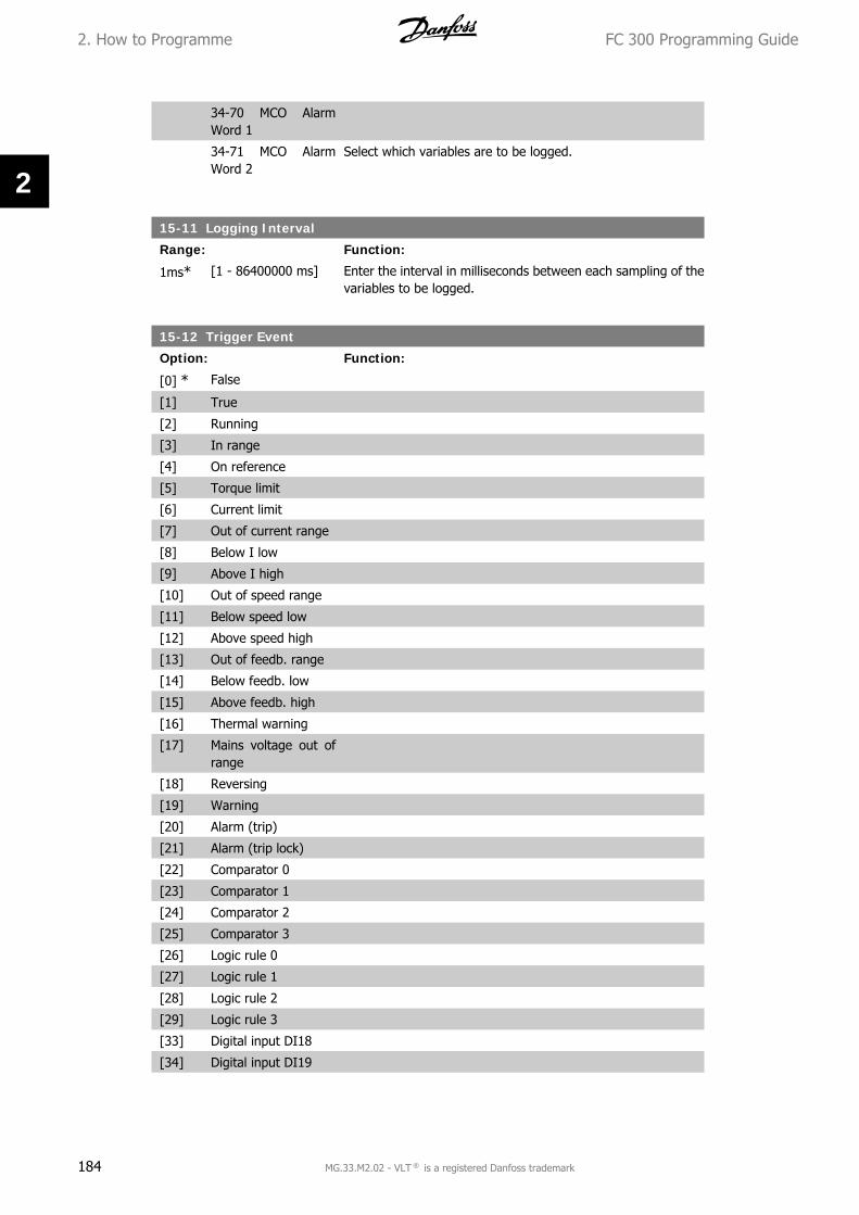
34-70 MCO AlarmWord 1
34-71 MCO AlarmWord 2
Select which variables are to be logged.
15-11 Logging Interval
Range: Function:
1ms* [1 - 86400000 ms] Enter the interval in milliseconds between each sampling of thevariables to be logged.
15-12 Trigger Event
Option: Function:
[0] * False
[1] True
[2] Running
[3] In range
[4] On reference
[5] Torque limit
[6] Current limit
[7] Out of current range
[8] Below I low
[9] Above I high
[10] Out of speed range
[11] Below speed low
[12] Above speed high
[13] Out of feedb. range
[14] Below feedb. low
[15] Above feedb. high
[16] Thermal warning
[17] Mains voltage out ofrange
[18] Reversing
[19] Warning
[20] Alarm (trip)
[21] Alarm (trip lock)
[22] Comparator 0
[23] Comparator 1
[24] Comparator 2
[25] Comparator 3
[26] Logic rule 0
[27] Logic rule 1
[28] Logic rule 2
[29] Logic rule 3
[33] Digital input DI18
[34] Digital input DI19
2. How to Programme FC 300 Programming Guide
184 MG.33.M2.02 - VLT ® is a registered Danfoss trademark
2

[35] Digital input DI27
[36] Digital input DI29 (FC302 only)
[37] Digital input DI32
[38] Digital input DI33
[50] Comparator 4
[51] Comparator 5
[60] Logic rule 4
[61] Logic rule 5 Select the trigger event. When the trigger event occurs, a win-dow is applied to freeze the log. The log will then retain aspecified percentage of samples before the occurrence of thetrigger event (par. 15-14).
15-13 Logging Mode
Option: Function:
[0] * Log always
[1] Log once on trigger Select Log always [0] for continuous logging.Select Log once on trigger [1] to conditionally start and stoplogging using par. 15-12 and par. 15-14.
15-14 Samples Before Trigger
Range: Function:
50* [0 - 100] Enter the percentage of all samples prior to a trigger eventwhich are to be retained in the log. See also par. 15-12 and par.15-13.
2.16.4. Historic Log,15-2*
View up to 50 logged data items via the array parameters in this parameter group. For all pa-rameters in the group, [0] is the most recent data and [49] the oldest data. Data is logged everytime an event occurs (not to be confused with SLC events). Events in this context are defined asa change in one of the following areas:
1. Digital input
2. Digital outputs (not monitored in this SW release)
3. Warning word
4. Alarm word
5. Status word
6. Control word
7. Extended status word
Events are logged with value, and time stamp in msec. The time interval between two eventsdepends on how often events occur (maximum once every scan time). Data logging is continuousbut if an alarm occurs, the log is saved and the values can be viewed on the display. This featureis useful, for example when carrying out service following a trip. View the historic log containedin this parameter via the serial communication port or via the display.
FC 300 Programming Guide 2. How to Programme
MG.33.M2.02 - VLT ® is a registered Danfoss trademark 185
2
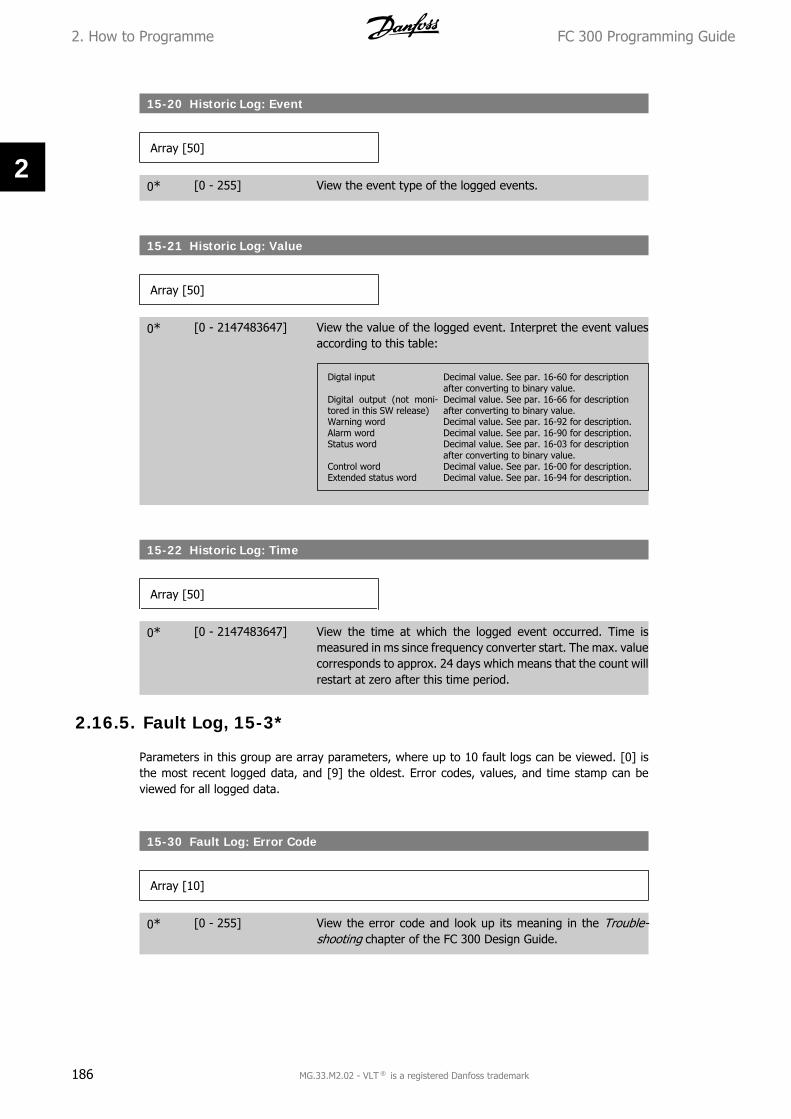
15-20 Historic Log: Event
Array [50]
0* [0 - 255] View the event type of the logged events.
15-21 Historic Log: Value
Array [50]
0* [0 - 2147483647] View the value of the logged event. Interpret the event valuesaccording to this table:
Digtal input Decimal value. See par. 16-60 for descriptionafter converting to binary value.
Digital output (not moni-tored in this SW release)
Decimal value. See par. 16-66 for descriptionafter converting to binary value.
Warning word Decimal value. See par. 16-92 for description.Alarm word Decimal value. See par. 16-90 for description.Status word Decimal value. See par. 16-03 for description
after converting to binary value.Control word Decimal value. See par. 16-00 for description.Extended status word Decimal value. See par. 16-94 for description.
15-22 Historic Log: Time
Array [50]
0* [0 - 2147483647] View the time at which the logged event occurred. Time ismeasured in ms since frequency converter start. The max. valuecorresponds to approx. 24 days which means that the count willrestart at zero after this time period.
2.16.5. Fault Log, 15-3*
Parameters in this group are array parameters, where up to 10 fault logs can be viewed. [0] isthe most recent logged data, and [9] the oldest. Error codes, values, and time stamp can beviewed for all logged data.
15-30 Fault Log: Error Code
Array [10]
0* [0 - 255] View the error code and look up its meaning in the Trouble-shooting chapter of the FC 300 Design Guide.
2. How to Programme FC 300 Programming Guide
186 MG.33.M2.02 - VLT ® is a registered Danfoss trademark
2
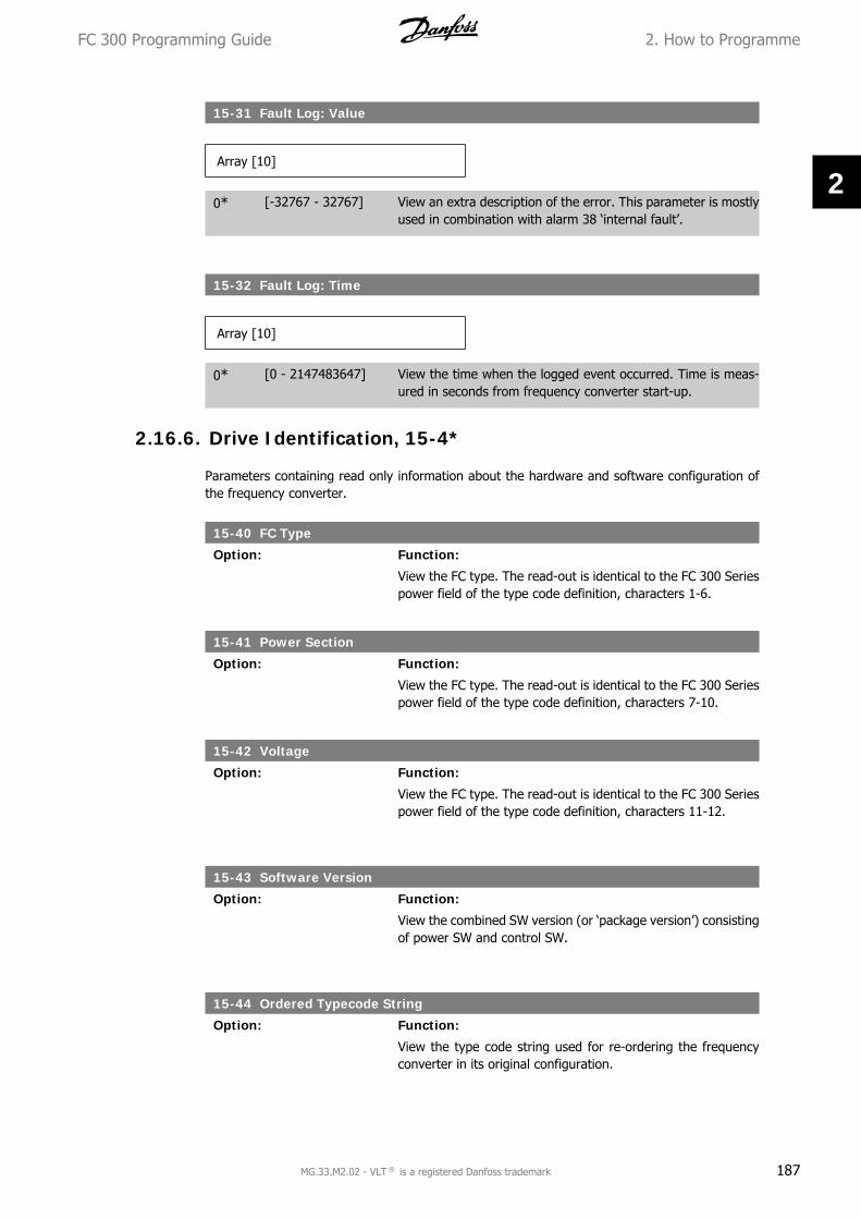
15-31 Fault Log: Value
Array [10]
0* [-32767 - 32767] View an extra description of the error. This parameter is mostlyused in combination with alarm 38 ‘internal fault’.
15-32 Fault Log: Time
Array [10]
0* [0 - 2147483647] View the time when the logged event occurred. Time is meas-ured in seconds from frequency converter start-up.
2.16.6. Drive Identification, 15-4*
Parameters containing read only information about the hardware and software configuration ofthe frequency converter.
15-40 FC Type
Option: Function:
View the FC type. The read-out is identical to the FC 300 Seriespower field of the type code definition, characters 1-6.
15-41 Power Section
Option: Function:
View the FC type. The read-out is identical to the FC 300 Seriespower field of the type code definition, characters 7-10.
15-42 Voltage
Option: Function:
View the FC type. The read-out is identical to the FC 300 Seriespower field of the type code definition, characters 11-12.
15-43 Software Version
Option: Function:
View the combined SW version (or ‘package version’) consistingof power SW and control SW.
15-44 Ordered Typecode String
Option: Function:
View the type code string used for re-ordering the frequencyconverter in its original configuration.
FC 300 Programming Guide 2. How to Programme
MG.33.M2.02 - VLT ® is a registered Danfoss trademark 187
2

15-45 Actual Typecode String
Option: Function:
View the actual type code string.
15-46 Frequency Converter Ordering No
Option: Function:
View the 8-digit ordering number used for re-ordering the fre-quency converter in its original configuration.
15-47 Power Card Ordering No
Option: Function:
View the power card ordering number.
15-48 LCP Id No
Option: Function:
View the LCP ID number.
15-49 SW ID Control Card
Option: Function:
View the control card software version number.
15-50 SW ID Power Card
Option: Function:
View the power card software version number.
15-51 Frequency Converter Serial Number
Option: Function:
View the frequency converter serial number.
15-53 Power Card Serial Number
Option: Function:
View the power card serial number.
2.16.7. Option Ident. 15-6*
This read-only parameter group contains information about the hardware and software configu-ration of the options installed in slots A, B C0 and C1.
2. How to Programme FC 300 Programming Guide
188 MG.33.M2.02 - VLT ® is a registered Danfoss trademark
2
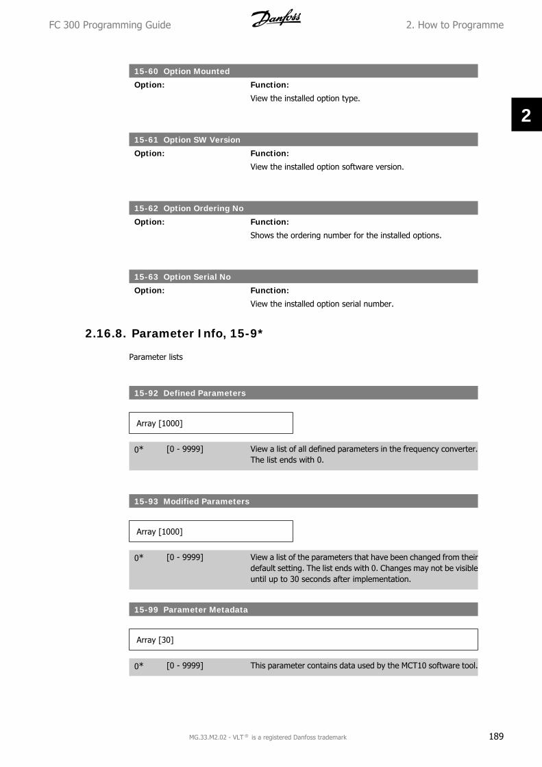
15-60 Option Mounted
Option: Function:
View the installed option type.
15-61 Option SW Version
Option: Function:
View the installed option software version.
15-62 Option Ordering No
Option: Function:
Shows the ordering number for the installed options.
15-63 Option Serial No
Option: Function:
View the installed option serial number.
2.16.8. Parameter Info, 15-9*
Parameter lists
15-92 Defined Parameters
Array [1000]
0* [0 - 9999] View a list of all defined parameters in the frequency converter.The list ends with 0.
15-93 Modified Parameters
Array [1000]
0* [0 - 9999] View a list of the parameters that have been changed from theirdefault setting. The list ends with 0. Changes may not be visibleuntil up to 30 seconds after implementation.
15-99 Parameter Metadata
Array [30]
0* [0 - 9999] This parameter contains data used by the MCT10 software tool.
FC 300 Programming Guide 2. How to Programme
MG.33.M2.02 - VLT ® is a registered Danfoss trademark 189
2

2.17. Parameters: Data Read-outs
2.17.1. 16-** Data Readouts
Parameter group for data read-outs, e.g. actual references, voltages, control, alarm, warning andstatus words.
2.17.2. 16-0* General Status
Parameters for reading the general status, e.g. the calculated reference, the active control word,status.
16-00 Control Word
Range: Function:
0* [0 - FFFF] View the Control word sent from the frequency converter via theserial communication port in hex code.
16-01 Reference [Unit]
Range: Function:
0.000* [-999999.000 -999999.000]
View the present reference value applied on impulse or analogbasis in the unit resulting from the configuration selected in par.1-00 (Hz, Nm or RPM).
16-02 -200.0 - 200.0 %
Range: Function:
0.0%* [] View the total reference. The total reference is the sum of dig-ital, analog, preset, bus, and freeze references, plus catch-upand slow-down.
16-03 Status Word
Range: Function:
0* [0 - FFFF] View the Status word sent from the frequency converter via theserial communication port in hex code.
16-05 Main Actual Value [%]
Range: Function:
0%* [-100 to +100%] View the two-byte word sent with the Status word to the busMaster reporting the Main Actual Value.
16-09 Custom Readout
Range: Function:
0.00unit*
[x.xx - x.xx unit] View the value of custom readout from par. 0-30 to par. 0-32
2. How to Programme FC 300 Programming Guide
190 MG.33.M2.02 - VLT ® is a registered Danfoss trademark
2

2.17.3. 16-1* Motor Status
Parameters for reading the motor status values.
16-10 Power [kW]
Range: Function:
0.0kW* [0.0 - 1000.0 kW] View the motor power in kW. The value shown is calculated onthe basis of the actual motor voltage and motor current. Thevalue is filtered, and therefore approx. 30 ms may pass fromwhen an input value changes to when the data read-out valueschange.
16-11 Power [hp]
Range: Function:
0.00hp* [0.00 - 1000.00 hp] View the motor power in hp. The value shown is calculated onthe basis of the actual motor voltage and motor current. Thevalue is filtered, and therefore approx. 30 ms may pass fromwhen an input value changes to when the data read-out valueschange.
16-12 Motor Voltage
Range: Function:
0.0V* [0.0 - 6000.0 V] View the motor voltage, a calculated value used for controllingthe motor.
16-13 Motor Frequency
Range: Function:
0.0Hz* [0.0 - 6500.0 Hz] View the motor frequency, without resonance dampening.
16-14 Motor Current
Range: Function:
0.00A* [0.00 - 0.00 A] View the motor current measured as a mean value, IRMS. Thevalue is filtered, and thus approx. 30 ms may pass from whenan input value changes to when the data read-out valueschange.
16-15 Frequency [%]
Range: Function:
0.00%* [0.00 - 0.00 %] View a two-byte word reporting the actual motor frequency(without resonance dampening) as a percentage (scale0000-4000 Hex) of par. 4-19 Max. Output Frequency. Set par.9-16 index 1 to send it with the Status Word instead of the MAV.
FC 300 Programming Guide 2. How to Programme
MG.33.M2.02 - VLT ® is a registered Danfoss trademark 191
2

16-16 Torque
Range: Function:
0.0Nm* [-3000.0 - 3000.0Nm]
View the torque value with sign, applied to the motor shaft.Linearity is not exact between 160% motor current and torquein relation to the rated torque. Some motors supply more than160% torque. Consequently, the min. value and the max. valuewill depend on the max. motor current as well as the motorused. The value is filtered, and thus approx. 30 ms may passfrom when an input changes value to when the data read-outvalues change.
16-17 Speed [RPM]
Range: Function:
0 RPM* [0 - 0 RPM] View the actual motor RPM. In open loop or closed loop processcontrol the motor RPM is estimated. In speed closed loop modesthe motor RPM is measured.
16-18 Motor Thermal
Range: Function:
0 %* [0 - 100 %] View the calculated thermal load on the motor. The cut-out limitis 100%. The basis for calculation is the ETR function selectedin par.1-90.
16-19 KTY Sensor Temperature
Range: Function:
0°C* [0 - xxx °C] Returning the actual temperature on KTY sensor buil into themotor.See par. 1-9*.
16-20 Motor Angle
Range: Function:
0* [0 - 65535] View the current encoder/resolver angle offset relative to theindex position. The value range of 0-65535 corresponds to0-2*pi (radians).
16-22 Torque [%]
Range: Function:
0%* [-200 - 200%] Value shown is the torque in percent of nominal torque, withsign, applied to the motor shaft.
2.17.4. 16-3* Drive Status
Parameters for reporting the status of the frequency converter.
2. How to Programme FC 300 Programming Guide
192 MG.33.M2.02 - VLT ® is a registered Danfoss trademark
2

16-30 DC Link Voltage
Range: Function:
0V* [0 - 10000 V] View a measured value. The value is filtered, and thus approx.30 ms may pass from when an input value changes to when thedata read-out value changes.
16-32 Brake Energy /s
Range: Function:
0.000kW*
[0.000 - 0.000 kW] View the brake power transmitted to an external brake resistor,stated as an instantaneous value.
16-33 Brake Energy /2 min
Range: Function:
0.000kW*
[0.000 - 500.000 kW] View the brake power transmitted to an external brake resistor.The mean power is calculated on an average basis for the mostrecent 120 seconds.
16-34 Heatsink Temp.
Range: Function:
0°C* [0 - 255 °C] View the frequency converter heatsink temperature. The cut-out limit is 90 ± 5 °C, and the motor cuts back in at 60 ± 5 °C.
16-35 Inverter Thermal
Range: Function:
0 %* [0 - 0 %] View the percentage load on the inverter.
16-36 Inv. Nom. Current
Range: Function:
A* [0.01 - 10000.00 A] View the inverter nominal current, which should match thenameplate data on the connected motor. The data are used forcalculation of torque, motor protection, etc.
16-37 Inv. Max. Current
Range: Function:
A* [0.01 - 10000.00 A] View the inverter maximum current, which should match thenameplate data on the connected motor. The data are used forcalculation of torque, motor protection, etc.
16-38 SL Controller State
Range: Function:
0* [0 - 100] View the state of the event under execution by the SL controller.
16-39 Control Card Temp.
Range: Function:
0°C* [0 - 100 °C] View the temperature on the control card, stated in °C.
FC 300 Programming Guide 2. How to Programme
MG.33.M2.02 - VLT ® is a registered Danfoss trademark 193
2

16-40 Logging Buffer Full
Option: Function:
[0] * No
[1] Yes View whether the logging buffer is full (see par. 15-1*). Thelogging buffer will never be full when par. 15-13 LoggingMode is set to Log always [0].
2.17.5. 16-5* Ref. & Feedb.
Parameters for reporting the reference and feedback input.
16-50 External Reference
Range: Function:
0.0* [-200.0 - 200.0] View the total reference, the sum of digital, analog, preset, busand freeze references, plus catch-up and slow-down.
16-51 Pulse Reference
Range: Function:
0.0* [-200 - 200] View the reference value from programmed digital input(s). Theread-out can also reflect the impulses from an incremental en-coder.
16-52 Feedback [Unit]
Range: Function:
0.0* [-999999.999 -999999.999]
View the feedback unit resulting from the selection of unit andscaling in par. 3-00, 3-01, 3-02 and 3-03.
16-53 Digi Pot Reference
Range: Function:
0.0* [-200 - 200] View the contribution of the Digital Potentiometer to the actualreference.
2.17.6. 16-6* Inputs and Outputs
Parameters for reporting the digital and analog IO ports.
16-60 Digital Input
Range: Function:
0* [0 - 63] View the signal states from the active digital inputs. Example:Input 18 corresponds to bit no. 5, ‘0’ = no signal, ‘1’ = connectedsignal.
2. How to Programme FC 300 Programming Guide
194 MG.33.M2.02 - VLT ® is a registered Danfoss trademark
2

Bit 0 Digital input term. 33Bit 1 Digital input term. 32Bit 2 Digital input term. 29Bit 3 Digital input term. 27Bit 4 Digital input term. 19Bit 5 Digital input term. 18Bit 6 Digital input term. 37Bit 7 Digital input GP I/O term. X30/4Bit 8 Digital input GP I/O term. X30/3Bit 9 Digital input GP I/O term. X30/2Bit 10-63 Reserved for future terminals
16-61 Terminal 53 Switch Setting
Option: Function:
[0] * Current
[1] Voltage View the setting of input terminal 53. Current = 0; Voltage = 1.
16-62 Analog Input 53
Range: Function:
0.000* [-20.000 - 20.000] View the actual value at input 53.
16-63 Terminal 54 Switch Setting
Option: Function:
[0] * Current
[1] Voltage View the setting of input terminal 54. Current = 0; Voltage = 1.
16-64 Analog Input 54
Range: Function:
0.000* [-20.000 - 20.000] View the actual value at input 54.
16-65 Analog Output 42 [mA]
Range: Function:
0.000* [0.000 - 30.000] View the actual value at output 42 in mA. The value shown re-flects the selection in par. 06-50.
16-66 Digital Output [bin]
Range: Function:
0* [0 - 115] View the binary value of all digital outputs.
16-67 Freq. Input 29 [Hz]
Range: Function:
0* [0 - 0] View the actual frequency rate on terminal 29.
FC 300 Programming Guide 2. How to Programme
MG.33.M2.02 - VLT ® is a registered Danfoss trademark 195
2

16-68 Freq. Input #33 [Hz]
Range: Function:
0* [0 - 130000] View the actual value of the frequency applied at terminal 33 asan impulse input.
16-69 Pulse Output #27 [Hz]
Range: Function:
0* [0 - 40000] View the actual value of pulses applied to terminal 27 in digitaloutput mode.
16-70 Pulse Output #29 [Hz]
Range: Function:
0* [0 - 40000] View the actual value of pulses at terminal 29 in digital outputmode.This parameter is available for FC 302 only.
16-71 Relay Output [bin]
Range: Function:
0* [0 - 31] View the settings of all relays.
16-72 Counter A
Range: Function:
0* [-2147483648-2147483647]
View the present value of Counter A. Counters are useful ascomparator operands, see par. 13-10.The value can be reset or changed either via digital inputs (pa-rameter group 5-1*) or by using an SLC action (par. 13-52).
16-73 Counter B
Range: Function:
0* [-2147483648-2147483647]
View the present value of Counter B. Counters are useful ascomparator operands (par. 13-10).The value can be reset or changed either via digital inputs (pa-rameter group 5-1*) or by using an SLC action (par. 13-52).
16-74 Precise Stop Counter
Range: Function:
0* [0 - 2147483647] Returns the actual counter value of precise counter (par. 1-84).
2. How to Programme FC 300 Programming Guide
196 MG.33.M2.02 - VLT ® is a registered Danfoss trademark
2

16-75 Analog In X30/11
Range: Function:
0.000* [0.000 - 0.000] View the actual value at input X30/11 of MCB 101.
16-76 Analog In X30/12
Range: Function:
0.000* [0.000 - 0.000] View the actual value at input X30/12 of MCB 101.
16-77 Analog Out X30/8 16-77 [mA]
Range: Function:
0.000* [0.000 - 0.000] View the actual value at input X30/8 in mA.
2.17.7. 16-8* Fieldbus & FC Port
Parameters for reporting the BUS references and control words.
16-80 Fieldbus CTW 1
Range: Function:
0* [0 - 65535] View the two-byte Control word (CTW) received from the Bus-Master. Interpretation of the Control word depends on thefieldbus option installed and the Control word profile selected inpar. 8-10.For more information please refer to the relevant fieldbus man-ual.
16-82 Fieldbus REF 1
Range: Function:
0* [-200 - 200] View the two-byte word sent with the control word form theBus-Master to set the reference value.For more information please refer to the relevant fieldbus man-ual.
16-84 Comm. Option STW
Range: Function:
0* [0 - 65535] View the extended fieldbus comm. option status word.For more information please refer to the relevant fieldbus man-ual.
16-85 FC Port CTW 1
Range: Function:
0* [0 - 65535] View the two-byte Control word (CTW) received from the Bus-Master. Interpretation of the control word depends on the field-bus option installed and the Control word profile selected in par.8-10.
FC 300 Programming Guide 2. How to Programme
MG.33.M2.02 - VLT ® is a registered Danfoss trademark 197
2

16-86 FC Port REF 1
Range: Function:
0* [0 - 0] View the two-byte Status word (STW) sent to the Bus-Master.Interpretation of the Status word depends on the fieldbus optioninstalled and the Control word profile selected in par. 8-10.
2.17.8. 16-9* Diagnosis Read-Out
Parameters displaying alarm, warning and extended status words.
16-90 Alarm Word
Range: Function:
0* [0 - FFFFFFFF] View the alarm word sent via the serial communication port inhex code.
16-90 Alarm Word 2
Range: Function:
0* [0 - FFFFFFFF] View the alarm word sent via the serial communication port inhex code.
16-92 Warning Word
Range: Function:
0* [0 - FFFFFFFF] View the warning word sent via the serial communication portin hex code.
16-93 Warning Word 2
Range: Function:
0* [0 - FFFF] View the warning word sent via the serial communication portin hex code.
16-94 Ext. Status Word
Range: Function:
0* [0 - FFFF] Returns the extended warning word sent via the serial commu-nication port in hex code.
2.18. Parameters: Encoder Input
2.18.1. 17-** Motor Feedb. Option
Additional parameters to configure the Encoder (MCB102) or the Resolver (MCB103) FeedbackOption.
2. How to Programme FC 300 Programming Guide
198 MG.33.M2.02 - VLT ® is a registered Danfoss trademark
2

2.18.2. 17-1* Inc. Enc. Interface
Parameters in this group configure the incremental interface of the MCB102 option. Note that boththe incremental and absolute interfaces are active at the same time.
17-10 Signal Type
Option: Function:
[0] None
[1] * RS422 (5V TTL/linedrv.)
[2] Sinusoidal 1Vpp Select the incremental type (A/B channel) of the encoder in use.Find the information on the encoder data sheet.Select None [0] if the feedback sensor is an absolute encoderonly.This parameter cannot be adjusted while the motor is running.
17-11 Resolution (PPR)
Range: Function:
1024* [10 - 10000] Enter the resolution of the incremental track, i.e. the number ofpulses or periods per revolution.This parameter cannot be adjusted while the motor is running.
2.18.3. 17-2* Abs. Enc. Interface
Parameters in this group configure the absolute interface of the MCB102 option. Note that boththe incremental and absolute interfaces are active at the same time.
17-20 Protocol Selection
Option: Function:
[0] * None
[1] HIPERFACE
[2] EnDat
[4] SSI Select HIPERFACE [1] if the encoder is absolute only.Select None [0] if the feedback sensor is an incremental encoderonly.This parameter cannot be adjusted while the motor is running.
17-21 Resolution (Positions/Rev)
Option: Function:
[512] 512
[1024] 1024
[2048] 2048
[4096] 4096
[8192] SSI 4 - 8192
[16384] 16384
[32768] HIPERFACE 512 -32768
Select the resolution of the absolute encoder, i.e. the numberof counts per revolution.
FC 300 Programming Guide 2. How to Programme
MG.33.M2.02 - VLT ® is a registered Danfoss trademark 199
2

This parameter cannot be adjusted while the motor is running.The value depends on setting in par. 17-20.
17-24 SSI Data Length
Range: Function:
13* [13 - 25] Set the number of bits for the SSI telegram. Choose 13 bits forsingle-turn encoders and 25 bits for multi-turn encoder.
17-25 Clock Rate
Range: Function:
260kHz*
[100 - 260 kHz] Set the SSI clock rate. With long encoder cables the clock ratemust be reduced.
17-26 SSI Data Format
Option: Function:
[0] * Gray Code
[1] Binary Code Set the data format of the SSI data. Choose between Gray orBinary format.
17-34 HIPERFACE Baudrate
Option: Function:
[0] 600
[1] 1200
[2] 2400
[3] 4800
[4] * 9600
[5] 19200
[6] 38400 Select the baud rate of the attached encoder.This parameter cannot be adjusted while the motor is running.The parameter is only accessible when par. 17-20 is set to HI-PERFACE [1].
2.18.4. 17-5* Resolver Interface
Parameter group 17-5* is used for setting parameters for the MCB 103 Resolver Option.Usually the resolver feedback is used as motor feedback from Permanent Magnet motors with par.1-01 set to Flux with motor feedback.Resolver parameters cannot be adjusted while the motor is running.
17-50 Resolver Poles
Range: Function:
2* [2-2] Set the number of poles on the resolver.The value is stated in the data sheet for resolvers.
2. How to Programme FC 300 Programming Guide
200 MG.33.M2.02 - VLT ® is a registered Danfoss trademark
2
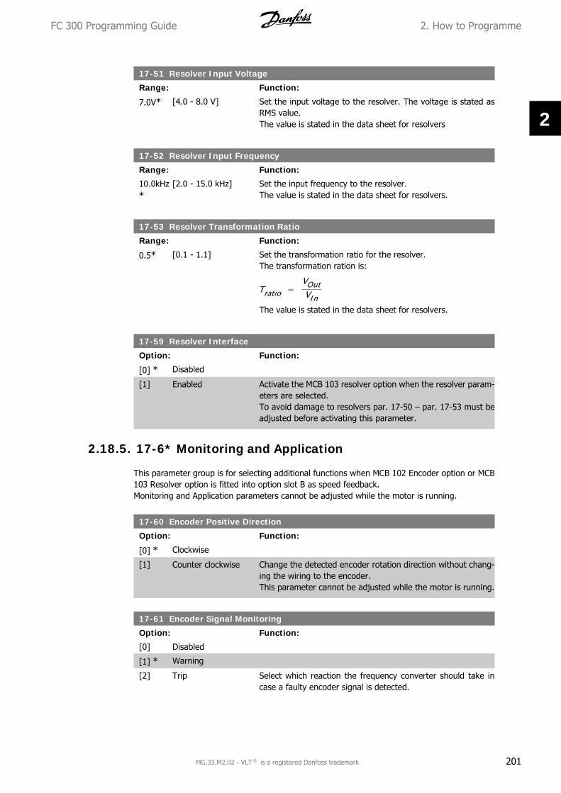
17-51 Resolver Input Voltage
Range: Function:
7.0V* [4.0 - 8.0 V] Set the input voltage to the resolver. The voltage is stated asRMS value.The value is stated in the data sheet for resolvers
17-52 Resolver Input Frequency
Range: Function:
10.0kHz*
[2.0 - 15.0 kHz] Set the input frequency to the resolver.The value is stated in the data sheet for resolvers.
17-53 Resolver Transformation Ratio
Range: Function:
0.5* [0.1 - 1.1] Set the transformation ratio for the resolver.The transformation ration is:
Tratio =VOutVIn
The value is stated in the data sheet for resolvers.
17-59 Resolver Interface
Option: Function:
[0] * Disabled
[1] Enabled Activate the MCB 103 resolver option when the resolver param-eters are selected.To avoid damage to resolvers par. 17-50 – par. 17-53 must beadjusted before activating this parameter.
2.18.5. 17-6* Monitoring and Application
This parameter group is for selecting additional functions when MCB 102 Encoder option or MCB103 Resolver option is fitted into option slot B as speed feedback.Monitoring and Application parameters cannot be adjusted while the motor is running.
17-60 Encoder Positive Direction
Option: Function:
[0] * Clockwise
[1] Counter clockwise Change the detected encoder rotation direction without chang-ing the wiring to the encoder.This parameter cannot be adjusted while the motor is running.
17-61 Encoder Signal Monitoring
Option: Function:
[0] Disabled
[1] * Warning
[2] Trip Select which reaction the frequency converter should take incase a faulty encoder signal is detected.
FC 300 Programming Guide 2. How to Programme
MG.33.M2.02 - VLT ® is a registered Danfoss trademark 201
2

The encoder function in par. 17-61 is an electrical check of thehardware circuit in the encoder system.
2.19. Parameter Lists
FC SeriesAll = valid for FC 301 and FC 302 series01 = valid for FC 301 only02 = valid for FC 302 only
Changes during operation”TRUE” means that the parameter can be changed while the frequency converter is in operationand “FALSE” means that the frequency converter must be stopped before a change can be made.
4-Set-up'All set-ups': the parameter can be set individually in each of the four set-ups, i. e. one singleparameter can have four different data values.’1 set-up’: data value will be the same in all set-ups.
Conversion indexThis number refers to a conversion figure used when writing or reading by means of a frequencyconverter.
Conv. index 100 67 6 5 4 3 2 1 0 -1 -2 -3 -4 -5 -6Conv. factor 1 1/60 100000
0100000 10000 1000 100 10 1 0.1 0.01 0.00
10.000
10.0000
10.000001
Data type Description Type2 Integer 8 Int83 Integer 16 Int164 Integer 32 Int325 Unsigned 8 Uint86 Unsigned 16 Uint167 Unsigned 32 Uint329 Visible String VisStr33 Normalized value 2 bytes N235 Bit sequence of 16 boolean variables V254 Time difference w/o date TimD
2. How to Programme FC 300 Programming Guide
202 MG.33.M2.02 - VLT ® is a registered Danfoss trademark
2

Par.
No.
#Pa
ram
eter
des
crip
tion
Def
ault
valu
e (S
R -
Size
Rel
ated
)4-
set-
upFC
302
only
Chan
gedu
ring
oper
atio
n
Conv
ersi
onin
dex
Type
0-0*
Bas
ic S
etti
ngs
0-01
Lang
uage
[0]
Engl
ish
1 se
t-up
TRU
E-
Uin
t80-
02M
otor
Spe
ed U
nit
[0]
RPM
2 se
t-up
sFA
LSE
-U
int8
0-03
Reg
iona
l Set
tings
[0]
Inte
rnat
iona
l2
set-
ups
FALS
E-
Uin
t80-
04O
pera
ting
Stat
e at
Pow
er-u
p (H
and)
[1]
Forc
ed s
top,
ref
=ol
dAl
l set
-ups
TRU
E-
Uin
t80-
1* S
et-u
p O
pera
tion
s0-
10Ac
tive
Set-
up[1
] Se
t-up
11
set-
upTR
UE
-U
int8
0-11
Edit
Set-
up[1
] Se
t-up
1Al
l set
-ups
TRU
E-
Uin
t80-
12Th
is S
et-u
p Li
nked
to
[0]
Not
link
edAl
l set
-ups
FALS
E-
Uin
t80-
13Re
adou
t: L
inke
d Se
t-up
s0
All s
et-u
psFA
LSE
0U
int1
60-
14Re
adou
t: E
dit
Set-
ups
/ Ch
anne
l0
All s
et-u
psTR
UE
0In
t32
0-2*
LC
P D
ispl
ay0-
20D
ispl
ay L
ine
1.1
Smal
l16
17Al
l set
-ups
TRU
E-
Uin
t16
0-21
Dis
play
Lin
e 1.
2 Sm
all
1614
All s
et-u
psTR
UE
-U
int1
60-
22D
ispl
ay L
ine
1.3
Smal
l16
10Al
l set
-ups
TRU
E-
Uin
t16
0-23
Dis
play
Lin
e 2
Larg
e16
13Al
l set
-ups
TRU
E-
Uin
t16
0-24
Dis
play
Lin
e 3
Larg
e16
02Al
l set
-ups
TRU
E-
Uin
t16
0-25
My
Pers
onal
Men
uSR
1 se
t-up
TRU
E0
Uin
t16
0-3*
LC
P C
ust
om R
eado
ut
0-30
Uni
t fo
r U
ser-
defin
ed R
eado
ut[0
] N
one
All s
et-u
psTR
UE
-U
int8
0-31
Min
Val
ue o
f U
ser-
defin
ed R
eado
ut0.
00Al
l set
-ups
TRU
E-2
Int3
20-
32M
ax V
alue
of U
ser-
defin
ed R
eado
ut10
0.00
All s
et-u
psTR
UE
-2In
t32
0-4*
LC
P K
eypa
d0-
40[H
and
on]
Key
on L
CP[1
] En
able
dAl
l set
-ups
TRU
E-
Uin
t80-
41[O
ff]
Key
on L
CP[1
] En
able
dAl
l set
-ups
TRU
E-
Uin
t80-
42[A
uto
on]
Key
on L
CP[1
] En
able
dAl
l set
-ups
TRU
E-
Uin
t80-
43[R
eset
] Ke
y on
LCP
[1]
Enab
led
All s
et-u
psTR
UE
-U
int8
0-5*
Cop
y/Sa
ve0-
50LC
P Co
py[0
] N
o co
pyAl
l set
-ups
FALS
E-
Uin
t80-
51Se
t-up
Cop
y[0
] N
o co
pyAl
l set
-ups
FALS
E-
Uin
t80-
6* P
assw
ord
0-60
Mai
n M
enu
Pass
wor
d10
01
set-
upTR
UE
0U
int1
60-
61Ac
cess
to
Mai
n M
enu
w/o
Pas
swor
d[0
] Fu
ll ac
cess
1 se
t-up
TRU
E-
Uin
t80-
65Q
uick
Men
u Pa
ssw
ord
200
1 se
t-up
TRU
E0
Uin
t16
0-66
Acce
ss t
o Q
uick
Men
u w
/o P
assw
ord
[0]
Full
acce
ss1
set-
upTR
UE
-U
int8
2.1
9.1
.0
-**
Ope
rati
on/D
ispl
ay
FC 300 Programming Guide 2. How to Programme
MG.33.M2.02 - VLT ® is a registered Danfoss trademark 203
2

Par.
No.
#Pa
ram
eter
des
crip
tion
Def
ault
valu
e4-
set-
upFC
302
only
Chan
ge d
urin
g op
-er
atio
nCo
nver
-si
on in
dex
Type
1-0*
Gen
eral
Set
tin
gs1-
00Co
nfig
urat
ion
Mod
enu
llAl
l set
-ups
TRU
E-
Uin
t81-
01M
otor
Con
trol
Prin
cipl
enu
llAl
l set
-ups
FALS
E-
Uin
t81-
02Fl
ux M
otor
Fee
dbac
k So
urce
[1]
24V
enco
der
All s
et-u
psx
FALS
E-
Uin
t81-
03To
rque
Cha
ract
eris
tics
[0]
Cons
tant
tor
que
All s
et-u
psTR
UE
-U
int8
1-04
Ove
rload
Mod
e[0
] H
igh
torq
ueAl
l set
-ups
FALS
E-
Uin
t81-
05Lo
cal M
ode
Conf
igur
atio
n[2
] As
mod
e pa
r 1-
00Al
l set
-ups
TRU
E-
Uin
t81-
1* M
otor
Sel
ecti
on1-
10M
otor
Con
stru
ctio
n[0
] As
ynch
ron
All s
et-u
psFA
LSE
-U
int8
1-2*
Mot
or D
ata
1-20
Mot
or P
ower
[kW
]Ex
pres
sion
Lim
itAl
l set
-ups
FALS
E1
Uin
t32
1-21
Mot
or P
ower
[H
P]Ex
pres
sion
Lim
itAl
l set
-ups
FALS
E-2
Uin
t32
1-22
Mot
or V
olta
geEx
pres
sion
Lim
itAl
l set
-ups
FALS
E0
Uin
t16
1-23
Mot
or F
requ
ency
Expr
essi
onLi
mit
All s
et-u
psFA
LSE
0U
int1
61-
24M
otor
Cur
rent
Expr
essi
onLi
mit
All s
et-u
psFA
LSE
-2U
int3
21-
25M
otor
Nom
inal
Spe
edEx
pres
sion
Lim
itAl
l set
-ups
FALS
E67
Uin
t16
1-26
Mot
or C
ont.
Rat
ed T
orqu
eEx
pres
sion
Lim
itAl
l set
-ups
FALS
E-1
Uin
t32
1-29
Auto
mat
ic M
otor
Ada
ptat
ion
(AM
A)[0
] O
ffAl
l set
-ups
FALS
E-
Uin
t81-
3* A
dv. M
otor
Dat
a1-
30St
ator
Res
ista
nce
(Rs)
Expr
essi
onLi
mit
All s
et-u
psFA
LSE
-4U
int3
21-
31Rot
or R
esis
tanc
e (R
r)Ex
pres
sion
Lim
itAl
l set
-ups
FALS
E-4
Uin
t32
1-33
Stat
or L
eaka
ge R
eact
ance
(X1
)Ex
pres
sion
Lim
itAl
l set
-ups
FALS
E-4
Uin
t32
1-34
Rot
or L
eaka
ge R
eact
ance
(X2
)Ex
pres
sion
Lim
itAl
l set
-ups
FALS
E-4
Uin
t32
1-35
Mai
n Rea
ctan
ce (
Xh)
Expr
essi
onLi
mit
All s
et-u
psFA
LSE
-4U
int3
21-
36Ir
on L
oss
Resi
stan
ce (
Rfe)
Expr
essi
onLi
mit
All s
et-u
psFA
LSE
-3U
int3
21-
37d-
axis
Ind
ucta
nce
(Ld)
Expr
essi
onLi
mit
All s
et-u
psx
FALS
E-4
Int3
21-
39M
otor
Pol
esEx
pres
sion
Lim
itAl
l set
-ups
FALS
E0
Uin
t81-
40Ba
ck E
MF
at 1
000
RPM
Expr
essi
onLi
mit
All s
et-u
psx
FALS
E0
Uin
t16
1-41
Mot
or A
ngle
Off
set
0 N
/AAl
l set
-ups
FALS
E0
Int1
61-
5* L
oad
Inde
p. S
etti
ng
1-50
Mot
or M
agne
tisat
ion
at Z
ero
Spee
d10
0 %
All s
et-u
psTR
UE
0U
int1
61-
51M
in S
peed
Nor
mal
Mag
netis
ing
[RPM
]Ex
pres
sion
Lim
itAl
l set
-ups
TRU
E67
Uin
t16
1-52
Min
Spe
ed N
orm
al M
agne
tisin
g [H
z]Ex
pres
sion
Lim
itAl
l set
-ups
TRU
E-1
Uin
t16
1-53
Mod
el S
hift
Fre
quen
cyEx
pres
sion
Lim
itAl
l set
-ups
xFA
LSE
-1U
int1
61-
55U
/f C
hara
cter
istic
- U
Expr
essi
onLi
mit
All s
et-u
psTR
UE
-1U
int1
61-
56U
/f C
hara
cter
istic
- F
Expr
essi
onLi
mit
All s
et-u
psTR
UE
-1U
int1
6
2.1
9.2
.1
-**
Loa
d/M
otor
2. How to Programme FC 300 Programming Guide
204 MG.33.M2.02 - VLT ® is a registered Danfoss trademark
2

Par.
No.
#Pa
ram
eter
des
crip
tion
Def
ault
valu
e4-
set-
upFC
302
only
Chan
ge d
urin
g op
-er
atio
nCo
nver
-si
on in
dex
Type
1-6*
Loa
d D
epen
. Set
ting
1-60
Low
Spe
ed L
oad
Com
pens
atio
n10
0 %
All s
et-u
psTR
UE
0In
t16
1-61
Hig
h Sp
eed
Load
Com
pens
atio
n10
0 %
All s
et-u
psTR
UE
0In
t16
1-62
Slip
Com
pens
atio
nEx
pres
sion
Lim
itAl
l set
-ups
TRU
E0
Int1
61-
63Sl
ip C
ompe
nsat
ion
Tim
e Co
nsta
ntEx
pres
sion
Lim
itAl
l set
-ups
TRU
E-2
Uin
t16
1-64
Res
onan
ce D
ampe
ning
100
%Al
l set
-ups
TRU
E0
Uin
t16
1-65
Res
onan
ce D
ampe
ning
Tim
e Co
nsta
nt5
ms
All s
et-u
psTR
UE
-3U
int8
1-66
Min
. Cur
rent
at
Low
Spe
ed10
0 %
All s
et-u
psx
TRU
E0
Uin
t81-
67Lo
ad T
ype
[0]
Pass
ive
load
All s
et-u
psx
TRU
E-
Uin
t81-
68M
inim
um I
nert
iaEx
pres
sion
Lim
itAl
l set
-ups
xFA
LSE
-4U
int3
21-
69M
axim
um I
nert
iaEx
pres
sion
Lim
itAl
l set
-ups
xFA
LSE
-4U
int3
21-
7* S
tart
Adj
ust
men
ts1-
71St
art
Del
ay0.
0 s
All s
et-u
psTR
UE
-1U
int8
1-72
Star
t Fu
nctio
n[2
] Co
ast/
dela
y tim
eAl
l set
-ups
TRU
E-
Uin
t81-
73Fl
ying
Sta
rt[0
] D
isab
led
All s
et-u
psFA
LSE
-U
int8
1-74
Star
t Sp
eed
[RPM
]Ex
pres
sion
Lim
itAl
l set
-ups
TRU
E67
Uin
t16
1-75
Star
t Sp
eed
[Hz]
Expr
essi
onLi
mit
All s
et-u
psTR
UE
-1U
int1
61-
76St
art
Curr
ent
0.00
AAl
l set
-ups
TRU
E-2
Uin
t32
1-8*
Sto
p A
djus
tmen
ts1-
80Fu
nctio
n at
Sto
p[0
] Co
ast
All s
et-u
psTR
UE
-U
int8
1-81
Min
Spe
ed f
or F
unct
ion
at S
top
[RPM
]Ex
pres
sion
Lim
itAl
l set
-ups
TRU
E67
Uin
t16
1-82
Min
Spe
ed f
or F
unct
ion
at S
top
[Hz]
Expr
essi
onLi
mit
All s
et-u
psTR
UE
-1U
int1
61-
83Pr
ecis
e St
op F
unct
ion
[0]
Prec
ise
ram
p st
opAl
l set
-ups
FALS
E-
Uin
t81-
84Pr
ecis
e St
op C
ount
er V
alue
1000
00 N
/AAl
l set
-ups
TRU
E0
Uin
t32
1-85
Prec
ise
Stop
Spe
ed C
ompe
nsat
ion
Del
ay10
ms
All s
et-u
psTR
UE
-3U
int8
1-9*
Mot
or T
empe
ratu
re1-
90M
otor
The
rmal
Pro
tect
ion
[0]
No
prot
ectio
nAl
l set
-ups
TRU
E-
Uin
t81-
91M
otor
Ext
erna
l Fan
[0]
No
All s
et-u
psTR
UE
-U
int1
61-
93Th
erm
isto
r Re
sour
ce[0
] N
one
All s
et-u
psTR
UE
-U
int8
1-95
KTY
Sens
or T
ype
[0]
KTY
Sens
or 1
All s
et-u
psx
TRU
E-
Uin
t81-
96KT
Y Th
erm
isto
r Res
ourc
e[0
] N
one
All s
et-u
psx
TRU
E-
Uin
t81-
97KT
Y Th
resh
old
leve
l80
°C
1 se
t-up
xTR
UE
100
Int1
6
FC 300 Programming Guide 2. How to Programme
MG.33.M2.02 - VLT ® is a registered Danfoss trademark 205
2

Par.
No.
#Pa
ram
eter
des
crip
tion
Def
ault
valu
e4-
set-
upFC
302
only
Chan
ge d
urin
g op
-er
atio
nCo
nver
-si
on in
dex
Type
2-0*
DC
-Bra
ke2-
00D
C H
old
Curr
ent
50 %
All s
et-u
psTR
UE
0U
int8
2-01
DC
Brak
e Cu
rren
t50
%Al
l set
-ups
TRU
E0
Uin
t16
2-02
DC
Brak
ing
Tim
e10
.0 s
All s
et-u
psTR
UE
-1U
int1
62-
03D
C Br
ake
Cut
In S
peed
[RP
M]
Expr
essi
onLi
mit
All s
et-u
psTR
UE
67U
int1
62-
04D
C Br
ake
Cut
In S
peed
[H
z]Ex
pres
sion
Lim
itAl
l set
-ups
TRU
E-1
Uin
t16
2-1*
Bra
ke E
ner
gy F
un
ct.
2-10
Brak
e Fu
nctio
nnu
llAl
l set
-ups
TRU
E-
Uin
t82-
11Br
ake
Resi
stor
(oh
m)
Expr
essi
onLi
mit
All s
et-u
psTR
UE
0U
int1
62-
12Br
ake
Pow
er L
imit
(kW
)Ex
pres
sion
Lim
itAl
l set
-ups
TRU
E0
Uin
t32
2-13
Brak
e Po
wer
Mon
itorin
g[0
] O
ffAl
l set
-ups
TRU
E-
Uin
t82-
15Br
ake
Chec
k[0
] O
ffAl
l set
-ups
TRU
E-
Uin
t82-
16AC
bra
ke M
ax. C
urre
nt10
0.0
%Al
l set
-ups
TRU
E-1
Uin
t32
2-17
Ove
r-vo
ltage
Con
trol
[0]
Dis
able
dAl
l set
-ups
TRU
E-
Uin
t82-
2* M
ech
anic
al B
rake
2-20
Rel
ease
Bra
ke C
urre
ntIm
axVL
T (P
1637
)Al
l set
-ups
TRU
E-2
Uin
t32
2-21
Activ
ate
Brak
e Sp
eed
[RPM
]Ex
pres
sion
Lim
itAl
l set
-ups
TRU
E67
Uin
t16
2-22
Activ
ate
Brak
e Sp
eed
[Hz]
Expr
essi
onLi
mit
All s
et-u
psTR
UE
-1U
int1
62-
23Ac
tivat
e Br
ake
Del
ay0.
0 s
All s
et-u
psTR
UE
-1U
int8
2-24
Stop
Del
ay0.
0 s
All s
et-u
psTR
UE
-1U
int8
2-25
Brak
e Re
leas
e Ti
me
0.20
sAl
l set
-ups
TRU
E-2
Uin
t16
2-26
Torq
ue R
ef0.
00 %
All s
et-u
psTR
UE
-2In
t16
2-27
Torq
ue R
amp
Tim
e0.
2 s
All s
et-u
psTR
UE
-1U
int8
2-28
Gai
n Bo
ost
Fact
or1.
00 N
/AAl
l set
-ups
TRU
E-2
Uin
t16
2.1
9.3
.2
-**
Bra
kes
2. How to Programme FC 300 Programming Guide
206 MG.33.M2.02 - VLT ® is a registered Danfoss trademark
2
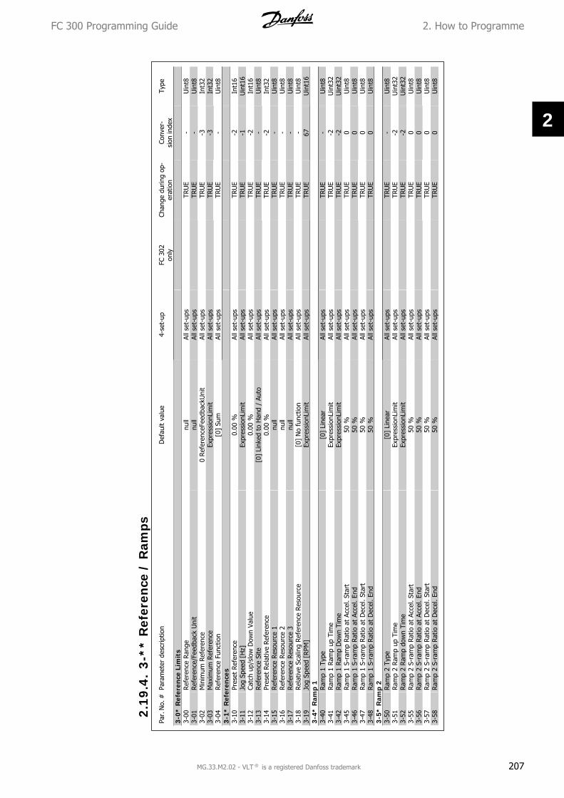
Par.
No.
#Pa
ram
eter
des
crip
tion
Def
ault
valu
e4-
set-
upFC
302
only
Chan
ge d
urin
g op
-er
atio
nCo
nver
-si
on in
dex
Type
3-0*
Ref
eren
ce L
imit
s3-
00R
efer
ence
Ran
genu
llAl
l set
-ups
TRU
E-
Uin
t83-
01Ref
eren
ce/F
eedb
ack
Uni
tnu
llAl
l set
-ups
TRU
E-
Uin
t83-
02M
inim
um R
efer
ence
0 Re
fere
nceF
eedb
ackU
nit
All s
et-u
psTR
UE
-3In
t32
3-03
Max
imum
Ref
eren
ceEx
pres
sion
Lim
itAl
l set
-ups
TRU
E-3
Int3
23-
04Ref
eren
ce F
unct
ion
[0]
Sum
All s
et-u
psTR
UE
-U
int8
3-1*
Ref
eren
ces
3-10
Pres
et R
efer
ence
0.00
%Al
l set
-ups
TRU
E-2
Int1
63-
11Jo
g Sp
eed
[Hz]
Expr
essi
onLi
mit
All s
et-u
psTR
UE
-1U
int1
63-
12Ca
tch
up/s
low
Dow
n Va
lue
0.00
%Al
l set
-ups
TRU
E-2
Int1
63-
13R
efer
ence
Site
[0]
Link
ed t
o H
and
/ Au
toAl
l set
-ups
TRU
E-
Uin
t83-
14Pr
eset
Rel
ativ
e Ref
eren
ce0.
00 %
All s
et-u
psTR
UE
-2In
t32
3-15
Ref
eren
ce R
esou
rce
1nu
llAl
l set
-ups
TRU
E-
Uin
t83-
16Ref
eren
ce R
esou
rce
2nu
llAl
l set
-ups
TRU
E-
Uin
t83-
17R
efer
ence
Res
ourc
e 3
null
All s
et-u
psTR
UE
-U
int8
3-18
Rel
ativ
e Sc
alin
g Re
fere
nce
Reso
urce
[0]
No
func
tion
All s
et-u
psTR
UE
-U
int8
3-19
Jog
Spee
d [R
PM]
Expr
essi
onLi
mit
All s
et-u
psTR
UE
67U
int1
63-
4* R
amp
13-
40Ram
p 1
Type
[0]
Line
arAl
l set
-ups
TRU
E-
Uin
t83-
41Ram
p 1
Ram
p up
Tim
eEx
pres
sion
Lim
itAl
l set
-ups
TRU
E-2
Uin
t32
3-42
Ram
p 1
Ram
p D
own
Tim
eEx
pres
sion
Lim
itAl
l set
-ups
TRU
E-2
Uin
t32
3-45
Ram
p 1
S-ra
mp
Rat
io a
t Ac
cel.
Star
t50
%Al
l set
-ups
TRU
E0
Uin
t83-
46Ra
mp
1 S-
ram
p Ra
tio a
t Ac
cel.
End
50 %
All s
et-u
psTR
UE
0U
int8
3-47
Ram
p 1
S-ra
mp
Rat
io a
t D
ecel
. Sta
rt50
%Al
l set
-ups
TRU
E0
Uin
t83-
48Ra
mp
1 S-
ram
p Ra
tio a
t D
ecel
. En
d50
%Al
l set
-ups
TRU
E0
Uin
t83-
5* R
amp
23-
50Ram
p 2
Type
[0]
Line
arAl
l set
-ups
TRU
E-
Uin
t83-
51Ram
p 2
Ram
p up
Tim
eEx
pres
sion
Lim
itAl
l set
-ups
TRU
E-2
Uin
t32
3-52
Ram
p 2
Ram
p do
wn
Tim
eEx
pres
sion
Lim
itAl
l set
-ups
TRU
E-2
Uin
t32
3-55
Ram
p 2
S-ra
mp
Rat
io a
t Ac
cel.
Star
t50
%Al
l set
-ups
TRU
E0
Uin
t83-
56Ra
mp
2 S-
ram
p Ra
tio a
t Ac
cel.
End
50 %
All s
et-u
psTR
UE
0U
int8
3-57
Ram
p 2
S-ra
mp
Rat
io a
t D
ecel
. Sta
rt50
%Al
l set
-ups
TRU
E0
Uin
t83-
58Ra
mp
2 S-
ram
p Ra
tio a
t D
ecel
. En
d50
%Al
l set
-ups
TRU
E0
Uin
t8
2.1
9.4
.3
-**
Ref
eren
ce /
Ram
ps
FC 300 Programming Guide 2. How to Programme
MG.33.M2.02 - VLT ® is a registered Danfoss trademark 207
2
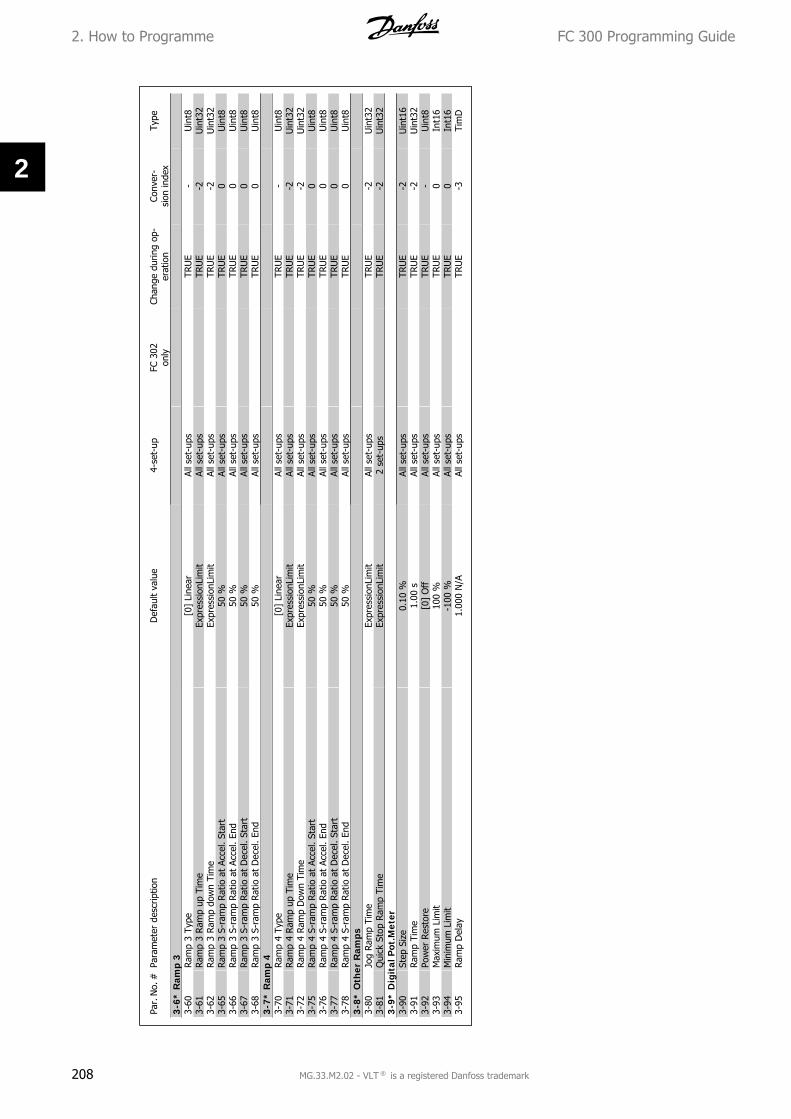
Par.
No.
#Pa
ram
eter
des
crip
tion
Def
ault
valu
e4-
set-
upFC
302
only
Chan
ge d
urin
g op
-er
atio
nCo
nver
-si
on in
dex
Type
3-6*
Ram
p 3
3-60
Ram
p 3
Type
[0]
Line
arAl
l set
-ups
TRU
E-
Uin
t83-
61Ram
p 3
Ram
p up
Tim
eEx
pres
sion
Lim
itAl
l set
-ups
TRU
E-2
Uin
t32
3-62
Ram
p 3
Ram
p do
wn
Tim
eEx
pres
sion
Lim
itAl
l set
-ups
TRU
E-2
Uin
t32
3-65
Ram
p 3
S-ra
mp
Ratio
at
Acce
l. St
art
50 %
All s
et-u
psTR
UE
0U
int8
3-66
Ram
p 3
S-ra
mp
Rat
io a
t Ac
cel.
End
50 %
All s
et-u
psTR
UE
0U
int8
3-67
Ram
p 3
S-ra
mp
Ratio
at
Dec
el. S
tart
50 %
All s
et-u
psTR
UE
0U
int8
3-68
Ram
p 3
S-ra
mp
Ratio
at
Dec
el.
End
50 %
All s
et-u
psTR
UE
0U
int8
3-7*
Ram
p 4
3-70
Ram
p 4
Type
[0]
Line
arAl
l set
-ups
TRU
E-
Uin
t83-
71Ram
p 4
Ram
p up
Tim
eEx
pres
sion
Lim
itAl
l set
-ups
TRU
E-2
Uin
t32
3-72
Ram
p 4
Ram
p D
own
Tim
eEx
pres
sion
Lim
itAl
l set
-ups
TRU
E-2
Uin
t32
3-75
Ram
p 4
S-ra
mp
Ratio
at
Acce
l. St
art
50 %
All s
et-u
psTR
UE
0U
int8
3-76
Ram
p 4
S-ra
mp
Rat
io a
t Ac
cel.
End
50 %
All s
et-u
psTR
UE
0U
int8
3-77
Ram
p 4
S-ra
mp
Ratio
at
Dec
el. S
tart
50 %
All s
et-u
psTR
UE
0U
int8
3-78
Ram
p 4
S-ra
mp
Ratio
at
Dec
el.
End
50 %
All s
et-u
psTR
UE
0U
int8
3-8*
Oth
er R
amps
3-80
Jog
Ram
p Ti
me
Expr
essi
onLi
mit
All s
et-u
psTR
UE
-2U
int3
23-
81Q
uick
Sto
p Ra
mp
Tim
eEx
pres
sion
Lim
it2
set-
ups
TRU
E-2
Uin
t32
3-9*
Dig
ital
Pot
.Met
er3-
90St
ep S
ize
0.10
%Al
l set
-ups
TRU
E-2
Uin
t16
3-91
Ram
p Ti
me
1.00
sAl
l set
-ups
TRU
E-2
Uin
t32
3-92
Pow
er R
esto
re[0
] O
ffAl
l set
-ups
TRU
E-
Uin
t83-
93M
axim
um L
imit
100
%Al
l set
-ups
TRU
E0
Int1
63-
94M
inim
um L
imit
-100
%Al
l set
-ups
TRU
E0
Int1
63-
95Ram
p D
elay
1.00
0 N
/AAl
l set
-ups
TRU
E-3
Tim
D
2. How to Programme FC 300 Programming Guide
208 MG.33.M2.02 - VLT ® is a registered Danfoss trademark
2

Par.
No.
#Pa
ram
eter
des
crip
tion
Def
ault
valu
e4-
set-
upFC
302
only
Chan
ge d
urin
g op
-er
atio
nCo
nver
-si
on in
dex
Type
4-1*
Mot
or L
imit
s4-
10M
otor
Spe
ed D
irect
ion
null
All s
et-u
psFA
LSE
-U
int8
4-11
Mot
or S
peed
Low
Lim
it [R
PM]
Expr
essi
onLi
mit
All s
et-u
psTR
UE
67U
int1
64-
12M
otor
Spe
ed L
ow L
imit
[Hz]
Expr
essi
onLi
mit
All s
et-u
psTR
UE
-1U
int1
64-
13M
otor
Spe
ed H
igh
Lim
it [R
PM]
Expr
essi
onLi
mit
All s
et-u
psTR
UE
67U
int1
64-
14M
otor
Spe
ed H
igh
Lim
it [H
z]Ex
pres
sion
Lim
itAl
l set
-ups
TRU
E-1
Uin
t16
4-16
Torq
ue L
imit
Mot
or M
ode
Expr
essi
onLi
mit
All s
et-u
psTR
UE
-1U
int1
64-
17To
rque
Lim
it G
ener
ator
Mod
e10
0.0
%Al
l set
-ups
TRU
E-1
Uin
t16
4-18
Curr
ent
Lim
itEx
pres
sion
Lim
itAl
l set
-ups
TRU
E-1
Uin
t32
4-19
Max
Out
put
Freq
uenc
y13
2.0
Hz
All s
et-u
psFA
LSE
-1U
int1
64-
2* L
imit
Fac
tors
4-20
Torq
ue L
imit
Fact
or S
ourc
e[0
] N
o fu
nctio
nAl
l set
-ups
TRU
E-
Uin
t84-
21Sp
eed
Lim
it Fa
ctor
Sou
rce
[0]
No
func
tion
All s
et-u
psTR
UE
-U
int8
4-3*
Mot
or F
b M
onit
or4-
30M
otor
Fee
dbac
k Lo
ss F
unct
ion
[2]
Trip
All s
et-u
psTR
UE
-U
int8
4-31
Mot
or F
eedb
ack
Spee
d Er
ror
300
RPM
All s
et-u
psTR
UE
67U
int1
64-
32M
otor
Fee
dbac
k Lo
ss T
imeo
ut0.
05 s
All s
et-u
psTR
UE
-2U
int1
64-
5* A
dj. W
arn
ings
4-50
War
ning
Cur
rent
Low
0.00
AAl
l set
-ups
TRU
E-2
Uin
t32
4-51
War
ning
Cur
rent
Hig
hIm
axVL
T (P
1637
)Al
l set
-ups
TRU
E-2
Uin
t32
4-52
War
ning
Spe
ed L
ow0
RPM
All s
et-u
psTR
UE
67U
int1
64-
53W
arni
ng S
peed
Hig
hou
tput
Spee
dHig
hLim
it (P
413)
All s
et-u
psTR
UE
67U
int1
64-
54W
arni
ng R
efer
ence
Low
-999
999.
999
N/A
All s
et-u
psTR
UE
-3In
t32
4-55
War
ning
Ref
eren
ce H
igh
9999
99.9
99 N
/AAl
l set
-ups
TRU
E-3
Int3
24-
56W
arni
ng F
eedb
ack
Low
-999
999.
999
Refe
renc
eFee
dbac
kUni
tAl
l set
-ups
TRU
E-3
Int3
24-
57W
arni
ng F
eedb
ack
Hig
h99
9999
.999
Ref
eren
ceFe
edba
ckU
nit
All s
et-u
psTR
UE
-3In
t32
4-58
Mis
sing
Mot
or P
hase
Fun
ctio
n[1
] O
nAl
l set
-ups
TRU
E-
Uin
t84-
6* S
peed
Byp
ass
4-60
Bypa
ss S
peed
Fro
m [
RPM
]Ex
pres
sion
Lim
itAl
l set
-ups
TRU
E67
Uin
t16
4-61
Bypa
ss S
peed
Fro
m [
Hz]
Expr
essi
onLi
mit
All s
et-u
psTR
UE
-1U
int1
64-
62By
pass
Spe
ed T
o [R
PM]
Expr
essi
onLi
mit
All s
et-u
psTR
UE
67U
int1
64-
63By
pass
Spe
ed T
o [H
z]Ex
pres
sion
Lim
itAl
l set
-ups
TRU
E-1
Uin
t16
2.1
9.5
.4
-**
Lim
its
/ W
arn
ings
FC 300 Programming Guide 2. How to Programme
MG.33.M2.02 - VLT ® is a registered Danfoss trademark 209
2

Par.
No.
#Pa
ram
eter
des
crip
tion
Def
ault
valu
e4-
set-
upFC
302
only
Chan
ge d
urin
g op
-er
atio
nCo
nver
-si
on in
dex
Type
5-0*
Dig
ital
I/O
mod
e5-
00D
igita
l I/O
Mod
e[0
] PN
PAl
l set
-ups
FALS
E-
Uin
t85-
01Te
rmin
al 2
7 M
ode
[0]
Inpu
tAl
l set
-ups
TRU
E-
Uin
t85-
02Te
rmin
al 2
9 M
ode
[0]
Inpu
tAl
l set
-ups
xTR
UE
-U
int8
5-1*
Dig
ital
In
puts
5-10
Term
inal
18
Dig
ital I
nput
null
All s
et-u
psTR
UE
-U
int8
5-11
Term
inal
19
Dig
ital I
nput
null
All s
et-u
psTR
UE
-U
int8
5-12
Term
inal
27
Dig
ital I
nput
null
All s
et-u
psTR
UE
-U
int8
5-13
Term
inal
29
Dig
ital I
nput
null
All s
et-u
psx
TRU
E-
Uin
t85-
14Te
rmin
al 3
2 D
igita
l Inp
ut[0
] N
o op
erat
ion
All s
et-u
psTR
UE
-U
int8
5-15
Term
inal
33
Dig
ital I
nput
[0]
No
oper
atio
nAl
l set
-ups
TRU
E-
Uin
t85-
16Te
rmin
al X
30/2
Dig
ital I
nput
[0]
No
oper
atio
nAl
l set
-ups
TRU
E-
Uin
t85-
17Te
rmin
al X
30/3
Dig
ital I
nput
[0]
No
oper
atio
nAl
l set
-ups
TRU
E-
Uin
t85-
18Te
rmin
al X
30/4
Dig
ital I
nput
[0]
No
oper
atio
nAl
l set
-ups
TRU
E-
Uin
t85-
19Te
rmin
al 3
7 Sa
fe S
top
[1]
Safe
Sto
p Al
arm
1 se
t-up
xTR
UE
-U
int8
5-3*
Dig
ital
Ou
tpu
ts5-
30Te
rmin
al 2
7 D
igita
l Out
put
null
All s
et-u
psTR
UE
-U
int8
5-31
Term
inal
29
Dig
ital O
utpu
tnu
llAl
l set
-ups
xTR
UE
-U
int8
5-32
Term
X30
/6 D
igi O
ut (
MCB
101
)nu
llAl
l set
-ups
TRU
E-
Uin
t85-
33Te
rm X
30/7
Dig
i Out
(M
CB 1
01)
null
All s
et-u
psTR
UE
-U
int8
5-4*
Rel
ays
5-40
Func
tion
Rela
ynu
llAl
l set
-ups
TRU
E-
Uin
t85-
41O
n D
elay
, Rel
ay0.
01 s
All s
et-u
psTR
UE
-2U
int1
65-
42O
ff D
elay
, Rel
ay0.
01 s
All s
et-u
psTR
UE
-2U
int1
65-
5* P
ulse
In
put
5-50
Term
. 29
Low
Fre
quen
cy10
0 H
zAl
l set
-ups
xTR
UE
0U
int3
25-
51Te
rm. 2
9 H
igh
Freq
uenc
y10
0 H
zAl
l set
-ups
xTR
UE
0U
int3
25-
52Te
rm. 2
9 Lo
w R
ef./
Feed
b. V
alue
0.00
0 Ref
eren
ceFe
edba
ckU
nit
All s
et-u
psx
TRU
E-3
Int3
25-
53Te
rm. 2
9 H
igh
Ref./F
eedb
. Va
lue
Expr
essi
onLi
mit
All s
et-u
psx
TRU
E-3
Int3
25-
54Pu
lse
Filte
r Ti
me
Cons
tant
#29
100
ms
All s
et-u
psx
FALS
E-3
Uin
t16
5-55
Term
. 33
Low
Fre
quen
cy10
0 H
zAl
l set
-ups
TRU
E0
Uin
t32
5-56
Term
. 33
Hig
h Fr
eque
ncy
100
Hz
All s
et-u
psTR
UE
0U
int3
25-
57Te
rm. 3
3 Lo
w R
ef./
Feed
b. V
alue
0.00
0 Ref
eren
ceFe
edba
ckU
nit
All s
et-u
psTR
UE
-3In
t32
5-58
Term
. 33
Hig
h Re
f./F
eedb
. Va
lue
Expr
essi
onLi
mit
All s
et-u
psTR
UE
-3In
t32
5-59
Puls
e Fi
lter
Tim
e Co
nsta
nt #
3310
0 m
sAl
l set
-ups
FALS
E-3
Uin
t16
2.1
9.6
.5
-**
Dig
ital
In
/Ou
t
2. How to Programme FC 300 Programming Guide
210 MG.33.M2.02 - VLT ® is a registered Danfoss trademark
2

Par.
No.
#Pa
ram
eter
des
crip
tion
Def
ault
valu
e4-
set-
upFC
302
only
Chan
ge d
urin
g op
-er
atio
nCo
nver
-si
on in
dex
Type
5-6*
Pu
lse
Ou
tpu
t5-
60Te
rmin
al 2
7 Pu
lse
Out
put
Varia
ble
null
All s
et-u
psTR
UE
-U
int8
5-62
Puls
e O
utpu
t M
ax F
req
#27
Expr
essi
onLi
mit
All s
et-u
psTR
UE
0U
int3
25-
63Te
rmin
al 2
9 Pu
lse
Out
put
Varia
ble
null
All s
et-u
psx
TRU
E-
Uin
t85-
65Pu
lse
Out
put
Max
Fre
q #
29Ex
pres
sion
Lim
itAl
l set
-ups
xTR
UE
0U
int3
25-
66Te
rmin
al X
30/6
Pul
se O
utpu
t Va
riabl
enu
llAl
l set
-ups
TRU
E-
Uin
t85-
68Pu
lse
Out
put
Max
Fre
q #
X30/
6Ex
pres
sion
Lim
itAl
l set
-ups
TRU
E0
Uin
t32
5-7*
24V
En
code
r In
put
5-70
Term
32/
33 P
ulse
s pe
r Re
volu
tion
1024
N/A
All s
et-u
psFA
LSE
0U
int1
65-
71Te
rm 3
2/33
Enc
oder
Dire
ctio
n[0
] Cl
ockw
ise
All s
et-u
psFA
LSE
-U
int8
5-9*
Bu
s C
ontr
olle
d5-
90D
igita
l & R
elay
Bus
Con
trol
0 N
/AAl
l set
-ups
TRU
E0
Uin
t32
5-93
Puls
e O
ut #
27 B
us C
ontr
ol0.
00 %
All s
et-u
psTR
UE
-2N
25-
94Pu
lse
Out
#27
Tim
eout
Pre
set
0.00
%1
set-
upTR
UE
-2U
int1
65-
95Pu
lse
Out
#29
Bus
Con
trol
0.00
%Al
l set
-ups
xTR
UE
-2N
25-
96Pu
lse
Out
#29
Tim
eout
Pre
set
0.00
%1
set-
upx
TRU
E-2
Uin
t16
FC 300 Programming Guide 2. How to Programme
MG.33.M2.02 - VLT ® is a registered Danfoss trademark 211
2
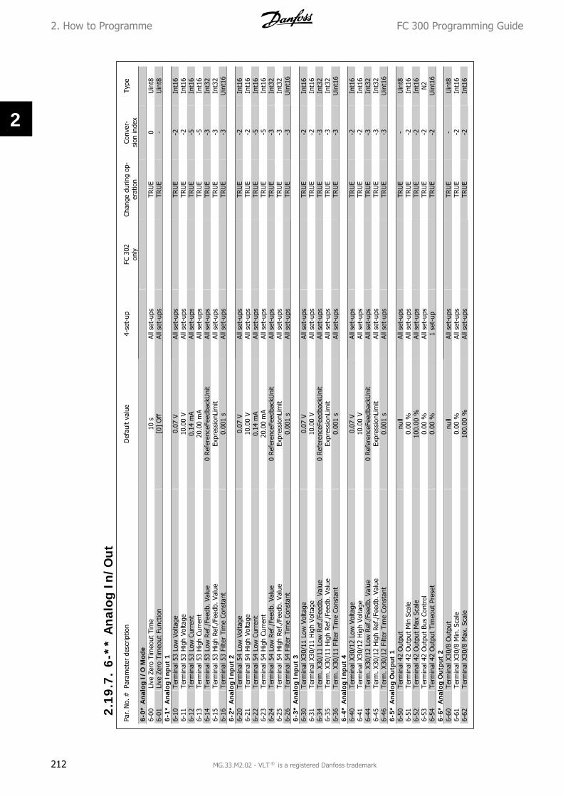
Par.
No.
#Pa
ram
eter
des
crip
tion
Def
ault
valu
e4-
set-
upFC
302
only
Chan
ge d
urin
g op
-er
atio
nCo
nver
-si
on in
dex
Type
6-0*
An
alog
I/O
Mod
e6-
00Li
ve Z
ero
Tim
eout
Tim
e10
sAl
l set
-ups
TRU
E0
Uin
t86-
01Li
ve Z
ero
Tim
eout
Fun
ctio
n[0
] O
ffAl
l set
-ups
TRU
E-
Uin
t86-
1* A
nal
og I
nput
16-
10Te
rmin
al 5
3 Lo
w V
olta
ge0.
07 V
All s
et-u
psTR
UE
-2In
t16
6-11
Term
inal
53
Hig
h Vo
ltage
10.0
0 V
All s
et-u
psTR
UE
-2In
t16
6-12
Term
inal
53
Low
Cur
rent
0.14
mA
All s
et-u
psTR
UE
-5In
t16
6-13
Term
inal
53
Hig
h Cu
rren
t20
.00
mA
All s
et-u
psTR
UE
-5In
t16
6-14
Term
inal
53
Low
Ref
./Fe
edb.
Val
ue0
Refe
renc
eFee
dbac
kUni
tAl
l set
-ups
TRU
E-3
Int3
26-
15Te
rmin
al 5
3 H
igh
Ref
./Fe
edb.
Val
ueEx
pres
sion
Lim
itAl
l set
-ups
TRU
E-3
Int3
26-
16Te
rmin
al 5
3 Fi
lter
Tim
e Co
nsta
nt0.
001
sAl
l set
-ups
TRU
E-3
Uin
t16
6-2*
An
alog
Inp
ut 2
6-20
Term
inal
54
Low
Vol
tage
0.07
VAl
l set
-ups
TRU
E-2
Int1
66-
21Te
rmin
al 5
4 H
igh
Volta
ge10
.00
VAl
l set
-ups
TRU
E-2
Int1
66-
22Te
rmin
al 5
4 Lo
w C
urre
nt0.
14 m
AAl
l set
-ups
TRU
E-5
Int1
66-
23Te
rmin
al 5
4 H
igh
Curr
ent
20.0
0 m
AAl
l set
-ups
TRU
E-5
Int1
66-
24Te
rmin
al 5
4 Lo
w R
ef./
Feed
b. V
alue
0 Re
fere
nceF
eedb
ackU
nit
All s
et-u
psTR
UE
-3In
t32
6-25
Term
inal
54
Hig
h Ref
./Fe
edb.
Val
ueEx
pres
sion
Lim
itAl
l set
-ups
TRU
E-3
Int3
26-
26Te
rmin
al 5
4 Fi
lter
Tim
e Co
nsta
nt0.
001
sAl
l set
-ups
TRU
E-3
Uin
t16
6-3*
An
alog
Inp
ut 3
6-30
Term
inal
X30
/11
Low
Vol
tage
0.07
VAl
l set
-ups
TRU
E-2
Int1
66-
31Te
rmin
al X
30/1
1 H
igh
Volta
ge10
.00
VAl
l set
-ups
TRU
E-2
Int1
66-
34Te
rm. X
30/1
1 Lo
w R
ef./
Feed
b. V
alue
0 Re
fere
nceF
eedb
ackU
nit
All s
et-u
psTR
UE
-3In
t32
6-35
Term
. X30
/11
Hig
h Re
f./F
eedb
. Val
ueEx
pres
sion
Lim
itAl
l set
-ups
TRU
E-3
Int3
26-
36Te
rm. X
30/1
1 Fi
lter
Tim
e Co
nsta
nt0.
001
sAl
l set
-ups
TRU
E-3
Uin
t16
6-4*
An
alog
Inp
ut 4
6-40
Term
inal
X30
/12
Low
Vol
tage
0.07
VAl
l set
-ups
TRU
E-2
Int1
66-
41Te
rmin
al X
30/1
2 H
igh
Volta
ge10
.00
VAl
l set
-ups
TRU
E-2
Int1
66-
44Te
rm. X
30/1
2 Lo
w R
ef./
Feed
b. V
alue
0 Re
fere
nceF
eedb
ackU
nit
All s
et-u
psTR
UE
-3In
t32
6-45
Term
. X30
/12
Hig
h Re
f./F
eedb
. Val
ueEx
pres
sion
Lim
itAl
l set
-ups
TRU
E-3
Int3
26-
46Te
rm. X
30/1
2 Fi
lter
Tim
e Co
nsta
nt0.
001
sAl
l set
-ups
TRU
E-3
Uin
t16
6-5*
An
alog
Ou
tpu
t 1
6-50
Term
inal
42
Out
put
null
All s
et-u
psTR
UE
-U
int8
6-51
Term
inal
42
Out
put
Min
Sca
le0.
00 %
All s
et-u
psTR
UE
-2In
t16
6-52
Term
inal
42
Out
put
Max
Sca
le10
0.00
%Al
l set
-ups
TRU
E-2
Int1
66-
53Te
rmin
al 4
2 O
utpu
t Bu
s Co
ntro
l0.
00 %
All s
et-u
psTR
UE
-2N
26-
54Te
rmin
al 4
2 O
utpu
t Ti
meo
ut P
rese
t0.
00 %
1 se
t-up
TRU
E-2
Uin
t16
6-6*
An
alog
Ou
tpu
t 2
6-60
Term
inal
X30
/8 O
utpu
tnu
llAl
l set
-ups
TRU
E-
Uin
t86-
61Te
rmin
al X
30/8
Min
. Sca
le0.
00 %
All s
et-u
psTR
UE
-2In
t16
6-62
Term
inal
X30
/8 M
ax. S
cale
100.
00 %
All s
et-u
psTR
UE
-2In
t16
2.1
9.7
.6
-**
An
alog
In
/Ou
t
2. How to Programme FC 300 Programming Guide
212 MG.33.M2.02 - VLT ® is a registered Danfoss trademark
2

Par.
No.
#Pa
ram
eter
des
crip
tion
Def
ault
valu
e4-
set-
upFC
302
only
Chan
ge d
urin
g op
-er
atio
nCo
nver
-si
on in
dex
Type
7-0*
Spe
ed P
ID C
trl.
7-00
Spee
d PI
D F
eedb
ack
Sour
cenu
llAl
l set
-ups
FALS
E-
Uin
t87-
02Sp
eed
PID
Pro
port
iona
l Gai
nEx
pres
sion
Lim
itAl
l set
-ups
TRU
E-3
Uin
t16
7-03
Spee
d PI
D I
nteg
ral T
ime
Expr
essi
onLi
mit
All s
et-u
psTR
UE
-4U
int3
27-
04Sp
eed
PID
Diff
eren
tiatio
n Ti
me
Expr
essi
onLi
mit
All s
et-u
psTR
UE
-4U
int1
67-
05Sp
eed
PID
Diff
. G
ain
Lim
it5.
0 N
/AAl
l set
-ups
TRU
E-1
Uin
t16
7-06
Spee
d PI
D L
owpa
ss F
ilter
Tim
e10
.0 m
sAl
l set
-ups
TRU
E-4
Uin
t16
7-08
Spee
d PI
D F
eed
Forw
ard
Fact
or0
%Al
l set
-ups
FALS
E0
Uin
t16
7-2*
Pro
cess
Ctr
l. Fe
edb
7-20
Proc
ess
CL F
eedb
ack
1 Res
ourc
e[0
] N
o fu
nctio
nAl
l set
-ups
TRU
E-
Uin
t87-
22Pr
oces
s CL
Fee
dbac
k 2
Res
ourc
e[0
] N
o fu
nctio
nAl
l set
-ups
TRU
E-
Uin
t87-
3* P
roce
ss P
ID C
trl.
7-30
Proc
ess
PID
Nor
mal
/ In
vers
e Co
ntro
l[0
] N
orm
alAl
l set
-ups
TRU
E-
Uin
t87-
31Pr
oces
s PI
D A
nti W
indu
p[1
] O
nAl
l set
-ups
TRU
E-
Uin
t87-
32Pr
oces
s PI
D S
tart
Spe
ed0
RPM
All s
et-u
psTR
UE
67U
int1
67-
33Pr
oces
s PI
D P
ropo
rtio
nal G
ain
0.01
N/A
All s
et-u
psTR
UE
-2U
int1
67-
34Pr
oces
s PI
D I
nteg
ral T
ime
1000
0.00
sAl
l set
-ups
TRU
E-2
Uin
t32
7-35
Proc
ess
PID
Diff
eren
tiatio
n Ti
me
0.00
sAl
l set
-ups
TRU
E-2
Uin
t16
7-36
Proc
ess
PID
Diff
. Gai
n Li
mit
5.0
N/A
All s
et-u
psTR
UE
-1U
int1
67-
38Pr
oces
s PI
D F
eed
Forw
ard
Fact
or0
%Al
l set
-ups
TRU
E0
Uin
t16
7-39
On
Refe
renc
e Ba
ndw
idth
5 %
All s
et-u
psTR
UE
0U
int8
2.1
9.8
.7
-**
Con
trol
lers
FC 300 Programming Guide 2. How to Programme
MG.33.M2.02 - VLT ® is a registered Danfoss trademark 213
2

Par.
No.
#Pa
ram
eter
des
crip
tion
Def
ault
valu
e4-
set-
upFC
302
only
Chan
ge d
urin
g op
-er
atio
nCo
nver
-si
on in
dex
Type
8-0*
Gen
eral
Set
tin
gs8-
01Co
ntro
l Site
[0]
Dig
ital a
nd c
trl.w
ord
All s
et-u
psTR
UE
-U
int8
8-02
Cont
rol W
ord
Sour
cenu
llAl
l set
-ups
TRU
E-
Uin
t88-
03Co
ntro
l Wor
d Ti
meo
ut T
ime
1.0
s1
set-
upTR
UE
-1U
int3
28-
04Co
ntro
l Wor
d Ti
meo
ut F
unct
ion
[0]
Off
1 se
t-up
TRU
E-
Uin
t88-
05En
d-of
-Tim
eout
Fun
ctio
n[1
] Re
sum
e se
t-up
1 se
t-up
TRU
E-
Uin
t88-
06Res
et C
ontr
ol W
ord
Tim
eout
[0]
Do
not
rese
tAl
l set
-ups
TRU
E-
Uin
t88-
07D
iagn
osis
Trig
ger
[0]
Dis
able
2 se
t-up
sTR
UE
-U
int8
8-1*
Ctr
l. W
ord
Sett
ings
8-10
Cont
rol W
ord
Prof
ile[0
] FC
pro
file
All s
et-u
psTR
UE
-U
int8
8-13
Conf
igur
able
Sta
tus
Wor
d ST
W[1
] Pr
ofile
Def
ault
All s
et-u
psTR
UE
-U
int8
8-3*
FC
Por
t Se
ttin
gs8-
30Pr
otoc
ol[0
] FC
1 se
t-up
TRU
E-
Uin
t88-
31Ad
dres
s1
N/A
1 se
t-up
TRU
E0
Uin
t88-
32FC
Por
t Ba
ud R
ate
[2]
9600
Bau
d1
set-
upTR
UE
-U
int8
8-35
Min
imum
Res
pons
e D
elay
10 m
sAl
l set
-ups
TRU
E-3
Uin
t16
8-36
Max
Res
pons
e D
elay
5000
ms
1 se
t-up
TRU
E-3
Uin
t16
8-37
Max
Int
er-C
har
Del
ay25
ms
1 se
t-up
TRU
E-3
Uin
t16
8-4*
FC
MC
pro
toco
l set
8-40
Tele
gram
sel
ectio
n[1
] St
anda
rd t
eleg
ram
12
set-
ups
TRU
E-
Uin
t88-
5* D
igit
al/B
us
8-50
Coas
ting
Sele
ct[3
] Lo
gic
OR
All s
et-u
psTR
UE
-U
int8
8-51
Qui
ck S
top
Sele
ct[3
] Lo
gic
OR
All s
et-u
psTR
UE
-U
int8
8-52
DC
Brak
e Se
lect
[3]
Logi
c O
RAl
l set
-ups
TRU
E-
Uin
t88-
53St
art
Sele
ct[3
] Lo
gic
OR
All s
et-u
psTR
UE
-U
int8
8-54
Rev
ersi
ng S
elec
t[3
] Lo
gic
OR
All s
et-u
psTR
UE
-U
int8
8-55
Set-
up S
elec
t[3
] Lo
gic
OR
All s
et-u
psTR
UE
-U
int8
8-56
Pres
et R
efer
ence
Sel
ect
[3]
Logi
c O
RAl
l set
-ups
TRU
E-
Uin
t88-
9* B
us
Jog
8-90
Bus
Jog
1 Sp
eed
100
RPM
All s
et-u
psTR
UE
67U
int1
68-
91Bu
s Jo
g 2
Spee
d20
0 RPM
All s
et-u
psTR
UE
67U
int1
6
2.1
9.9
.8
-**
Com
m. a
nd
Opt
ion
s
2. How to Programme FC 300 Programming Guide
214 MG.33.M2.02 - VLT ® is a registered Danfoss trademark
2

Par.
No.
#Pa
ram
eter
des
crip
tion
Def
ault
valu
e4-
set-
upFC
302
only
Chan
ge d
urin
g op
-er
atio
nCo
nver
-si
on in
dex
Type
9-00
Setp
oint
0 N
/AAl
l set
-ups
TRU
E0
Uin
t16
9-07
Actu
al V
alue
0 N
/AAl
l set
-ups
FALS
E0
Uin
t16
9-15
PCD
Writ
e Co
nfig
urat
ion
Expr
essi
onLi
mit
2 se
t-up
sTR
UE
-U
int1
69-
16PC
D R
ead
Conf
igur
atio
nEx
pres
sion
Lim
it2
set-
ups
TRU
E-
Uin
t16
9-18
Nod
e Ad
dres
s12
6 N
/A1
set-
upTR
UE
0U
int8
9-22
Tele
gram
Sel
ectio
n[1
08]
PPO
81
set-
upTR
UE
-U
int8
9-23
Para
met
ers
for
Sign
als
0Al
l set
-ups
TRU
E-
Uin
t16
9-27
Para
met
er E
dit
[1]
Enab
led
2 se
t-up
sFA
LSE
-U
int1
69-
28Pr
oces
s Co
ntro
l[1
] En
able
cyc
lic m
aste
r2
set-
ups
FALS
E-
Uin
t89-
31Sa
fe A
ddre
ss0
N/A
1 se
t-up
TRU
E0
Uin
t16
9-44
Faul
t M
essa
ge C
ount
er0
N/A
All s
et-u
psTR
UE
0U
int1
69-
45Fa
ult
Code
0 N
/AAl
l set
-ups
TRU
E0
Uin
t16
9-47
Faul
t N
umbe
r0
N/A
All s
et-u
psTR
UE
0U
int1
69-
52Fa
ult
Situ
atio
n Co
unte
r0
N/A
All s
et-u
psTR
UE
0U
int1
69-
53Pr
ofib
us W
arni
ng W
ord
0 N
/AAl
l set
-ups
TRU
E0
V29-
63Ac
tual
Bau
d Ra
te[2
55]
No
baud
rate
fou
ndAl
l set
-ups
TRU
E-
Uin
t89-
64D
evic
e Id
entif
icat
ion
0 N
/AAl
l set
-ups
TRU
E0
Uin
t16
9-65
Prof
ile N
umbe
r0
N/A
All s
et-u
psTR
UE
0O
ctSt
r[2]
9-67
Cont
rol W
ord
10
N/A
All s
et-u
psTR
UE
0V2
9-68
Stat
us W
ord
10
N/A
All s
et-u
psTR
UE
0V2
9-71
Prof
ibus
Sav
e D
ata
Valu
es[0
] O
ffAl
l set
-ups
TRU
E-
Uin
t89-
72Pr
ofib
usD
riveR
eset
[0]
No
actio
n1
set-
upFA
LSE
-U
int8
9-80
Def
ined
Par
amet
ers
(1)
0 N
/AAl
l set
-ups
FALS
E0
Uin
t16
9-81
Def
ined
Par
amet
ers
(2)
0 N
/AAl
l set
-ups
FALS
E0
Uin
t16
9-82
Def
ined
Par
amet
ers
(3)
0 N
/AAl
l set
-ups
FALS
E0
Uin
t16
9-83
Def
ined
Par
amet
ers
(4)
0 N
/AAl
l set
-ups
FALS
E0
Uin
t16
9-84
Def
ined
Par
amet
ers
(5)
0 N
/AAl
l set
-ups
FALS
E0
Uin
t16
9-90
Chan
ged
Para
met
ers
(1)
0 N
/AAl
l set
-ups
FALS
E0
Uin
t16
9-91
Chan
ged
Para
met
ers
(2)
0 N
/AAl
l set
-ups
FALS
E0
Uin
t16
9-92
Chan
ged
Para
met
ers
(3)
0 N
/AAl
l set
-ups
FALS
E0
Uin
t16
9-93
Chan
ged
para
met
ers
(4)
0 N
/AAl
l set
-ups
FALS
E0
Uin
t16
9-94
Chan
ged
para
met
ers
(5)
0 N
/AAl
l set
-ups
FALS
E0
Uin
t16
9-99
Prof
ibus
Rev
isio
n Co
unte
r0
N/A
All s
et-u
psTR
UE
0U
int1
6
2.1
9.1
0.
9-*
* P
rofi
bus
FC 300 Programming Guide 2. How to Programme
MG.33.M2.02 - VLT ® is a registered Danfoss trademark 215
2
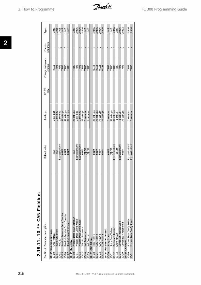
Par.
No.
#Pa
ram
eter
des
crip
tion
Def
ault
valu
e4-
set-
upFC
302
only
Chan
ge d
urin
g op
-er
atio
nCo
nver
-si
on in
dex
Type
10-0
* C
omm
on S
etti
ngs
10-0
0CA
N P
roto
col
null
2 se
t-up
sFA
LSE
-U
int8
10-0
1Ba
ud R
ate
Sele
ctnu
ll2
set-
ups
TRU
E-
Uin
t810
-02
MAC
ID
Expr
essi
onLi
mit
2 se
t-up
sTR
UE
0U
int8
10-0
5Rea
dout
Tra
nsm
it Er
ror
Coun
ter
0 N
/AAl
l set
-ups
TRU
E0
Uin
t810
-06
Rea
dout
Rec
eive
Err
or C
ount
er0
N/A
All s
et-u
psTR
UE
0U
int8
10-0
7Rea
dout
Bus
Off
Cou
nter
0 N
/AAl
l set
-ups
TRU
E0
Uin
t810
-1*
Dev
iceN
et10
-10
Proc
ess
Dat
a Ty
pe S
elec
tion
null
All s
et-u
psTR
UE
-U
int8
10-1
1Pr
oces
s D
ata
Conf
ig W
rite
Expr
essi
onLi
mit
2 se
t-up
sTR
UE
-U
int1
610
-12
Proc
ess
Dat
a Co
nfig
Rea
dEx
pres
sion
Lim
it2
set-
ups
TRU
E-
Uin
t16
10-1
3W
arni
ng P
aram
eter
0 N
/AAl
l set
-ups
TRU
E0
Uin
t16
10-1
4N
et R
efer
ence
[0]
Off
2 se
t-up
sTR
UE
-U
int8
10-1
5N
et C
ontr
ol[0
] O
ff2
set-
ups
TRU
E-
Uin
t810
-2*
CO
S Fi
lter
s10
-20
COS
Filte
r 1
0 N
/AAl
l set
-ups
FALS
E0
Uin
t16
10-2
1CO
S Fi
lter
20
N/A
All s
et-u
psFA
LSE
0U
int1
610
-22
COS
Filte
r 3
0 N
/AAl
l set
-ups
FALS
E0
Uin
t16
10-2
3CO
S Fi
lter
40
N/A
All s
et-u
psFA
LSE
0U
int1
610
-3*
Par
amet
er A
cces
s10
-30
Arra
y In
dex
0 N
/A2
set-
ups
TRU
E0
Uin
t810
-31
Stor
e D
ata
Valu
es[0
] O
ffAl
l set
-ups
TRU
E-
Uin
t810
-32
Dev
icen
et R
evis
ion
Expr
essi
onLi
mit
All s
et-u
psTR
UE
0U
int1
610
-33
Stor
e Al
way
s[0
] O
ff1
set-
upTR
UE
-U
int8
10-3
4D
evic
eNet
Pro
duct
Cod
eEx
pres
sion
Lim
it1
set-
upTR
UE
0U
int1
610
-39
Dev
icen
et F
Par
amet
ers
0 N
/AAl
l set
-ups
TRU
E0
Uin
t32
10-5
* C
AN
open
10-5
0Pr
oces
s D
ata
Conf
ig W
rite.
Expr
essi
onLi
mit
2 se
t-up
sTR
UE
-U
int1
610
-51
Proc
ess
Dat
a Co
nfig
Rea
d.Ex
pres
sion
Lim
it2
set-
ups
TRU
E-
Uin
t16
2.1
9.1
1.
10
-**
CA
N F
ield
bus
2. How to Programme FC 300 Programming Guide
216 MG.33.M2.02 - VLT ® is a registered Danfoss trademark
2

Par.
No.
#Pa
ram
eter
des
crip
tion
Def
ault
valu
e4-
set-
upFC
302
only
Chan
ge d
urin
g op
-er
atio
nCo
nver
-si
on in
dex
Type
13
-0*
SLC
Set
tin
gs13
-00
SL C
ontr
olle
r M
ode
null
2 se
t-up
sTR
UE
-U
int8
13-0
1St
art
Even
tnu
ll2
set-
ups
TRU
E-
Uin
t813
-02
Stop
Eve
ntnu
ll2
set-
ups
TRU
E-
Uin
t813
-03
Res
et S
LC[0
] D
o no
t re
set
SLC
All s
et-u
psTR
UE
-U
int8
13
-1*
Com
para
tors
13-1
0Co
mpa
rato
r O
pera
ndnu
ll2
set-
ups
TRU
E-
Uin
t813
-11
Com
para
tor
Ope
rato
rnu
ll2
set-
ups
TRU
E-
Uin
t813
-12
Com
para
tor
Valu
eEx
pres
sion
Lim
it2
set-
ups
TRU
E-3
Int3
213
-2*
Tim
ers
13-2
0SL
Con
trol
ler
Tim
erEx
pres
sion
Lim
it1
set-
upTR
UE
-3Ti
mD
13-4
* Lo
gic
Ru
les
13-4
0Lo
gic
Rule
Boo
lean
1nu
ll2
set-
ups
TRU
E-
Uin
t813
-41
Logi
c Ru
le O
pera
tor
1nu
ll2
set-
ups
TRU
E-
Uin
t813
-42
Logi
c Ru
le B
oole
an 2
null
2 se
t-up
sTR
UE
-U
int8
13-4
3Lo
gic
Rul
e O
pera
tor
2nu
ll2
set-
ups
TRU
E-
Uin
t813
-44
Logi
c Ru
le B
oole
an 3
null
2 se
t-up
sTR
UE
-U
int8
13-5
* St
ates
13-5
1SL
Con
trol
ler
Even
tnu
ll2
set-
ups
TRU
E-
Uin
t813
-52
SL C
ontr
olle
r Ac
tion
null
2 se
t-up
sTR
UE
-U
int8
2.1
9.1
2.
13
-**
Sm
art
Logi
c
FC 300 Programming Guide 2. How to Programme
MG.33.M2.02 - VLT ® is a registered Danfoss trademark 217
2

Par.
No.
#Pa
ram
eter
des
crip
tion
Def
ault
valu
e4-
set-
upFC
302
only
Chan
ge d
urin
g op
-er
atio
nCo
nver
-si
on in
dex
Type
14-0
* In
vert
er S
wit
chin
g14
-00
Switc
hing
Pat
tern
[1]
SFAV
MAl
l set
-ups
TRU
E-
Uin
t814
-01
Switc
hing
Fre
quen
cynu
llAl
l set
-ups
TRU
E-
Uin
t814
-03
Ove
rmod
ulat
ion
[1]
On
All s
et-u
psFA
LSE
-U
int8
14-0
4PW
M R
ando
m[0
] O
ffAl
l set
-ups
TRU
E-
Uin
t814
-1*
Mai
ns
On
/Off
14-1
0M
ains
Fai
lure
[0]
No
func
tion
All s
et-u
psFA
LSE
-U
int8
14-1
1M
ains
Vol
tage
at
Mai
ns F
ault
Expr
essi
onLi
mit
All s
et-u
psTR
UE
0U
int1
614
-12
Func
tion
at M
ains
Im
bala
nce
[0]
Trip
All s
et-u
psTR
UE
-U
int8
14-2
* Tr
ip R
eset
14-2
0Res
et M
ode
[0]
Man
ual r
eset
All s
et-u
psTR
UE
-U
int8
14-2
1Au
tom
atic
Res
tart
Tim
e10
sAl
l set
-ups
TRU
E0
Uin
t16
14-2
2O
pera
tion
Mod
e[0
] N
orm
al o
pera
tion
All s
et-u
psTR
UE
-U
int8
14-2
3Ty
peco
de S
ettin
gnu
ll2
set-
ups
FALS
E-
Uin
t814
-25
Trip
Del
ay a
t To
rque
Lim
it60
sAl
l set
-ups
TRU
E0
Uin
t814
-26
Trip
Del
ay a
t In
vert
er F
ault
Expr
essi
onLi
mit
All s
et-u
psTR
UE
0U
int8
14-2
8Pr
oduc
tion
Sett
ings
[0]
No
actio
nAl
l set
-ups
TRU
E-
Uin
t814
-29
Serv
ice
Code
0 N
/AAl
l set
-ups
TRU
E0
Int3
214
-3*
Cur
ren
t Li
mit
Ctr
l.14
-30
Curr
ent
Lim
Con
t, P
ropo
rtio
nal G
ain
100
%Al
l set
-ups
FALS
E0
Uin
t16
14-3
1Cu
rren
t Li
m C
ontr
, Int
egra
tion
Tim
e0.
020
sAl
l set
-ups
FALS
E-3
Uin
t16
14-4
* En
ergy
Opt
imis
ing
14-4
0VT
Lev
el66
%Al
l set
-ups
FALS
E0
Uin
t814
-41
AEO
Min
imum
Mag
netis
atio
n40
%Al
l set
-ups
TRU
E0
Uin
t814
-42
Min
imum
AEO
Fre
quen
cy10
Hz
All s
et-u
psTR
UE
0U
int8
14-4
3M
otor
Cos
phi
Expr
essi
onLi
mit
All s
et-u
psTR
UE
-2U
int1
614
-5*
Envi
ron
men
t14
-50
RFI
Filt
er[1
] O
n1
set-
upx
FALS
E-
Uin
t814
-52
Fan
Cont
rol
[0]
Auto
All s
et-u
psTR
UE
-U
int8
14-5
3Fa
n M
onito
r[1
] W
arni
ngAl
l set
-ups
TRU
E-
Uin
t814
-55
Out
put
Filte
r[0
] N
o Fi
lter
1 se
t-up
FALS
E-
Uin
t814
-56
Capa
cita
nce
Out
put
Filte
r2.
0 uF
1 se
t-up
FALS
E-7
Uin
t16
14-5
7In
duct
ance
Out
put
Filte
r7.
000
mH
1 se
t-up
FALS
E-6
Uin
t16
14-7
* C
ompa
tibi
lity
14-7
2VL
T Al
arm
Wor
d0
N/A
All s
et-u
psFA
LSE
0U
int3
214
-73
VLT
War
ning
Wor
d0
N/A
All s
et-u
psFA
LSE
0U
int3
214
-74
VLT
Ext.
Sta
tus
Wor
d0
N/A
All s
et-u
psFA
LSE
0U
int3
2
2.1
9.1
3.
14
-**
Spe
cial
Fu
nct
ion
s
2. How to Programme FC 300 Programming Guide
218 MG.33.M2.02 - VLT ® is a registered Danfoss trademark
2

Par.
No.
#Pa
ram
eter
des
crip
tion
Def
ault
valu
e4-
set-
upFC
302
only
Chan
ge d
urin
g op
-er
atio
nCo
nver
-si
on in
dex
Type
15
-0*
Ope
rati
ng D
ata
15-0
0O
pera
ting
Hou
rs0
hAl
l set
-ups
FALS
E74
Uin
t32
15-0
1Run
ning
Hou
rs0
hAl
l set
-ups
FALS
E74
Uin
t32
15-0
2kW
h Co
unte
r0
kWh
All s
et-u
psFA
LSE
75U
int3
215
-03
Pow
er U
p's
0 N
/AAl
l set
-ups
FALS
E0
Uin
t32
15-0
4O
ver
Tem
p's
0 N
/AAl
l set
-ups
FALS
E0
Uin
t16
15-0
5O
ver
Volt'
s0
N/A
All s
et-u
psFA
LSE
0U
int1
615
-06
Res
et k
Wh
Coun
ter
[0]
Do
not
rese
tAl
l set
-ups
TRU
E-
Uin
t815
-07
Res
et R
unni
ng H
ours
Cou
nter
[0]
Do
not
rese
tAl
l set
-ups
TRU
E-
Uin
t815
-1*
Dat
a Lo
g Se
ttin
gs15
-10
Logg
ing
Sour
ce0
2 se
t-up
sTR
UE
-U
int1
615
-11
Logg
ing
Inte
rval
Expr
essi
onLi
mit
2 se
t-up
sTR
UE
-3Ti
mD
15-1
2Tr
igge
r Ev
ent
[0]
Fals
e1
set-
upTR
UE
-U
int8
15-1
3Lo
ggin
g M
ode
[0]
Log
alw
ays
2 se
t-up
sTR
UE
-U
int8
15-1
4Sa
mpl
es B
efor
e Tr
igge
r50
N/A
2 se
t-up
sTR
UE
0U
int8
15-2
* H
isto
ric
Log
15-2
0H
isto
ric L
og:
Even
t0
N/A
All s
et-u
psFA
LSE
0U
int8
15-2
1H
isto
ric L
og:
Valu
e0
N/A
All s
et-u
psFA
LSE
0U
int3
215
-22
His
toric
Log
: Ti
me
0 m
sAl
l set
-ups
FALS
E-3
Uin
t32
15-3
* Fa
ult
Log
15-3
0Fa
ult
Log:
Err
or C
ode
0 N
/AAl
l set
-ups
FALS
E0
Uin
t815
-31
Faul
t Lo
g: V
alue
0 N
/AAl
l set
-ups
FALS
E0
Int1
615
-32
Faul
t Lo
g: T
ime
0 s
All s
et-u
psFA
LSE
0U
int3
215
-4*
Dri
ve I
den
tifi
cati
on15
-40
FC T
ype
0 N
/AAl
l set
-ups
FALS
E0
VisS
tr[6
]15
-41
Pow
er S
ectio
n0
N/A
All s
et-u
psFA
LSE
0Vi
sStr
[20]
15-4
2Vo
ltage
0 N
/AAl
l set
-ups
FALS
E0
VisS
tr[2
0]15
-43
Soft
war
e Ve
rsio
n0
N/A
All s
et-u
psFA
LSE
0Vi
sStr
[5]
15-4
4O
rder
ed T
ypec
ode
Strin
g0
N/A
All s
et-u
psFA
LSE
0Vi
sStr
[40]
15-4
5Ac
tual
Typ
ecod
e St
ring
0 N
/AAl
l set
-ups
FALS
E0
VisS
tr[4
0]15
-46
Freq
uenc
y Co
nver
ter
Ord
erin
g N
o0
N/A
All s
et-u
psFA
LSE
0Vi
sStr
[8]
15-4
7Po
wer
Car
d O
rder
ing
No
0 N
/AAl
l set
-ups
FALS
E0
VisS
tr[8
]15
-48
LCP
Id N
o0
N/A
All s
et-u
psFA
LSE
0Vi
sStr
[20]
15-4
9SW
ID
Con
trol
Car
d0
N/A
All s
et-u
psFA
LSE
0Vi
sStr
[20]
15-5
0SW
ID
Pow
er C
ard
0 N
/AAl
l set
-ups
FALS
E0
VisS
tr[2
0]15
-51
Freq
uenc
y Co
nver
ter
Seria
l Num
ber
0 N
/AAl
l set
-ups
FALS
E0
VisS
tr[1
0]15
-53
Pow
er C
ard
Seria
l Num
ber
0 N
/AAl
l set
-ups
FALS
E0
VisS
tr[1
9]
2.1
9.1
4.
15
-**
Dri
ve I
nfo
rmat
ion
FC 300 Programming Guide 2. How to Programme
MG.33.M2.02 - VLT ® is a registered Danfoss trademark 219
2

Par.
No.
#Pa
ram
eter
des
crip
tion
Def
ault
valu
e4-
set-
upFC
302
only
Chan
ge d
urin
g op
-er
atio
nCo
nver
-si
on in
dex
Type
15-6
* O
ptio
n I
den
t15
-60
Opt
ion
Mou
nted
0 N
/AAl
l set
-ups
FALS
E0
VisS
tr[3
0]15
-61
Opt
ion
SW V
ersi
on0
N/A
All s
et-u
psFA
LSE
0Vi
sStr
[20]
15-6
2O
ptio
n O
rder
ing
No
0 N
/AAl
l set
-ups
FALS
E0
VisS
tr[8
]15
-63
Opt
ion
Seria
l No
0 N
/AAl
l set
-ups
FALS
E0
VisS
tr[1
8]15
-70
Opt
ion
in S
lot
A0
N/A
All s
et-u
psFA
LSE
0Vi
sStr
[30]
15-7
1Sl
ot A
Opt
ion
SW V
ersi
on0
N/A
All s
et-u
psFA
LSE
0Vi
sStr
[20]
15-7
2O
ptio
n in
Slo
t B
0 N
/AAl
l set
-ups
FALS
E0
VisS
tr[3
0]15
-73
Slot
B O
ptio
n SW
Ver
sion
0 N
/AAl
l set
-ups
FALS
E0
VisS
tr[2
0]15
-74
Opt
ion
in S
lot
C00
N/A
All s
et-u
psFA
LSE
0Vi
sStr
[30]
15-7
5Sl
ot C
0 O
ptio
n SW
Ver
sion
0 N
/AAl
l set
-ups
FALS
E0
VisS
tr[2
0]15
-76
Opt
ion
in S
lot
C10
N/A
All s
et-u
psFA
LSE
0Vi
sStr
[30]
15-7
7Sl
ot C
1 O
ptio
n SW
Ver
sion
0 N
/AAl
l set
-ups
FALS
E0
VisS
tr[2
0]15
-9*
Par
amet
er I
nfo
15-9
2D
efin
ed P
aram
eter
s0
N/A
All s
et-u
psFA
LSE
0U
int1
615
-93
Mod
ified
Par
amet
ers
0 N
/AAl
l set
-ups
FALS
E0
Uin
t16
15-9
9Pa
ram
eter
Met
adat
a0
N/A
All s
et-u
psFA
LSE
0U
int1
6
2. How to Programme FC 300 Programming Guide
220 MG.33.M2.02 - VLT ® is a registered Danfoss trademark
2

Par.
No.
#Pa
ram
eter
des
crip
tion
Def
ault
valu
e4-
set-
upFC
302
only
Chan
ge d
urin
g op
-er
atio
nCo
nver
-si
on in
dex
Type
16-0
* G
ener
al S
tatu
s16
-00
Cont
rol W
ord
0 N
/AAl
l set
-ups
FALS
E0
V216
-01
Ref
eren
ce [
Uni
t]0.
000
Ref
eren
ceFe
edba
ckU
nit
All s
et-u
psFA
LSE
-3In
t32
16-0
2Ref
eren
ce %
0.0
%Al
l set
-ups
FALS
E-1
Int1
616
-03
Stat
us W
ord
0 N
/AAl
l set
-ups
FALS
E0
V216
-05
Mai
n Ac
tual
Val
ue [
%]
0.00
%Al
l set
-ups
FALS
E-2
N2
16-0
9Cu
stom
Rea
dout
0.00
Cus
tom
Read
outU
nit
All s
et-u
psFA
LSE
-2In
t32
16-1
* M
otor
Sta
tus
16-1
0Po
wer
[kW
]0.
00 k
WAl
l set
-ups
FALS
E1
Int3
216
-11
Pow
er [
hp]
0.00
hp
All s
et-u
psFA
LSE
-2In
t32
16-1
2M
otor
Vol
tage
0.0
VAl
l set
-ups
FALS
E-1
Uin
t16
16-1
3Fr
eque
ncy
0.0
Hz
All s
et-u
psFA
LSE
-1U
int1
616
-14
Mot
or C
urre
nt0.
00 A
All s
et-u
psFA
LSE
-2In
t32
16-1
5Fr
eque
ncy
[%]
0.00
%Al
l set
-ups
FALS
E-2
N2
16-1
6To
rque
[N
m]
0.0
Nm
All s
et-u
psFA
LSE
-1In
t32
16-1
7Sp
eed
[RPM
]0
RPM
All s
et-u
psFA
LSE
67In
t32
16-1
8M
otor
The
rmal
0 %
All s
et-u
psFA
LSE
0U
int8
16-1
9KT
Y se
nsor
tem
pera
ture
0 °C
All s
et-u
psFA
LSE
100
Int1
616
-20
Mot
or A
ngle
0 N
/AAl
l set
-ups
TRU
E0
Uin
t16
16-2
2To
rque
[%
]0
%Al
l set
-ups
FALS
E0
Int1
616
-3*
Dri
ve S
tatu
s16
-30
DC
Link
Vol
tage
0 V
All s
et-u
psFA
LSE
0U
int1
616
-32
Brak
e En
ergy
/s
0.00
0 kW
All s
et-u
psFA
LSE
0U
int3
216
-33
Brak
e En
ergy
/2
min
0.00
0 kW
All s
et-u
psFA
LSE
0U
int3
216
-34
Hea
tsin
k Te
mp.
0 °C
All s
et-u
psFA
LSE
100
Uin
t816
-35
Inve
rter
The
rmal
0 %
All s
et-u
psFA
LSE
0U
int8
16-3
6In
v. N
om. C
urre
ntEx
pres
sion
Lim
itAl
l set
-ups
FALS
E-2
Uin
t32
16-3
7In
v. M
ax. C
urre
ntEx
pres
sion
Lim
itAl
l set
-ups
FALS
E-2
Uin
t32
16-3
8SL
Con
trol
ler
Stat
e0
N/A
All s
et-u
psFA
LSE
0U
int8
16-3
9Co
ntro
l Car
d Te
mp.
0 °C
All s
et-u
psFA
LSE
100
Uin
t816
-40
Logg
ing
Buff
er F
ull
[0]
No
All s
et-u
psTR
UE
-U
int8
16
-5*
Ref
. & F
eedb
.16
-50
Exte
rnal
Ref
eren
ce0.
0 N
/AAl
l set
-ups
FALS
E-1
Int1
616
-51
Puls
e Re
fere
nce
0.0
N/A
All s
et-u
psFA
LSE
-1In
t16
16-5
2Fe
edba
ck [
Uni
t]0.
000
Ref
eren
ceFe
edba
ckU
nit
All s
et-u
psFA
LSE
-3In
t32
16-5
3D
igi P
ot R
efer
ence
0.00
N/A
All s
et-u
psFA
LSE
-2In
t16
2.1
9.1
5.
16
-**
Dat
a R
eado
uts
FC 300 Programming Guide 2. How to Programme
MG.33.M2.02 - VLT ® is a registered Danfoss trademark 221
2
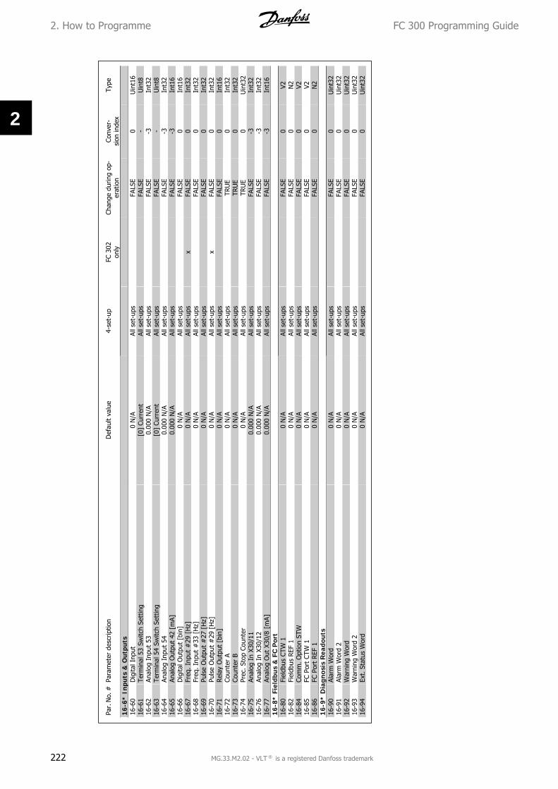
Par.
No.
#Pa
ram
eter
des
crip
tion
Def
ault
valu
e4-
set-
upFC
302
only
Chan
ge d
urin
g op
-er
atio
nCo
nver
-si
on in
dex
Type
16-6
* In
puts
& O
utpu
ts16
-60
Dig
ital I
nput
0 N
/AAl
l set
-ups
FALS
E0
Uin
t16
16-6
1Te
rmin
al 5
3 Sw
itch
Sett
ing
[0]
Curr
ent
All s
et-u
psFA
LSE
-U
int8
16-6
2An
alog
Inp
ut 5
30.
000
N/A
All s
et-u
psFA
LSE
-3In
t32
16-6
3Te
rmin
al 5
4 Sw
itch
Sett
ing
[0]
Curr
ent
All s
et-u
psFA
LSE
-U
int8
16-6
4An
alog
Inp
ut 5
40.
000
N/A
All s
et-u
psFA
LSE
-3In
t32
16-6
5An
alog
Out
put
42 [
mA]
0.00
0 N
/AAl
l set
-ups
FALS
E-3
Int1
616
-66
Dig
ital O
utpu
t [b
in]
0 N
/AAl
l set
-ups
FALS
E0
Int1
616
-67
Freq
. Inp
ut #
29 [
Hz]
0 N
/AAl
l set
-ups
xFA
LSE
0In
t32
16-6
8Fr
eq. I
nput
#33
[H
z]0
N/A
All s
et-u
psFA
LSE
0In
t32
16-6
9Pu
lse
Out
put
#27
[H
z]0
N/A
All s
et-u
psFA
LSE
0In
t32
16-7
0Pu
lse
Out
put
#29
[H
z]0
N/A
All s
et-u
psx
FALS
E0
Int3
216
-71
Rel
ay O
utpu
t [b
in]
0 N
/AAl
l set
-ups
FALS
E0
Int1
616
-72
Coun
ter
A0
N/A
All s
et-u
psTR
UE
0In
t32
16-7
3Co
unte
r B
0 N
/AAl
l set
-ups
TRU
E0
Int3
216
-74
Prec
. Sto
p Co
unte
r0
N/A
All s
et-u
psTR
UE
0U
int3
216
-75
Anal
og I
n X3
0/11
0.00
0 N
/AAl
l set
-ups
FALS
E-3
Int3
216
-76
Anal
og I
n X3
0/12
0.00
0 N
/AAl
l set
-ups
FALS
E-3
Int3
216
-77
Anal
og O
ut X
30/8
[m
A]0.
000
N/A
All s
et-u
psFA
LSE
-3In
t16
16-8
* Fi
eldb
us
& F
C P
ort
16-8
0Fi
eldb
us C
TW 1
0 N
/AAl
l set
-ups
FALS
E0
V216
-82
Fiel
dbus
REF
10
N/A
All s
et-u
psFA
LSE
0N
216
-84
Com
m. O
ptio
n ST
W0
N/A
All s
et-u
psFA
LSE
0V2
16-8
5FC
Por
t CT
W 1
0 N
/AAl
l set
-ups
FALS
E0
V216
-86
FC P
ort
REF
10
N/A
All s
et-u
psFA
LSE
0N
21
6-9
* D
iagn
osis
Rea
dout
s16
-90
Alar
m W
ord
0 N
/AAl
l set
-ups
FALS
E0
Uin
t32
16-9
1Al
arm
Wor
d 2
0 N
/AAl
l set
-ups
FALS
E0
Uin
t32
16-9
2W
arni
ng W
ord
0 N
/AAl
l set
-ups
FALS
E0
Uin
t32
16-9
3W
arni
ng W
ord
20
N/A
All s
et-u
psFA
LSE
0U
int3
216
-94
Ext.
Sta
tus
Wor
d0
N/A
All s
et-u
psFA
LSE
0U
int3
2
2. How to Programme FC 300 Programming Guide
222 MG.33.M2.02 - VLT ® is a registered Danfoss trademark
2

Par.
No.
#Pa
ram
eter
des
crip
tion
Def
ault
valu
e4-
set-
upFC
302
only
Chan
ge d
urin
g op
-er
atio
nCo
nver
-si
on in
dex
Type
17-1
* In
c. E
nc.
In
terf
ace
17-1
0Si
gnal
Typ
e[1
] RS
422
(5V
TTL)
All s
et-u
psFA
LSE
-U
int8
17-1
1Res
olut
ion
(PPR
)10
24 N
/AAl
l set
-ups
FALS
E0
Uin
t16
17-2
* A
bs. E
nc.
Int
erfa
ce17
-20
Prot
ocol
Sel
ectio
n[0
] N
one
All s
et-u
psFA
LSE
-U
int8
17-2
1Res
olut
ion
(Pos
ition
s/Re
v)Ex
pres
sion
Lim
itAl
l set
-ups
FALS
E0
Uin
t32
17-2
4SS
I D
ata
Leng
th13
N/A
All s
et-u
psFA
LSE
0U
int8
17-2
5Cl
ock
Rate
Expr
essi
onLi
mit
All s
et-u
psFA
LSE
3U
int1
617
-26
SSI
Dat
a Fo
rmat
[0]
Gra
y co
deAl
l set
-ups
FALS
E-
Uin
t817
-34
HIP
ERFA
CE B
audr
ate
[4]
9600
All s
et-u
psFA
LSE
-U
int8
17-5
* R
esol
ver
Inte
rfac
e17
-50
Pole
s2
N/A
1 se
t-up
FALS
E0
Uin
t817
-51
Inpu
t Vo
ltage
7.0
V1
set-
upFA
LSE
-1U
int8
17-5
2In
put
Freq
uenc
y10
.0 k
Hz
1 se
t-up
FALS
E2
Uin
t817
-53
Tran
sfor
mat
ion
Ratio
0.5
N/A
1 se
t-up
FALS
E-1
Uin
t817
-59
Res
olve
r In
terf
ace
[0]
Dis
able
dAl
l set
-ups
FALS
E-
Uin
t817
-6*
Mon
itor
ing
and
App
.17
-60
Feed
back
Dire
ctio
n[0
] Cl
ockw
ise
All s
et-u
psFA
LSE
-U
int8
17-6
1Fe
edba
ck S
igna
l Mon
itorin
g[1
] W
arni
ngAl
l set
-ups
TRU
E-
Uin
t8
2.1
9.1
6.
17
-**
Mot
or F
eedb
.Opt
ion
FC 300 Programming Guide 2. How to Programme
MG.33.M2.02 - VLT ® is a registered Danfoss trademark 223
2

Par.
No.
#Pa
ram
eter
des
crip
tion
Def
ault
valu
e4-
set-
upFC
302
only
Chan
ge d
urin
g op
-er
atio
nCo
nver
-si
on in
dex
Type
32-0
* En
code
r 2
32-0
0In
crem
enta
l Sig
nal T
ype
[1]
RS42
2 (5
V TT
L)2
set-
ups
TRU
E-
Uin
t832
-01
Incr
emen
tal R
esol
utio
n10
24 N
/A2
set-
ups
TRU
E0
Uin
t32
32-0
2Ab
solu
te P
roto
col
[0]
Non
e2
set-
ups
TRU
E-
Uin
t832
-03
Abso
lute
Res
olut
ion
8192
N/A
2 se
t-up
sTR
UE
0U
int3
232
-05
Abso
lute
Enc
oder
Dat
a Le
ngth
25 N
/A2
set-
ups
TRU
E0
Uin
t832
-06
Abso
lute
Enc
oder
Clo
ck F
requ
ency
262.
000
kHz
2 se
t-up
sTR
UE
0U
int3
232
-07
Abso
lute
Enc
oder
Clo
ck G
ener
atio
n[1
] O
n2
set-
ups
TRU
E-
Uin
t832
-08
Abso
lute
Enc
oder
Cab
le L
engt
h0
m2
set-
ups
TRU
E0
Uin
t16
32-0
9En
code
r M
onito
ring
[0]
Off
2 se
t-up
sTR
UE
-U
int8
32-1
0Rot
atio
nal D
irect
ion
[1]
No
actio
n2
set-
ups
TRU
E-
Uin
t832
-11
Use
r U
nit
Den
omin
ator
1 N
/A2
set-
ups
TRU
E0
Uin
t32
32-1
2U
ser
Uni
t N
umer
ator
1 N
/A2
set-
ups
TRU
E0
Uin
t32
32-3
* En
code
r 1
32-3
0In
crem
enta
l Sig
nal T
ype
[1]
RS42
2 (5
V TT
L)2
set-
ups
TRU
E-
Uin
t832
-31
Incr
emen
tal R
esol
utio
n10
24 N
/A2
set-
ups
TRU
E0
Uin
t32
32-3
2Ab
solu
te P
roto
col
[0]
Non
e2
set-
ups
TRU
E-
Uin
t832
-33
Abso
lute
Res
olut
ion
8192
N/A
2 se
t-up
sTR
UE
0U
int3
232
-35
Abso
lute
Enc
oder
Dat
a Le
ngth
25 N
/A2
set-
ups
TRU
E0
Uin
t832
-36
Abso
lute
Enc
oder
Clo
ck F
requ
ency
262.
000
kHz
2 se
t-up
sTR
UE
0U
int3
232
-37
Abso
lute
Enc
oder
Clo
ck G
ener
atio
n[1
] O
n2
set-
ups
TRU
E-
Uin
t832
-38
Abso
lute
Enc
oder
Cab
le L
engt
h0
m2
set-
ups
TRU
E0
Uin
t16
32-3
9En
code
r M
onito
ring
[0]
Off
2 se
t-up
sTR
UE
-U
int8
32-4
0En
code
r Te
rmin
atio
n[1
] O
n2
set-
ups
TRU
E-
Uin
t832
-5*
Feed
back
Sou
rce
32-5
0So
urce
Sla
ve[2
] En
code
r 2
2 se
t-up
sTR
UE
-U
int8
2.1
9.1
7.
32
-**
MC
O B
asic
Set
tin
gs
2. How to Programme FC 300 Programming Guide
224 MG.33.M2.02 - VLT ® is a registered Danfoss trademark
2
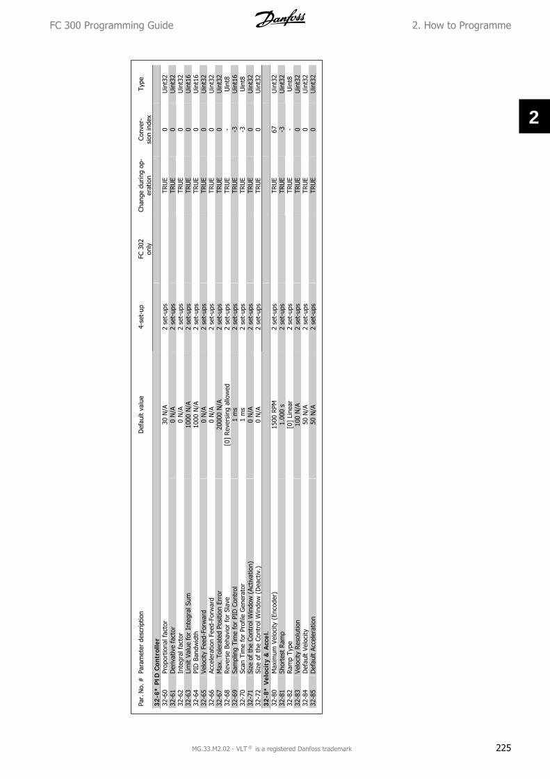
Par.
No.
#Pa
ram
eter
des
crip
tion
Def
ault
valu
e4-
set-
upFC
302
only
Chan
ge d
urin
g op
-er
atio
nCo
nver
-si
on in
dex
Type
32-6
* P
ID C
ontr
olle
r32
-60
Prop
ortio
nal f
acto
r30
N/A
2 se
t-up
sTR
UE
0U
int3
232
-61
Der
ivat
ive
fact
or0
N/A
2 se
t-up
sTR
UE
0U
int3
232
-62
Inte
gral
fac
tor
0 N
/A2
set-
ups
TRU
E0
Uin
t32
32-6
3Li
mit
Valu
e fo
r In
tegr
al S
um10
00 N
/A2
set-
ups
TRU
E0
Uin
t16
32-6
4PI
D B
andw
idth
1000
N/A
2 se
t-up
sTR
UE
0U
int1
632
-65
Velo
city
Fee
d-Fo
rwar
d0
N/A
2 se
t-up
sTR
UE
0U
int3
232
-66
Acce
lera
tion
Feed
-For
war
d0
N/A
2 se
t-up
sTR
UE
0U
int3
232
-67
Max
. Tol
erat
ed P
ositi
on E
rror
2000
0 N
/A2
set-
ups
TRU
E0
Uin
t32
32-6
8Rev
erse
Beh
avio
r fo
r Sl
ave
[0]
Reve
rsin
g al
low
ed2
set-
ups
TRU
E-
Uin
t832
-69
Sam
plin
g Ti
me
for
PID
Con
trol
1 m
s2
set-
ups
TRU
E-3
Uin
t16
32-7
0Sc
an T
ime
for
Prof
ile G
ener
ator
1 m
s2
set-
ups
TRU
E-3
Uin
t832
-71
Size
of
the
Cont
rol W
indo
w (
Activ
atio
n)0
N/A
2 se
t-up
sTR
UE
0U
int3
232
-72
Size
of
the
Cont
rol W
indo
w (
Dea
ctiv
.)0
N/A
2 se
t-up
sTR
UE
0U
int3
232
-8*
Vel
ocit
y &
Acc
el.
32-8
0M
axim
um V
eloc
ity (
Enco
der)
1500
RPM
2 se
t-up
sTR
UE
67U
int3
232
-81
Shor
test
Ram
p1.
000
s2
set-
ups
TRU
E-3
Uin
t32
32-8
2Ram
p Ty
pe[0
] Li
near
2 se
t-up
sTR
UE
-U
int8
32-8
3Ve
loci
ty R
esol
utio
n10
0 N
/A2
set-
ups
TRU
E0
Uin
t32
32-8
4D
efau
lt Ve
loci
ty50
N/A
2 se
t-up
sTR
UE
0U
int3
232
-85
Def
ault
Acce
lera
tion
50 N
/A2
set-
ups
TRU
E0
Uin
t32
FC 300 Programming Guide 2. How to Programme
MG.33.M2.02 - VLT ® is a registered Danfoss trademark 225
2

Par.
No.
#Pa
ram
eter
des
crip
tion
Def
ault
valu
e4-
set-
upFC
302
only
Chan
ge d
urin
g op
-er
atio
nCo
nver
-si
on in
dex
Type
33-0
* H
ome
Mot
ion
33-0
0Fo
rce
HO
ME
[0]
Hom
e no
t fo
rced
2 se
t-up
sTR
UE
-U
int8
33-0
1Ze
ro P
oint
Off
set
from
Hom
e Po
s.0
N/A
2 se
t-up
sTR
UE
0In
t32
33-0
2Ram
p fo
r H
ome
Mot
ion
10 N
/A2
set-
ups
TRU
E0
Uin
t32
33-0
3Ve
loci
ty o
f H
ome
Mot
ion
10 N
/A2
set-
ups
TRU
E0
Int3
233
-04
Beha
viou
r du
ring
Hom
eMot
ion
[0]
Reve
rs a
nd in
dex
2 se
t-up
sTR
UE
-U
int8
33-1
* Sy
nchr
oniz
atio
n33
-10
Sync
hron
izat
ion
Fact
or M
aste
r (M
:S)
1 N
/A2
set-
ups
TRU
E0
Int3
233
-11
Sync
hron
izat
ion
Fact
or S
lave
(M
:S)
1 N
/A2
set-
ups
TRU
E0
Int3
233
-12
Posi
tion
Off
set
for
Sync
hron
izat
ion
0 N
/A2
set-
ups
TRU
E0
Int3
233
-13
Accu
racy
Win
dow
for
Pos
ition
Syn
c.10
00 N
/A2
set-
ups
TRU
E0
Int3
233
-14
Rel
ativ
e Sl
ave
Velo
city
Lim
it0
%2
set-
ups
TRU
E0
Uin
t833
-15
Mar
ker
Num
ber
for
Mas
ter
1 N
/A2
set-
ups
TRU
E0
Uin
t16
33-1
6M
arke
r N
umbe
r fo
r Sl
ave
1 N
/A2
set-
ups
TRU
E0
Uin
t16
33-1
7M
aste
r M
arke
r D
ista
nce
4096
N/A
2 se
t-up
sTR
UE
0U
int3
233
-18
Slav
e M
arke
r D
ista
nce
4096
N/A
2 se
t-up
sTR
UE
0U
int3
233
-19
Mas
ter
Mar
ker
Type
[0]
Enco
der
Z po
sitiv
e2
set-
ups
TRU
E-
Uin
t833
-20
Slav
e M
arke
r Ty
pe[0
] En
code
r Z
posi
tive
2 se
t-up
sTR
UE
-U
int8
33-2
1M
aste
r M
arke
r To
lera
nce
Win
dow
0 N
/A2
set-
ups
TRU
E0
Uin
t32
33-2
2Sl
ave
Mar
ker
Tole
ranc
e W
indo
w0
N/A
2 se
t-up
sTR
UE
0U
int3
233
-23
Star
t Be
havi
our
for
Mar
ker
Sync
[0]
Star
t Fu
nctio
n 1
2 se
t-up
sTR
UE
-U
int1
633
-24
Mar
ker
Num
ber
for
Faul
t10
N/A
2 se
t-up
sTR
UE
0U
int1
633
-25
Mar
ker
Num
ber
for
Rea
dy1
N/A
2 se
t-up
sTR
UE
0U
int1
633
-26
Velo
city
Filt
er0
us2
set-
ups
TRU
E-6
Int3
233
-27
Off
set
Filte
r Ti
me
0 m
s2
set-
ups
TRU
E-3
Uin
t32
33-2
8M
arke
r Fi
lter
Conf
igur
atio
n[0
] M
arke
r fil
ter
12
set-
ups
TRU
E-
Uin
t833
-29
Filte
r Ti
me
for
Mar
ker
Filte
r0
ms
2 se
t-up
sTR
UE
-3In
t32
33-3
0M
axim
um M
arke
r Co
rrec
tion
0 N
/A2
set-
ups
TRU
E0
Uin
t32
33-3
1Sy
nchr
onis
atio
n Ty
pe[0
] St
anda
rd2
set-
ups
TRU
E-
Uin
t833
-4*
Lim
it H
andl
ing
33-4
0Be
havi
our
atEn
d Li
mit
Switc
h[0
] Ca
ll er
ror
hand
ler
2 se
t-up
sTR
UE
-U
int8
33-4
1N
egat
ive
Soft
war
e En
d Li
mit
-500
000
N/A
2 se
t-up
sTR
UE
0In
t32
33-4
2Po
sitiv
e So
ftw
are
End
Lim
it50
0000
N/A
2 se
t-up
sTR
UE
0In
t32
33-4
3N
egat
ive
Soft
war
e En
d Li
mit
Activ
e[0
] In
activ
e2
set-
ups
TRU
E-
Uin
t833
-44
Posi
tive
Soft
war
e En
d Li
mit
Activ
e[0
] In
activ
e2
set-
ups
TRU
E-
Uin
t833
-45
Tim
e in
Tar
get
Win
dow
0 m
s2
set-
ups
TRU
E-3
Uin
t833
-46
Targ
et W
indo
w L
imitV
alue
1 N
/A2
set-
ups
TRU
E0
Uin
t16
33-4
7Si
ze o
f Ta
rget
Win
dow
0 N
/A2
set-
ups
TRU
E0
Uin
t16
2.1
9.1
8.
33
-**
MC
O A
dv. S
etti
ngs
2. How to Programme FC 300 Programming Guide
226 MG.33.M2.02 - VLT ® is a registered Danfoss trademark
2
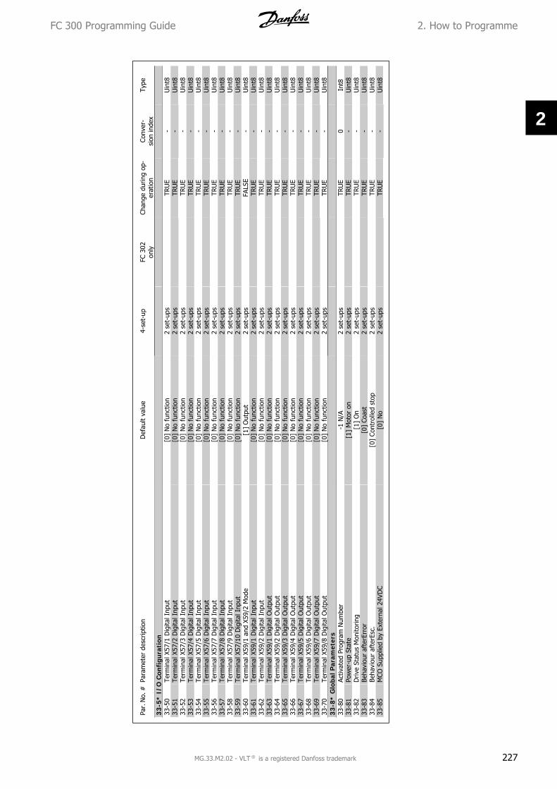
Par.
No.
#Pa
ram
eter
des
crip
tion
Def
ault
valu
e4-
set-
upFC
302
only
Chan
ge d
urin
g op
-er
atio
nCo
nver
-si
on in
dex
Type
33
-5*
I/O
Con
figu
rati
on33
-50
Term
inal
X57
/1 D
igita
l Inp
ut[0
] N
o fu
nctio
n2
set-
ups
TRU
E-
Uin
t833
-51
Term
inal
X57
/2 D
igita
l Inp
ut[0
] N
o fu
nctio
n2
set-
ups
TRU
E-
Uin
t833
-52
Term
inal
X57
/3 D
igita
l Inp
ut[0
] N
o fu
nctio
n2
set-
ups
TRU
E-
Uin
t833
-53
Term
inal
X57
/4 D
igita
l Inp
ut[0
] N
o fu
nctio
n2
set-
ups
TRU
E-
Uin
t833
-54
Term
inal
X57
/5 D
igita
l Inp
ut[0
] N
o fu
nctio
n2
set-
ups
TRU
E-
Uin
t833
-55
Term
inal
X57
/6 D
igita
l Inp
ut[0
] N
o fu
nctio
n2
set-
ups
TRU
E-
Uin
t833
-56
Term
inal
X57
/7 D
igita
l Inp
ut[0
] N
o fu
nctio
n2
set-
ups
TRU
E-
Uin
t833
-57
Term
inal
X57
/8 D
igita
l Inp
ut[0
] N
o fu
nctio
n2
set-
ups
TRU
E-
Uin
t833
-58
Term
inal
X57
/9 D
igita
l Inp
ut[0
] N
o fu
nctio
n2
set-
ups
TRU
E-
Uin
t833
-59
Term
inal
X57
/10
Dig
ital I
nput
[0]
No
func
tion
2 se
t-up
sTR
UE
-U
int8
33-6
0Te
rmin
al X
59/1
and
X59
/2 M
ode
[1]
Out
put
2 se
t-up
sFA
LSE
-U
int8
33-6
1Te
rmin
al X
59/1
Dig
ital I
nput
[0]
No
func
tion
2 se
t-up
sTR
UE
-U
int8
33-6
2Te
rmin
al X
59/2
Dig
ital I
nput
[0]
No
func
tion
2 se
t-up
sTR
UE
-U
int8
33-6
3Te
rmin
al X
59/1
Dig
ital O
utpu
t[0
] N
o fu
nctio
n2
set-
ups
TRU
E-
Uin
t833
-64
Term
inal
X59
/2 D
igita
l Out
put
[0]
No
func
tion
2 se
t-up
sTR
UE
-U
int8
33-6
5Te
rmin
al X
59/3
Dig
ital O
utpu
t[0
] N
o fu
nctio
n2
set-
ups
TRU
E-
Uin
t833
-66
Term
inal
X59
/4 D
igita
l Out
put
[0]
No
func
tion
2 se
t-up
sTR
UE
-U
int8
33-6
7Te
rmin
al X
59/5
Dig
ital O
utpu
t[0
] N
o fu
nctio
n2
set-
ups
TRU
E-
Uin
t833
-68
Term
inal
X59
/6 D
igita
l Out
put
[0]
No
func
tion
2 se
t-up
sTR
UE
-U
int8
33-6
9Te
rmin
al X
59/7
Dig
ital O
utpu
t[0
] N
o fu
nctio
n2
set-
ups
TRU
E-
Uin
t833
-70
Term
inal
X59
/8 D
igita
l Out
put
[0]
No
func
tion
2 se
t-up
sTR
UE
-U
int8
33-8
* G
loba
l Par
amet
ers
33-8
0Ac
tivat
ed P
rogr
am N
umbe
r-1
N/A
2 se
t-up
sTR
UE
0In
t833
-81
Pow
er-u
p St
ate
[1]
Mot
or o
n2
set-
ups
TRU
E-
Uin
t833
-82
Driv
e St
atus
Mon
itorin
g[1
] O
n2
set-
ups
TRU
E-
Uin
t833
-83
Beha
viou
r af
terE
rror
[0]
Coas
t2
set-
ups
TRU
E-
Uin
t833
-84
Beha
viou
r af
terE
sc.
[0]
Cont
rolle
d st
op2
set-
ups
TRU
E-
Uin
t833
-85
MCO
Sup
plie
d by
Ext
erna
l 24V
DC
[0]
No
2 se
t-up
sTR
UE
-U
int8
FC 300 Programming Guide 2. How to Programme
MG.33.M2.02 - VLT ® is a registered Danfoss trademark 227
2

Par.
No.
#Pa
ram
eter
des
crip
tion
Def
ault
valu
e4-
set-
upFC
302
only
Chan
ge d
urin
g op
-er
atio
nCo
nver
-si
on in
dex
Type
34-0
* P
CD
Wri
te P
ar.
34-0
1PC
D 1
Writ
e to
MCO
0 N
/AAl
l set
-ups
TRU
E0
Uin
t16
34-0
2PC
D 2
Writ
e to
MCO
0 N
/AAl
l set
-ups
TRU
E0
Uin
t16
34-0
3PC
D 3
Writ
e to
MCO
0 N
/AAl
l set
-ups
TRU
E0
Uin
t16
34-0
4PC
D 4
Writ
e to
MCO
0 N
/AAl
l set
-ups
TRU
E0
Uin
t16
34-0
5PC
D 5
Writ
e to
MCO
0 N
/AAl
l set
-ups
TRU
E0
Uin
t16
34-0
6PC
D 6
Writ
e to
MCO
0 N
/AAl
l set
-ups
TRU
E0
Uin
t16
34-0
7PC
D 7
Writ
e to
MCO
0 N
/AAl
l set
-ups
TRU
E0
Uin
t16
34-0
8PC
D 8
Writ
e to
MCO
0 N
/AAl
l set
-ups
TRU
E0
Uin
t16
34-0
9PC
D 9
Writ
e to
MCO
0 N
/AAl
l set
-ups
TRU
E0
Uin
t16
34-1
0PC
D 1
0 W
rite
to M
CO0
N/A
All s
et-u
psTR
UE
0U
int1
634
-2*
PC
D R
ead
Par
.34
-21
PCD
1 R
ead
from
MCO
0 N
/AAl
l set
-ups
TRU
E0
Uin
t16
34-2
2PC
D 2
Rea
d fr
om M
CO0
N/A
All s
et-u
psTR
UE
0U
int1
634
-23
PCD
3 R
ead
from
MCO
0 N
/AAl
l set
-ups
TRU
E0
Uin
t16
34-2
4PC
D 4
Rea
d fr
om M
CO0
N/A
All s
et-u
psTR
UE
0U
int1
634
-25
PCD
5 R
ead
from
MCO
0 N
/AAl
l set
-ups
TRU
E0
Uin
t16
34-2
6PC
D 6
Rea
d fr
om M
CO0
N/A
All s
et-u
psTR
UE
0U
int1
634
-27
PCD
7 R
ead
from
MCO
0 N
/AAl
l set
-ups
TRU
E0
Uin
t16
34-2
8PC
D 8
Rea
d fr
om M
CO0
N/A
All s
et-u
psTR
UE
0U
int1
634
-29
PCD
9 R
ead
from
MCO
0 N
/AAl
l set
-ups
TRU
E0
Uin
t16
34-3
0PC
D 1
0 Re
ad f
rom
MCO
0 N
/AAl
l set
-ups
TRU
E0
Uin
t16
34-4
* In
puts
& O
utpu
ts34
-40
Dig
ital I
nput
s0
N/A
All s
et-u
psTR
UE
0U
int1
634
-41
Dig
ital O
utpu
ts0
N/A
All s
et-u
psTR
UE
0U
int1
634
-5*
Pro
cess
Dat
a34
-50
Actu
al P
ositi
on0
N/A
All s
et-u
psTR
UE
0In
t32
34-5
1Co
mm
ande
d Po
sitio
n0
N/A
All s
et-u
psTR
UE
0In
t32
34-5
2Ac
tual
Mas
ter
Posi
tion
0 N
/AAl
l set
-ups
TRU
E0
Int3
234
-53
Slav
e In
dex
Posi
tion
0 N
/AAl
l set
-ups
TRU
E0
Int3
234
-54
Mas
ter
Inde
x Po
sitio
n0
N/A
All s
et-u
psTR
UE
0In
t32
34-5
5Cu
rve
Posi
tion
0 N
/AAl
l set
-ups
TRU
E0
Int3
234
-56
Trac
k Er
ror
0 N
/AAl
l set
-ups
TRU
E0
Int3
234
-57
Sync
hron
izin
g Er
ror
0 N
/AAl
l set
-ups
TRU
E0
Int3
234
-58
Actu
al V
eloc
ity0
N/A
All s
et-u
psTR
UE
0In
t32
34-5
9Ac
tual
Mas
ter
Velo
city
0 N
/AAl
l set
-ups
TRU
E0
Int3
234
-60
Sync
hron
izin
g St
atus
0 N
/AAl
l set
-ups
TRU
E0
Int3
234
-61
Axis
Sta
tus
0 N
/AAl
l set
-ups
TRU
E0
Int3
234
-62
Prog
ram
Sta
tus
0 N
/AAl
l set
-ups
TRU
E0
Int3
23
4-7
* D
iagn
osis
rea
dout
s34
-70
MCO
Ala
rm W
ord
10
N/A
All s
et-u
psFA
LSE
0U
int3
234
-71
MCO
Ala
rm W
ord
20
N/A
All s
et-u
psFA
LSE
0U
int3
2
2.1
9.1
9.
34
-**
MC
O D
ata
Rea
dou
ts
2. How to Programme FC 300 Programming Guide
228 MG.33.M2.02 - VLT ® is a registered Danfoss trademark
2

Index
110-1* Devicenet 146
16-1* Motor Status 191
224 V Encoder 43
55-9* Bus Controlled 111
AAbbreviations 4
Access To Quick Menu W/o Password 42
Active Set-up 29
Actual Typecode String, 15-45 188
Alarm Word 129
Alarm Word, 16-90 198
Alarm Word, 16-91 198
Analog Inputs 6
Analog Inputs 6
Automatic Motor Adaptation (ama) 46
Automatic Restart Time, 14-21 175
BBack Emf At 1000 Rpm 49
Baud Rate 25
Brake Check 66
Brake Current 68
Brake Power 6
Brake Power 65
Brake Power 65
Brake Power Monitoring 65
Brake Resistor (ohm) 2-11 64
Break-away Torque 5
Bus Jog 2 Speed 134
Bus Password Access 42
CCatch Up 98
Catch Up/slow Down Value 73
Changing A Data Value 22
Changing A Group Of Numeric Data Values 21
Changing A Text Value 20
Changing Data 20
Clockwise 55, 56
Clockwise 86, 111, 201
Coasting 4, 14
Coasting Select, 8-50 131
Configurable Status Word Stw, 8-13 130
Configuration Mode 42
Control Site, 8-01 127
Control Word Timeout Function 128
Cooling 58
Counter Clockwise 86
Current Lim Cont, 14-30 178
Current Lim Contr, Int. Time, 14-31 178
DData Log Settings, 15-1* 182
FC 300 Programming Guide Index
MG.33.M2.02 - VLT ® is a registered Danfoss trademark 229

D-axis Inductance (ld) 49
Dc Brake 63
Dc Brake Select, 8-52 132
Dc Braking Time 64
Dc Hold 55, 57
Dc Hold 63
Dc Link Voltage 193
Default Settings 202
Default Settings 25
Defined Parameters, 15-92 189
Definitions 4
Devicenet And Can Fieldbus 145
Devicenet F Parameters 10-39 152
Digital Input, 16-60 194
Display Line 2 Large 36
Display Line 3 Large, 0-24 36
Display Mode 16
Display Mode - Selection Of Read-outs 16
Drive Identification, 15-4* 187
Drive Information 181
Drive Ordering Number, 15-46 188
Drive Serial No, 15-51 188
EElectronic Terminal Relay 60
Encoder Positive Direction 201
Encoder Pulses 111
Encoder Signal Monitoring 201
End-of-timeout Function, 8-05 128
Environment, 14-5* 179
Etr 59, 192
Ext. Status Word 198
External Reference 194
FFan Monitor, 14-53 179
Fault Log, 15-3* 186
Fault Log: Error Code 186
Fault Log: Time, 15-32 187
Fault Log: Value, 15-31 186
Flying Start 56
Freeze Output 4
Freq. Input #33 [hz] 196
Function At Stop 57
GGeneral Warning 3
Graphical Display 11
HHeatsink Temp. 193
Hist. Log: Time, 15-22 186
Hist. Log: Value, 15-21 186
Historic Log,15-2* 185
Historic Log: Event, 15-20 185
IIncremental Encoder 194
Indexed Parameters 22
Indicator Lights 12
Infinitely Variable Change Of Numeric Data Value 21
Initialisation 25
Inverter Switching, 14-0* 172
Index FC 300 Programming Guide
230 MG.33.M2.02 - VLT ® is a registered Danfoss trademark

Iron Loss Resistance (rfe) 49
It Mains 179
JJog 5
Jog Ramp Time 83
Jog Speed 73, 76
KKwh Counter, 15-02 181
LLanguage 27
Language Package 1 27
Language Package 2 27
Language Package 3 27
Language Package 4 27
Lcp 4, 7, 11, 14, 23
Lcp 102 11
Lcp Copy 40
Lcp Id No 188
Lcp Id No, 15-48 188
Lcp Keypad, 0-4* 39
Leds 11
Live Zero Timeout Time, 6-00 113
Load Type 54
Local Control Keys 24
Local Reference 28
Logging Interval, 15-11 184
Logging Mode, 15-13 185
MMain Actual Value [%], 16-05 190
Main Menu 17
Main Menu Mode 13
Main Menu Mode 20
Main Reactance 46
Main Reactance (xh) 48
Mains Failure 172
Mains Rfi Filter Circuit 179
Mains Supply 9
Mains Voltage At Mains Fault, 14-11 174
Max Output Frequency 88
Maximum Inertia 55
Maximum Limit 85
Maximum Reference 72
Min. Frequency For Function At Stop, 1-81 57
Min. Speed For Function At Stop [hz], 1-82 57
Minimum Aeo Frequency, 14-42 178
Minimum Inertia 54
Minimum Limit 85
Minimum Magnetisation, 14-41 178
Missing Motor Phase Function, 4-58 92
Modified Parameters, 15-93 189
Motor Angle Offset 50
Motor Cont. Rated Torque 46
Motor Current 46
Motor Feedback 43
Motor Frequency 45, 191
Motor Magnetizing At Zero Speed, 1-50 50
Motor Nominal Speed 46
Motor Poles 49
Motor Power 45
Motor Power [hp] 45
FC 300 Programming Guide Index
MG.33.M2.02 - VLT ® is a registered Danfoss trademark 231

Motor Protection 58
Motor Speed High Limit [hz], 4-14 87
Motor Speed Unit 28
Motor Thermal Protection 58
Motor Voltage 45, 191
NNet Control 10-15 151
Net Reference 10-14 150
Normal Torque 44
Numerical Local Control Panel 23
OOperating Hours, 15-00 181
Operating Mode 28
Operating State At Power-up (hand) 28
Operation Mode 176
Option Ident. 15-6* 188
Option Mounted, 15-60 188
Option Ordering No, 15-62 189
Option Serial No, 15-63 189
Option Sw Version, 15-61 189
Ordered Type Code String, 15-44 187
Output Filter, 14-55 180
Output Speed 55
Over Temps, 15-04 181
Over Volts, 15-05 181
Over-voltage Control 67
PParameter Access 151
Parameter Info, 15-9* 189
Parameter Selection 20
Parameter Set-up 17
Passive Load 54
Power Card Ordering No, 15-47 188
Power Card Serial No, 15-53 188
Power Hp, 16-11 191
Power Restore 85
Power Ups, 15-03 181
Precise Stop 58
Precise Stop Counter 196
Precise Stop Function 57
Pre-magnetizing 57
Preset Reference 72
Preset Reference Select, 8-56 134
Process Control, 9-28 139
Profibus Warning Word 140
Proportionalgain 122
Pulse Filter Time Constant #33, 5-59 108
Pulse Input 29, 16-67 195
Pulse Output Maximum Frequency #29, 5-65 110
Pulse Output Maximum Frequency #x30/6, 5-68 110
Pulse Reference 194
Pwm Random, 14-04 172
QQuick Menu 13, 17
Quick Menu Mode 13, 17
Quick Menu Password 41
Quick Stop Ramp Time 84
Quick Stop Select 132
Quick Transfer Of Parameter Settings Between Multiple Frequency Converters 14
Index FC 300 Programming Guide
232 MG.33.M2.02 - VLT ® is a registered Danfoss trademark
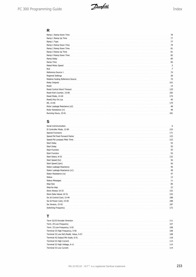
RRamp 1 Ramp Down Time 78
Ramp 1 Ramp Up Time 77
Ramp 1 Type 77
Ramp 2 Ramp Down Time 79
Ramp 3 Ramp Down Time 81
Ramp 3 Ramp Up Time 81
Ramp 4 Ramp Down Time 82
Ramp Delay 85
Ramp Time 85
Rated Motor Speed 5
Rcd 7
Reference Source 1 74
Regional Settings 28
Relative Scaling Reference Source 75
Relay Outputs 101
Reset 14
Reset Control Word Timeout 129
Reset Kwh Counter, 15-06 182
Reset Mode, 14-20 174
Reset] Key On Lcp 40
Rfi, 14-50 179
Rotor Leakage Reactance (x2) 48
Rotor Resistance (rr) 48
Running Hours, 15-01 181
SSerial Communication 6
Sl Controller Mode, 13-00 153
Special Functions 171
Speed Pid Feed Forward Factor 123
Speed Pid Lowpass Filter Time 123
Start Delay 55
Start Delay 55
Start Function 55
Start Function 55
Start Select, 8-53 132
Start Speed [hz] 56
Start Speed [rpm] 56
Stator Leakage Reactance 46
Stator Leakage Reactance (x1) 48
Stator Resistance (rs) 47
Status 13
Status Messages 11
Step Size 85
Step-by-step 22
Store Always 10-33 152
Store Data Values 10-31 152
Sw Id Control Card, 15-49 188
Sw Id Power Card, 15-50 188
Sw Version, 15-43 187
Switching Frequency 172
TTerm 32/33 Encoder Direction 111
Term. 29 Low Frequency 107
Term. 33 Low Frequency, 5-55 108
Terminal 33 High Frequency, 5-56 108
Terminal 33 Low Ref./feedb. Value, 5-57 108
Terminal 42 Output Min Scale, 6-51 118
Terminal 53 High Current 114
Terminal 53 High Voltage, 6-11 114
Terminal 53 Low Current 114
FC 300 Programming Guide Index
MG.33.M2.02 - VLT ® is a registered Danfoss trademark 233

Terminal 54 High Current 115
Terminal 54 Low Current 115
Terminal 54 Switch Setting, 16-63 195
Terminal X30/6 Pulse Output Variable, 5-66 110
Thermal Load 50, 192
Thermistor 59
Thermistor 8
Thermistor Source, 1-93 61
Torque Limit Generator Mode 88
Trip Delay At Torque Limit 177
Trip Reset, 14-2* 174
VVariable Torque 44
Vt Level, 14-40 178
Vvcplus 8, 43
WWarning Word 2 198
Warning Word, 16-92 198
Index FC 300 Programming Guide
234 MG.33.M2.02 - VLT ® is a registered Danfoss trademark