Visualizing Defeasible Logic Rules for the Semantic Web
15
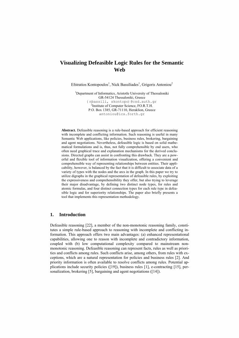
Visualizing Defeasible Logic Rules for the Semantic Web Efstratios Kontopoulos 1 , Nick Bassiliades 1 , Grigoris Antoniou 2 1 Department of Informatics, Aristotle University of Thessaloniki GR-54124 Thessaloniki, Greece {nbassili, skontopo}@csd.auth.gr 2 Institute of Computer Science, FO.R.T.H. P.O. Box 1385, GR-71110, Heraklion, Greece [email protected] Abstract. Defeasible reasoning is a rule-based approach for efficient reasoning with incomplete and conflicting information. Such reasoning is useful in many Semantic Web applications, like policies, business rules, brokering, bargaining and agent negotiations. Nevertheless, defeasible logic is based on solid mathe- matical formulations and is, thus, not fully comprehensible by end users, who often need graphical trace and explanation mechanisms for the derived conclu- sions. Directed graphs can assist in confronting this drawback. They are a pow- erful and flexible tool of information visualization, offering a convenient and comprehensible way of representing relationships between entities. Their appli- cability, however, is balanced by the fact that it is difficult to associate data of a variety of types with the nodes and the arcs in the graph. In this paper we try to utilize digraphs in the graphical representation of defeasible rules, by exploiting the expressiveness and comprehensibility they offer, but also trying to leverage their major disadvantage, by defining two distinct node types, for rules and atomic formulas, and four distinct connection types for each rule type in defea- sible logic and for superiority relationships. The paper also briefly presents a tool that implements this representation methodology. 1. Introduction Defeasible reasoning [22], a member of the non-monotonic reasoning family, consti- tutes a simple rule-based approach to reasoning with incomplete and conflicting in- formation. This approach offers two main advantages: (a) enhanced representational capabilities, allowing one to reason with incomplete and contradictory information, coupled with (b) low computational complexity compared to mainstream non- monotonic reasoning. Defeasible reasoning can represent facts, rules as well as priori- ties and conflicts among rules. Such conflicts arise, among others, from rules with ex- ceptions, which are a natural representation for policies and business rules [2]. And priority information is often available to resolve conflicts among rules. Potential ap- plications include security policies ([19]), business rules [1], e-contracting [15], per- sonalization, brokering [5], bargaining and agent negotiations ([14]).
Transcript of Visualizing Defeasible Logic Rules for the Semantic Web
Visualizing Defeasible Logic Rules for the Semantic Web
Efstratios Kontopoulos1, Nick Bassiliades1, Grigoris Antoniou2
1Department of Informatics, Aristotle University of Thessaloniki GR-54124 Thessaloniki, Greece
{nbassili, skontopo}@csd.auth.gr 2Institute of Computer Science, FO.R.T.H.
P.O. Box 1385, GR-71110, Heraklion, Greece [email protected]
Abstract. Defeasible reasoning is a rule-based approach for efficient reasoning with incomplete and conflicting information. Such reasoning is useful in many Semantic Web applications, like policies, business rules, brokering, bargaining and agent negotiations. Nevertheless, defeasible logic is based on solid mathe-matical formulations and is, thus, not fully comprehensible by end users, who often need graphical trace and explanation mechanisms for the derived conclu-sions. Directed graphs can assist in confronting this drawback. They are a pow-erful and flexible tool of information visualization, offering a convenient and comprehensible way of representing relationships between entities. Their appli-cability, however, is balanced by the fact that it is difficult to associate data of a variety of types with the nodes and the arcs in the graph. In this paper we try to utilize digraphs in the graphical representation of defeasible rules, by exploiting the expressiveness and comprehensibility they offer, but also trying to leverage their major disadvantage, by defining two distinct node types, for rules and atomic formulas, and four distinct connection types for each rule type in defea-sible logic and for superiority relationships. The paper also briefly presents a tool that implements this representation methodology.
1. Introduction
Defeasible reasoning [22], a member of the non-monotonic reasoning family, consti-tutes a simple rule-based approach to reasoning with incomplete and conflicting in-formation. This approach offers two main advantages: (a) enhanced representational capabilities, allowing one to reason with incomplete and contradictory information, coupled with (b) low computational complexity compared to mainstream non-monotonic reasoning. Defeasible reasoning can represent facts, rules as well as priori-ties and conflicts among rules. Such conflicts arise, among others, from rules with ex-ceptions, which are a natural representation for policies and business rules [2]. And priority information is often available to resolve conflicts among rules. Potential ap-plications include security policies ([19]), business rules [1], e-contracting [15], per-sonalization, brokering [5], bargaining and agent negotiations ([14]).
However, although defeasible reasoning features a significant degree of expres-siveness and intuitiveness, it is still based on a solid mathematical formulation, which, in many cases, may seem too complicated. So, end users might often consider the conclusion of a defeasible logic theory incomprehensible and complex and, thus, a graphical trace and an explanation mechanism would be very beneficial.
In this paper we try to utilize directed graphs in the graphical representation of de-feasible rules. Directed graphs, or digraphs, as they are usually referred to, are a spe-cial case of graphs that constitute a powerful and convenient way of representing rela-tionships between entities [11].
Usually in a digraph, entities are represented as nodes and relationships as directed lines or arrows that connect the nodes. Each arrow connects only two entities at a time and there can be no two (or more) arrows that connect the same pair of nodes. The orientation of the arrows follows the flow of information in the digraph. A mathe-matical definition of directed graphs as well as details on graph theory in general can be found in [13].
Digraphs offer a number of advantages to information visualization: • comprehensibility: the information that a digraph contains can be easily and accu-
rately understood by humans [21] and • expressiveness: although the appearance and structure of a digraph may seem sim-
plistic, its topology bears non-trivial information [11] Furthermore, in the case of graphical representation of logic rules, digraphs seem
to be extremely appropriate, since they offer a number of extra advantages: • explanation of derived conclusions: the series of inference steps in the graph can be
easily detected and retraced [3] • proof visualization and validation: by going backwards from the conclusion to the
triggering conditions, one can validate the truth of the inference result • especially in the case of defeasible logic rules, the notion of direction can also as-
sist in graphical representations of rule attacks, superiorities etc. However, their major disadvantage is the fact that it is difficult to associate data of
a variety of types with the nodes and with the connections between the nodes in the graph [11].
Therefore, in this paper we attempt to exploit the expressiveness and comprehensi-bility of directed graphs, as well as their suitability for rule representation, but also try to leverage their aforementioned disadvantage, by adopting a new, “enhanced” di-graph approach. This visualization scheme was implemented as part of the VDR-DEVICE system, which is a visual integrated development environment for develop-ing and using defeasible logic rule bases on top of RDF ontologies [7] for the Seman-tic Web and is also briefly presented in this work.
The rest of this paper is organized as follows: Section 2 explains an approach of rule representation with digraphs, including representation of literals, arguments, vari-ables and simple conditions. Section 3 introduces the semantics of defeasible logics and presents the representation methodology of defeasible reasoning with directed graphs. Section 4 briefly presents the architecture and functionality of the VDR-DEVICE system, while the next section describes representational enhancements, based on the VDR-DEVICE object-oriented model, including the recently added util-ity for drawing directed defeasible rule graphs. Finally, section 6 discusses related work, followed by conclusions and directions for future work.
2. Representing Rules with Digraphs
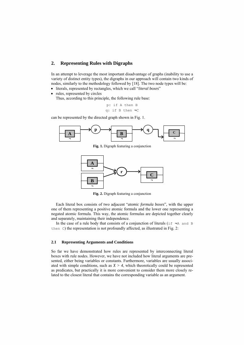
In an attempt to leverage the most important disadvantage of graphs (inability to use a variety of distinct entity types), the digraphs in our approach will contain two kinds of nodes, similarly to the methodology followed by [18]. The two node types will be: • literals, represented by rectangles, which we call “literal boxes” • rules, represented by circles
Thus, according to this principle, the following rule base: p: if A then B q: if B then ¬C
can be represented by the directed graph shown in Fig. 1.
p A B
qC
¬ ¬ ¬ Fig. 1. Digraph featuring a conjunction
r
A
C B
¬
¬ ¬
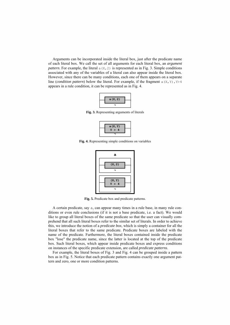
Fig. 2. Digraph featuring a conjunction
Each literal box consists of two adjacent “atomic formula boxes”, with the upper one of them representing a positive atomic formula and the lower one representing a negated atomic formula. This way, the atomic formulas are depicted together clearly and separately, maintaining their independence.
In the case of a rule body that consists of a conjunction of literals (if ¬A and B then C) the representation is not profoundly affected, as illustrated in Fig. 2:
2.1 Representing Arguments and Conditions
So far we have demonstrated how rules are represented by interconnecting literal boxes with rule nodes. However, we have not included how literal arguments are pre-sented, either being variables or constants. Furthermore, variables are usually associ-ated with simple conditions, such as X > 4, which theoretically could be represented as predicates, but practically it is more convenient to consider them more closely re-lated to the closest literal that contains the corresponding variable as an argument.
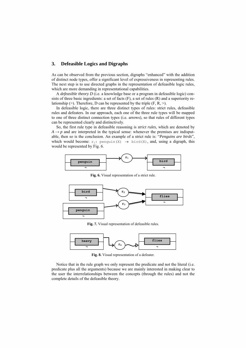
Arguments can be incorporated inside the literal box, just after the predicate name of each literal box. We call the set of all arguments for each literal box, an argument pattern. For example, the literal a(X,2) is represented as in Fig. 3. Simple conditions associated with any of the variables of a literal can also appear inside the literal box. However, since there can be many conditions, each one of them appears on a separate line (condition pattern) below the literal. For example, if the fragment a(X,Y),Y>4 appears in a rule condition, it can be represented as in Fig. 4.
¬
a(X,2)
Fig. 3. Representing arguments of literals
¬
a(X,Y)Y > 4
Fig. 4. Representing simple conditions on variables
a
¬
(X,Y)Y > 4
¬
(X,2)
Fig. 5. Predicate box and predicate patterns.
A certain predicate, say a, can appear many times in a rule base, in many rule con-ditions or even rule conclusions (if it is not a base predicate, i.e. a fact). We would like to group all literal boxes of the same predicate so that the user can visually com-prehend that all such literal boxes refer to the similar set of literals. In order to achieve this, we introduce the notion of a predicate box, which is simply a container for all the literal boxes that refer to the same predicate. Predicate boxes are labeled with the name of the predicate. Furthermore, the literal boxes contained inside the predicate box "lose" the predicate name, since the latter is located at the top of the predicate box. Such literal boxes, which appear inside predicate boxes and express conditions on instances of the specific predicate extension, are called predicate patterns.
For example, the literal boxes of Fig. 3 and Fig. 4 can be grouped inside a pattern box as in Fig. 5. Notice that each predicate pattern contains exactly one argument pat-tern and zero, one or more condition patterns.
3. Defeasible Logics and Digraphs
As can be observed from the previous section, digraphs “enhanced” with the addition of distinct node types, offer a significant level of expressiveness in representing rules. The next step is to use directed graphs in the representation of defeasible logic rules, which are more demanding in representational capabilities.
A defeasible theory D (i.e. a knowledge base or a program in defeasible logic) con-sists of three basic ingredients: a set of facts (F), a set of rules (R) and a superiority re-lationship (>). Therefore, D can be represented by the triple (F, R, >).
In defeasible logic, there are three distinct types of rules: strict rules, defeasible rules and defeaters. In our approach, each one of the three rule types will be mapped to one of three distinct connection types (i.e. arrows), so that rules of different types can be represented clearly and distinctively.
So, the first rule type in defeasible reasoning is strict rules, which are denoted by A → p and are interpreted in the typical sense: whenever the premises are indisput-able, then so is the conclusion. An example of a strict rule is: “Penguins are birds”, which would become: r1: penguin(X) → bird(X), and, using a digraph, this would be represented by Fig. 6.
r1penguin bird
¬ ¬ Fig. 6. Visual representation of a strict rule.
r3
r2flies
¬
¬ penguin
¬ bird
Fig. 7. Visual representation of defeasible rules.
r4heavy
¬
flies
¬ Fig. 8. Visual representation of a defeater.
Notice that in the rule graph we only represent the predicate and not the literal (i.e. predicate plus all the arguments) because we are mainly interested in making clear to the user the interrelationships between the concepts (through the rules) and not the complete details of the defeasible theory.
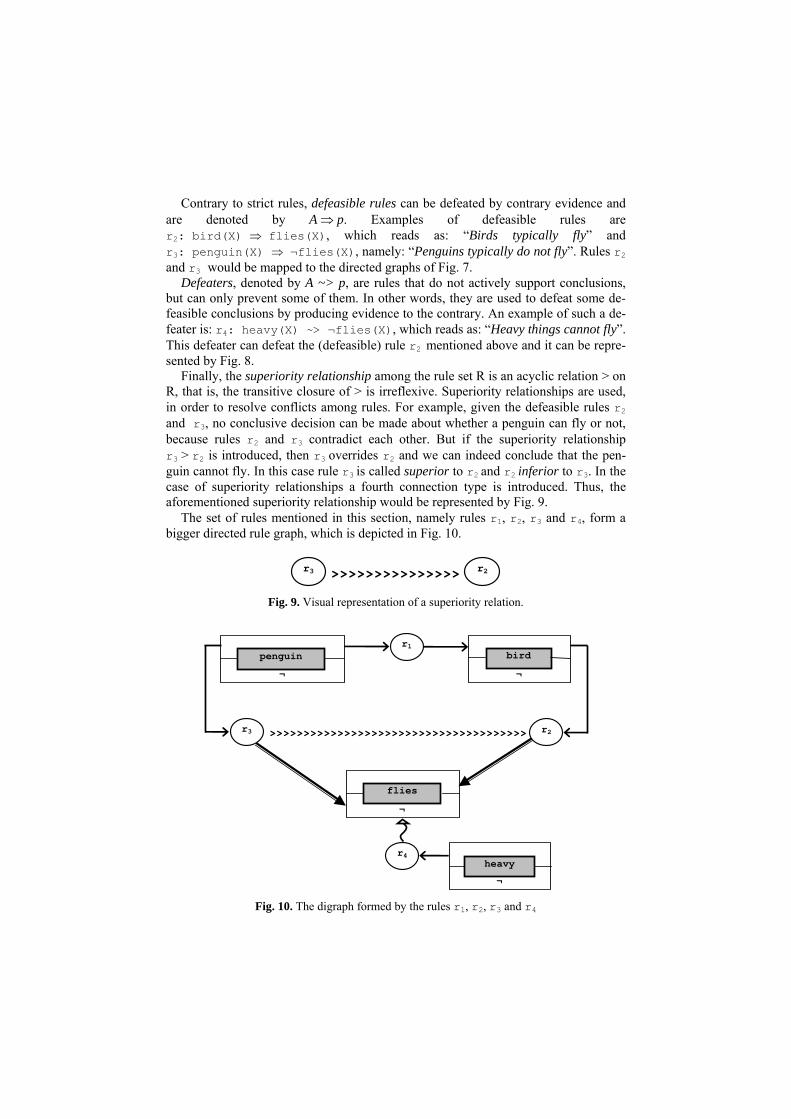
Contrary to strict rules, defeasible rules can be defeated by contrary evidence and are denoted by A ⇒ p. Examples of defeasible rules are r2: bird(X) ⇒ flies(X), which reads as: “Birds typically fly” and r3: penguin(X) ⇒ ¬flies(X), namely: “Penguins typically do not fly”. Rules r2 and r3 would be mapped to the directed graphs of Fig. 7.
Defeaters, denoted by A ~> p, are rules that do not actively support conclusions, but can only prevent some of them. In other words, they are used to defeat some de-feasible conclusions by producing evidence to the contrary. An example of such a de-feater is: r4: heavy(X) ~> ¬flies(X), which reads as: “Heavy things cannot fly”. This defeater can defeat the (defeasible) rule r2 mentioned above and it can be repre-sented by Fig. 8.
Finally, the superiority relationship among the rule set R is an acyclic relation > on R, that is, the transitive closure of > is irreflexive. Superiority relationships are used, in order to resolve conflicts among rules. For example, given the defeasible rules r2 and r3, no conclusive decision can be made about whether a penguin can fly or not, because rules r2 and r3 contradict each other. But if the superiority relationship r3 > r2 is introduced, then r3 overrides r2 and we can indeed conclude that the pen-guin cannot fly. In this case rule r3 is called superior to r2 and r2 inferior to r3. In the case of superiority relationships a fourth connection type is introduced. Thus, the aforementioned superiority relationship would be represented by Fig. 9.
The set of rules mentioned in this section, namely rules r1, r2, r3 and r4, form a bigger directed rule graph, which is depicted in Fig. 10.
r3 r2>>>>>>>>>>>>>>>
Fig. 9. Visual representation of a superiority relation.
¬ penguin
r1
¬
bird
>>>>>>>>>>>>>>>>>>>>>>>>>>>>>>>>>>>>>>r3 r2
¬
flies
r4heavy
¬ Fig. 10. The digraph formed by the rules r1, r2, r3 and r4
r2
r1
p
...
...
r3
¬ a
¬ c
¬ b
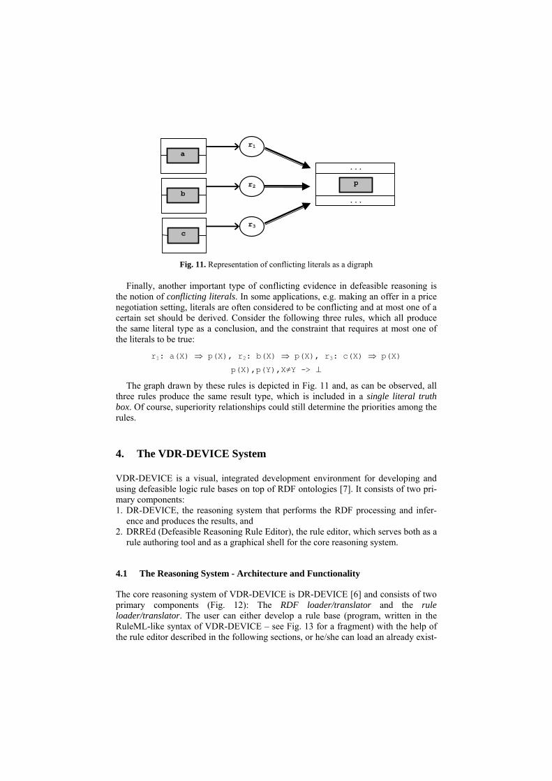
Fig. 11. Representation of conflicting literals as a digraph
Finally, another important type of conflicting evidence in defeasible reasoning is the notion of conflicting literals. In some applications, e.g. making an offer in a price negotiation setting, literals are often considered to be conflicting and at most one of a certain set should be derived. Consider the following three rules, which all produce the same literal type as a conclusion, and the constraint that requires at most one of the literals to be true:
r1: a(X) ⇒ p(X), r2: b(X) ⇒ p(X), r3: c(X) ⇒ p(X)
p(X),p(Y),X≠Y -> ⊥
The graph drawn by these rules is depicted in Fig. 11 and, as can be observed, all three rules produce the same result type, which is included in a single literal truth box. Of course, superiority relationships could still determine the priorities among the rules.
4. The VDR-DEVICE System
VDR-DEVICE is a visual, integrated development environment for developing and using defeasible logic rule bases on top of RDF ontologies [7]. It consists of two pri-mary components: 1. DR-DEVICE, the reasoning system that performs the RDF processing and infer-
ence and produces the results, and 2. DRREd (Defeasible Reasoning Rule Editor), the rule editor, which serves both as a
rule authoring tool and as a graphical shell for the core reasoning system.
4.1 The Reasoning System - Architecture and Functionality
The core reasoning system of VDR-DEVICE is DR-DEVICE [6] and consists of two primary components (Fig. 12): The RDF loader/translator and the rule loader/translator. The user can either develop a rule base (program, written in the RuleML-like syntax of VDR-DEVICE – see Fig. 13 for a fragment) with the help of the rule editor described in the following sections, or he/she can load an already exist-
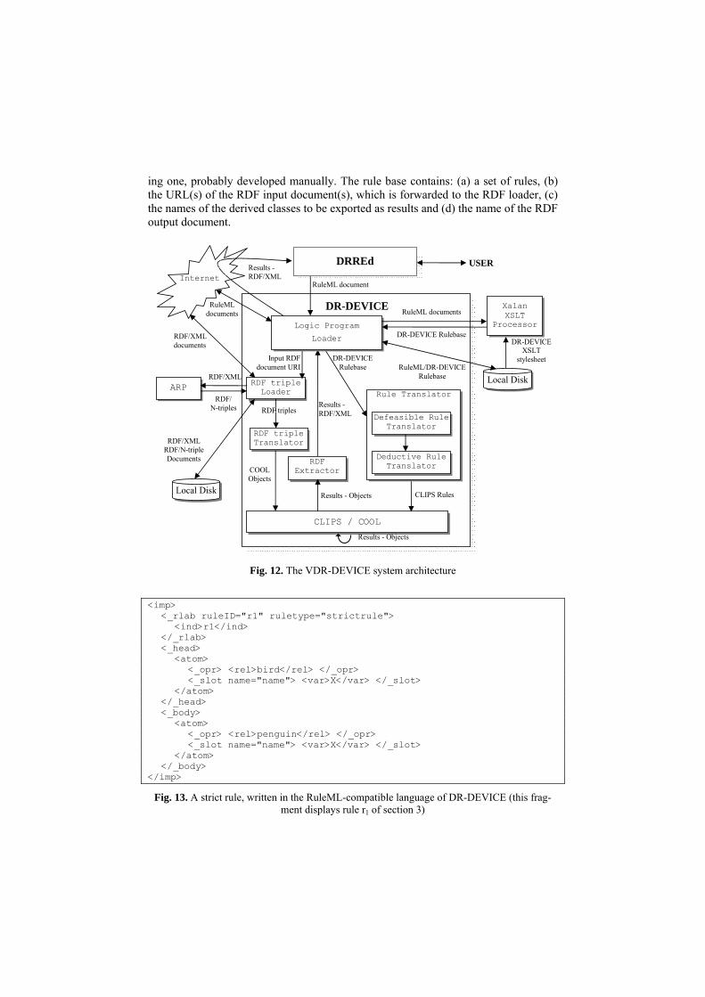
ing one, probably developed manually. The rule base contains: (a) a set of rules, (b) the URL(s) of the RDF input document(s), which is forwarded to the RDF loader, (c) the names of the derived classes to be exported as results and (d) the name of the RDF output document.
RDF triple Loader
RDF triple Translator
Local Disk
Input RDF document URI
ARP
RuleML/DR-DEVICE Rulebase
CLIPS / COOL
RDF triples
COOL Objects
RDF/XML documents
RDF/XML
RDF/ N-triples
Results - Objects
Results -RDF/XML
DR-DEVICE
RDF/XML RDF/N-triple Documents RDF
Extractor
Results - Objects CLIPS Rules
Logic Program
Loader
Xalan XSLT
Processor
Local Disk
RuleML documents
RuleML document
RuleML documents
DR-DEVICE Rulebase
Rule Translator
Defeasible RuleTranslator
Deductive Rule Translator
DR-DEVICE Rulebase
Results - RDF/XML
DR-DEVICE XSLT
stylesheet
Internet
DRREd USER
Fig. 12. The VDR-DEVICE system architecture
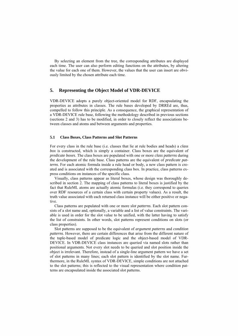
<imp> <_rlab ruleID="r1" ruletype="strictrule"> <ind>r1</ind> </_rlab> <_head> <atom> <_opr> <rel>bird</rel> </_opr> <_slot name="name"> <var>X</var> </_slot> </atom> </_head> <_body> <atom> <_opr> <rel>penguin</rel> </_opr> <_slot name="name"> <var>X</var> </_slot> </atom> </_body> </imp>
Fig. 13. A strict rule, written in the RuleML-compatible language of DR-DEVICE (this frag-ment displays rule r1 of section 3)

The rule base is then submitted to the rule loader which transforms it into the na-tive CLIPS-like syntax through an XSLT stylesheet and the resulting program is then forwarded to the rule translator, where the defeasible logic rules are compiled into a set of CLIPS production rules [12]. This is a two-step process: First, the defeasible logic rules are translated into sets of deductive, derived attribute and aggregate attrib-ute rules of the basic deductive rule language, using the translation scheme described in [6]. Then, all these deductive rules are translated into CLIPS production rules ac-cording to the rule translation scheme in [8].
Meanwhile, the RDF loader downloads the input RDF documents, including their schemas, and translates RDF descriptions into CLIPS objects [12], according to the RDF-to-object translation scheme in [8], which is briefly described below.
The inference engine of CLIPS performs the reasoning by running the production rules and generates the objects that constitute the result of the initial rule program. The compilation phase guarantees correctness of the reasoning process according to the operational semantics of defeasible logic. Finally, the result-objects are exported to the user as an RDF/XML document through the RDF extractor. The RDF docu-ment includes the instances of the exported derived classes, which have been proved.
The Object-Oriented RDF Data Model The DR-DEVICE system employs an OO RDF data model, which is different from the established triple-based data model for RDF. The main difference is that DR-DEVICE treats properties both as first-class objects and as normal encapsulated at-tributes of resource objects. In this way properties of resources are not scattered across several triples as in most other RDF inferencing systems, resulting in increased query performance due to less joins. For example, Fig. 14 shows an RDF resource that describes a person, which is represented as a COOL object in DR-DEVICE (Fig. 15).
<rdf:RDF ... xmlns:ex="http://...rdfs" xmlns:ex_in="http://...rdf"> <ex:person rdf:about="&ex_in;p1"> <ex:name>John Smith</ex:name> <ex:age rdf:datatype="&xsd;integer">25</ex:age> <ex:sex>M</ex:sex> </ex:person> ... </rdf:RDF>
Fig. 14. RDF document excerpt for a person.
[ex_in:p1] of ex:person (ex:name "John Smith") (ex:age 25) (ex:sex "M")
Fig. 15. COOL object for the RDF resource of Fig. 14.

4.2 Rule Editor – Design and Functionality
Writing rules in RuleML can often be a highly cumbersome task. Thus, the need for authoring tools that assist end-users in writing and expressing rules is apparently im-perative. VDR-DEVICE is equipped with DRREd (Fig. 16), a Java-built visual rule editor that aims at enhancing user-friendliness and efficiency during the development of VDR-DEVICE RuleML documents [7]. Its implementation is oriented towards simplicity of use and familiarity of interface. Other key features of the software in-clude: (a) functional flexibility - program utilities can be triggered via a variety of overhead menu actions, keyboard shortcuts or popup menus, (b) improved develop-ment speed - rule bases can be developed in just a few steps and (c) powerful safety mechanisms – the correct syntax is ensured and the user is protected from syntactic or RDF Schema related semantic errors.
Fig. 16. The graphical rule editor and the namespace dialog window.
The rule base is displayed in XML-tree format, which is one of the most intuitive means of displaying RuleML-like syntax, because of its hierarchical nature. The user has the option of navigating through the entire tree and can add to or remove elements from the tree. However, since each rule base is backed by a DTD document, potential addition or removal of tree elements has to obey to the DTD limitations. Therefore, the rule editor allows a limited number of operations performed on each element, ac-cording to the element's meaning within the rule tree.
By selecting an element from the tree, the corresponding attributes are displayed each time. The user can also perform editing functions on the attributes, by altering the value for each one of them. However, the values that the user can insert are obvi-ously limited by the chosen attribute each time.
5. Representing the Object Model of VDR-DEVICE
VDR-DEVICE adopts a purely object-oriented model for RDF, encapsulating the properties as attributes in classes. The rule bases developed by DRREd are, thus, compelled to follow this principle. As a consequence, the graphical representation of a VDR-DEVICE rule base, following the methodology described in previous sections (sections 2 and 3) has to be modified, in order to closely reflect the associations be-tween classes and atoms and between arguments and properties.
5.1 Class Boxes, Class Patterns and Slot Patterns
For every class in the rule base (i.e. classes that lie at rule bodies and heads) a class box is constructed, which is simply a container. Class boxes are the equivalent of predicate boxes. The class boxes are populated with one or more class patterns during the development of the rule base. Class patterns are the equivalent of predicate pat-terns. For each atomic formula inside a rule head or body, a new class pattern is cre-ated and is associated with the corresponding class box. In practice, class patterns ex-press conditions on instances of the specific class.
Visually, class patterns appear as literal boxes, whose design was thoroughly de-scribed in section 2. The mapping of class patterns to literal boxes is justified by the fact that RuleML atoms are actually atomic formulas (i.e. they correspond to queries over RDF resources of a certain class with certain property values). As a result, the truth value associated with each returned class instance will be either positive or nega-tive.
Class patterns are populated with one or more slot patterns. Each slot pattern con-sists of a slot name and, optionally, a variable and a list of value constraints. The vari-able is used in order for the slot value to be unified, with the latter having to satisfy the list of constraints. In other words, slot patterns represent conditions on slots (or class properties).
Slot patterns are supposed to be the equivalent of argument patterns and condition patterns. However, there are certain differences that arise from the different nature of the tuple-based model of predicate logic and the object-based model of VDR-DEVICE. In VDR-DEVICE class instances are queried via named slots rather than positional arguments. Not every slot needs to be queried and slot position inside the object is irrelevant. Therefore, instead of a single-line argument pattern we have a set of slot patterns in many lines; each slot pattern is identified by the slot name. Fur-thermore, in the RuleML syntax of VDR-DEVICE, simple conditions are not attached to the slot patterns; this is reflected to the visual representation where condition pat-terns are encapsulated inside the associated slot patterns.

An example of all the above can be seen in Fig. 17. The figure illustrates a class box that contains three class patterns applied on the person class (see also Fig. 14 and Fig. 15) and a code fragment matching the third class pattern, written in the RuleML-like syntax of VDR-DEVICE. The first two class patterns contain one slot pattern each, while the third one contains two slot patterns. As can be observed, the argument list of each slot pattern is divided into two parts, separated by ”|”; on the left all the variables are placed and on the right all the corresponding expressions and conditions, regarding the variables on the left. In the case of constant values, only the right-hand side is utilized; thus, the second class pattern of the box in Fig. 17, for example, refers to all the male persons. This way the content of the slot arguments is clearly depicted and easily comprehended.
person
¬ name( X | )
¬ sex( | “M” )
sex( | “F” ) age(X | X>18)
¬
<atom><_opr>
<rel href="person"/>
</_opr>
<_slot name="sex">
<ind>"F"</ind>
</_slot>
<_slot name="age">
<_and>
<var>x</var>
<function_call
name=">">
<var>x</var>
<ind>18</ind>
</function_call>
</_and>
</_slot>
</atom> Fig. 17. A class box example and a code fragment for the third class pattern.
5.2 The Digraph Utility of VDR-DEVICE
DRREd is equipped with a utility that allows the creation of a directed rule graph from the defeasible rule base developed by the editor. This way, users are offered an extra means of visualizing the rule base, besides XML-tree format and, thus, possess a better aspect of the rule base displayed and the inference results produced. Note, how-ever, that the implemented module currently employs the methodology described in sections 2 (excluding section 2.1) and 3 and not the principles described in the previ-ous section (section 5.1). However, this is included in the directions for future work.
The two aspects of the rule base, namely the XML-tree and the directed graph are correlated, meaning that traversal and alterations in one will be reflected in the other and vice versa. So, if for example the user focuses on a specific element in the tree and then switches to the digraph view, the corresponding element in the digraph will also be selected and the information relevant to it displayed.
More specifically, the digraph drawing utility simply analyzes the rule base into a set of rules, detecting the head and body for every rule, as well as information rele-vant to each rule (i.e. rule type, ruleID, superiority relationships between rules etc.). Each rule body can potentially consist of more than one atomic formula.
When this analysis comes to an end, the corresponding digraph can be derived, with the more complex rules being placed first (rules with many atomic formulas in the rule body) and the simpler rules being gradually placed afterwards. Since facts can be considered as very simple rules (rules with no body), they are placed into the rule graph in the end.
In case the derived digraph is too big to fit the screen, the user has the option of fo-cusing on a specific part of it and can also traverse the rest of the graph parts by using the scroll controls. Furthermore, similarly to the XML-tree format of the rule base, in the digraph there is also the possibility to collapse or expand certain parts of it. This way, a twofold advantage is offered: (a) the complexity of the digraph is minimized, since only a limited number of graph parts are visible at a time and (b) the level of comprehensibility on behalf of the user is raised, since he/she does not have to focus on the whole graph, but only to a part of it.
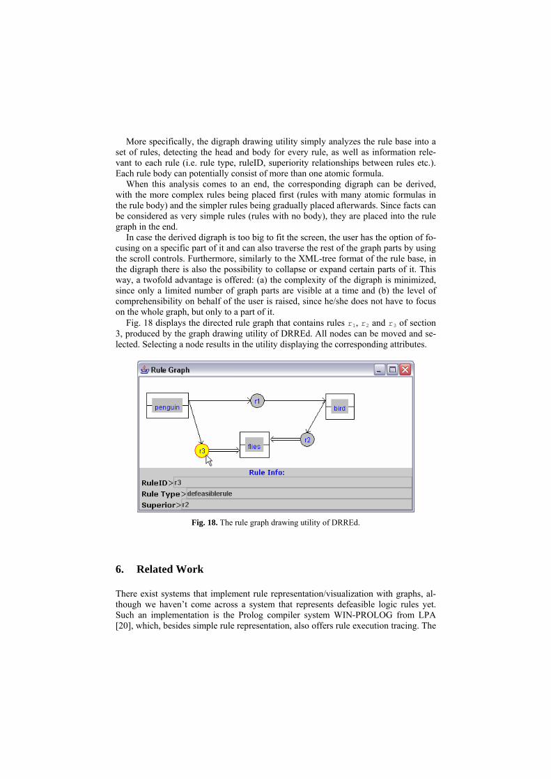
Fig. 18 displays the directed rule graph that contains rules r1, r2 and r3 of section 3, produced by the graph drawing utility of DRREd. All nodes can be moved and se-lected. Selecting a node results in the utility displaying the corresponding attributes.
Fig. 18. The rule graph drawing utility of DRREd.
6. Related Work
There exist systems that implement rule representation/visualization with graphs, al-though we haven’t come across a system that represents defeasible logic rules yet. Such an implementation is the Prolog compiler system WIN-PROLOG from LPA [20], which, besides simple rule representation, also offers rule execution tracing. The

graphs produced, however, feature an elementary level of detail and, therefore, do not assist significantly in the visualization of the rule bases developed.
Certain knowledge-based system development tools also feature rule and execution graph-drawing. An example is KEE (Knowledge Engineering Environment) [17] that offers several execution control mechanisms. The main features of the software in-clude: (a) a knowledge base development tool, (b) utilities for the interface with the user and (c) graph drawing tools for the knowledge base and execution.
Another example is Graphviz [16], which is an open-source graph visualization software, with several main graph layout programs. Its applications are not limited to drawing rule graphs, but can also include other domains, like software engineering, database and web design, networking and visual interfaces. As a general-purpose graph drawing utility, Graphviz can be applied in rule graph drawing, since it offers variation in graph node types, but does not feature variety in the connection types in the graph and is, therefore, unsuitable for the representation of defeasible rules.
Finally, there have been attempts of creating rule graphs for certain rule types, like association rules ([10], [23]) or production rules [18], but they remained at an elemen-tary stage of development.
7. Conclusions and Future Work
In this paper we argued that graphs can be a helpful tool in the field of information visualization. Especially in the case of rules, directed graphs can be particularly use-ful, since by definition they embrace the idea of information flow, a notion that is also encountered in rules and inference. Directed graphs have, however, a major disadvan-tage, which is their inability to associate data of a variety of types with the nodes and with the connections between the nodes in the graph. In this paper we propose an ap-proach that aims at leveraging this disadvantage by allowing different node and con-nection types in the graph. We also demonstrated that digraphs, “enhanced” with these extra features, can assist significantly in representing defeasible logic rules.
Our future plans involve improvement of the VDR-DEVICE graph-drawing utility demonstrated, by introducing the full representational methodology described in this paper. The issue of scalability (i.e. applicability to more complex rule sets) has to be addressed as well, since the tool currently only deals with simpler rule bases. Also, a user evaluation of the tool should also be considered, in order to realize at what ex-tend the proposed representation is actually helpful. Furthermore, in the future, we plan to delve deeper into the visualization of the proof layer of the Semantic Web ar-chitecture by enhancing the rule representation utility with rule execution tracing, ex-planation, proof visualization, etc. These facilities would be useful in order to auto-mate proof exchange and trust among agents in the Semantic Web and, ultimately, to increase the trust of users towards the Semantic Web.
Acknowledgments
This work was partially supported by the European Network of Excellence REW-ERSE.

8. References
[1] Antoniou G. and Arief M., “Executable Declarative Business rules and their use in Elec-tronic Commerce”, Proc. ACM Symposium on Applied Computing, 2002.
[2] Antoniou G., Billington D. and Maher M.J., “On the analysis of regulations using defeasi-ble rules”, Proc. 32nd Hawaii International Conference on Systems Science, 1999.
[3] Antoniou G., Harmelen F. van, A Semantic Web Primer, MIT Press, 2004. [4] Antoniou G., Nonmonotonic Reasoning, MIT Press, 1997. [5] Antoniou G., Skylogiannis T., Bikakis A., Bassiliades N., “DR-BROKERING – A Defea-
sible Logic-Based System for Semantic Brokering”, IEEE Int. Conf. on E-Technology, E-Commerce and E-Service, pp. 414-417, Hong Kong, 2005.
[6] Bassiliades N., Antoniou, G., Vlahavas I., “A Defeasible Logic Reasoner for the Semantic Web”, Int. Journal on Semantic Web and Information Systems, 2(1), pp. 1-41, 2006.
[7] Bassiliades N., Kontopoulos E., Antoniou G., “A Visual Environment for Developing De-feasible Rule Bases for the Semantic Web”, Proc. International Conference on Rules and Rule Markup Languages for the Semantic Web (RuleML-2005), A. Adi, S. Stoutenburg, S. Tabet (Ed.), Springer-Verlag, LNCS 3791, pp. 172-186, Galway, Ireland, 2005.
[8] Bassiliades N., Vlahavas I., “R-DEVICE: An Object-Oriented Knowledge Base System for RDF Metadata”, Int. Journal on Semantic Web and Information Systems, 2(2), pp. 24-90, 2006.
[9] Boley H., Tabet S., The Rule Markup Initiative, www.ruleml.org/ [10] Chakravarthy S., Zhang H., “Visualization of association rules over relational DBMSs”,
Proc. 2003 ACM Symp. on Applied Computing, ACM Press, pp. 922-926, Melbourne, Florida, 2003.
[11] Clarke D., “An Augmented Directed Graph Base for Application Development”, Proc. 20th Annual Southeast Regional Conf., ACM Press, pp. 155-159, Knoxville, Tennessee, USA, 1982.
[12] CLIPS Basic Programming Guide (v. 6.21), www.ghg.net/clips/CLIPS.html. [13] Diestel R., Graph Theory (Graduate Texts in Mathematics), 2nd ed., Springer, 2000. [14] Governatori G., Dumas M., Hofstede A. ter and Oaks P., “A formal approach to protocols
and strategies for (legal) negotiation”, Proc. ICAIL 2001, pp. 168-177, 2001. [15] Governatori, G., "Representing business contracts in RuleML", International Journal of
Cooperative Information Systems, 14 (2-3), pp. 181-216, 2005. [16] Graphviz - Graph Visualization Software, http://www.graphviz.org. [17] Intellicorp, The Knowledge Engineering Environment, 1984. [18] Jantzen J., “Inference Planning Using Digraphs and Boolean Arrays”, Proc. International
Conference on APL, ACM Press, pp. 200-204, New York, USA, 1989. [19] Li N., Grosof B. N. and Feigenbaum J., “Delegation Logic: A Logic-based Approach to
Distributed Authorization”, ACM Trans. on Information Systems Security, 6(1), 2003. [20] LPA WIN-PROLOG, http://www.lpa.co.uk/win.htm. [21] Nascimento H. A. D. do, “A Framework for Human-Computer Interaction in Directed
Graph Drawing”, Proc. Australian Symp. on Information Visualization, Australian Com-puter Society, pp. 63-69, Sydney, Australia, 2001.
[22] Nute D., “Defeasible Reasoning”, Proc. 20th Int. Conference on Systems Science, IEEE Press, 1987, pp. 470-477.
[23] Wong P. C., Whitney P., Thomas J., “Visualizing Association Rules for Text Mining”, Proc. IEEE Symp. on Information Visualization, IEEE Computer Society, p. 120, 1999.