Visualisation in architecture, engineering and construction (AEC
9
Visualisation in architecture, engineering and construction (AEC) Dino Bouchlaghem * , Huiping Shang, Jennifer Whyte, Abdulkadir Ganah Department of Civil and Building Engineering, Loughborough University, Loughborough, Leicestershire, LE11 3TU, UK Received 1 February 2004; received in revised form 1 July 2004; accepted 1 August 2004 Abstract In the architecture, engineering and construction industries, computer visualization usage can cover the whole lifecycle of a product from presentation of initial concepts to the final stages of production and can also extend to maintenance issues. Three- dimensional walkthroughs can be created from hand drawn sketches at the very early stages of the design process. Three- dimensional models can be used by design teams to communicate design intent to client and users and to compare and evaluate design options. During more advanced stages of design, three-dimensional representations can be used to check the integrity of services coordination, accessibility and maintainability. During construction, visualization can facilitate the interpretation of design details by site operatives. The concept of visualization is not limited to modeling physical objects but can extend to the representation of abstract data sets of the type obtained from simulation programs used in performance assessment or from Computation Fluid Dynamics (CFD) applications. This paper will review the application of visualization in the process of design and construction and then present findings from three research projects that made use of some of these techniques at various stages of the process: for collaborative working during concept design stage, for design development and marketing in the house building sector, and for the modeling of design details during the construction stage. D 2004 Elsevier B.V. All rights reserved. Keywords: Visualisation; Architecture; Engineering; Construction 1. Introduction In design applications, visualization is not an end in itself. The process of design and visualization should be iterative, with changes made as a result of insights gained through visualization propagated into the next version of the design. The iterative nature of this process requires adequate software support and thought processes should not be interrupted by a requirement to translate the design concepts into software terms for visualization [1]. The design of the urban environment involves many stakeholders. These different stakeholders, who view the process from different perspectives, include professionals such as engineers, architects, and planners and non-specialists such as clients and users. Collaborative building design requires a shared understanding to be reached between all of the parties 0926-5805/$ - see front matter D 2004 Elsevier B.V. All rights reserved. doi:10.1016/j.autcon.2004.08.012 * Corresponding author. E-mail address: [email protected] (D. Bouchlaghem). Automation in Construction 14 (2005) 287 – 295 www.elsevier.com/locate/autcon
-
Upload
independent -
Category
Documents
-
view
2 -
download
0
Transcript of Visualisation in architecture, engineering and construction (AEC
www.elsevier.com/locate/autcon
Automation in Constructio
Visualisation in architecture, engineering and construction (AEC)
Dino Bouchlaghem*, Huiping Shang, Jennifer Whyte, Abdulkadir Ganah
Department of Civil and Building Engineering, Loughborough University, Loughborough, Leicestershire, LE11 3TU, UK
Received 1 February 2004; received in revised form 1 July 2004; accepted 1 August 2004
Abstract
In the architecture, engineering and construction industries, computer visualization usage can cover the whole lifecycle of a
product from presentation of initial concepts to the final stages of production and can also extend to maintenance issues. Three-
dimensional walkthroughs can be created from hand drawn sketches at the very early stages of the design process. Three-
dimensional models can be used by design teams to communicate design intent to client and users and to compare and evaluate
design options. During more advanced stages of design, three-dimensional representations can be used to check the integrity of
services coordination, accessibility and maintainability. During construction, visualization can facilitate the interpretation of
design details by site operatives. The concept of visualization is not limited to modeling physical objects but can extend to the
representation of abstract data sets of the type obtained from simulation programs used in performance assessment or from
Computation Fluid Dynamics (CFD) applications. This paper will review the application of visualization in the process of
design and construction and then present findings from three research projects that made use of some of these techniques at
various stages of the process: for collaborative working during concept design stage, for design development and marketing in
the house building sector, and for the modeling of design details during the construction stage.
D 2004 Elsevier B.V. All rights reserved.
Keywords: Visualisation; Architecture; Engineering; Construction
1. Introduction
In design applications, visualization is not an end
in itself. The process of design and visualization
should be iterative, with changes made as a result of
insights gained through visualization propagated into
the next version of the design. The iterative nature of
0926-5805/$ - see front matter D 2004 Elsevier B.V. All rights reserved.
doi:10.1016/j.autcon.2004.08.012
* Corresponding author.
E-mail address: [email protected]
(D. Bouchlaghem).
this process requires adequate software support and
thought processes should not be interrupted by a
requirement to translate the design concepts into
software terms for visualization [1].
The design of the urban environment involves
many stakeholders. These different stakeholders, who
view the process from different perspectives, include
professionals such as engineers, architects, and
planners and non-specialists such as clients and users.
Collaborative building design requires a shared
understanding to be reached between all of the parties
n 14 (2005) 287–295

D. Bouchlaghem et al. / Automation in Construction 14 (2005) 287–295288
involved. 3D visualization techniques can facilitate
this shared understanding across interdisciplinary
groups. Virtual Reality (VR), for example, offers a
natural medium for building design providing three-
dimensional visualization that can be manipulated in
real-time and can be used collaboratively to explore
design options and simulate different stages of the
construction process. In the future, it may be possible
to generate and print two-dimensional CAD drawings
directly from the VR models used for architectural
design. However, in order for the use of VR to mature
to such a level, the integration of its use with existing
technologies such as CAD needs to become the focus
of research [2], and appropriate standards and proto-
cols need to be developed.
In this paper applications and benefits of 3D
visualization and virtual reality in the built environ-
ment field are reviewed followed by the presentation
of three case study applications where different
visualization techniques are implemented and trailed
at different stages of the design and construction
process, early conceptual design, design development,
and finally on site construction. Conclusion are then
drawn, based on this work, regarding the barriers in
the way of realizing full benefits from visualization
technologies in the AEC industry.
2. Visualization and VR in AEC
2.1. Building design and construction
Architectural design has been the main driving
force for developments in 3D modeling and Virtual
Reality. By allowing architects to visualize and
immerse themselves in the their designs, a much
clearer understanding is gained of both the qualitative
and quantitative nature of the space they are designing.
Visualization and VR enable designers to evaluate
proportion and scale using intuitive interactive model-
ing environments [3] and simulate the effects of
lighting, ventilation and acoustics in internal environ-
ments [4,5]. The use of visualization in this area also
includes the simulation of egress from buildings for the
design of fire escape routes [6]. As a visualization tool
VR is also used to communicate design ideas from
designers to clients by generating walkthrough models
to test the design with the clients in a more direct
manner [7]. Visualization can also be used to model
the construction sequence in order to simulate and
monitor site progress. This is done using a pre-
prepared library of 3D graphical images of building
components, facilities etc. and their related activities,
and generate models representing views of the con-
struction sequence at any given time of the process [8].
At a larger scale of visualization Web-based Virtual
Reality techniques generated a lot of activity in Urban
modeling which led to the introduction of the concept
of bVirtual CitiesQ [9]. The most popular approach in
the development of these 3D models is using VRML
(Virtual Reality Modeling Language), which is a Web
modeling language that is able to construct objects in
three dimensions.
Another application of visualization technologies,
which is gaining momentum in this field of research,
is environmental simulation for landscape design
practice. Here many attempts were made to demon-
strate the use of VR in environmental design [10–17]
highlighting the limitations and problems still to be
overcome. Most of these studies highlighted the
benefits of future potential that visualization technol-
ogies can offer in the field of environmental simu-
lation. Furthermore, the use of some of these
techniques for the environmental assessment of new
developments has already been demonstrated through
a number of examples including the Tower of London
project [18] and new developments in the city centre
of Bath [19].
2.2. Collaborative environments
Visualization technologies such as VR have given
birth to Collaborative Virtual Environments (CVEs)
within which users are virtually co-located and can
interact with one another. One example of this is the
Virtual Meeting Room (VMR), which represents an
extension of the concept of desktop video-confer-
encing. In a virtual meeting room, team members are
able to interact intuitively in 3D space and feel as
though they were all in the same room. This is
considered to be more realistic than desktop confer-
encing but requires the use of appropriate metaphors
to represent both real world objects and, the collab-
orating parties. It is essential in VMR that normal
meeting room decorum is observed and that all
members of the team can see and hear one another
D. Bouchlaghem et al. / Automation in Construction 14 (2005) 287–295 289
[20]. This technology is still in its infancy and does
not at present support realistic pictorial representation
of the parties present in a meeting. Collaborative
virtual environments can also be a medium for the
remote collaboration of urban designers, and the
discussion of urban proposals by the general public.
At present the benefits that visualization and VR
can bring to the construction industry are fully
appreciated by the majority of practitioners. However
despite the continually falling costs associated with
the hardware and software, there remains a big
obstacle to its full uptake, this is the low compatibility
between VR and the existing CAD infrastructures
making its implementation costly due to the resource
intensive task of creating the models.
3. Case studies of visualisation applications in the
AEC industry
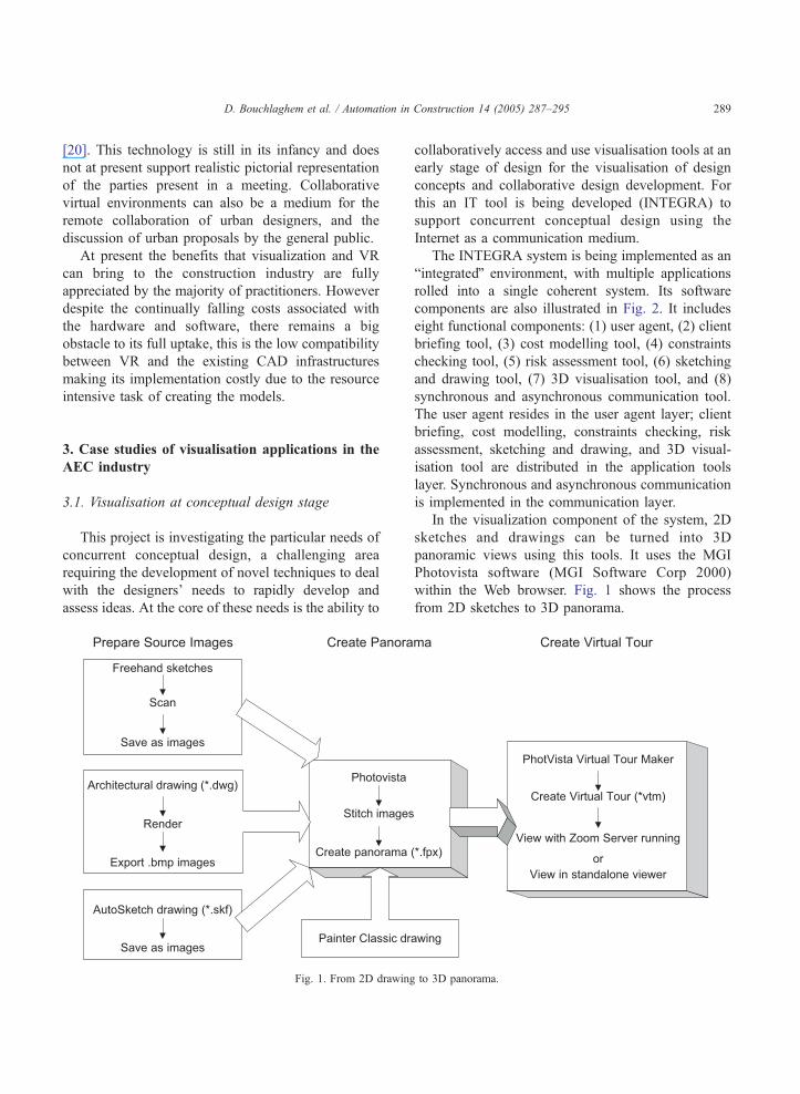
3.1. Visualisation at conceptual design stage
This project is investigating the particular needs of
concurrent conceptual design, a challenging area
requiring the development of novel techniques to deal
with the designers’ needs to rapidly develop and
assess ideas. At the core of these needs is the ability to
Fig. 1. From 2D drawing
collaboratively access and use visualisation tools at an
early stage of design for the visualisation of design
concepts and collaborative design development. For
this an IT tool is being developed (INTEGRA) to
support concurrent conceptual design using the
Internet as a communication medium.
The INTEGRA system is being implemented as an
bintegratedQ environment, with multiple applications
rolled into a single coherent system. Its software
components are also illustrated in Fig. 2. It includes
eight functional components: (1) user agent, (2) client
briefing tool, (3) cost modelling tool, (4) constraints
checking tool, (5) risk assessment tool, (6) sketching
and drawing tool, (7) 3D visualisation tool, and (8)
synchronous and asynchronous communication tool.
The user agent resides in the user agent layer; client
briefing, cost modelling, constraints checking, risk
assessment, sketching and drawing, and 3D visual-
isation tool are distributed in the application tools
layer. Synchronous and asynchronous communication
is implemented in the communication layer.
In the visualization component of the system, 2D
sketches and drawings can be turned into 3D
panoramic views using this tools. It uses the MGI
Photovista software (MGI Software Corp 2000)
within the Web browser. Fig. 1 shows the process
from 2D sketches to 3D panorama.
to 3D panorama.
D. Bouchlaghem et al. / Automation in Construction 14 (2005) 287–295290
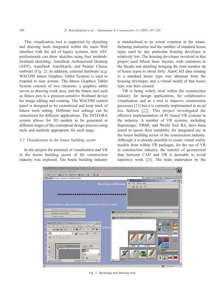
This visualization tool is supported by sketching
and drawing tools integrated within the main Web
interface with the aid of legacy systems, here AEC
professionals can draw sketches using four methods:
freehand sketching, AutoDesk Architectural Desktop
(ADT), AutoDesk AutoSketch, and Painter Classic
software (Fig. 2). In addition, external hardware (e.g.
WACOM Intuos Graphics Tablet System) is used to
respond to user actions. The Intuos Graphics Tablet
System consists of two elements: a graphics tablet
serves as drawing work area, and the Intuos tool such
as Intuos pen is a pressure-sensitive freehand device
for image editing and creating. The WACOM control
panel is designed to be customized and keep track of
Intuos tools setting. Different tool settings can be
customized for different applications. The INTEGRA
system allows for 3D models to be generated at
different stages of the conceptual design process using
tools and methods appropriate for each stage.
3.2. Visualisation in the house building sector
In this project the potential of visualization and VR
in the house building sector of the construction
industry was explored. The house building industry
Fig. 2. Sketching and
is standardised to an extent common in the manu-
facturing industries and the number of standard house
types used by any particular housing developer is
relatively low. The housing developer involved in this
project used fifteen basic layouts, with variations to
the facade and detailing bringing the total number up
of house types to about forty. AutoCAD data relating
to a standard house type was obtained from the
housing developer, and a virtual model of that house
type was then created.
VR is being widely tried within the construction
industry for design applications, for collaborative
visualisation and as a tool to improve construction
processes [21] but it is currently implemented in an ad
hoc fashion [22]. This project investigated the
effective implementation of PC-based VR systems in
the industry. A number of VR systems, including
Superscape, VRML and World Tool Kit, have been
tested to assess their suitability for integrated use in
the house building sector of the construction industry.
Although it is already possible to create virtual reality
models from within VR packages, for the use of VR
in construction industry, the transfer of geometrical
data between CAD and VR is desirable to avoid
repetitive work [23]. The trials undertaken by the
drawing tool.
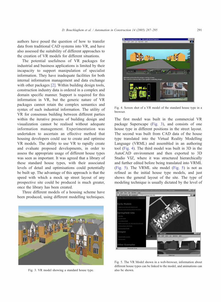
Fig. 4. Screen shot of a VR model of the standard house type in a
browser.
D. Bouchlaghem et al. / Automation in Construction 14 (2005) 287–295 291
authors have posed the question of how to transfer
data from traditional CAD systems into VR, and have
also assessed the suitability of different approaches to
the creation of VR models for different situations.
The potential usefulness of VR packages for
industrial and business applications is limited by their
incapacity to support manipulation of specialist
information. They have inadequate facilities for both
internal information management and data exchange
with other packages [2]. Within building design tools,
construction industry data is ordered in a complex and
domain specific manner. Support is required for this
information in VR, but the generic nature of VR
packages cannot retain the complex semantics and
syntax of such industrial information. The utility of
VR for consensus building between different parties
within the iterative process of building design and
visualization cannot be realised without adequate
information management. Experimentation was
undertaken to ascertain an effective method that
housing developers could use to create and optimise
VR models. The ability to use VR to rapidly create
and evaluate proposed developments, in order to
assess the appropriate usage of different house types
was seen as important. It was agreed that a library of
these standard house types, with their associated
levels of detail and optimisations could potentially
be built up. The advantage of this approach is that the
speed with which a mock up street layout of any
prospective site could be produced is much greater,
once the library has been created.
Three different models of a housing scheme have
been produced, using different modelling techniques.
Fig. 3. VR model showing a standard house type.
Fig. 5. The VR Model shown in a web-browser, information abou
different house types can be linked to the model, and animations can
also be shown.
The first model was built in the commercial VR
package Superscape (Fig. 3), and consists of one
house type in different positions in the street layout.
The second was built from CAD data of the house
type translated into the Virtual Reality Modelling
Language (VRML) and assembled in an authoring
tool (Fig. 4). The third model was built in 3D in the
AutoCAD environment and then exported to 3D
Studio VIZ, where it was structured hierarchically
and further edited before being translated into VRML
(Fig. 5). The VRML site model (Fig. 5) is not as
refined as the initial house type models, and just
shows the general layout of the site. The type of
modeling technique is usually dictated by the level of
t
D. Bouchlaghem et al. / Automation in Construction 14 (2005) 287–295292
detail required, the first one being suitable for single
house types for walk-through purposes, while the
second and third techniques are used to show street
layouts and hence requiring less detail on the
individual house models.
However these models demonstrate the potential
for the project to be accessed through a browser, (Fig.
5) either remotely, or on the local computer. In such a
distributed use, bandwidth considerations lead to the
necessity to seek a compromise between model detail
and speed of navigation within the model. Technical
data or photographic marketing images can also be
displayed when the user enquires about relevant parts
of the housing scheme from within the virtual
environment using hotspots.
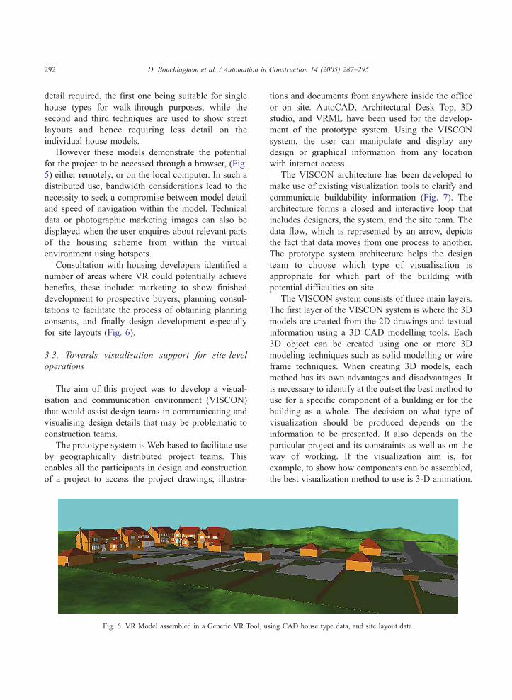
Consultation with housing developers identified a
number of areas where VR could potentially achieve
benefits, these include: marketing to show finished
development to prospective buyers, planning consul-
tations to facilitate the process of obtaining planning
consents, and finally design development especially
for site layouts (Fig. 6).
3.3. Towards visualisation support for site-level
operations
The aim of this project was to develop a visual-
isation and communication environment (VISCON)
that would assist design teams in communicating and
visualising design details that may be problematic to
construction teams.
The prototype system is Web-based to facilitate use
by geographically distributed project teams. This
enables all the participants in design and construction
of a project to access the project drawings, illustra-
Fig. 6. VR Model assembled in a Generic VR Tool, u
tions and documents from anywhere inside the office
or on site. AutoCAD, Architectural Desk Top, 3D
studio, and VRML have been used for the develop-
ment of the prototype system. Using the VISCON
system, the user can manipulate and display any
design or graphical information from any location
with internet access.
The VISCON architecture has been developed to
make use of existing visualization tools to clarify and
communicate buildability information (Fig. 7). The
architecture forms a closed and interactive loop that
includes designers, the system, and the site team. The
data flow, which is represented by an arrow, depicts
the fact that data moves from one process to another.
The prototype system architecture helps the design
team to choose which type of visualisation is
appropriate for which part of the building with
potential difficulties on site.
The VISCON system consists of three main layers.
The first layer of the VISCON system is where the 3D
models are created from the 2D drawings and textual
information using a 3D CAD modelling tools. Each
3D object can be created using one or more 3D
modeling techniques such as solid modelling or wire
frame techniques. When creating 3D models, each
method has its own advantages and disadvantages. It
is necessary to identify at the outset the best method to
use for a specific component of a building or for the
building as a whole. The decision on what type of
visualization should be produced depends on the
information to be presented. It also depends on the
particular project and its constraints as well as on the
way of working. If the visualization aim is, for
example, to show how components can be assembled,
the best visualization method to use is 3-D animation.
sing CAD house type data, and site layout data.
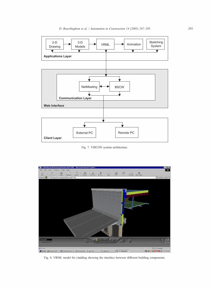
Fig. 8. VRML model for cladding showing the interface between different building components.
Fig. 7. VISCON system architecture.
D. Bouchlaghem et al. / Automation in Construction 14 (2005) 287–295 293
D. Bouchlaghem et al. / Automation in Construction 14 (2005) 287–295294
To view the final product, it is best to use a VRML
model, which can be manipulated and viewed from
different angles and sides.
Rendered images are useful for visualizing materi-
als and their appearance. This enables users to decide
on the best materials from an aesthetic point of view.
VISCON also offers other visualization systems
currently available (such as VR proprietary software)
and is flexible enough to incorporate other systems
that will be available in future.
The models created within the system (see example
in Fig. 8) can be linked to the main CAD drawing.
Rendered drawings, 3D animations and VRML
models can be hyperlinked to a 2-D plan of the
proposed building or structure so that it can be viewed
or downloaded.
The second layer of the system consists of the
communication infrastructure including site video
links using tools such as NetMeeting, and collabo-
rative support systems such as BSCW (Basic Support
for Collaborative Working). The third layer or client
layer provides external and remote access to the
system.
4. Conclusions
The paper presented a review of visualization
applications in the AEC sector followed by three case
study projects where various technologies have been
applied to different stages of design and construction.
This highlighted ways in which visualization can
assist AEC professionals improve aspects of their
work. During conceptual design visualization can help
designers work collaboratively and communicate
ideas more efficiently. In housing development, site
layout models can be used as a marketing tool with
clients or for planning consultations with planners, at
the same time it can improve the way house type
designs are developed by design teams. It has also
been shown in the last case study that visualization
can bridge the gap between designers and site teams
in facilitating the exchange of information for build-
ability problems. Visualization applications are
becoming more readily available and accessible to
construction professionals due to the continuous
decreasing cost of software and hardware. Some
leading construction firms have invested large resour-
ces for the use of visualization in house realizing its
business benefits. Some of these companies are using
advanced tools for the creation of walkthrough models
of new developments to communicate concepts to
clients, or to check the integrity of designs in terms of
clash detection between the services and the structure.
Implementation problems of these new technologies
have always been the main barrier in adopting them,
however while in the past the main problem was cost,
it is now more organizational and human issues that
stand in the way of taking full advantage of the
benefits that can be realized. This is now being seen as
the next challenge in this area of research where both
academics and practitioners are realizing that success-
ful adoption of new technologies depends on careful
consideration of organizational and business issues.
References
[1] S. Johnson, What’s in a representation, why do we care, and
what does it mean? Examining evidence from psychology,
Automation in Construction 8 (1) (1998) 5–24.
[2] J. Whyte, N. Bouchlaghem, A. Thorpe, The promise and
problems of implementing virtual reality in construction
practice, Proceedings of CIB W78, The Life-cycle of
Construction IT Innovations: Technology Transfer From
Research To practice Stockholm, 3–5 June, 1998.
[3] D. Kurmann, Sculptor—A Tool for Intuitive Architectural
Design, in: M. Tan, R. Teh (Eds.), CAAD Futures ’95—The
Global Design Studio, 1995, pp. 323–330, Singapore.
[4] J.S. Nimeroff, E. Simoncelli, I. Badler, J. Dorsey, Rendering
spaces for architectural environments, Presence: Teleoperators
and Virtual Environments 4 (3) (1995) 286–297.
[5] Y. Shinomiya, et al., Soundproof simulation in the living
environment using virtual reality, Proceedings of the Interna-
tional Conference Virtual Reality Environments in Architec-
ture and Design, Leeds, November 2–3, 1994.
[6] M.J. Spearpoint, Virtual Reality Simulation of Fire in a
Dwelling, New Horizons, BEPAC Seminar, Oxford, 1994.
[7] M. Ormerod, G. Aouad, The need for matching visualisation
techniques to client understanding in the UK construction
industry, Proceedings of the International Conference on
Information Visualisation IV’97, London, August 27–29,
1997, pp. 322–328.
[8] T. Adeji-Kumi, A. Retik, A library-based 4D visualisation of
construction processes, Proceedings of the IEEE International
Conference on Information Visualisation (IV’97) London, 27–
29 August, 1997.
[9] A. Day, New tools for urban design, Urban Design Quarterly
(1994 July) 20–23.
[10] D. Campbell, J. Davidson, Community and Environmental
Design and Simulation, Designing the Digital Space, John
Wiley & Sons, New York, 1997.
D. Bouchlaghem et al. / Automation in Construction 14 (2005) 287–295 295
[11] S.M. Ervin, Virtual possibilities, Landscape Architecture 87
(6) (1997) 46–51.
[12] M.A. Gigante, Virtual Reality: Enabling Technologies, Virtula
Reality Systems, Academic Press, London, 1993.
[13] R. Grabowski, CAD Presentations Get Real, Architectural
Record 184 (1) (1996) 36–40.
[14] A.C. Hall, Computer Visualisation in Planning Control,
Visualisation and Intelligent Design in Engineering and
Architecture, Computational Mechanics, Southampton, 1993.
[15] S. Menoni, G. Viganti, Experiences and rules in Simulating
Architectural Reality, Visualisation and Intelligent Design in
Engineering and Architecture, Computational Mechanics,
Southampton, 1993.
[16] H. Regenbrecht, D. Donath, Architectural Education and
Virtual Reality Aided Design, Designing the Digital Space,
John Wiley & Sons, New York, 1997.
[17] J.L. Sipes, Computers: simulating natural phenomena, Land-
scape Architecture 84 (5) (1994) 30.
[18] J. Counsell, B. Phillips, The Tower of London Computer
Models, Proceedings of the IEEE International Conference on
Information Visualisation (IV’97), London, England, 27–29
August, 1997.
[19] V. Bourdakis, A. Day, A VRML Model of Bath, EuropIA97
Conference Proceedings, 1997.
[20] D. Madigan, BICC’s experience of multimedia communica-
tions: issues in CSCW’, IEE Colloquium on Multimedia and
Professional Applications, London, February, 1993.
[21] N.M. Bouchlaghem, I.G. Liyanage, Virtual reality applications
in the UK’s construction industry, in: Z. Turk (Ed.),
Construction on the Information Highway, CIB W78 Working
Commission on Information Technology in Construction, Bled
(Slovenia), University of Ljublajana, 1996.
[22] G. Aouad, M. Kagioglou, R. Cooper, J. Hinks, M. Sexton,
Technology management of IT in construction: a driver or an
enabler? Logistics Information Management 12 (1/2) (1998)
130–137.
[23] M. Alshawi, Integrating CAD and virtual reality in construc-
tion, in: J. Powell (Ed.), Virtual Reality and Rapid Prototyping
in Engineering, DRAL (EPSRC), Salford, 1995, pp. 78–85.