Video Communication System - pro.sony
200
© 2006 Sony Corporation 3-991-626-15 (1) Video Communication System Operating Instructions (Version 2.2) Before operating the unit, please read this manual thoroughly and retain it for future reference. PCS-HG90
-
Upload
khangminh22 -
Category
Documents
-
view
1 -
download
0
Transcript of Video Communication System - pro.sony
© 2006 Sony Corporation
3-991-626-15 (1)
Video Communication System
Operating Instructions (Version 2.2)Before operating the unit, please read this manual thoroughly and retain it for future reference.
PCS-HG90

Owner’s Record
The model and the serial numbers are located on the side. Record the serial number in the space provided below. Refer to these numbers whenever you call upon your Sony dealer regarding this product.
Model No. PCS-HG90Serial No. ______________
WARNING
To reduce a risk of fire or electric shock, do not expose this product to rain or moisture.
To avoid electrical shock, do not open the cabinet. Refer servicing to qualified personnel only.
WARNINGTHIS APPARATUS MUST BE EARTHED.
CAUTIONThe mains plug on this equipment must be used to disconnect mains power.Please ensure that the socket outlet is installed near the equipment and shall be easily accessible.In the event of abnormal operations, disconnect the mains plug.
NOTICEUse the power cord set approved by the appropriate testing organization for the specific countries where this unit is to be used.
CAUTION for LAN portFor safety reasons, do not connect the LAN port to any network devices that might have excessive voltage.
Installing batteriesTwo R6 (size AA) batteries are supplied for Remote Commander.To avoid risk of explosion, use R6 (size AA) manganese or alkaline batteries.
CAUTIONRISK OF EXPLOSION IF BATTERY IS REPLACED BY AN INCORRECT TYPE.DISPOSE OF USED BATTERIES ACCORDING TO ALL APPLICABLE LOCAL REGULATIONS.
For the customers in the USA
WARNING
This equipment has been tested and found to comply with the limits for a Class A digital device, pursuant to Part 15 of the FCC Rules. These limits are designed to provide reasonable protection against harmful interference when the equipment is operated in a commercial environment. This equipment generates, uses, and can radiate radio frequency energy and, if not installed and used in accordance with the instruction manual, may cause harmful interference to radio communications. Operation of this equipment in a residential area is likely to cause harmful interference in which case the user will be required to correct the interference at his own expense.
You are cautioned that any changes or modifications not expressly approved in this manual could void your authority to operate this equipment.
This device complies with Part 15 of the FCC Rules.Operation is subject to the following two conditions: (1) This device may not cause harmful interference, and (2) this device must accept any interference received, including interference that may cause undesired operation.
2
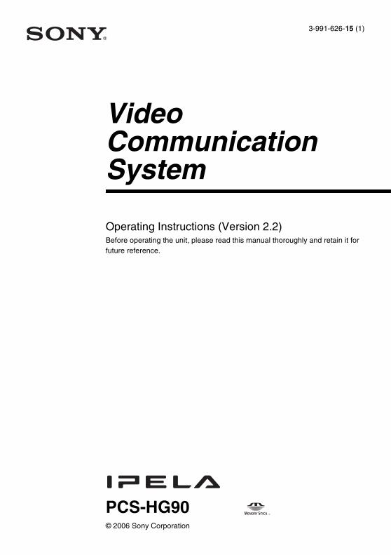
All interface cables used to connect peripherals must be shielded in order to comply with the limits for a digital device pursuant to Subpart B or Part 15 of FCC Rules.
For the customers in Canada
This Class A digital apparatus complies with Canadian ICES-003.
Cet appareil numérique de la classe A est conforme à la norme NMB-003 du Canada.
For the customers in Europe
WARNINGThis is a Class A product. In a domestic environment, this product may cause radio interference in which case the user may be required to take adequate measures.In the case that interference should occur, consult your nearest authorized Sony service facility.
Voor de Klanten in Nederland
If you dispose the unit, consult your nearest Sony Service Center. The built-in battery must be treated as a chemical waste.
Für Kunden in DeutschlandEntsorgungshinweis: Bitte werfen Sie nur entladene Batterien in die Sammelboxen beim Handel oder den Kommunen. Entladen sind Batterien in der Regel dann, wenn das Gerät abschaltet und signalisiert “Batterie leer” oder nach längerer Gebrauchsdauer der Batterien “nicht mehr einwandfrei funktioniert”. Um sicherzugehen, kleben Sie die Batteriepole z.B. mit einem Klebestreifen ab oder geben Sie die Batterien einzeln in einen Plastikbeutel.
For Customers in Taiwan only
Gooi de batterij niet weg maar lever deze in als klein chemisch afval (KCA).
3
Table of Contents
Chapter 1: Installation and Preparation
Using This Manual ................................................................................................... 9Features .................................................................................................................. 10System Components .............................................................................................. 11
Basic System Components ............................................................................... 11Optional Equipment ......................................................................................... 12
System Configuration ............................................................................................ 14System Configuration for Peer-to-Peer Connection ........................................ 14System Configuration for Multipoint Connection ........................................... 15System Configuration Using the PCSA-A7 Echo Canceling Microphones .... 16
System Connections ............................................................................................... 17System Connection ........................................................................................... 17
Preparing the System ............................................................................................. 21Attaching the Remote Control Receiver .......................................................... 21Inserting Batteries into the Remote Commander ............................................. 22
Turning the System On/Off ................................................................................... 24Turning On ....................................................................................................... 24Standby Mode Function ................................................................................... 26Setting the Video Communication System to Standby Mode .......................... 26Turning Off ...................................................................................................... 27Adjusting the Volume on the TV Monitor ....................................................... 27Displaying Help ............................................................................................... 28Displaying the Versions ................................................................................... 28
Setting Up the System for the First Time — Initial Setup Wizard ........................ 29Using the Menus .................................................................................................... 30
Operation .......................................................................................................... 30Menu Configuration ......................................................................................... 32Entering Characters .......................................................................................... 34
Chapter 2: Registration and Setup for System Administrators
Registering Local Information ............................................................................... 36Opening the Setup Menu .................................................................................. 36Dial Setup Menu .............................................................................................. 37Answer Menu ................................................................................................... 37Communication Mode Menu ........................................................................... 38
4 Table of Contents

Status Menu ...................................................................................................... 39Audio Setup Menu ............................................................................................ 41Video Setup Menu ............................................................................................ 43General Setup Menu ......................................................................................... 47Administrator Setup Menu ............................................................................... 50LAN Setup Menu ............................................................................................. 54Encryption Setup Menu .................................................................................... 59Machine Information Menu .............................................................................. 59
Registering a Remote Party – Phone Book ............................................................ 60Registering a New Remote Party in the Phone Book ....................................... 60Changing the Contents of the Phone Book ...................................................... 61Copying the Registered Remote Party ............................................................. 62Deleting the Registered Remote Party ............................................................. 62Registering a Remote Party in the Direct Phone Book .................................... 62Creating a Private Phone Book ........................................................................ 63
Setting Up the Network Configurations ................................................................. 65LAN (Connecting via DHCP) .......................................................................... 65LAN (Connecting Through a Router) .............................................................. 66LAN (Connecting through a Gatekeeper) ........................................................ 67LAN (Connecting through NAT) ..................................................................... 68LAN (PPPoE Connections) .............................................................................. 69
Measuring the Network Quality ............................................................................. 71Setting the Transmitting Image Quality ................................................................. 74
Chapter 3: Basic Connection
Starting a Communication by Calling a Remote Party .......................................... 76Turning on the Power ....................................................................................... 76Using the Launcher Menu ................................................................................ 77Displaying the Launcher Menu During Communication ................................. 80Calling a Remote Party ..................................................................................... 81
Receiving a Call from a Remote Party ................................................................... 89Answering a Call from a Remote Party ............................................................ 89
Ending the communication .................................................................................... 91Adjusting the Sound ............................................................................................... 92
Adjusting the Volume ...................................................................................... 92Turning Off the Sound Momentarily – Muting Function ................................. 92Turning Off the Sound On Answering – Mic on Answer Function ................. 93Reducing Echo – Echo Canceler ...................................................................... 93
Adjusting the Camera ............................................................................................. 95Selecting the Camera to be Controlled ............................................................. 95Adjusting the Camera Angle and Zoom ........................................................... 96
5Table of Contents
Adjusting the Focus and Brightness ................................................................. 98Presetting the Angle and Zoom Settings .......................................................... 99Recalling the Preset Angle and Zoom Setting ............................................... 101
Selecting the Input Picture and Sound ................................................................. 103Switching the Displayed Picture Between the Local and Remote Pictures ... 103Selecting the Input Picture ............................................................................. 103Switching the Sound to Be Sent to the Remote Party .................................... 104Switching Video and Audio simultaneously .................................................. 104
Monitoring the Local Picture as a Window Picture – PinP Feature .................... 105Monitoring the Local and Remote Pictures at the Same Time – PandP/Side by Side Feature ................................................................................................................. 107Capturing the Image ............................................................................................. 109Using a “Memory Stick” ...................................................................................... 111
Saving Still Images to a “Memory Stick” ...................................................... 111Formatting a “Memory Stick” ........................................................................ 113
Chapter 4: Connection With Optional Equipment
Using a Monitor Exclusively for Local Pictures ................................................. 115Using Multiple Microphones ............................................................................... 117Using the Echo Canceling Microphones ............................................................. 120Using the Second Camera Unit ............................................................................ 123Recording During a Communication ................................................................... 124Sending Audio/Video from the External Equipment to a Remote Party ............. 125
Chapter 5: Encrypted Connection
Preparing for an Encrypted Connection ............................................................... 128Starting an Encrypted Connection ....................................................................... 130
Chapter 6: Multipoint Connection
Connection Example for a Multipoint Connection .............................................. 131Setting for a Multipoint Connection .................................................................... 132
Confirming the Communication Mode Menu ................................................ 132Registering the Remote Parties in the Multipoint Connection List ............... 132
Starting a Multipoint Connection ........................................................................ 136Calling Remote Parties ................................................................................... 136Receiving a Call from a Remote Party ........................................................... 140
Using the Display Control ................................................................................... 141
6 Table of Contents
What is “Broadcast Mode”? ........................................................................... 141Switching the Broadcast Mode ....................................................................... 141Receiving the Broadcast Requested From Any Other Terminal .................... 142
Ending the Multipoint Connection ....................................................................... 143
Chapter 7: Web Control Function
Open the Web page .............................................................................................. 144Identify a user ....................................................................................................... 145Select a tool .......................................................................................................... 146How to use “Controller” ...................................................................................... 147
To control the PCS-HG90 from the on-screen controller .............................. 147To control the PCS-HG90 from the on-screen Remote Commander ............. 148
How to use “Dial/Disconnect” ............................................................................. 149For Peer-to-Peer Connection .......................................................................... 149For Multipoint Connection ............................................................................. 150
How to use “Phone Book” ................................................................................... 151“Phone Book-Edit” page ................................................................................ 152“Phone Book-New” page ............................................................................... 153
How to use “Setup” .............................................................................................. 154“Send Message” page ..................................................................................... 156“Erase” page ................................................................................................... 157
How to use “Info” ................................................................................................ 158“Cause Code” list page ................................................................................... 159“Call Log” page .............................................................................................. 160
Monitor a Meeting Over the Web ........................................................................ 161
Appendix
Location and Function of Parts and Controls ....................................................... 162PCS-PHG90 Communication Terminal ......................................................... 162PCSA-CHG90 Camera Unit (Optional) ......................................................... 164PCSA-RG1 Remote Commander ................................................................... 166
Indicators .............................................................................................................. 168On-screen Messages ............................................................................................. 171Troubleshooting ................................................................................................... 177Specifications ....................................................................................................... 179
PCS-PHG90 Communication Terminal ......................................................... 179PCSA-RG1 Remote Commander ................................................................... 179PCSA-CHG90 Camera Unit (optional) .......................................................... 179PCS-A1 Microphone (Optional) .................................................................... 180
7Table of Contents

PCSA-A3 Microphone (Optional) ................................................................. 180PCSA-A7P4 Microphone (4-pack, optional) ................................................. 180Acceptable RGB Input/Output Signals .......................................................... 181Pin Assignments ............................................................................................. 182List of Port Numbers Used on the PCS-HG90 ............................................... 184
Video Communication Room Layout .................................................................. 185Camera Range ................................................................................................ 185
“Memory Stick” Media ........................................................................................ 186Glossary ............................................................................................................... 188Menu Configuration ............................................................................................. 190
8 Table of Contents

Chapter 1: Installation and P
reparation
Using This Manual
The chapters cover the following contents; please read the chapters that may be required for your type of connection.
Chapter 1: Installation and PreparationThis chapter guides you through the system configuration and information required to use your Video Communication System for the first time. It shows you how to install and connect your Video Communication System, to turn the system on/off and how to access basic on-screen menus.
Chapter 2: Registration and Setup for System AdministratorThis chapter describes how to register and set up all the necessary items for system administrators, using the on-screen menus.
Chapter 3: Basic ConnectionThis chapter guides you through the basic operations and settings for connecting to a remote party. You will learn how to connect from start to finish. It is recommended that this chapter be read by participants in connection.
Chapter 4: Connection With Optional EquipmentThis chapter shows advanced connection using the optional equipment.
Chapter 5: Encrypted ConnectionThis chapter describes how to connect with encrypted video and audio.
Chapter 6: Multipoint ConnectionThis chapter shows you how to connect at the multipoint.
Chapter 7: Web Control FunctionThis chapter shows you how to control the PCS-HG90 or set it up via a Web browser.
AppendixThe appendix contains descriptions of the controls and connectors on the components of the Video Communication System, message and troubleshooting lists, specifications, and a glossary.
Chapter 1: Installation and Preparation
9Using This Manual

Features
The PCS-HG90 is a Video Communication System that connects with a remote party via a LAN (Local Area Network). It provides natural, face-to-face communication with the remote party by transmitting and receiving high-definition pictures and stereo sounds at high speed.
Network Quality Measurement
The system is capable of diagnosing the network conditions easily by measuring reachability, packet loss, etc.
Supports transmission and reception of high-definition images
The Video Communication System supports H.264 high-definition video compression format, enabling transmission and reception of pictures with a high resolution of 1280 × 720 by 60 frames (maximum) per second.
Supports transmission and reception of wide-range stereo sound
The system supports MPEG4 AAC (Advanced Audio Coding) stereo/monaural audio compression format of 22 kHz with echo canceler, enabling transmission and reception of high-quality audio sound.
Equipped with professional-standard AV interface
The system is equipped with HD-SDI connectors and YPbPr (component signal) connectors for video input/output, allowing shooting, transmission and reception of digital signal. It is also equipped with XLR-type audio input/output connectors, enabling connection with audio equipment for professional use.
QoS (Quality of Service) function for optimization of bandwidth and traffic packet through networkThe system includes “Packet Resend Request”, “Adaptive Rate Control”, and “Forward Error Control” functions. Depending on the network status, these functions are used to guarantee consistent, high-quality communications.
Easy operationHelp is displayed on the monitor when you need guidance.
Supports multipoint connectionThe system allows a multipoint connection among up to four points.
Equipped with Memory Stick slotThe Communication Terminal is equipped with a Memory Stick Slot, allowing saving of still images, creation of private phone books and storage of customized settings in a “Memory Stick”.
Echo Canceling MicrophoneUsing a cascade connection, up to 40 PCSA-A7 Echo Canceling Microphones (optional) can be connected to one port without losing sound quality.
Supports Encrypted ConnectionThis system supports the standard encryption format based on H.235 which is regulated in ITU-T. A highly confidential communication can be held.
“IPELA” and are trademarks of Sony Corporation.
10 Features

Chapter 1: Installation and P
reparation
System ComponentsThe PCS-HG90 Video Communication System is composed of basic system components for a basic connection, and optional equipment for an enhanced communication.
The PCS-PHG90 Communication Terminal is the basic system of the PCS-HG90 Video Communication System. It contains the following components:
Basic System Components
Unit Description
PCS-PHG90 Communication Terminal
Contains the video codec, audio codec, echo canceler, network interfaces and system controller.
PCSA-RG1 Remote Commander
Used to operate the Communication Terminal and Camera Unit.
AC power cord Supplies power to the Communication Terminal.
Remote Control Receiver Connects to the Communication Terminal and receives signals from the Remote Commander.
The Camera Unit cannot receive signals from the Remote Commander.
Note
11System Components
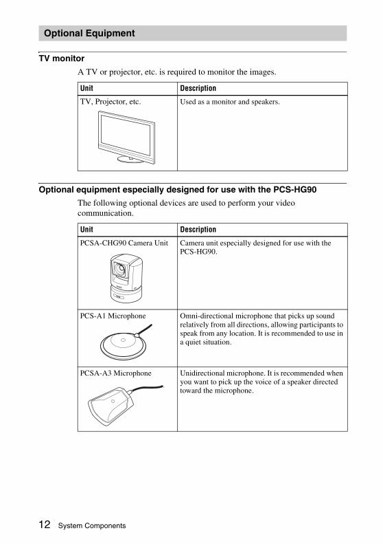
TV monitor
A TV or projector, etc. is required to monitor the images.
Optional equipment especially designed for use with the PCS-HG90
The following optional devices are used to perform your video communication.
Optional Equipment
Unit Description
TV, Projector, etc. Used as a monitor and speakers.
Unit Description
PCSA-CHG90 Camera Unit Camera unit especially designed for use with the PCS-HG90.
PCS-A1 Microphone Omni-directional microphone that picks up sound relatively from all directions, allowing participants to speak from any location. It is recommended to use in a quiet situation.
PCSA-A3 Microphone Unidirectional microphone. It is recommended when you want to pick up the voice of a speaker directed toward the microphone.
12 System Components
Chapter 1: Installation and P
reparation
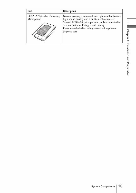
PCSA-A7P4 Echo Canceling Microphone
Narrow coverage monaural microphones that feature high sound quality and a built-in echo canceler. Several PCSA-A7 microphones can be connected in cascade, without losing sound quality. Recommended when using several microphones.(4-piece set)
Unit Description
13System Components

System ConfigurationThe PCS-HG90 Video Communication System has various system configuration capabilities using the basic components and optional equipment. This section describes the capabilities and necessary equipment for some typical configuration examples.
This allows you to:• Hold a peer-to-peer connection over LAN.• Pick up the sound of a communication in stereo by connecting two external
microphones.
System configuration
System Configuration for Peer-to-Peer Connection
ON LINE POWER/STANDBY LAN ALERT
ON LINE POWER/STANDBY LAN ALERT
1 PCS-PHG90 Communication Terminal2 PCSA-CHG90 Camera Unit
(not supplied)3 PCSA-RG1 Remote Commander4 Remote Control Receiver5 TV monitor (not supplied)6 PCSA-A3 Microphones (not supplied), 2
pieces
14 System Configuration

Chapter 1: Installation and P
reparation
This allows you to:• Hold a multipoint connection among up to four sites over LAN.
System configuration
System Configuration for Multipoint Connection
ON LINE POWER/STANDBY LAN ALERT
ON LINE POWER/STANDBY LAN ALERT
ON LINE POWER/STANDBY LAN ALERT
ON LINE POWER/STANDBY LAN ALERT
1 PCS-PHG90 Communication Terminal2 PCSA-CHG90 Camera Unit (not supplied)3 PCSA-RG1 Remote Commander4 Remote Control Receiver5 TV monitor (not supplied)6 PCSA-A3 Microphones (not supplied), 2 pieces
15System Configuration
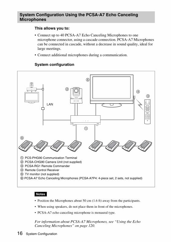
This allows you to:
• Connect up to 40 PCSA-A7 Echo Canceling Microphones to one microphone connector, using a cascade connection. PCSA-A7 Microphones can be connected in cascade, without a decrease in sound quality, ideal for large meetings.
• Connect additional microphones during a communication.
System configuration
• Position the Microphones about 50 cm (1.6 ft) away from the participants.
• When using speakers, do not place them in front of the microphones.
• PCSA-A7 echo canceling microphone is monaural type.
For information about PCSA-A7 Microphones, see “Using the Echo Canceling Microphones” on page 120.
System Configuration Using the PCSA-A7 Echo Canceling Microphones
Notes
ON LINE POWER/STANDBY LAN ALERT
ON LINE POWER/STANDBY LAN ALERT
1 PCS-PHG90 Communication Terminal2 PCSA-CHG90 Camera Unit (not supplied)3 PCSA-RG1 Remote Commander4 Remote Control Receiver5 TV monitor (not supplied)6 PCSA-A7 Echo Canceling Microphones (PCSA-A7P4: 4-piece set, 2 sets, not supplied)
16 System Configuration

Chapter 1: Installation and P
reparation
System ConnectionsThis section describes the typical system connections.
• Be sure to turn off all the equipment before making any connections.• Do not connect/disconnect the BNC cable or VISCA cable with the power on. Doing so
may damage the Camera Unit or Communication Terminal.• For safety, do not connect the 100BASE-TX/10BASE-T connector to a network that
applies an excess voltage via the 100BASE-TX/10BASE-T connector.
• Be sure to connect the Camera Unit to the Communication Terminal using both the BNC and VISCA cables. The picture from the camera cannot be viewed if it is directly connected to a TV monitor.
• The REC OUT (MIXED) connectors are used to make an audio recording. These are not used normaly.
Caution
System Connection
Notes
RGB
AUX CONTROL
CAMERA CONTROL 100BASE-TX/10BASE-T(VISCA)
~ AC IN
SUB MAIN
CTRL-S
REC OUT(MIXED)AUDIO OUTR LR
AUDIO IN
VIDEO IN
S-VIDEO Y1
VIDEO OUT
Y Pb Pr
(NEAR ONLY)
Y Pb Pr2
HD-SDI HD-SDIHD-SDI
SUBCAMERA
MAINCAMERA
Pb Pr
R MIC L R
AUX 2R
MICEC-MIC(A7)
1 2
A1/A3
(PLUG IN POWER)
1(R) 2(L)
L R L
AUX 1 L L
REC OUT (MIXED) connectors
17System Connections

* Use of an optional BNC cable or VISCA cable allows connection of up to 100 m (328 ft.).
VISCA RS-4221 2 3 4 5 6 7 8 9
VISCA RS-232C OUT
DC IN 12V
HFBK-HD1
MONITOR HD-SDI
RGB
AUX CONTROL
CAMERA CONTROL 100BASE-TX/10BASE-T(VISCA)
~ AC IN
SUB MAIN
CTRL-S
REC OUT(MIXED)AUDIO OUTR LR
AUDIO IN
VIDEO IN
S-VIDEO Y1
VIDEO OUT
Y Pb Pr
(NEAR ONLY)
Y Pb Pr2
HD-SDI HD-SDIHD-SDI
SUBCAMERA
MAINCAMERA
Pb Pr
R MIC L R
AUX 2R
MICEC-MIC(A7)
1 2
A1/A3
(PLUG IN POWER)
1(R) 2(L)
L R L
AUX 1 L L
PCSA-CHG90 Camera Unit
Power cord (supplied)
PCS-PHG90Communication Terminal
to a wall outlet
to LAN
to VISCA RS-232C IN
to MIC A1/A3
TV monitor (not supplied)
UTP cable(category 5, straight, not supplied)
to video inputs
to AC outlet
PCSA-A3 or PCS-A1 microphones (not supplied)
to AC outlet
to HD-SDI
to VIDEO OUT YPbPrto AUDIO
OUT R/L
to VIDEO IN HD-SDI MAIN CAMERA
VISCA cable (supplied with the Camera Unit)
BNC cable*(supplied with the Camera Unit)
to CAMERA CONTROL (VISCA) MAIN
Audio connecting cable (not supplied)
to audio inputs
Video connecting cable (not supplied)
18 System Connections
Chapter 1: Installation and P
reparation
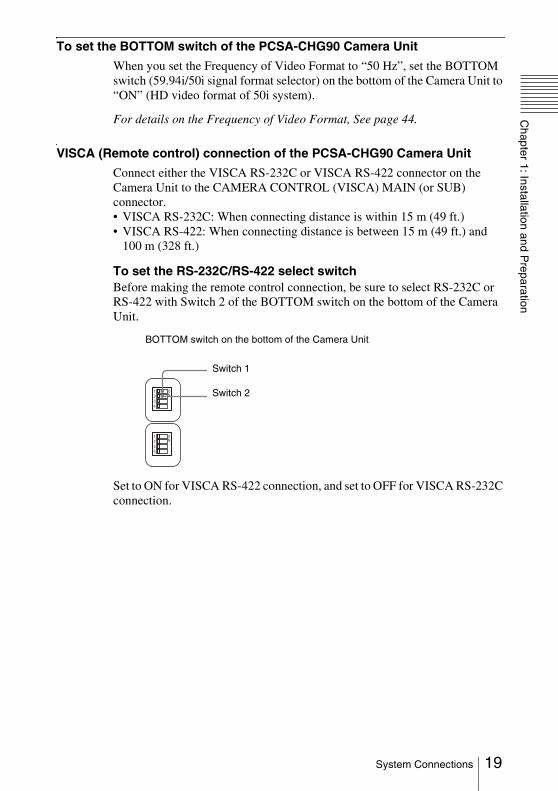
To set the BOTTOM switch of the PCSA-CHG90 Camera UnitWhen you set the Frequency of Video Format to “50 Hz”, set the BOTTOM switch (59.94i/50i signal format selector) on the bottom of the Camera Unit to “ON” (HD video format of 50i system).
For details on the Frequency of Video Format, See page 44.
VISCA (Remote control) connection of the PCSA-CHG90 Camera Unit
Connect either the VISCA RS-232C or VISCA RS-422 connector on the Camera Unit to the CAMERA CONTROL (VISCA) MAIN (or SUB) connector.• VISCA RS-232C: When connecting distance is within 15 m (49 ft.)• VISCA RS-422: When connecting distance is between 15 m (49 ft.) and
100 m (328 ft.)
To set the RS-232C/RS-422 select switchBefore making the remote control connection, be sure to select RS-232C or RS-422 with Switch 2 of the BOTTOM switch on the bottom of the Camera Unit.
Set to ON for VISCA RS-422 connection, and set to OFF for VISCA RS-232C connection.
ON
1234
ON
1234
Switch 1
BOTTOM switch on the bottom of the Camera Unit
Switch 2
19System Connections

Connection using the VISCA RS-422When you use the VISCA RS-422 connector on the Camera Unit to make the remote control connection with the Communication Terminal instead of the VISCA RS-232C connector, use of a converter between RS-422 and RS-232C is required. For details on the converter, consult with the contractor of the Camera Unit. Preparation of the connecting cable using the RS-422 connector plug (supplied with the Camera Unit) is also required. For making the cable and the use of the RS-422 connector plugs, refer to the Operating Instructions of the Camera Unit.
• For the connector plugs of the connecting cables for the optional converter, prepare plugs that match the connectors on the converter.
• When using the VISCA RS-422 connector, check that the BOTTOM switch on the bottom of the Camera Unit is set to RS-422.
Notes
VISCA RS-4221 2 3 4 5 6 7 8 9
VISCA RS-232C OUT
DC IN 12V
R
HFBK-HD1
MONITOR HD-SDI
RGB
AUX CONTROL
CAMERA CONTROL 100BASE-TX/10BASE-T(VISCA)
~ AC IN
SUB MAIN
CTRL-S
REC OUT(MIXED)AUDIO OUTR LR
AUDIO IN
VIDEO IN
S-VIDEO Y1
VIDEO OUT
Y Pb Pr
(NEAR ONLY)
Y Pb Pr2
HD-SDI HD-SDIHD-SDI
SUBCAMERA
MAINCAMERA
Pb Pr
R MIC L R
AUX 2R
MICEC-MIC(A7)
1 2
A1/A3
(PLUG IN POWER)
1(R) 2(L)
L R L
AUX 1 L L
to AC outlet
VISCA RS-422 cable(prepared by using the RS-422 connector plug supplied with the Camera Unit)
Converter (RS-422yRS-232C) (not supplied)
to VISCA RS-422
to CAMERA CONTROL(VISCA) MAIN (or SUB)
VIS
CA
RS
-232
C c
able
PCSA-CHG90 Camera Unit
20 System Connections

Chapter 1: Installation and P
reparation
Preparing the System
Most operations with the Video Communication System can be controlled with the supplied Remote Commander. To use the Remote Commander, point it to the supplied remote control receiver. Connect the remote control receiver to the CTRL-S jack on the Communication Terminal. Use the supplied Velcro to fix the remote control receiver to a monitor, etc.
For details on connecting the Camera Unit, see “System Connections” on page 17.
• Be careful not to hide the surface incorporating the indicator, which is the remote sensor of the remote control receiver.
• When an inverter type or brightness-adjustable type of fluorescent lamp is used, the sensitivity of the Remote Commander may deteriorate. If the Remote Commander does not function, attach the supplied filter over the remote sensor of the remote control receiver (see page 22) or change the location of the remote control receiver to avoid direct light.
Attaching the Remote Control Receiver
Notes
VISCA RS-4221 2 3 4 5 6 7 8 9
VISCA RS-232C OUT
DC IN 12V
HFBK-HD1
MONITOR HD-SDI
AUX CONTROL
CAMERA CONTROL 100BASE-TX/10BASE-T(VISCA)
~ AC IN
SUB MAIN
CTRL-S
REC OUT(MIXED)AUDIO OUTR LR
AUDIO IN
EO IN
1
VIDEO OUT
Y Pb Pr
(NEAR ONLY)
Y Pb Pr2
HD-SDI HD-SDIHD-SDI
SUBCAMERA
MAINCAMERA
Pb Pr
R
AUX 2R L R L
AUX 1 L L
TV monitor
to CTRL-S Remote sensor
21Preparing the System
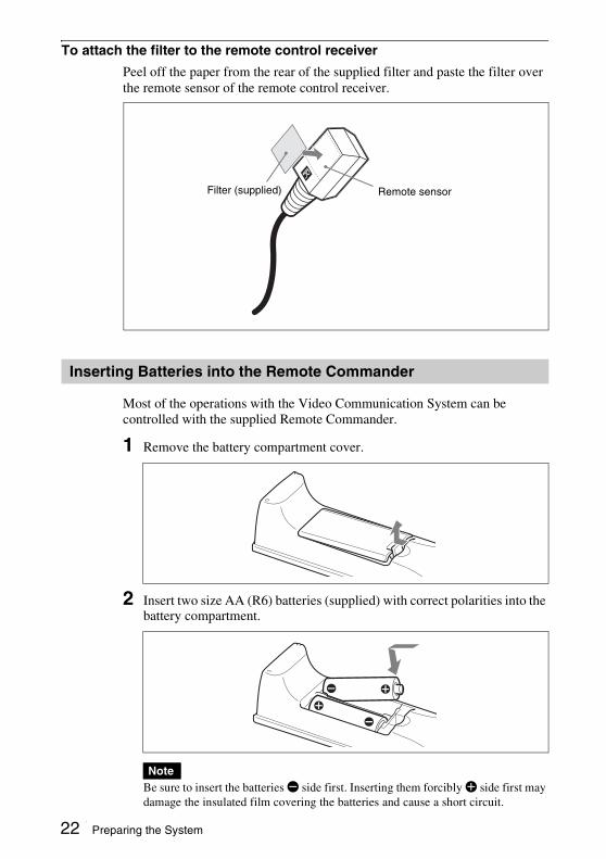
To attach the filter to the remote control receiver
Peel off the paper from the rear of the supplied filter and paste the filter over the remote sensor of the remote control receiver.
Most of the operations with the Video Communication System can be controlled with the supplied Remote Commander.
1 Remove the battery compartment cover.
2 Insert two size AA (R6) batteries (supplied) with correct polarities into the battery compartment.
Be sure to insert the batteries E side first. Inserting them forcibly e side first may damage the insulated film covering the batteries and cause a short circuit.
Inserting Batteries into the Remote Commander
Note
Filter (supplied) Remote sensor
22 Preparing the System
Chapter 1: Installation and P
reparation
3 Replace the cover.Battery lifeWhen the Remote Commander does not function properly, replace both the batteries with new ones.
Notes on batteriesTo avoid damage from possible battery leakage or corrosion, observe the following:• Make sure to insert the batteries with the polarities in the correct direction.• Do not mix old and new batteries, or different types of batteries.• Do not attempt to charge the batteries.• If you do not intend to use the Remote Commander for a long period of time,
remove the batteries.• If battery leakage occurs, clean the battery compartment and replace all the
batteries with new ones.
23Preparing the System
Turning the System On/Off
This section describes how to turn on or off the Communication Terminal.
1 Turn on the TV monitor.
2 Turn on the power of any other equipment to be used.
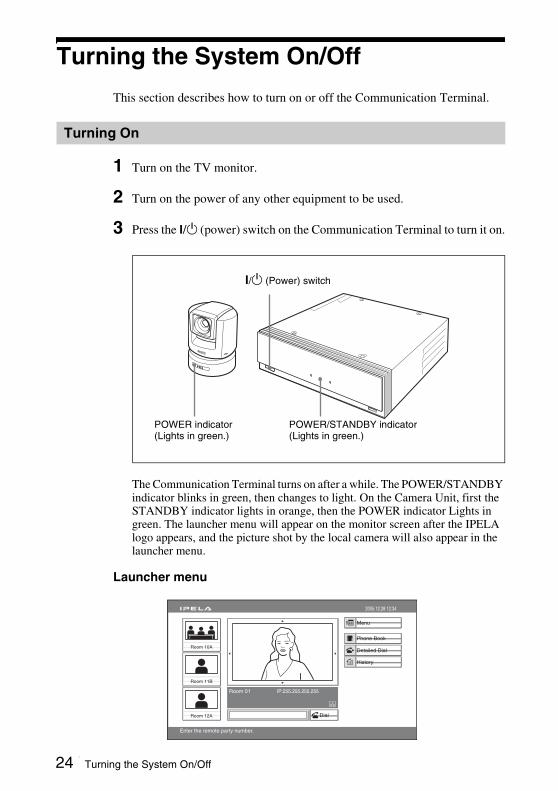
3 Press the ?/1 (power) switch on the Communication Terminal to turn it on.
The Communication Terminal turns on after a while. The POWER/STANDBY indicator blinks in green, then changes to light. On the Camera Unit, first the STANDBY indicator lights in orange, then the POWER indicator Lights in green. The launcher menu will appear on the monitor screen after the IPELA logo appears, and the picture shot by the local camera will also appear in the launcher menu.
Launcher menu
Turning On
POWER/STANDBY indicator(Lights in green.)
?/1 (Power) switch
POWER indicator(Lights in green.)
Capture
Room 10A
Room 11B
Room 12A
Room 01 IP:255.255.255.255
2005.12.28 12:34
Menu
Phone Book
Detailed Dial
History
Enter the remote party number.
Dial
24 Turning the System On/Off

Chapter 1: Installation and P
reparation
• If you use force to prevent the camera moving, it may not resume moving and not output a signal to the Communication Terminal. In this case, turn off the terminal, and turn it on again.
• When you turn on the power of the Communication Terminal for the first time after installation, the setup wizard will appear after the self-diagnosis is completed. Set up your system following the wizard.
For setups using the wizard, see “Setting Up the System for the First Time — Initial Setup Wizard” on page 29.
If no picture appears on the TV monitor
The video format of the Communication Terminal is set to “1080/60i” at the factory. If the video format set on the TV monitor is different from that on the Communication Terminal, no picture appears on the TV monitor. Check the video format setting on the TV monitor, and, if necessary, change the video format setting on the Communication Terminal.
To change the video format on the Communication Terminal
Use the FAR/NEAR button and number buttons 1, 2 and 3 on the supplied Remote Commander.
When you change the Output Video Format, the system will reboot automatically.
Notes
Video format to be set Operation
1080/60i Press “FAR/NEAR”, then press “1” three times.
1080/50i Press “FAR/NEAR”, then press “2” three times.
720/60p Press “FAR/NEAR”, then press “3” three times.
Note
DISPLAY
PUSHENTER
CONNECT/DISCONNECT
VIDEO INPUT
RETURN MENU
CLEAR SYMBOL
PinP FAR/NEARBACKSPACE
ALPHA/NUM FAR/NEAR button
Number buttons 1, 2, 3
25Turning the System On/Off
To save power, the Communication Terminal can enter standby mode if you do not operate it for a specified period of time.When the Communication Terminal is in standby mode, the STANDBY indicator on the Camera Unit and the POWER/STANDBY indicator on the Communication Terminal light in orange. You can turn on the Video Communication System with any button on the Remote Commander if it is in standby mode.Once the Communication Terminal receives a call, the standby mode is automatically released.
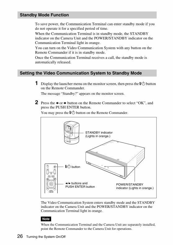
1 Display the launcher menu on the monitor screen, then press the @/1 button on the Remote Commander.The message “Standby?” appears on the monitor screen.
2 Press the B or b button on the Remote Commander to select “OK”, and press the PUSH ENTER button. You may press the @/1 button on the Remote Commander.
The Video Communication System enters standby mode and the STANDBY indicator on the Camera Unit and the POWER/STANDBY indicator on the Communication Terminal light in orange.
When the Communication Terminal and the Camera Unit are separately installed, point the Remote Commander to the Camera Unit for operations.
Standby Mode Function
Setting the Video Communication System to Standby Mode
Note
MICON/OFF
VOLUME ZOOM
PRESENTATION
DISPLAY
PUSHENTER
CONNECT/DISCONNECT
VIDEO INPUT
RETURN MENU
CLEAR SYMBOL
PinP FAR/NEARBACKSPACE
ALPHA/NUM
STANDBY indicator(Lights in orange.)
POWER/STANDBY indicator (Lights in orange.)
@/1 button
B/b buttons and PUSH ENTER button
26 Turning the System On/Off
Chapter 1: Installation and P
reparation
To cancel setting the system to standbySelect “Cancel” with the B or b button on the Remote Commander, then press the PUSH ENTER button in step 2 above.To release the standby modePress any button on the Remote Commander.
To specify the standby timeSpecify the time that you want the system to remain on before entering into standby mode (max. 99 minutes) by selecting “Device Setup” on the General Setup menu, and then setting “Standby Time”. If you do not want the system to enter the standby mode, set “Standby Mode” to “Off”.
For the “Standby Time” and “Standby Mode” settings, see “General Setup Menu” on page 47.
1 Press the ?/1 (power) switch on the Communication Terminal.The message “Power Off?” appears on the monitor screen and the POWER/STANDBY indicator on the Communication Terminal flashes.
2 Press the ?/1 (power) switch again within five seconds.The power of the system is turned off.
3 Turn off the power of other equipment.
• Set the power switch on the Communication Terminal off when the system will not be used for an extended period. While the power switch is off, you cannot receive a call from a remote party.
• Disconnect the power cord from the AC outlet after the power of the system has been completely turned off.
• If the Communication Terminal is left with its power cord disconnected from the AC outlet for approximately 10 days or more, the date and time setting will be cleared. In this case, set the date and time again using “Clock Set” in the General Setup menu.
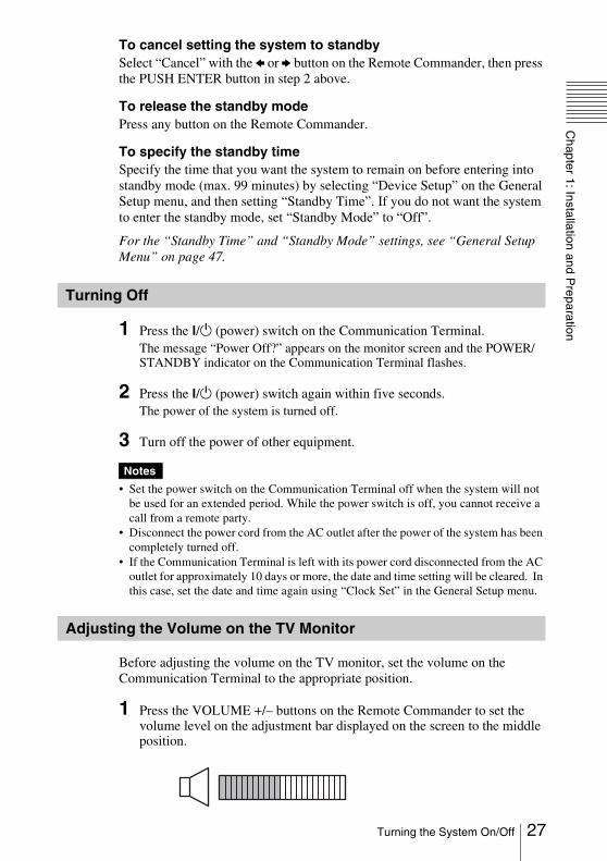
Before adjusting the volume on the TV monitor, set the volume on the Communication Terminal to the appropriate position.
1 Press the VOLUME +/– buttons on the Remote Commander to set the volume level on the adjustment bar displayed on the screen to the middle position.
Turning Off
Notes
Adjusting the Volume on the TV Monitor
27Turning the System On/Off
2 Adjust the volume on the TV monitor so that you can properly hear a remote party speaking.
Do not activate the TV’s surround sound feature as it may cause the echo canceler of the Communication Terminal not to function properly and make strange sounds.
Pressing the HELP button on the Remote Commander displays help to guide most operations in the guidance area.
You can hide the help used for entering characters.Press the MENU button on the Remote Commander to show the menu, and set “Character Input Help” under “Menu Screens” of the General Setup menu to “Off”. (See page 48.)
You can check the version, IP address, etc. of the Communication Terminal by displaying the Machine Information menu on the monitor screen.
For details on the Status menu, see “Machine Information Menu” on page 59.
Note
Displaying Help
Note
Displaying the Versions
28 Turning the System On/Off

Chapter 1: Installation and P
reparation
Setting Up the System for the First Time — Initial Setup WizardWhen you turn on the Communication Terminal for the first time after installation and the self-diagnosis is completed, the setup wizard appears on the monitor screen. Set your local system data with the setup wizard using the Remote Commander.You can change the settings made with the setup wizard later.
1 Use the V or v button on the Remote Commander to select the language used for the on-screen menus and messages in the Language Setup Wizard.Language: Select one of the following
languages: English, French, German, Japanese, Spanish, Italian, Simplified Chinese, Portuguese, Traditional Chinese, Korean, or Russian.
2 Use the V, v, B or b button on the Remote Commander to select “Next”, then press the PUSH ENTER button.The LAN Setup Wizard appears.
3 Set the following items on the LAN.
DHCP ModeSets the DHCP (Dynamic Host Configuration Protocol).
Auto: Automatically assigns your IP address, network mask, gateway address and DNS address.
Off: Deactivates DHCP. In this case set your IP address, network mask, gateway address and DNS address manually.
Host NameEnter your host name (up to 30 characters).IP AddressEnter your IP address.Network MaskEnter your network mask.Gateway AddressEnter your default gateway address.DNS AddressEnter your DNS (Domain Name System) server address.
When you set “DHCP Mode” to “Auto”, the assigned IP address is shown in the launcher menu (page 54) or Machine Information menu (page 59).
If you do not know how to set up the LAN configuration, contact your network administrator.
4 Use the V, v, B or b button to select “Save”, then press the PUSH ENTER button.
The settings are saved.
To cancel the settingPress the V, v, B or b button to select “Cancel”, then press the PUSH ENTER button.
To go back to the previous wizardPress the V, v, B or b button to select “Previous”, then press the PUSH ENTER button.
Language Setup Wizard
CancelNext
2005.12.28 12:34
EnglishLanguage
LAN Setup Wizard
CancelNextPrevious
2005.12.28 12:34
Host Name
Auto
. . .
. . .
. . .
. . .
DHCP Mode
Network Mask
IP Address
DNS Address
Gateway Address
Note
CancelPrevious Save
Save Setup?
29Setting Up the System for the First Time — Initial Setup Wizard
Using the Menus
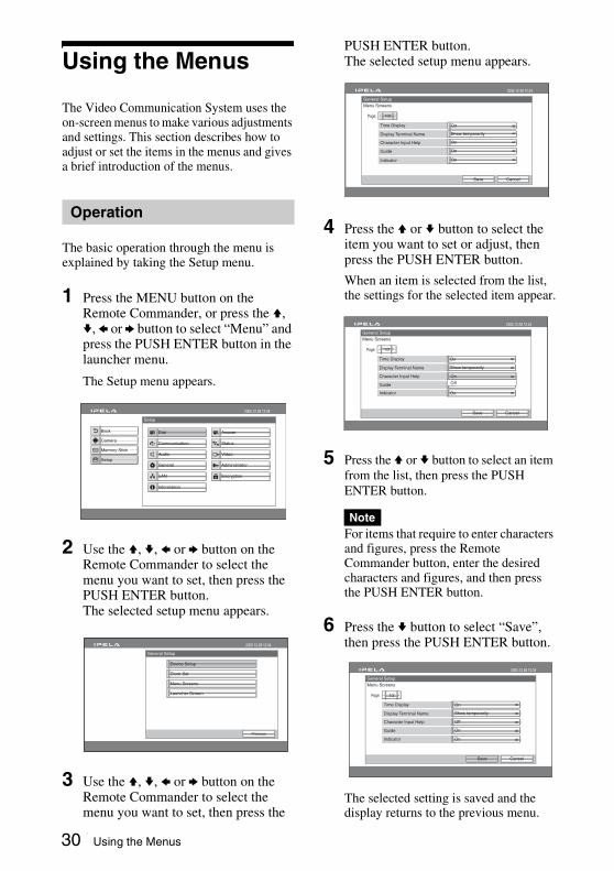
The Video Communication System uses the on-screen menus to make various adjustments and settings. This section describes how to adjust or set the items in the menus and gives a brief introduction of the menus.
The basic operation through the menu is explained by taking the Setup menu.
1 Press the MENU button on the Remote Commander, or press the V, v, B or b button to select “Menu” and press the PUSH ENTER button in the launcher menu.
The Setup menu appears.
2 Use the V, v, B or b button on the Remote Commander to select the menu you want to set, then press the PUSH ENTER button.The selected setup menu appears.
.
3 Use the V, v, B or b button on the Remote Commander to select the menu you want to set, then press the
PUSH ENTER button.The selected setup menu appears.
4 Press the V or v button to select the item you want to set or adjust, then press the PUSH ENTER button.
When an item is selected from the list, the settings for the selected item appear.
5 Press the V or v button to select an item from the list, then press the PUSH ENTER button.
For items that require to enter characters and figures, press the Remote Commander button, enter the desired characters and figures, and then press the PUSH ENTER button.
6 Press the v button to select “Save”, then press the PUSH ENTER button.
The selected setting is saved and the display returns to the previous menu.
Operation
Dial
Setup
Communication
Audio
General
LAN
Answer
Status
Video
Administrator
Information
2005.12.28 12:34
Encryption
Back
Setup
Camera
Memory Stick
General Setup
Previous
2005.12.28 12:34
Device Setup
Menu Screens
Clock Set
Launcher Screen
Note
2005.12.28 12:34
Display Terminal Name
Character Input Help
Guide
Indicator
Show temporarily
On
On
On
OnTime Display
1/2Page:
General Setup
Menu Screens
CancelSave
2005.12.28 12:34
Display Terminal Name
Character Input Help
Guide
Indicator
Show temporarily
On
OnTime Display
On
1/2Page:
General Setup
Menu Screens
CancelSave
On
Off
2005.12.28 12:34
Display Terminal Name
Character Input Help
Guide
Indicator
Show temporarily
Off
On
On
OnTime Display
1/2Page:
General Setup
Menu Screens
CancelSave
30 Using the Menus

Chapter 1: Installation and P
reparation
To return to the previous menuPress the RETURN button on the Remote Commander.31Using the Menus

The system menus are configured as outlined below.For details about menu configuration, see “Menu Configuration” on page 190.
Menu Configuration
Capture
Room 10A
Room 11B
Room 12A
Room 01 IP:255.255.255.255
2005.12.28 12:34
Menu
Phone Book
Detailed Dial
History
Enter the remote party number.
Dial
Dial
Setup
Communication
Audio
General
LAN
Answer
Status
Administrator
Information
2005.12.28 12:34
Encryption
Phone Book
Cancel
2005.12.28 12:34
0-9
A-I
J-S
T-Z
New Entry
Recent
Room 10A
Room 16A
Room 11B
Room 16B
Room 12A
Room 17A
Room 12B
Room 18A
More options
Detailed
CancelSaveDial
2005.12.28 12:34
SingleDial Mode
2 MbpsCommunication Bit Rate
IP
History
Cancel
2005.12.28 12:34
2005.12.27 06:12 PMRoom 11B LAN 255.255.254.128
2005.12.28 09:00 AMRoom 10A LAN 255.255.255.255
2005.12.27 02:52 PMRoom 12A LAN 255.255.253.64
2005.12.27 11:11 AMRoom 12B LAN 255.255.253.32
2005.12.26 04:28 PMRoom 16A LAN 255.255.249.16
Auto Track Stop
Camera
2005.12.28 12:34
Preset Save
Preset Load
Adjustments
HD-SDI
Dial Setup
CancelSave
2005.12.28 12:34
Off
1/1
More Options Enable
Page:
Off
Disable
User Name Input
Select LAN Prefix
LAN Prefix
List Edit
CancelSaveMore Options
2005.12.28 12:34
IP
SingleIndex Dial Mode
2 Mbps
Communication cation Bit Rate
Setup
Camera
Memory Stick
Back
Setup
Camera
Memory Stick
Back
Memory Stick
2005.12.28 12:34
Format
Back
Setup
Camera
Memory Stick 1 2Save
Launcher menu
Phone Book/Private Phone Book
Detailed Dial menu
History
Camera menu
Setup menu Setup menus
List Edit menu
Launcher menu not displayed
Memory Stick menu
32 Using the Menus

Chapter 1: Installation and P
reparation
Launcher menuThe launcher menu is displayed when the Video Communication System is turned on.
For details on the launcher menu, see page 77.
Setup menu
The Setup menu is used to set various detailed items on the system.
The menu appears when you select “Menu” on the launcher menu or you press the MENU button on the Remote Commander.
For details on the Setup menu, see pages 36 to 59.
Phone Book
The Phone Book is used to register a remote party, or to call a registered remote party.
The Phone Book appears when you select “Phone Book” on the launcher menu.
For details on the Phone Book, see pages 60 to 64 and 81 to 88.
Detailed Dial menu
The Detailed Dial menu is used to call a remote party who is not registered in the Phone Book. The Detailed Dial menu appears when you select “Detailed Dial” on the launcher menu. The menu also appears when you press the CONNECT/DISCONNECT ( / ) button on the Remote Commander.
For details on the Detailed Dial menu, see pages 81 to 84.
History
This menu is used to display the communication history information. The menu appears when you select “History” on the launcher menu.
For details on the History, see page 85.
Capture
Room 10A
Room 11B
Room 12A
Room 01 IP:255.255.255.255
2005.12.28 12:34
Menu
Phone Book
Detailed Dial
History
Enter the remote party number.
Dial
Dial
Setup
Communication
Audio
General
LAN
Answer
Status
Video
Administrator
Encryption
Information
2005.12.28 12:34
Back
Setup
Camera
Memory Stick
Phone Book
Cancel
2005.12.28 12:34
0-9
A-I
J-S
T-Z
New Entry
Recent
Room 10A
Room 16A
Room 11B
Room 16B
Room 12A
Room 17A
Room 12B
Room 18A
More options
Detailed Dial
CancelSaveDial
2005.12.28 12:34
SingleDial Mode
2 MbpsCommunication Bit Rate
IP
History
Cancel
2005.12.28 12:34
2005.12.27 06:12 PMRoom 11B LAN 255.255.254.128
2005.12.28 09:00 AMRoom 10A LAN 255.255.255.255
2005.12.27 02:52 PMRoom 12A LAN 255.255.253.64
2005.12.27 11:11 AMRoom 12B LAN 255.255.253.32
2005.12.26 04:28 PMRoom 16A LAN 255.255.249.16
33Using the Menus

Camera menu
The Camera menu is used to adjust the camera angle or to zoom the displayed image. To display the menu, select “Menu” on the launcher menu to display the setting menu and then select “Camera” displayed on the left side.
For details on the Camera menu, see pages 97 to 102.
Memory Stick menu
The Memory stick menu is used when the “Memory Stick” is used. This is not displayed if “Memory Stick” is not inserted.To display the menu, select “Menu” on the launcher menu to display the setting menu and then select “Memory Stick” displayed on the left side.
For details on the Memory Stick menu, see page 111.
This section explains how to enter the letters, numbers or symbols on the text box in the menu using the Remote Commander.
To enter letters or numbers
1 Press the FAR/NEAR (ALPHA/NUM) button repeatedly to enable the letters or numbers to be input.
2 Press the number buttons repeatedly to enter the letters or numbers that you want.You can enter the letter shown on each button by pressing it repeatedly.You can enter the number shown on each button by pressing it.
Auto Track StopSetup
Camera
Memory Stick
Camera
2005.12.28 12:34
Preset Save
Preset Load
Adjustments
Video: HD-SD 1
Back
Memory Stick
2005.12.28 12:34
Format
Back
Setup
Camera
Memory Stick 1 2Save
Entering Characters
PCSA-RG1
MICON/OFF
VOLUME ZOOM
PRESENTATION
DISPLAY
PUSHENTER
CONNECT/DISCONNECT
HELP
VIDEO INPUT
RETURN MENU
CLEAR SYMBOL
PinP FAR/NEARBACKSPACE
ALPHA/NUM
DISPLAY (CLEAR) button
FAR/NEAR (ALPHA/NUM) button
VIDEO INPUT (SYMBOL) button
PinP (BACK SPACE) button
Number buttons
(dot) button
34 Using the Menus
Chapter 1: Installation and P
reparation
To enter a symbolPress the VIDEO INPUT (SYMBOL) button repeatedly to select the desired symbol. Pressing the 0 button repeatedly also enables you to enter a symbol.To enter a dot (.) for an IP addressPress the button.
To delete a characterPress the PinP (BACK SPACE) button. The last entered character is deleted.
To delete all characters in a lineMove the cursor to the line to be deleted, then press the DISPLAY (CLEAR) button.
When you press the HELP button on the Remote Commander to show helps, you can hide only the help used for entering characters.Set “Character Input Help” of “Menu Screens” in the General Setup menu to “Off”. (See page 48.)
Note
35Using the Menus
This chapter describes the registration and settings to be carried out by the system administrator.The chapter is intended to be read by the system administrator.
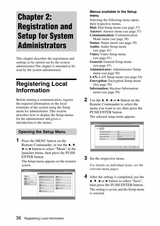
Registering Local InformationBefore starting a communication, register the required information on the local terminals of the system using the Setup menu for administrator. This section describes how to display the Setup menus for the administrator and gives a introduction to the menus.
1 Press the MENU button on the Remote Commander, or use the V, v, B or b button to select “Menu” in the launcher menu, then press the PUSH ENTER button.The Setup menu appears on the monitor screen.
Menus available in the Setup menuSelecting the following items opens their respective menus.Dial: Dial Setup menu (see page 37)Answer: Answer menu (see page 37)Communication: Communication
Mode menu (see page 38)Status: Status menu (see page 39)Audio: Audio Setup menu
(see page 41)Video: Video Setup menu
(see page 43) General: General Setup menu
(see page 47)Administrator: Administrator Setup
menu (see page 50)LAN: LAN Setup menu (see page 54)Encryption: Encryption Setup menu
(See page 59)Information: Machine Information
menu (see page 59)
2 Use the V, v, B or b button on the Remote Commander to select the menu you want to set, then press the PUSH ENTER button.The selected setup menu appears.
3 Set the respective items.
For details on individual items, see the relevant menu pages.
4 After the setting is completed, use the V, v, B or b button to select “Save”, then press the PUSH ENTER button.The setting is saved, and the Setup menu is restored.
Chapter 2: Registration and Setup for System Administrators
Opening the Setup Menu
Dial
Setup
Communication
Audio
General
LAN
Answer
Status
Video
Administrator
Information
2005.12.28 12:34
Back
Encryption
Setup
Camera
Memory Stick
Dial Setup
CancelSave
2005.12.28 12:34
Off
1/1
More Options Enable
Page:
Off
Disable
User Name Input
Select LAN Prefix
LAN Prefix
36 Registering Local Information
Chapter 2: R
egistration and Setup for S
ystem A
dministrators
To cancel the setupUse the V, v, B or b button on the Remote Commander to select “Cancel”, then press the PUSH ENTER button. Or press the RETURN button on the Remote Commander.
To page up or down the selected menuUse the V, v, B or b button on the Remote Commander to select the Page box, then press the b button to advance the page and the B button to go back to the previous page.
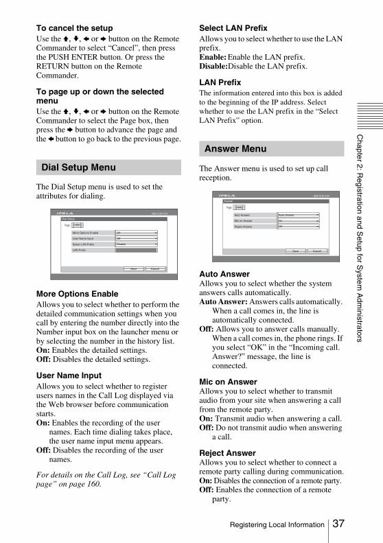
The Dial Setup menu is used to set the attributes for dialing.
More Options EnableAllows you to select whether to perform the detailed communication settings when you call by entering the number directly into the Number input box on the launcher menu or by selecting the number in the history list.On: Enables the detailed settings.Off: Disables the detailed settings.
User Name InputAllows you to select whether to register users names in the Call Log displayed via the Web browser before communication starts.On: Enables the recording of the user
names. Each time dialing takes place, the user name input menu appears.
Off: Disables the recording of the user names.
For details on the Call Log, see “Call Log page” on page 160.
Select LAN PrefixAllows you to select whether to use the LAN prefix.Enable: Enable the LAN prefix.Disable:Disable the LAN prefix.
LAN PrefixThe information entered into this box is added to the beginning of the IP address. Select whether to use the LAN prefix in the “Select LAN Prefix” option.
The Answer menu is used to set up call reception.
Auto AnswerAllows you to select whether the system answers calls automatically.Auto Answer: Answers calls automatically.
When a call comes in, the line is automatically connected.
Off: Allows you to answer calls manually. When a call comes in, the phone rings. If you select “OK” in the “Incoming call. Answer?” message, the line is connected.
Mic on AnswerAllows you to select whether to transmit audio from your site when answering a call from the remote party.On: Transmit audio when answering a call.Off: Do not transmit audio when answering
a call.
Reject AnswerAllows you to select whether to connect a remote party calling during communication.On: Disables the connection of a remote party.Off: Enables the connection of a remote
party.
Dial Setup Menu
Dial Setup
CancelSave
2005.12.28 12:34
Off
1/1
More Options Enable
Page:
Off
Disable
User Name Input
Select LAN Prefix
LAN Prefix
Answer Menu
Answer
CancelSave
2005.12.28 12:34
Auto Answer
1/1
Auto Answer
Page:
On
Off
Mic on Answer
Reject Answer
37Registering Local Information
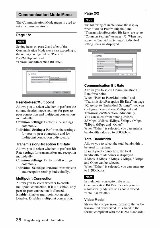
The Communication Mode menu is used to set up communications.
Page 1/2
Setting items on page 2 and after of the Communication Mode menu vary according to the settings configured by “Peer-to-Peer/Multipoint” and “Transmission/Reception Bit Rate”.
Peer-to-Peer/MultipointAllows you to select whether to perform the communication mode settings for peer-to-peer connection and multipoint connection individually.Common Settings: Performs the settings
commonly.Individual Settings: Performs the settings
for peer-to-peer connection and for multipoint connection individually.
Transmission/Reception Bit RateAllows you to select whether to perform Bit Rate settings for transmission and reception individually.Common Settings: Performs all settings
commonly.Individual Settings: Performs transmission
and reception settings individually.
Multipoint ConnectionAllows you to select whether to enable multipoint connection. If it is disabled, only peer-to-peer connection is allowed.Enable: Enables multipoint connectionDisable: Disables multipoint connection.
Page 2/2
The following example shows the display when “Peer-to-Peer/Multipoint” and “Transmission/Reception Bit Rate” are set to “Common Settings” on page 1/2. When they are set to “Individual Settings”, individual setting items are displayed.
Communication Bit RateAllows you to select Communication Bit Rate for a point.When “Peer-to-Peer/Multipoint” and “Transmission/Reception Bit Rate” on page 1/2 are set to “Individual Settings”, you can configure Peer-to-Peer/Multipoint and Transmission/Reception individually.You can select from among 2Mbps, 2.5Mbps, 3Mbps, 4Mbps, 5Mbps, 6Mbps, 7Mbps, 8Mbps and “Other”. When “Other” is selected, you can enter a bandwidth value up to 8000Kbps.
Total BandwidthAllows you to select the total bandwidth to be used for system.In multipoint connection, the total bandwidth of all points is displayed.4 Mbps, 5 Mbps, 6 Mbps, 7 Mbps, 8 Mbps and Other can be selected.When “Other” is selected, you can enter up to 1,2000Kbps.
In multipoint connection, the actual Communication Bit Rate for each point is automatically adjusted so as not to exceed “Total Bandwidth”.
Video ModeShows the compression format of the video transmitted or received. It is fixed to the format compliant with the H.264 standards.
Communication Mode Menu
Note
Communication Mode
CancelSave
2005.12.28 12:34
Common Settings
1/2
Peer-to-Peer/Multipoint
Page:
Common SettingsTransmission/Reception Bit Rate
EnableMultipoint Connection
Note
Note
Communication Mode
CancelSave
2005.12.28 12:34
2 Mbps
Auto
Auto
Off
2/2
Communication Bit Rate
Page:
4 Mbps
H.264
Total Bandwidth
Video Mode
Video Frame
Audio Mode
Far End Camera Control
38 Registering Local Information

Chapter 2: R
egistration and Setup for S
ystem A
dministrators
When “Peer-to-Peer/Multipoint” on page 1/2 is set to “Individual Settings”, you can configure Peer-to-Peer and Multipoint individually.
Video FrameAllows you to select the number of video frames during transmission or reception. When “Peer-to-Peer/Multipoint” on page 1/2 is set to “Individual Settings”, you can configure Multipoint and Peer-to-Peer individually.When the “Frequency” in the Video Setting menu (page 44) is set to “60 Hz”, “60p” or “50p” is displayed.When the “Frequency” in the Video Setting menu (page 44) is set to “50 Hz”, “50p” or “25p” is displayed.60p: Sends or receives pictures at a
maximum rate of 60 frames per second.30p: Sends or receives pictures at a
maximum rate of 30 frames per second.50p: Sends or receives pictures at a
maximum rate of 50 frames per second.25p: Sends or receives pictures at a
maximum rate of 25 frames per second.Auto: Switches the number of frames
automatically.
When the communication bit rate is less than 2 Mbps, the number of transmitted or received video frames is 30 frames, or 25 frames or fewer.
Audio ModeAllows you to select the compression format of audio. When “Peer-to-Peer/Multipoint” on page 1/2 is set to “Individual Settings”, you can configure Multipoint and Peer-to-Peer individually.Auto: Sends or receives audio matching the
compression format of the remote site.AAC Monaural 48K: Sends or receives
audio based on the MPEG4 AAC monaural format (48K).
AAC Monaural 96K: Sends or receives audio based on the MPEG4 AAC monaural format (96K).
AAC Stereo 48K: Sends or receives audio based on the MPEG4 AAC stereo format (48K).
AAC Stereo 96K: Sends or receives audio based on the MPEG4 AAC stereo format (96K).
G.728: Sends or receives audio based on the G.728 standard.
G.722: Sends or receives audio based on the G.722 standard.
G.711: Sends or receives audio based on the G.711 standard.
When the remote system does not support the audio mode selected by the local site, the Audio Mode is automatically switched to “G.711”.
Far End Camera ControlAllows you to select whether to enable the control of each other’s camera from each other’s site.When “Peer-to-Peer/Multipoint” on page 1/2 is set to “Individual Settings”, you can configure Multipoint and Peer-to-Peer individually.On: Enables the control of each other’s
camera. This is the default setting.Off: Disables the control of each other’s
camera.
The following menus appear when you select “Status” on the Setup menu. Select the desired menu.
Communication Mode StatusOne page for each point connected to the system will be displayed to show the current communication status.The connected point is shown at the upper left corner of the page as “Connection A (or B, C)”.
Note
Note
Status Menu
Status
2005.12.28 12:34
Communication Mode Status
LAN Connection Status
Input/Output/Peripheral Status
Previous
39Registering Local Information
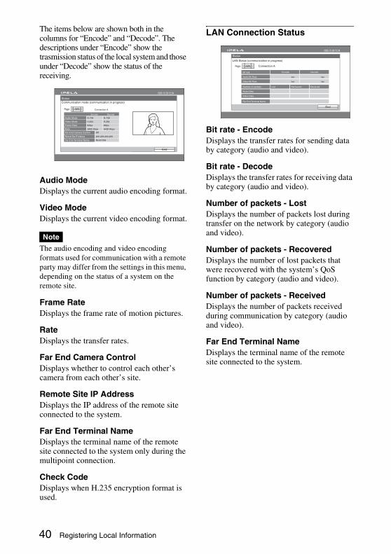
The items below are shown both in the columns for “Encode” and “Decode”. The descriptions under “Encode” show the trasmission status of the local system and those under “Decode” show the status of the receiving.
Audio ModeDisplays the current audio encoding format.
Video ModeDisplays the current video encoding format.
The audio encoding and video encoding formats used for communication with a remote party may differ from the settings in this menu, depending on the status of a system on the remote site.
Frame RateDisplays the frame rate of motion pictures.
RateDisplays the transfer rates.
Far End Camera ControlDisplays whether to control each other’s camera from each other’s site.
Remote Site IP AddressDisplays the IP address of the remote site connected to the system.
Far End Terminal NameDisplays the terminal name of the remote site connected to the system only during the multipoint connection.
Check CodeDisplays when H.235 encryption format is used.
LAN Connection Status
Bit rate - EncodeDisplays the transfer rates for sending data by category (audio and video).
Bit rate - DecodeDisplays the transfer rates for receiving data by category (audio and video).
Number of packets - LostDisplays the number of packets lost during transfer on the network by category (audio and video).
Number of packets - RecoveredDisplays the number of lost packets that were recovered with the system’s QoS function by category (audio and video).
Number of packets - ReceivedDisplays the number of packets received during communication by category (audio and video).
Far End Terminal NameDisplays the terminal name of the remote site connected to the system.
Note
Save
Status
End
2005.12.28 12:34
1/1
Encode
Audio Mode G.728
Connection A
G.728
Video Mode H.264 H.264
Frame Rate 60fps 60fps
Rate 6400 Kbps 6400 Kbps
Room10A
Remote Site IP Address
Far End Terminal Name
255.255.255.255
Decode
Page:
Communication mode (communication in progress)
Far End Camera Control Off
Status
2005.12.28 12:34
End
1/1Page:
Audio Bit Rate
Bit rate
bps bps
bps bpsVideo Bit Rate
Number of packets Lost Recovered Received
Audio Data
Video Data
Encode Decode
Far End Terminal Name
LAN Status (communication in progress)
Connection A
40 Registering Local Information
Chapter 2: R
egistration and Setup for S
ystem A
dministrators
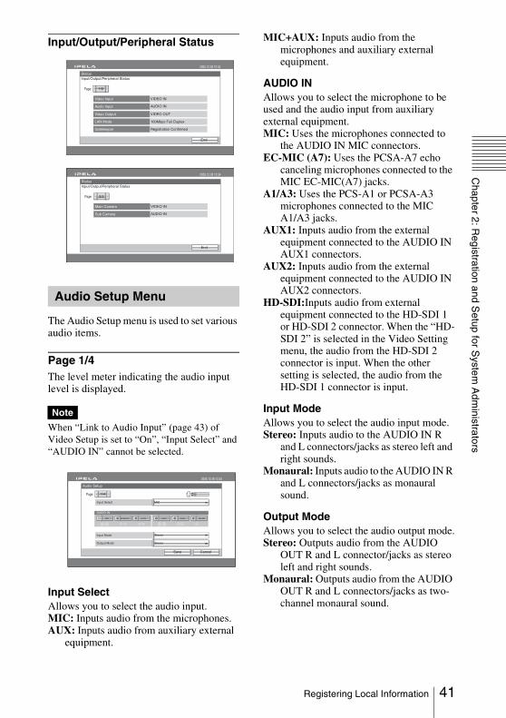
Input/Output/Peripheral Status
The Audio Setup menu is used to set various audio items.
Page 1/4The level meter indicating the audio input level is displayed.
When “Link to Audio Input” (page 43) of Video Setup is set to “On”, “Input Select” and “AUDIO IN” cannot be selected.
Input SelectAllows you to select the audio input.MIC: Inputs audio from the microphones.AUX: Inputs audio from auxiliary external
equipment.
MIC+AUX: Inputs audio from the microphones and auxiliary external equipment.
AUDIO INAllows you to select the microphone to be used and the audio input from auxiliary external equipment.MIC: Uses the microphones connected to
the AUDIO IN MIC connectors.EC-MIC (A7): Uses the PCSA-A7 echo
canceling microphones connected to the MIC EC-MIC(A7) jacks.
A1/A3: Uses the PCS-A1 or PCSA-A3 microphones connected to the MIC A1/A3 jacks.
AUX1: Inputs audio from the external equipment connected to the AUDIO IN AUX1 connectors.
AUX2: Inputs audio from the external equipment connected to the AUDIO IN AUX2 connectors.
HD-SDI:Inputs audio from external equipment connected to the HD-SDI 1 or HD-SDI 2 connector. When the “HD-SDI 2” is selected in the Video Setting menu, the audio from the HD-SDI 2 connector is input. When the other setting is selected, the audio from the HD-SDI 1 connector is input.
Input ModeAllows you to select the audio input mode.Stereo: Inputs audio to the AUDIO IN R
and L connectors/jacks as stereo left and right sounds.
Monaural: Inputs audio to the AUDIO IN R and L connectors/jacks as monaural sound.
Output ModeAllows you to select the audio output mode.Stereo: Outputs audio from the AUDIO
OUT R and L connector/jacks as stereo left and right sounds.
Monaural: Outputs audio from the AUDIO OUT R and L connectors/jacks as two-channel monaural sound.
Audio Setup Menu
Note
Status
End
2005.12.28 12:34
1/2
Video Input
Page:
100Mbps Full Duplex
VIDEO IN
AUDIO IN
VIDEO OUT
Audio Input
Video Output
LAN Mode
Registration ConfirmedGatekeeper
Input/Output/Peripheral Status
Status
End
2005.12.28 12:34
2/2
Main Camera
Page:
VIDEO IN
AUDIO INSub Camera
Input/Output/Peripheral Status
L
R
Audio Setup
2005.12.28 12:34
CancelSave
1/4Page:
Input Select
AUDIO IN
MIC
Input Mode Stereo
Output Mode Stereo
AUX2AUX1A1/A3EC-MIC(A7)MIC HD-SDI
41Registering Local Information
Page 2/4
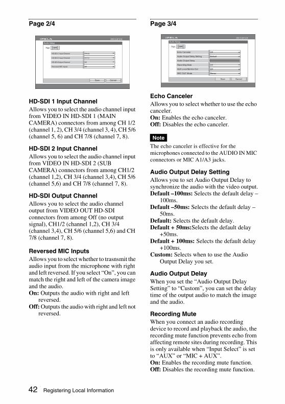
HD-SDI 1 Input ChannelAllows you to select the audio channel input from VIDEO IN HD-SDI 1 (MAIN CAMERA) connectors from among CH 1/2 (channel 1, 2), CH 3/4 (channel 3, 4), CH 5/6 (channel 5, 6) and CH 7/8 (channel 7, 8).
HD-SDI 2 Input ChannelAllows you to select the audio channel input from VIDEO IN HD-SDI 2 (SUB CAMERA) connectors from among CH1/2 (channel 1,2), CH 3/4 (channel 3,4), CH 5/6 (channel 5,6) and CH 7/8 (channel 7, 8).
HD-SDI Output ChannelAllows you to select the audio channel output from VIDEO OUT HD-SDI connectors from among Off (no output signal), CH1/2 (channel 1,2), CH 3/4 (channel 3,4), CH 5/6 (channel 5,6) and CH 7/8 (channel 7, 8).
Reversed MIC InputsAllows you to select whether to trasnsmit the audio input from the microphone with right and left reversed. If you select “On”, you can match the right and left of the camera image and the audio.On: Outputs the audio with right and left
reversed.Off: Outputs the audio with right and left not
reversed.
Page 3/4
Echo CancelerAllows you to select whether to use the echo canceler.On: Enables the echo canceler.Off: Disables the echo canceler.
The echo canceler is effective for the microphones connected to the AUDIO IN MIC connectors or MIC A1/A3 jacks.
Audio Output Delay SettingAllows you to set Audio Output Delay to synchronize the audio with the video output.Default –100ms: Selects the default delay –
100ms.Default –50ms: Selects the default delay –
50ms.Default: Selects the default delay.Default + 50ms:Selects the default delay
+50ms.Default + 100ms: Selects the default delay
+100ms.Custom: Selects when to use the Audio
Output Delay you set.
Audio Output DelayWhen you set the “Audio Output Delay Setting” to “Custom”, you can set the delay time of the output audio to match the image and the audio.
Recording MuteWhen you connect an audio recording device to record and playback the audio, the recording mute function prevents echo from affecting remote sites during recording. This is only available when “Input Select” is set to “AUX” or “MIC + AUX”. On: Enables the recording mute function.Off: Disables the recording mute function.
Audio Setup
2005.12.28 12:34
2/4
HD-SDI 1 Input Channel
Page:
HD-SDI 2 Input Channel
CancelSave
CH1/2
CH1/2
HD-SDI Output Channel
Reversed MIC Inputs
Off
Off
Note
Audio Setup
2005.12.28 12:34
3/4
Echo Canceler
Page:
Recording Mute
AUX Local Monitor Out
CancelSave
Off
Audio Output Delay Setting Default
Audio Output Delay
Off
Off
REC OUT Mode Stereo
42 Registering Local Information

Chapter 2: R
egistration and Setup for S
ystem A
dministrators
AUX Local Monitor OutAllows you to select whether to output the audio which is input from the AUDIO IN AUX 1 or the AUX 2 connectors from the audio output of the communication terminal.On: Outputs from the audio output.Off: Does not output from the audio output.
REC OUT ModeMonaural 2ch: Outputs audio from the
REC OUT (MIXED) R and L connectors as two-channel monaural sound.
Stereo: Outputs audio from the REC OUT (MIXED) R and L connectors as stereo left and right sounds.
Page 4/4
Beep SoundAllows you to select whether the system beeps each time you press a button on the Remote Commander.On: Enables beeping.Off: Disables beeping.
Sound EffectAllows you to select whether to output sounds when the system starts, a video communication starts or ends.On: Outputs sounds.Off: Does not output sounds.
Dial ToneAllows you to select whether to output a ring-back tone when you are dialing and busy tone when the line is busy.On: Outputs dial tones.Off: Does not output dial tones.
Ringer ToneAllows you to select whether to output a ringer tone when you receive a call.On: Outputs the ringer tone.Off: Does not output the ringer tone.
The following menus appear when you select “Video” on the Setup menu. Select the desired menu.
Video Input/Output
Link to Audio InputAllows you to switch the audio input in conjunction with switching the video input by linking each video input and a specific audio input.On: Links switching of the video input and
the audio input.Off: Switches the video input and the audio
input separately.
When “Link to Audio Input” is set to “On”, “Input Select” and “AUDIO IN” on page 1/2 of Audio Setup menu cannot be selected.
VIDEO INAllows you to select video input.HD-SDI 1: Selects the picture from the
camera connected to the VIDEO IN HD-SDI 1 (MAIN CAMERA) connector.
HD-SDI 2: Selects the picture from the camera connected to the VIDEO IN HD-SDI 2 (SUB CAMERA) connector.
YPbPr: Selects the picture from external equipment connected to the VIDEO IN YPbPr connector.
Audio Setup
2005.12.28 12:34
4/4
Beep Sound
Page:
Sound Effect
Dial Tone
Ringer Tone
CancelSave
On
On
On
On
Video Setup Menu
Note
Video Setup
Previous
2005.12.28 12:34
Video Input /Output
Video Format
Custom Input Label
Transmitting Image Quality
Other Settings
MIC
OffLink to Audio Input
Audio Input Select
AUDIO IN
AUX2AUX1A1/A3EC-MIC(A7)MIC HD-SDI
Video Setup
CancelSave
2005.12.28 12:34
VIDEO IN
RGB YPbPr
SUB CAMERA MAIN CAMERA
HD-SDI2
HD-SDI1S-VIDEO
43Registering Local Information
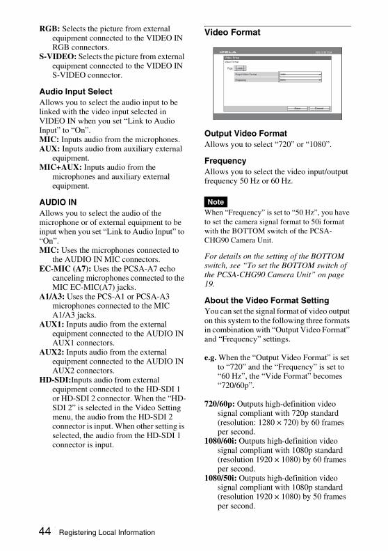
RGB: Selects the picture from external equipment connected to the VIDEO IN RGB connectors.
S-VIDEO: Selects the picture from external equipment connected to the VIDEO IN S-VIDEO connector.
Audio Input SelectAllows you to select the audio input to be linked with the video input selected in VIDEO IN when you set “Link to Audio Input” to “On”.MIC: Inputs audio from the microphones.AUX: Inputs audio from auxiliary external
equipment.MIC+AUX: Inputs audio from the
microphones and auxiliary external equipment.
AUDIO INAllows you to select the audio of the microphone or of external equipment to be input when you set “Link to Audio Input” to “On”.MIC: Uses the microphones connected to
the AUDIO IN MIC connectors.EC-MIC (A7): Uses the PCSA-A7 echo
canceling microphones connected to the MIC EC-MIC(A7) jacks.
A1/A3: Uses the PCS-A1 or PCSA-A3 microphones connected to the MIC A1/A3 jacks.
AUX1: Inputs audio from the external equipment connected to the AUDIO IN AUX1 connectors.
AUX2: Inputs audio from the external equipment connected to the AUDIO IN AUX2 connectors.
HD-SDI:Inputs audio from external equipment connected to the HD-SDI 1 or HD-SDI 2 connector. When the “HD-SDI 2” is selected in the Video Setting menu, the audio from the HD-SDI 2 connector is input. When other setting is selected, the audio from the HD-SDI 1 connector is input.
Video Format
Output Video FormatAllows you to select “720” or “1080”.
FrequencyAllows you to select the video input/output frequency 50 Hz or 60 Hz.
When “Frequency” is set to “50 Hz”, you have to set the camera signal format to 50i format with the BOTTOM switch of the PCSA-CHG90 Camera Unit.
For details on the setting of the BOTTOM switch, see “To set the BOTTOM switch of the PCSA-CHG90 Camera Unit” on page 19.
About the Video Format SettingYou can set the signal format of video output on this system to the following three formats in combination with “Output Video Format” and “Frequency” settings.
e.g. When the “Output Video Format” is set to “720” and the “Frequency” is set to “60 Hz”, the “Vide Format” becomes “720/60p”.
720/60p: Outputs high-definition video signal compliant with 720p standard (resolution: 1280 × 720) by 60 frames per second.
1080/60i: Outputs high-definition video signal compliant with 1080p standard (resolution 1920 × 1080) by 60 frames per second.
1080/50i: Outputs high-definition video signal compliant with 1080p standard (resolution 1920 × 1080) by 50 frames per second.
Note
Video Srtup
Video Format
CancelSave
2005.12.28 12:34
Frequency
Output Video Format
1/1Page:
1080
60Hz
44 Registering Local Information
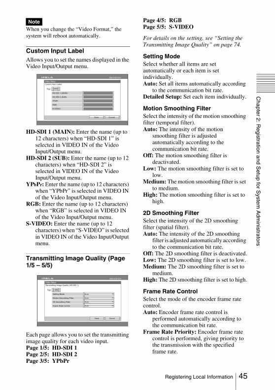
Chapter 2: R
egistration and Setup for S
ystem A
dministrators
When you change the “Video Format,” the system will reboot automatically.
Custom Input LabelAllows you to set the names displayed in the Video Input/Output menu.
HD-SDI 1 (MAIN): Enter the name (up to 12 characters) when “HD-SDI 1” is selected in VIDEO IN of the Video Input/Output menu.
HD-SDI 2 (SUB): Enter the name (up to 12 characters) when “HD-SDI 2” is selected in VIDEO IN of the Video Input/Output menu.
YPbPr: Enter the name (up to 12 characters) when “YPbPr” is selected in VIDEO IN of the Video Input/Output menu.
RGB: Enter the name (up to 12 characters) when “RGB” is selected in VIDEO IN of the Video Input/Output menu.
S-VIDEO: Enter the name (up to 12 characters) when “S-VIDEO” is selected in VIDEO IN of the Video Input/Output menu.
Transmitting Image Quality (Page 1/5 – 5/5)
Each page allows you to set the transmitting image quality for each video input.Page 1/5: HD-SDI 1Page 2/5: HD-SDI 2Page 3/5: YPbPr
Page 4/5: RGBPage 5/5: S-VIDEO
For details on the setting, see “Setting the Transmitting Image Quality” on page 74.
Setting ModeSelect whether all items are set automatically or each item is set individually.Auto: Set all items automatically according
to the communication bit rate.Detailed Setup: Set each item individually.
Motion Smoothing FilterSelect the intensity of the motion smoothing filter (temporal filter).Auto: The intensity of the motion
smoothing filter is adjusted automatically according to the communication bit rate.
Off: The motion smoothing filter is deactivated.
Low: The motion smoothing filter is set to low.
Medium: The motion smoothing filter is set to medium.
High: The motion smoothing filter is set to high.
2D Smoothing FilterSelect the intensity of the 2D smoothing filter (spatial filter).Auto: The intensity of the 2D smoothing
filter is adjusted automatically according to the communication bit rate.
Off: The 2D smoothing filter is deactivated.Low: The 2D smoothing filter is set to low.Medium: The 2D smoothing filter is set to
medium.High: The 2D smoothing filter is set to high.
Frame Rate ControlSelect the mode of the encoder frame rate control.Auto: Encoder frame rate control is
performed automatically according to the communication bit rate.
Frame Rate Priority: Encoder frame rate control is performed, giving priority to the transmission with the specified frame rate.
Note
Video Setup
Custom Input Label
CancelSave
2005.12.28 12:34
HD-SDI 2 (SUB)
YPbPr
RGB
S-VIDEO
HD-SDI 1 (MAIN)
1/1Page:
Video Setup
Transmitting Image Quality (HD-SDI 1)
CancelSave
2005.12.28 12:34
Motion Smoothing Filter
2D Smoothing Filter
Setting Mode
1/5Page:
Auto
Auto
Auto
Frame Rate Control Auto
45Registering Local Information
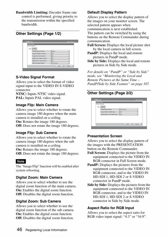
Bandwidth Limiting: Encoder frame rate control is performed, giving priority to the transmission within the specified bandwidth.
Other Settings (Page 1/2)
S-Video Signal FormatAllows you to select the format of video signal input to the VIDEO IN S-VIDEO connector.NTSC: Inputs NTSC video signal.PAL: Inputs PAL video signal.
Image Flip: Main CameraAllows you to select whether to rotate the camera image 180 degrees when the main camera is installed on a ceiling.On: Rotates the image 180 degrees.Off: Does not rotate the image 180 degrees.
Image Flip: Sub CameraAllows you to select whether to rotate the camera image 180 degrees when the sub camera is installed on a ceiling.On: Rotates the image 180 degrees.Off: Does not rotate the image 180 degrees.
The “Image Flip” function will be enabled after system rebooting.
Digital Zoom: Main CameraAllows you to select whether to use the digital zoom function of the main camera.On: Enables the digital zoom function.Off: Disables the digital zoom function.
Digital Zoom: Sub CameraAllows you to select whether to use the digital zoom function of the sub camera.On: Enables the digital zoom function.Off: Disables the digital zoom function.
Default Display PatternAllows you to select the display pattern of the images on your monitor screen. The selected pattern appears when communication is next established.The pattern can be switched by using the buttons on the Remote Commander during communication.Full Screen: Displays the local picture shot
by the local camera in full screen. PandP: Displays the local and remote
pictures in PandP mode.Side by Side: Displays the local and remote
pictures in Side by Side mode.
For details on “PandP” or “Side by Side” mode, see “Monitoring the Local and Remote Pictures at the Same Time – PandP/Side by Side Feature” on page 107.
Other Settings (Page 2/2)
Presentation ScreenAllows you to select the display pattern of the images with the PRESENTATION button on the Remote Commander.Full Screen: Displays the picture from the
equipment connected to the VIDEO IN RGB connector in Full Screen mode.
PandP: Displays the pictures from the equipment connected to the VIDEO IN RGB connector, and to the VIDEO IN HD-SDI 1, HD-SDI 2 or S-VIDEO connector in PandP mode.
Side by Side: Displays the pictures from the equipment connected to the VIDEO IN RGB connector, and to the VIDEO IN HD-SDI 1, HD-SDI 2 or S-VIDEO connector in Side by Side mode.
Aspect Ratio for RGB InputAllows you to select the aspect ratio for RGB video input signal: “4:3” or “16:9”.
Note
Video Setup
Other Settings
CancelSave
2005.12.28 12:34
Image Flip: Main Camera
Image Flip: Sub Camera
S-Video Signal Format
1/2Page:
NTSC
Off
Off
Digital Zoom: Main Camera Off
Digital Zoom: Sub Camera Off
Default Display Pattern Full Screen
Video Setup
Other Settings
CancelSave
2005.12.28 12:34
2/2Page:
Presentation Screen Full Screen
Aspect Ratio for RGB input 4:3
Aspect Ratio for S-VIDEO input 4:3
46 Registering Local Information
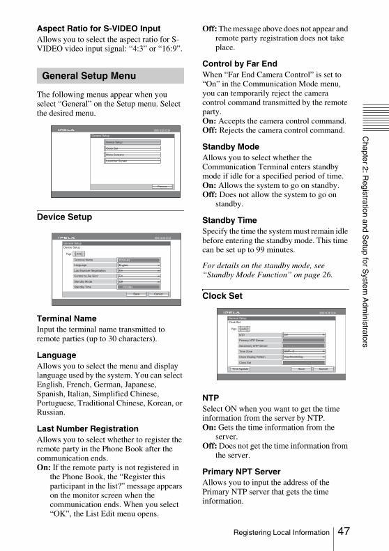
Chapter 2: R
egistration and Setup for S
ystem A
dministrators
Aspect Ratio for S-VIDEO InputAllows you to select the aspect ratio for S-VIDEO video input signal: “4:3” or “16:9”.
The following menus appear when you select “General” on the Setup menu. Select the desired menu.
Device Setup
Terminal NameInput the terminal name transmitted to remote parties (up to 30 characters).
LanguageAllows you to select the menu and display language used by the system. You can select English, French, German, Japanese, Spanish, Italian, Simplified Chinese, Portuguese, Traditional Chinese, Korean, or Russian.
Last Number RegistrationAllows you to select whether to register the remote party in the Phone Book after the communication ends.On: If the remote party is not registered in
the Phone Book, the “Register this participant in the list?” message appears on the monitor screen when the communication ends. When you select “OK”, the List Edit menu opens.
Off: The message above does not appear and remote party registration does not take place.
Control by Far EndWhen “Far End Camera Control” is set to “On” in the Communication Mode menu, you can temporarily reject the camera control command transmitted by the remote party.On: Accepts the camera control command.Off: Rejects the camera control command.
Standby ModeAllows you to select whether the Communication Terminal enters standby mode if idle for a specified period of time.On: Allows the system to go on standby.Off: Does not allow the system to go on
standby.
Standby TimeSpecify the time the system must remain idle before entering the standby mode. This time can be set up to 99 minutes.
For details on the standby mode, see “Standby Mode Function” on page 26.
Clock Set
NTPSelect ON when you want to get the time information from the server by NTP.On: Gets the time information from the
server.Off: Does not get the time information from
the server.
Primary NPT ServerAllows you to input the address of the Primary NTP server that gets the time information.
General Setup Menu
Back
Setup
Camera
Memory Stick
General Setup
Previous
2005.12.28 12:34
Device Setup
Menu Screens
Clock Set
Launcher Screen
2005.12.28 12:34
Last Number Registration
Control by Far End
Standby Time
On
On
minutes
PCS-HG
Standby Mode Off
EnglishLanguage
Terminal Name
1/1Page:
General Setup
Device Setup
CancelSave
2005.12.28 12:34
1/1Page:
General Setup
Clock Set
CancelSaveTime Update
Primary NTP Server
Time Zone
Clock Display Pattern
Clock Set
GMT= 0
Year/Month/Day
OffNTP
: :
. . .
Secondary NTP Server . . .
47Registering Local Information
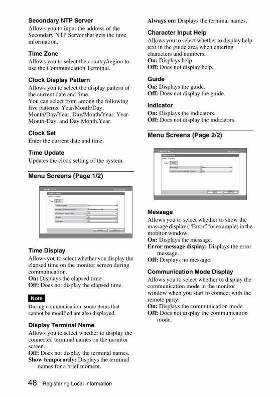
Secondary NTP ServerAllows you to input the address of the Secondary NTP Server that gets the time information.
Time ZoneAllows you to select the country/region to use the Communication Terminal.
Clock Display PatternAllows you to select the display pattern of the current date and time.You can select from among the following five patterns: Year/Month/Day, Month/Day/Year, Day/Month/Year, Year-Month-Day, and Day.Month.Year.
Clock SetEnter the current date and time.
Time Update Updates the clock setting of the system.
Menu Screens (Page 1/2)
Time DisplayAllows you to select whether you display the elapsed time on the monitor screen during communication.On: Displays the elapsed time.Off: Does not display the elapsed time.
During communication, some items that cannot be modified are also displayed.
Display Terminal NameAllows you to select whether to display the connected terminal names on the monitor screen.Off: Does not display the terminal names.Show temporarily: Displays the terminal
names for a brief moment.
Always on: Displays the terminal names.
Character Input HelpAllows you to select whether to display help text in the guide area when entering characters and numbers. On: Displays help.Off: Does not display help.
GuideOn: Displays the guide.Off: Does not display the guide.
IndicatorOn: Displays the indicators.Off: Does not display the indicators.
Menu Screens (Page 2/2)
MessageAllows you to select whether to show the massage display (“Error” for example) in the monitor window.On: Displays the message.Error message display: Displays the error
message.Off: Displays no message.
Communication Mode DisplayAllows you to select whether to display the communication mode in the monitor window when you start to connect with the remote party.On: Displays the communication mode.Off: Does not display the communication
mode.
Note
2005.12.28 12:34
Display Terminal Name
Character Input Help
Guide
Show temporarily
Off
On
Indicator On
OnTime Display
1/2Page:
General Setup
Menu Screens
CancelSave
2005.12.28 12:34
Communication Mode Display Off
OnMessage
2/2Page:
General Setup
Menu Screens
CancelSave
48 Registering Local Information

Chapter 2: R
egistration and Setup for S
ystem A
dministrators
Launcher Screen (Page 1/3)Allows you to select whether to display menus and buttons of the launcher screen.
Launcher DisplayAllows you to select whether to display the launcher menu automatically in the startup screen when the power of the system is turned on.On: Displays the launcher menu.Off: Does not display the launcher menu.
With this setting, you can display the launcher menu by pressing the MENU button on the Remote Commander.
Phone Book ButtonOn: Displays “Phone Book”.Off: Does not display “Phone Book”.
Detailed Dial ButtonOn: Displays “Detailed Dial”.Off: Does not display “Detailed Dial”.
History ButtonOn: Displays “History”.Off: Does not display “History”.
Camera ButtonOn: Displays “Camera”.Off: Does not display “Camera”.
Memory Stick ButtonOn: Displays “Memory Stick”.Off: Does not display “Memory Stick”.
Launcher Screen (Page 2/3)Allows you to select whether to display menus and buttons of the launcher screen.
Direct Phone Book ButtonOn: Displays “Direct Phone Book”.Off: Does not display “Direct Phone Book”.
Direct DialOn: Displays the Direct Dial text box.Off: Does not display the Direct Dial text box.
Clock DisplayOn: Displays the current date and time.Off: Does not display the current date and
time.
Local Terminal NameOn: Displays your terminal name.Off: Does not display your terminal name.
Capture ButtonOn: Displays “Capture”.Off: Does not display “Capture”.
Launcher Screen (Page 3/3)Allows you to select whether to display menus and buttons of the launcher screen.
Number DisplayAllows you to select the identification of the local system, such as the IP or user number, to be displayed in the launcher menu.
2005.12.28 12:34
Detailed Dial Button
History Button
Camera Button
On
On
On
Memory Stick Button On
OnPhone Book Button
OnLauncher Display
1/3Page:
General Setup
Launcher Screen
CancelSave
2005.12.28 12:34
Direct Dial
Clock Display
Local Terminal Name
On
On
On
Capture Button Off
OnDirect Phone Book Button
2/3Page:
General Setup
Launcher Screen
CancelSave
2005.12.28 12:34
Video Input Display
Audio Input Display
Level Meter
On
On
On
IP:AddressNumber Display
3/3Page:
General Setup
Launcher Screen
CancelSave
49Registering Local Information
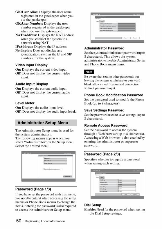
GK:User Alias: Displays the user name registered in the gatekeeper when you use the gatekeeper.
GK:User Number: Displays the user number registered in the gatekeeper when you use the gatekeeper.
NAT:Address: Displays the NAT address when you connect the system to a network using NAT.
IP:Address: Displays the IP address.No display: Does not display any
identification, such as the IP and SIP numbers, for the system.
Video Input DisplayOn: Displays the current video input.Off: Does not display the current video
input.
Audio Input DisplayOn: Displays the current audio input.Off: Does not display the current audio
input.
Level MeterOn: Displays the audio input level.Off: Does not display the audio input level.
The Administrator Setup menu is used for the system administrators.The following menus appear when you select “Administrator” on the Setup menu. Select the desired menu.
Password (Page 1/3)If you have set the password with this menu, you need to enter it when accessing the setup menus or Phone Book menus to change the items. Entering the password is also required to access the Administrator Setup menu.
Administrator PasswordSet the system administrator password (up to 8 characters). This allows the system administrator to modify Administrator Setup and Phone Book menu items.
Be aware that setting other passwords but leaving the system administrator password blank allows modification and connection without password input.
Phone Book Modification PasswordSet the password used to modify the Phone Book (up to 8 characters).
Save Settings PasswordSet the password used to save settings (up to 8 characters).
Remote Access Password Set the password to access the system through a Web browser (up to 8 characters). Accessing a Web browser is also enabled by entering the administrator or superuser password.
Password (Page 2/3)Specifies whether to require a password when saving each setting.
Dial SetupEnable: Need for the password when saving
the Dial Setup settings.
Administrator Setup Menu
Administrator Setup
2005.12.28 12:34
Password
Phone Book
Other Settings
Network Quality Measurement
Previous
Note
Administrator Setup
Password
CancelSave
2005.12.28 12:34
Phone Book Modification Password
Save Settings Password
Remote Access Password
Administrator Password
1/3Page:
Administrator Setup
Password
CancelSave
2005.12.28 12:34
2/3Page:
Answer Setup
Communication
Audio Setup
Video Setup
General Setup
Dial Setup Enable
Enable
Enable
Enable
Enable
Enable
50 Registering Local Information

Chapter 2: R
egistration and Setup for S
ystem A
dministrators
Disable: No need for the password when saving the Dial Setup settings.
Answer SetupEnable: Need for the password when saving
the Answer settings.Disable: No need for the password when
saving the Answer settings.
CommunicationEnable: Need for the password when saving
the Communication Mode settings.Disable: No need for the password when
saving the Communication Mode settings.
Audio SetupEnable: Need for the password when saving
the Audio Setup settings.Disable: No need for the password when
saving the Audio Setup settings.
Video SetupEnable: Need for the password when saving
the Video Setup settings.Disable: No need for the password when
saving the Video Setup settings.
General SetupEnable: Need for the password when saving
the General Setup settings.Disable: No need for the password when
saving the General Setup settings.
Password (Page 3/3)Specifies whether to require a password when saving each setting.
LAN SetupEnable: Need for the password when saving
the LAN Setup settings.Disable: No need for the password when
saving the LAN Setup settings.
Encryption SetupEnable: No need for the pass word when
saving the Encryption Setup settings.Disable: Need for the password when
saving the Encryption Setup settings.
Phone Book (Page 1/2)
Save Phone BookAllows you to save the data in the Phone Book on a “Memory Stick”. The data already on the “Memory Stick” is then overwritten.
Load Phone BookAllows you to load the data in the Phone Book from a “Memory Stick”. The data already in the Phone Book is then overwritten.
When saving and loading Phone Book data, make sure that the version of the terminal from which the data was originally saved is the same as the version of the local terminal. If the versions differ, the data may not be properly recognized.
Clear Phone BookAllows you to delete a Phone book on the Communication Terminal.
You cannot recover the cleared Phone Book.
Phone Book (Page 2/2)
Administrator Setup
Password
CancelSave
2005.12.28 12:34
3/3Page:
LAN Setup Enable
Encryption Setup Enable
Note
Note
Administrator Setup
Phone Book
Cancel
2005.12.28 12:34
1/2Page:
Save Phone Book
Load Phone Book
Clear Phone Book
Administrator Setup
Phone Book
CancelSave
2005.12.28 12:34
2/2Page:
Create Private Phone Book
Delete Private Phone Book
Copy to Private Phone Book
OnAuto Dialing
51Registering Local Information

Auto DialingAllows you to automatically contact the remote parties of the selected Private Phone Book on a “Memory Stick” when you insert it into the system.On: Enables automatic dialing.Off: Disables automatic dialing.
For details, see “To dial a specified list in a Private Phone Book automatically” on page 64.
Create Private Phone BookAllows you to create an empty folder and file for a Private Phone Book on a “Memory Stick” inserted into the system.
Delete Private Phone BookAllows you to delete the Private Phone Book on a “Memory Stick” inserted into the system.
Copy to Private Phone bookAllows you to copy the entire contents of the Phone Book to a Private Phone Book on a “Memory Stick” inserted into the system.
Other Settings (Page 1/2)
Web MonitorSelects whether or not to permit monitoring of the JPEG images of this System via a Web browser.On: Permits monitoring via a Web browser.Off: Disables monitoring.
Web AccessSelects whether or not to permit accessing the PCS-HG90 via a Web browser or Telnet.Disabled: Prohibits accessing via a Web
browser or Telnet.Enabled: Permits accessing via a Web
browser or Telnet.
Save Setup
Saves the data for each setting to a “Memory Stick”. The data for each setting saved on the “Memory Stick” is overwritten.
Phone Book and History data are not saved.
Load SetupLoads the data for each setting from a “Memory Stick”. The data for each setting saved on the unit is overwritten.
When saving and loading settings, make sure that the version of the terminal from which the data was originally saved is the same as the version of the local terminal. If the versions differ, the data may not be properly recognized.
Other Settings (Page 2/2)
Measurement from Remote SiteSelect whether to allow the remote terminal activating the network quality measurement.Disabled: Prohibits the remote terminal
activating the network quality measurement.
Enabled: Permits the remote terminal activating the network quality measurement.
Test Port NumberEnter the port number to be used for the network quality measurement.
Network Quality Measurement (Page 1/4)Allows you to set up for Network Quality Measurement.After the settings, you can start the measurement by selecting “Start Measurement”.
OnAuto Restore
Administrator Setup
Other Settings
CancelSave
2005.12.28 12:34
1/1Page:
Save Setup
Load Setup
EnabledWeb Access
OffWeb Monitor
Note
Note
Administrator Setup
Other Settings
CancelSave
2005.12.28 12:34
2/2Page:
DisabledMeasurement from Remote Site
Test Port Number
52 Registering Local Information

Chapter 2: R
egistration and Setup for S
ystem A
dministrators
For details on the measurement, see “Measuring the Network Quality” on page 71.
IP Address of Remote SiteEnter the IP address of the remote terminal you want to measure.
IP Address of Remote SiteEnter the port number of the remote terminal you want to measure.
Maximum BandwidthSelect the maximum bandwidth you want to measure.You can select from among 2Mbps, 2.5Mbps, 3Mbps, 4Mbps, 5Mbps, 6Mbps, 7Mbps, 8Mbps and “Other”.When “Other” is selected, you can enter a bandwidth value between 192 and 12288 Kbps.
Packet SizeAllows you to change the size of the packet you want to use for the measurement.
GatewayPut a check mark when you want to check the default gateway with the network quality measurement.
pingPut a check mark when you want to check the reachability with the network quality measurement.
TraceroutePut a check mark when you want to check the network route with the network quality measurement.
Load and Stress TestPut a check mark when you want to check the load and stress on the network with the network quality measurement.
The load and stress test is possible only when the remote terminal is PCS-HG90 with version 2.2 or later.
Start MeasurementSelect this button to start the network quality measurement.The network quality measurement will take several minutes depending on the selected measurement items.
Result of Network Quality Measurement (Page 2/4)The result of the network quality measurement is shown on this page.
GatewayDisplays the measurement result of the default gateway.
pingDisplays the measurement results of reachablility, packet loss, RTT (Round-Trip Time) and H.323 (H.323 communication availability).
TracerouteDisplays the measurement results of HOP (number of routers passed through to reach the remote site) and total RTT.
Result of Network Quality Measurement (Simplex) (Page 3/4)The result of the network quality measurement in one direction from this unit to the remote party is shown on this page.
Note
Administrator Setup
Network Quality Measurement
PreviousStart Measurement
2005.12.28 12:34
1/4Page:
Gateway ping
Traceroute Load and Stress Test
IP Address of Remote Site
2 Mbps
Port Number of Remote Site
Maximum Bandwidth
Packet Size
Administrator Setup
2005.12.28 12:34
End
2/4Page:
Gateway Result
ping Result
Packet Loss (%)
RTT
H.323
Traceroute Hop
Total RTT
Resolt of Network Quality Measurement
53Registering Local Information
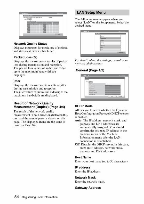
Network Quality StatusDisplays the reason for the failure of the load and stress test, when it has failed.
Packet Loss (%)Displays the measurement results of packet loss during transmission and reception.The packet loss values of audio, and video up to the maximum bandwidth are displayed.
jitterDisplays the measurements results of jitter during transmission and reception.The jitter values of audio, and video up to the maximum bandwidth are displayed.
Result of Network Quality Measurement (Duplex) (Page 4/4)The result of the network quality measurement in both directions between this unit and the remote party is shown on this page. The displayed items are the same as those on Page 3/4.
The following menus appear when you select “LAN” on the Setup menu. Select the desired menu.
For details about the settings, consult your network administrator.
General (Page 1/2)
DHCP ModeAllows you to select whether the Dynamic Host Configuration Protocol (DHCP) server is enabled.Auto: The IP address, network mask, and
gateway and DNS addresses are automatically assigned. You should confirm the assigned IP address in the launcher menu or the Machine Information menu after the LAN connection is established.
Off: Disables the DHCP server. In this case, enter an IP address, network mask, gateway and DNS addresses.
Host NameEnter your host name (up to 30 characters).
IP addressEnter the IP address.
Network MaskEnter the network mask.
Gateway Address
Audio
2M
2.5M
3M
4M
Packet Loss (%)
Encode Decode
Jitter (ms)
Encode Decode
5M
6M
7M
8M
Other
Packet Loss (%)
Encode Decode
Jitter (ms)
Encode Decode
Administrator Setup
2005.12.28 12:34
End
3/4Page:
Resout of Network Quality Measurement Simplex
Network Quality Status
LAN Setup Menu
LAN Setup
2005.12.28 12:34
Previous
General
Gatekeeper
SNMP
PPPoE
NAT/Port
QoS
TOS
LAN Setup
General
CancelSave
2005.12.28 12:34
Host Name
Auto
local host
. . .
. . .
. . .
DHCP Mode
Network Mask
IP Address
DNS Address
Gateway Address
1/2Page:
54 Registering Local Information

Chapter 2: R
egistration and Setup for S
ystem A
dministrators
Enter the default gateway address.
DNS AddressEnter the DNS (Domain Name System) address.
General (Page 2/2)
LAN ModeAllows you to select the interface type and the communication mode of the LAN connection.Auto Negotiation: The interface type and
the communication mode are detected automatically.
100Mbps Full Duplex: Connects via 100BASE-TX in full duplex mode.
100Mbps Half Duplex: Connects via 100BASE-TX in half duplex mode.
10Mbps Full Duplex: Connects via 10BASE-T in full duplex mode.
10Mbps Half Duplex: Connects via 10BASE-T in half duplex mode.
Gatekeeper
Gatekeeper ModeAllows you to select whether to use the gatekeeper to control access to a LAN. Using the gatekeeper allows you to dial using the user name or user number.The status of registration to a gatekeeper is displayed on the screen.On: Enables the gatekeeper.Off: Disables the gatekeeper.
Gatekeeper AddressEnter the address of the gatekeeper used when “Gatekeeper Mode” is set to “On”.
User AliasEnter the user name (H.323 alias) registered in the gatekeeper.
User NumberEnter the user number (E.164 number) registered in the gatekeeper.
SNMP
SNMP ModeAllows you to select whether the Simple Network Management Protocol (SNMP) agent is enabled.On: Enables the SNMP agent.Off: Disables the SNMP agent.
Trap DestinationEnter the address of the trap destination SNMP manager.
CommunityEnter the community name managed by the SNMP manager (up to 24 characters). By default, this is “public”.
DescriptionEnter the description of this terminal. By default, this is “Videoconference Device” and this description does not need to be changed.
LocationEnter the location where this terminal is installed (up to 30 characters).
ContactEnter information about the terminal administrator (up to 30 characters).
LAN Setup
General
CancelSave
2005.12.28 12:34
Auto NegotiationLAN Mode
2/2Page:
LAN Setup
Gatekeeper
CancelSave
2005.12.28 12:34
Gatekeeper Address
OffGatekeeper Mode
User Number
User Alias
1/1Page:
LAN Setup
SNMP
CancelSave
2005.12.28 12:34
Trap Destination
Off
Public
VideoConference Device
SNMP Mode
Description
Community
Contact
Location
1/1Page:
. . .
55Registering Local Information
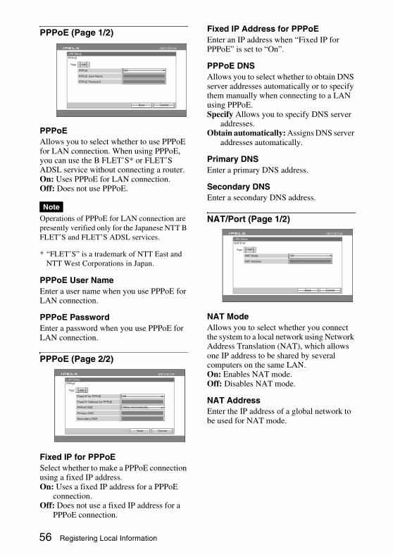
PPPoE (Page 1/2)
PPPoEAllows you to select whether to use PPPoE for LAN connection. When using PPPoE, you can use the B FLET’S* or FLET’S ADSL service without connecting a router.On: Uses PPPoE for LAN connection.Off: Does not use PPPoE.
Operations of PPPoE for LAN connection are presently verified only for the Japanese NTT B FLET’S and FLET’S ADSL services.
* “FLET’S” is a trademark of NTT East and NTT West Corporations in Japan.
PPPoE User NameEnter a user name when you use PPPoE for LAN connection.
PPPoE PasswordEnter a password when you use PPPoE for LAN connection.
PPPoE (Page 2/2)
Fixed IP for PPPoESelect whether to make a PPPoE connection using a fixed IP address.On: Uses a fixed IP address for a PPPoE
connection.Off: Does not use a fixed IP address for a
PPPoE connection.
Fixed IP Address for PPPoEEnter an IP address when “Fixed IP for PPPoE” is set to “On”.
PPPoE DNSAllows you to select whether to obtain DNS server addresses automatically or to specify them manually when connecting to a LAN using PPPoE.Specify Allows you to specify DNS server
addresses.Obtain automatically: Assigns DNS server
addresses automatically.
Primary DNSEnter a primary DNS address.
Secondary DNSEnter a secondary DNS address.
NAT/Port (Page 1/2)
NAT ModeAllows you to select whether you connect the system to a local network using Network Address Translation (NAT), which allows one IP address to be shared by several computers on the same LAN.On: Enables NAT mode.Off: Disables NAT mode.
NAT AddressEnter the IP address of a global network to be used for NAT mode.
Note
LAN Setup
PPPoE
CancelSave
2005.12.28 12:34
PPPoE User Name
OffPPPoE
PPPoE Password
1/2Page:
LAN Setup
PPPoE
CancelSave
2005.12.28 12:34
2/2Page:
Fixed IP Address for PPPoE
Off
Obtain Automatically
. . .
. . .
Fixed IP for PPPoE
PPPoE DNS
Primary DNS
. . .Secondary DNS
TCP Port Number
Custom
Default
. . .
Port Number Used
Port Number Used
LAN Setup
NAT/Port
CancelSave
2005.12.28 12:34
1/2Page:
NAT Address
Off
. . .
NAT Mode
56 Registering Local Information
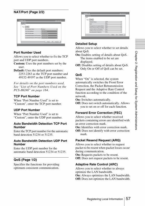
Chapter 2: R
egistration and Setup for S
ystem A
dministrators
NAT/Port (Page 2/2)
Port Number UsedAllows you to select whether to fix the TCP port and UDP port numbers.Custom: Uses the port numbers set by the
user.Default: Uses the default port numbers:
2253-2263 as the TCP port number and 49152-49197 as the UDP port number.
For details on the port numbers used, See “List of Port Numbers Used on the PCS-HG90” on page 184.
TCP Port NumberWhen “Port Number Used” is set to “Custom”, enter the TCP port number.
UDP Port NumberWhen “Port Number Used” is set to “Custom”, enter the UDP port number.
Auto Bandwidth Detection TCP Port NumberEnter the TCP port number for the automatic band detection 51234 or 51235.
Auto Bandwidth Detection UDP Port NumberEnter the UDP port number for the automatic band detection 51234 or 51235.
QoS (Page 1/2)Specifies the functions for providing optimum consistent communication.
Detailed SetupAllows you to select whether to set details about QoS.On: Enables setting of details about QoS.
The items enabled to be set are displayed.
Off: Disables setting of details about QoS. Only On or Off of QoS can be set.
QoSWhen “On” is selected, the system automatically switches the Front Error Correction, the Packet Retransmission Request and the Adaptive Rate Control function according to the condition of the network.On: Switches automatically.Off: Does not switch automatically. Allows
you to set on or off for each function.
Forward Error Correction (FEC)Allows you to select whether received packets containing errors are identified with an error correction mark.On: Identifies with error correction mark.Off: Does not identify with error correction
mark.
Packet Resend Request (ARQ)Allows you to select whether to request packet to be resent when packet losses occur during communication.On: Requests packets to be resent.Off: Does not request packets to be resent.
Adaptive Rate Control (ARC)Allows you to select whether to always optimize the LAN bandwidth.On: Always optimizes the LAN bandwidth.Off: Does not optimize the LAN bandwidth.
LAN Setup
NAT/Port
CancelSave
2005.12.28 12:34
2/2Page:
2253-2263TCP Port Number
49152-49197UDP Port Number
51234-51235Auto Bandwidth Detection TCP Port Number
51234-51235Auto Bandwidth Detection UDP Port Number
DefaultPort Number Used
LAN Setup
QoS
CancelSave
2005.12.28 12:34
1/2Page:
Detailed Setup Off
On
On
QoS
Forward Error Correction(FEC)
Packed Resend Request(ARQ) On
On
On
Adaptive Rate Control(ARC)
Auto Bandwidth Detection
57Registering Local Information

Auto Bandwidth DetectionSwitches On and Off of the auto bandwidth detection function.On: Uses the automatic bandwidth detection
function.Off: Does not use the automatic bandwidth
detection function.
QoS (Page 2/2)
Forward Error Correction RedundancyAllows you to set the redundancy of the packet used for the Forward Error Correction (FEC).You can select from among 8, 4, 2, and Auto.
When 8, 4, or 2 is selected, the communication bit rate may be different from the specified value.
Buffering TimeAllows you to set the size of the buffer used for the Packet Resend Request (ARQ).You can select from among 300 ms, 150 ms, 80 ms, Auto, and Custom.When you select “Custom”, you can enter the optional buffering time in “Custom”.
CustomWhen you select “Custom” for “Buffering Time”, enter a buffering time (50 ms to 999 ms).
TOS (Page 1/3-3/3)
Each page allows you to configure the Type of Service (TOS) field of specific types of data.
Page 1/3: TOS (Video)Configure the TOS field for video data.
Page 2/3: TOS (Audio)Configure the TOS field for audio data.
Page 3/3: TOS (Camera Control)Configure the TOS field for camera control signals.
TOSAllows you to select how to define the Type of Service (TOS) field.Off: Does not define the TOS field.IP Precedence: Defines the TOS field as IP
Precedence.Diffserve: Defines the TOS field as
Diffserve.
IP PrecedenceEnter the IP Precedence value, between 0 and 7.
Low DelayAllows you to select whether to enable the Low Delay bit rate of the TOS field.On: Enables the Low Delay bit rate of the
TOS field.Off: Disables the Low Delay bit rate of the
TOS field.
High ThroughputAllows you to select whether to enable the High Throughput bit rate of the TOS field.On: Enables the High Throughput bit rate of
the TOS field.Off: Disables the High Throughput bit rate
of the TOS field.
High Reliability
Note
LAN Setup
QoS
CancelSave
2005.12.28 12:34
2/2Page:
Auto
Auto
ms
Forward Error Correction Redundancy
Buffering Time
Custom
LAN Setup
TOS (Video)
CancelSave
2005.12.28 12:34
1/3Page:
IP Precedence
Off
Off
Off
TOS
Low Delay
High Throughput
Off
Off
High Reliability
Minimum Cost
58 Registering Local Information
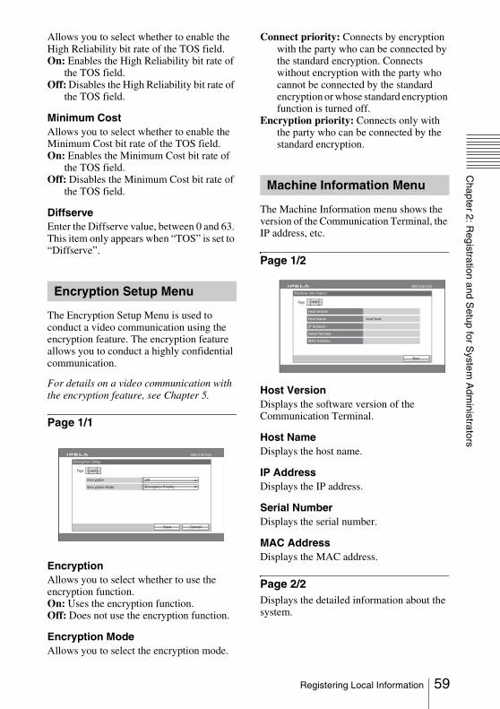
Chapter 2: R
egistration and Setup for S
ystem A
dministrators
Allows you to select whether to enable the High Reliability bit rate of the TOS field.On: Enables the High Reliability bit rate of
the TOS field.Off: Disables the High Reliability bit rate of
the TOS field.
Minimum CostAllows you to select whether to enable the Minimum Cost bit rate of the TOS field.On: Enables the Minimum Cost bit rate of
the TOS field.Off: Disables the Minimum Cost bit rate of
the TOS field.
DiffserveEnter the Diffserve value, between 0 and 63. This item only appears when “TOS” is set to “Diffserve”.
The Encryption Setup Menu is used to conduct a video communication using the encryption feature. The encryption feature allows you to conduct a highly confidential communication.
For details on a video communication with the encryption feature, see Chapter 5.
Page 1/1
EncryptionAllows you to select whether to use the encryption function.On: Uses the encryption function.Off: Does not use the encryption function.
Encryption ModeAllows you to select the encryption mode.
Connect priority: Connects by encryption with the party who can be connected by the standard encryption. Connects without encryption with the party who cannot be connected by the standard encryption or whose standard encryption function is turned off.
Encryption priority: Connects only with the party who can be connected by the standard encryption.
The Machine Information menu shows the version of the Communication Terminal, the IP address, etc.
Page 1/2
Host VersionDisplays the software version of the Communication Terminal.
Host NameDisplays the host name.
IP AddressDisplays the IP address.
Serial NumberDisplays the serial number.
MAC AddressDisplays the MAC address.
Page 2/2Displays the detailed information about the system.
Encryption Setup Menu
Encryption Setup
CancelSave
2005.12.28 12:34
1/1Page:
Off
Encryption Priority
Encryption
Encryption Mode
Machine Information Menu
Machine Information
End
2005.12.28 12:34
Host Version
Host Name
IP Address
Serial Number
local host
MAC Address
1/2Page:
59Registering Local Information
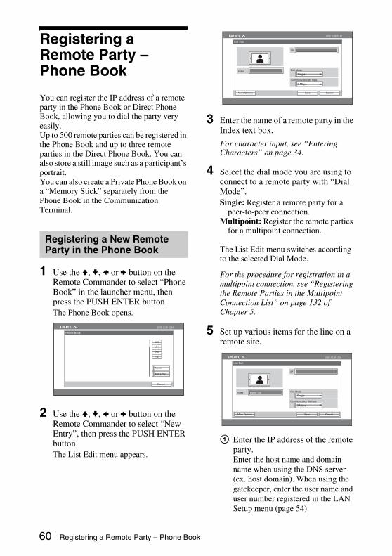
Registering a Remote Party – Phone Book
You can register the IP address of a remote party in the Phone Book or Direct Phone Book, allowing you to dial the party very easily.Up to 500 remote parties can be registered in the Phone Book and up to three remote parties in the Direct Phone Book. You can also store a still image such as a participant’s portrait.You can also create a Private Phone Book on a “Memory Stick” separately from the Phone Book in the Communication Terminal.
1 Use the V, v, B or b button on the Remote Commander to select “Phone Book” in the launcher menu, then press the PUSH ENTER button.The Phone Book opens.
2 Use the V, v, B or b button on the Remote Commander to select “New Entry”, then press the PUSH ENTER button.The List Edit menu appears.
3 Enter the name of a remote party in the Index text box.
For character input, see “Entering Characters” on page 34.
4 Select the dial mode you are using to connect to a remote party with “Dial Mode”.Single: Register a remote party for a
peer-to-peer connection.Multipoint: Register the remote parties
for a multipoint connection.
The List Edit menu switches according to the selected Dial Mode.
For the procedure for registration in a multipoint connection, see “Registering the Remote Parties in the Multipoint Connection List” on page 132 of Chapter 5.
5 Set up various items for the line on a remote site.
1 Enter the IP address of the remote party.Enter the host name and domain name when using the DNS server (ex. host.domain). When using the gatekeeper, enter the user name and user number registered in the LAN Setup menu (page 54).
Registering a New Remote Party in the Phone Book
Phone Book
Cancel
2005.12.28 12:34
0-9
A-I
J-S
T-Z
New Entry
Recent
List Edit
CancelSaveMore Options
2005.12.28 12:34
IP
SingleIndex Dial Mode
2 Mbps
Communication Bit Rate
List Edit
CancelSaveMore Options
2005.12.28 12:34
IP
SingleIndex Dial Mode
2 Mbps
Communication Bit Rate
Room 10A
60 Registering a Remote Party – Phone Book
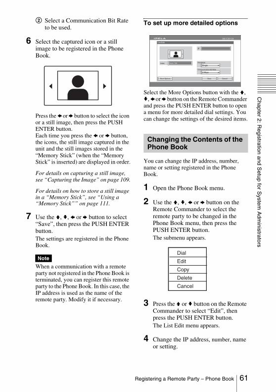
Chapter 2: R
egistration and Setup for S
ystem A
dministrators
2 Select a Communication Bit Rate to be used.
6 Select the captured icon or a still image to be registered in the Phone Book.
Press the B or b button to select the icon or a still image, then press the PUSH ENTER button.Each time you press the B or b button, the icons, the still image captured in the unit and the still images stored in the “Memory Stick” (when the “Memory Stick” is inserted) are displayed in order.
For details on capturing a still image, see “Capturing the Image” on page 109.
For details on how to store a still image in a “Memory Stick”, see “Using a “Memory Stick”” on page 111.
7 Use the V, v, B or b button to select “Save”, then press the PUSH ENTER button.The settings are registered in the Phone Book.
When a communication with a remote party not registered in the Phone Book is terminated, you can register this remote party to the Phone Book. In this case, the IP address is used as the name of the remote party. Modify it if necessary.
To set up more detailed options
Select the More Options button with the V, v, B or b button on the Remote Commander and press the PUSH ENTER button to open a menu for more detailed dial settings. You can change the settings of the desired items.
You can change the IP address, number, name or setting registered in the Phone Book.
1 Open the Phone Book menu.
2 Use the V, v, B or b button on the Remote Commander to select the remote party to be changed in the Phone Book menu, then press the PUSH ENTER button.The submenu appears.
3 Press the V or v button on the Remote Commander to select “Edit”, then press the PUSH ENTER button.The List Edit menu appears.
4 Change the IP address, number, name or setting.
Note
Changing the Contents of the Phone Book
Room 10A
List Edit
CancelSaveMore Options
2005.12.28 12:34
IP
SingleIndex Dial Mode
2 Mbps
Communication Bit Rate
Dial
Edit
Copy
Delete
Cancel
61Registering a Remote Party – Phone Book

5 Use the V, v, B or b button on the Remote Commander to select “Save”, then press the PUSH ENTER button.The correction is completed.
1 Open the Phone Book menu.
2 Use the V, v, B or b button on the Remote Commander to select the remote party to be copied in the Phone Book menu, then press the PUSH ENTER button.The submenu appears.
3 Press the V or v button on the Remote Commander to select “Copy”, then press the PUSH ENTER button.The items for the selected party are copied, and the file name is followed by “–2”. You can use the setting after modifying the necessary items.
Follow the procedure below to delete the remote party from the Phone Book.
1 Open the Phone Book menu.
2 Use the V, v, B or b button on the Remote Commander to select the remote party to be deleted in the Phone Book menu, then press the PUSH ENTER button.The submenu appears.
3 Press the V or v button on the Remote Commander to select “Delete”, then press the PUSH ENTER button.The message “Delete Entry?” appears.
4 Use the V, v, B or b button on the Remote Commander to select “OK”, then press the PUSH ENTER button.The selected party is deleted.
To cancel deletingSelect “Cancel” in step 4, then press the PUSH ENTER button.
You can register up to three remote parties in the Direct Phone Book in the launcher menu. It is convenient if you register the parties to whom you often dial.
1 Use the V, v, B or b button on the Remote Commander to select one list from the Direct Phone Book, then press the PUSH ENTER button.The List Edit menu appears.
2 Register the remote party in the List Edit menu.The procedure is the same as that for registering in the Phone Book. Proceed with steps 3 to 7 in “Registering a New Remote Party in the Phone Book” on page 60.
The procedures for changing the contents of the Direct Phone Book or for deleting the registered parties are the same as those for the Phone Book. Select a remote party in the Direct Phone Book to open the submenu, then perform the
Copying the Registered Remote Party
Deleting the Registered Remote Party
Registering a Remote Party in the Direct Phone Book
Capture
Room 10A
Room 11B
Room 12A
Room 01 IP:255.255.255.255
2005.12.28 12:34
Menu
Phone Book
Detailed Dial
History
Enter the remote party number.
Dial
Direct Phone Book
62 Registering a Remote Party – Phone Book

Chapter 2: R
egistration and Setup for S
ystem A
dministrators
same procedure as that with the Phone Book.
You cannot check, modify or copy the Direct Phone Book by using the Web function.
You can create your own Phone Book (Private Phone Book) on a “Memory Stick”. Once the Private Phone Book is registered, inserting the “Memory Stick” into the Communication Terminal changes the Phone Book menu to the Private Phone Book menu. You can also activate the Auto Dial feature, allowing you to start dialing automatically to one of the lists simply by inserting the “Memory Stick”.
To register a new remote party in a Private Phone Book
1 Insert a “Memory Stick” in which you want to register a remote party into the Memory Stick slot on the Communication Terminal.Insert the “Memory Stick” in the direction of the arrow with the mark facing upward.
2 Open Page 2/2 of “Phone Book” in the Administrator Setup menu.
For how to open the menu, see “Registering Local Information” on page 36.
3 Select “Create Private Phone Book”.An empty folder and file for a Private Phone Book are created in the “Memory Stick”.
4 Register a new remote party.The procedure is the same as that for registering in the Phone Book. Proceed with steps 2 to 7 in “Registering a New Remote Party in the Phone Book” on page 60.
The procedures for how to change the contents of the Private Phone Book, how to delete the registered remote party, or how to copy the setting of the Private Phone Book are the same as those for the Phone Book. Selet the remote party in the Private Phone Book menu to open the submenu, and perform the same procedure as that with the Phone Book menu.
To copy all the contents of the Phone Book to the Private Phone BookInsert the “Memory Stick” in which you want to store the Private Phone Book into the Memory Stick slot on the Communication Terminal, then select “Copy to Private Phone Book” from the “Phone Book (Page 2/2)” of the Administrator Setup menu. All the data registered in the Phone Book are copied to the inserted “Memory Stick”.
Note
Creating a Private Phone Book
Administrator Setup
Phone Book
CancelSave
2005.12.28 12:34
2/2Page:
Create Private Phone Book
Delete Private Phone Book
Copy to Private Phone Book
OnAuto Dial
63Registering a Remote Party – Phone Book

To delete the Private Phone Book from the “Memory Stick”Insert the “Memory Stick” from which you want to delete the registered Private Phone Book into the Memory Stick slot on the Communication Terminal, then select “Delete Private Phone Book” from the “Phone Book (Page 2/2)” of the Administrator Setup menu. All the data are deleted from the inserted “Memory Stick”.
To dial a specified list in a Private Phone Book automaticallyIf you set “Auto Dialing” in the “Phone Book (Page 2/2)” of the Administrator Setup menu to “On”, you can automatically dial one of the lists registered in the Private Phone Book simply by inserting the “Memory Stick” in which the Private Phone Book is registered.
1 Open Page 2/2 in the Phone Book menu.
2 Use the V, v, B or b button on the Remote Commander to select the remote party to dial automatically, then press the PUSH ENTER button.
3 Press the V or v button on the Remote Commander to select “Edit”, then press the PUSH ENTER button.The List Edit menu appears.
4 Use the V, v, B or b button on the Remote Commander to select “Auto Dial”, then press the PUSH ENTER button.
5 Use the V, v, B or b button on the Remote Commander to select “Save”, then press the PUSH ENTER button.The setting is registered and “AUTO” appears on the registered list.
Sa
ex
List Edit
CancelveMore Options
2005.12.28 12:34
IP
Singl
Auto Dial
Inde Dial Mode
2 Mbps
Communication Bit Rate
Room 10A
AUTO
Private Phone Book
Cancel
2005.12.28 12:34
0-9
A-I
J-S
T-Z
New Entry
Recent
Jane Mary
64 Registering a Remote Party – Phone Book

Chapter 2: R
egistration and Setup for S
ystem A
dministrators
Setting Up the Network ConfigurationsThis section describes how to set up the network configurations for use with various networks.
For details on the LAN Setup menu, see “LAN Setup Menu” (page 54).
For details on configurations, consult with the system administrator.
Configuration example
Set “DHCP Mode” to “Auto“ under Page 1/2 of the General screen in the LAN Setup menu.
The setting has been configured properly if the IP address appears in the launcher menu.
To connect
Select “Single” under “Dial Mode”, enter the remote party’s IP address, and dial.
LAN (Connecting via DHCP)
LAN1 LAN2
DHCP server 1
LAN Setup
General
CancelSave
2005.12.28 12:34
Host Name
Auto
. . .
. . .
. . .
. . .
DHCP Mode
Network Mask
IP Address
DNS Address
Gateway Address
1/2Page:
65Setting Up the Network Configurations

Configuration example
Enter a name in “Host Name” under Page 1/2 of the General screen in the LAN Setup menu, and enter the appropriate values for “IP Address”, “Network Mask”, and “Gateway Address”.
The setting has been configured properly if the correct IP address appears in the launcher menu.
To connect
Select “Single” under “Dial Mode”, enter the remote party’s IP address, and dial.
LAN (Connecting Through a Router)
192.100.10.10
Virtual Private Network (VPN)
Router Router
LAN 1192.100.10.1
192.100.20.20
LAN 2192.100.20.1
LAN Setup
General
CancelSave
2005.12.28 12:34
Host Name
OffDHCP Mode
Network Mask
IP Address
DNS Address
Gateway Address
1/2Page:
Sony
192.100.10.10
225.225.225.0
192.100.10.1
. . .
66 Setting Up the Network Configurations
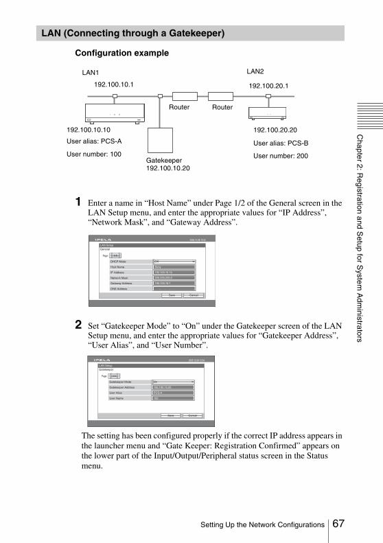
Chapter 2: R
egistration and Setup for S
ystem A
dministrators
Configuration example
1 Enter a name in “Host Name” under Page 1/2 of the General screen in the LAN Setup menu, and enter the appropriate values for “IP Address”, “Network Mask”, and “Gateway Address”.
2 Set “Gatekeeper Mode” to “On” under the Gatekeeper screen of the LAN Setup menu, and enter the appropriate values for “Gatekeeper Address”, “User Alias”, and “User Number”.
The setting has been configured properly if the correct IP address appears in the launcher menu and “Gate Keeper: Registration Confirmed” appears on the lower part of the Input/Output/Peripheral status screen in the Status menu.
LAN (Connecting through a Gatekeeper)
User number: 100
LAN2
192.100.10.10
User alias: PCS-A
RouterRouter
User number: 200
LAN1
192.100.10.1
192.100.20.20
Gatekeeper 192.100.10.20
192.100.20.1
User alias: PCS-B
LAN Setup
General
CancelSave
2005.12.28 12:34
Host Name
OffDHCP Mode
Network Mask
IP Address
DNS Address
Gateway Address
1/2Page:
Sony
192.100.10.10
225.225.225.0
192.100.10.1
. . .
192.100.10.20
PCS-A
100
LAN Setup
Gatekeeper
CancelSave
2005.12.28 12:34
Gatekeeper Address
OnGatekeeper Mode
User Name
User Alias
1/1Page:
67Setting Up the Network Configurations

To connect
Select “Single” under “Dial Mode”, enter the user name or user number set by the remote party, and dial.
Connection using NAT allows one IP address to be shared by several computers on the same LAN. This section describes how to set up for a video communication conducted in NAT and global IP environments.
Configuration example
1 Enter a name in “Host Name” under Page 1/2 of the General screen in the LAN Setup menu, and enter the appropriate values for “IP Address”, “Network Mask”, and “Gateway Address”.
2 Set “NAT Mode” (Page 1/2) to “On” in the NAT/Port screen of the LAN Setup menu, and enter the appropriate IP address in “NAT Address”.
The setting has been configured properly if the correct NAT address appears in the launcher menu.
LAN (Connecting through NAT)
Internet
210.10.10.1 RouterRouter
210.20.20.2(Global address)
192.168.10.10
192.168.10.1 210.20.20.1
LAN Setup
General
CancelSave
2005.12.28 12:34
Host Name
OffDHCP Mode
Network Mask
IP Address
DNS Address
Gateway Address
1/2Page:
Sony
192.100.10.10
225.225.225.0
192.100.10.1
. . .
LAN Setup
NAT/Port
CancelSave
2005.12.28 12:34
1/2Page:
NAT Address
On
210.10.1.1
NAT Mode
68 Setting Up the Network Configurations
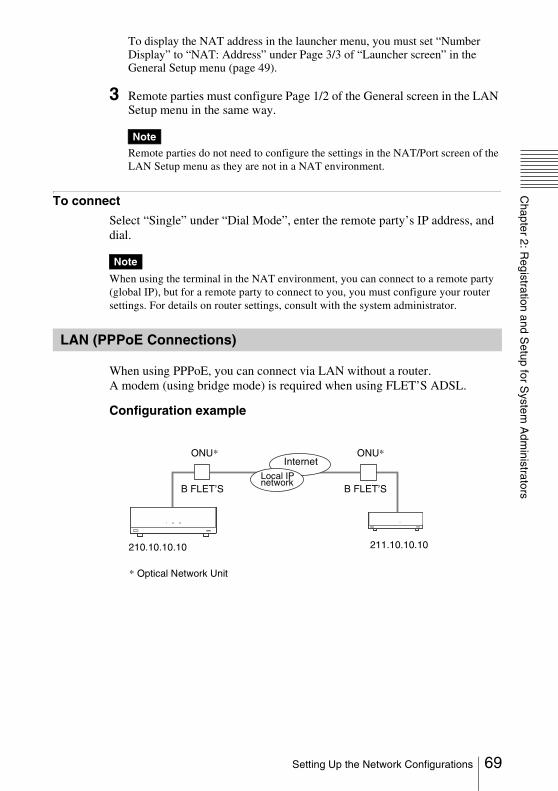
Chapter 2: R
egistration and Setup for S
ystem A
dministrators
To display the NAT address in the launcher menu, you must set “Number Display” to “NAT: Address” under Page 3/3 of “Launcher screen” in the General Setup menu (page 49).
3 Remote parties must configure Page 1/2 of the General screen in the LAN Setup menu in the same way.
Remote parties do not need to configure the settings in the NAT/Port screen of the LAN Setup menu as they are not in a NAT environment.
To connect
Select “Single” under “Dial Mode”, enter the remote party’s IP address, and dial.
When using the terminal in the NAT environment, you can connect to a remote party (global IP), but for a remote party to connect to you, you must configure your router settings. For details on router settings, consult with the system administrator.
When using PPPoE, you can connect via LAN without a router.A modem (using bridge mode) is required when using FLET’S ADSL.
Configuration example
Note
Note
LAN (PPPoE Connections)
ONU*
211.10.10.10
B FLET’S B FLET’S
ONU*
210.10.10.10
Local IP network
Internet
* Optical Network Unit
69Setting Up the Network Configurations
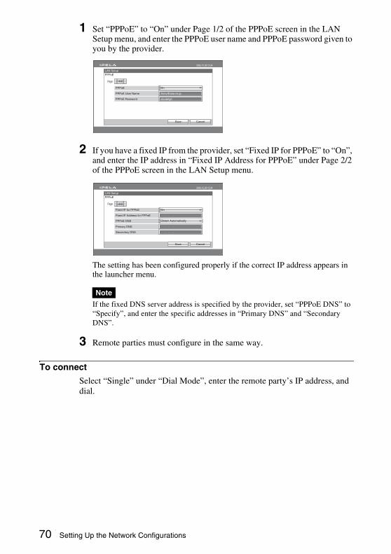
1 Set “PPPoE” to “On” under Page 1/2 of the PPPoE screen in the LAN Setup menu, and enter the PPPoE user name and PPPoE password given to you by the provider.
2 If you have a fixed IP from the provider, set “Fixed IP for PPPoE” to “On”, and enter the IP address in “Fixed IP Address for PPPoE” under Page 2/2 of the PPPoE screen in the LAN Setup menu.
The setting has been configured properly if the correct IP address appears in the launcher menu.
If the fixed DNS server address is specified by the provider, set “PPPoE DNS” to “Specify”, and enter the specific addresses in “Primary DNS” and “Secondary DNS”.
3 Remote parties must configure in the same way.
To connect
Select “Single” under “Dial Mode”, enter the remote party’s IP address, and dial.
Note
LAN Setup
PPPoE
CancelSave
2005.12.28 12:34
1/2Page:
PPPoE User Name
On
abcdefgh
PPPoE
PPPoE Password
LAN Setup
PPPoE
CancelSave
2005.12.28 12:34
2/2Page:
Fixed IP Address for PPPoE
On
Obtain Automatically
. . .
. . .
Fixed IP for PPPoE
PPPoE DNS
Primary DNS
. . .Secondary DNS
70 Setting Up the Network Configurations
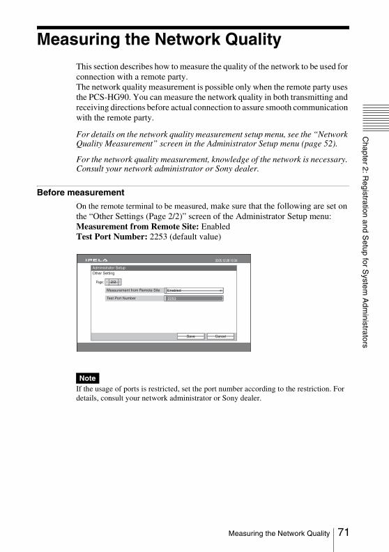
Chapter 2: R
egistration and Setup for S
ystem A
dministrators
Measuring the Network QualityThis section describes how to measure the quality of the network to be used for connection with a remote party.The network quality measurement is possible only when the remote party uses the PCS-HG90. You can measure the network quality in both transmitting and receiving directions before actual connection to assure smooth communication with the remote party.
For details on the network quality measurement setup menu, see the “Network Quality Measurement” screen in the Administrator Setup menu (page 52).
For the network quality measurement, knowledge of the network is necessary. Consult your network administrator or Sony dealer.
Before measurement
On the remote terminal to be measured, make sure that the following are set on the “Other Settings (Page 2/2)” screen of the Administrator Setup menu:Measurement from Remote Site: EnabledTest Port Number: 2253 (default value)
If the usage of ports is restricted, set the port number according to the restriction. For details, consult your network administrator or Sony dealer.
Note
Administrator Setup
Other Setting
CancelSave
2005.12.28 12:34
2/2Page:
EnabledMeasurement from Remote Site
Test Port Number 2253
71Measuring the Network Quality
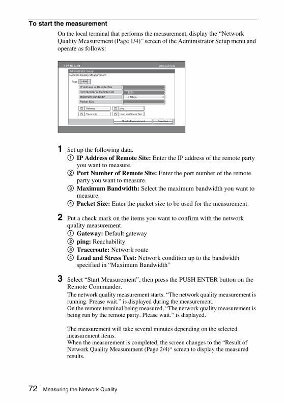
To start the measurement
On the local terminal that performs the measurement, display the “Network Quality Measurement (Page 1/4)” screen of the Administrator Setup menu and operate as follows:
1 Set up the following data.1 IP Address of Remote Site: Enter the IP address of the remote party
you want to measure.2 Port Number of Remote Site: Enter the port number of the remote
party you want to measure.3 Maximum Bandwidth: Select the maximum bandwidth you want to
measure.4 Packet Size: Enter the packet size to be used for the measurement.
2 Put a check mark on the items you want to confirm with the network quality measurement.1 Gateway: Default gateway2 ping: Reachability3 Traceroute: Network route4 Load and Stress Test: Network condition up to the bandwidth
specified in “Maximum Bandwidth”
3 Select “Start Measurement”, then press the PUSH ENTER button on the Remote Commander.The network quality measurement starts. “The network quality measurement is running. Prease wait.” is displayed during the measurement. On the remote terminal being measured, “The network quality measurement is being run by the remote party. Please wait.” is displayed.
The measurement will take several minutes depending on the selected measurement items.When the measurement is completed, the screen changes to the “Result of Network Quality Measurement (Page 2/4)“ screen to display the measured results.
Administrator Setup
Network Quality Measurement
PreviousStart Measurement
2005.12.28 12:34
1/4Page:
Gateway ping
Traceroute Load and Stress Test
IP Address of Remote Site
2 Mbps
2253Port Number of Remote Site
Maximum Bandwidth
Packet Size
72 Measuring the Network Quality
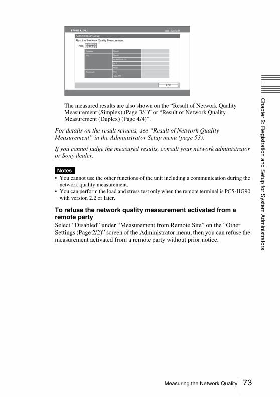
Chapter 2: R
egistration and Setup for S
ystem A
dministrators
The measured results are also shown on the “Result of Network Quality Measurement (Simplex) (Page 3/4)” or “Result of Network Quality Measurement (Duplex) (Page 4/4)”.
For details on the result screens, see “Result of Network Quality Measurement” in the Administrator Setup menu (page 53).
If you cannot judge the measured results, consult your network administrator or Sony dealer.
• You cannot use the other functions of the unit including a communication during the network quality measurement.
• You can perform the load and stress test only when the remote terminal is PCS-HG90 with version 2.2 or later.
To refuse the network quality measurement activated from a remote partySelect “Disabled” under “Measurement from Remote Site” on the “Other Settings (Page 2/2)” screen of the Administrator menu, then you can refuse the measurement activated from a remote party without prior notice.
Notes
Administrator Setup
2005.12.28 12:34
End
2/4Page:
Gateway Result
ping Result
Packet Loss (%)
RTT
H.323
Traceroute Hop
Total RTT
Result of Network Quality Measurement
73Measuring the Network Quality

Setting the Transmitting Image QualityThis section describes how to set up the transmitting image quality using the “Transmitting Image Quality” screen of the Video Setup menu.There are five Transmitting Image Quality pages (Page 1/5 to 5/5). Each page allows set-up of the transmitting image quality for each video input.The following illustration shows an example screen of Page 1/5 for HD-SDI 1.
When “Setting Mode” is set to “Auto”, “Motion Smoothing Filter”, “2D Smoothing Filter” and “Frame Rate Control” are automatically set to “Auto” and all three items are automatically adjusted to the optimum value for the selected communication bit rate.When “Setting Mode” is set to “Detailed Setup”, you can set up each item individually. Refer to the following description for setup.
Motion Smoothing FilterThe motion smoothing filter compares the current frame of an input video signal with that of the adjacent frame and smoothes the temporal variation of each pixel. The use of this filter reduces random noise included in the video signal. It is useful when the camera is shooting a dark place, the video signal from the S-VIDEO input is being transmitted or in other situations where random noise may occur easily.The filter is also effective for smoothing picture motion as a consequence of enhanced correlation between frames, as well as improving the coding efficiency. If the filter is activated when the bit rate is the same, block noise will be reduced and the picture quality may be improved. On the other hand, if the intensity of the filter is too much, afterimage may remain at portions where there was motion in the picture, being viewed as a trajectory.
2D (two-dimension) smoothing filterThe 2D smoothing filter smoothes the variation of pixels in one frame of an input video signal. The use of this filter reduces random noise included in the video signal. It is also effective for improving the coding efficiency as a consequence of reduction of high frequency components (detailed picture) in the video signal. If the filter is activated when the bit rate is the same, block noise will be reduced and the picture quality may be improved. On the other
Video Setup
Transmitting Image Quality (HD-SDI 1)
CancelSave
2005.12.28 12:34
Motion Smoothing Filter
2D Smoothing Filter
Setting Mode
1/5Page:
Auto
Auto
Auto
Frame Rate Control Auto
74 Setting the Transmitting Image Quality

Chapter 2: R
egistration and Setup for S
ystem A
dministrators
hand, reduction of high frequency components may degrade the resolution and picture details may blur. These effects depend on picture details. Use the 2D smoothing filter when the input video signal is noisy or a videoconference is to be conducted with a lower bit rate.
Frame Rate ControlThe encoder of the Communication Terminal automatically and finely adjusts parameters to control the bit rate. This control normally sets the actual transmission bit rate to the selected communication bit rate. However, the transmission bit rate may exceed the selected bit rate when the communication bit rate is low or with some types of picture details. If “Frame Rate Control” is set to “Bandwidth Limiting Priority”, the Communication Terminal stops the encoder to maintain a transmission bit rate lower than the selected communication bit rate. The encoder restores encoding after a certain period of time has elapsed and data transmission becomes possible, but the bit rate on the receiver side is apparently reduced due to the period without video data transmission.When “Frame Rate Control” is set to “Frame Rate Priority”, priority is given to video transmission at the selected frame rate, allowing the encoder to exceed the selected communication bit rate. The degree of excess allowance depends on the communication bit rate setting or the picture details. Note that a frequent packet loss may occur with the “Frame Rate Priority” setting, especially when you are using a network with a lower bandwidth, as the Communication Terminal tries to transmit data at a bit rate much greater than the selected communication bit rate.
75Setting the Transmitting Image Quality
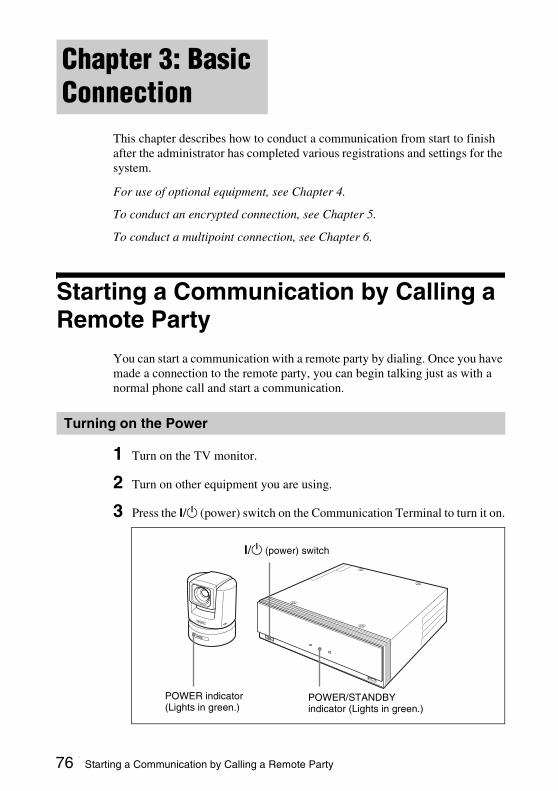
This chapter describes how to conduct a communication from start to finish after the administrator has completed various registrations and settings for the system.
For use of optional equipment, see Chapter 4.
To conduct an encrypted connection, see Chapter 5.
To conduct a multipoint connection, see Chapter 6.
Starting a Communication by Calling a Remote Party
You can start a communication with a remote party by dialing. Once you have made a connection to the remote party, you can begin talking just as with a normal phone call and start a communication.
1 Turn on the TV monitor.
2 Turn on other equipment you are using.
3 Press the ?/1 (power) switch on the Communication Terminal to turn it on.
Chapter 3: Basic Connection
Turning on the Power
?/1 (power) switch
POWER/STANDBY indicator (Lights in green.)
POWER indicator (Lights in green.)
76 Starting a Communication by Calling a Remote Party
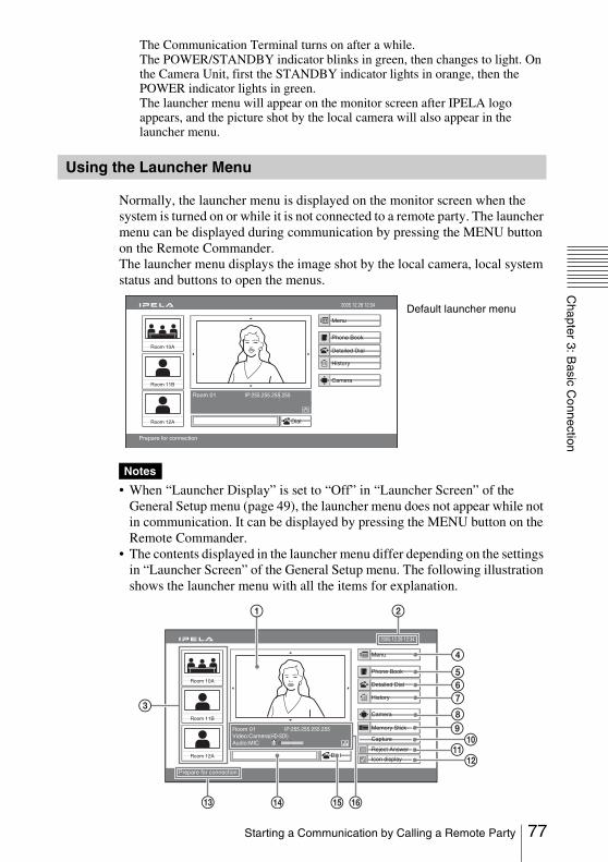
Chapter 3: B
asic Connection
The Communication Terminal turns on after a while.The POWER/STANDBY indicator blinks in green, then changes to light. On the Camera Unit, first the STANDBY indicator lights in orange, then the POWER indicator lights in green.The launcher menu will appear on the monitor screen after IPELA logo appears, and the picture shot by the local camera will also appear in the launcher menu.
Normally, the launcher menu is displayed on the monitor screen when the system is turned on or while it is not connected to a remote party. The launcher menu can be displayed during communication by pressing the MENU button on the Remote Commander.The launcher menu displays the image shot by the local camera, local system status and buttons to open the menus.
• When “Launcher Display” is set to “Off” in “Launcher Screen” of the General Setup menu (page 49), the launcher menu does not appear while not in communication. It can be displayed by pressing the MENU button on the Remote Commander.
• The contents displayed in the launcher menu differ depending on the settings in “Launcher Screen” of the General Setup menu. The following illustration shows the launcher menu with all the items for explanation.
Using the Launcher Menu
Notes
Capture
Room 10A
Room 11B
Room 12A
Room 01 IP:255.255.255.255
2005.12.28 12:34
Menu
Phone Book
Detailed Dial
History
Prepare for connection
Dial
Camera
Default launcher menu
Capture 9
qa0
qs
Room 10A
Room 11B
Room 12A
Room 01 IP:255.255.255.255Video:Camera(HD-SDI)Audio:MIC
Camera
Memory Stick
Capture
Reject Answer
Icon display
2005.12.28 12:34
Menu
Phone Book
Detailed Dial
History
Prepare for connection
Dial
1 2
3
4
567
8
qhqgqd qf
77Starting a Communication by Calling a Remote Party

1 ScreenThe image shot by the local camera is displayed.
2 Clock displayThe current date and time are displayed.
3 Direct Phone Book buttonsYou can start calling a remote party registered in the Direct Phone Book when you select the thumbnail by pressing the V, v, B or b, and then the PUSH ENTER button on the Remote Commander.
4 Menu buttonYou can display the Setup menu when you select this button by pressing the V, v, B or b button and then the PUSH ENTER button on the Remote Commander.
5 Phone Book buttonThe Phone Book menu is displayed when you select this button by pressing the V, v, B or b button and then the PUSH ENTER button on the Remote Commander.
6 Detailed Dial buttonThe Detailed Dial menu appears when you select this button by pressing the V, v, B or b button, and then the PUSH ENTER button on the Remote Commander.
7 History buttonThe History menu appears when you select this button by pressing the V, v, B or b button, and then the PUSH ENTER button on the Remote Commander.
8 Camera buttonThe Camera menu is displayed when you select this button by pressing the V, v, B or b button, and then the PUSH ENTER button on the Remote Commander.
9 Memory Stick buttonThe Memory stick menu is displayed when you select this button by pressing the V, v, B or b button, and then the PUSH ENTER button on the Remote Commander.
0 Capture buttonThe image displayed in the screen is captured when you select this button by pressing the V, v, B or b button, and then the PUSH ENTER button on the Remote Commander.
qa Reject Answer button (displayed during communication only) If you select this button to put a check mark by pressing the V, v, B or b button and the PUSH ENTER button on the Remote Commander, you can reject to answer a calling from another remote party during communication.If you select this button again to remove a check mark, you can connect the remote party who is calling.
qs Icon Display button (displayed during communication only) The indicators and icons are not displayed on the monitor screen when you select this button to remove a check mark by pressing the V, v, B or b button and the PUSH ENTER button on the Remote Commander.
78 Starting a Communication by Calling a Remote Party
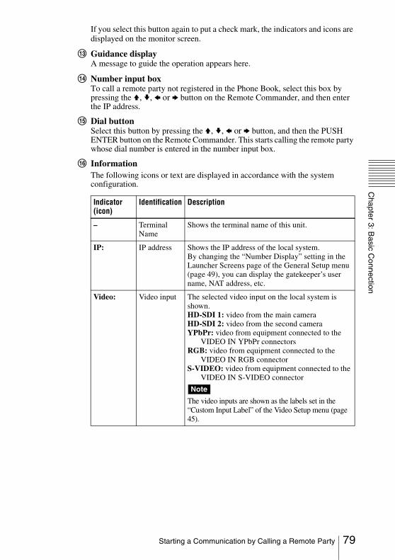
Chapter 3: B
asic Connection
If you select this button again to put a check mark, the indicators and icons are displayed on the monitor screen.
qd Guidance displayA message to guide the operation appears here.
qf Number input boxTo call a remote party not registered in the Phone Book, select this box by pressing the V, v, B or b button on the Remote Commander, and then enter the IP address.
qg Dial buttonSelect this button by pressing the V, v, B or b button, and then the PUSH ENTER button on the Remote Commander. This starts calling the remote party whose dial number is entered in the number input box.
qh InformationThe following icons or text are displayed in accordance with the system configuration.
Indicator (icon)
Identification Description
– Terminal Name
Shows the terminal name of this unit.
IP: IP address Shows the IP address of the local system.By changing the “Number Display” setting in the Launcher Screens page of the General Setup menu (page 49), you can display the gatekeeper’s user name, NAT address, etc.
Video: Video input The selected video input on the local system is shown.HD-SDI 1: video from the main cameraHD-SDI 2: video from the second cameraYPbPr: video from equipment connected to the
VIDEO IN YPbPr connectorsRGB: video from equipment connected to the
VIDEO IN RGB connectorS-VIDEO: video from equipment connected to the
VIDEO IN S-VIDEO connector
The video inputs are shown as the labels set in the “Custom Input Label” of the Video Setup menu (page 45).
Note
79Starting a Communication by Calling a Remote Party

The launcher menu is not displayed during communication or when “Launcher Display” is set to “Off”on the“Launcher Screen” page of the General Setup menu. To display the launcher menu in these cases, press the MENU button on the Remote Commander.To turn off the displayed launcher menu, press the MENU button again.
Audio: Audio input The audio input on the local system is shown according to the settings in the Audio Setup menu.When “Input Select” in the Audio Setup menu is set to “MIC”, one of the following indicators is shown to identify the microphones selected with “AUDIO IN” in the Audio Setup menu:MIC: Sound from external microphones connected
to the AUDIO IN MIC connectors.A1/A3: Sound from the PCS-A1 or PCSA-A3
microphones connected to the MIC A1/A3 jacks.
EC-MIC: Sound from the PCSA-A7 Echo Canceling Microphones connected to the MIC EC-MIC(A7) jacks.
When “Input Select” is set to “AUX”, one of the following indicators is shown to identify the external equipment selected with “AUDIO IN”:AUX1: Sound from external equipment connected
to the AUDIO IN AUX1 connectors.AUX2: Sound from external equipment connected
to the AUDIO IN AUX2 jacks.HD SDI 1: Sound from external equipment
connected to the HD-SDI 1 connector.HD SDI 2: Sound from external equipment
connected to the HD-SDI 2 connector.
When “Input Select” is set to “MIC + AUX”, the indicator, for example “A1/A3 + AUX2” is shown to indicate that both the sound from the microphones and that from the external equipment are input.
Audio level metert
Shows the audio input level.
Displaying the Launcher Menu During Communication
Indicator (icon)
Identification Description
80 Starting a Communication by Calling a Remote Party

Chapter 3: B
asic Connection
You can select one from among five ways how to call a remote party. Use an appropriate way depending on your registration status.
To call a remote party by entering their number directly
1 Press the V, v, B or b button on the Remote Commander to select the number input box in the launcher menu, and then the PUSH ENTER button.
2 Enter the remote party’s IP address using the number buttons on the Remote Commander.
3 Press the V, v, B or b button to select “Dial”, and then press the PUSH ENTER button on the Remote Commander. Or press the CONNECT/DISCONNECT ( / ) button on the Remote Commander.The system begins dialing the IP address entered in step 2. “Dialing” appears on the monitor screen.When the system connects to the remote system, the message “Session Connected” appears on the screen, and the ON LINE indicator stops blinking and lights in blue.
To call a remote party by selecting them from the Detailed Dial menu.
1 Use the V, v, B or b button on the Remote Commander to select “Detailed Dial”, then press the PUSH ENTER button, or press the CONNECT/DISCONNECT ( / ) button on the Remote Commander.The Detailed Dial menu appears on the screen.
Calling a Remote Party
Capture
Room 10A
Room 11B
Room 12A
Room 01 IP:255.255.255.255
2005.12.28 12:34
Menu
Phone Book
Detailed Dial
History
Enter the remote party number.
Dial
Number input box Dial
81Starting a Communication by Calling a Remote Party

2 Select the dial mode to be used for communication.
Use the V, v, B or b button to select “Dial Mode”, then press the PUSH ENTER button. The submenu appears. Press the V or v button to select the dial mode to be used to connect to the remote party, then press the PUSH ENTER button.
Single: Connects to the video communication system for a peer-to-peer connection.
Multipoint: Connects to the video communication system for a multipoint connection.
3 Select “Comunication Bit Rate”.Use the V, v, B or b button to select “Communication Bit Rate”, then press the PUSH ENTER button. Press the V or v button to select the bandwidth from the displayed submenu, then press the PUSH ENTER button.
Detailed Dial
CancelSaveDial
2005.12.28 12:34
SingleDial Mode
2 MbpsCommunication Bit Rate
IP
More options
Detailed Dial
CancelSaveDial
2005.12.28 12:34
SingleDial Mode
2 MbpsCommunication Bit Rate
IP
Multipoint
More options
More options
Detailed Dial
CancelSaveDial
2005.12.28 12:34
SingleDial Mode
2 MbpsCommunication Bit Rate
IP
82 Starting a Communication by Calling a Remote Party
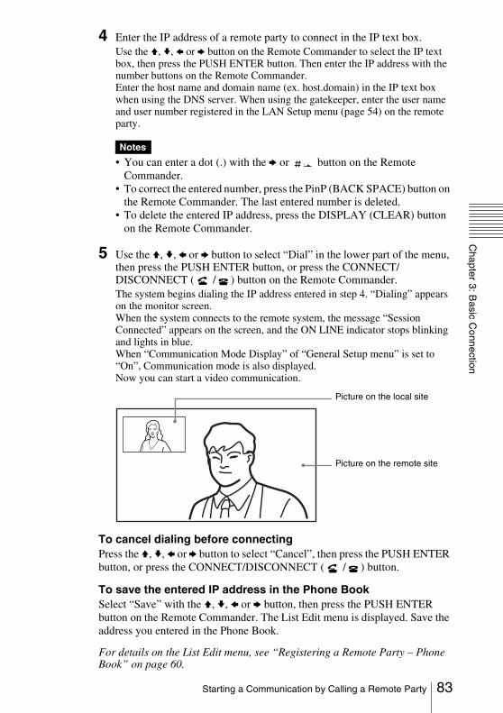
Chapter 3: B
asic Connection
4 Enter the IP address of a remote party to connect in the IP text box. Use the V, v, B or b button on the Remote Commander to select the IP text box, then press the PUSH ENTER button. Then enter the IP address with the number buttons on the Remote Commander. Enter the host name and domain name (ex. host.domain) in the IP text box when using the DNS server. When using the gatekeeper, enter the user name and user number registered in the LAN Setup menu (page 54) on the remote party.
• You can enter a dot (.) with the b or button on the Remote Commander.
• To correct the entered number, press the PinP (BACK SPACE) button on the Remote Commander. The last entered number is deleted.
• To delete the entered IP address, press the DISPLAY (CLEAR) button on the Remote Commander.
5 Use the V, v, B or b button to select “Dial” in the lower part of the menu, then press the PUSH ENTER button, or press the CONNECT/DISCONNECT ( / ) button on the Remote Commander.The system begins dialing the IP address entered in step 4. “Dialing” appears on the monitor screen.When the system connects to the remote system, the message “Session Connected” appears on the screen, and the ON LINE indicator stops blinking and lights in blue.When “Communication Mode Display” of “General Setup menu” is set to “On”, Communication mode is also displayed.Now you can start a video communication.
To cancel dialing before connectingPress the V, v, B or b button to select “Cancel”, then press the PUSH ENTER button, or press the CONNECT/DISCONNECT ( / ) button.
To save the entered IP address in the Phone BookSelect “Save” with the V, v, B or b button, then press the PUSH ENTER button on the Remote Commander. The List Edit menu is displayed. Save the address you entered in the Phone Book.
For details on the List Edit menu, see “Registering a Remote Party – Phone Book” on page 60.
Notes
Picture on the remote site
Picture on the local site
83Starting a Communication by Calling a Remote Party
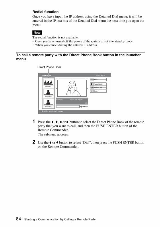
Redial functionOnce you have input the IP address using the Detailed Dial menu, it will be entered in the IP text box of the Detailed Dial menu the next time you open the menu.
The redial function is not available: • Once you have turned off the power of the system or set it to standby mode.• When you cancel dialing the entered IP address.
To call a remote party with the Direct Phone Book button in the launcher menu
1 Press the V, v, B or b button to select the Direct Phone Book of the remote party that you want to call, and then the PUSH ENTER button of the Remote Commander. The submenu appears.
2 Use the V or v button to select “Dial”, then press the PUSH ENTER button on the Remote Commander.
Note
Capture
Room 10A
Room 11B
Room 12A
Room 01 IP:255.255.255.255
2005.12.28 12:34
Menu
Phone Book
Detailed Dial
History
Enter the remote party number.
Dial
Direct Phone Book
84 Starting a Communication by Calling a Remote Party
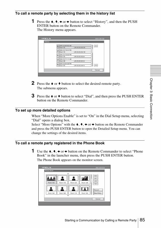
Chapter 3: B
asic Connection
To call a remote party by selecting them in the history list
1 Press the V, v, B or b button to select “History”, and then the PUSH ENTER button on the Remote Commander. The History menu appears.
2 Press the V or v button to select the desired remote party. The submenu appears.
3 Press the V or v button to select “Dial”, and then press the PUSH ENTER button on the Remote Commander.
To set up more detailed options
When “More Options Enable” is set to “On” in the Dial Setup menu, selecting “Dial” opens a dialog box.Select “More Options” with the V, v, B or b button on the Remote Commander and press the PUSH ENTER button to open the Detailed Setup menu. You can change the settings of the desired items.
To call a remote party registered in the Phone Book
1 Use the V, v, B or b button on the Remote Commander to select “Phone Book” in the launcher menu, then press the PUSH ENTER button.The Phone Book appears on the monitor screen.
History
Cancel
2005.12.28 12:34
2005.12.27 06:12 PMRoom 11B LAN 255.255.254.128
2005.12.28 09:00 AMRoom 10A LAN 255.255.255.255
2005.12.27 02:52 PMRoom 12A LAN 255.255.253.64
2005.12.27 11:11 AMRoom 12B LAN 255.255.253.32
2005.12.26 04:28 PMRoom 16A LAN 255.255.249.16
Phone Book
Cancel
2005.12.28 12:34
0-9
A-I
J-S
T-Z
New Entry
Recent
Room 10A
Room 16A
Room 11B
Room 16B
Room 12A
Room 17A
Room 12B
Room 18A
85Starting a Communication by Calling a Remote Party

If the desired remote party does not appear, see “To search for a remote party in the Phone Book” on page 87.
2 Use the V, v, B or b button on the Remote Commander to select a remote party from the Phone Book, then press the PUSH ENTER button.The submenu appears.
3 Use the V or v button on the Remote Commander to select “Dial”, then press the PUSH ENTER button, or press the CONNECT/DISCONNECT ( / ) button on the Remote Commander.The system begins dialing the party selected in step 2. “Dialing” appears on the monitor screen.When the system connects to the system on the remote site, the message “Session Connected” appears on the screen, and the ON LINE indicator stops blinking and lights in blue.Now you can start a video communication.
To cancel dialing before connectingPress the V, v, B or b button to select “Cancel”, then press the PUSH ENTER button, or press the CONNECT/DISCONNECT ( / ) button on the Remote Commander.
Phone Book
Cancel
2005.12.28 12:34
0-9
A-I
J-S
T-Z
New Entry
Recent
Room 10A
Room 16A
Room 11B
Room 16B
Room 12A
Room 17A
Room 12B
Room 18A
Dial
Edit
Copy
Delete
Cancel
Picture on the remote site
Picture on the local site
86 Starting a Communication by Calling a Remote Party

Chapter 3: B
asic Connection
To call a remote party registered in the Private Phone Book
1 Insert the “Memory Stick” that contains the Private Phone Book into the Memory Stick slot on the Communication Terminal.The Phone Book menu changes to the Private Phone Book menu.
2 Use the V, v, B or b button on the Remote Commander to select a remote party you want to call from the Private Phone Book, then press the PUSH ENTER button.
3 Select “Dial” from the submenu and press the PUSH ENTER button, or press the CONNECT/DISCONNECT ( / ) button on the Remote Commander.The system dials the selected remote party.
If the auto dialing feature of the Private Phone Book is activated, the system begins dialing when the “Memory Stick” is inserted.
To search for a remote party in the Phone Book
The Phone Book displays the list of up to eight parties on a page.When you select “Recent”, the Phone Book lists the eight names you have most recently dialed.Selecting the “0-9”, “A-I”, “J-S” or “T-Z” tab opens the submenu. When you select the desired number or letter from the corresponding submenu, the Phone Book lists up to eight party names which start with the selected number or letter.
Note
Private Phone Book
Cancel
2005.12.28 12:34
0-9
A-I
J-S
T-Z
New Entry
Recent
Jane Mary
Private Phone Book
Cancel
2005.12.28 12:34
0-9
A-I
J-S
T-Z
New Entry
Recent
Jane Mary
87Starting a Communication by Calling a Remote Party

You can also search for remote parties by pressing the number buttons (0 to 9) on the Remote Commander. Pressing the number button lists up to eight party names which start with the alphabetical letter on the number button of the Remote Commander.
Note
88 Starting a Communication by Calling a Remote Party

Chapter 3: B
asic Connection
Receiving a Call from a Remote PartyOperations for answering a call differ depending on the setting of the answer mode.
Auto answer modeThe system automatically receives a call from a remote party and you can start a communication. Although no operation is necessary to start, the picture on the local site will be displayed on the remote site screen even if you are not ready to begin.
Manual answer modeWhen there is an incoming call, the Communication Terminal rings. You need to connect the call manually before starting a communication. You can start it whenever you are ready.
• You cannot answer the call unless the power switch on the Communication Terminal is set to on.
• Make sure that the TV monitor is turned on.
For setting of the answer mode, see “Auto Answer” in the Answer menu on page 37.
To answer a call in auto answer mode
When you receive a call, the Communication Terminal rings and the message “Incoming Call” appears on the monitor screen. The system is automatically connected and the picture of the remote party is displayed on the local monitor screen and the sound is heard. The picture and sound on the local site will be enabled on the remote site at the same time.The message “Session Connected” appears on the monitor screen.You are now ready to start a communication.
Notes
Answering a Call from a Remote Party
Picture on the remote site
Picture on the local site
89Receiving a Call from a Remote Party
See pages 92 to 108 to adjust the sound and picture during a communication.
To receive a call in manual answer mode
When you receive a call, the Communication Terminal rings and the message “Incoming call. Answer?” appears on the monitor screen.
Press B or b on the Remote Commander to select “OK”, then press the PUSH ENTER button. The system is then connected. Once the connection is made, the picture of the remote party is displayed on the local monitor screen and the sound is heard. The picture and sound on the local site will be enabled on the remote site at the same time.The message “Session Connected” appears on the monitor screen.You are now ready to start a communication.
See pages 92 to 108 to adjust the sound and picture during a communication.
When you do not want to answer the callPress B or b to select “Cancel”, then press the PUSH ENTER button. Ringing stops.
To display the elapsed communication time
You can display the elapsed communication time on the monitor screen if “Time Display” in the General Setup menu is set to “On”.To turn off the indicator, set “Time Display” in the General Setup menu to “Off”. To turn off the indicator during communication with a remote party, select “Indicator” in the launcher menu and remove a check mark.
For “Time Display” setting, see “General Setup Menu” on page 48.
Note
Note
90 Receiving a Call from a Remote Party
Chapter 3: B
asic Connection
Ending the communication1 Press the CONNECT/DISCONNECT ( / ) button on the Remote
Commander.The message “Disconnect?” appears on the monitor screen.
2 Press the B or b button on the Remote Commander to select “OK”, then press the PUSH ENTER button, or press the CONNECT/DISCONNECT ( / ) button on the Remote Commander again.The system is disconnected.
The power of the Communication Terminal remains on even if the system is disconnected.
To cancel disconnection of the systemSelect “Cancel” with the B or b button, then press the PUSH ENTER button.
To register the connected remote party in the Phone Book
You can easily register the remote party who has just disconnected.If you set “Last Number Registration” in the General Setup menu to “On”, the message “Register this participant in the list?” appears after a communication with an unregistered remote party is finished. When you select “OK”, the List Edit menu appears.
If the “Last Number Registration” is set to “Off”, the message does not appear.
For “Last Number Registration” setting,“Device Setup” page of the General Setup menu on page 47.
Note
Note
91Ending the communication

Adjusting the Sound
You can adjust the volume of the sound to be received from a remote party.Press the VOLUME + button on the Remote Commander to increase the volume, VOLUME – button to decrease it. The volume level indicator appears on the monitor screen. The indicator will automatically disappear if you do not operate the buttons for a certain time.
• You need to set the volume of the TV monitor to an appropriate level first.• If feedback caused by increasing the volume occurs, decrease the volume.
You can momentarily turn off the sound to be sent to the remote party.Press the MIC ON/OFF button on the Remote Commander. The sound of the local party is not heard by the remote party. The (Mic off) indicator appears on the monitor screen.
To restore the soundPress the MIC ON/OFF button again.The indicator disappears and the sound is heard by the remote party.
Adjusting the Volume
Notes
Turning Off the Sound Momentarily – Muting Function
92 Adjusting the Sound
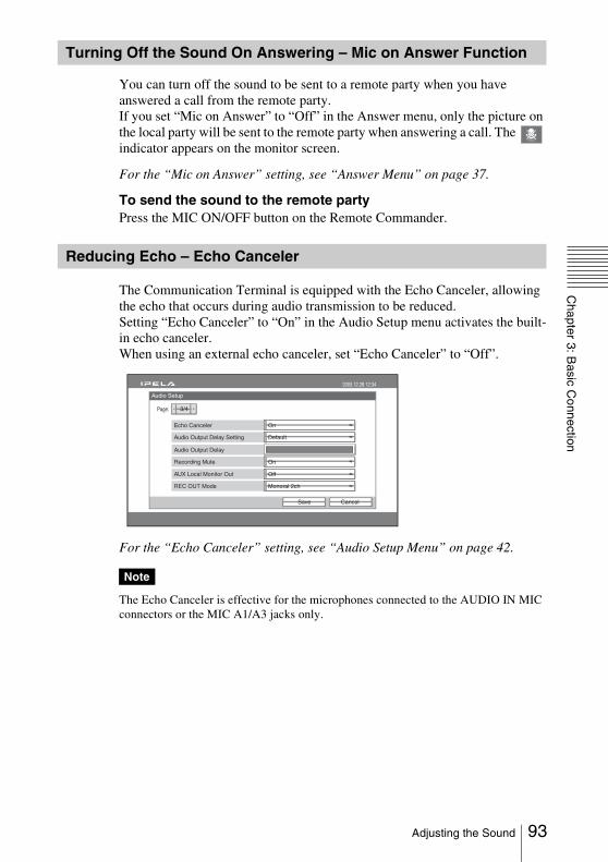
Chapter 3: B
asic Connection
You can turn off the sound to be sent to a remote party when you have answered a call from the remote party.If you set “Mic on Answer” to “Off” in the Answer menu, only the picture on the local party will be sent to the remote party when answering a call. The indicator appears on the monitor screen.
For the “Mic on Answer” setting, see “Answer Menu” on page 37.
To send the sound to the remote partyPress the MIC ON/OFF button on the Remote Commander.
The Communication Terminal is equipped with the Echo Canceler, allowing the echo that occurs during audio transmission to be reduced.Setting “Echo Canceler” to “On” in the Audio Setup menu activates the built-in echo canceler.When using an external echo canceler, set “Echo Canceler” to “Off”.
For the “Echo Canceler” setting, see “Audio Setup Menu” on page 42.
The Echo Canceler is effective for the microphones connected to the AUDIO IN MIC connectors or the MIC A1/A3 jacks only.
Turning Off the Sound On Answering – Mic on Answer Function
Reducing Echo – Echo Canceler
Note
Audio Setup
2005.12.28 12:34
3/4
Echo Canceler
Page:
Audio Output Delay
Recording Mute
CancelSave
On
Audio Output Delay Setting Default
On
AUX Local Monitor Out
REC OUT Mode
Off
Monoral 2ch
93Adjusting the Sound

Connection example for using an external echo canceler
VISCA RS-4221 2 3 4 5 6 7 8 9
VISCA RS-232C OUT
DC IN 12V
HFBK-HD1
MONITOR HD-SDI
RGB
AUX CONTROL
CAMERA CONTROL 100BASE-TX/10BASE-T(VISCA)
~ AC IN
SUB MAIN
CTRL-S
REC OUT(MIXED)AUDIO OUTR LR
AUDIO IN
VIDEO IN
S-VIDEO Y1
VIDEO OUT
Y Pb Pr
(NEAR ONLY)
Y Pb Pr2
HD-SDI HD-SDIHD-SDI
SUBCAMERA
MAINCAMERA
Pb Pr
R MIC L R
AUX 2R
MICEC-MIC(A7)
1 2
A1/A3
(PLUG IN POWER)
1(R) 2(L)
L R L
AUX 1 L L
to AUDIO IN MIC
External echo canceler
External microphone mixer
PCS-A1 Microphones(not supplied)
94 Adjusting the Sound
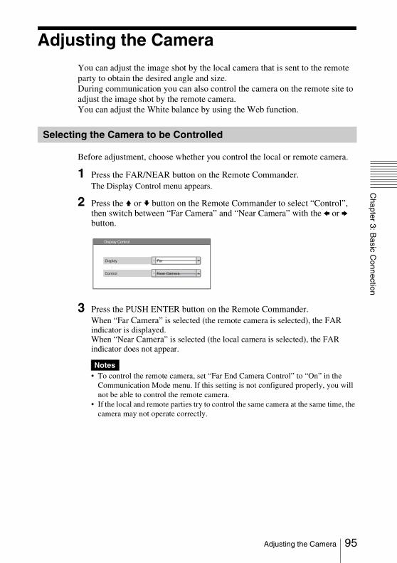
Chapter 3: B
asic Connection
Adjusting the CameraYou can adjust the image shot by the local camera that is sent to the remote party to obtain the desired angle and size.During communication you can also control the camera on the remote site to adjust the image shot by the remote camera.You can adjust the White balance by using the Web function.
Before adjustment, choose whether you control the local or remote camera.
1 Press the FAR/NEAR button on the Remote Commander.The Display Control menu appears.
2 Press the V or v button on the Remote Commander to select “Control”, then switch between “Far Camera” and “Near Camera” with the B or b button.
3 Press the PUSH ENTER button on the Remote Commander.When “Far Camera” is selected (the remote camera is selected), the FAR indicator is displayed.When “Near Camera” is selected (the local camera is selected), the FAR indicator does not appear.
• To control the remote camera, set “Far End Camera Control” to “On” in the Communication Mode menu. If this setting is not configured properly, you will not be able to control the remote camera.
• If the local and remote parties try to control the same camera at the same time, the camera may not operate correctly.
Selecting the Camera to be Controlled
Notes
Near CameraControl
FarDisplay
Display Control
95Adjusting the Camera
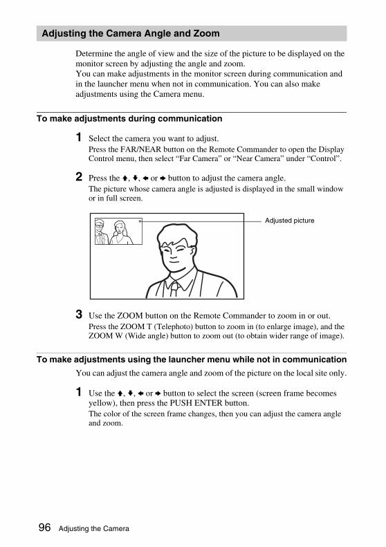
Determine the angle of view and the size of the picture to be displayed on the monitor screen by adjusting the angle and zoom.You can make adjustments in the monitor screen during communication and in the launcher menu when not in communication. You can also make adjustments using the Camera menu.
To make adjustments during communication
1 Select the camera you want to adjust.Press the FAR/NEAR button on the Remote Commander to open the Display Control menu, then select “Far Camera” or “Near Camera” under “Control”.
2 Press the V, v, B or b button to adjust the camera angle.The picture whose camera angle is adjusted is displayed in the small window or in full screen.
3 Use the ZOOM button on the Remote Commander to zoom in or out.Press the ZOOM T (Telephoto) button to zoom in (to enlarge image), and the ZOOM W (Wide angle) button to zoom out (to obtain wider range of image).
To make adjustments using the launcher menu while not in communication
You can adjust the camera angle and zoom of the picture on the local site only.
1 Use the V, v, B or b button to select the screen (screen frame becomes yellow), then press the PUSH ENTER button.The color of the screen frame changes, then you can adjust the camera angle and zoom.
Adjusting the Camera Angle and Zoom
Adjusted picture
96 Adjusting the Camera
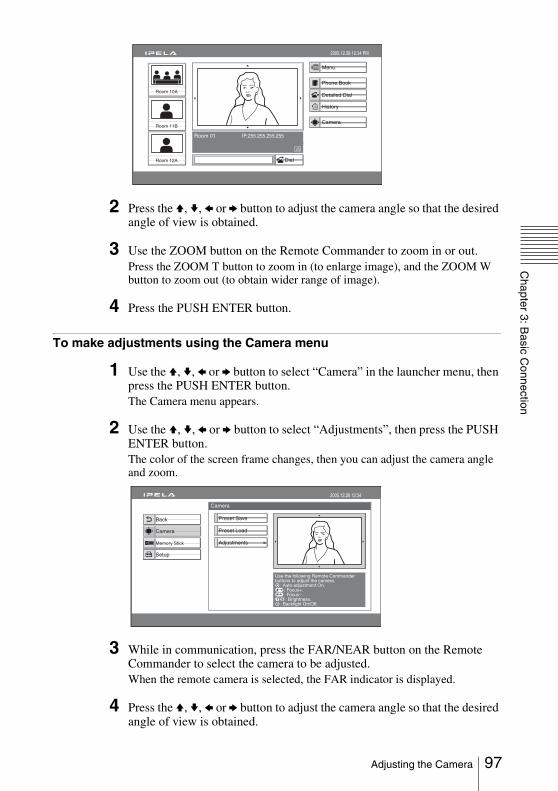
Chapter 3: B
asic Connection
2 Press the V, v, B or b button to adjust the camera angle so that the desired angle of view is obtained.
3 Use the ZOOM button on the Remote Commander to zoom in or out.Press the ZOOM T button to zoom in (to enlarge image), and the ZOOM W button to zoom out (to obtain wider range of image).
4 Press the PUSH ENTER button.
To make adjustments using the Camera menu
1 Use the V, v, B or b button to select “Camera” in the launcher menu, then press the PUSH ENTER button.The Camera menu appears.
2 Use the V, v, B or b button to select “Adjustments”, then press the PUSH ENTER button.The color of the screen frame changes, then you can adjust the camera angle and zoom.
3 While in communication, press the FAR/NEAR button on the Remote Commander to select the camera to be adjusted.When the remote camera is selected, the FAR indicator is displayed.
4 Press the V, v, B or b button to adjust the camera angle so that the desired angle of view is obtained.
Capture
Room 10A
Room 11B
Room 12A
Room 01 IP:255.255.255.255
Camera
2005.12.28 12:34 PM
Menu
Phone Book
Detailed Dial
History
Dial
Auto Track Stop
Camera
2005.12.28 12:34
Preset Save
Preset Load
Adjustments
Back
Setup
Camera
Memory Stick
Use the following Remote Commanderbuttons to adjust the camera. : Auto adjustment On. : Focus+. : Focus–. : Brightness. : Backlight On/Off.
97Adjusting the Camera
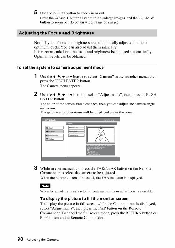
5 Use the ZOOM button to zoom in or out.Press the ZOOM T button to zoom in (to enlarge image), and the ZOOM W button to zoom out (to obtain wider range of image).
Normally, the focus and brightness are automatically adjusted to obtain optimum levels. You can also adjust them manually.It is recommended that the focus and brightness be adjusted automatically.Optimum levels can be obtained.
To set the system to camera adjustment mode
1 Use the V, v, B or b button to select “Camera” in the launcher menu, then press the PUSH ENTER button.The Camera menu appears.
2 Use the V, v, B or b button to select “Adjustments”, then press the PUSH ENTER button.The color of the screen frame changes, then you can adjust the camera angle and zoom.The guidance for operations will be displayed under the screen.
3 While in communication, press the FAR/NEAR button on the Remote Commander to select the camera to be adjusted.When the remote camera is selected, the FAR indicator is displayed.
When the remote camera is selected, only manual focus adjustment is available.
To display the picture to fill the monitor screenTo display the picture in full screen while the Camera menu is displayed, select “Adjustments”, then press the PinP button on the Remote Commander. To cancel the full screen mode, press the RETURN button or PinP button on the Remote Commander.
Adjusting the Focus and Brightness
Note
Auto Track Stop
Camera
2005.12.28 12:34
Preset Save
Preset Load
Adjustments
Back
Setup
Camera
Memory Stick
Use the following Remote Commanderbuttons to adjust the camera. : Auto adjustment On. : Focus+. : Focus–. : Brightness. : Backlight On/Off.
98 Adjusting the Camera
Chapter 3: B
asic Connection
To adjust the focus and brightness automatically
Press the number button 0 on the Remote Commander.The “Auto Camera” indicator appears and the focus and brightness are automatically adjusted.
To adjust the focus manually
Press the button on the Remote Commander repeatedly to move the focus point further away from the camera. The “Focus Far” indicator is displayed.Press the button on the Remote Commander repeatedly to move the focus point closer to the camera. The “Focus Near” indicator is displayed.
To adjust the brightness manually
Press the number button 9 on the Remote Commander repeatedly to make the picture brighter. The “Brightness +” indicator is displayed.Press the “7” button on the Remote Commander repeatedly to make the picture darker. The “Brightness –” indicator is displayed.
To shoot the picture with backlight compensation
Use backlight compensation when shooting a subject with bright background.Each time you press the number button 8, the backlight compensation is activated or deactivated. When it is activated, the “Backlight On” indicator is displayed. When it is deactivated, the “Backlight Off” indicator is displayed.
Up to six settings for camera angle and zoom can be registered in the preset memory. Once you have stored the settings, you can easily recall them to move the camera.You can preset the settings in the monitor screen while in communication, and in the launcher menu while not in communication. You can also do so using the Camera menu.
To preset the setting in the monitor screen while in communication
1 Select the camera whose camera angle and zoom setting you want to preset.Press the FAR/NEAR button on the Remote Commander to open the Display Control menu, then select “Far Camera” or “Near Camera” under “Control”.
2 Adjust the camera angle and zoom.Use the V, v, B or b button to adjust the camera angle, and ZOOM button to adjust the zoom.
Presetting the Angle and Zoom Settings
99Adjusting the Camera

3 Hold down one of the number buttons 1 to 6.The angle and zoom setting is stored in the selected number button, and the message “Registered to Preset number 1 (to 6).” appears.
To preset the setting in the launcher menu while not in communication
The settings for local camera angle and zoom can be registered in the preset memory.
1 Adjust the camera angle and zoom in the launcher menu.Use the V, v, B or b button to select the screen and press the PUSH ENTER button, then press the V, v, B or b button to adjust the angle and the ZOOM buttons to adjust the zoom.
2 Hold down one of the number buttons 1 to 6. The angle and zoom setting is stored in the selected number button, and the message “Registered to Preset number 1 (to 6).” appears.
To preset the setting using the Camera menu
1 Use the V, v, B or b button to select “Camera” in the launcher menu, then press the PUSH ENTER button.The Camera menu appears.
2 Use the V, v, B or b button on the Remote Commander to select “Preset Save”, then press the PUSH ENTER button or b button.
3 Select the preset number (1 to 6) in which you want to register with the V or v button, then press the PUSH ENTER button.The color of the screen frame changes, then you can adjust the camera angle and zoom.
4 While in communication, select the camera to be adjusted with the FAR/NEAR button on the Remote Commander.The FAR indicator is displayed on the monitor screen when the remote camera is selected.
Auto Track Stop
Camera
2005.12.28 12:34
Preset Save
Preset Load
Adjustments
Video: HD-SDI 1
Back
Setup
Camera
Memory Stick
100 Adjusting the Camera
Chapter 3: B
asic Connection
5 Adjust the angle and zoom.Use the V, v, B or b button to adjust the camera angle, and ZOOM button to adjust the zoom.
6 Press the PUSH ENTER button.The setting is registered in the selected preset number.
You can move the camera to the preset position by recalling the preset camera angle and zoom with the monitor screen displayed while in communication. You can do the same with the launcher menu displayed while not in communication. Using the Camera menu also enables movement of the camera to the preset position.
To recall the preset setting in the monitor screen while in communication
1 Select the camera which you want to move to the preset position.Press the FAR/NEAR button on the Remote Commander to open the Display Control menu, then select “Far Camera” or “Near Camera” under “Control”.
2 Press one of the number buttons 1 to 6 on the Remote Commander.The setting of the selected preset number is recalled, and the camera moves to the preset position. The message “Preset 1 (to 6) selected” appears.
To recall the preset setting in the launcher menu while not in communication
You can move the local camera to the preset position.
1 Select the screen in the launcher menu, then press the PUSH ENTER button.
2 Press one of the number buttons 1 to 6 on the Remote Commander.The setting of the selected preset number is recalled, and the camera moves to the preset position. The message “Preset 1 (to 6) selected” appears.
To recall the preset setting in the Camera menu
1 Use the V, v, B or b button to select “Camera” in the launcher menu, then press the PUSH ENTER button.
2 Use the V, v, B or b button on the Remote Commander to select “Preset Load”, then press the PUSH ENTER button or b button.
3 Press the V or v button to select the preset number (1-6) you want to recall, then press the PUSH ENTER button.
Recalling the Preset Angle and Zoom Setting
101Adjusting the Camera
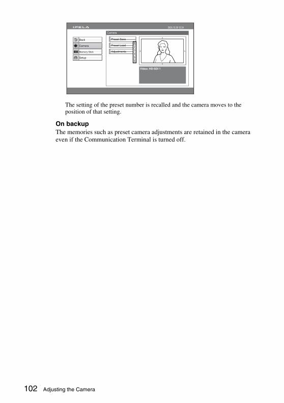
The setting of the preset number is recalled and the camera moves to the position of that setting.
On backup The memories such as preset camera adjustments are retained in the camera even if the Communication Terminal is turned off.
Auto Track Stop
Camera
2005.12.28 12:34
Preset Save
Preset Load
Adjustments
Video: HD-SDI 1
Back
Setup
Camera
Memory Stick
102 Adjusting the Camera

Chapter 3: B
asic Connection
Selecting the Input Picture and SoundThis section describes how to switch the picture displayed on the monitor screen, and how to switch the input picture and sound.
1 Press the FAR/NEAR button on the Remote Commander.The Display Control menu appears.
2 Use the V, v, B or b button on the Remote Commander to select “Near” or “Far” under “Display”.
3 Press the PUSH ENTER button on the Remote Commander.
Press the VIDEO INPUT button on the Remote Commander to select the input picture.Each time you press the button, the video input is switched and the selected video input name is displayed on the monitor screen.
HD-SDI 1: video input from the main cameraHD-SDI 2: video input from the second cameraYPbPr: video input from equipment connected to the VIDEO IN YPbPr
connectorsRGB: video input from equipment connected to the VIDEO IN RGB
connectorsS-VIDEO: video input from equipment connected to the VIDEO IN S-VIDEO
connector
Switching the Displayed Picture Between the Local and Remote Pictures
Selecting the Input Picture
Near CameraControl
FarDisplay
Display Control
Video HD-SDI 1
Audio MIC
103Selecting the Input Picture and Sound
To change the video input name displayed on the monitor screen
You can label the desired name for each video input using “Custom Input Label” in the Video Setup menu. When you switch the video input, the video input name you set is displayed on the monitor screen.
You can switch the sound sent to the remote party between the sound from the microphone and that from the connected equipment. Use “Input Select” in the Audio Setup menu.
For details on the “Input Select” setting, see the Audio Setup Menu on page 41.
Set “Link to Audio Input” to “On” in “Video Input” page of Video Setup Menu. When you switch the video input, the audio input automatically switches to the one which has been set to link to the switched video input.
For details on the “Video Input/Output”setting, see the Video Setup Menu on page 43.
Switching the Sound to Be Sent to the Remote Party
Switching Video and Audio simultaneously
104 Selecting the Input Picture and Sound
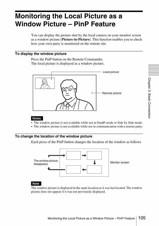
Chapter 3: B
asic Connection
Monitoring the Local Picture as a Window Picture – PinP Feature
You can display the picture shot by the local camera on your monitor screen as a window picture (Picture-in-Picture). This function enables you to check how your own party is monitored on the remote site.
To display the window picture
Press the PinP button on the Remote Commander.The local picture is displayed as a window picture.
• The window picture is not available while not in PandP mode or Side by Side mode.• The window picture is not available while not in communication with a remote party.
To change the location of the window picture
Each press of the PinP button changes the location of the window as follows:
The window picture is displayed in the same location as it was last located. The window picture does not appear if it was not previously displayed.
Notes
Note
Remote picture
Local picture
The window picture disappears. Monitor screen
105Monitoring the Local Picture as a Window Picture – PinP Feature

To display the remote picture as a window picture
Press the FAR/NEAR button on the Remote Commander to open the Display Control menu and select “Near” under “Display” when the local picture is displayed as a window picture. The remote picture is displayed as a window picture with the local picture as the main picture.
106 Monitoring the Local Picture as a Window Picture – PinP Feature

Chapter 3: B
asic Connection
Monitoring the Local and Remote Pictures at the Same Time – PandP/Side by Side Feature
You can display the local and remote pictures at the same time on the monitor screen.
To display twin pictures
Press the DISPLAY button on the Remote Commander during communication with a remote party.Each press of the button changes the display on the monitor screen as follows:
To swap the left and right pictures
Press the FAR/NEAR button on the Remote Commander to display the Display Control menu. Changing the setting under “Display” (Far or Near) swaps the left and right pictures.
Local picture
Remote picture
Remote picture
PandP (Picture-and-Picture) mode
Full screen mode
Side by Side mode
107Monitoring the Local and Remote Pictures at the Same Time – PandP/Side by Side Feature
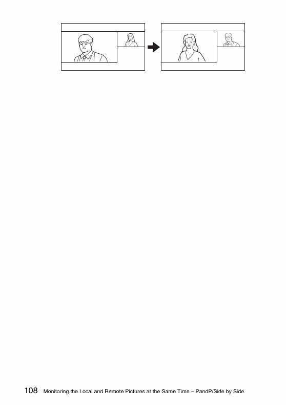
108 Monitoring the Local and Remote Pictures at the Same Time – PandP/Side by Side

Chapter 3: B
asic Connection
Capturing the ImageYou can capture the image displayed on the screen by using the Capture button on the Launcher menu and display the capturing image on the Phone Book.
• When “Capture” button is not displayed in the Launcher menu, set “Capture Button” to “On” in “Launcher Screen (Page 2/3)” of the General Setup menu (page 49).
• You cannot save still images to a “Memory Stick” using the Capture button.
To save an image displayed on the screen to a “Memory Stick”, see “Saving Still Images to a “Memory Stick”” on page 111.
Capturing Image• Only one capturing image can be saved. The last image will be overwritten
by the new capturing image.• The size of the capturing image is thumbnail size.• When the power is turned off, the capturing image will be deleted.
Capturing the Local image
1 Display the image you want to capture in the screen of the launcher menu.
For details on adjusting the camera, see “Adjusting the Camera” on page 95.
2 Press the V, v, B or b button to select “Capture”, and then the PUSH ENTER button on the Remote Commander.The image displayed on the screen is saved in the memory of this unit.
Notes
Capture
Room 10A
Room 11B
Room 12A
Room 01 IP:255.255.255.255Video:Camera(HD-SDI)Audio:MIC
Camera
Memory Stick
Capture
Reject Answer
Indicator
2005.12.28 12:34
Menu
Phone Book
Detailed Dial
History
Prepare for connection
Dial
Capture button
109Capturing the Image
Capturing the Far image
1 Display the Far image you want to capture on the screen during communication.
For details on adjusting the Far camera, see “Adjusting the Camera” on page 95.
2 Press the Menu button on the Remote Commander to display the launcher menu.
3 Press the V, v, B or b button to select “Capture”, and then the PUSH ENTER button on the Remote Commander.The Far image is saved in the memory of this unit.
110 Capturing the Image
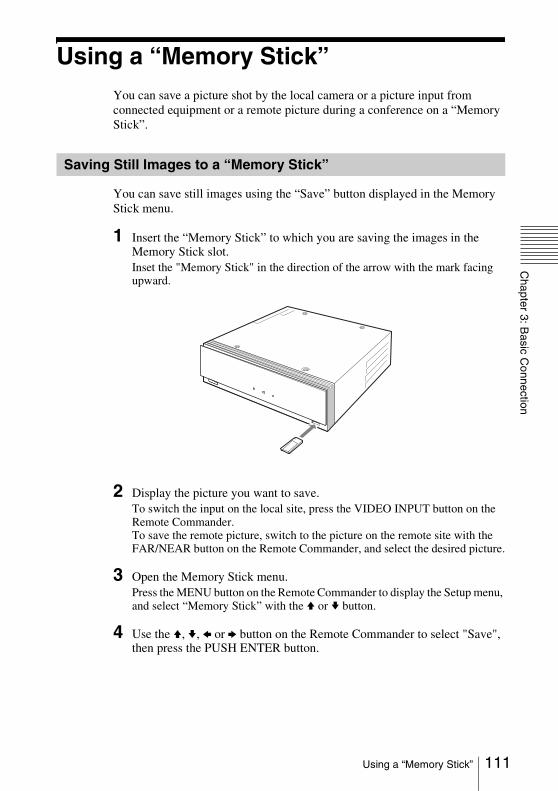
Chapter 3: B
asic Connection
Using a “Memory Stick”You can save a picture shot by the local camera or a picture input from connected equipment or a remote picture during a conference on a “Memory Stick”.
You can save still images using the “Save” button displayed in the Memory Stick menu.
1 Insert the “Memory Stick” to which you are saving the images in the Memory Stick slot.Inset the "Memory Stick" in the direction of the arrow with the mark facing upward.
2 Display the picture you want to save.To switch the input on the local site, press the VIDEO INPUT button on the Remote Commander.To save the remote picture, switch to the picture on the remote site with the FAR/NEAR button on the Remote Commander, and select the desired picture.
3 Open the Memory Stick menu.Press the MENU button on the Remote Commander to display the Setup menu, and select “Memory Stick” with the V or v button.
4 Use the V, v, B or b button on the Remote Commander to select "Save", then press the PUSH ENTER button.
Saving Still Images to a “Memory Stick”
111Using a “Memory Stick”

The selected picture is saved to the “Memory Stick” and a thumbnail is created.
Pressing the FAR/NEAR button on the Remote Commander during a videoconference switches the display between the local and remote pictures. When the remote pictures are being displayed, the FAR icon appears.
• Do not remove the “Memory Stick” until the data is completely loaded. If you do, the “Memory Stick” may be damaged or the Communication Terminal may cause a malfunction.
• A still image file is saved as a new file. It will not be overwritten.• The images inside one of the folders within the “Memory Stick” directory, from
“\DCIM\100MSDCF” to “\DCIM\109MSDCF”, will be displayed. The displayed folder goes by the following order of priority:”109MSDCF”, “108MSDCF”, “107MSDCF”, etc.
• If a still image cannot be displayed, “JPEG” appears in its place.
When the write-protect tab on the “Memory Stick” is set to “LOCK” The message “Memory Stick write-protected” appears and you cannot save the still image file.
When the memory of the “Memory Stick” is fullThe message “Memory full.” appears and you cannot save the still image file.
Image format that can be stored on a “Memory Stick”
File nameThe image file is saved as “DSCXXXXX.jpg” under the“\DCIM\100MSDCF” directory of the “Memory Stick”.
Compression formatThe Communication Terminal compresses and records the recorded image data in the JPEG (Joint Photographic Experts Group) format. The file extension is “.jpg”.
Tip
Notes
Memory Stick
2005.12.28 12:34
Format
Back
Setup
Camera
Memory Stick Save
Picture to be saved
112 Using a “Memory Stick”

Chapter 3: B
asic Connection
The Communication Terminal is not compatible with progressive JPEG format data.
To delete a still image
Display the Memory Stick menu, select the still image you want to delete, and press the PUSH ENTER button. Select “Delete” from the displayed submenu with the V or v button, then press the PUSH ENTER button. When the message “Delete File?” appears, select “OK” and press the PUSH ENTER button. The selected still image is deleted from the “Memory Stick”.
To remove the “Memory Stick”
Push the “Memory Stick” and release your finger. The “Memory Stick” will slide out a little, and you can then remove it.
• A “Memory Stick” formatted with a computer cannot be guaranteed on the Communication Terminal. Make sure to use a “Memory Stick” that has been formatted with the Communication Terminal.
• If you format a “Memory Stick”, all data, including the still images and Phone Book, will be lost.
To format a “Memory Stick”
Select “Format” in the Memory Stick menu, and the “Format a Memory Stick?” message appears. Select “OK” to format the “Memory Stick”.
When an unformatted “Memory Stick” is inserted
The “Format a Memory Stick?” message appears. Select “OK” to format the“Memory Stick”. Select “Cancel” to cancel the formatting operation.
Note
Formatting a “Memory Stick”
Notes
Memory Stick
2005.12.28 12:34
Format
Back
Setup
Camera
Memory Stick 2 SaveDelete
Cancel
113Using a “Memory Stick”
This chapter describes the various connection using the optional equipment in addition to the components contained in the PCS-HG90 Video Communication System.
To conduct a multipoint connection, see Chapter 6.
Chapter 4: Connection With Optional Equipment
114
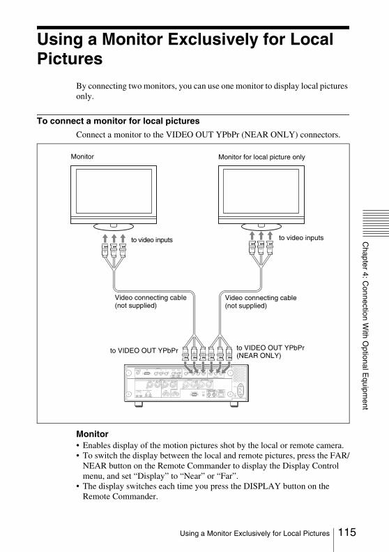
Chapter 4: C
onnection With O
ptional Equipm
ent
Using a Monitor Exclusively for Local Pictures
By connecting two monitors, you can use one monitor to display local pictures only.
To connect a monitor for local pictures
Connect a monitor to the VIDEO OUT YPbPr (NEAR ONLY) connectors.
Monitor• Enables display of the motion pictures shot by the local or remote camera.• To switch the display between the local and remote pictures, press the FAR/
NEAR button on the Remote Commander to display the Display Control menu, and set “Display” to “Near” or “Far”.
• The display switches each time you press the DISPLAY button on the Remote Commander.
RGB
AUX CONTROL
CAMERA CONTROL 100BASE-TX/10BASE-T(VISCA)
~ AC IN
SUB MAIN
CTRL-S
REC OUT(MIXED)AUDIO OUTR LR
AUDIO IN
VIDEO IN
S-VIDEO Y1
VIDEO OUT
Y Pb Pr
(NEAR ONLY)
Y Pb Pr2
HD-SDI HD-SDIHD-SDI
SUBCAMERA
MAINCAMERA
Pb Pr
R MIC L R
AUX 2R
MICEC-MIC(A7)
1 2
A1/A3
(PLUG IN POWER)
1(R) 2(L)
L R L
AUX 1 L L
Monitor
to VIDEO OUT YPbPr
Monitor for local picture only
to video inputs to video inputs
to VIDEO OUT YPbPr (NEAR ONLY)
Video connecting cable (not supplied)
Video connecting cable (not supplied)
115Using a Monitor Exclusively for Local Pictures
Monitor for local pictures onlyEnables display of the local pictures only.
To display the picture as a small window
Press the PinP button on the Remote Commander during communication. The picture appears as a window picture on the monitor.
• You can display a window picture only in full screen mode (page 107).• You cannot display a window picture on a monitor for local picture only.
Notes
116 Using a Monitor Exclusively for Local Pictures
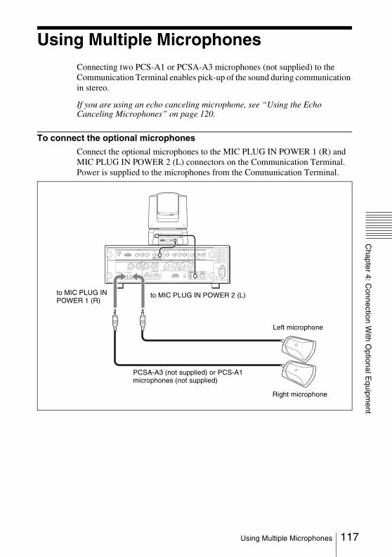
Chapter 4: C
onnection With O
ptional Equipm
ent
Using Multiple MicrophonesConnecting two PCS-A1 or PCSA-A3 microphones (not supplied) to the Communication Terminal enables pick-up of the sound during communication in stereo.
If you are using an echo canceling microphone, see “Using the Echo Canceling Microphones” on page 120.
To connect the optional microphones
Connect the optional microphones to the MIC PLUG IN POWER 1 (R) and MIC PLUG IN POWER 2 (L) connectors on the Communication Terminal. Power is supplied to the microphones from the Communication Terminal.
S-VIDEO
VISCA RS-4221 2 3 4 5 6 7 8 9
VISCA RS-232C OUT
DC IN 12V
HFBK-HD1
MONITOR HD-SDI
RGB
AUX CONTROL
CAMERA CONTROL 100BASE-TX/10BASE-T(VISCA)
~ AC IN
SUB MAIN
CTRL-S
REC OUT(MIXED)AUDIO OUTR LR
AUDIO IN
VIDEO IN
Y1
VIDEO OUT
Y Pb Pr
(NEAR ONLY)
Y Pb Pr2
HD-SDI HD-SDIHD-SDI
SUBCAMERA
MAINCAMERA
Pb Pr
R MIC L R
AUX 2R
MICEC-MIC(A7)
1 2
A1/A3
(PLUG IN POWER)
1(R) 2(L)
L R L
AUX 1 L L
to MIC PLUG IN POWER 2 (L)to MIC PLUG IN POWER 1 (R)
PCSA-A3 (not supplied) or PCS-A1 microphones (not supplied)
Left microphone
Right microphone
117Using Multiple Microphones
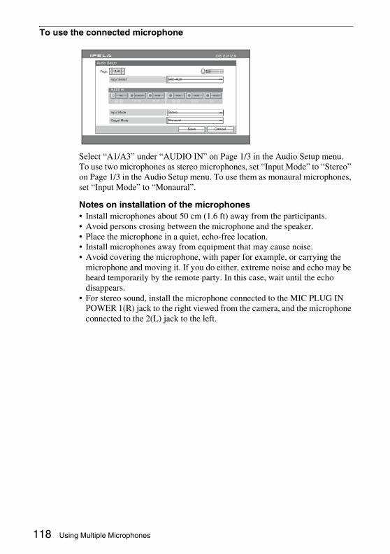
To use the connected microphone
Select “A1/A3” under “AUDIO IN” on Page 1/3 in the Audio Setup menu.To use two microphones as stereo microphones, set “Input Mode” to “Stereo” on Page 1/3 in the Audio Setup menu. To use them as monaural microphones, set “Input Mode” to “Monaural”.
Notes on installation of the microphones• Install microphones about 50 cm (1.6 ft) away from the participants.• Avoid persons crosing between the microphone and the speaker.• Place the microphone in a quiet, echo-free location.• Install microphones away from equipment that may cause noise.• Avoid covering the microphone, with paper for example, or carrying the
microphone and moving it. If you do either, extreme noise and echo may be heard temporarily by the remote party. In this case, wait until the echo disappears.
• For stereo sound, install the microphone connected to the MIC PLUG IN POWER 1(R) jack to the right viewed from the camera, and the microphone connected to the 2(L) jack to the left.
L
R
Audio Setup
2005.12.28 12:34
CancelSave
1/4Page:
Input Select
AUDIO IN
MIC+AUX
Input Mode Stereo
Output Mode Monaural
AUX2AUX1A1/A3EC-MIC(A7)MIC HD-SDI
118 Using Multiple Microphones
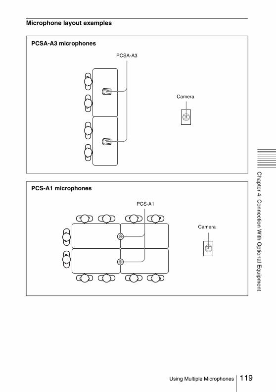
Chapter 4: C
onnection With O
ptional Equipm
ent
Microphone layout examplesPCSA-A3
PCSA-A3 microphones
Camera
PCS-A1
Camera
PCS-A1 microphones
119Using Multiple Microphones

Using the Echo Canceling MicrophonesYou can connect multiple PCSA-A7 Echo Canceling Microphones (optional) to conduct a multi-participant communication.PCSA-A7 microphones have the following characteristics:• A built-in echo canceler• Noise reduction• High quality sound• Several PCSA-A7 microphones can be connected in cascade without
reducing sound quality.
The PCSA-A7 Echo Canceling Microphones support monaural audio only and cannot pick up sound in stereo.
To connect the PCSA-A7 microphones
Connect the PCSA-A7 microphones to the MIC EC-MIC (A7) 1 and EC-MIC (A7) 2 connectors of the Communication Terminal. Power to the microphones is supplied by the Communication Terminal.
Note
S-VIDEO
VISCA RS-4221 2 3 4 5 6 7 8 9
VISCA RS-232C OUT
DC IN 12V
HFBK-HD1
MONITOR HD-SDI
RGB
AUX CONTROL
CAMERA CONTROL 100BASE-TX/10BASE-T(VISCA)
~ AC IN
SUB MAIN
CTRL-S
REC OUT(MIXED)AUDIO OUTR LR
AUDIO IN
VIDEO IN
Y1
VIDEO OUT
Y Pb Pr
(NEAR ONLY)
Y Pb Pr2
HD-SDI HD-SDIHD-SDI
SUBCAMERA
MAINCAMERA
Pb Pr
R MIC L R
AUX 2R
MICEC-MIC(A7)
1 2
A1/A3
(PLUG IN POWER)
1(R) 2(L)
L R L
AUX 1 L L
to EC-MIC (A7) 2to EC-MIC (A7) 1
PCSA-A7 Echo Canceling Microphones (PCSA-A7P4: 4-piece set)
120 Using the Echo Canceling Microphones
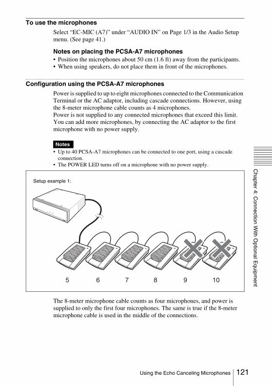
Chapter 4: C
onnection With O
ptional Equipm
ent
To use the microphonesSelect “EC-MIC (A7)” under “AUDIO IN” on Page 1/3 in the Audio Setup menu. (See page 41.)
Notes on placing the PCSA-A7 microphones• Position the microphones about 50 cm (1.6 ft) away from the participants.• When using speakers, do not place them in front of the microphones.
Configuration using the PCSA-A7 microphones
Power is supplied to up to eight microphones connected to the Communication Terminal or the AC adaptor, including cascade connections. However, using the 8-meter microphone cable counts as 4 microphones.Power is not supplied to any connected microphones that exceed this limit. You can add more microphones, by connecting the AC adaptor to the first microphone with no power supply.
• Up to 40 PCSA-A7 microphones can be connected to one port, using a cascade connection.
• The POWER LED turns off on a microphone with no power supply.
The 8-meter microphone cable counts as four microphones, and power is supplied to only the first four microphones. The same is true if the 8-meter microphone cable is used in the middle of the connections.
Notes
5 6 7 8 9 10
Setup example 1:
121Using the Echo Canceling Microphones
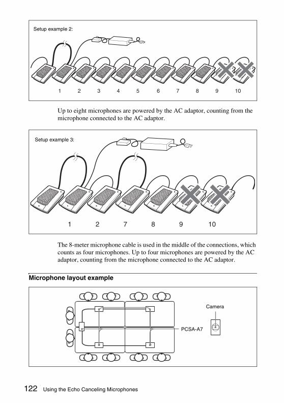
Up to eight microphones are powered by the AC adaptor, counting from the microphone connected to the AC adaptor.
The 8-meter microphone cable is used in the middle of the connections, which counts as four microphones. Up to four microphones are powered by the AC adaptor, counting from the microphone connected to the AC adaptor.
Microphone layout example
1 2 3 4 5 6 7 8 9 10
Setup example 2:
1 2 7 8 9 10
Setup example 3:
Camera
PCSA-A7
122 Using the Echo Canceling Microphones
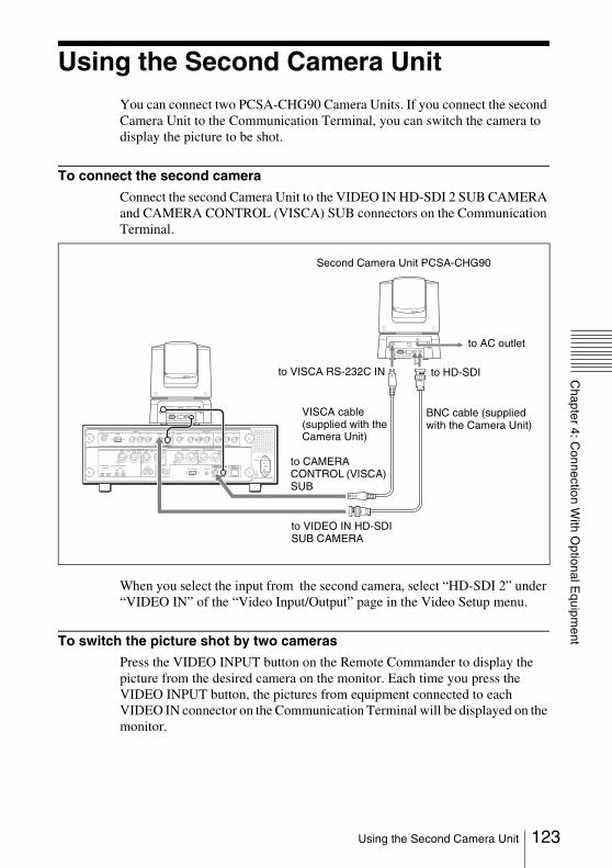
Chapter 4: C
onnection With O
ptional Equipm
ent
Using the Second Camera UnitYou can connect two PCSA-CHG90 Camera Units. If you connect the second Camera Unit to the Communication Terminal, you can switch the camera to display the picture to be shot.
To connect the second camera
Connect the second Camera Unit to the VIDEO IN HD-SDI 2 SUB CAMERA and CAMERA CONTROL (VISCA) SUB connectors on the Communication Terminal.
When you select the input from the second camera, select “HD-SDI 2” under “VIDEO IN” of the “Video Input/Output” page in the Video Setup menu.
To switch the picture shot by two cameras
Press the VIDEO INPUT button on the Remote Commander to display the picture from the desired camera on the monitor. Each time you press the VIDEO INPUT button, the pictures from equipment connected to each VIDEO IN connector on the Communication Terminal will be displayed on the monitor.
S-VIDEO
VISCA RS-4221 2 3 4 5 6 7 8 9
VISCA RS-232C OUT
DC IN 12V
HFBK-HD1
MONITOR HD-SDI
VISCA RS-4221 2 3 4 5 6 7 8 9
VISCA RS-232C OUT
DC IN 12V
HFBK-HD1
MONITOR HD-SDI
RGB
AUX CONTROL
CAMERA CONTROL 100BASE-TX/10BASE-T(VISCA)
~ AC IN
SUB MAIN
CTRL-S
REC OUT(MIXED)AUDIO OUTR LR
AUDIO IN
VIDEO IN
Y1
VIDEO OUT
Y Pb Pr
(NEAR ONLY)
Y Pb Pr2
HD-SDI HD-SDIHD-SDI
SUBCAMERA
MAINCAMERA
Pb Pr
R MIC L R
AUX 2R
MICEC-MIC(A7)
1 2
A1/A3
(PLUG IN POWER)
1(R) 2(L)
L R L
AUX 1 L L
to AC outlet
Second Camera Unit PCSA-CHG90
to VIDEO IN HD-SDI SUB CAMERA
to CAMERA CONTROL (VISCA) SUB
to HD-SDIto VISCA RS-232C IN
VISCA cable (supplied with the Camera Unit)
BNC cable (supplied with the Camera Unit)
123Using the Second Camera Unit
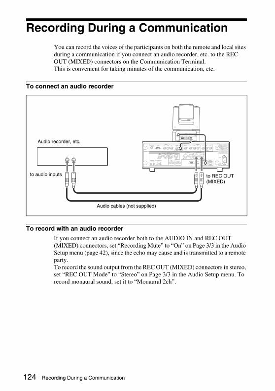
Recording During a CommunicationYou can record the voices of the participants on both the remote and local sites during a communication if you connect an audio recorder, etc. to the REC OUT (MIXED) connectors on the Communication Terminal.This is convenient for taking minutes of the communication, etc.
To connect an audio recorder
To record with an audio recorder
If you connect an audio recorder both to the AUDIO IN and REC OUT (MIXED) connectors, set “Recording Mute” to “On” on Page 3/3 in the Audio Setup menu (page 42), since the echo may cause and is transmitted to a remote party.To record the sound output from the REC OUT (MIXED) connectors in stereo, set “REC OUT Mode” to “Stereo” on Page 3/3 in the Audio Setup menu. To record monaural sound, set it to “Monaural 2ch”.
S-VIDEO
VISCA RS-4221 2 3 4 5 6 7 8 9
VISCA RS-232C OUT
DC IN 12V
HFBK-HD1
MONITOR HD-SDI
RGB
AUX CONTROL
CAMERA CONTROL 100BASE-TX/10BASE-T(VISCA)
~ AC IN
SUB MAIN
CTRL-S
REC OUT(MIXED)AUDIO OUTR LR
AUDIO IN
VIDEO IN
Y1
VIDEO OUT
Y Pb Pr
(NEAR ONLY)
Y Pb Pr2
HD-SDI HD-SDIHD-SDI
SUBCAMERA
MAINCAMERA
Pb Pr
R MIC L R
AUX 2R
MICEC-MIC(A7)
1 2
A1/A3
(PLUG IN POWER)
1(R) 2(L)
L R L
AUX 1 L L
to audio inputs
Audio recorder, etc.
Audio cables (not supplied)
to REC OUT (MIXED)
124 Recording During a Communication

Chapter 4: C
onnection With O
ptional Equipm
ent
Sending Audio/Video from the External Equipment to a Remote Party
The Communication Terminal allows you to send the picture and sound output from the connected equipment such as a VCR to the remote party.
To connect the video equipment for input
VISCA RS-4221 2 3 4 5 6 7 8 9
VISCA RS-232C OUT
DC IN 12V
HFBK-HD1
MONITOR HD-SDI
RGB
AUX CONTROL
CAMERA CONTROL 100BASE-TX/10BASE-T(VISCA)
~ AC IN
SUB MAIN
CTRL-S
REC OUT(MIXED)AUDIO OUTR LR
AUDIO IN
VIDEO IN
S-VIDEO Y1
VIDEO OUT
Y Pb Pr
(NEAR ONLY)
Y Pb Pr2
HD-SDI HD-SDIHD-SDI
SUBCAMERA
MAINCAMERA
Pb Pr
R MIC L R
AUX 2R
MICEC-MIC(A7)
1 2
A1/A3
(PLUG IN POWER)
1(R) 2(L)
L R L
AUX 1 L L
VCR, etc.
to RGB output
Computer, etc.
to VIDEO IN S-VIDEO
to audio outputs
to AUDIO IN AUX 1
S-video connecting cable (not supplied)
to VIDEO IN YPbPr
to video outputs (YPbPr)
Audio connecting cable (not supplied)
to S-video output
DVD player, etc.
to AUDIO IN AUX2
to VIDEO IN RGB
to audio outputs
125Sending Audio/Video from the External Equipment to a Remote Party

To input audio/video from external equipment
To input videoPress the VIDEO INPUT button on the Remote Commander to select the video you want to input. Each press of the button changes the video input from equipment connected to each VIDEO IN connector.The selected input is displayed upper left on the monitor screen.HD-SDI 1: video input from main cameraHD-SDI 2: video input from second cameraYPbPr: video input from equipment connected to the VIDEO IN YPbPr
connectorsRGB: video input from equipment connected to the VIDEO IN RGB
connectorS-Video: video input from equipment connected to the VIDEO IN S-VIDEO
connector
To switch to RGB input from a computer by pressing one buttonOne press of the PRESENTATION button on the Remote Commander switches to the RGB picture (the picture from a computer connected to the VIDEO IN RGB connector), etc. during communication.The following pictures can be displayed depending on the setting of “Presentation Screen” on the “Other Settings (Page 2/2)” screen of the Video Setup menu.Full Screen: The RGB picture is displayed in Full Screen mode.PandP: The RGB picture and the HD-SDI 1, HD-SDI 2 or S-Video picture are
displayed in PandP mode.Side by Side: The RGB picture and the HD-SDI 1, HD-SDI 2 or S-Video
picture are displayed in Side by Side mode.
PandP mode
Video HD-SDI 1
Audio MIC
RGB picture HD-SDI 1, HD-SDI 2 or S-Video picture
126 Sending Audio/Video from the External Equipment to a Remote Party

Chapter 4: C
onnection With O
ptional Equipm
ent
Side by Side modeIn PandP or Side by Side mode, the left picture is fixed to the RGB picture, and the right picture can be switched by pressing the PRESENTATION button.
To input audioSet “Input Select” to “AUX” or “MIC + AUX” on Page 1/3 of the Audio Setup menu. (See page 41.)When set to “AUX”, the sound from the external equipment is input and the sound from microphones is deactivated. When set to “MIC + AUX”, both sounds are input.To switch the audio input from external equipment connected to the AUDIO IN AUX1 connectors, AUDIO IN AUX2 jacks, HD SDI1 connector or HD SDI2 connector, select “AUX1”, “AUX2” or “HD SDI” under “AUDIO IN” on Page 1/3 of the Audio Setup menu. (See page 41.)The selected input is displayed upper left on the monitor screen.
To Switch Input Video and Input Audio simultaneously
Set “Link to Audio Input” to “On” on “Video Input” page of Video Setup Menu (page 43) so as to link the audio you want to switch simultaneously with the video input.When the video input is switched, the audio input is automatically switched to the one linked to the video input.
RGB picture HD-SDI 1, HD-SDI 2 or S-Video picture
127Sending Audio/Video from the External Equipment to a Remote Party
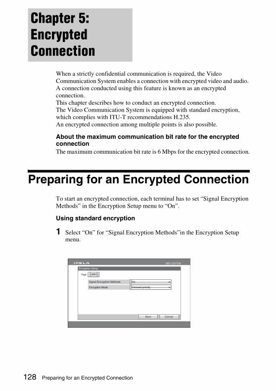
When a strictly confidential communication is required, the Video Communication System enables a connection with encrypted video and audio. A connection conducted using this feature is known as an encrypted connection.This chapter describes how to conduct an encrypted connection.The Video Communication System is equipped with standard encryption, which complies with ITU-T recommendations H.235.An encrypted connection among multiple points is also possible.
About the maximum communication bit rate for the encrypted connection The maximum communication bit rate is 6 Mbps for the encrypted connection.
Preparing for an Encrypted ConnectionTo start an encrypted connection, each terminal has to set “Signal Encryption Methods” in the Encryption Setup menu to “On”.
Using standard encryption
1 Select “On” for “Signal Encryption Methods”in the Encryption Setup menu.
Chapter 5: Encrypted Connection
Encryption Setup
2005.12.28 12:34
1/1
Signal Encryption Methods
:
CancelSave
On
Connect priorityEncryption Mode
Page
128 Preparing for an Encrypted Connection

Chapter 5: E
ncrypted Connection
2 Select an encryption mode.
Connect priorityConnects with encryption to a remote party with standard encrypted connection enabled. Connects without encryption to parties unable to connect with standard encryption or parties with encryption set to off.
Encrypt priorityConnects only to remote parties with standard encrypted connection enabled.
ON LINE POWER LAN ALERT ON LINE POWER LAN ALERT
ON LINE POWER LAN ALERT ON LINE POWER LAN ALERT
Connect with encryption
Standard encryption connection available
Standard encryption connection available
Connect without encryption
Standard encryption connection available
Standard encryption connection unavailable
ON LINE POWER LAN ALERT ON LINE POWER LAN ALERT
ON LINE POWER LAN ALERT ON LINE POWER LAN ALERT
Connect with encryption
Standard encryption connection available
Standard encryption connection availableDo not connect
Standard encryption connection available
Standard encryption connection unavailable
129Preparing for an Encrypted Connection
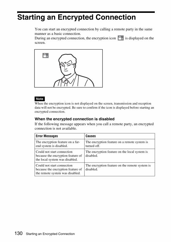
Starting an Encrypted ConnectionYou can start an encrypted connection by calling a remote party in the same manner as a basic connection.During an encrypted connection, the encryption icon is displayed on the screen.
When the encryption icon is not displayed on the screen, transmission and reception data will not be encrypted. Be sure to confirm if the icon is displayed before starting an encrypted connection.
When the encrypted connection is disabledIf the following message appears when you call a remote party, an encrypted connection is not available.
Note
Error Messages Causes
The encryption feature on a far-end system is disabled.
The encryption feature on a remote system is turned off.
Could not start connection because the encryption feature of the local system was disabled.
The encryption feature on the local system is disabled.
Could not start connection because the encryption feature of the remote system was disabled.
The encryption feature on the remote system is disabled.
H
H
130 Starting an Encrypted Connection
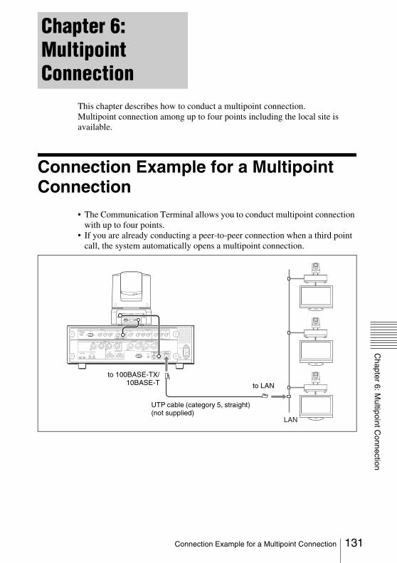
Chapter 6: M
ultipoint Connection
This chapter describes how to conduct a multipoint connection. Multipoint connection among up to four points including the local site is available.
Connection Example for a Multipoint Connection
• The Communication Terminal allows you to conduct multipoint connection with up to four points.
• If you are already conducting a peer-to-peer connection when a third point call, the system automatically opens a multipoint connection.
Chapter 6: Multipoint Connection
VISCA RS-4221 2 3 4 5 6 7 8 9
VISCA RS-232C OUT
DC IN 12V
HFBK-HD1
MONITOR HD-SDI
RGB
AUX CONTROL
CAMERA CONTROL 100BASE-TX/10BASE-T(VISCA)
~ AC IN
SUB MAIN
CTRL-S
REC OUT(MIXED)AUDIO OUTR LR
AUDIO IN
VIDEO IN
S-VIDEO Y1
VIDEO OUT
Y Pb Pr
(NEAR ONLY)
Y Pb Pr2
HD-SDI HD-SDIHD-SDI
SUBCAMERA
MAINCAMERA
Pb Pr
R MIC L R
AUX 2R
MICEC-MIC(A7)
1 2
A1/A3
(PLUG IN POWER)
1(R) 2(L)
L R L
AUX 1 L L
LAN
to 100BASE-TX/10BASE-T
UTP cable (category 5, straight) (not supplied)
to LAN
131Connection Example for a Multipoint Connection
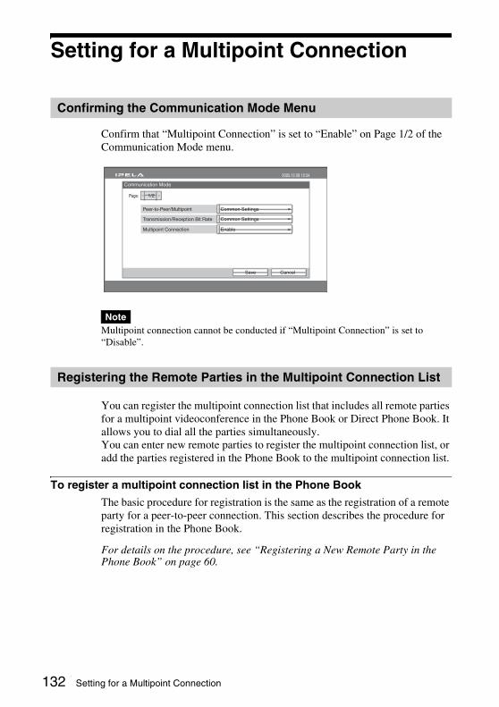
Setting for a Multipoint Connection
Confirm that “Multipoint Connection” is set to “Enable” on Page 1/2 of the Communication Mode menu.
Multipoint connection cannot be conducted if “Multipoint Connection” is set to “Disable”.
You can register the multipoint connection list that includes all remote parties for a multipoint videoconference in the Phone Book or Direct Phone Book. It allows you to dial all the parties simultaneously.You can enter new remote parties to register the multipoint connection list, or add the parties registered in the Phone Book to the multipoint connection list.
To register a multipoint connection list in the Phone Book
The basic procedure for registration is the same as the registration of a remote party for a peer-to-peer connection. This section describes the procedure for registration in the Phone Book.
For details on the procedure, see “Registering a New Remote Party in the Phone Book” on page 60.
Confirming the Communication Mode Menu
Note
Registering the Remote Parties in the Multipoint Connection List
Communication Mode
CancelSave
2005.12.28 12:34
Common Settings
1/2
Peer-to-Peer/Multipoint
Page:
Common SettingsTransmission/Reception Bit Rate
EnableMultipoint Connection
132 Setting for a Multipoint Connection

Chapter 6: M
ultipoint Connection
1 Select “New Entry” in the Phone Book menu to display the List Edit menu, then enter the name of the multipoint connection list in the Index text box.
2 Select “Multipoint” under “Dial Mode”.
3 Select the multipoint icon or a still image stored in “Memory Stick” to be displayed in the Phone Book.The multipoint icon is shown as “ ”.
4 Set up the line data of the remote parties.
1 Enter the IP addresses of all the parties for the multipoint connection in text boxes A to C.
2 Select the Communication Bit Rate on a point in “Communication Bit Rate”.
For details on the setups, see step 5 in “Registering a New Remote Party in the Phone Book” on page 60.
MULTI LIST
List Edit
CancelSaveMore Options
2005.12.28 12:34
IP
SingleIndex Dial Mode
2 Mbps
Communication Bit Rate
MULTI LIST
List Edit
CancelSaveMore Options
2005.12.28 12:34
MultipointIndex Dial Mode
2 Mbps
Communication Bit Rate
A
B
C
MULTI LIST
List Edit
CancelSaveMore Options
2005.12.28 12:34
MultipointIndex Dial Mode
2 Mbps
Communication Bit Rate
A 123.123.123.1
123.123.123.2
123.123.123.3
B
C
133Setting for a Multipoint Connection
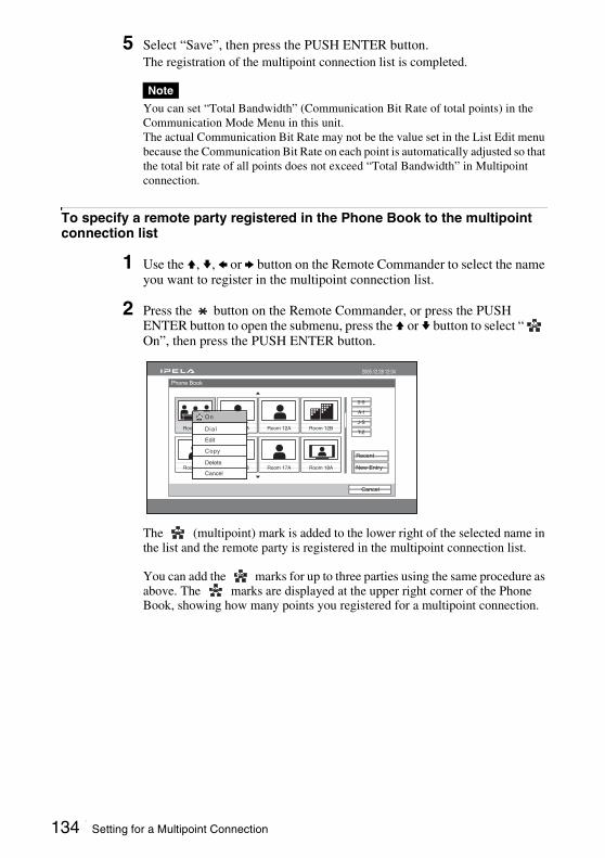
5 Select “Save”, then press the PUSH ENTER button.The registration of the multipoint connection list is completed.
You can set “Total Bandwidth” (Communication Bit Rate of total points) in the Communication Mode Menu in this unit.The actual Communication Bit Rate may not be the value set in the List Edit menu because the Communication Bit Rate on each point is automatically adjusted so that the total bit rate of all points does not exceed “Total Bandwidth” in Multipoint connection.
To specify a remote party registered in the Phone Book to the multipoint connection list
1 Use the V, v, B or b button on the Remote Commander to select the name you want to register in the multipoint connection list.
2 Press the button on the Remote Commander, or press the PUSH ENTER button to open the submenu, press the V or v button to select “ On”, then press the PUSH ENTER button.
The (multipoint) mark is added to the lower right of the selected name in the list and the remote party is registered in the multipoint connection list.
You can add the marks for up to three parties using the same procedure as above. The marks are displayed at the upper right corner of the Phone Book, showing how many points you registered for a multipoint connection.
Note
Phone Book
Cancel
2005.12.28 12:34
0-9
A-I
J-S
T-Z
New Entry
Recent
Room 10A
Room 16A
Room 11B
Room 16B
Room 12A
Room 17A
Room 12B
Room 18A
Dial
On
Edit
Copy
Delete
Cancel
134 Setting for a Multipoint Connection

Chapter 6: M
ultipoint Connection
To delete the mark from the name list, press the button again, or press the PUSH ENTER button to open the submenu, press the V or v button to select “ Off”, then press the PUSH ENTER button.
3 Select one of the remote parties with the mark, then press the PUSH ENTER button.
4 Press the V or v button to select “ Edit” from the submenu, then press the PUSH ENTER button.The List Edit menu appears. All the IP addresses of the parties marked with are entered in the number text boxes.
5 Enter the name of the multipoint connection list in the Index text box.
6 Select “Save”, then press the PUSH ENTER button.The registration of the multipoint connection list is completed.
Note
Phone Book
Cancel
2005.12.28 12:34
0-9
A-I
J-S
T-Z
New Entry
Recent
Room 10A
Room 16A
Room 11B
Room 16B
Room 12A
Room 17A
Room 12B
Room 18A
Number of registered pointsMultipoint mark
MULTI LIST
List Edit
CancelSaveMore Options
2005.12.28 12:34
MultipointIndex Dial Mode
2 Mbps
Communication Bit Rate
A 123.123.123.1
123.123.123.2
123.123.123.3
B
C
135Setting for a Multipoint Connection

Starting a Multipoint Connection
To call remote parties registered in the multipoint connection lists
1 Select the multipoint connection list registered in the Phone Book or Direct Phone Book.The multipoint connection lists are marked with “ ”.
2 Press the CONNECT/DISCONNECT ( / ) button on the Remote Commander, or press the PUSH ENTER button to display the submenu, press the V or v button to select “ Dial”, then press the PUSH ENTER button.
The system begins dialing the numbers of the remote parties registered in the multipoint connection list. “Dialing” appears on the monitor screen.When the system connects to all the remote points, the message “Session Connected” appears on the screen, and the ON LINE indicator stops blinking and lights in blue.
To call remote parties by selecting from the Phone Book or Direct Phone Book
1 Select a remote party to which you want to connect for a multipoint connection from the Phone Book or Direct Phone Book.
2 Press the button on the Remote Commander, or press the PUSH ENTER button to open the submenu, press the V or v button to select “ On”, then press the PUSH ENTER button.
Calling Remote Parties
Phone Book
Cancel
2005.12.28 12:34
0-9
A-I
J-S
T-Z
New Entry
Recent
Room 10A
Room 16A
Room 11B
Room 16B
Room 12A
Room 17A
Room 12B
Room 18A
Dial
On
Edit
Copy
Delete
Cancel
136 Starting a Multipoint Connection
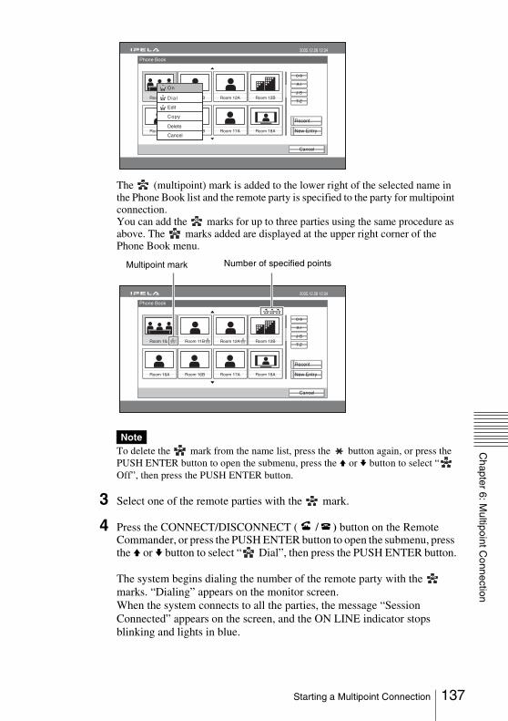
Chapter 6: M
ultipoint Connection
The (multipoint) mark is added to the lower right of the selected name in the Phone Book list and the remote party is specified to the party for multipoint connection.You can add the marks for up to three parties using the same procedure as above. The marks added are displayed at the upper right corner of the Phone Book menu.
To delete the mark from the name list, press the button again, or press the PUSH ENTER button to open the submenu, press the V or v button to select “ Off”, then press the PUSH ENTER button.
3 Select one of the remote parties with the mark.
4 Press the CONNECT/DISCONNECT ( / ) button on the Remote Commander, or press the PUSH ENTER button to open the submenu, press the V or v button to select “ Dial”, then press the PUSH ENTER button.
The system begins dialing the number of the remote party with the marks. “Dialing” appears on the monitor screen.When the system connects to all the parties, the message “Session Connected” appears on the screen, and the ON LINE indicator stops blinking and lights in blue.
Note
Phone Book
Cancel
2005.12.28 12:34
0-9
A-I
J-S
T-Z
New Entry
Recent
Room 10A
Room 16A
Room 11B
Room 16B
Room 12A
Room 17A
Room 12B
Room 18A
Dial
On
Edit
Copy
Delete
Cancel
Phone Book
Cancel
2005.12.28 12:34
0-9
A-I
J-S
T-Z
New Entry
Recent
Room 10A
Room 16A
Room 11B
Room 16B
Room 12A
Room 17A
Room 12B
Room 18A
Number of specified pointsMultipoint mark
137Starting a Multipoint Connection
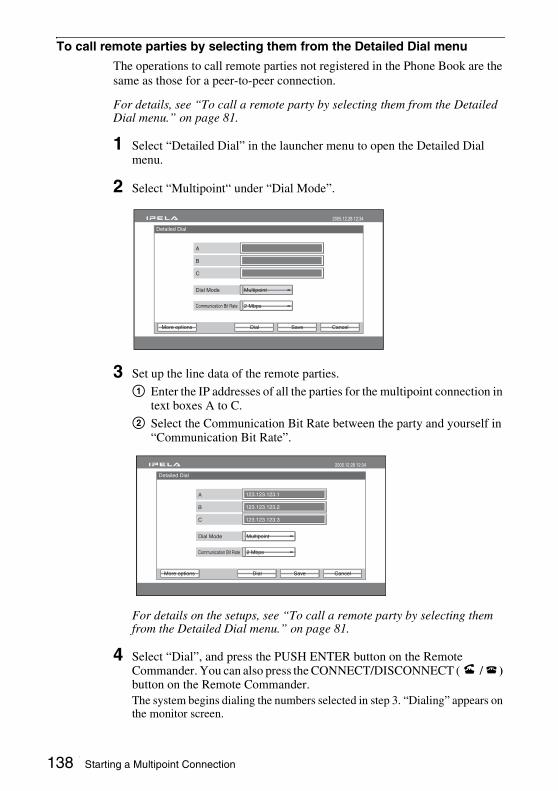
To call remote parties by selecting them from the Detailed Dial menu
The operations to call remote parties not registered in the Phone Book are the same as those for a peer-to-peer connection.
For details, see “To call a remote party by selecting them from the Detailed Dial menu.” on page 81.
1 Select “Detailed Dial” in the launcher menu to open the Detailed Dial menu.
2 Select “Multipoint“ under “Dial Mode”.
3 Set up the line data of the remote parties.
1 Enter the IP addresses of all the parties for the multipoint connection in text boxes A to C.
2 Select the Communication Bit Rate between the party and yourself in “Communication Bit Rate”.
For details on the setups, see “To call a remote party by selecting them from the Detailed Dial menu.” on page 81.
4 Select “Dial”, and press the PUSH ENTER button on the Remote Commander. You can also press the CONNECT/DISCONNECT ( / ) button on the Remote Commander.The system begins dialing the numbers selected in step 3. “Dialing” appears on the monitor screen.
Detailed Dial
CancelSaveDial
2005.12.28 12:34
MultipointDial Mode
2 MbpsCommunication Bit Rate
A
B
C
More options
Detailed Dial
CancelSaveDial
2005.12.28 12:34
MultipointDial Mode
2 MbpsCommunication Bit Rate
A
B
C
123.123.123.1
123.123.123.2
123.123.123.3
More options
138 Starting a Multipoint Connection
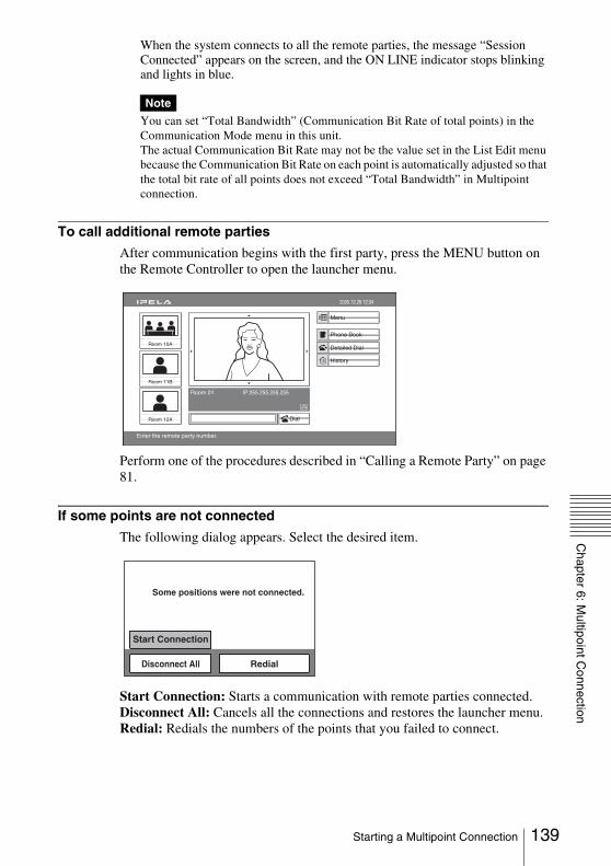
Chapter 6: M
ultipoint Connection
When the system connects to all the remote parties, the message “Session Connected” appears on the screen, and the ON LINE indicator stops blinking and lights in blue.
You can set “Total Bandwidth” (Communication Bit Rate of total points) in the Communication Mode menu in this unit.The actual Communication Bit Rate may not be the value set in the List Edit menu because the Communication Bit Rate on each point is automatically adjusted so that the total bit rate of all points does not exceed “Total Bandwidth” in Multipoint connection.
To call additional remote parties
After communication begins with the first party, press the MENU button on the Remote Controller to open the launcher menu.
Perform one of the procedures described in “Calling a Remote Party” on page 81.
If some points are not connected
The following dialog appears. Select the desired item.
Start Connection: Starts a communication with remote parties connected.Disconnect All: Cancels all the connections and restores the launcher menu.Redial: Redials the numbers of the points that you failed to connect.
Note
Capture
Room 10A
Room 11B
Room 12A
Room 01 IP:255.255.255.255
2005.12.28 12:34
Menu
Phone Book
Detailed Dial
History
Enter the remote party number.
Dial
Some positions were not connected.
RedialDisconnect All
Start Connection
139Starting a Multipoint Connection
Operations are the same as those for a peer-to-peer connection.
For details, see “Receiving a Call from a Remote Party” on page 89.
Receiving a Call from a Remote Party
140 Starting a Multipoint Connection
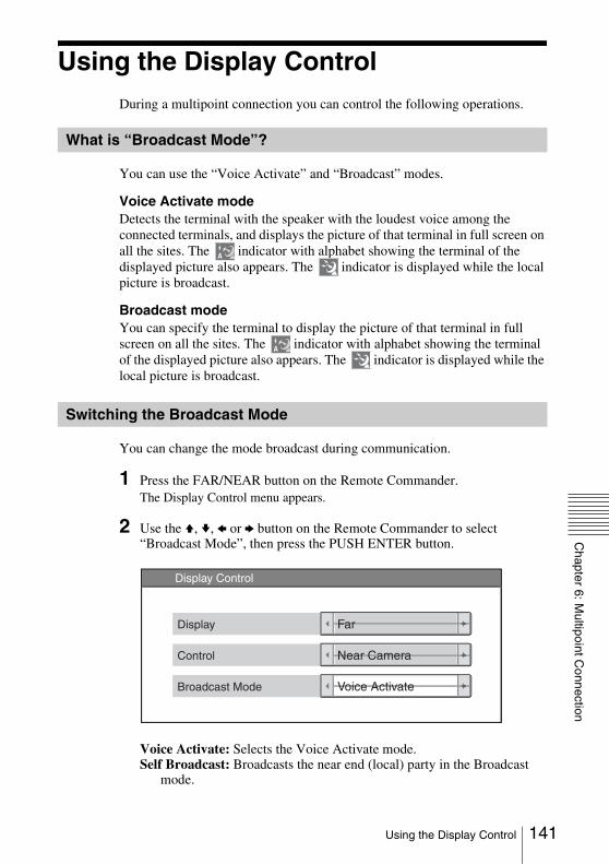
Chapter 6: M
ultipoint Connection
Using the Display ControlDuring a multipoint connection you can control the following operations.
You can use the “Voice Activate” and “Broadcast” modes.
Voice Activate modeDetects the terminal with the speaker with the loudest voice among the connected terminals, and displays the picture of that terminal in full screen on all the sites. The indicator with alphabet showing the terminal of the displayed picture also appears. The indicator is displayed while the local picture is broadcast.
Broadcast modeYou can specify the terminal to display the picture of that terminal in full screen on all the sites. The indicator with alphabet showing the terminal of the displayed picture also appears. The indicator is displayed while the local picture is broadcast.
You can change the mode broadcast during communication.
1 Press the FAR/NEAR button on the Remote Commander.The Display Control menu appears.
2 Use the V, v, B or b button on the Remote Commander to select “Broadcast Mode”, then press the PUSH ENTER button.
Voice Activate: Selects the Voice Activate mode.Self Broadcast: Broadcasts the near end (local) party in the Broadcast
mode.
What is “Broadcast Mode”?
Switching the Broadcast Mode
A
A
FarDisplay
Near CameraControl
Voice ActivateBroadcast Mode
Display Control
141Using the Display Control

A Broadcast: Broadcasts the picture of the terminal connected first in the Broadcast mode.
B Broadcast: Broadcasts the picture of the terminal connected second in the Broadcast mode.
C Broadcast: Broadcasts the picture of the terminal connected third in the Broadcast mode.
Stop Broadcast: Stops broadcasting in the Broadcast Mode.
To display the local picture in the Voice Activate mode
You can display the local picture only on your monitor screen while the broadcast mode remains in Voice Activate mode.
1 Press the FAR/NEAR button on the Remote Commander.The Display Control menu appears.
2 Use the V, v, B or b button to select “Near” under “Display”, then press the PUSH ENTER button.The local picture appears on your monitor screen.
To restore the picture of the remote partyPress the FAR/NEAR button on the Remote Commander again, and select “Far” under “Display”.
When you receive “Self Broadcast” command from one of the terminals connected, the picture of that terminal is broadcast in full screen.When you receive “Stop Broadcat” command from one of the terminals connected, the system returns to the previous mode.
If you have received “Self Broadcast” command from another terminal, the operation above will not be carried out.
Receiving the Broadcast Requested From Any Other Terminal
Note
142 Using the Display Control
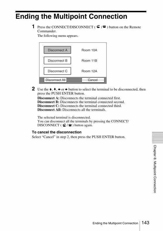
Chapter 6: M
ultipoint Connection
Ending the Multipoint Connection1 Press the CONNECT/DISCONNECT ( / ) button on the Remote
Commander.The following menu appears.
2 Use the V, v, B or b button to select the terminal to be disconnected, then press the PUSH ENTER button.Disconnect A: Disconnects the terminal connected first.Disconnect B: Disconnects the terminal connected second.Disconnect C: Disconnects the terminal connected third.Disconnect All: Disconnects all the terminals.
The selected terminal is disconnected.You can disconnect all the terminals by pressing the CONNECT/DISCONNECT ( / ) button again.
To cancel the disconnectionSelect “Cancel” in step 2, then press the PUSH ENTER button.
CancelDisconnect All
Disconnect C Room 12A
Disconnect B Room 11B
Disconnect A Room 10A
143Ending the Multipoint Connection
This chapter describes the Web Control Functions used when operating the PCS-HG90. The Web Control Function helps you control the PCS-HG90, or change its setup configuration, using a Web browser installed on your PC, such as Internet Explorer. The following is a set of Operating Instructions for the Web Control Function.
Internet Explorer is a product of the Microsoft Corporation. Please use Version 5.0, or above (Version 6.0 recommended).
Open the Web pageEnter the IP address assigned to the PCS-HG90 in the address line of your browser.The format of an address is:http://XXX.XXX.XXX.XXX/
For instance, if the IP address is “192.168.1.24”, enter “http://192.168.1.24/” in the address line.
When a proxy server in an external network segment has been set, the Gateway address in the PCS-HG90 LAN setting must also be set. Or set your Web browser proxy setting to “No Proxy” for the PCS-HG90.
Chapter 7: Web Control Function
Note
144 Open the Web page

Chapter 7: W
eb Control F
unction
Identify a userOnce you reach the Web page, the following window will be displayed asking you to identify yourself as the user.
Enter one of the following user names (see below) into the “User Name” box and the corresponding password into the “Password” box, then click the [OK] button.Each character of a password is shown as “*” on the screen. When the user name and password are correct, the “Dial/Disconnect” page will come up. If an incorrect user name or password is entered three times, an error message appears on the screen.
Notes on the user name and the password• When you enter “user” in the “User Name” box and then its password
(Remote Access Password) in the “Password” box, you can access and check the “Phone Book” and “Setup” pages.
• When you enter “super” in the “User Name” box and then its password (Phone Book Modification Password) in the “Password” box, you can access the “Phone Book” page, change the setting of the page, and register a new entry onto the page. And you can check the “Setup” page.
• When you enter “sonypcs” in the “User Name” box and then its password (Administrator Password) in the “Password” box, you can access the “Phone Book” page, change the setting of the page, and register a new entry onto the page. And you can check and modify the “Setup” page.
• If the corresponding password is not assigned, leave the “Password” box blank and click the [OK] button.
• Administrator Setup Password, Phone Book Modification Password, and Remote Access Password settings are in the Administrator Setup menu.
145Identify a user

Select a toolBy clicking a tool button on the top part of the page, you can jump to the corresponding tool page. A brief introduction of each tool is presented below.
[Controller]Controls the PCS-HG90 using the on-screen controller, or controls using the on-screen Remote Commander in the same manner as you do with the PCSA-RG1 Remote Commander.
[Dial/Disconnect]Calls a remote party, or ends a meeting.
[Phone Book]Displays the dial list.Connects from the dial list.Registers, confirms or edits the dial list.
For a private phone book, the “Phone Book” button changes to the “Private Phone Book” button.
[Setup]Confirms or modifies the setup.Sends messages.Erases the saved values or information (only when “sonypcs” has been entered as the user name).
[Info]Displays the connection status, line status, or other machine information.Displays the “Cause Code.”Displays the “Call Log”(only when “sonypcs” has been entered as the user name).
[Monitor]You can monitor the image of PCS-HG90.
When “Web monitor” of the Administrator Setup menu is set to “Off”, you cannot monitor the image.
Note
146 Select a tool

Chapter 7: W
eb Control F
unction
How to use “Controller”
When you click the [Controller] button, the on-screen control panel appears. By clicking the buttons on this control panel, you can control the PCS-HG90, operating the camera, registering preset camera settings, adjusting the white balance, and so on.
For example, in order to preset and load a camera setting:
1 Set the camera at the desired position using the Camera Control buttons.2 Click one of the “Preset Save” 1 to 6 buttons on the image.3 The preset is done.4 Click one of the “Preset Load” 1 to 6 buttons on the image to load it.
To adjust the white balance
You can adjust the white balance as the currently displayed subject color is white by clicking the OPT (On Push Trigger) button of the White Balance section.
To switch the broadcast mode
You can switch the broadcasting picture by clicking the button of the Broadcast Mode section.
To control the PCS-HG90 from the on-screen controller
147How to use “Controller”
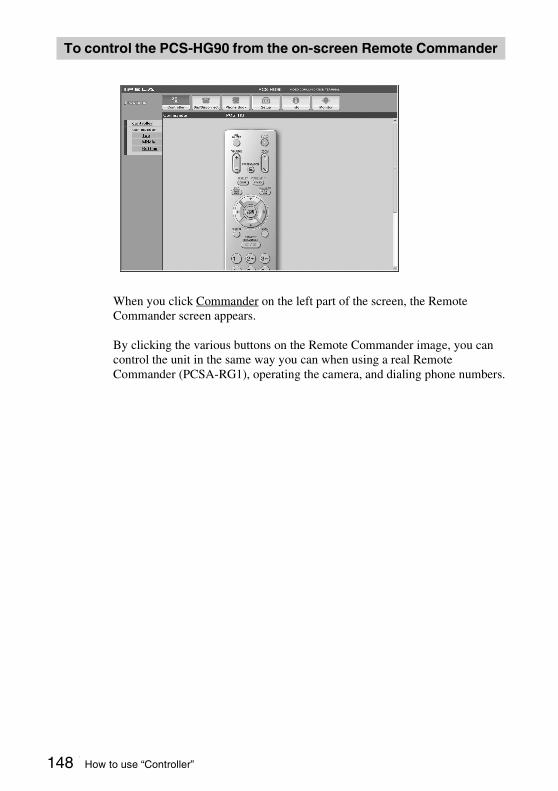
When you click Commander on the left part of the screen, the Remote Commander screen appears.
By clicking the various buttons on the Remote Commander image, you can control the unit in the same way you can when using a real Remote Commander (PCSA-RG1), operating the camera, and dialing phone numbers.
To control the PCS-HG90 from the on-screen Remote Commander
148 How to use “Controller”

Chapter 7: W
eb Control F
unction
How to use “Dial/Disconnect”
By clicking the [Dial/Disconnect] button, you can jump to the “Dial/Disconnect” page.
To connect:
1 Enter an IP address or a DNS name of a remote party into box A. (Enter that of another remote party into box B or C, if necessary.)
2 Select the dial mode in “Dial Mode” and set up the other items as required.3 Click the [DIAL] button.4 The message, “Now dialing...” appears.5 After the connection is made, the message, “Connect OK.” will appear, and
the screen will return to the “Dial/Disconnect” page.
To disconnect:
1 Click the [DISCONNECT] button.2 The message, “Now disconnecting...” appears.3 After the disconnection is completed, the message “Disconnect OK.” will
appear, and the screen will return to the “Dial/Disconnect” page.
To clear the dial number:
1 Click the [CLEAR] button. 2 The number(s) entered on this menu will be cleared and the screen will
return to the “Dial/Disconnect” page.
For Peer-to-Peer Connection
149How to use “Dial/Disconnect”
To connect:
1 Select “Multipoint” for “Dial Mode”.2 Enter IP addresses or DNS names of remote parties into boxes A to C.3 Set the communication attributes.4 Click the [DIAL] button.5 The message, “Now dialing…” appears.6 After the connection is made, the message, “Connect OK.” will appear, and
the screen will return to the “Dial/Disconnect” page.
To disconnect (all remote parties at once):
1 Click the [DISCONNECT] button.2 The message “Now disconnecting…” appears.3 After the disconnection is complete, the message, “Disconnect OK.” will
appear, and the screen will return to the “Dial/Disconnect” page.
To disconnect (one party at a time):
1 Click the button (Disconnect A to C) that corresponds to the party you wish to disconnect.
2 The message “Now disconnecting…” appears.3 After the disconnection is complete, the message, “Disconnect OK.” will
appear, and the screen will return to the “Dial/Disconnect” page.
To clear the dial number:
1 Click the [CLEAR] button.2 The number(s) entered on this menu will be cleared and the screen will
return to the “Dial/Disconnect” page.
For Multipoint Connection
150 How to use “Dial/Disconnect”

Chapter 7: W
eb Control F
unction
How to use “Phone Book”
By clicking the [Phone Book] button, you can jump to the “Phone Book list” page.
To connect:
1 Click sDial next to the index title that you are dialing. Then, the message, “Now dialing...” will appear.
2 After the connection is made, you will see the message, “Connect OK.,” and the screen will return to the list page.
151How to use “Phone Book”

To edit the communication attribute (only when “super” or “sonypcs” has been entered as the user name):
1 Click sEdit... next to the index title whose communication attribute you want to edit or modify on the list page. Then, the “Phone Book-Edit” page will appear.
2 Edit or modify the telephone numbers and attributes.3 Click the [SAVE] button. After saving the changes, the screen will return
to the list page.
To delete data from the Phone Book (only when “super” or “sonypcs” has been entered as the user name):
1 Click sEdit... next to the index title whose data you want to delete on the list page. Then, the “Phone Book-Edit” page will appear.
2 Click the [DELETE] button. After the deletion is complete, the list page will appear.
To return to the list page:
1 Click Return on the left part of the page. The list page will appear.
“Phone Book-Edit” page
152 How to use “Phone Book”
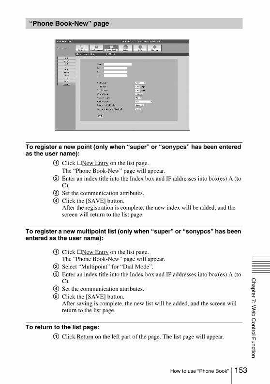
Chapter 7: W
eb Control F
unction
To register a new point (only when “super” or “sonypcs” has been entered as the user name):
1 Click sNew Entry on the list page.The “Phone Book-New” page will appear.
2 Enter an index title into the Index box and IP addresses into box(es) A (to C).
3 Set the communication attributes.4 Click the [SAVE] button.
After the registration is complete, the new index will be added, and the screen will return to the list page.
To register a new multipoint list (only when “super” or “sonypcs” has been entered as the user name):
1 Click sNew Entry on the list page.The “Phone Book-New” page will appear.
2 Select “Multipoint” for “Dial Mode”.3 Enter an index title into the Index box and IP addresses into box(es) A (to
C).4 Set the communication attributes.5 Click the [SAVE] button.
After saving is complete, the new list will be added, and the screen will return to the list page.
To return to the list page:
1 Click Return on the left part of the page. The list page will appear.
“Phone Book-New” page
153How to use “Phone Book”

How to use “Setup”
Click the [Setup] button, and you will jump to the “Dial Setup” page.
Click Dial, Answer, Communication, Audio, Video, General, LAN on the left part of the screen, according to what you are setting up.
To modify the attribute (only when “sonypcs” has been entered as the user name)
1 Open the page whose attributes you want to modify.2 Modify the attributes.3 Click the [SAVE] button. After the modification is complete, the screen
will return to the same page as you see in step 1.
Sometimes the screen may not go back to the previous page after modifying the “LAN” page. This is not a malfunction.
Note
154 How to use “Setup”

Chapter 7: W
eb Control F
unction
To enable More Options1 Open the “Dial Setup” page.2 Set “More Options Enable” to “On”.3 Click the [SAVE] button. After saving is complete, the screen will return
to the “Dial Setup” page.
When “More Options Enable” is set to “On”, the following settings are added to the “Dial/Disconnect” and “Phone Book” pages. For details on these settings, see “Dial Setup Menu” (page 37) and “Communication Mode Menu” (page 38).
155How to use “Setup”
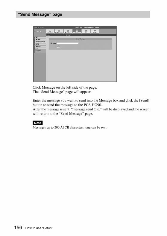
Click Message on the left side of the page.The “Send Message” page will appear.
Enter the message you want to send into the Message box and click the [Send] button to send the message to the PCS-HG90.After the message is sent, “message send OK.” will be displayed and the screen will return to the “Send Message” page.
Messages up to 200 ASCII characters long can be sent.
“Send Message” page
Note
156 How to use “Setup”

Chapter 7: W
eb Control F
unction
Click Erase on the left part of the page. The “Erase” page will appear (only when “sonypcs” has been entered as the user name).1 Click on the desired item.
A dialog box will appear.2 Click the [OK] button.
“Erase Configuration Setup”
Returns to the factory setting values.
“Erase Phone Book”
Erases all information saved in the “Phone Book.”
“Erase Call Log”
Erases all information saved in the “Call Log.”
“Erase” page
157How to use “Setup”
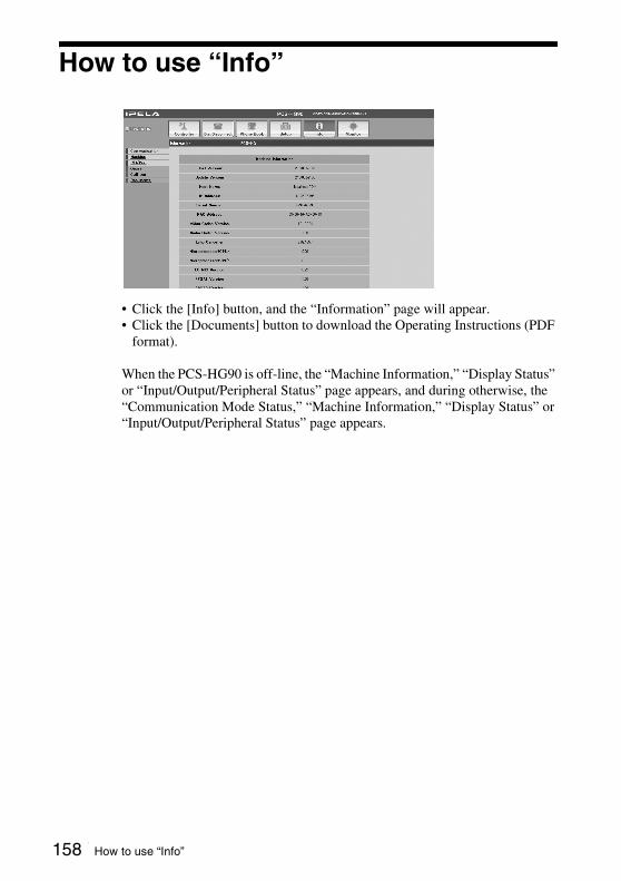
How to use “Info”
• Click the [Info] button, and the “Information” page will appear.• Click the [Documents] button to download the Operating Instructions (PDF
format).
When the PCS-HG90 is off-line, the “Machine Information,” “Display Status” or “Input/Output/Peripheral Status” page appears, and during otherwise, the “Communication Mode Status,” “Machine Information,” “Display Status” or “Input/Output/Peripheral Status” page appears.
158 How to use “Info”

Chapter 7: W
eb Control F
unction
By clicking Cause on the left part of the page, you can jump to the “Cause Code” page, and see the Cause Code list.
“Cause Code” list page
159How to use “Info”

By clicking Call Log on the left part of the page, you can jump to the “Call Log” page (only when “sonypcs” has been entered as the user name).
“Call Log” page
160 How to use “Info”
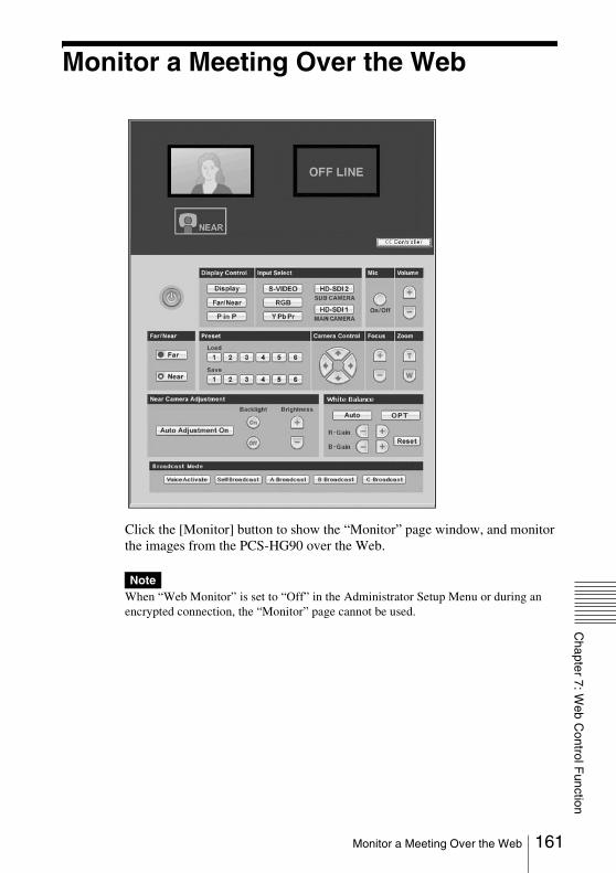
Chapter 7: W
eb Control F
unction
Monitor a Meeting Over the Web
Click the [Monitor] button to show the “Monitor” page window, and monitor the images from the PCS-HG90 over the Web.
When “Web Monitor” is set to “Off” in the Administrator Setup Menu or during an encrypted connection, the “Monitor” page cannot be used.
Note
161Monitor a Meeting Over the Web

Location and Function of Parts and Controls
Front
a ON LINE indicatorLights in blue when connection is completed. It turns off when the system is disconnected.
b POWER/STANDBY indicatorLights in green after blinks when the power is on. Lights in orange when the Communication Terminal is set to standby mode.
c LAN ALERT indicatorLights in orange when packet error (loss) or link error occurs during communication.
d @/ 1 (power) switchTurns on/off the Communication Terminal.
e Memory Stick slotInsert a “Memory Stick” (not supplied) into this slot.
Appendix
PCS-PHG90 Communication Terminal
ON LINE POWER/STANDBY LAN ALERT
1 2 3
4 5
162 Location and Function of Parts and Controls
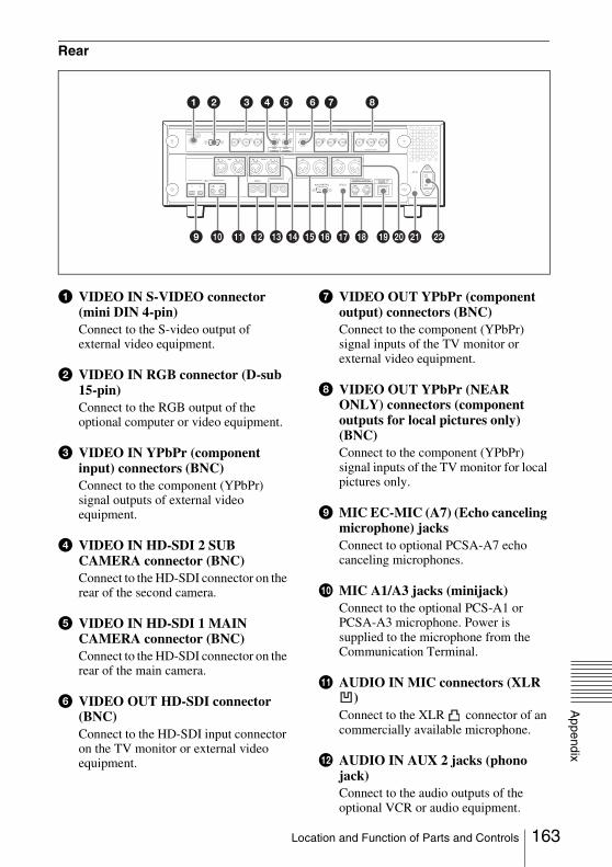
Appendix
Rear
a VIDEO IN S-VIDEO connector (mini DIN 4-pin)Connect to the S-video output of external video equipment.
b VIDEO IN RGB connector (D-sub 15-pin)Connect to the RGB output of the optional computer or video equipment.
c VIDEO IN YPbPr (component input) connectors (BNC)Connect to the component (YPbPr) signal outputs of external video equipment.
d VIDEO IN HD-SDI 2 SUB CAMERA connector (BNC)Connect to the HD-SDI connector on the rear of the second camera.
e VIDEO IN HD-SDI 1 MAIN CAMERA connector (BNC)Connect to the HD-SDI connector on the rear of the main camera.
f VIDEO OUT HD-SDI connector (BNC)Connect to the HD-SDI input connector on the TV monitor or external video equipment.
g VIDEO OUT YPbPr (component output) connectors (BNC)Connect to the component (YPbPr) signal inputs of the TV monitor or external video equipment.
h VIDEO OUT YPbPr (NEAR ONLY) connectors (component outputs for local pictures only) (BNC)Connect to the component (YPbPr) signal inputs of the TV monitor for local pictures only.
i MIC EC-MIC (A7) (Echo canceling microphone) jacksConnect to optional PCSA-A7 echo canceling microphones.
j MIC A1/A3 jacks (minijack)Connect to the optional PCS-A1 or PCSA-A3 microphone. Power is supplied to the microphone from the Communication Terminal.
k AUDIO IN MIC connectors (XLR )
Connect to the XLR connector of an commercially available microphone.
l AUDIO IN AUX 2 jacks (phono jack)Connect to the audio outputs of the optional VCR or audio equipment.
RGB
AUX CONTROL
CAMERA CONTROL 100BASE-TX/10BASE-T(VISCA)
~ AC IN
SUB MAIN
CTRL-S
REC OUT(MIXED)AUDIO OUTR LR
AUDIO IN
VIDEO IN
S-VIDEO Y1
VIDEO OUT
Y Pb Pr
(NEAR ONLY)
Y Pb Pr2
HD-SDI HD-SDIHD-SDI
SUBCAMERA
MAINCAMERA
Pb Pr
R MIC L R
AUX 2R
MICEC-MIC(A7)
1 2
A1/A3
(PLUG IN POWER)
1(R) 2(L)
L R L
AUX 1 L L
3 7 85421 6
qj qlqh wa9 0 qa qs qkqd qf qg wsw;
163Location and Function of Parts and Controls
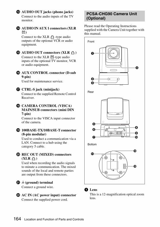
m AUDIO OUT jacks (phono jacks)Connect to the audio inputs of the TV monitor.
n AUDIO IN AUX 1 connectors (XLR )
Connect to the XLR -type audio outputs of the optional VCR or audio equipment.
o AUDIO OUT connectors (XLR )Connect to the XLR -type audio inputs of the optional TV monitor, VCR or audio equipment.
p AUX CONTROL connector (D-sub 9-pin)Used for maintenance service.
q CTRL-S jack (minijack)Connect to the supplied Remote Control Receiver.
r CAMERA CONTROL (VISCA) MAIN/SUB connectors (mini DIN 7-pin)Connect to the VISCA input connector of the camera.
s 100BASE-TX/10BASE-T connector (8-pin modular)Used to conduct a communication via a LAN. Connect to a hub using the category 5 cable.
t REC OUT (MIXED) connectors (XLR )Used when recording the audio signals to minute a communication. The mixed sounds of the local and remote parties are output from these connectors.
u U (ground) terminalConnect a ground wire.
v AC IN (AC power input) connectorConnect the supplied power cord.
Please read the Operating Instructions supplied with the Camera Unit together with this manual.
a LensThis is a 12-magnification optical zoom lens.
PCSA-CHG90 Camera Unit (Optional)
1
4
2
3
VISCA RS-4221 2 3 4 5 6 7 8 9
VISCA RS-232C OUT
DC IN 12V
HFBK-HD1
MONITOR HD-SDI
6
7
5
9
0
8
qd
qsqa
Front
Rear
Bottom
164 Location and Function of Parts and Controls

Appendix
b POWER lampLights in green when the Camera Unit is connected to an AC outlet using theAC power adaptor and AC power cord supplied with the Camera Unit.
c STANDBY lampLights in orange when the Communication Terminal is set to standby mode or is turned off.
d ND filter select switch (bottom of the camera block)Switches the setting of the built-in ND filter according to the brightness of the subject to be shot.
e VISCA RS-422 connectorUsed for VISCA control. Connect to the CAMERA CONTROL (VISCA) MAIN (or SUB) connector on the Communication Terminal.
f VISCA RS-232C IN connectorUsed for VISCA control. Connect to the CAMERA CONTROL (VISCA) MAIN (or SUB) connector on the Communication Terminal using the VISCA cable supplied with the Camera Unit.
g MONITOR connector (D-sub 15-pin)Do not use this connector. This is an analog output connector to be used by service personnel.
h DC IN 12V connectorConnect the AC power adaptor supplied with the Camera Unit.
i HD-SDI connector (BNC)Connect to the VIDEO IN HD-SDI 1 MAIN CAMERA (or HD-SDI 2 SUB CAMERA) connector on the Communication Terminal using the BNC cable supplied with the Camera Unit.
j Cable cover
k Ceiling bracket mounting screw holesWhen you install the Camera Unit to the ceiling, secure the ceiling bracket supplied with the Camera Unit to these holes.
l Tripod screw holesWhen you install the Camera Unit to a tripod, secure the tripod to these holes.
m BOTTOM switchesUsed for the output signal format selection and RS-232C/RS-422 selection.
165Location and Function of Parts and Controls

You can set for a beep not to sound by pressing the button on the Remote Commander with the Audio Setup menu.
For the setting, see “Audio Setup Menu” on page 41.
a Battery compartment (rear)Insert two size AA (R6) batteries.
b MIC ON/OFF buttonTurns off the local sound to be sent to a remote party. To restore the sound, press the button again.
c VOLUME +/– buttonsAdjusts the volume of the sound received from a remote party.+: to increase the volume–: to decrease the volume
d DISPLAY (CLEAR) buttonSwitches the picture displayed on the monitor screen. Deletes a line when used for character input.
e PinP (BACK SPACE) buttonDisplays a window picture when pressed during communication.Each time you press this button, the location of the window picture changes.Pressing the button displays the picture in full screen while the Camera menu opens.When used for character input, deletes the character you entered last.
f Arrow buttons (V/v/B/b)Used to select the menu or make various settings in the menu. Also used for camera angle adjustment.
g PUSH ENTER buttonExecutes the selection or setting in the menu and goes to the next layer.
h RETURN buttonUsed to return to the previous layer in the menu.
i Number (0-9, , ) buttonsUsed to enter the letters or numbers of an IP address, etc.Used for focus, brightness and backlight compensation adjustments.
j @/1 (power on/off) buttonSets the Communication Terminal to standby mode when it is turned on. Turns on the Communication Terminal when it is in standby.
PCSA-RG1 Remote Commander
MICON/OFF
VOLUME ZOOM
PRESENTATION
DISPLAY
PUSHENTER
CONNECT/DISCONNECT
HELP
VIDEO INPUT
RETURN MENU
CLEAR SYMBOL
PinP FAR/NEARBACKSPACE
ALPHA/NUM
1
2 0qa
qs
qd
qf
qg
qh
qj
3
4
5
6
7
8
9
166 Location and Function of Parts and Controls
Appendix
k PRESENTATION buttonSwitches the video input signal from external video equipment during communication and restores the previous video input.
l ZOOM (T/W) buttonsZooms in or out.T: to enlarge the pictureW: to reduce the picture
m VIDEO INPUT (SYMBOL) buttonSelects the video input signal. Each time you press the button, the input signal switches.Used to enter a symbol for character input.
n FAR/NEAR (ALPHA/NUM) buttonSwitches the picture on a local or remote site.Switches the input mode between alphabets and numbers for character input.
o MENU buttonUsed to display the Setup menu or the launcher menu.
p CONNECT/DISCONNECT ( /) button
Used to connect or disconnect a remote party.
q HELP buttonUsed to show the help guide.
167Location and Function of Parts and Controls
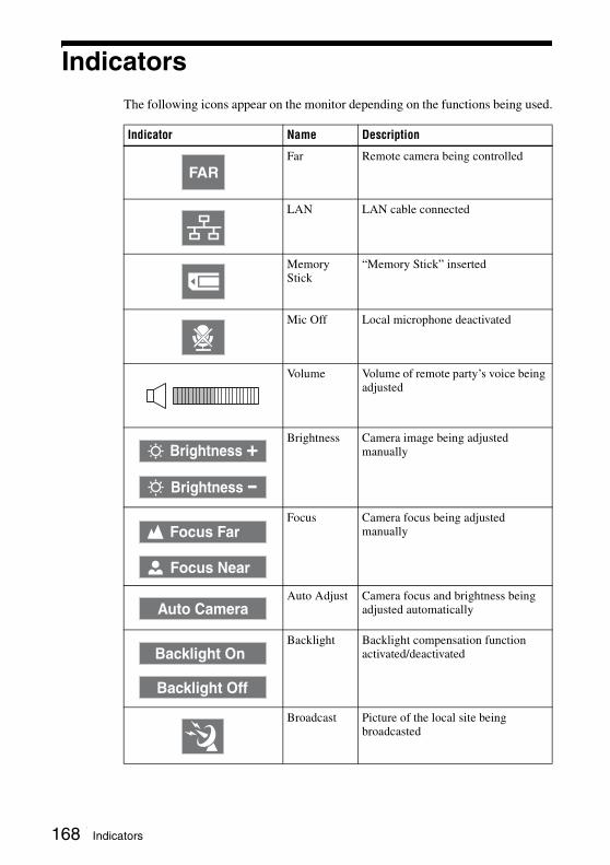
IndicatorsThe following icons appear on the monitor depending on the functions being used.
Indicator Name Description
Far Remote camera being controlled
LAN LAN cable connected
Memory Stick
“Memory Stick” inserted
Mic Off Local microphone deactivated
Volume Volume of remote party’s voice being adjusted
Brightness Camera image being adjusted manually
Focus Camera focus being adjusted manually
Auto Adjust Camera focus and brightness being adjusted automatically
Backlight Backlight compensation function activated/deactivated
Broadcast Picture of the local site being broadcasted
FAR
Brightness +
Brightness -
Focus Far
Focus Near
Auto Camera
Backlight On
Backlight Off
168 Indicators
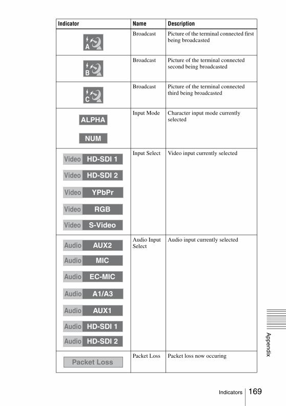
Appendix
Broadcast Picture of the terminal connected first being broadcasted
Broadcast Picture of the terminal connected second being broadcasted
Broadcast Picture of the terminal connected third being broadcasted
Input Mode Character input mode currently selected
Input Select Video input currently selected
Audio Input Select
Audio input currently selected
Packet Loss Packet loss now occuring
Indicator Name Description
A
B
C
ALPHA
NUM
Video HD-SDI 1
Video HD-SDI 2
Video YPbPr
Video RGB
Video S-Video
Audio AUX2
Audio MIC
Audio EC-MIC
Audio A1/A3
Audio AUX1
Audio HD-SDI 1
Audio HD-SDI 2
Packet Loss
169Indicators
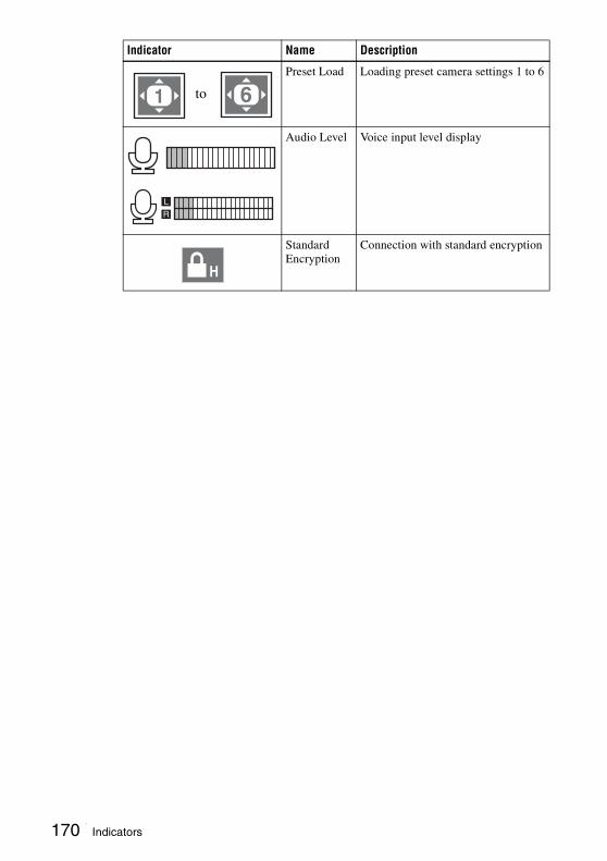
Preset Load Loading preset camera settings 1 to 6
Audio Level Voice input level display
Standard Encryption
Connection with standard encryption
Indicator Name Description
to
L
R
H
170 Indicators
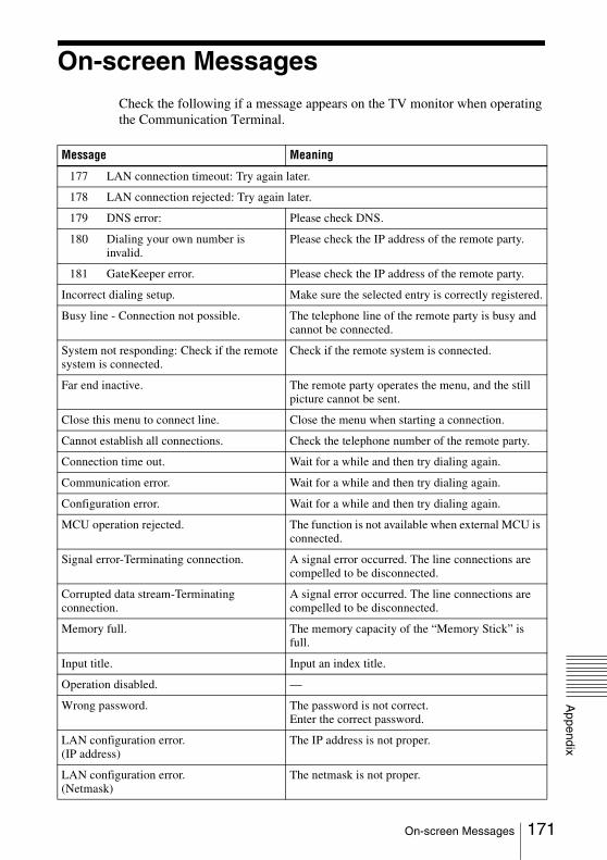
Appendix
On-screen MessagesCheck the following if a message appears on the TV monitor when operating the Communication Terminal.
Message Meaning
177 LAN connection timeout: Try again later.
178 LAN connection rejected: Try again later.
179 DNS error: Please check DNS.
180 Dialing your own number is invalid.
Please check the IP address of the remote party.
181 GateKeeper error. Please check the IP address of the remote party.
Incorrect dialing setup. Make sure the selected entry is correctly registered.
Busy line - Connection not possible. The telephone line of the remote party is busy and cannot be connected.
System not responding: Check if the remote system is connected.
Check if the remote system is connected.
Far end inactive. The remote party operates the menu, and the still picture cannot be sent.
Close this menu to connect line. Close the menu when starting a connection.
Cannot establish all connections. Check the telephone number of the remote party.
Connection time out. Wait for a while and then try dialing again.
Communication error. Wait for a while and then try dialing again.
Configuration error. Wait for a while and then try dialing again.
MCU operation rejected. The function is not available when external MCU is connected.
Signal error-Terminating connection. A signal error occurred. The line connections are compelled to be disconnected.
Corrupted data stream-Terminating connection.
A signal error occurred. The line connections are compelled to be disconnected.
Memory full. The memory capacity of the “Memory Stick” is full.
Input title. Input an index title.
Operation disabled. —
Wrong password. The password is not correct.Enter the correct password.
LAN configuration error.(IP address)
The IP address is not proper.
LAN configuration error.(Netmask)
The netmask is not proper.
171On-screen Messages
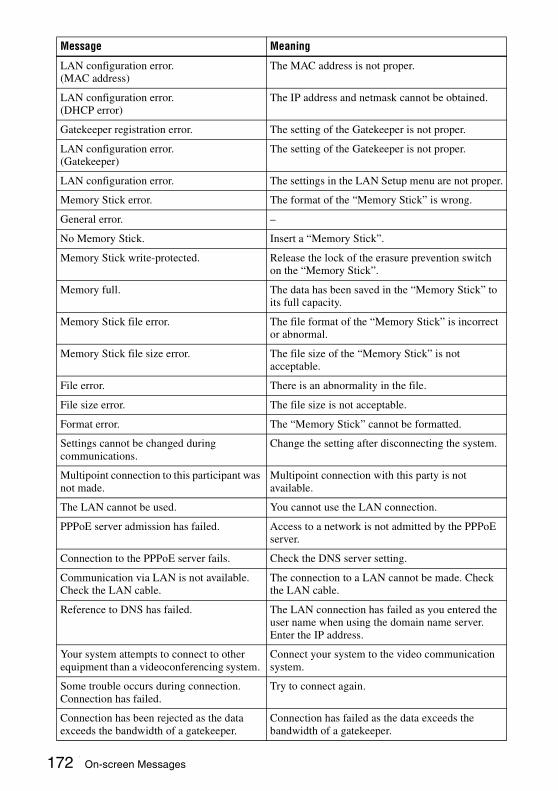
LAN configuration error.(MAC address)
The MAC address is not proper.
LAN configuration error.(DHCP error)
The IP address and netmask cannot be obtained.
Gatekeeper registration error. The setting of the Gatekeeper is not proper.
LAN configuration error.(Gatekeeper)
The setting of the Gatekeeper is not proper.
LAN configuration error. The settings in the LAN Setup menu are not proper.
Memory Stick error. The format of the “Memory Stick” is wrong.
General error. –
No Memory Stick. Insert a “Memory Stick”.
Memory Stick write-protected. Release the lock of the erasure prevention switch on the “Memory Stick”.
Memory full. The data has been saved in the “Memory Stick” to its full capacity.
Memory Stick file error. The file format of the “Memory Stick” is incorrect or abnormal.
Memory Stick file size error. The file size of the “Memory Stick” is not acceptable.
File error. There is an abnormality in the file.
File size error. The file size is not acceptable.
Format error. The “Memory Stick” cannot be formatted.
Settings cannot be changed during communications.
Change the setting after disconnecting the system.
Multipoint connection to this participant was not made.
Multipoint connection with this party is not available.
The LAN cannot be used. You cannot use the LAN connection.
PPPoE server admission has failed. Access to a network is not admitted by the PPPoE server.
Connection to the PPPoE server fails. Check the DNS server setting.
Communication via LAN is not available. Check the LAN cable.
The connection to a LAN cannot be made. Check the LAN cable.
Reference to DNS has failed. The LAN connection has failed as you entered the user name when using the domain name server. Enter the IP address.
Your system attempts to connect to other equipment than a videoconferencing system.
Connect your system to the video communication system.
Some trouble occurs during connection. Connection has failed.
Try to connect again.
Connection has been rejected as the data exceeds the bandwidth of a gatekeeper.
Connection has failed as the data exceeds the bandwidth of a gatekeeper.
Message Meaning
172 On-screen Messages
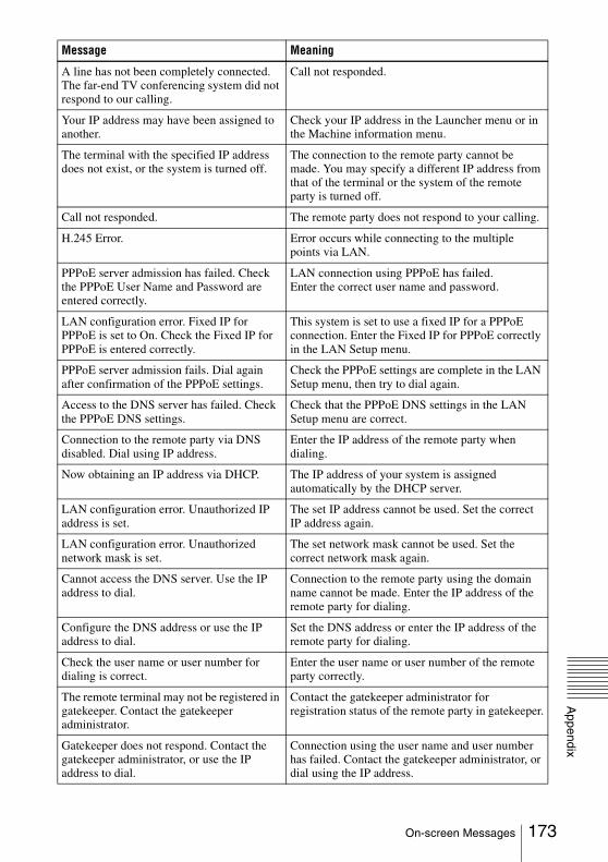
Appendix
A line has not been completely connected. The far-end TV conferencing system did not respond to our calling.
Call not responded.
Your IP address may have been assigned to another.
Check your IP address in the Launcher menu or in the Machine information menu.
The terminal with the specified IP address does not exist, or the system is turned off.
The connection to the remote party cannot be made. You may specify a different IP address from that of the terminal or the system of the remote party is turned off.
Call not responded. The remote party does not respond to your calling.
H.245 Error. Error occurs while connecting to the multiple points via LAN.
PPPoE server admission has failed. Check the PPPoE User Name and Password are entered correctly.
LAN connection using PPPoE has failed.Enter the correct user name and password.
LAN configuration error. Fixed IP for PPPoE is set to On. Check the Fixed IP for PPPoE is entered correctly.
This system is set to use a fixed IP for a PPPoE connection. Enter the Fixed IP for PPPoE correctly in the LAN Setup menu.
PPPoE server admission fails. Dial again after confirmation of the PPPoE settings.
Check the PPPoE settings are complete in the LAN Setup menu, then try to dial again.
Access to the DNS server has failed. Check the PPPoE DNS settings.
Check that the PPPoE DNS settings in the LAN Setup menu are correct.
Connection to the remote party via DNS disabled. Dial using IP address.
Enter the IP address of the remote party when dialing.
Now obtaining an IP address via DHCP. The IP address of your system is assigned automatically by the DHCP server.
LAN configuration error. Unauthorized IP address is set.
The set IP address cannot be used. Set the correct IP address again.
LAN configuration error. Unauthorized network mask is set.
The set network mask cannot be used. Set the correct network mask again.
Cannot access the DNS server. Use the IP address to dial.
Connection to the remote party using the domain name cannot be made. Enter the IP address of the remote party for dialing.
Configure the DNS address or use the IP address to dial.
Set the DNS address or enter the IP address of the remote party for dialing.
Check the user name or user number for dialing is correct.
Enter the user name or user number of the remote party correctly.
The remote terminal may not be registered in gatekeeper. Contact the gatekeeper administrator.
Contact the gatekeeper administrator for registration status of the remote party in gatekeeper.
Gatekeeper does not respond. Contact the gatekeeper administrator, or use the IP address to dial.
Connection using the user name and user number has failed. Contact the gatekeeper administrator, or dial using the IP address.
Message Meaning
173On-screen Messages

LAN configuration error. Gatekeeper Mode is set to On. Enter the gatekeeper address.
LAN connection is set to use the gatekeeper. Enter the gatekeeper address.
LAN configuration error. NAT Mode is set to On. Check the NAT address.
LAN connection is set to use NAT. Check the NAT address in the LAN Setup menu.
LAN configuration error. Unauthorized NAT address is specified. Check the NAT address.
The set NAT address cannot be used. Enter the correct NAT address in the LAN Setup menu.
LAN configuration error. Different address from NAT machines is specified. Check the NAT address.
Enter the correct NAT address in the LAN Setup menu.
LAN configuration error. Connection is not complete as the port number overlaps.
Check the TCP and UDP port numbers in the LAN Setup menu.
LAN configuration error. Connection is not complete as an invalid port number is specified.
Check the TCP and UDP port numbers in the LAN Setup menu.
Line is busy. Try to dial again later. Connection has filed as the line is busy. Try to dial again later.
Dialing the same address is invalid. You are calling the same party.
Check the line interface or the IP address is set correctly.
Select the correct dial mode or enter the correct IP address in the Detailed Dial menu.
Dial setup error. No prefix number is entered.
The LAN prefix is not registered in the Dial Setup menu.
LAN configuration error. PPPoE is set to On. Check the PPPoE User Name and Password.
PPPoE is set for LAN connection. Configuration of the user name and password is required.
LAN configuration error. Fixed IP for PPPoE is set to On. Check the Fixed IP for PPPoE is entered correctly.
Enter a correct IP address in “Fixed IP Address for PPPoE” in the LAN Setup menu.
LAN configuration error. IP Precedence exceeds the maximum value.
Set the IP Precedence value between 0 and 7 in the LAN Setup menu.
LAN configuration error. Diffserve exceeds the maximum value.
Set the Diffserve value between 0 and 64 in the LAN Setup menu.
Warning!! The fan of the main camera has stopped.
The main camera has a problem and operating the camera in this condition may damage it. Turn off the power of the main camera and consult your Sony dealer.
Warning!! The fan of the sub camera has stopped.
The sub camera has a problem and operating the camera in this condition may damage it. Turn off the power of the sub camera and consult your Sony dealer.
The encryption feature on a far-end system is disabled.
Have the far-end side enable their encryption feature.
Could not start connection because the encryption feature of the local system was disabled.
Enable the encryption feature.
Message Meaning
174 On-screen Messages
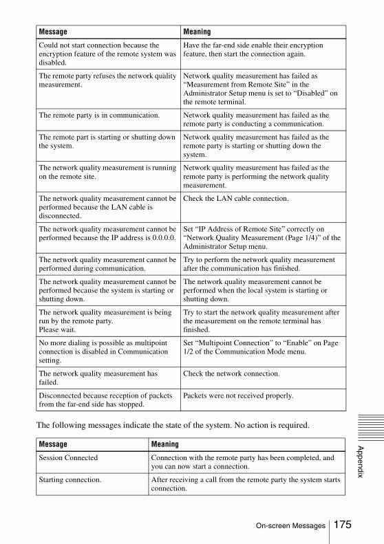
Appendix
The following messages indicate the state of the system. No action is required.
Could not start connection because the encryption feature of the remote system was disabled.
Have the far-end side enable their encryption feature, then start the connection again.
The remote party refuses the network quality measurement.
Network quality measurement has failed as “Measurement from Remote Site” in the Administrator Setup menu is set to “Disabled” on the remote terminal.
The remote party is in communication. Network quality measurement has failed as the remote party is conducting a communication.
The remote part is starting or shutting down the system.
Network quality measurement has failed as the remote party is starting or shutting down the system.
The network quality measurement is running on the remote site.
Network quality measurement has failed as the remote party is performing the network quality measurement.
The network quality measurement cannot be performed because the LAN cable is disconnected.
Check the LAN cable connection.
The network quality measurement cannot be performed because the IP address is 0.0.0.0.
Set “IP Address of Remote Site” correctly on “Network Quality Measurement (Page 1/4)” of the Administrator Setup menu.
The network quality measurement cannot be performed during communication.
Try to perform the network quality measurement after the communication has finished.
The network quality measurement cannot be performed because the system is starting or shutting down.
The network quality measurement cannot be performed when the local system is starting or shutting down.
The network quality measurement is being run by the remote party.Please wait.
Try to start the network quality measurement after the measurement on the remote terminal has finished.
No more dialing is possible as multipoint connection is disabled in Communication setting.
Set “Multipoint Connection” to “Enable” on Page 1/2 of the Communication Mode menu.
The network quality measurement has failed.
Check the network connection.
Disconnected because reception of packets from the far-end side has stopped.
Packets were not received properly.
Message Meaning
Session Connected Connection with the remote party has been completed, and you can now start a connection.
Starting connection. After receiving a call from the remote party the system starts connection.
Message Meaning
175On-screen Messages
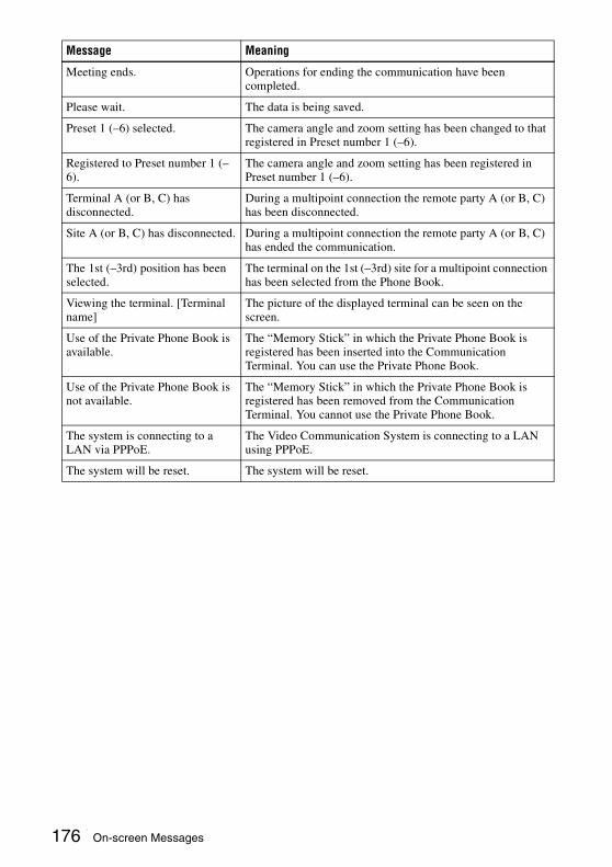
Meeting ends. Operations for ending the communication have been completed.
Please wait. The data is being saved.
Preset 1 (–6) selected. The camera angle and zoom setting has been changed to that registered in Preset number 1 (–6).
Registered to Preset number 1 (–6).
The camera angle and zoom setting has been registered in Preset number 1 (–6).
Terminal A (or B, C) has disconnected.
During a multipoint connection the remote party A (or B, C) has been disconnected.
Site A (or B, C) has disconnected. During a multipoint connection the remote party A (or B, C) has ended the communication.
The 1st (–3rd) position has been selected.
The terminal on the 1st (–3rd) site for a multipoint connection has been selected from the Phone Book.
Viewing the terminal. [Terminal name]
The picture of the displayed terminal can be seen on the screen.
Use of the Private Phone Book is available.
The “Memory Stick” in which the Private Phone Book is registered has been inserted into the Communication Terminal. You can use the Private Phone Book.
Use of the Private Phone Book is not available.
The “Memory Stick” in which the Private Phone Book is registered has been removed from the Communication Terminal. You cannot use the Private Phone Book.
The system is connecting to a LAN via PPPoE.
The Video Communication System is connecting to a LAN using PPPoE.
The system will be reset. The system will be reset.
Message Meaning
176 On-screen Messages
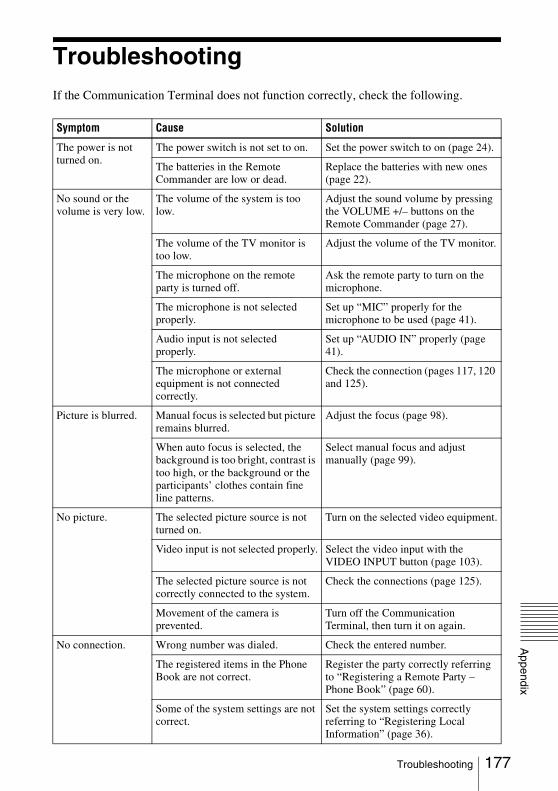
Appendix
TroubleshootingIf the Communication Terminal does not function correctly, check the following.
Symptom Cause Solution
The power is not turned on.
The power switch is not set to on. Set the power switch to on (page 24).
The batteries in the Remote Commander are low or dead.
Replace the batteries with new ones (page 22).
No sound or the volume is very low.
The volume of the system is too low.
Adjust the sound volume by pressing the VOLUME +/– buttons on the Remote Commander (page 27).
The volume of the TV monitor is too low.
Adjust the volume of the TV monitor.
The microphone on the remote party is turned off.
Ask the remote party to turn on the microphone.
The microphone is not selected properly.
Set up “MIC” properly for the microphone to be used (page 41).
Audio input is not selected properly.
Set up “AUDIO IN” properly (page 41).
The microphone or external equipment is not connected correctly.
Check the connection (pages 117, 120 and 125).
Picture is blurred. Manual focus is selected but picture remains blurred.
Adjust the focus (page 98).
When auto focus is selected, the background is too bright, contrast is too high, or the background or the participants’ clothes contain fine line patterns.
Select manual focus and adjust manually (page 99).
No picture. The selected picture source is not turned on.
Turn on the selected video equipment.
Video input is not selected properly. Select the video input with the VIDEO INPUT button (page 103).
The selected picture source is not correctly connected to the system.
Check the connections (page 125).
Movement of the camera is prevented.
Turn off the Communication Terminal, then turn it on again.
No connection. Wrong number was dialed. Check the entered number.
The registered items in the Phone Book are not correct.
Register the party correctly referring to “Registering a Remote Party – Phone Book” (page 60).
Some of the system settings are not correct.
Set the system settings correctly referring to “Registering Local Information” (page 36).
177Troubleshooting

No connection. The IP address and network mask are not set correctly.
Ask the system administrator to set them correctly (page 54).
The LAN cable is disconnected. Connect correctly (page 17).
The LAN cable is connected to the incorrect connector.
Connect correctly (page 17).
The LAN cable is down. Replace the cable with a new one.
Incorrect type of cable (cross or straight cable) is used for the LAN connection.
Use the correct type of cable.
If you repeat plugging/unplugging or turning on/off, you may not connect to the network for a while.
Turn off the power of the system and wait for a few minutes before turning it on again.
LAN connection timeout. Try again later.
Packet for videoconferencing is not acceptable under the current LAN environment.
Consult with the system administrator so that the packet for video communication becomes acceptable under your LAN environment.
The remote terminal is not turned on.
Ask the remote party to turn on the terminal.
It takes a long time for the remote party to be able to answer from the standby mode.
Ask the remote party to cancel the standby mode.
The remote party is in communication with another party.
Call the remote party after they end the communication with another party.
Answering the call is not permitted by the remote terminal as it is operating for setups, etc.
Ask the remote party to permit answering a call.
The remote terminal is not set to auto answer mode.
Ask the remote party to set the terminal to auto answer mode, or to answer a call manually.
There is some problem with the remote terminal.
Try to dial the number of another terminal.
A message appears on the screen. See “On-screen Messages“ (page 171).
The Phone Book cannot be saved to the “Memory Stick.”
The write-protect tab on the “Memory Stick” is set to LOCK.
Release the lock. (page 186)
The “Memory Stick” has already been recorded to full capacity.
Use another “Memory Stick.”
Symptom Cause Solution
178 Troubleshooting
Appendix
Specifications
This unit is compliant with ITU-T Recommendations H.323.
Motion pictureOperating bandwidth
512 Kbps to 8,192 KbpsCoding H.264
HD video format 720 × 60p/50p/30p/25p supported
SoundBandwidth 44 kHz (MPEG4 AAC Stereo/
Monaural, AUX1 input/AUX2 input)
22 kHz (MPEG4 AAC Stereo/Monaural, MIC inputs not including EC-MIC input)
14 kHz (MPEG4 AAC Monaural, EC-MIC input)
7 kHz (G.722 compliant with ITU-T Recommendation)
3.4 kHz (G.711/G.728 compliant with ITU-T Recommendation)
Transmission rate56 Kbps, 64 Kbps (G.711
compliant with ITU-T Recommendation)
48 Kbps, 56 Kbps, 64 Kbps (G.722 compliant with ITU-T Recommendation)
96 Kbps (MPEG4 AAC Monaural)192 Kbps (MPEG4 AAC Stereo)16 Kbps (G.728 compliant with
ITU-T Recommendation)
NetworkInterface LAN (100BASE-TX/10BASE-T),
512 Kbps to 12,288 KbpsLAN protocol supported
HTTPFTPTelnetRTP/RTCPTCP/UDPSNMP
Remote controlFar end camera control
H.281 (compliant with ITU-T Recommendation)
GeneralPower requirements
100V to 240 V ACCurrent 1.8 AOperating temperature
5°C to 35°C (41°F to 94°F)Operating humidity
20% to 80%Storage temperature
–20°C to +60°C (–4°F to +140°F)Storage humidity
20% to 80% (no condensation)Dimensions 440 × 133 × 450 mm (W × H × D)
(17 3/8 × 5 1/4 × 17 1/4 in.) (not including projections and feet)
Mass Approx. 13.0 kg (28 lb. 11 oz.)Supplied accessories
Remote Commander PCSA-RG1 (1)
Size AA (R6) batteries for Remote Commander (2)
Remote control receiver (1)Power cord (1)CD-ROM (1)Before Using this Unit (1)Connection Sheet (English and
Japanese editions, 1 of each)Quick Connection Guide/Remote
Control Guide (English and Japanese editions, 1 of each)
Important Notice Regarding Software (1)
Warranty booklet (1)
Signal formatInfrared SIRCS
Control DC 3V using two size AA (R6) batteries
Video signal 1080/59.94i, 1080/50i (switched with the BOTTOM switch)
Image device 1/3 type (6 mm), 3CCD Interline transfer type
PCS-PHG90 Communication Terminal
PCSA-RG1 Remote Commander
PCSA-CHG90 Camera Unit (optional)
179Specifications

Total picture elements: Approx. 1,120,000 pixels
Effective picture elements: Approx. 1,020,000 pixels
Lens Carl Zeiss Vario-SonnarT*12× (optical), 4× (digital)Filter diameter: 72 mm (Wide and
tele conversion lenses cannot be attached.)
f = 4.5 – 54 mm, F1.6 – F2.8F = 32.5 – 390 mm (equivalent to
the focal length of a 35-mm camera)
Minimum object distance800 mm (31 1/2 inches) (TELE
end)/500 mm (19 3/4 inches) (WIDE end)
Minimum illumination6 lux (F1.6) with 50 IRE (WIDE
end)Horizontal resolution
More than 620 linesPan/tilt action Horizontal: ±170 degrees
Vertical: +90 degrees, –25 degreesInput voltage 12 V DC (10.8 to 13.2 V DC)Current consumption
2.0 A (at 12 V DC), 24 WOperating temperature
5ºC to 40ºC (41ºF to 104ºF)Storage temperature
–20ºC to +60ºC (–4ºF to +140ºF)Dimensions ø208 × 272 mm (ø8 1/4 × 10 3/4
inches) (diameter/h)Mass Approx. 4.4 kg (9 lb 11 oz)Installation angle
Less than ±15 degrees to the horizontal surface
Supplied accessoriesAC power adaptor MPA-AC1
(Sony) (100 to 240 V AC, 50/60 Hz) (1)
AC power cord (1)Ceiling bracket (A) (1)Ceiling bracket (B) (1)Wire rope (1)Screws (3M3 × 8) (7)Screw (3M4 × 8) (1)RS-422 connector plug (1)VISCA cable (3 m (9.8 ft.)) (1)BNC cable (3 m (9.8 ft.)) (1)Operating Instructions (1)Warranty booklet (1)
Bandwidth 13 kHzDirectional characteristic
OmnidirectionalDimensions 74 × 16 × 93 mm (W × H × D)
(3 × 21/32 × 3 3/4 in.)Mass Approx. 170 g (6 oz.)Power Plug in powerCable length 8 m (26.2 ft)
Bandwidth 13 kHzDirectional characteristic
UnidirectionalDimension 68 × 16 × 96 mm (W × H × D)
(2 3/4 × 21/32 × 3 7/8 in.)Mass Approx. 200 g (7 oz.)Power Plug in powerCable length 8 m (26.2 ft)
Dimensions 64 × 26 × 102 mm (W × H × D) (2 1/2 × 1 1/16 × 4 inches) (including feet)
Mass Approx. 130 g (4.6 oz)Power requirements
12 V DC, powered by PCS-PHG90 Communication Terminal or AC adaptor
Power consumptionless than 2.5 W (per microphone)
Operating temperature5°C to 35°C (41°F to 94°F)
Operating humidity20% to 80%
Storage temperature–20°C to +60°C (–4°F to +140°F)
Storage humidity20% to 80% (no condensation)
Supplied accessoriesPCSA-A7 Microphone (4)Microphone cable (8 m, 26.3 ft)
(2)Microphone cable (1.5 m, 4.9 ft)
(4)MPA-AC1 AC adaptor (1)Power cord (1)Cord adaptor (1)DC cord (1)Operating Instructions (1)Warranty booklet (1)Warranty card (1)
Design and specifications are subject to change without notice.
PCS-A1 Microphone (Optional)
PCSA-A3 Microphone (Optional)
PCSA-A7P4 Microphone (4-pack, optional)
180 Specifications

Appendix
PCS-PHG90 Communication Terminal (RGB IN)
Always verify that the unit is operating properly before use. SONY WILL NOT BE LIABLE FOR DAMAGES OF ANY KIND INCLUDING, BUT NOT LIMITED TO, COMPENSATION OR REIMBURSEMENT ON ACCOUNT OF THE LOSS OF PRESENT OR PROSPECTIVE PROFITS DUE TO FAILURE OF THIS UNIT, EITHER DURING THE WARRANTY PERIOD OR AFTER EXPIRATION OF THE WARRANTY, OR FOR ANY OTHER REASON WHATSOEVER.
Acceptable RGB Input/Output Signals
Picture element Signal format fh (kHz) fV (Hz) Dot clock (MHz)
Sync
640 × 480 VGA 31.469 59.940 25.175 H-neg V-neg
37.861 72.809 31.500 H-neg V-neg
37.500 75.000 31.500 H-neg V-neg
43.269 85.008 36.000 H-neg V-neg
800 × 600 SVGA 35.156 56.250 36.000 H-pos V-pos
37.879 60.317 40.000 H-pos V-pos
48.077 72.188 50.000 H-pos V-pos
46.875 75.000 49.500 H-pos V-pos
53.674 85.061 56.250 H-pos V-pos
1024 × 768 XGA 48.363 60.004 65.000 H-neg V-neg
56.476 70.069 75.000 H-neg V-neg
60.023 75.029 78.750 H-pos V-pos
68.677 84.997 94.500 H-pos V-pos
1280 × 1024 SXGA 63.981 60.020 108.000 H-pos V-pos
Note
181Specifications
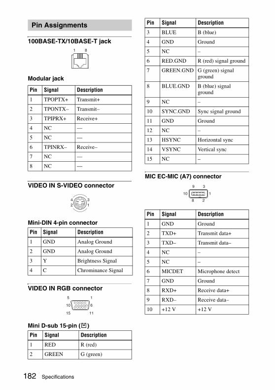
100BASE-TX/10BASE-T jack
Modular jack
VIDEO IN S-VIDEO connector
Mini-DIN 4-pin connector
VIDEO IN RGB connector
Mini D-sub 15-pin ( )
MIC EC-MIC (A7) connector
Pin Assignments
Pin Signal Description
1 TPOPTX+ Transmit+
2 TPONTX– Transmit–
3 TPIPRX+ Receive+
4 NC —
5 NC —
6 TPINRX– Receive–
7 NC —
8 NC —
Pin Signal Description
1 GND Analog Ground
2 GND Analog Ground
3 Y Brightness Signal
4 C Chrominance Signal
Pin Signal Description
1 RED R (red)
2 GREEN G (green)
1 8
42
31
15 11
5 1
10 6
3 BLUE B (blue)
4 GND Ground
5 NC –
6 RED.GND R (red) signal ground
7 GREEN.GND G (green) signal ground
8 BLUE.GND B (blue) signal ground
9 NC –
10 SYNC.GND Sync signal ground
11 GND Ground
12 NC –
13 HSYNC Horizontal sync
14 VSYNC Vertical sync
15 NC –
Pin Signal Description
1 GND Ground
2 TXD+ Transmit data+
3 TXD– Transmit data–
4 NC –
5 NC –
6 MICDET Microphone detect
7 GND Ground
8 RXD+ Receive data+
9 RXD– Receive data–
10 +12 V +12 V
Pin Signal Description
1
3
2
9
8
10
182 Specifications

Appendix
AUDIO IN MIC/AUX 1 connector
XLR 3-pin connector ( )
AUDIO OUT/REC OUT (MIXED) connector
XLR 3-pin connector ( )
CAMERA CONTROL (VISCA) MAIN/SUB connector
Mini DIN 8-pin connector ( )
Pin Signal Description
1 GND Ground
2 X Audio signal+
3 Y Audio signal–
Pin Signal Description
1 GND Ground
2 X Audio signal+
3 Y Audio signal–
Pin Signal Description
1 DTR DTR output
2 DSR NC
3 TXD Transmit data output
4 GND Ground
12
3
21
3
136
258
7
5 RXD Receive data input
6 GND Ground
7 NC –
8 NC –
Pin Signal Description
183Specifications
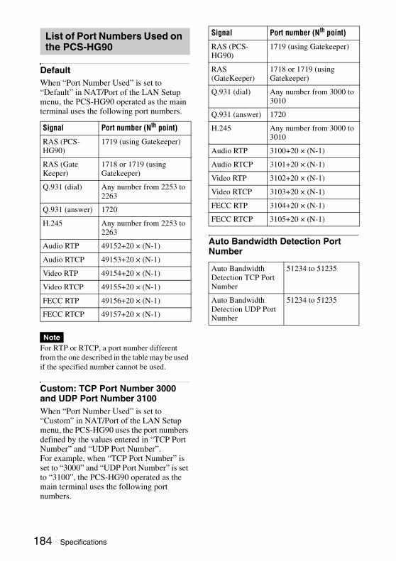
DefaultWhen “Port Number Used” is set to “Default” in NAT/Port of the LAN Setup menu, the PCS-HG90 operated as the main terminal uses the following port numbers.
For RTP or RTCP, a port number different from the one described in the table may be used if the specified number cannot be used.
Custom: TCP Port Number 3000 and UDP Port Number 3100When “Port Number Used” is set to “Custom” in NAT/Port of the LAN Setup menu, the PCS-HG90 uses the port numbers defined by the values entered in “TCP Port Number” and “UDP Port Number”.For example, when “TCP Port Number” is set to “3000” and “UDP Port Number” is set to “3100”, the PCS-HG90 operated as the main terminal uses the following port numbers.
Auto Bandwidth Detection Port Number
List of Port Numbers Used on the PCS-HG90
Signal Port number (Nth point)
RAS (PCS-HG90)
1719 (using Gatekeeper)
RAS (GateKeeper)
1718 or 1719 (using Gatekeeper)
Q.931 (dial) Any number from 2253 to 2263
Q.931 (answer) 1720
H.245 Any number from 2253 to 2263
Audio RTP 49152+20 × (N-1)
Audio RTCP 49153+20 × (N-1)
Video RTP 49154+20 × (N-1)
Video RTCP 49155+20 × (N-1)
FECC RTP 49156+20 × (N-1)
FECC RTCP 49157+20 × (N-1)
Note
Signal Port number (Nth point)
RAS (PCS-HG90)
1719 (using Gatekeeper)
RAS (GateKeeper)
1718 or 1719 (using Gatekeeper)
Q.931 (dial) Any number from 3000 to 3010
Q.931 (answer) 1720
H.245 Any number from 3000 to 3010
Audio RTP 3100+20 × (N-1)
Audio RTCP 3101+20 × (N-1)
Video RTP 3102+20 × (N-1)
Video RTCP 3103+20 × (N-1)
FECC RTP 3104+20 × (N-1)
FECC RTCP 3105+20 × (N-1)
Auto Bandwidth Detection TCP Port Number
51234 to 51235
Auto Bandwidth Detection UDP Port Number
51234 to 51235
184 Specifications

Appendix
Video Communication Room Layout
Be sure to position the camera and microphone appropriately in your video communication room.
represents the shooting area of the camera when the zoom has been extended fully. indicates the shooting area of the camera when the left/right angling function is fully utilized. Use the measurements below as a guide for the layout of your video communication room.
Top view (horizontal range at maximum zoom-out)
Side view (vertical range at maximum zoom-out)
Layout Considerations• Avoid having large, moving objects,
especially people, behind the participants, as the quality of the picture transmitted to the remote party will deteriorate.
• Do not seat participants in front of a wall with fine stripe patterns.
• Choose a room where echo will not occur.• Do not install the system near noise
sources such as air conditioners or copy machines.
• Avoid placing the system in a room where there are the speakers used for an in-house broadcasting system.
Lighting ConsiderationsDo not point the camera toward a window where sunlight comes in as back lighting may decrease the contrast. If it is necessary, cover the window with a thick curtain.
Camera Range
185Video Communication Room Layout
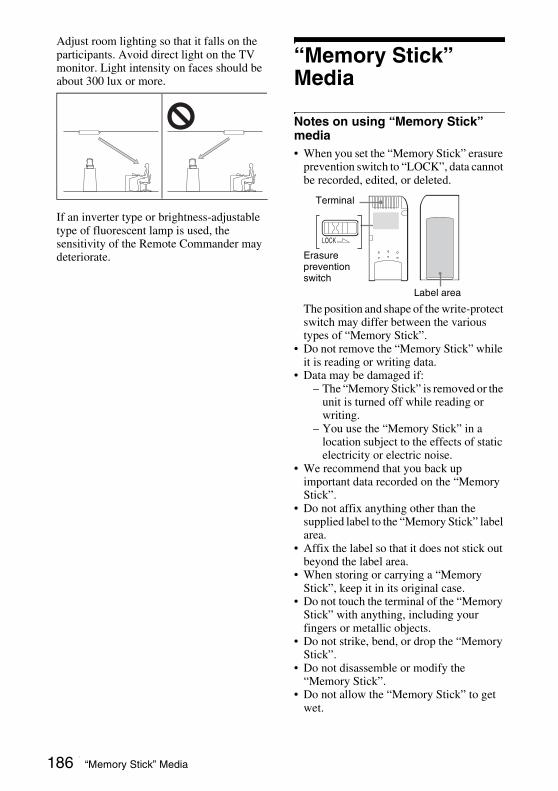
Adjust room lighting so that it falls on the participants. Avoid direct light on the TV monitor. Light intensity on faces should be about 300 lux or more.
If an inverter type or brightness-adjustable type of fluorescent lamp is used, the sensitivity of the Remote Commander may deteriorate.
“Memory Stick” Media
Notes on using “Memory Stick” media • When you set the “Memory Stick” erasure
prevention switch to “LOCK”, data cannot be recorded, edited, or deleted.
The position and shape of the write-protect switch may differ between the various types of “Memory Stick”.
• Do not remove the “Memory Stick” while it is reading or writing data.
• Data may be damaged if:– The “Memory Stick” is removed or the
unit is turned off while reading or writing.
– You use the “Memory Stick” in a location subject to the effects of static electricity or electric noise.
• We recommend that you back up important data recorded on the “Memory Stick”.
• Do not affix anything other than the supplied label to the “Memory Stick” label area.
• Affix the label so that it does not stick out beyond the label area.
• When storing or carrying a “Memory Stick”, keep it in its original case.
• Do not touch the terminal of the “Memory Stick” with anything, including your fingers or metallic objects.
• Do not strike, bend, or drop the “Memory Stick”.
• Do not disassemble or modify the “Memory Stick”.
• Do not allow the “Memory Stick” to get wet.
Terminal
Erasure prevention switch
Label area
186 “Memory Stick” Media
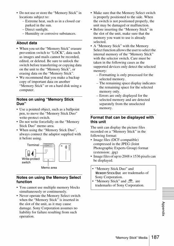
Appendix
• Do not use or store the “Memory Stick” in locations subject to:
– Extreme heat, such as in a closed car parked in the sun.
– Direct sunlight.– Humidity or corrosive substances.
About data• When you set the “Memory Stick” erasure
prevention switch to “LOCK”, data such as images and mails cannot be recorded, edited, or deleted. Be sure to unlock the switch before transferring or copying data on the unit to the “Memory Stick”, or erasing data on the “Memory Stick”.
• We recommend that you make a backup copy of important data on another “Memory Stick” or on a hard disk using a computer.
Notes on using “Memory Stick Duo”• Use a pointed object, such as a ballpoint
pen, to move the “Memory Stick Duo” write-protect switch.
• Do not write forcefully on the “Memory Stick Duo” memo area.
• When using the “Memory Stick Duo”, always connect the adaptor supplied with it before using.
Notes on using the Memory Select function• You cannot use multiple memory blocks
simultaneously or continuously.• Never operate the Memory Select switch
when the “Memory Stick” is inserted in the slot of the unit, as it may cause damage. Sony Corporation assumes no liability for failure resulting from such operation.
• Make sure that the Memory Select switch is properly positioned to the side. When the switch is not positioned properly, the unit may be damaged or malfunction.
• Before inserting the “Memory Stick” in the slot of the unit, make sure that the memory you want to use is already selected.
• A “Memory Stick” with the Memory Select function allows the user to select the internal memory of the “Memory Stick” with the selector switch. Care must be taken in the following cases as the supported devices only detect the selected memory:
– Formatting is only processed for the selected memory.
– The remaining space display indicates the remaining space for the selected memory only.
– Errors are only displayed for the selected memory and are detected separately from the unselected memory.
Format that can be displayed with this unitThe unit can display the picture files recorded on a “Memory Stick” in the following format:• Image files (DCF-compatible)
compressed in the JPEG (Joint Photographic Experts Group) format (extension: .jpg)
• Image files of up to 2048 × 1536 pixels can be displayed.
Terminal
Write-protect switch
Memo area • “Memory Stick Duo” and are trademarks of
Sony Corporation.• “Memory Stick” and are
trademarks of Sony Corporation.
187“Memory Stick” Media
Glossary
ARCAn abbreviation for Adaptive Rate Control. Technology which automatically lowers a video streaming bitrate against network congestion.
ARQAn abbreviation for Automatic Repeat reQuest. Error control method in which the receiver requests a retransmission from the transmitter when a packet loss occurs.
Auto Bandwidth DetectionDetects the network bandwidth and others before communication. By using this value for the QoS function, optimum QoS control is available from the beginning of the communication.
CodecAn abbreviation for COder-DECoder. An integrated device of a coder that converts an analog audio/video signal to a digital data stream and compresses it, and a decoder for expanding to restore the original analog signal.
DHCPAn abbreviation for Dynamic Host Configuration Protocol. Manages IP addresses in the network.
DNSAn abbreviation for Domain Name System. Defines the domain name system.
Echo CancelerDevice to eliminate echo that occurs when transmitting audio.
FECAn abbreviation for Forward Error Correction. Error control method in which the receiver can correct errors without requesting a retransmission from the transmitter.
Frame rate
The number of frames which can be encoded/decoded in one second.
G.711Audio encoding/decoding format recommended by the ITU-T. A phone bandwidth audio signal is converted to a digital signal with a data rate of 64 Kbps. It can be transmitted with a data rate of 56 Kbps.
G.722Audio encoding/decoding format recommended by the ITU-T. A 7-kHz bandwidth audio signal is converted to a digital signal with a data rate of 48 Kbps, 56 Kbps or 64 Kbps.
G.728Audio encoding/decoding format recommended by the ITU-T. A phone bandwidth audio signal is converted to a digital signal with a data rate of 16 Kbps.
GatekeeperControls the access of H.323 video communication devices on a network. Administers the zone, access limitation, audio/video bandwidth, and alias etc.
H.264A video coding algorithm standardized by the ITU-T in May 2003. This format realizes high-quality picture via a lower bit rate. It provides an equal picture quality via half as low bit rate as the H.263 format. The H.264 format is also called as MPEG4 Advanced Video Coding (AVC).
H.323This enables communications on the non-QOS (Quality of Service) LAN.
HDAn abbreviation for High Definition. High Definition television provides a high-resolution and high-quality picture. There are 1080i and 720p HD formats.
HD-SDIHigh Definition Serial Digital Interface. This is the standard that defines business-use serial digital video format.
188 Glossary
Appendix
HOPNumber of routers that have passed through to reach the remote party.
ITU-TAn abbreviation for International Telecommunication Union, Telecommunications.
MCUAn abbreviation for Multipoint Control Unit. When connecting an MCU, a multipoint connection is possible.
NTSCAn abbreviation for National TV Standards Committee. NTSC is the television system in use in Japan, the United States, etc.It is not compatible with the PAL system.
PALAn abbreviation for Phase Alternation Line. PAL is the television system in use in Europe, China, etc.It is not compatible with the NTSC system.
pingA command to check if the specified IP address is connected to the IP network.
QoSAn abbreviation for Quality of Service. QoS reserves a bandwidth for specific communication in the network and guarantees a given communication speed.
RTT (Round Trip Time)Round-trip delay time. The time required for a packet to reach a remote terminal and come back.
SNMPAn abbreviation for Simple Network Management Protocol. This protocol is for management information between the management station and the managed terminals.
TOSInputting the information data in the TOS field of the IP address allows the communication system to judge the packet transmission priority, etc. It also enables
change of path according to the types of service (Delay or Size).
TracerouteA command to trace the route across the IP network to reach the connected IP address.
YPbPrComponent video that is transmitted with three signal cables Y–, Pb and Pr.
189Glossary

Menu ConfigurationThe menus of this system are configured as described below.For detailed information, see pages in parentheses. The initial settings of each item are bolded.
Launcher Menu Dial Setup A Answer B Communication Mode C Status D Audio Setup E Video Setup F General Setup G Administrator Setup H LAN Setup I Encryption Setup J Machine Information K
Phone Book/ List Edit Still Image Private Index Phone Book IP Dial Mode Single, mulitpoint Communication Bit Rate 2Mbps, 2.5Mbps, 3Mbps, 4Mbps, 5Mbps, 6Mbps, 7Mbps, 8Mbps, Other Auto Dial On, Off Detailed Dial IP Dial Mode Single, multipoint Communication Bit Rate 2Mbps, 2.5Mbps, 3Mbps, 4Mbps, 5Mbps, 6Mbps, 7Mbps, 8Mbps, Other History Camera Preset Save 1, 2, 3, 4, 5, 6 Preset Load 1, 2, 3, 4, 5, 6 Adjustments Angle, Zoom, Focus, Auto adjustment On/Off, Brightness, Backlight On/Off Memory Stick Save Format Reject Answer On, Off Icon Display On, Off
(page 77) (page 36)
(page 60)
(page 81)
(page 85)
(page 78)
(page 97)
(page 78)
Continued on
(page 111)
190 Menu Configuration

Appendix
A Dial Setup Page: 1/1 More Options Enable On, Off User Name Input On, Off Select LAN Prefix Enable, Disable LAN Prefix Number input
(page 37)
B Answer Page: 1/1 Auto Answer Auto Answer, Off Mic on Answer On, Off Reject Answer On, Off
(page 37)
Communication Mode Page: 1/2 Peer-to-Peer/Multipoint Common Settings, Individual Settings Transmission/Reception Bit Rate Common Settings, Individual Settings Multipoint Connection Enable, Disable
Page: 2/2 Communication Bit Rate 1) 2Mbps, 2.5Mbps, 3Mbps, 4Mbps,5Mbps, 6Mbps, 7Mbps, 8Mbps, Other Total Bandwidth 4Mbp, 5Mbps, 6Mbps, 7Mbps, 8Mbps, Other Video Mode 2) H.264 Video Frame 3) 60p, 30p, 50p, 25p, Auto Audio Mode 4) Auto, AAC Monaural 48K, AAC Monaural 96K, AAC Stereo 48K, AAC Stereo 96K, G.728, G.722, G.711 Far End Camera Control On, Off
(page 38)
1) Setting items change according to the settings of “Peer-to-Peer/Multipoint” and “Transmission/Reception Bit Rate”.When “Peer-to-Peer/Multipoint” is set to “Individual Settings” or “Transmission/Reception Bit Rate” is set to “Individual Settings”, you can set this item for Peer-to-Peer connection and Multipoint connection respectively, or for transmission and reception respectively.
2), 3), 4) When “Peer-to-Peer/Multipoint” is set to “Individual Settings”, you can set these items for “Peer-to-Peer Connection” and “Multipoint Connection” respectively.
191Menu Configuration
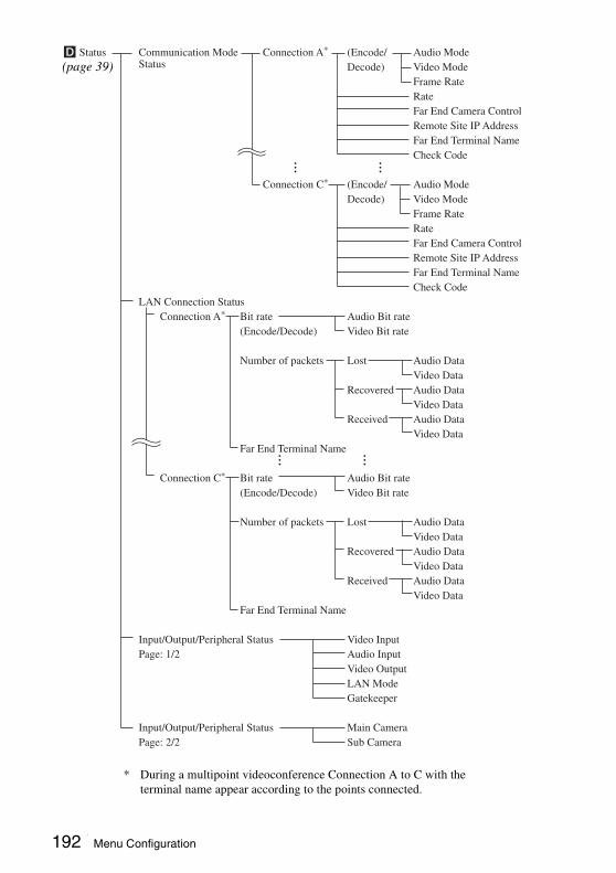
D Status Communication Mode Connection A* (Encode/ Audio Mode Status Decode) Video Mode Frame Rate Rate Far End Camera Control Remote Site IP Address Far End Terminal Name Check Code
Connection C* (Encode/ Audio Mode Decode) Video Mode Frame Rate Rate Far End Camera Control Remote Site IP Address Far End Terminal Name Check Code LAN Connection Status Connection A* Bit rate Audio Bit rate (Encode/Decode) Video Bit rate
Number of packets Lost Audio Data Video Data Recovered Audio Data Video Data Received Audio Data Video Data Far End Terminal Name
Connection C* Bit rate Audio Bit rate (Encode/Decode) Video Bit rate
Number of packets Lost Audio Data Video Data Recovered Audio Data Video Data Received Audio Data Video Data Far End Terminal Name
Input/Output/Peripheral Status Video Input Page: 1/2 Audio Input Video Output LAN Mode Gatekeeper
Input/Output/Peripheral Status Main Camera Page: 2/2 Sub Camera
...
...
...
...
(page 39)
* During a multipoint videoconference Connection A to C with the terminal name appear according to the points connected.
192 Menu Configuration
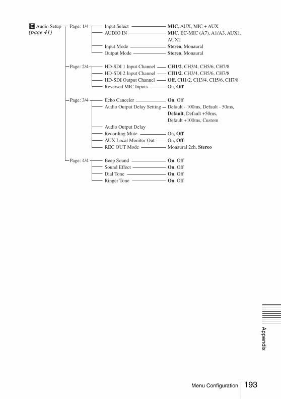
Appendix
E Audio Setup Page: 1/4 Input Select MIC, AUX, MIC + AUX AUDIO IN MIC, EC-MIC (A7), A1/A3, AUX1, AUX2 Input Mode Stereo, Monaural Output Mode Stereo, Monaural
Page: 2/4 HD-SDI 1 Input Channel CH1/2, CH3/4, CH5/6, CH7/8 HD-SDI 2 Input Channel CH1/2, CH3/4, CH5/6, CH7/8 HD-SDI Output Channel Off, CH1/2, CH3/4, CH5/6, CH7/8 Reversed MIC Inputs On, Off
Page: 3/4 Echo Canceler On, Off Audio Output Delay Setting Default - 100ms, Default - 50ms, Default, Default +50ms, Default +100ms, Custom Audio Output Delay Recording Mute On, Off AUX Local Monitor Out On, Off REC OUT Mode Monaural 2ch, Stereo
Page: 4/4 Beep Sound On, Off Sound Effect On, Off Dial Tone On, Off Ringer Tone On, Off
(page 41)
193Menu Configuration

F Video Setup Video Input / Link to Audio Input On, Off Output VIDEO IN HD-SDI 1, HD-SDI 2, YPbPr, RGB, S-VIDEO Audio Input Select MIC, AUX, MIC+AUX AUDIO IN MIC, EC-MIC(A7), A1/A3, AUX1, AUX2, HD-SDI Video Format Output Video Format 1080, 720 Page: 1/1 Frequency 50Hz, 60Hz Custom HD-SDI 1 (MAIN) Input Label HD-SDI 2 (SUB) Page:1/1 YPbPr
RGB S-VIDEO
Transmitting Image Quality (HD-SDI 1) Page: 1/5 Transmitting Image Quality (HD-SDI 2) Page: 2/5 Transmitting Image Quality (YPbPr) Page: 3/5 Transmitting Image Quality (RGB) Page: 4/5 Transmitting Image Quality (S-VIDEO) Page: 5/5
Other Settings S-Video Signal Format NTSC, PAL Page:1/2 Image Flip: Main Camera On, Off Image Flip: Sub Camera On, Off Digital Zoom: Main Camera On, Off Digital Zoom: Sub Camera On, Off Default Display Pattern Full Screen, PandP, Side by Side Other Settings Presentation Screen Full Screen, PandP, Side by Side Page:2/2 Aspect Ratio for RGB Input 4:3, 16:9 Aspect Ratio for S-VIDEO Input 4:3, 16:9
Setting Mode Auto, Detailed SetupMotion Smoothing Filter Auto, Off, Low, Medium, High2D Smoothing Filter Auto, Off, Low, Medium, HighFrame Rate Control Auto, Frame Rate Priority, Bandwidth Limiting Priority
(page 43)
194 Menu Configuration

Appendix
G General Setup Device Setup Terminal Name Page:1/1 Language English, French, German, Japanese, Spanish, Italian, Simplified Chinese, Portuguese, Traditional Chinese, Korean, Russian Last Number Registration On, Off Control by Far End On, Off Standby Mode On, Off Standby Time
Clock Set NTP On, Off Page: 1/1 Primary NTP Server Secondary NTP Server Time Zone Clock Display Pattern Year/Month/Day, Month/Day/Year, Day/Month/Year, Year-Month-Day, Day.Month.Year Clock Set Time Update Menu Screens Time Display On, Off Page: 1/2 Display Terminal Name Off, Show temporarily, Always on Character Input Help On, Off Guide On, Off Indicator On, Off
Menu Screens Message On, Error message display, Off Page: 2/2 Communication Mode Display On, Off
Launcher Screen Launcher Display On, Off Page: 1/3 Phone Book Button On, Off Detailed Dial Button On, Off History Button On, Off Camera Button On, Off Memory Stick Button On, Off
Launcher Screen Direct Phone Book Button On, Off Page: 2/3 Direct Dial On, Off Clock Display On, Off Local Terminal Name On, Off Capture Button On, Off
Launcher Screen Number Display GK:User Alias, GK:User Number, Page: 3/3 NAT:Address, IP:Address, No diaplay Video Input Diaplay On, Off Audio Input Diaplay On, Off Level Master On, Off
(page 47)
195Menu Configuration

Network Quality Measurement IP Address of Remote SitePage: 1/4 Port Number of Remote Site Maximum Bandwidth 2Mbps, 2.5Mbps, 3Mbps, 4Mbps, 5Mbps, 6Mbps, 7Mbps, 8Mbps, Other Packet Size Gateway ping Traceroute Load and Stress Test Start Measurement
Result of Network Quality Measurement Gateway ResultPage: 2/4 ping Result, Packet Loss, RTT, H.323 Traceroute HOP, Total RTT
Result of Network Quality Measurement Network Quality Status(Simplex) Packet Loss Page: 3/4 (Encode/Decode) Audio, 2Mbps, 2.5Mbps, 3Mbps, 4Mbps, 5Mbps, 6Mbps, 7Mbps, 8Mbps, Other Jitter (Encode/Decode) Audio, 2Mbps, 2.5Mbps, 3Mbps, 4Mbps, 5Mbps, 6Mbps, 7Mbps, 8Mbps, Other
H Administrator Setup Password Administrator PasswordPage: 1/3 Phone Book Modification Password Save Settings Password Remote Access Password
Password Dial Setup Enable, DisablePage: 2/3 Answer Setup Enable, Disable Communication Enable, Disable Audio Setup Enable, Disable Video Setup Enable, Disable General Setup Enable, DisablePassword LAN Setup Enable, DisablePage: 3/3 Encryption Setup Enable, Disable
Phone Book Save Phone BookPage: 1/2 Load Phone Book Clear Phone BookPhone Book Auto Dialing On, OffPage: 2/2 Create Private Phone Book Delete Private Phone Book Copy to Private Phone Book
(page 50)
r Continued
196 Menu Configuration
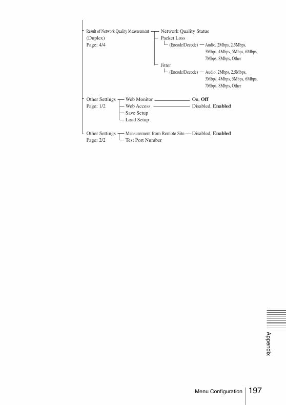
Appendix
Result of Network Quality Measurement Network Quality Status(Duplex) Packet Loss Page: 4/4 (Encode/Decode) Audio, 2Mbps, 2.5Mbps, 3Mbps, 4Mbps, 5Mbps, 6Mbps, 7Mbps, 8Mbps, Other Jitter (Encode/Decode) Audio, 2Mbps, 2.5Mbps, 3Mbps, 4Mbps, 5Mbps, 6Mbps, 7Mbps, 8Mbps, Other Other Settings Web Monitor On, OffPage: 1/2 Web Access Disabled, Enabled Save Setup Load Setup
Other Settings Measurement from Remote Site Disabled, EnabledPage: 2/2 Test Port Number
197Menu Configuration

I LAN Setup General DHCP Mode Auto, Off Page: 1/2 Host Name IP Address Network Mask Gateway Address DNS Address General LAN Mode Auto Negotiation, 100Mbps Full Duplex, Page: 2/2 100Mbps Half Duplex, 10Mbps Full Duplex, 10Mbps Half Duplex
Gatekeeper Gatekeeper Mode On, Off Page: 1/1 Gatekeeper Address User Alias User Number
SNMP SNMP Mode On, Off Page: 1/1 Trap Destination Community Description Location Contact
PPPoE PPPoE On, Off Page: 1/2 PPPoE User Name PPPoE Password
PPPoE Fixed IP for PPPoE On, Off Page: 2/2 Fixed IP Address for PPPoE PPPoE DNS Specify, Obtain automatically Primary DNS Secondary DNS
NAT/Port NAT Mode On, Off Page: 1/2 NAT Address
NAT/Port Port Number Used Custom, Default Page: 2/2 TCP Port Number UDP Port Number Auto Bandwidth Delection TCP Port Number Auto Bandwidth Delection UDP Port Number
QoS Detailed Setup On, Off Page: 1/2 QoS On, Off Forward Error Correction (FEC) On, Off Packet Resend Request (ARQ) On, Off Adaptive Rate Control (ARC) On, Off Auto Bandwidth Detection On, Off
QoS Forward Error Correction Page: 2/2 Redundancy 8, 4, 2, Auto Buffering Time 300ms, 150ms, 80ms, Auto, Custom Custom
TOS Off Page: 1/3 IP Precedence IP Precedence (Video) Low Delay On, Off Page: 2/3 High Throughput On, Off (Audio) High Reliability On, Off Page: 3/3 Minimum Cost On, Off (Camera Diffserve Diffserve value Control)
(page 54)
198 Menu Configuration
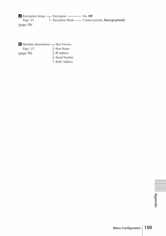
Appendix
J Encryption Setup Encryption On, OffPage: 1/1 Encryption Mode Connect priority, Encrypt priority
(page 59)
K Machine Information Host VersionPage: 1/2 Host Name IP Address Serial Number MAC Address
(page 59)
199Menu Configuration

Sony Corporation