Verifying Autonomic Fault Mitigation Strategies in Large Scale Real-Time Systems
10
Verifying Autonomic Fault Mitigation Strategies in Large Scale Real-Time Systems Abhishek Dubey Steve Nordstrom Turker Keskinpala Sandeep Neema Ted Bapty Institute for Software Integrated Systems Department of Electrical Engineering and Computer Science Vanderbilt University, Nashville, TN 37203, USA {dabhishe, steve-o, tkeskinpala, sandeep, bapty}@isis.vanderbilt.edu Abstract In large scale real-time systems many problems associ- ated with self-management are exacerbated by the addition of time deadlines. In these systems any autonomic behavior must not only be functionally correct but they must also not violate properties of liveness, safety and bounded time re- sponsiveness. In this paper we present and analyze a real- time Reflex Engine for providing fault mitigation capabil- ity to large scale real time systems. We also present a se- mantic domain for analyzing and verifying the properties of such systems along with the framework of real-time reflex engines. 1. Introduction Advancements in computing technology coupled with increased integration between information and the physical world has enabled the use of computing devices for control- ling modern systems. At the same time, the proliferation in communication bandwidth and ability to construct complex systems from simpler components is abetting the increase in capability and complexity of these computer based systems (CBS). The impact of this technological progress can be felt from small systems such as pacemakers to large systems used in military, high performance computing and avionics. A side-effect of an increase in system complexity is an increase in chances of system failure. On the other hand, an interesting contradiction is the rise in demand of relia- bility of complex CBS used in critical areas such as nuclear plants. The demand of system reliability even in the wake of increasing complexity has ensured that fault-tolerance be- comes a sine qua non of the design cycle. Fault tolerance can be implemented by employing hu- mans to make fault mitigation decisions. However, usually the involvement of humans leads to latency in a fault miti- gation decision which (a) might not be acceptable in critical systems, and (b) usually results in pecuniary losses. More- over, in certain situations human decision making might be unavailable due to a lack of plant accessibility such as in high energy physics applications and space systems. This drives the need for an alternate paradigm for au- tonomic computing systems that are self aware, self con- figuring, self healing, and self protecting [1, 2, 3]. Such systems employ fault managers for making the necessary changes in the wake of failures. A motivation for this al- ternate paradigm comes from the biological world and the ways in which biological systems handle similar challenges of fault tolerance and self management. Challenges associated with self-management are exacer- bated by the addition of time deadlines. In real-time sys- tems, it is not enough to compute correct results, but to compute correct results within the given time deadline [4]. In such systems, a correct but “late” fault mitigation action is an incorrect system behavior. Even in systems which are not real-time by themselves it may be required that the sys- tem is repaired within strict time bounds. The autonomic behaviors for such systems must not only be functionally correct but they must also not violate the following proper- ties: 1. Liveness: Assuming that the original system was dead- lock free, the addition of autonomic behaviors will not lead to a deadlock in the system. 2. Safety: The system will meet all of its deadlines and never operate in unsafe modes. 3. Bounded time responsiveness: In the case of faults, the designed fault mitigation action will be executed within a specified time bound. Our previous work in large scale autonomic computing yielded a Reflex and Healing (RH) framework presented in
-
Upload
independent -
Category
Documents
-
view
1 -
download
0
Transcript of Verifying Autonomic Fault Mitigation Strategies in Large Scale Real-Time Systems

Verifying Autonomic Fault Mitigation Strategies in Large Scale Real-TimeSystems
Abhishek Dubey Steve Nordstrom Turker Keskinpala Sandeep Neema Ted Bapty
Institute for Software Integrated SystemsDepartment of Electrical Engineering and Computer Science
Vanderbilt University, Nashville, TN 37203, USA{dabhishe, steve-o, tkeskinpala, sandeep, bapty}@isis.vanderbilt.edu
Abstract
In large scale real-time systems many problems associ-ated with self-management are exacerbated by the additionof time deadlines. In these systems any autonomic behaviormust not only be functionally correct but they must also notviolate properties of liveness, safety and bounded time re-sponsiveness. In this paper we present and analyze a real-time Reflex Engine for providing fault mitigation capabil-ity to large scale real time systems. We also present a se-mantic domain for analyzing and verifying the properties ofsuch systems along with the framework of real-time reflexengines.
1. Introduction
Advancements in computing technology coupled withincreased integration between information and the physicalworld has enabled the use of computing devices for control-ling modern systems. At the same time, the proliferation incommunication bandwidth and ability to construct complexsystems from simpler components is abetting the increase incapability and complexity of these computer based systems(CBS). The impact of this technological progress can be feltfrom small systems such as pacemakers to large systemsused in military, high performance computing and avionics.
A side-effect of an increase in system complexity is anincrease in chances of system failure. On the other hand,an interesting contradiction is the rise in demand of relia-bility of complex CBS used in critical areas such as nuclearplants. The demand of system reliability even in the wake ofincreasing complexity has ensured that fault-tolerance be-comes a sine qua non of the design cycle.
Fault tolerance can be implemented by employing hu-mans to make fault mitigation decisions. However, usually
the involvement of humans leads to latency in a fault miti-gation decision which (a) might not be acceptable in criticalsystems, and (b) usually results in pecuniary losses. More-over, in certain situations human decision making might beunavailable due to a lack of plant accessibility such as inhigh energy physics applications and space systems.
This drives the need for an alternate paradigm for au-tonomic computing systems that are self aware, self con-figuring, self healing, and self protecting [1, 2, 3]. Suchsystems employ fault managers for making the necessarychanges in the wake of failures. A motivation for this al-ternate paradigm comes from the biological world and theways in which biological systems handle similar challengesof fault tolerance and self management.
Challenges associated with self-management are exacer-bated by the addition of time deadlines. In real-time sys-tems, it is not enough to compute correct results, but tocompute correct results within the given time deadline [4].In such systems, a correct but “late” fault mitigation actionis an incorrect system behavior. Even in systems which arenot real-time by themselves it may be required that the sys-tem is repaired within strict time bounds. The autonomicbehaviors for such systems must not only be functionallycorrect but they must also not violate the following proper-ties:
1. Liveness: Assuming that the original system was dead-lock free, the addition of autonomic behaviors will notlead to a deadlock in the system.
2. Safety: The system will meet all of its deadlines andnever operate in unsafe modes.
3. Bounded time responsiveness: In the case of faults,the designed fault mitigation action will be executedwithin a specified time bound.
Our previous work in large scale autonomic computingyielded a Reflex and Healing (RH) framework presented in

[5, 6, 7]. This framework employs a hierarchical networkof fault management entities, called reflex engines, whosesole purpose is to implement fast reflexive actions when afault is detected.
An initial investigation toward applying real-time analy-sis techniques to this framework showed the modeling for-malism for RH systems to be inadequate for timed analysis.In this paper, we augment our existing RH framework basedon our earlier work to provide timed analysis capability, andpresent an approach to transform the augmented RH systeminto a semantically equivalent network of timed automa-ton models [8, 9]. Once transformed, the timed automatonmodels can be checked for the properties that ought to besatisfied by autonomic computing systems by using modelchecking tools such as UPPAAL [10], and KRONOS [11].
The outline for the remainder of this paper is as follows:In the next section we review the background of timed au-tomaton which is essential to our solution approach. Wethen describe the definition of a timed RH framework. Wewill then present the transformation of the RH frameworkinto network of timed automatons. The paper will concludewith a case study in which we will check a simple applica-tion system with two reflex strategies.
2. Background
For the benefit of our readers, we provide in this sectiona brief overview of the RH framework as well as a reviewof the definitions and semantics of a timed automaton andnetworks of timed automatons. However, readers who arefamiliar with these concepts may wish to proceed to Section3.
2.1. Reflex and Healing Framework
A reflex and healing architecture is a tree-like hierarchi-cal deployment of fault managers, also known as reflex en-gines. The justification for a hierarchical deployment vs. asingle layered approach is beyond the scope of this review.However, readers are referred to [5, 6] for a more compre-hensive study of the subject.
Fig. 1 shows an example deployment of this framework.Each reflex engine has a management domain which con-straints its zone of influence in order to manage the diffi-culty of implementing a scalable, high performance central-ized fault diagnosis and mitigation for a large system.
User applications, such as those shown in the Fig. 1,are managed by the lowest level reflex engines, termed lo-cal managers. A number of local managers themselves aregrouped together under the zone of influence of a higherlevel manager termed as regional managers. At the top liesthe global manager which supervises the health of regionalmanagers. There can be other mid-tier managers over the
Figure 1. Hierarchical fault management enti-ties in Reflex and Healing architecture.
regional managers. The communication between managersis restricted to communication between parent and children,i.e. direct communication between two managers at thesame level is forbidden. This is necessary to prevent leak-age of faults between peer zones.
2.2. Timed Automaton
Classically, for systems with continuous timed variables,the timed automaton (TA) model [8, 9] is used for prov-ing the correctness of system designs. This approach hasalso been applied to solve scheduling problems by model-ing real-time tasks and scheduling algorithms as variants oftimed automaton and performing reachability analysis onthe model [12, 13]. In this paper we have followed a similarapproach to analyze an RH framework.
A timed automaton consists of a finite set of states calledlocations and a finite set of real-valued clocks. It is as-sumed that time passes at a uniform rate for each clock inthe automaton. Transitions between locations are triggeredby the satisfaction of associated clock constraints known asguards. During a transition, a clock is allowed to be resetto zero value. These transitions are assumed to be instanta-neous. At any time the value of each clock is equal to thetime passed since the last reset of that clock. In order tomake the timed automaton urgent, locations are also asso-ciated with clock constraints called invariants which mustbe satisfied for a timed automaton to remain inside a loca-tion. If there is no enabled transition out of a location whoseinvariant has been violated, the timed automaton is said tobe blocked. Formally, a timed automaton can be defined asfollows:
Definition 1 (Timed Automaton) A timed automaton is a6-tuple TA=< Σ, S, S0, X, I, T > such that
• Σ is a finite set of alphabets which TA can accept.
• S is a finite set of locations.
• S0 ⊆ S is a set of initial locations.
• X is a finite set of clocks.
• I : S → C (X) is a mapping called location invariant.C (X) is the set of clock constraints over X defined inBNF grammar by α ::= x ≺ c|¬α|α∧α, where x ∈ Xis a clock, α ∈ C (X), ≺∈ {<,≤}, and c is a rationalnumber.
• T ⊆ S × Σ× C (X)× 2X × S is a set of transitions.The 5-tuple < s, σ, ψ, λ, s′ > corresponds to a tran-sition from location s to s′ via an alphabet σ, a clockconstraint ψ specifies when the transition will be en-abled and λ ⊆ X is the set of clocks whose value willbe reset to 0.
Figure 2. A Timed automaton model of a be-havior of traffic light.
It is customary to draw a timed automaton model as a di-rected graph with its nodes, drawn as circles or ellipses, torepresent the locations and the edges to represent the transi-tions. Initial locations are marked using concentric ellipsesor circles. Fig. 2 shows a timed automaton model of a traf-fic light. This automaton has three locations and one clockvariable. The model periodically circulates between red,yellow, and green location at a time gap of 5 units, 1 unit,and 5 units respectively.
The semantics of timed automaton models are describedas an infinite state transition graph A =< Σ, Q,Q0, R >.Each state in Q is a pair (s, v), where s ∈ S and v : X →R+ is clock value map, assigning each clock a positive realvalue. It is assumed that at any time all clocks increase witha uniform unit rate i.e. ∀x ∈ X(x = 1) is true. The initialstate of A, Q0 is given by {(q, v)|q ∈ S0 ∧∀x ∈ X(v(x) =0)}. Before defining the transition relations we must givesome notations. For any d ∈ R+, let us define v+ d a clockassignment map which increases the value of each clockx ∈ X to v(x) + d. For λ ⊆ X introduce v[λ := 0] to bethe clock assignment that maps each clock y ∈ λ to 0, butkeep the value of all clocks x ∈ X − λ same.
The transition relation R is composed of two types oftransitions:
• Delay Transitions refer to passage of time while stay-ing in the same location. They are written as (s, v) d→(s, v + d). The necessary condition is v ∈ I(s) andv + d ∈ I(s)
• Action Transitions refer to occurrence of a transi-tion from the set T . Therefore for any transition <s, σ, ψ, λ, s′ >, we can write (s, v) σ→ (s′, v[λ := 0]),given that v[λ := 0] ∈ I(s′) and v ∈ ψ.
Usually, a system is composed of several sub-systems,each of which can be modeled as a timed automaton. There-fore, for modeling of the complete system we will have toconsider the parallel composition of a network of timed au-tomatons [10, 14, 11].
2.3. Networks of Timed Automatons
We consider a network of timed automatons as the syn-chronous parallel composition of TA1||TA2||.....||TAn ofn timed automatons. Each timed automaton can synchro-nize with any other timed automaton by hand shake syn-chronization using input events and output actions. For thispurpose we assume the alphabet set Σ to consist of symbolsfor input events denoted by σ? and output actions σ! andinternal events τ . Apart from these synchronizing events,we also use the concept of a shared variable of integer typeand arrays of integers. This concept is motivated from theconcepts in timed automaton based tools such as UPPAALand KRONOS. Effectively, guard conditions can also be seton the values of shared variables. During a reset, the valuesof these shared variables can be changed to some integralquantity.
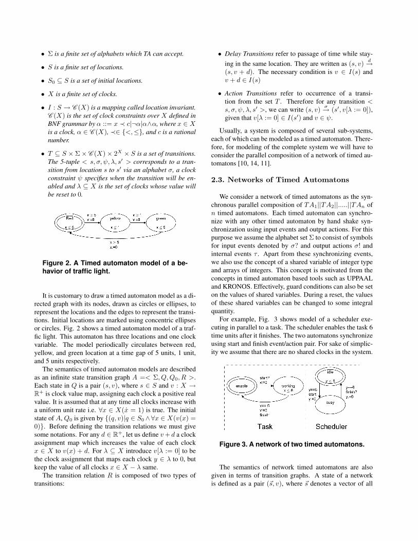
For example, Fig. 3 shows model of a scheduler exe-cuting in parallel to a task. The scheduler enables the task 6time units after it finishes. The two automatons synchronizeusing start and finish event/action pair. For sake of simplic-ity we assume that there are no shared clocks in the system.
Figure 3. A network of two timed automatons.
The semantics of network timed automatons are alsogiven in terms of transition graphs. A state of a networkis defined as a pair (~s, v), where ~s denotes a vector of all

the current locations of the network, one for each timedautomaton, and v is the clock assignment map for all theclocks of the network. The rules for delay transitions aresame as those for a single timed automaton. However, theaction transitions are composed of internal actions and syn-chronizing actions. These actions can be described as fol-lows:
1. Delay transitions are described as (~s, v) d→ (~s, v + d),if v, v + d ∈ ∩i=n
i=1 I(si), where ∀i si ∈ ~s and n is thetotal number of timed automaton in the network.
2. Internal action transitions are described as (~s, v) τ→(~s[s′
i|si], v′) if an action transition siτ→ s′
i is possiblefor ith timed automaton in the network . All the timedautomatons in the network are allowed to have internalaction transition at the same time.
3. External action transitions are associated with changein state of transitions of at least two timed automatonof the network in parallel. Suppose ith timed automa-ton produces an output action a! which is consumed byjth timed automaton as a?. Then the external actiontransition is written as (~s, v) a→ (~s[s′
i ∧ s′j |si ∧ sj ], v′).
This transition is composed of two actions transitionsof i, j single timed automaton given as si
a!→ s′i and
sja?→ s′
j . The final clock value v′ = v[λi := 0][λj :=0].
2.4. Timed Automaton Based Verification
In real-time systems, Timed Computation Tree Logic(TCTL) [15, 14, 16] is usually used in order to specify thesystem properties that need to be verified. A number ofmodel checking tools are then used to check the veracityof these properties against the system model. These toolsuse well developed algorithms described in [8, 9, 10, 11]and other similar works. The TCTL properties that can bechecked in these tools can be summarized as:
• Reachability: These set of properties deal with the pos-sible satisfaction of a given state-based predicate logicformula in a possible future state of the system. For ex-ample, the TCTL formula E3φ is true if the predicatelogic formula φ is eventually satisfied on any executionpath of the system.
• Invariance: These set of properties are also termedas safety properties. As the name suggests, invari-ance properties are supposed to be either true or falsethroughout the execution lifetime of the system. Forexample, the TCTL formula A2φ is true if the systemalways satisfies the predicate logic formula φ. A re-strictive form of invariance property is sometimes used
to check if some logical formula is always true on someexecution path of the system. An example of such aTCTL property is E2φ.
• Liveness: Liveness of a system means that it will neverdeadlock, i.e. in all the states of the system eitherthere will be an enabled action transition and/or timewill be allowed to pass without violating any loca-tion invariants. Liveness is also related to the sys-tem responsiveness. For example, the TCTL formulaA2(ψ → A3φ) is true if a state of the system sat-isfying ψ always eventually leads to a state satisfyingφ.
3. Remodeling the Reflex and Healing Frame-work
Our earlier definition of the Reflex and Healing (RH)framework provided in [5, 6] was inadequate to formally de-fine the timed behavior of a Reflex Engine (RE). This wasbecause the modeling formalism didn’t provide for faultsthat can be signaled not only by the presence of an event, butalso by the absence of a certain event in a given time inter-val. Moreover, in the earlier definition the notion of sched-ulers on a Reflex Engine was lacking. A scheduler is impor-tant in scenarios where a Reflex Engine has to choose be-tween various triggered events and process them in a timelyfashion. What follows in the next section is the new defini-tion for a Reflex Engine which adds to our earlier design ofRH framework in order to bridge the gaps described earlier.This new definition will allow us to model the RH frame-work as an equivalent network of timed automaton for anal-ysis.
3.1. Real-Time Reflex Engines
Figure 4. An overview of a real-time ReflexEngine
A real-time Reflex Engine, as shown in Fig. 4, comprisesof multiple fault-mitigation strategies that takes action inthe presence of certain input events which signify a fault

condition. New strategies can be added online to a real timereflex engine by an upper level external reflex engine or bydirect human intervention. Moreover, a supervisory higherlevel reflex engine can enable or disable a strategy.
The difference from our earlier design for RE is the pres-ence of a scheduler and ability of fault-mitigation strategyto measure time progress. A formalized notion of a sched-uler is required because availability of multiple events inthe buffer could enable multiple strategies. A scheduler ar-bitrates the dispatch of strategies onto the available threadsbased on the priority of the notification event that triggeredthe strategy. Formally, a real-time Reflex Engine can be de-fined as:
Definition 2 (Real-Time Reflex Engine) A real time reflexengine Er is a tuple < S,B,S ,S ′,Zi,Zo >, where S isthe scheduler , B is a buffer, S is a parallel compositionof all the enabled strategies and S ′ is the set of disabledstrategies, Zi is the set of all the possible inputs to a reflexengine and Zo is the set of all the possible outputs gener-ated by the reflex engine.
All possible communication in and out of a real-time Re-flex Engine1 is carried out through event sets Zi,Zo. Theseevent sets are a union of corresponding input and outputevent sets of all strategies implemented by that engine. Ina multi-level hierarchy as the one motivated in [6], someevents are reserved for communication between reflex en-gines that have a parent and child relationship.
We will now present the definition of the components ofa real-time Reflex Engine.
Definition 3 (Fault Mitigation Strategy) A fault mitiga-tion strategy used in a real time reflex engine is state ma-chine based failure management logic. It can be defined asa tuple S =< Q, q,Enable, Zi, Zτ+ ,T , R, Zo >, where
• Q is the set of all possible states.
• q is the initial state.
• Enable ∈ {True, False} is a Boolean flag used toenable or disable a strategy.
• Zi is the set of all possible external events (input) towhich the strategy is subscribed. Every strategy hastwo special events start ∈ Zi and finish ∈ Zo whichare used to communicate with the scheduler.
• Zτ+ is the set of all events generated due to passage oftime.
• T ∈ Q × (Zi ∪ Zτ+) × Q is the set of all possibletransitions that can change the state of the strategy dueto passage of time or arrival of an input event.
1In the rest of this paper we will use the term reflex engine and real-timeReflex Engine interchangeably without ambiguity.
• Zo is the set of all possible output events and miti-gation actions generated by the strategy. For sake ofbrevity one can abstract the mitigation action as anevent.
• R : T → Zo is the reflex action map which generatesan output event every time a transition is taken.
In order to make the communication between the reflexengines and the plant unambiguous it is required that thereis no overlap between subscribed events of two differentstrategies.
The time-based events associated with any strategy canbe divided into two groups, internal time-based events andexternal time-based events. Internal time-based events aregenerated and used to measure time while the strategy isexecuting on a thread. However, if the strategy needs tomeasure time across two instances of execution, it can starta timer task, which shall generate the time-based event afterthe required passage of time. This timer is a high prioritytask and it should be allowed to execute non-preemptivelyuntil completion. We call the execution time duration ofthe timer as the lifetime of the timer. For the purposes ofanalysis we restrict the lifetime of the timer to the set ofdense but countable positive rational numbers.
The execution of timers and strategies is governed by thescheduler. This scheduler picks up the input events fromthe buffer and then executes a number of strategies whichin turn will perform the required mitigation action and gen-erate some output events. We say that a strategy is triggeredwhen the event to which it is subscribed is present in thebuffer. We can describe the scheduler as follows:
Definition 4 (Scheduler) A scheduler S, maps the inputevents in the buffer to the corresponding strategies. It thenuses an arbitration scheme to select and execute a maximumm triggered strategies based on the priority of the notifica-tion event that triggered the strategy. Here m signifies thenumber of available threads.
A primitive scheduler may employ First in First out(FIFO) scheme to dispatch triggered strategies on the avail-able thread.
3.2. Problem Formalization
Consider a large scale real time system supported by aframework of hierarchical reflex engines for fault mitiga-tion purposes. In order to guarantee the correctness of thesystem we need to be able to verify that the system pos-sesses the properties of liveliness, safety, and bounded timeresponsiveness.
Property 1 (Safety) The system shall always be schedula-ble i.e. it will not miss any deadline. Moreover, buffers ofreflex engines shall never overflow.

Property 2 (Liveness) The system shall always be void ofdeadlocks.
Property 3 (Bounded Time Responsiveness) The mitiga-tion response from a strategy shall be produced within cer-tain time period off the generation of fault event.
4. Analyzing the RH Framework
In this paper, we show that the real-time reflex and heal-ing architecture can be treated as a network of timed au-tomaton. With this semantic representation, we can posequestions of safety, liveness and bounded time response ascorresponding model checking questions on the timed au-tomaton models. Though, we have done this transformationmanually, one can use the transformation rules to automati-cally synthesize the analysis model from a given specifica-tion of an RH framework.
4.1. Reflex Engines as a Network of TimedAutomatons
In this section we will map all the components of a reflexengine (refer to section 3.1) namely its strategies, buffer,and the scheduler to timed automaton models.
4.1.1 Timer timed automaton
Figure 5. Timer timed automaton.
A timer timed automaton has two locations, idle, busyand a single clock variable x. The transition from idle tobusy is guarded by a synchronized event measure? whichallows the timer to start working. The invariant associatedwith busy is given by x ≤ γ, where γ ∈ Q+ is the time in-terval which has to be measured for the requesting strategy.The transition from busy to idle is guarded by constraintx = γ. Upon this transition from busy to idle, the timergenerates an output action timeout! which is an input eventfor the requesting strategy. Fig. 5 shows this model.
4.1.2 Strategy Timed Automaton Model
Consider any strategy of a reflex engine modeled as de-scribed in Section 3. We can formulate an equivalent timedautomaton model TA=< Σ, S, S0, X, I, T > in the follow-ing way:
Figure 6. An example strategy and its corre-sponding timed automaton.
• States of the strategy Q are transformed as loca-tions of the timed automaton model. Furthermore,two new locations {Enabled,Disabled} are addedto model the cases when strategy is enabled or dis-abled. Only when the strategy is enabled can it betriggered by the presence of events in the buffer anddispatched to a thread by the scheduler. Thus S =Q ∪ {Enabled,Disabled}.
• Initial locations of the timed automaton, S0 are de-rived from the initial states of the strategy plus thenew locations {Enabled,Disabled}. Thus S0 = q ∪{Enabled,Disabled}.
• In order to measure the time spent by the strategyin each of its locations we use a clock variable x ∈X . This clock is used to generate internal time-basedevents while the strategy is executing.
• All invariants and guards to TA are specified by a timespecification used for the generation of internal time-based events that can trigger a transition.
• Output actions of the timed automaton are the sameas the set Zo and are all written with a suffix of ‘!’.The input events are same as the set Zi ∪ Zτ+ and arewritten with a suffix of ‘?’. Therefore, Σ = Zi∪Zτ+∪Zo.
• Transitions T of the timed automaton are a union oftransitions of the strategy i.e. T and transitions due toDisabled and Enabled locations. To model the abil-ity of disabling the strategy from any of its states, wespecify transitions from all locations of the timed au-tomaton to theDisabled location. Moreover, one tran-sition from Disabled to Enabled location is specifiedto model the enabling of the strategy. Lastly, a transi-tion is added from Enabled location to the initial stateq of the strategy.

• The reflex action map R of the strategy is created bymapping the output events Zo to the correspondingtransition of the timed automaton as output actions.
Fig. 6 shows an example of a strategy which has twostates nominal and faulty and its corresponding timed au-tomaton model. Note the extra states and transitions addedin the timed automaton model. The events d, e are used bythe supervisory reflex engine to disable or enable the strat-egy.
4.1.3 Buffer Timed Automaton Model
Figure 7. Buffer timed automaton listeningto two different events. More events can beadded to the model by creating new self tran-sitions.
Buffer timed automatons have an associated shared arrayof integers, called a queue. In order to uniquely identifyevents in the model, we map them to the domain of positiveintegers. The Buffer TA (see Fig. 7) has only one locationand no clocks. It uses an internal integer variable, Top, tokeep track of the queue size. An event is added to the queueby using a self transition that also increments Top. If morethan one event is available for addition to the queue at thesame time, only one gets added while the others might bedropped. Moreover, a maximum queue size is set to dropevents if the queue becomes full.
The possible dropping of events in a buffer is a safetyconcern for the RH framework. Therefore, a property thatmust be checked is to ensuring that no events are dropped.
4.1.4 Scheduler Timed Automaton Model
To express the mapping implemented by the schedulerof a reflex engine, we introduce the scheduler timed au-tomaton construct as shown in Fig.8. This automatonshares the variable queue with the buffer timed automatonmodel. The possible locations for a scheduler model are{idle, select, Strategy 1, · · · , Strategy n}, where thereare n strategies in the reflex engine.
There are no clocks in the scheduler automaton. All tran-sitions are synchronized via the start and finished events
of the strategies. The select state implements the schedul-ing policy by sorting the queue with a given priority asso-ciated with the incoming events. In the simplest case, allevents have equal priority and the select algorithm picks upthe event from the front of the queue without sorting thequeue and starts the strategy which is subscribed to this in-put event. Upon processing the event from the top of thequeue, the scheduler decrements the queue by deleting itsfront element and updating all the indices. A number ofscheduler TA models can be executed as concurrent pro-cesses when more than one thread is available to the reflexengine.
Figure 8. A scheduler timed automaton. Theselect state is the one in which the schedul-ing decision is made.
We have not delved into the modeling of main appli-cation and diagnosers as timed automatons in this paper.However, one can argue that the concerned model can bededuced from the abstraction of main application’s behav-ior used for designing the fault-mitigation strategy.
5. Timed Automaton Based Verification
Once we transform the reflex engine architecture intoa network of timed automatons we can utilize the modelchecking algorithms built in UPPAAL and KRONOS. How-ever, first we have to translate the safety, liveness, andbounded time responsiveness questions for the reflex andhealing architecture as a TCTL formula for the network oftimed automatons:
• Liveness of the reflex and healing architecture willamount to checking if the system has any deadlocks. InUPPAAL this property is preprogrammed as a macroA2 not deadlock.
• Safety of the reflex and healing architecture can bechecked by introducing an error location in all time au-tomatons and forcing a transition to error if any dead-line is missed. Then the checking of the safety prop-erty will amount to checking the reachability propertynot E3 error.

• Bounded Response Properties can be formalized usingthe reachability property and liveness property. Sup-pose we have to check if state = state1 happens thenstate = state2 will happen within 5 time units. Inorder to formulate this property, we augment the timeautomaton with an additional clock called a formulaclock, say z, whereby we reset its value to 0 on allthe transitions leading to state1 and check if the live-ness property A2(state = state1 → A3state =state1 ∧ z <= 5) is true or not.
6. Case Study
In this case study we consider a real-time experimentalphysics data processing system [17, 18], which employ asoftware task commonly referred to as a filter application.This application is responsible for filtering and marking thedata generated from high-energy particle interactions insidea particle accelerator. Interactions are classified as scientif-ically significant or not, causing only interesting data to bestored.
In order to specify the real-time properties of the filter,we assume that it has a deadline of 25 milliseconds for pro-cessing one data element. It is known that the worst caseexecution time of the filter lies between 20 to 25 millisec-onds. Fig. 9 shows the correct working filter modeled as atimed automaton. For this study we consider two types offaults:
Figure 9. In the request mode the filter col-lects the next data within 1 millisecond. Itmust complete processing within 25 millisec-onds.
• CRC faults (Fault 0) are caused if a number of dataerrors occur consecutively without giving enough timefor the filter application to apply correction algorithms.For this study, we assume a fault if the filter witnessesconsecutive occurrences of 5 CRC faults, with the timeof arrival between all consecutive pairs of faults beingless than 10 milliseconds. The mitigation action recon-figures the error detection and correction scheme to amore robust code such as Convolutional code [19].
• Timeout faults (Fault 1) are caused if a filter violatesthe 25 millisecond deadline for processing any data el-ement assigned to it. The mitigation action (mitigation1) for this fault is to reconfigure the filter, changing itsprecision, and to forward the data element to the next-level filters.
6.1. Description of Designed Strategies
For this system, we used one reflex engine, which has asingle available thread executing two possible behaviors:
• Strategy 0 uses a timer for measuring the time betweentwo consecutive occurrences of a CRC error detection.This behavior produces a mitigation action if the inter-arrival time was less than 10 milliseconds for 5 con-secutive pairs. Fig. 10 shows the state-based logic ofthis behavior along with its timer.
Figure 10. Logic of the first strategy.
• Strategy 1 simply tracks the incoming event, Timeoutfault. Its corresponding mitigation action (mitigation1) causes a change of state to a reconfiguration state,shown in Fig. 9. It has two possible locations, idle andbusy. Fig. 11 shows the logic of this state machinebased behavior.
Figure 11. Logic of second the strategy. Startand finished events are used to communicatewith the scheduler.
6.2. Analysis
We used the timed automaton model checking tool UP-PAAL for this case study. Using the mapping procedure

Figure 12. Network of timed automatons for the case study
outlined in Section 4.1, we transformed the reflex engineinto a network of timed automatons. We used the integers0,1, and 2 to represent fault 0, CRC error event, and timeoutevent of the timer in the buffer TA. The complete networkof timed automatons for this configuration is shown in Fig.12. Overall, the network has 10 synchronized input/outputevent/action pairs and 5 clocks. One clock is for the sched-uler, one measures the execution time of behavior 1, onemeasures the filter time, one is for the timer, the last clockmeasures the bounded response time for fault 0.
In order to formalize a bounded response for faults(communicated through events) using state-based predi-cates we had to use special locations called Committed lo-cations [16]. By definition, time is not allowed to passin a Committed location. Therefore, one can identifythe generation of a fault or mitigation event as an en-try/exit to/from these locations. For example, we usedthe Committed locations Filter1.Fault1 ExecV iol andFilter1.reconfiguration to represent the occurrence offault 1 and the corresponding mitigation action. Finally,the TCTL formula A2(Filter1.Fault1 ExecV iol → A
3Filter1.reconfiguration ∧ Filter1.z <= 3) was usedto check if mitigation 1 causes filter 1 to reconfigure within3 milliseconds of any occurrence of fault 1.
Table 1 shows the various properties that were verifiedfor this case study. The computer used to perform theUPPAAL analysis was a Pentium IV 3.0 GHz dual coremachine with 512 MB memory. Of the 4 properties wechecked, we discovered that the mitigation action for fault1 (execution time violation fault) cannot happen within 2milliseconds. Therefore, we can safely conclude that forthis model we will need at least 2 milliseconds to recoverfrom fault 1.
7. Conclusion and Future Work
In this paper, we presented a method for representing andanalyzing real-time autonomic systems based on our exist-ing RH framework. The real-time behavior of the systemcan be analyzed by mapping the engine components to asemantic domain of networked timed automatons.
We demonstrated our approach with a case study of a

Table 1. ResultsProperty TCTL formula ResultsLiveness A2not deadlock TrueSafety: Queue will never overflow A2not Queue.QueueOverflow TrueBounded Response: Mitigation 1 will A2(Filter1.Fault1 ExecV iolhappen within 3 milliseconds of fault 1 → A3Filter1.reconfiguration ∧ Filter1.z <= 3) TrueBounded Response: Mitigation 1 will A2(Filter1.Fault1 ExecV iolhappen within 1 milliseconds of fault 1 → A3Filter1.reconfiguration ∧ Filter1.z <= 1) False
simple filter application with two kinds of faults. Eventhough the timing data used for this case study was simu-lated, we have constructed similar autonomic systems withreal embedded hardware processing real data. These toolsand methods can be used to analyze the time-correctnessof autonomous fault tolerant strategies before they are de-ployed in a real system.
It is noteworthy to point out that computer memory re-quired for timed automaton model checking algorithms in-creases exponentially with the number of clocks. Therefore,as the size of system increases, the verification algorithmwill require an infeasible amount of memory/time in orderto execute to completion. Thus, it is not a straightforwardtask to scale this approach of model checking large systemsas a network of timed automatons.
In order to address the scalability issues we will eitherhave to reduce the total number of clocks in the systemmodel or will have to investigate ways of finding symmetri-cal patterns in the hierarchical fault architectures so that weonly need to verify the basic patterns of operation, insteadof the complete system model. We are currently exploringboth of these possibilities in order to make our approacheffective.
8. Acknowledgments
This work is supported by NSF under the ITR grant ACI-0121658. Authors are also grateful for the help of their col-leagues in the Real Time Embedded Systems (RTES) group.
References
[1] R. Sterritt and M. G. Hinchey. Autonomic computing -panacea or poppycock? In ECBS, pages 535–539, 2005.
[2] R. Sterritt. Autonomic computing. Innovations in Systemsand Software Engineering, 1(1):79–88, April 2005.
[3] M. Parashar and S. Hariri. Autonomic computing: Anoverview. In UPP, pages 257–269, 2004.
[4] G. C. Buttazzo. Hard Real-Time Computing Systems: Pre-dictable Scheduling Algorithms and Applications. KluwerAcademic Publishers, Norwell, MA, USA, 2005.
[5] S. Shetty, S. Nordstrom, S. Ahuja, D. Yao, T. Bapty, andS. Neema. Systems integration of large scale autonomic sys-
tems using multiple domain specific modeling languages. InECBS, pages 481–489, 2005.
[6] S. Nordstrom, S. Shetty, S. K. Neema, and T. A. Bapty.Modeling reflex-healing autonomy for large scale embeddedsystems. IEEE Transactions on Systems, Man, and Cyber-netics, Special Issue on Autonomic Computing, to be pub-lished in 2006.
[7] D. Yao, S. Neema, S. Nordstrom, S. Shetty, S. Ahuja, andT. Bapty. Specification and implementation of autonomiclarge-scale system behaviors using domain specific model-ing language tools. In Proceding of International Confer-ence on Software Engineering and Practice, June 2005.
[8] R. Alur and D. L. Dill. A theory of timed automata. Theo-retical Computer Science, 126(2):183–235, 1994.
[9] T. A. Henzinger, X. Nicollin, J. Sifakis, and S. Yovine. Sym-bolic model checking for real-time systems. Inf. Comput.,111(2):193–244, 1994.
[10] J. Bengtsson, K. Larsen, F. Larsson, P. Pettersson, and W. Yi.Uppaala tool suite for automatic verification of real-timesystems. In Proceedings of the DIMACS/SYCON workshopon Hybrid systems III : verification and control, pages 232–243, Secaucus, NJ, USA, 1996. Springer-Verlag New York,Inc.
[11] S. Yovine. Kronos: A verification tool for real-time sys-tems. International Journal on Software Tools for Technol-ogy Transfer, 126:110–122, 1997.
[12] P. Krcal and W. Yi. Decidable and undecidable problemsin schedulability analysis using timed automata. In TACAS,pages 236–250, 2004.
[13] G. Madl, S. Abdelwahed, and G. Karsai. Automatic verifi-cation of component-based real-time corba applications. InRTSS, pages 231–240, 2004.
[14] E. M. Clarke, O. Grumberg, and D. A. Peled. Model Check-ing. MIT Press, Cambridge MA, USA, 2000.
[15] M. Huth and M. Ryan. Logic in Computer Science: Mod-elling and Reasoning about Systems. Cambridge Universitypress, 2 edition, 2000.
[16] G. Behrmann, A. David, and K. G. Larsen. A tutorial onuppaal. In SFM, pages 200–236, 2004.
[17] J. G. et. al. Clustered data acquisition for the cms experi-ment. In International Conference on Computing In HighEnergy and Nuclear Physics, September 2001.
[18] S. Kwan. The btev pixel detector and trigger system. InFERMILAB-Conf-02/313, December 2002.
[19] A. J. Viterbi. Convolutional codes and their performance incommunication systems. IEEE Transactions on Communi-cations, 19(5):751–772, October 1971.