Venus GX Manual
58
Venus GX Manual ENGLISH
-
Upload
khangminh22 -
Category
Documents
-
view
2 -
download
0
Transcript of Venus GX Manual

Venus GX Manual
ENGLISH
Table of Contents1 Introduction 4
11 What is the Venus GX 412 Whats in the box 4
2 Internet connectivity 621 Ethernet LAN port 622 Wi-Fi 623 GX GSM 724 Mobile (cellular) network using a 3G or 4G router 725 USB tethering using a mobile phone 726 IP Configuration 827 Connecting both Ethernet and Wi-Fi (failover) 828 Minimize internet traffic 829 More information about setting up an internet connection and VRM 9
3 Accessing the GX device 1031 Accessing via the built-in WiFi Access Point 1032 Accessing Remote Console via the local LANWiFi Network 10
321 Alternative methods to find the IP Address for Remote Console 1133 Accessing via VRM 13
4 Configuration 1541 Menu structure and configurable parameters 1542 Battery State of Charge (SOC) 19
421 Which device should I use for SOC calculation 19422 The different solutions explained in detail 19423 Notes on SOC 20424 Selecting SOC source 20425 Details on VEBus SOC 22
43 Customize the logo on the Boat amp Motorhome page 2244 LEDs and Push-button 22
441 LEDs 22442 Small button located to the right of the green 14-Terminal Connector Block 22
5 Updating GX Firmware 2351 Via internet or with microSD-cardUSB-stick 2352 Direct download from the internet 2353 MicroSD-card or USB-stick 2354 Changelog 24
6 VEBus Invertercharger monitoring 2561 Input current-limiter setting 2562 Phase rotation warning 2663 Grid failure monitoring 2764 Advanced menu 27
7 DVCC - Distributed Voltage and Current Control 2971 Introduction and features 2972 DVCC Requirements 3073 DVCC effects on the charge algorithm 3074 DVCC features for all systems 31
741 Limit charge current 31742 Shared Voltage Sense (SVS) 31743 Shared Temperature Sense (STS) 32744 Shared Current Sense (SCS) 32
75 DVCC Features when using CAN-bus BMS Battery 3276 DVCC for systems with the ESS Assistant 33
8 VRM Portal 3481 VRM Portal Introduction 3482 Registering on VRM 3483 Datalogging to VRM 3484 Trouble shooting data logging 3585 Analysing data offline without VRM 3886 Remote Console on VRM - Trouble shooting 38
9 Marine MFD integration by App 4091 Introduction amp requirements 4092 Compatible MFDs and instructions 41
10 Marine MFD integration by NMEA2000 42101 NMEA2000 Introduction 42102 Supported Devices PGNs 42103 NMEA2000 Related menu settings 43104 NMEA2000-out technical details 44
Venus GX Manual
2
1041 NMEA2000 Glossary 441042 NMEA2000 Virtual-devices35 (Electrical generation) 441043 NMEA2000 Classes and functions 441044 NMEA2000 Instances 441045 NMEA2000 Changing Instances 451046 PGN 60928 NAME Unique Identity Numbers 46
11 Digital Inputs 47111 Wiring details 47112 Configuration 47113 Read-out of digital inputs via Modbus-TCP 49
12 Factory reset 5013 Error Codes 5114 FAQ 52
141 Venus GX FAQ 52142 Q2 Do I need a BMV to see proper battery state of charge 52143 Q3 I have no internet where can I insert a sim-card 52144 Q4 Can I connect both a GX Device and a VGR2VER to a MultiInverterQuattro 52145 Q5 Can I connect multiple Color Controls to a MultiInverterQuattro 52146 Q6 I see incorrect current (amps) or power readings on my VGX 52147 Q7 There is a menu entry named Multi instead of the VEBus product name 53148 Q8 There is a menu entry named Multi while there is no Inverter Multi or Quattro connected 53149 Q9 When I type the ip-address of the Color Control into my browser I see a web page mentioning Hia-watha 531410 Q10 I have multiple Solar chargers MPPT 15070 running in parallel From which one will I see therelay status in the VGX menu 531411 Q11 How long should an automatic update take 531412 Q12 I have a VGR with IO Extender how can I replace this with a Venus GX 531413 Q13 Can I use Remote VEConfigure as I was doing with the VGR2 531414 Q14 The Blue Power Panel could be powered through the VENet network can I also do that with aVenus GX 541415 Q15 What type of networking is used by the Venus GX (TCP and UDP ports) 541416 Q16 What is the functionality behind the menu item Remote support (SSH) in the Ethernet menu 541417 Q17 I donrsquot see support for VENet products in the list is that still coming 541418 Q18 What is the data usage of the Venus GX 551419 Q19 How many AC Current Sensors can I connect in one VEBus system 551420 Q20 Issues with Multi not starting when VGX is connected Caution when powering the VGX from theAC-out terminal of a VEBus Inverter Multi or Quattro 551421 Q21 I love Linux programming Victron and the VGX Can I do more 561422 Q22 How do I change the logo 561423 Q23 Multi restarts all the time (after every 10sec) 561424 Q24 What is Error 42 561425 GPL Note 57
15 More information 58
Venus GX Manual
3
1 Introduction
11 What is the Venus GXThe VGX sits at the heart of your energy installation All the other system-components - such as inverterchargers solar chargersand batteries - are connected to it The VGX ensures that they all work in harmony
Monitoring of the system can be done either with the VGX in front of you - or from anywhere in the world using an internet con-nection and the VRM Portal
The VGX also provides Remote firmware updates and allows settings to be Changed Remotely
The Venus GX is part of the GX product family GX products are Victrons state-of-the-art monitoring solution that run our Ve-nus OS operating system
All the information in this manual refers to the latest software You can check your device has the latest version in the Firmwaremenu [15] when the GX device is connected to the internet For installations without internet you can find the latest version inVictron Professional
12 Whats in the boxbull Venus GXbull Power cable with inline fuse and M8 terminal eyes for battery or DC busbar-attachmentbull Terminal Blocks for all the connectors on each sidebull Label showing WiFi key and product detailsbull Can terminator (2 pcs)
Venus GX Manual
4
Venus GX Manual
5
2 Internet connectivity
Connect the VGX to the internet to get all the advantages of the VRM Portal The VGX sends data from all connected products tothe VRM portal - from where you can monitor energy usage view the current status of connected products configure emailalarms and download data in CSV and Excel formats
To monitor this data from your smartphone or tablet download the iOS or Android VRM App
In addition to remote monitoring an active internet connection allows the VGX to regularly check for a new firmware versions -which will be automatically downloaded and installed
There are several ways to connect a VGX to the internet
bull Run a network cable between a router and the VGX Ethernet LAN portbull Connect to the router wirelessly using WiFibull Via the mobile (cellular) network using the GX GSM - a cellular USB modem or with a 3G or 4G routerbull USB Tethering on a mobile phone
This video explains how to connect LAN WiFi and a GX GSM
httpswwwyoutubecomembed645QrB7bmvY
21 Ethernet LAN portWhen you connect an ethernet cable between a router and VGX the Settings -gt Ethernet page of your VGX will confirm connec-tion
22 Wi-FiThe Venus GX includes built in Wi-Fi It is also possible to connect a supported external USB Wi-Fi dongle (to increase wirelessrange outside of a cabinet for example)
Using Wi-Fi it is possible to connect to WEP WPA and WPA2 secured networks There are five supported USB Wi-Fi donglesTwo of them are also available from stock at Victron Energy
bull Partno BPP900100200 - VGX WiFi module simple (Nano USB) small low costbull Partno BPP900200300 - Asus USB-N14 slightly higher cost and also better reception than the Nano USB Supported since
software version 223
WiFi modules that are no longer available but still supported are
bull Partno BPP900200100 - Startech USB300WN2X2Dbull Partno BPP900100100 - Zyxel NWD2105
Venus GX Manual
6
bull Partno BPP900200200 - Gembird WNP-UA-002 slightly higher cost and also better reception
Although other Wi-Fi dongles may work they have not been tested and we do not offer support for other dongles
The Wi-Fi menu shows the available networks When a network is selected it is possible to fill in the password (if the password isnot already known) to connect to the network Setting up via WPS (Wi-Fi Protected Setup) is not supported
When the VGX finds multiple Wi-Fi networks of which the password is known the strongest network is selected automaticallyWhen the signal of the connected network becomes too weak it will automatically switch to a stronger network - if it knows thepassword of that network
Wi-Fi is an inherently less reliable connection than a hardwired ethernet cable It should always be a preference to connect viaethernet when possible Signal strength should always be at least 50
23 GX GSMPlease see the GX GSM Manual
24 Mobile (cellular) network using a 3G or 4G routerTo connect the VGX to a mobile (cellular) network such as a 3G or 4G network use a cellular router Connect the VGX to thatrouter with either a LAN cable or the routers Wi-Fi network
Make sure you use a router that is designed for unattended setups Do not use low cost consumer-grade routers intended forbusiness or leisure travel A more expensive professional router will quickly pay for itself and you wont have wasted journeyssimply to perform a re-set Examples of such professional routers are the H685 4G LTE from Proroute as well as the Industrial4G router range from Pepwave
More information in this blogpost
Note that the VGX does not support USB 3G4G dongles other than the GX GSM available from Victron
25 USB tethering using a mobile phoneThis is a useful facility when it works - but dont rely on it because it has not proved very dependable Consult the internet forinstructions about tethering for your phone and its particular operating system We have heard of it working on
bull Samsung Galaxy S4
hellipbut not on
bull iPhone 5s with iOS 811
Venus GX Manual
7
26 IP ConfigurationAlmost no installations will need the IP address configuration to be inserted manually as most systems support automatic IP con-figuration (DHCP) - and that is also the VGX default setting If you do need to configure the address manually select the followingtemplate
Complete details of IP requirements as well as used port numbers will be found in the VRM FAQ - ports and connections used bythe VGX
27 Connecting both Ethernet and Wi-Fi (failover)It is possible to connect the VGX to both Ethernet and Wi-Fi In this case the VGX will try to determine which interface providesan active internet connection and then use that interface When both have an active internet connection the Ethernet connectionis used The VGX will automatically check again for active internet connections when something changes on the interfaces
28 Minimize internet trafficIn situations where internet traffic is expensive for example a satellite uplink or with roaming GSMcellular charges you may wantto minimize the internet traffic The steps to take are
bull Disable auto-updatebull Do not enable remote supportbull Reduce the Logging interval to a very low frequency Note that state changes (charging rarr inverting or bulkrarrfloat) and also
alarms will cause extra messages to be sent
To find out how much data allowance you need to buy the best way is to let the system run for a couple of days and monitor theinternet RX and TX counters in your 3G or 4G router Or even better some mobile companies will report the data used via awebsite
The amount of data used is also very dependent on the system
More products connected to the VGX will generate more data
bull A state change (from inverter to charger for example) will trigger a data transmission so a system with very frequent statechanges will also tend to generate more data This is especially true in certain Hub-1 and Hub-2 systems
We recommend setting-up your data plan in such a way as to avoid costly excess charges Make sure you put a cap on yourdata usage or use a pre-paid plan
One customer - burdened with global costs of between twenty cents and several euros per mb of data - invented a clever solu-tion Using a VPN he modified the IP to route ALL traffic to and from the GX device via his VPN Using a firewall at the VPNserver allows him to control traffic according to time connection type place and destinations Although this is beyond the scopeof this manual it works and - with the help of a Linux and networking expert - it can work for you
Venus GX Manual
8
29 More information about setting up an internet connection and VRMbull Setting up a VRM accountbull VRM Portal alarms and monitoringbull VRM Portal - Frequently asked questions
Venus GX Manual
9
3 Accessing the GX device
It is possible to access the GX device using either a smartphone tablet or computer
This access is called Remote Console In GX devices with a display this Remote Console feature may be disabled by default andneed to be enabled GX devices without a display have Remote Console enabled by default
There are several ways to get access
bull By using the built-in WiFi Access Pointbull Via the local LANWiFi networkbull Through the online VRM Portal which requires internet
31 Accessing via the built-in WiFi Access PointThis method requires the VictronConnect App to be installed on your smartphone tablet or laptop
Steps to Connect Automatically via the QR Code
1 Locate the QR code sticker on the side of the VGX2 Scan the QR code using your phones camera function or a QR code scanning app3 If supported by your phone this will prompt you to connect you to the WiFi Access point4 Once connected open VictronConnect5 Select the GX device from the list6 Open the Remote Console
Steps to Manually Connect
1 Stand as close as possible from the Venus GX and no further than a few meters away2 Go to the WiFi settings on your phone tablet laptop3 After searching the Venus GX will show up in the list as Venus-HQ1940DEFR4-3b6 Where HQhellip is the serial number as
printed on the side of the box4 Connect to WiFi using the WiFi key which you will find printed on the side of the box hellipand also on a card in the plastic bag
Keep that in a safe place5 Open VictronConnect it will start scanning the WiFi network automatically6 Once found select the GX device from the list7 Open the Remote Console
Notes
bull If you cannot use VictronConnect you can use a web browser and navigate to the IP address http17224241 or httpvenuslocal
bull For added security it is possible to disable the WiFi Access Point See Settings rarr Wi-Fi rarr Create access point See belowchapter explaining the Push button for how to restore access in case ever necessary
Instruction video
Step by step instruction video on how to connect to a GX device using the VictronConnect App
httpswwwyoutubecomembedaKJMXxRIkG0
Detailed instruction video
This second video was made before VictronConnect got the feature to find a device on a network All the explanations in thevideo regarding IP Addressing can be ignored and use VictronConnect as in above video instead
httpswwwyoutubecomembedptYV_JEcaMU
32 Accessing Remote Console via the local LANWiFi NetworkThis section explains how to connected to Remote Console when the Venus GX is connected to the local computer network witheither an Ethernet cable or having it configured to connect to a local WiFi network
This method does not require an internet connection Just a local computer network is sufficient
Once connected connect to the GX Device by running the VictronConnect App on a phone tablet or laptop Note that will need tobe connected to the same computer network as the Venus GX
This video shows how it is done
httpswwwyoutubecomembedaKJMXxRIkG0
Venus GX Manual
10
321 Alternative methods to find the IP Address for Remote ConsoleIn case VictronConnect cant be used here are a few other methods to find the Venus GX ie its IP Address
Link Local Address - Venuslocal
When the Remote Console on LAN setting is enabled A direct connection (via network cable without a router or DHCP server) ispossible You can access the GX device by typing venuslocal or httpvenuslocal into a web browser or in VictronConnect whenconnected to the same network Only Enable this function on trusted networks or direct connections Make sure you have disa-bled the password check or set a password first
IP Address on VRM
On the VRM Portal youll find the IP address on the Device List page of the installation Note that this does require the Venus GXto be connected to the internet
Network (on Microsoft Windows)
In a local network for example at home you can also find the Venus GX in the Windows Network overview
Double-clicking the icon will open up Remote Console on LAN
Venus GX Manual
11
Open the Properties window to see the IP address
Venus GX Manual
12
This uses Universal plug-and-play broadcast technology
33 Accessing via VRMThis method requires a working internet connection both on your phonetabletlaptop as well as for the Venus GX For a newinstall this means that it needs to be connected by Ethernet cable
Step by step instructions
First connect the Venus GX to the internet by plugging it into a working Ethernet network which has a DHCP server as mostnetworks do and which is connected to the internet The Venus GX will immediately connect to VRM
Now go to the VRM Portal httpsvrmvictronenergycom and follow the instructions to add the device More information aboutthis is available in the VRM Manual
Then once visible on VRM click the Remote Console link to open the window Which will look like below screenshot
More information about Remote Console on VRM is explained in the VGX Manual VRM Remote Console chapter
Venus GX Manual
13
Venus GX Manual
14
4 Configuration
41 Menu structure and configurable parametersAfter completing the installation and setting up the internet connection (if required) go through the menu from top to bottom toconfigure the VGX
Item Default Description
General
Access level User and installer Set this to User to prevent accidental and unwanted changes to the configuration Installer hasadditional privileges and once changed from default requires a password Password is availablefrom your dealer
Remote support No No Yes - Enable this to allow Victron engineers to access your system in case there is a prob-lem
Reboot Reboots the GX device
Audible alarm Yes When there is an alarm on the VGX or a connected product the VGX will beep - unless this set-ting is set to Off
Demo mode Disabled Demonstrates product and installation features to a client or at an exhibition This simulationmode will allow better understanding without (yet) changing any settings Note that this will addsimulated devices to a VRM installation Demos for ESS Boat and Motorhome are available
Firmware
Firmware Version xxx Displays the currently installed firmware version
Online updates Auto update Check only If this is Enabled the GX device will check with the server to see if there is a new version availa-ble It is possible to set to disable or update automatically
Online updates Update to Latest release Use the default setting unless you want to participate in test versions End-user systems shouldcertainly be set to Latest release
Install firmware from SDUSB Use this menu to install a new version from a microSD card or USB stick Insert the card or stickthat holds the new firmware swu file
Stored backup firmware With this feature you can go back to the previously installed firmware version
Date amp time
DateTime UTC Automatic from internet -
DateTime local Automatic from internet When connected to the internet time will be automatically synchronised regardless of this settingToggle this setting to Manually input the time where no internet connection is present
Change time zone Select the correct local time zone
Remote Console - Read full feature description [10]
Disable password check Password authentication not required for remote console access
Enable password check Choose password to allow remote console access
Enable on VRM No No Yes - Enabling on VRM will allow connection to the VGX from anywhere via the VRM portalTrouble shooting Remote Console on VRM
Remote Console on VRM - Sta-tus
- Displays the connection state of the VRM Remote Console Feature eg Online Offline Disabled
Enable on LAN No No Yes - Enabling will allow direct connection to the VGX by typing its IP address or Venuslocalinto a web browser or in VictronConnect when connected to the same network Only Enable thisfunction on trusted networks Disable password check or set password first
System setup
System name Automatic Select the system name - presets or user defined
AC input 1 Generator Select Generator Grid or Shore power Note additional configuration is required for complete set-up of these options
AC input 2 Grid Same choices as above
Monitor for grid failure Disabled Monitors for loss of AC-input and triggers an Alarm if detected Alarm is cleared when the AC-input is reconnected
Battery monitor Automatic Select the SOC source This function is useful where there is more than one BMV More details
Has DC system No Enable this for boats vehicles and installations with DC loads and chargers - in addition to Multiand MPPT chargers This wont be applicable to most off-grid installations and any discrepancybetween the DC current measured by the Multi and by the BMV will be attributed to a DC sys-tem This may be power-in from an alternator or power-out from a pump for example
A positive value indicates consumption A negative value indicates charging for example by analternator
Note that the value shown will always be an approximation and is affected by the variation insample rate between elements of the system
Marine MFD App Configuration Not set Set up what batteries you want to see on the MFD and by what name
DVCC - Read full feature description [29]
DVCC No Enabling DVCC changes a GX device from a passive monitor into an active controller Defaultsetting is No unless a compatible BMS-Can managed battery is connected then setting is setand locked to manufacturers specification
Limit Charge Current No No Yes - User-configurable system wide maximum charge current setting in Amps
Venus GX Manual
15
Item Default Description
SVS - Shared voltage sense No No Yes - The GX device automatically selects the best available voltage measurement andshares it with other connected devices
STS - Shared temperaturesense
No No Yes - The GX device will send the measured battery temperature to the Invertercharger sys-tem as well as all connected Solar Chargers
Temperature sensor Automatic Select the temperature sensor to use for shared temperature sense measurement
SCS - Shared current sense No Forwards the battery current as measured by a battery monitor connected to the GX device to allconnected solar chargers
SCS status Describes if SCS is enabled or why it is disabled
Display amp language
Brightness Configure the brightness between 0 and 100
Display off time Set time-to-off between 10s 30s - 1m 10m 30m - or never
Show mobile overview No Enable this to show the mobile overview page which is designed for Marine and Remote Vehicleapplications This overview gives direct access to the AC Current limit as well as the OnOffCharger-only settings and pump control Also shows up to four tank levels
Language English Choose between English Dutch Chinese German Spanish French Italian Swedish Turkishand Arabic
VRM online portal - Read full feature description [34]
Logging enabled Enabled -
VRM Portal ID - Use this value when registering the GX device onto the VRM Portal
Log interval 15 minutes Set to anything between 1 minute and 1 day Choose longer times on systems with an unreliableconnection Note that this setting does not affect reporting problems and state changes (bulk rarrabsorption) to the VRM Portal These events initiate an immediate transmission of all parameters
Use secure connection (HTTPS) Yes This encrypts the communication between the GX device and the VRM server
Last contact - Time since the VRM server was last contacted
Connection error - Displayed if there is an error in VRM communications See here for more details on troubleshoot-ing VRM errors [35]
VRM two-way communication No Enable remote configuration and firmware updates
Reboot device when no contact No The GX device will reset itself to attempt to correct a potential networking issue if the internet con-nection is lost for the set delay period
No contact reset delay (hhmm) 0100 How long the unit must be offline before restarting itself
Storage location Internal storage Displays if an external storage device (eg USB drive or microSD card) is mounted or the internalstorage is in use
Free disk space -
microSDUSB - Select to Safely Eject an external microSD or USB storage (if one is connected) before physicallyremoving it Failure to do so can cause data loss
Stored records - How many records are stored locally when no internet connection is available The GX device willstore as many records as it can locally then upload them when internet is available again
Oldest record age - If internetVRM is not available then this will display the oldest record stored on the GX device
ESS - An Energy Storage System (ESS) is a specific type of power system that integrates a power grid connection with a Victron InverterCharger GX device andbattery system Read full feature description
Mode Optimized (with Battery-Life)
Optimized (with BatteryLife) and Optimized (without BatteryLife) Keep batteries charged Exter-nal control
Grid Meter Leave default when there is no External Victron grid meter is installed
Inverter AC output in use Yes Setting this to No hides the AC-out graphic in the overview pane
Multiphase regulation - Use the Phase compensation setting in systems with a three-phase connection to the utility grid
Minimum SOC (unless grid fails) 10 Configurable minimum SOC limit ESS will supply loads from the grid once the SOC has fallen tothe configured setting - except when the utility grid has failed and the system is in Inverter mode
Active SOC limit 10 Use this setting to see the current BatteryLife SOC level
BatteryLife state Self-Consumption Self-consumption Discharge disabled Slow charge Sustain Recharge
Limit charge power No This setting limits the flow of power from AC to DC for battery charging from AC-in
Limit inverter power No Limit the power drawn by the Multi ie limit the power being inverted from DC to AC
Grid setpoint 50W This sets the point at which power is taken from the grid when the installation is in self-consump-tion mode
Scheduled charging No Allows you to set up to five scheduled periods during which the system will take power from thegrid to charge the battery
Energy meters - Read full feature description
Role Grid meter Grid meter PV inverter Generator
Phase type Single phase
Modbus unit ID 30
PV inverters - Read full feature description
Inverters Shows connected AC PV inverters
Inv Position AC Input 1 AC input 1 AC input 2 AC Output
Inv Phase L1
Inv Show Yes
Find PV inverters Scan for available PV inverters
Venus GX Manual
16
Item Default Description
Detected IP addresses Shows the IP address of PV inverters that have been discovered
Add IP address manually If an inverter has a manually assigned IP address you can add it directly here
Automatic scanning Yes This setting will continue to look for PV inverters this can be useful if using a DHCP assigned IPaddress that might change
Wireless AC sensors
Select the position for each AC sensor (PV Inverter on AC-input 1 2 or on AC-output) More information about the Wireless AC sensors
Ethernet - read full feature description [6]
State Connected
MAC address -
IP configuration Automatic
IP address -
Netmask -
Gateway -
DNS server -
Link-local IP address -
Select the configuration type (DHCP vs manual configuration) and IP settings
Wi-Fi- Read full feature description [6]
Create access point
Wi-Fi networks
Name
Connect to network
Forget network
Signal strength
MAC address
IP configuration
IP address
Netmask
Gateway
DNS server
Manage wireless networks and IP settings
GSM modem - Read full feature description
GPS - Read full feature description
GPS information Status Latitude Longitude Speed Course Altitude Number of satellites
Format Select the format in which to show the Latitude and Longitude
Speed unit kmh Choose between kmh meters per second miles per hour or knots
Device Connected Connection Product Product ID Firmware version Device instance
Generator startstop
Configure generator autostart settings and conditions Read full feature description
State Displays if the generator is running or not
Error Displays if there is error (eg generator is supposed to be running but no AC input is detected)
Total run time Total time the generator has been running since reset
Time to next test run If a periodic run is programmed this counter will display in days and hours how long before thatwill occur
Auto start functionality Enable or Disable the Autostart functions this can be further configured in the Generator -gt Set-tings -gt Conditions menu
Manual start Start generator Run for hhmm
Daily run time Submenu shows the history of time generator has been running (minutes) each day for the previ-ous 30 days
Generator startstop -gt Settings
Generator startstop -gt Settings -gt Conditions
On loss of communication Stop generator Stop Start Keep generator running
Do not run generator when AC1is in use
No This option is ideal for back-up systems where a Quattro has mainsgrid electricity connected toits AC-in 1 terminal and a Genset connected to its AC-in 2 terminal With this option enabled theGenset will only start after a mains failure
Battery SOC No Use Battery SOC value to startstop - No Yes
Start when SOC is lower than -
Start value during quiet hours - (to override programmed quiet hours when absolutely necessa-ry)
Stop when Battery SOC is higher than -
Stop value during quiet hours - (allows for less runtime during quiet hours once system is re-covered)
Venus GX Manual
17
Item Default Description
Battery current
Battery voltage
AC output
No Use value to startstop - No Yess
Start when value is higher than - Amps Voltage Watts
Start value during quiet hours - Amps Voltage Watts (to override programmed quiet hours whenabsolutely necessary)
Start after condition is reached for - seconds (to allow for momentary spikes to pass without trig-gering start)
Stop when value is lower than - Amps Voltage Watts
Stop value during quiet hours - Amps Voltage Watts (allows for less runtime during quiet hoursonce system is recovered)
Stop after the condition is reached for - seconds (to allow for momentary dips without stoppingthe running generator)
Inverter high temperature
Inverter overload
No Start on value warning - No Yes
Start when warning is active for - seconds (to allow for momentary spikes to pass without trigger-ing start)
When warning is cleared stop after - seconds (to allow for momentary dips without stopping therunning generator)
Generator startstop -gt Settings -gt Conditions -gt Periodic run
Periodic run No Enable - No Yes
Run interval
Skip run if has been running for
Run interval start date
Start time
Run duration (hhmm)
Run until battery is fully charged
Generator startstop -gt Settings
Minimum run time 0 The minimum number of minutes the generator will run for any time that it is started even afterstop conditions
Detect generator at AC input No No Yes - An alarm will be triggered when no power from the generator is detected at the inverterAC input Make sure that the correct AC input is set to generator on the system setup page
Quiet hours 0 Quiet hours will prevent normal generator run conditions from starting the generator It is possiblefor some settings to specify override values to the quiet hours ( an extremely low battery voltagetrigger to prevent a system shutdown for example)
Reset daily run time counters An option to reset generator run time counters for example if these are used for service or if thegenerator is replaced or majorly repaired
Generator total run time (hours) The total time the generator has been running since the counter was reset
Tank pump
Configure automatic starting and stopping of pump based on tank level(sender) information Pump auto startstop with Color Control GX
Pump state Displays if the pump is running or not
Mode Auto Options are Auto On and Off This is the manual override to the start and stop level triggers whena tank sensor is connected
Tank Sensor Automatic Select the tank sensor that is used for the tank pump trigger No tank sensor will be displayed ifno tank sensor is connected or detected
Start level 50 The trigger point of the tank level to start the tank pump (close the relay)
Stop level 80 The trigger point of the tank level to stop the tank pump (open the relay)
Relay
Function Alarm relay Select the relay function Possible functions are Alarm relay Generator startstop Tank pumpand None (disabled)
Polarity Normally open Select the polarity of the relay on the back of the VGX Normally open or Normally closed (Notethat setting it to normally closed increases the VGX power draw)
Services
ModbusTCP Off This setting enables the ModbusTCP service More information about ModbusTCP in this docu-ment and in the communications white paper httpswwwvictronenergycomuploaddocumentsWhitepaper-Data-communication-with-Victron-Energy-products_ENpdf
MQTT on LAN (SSL) On Enables MQTT on LAN - More information on MQTT is available on Victron Community
MQTT on LAN (Plaintext) Off This setting is required to be enabled when connecting an Marine MFD
VECan port VECan CAN-bus profile (Disabled VECan amp Lynx Ion BMS 250 kbits VECan amp Can-bus BMS 250kbits CAN-bus BMS 500 kbits Oceanvolt 250 kbits) Send data to VECan Unique devicenumber for VECan Check unique numbers
CAN-bus BMS (500 kbits)
CAN-bus CAN-bus profile Send data to VECan Unique device number for VECan Check unique num-bers
IO
Analog inputs On Available tank level sensors OnOff Available Temperature sensors OnOff
Venus GX Manual
18
Item Default Description
Digital inputs Off Available Digital inputs Off Door alarm Bilge pump Bilge alarm Burglar alarm Smoke alarmFire alarm CO2 alarm Generator
When using a VEBus system it is possible to configure the severity of problems on the VEBus system that should cause a notifi-cation to show up on the VGX (and make it beep)
bull Disabled The VGX will never beep or show a notificationbull Alarm only The VGX will only beep and show a notification when the VEBus system switched off in an alarm conditionbull Enabled (default) The VGX will beep and show a notification
When all done dont forget to change the access level to user when required
42 Battery State of Charge (SOC)
421 Which device should I use for SOC calculationThere are three products types that calculate State Of Charge (SOC) The VGX itself does not calculate SOC it only retrieves itfrom the connected devices
The three products that calculate SOC are
1 Battery Monitors such as the BMVs the Lynx Shunt or the Lynx Ion BMS2 Multi and Quattro inverterchargers3 Batteries with built-in battery monitor and a (mostly BMS-Can) connection to the VGX
When to use what
If you have a battery with build-in battery monitor such as a BYD or Freedomwon battery its easy Use that
If not then the options depend on the type of system
1 If the MultiPlus or Quattro invertercharger is the only source of charge to the batteries and the only draw then it can functionas a basic battery monitor because it counts what went in and counts what comes out No need for a dedicated battery moni-tor such as the BMV
2 If the systems consists of an invertercharger MPPTs and a GX device then there is still no need to add a dedicated batterymonitor
3 For any other system types such as a boat or vehicle with DC lights and other loads a dedicated battery monitor will berequired
422 The different solutions explained in detail(A) Battery and Multi or Quattro (a typical backup system)
No battery monitor is required the Multi or Quattro is the only product connected to the battery and has full control over all chargeand discharge currents Therefore it can calculate the correct SOC itself
Configuration
1 Enable and configure the Battery Monitor in VEConfigure2 In the VGX in Settings rarr System setup verify the selected Battery Monitor It should be set to the Multi or Quattro
(B) Battery with Multi or Quattro and MPPT Solar Chargers -ALSO- An EasySolar with GX Device built-in
No battery monitor is required as long as all MPPT Solar Chargers are Victron products and are connected to the VGX TheVGX will continuously read the actual charge current from all solar chargers and send the total to the Multi (or Quattro) whichthen uses that information in its SOC calculations
Configuration
1 Enable and configure the Battery Monitor in VEConfigure2 On the VGX in Settings rarr System setup verify the selected Battery Monitor It should be the Multi or Quattro3 In the same menu verify that the option Use solar charger current to improve VEBus SOC is enabled Note that this is not a
setting - it just an indicator of an automatic process
Note that this feature requires recent firmware versions in both the Multis or Quattros (402 minimum) and the VGX (v206 mini-mum)
(C) Batteries with a built-in battery monitor
In cases where the system includes a battery which has a built-in battery monitor and SOC calculation - such as many of thebatteries listed here - a dedicated battery monitor is not required
Configuration
Venus GX Manual
19
1 Connect the battery communications cable to the VGX according to the instructions2 In the VGX in Settings rarr System setup verify that the selected Battery Monitor is the battery
Note that the Battery Monitor setting in VEConfigure3 is irrelevant For systems like this changing this setting will have no effecton the charge or any other parameters in this type of system
(D) Other system types
When there are more chargers or loads connected to the battery than just the Multi or MPPT Solar Chargers a dedicated Bat-tery Monitor will be required Examples are
bull House loads in Marine or Vehicle systembull PWM Solar Chargersbull AC chargers such as Skylla-is Phoenix chargers non Victron chargers etcbull Alternatorsbull DC-DC chargersbull Wind turbinesbull Hydro turbines
In case a battery with built-in monitor is used such as explained in (C) then that is the dedicated battery Monitor Refer to section(C)
Otherwise install a BMV or Lynx Shunt VECan
Configuration
1 Configure the battery monitor as per its documentation2 In the VGX in Settings rarr System setup verify the selected Battery Monitor3 It should be the BMV or Lynx Shunt Battery Monitor4 Finished
Note that the Battery Monitor setting in VEConfigure3 is irrelevant For systems like this changing this setting will have no effecton the charge - or any other parameters - in this type of system
423 Notes on SOC
bull Note that this is all about showing an accurate state of charge to the user rather than being required for an efficient systemThe SOC percentage is not used for battery charging It is however required when a generator needs to be started and stop-ped automatically based on battery SOC
More information
VRM Portal FAQ - difference between BMV SOC and VEBus SOC
See Configurable Parameters Section [15] on Battery Monitor selection and Has DC System
424 Selecting SOC source(Settings rarr System Setup rarr Battery monitor)
In the image below you can see a range of selectable choices for the SOC values which are shown in the main Overview screenChoose the source you want to see on the main Overview screen of your VGX
Venus GX Manual
20
In the image above we have chosen the Automatic setting When automatic is selected the System setup screen will be as shownin the image below
The Automatic function uses the following logic
1 When available it will use a dedicated Battery Monitor such as the BMV or a Lynx Shunt or a battery with built-in batterymonitor
2 When there is more than one of those connected it will use a random one - although you can select one manually3 when there is no dedicated Battery Monitor it will use the VEBus SOC
When should I use the No battery monitor option
Use that in systems where
1 there is a Multi or Quattro installed2 no BMV or other battery monitor is installed
Venus GX Manual
21
3 the system has other DC loads or other chargers connected to the same battery which are not connected to the VGX
A short explanation the VEBus SOC as determined by the Multi or Quattro will be incorrect in above situation As it will not takethe discharge and charge currents by those other DC Loads and also unmonitored chargers into account
425 Details on VEBus SOC
bull While the InverterCharger is in bulk the SOC will not rise above the value as set in VEConfigure3 for the ldquoState of chargewhen Bulk finishedldquo parameter on the General tab default 85 In a system with Solar chargers make sure that the Absorptionvoltage as configured in the MPPT is slightly above the same setting in the invertercharger The latter needs to recognize thatthe battery voltage has reached the absorption level If it doesnrsquot the SOC will be stuck at the earlier mentioned End-of-bulkpercentage default 85
43 Customize the logo on the Boat amp Motorhome pageIt is possible to use a custom logo onto the Boat amp Motorhome page
Type the following address into the web browser of a device connected to the same network Using this address as a tem-plate httpvenuslocallogophp or http[ip-here]logophp (inserting your devicersquos IP address between the square brackets) TheIP address can be found by going to Settings -gt Ethernet or Wifi Once the page is loaded Choose an image file from your de-vice Re-boot the GX device
44 LEDs and Push-button
441 LEDsBoot-up
On the side of the Venus GX there is a LED During power-up it it goes through these states
bull Stage 1 Both green and red illuminate briefly and faintly (its hard to see the green) for approximately 1 secondbull Stage 2 Red illuminates for approximately 1 secondbull Stage 3 Green illuminates for approximately 05 secondsbull Stage 4 Both green and red illuminate briefly and faintly (its hard to see the green) for approximately 1 second
During operation
bull Slow blinking built-in WiFi access point disabledbull Fast blinking built-in WiFi access point enabled (default)
Slow blinking is once per second Fast blinking is twice per second
442 Small button located to the right of the green 14-Terminal Connector BlockShort press WiFi Access point onoff
A single short press toggles the internal WiFi access point on and off The LED indicates its state when the LED blinks greenslow then the built-in Access Point is disabled when the LED is green and blinking fast then the built-in Access Point is enabled
Long press reset all network settings to factory defaults
Press and hold the small button for a minimum of four seconds The LED will stay on for 2 seconds to indicate that the log presshas been recognised then release the button again
bull Ethernet is set back to DHCPbull WiFi Access Point is enabledbull Remote Console password is disabledbull Remote Console on LAN and on VRM is enabled
The same button is available on the Octo GX button is marked SD_BOOT and available under the lid at the top
Venus GX Manual
22
5 Updating GX Firmware
51 Via internet or with microSD-cardUSB-stickThere are two ways to update the firmware
1 Update it via the internet either manually or let it check for new updates every day2 Update it from a microSD-card or USB-stick
52 Direct download from the internetDirect download from the internet
To update from the internet navigate to Settingsrarr FirmwarerarrOnline updates
53 MicroSD-card or USB-stickUpdating with a microSD-card or USB-stick is called Offline updating Use it when updating a device that is not connected to theinternet
Step 1 Download
Get the latest swu file
bull venus-swuccgxswubull venus-swu-beagleboneswu
Note that the same files and the change log is available on Victron Professional That also features a dropbox connection soyou can always have the latest file available on your laptop
Step 2 Install on a microSD card or usb stick
Store the file in the root folder of a USB-stick or microSD-card
Step 3 Insert the device
Note that you will see a warning ldquoNot using media for storing logsrdquo That warning can safely be ignored
Venus GX Manual
23
Step 4 Initiate the update
Navigate to Settings rarr Firmware rarr Offline updates
Press Check for updates
If the firmware in the microSD-card or USB-stick is newer than the running one ldquoUpdate availablerdquo item will appear press it tostart the update process
54 ChangelogThe change log is available in Victron Professional under Firmware Venus OS
Venus GX Manual
24
6 VEBus Invertercharger monitoring
61 Input current-limiter settingOverruled by remote setting in VEConfigure
This chapter explains the implications of enabling or disabling user control of the input current-limiter setting as seen here in themenu
The limit as set by the user in the VGX will be applied to all inputs where Overruled by remote configured with VictronConnect orVEConfigure is enabled
Using the example of a boat with two AC inputs and a Quattro where
1 A Genset capable of delivering 50A is connected to input 12 Shore power is connected to input 2 (Available power depends on the rating of the harbour power-supply)
Configure the system exactly as in above VEConfigure screenshot Input 1 has priority over input 2 therefore the system will au-tomatically connect to the genset whenever it is running The fixed input current limit of 50A will be applied And when the gensetis not available and mains is available on input 2 the Quattro will use the input current limit as configured in the VGX
Two more examples (In both cases if you disable Overrule by remote setting a current limit in the VGX will have no effect And ifyou enable Overrule by remote for both inputs the current limit set in the VGX will be applied to both inputs)
Venus GX Manual
25
Minimum input current limit values
When PowerAssist is enabled in VEConfigure there is a minimum input current limit The actual limit differs for each model
After setting the input current to a value below the limit it will automatically be increased again to the limit
Note that is still possible to set the input current limit to 0 When set to 0 the system will be in passthrough (charger disabled)
Parallel and three phase systems
The configured AC input current limit is the total limit per phase
62 Phase rotation warningThe AC supply either Generator or Grid to a three phase invertercharger system needs to be in the correct rotation also knownas sequence If not then the Inverterchargers will not accept the AC supply and remain in Inverter mode
The Phase rotation warning will be raised in such case To resolve the issue change the wiring on the AC input swap either oneof the phases effectively changing the rotation from L3 rarr L2 rarr L1 to L1 rarr L2 rarr L3 Or reprogram the Multis and modify thephase assigned to match the wiring
On the GX device itself the warning will be popup as a notification on the GUI
Also it is visible in the menus
And on the VRM Portal it is visible on the VEBus Alarms amp warnings widget on the Advanced page
Venus GX Manual
26
And also it will be listed in the Alarm Log on VRM and an email will be sent using the VRM Alarm Monitoring system
63 Grid failure monitoringWhen this feature is enabled an alarm is raised when the system hasnt been connected to the AC input configured to be Grid orShore for more than 5 seconds
The alarm shows as a Notification in the GUI and as an alarm on the VRM Portal and is available on ModbusTCP MQTT
Recommend to use for backup systems But also for yachts or vehicles on shore power
Note that this settings monitors that the system is connected to gridshore Generator monitoring is already available as part ofthe Generator startstop function and not part of this
Do not use this feature in systems that use the Ignore AC Input settings in our inverterchargers when the system ignores the ACinput ie runs in island mode as intended even though grid is available it will report a grid failure
64 Advanced menu
Equalisation
Starts equalisation See Multi or Quattro documentation for details
Redetect system
Venus GX Manual
27
Redetects the type of invertercharger and its features ampamp configuration Use this feature when for example a VEBus BMSused to be part of a system and is no longer
System reset
Restarts the invertercharger when it has stopped retrying For example after a (very) heavy overload or three overloads in a row
ESS Relay test
Shows the status of the ESS Relay test Only relevant when its an ESS system See Q9 in the ESS Manual FAQ for details
Venus GX Manual
28
7 DVCC - Distributed Voltage and Current Control
71 Introduction and featuresEnabling DVCC changes a GX device from a passive monitor into an active controller The available features and effects of ena-bling DVCC depend on the type of battery used The effect also depends on the installed Victron components and their configura-tion
Example 1 - Managed CAN-bus batteries For example in systems with an Managed CAN-bus BMS battery connected the GXreceives a Charge Voltage Limit (CVL) Charge Current Limit (CCL) Discharge Current Limit (DCL) from that battery and relaysthat to the connected inverterchargers and solar chargers These then disable their internal charge algorithms and simply dowhat theyre told by the battery There is no need to set-up charge voltages or choose the charge algorithm type
Example 2 - Lead batteries For systems with lead batteries DVCC offers features such as a configurable system wide chargecurrent limit where the GX device actively limits the invertercharger in case the solar chargers are already charging at full powerAs well as shared temperature sense (STS) and shared current sense (SCS)
This table shows the recommend settings for different battery types
Carefully study the following chapters to fully understand DVCC for a particular system
To enable or disable DVCC see Settings rarr DVCC in the menus
Venus GX Manual
29
72 DVCC RequirementsBattery compatilibity
For CAN-bus connected batteries check the relevant page on the Battery Compatibility manual to see if enabling DVCC hasbeen tested with your battery-type and is supported If DVCC is not mentioned in notes relating to your battery do not enableDVCC
For Gel AGM OPzS and other lead batteries DVCC can be used without any problem The same is true for Victron Energy lithi-um batteries with the VEBus BMS the Lynx Ion + Shunt BMS or the Lynx Ion BMS DVCC is the preferred operating mode forRedflow ZBM2ZCell batteries using the Redflow CANBus BMS
Firmware versions
Do not use DVCC in cases where these requirements are not met In all cases we recommend to install the latest available firm-ware during commissioning Once running well there is no need to pro-actively update firmware without reason In case of diffi-culty the first action is to update firmware
Required minimum firmware versions
bull MultiQuattro 422bull MultiGrid 424bull VGX v212bull VEDirect MPPTs v146bull VECan MPPTs with VEDirect v104bull Older style VECan MPPT Solar Chargers (with the screen) cannot be used they do not support the new control mechanismsbull Lynx Ion + Shunt v204bull Lynx BMS v109
From Venus firmware v240 there will be a warning message Error 48 - DVCC with incompatible firmware when one of thedevices has an incompatible firmware while using DVCC
In case of an ESS System the ESS Assistant needs to be version 164 or later (Released in November 2017)
73 DVCC effects on the charge algorithmOur inverterchargers and MPPT Solar Chargers use their own internal charge algorithm when in stand-alone mode This meansthat they determine how long to remain in Absorption when to switch to Float when to switch back to Bulk or Storage And inthose various phases they use the configured parameters in VictronConnect and VEConfigure
In certain systems the internal charge algorithm is disabled and the charger is then working with an externally controlled chargevoltage target
This guide explains the different possibilities
Internal
The internal charge algorithm (bulk rarr absorption rarr float rarr re-bulk) and the configured charge voltages are active
Invertercharger indicated charge state bulk absorption float and-so-forth
MPPT indicated charge state bulk absorption float and-so-forth (firmware version v142 onwards Earlier versions have a bugthat make the MPPT say ldquoExt Controlrdquo when it is only being current limited its internal charge algorithm still active
Invertercharger (applies to MPPTs only)
Venus GX Manual
30
The MPPTs internal charge algorithm is disabled instead its being controlled by a charge voltage setpoint coming from the inver-tercharger
MPPT indicated charge state Ext control
Battery
The internal charge algorithm is disabled and instead the device is being controlled by the battery
Invertercharger indicated charge state Bulk when in current controlled mode Absorption when in voltage controlled mode NeverFloat even though currents might be low battery might be full
MPPT indicated charge state Ext control
74 DVCC features for all systemsThese features apply to all types of systems when DVCC is enabled with or without ESS Assistant and with lead or other normalbatteries as well as when an intelligent CAN-bus BMS connected battery is installed
741 Limit charge currentThis is a user-configurable maximum charge current setting It works across the whole system MPPT Solar Chargers are auto-matically prioritized over the mainsgenerator
This setting is available in the ldquoSettings rarr ldquoSystem Setuprdquo menu on the GX device
Particulars
1) If a CANBUS-BMS is connected and the BMS requests a maximum charge current that is different from the user-configurablesetting the lower of the two will be used
2) This mechanism only works for Victron inverterchargers and Solar chargers Other chargers such as Skylla-irsquos are not control-led and also their charge current is not taken into account The same applies for devices that are not connected to the GX devicesuch as an alternator Worded differently the total charge current of the inverterchargers and all MPPTs will be controlled noth-ing else Any other sources will be extra charge current unaccounted for Even when installing a BMV or other battery monitor
3) DC Loads are not accounted for Even when a BMV or other battery monitor is installed For example with a configured maxi-mum charge current of 50 Amps and DC Loads drawing 20 Amps the battery will be charged with 30 Amps Not with the fullallowed 50 Amps
4) Current drawn from the system by the invertercharger is compensated for For example if 10A is drawn to power AC loadsand the limit is 50A the system will allow the solar chargers to charge with a maximum of 60 Amps
5) In all situations the maximum charge limit configured in a device itself ie the Charge current limit set with VictronConnect orVEConfigure for the Solar chargers or Inverterchargers will still be in effect An example to illustrate this in case there is only anInvertercharger in the system and in VEConfigure or VictronConnect the charge current is configured to 50 Amps And on theGX Device a limit of 100A is configured then the working limit will be 50 Amps
742 Shared Voltage Sense (SVS)Works with VEBus devices and VEDirect Solar Chargers
The system automatically selects the best available voltage measurement It will use the voltage from the BMS or a BMV batterymonitor if possible otherwise it will use the battery voltage reported by the VEBus system
The voltage displayed on the GUI reflects the same voltage measurement
Shared Voltage Sense (SVS) is by default enabled when DVCC is enabled It can be disabled with a switch in the Settings rarrSystem Setup menu
Venus GX Manual
31
743 Shared Temperature Sense (STS)Select the temperature sensor to use and the GX device will send the measured battery temperature to the Invertercharger sys-tem as well as all connected Solar Chargers
Selectable sources for the battery temperature are
bull BMV-702 battery monitorbull BMV-712 battery monitorbull Lynx Shunt VECan battery monitorsbull Temperature inputs on a Venus GX (and same for other GX devices that have a temperature input)bull MultiQuattro inverterchargerbull Solar Chargers (if fitted with a temperature sensor)
744 Shared Current Sense (SCS)This feature forwards the battery current as measured by a battery monitor connected to the GX device to all connected solarchargers
The solar chargers can be configured to use the battery current for its tail current mechanism that ends absorption when the cur-rent is below the configured threshold For more information about that refer to Solar charger documentation
This feature only applies to systems that are not ESS andor donrsquot have a managed battery since in both of those cases theMPPT is already externally controlled
Requires MPPT solar charger firmware v147 or newer
75 DVCC Features when using CAN-bus BMS BatteryThis chapter applies to all systems where an intelligent battery BMS is installed and connected via CAN-bus Note that this doesnot include the Victron VEBus BMS
Such intelligent BMS sends four parameters to the GX device
1 Charge voltage limit (CVL) the maximum charge voltage that the battery currently accepts2 Charge current limit (CCL) the maximum charge current requested by the battery3 Discharge current limit (DCL) the maximum discharge current as requested by the battery
For all three parameters some types of batteries transmit dynamic values For example they determine the maximum charge volt-age based on cell voltages state of charge or for example temperature Other makes and brands use a fixed value
Here is the page in the menus showing the parameters
For such batteries there is no need to wire allow-to-charge and allow-to-discharge connections to the AUX inputs on a Multi or aQuattro
When inverting ie in Island mode Multis and Quattros will shut down when the max discharge current is zero They will automati-cally start again as soon as either AC mains returns or when the BMS increases the max discharge current again
See previous chapter ldquoLimit charge currentrdquo the user setting for details about how the Maximum charge current is used how itprioritises solar and more
All above means that setting up charge voltages or charge profiles in VEConfigure or VictronConnect is not necessary and willalso have no effect The Multis Quattros and MPPT Solar Chargers will charge with the voltage as received via CAN-bus from thebattery
Venus GX Manual
32
76 DVCC for systems with the ESS Assistantbull The ESS Keep batteries charged mode works properly It does not without DVCCbull A fixed solar offset of 04V is used instead of a variable 2V (values for 48V systems divide by 4 for 12V) Note that this solar
offset is only applied when ESS-mode is set to Optimized in combination with the Feed-in excess solar charger power-settingenabled or when ESS-mode is set to Keep batteries charged
bull Add Auto-recharge feature for the ESS Modes Optimized and Optimized (with BatteryLife) The system will automatically re-charge the battery (from the grid) when the SOC drops 5 or more below the value of lsquoMinimum SOCrsquo in the ESS menu Re-charge stops when it reaches the Minimum SOC
bull ESS improved state display In addition to the charger states (BulkAbsorptionFloat) additional Discharging and Sus-tain modes were added In addition it also shows reasons for the state it is inbull 1 Low SOC discharge disabledbull 2 BatteryLife is activebull 3 Charging disabled by BMSbull 4 Discharging disabled by BMSbull 5 Slow Charge in progress (part of BatteryLife see above)bull 6 User configured a charge limit of zerobull 7 User configured a discharge limit of zero
Venus GX Manual
33
8 VRM Portal
81 VRM Portal IntroductionWhen connected to the internet a GX device can be used in combination with the Victron Remote Management (VRM) portalwhich enables
bull Easy remote access to all statistics and systems status onlinebull Remote Console on VRM access and configure your system as if you were standing besides itbull Remote Firmware updates of connected Solar Chargers and other Victron productsbull Use of the VRM App for iOS and Android
See Internet Connectivity chapter [6] for how to connect the device to the internet
82 Registering on VRMInstructions are in the VRM Portal Getting Started document
Note that any system will need to first have been able to successfully send data to the VRM Portal As long is there has been nosuccessful connection it will not be possible to register the system to your VRM user account In such case refer to below Trou-bleshooting section 57
83 Datalogging to VRMData-logs are transmitted to the VRM Portal over the Internet if its available All related settings are available in the VRM OnlinePortal menu
The transmission of the data logs has been designed to work also on bad internet connections Lines of up to 70 permenantpacket loss are still sufficient to get the data out even if delayed in some cases
Adding an external storage device
When unable to transmit the logs then the GX device will store them to non-volatile storage (ie data is not lost on a power loss orreboot)
The GX device has a buffer to store a couple of days worth of logs internally To extend this period insert a microSD card or USBstick You can see the internal storage status in the settings
Note that when inserting such storage device any internally stored logs will automatically be transferred to the inserted stick nodata is lost
With or without an external storage device inserted the GX Device will always keep trying to connect to the portal and transmit allbacklogged logs That means that even with months worth of backlog once it re-acquires an Internet connection all of the back-log is sent out The data is sent in a compressed manner sending a lot of backlogged data will use considerably less bandwidththan than sending the data with a continuously available internet connection
Storage device requirements
bull MicroSD cards or USB flash drives must be formatted as FAT12 FAT16 or FAT32 file systems - and not exFAT or NTFSbull SD and SDHC type microSD cards of 32 GB capacity and smaller are sold containing FAT12 FAT16 or FAT32 They can be
used without a problem unless they are subsequently re-formatted to a different file systembull SDXC type microSD cards which have greater than 32 GB capacity are often formatted with exFAT and therefore cannot be
used with the VGX without reformatting and possibly re-partitioning
Manually transferring datalogs to VRM
Venus GX Manual
34
For devices permanently without Internet it is possible to take the data out and then upload it manually from a laptop
1 go to Settings rarr VRM Portal and click Eject the storage Make sure to never just remove the SD-cardUSB-stick this canlead to corruption and data loss
2 now remove the storage device and insert it into a computer or laptop that is connected to the internet3 open a webbrowser and navigate to the VRM Portal4 Login and then click the Upload GX file option and follow instructions
5 Remove the file from the storage device and then it re-insert it into the GX Device Note that uploading the same data twicedoes not cause any problems but still it is better not to do that
With a log interval of once per minute the required storage space roughly amounts to about 25 MB per month depending on thenumber of connected products So with a 1 GB microSD card you can store about 3 years of backlog In other words any mi-croSD card or USB stick should be sufficient to store the 6 months of data which VRM retains
When the storage device is full no more data will be logged
If multiple storage devices are inserted the GX device will store the data on the one inserted first When that is removed itwill not use the other one Instead it will create an internal backlog buffer Only inserting a new one will make it switch to usingexternal storage again
Network watchdog auto-reboot
This feature disabled by default makes the GX device automatically reboot itself in case it has not been able to connect to theVRM Portal
Please be careful with enabling this feature on ESS systems when grid connection is lost and the GX device reboots the systemcan lose power when rebooting takes too long (when grid is present the Multis or Quattros will enter passthru)
84 Trouble shooting data loggingThis chapter explains what to do when the GX Device cannot transmit data to the VRM Portal
The communication required to send logs to the VRM Portal is
1 Working DNS2 Proper IP address3 Working internet connection4 Outbound http(s) connection to httpccgxloggingvictronenergycom on port 80 and 443 Note that should never be an issue
unless on very specialized company networks
Note that the VGX does not support a proxy setup For more details on the required networking see here
Step 1 Update the GX Device to the latest available firmware
GX Device firmware update instructions
Step 2 Verify the network and internet connection
In the menu Settings rarr Ethernet or Settings rarr Wi-Fi check the following
1 State must be lsquoConnectedrsquo
Venus GX Manual
35
2 There must be an IP address that does not start with 1693 There must be a gateway4 There must be DNS servers
For a GX GSM see the Troubleshooting guide in the GX GSM Menu
In case the IP address starts with 169 check whether your network has a DHCP server running 99 of all networks have aDHCP server running and it is enabled by default on all well-known ADSL cable and 3G routers If there is no DHCP server run-ning then configure the ip address manually
Ethernet
When using Ethernet and State shows Unplugged verify that the Ethernet network cable is not faulty try another one The twolights at the back of the VGX where the Ethernet RJ45 cable plugs in should be lit or blinking Two dead lights indicate a connec-tion problem
WiFi
When using Wi-Fi and the menu shows No Wi-Fi adapter connected check the USB connection to the Wi-Fi dongle Try to re-move the dongle and insert it again
When using Wi-Fi and the State shows Failure it might be that the Wi-Fi password is incorrect Press Forget network and try toconnect again with the correct password
Step 3 Verify VRM Portal Connectivity
Navigate to Settings rarr VRM online portal and check the Connection error status
Venus GX Manual
36
If a Connection error is shown the VGX is not able to contact the VRM database The connection error will show an error codethat indicates the nature of the connectivity problem Also details of the error message are shown to facilitate on site IT expertsto diagnose the problem
bull Error 150 Unexpected response text The httphttps call succeeded but the response was incorrect This indicates that thereis a WiFi or network login page Such as seen in Airports Hotels Marinas or RV campgrounds some times There is no solutionto make the CCGX work with a WiFi network that requires such login page andor accepting of terms of use
bull Error 151 Unexpected HTTP Response A connection succeeded but the response did not indicate a successful HTTP resultcode (normally 200) This might indicate that a transparent proxy is hijacking the connection See 150 above for examples
bull Error 152 Connection time-out this could indicate a poor quality internet connection or a restrictive firewallbull Error 153 Connection error this could indicate a routing problem For details check the shown error message
bull Error 153 Connection problem and then specifically an SSL related issue such as in below screenshot check the date andtime setting of the Gx Device and also the time zone And check that your router router is not showing a special disclaimerlogin or acceptance page like often seen in airports hotels and other public wifi
bull Error 154 DNS Failure Make sure that a valid DNS server is configured in the Ethernet or WiFi menu Typically this is as-signed automatically by a DHCP server in a network
bull Error 155 Routing error VRM is unreachable This error occurs if an ICMP error is received indicating that no route exists tothe VRM server Make sure your DHCP server assigns a working default route or that the gateway is correctly configured forstatic configurations
bull Error 159 Unknown error this is a catch-all error for errors that cannot be directly categorised In such cases the Error mes-sage will provide information about the problem
Venus GX Manual
37
Check Last contact If this shows dashes the GX device has not been able to contact the VRM Portal since power up If it showsa time but still an error is shown then the GX device has been able to send data but has since lost contact
The Buffered items indicates the number of logs that it has stored to send later If this is larger than 0 it means that the VenusGX can not connect to the VRM Portal All data is sent using the First in First out principle the VRM Portal will only show the mostup to date information after all old data has been sent
85 Analysing data offline without VRMIn certain cases for example for very remote sites where there is no internet available it can be useful to be able to analyse thedata without first having to upload it to the VRM Portal
1 Install VictronConnect on a Windows or Apple laptop2 Insert the storage device containing the log file(s)In Victron3 Connect use the GX Log Converter feature to convert them to Excel sheets
86 Remote Console on VRM - Trouble shootingFollow these steps to trouble shoot Remote Console on VRM
1 Make sure that Logging to the VRM portal works see chapter 54 Without this Remote Console on VRM will not work2 After enabling the Remote Console feature make sure to set (or disable) the password3 Also make sure to restart the VGX after setting (or disabling) the password4 Make sure to update the VGX to the latest firmware version The last stability improvement for Remote Console was made in
version v2305 After the restart check the Remote Console on VRM status shows online or a port number In case it says offline or port
number 0 the VGX was unable to connect to the Remote Console server This is normally caused by a (company) firewallblocking the connection The solution is then to configure an exception rule in the firewall
6 -Verify that your web browser on which youre using VRM can access both of below URLs Click both of the links to checkthem Note that seeing an Error means that all is OK The good error is Error response Error code 405 Method Not AllowedIf you get a timeout or another (browser) error there may be a firewall blocking the connection httpsvncrelayvictronener-gycom amp httpsvncrelay2victronenergycom
Technical background
To have Remote Console on VRM working your web browser and the GX Device need to have a connection between them Thisconnection is designed such that it doesnt need any special configuration or opening up of firewalls in almost all situations The01 of situations where it doesnt work out of the box are for example large corporate networks with special security or longrange expensive satellite or radio supported networks such as seen in rural areas of Africa and other remote areas
When Remote Console on VRM is enabled the GX Device will open and maintain a connection to any of the servers pointed toby supporthostsvictronenergycom Which currently resolves to two IP addresses (8422107120 and 842210849) and likelymore in the future The technology used is SSH and it will try to connect using port 22 80 and 443 only one of them needs towork The reason for it to try all three is that on most networks at least one of them will be allowed by the local firewall
Once connected to one the the supporthost servers that reverse SSH tunnel is waiting to be connected from someone needingthe connection Which can be your browser or a Victron engineer since this same technology is used for the Remote Supportfunctionality for more information see above
Venus GX Manual
38
When using Remote Console on VRM the browser will connect to either vncrelayvictronenergycom or vncrelay2victronener-gycom using websockets on port 443 For more details of used connections by the GX Device see Q15 of the FAQ
Venus GX Manual
39
9 Marine MFD integration by App
91 Introduction amp requirementsA Glass Bridge is a MFD (Multi-Functional Display) that integrates a boatrsquos systems and navigation status into a large screen orscreens at the helm of the vessel so doing away with multiple gauges brackets and wiring complications
A Victron system can be easily integrated into that as shown in this video
httpswwwyoutubecomwatchv=RWdEQfYZKEs
Functionalities
bull Monitor shore power and generator statusbull Monitor battery status for one or more batteries By using the voltage of for example battery chargers it can also visualise sec-
ondary batteries such as Generator starter batteriesbull Monitor the power conversion equipment chargers inverters inverterchargersbull Monitor solar production from an MPPT Solar Chargerbull Monitor AC loads and DC loadsbull Control shore power input current limitbull Control the invertercharger switch it off on or set it to charger-onlybull Optionally open the Victron Remote Console panel allowing access to further parameters
Victron equipment compatibility
bull All Victron inverterchargers From a 500VA single phase device up to a large 180kVA three phase-system including MultisQuattros 230VAC and 120VAC models
bull Battery Monitors BMV-700 BMV-702 BMV-712 SmartShunt and newer Lynx Shunt VECan Lynx Ion BMSbull All Victron MPPT Solar Charge Controllers
Required components
Venus GX Manual
40
bull Battery systembull Victron GX Device (all models are compatible CCGX Cerbo GX Venus GX and so forth)bull Victron Inverterchargerbull Victron Battery monitorbull Ethernet network cable connected between MFD and the GX devicebull MFD specific ethernet adapter cable (only for some brands see detailed information in below links)
92 Compatible MFDs and instructionsInstructions for Garmin MFDs
Instructions for Navico MFDs (Simrad BampD Lowrance)
Instructions for Raymarine
Instructions for Furuno
Using the App for other purposes
The App as visible on the MFDs is a HTML5 App hosted on the GX Device It can also be accessed from a normal PC (or atablet) by navigating to with a browser to httpvenuslocalapp Or replace venuslocal with the GX IP address
Venus GX Manual
41
10 Marine MFD integration by NMEA2000
101 NMEA2000 IntroductionOur GX Devices feature an NMEA 2000-out function when enabled the GX Device acts as a bridge it makes all Battery moni-tors Inverterchargers and other products connected to the GX device available on the NMEA2000 network
Using that feature and having the GX Device connected a NMEA2000 network Marine MFDs can read this data and visualise itto the user Often in a highly configurable manner
Use our VECan to NMEA2000 micro-C male cable to connect the GX Device to the NMEA 2000 network
Comparison to the App integration
Compared to MFD integration using the App as explained in the previous chapter integration via N2K offers a more customisableconfiguration The downside of integration via N2K is that there is more work in making such configuration as well as makingsure all PGNs and fields therein are supported and compatible between the Victron system and the MFD
More information
Besides this chapter make sure to also read the introduction blogpost as well as our main Marine MFD Integration document
Besides this chapter make sure to also read (1) the introduction blogpost (2) our main Marine MFD Integration document and (3)the NMEA2000 chapter in the Victron manual for the MFD you are using (NavicoSimradLowranceBampG or Raymarine or Gar-min or Furuno)
Yes that is a lot of reading but that is basically inherent to NMEA2000 for example some of those MFDs support displaying ACdata received over the NMEA2000 wiring others do not Some require changing Data instances others do not and so forth
102 Supported Devices PGNsNMEA 2000 defines several messages Messages are identified by their parameter group number (PGN) A textual description ofthe message is publicly available on the NMEA 2000 website (httpwwwnmeaorg)
Detailed specification of the protocol and message definition or part thereof can be ordered online on the NMEA 2000 website
NMEA 2000 is based on and compatible with SAE J1939 All AC information messages are in the AC status message format asdefined in J1939-75 The specification of these messages can be bought on the SAE website (httpwwwsaeorg)
For a detailed list of PGNs please refer to our data communication whitepaper
Inverterchargers
All inverterchargers that connect using a VEBus port are supported This includes Multis Quattros MultiPlus-IIs and other (simi-lar) Victron inverterchargers
Data is transmitted out and its possible to set shore current as well as switch the inverter charger on off inverter only and charg-er only
The interface has two functions
bull The function ldquo153 Inverterrdquo represents the AC-outputbull The function ldquo154 AC Inputrdquo monitor represents the AC-input
Charger Status messages will be sent by the Inverter function Both functions have their own network address
Since both functions transmit the same PGNs for example an AC Status PGN containing voltage current and more informationNMEA 2000 data consumers like generic displays will need to be able to make a distinction based on the network address
Depending on the function belonging to that network address the need to interpret it as either Inverter Input or Inverter Output
Venus GX Manual
42
Displays not being capable of doing so will regard the data as belonging to the mains (utility)
The Inverter Output is then interpreted as utility 0 and Inverter Input as utility 1 These default instance numbers can bechanged by a network configuration tool if necessary
Inverters
Only VEBus type inverters are supported any Inverter connected using VEDirect is not (yet) made available on the N2K bus
Battery monitors
Supported This includes any battery monitor as supported by the GX Device
Solar chargers
Not yet supported by the NMEA2000-out function but in the works and expected after in a firmware update after the summer of2020
Tank level data
Not yet supported by the NMEA2000-out function but in the works and expected after in a firmware update after the summer of2020
Other data and product types
Not supported Above explicitly mentioned types are the only ones now supported For example data from a charger (such as thePhoenix Smart Charger connected via VEDirect) is not supported and not expected to be supported soon
103 NMEA2000 Related menu settings
Table 1 Setting Default Description
CAN-bus Profile VECan Defines the type amp baudrate of the CAN-bus network To use in combination with NMEA2000 make sure to choose one of theprofiles that include VECan and is at 250kbits
Send data toVECan
Off Enables and disabled the NMEA2000-out function
Unique devicenumber
1 Selects the block of numbers to use for the NAME Unique Identity Numbers in the PGN 60928 NAME field For the GX Deviceitself and when NMEA2000-out is enabled also for the virtual-devices Change it only when installing multiple GX Devices in thesame VECan network There are no other reasons to change this number
Venus GX Manual
43
Setting Default Description
Check uniquenumbers
Searches for other devices that use the same unique number When the search is completed it will respond with either an OK orthe text
There is another device connected with this unique number please select another one
Note that there is normally no reason to use this function the GX Device automatically and continuously checks uniqueness of thenumbers in use and will warn when in case there is a conflict This setting is made available to quickly confirm that everything isOK after changing the setting
104 NMEA2000-out technical details
1041 NMEA2000 GlossaryHere is a glossary to help with the interpretation of this text
bull Virtual-device a Battery Monitor Inverter or other Victron device that does not have a CAN-bus port by itself made availableldquovirtuallyrdquo on the CAN-bus by the NMEA2000-out function of the GX Device
bull CAN-bus the VECan port on the GX Device that in the context of this chapter is most likely connected to a NMEA2000 net-work
bull NMEA2000-out function the software feature in the GX Device which is described in this chapterbull NMEA2000 Marine CAN-bus protocol based on J1939bull Instance there are many types of instances and explained in detail belowbull J1939 A set of standards defining a CAN-bus protocol defined by the SAE organisationbull Address Claim procedure (ACL) a mechanism specified by J1939 and used in NMEA2000 which used by devices on the net-
work to negotiate and assign each device on the network a unique network addresses Its is a number from 0 to 252 There arethree special network addresses defined1 0xFD (253) - Reserved2 0xFE (254) - Unable to claim address - for example when all others are in use3 0xFF (255) - The broadcast address
1042 NMEA2000 Virtual-devices35 (Electrical generation)When the NMEA2000-out feature is enabled the GX Device acts as a bridge it will make each Battery monitor Inverterchargeror other device that is connected available individually on the CAN-bus
Individually as in each with its own network address its own device instance function codes and so forth
For example a GX Device with two BMVs connected on a VEDirect port and an invertercharger connected using VEBus willmake the following data available on the CAN-bus
Table 2 Address Class Function Description
0xE1 130 (Display) 120 (Display) The GX Device itself
0x03 35 (Electrical generation) 170 (Battery) The 1st BMV
0xE4 35 (Electrical generation) 170 (Battery) The 2nd BMV
0xD3 35 (Electrical generation) 153 The invertercharger (AC-output)
0xD6 35 (Electrical generation) 154 The invertercharger (AC-input)
1043 NMEA2000 Classes and functionsAs per NMEA2000 specification these define the types of senders and devices connected to the CAN-bus Classes are the maincategories and functions specify it to a further detail
1044 NMEA2000 InstancesNMEA2000 defines three different instances
1 Data instance2 Device instance3 System instance
For all Battery monitors and other devices that the GX Device makes available on the CAN-bus each of the above types of in-stance is available and can be individually configured
Per virtual-device there is one Device instance and one System instance And depending on the type of the virtual-device thereare one or multiple Data instances
For example for a BMV-712 there are two data instances one ldquoDC Instancerdquo for the main battery and another one for the Starterbattery voltage
Venus GX Manual
44
How to configure the instances depends on the equipment and software that is used to read them from the CAN-bus Examplesof equipment and software meant here are MFDs such as from Garmin Raymarine or Navico as well as more software orientedsolutions from for example Actisense and Maretron
Most or hopefully all of those solutions identify parameters and products by requiring unique Device instances or using the PGN60928 NAME Unique Identity Numbers They do not rely on the data instances to be globally unique
The NMEA2000 specification specifies the following ldquoData instances shall be unique in the same PGNs transmitted by a deviceData instances shall not be globally unique on the network Field programmability shall be implemented through the use of PGN126208 Write Fields Group Functionrdquo
In other words data instances need to be unique only within a single device There is no requirement for them to be globallyunique ndash the only exception is ldquoEngine Instancerdquo that at least for now to cope with legacy devices needs to be globally unique(eg Port = 0 Starboard = 1) For example some of our BMV Battery monitors can measure two voltages one for the mainbattery and one for the starter battery and thats where data instancing is used Similar for multiple-output battery chargers Notethat there is no need for the installer to change those data instances as those products are pre-configured to transmit the rele-vant PGNs with unique data instances (Battery instance ampamp DC Detailed instance in this case)
WARNING whilst it is possible to change the data instances changing them on a Victron devices will render that device impossi-ble to read correctly by other Victron devices
A note about the Device instances it is not necessary to assign a unique device instance to each device on the CAN-bus Its noproblem for a battery monitor and a solar charger to both be configured with (their default) Device instance 0 Also when havingmultiple battery monitors or solar chargers it is not always necessary to assign each of them a unique device instance If at allnecessary they only need to be unique between the devices that use the same Function
And note that changing the Device instance on a Victron device can change its operation see below
System instances
As per NMEA2000 specification this instance is a 4-bit field with a valid range from 0 to 15 that indicates the occurrence of devi-ces in additional network segments redundant or parallel networks or sub networks
The System Instance Field can be utilized to facilitate multiple NMEA 2000 networks on these larger marine platforms NMEA2000 Devices behind a bridge router gateway or as part of some network segment could all indicate this by use and applicationof the System Instance Field
The ECU instance and Function instance
In some documentation and software tools yet other terminology is used
bull ECU Instancebull Function Instancebull Device Instance Lowerbull Device Instance Upper
Here is how they all relate the ECU Instance and Function Instance terminology originates from the SAE J1939 and ISO 11783-5specification And they do not exist in the NMEA2000 definition However they all do define the same fields in the same CAN-busmessages which NMEA2000 defines as Device instance
In more detail the field that J1939 defines as ECU Instance is in the NMEA2000 specification renamed to Device Instance lowerThe Function Instance is renamed to Device Instance Upper And together they form the Device Instance an NMEA2000 defini-tion
While using different terms those fields are the same fields in both standards Device Instance Lower being 3 bits in length andDevice Instance Upper 5 together 8 bits Which is the one byte being the NMEA2000 Device Instance
The Unique Instance
The Unique Instance is one more word used to describe almost the same information Its used by Maretron and can be madevisible in their software by enabling the column The Maretron software itself chooses between Device Instance and Data In-stance
1045 NMEA2000 Changing InstancesData instance
Even though we recommend to not change data instances (see explanation and WARNING above) it is possible to change them
There is no option within Venus OS to change them - a third party tool is required and the only tool that we know can do that isActisense NMEA2000 reader
To change the Data instances see this document
Device instance
Venus GX Manual
45
To change the Device instances see this document
WARNING these (Victron-)features depend on the Device Instance
1 For an ESS system with Solar chargers connected on a VECan network those Solar chargers must remain to be configuredto their default Device instance (0) for proper operation This does not apply to VEDirect-connected Solar Chargers madeavailable on the CAN-Bus as a Virtual-device using the NMEA2000-out function Unless the Device instance of the GX De-vice is re-configured to another Device Instance Which is technically possible but not advised and also never required But inthat situation the chargers must be configured to the same instance as the GX Device
2 For systems with managed batteries the same3 For both Solar chargers as well as AC-Connected battery chargers when connected in a VECan network they will syn-
chronise their operation Charge state and such For that function to work all chargers must be configured to the same deviceinstance
In summary for the majority of systems we recommend to leave the Device instance to its default 0
1046 PGN 60928 NAME Unique Identity NumbersThe GX device will assign an individual Unique Identity Number to each virtual-device The number assigned is a function ofthe PGN 60928 NAME Unique Identity Number block aka Unique device number for VECan as in above screenshot as config-ured in the settings of the GX Device
This table shows how changing that setting translates into the virtual-devices as made available on the CAN-bus
Table 3 configured Unique Identity block 1 2 3 4
GX device 500 1000 1500 2000
1st virtual-device (for example a BMV) 501 1001 1501 2001
2nd virtual-device (for example another BMV) 502 1002 1502 2002
3rd virtual-device (for example a third BMV) 503 1003 1503 2003
Venus GX Manual
46
11 Digital Inputs
The Venus GX digital inputs are shown in the overview of connections
The Venus GX digital input channels are accessible via the RJ-12 socket on the side This is available for self-wiring by the userinstaller
111 Wiring detailsThe inputs are non-isolated They operate at 3V3 levels and can withstand up to 5V input Each input has an internal 10k pull-upresistor to 3V3 We recommend wiring it to a potential free relay or otherwise open collectoroptocoupler output
RJ12 pinout Input
pin1 input1
pin2 input2
pin3 input3
pin4 input4
pin5 gnd
pin6 input5
112 ConfigurationEach of the digital inputs can be configured as one of a number of predefined sensors that can also be configured as alarms
The possible configurable functions are
Function States
Pulse meter NA
Door alarm OpenClosed
Bilge pump OnOff
Bilge alarm OkAlarm
Burglar alarm OkAlarm
Smoke alarm OkAlarm
Fire alarm OkAlarm
CO2 alarm OkAlarm
Generator RunningStopped
The function of each input can be configured in the GUI under Settings rarr IO rarr Digital Inputs
Venus GX Manual
47
Once the input is configured for its intended purpose it will show up with other devices
Other parameters related to that function can be configured by entering the device menu and selecting Setup
For pulse meters you can configure the unit the multiplier (the volume represented by each pulse) and reset the counter
Venus GX Manual
48
For sensors and alarms you can decide whether the input should be treated as an alarm condition whether the labels should beinverted and whether the logical levels should be inverted
bull To swap the labels attached to the alarm set Inverted to onbull If a logical low input (0V) should be considered a positive condition set Inverted alarm logic to on
113 Read-out of digital inputs via Modbus-TCPThe valuesstates of the digital inputs are available on Modbus-TCP For more details about this please download a copy of thedocument ldquoModbus-TCP register listrdquo from our website And see our Modbus-TCP FAQ
Venus GX Manual
49
12 Factory reset
See above chapter on the push button [22]
Venus GX Manual
50
13 Error Codes
Different origins of errors
On your GX device some error codes shown will be from the GX device itself in that case see below list As the system controlpanel it also shows error codes from the connected devices
bull Multi and Quattro inverterchargers VEBus Error Codesbull MPPT Solar Chargers MPPT Solar Charger Error Codes
GX Error 42 - Storage corrupt
This error means that the flash memory inside the GX Device is corrupt
The device must be sent in for repairreplacement It is not possible to correct this issue in the field or with a firmware update
The affected flash memory is the partition that holds all user settings and factory data such as serial numbers and wifi codes
GX Error 47 - Data partition issue
The internal storage in the GX Device is most likely broken causing it to loose its configuration
Contact your dealer or installer see wwwvictronenergycomsupport
GX Error 48 - DVCC with incompatible firmware
This error is raised when the DVCC feature is enabled whilst not all devices in the system are updated to recent enough firmwareMore information about DVCC and minimal required firmware versions in chapter 4 of this manual
Note for systems with BYD MG Energy Systems and Victron Lynx Ion BMS batteries
Since Venus OS v240 released in December 2019 the DVCC feature is automatically switched on when the system detects asupported batteryBMS type connected In systems that require DVCC to be enabled by the battery manufacturers it is now nolonger possible to switch DVCC off
This creates an issue for systems installed and commissioned a long time ago before DVCC was available and they may nothave the other necessary components or firmware to work correctly with it enabled
The solution is to
1 Disable automatic updates Settings rarr Firmware rarr Online updates2 Roll back to v233 See Settings Firmware and then Stored backup firmware3 Make sure that DVCC is disabled again
Please do consult your installer to check if the battery system is managed with two wire control (an earlier alternative controlmethod to DVCC) or not
If there is no charge- and discharge- wiring between BMS inverterchargers and charge controllers then DVCC is required forabove mentioned battery brands and this also has certain minimum firmware requirements for connected Inverterchargers andSolar charge controllers
Whats new since Venus OS v240 is (a) that it automatically enables DVCC when it sees the above mentioned battery types and(b) that when DVCC is enabled it checks the connected devices for the minimum firmware and raises Error 48 in case the firm-ware of one or more connected devices is too old
Venus GX Manual
51
14 FAQ
141 Venus GX FAQQ1 I cannot switch my MultiQuattro system on or off
To solve the problem first find out how the system is connected and then follow the right step by step instruction below Thereare two ways to connect a MultiQuattro system to a Venus GX In most systems they will be connected directly to the VEBusport on the back of the VGX And option two in some systems they are connected to the Venus GX using a VEBus to VECaninterface
Step by step instructions when connected to VEBus port on the VGX
1 Update the Color Control to the latest available version See our blog posts in the httpswwwvictronenergycomblogcatego-ryfirmware-software
2 Do you have a Digital Multi Control or VEBus BMS in the system In that case it is normal that onoff is disabled See alsothe VEBus related notes in the VGX manual
3 In case you have had a Digital Multi Control or VEBus BMS connected to your system the Color Control remembers it andeven when those accessories have been removed the Onoff switch will still be disabled To clear the memory execute a Re-detect system the option is in the Multi or Quattro section of the Venus GX menu
4 For parallelthree phase systems consisting of more than 5 units depending on temperature and other circumstances it mightnot be possible to switch a system back on after switching it off with the VGX As a work around youll need to unplug theVEBus cable from the back of the VGX And plug it back in after starting the VEBus system The real resolution is to installthe ldquoVGX dongle for large VEBus systemsrdquo partnumber BPP900300100 For details read its connection instruction
Step by step instructions when connected to VGX via VECan
1 Update the Color Control to the latest available version See our blog posts in the firmware category2 Update the VEBus to VECan interface to the latest version The easiest way to do that is by using Remote firmware update
having a special piece of hardware the CANUSB is then not necessary3 Do you have a Digital Multi Control or VEBus BMS in the system In that case it is normal that onoff is disabled See also
the VEBus related notes in the VGX manual4 In case you have had a Digital Multi Control or VEBus BMS connected to your system and it is now no longer connected the
Canbus interface remembers it Therefore even after those accessories have been removed the Onoff switch will still bedisabled Clearing this memory is unfortunately not possible yourself please contact us so we can help you
142 Q2 Do I need a BMV to see proper battery state of chargeMoved here
143 Q3 I have no internet where can I insert a sim-cardThere is no 3G modem in the GX Device and therefore also no slot for a sim-card Go to a local store and buy a 3G router withEthernet ports More information in the blog post link below and particularly in the comments section as more users try differingequipment
httpswwwvictronenergycomblog20140309off-grid-color-control-gx-to-vrm-portal-connectivity
Note that it is not possible to use a VGR2 or VER for this Also it will not be possible in the foreseeable future
144 Q4 Can I connect both a GX Device and a VGR2VER to a MultiInverterQuattroNo Also instead of this combination we recommend to use the Venus GX and add a 3G or similar mobile router See Internetconnectivity [6]
145 Q5 Can I connect multiple Color Controls to a MultiInverterQuattroNo
146 Q6 I see incorrect current (amps) or power readings on my VGXExamples are
bull I know that a load is drawing 40W from the Multi but the VGX shows 10W or even 0Wbull I see that the Multi is supplying a load with 2000W while in inverter mode but from the battery only 1850W is being taken Is
those 150W coming out of nowhere
The general answer is the Multi and Quattros are not measurement instruments they are inverterchargers and the measure-ments shown are a best effort delivery
In more detail there are several causes for measurement inaccuracies
Venus GX Manual
52
1 Part of the power taken from a battery by the inverter is being lost in the inverter converted into heat efficiency losses2 The Multi does not really measure the power being drawn from the battery It measures the current at the output of the inver-
ter and then makes an assumption of the power being drawn from the battery3 Watts vs VA depending on the MultiQuattro firmware version and also the VGX firmware version you are either looking at
VAs (the result of calculating AC voltage AC current) or looking at a Watts measurement To see WATTS on the VGX up-date your VGX to the latest version (v121 or newer) Also make sure the firmware version in your Multi supports Watts read-out minimum versions are xxxx154 xxxx205 and xxxx300
4 MultisQuattros connected to the VGX via a VEBus to VECan interface will always reports VAs not (yet) Watts5 If a current sensor assistant is loaded in a MultiQuattro and no sensor is connected it will return invalid power kWh values6 If a current sensor assistant is loaded in a MultiQuattro make sure the position is set correctly and the scale match with the
dipswitches on the sensor itself7 A current sensor assistant measures and reports VAs not Watts
Notes for systems with multiple units in parallel
1 VGX version prior to v120 use the power and current reported by the master of a phase and multiplied that by the number ofdevices in that phase Since version v120 the values of all device is summed per phase and hence should be more accurate
2 This revealed a bug for in the firmware of the multi when running in parallel Ccgx v121 workarounds this by falling back tothe original behavior when it sees an affected firmware version For better readings the multis should be updated The bughas been fixed in VEBus firmware version xxxx159 xxxx209 xxxx306 That firmware was released on February 17th 2015
3 Multi firmware versions since 26xx207 xxxx300 can also freeze the Power values at a certain moment in time
Tips to prevent measurement problems
1 Do not connect VEConfigure while the VGX is connected2 VEBus is not a 100 plug and play system if you disconnect the VGX from one Multi and very quickly connect it to another
it can result it wrong values To make sure that this is not the case use the redetect system option in the MultiQuattro menuon the VGX
147 Q7 There is a menu entry named Multi instead of the VEBus productnameA VEBus system can be completely turned off including its communication If you turn a VEBus system off and thereafter resetthe VGX the VGX cannot obtain the detailed product name and shows ldquoMultirdquo instead
To get the proper name again go into the Multi menu on the VGX and set the Switch menu entry to On or in case a Digital MultiControl is present set the physical switch to On Note that when there is a BMS above procedure only works when within batteryworking voltages
148 Q8 There is a menu entry named Multi while there is no Inverter Multior Quattro connectedIf a VGX ever saw a VEBus BMS or Digital Multi Control (DMC) it will remember them until Redetect system is started from theVGX menuAfter a minute restart the VGX Settings rarr General rarr Reboot
149 Q9 When I type the ip-address of the Color Control into my browser I seea web page mentioning HiawathaOur plan is to at least run a website where you can change settings and see the current status If all works out as we would liketo there might come be a fully functional version of the online VRM Portal running locally on the Venus GX This allows peoplewithout an internet connection or an intermittent internet connection to have the same features and functionality
1410 Q10 I have multiple Solar chargers MPPT 15070 running in parallel Fromwhich one will I see the relay status in the VGX menuFrom a random one
1411 Q11 How long should an automatic update takeThe size of the download typically is around 90MB After download it will install the files which can take up to 5 minutes
1412 Q12 I have a VGR with IO Extender how can I replace this with a VenusGXIt is not yet possible to replace the IO Extender functionality
1413 Q13 Can I use Remote VEConfigure as I was doing with the VGR2Yes see VE Power Setup manual
Venus GX Manual
53
1414 Q14 The Blue Power Panel could be powered through the VENet net-work can I also do that with a Venus GXNo a Venus GX always needs to be powered itself
1415 Q15 What type of networking is used by the Venus GX (TCP and UDPports)Basics
bull The Venus GX needs to get a valid IP address from a DHCP server including a working DNS server and gateway or a static IPconfiguration
bull DNS port 53 UDP and TCPbull NTP (time sync) UDP port 123
VRM Portal
bull Data to the VRM Portal is sent via HTTP POST and GET requests to httpccgxloggingvictronenergycom on port 80 Sensitivedata is sent using HTTPS on port 443 to the same host
Firmware updates
bull The VGX connects to httpupdatesvictronenergycom on port 443
Remote support (default disabled)
bull When enabled an outbound SSH connection to supporthostvictronenergycom is maintained The VGX will try to connect onport 22 80 and 443 and the first that works is maintained
bull Enabling Remote Support also enables the sshd daemon listening for incoming SSH requests on port 22 See next FAQ entryfor more information about the Remote Support functionality
Two way communication (Remote VEConfig and Remote Firmware updates)
bull Pre-v220 Uses HTTPS (port 443) to the Pubnub serversbull v220 and later connects to mqtt-rpcvictronenergycom on port 443
MQTT (default disabled)
bull When enabled a local MQTT broker is started which accepts TCP connections on port 1883 The VGX will also try to connectto the victron MQTT cloud server (mqttvictronenergycom) using SSL on port 8883
Remote Console on VRM (default disabled)
bull Remote Console on VRM uses the same reverse ssh tunnel as is used for Remote Support outbound connection to suppor-thostsvictronenergycom on port 22 80 or 443 No port forwarding in routers is necessary to use Remote Console on VRMNote that supporthostsvictronenergycom resolves to multiple IP addresses 842210849 and 8422107120
bull See here to trouble shoot Remote Console on VRM
Remote Console on LAN (default disabled)
bull Remote Console on LAN requires port 80 (small website hosted on local hiawatha webserver on VGX) And also requires port81 which is the listening port for the websocket tunnel to VNC
Modbus TCP (default disabled)
bull ModbusTCP server uses port 502
1416 Q16 What is the functionality behind the menu item Remote support(SSH) in the Ethernet menuWhen enabled the Color Control will open a SSH connection to our secure server with a reverse tunnel back to the Color Con-trol Through this tunnel Victron engineers can login to your Venus GX and perform remote support This works when the VenusGX is installed on an internet connection The connection will even work when installed behind a firewall The SSH connection willbe outbound to port 80 22 or 443 at supporthostvictronenergycom Remote support function is by default disabled
1417 Q17 I donrsquot see support for VENet products in the list is that still com-ingNo
Venus GX Manual
54
1418 Q18 What is the data usage of the Venus GXData usage depends heavily on amount of connected products and behavior and usage of those products The measurementsbelow are an indication only and taken from a system with one VGX one Multi one BMV and one MPPT Log interval set to 15minutes If you are on an expensive data-plan do make some fail-safe
Data consumption per month
bull VRM logging 15MB download 45MB uploadbull Remote support 22MB download 40MB uploadbull Update checks 8MB download 03MB upload (This does not include the update itself)bull 2 way communication 26MB download 48MB upload
Mentioned megabytes do not include the download of a Color Control firmware update Firmware updates of 60MB are not un-common
1419 Q19 How many AC Current Sensors can I connect in one VEBus sys-temThe current maximum is 9 sensors (since Venus GX v131) Note that each need to be configured separately with an assistant inthe Multi or Quattro to which it is wired
1420 Q20 Issues with Multi not starting when VGX is connected Cautionwhen powering the VGX from the AC-out terminal of a VEBus Inverter Multi orQuattroMake sure that the GX device and MultiPlus is running the latest firmware version
If you power the VGX from an AC adaptor connected to the AC-out port of any VEBus product (Inverter Multi or Quattro) then adeadlock can occur after the VEBus products are powered-down for any reason (after any operational fault or during a blackstart) The VEBus devices will not boot-up until the VGX has power hellipbut the VGX will not boot-up until it has powerSee FAQ for more information about this
This deadlock can be rectified by briefly unplugging the VGX VEBus cable at which point you will observe the VEBus productswill immediately begin to boot-up
This deadlock can be avoided in two ways
bull Power the VGX from the battery orbull Cut pin 7 in the VEBus cable connected to the VGX
CuttingRemoving pin 7 of the VEBus cable to the VGX (brownwhite according to standard RJ45 ethernet cable colour coding)allows the VEBus products to start up without waiting for the VGX to boot up first
Note that when using a Redflow ZBM2ZCell battery pin 7 should be cut even if the VGX is DC powered to avoid the same dead-lock at times when the Redflow battery cluster is at 0 SoC
Venus GX Manual
55
The disadvantage of cutting pin 7 is that switching the VEBus device off will be less effective although it will stop charging andinverting it will still be in standby mode and therefore drawing more current from the battery than if pin 7 had been left in placeTypically this is only relevant in Marine or Automotive systems where its normal to regularly switch the VEBus device off Forthose types of systems we recommend that you do not cut pin 7 but simply power the VGX from the battery
1421 Q21 I love Linux programming Victron and the VGX Can I do moreYes you can We intend to release almost all code as open source but we are not that far yet What we can offer today is thatmany parts of the software are in script or other non-precompiled languages such as Python and QML and therefore availableon your Venus GX and easy to change Root password and more information is available here
1422 Q22 How do I change the logoTypic the following address into the web browser of a device connected to the same network Using this address as a tem-plate http[ip-here]logophp (inserting your devicersquos IP address between the square brackets) The IP address can be found bygoing to Settings ampgt Ethernet or Wifi Once the page is loaded Choose an image file from your device Re-boot the GX device
1423 Q23 Multi restarts all the time (after every 10sec)Please check the remote switch connection on the Multi control PCB There should be a wire bridge between the left and middleterminal The VGX switches a line which enables the power of the Multi control board After 10 seconds this line is released andthe Multi should take over from there When the remote switch connection is not wired the Multi is unable to take over its ownsupply The VGX will retry the Multi will boot and after 10 seconds stop and so on
1424 Q24 What is Error 42If the GX Device shows an Error 42 - Hardware fault In that case the flash storage on the device is corrupt As a result settingswill not be saved (rebooting resets back to default) and other problems will rise
This error is not recoverable in the field or by repair departments Contact your dealer for a replacement
Venus GX Manual
56
Firmware versions until v230 did not report the error Since v230 its visible on the device itself (in the GUI) and on the VRMPortal
1425 GPL NoteThe software included in this product contains copyrighted software that is licensed under the GPL You may obtain the Corre-sponding Source code from us for a period of three years after our last shipment of this product
Venus GX Manual
57
15 More information
bull GX - Generator auto startstopbull GX - Using Fischer Panda Generatorsbull GX - GSM cellular modembull VRM Portal - Remote VEConfigure and remote firmware updatesbull VRM Portal - Documentation and troubleshooting
Venus GX Manual
58
- Venus GX Manual
- Table of Contents
- 1 Introduction
-
- 11 What is the Venus GX
- 12 Whats in the box
-
- 2 Internet connectivity
-
- 21 Ethernet LAN port
- 22 Wi-Fi
- 23 GX GSM
- 24 Mobile (cellular) network using a 3G or 4G router
- 25 USB tethering using a mobile phone
- 26 IP Configuration
- 27 Connecting both Ethernet and Wi-Fi (failover)
- 28 Minimize internet traffic
- 29 More information about setting up an internet connection and VRM
-
- 3 Accessing the GX device
-
- 31 Accessing via the built-in WiFi Access Point
- 32 Accessing Remote Console via the local LANWiFi Network
-
- 321 Alternative methods to find the IP Address for Remote Console
-
- 33 Accessing via VRM
-
- 4 Configuration
-
- 41 Menu structure and configurable parameters
- 42 Battery State of Charge (SOC)
-
- 421 Which device should I use for SOC calculation
- 422 The different solutions explained in detail
- 423 Notes on SOC
- 424 Selecting SOC source
- 425 Details on VEBus SOC
-
- 43 Customize the logo on the Boat amp Motorhome page
- 44 LEDs and Push-button
-
- 441 LEDs
- 442 Small button located to the right of the green 14-Terminal Connector Block
-
- 5 Updating GX Firmware
-
- 51 Via internet or with microSD-cardUSB-stick
- 52 Direct download from the internet
- 53 MicroSD-card or USB-stick
- 54 Changelog
-
- 6 VEBus Invertercharger monitoring
-
- 61 Input current-limiter setting
- 62 Phase rotation warning
- 63 Grid failure monitoring
- 64 Advanced menu
-
- 7 DVCC - Distributed Voltage and Current Control
-
- 71 Introduction and features
- 72 DVCC Requirements
- 73 DVCC effects on the charge algorithm
- 74 DVCC features for all systems
-
- 741 Limit charge current
- 742 Shared Voltage Sense (SVS)
- 743 Shared Temperature Sense (STS)
- 744 Shared Current Sense (SCS)
-
- 75 DVCC Features when using CAN-bus BMS Battery
- 76 DVCC for systems with the ESS Assistant
-
- 8 VRM Portal
-
- 81 VRM Portal Introduction
- 82 Registering on VRM
- 83 Datalogging to VRM
- 84 Trouble shooting data logging
- 85 Analysing data offline without VRM
- 86 Remote Console on VRM - Trouble shooting
-
- 9 Marine MFD integration by App
-
- 91 Introduction amp requirements
- 92 Compatible MFDs and instructions
-
- 10 Marine MFD integration by NMEA2000
-
- 101 NMEA2000 Introduction
- 102 Supported Devices PGNs
- 103 NMEA2000 Related menu settings
- 104 NMEA2000-out technical details
-
- 1041 NMEA2000 Glossary
- 1042 NMEA2000 Virtual-devices35 (Electrical generation)
- 1043 NMEA2000 Classes and functions
- 1044 NMEA2000 Instances
- 1045 NMEA2000 Changing Instances
- 1046 PGN 60928 NAME Unique Identity Numbers
-
- 11 Digital Inputs
-
- 111 Wiring details
- 112 Configuration
- 113 Read-out of digital inputs via Modbus-TCP
-
- 12 Factory reset
- 13 Error Codes
- 14 FAQ
-
- 141 Venus GX FAQ
- 142 Q2 Do I need a BMV to see proper battery state of charge
- 143 Q3 I have no internet where can I insert a sim-card
- 144 Q4 Can I connect both a GX Device and a VGR2VER to a MultiInverterQuattro
- 145 Q5 Can I connect multiple Color Controls to a MultiInverterQuattro
- 146 Q6 I see incorrect current (amps) or power readings on my VGX
- 147 Q7 There is a menu entry named Multi instead of the VEBus product name
- 148 Q8 There is a menu entry named Multi while there is no Inverter Multi or Quattro connected
- 149 Q9 When I type the ip-address of the Color Control into my browser I see a web page mentioning Hiawatha
- 1410 Q10 I have multiple Solar chargers MPPT 15070 running in parallel From which one will I see the relay status in the VGX menu
- 1411 Q11 How long should an automatic update take
- 1412 Q12 I have a VGR with IO Extender how can I replace this with a Venus GX
- 1413 Q13 Can I use Remote VEConfigure as I was doing with the VGR2
- 1414 Q14 The Blue Power Panel could be powered through the VENet network can I also do that with a Venus GX
- 1415 Q15 What type of networking is used by the Venus GX (TCP and UDP ports)
- 1416 Q16 What is the functionality behind the menu item Remote support (SSH) in the Ethernet menu
- 1417 Q17 I donrsquot see support for VENet products in the list is that still coming
- 1418 Q18 What is the data usage of the Venus GX
- 1419 Q19 How many AC Current Sensors can I connect in one VEBus system
- 1420 Q20 Issues with Multi not starting when VGX is connected Caution when powering the VGX from the AC-out terminal of a VEBus Inverter Multi or Quattro
- 1421 Q21 I love Linux programming Victron and the VGX Can I do more
- 1422 Q22 How do I change the logo
- 1423 Q23 Multi restarts all the time (after every 10sec)
- 1424 Q24 What is Error 42
- 1425 GPL Note
-
- 15 More information
-

Venus GX Manual
5
2 Internet connectivity
Connect the VGX to the internet to get all the advantages of the VRM Portal The VGX sends data from all connected products tothe VRM portal - from where you can monitor energy usage view the current status of connected products configure emailalarms and download data in CSV and Excel formats
To monitor this data from your smartphone or tablet download the iOS or Android VRM App
In addition to remote monitoring an active internet connection allows the VGX to regularly check for a new firmware versions -which will be automatically downloaded and installed
There are several ways to connect a VGX to the internet
bull Run a network cable between a router and the VGX Ethernet LAN portbull Connect to the router wirelessly using WiFibull Via the mobile (cellular) network using the GX GSM - a cellular USB modem or with a 3G or 4G routerbull USB Tethering on a mobile phone
This video explains how to connect LAN WiFi and a GX GSM
httpswwwyoutubecomembed645QrB7bmvY
21 Ethernet LAN portWhen you connect an ethernet cable between a router and VGX the Settings -gt Ethernet page of your VGX will confirm connec-tion
22 Wi-FiThe Venus GX includes built in Wi-Fi It is also possible to connect a supported external USB Wi-Fi dongle (to increase wirelessrange outside of a cabinet for example)
Using Wi-Fi it is possible to connect to WEP WPA and WPA2 secured networks There are five supported USB Wi-Fi donglesTwo of them are also available from stock at Victron Energy
bull Partno BPP900100200 - VGX WiFi module simple (Nano USB) small low costbull Partno BPP900200300 - Asus USB-N14 slightly higher cost and also better reception than the Nano USB Supported since
software version 223
WiFi modules that are no longer available but still supported are
bull Partno BPP900200100 - Startech USB300WN2X2Dbull Partno BPP900100100 - Zyxel NWD2105
Venus GX Manual
6
bull Partno BPP900200200 - Gembird WNP-UA-002 slightly higher cost and also better reception
Although other Wi-Fi dongles may work they have not been tested and we do not offer support for other dongles
The Wi-Fi menu shows the available networks When a network is selected it is possible to fill in the password (if the password isnot already known) to connect to the network Setting up via WPS (Wi-Fi Protected Setup) is not supported
When the VGX finds multiple Wi-Fi networks of which the password is known the strongest network is selected automaticallyWhen the signal of the connected network becomes too weak it will automatically switch to a stronger network - if it knows thepassword of that network
Wi-Fi is an inherently less reliable connection than a hardwired ethernet cable It should always be a preference to connect viaethernet when possible Signal strength should always be at least 50
23 GX GSMPlease see the GX GSM Manual
24 Mobile (cellular) network using a 3G or 4G routerTo connect the VGX to a mobile (cellular) network such as a 3G or 4G network use a cellular router Connect the VGX to thatrouter with either a LAN cable or the routers Wi-Fi network
Make sure you use a router that is designed for unattended setups Do not use low cost consumer-grade routers intended forbusiness or leisure travel A more expensive professional router will quickly pay for itself and you wont have wasted journeyssimply to perform a re-set Examples of such professional routers are the H685 4G LTE from Proroute as well as the Industrial4G router range from Pepwave
More information in this blogpost
Note that the VGX does not support USB 3G4G dongles other than the GX GSM available from Victron
25 USB tethering using a mobile phoneThis is a useful facility when it works - but dont rely on it because it has not proved very dependable Consult the internet forinstructions about tethering for your phone and its particular operating system We have heard of it working on
bull Samsung Galaxy S4
hellipbut not on
bull iPhone 5s with iOS 811
Venus GX Manual
7
26 IP ConfigurationAlmost no installations will need the IP address configuration to be inserted manually as most systems support automatic IP con-figuration (DHCP) - and that is also the VGX default setting If you do need to configure the address manually select the followingtemplate
Complete details of IP requirements as well as used port numbers will be found in the VRM FAQ - ports and connections used bythe VGX
27 Connecting both Ethernet and Wi-Fi (failover)It is possible to connect the VGX to both Ethernet and Wi-Fi In this case the VGX will try to determine which interface providesan active internet connection and then use that interface When both have an active internet connection the Ethernet connectionis used The VGX will automatically check again for active internet connections when something changes on the interfaces
28 Minimize internet trafficIn situations where internet traffic is expensive for example a satellite uplink or with roaming GSMcellular charges you may wantto minimize the internet traffic The steps to take are
bull Disable auto-updatebull Do not enable remote supportbull Reduce the Logging interval to a very low frequency Note that state changes (charging rarr inverting or bulkrarrfloat) and also
alarms will cause extra messages to be sent
To find out how much data allowance you need to buy the best way is to let the system run for a couple of days and monitor theinternet RX and TX counters in your 3G or 4G router Or even better some mobile companies will report the data used via awebsite
The amount of data used is also very dependent on the system
More products connected to the VGX will generate more data
bull A state change (from inverter to charger for example) will trigger a data transmission so a system with very frequent statechanges will also tend to generate more data This is especially true in certain Hub-1 and Hub-2 systems
We recommend setting-up your data plan in such a way as to avoid costly excess charges Make sure you put a cap on yourdata usage or use a pre-paid plan
One customer - burdened with global costs of between twenty cents and several euros per mb of data - invented a clever solu-tion Using a VPN he modified the IP to route ALL traffic to and from the GX device via his VPN Using a firewall at the VPNserver allows him to control traffic according to time connection type place and destinations Although this is beyond the scopeof this manual it works and - with the help of a Linux and networking expert - it can work for you
Venus GX Manual
8
29 More information about setting up an internet connection and VRMbull Setting up a VRM accountbull VRM Portal alarms and monitoringbull VRM Portal - Frequently asked questions
Venus GX Manual
9
3 Accessing the GX device
It is possible to access the GX device using either a smartphone tablet or computer
This access is called Remote Console In GX devices with a display this Remote Console feature may be disabled by default andneed to be enabled GX devices without a display have Remote Console enabled by default
There are several ways to get access
bull By using the built-in WiFi Access Pointbull Via the local LANWiFi networkbull Through the online VRM Portal which requires internet
31 Accessing via the built-in WiFi Access PointThis method requires the VictronConnect App to be installed on your smartphone tablet or laptop
Steps to Connect Automatically via the QR Code
1 Locate the QR code sticker on the side of the VGX2 Scan the QR code using your phones camera function or a QR code scanning app3 If supported by your phone this will prompt you to connect you to the WiFi Access point4 Once connected open VictronConnect5 Select the GX device from the list6 Open the Remote Console
Steps to Manually Connect
1 Stand as close as possible from the Venus GX and no further than a few meters away2 Go to the WiFi settings on your phone tablet laptop3 After searching the Venus GX will show up in the list as Venus-HQ1940DEFR4-3b6 Where HQhellip is the serial number as
printed on the side of the box4 Connect to WiFi using the WiFi key which you will find printed on the side of the box hellipand also on a card in the plastic bag
Keep that in a safe place5 Open VictronConnect it will start scanning the WiFi network automatically6 Once found select the GX device from the list7 Open the Remote Console
Notes
bull If you cannot use VictronConnect you can use a web browser and navigate to the IP address http17224241 or httpvenuslocal
bull For added security it is possible to disable the WiFi Access Point See Settings rarr Wi-Fi rarr Create access point See belowchapter explaining the Push button for how to restore access in case ever necessary
Instruction video
Step by step instruction video on how to connect to a GX device using the VictronConnect App
httpswwwyoutubecomembedaKJMXxRIkG0
Detailed instruction video
This second video was made before VictronConnect got the feature to find a device on a network All the explanations in thevideo regarding IP Addressing can be ignored and use VictronConnect as in above video instead
httpswwwyoutubecomembedptYV_JEcaMU
32 Accessing Remote Console via the local LANWiFi NetworkThis section explains how to connected to Remote Console when the Venus GX is connected to the local computer network witheither an Ethernet cable or having it configured to connect to a local WiFi network
This method does not require an internet connection Just a local computer network is sufficient
Once connected connect to the GX Device by running the VictronConnect App on a phone tablet or laptop Note that will need tobe connected to the same computer network as the Venus GX
This video shows how it is done
httpswwwyoutubecomembedaKJMXxRIkG0
Venus GX Manual
10
321 Alternative methods to find the IP Address for Remote ConsoleIn case VictronConnect cant be used here are a few other methods to find the Venus GX ie its IP Address
Link Local Address - Venuslocal
When the Remote Console on LAN setting is enabled A direct connection (via network cable without a router or DHCP server) ispossible You can access the GX device by typing venuslocal or httpvenuslocal into a web browser or in VictronConnect whenconnected to the same network Only Enable this function on trusted networks or direct connections Make sure you have disa-bled the password check or set a password first
IP Address on VRM
On the VRM Portal youll find the IP address on the Device List page of the installation Note that this does require the Venus GXto be connected to the internet
Network (on Microsoft Windows)
In a local network for example at home you can also find the Venus GX in the Windows Network overview
Double-clicking the icon will open up Remote Console on LAN
Venus GX Manual
11
Open the Properties window to see the IP address
Venus GX Manual
12
This uses Universal plug-and-play broadcast technology
33 Accessing via VRMThis method requires a working internet connection both on your phonetabletlaptop as well as for the Venus GX For a newinstall this means that it needs to be connected by Ethernet cable
Step by step instructions
First connect the Venus GX to the internet by plugging it into a working Ethernet network which has a DHCP server as mostnetworks do and which is connected to the internet The Venus GX will immediately connect to VRM
Now go to the VRM Portal httpsvrmvictronenergycom and follow the instructions to add the device More information aboutthis is available in the VRM Manual
Then once visible on VRM click the Remote Console link to open the window Which will look like below screenshot
More information about Remote Console on VRM is explained in the VGX Manual VRM Remote Console chapter
Venus GX Manual
13
Venus GX Manual
14
4 Configuration
41 Menu structure and configurable parametersAfter completing the installation and setting up the internet connection (if required) go through the menu from top to bottom toconfigure the VGX
Item Default Description
General
Access level User and installer Set this to User to prevent accidental and unwanted changes to the configuration Installer hasadditional privileges and once changed from default requires a password Password is availablefrom your dealer
Remote support No No Yes - Enable this to allow Victron engineers to access your system in case there is a prob-lem
Reboot Reboots the GX device
Audible alarm Yes When there is an alarm on the VGX or a connected product the VGX will beep - unless this set-ting is set to Off
Demo mode Disabled Demonstrates product and installation features to a client or at an exhibition This simulationmode will allow better understanding without (yet) changing any settings Note that this will addsimulated devices to a VRM installation Demos for ESS Boat and Motorhome are available
Firmware
Firmware Version xxx Displays the currently installed firmware version
Online updates Auto update Check only If this is Enabled the GX device will check with the server to see if there is a new version availa-ble It is possible to set to disable or update automatically
Online updates Update to Latest release Use the default setting unless you want to participate in test versions End-user systems shouldcertainly be set to Latest release
Install firmware from SDUSB Use this menu to install a new version from a microSD card or USB stick Insert the card or stickthat holds the new firmware swu file
Stored backup firmware With this feature you can go back to the previously installed firmware version
Date amp time
DateTime UTC Automatic from internet -
DateTime local Automatic from internet When connected to the internet time will be automatically synchronised regardless of this settingToggle this setting to Manually input the time where no internet connection is present
Change time zone Select the correct local time zone
Remote Console - Read full feature description [10]
Disable password check Password authentication not required for remote console access
Enable password check Choose password to allow remote console access
Enable on VRM No No Yes - Enabling on VRM will allow connection to the VGX from anywhere via the VRM portalTrouble shooting Remote Console on VRM
Remote Console on VRM - Sta-tus
- Displays the connection state of the VRM Remote Console Feature eg Online Offline Disabled
Enable on LAN No No Yes - Enabling will allow direct connection to the VGX by typing its IP address or Venuslocalinto a web browser or in VictronConnect when connected to the same network Only Enable thisfunction on trusted networks Disable password check or set password first
System setup
System name Automatic Select the system name - presets or user defined
AC input 1 Generator Select Generator Grid or Shore power Note additional configuration is required for complete set-up of these options
AC input 2 Grid Same choices as above
Monitor for grid failure Disabled Monitors for loss of AC-input and triggers an Alarm if detected Alarm is cleared when the AC-input is reconnected
Battery monitor Automatic Select the SOC source This function is useful where there is more than one BMV More details
Has DC system No Enable this for boats vehicles and installations with DC loads and chargers - in addition to Multiand MPPT chargers This wont be applicable to most off-grid installations and any discrepancybetween the DC current measured by the Multi and by the BMV will be attributed to a DC sys-tem This may be power-in from an alternator or power-out from a pump for example
A positive value indicates consumption A negative value indicates charging for example by analternator
Note that the value shown will always be an approximation and is affected by the variation insample rate between elements of the system
Marine MFD App Configuration Not set Set up what batteries you want to see on the MFD and by what name
DVCC - Read full feature description [29]
DVCC No Enabling DVCC changes a GX device from a passive monitor into an active controller Defaultsetting is No unless a compatible BMS-Can managed battery is connected then setting is setand locked to manufacturers specification
Limit Charge Current No No Yes - User-configurable system wide maximum charge current setting in Amps
Venus GX Manual
15
Item Default Description
SVS - Shared voltage sense No No Yes - The GX device automatically selects the best available voltage measurement andshares it with other connected devices
STS - Shared temperaturesense
No No Yes - The GX device will send the measured battery temperature to the Invertercharger sys-tem as well as all connected Solar Chargers
Temperature sensor Automatic Select the temperature sensor to use for shared temperature sense measurement
SCS - Shared current sense No Forwards the battery current as measured by a battery monitor connected to the GX device to allconnected solar chargers
SCS status Describes if SCS is enabled or why it is disabled
Display amp language
Brightness Configure the brightness between 0 and 100
Display off time Set time-to-off between 10s 30s - 1m 10m 30m - or never
Show mobile overview No Enable this to show the mobile overview page which is designed for Marine and Remote Vehicleapplications This overview gives direct access to the AC Current limit as well as the OnOffCharger-only settings and pump control Also shows up to four tank levels
Language English Choose between English Dutch Chinese German Spanish French Italian Swedish Turkishand Arabic
VRM online portal - Read full feature description [34]
Logging enabled Enabled -
VRM Portal ID - Use this value when registering the GX device onto the VRM Portal
Log interval 15 minutes Set to anything between 1 minute and 1 day Choose longer times on systems with an unreliableconnection Note that this setting does not affect reporting problems and state changes (bulk rarrabsorption) to the VRM Portal These events initiate an immediate transmission of all parameters
Use secure connection (HTTPS) Yes This encrypts the communication between the GX device and the VRM server
Last contact - Time since the VRM server was last contacted
Connection error - Displayed if there is an error in VRM communications See here for more details on troubleshoot-ing VRM errors [35]
VRM two-way communication No Enable remote configuration and firmware updates
Reboot device when no contact No The GX device will reset itself to attempt to correct a potential networking issue if the internet con-nection is lost for the set delay period
No contact reset delay (hhmm) 0100 How long the unit must be offline before restarting itself
Storage location Internal storage Displays if an external storage device (eg USB drive or microSD card) is mounted or the internalstorage is in use
Free disk space -
microSDUSB - Select to Safely Eject an external microSD or USB storage (if one is connected) before physicallyremoving it Failure to do so can cause data loss
Stored records - How many records are stored locally when no internet connection is available The GX device willstore as many records as it can locally then upload them when internet is available again
Oldest record age - If internetVRM is not available then this will display the oldest record stored on the GX device
ESS - An Energy Storage System (ESS) is a specific type of power system that integrates a power grid connection with a Victron InverterCharger GX device andbattery system Read full feature description
Mode Optimized (with Battery-Life)
Optimized (with BatteryLife) and Optimized (without BatteryLife) Keep batteries charged Exter-nal control
Grid Meter Leave default when there is no External Victron grid meter is installed
Inverter AC output in use Yes Setting this to No hides the AC-out graphic in the overview pane
Multiphase regulation - Use the Phase compensation setting in systems with a three-phase connection to the utility grid
Minimum SOC (unless grid fails) 10 Configurable minimum SOC limit ESS will supply loads from the grid once the SOC has fallen tothe configured setting - except when the utility grid has failed and the system is in Inverter mode
Active SOC limit 10 Use this setting to see the current BatteryLife SOC level
BatteryLife state Self-Consumption Self-consumption Discharge disabled Slow charge Sustain Recharge
Limit charge power No This setting limits the flow of power from AC to DC for battery charging from AC-in
Limit inverter power No Limit the power drawn by the Multi ie limit the power being inverted from DC to AC
Grid setpoint 50W This sets the point at which power is taken from the grid when the installation is in self-consump-tion mode
Scheduled charging No Allows you to set up to five scheduled periods during which the system will take power from thegrid to charge the battery
Energy meters - Read full feature description
Role Grid meter Grid meter PV inverter Generator
Phase type Single phase
Modbus unit ID 30
PV inverters - Read full feature description
Inverters Shows connected AC PV inverters
Inv Position AC Input 1 AC input 1 AC input 2 AC Output
Inv Phase L1
Inv Show Yes
Find PV inverters Scan for available PV inverters
Venus GX Manual
16
Item Default Description
Detected IP addresses Shows the IP address of PV inverters that have been discovered
Add IP address manually If an inverter has a manually assigned IP address you can add it directly here
Automatic scanning Yes This setting will continue to look for PV inverters this can be useful if using a DHCP assigned IPaddress that might change
Wireless AC sensors
Select the position for each AC sensor (PV Inverter on AC-input 1 2 or on AC-output) More information about the Wireless AC sensors
Ethernet - read full feature description [6]
State Connected
MAC address -
IP configuration Automatic
IP address -
Netmask -
Gateway -
DNS server -
Link-local IP address -
Select the configuration type (DHCP vs manual configuration) and IP settings
Wi-Fi- Read full feature description [6]
Create access point
Wi-Fi networks
Name
Connect to network
Forget network
Signal strength
MAC address
IP configuration
IP address
Netmask
Gateway
DNS server
Manage wireless networks and IP settings
GSM modem - Read full feature description
GPS - Read full feature description
GPS information Status Latitude Longitude Speed Course Altitude Number of satellites
Format Select the format in which to show the Latitude and Longitude
Speed unit kmh Choose between kmh meters per second miles per hour or knots
Device Connected Connection Product Product ID Firmware version Device instance
Generator startstop
Configure generator autostart settings and conditions Read full feature description
State Displays if the generator is running or not
Error Displays if there is error (eg generator is supposed to be running but no AC input is detected)
Total run time Total time the generator has been running since reset
Time to next test run If a periodic run is programmed this counter will display in days and hours how long before thatwill occur
Auto start functionality Enable or Disable the Autostart functions this can be further configured in the Generator -gt Set-tings -gt Conditions menu
Manual start Start generator Run for hhmm
Daily run time Submenu shows the history of time generator has been running (minutes) each day for the previ-ous 30 days
Generator startstop -gt Settings
Generator startstop -gt Settings -gt Conditions
On loss of communication Stop generator Stop Start Keep generator running
Do not run generator when AC1is in use
No This option is ideal for back-up systems where a Quattro has mainsgrid electricity connected toits AC-in 1 terminal and a Genset connected to its AC-in 2 terminal With this option enabled theGenset will only start after a mains failure
Battery SOC No Use Battery SOC value to startstop - No Yes
Start when SOC is lower than -
Start value during quiet hours - (to override programmed quiet hours when absolutely necessa-ry)
Stop when Battery SOC is higher than -
Stop value during quiet hours - (allows for less runtime during quiet hours once system is re-covered)
Venus GX Manual
17
Item Default Description
Battery current
Battery voltage
AC output
No Use value to startstop - No Yess
Start when value is higher than - Amps Voltage Watts
Start value during quiet hours - Amps Voltage Watts (to override programmed quiet hours whenabsolutely necessary)
Start after condition is reached for - seconds (to allow for momentary spikes to pass without trig-gering start)
Stop when value is lower than - Amps Voltage Watts
Stop value during quiet hours - Amps Voltage Watts (allows for less runtime during quiet hoursonce system is recovered)
Stop after the condition is reached for - seconds (to allow for momentary dips without stoppingthe running generator)
Inverter high temperature
Inverter overload
No Start on value warning - No Yes
Start when warning is active for - seconds (to allow for momentary spikes to pass without trigger-ing start)
When warning is cleared stop after - seconds (to allow for momentary dips without stopping therunning generator)
Generator startstop -gt Settings -gt Conditions -gt Periodic run
Periodic run No Enable - No Yes
Run interval
Skip run if has been running for
Run interval start date
Start time
Run duration (hhmm)
Run until battery is fully charged
Generator startstop -gt Settings
Minimum run time 0 The minimum number of minutes the generator will run for any time that it is started even afterstop conditions
Detect generator at AC input No No Yes - An alarm will be triggered when no power from the generator is detected at the inverterAC input Make sure that the correct AC input is set to generator on the system setup page
Quiet hours 0 Quiet hours will prevent normal generator run conditions from starting the generator It is possiblefor some settings to specify override values to the quiet hours ( an extremely low battery voltagetrigger to prevent a system shutdown for example)
Reset daily run time counters An option to reset generator run time counters for example if these are used for service or if thegenerator is replaced or majorly repaired
Generator total run time (hours) The total time the generator has been running since the counter was reset
Tank pump
Configure automatic starting and stopping of pump based on tank level(sender) information Pump auto startstop with Color Control GX
Pump state Displays if the pump is running or not
Mode Auto Options are Auto On and Off This is the manual override to the start and stop level triggers whena tank sensor is connected
Tank Sensor Automatic Select the tank sensor that is used for the tank pump trigger No tank sensor will be displayed ifno tank sensor is connected or detected
Start level 50 The trigger point of the tank level to start the tank pump (close the relay)
Stop level 80 The trigger point of the tank level to stop the tank pump (open the relay)
Relay
Function Alarm relay Select the relay function Possible functions are Alarm relay Generator startstop Tank pumpand None (disabled)
Polarity Normally open Select the polarity of the relay on the back of the VGX Normally open or Normally closed (Notethat setting it to normally closed increases the VGX power draw)
Services
ModbusTCP Off This setting enables the ModbusTCP service More information about ModbusTCP in this docu-ment and in the communications white paper httpswwwvictronenergycomuploaddocumentsWhitepaper-Data-communication-with-Victron-Energy-products_ENpdf
MQTT on LAN (SSL) On Enables MQTT on LAN - More information on MQTT is available on Victron Community
MQTT on LAN (Plaintext) Off This setting is required to be enabled when connecting an Marine MFD
VECan port VECan CAN-bus profile (Disabled VECan amp Lynx Ion BMS 250 kbits VECan amp Can-bus BMS 250kbits CAN-bus BMS 500 kbits Oceanvolt 250 kbits) Send data to VECan Unique devicenumber for VECan Check unique numbers
CAN-bus BMS (500 kbits)
CAN-bus CAN-bus profile Send data to VECan Unique device number for VECan Check unique num-bers
IO
Analog inputs On Available tank level sensors OnOff Available Temperature sensors OnOff
Venus GX Manual
18
Item Default Description
Digital inputs Off Available Digital inputs Off Door alarm Bilge pump Bilge alarm Burglar alarm Smoke alarmFire alarm CO2 alarm Generator
When using a VEBus system it is possible to configure the severity of problems on the VEBus system that should cause a notifi-cation to show up on the VGX (and make it beep)
bull Disabled The VGX will never beep or show a notificationbull Alarm only The VGX will only beep and show a notification when the VEBus system switched off in an alarm conditionbull Enabled (default) The VGX will beep and show a notification
When all done dont forget to change the access level to user when required
42 Battery State of Charge (SOC)
421 Which device should I use for SOC calculationThere are three products types that calculate State Of Charge (SOC) The VGX itself does not calculate SOC it only retrieves itfrom the connected devices
The three products that calculate SOC are
1 Battery Monitors such as the BMVs the Lynx Shunt or the Lynx Ion BMS2 Multi and Quattro inverterchargers3 Batteries with built-in battery monitor and a (mostly BMS-Can) connection to the VGX
When to use what
If you have a battery with build-in battery monitor such as a BYD or Freedomwon battery its easy Use that
If not then the options depend on the type of system
1 If the MultiPlus or Quattro invertercharger is the only source of charge to the batteries and the only draw then it can functionas a basic battery monitor because it counts what went in and counts what comes out No need for a dedicated battery moni-tor such as the BMV
2 If the systems consists of an invertercharger MPPTs and a GX device then there is still no need to add a dedicated batterymonitor
3 For any other system types such as a boat or vehicle with DC lights and other loads a dedicated battery monitor will berequired
422 The different solutions explained in detail(A) Battery and Multi or Quattro (a typical backup system)
No battery monitor is required the Multi or Quattro is the only product connected to the battery and has full control over all chargeand discharge currents Therefore it can calculate the correct SOC itself
Configuration
1 Enable and configure the Battery Monitor in VEConfigure2 In the VGX in Settings rarr System setup verify the selected Battery Monitor It should be set to the Multi or Quattro
(B) Battery with Multi or Quattro and MPPT Solar Chargers -ALSO- An EasySolar with GX Device built-in
No battery monitor is required as long as all MPPT Solar Chargers are Victron products and are connected to the VGX TheVGX will continuously read the actual charge current from all solar chargers and send the total to the Multi (or Quattro) whichthen uses that information in its SOC calculations
Configuration
1 Enable and configure the Battery Monitor in VEConfigure2 On the VGX in Settings rarr System setup verify the selected Battery Monitor It should be the Multi or Quattro3 In the same menu verify that the option Use solar charger current to improve VEBus SOC is enabled Note that this is not a
setting - it just an indicator of an automatic process
Note that this feature requires recent firmware versions in both the Multis or Quattros (402 minimum) and the VGX (v206 mini-mum)
(C) Batteries with a built-in battery monitor
In cases where the system includes a battery which has a built-in battery monitor and SOC calculation - such as many of thebatteries listed here - a dedicated battery monitor is not required
Configuration
Venus GX Manual
19
1 Connect the battery communications cable to the VGX according to the instructions2 In the VGX in Settings rarr System setup verify that the selected Battery Monitor is the battery
Note that the Battery Monitor setting in VEConfigure3 is irrelevant For systems like this changing this setting will have no effecton the charge or any other parameters in this type of system
(D) Other system types
When there are more chargers or loads connected to the battery than just the Multi or MPPT Solar Chargers a dedicated Bat-tery Monitor will be required Examples are
bull House loads in Marine or Vehicle systembull PWM Solar Chargersbull AC chargers such as Skylla-is Phoenix chargers non Victron chargers etcbull Alternatorsbull DC-DC chargersbull Wind turbinesbull Hydro turbines
In case a battery with built-in monitor is used such as explained in (C) then that is the dedicated battery Monitor Refer to section(C)
Otherwise install a BMV or Lynx Shunt VECan
Configuration
1 Configure the battery monitor as per its documentation2 In the VGX in Settings rarr System setup verify the selected Battery Monitor3 It should be the BMV or Lynx Shunt Battery Monitor4 Finished
Note that the Battery Monitor setting in VEConfigure3 is irrelevant For systems like this changing this setting will have no effecton the charge - or any other parameters - in this type of system
423 Notes on SOC
bull Note that this is all about showing an accurate state of charge to the user rather than being required for an efficient systemThe SOC percentage is not used for battery charging It is however required when a generator needs to be started and stop-ped automatically based on battery SOC
More information
VRM Portal FAQ - difference between BMV SOC and VEBus SOC
See Configurable Parameters Section [15] on Battery Monitor selection and Has DC System
424 Selecting SOC source(Settings rarr System Setup rarr Battery monitor)
In the image below you can see a range of selectable choices for the SOC values which are shown in the main Overview screenChoose the source you want to see on the main Overview screen of your VGX
Venus GX Manual
20
In the image above we have chosen the Automatic setting When automatic is selected the System setup screen will be as shownin the image below
The Automatic function uses the following logic
1 When available it will use a dedicated Battery Monitor such as the BMV or a Lynx Shunt or a battery with built-in batterymonitor
2 When there is more than one of those connected it will use a random one - although you can select one manually3 when there is no dedicated Battery Monitor it will use the VEBus SOC
When should I use the No battery monitor option
Use that in systems where
1 there is a Multi or Quattro installed2 no BMV or other battery monitor is installed
Venus GX Manual
21
3 the system has other DC loads or other chargers connected to the same battery which are not connected to the VGX
A short explanation the VEBus SOC as determined by the Multi or Quattro will be incorrect in above situation As it will not takethe discharge and charge currents by those other DC Loads and also unmonitored chargers into account
425 Details on VEBus SOC
bull While the InverterCharger is in bulk the SOC will not rise above the value as set in VEConfigure3 for the ldquoState of chargewhen Bulk finishedldquo parameter on the General tab default 85 In a system with Solar chargers make sure that the Absorptionvoltage as configured in the MPPT is slightly above the same setting in the invertercharger The latter needs to recognize thatthe battery voltage has reached the absorption level If it doesnrsquot the SOC will be stuck at the earlier mentioned End-of-bulkpercentage default 85
43 Customize the logo on the Boat amp Motorhome pageIt is possible to use a custom logo onto the Boat amp Motorhome page
Type the following address into the web browser of a device connected to the same network Using this address as a tem-plate httpvenuslocallogophp or http[ip-here]logophp (inserting your devicersquos IP address between the square brackets) TheIP address can be found by going to Settings -gt Ethernet or Wifi Once the page is loaded Choose an image file from your de-vice Re-boot the GX device
44 LEDs and Push-button
441 LEDsBoot-up
On the side of the Venus GX there is a LED During power-up it it goes through these states
bull Stage 1 Both green and red illuminate briefly and faintly (its hard to see the green) for approximately 1 secondbull Stage 2 Red illuminates for approximately 1 secondbull Stage 3 Green illuminates for approximately 05 secondsbull Stage 4 Both green and red illuminate briefly and faintly (its hard to see the green) for approximately 1 second
During operation
bull Slow blinking built-in WiFi access point disabledbull Fast blinking built-in WiFi access point enabled (default)
Slow blinking is once per second Fast blinking is twice per second
442 Small button located to the right of the green 14-Terminal Connector BlockShort press WiFi Access point onoff
A single short press toggles the internal WiFi access point on and off The LED indicates its state when the LED blinks greenslow then the built-in Access Point is disabled when the LED is green and blinking fast then the built-in Access Point is enabled
Long press reset all network settings to factory defaults
Press and hold the small button for a minimum of four seconds The LED will stay on for 2 seconds to indicate that the log presshas been recognised then release the button again
bull Ethernet is set back to DHCPbull WiFi Access Point is enabledbull Remote Console password is disabledbull Remote Console on LAN and on VRM is enabled
The same button is available on the Octo GX button is marked SD_BOOT and available under the lid at the top
Venus GX Manual
22
5 Updating GX Firmware
51 Via internet or with microSD-cardUSB-stickThere are two ways to update the firmware
1 Update it via the internet either manually or let it check for new updates every day2 Update it from a microSD-card or USB-stick
52 Direct download from the internetDirect download from the internet
To update from the internet navigate to Settingsrarr FirmwarerarrOnline updates
53 MicroSD-card or USB-stickUpdating with a microSD-card or USB-stick is called Offline updating Use it when updating a device that is not connected to theinternet
Step 1 Download
Get the latest swu file
bull venus-swuccgxswubull venus-swu-beagleboneswu
Note that the same files and the change log is available on Victron Professional That also features a dropbox connection soyou can always have the latest file available on your laptop
Step 2 Install on a microSD card or usb stick
Store the file in the root folder of a USB-stick or microSD-card
Step 3 Insert the device
Note that you will see a warning ldquoNot using media for storing logsrdquo That warning can safely be ignored
Venus GX Manual
23
Step 4 Initiate the update
Navigate to Settings rarr Firmware rarr Offline updates
Press Check for updates
If the firmware in the microSD-card or USB-stick is newer than the running one ldquoUpdate availablerdquo item will appear press it tostart the update process
54 ChangelogThe change log is available in Victron Professional under Firmware Venus OS
Venus GX Manual
24
6 VEBus Invertercharger monitoring
61 Input current-limiter settingOverruled by remote setting in VEConfigure
This chapter explains the implications of enabling or disabling user control of the input current-limiter setting as seen here in themenu
The limit as set by the user in the VGX will be applied to all inputs where Overruled by remote configured with VictronConnect orVEConfigure is enabled
Using the example of a boat with two AC inputs and a Quattro where
1 A Genset capable of delivering 50A is connected to input 12 Shore power is connected to input 2 (Available power depends on the rating of the harbour power-supply)
Configure the system exactly as in above VEConfigure screenshot Input 1 has priority over input 2 therefore the system will au-tomatically connect to the genset whenever it is running The fixed input current limit of 50A will be applied And when the gensetis not available and mains is available on input 2 the Quattro will use the input current limit as configured in the VGX
Two more examples (In both cases if you disable Overrule by remote setting a current limit in the VGX will have no effect And ifyou enable Overrule by remote for both inputs the current limit set in the VGX will be applied to both inputs)
Venus GX Manual
25
Minimum input current limit values
When PowerAssist is enabled in VEConfigure there is a minimum input current limit The actual limit differs for each model
After setting the input current to a value below the limit it will automatically be increased again to the limit
Note that is still possible to set the input current limit to 0 When set to 0 the system will be in passthrough (charger disabled)
Parallel and three phase systems
The configured AC input current limit is the total limit per phase
62 Phase rotation warningThe AC supply either Generator or Grid to a three phase invertercharger system needs to be in the correct rotation also knownas sequence If not then the Inverterchargers will not accept the AC supply and remain in Inverter mode
The Phase rotation warning will be raised in such case To resolve the issue change the wiring on the AC input swap either oneof the phases effectively changing the rotation from L3 rarr L2 rarr L1 to L1 rarr L2 rarr L3 Or reprogram the Multis and modify thephase assigned to match the wiring
On the GX device itself the warning will be popup as a notification on the GUI
Also it is visible in the menus
And on the VRM Portal it is visible on the VEBus Alarms amp warnings widget on the Advanced page
Venus GX Manual
26
And also it will be listed in the Alarm Log on VRM and an email will be sent using the VRM Alarm Monitoring system
63 Grid failure monitoringWhen this feature is enabled an alarm is raised when the system hasnt been connected to the AC input configured to be Grid orShore for more than 5 seconds
The alarm shows as a Notification in the GUI and as an alarm on the VRM Portal and is available on ModbusTCP MQTT
Recommend to use for backup systems But also for yachts or vehicles on shore power
Note that this settings monitors that the system is connected to gridshore Generator monitoring is already available as part ofthe Generator startstop function and not part of this
Do not use this feature in systems that use the Ignore AC Input settings in our inverterchargers when the system ignores the ACinput ie runs in island mode as intended even though grid is available it will report a grid failure
64 Advanced menu
Equalisation
Starts equalisation See Multi or Quattro documentation for details
Redetect system
Venus GX Manual
27
Redetects the type of invertercharger and its features ampamp configuration Use this feature when for example a VEBus BMSused to be part of a system and is no longer
System reset
Restarts the invertercharger when it has stopped retrying For example after a (very) heavy overload or three overloads in a row
ESS Relay test
Shows the status of the ESS Relay test Only relevant when its an ESS system See Q9 in the ESS Manual FAQ for details
Venus GX Manual
28
7 DVCC - Distributed Voltage and Current Control
71 Introduction and featuresEnabling DVCC changes a GX device from a passive monitor into an active controller The available features and effects of ena-bling DVCC depend on the type of battery used The effect also depends on the installed Victron components and their configura-tion
Example 1 - Managed CAN-bus batteries For example in systems with an Managed CAN-bus BMS battery connected the GXreceives a Charge Voltage Limit (CVL) Charge Current Limit (CCL) Discharge Current Limit (DCL) from that battery and relaysthat to the connected inverterchargers and solar chargers These then disable their internal charge algorithms and simply dowhat theyre told by the battery There is no need to set-up charge voltages or choose the charge algorithm type
Example 2 - Lead batteries For systems with lead batteries DVCC offers features such as a configurable system wide chargecurrent limit where the GX device actively limits the invertercharger in case the solar chargers are already charging at full powerAs well as shared temperature sense (STS) and shared current sense (SCS)
This table shows the recommend settings for different battery types
Carefully study the following chapters to fully understand DVCC for a particular system
To enable or disable DVCC see Settings rarr DVCC in the menus
Venus GX Manual
29
72 DVCC RequirementsBattery compatilibity
For CAN-bus connected batteries check the relevant page on the Battery Compatibility manual to see if enabling DVCC hasbeen tested with your battery-type and is supported If DVCC is not mentioned in notes relating to your battery do not enableDVCC
For Gel AGM OPzS and other lead batteries DVCC can be used without any problem The same is true for Victron Energy lithi-um batteries with the VEBus BMS the Lynx Ion + Shunt BMS or the Lynx Ion BMS DVCC is the preferred operating mode forRedflow ZBM2ZCell batteries using the Redflow CANBus BMS
Firmware versions
Do not use DVCC in cases where these requirements are not met In all cases we recommend to install the latest available firm-ware during commissioning Once running well there is no need to pro-actively update firmware without reason In case of diffi-culty the first action is to update firmware
Required minimum firmware versions
bull MultiQuattro 422bull MultiGrid 424bull VGX v212bull VEDirect MPPTs v146bull VECan MPPTs with VEDirect v104bull Older style VECan MPPT Solar Chargers (with the screen) cannot be used they do not support the new control mechanismsbull Lynx Ion + Shunt v204bull Lynx BMS v109
From Venus firmware v240 there will be a warning message Error 48 - DVCC with incompatible firmware when one of thedevices has an incompatible firmware while using DVCC
In case of an ESS System the ESS Assistant needs to be version 164 or later (Released in November 2017)
73 DVCC effects on the charge algorithmOur inverterchargers and MPPT Solar Chargers use their own internal charge algorithm when in stand-alone mode This meansthat they determine how long to remain in Absorption when to switch to Float when to switch back to Bulk or Storage And inthose various phases they use the configured parameters in VictronConnect and VEConfigure
In certain systems the internal charge algorithm is disabled and the charger is then working with an externally controlled chargevoltage target
This guide explains the different possibilities
Internal
The internal charge algorithm (bulk rarr absorption rarr float rarr re-bulk) and the configured charge voltages are active
Invertercharger indicated charge state bulk absorption float and-so-forth
MPPT indicated charge state bulk absorption float and-so-forth (firmware version v142 onwards Earlier versions have a bugthat make the MPPT say ldquoExt Controlrdquo when it is only being current limited its internal charge algorithm still active
Invertercharger (applies to MPPTs only)
Venus GX Manual
30
The MPPTs internal charge algorithm is disabled instead its being controlled by a charge voltage setpoint coming from the inver-tercharger
MPPT indicated charge state Ext control
Battery
The internal charge algorithm is disabled and instead the device is being controlled by the battery
Invertercharger indicated charge state Bulk when in current controlled mode Absorption when in voltage controlled mode NeverFloat even though currents might be low battery might be full
MPPT indicated charge state Ext control
74 DVCC features for all systemsThese features apply to all types of systems when DVCC is enabled with or without ESS Assistant and with lead or other normalbatteries as well as when an intelligent CAN-bus BMS connected battery is installed
741 Limit charge currentThis is a user-configurable maximum charge current setting It works across the whole system MPPT Solar Chargers are auto-matically prioritized over the mainsgenerator
This setting is available in the ldquoSettings rarr ldquoSystem Setuprdquo menu on the GX device
Particulars
1) If a CANBUS-BMS is connected and the BMS requests a maximum charge current that is different from the user-configurablesetting the lower of the two will be used
2) This mechanism only works for Victron inverterchargers and Solar chargers Other chargers such as Skylla-irsquos are not control-led and also their charge current is not taken into account The same applies for devices that are not connected to the GX devicesuch as an alternator Worded differently the total charge current of the inverterchargers and all MPPTs will be controlled noth-ing else Any other sources will be extra charge current unaccounted for Even when installing a BMV or other battery monitor
3) DC Loads are not accounted for Even when a BMV or other battery monitor is installed For example with a configured maxi-mum charge current of 50 Amps and DC Loads drawing 20 Amps the battery will be charged with 30 Amps Not with the fullallowed 50 Amps
4) Current drawn from the system by the invertercharger is compensated for For example if 10A is drawn to power AC loadsand the limit is 50A the system will allow the solar chargers to charge with a maximum of 60 Amps
5) In all situations the maximum charge limit configured in a device itself ie the Charge current limit set with VictronConnect orVEConfigure for the Solar chargers or Inverterchargers will still be in effect An example to illustrate this in case there is only anInvertercharger in the system and in VEConfigure or VictronConnect the charge current is configured to 50 Amps And on theGX Device a limit of 100A is configured then the working limit will be 50 Amps
742 Shared Voltage Sense (SVS)Works with VEBus devices and VEDirect Solar Chargers
The system automatically selects the best available voltage measurement It will use the voltage from the BMS or a BMV batterymonitor if possible otherwise it will use the battery voltage reported by the VEBus system
The voltage displayed on the GUI reflects the same voltage measurement
Shared Voltage Sense (SVS) is by default enabled when DVCC is enabled It can be disabled with a switch in the Settings rarrSystem Setup menu
Venus GX Manual
31
743 Shared Temperature Sense (STS)Select the temperature sensor to use and the GX device will send the measured battery temperature to the Invertercharger sys-tem as well as all connected Solar Chargers
Selectable sources for the battery temperature are
bull BMV-702 battery monitorbull BMV-712 battery monitorbull Lynx Shunt VECan battery monitorsbull Temperature inputs on a Venus GX (and same for other GX devices that have a temperature input)bull MultiQuattro inverterchargerbull Solar Chargers (if fitted with a temperature sensor)
744 Shared Current Sense (SCS)This feature forwards the battery current as measured by a battery monitor connected to the GX device to all connected solarchargers
The solar chargers can be configured to use the battery current for its tail current mechanism that ends absorption when the cur-rent is below the configured threshold For more information about that refer to Solar charger documentation
This feature only applies to systems that are not ESS andor donrsquot have a managed battery since in both of those cases theMPPT is already externally controlled
Requires MPPT solar charger firmware v147 or newer
75 DVCC Features when using CAN-bus BMS BatteryThis chapter applies to all systems where an intelligent battery BMS is installed and connected via CAN-bus Note that this doesnot include the Victron VEBus BMS
Such intelligent BMS sends four parameters to the GX device
1 Charge voltage limit (CVL) the maximum charge voltage that the battery currently accepts2 Charge current limit (CCL) the maximum charge current requested by the battery3 Discharge current limit (DCL) the maximum discharge current as requested by the battery
For all three parameters some types of batteries transmit dynamic values For example they determine the maximum charge volt-age based on cell voltages state of charge or for example temperature Other makes and brands use a fixed value
Here is the page in the menus showing the parameters
For such batteries there is no need to wire allow-to-charge and allow-to-discharge connections to the AUX inputs on a Multi or aQuattro
When inverting ie in Island mode Multis and Quattros will shut down when the max discharge current is zero They will automati-cally start again as soon as either AC mains returns or when the BMS increases the max discharge current again
See previous chapter ldquoLimit charge currentrdquo the user setting for details about how the Maximum charge current is used how itprioritises solar and more
All above means that setting up charge voltages or charge profiles in VEConfigure or VictronConnect is not necessary and willalso have no effect The Multis Quattros and MPPT Solar Chargers will charge with the voltage as received via CAN-bus from thebattery
Venus GX Manual
32
76 DVCC for systems with the ESS Assistantbull The ESS Keep batteries charged mode works properly It does not without DVCCbull A fixed solar offset of 04V is used instead of a variable 2V (values for 48V systems divide by 4 for 12V) Note that this solar
offset is only applied when ESS-mode is set to Optimized in combination with the Feed-in excess solar charger power-settingenabled or when ESS-mode is set to Keep batteries charged
bull Add Auto-recharge feature for the ESS Modes Optimized and Optimized (with BatteryLife) The system will automatically re-charge the battery (from the grid) when the SOC drops 5 or more below the value of lsquoMinimum SOCrsquo in the ESS menu Re-charge stops when it reaches the Minimum SOC
bull ESS improved state display In addition to the charger states (BulkAbsorptionFloat) additional Discharging and Sus-tain modes were added In addition it also shows reasons for the state it is inbull 1 Low SOC discharge disabledbull 2 BatteryLife is activebull 3 Charging disabled by BMSbull 4 Discharging disabled by BMSbull 5 Slow Charge in progress (part of BatteryLife see above)bull 6 User configured a charge limit of zerobull 7 User configured a discharge limit of zero
Venus GX Manual
33
8 VRM Portal
81 VRM Portal IntroductionWhen connected to the internet a GX device can be used in combination with the Victron Remote Management (VRM) portalwhich enables
bull Easy remote access to all statistics and systems status onlinebull Remote Console on VRM access and configure your system as if you were standing besides itbull Remote Firmware updates of connected Solar Chargers and other Victron productsbull Use of the VRM App for iOS and Android
See Internet Connectivity chapter [6] for how to connect the device to the internet
82 Registering on VRMInstructions are in the VRM Portal Getting Started document
Note that any system will need to first have been able to successfully send data to the VRM Portal As long is there has been nosuccessful connection it will not be possible to register the system to your VRM user account In such case refer to below Trou-bleshooting section 57
83 Datalogging to VRMData-logs are transmitted to the VRM Portal over the Internet if its available All related settings are available in the VRM OnlinePortal menu
The transmission of the data logs has been designed to work also on bad internet connections Lines of up to 70 permenantpacket loss are still sufficient to get the data out even if delayed in some cases
Adding an external storage device
When unable to transmit the logs then the GX device will store them to non-volatile storage (ie data is not lost on a power loss orreboot)
The GX device has a buffer to store a couple of days worth of logs internally To extend this period insert a microSD card or USBstick You can see the internal storage status in the settings
Note that when inserting such storage device any internally stored logs will automatically be transferred to the inserted stick nodata is lost
With or without an external storage device inserted the GX Device will always keep trying to connect to the portal and transmit allbacklogged logs That means that even with months worth of backlog once it re-acquires an Internet connection all of the back-log is sent out The data is sent in a compressed manner sending a lot of backlogged data will use considerably less bandwidththan than sending the data with a continuously available internet connection
Storage device requirements
bull MicroSD cards or USB flash drives must be formatted as FAT12 FAT16 or FAT32 file systems - and not exFAT or NTFSbull SD and SDHC type microSD cards of 32 GB capacity and smaller are sold containing FAT12 FAT16 or FAT32 They can be
used without a problem unless they are subsequently re-formatted to a different file systembull SDXC type microSD cards which have greater than 32 GB capacity are often formatted with exFAT and therefore cannot be
used with the VGX without reformatting and possibly re-partitioning
Manually transferring datalogs to VRM
Venus GX Manual
34
For devices permanently without Internet it is possible to take the data out and then upload it manually from a laptop
1 go to Settings rarr VRM Portal and click Eject the storage Make sure to never just remove the SD-cardUSB-stick this canlead to corruption and data loss
2 now remove the storage device and insert it into a computer or laptop that is connected to the internet3 open a webbrowser and navigate to the VRM Portal4 Login and then click the Upload GX file option and follow instructions
5 Remove the file from the storage device and then it re-insert it into the GX Device Note that uploading the same data twicedoes not cause any problems but still it is better not to do that
With a log interval of once per minute the required storage space roughly amounts to about 25 MB per month depending on thenumber of connected products So with a 1 GB microSD card you can store about 3 years of backlog In other words any mi-croSD card or USB stick should be sufficient to store the 6 months of data which VRM retains
When the storage device is full no more data will be logged
If multiple storage devices are inserted the GX device will store the data on the one inserted first When that is removed itwill not use the other one Instead it will create an internal backlog buffer Only inserting a new one will make it switch to usingexternal storage again
Network watchdog auto-reboot
This feature disabled by default makes the GX device automatically reboot itself in case it has not been able to connect to theVRM Portal
Please be careful with enabling this feature on ESS systems when grid connection is lost and the GX device reboots the systemcan lose power when rebooting takes too long (when grid is present the Multis or Quattros will enter passthru)
84 Trouble shooting data loggingThis chapter explains what to do when the GX Device cannot transmit data to the VRM Portal
The communication required to send logs to the VRM Portal is
1 Working DNS2 Proper IP address3 Working internet connection4 Outbound http(s) connection to httpccgxloggingvictronenergycom on port 80 and 443 Note that should never be an issue
unless on very specialized company networks
Note that the VGX does not support a proxy setup For more details on the required networking see here
Step 1 Update the GX Device to the latest available firmware
GX Device firmware update instructions
Step 2 Verify the network and internet connection
In the menu Settings rarr Ethernet or Settings rarr Wi-Fi check the following
1 State must be lsquoConnectedrsquo
Venus GX Manual
35
2 There must be an IP address that does not start with 1693 There must be a gateway4 There must be DNS servers
For a GX GSM see the Troubleshooting guide in the GX GSM Menu
In case the IP address starts with 169 check whether your network has a DHCP server running 99 of all networks have aDHCP server running and it is enabled by default on all well-known ADSL cable and 3G routers If there is no DHCP server run-ning then configure the ip address manually
Ethernet
When using Ethernet and State shows Unplugged verify that the Ethernet network cable is not faulty try another one The twolights at the back of the VGX where the Ethernet RJ45 cable plugs in should be lit or blinking Two dead lights indicate a connec-tion problem
WiFi
When using Wi-Fi and the menu shows No Wi-Fi adapter connected check the USB connection to the Wi-Fi dongle Try to re-move the dongle and insert it again
When using Wi-Fi and the State shows Failure it might be that the Wi-Fi password is incorrect Press Forget network and try toconnect again with the correct password
Step 3 Verify VRM Portal Connectivity
Navigate to Settings rarr VRM online portal and check the Connection error status
Venus GX Manual
36
If a Connection error is shown the VGX is not able to contact the VRM database The connection error will show an error codethat indicates the nature of the connectivity problem Also details of the error message are shown to facilitate on site IT expertsto diagnose the problem
bull Error 150 Unexpected response text The httphttps call succeeded but the response was incorrect This indicates that thereis a WiFi or network login page Such as seen in Airports Hotels Marinas or RV campgrounds some times There is no solutionto make the CCGX work with a WiFi network that requires such login page andor accepting of terms of use
bull Error 151 Unexpected HTTP Response A connection succeeded but the response did not indicate a successful HTTP resultcode (normally 200) This might indicate that a transparent proxy is hijacking the connection See 150 above for examples
bull Error 152 Connection time-out this could indicate a poor quality internet connection or a restrictive firewallbull Error 153 Connection error this could indicate a routing problem For details check the shown error message
bull Error 153 Connection problem and then specifically an SSL related issue such as in below screenshot check the date andtime setting of the Gx Device and also the time zone And check that your router router is not showing a special disclaimerlogin or acceptance page like often seen in airports hotels and other public wifi
bull Error 154 DNS Failure Make sure that a valid DNS server is configured in the Ethernet or WiFi menu Typically this is as-signed automatically by a DHCP server in a network
bull Error 155 Routing error VRM is unreachable This error occurs if an ICMP error is received indicating that no route exists tothe VRM server Make sure your DHCP server assigns a working default route or that the gateway is correctly configured forstatic configurations
bull Error 159 Unknown error this is a catch-all error for errors that cannot be directly categorised In such cases the Error mes-sage will provide information about the problem
Venus GX Manual
37
Check Last contact If this shows dashes the GX device has not been able to contact the VRM Portal since power up If it showsa time but still an error is shown then the GX device has been able to send data but has since lost contact
The Buffered items indicates the number of logs that it has stored to send later If this is larger than 0 it means that the VenusGX can not connect to the VRM Portal All data is sent using the First in First out principle the VRM Portal will only show the mostup to date information after all old data has been sent
85 Analysing data offline without VRMIn certain cases for example for very remote sites where there is no internet available it can be useful to be able to analyse thedata without first having to upload it to the VRM Portal
1 Install VictronConnect on a Windows or Apple laptop2 Insert the storage device containing the log file(s)In Victron3 Connect use the GX Log Converter feature to convert them to Excel sheets
86 Remote Console on VRM - Trouble shootingFollow these steps to trouble shoot Remote Console on VRM
1 Make sure that Logging to the VRM portal works see chapter 54 Without this Remote Console on VRM will not work2 After enabling the Remote Console feature make sure to set (or disable) the password3 Also make sure to restart the VGX after setting (or disabling) the password4 Make sure to update the VGX to the latest firmware version The last stability improvement for Remote Console was made in
version v2305 After the restart check the Remote Console on VRM status shows online or a port number In case it says offline or port
number 0 the VGX was unable to connect to the Remote Console server This is normally caused by a (company) firewallblocking the connection The solution is then to configure an exception rule in the firewall
6 -Verify that your web browser on which youre using VRM can access both of below URLs Click both of the links to checkthem Note that seeing an Error means that all is OK The good error is Error response Error code 405 Method Not AllowedIf you get a timeout or another (browser) error there may be a firewall blocking the connection httpsvncrelayvictronener-gycom amp httpsvncrelay2victronenergycom
Technical background
To have Remote Console on VRM working your web browser and the GX Device need to have a connection between them Thisconnection is designed such that it doesnt need any special configuration or opening up of firewalls in almost all situations The01 of situations where it doesnt work out of the box are for example large corporate networks with special security or longrange expensive satellite or radio supported networks such as seen in rural areas of Africa and other remote areas
When Remote Console on VRM is enabled the GX Device will open and maintain a connection to any of the servers pointed toby supporthostsvictronenergycom Which currently resolves to two IP addresses (8422107120 and 842210849) and likelymore in the future The technology used is SSH and it will try to connect using port 22 80 and 443 only one of them needs towork The reason for it to try all three is that on most networks at least one of them will be allowed by the local firewall
Once connected to one the the supporthost servers that reverse SSH tunnel is waiting to be connected from someone needingthe connection Which can be your browser or a Victron engineer since this same technology is used for the Remote Supportfunctionality for more information see above
Venus GX Manual
38
When using Remote Console on VRM the browser will connect to either vncrelayvictronenergycom or vncrelay2victronener-gycom using websockets on port 443 For more details of used connections by the GX Device see Q15 of the FAQ
Venus GX Manual
39
9 Marine MFD integration by App
91 Introduction amp requirementsA Glass Bridge is a MFD (Multi-Functional Display) that integrates a boatrsquos systems and navigation status into a large screen orscreens at the helm of the vessel so doing away with multiple gauges brackets and wiring complications
A Victron system can be easily integrated into that as shown in this video
httpswwwyoutubecomwatchv=RWdEQfYZKEs
Functionalities
bull Monitor shore power and generator statusbull Monitor battery status for one or more batteries By using the voltage of for example battery chargers it can also visualise sec-
ondary batteries such as Generator starter batteriesbull Monitor the power conversion equipment chargers inverters inverterchargersbull Monitor solar production from an MPPT Solar Chargerbull Monitor AC loads and DC loadsbull Control shore power input current limitbull Control the invertercharger switch it off on or set it to charger-onlybull Optionally open the Victron Remote Console panel allowing access to further parameters
Victron equipment compatibility
bull All Victron inverterchargers From a 500VA single phase device up to a large 180kVA three phase-system including MultisQuattros 230VAC and 120VAC models
bull Battery Monitors BMV-700 BMV-702 BMV-712 SmartShunt and newer Lynx Shunt VECan Lynx Ion BMSbull All Victron MPPT Solar Charge Controllers
Required components
Venus GX Manual
40
bull Battery systembull Victron GX Device (all models are compatible CCGX Cerbo GX Venus GX and so forth)bull Victron Inverterchargerbull Victron Battery monitorbull Ethernet network cable connected between MFD and the GX devicebull MFD specific ethernet adapter cable (only for some brands see detailed information in below links)
92 Compatible MFDs and instructionsInstructions for Garmin MFDs
Instructions for Navico MFDs (Simrad BampD Lowrance)
Instructions for Raymarine
Instructions for Furuno
Using the App for other purposes
The App as visible on the MFDs is a HTML5 App hosted on the GX Device It can also be accessed from a normal PC (or atablet) by navigating to with a browser to httpvenuslocalapp Or replace venuslocal with the GX IP address
Venus GX Manual
41
10 Marine MFD integration by NMEA2000
101 NMEA2000 IntroductionOur GX Devices feature an NMEA 2000-out function when enabled the GX Device acts as a bridge it makes all Battery moni-tors Inverterchargers and other products connected to the GX device available on the NMEA2000 network
Using that feature and having the GX Device connected a NMEA2000 network Marine MFDs can read this data and visualise itto the user Often in a highly configurable manner
Use our VECan to NMEA2000 micro-C male cable to connect the GX Device to the NMEA 2000 network
Comparison to the App integration
Compared to MFD integration using the App as explained in the previous chapter integration via N2K offers a more customisableconfiguration The downside of integration via N2K is that there is more work in making such configuration as well as makingsure all PGNs and fields therein are supported and compatible between the Victron system and the MFD
More information
Besides this chapter make sure to also read the introduction blogpost as well as our main Marine MFD Integration document
Besides this chapter make sure to also read (1) the introduction blogpost (2) our main Marine MFD Integration document and (3)the NMEA2000 chapter in the Victron manual for the MFD you are using (NavicoSimradLowranceBampG or Raymarine or Gar-min or Furuno)
Yes that is a lot of reading but that is basically inherent to NMEA2000 for example some of those MFDs support displaying ACdata received over the NMEA2000 wiring others do not Some require changing Data instances others do not and so forth
102 Supported Devices PGNsNMEA 2000 defines several messages Messages are identified by their parameter group number (PGN) A textual description ofthe message is publicly available on the NMEA 2000 website (httpwwwnmeaorg)
Detailed specification of the protocol and message definition or part thereof can be ordered online on the NMEA 2000 website
NMEA 2000 is based on and compatible with SAE J1939 All AC information messages are in the AC status message format asdefined in J1939-75 The specification of these messages can be bought on the SAE website (httpwwwsaeorg)
For a detailed list of PGNs please refer to our data communication whitepaper
Inverterchargers
All inverterchargers that connect using a VEBus port are supported This includes Multis Quattros MultiPlus-IIs and other (simi-lar) Victron inverterchargers
Data is transmitted out and its possible to set shore current as well as switch the inverter charger on off inverter only and charg-er only
The interface has two functions
bull The function ldquo153 Inverterrdquo represents the AC-outputbull The function ldquo154 AC Inputrdquo monitor represents the AC-input
Charger Status messages will be sent by the Inverter function Both functions have their own network address
Since both functions transmit the same PGNs for example an AC Status PGN containing voltage current and more informationNMEA 2000 data consumers like generic displays will need to be able to make a distinction based on the network address
Depending on the function belonging to that network address the need to interpret it as either Inverter Input or Inverter Output
Venus GX Manual
42
Displays not being capable of doing so will regard the data as belonging to the mains (utility)
The Inverter Output is then interpreted as utility 0 and Inverter Input as utility 1 These default instance numbers can bechanged by a network configuration tool if necessary
Inverters
Only VEBus type inverters are supported any Inverter connected using VEDirect is not (yet) made available on the N2K bus
Battery monitors
Supported This includes any battery monitor as supported by the GX Device
Solar chargers
Not yet supported by the NMEA2000-out function but in the works and expected after in a firmware update after the summer of2020
Tank level data
Not yet supported by the NMEA2000-out function but in the works and expected after in a firmware update after the summer of2020
Other data and product types
Not supported Above explicitly mentioned types are the only ones now supported For example data from a charger (such as thePhoenix Smart Charger connected via VEDirect) is not supported and not expected to be supported soon
103 NMEA2000 Related menu settings
Table 1 Setting Default Description
CAN-bus Profile VECan Defines the type amp baudrate of the CAN-bus network To use in combination with NMEA2000 make sure to choose one of theprofiles that include VECan and is at 250kbits
Send data toVECan
Off Enables and disabled the NMEA2000-out function
Unique devicenumber
1 Selects the block of numbers to use for the NAME Unique Identity Numbers in the PGN 60928 NAME field For the GX Deviceitself and when NMEA2000-out is enabled also for the virtual-devices Change it only when installing multiple GX Devices in thesame VECan network There are no other reasons to change this number
Venus GX Manual
43
Setting Default Description
Check uniquenumbers
Searches for other devices that use the same unique number When the search is completed it will respond with either an OK orthe text
There is another device connected with this unique number please select another one
Note that there is normally no reason to use this function the GX Device automatically and continuously checks uniqueness of thenumbers in use and will warn when in case there is a conflict This setting is made available to quickly confirm that everything isOK after changing the setting
104 NMEA2000-out technical details
1041 NMEA2000 GlossaryHere is a glossary to help with the interpretation of this text
bull Virtual-device a Battery Monitor Inverter or other Victron device that does not have a CAN-bus port by itself made availableldquovirtuallyrdquo on the CAN-bus by the NMEA2000-out function of the GX Device
bull CAN-bus the VECan port on the GX Device that in the context of this chapter is most likely connected to a NMEA2000 net-work
bull NMEA2000-out function the software feature in the GX Device which is described in this chapterbull NMEA2000 Marine CAN-bus protocol based on J1939bull Instance there are many types of instances and explained in detail belowbull J1939 A set of standards defining a CAN-bus protocol defined by the SAE organisationbull Address Claim procedure (ACL) a mechanism specified by J1939 and used in NMEA2000 which used by devices on the net-
work to negotiate and assign each device on the network a unique network addresses Its is a number from 0 to 252 There arethree special network addresses defined1 0xFD (253) - Reserved2 0xFE (254) - Unable to claim address - for example when all others are in use3 0xFF (255) - The broadcast address
1042 NMEA2000 Virtual-devices35 (Electrical generation)When the NMEA2000-out feature is enabled the GX Device acts as a bridge it will make each Battery monitor Inverterchargeror other device that is connected available individually on the CAN-bus
Individually as in each with its own network address its own device instance function codes and so forth
For example a GX Device with two BMVs connected on a VEDirect port and an invertercharger connected using VEBus willmake the following data available on the CAN-bus
Table 2 Address Class Function Description
0xE1 130 (Display) 120 (Display) The GX Device itself
0x03 35 (Electrical generation) 170 (Battery) The 1st BMV
0xE4 35 (Electrical generation) 170 (Battery) The 2nd BMV
0xD3 35 (Electrical generation) 153 The invertercharger (AC-output)
0xD6 35 (Electrical generation) 154 The invertercharger (AC-input)
1043 NMEA2000 Classes and functionsAs per NMEA2000 specification these define the types of senders and devices connected to the CAN-bus Classes are the maincategories and functions specify it to a further detail
1044 NMEA2000 InstancesNMEA2000 defines three different instances
1 Data instance2 Device instance3 System instance
For all Battery monitors and other devices that the GX Device makes available on the CAN-bus each of the above types of in-stance is available and can be individually configured
Per virtual-device there is one Device instance and one System instance And depending on the type of the virtual-device thereare one or multiple Data instances
For example for a BMV-712 there are two data instances one ldquoDC Instancerdquo for the main battery and another one for the Starterbattery voltage
Venus GX Manual
44
How to configure the instances depends on the equipment and software that is used to read them from the CAN-bus Examplesof equipment and software meant here are MFDs such as from Garmin Raymarine or Navico as well as more software orientedsolutions from for example Actisense and Maretron
Most or hopefully all of those solutions identify parameters and products by requiring unique Device instances or using the PGN60928 NAME Unique Identity Numbers They do not rely on the data instances to be globally unique
The NMEA2000 specification specifies the following ldquoData instances shall be unique in the same PGNs transmitted by a deviceData instances shall not be globally unique on the network Field programmability shall be implemented through the use of PGN126208 Write Fields Group Functionrdquo
In other words data instances need to be unique only within a single device There is no requirement for them to be globallyunique ndash the only exception is ldquoEngine Instancerdquo that at least for now to cope with legacy devices needs to be globally unique(eg Port = 0 Starboard = 1) For example some of our BMV Battery monitors can measure two voltages one for the mainbattery and one for the starter battery and thats where data instancing is used Similar for multiple-output battery chargers Notethat there is no need for the installer to change those data instances as those products are pre-configured to transmit the rele-vant PGNs with unique data instances (Battery instance ampamp DC Detailed instance in this case)
WARNING whilst it is possible to change the data instances changing them on a Victron devices will render that device impossi-ble to read correctly by other Victron devices
A note about the Device instances it is not necessary to assign a unique device instance to each device on the CAN-bus Its noproblem for a battery monitor and a solar charger to both be configured with (their default) Device instance 0 Also when havingmultiple battery monitors or solar chargers it is not always necessary to assign each of them a unique device instance If at allnecessary they only need to be unique between the devices that use the same Function
And note that changing the Device instance on a Victron device can change its operation see below
System instances
As per NMEA2000 specification this instance is a 4-bit field with a valid range from 0 to 15 that indicates the occurrence of devi-ces in additional network segments redundant or parallel networks or sub networks
The System Instance Field can be utilized to facilitate multiple NMEA 2000 networks on these larger marine platforms NMEA2000 Devices behind a bridge router gateway or as part of some network segment could all indicate this by use and applicationof the System Instance Field
The ECU instance and Function instance
In some documentation and software tools yet other terminology is used
bull ECU Instancebull Function Instancebull Device Instance Lowerbull Device Instance Upper
Here is how they all relate the ECU Instance and Function Instance terminology originates from the SAE J1939 and ISO 11783-5specification And they do not exist in the NMEA2000 definition However they all do define the same fields in the same CAN-busmessages which NMEA2000 defines as Device instance
In more detail the field that J1939 defines as ECU Instance is in the NMEA2000 specification renamed to Device Instance lowerThe Function Instance is renamed to Device Instance Upper And together they form the Device Instance an NMEA2000 defini-tion
While using different terms those fields are the same fields in both standards Device Instance Lower being 3 bits in length andDevice Instance Upper 5 together 8 bits Which is the one byte being the NMEA2000 Device Instance
The Unique Instance
The Unique Instance is one more word used to describe almost the same information Its used by Maretron and can be madevisible in their software by enabling the column The Maretron software itself chooses between Device Instance and Data In-stance
1045 NMEA2000 Changing InstancesData instance
Even though we recommend to not change data instances (see explanation and WARNING above) it is possible to change them
There is no option within Venus OS to change them - a third party tool is required and the only tool that we know can do that isActisense NMEA2000 reader
To change the Data instances see this document
Device instance
Venus GX Manual
45
To change the Device instances see this document
WARNING these (Victron-)features depend on the Device Instance
1 For an ESS system with Solar chargers connected on a VECan network those Solar chargers must remain to be configuredto their default Device instance (0) for proper operation This does not apply to VEDirect-connected Solar Chargers madeavailable on the CAN-Bus as a Virtual-device using the NMEA2000-out function Unless the Device instance of the GX De-vice is re-configured to another Device Instance Which is technically possible but not advised and also never required But inthat situation the chargers must be configured to the same instance as the GX Device
2 For systems with managed batteries the same3 For both Solar chargers as well as AC-Connected battery chargers when connected in a VECan network they will syn-
chronise their operation Charge state and such For that function to work all chargers must be configured to the same deviceinstance
In summary for the majority of systems we recommend to leave the Device instance to its default 0
1046 PGN 60928 NAME Unique Identity NumbersThe GX device will assign an individual Unique Identity Number to each virtual-device The number assigned is a function ofthe PGN 60928 NAME Unique Identity Number block aka Unique device number for VECan as in above screenshot as config-ured in the settings of the GX Device
This table shows how changing that setting translates into the virtual-devices as made available on the CAN-bus
Table 3 configured Unique Identity block 1 2 3 4
GX device 500 1000 1500 2000
1st virtual-device (for example a BMV) 501 1001 1501 2001
2nd virtual-device (for example another BMV) 502 1002 1502 2002
3rd virtual-device (for example a third BMV) 503 1003 1503 2003
Venus GX Manual
46
11 Digital Inputs
The Venus GX digital inputs are shown in the overview of connections
The Venus GX digital input channels are accessible via the RJ-12 socket on the side This is available for self-wiring by the userinstaller
111 Wiring detailsThe inputs are non-isolated They operate at 3V3 levels and can withstand up to 5V input Each input has an internal 10k pull-upresistor to 3V3 We recommend wiring it to a potential free relay or otherwise open collectoroptocoupler output
RJ12 pinout Input
pin1 input1
pin2 input2
pin3 input3
pin4 input4
pin5 gnd
pin6 input5
112 ConfigurationEach of the digital inputs can be configured as one of a number of predefined sensors that can also be configured as alarms
The possible configurable functions are
Function States
Pulse meter NA
Door alarm OpenClosed
Bilge pump OnOff
Bilge alarm OkAlarm
Burglar alarm OkAlarm
Smoke alarm OkAlarm
Fire alarm OkAlarm
CO2 alarm OkAlarm
Generator RunningStopped
The function of each input can be configured in the GUI under Settings rarr IO rarr Digital Inputs
Venus GX Manual
47
Once the input is configured for its intended purpose it will show up with other devices
Other parameters related to that function can be configured by entering the device menu and selecting Setup
For pulse meters you can configure the unit the multiplier (the volume represented by each pulse) and reset the counter
Venus GX Manual
48
For sensors and alarms you can decide whether the input should be treated as an alarm condition whether the labels should beinverted and whether the logical levels should be inverted
bull To swap the labels attached to the alarm set Inverted to onbull If a logical low input (0V) should be considered a positive condition set Inverted alarm logic to on
113 Read-out of digital inputs via Modbus-TCPThe valuesstates of the digital inputs are available on Modbus-TCP For more details about this please download a copy of thedocument ldquoModbus-TCP register listrdquo from our website And see our Modbus-TCP FAQ
Venus GX Manual
49
12 Factory reset
See above chapter on the push button [22]
Venus GX Manual
50
13 Error Codes
Different origins of errors
On your GX device some error codes shown will be from the GX device itself in that case see below list As the system controlpanel it also shows error codes from the connected devices
bull Multi and Quattro inverterchargers VEBus Error Codesbull MPPT Solar Chargers MPPT Solar Charger Error Codes
GX Error 42 - Storage corrupt
This error means that the flash memory inside the GX Device is corrupt
The device must be sent in for repairreplacement It is not possible to correct this issue in the field or with a firmware update
The affected flash memory is the partition that holds all user settings and factory data such as serial numbers and wifi codes
GX Error 47 - Data partition issue
The internal storage in the GX Device is most likely broken causing it to loose its configuration
Contact your dealer or installer see wwwvictronenergycomsupport
GX Error 48 - DVCC with incompatible firmware
This error is raised when the DVCC feature is enabled whilst not all devices in the system are updated to recent enough firmwareMore information about DVCC and minimal required firmware versions in chapter 4 of this manual
Note for systems with BYD MG Energy Systems and Victron Lynx Ion BMS batteries
Since Venus OS v240 released in December 2019 the DVCC feature is automatically switched on when the system detects asupported batteryBMS type connected In systems that require DVCC to be enabled by the battery manufacturers it is now nolonger possible to switch DVCC off
This creates an issue for systems installed and commissioned a long time ago before DVCC was available and they may nothave the other necessary components or firmware to work correctly with it enabled
The solution is to
1 Disable automatic updates Settings rarr Firmware rarr Online updates2 Roll back to v233 See Settings Firmware and then Stored backup firmware3 Make sure that DVCC is disabled again
Please do consult your installer to check if the battery system is managed with two wire control (an earlier alternative controlmethod to DVCC) or not
If there is no charge- and discharge- wiring between BMS inverterchargers and charge controllers then DVCC is required forabove mentioned battery brands and this also has certain minimum firmware requirements for connected Inverterchargers andSolar charge controllers
Whats new since Venus OS v240 is (a) that it automatically enables DVCC when it sees the above mentioned battery types and(b) that when DVCC is enabled it checks the connected devices for the minimum firmware and raises Error 48 in case the firm-ware of one or more connected devices is too old
Venus GX Manual
51
14 FAQ
141 Venus GX FAQQ1 I cannot switch my MultiQuattro system on or off
To solve the problem first find out how the system is connected and then follow the right step by step instruction below Thereare two ways to connect a MultiQuattro system to a Venus GX In most systems they will be connected directly to the VEBusport on the back of the VGX And option two in some systems they are connected to the Venus GX using a VEBus to VECaninterface
Step by step instructions when connected to VEBus port on the VGX
1 Update the Color Control to the latest available version See our blog posts in the httpswwwvictronenergycomblogcatego-ryfirmware-software
2 Do you have a Digital Multi Control or VEBus BMS in the system In that case it is normal that onoff is disabled See alsothe VEBus related notes in the VGX manual
3 In case you have had a Digital Multi Control or VEBus BMS connected to your system the Color Control remembers it andeven when those accessories have been removed the Onoff switch will still be disabled To clear the memory execute a Re-detect system the option is in the Multi or Quattro section of the Venus GX menu
4 For parallelthree phase systems consisting of more than 5 units depending on temperature and other circumstances it mightnot be possible to switch a system back on after switching it off with the VGX As a work around youll need to unplug theVEBus cable from the back of the VGX And plug it back in after starting the VEBus system The real resolution is to installthe ldquoVGX dongle for large VEBus systemsrdquo partnumber BPP900300100 For details read its connection instruction
Step by step instructions when connected to VGX via VECan
1 Update the Color Control to the latest available version See our blog posts in the firmware category2 Update the VEBus to VECan interface to the latest version The easiest way to do that is by using Remote firmware update
having a special piece of hardware the CANUSB is then not necessary3 Do you have a Digital Multi Control or VEBus BMS in the system In that case it is normal that onoff is disabled See also
the VEBus related notes in the VGX manual4 In case you have had a Digital Multi Control or VEBus BMS connected to your system and it is now no longer connected the
Canbus interface remembers it Therefore even after those accessories have been removed the Onoff switch will still bedisabled Clearing this memory is unfortunately not possible yourself please contact us so we can help you
142 Q2 Do I need a BMV to see proper battery state of chargeMoved here
143 Q3 I have no internet where can I insert a sim-cardThere is no 3G modem in the GX Device and therefore also no slot for a sim-card Go to a local store and buy a 3G router withEthernet ports More information in the blog post link below and particularly in the comments section as more users try differingequipment
httpswwwvictronenergycomblog20140309off-grid-color-control-gx-to-vrm-portal-connectivity
Note that it is not possible to use a VGR2 or VER for this Also it will not be possible in the foreseeable future
144 Q4 Can I connect both a GX Device and a VGR2VER to a MultiInverterQuattroNo Also instead of this combination we recommend to use the Venus GX and add a 3G or similar mobile router See Internetconnectivity [6]
145 Q5 Can I connect multiple Color Controls to a MultiInverterQuattroNo
146 Q6 I see incorrect current (amps) or power readings on my VGXExamples are
bull I know that a load is drawing 40W from the Multi but the VGX shows 10W or even 0Wbull I see that the Multi is supplying a load with 2000W while in inverter mode but from the battery only 1850W is being taken Is
those 150W coming out of nowhere
The general answer is the Multi and Quattros are not measurement instruments they are inverterchargers and the measure-ments shown are a best effort delivery
In more detail there are several causes for measurement inaccuracies
Venus GX Manual
52
1 Part of the power taken from a battery by the inverter is being lost in the inverter converted into heat efficiency losses2 The Multi does not really measure the power being drawn from the battery It measures the current at the output of the inver-
ter and then makes an assumption of the power being drawn from the battery3 Watts vs VA depending on the MultiQuattro firmware version and also the VGX firmware version you are either looking at
VAs (the result of calculating AC voltage AC current) or looking at a Watts measurement To see WATTS on the VGX up-date your VGX to the latest version (v121 or newer) Also make sure the firmware version in your Multi supports Watts read-out minimum versions are xxxx154 xxxx205 and xxxx300
4 MultisQuattros connected to the VGX via a VEBus to VECan interface will always reports VAs not (yet) Watts5 If a current sensor assistant is loaded in a MultiQuattro and no sensor is connected it will return invalid power kWh values6 If a current sensor assistant is loaded in a MultiQuattro make sure the position is set correctly and the scale match with the
dipswitches on the sensor itself7 A current sensor assistant measures and reports VAs not Watts
Notes for systems with multiple units in parallel
1 VGX version prior to v120 use the power and current reported by the master of a phase and multiplied that by the number ofdevices in that phase Since version v120 the values of all device is summed per phase and hence should be more accurate
2 This revealed a bug for in the firmware of the multi when running in parallel Ccgx v121 workarounds this by falling back tothe original behavior when it sees an affected firmware version For better readings the multis should be updated The bughas been fixed in VEBus firmware version xxxx159 xxxx209 xxxx306 That firmware was released on February 17th 2015
3 Multi firmware versions since 26xx207 xxxx300 can also freeze the Power values at a certain moment in time
Tips to prevent measurement problems
1 Do not connect VEConfigure while the VGX is connected2 VEBus is not a 100 plug and play system if you disconnect the VGX from one Multi and very quickly connect it to another
it can result it wrong values To make sure that this is not the case use the redetect system option in the MultiQuattro menuon the VGX
147 Q7 There is a menu entry named Multi instead of the VEBus productnameA VEBus system can be completely turned off including its communication If you turn a VEBus system off and thereafter resetthe VGX the VGX cannot obtain the detailed product name and shows ldquoMultirdquo instead
To get the proper name again go into the Multi menu on the VGX and set the Switch menu entry to On or in case a Digital MultiControl is present set the physical switch to On Note that when there is a BMS above procedure only works when within batteryworking voltages
148 Q8 There is a menu entry named Multi while there is no Inverter Multior Quattro connectedIf a VGX ever saw a VEBus BMS or Digital Multi Control (DMC) it will remember them until Redetect system is started from theVGX menuAfter a minute restart the VGX Settings rarr General rarr Reboot
149 Q9 When I type the ip-address of the Color Control into my browser I seea web page mentioning HiawathaOur plan is to at least run a website where you can change settings and see the current status If all works out as we would liketo there might come be a fully functional version of the online VRM Portal running locally on the Venus GX This allows peoplewithout an internet connection or an intermittent internet connection to have the same features and functionality
1410 Q10 I have multiple Solar chargers MPPT 15070 running in parallel Fromwhich one will I see the relay status in the VGX menuFrom a random one
1411 Q11 How long should an automatic update takeThe size of the download typically is around 90MB After download it will install the files which can take up to 5 minutes
1412 Q12 I have a VGR with IO Extender how can I replace this with a VenusGXIt is not yet possible to replace the IO Extender functionality
1413 Q13 Can I use Remote VEConfigure as I was doing with the VGR2Yes see VE Power Setup manual
Venus GX Manual
53
1414 Q14 The Blue Power Panel could be powered through the VENet net-work can I also do that with a Venus GXNo a Venus GX always needs to be powered itself
1415 Q15 What type of networking is used by the Venus GX (TCP and UDPports)Basics
bull The Venus GX needs to get a valid IP address from a DHCP server including a working DNS server and gateway or a static IPconfiguration
bull DNS port 53 UDP and TCPbull NTP (time sync) UDP port 123
VRM Portal
bull Data to the VRM Portal is sent via HTTP POST and GET requests to httpccgxloggingvictronenergycom on port 80 Sensitivedata is sent using HTTPS on port 443 to the same host
Firmware updates
bull The VGX connects to httpupdatesvictronenergycom on port 443
Remote support (default disabled)
bull When enabled an outbound SSH connection to supporthostvictronenergycom is maintained The VGX will try to connect onport 22 80 and 443 and the first that works is maintained
bull Enabling Remote Support also enables the sshd daemon listening for incoming SSH requests on port 22 See next FAQ entryfor more information about the Remote Support functionality
Two way communication (Remote VEConfig and Remote Firmware updates)
bull Pre-v220 Uses HTTPS (port 443) to the Pubnub serversbull v220 and later connects to mqtt-rpcvictronenergycom on port 443
MQTT (default disabled)
bull When enabled a local MQTT broker is started which accepts TCP connections on port 1883 The VGX will also try to connectto the victron MQTT cloud server (mqttvictronenergycom) using SSL on port 8883
Remote Console on VRM (default disabled)
bull Remote Console on VRM uses the same reverse ssh tunnel as is used for Remote Support outbound connection to suppor-thostsvictronenergycom on port 22 80 or 443 No port forwarding in routers is necessary to use Remote Console on VRMNote that supporthostsvictronenergycom resolves to multiple IP addresses 842210849 and 8422107120
bull See here to trouble shoot Remote Console on VRM
Remote Console on LAN (default disabled)
bull Remote Console on LAN requires port 80 (small website hosted on local hiawatha webserver on VGX) And also requires port81 which is the listening port for the websocket tunnel to VNC
Modbus TCP (default disabled)
bull ModbusTCP server uses port 502
1416 Q16 What is the functionality behind the menu item Remote support(SSH) in the Ethernet menuWhen enabled the Color Control will open a SSH connection to our secure server with a reverse tunnel back to the Color Con-trol Through this tunnel Victron engineers can login to your Venus GX and perform remote support This works when the VenusGX is installed on an internet connection The connection will even work when installed behind a firewall The SSH connection willbe outbound to port 80 22 or 443 at supporthostvictronenergycom Remote support function is by default disabled
1417 Q17 I donrsquot see support for VENet products in the list is that still com-ingNo
Venus GX Manual
54
1418 Q18 What is the data usage of the Venus GXData usage depends heavily on amount of connected products and behavior and usage of those products The measurementsbelow are an indication only and taken from a system with one VGX one Multi one BMV and one MPPT Log interval set to 15minutes If you are on an expensive data-plan do make some fail-safe
Data consumption per month
bull VRM logging 15MB download 45MB uploadbull Remote support 22MB download 40MB uploadbull Update checks 8MB download 03MB upload (This does not include the update itself)bull 2 way communication 26MB download 48MB upload
Mentioned megabytes do not include the download of a Color Control firmware update Firmware updates of 60MB are not un-common
1419 Q19 How many AC Current Sensors can I connect in one VEBus sys-temThe current maximum is 9 sensors (since Venus GX v131) Note that each need to be configured separately with an assistant inthe Multi or Quattro to which it is wired
1420 Q20 Issues with Multi not starting when VGX is connected Cautionwhen powering the VGX from the AC-out terminal of a VEBus Inverter Multi orQuattroMake sure that the GX device and MultiPlus is running the latest firmware version
If you power the VGX from an AC adaptor connected to the AC-out port of any VEBus product (Inverter Multi or Quattro) then adeadlock can occur after the VEBus products are powered-down for any reason (after any operational fault or during a blackstart) The VEBus devices will not boot-up until the VGX has power hellipbut the VGX will not boot-up until it has powerSee FAQ for more information about this
This deadlock can be rectified by briefly unplugging the VGX VEBus cable at which point you will observe the VEBus productswill immediately begin to boot-up
This deadlock can be avoided in two ways
bull Power the VGX from the battery orbull Cut pin 7 in the VEBus cable connected to the VGX
CuttingRemoving pin 7 of the VEBus cable to the VGX (brownwhite according to standard RJ45 ethernet cable colour coding)allows the VEBus products to start up without waiting for the VGX to boot up first
Note that when using a Redflow ZBM2ZCell battery pin 7 should be cut even if the VGX is DC powered to avoid the same dead-lock at times when the Redflow battery cluster is at 0 SoC
Venus GX Manual
55
The disadvantage of cutting pin 7 is that switching the VEBus device off will be less effective although it will stop charging andinverting it will still be in standby mode and therefore drawing more current from the battery than if pin 7 had been left in placeTypically this is only relevant in Marine or Automotive systems where its normal to regularly switch the VEBus device off Forthose types of systems we recommend that you do not cut pin 7 but simply power the VGX from the battery
1421 Q21 I love Linux programming Victron and the VGX Can I do moreYes you can We intend to release almost all code as open source but we are not that far yet What we can offer today is thatmany parts of the software are in script or other non-precompiled languages such as Python and QML and therefore availableon your Venus GX and easy to change Root password and more information is available here
1422 Q22 How do I change the logoTypic the following address into the web browser of a device connected to the same network Using this address as a tem-plate http[ip-here]logophp (inserting your devicersquos IP address between the square brackets) The IP address can be found bygoing to Settings ampgt Ethernet or Wifi Once the page is loaded Choose an image file from your device Re-boot the GX device
1423 Q23 Multi restarts all the time (after every 10sec)Please check the remote switch connection on the Multi control PCB There should be a wire bridge between the left and middleterminal The VGX switches a line which enables the power of the Multi control board After 10 seconds this line is released andthe Multi should take over from there When the remote switch connection is not wired the Multi is unable to take over its ownsupply The VGX will retry the Multi will boot and after 10 seconds stop and so on
1424 Q24 What is Error 42If the GX Device shows an Error 42 - Hardware fault In that case the flash storage on the device is corrupt As a result settingswill not be saved (rebooting resets back to default) and other problems will rise
This error is not recoverable in the field or by repair departments Contact your dealer for a replacement
Venus GX Manual
56
Firmware versions until v230 did not report the error Since v230 its visible on the device itself (in the GUI) and on the VRMPortal
1425 GPL NoteThe software included in this product contains copyrighted software that is licensed under the GPL You may obtain the Corre-sponding Source code from us for a period of three years after our last shipment of this product
Venus GX Manual
57
15 More information
bull GX - Generator auto startstopbull GX - Using Fischer Panda Generatorsbull GX - GSM cellular modembull VRM Portal - Remote VEConfigure and remote firmware updatesbull VRM Portal - Documentation and troubleshooting
Venus GX Manual
58
- Venus GX Manual
- Table of Contents
- 1 Introduction
-
- 11 What is the Venus GX
- 12 Whats in the box
-
- 2 Internet connectivity
-
- 21 Ethernet LAN port
- 22 Wi-Fi
- 23 GX GSM
- 24 Mobile (cellular) network using a 3G or 4G router
- 25 USB tethering using a mobile phone
- 26 IP Configuration
- 27 Connecting both Ethernet and Wi-Fi (failover)
- 28 Minimize internet traffic
- 29 More information about setting up an internet connection and VRM
-
- 3 Accessing the GX device
-
- 31 Accessing via the built-in WiFi Access Point
- 32 Accessing Remote Console via the local LANWiFi Network
-
- 321 Alternative methods to find the IP Address for Remote Console
-
- 33 Accessing via VRM
-
- 4 Configuration
-
- 41 Menu structure and configurable parameters
- 42 Battery State of Charge (SOC)
-
- 421 Which device should I use for SOC calculation
- 422 The different solutions explained in detail
- 423 Notes on SOC
- 424 Selecting SOC source
- 425 Details on VEBus SOC
-
- 43 Customize the logo on the Boat amp Motorhome page
- 44 LEDs and Push-button
-
- 441 LEDs
- 442 Small button located to the right of the green 14-Terminal Connector Block
-
- 5 Updating GX Firmware
-
- 51 Via internet or with microSD-cardUSB-stick
- 52 Direct download from the internet
- 53 MicroSD-card or USB-stick
- 54 Changelog
-
- 6 VEBus Invertercharger monitoring
-
- 61 Input current-limiter setting
- 62 Phase rotation warning
- 63 Grid failure monitoring
- 64 Advanced menu
-
- 7 DVCC - Distributed Voltage and Current Control
-
- 71 Introduction and features
- 72 DVCC Requirements
- 73 DVCC effects on the charge algorithm
- 74 DVCC features for all systems
-
- 741 Limit charge current
- 742 Shared Voltage Sense (SVS)
- 743 Shared Temperature Sense (STS)
- 744 Shared Current Sense (SCS)
-
- 75 DVCC Features when using CAN-bus BMS Battery
- 76 DVCC for systems with the ESS Assistant
-
- 8 VRM Portal
-
- 81 VRM Portal Introduction
- 82 Registering on VRM
- 83 Datalogging to VRM
- 84 Trouble shooting data logging
- 85 Analysing data offline without VRM
- 86 Remote Console on VRM - Trouble shooting
-
- 9 Marine MFD integration by App
-
- 91 Introduction amp requirements
- 92 Compatible MFDs and instructions
-
- 10 Marine MFD integration by NMEA2000
-
- 101 NMEA2000 Introduction
- 102 Supported Devices PGNs
- 103 NMEA2000 Related menu settings
- 104 NMEA2000-out technical details
-
- 1041 NMEA2000 Glossary
- 1042 NMEA2000 Virtual-devices35 (Electrical generation)
- 1043 NMEA2000 Classes and functions
- 1044 NMEA2000 Instances
- 1045 NMEA2000 Changing Instances
- 1046 PGN 60928 NAME Unique Identity Numbers
-
- 11 Digital Inputs
-
- 111 Wiring details
- 112 Configuration
- 113 Read-out of digital inputs via Modbus-TCP
-
- 12 Factory reset
- 13 Error Codes
- 14 FAQ
-
- 141 Venus GX FAQ
- 142 Q2 Do I need a BMV to see proper battery state of charge
- 143 Q3 I have no internet where can I insert a sim-card
- 144 Q4 Can I connect both a GX Device and a VGR2VER to a MultiInverterQuattro
- 145 Q5 Can I connect multiple Color Controls to a MultiInverterQuattro
- 146 Q6 I see incorrect current (amps) or power readings on my VGX
- 147 Q7 There is a menu entry named Multi instead of the VEBus product name
- 148 Q8 There is a menu entry named Multi while there is no Inverter Multi or Quattro connected
- 149 Q9 When I type the ip-address of the Color Control into my browser I see a web page mentioning Hiawatha
- 1410 Q10 I have multiple Solar chargers MPPT 15070 running in parallel From which one will I see the relay status in the VGX menu
- 1411 Q11 How long should an automatic update take
- 1412 Q12 I have a VGR with IO Extender how can I replace this with a Venus GX
- 1413 Q13 Can I use Remote VEConfigure as I was doing with the VGR2
- 1414 Q14 The Blue Power Panel could be powered through the VENet network can I also do that with a Venus GX
- 1415 Q15 What type of networking is used by the Venus GX (TCP and UDP ports)
- 1416 Q16 What is the functionality behind the menu item Remote support (SSH) in the Ethernet menu
- 1417 Q17 I donrsquot see support for VENet products in the list is that still coming
- 1418 Q18 What is the data usage of the Venus GX
- 1419 Q19 How many AC Current Sensors can I connect in one VEBus system
- 1420 Q20 Issues with Multi not starting when VGX is connected Caution when powering the VGX from the AC-out terminal of a VEBus Inverter Multi or Quattro
- 1421 Q21 I love Linux programming Victron and the VGX Can I do more
- 1422 Q22 How do I change the logo
- 1423 Q23 Multi restarts all the time (after every 10sec)
- 1424 Q24 What is Error 42
- 1425 GPL Note
-
- 15 More information
-
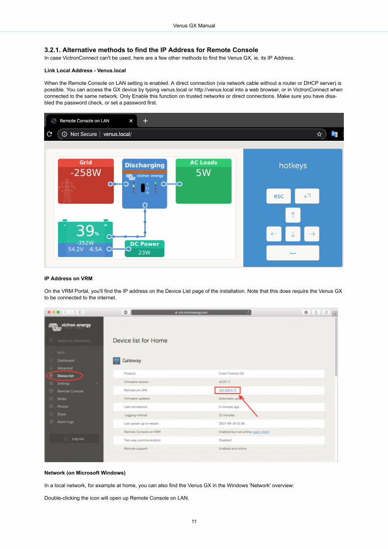

Venus GX Manual
14
4 Configuration
41 Menu structure and configurable parametersAfter completing the installation and setting up the internet connection (if required) go through the menu from top to bottom toconfigure the VGX
Item Default Description
General
Access level User and installer Set this to User to prevent accidental and unwanted changes to the configuration Installer hasadditional privileges and once changed from default requires a password Password is availablefrom your dealer
Remote support No No Yes - Enable this to allow Victron engineers to access your system in case there is a prob-lem
Reboot Reboots the GX device
Audible alarm Yes When there is an alarm on the VGX or a connected product the VGX will beep - unless this set-ting is set to Off
Demo mode Disabled Demonstrates product and installation features to a client or at an exhibition This simulationmode will allow better understanding without (yet) changing any settings Note that this will addsimulated devices to a VRM installation Demos for ESS Boat and Motorhome are available
Firmware
Firmware Version xxx Displays the currently installed firmware version
Online updates Auto update Check only If this is Enabled the GX device will check with the server to see if there is a new version availa-ble It is possible to set to disable or update automatically
Online updates Update to Latest release Use the default setting unless you want to participate in test versions End-user systems shouldcertainly be set to Latest release
Install firmware from SDUSB Use this menu to install a new version from a microSD card or USB stick Insert the card or stickthat holds the new firmware swu file
Stored backup firmware With this feature you can go back to the previously installed firmware version
Date amp time
DateTime UTC Automatic from internet -
DateTime local Automatic from internet When connected to the internet time will be automatically synchronised regardless of this settingToggle this setting to Manually input the time where no internet connection is present
Change time zone Select the correct local time zone
Remote Console - Read full feature description [10]
Disable password check Password authentication not required for remote console access
Enable password check Choose password to allow remote console access
Enable on VRM No No Yes - Enabling on VRM will allow connection to the VGX from anywhere via the VRM portalTrouble shooting Remote Console on VRM
Remote Console on VRM - Sta-tus
- Displays the connection state of the VRM Remote Console Feature eg Online Offline Disabled
Enable on LAN No No Yes - Enabling will allow direct connection to the VGX by typing its IP address or Venuslocalinto a web browser or in VictronConnect when connected to the same network Only Enable thisfunction on trusted networks Disable password check or set password first
System setup
System name Automatic Select the system name - presets or user defined
AC input 1 Generator Select Generator Grid or Shore power Note additional configuration is required for complete set-up of these options
AC input 2 Grid Same choices as above
Monitor for grid failure Disabled Monitors for loss of AC-input and triggers an Alarm if detected Alarm is cleared when the AC-input is reconnected
Battery monitor Automatic Select the SOC source This function is useful where there is more than one BMV More details
Has DC system No Enable this for boats vehicles and installations with DC loads and chargers - in addition to Multiand MPPT chargers This wont be applicable to most off-grid installations and any discrepancybetween the DC current measured by the Multi and by the BMV will be attributed to a DC sys-tem This may be power-in from an alternator or power-out from a pump for example
A positive value indicates consumption A negative value indicates charging for example by analternator
Note that the value shown will always be an approximation and is affected by the variation insample rate between elements of the system
Marine MFD App Configuration Not set Set up what batteries you want to see on the MFD and by what name
DVCC - Read full feature description [29]
DVCC No Enabling DVCC changes a GX device from a passive monitor into an active controller Defaultsetting is No unless a compatible BMS-Can managed battery is connected then setting is setand locked to manufacturers specification
Limit Charge Current No No Yes - User-configurable system wide maximum charge current setting in Amps
Venus GX Manual
15
Item Default Description
SVS - Shared voltage sense No No Yes - The GX device automatically selects the best available voltage measurement andshares it with other connected devices
STS - Shared temperaturesense
No No Yes - The GX device will send the measured battery temperature to the Invertercharger sys-tem as well as all connected Solar Chargers
Temperature sensor Automatic Select the temperature sensor to use for shared temperature sense measurement
SCS - Shared current sense No Forwards the battery current as measured by a battery monitor connected to the GX device to allconnected solar chargers
SCS status Describes if SCS is enabled or why it is disabled
Display amp language
Brightness Configure the brightness between 0 and 100
Display off time Set time-to-off between 10s 30s - 1m 10m 30m - or never
Show mobile overview No Enable this to show the mobile overview page which is designed for Marine and Remote Vehicleapplications This overview gives direct access to the AC Current limit as well as the OnOffCharger-only settings and pump control Also shows up to four tank levels
Language English Choose between English Dutch Chinese German Spanish French Italian Swedish Turkishand Arabic
VRM online portal - Read full feature description [34]
Logging enabled Enabled -
VRM Portal ID - Use this value when registering the GX device onto the VRM Portal
Log interval 15 minutes Set to anything between 1 minute and 1 day Choose longer times on systems with an unreliableconnection Note that this setting does not affect reporting problems and state changes (bulk rarrabsorption) to the VRM Portal These events initiate an immediate transmission of all parameters
Use secure connection (HTTPS) Yes This encrypts the communication between the GX device and the VRM server
Last contact - Time since the VRM server was last contacted
Connection error - Displayed if there is an error in VRM communications See here for more details on troubleshoot-ing VRM errors [35]
VRM two-way communication No Enable remote configuration and firmware updates
Reboot device when no contact No The GX device will reset itself to attempt to correct a potential networking issue if the internet con-nection is lost for the set delay period
No contact reset delay (hhmm) 0100 How long the unit must be offline before restarting itself
Storage location Internal storage Displays if an external storage device (eg USB drive or microSD card) is mounted or the internalstorage is in use
Free disk space -
microSDUSB - Select to Safely Eject an external microSD or USB storage (if one is connected) before physicallyremoving it Failure to do so can cause data loss
Stored records - How many records are stored locally when no internet connection is available The GX device willstore as many records as it can locally then upload them when internet is available again
Oldest record age - If internetVRM is not available then this will display the oldest record stored on the GX device
ESS - An Energy Storage System (ESS) is a specific type of power system that integrates a power grid connection with a Victron InverterCharger GX device andbattery system Read full feature description
Mode Optimized (with Battery-Life)
Optimized (with BatteryLife) and Optimized (without BatteryLife) Keep batteries charged Exter-nal control
Grid Meter Leave default when there is no External Victron grid meter is installed
Inverter AC output in use Yes Setting this to No hides the AC-out graphic in the overview pane
Multiphase regulation - Use the Phase compensation setting in systems with a three-phase connection to the utility grid
Minimum SOC (unless grid fails) 10 Configurable minimum SOC limit ESS will supply loads from the grid once the SOC has fallen tothe configured setting - except when the utility grid has failed and the system is in Inverter mode
Active SOC limit 10 Use this setting to see the current BatteryLife SOC level
BatteryLife state Self-Consumption Self-consumption Discharge disabled Slow charge Sustain Recharge
Limit charge power No This setting limits the flow of power from AC to DC for battery charging from AC-in
Limit inverter power No Limit the power drawn by the Multi ie limit the power being inverted from DC to AC
Grid setpoint 50W This sets the point at which power is taken from the grid when the installation is in self-consump-tion mode
Scheduled charging No Allows you to set up to five scheduled periods during which the system will take power from thegrid to charge the battery
Energy meters - Read full feature description
Role Grid meter Grid meter PV inverter Generator
Phase type Single phase
Modbus unit ID 30
PV inverters - Read full feature description
Inverters Shows connected AC PV inverters
Inv Position AC Input 1 AC input 1 AC input 2 AC Output
Inv Phase L1
Inv Show Yes
Find PV inverters Scan for available PV inverters
Venus GX Manual
16
Item Default Description
Detected IP addresses Shows the IP address of PV inverters that have been discovered
Add IP address manually If an inverter has a manually assigned IP address you can add it directly here
Automatic scanning Yes This setting will continue to look for PV inverters this can be useful if using a DHCP assigned IPaddress that might change
Wireless AC sensors
Select the position for each AC sensor (PV Inverter on AC-input 1 2 or on AC-output) More information about the Wireless AC sensors
Ethernet - read full feature description [6]
State Connected
MAC address -
IP configuration Automatic
IP address -
Netmask -
Gateway -
DNS server -
Link-local IP address -
Select the configuration type (DHCP vs manual configuration) and IP settings
Wi-Fi- Read full feature description [6]
Create access point
Wi-Fi networks
Name
Connect to network
Forget network
Signal strength
MAC address
IP configuration
IP address
Netmask
Gateway
DNS server
Manage wireless networks and IP settings
GSM modem - Read full feature description
GPS - Read full feature description
GPS information Status Latitude Longitude Speed Course Altitude Number of satellites
Format Select the format in which to show the Latitude and Longitude
Speed unit kmh Choose between kmh meters per second miles per hour or knots
Device Connected Connection Product Product ID Firmware version Device instance
Generator startstop
Configure generator autostart settings and conditions Read full feature description
State Displays if the generator is running or not
Error Displays if there is error (eg generator is supposed to be running but no AC input is detected)
Total run time Total time the generator has been running since reset
Time to next test run If a periodic run is programmed this counter will display in days and hours how long before thatwill occur
Auto start functionality Enable or Disable the Autostart functions this can be further configured in the Generator -gt Set-tings -gt Conditions menu
Manual start Start generator Run for hhmm
Daily run time Submenu shows the history of time generator has been running (minutes) each day for the previ-ous 30 days
Generator startstop -gt Settings
Generator startstop -gt Settings -gt Conditions
On loss of communication Stop generator Stop Start Keep generator running
Do not run generator when AC1is in use
No This option is ideal for back-up systems where a Quattro has mainsgrid electricity connected toits AC-in 1 terminal and a Genset connected to its AC-in 2 terminal With this option enabled theGenset will only start after a mains failure
Battery SOC No Use Battery SOC value to startstop - No Yes
Start when SOC is lower than -
Start value during quiet hours - (to override programmed quiet hours when absolutely necessa-ry)
Stop when Battery SOC is higher than -
Stop value during quiet hours - (allows for less runtime during quiet hours once system is re-covered)
Venus GX Manual
17
Item Default Description
Battery current
Battery voltage
AC output
No Use value to startstop - No Yess
Start when value is higher than - Amps Voltage Watts
Start value during quiet hours - Amps Voltage Watts (to override programmed quiet hours whenabsolutely necessary)
Start after condition is reached for - seconds (to allow for momentary spikes to pass without trig-gering start)
Stop when value is lower than - Amps Voltage Watts
Stop value during quiet hours - Amps Voltage Watts (allows for less runtime during quiet hoursonce system is recovered)
Stop after the condition is reached for - seconds (to allow for momentary dips without stoppingthe running generator)
Inverter high temperature
Inverter overload
No Start on value warning - No Yes
Start when warning is active for - seconds (to allow for momentary spikes to pass without trigger-ing start)
When warning is cleared stop after - seconds (to allow for momentary dips without stopping therunning generator)
Generator startstop -gt Settings -gt Conditions -gt Periodic run
Periodic run No Enable - No Yes
Run interval
Skip run if has been running for
Run interval start date
Start time
Run duration (hhmm)
Run until battery is fully charged
Generator startstop -gt Settings
Minimum run time 0 The minimum number of minutes the generator will run for any time that it is started even afterstop conditions
Detect generator at AC input No No Yes - An alarm will be triggered when no power from the generator is detected at the inverterAC input Make sure that the correct AC input is set to generator on the system setup page
Quiet hours 0 Quiet hours will prevent normal generator run conditions from starting the generator It is possiblefor some settings to specify override values to the quiet hours ( an extremely low battery voltagetrigger to prevent a system shutdown for example)
Reset daily run time counters An option to reset generator run time counters for example if these are used for service or if thegenerator is replaced or majorly repaired
Generator total run time (hours) The total time the generator has been running since the counter was reset
Tank pump
Configure automatic starting and stopping of pump based on tank level(sender) information Pump auto startstop with Color Control GX
Pump state Displays if the pump is running or not
Mode Auto Options are Auto On and Off This is the manual override to the start and stop level triggers whena tank sensor is connected
Tank Sensor Automatic Select the tank sensor that is used for the tank pump trigger No tank sensor will be displayed ifno tank sensor is connected or detected
Start level 50 The trigger point of the tank level to start the tank pump (close the relay)
Stop level 80 The trigger point of the tank level to stop the tank pump (open the relay)
Relay
Function Alarm relay Select the relay function Possible functions are Alarm relay Generator startstop Tank pumpand None (disabled)
Polarity Normally open Select the polarity of the relay on the back of the VGX Normally open or Normally closed (Notethat setting it to normally closed increases the VGX power draw)
Services
ModbusTCP Off This setting enables the ModbusTCP service More information about ModbusTCP in this docu-ment and in the communications white paper httpswwwvictronenergycomuploaddocumentsWhitepaper-Data-communication-with-Victron-Energy-products_ENpdf
MQTT on LAN (SSL) On Enables MQTT on LAN - More information on MQTT is available on Victron Community
MQTT on LAN (Plaintext) Off This setting is required to be enabled when connecting an Marine MFD
VECan port VECan CAN-bus profile (Disabled VECan amp Lynx Ion BMS 250 kbits VECan amp Can-bus BMS 250kbits CAN-bus BMS 500 kbits Oceanvolt 250 kbits) Send data to VECan Unique devicenumber for VECan Check unique numbers
CAN-bus BMS (500 kbits)
CAN-bus CAN-bus profile Send data to VECan Unique device number for VECan Check unique num-bers
IO
Analog inputs On Available tank level sensors OnOff Available Temperature sensors OnOff
Venus GX Manual
18
Item Default Description
Digital inputs Off Available Digital inputs Off Door alarm Bilge pump Bilge alarm Burglar alarm Smoke alarmFire alarm CO2 alarm Generator
When using a VEBus system it is possible to configure the severity of problems on the VEBus system that should cause a notifi-cation to show up on the VGX (and make it beep)
bull Disabled The VGX will never beep or show a notificationbull Alarm only The VGX will only beep and show a notification when the VEBus system switched off in an alarm conditionbull Enabled (default) The VGX will beep and show a notification
When all done dont forget to change the access level to user when required
42 Battery State of Charge (SOC)
421 Which device should I use for SOC calculationThere are three products types that calculate State Of Charge (SOC) The VGX itself does not calculate SOC it only retrieves itfrom the connected devices
The three products that calculate SOC are
1 Battery Monitors such as the BMVs the Lynx Shunt or the Lynx Ion BMS2 Multi and Quattro inverterchargers3 Batteries with built-in battery monitor and a (mostly BMS-Can) connection to the VGX
When to use what
If you have a battery with build-in battery monitor such as a BYD or Freedomwon battery its easy Use that
If not then the options depend on the type of system
1 If the MultiPlus or Quattro invertercharger is the only source of charge to the batteries and the only draw then it can functionas a basic battery monitor because it counts what went in and counts what comes out No need for a dedicated battery moni-tor such as the BMV
2 If the systems consists of an invertercharger MPPTs and a GX device then there is still no need to add a dedicated batterymonitor
3 For any other system types such as a boat or vehicle with DC lights and other loads a dedicated battery monitor will berequired
422 The different solutions explained in detail(A) Battery and Multi or Quattro (a typical backup system)
No battery monitor is required the Multi or Quattro is the only product connected to the battery and has full control over all chargeand discharge currents Therefore it can calculate the correct SOC itself
Configuration
1 Enable and configure the Battery Monitor in VEConfigure2 In the VGX in Settings rarr System setup verify the selected Battery Monitor It should be set to the Multi or Quattro
(B) Battery with Multi or Quattro and MPPT Solar Chargers -ALSO- An EasySolar with GX Device built-in
No battery monitor is required as long as all MPPT Solar Chargers are Victron products and are connected to the VGX TheVGX will continuously read the actual charge current from all solar chargers and send the total to the Multi (or Quattro) whichthen uses that information in its SOC calculations
Configuration
1 Enable and configure the Battery Monitor in VEConfigure2 On the VGX in Settings rarr System setup verify the selected Battery Monitor It should be the Multi or Quattro3 In the same menu verify that the option Use solar charger current to improve VEBus SOC is enabled Note that this is not a
setting - it just an indicator of an automatic process
Note that this feature requires recent firmware versions in both the Multis or Quattros (402 minimum) and the VGX (v206 mini-mum)
(C) Batteries with a built-in battery monitor
In cases where the system includes a battery which has a built-in battery monitor and SOC calculation - such as many of thebatteries listed here - a dedicated battery monitor is not required
Configuration
Venus GX Manual
19
1 Connect the battery communications cable to the VGX according to the instructions2 In the VGX in Settings rarr System setup verify that the selected Battery Monitor is the battery
Note that the Battery Monitor setting in VEConfigure3 is irrelevant For systems like this changing this setting will have no effecton the charge or any other parameters in this type of system
(D) Other system types
When there are more chargers or loads connected to the battery than just the Multi or MPPT Solar Chargers a dedicated Bat-tery Monitor will be required Examples are
bull House loads in Marine or Vehicle systembull PWM Solar Chargersbull AC chargers such as Skylla-is Phoenix chargers non Victron chargers etcbull Alternatorsbull DC-DC chargersbull Wind turbinesbull Hydro turbines
In case a battery with built-in monitor is used such as explained in (C) then that is the dedicated battery Monitor Refer to section(C)
Otherwise install a BMV or Lynx Shunt VECan
Configuration
1 Configure the battery monitor as per its documentation2 In the VGX in Settings rarr System setup verify the selected Battery Monitor3 It should be the BMV or Lynx Shunt Battery Monitor4 Finished
Note that the Battery Monitor setting in VEConfigure3 is irrelevant For systems like this changing this setting will have no effecton the charge - or any other parameters - in this type of system
423 Notes on SOC
bull Note that this is all about showing an accurate state of charge to the user rather than being required for an efficient systemThe SOC percentage is not used for battery charging It is however required when a generator needs to be started and stop-ped automatically based on battery SOC
More information
VRM Portal FAQ - difference between BMV SOC and VEBus SOC
See Configurable Parameters Section [15] on Battery Monitor selection and Has DC System
424 Selecting SOC source(Settings rarr System Setup rarr Battery monitor)
In the image below you can see a range of selectable choices for the SOC values which are shown in the main Overview screenChoose the source you want to see on the main Overview screen of your VGX
Venus GX Manual
20
In the image above we have chosen the Automatic setting When automatic is selected the System setup screen will be as shownin the image below
The Automatic function uses the following logic
1 When available it will use a dedicated Battery Monitor such as the BMV or a Lynx Shunt or a battery with built-in batterymonitor
2 When there is more than one of those connected it will use a random one - although you can select one manually3 when there is no dedicated Battery Monitor it will use the VEBus SOC
When should I use the No battery monitor option
Use that in systems where
1 there is a Multi or Quattro installed2 no BMV or other battery monitor is installed
Venus GX Manual
21
3 the system has other DC loads or other chargers connected to the same battery which are not connected to the VGX
A short explanation the VEBus SOC as determined by the Multi or Quattro will be incorrect in above situation As it will not takethe discharge and charge currents by those other DC Loads and also unmonitored chargers into account
425 Details on VEBus SOC
bull While the InverterCharger is in bulk the SOC will not rise above the value as set in VEConfigure3 for the ldquoState of chargewhen Bulk finishedldquo parameter on the General tab default 85 In a system with Solar chargers make sure that the Absorptionvoltage as configured in the MPPT is slightly above the same setting in the invertercharger The latter needs to recognize thatthe battery voltage has reached the absorption level If it doesnrsquot the SOC will be stuck at the earlier mentioned End-of-bulkpercentage default 85
43 Customize the logo on the Boat amp Motorhome pageIt is possible to use a custom logo onto the Boat amp Motorhome page
Type the following address into the web browser of a device connected to the same network Using this address as a tem-plate httpvenuslocallogophp or http[ip-here]logophp (inserting your devicersquos IP address between the square brackets) TheIP address can be found by going to Settings -gt Ethernet or Wifi Once the page is loaded Choose an image file from your de-vice Re-boot the GX device
44 LEDs and Push-button
441 LEDsBoot-up
On the side of the Venus GX there is a LED During power-up it it goes through these states
bull Stage 1 Both green and red illuminate briefly and faintly (its hard to see the green) for approximately 1 secondbull Stage 2 Red illuminates for approximately 1 secondbull Stage 3 Green illuminates for approximately 05 secondsbull Stage 4 Both green and red illuminate briefly and faintly (its hard to see the green) for approximately 1 second
During operation
bull Slow blinking built-in WiFi access point disabledbull Fast blinking built-in WiFi access point enabled (default)
Slow blinking is once per second Fast blinking is twice per second
442 Small button located to the right of the green 14-Terminal Connector BlockShort press WiFi Access point onoff
A single short press toggles the internal WiFi access point on and off The LED indicates its state when the LED blinks greenslow then the built-in Access Point is disabled when the LED is green and blinking fast then the built-in Access Point is enabled
Long press reset all network settings to factory defaults
Press and hold the small button for a minimum of four seconds The LED will stay on for 2 seconds to indicate that the log presshas been recognised then release the button again
bull Ethernet is set back to DHCPbull WiFi Access Point is enabledbull Remote Console password is disabledbull Remote Console on LAN and on VRM is enabled
The same button is available on the Octo GX button is marked SD_BOOT and available under the lid at the top
Venus GX Manual
22
5 Updating GX Firmware
51 Via internet or with microSD-cardUSB-stickThere are two ways to update the firmware
1 Update it via the internet either manually or let it check for new updates every day2 Update it from a microSD-card or USB-stick
52 Direct download from the internetDirect download from the internet
To update from the internet navigate to Settingsrarr FirmwarerarrOnline updates
53 MicroSD-card or USB-stickUpdating with a microSD-card or USB-stick is called Offline updating Use it when updating a device that is not connected to theinternet
Step 1 Download
Get the latest swu file
bull venus-swuccgxswubull venus-swu-beagleboneswu
Note that the same files and the change log is available on Victron Professional That also features a dropbox connection soyou can always have the latest file available on your laptop
Step 2 Install on a microSD card or usb stick
Store the file in the root folder of a USB-stick or microSD-card
Step 3 Insert the device
Note that you will see a warning ldquoNot using media for storing logsrdquo That warning can safely be ignored
Venus GX Manual
23
Step 4 Initiate the update
Navigate to Settings rarr Firmware rarr Offline updates
Press Check for updates
If the firmware in the microSD-card or USB-stick is newer than the running one ldquoUpdate availablerdquo item will appear press it tostart the update process
54 ChangelogThe change log is available in Victron Professional under Firmware Venus OS
Venus GX Manual
24
6 VEBus Invertercharger monitoring
61 Input current-limiter settingOverruled by remote setting in VEConfigure
This chapter explains the implications of enabling or disabling user control of the input current-limiter setting as seen here in themenu
The limit as set by the user in the VGX will be applied to all inputs where Overruled by remote configured with VictronConnect orVEConfigure is enabled
Using the example of a boat with two AC inputs and a Quattro where
1 A Genset capable of delivering 50A is connected to input 12 Shore power is connected to input 2 (Available power depends on the rating of the harbour power-supply)
Configure the system exactly as in above VEConfigure screenshot Input 1 has priority over input 2 therefore the system will au-tomatically connect to the genset whenever it is running The fixed input current limit of 50A will be applied And when the gensetis not available and mains is available on input 2 the Quattro will use the input current limit as configured in the VGX
Two more examples (In both cases if you disable Overrule by remote setting a current limit in the VGX will have no effect And ifyou enable Overrule by remote for both inputs the current limit set in the VGX will be applied to both inputs)
Venus GX Manual
25
Minimum input current limit values
When PowerAssist is enabled in VEConfigure there is a minimum input current limit The actual limit differs for each model
After setting the input current to a value below the limit it will automatically be increased again to the limit
Note that is still possible to set the input current limit to 0 When set to 0 the system will be in passthrough (charger disabled)
Parallel and three phase systems
The configured AC input current limit is the total limit per phase
62 Phase rotation warningThe AC supply either Generator or Grid to a three phase invertercharger system needs to be in the correct rotation also knownas sequence If not then the Inverterchargers will not accept the AC supply and remain in Inverter mode
The Phase rotation warning will be raised in such case To resolve the issue change the wiring on the AC input swap either oneof the phases effectively changing the rotation from L3 rarr L2 rarr L1 to L1 rarr L2 rarr L3 Or reprogram the Multis and modify thephase assigned to match the wiring
On the GX device itself the warning will be popup as a notification on the GUI
Also it is visible in the menus
And on the VRM Portal it is visible on the VEBus Alarms amp warnings widget on the Advanced page
Venus GX Manual
26
And also it will be listed in the Alarm Log on VRM and an email will be sent using the VRM Alarm Monitoring system
63 Grid failure monitoringWhen this feature is enabled an alarm is raised when the system hasnt been connected to the AC input configured to be Grid orShore for more than 5 seconds
The alarm shows as a Notification in the GUI and as an alarm on the VRM Portal and is available on ModbusTCP MQTT
Recommend to use for backup systems But also for yachts or vehicles on shore power
Note that this settings monitors that the system is connected to gridshore Generator monitoring is already available as part ofthe Generator startstop function and not part of this
Do not use this feature in systems that use the Ignore AC Input settings in our inverterchargers when the system ignores the ACinput ie runs in island mode as intended even though grid is available it will report a grid failure
64 Advanced menu
Equalisation
Starts equalisation See Multi or Quattro documentation for details
Redetect system
Venus GX Manual
27
Redetects the type of invertercharger and its features ampamp configuration Use this feature when for example a VEBus BMSused to be part of a system and is no longer
System reset
Restarts the invertercharger when it has stopped retrying For example after a (very) heavy overload or three overloads in a row
ESS Relay test
Shows the status of the ESS Relay test Only relevant when its an ESS system See Q9 in the ESS Manual FAQ for details
Venus GX Manual
28
7 DVCC - Distributed Voltage and Current Control
71 Introduction and featuresEnabling DVCC changes a GX device from a passive monitor into an active controller The available features and effects of ena-bling DVCC depend on the type of battery used The effect also depends on the installed Victron components and their configura-tion
Example 1 - Managed CAN-bus batteries For example in systems with an Managed CAN-bus BMS battery connected the GXreceives a Charge Voltage Limit (CVL) Charge Current Limit (CCL) Discharge Current Limit (DCL) from that battery and relaysthat to the connected inverterchargers and solar chargers These then disable their internal charge algorithms and simply dowhat theyre told by the battery There is no need to set-up charge voltages or choose the charge algorithm type
Example 2 - Lead batteries For systems with lead batteries DVCC offers features such as a configurable system wide chargecurrent limit where the GX device actively limits the invertercharger in case the solar chargers are already charging at full powerAs well as shared temperature sense (STS) and shared current sense (SCS)
This table shows the recommend settings for different battery types
Carefully study the following chapters to fully understand DVCC for a particular system
To enable or disable DVCC see Settings rarr DVCC in the menus
Venus GX Manual
29
72 DVCC RequirementsBattery compatilibity
For CAN-bus connected batteries check the relevant page on the Battery Compatibility manual to see if enabling DVCC hasbeen tested with your battery-type and is supported If DVCC is not mentioned in notes relating to your battery do not enableDVCC
For Gel AGM OPzS and other lead batteries DVCC can be used without any problem The same is true for Victron Energy lithi-um batteries with the VEBus BMS the Lynx Ion + Shunt BMS or the Lynx Ion BMS DVCC is the preferred operating mode forRedflow ZBM2ZCell batteries using the Redflow CANBus BMS
Firmware versions
Do not use DVCC in cases where these requirements are not met In all cases we recommend to install the latest available firm-ware during commissioning Once running well there is no need to pro-actively update firmware without reason In case of diffi-culty the first action is to update firmware
Required minimum firmware versions
bull MultiQuattro 422bull MultiGrid 424bull VGX v212bull VEDirect MPPTs v146bull VECan MPPTs with VEDirect v104bull Older style VECan MPPT Solar Chargers (with the screen) cannot be used they do not support the new control mechanismsbull Lynx Ion + Shunt v204bull Lynx BMS v109
From Venus firmware v240 there will be a warning message Error 48 - DVCC with incompatible firmware when one of thedevices has an incompatible firmware while using DVCC
In case of an ESS System the ESS Assistant needs to be version 164 or later (Released in November 2017)
73 DVCC effects on the charge algorithmOur inverterchargers and MPPT Solar Chargers use their own internal charge algorithm when in stand-alone mode This meansthat they determine how long to remain in Absorption when to switch to Float when to switch back to Bulk or Storage And inthose various phases they use the configured parameters in VictronConnect and VEConfigure
In certain systems the internal charge algorithm is disabled and the charger is then working with an externally controlled chargevoltage target
This guide explains the different possibilities
Internal
The internal charge algorithm (bulk rarr absorption rarr float rarr re-bulk) and the configured charge voltages are active
Invertercharger indicated charge state bulk absorption float and-so-forth
MPPT indicated charge state bulk absorption float and-so-forth (firmware version v142 onwards Earlier versions have a bugthat make the MPPT say ldquoExt Controlrdquo when it is only being current limited its internal charge algorithm still active
Invertercharger (applies to MPPTs only)
Venus GX Manual
30
The MPPTs internal charge algorithm is disabled instead its being controlled by a charge voltage setpoint coming from the inver-tercharger
MPPT indicated charge state Ext control
Battery
The internal charge algorithm is disabled and instead the device is being controlled by the battery
Invertercharger indicated charge state Bulk when in current controlled mode Absorption when in voltage controlled mode NeverFloat even though currents might be low battery might be full
MPPT indicated charge state Ext control
74 DVCC features for all systemsThese features apply to all types of systems when DVCC is enabled with or without ESS Assistant and with lead or other normalbatteries as well as when an intelligent CAN-bus BMS connected battery is installed
741 Limit charge currentThis is a user-configurable maximum charge current setting It works across the whole system MPPT Solar Chargers are auto-matically prioritized over the mainsgenerator
This setting is available in the ldquoSettings rarr ldquoSystem Setuprdquo menu on the GX device
Particulars
1) If a CANBUS-BMS is connected and the BMS requests a maximum charge current that is different from the user-configurablesetting the lower of the two will be used
2) This mechanism only works for Victron inverterchargers and Solar chargers Other chargers such as Skylla-irsquos are not control-led and also their charge current is not taken into account The same applies for devices that are not connected to the GX devicesuch as an alternator Worded differently the total charge current of the inverterchargers and all MPPTs will be controlled noth-ing else Any other sources will be extra charge current unaccounted for Even when installing a BMV or other battery monitor
3) DC Loads are not accounted for Even when a BMV or other battery monitor is installed For example with a configured maxi-mum charge current of 50 Amps and DC Loads drawing 20 Amps the battery will be charged with 30 Amps Not with the fullallowed 50 Amps
4) Current drawn from the system by the invertercharger is compensated for For example if 10A is drawn to power AC loadsand the limit is 50A the system will allow the solar chargers to charge with a maximum of 60 Amps
5) In all situations the maximum charge limit configured in a device itself ie the Charge current limit set with VictronConnect orVEConfigure for the Solar chargers or Inverterchargers will still be in effect An example to illustrate this in case there is only anInvertercharger in the system and in VEConfigure or VictronConnect the charge current is configured to 50 Amps And on theGX Device a limit of 100A is configured then the working limit will be 50 Amps
742 Shared Voltage Sense (SVS)Works with VEBus devices and VEDirect Solar Chargers
The system automatically selects the best available voltage measurement It will use the voltage from the BMS or a BMV batterymonitor if possible otherwise it will use the battery voltage reported by the VEBus system
The voltage displayed on the GUI reflects the same voltage measurement
Shared Voltage Sense (SVS) is by default enabled when DVCC is enabled It can be disabled with a switch in the Settings rarrSystem Setup menu
Venus GX Manual
31
743 Shared Temperature Sense (STS)Select the temperature sensor to use and the GX device will send the measured battery temperature to the Invertercharger sys-tem as well as all connected Solar Chargers
Selectable sources for the battery temperature are
bull BMV-702 battery monitorbull BMV-712 battery monitorbull Lynx Shunt VECan battery monitorsbull Temperature inputs on a Venus GX (and same for other GX devices that have a temperature input)bull MultiQuattro inverterchargerbull Solar Chargers (if fitted with a temperature sensor)
744 Shared Current Sense (SCS)This feature forwards the battery current as measured by a battery monitor connected to the GX device to all connected solarchargers
The solar chargers can be configured to use the battery current for its tail current mechanism that ends absorption when the cur-rent is below the configured threshold For more information about that refer to Solar charger documentation
This feature only applies to systems that are not ESS andor donrsquot have a managed battery since in both of those cases theMPPT is already externally controlled
Requires MPPT solar charger firmware v147 or newer
75 DVCC Features when using CAN-bus BMS BatteryThis chapter applies to all systems where an intelligent battery BMS is installed and connected via CAN-bus Note that this doesnot include the Victron VEBus BMS
Such intelligent BMS sends four parameters to the GX device
1 Charge voltage limit (CVL) the maximum charge voltage that the battery currently accepts2 Charge current limit (CCL) the maximum charge current requested by the battery3 Discharge current limit (DCL) the maximum discharge current as requested by the battery
For all three parameters some types of batteries transmit dynamic values For example they determine the maximum charge volt-age based on cell voltages state of charge or for example temperature Other makes and brands use a fixed value
Here is the page in the menus showing the parameters
For such batteries there is no need to wire allow-to-charge and allow-to-discharge connections to the AUX inputs on a Multi or aQuattro
When inverting ie in Island mode Multis and Quattros will shut down when the max discharge current is zero They will automati-cally start again as soon as either AC mains returns or when the BMS increases the max discharge current again
See previous chapter ldquoLimit charge currentrdquo the user setting for details about how the Maximum charge current is used how itprioritises solar and more
All above means that setting up charge voltages or charge profiles in VEConfigure or VictronConnect is not necessary and willalso have no effect The Multis Quattros and MPPT Solar Chargers will charge with the voltage as received via CAN-bus from thebattery
Venus GX Manual
32
76 DVCC for systems with the ESS Assistantbull The ESS Keep batteries charged mode works properly It does not without DVCCbull A fixed solar offset of 04V is used instead of a variable 2V (values for 48V systems divide by 4 for 12V) Note that this solar
offset is only applied when ESS-mode is set to Optimized in combination with the Feed-in excess solar charger power-settingenabled or when ESS-mode is set to Keep batteries charged
bull Add Auto-recharge feature for the ESS Modes Optimized and Optimized (with BatteryLife) The system will automatically re-charge the battery (from the grid) when the SOC drops 5 or more below the value of lsquoMinimum SOCrsquo in the ESS menu Re-charge stops when it reaches the Minimum SOC
bull ESS improved state display In addition to the charger states (BulkAbsorptionFloat) additional Discharging and Sus-tain modes were added In addition it also shows reasons for the state it is inbull 1 Low SOC discharge disabledbull 2 BatteryLife is activebull 3 Charging disabled by BMSbull 4 Discharging disabled by BMSbull 5 Slow Charge in progress (part of BatteryLife see above)bull 6 User configured a charge limit of zerobull 7 User configured a discharge limit of zero
Venus GX Manual
33
8 VRM Portal
81 VRM Portal IntroductionWhen connected to the internet a GX device can be used in combination with the Victron Remote Management (VRM) portalwhich enables
bull Easy remote access to all statistics and systems status onlinebull Remote Console on VRM access and configure your system as if you were standing besides itbull Remote Firmware updates of connected Solar Chargers and other Victron productsbull Use of the VRM App for iOS and Android
See Internet Connectivity chapter [6] for how to connect the device to the internet
82 Registering on VRMInstructions are in the VRM Portal Getting Started document
Note that any system will need to first have been able to successfully send data to the VRM Portal As long is there has been nosuccessful connection it will not be possible to register the system to your VRM user account In such case refer to below Trou-bleshooting section 57
83 Datalogging to VRMData-logs are transmitted to the VRM Portal over the Internet if its available All related settings are available in the VRM OnlinePortal menu
The transmission of the data logs has been designed to work also on bad internet connections Lines of up to 70 permenantpacket loss are still sufficient to get the data out even if delayed in some cases
Adding an external storage device
When unable to transmit the logs then the GX device will store them to non-volatile storage (ie data is not lost on a power loss orreboot)
The GX device has a buffer to store a couple of days worth of logs internally To extend this period insert a microSD card or USBstick You can see the internal storage status in the settings
Note that when inserting such storage device any internally stored logs will automatically be transferred to the inserted stick nodata is lost
With or without an external storage device inserted the GX Device will always keep trying to connect to the portal and transmit allbacklogged logs That means that even with months worth of backlog once it re-acquires an Internet connection all of the back-log is sent out The data is sent in a compressed manner sending a lot of backlogged data will use considerably less bandwidththan than sending the data with a continuously available internet connection
Storage device requirements
bull MicroSD cards or USB flash drives must be formatted as FAT12 FAT16 or FAT32 file systems - and not exFAT or NTFSbull SD and SDHC type microSD cards of 32 GB capacity and smaller are sold containing FAT12 FAT16 or FAT32 They can be
used without a problem unless they are subsequently re-formatted to a different file systembull SDXC type microSD cards which have greater than 32 GB capacity are often formatted with exFAT and therefore cannot be
used with the VGX without reformatting and possibly re-partitioning
Manually transferring datalogs to VRM
Venus GX Manual
34
For devices permanently without Internet it is possible to take the data out and then upload it manually from a laptop
1 go to Settings rarr VRM Portal and click Eject the storage Make sure to never just remove the SD-cardUSB-stick this canlead to corruption and data loss
2 now remove the storage device and insert it into a computer or laptop that is connected to the internet3 open a webbrowser and navigate to the VRM Portal4 Login and then click the Upload GX file option and follow instructions
5 Remove the file from the storage device and then it re-insert it into the GX Device Note that uploading the same data twicedoes not cause any problems but still it is better not to do that
With a log interval of once per minute the required storage space roughly amounts to about 25 MB per month depending on thenumber of connected products So with a 1 GB microSD card you can store about 3 years of backlog In other words any mi-croSD card or USB stick should be sufficient to store the 6 months of data which VRM retains
When the storage device is full no more data will be logged
If multiple storage devices are inserted the GX device will store the data on the one inserted first When that is removed itwill not use the other one Instead it will create an internal backlog buffer Only inserting a new one will make it switch to usingexternal storage again
Network watchdog auto-reboot
This feature disabled by default makes the GX device automatically reboot itself in case it has not been able to connect to theVRM Portal
Please be careful with enabling this feature on ESS systems when grid connection is lost and the GX device reboots the systemcan lose power when rebooting takes too long (when grid is present the Multis or Quattros will enter passthru)
84 Trouble shooting data loggingThis chapter explains what to do when the GX Device cannot transmit data to the VRM Portal
The communication required to send logs to the VRM Portal is
1 Working DNS2 Proper IP address3 Working internet connection4 Outbound http(s) connection to httpccgxloggingvictronenergycom on port 80 and 443 Note that should never be an issue
unless on very specialized company networks
Note that the VGX does not support a proxy setup For more details on the required networking see here
Step 1 Update the GX Device to the latest available firmware
GX Device firmware update instructions
Step 2 Verify the network and internet connection
In the menu Settings rarr Ethernet or Settings rarr Wi-Fi check the following
1 State must be lsquoConnectedrsquo
Venus GX Manual
35
2 There must be an IP address that does not start with 1693 There must be a gateway4 There must be DNS servers
For a GX GSM see the Troubleshooting guide in the GX GSM Menu
In case the IP address starts with 169 check whether your network has a DHCP server running 99 of all networks have aDHCP server running and it is enabled by default on all well-known ADSL cable and 3G routers If there is no DHCP server run-ning then configure the ip address manually
Ethernet
When using Ethernet and State shows Unplugged verify that the Ethernet network cable is not faulty try another one The twolights at the back of the VGX where the Ethernet RJ45 cable plugs in should be lit or blinking Two dead lights indicate a connec-tion problem
WiFi
When using Wi-Fi and the menu shows No Wi-Fi adapter connected check the USB connection to the Wi-Fi dongle Try to re-move the dongle and insert it again
When using Wi-Fi and the State shows Failure it might be that the Wi-Fi password is incorrect Press Forget network and try toconnect again with the correct password
Step 3 Verify VRM Portal Connectivity
Navigate to Settings rarr VRM online portal and check the Connection error status
Venus GX Manual
36
If a Connection error is shown the VGX is not able to contact the VRM database The connection error will show an error codethat indicates the nature of the connectivity problem Also details of the error message are shown to facilitate on site IT expertsto diagnose the problem
bull Error 150 Unexpected response text The httphttps call succeeded but the response was incorrect This indicates that thereis a WiFi or network login page Such as seen in Airports Hotels Marinas or RV campgrounds some times There is no solutionto make the CCGX work with a WiFi network that requires such login page andor accepting of terms of use
bull Error 151 Unexpected HTTP Response A connection succeeded but the response did not indicate a successful HTTP resultcode (normally 200) This might indicate that a transparent proxy is hijacking the connection See 150 above for examples
bull Error 152 Connection time-out this could indicate a poor quality internet connection or a restrictive firewallbull Error 153 Connection error this could indicate a routing problem For details check the shown error message
bull Error 153 Connection problem and then specifically an SSL related issue such as in below screenshot check the date andtime setting of the Gx Device and also the time zone And check that your router router is not showing a special disclaimerlogin or acceptance page like often seen in airports hotels and other public wifi
bull Error 154 DNS Failure Make sure that a valid DNS server is configured in the Ethernet or WiFi menu Typically this is as-signed automatically by a DHCP server in a network
bull Error 155 Routing error VRM is unreachable This error occurs if an ICMP error is received indicating that no route exists tothe VRM server Make sure your DHCP server assigns a working default route or that the gateway is correctly configured forstatic configurations
bull Error 159 Unknown error this is a catch-all error for errors that cannot be directly categorised In such cases the Error mes-sage will provide information about the problem
Venus GX Manual
37
Check Last contact If this shows dashes the GX device has not been able to contact the VRM Portal since power up If it showsa time but still an error is shown then the GX device has been able to send data but has since lost contact
The Buffered items indicates the number of logs that it has stored to send later If this is larger than 0 it means that the VenusGX can not connect to the VRM Portal All data is sent using the First in First out principle the VRM Portal will only show the mostup to date information after all old data has been sent
85 Analysing data offline without VRMIn certain cases for example for very remote sites where there is no internet available it can be useful to be able to analyse thedata without first having to upload it to the VRM Portal
1 Install VictronConnect on a Windows or Apple laptop2 Insert the storage device containing the log file(s)In Victron3 Connect use the GX Log Converter feature to convert them to Excel sheets
86 Remote Console on VRM - Trouble shootingFollow these steps to trouble shoot Remote Console on VRM
1 Make sure that Logging to the VRM portal works see chapter 54 Without this Remote Console on VRM will not work2 After enabling the Remote Console feature make sure to set (or disable) the password3 Also make sure to restart the VGX after setting (or disabling) the password4 Make sure to update the VGX to the latest firmware version The last stability improvement for Remote Console was made in
version v2305 After the restart check the Remote Console on VRM status shows online or a port number In case it says offline or port
number 0 the VGX was unable to connect to the Remote Console server This is normally caused by a (company) firewallblocking the connection The solution is then to configure an exception rule in the firewall
6 -Verify that your web browser on which youre using VRM can access both of below URLs Click both of the links to checkthem Note that seeing an Error means that all is OK The good error is Error response Error code 405 Method Not AllowedIf you get a timeout or another (browser) error there may be a firewall blocking the connection httpsvncrelayvictronener-gycom amp httpsvncrelay2victronenergycom
Technical background
To have Remote Console on VRM working your web browser and the GX Device need to have a connection between them Thisconnection is designed such that it doesnt need any special configuration or opening up of firewalls in almost all situations The01 of situations where it doesnt work out of the box are for example large corporate networks with special security or longrange expensive satellite or radio supported networks such as seen in rural areas of Africa and other remote areas
When Remote Console on VRM is enabled the GX Device will open and maintain a connection to any of the servers pointed toby supporthostsvictronenergycom Which currently resolves to two IP addresses (8422107120 and 842210849) and likelymore in the future The technology used is SSH and it will try to connect using port 22 80 and 443 only one of them needs towork The reason for it to try all three is that on most networks at least one of them will be allowed by the local firewall
Once connected to one the the supporthost servers that reverse SSH tunnel is waiting to be connected from someone needingthe connection Which can be your browser or a Victron engineer since this same technology is used for the Remote Supportfunctionality for more information see above
Venus GX Manual
38
When using Remote Console on VRM the browser will connect to either vncrelayvictronenergycom or vncrelay2victronener-gycom using websockets on port 443 For more details of used connections by the GX Device see Q15 of the FAQ
Venus GX Manual
39
9 Marine MFD integration by App
91 Introduction amp requirementsA Glass Bridge is a MFD (Multi-Functional Display) that integrates a boatrsquos systems and navigation status into a large screen orscreens at the helm of the vessel so doing away with multiple gauges brackets and wiring complications
A Victron system can be easily integrated into that as shown in this video
httpswwwyoutubecomwatchv=RWdEQfYZKEs
Functionalities
bull Monitor shore power and generator statusbull Monitor battery status for one or more batteries By using the voltage of for example battery chargers it can also visualise sec-
ondary batteries such as Generator starter batteriesbull Monitor the power conversion equipment chargers inverters inverterchargersbull Monitor solar production from an MPPT Solar Chargerbull Monitor AC loads and DC loadsbull Control shore power input current limitbull Control the invertercharger switch it off on or set it to charger-onlybull Optionally open the Victron Remote Console panel allowing access to further parameters
Victron equipment compatibility
bull All Victron inverterchargers From a 500VA single phase device up to a large 180kVA three phase-system including MultisQuattros 230VAC and 120VAC models
bull Battery Monitors BMV-700 BMV-702 BMV-712 SmartShunt and newer Lynx Shunt VECan Lynx Ion BMSbull All Victron MPPT Solar Charge Controllers
Required components
Venus GX Manual
40
bull Battery systembull Victron GX Device (all models are compatible CCGX Cerbo GX Venus GX and so forth)bull Victron Inverterchargerbull Victron Battery monitorbull Ethernet network cable connected between MFD and the GX devicebull MFD specific ethernet adapter cable (only for some brands see detailed information in below links)
92 Compatible MFDs and instructionsInstructions for Garmin MFDs
Instructions for Navico MFDs (Simrad BampD Lowrance)
Instructions for Raymarine
Instructions for Furuno
Using the App for other purposes
The App as visible on the MFDs is a HTML5 App hosted on the GX Device It can also be accessed from a normal PC (or atablet) by navigating to with a browser to httpvenuslocalapp Or replace venuslocal with the GX IP address
Venus GX Manual
41
10 Marine MFD integration by NMEA2000
101 NMEA2000 IntroductionOur GX Devices feature an NMEA 2000-out function when enabled the GX Device acts as a bridge it makes all Battery moni-tors Inverterchargers and other products connected to the GX device available on the NMEA2000 network
Using that feature and having the GX Device connected a NMEA2000 network Marine MFDs can read this data and visualise itto the user Often in a highly configurable manner
Use our VECan to NMEA2000 micro-C male cable to connect the GX Device to the NMEA 2000 network
Comparison to the App integration
Compared to MFD integration using the App as explained in the previous chapter integration via N2K offers a more customisableconfiguration The downside of integration via N2K is that there is more work in making such configuration as well as makingsure all PGNs and fields therein are supported and compatible between the Victron system and the MFD
More information
Besides this chapter make sure to also read the introduction blogpost as well as our main Marine MFD Integration document
Besides this chapter make sure to also read (1) the introduction blogpost (2) our main Marine MFD Integration document and (3)the NMEA2000 chapter in the Victron manual for the MFD you are using (NavicoSimradLowranceBampG or Raymarine or Gar-min or Furuno)
Yes that is a lot of reading but that is basically inherent to NMEA2000 for example some of those MFDs support displaying ACdata received over the NMEA2000 wiring others do not Some require changing Data instances others do not and so forth
102 Supported Devices PGNsNMEA 2000 defines several messages Messages are identified by their parameter group number (PGN) A textual description ofthe message is publicly available on the NMEA 2000 website (httpwwwnmeaorg)
Detailed specification of the protocol and message definition or part thereof can be ordered online on the NMEA 2000 website
NMEA 2000 is based on and compatible with SAE J1939 All AC information messages are in the AC status message format asdefined in J1939-75 The specification of these messages can be bought on the SAE website (httpwwwsaeorg)
For a detailed list of PGNs please refer to our data communication whitepaper
Inverterchargers
All inverterchargers that connect using a VEBus port are supported This includes Multis Quattros MultiPlus-IIs and other (simi-lar) Victron inverterchargers
Data is transmitted out and its possible to set shore current as well as switch the inverter charger on off inverter only and charg-er only
The interface has two functions
bull The function ldquo153 Inverterrdquo represents the AC-outputbull The function ldquo154 AC Inputrdquo monitor represents the AC-input
Charger Status messages will be sent by the Inverter function Both functions have their own network address
Since both functions transmit the same PGNs for example an AC Status PGN containing voltage current and more informationNMEA 2000 data consumers like generic displays will need to be able to make a distinction based on the network address
Depending on the function belonging to that network address the need to interpret it as either Inverter Input or Inverter Output
Venus GX Manual
42
Displays not being capable of doing so will regard the data as belonging to the mains (utility)
The Inverter Output is then interpreted as utility 0 and Inverter Input as utility 1 These default instance numbers can bechanged by a network configuration tool if necessary
Inverters
Only VEBus type inverters are supported any Inverter connected using VEDirect is not (yet) made available on the N2K bus
Battery monitors
Supported This includes any battery monitor as supported by the GX Device
Solar chargers
Not yet supported by the NMEA2000-out function but in the works and expected after in a firmware update after the summer of2020
Tank level data
Not yet supported by the NMEA2000-out function but in the works and expected after in a firmware update after the summer of2020
Other data and product types
Not supported Above explicitly mentioned types are the only ones now supported For example data from a charger (such as thePhoenix Smart Charger connected via VEDirect) is not supported and not expected to be supported soon
103 NMEA2000 Related menu settings
Table 1 Setting Default Description
CAN-bus Profile VECan Defines the type amp baudrate of the CAN-bus network To use in combination with NMEA2000 make sure to choose one of theprofiles that include VECan and is at 250kbits
Send data toVECan
Off Enables and disabled the NMEA2000-out function
Unique devicenumber
1 Selects the block of numbers to use for the NAME Unique Identity Numbers in the PGN 60928 NAME field For the GX Deviceitself and when NMEA2000-out is enabled also for the virtual-devices Change it only when installing multiple GX Devices in thesame VECan network There are no other reasons to change this number
Venus GX Manual
43
Setting Default Description
Check uniquenumbers
Searches for other devices that use the same unique number When the search is completed it will respond with either an OK orthe text
There is another device connected with this unique number please select another one
Note that there is normally no reason to use this function the GX Device automatically and continuously checks uniqueness of thenumbers in use and will warn when in case there is a conflict This setting is made available to quickly confirm that everything isOK after changing the setting
104 NMEA2000-out technical details
1041 NMEA2000 GlossaryHere is a glossary to help with the interpretation of this text
bull Virtual-device a Battery Monitor Inverter or other Victron device that does not have a CAN-bus port by itself made availableldquovirtuallyrdquo on the CAN-bus by the NMEA2000-out function of the GX Device
bull CAN-bus the VECan port on the GX Device that in the context of this chapter is most likely connected to a NMEA2000 net-work
bull NMEA2000-out function the software feature in the GX Device which is described in this chapterbull NMEA2000 Marine CAN-bus protocol based on J1939bull Instance there are many types of instances and explained in detail belowbull J1939 A set of standards defining a CAN-bus protocol defined by the SAE organisationbull Address Claim procedure (ACL) a mechanism specified by J1939 and used in NMEA2000 which used by devices on the net-
work to negotiate and assign each device on the network a unique network addresses Its is a number from 0 to 252 There arethree special network addresses defined1 0xFD (253) - Reserved2 0xFE (254) - Unable to claim address - for example when all others are in use3 0xFF (255) - The broadcast address
1042 NMEA2000 Virtual-devices35 (Electrical generation)When the NMEA2000-out feature is enabled the GX Device acts as a bridge it will make each Battery monitor Inverterchargeror other device that is connected available individually on the CAN-bus
Individually as in each with its own network address its own device instance function codes and so forth
For example a GX Device with two BMVs connected on a VEDirect port and an invertercharger connected using VEBus willmake the following data available on the CAN-bus
Table 2 Address Class Function Description
0xE1 130 (Display) 120 (Display) The GX Device itself
0x03 35 (Electrical generation) 170 (Battery) The 1st BMV
0xE4 35 (Electrical generation) 170 (Battery) The 2nd BMV
0xD3 35 (Electrical generation) 153 The invertercharger (AC-output)
0xD6 35 (Electrical generation) 154 The invertercharger (AC-input)
1043 NMEA2000 Classes and functionsAs per NMEA2000 specification these define the types of senders and devices connected to the CAN-bus Classes are the maincategories and functions specify it to a further detail
1044 NMEA2000 InstancesNMEA2000 defines three different instances
1 Data instance2 Device instance3 System instance
For all Battery monitors and other devices that the GX Device makes available on the CAN-bus each of the above types of in-stance is available and can be individually configured
Per virtual-device there is one Device instance and one System instance And depending on the type of the virtual-device thereare one or multiple Data instances
For example for a BMV-712 there are two data instances one ldquoDC Instancerdquo for the main battery and another one for the Starterbattery voltage
Venus GX Manual
44
How to configure the instances depends on the equipment and software that is used to read them from the CAN-bus Examplesof equipment and software meant here are MFDs such as from Garmin Raymarine or Navico as well as more software orientedsolutions from for example Actisense and Maretron
Most or hopefully all of those solutions identify parameters and products by requiring unique Device instances or using the PGN60928 NAME Unique Identity Numbers They do not rely on the data instances to be globally unique
The NMEA2000 specification specifies the following ldquoData instances shall be unique in the same PGNs transmitted by a deviceData instances shall not be globally unique on the network Field programmability shall be implemented through the use of PGN126208 Write Fields Group Functionrdquo
In other words data instances need to be unique only within a single device There is no requirement for them to be globallyunique ndash the only exception is ldquoEngine Instancerdquo that at least for now to cope with legacy devices needs to be globally unique(eg Port = 0 Starboard = 1) For example some of our BMV Battery monitors can measure two voltages one for the mainbattery and one for the starter battery and thats where data instancing is used Similar for multiple-output battery chargers Notethat there is no need for the installer to change those data instances as those products are pre-configured to transmit the rele-vant PGNs with unique data instances (Battery instance ampamp DC Detailed instance in this case)
WARNING whilst it is possible to change the data instances changing them on a Victron devices will render that device impossi-ble to read correctly by other Victron devices
A note about the Device instances it is not necessary to assign a unique device instance to each device on the CAN-bus Its noproblem for a battery monitor and a solar charger to both be configured with (their default) Device instance 0 Also when havingmultiple battery monitors or solar chargers it is not always necessary to assign each of them a unique device instance If at allnecessary they only need to be unique between the devices that use the same Function
And note that changing the Device instance on a Victron device can change its operation see below
System instances
As per NMEA2000 specification this instance is a 4-bit field with a valid range from 0 to 15 that indicates the occurrence of devi-ces in additional network segments redundant or parallel networks or sub networks
The System Instance Field can be utilized to facilitate multiple NMEA 2000 networks on these larger marine platforms NMEA2000 Devices behind a bridge router gateway or as part of some network segment could all indicate this by use and applicationof the System Instance Field
The ECU instance and Function instance
In some documentation and software tools yet other terminology is used
bull ECU Instancebull Function Instancebull Device Instance Lowerbull Device Instance Upper
Here is how they all relate the ECU Instance and Function Instance terminology originates from the SAE J1939 and ISO 11783-5specification And they do not exist in the NMEA2000 definition However they all do define the same fields in the same CAN-busmessages which NMEA2000 defines as Device instance
In more detail the field that J1939 defines as ECU Instance is in the NMEA2000 specification renamed to Device Instance lowerThe Function Instance is renamed to Device Instance Upper And together they form the Device Instance an NMEA2000 defini-tion
While using different terms those fields are the same fields in both standards Device Instance Lower being 3 bits in length andDevice Instance Upper 5 together 8 bits Which is the one byte being the NMEA2000 Device Instance
The Unique Instance
The Unique Instance is one more word used to describe almost the same information Its used by Maretron and can be madevisible in their software by enabling the column The Maretron software itself chooses between Device Instance and Data In-stance
1045 NMEA2000 Changing InstancesData instance
Even though we recommend to not change data instances (see explanation and WARNING above) it is possible to change them
There is no option within Venus OS to change them - a third party tool is required and the only tool that we know can do that isActisense NMEA2000 reader
To change the Data instances see this document
Device instance
Venus GX Manual
45
To change the Device instances see this document
WARNING these (Victron-)features depend on the Device Instance
1 For an ESS system with Solar chargers connected on a VECan network those Solar chargers must remain to be configuredto their default Device instance (0) for proper operation This does not apply to VEDirect-connected Solar Chargers madeavailable on the CAN-Bus as a Virtual-device using the NMEA2000-out function Unless the Device instance of the GX De-vice is re-configured to another Device Instance Which is technically possible but not advised and also never required But inthat situation the chargers must be configured to the same instance as the GX Device
2 For systems with managed batteries the same3 For both Solar chargers as well as AC-Connected battery chargers when connected in a VECan network they will syn-
chronise their operation Charge state and such For that function to work all chargers must be configured to the same deviceinstance
In summary for the majority of systems we recommend to leave the Device instance to its default 0
1046 PGN 60928 NAME Unique Identity NumbersThe GX device will assign an individual Unique Identity Number to each virtual-device The number assigned is a function ofthe PGN 60928 NAME Unique Identity Number block aka Unique device number for VECan as in above screenshot as config-ured in the settings of the GX Device
This table shows how changing that setting translates into the virtual-devices as made available on the CAN-bus
Table 3 configured Unique Identity block 1 2 3 4
GX device 500 1000 1500 2000
1st virtual-device (for example a BMV) 501 1001 1501 2001
2nd virtual-device (for example another BMV) 502 1002 1502 2002
3rd virtual-device (for example a third BMV) 503 1003 1503 2003
Venus GX Manual
46
11 Digital Inputs
The Venus GX digital inputs are shown in the overview of connections
The Venus GX digital input channels are accessible via the RJ-12 socket on the side This is available for self-wiring by the userinstaller
111 Wiring detailsThe inputs are non-isolated They operate at 3V3 levels and can withstand up to 5V input Each input has an internal 10k pull-upresistor to 3V3 We recommend wiring it to a potential free relay or otherwise open collectoroptocoupler output
RJ12 pinout Input
pin1 input1
pin2 input2
pin3 input3
pin4 input4
pin5 gnd
pin6 input5
112 ConfigurationEach of the digital inputs can be configured as one of a number of predefined sensors that can also be configured as alarms
The possible configurable functions are
Function States
Pulse meter NA
Door alarm OpenClosed
Bilge pump OnOff
Bilge alarm OkAlarm
Burglar alarm OkAlarm
Smoke alarm OkAlarm
Fire alarm OkAlarm
CO2 alarm OkAlarm
Generator RunningStopped
The function of each input can be configured in the GUI under Settings rarr IO rarr Digital Inputs
Venus GX Manual
47
Once the input is configured for its intended purpose it will show up with other devices
Other parameters related to that function can be configured by entering the device menu and selecting Setup
For pulse meters you can configure the unit the multiplier (the volume represented by each pulse) and reset the counter
Venus GX Manual
48
For sensors and alarms you can decide whether the input should be treated as an alarm condition whether the labels should beinverted and whether the logical levels should be inverted
bull To swap the labels attached to the alarm set Inverted to onbull If a logical low input (0V) should be considered a positive condition set Inverted alarm logic to on
113 Read-out of digital inputs via Modbus-TCPThe valuesstates of the digital inputs are available on Modbus-TCP For more details about this please download a copy of thedocument ldquoModbus-TCP register listrdquo from our website And see our Modbus-TCP FAQ
Venus GX Manual
49
12 Factory reset
See above chapter on the push button [22]
Venus GX Manual
50
13 Error Codes
Different origins of errors
On your GX device some error codes shown will be from the GX device itself in that case see below list As the system controlpanel it also shows error codes from the connected devices
bull Multi and Quattro inverterchargers VEBus Error Codesbull MPPT Solar Chargers MPPT Solar Charger Error Codes
GX Error 42 - Storage corrupt
This error means that the flash memory inside the GX Device is corrupt
The device must be sent in for repairreplacement It is not possible to correct this issue in the field or with a firmware update
The affected flash memory is the partition that holds all user settings and factory data such as serial numbers and wifi codes
GX Error 47 - Data partition issue
The internal storage in the GX Device is most likely broken causing it to loose its configuration
Contact your dealer or installer see wwwvictronenergycomsupport
GX Error 48 - DVCC with incompatible firmware
This error is raised when the DVCC feature is enabled whilst not all devices in the system are updated to recent enough firmwareMore information about DVCC and minimal required firmware versions in chapter 4 of this manual
Note for systems with BYD MG Energy Systems and Victron Lynx Ion BMS batteries
Since Venus OS v240 released in December 2019 the DVCC feature is automatically switched on when the system detects asupported batteryBMS type connected In systems that require DVCC to be enabled by the battery manufacturers it is now nolonger possible to switch DVCC off
This creates an issue for systems installed and commissioned a long time ago before DVCC was available and they may nothave the other necessary components or firmware to work correctly with it enabled
The solution is to
1 Disable automatic updates Settings rarr Firmware rarr Online updates2 Roll back to v233 See Settings Firmware and then Stored backup firmware3 Make sure that DVCC is disabled again
Please do consult your installer to check if the battery system is managed with two wire control (an earlier alternative controlmethod to DVCC) or not
If there is no charge- and discharge- wiring between BMS inverterchargers and charge controllers then DVCC is required forabove mentioned battery brands and this also has certain minimum firmware requirements for connected Inverterchargers andSolar charge controllers
Whats new since Venus OS v240 is (a) that it automatically enables DVCC when it sees the above mentioned battery types and(b) that when DVCC is enabled it checks the connected devices for the minimum firmware and raises Error 48 in case the firm-ware of one or more connected devices is too old
Venus GX Manual
51
14 FAQ
141 Venus GX FAQQ1 I cannot switch my MultiQuattro system on or off
To solve the problem first find out how the system is connected and then follow the right step by step instruction below Thereare two ways to connect a MultiQuattro system to a Venus GX In most systems they will be connected directly to the VEBusport on the back of the VGX And option two in some systems they are connected to the Venus GX using a VEBus to VECaninterface
Step by step instructions when connected to VEBus port on the VGX
1 Update the Color Control to the latest available version See our blog posts in the httpswwwvictronenergycomblogcatego-ryfirmware-software
2 Do you have a Digital Multi Control or VEBus BMS in the system In that case it is normal that onoff is disabled See alsothe VEBus related notes in the VGX manual
3 In case you have had a Digital Multi Control or VEBus BMS connected to your system the Color Control remembers it andeven when those accessories have been removed the Onoff switch will still be disabled To clear the memory execute a Re-detect system the option is in the Multi or Quattro section of the Venus GX menu
4 For parallelthree phase systems consisting of more than 5 units depending on temperature and other circumstances it mightnot be possible to switch a system back on after switching it off with the VGX As a work around youll need to unplug theVEBus cable from the back of the VGX And plug it back in after starting the VEBus system The real resolution is to installthe ldquoVGX dongle for large VEBus systemsrdquo partnumber BPP900300100 For details read its connection instruction
Step by step instructions when connected to VGX via VECan
1 Update the Color Control to the latest available version See our blog posts in the firmware category2 Update the VEBus to VECan interface to the latest version The easiest way to do that is by using Remote firmware update
having a special piece of hardware the CANUSB is then not necessary3 Do you have a Digital Multi Control or VEBus BMS in the system In that case it is normal that onoff is disabled See also
the VEBus related notes in the VGX manual4 In case you have had a Digital Multi Control or VEBus BMS connected to your system and it is now no longer connected the
Canbus interface remembers it Therefore even after those accessories have been removed the Onoff switch will still bedisabled Clearing this memory is unfortunately not possible yourself please contact us so we can help you
142 Q2 Do I need a BMV to see proper battery state of chargeMoved here
143 Q3 I have no internet where can I insert a sim-cardThere is no 3G modem in the GX Device and therefore also no slot for a sim-card Go to a local store and buy a 3G router withEthernet ports More information in the blog post link below and particularly in the comments section as more users try differingequipment
httpswwwvictronenergycomblog20140309off-grid-color-control-gx-to-vrm-portal-connectivity
Note that it is not possible to use a VGR2 or VER for this Also it will not be possible in the foreseeable future
144 Q4 Can I connect both a GX Device and a VGR2VER to a MultiInverterQuattroNo Also instead of this combination we recommend to use the Venus GX and add a 3G or similar mobile router See Internetconnectivity [6]
145 Q5 Can I connect multiple Color Controls to a MultiInverterQuattroNo
146 Q6 I see incorrect current (amps) or power readings on my VGXExamples are
bull I know that a load is drawing 40W from the Multi but the VGX shows 10W or even 0Wbull I see that the Multi is supplying a load with 2000W while in inverter mode but from the battery only 1850W is being taken Is
those 150W coming out of nowhere
The general answer is the Multi and Quattros are not measurement instruments they are inverterchargers and the measure-ments shown are a best effort delivery
In more detail there are several causes for measurement inaccuracies
Venus GX Manual
52
1 Part of the power taken from a battery by the inverter is being lost in the inverter converted into heat efficiency losses2 The Multi does not really measure the power being drawn from the battery It measures the current at the output of the inver-
ter and then makes an assumption of the power being drawn from the battery3 Watts vs VA depending on the MultiQuattro firmware version and also the VGX firmware version you are either looking at
VAs (the result of calculating AC voltage AC current) or looking at a Watts measurement To see WATTS on the VGX up-date your VGX to the latest version (v121 or newer) Also make sure the firmware version in your Multi supports Watts read-out minimum versions are xxxx154 xxxx205 and xxxx300
4 MultisQuattros connected to the VGX via a VEBus to VECan interface will always reports VAs not (yet) Watts5 If a current sensor assistant is loaded in a MultiQuattro and no sensor is connected it will return invalid power kWh values6 If a current sensor assistant is loaded in a MultiQuattro make sure the position is set correctly and the scale match with the
dipswitches on the sensor itself7 A current sensor assistant measures and reports VAs not Watts
Notes for systems with multiple units in parallel
1 VGX version prior to v120 use the power and current reported by the master of a phase and multiplied that by the number ofdevices in that phase Since version v120 the values of all device is summed per phase and hence should be more accurate
2 This revealed a bug for in the firmware of the multi when running in parallel Ccgx v121 workarounds this by falling back tothe original behavior when it sees an affected firmware version For better readings the multis should be updated The bughas been fixed in VEBus firmware version xxxx159 xxxx209 xxxx306 That firmware was released on February 17th 2015
3 Multi firmware versions since 26xx207 xxxx300 can also freeze the Power values at a certain moment in time
Tips to prevent measurement problems
1 Do not connect VEConfigure while the VGX is connected2 VEBus is not a 100 plug and play system if you disconnect the VGX from one Multi and very quickly connect it to another
it can result it wrong values To make sure that this is not the case use the redetect system option in the MultiQuattro menuon the VGX
147 Q7 There is a menu entry named Multi instead of the VEBus productnameA VEBus system can be completely turned off including its communication If you turn a VEBus system off and thereafter resetthe VGX the VGX cannot obtain the detailed product name and shows ldquoMultirdquo instead
To get the proper name again go into the Multi menu on the VGX and set the Switch menu entry to On or in case a Digital MultiControl is present set the physical switch to On Note that when there is a BMS above procedure only works when within batteryworking voltages
148 Q8 There is a menu entry named Multi while there is no Inverter Multior Quattro connectedIf a VGX ever saw a VEBus BMS or Digital Multi Control (DMC) it will remember them until Redetect system is started from theVGX menuAfter a minute restart the VGX Settings rarr General rarr Reboot
149 Q9 When I type the ip-address of the Color Control into my browser I seea web page mentioning HiawathaOur plan is to at least run a website where you can change settings and see the current status If all works out as we would liketo there might come be a fully functional version of the online VRM Portal running locally on the Venus GX This allows peoplewithout an internet connection or an intermittent internet connection to have the same features and functionality
1410 Q10 I have multiple Solar chargers MPPT 15070 running in parallel Fromwhich one will I see the relay status in the VGX menuFrom a random one
1411 Q11 How long should an automatic update takeThe size of the download typically is around 90MB After download it will install the files which can take up to 5 minutes
1412 Q12 I have a VGR with IO Extender how can I replace this with a VenusGXIt is not yet possible to replace the IO Extender functionality
1413 Q13 Can I use Remote VEConfigure as I was doing with the VGR2Yes see VE Power Setup manual
Venus GX Manual
53
1414 Q14 The Blue Power Panel could be powered through the VENet net-work can I also do that with a Venus GXNo a Venus GX always needs to be powered itself
1415 Q15 What type of networking is used by the Venus GX (TCP and UDPports)Basics
bull The Venus GX needs to get a valid IP address from a DHCP server including a working DNS server and gateway or a static IPconfiguration
bull DNS port 53 UDP and TCPbull NTP (time sync) UDP port 123
VRM Portal
bull Data to the VRM Portal is sent via HTTP POST and GET requests to httpccgxloggingvictronenergycom on port 80 Sensitivedata is sent using HTTPS on port 443 to the same host
Firmware updates
bull The VGX connects to httpupdatesvictronenergycom on port 443
Remote support (default disabled)
bull When enabled an outbound SSH connection to supporthostvictronenergycom is maintained The VGX will try to connect onport 22 80 and 443 and the first that works is maintained
bull Enabling Remote Support also enables the sshd daemon listening for incoming SSH requests on port 22 See next FAQ entryfor more information about the Remote Support functionality
Two way communication (Remote VEConfig and Remote Firmware updates)
bull Pre-v220 Uses HTTPS (port 443) to the Pubnub serversbull v220 and later connects to mqtt-rpcvictronenergycom on port 443
MQTT (default disabled)
bull When enabled a local MQTT broker is started which accepts TCP connections on port 1883 The VGX will also try to connectto the victron MQTT cloud server (mqttvictronenergycom) using SSL on port 8883
Remote Console on VRM (default disabled)
bull Remote Console on VRM uses the same reverse ssh tunnel as is used for Remote Support outbound connection to suppor-thostsvictronenergycom on port 22 80 or 443 No port forwarding in routers is necessary to use Remote Console on VRMNote that supporthostsvictronenergycom resolves to multiple IP addresses 842210849 and 8422107120
bull See here to trouble shoot Remote Console on VRM
Remote Console on LAN (default disabled)
bull Remote Console on LAN requires port 80 (small website hosted on local hiawatha webserver on VGX) And also requires port81 which is the listening port for the websocket tunnel to VNC
Modbus TCP (default disabled)
bull ModbusTCP server uses port 502
1416 Q16 What is the functionality behind the menu item Remote support(SSH) in the Ethernet menuWhen enabled the Color Control will open a SSH connection to our secure server with a reverse tunnel back to the Color Con-trol Through this tunnel Victron engineers can login to your Venus GX and perform remote support This works when the VenusGX is installed on an internet connection The connection will even work when installed behind a firewall The SSH connection willbe outbound to port 80 22 or 443 at supporthostvictronenergycom Remote support function is by default disabled
1417 Q17 I donrsquot see support for VENet products in the list is that still com-ingNo
Venus GX Manual
54
1418 Q18 What is the data usage of the Venus GXData usage depends heavily on amount of connected products and behavior and usage of those products The measurementsbelow are an indication only and taken from a system with one VGX one Multi one BMV and one MPPT Log interval set to 15minutes If you are on an expensive data-plan do make some fail-safe
Data consumption per month
bull VRM logging 15MB download 45MB uploadbull Remote support 22MB download 40MB uploadbull Update checks 8MB download 03MB upload (This does not include the update itself)bull 2 way communication 26MB download 48MB upload
Mentioned megabytes do not include the download of a Color Control firmware update Firmware updates of 60MB are not un-common
1419 Q19 How many AC Current Sensors can I connect in one VEBus sys-temThe current maximum is 9 sensors (since Venus GX v131) Note that each need to be configured separately with an assistant inthe Multi or Quattro to which it is wired
1420 Q20 Issues with Multi not starting when VGX is connected Cautionwhen powering the VGX from the AC-out terminal of a VEBus Inverter Multi orQuattroMake sure that the GX device and MultiPlus is running the latest firmware version
If you power the VGX from an AC adaptor connected to the AC-out port of any VEBus product (Inverter Multi or Quattro) then adeadlock can occur after the VEBus products are powered-down for any reason (after any operational fault or during a blackstart) The VEBus devices will not boot-up until the VGX has power hellipbut the VGX will not boot-up until it has powerSee FAQ for more information about this
This deadlock can be rectified by briefly unplugging the VGX VEBus cable at which point you will observe the VEBus productswill immediately begin to boot-up
This deadlock can be avoided in two ways
bull Power the VGX from the battery orbull Cut pin 7 in the VEBus cable connected to the VGX
CuttingRemoving pin 7 of the VEBus cable to the VGX (brownwhite according to standard RJ45 ethernet cable colour coding)allows the VEBus products to start up without waiting for the VGX to boot up first
Note that when using a Redflow ZBM2ZCell battery pin 7 should be cut even if the VGX is DC powered to avoid the same dead-lock at times when the Redflow battery cluster is at 0 SoC
Venus GX Manual
55
The disadvantage of cutting pin 7 is that switching the VEBus device off will be less effective although it will stop charging andinverting it will still be in standby mode and therefore drawing more current from the battery than if pin 7 had been left in placeTypically this is only relevant in Marine or Automotive systems where its normal to regularly switch the VEBus device off Forthose types of systems we recommend that you do not cut pin 7 but simply power the VGX from the battery
1421 Q21 I love Linux programming Victron and the VGX Can I do moreYes you can We intend to release almost all code as open source but we are not that far yet What we can offer today is thatmany parts of the software are in script or other non-precompiled languages such as Python and QML and therefore availableon your Venus GX and easy to change Root password and more information is available here
1422 Q22 How do I change the logoTypic the following address into the web browser of a device connected to the same network Using this address as a tem-plate http[ip-here]logophp (inserting your devicersquos IP address between the square brackets) The IP address can be found bygoing to Settings ampgt Ethernet or Wifi Once the page is loaded Choose an image file from your device Re-boot the GX device
1423 Q23 Multi restarts all the time (after every 10sec)Please check the remote switch connection on the Multi control PCB There should be a wire bridge between the left and middleterminal The VGX switches a line which enables the power of the Multi control board After 10 seconds this line is released andthe Multi should take over from there When the remote switch connection is not wired the Multi is unable to take over its ownsupply The VGX will retry the Multi will boot and after 10 seconds stop and so on
1424 Q24 What is Error 42If the GX Device shows an Error 42 - Hardware fault In that case the flash storage on the device is corrupt As a result settingswill not be saved (rebooting resets back to default) and other problems will rise
This error is not recoverable in the field or by repair departments Contact your dealer for a replacement
Venus GX Manual
56
Firmware versions until v230 did not report the error Since v230 its visible on the device itself (in the GUI) and on the VRMPortal
1425 GPL NoteThe software included in this product contains copyrighted software that is licensed under the GPL You may obtain the Corre-sponding Source code from us for a period of three years after our last shipment of this product
Venus GX Manual
57
15 More information
bull GX - Generator auto startstopbull GX - Using Fischer Panda Generatorsbull GX - GSM cellular modembull VRM Portal - Remote VEConfigure and remote firmware updatesbull VRM Portal - Documentation and troubleshooting
Venus GX Manual
58
- Venus GX Manual
- Table of Contents
- 1 Introduction
-
- 11 What is the Venus GX
- 12 Whats in the box
-
- 2 Internet connectivity
-
- 21 Ethernet LAN port
- 22 Wi-Fi
- 23 GX GSM
- 24 Mobile (cellular) network using a 3G or 4G router
- 25 USB tethering using a mobile phone
- 26 IP Configuration
- 27 Connecting both Ethernet and Wi-Fi (failover)
- 28 Minimize internet traffic
- 29 More information about setting up an internet connection and VRM
-
- 3 Accessing the GX device
-
- 31 Accessing via the built-in WiFi Access Point
- 32 Accessing Remote Console via the local LANWiFi Network
-
- 321 Alternative methods to find the IP Address for Remote Console
-
- 33 Accessing via VRM
-
- 4 Configuration
-
- 41 Menu structure and configurable parameters
- 42 Battery State of Charge (SOC)
-
- 421 Which device should I use for SOC calculation
- 422 The different solutions explained in detail
- 423 Notes on SOC
- 424 Selecting SOC source
- 425 Details on VEBus SOC
-
- 43 Customize the logo on the Boat amp Motorhome page
- 44 LEDs and Push-button
-
- 441 LEDs
- 442 Small button located to the right of the green 14-Terminal Connector Block
-
- 5 Updating GX Firmware
-
- 51 Via internet or with microSD-cardUSB-stick
- 52 Direct download from the internet
- 53 MicroSD-card or USB-stick
- 54 Changelog
-
- 6 VEBus Invertercharger monitoring
-
- 61 Input current-limiter setting
- 62 Phase rotation warning
- 63 Grid failure monitoring
- 64 Advanced menu
-
- 7 DVCC - Distributed Voltage and Current Control
-
- 71 Introduction and features
- 72 DVCC Requirements
- 73 DVCC effects on the charge algorithm
- 74 DVCC features for all systems
-
- 741 Limit charge current
- 742 Shared Voltage Sense (SVS)
- 743 Shared Temperature Sense (STS)
- 744 Shared Current Sense (SCS)
-
- 75 DVCC Features when using CAN-bus BMS Battery
- 76 DVCC for systems with the ESS Assistant
-
- 8 VRM Portal
-
- 81 VRM Portal Introduction
- 82 Registering on VRM
- 83 Datalogging to VRM
- 84 Trouble shooting data logging
- 85 Analysing data offline without VRM
- 86 Remote Console on VRM - Trouble shooting
-
- 9 Marine MFD integration by App
-
- 91 Introduction amp requirements
- 92 Compatible MFDs and instructions
-
- 10 Marine MFD integration by NMEA2000
-
- 101 NMEA2000 Introduction
- 102 Supported Devices PGNs
- 103 NMEA2000 Related menu settings
- 104 NMEA2000-out technical details
-
- 1041 NMEA2000 Glossary
- 1042 NMEA2000 Virtual-devices35 (Electrical generation)
- 1043 NMEA2000 Classes and functions
- 1044 NMEA2000 Instances
- 1045 NMEA2000 Changing Instances
- 1046 PGN 60928 NAME Unique Identity Numbers
-
- 11 Digital Inputs
-
- 111 Wiring details
- 112 Configuration
- 113 Read-out of digital inputs via Modbus-TCP
-
- 12 Factory reset
- 13 Error Codes
- 14 FAQ
-
- 141 Venus GX FAQ
- 142 Q2 Do I need a BMV to see proper battery state of charge
- 143 Q3 I have no internet where can I insert a sim-card
- 144 Q4 Can I connect both a GX Device and a VGR2VER to a MultiInverterQuattro
- 145 Q5 Can I connect multiple Color Controls to a MultiInverterQuattro
- 146 Q6 I see incorrect current (amps) or power readings on my VGX
- 147 Q7 There is a menu entry named Multi instead of the VEBus product name
- 148 Q8 There is a menu entry named Multi while there is no Inverter Multi or Quattro connected
- 149 Q9 When I type the ip-address of the Color Control into my browser I see a web page mentioning Hiawatha
- 1410 Q10 I have multiple Solar chargers MPPT 15070 running in parallel From which one will I see the relay status in the VGX menu
- 1411 Q11 How long should an automatic update take
- 1412 Q12 I have a VGR with IO Extender how can I replace this with a Venus GX
- 1413 Q13 Can I use Remote VEConfigure as I was doing with the VGR2
- 1414 Q14 The Blue Power Panel could be powered through the VENet network can I also do that with a Venus GX
- 1415 Q15 What type of networking is used by the Venus GX (TCP and UDP ports)
- 1416 Q16 What is the functionality behind the menu item Remote support (SSH) in the Ethernet menu
- 1417 Q17 I donrsquot see support for VENet products in the list is that still coming
- 1418 Q18 What is the data usage of the Venus GX
- 1419 Q19 How many AC Current Sensors can I connect in one VEBus system
- 1420 Q20 Issues with Multi not starting when VGX is connected Caution when powering the VGX from the AC-out terminal of a VEBus Inverter Multi or Quattro
- 1421 Q21 I love Linux programming Victron and the VGX Can I do more
- 1422 Q22 How do I change the logo
- 1423 Q23 Multi restarts all the time (after every 10sec)
- 1424 Q24 What is Error 42
- 1425 GPL Note
-
- 15 More information
-

Item Default Description
Digital inputs Off Available Digital inputs Off Door alarm Bilge pump Bilge alarm Burglar alarm Smoke alarmFire alarm CO2 alarm Generator
When using a VEBus system it is possible to configure the severity of problems on the VEBus system that should cause a notifi-cation to show up on the VGX (and make it beep)
bull Disabled The VGX will never beep or show a notificationbull Alarm only The VGX will only beep and show a notification when the VEBus system switched off in an alarm conditionbull Enabled (default) The VGX will beep and show a notification
When all done dont forget to change the access level to user when required
42 Battery State of Charge (SOC)
421 Which device should I use for SOC calculationThere are three products types that calculate State Of Charge (SOC) The VGX itself does not calculate SOC it only retrieves itfrom the connected devices
The three products that calculate SOC are
1 Battery Monitors such as the BMVs the Lynx Shunt or the Lynx Ion BMS2 Multi and Quattro inverterchargers3 Batteries with built-in battery monitor and a (mostly BMS-Can) connection to the VGX
When to use what
If you have a battery with build-in battery monitor such as a BYD or Freedomwon battery its easy Use that
If not then the options depend on the type of system
1 If the MultiPlus or Quattro invertercharger is the only source of charge to the batteries and the only draw then it can functionas a basic battery monitor because it counts what went in and counts what comes out No need for a dedicated battery moni-tor such as the BMV
2 If the systems consists of an invertercharger MPPTs and a GX device then there is still no need to add a dedicated batterymonitor
3 For any other system types such as a boat or vehicle with DC lights and other loads a dedicated battery monitor will berequired
422 The different solutions explained in detail(A) Battery and Multi or Quattro (a typical backup system)
No battery monitor is required the Multi or Quattro is the only product connected to the battery and has full control over all chargeand discharge currents Therefore it can calculate the correct SOC itself
Configuration
1 Enable and configure the Battery Monitor in VEConfigure2 In the VGX in Settings rarr System setup verify the selected Battery Monitor It should be set to the Multi or Quattro
(B) Battery with Multi or Quattro and MPPT Solar Chargers -ALSO- An EasySolar with GX Device built-in
No battery monitor is required as long as all MPPT Solar Chargers are Victron products and are connected to the VGX TheVGX will continuously read the actual charge current from all solar chargers and send the total to the Multi (or Quattro) whichthen uses that information in its SOC calculations
Configuration
1 Enable and configure the Battery Monitor in VEConfigure2 On the VGX in Settings rarr System setup verify the selected Battery Monitor It should be the Multi or Quattro3 In the same menu verify that the option Use solar charger current to improve VEBus SOC is enabled Note that this is not a
setting - it just an indicator of an automatic process
Note that this feature requires recent firmware versions in both the Multis or Quattros (402 minimum) and the VGX (v206 mini-mum)
(C) Batteries with a built-in battery monitor
In cases where the system includes a battery which has a built-in battery monitor and SOC calculation - such as many of thebatteries listed here - a dedicated battery monitor is not required
Configuration
Venus GX Manual
19
1 Connect the battery communications cable to the VGX according to the instructions2 In the VGX in Settings rarr System setup verify that the selected Battery Monitor is the battery
Note that the Battery Monitor setting in VEConfigure3 is irrelevant For systems like this changing this setting will have no effecton the charge or any other parameters in this type of system
(D) Other system types
When there are more chargers or loads connected to the battery than just the Multi or MPPT Solar Chargers a dedicated Bat-tery Monitor will be required Examples are
bull House loads in Marine or Vehicle systembull PWM Solar Chargersbull AC chargers such as Skylla-is Phoenix chargers non Victron chargers etcbull Alternatorsbull DC-DC chargersbull Wind turbinesbull Hydro turbines
In case a battery with built-in monitor is used such as explained in (C) then that is the dedicated battery Monitor Refer to section(C)
Otherwise install a BMV or Lynx Shunt VECan
Configuration
1 Configure the battery monitor as per its documentation2 In the VGX in Settings rarr System setup verify the selected Battery Monitor3 It should be the BMV or Lynx Shunt Battery Monitor4 Finished
Note that the Battery Monitor setting in VEConfigure3 is irrelevant For systems like this changing this setting will have no effecton the charge - or any other parameters - in this type of system
423 Notes on SOC
bull Note that this is all about showing an accurate state of charge to the user rather than being required for an efficient systemThe SOC percentage is not used for battery charging It is however required when a generator needs to be started and stop-ped automatically based on battery SOC
More information
VRM Portal FAQ - difference between BMV SOC and VEBus SOC
See Configurable Parameters Section [15] on Battery Monitor selection and Has DC System
424 Selecting SOC source(Settings rarr System Setup rarr Battery monitor)
In the image below you can see a range of selectable choices for the SOC values which are shown in the main Overview screenChoose the source you want to see on the main Overview screen of your VGX
Venus GX Manual
20
In the image above we have chosen the Automatic setting When automatic is selected the System setup screen will be as shownin the image below
The Automatic function uses the following logic
1 When available it will use a dedicated Battery Monitor such as the BMV or a Lynx Shunt or a battery with built-in batterymonitor
2 When there is more than one of those connected it will use a random one - although you can select one manually3 when there is no dedicated Battery Monitor it will use the VEBus SOC
When should I use the No battery monitor option
Use that in systems where
1 there is a Multi or Quattro installed2 no BMV or other battery monitor is installed
Venus GX Manual
21
3 the system has other DC loads or other chargers connected to the same battery which are not connected to the VGX
A short explanation the VEBus SOC as determined by the Multi or Quattro will be incorrect in above situation As it will not takethe discharge and charge currents by those other DC Loads and also unmonitored chargers into account
425 Details on VEBus SOC
bull While the InverterCharger is in bulk the SOC will not rise above the value as set in VEConfigure3 for the ldquoState of chargewhen Bulk finishedldquo parameter on the General tab default 85 In a system with Solar chargers make sure that the Absorptionvoltage as configured in the MPPT is slightly above the same setting in the invertercharger The latter needs to recognize thatthe battery voltage has reached the absorption level If it doesnrsquot the SOC will be stuck at the earlier mentioned End-of-bulkpercentage default 85
43 Customize the logo on the Boat amp Motorhome pageIt is possible to use a custom logo onto the Boat amp Motorhome page
Type the following address into the web browser of a device connected to the same network Using this address as a tem-plate httpvenuslocallogophp or http[ip-here]logophp (inserting your devicersquos IP address between the square brackets) TheIP address can be found by going to Settings -gt Ethernet or Wifi Once the page is loaded Choose an image file from your de-vice Re-boot the GX device
44 LEDs and Push-button
441 LEDsBoot-up
On the side of the Venus GX there is a LED During power-up it it goes through these states
bull Stage 1 Both green and red illuminate briefly and faintly (its hard to see the green) for approximately 1 secondbull Stage 2 Red illuminates for approximately 1 secondbull Stage 3 Green illuminates for approximately 05 secondsbull Stage 4 Both green and red illuminate briefly and faintly (its hard to see the green) for approximately 1 second
During operation
bull Slow blinking built-in WiFi access point disabledbull Fast blinking built-in WiFi access point enabled (default)
Slow blinking is once per second Fast blinking is twice per second
442 Small button located to the right of the green 14-Terminal Connector BlockShort press WiFi Access point onoff
A single short press toggles the internal WiFi access point on and off The LED indicates its state when the LED blinks greenslow then the built-in Access Point is disabled when the LED is green and blinking fast then the built-in Access Point is enabled
Long press reset all network settings to factory defaults
Press and hold the small button for a minimum of four seconds The LED will stay on for 2 seconds to indicate that the log presshas been recognised then release the button again
bull Ethernet is set back to DHCPbull WiFi Access Point is enabledbull Remote Console password is disabledbull Remote Console on LAN and on VRM is enabled
The same button is available on the Octo GX button is marked SD_BOOT and available under the lid at the top
Venus GX Manual
22
5 Updating GX Firmware
51 Via internet or with microSD-cardUSB-stickThere are two ways to update the firmware
1 Update it via the internet either manually or let it check for new updates every day2 Update it from a microSD-card or USB-stick
52 Direct download from the internetDirect download from the internet
To update from the internet navigate to Settingsrarr FirmwarerarrOnline updates
53 MicroSD-card or USB-stickUpdating with a microSD-card or USB-stick is called Offline updating Use it when updating a device that is not connected to theinternet
Step 1 Download
Get the latest swu file
bull venus-swuccgxswubull venus-swu-beagleboneswu
Note that the same files and the change log is available on Victron Professional That also features a dropbox connection soyou can always have the latest file available on your laptop
Step 2 Install on a microSD card or usb stick
Store the file in the root folder of a USB-stick or microSD-card
Step 3 Insert the device
Note that you will see a warning ldquoNot using media for storing logsrdquo That warning can safely be ignored
Venus GX Manual
23
Step 4 Initiate the update
Navigate to Settings rarr Firmware rarr Offline updates
Press Check for updates
If the firmware in the microSD-card or USB-stick is newer than the running one ldquoUpdate availablerdquo item will appear press it tostart the update process
54 ChangelogThe change log is available in Victron Professional under Firmware Venus OS
Venus GX Manual
24
6 VEBus Invertercharger monitoring
61 Input current-limiter settingOverruled by remote setting in VEConfigure
This chapter explains the implications of enabling or disabling user control of the input current-limiter setting as seen here in themenu
The limit as set by the user in the VGX will be applied to all inputs where Overruled by remote configured with VictronConnect orVEConfigure is enabled
Using the example of a boat with two AC inputs and a Quattro where
1 A Genset capable of delivering 50A is connected to input 12 Shore power is connected to input 2 (Available power depends on the rating of the harbour power-supply)
Configure the system exactly as in above VEConfigure screenshot Input 1 has priority over input 2 therefore the system will au-tomatically connect to the genset whenever it is running The fixed input current limit of 50A will be applied And when the gensetis not available and mains is available on input 2 the Quattro will use the input current limit as configured in the VGX
Two more examples (In both cases if you disable Overrule by remote setting a current limit in the VGX will have no effect And ifyou enable Overrule by remote for both inputs the current limit set in the VGX will be applied to both inputs)
Venus GX Manual
25
Minimum input current limit values
When PowerAssist is enabled in VEConfigure there is a minimum input current limit The actual limit differs for each model
After setting the input current to a value below the limit it will automatically be increased again to the limit
Note that is still possible to set the input current limit to 0 When set to 0 the system will be in passthrough (charger disabled)
Parallel and three phase systems
The configured AC input current limit is the total limit per phase
62 Phase rotation warningThe AC supply either Generator or Grid to a three phase invertercharger system needs to be in the correct rotation also knownas sequence If not then the Inverterchargers will not accept the AC supply and remain in Inverter mode
The Phase rotation warning will be raised in such case To resolve the issue change the wiring on the AC input swap either oneof the phases effectively changing the rotation from L3 rarr L2 rarr L1 to L1 rarr L2 rarr L3 Or reprogram the Multis and modify thephase assigned to match the wiring
On the GX device itself the warning will be popup as a notification on the GUI
Also it is visible in the menus
And on the VRM Portal it is visible on the VEBus Alarms amp warnings widget on the Advanced page
Venus GX Manual
26
And also it will be listed in the Alarm Log on VRM and an email will be sent using the VRM Alarm Monitoring system
63 Grid failure monitoringWhen this feature is enabled an alarm is raised when the system hasnt been connected to the AC input configured to be Grid orShore for more than 5 seconds
The alarm shows as a Notification in the GUI and as an alarm on the VRM Portal and is available on ModbusTCP MQTT
Recommend to use for backup systems But also for yachts or vehicles on shore power
Note that this settings monitors that the system is connected to gridshore Generator monitoring is already available as part ofthe Generator startstop function and not part of this
Do not use this feature in systems that use the Ignore AC Input settings in our inverterchargers when the system ignores the ACinput ie runs in island mode as intended even though grid is available it will report a grid failure
64 Advanced menu
Equalisation
Starts equalisation See Multi or Quattro documentation for details
Redetect system
Venus GX Manual
27
Redetects the type of invertercharger and its features ampamp configuration Use this feature when for example a VEBus BMSused to be part of a system and is no longer
System reset
Restarts the invertercharger when it has stopped retrying For example after a (very) heavy overload or three overloads in a row
ESS Relay test
Shows the status of the ESS Relay test Only relevant when its an ESS system See Q9 in the ESS Manual FAQ for details
Venus GX Manual
28
7 DVCC - Distributed Voltage and Current Control
71 Introduction and featuresEnabling DVCC changes a GX device from a passive monitor into an active controller The available features and effects of ena-bling DVCC depend on the type of battery used The effect also depends on the installed Victron components and their configura-tion
Example 1 - Managed CAN-bus batteries For example in systems with an Managed CAN-bus BMS battery connected the GXreceives a Charge Voltage Limit (CVL) Charge Current Limit (CCL) Discharge Current Limit (DCL) from that battery and relaysthat to the connected inverterchargers and solar chargers These then disable their internal charge algorithms and simply dowhat theyre told by the battery There is no need to set-up charge voltages or choose the charge algorithm type
Example 2 - Lead batteries For systems with lead batteries DVCC offers features such as a configurable system wide chargecurrent limit where the GX device actively limits the invertercharger in case the solar chargers are already charging at full powerAs well as shared temperature sense (STS) and shared current sense (SCS)
This table shows the recommend settings for different battery types
Carefully study the following chapters to fully understand DVCC for a particular system
To enable or disable DVCC see Settings rarr DVCC in the menus
Venus GX Manual
29
72 DVCC RequirementsBattery compatilibity
For CAN-bus connected batteries check the relevant page on the Battery Compatibility manual to see if enabling DVCC hasbeen tested with your battery-type and is supported If DVCC is not mentioned in notes relating to your battery do not enableDVCC
For Gel AGM OPzS and other lead batteries DVCC can be used without any problem The same is true for Victron Energy lithi-um batteries with the VEBus BMS the Lynx Ion + Shunt BMS or the Lynx Ion BMS DVCC is the preferred operating mode forRedflow ZBM2ZCell batteries using the Redflow CANBus BMS
Firmware versions
Do not use DVCC in cases where these requirements are not met In all cases we recommend to install the latest available firm-ware during commissioning Once running well there is no need to pro-actively update firmware without reason In case of diffi-culty the first action is to update firmware
Required minimum firmware versions
bull MultiQuattro 422bull MultiGrid 424bull VGX v212bull VEDirect MPPTs v146bull VECan MPPTs with VEDirect v104bull Older style VECan MPPT Solar Chargers (with the screen) cannot be used they do not support the new control mechanismsbull Lynx Ion + Shunt v204bull Lynx BMS v109
From Venus firmware v240 there will be a warning message Error 48 - DVCC with incompatible firmware when one of thedevices has an incompatible firmware while using DVCC
In case of an ESS System the ESS Assistant needs to be version 164 or later (Released in November 2017)
73 DVCC effects on the charge algorithmOur inverterchargers and MPPT Solar Chargers use their own internal charge algorithm when in stand-alone mode This meansthat they determine how long to remain in Absorption when to switch to Float when to switch back to Bulk or Storage And inthose various phases they use the configured parameters in VictronConnect and VEConfigure
In certain systems the internal charge algorithm is disabled and the charger is then working with an externally controlled chargevoltage target
This guide explains the different possibilities
Internal
The internal charge algorithm (bulk rarr absorption rarr float rarr re-bulk) and the configured charge voltages are active
Invertercharger indicated charge state bulk absorption float and-so-forth
MPPT indicated charge state bulk absorption float and-so-forth (firmware version v142 onwards Earlier versions have a bugthat make the MPPT say ldquoExt Controlrdquo when it is only being current limited its internal charge algorithm still active
Invertercharger (applies to MPPTs only)
Venus GX Manual
30
The MPPTs internal charge algorithm is disabled instead its being controlled by a charge voltage setpoint coming from the inver-tercharger
MPPT indicated charge state Ext control
Battery
The internal charge algorithm is disabled and instead the device is being controlled by the battery
Invertercharger indicated charge state Bulk when in current controlled mode Absorption when in voltage controlled mode NeverFloat even though currents might be low battery might be full
MPPT indicated charge state Ext control
74 DVCC features for all systemsThese features apply to all types of systems when DVCC is enabled with or without ESS Assistant and with lead or other normalbatteries as well as when an intelligent CAN-bus BMS connected battery is installed
741 Limit charge currentThis is a user-configurable maximum charge current setting It works across the whole system MPPT Solar Chargers are auto-matically prioritized over the mainsgenerator
This setting is available in the ldquoSettings rarr ldquoSystem Setuprdquo menu on the GX device
Particulars
1) If a CANBUS-BMS is connected and the BMS requests a maximum charge current that is different from the user-configurablesetting the lower of the two will be used
2) This mechanism only works for Victron inverterchargers and Solar chargers Other chargers such as Skylla-irsquos are not control-led and also their charge current is not taken into account The same applies for devices that are not connected to the GX devicesuch as an alternator Worded differently the total charge current of the inverterchargers and all MPPTs will be controlled noth-ing else Any other sources will be extra charge current unaccounted for Even when installing a BMV or other battery monitor
3) DC Loads are not accounted for Even when a BMV or other battery monitor is installed For example with a configured maxi-mum charge current of 50 Amps and DC Loads drawing 20 Amps the battery will be charged with 30 Amps Not with the fullallowed 50 Amps
4) Current drawn from the system by the invertercharger is compensated for For example if 10A is drawn to power AC loadsand the limit is 50A the system will allow the solar chargers to charge with a maximum of 60 Amps
5) In all situations the maximum charge limit configured in a device itself ie the Charge current limit set with VictronConnect orVEConfigure for the Solar chargers or Inverterchargers will still be in effect An example to illustrate this in case there is only anInvertercharger in the system and in VEConfigure or VictronConnect the charge current is configured to 50 Amps And on theGX Device a limit of 100A is configured then the working limit will be 50 Amps
742 Shared Voltage Sense (SVS)Works with VEBus devices and VEDirect Solar Chargers
The system automatically selects the best available voltage measurement It will use the voltage from the BMS or a BMV batterymonitor if possible otherwise it will use the battery voltage reported by the VEBus system
The voltage displayed on the GUI reflects the same voltage measurement
Shared Voltage Sense (SVS) is by default enabled when DVCC is enabled It can be disabled with a switch in the Settings rarrSystem Setup menu
Venus GX Manual
31
743 Shared Temperature Sense (STS)Select the temperature sensor to use and the GX device will send the measured battery temperature to the Invertercharger sys-tem as well as all connected Solar Chargers
Selectable sources for the battery temperature are
bull BMV-702 battery monitorbull BMV-712 battery monitorbull Lynx Shunt VECan battery monitorsbull Temperature inputs on a Venus GX (and same for other GX devices that have a temperature input)bull MultiQuattro inverterchargerbull Solar Chargers (if fitted with a temperature sensor)
744 Shared Current Sense (SCS)This feature forwards the battery current as measured by a battery monitor connected to the GX device to all connected solarchargers
The solar chargers can be configured to use the battery current for its tail current mechanism that ends absorption when the cur-rent is below the configured threshold For more information about that refer to Solar charger documentation
This feature only applies to systems that are not ESS andor donrsquot have a managed battery since in both of those cases theMPPT is already externally controlled
Requires MPPT solar charger firmware v147 or newer
75 DVCC Features when using CAN-bus BMS BatteryThis chapter applies to all systems where an intelligent battery BMS is installed and connected via CAN-bus Note that this doesnot include the Victron VEBus BMS
Such intelligent BMS sends four parameters to the GX device
1 Charge voltage limit (CVL) the maximum charge voltage that the battery currently accepts2 Charge current limit (CCL) the maximum charge current requested by the battery3 Discharge current limit (DCL) the maximum discharge current as requested by the battery
For all three parameters some types of batteries transmit dynamic values For example they determine the maximum charge volt-age based on cell voltages state of charge or for example temperature Other makes and brands use a fixed value
Here is the page in the menus showing the parameters
For such batteries there is no need to wire allow-to-charge and allow-to-discharge connections to the AUX inputs on a Multi or aQuattro
When inverting ie in Island mode Multis and Quattros will shut down when the max discharge current is zero They will automati-cally start again as soon as either AC mains returns or when the BMS increases the max discharge current again
See previous chapter ldquoLimit charge currentrdquo the user setting for details about how the Maximum charge current is used how itprioritises solar and more
All above means that setting up charge voltages or charge profiles in VEConfigure or VictronConnect is not necessary and willalso have no effect The Multis Quattros and MPPT Solar Chargers will charge with the voltage as received via CAN-bus from thebattery
Venus GX Manual
32
76 DVCC for systems with the ESS Assistantbull The ESS Keep batteries charged mode works properly It does not without DVCCbull A fixed solar offset of 04V is used instead of a variable 2V (values for 48V systems divide by 4 for 12V) Note that this solar
offset is only applied when ESS-mode is set to Optimized in combination with the Feed-in excess solar charger power-settingenabled or when ESS-mode is set to Keep batteries charged
bull Add Auto-recharge feature for the ESS Modes Optimized and Optimized (with BatteryLife) The system will automatically re-charge the battery (from the grid) when the SOC drops 5 or more below the value of lsquoMinimum SOCrsquo in the ESS menu Re-charge stops when it reaches the Minimum SOC
bull ESS improved state display In addition to the charger states (BulkAbsorptionFloat) additional Discharging and Sus-tain modes were added In addition it also shows reasons for the state it is inbull 1 Low SOC discharge disabledbull 2 BatteryLife is activebull 3 Charging disabled by BMSbull 4 Discharging disabled by BMSbull 5 Slow Charge in progress (part of BatteryLife see above)bull 6 User configured a charge limit of zerobull 7 User configured a discharge limit of zero
Venus GX Manual
33
8 VRM Portal
81 VRM Portal IntroductionWhen connected to the internet a GX device can be used in combination with the Victron Remote Management (VRM) portalwhich enables
bull Easy remote access to all statistics and systems status onlinebull Remote Console on VRM access and configure your system as if you were standing besides itbull Remote Firmware updates of connected Solar Chargers and other Victron productsbull Use of the VRM App for iOS and Android
See Internet Connectivity chapter [6] for how to connect the device to the internet
82 Registering on VRMInstructions are in the VRM Portal Getting Started document
Note that any system will need to first have been able to successfully send data to the VRM Portal As long is there has been nosuccessful connection it will not be possible to register the system to your VRM user account In such case refer to below Trou-bleshooting section 57
83 Datalogging to VRMData-logs are transmitted to the VRM Portal over the Internet if its available All related settings are available in the VRM OnlinePortal menu
The transmission of the data logs has been designed to work also on bad internet connections Lines of up to 70 permenantpacket loss are still sufficient to get the data out even if delayed in some cases
Adding an external storage device
When unable to transmit the logs then the GX device will store them to non-volatile storage (ie data is not lost on a power loss orreboot)
The GX device has a buffer to store a couple of days worth of logs internally To extend this period insert a microSD card or USBstick You can see the internal storage status in the settings
Note that when inserting such storage device any internally stored logs will automatically be transferred to the inserted stick nodata is lost
With or without an external storage device inserted the GX Device will always keep trying to connect to the portal and transmit allbacklogged logs That means that even with months worth of backlog once it re-acquires an Internet connection all of the back-log is sent out The data is sent in a compressed manner sending a lot of backlogged data will use considerably less bandwidththan than sending the data with a continuously available internet connection
Storage device requirements
bull MicroSD cards or USB flash drives must be formatted as FAT12 FAT16 or FAT32 file systems - and not exFAT or NTFSbull SD and SDHC type microSD cards of 32 GB capacity and smaller are sold containing FAT12 FAT16 or FAT32 They can be
used without a problem unless they are subsequently re-formatted to a different file systembull SDXC type microSD cards which have greater than 32 GB capacity are often formatted with exFAT and therefore cannot be
used with the VGX without reformatting and possibly re-partitioning
Manually transferring datalogs to VRM
Venus GX Manual
34
For devices permanently without Internet it is possible to take the data out and then upload it manually from a laptop
1 go to Settings rarr VRM Portal and click Eject the storage Make sure to never just remove the SD-cardUSB-stick this canlead to corruption and data loss
2 now remove the storage device and insert it into a computer or laptop that is connected to the internet3 open a webbrowser and navigate to the VRM Portal4 Login and then click the Upload GX file option and follow instructions
5 Remove the file from the storage device and then it re-insert it into the GX Device Note that uploading the same data twicedoes not cause any problems but still it is better not to do that
With a log interval of once per minute the required storage space roughly amounts to about 25 MB per month depending on thenumber of connected products So with a 1 GB microSD card you can store about 3 years of backlog In other words any mi-croSD card or USB stick should be sufficient to store the 6 months of data which VRM retains
When the storage device is full no more data will be logged
If multiple storage devices are inserted the GX device will store the data on the one inserted first When that is removed itwill not use the other one Instead it will create an internal backlog buffer Only inserting a new one will make it switch to usingexternal storage again
Network watchdog auto-reboot
This feature disabled by default makes the GX device automatically reboot itself in case it has not been able to connect to theVRM Portal
Please be careful with enabling this feature on ESS systems when grid connection is lost and the GX device reboots the systemcan lose power when rebooting takes too long (when grid is present the Multis or Quattros will enter passthru)
84 Trouble shooting data loggingThis chapter explains what to do when the GX Device cannot transmit data to the VRM Portal
The communication required to send logs to the VRM Portal is
1 Working DNS2 Proper IP address3 Working internet connection4 Outbound http(s) connection to httpccgxloggingvictronenergycom on port 80 and 443 Note that should never be an issue
unless on very specialized company networks
Note that the VGX does not support a proxy setup For more details on the required networking see here
Step 1 Update the GX Device to the latest available firmware
GX Device firmware update instructions
Step 2 Verify the network and internet connection
In the menu Settings rarr Ethernet or Settings rarr Wi-Fi check the following
1 State must be lsquoConnectedrsquo
Venus GX Manual
35
2 There must be an IP address that does not start with 1693 There must be a gateway4 There must be DNS servers
For a GX GSM see the Troubleshooting guide in the GX GSM Menu
In case the IP address starts with 169 check whether your network has a DHCP server running 99 of all networks have aDHCP server running and it is enabled by default on all well-known ADSL cable and 3G routers If there is no DHCP server run-ning then configure the ip address manually
Ethernet
When using Ethernet and State shows Unplugged verify that the Ethernet network cable is not faulty try another one The twolights at the back of the VGX where the Ethernet RJ45 cable plugs in should be lit or blinking Two dead lights indicate a connec-tion problem
WiFi
When using Wi-Fi and the menu shows No Wi-Fi adapter connected check the USB connection to the Wi-Fi dongle Try to re-move the dongle and insert it again
When using Wi-Fi and the State shows Failure it might be that the Wi-Fi password is incorrect Press Forget network and try toconnect again with the correct password
Step 3 Verify VRM Portal Connectivity
Navigate to Settings rarr VRM online portal and check the Connection error status
Venus GX Manual
36
If a Connection error is shown the VGX is not able to contact the VRM database The connection error will show an error codethat indicates the nature of the connectivity problem Also details of the error message are shown to facilitate on site IT expertsto diagnose the problem
bull Error 150 Unexpected response text The httphttps call succeeded but the response was incorrect This indicates that thereis a WiFi or network login page Such as seen in Airports Hotels Marinas or RV campgrounds some times There is no solutionto make the CCGX work with a WiFi network that requires such login page andor accepting of terms of use
bull Error 151 Unexpected HTTP Response A connection succeeded but the response did not indicate a successful HTTP resultcode (normally 200) This might indicate that a transparent proxy is hijacking the connection See 150 above for examples
bull Error 152 Connection time-out this could indicate a poor quality internet connection or a restrictive firewallbull Error 153 Connection error this could indicate a routing problem For details check the shown error message
bull Error 153 Connection problem and then specifically an SSL related issue such as in below screenshot check the date andtime setting of the Gx Device and also the time zone And check that your router router is not showing a special disclaimerlogin or acceptance page like often seen in airports hotels and other public wifi
bull Error 154 DNS Failure Make sure that a valid DNS server is configured in the Ethernet or WiFi menu Typically this is as-signed automatically by a DHCP server in a network
bull Error 155 Routing error VRM is unreachable This error occurs if an ICMP error is received indicating that no route exists tothe VRM server Make sure your DHCP server assigns a working default route or that the gateway is correctly configured forstatic configurations
bull Error 159 Unknown error this is a catch-all error for errors that cannot be directly categorised In such cases the Error mes-sage will provide information about the problem
Venus GX Manual
37
Check Last contact If this shows dashes the GX device has not been able to contact the VRM Portal since power up If it showsa time but still an error is shown then the GX device has been able to send data but has since lost contact
The Buffered items indicates the number of logs that it has stored to send later If this is larger than 0 it means that the VenusGX can not connect to the VRM Portal All data is sent using the First in First out principle the VRM Portal will only show the mostup to date information after all old data has been sent
85 Analysing data offline without VRMIn certain cases for example for very remote sites where there is no internet available it can be useful to be able to analyse thedata without first having to upload it to the VRM Portal
1 Install VictronConnect on a Windows or Apple laptop2 Insert the storage device containing the log file(s)In Victron3 Connect use the GX Log Converter feature to convert them to Excel sheets
86 Remote Console on VRM - Trouble shootingFollow these steps to trouble shoot Remote Console on VRM
1 Make sure that Logging to the VRM portal works see chapter 54 Without this Remote Console on VRM will not work2 After enabling the Remote Console feature make sure to set (or disable) the password3 Also make sure to restart the VGX after setting (or disabling) the password4 Make sure to update the VGX to the latest firmware version The last stability improvement for Remote Console was made in
version v2305 After the restart check the Remote Console on VRM status shows online or a port number In case it says offline or port
number 0 the VGX was unable to connect to the Remote Console server This is normally caused by a (company) firewallblocking the connection The solution is then to configure an exception rule in the firewall
6 -Verify that your web browser on which youre using VRM can access both of below URLs Click both of the links to checkthem Note that seeing an Error means that all is OK The good error is Error response Error code 405 Method Not AllowedIf you get a timeout or another (browser) error there may be a firewall blocking the connection httpsvncrelayvictronener-gycom amp httpsvncrelay2victronenergycom
Technical background
To have Remote Console on VRM working your web browser and the GX Device need to have a connection between them Thisconnection is designed such that it doesnt need any special configuration or opening up of firewalls in almost all situations The01 of situations where it doesnt work out of the box are for example large corporate networks with special security or longrange expensive satellite or radio supported networks such as seen in rural areas of Africa and other remote areas
When Remote Console on VRM is enabled the GX Device will open and maintain a connection to any of the servers pointed toby supporthostsvictronenergycom Which currently resolves to two IP addresses (8422107120 and 842210849) and likelymore in the future The technology used is SSH and it will try to connect using port 22 80 and 443 only one of them needs towork The reason for it to try all three is that on most networks at least one of them will be allowed by the local firewall
Once connected to one the the supporthost servers that reverse SSH tunnel is waiting to be connected from someone needingthe connection Which can be your browser or a Victron engineer since this same technology is used for the Remote Supportfunctionality for more information see above
Venus GX Manual
38
When using Remote Console on VRM the browser will connect to either vncrelayvictronenergycom or vncrelay2victronener-gycom using websockets on port 443 For more details of used connections by the GX Device see Q15 of the FAQ
Venus GX Manual
39
9 Marine MFD integration by App
91 Introduction amp requirementsA Glass Bridge is a MFD (Multi-Functional Display) that integrates a boatrsquos systems and navigation status into a large screen orscreens at the helm of the vessel so doing away with multiple gauges brackets and wiring complications
A Victron system can be easily integrated into that as shown in this video
httpswwwyoutubecomwatchv=RWdEQfYZKEs
Functionalities
bull Monitor shore power and generator statusbull Monitor battery status for one or more batteries By using the voltage of for example battery chargers it can also visualise sec-
ondary batteries such as Generator starter batteriesbull Monitor the power conversion equipment chargers inverters inverterchargersbull Monitor solar production from an MPPT Solar Chargerbull Monitor AC loads and DC loadsbull Control shore power input current limitbull Control the invertercharger switch it off on or set it to charger-onlybull Optionally open the Victron Remote Console panel allowing access to further parameters
Victron equipment compatibility
bull All Victron inverterchargers From a 500VA single phase device up to a large 180kVA three phase-system including MultisQuattros 230VAC and 120VAC models
bull Battery Monitors BMV-700 BMV-702 BMV-712 SmartShunt and newer Lynx Shunt VECan Lynx Ion BMSbull All Victron MPPT Solar Charge Controllers
Required components
Venus GX Manual
40
bull Battery systembull Victron GX Device (all models are compatible CCGX Cerbo GX Venus GX and so forth)bull Victron Inverterchargerbull Victron Battery monitorbull Ethernet network cable connected between MFD and the GX devicebull MFD specific ethernet adapter cable (only for some brands see detailed information in below links)
92 Compatible MFDs and instructionsInstructions for Garmin MFDs
Instructions for Navico MFDs (Simrad BampD Lowrance)
Instructions for Raymarine
Instructions for Furuno
Using the App for other purposes
The App as visible on the MFDs is a HTML5 App hosted on the GX Device It can also be accessed from a normal PC (or atablet) by navigating to with a browser to httpvenuslocalapp Or replace venuslocal with the GX IP address
Venus GX Manual
41
10 Marine MFD integration by NMEA2000
101 NMEA2000 IntroductionOur GX Devices feature an NMEA 2000-out function when enabled the GX Device acts as a bridge it makes all Battery moni-tors Inverterchargers and other products connected to the GX device available on the NMEA2000 network
Using that feature and having the GX Device connected a NMEA2000 network Marine MFDs can read this data and visualise itto the user Often in a highly configurable manner
Use our VECan to NMEA2000 micro-C male cable to connect the GX Device to the NMEA 2000 network
Comparison to the App integration
Compared to MFD integration using the App as explained in the previous chapter integration via N2K offers a more customisableconfiguration The downside of integration via N2K is that there is more work in making such configuration as well as makingsure all PGNs and fields therein are supported and compatible between the Victron system and the MFD
More information
Besides this chapter make sure to also read the introduction blogpost as well as our main Marine MFD Integration document
Besides this chapter make sure to also read (1) the introduction blogpost (2) our main Marine MFD Integration document and (3)the NMEA2000 chapter in the Victron manual for the MFD you are using (NavicoSimradLowranceBampG or Raymarine or Gar-min or Furuno)
Yes that is a lot of reading but that is basically inherent to NMEA2000 for example some of those MFDs support displaying ACdata received over the NMEA2000 wiring others do not Some require changing Data instances others do not and so forth
102 Supported Devices PGNsNMEA 2000 defines several messages Messages are identified by their parameter group number (PGN) A textual description ofthe message is publicly available on the NMEA 2000 website (httpwwwnmeaorg)
Detailed specification of the protocol and message definition or part thereof can be ordered online on the NMEA 2000 website
NMEA 2000 is based on and compatible with SAE J1939 All AC information messages are in the AC status message format asdefined in J1939-75 The specification of these messages can be bought on the SAE website (httpwwwsaeorg)
For a detailed list of PGNs please refer to our data communication whitepaper
Inverterchargers
All inverterchargers that connect using a VEBus port are supported This includes Multis Quattros MultiPlus-IIs and other (simi-lar) Victron inverterchargers
Data is transmitted out and its possible to set shore current as well as switch the inverter charger on off inverter only and charg-er only
The interface has two functions
bull The function ldquo153 Inverterrdquo represents the AC-outputbull The function ldquo154 AC Inputrdquo monitor represents the AC-input
Charger Status messages will be sent by the Inverter function Both functions have their own network address
Since both functions transmit the same PGNs for example an AC Status PGN containing voltage current and more informationNMEA 2000 data consumers like generic displays will need to be able to make a distinction based on the network address
Depending on the function belonging to that network address the need to interpret it as either Inverter Input or Inverter Output
Venus GX Manual
42
Displays not being capable of doing so will regard the data as belonging to the mains (utility)
The Inverter Output is then interpreted as utility 0 and Inverter Input as utility 1 These default instance numbers can bechanged by a network configuration tool if necessary
Inverters
Only VEBus type inverters are supported any Inverter connected using VEDirect is not (yet) made available on the N2K bus
Battery monitors
Supported This includes any battery monitor as supported by the GX Device
Solar chargers
Not yet supported by the NMEA2000-out function but in the works and expected after in a firmware update after the summer of2020
Tank level data
Not yet supported by the NMEA2000-out function but in the works and expected after in a firmware update after the summer of2020
Other data and product types
Not supported Above explicitly mentioned types are the only ones now supported For example data from a charger (such as thePhoenix Smart Charger connected via VEDirect) is not supported and not expected to be supported soon
103 NMEA2000 Related menu settings
Table 1 Setting Default Description
CAN-bus Profile VECan Defines the type amp baudrate of the CAN-bus network To use in combination with NMEA2000 make sure to choose one of theprofiles that include VECan and is at 250kbits
Send data toVECan
Off Enables and disabled the NMEA2000-out function
Unique devicenumber
1 Selects the block of numbers to use for the NAME Unique Identity Numbers in the PGN 60928 NAME field For the GX Deviceitself and when NMEA2000-out is enabled also for the virtual-devices Change it only when installing multiple GX Devices in thesame VECan network There are no other reasons to change this number
Venus GX Manual
43
Setting Default Description
Check uniquenumbers
Searches for other devices that use the same unique number When the search is completed it will respond with either an OK orthe text
There is another device connected with this unique number please select another one
Note that there is normally no reason to use this function the GX Device automatically and continuously checks uniqueness of thenumbers in use and will warn when in case there is a conflict This setting is made available to quickly confirm that everything isOK after changing the setting
104 NMEA2000-out technical details
1041 NMEA2000 GlossaryHere is a glossary to help with the interpretation of this text
bull Virtual-device a Battery Monitor Inverter or other Victron device that does not have a CAN-bus port by itself made availableldquovirtuallyrdquo on the CAN-bus by the NMEA2000-out function of the GX Device
bull CAN-bus the VECan port on the GX Device that in the context of this chapter is most likely connected to a NMEA2000 net-work
bull NMEA2000-out function the software feature in the GX Device which is described in this chapterbull NMEA2000 Marine CAN-bus protocol based on J1939bull Instance there are many types of instances and explained in detail belowbull J1939 A set of standards defining a CAN-bus protocol defined by the SAE organisationbull Address Claim procedure (ACL) a mechanism specified by J1939 and used in NMEA2000 which used by devices on the net-
work to negotiate and assign each device on the network a unique network addresses Its is a number from 0 to 252 There arethree special network addresses defined1 0xFD (253) - Reserved2 0xFE (254) - Unable to claim address - for example when all others are in use3 0xFF (255) - The broadcast address
1042 NMEA2000 Virtual-devices35 (Electrical generation)When the NMEA2000-out feature is enabled the GX Device acts as a bridge it will make each Battery monitor Inverterchargeror other device that is connected available individually on the CAN-bus
Individually as in each with its own network address its own device instance function codes and so forth
For example a GX Device with two BMVs connected on a VEDirect port and an invertercharger connected using VEBus willmake the following data available on the CAN-bus
Table 2 Address Class Function Description
0xE1 130 (Display) 120 (Display) The GX Device itself
0x03 35 (Electrical generation) 170 (Battery) The 1st BMV
0xE4 35 (Electrical generation) 170 (Battery) The 2nd BMV
0xD3 35 (Electrical generation) 153 The invertercharger (AC-output)
0xD6 35 (Electrical generation) 154 The invertercharger (AC-input)
1043 NMEA2000 Classes and functionsAs per NMEA2000 specification these define the types of senders and devices connected to the CAN-bus Classes are the maincategories and functions specify it to a further detail
1044 NMEA2000 InstancesNMEA2000 defines three different instances
1 Data instance2 Device instance3 System instance
For all Battery monitors and other devices that the GX Device makes available on the CAN-bus each of the above types of in-stance is available and can be individually configured
Per virtual-device there is one Device instance and one System instance And depending on the type of the virtual-device thereare one or multiple Data instances
For example for a BMV-712 there are two data instances one ldquoDC Instancerdquo for the main battery and another one for the Starterbattery voltage
Venus GX Manual
44
How to configure the instances depends on the equipment and software that is used to read them from the CAN-bus Examplesof equipment and software meant here are MFDs such as from Garmin Raymarine or Navico as well as more software orientedsolutions from for example Actisense and Maretron
Most or hopefully all of those solutions identify parameters and products by requiring unique Device instances or using the PGN60928 NAME Unique Identity Numbers They do not rely on the data instances to be globally unique
The NMEA2000 specification specifies the following ldquoData instances shall be unique in the same PGNs transmitted by a deviceData instances shall not be globally unique on the network Field programmability shall be implemented through the use of PGN126208 Write Fields Group Functionrdquo
In other words data instances need to be unique only within a single device There is no requirement for them to be globallyunique ndash the only exception is ldquoEngine Instancerdquo that at least for now to cope with legacy devices needs to be globally unique(eg Port = 0 Starboard = 1) For example some of our BMV Battery monitors can measure two voltages one for the mainbattery and one for the starter battery and thats where data instancing is used Similar for multiple-output battery chargers Notethat there is no need for the installer to change those data instances as those products are pre-configured to transmit the rele-vant PGNs with unique data instances (Battery instance ampamp DC Detailed instance in this case)
WARNING whilst it is possible to change the data instances changing them on a Victron devices will render that device impossi-ble to read correctly by other Victron devices
A note about the Device instances it is not necessary to assign a unique device instance to each device on the CAN-bus Its noproblem for a battery monitor and a solar charger to both be configured with (their default) Device instance 0 Also when havingmultiple battery monitors or solar chargers it is not always necessary to assign each of them a unique device instance If at allnecessary they only need to be unique between the devices that use the same Function
And note that changing the Device instance on a Victron device can change its operation see below
System instances
As per NMEA2000 specification this instance is a 4-bit field with a valid range from 0 to 15 that indicates the occurrence of devi-ces in additional network segments redundant or parallel networks or sub networks
The System Instance Field can be utilized to facilitate multiple NMEA 2000 networks on these larger marine platforms NMEA2000 Devices behind a bridge router gateway or as part of some network segment could all indicate this by use and applicationof the System Instance Field
The ECU instance and Function instance
In some documentation and software tools yet other terminology is used
bull ECU Instancebull Function Instancebull Device Instance Lowerbull Device Instance Upper
Here is how they all relate the ECU Instance and Function Instance terminology originates from the SAE J1939 and ISO 11783-5specification And they do not exist in the NMEA2000 definition However they all do define the same fields in the same CAN-busmessages which NMEA2000 defines as Device instance
In more detail the field that J1939 defines as ECU Instance is in the NMEA2000 specification renamed to Device Instance lowerThe Function Instance is renamed to Device Instance Upper And together they form the Device Instance an NMEA2000 defini-tion
While using different terms those fields are the same fields in both standards Device Instance Lower being 3 bits in length andDevice Instance Upper 5 together 8 bits Which is the one byte being the NMEA2000 Device Instance
The Unique Instance
The Unique Instance is one more word used to describe almost the same information Its used by Maretron and can be madevisible in their software by enabling the column The Maretron software itself chooses between Device Instance and Data In-stance
1045 NMEA2000 Changing InstancesData instance
Even though we recommend to not change data instances (see explanation and WARNING above) it is possible to change them
There is no option within Venus OS to change them - a third party tool is required and the only tool that we know can do that isActisense NMEA2000 reader
To change the Data instances see this document
Device instance
Venus GX Manual
45
To change the Device instances see this document
WARNING these (Victron-)features depend on the Device Instance
1 For an ESS system with Solar chargers connected on a VECan network those Solar chargers must remain to be configuredto their default Device instance (0) for proper operation This does not apply to VEDirect-connected Solar Chargers madeavailable on the CAN-Bus as a Virtual-device using the NMEA2000-out function Unless the Device instance of the GX De-vice is re-configured to another Device Instance Which is technically possible but not advised and also never required But inthat situation the chargers must be configured to the same instance as the GX Device
2 For systems with managed batteries the same3 For both Solar chargers as well as AC-Connected battery chargers when connected in a VECan network they will syn-
chronise their operation Charge state and such For that function to work all chargers must be configured to the same deviceinstance
In summary for the majority of systems we recommend to leave the Device instance to its default 0
1046 PGN 60928 NAME Unique Identity NumbersThe GX device will assign an individual Unique Identity Number to each virtual-device The number assigned is a function ofthe PGN 60928 NAME Unique Identity Number block aka Unique device number for VECan as in above screenshot as config-ured in the settings of the GX Device
This table shows how changing that setting translates into the virtual-devices as made available on the CAN-bus
Table 3 configured Unique Identity block 1 2 3 4
GX device 500 1000 1500 2000
1st virtual-device (for example a BMV) 501 1001 1501 2001
2nd virtual-device (for example another BMV) 502 1002 1502 2002
3rd virtual-device (for example a third BMV) 503 1003 1503 2003
Venus GX Manual
46
11 Digital Inputs
The Venus GX digital inputs are shown in the overview of connections
The Venus GX digital input channels are accessible via the RJ-12 socket on the side This is available for self-wiring by the userinstaller
111 Wiring detailsThe inputs are non-isolated They operate at 3V3 levels and can withstand up to 5V input Each input has an internal 10k pull-upresistor to 3V3 We recommend wiring it to a potential free relay or otherwise open collectoroptocoupler output
RJ12 pinout Input
pin1 input1
pin2 input2
pin3 input3
pin4 input4
pin5 gnd
pin6 input5
112 ConfigurationEach of the digital inputs can be configured as one of a number of predefined sensors that can also be configured as alarms
The possible configurable functions are
Function States
Pulse meter NA
Door alarm OpenClosed
Bilge pump OnOff
Bilge alarm OkAlarm
Burglar alarm OkAlarm
Smoke alarm OkAlarm
Fire alarm OkAlarm
CO2 alarm OkAlarm
Generator RunningStopped
The function of each input can be configured in the GUI under Settings rarr IO rarr Digital Inputs
Venus GX Manual
47
Once the input is configured for its intended purpose it will show up with other devices
Other parameters related to that function can be configured by entering the device menu and selecting Setup
For pulse meters you can configure the unit the multiplier (the volume represented by each pulse) and reset the counter
Venus GX Manual
48
For sensors and alarms you can decide whether the input should be treated as an alarm condition whether the labels should beinverted and whether the logical levels should be inverted
bull To swap the labels attached to the alarm set Inverted to onbull If a logical low input (0V) should be considered a positive condition set Inverted alarm logic to on
113 Read-out of digital inputs via Modbus-TCPThe valuesstates of the digital inputs are available on Modbus-TCP For more details about this please download a copy of thedocument ldquoModbus-TCP register listrdquo from our website And see our Modbus-TCP FAQ
Venus GX Manual
49
12 Factory reset
See above chapter on the push button [22]
Venus GX Manual
50
13 Error Codes
Different origins of errors
On your GX device some error codes shown will be from the GX device itself in that case see below list As the system controlpanel it also shows error codes from the connected devices
bull Multi and Quattro inverterchargers VEBus Error Codesbull MPPT Solar Chargers MPPT Solar Charger Error Codes
GX Error 42 - Storage corrupt
This error means that the flash memory inside the GX Device is corrupt
The device must be sent in for repairreplacement It is not possible to correct this issue in the field or with a firmware update
The affected flash memory is the partition that holds all user settings and factory data such as serial numbers and wifi codes
GX Error 47 - Data partition issue
The internal storage in the GX Device is most likely broken causing it to loose its configuration
Contact your dealer or installer see wwwvictronenergycomsupport
GX Error 48 - DVCC with incompatible firmware
This error is raised when the DVCC feature is enabled whilst not all devices in the system are updated to recent enough firmwareMore information about DVCC and minimal required firmware versions in chapter 4 of this manual
Note for systems with BYD MG Energy Systems and Victron Lynx Ion BMS batteries
Since Venus OS v240 released in December 2019 the DVCC feature is automatically switched on when the system detects asupported batteryBMS type connected In systems that require DVCC to be enabled by the battery manufacturers it is now nolonger possible to switch DVCC off
This creates an issue for systems installed and commissioned a long time ago before DVCC was available and they may nothave the other necessary components or firmware to work correctly with it enabled
The solution is to
1 Disable automatic updates Settings rarr Firmware rarr Online updates2 Roll back to v233 See Settings Firmware and then Stored backup firmware3 Make sure that DVCC is disabled again
Please do consult your installer to check if the battery system is managed with two wire control (an earlier alternative controlmethod to DVCC) or not
If there is no charge- and discharge- wiring between BMS inverterchargers and charge controllers then DVCC is required forabove mentioned battery brands and this also has certain minimum firmware requirements for connected Inverterchargers andSolar charge controllers
Whats new since Venus OS v240 is (a) that it automatically enables DVCC when it sees the above mentioned battery types and(b) that when DVCC is enabled it checks the connected devices for the minimum firmware and raises Error 48 in case the firm-ware of one or more connected devices is too old
Venus GX Manual
51
14 FAQ
141 Venus GX FAQQ1 I cannot switch my MultiQuattro system on or off
To solve the problem first find out how the system is connected and then follow the right step by step instruction below Thereare two ways to connect a MultiQuattro system to a Venus GX In most systems they will be connected directly to the VEBusport on the back of the VGX And option two in some systems they are connected to the Venus GX using a VEBus to VECaninterface
Step by step instructions when connected to VEBus port on the VGX
1 Update the Color Control to the latest available version See our blog posts in the httpswwwvictronenergycomblogcatego-ryfirmware-software
2 Do you have a Digital Multi Control or VEBus BMS in the system In that case it is normal that onoff is disabled See alsothe VEBus related notes in the VGX manual
3 In case you have had a Digital Multi Control or VEBus BMS connected to your system the Color Control remembers it andeven when those accessories have been removed the Onoff switch will still be disabled To clear the memory execute a Re-detect system the option is in the Multi or Quattro section of the Venus GX menu
4 For parallelthree phase systems consisting of more than 5 units depending on temperature and other circumstances it mightnot be possible to switch a system back on after switching it off with the VGX As a work around youll need to unplug theVEBus cable from the back of the VGX And plug it back in after starting the VEBus system The real resolution is to installthe ldquoVGX dongle for large VEBus systemsrdquo partnumber BPP900300100 For details read its connection instruction
Step by step instructions when connected to VGX via VECan
1 Update the Color Control to the latest available version See our blog posts in the firmware category2 Update the VEBus to VECan interface to the latest version The easiest way to do that is by using Remote firmware update
having a special piece of hardware the CANUSB is then not necessary3 Do you have a Digital Multi Control or VEBus BMS in the system In that case it is normal that onoff is disabled See also
the VEBus related notes in the VGX manual4 In case you have had a Digital Multi Control or VEBus BMS connected to your system and it is now no longer connected the
Canbus interface remembers it Therefore even after those accessories have been removed the Onoff switch will still bedisabled Clearing this memory is unfortunately not possible yourself please contact us so we can help you
142 Q2 Do I need a BMV to see proper battery state of chargeMoved here
143 Q3 I have no internet where can I insert a sim-cardThere is no 3G modem in the GX Device and therefore also no slot for a sim-card Go to a local store and buy a 3G router withEthernet ports More information in the blog post link below and particularly in the comments section as more users try differingequipment
httpswwwvictronenergycomblog20140309off-grid-color-control-gx-to-vrm-portal-connectivity
Note that it is not possible to use a VGR2 or VER for this Also it will not be possible in the foreseeable future
144 Q4 Can I connect both a GX Device and a VGR2VER to a MultiInverterQuattroNo Also instead of this combination we recommend to use the Venus GX and add a 3G or similar mobile router See Internetconnectivity [6]
145 Q5 Can I connect multiple Color Controls to a MultiInverterQuattroNo
146 Q6 I see incorrect current (amps) or power readings on my VGXExamples are
bull I know that a load is drawing 40W from the Multi but the VGX shows 10W or even 0Wbull I see that the Multi is supplying a load with 2000W while in inverter mode but from the battery only 1850W is being taken Is
those 150W coming out of nowhere
The general answer is the Multi and Quattros are not measurement instruments they are inverterchargers and the measure-ments shown are a best effort delivery
In more detail there are several causes for measurement inaccuracies
Venus GX Manual
52
1 Part of the power taken from a battery by the inverter is being lost in the inverter converted into heat efficiency losses2 The Multi does not really measure the power being drawn from the battery It measures the current at the output of the inver-
ter and then makes an assumption of the power being drawn from the battery3 Watts vs VA depending on the MultiQuattro firmware version and also the VGX firmware version you are either looking at
VAs (the result of calculating AC voltage AC current) or looking at a Watts measurement To see WATTS on the VGX up-date your VGX to the latest version (v121 or newer) Also make sure the firmware version in your Multi supports Watts read-out minimum versions are xxxx154 xxxx205 and xxxx300
4 MultisQuattros connected to the VGX via a VEBus to VECan interface will always reports VAs not (yet) Watts5 If a current sensor assistant is loaded in a MultiQuattro and no sensor is connected it will return invalid power kWh values6 If a current sensor assistant is loaded in a MultiQuattro make sure the position is set correctly and the scale match with the
dipswitches on the sensor itself7 A current sensor assistant measures and reports VAs not Watts
Notes for systems with multiple units in parallel
1 VGX version prior to v120 use the power and current reported by the master of a phase and multiplied that by the number ofdevices in that phase Since version v120 the values of all device is summed per phase and hence should be more accurate
2 This revealed a bug for in the firmware of the multi when running in parallel Ccgx v121 workarounds this by falling back tothe original behavior when it sees an affected firmware version For better readings the multis should be updated The bughas been fixed in VEBus firmware version xxxx159 xxxx209 xxxx306 That firmware was released on February 17th 2015
3 Multi firmware versions since 26xx207 xxxx300 can also freeze the Power values at a certain moment in time
Tips to prevent measurement problems
1 Do not connect VEConfigure while the VGX is connected2 VEBus is not a 100 plug and play system if you disconnect the VGX from one Multi and very quickly connect it to another
it can result it wrong values To make sure that this is not the case use the redetect system option in the MultiQuattro menuon the VGX
147 Q7 There is a menu entry named Multi instead of the VEBus productnameA VEBus system can be completely turned off including its communication If you turn a VEBus system off and thereafter resetthe VGX the VGX cannot obtain the detailed product name and shows ldquoMultirdquo instead
To get the proper name again go into the Multi menu on the VGX and set the Switch menu entry to On or in case a Digital MultiControl is present set the physical switch to On Note that when there is a BMS above procedure only works when within batteryworking voltages
148 Q8 There is a menu entry named Multi while there is no Inverter Multior Quattro connectedIf a VGX ever saw a VEBus BMS or Digital Multi Control (DMC) it will remember them until Redetect system is started from theVGX menuAfter a minute restart the VGX Settings rarr General rarr Reboot
149 Q9 When I type the ip-address of the Color Control into my browser I seea web page mentioning HiawathaOur plan is to at least run a website where you can change settings and see the current status If all works out as we would liketo there might come be a fully functional version of the online VRM Portal running locally on the Venus GX This allows peoplewithout an internet connection or an intermittent internet connection to have the same features and functionality
1410 Q10 I have multiple Solar chargers MPPT 15070 running in parallel Fromwhich one will I see the relay status in the VGX menuFrom a random one
1411 Q11 How long should an automatic update takeThe size of the download typically is around 90MB After download it will install the files which can take up to 5 minutes
1412 Q12 I have a VGR with IO Extender how can I replace this with a VenusGXIt is not yet possible to replace the IO Extender functionality
1413 Q13 Can I use Remote VEConfigure as I was doing with the VGR2Yes see VE Power Setup manual
Venus GX Manual
53
1414 Q14 The Blue Power Panel could be powered through the VENet net-work can I also do that with a Venus GXNo a Venus GX always needs to be powered itself
1415 Q15 What type of networking is used by the Venus GX (TCP and UDPports)Basics
bull The Venus GX needs to get a valid IP address from a DHCP server including a working DNS server and gateway or a static IPconfiguration
bull DNS port 53 UDP and TCPbull NTP (time sync) UDP port 123
VRM Portal
bull Data to the VRM Portal is sent via HTTP POST and GET requests to httpccgxloggingvictronenergycom on port 80 Sensitivedata is sent using HTTPS on port 443 to the same host
Firmware updates
bull The VGX connects to httpupdatesvictronenergycom on port 443
Remote support (default disabled)
bull When enabled an outbound SSH connection to supporthostvictronenergycom is maintained The VGX will try to connect onport 22 80 and 443 and the first that works is maintained
bull Enabling Remote Support also enables the sshd daemon listening for incoming SSH requests on port 22 See next FAQ entryfor more information about the Remote Support functionality
Two way communication (Remote VEConfig and Remote Firmware updates)
bull Pre-v220 Uses HTTPS (port 443) to the Pubnub serversbull v220 and later connects to mqtt-rpcvictronenergycom on port 443
MQTT (default disabled)
bull When enabled a local MQTT broker is started which accepts TCP connections on port 1883 The VGX will also try to connectto the victron MQTT cloud server (mqttvictronenergycom) using SSL on port 8883
Remote Console on VRM (default disabled)
bull Remote Console on VRM uses the same reverse ssh tunnel as is used for Remote Support outbound connection to suppor-thostsvictronenergycom on port 22 80 or 443 No port forwarding in routers is necessary to use Remote Console on VRMNote that supporthostsvictronenergycom resolves to multiple IP addresses 842210849 and 8422107120
bull See here to trouble shoot Remote Console on VRM
Remote Console on LAN (default disabled)
bull Remote Console on LAN requires port 80 (small website hosted on local hiawatha webserver on VGX) And also requires port81 which is the listening port for the websocket tunnel to VNC
Modbus TCP (default disabled)
bull ModbusTCP server uses port 502
1416 Q16 What is the functionality behind the menu item Remote support(SSH) in the Ethernet menuWhen enabled the Color Control will open a SSH connection to our secure server with a reverse tunnel back to the Color Con-trol Through this tunnel Victron engineers can login to your Venus GX and perform remote support This works when the VenusGX is installed on an internet connection The connection will even work when installed behind a firewall The SSH connection willbe outbound to port 80 22 or 443 at supporthostvictronenergycom Remote support function is by default disabled
1417 Q17 I donrsquot see support for VENet products in the list is that still com-ingNo
Venus GX Manual
54
1418 Q18 What is the data usage of the Venus GXData usage depends heavily on amount of connected products and behavior and usage of those products The measurementsbelow are an indication only and taken from a system with one VGX one Multi one BMV and one MPPT Log interval set to 15minutes If you are on an expensive data-plan do make some fail-safe
Data consumption per month
bull VRM logging 15MB download 45MB uploadbull Remote support 22MB download 40MB uploadbull Update checks 8MB download 03MB upload (This does not include the update itself)bull 2 way communication 26MB download 48MB upload
Mentioned megabytes do not include the download of a Color Control firmware update Firmware updates of 60MB are not un-common
1419 Q19 How many AC Current Sensors can I connect in one VEBus sys-temThe current maximum is 9 sensors (since Venus GX v131) Note that each need to be configured separately with an assistant inthe Multi or Quattro to which it is wired
1420 Q20 Issues with Multi not starting when VGX is connected Cautionwhen powering the VGX from the AC-out terminal of a VEBus Inverter Multi orQuattroMake sure that the GX device and MultiPlus is running the latest firmware version
If you power the VGX from an AC adaptor connected to the AC-out port of any VEBus product (Inverter Multi or Quattro) then adeadlock can occur after the VEBus products are powered-down for any reason (after any operational fault or during a blackstart) The VEBus devices will not boot-up until the VGX has power hellipbut the VGX will not boot-up until it has powerSee FAQ for more information about this
This deadlock can be rectified by briefly unplugging the VGX VEBus cable at which point you will observe the VEBus productswill immediately begin to boot-up
This deadlock can be avoided in two ways
bull Power the VGX from the battery orbull Cut pin 7 in the VEBus cable connected to the VGX
CuttingRemoving pin 7 of the VEBus cable to the VGX (brownwhite according to standard RJ45 ethernet cable colour coding)allows the VEBus products to start up without waiting for the VGX to boot up first
Note that when using a Redflow ZBM2ZCell battery pin 7 should be cut even if the VGX is DC powered to avoid the same dead-lock at times when the Redflow battery cluster is at 0 SoC
Venus GX Manual
55
The disadvantage of cutting pin 7 is that switching the VEBus device off will be less effective although it will stop charging andinverting it will still be in standby mode and therefore drawing more current from the battery than if pin 7 had been left in placeTypically this is only relevant in Marine or Automotive systems where its normal to regularly switch the VEBus device off Forthose types of systems we recommend that you do not cut pin 7 but simply power the VGX from the battery
1421 Q21 I love Linux programming Victron and the VGX Can I do moreYes you can We intend to release almost all code as open source but we are not that far yet What we can offer today is thatmany parts of the software are in script or other non-precompiled languages such as Python and QML and therefore availableon your Venus GX and easy to change Root password and more information is available here
1422 Q22 How do I change the logoTypic the following address into the web browser of a device connected to the same network Using this address as a tem-plate http[ip-here]logophp (inserting your devicersquos IP address between the square brackets) The IP address can be found bygoing to Settings ampgt Ethernet or Wifi Once the page is loaded Choose an image file from your device Re-boot the GX device
1423 Q23 Multi restarts all the time (after every 10sec)Please check the remote switch connection on the Multi control PCB There should be a wire bridge between the left and middleterminal The VGX switches a line which enables the power of the Multi control board After 10 seconds this line is released andthe Multi should take over from there When the remote switch connection is not wired the Multi is unable to take over its ownsupply The VGX will retry the Multi will boot and after 10 seconds stop and so on
1424 Q24 What is Error 42If the GX Device shows an Error 42 - Hardware fault In that case the flash storage on the device is corrupt As a result settingswill not be saved (rebooting resets back to default) and other problems will rise
This error is not recoverable in the field or by repair departments Contact your dealer for a replacement
Venus GX Manual
56
Firmware versions until v230 did not report the error Since v230 its visible on the device itself (in the GUI) and on the VRMPortal
1425 GPL NoteThe software included in this product contains copyrighted software that is licensed under the GPL You may obtain the Corre-sponding Source code from us for a period of three years after our last shipment of this product
Venus GX Manual
57
15 More information
bull GX - Generator auto startstopbull GX - Using Fischer Panda Generatorsbull GX - GSM cellular modembull VRM Portal - Remote VEConfigure and remote firmware updatesbull VRM Portal - Documentation and troubleshooting
Venus GX Manual
58
- Venus GX Manual
- Table of Contents
- 1 Introduction
-
- 11 What is the Venus GX
- 12 Whats in the box
-
- 2 Internet connectivity
-
- 21 Ethernet LAN port
- 22 Wi-Fi
- 23 GX GSM
- 24 Mobile (cellular) network using a 3G or 4G router
- 25 USB tethering using a mobile phone
- 26 IP Configuration
- 27 Connecting both Ethernet and Wi-Fi (failover)
- 28 Minimize internet traffic
- 29 More information about setting up an internet connection and VRM
-
- 3 Accessing the GX device
-
- 31 Accessing via the built-in WiFi Access Point
- 32 Accessing Remote Console via the local LANWiFi Network
-
- 321 Alternative methods to find the IP Address for Remote Console
-
- 33 Accessing via VRM
-
- 4 Configuration
-
- 41 Menu structure and configurable parameters
- 42 Battery State of Charge (SOC)
-
- 421 Which device should I use for SOC calculation
- 422 The different solutions explained in detail
- 423 Notes on SOC
- 424 Selecting SOC source
- 425 Details on VEBus SOC
-
- 43 Customize the logo on the Boat amp Motorhome page
- 44 LEDs and Push-button
-
- 441 LEDs
- 442 Small button located to the right of the green 14-Terminal Connector Block
-
- 5 Updating GX Firmware
-
- 51 Via internet or with microSD-cardUSB-stick
- 52 Direct download from the internet
- 53 MicroSD-card or USB-stick
- 54 Changelog
-
- 6 VEBus Invertercharger monitoring
-
- 61 Input current-limiter setting
- 62 Phase rotation warning
- 63 Grid failure monitoring
- 64 Advanced menu
-
- 7 DVCC - Distributed Voltage and Current Control
-
- 71 Introduction and features
- 72 DVCC Requirements
- 73 DVCC effects on the charge algorithm
- 74 DVCC features for all systems
-
- 741 Limit charge current
- 742 Shared Voltage Sense (SVS)
- 743 Shared Temperature Sense (STS)
- 744 Shared Current Sense (SCS)
-
- 75 DVCC Features when using CAN-bus BMS Battery
- 76 DVCC for systems with the ESS Assistant
-
- 8 VRM Portal
-
- 81 VRM Portal Introduction
- 82 Registering on VRM
- 83 Datalogging to VRM
- 84 Trouble shooting data logging
- 85 Analysing data offline without VRM
- 86 Remote Console on VRM - Trouble shooting
-
- 9 Marine MFD integration by App
-
- 91 Introduction amp requirements
- 92 Compatible MFDs and instructions
-
- 10 Marine MFD integration by NMEA2000
-
- 101 NMEA2000 Introduction
- 102 Supported Devices PGNs
- 103 NMEA2000 Related menu settings
- 104 NMEA2000-out technical details
-
- 1041 NMEA2000 Glossary
- 1042 NMEA2000 Virtual-devices35 (Electrical generation)
- 1043 NMEA2000 Classes and functions
- 1044 NMEA2000 Instances
- 1045 NMEA2000 Changing Instances
- 1046 PGN 60928 NAME Unique Identity Numbers
-
- 11 Digital Inputs
-
- 111 Wiring details
- 112 Configuration
- 113 Read-out of digital inputs via Modbus-TCP
-
- 12 Factory reset
- 13 Error Codes
- 14 FAQ
-
- 141 Venus GX FAQ
- 142 Q2 Do I need a BMV to see proper battery state of charge
- 143 Q3 I have no internet where can I insert a sim-card
- 144 Q4 Can I connect both a GX Device and a VGR2VER to a MultiInverterQuattro
- 145 Q5 Can I connect multiple Color Controls to a MultiInverterQuattro
- 146 Q6 I see incorrect current (amps) or power readings on my VGX
- 147 Q7 There is a menu entry named Multi instead of the VEBus product name
- 148 Q8 There is a menu entry named Multi while there is no Inverter Multi or Quattro connected
- 149 Q9 When I type the ip-address of the Color Control into my browser I see a web page mentioning Hiawatha
- 1410 Q10 I have multiple Solar chargers MPPT 15070 running in parallel From which one will I see the relay status in the VGX menu
- 1411 Q11 How long should an automatic update take
- 1412 Q12 I have a VGR with IO Extender how can I replace this with a Venus GX
- 1413 Q13 Can I use Remote VEConfigure as I was doing with the VGR2
- 1414 Q14 The Blue Power Panel could be powered through the VENet network can I also do that with a Venus GX
- 1415 Q15 What type of networking is used by the Venus GX (TCP and UDP ports)
- 1416 Q16 What is the functionality behind the menu item Remote support (SSH) in the Ethernet menu
- 1417 Q17 I donrsquot see support for VENet products in the list is that still coming
- 1418 Q18 What is the data usage of the Venus GX
- 1419 Q19 How many AC Current Sensors can I connect in one VEBus system
- 1420 Q20 Issues with Multi not starting when VGX is connected Caution when powering the VGX from the AC-out terminal of a VEBus Inverter Multi or Quattro
- 1421 Q21 I love Linux programming Victron and the VGX Can I do more
- 1422 Q22 How do I change the logo
- 1423 Q23 Multi restarts all the time (after every 10sec)
- 1424 Q24 What is Error 42
- 1425 GPL Note
-
- 15 More information
-
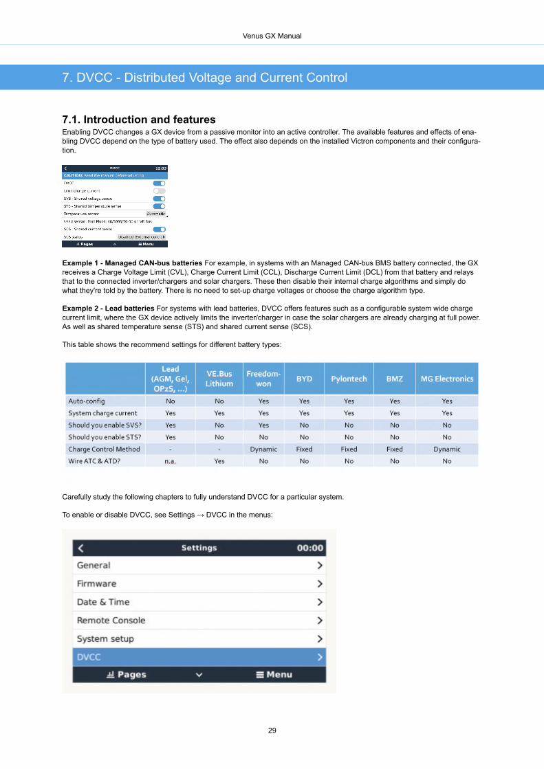
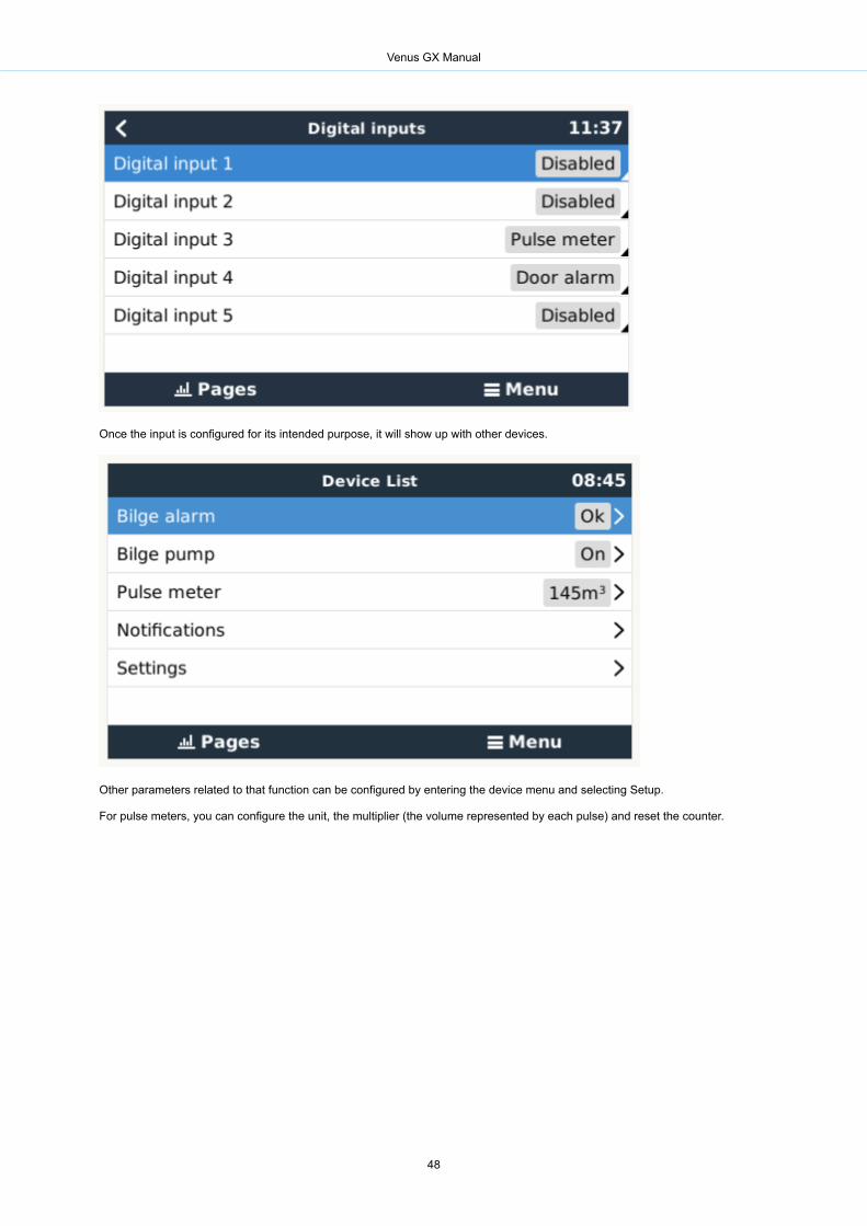
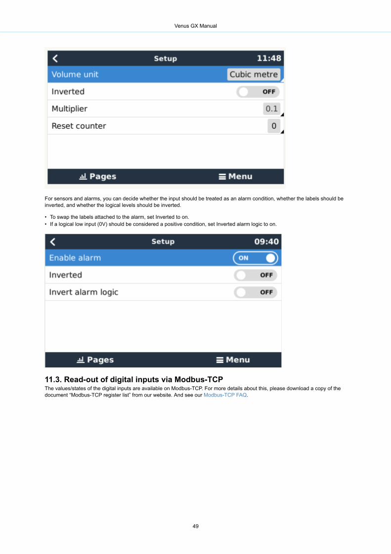


![In conjunction with Venus [planetary radar astronomy]](https://static.fdokumen.com/doc/165x107/631a4f09bb40f9952b01f2bc/in-conjunction-with-venus-planetary-radar-astronomy.jpg)