Validation of Indian standard code provisions for fire ...
10
Original Article Validation of Indian standard code provisions for fire resistance of flexural elements Aneesha Balaji*, Praveen Nagarajan, and Madhavan Pillai Department of Civil Engineering, National Institute of Technology, Calicut, India. Received: 21 October 2013; Accepted: 13 January 2015 Abstract Fire resistance provisions in Indian codes are prescriptive in nature and provide only tabulated fire ratings for structural members. Eurocode EN 1992-1-2:2004 suggests simplified methods which include explicit equations for fire resistant design. The aim of this paper is to familiarize the simplified method, i.e., 500°C isotherm method. The procedure is customized for Indian conditions and a parametric study is done to determine the fire rating for flexural elements. Fire ratings recommended in IS 456:2000 is compared with strength criteria by using the 500°C isotherm method. It is also compared by thermal criteria obtained by heat transfer analysis of finite element model. Through these studies, it is shown that for most of the cross-sections, the fire rating obtained from the two methods is higher than that given in IS 456:2000 provisions and the increase in cover has significant effect in increasing fire rating only for lower values of cover to reinforcement. Keywords: 500°C isotherm method, fire rating, transient thermal analysis, tabulated data, structural elements, reinforced concrete Songklanakarin J. Sci. Technol. 37 (2), 183-192, Mar.-Apr. 2015 1. Introduction Fire resistance is a measurement of the ability of the structure to resist collapse, fire spread or other failure during exposure to a fire of specified severity or in other words it is the duration a structural member (system) exhibits resistance with respect to temperature transmission, structural integrity, and stability under fire conditions. The fundamental step in designing structures for fire safety is to verify that the fire resistance of the structure or each part of the structure is greater than the severity of the fire to which the structure is exposed. The current prescriptive methods for fire resistance are derived from data obtained from standard fire resistance tests and do not consider the effect of many of the important parameters such as load level, fire scenario, and concrete strength (Kodur and Dwaikat, 2008). Although, there have been a number of studies conducted on the behavior of reinforced concrete (RC) structures in fire conditions, such studies have largely been research oriented and used specially developed software. Therefore, it is necessary to generalize the analysis using commercial software packages such as ANSYS, ABAQUS, or others. In the present work, a parametric study is done using the 500 °C isotherm method and heat transfer analysis using general finite element software ANSYS. The fire ratings provided in IS 456:2000 are compared with strength criteria by using 500°C isotherm method. It is also compared by thermal criteria using heat transfer analysis of the finite element model. 2. Different Methods for Assessment of Fire Resistance The fire resistance of concrete structural elements can be evaluated using different approaches like tabulated data, standard fire tests, advanced calculation methods and simplified calculation methods (Buchanan, 2001). These methods are briefed in following sections. * Corresponding author. Email address: [email protected] http://www.sjst.psu.ac.th
-
Upload
khangminh22 -
Category
Documents
-
view
0 -
download
0
Transcript of Validation of Indian standard code provisions for fire ...
Original Article
Validation of Indian standard code provisionsfor fire resistance of flexural elements
Aneesha Balaji*, Praveen Nagarajan, and Madhavan Pillai
Department of Civil Engineering, National Institute of Technology, Calicut, India.
Received: 21 October 2013; Accepted: 13 January 2015
Abstract
Fire resistance provisions in Indian codes are prescriptive in nature and provide only tabulated fire ratings forstructural members. Eurocode EN 1992-1-2:2004 suggests simplified methods which include explicit equations for fire resistantdesign. The aim of this paper is to familiarize the simplified method, i.e., 500°C isotherm method. The procedure is customizedfor Indian conditions and a parametric study is done to determine the fire rating for flexural elements. Fire ratingsrecommended in IS 456:2000 is compared with strength criteria by using the 500°C isotherm method. It is also compared bythermal criteria obtained by heat transfer analysis of finite element model. Through these studies, it is shown that for mostof the cross-sections, the fire rating obtained from the two methods is higher than that given in IS 456:2000 provisions andthe increase in cover has significant effect in increasing fire rating only for lower values of cover to reinforcement.
Keywords: 500°C isotherm method, fire rating, transient thermal analysis, tabulated data, structural elements,reinforced concrete
Songklanakarin J. Sci. Technol.37 (2), 183-192, Mar.-Apr. 2015
1. Introduction
Fire resistance is a measurement of the ability of thestructure to resist collapse, fire spread or other failure duringexposure to a fire of specified severity or in other words it isthe duration a structural member (system) exhibits resistancewith respect to temperature transmission, structural integrity,and stability under fire conditions. The fundamental step indesigning structures for fire safety is to verify that the fireresistance of the structure or each part of the structure isgreater than the severity of the fire to which the structure isexposed. The current prescriptive methods for fire resistanceare derived from data obtained from standard fire resistancetests and do not consider the effect of many of the importantparameters such as load level, fire scenario, and concretestrength (Kodur and Dwaikat, 2008).
Although, there have been a number of studiesconducted on the behavior of reinforced concrete (RC)structures in fire conditions, such studies have largely beenresearch oriented and used specially developed software.Therefore, it is necessary to generalize the analysis usingcommercial software packages such as ANSYS, ABAQUS,or others. In the present work, a parametric study is doneusing the 500 °C isotherm method and heat transfer analysisusing general finite element software ANSYS. The fire ratingsprovided in IS 456:2000 are compared with strength criteriaby using 500°C isotherm method. It is also compared bythermal criteria using heat transfer analysis of the finiteelement model.
2. Different Methods for Assessment of Fire Resistance
The fire resistance of concrete structural elementscan be evaluated using different approaches like tabulateddata, standard fire tests, advanced calculation methods andsimplified calculation methods (Buchanan, 2001). Thesemethods are briefed in following sections.
* Corresponding author.Email address: [email protected]
http://www.sjst.psu.ac.th
A. Balaji et al. / Songklanakarin J. Sci. Technol. 37 (2), 183-192, 2015184
2.1 Tabulated data
Tabulated data that are incorporated in most of thecodes and standards are available only for structuralelements. These data are quite useful in preliminary designstage; but is not applicable for structural systems. The maindrawback of this method is that the backgrounds to the dataare not very clear. IS code provisions for fire resistance arebased on these tabulated data in which there are provisionsfor minimum cross-section and cover to reinforcement forvarious structural elements based on support conditions.The code does not mention any further data or other proce-dures that are available in various foreign codes (Dwaikatand Kodur, 2008).
2.2 Standard fire tests
Fire resistance testing is usually done on structuralelements such as beams, columns, floors, or walls of specificdimension subjected to a standard fire exposure (likeASTME119, ISO curves) in a specially designed fire testfurnace. The failure criterion for this test may be generallybased on a simple limit, such as unexposed side temperatureor critical limiting temperature in steel (normally taken as593°C). The fire test is not accurate if scaling is done. Thisapproach provides only minimum data for validation and istoo expensive and time consuming.
Full-scale fire tests done on structural systems aremore effective than the fire resistance tests on structuralelements. The studies like Cardington fire test, conducted bythe Building Research Establishment (BRE) in UK confirmedthat the fire resistance of complex building (structural system)is significantly higher than that of single elements from whichthe performance is usually assessed (Kodur et al., 2007).These methods even though it is more accurate and givesreal behavior of structure are very expensive and cannot beimplemented in regular basis.
2.3 Advanced calculation methods
This method is a time-dependent thermal and mecha-nical analysis based on equations of heat transfer and
structural mechanics performed to assess the fire resistance.These are also called numerical methods and are implementedusing tools like finite difference method, finite elementmethod, and boundary element method. There are generalpurpose finite element softwares such as ANSYS, ABAQUS,SAFIR, etc., which are available for analyzing the fireresponse of structural members and assembly by this numeri-cal approach.
2.4 Simplified calculation methods
The above discussed methods cannot be used forroutine design calculations performed in a design office. Insuch cases simple analytical methods are required to predictthe capacity of structural elements. So, the next option is thesimplified calculation methods. These methods are usuallythe direct extrapolation to higher temperature of traditionalmethods that are used in ambient conditions. Differentmethods are available for each combination of material andelement type. Such methods are recommended in FIP-CEBrecommendations and in the European Standard EN 1992-1-2:2004 (E) (Eurocode, 2000).
3. Introduction to IS Code Provisions
The provisions for fire resistance given in IS 456:2000and IS 1642:1988 are same and are based on the tabulated datain which there are provisions for minimum cross-section andcover to reinforcement for various structural elements basedon support conditions. Table 1 and 2 show the minimumwidth and cover required for beams and slabs for variousfire ratings varying from 30 minutes to four hours.
4. Simplified Design Procedures for Fire Resistance Givenin EN 1992-1-2:2004 (E)
Eurocode suggest two methods for the fire resistantdesign of concrete structural elements: a) 500°C isothermmethod and b) zone method. The 500°C isotherm method isapplicable to both a standard fire exposure and any firecurves, which cause similar effect in the fire exposedmembers. Concrete section with temperatures lower than
Table 1. Minimum dimensions and nominal cover to meet specified period of fire resistance forRC beam (IS 456:2000).
Minimum Dimensions (mm), excluding any finish fora fire resistance of
0.5h 1 h 1.5 h 2 h 3 h 4 h
1 Reinforced concrete Width 80 120 150 200 240 280 (simply supported) Cover 20 30 40 60 70 80
2 Reinforced concrete Width 80 80 120 150 200 240 (continuous) Cover 20 20 35 50 60 70
Nature ofConstruction Materials
185A. Balaji et al. / Songklanakarin J. Sci. Technol. 37 (2), 183-192, 2015
500°C is assumed to have full strength and those having atemperature with higher value are discarded. The 500°Cisotherm for the specified fire exposure can be calculatedusing standard fire curve specified using Equation 1.A reduced cross-section is obtained by excluding theconcrete outside the 500°C isotherm. The zone method isapplicable to the standard temperature curve only. In thismethod, the cross section is divided into a number of parallelzones of equal thickness (rectangular elements). The meantemperature and the corresponding mean compressivestrength of each zone is assessed. The reduction of the cross-section is based on a damaged zone of thickness at the fireexposed surfaces. After the determination of reduced crosssection, the fire design follows the normal design procedure.Out of these two methods, as 500°C isotherm method is easyto analyze, a parametric study based on cross-section andcover is done using this method for flexural elements. Thefire rating is evaluated based on strength criteria. The failureis assumed to occur at the time when the moment of resis-tance at elevated temperature is less than the design momentfor fire. The design is done using IS code recommendationsand the temperature profile for the cross-section and reduc-tion factor for steel reinforcement at elevated temperaturesare taken from EN 1992-1-2:2004 (E). The basic steps for thedesign are detailed below.
4.1 Fire load modeling
The first step is to determine the fire load; with thisthe temperature distribution of the structure subjected to fireis established. For this purpose the various fire loads likeASTM E119 fire, ISO 834 fire, hydrocarbon fire etc., are thestandard fire scenarios used to develop fire rating in variouscountries. In present study, ISO 834 fire curve which is alsogiven in IS 3809:1979 is used. The curve is defined accordingto the equation,
T = T0 + 345 log10 (8t+1) (1)
where T is the applied temperature (°C), t is the time(minutes) and T0 is the ambient temperature (°C).
4.2 Temperature profiles for concrete elements
The establishment of temperature depended proper-ties of material are important for understanding the behaviorof structures in fire. Hence there is a need to get the tempera-ture profile of structural elements subjected to fire loads forvarious time of exposure. A common way of providing thetemperature data is by using graphical presentation given indesign codes or from numerical methods. In the presentstudy, temperature profiles available in EN 1992-1-2:2004 (E)are used.
4.3 500°C isotherm method
This method is applicable to both a standard fireexposure and any fire curves, which cause similar effect in thefire exposed members. Concrete section with temperatureslower than 500°C is assumed to have full strength and thosewith higher value are discarded.
The basic design procedure as per 500°C isothermmethod available in EN 1992-1-2:2004 (E) is given below.
1. The 500°C isotherm for the specified fire exposureis calculated using standard fire or parametric fire.
2. A reduced width bf and effective depth df of thecross-section is obtained by excluding the concrete outsidethe 500°C isotherm. The temperature of the individualreinforcing bars is evaluated from the temperature profilesin Annex A of EN 1992-1-2:2004 (E). Those reinforcing barswhich fall outside the reduced cross-section may also beincluded in the calculation of the ultimate load carryingcapacity of the fire exposed cross section. In the present studyfor lower exposure times, all reinforcement bars fall inside thereduced cross-section. But as the time of exposure increasesthe cross-section size decreases and hence some reinforce-ment bars fall outside the reduced cross-section. In thosecases, those reinforcements are accounted to calculateultimate load capacity.
3. The reduced strength of the reinforcement due tothe temperature is determined according to Cl. 4.2.4.3 of EN1992-1-2:2004 (E). The corresponding reduction factor isshown in Table A1 of Appendix I
Table 2. Minimum dimensions and nominal cover to meet specified period of fire resistance for RC slab(IS 456:2000).
Minimum Dimensions (mm), excluding any finish fora fire resistance of
0.5h 1 h 1.5 h 2 h 3 h 4 h
1 Reinforced concrete Thickness 75 95 110 125 150 170 (simply supported) Cover 15 20 25 35 45 55
2 Reinforced concrete Thickness 75 95 110 125 150 170 (continuous) Cover 15 20 20 25 35 45
Nature ofConstruction Materials
A. Balaji et al. / Songklanakarin J. Sci. Technol. 37 (2), 183-192, 2015186
4. The conventional calculation methods for thedetermination of the ultimate strength based on limit-statedesign specified in Indian code is used to find the ultimateload-carrying capacity for reduced cross-section withstrength of the reinforcing bars as obtained from step 3 and
5. The ultimate load-carrying capacity is comparedwith the design capacity or, alternatively, the estimated fireresistance with the required resistance.
The above mentioned method is used to determinethe moment capacity and hence the failure time for flexuralmembers. In this work the beams are exposed to fire frombottom and sides while slab is heated only from bottom.Therefore the temperature in slab varies only across thethickness. Hence, heat transfer in slab can be assumed asone dimensional in 500°C isotherm method.
5. Numerical Methods
The standard fire resistance test performed in afurnace has been used quite intensively for the evaluation ofthe fire endurance of structural elements, yet in its presentform the test procedure has several shortcomings, like thepreparation of the experiment and delays involved, the costof the test, the size of the element to be tested, the heatingand restraint characteristics. Therefore the need for analyticalpredictions of thermal and structural responses has grownmore and more intensively (Dotreppe and Franssen, 1985).In the case of steel structures it is usually accepted that theycan be analyzed using simple methods of calculation. This isdue to the fact that the temperature of steel does not varymuch from one point to another in the same element. This isno longer true when a considerable amount of concrete ispresent, which is the case for composite and RC structures.Furthermore, the study of the mechanical behavior ofconcrete at high temperature is complicated. Therefore it isnecessary to use more refined models for these types ofstructures: a step-by-step analysis should be performedtaking into account material and geometric non-linearity. Tosolve these problems it is necessary to use data on thermaland mechanical properties of steel and concrete at hightemperature (Kodur et al., 2008). The present work includesa heat transfer analysis using finite element model and thematerial properties for the analysis are taken from EN 1992-1-2:2004 (E).
5.1 Material properties
Concrete generally has good fire resistance proper-ties. The temperature depended material properties areimportant for establishing an understanding of the fireresponse of reinforced concrete structures. IS code does notgive any provision for material properties of either concreteor steel. These temperature depended properties are speci-fied in codes such as EN 1992-1-2:2004 (E) (Eurocode, 2000)and in ASCE manual (ASCE, 1992). For the analysis presentedhere, the thermal properties of concrete specified in EN 1992-
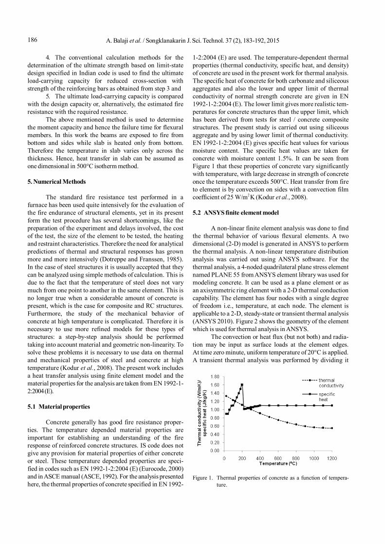
1-2:2004 (E) are used. The temperature-dependent thermalproperties (thermal conductivity, specific heat, and density)of concrete are used in the present work for thermal analysis.The specific heat of concrete for both carbonate and siliceousaggregates and also the lower and upper limit of thermalconductivity of normal strength concrete are given in EN1992-1-2:2004 (E). The lower limit gives more realistic tem-peratures for concrete structures than the upper limit, whichhas been derived from tests for steel / concrete compositestructures. The present study is carried out using siliceousaggregate and by using lower limit of thermal conductivity.EN 1992-1-2:2004 (E) gives specific heat values for variousmoisture content. The specific heat values are taken forconcrete with moisture content 1.5%. It can be seen fromFigure 1 that these properties of concrete vary significantlywith temperature, with large decrease in strength of concreteonce the temperature exceeds 500°C. Heat transfer from fireto element is by convection on sides with a convection filmcoefficient of 25 W/m2 K (Kodur et al., 2008).
5.2 ANSYS finite element model
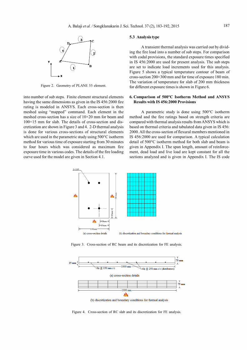
A non-linear finite element analysis was done to findthe thermal behavior of various flexural elements. A twodimensional (2-D) model is generated in ANSYS to performthe thermal analysis. A non-linear temperature distributionanalysis was carried out using ANSYS software. For thethermal analysis, a 4-noded quadrilateral plane stress elementnamed PLANE 55 from ANSYS element library was used formodeling concrete. It can be used as a plane element or asan axisymmetric ring element with a 2-D thermal conductioncapability. The element has four nodes with a single degreeof freedom i.e., temperature, at each node. The element isapplicable to a 2-D, steady-state or transient thermal analysis(ANSYS 2010). Figure 2 shows the geometry of the elementwhich is used for thermal analysis in ANSYS.
The convection or heat flux (but not both) and radia-tion may be input as surface loads at the element edges.At time zero minute, uniform temperature of 20°C is applied.A transient thermal analysis was performed by dividing it
Figure 1. Thermal properties of concrete as a function of tempera-ture.
187A. Balaji et al. / Songklanakarin J. Sci. Technol. 37 (2), 183-192, 2015
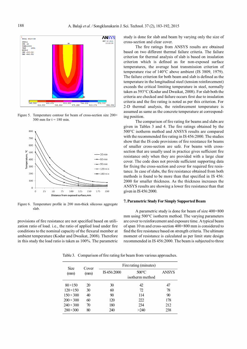
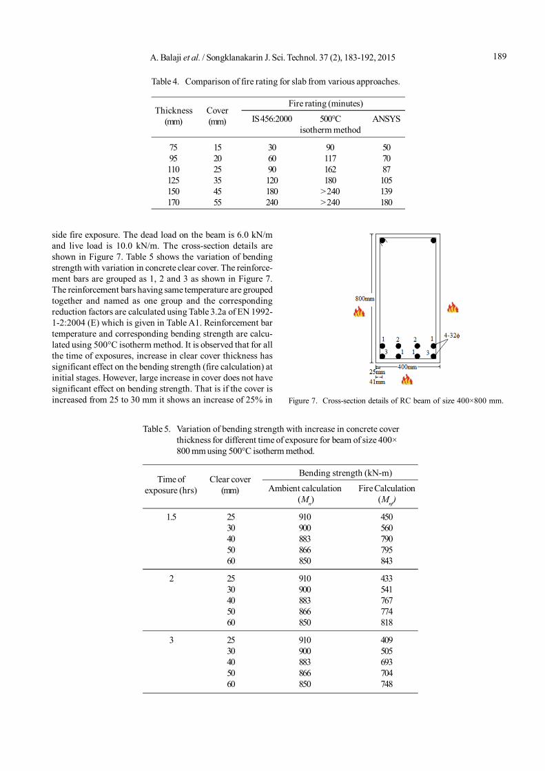
into number of sub steps. Finite element structural elementshaving the same dimensions as given in the IS 456:2000 firerating is modeled in ANSYS. Each cross-section is thenmeshed using “mapped” command. Each element in themeshed cross-section has a size of 10×20 mm for beam and100×15 mm for slab. The details of cross-section and dis-cretization are shown in Figure 3 and 4. 2-D thermal analysisis done for various cross-sections of structural elementswhich are used in the parametric study using 500°C isothermmethod for various time of exposure starting from 30 minutesto four hours which was considered as maximum fireexposure time in various codes. The details of the fire loadingcurve used for the model are given in Section 4.1.
5.3 Analysis type
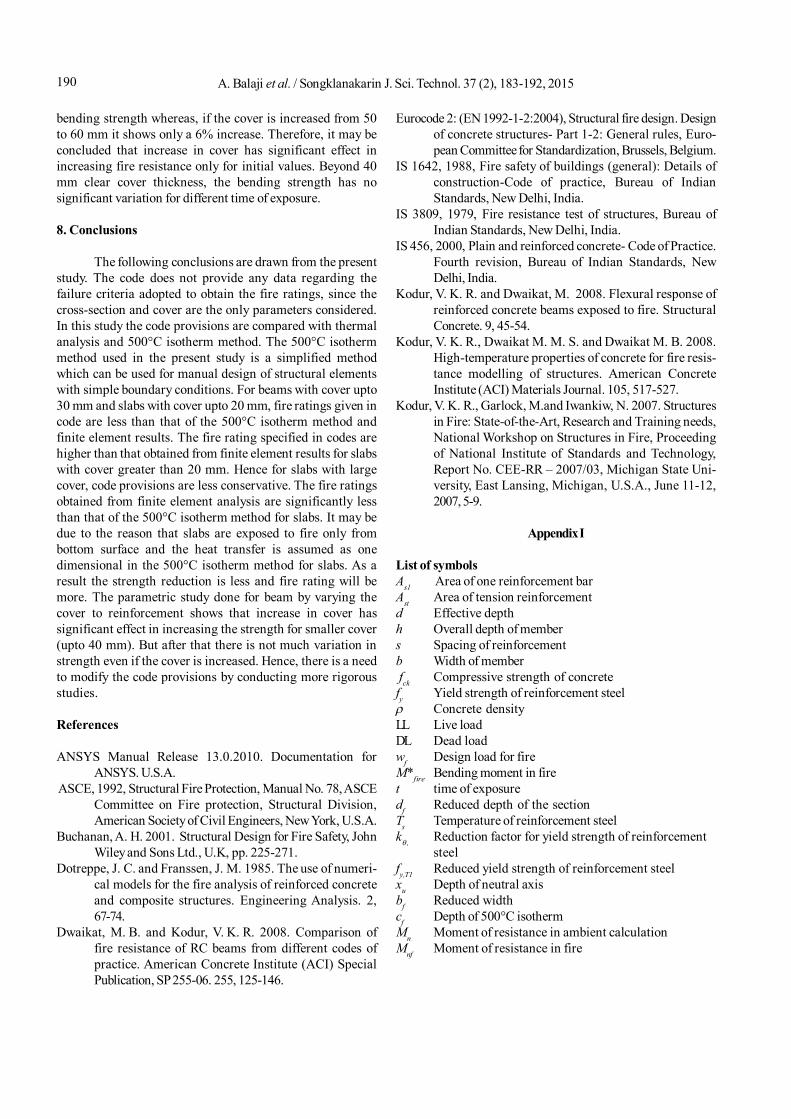
A transient thermal analysis was carried out by divid-ing the fire load into a number of sub steps. For comparisonwith codal provisions, the standard exposure times specifiedin IS 456:2000 are used for present analysis. The sub stepsare set to indicate load increments used for this analysis.Figure 5 shows a typical temperature contour of beam ofcross-section 200×300 mm and for time of exposure 180 min.The variation of temperature for slab of 200 mm thicknessfor different exposure times is shown in Figure 6.
6. Comparison of 500°C Isotherm Method and ANSYSResults with IS 456:2000 Provisions
A parametric study is done using 500°C isothermmethod and the fire ratings based on strength criteria arecompared with thermal analysis results from ANSYS which isbased on thermal criteria and tabulated data given in IS 456:2000. All the cross-section of flexural members mentioned inIS 456:2000 are used for comparison. A typical calculationdetail of 500°C isotherm method for both slab and beam isgiven in Appendix I. The span length, amount of reinforce-ment, dead load and live load are kept constant for all thesections analyzed and is given in Appendix I. The IS code
Figure 2. Geometry of PLANE 55 element.
Figure 3. Cross-section of RC beam and its discretization for FE analysis.
Figure 4. Cross-section of RC slab and its discretization for FE analysis.
A. Balaji et al. / Songklanakarin J. Sci. Technol. 37 (2), 183-192, 2015188
provisions of fire resistance are not specified based on utili-zation ratio of load. i.e., the ratio of applied load under fireconditions to the nominal capacity of the flexural member atambient temperature (Kodur and Dwaikat, 2008). Thereforein this study the load ratio is taken as 100%. The parametric
study is done for slab and beam by varying only the size ofcross-section and clear cover.
The fire ratings from ANSYS results are obtainedbased on two different thermal failure criteria. The failurecriterion for thermal analysis of slab is based on insulationcriterion which is defined as for non-exposed surfacetemperatures, the average heat transmission criterion oftemperature rise of 140°C above ambient (IS 3809, 1979).The failure criterion for both beam and slab is defined as thetemperature in the longitudinal steel (tension reinforcement)exceeds the critical limiting temperature in steel, normallytaken as 593°C (Kodur and Dwaikat, 2008). For slab both thecriteria are checked and failure occurs first due to insulationcriteria and the fire rating is noted as per this criterion. For2-D thermal analysis, the reinforcement temperature isassumed as same as the concrete temperature at correspond-ing position.
The comparison of fire rating for beams and slabs aregiven in Tables 3 and 4. The fire ratings obtained by the500°C isotherm method and ANSYS results are comparedwith the recommended fire rating in IS 456:2000. The studiesshow that the IS code provisions of fire resistance for beamsof smaller cross-section are safe. For beams with cross-section that are usually used in practice gives sufficient fireresistance only when they are provided with a large clearcover. The code does not provide sufficient supporting datafor fixing the cross-section and cover for required fire resis-tance. In case of slabs, the fire resistance obtained from bothmethods is found to be more than that specified in IS 456:2000 for smaller thickness. As the thickness increases theANSYS results are showing a lower fire resistance than thatgiven in IS 456:2000.
7. Parametric Study For Simply Supported Beam
A parametric study is done for beam of size 400×800mm using 500°C isotherm method. The varying parametersare cover to reinforcement and exposure time. A typical beamof span 10 m and cross-section 400×800 mm is considered tofind the fire resistance based on strength criteria. The ultimatemoment of resistance is calculated as per limit state designrecommended in IS 456:2000. The beam is subjected to three
Figure 5. Temperature contour for beam of cross-section size 200×300 mm for t = 180 min.
Table 3. Comparison of fire rating for beam from various approaches.
Fire rating (minutes)
IS 456:2000 500°C ANSYSisotherm method
80 ×150 20 30 42 47120 ×150 30 60 72 78150 × 300 40 90 114 90200 × 300 60 120 222 178240 × 300 70 180 234 212280 ×300 80 240 >240 238
Cover(mm)
Size(mm)
Figure 6. Temperature profile in 200 mm-thick siliceous aggregateslab.
189A. Balaji et al. / Songklanakarin J. Sci. Technol. 37 (2), 183-192, 2015
side fire exposure. The dead load on the beam is 6.0 kN/mand live load is 10.0 kN/m. The cross-section details areshown in Figure 7. Table 5 shows the variation of bendingstrength with variation in concrete clear cover. The reinforce-ment bars are grouped as 1, 2 and 3 as shown in Figure 7.The reinforcement bars having same temperature are groupedtogether and named as one group and the correspondingreduction factors are calculated using Table 3.2a of EN 1992-1-2:2004 (E) which is given in Table A1. Reinforcement bartemperature and corresponding bending strength are calcu-lated using 500°C isotherm method. It is observed that for allthe time of exposures, increase in clear cover thickness hassignificant effect on the bending strength (fire calculation) atinitial stages. However, large increase in cover does not havesignificant effect on bending strength. That is if the cover isincreased from 25 to 30 mm it shows an increase of 25% in
Table 4. Comparison of fire rating for slab from various approaches.
Fire rating (minutes)
IS 456:2000 500°C ANSYSisotherm method
75 15 30 90 5095 20 60 117 70110 25 90 162 87125 35 120 180 105150 45 180 > 240 139170 55 240 > 240 180
Cover(mm)
Thickness(mm)
Table 5. Variation of bending strength with increase in concrete coverthickness for different time of exposure for beam of size 400×800 mm using 500°C isotherm method.
Bending strength (kN-m)
Ambient calculation Fire Calculation (Mn) (Mnf)
1.5 25 910 45030 900 56040 883 79050 866 79560 850 843
2 25 910 43330 900 54140 883 76750 866 77460 850 818
3 25 910 40930 900 50540 883 69350 866 70460 850 748
Time ofexposure (hrs)
Clear cover(mm)
Figure 7. Cross-section details of RC beam of size 400×800 mm.
A. Balaji et al. / Songklanakarin J. Sci. Technol. 37 (2), 183-192, 2015190
bending strength whereas, if the cover is increased from 50to 60 mm it shows only a 6% increase. Therefore, it may beconcluded that increase in cover has significant effect inincreasing fire resistance only for initial values. Beyond 40mm clear cover thickness, the bending strength has nosignificant variation for different time of exposure.
8. Conclusions
The following conclusions are drawn from the presentstudy. The code does not provide any data regarding thefailure criteria adopted to obtain the fire ratings, since thecross-section and cover are the only parameters considered.In this study the code provisions are compared with thermalanalysis and 500°C isotherm method. The 500°C isothermmethod used in the present study is a simplified methodwhich can be used for manual design of structural elementswith simple boundary conditions. For beams with cover upto30 mm and slabs with cover upto 20 mm, fire ratings given incode are less than that of the 500°C isotherm method andfinite element results. The fire rating specified in codes arehigher than that obtained from finite element results for slabswith cover greater than 20 mm. Hence for slabs with largecover, code provisions are less conservative. The fire ratingsobtained from finite element analysis are significantly lessthan that of the 500°C isotherm method for slabs. It may bedue to the reason that slabs are exposed to fire only frombottom surface and the heat transfer is assumed as onedimensional in the 500°C isotherm method for slabs. As aresult the strength reduction is less and fire rating will bemore. The parametric study done for beam by varying thecover to reinforcement shows that increase in cover hassignificant effect in increasing the strength for smaller cover(upto 40 mm). But after that there is not much variation instrength even if the cover is increased. Hence, there is a needto modify the code provisions by conducting more rigorousstudies.
References
ANSYS Manual Release 13.0.2010. Documentation forANSYS. U.S.A.
ASCE, 1992, Structural Fire Protection, Manual No. 78, ASCECommittee on Fire protection, Structural Division,American Society of Civil Engineers, New York, U.S.A.
Buchanan, A. H. 2001. Structural Design for Fire Safety, JohnWiley and Sons Ltd., U.K, pp. 225-271.
Dotreppe, J. C. and Franssen, J. M. 1985. The use of numeri-cal models for the fire analysis of reinforced concreteand composite structures. Engineering Analysis. 2,67-74.
Dwaikat, M. B. and Kodur, V. K. R. 2008. Comparison offire resistance of RC beams from different codes ofpractice. American Concrete Institute (ACI) SpecialPublication, SP 255-06. 255, 125-146.
Eurocode 2: (EN 1992-1-2:2004), Structural fire design. Designof concrete structures- Part 1-2: General rules, Euro-pean Committee for Standardization, Brussels, Belgium.
IS 1642, 1988, Fire safety of buildings (general): Details ofconstruction-Code of practice, Bureau of IndianStandards, New Delhi, India.
IS 3809, 1979, Fire resistance test of structures, Bureau ofIndian Standards, New Delhi, India.
IS 456, 2000, Plain and reinforced concrete- Code of Practice.Fourth revision, Bureau of Indian Standards, NewDelhi, India.
Kodur, V. K. R. and Dwaikat, M. 2008. Flexural response ofreinforced concrete beams exposed to fire. StructuralConcrete. 9, 45-54.
Kodur, V. K. R., Dwaikat M. M. S. and Dwaikat M. B. 2008.High-temperature properties of concrete for fire resis-tance modelling of structures. American ConcreteInstitute (ACI) Materials Journal. 105, 517-527.
Kodur, V. K. R., Garlock, M.and Iwankiw, N. 2007. Structuresin Fire: State-of-the-Art, Research and Training needs,National Workshop on Structures in Fire, Proceedingof National Institute of Standards and Technology,Report No. CEE-RR – 2007/03, Michigan State Uni-versity, East Lansing, Michigan, U.S.A., June 11-12,2007, 5-9.
Appendix I
List of symbolsAs1 Area of one reinforcement barAst Area of tension reinforcementd Effective depthh Overall depth of members Spacing of reinforcementb Width of member fck Compressive strength of concretefy Yield strength of reinforcement steel Concrete densityLL Live loadDL Dead loadwf Design load for fireM*fire Bending moment in firet time of exposuredf Reduced depth of the sectionTs Temperature of reinforcement steelk , Reduction factor for yield strength of reinforcement
steelfy,T1 Reduced yield strength of reinforcement steelxu Depth of neutral axisbf Reduced widthcf Depth of 500°C isothermMn Moment of resistance in ambient calculationMnf Moment of resistance in fire
191A. Balaji et al. / Songklanakarin J. Sci. Technol. 37 (2), 183-192, 2015
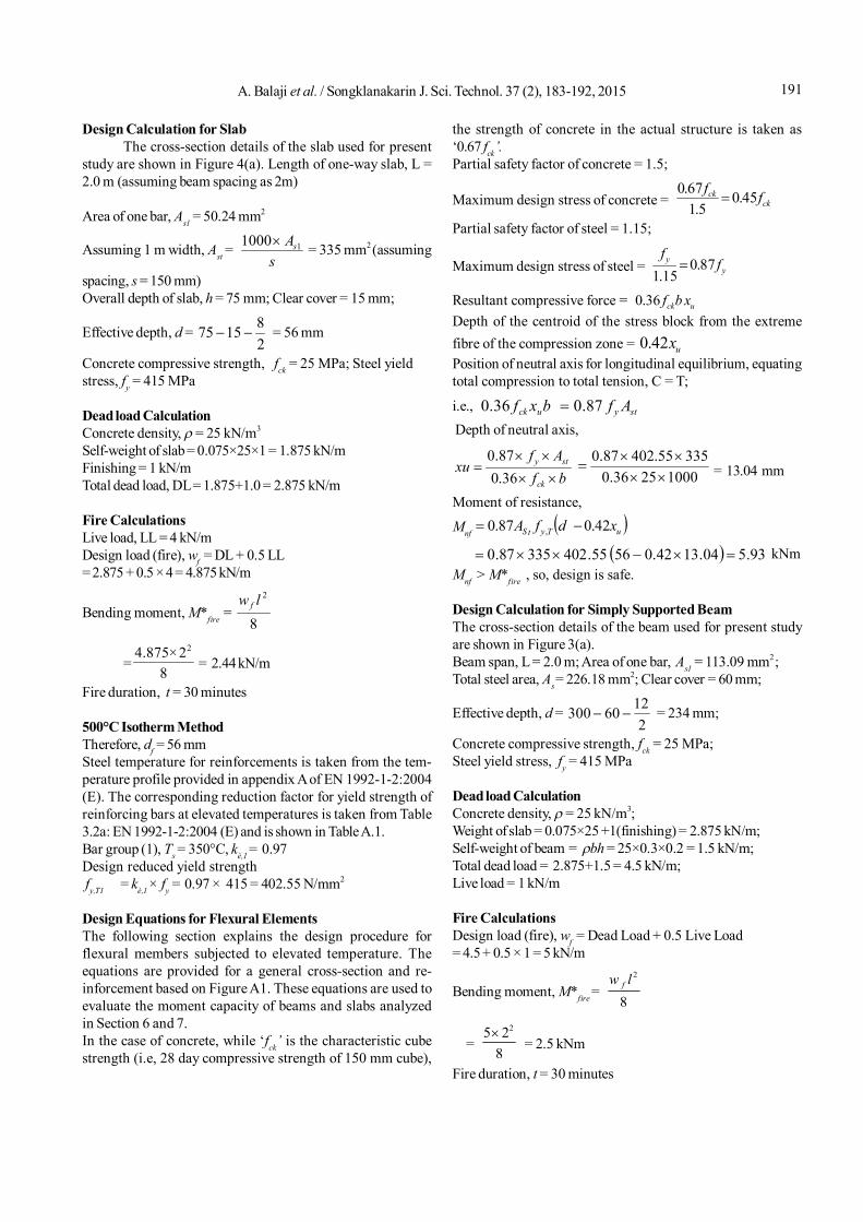
Design Calculation for SlabThe cross-section details of the slab used for present
study are shown in Figure 4(a). Length of one-way slab, L =2.0 m (assuming beam spacing as 2m)
Area of one bar, As1 = 50.24 mm2
Assuming 1 m width, Ast = s
As11000 = 335 mm2 (assuming
spacing, s = 150 mm)Overall depth of slab, h = 75 mm; Clear cover = 15 mm;
Effective depth, d = 281575 = 56 mm
Concrete compressive strength, fck = 25 MPa; Steel yieldstress, fy = 415 MPa
Dead load CalculationConcrete density, = 25 kN/m3
Self-weight of slab = 0.075×25×1 = 1.875 kN/mFinishing = 1 kN/mTotal dead load, DL = 1.875+1.0 = 2.875 kN/m
Fire CalculationsLive load, LL = 4 kN/mDesign load (fire), wf = DL + 0.5 LL= 2.875 + 0.5 × 4 = 4.875 kN/m
Bending moment, M*fire = 8
2lw f
=8
2×4.875 2
= 2.44 kN/m
Fire duration, t = 30 minutes
500°C Isotherm MethodTherefore, df = 56 mmSteel temperature for reinforcements is taken from the tem-perature profile provided in appendix A of EN 1992-1-2:2004(E). The corresponding reduction factor for yield strength ofreinforcing bars at elevated temperatures is taken from Table3.2a: EN 1992-1-2:2004 (E) and is shown in Table A.1.Bar group (1), Ts = 350°C, kè,1 = 0.97Design reduced yield strength fy,T1 = kè,1 × fy = 0.97 × 415 = 402.55 N/mm2
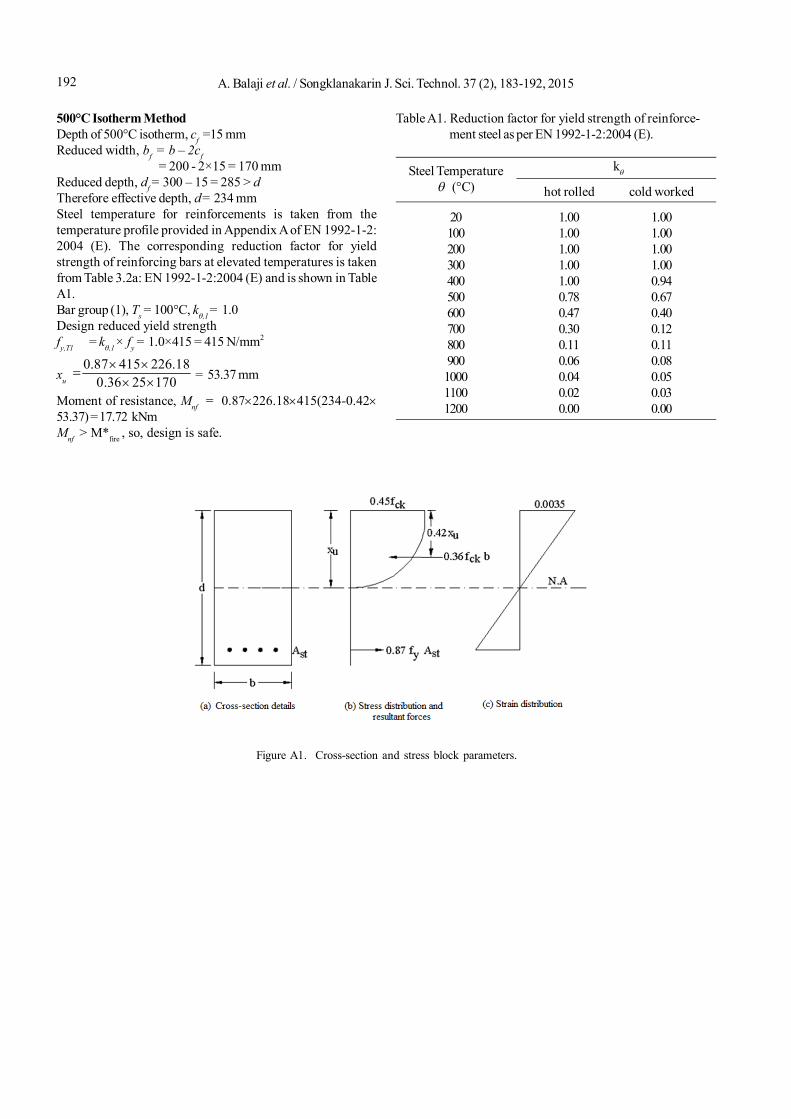
Design Equations for Flexural ElementsThe following section explains the design procedure forflexural members subjected to elevated temperature. Theequations are provided for a general cross-section and re-inforcement based on Figure A1. These equations are used toevaluate the moment capacity of beams and slabs analyzedin Section 6 and 7.In the case of concrete, while ‘fck’ is the characteristic cubestrength (i.e, 28 day compressive strength of 150 mm cube),
the strength of concrete in the actual structure is taken as‘0.67 fck’.Partial safety factor of concrete = 1.5;
Maximum design stress of concrete = ckck ff 45.0
5.167.0
Partial safety factor of steel = 1.15;
Maximum design stress of steel = yy f
f87.0
15.1
Resultant compressive force = uck xbf36.0Depth of the centroid of the stress block from the extremefibre of the compression zone = ux42.0Position of neutral axis for longitudinal equilibrium, equatingtotal compression to total tension, C = T;
i.e., styuck Afbxf 87.036.0 Depth of neutral axis,
bfAf
xuck
sty
36.087.0
10002536.033555.40287.0
= 13.04 mm
Moment of resistance,
Mnf uTytS xdfA 42.087.0 ,
93.504.1342.05655.40233587.0 kNmMnf > M*fire , so, design is safe.
Design Calculation for Simply Supported BeamThe cross-section details of the beam used for present studyare shown in Figure 3(a).Beam span, L = 2.0 m; Area of one bar, As1 = 113.09 mm2 ;Total steel area, As = 226.18 mm2; Clear cover = 60 mm;
Effective depth, d = 2
1260300 = 234 mm;
Concrete compressive strength, fck = 25 MPa;Steel yield stress, fy = 415 MPa
Dead load CalculationConcrete density, = 25 kN/m3;Weight of slab = 0.075×25 +1(finishing) = 2.875 kN/m;Self-weight of beam = bh = 25×0.3×0.2 = 1.5 kN/m;Total dead load = 2.875+1.5 = 4.5 kN/m;Live load = 1 kN/m
Fire CalculationsDesign load (fire), wf = Dead Load + 0.5 Live Load= 4.5 + 0.5 × 1 = 5 kN/m
Bending moment, M*fire = 2
8fw l
= 25 2
8
= 2.5 kNm
Fire duration, t = 30 minutes
A. Balaji et al. / Songklanakarin J. Sci. Technol. 37 (2), 183-192, 2015192
500°C Isotherm MethodDepth of 500°C isotherm, cf =15 mmReduced width, bf
= b – 2cf = 200 - 2×15 = 170 mm
Reduced depth, df = 300 – 15 = 285 > dTherefore effective depth, d = 234 mmSteel temperature for reinforcements is taken from thetemperature profile provided in Appendix A of EN 1992-1-2:2004 (E). The corresponding reduction factor for yieldstrength of reinforcing bars at elevated temperatures is takenfrom Table 3.2a: EN 1992-1-2:2004 (E) and is shown in TableA1.Bar group (1), Ts = 100°C, k,1 = 1.0Design reduced yield strengthfy,T1 = k,1 × fy = 1.0×415 = 415 N/mm2
xu 0.87 415 226.18
0.36 25 170 = 53.37 mm
Moment of resistance, Mnf = 0.87226.18415(234-0.4253.37) = 17.72 kNmMnf > M*fire , so, design is safe.
Figure A1. Cross-section and stress block parameters.
Table A1. Reduction factor for yield strength of reinforce- ment steel as per EN 1992-1-2:2004 (E).
k
hot rolled cold worked
20 1.00 1.00100 1.00 1.00200 1.00 1.00300 1.00 1.00400 1.00 0.94500 0.78 0.67600 0.47 0.40700 0.30 0.12800 0.11 0.11900 0.06 0.081000 0.04 0.051100 0.02 0.031200 0.00 0.00
Steel Temperature (°C)