Understanding Building Information Modeling (BIM) Interoperability
Upload
independentCategory
view
1download
0
274
Using the Unified Modeling Language (UML) to Model Distributed GISComponents for Improving Interoperability
Krzysztof KolodziejDepartment of Urban Studies and Planning
Massachusetts Institute of TechnologyCambridge, MA 02139-4307 USA+1 617 722 0150; [email protected]
Abstract
The need for global access to and decentralized management of geographic information ispushing the GIS community (OpenGIS Consortium) to establish a distributed GIS architec-ture. Integration of distributed GIS processing and of heterogeneous GIS systems is part ofthat architecture. Distributive GIS processes focus on open, distributed, task-centered com-ponents (programs). One important advantage of distributed processing is the independencefrom different operating systems, hardware/software, network environments, and applica-tions.
This paper investigates the usefulness of the Unified Modeling Language (UML)1 as anobject oriented modeling method to represent, specify, and facilitate distributive GIS compo-nents. UML is an abstract solution to the integration problem because it is independent of aparticular computing environment (i.e., it is implementation independent). UML models areautomated into a specified programming language (C++, VB, Java) using CASE tools. Codescan be assembled into components and stored in an object library for future use. The idea isto create components that stack and interlock to form a dynamic GIS package for specificuse, which will broaden the usage of geographic information into a wide range of GIS appli-cations. GIS are both data-oriented and process-oriented. Without considering distributedGIS processing, data can be shared but processing remains centralized. Full interoperabilitywithout distributed, interchangeable GIS components is impossible.
1. Introduction
It is now increasingly common for computational tasks to be carried out in a heterogeneous,distributed computing environment. Frequently programs have to be re-written in anotherprogramming language so that they can be compiled and executed on another architecture.Furthermore, integrated systems are now scaling beyond the Intranet to include data andcompute resources available throughout the Internet. Maintaining a working software systemin this computational jungle is a laborious and time-consuming practice.
This paper explores the issue of how to manage the process of GIS processing by differentusers in different software/hardware/system environment. This is addressed on two levels:(1) distributed system architecture/infrastructure that enables such collaboration; and (2) ab-straction, representation, and automation of GIS components using UML and code generat-ing tools.
This paper is organized under the following headings:
- distributive system architecture,
- UML abstraction, representation, and automation of GIS components,
- UML based code generation using CASE tools
275
- UML/CASE tools limitations
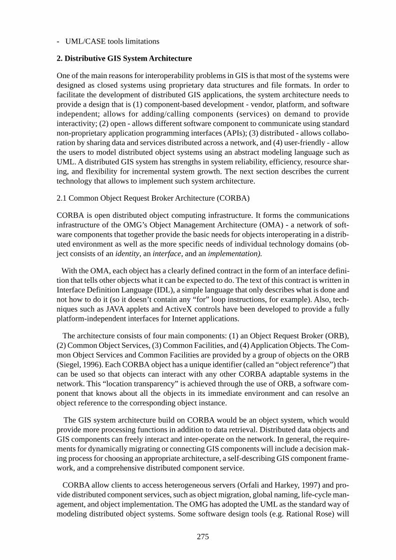
2. Distributive GIS System Architecture
One of the main reasons for interoperability problems in GIS is that most of the systems weredesigned as closed systems using proprietary data structures and file formats. In order tofacilitate the development of distributed GIS applications, the system architecture needs toprovide a design that is (1) component-based development - vendor, platform, and softwareindependent; allows for adding/calling components (services) on demand to provideinteractivity; (2) open - allows different software component to communicate using standardnon-proprietary application programming interfaces (APIs); (3) distributed - allows collabo-ration by sharing data and services distributed across a network, and (4) user-friendly - allowthe users to model distributed object systems using an abstract modeling language such asUML. A distributed GIS system has strengths in system reliability, efficiency, resource shar-ing, and flexibility for incremental system growth. The next section describes the currenttechnology that allows to implement such system architecture.
2.1 Common Object Request Broker Architecture (CORBA)
CORBA is open distributed object computing infrastructure. It forms the communicationsinfrastructure of the OMG’s Object Management Architecture (OMA) - a network of soft-ware components that together provide the basic needs for objects interoperating in a distrib-uted environment as well as the more specific needs of individual technology domains (ob-ject consists of an identity, an interface, and an implementation).
With the OMA, each object has a clearly defined contract in the form of an interface defini-tion that tells other objects what it can be expected to do. The text of this contract is written inInterface Definition Language (IDL), a simple language that only describes what is done andnot how to do it (so it doesn’t contain any “for” loop instructions, for example). Also, tech-niques such as JAVA applets and ActiveX controls have been developed to provide a fullyplatform-independent interfaces for Internet applications.
The architecture consists of four main components: (1) an Object Request Broker (ORB),(2) Common Object Services, (3) Common Facilities, and (4) Application Objects. The Com-mon Object Services and Common Facilities are provided by a group of objects on the ORB(Siegel, 1996). Each CORBA object has a unique identifier (called an “object reference”) thatcan be used so that objects can interact with any other CORBA adaptable systems in thenetwork. This “location transparency” is achieved through the use of ORB, a software com-ponent that knows about all the objects in its immediate environment and can resolve anobject reference to the corresponding object instance.
The GIS system architecture build on CORBA would be an object system, which wouldprovide more processing functions in addition to data retrieval. Distributed data objects andGIS components can freely interact and inter-operate on the network. In general, the require-ments for dynamically migrating or connecting GIS components will include a decision mak-ing process for choosing an appropriate architecture, a self-describing GIS component frame-work, and a comprehensive distributed component service.
CORBA allow clients to access heterogeneous servers (Orfali and Harkey, 1997) and pro-vide distributed component services, such as object migration, global naming, life-cycle man-agement, and object implementation. The OMG has adopted the UML as the standard way ofmodeling distributed object systems. Some software design tools (e.g. Rational Rose) will

276
now generate IDL directly from a UML design. Future OMG specifications promise to fur-ther ease the process of designing and implementing distributed systems based around CORBA.The trend is to provide a comprehensively open distributed computing environment, wherethe “network” is the “computer”.
3. UML Abstraction, Representation, and Automation of GIS Components
This section describes the usefulness of UML for modeling GIS components. UML-to-com-ponents procedures should allow the creation of components for any hardware and softwareplatform based on the defined functionality in order to achieve interoperability.
3.1 Distributive GIS Components
Under a general definition, a distributed component is a ready-to-run, replaceable, package ofcode (source, binary or executable or equivalents such as scripts or command files) that getsdynamically loaded into a system to extend its functionality (Pountain, 1997; UML 1.3). Inprinciple, the features of distributed components should be plug-and-play, interoperable, por-table and reusable, self-describing, and self-managing (Orfali at al, 1996; Pountain, 1997).
Each GIS component will be constructed using objects that have self-contained command(“methods”) and attributes (“variables”) needed to perform a specific task. An object per-forms a task when it receives a message requesting action. Objects can be reused as a unit inany GIS component (program). This approach enables object libraries to provide a standardset of “hooks” by which a GIS component can integrate with other GIS programs.
The dynamic combination and migration of GIS components will benefit GIS processingwith current distributed network environments. It can provide customizable services for dif-ferent users, heterogeneous platforms, and various network connections. The same compo-nent can be copied, moved, and executed in different machines with different configurations.Distributed components can interact with each other or be combined together to provideintegrated services to users. The development of distributed components shifts the GIS soft-ware paradigm from a monolithic, feature-heavy approach to a flexible, modularized, andplug-and-play approach.
GIS components should be designed and allocated based on different task-oriented catego-ries2. The major advantage of task-oriented GIS components is that they are ready-to-use forspecific GIS tasks. Users can select these GIS components based on applications and taskswithout worrying about compatibility with their systems and the installation details. TheseGIS components can have “plug-and-play” functionality by adopting standardized communi-cation protocols and specified metadata. The OpenGIS Specification enables vendors to pro-vide their software with interfaces that enable “plug-and-play” geoprocessing tools that userscan use to build specific functions/GIS packages. Computing is moving toward“componentware and network-based computing, and OpenGIS interfaces make it possiblefor geoprocessing to be part of this process” (OGC, 1998). Moreover, “each interface compo-nent must have encapsulated interface metadata, which describes available functions, meth-ods, and behaviors for each interface component and GIS operators, and facilitate a modular-ized user interface infrastructure” (Tsou and Buttenfield, 1998).
An example of GIS components is ESRI’s MapObjects, which is a collection of mappingand GIS components. MapObjects include an ActiveX control (OCX) and more than 45ActiveX automation objects that provides GIS components for custom application develop-ment. With MapObjects a developer is able to add mapping components to existing applica-

277
tions, build lightweight data viewers or customize mapping and GIS programs to fulfill spe-cific tasks. Although the analysis capabilities available are not on par with a full-featured GISpackage, the intention of the product is to provide enough functionality to embed mappingoperations and a moderate spatial query capability in specific applications. However,MapObjects works in standard Windows development environments (platform-dependent)such as Visual Basic and Visual C++. On the other hand, UML is platform independent andmodels can be automated into programming languages like C++ (platform-independent).
3.2 Specifying GIS Components using UML
UML is a standard way to specify, construct, and document systems that use object-orientedcode such as Java, C++ or IDL. UML focuses on a standard modeling language, not a stan-dard process. It promotes a development process that is use-case driven, architecture centric,and iterative and incremental. It allows deviations to be expressed in terms of its extensionmechanisms. (UML Summary, Version 1.3). In addition, non-semantic information can beattached to models using the three built-in extension mechanisms. that enable new kinds ofmodeling elements to be added to the modeler’s repertoire as well as to attach free-forminformation to modeling elements.
UML provides a rich set of modeling concepts and notations designed to meet the needs oftypical software modeling projects3. As with any language, the UML has its own notation andsyntax. Its notation comprises a set of specialized shapes for constructing different kinds ofsoftware diagrams. Each shape has a particular meaning, and the UML syntax dictates howthe shapes can be combined.
The following are the current UML diagrams (OMG, UML Specification, V 1.3):
- Use Case Diagram displays the relationship among actors and use cases.
- Class Diagram models class structure and contents using design elements such as classes,packages and objects. It also displays relationships such as containment, inheritance, associations and others.
- State Diagram displays the sequences of states that an object of an interaction goes throughduring its life in response to received stimuli, together with its responses and actions.
- Sequence Diagram displays the time sequence of the objects participating in the interaction. This consists of the vertical dimension (time) and horizontal dimension (differentobjects).
- Collaboration Diagram displays an interaction organized around the objects and their linksto one another. Numbers are used to show the sequence of messages.
- Activity Diagram displays a special state diagram where most of the states are action statesand most of the transitions are triggered by completion of the actions in the source states.This diagram focuses on flows driven by internal processing.
- Component Diagram displays the high level packaged structure of the code itself. Dependencies among components are shown, including source code components, binary codecomponents, and executable components. Some components exist at compile time, at linktime, at run times well as at more than one time.
- Deployment Diagram displays the configuration of run-time processing elements and the
278
software components, processes, and objects that live on them. Software component instances represent run-time manifestations of code units.
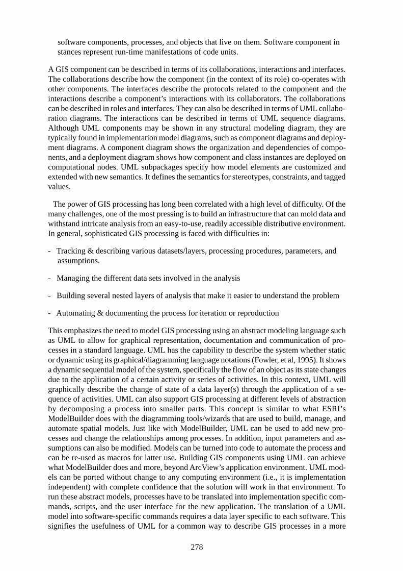
A GIS component can be described in terms of its collaborations, interactions and interfaces.The collaborations describe how the component (in the context of its role) co-operates withother components. The interfaces describe the protocols related to the component and theinteractions describe a component’s interactions with its collaborators. The collaborationscan be described in roles and interfaces. They can also be described in terms of UML collabo-ration diagrams. The interactions can be described in terms of UML sequence diagrams.Although UML components may be shown in any structural modeling diagram, they aretypically found in implementation model diagrams, such as component diagrams and deploy-ment diagrams. A component diagram shows the organization and dependencies of compo-nents, and a deployment diagram shows how component and class instances are deployed oncomputational nodes. UML subpackages specify how model elements are customized andextended with new semantics. It defines the semantics for stereotypes, constraints, and taggedvalues.
The power of GIS processing has long been correlated with a high level of difficulty. Of themany challenges, one of the most pressing is to build an infrastructure that can mold data andwithstand intricate analysis from an easy-to-use, readily accessible distributive environment.In general, sophisticated GIS processing is faced with difficulties in:
- Tracking & describing various datasets/layers, processing procedures, parameters, andassumptions.
- Managing the different data sets involved in the analysis
- Building several nested layers of analysis that make it easier to understand the problem
- Automating & documenting the process for iteration or reproduction
This emphasizes the need to model GIS processing using an abstract modeling language suchas UML to allow for graphical representation, documentation and communication of pro-cesses in a standard language. UML has the capability to describe the system whether staticor dynamic using its graphical/diagramming language notations (Fowler, et al, 1995). It showsa dynamic sequential model of the system, specifically the flow of an object as its state changesdue to the application of a certain activity or series of activities. In this context, UML willgraphically describe the change of state of a data layer(s) through the application of a se-quence of activities. UML can also support GIS processing at different levels of abstractionby decomposing a process into smaller parts. This concept is similar to what ESRI’sModelBuilder does with the diagramming tools/wizards that are used to build, manage, andautomate spatial models. Just like with ModelBuilder, UML can be used to add new pro-cesses and change the relationships among processes. In addition, input parameters and as-sumptions can also be modified. Models can be turned into code to automate the process andcan be re-used as macros for latter use. Building GIS components using UML can achievewhat ModelBuilder does and more, beyond ArcView’s application environment. UML mod-els can be ported without change to any computing environment (i.e., it is implementationindependent) with complete confidence that the solution will work in that environment. Torun these abstract models, processes have to be translated into implementation specific com-mands, scripts, and the user interface for the new application. The translation of a UMLmodel into software-specific commands requires a data layer specific to each software. Thissignifies the usefulness of UML for a common way to describe GIS processes in a more
279
abstract way. The next section describes how code is generated from UML models.
4. UML based Code Generation using CASE Tools
This section covers tool features and development techniques used to produce code fromUML object models. Model-based code generation produces application source code auto-matically from graphical models of system behavior or architecture. Code can be in the formof stored procedures, statements, triggers, check clauses, and so on. As diagrams are refined,new code can be created as existing code can be modified.
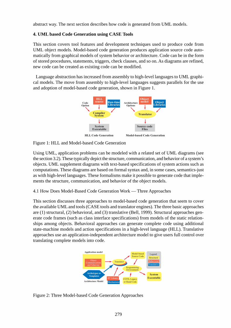
Language abstraction has increased from assembly to high-level languages to UML graphi-cal models. The move from assembly to high-level languages suggests parallels for the useand adoption of model-based code generation, shown in Figure 1.
Figure 1: HLL and Model-based Code Generation
Using UML, application problems can be modeled with a related set of UML diagrams (seethe section 3.2). These typically depict the structure, communication, and behavior of a system’sobjects. UML supplement diagrams with text-based specifications of system actions such ascomputations. These diagrams are based on formal syntax and, in some cases, semantics-justas with high-level languages. These formalisms make it possible to generate code that imple-ments the structure, communication, and behavior of the object models.
4.1 How Does Model-Based Code Generation Work — Three Approaches
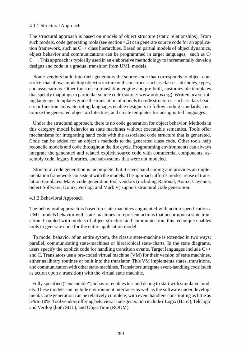
This section discusses three approaches to model-based code generation that seem to coverthe available UML and tools (CASE tools and translator engines). The three basic approachesare (1) structural, (2) behavioral, and (3) translative (Bell, 1999). Structural approaches gen-erate code frames (such as class interface specifications) from models of the static relation-ships among objects. Behavioral approaches can generate complete code using additionalstate-machine models and action specifications in a high-level language (HLL). Translativeapproaches use an application-independent architecture model to give users full control overtranslating complete models into code.
Figure 2: Three Model-based Code Generation Approaches
280
4.1.1 Structural Approach
The structural approach is based on models of object structure (static relationships). Fromsuch models, code generating tools (see section 4.2) can generate source code for an applica-tion framework, such as C++ class hierarchies. Based on partial models of object dynamics,object behavior and communications can be programmed in target languages, such as C/C++. This approach is typically used in an elaborative methodology to incrementally developdesigns and code in a gradual transition from UML models.
Some vendors build into their generators the source code that corresponds to object con-structs that allows modeling object structure with constructs such as classes, attributes, types,and associations. Other tools use a translation engine and pre-built, customizable templatesthat specify mappings to particular source code (source: www.ootips.org). Written in a script-ing language, templates guide the translation of models to code structures, such as class head-ers or function stubs. Scripting languages enable designers to follow coding standards, cus-tomize the generated object architecture, and create templates for unsupported languages.
Under the structural approach, there is no code generation for object behavior. Methods inthis category model behavior as state machines without executable semantics. Tools offermechanisms for integrating hand code with the associated code structure that is generated.Code can be added for an object’s methods to the generated class code. Other tools helpreconcile models and code throughout the life cycle. Programming environments can alwaysintegrate the generated and related explicit source code with commercial components, as-sembly code, legacy libraries, and subsystems that were not modeled.
Structural code generation is incomplete, but it saves hand coding and provides an imple-mentation framework consistent with the models. The approach affords modest reuse of trans-lation templates. Many code generation tool vendors (including Rational, Aonix, Cayenne,Select Software, Iconix, Verilog, and Mark V) support structural code generation.
4.1.2 Behavioral Approach
The behavioral approach is based on state-machines augmented with action specifications.UML models behavior with state-machines to represent actions that occur upon a state tran-sition. Coupled with models of object structure and communication, this technique enablestools to generate code for the entire application model.
To model behavior of an entire system, the classic state-machine is extended in two ways:parallel, communicating state-machines or hierarchical state-charts. In the state diagrams,users specify the explicit code for handling transition events. Target languages include C++and C. Translators use a pre-coded virtual machine (VM) for their version of state machines,either as library routines or built into the translator. This VM implements states, transitions,and communication with other state-machines. Translators integrate event-handling code (suchas action upon a transition) with the virtual state machine.
Fully specified (“executable”) behavior enables test and debug to start with simulated mod-els. These models can include environment interfaces as well as the software under develop-ment. Code generation can be relatively complete, with event handlers constituting as little as5% to 10%. Tool vendors offering behavioral code generation include i-Logix (Harel), Telelogicand Verilog (both SDL), and ObjecTime (ROOM).

281
4.1.3 Translative Approach
The translative approach is based on application and architecture models that are indepen-dent of one another. A complete application model of object structure, behavior, and commu-nication is created using UML. A translation engine then generates code for the applicationaccording to the mapping rules in the architecture. The translative approach offers significantreuse because the application and architecture models are independent.
An architecture model is developed with a tool that supports this approach. An architecturemodel is a complete set of translation rules (code patterns called templates) that map UMLconstructs onto source code. The mapping should be complete, that is, all UML constructsused in application models are translated. Typical mappings address concurrency (for ex-ample, threads, multi-tasking, single task), event handling (inter-process communication, orI/O streams), and data (structures, storage mechanism, and persistence). Templates or mecha-nisms address embedded issues such as memory layout, hard deadlines, interrupt service,timers, and hardware access. Any target language can be supported with the translative ap-proach; various projects have used C, C++.
Given an application model and an architecture, the translation engine extracts identifiedobjects from the model repository, makes substitutions, and emits code according to the scriptedmapping rules. Translation can include code from a run-time library and can vary generatedcode according to options or model annotations about design properties. Code generation istotally controlled using in the translative approach and the code is potentially complete. Projectsreport generating up to 95% of code of medium-sized systems.
4.1.4 Summary of Code Generation Approaches
All the above specified approaches share a common advantage: they strengthen the advan-tages of using object oriented modeling methods such as UML. These advantages include theability to build larger, more complex systems and improve maintainability with models thatare more understandable than code. With the capability to synchronize changes in models andcode comes the opportunity to easily iterate application development in support of an elabo-rative methodology.
A useful way to explore model-based code generation is to consider what the approacheshave in common and how they vary.
Commonalties:
- All approaches are associated with at least one analysis and design method
- All approaches are supported by commercial tools
- All tools translate these models into corresponding code for system objects, providing aframework to implement for communication and behavior code
- All the tools support generation of C++ (and other targeted programming languages)
- Most tools offer a mechanism by which to keep models and code synchronized (see CASEtool example)
- All methods use state machines for behavior, irrespective of code generation
282
Distinctions - The approaches vary in how different tools support them. Some variables in-clude:
- Behavior verification before code generation
- The target languages supported (other than C++)
- The extent of code generated (especially whether it includes behavioral code)
- Synchronizing or reconciling models and code
- Customization of translator technology
- Integrating non-generated code
Also, the following are considerations that should be noted when choosing a code generationapproach:
- The sufficiency of modeling constructs for generating code
- The maturity of translators for generating quality code
- Tools for development tasks related to code generation (such as debug)
- Methodologies for employing code generation effectively
4.2 CASE Tools
The purpose of this section is to describe object-oriented CASE (computer-aided softwareengineering) tools and their capability in generating code from UML models. The purpose ofCASE is to provide software engineers and programmers with software-based tools that helpspecify functional requirements and architect designs for software applications. CASE toolsmay also serve as a repository for or be linked to document and program libraries containingthe project’s design requirements, design specifications, detailed code specifications, the codeunits, and test cases and results.
Currently, there are a large number of CASE tools. These include Rational Rose from Ra-tional, Select OMT from Select Software, Paradigm Plus from Protosoft, WithClass fromMicroGold Software, like Objecteering/UML from Softeam, and ObjectiF from MicroTool.All of these O-O CASE tools are similar in terms of their capability to create UML diagrams,text specifications for reports, and code generation. Some are weak on code generation butothers claim to generate 70% of the final code, and in some cases even better. They differgreatly in terms of their extendibility, number of supported platforms/operating systems andadditional capabilities (e.g. support for different methodologies and computer language codegeneration). UML helps developers analyze and understand a system, but the bottom line ofanalysis and design methods has been the transition to code.
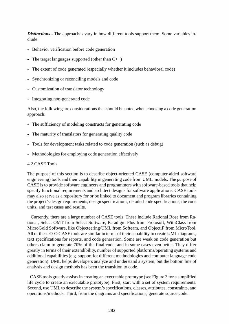
CASE tools greatly assists in creating an executable prototype (see Figure 3 for a simplifiedlife cycle to create an executable prototype). First, start with a set of system requirements.Second, use UML to describe the system’s specifications, classes, attributes, constraints, andoperations/methods. Third, from the diagrams and specifications, generate source code.
283
Figure 3: Executable Prototype Life Cycle
Currently most O-O CASE tools generate C++ source code. Many CASE tools have a script-ing language to create specialized scripts to generate source code for a particular compiler,class library, and database management system. Typically, the generated source code must beupdated with messages and transformations, e.g. formulas, expressions, and equations. Thenthe source code may be compiled, linked, and run in a programming environment such asVisual C++ or C++ environments. At this point there are significant iterations of code update,compile, link, run until a suitable executable prototype is created. At anytime during theseiterations, the updated source code may be sent back to the CASE tool for reverse engineer-ing. The CASE tool creates new updated diagrams based upon the updated source code.
4.2.1 CASE Tool Example: Objecteering/UML from Softeam
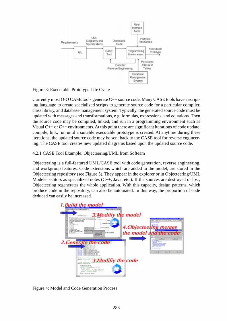
Objecteering is a full-featured UML/CASE tool with code generation, reverse engineering,and workgroup features. Code extensions which are added to the model, are stored in theObjecteering repository (see Figure 5). They appear in the explorer or in Objecteering/UMLModeler editors as specialized notes (C++, Java, etc.). If the sources are destroyed or lost,Objecteering regenerates the whole application. With this capacity, design patterns, whichproduce code in the repository, can also be automated. In this way, the proportion of codededuced can easily be increased.
Figure 4: Model and Code Generation Process
284
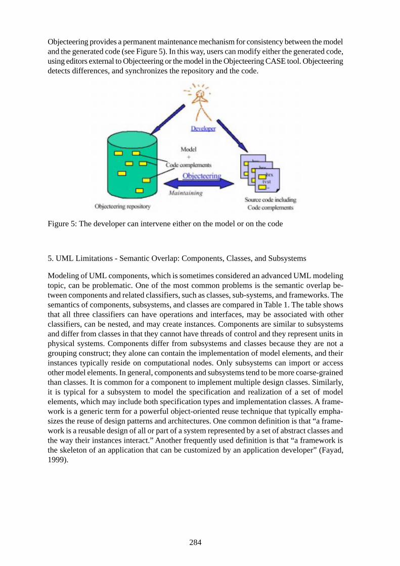
Objecteering provides a permanent maintenance mechanism for consistency between the modeland the generated code (see Figure 5). In this way, users can modify either the generated code,using editors external to Objecteering or the model in the Objecteering CASE tool. Objecteeringdetects differences, and synchronizes the repository and the code.
Figure 5: The developer can intervene either on the model or on the code
5. UML Limitations - Semantic Overlap: Components, Classes, and Subsystems
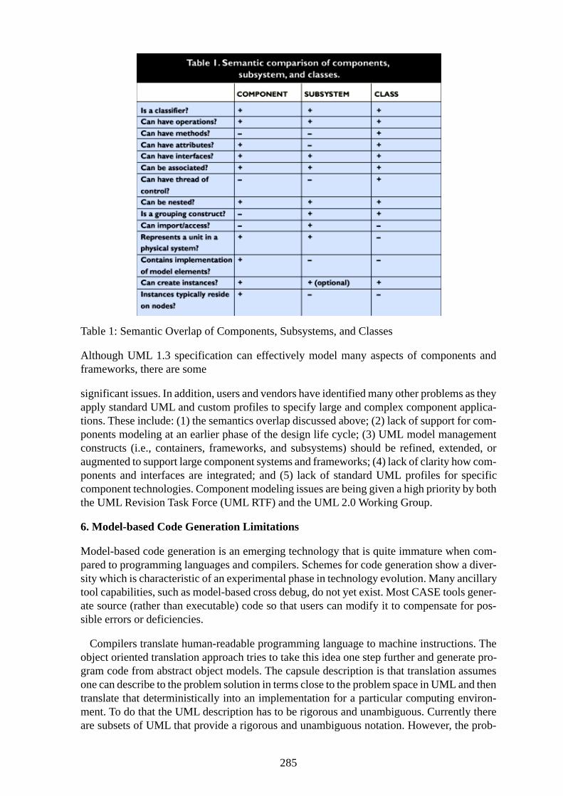
Modeling of UML components, which is sometimes considered an advanced UML modelingtopic, can be problematic. One of the most common problems is the semantic overlap be-tween components and related classifiers, such as classes, sub-systems, and frameworks. Thesemantics of components, subsystems, and classes are compared in Table 1. The table showsthat all three classifiers can have operations and interfaces, may be associated with otherclassifiers, can be nested, and may create instances. Components are similar to subsystemsand differ from classes in that they cannot have threads of control and they represent units inphysical systems. Components differ from subsystems and classes because they are not agrouping construct; they alone can contain the implementation of model elements, and theirinstances typically reside on computational nodes. Only subsystems can import or accessother model elements. In general, components and subsystems tend to be more coarse-grainedthan classes. It is common for a component to implement multiple design classes. Similarly,it is typical for a subsystem to model the specification and realization of a set of modelelements, which may include both specification types and implementation classes. A frame-work is a generic term for a powerful object-oriented reuse technique that typically empha-sizes the reuse of design patterns and architectures. One common definition is that “a frame-work is a reusable design of all or part of a system represented by a set of abstract classes andthe way their instances interact.” Another frequently used definition is that “a framework isthe skeleton of an application that can be customized by an application developer” (Fayad,1999).
285
Table 1: Semantic Overlap of Components, Subsystems, and Classes
Although UML 1.3 specification can effectively model many aspects of components andframeworks, there are some
significant issues. In addition, users and vendors have identified many other problems as theyapply standard UML and custom profiles to specify large and complex component applica-tions. These include: (1) the semantics overlap discussed above; (2) lack of support for com-ponents modeling at an earlier phase of the design life cycle; (3) UML model managementconstructs (i.e., containers, frameworks, and subsystems) should be refined, extended, oraugmented to support large component systems and frameworks; (4) lack of clarity how com-ponents and interfaces are integrated; and (5) lack of standard UML profiles for specificcomponent technologies. Component modeling issues are being given a high priority by boththe UML Revision Task Force (UML RTF) and the UML 2.0 Working Group.
6. Model-based Code Generation Limitations
Model-based code generation is an emerging technology that is quite immature when com-pared to programming languages and compilers. Schemes for code generation show a diver-sity which is characteristic of an experimental phase in technology evolution. Many ancillarytool capabilities, such as model-based cross debug, do not yet exist. Most CASE tools gener-ate source (rather than executable) code so that users can modify it to compensate for pos-sible errors or deficiencies.
Compilers translate human-readable programming language to machine instructions. Theobject oriented translation approach tries to take this idea one step further and generate pro-gram code from abstract object models. The capsule description is that translation assumesone can describe to the problem solution in terms close to the problem space in UML and thentranslate that deterministically into an implementation for a particular computing environ-ment. To do that the UML description has to be rigorous and unambiguous. Currently thereare subsets of UML that provide a rigorous and unambiguous notation. However, the prob-

286
lem is that the methods and actions still need to specified. Currently Rational and the majortranslation vendors are jointly proposing a meta model for action languages to OMG as anaddition to UML. Also, translation makes a key separation in code generation from UMLmodels but most of the tools on the market that support translation are monolithic IDEs thatprovide everything. Unfortunately they are also limited because they only support one or, atmost, a few platforms for the implementation. The good news is that the marketplace isbeginning to recognize the value of specialization combined with modern interoperability.
7. Conclusion
There is an emerging need for Distributed Geographical Information Systems. The possibil-ity for realizing such systems is being supported through ISO-DIS 10746 Reference Modelfor Open Distributed Processing (ODP), and new distributed object technology such as OMGCORBA, as enabling technologies for communication and information infrastructures. TheOpenGIS Consortium Abstract Specifications define the behavior of geoprocessing softwareservices with access, interchange, manage, manipulate, and present geodata (Buehler andMcKee, 1998). These interfaces need to be independent of operating systems, programminglanguage, hardware, and network. UML can be used to develop a language-neutral softwarespecification because it is unambiguous, independent of implementation platforms and pro-gramming languages. Object GISs have been considered a major trend of the development ofGIS technology (Buehler and McKee, 1998). The usage of UML as an implementation speci-fication language, with automatic mappings to various platforms and storage structures hasbeen also promoted with the ISO/TC211 Geographic Information/Geomatics (ISO 15046).The Conceptual Schema Language (CSL), using UML, has also been developed (ISO 15046-3).
The advantages of distributed GIS have long been realized by GIS practitioners and re-searchers (Love, 1998; Newell, 1991; Meredith, 1995). The National Center for GeographicInformation Analysis (NCGIA) included distributed GIS in its research plan (NCGIA, 1989).The University Consortium for Geographic Information Science included distributed com-puting and interoperability in its research priorities (UCGIS, 1996). Research has been con-ducted for developing distributed GISs, for example, by Edmondson (1992) and Goodman(1994). The more recent work includes the DISGIS project in Norway (Norwegian MappingAuthority, 1997). To facilitate geospatial data sharing and interoperability, international andnational standards were developed, including the Open Geodata Interoperability Specifica-tion (OGIS).
UML modeling promises benefits such as code reusability and maintainability and the inte-gration of versatile data and analysis models across many programming environments. Toolenvironments will support the integration of foreign models and HLL programming tools.Simulatable models will evolve into executable ones that prototype system operation andserve as monitors for debug and analysis. Target languages will diversify and code qualitywill improve. Translators will generate machine code directly and support optimizations.Architectures will be built with special modeling tools. More of a system will be model-based, but HLL and even assembly-based objects will continue to play a role (source:www.ootips.org).
The current UML 1.3 specification provides basic support for modeling components andcomponent frameworks. Users can specify components in various ways, including those out-lined by software methods that support component-based development (D’Souza. and Wills,1999; Jacobson, 1999). There are also substantive issues related to modeling components
287
with the current UML 1.3 specification. These range from restrictive yet over-lapping seman-tics to the lack of robust model management constructs and component technology profiles.Component modeling issues are being given a high priority by both the UML revision taskforce and the UML 2.0 working group. Component technology is still at the beginning of itsadoption curve and as it enters more into mainstream computing we can expect it to have adramatic impact on how software is designed, constructed, and deployed. UML will evolvealong with components to meet their special needs.
Acknowledgment
The author would like to thank the following for their comments:
Liou Cao, Ph.D. candidate, Planning Support Systems Group, DUSP, MIT
Jingsong Wu, Ph.D. candidate, Intelligent Eng. System Lab (IESL), IT group of CEE, MIT
References
Bell, R (1999). Code Generation from Object Models. Embedded Systems Programming. CMP Media, Inc.
Buehler, K. and McKee, L. (1998). The OpenGIS Guide (Third Edition), Wayland, MA: Open GIS Consortium,Inc.
Davies, C. (1995). Tasks and Task Description for GIS. Cognitive Aspects of Human-Computer Interaction forGeographic Information Systems. Dordrecht: Kluwer Academic Publishers: 372-342.
D’Souza, D. and Wills, A (1999). Objects, Components and Frameworks with UML: The Catalysis Approach.Addison-Wesley, Reading, MA.
Edmondson, P. (1992). “Managing the Distributed GIS Infrastructure•An Organizational Perspective,” Pro-ceedings of GIS/LIS’92, Vol. 1:196-207, San Jose, California, USA.
Fayad, M., et al (1999). Building Application Frameworks. Wiley, NY.
Fowler, M., et al (2000). UML Distilled: A Brief Guide to the Standard Object Modeling Language. SecondEdition: A Brief Guide to the Standard Object Modeling Language. The Addison-Wesley, Reading MA
Goodman, J. (1994).“Alberta Land Related Information System, a Federated Database System Case Study,”URISA 1994 Annual Conference Proceedings, Washington D.C.: Urban and Regional Information SystemsAssociation, Vol. 1:421-431.
Kottman, C. (1997). An OpenGIS White Paper: The Schedule and Priority of OpenGIS Conceptual SoftwareComponents, Wayland, Massachusetts: Open GIS Consortium, Inc.
Love, K (1988). “Distributed Processing/Distributed Databases for GIS Applications • Basic Concepts andIssues,” URISA 1988 Annual Conference Proceedings, Vol. 3:228-241, Los Angeles, California, USA.
Martin, J. and Odell, J. (1996). Object oriented methods: pragmatic considerations, Prentice Hall, EnglewoodCliffs, NJ.
Meredith, P (1995).“Distributed GIS: If its Time is Now, Why is it Resisted?” in H.J. Onsrud and G. Rushtoneds. Sharing Geographic Information, New Brunswick, N.J.: Center for Urban Policy Research.
NCGIA (National Center for Geographic Information and Analysis)(1989). “The Research Plan of the NationalCenter for Geographic Information and Analysis,” International Journal of Geographical Information Systems,Vol. 3(2):117-136.

288
Norwegian Mapping authority (1997). Project Summary, http://www.statkart.no/disgis
OMG Unified Modeling Language Specifications. V 1.3 (June 1999). Available On-line:
http://www.rational.com/media/uml/post.pdf
Orfali, R., & Harkey, D. (1997). Client/Server Programming with Java and CORBA. New York, New York: JohnWiley & Sons .
Plewe, B. (1997). GIS Online: Information Retrieval, Mapping, and the Internet. OnWorld Press, Santa Fe, NM
Rational Software Corporation, URL: http://www.rational.com
Rumbaugh, J. (2000). Trends in UML and e-Development. On-line article:
http://www.therationaledge.com/content/dec_00/f_uml.html (Rational Software)
Siegel, J (1996). CORBA Fundamentals and Programming, New York: John Wiley & Sons, Inc.
Tsou and Buttenfield, 1998. An Agent-based, Global User Interface for Distributed Geographic InformationServices. Proceedings 7th International Symposium on Spatial Data Handling, Vancouver, British Columbia,July, 1998: 603-612.
OMG UML Specification, V 1.3 (March 2000)
UML Revision Task Force, OMG Unified Modeling Language Specification, v. 1.3, document ad/99-06-08.Object Management Group, June 1999.
1 UML has been proposed by Booch, Jacobson, and Rumbaugh (now working at Rational Rose Corp.) and hasbeen standardized as the de facto object oriented modeling language for software development by the ObjectManagement Group (OMG) in 1994.
2 Davies (1995) and more recently the OGC (Kottman, 1997) has identified 40 task-oriented components under6 categories: (1) Fundamental tools (i.e., referencing, queries, display); (2) Advanced Features (i.e., relationalmodeling, network and temporal tools); (3) Components supporting coverages (i.e., tools for gridded cover-ages); (4) Information Communities (i.e., tools for handling Metadata types, schema transformation); (5) MetricImagery (i.e., image exploitation interfaces; and (6) Other (i.e., conflation interfaces).
3 ISO-15046-3 (Geographic Information/Geomatics) provides good guidelines for modeling GIS components/services using UML. It includes guidelines for identifying service responsibilities, specifying operations, at-tributes, and services relationships, completion of constraints on operations, and service definition harmoniza-tion.
Copyright © 2022 FDOKUMEN