investigation of temperature measurements in 300" to 1100" k ...
Upload
khangminh22Category
view
1download
0
USING THE TORMACH PCNC 1100
PROGRAMMER’S AND OPERATOR’S GUIDE TO THE PERSONAL CNC 1100
© 2013 Tormach® LLC. All rights reserved.
Questions or comments? Please e-mail us at: [email protected] UM10087_PCNC_1100_SERIES_3_USER_MANUAL_1013A

Before calling Tormach Technical Support for assistance, you will need your machine serial number and information on any machine upgrades and/or maintenance to the system.
For easy referral, record your machine serial number on the line below. The serial number is found on the outside of the shipping crate, the shipping invoice, and stamped metal plaque located on the right-hand side of the main electrical housing.
Serial Number: Date of Purchase:
Upgrades and Maintenance Records:

TOC
1. Preface 81.1 Intended Use Statement 81.2 Support 81.3 Outside of the Scope of Intended Use 81.4 Safety 81.4.1 Electrical Safety 81.4.2 General Operating Safety 91.4.3 Safety Publications 91.4.4 Safety Precautions 91.5 Personal CNC Concept 101.6 Performance Expectations 101.6.1 Cutting Ability 101.6.2 Understanding Accuracy 111.6.3 Resolution, Accuracy and Repeatability of the PCNC 111.7 Scope and Intellectual Property 111.8 Nomenclature 122.1 Planning for Your PCNC 132.1.1 Electrical Connection 132.1.2 Location and Mounting 132. Preparation 132.1.3 Controller Setup 142.1.4 Learning and Training 152.2 Receiving, Unpacking and Checking Shipment 162.2.1 Moving the Crate 162.2.2 Uncrating and Inspection 162.3 Assembling Y-axis Drive 172.4 Mounting the PCNC 172.4.1 Lifting onto Stand 172.4.1.1 Lifting from Below 182.4.1.2 Lifting from Above (Preferred Method) 182.4.2 Fixing to Stand 192.4.3 Accessories 192.4.4 Installing Central Lubrication Pump 192.5 Power to the PCNC 192.6 Power for Machine Accessories 202.7 Tormach Machine Controller and Software Installation 202.7.1 Control Computer 202.7.2 Setting Up Your Tormach Controller 212.7.2.1 Positioning the Controller 212.7.2.2 Keyboard and Mouse 212.7.2.3 Display 212.7.2.4 Speaker and Microphone Connections 212.7.2.5 Power Connections 212.7.3 Operating the Controller 212.7.3.1 About the Operating System 212.7.3.2 Starting the Controller 22
2.7.3.3 Stopping the Controller 222.7.3.4 Mach3 License Installation 222.7.4 Resetting the Controller 222.8 Connecting and Running the PCNC 232.8.1 Main Switch and Operator/ Control Panel 232.8.2 Changing the Spindle Speed Range 252.8.3 Computer Control of the Spindle and Coolant 252.8.4 MDI for Entering G- and M-code Commands 262.8.5 Jogging the Axes 262.9 Summary 273. Making Your First Part 283.1 Coordinates 283.1.1 Referencing the Machine 283.2 Loading a Demonstration Program 293.3 Running the Demonstration Part-Program 303.3.1 Part Material 303.3.2 Setting Work Offsets 303.3.3 Cutting in Air 303.3.4 Cutting the Actual Part 313.3.5 Summary 324. Routes From an Idea to a Part 334.1 Controlling the PCNC 334.2 Choosing the Appropriate Design Software 344.3 Software for CAD/CAM 344.3.1 3D CAD 344.3.2 2D CAD 354.3.3 CAM 364.3.4 Running the G-code 374.3.5 CAD/CAM Systems 374.4 Programming with Wizards 404.4.1 Machining Wizard Concept 404.4.1.1 Selecting and Running a Wizard 404.4.1.2 Standard Wizard Features 404.4.1.3 G-code from a Wizard 414.4.1.4 Commercial Wizards 415. Machine Controls 425.1 Machine Operation 425.1.1 Operator/Control Panel 425.1.2 Tool Changing 435.1.2.1 Tooling Strategy 435.1.2.2 Changing R8 Tools 445.1.2.3 Changing TTS Tools 455.1.3 Spindle Speed Ranges 465.2 Screen Control Panels 47
TABLE OF CONTENTS
3 UM10087_PCNC_1100_SERIES_3_USER_MANUAL_1013A

5.2.1 Using the Screens 475.2.2 Families of Related Controls 475.2.2.1 Persistent Controls 475.2.2.2 Axis Control Family 475.2.2.3 Jogging Control Family 485.2.2.4 Spindle Speed Control Family 505.2.2.5 Feed Control Family 505.2.2.6 Program Running Control Family 515.2.2.7 Toolpath and G-Code Display Control Family 525.2.2.8 File Control Family 535.2.2.9 Work Offset and Tool Table Control Family 535.2.2.10 MDI and Teach Control Family 535.2.2.11 Loop Control Family 545.2.2.12 Modes and Mode Alarm Control Family 545.2.2.13 Rotational Diameter Control Family 545.2.2.14 Toolchange Position Control Family 545.2.2.15 Inhibits and Overrides Control Family 555.2.2.16 Feeds and Speeds Calculator 555.2.2.17 Tapping Configuration Family 555.2.2.18 Misc. Settings Control Family 565.3 USB Jogging Pendants 575.3.1 Jog/Shuttle Controller 575.3.2 Keypad Pendant 576. Using Multiple Tools 586.1 Offsets and Coordinate Systems 586.2 Tool Length Offsets and the Tool Table 586.2.1 Example Operation of Multiple Tools 586.2.1.1 Zeroing to Work Height 606.2.1.2 Using Tool #2 606.2.1.3 Using Other Tools 606.2.1.4 Changing to a Different Workpiece 606.2.2 Programming, Buttons, or Direct Entry 626.3 Alternative Methods Setting Up Tools 626.3.1 Measuring Techniques 636.3.1.1 Feeler Gauge Method 636.3.1.2 Roller Gauge Method 636.3.1.3 Adjustable Parallel Method 646.3.2 Comments on Accuracy 646.3.3 Working Without the Tool Table 656.3.3.1 Direct Entry to Axis DRO 656.3.3.2 Using the Touch Buttons 656.3.4 Tool Table with General Tooling 666.3.5 Tool Table with the Tool Setter 676.4 Comments on Tool Offsets 676.5 Setting X and Y Offsets 676.5.1 By Eye 67
6.5.2 With a Probe 676.5.3 Measuring With an Edge Finder 686.5.4 Laser Centering Techniques 686.5.5 Haimer Centering Techniques 696.6 How Work Offsets Work 696.7 Multiple Work Origins 716.7.1 G54 Work Offset 716.7.2 Other Work Offsets 716.8 Cutter Diameter Compensation 716.8.1 CAD/CAM and Wizards 716.8.2 Concepts for Cutter Diameter /Radius Compensation 726.8.3 Caveats in the Use of Cutter Compensation 726.8.4 Examples of Operation 736.8.5 Look Ahead Issues 757. Part-Programming Language Reference 787.1 Definitions 787.1.1 Control Software 787.1.2 Linear Axes 787.1.3 Rotational Axes 787.1.4 Scaling Input 787.1.5 Controlled Point 787.1.6 Coordinated Linear Motion 787.1.7 Feed Rate 797.1.8 Arc Motion 797.1.9 Coolant 797.1.10 Dwell 797.1.11 Units 797.1.12 Current Position 797.1.13 Selected Plane 807.1.14 Tool Table 807.1.15 Path Control Modes 807.2 Interpreter Interaction with Controls 807.2.1 Feed and Speed Override Controls 807.2.2 Block Delete Control 807.2.3 Optional Program Stop Control 807.3 Tool File 807.4 Part-Programs Language 807.4.1 Overview 807.4.2 Parameters 817.4.3 Coordinate Systems 817.5 Formatting Code Lines (Block) 817.5.1 Line Number 817.5.2 Subroutine Labels 817.5.3 Word 827.5.3.1 Number 82
4UM10087_PCNC_1100_SERIES_3_USER_MANUAL_1013A

TOC
7.5.3.2 Parameter Value 837.5.3.3 Expressions and Binary Operations 837.5.3.4 Unary Operation Value 837.5.4 Parameter Setting 847.5.5 Comments and Messages 847.5.6 Item Repeats 847.5.7 Item Order 847.5.8 Commands and Machine Modes 857.6 Modal Groups 857.7 G-codes 857.7.1 Rapid Linear Motion – G00 877.7.2 Linear Motion at Feed Rate – G01 887.7.3 Arc at Feed Rate – G02 and G03 897.7.3.1 Radius Format Arc 897.7.3.2 Center Format Arc 907.7.4 Dwell – G04 917.7.5 Coordinate System Data Tool and Work Offset Tables – G10 927.7.6 Clockwise/Counterclockwise Circular Pocket – G12 and G13 927.7.7 Exit and Enter Polar Mode – G15 and G16 927.7.8 Plane Selection – G17, G18 and G19 937.7.9 Length Units – G20 and G21 937.7.10 Return to Home – G28 and G30 937.7.11 Reference Axes – G28.1 947.7.12 Straight Probe – G31 947.7.12.1 Straight Probe Command 947.7.12.2 Using the Straight Probe Command 947.7.12.3 Example Code 957.7.13 Cutter Radius Compensation – G40, G41 and G42 957.7.14 Tool Length Offsets – G43, G44 and G49 967.7.15 Scale Factors – G50 and G51 967.7.16 Temporary Coordinate System Offset – G52 967.7.17 Move in Absolute Coordinates – G53 977.7.18 Select Work Offset Coordinate System – G54 to G59 & G59 P~ 977.7.19 Set Path Control Mode – G61 and G64 987.7.20 Coordinate System Rotation – G68 and G69 987.7.21 Canned Cycle – High Speed Peck Drill – G73 987.7.22 Cancel Modal Motion – G80 997.7.23 Canned Cycles – G81 to G89 997.7.23.1 Preliminary and In-Between Motion 1007.7.23.2 G81 Cycle 100
7.7.23.3 G82 Cycle 1017.7.23.4 G83 Cycle 1017.7.23.5 G85 Cycle 1017.7.23.6 G86 Cycle 1017.7.23.7 G88 Cycle 1027.7.23.8 G89 Cycle 1027.7.24 Distance Mode – G90 and G91 1027.7.25 G92 Offsets – G92, G92.1, G92.2 and G92.3 1027.7.26 Feed Rate Mode – G93, G94 and G95 1037.7.27 Canned Cycle Return Level – G98 and G99 1037.8 Built-in M-codes 1047.8.1 Program Stopping and Ending – M0, M1, M2 and M30 1047.8.2 Spindle Control – M3, M4 and M5 1047.8.3 Tool Change – M6 1047.8.4 Coolant Control – M7, M8 and M9 1057.8.5 Re-run from First Line – M47 1057.8.6 Override Control – M48 and M49 1057.8.7 Call Subroutine – M98 1057.8.8 Return from Subroutine – M99 1057.9 Application Defined M-codes 1057.9.1 Self-reversing Tapping Cycles 1057.9.2 Goto Tool Change Position – M998 1067.10 Other Input Codes 1067.10.1 Feed Rate – F 1067.10.2 Spindle Speed – S 1067.10.3 Select Tool – T 1067.11 Order of Execution 1067.12 Error Handling 1078. Machine Upgrades & Configuration 1088.1 Fourth Axis – Rotary Table 1088.1.1 Installing the Electronics 1088.1.2 Utilizing the Fourth Axis 1088.1.2.1 Referencing and Zeroing the Fourth Axis 1088.1.2.2 Diameter Compensation Feature 1088.1.3 Fourth Axis Applications 1088.1.3.1 Engraving on a Periphery of a Cylinder 1088.1.3.2 Gear Cutting 1098.2 Probes (Active and Passive) and Tool Setters 1108.2.1 Introduction to Uses of Probes and Tool Setters 1108.2.2 Probing for Work/Tool Setting 1118.2.2.1 Simple X/Y Probing 1118.2.2.2 Z Probing 113
5 UM10087_PCNC_1100_SERIES_3_USER_MANUAL_1013A

8.2.2.3 Comprehensive X/Y Probing 1168.2.2.4 Probe Calibration 1188.2.3 Digitizing Parts From a Model or For Reverse Engineering 1198.2.4 The Probe Electrical Interface 1198.3 Tapping 1209. Specifications and Customization 1219.1 Specifications 1219.1.1 Mechanical 1219.1.2 Electrical 1219.1.3 System 1219.1.4 Options 1219.2 Maintenance 1229.2.1 Foreword – Understanding Machine Design 1229.2.1.1 Machine Stiffness 1229.2.1.2 Backlash, Friction, and Lost Motion 1229.2.1.3 Factors Combine 1229.2.1.4 Adjusting Geometry 1229.2.1.5 Achieving Accuracy in Machining 1239.2.2 Protecting from Rust 1239.2.3 Gibs, Dovetail Slideways and Lubrication 1239.2.4 Way Covers 1249.2.5 Axis Gib Adjustment 1249.2.6 Adjusting Ballscrew Preload 1269.2.6.1 Understanding Preloaded Angular Contact Bearings 1269.2.6.2 Making the Adjustment 1289.2.7 Adjusting Mating Surfaces 1299.2.8 Speed Calibration 1299.2.9 Using a Non-standard Printer Port 1309.2.10 Defining Your Own Sizes for Step-mode Jogging 1319.2.11 Defining Probe Type 1329.2.12 Enabling 4th Axis Homing 1329.2.13 Configuring to Start in Metric Units 13310. Troubleshooting 13410.1 Overview 13410.2 Philosophy of Troubleshooting 13610.3 Tips and Tools for Troubleshooting (Equipment and Procedures) 13610.3.1 Safety 13610.3.2 Tips on Computer Diagnostics 13710.3.3 Tools 13710.3.4 Using the Digital Multi Meter for Electrical Tests 13710.3.5 Contacting Technical Support 138
10.4 Frequently Found Problems (Repeat Offenders) 13910.4.1 Loose Wires 13910.4.2 Wire Hairs 13910.4.3 Poor Cable Connections 13910.4.4 Software Restart 13910.4.5 Sensors (on the PCNC the End of Travel Sensors) 13910.4.6 Flaky Computer 13910.4.7 Control Software License Not Installed 13910.4.8 Unexplained Stop or Limit Switch Error While Running 14010.5 Which Sub-System Should I Troubleshoot? 14010.5.1 Power Distribution Sub-system 14210.5.2 Details of the Power Distribution Sub-system 14510.5.3 Control Power Sub-System 14510.5.4 Details of the Control Power Sub-system 14610.5.5 Computer Control Communication Sub-Section 14810.5.6 Axes Drive Sub-system 14910.5.7 Spindle Drive Sub-System 16310.6 Mechanical Maintenance 17210.7 Electrical Maintenance 17210.8 Preparation for Transport 17310.9 Disassembly for Transport 17310.10 Best Practice Tips for a Mach3 Controller 17310.10.1 Additional Technical Information 174 Appendix 1: Exploded Parts Views 175 Appendix 2 192A2.1.1 Choice of Computer 192A2.1.2 Optimizing the Windows Installation 192A2.1.3 Installing the Control Software 193A2.1.3.1 Installing 193A2.1.3.2 Vital Re-boot 193A2.1.3.3 Testing the Installation 193A2.1.3.1 DriverTest After a Software Crash 194A2.1.3.2 Manual Driver Installation and Un-installation 195A2.1.4 Optimization of Windows XP 195A2.1.4.1 Remove Unnecessary Services and Startup Programs 195A2.1.4.1 Disable Power Management 196A2.1.4.1 Disable Sound Card 196A2.1.4.2 Disable Automatic Updates 196
6UM10087_PCNC_1100_SERIES_3_USER_MANUAL_1013A

TOC
A2.1.4.1 Set Computer to Standard PC not ACPI PC 196
7 UM10087_PCNC_1100_SERIES_3_USER_MANUAL_1013A

1.1 Intended Use Statement
The PCNC is intended for use as a general purpose CNC milling machine. The intended use includes cutting conventional (non-abrasive) materials such as unhardened mild or alloy steels, aluminum, plastics, wood and similar materials – in fact any material that can be cut with a rotating cutter. The PCNC is intended to be used with the software configuration files provided by Tormach.
1.2 Support
Tormach provides free technical support through multiple channels. The methods are listed below, in order of preference. The quickest way to get the answers you need is normally checking in order of preference:
• This manual – ALWAYS the first place to check!• Related documents found at:
http://www.tormach.com/documents.html• Our website at: www.tormach.com• Email to: [email protected]• Telephone Tormach at: 608-849-8381• Fax Tormach at: 209-885-4534
1.3 Outside of the Scope of Intended Use
Applications for the equipment or modifications of the equipment outside of the Intended Use Statement are supported through consulting engineering, not through our free support policy. There are no limits to the applications that Tormach products can be used for or to the modifications that can be applied to the Tormach machinery. Tormach designs use standard industrial components and incorporate the principles of Open Architecture specifically to allow and promote these variations. With Open Architecture controls, industrial engineers will find Tormach products cost effective to incorporate into larger manufacturing systems, or with easily separable base, column and head sections manufacturing engineers looking to design specialized in-house equipment will find they can use the base as a low cost motorized XY table. Some machinists may want to convert a stepper mill to servos or some software engineers may want to replace the Tormach approved software with something of their own creation.
All of the technical information and insight required to support these variations from the intended use cannot possibly be foreseen. If the extensive documentation
provided does not supply all the information you need, we can provide additional information and engineering support required for your project on a consulting engineering basis. If you have your questions well organized we can normally provide all the information you need in short order. Consulting engineering is done by electrical and mechanical engineers and billed at current hourly rates.
As you might expect, all warranties for Tormach equipment are voided through modification to the equipment or use outside of the Intended Use. Individuals or companies involved with modifying the equipment or applying the products assume all consequent liability.
1.4 Safety
Any machine tool is potentially dangerous. Computer controlled machines are potentially more dangerous than manual ones because, for example, a computer is quite prepared to
plunge a 3” diameter facing cutter at 50 inches per minute into a block of high-carbon steel or to mill the clamps off your table.
The PCNC 1100 can deliver sufficient force to break brittle tools, to crush bones and to tear flesh.
This manual tries to give you guidance on safety precautions and techniques but because we do not know the details of your workshop or other local conditions we can accept no responsibility for the performance of the machine or any damage or injury caused by its use. It is your responsibility to ensure that you understand the implications of what you are doing and to comply with any legislation and codes of practice applicable to your country or state.
1.4.1 Electrical Safety
Dual Power Input: The PCNC 1100 has two electrical power inputs. The primary supply is 230 VAC and is used for all axis and spindle motion. The secondary supply is 115 VAC. The
secondary supply is used to provide power to the accessory outlets only and is not used for machine control. Either power supply can provide lethal electrical shocks. Both power inputs should be unplugged before working in the electrical cabinet.
1. PREFACE
8UM10087_PCNC_1100_SERIES_3_USER_MANUAL_1013A

CH
1
Grounding: Both primary and secondary power inputs must be grounded. During installation it is not enough to assume that the ground line of a wall outlet is properly grounded. Check continuity between the machine frame and true earth ground (water pipe or similar) to ensure a good ground connection.
A Ground Fault Interrupt or GFI (i.e., Residual Current Circuit Breaker or RCCB in Europe) outlet must be used to supply the power to the 115 VAC power input. Your computer, monitor and coolant system are not bolted to the machine frame so proper grounding cannot be assumed. The combination of electrical power and water based coolant systems makes the GFI protection very important.
Electrical Panel: NEVER operate the machine tool with the cabinet door open. NEVER allow a coolant pump to operate with the cabinet door open. DO NOT allow the coolant system to flow coolant directly at the cabinet door seal or on the operator console controls. Neither the cabinet door seal nor the electrical controls are sealed against liquids.
Retained Electrical Power: Electronic devices within the electrical cabinet may retain dangerous electrical voltages after the power has been removed.
Electrical Service: Certain service and troubleshooting operations require access to the electrical cabinet while the electrical power is on. Only qualified electrical technicians should perform such operations.
1.4.2 General Operating Safety
Safe operation of the machine depends on its proper use and the precautions taken by each operator.
Read and understand this manual. Be certain every operator understands the operation and safety requirements of this machine before operating the machine.
Always wear safety glasses and safety shoes.
Always stop the spindle and check to ensure the CNC control is in the stop mode before changing or adjusting the belt/pulley position, tool or work piece.
Never wear rings, watches, gloves, long sleeves, neckties, jewelry or other loose items when operating or working
around the machine. Long hair should be bound or kept under a hat.
Use adequate safeguarding around the operating envelope. It is the responsibility of the employer to provide and ensure point of operation safeguarding per OSHA 1910.212 – Milling Machine.
1.4.3 Safety Publications
Tormach recommends the following publications for assistance in enhancing the safe use of this machine.
• Safety Requirements for The Construction, Care and Use of Drilling, Milling and Boring Machines (ANSI B11.8-1983). Available from The American National Standards Institute, 1430 Broadway, New York, New York 10018.
• Concepts and Techniques of Machine Safeguarding (OSHA Publication Number 3067). Available from The Publication Office – O.S.H.A., U.S. Department of Labor, 200 Constitution Avenue, NW, Washington, DC 20210.
1.4.4 Safety Precautions
1. Do not run this machine without knowing the function of every control key, button, knob or handle. Refer to the manual or contact Tormach if any function is not understood.
2. Protect your eyes. Wear approved safety glasses (with side shields) at all times. You should never use compressed air to remove chips or to clean the machine. An air blast will often launch a metal chip into a place it should not be.
3. Ear protection should be used on any operations that exceed sound levels of 85dBa.
4. Avoid moving parts. Before operating this machine remove all jewellery including watches and rings, neckties and any loose-fitting clothing.
5. Keep your hair away from moving parts. 6. Take off gloves before you operate the machine.
Gloves are easily caught in moving parts or cutting tools.
7. Never operate with unbalanced tooling or spindle fixtures.
8. Remove all tools (wrenches, chuck keys, etc.) from the spindle and machine surface before you begin. Loose items can become dangerous flying projectiles.
9 UM10087_PCNC_1100_SERIES_3_USER_MANUAL_1013A

9. Use adequate work clamping. Do not allow your work piece to become a projectile.
10.Never operate a milling machine after consuming alcoholic beverages or taking strong medication.
11.Protect your hands. Stop the machine spindle and ensure that the computer control is stopped before you: • Change tools;• Change parts or adjust the work piece; • Change the belt/pulley position;• Clear away chips, oil or coolant – always use a chip
scraper or brush; • Make an adjustment to the part, fixture, coolant
nozzle or take measurements; • Remove protective shields or safeguards – do not
reach for the part, tool or fixture around a guard.12.Keep work area well lit. Ask for additional light if
needed.13.Keep the computer area clear of clutter. Recognize
that machine motion can occur when certain keys are pressed. Objects falling on the keyboard can result in unexpected motion.
14.Avoid getting pinched in places where the table, saddle or spindle head create “pinch points” while in motion.
15.Securely clamp the work piece in a vise, on the table or in the fixture. Use proper holding clamping attachments and position them clear of the toolpath. Be aware of larger pieces that will be cut free during operations – loose parts can become projectiles.
16.Always use proper feeds and speeds, as well as depth and width of cut, to prevent tool breakage.
17.Use proper cutting tools for the job.18.Do not use dull or damaged cutting tools. They break
easily and become dangerous projectiles. Never use longer or larger tools than necessary.
19.Chips and dust from certain materials (e.g., magnesium) can be flammable. Fine dust from normally non-flammable materials can be flammable or even explosive.
20.Chips and dust from certain materials can be toxic. Vapours from certain overheated materials can be toxic. Always check a Materials Safety Data Sheet (MSDS) of suspect materials. Refuse machining work requests of unknown materials.
21. If you are in any doubt you must seek guidance from a professionally qualified expert rather than risk injury to yourself or to others.
1.5 Personal CNC Concept
The PCNC 1100 is a machine tool intended to make CNC machining more personal. As with the evolution of personal computers, the evolution of personal CNC alters the paradigm of what a machine tool is about. We aim for a machine tool so affordable that anyone can have one.
We feel that the work of engineers, inventors, technicians, hobbyists, educators and others will be enhanced when they have access to CNC machinery. In education, each student can run his own machine instead of waiting in line when the machine tool costs less than 20% of a small machining center. In R & D, turn-around on prototype design takes minutes instead of days when a machine is “at the ready” and on site. In general engineering, designs sent to the production machine shop are improved when the design engineer has been more involved in the prototype creation.
The PCNC offers the precision of a production machine but with cost/performance optimized for short run operation.
1.6 Performance Expectations
1.6.1 Cutting Ability
The machine is capable of cutting most materials at or near their recommended feeds and speeds. For example, for fast metal removal on 6061 aluminium we will run a 1/2” diameter 2 flute cutter at around 18 IPM (inches per minute) and 3000 RPM, using a full 1/2” depth of cut; that is a pretty good volumetric rate of metal removal so it is essential to clear chips with a flood coolant. We will run smaller cutters when we are not trying to remove large amounts in a hurry. For most aluminium work we use 3/8”. The example above, using a 1/2” cutter, results in a surface speed of 390 SFM (surface feed per minute), a 3/8” cutter needs 4000 RPM to get the same surface speed, well within the performance envelope of the machine.
Cutting steel and iron needs a lower volumetric rate, thus slower feed and speed. The PCNC will run best using smaller cutters when working with tougher materials. For example, the general machining recommendation for some oil hardening steels is 30 SFM. Doing this with a ¾” end mill, the surface speed calculation indicates 150 RPM, but that is very near the minimum spindle speed of the PCNC 1100 and certainly where limited power is available.
10UM10087_PCNC_1100_SERIES_3_USER_MANUAL_1013A

CH
1
By switching to a 1/4” end mill the recommended spindle speed becomes 460 RPM, well within the capability of the PCNC. By keeping close to general machining recommendations your tools will last longer and you will have a better cut.
1.6.2 Understanding Accuracy
While a machine tool may seem absolutely rigid, the truth of the matter is that everything has some elasticity. Related to elasticity is the compressibility of components such as ball nuts and bearings. Preloading of bearings and ballscrews can remove the physical open space between moving parts, but the technique cannot eliminate compressibility. The key to achieving maximum accuracy is understanding and controlling the magnitude and direction of forces. Maximum accuracy is achieved when the forces are minimized, as occurs in a finishing cut. Maximum repeatability is achieved when the forces are repeatable, both in magnitude and direction.
1.6.3 Resolution, Accuracy and Repeatability of the PCNC
The minimum discrete position move is 0.0001”, this is the resolution of motion. Machine accuracy is closely related to ballscrew accuracy. Our ballscrews are accurate to 0.0006” per foot, but considering all the other factors that come into play, we prefer to keep accuracy expectations to 0.0013” per foot. Repeatability will be better than 0.001” per foot.
Machining is a mix of science, skill and art. The caveat in stating accuracy and repeatability is that these factors depend on the techniques used by the machinist. A skilled machinist can often deliver accuracy that exceeds the accuracy specified by the machine builder, while an inexperienced machinist may have difficulty delivering the expected accuracy. With this understanding, we cannot tell you what accuracy you will be able to achieve in your own work. Nevertheless, the accuracy specified by a machine builder remains an important reference point.
1.7 Scope and Intellectual Property
This document is intended to provide sufficient information and detail to allow you to install, setup and use your Tormach mill. It assumes that you have appropriate experience and/or access to training for
any Computer Aided Design/Manufacture software that you intend to use with the machine. This document also assumes familiarity with typical Microsoft Windows applications programs as the control software for the PCNC runs under the Windows operating system.
Tormach LLC is dedicated to continual improvement of its products, so suggestions for enhancements, corrections and clarifications will be gratefully received.
Tormach LLC, Art Fenerty and John Prentice assert their right to be identified as the authors of this work. This work is copyrighted by Tormach LLC. The right to make copies of this manual is granted solely for the purpose of training courses related to, evaluation of and/or use of the PCNC. It is not permitted, under this right, for third parties to charge for copies of this manual beyond the cost of printing.
Every effort has been made to make this manual as complete and as accurate as possible but no warranty or fitness is claimed or implied. All information provided is on an “as is” basis. The authors, publisher, and Tormach LLC shall not have any liability for, or responsibility to, any person or entity for any reason for any loss or damage arising from the information contained in this manual.
Tormach, PCNC1100 Personal CNC, PCNC770 Personal CNC, and Tormach Tooling System are registered trademarks of Tormach. Windows XP and Windows 7 are registered trademarks of Microsoft Corporation. If other trademarks are used in this manual, but not acknowledged, please notify Tormach LLC so this can be remedied in subsequent editions.
Tormach milling machines and accessories are covered by one or more of the following U.S. Patents: 7,386,362, D606,568, D612,406, D621,859 and Patent(s) Pending.
11 UM10087_PCNC_1100_SERIES_3_USER_MANUAL_1013A

1.8 Nomenclature
This manual uses the following typographical nomenclature: Software Control
Refers to a Control Software “soft” control. (i.e., a Windows control on the PC screen).
Hardware ControlRefers to a physical button or switch on the Operator’s Panel of the machine. G-CODE (e.g., G01X34.8)Used to show G-code programs. Key name (e.g., Enter)Tells you to press the indicated key.
12UM10087_PCNC_1100_SERIES_3_USER_MANUAL_1013A

CH
2
This chapter describes the work required to unpack and to commission the hardware and software of the PCNC.
It contains a lot of detail but can be completed in one or two hours by a person familiar with CNC machines. Enough detail is given here so that a beginner should be successful but some users may prefer to arrange for a machine tool expert to do this work.
If your machine has already been set-up then you can skip this chapter.
2.1 Planning for Your PCNC
2.1.1 Electrical Connection
The PCNC 1100 is shipped with a 3-wire cord and no electrical plug. There are several different NEMA (National Electric Manufacturers Association) and non-NEMA plug
patterns that can be used. Straight blade patterns are common in household use; twist-lock patterns are more common in industrial locations. Power required is 200 to 250 VAC, 50 or 60 Hz. Continuous current is below 15 amps, but a 20 amp breaker or slow blow fuse is recommended.
Both primary and secondary power inputs must be grounded. During installation it is not enough to assume that the ground line of a wall outlet is properly grounded. Check continuity between the machine frame and true earth ground (water pipe or similar) to ensure a good ground connection.
Note: It is not uncommon for some buildings to include a GFCI (called a RCCB in Europe) device on the circuit. Typical industrial Variable frequency Drivers (VFDs) such as the one used to control the spindle are not compatible with these devices. If your circuit breaker trips when you turn on your mill spindle, then its’ likely the wiring in your building that powers your mill has a GFCI. It may be necessary to hire a certified electrician to provide a suitable solution.
Note: The PCNC 1100 will run on voltages between 200-250VAC. However, a Buck-Boost transformer is recommended for minor adjustments of stable line voltages below 230VAC to eliminate performance
degradation. Buck Boosts should only be installed by qualified electricians.
2.1.2 Location and Mounting
People experienced with CNC machining will undoubtedly have ideas as to how they want to setup their PCNC (figure 2.1). While the machine can be configured in many different ways, there are a few limitations. Many fully enclosed vertical machining centers incorporate high volume coolant systems that make the inside of the machine look like the inside of a dishwasher. The PCNC electrical cabinet and operator console should not be exposed to such conditions. Additionally, there should never be an enclosure or accessory that limits access to the emergency stop. Please keep these limitations in mind when you plan your configuration.
Figure 2.1: An Example Mounting on Stand
If your prior experience is limited to manual mills then keep in mind that, as CNC dramatically extends your machining capabilities, it will also change the way you cut metal. When your metal cutting is done by turning handles on a manual mill your operations will generally be limited to cleaning up a surface, drilling a hole pattern or cutting to a dimensional outline. With manual milling many people are accustomed to dry cutting, clearing chips with a small brush as they go.
With CNC you have a whole new world open to you. In many cases you may turn the majority of the stock into chips, cutting a shape out of a solid block of metal the way Michelangelo would cut a sculpture from a block of marble. Unless you are limiting yourself to cutting
2. PREPARATION
13 UM10087_PCNC_1100_SERIES_3_USER_MANUAL_1013A

cast iron, wood, printed circuit boards or certain other materials, you will probably want a coolant system on your machine. Mist coolant can be effective for keeping your cutting tools cool, but it does little for clearing chips. Flood coolant will cool the cutting tools while clearing chips, but is more challenging to contain. The table of the PCNC has drain slots and a hole tapped for a pipe fitting to allow coolant collection, as is common on most small mills. Nevertheless, CNC machining operations commonly produce so many chips that you simply cannot keep the table drain running. At times, you may need a coolant flow that is simply too much for the table drain. The little drain tray that is common under manual machines or the open frame setup of a Bridgeport style knee mill just does not make it. We strongly recommend that you plan your setup with a full motion tray, such that coolant will be captured as it overflows the machine table within the full operating envelope of the machine.
Another reason to use a full motion tray is to reserve the space that will be required when the machine moves. If you use a narrow drip tray or none at all, you should plan for full machine motion plus some human space when you place the machine in your workshop. You do not want to locate it where you can create crush points between the machine table and a wall. When in operation, the X, Y and Z motions will not stop when they hit something. The machine will move with hundreds of pounds of force, enough to punch through a wall, tip over the machine or crush someone in the way.
Machine safety is the responsibility of the operator. This includes all aspects of safety: setup, location, operation, security and all other factors that involve safety.
The PCNC requires a minimum plan area of 67” wide by 43” deep. This gives clearance for the full motion of the table and for minimal access for cabling etc. The overall height required is 84” assuming that it is installed with the table at a working height of 36”.
You should choose a well lit location and provide any additional task-lighting to make it easy to setup work on the table.
Over time you will find that you accumulate a range of tools and tool holders so you should allocate space for storage of these near the machine. A rack with numbered slots is convenient to avoid errors when doing tool changes during a job.
2.1.3 Controller Setup
Keep the computer in a clean location, preferably inside the stand of the milling machine. Resist the temptation to expose the computer in any way. Providing access to floppy disks, CDs or direct computer controls will also open the computer to contamination and risk. Tormach offers accessories that will allow you to operate the system without exposing your computer.
While there are many possible configurations for your machine control computer, we suggest the following (figure 2.2):
1. USB bulkhead (panel mount) cable. This allows you to mount a USB socket directly on the side of the cabinet. You can use a standard USB flash drive to transfer G-code programs and other files to the machine controller. This is Tormach PN 30278 (USB bulkhead mount cable – 3’ Version 2.0 USB A to A extension M-F).
2. USB extension cable, extending the short cable normally found on keyboards and other USB devices. Tormach PN 30279 (10FT USB 2.0 A to A Male/Female Extension Cable).
3. USB mini-keyboard. This is about the size of most laptop keyboards. The keyboard includes a key which will power down the computer, allowing a convenient way to shutdown the system. This is Tormach PN 31371 (Mini Keyboard). The keyboard can be protected against coolant or chips by addition of Keyboard Cover PN 31384.
4. A Tormach USB jogging pendent is a very useful accessory for jogging, manual operations and machine setup. Two options are available: a key based pendant (Tormach PN 30214 Pendent, 10 key USB keypad) and a jog/shuttle controller pendant that gives very fine control of jogging speeds and distances. (Tormach PN 30616 Jog/Shuttle Controller).
5. LCD monitor signal cables are normally too short. Most inexpensive VGA signal extension cables create serious signal degradation. This is particularly true with Super VGA screen resolutions. Tormach PN 30280 (10FT SVGA Super VGA M/F Monitor Cable w/ ferrites) is designed to extend Super VGA signals without degradation.
6. This is simply the AC power cord of the computer. The Computer switch on the operator console controls a convenience outlet on the bottom of the machine control cabinet. If you set the BIOS/CMOS configuration in your computer to start the computer when it sees AC power then the console switch will
14UM10087_PCNC_1100_SERIES_3_USER_MANUAL_1013A

CH
2
allow you to start the computer from the console. You should not shut off the computer from this switch due to issues with the Microsoft Windows operating system, but you can turn the computer on from the keyboard/screen controls.
7. Parallel Cable: This cable connects the communications between the control computer and the mill.
There are several important points to bear in mind when using devices interfaced with USB (Universal Serial Bus).
Do not attempt to run a G-code program that is stored on a USB drive (often called pen drives, thumb drives, memory sticks, flash drives). Copy your G-code files into a folder on the hard drive (usually C: of the control computer.) Remove the USB drive after making the copy.
Do not use external USB hubs or devices like monitors or keyboards containing hubs.
USB devices can be affected by electrical noise on the computer mains power line. Devices with large motors
like compressors and ‘shop vacuum cleaners should not be plugged into a multiple outlet used by the control computer.
These rules minimize the chance of Windows deciding to manage USB devices when you are running cuts on the mill (thus causing errors).
In addition, the machine itself requires a 230 volt single phase wall power outlet rated at 20 amps. In addition, you MUST also provide a separate wall outlet for 115 or 230 volts, depending on your locality, to act as power source for the computer, monitor and coolant pump (if used) which should be specified to suit your local voltage.
2.1.4 Learning and Training
The final element of planning your installation is to consider the training that you and any other users of the machine will need.
Figure 2.2: Computer and Display
2
3
4
5
71
6
15 UM10087_PCNC_1100_SERIES_3_USER_MANUAL_1013A

This manual will give you the basic information required to start manufacturing components with you PCNC. You must, however, expect to have to invest time in learning how to achieve the best results. The areas which you will find easy and those which will require more effort will of course depend on your background; you might be most comfortable with machining or with component design or even with information technology.
We believe that you will find it highly cost-effective to acquire additional training materials for areas of CAD/CAM/CNC which are new to you. Tormach sales can help point you in appropriate directions.
2.2 Receiving, Unpacking and Checking Shipment
2.2.1 Moving the Crate
The PCNC is supplied on a standard pallet and can be offloaded from a truck with a tailgate lift and moved on smooth surfaces using a hydraulic pallet jack. This makes delivery very economical (figure 2.3).
Remove the crate top and sides with care as the axis drive stepper motors are in vulnerable places (figure 2.4).
The crated system weighs less than 1300 lbs (600 kg) nevertheless, it requires mechanical handling to move it over rough ground and to lift it onto the stand. Tormach advises you to employ the services of a specialist rigger if the machine has to be moved in situations where the pallet lifter cannot be used or where there is no crane to lift the machine onto its stand. It is possible to improvise using a small trailer, a portable engine crane and similar tools if there is no alternative but this risks injury to you and damage to the machine.
Figure 2.3: Crated Machine as Delivered
2.2.2 Uncrating and Inspection
After uncrating you should check the contents against the parts listed on the packing slip and inspect the machine for any damage incurred during transit so any claims can be made within the carrier’s deadline.
Figure 2.4: Uncrated Machine on a Pallet
16UM10087_PCNC_1100_SERIES_3_USER_MANUAL_1013A

CH
2
2.3 Assembling Y-axis Drive
The PCNC is supplied with the Y-axis drive motor mechanically disconnected. You are advised to mount it before attempting to remove the machine from its pallet.
TAKE CARE NOT TO LET MOTOR WEIGHT HANG FROM THE MOTOR WIRES, AS DAMAGE TO YOUR MACHINE CAN OCCUR.
• Un-strap the stepper motor from its transit position (figure 2.5).
Figure 2.5: Y-axis Motor as Shipped and Mounting Flange• Remove the sheet steel cover from the Y-axis drive
coupling box (at base of column behind the machine).• Remove the four cap head screws from the back face
of the coupling box and loosen the two screws in the shaft coupling on the end of the Y- axis ballscrew (4 mm or 5/32” hex wrench).
• Use the cap screws to mount the motor on the back face of the coupling box. The wiring runs downwards from the motor. It is important to ensure that the motor flange can pull up flush to the machined face of the coupling box. Remove any paint that could cause mis-alignment. After tightening the cap screws, back them off ¼ turn so the motor is free to self align.
• Ensure that the coupling is centrally positioned on motor shaft and the machined end of the ballscrew and tighten the cap screws on the coupling. Then tighten the cap screws holding the motor (figure 2.6).
Figure 2.6: Coupling the Y Drive Motor
• Check that the axis turns with no tight spots. The smooth (i.e., outside face) of an old auto engine timing belt or poly-vee auxiliary drive belt, which has been cut to make a strip, can be used to turn the coupling between the stepper motor and ball screw (figure 2.9). If it does feel tight then you need to recheck the alignment of the coupling.
• A final check of alignment should be made when the machine is under computer control. This involves loosening the motor retaining screws ¼ turn and jogging the axis. The motor should show no signs of wobbling. If it does wobble or move relative to the coupling housing then the coupling screws should be slackened and retightened and the motor rechecked for movement. When alignment is perfect, retighten the motor fixing screws and refit the coupling box cover.
2.4 Mounting the PCNC
2.4.1 Lifting onto Stand
The machine can be lifted onto an operating stand by either of two methods: from below using the base connection points or from above using a slinging technique. In either case caution and common sense are needed for the protection of the machine and the people involved. Lifting over 1000 lbs can be simple with proper preparation and good equipment, but it is never trivial and the dangers involved should be taken seriously.
The work of lifting and placing heavy equipment is called rigging. If you are not trained or prepared then you should seek the advice of those who are. Professional riggers can be found in most areas.
17 UM10087_PCNC_1100_SERIES_3_USER_MANUAL_1013A

2.4.1.1 Lifting from Below
The base of the machine has four 7/8” holes. By sliding two steel bars into these holes, at least 32” in length, you end up with some outrigger wings that can be used in combination with a fork lift truck to lift the machine. These should be solid steel bars, not pipes and be ¾” or 7/8” in diameter.
2.4.1.2 Lifting from Above (Preferred Method)
The alternative way to mount your PCNC to a stand involves lifting from above. The eye in the top of the column is suitable for lifting the machine, but it is not in line with the center of gravity. The machine will tilt when lifted solely from the eye. The alternative is to sling the machine using a combination of the eye and an eye in a T-nut on the table using a Tormach special tool (Lifting Bar) (figure 2.7).
Figure 2.7: Lifting Bar for Slinging the Mill
Figure 2.8 shows the geometry of the slinging. The table should be as far away from the column and as far to the right as possible to optimize the balance.
It is most important that the machine is not lifted by the control cabinet or by any of the protruding stepper motors
or the head or the table. Incorrect rigging of the sling will likely result in serious damage to the PCNC.
The optimal balance for lifting should be checked with the machine an inch or two off the floor.
The X- and Y-axes can easily be moved by hand if the covers on their coupling boxes are removed. The smooth (i.e., outside face) of an old auto engine timing belt or poly-vee auxiliary drive belt, which has been cut to make a strip, can be used to turn the coupling between the stepper motor and ball screw (figure 2.9). As an alternative to adjust the Y-axis to the front position before you fit the stepper motor, you can temporarily clamp a length of ½” bar into the coupling and turn the bar with a pair of slip-joint pliers.
Note: The Z-axis may also be moved with this method. However, due to the Z-axis holding the break, significant resistance may be encountered.
When you are ready to lift the machine you should remove the nuts from the four screws holding it down to the pallet.
Figure 2.8: Slinging Geometry
18UM10087_PCNC_1100_SERIES_3_USER_MANUAL_1013A

CH
2
Figure 2.9: Manual Moving Table by Back of Old Toothed Belt
2.4.2 Fixing to Stand
Unlike very large mills, the level of your mill does not significantly alter machine accuracy. Leveling should be sufficient to provide proper coolant drainage, but precision leveling is not necessary.
The supports under the corners of the base of the mill are important to machine accuracy. Despite the apparent stiffness of the base casting, it will respond to the weight of the machine. The result will be errors in the left/right tram of the mill. For best accuracy, add shims under the left front or right front corners of the machine as needed, such that the left/right tram is within your desired tolerance. Something like 0.00 2” is usually all that is needed; however it is certainly possible to do even better.
A welded steel stand is unlikely to be flat. Furthermore, if it is flat sitting on its own, it will sag down as the 1300 lb machine is placed on it. Be aware that welded steel stands are neither stress relieved nor as stiff as the machine base itself. If, for example, you place a 0.050” shim between the base of the mill and the stand, you’re not actually lifting the corner of the base up by 0.050”. It is more likely that you are moving the mill up by 0.005” and the corresponding point on the stand down by 0.045”.
2.4.3 Accessories
Note: Before installing machine accessories, such as the Power Draw Bar (PDB) and Automatic Tool Changer (ATC), proceed with the steps in the remainder of this chapter.
You should now mount any machine arms (if purchased) and try out the positioning of the screen, computer and coolant sub-system, if any.
2.4.4 Installing Central Lubrication Pump
The standard pump is manually operated. An optional automatic pump is available. It comes with its own installation instructions.
The manual pump is fixed by the two socket screws provided to tapped holes on the left hand side of the stand.
Connect the lube pipe to the elbow on the pump and fill it with suitable clean way lubrication oil.
2.5 Power to the PCNC
The PCNC 1100 is powered by 230 volt single phase AC (50 or 60 Hz). Auxiliary services like the control computer and coolant pump are separate and can be 115 or 230 volts. Some coolant pumps were supplied as 115 volt only. Some models can be configured to suit your auxiliary voltage. Please contact Tormach for more information.
19 UM10087_PCNC_1100_SERIES_3_USER_MANUAL_1013A

Note: The Tormach Machine Controller can be run on either 115 or 230 volts. For 230 volt applications, be sure to flip the switch in the back of the controller to “230”. The Tormach Coolant pump that comes with the Deluxe Stand is wired for 115 volts. Similarly, other products such as the Duality Lathe or companion high speed spindles are rated for 115 volts only.
The main machine power lead is shipped in the protective tray. Terminate it with a suitable plug for the wall outlet which you intend to use. Before powering the machine up for the first time, take a few minutes to go through the electrical cabinet and tighten down each live wire terminal and ensure all ribbon cables are seated properly.
2.6 Power for Machine Accessories
There is an IEC inlet on the bottom of the control cabinet for the computer/coolant. This should be connected to a GFI (Ground Fault Interrupt) wall outlet. This separate supply, like the main machine supply, is controlled by the main power switch but allows use of 115 volt accessories on a 230 volt mill.
Figure 2.11: Power and Interface Connectors
The 115 VAC outlet under the panel that is furthest from the column feeds the coolant pump and is controlled by the CNC software. The pair of similar outlets nearer the column is controlled by the Computer switch on the front panel and are intended to control the computer and monitor.
Both the 115 VAC power and ground are autonomous from the main machine power and ground (230 VAC) in order to allow correct operation of a ground fault interrupter (GFI) on the 115 volt circuit. The computer control of the coolant outlet is accomplished by an isolated relay. Refer
to the upper portion of the circuit diagram in Appendix 1 for details, wire numbers 200 through 207.
2.7 Tormach Machine Controller and Software Installation
2.7.1 Control Computer
We recommend that you purchase a Tormach Machine Controller as part of the mill package as the whole system will be covered by the Tormach warranty.
We recommend that you purchase a Tormach Machine Controller as part of the mill package. Tormach Machine Controllers include MachOS, an implementation of Microsoft Windows Embedded which was developed by Tormach to avoid the problems frequently seen with configurations based on Windows XP, Vista, or 7. The Machine Controller is available as either a Basic and Performance model.
Note: Your Tormach Machine Controller may look somewhat different than the controller shown in figures 2.12 and 2.13, but all connections are the same.
Figure 2.12: Front of TMC
20UM10087_PCNC_1100_SERIES_3_USER_MANUAL_1013A
CH
2
Figure 2.13: Rear of TMC
If, in exceptional circumstances, you wish to provide your own computer, it needs to run the 32 bit version (x86) of Microsoft Windows XP (Home or Professional edition) or Microsoft Windows 7. Our experience is that the more modern and high performance the motherboard in your computer is, the less reliable the performance running a real-time task will be. This is due to many power saving and temperature control tricks used by the chip manufacturers. The Tormach Machine Controller is specifically selected for real-time applications.
Details of the minimum computer requirements and software installation for a standard PC can be found in Appendix 2.
2.7.2 Setting Up Your Tormach Controller
2.7.2.1 Positioning the Controller
The controller should be positioned where it will remain clean and dry. It can be placed vertically or horizontally. When vertical it should be resting on the rubber pads. When horizontal it should be resting such that the CDROM drive is above, with the power button on the lower right corner.
Do not allow anything to block the vented cabinet holes. The steel cabinets design for PCNC series mills have storage sections intended for the controller. For most installations, the cabinet storage areas are large enough to provide adequate cooling without the need for additional fans. The controller remains well protected in the machine stand, but access to the controller is less inconvenient. This isn’t a concern if you power the controller through the computer outlet on the PCNC mill (see the section below Operating the Controller: Starting the Controller) and if you extend the USB ports using USB Bulkhead Cable (PN 302781) which positions a USB port to the outside of the machine stand.
2.7.2.2 Keyboard and Mouse
The controller supports six total USB (figure 2.13, socket 4) or PS/2 style mouse and keyboard connections (socket 1). Wireless keyboards and mice should not be used. Both powered and passive USB hubs have a history of problems when used in combination with Mach3 software. We recommend that all USB devices plug directly into the USB ports on the controller (sockets 4 - six total and 2 in front).
2.7.2.3 Display
Connect the display to socket 2 - figure 2.13.
2.7.2.4 Speaker and Microphone Connections
Speaker and microphone connections are not recommended. All sound functions have been disabled at the factory.
2.7.2.5 Power Connections
Check the voltage setting before connecting power (figure 2.13 – location 11). The controller can be set to run on either 115 VAC or 230 VAC and will operate equally well on 50 or 60 Hz power.
2.7.3 Operating the Controller
2.7.3.1 About the Operating System
The MachOS operating system is built with Microsoft Embedded Standard, but it looks and acts much like Windows XP Pro. The Tormach Machine Controller has been designed and configured to work with Mach
1 Refer to http://www.tormach.com/document_library/DS30278_USBBulkheadCable.pdf
21 UM10087_PCNC_1100_SERIES_3_USER_MANUAL_1013A

CNC control software. Under most circumstances, no modification to the configuration is needed. Modification to the configuration of the operating system can disable the controller.
The controller is licensed as a dedicated machine controller. Do not attempt to use it as a desktop computer and do not try to install general purpose software such as Microsoft Office or Microsoft Word.
2.7.3.2 Starting the Controller
The Controller is configured to boot immediately upon the application of power. This allows you to turn the computer on using a remote power switch, such as the COMPUTER switch located on the front of the PCNC mill control panel. You can also start the controller using the power button on the front panel of the Controller. At this point, just power the Controller and your monitor from a wall outlet.
The first time the computer boots you must first read and accept the end-user license agreement. The Tormach Machine Controller Configuration menu will then open. For customers with new Tormach machinery, select either Configure for new PCnC 1100 SerieS 3 or Configure for new PCnC 1100 SerieS 3 with atC.
Follow the prompts in the series of setup screens, reading the text on each screen for additional information. When the installation is complete, click the finiSh button on the Installation Successful window. The controller will automatically re-boot and a Notice of Liability will appear on the screen. Review the terms of agreement and click “i agree” The Mach3 CNC Controller interface will open and can be closed and re-opened at any time by clicking the PCNC1100 icon on the main desktop screen.
2.7.3.3 Stopping the Controller
The controller should be stopped by clicking on the Start > Shutdown function on the lower left corner of the computer screen. It is not a good idea to simply turn off the controller, it should be allowed to shutdown properly.
After you have shutdown the computer, turn off the computer power using the switch on the front panel of the mill. This will allow you to use the power switch to turn the computer back on. If you forget to turn off the power then you will not be able to turn it on using a quick off-on cycle of the computer power switch. The computer power
needs to be off for 30 seconds before the function of “Boot upon Power” will work. We recommend that you shut down and restart your controller once a day.
2.7.3.4 Mach3 License Installation
Note: The controller is shipped without the Mach3 license on its hard drive. If the license is not installed, the Mach3 control program will only work in demo mode (limit 500 lines of code). Tormach ships the Mach3 software license on a separate CD. To install you license file, simply insert the license CD after the controller has booted up. The license file will automatically be transferred to the hard drive. You can then remove the license CD and store it in a safe location.
Note: Replacement discs may be re-ordered from Tormach for a fee.
2.7.4 Resetting the Controller
Your controller ships with a restore disc that will reset your system to the factory configurations. Should you need to restore your system to the factory default, you will need to use this disc; keep it in a safe place.
22UM10087_PCNC_1100_SERIES_3_USER_MANUAL_1013A

CH
2
Note: Replacement discs may be re-ordered from Tormach for a fee.
2.8 Connecting and Running the PCNC
You have now completed the installation and merely need to connect the PCNC to the computer.
Now close down MachOS and switch off the Controller. Connect the parallel port of the computer (figure 2.13, rear of the TMC) to the DB25 connector on the underside of the PCNC control cabinet. The cable provided to connect the computer to the mill meets IEEE 1284 specifications. This provides a high level of immunity to electrical noise, which is important to reliable operation. Do not use inferior cables. The cable should come with a ferrite.
2.8.1 Main Switch and Operator/Control Panel
The rotary main switch on the right hand side of the control cabinet disconnects the mains power from the PCNC itself and isolates computer/coolant (115/230 VAC) outlets that are on the bottom of the cabinet.
WARNING! YOU SHOULD NOT OPEN THE CONTROL CABINET UNTIL THE POWER TO THE MACHINE AND TO THE COMPUTER/COOLANT PUMP ARE BOTH
REMOVED FROM THE WALL OUTLET. LIVE PARTS MAY BE EXPOSED EVEN WHEN THE MAIN SWITCH IS IN THE OFF POSITION.
WARNING! THE FOLLOWING POWER-UP AND POWER-DOWN SEQUENCES SHOULD BE FOLLOWED EXACTLY TO AVOID THE RISK OF UNINTENDED
MACHINE MOTION WHICH COULD CAUSE INJURY TO YOU OR DAMAGE TO THE MACHINE.
Switch the main switch ON and switch the computer power on at the PCNC control panel (figure 2.14).
The computer will power up and launch the Control Program (figure 2.15).
The screen “Light Emitting Diodes” (LEDs in this manual) by the Reset button will be flashing as will the Machine OK LED.
Figure 2.14: Operator/Control Panel
23 UM10087_PCNC_1100_SERIES_3_USER_MANUAL_1013A

Now, returning to the operator/control panel:
Start and EStop
The START button will energize the circuits for the axis drives. The STOP button stops all motion and is the Emergency Stop (EStop) control. The STOP button locks in the off position once it has been pressed as a safety feature. It can be released by a turning the button-head a quarter-turn clockwise.
Note: Once the stop button has been pressed the start button is inoperative until the stop button is released.
The MACHINE LED indicates that the Start button has been pressed. When it is lit then the MaChine oK LED on the computer screen should be solid green. If this does not happen then you should check that the cable between the PCNC and computer is fully plugged-in at both ends. You will be able to test some controls on the PCNC, even if the LED does not give the correct indication but you will have to find the fault before you can move the PCNC axes under computer control.
Figure 2.15: Simple Main Screen
Shut Down
1. Push the red Stop button (mentioned above)2. Exit from Mach33. Perform a soft shut down of the control computer
(click the Windows Start button on the screen, then select TURN OFF COMPUTER and the TURN OFF)
4. Switch the COMPUTER ON/OFF switch on the machine control panel to the Off position
Note: You should not shut down or turn off the control computer while the PCNC mill is powered up! Should this happen, the Z axis may drop damaging tools or causing injury.
Spindle
An important safety feature, the interlock disables the rotation of the spindle (while maintaining axis drive power) by the Spindle Lockout key-switch. The switch on the spindle cover door performs the same function. These are used to ensure that the spindle cannot start when a tool holder is being changed (door open) or when a tool is being changed in a collet chuck. Turning the Spindle Lockout key or opening the spindle cover while the spindle is running will also stop the spindle. Stopping the spindle in that way will not damage any machine components, but it is generally a poor practice.
The controls above the key-switch are all concerned with manual control of the spindle. If the Manual/Auto switch is in the Auto position then none of the other spindle controls have any effect. In the Manual position the computer control of the spindle is disabled.
Switch to Manual and turn the speed control knob fully counterclockwise. Press the Spindle Start rocker. The spindle should start turning slowly in the clockwise (forward) or counterclockwise (Reverse) direction (viewed from above) depending on the setting of the Forward/Reverse switch. You can safely switch directions while the spindle is turning.
Try changing the speed using the rotary control knob. The actual speed will depend upon which of the two pulley ratios you have selected.
Pressing the Spindle Stop rocker will halt the spindle.
Coolant
The Coolant switch controls the power to the coolant pump outlet on the underside of the control cabinet. In the Off position, the outlet is not powered and the pump will not run. In the On position, power is applied to the outlet and the pump will run until the switch is switched to either off or auto positions. In the Auto position, outlet power is under program control and the pump will run if the Control Program requests coolant.
24UM10087_PCNC_1100_SERIES_3_USER_MANUAL_1013A

CH
2
Accessory Socket
The Accessory socket is for connection of accessories such as a touch probe. See Chapter 8 for details of the interface.
2.8.2 Changing the Spindle Speed Range
The PCNC has two speed ranges. The low range, 100 to 2000 RPM, is suitable for most machining operations with ferrous and other tough materials. The high range, 250 to 5140 RPM is suitable for small diameter cutters, plastics and non-ferrous materials. The range change is performed by moving the V-belt from the upper pair of pulleys (high speed range) to the lower pair (low speed range).
Open the spindle drive door. The interlock will prevent the motor from running.
Note: Opening the spindle drive door will also stop a running spindle; however, this is a safety hazard and should not be used as a substitute for stopping the spindle with the spindle controls in the Control Software.
Use the rear handle to unlock the motor mounting plate and pull the motor forwards. The belt will slacken and can be moved from one set of pulleys to the other (figure 2.17).
Figure 2.17: Changing Spindle Pulleys
2.8.3 Computer Control of the Spindle and Coolant
For the following tests, select the low speed range by placing the belt on the lower pair of pulleys). Retighten the belt so there is between 1/8” and ¼” movement between the pulleys, lock the motor mounting and stow the handles in the vertical position.
Switch the Spindle and Coolant to Auto on the control panel. Make sure the computer is displaying the Simple Run screen as shown in figure 2.15. The portion shown in figure 2.18 shows the controls for the spindle.
Figure 2.18: Spindle Controls
Use the mouse to click the hi/lo button. You will see that the screen LEDs depicting the pulleys will change and the appropriate maximum speed will be displayed below them. Choose the Low setting to correspond to the PCNC pulleys.
Note: Just after starting the system the screen LEDs may not correspond to the indicated maximum speed. The speed value is always correct and a click on the Hi/Lo button will bring the LEDs into step.
Next to the label S, is a digital read-out (DRO) of the requested spindle speed. You can change this by clicking the mouse on it. It will become highlighted. Type a number, say 500 (for 500 rpm) and press Enter. Figure 2.19 shows the screen just before pressing Enter. If you make a mistake you can press Esc to return to the original value.
25 UM10087_PCNC_1100_SERIES_3_USER_MANUAL_1013A

Figure 2.19: Setting S Word
This technique is used for setting any DRO. Remember to use Enter after any DRO change. If you forget and just click on another DRO, then any value you have just entered will be discarded. This is designed to avoid accidental changes.
Now check that the machine is safe and that the motor door is closed and click on the SPindle Cw f5 button. The spindle will start running. Clicking the button again will stop it.
The F5 in the caption tells you that function key F5 is a “shortcut” to this button; it can also be used to start and stop the spindle.
Notice that there are two sets of screen LEDs. The outer set indicates that the machine is dwelling to ensure the spindle has started and fully stopped. The center LED indicates that it is running.
If you have connected a coolant pump to the outlet under the control box then you will be able to control it by the Coolant Ctrl-C button or its shortcut which is the Ctrl-C key. Beware of the position of the coolant nozzle before you try this!
2.8.4 MDI for Entering G- and M-code Commands
When you are making parts the commands to the machine (G- and M-codes) will generally be read from a file. It is however often convenient to command the PCNC directly. This can be done by typing command into the Manual Data Input (or MDI for short) line.
The command to start the spindle in the clockwise direction is M3 and the command to stop it is M5.
Click the mouse in the bar marked MDI. It will highlight. You type the command in the highlighted line. Unlike in DROs, the Backspace, Del, Left and Right arrow keys are available to help you correct any typing errors.
When you press Enter the command will be executed. Pressing Esc abandons it and closes the MDI line. You can try starting and stopping the spindle with M3 and M5 G-codes.
Notice that the recent commands are displayed in a fly-out box. You can choose one of these to copy into the MDI line using the Up and Down arrow keys.
Figure 2.20 shows the MDI line after the spindle has been started (M3) and the M5 has been typed but not yet executed by Enter.
Figure 2.20: MDI Line in Use
There are some handy features of the MDI box. It can be opened by pressing Enter (rather than needing a mouse click). It stays open after a command has been executed. It can be closed by Enter when it is blank.
Note: All keystrokes go to the MDI when it is open so it is not possible to execute shortcuts or jog the axes. If the keyboard does not do what you expect then you probably still have the MDI line open.
2.8.5 Jogging the Axes
The final thing to try before actually making your first part is to move (jog) the PCNC axes using the keyboard.
There are several options for jogging which will be explained in detail below. The jogging controls are at the top right hand side of the screen (figure 2.21).
26UM10087_PCNC_1100_SERIES_3_USER_MANUAL_1013A

CH
2
Figure 2.21: Simple Jog Controls
Click the Jog on/off button (or use its shortcut Ctrl-Alt-J) to turn on the screen LEDs beside it if they are not already on. Click Jog Mode (or use its shortcut) to turn on the larger of the LEDs above the word Cont (for Continuous jogging). Type the value 10 into the Slow Jog rate dro; do not forget the Enter to accept the value).
In the next steps you may find the directions of movement are unexpected. Therefore, when you use the arrow keys you should be prepared to quickly release the key if the axes moves in an unexpected direction or is near its limit of travel. Now, press the Left, Right, Up and Down arrows on the keyboard. The table will move while you hold the key down. If you crash into the limit switches then the LED beside the red Reset button will flash and the machine will stop. Click on Reset and very carefully jog the other way. Take care not to mechanically hit the limit doing this in the wrong direction. You will lose the referenced status if you trip a limit switch.
You might find the directions of movement are unexpected. Figure 2.22 shows the tool above a work piece. The positive X, Y and Z directions are marked by arrows. If you press the Right arrow key then the tool will move in the positive X direction (i.e., to the right of the work). Similarly the Up arrow moves the tool in the positive Y direction (i.e., towards the PCNC column). Of course, this actually happens on the PCNC by the table moving under the tool but you must imagine what it would look like if you were sitting on the table and watching the tool.
Figure 2.21: Jogging is to Move the Tool Relative to Work
You should jog around until you are quite confident which way the machine moves when you press any key. Notice that the values in the Axis DROs change as you jog the tool around.
Jogging the Z-axis is done by using the Page up and Page down keys. Here of course it is the tool that moves, so “Up” is indeed up.
2.9 Summary
This chapter has covered a lot of basic ground. Much of it only has to be done once. You may however wish to revisit the latter parts if you are not fully confident with using buttons, DROs, the MDI and jogging. We will give less detail on using these (e.g., assume you know about shortcuts and when to use Enter) in subsequent chapters.
27 UM10087_PCNC_1100_SERIES_3_USER_MANUAL_1013A

This chapter shows you how to make your first part with the PCNC. It assumes that you have no prior experience with running a part-program on a Computer Numerically Controlled machine tool.
Even if you have previous experience you will find that following this tutorial gives you an introduction to the controls of the machine.
Refer to section 3.3 for a list of recommended materials.
3.1 Coordinates
Coordinates are simply how you describe where the tool is positioned. We assume that you have the computer and PCNC setup and switched on and are looking at the Simple screen.
3.1.1 Referencing the Machine
You have seen that jogging the machine moves the tool and this changes the numbers in the X-, Y- and Z-axis DROs. You may have wondered where these numbers come from and indeed doubted that they are very sensible. The answer is that they are probably meaningless. The computer has no way of knowing yet where the tool or table is positioned.
Figure 3.1: The Axis DROS Un-Referenced
Referencing is the process which puts the machine in a known mechanical position and sets the corresponding axis DROs. The known position is where the limit switches operate with Z at the top of the column and the spindle over the top left-hand corner of the table. This position is called Home and so these limit switches are called the Home switches. Their operation is very obvious on the Z-axis. A software trick makes the X and Y arrangement slightly harder to understand but this is of no importance at present.
Figure 3.1 shows how the DROs might look when you start up the system. They have arbitrary values in them and the three screen LEDs are red.
Check that the LEDs by the red Reset button are not flashing and that nothing is in the way of movement of the table and head of the PCNC. Click the Ref All button.
The Z-axis will first move up to the top of the column, stop at the switch and then move down a fraction. The Z DRO will be set to zero and its LED turn to green. This will be followed by the same action with X and Y. Be wary the first time you do this and if an axis does not stop at its switch you must hit the EStop button on the PCNC control panel and look at the Maintenance/Troubleshooting section of this manual (figure 3.2).
Figure 3.2: Referenced and Ready to Use
Note: It is important to reference the PCNC before using it. Failure to do so can result in running into the limit switches or, worse, the tool attempting to cut into the vise or table. The Control Program tries to protect you from this sort of trouble but intentionally leaves the responsibility of referencing to you. You can repeat the referencing operation at any time if you have reason to suspect that the PCNC is in the wrong position (e.g., an error in a depth of cut has stalled the machine).
Despite the advantages of having the machine referenced, you can still use it without, for example if one of the home switches fails or becomes unreliable. We advise you to treat this as a crippled mode for use until you can get the switch fixed. The Goto toolchange position macro M998 will not work if the machine is not homed but you can ignore the error message and jog the axes by hand to get clearance to change the tool. The home reference procedure is how the machine learns where it is within its own framework and that knowledge is essential to execute M998 and G28.
3. MAKING YOUR FIRST PART
28UM10087_PCNC_1100_SERIES_3_USER_MANUAL_0713A

CH
3
The accuracy of the limit switches is subject to contamination by dried up coolant, the presence of chips, and other factors. Consider the work offsets to be approximate only and do not depend on the automated reference procedure for your most accurate work. For maximum accuracy, you should touch off in X, Y, and Z after referencing and before proceeding to cut.
The Control Software now knows exactly where the PCNC axes are and has called this home position X = 0.0, Y = 0.0 and Z = 0.0. You probably think that this position is not very convenient and you are correct. The Control Software will let you define any other place to be 0, 0, 0 when you are running a part-program but will always keep a record of the machine position using home as machine zero. Normally the axis DROs will show your coordinates for the position but you can see the Control Software machine coordinates by clicking the Machine Coords button. A big flashing LED warns you that you are not looking at your version of the coordinates.
3.2 Loading a Demonstration Program
The system comes with a demonstration program in the file C:\PCNC3\GCode\FirstPart.nc
If you do not see FirstPart.nc in the list of files, select “All Files” in the drop down menu for types of files.
Run the Control Software and make sure the screen LEDs by Reset button are not flashing and that the axes are referenced.
Click the OpenG button. You will be given a Windows open file dialog. Navigate to the G-code folder and open the file (figure 3.3).
Figure 3.3: File Opening
You will see the code of the program in the window at the left of the screen and the path that the tool will take in the toolpath display. Use the mouse to drag with the left-hand button in the toolpath display to rotate the display. It behaves as if it is drawn inside a clear ball and the mouse turns the ball.
So that you understand what is going to happen we should look at the way this file was produced using a Computer Aided Design/ Computer Aided Manufacturing (CAD/CAM) program. The PCNC will produce parts designed in any available industry standard tools. Tormach offers a number of powerful, yet reasonably priced software tools, some of which are used as examples in this manual.
The original drawing is shown in figure 3.4. It consists of the characters “PCNC” and an irregular quadrilateral.
Figure 3.4: the Drawing for FirstPart
29 UM10087_PCNC_1100_SERIES_3_USER_MANUAL_0713A

Having drawn the outline of the part, we defined the material from which it will be cut, the size of tool to cut the letters ( ¼”) , the depth of the letters, the size of tool to cut the recess (½”) and the depth of the recess. The program automatically creates the part-program (G- and M-codes) to make the part and can display a visualization of the finished work (figure 3.5). We will discuss the options which you have for designing your own parts in the next chapter.
Figure 3.5: CAD/CAM Visualization of Finished Part
You should now be able to relate the toolpath display to the part illustrated
3.3 Running the Demonstration Part-Program
3.3.1 Part Material
We suggest that you use a free-cutting material to make this first part. MDF, birch ply or, as we used, resin impregnated ply are all suitable. You need a piece at least ½” thick and 7” by 4”. Clamp this securely to the PCNC table. For many jobs it is worth putting a layer of scrap material under the work. This will protect the table when through holes are to be cut and may save damage in the event of a mistake in the part program or in operating the machine.
Put a ¼” diameter tool into a tool holder in the spindle. Ensure the lower spindle pulleys are selected on the machine and are set on the screen using the Hi/Lo button.
Use masking tape to indicate a 5” length near the middle. This length must be clear of the clamps.
3.3.2 Setting Work Offsets
Jog the axes so that the tool is just above the material at the top left-hand corner of the 5” section (figure 3.6).
Figure 3.6: Tool Setup at Zero Points
We suggest that you do a dummy run cutting in the air so jog the Z-axis up about two inches.
Now click in the X-, Y- and Z-axis DROs, in turn and type the value 0 into each of them. Do not forget to press Enter to accept the values. The reason for doing this is that you want the position of the tool (i.e., at the top left of your material and an inch above it) to be X = 0, Y = 0 and Z = 0. The Control Software still refers to the home switches as zero internally but lets you have your own separate coordinate system for the work. The difference between the machine coordinates and your coordinates is called the Work Offset.
Note: We are going to cut this part by giving you a “recipe”. You will learn why and how it works later. Please don’t add anything extra to the recipe. Adding yeast to a soda bread recipe makes a fine mess. For example, here, you should have the length of each tool in the tool table still set to zero.
You are now ready to run the program.
3.3.3 Cutting in Air
Click the Cycle Start button. The PCNC will start running but almost immediately ask for tool number 1. This is already loaded so just click Cycle Start again. The machine
30UM10087_PCNC_1100_SERIES_3_USER_MANUAL_0713A

CH
3
will trace the letters PCNC in the air. It does this four times because they are to be cut 0.2” deep and the program is designed only to cut 0.05” each time. This is conservative but runs no risk of breaking the ¼” diameter tool.
The toolpath shows the tool as it moves by a different colored line (figure 3.7).
Figure 3.7: Toolpath During a Cut
After “cutting” the letters the machine will stop and ask for tool number 2. Jog the Z-axis up a few inches so you can put the ½” cutter into the tool holder. Then jog down to about 2” above the material, and type the value 0 into the Z DRO. Do not forget to press Enter to accept the value.
Now click Cycle Start again. The machine will use a spiral path to cut out the recess (called a pocket).
3.3.4 Cutting the Actual Part
You should now be ready to actually cut the part.
Jog the Z-axis and swap back to the ¼” tool. You must now set this so it is just touching the surface of your material and define this as Z = 0. There are many good ways of doing this and we will look at them in a later chapter. For now you just need a thin sheet of paper or perhaps a plastic wrapper from a candy packet.
Jog the Z-axis down to ¼” or so above the material. If you are using keyboard jogging, change the Slow Jog % DRO from 10% to 2%. The Tormach Jog/Shuttle Controller allows you to control the speed depending on how far you turn the ring.
Then with the paper below the tool, carefully jog down until the paper just gets trapped by the tool. You must
avoid ramming the tool into the material; you want to just touch the paper (figure 3.8).
Figure 3.8: Touching a Tool
When in position type 0 and Enter into the Z-axis DRO. You now have the Work Offsets set to suit your material thickness and length of tool.
Make certain you have properly shut the door protecting the motor and spindle belts or the spindle will not start and a non-rotating tool will try to cut the work.
Click Cycle Start. The program will stop for a tool change to tool 1. Just click CyCle Start as you have tool 1 already in the spindle.
The PCNC will cut the letters in four passes. Figure 3.9 shows this process in pass two.
Figure 3.9: Cutting the Text
When the text is done the machine will stop and request a change to tool 2. Jog up so you can change the tool to the ½” cutter. If you hold the Shift key down when jogging the
31 UM10087_PCNC_1100_SERIES_3_USER_MANUAL_0713A

jog will take place at full speed rather than the 2% used for very careful positioning. Change the tool and jog down with the paper under the tool. Type 0 and Enter into the Z-axis DRO to define the new Work Offsets. Again check that the door is shut.
Click CyCle Start to run the program to cut the pocket. Figure 3.10 shows this partially done.
Figure 3.10: Cutting the Pocket
When the pocket is completed the machine will stop and rewind the program so it can be used to cut another copy of the part.
The completed piece is shown in Figure 3.11. You can compare this with the CAD/CAM visualization in figure 3.7.
Figure 3.11: The Completed Part
3.3.5 Summary
This chapter has allowed you to make your first part with the PCNC. Although it is fairly simple it would be very difficult to make without a CNC machine. When you are experienced you should be able to design and make something like it from scratch in about 45 minutes.You might have wondered about some of the things that you were told to do. Why did you cut the text then remove half its depth with the pocket? Could the system be told how long each tool is so you do not need to touch tools each time you make a part? Could the part be made in steel with the same program?
These are all good questions. What you were told to do was to make this first part in the easiest way not necessarily the quickest or most accurate. Subsequent chapters will tell you the answers to these questions and give you the understanding to make the right design and manufacturing decisions for yourself. This experience and understanding will be invaluable whether you make production parts yourself or your designs are manufactured by others.
32UM10087_PCNC_1100_SERIES_3_USER_MANUAL_0713A
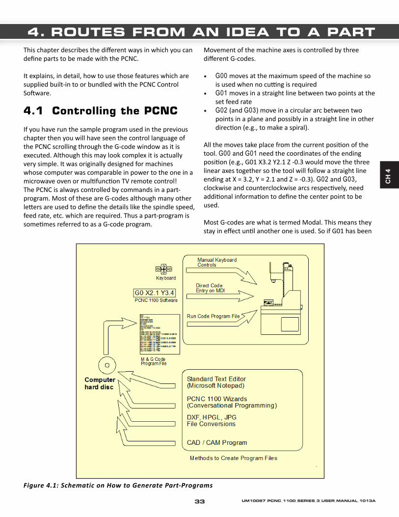
CH
4
This chapter describes the different ways in which you can define parts to be made with the PCNC.
It explains, in detail, how to use those features which are supplied built-in to or bundled with the PCNC Control Software.
4.1 Controlling the PCNC
If you have run the sample program used in the previous chapter then you will have seen the control language of the PCNC scrolling through the G-code window as it is executed. Although this may look complex it is actually very simple. It was originally designed for machines whose computer was comparable in power to the one in a microwave oven or multifunction TV remote control!The PCNC is always controlled by commands in a part-program. Most of these are G-codes although many other letters are used to define the details like the spindle speed, feed rate, etc. which are required. Thus a part-program is sometimes referred to as a G-code program.
Movement of the machine axes is controlled by three different G-codes.
• G00 moves at the maximum speed of the machine so is used when no cutting is required
• G01 moves in a straight line between two points at the set feed rate
• G02 (and G03) move in a circular arc between two points in a plane and possibly in a straight line in other direction (e.g., to make a spiral).
All the moves take place from the current position of the tool. G00 and G01 need the coordinates of the ending position (e.g., G01 X3.2 Y2.1 Z -0.3 would move the three linear axes together so the tool will follow a straight line ending at X = 3.2, Y = 2.1 and Z = -0.3). G02 and G03, clockwise and counterclockwise arcs respectively, need additional information to define the center point to be used.
Most G-codes are what is termed Modal. This means they stay in effect until another one is used. So if G01 has been
Figure 4.1: Schematic on How to Generate Part-Programs
4. ROUTES FROM AN IDEA TO A PART
33 UM10087_PCNC_1100_SERIES_3_USER_MANUAL_1013A

used on one line of code then the following lines only need to give the position of the end of the move. As an example the following code will move the tool to a start position (X = 1, Y = 2) and then move it in a square of side 3.1.
G00 X1.0 Y2.0G01 X4.1Y5.1X1Y2
In practice, however, the simplicity of G-codes is deceptive. Calculating the position of the “center” of the tool by hand is tedious and error prone. If you wanted to cut around the outside of a block of material to make the 3.1” square then you need to allow for the diameter of the tool and need to move the Z-axis to take acceptable sized cuts in each of several passes.
You will easily be able to learn what a part-program is intended to do but it is unusual to write one by hand as there is a wide range of software tools that can help you (figure 4.1).
4.2 Choosing the Appropriate Design Software
A mill is capable of producing three different classes of work which are usually referred to as 3D, 2½D and 2D.
A 3D product has complex and often smooth curves in all three dimensions. A typical example is a mold for die-casting, vacuum forming or injection molding.
A 2½D product has detail at several depths from the surface of the material but each piece of detail has a flat bottom surface. The FirstPart cut in Chapter 3 is an example of a simple 2½D component.
A 2D product has no changes in depth. This might be a mechanism link cut out of a sheet of steel or lettering cut out of vinyl sheet. 2D products can be milled but are usually produced on specialist machines (e.g., a laser table or plasma cutter).
Design and particularly production of a 3D shape is much more time consuming than something which is 2½D. If the pocket in FirstPart had a dished shape with a fillet in the corners then it would have been cut with a ball nosed tool and would have required many passes a few thou apart
rather than the passes about 0.3” apart that could be used with the flat end mill. In addition the design process is complicated because the pocket cannot be defined by a single number (i.e., its depth) if it is 3D.
With current CAD software you will probably find it is easiest to design 2½D parts with a 2½D CAD package or with a full 3D one running in 2½D mode.
4.3 Software for CAD/CAM
This section gives some guidance on things to consider when choosing software. It is a very big topic whose surface we try to skim.
The two most important points are that (a) the PCNC, because of its open and standard architecture, will run the part-programs produced by virtually all Computer Aided Design/Computer Aided Manufacture (CAD/CAM) software and (b) that the more comprehensive the software that you use, the greater will be your and the PCNC’s, productivity and the better the quality of the parts made. A common mistake is to purchase inadequate design software and then have to discard it and the investment made in learning to use it.
The Control Software itself includes features for defining and cutting simple parts like keyways, rectangular and circular pockets or a plane face by conversational Wizards. You will be able to do useful work with these features but you will get better control and documentation of your parts be using a dedicated CAD/CAM system. Some software integrates the “drawing” (CAD) and G-code production (CAM) functions but it is equally common to use different programs from different suppliers for the two functions.
It is perfectly possible and often efficient to design using a 3D CAD package and machine with a 2½D CAM package.
4.3.1 3D CAD
3D CAD software has the biggest range of purchase cost and the steepest learning curve. If you want to produce true 3D parts like molds then you have no option but to buy the best package you can afford. Alibre produces a good example of a mid-range 3D CAD package and Alibre Design XPress is bundled with the PCNC 1100.
34UM10087_PCNC_1100_SERIES_3_USER_MANUAL_1013A

CH
4
Alibre allows you to design parts by extruding 2D shapes. The extrusions can be from different planes or surfaces of the part as it is built up and can be solid material or holes.
Figure 4.2: Keyhole
Several parts can be put together into an assembly and conventional orthographic engineering drawings more or less automatically produced from the model.
High-end programs like Solidworks and Pro/ENGINEER also work in the same way and can be used to design for manufacture with the PCNC.
A 3D CAD program will typically allow the export of solid models (IGES or STL format) for input to a 3D CAM program or DXF format files for use in 2½D CAM.
4.3.2 2D CAD
In a 2D CAD program you represent parts by drawing the individual views of the engineering drawings. A vast range of software is available (much of it “free”).
We advise that you use software that allows you to express the “intent” of your design in the drawings rather than just drawing a set of lines.
As an example let us assume you want to make a key-hole shaped slot in a block of material. This can easily be drawn as two arcs and two lines with the hole that accepts the key’s shank being highlighted (figure 4.2).
How useful this drawing is depends of how intelligently the CAD program can interpret the lines. As drawn they are probably separate and can be moved independently (figure 4.3). Most software will allow joining the lines so they move together (figure 4.4). This however does not really reflect what the part is like.
Figure 4.3: Line Moved
Figure 4.4: Joined Points but Line Moved
The important things about the intent of this design are that the straight lines should be parallel and the same length and that they form a tangent to the arc at the bottom of the slot. If these constraints can be given to the CAD software then it will be possible to change its sizes (e.g., the width of the slot by dragging the radius of the bottom arc) while retaining the shape (figure 4.5).
If the shape is defined like this then the software can display the minimum set of dimensions required to define it (figure 4.6). Finally if a dimension is changed then the part can be redrawn to correspond to the new size (figure 4.7).
35 UM10087_PCNC_1100_SERIES_3_USER_MANUAL_1013A

Figure 4.5: Constrained and Size Changed
4.3.3 CAM
We have seen the sort of features you can get from a CAD program. There are also big differences between different CAM programs. Some CAM programs accept 2D models (drawings) of your part (e.g., DXF) files and expect you to define the Z depth of features like pickets, engraved text and holes. Alternatively a 3D CAM program will find all the dimensional information in the model (e.g., IGES) file.
Figure 4.6: Automatic Dimensions Displayed
Figure 4.7: Changed Dimension Changes Drawing
The main issues to consider are how many times you need to tell the CAM program how to machine the part and how good a visualization of the part you will be shown.
Figure 4.8: Path of Tool and G-Code
36UM10087_PCNC_1100_SERIES_3_USER_MANUAL_1013A

CH
4
Suppose we decide that the inside of the keyhole slot is to be cut with a 0.125” end mill using conventional milling to a depth of 0.5” with each pass being 0.1” deep. The CAM software will generate a G-code program for this.
In some freestanding CAM software, if the size of the slot is changed so the drawing changes, then you would have to create the pocket G-code for the slot from scratch with each revision of the drawing. Integrated CAD/CAM software will work dynamically with the CAD and automatically recreate the new G-code with each change in dimension.
A reasonably sophisticated CAM program will give you a choice of views of the finished part and the path of the tool as it is manufactured.
Figure 4.8 is a screen shot of a typical CAD/CAM program and shows the toolpath for one version of the slot. It is shown in a plan view together with a pane which displays the G-code generated to perform the operation.
Figure 4.9 is the result of retyping the radius of the end of the slot as 0.15” and displaying a rendered isometric view of the part. The G-code (moved into a smaller pane for clarity on the rendered view) was automatically updated to reflect the new slot width.
4.3.4 Running the G-code
The CAM program will write the G-code part-program to disk. Assuming you are using a different computer to design your part from that controlling the machine you need to transfer the file to the hard drive of the control computer. Then you can load and run it in the same way you did for the FirstPart program. Figure 4.10 shows the keyhole loaded into the Control Software.
Note: Do not attempt to run part-programs off a USB key drive or floppy disc.
4.3.5 CAD/CAM Systems
Vectric Cut 2D is a 2½D system which will accept DXF drawings from virtually any source, has powerful features and is very easy to learn. If you already have a favorite CAD program then this will be a good choice for you to do CAM work.
Figure 4.11 shows a DXF drawing of a mounting plate for a motor. This was produced from the solid model in figure 4.12 but could have been drawn with virtually any program.
Figure 4.9: Rendered Isometric view of Narrower Keyhole Slot
37 UM10087_PCNC_1100_SERIES_3_USER_MANUAL_1013A

Figure 4.11: Motor Mount DXF
Figure 4.12: Model for Mount
Figure 4.13 shows the drawing loaded as a Cut 2D job If your work needs powerful parametric solid modeling and 3D milling from these models then the matched combination of Alibre Design and SprutCAM is available from Tormach. Figures 4.14 through 4.16 illustrate a part
being designed in Alibre, the manufacture being defined in SprutCAM and a finished test piece.
Virtually any other commercially available CAD/CAM systems can be used with the PCNC control software because of its compliance with industry standards. CAD/CAM software is configured to generate appropriate code for a particular machine tool by a post-processor. You should consult Tormach for advice on the best post-processor option to purchase with your preferred software.
Figure 4.14: Modelling a 3D Part
Figure 4.10: Keyhole Loaded and Ready to Run
38UM10087_PCNC_1100_SERIES_3_USER_MANUAL_1013A

CH
4
Figure 4.15: Defining the Machining Technology Figure 4.16: The Machined Test Piece
Figure 4.13: Cut2D Job for Motor Mount
39 UM10087_PCNC_1100_SERIES_3_USER_MANUAL_1013A
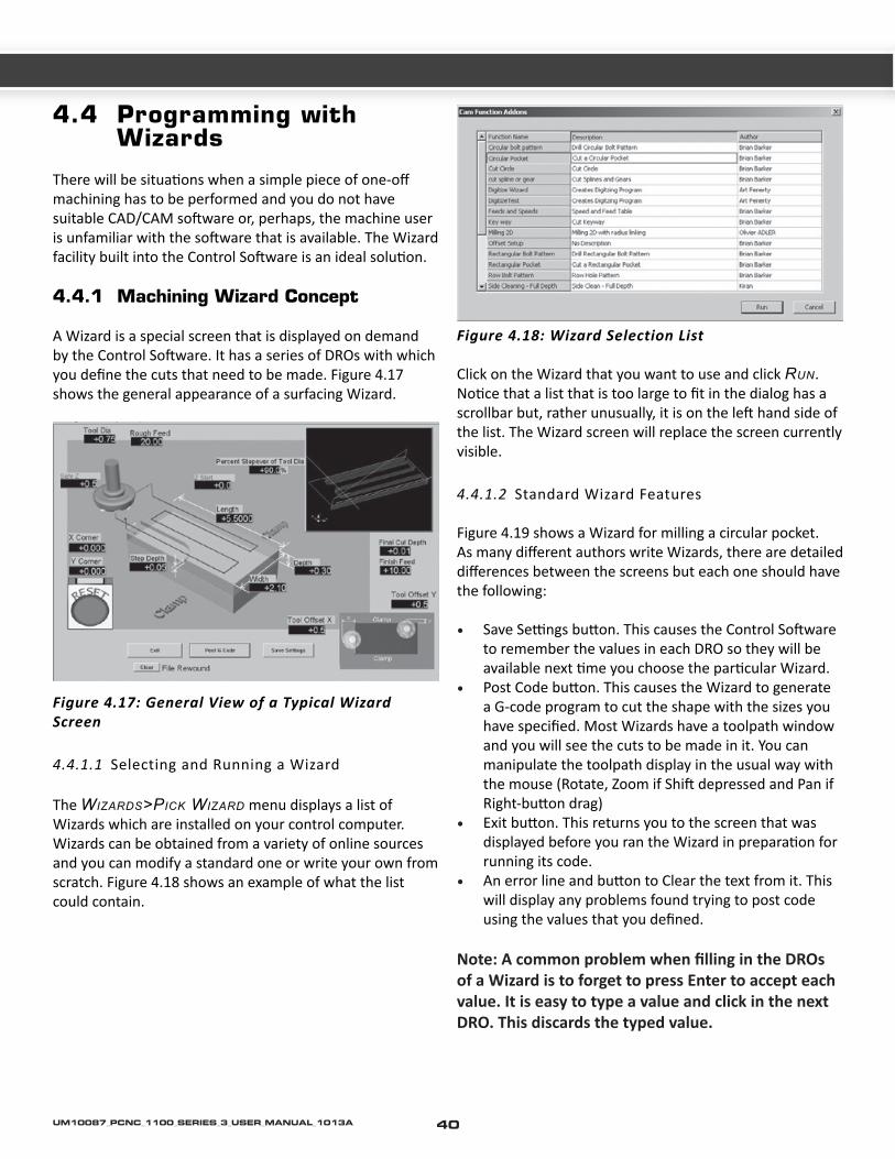
4.4 Programming with Wizards
There will be situations when a simple piece of one-off machining has to be performed and you do not have suitable CAD/CAM software or, perhaps, the machine user is unfamiliar with the software that is available. The Wizard facility built into the Control Software is an ideal solution.
4.4.1 Machining Wizard Concept
A Wizard is a special screen that is displayed on demand by the Control Software. It has a series of DROs with which you define the cuts that need to be made. Figure 4.17 shows the general appearance of a surfacing Wizard.
Figure 4.17: General View of a Typical Wizard Screen
4.4.1.1 Selecting and Running a Wizard
The wizardS>PiCK wizard menu displays a list of Wizards which are installed on your control computer. Wizards can be obtained from a variety of online sources and you can modify a standard one or write your own from scratch. Figure 4.18 shows an example of what the list could contain.
Figure 4.18: Wizard Selection List
Click on the Wizard that you want to use and click run. Notice that a list that is too large to fit in the dialog has a scrollbar but, rather unusually, it is on the left hand side of the list. The Wizard screen will replace the screen currently visible.
4.4.1.2 Standard Wizard Features
Figure 4.19 shows a Wizard for milling a circular pocket.As many different authors write Wizards, there are detailed differences between the screens but each one should have the following:
• Save Settings button. This causes the Control Software to remember the values in each DRO so they will be available next time you choose the particular Wizard.
• Post Code button. This causes the Wizard to generate a G-code program to cut the shape with the sizes you have specified. Most Wizards have a toolpath window and you will see the cuts to be made in it. You can manipulate the toolpath display in the usual way with the mouse (Rotate, Zoom if Shift depressed and Pan if Right-button drag)
• Exit button. This returns you to the screen that was displayed before you ran the Wizard in preparation for running its code.
• An error line and button to Clear the text from it. This will display any problems found trying to post code using the values that you defined.
Note: A common problem when filling in the DROs of a Wizard is to forget to press Enter to accept each value. It is easy to type a value and click in the next DRO. This discards the typed value.
40UM10087_PCNC_1100_SERIES_3_USER_MANUAL_1013A
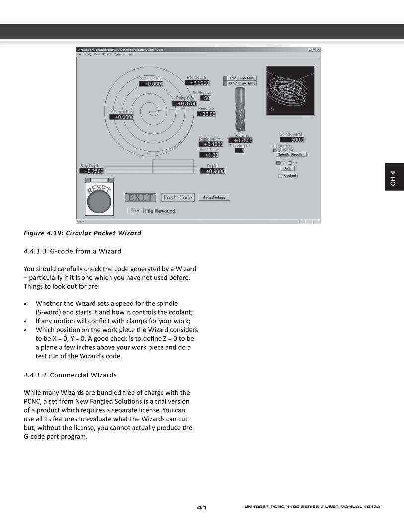
CH
4
4.4.1.3 G-code from a Wizard
You should carefully check the code generated by a Wizard – particularly if it is one which you have not used before.Things to look out for are:
• Whether the Wizard sets a speed for the spindle (S-word) and starts it and how it controls the coolant;
• If any motion will conflict with clamps for your work;• Which position on the work piece the Wizard considers
to be X = 0, Y = 0. A good check is to define Z = 0 to be a plane a few inches above your work piece and do a test run of the Wizard’s code.
4.4.1.4 Commercial Wizards
While many Wizards are bundled free of charge with the PCNC, a set from New Fangled Solutions is a trial version of a product which requires a separate license. You can use all its features to evaluate what the Wizards can cut but, without the license, you cannot actually produce the G-code part-program.
Figure 4.19: Circular Pocket Wizard
41 UM10087_PCNC_1100_SERIES_3_USER_MANUAL_1013A

This chapter gives a description of all the PCNC controls on the operator’s panel and the Control Program screens.
If you have been through the section “Running the PCNC” in Chapter 2 you already have a good grounding and may wish to skim through this chapter on first reading of the manual and come back to it when you want to understand exactly how some feature works.
5.1 Machine Operation
5.1.1 Operator/Control Panel
The operator’s panel is shown in figure 5.1. It controls the PCNC directly and is independent of the software in the control computer. When the Spindle and Coolant switches are in the Auto position then control of these functions is given to the computer.
Main Switch
The main switch is mounted on the right hand side of the control cabinet. A padlock can be inserted to lock it in the off position for lockout/tag out. The main switch controls the 230 volt power to the main machine and the auxiliary power from the IEC inlet under the control cabinet to the computer and coolant system.
Note: Disconnect the machine from the wall outlets before opening the control cabinet door as it is possible that live terminals can be touched even when the main switch is in the OFF position.
WARNING! THE FOLLOWING POWER-UP AND POWER-DOWN SEQUENCES SHOULD BE FOLLOWED EXACTLY TO AVOID THE RISK OF UNINTENDED
MACHINE MOTION WHICH COULD CAUSE INJURY TO YOU OR DAMAGE TO THE MACHINE.
1. BOOT UP THE CONTROL COMPUTER AND ALLOW THE CONTROL SOFTWARE TO FULLY LOAD. VERIFY MACH 3 IS RUNNING ON THE CONTROL SCREEN.
2. PUSH THE GREEN START BUTTON ON THE CONTROL PANEL. THIS APPLIES POWER TO THE MILL AXES.
SIMILARLY, POWER OFF THE MILL BEFORE SHUTTING DOWN THE CONTROL SOFTWARE AND THE COMPUTER. USE THE RED STOP BUTTON TO DISENGAGE POWER TO THE MILL AXES.
Figure 5.1: Operator/Control Panel
5. MACHINE CONTROLS
42UM10087_PCNC_1100_SERIES_3_USER_MANUAL_1013A

CH
5
Computer On/Off
The Computer On/Off switch controls the power from the IEC (auxiliarry) inlet to the two outlets that are intended for the computer and monitor. This is provided for convenience. In some applications the computer/monitor might be powered directly from a wall outlet and this “computer” circuit left unused or used for other functions such as to powering a work-light.Start and EStop
The Start button will energize the circuits for the axis drives. The Stop button, which locks in once pressed, stops all motion and is the Emergency Stop (EStop) control. The Stop button is released by a turning the button-head a quarter-turn clockwise.
If you experience a power interruption, the machine will not automatically start once power is resumed. The PCNC requires Start to be pressed on re-application of power.
Status LEDs
The Machine LED indicates that the Start button has been pressed. When it is lit then the Machine OK LED on the computer screen should be solid green.
The Computer LED indicates that the Control Software is running.
Spindle
An important safety interlock is that the rotation of the spindle can be disabled (while maintaining axis drive power) by the Spindle Lockout key-switch. The switch on the belt-guard door performs the same function. These are used to ensure that the spindle cannot start when an R8 tool holder is being changed (guard door open) or when a tool is being changed in a collet chuck. The spindle lockout should also be used when probing.
The controls above the key-switch are all concerned with manual control of the spindle. If the Manual/Auto switch is in Auto position then none of the other panel spindle controls have any effect. In the Manual position the computer cannot control the spindle.
The rotary control potentiometer (RPM x 100) controls the speed on the spindle when it is in Manual mode. Its legend indicates approximate spindle speed in the two pulley ranges.
The Spindle Start spring loaded rocker starts the spindle and the Spindle Stop rocker stops it. The direction is determined by the setting of the Forward/Reverse switch. Forward corresponds to clockwise rotation of the spindle. You can safely switch direction while the spindle is turning.
Coolant
The Coolant switch controls the power from the coolant pump outlet on the underside of the control cabinet. In the Off position the pump does not run. In the On position it runs irrespective of the computer control. In the Auto position it will run if the Control Program requests coolant.
Accessory Socket
The Accessory socket is for connection of accessories such as a touch probe.
5.1.2 Tool Changing
5.1.2.1 Tooling Strategy
The PCNC uses an R8 spindle and so you have access to a vast range of standard tooling. The main options open to you are:
Figure 5.2: Holders in the TTS Range with Collet
• Tormach Tooling System (TTS) – this allows you to have all the tools that you commonly use mounted in low cost tool holders and to change them very quickly. The working length of each tool is accurately maintained each time it is loaded into the spindle so it can be used
43 UM10087_PCNC_1100_SERIES_3_USER_MANUAL_1013A

for cutting with no further setup. Tool lengths can be setup and checked in a stores or inspection area without using the PCNC (figures 5.2 & 5.3).
• R8 tool holders – offer similar features to TTS holders but need to be setup once in the machine and are slower to exchange (figure 5.4).
• Screwed shank cutter collet chuck (Clarkson/Posilok type) – allows you to exchange a cutter while maintaining a known length as the center hole at the back end of the cutter registers in the chuck (figure 5.5).
• ER or similar collet – accepts a wide range of cutter diameters but the length of the tool is not accurately repeatable so the offset needs to be reset after each tool change (figure 5.6).
• R8 collet – gives the shortest overhang from the spindle nose but requires an individual collet for each tool diameter and, as with ER collets, length is not repeatable.
• The tool changing procedure is slightly different depending on the tool-holders you have.
Figure 5.3: TTS Presetting
Figure 5.4: R8 Tool Holder
5.1.2.2 Changing R8 Tools
Open the spindle drive cover.
Swing the spindle locking fork so it engages with the flats on the upper part of the spindle. You will have to turn the spindle a little to get it to line-up.
Figure 5.5 Autolock Chuck
Figure 5.6: ER32 Collet Tool Holder
The locked spindle is shown in figure 5.7
44UM10087_PCNC_1100_SERIES_3_USER_MANUAL_1013A

CH
5
Figure 5.7: Spindle Lock Fork Engaged
To remove any installed tools:
• Wipe any debris from the spindle nose and the tool being removed to avoid any risk of it getting into the spindle bore;
• Using the supplied 13 mm wrench on the squared end, loosen the drawbar by about one turn. Tap the end of it with a copper-faced hammer to disengage the R8 taper;
• While holding the tooling in one hand, fully unscrew the drawbar and remove the tooling.
To insert a new tool:
• Check that the R8 taper on the tool-holder/collet is quite clean;
• Insert the tool-holder/collet into the spindle turning it to ensure that the drive keyway engages with the key in the spindle. Start the drawbar thread to retain the tool-holder/collet;
• If you are using a tool-holder then the drawbar can be tightened. Otherwise, using the drawbar to prevent the collet jaws from closing in the spindle taper, insert the TTS holder or tool into the collet. Then tighten the drawbar.
• Finally disengage the locking forks and close the door.
5.1.2.3 Changing TTS Tools
For more information on the Tormach Tooling system, please review the TTS manual from the Tormach web site. For detailed reading on the subject, feel free to read up on “Preventing Collet Slip” in the Engineering Documents section of the web site.
The system uses a precision ¾” R8 collet in the spindle. Insert this as described above for R8 tooling.
Tool holders can be changed by loosening the drawbar by just one turn and using the copper-faced hammer on the squared end to disengage the collet taper. You do not need to remove the collet.
Note: You can change the tools in TTS drill chucks or the ER collet adaptor while these are fitted to the PCNC spindle although doing this will not exploit the pre-settable nature of the tools. It is recommended to use two wrenches when changing end mills on an ER holder to avoid damage to the spindle alignment pin.
If you change a cutter or drill without opening the door to lock the spindle you should use the Spindle Lockout key to avoid any risk of the spindle starting. If the door is open the spindle is automatically inhibited.
Note: the draw bar is a wear part. After many repeated tool changes, the draw bar will become worn both at its threads, and on the shoulder near the top. This wear can adversely affect your ability to tighten tools properly. Inspect your draw bar regularly and replace as required.
45 UM10087_PCNC_1100_SERIES_3_USER_MANUAL_1013A

Figure 5.8:Changing Spindle Speed Range
5.1.3 Spindle Speed Ranges
The PCNC has two speed ranges. The low range, 100 to 2000 RPM, is suitable for most machining operations with ferrous and other tough materials. The high range, 250 to 5140 RPM is suitable for small diameter cutters and plastics and non-ferrous materials.
The range change is performed by moving the V-belt from the motor top pair of pulleys (high speed range) to the lower pair (low speed range).
To change the belt position:
• Open the protective door. Use the rear handle to unlock the motor mounting plate and pull the motor forwards. The belt will slacken and can be moved from one pulley to another (figure 5.8).
• Retighten the belt so there is between 1/8” and ¼” belt movement midway between the pulleys. Lock the motor mounting and stow the handles in the vertical position.
46UM10087_PCNC_1100_SERIES_3_USER_MANUAL_1013A

CH
5
5.2 Screen Control Panels
5.2.1 Using the Screens
Although at first sight you may feel daunted by the range of options and data displayed by Control Software, this is actually organized into a few logical groups. We refer to these as Families of Controls. By way of explanation of the term “control,” this covers both buttons and their associated keyboard shortcuts used to operate the software and the information displayed by DROs (digital read-outs), labels or LEDs (light emitting diodes).
The elements of each control family are defined for reference in this chapter. The families are explained in order of importance for most users.
You should, however, note that all the screens of your system do not include all the controls of a family. This may be to increase readability of a particular screen or to avoid accidental changes to the part being machined in a production environment
5.2.2 Families of Related Controls
5.2.2.1 Persistent Controls
These controls appear on each screen. They allow switching between screens and also display information about the current state of the system (figure 5.9).
Reset
This is a toggle. When the system is Reset the LED glows green steadily.
Error and Machine Profile Information
The Machine OK LED indicates that the PCNC mill is powered on.
The “text labels” display the last “error” message, the current modes, the file name of the currently loaded part-program (if any) and the machine profile that is in use.
The Clear button clears the text from the error line. The entries written to the error line are logged in the file C:\PCNC3\LastErrors.txt. This can be opened and inspected with a text editor like Notepad if you want to analyze a history of events.
Screen Selection Buttons
These buttons switch the display from screen to screen. The button text changes from black to blue when that screen is active.
The keyboard shortcuts are given after the names. For clarity they are letters are shown in upper-case. You should not, however, use the shift key when pressing the shortcut.
5.2.2.2 Axis Control Family
This family is concerned with the current position of the tool, or more precisely, the controlled point (figure 5.10).
The axes have the following controls:
Coordinate Value DROs
These are displayed in the current units (inch/metric = G20/G21). The value is the coordinate of the controlled point in the displayed coordinate system. This will generally be the coordinate system of the current Work
Figure 5.9: Screen Switching Control Family
Screen Selection
Text LabelsMachine OK/Reset
47 UM10087_PCNC_1100_SERIES_3_USER_MANUAL_1013A

Offset (initially 1 – i.e., G54) together with any Tool length offset and G52/G92 offsets applied.
If the X and Y coordinates display in red then they have been rotated by a G68 command.
You can type a new value into an Axis DRO. This will modify the current Work Offset to make the controlled point in the current coordinate system be the value you have set. You are advised to set-up Work Offsets using the Offsets screen until you are fully familiar with working with multiple coordinate systems.
Referenced
The LED is green if the axis has been referenced (i.e., is in a known actual position).
Many users prefer to always run the PCNC in the referenced state.
Each axis can be referenced using its Ref button or the linear axes can be referenced together using the Ref XYZ button.
The de-ref All button does not move the axes but stops them being in the referenced state.
Figure 5.10: Axis Control Family
Scale
Scale factors for any axes can be set by G51 and can be cleared by G50. If a scale factor (other than 1.0) is set then it is applied to coordinates when they appear in G-code (e.g., as X words, Y words etc.) . The Scale LED will flash as a reminder that a scale is set at a value other than 1.0 for an axis. The value defined by G51 will appear and can be set, in the Scale DRO. Negative values mirror the coordinates about the relevant axis.
The G50 button executes a G50 command to set all scales to 1.0
Correction Radius
Rotary axes can have the approximate size of the work piece defined using the Rotational Diameter control family. This size is used when making blended feed rate calculations for coordinated motion including the 4th Axis. The LED indicates that a non-zero value is defined.
Jog/Shuttle Axis
The axis that is selected for jogging by the Tormach Jog/Shuttle Controller is indicated by a LED by the top left corner of the corresponding DRO.
5.2.2.3 Jogging Control Family
Jogging can be performed in two ways: (a) using the keyboard (or optional Keypad pendant) or (b) Using the optional Tormach Jog/Shuttle Controller
Figure 5.11: Jogging Control Family
Scale
Axis ReferenceDRO
Correction Radius
48UM10087_PCNC_1100_SERIES_3_USER_MANUAL_1013A

CH
5
Keyboard Jogging
Whenever the Jog on/off button is displayed on the current screen then the axes of the machine can be jogged using the jog hotkeys (arrows up, down, left and right) on main keyboard or a pendant keyboard.
Hotkeys
If the Jog on/off button is not displayed or it is toggled to off then keyboard jogging is not allowed for safety reasons.
There are two modes, Continuous and Step which are selected by the Jog Mode button and indicated by the LEDs.
Continuous mode moves the axis or axes at the defined slow jog rate while the hotkeys are pressed.
The continuous jog speed is defined as shown below but this can be overridden by pressing Shift with the hotkey(s). A LED beside the Cont. LED indicates this full speed jogging is selected.
The jogging speed used with hotkeys in Continuous mode is set as a percentage of the rapid traverse rate for the axis by the Slow Jog Percentage DRO. This can be set (in the range 0.1% to 100%) by typing into the DRO. It can be nudged in 5% increments by the buttons or their hotkeys.
Step mode moves the axis by one increment (as defined by the Step DRO) for each key press. The current feed rate (as defined by the F word) is used for these moves. The size of increment can be set by typing it into the Step DRO or values can be set in this DRO by cycling through a set of predefined values using the Jog SteP button.
Incremental mode is selected by the toggle button or, if in Continuous Mode temporarily selected by holding down Ctrl before performing the jog. Press the left and right arrows to move the x-axis; the up and down arrows to move the y-axis, and the page up and down keys to move the z-axis.
Tormach Jog/Shuttle Controller
This jogging device is available as an optional accessory (part number 30616, figure 5.12).
Figure 5.12: Tormach Jog/Shuttle Controller
Many users will find that it increases their productivity, especially on short-run jobs requiring a lot of setting up of workpiece and tooling.
The four buttons starting at the left are allocated to select jogging of axes X, Y, Z and A respectively. A LED beside an axis DRO indicates that this axis is the one that will be jogged.
The fifth button cycle through the available jog step sizes. Alternatively you can type a step size into the Step DRO.Continuous jogging is performed by turning the spring loaded ring counterclockwise for the minus direction and clockwise for the plus direction. There are seven speeds, in geometric ratio, from very slow to full speed so you can position any axis with great speed and precision.
The inner wheel (with finger dimple) will jog by one Step as defined in the Step DRO for each click. The move will be made at the current feed rate.
49 UM10087_PCNC_1100_SERIES_3_USER_MANUAL_1013A

5.2.2.4 Spindle Speed Control Family
The machine spindle can be controlled in two ways: (a) by hand or (b) by switching to Auto on Operator’s panel, thus making the speed and direction set by the Control Software.
This control family is only important for case (b).
The S DRO has its value set when an S word is used in a part-program. It is the desired spindle speed. It can also be set by typing into the DRO (figure 5.13).
Figure 5.13: Spindle Speed Control Family
It is an error to try to set it (in either way) to a speed greater than that displayed in Max SPeed for the chosen pulley and the nearest legal value will be chosen.
The hi/lo button toggles between the two belt/pulley settings with the LEDs indicating the configuration (spindle on left, motor on right).
The maximum available speed is indicated.
The S- and S+ buttons increase and decrease the value in the S DRO geometrically using a ratio of 1.15 for each click on the button. This reflects the usual arrangement of gearbox in a manual machine tool.The spindle can be started in a clockwise direction by the Spindle CW button. An M-code (M4) in the MDI box is required if you want to select counterclockwise running.
The main LED above the SPindle Cw button indicates that the spindle is “running” – although actual movement may be inhibited by the key and/or door interlocks. The two LEDs that flank it indicate a Dwell while the spindle gets up to speed or fully stops.
The Coolant button and its associated LED control the coolant power outlet under the control cabinet.
5.2.2.5 Feed Control Family
Feed Units per Minute
The f dro gives the feed rate in current units (inches/millimeters per minute). It is set by the F word in a part-program or by typing into the F DRO. The control software will aim to use this speed as the actual rate of the coordinated movement of the tool through the material. If this rate is not possible because of the maximum permitted speed of any axis then the actual feed rate will be the highest achievable (figure 5.14).
Figure 5.14: Feed Control Family
Feed Units per Revolution
As modern cutters are often specified by the permitted cut per “tip” it may be convenient to specify the feed per revolution (i.e., feed per tip x number of tips on tool). In this case the F DRO gives the feed rate in current units (inches/millimeters) per rev of the spindle. It is set by the F word in a part-program or by typing into the DRO.
NOTICE THAT THE NUMERIC VALUES IN THE CONTROL WILL BE VERY DIFFERENT UNLESS SPINDLE SPEED IS NEAR TO 1 RPM! SO USING A FEED PER MINUTE
FIGURE WITH FEED PER REV MODE WILL PROBABLY PRODUCE A DISASTROUS CRASH!
Feed Display
The actual feed in operation allowing for the coordinated motion of all axes is displayed in unitS/Min and unitS/
50UM10087_PCNC_1100_SERIES_3_USER_MANUAL_1013A

CH
5
rev. If the spindle speed is not set and the actual spindle speed is not measured then the Feed per rev value will be meaningless.
Feed Override
Unless M49 (disable feed rate override) is in use, the feed rate can manually be overridden in the range of 20% to 100% by entering a percentage in the (feed rate override) DRO with a % sign. While it is possible to enter numbers higher than 100%, the practice is not recommended. The LED warns if an override is in operation.The control software will apply any changes in feed rate override as quickly as possible. This could be very important if you decide you have too high a feed rate for safety. To optimize performance, the software keeps a queue of moves ready to be implemented. It is possible if you increase the federate that you will make one of these queued moves be faster than the PCNC can move or accelerate and so it will loose steps. The best strategy is to write the part program to run at the highest anticipated feed rate and then use the override at less than 100% to reduce it to produce the best operating condition.
The FRO DRO displays the calculated result of applying the percentage override to the set feed rate.
5.2.2.6 Program Running Control Family
These controls handle the execution of a loaded part-program or the commands on an MDI line (figure 5.15).
Figure 5.15: Program Running Family
Cycle Start
SAFETY WARNING: NOTE THAT THE CYCLE START BUTTON WILL, IN GENERAL, START THE SPINDLE AND AXIS MOVEMENT.
Program Reset
PrograM reSet stops the spindle and axis motion and rewinds the G-code.
Single BLK
Single BlK is a toggle (with indicator LED). In Single Block mode a Cycle Start will execute the next single line of the part-program.
Line Number
Line DRO is the ordinal number of the current line in the G-code display window (starting from 0). Note that this is not related to the “N word” line number.
You can type into this DRO to set the current line.
Run from Here
run froM here performs a dummy run of the part-program to establish what the modal state (G20/G21, G90/G91, etc.) should be and then prompts for a move to put the controlled point in the correct position to for the start of the line in Line Number. You should not attempt to Run from here in the middle of a subroutine.
SAFETY WARNING: NOTE THAT THE RUN FROM HERE OPERATION WILL RUN FROM THE LAST KNOWN LOCATION. IN GENERAL, YOU SHOULD RUN THIS
FEATURE FROM THE TOOL CHANGE LINE. CAREFULLY REVIEW THE LAST KNOWN LOCATION VALUE IN THE “PREPARATION POSITIONING” WINDOW.
Set Next Line
Like run froM here but without the preparatory mode setting up processing.
Block Delete
The ignore “/” BloCKS button toggles the Block Delete “switch.” If enabled then lines of G-code which start with a slash (i.e., / - will not be executed).
51 UM10087_PCNC_1100_SERIES_3_USER_MANUAL_1013A

Optional Stop
The M01 BreaK button toggles the Optional Stop “switch.” If enabled, the M01 command will be treated as M00.
Goto Toolchange
This button provides manual movement of the controlled point when the part-program is stopped.
Tool Details
Controls display the current tool, its name, the offsets for its length and diameter and whether the offsets are active (ON).
Unless tool change requests are being ignored, on encountering an M6 the Control Software will stop and flash the Change Req LED. You continue (after changing the tool) by clicking Cycle Start.
Work Offset Details
The name of the current work offset coordinate system is displayed.
5.2.2.7 Toolpath and G-Code Display Control Family
The currently loaded part-program is displayed in the G-code window. The current line is highlighted and can be moved using the scroll bar on the window (figure 5.16).
Figure 5.16: Toolpath and G-Code Display Family
The Toolpath display shows the path that the controlled point will follow in the X, Y and Z planes. When a part-program is executing, the path is over painted in green. This over painting is dynamic and is not preserved when you change screens or indeed alter views of the toolpath.
On occasions you will find that the display does not exactly follow the planned path. This occurs because the Control Software prioritizes the tasks it is doing. Sending accurate step pulses to the machine tool is the first priority. Drawing the toolpath is a lower priority. It will draw points on the toolpath display whenever it has spare time and it joins these points by straight lines. So, if time is short, only a few points will be drawn and circles will tend to appear as polygons where the straight sides are very noticeable. This is nothing to worry about.
The toolpath display can be turned off using the toolPath on/off button on the diagnostics screen. This should be done on long programs to decrease the demands of the screen redraw on the computer processor.
52UM10087_PCNC_1100_SERIES_3_USER_MANUAL_1013A

CH
5
The SiMulate PrograM run button will execute the G-code, but without any tool movement and allow the time to make the part to be estimated.
The aBSolute Motion extreMeS data allow you to check if the maximum excursion of the controlled point is reasonable (e.g., not milling the top of the table).
The toolpath display can be rotated by left clicking and dragging the mouse in it. It can be zoomed by shift-left clicking and dragging and can be panned by dragging a right click.
The regenerate button will regenerate the toolpath display from the G-code with the currently enabled fixture and G92 offsets.
The diSPlay Mode button will choose whether the default toolpath display is sized for the machine envelope or the object defined by the extremis of the part-program.
The Jog follow button allows the toolpath display to be automatically scrolled as the controlled point is jogged.
5.2.2.8 File Control Family
These controls are involved with the file with your part’s guide program. Most should be self-evident in operation.
Figure 5.17: File Control Family
Change G-code allows you to use the Notepad editor to edit the part-program you have loaded. When clicked it displays the current file (figure 5.18).
Figure 5.18: Notepad to Edit G-Code
5.2.2.9 Work Offset and Tool Table Control Family
This family is explained in detail in Chapter 6.
5.2.2.10 MDI and Teach Control Family
G-code lines (blocks) can be entered, for immediate execution, into the MDI (Manual Data Input) line. This is selected by clicking in it or the MDI hotkey (Enter). When the MDI line is active its color changes and a fly-out box showing the recently entered commands is displayed (figure 5.20). The cursor up and down arrow keys can be used to select from the fly-out so that you can reuse a line that you have already entered. The Enter key causes the current MDI line to be executed and the MDI remains active for input of another set of commands. The Esc key clears the line and de-selects it. You need to remember that when it is selected all keyboard is written in the MDI line rather than controlling the machine. In particular, jogging keys will not be recognized – you must Esc after entering MDI.
Figure 5.20: MDI and Teach Control Family
53 UM10087_PCNC_1100_SERIES_3_USER_MANUAL_1013A

The Control Software can remember all the MDI lines as it executes them and store them in a file by using the Teach facility. Click Start Teach, enter the required commands and then click Stop Teach. The LED blinks to remind you that you are in Teach Mode. The commands are written in the file with the conventional name C:/PCNC3/GCode/MDITeach.tap. Clicking load/edit will load this file so it can be run or edited in the usual way – you need to go to the Simple Run or Comp Run screen to see it. If you wish to keep a given set of taught commands then you should Edit the file and use Save As in the editor to give it your own name and put it in a convenient folder.
5.2.2.11 Loop Control Family
The Control Software can execute a part-program many times, automatically updating a limit to the depth to which the Z-axis can move (figure 5.21).
Figure 5.21: Loop Control
The part-program must end with an M30 (rewind) code.
The number of passes you require is entered into the Cycles DRO. The initial lowest Z position is put into Z inhibit (note this will often be negative) and the distance Z is to move down each cycle is put into Z Step (usually positive). The On/Off button enables the feature.
The Multipass button will prompt for the values by a series of dialogs rather than requiring the DROs to be filled in.
5.2.2.12 Modes and Mode Alarm Control Family
Figure 5.22: Current Modes Display
These families display the current modes of the Control Software and an “alarm” LED for unusual modes. The alarm is on the Diagnostics screen. Click on the flashing LED to see a list of unusual modes (figure 5.22).
These modes might arise from running a part-program produced by a CAD/CAM system not customized for all the features of the PCNC.
An unusual mode does not imply a fault in your system, simply a hint of what to look for if unusual things are happening (figure 5.23).
Figure 5.23: Unusual Modes Display on Diagnostics
If for any reason the standard modes do not suit your normal working then by double-click on the unusual modes LED you can define the current state as “usual.”
5.2.2.13 Rotational Diameter Control Family
As described in the Feed Rate control family, it is possible to define the approximate size of a rotated work piece so the rotational axis speed can be correctly included in the blended feed rate. The relevant diameters are entered in the DRO on this family (figure 5.24).
Figure 5.24: Rotational Diameters
The Axis control Family has a warning LED to indicate the setting of a non-zero value here.
Note: A value is not required if rotary movement is not to be coordinated with linear axes. In this case a suitable F word for degrees per minute or degrees per rev should be programmed.
5.2.2.14 Toolchange Position Control Family
54UM10087_PCNC_1100_SERIES_3_USER_MANUAL_1013A

CH
5
This family defines the place the machine should go to when a request to change a tool occurs or when the Goto Toolchange button is clicked. A part-program can go to it by using the M998 code (figure 5.25).
Figure 5.25: Tool Change Position
The position is defined in machine coordinates (i.e., relative to the home switches) and in the default machine units.
Enter the special value 9999 if you do not want a given axis to move when a tool change is requested.
The units in which you define your toolchange position can be configured by the Toggle T/C Units button.
Note: The move will take place correctly whatever units the machine is in at the time and, because machine coordinates are used, to a fixed place irrespective of the offsets in use.
The tool change position is also used when you want to use the central lubrication system.
This family also allows you to set the machine coordinates used if your part-program executes a G28. We advise you to use the M998 toolchange location whenever possible as this checks that the machine is referenced (i.e., the machine coordinates are valid). G28 will use whatever values are in use irrespective of them being valid because the machine is referenced.5.2.2.15 Inhibits and Overrides Control Family
In testing a part-program it is sometimes useful to be able to inhibit the movement of an axis (e.g., typically Z). This is done with the Axis Inhibit buttons (figure 5.26).
Figure 5.26: Inhibits and Overrides Family
When an axis hits a limit switch it will trigger a software EStop condition so all movement will cease. If Auto LimitOverRide is enabled then you can reset the system and carefully jog off the limit. If you want more security in this situation you can disable autoliMitoverride and click the override liMitS button before clicking Reset on each occasion.
5.2.2.16 Feeds and Speeds Calculator
Different materials and tooling require different cutting speeds and feed so you will need to use published tables and your experience to define the optimum spindle speed and the feed rate for any given job. A simple calculator on the Settings screen will, however, do the math for you when you know a cutting speed (in feet per minute) and a chip per tooth loading (figure 5.27).
Figure 5.27: Speed/Feed Calculator
Enter your cutting data into the DROs, not forgetting to press Enter for each value and click the CalC rPM/feed button. The screen labels show the calculation that is being done for you.
5.2.2.17 Tapping Configuration Family
The control software allows use of the Tormach Tapping Heads (PN 30612 and 30613) and Procunier without a detailed understanding of the sequence of moves that are
55 UM10087_PCNC_1100_SERIES_3_USER_MANUAL_1013A

needed to control the head. The holes are tapped by using one of the M-code macros M871, M872, M873 or M874. The macros work as a kind on canned cycle. Each macro is set up for a particular pitch of thread and choice of tapping head. This information is provided by the Tapping Configuration family of controls (figure 5.28).
Figure 5.28: Tapping Configuration
The TPI or Pitch DRO is interpreted in a different way depending on whether the part program calling its macro is running in Inch (G20) or metric (G21) mode. In G20 mode the value is a number of threads per inch and in G21 mode it is the pitch of the thread in millimeters. It is perfectly possible to change modes within a program and so have a job with mixed thread standards. Fortunately Inch numbers are unlikely to be pitches and vice-versa. The control software checks that the chosen pitch can be cut at the current spindle speed when the macro is called so there is little chance of damage to a tap.
If you select Dwell mode then the macro will use an alternative movement algorithm which dwells (pauses) at the bottom of the thread. This gives a more accurate depth but slower tapping and more wear on the mechanism of the tapping head.
Both tapping heads have a high-speed reverse feature to minimize tapping time. As the gear ratios are different for each head you must define which is going to be used by toggling to the appropriate large or small LED.
5.2.2.18 Misc. Settings Control Family
Current Units
This displays the units currently selected (figure 5.29).
Figure 5.29: Miscellaneous Settings
Ignore Tool Change
Normally when the part-program calls for a different tool execution will stop, the Tool Change LED will flash and you need to press Cycle Start to continue. Tool change requests can be ignored by clicking the Ignore M6 Tool Change button. This can be useful when air-cutting to prove/time a part program.
G73 Pullback
This DRO defines the distance that a high speed peck drill cycle (G73) will pullback when breaking the chip. You may need to alter this value for metric use.
IJ Mode
The IJ mode defines how the I, J and K words in a G02 or G03 are interpreted. There is no standard for this so different CAM post processors will use different conventions. The PCNC usually runs with I, J and K being incremental distances from the current point. You can make the Control Software treat them as absolute positions by clicking the Set Abs I/J button. The symptoms of an incorrect setting are that small arcs can display a massive circle on the toolpath or you get an error message about the radius of an arc being different at the start and end of a cut.
56UM10087_PCNC_1100_SERIES_3_USER_MANUAL_1013A
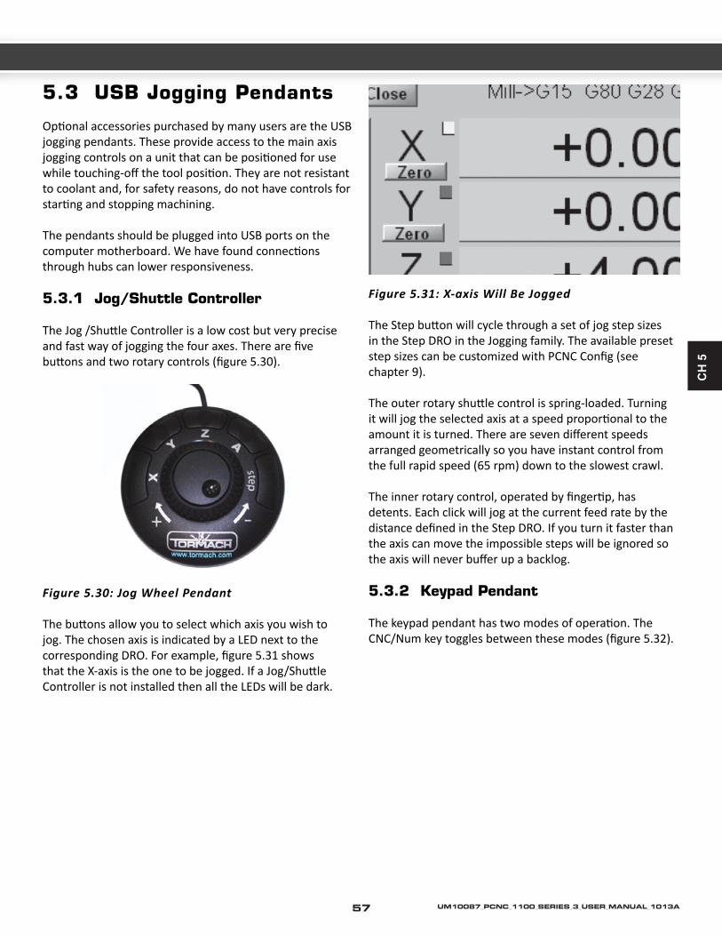
CH
5
5.3 USB Jogging Pendants
Optional accessories purchased by many users are the USB jogging pendants. These provide access to the main axis jogging controls on a unit that can be positioned for use while touching-off the tool position. They are not resistant to coolant and, for safety reasons, do not have controls for starting and stopping machining.
The pendants should be plugged into USB ports on the computer motherboard. We have found connections through hubs can lower responsiveness.
5.3.1 Jog/Shuttle Controller
The Jog /Shuttle Controller is a low cost but very precise and fast way of jogging the four axes. There are five buttons and two rotary controls (figure 5.30).
Figure 5.30: Jog Wheel Pendant
The buttons allow you to select which axis you wish to jog. The chosen axis is indicated by a LED next to the corresponding DRO. For example, figure 5.31 shows that the X-axis is the one to be jogged. If a Jog/Shuttle Controller is not installed then all the LEDs will be dark.
Figure 5.31: X-axis Will Be Jogged
The Step button will cycle through a set of jog step sizes in the Step DRO in the Jogging family. The available preset step sizes can be customized with PCNC Config (see chapter 9).
The outer rotary shuttle control is spring-loaded. Turning it will jog the selected axis at a speed proportional to the amount it is turned. There are seven different speeds arranged geometrically so you have instant control from the full rapid speed (65 rpm) down to the slowest crawl.
The inner rotary control, operated by fingertip, has detents. Each click will jog at the current feed rate by the distance defined in the Step DRO. If you turn it faster than the axis can move the impossible steps will be ignored so the axis will never buffer up a backlog.
5.3.2 Keypad Pendant
The keypad pendant has two modes of operation. The CNC/Num key toggles between these modes (figure 5.32).
57 UM10087_PCNC_1100_SERIES_3_USER_MANUAL_1013A

This chapter explains how you can configure the PCNC to use several tools without having to waste time at each tool change defining the length of the new tool. It also covers techniques for simplifying machining of work in a vise or other fixture.
Offsets used are often considered as advanced features but the design of the PCNC Control Software should make them easy to use. You will find it worthwhile to master this chapter even if it needs more than one reading to do so.
6.1 Offsets and Coordinate Systems
If you made the Fir R:\Manuals\Operator Manual Source Files from John stPart in Chapter 5 then you will already have met and used the ideas explained in this section.
When you Reference the PCNC, when it is started, the X-, Y- and Z-axes are moved so that they are just off the home switches and the machine coordinates are set to 0.0. We saw that this is not useful when you want to run a part-program, as the program will have its own view of where zero should be; in the case of FirstPart this is the top left corner of the material for X = 0, Y = 0 and the top surface for Z = 0. By moving the tool to this position and zeroing the axis DROs you defined relationship between the Machine Coordinates and the coordinates which the part-program would use – the Program Coordinates. The general term for the relationship is Offsets.
6.2 Tool Length Offsets and the Tool Table
For a given machining operation the X and Y position of the workpiece will be fixed. However you will often need to use several tools and as these will be different lengths then you need to change the Z offset. The control software allows you to switch tools quickly and without the need to set up the machine every time a tool is mounted. Each tool and holder only needs to be “measured” once, either offline or in the machine.
If you do not have enough holders for all the tools for a job then you will need to set the Z work-offset each time you load a new tool. Using the tool table is only useful if you can put each tool into the spindle in a fixed position. Skip this section if you do not want to use the tool table.
The following example demonstrates a typical sequence
using the Tormach Tooling System and setting up a “touch off” tool and three cutting tools in the tool table.
6.2.1 Example Operation of Multiple Tools
The following example has three simple steps:
1. Fill the tool table with the tools you plan to use2. Zero to the work height3. Apply the tool offset
Figure 6.1: Example Set of Tools
To fill the table:
Figure 6.2: Open Tool Table
Figure 6.3: Tool Table
6. USING MULTIPLE TOOLS
58UM10087_PCNC_1100_SERIES_3_USER_MANUAL_1013A

CH
6
• Select the three tools to use, we’ll use the touch off tool as #1 and the cutting tools of drill, end mill, and face mill as #2, #3 and #4
• Use the Config menu to open the tool table (figure 6.2). It will look something like figure 6.3
• Using the TTS height gauge and the granite block, measure the tools, adding each one’s name and length to the table. The touch tool (#1) length is measured when the dial reads 0.
• Here are the measurements we took:
Tool Number Description Height
Tool #1 Touch Tool 7.084"Tool #2 Drill 3/16” 7.151"Tool #3 End Mill 3/8”
rougher4.396"
Tool #4 Face Mill 1.5” face 4.115"
The completed table will look like figure 6.5.
Note: The Diameter Wear and Height Wear values in the table should not have data in them as they are ignored by the current version of the control software.
Figure 6.4a Figure 6.4b Figure 6.4c Figure 6.4d
Figure 6.5: Data in Tool Table
59 UM10087_PCNC_1100_SERIES_3_USER_MANUAL_1013A

Note: The values in this table are always in inches. If you want to input tool lengths in millimeters then you can do this when you are in metric (G21) mode by using the tool length part of the Offsets screen.
If you change a tool, for example by sharpening it, if it comes loose in its holder or fitting a new cutter, then you must make sure you re-measure it on the granite block and update the tool table.
6.2.1.1 Zeroing to Work Height
Here you are going to set the work offset of Z so tool #1 is touching the top of the work when Z = 0.0. As the tool table gives the lengths of all tools that means Z will be zero when each tool in on the spindle and selected from the tool table by its number.
Figure 6.6: Selecting Tool #1
• Mount the touch tool (#1) in the spindle• Set the current tool by typing 1 (followed by Enter) into
the DRO labelled T• Jog the Z axis down so the dial indicator touches the
top of the work and reads 0.0 (i.e. the position of the pointer when you measured the tool length – remember the tool is upside down now relative to when you measured it) (figure 6.7)
• Click the zero button on the Z Axis DRO (to set the work offset) (figure 6.8)
6.2.1.2 Using Tool #2
• Set the value 2 in the T DRO. • Mount tool #2 in the spindle.
6.2.1.3 Using Other Tools
Repeat the above for any tool number that you have defined in the tool table
6.2.1.4 Changing to a Different Workpiece
All you have to do is repeat the Zeroing to work height process with the touch off tool when you have clamped another work-piece in the vise or on the table.
Figure 6.7: Dial Zero Touching Work
Figure 6.8: Setting Work Offset so Z=0.0
60UM10087_PCNC_1100_SERIES_3_USER_MANUAL_1013A

CH
6
How This Multiple Tooling Setup Works
As explained above the machine works with two types of coordinates:
Machine coordinates are really an internal function of the machine. It’s the machine’s way of keeping track the positions of its parts, like the height of the spindle head.
Program coordinates are what we worry about. Program coordinates are what shows up in the normal axis DROs and they are the positions that most G code commands reference.
The conversion between program coordinates and machine coordinates is done by the offsets. They apply to all linear axes, X, Y, Z and the rotary axis A. The way offsets work in Z is shown in figure 6.9.
In the image above, it should be clear that the following equation applies:
Program Coordinates + Work Offset + Tool Length = Machine Coordinates
The tool length comes from the tool table. The work offset comes from the work offsets table, also sometimes called the fixture table. There 255 different work offsets available. The first few are called by G54 through G59. You can do virtually all straightforward machining using just the one default work offset system (G54). You only need multiple systems if you decide to use more than one vise or other complex fixturing clamps. We will talk more about the work offsets later.
Figure 6.9: A Possible Way of Measuring Coordinates
61 UM10087_PCNC_1100_SERIES_3_USER_MANUAL_1013A

When we used the Z axis Zero button with the tool touching the top of the work, what happened is that current value of the Program Coordinate was added to the current work offset. For example, if we had the following before pressing the Zero button.
Program Coordinates + Work Offset + Tool Length = Machine Coordinates3 + 2 + 4 = 9
Then after the Zero button was pressed we would have the following result:
Program Coordinates + Work Offset + Tool Length = Machine Coordinates0 + 5 + 4 = 9
so making the program coordinates of the top of the work be zero as is conventional for most programs.
Figure 6.9 shows the top of the table as being machine zero. This is arbitrary. We could have chosen the top face of the stand and the diagram would have looked very similar – just that the work offset and machine coordinates for the given head position would have been bigger.
In practice the zero position of the referenced machine is chosen to be where the head stops after clicking ref z i.e. just below the Z limit/home switch (figure 6.10). This means that in normal use all Z machine coordinate values will be negative numbers and the work offset values will be negative too. The arithmetic of the equation
Figure 6.10: Actual Machine Zero
Program Coordinates + Work Offset + Tool Length = Machine Coordinates
works fine with the negative values but it is not possible to draw a simple sketch like figure 6.9.
The fact that machine zero can be anywhere and the work offset relates it to the work location explains why it is possible to use the machine un-referenced. In this case machine zero can be anywhere; below the floor, up in the roof space, etc. The work offset value when you have touched the tool on the top of the work will make this position be program coordinate Z = 0.0.
6.2.2 Programming, Buttons, or Direct Entry
The example above shows the tool being selected directly through typing a number into the tool DRO.
You can also command the tool change by entering directly into the MDI line. Specifically when switching to tool number n, enter Tn M6 G43 Hn on the MDI line. M6 is the command to do a tool change and T indicates the tool number to use. G43 says that a tool length offset must be be applied with H giving the offset length to use – this is usually the same as the number of the tool you have chosen. As an example, if you want to change to tool #21, the command would be:
T21 M6 G43 H21
If you’re creating a G&M code program by hand, in a text editor, this sort of line will be needed when your code intends to command a switch from one tool to the next. If you develop your code using a CAM program, your CAM program will automatically insert this line.
6.3 Alternative Methods Setting Up Tools
The previous section showed you how to measure tools and set up the tool table if you have the Tormach Tooling System (TTS) and its touch tool. Working this way is easy to explain and understand as well as allowing you to set up tools for the next job while using the machine to run a job. Offline measurement is common in professional toolrooms but TTS is one of the few systems making it available to small shops.
62UM10087_PCNC_1100_SERIES_3_USER_MANUAL_1013A

CH
6
This section describes ways of using the mill itself to measure tools and is applicable to standard R8 tooling which is difficult to measure offline.
It can, of course, also be used with TTS if you do not wish to measure offline. You must however be consistent with the method you use. You cannot measure some tools offline and some online. The reason for this is that any measurement is based on a reference or datum position. In TTS, the datum is the cylindrical ground spacing piece in which the tools stand. When measuring online you have to consider one of your tools to be the reference or “master” tool.
6.3.1 Measuring Techniques
Now it is time to go from the theory of coordinate systems to the very practical choice of the best ways of finding where a tool is in relation to stock which you want to machine. We will look at ways of measuring tool position and then how you use these measurements to set up the PCNC.
We will concentrate for the present on the position of the Z-axis. There are several reasons for this:
• The Z dimension is often the one with the highest accuracy constraints because the stock is often oversize in both dimensions in X and Y and is, at any event, not easy to locate precisely on the table.
• The Z direction is not only important for setting the initial position of the stock it needs to be accounted for when using several tools which are, almost inevitably, of different lengths.
Note: We assume that the top surface of your work-piece is the plane Z = 0.0.
6.3.1.1 Feeler Gauge Method
This is a time honored machinists’ method which traditionally uses a sheet of thin paper around 0.002” in thickness.
Jog the tool very carefully down to the stock with a piece of paper/foil on it (figure 6.11). You will be able to feel when the paper/foil gets trapped.
Figure 6.11: “Roll-Your-Own” Gauge in Use
You then know that the tool is 0.002” (two “thou”) above the stock.
The advantage of this method is that you will always be able to “find” a gauge and it can be used on a very small flat surface on the stock (e.g., the boss of a casting). The disadvantage, particularly with hard stock and brittle tools (e.g., carbide) is that it is easy to jog down too far and damage the tool cutting edge.
6.3.1.2 Roller Gauge Method
For this method you need a short length of rod of a known diameter (¼” is quite suitable for most jobs). The shank of a twist-drill can be used in an emergency but take care to use one without scoring on it and measure the diameter rather than assuming it is the nominal size of the drill.
Jog the tool so it is clear of the stock but no more than the gauge diameter above it. You will be unable to roll the gauge under the tool (figure 6.12). While attempting to roll the gauge into the gap, very slowly jog upwards. You will easily feel the point where the gauge rolls under (figure 6.13). If you jog too far then it is easy to remove the gauge, jog down a little and try again.
63 UM10087_PCNC_1100_SERIES_3_USER_MANUAL_1013A

Figure 6.12: Tool Much Low For Gauge
Figure 6.13: Gauge Just Rolls Under Tool
You know that the tool is the diameter of the gauge above the stock.
The advantages of this method are that you do not risk crashing the tool into anything. If you are repeatedly gauging, (say multiple tools) then you do not have to keep typing a measurement into the Control Program. One disadvantage is that any backlash in the Z axis will cause an error as you are jogging on the other side of the backlash from that when a cut has been applied. You also need to be able to jog slowly to get an accurate result. The Jog/Shuttle device is very convenient on account of its variable jogging speeds.
6.3.1.3 Adjustable Parallel Method
You need an adjustable sliding parallel gauge.
Jog by eye so that the tool is about the nominal size of the parallel. Insert it in the gap between tool and stock, slide it to fill the gap and lock it off (figure 6.14).
Figure 6.14: Parallel Adjusted to Gap
Carefully remove the parallel and measure it with a micrometer or caliper (figure 6.15).
Figure 6.15: Measuring the Parallel Gauge
The advantage of this method is that you do not need any careful jogging. The disadvantages are the need to measure the parallel and then to accurately type the result, which will generally be an awkward number, into the DRO.
You can of course use a combination of these methods depending on what you have on hand.
6.3.2 Comments on Accuracy
With practice you will be able to use these methods to measure to better than 0.001”. It is, however, interesting to look at other issues which affect the accuracy of your work.
The PCNC is a rigid machine and is fitted with precision anti-backlash ballscrews and laser aligned in the factory so is inherently very accurate. You do however need to consider the following points:
64UM10087_PCNC_1100_SERIES_3_USER_MANUAL_1013A

CH
6
• You are measuring at one point on the stock. If its surface in not flat or it is not clamped exactly parallel to the table then the height at other places will be different.
• A change of 40o F in the temperature of a ballscrew (say between early morning in the winter and when the shop and machine has heated up in the afternoon) will amount to a difference of around 0.004” when the tool is near the table at the bottom of the Z-axis.
General Accuracy Issues
Machining is a mix of science, skill and art. The caveat in stating accuracy and repeatability is that these factors depend on the techniques used by the machinist. A skilled machinist can often deliver accuracy that exceeds the accuracy specified by the machine builder, while an inexperienced machinist may have difficulty delivering the expected accuracy. With this understanding, we cannot tell you what accuracy you will be able to achieve in your own work.
While a machine tool may seem absolutely rigid, the truth of the matter is that everything has some elasticity. Related to elasticity is the compressibility of components such as ball nuts and bearings. Preloading of bearings and ballscrews can remove the physical open space between moving parts, but the technique cannot eliminate compressibility. The key to achieving maximum accuracy is understanding and controlling the magnitude and direction of forces. Maximum accuracy is achieved when the forces are minimized, as occurs in a finishing cut. Maximum repeatability is achieved when the forces are repeatable, both in magnitude and direction.
6.3.3 Working Without the Tool Table
If you hold your tools by a method which does not give a consistent length (e.g. exchanging tools in a collet) then you will not be able to use a tool table.
If you have work which is generally one-off and you use a very wide range of tools (e.g. many different drill diameters) then it is probably not worth the trouble of setting up the tool table.
To work without a tool table you merely reset the Z axis work offset value each time you change the tool.
6.3.3.1 Direct Entry to Axis DRO
All the measurement methods give the current position of the tool relative to the stock, assuming the face you have measured to is to be zero in the program coordinates, all you need to do is to type the value into the relevant axis DRO. You can do this on any screen.
For example after using the adjustable parallels (figure 6.15) and without moving the axis, you would enter 0.547 into the Z-axis DRO (figure 6.16).
Figure 6.16: Gauge Size Entered to DRO
The program coordinates say Z = 0.547 and the tool is 0.547” above the stock so, for example, G00 Z0.0 will move the tool so it exactly touches the stock.
You may have noticed that in making FirstPart we cheated a little by assuming the paper gauge was zero thickness. This is often sufficiently accurate and allows use of the zero buttons rather than typing a value.
6.3.3.2 Using the Touch Buttons
The feeler gauge and roller gauge methods will always give you the same measurement to be typed in. On the Offsets screen you can do this once and use it each time you want to set-up an offset.
The gauge thickness is typed into the Touch Correction DRO on the Offsets screen. Figure 6.17 shows this being set for the ¼” roller gauge. Note the correction is also enabled as shown by the LED by the On/Off button.
65 UM10087_PCNC_1100_SERIES_3_USER_MANUAL_1013A

Figure 6.17: Entering Roller Gauge Size
When the gauge is in place, clicking the Touch button for the axis will set the offset. Figure 6.18 shows the program coordinates after Touch on Z-axis.
6.3.4 Tool Table with General Tooling
With conventional tool holders you will not be able to measure them with a height gauge (unless, of course, you make your own dummy R8 spindle nose). The following procedure uses the PCNC as a measuring device.
Note: If you follow these instructions VERY CAREFULLY you can mix tools entered into the tool table by measuring on the TTS granite block with those measured in the machine. We suggest, however, that you do not mix the two methods. If you want to use TTS and R8 tools on a job then just measure all of them on the machine as described below.
1. Mount a piece of flat stock on the table or in a vise on the PCNC. Work throughout on the Offsets screen. If you have some TTS tools preset in the tool table then one of these must be the master tool. If you have R8 tooling choose one that you do not expect to wear
much in use to be tool #1. This is termed the master tool.
2. Load the master tool, select tool #1 (or tool #0 if you have a non-cutting master) in the T DRO. If it is a TTS tool already in the table, then its length should be shown as in the Length DRO. If it is not in the table then type 0.0 in the Length press Enter to accept it.
Figure 6.19: Setting up a Conventional Tool Holder as Tool #4
3. Now set the work offset with it touching the work to Z = 0.0 by any of the gauging methods described above. Now jog the Z-axis so you can load each tool holder in turn. Enter its number into the T DRO. Jog and gauge (by any of the touching methods already used) but instead of entering the gauged position into the Z-axis DRO you must always enter it into the Touch Correction DRO and click the tool Touch button marked Length – not any of those in the Work Offsets column.
Figure 6.18: Touch Done on Z With Roller Gauge
66UM10087_PCNC_1100_SERIES_3_USER_MANUAL_1013A

CH
6
For completeness, enter the diameter of the tool in the Tool Diameter DRO. Do not forget that you have to press Enter to accept values typed into DROs.
What you are doing is setting the lengths of all the tools relative to the Master Tool.
Figure 6.19 shows this having been done for tool #4.
6.3.5 Tool Table with the Tool Setter
If you have the Tormach Tool Setter then this can easily be used to set entries in the tool table. Details are given in Chapter 8 (figure 6.20).
Figure 6.20: Toolsetter
6.4 Comments on Tool Offsets
If you do not save the Tool Table then, when you close down the Control Program, you will be asked if you want to save it. Unless you have made a serious error in setting up tool offsets you should save them or you will have to enter them again next time you run the Control Program.
Using the T DRO on a screen is a very easy way of changing a tool. The process is more complex in a part-program. This is because the RS-274 standard part-programs can run on large CNC systems with complex automatic tool changers. The RS-274 process consists of choosing the next
tool to use with a T word, Loading the tool with M06 and applying its offsets with G43. The required commands will be generated by CAD/CAM systems and the Wizards. We strongly advise you to put all three stages (T~, M06 and G43 H~) on one line in you program and to check that the post processor of your CAM system does this. If you do not follow this “Triplet Rule” then you will encounter problems if you mix using tool lengths in the tool table and just setting the work offset when you change a tool.
6.5 Setting X and Y Offsets
The X and Y offsets allow the actual position of you work on the table to be converted to the machine coordinates whenever a movement is required. It is usual to the top left corner of the work-piece to be used in the G-code as X = 0.0, Y = 0.0. If your code uses another convention then set 0, 0 to the place used in your code.
6.5.1 By Eye
It is sometimes quite acceptable to define the program coordinate zeros by eye as was done for FirstPart.
Move the tool to be above the point you want to be X = 0.0 and click the Zero button by the X axis DRO (on any screen). Now move the table so the tool center is above the position to be Y = 0.0 and click Zero by the Y axis DRO. You can if you prefer just type 0 (followed by Enter) into the DRO and Y = 0.0 and
There are useful techniques when more accuracy is required.
6.5.2 With a Probe
One of the most accurate and quickest ways of setting X and Y offsets to a piece of stock material or to a part-machined component is with a probe such as that illustrated in figure 6.21 Full details of the support for this accessory are given in chapter 8.
67 UM10087_PCNC_1100_SERIES_3_USER_MANUAL_1013A

Figure 6.21: The Tormach Probe
6.5.3 Measuring With an Edge Finder
Edge finders are simple devices used for referencing your machine to the workplace.
The basic model edge finder has a cylindrical tip 0.2” in diameter with two sections, the body and the tip. This technique is often referred to as the “wiggler method” using a mechanical edge finder with three modes: orbiting, centered, and offset. The edge is found at the transition point between centered and offset.
Figure 6.22: Measuring Edge with the Wiggler Method
Simply turn the spindle on low speed and jog the edge finder to the x or y edge of your part.
Be careful not to over travel too far, bring the edge finder tip into contact with the part; notice that the tip wiggles as it is pushed off center. Back off by small increments until you see that the tip is no longer wiggling. The center line of the spindle is now one tip radius away from the edge of your part. With the proper tip radius entered into the touch correction window, click the zero button relating to the axis you are working with.
Note: You need to be careful about whether the correction is plus or minus. For the outside of a workpiece the value should be positive.
Figure 6.23: “Inside”Corrections are Negative
6.5.4 Laser Centering Techniques
If you need to setup the X and Y program coordinates to features marked on, or already machined in, the workpiece then a laser finder is very useful.
Figure 6.24: Laser Finder on Scribed Mark
68UM10087_PCNC_1100_SERIES_3_USER_MANUAL_1013A

CH
6
Figure 6.24 shows a laser finder located near a center-punch mark on the stock. The point of light can be more clearly seen in the close-up view (figure 6.25).
Figure 6.25: Close-up of Spot of Light
Viewing the feature through a centering microscope has the same effect although the height of the Z-axis is then much more important as it affects the focusing of the microscope.
Obviously no correction is needed for the position as the beam is where the center of the tool will be.
6.5.5 Haimer Centering Techniques
An easy and straightforward tool for setting X and Y offsets, the Haimer Zero Master 3D sensors are professional quality precision German-made universal 3D sensors for precise and fast indication of edges and surfaces (X, Y or Z axis).
Considered the ultimate in 3D edge and surface detection, with nominal measuring accuracy of +/- 0.01 mm, Haimer
Zero Master 3D sensors (or 3D tasters, as referred to in Germany) are available from Tormach.
Unlike other centering techniques requiring the user to subtract 1/2 the diameter of the tool out of the DRO, the Haimer Zero Master is pre-calibrated to zero in the DRO screen.
Simply jog the measurement tool for each axis until the value on the edge finder reads zero. Click the zero button for each axis on the DRO screen on Mach 3.
6.6 How Work Offsets Work
We have shown you several uses of offsets. This section gives a summary of how they work internally.
As explained above the PCNC keeps track of the absolute position of all axes. If it has been referenced then these will be measurements relative to the home switches on the X, Y and Z axes. It it has not been referenced then the machine coordinates will be arbitrary.
Figure 6.26: Illustrating Program and Machine Coordinates
69 UM10087_PCNC_1100_SERIES_3_USER_MANUAL_1013A

Machine coordinates are useless for programming the machine as you will not know when designing a part what they will be at a datum position (e.g. one corner of the part. This is why you define a relation between the Program Coordinates and Machine Coordinates.
This relationship is just a series of Offsets. The offsets are numbers which are added by the Control Software to your program X, Y, Z coordinates to get the machine coordinates.
Figure 6.26 is a view of part of the Offsets screen. You will probably find it useful to look at this screen on your machine as you read this material. The machine is set-up in Inch (imperial units). If your machine is set-up for metric units then you can either experiment with the same numbers as we use or, of course, roughly convert them to inches.
To obtain figure 6.26 the PCNC was referenced (notice the green “referenced” LEDs at right of screen) and a tool jogged to the surface of a piece of stock just touching the surface at the top left corner. So you can imagine it, let us say that the jogging moved the Z-axis down about 9.5”, the tool 3” to the right and 2.5” towards the front of the machine.
The Zero button for X-, Y- and Z-axes was clicked (we could have typed 0 into the axis DROs with exactly the same effect). The Manual Data Input (MDI) was then used to go to the program coordinate position X = 1, Y = -1.4 and Z = 0.5 by:
G00 X1.0 Y1.4 Z0.5
Figure 6.27 shows the axis DROs that you would see, while the whole story is shown in figure 6.26. Let us use X as an example. The program coordinate for the tool is currently X= 1.0 (we did a G00 X1.0). The offset to be added to this to get the machine coordinate is 3”. Adding these two values together gives the machine coordinate value of 4. These numbers are nice round values in practice if you jogged exactly to the top left corner of the stock they will have a decimal fraction part (e.g. 9.076).
Figure 6.27: Axis DROs Corresponding to Figure 6.26
Now look at Z. The jog was about 9.5” down but we put the tool exactly on the surface of the stock. The program coordinate is Z = 0.5 (from the G00 Z0.5). The Z offset value is actually -9.5. Adding the program coordinate to the offset gives the machine coordinate of -9.0. This is of course the distance that the head currently is below the home switch position. It may seem strange at first when you have negative numbers. All you have to remember is that a sum:
4.3 + (-2.1) is identical to 4.3 – 2.1
The offsets we have been setting are called Work Offsets as they are different for each piece of work loaded onto the machine. The Z offset includes the length of the tool. If you change the tool then you would have to jog so the new one is just touching the work and click zero again. In the next section we will see how another sort of offsets, Tool Offsets, can allow for the different projection of different tools from the spindle nose.
You are probably wondering how you can jog so that the spindle axis (i.e. the center of the tool) is exactly over the corner of a workpiece (to set X = 0.0 and Y = 0.0) and how to safely lower the tool to the top of the work to get Z = 0.0. There are many possible techniques some of which are explained later in this chapter.
Although we referenced the machine so machine coordinates are zero at the home switch position this is not essential. Clicking the zero button on axis DROs will set a work offset value whatever the value of the machine coordinates.
So to summarize, any move made in a part-program or by typing in the MDI line which gives a new set of program
70UM10087_PCNC_1100_SERIES_3_USER_MANUAL_1013A
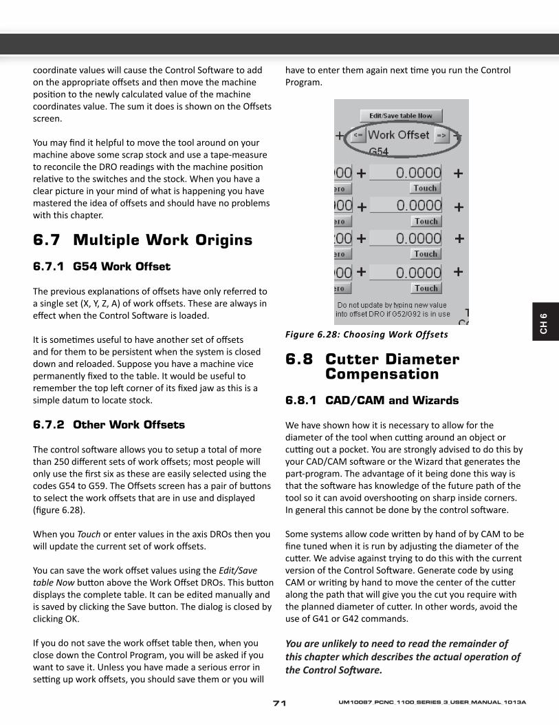
CH
6
coordinate values will cause the Control Software to add on the appropriate offsets and then move the machine position to the newly calculated value of the machine coordinates value. The sum it does is shown on the Offsets screen.
You may find it helpful to move the tool around on your machine above some scrap stock and use a tape-measure to reconcile the DRO readings with the machine position relative to the switches and the stock. When you have a clear picture in your mind of what is happening you have mastered the idea of offsets and should have no problems with this chapter.
6.7 Multiple Work Origins
6.7.1 G54 Work Offset
The previous explanations of offsets have only referred to a single set (X, Y, Z, A) of work offsets. These are always in effect when the Control Software is loaded.
It is sometimes useful to have another set of offsets and for them to be persistent when the system is closed down and reloaded. Suppose you have a machine vice permanently fixed to the table. It would be useful to remember the top left corner of its fixed jaw as this is a simple datum to locate stock.
6.7.2 Other Work Offsets
The control software allows you to setup a total of more than 250 different sets of work offsets; most people will only use the first six as these are easily selected using the codes G54 to G59. The Offsets screen has a pair of buttons to select the work offsets that are in use and displayed (figure 6.28).
When you Touch or enter values in the axis DROs then you will update the current set of work offsets.
You can save the work offset values using the Edit/Save table Now button above the Work Offset DROs. This button displays the complete table. It can be edited manually and is saved by clicking the Save button. The dialog is closed by clicking OK.
If you do not save the work offset table then, when you close down the Control Program, you will be asked if you want to save it. Unless you have made a serious error in setting up work offsets, you should save them or you will
have to enter them again next time you run the Control Program.
Figure 6.28: Choosing Work Offsets
6.8 Cutter Diameter Compensation
6.8.1 CAD/CAM and Wizards
We have shown how it is necessary to allow for the diameter of the tool when cutting around an object or cutting out a pocket. You are strongly advised to do this by your CAD/CAM software or the Wizard that generates the part-program. The advantage of it being done this way is that the software has knowledge of the future path of the tool so it can avoid overshooting on sharp inside corners. In general this cannot be done by the control software.
Some systems allow code written by hand of by CAM to be fine tuned when it is run by adjusting the diameter of the cutter. We advise against trying to do this with the current version of the Control Software. Generate code by using CAM or writing by hand to move the center of the cutter along the path that will give you the cut you require with the planned diameter of cutter. In other words, avoid the use of G41 or G42 commands.
You are unlikely to need to read the remainder of this chapter which describes the actual operation of the Control Software.
71 UM10087_PCNC_1100_SERIES_3_USER_MANUAL_1013A

6.8.2 Concepts for Cutter Diameter/Radius Compensation
The standard mode is for cutter compensation to be off (G40). Without cutter compensation the machine will follow a tool path that is defined by the G-code program. With cutter compensation turned on (G41, G42) the actual path the machine follows will be offset, left or right of the stated path, by an amount specified in the tool offset table. There are two ways to use cutter radius compensation. The most obvious way is to have the offset stated in the tool table to be the diameter of the tool. In theory this would allow the G-code program to simply define the geometry of the actual part to be machined with the machine controller left to calculate the tool paths necessary to compensate for cutter diameter. In practice the problem is far more complex and can lead to a great deal of trouble in debugging the G-code program.
Another way to use cutter compensation is as a small correction factor, where the tool path planning is done outside of the machine and the offset is used to only to make minor adjustments. This approach can be used to make fine adjustments for tool wear, part tolerance, or final finish cuts for rough cutting to finish cutting.
6.8.3 Caveats in the Use of Cutter Compensation
While the concept has useful applications, there are many pitfalls in actual practice. This is not a programming technique for beginners. A few of the issues are listed below:
1. Proper application is complex and involves a large number of coding specific rules. The most complete reference we know of is A Comprehensive Guide to Practical CNC Programming2 in which the author describes how to apply radius offsets in 24 pages of the book.
2. Path planning is highly sensitive to lead in and lead out planning. The machine controller cannot compensate under all conditions.
3. There is no truly standard implementation of cutter compensation. If you have experience in using cutter compensation with Fanuc, Siemens, GSK, Haas, Centroid, or other control systems, do not expect the Mach3 implementation to react in the same manner.
4. Utility and application may be limited by the look-ahead limit. Cutter compensation in Mach3 cannot prevent clipping corners when going into internal cavities. See the example in section 6.6.4.
5. Mach3 has limitations in scope of application of cutter radius compensation. We advise against using cutter compensation in combination with subroutine programming, canned cycles, macro programming,
(end at X1.25, Y-1.5)
(begin at X1.50, Y-1.25)
Actual Tool Path withCutter Compensation
(end at X1, Y-1.5)(begin at X1.50, Y-1.25)
G Code Path
Figure 6.29: Toolpath in Example 1
2 A Comprehensive Guide to Practical CNC Programming (ISBN 978-0-8311-3347-4) by Peter Smid is one of several advanced machining and programming books available from the Tormach web site (www.tormach.com).
72UM10087_PCNC_1100_SERIES_3_USER_MANUAL_1013A

CH
6
polar mode, with run from here function, and with multiple work offsets.
The complexity of application for cutter compensation can lead to hours of programming debugging. Given the nature of the problem, Tormach cannot provide program debugging support nor resolve application specific questions regarding the use of cutter compensation.
Wear Compensation Example
Suppose a shop prefers to resharpen cutting tools, not disposing of a tool until it is more than 0.005” reduced in diameter. In this situation a programmer could do his CAM work and create a G & M code with a tool path that assumes a 0.495” diameter for a 1/2” diameter tool. When the tool is new and has a true 0.500” diameter, the operator will put 0.005” in the offset table for the tool (0.495 + 0.005 = 0.500). As the tool is sharpened and becomes smaller, the offset is appropriately reduced. When the offset needed is zero, the tool is replaced. Using this approach the operator can us both new and resharpened tools with the same G&M code program.
6.8.4 Examples of Operation
The program below plans cutting a rectangle which is 2” x 2”. The graphic below shows two paths. On the left, in a solid line, we see the path described by the G code
program. On the right, in the dashed line, we see the actual path that is followed by the Mach3 controller when tool #1 is programmed with a 0.5” diameter. Example 1:
G17 G20 G40 G49 G50 G64 G90 G94M6 T1 G43 H1 (SELECT TOOL 1 AND OFFSET 1)G0 Z1 M3 S1000 (START SPINDLE)X1.5 Y-1.25 (MOVE TO LEAD IN POSITION)G1 Z-.5 F50 (Z DOWN TO CUTTING LEVEL)G41 (TURN ON CUTTER COMPENSATION)G1 X1 Y-1 (CUT AROUND BLOCK WHICH IS 2X2 IN DIMENSION)X-1 Y-1X-1 Y1X1 Y1X1 Y-1.5G40G0 X 1.5 Y-1.5 Z1 M5(Z UP, SPINDLE OFF)
The result of the offset is that the planned 2”x 2” block is cut out. A composite drawing, figure 6.30, shows this along with the tool diameter.
Now let’s look at a slightly different example to see what can go wrong. The example below is nearly identical, but a
(end at X1.25, Y-1.50)
(begin at X1.50, Y-1.50)(begin at X1.50, Y-1.50)
G Code Path
Actual Tool Path withCutter Compensation
Figure 6.31: Toolpath in Example 2
73 UM10087_PCNC_1100_SERIES_3_USER_MANUAL_1013A

slightly different starting point is used which is 0.25” lower in Y. At first glance it seems fine.
(end at X1.25, Y-1.50)
(begin at X1.50, Y-1.25)
Figure 6.30: Example 1 Overlaid
Example 2:
G17 G20 G40 G49 G50 G64 G90 G94M6 T1 G43 H1 (SELECT TOOL1)G0 Z1 M3 S1000 (START SPINDLE)X1.5 Y-1.5 (POSITION ABOVE LEAD IN POINT)G1 Z-.5 F50 (Z DOWN TO CUTTING LEVEL)G41 (TURN ON CUTTER COMPENSATION)G1 X1 Y-1X-1 Y-1X-1 Y1X1 Y1X1 Y-1.5
G40G0 X 1.5 Y-1.5 Z1 M5M30The coded path and resulting compensated tool look similar, but the lead in here is coming in at a 45 degree angle.
Looking at the combined result (figure 6.32) we what might seem correct.
(end at X1.25, Y-1.50)
(begin at X1.50, Y-1.50)
Figure 6.32 Example 2 Overlaid
But when we take a closer look at the first corner we can see that the lead in came a bit short, leading to a burr on the corner. An adjustment of the initial lead in position is necessary to fix this. Detailed issues like this are difficult to find in advance, which is one of the reasons that use of cutter compensation can be time consuming to debug. Programming of entry moves is critical when using cutter
Figure 6.34: General Entry Move Solution
74UM10087_PCNC_1100_SERIES_3_USER_MANUAL_1013A

CH
6
compensation and some debugging of a program is frequently necessary.
Figure 6.33: Detail of Example 2
Programming Entry Considerations
In general, an alignment move and two entry moves are best to begin compensation correctly. However, where the G41/G42 compensation is only going to be used as a small correction factor, it’s usually possible to incorporate only one entry move (plus, possibly, a pre-entry move) is needed. The general method, which will work in most situations, is described first. We assume here that the programmer knows what the contour is already and has the job of adding entry moves.
General Method
The general method includes programming an alignment move and two entry moves. The entry moves given above will be used as an example. Here is the relevant code:
G1 X1 Y4.5 (MAKE ALIGNMENT MOVE TO POINT C)
G41 G1 Y3.5 (TURN COMPENSATION ON AND MAKE FIRST ENTRY MOVE TO POINT B)
G3 X2 Y2.5 I1 (MAKE SECOND ENTRY MOVE TO POINT A)
Figure 6.34 shows the two entry moves but not the alignment move. First, pick a point A on the contour where it is convenient to attach an entry arc. Specify an arc outside the contour which begins at a point B and ends at A tangent to the contour (and going in the same direction as it is planned to go around the contour). The radius of the arc should be larger than half the diameter given in the
tool table. Then extend a line tangent to the arc from B to some point C, located so that the line BC is more than one radius long. After the construction is finished, the code is written in the reverse order from the construction. Cutter radius compensation is turned on after the alignment move and before the first entry move. In the code above, line N0010 is the alignment move, line N0020 turns compensation on and makes the first entry move and line N0030 makes the second entry move.
In this example, the arc AB and the line BC are fairly large, but they need not be. For a toolpath contour, the radius of arc AB need only be slightly larger than the maximum possible deviation of the radius of the tool from the exact size. Also for a toolpath contour, the side chosen for compensation should be the one to use if the tool is oversized. As mentioned earlier, if the tool is undersized, the interpreter will switch sides.
6.8.5 Look Ahead Issues
There can be problems with cutter compensation related to the lack of foresight on the part of the controller. The program below plans cutting an edge using cutter compensation shown in the graphic as CDEFGHIJ. he segments AB and BC are entry segments as described above.
G17 G20 G40 G49 G50 G64 G90 G94M6 T1 G43 H1G0 X-1 Y2 Z1 M3 S1000 (POSITION ABOVE STARTING POINT)G1 Z-0.5 F50 (Z DOWN TO CUTTING HEIGHT)G41 X-1 Y1 (MAKING THE FIRST ENTRY MOVE TO POINT B)G3 X0 Y0 R1 (DOING THE ENTRY ARC TO POINT C)G1 X1 (CUTTING TO POINT D)Y-1.5 (CUTTING TO POINT E)X2 (CUTTING TO POINT F)Y-0.5 X1.5Y0X3.5G40G0 Z1 M5M30
In figure 6.35 we can see how a 1/4” tool will cut this. The process is successful, but only because of the small diameter of the cutter.
75 UM10087_PCNC_1100_SERIES_3_USER_MANUAL_1013A

A
B
C D
E F
GHI J
Figure 6.35: Compensating a Small Tool
If we change to a 0.787” cutter (common 20 mm end mill) we see the results in figure 6.36.
A
B
C D
E F
GHI J
Figure 6.36: Compensation Fails with Large Tool
What has happened here is that the cutter is too big for the channel in the pocket. As it is cutting path DE, it’s removing the sidewall of IH. Likewise on the way out, it will destroy a segment of wall DE while it climbs out along path IH. We would prefer that the controller would either, 1) stop and generate an error message, or 2) cut a path from D to I, avoiding the cavity created by EFGH. That’s not what happens. This type of error is less common when doing cutter offsets and exact path planning in your CAM software as opposed to using the controller to calculate offsets.
Other Restrictions
• All moves should be longer than the amount to be offset. This restriction makes it clear the increased limitations of using cutter compensation to offset for the full tool radius instead of using it to only compensate for wear, tolerance, or final finish depth of cut.
• Lead in moves should be longer than the amount you want to offset.
• The radius of an inside arc should be greater than that of the cutting tool.
• The Mach3 tool table includes both Diameter and Diameter Wear columns. Always use the Diameter column, even when only using G41/G42 for wear compensation. The Diameter Wear data column in the Mach3 tool table is for future development and does not function as of this writing.
• There must not be more than 50 consecutive lines of code without a movement command, e.g. XY positions only.
• Cutter compensation must not be applied or canceled on a G02 or G03 command. A legal line would be:
G01 G42 P2.5 X20 (LEGAL)
G02 G42 P2.5 X20 Y0 R10 (ILLEGAL)
Perspective on Cutter Compensation
In the past, effective and affordable CAM software was simply not available and, despite all the pitfalls and complications, application of G41/G42 cutter compensation in a CNC machine tool was more common. There was simply no other solution. Now that high quality CAM software is widely available most people do tool offsets in CAM and don’t bother with using G41/G42 for offsets in the machine controller.
Nevertheless, there remain instances where controller based offsets are useful. If you decide to use the G41/G42 codes, be prepared for considerable debugging. Some apparent roadblocks may be avoided through experimentation and minor modifications to your G-code program. Others may be inherent to Mach3 or the desired geometry you are trying to achieve.
As a matter of practical experience, we recommend path planning in CAM and avoiding the use of G41/G42 where possible. When it becomes necessary to us the G41/G42 functions we suggest you apply the codes to
76UM10087_PCNC_1100_SERIES_3_USER_MANUAL_1013A

CH
6
simple geometry parts, applying small compensations (i.e. wear compensation, not cutter radius compensation), using 2 segment lead in, and be prepared for some experimentation/debugging.
Resources for Debugging Cutter Compensation
As noted earlier, Tormach cannot provide program debugging support nor resolve application specific questions regarding the use of cutter compensation. Basic solutions for debugging code files can usually be resolved through a systematic approach of “divide and conquer”, where you section codes and single step through a code, sometimes in combination with M1 optional stop statements. Additional guidance can be had from:
Programming of CNC Machines, by Ken Evans. Refer to section 4 pages 250 to 261
CNC Programming Techniques, by Peter Smid. Refer to chapter 4, pages 46 to 66
Both of these reference books are available through the Tormach web site (www.tormach.com)
Final Note: We should re-iterate that it is much better for a CAM program to generate the path of the tool allowing for its diameter because it can “see” the implications of cutting complex corners in a way which the control software cannot.
77 UM10087_PCNC_1100_SERIES_3_USER_MANUAL_1013A

This section defines the language (G-codes, etc.) that are understood and interpreted by the Control Software.
This chapter is intended for reference purposes. Sample programs using these commands are included in the folder C:/PCNC3/GCODE.
If you want to learn about the principles of the control language so you can write programs by hand from first principles then you should consult an introductory textbook on G-code programming.
7.1 Definitions
7.1.1 Control Software
This is the term used for the program running under Microsoft Windows in the PC connected to your PCNC.
7.1.2 Linear Axes
The X-, Y- and Z-axes form a standard right-handed coordinate system of orthogonal linear axes. Positions of the three linear motion mechanisms are expressed using coordinates on these axes.
7.1.3 Rotational Axes
The rotational axes are measured in degrees as wrapped linear axes in which the direction of positive rotation is counterclockwise when viewed from the positive end of the corresponding X-, Y- or Z-axis. By “wrapped linear axis,” we mean one on which the angular position increases without limit (goes towards plus infinity) as the axis turns counterclockwise and decreases without limit (goes towards minus infinity) as the axis turns clockwise. Wrapped linear axes are used regardless of whether or not there is a mechanical limit on rotation.
Clockwise or counterclockwise is from the point of view of the workpiece. If the workpiece is fastened to a turntable which turns on a rotational axis, a counterclockwise turn from the point of view of the workpiece is accomplished by turning the turntable in a direction that (for most common machine configurations) looks clockwise from the point of view of someone standing next to the machine.
7.1.4 Scaling Input
It is possible to set-up scaling factors for each axis. These will be applied to the values of X, Y, Z, A, I, J and R words
whenever these are entered. This allows the size of features machined to be altered and mirror images to be created – by use of negative scale factors.
The scaling is the first thing done with the values and things like feed rate are always based on the scaled values.
The offsets stored in tool and fixture tables are not scaled before use. Scaling may, of course, have been applied at the time the values were entered (say using G10).
7.1.5 Controlled Point
The controlled point is the point whose position and rate of motion are controlled. When the tool length offset is zero (the default value), this is a point on the spindle axis (often called the gauge point) that is some fixed distance beyond the end of the spindle, usually near the end of a tool holder that fits into the spindle. The location of the controlled point can be moved out along the spindle axis by specifying some positive amount for the tool length offset. This amount is normally the length of the cutting tool in use, so that the controlled point is at the end of the cutting tool.
7.1.6 Coordinated Linear Motion
To drive a tool along a specified path, a machining system must often coordinate the motion of several axes. We use the term “coordinated linear motion” to describe the situation in which, nominally, each axis moves at constant speed and all axes move from their starting positions to their end positions at the same time. If only the X-, Y- and Z-axes (or any one or two of them) move, this produces motion in a straight line, hence the word “linear” in the term. In actual motions, it is often not possible to maintain constant speed because acceleration or deceleration is required at the beginning and/or end of the motion. It is feasible, however, to control the axes so that, at all times, each axis has completed the same fraction of its required motion as the other axes. This moves the tool along the same path and we also call this kind of motion coordinated linear motion.
Coordinated linear motion can be performed either at the prevailing feed rate or at rapid traverse rate. If physical limits on axis speed make the desired rate unobtainable, all axes are slowed to maintain the desired path.
7. PART-PROGRAMMING LANGUAGE REFERENCE
78UM10087_PCNC_1100_SERIES_3_USER_MANUAL_1013A

CH
7
7.1.7 Feed Rate
The rate at which the controlled point or the axes move is nominally a steady rate which may be set by the user. In the Interpreter, the interpretation of the feed rate is as follows unless inverse time feed rate (G93) mode is being used:• For motion involving one or more of the linear axes
(X, Y, Z and optionally A, B, C), without simultaneous rotational axis motion, the feed rate means length units per minute along the programmed linear XYZ(ABC) path.
• For motion involving one or more of the linear axes (X, Y, Z and optionally A, B, C), with simultaneous rotational axis motion, the feed rate means length units per minute along the programmed linear XYZ(ABC) path combined with the angular velocity of the rotary axes multiplied by the appropriate axis Correction Diameter multiplied by pi , where ∏=3.14152 (i.e., the declared “circumference” of the part).
• For motion of one rotational axis with X-, Y- and Z-axes not moving, the feed rate means degrees per minute rotation of the rotational axis.
• For motion of two or three rotational axes with X-, Y- and Z-axes not moving, the rate is applied as follows: Let dA, dB and dC be the angles in degrees through which the A-, B- and C-axes, respectively, must move. Let D = sqrt (dA2 + dB2 + dC2). Conceptually, D is a measure of total angular motion, using the usual Euclidean metric. Let T be the amount of time required to move through D degrees at the current feed rate in degrees per minute. The rotational axes should be moved in coordinated linear motion so that the elapsed time from the start to the end of the motion is T plus any time required for acceleration or deceleration.
7.1.8 Arc Motion
Any pair of the linear axes (XY, YZ and XZ) can be controlled to move in a circular arc in the plane of that pair of axes. While this is occurring, the third linear axis and the rotational axes can be controlled to move simultaneously at effectively a constant rate. As in coordinated linear motion, the motions can be coordinated so that acceleration and deceleration do not affect the path.
If the rotational axes do not move, but the third linear axis does move, the trajectory of the controlled point is a helix.
The feed rate during arc motion is as described in Feed
Rate above. In the case of helical motion, the rate is applied along the helix. Beware as other interpretations are used on other systems.
7.1.9 Coolant
Flood coolant and mist coolant may each be turned on independently. They are turned off together.
Note: PCNC milling machines only have one output for coolant. Turning on either mist or flood coolant will control only the one output.
7.1.10 Dwell
A machining system may be commanded to dwell (i.e., keep all axes unmoving) for a specific amount of time. The most common use of dwell is to break and clear chips or for a spindle to get up to speed. The units in which you specify Dwell are either seconds or Milliseconds depending on the setting on Configure>Logic.
7.1.11 Units
Units used for distances along the X-, Y- and Z-axes may be measured in millimeters or inches. Units for all other quantities involved in machine control cannot be changed. Different quantities use different specific units. Spindle speed is measured in revolutions per minute. The positions of rotational axes are measured in degrees. Feed rates are expressed in current length units per minute, or in degrees per minute, as described above.
WARNING: WE ADVISE YOU TO CHECK VERY CAREFULLY THE SYSTEM’S RESPONSE TO CHANGING UNITS WHILE TOOL AND FIXTURE OFFSETS ARE
LOADED INTO THE TABLES, WHILE THESE OFFSETS ARE ACTIVE AND/OR WHILE A PART-PROGRAM IS EXECUTING.
7.1.12 Current Position
The controlled point is always at some location called the “current position” and the Control Software always knows where that is. The numbers representing the current position are adjusted in the absence of any axis motion if any of several events take place:
7. PART-PROGRAMMING LANGUAGE REFERENCE
79 UM10087_PCNC_1100_SERIES_3_USER_MANUAL_1013A

• Length units are changed (see Warning above); • Tool length offset is changed;• Coordinate system offsets are changed.
7.1.13 Selected Plane
There is always a “selected plane,” which must be the XY-plane, the YZ-plane or the XZ-plane of the machining system. The Z-axis is, of course, perpendicular to the XY-plane, the X-axis to the YZ-plane and the Y-axis to the XZ-plane.
7.1.14 Tool Table
Zero or one tool is assigned to each slot in the tool table.
7.1.15 Path Control Modes
The machining system may be put into any one of two path control modes: (1) exact stop mode, (2) constant velocity mode. In exact stop mode, the machine stops briefly at the end of each programmed move. In constant velocity mode, sharp corners of the path may be rounded slightly so that the feed rate may be kept up. These modes are to allow the user to control the compromise involved in turning corners because a real machine has a finite acceleration due to the inertia of its mechanism.
Exact stop does what it says. The machine will come to rest at each change of direction and the tool will therefore precisely follow the commanded path.
Constant velocity will overlap acceleration in the new direction with deceleration in the current one in order to keep the commanded feed rate. This implies a rounding of any corner but faster and smoother cutting. This is particularly important in routing and plasma cutting. The lower the acceleration of the machine axes, the greater will be the radius of the rounded corner.
In Plasma mode (set on Configure Logic dialog) the system attempts to optimize corner motion for plasma cutting by a proprietary algorithm.
It is also possible to define a limiting angle so that changes in direction of more than this angle will always be treated as Exact Stop even though Constant Velocity is selected. This allows gentle corners to be smoother but avoids excessive rounding of sharp corners even on machines with low acceleration on one or more axes. This feature
is enabled in the Configure Logic dialog and the limiting angle is set by a DRO. This setting will probably need to be chosen experimentally depending on the characteristics of the machine tool and, perhaps, the toolpath of an individual job.
7.2 Interpreter Interaction with Controls
7.2.1 Feed and Speed Override Controls
The Control Software has commands which enable (M48) or disable (M49) the feed and speed override switches. It is useful to be able to override these switches for some machining operations. The idea is that optimal settings have been included in the program and the operator should not change them.
7.2.2 Block Delete Control
If the block delete control is ON, lines of code which start with a slash (the block delete character) are not executed. If the switch is off, such lines are executed. 7.2.3 Optional Program Stop Control
The optional program stop control works as follows. If this control is ON and an input line contains an M01-code, program execution is stopped at the end on the commands on that line until the CyCle Start button is pushed.
7.3 Tool File
The Control Software maintains a tool file for each of the 256 tools which can be used.
Each data line of the file contains the data for one tool. This allows the definition of the tool length (Z-axis), tool diameter (for milling) and tool tip radius (for turning).
7.4 Part-Programs Language
7.4.1 Overview
The language is based on lines of code or “text.” Each line (also called a “block”) may include commands to the machining system to do several different things. Lines of code may be collected in a file to make a program.
80UM10087_PCNC_1100_SERIES_3_USER_MANUAL_1013A

CH
7
A typical line of code consists of an optional line number at the beginning followed by one or more “words.” A word consists of a letter followed by a number (or something that evaluates to a number). A word may either give a command or provide an argument to a command. For example, G1 X3 is a valid line of code with two words. “G1” is a command meaning “move in a straight line at the programmed feed rate,” and “X3” provides an argument value (the value of X should be 3 at the end of the move). Most commands start with either G (General) or M (Miscellaneous). The words for these commands are called “G-codes” and “M-codes.”
The language has two commands, M2 and M30, either of which ends a program. A program may end before the end of a file. Lines of a file that occur after the end of a program are not to be executed in the normal flow so will generally be parts of subroutines.
7.4.2 Parameters
Note: There are significant differences between controls in the way parameters work. Do not assume that code from another control will work in the same way with Mach 3. Tormach advises that you avoid writing parametric G-code as this is difficult to debug and very difficult for another operator to understand. Modern CAM virtually eliminates the need for it.
7.4.3 Coordinate Systems
The machining system has an absolute coordinate system and 254 work offset (fixture) systems.
You can set the offsets of tools by G10 L1 P~ X~ Z~. The “P word” defines the tool number to be set.
You can set the offsets of the fixture systems using G10 L2 P~ X~ Y~ Z~ A~ B~ C~. The P word defines the fixture to be set. The X, Y, Z, etc. words are the coordinates for the origin of the axes in terms of the absolute coordinate system.
You can select one of the first seven work offsets by using G54, G55, G56, G57, G58 or G59. Any of the 254 work offsets can be selected by G59 P~ (e.g., G59 P23 would select fixture 23). The absolute coordinate system can be selected by G59 P0.
You can offset the current coordinate system using G92 or G92.3. This offset will then be applied on top of work offset coordinate systems. This offset may be cancelled with G92.1 or G92.2.
You can make straight moves in the absolute machine coordinate system by using G53 with either G0 or G1.
7.5 Formatting Code Lines (Block)
A permissible line of input code consists of the following, in order, with the restriction that there is a maximum (currently 256) to the number of characters allowed on a line.
• Optional block delete character, which is a slash “/” • Optional line number • Any number of words, parameter settings and
comments • End of line marker (carriage return or line feed or both)
Any input not explicitly allowed is illegal and will cause the Interpreter to signal an error or to ignore the line.
Currently programs are limited to 999,999 lines of code.
Spaces and tabs are allowed anywhere on a line of code and do not change the meaning of the line, except inside comments. This makes some strange-looking input legal. For example, the line G0X +0. 12 34Y 7 is equivalent to G0 X+0.1234 Y7
Blank lines are allowed in the input. They will be ignored. Input is case insensitive, except in comments; thus, any letter outside a comment may be in upper or lower case without changing the meaning of a line.
7.5.1 Line Number
A line number is the letter N followed by an integer (with no sign) between 0 and 99,999,999 written without commas. Line numbers may be repeated or used out of order, although normal practice is to avoid such usage. A line number is not required to be used (and this omission is common) but it must be in the proper place if it is used.
7.5.2 Subroutine Labels
A subroutine label is the letter O followed by an integer (with no sign) between 0 and 99999 written with no more
81 UM10087_PCNC_1100_SERIES_3_USER_MANUAL_1013A

Figure 7.1: Word Initial Letters
than five digits (000009 is not permitted, for example). Subroutine labels may be used in any order but must be unique in a program. Nothing else except a comment should appear on the same line as a subroutine label. Note that line numbers are not permitted with an O word in the current release of the software.
WARNING: THE MACH 3 CONTROL SOFTWARE HAS KNOWN ISSUES WITH SUBROUTINES, INCLUDING BUT NOT LIMITED TO:
• CUTTER RADIUS COMPENSATION IS UNRELIABLE IN SUBROUNTINES
• THE “RUN FROM HERE” FEATURE IS UNRELIABLE IN SUBROUTINES
• PROGRAMS THAT MAKE USE OF LARGE NUMBERS OF SUBROUTINE CALLS MAY HAVE ISSUES WITH TOOL PATH DISPLAY AND MAY, IN EXTREME CASES, RESULT IN POSITION LOSS
7.5.3 Word
A word is a letter other than N or O followed by a real value.
Words may begin with any of the letters (figure 7.1). The table includes N and O for completeness, even though, as defined above, line numbers are not words. Several letters (I, J, K, L, P and R) may have different meanings in different contexts.
A real value is some collection of characters that can be processed to come up with a number. A real value may be an explicit number (such as 341 or -0.8807), a parameter value, an expression or a unary operation value. Definitions of these follow immediately. Processing characters to come up with a number is called “evaluating.” An explicit number evaluates to itself.
See warning above on risks of using parameters.
7.5.3.1 Number
The following rules are used for (explicit) numbers. In these rules a digit is a single character between 0 and 9.
• A number consists of (1) an optional plus or minus sign, followed by (2) zero to many digits, followed, possibly, by (3) one decimal point, followed by (4) zero to many digits – provided that there is at least one
Letter Meaning
A A-axis of machine B B-axis of machine C C-axis of machine D tool radius compensation number F feed rate G general function (see Table 5) H tool length offset index I X-axis offset for arcs
X offset in G87 canned cycleJ Y-axis offset for arcs
Y offset in G87 canned cycleK Z-axis offset for arcs
Z offset in G87 canned cycleL number of repetitions in canned
cycles/subroutines key used with G10
M miscellaneous function (see Table 7)N line numberO Subroutine label numberP dwell time in canned cycles
dwell time with G4 key used with G10 tapping depth in M871 – M874
Q feed increment in G83 canned cycle repetitions of subroutine call
R arc radius canned cycle retract level
S spindle speedT tool selectionU Synonymous with AV Synonymous with BW Synonymous with CX X-axis of machineY Y-axis of machineZ Z-axis of machine
82UM10087_PCNC_1100_SERIES_3_USER_MANUAL_1013A

CH
7
digit somewhere in the number. • There are two kinds of numbers: integers and
decimals. An integer does not have a decimal point in it; a decimal does.
• Numbers may have any number of digits, subject to the limitation on line length. Only about seventeen significant figures will be retained, however (enough for all known applications).
• A non-zero number with no sign as the first character is assumed to be positive.
Notice that initial (before the decimal point and the first non-zero digit) and trailing (after the decimal point and the last non-zero digit) zeros are allowed but not required. A number written with initial or trailing zeros will have the same value when it is read as if the extra zeros were not there.
Numbers used for specific purposes by the Control Software are often restricted to some finite set of values or some to some range of values. In many uses, decimal numbers must be close to integers; this includes the values of indexes (for parameters and carousel slot numbers, for example), M-codes and G-codes multiplied by ten. A decimal number which is supposed to be close to an integer is considered close enough if it is within 0.0001 of an integer.
7.5.3.2 Parameter Value
A parameter value is the hash character # followed by a real value. The real value must evaluate to an integer between 1 and 10320. The integer is the parameter identification number. Think of it as the number of a pigeon-hole and distinguish this from its real value which is whatever number is stored in it.
The # character takes precedence over other operations, so that, for example, #1+2 means the number found by adding 2 to the value of parameter 1, not the value found in parameter 3. Of course, #[1+2] does mean the value found in parameter 3. The # character may be repeated; for example ##2 means the value of the parameter whose index is the (integer) value of parameter 2.
7.5.3.3 Expressions and Binary Operations
An expression is a set of characters starting with a left bracket ([) and ending with a balancing right bracket (]). In between the brackets are numbers, parameter values, mathematical operations and other expressions. An
expression may be evaluated to produce a number. The expressions on a line are evaluated when the line is read, before anything on the line is executed. An example of an expression is:
[1+ACOS[0]-[#3**[4.0/2]]]
Binary operations appear only inside expressions. Nine binary operations are defined. There are four basic mathematical operations: addition (+), subtraction (-), multiplication (*) and division (/). There are three logical operations: non-exclusive or (OR), exclusive or (XOR) and logical and (AND). The eighth operation is the modulus operation (MOD). The ninth operation is the “power” operation (**) of raising the number on the left of the operation to the power on the right.
The binary operations are divided into three groups. The first group is: power. The second group is: multiplication, division and modulus. The third group is: addition, subtraction, logical non-exclusive or, logical exclusive or and logical. If operations are strung together (for example in the expression [2.0/3*1.5-5.5/11.0]), operations in the first group are to be performed before operations in the second group and operations in the second group before operations in the third group. If an expression contains more than one operation from the same group (such as the first / and * in the example), the operation on the left is performed first. Thus, the example is equivalent to: [((2.0/3)*1.5)-(5.5/11.0)] which simplifies to [1.0-0.5] which is 0.5.
The logical operations and modulus are to be performed on any real numbers, not just on integers. The number zero is equivalent to logical false and any non-zero number is equivalent to logical true.
7.5.3.4 Unary Operation Value
A unary operation value is either “ATAN” followed by one expression divided by another expression (for example ATAN[2]/[1+3]) or any other unary operation name followed by an expression (for example SIN[90]). The unary operations are: ABS (absolute value), ACOS (arc cosine), ASIN (arc sine), ATAN (arc tangent), COS (cosine), EXP (e raised to the given power), FIX (round down), FUP (round up), LN (natural logarithm), ROUND (round to the nearest whole number), SIN (sine), SQRT (square root) and TAN (tangent). Arguments to unary operations which take angle measures (COS, SIN and TAN) are in degrees. Values returned by unary operations which return angle measures
83 UM10087_PCNC_1100_SERIES_3_USER_MANUAL_1013A

(ACOS, ASIN and ATAN) are also in degrees.
The FIX operation rounds towards the left (less positive or more negative) on a number line, so that FIX[2.8]=2 and FIX[-2.8]=-3, for example. The FUP operation rounds towards the right (more positive or less negative) on a number line; FUP[2.8]=3 and FUP[-2.8]=-2, for example.
7.5.4 Parameter Setting
See warning above on risks of using parameters.A parameter setting is the following four items one after the other:
• a pound character # ;• a real value which evaluates to an integer between 1
and 10320;• an equal sign = ; • a real value. • For example “#3 = 15” is a parameter setting meaning
“set parameter 3 to 15.”
A parameter setting does not take effect until after all parameter values on the same line have been found. For example, if parameter 3 has been previously set to 15 and the line #3=6 G1 x#3 is interpreted, a straight move to a point where x equals 15 will occur and the value of parameter 3 will be 6.
CAUTION: DUE TO THE COMPLEXITY OF PARAMETERIZED PROGRAMMING, TORMACH TECHNICAL SUPPORT IS UNABLE TO DEBUG THIS CODE. SEE SECTIONS 7.5.3.2 - 7.5.3.4 FOR RULES CONCERNING PARAMETER ASSIGNMENT.
7.5.5 Comments and Messages
Printable characters and white space inside parentheses are considered a “comment.” A left parenthesis always starts a comment. The comment ends at the first right parenthesis found thereafter. Once a left parenthesis is placed on a line, a matching right parenthesis must appear before the end of the line. Comments may not be nested; it is an error if a left parenthesis is found after the start of a comment and before the end of the comment. Here is an example of a line containing a comment: G80 M5 (STOP MOTION)
Comments do not cause the machining system to do anything. Messages are displayed on screen in the “Error” message line.
7.5.6 Item Repeats
A line may have any number of G words, but two G words from the same modal group may not appear on the same line.
A line may have zero to four M words. Two M words from the same modal group may not appear on the same line. For all other legal letters, a line may have only one word beginning with that letter.
If a parameter setting of the same parameter is repeated on a line, #3=15 #3=6, for example, only the last setting will take effect. It is silly, but not illegal, to set the same parameter twice on the same line.
If more than one comment appears on a line, only the last one will be used; each of the other comments will be read and its format will be checked, but it will be ignored thereafter. It is expected that putting more than one comment on a line will be very rare.
7.5.7 Item Order
The three types of item whose order may vary on a line (as given at the beginning of this section) are word, parameter setting and comment. Imagine that these three types of item are divided into three groups by type.
The first group (the words) may be reordered in any way without changing the meaning of the line.
If the second group (the parameter settings) is reordered, there will be no change in the meaning of the line unless the same parameter is set more than once. In this case, only the last setting of the parameter will take effect. For example, after the line #3=15 #3=6 has been interpreted, the value of parameter 3 will be 6. If the order is reversed to #3=6 #3=15 and the line is interpreted, the value of parameter 3 will be 15.
If the third group (the comments) contains more than one comment and is reordered, only the last comment will be used.
If each group is kept in order or reordered without changing the meaning of the line, then the three groups may be interleaved in any way without changing the meaning of the line. For example, the line G40 G01 #3=15 (COMMENT) #4=-7.0 has five items and means exactly the same thing in any of the 120 possible orders – such as #4=-7.0 G01 #3=15 G40 (COMMENT) – for the five items.
84UM10087_PCNC_1100_SERIES_3_USER_MANUAL_1013A
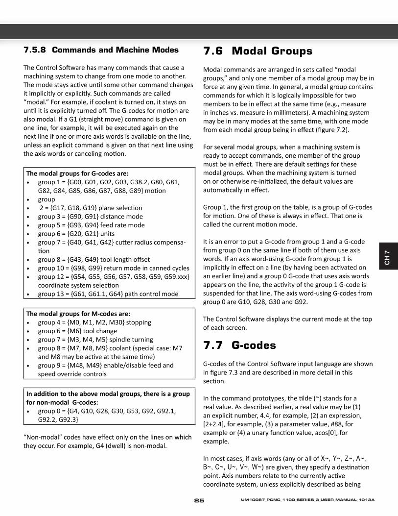
CH
7
7.5.8 Commands and Machine Modes
The Control Software has many commands that cause a machining system to change from one mode to another. The mode stays active until some other command changes it implicitly or explicitly. Such commands are called “modal.” For example, if coolant is turned on, it stays on until it is explicitly turned off. The G-codes for motion are also modal. If a G1 (straight move) command is given on one line, for example, it will be executed again on the next line if one or more axis words is available on the line, unless an explicit command is given on that next line using the axis words or canceling motion.
The modal groups for G-codes are:• group 1 = {G00, G01, G02, G03, G38.2, G80, G81,
G82, G84, G85, G86, G87, G88, G89} motion• group• 2 = {G17, G18, G19} plane selection• group 3 = {G90, G91} distance mode• group 5 = {G93, G94} feed rate mode• group 6 = {G20, G21} units• group 7 = {G40, G41, G42} cutter radius compensa-
tion• group 8 = {G43, G49} tool length offset• group 10 = {G98, G99} return mode in canned cycles• group 12 = {G54, G55, G56, G57, G58, G59, G59.xxx}
coordinate system selection• group 13 = {G61, G61.1, G64} path control mode
The modal groups for M-codes are: • group 4 = {M0, M1, M2, M30} stopping • group 6 = {M6} tool change • group 7 = {M3, M4, M5} spindle turning • group 8 = {M7, M8, M9} coolant (special case: M7
and M8 may be active at the same time) • group 9 = {M48, M49} enable/disable feed and
speed override controls
In addition to the above modal groups, there is a group for non-modal G-codes: • group 0 = {G4, G10, G28, G30, G53, G92, G92.1,
G92.2, G92.3}
“Non-modal” codes have effect only on the lines on which they occur. For example, G4 (dwell) is non-modal.
7.6 Modal Groups
Modal commands are arranged in sets called “modal groups,” and only one member of a modal group may be in force at any given time. In general, a modal group contains commands for which it is logically impossible for two members to be in effect at the same time (e.g., measure in inches vs. measure in millimeters). A machining system may be in many modes at the same time, with one mode from each modal group being in effect (figure 7.2).
For several modal groups, when a machining system is ready to accept commands, one member of the group must be in effect. There are default settings for these modal groups. When the machining system is turned on or otherwise re-initialized, the default values are automatically in effect.
Group 1, the first group on the table, is a group of G-codes for motion. One of these is always in effect. That one is called the current motion mode.
It is an error to put a G-code from group 1 and a G-code from group 0 on the same line if both of them use axis words. If an axis word-using G-code from group 1 is implicitly in effect on a line (by having been activated on an earlier line) and a group 0 G-code that uses axis words appears on the line, the activity of the group 1 G-code is suspended for that line. The axis word-using G-codes from group 0 are G10, G28, G30 and G92.
The Control Software displays the current mode at the top of each screen.
7.7 G-codes
G-codes of the Control Software input language are shown in figure 7.3 and are described in more detail in this section.
In the command prototypes, the tilde (~) stands for a real value. As described earlier, a real value may be (1) an explicit number, 4.4, for example, (2) an expression, [2+2.4], for example, (3) a parameter value, #88, for example or (4) a unary function value, acos[0], for example.
In most cases, if axis words (any or all of X~, Y~, Z~, A~, B~, C~, U~, V~, W~) are given, they specify a destination point. Axis numbers relate to the currently active coordinate system, unless explicitly described as being
85 UM10087_PCNC_1100_SERIES_3_USER_MANUAL_1013A

Summary of G-codes
G00 Rapid positioningG01 Linear interpolationG02 Clockwise circular/helical interpolationG03 Counterclockwise circular/helical interpolationG04 DwellG10 Coordinate system origin settingG12 Clockwise circular pocketG13 Counterclockwise circular pocketG15/G16 Polar Coordinate moves in G00 and G01G17 XY Plane selectG18 XZ plane selectG19 YZ plane selectG20/G21 Inch/millimeter unitG28 Return homeG28.1 Reference axesG30 Return homeG31 Straight probeG40 Cancel cutter radius compensationG41/G42 Start cutter radius compensation left/rightG43 Apply tool length offset (plus)G49 Cancel tool length offsetG50 Reset all scale factors to 1.0G51 Set axis data input scale factorsG52 Temporary coordinate system offsetsG53 Move in absolute machine coordinate systemG54 Use fixture offset 1G55 Use fixture offset 2G56-58 Use fixture offset 3, 4, 5G59 Use fixture offset 6 / use general fixture numberG61/G64 Exact stop/Constant Velocity modeG68/G69 Coordinate system rotationG73 Canned cycle - peck drillingG80 Cancel motion mode (including canned cycles)G81 Canned cycle – drillingG82 Canned cycle – drilling with dwellG83 Canned cycle – peck drillingG85 Canned cycle – boring, no dwell, feed outG86 Canned cycle – boring, spindle stop, rapid outG88 Canned cycle – boring, spindle stop, manual outG89 Canned cycle – boring, dwell, feed outG90 Absolute distance modeG90.1 Absolute IJK
86UM10087_PCNC_1100_SERIES_3_USER_MANUAL_1013A

CH
7
in the absolute coordinate system. Where axis words are optional, any omitted axes will have their current value. Any items in the command prototypes not explicitly described as optional are required. It is an error if a required item is omitted.
U, V and W are synonyms for A, B and C. Use of A with U, B with V, etc. is erroneous (like using A twice on a line). In the detailed descriptions of codes U, V and W are not explicitly mentioned each time but are implied by A, B or C.
In the prototypes, the values following letters are often given as explicit numbers. Unless stated otherwise, the explicit numbers can be real values. For example, G10 L2 could equally well be written G[2*5] L[1+1]. If the value of parameter 100 were 2, G10 L#100 would also mean the same. Using real values which are not explicit numbers as just shown in the examples is rarely useful.
If L~ is written in a prototype the “~” will often be referred to as the “L number.” Similarly the “~” in H~ may be called the “H number,” and so on for any other letter.
If a scale factor is applied to any axis then it will be applied to the value of the corresponding X, Y, Z, A/U, B/V, C/W word and to the relevant I, J, K or R words when they are used.
7.7.1 Rapid Linear Motion – G00
(a) For rapid linear motion, program: G0 X~ Y~ Z~ A~ where all the axis words are optional, except that at least one must be used. The G00 is optional if the current motion mode is G0. This will produce coordinated linear motion to the destination point at the current traverse rate (or slower if the machine will not go that fast). It
is expected that cutting will not take place when a G00 command is executing.
(b) If G16 has been executed to set a Polar Origin then for rapid linear motion to a point described by a radius and angle G0 X~ Y~ can be used. X~ is the radius of the line from the
G16 polar origin and Y~ is the angle in degrees measured with increasing values counterclockwise from the 3 o’clock direction (i.e., the conventional four quadrant conventions).
Coordinates of the current point at the time of executing the G16 are the polar origin.
It is an error if all axis words are omitted.
If cutter radius compensation is active, the motion will differ from the above; see Cutter Compensation. If G53 is programmed on the same line, the motion will also differ; see Absolute Coordinates.
The G00 command is used to move the tool quickly from one point to another without cutting, thus allowing for quick tool positioning.
Summary of G-codes
G91 Incremental distance modeG91.1 Incremental IJKG92 Offset coordinates and set parametersG92.x Cancel G92 etc.G93 Inverse time feed modeG94 Feed per minute modeG95 Feed per rev modeG98 Initial level return after canned cyclesG99 R-point level return after canned cycles
Figure 7.3: Table of G-codes
87 UM10087_PCNC_1100_SERIES_3_USER_MANUAL_1013A

Note that the G00 rapid move should have two distinct movements to ensure that vertical moves are always separate from horizontal moves. In a typical rapid move toward the part, the tool first rapids in the flat, horizontal XY plane. Then, it feeds down in the Z axis. When rapiding out of a part, the G00 command always goes up in the Z axis first, then laterally in the XY plane.
Depending on where the tool is located, there are two basic rules to follow for safety’s sake:
If the Z value represents a cutting move in the negative direction, the X and Y axes should be executed first.
If the Z value represents a move in the positive direction, the X and Y axes should be executed last.
Example: N25 G00 X2.5 Y4.75 (RAPID TO X2.5,Y4.75)N30 Z0.1 (RAPID DOWN TO Z0.1)
As this diagram shows, if the basic rules are not followed, an accident can result. Improper use of G00 often occurs because clamps are not taken into consideration. Following the basic rules will reduce any chance of error.
7.7.2 Linear Motion at Feed Rate – G01
(a) For linear motion at feed rate (for cutting or not), program: G01 X~ Y~ Z~ A~, where all the axis words are optional, except that at least one must be used. The G01 is optional if the current motion mode is G01. This will produce coordinated linear motion to the destination point at the current feed rate (or slower if the machine will not go that fast). (b) If G16 has been executed to set a polar origin then linear motion at feed rate to a point described by a radius and angle G00 X~ Y~ can be used. X~ is the radius of the line from the G16 polar origin and Y~ is the angle in degrees measured with increasing values counterclockwise from the 3 o’clock direction (i.e., the conventional four quadrant conventions).
Coordinates of the current point at the time of executing the G16 are the polar origin.
It is an error if all axis words are omitted.
If cutter radius compensation is active, the motion will differ from the above; see Cutter Compensation. If G53 is programmed on the same line, the motion will also differ; see Absolute Coordinates.
Linear Interpolation, or straightline feed moves, on the flat XY plane (no Z values are specified).
G01 command, using multi-axis feed moves. All diagonal feed moves are a result of a G01 command, where two or more axes are used at once.
88UM10087_PCNC_1100_SERIES_3_USER_MANUAL_1013A

CH
7
(Sample Program G01EX2:)(Workpiece Size: X4, Y3, Z1)(Tool: Tool #3, 3/8” Slot Drill)(Tool Start Position: X0, Y0, Z1)
N2 G90 G80 G40 G54 G20 G17 G50 G94 G64 (SAFETY BLOCK)N5 G90 G20 (BLOCK #5, ABSOLUTE IN INCHES)N10 M06 T3 G43 H3 (TOOL CHANGE TO TOOL #3)N15 M03 S1250 (SPINDLE ON CW AT 1250 RPM)N20 G00 X1.0 Y1.0 (RAPID OVER TO X1,Y1)N25 Z0.1 (RAPID DOWN TO Z0.1)N30 G01 Z-0.125 F5 (FEED DOWN TO Z–0.125 AT 5 IPM)N35 X3 Y2 F10 (FEED DIAGONALLY TO X3,Y2 AT 10 IPM)N40 G00 Z1.0 (RAPID UP TO Z1)N45 X0.0 Y0.0 (RAPID OVER TO X0,Y0)N50 M05 (SPINDLE OFF)N55 M30 (PROGRAM END)
In the sample program, several different examples of the G01 command are shown:
1. The first G01 command (in N30) instructs the machine to plunge feed the tool below the surface of the part by 0.125 in. at a feedrate of 5 in./min.
2. N35 is a two-axis (X and Y) diagonal feed move, and the linear feedrate is increased to 10 ipm.
Note: Because there is contact between the cutting tool and the workpiece, it is imperative that the proper spindle speeds and feedrates be used. It is the programmer’s responsibility to ensure acceptable cutter speeds and feeds.
7.7.3 Arc at Feed Rate – G02 and G03
A circular or helical arc is specified using either G02 (clockwise arc) or G03 (counterclockwise arc). The axis of the circle or helix must be parallel to the X-, Y- or Z-axis of the machine coordinate system. The axis (or, equivalently, the plane perpendicular to the axis) is selected with G17 (Z-axis, XY-plane), G18 (Y-axis, XZ-plane) or G19 (X-axis, YZ-plane). If the arc is circular, it lies in a plane parallel to the selected plane.
If a line of code makes an arc and includes rotational axis motion, the rotational axes turn at a constant rate so that the rotational motion starts and finishes when the XYZ motion starts and finishes. Lines of this sort are hardly ever programmed.
If cutter radius compensation is active, the motion will differ from the above; see Cutter Compensation.
Two formats are allowed for specifying an arc. We will call these the center format and the radius format. In both formats the G02 or G03 is optional if it is the current motion mode.
Y
Center
3
2
1
1 2 3X
Shows G02 arc start point, endpoint, and center point.
Y
Center
3
2
1
1 2 3X
Shows G03 arc start point, endpoint, and center point.
7.7.3.1 Radius Format Arc
In the radius format, the coordinates of the end point of the arc in the selected plane are specified along with the radius of the arc. Program: G02 X~ Y~ Z~ A~ R~ (or use G03 instead of G02). R is the radius. The axis words are all optional except that at least one of the two words for the axes in the selected plane must be used. The R
89 UM10087_PCNC_1100_SERIES_3_USER_MANUAL_1013A

number is the radius. A positive radius indicates that the arc turns through 180 degrees or less, while a negative radius indicates a turn of 180 degrees to 359.999 degrees. If the arc is helical, the value of the end point of the arc on the coordinate axis parallel to the axis of the helix is also specified.
It is an error if:
• Both of the axis words for the axes of the selected plane are omitted;
• No R word is given; • The end point of the arc is the same as the current
point.
It is not good practice to program radius format arcs that are nearly full circles or are semicircles (or nearly semicircles) because a small change in the location of the end point will produce a much larger change in the location of the center of the circle (and, hence, the middle of the arc). The magnification effect is large enough that rounding error in a number can produce out-of-tolerance cuts. Nearly full circles are outrageously bad, semicircles (and nearly so) are only very bad. Other size arcs (in the range tiny to 165 degrees or 195 to 345 degrees) are OK.
Here is an example of a radius format command to mill an arc:
G17 G02 X 1.0 Y 1.5 R 2.0 Z 0.5
That means to make a clockwise (as viewed from the positive Z-axis) circular or helical arc whose axis is parallel to the Z-axis, ending where X=1.0, Y=1.5 and Z=0.5, with a radius of 2.0. If the starting value of Z is 0.5, this is an arc of a circle parallel to the XY-plane; otherwise it is a helical arc.
7.7.3.2 Center Format Arc
In the center format, the coordinates of the end point of the arc in the selected plane are specified along with the offsets of the center of the arc from the current location. In this format, it is OK if the end point of the arc is the same as the current point.
It is an error if when the arc is projected on the selected plane, the distance from the current point to the center differs from the distance from the end point to the center by more than 0.0002 inch (if inches are being used) or 0.002 millimeter (if millimeters are being used).
The center is specified using the I and J words. There are two ways of interpreting them. The usual way is that I and J are the center relative to the current point at the start of the arc. This is sometimes called Incremental IJ mode. The second way is that I and J specify the center as actual coordinates in the current system. This is rather misleadingly called Absolute IJ mode. The IJ mode is set using the button and LED on the Settings screen. The choice of modes is to provide compatibility with commercial controllers. You will probably find Incremental to be best. In Absolute it will, of course usually be necessary to use both I and J words unless by chance the arc’s center is at the origin.
When the XY-plane is selected, program: G2 X~ Y~ Z~ A~ I~ J~ (or use G3 instead of G2). The axis words are all optional except that at least one of X and Y must be used. I and J are the offsets from the current location or coordinates – depending on IJ mode (X and Y directions, respectively) of the center of the circle. I and J are optional except that at least one of the two must be used. It is an error if:
• X and Y are both omitted; • I and J are both omitted.
When the XZ-plane is selected, program: G02 X~ Y~ Z~ A~ I~ K~ (or use G03 instead of G02). The axis words are all optional except that at least one of X and Z must be used. I and K are the offsets from the current location or coordinates – depending on IJ mode (X and Z directions, respectively) of the center of the circle. I and K are optional except that at least one of the two must be used.
It is an error if:
• X and Z are both omitted; • I and K are both omitted.
When the YZ-plane is selected, program: G02 X~ Y~ Z~ A~ J~ K~ (or use G03 instead of G02). The axis words are all optional except that at least one of Y and Z must be used. J and K are the offsets from the current location or coordinates – depending on IJ mode (Y and Z directions, respectively) of the center of the circle. J and K are optional except that at least one of the two must be used.
It is an error if:
• Y and Z are both omitted; • J and K are both omitted.
90UM10087_PCNC_1100_SERIES_3_USER_MANUAL_1013A

CH
7
Here is an example of a center format command to mill an arc in Incremental IJ mode:
G17 G02 X1.0 Y1.6 I0.3 J0.4 Z0.9
That means to make a clockwise (as viewed from the positive Z-axis) circular or helical arc whose axis is parallel to the Z-axis, ending where X=1.0, Y=1.6 and Z=0.9, with its center offset in the X direction by 0.3 units from the current X location and offset in the Y direction by 0.4 units from the current Y location. If the current location has X=0.7, Y=0.7 at the outset, the center will be at X=1.0, Y=1.1. If the starting value of Z is 0.9, this is a circular arc; otherwise it is a helical arc. The radius of this arc would be 0.5.
The above arc in Absolute IJ mode would be:
G17 G02 X1.0 Y1.6 I1.0 J1.1 Z0.9
In the center format, the radius of the arc is not specified, but it may be found easily as the distance from the center of the circle to either the current point or the end point of the arc.
(Sample Program G02EX3:)(Workpiece Size: X4, Y3, Z1)(Tool: Tool #2, 1/4” Slot Drill)(Tool Start Position: X0, Y0, Z1)
N2 G90 G80 G40 G54 G20 G17 G50 G94 G64 (SAFETY BLOCK)N5 G90 G20N10 M06 T2 G43 H2N15 M03 S1200N20 G00 X1 Y1N25 Z0.1N30 G01 Z-0.1 F5N35 G02 X2 Y2 I1 J0 F20 (ARC FEED CW, RADIUS I1,J0 AT 20 IPM)N40 G01 X3.5N45 G02 X3 Y0.5 R2 (ARC FEED CW, RADIUS 2)N50 X1 Y1 R2 (ARC FEED CW, RADIUS 2)N55 G00 Z0.1N60 X2 Y1.5N65 G01 Z-0.25N70 G02 X2 Y1.5 I0.25 J-0.25 (FULL CIRCLE ARC FEED MOVE CW)N75 G00 Z1N80 X0 Y0N85 M05N90 M30
7.7.4 Dwell – G04
For a dwell, program: G04 P~. This will keep the axes unmoving for the period of time in seconds specified by the P number.
It is an error if the P number is negative.
(Sample Program G04EX5:)(Workpiece Size: X3.5, Y2, Z0.5)(Tool: Tool #1, 1/8” Slot Mill)(Tool Start Position: X0, Y0, Z1)
The tool will pause for a short time only, rarely more than several seconds. For a definite program pause, refer to the M00 and M01 commands. Being nonmodal, the G04 must be reentered each time Dwell is to be executed.
N2 G90 G80 G40 G54 G20 G17 G50 G94 G64 (SAFETY BLOCK)N5 G90 G20 (ABSOLUTE PROGRAMMING IN INCH MODE)N10 M06 T1 G43 H1 (TOOL CHANGE TO TOOL #1)N15 M03 S1300 (SPINDLE ON CW AT 1300 RPM)N20 G00 X3 Y1 Z0.1 (RAPID TO X3,Y1,Z0.1)N25 G01 Z-0.125 F5.0 (FEED DOWN TO Z–0.125 AT 5 IPM)N30 G04 P2 (DWELL FOR 2 SECONDS)N35 G00 X2 Z0.1 (RAPID UP TO 0.1 AND OVER TO X2)N40 X2 (RAPID OVER TO X2)N45 G01 Z-0.125 F5.0 (FEED DOWN TO Z–0.125)N50 G04 P1 (DWELL FOR 1 SECOND)N55 G00 Z1.0 (RAPID OUT TO Z1)N60 X0. Y0. (RAPID TO X0, Y0)N65 M05 (SPINDLE OFF )N70 M30 (PROGRAM END)
91 UM10087_PCNC_1100_SERIES_3_USER_MANUAL_1013A

7.7.5 Coordinate System Data Tool and Work Offset Tables – G10
See details of tool and work offsets for further information on coordinate systems.
To set the offset values of a tool, program:
G10 L1 P~ X~ Z~ A~, where the P number must evaluate to an integer in the range 0 to 255 – the tool number – and offsets of the tool specified by the P number are reset to the given. The A number will reset the tool tip radius. Only those values for which an axis word is included on the line will be reset. The Tool diameter cannot be set in this way.
To set the coordinate values for the origin of a fixture coordinate system, program:
G10 L2 P~ X~ Y~ Z~ A~, where the P number must evaluate to an integer in the range 1 to 255 – the fixture number (Values 1 to 6 corresponding to G54 to G59) – and all axis words are optional. The coordinates of the origin of the coordinate system specified by the P number are reset to the coordinate values given (in terms of the absolute coordinate system). Only those coordinates for which an axis word is included on the line will be reset.
It is an error if:
• The P number does not evaluate to an integer in the range 0 to 255.
If origin offsets (made by G92 or G92.3) were in effect before G10 is used, they will continue to be in effect afterwards.
The coordinate system whose origin is set by a G10 command may be active or inactive at the time the G10 is executed.
The values set will not be persistent unless the tool or fixture tables are saved using the buttons on Tables screen.
Example: G10 L2 P1 X3.5 Y17.2 sets the origin of the first coordinate system (the one selected by G54) to a point where X is 3.5 and Y is 17.2 (in absolute coordinates). The Z coordinate of the origin (and the coordinates for any rotational axes) are whatever those coordinates of the origin were before the line was executed.
7.7.6 Clockwise/Counterclockwise Circular Pocket – G12 and G13
These circular pocket commands are a sort of canned cycle which can be used to produce a circular hole larger than the tool in use or with a suitable tool (like a woodruff key cutter) to cut internal grooves for “O” rings etc.
Program: G12 I~ for a clockwise move and G13 I~ for a counterclockwise move.
The tool is moved in the X direction by the value of the I word and a circle cut in the direction specified with the original X and Y coordinates as the center. The tool is returned to the center.
• Its effect is undefined if the current plane is not XY
7.7.7 Exit and Enter Polar Mode – G15 and G16
It is possible for G0 and G1 moves in the X/Y plane only to specify coordinates as a radius and angle relative to a temporary center point; program G16 to enter this mode. The current coordinates of the controlled point are the temporary center.
PROGRAM: G15 TO REVERT TO NORMAL CARTESIAN COORDINATES.G0 X2.0 Y2.0 // NORMAL G0 MOVE TO 2.0,2.0G16 //START OF POLAR MODE.G10 X1.0 Y45
(this will move to X = 2.7071, Y = 2.7071 which is a spot on a circle) (of radius 1.0 at 45 degrees from the initial coordinates of 2.0,2.0.)
This can be very useful, for example, for drilling a circle of holes. The code below moves to a circle of holes every 90 degrees on a circle of radius 2.5”, center X = 0.5, Y = 0.6 and high- speed peck drills to Z = -0.6
G0 Z0.0X0.5 Y0.6 (goto the center point)G16 (enable Polar coordinates)G81 X2.5 Y0.0 R0.0 Z-.6 F3(in G16 mode the X becomes the offset from center and the Y becomes the degrees of rotation from the center)X2.5 Y90X2.5 Y180X2.6 Y270
92UM10087_PCNC_1100_SERIES_3_USER_MANUAL_1013A

CH
7
G15 (cancels the g16)G80 (cancels the canned cycle)G0 Z0.0X0.0 Y0.0M30
Note:(1) You MUST NOT make X or Y moves other than by using G0 or G1 when G16 is active;(2) This G16 is different to a Fanuc implementation in that it uses the current point as the polar center. The Fanuc version requires a lot of origin shifting to get the desired result for any circle not centered on 0, 0.
7.7.8 Plane Selection – G17, G18 and G19
Program G17 to select the XY-plane, G18 to select the XZ-plane or G19 to select the YZ-plane.
The effects of having a plane selected are discussed in under G2/3 and Canned cycles.
A circular tool move in the G17 plane.
Example of an arc cut in the G18 XZ plane. Keep in mind that, because the primary and secondary axes are reversed, this arc is actually a G03 command
Tool cutting an arc in the YZ plane – G19.
7.7.9 Length Units – G20 and G21
Program G20 to use inches for length units and program G21 to use millimeters.
It is usually a good idea to program either G20 or G21 near the beginning of a program before any motion occurs and not to use either one anywhere else in the program. It is the responsibility of the user to be sure all numbers are appropriate for use with the current length units.
7.7.10 Return to Home – G28 and G30
A home position is defined.
To return to home position by way of the programmed position, program:
G28 X~ Y~ Z~ A~ (or use G30). All axis words are optional. The path is made by a traverse move from the current position to the programmed position, followed by a traverse move to the home position. If no axis words are programmed, the intermediate point is the current point, only one move is made.
(Sample Program G28EX111:)(Workpiece Size: X4, Y4, Z1)(Tools: Tool #7, 1” Slot Drill)(Tool #10, 1/2” HSS Drill)(Tool Start Position: X0, Y0, Z1)(Reference Point: X0, Y0, Z5 )
93 UM10087_PCNC_1100_SERIES_3_USER_MANUAL_1013A
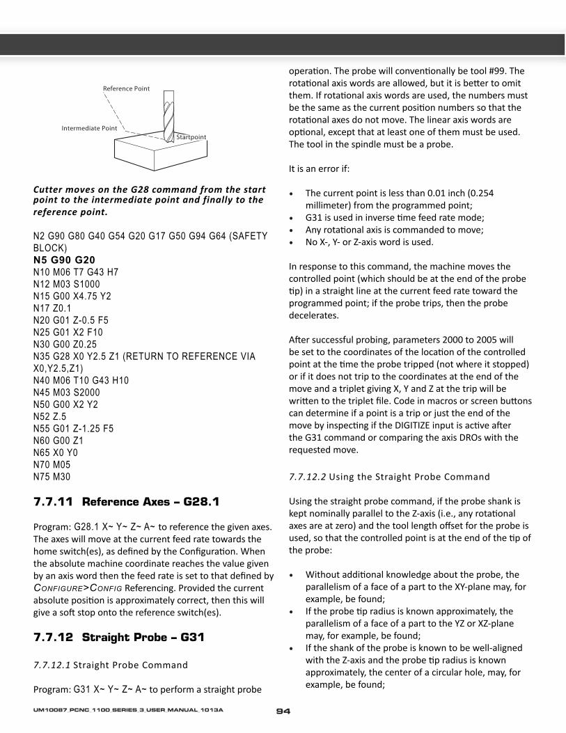
Reference Point
Intermediate PointStartpoint
Cutter moves on the G28 command from the start point to the intermediate point and finally to the reference point.
N2 G90 G80 G40 G54 G20 G17 G50 G94 G64 (SAFETY BLOCK)N5 G90 G20N10 M06 T7 G43 H7N12 M03 S1000N15 G00 X4.75 Y2N17 Z0.1N20 G01 Z-0.5 F5N25 G01 X2 F10N30 G00 Z0.25N35 G28 X0 Y2.5 Z1 (RETURN TO REFERENCE VIA X0,Y2.5,Z1)N40 M06 T10 G43 H10N45 M03 S2000N50 G00 X2 Y2N52 Z.5N55 G01 Z-1.25 F5N60 G00 Z1N65 X0 Y0N70 M05N75 M30
7.7.11 Reference Axes – G28.1
Program: G28.1 X~ Y~ Z~ A~ to reference the given axes. The axes will move at the current feed rate towards the home switch(es), as defined by the Configuration. When the absolute machine coordinate reaches the value given by an axis word then the feed rate is set to that defined by Configure>Config Referencing. Provided the current absolute position is approximately correct, then this will give a soft stop onto the reference switch(es).
7.7.12 Straight Probe – G31
7.7.12.1 Straight Probe Command
Program: G31 X~ Y~ Z~ A~ to perform a straight probe
operation. The probe will conventionally be tool #99. The rotational axis words are allowed, but it is better to omit them. If rotational axis words are used, the numbers must be the same as the current position numbers so that the rotational axes do not move. The linear axis words are optional, except that at least one of them must be used. The tool in the spindle must be a probe.
It is an error if:
• The current point is less than 0.01 inch (0.254 millimeter) from the programmed point;
• G31 is used in inverse time feed rate mode;• Any rotational axis is commanded to move; • No X-, Y- or Z-axis word is used.
In response to this command, the machine moves the controlled point (which should be at the end of the probe tip) in a straight line at the current feed rate toward the programmed point; if the probe trips, then the probe decelerates.
After successful probing, parameters 2000 to 2005 will be set to the coordinates of the location of the controlled point at the time the probe tripped (not where it stopped) or if it does not trip to the coordinates at the end of the move and a triplet giving X, Y and Z at the trip will be written to the triplet file. Code in macros or screen buttons can determine if a point is a trip or just the end of the move by inspecting if the DIGITIZE input is active after the G31 command or comparing the axis DROs with the requested move.
7.7.12.2 Using the Straight Probe Command
Using the straight probe command, if the probe shank is kept nominally parallel to the Z-axis (i.e., any rotational axes are at zero) and the tool length offset for the probe is used, so that the controlled point is at the end of the tip of the probe:
• Without additional knowledge about the probe, the parallelism of a face of a part to the XY-plane may, for example, be found;
• If the probe tip radius is known approximately, the parallelism of a face of a part to the YZ or XZ-plane may, for example, be found;
• If the shank of the probe is known to be well-aligned with the Z-axis and the probe tip radius is known approximately, the center of a circular hole, may, for example, be found;
94UM10087_PCNC_1100_SERIES_3_USER_MANUAL_1013A

CH
7
• If the shank of the probe is known to be well-aligned with the Z-axis and the probe tip radius is known precisely, more uses may be made of the straight probe command, such as finding the diameter of a circular hole.
If the straightness of the probe shank cannot be adjusted to high accuracy, it is desirable to know the effective radii of the probe tip in at least the +X, -X, +Y and -Y directions. These quantities can be stored in parameters either by being included in the parameter file or by being set in a part-program.
Using the probe with rotational axes not set to zero is also feasible. Doing so is more complex than when rotational axes are at zero and we do not deal with it here.
7.7.12.3 Example Code
As a usable example, see the code for finding the center and diameter of a circular hole. For this code to yield accurate results, the probe shank must be well-aligned with the Z-axis, the cross section of the probe tip at its widest point must be very circular and the probe tip radius (i.e., the radius of the circular cross section) must be known precisely. If the probe tip radius is known only approximately (but the other conditions hold), the location of the hole center will still be accurate, but the hole diameter will not.
N010 (PROBE TO FIND CENTER AND DIAMETER OF CIRCULAR HOLE) N020 (THIS PROGRAM WILL NOT RUN AS GIVEN HERE. YOU HAVE TO) N030 (INSERT NUMBERS IN PLACE OF <DESCRIPTION OF NUMBER>.) N040 (DELETE LINES N020, N030 AND N040 WHEN YOU DO THAT.) N050 G0 Z <Z-VALUE OF RETRACTED POSITION> F <FEED RATE> N060 #1001=<NOMINAL X-VALUE OF HOLE CENTER> N070 #1002=<NOMINAL Y-VALUE OF HOLE CENTER> N080 #1003=<SOME Z-VALUE INSIDE THE HOLE> N090 #1004=<PROBE TIP RADIUS> N100 #1005=[<NOMINAL HOLE DIAMETER>/2.0 - #1004] N110 G0 X#1001 Y#1002 (MOVE ABOVE NOMINAL HOLE CE NTER) N120 G0 Z#1003 (MOVE INTO HOLE - TO BE CAUTIOUS, SUBSTITUTE G1 FOR G0 HERE) N130 G31 X[#1001 + #1005] (PROBE +X SIDE OF HOLE) N140 #1011=#2000 (SAVE RESULTS) N150 G0 X#1001 Y#1002 (BACK TO CENTER OF HOLE)
N160 G31 X[#1001 - #1005] (PROBE -X SIDE OF HOLE) N170 #1021=[[#1011 + #2000] / 2.0] (FIND PRETTY GOOD X-VALUE OF HOLE CENTER) N180 G0 X#1021 Y#1002 (BACK TO CENTER OF HOLE) N190 G31 Y[#1002 + #1005] (PROBE +Y SIDE OF HOLE) N200 #1012=#2001 (SAVE RESULTS) N210 G0 X#1021 Y#1002 (BACK TO CENTER OF HOLE) N220 G31 Y[#1002 - #1005] (PROBE -Y SIDE OF HOLE) N230 #1022=[[#1012 + #2001] / 2.0] (FIND VERY GOOD Y-VALUE OF HOLE CENTER) N240 #1014=[#1012 - #2001 + [2 * #1004]] (FIND HOLE DIAMETER IN Y-DIRECTION) N250 G0 X#1021 Y#1022 (BACK TO CENTER OF HOLE) N260 G31 X[#1021 + #1005] (PROBE +X SIDE OF HOLE) N270 #1031=#2000 (SAVE RESULTS) N280 G0 X#1021 Y#1022 (BACK TO CENTER OF HOLE) N290 G31 X[#1021 - #1005] (PROBE -X SIDE OF HOLE) N300 #1041=[[#1031 + #2000] / 2.0] (FIND VERY GOOD X-VALUE OF HOLE CENTER) N310 #1024=[#1031 - #2000 + [2 * #1004]] (FIND HOLE DIAMETER IN X-DIRECTION) N320 #1034=[[#1014 + #1024] / 2.0] (FIND AVERAGE HOLE DIAMETER) N330 #1035=[#1024 - #1014] (FIND DIFFERENCE IN HOLE DIAMETERS) N340 G0 X#1041 Y#1022 (BACK TO CENTER OF HOLE) N350 M2 (THAT’S ALL, FOLKS)
In the above code, an entry of the form <description of a number> is meant to be replaced by an actual number that matches the description of number. After this section of code has executed, the X-value of the center will be in parameter 1041, the Y-value of the center in parameter 1022 and the diameter in parameter 1034. In addition, the diameter parallel to the X-axis will be in parameter 1024, the diameter parallel to the Y-axis in parameter 1014 and the difference (an indicator of circularity) in parameter 1035. The probe tip will be in the hole at the XY center of the hole.
The example does not include a tool change to put a probe in the spindle. Add the tool change code at the beginning, if needed.
7.7.13 Cutter Radius Compensation – G40, G41 and G42
Note: Cutter compensation is an area of active development for the Mach3 control software. The current version of Mach3 implements a primitive version of cutter compensation (G41, G42) which
95 UM10087_PCNC_1100_SERIES_3_USER_MANUAL_1013A

we do not recommend for most applications. The demonstration example in section 6.8 does work and G41, G42 can be used successfully under certain conditions, never the less, there are enough exceptions to make programming with G41, G42 an exercise in frustration. All modern CAM programs support path planning for tool offsets which offer a more practical solution at this time.
To turn cutter radius compensation off, program: G40. It is OK to turn compensation off when it is already off. Cutter radius compensation may be performed only if the XY-plane is active.
To turn cutter radius compensation on left (i.e., the cutter stays to the left of the programmed path when the tool radius is positive), program: G41 D~. To turn cutter radius compensation on right (i.e., the cutter stays to the right of the programmed path when the tool radius is positive), program: G42 D~. The D word is optional; if there is no D word, the radius of the tool currently in the spindle will be used. If used, the D number should normally be the slot number of the tool in the spindle, although this is not required. It is OK for the D number to be zero; a radius value of zero will be used.
G41 and G42 can be qualified by a P-word. This will override the value of the diameter of the tool (if any) given in the current tool table entry.
It is an error if:
• The D number is not an integer, is negative or is larger than the number of carousel slots;
• The XY-plane is not active; • Cutter radius compensation is commanded to turn on
when it is already on.
The behavior of the machining system when cutter radius compensation is ON is described in the chapter on Cutter Compensation. Notice the importance of programming valid entry and exit moves.
Note: The tool offsets must have been applied with a G43 H~ for compensation to work.
7.7.14 Tool Length Offsets – G43, G44 and G49
To use a tool length offset, program: G43 H~, where the H number is the desired index in the tool table. It is expected that all entries in this table will be positive. The H number should be, but does not have to be, the same as the slot number of the tool currently in the spindle. The H
number may be zero; an offset value of zero will be used. Omitting H has the same effect as a zero value.
G44 is provided for compatibility and is used if entries in the table give negative offsets.
It is an error if the H number is not an integer, is negative or is larger than the number of carousel slots.
To use no tool length offset, program: G49.
It is OK to program using the same offset already in use. It is also OK to program using no tool length offset if none is currently being used.
It is strongly advised to put the G43 command on the same line (block) as the T~ and the M06 which actually implements the change. If this is done then the control software anticipates the new offset during the time the operator has control for changing the tool. The operator can change the work Z offset safely if this condition is met.
7.7.15 Scale Factors – G50 and G51
To define a scale factor which will be applied to an X, Y, Z, A, I & J word before it is used program: G51 X~ Y~ Z~ A~ where the X, Y, Z etc. words are the scale factors for the given axes. These values are, of course, never themselves scaled.
It is not permitted to use unequal scale factors to produce elliptical arcs with G2 or G3.
To reset the scale factors of all axes to 1.0 program: G50.
7.7.16 Temporary Coordinate System Offset – G52
To offset the current point by a given positive or negative distance (without motion), program:
96UM10087_PCNC_1100_SERIES_3_USER_MANUAL_1013A

CH
7
G52 X~ Y~ Z~ A~, where the axis words contain the offsets you want to provide. All axis words are optional, except that at least one must be used. If an axis word is not used for a given axis, the coordinate on that axis of the current point is not changed.
It is an error if all axis words are omitted.
G52 and G92 use common internal mechanisms in the Control Software and may not be used together.
When G52 is executed, the origin of the currently active coordinate system moves by the values given.
The effect of G52 is cancelled by programming: G52 X0 Y0 etc.
Here is an example. Suppose the current point is at X=4 in the currently specified coordinate system, then G52 X7 sets the X-axis offset to 7 and so causes the X-coordinate of the current point to be -3.
The axis offsets are always used when motion is specified in absolute distance mode using any of the fixture coordinate systems. Thus all fixture coordinate systems are affected by G52.
7.7.17 Move in Absolute Coordinates – G53
For linear motion to a point expressed in absolute coordinates, program: G1 G53 X~ Y~ Z~ A~ (or similarly with G0 instead of G1), where all the axis words are optional, except that at least one must be used. The G0 or G1 is optional if it is in the current motion mode. G53 is not modal and must be programmed on each line on which it is intended to be active. This will produce coordinated linear motion to the programmed point. If G1 is active, the speed of motion is the current feed rate (or slower if the machine will not go that fast). If G0 is active, the speed of motion is the current traverse rate (or slower if the machine will not go that fast).
It is an error if:
• G53 is used without G0 or G1 being active; • G53 is used while cutter radius compensation is on.
See relevant chapter for an overview of coordinate systems.
7.7.18 Select Work Offset Coordinate System – G54 to G59 & G59 P~
There are 254 work offset coordinate systems available in the control software. The first six work offset coordinate systems are G54, G55, G56, G57, G58, and G59. There are an additional 248 work offsets available through a G59 P~ command where the P word gives the work offset coordinate system number. Thus G59 P3 is identical in effect to G56.
Note that the machine defaults to the G54 work offset coordinate system on start up.
Programming example for accessing the G56 work offset coordinate system: G56
Programming example for accessing work offset coordinate system 7: G59 P7
It is an error if one of these G codes is used while cutter radius compensation is on.
See relevant chapter for an overview of coordinate systems.
(SAMPLE PROGRAM G54EX19:)(WORKPIECE SIZE: X8, Y5, Z2)(TOOL: TOOL #6, 3/4” HSS DRILL)(TOOL START POSITION: X0, Y0, Z1)(WORKPIECE COORDINATE SYSTEM 2: X1, Y1, Z0)(WORKPIECE COORDINATE SYSTEM 3: X5, Y1, Z0)
N2 G90 G80 G40 G54 G20 G17 G50 G94 G64 (SAFETY BLOCK)N5 G90 G80 G20N10 M06 T6 G43 H6N15 M03 S1300N20 G55 G00 X1.0 Y1.0 (RAPID TO X1, Y1 OF WORK COORDINATE SYSTEM 2)N25 Z0.5N30 G82 Z-0.25 R0.125 P1 F5N35 Y2N40 X2N45 Y1N50 X1.5 Y1.5N60 G80 G00 Z1N65 G56 G00 X1.0 Y1.0 (RAPID TO X1, Y1 OF WORK COORDINATE SYSTEM 3)N70 Z0.5N75 G82 Z-0.25 R0.125 P1 F5N80 Y2
97 UM10087_PCNC_1100_SERIES_3_USER_MANUAL_1013A
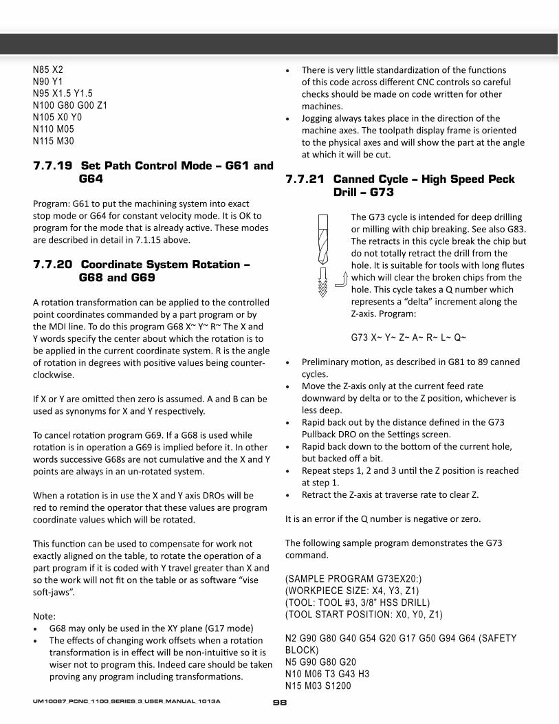
N85 X2N90 Y1N95 X1.5 Y1.5N100 G80 G00 Z1N105 X0 Y0N110 M05N115 M30
7.7.19 Set Path Control Mode – G61 and G64
Program: G61 to put the machining system into exact stop mode or G64 for constant velocity mode. It is OK to program for the mode that is already active. These modes are described in detail in 7.1.15 above.
7.7.20 Coordinate System Rotation – G68 and G69
A rotation transformation can be applied to the controlled point coordinates commanded by a part program or by the MDI line. To do this program G68 X~ Y~ R~ The X and Y words specify the center about which the rotation is to be applied in the current coordinate system. R is the angle of rotation in degrees with positive values being counter-clockwise.
If X or Y are omitted then zero is assumed. A and B can be used as synonyms for X and Y respectively.
To cancel rotation program G69. If a G68 is used while rotation is in operation a G69 is implied before it. In other words successive G68s are not cumulative and the X and Y points are always in an un-rotated system.
When a rotation is in use the X and Y axis DROs will be red to remind the operator that these values are program coordinate values which will be rotated.
This function can be used to compensate for work not exactly aligned on the table, to rotate the operation of a part program if it is coded with Y travel greater than X and so the work will not fit on the table or as software “vise soft-jaws”.
Note:• G68 may only be used in the XY plane (G17 mode)• The effects of changing work offsets when a rotation
transformation is in effect will be non-intuitive so it is wiser not to program this. Indeed care should be taken proving any program including transformations.
• There is very little standardization of the functions of this code across different CNC controls so careful checks should be made on code written for other machines.
• Jogging always takes place in the direction of the machine axes. The toolpath display frame is oriented to the physical axes and will show the part at the angle at which it will be cut.
7.7.21 Canned Cycle – High Speed Peck Drill – G73
The G73 cycle is intended for deep drilling or milling with chip breaking. See also G83. The retracts in this cycle break the chip but do not totally retract the drill from the hole. It is suitable for tools with long flutes which will clear the broken chips from the hole. This cycle takes a Q number which represents a “delta” increment along the Z-axis. Program:
G73 X~ Y~ Z~ A~ R~ L~ Q~ • Preliminary motion, as described in G81 to 89 canned
cycles. • Move the Z-axis only at the current feed rate
downward by delta or to the Z position, whichever is less deep.
• Rapid back out by the distance defined in the G73 Pullback DRO on the Settings screen.
• Rapid back down to the bottom of the current hole, but backed off a bit.
• Repeat steps 1, 2 and 3 until the Z position is reached at step 1.
• Retract the Z-axis at traverse rate to clear Z.
It is an error if the Q number is negative or zero.
The following sample program demonstrates the G73 command.
(SAMPLE PROGRAM G73EX20:)(WORKPIECE SIZE: X4, Y3, Z1)(TOOL: TOOL #3, 3/8” HSS DRILL)(TOOL START POSITION: X0, Y0, Z1)
N2 G90 G80 G40 G54 G20 G17 G50 G94 G64 (SAFETY BLOCK)N5 G90 G80 G20N10 M06 T3 G43 H3N15 M03 S1200
98UM10087_PCNC_1100_SERIES_3_USER_MANUAL_1013A
CH
7
N20 G00 X1 Y1N25 G73 Z-0.75 R0.125 Q0.0625 F5 (INVOKE G73 CYCLE)N30 X2.0N35 X3.0N40 Y2.0N45 X2.0N50 X1.0N55 G80 G00 Z1 (CANNED CYCLE CANCEL)N60 X0 Y0N65 M05N70 M30
7.7.22 Cancel Modal Motion – G80
Program: G80 to ensure no axis motion will occur, to terminate canned cycles etc. Note that it cancels the current G2 or G3 mode so this must be re-established for the next move that is required. This particularly affects people adapting a CAM postprocessors from another machine as this behavior varies between different CNC controls.
It is an error if:
• Axis words are programmed when G80 is active, unless a modal group 0 G-code is programmed which uses axis words.
7.7.23 Canned Cycles – G81 to G89
The canned cycles G81 through G89 have been implemented as described in this section. Two examples are given with the description of G81 below.
All canned cycles are performed with respect to the currently selected plane. Any of the three planes (XY, YZ, and ZX) may be selected. Throughout this section, most of the descriptions assume the XY-plane has been selected. The behavior is always analogous if the YZ or XZ-plane is selected.
Rotational axis words are allowed in canned cycles, but it is better to omit them. If rotational axis words are used, the numbers must be the same as the current position numbers so that the rotational axes do not move.
All canned cycles use X, Y, R and Z numbers in the NC-code. These numbers are used to determine X, Y, R and Z positions. The R (usually meaning retract) position is along the axis perpendicular to the currently selected plane (Z-axis for XY-plane, X-axis for YZ-plane, Y-axis for XZ-plane).
Some canned cycles use additional arguments.
For canned cycles, we will call a number “sticky” if, when the same cycle is used on several lines of code in a row, the number must be used the first time, but is optional on the rest of the lines. Sticky numbers keep their value on the rest of the lines if they are not explicitly programmed to be different. The R number is always sticky.
In incremental distance mode: when the XY-plane is selected, X, Y and R numbers are treated as increments to the current position and Z as an increment from the Z-axis position before the move involving Z takes place; when the YZ or XZ-plane is selected, treatment of the axis words is analogous. In absolute distance mode, the X, Y, R and Z numbers are absolute positions in the current coordinate system.
The L number is optional and represents the number of repeats. L=0 is not allowed. If the repeat feature is used, it is normally used in incremental distance mode, so that the same sequence of motions is repeated in several equally spaced places along a straight line. In absolute distance mode, L > 1 means “do the same cycle in the same place several times,” Omitting the L word is equivalent to specifying L=1. The L number is not sticky.
When L > 1 in incremental mode with the XY-plane selected, the X and Y positions are determined by adding the given X and Y numbers either to the current X and Y positions (on the first go-around) or to the X and Y positions at the end of the previous go-around (on the repetitions). The R and Z positions do not change during the repeats.
The height of the retract move at the end of each repeat (called “clear Z” in the descriptions below) is determined by the setting of the retract mode: either to the original Z position (if that is above the R position and the retract mode is G98) or otherwise to the R position.
It is an error if:
• X, Y and Z words are all missing during a canned cycle; • A P number is required and a negative P number is
used; • An L number is used that does not evaluate to a
positive integer; • Rotational axis motion is used during a canned cycle; • Inverse time feed rate is active during a canned cycle; • Cutter radius compensation is active during a canned
cycle.
99 UM10087_PCNC_1100_SERIES_3_USER_MANUAL_1013A

When the XY plane is active, the Z number is sticky and it is an error if:
• The Z number is missing and the same canned cycle was not already active;
• The R number is less than the Z number.
When the XZ plane is active, the Y number is sticky and it is an error if:
• The Y number is missing and the same canned cycle was not already active;
• The R number is less than the Y number.
When the YZ plane is active, the X number is sticky and it is an error if:
• The X number is missing and the same canned cycle was not already active;
• The R number is less than the X number.
7.7.23.1 Preliminary and In-Between Motion
At the very beginning of the execution of any of the canned cycles, with the XY-plane selected, if the current Z position is below the R position, the Z-axis is traversed to the R position. This happens only once, regardless of the value of L.
In addition, at the beginning of the first cycle and each repeat, the following one or two moves are made:
• A straight traverse parallel to the XY-plane to the given XY-position;
• A straight traverse of the Z-axis only to the R position, if it is not already at the R position.
If the XZ or YZ plane is active, the preliminary and in-between motions are analogous.
7.7.23.2 G81 Cycle
The G81 cycle is intended for drilling. Program: G81 X~ Y~ Z~ A~ R~ L~
• Preliminary motion, as described above. • Move the Z-axis only at the current feed rate to the Z
position. • Retract the Z-axis at traverse rate to clear Z. • Example 1: Suppose the current position is (1, 2, 3) and
the XY-plane has been selected and the following line of NC-code is interpreted.
G90 G81 G98 X4 Y5 Z1.5 R2.8
This calls for absolute distance mode (G90), old “Z” retract mode (G98) and calls for the G81 drilling cycle to be performed once. The X number and X position are 4. The Y number and Y position are 5. The Z number and Z position are 1.5. The R number and clear Z are 2.8. The following moves take place.
• a traverse parallel to the XY-plane to (4,5,3); • a traverse parallel to the Z-axis to (4,5,2.8); • a feed parallel to the Z-axis to (4,5,1.5); • a traverse parallel to the Z-axis to (4,5,3).
Example 2: Suppose the current position is (1, 2, 3) and the XY-plane has been selected and the following line of NC-code is interpreted.
G91 G81 G98 X4 Y5 Z-0.6 R1.8 L3
This calls for incremental distance mode (G91), old “Z” retract mode and calls for the G81 drilling cycle to be repeated three times. The X number is 4, the Y number is 5, the Z number is -0.6 and the R number is 1.8. The initial X position is 5 (=1+4), the initial Y position is 7 (=2+5), the clear Z position is 4.8 (=1.8+3) and the Z position is 4.2 (=4.8-0.6). Old Z is 3.0
The first move is a traverse along the Z-axis to (1,2,4.8), since old Z < clear Z.
The first repeat consists of 3 moves.
• a traverse parallel to the XY-plane to (5,7,4.8); • a feed parallel to the Z-axis to (5,7, 4.2); • a traverse parallel to the Z-axis to (5,7,4.8).
The second repeat consists of 3 moves. The X position is reset to 9 (=5+4) and the Y position to 12 (=7+5).
• a traverse parallel to the XY-plane to (9,12,4.8); • a feed parallel to the Z-axis to (9,12, 4.2); • a traverse parallel to the Z-axis to (9,12,4.8).
100UM10087_PCNC_1100_SERIES_3_USER_MANUAL_1013A

CH
7
The third repeat consists of 3 moves. The X position is reset to 13 (=9+4) and the Y position to 17 (=12+5).
• a traverse parallel to the XY-plane to (13,17,4.8); • a feed parallel to the Z-axis to (13,17, 4.2); • a traverse parallel to the Z-axis to (13,17,4.8).
Execute the following to observe the G81 drill cycle. Remember, the G81 command follows a certain sequence.
(SAMPLE PROGRAM G81EX18:)(WORKPIECE SIZE: X4, Y3, Z1)(TOOL: TOOL #6, 3/4” HSS DRILL)(TOOL START POSITION: X0, Y0, Z1)
N2 G90 G80 G40 G54 G20 G17 G50 G94 G64 (SAFETY BLOCK)N5 G90 G80 G20N10 M06 T6 G43 H6N15 M03 S1300N20 G00 X1 Y1N25 Z0.5N30 G81 Z-0.25 R0.125 F5 (DRILL CYCLE INVOKED)N35 X2N40 X3N45 Y2N50 X2N55 X1N60 G80 G00 Z1 (CANCEL CANNED CYCLES)N65 X0 Y0N70 M05N75 M30
7.7.23.3 G82 Cycle
The G82 cycle is intended for drilling. Program:
G82 X~ Y~ Z~ A~ R~ L~ P~
• Preliminary motion, as described above. • Move the Z-axis only at the current feed rate to the Z
position. • Dwell for the P number of seconds. • Retract the Z-axis at traverse rate to clear Z.
7.7.23.4 G83 Cycle
The G83 cycle (often called peck drilling) is intended for deep drilling or milling with chip breaking. See also G73. The retracts in this cycle clear the hole of chips and cut off any long stringers (which are common when drilling in aluminum). This cycle takes a Q number which represents a “delta” increment along the Z-axis. Program:
G83 X~ Y~ Z~ A~ R~ L~ Q~
• Preliminary motion, as described above. • Move the Z-axis only at the current feed rate
downward by delta or to the Z position, whichever is less deep.
• Rapid back out to the clear Z. • Rapid back down to the current hole bottom, backed
off a bit. • Repeat steps 1, 2 and 3 until the Z position is reached
at step 1. • Retract the Z-axis at traverse rate to clear Z.
It is an error if:
• The Q number is negative or zero.
7.7.23.5 G85 Cycle
The G85 cycle is intended for boring or reaming, but could be used for drilling or milling. Program:
G85 X~ Y~ Z~ A~ R~ L~
• Preliminary motion, as described above. • Move the Z-axis only at the current feed rate to the Z
position. • Retract the Z-axis at the current feed rate to clear Z.
7.7.23.6 G86 Cycle
The G86 cycle is intended for boring. This cycle uses a P number for the number of seconds to dwell.
Program: G86 X~ Y~ Z~ A~ R~ L~ P~
• Preliminary motion, as described above. • Move the Z-axis only at the current feed rate to the Z
position.
101 UM10087_PCNC_1100_SERIES_3_USER_MANUAL_1013A

• Dwell for the P number of seconds. • Stop the spindle turning. • Retract the Z-axis at traverse rate to clear Z. • Restart the spindle in the direction it was going.
The spindle must be turning before this cycle is used. It is an error if:
• The spindle is not turning before this cycle is executed.
7.7.23.7 G88 Cycle
The G88 cycle is intended for boring. This cycle uses a P word, where P specifies the number of seconds to dwell.
Program: G88 X~ Y~ Z~ A~ R~ L~ P~
• Preliminary motion, as described above. • Move the Z-axis only at the current feed rate to the Z
position. • Dwell for the P number of seconds. • Stop the spindle turning. • Stop the program so the operator can retract the
spindle manually. • Restart the spindle in the direction it was going.
7.7.23.8 G89 Cycle
The G89 cycle is intended for boring. This cycle uses a P number, where P specifies the number of seconds to dwell.
Program: G89 X~ Y~ Z~ A~ R~ L~ P~
• Preliminary motion, as described above. • Move the Z-axis only at the current feed rate to the Z
position. • Dwell for the P number of seconds. • Retract the Z-axis at the current feed rate to clear Z.
7.7.24 Distance Mode – G90 and G91
Interpretation of the Control Software code can be in one of two distance modes: absolute or incremental.
To go into absolute distance mode, program: G90. In absolute distance mode, axis numbers (X, Y, Z, A) usually represent positions in terms of the currently active coordinate system. Any exceptions to that rule are described explicitly in this section
describing G-codes.
To go into incremental distance mode, program: G91. In incremental distance mode, axis numbers (X, Y, Z, A) usually represent increments from the current values of the numbers.
I and J numbers always represent increments, regardless of the distance mode setting. K numbers represent increments.
7.7.25 G92 Offsets – G92, G92.1, G92.2 and G92.3
Three feed rate modes are supported:
• G93: Inverse Time Mode• G94: Feed per Minute Mode• G95: Feed per Rev Mode
The most common method for programming a CNC Mill is the G94 mode, which is feed rate per minute. When the controller is set in G94, any multi-axis motion G1 command will be interpreted automatically by the CNC Controller into individual axis feed rates so that the resulting tool path will be the shortest distance. This is suitable for 3-axis motion, where the X-, Y-, and Z- axis are all linear axes.
Rotary motion (i.e., A-axis) is programmed in angular, instead of linear distance. If we want to move all 4 axes simultaneously (that is, in a single programming block), we must apply a single feed rate (F-word) to the block. But the F-word has a different meaning for the A- axis than the X-, Y-, and Z- axes when the controller is set to G94.
For the X-, Y-, Z- axes the F-word is understood as linear distance per minute (IPM or mm/min).
For the A-axis, the F-word is understood to be angular distance per minute.
The G93 mode, Inverse Time Feed rate, is often used to for programming 4-axis simultaneous motion. Instead of interpreting a feed rate in IPM or mm/min, it instead interprets the feed rate as the inverse of time. Time is represented as a part of a minute. For example, consider:
N1000 G93 G1 A30 F6
In this block, the cutter is programmed to travel an angular distance of 30 degrees in 1/6 of a minute (1/6 is the
102UM10087_PCNC_1100_SERIES_3_USER_MANUAL_1013A

CH
7
inverse of 6). In other words, the program block will take 10 sec. to complete. Small moves near the center of the A axis will take a painfully long time complete because the cutter velocity scales with rotational diameter of the work piece. However, consider the following block:
N1000 G93 G1 A30 F600
Here, the same angular move is finished in 1/600 of a minute - that’s 0.1seconds. Additionally, any X-, Y-, or Z- motion on the same line will also be interpreted as G93. By representing feed rates this way instead of as velocities (as in G94), we are able to coordinate motion of both linear and rotary axes independent of the rotational diameter.
When inverse time feed rate mode is active, an F word must appear on every line which has a G1, G2, or G3 motion and an F word on a line that does not have G1, G2, or G3 is ignored. Faliure to do this will result in error. Inverse time feed rate mode does not affect G0 (rapid traverse) motion.
In practice, it is unrealistic to hand code G93 feed rates. A CAM system is needed that is capable of programming G93 commands – anything capable of continuous 4th Axis programming should be able to do this.
G95 mode, or feed per rev mode is not commonly employed in mill programming, but is frequently used for CNC lathe programming.
7.7.26 Feed Rate Mode – G93, G94 and G95
Three feed rate modes are recognized: inverse time, units per minute and units per revolution of spindle. Program: G93 to start the inverse time mode (this is very infrequently employed). Program: G94 to start the units per minute mode. Program: G95 to start the units per rev mode.
In inverse time feed rate mode, an F word means the move should be completed in [one divided by the F number] minutes. For example, if the F number is 2.0, the move should be completed in half a minute.
In units per minute feed rate mode, an F word on the line is interpreted to mean the controlled point should move at a certain number of inches per minute, millimeters per minute or degrees per minute, depending upon what length units are being used and which axis or axes are
moving.
In units per rev feed rate mode, an F word on the line is interpreted to mean the controlled point should move at a certain number of inches per spindle revolution, millimeters per spindle revolution or degrees per spindle revolution, depending upon what length units are being used and which axis or axes are moving.
When the inverse time feed rate mode is active, an F word must appear on every line which has a G1, G2 or G3 motion and an F word on a line that does not have G1, G2 or G3 is ignored. Being in inverse time feed rate mode does not affect G0 (rapid traverse) motions.
It is an error if inverse time feed rate mode is active and a line with G1, G2 or G3 (explicitly or implicitly) does not have an F word.
7.7.27 Canned Cycle Return Level – G98 and G99
When the spindle retracts during canned cycles, there is a choice of how far it retracts:
1. Retract perpendicular to the selected plane to the position indicated by the R word; 2. Retract perpendicular to the selected
plane to the position that axis was in just before the canned cycle started (unless that position is lower than the position indicated by the R word, in which case use the R word position).
To use option 1, program: G99. To use option 2, program: G98. Remember that the R word has different meanings in absolute distance mode and incremental distance mode.
103 UM10087_PCNC_1100_SERIES_3_USER_MANUAL_1013A

7.8 Built-in M-codes
M-codes interpreted directly by the Control Software are shown in figure 7.5.
7.8.1 Program Stopping and Ending – M0, M1, M2 and M30
To stop a running program temporarily (regardless of the setting of the optional stop switch), program: M0.
To stop a running program temporarily (but only if the optional stop switch is on), program: M1.
It is OK to program M0 and M1 in MDI mode, but the effect will probably not be noticeable, because normal behavior in MDI mode is to stop after each line of input, anyway.
If a program is stopped by an M0, M1, pressing the cycle start button will restart the program at the following line.
To end a program, program: M2 or M30. M2 leaves the next line to be executed as the M2 line. M30 “rewinds” the G-code file. These commands can have the following effects depending on the options chosen on the Configure>Logic dialog:
• Axis offsets are set to zero (like G92.2) and origin offsets are set to the default (like G54).
• Selected plane is set to XY (like G17). • Distance mode is set to absolute (like G90). • Feed rate mode is set to Units per minute mode (like
G94). • Feed and speed overrides are set to ON (like M48). • Cutter compensation is turned off (like G40). • The spindle is stopped (like M5). • The current motion mode is set to G1 (like G1). • Coolant is turned off (like M9).
No more lines of code in the file will be executed after the M2 or M30 command is executed. Pressing cycle start will resume the program (M2) or start the program back at the beginning of the file (M30).
7.8.2 Spindle Control – M3, M4 and M5
To start the spindle turning clockwise at the currently programmed speed, program: M3.
To start the spindle turning counterclockwise at the
currently programmed speed, program: M4.
Use an S word to command the spindle speed. To stop the spindle from turning, program: M5.
M-Code Meaning
M0 Program stopM1 Optional program stopM2 Program end
M3/4 Rotate spindle clockwise/counterclock-wise
M5 Stop spindle rotation
M6 Tool change (by two macros)M7 Mist coolant onM8 Flood coolant onM9 All coolant off
M30 Program end and RewindM47 Repeat program from first lineM48 Enable speed and feed overrideM49 Disable speed and feed overrideM98 Call subroutineM99 Return from subroutine/repeat
M871 Tapping CyclesM872M873M874M998 Move to tool change position
Figure 7.4: Built in M-codes
It is OK to use M3 or M4 if the spindle speed is set to zero; if this is done (or if the speed override switch is enabled and set to zero), the spindle will not start turning. If, later, the spindle speed is set above zero (or the override switch is turned up), the spindle will start turning. It is permitted to use M3 or M4 when the spindle is already turning or to use M5 when the spindle is already stopped but see the discussion on safety interlocks in configuration for the implications of a sequence that would reverse an already running spindle.
7.8.3 Tool Change – M6
When using a machine NOT equipped with an automatic tool changer:
When the control software encounters an M6
104UM10087_PCNC_1100_SERIES_3_USER_MANUAL_1013A

CH
7
the machine will stop the spindle, pause G code program execution, and prompt the operator to change tools by flashing the Tool Change LED. After the operator presses Cycle Start button to signal that the tool has been changed the g code program will resume.
When using a machine equipped with an automatic tool changer:
If the requested tool (T number) is assigned to the carousel, M6 will initiate an automatic tool change. If the tool is not assigned to the carousel the user will prompted to manually change tools, and then press Cycle Start to continue g code program execution.
You are strongly advised to put the T~, the M06 and the G43 H~ on one line (block) of code. See G43 for more details.
For example: N191 M06 T3 G43 H3
7.8.4 Coolant Control – M7, M8 and M9
To turn mist coolant on, program: M7.
To turn flood coolant on, program: M8.
To turn all coolant off, program: M9.
It is always OK to use any of these commands, regardless of what coolant is on or off.
7.8.5 Re-run from First Line – M47
On encountering an M47 the part-program will continue running from its first line.
It is an error if M47 is executed in a subroutine. The run can be stopped by the Pause or Stop buttons.
See also the use of M99 outside a subroutine to achieve the same effect.
7.8.6 Override Control – M48 and M49
To enable the speed and feed override, program: M48. To disable both overrides, program: M49. It is OK to enable or disable the switches when they are already enabled or disabled.
7.8.7 Call Subroutine – M98
To call a subroutine program: M98 P~ L~ OR M98 ~P ~Q. The program must contain a letter O line with the number of the P word of the Call (for instance O1, O125, O777). This O line is a sort of “label” which indicates the start of the subroutine. The O line may not have a line number (e.g N123 O777) on it. The O line and the following code, will normally be written with other subroutines and follow an M2, M30 or M99 so it is not reached directly by the flow of the program.
The L word (or optionally the Q word) gives the number of times that the subroutine is to be called before continuing with the line following the M98. If the L (Q) word is omitted its value defaults to 1.
By using parameters values or incremental moves a repeated subroutine can make several roughing cuts around a complex path or cut several identical objects from one piece of material.
Subroutine calls may be nested. That is to say a subroutine may contain a M98 call to another subroutine. As no conditional branching is permitted it is not meaningful for subroutines to call themselves recursively.
CAUTION: USE SUBROUTINES WITH CARE. CUTTER COMPENSATION AND RUN FROM HERE FUNCTIONALITY ARE NOT SUPPORTED WITHIN
SUBROUTINES. EXPLICIT PROGRAMMING USING A CAM SYSTEM IS STRONGLY ENCOURAGED OVER SUBROUTINE PROGRAMMING FOR ALL BUT THE MOST BASIC PROGRAMMING SCENARIOS.
7.8.8 Return from Subroutine – M99
To return from a subroutine program: M99. Execution will continue after the M98 which called the subroutine.
Use M47 to start program execution from the first line again.
7.9 Application Defined M-codes
7.9.1 Self-reversing Tapping Cycles
To use the Tormach Auto-reverse tapping heads program
105 UM10087_PCNC_1100_SERIES_3_USER_MANUAL_1013A

M871 P~ (or M872, M873, M874)
The P word specifies the depth to be threaded relative to the current Z position which will typically be just clear of the workpiece surface. The P word can be negative or positive with the same meaning.
Before use of these codes the type of tapping head to be used and the pitch of the thread must be defined in the appropriated place on the Settings screen. If the part program is running in Inch (G20) mode then the pitch is taken as a number of threads per inch. If it is metric (G21) then the pitch will be in millimeters. If the spindle speed is too high for the chosen pitch then an error message will be displayed and the cycle will not be performed.
The cycle operates as follows:
The currently set spindle speed and thread pitch are used to calculate the feed rate required to move the tap at the correct speed. The corresponding feedrate for the high speed retraction of the tap is also calculated. If this exceeds the available rapid rate then an error is displayed.
The tap is then fed downwards for the commanded depth (P word).
At the end of the down-feed the spindle is rapidly retracted by the appropriate distance for the size of the head in use. This engages the reverse drive.
The spindle is then retracted, at the higher reverse rate previously calculated, for a distance sufficient to ensure the tap springs clear of the hole.
The Z axis is then positioned at the original height above the work ready to move to another hole or another tool and operation.
Note:
• The above explanation is slightly simplified from the actual code used to aid understanding.
• For best results, especially for deep holes and blind tapping, the spindle speed chosen should be checked with a tachometer to ensure it is as near the commanded (S word) speed as possible.
7.9.2 Goto Tool Change Position – M998
Execution of M998 will send the machine to the tool change position. The tool change position is defined on
the Settings screen. The Z-axis will move first, then X and Y. An entry of 9999 will disable the axis. Execution of this function requires the machine to be referenced (Homed).
7.10 Other Input Codes
7.10.1 Feed Rate – F
To set the feed rate, program: F~.
Depending on the setting of the Feed Mode toggle the rate may be in units-per-minute or units-per-rev of the spindle.
The units are those defined by the G20/G21 mode.
Depending on the setting in Configure > Logic a revolution of the spindle may be defined as a pulse appearing on the Index input or be derived from the speed requested by the S word or Set Spindle speed DRO.
The feed rate may sometimes be overridden as described in M48 and M49 above.
7.10.2 Spindle Speed – S
To set the speed in revolutions per minute (rpm) of the spindle, program: S~. The spindle will turn at that speed when it has been programmed to start turning. It is OK to program an S word whether the spindle is turning or not. If the speed override switch is enabled and not set at 100%, the speed will be different from what is programmed. It is OK to program S0; the spindle will not turn if that is done.
It is an error if: The S number is negative.
7.10.3 Select Tool – T
To select a tool, program: T~, where the T number is slot number for the tool. The tool is not changed automatically. It is OK, but not normally useful, if T words appear on two or more lines with no tool change. It is OK to program T0; no tool will be selected. This is useful if you want the spindle to be empty after a tool change. It is an error if:
• A negative T number is used or a T number larger than 255 is used.
7.11 Order of Execution
The order of execution of items on a line is critical to safe and effective machine operation. Items are executed in the
106UM10087_PCNC_1100_SERIES_3_USER_MANUAL_1013A

CH
7
order shown in figure 7.5 if they occur on the same line.If you wish to impose a different order (e.g. to turn coolant off before the spindle is stopped) just code the commands on separate blocks.
7.12 Error Handling
This section describes error handling in the Control Software.
The Control Software sometimes ignores things that it does not understand. If a command does not work as expected or does not do anything, check that you have typed it correctly. The Control Software does not check for axis over travel or excessively high feeds or speeds. Nor does it does not detect situations where a legal command does something unfortunate, such as machining a fixture.
Order Item
1 Comment (including message)2 Set feed rate mode (G93, G94, G95)3 Set feed rate (F)4 Set spindle speed (S)5 Select tool
6 Tool change (M6) and Execute M-code macros7 Spindle On/Off (M3, M4, M5)8 Coolant On/Off (M7, M8, M9)9 Enable/disable overrides (M48, M49)
10 Dwell (G4)11 Set active plane (G17, G18, G18)12 Set length units (G20, G21)13 Cutter radius compensation On/Off (G40, G41,
G42)14 Tool table offset On/Off (G43, G49)15 Fixture table select (G54 – G58 & G59 P~)16 Set path control mode (G61, G61.1, G64)17 Set distance mode (G90, G91)18 Set canned cycle return level mode (G98, G99)19 Home, change coordinate system data (G10) or
set offsets (G92, G94)20 Perform motion (G0 to G3, G12, G13, G80 to
G89 as modified by G5321 Stop or repeat (M0, M1, M2, M30, M47, M99)
Table 7.5: Order of execution of commands on a line.
107 UM10087_PCNC_1100_SERIES_3_USER_MANUAL_1013A
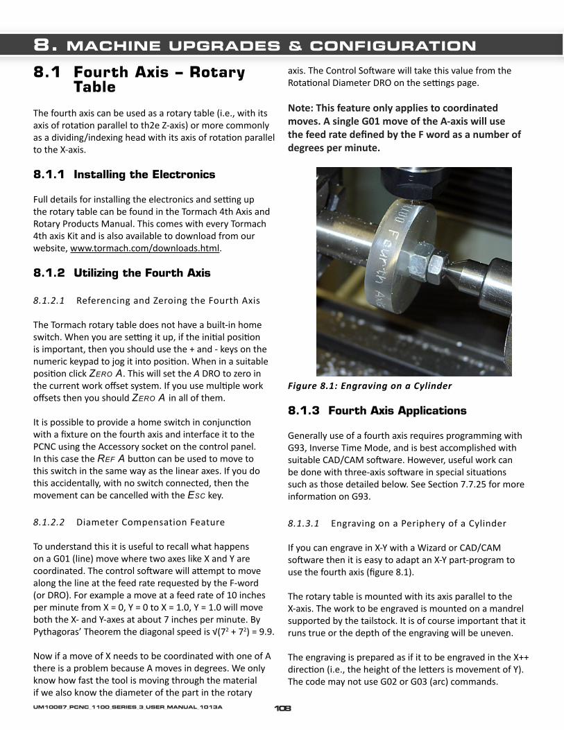
8.1 Fourth Axis – Rotary Table
The fourth axis can be used as a rotary table (i.e., with its axis of rotation parallel to th2e Z-axis) or more commonly as a dividing/indexing head with its axis of rotation parallel to the X-axis.
8.1.1 Installing the Electronics
Full details for installing the electronics and setting up the rotary table can be found in the Tormach 4th Axis and Rotary Products Manual. This comes with every Tormach 4th axis Kit and is also available to download from our website, www.tormach.com/downloads.html.
8.1.2 Utilizing the Fourth Axis
8.1.2.1 Referencing and Zeroing the Fourth Axis
The Tormach rotary table does not have a built-in home switch. When you are setting it up, if the initial position is important, then you should use the + and - keys on the numeric keypad to jog it into position. When in a suitable position click zero a. This will set the A DRO to zero in the current work offset system. If you use multiple work offsets then you should zero a in all of them.
It is possible to provide a home switch in conjunction with a fixture on the fourth axis and interface it to the PCNC using the Accessory socket on the control panel. In this case the ref a button can be used to move to this switch in the same way as the linear axes. If you do this accidentally, with no switch connected, then the movement can be cancelled with the eSC key.
8.1.2.2 Diameter Compensation Feature
To understand this it is useful to recall what happens on a G01 (line) move where two axes like X and Y are coordinated. The control software will attempt to move along the line at the feed rate requested by the F-word (or DRO). For example a move at a feed rate of 10 inches per minute from X = 0, Y = 0 to X = 1.0, Y = 1.0 will move both the X- and Y-axes at about 7 inches per minute. By Pythagoras’ Theorem the diagonal speed is √(72 + 72) = 9.9.
Now if a move of X needs to be coordinated with one of A there is a problem because A moves in degrees. We only know how fast the tool is moving through the material if we also know the diameter of the part in the rotary
axis. The Control Software will take this value from the Rotational Diameter DRO on the settings page.
Note: This feature only applies to coordinated moves. A single G01 move of the A-axis will use the feed rate defined by the F word as a number of degrees per minute.
Figure 8.1: Engraving on a Cylinder
8.1.3 Fourth Axis Applications
Generally use of a fourth axis requires programming with G93, Inverse Time Mode, and is best accomplished with suitable CAD/CAM software. However, useful work can be done with three-axis software in special situations such as those detailed below. See Section 7.7.25 for more information on G93.
8.1.3.1 Engraving on a Periphery of a Cylinder
If you can engrave in X-Y with a Wizard or CAD/CAM software then it is easy to adapt an X-Y part-program to use the fourth axis (figure 8.1).
The rotary table is mounted with its axis parallel to the X-axis. The work to be engraved is mounted on a mandrel supported by the tailstock. It is of course important that it runs true or the depth of the engraving will be uneven.
The engraving is prepared as if it to be engraved in the X++ direction (i.e., the height of the letters is movement of Y). The code may not use G02 or G03 (arc) commands.
8. MACHINE UPGRADES & CONFIGURATION
108UM10087_PCNC_1100_SERIES_3_USER_MANUAL_1013A

CH
8
There are then three stages in engraving on the cylinder: (a) the part program is converted to be motion in A and X instead of X and Y; (b) the A motion is scaled to convert it to degrees; and (c) the radius of the cylinder is defined to ensure the correct feed rate on the surface being engraved.
Editing the Part-program
Load the X-Y engraving part-program for your text. Click the Edit button in the File Control Family. Use the Replace function of the edit to change all instances of “X” to “A” and then all instances of “Y” to “X.” This orients the engraving (figure 8.1).
Scaling the “Width” of the Text
The original part-program will move along the engraving in linear units (e.g., inches) but now it is edited to use degrees, the A-axis needs scaling. If the radius of the cylinder is R (mm or inches depending on what the control program is set in) then the A-axis scale should be set to 57.3 ÷R (i.e., 360 / (2 ∏x R)). For example, the radius of the disk in figure 8.1 is 1.21” so the scale for A was set to 47.36 by typing this value into the A Scale DRO on the MDI screen (figure 8.2).
Figure 8.2: Scale and Radius Correction
Setting the Radius Correction
If you are using this improvised sort of code for a fourth axis then you must set the Radius Correction DRO which is on the Settings and also the MDI screens to an estimate of the radius of the part mounted in the axis (figure 8.2). This ensures that the feed rate will be correct.
8.1.3.2 Gear Cutting
Figures 8.3 and 8.4 show the fourth axis set-up for cutting a spur gear.
Figure 8.3: Gear Cutting
Figure 8.4: Gear Cutting (Tailstock Removed for Clarity)
The G-code for this is easily produced by hand or by a Wizard as it consists of a series of passes cutting a tooth followed by indexing by an angle (say A) corresponding to the number of teeth (N). A = 360 ÷ N .
It is important that the gear cutter is exactly on the centerline of the gear and its mandrel. A steel rule can be used to set this quite accurately (figures 8.5 and 8.6).
The rule can be seen against the body of the chuck above the mandrel.
8. MACHINE UPGRADES & CONFIGURATION
109 UM10087_PCNC_1100_SERIES_3_USER_MANUAL_1013A

Notice that the test is more sensitive the smaller the diameter of the object onto which the rule is placed, so the setup is done on the mandrel not on the gear blank itself.
If the gear cutter is mounted so that it can be inserted at the same height each time (e.g., on an R8 holder), then it may be worthwhile to set-up and save a work offset giving the centerline as Y=0.0 and Z=0.0 so that the setup does not need to be repeated each time the machine is switched on.
Figure 8.5: Ruler Vertical so on Center
Figure 8.6: Ruler Tilted to Left (so Cutter is too High)
8.2 Probes (Active and Passive) and Tool Setters
8.2.1 Introduction to Uses of Probes and Tool Setters
If you mount a switch in the spindle instead of a cutting tool and connect the switch to the control computer so that the software can “read” it, then you can use the machine for measuring instead of cutting. The switch is usually arranged so it operates when a probe tip is moved horizontally in any direction or pushed up. Figure 8.7a shows a probe from the Tormach range of accessories (p/n 30668) probing the top of a partially machined part.
The Tormach probe has a standard TTS (¾”) shank and is best used in the ¾” R8 collet (p/n 30146).
Figure 8.7a: Touch Probe
Note: We advise you to mark the spindle pulley with a dot of paint and always to insert the probe with the spindle in the same position. This eliminates any errors caused by random positioning. Keep the spindle lock ON when the probe is in. This will prevent any accidental startup of the spindle motor which would rip the cable out of the probe body.
A Renishaw or other standard probe can be interfaced using an appropriate cable. Interface details are given below.
110UM10087_PCNC_1100_SERIES_3_USER_MANUAL_1013A

CH
8
Figure 8.7b: Some Probe Packaging Options
The other possibility is to have a tool in the spindle and “replace” the work with the switch. This allows measurement of the length of the tool and setting the coordinates of the plane on which the switch is standing. Figure 8.8 shows the Tormach Tool Setter (p/n 30669) in use on a tooling plate.
There are two main uses for the measurements taken:
(a) They can be used to set up the offsets in the Control Software so that the cutting defined by the part program is in the correct place relative to the stock material or part machined component.
(b) They can be recorded to allow the shape of an existing model object to be input to a computer aided design (CAD) program.
We refer to the first application as probing and the second as digitizing.
Note: Our Probes and Tool Setters have changed in appearance a bit from the ones pictured in the following sections. All instructions and descriptions still apply.
8.2.2 Probing for Work/Tool Setting
The basic operation of the probe is controlled by the G31 code (q.v.). In practice you will not want to write programs to set up a job so a series of interactive screens is provided to perform probing operations. These are divided into measuring (probing) X and/or Y positions and probing Z positions. To make effective use of these screens you need a basic understandings of the concepts of Work Offsets and the Tool Length offset. You will have used Work Offsets already in setting up any work on the table even if only unconsciously by using the axis Zero buttons.
Figure 8.9: Data for Probe (T#99)
The screen buttons all use the current feedrate (F DRO). We recommend using 20 IPM.
As they do not involve Tool length offsets we will describe the X/Y Probing screen first.
Before this there is one bit of configuration to do.
• The standard tip diameter is around 3 millimeters (0.1180”). Always verify probe tip diameter via direct measurement.
• If you have configured your system to start in metric units, then the probe tip diameter should be specified in mm.
• Enter this diameter for Tool #99 on the Offsets Screen (figure 8.9). Ignore the Length for now and if it is zero then the Offset On/Off LED will not be lit. This is unimportant.
Note: The geometry of probing is complex and the certified effective diameter will be different from the actual diameter that you can measure.
8.2.2.1 Simple X/Y Probing
This screen (figure 8.10) allows you to set the origin (X = 0.0, Y = 0.0 point) to some feature of the stock material or a partly finished component.
111 UM10087_PCNC_1100_SERIES_3_USER_MANUAL_1013A

The three pictures represent the three operations on this screen. (a) Finding center of a bore, (b) Finding a plane surface and (c) Finding the corner of the fixed jaw of a vise. The convention is on all screens is that a yellow screen button will make the PCNC move the probe looking for the part. Obviously two things are necessary. The probe must be plugged in to the socket on the PCNC control panel (and hence be connected to the computer) and the Z height must be low enough so the probe tip will actually touch the work.
IMPORTANT: IF THE PROBE IS NOT PROPERLY CONNECTED THEN THE CONTROL SOFTWARE WILL KEEP MOVING EVEN WHEN THE PROBE
TOUCHES THE WORK. THIS CAN CAUSE IT TO BE BENT. EACH TIME THAT YOU CONNECT UP THE PROBE YOU SHOULD CHECK THAT THE SCREEN LED MARKED TEST PROBE BEFORE USE LIGHTS WHEN YOU GENTLY DISPLACE THE TIP. THE RED LIGHTS IN THE PROBE WILL ILLUMINATE TOO BUT THE SCREEN LED IS A MORE COMPLETE TEST.
We strongly recommend use of the Jog/Shuttle controller for jogging the probe position. because it combines precision with speed. If you hit anything while jogging the machine does not stop and, although the probe tip has a lot of over-travel, there is a risk of bending it or breaking
the ruby tip.
You are also advised to set the current tool number to 99 when you insert the probe into the spindle. This ensures that the correct offsets are used by the Control Software whatever sequences of moves you perform.
Bore Center
Jog to position the probe tip so it is just below the top surface of the bore to be probed and anywhere roughly near the center. No precision is needed in this position. Click the find Center and Set worK origin button.
The probe will make three pairs of exploratory moves. First it goes left and right (X – then X++) and so estimates the X coordinate of the center. Then it goes to the estimated X-center and probes back and forward (Y—and Y++). This gives the exact Y center. Finally, using this, it refines the X center by the final pair of moves (The initial X moves off the Y center could have been slightly inaccurate because of the oblique contact of probe tip with the bore).
Then the current work offsets (typically by default the G54 system) are set so the bore center is 0,0 (the X/Y origin). As the probe tip is in the center the X and Y axis DROs will read 0.0.
Figure 8:10: Simple X/Y Probing
112UM10087_PCNC_1100_SERIES_3_USER_MANUAL_1013A

CH
8
Position of a Face
You can set the X origin of a plane face perpendicular to X or the Y origin of a plane face perpendicular to Y. The Yellow buttons x+, x-, y+ and y- determine which direction the probe will move. You should start within ½” or so of the face and with Z low enough so the tip hits the face.
After the probe trips it moves slightly away from the face that it has found and the control software sets the corresponding current work offset so that the face is coordinate 0.0. This is typically useful to set the two edges of a piece of material to be the origin of their axes (i.e. the corner will be 0.0, 0.0)
There are occasions when you actually want to set both X and Y offset values to the location of the point probed. To do this toggle the green button Set x and y before making the probe move (figure 8.11). Two different moves will not, of course, be meaningful if they use “Set X and Y” as the second overrides the first.
Figure 8.11
The probed face should not be significantly angled to the X or Y axes and should be flat. Any errors here will be reflected in the accuracy of the probed position. If you need to probe inclined and/or radiused faces then you need to look at the Comprehensive X/Y Probing screen.
Corner of Vise
It is very quick, for machining a small batch of parts that can be held in a vise, to align the stock by feel to the corner of the fixed jaw. This function allows you to find the back left corner which is a typical choice for X = 0.0 Y = 0.0.
Jog the probe to ¼” to ½” down and to the left (South-West) of the corner of the fixed jaw. The Z height make the probe tip be below the top of the jaws. Set the jaw width
DRO to the size of your vise (this will be remembered for subsequent uses of the screen).
The probe explores using the three moves shown on the screen panel (figure 8.12).
Figure 8.12: Vise Jaw Corner
Move 1 establishes the rough position of the jaw. Move 2, near the far end establishes the angle the vise is mounted at (and displays it in the DRO). Move 3 approaches the end of the jaw (along a perpendicular). The X/Y origin of the current work offsets is then set to the calculated position of the corner and the probe moves to its starting point.
The angle DRO gives you a confidence check the setup accuracy of your vise. If it is a long way from 0.0 degrees then Move 2 might not find the jaw (or might even hit the moving jaw). If you need to work with a significantly skewed vise or to very close tolerances then the Comprehensive X/Y probing screen has features that will help.
Notes for all operations: You can use these operations with a part program loaded or indeed with one partly run (say to an optional stop). The probing will however set the Control Software to Absolute Coordinates (G90), No Rotation (G69), No Axis Scaling (G50) and Cancel Canned Cycles (G80).
8.2.2.2 Z Probing
Figure 8.13 shows the Z probing screen. It has two distinct functions depending on whether the probe is in the spindle or a normal tool is in the spindle and the tool setter is connected to the probe input.
113 UM10087_PCNC_1100_SERIES_3_USER_MANUAL_1013A

The yellow buttons perform machine moves and set offsets. Depending on the button, these will be the Z offset in the current work offsets or the length of a tool.
IMPORTANT: IF THE PROBE OR TOOL SETTER IS NOT PROPERLY CONNECTED THEN THE CONTROL SOFTWARE WILL KEEP MOVING EVEN WHEN THE PROBE
TOUCHES OR THE SETTER IS TOUCHED. THIS CAN CAUSE THE PROBE TIP TO BE CRUSHED OR THE CUTTING EDGES OF THE PROBING TOOL TO BE CHIPPED ON THE CARBIDE TOP OF THE SETTER - THE PCNC IS VERY POWERFUL! EACH TIME THAT YOU CONNECT UP THE PROBE OR TOOL SETTER YOU SHOULD CHECK THAT THE SCREEN LED MARKED TEST PROBE BEFORE USE LIGHTS WHEN YOU GENTLY DISPLACE THE TIP OR CAP. THE RED LIGHTS IN THE DEVICE WILL ILLUMINATE TOO BUT THE SCREEN LED IS A MORE COMPLETE TEST.
We strongly recommend use of the Jog/Shuttle controller for jogging the probe position. because it combines precision with speed. If you hit anything while jogging, the machine does not stop and, although the devices have some over-travel, there is a risk of damage.
Probing a Z Surface
If the Control Software knows the length of the probe relative to the master tool then you can set the current work offset so any surface you probe is Z = 0.0; conversely if you have a Z = 0.0 surface then you can set the length of the probe in the tool table. The pane that does this is shown in figure 8.14.
We describe setting the tool length first although it needs to be done very infrequently (e.g. if the probe tip is changed or the master tool length has to be altered). The yellow button is semi-transparent to reflect the infrequent use and visually draw you to the Set Work Offset button.
• Put the master tool in the spindle and type its number (traditionally tool #0 or #1) into the T DRO. Jog Z so it just touches the table or any flat Z surface. Zero the Z axis DRO. You can use this or any of the standard setup processes for the Z work offset (for details, revise offsets and in particular sections 6.1 and 6.3)
• Load the probe into the spindle• Click the button Move and Set Tool Length so the
probe trips on the same surface you used to touch the master tool. This will set the length of Tool #99 (the probe) relative to the master tool.
Figure 8.13: Z Probing Screen
114UM10087_PCNC_1100_SERIES_3_USER_MANUAL_1013A
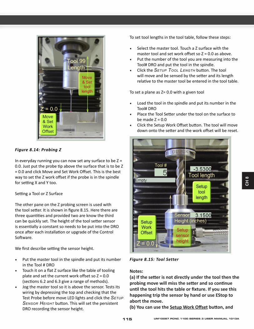
CH
8
Figure 8.14: Probing Z
In everyday running you can now set any surface to be Z = 0.0. Just put the probe tip above the surface that is to be Z = 0.0 and click Move and Set Work Offset. This is the best way to set the Z work offset if the probe is in the spindle for setting X and Y too.
Setting a Tool or Z Surface
The other pane on the Z probing screen is used with the tool setter. It is shown in figure 8.15. Here there are three quantities and provided two are know the third can be quickly set. The height of the tool setter sensor is essentially a constant so needs to be put into the DRO once after each installation or upgrade of the Control Software.
We first describe setting the sensor height.
• Put the master tool in the spindle and put its number in the Tool # DRO
• Touch it on a flat Z surface like the table of tooling plate and set the current work offset so Z = 0.0 (sections 6.2 and 6.3 give a range of methods).
• Jog the master tool so it is above the sensor. Tests its wiring by depressing the top and checking that the Test Probe before move LED lights and click the SetuP SenSor height button. This will set the persistent DRO recording the sensor height.
To set tool lengths in the tool table, follow these steps:
• Select the master tool. Touch a Z surface with the master tool and set work offset so Z = 0.0 as above.
• Put the number of the tool you are measuring into the Tool# DRO and put the tool in the spindle.
• Click the SetuP tool length button. The tool will move and be sensed by the setter and its length relative to the master tool be entered in the tool table.
To set a plane as Z= 0.0 with a given tool
• Load the tool in the spindle and put its number in the Tool# DRO
• Place the Tool Setter under the tool on the surface to be made Z = 0.0
• Click the Setup Work Offset button. The tool will move down onto the setter and the work offset will be reset.
Figure 8.15: Tool Setter
Notes: (a) If the setter is not directly under the tool then the probing move will miss the setter and so continue until the tool hits the table or fixture. If you see this happening trip the sensor by hand or use EStop to abort the move.(b) You can use the Setup Work Offset button, and
115 UM10087_PCNC_1100_SERIES_3_USER_MANUAL_1013A

the setter, for tools held by a system like ER collets where you do not know the tool length. You must set up the setter height correctly but then click Setup Work Offset WHENEVER you change a tool. In this case the tool length does not matter – everything is done by the Z work offset. You MUST NOT mix this method of working for some tools with using the tool table for others because of the differing use of the work offsets in the two methods.
Figure 8.16: Accessing the Comp Probing Screen
8.2.2.3 Comprehensive X/Y Probing
The simple X/Y probing screen is designed so that the one click does everything needed to set the required offsets. This imposes the limitation that the moves are performed by the software rather than by the operator. For example while you can find the center of a circular bore you cannot find the center of a circular protruding boss even though the basic geometry is identical. A Comprehensive Probing screen is provided to overcome this limitation. The screen is accessed by a button on the simple X/Y probing screen (figure 8.16).
Figure 8.17 shows the Comp X/Y Probing screen.
It gives the operator the required flexibility by separating the actions of probing for feature on the work and setting work offsets from the features. The interface between the operations is the X/Y coordinates of three points which are stored and displayed in a bank of DROs.
The probing and recording function is done using the yellow buttons and the DROs enclosed in the red box of the figure. The offset setting is done with the DROs and green buttons enclosed in the blue box.
Probing to Set Point DROs
Before probing you should set which Point will be used to record the probed coordinates by clicking SeleCt 1,
SeleCt 2, or SeleCt 3. The adjacent LED will indicate the currently selected point.
The circular central yellow button will set the Point to the centre of the circular hole in which the probe tip is placed. Ensure that the Z axis is lowered sufficiently so contact is made on the “equator” of the tip.
The cross-pattern of square buttons probes in the two X directions and the two Y directions. Unlike on the simple X/Y Probing screen, the face being probed does not need to be square-on to an axis and can be a circular arc segment. This is indicated by the graphic on the buttons.
The angle and possibility of an arc are detected by making a main probe move followed by two side-steps 0.2” either side of the main move. The coordinate recorded in the selected Point DROs is the point where the main move contacts the work. The diameter of the probe tip is allowed for so, as for simple probing, it must be correctly entered for tool #99 in the tool table. The probe is returned to its initial point.
Progress of the operation is noted on screen in the message line. If Verbose Messages are selected (indicated by the LED next to the toggle button) then details of what the probe found will be given. If the face has a radius of curvature of greater than or equal to 20” the angle of the face (or tangent to the large circle it is part of) will be given. If the radius of curvature is less than 20” then an estimate of the radius and the center point will be displayed. Clearly these will not be particularly accurate as they are derived from three points that are very close together but this information can be a useful check on the setting of the work.
When one point has been probed then another can be selected and the DROs set by probing another feature.In some situations you may not need to probe to set the Point DROs. You can just type values into then (followed of course by Enter). Point 1 can also be zeroed by a button.Figure 8.18 shows probing for three points to find the center of a feature that could not be located by the simple X/Y Probing screen.
Setting Offsets from Points
Once you have a point or some points you can use them to set work offsets by using the green buttons.
Origin X, Y, or X and Y from a point: The buttons outside the circle use just one point. If you only want to set the X
116UM10087_PCNC_1100_SERIES_3_USER_MANUAL_1013A

CH
8
offset use Point 1. If you want to set just the Y offset use Point 2. To set both X and Y use Point 3.
Origin X and Y are center of an arc: Set all three Points to lie on the circle or arc. Click the Origin is Center button. Although the picture on the screen implies the points are roughly equally spaced around the circle, and this will give the greatest accuracy, you can work with a small segment of arc drawn from a large circle whose center is outside the machining envelope by many feet. As the points can be centers of holes it can find the center of a set of holes on a pitch circle like a pipe flange.
Figure 8.18: Finding a Tricky Center
Origin X and Y are at intersection of line and perpendicular from a point: Again you set all three Points. Points 2 and 3 define the line and Point 1 from where the perpendicular is to be dropped. Click the origin is “corner” button.
The picture implies that the perpendicular should intersect the line between the probed points but this is not necessary. The “corner” can be on any projection of the line. This function is a generalization of the vise jaw locator
Figure 8.17: The Two Areas of Comp X/Y Probe Screen
117 UM10087_PCNC_1100_SERIES_3_USER_MANUAL_1013A

on the simple screen. It can set the origin to any corner of an object in any orientation.
Setting Rotation from Points
This function is used to set up the machine to mill components where the X/Y axis of the part is not square to the X/Y axis of the machine. This might be because the part does not have any square faces accessible when it is mounted for a second operation. The function uses the G68 code to rotate the working coordinate system relative to the machine coordinate system. You should be sure you understand the working of G68 by running test pieces before you use it on a job.
Point 1 defines the center of rotation in the existing work coordinates. It is often convenient to keep this as 0,0 or for it to be the same as one of the other points. Points 2 and 3 define a line whose angle is the direction of the new coordinate system.
If no flat face is accessible it will often be useful to have Points 2 and 3 as the centers of holes already drilled or bored in the part.
Click the button Axes to set the G68 command. The angle of rotation used is displayed in the DRO and if it is non-zero the LED on this screen and next to all axis DROs will indicate that G68 is active. The X and Y DROs will be red to remind you the rotation is active.
Rotation is removed by clicking the Clear Rot button, by typing 0 into the angle DRO or by using a G69 command.
8.2.2.4 Probe Calibration
For the probe readings to be meaningful, the center of the probing tip ball needs to lie on the centerline of the spindle.
To align the probe tip you will need a hole about ½” diameter and ¾” or so deep machined in a block of material so that it is perpendicular to the bottom face of the block.
The hole should be as circular as possible so ideally be reamed or bored on a lathe. If it is produced on a lathe then having a through hole and facing the end provides the accurate bottom face.
A rough setting can be made using the TTS Measurement Fixture (PN 30140) or TTS Granite Surface Plate (PN
31713); however, neither bore is finish machined.
To Calibrate the Tormach Digitizing Probe (PN 31858):
The Tormach probe has three set screws which are used to adjust this alignment. Most other probes will have similar features although the pitch of the threads and the orientation of the screws may differ and so require alteration to the details of this procedure.
• Insert the probe in the machine spindle (in the collet with which it will be used) so that the connector and cable are on the left (X --) direction. Leave the spindle lock on. This is CABLE LEFT position.
• Work using the Comp X/Y Probing screen. Zero the Point 1 DROs as it is not used. Select Point 2 and use the round yellow centre finding button to record the center of the alignment bore. This is illustrated in figure 8.19.
1
2
3
Point 2
Figure 8.19: Cable Left Position
• Rotate the spindle by half a turn and re-lock it. The cable will now be to the right (figure 8.20). This is CABLE RIGHT position.
1
3
2
Point 2
Figure 8.20: Cable Right Position
Select Point 3. Again use the round yellow button to find the center of the alignment bore. If the probe was perfectly set points 2 and 3 would be coincident. More than likely, this will not be the case and you will need to adjust the screws in the following manner.
1. Rotate the probe back to the CABLE LEFT position.2. Click the ADJUST PROBE FROM 2 and 3 button. The
message line will display the movement required on
118UM10087_PCNC_1100_SERIES_3_USER_MANUAL_1013A

CH
8
the three screws to centralize the probe tip. A positive number indicates the screw should be tightened and a negative number indicates the screw should be loosened. The numeric value displayed is in millimeter, with 1mm equating to ONE complete turn of the adjustment screw.
Figure 8.21: Controls for Probe Alignment
For example:
SCREW 1 = 1.25 SCREW 2 = -0.5 SCREW 3 = 0.00
Means
• Loosen SCREW 2 by ½ turn.• Tighten SCREW 1 by 1¼ turns• Leave SCREW 3 unchanged.
Be sure to first loosen any screws before tightening the remaining screws.
On the digitizing probe, the screw directly above the connector and cable is SCREW 1 (“west”) and the others number clockwise looking from the top. With the probe in CABLE LEFT position, the screw positions are described as follows:
1. SCREW 1 (“west”)2. SCREW 2 (“northeast”)3. SCREW 3 (“southeast”)
To Calibrate the Tormach Passive Probe (PN 32310):
Follow the same procedure as for the digitizing probe. The adjustment screws are the small Allen set screws. The larger socket head cap screws are retaining screws, which need to be loosened at least 1-2 turns before adjusting the set screws. The set screw under the connector is SCREW 1, and the others number clockwise when looking from the
top. As with the active probe, a positive number indicates tightening the screw and a negative number loosening it. Again, you must loosen the screw(s) first then tighten the other(s).
You will not be able to estimate, say, 0.11 turns so get as near as you can and repeat the procedure getting nearer and nearer to the ideal point where all screw movements are zero. For most purposes 0.03 of a turn which is about 0.001” will be good enough.
Make sure all the screws are tight and re-check the calibration. On a perfectly centered probe, Pressing the ADJUST PROBE from 2 and 3 will result in a reading of “0.00” for all three screw.
You will most likely need to iterate the process several times until you are happy with the achieved accuracy. For most purposes, ad adjustment of 0.03 of a turn or less indicates precision better than 0.001”. This is a good target value for most typical milling work.
8.2.3 Digitizing Parts From a Model or For Reverse Engineering
Details of the software for this will be published in a later revision of this document.
8.2.4 The Probe Electrical Interface
Probes are connected to the auxiliary socket is provided on the operators control panel. This can be used for interfacing any device that needs an input that can be read by the Control Software. It can be used for user supplied devices. The exact interfacing will depend on the device to be used but the following description of the available signals will allow liaison with the device supplier/designer.
The interface is presented as a 5 pin DIN socket. The pin assignment is:
Pin number 1 is +5 Vdc, useful if you have to bring power to active electronics on a probe.
Pin number 3 is +12 Vdc, useful if you need to supply power to active electronics on a probe.
Pin number 4 is logic ground. Do not attach to the machine ground (i.e., your probe casing should be isolated from this ground).
119 UM10087_PCNC_1100_SERIES_3_USER_MANUAL_1013A

Pin number 5 is the signal. It is internally pulled up to 5 volts in the PCNC. The input is active (“on”) when this is pulled to ground. Thus by jumpering 4 to 5 and you will see the probe LED change on the Diagnostics screen.
Other
There are a number of other tools available that are less integrated than those described in this chapter, but are designed to accomplish similar tasks, such as our Haimer® edge finders, rotating lighted edge finders, tool length touch off tools and off line tool length measurement devices. Please review our full Tormach Tool System (TTS) datasheet catalog at www.tormach.com/documents.html for more information.
8.3 Tapping
Tormach offers three tapping head options that are appropriate for use with the Tormach PCNC milling machines. They are: ER series and modular tension/compression collet chuck, and the Procunier TruTAP auto-reversing tapping head. The Tormach Technical Document TD10077_CNC_Tapping_Guidelines offers a comprehensive explanation of tapping with a Tormach PCNC mill, as well as the M871-M873 auto-reversing tapping macros, long-hand code, and the G85 cycle. This document is free and available for download on www.tormach.com/documents.
Figure 8.22: PNC1100 Interface to Probe
120UM10087_PCNC_1100_SERIES_3_USER_MANUAL_1013A

CH
9
9.1 Specifications
9.1.1 Mechanical
• Table Size – 34” x 9.5” • Table Slots – 2 drainage/alignment slots, 3 T-Slots
0.625” (5/8”) – center slot -0.00 + 0.004” – outer slots – 0.000 + 0.008”
• Travel (X-, Y-, Z-axis) – 18” x 9.5” x 16.5” • Spindle Nose Diameter – 3 3/8”• Spindle Taper – R8 with spindle lock for easy single
hand drawbar operation. • Spindle Speed Range RPM – 100 to 5140. Computer
controlled spindle speed and direction with regenerative braking from a 1.5 hp induction motor (2 hp peak).
• Cartridge style spindle with V-belt transmission. There are two overlapping speed ranges. Low belt speed is 100 – 2000 RPM, high belt is 250 – 5140 RPM
• Spindle Center to Column Face – 11” • Maximum Weight of Workpiece – 500 lbs. • Max spindle nose to table – 17” • Forward opening electrical cabinet. This unique design
allows service even when the machine is placed near to a wall.
• Weight net / shipping. – 1130 / 1325 lbs• Operating temperature range 45 to 100 oF (7 to 38 oC)• Rapid traverse X, Y = 110 IPM, Z = 90 IPM• NEMA 34 stepper motors on X, Y and Z • Single Shot Lube Pump• 15 point lubrication. Each axis has an oil distribution
channel milled full length on left and right vertical and horizontal surfaces (all 4 sliding surfaces) plus an oil line plumbed directly to the ball nut assembly.
• Precision ground ball screws in the X, Y and Z motion. ISO/DIN P4 grade.
• Slide ways are a bonded low friction surface (PTFE filled acetyl), hand scraped slide ways with milled oil distribution slots.
• 1 Year warranty. There are no on-site factory service personnel. Warranty service will involve replacement of components with direction from Tormach support staff.
9.1.2 Electrical
• Spindle safety is enhanced with a tool change safety interlock and key switch lockout. Main spindle contactor (VFD power) is automatically disengaged when operator is changing a tool. Spindle M-codes or manual spindle start will reengage VFD power
automatically after tool change is completed.• Operator console has manual override for all spindle
controls.• PC Windows Control with integrated safety and manual
overrides (PC not included, Windows XP or Windows Vista is required). Computer control is integrated with an operator control panel for spindle lockout, manual spindle controls, manual coolant control and PC power control.
• Digitizing and tool touch off port, optically isolated.• Coolant or accessory AC outlet. The AC outlet for
coolant is automatically controlled via M-codes while the operator console offers a convenient manual override.
• PC or accessory AC outlets, manually controlled on the operator console.
• Power requirements – Machine tool: 200 to 250 VAC single phase. Auxiliary: 115 VAC coolant system and computer (USA).
9.1.3 System
• RS-274 (G- & M-codes) implementation with virtually unlimited program size. Conventional G- & M-code operations are complemented with manual mode operations, operation wizards. Operation Wizards allow pocketing, surfacing, cutouts, drill patterns and other standard operations to be completed without the need for addition software or manual code writing.
• See the table in Section 7.7, G-codes for a complete list of supported codes.
9.1.4 Options
The PCNC comes preconfigured for low cost 4th axis addition. Software support, wiring, cabinet holes and drive mount holes are all in place for an easy 4th axis addition.
A wide range of accessories such as tapping heads, probes, tool setting sensors, Power Draw Bar and Automatic Tool Changer are available.
9. SPECIFICATIONS AND CUSTOMIZATION
121 UM10087_PCNC_1100_SERIES_3_USER_MANUAL_1013A

9.2 Maintenance
9.2.1 Foreword – Understanding Machine Design
The PCNC has been designed for user maintenance, but an important prerequisite to effective maintenance is an understanding of some general machine design concepts. For many owners the PCNC is their first experience with a serious machine tool and they may be unfamiliar with the ideas presented here. This section should be read and understood before attempting any adjustments to the machine.
9.2.1.1 Machine Stiffness
Iron is a wonderful thing. In the context of the human experience, the iron and steel of your mill seems exceptionally stiff and essentially immovable. Never the less, any physicist or material scientist will tell you that iron is a Hookean material, meaning that it always obeys Hooks Law and will distort linearly in proportion to applied force. In simple terms, it acts like a spring. Small force, small distortion; large force makes for a large distortion.
Precision dial indicators are also wonderful things. The ability of a $20 indicator to show motion of a distance 0.0002” is amazing. This sort of distance is outside the scope of normal human experience. In the context of a dial indicator, the iron and steel of your mill no longer seems rigid. The motion of the frame under force becomes quite apparent. You should know that this flexibility is natural. You would see more flex on an 800 lb machine and less on an 8000 lb machine. One of the keys to creating accurate parts with your mill is developing an awareness of machine flex. The flexure of the machine and the cutting tool are the principle reasons that a light finishing cut yields a more accurate part. There are, of course, many other implications that flex has in planning your machining processes such as the direction of cutting (climb versus conventional milling), tool geometry, and much more.
9.2.1.2 Backlash, Friction, and Lost Motion
All machines will show backlash. Conventional backlash is the result of open spaces between moving parts. For example most ball bearings have clearance between the balls and races which results in backlash. Preloading bearings is the technique of putting opposing pairs of bearings in compression. This technique will eliminate the open space, but apparent backlash, more correctly called
lost motion, will still exist. There will always be some force required for motion. Since the bearings are compressible (remember steel is a spring), there will be some motion required for compression before enough force is delivered and motion is obtained. This is lost motion and has the same effect as conventional backlash.
There are compromises and tradeoffs made when you tune a machine. Tightening the gibs on the X axis will reduce backlash in Y, but it also increases the force required for motion in X, thus increasing lost motion in X. Increasing the preload on a bearing pair will reduce lost motion, but it will shorten the life of the bearing.
9.2.1.3 Factors Combine
Machine setup and tuning is done under no-load conditions. The accuracy of machined work is going to be worse because tool flex, work piece flex, fixture flex, and other factors combine with the basic machine accuracy. Even thermal expansion adds to the mix. A 30” ball screw will change 0.0025” in length with a 10 degree F change in temperature.
9.2.1.4 Adjusting Geometry
It’s not unheard of for a machine to need adjustment. All of the iron castings of your machine undergo thermal stress reliving. Major elements, such as the column and base, also undergo a vibratory stress relief process between rough machining and final machining. Never the less, it is possible that any iron casting can change shape a small amount, whether due to changes in the crystalline structure over time or changes induced through tool crashes and abuse.
Before making any adjustment, think carefully about the need for the adjustment and implications associated with it. As an example, consider the G6 test on your machine QC specification sheet. This is simply mounting a dial indicator on the spindle, about 4” from the spindle center, then measuring the variation in distance to the table. This is sometimes referred to as swinging the head or tramming. It’s an easy test to take, but people often overrate the resulting measurements. If there is 0.003” difference, that’s 0.003” in 8”, or 0.00035” per inch. This will put your milling out of square such that, with a 3/8” end mill, the flat bottom will be off by 0.00014” and the sidewall on a 1” thick piece will be slanted by 0.00035”. The errors introduced by tool flex and other issues will be far larger so, for most applications, the error is acceptable and does
122UM10087_PCNC_1100_SERIES_3_USER_MANUAL_1013A

CH
9
not need correction.
If you do decide to correct, don’t make assumptions as to where the error comes from. The error could be a specific problem, like the spindle head leaning down because the gib in the Z axis is too loose, or it could be the combined effect from gib adjustments, the column/base interface, or the Z saddle/head interface. If you make an adjustment in the wrong place, you could make matters worse. As an example, if the Z axis gib is loose and the head tilts down, someone could easily assume that they should shim the column/base connection. This would make the column slant back to correct for the head leaning down. Now they have the machine running in a slight parallelogram in addition to a loose head. Accuracy in deep hole drilling will certainly suffer.
We don’t mean to overcomplicate the issue here. Adjustments can be made and are sometimes necessary. The point of this discussion is that you should proceed slowly and think carefully, assessing the need for any adjustment and the best method for making that adjustment. Drawing out the machine on a piece of paper while thinking about how to do it will often make the process clear.
9.2.1.5 Achieving Accuracy in Machining
The key to achieving maximum accuracy is understanding and controlling the magnitude and direction of forces. Maximum accuracy is achieved when the forces are minimized, as occurs in a finishing cut. Maximum repeatability is achieved when the forces are repeatable, both in magnitude and direction.
Machining is a mix of science, skill, and art. The caveat in stating accuracy and repeatability is that these factors depend on the techniques used by the machinist. A skilled machinist can often deliver accuracy that exceeds the accuracy specified by the machine builder, while an inexperienced machinist may have difficulty delivering the expected accuracy. With this understanding, we cannot tell you what accuracy you will be able to achieve in your own work.
9.2.2 Protecting from Rust
Exposed iron and steel surfaces should always be protected from rust and corrosive environments. If your machine will be unused for more than a couple days you should mist the machine with light water repellant oil such as WD-40.
The rust preventative characteristics of coolant may not be effective in trapped areas. It is desirable to apply way oil or machine oil directly to the table surface under the trapped area when you mount a vise or fixture on the machine. Neglect this and you may be welcomed by a rusty machine surface when you remove the fixture some days later.
9.2.3 Gibs, Dovetail Slideways and Lubrication
The X, Y, and Z slideways have a bonded layer of skived plastic compound, a composition of acetyl and PTFE. The material is commonly known under the trade names of Turcite® or Rulon®. This is state of the art technology for oil lubricated slideways and superior to plain ground surfaces or hardened & chromed surfaces. We don’t have data on how long the material will last on the PCNC, but we do know that there have been no reports of appreciable wear, even on machines that are reported to have seen more than 5000 hours of operation. If you use the oil lubrication system and keep the protective bellows in good shape, the slideways are not normally maintenance items.
The central lubrication pump should be filled with quality way oil. This could be Perkins Perlube WL-68, Tonna 68 (Shell), Vactra No. 2 (Mobil), Way-lube 68 (Sunoco), WayLube 68 (Texaco), Febis 68 (Esso) or equivalent oil.A shot of lubrication should be given for each 4 hours of operation and after the machine has stood unused for more than 48 hours.
Always make certain that the lubrication oil is clean. The oil is delivered to 15 points throughout the machine. This includes the 12 sliding surfaces (4 each on the 3 axes) and 3 ballscrew nuts. These are some of the most critical and expensive mechanical parts of the machine. Any dirt or foreign material suspended in the oil is going to be delivered directly to these parts and can dramatically shorten the effective life of the machine.
Be sure to clean off the cover and surrounding area before refilling the oil reservoir. The strainer at the top of the reservoir is only a screen; it is not a filter.
123 UM10087_PCNC_1100_SERIES_3_USER_MANUAL_1013A

Note:• The pump is spring loaded, where the spring force
creates a very light hydraulic pressure. You can get the oil out quicker by pushing a bit, but apply too much force and you can pop off one of the oil lines.
• You will have a more uniform distribution of oil if the machine is moving when the hydraulic pressure is applied.
• The pump sucks up oil from the reservoir on the pull stroke and delivers it to the machine on the push stroke. If at some point the oil pump seems much easier on the push stroke then make certain that you do not have a broken oil line.
• Extreme axis positions can expose the oil distribution channels that are cut into the way support saddle surfaces. If the pump is used in those positions the hydraulic force of the oil will not apply it throughout the machine as intended. Instead the oil will simply squirt out at the point where the oil channel is exposed.
• After a long period of inactivity or in cold conditions the oil system may become clogged. See SB0031 – Flushing the Lubrication System in the Event of a Clog.
9.2.4 Way Covers
Way covers are important to keep abrasive debris out of the slide ways. Inspect the way covers frequently and replace as necessary. Tormach stocks replacement way covers.
9.2.5 Axis Gib Adjustment
The slide ways are hand scraped as part of the manufacturing process. This means that the Z axis saddle is fitted to the column. They are scraped in as a set and neither the saddle nor the column can be had as a replacement component. Likewise, the base, XY saddle, and machine table are scraped in as a set.
The slide ways have tapered gib plates (also hand scraped), where the position of the Gib Plate controls the tightness and friction in a slide way. For example in figure 9.1b, the Y-axis Gib Plate is part of the Saddle and is held in position on both front and back via the Gib Screws (see cutaway in figure 9.1b).
Adjustment Procedure:
The adjustment procedure is similar for all three axes. The Z axis is described in detail.
The Gib Plate is tapered down. When the Gib Plate is moved down relative to the Z-axis Saddle the slide way will become tighter, when it moves up the slide way will become looser. With the machine is turned on, move the Z-axis up to near the top of its travel. Remove the screws that attach the way cover to the Z-axis Saddle in order to gain access to the lower Gib Screw.
Figure 9.1a: Upper Z Gib Screw
It is difficult to assess the correct clearance for the Gib as a very small force on its end can, via the shallow taper, apply a large force to the dovetail. Too tight a gib results in zero gap and very high friction since there is no longer space for an oil film. The easiest method is by a form of “dead reckoning”. First make sure the Lower Gib Screw is loose by a few turns (this allows clearance for the Gib to be adjusted downward), then tighten the Upper Gib Screw in, thus pushing the Gib down until it is tight yet not hitting the bottom screw. Wiggle the head while you are tightening this screw to get the gib reasonably tight (this means “tight” but not so tight you are stripping the screw head or flexing the castings... ). Next, loosen the Upper Screw 4 full turns. Now tighten the Lower Screw thus pushing the gib back up against the upper screw (and creating a positive amount of “Gib Clearance”). Now the gib should be held in place with the upper and lower screw tight on the gib.
124UM10087_PCNC_1100_SERIES_3_USER_MANUAL_1013A

CH
9
Note: it is important that after any gib adjustment that both adjustment screws are tight. Failure to do this will result in the gib moving, and all your hard work going for nothing.
A more precise method of adjusting the gibs is to use lost motion (apparent as backlash on a dial indicator) to arrive at the correct setting. First, loosen the Upper
Screw 8 turns and tighten the Lower Screw 8 turns so that the Gib Clearance is quite loose. Use a dial indicator to measure the axis backlash. With a very loose gib, the measured backlash is entirely attributable to the backlash in the angular contact bearings and the ball nut. On a newer machine the value should be under 0.0014” on the Z axis (note: under .001” on X and Y). Next, tighten the Gib by one turn (by loosening the Lower Screw first, then tightening the Upper Screw). Measure the backlash again. Repeat this procedure until the measured backlash increases – this is the point at which the gib setting has started to induce lost motion in the axis. Back the adjustment off to the point just before you saw the increased backlash. That is the ideal setting for the axis (see figure 9.1c).
For the X axis, the Gib tightens with the Gib Screw on the left. No covers need to be removed.
For the Y axis, the Gib tightens with the Front Gib Screw. The front and rear Y-way bellows need to be removed where they screw to the Saddle.
Figure 9.1b :Typical arrangement of gibs and screws for X/Y slide.
Figure 9.1c :Changes in backlash with gib tightness
125 UM10087_PCNC_1100_SERIES_3_USER_MANUAL_1013A

9.2.6 Adjusting Ballscrew Preload
The ball screw itself is of the double-nut preloaded design. The preload is set at the factory via a precision ground spacer placed between the two ball nuts. They are not user adjustable. Under typical conditions there is less than 0.0004” of lost motion attributable to the ball nut.
The ball screw mount bearings are at the motor end of the ball screws. These are preloaded angular contact bearings and are user adjustable. They are typically adjusted for 0.0003” to 0.0013” of lost motion. Bearings are available individually and two are needed for each ball screw.
If the Bearing Adjustment Nuts are not set properly then there will be either excessive backlash in the machine (too loose) or rapid wear and excessive friction (too tight). Figure 9.1 shows the X-axis bearings, ballscrew and motor. The Y-axis and Z-axis are similar.
The recommended procedure for checking backlash is to observe motion at the table or head (via a dial indicator) while moving the machine using the axis motors. Tormach recommends adjusting the backlash on X and Y to something between 0.0004” and 0.001”. The recommended backlash for Z-axis is 0.0006” to 0.001”.Checking backlash by pushing or pulling on the axis is a less accurate method. The push/pull method will normally show a smaller backlash value. You can fool yourself into thinking there is zero backlash when the effective lost motion is within specification.
Figure 9.2b X-axis mount
9.2.6.1 Understanding Preloaded Angular Contact Bearings
Figure 9.3 shows a cross section of a typical ball screw shaft mount. The ball screw shaft is in the center and the crosshatched section is the iron casting that mounts the bearings. There are two angular contact ball bearings, forming a preloaded pair. The cover plate holds the two outer races together, along with the spacer that is between them.
The inner races are held between the sleeve (left side) and the shoulder cut into the ball screw shaft. The sleeve is held against the left inner bearing race by the adjustment nut and a locknut; as the adjustment nut is screwed toward the bearing pair, the preload increases.
Figure 9.4 shows how the force of preload is transmitted through the bearings, from the inner race to the outer race. In a preload pair, this force is then transmitted back to the inner race by an opposed bearing. It should be apparent that the correct orientation of the angular contact bearing is critical to the operation.
126UM10087_PCNC_1100_SERIES_3_USER_MANUAL_1013A

CH
9
Figure 9.2a: Section view of X-axis mount.
Figure 9.3: Detail of bearing system.
127 UM10087_PCNC_1100_SERIES_3_USER_MANUAL_1013A

Figure 9.4: Angular Contact Bearing
9.2.6.2 Making the Adjustment
In order to make the adjustment you will need two hook spanner wrenches (PN 30485) in order to rotate the two nuts on the ballscrew end (figure 9.5).
Figure 9.5: Spaner Wrenches
The nut nearer the bearing housing is the adjustment nut and the one nearer the stepper motor is the lock nut.
When working on the Z-axis you should remove any tooling from the spindle and support the head by resting the spindle nose on a block of lumber.
Loosen the lock nut and back it off about two turns. Hold the ballscrew to prevent it from rotating with a pair of pliers on the coupling and tighten the adjustment nut until there is slightly more backlash than you ultimately want to achieve – tightening the lock nut will slightly increase the bearing preload.
Figure 9.6 Feeling preload in bearings.
There are two possible methods to judge the preload:
(a) You can use a dial test indicator to measure backlash between the ballscrew end and the structure to which the bearings are mounted (table for X-axis or machine frame for Y- and Z-axes);(b) You can estimate the torque required to turn the ballscrew in the bearings.
If you are aiming for the smallest possible backlash then we suggest that you do both as it is not possible to be certain that you do not have excessive preload by just measuring backlash.
To estimate bearing drag torque you need to eliminate the stepper detent torque and the ballnut friction. This is done by allowing the stepper mounting box to rotate and measuring the torque required to do this.
(a) For adjusting the X-axis position the table near the right hand end of its travel (i.e., X near to zero). This ensures that the bearing is near to the ballnut to minimize bending of the screw during tests.(b) Slacken the two screws clamping the coupling between the stepper shaft and ballscrew end.(c) Remove the four cap screws holding the stepper motor to the coupler box. Remove the stepper. This is the reverse of the process for coupling the Y-axis drive shown in section 2.3.(d) Remove the four cap screws holding the motor coupler box to the table (X-axis) or frame of the machine (Y- and Z-axis). Move the axis so the mounting box comes free of its pins. The screw and box are supported on the ballnut so take care not to apply forces that could bend the screw (figure 9.6).(e) You can now rotate the box by hand and get a sensitive feel for the torque caused by the preload on the bearings. Rotation should be smooth with a small perceptible drag this corresponds to a medium preload of about 150 lbs. If the rotation feels tight you have too much preload and will dramatically shorten the life of the bearings. If the rotation is free and/or the box can be rocked perpendicular to the screw axis then you have little on no preload and backlash will be excessive. This test should be done with the lock nut tight. It is best to support the box on its dowel pins when adjusting the nuts to avoid damaging the ballnut or risking bending the screw.(f) Finally remount the box and motor ensuring that the
128UM10087_PCNC_1100_SERIES_3_USER_MANUAL_1013A

CH
9
coupling is symmetrically fitted to the motor shaft and the screw end and is fully tightened (figure 9.7 & 9.8).
Figure 9.7: Tightening the lock nut.
Figure 9.8 Another view of tightening the lock nut.
9.2.7 Adjusting Mating Surfaces
The mating surfaces between components are pinned with tapered metric dowels. The dowel holes are drilled after the parts have been aligned. The pins help maintain alignment during a tool crash and allow restoration
of original alignment in case the parts have to be disassembled.
Alignment between components can be adjusted with shims. In most cases any adjustment will only require a few thousandths of an inch and will not require a full disassembly. Normally the bolts can be loosened, the alignment dowels left in place, and the shim stock inserted in a small opening. Often the machine motion can be used to open the space to insert the shim stock. If alignment needs to be changed and requires removal of a dowel pin, the recommended procedure is to over drill and ream for the next large size dowel pin after adjustment. Each dowel pin has a small metric threaded hole in the center that can be used to extract a dowel.
9.2.8 Speed Calibration
This procedure is not necessary for operation of a machine, it is only recommended as an improvement to spindle speed accuracy. The spindle speed in your PCNC is factory calibrated, but your computer is not calibrated to your machine. The variations among PCs will affect the precision of the computer generated spindle speed. To improve spindle speed accuracy, your computer needs to be calibrated to your PCNC.
The PCNC uses a printer port of a standard PC for its machine control. The procedure described below will calibrate the PCNC to a specific computer. The procedure should be repeated any time the machine control computer is replaced.
While there is no electrical work involved, the procedure does require access to the electrical cabinet while under power. Points within the cabinet will contain high voltage. Exercise caution whenever opening the cabinet if the
machine is under power.
1. Turn on the machine and control computer and then open the PCNC control software program.
2. Set the belt to the LOW speed range and set the S word to 500 either by MDI of S500 or typing the value into the S DRO followed by Enter.
3. Start the spindle. 4. Inspect the value displayed on the panel of the VFD.
It should be around 35 Hz. See figure 9.9. Record the frequency shown. Shut down the PCNC Control Software.
129 UM10087_PCNC_1100_SERIES_3_USER_MANUAL_1013A

Figure 9.9: VFD frequency readout
5. Open the PCNCConfig software program located under “Programs” on your “Start” menu. This will have been installed when you installed the control software. Click the “Open Profile” button and choose the machine profile you wish to modify (figure 9.10). The profile for the PCNC 1100 is: C:\PCNC3\PCNC1100M3-3.XML.
Figure 9.10: Opening the Profile
6. Next, under the “Speed Calibration” heading enter the frequency you recorded earlier (figure 9.11). The software will display a new “Spindle steps per unit” value.
7. At this point, you should click the “Save Profile” button. If you are sure all the information is correct, click the “Done” button. Close the PCNCConfig software program.
8. Open the PCNC control software program again and confirm that the computer is calibrated with the machine by repeating step 4 and checking that the frequency is 34.6 Hz.
9. Occasionally, repeating the above steps may be required to hone in on the target speed.
Note: Since each computer is different, it is important to re-run the PCNCConfig program whenever you connect a new computer to your PCNC.
Figure 9.11: The measured frequency.
9.2.9 Using a Non-standard Printer Port
There are several reasons why you may wish to use a different printer (parallel) port from the one on your PC’s motherboard – for example a PCI bus plug-in card. In this case you will almost certainly need to reconfigure the PCNC Control Software to use a different address from the standard motherboard address which (in hexadecimal) is 0x378.
130UM10087_PCNC_1100_SERIES_3_USER_MANUAL_1013A

CH
9
Use this procedure.
1. Close the Control Software if you have it open.2. Click on the Start Menu and choose Control Panel 3. On the top left-hand side, click on Switch to Classic
View. Note: If it says “Switch to Category View” that means you have already switched to “Classic View.”
4. Double click the System icon. 5. Choose the “Hardware” tab and click on “Device
Manager.” 6. Find the “Ports (COM & LPT)” icon and click on the plus
sign (figure 9.12 shows the result of these steps). 7. Double click on “ECP Printer Port (LPT1)” – wording
may differ depending on your system. If you are looking for a plug-in card then the card name will probably appear in the title.
8. Choose the “Resources” tab and take note of the first number under “Setting” that corresponds with the first “Resource Type” I/O Range (figure 9.13). This shows the standard value for a motherboard port. A PCI post will not start with a zero – it will probably be something like CD80 (as it is a hexadecimal number it can have digits A, B, C, D, E or F in it). Write down the four numbers and/or letters. This is your “Printer port address in Hex.”
9. Finally, run the PCNCConfig program and open the PCNC3 profile (details in section 9.5.8 above) and enter this number under the “Printer Port” heading (figure 9.14).
9.2.10 Defining Your Own Sizes for Step-mode Jogging
When Step jogging (either by keyboard or the Jog/Shuttle controller) the size of step that will be taken is shown in the Step DRO. You can put any value you like into here. For safety avoid large movements.
The control software has a table of standard increments and you can go through these one by one and put them into the Step DRO using the Jog Step button.
Figure 9.13: IO Address in Resources
Figure 9.14: Entering Port Address
The values in this list can be configured using PCNCConfig.
You can either setup your own sequence in the indicated boxes or use a sequence of two small steps. Buttons are provided for metric steps (2 microns and 20 microns) or imperial steps (0.0001” and 0.001”).
If you choose your own steps you should take care that there is no unexpected jump going from the end of the list to the start.
131 UM10087_PCNC_1100_SERIES_3_USER_MANUAL_1013A

9.2.11 Defining Probe Type
The accessory port on the user panel can be used as an input port for a digitizing probe.
The Tormach Probe closes a contact when a touch is made and consequently is the default setting in the Probe Logic Sense portion of the PCNCConfig program.
A number of aftermarket probes require the opposite logic for proper function (opens a contact on touch). If an aftermarket probe of this sort is to be used, change the Probe Logic Sense using the indicated pull down menu (figure 9.15). Please note that it is up to the user to ensure that proper wiring and source voltages are recognized. Please refer to section 8.2.4 for more information.
9.2.12 Enabling 4th Axis Homing
To enable the optional 4th axis homing kit, please refer to figure 9.15 and select “Homing Enabled.
Figure 9.15: Step Sizes in PCNCConfig
Figure 9.12: Finding Printer Port
132UM10087_PCNC_1100_SERIES_3_USER_MANUAL_1013A

CH
9
9.2.13 Configuring to Start in Metric Units
The PCNC is designed based on the imperial (inch) system of units. Thus one step of each axis is exactly 0.0001”. It is, however, equally capable of working in metric units. The only limitation you will encounter is that if you look at the raw tool and work offset tables you will see that they are always in inches. Everything else on the screens is automatically in the units you have currently got selected.
In order to startup the system in metric each time you need to edit the file:
C:\PCNC3\MACROS\PCNC-M3\M990.M1S
The start of this file looks similar to this:
‘ THIS MACRO IMPLEMENTS PCNC INIT ACTIONS‘ ADD G21/G20 CHANGE IF NEEDED
‘ USES USERLABEL 2, USERDRO 1209
Using a simple text editor (e.g. Notepad++) add the following line after this code
CODE “G21” ‘ MAKE PCNC TO START IN METRIC (I.E. G21 MODE)
133 UM10087_PCNC_1100_SERIES_3_USER_MANUAL_1013A

10.1 Overview
Tormach is taking a different approach to troubleshooting documentation than is typically encountered. We feel that a discussion of general troubleshooting methods is quite important, yet we have not seen this information presented by others.
We have therefore begun this document with a section on the Philosophy of Troubleshooting. We feel that if you spend a few minutes on this section, you will be in a better position to effectively trouble shoot problems.
The Philosophy of Troubleshooting is followed by a section containing Tips and Tools for Troubleshooting.
Next comes a list of Frequently Found Problems (FFP’s) which comes from our experience in working with customers. We urge you to review this section every time you are having a problem. There is a reason the items made it to this list.
The remainder of this document addresses troubleshooting in each of several subsystems on the machine. Within this major troubleshooting section are three distinct areas:
• An overview of the Sub-system• A Problem Resolution Checklist• A Detailed Description of the Electrical Circuit
A detailed description of each subsystem is provided for users who want in-depth knowledge of the machine and who would prefer to take that knowledge and apply it to troubleshooting rather than to follow a checklist. For those who prefer to follow a step by step procedure, the Problem Resolution Checklist is provided.
Figure 10.1 is flowchart showing the recommended order in which to use the sections of this troubleshooting section of the manual.
10. TROUBLESHOOTING
134UM10087_PCNC_1100_SERIES_3_USER_MANUAL_1013A

CH
10
Figure 10.1: Troubleshooting Overview.
135 UM10087_PCNC_1100_SERIES_3_USER_MANUAL_1013A

10.2 Philosophy of Troubleshooting
The PCNC1100, like many modern machines, is an integration of mechanical components, electrical components, a computer, and software. Taken as a whole, the PCNC is a sophisticated machine; however, the machine is comprised of several sub-systems, each of which is much easier to understand than is the machine in its entirety. That, in fact, is the first key principle in troubleshooting, sometimes referred to as the “Divide and Conquer” approach. It is working on one problem at a time, and focusing on only those things that can be related to the problem.
So what is the second key principle in step in troubleshooting? Simply put, it is an understanding of how the machine is supposed to work. It is not possible to know that a machine is functioning improperly if one does not know how the machine is supposed to behave.
The third key principle in troubleshooting is noting what has changed in the environment since the machine worked properly. This principle becomes a larger factor after the machine has been in service for some time because the start-up learning process is complete and any “kinks” with the hardware have been worked out. The following are some events which could cause difficulties.
• The machine was moved• There was a thunderstorm and lots of lightning since
the machine was last used and now the electronics don’t work
• There was water in my basement where the machine is located
• It froze hard last night and the machine is in my unheated outbuilding
• My son was home on spring break and he may have run the machine while I was away, or even did something with the computer.
• There were problems when I tried to cut steel. I had only cut aluminum and plastic prior to this.
A fourth key principle is to work smart. One should always make a list of tests which can be done (make sure to save room for recording your results). After making up the list, rank the tests in order of difficulty in performing the test. Then, do the simple tests first and then do the tests that seem to address the most likely cause of the problem. We will rank the probability of the various potential causes of problems. We will also make note of those problems we
have found to be FFP’s (Frequently Found Problems).
A fifth key principle is to complete one test before starting anther. Don’t fall victim to making things worse by troubleshooting. More than once a troubleshooter has removed a wire to make a measurement and in his haste to solve the problem, moved on to the next test without putting the wire back on. This can impact the next test and certainly will impact the machine operation.We will build on these key principles by providing a description of each of the sub-systems on the PCNC. This will serve to help the user understand how the machine should work and provide an overview of the components that are involved in the sub-system. We will also list some guidelines for equipment and procedures used in troubleshooting.
As in most electromechanical machines, it is frequently easier to see problems in the mechanical systems than the electrical and computer systems. With this in mind, most of the details in the troubleshooting section will address non-mechanical areas.
The user may find that this background information will allow him to troubleshoot without any assistance from Tormach. At the minimum it should allow the user to begin the process of troubleshooting and make any contact with Tormach Technical Support go more smoothly.
Review of the Key Principles for Troubleshooting
• Know how the machine is supposed to work• Divide and Conquer—focus on one area• Analyze what has changed• Work Smart — do the easy and obvious tests first• Complete one test before starting another.
10.3 Tips and Tools for Troubleshooting (Equipment and Procedures)
10.3.1 Safety
Safety is always important. During troubleshooting one tends to expose themselves to more hazards than they incur during normal operation. Electrical tests may have to
136UM10087_PCNC_1100_SERIES_3_USER_MANUAL_1013A

CH
10
be done to live circuits. Guards may have to be removed and sometimes a safety switch will have to be “fooled” in order to make an observation. Take things slow and be extra cautious.
Keep in mind that we are not going to repeat a big safety paragraph before or between every step of a troubleshooting procedure. Doing so tends to underscore its importance. But do yourself a favor and think about safety whenever you are taking any action.
• Never do anything with machine power on that can be done with machine power off.
• Wear eye protection and use appropriate protective clothing such as gloves
• Don’t wear loose clothing • Don’t wear jewelry• Don’t do any electric testing if the floor is wet. Don’t
run the machine either.• Don’t put your hands anywhere you don’t have to.
Keep your hands in your pockets if you can.• Think about each move you are going to make and
what you can do to be as safe as possible before making the move.
• Focus on the task alone. If you feel preoccupied with something else and you think your mind could be wandering, wait until such time as you can concentrate fully on the task.
10.3.2 Tips on Computer Diagnostics
The Control Software provides a diagnostic screen which can be useful for troubleshooting. Become familiar with this screen.
The software also has an information line next to the “Reset” that can provide valuable information.
If calling Tormach Technical Assistance, make sure you know what version number of software, machine profile and screen you are running and have recorded information from the diagnostic screen and the “error” line.
10.3.3 Tools
The following are the minimum tools one should have on hand for troubleshooting
• Good lighting so you can truly see what you are looking for: a trouble light or a headlamp or a flashlight
• A digital multi-meter that can test for AC volts, up to
300 V, DC volts, up to 100V and Resistance, from 0 to 1MΩ (Ω is the common symbol for ohms)
• Assorted screwdrivers: #2 and if possible a #3 Phillips, 1/8” and 3/16” flat blade
• A wire stripper• Measuring tools: Tape measure, Calipers, Dial Indicator
(Optional)
10.3.4 Using the Digital Multi Meter for Electrical Tests
Almost all Digital Multi-meters have the capability of measuring AC Volts, DC Volts, and Resistance. These are the important functions use when troubleshooting a Tormach PCNC. Two test leads are required to measure these three functions. While many meters have more than 2 receptacles in which to plug leads, for our purposes the leads will always remain in the same 2 receptacles. One receptacle is almost universally labeled COM (for Common) and the black lead is to be plugged into this receptacle. The other lead, most often red in color, is plugged into the receptacle labeled VΩ (for volts and ohms).
Measuring DC Voltage
Select the DC voltage scale on the meter. The scale may be labeled DCV or
DC voltage has polarity so if the common lead on the meter is not placed on the common signal, the voltage will read as a negative number. This will not harm the meter, but could be confusing in certain cases. We will strive to define the common terminal when asking you to take a measurement.
Measuring AC Voltage
Select the AC voltage scale on the meter. The scale may be labeled ACV or
There is no polarity to AC voltage so either lead can be placed on either location we are having you measure.
Measuring Resistance (Ω is the symbol for ohms which are the units in which resistance is measured).
Select the resistance scale on the meter, most often labeled Ω.
There is no polarity to resistance so either lead can be placed on either location we are having you measure;
137 UM10087_PCNC_1100_SERIES_3_USER_MANUAL_1013A

however, resistance measurements are always taken with power off.
Note: When making resistance measurements on motors and other devices with low resistance, always take a tare* or zero reading on the meter before doing the resistance measurement on the motor or device.
*A tare reading is a reading using only the instrument. In the case of using a digital multi-meter to measure resistance, touch the probes together to get the tare reading. Subtract the tare reading from the meter reading when measuring the resistance of the motor to get a true value.
10.3.5 Contacting Technical Support
[email protected] 608-849-8381
There will be times when your troubleshooting efforts don’t end up solving a problem. There are a number of things that will make problem resolution easier should your be required to contact Tormach Technical Support.
1. Always have the serial number of your machine.2. Tell Tormach if you have had the problem before.
Tormach uses a case management system for tracking problems. If you contacted us in the past with a
problem, you should have a case management number which will be helpful to us.
3. Tell us if you bought the machine from someone else and have the name of the party available so that we can consult our case management system for problems that may have occurred on the machine for the previous owner.
4. Analyze what might have changed since the machine worked properly.
5. Read over the description of the subsystem involved to improve your understanding of that subsystem.
6. Make sure you can repeat the problems. Do it a few times and record the results. Determine if you can repeat the problem exactly.
7. Record information from the diagnostic screen of the control software
8. Try to define the problem as concisely as possible. Most often it is a good idea to write down the problem definition. Many times when doing this you find it leads you to answering the problem yourself.
9. Consider sending Technical Support an email rather than calling if time permits. It is often best to send an email rather than call because it tends to force you to define the problem better. When you correspond by email you don’t have to worry about keeping notes or having to interpret the hastily transcribed notes one takes during a phone conversation. Even if you want to call, having first sent an email can help the conversation go better.
Figure 10.2: Location of Version Numbers
Software Version
Screen Version
Machine Profile Version
138UM10087_PCNC_1100_SERIES_3_USER_MANUAL_1013A

CH
10
10.4 Frequently Found Problems (Repeat Offenders)
There are several frequently found problems with all electro-mechanical machinery such as the Tormach PCNC. It is not that the problems are frequent, but among the problems that have occurred, these are more frequent than others.
The first 6 items in this list fall into the category of machinery in general, while the last items are specific to the PCNC. These repeat offenders are important to keep in mind when troubleshooting.
10.4.1 Loose Wires
Try as we might it seems that on occasion we find a poor wire connection. This can be the wire in a screw clamp terminal where the clamp is loose, a problem with a crimp spade or ring connector where the connector is tight in the screw clamp terminal but the wire is loose in the crimp connector. This is most frequently found during the initial startup of the machine. The vibration that occurs during ravel tends to loosen connections. Use the 2 finger pull test--grasp the wire close to its termination point between your thumb and index finger, and gently but firmly tug each wire. If the wire comes loose, re-terminate it before moving on to other wires.
One of the graybeards at Tormach recalls industrial customers in the paper industry who were so plagued by problems caused by poor connections that they shut their entire operation down for days and checked virtually all connections. This act solved many problems for them.
10.4.2 Wire Hairs
Sometimes with stranded wire we find that a “wire hair” from the stripped end of the wire may be sticking out from the wire and touching another wire or the machine frame. This can cause short circuits.
10.4.3 Poor Cable Connections
There are a number of cables on a PCNC. Some are flat cables connecting the Tormach Control Board to the Axis Drives and other devices and some cables connect with the computer. An improperly seated cable can allow some functions to work and others to not work. We have found
that the ribbon cables plug connections can become loose during the shipping process.
10.4.4 Software Restart
It is rare but not impossible that the application software can get confused (imagine that). If an unexplained problem is occurring it may be worthwhile to restart the application (in the case of the PCNC, it is the Mach3 software). It is usually not required to restart the computer, but being a relatively easy thing to do, it should be considered.
10.4.5 Sensors (on the PCNC the End of Travel Sensors)
Sensors are one of the largest causes of problems with any machine. On the PCNC, the X and Y Axes have 1 limit switch which actuates at the end of travel in each direction of both axes. The Z axis on earlier machines has 2 limit switches, one for up and one for down. Newer machines have one for the up direction. These sensors will be discussed at length in the Axis Troubleshooting section of the manual.
10.4.6 Flaky Computer
Computers can exhibit some intermittent problems. A number of Tormach customers have purchased used computers for a song but ended up singing the blues. Remember the computer you bought on E-Bay or the like were probably being sold for a reason. Lots of unexplainable problems have been cured by swapping out computers whose history was unknown. It is far better to put an old computer you have confidence in on your machine than take a chance on an unknown used computer. Used computers have been found to be more susceptible to electrical noise.
Laptop computers will almost never work on a PCNC and should not be considered.
10.4.7 Control Software License Not Installed
The control software can be installed without the license. It will run small programs without the license being activated. Once a program exceeds approximately 500 lines, the program will fail to execute the following line and the program will halt without warning. No other diagnostic information will be displayed. Machine Controllers purchased through Tormach will have the control software
139 UM10087_PCNC_1100_SERIES_3_USER_MANUAL_1013A

loaded, but WILL NOT have the license loaded. It is up to the user to load the license CD that came with the machine.
10.4.8 Unexplained Stop or Limit Switch Error While Running
Electrical noise can cause “strange and un-repeatable” problems. Tormach has found that by adding a Ferrite suppressor to the Parallel Port Cable going from the computer to the machine will eliminate many of these problems. We have also found that simply adding a second Parallel Port Cable in series with the existing cable reduces the problems with electrical noise.
If extension cables are used frequently there are exposed metal parts on the connectors. If these metal parts contact other metal objects such as the machine frame, noise problems have been observed. Taping off the exposed metal parts of the connectors to prevent contact has proven to be effective.
10.5 Which Sub-System Should I Troubleshoot?
The flowchart in Figure 10.3 will guide you where to start troubleshooting the electrical system.
140UM10087_PCNC_1100_SERIES_3_USER_MANUAL_1013A

CH
10
Figure 10.3: Deciding which sub-system to troubleshoot.
Is there any ElectricalPower in the Machine,Coolant Pump, and orComputer?
Start
Proceed to the Power Distribution Sub-section.
(10.5.1 to 10.5.2)
End
Can you turn on Control Power (Machine LED is On)?
Proceed to the Control PowerSub-section.
(10.5.3 to 10.5.4)
Proceed to the Computer Control Subsection.
(10.5.5)
Can you turn on Computer LED?
Proceed to the Axis DriveSubsection.
(10.5.6)
Are the X, Y, Z and AAxes FunctioningProperly?
Proceed to the Spindle Drive Subsection.
(10.5.7)
Is the Spindle DriveFunctioning Properly?
141 UM10087_PCNC_1100_SERIES_3_USER_MANUAL_1013A

10.5.1 Power Distribution Sub-system
Overview
User supplied electrical power is run through the disconnect switch on the machine. This switch turns on and off all the electrical power to the entire machine and the computer system.
You will find listed immediately below a Problem Resolution Checklist section. For more in depth explanation of this subsystem, please go to the Details section that is after the Checklist section. Figure 10.4: Power Disconnect
Contents of the Power distribution Sub-System Problem Resolution Checklist
Table 1.1 GFI in customer supply for power for the computer and coolant pump trips
Table 1.2 Computer will not power upTable 1.3 Coolant Pump will not run when Coolant Switch is in the ON Position
Power Distribution ChecklistTable 1.1
GFI in customer supply for power for the computer and coolant pump trips
Possible Cause Probability Action to Identify Cause of Problem DiscussionGFI circuit defective High Test a device such as a drill or other
portable tool on the circuitIf the tool works, the circuit is OK
Loose wires in circuit Medium Remove power from the machine by turning off the disconnect switch and test for loose wires
Use the two finger tug test — see “Loose Wires” in the Frequently Found Problem list
Bad Control Board Low Remove power from the machine by turning off the disconnect switch
You can also unplug the power cord for the machine
Remove wires 202 and 205 from the Tormach Machine Control Board. Tape each wire individually so it cannot short out, then re-apply power.
If the problem disappears, a Control Board problem is indicated. You can run the machine by controlling the coolant pump in Manual until your are able to replace the Control Board.
Power Distribution ChecklistTable 1.2
Computer will not power upPossible Cause Probability Action to Identify Cause of Problem Discussion
Computer switch (SW6) on Operator panel turned off
High Check the switch Turn it on if required
Disconnect Switch in off posi-tion
Medium Check the switch Turn it on if required
Problem Resolution Checklist for the Power Distribution Sub-system
Disconnect Switch
142UM10087_PCNC_1100_SERIES_3_USER_MANUAL_1013A

CH
10
Breaker turned off in user panel supplying PCNC or GFI (if used) Tripped
Medium Check the breaker and GFI Turn it on and/or reset if required
Computer not plugged into outlet
Medium Check the plug Plug it in if required
Power Distribution ChecklistTable 1.3a
Coolant Pump will not run when Coolant Switch is in the ON Position
Possible Cause Probability Action to Identify Cause of Problem DiscussionCoolant Pump not plugged into outlet
High Check the plug Plug it in if required
Breaker turned off in electrical wall cabinet supplying PCNC or GFI (if used) Tripped
Medium Check the breaker and GFI Turn it on and/or reset if required
Disconnect Switch in off posi-tion
Low Check the switch Turn it on if required
Table 1.3bCoolant Pump will not run when Coolant Switch is in the Auto Position
Note: Review Table 1.3a first.
Possible Cause Probability Action to Identify Cause of Problem DiscussionComputer cable not plugged in Medium Re-seat computer cable Likely this symptom will
accompany other motion symptoms such as no axis or spindle control. If you can hear the small relay on the Main Control Board clicking when turning the coolant on and off with the computer, then cables are seated and working fine.
Fuse on control board blown Low Check fuse F2 on the Main Control Board Remove existing fuse and check continuity. Replace as needed.
Auto Coolant Control relay on Main Control Board has failed
Low With auxiliary input power removed, measure continuity from wire 202 to 205 while switch pump in auto
If the relay on the Main Control Board is not good, then there should be continuity from 202 to 205 when the pump is on.
Note: This relay will fail if too high of a current draw passes through it. This is common when electrical loads much larger than the Tormach coolant pump are plugged into the coolant outlet.
143 UM10087_PCNC_1100_SERIES_3_USER_MANUAL_1013A
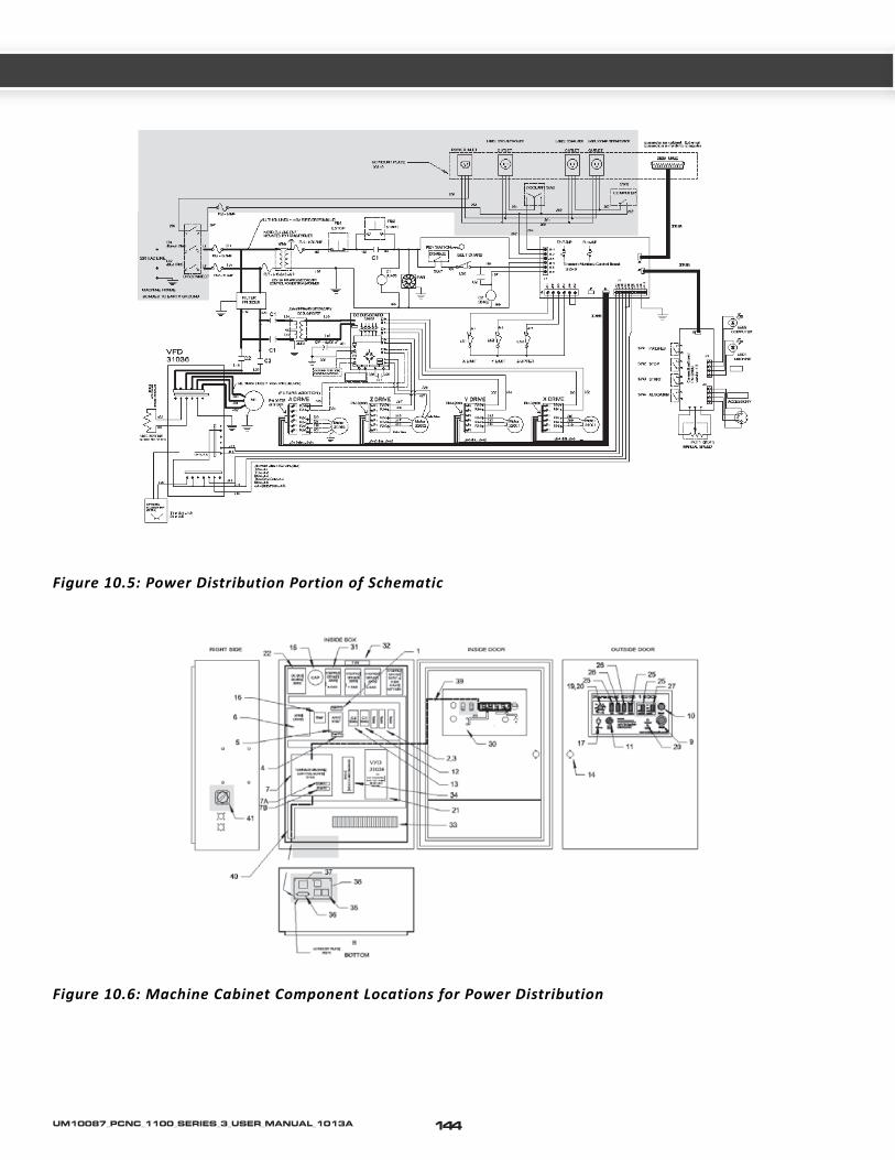
Figure 10.6: Machine Cabinet Component Locations for Power Distribution
Figure 10.5: Power Distribution Portion of Schematic
144UM10087_PCNC_1100_SERIES_3_USER_MANUAL_1013A

CH
10
10.5.2 Details of the Power Distribution Sub-system
The PCNC is powered by a user provided nominal 230/1/60 (230 V single phase, 60HZ) 20 Amp, 3 wire electrical circuit in North America and a 220/1/50 20 Amp, 3 wire electrical circuit in most other parts of the world. Tormach allows the voltage range to be from 200VAC to 250 VAC. The 2 current carrying conductors of this supply are connected to the Tormach disconnect switch located on the right side of the electrical panel. When this disconnect switch is in the off position, no power is applied to the main machine. Find the relevant portion of the electrical schematic highlighted below. You may find it helpful to have your electrical schematic available to use along with this discussion.
In addition to the main electrical supply to the machine, provisions are included so the user can supply a second electrical circuit to the cabinet. This second circuit is used to provide power to the computer and monitor and to the coolant pump. The power source for this circuit is 110/1/50, 115/1/60 or 220/1/50 single phase power with one leg of the 2 current carrying conductors grounded.
Figure 10.7: Operator/Control Panel Start, Stop and Machine LED Functions
Normally, a 115 VAC circuit would be supplied in North America. A third wire ground must also be provided. The ungrounded leg of this supply is connected to a third pole on the disconnect switch described in the paragraph above. Running this circuit in this manner allows the coolant pump outlet to be controlled either automatically by the machine under computer control or manually depending on the position of the Coolant switch, SW5, on the operator panel. The circuit also provides power to 2 outlets which can be used for the computer and monitor. These outlets are controlled by SW6, labelled Computer, on the operator panel. This allows turning off the computer when power is still applied to the main machine. Turning the disconnect switch to the off position removes power to the coolant and computer outlets.
10.5.3 Control Power Sub-System
Overview
Control Power enables running of the machine. When Control Power is on, some components in the cabinet are live but none of the motors and drives are powered
145 UM10087_PCNC_1100_SERIES_3_USER_MANUAL_1013A

up. Turn Control Power on when your desire to run the machine by pressing the start PB (push button) and turn off Control Power by pressing the stop PB when you are not running. The stop PB is a twist lock device. The button must be released by turning the button clockwise until the button “pops out”. The “machine” LED illuminates when Control Power is on.
You will find listed immediately below a Problem Resolution Checklist section. For more in depth explanation of this subsystem, please go to the Details section that is after the Checklist section.
10.5.4 Details of the Control Power Sub-system
Find the relevant portion of the electrical schematic highlighted below. You may find it helpful to have your electrical schematic available to use along with this discussion.
The Control Power circuit is that circuit which is energized when in a ready to run state and which de-energizes when the red stop button (PB1) is in the depressed position. The circuit does not energize until the Stop Pushbutton is released and the start Pushbutton (PB2) is momentarily depressed. When Control Power is off the machine is in an off state, however some components in the electrical
cabinet are still energized including the main fuses FU1 and FU2, the Control Power Transformer (XFM1), fuse FU3, and wires 102 and 103 on the Stop and Start Pushbuttons. Additionally, the Filter is powered by L11 and L21 and the Filter passes power on wires L23 and L24 to contacts on the contactors C1 and C2.
Should main power be lost to the machine when the Control Power circuit is on, the Control Power circuit turns off and stays off until power is restored and the start Button is pressed. This prevents the machine from re-starting without operator action after any removal of power which could occur with a brownout or momentary loss of power to a storm or power distribution problem.Transformer XFM1 reduces the incoming voltage from a nominal 230 (or 220) VAC to a nominal 115 (or 110) VAC. 115V control circuits are industry standard in North America (this allows the use of readily available Pushbuttons, Contactors, and other control circuit components).
If your wall breaker consistently trips whenever you power up the spindle then you should verify that the main machine power is not coming through a Ground Fault Circuit Interrupt devise (GFI or known as RCCB in Europe) as the filters in the spindle drive can allow minor leakage current to ground that, while considered safe, may also be sufficient to trip a normal GFI beaker.
Control Power Sub-system ChecklistTable 2.1
Control Power Cannot be Turned On
Possible Cause Probability Action to Identify Cause of Problem DiscussionStop button is in the locked position
High Twist the head of the button to release
Breaker turned off in electrical wall cabinet supplying PCNC
Medium Check the breaker Turn it on if required
Disconnect Switch in off posi-tion
Low Check the switch Turn it on if required. Measure for 230 VAC nominal between wires L1 and L2 if required
Fuse FU1 and/or FU2 blown Low Measure for 230 VAC nominal between wires L11 and L21
Turn off Disconnect Switch before checking or replacing fuses
Fuse 3 or 7 blown Low Measure for 115 VAC nominal between wires 102 and 100
Turn off Disconnect Switch before checking or replacing fuses
Transformer XFM1 bad Low First ensure fuse 3 is not blown then measure for 115 VAC nominal between wires 102 and 100
Turn off Disconnect Switch before replacing transformer
146UM10087_PCNC_1100_SERIES_3_USER_MANUAL_1013A

CH
10
Figure 10.8: Control Power Sub-system Portion of the Electrical Schematic
Figure 10.9: Machine Cabinet Component Locations for Control Power
147 UM10087_PCNC_1100_SERIES_3_USER_MANUAL_1013A

10.5.5 Computer Control Communication Sub-Section
Overview
The Mach3 Software is the machine control software for the PCNC. It allows for manual jogging of the X,Y,Z, and A axes, the spindle speed, and the coolant pump through the computer interface. It also allows the machine to run automatically with user supplied programs. The Mach 3 Software runs on a Personal Computer and communicates with the Tormach Machine Control Board to provide machine control. The “computer LED” on the machine operator panel must be illuminated before the computer can control the machine.
Details of the Computer Control Communication
Mach3 software is installed under Windows XP or
Windows Vista. The software allows the user to jog or position the X,Y,Z, and A axes and to control the spindle speed and coolant pump operation by use of the keyboard, mouse, and the jog/shuttle control. The software also accepts G-code programs that automatically control the machine.
The Windows computer’s parallel port communicates with the Tormach Machine Control Board through via a printer cable which has 25 pin D connectors on each end. In order for the computer to control the machine, the Mach3 software application must be running, the machine LED must be on, and communication must established between the computer and the Control Board. Communication is established by clicking the “Reset” button in the Mach3 software when the “Machine OK” indicator in on the Mach3 screen is solid green. This will cause the bar indicator above the “Reset” button to change from flashing green to solid green and will also turn on the “computer LED” on the machine operator panel. Once communication is established the Mach3 software can control machine
Figure 10.10: Computer Control Communications
148UM10087_PCNC_1100_SERIES_3_USER_MANUAL_1013A

CH
10
operation.
Note: The Spindle can be controlled via the computer or manually via the operator panel controls—see Figure 10.10. The “manual / auto” rocker switch must be in the auto position for computer control of the spindle. 10.5.6 Axes Drive Sub-system
Overview of the Axis Drive Sub-system
DC Stepper Motors are used to move the X,Y,Z (Z axis vertical travel, not rotation), and A axis. The motors are powered by electronic driver modules (also referred to as axis drivers or stepper drivers) which receive control signals from the Tormach Machine Control Board. The electronic driver modules get power from the DC Bus Board. Motion is limited in the extremes of travel by end of travel limit switches.
The next section is a Problem Resolution Checklist section which is presented in a table format.
Computer Control Communications Sub-system ChecklistTable 3.1
Computer Communication cannot be established(computer LED cannot be turned on)
Possible Cause Probability Action to Identify Cause of Problem DiscussionControl Power is off Medium Turn on Control Power See Control Power Sub-sectionRibbon Cable J4 between bulkhead connector and the Machine Control Board not plugged in
Medium Check the connections on both ends and ensure they are firmly seated
The connection at the Control Board has been known to loosen up during shipping.
Parallel Port cable is not connected properly between the computer and the machine
Medium Check the cable connections. Check the cable for damage.
You may want to try a new cable if you have one
Parallel port assignment incorrect
Low
or
High
Consult the PCNC Manual, section 9.5.9, Using a Non-standard printer port
If you supply your own computer you will most likely need to configure the port.
This problem is unlikely if you purchased the computer from Tormach
Parallel Port bad Low Try a new parallel port card You may have to perform the step above
Tormach Machine Control Board defective
Low Swap boards This is by far the least likely problem
Problem Resolution Checklists for the Axis Drive Sub-system
149 UM10087_PCNC_1100_SERIES_3_USER_MANUAL_1013A

Figure 10.11: Axis Drive Arrangement
150UM10087_PCNC_1100_SERIES_3_USER_MANUAL_1013A

CH
10
Contents of the Problem Resolution Checklists for the Axis Drive Sub-system
Table 4.1 None of the Axes will move when CommandedTable 4.2 One axis will not move or moves in only one direction, but other axes operate properlyTable 4.3 Stepper Motor Winding ResistanceTable 4.4 DC Bus Power DistributionTable 4.5 Axis movement is extremely noisyTable 4.6 Cannot Reference all Axes or End of Travel Limits don’t Work, aka Limit Switch ProblemsTable 4.7 Testing Limit Switch ProblemsTable 4.8 Steps are lost on Axis Travel
Axes Drive Sub-System ChecklistTable 4.1
None of the Axes will move when Commanded
Possible Cause Probability Action to Identify Cause of Problem DiscussionSoftware not commanding the move or computer problem
High Jog the axis and observe the machine coor-dinate display
If the displayed position does not change while jogging there is a software/computer problem. Try restarting the software first. If that does not solve the problem, try restarting the computer.
Control signals not reaching the electronic driver modules
Medium Problem with 25 pin D-connector cable from computer to machine
Check the connections on both ends and ensure they are firmly seated, and check for bent pin in the connectors.
Problem with cable bottom of machine cabinet to Tormach Machine Control BoardProblem with cable from Tormach Machine Control Board to Axis Drives
A malfunction of the DC Bus Low Troubleshoot using the information in the Details section
151 UM10087_PCNC_1100_SERIES_3_USER_MANUAL_1013A

Figure 10.12: Diagnosis by Swapping Two Axis
152UM10087_PCNC_1100_SERIES_3_USER_MANUAL_1013A

CH
10
Axes Drive Sub-System ChecklistTable 4.2
One axis will not move or moves in only one direction, but other axes operate properly
Possible Cause Probability Action to Identify Cause of Problem DiscussionParallel Port cable not fully plugged in or pin bent on connector
High Investigate connections If not tightened down, parallel cables will come loose, also look for any bent pins at the connection point.
Loose Wires or Ribbon Cables
High Remove power and check the ribbon cable and the wires from the DC Bus Board
Turn on power after completion and check for operation.
A loose coupling on the motor
Medium Jog the axis and listen to determine if you can hear the motor run
Remove the cover plate over the coupling and observe if the motor is turning but the screw is not.
A bad Electronic Driver Module
Medium Swap the ribbon cable connector for the control signals, and the motor/AC supply connector between a known functioning drive (X Axis in figure 10.12) and the malfunctioning drive (Y Axis in figure 10.12)
NOTE! Do not swap any wires on a live system. Power down first or damage may result!
Since there are at least 3 identical electronic driver modules in the Axis Drive Sub-system, swapping control signals between modules is very helpful during troubleshooting. One must recognize that if control signals are switched from the electronic driver modules on the non-functioning axis to a module on a functioning axis, the end of travel limit switch on the non-functioning axis will not work. Take care to avoid reaching the end of travel when moving an axis.
Jog the Y axis in both directions If the X axis moves properly, the control sig-nals are good then it is likely the Y axis driver is bad
Jog the X axis in both directions If the Y axis does not move or moves in only one direction, a bad Y axis driver is confirmedIf commanding the X Axis moves the Y Axis, it’s likely there was a poor connection in the ribbon cable connector to the axis driver module.Swap the ribbon cables back and repeat the test. Inspect the ribbon cable connectors. “Wiggling” them may be worthwhile to try.
It is also possible that there is a damaged Ribbon Cable J4, parallel port cable, or parallel port card in the control computer.
153 UM10087_PCNC_1100_SERIES_3_USER_MANUAL_1013A

Axes Drive Sub-System ChecklistTable 4.2
One axis will not move or moves in only one direction, but other axes operate properly
A bad motor or motor connection
Low Power down and remove the motor leads from the Axis Drive.
Simply unplug the power connector from the board
Measure the resistance of the windings of the motor per Table 4.3
Note: When making resistance measurements on motors and other devices with low resistance, always take a tare* reading on the meter before doing the resistance measurement on the motor or device. See “Measuring Resistance” in the “Using the digital Multi meter for electrical tests” section
If the resistance is out of range, check the wiring carefully. If the wiring is good and the resistance readings are out of range, the motor is bad
If unsure about the wiring it is best to disconnect the motor leads from the wiring and measure resistance at the motor. You can also check the wiring (which is now disconnected) for shorts wire to wire and wire to ground and also for wire breaks.
A blown fuse on the DC Bus Board
Low Monitor DC Voltage from the DC Bus Board
Refer to Table 4.4
Note that a blown fuse usually is the result of a bad drive. If you replace a fuse and it immediately blows, suspect a bad stepper drive or wiring to the drive.
Mechanical Problem
Low Gibs too tight or too loose Adjust using procedure in section 9.5.5. Note: Too tight results in too much friction in the system. Too loose can cause binding.
Oil not getting to the ways and ball screw. Investigate oiling system for lack of oil and/or plugged lines. Refer to Service Bulletin SB0031.
Oil residue from long term storage Repeatedly pump oil and slowly jog axis or axes
Debris on ball screw Clean ball screwThermal Trip on a Drive
Low Look at the LED's on the stepper drivers. If there is a red LED lit on the drive, then it has tripped.
Cycle power to the machine, and the trip should reset. If it persists, then try a new drive.
Electrical Short on a Drive
Low Look at the LED's on the stepper drivers. If there is a red LED lit on the drive, then it has tripped.
Cycle power to the machine, and the trip should reset. If it persists, then inspect the wiring for shorts, test teh motor resistance by using table 4.3 or try a new drive.
154UM10087_PCNC_1100_SERIES_3_USER_MANUAL_1013A

CH
10
Table 4.3 Stepper Motor Winding Resistance
X Axis Y Axis Z Axis A Axis ResistanceΩ
Above Tare*From (Black Probe)
To (Red Probe)
From (Black Probe)
To (Red Probe)
From (Black Probe)
To (Red Probe)
From (Black Probe)
To (Red Probe)
308 309310
312 313314
316 317318
320 321 322
0.5-2.0 Ω0.5-2.0 Ω>1 M Ω
310 309 314 313 318 317 322 323321
0.5-2,0 Ω1 M Ω
Note, resistance across leads on all phases for X, Y and Z should be about the same. Deviation may indicate a problem. This does not apply to A axis.All Wires Above
Ground Bar All Wires Above
Ground Bar All Wires Above
Ground Bar All Wires Above
Ground Bar >1 M Ω
Table 4.4 DC Bus Power Distribution
The DC Bus Board contains 4 fuses which are used to individually fuse power to the stepper driver modules. A 5th fuse is provided on the Supply Boards for the Z axis Brake. Fuses are noted on the circuit board. Note that the control power circuit must be on (“Machine” LED is on).Fuse Number on DC Bus Board Function Wire Numbers to Monitor with
Common Lead (0V) listed firstVoltage when DC Bus is OK and when fuse is good
F1 X X axis 303 302 55-75VDCF2 Y Y axis 305 304 55-75VDCF3 Z Z axis 307 306 55-75VDCF4 A A axis 325 324 55-75VDCF5 Brake Brake for Z axis 327 326 55-75 VDC
155 UM10087_PCNC_1100_SERIES_3_USER_MANUAL_1013A

Axes Drive Sub-System ChecklistTable 4.5
Axis movement is extremely noisy
Possible Cause Probability Action to Identify Cause of Problem DiscussionBad Capacitor for DC Bus Board
Low Turn off control power, and unplug the lower connector (contains 5 wires all labeled with 300 series numbers) from all of the electronic axis modules. With the cabinet door open, turn on control power
Observe the green LED on the DC Bus Board illuminate.
While observing the green LED on the DC Bus Board, press the Stop button.
If the LED extinguishes in 2 seconds or less, the capacitor is bad and must be replaced.
If the LED takes 5 seconds or more to extinguish, the capacitor is good.
If the results are not conclusive, turn off Control Power and unplug the power connectors from the axis drivesTurn on control power and measure DC voltage on wires 300 (common) and 301.
A DC voltage of a nominal 65 VDC (55-75) indicates the capacitor is OK
Turn off Control Power and plug the power connectors back on the axis drives
A DC voltage of a nominal 40 VDC (35-45) indicates the capacitor is defective.
Loose wire connection High Turn off power and tighten all screw connections
Bad stepper driver module Medium See Table 4.2 There have been cases of a noisy axis relating to a bad driver. This may be temperature dependant.
Wrong version of Mach3 for given machine configuration
Medium Contact Tormach Support Some versions of Mach 3 release by Tormach are not compatible with all machine configurations
Failing control computer, or control computer not suited for M3
Low Run DriveTest.exe found in the c:\pcnc3 folder
A Flaky computer, or one that is not suited to run real-time software such as Mach3 will not produce smooth step signals for good axis motion.
Loose Sheet Metal High Feel for vibrating sheet metal. Often loose sheet metal is mistakenly diagnosed as a noisy stepper motor. On some systems, certain stepper motor speeds can cause excessive vibration in the sheet metal stands. Identify the problem areas and treat with silicone caulk.
156UM10087_PCNC_1100_SERIES_3_USER_MANUAL_1013A

CH
10
Axes Drive Sub-System ChecklistTable 4.5
Axis movement is extremely noisy
Squeaky Z axis brake (Z axis only)
Low Noise will be noticed coming from the brake canister
Removing the brake (Caution, the brake wires are short and somewhat fragile –lift the brake canister off the motor with caution!!!) and placing a dab of grease on the motor spindle shaft and on the shafts mating surface on the under side of the brake will remove excess noise without compromising the brake’s function.
Axes Drive Sub-System ChecklistTable 4.6
Cannot Reference all Axes or End of Travel Limits don’t Workaka
Limit Switch Problems
Possible Cause Probability Action toIdentify Cause of Problem DiscussionLimit Switch Stuck in the on state
OR
Limit Switch wire broken or wire connection bad
High Consult the Diagnostic Screen in the Mach3 Software to see if a Limit Switch is being reported as actuated even though no axis is at the end of its travel
See Table 4.7
Limit Switch contacts stuck in the off state
Medium Consult the Diagnostic Screen in the Mach3 Software to see if a Limit Switch is being reported as not actuated even though the axis is at the end of its travel
See Table 4.7
Limit Switch not being contacted at end of travel
Medium Check to see if the limit switch loose or if the actuating cam is actually contact-ing the switch
If it looks like the switch is being actuated properly but the diagnostic screen does not report the switch as being made, go to next step,
Control Board Defective Low See Table 4.7 A defective control board will report no change in the state of the limit switch even though the switch and wiring are functioning properly.
157 UM10087_PCNC_1100_SERIES_3_USER_MANUAL_1013A

For more in depth explanation of this subsystem, please go to the Details section that is after the Checklist section.Axis drivers are mounted left to right in the sequence X, Y, Z, A.
Please note: often times a defective switch can be cleaned (blow out with compressed air) and sprayed with WD-40 to fix a problem.
Please note: On some machines, the stainless steel bed pan does not sit tight against the front edge of the mill bed; this allows coolant and chips to converge on the X-limit switch. Using a bit of silicon sealer between the pan and bed will prevent this from occurring.
Details of the Axis Drive Sub-system
Motion for the X,Y,Z, and optionally the A axis are provided by DC Stepper Motors. Each motor is powered by an electronic driver module. The driver module receives nominal 65 VDC power from the DC Bus Board and receives control signals from the Tormach Machine Control Board which processes and formats information sent by the control computer.
Find the relevant portion of the electrical schematic highlighted below. You may find it helpful to have your electrical schematic available to use along with this discussion.
Axes Drive Sub-System ChecklistTable 4.7
Testing Limit Switch Problems
Diagnostic Screen Inputs Status Reported Test to Perform on Wiring at the Control Board
Results and Conclusions
“X Limit and Home” light is always on even though the switch is not actuated
Jumper J2-1 to J2-4 at the Control Board If the light does not go out when the terminals are jumpered, the Control Board is defective.
If the light goes out when the terminals are jumpered, the wiring has a break or the limit switch is defective. Remove power from the machine, disconnect wires from the switch and tie the two wires together and tape over to prevent short circuits. Apply power. If the diagnostic light is off, the wiring is OK and the switch is bad. If the diagnostic light is on, the wiring has a break or bad connection.
“Y Limit and Home” light is always on even though the switch is not actuated
Jumper J2-2 to J2-4 at the Control Board
“Z Limit and Home” light is always on even though neither the up or down limit switch is not actuated
Jumper J2-3 to J2-4 at the Control Board
“X Limit and Home” light is never on even though the switch is actuated
Remove wire J2-1 at the Control Board If the light does not go on when the wire is removed, the Control Board is defective.
If the light goes on when wire is removed, the wiring has a short or the limit switch is defective. Remove power from the machine, disconnect wires from the switch and tape the end of each wire to prevent shorts. Apply power. If the diagnostic light is on, the wiring is OK and the switch is bad. If the diagnostic light is off, the wiring has a short circuit.
“Y Limit and Home” light is never on even though the switch is actuated
Remove wire J2-2 at the Control Board
“Z Limit and Home” light is never on even though either the up or down limit switch is actuated
Remove wire J2-3 at the Control Board
158UM10087_PCNC_1100_SERIES_3_USER_MANUAL_1013A

CH
10
Axes Drive Sub-System ChecklistTable 4.8-Steps are lost on Axis Travel
NOTE! It is advised to also consult Table 4.2 as the information there will also apply to lost steps.
Possible Cause Probability Action to Identify Cause of Problem DiscussionImproper use of tool offset (G43), Work offset (G54-59), or cutter compensation (G41-42)
High See Machine Position Test described after this table.
By far the most common cause of a perceived "loss of position" or "lost steps" is user error. Please refer to Chapter 7 for details on using machine offsets in Mach.
Spindle tooling not properly locked down (Z axis only)
High Inspect to insure the cutter is not slipping in the holder or that the tool holder is not pulling out of the collet.
Motor Coupling loose or cracked
Low Inspect You may find it useful to run the axis with the cover removed. A paint line from shaft, through coupling to screw can be used to see if there is any movement over time. Use caution; keep away from the rotating parts.
Holding Brake not releasing (Z axis only)
Low Z will usually move down properly but will not move up
You should be able to hear motor cogging whenever you tell the axis to move. It should be noted that usually, the brake alone does not have the torque to cause a loss of step. Typically a condition such as poor lubrication combined with a bad Z brake are required to actually lose position.
Computer or Software problem High Refer to the "Best Practice Tips for a Mach3 Controller" guidelines in Section 10.10.
Low Restart the application software first. If no success, then restart both the computer and the application software.
It may be required to swap out the computer, especially if you have observed other glitches with the computer. It is possible the computer being used is not up to the task of running real-time machining software such as Mach.
Low Re-install Mach 3 after downloading current version from the Tormach website, for your machine configuration.
If the wrong version of Mach 3 is being used for your particular machine configuration, loss of position is possible.
It has happened, on rare occasion, that Tormach mistakenly sent out versions of Mach 3 with an improper configuration file. downloading the latest version from our website will eliminate the possibility of this problem.
159 UM10087_PCNC_1100_SERIES_3_USER_MANUAL_1013A

Axes Drive Sub-System ChecklistTable 4.8-Steps are lost on Axis Travel
NOTE! It is advised to also consult Table 4.2 as the information there will also apply to lost steps.
Obstruction or excessive friction (gibs not adjusted properly or poor lubrication) or high load in the mechanical system
Low Jog the axis with the jog/shuttle control and carefully observe the motion.
If you lose steps, it is normally many steps. You should be able to hear the motor cogging; Mechanical issues most often result in losing a large number of steps or stalling. Typical mechanical issues include an increase in friction due to lack of oil at the way surfaces or ball screw and/or improperly adjusted gibs. They also come from excessive load on the system due to chips or debris on the way surfaces or ball screw, a sticking Z axis brake or an end-of-travel bumper wedged against the motor mount casting (this occurs sometimes after a limit switch failure and is more common on the Z axis)
Stepper Drivers have wrong DIP switch settings
Low See electrical schematic in the back of the manual. Note: new steppers from Tormach will require the user to set these DIP switches at installation.
Additional Notes on Lost Steps
In the spirit and philosophy of this guide, “divide and conquer” has no better application than in the case of trouble shooting loss of position, or “lost steps”. Please note, that as a general rule, a properly operational Tormach PCNC being used in overloaded cutting situations, should experience a spindle stall (or a broken cutting tool) long before an axis sees so high a cutting force that it stalls or skips. Keeping this in mind, it is worth mentioning that the vast majority of problems that are mistakenly associated with “lost steps” are actually due to one or more of the following:
1. Improper use/call-out of machine offsets such as G54/55 as well as G43
2. Tool pull out as a result of a cutter or holder not secured properly
3. The wrong diameter tool used in the CAM program (i.e. many 1/2” end mills aren’t actually .500 inches).
4. Machine referencing to the part was performed improperly and/or relying on the end of travel limit switches to set machine offsets.
5. Fixturing does not secure work, or does not facilitate repeatable mounting of work from one piece to the next.
These are what we call Process Errors and have little to do with a problem residing with the machine itself. The scope of this portion of the trouble shooting guide does not cover solutions to process errors.It is imperative to “Divide” a given set up into manageable portions so one can focus on where the problem really lies... is it a process problem, or is it a machine problem? In order to isolate machine problems from process problems, the “process” must be removed from the set up. The point of this test is to measure the machine motion explicitly, thus eliminating process based problems. This test is written for checking the X- axis, similar process can be used on Y and Z as well.
1. Be sure that G40 and G49 show up in the modals list at the top of the screen.
2. Mount a quality dial indicator on the mill bed, orienting the plunger along the X-axis. Place near the end of travel.
3. Orienting the axis such that the indicator plunger contacts an appropriate surface on the spindle head, move the X axis such that the indicator is zeroed, then zero the X-axis DRO.
4. After moving the spindle head away from the indicator, proceed with “exercising” the axis. This means, using manual moves, or a very simple G-code program, move the axis at varying speeds, particularly rapid
160UM10087_PCNC_1100_SERIES_3_USER_MANUAL_1013A
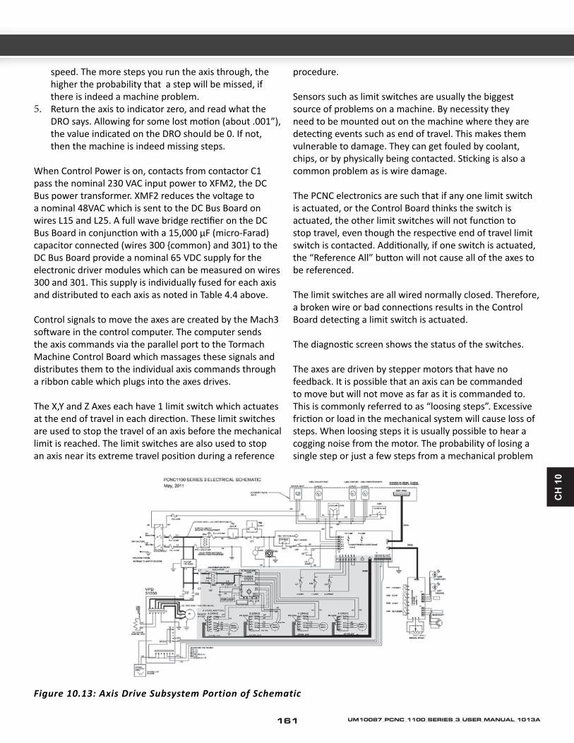
CH
10
speed. The more steps you run the axis through, the higher the probability that a step will be missed, if there is indeed a machine problem.
5. Return the axis to indicator zero, and read what the DRO says. Allowing for some lost motion (about .001”), the value indicated on the DRO should be 0. If not, then the machine is indeed missing steps.
When Control Power is on, contacts from contactor C1 pass the nominal 230 VAC input power to XFM2, the DC Bus power transformer. XMF2 reduces the voltage to a nominal 48VAC which is sent to the DC Bus Board on wires L15 and L25. A full wave bridge rectifier on the DC Bus Board in conjunction with a 15,000 μF (micro-Farad) capacitor connected (wires 300 {common} and 301) to the DC Bus Board provide a nominal 65 VDC supply for the electronic driver modules which can be measured on wires 300 and 301. This supply is individually fused for each axis and distributed to each axis as noted in Table 4.4 above.
Control signals to move the axes are created by the Mach3 software in the control computer. The computer sends the axis commands via the parallel port to the Tormach Machine Control Board which massages these signals and distributes them to the individual axis commands through a ribbon cable which plugs into the axes drives.
The X,Y and Z Axes each have 1 limit switch which actuates at the end of travel in each direction. These limit switches are used to stop the travel of an axis before the mechanical limit is reached. The limit switches are also used to stop an axis near its extreme travel position during a reference
procedure.
Sensors such as limit switches are usually the biggest source of problems on a machine. By necessity they need to be mounted out on the machine where they are detecting events such as end of travel. This makes them vulnerable to damage. They can get fouled by coolant, chips, or by physically being contacted. Sticking is also a common problem as is wire damage.
The PCNC electronics are such that if any one limit switch is actuated, or the Control Board thinks the switch is actuated, the other limit switches will not function to stop travel, even though the respective end of travel limit switch is contacted. Additionally, if one switch is actuated, the “Reference All” button will not cause all of the axes to be referenced.
The limit switches are all wired normally closed. Therefore, a broken wire or bad connections results in the Control Board detecting a limit switch is actuated.
The diagnostic screen shows the status of the switches.
The axes are driven by stepper motors that have no feedback. It is possible that an axis can be commanded to move but will not move as far as it is commanded to. This is commonly referred to as “loosing steps”. Excessive friction or load in the mechanical system will cause loss of steps. When loosing steps it is usually possible to hear a cogging noise from the motor. The probability of losing a single step or just a few steps from a mechanical problem
Figure 10.13: Axis Drive Subsystem Portion of Schematic
161 UM10087_PCNC_1100_SERIES_3_USER_MANUAL_1013A

is very low. Mechanical issues most often result in losing a large number steps or stalling the motor.
Tormach has found that loosing steps is usually due to the software or the computer. Appearing to lose steps on the Z axis is frequently due to the tool holder being pulled out of the collet or the cutter slipping in the holder.
Figure 10.14: Machine Cabinet Component Locations for the Axis Drive Subsystem
162UM10087_PCNC_1100_SERIES_3_USER_MANUAL_1013A

CH
10
10.5.7 Spindle Drive Sub-System
Overview
The Spindle on the PCNC is powered by an AC motor whose speed is controlled by a variable frequency drive (VFD).
Figure 10.15: Spindle Drive Subsystem
163 UM10087_PCNC_1100_SERIES_3_USER_MANUAL_1013A

With Control Power On, the Spindle Lockout Keyswitch On, and the Spindle Drive Door closed, the drive is in a ready to run condition.
When the Manual Auto Switch is in the Manual position, the drive is turned on and off with the Start and Stop Rocker Switches. The Speed Pot will then control motor speed.
When the Manual Auto Switch is in the Auto position, the machine control software provides start, stop, and speed information based on user input.
You will find listed immediately below a Problem Resolution Checklist section. For more in depth explanation of this subsystem, please go to the Details section that is after the Checklist section.
Figure 10.16: Operator Spindle Control Components
164UM10087_PCNC_1100_SERIES_3_USER_MANUAL_1013A

CH
10
Contents of the Spindle Drive Sub-System Problem Resolution Checklist
Table 5.1 Spindle will not turn in Manual or Auto Table 5.2 Run and Direction Commands to DriveTable 5.3 Spindle Will Not Run At High Speed
Spindle VFD Sub-System ChecklistTable 5.1
Spindle will not turn in Manual or Auto
Possible Cause Probability Action to Identify Cause of Problem DiscussionNo Power to Spindle If the display on the VFD is on,
proceed to “Belt is Loose or Broken”
No Power to VFD The VFD has power if the digital display lights up.
Note: When power is removed, the VFD display will remain active until the internal capacitors dissipate their energy, usually about 15 seconds or so.
No Power to VFD because Contactor C2 is not energizing. This can be checked by checking the voltage across L16 and L26 at the VFD.Meter should read 200-250 VAC
High Spindle Lockout key switch off or defective 115 VAC measured from wire 100 to wire 105 when OK
High Spindle Cover Door not holding Belt Guard switch closed or switch defective
115 VAC measured from wire 100 to wire 106 when OK
Medium Loose wires in circuit Turn off power and search for loose wires. Re-apply power when finished and check operation.
Low Tormach Machine Control Board not providing run command or holding contact on C2 between wires 106 and 107 bad
In manual mode press the stop rocker switch. With the door open press the start rocker switch and listen for a soft audible click on the control board. If you hear this click (from a relay contact on the board), the board is func-tioning properly.
Ensure you have 115 VAC measured from wire 100 to wire 106 (see above). Make a jumper wire and using proper care associated with live circuits, momentarily jumper wires 106 and 107. If Contactor C2 pulls in (you will hear an audible clunk) while you have the jumper on but drops out as soon as you remove the jumper, the holding contact on C2 is defective. If C2 stays energized, the control board is not passing the run signal to the circuit. Make certain you are commanding the VFD to run. If so, the Tormach Machine Control Board is defective.
165 UM10087_PCNC_1100_SERIES_3_USER_MANUAL_1013A

Spindle VFD Sub-System ChecklistTable 5.1
Spindle will not turn in Manual or Auto
VFD has tripped Low The display will show if the VFD has tripped. Record the information from the display should the trip be happening frequently or should the trip not clear as described in the Discussion column to the right. The display will look similar to that shown to the right
VFD trips may be cleared by removing power from the VFD for 30 seconds by use of the Spindle Lockout Key Switch
The letters tr on the left side of the display indicate a VFD trip and the letters on the right define the type of trip.
See Table 5.3 “Spindle VFD Trips” in the Details section for a list of VFD trips
Err 0 occurs Low Check wiring to braking resistor Symptoms are spindle takes a long time to slow down
Belt is Loose or Broken
OR
sheaves are not fixed to motor or spindle
Low Check the mechanical system Turn off Disconnect Switch before investigating
Defective VFD Low If the display is not on and there is nominal 230 VAC between wires L16 and L26, the VFD is defective.
If the VFD displays a trip condition that does not clear with removal of power, it is possible the VFD is bad.
Un/Mis-programmed VFD Low Push the “M” button on the front panel of the VFD momentarily. The display will change to 01___0.0 with the 01 blinking. Momentarily push the up arrow key to the right of the M key, the 01 changes to 02. Take note of the number to the right of the 02. Your VFD should read ‘170.X’, where ‘X’ designates the VFD program version. If it does not display this value than your VFD requires re-programming. To exit this mode, push and hold the M button until the display reverts.
A VFD reprogram is a simple operation, but requires a programming key from Tormach.
166UM10087_PCNC_1100_SERIES_3_USER_MANUAL_1013A

CH
10
Spindle VFD Sub-System ChecklistTable 5.1
Spindle will not turn in Manual or Auto
Defective Tormach Machine Control Board
or
Defective cables between the Control Board and the Spindle VFD
Low Check that all cables are seated properly in their connectors on the board
Attempt to run the VFD. If the display reads Fr xy.z or Ld xy.z where xy and z are numbers between 0 and 9, the Control Board is send-ing a run (enable) signal to the VFD. A reading of rd 0.0 indicates the VFD is ready but not receiving a run command.
Note that the VFD may be displaying numbers on the left side of the display. If the digits on the right side of the display are flashing, momentarily press and release the M button just below the display to cause the left side digits to flash. With the left side digits flashing, press and hold the M button for 3 seconds and the display will change to Fr, Ld or rd as described above.
If the display reads rd 0.0, measure DC voltage per Table 5.2 below. Be sure to measure at the Control Board and at the VFD to determine if there is a problem with the wiring. It is not critical that the measurement for reverse be made as it is not required to make the Spindle turn; however it may aid in further trouble-shooting. If your measurements match those in Table 5.2, the Control Board and wiring to the VFD are good.
Defective Tormach Machine Control Board or cables between the Control Board and VFD
Attempt to run in manual with the Speed Pot in a mid-range position
2-3.5 VDC measured on the Control Board between wires J1-2 (common) and J1-1 indi-cates the Control Board speed output signal is OK. Turning the pot from minimum to max-imum should cause the voltage to range from <1 to >4.5 VDC. Return Pot to mid-position.
Determination of Defective VFD or Control Board
If the voltage measurements in the two tests above are not good, the Control Board is defective; if correct the VFD is bad
Defective Motor Low Power down the VFD using the Key Switch. Wait 30 seconds and measure resistance between the leads of the motor which are wire numbers 400, 401, and 402. Remember to take a tare reading with your meter, See the section on using your multi-meter in the “Tips and Tools” section following the “Philosophy of Troubleshooting.”
Resistance should be in the range of 2-4 Ω. 0 Ω would indicate the winding is shorted and >1M Ω would indicate the winding is open, both cases indicate a defective motor or compromised wiring to the motor from the VFD.
167 UM10087_PCNC_1100_SERIES_3_USER_MANUAL_1013A

Table 5.2a Run and Direction Commands to Drive
Command From Card Monitoring Points One Probe on each Voltage MeasuredCommon Wire Number Wire Number Voltage when Control
Board Command IS onVoltage when Control Board Command IS NOT on
Run J1-2 J1-3 20-28 VDC 0 VDCReverse J1-2 J1-6 0 VDC 20-28 VDC
Table 5.2b Main Control Board LED Indicators for Run and Speed Commands to Drive
Mode Setting IndicatorManual (front panel switch turned to "Manual")
Start button on front panel engaged Yellow LED D15 lights. Brightness propor-tional to speed
Auto (front panel switch turned to "Auto") Start button on computer screen engaged Yellow LED D15 lights. Brightness propor-tional to speedGreen LED D10 lights and blinks at a rate proportional to speed
168UM10087_PCNC_1100_SERIES_3_USER_MANUAL_1013A

CH
10
Figure 10.17: Spindle Drive Sub-system Portion of the Electrical Schematic
Figure 10.18: Machine Cabinet Component Locations for Spindle Drive Sub-System
169 UM10087_PCNC_1100_SERIES_3_USER_MANUAL_1013A

The relevant portion of the electrical schematic is highlighted in Figure 10.18. You may find it helpful to have your electrical schematic available to use along with this discussion.
Power is supplied to the drive through a contactor that allows power to pass when the drive is commanded to run by the user. When the Mushroom Head stop button is pressed, or the when Spindle Lockout Key Switch S7 is turned off, or when the Spindle Drive Door is opened, Contactor C2 interrupts power to the VFD and prevents the motor from running.
Note: After a power down, the VFD will only power back up when first commanded to spin in either manual or auto. The VFD will not power up simply upon pushing the green start button on the Operator Panel. Once the VFD is powered up, it will stay powered until one of the above conditions occurs.
Control signals are sent to the drive from the Tormach Machine Control Board which gets commands from the computer in Automatic mode or from the Operator Panel in Manual mode. When Manual is selected with the Manual Auto Rocker Switch, the start and stop Rocker Switches, the forward / reverse Rocker Switch and the Speed Pot are used to control the Spindle speed. In the Auto mode, none of these controls are functional and all control for the spindle is provided by the Computer and machine control software.
The Tormach Machine Control Board provides a contact closure between wires 106 and 107 to cause power to be applied to the drive. It also provides a run command, a direction command, and an analog voltage in the range of 0-5 VDC to wires J1-1 (com) and J1-2 proportional to desired speed. See the Problem Resolution Checklist for the Spindle Drive Sub-system, Table 5.1, and Run and Direction Commands, Table 5.2, above.
The display on machines provides valuable information for troubleshooting. The display will provide diagnostics which include:
• Frequency output (proportional to speed. Range is ~7 HZ to 142 HZ)
• Load in percent (Load is proportional to the torque the motor is outputting)
• Status (rd for ready, ih for inhibit which will occur when there is no jumper between terminals B2 and B4 on the drive)
• Fault information (letters tr {for trip}) and a code for the fault
There are several trips that are worthy of note shown in the table below.
The drive can also provide parameter information. This is information from the Tormach program of the drive and is usually not important from a user standpoint. If the drive is displaying this sort of information, which always has 2 digit numbers displayed on the left side of the display, the user must take action to allow the drive to display the diagnostic information (above).
If the right side digits are flashing, momentarily press and release the M button just below the display to cause the left side digits to flash. Now with the left side digits flashing, press and hold the M button for 3 seconds and the display will change to display diagnostics.
If frequency is displayed and it is desired to display load, or vice versa, press and hold the M button for 3 seconds.
Tormach highly recommends against changing any parameter values in the VFD, There are no user settable parameters available.
170UM10087_PCNC_1100_SERIES_3_USER_MANUAL_1013A

CH
10
Table 5.3 Spindle VFD Trips
Trip Code Condition Likely CauseUU DC Bus Under voltage This happens every time the VFD is powered downOU DC Bus Overvoltage Braking Resistor failed open or wiring connection open between the
VFD and the resistor. Resistance to measure 75 Ohms. OI.AC VFD output instantaneous over current Phase to phase or phase to ground short on output of VFD to motorOI.br Braking resistor instantaneous over cur-
rentBraking resistor shorted or partially shorted out or short in wiring between the VFD and the resistor. Resistance to measure 75 Ohms.
It.br I2t (power) on braking resistor Excessive braking resistor energy caused by too frequent and too severe deceleration cycles or AC supply voltage too high
It.AC I2t (power) on VFD output current (used to protect motor)
You are working the spindle motor too hard. Consider running the spindle motor at half speed for 10 minutes with no load to cool the motor down.
O.ht1 VFD has calculated it is working too hard and needs to stop to cool power electron-ics down to prevent failure
You are working the spindle motor too hard. Stop running the spindle but leave the VFD power on and let the power electronics cool down.
O.ht2 Heat sink temperature is too high because the VFD is working too hard and needs to stop to cool power electronics down to prevent failure. Cabinet may also be too hot.
You are working the spindle motor too hard or it is too hot in your shop. Stop running the spindle but leave the VFD power on and let the power electronics cool down. Check to see if the fan on the VFD is running and check your filters on the cabinet. Cool your shop down if required.
Hf.29 Cooling fan not cooling Failed drive.
171 UM10087_PCNC_1100_SERIES_3_USER_MANUAL_1013A

10.6 Mechanical Maintenance
The mechanical design and assembly is conventional in all aspects. Adjustments should be simple to make, but rarely needed. The exploded views are your primary resource for understanding assembly and adjustment. We
encourage you to contact Tormach if additional information is needed. Specific items to be aware of include the following:
• The Z-axis is held up by the Z-axis ballscrew and motor. Decoupling the motor will result in a dangerous and destructive fall, with the entire spindle head crashing into the table.
• X-, Y- and Z-axis ballscrews are mounted on angular contact bearings. The preload adjustment on these bearings affects the axis backlash and bearing wear. Spanner wrenches are very helpful to adjusting the locknuts and setting the tension. Tormach offers the correct spanner wrenches (PN 30485) if you need to adjust or replace these bearings
• X-, Y- and Z-axis ballscrew nuts are preloaded using precision ground spacers. These are factory set and cannot be adjusted.
• X-, Y- and Z-axis slide ways each have a tapered gib plate, locked in place at each end. Tapered gibs can act as wedges and jam the machine if the lock screws are not tight.
• When correctly adjusted for preload, sustained high spindle speed will bring the spindle bearings to about 155oF (68oC). This is a normal condition. Higher preload in the spindle bearings will result in even higher temperatures and excessive wear.
• Service Bulletin SB0024 covers the rebuilding of PCNC1100 spindle cartridges.
• Major castings are fitted or scraped for precision fits and machine accuracy. Exchanging parts between machines or replacing parts can affect the machine accuracy. Dowel pins are used for alignment between parts. The dowel holes are drilled after alignment between parts and are unique the original parts. Replacement parts cannot use the original dowel holes.
The following tightening torques are appropriate to the metric fasteners used in the PCNC:
Diameter (mm) Torque (Nm)5 76 128 3010 5512 10014 16016 24520 480
10.7 Electrical Maintenance
Electrical Service: Certain service and troubleshooting operations require access to the electrical cabinet while the electrical power is on. Only qualified electrical technicians should perform such operations.
Many electrical problems are self-apparent. Tracing electrical problems can be done with a combination of the machine control software, the LED indicators within the machine cabinet and the machine actions.
The operating software has colored rectangular indicators, referred as LEDs, on various screens to indicate output or functional status. The Diagnostics screen also has indicators for X, Y and Z home/limit switches and accessory input status. These are useful to determine if the input is operational.
There are also various physical LED indicators within the electrical cabinet. Among these are:
• DC Power LED – Indicates voltage on the DC bus, power to axis drivers;
• X-, Y-, Z- drivers – Green Indicate power to each individual drive. Red indicates a Fault;
• A-driver – Green indicates power to the drive;• Control Board LED1 – Indicates power to the control
board;• Control Board D10 – Blinking indicates speed signal
from software. Manual speed demand is not shown.• Control Board D15 – Brightness indicates speed signal
to spindle driver.
Beyond the obvious problems of broken limit switches, blown fuses and damaged motor cables, we suggest contacting Tormach directly for advice on diagnosing or correcting electrical problems.
172UM10087_PCNC_1100_SERIES_3_USER_MANUAL_1013A

CH
10
10.8 Preparation for Transport
It will generally be straightforward to transfer the machine to a pallet and transport it in one piece.
The Z-axis should be lowered and the spindle supported from the table on a box or solid block of timber. The Z-axis should be under a relatively neutral force, not under stress by being parked with a high downward force, nor held up by the ballscrew. Run it down to a wooden block, but do not crunch it hard into the block.
If required, the stepper motors for the axes can be removed following the reverse of the procedure described for installing the Y-axis drive. You can also remove the Z-axis motor to reduce the overall height of the machine. Take care to secure the motors after they are removed so strain is not placed on the wiring.
All bare metal surfaces should be oiled before moving the machine as a means of protection against condensation and corrosion.
IMPORTANT! YOUR PCNC MUST BE REMOVED FROM THE TORMACH STAND (IF EQUIPPED) FOR TRANSPORT. THE STAND IS NOT DESIGNED TO HOLD UP
THE WEIGHT OF THE MILL DURING TRANSPORT.
10.9 Disassembly for Transport
Warranty is void if the machine is disassembled. Tormach recognizes that there are situations where users need to disassemble their mill and has made provisions in the design of the mill to facilitate this. Never the less, Tormach cannot be held responsible for alignment, precision and operating functions after the machine has been disassembled. Test your machine before disassembling it.
The major sub-assemblies of spindle head, column and base are bolted and dowelled together so the machine can be separated into smaller components to meet very challenging transport problems. Note, however, that this entails disconnecting wiring and the lubrication lines. We recommend taking a very large number of photographs from all angles including detail photographs of any wires or oil lines that will be take apart. Dowel pins must be removed before the bolts on disassembly. Dowel pins must
be installed before the bolts on assembly.
Tormach strongly recommends that all precision sliding and rotating joints remain intact during disassembly. This means that you should not remove ballscrews, bearings or separate sliding joints. For example, in reference to the head and column exploded view (drawing D40134), you should not separate item 82 (Z-axis slide) from item 75 (column). Instead you should separate item 19 (Head Casting) from item 82 (Z-axis slide).
Detailed advice should be sought from Tormach support.
10.10 Best Practice Tips for a Mach3 Controller
The following best practices are taken from our own engineering testing, customer experiences, and the authors of Mach 3. These tips apply to anyone running a Mach3 controlled CNC tool, whether you are using the Tormach Machine Controller, or your own control computer. These tips follow a similar theme: ask yourself when loading or connecting something new to your control computer “will this device/software distract the CPU from its primary task of controlling the machine?” Recognize that a distraction of 0.001 seconds (one millisecond) is enough to create a serious machining error.
When in doubt, err on the side of caution.
1. Do not use anti-virus or anti mal-wear (scan your thumb drive on your desk computer before transferring files to keep your control computer clean).
2. Avoid loading extraneous software onto the control computer. Think of your control computer as just that, a device dedicated to controlling your CNC equipment and not as an office computer.
3. Never run software other than Mach 3 while machining.
4. Do not network the computer, especially while machining. Tormach computers are not intended to be connected to the internet – they do not have antivirus software installed and they are shipped with the network Ethernet disabled.
5. Avoid passive and powered USB hubs.6. Avoid wireless devices.7. A USB based parallel port will not work. A true parallel
printer port is required.8. When using a thumb drive (flash drive) to transfer
your g-code files, be sure to transfer the file to the
173 UM10087_PCNC_1100_SERIES_3_USER_MANUAL_1013A
hard drive, and UNPLUG your thumb drive. Some USB drives will run programs in the background when plugged into your computer’s USB port.
9. While running long programs (250k lines or more), or code using 4th axis motion, turn off the tool path display.
10.While running G-code, it’s recommended to limit what the controller needs to do besides run your code: don’t minimize/maximize screens, don’t click “update tool path”, don’t switch between mach screens, don’t open file manager or note pad.
The following tips are more related to the nuances of Mach3 or simply computers in general than a function of running real time software on a PC platform.
1. When creating G-code created with a generic Fanuc CAM post processesor, be mindful of tool change call outs. Review your machine owner’s manual on how Mach3 prefers to see tool change call outs (section 7.8.3 of any recent Tormach PCNC owner’s manuals).
2. Avoid unnecessary code usage, such as turning on a complex mode (G81) immediately followed by turning off the same mode (G80). Verbose and pointless codes are often inserted by poorly planned CAM posts and they can suck up computer cycles.
3. It is advised to reboot your controller once a day.4. Mach3 configurations can become corrupt. Keep your
Mach 3 software disc, the Tormach controller restore disc (if supplied), and Mach 3 license CD someplace safe should you find the need to re-load this on your control computer.
5. Noisy electrical supply lines to your computer can cause any number of USB related issues. Most commonly this results in USB device lock up (keyboard, mouse etc). Please contact Tormach tech support for a Technical Document on this subject.
Issues or problems that result from ignoring these “best practices” are usually infrequent but they can be significant when they occur. Machining the same part 99 times can lead to a complacency that is shattered when Mach3 stumbles and damages a part or a tool on the 100th run.
10.10.1 Additional Technical Information
Mach 3 does not require a computer with a powerful processor but it does need the computer’s full attention. Because Mach is a real-time motion control program it depends on the computer to consistently create the control signals used by the stepper drivers and motors to
create motion. If, during machine motion, the computer spends time (measured in milliseconds, or even micro-seconds) processing information unrelated to Mach the control signals will be inconsistent. Poor-quality signals from the control computer result in problems ranging from minor loss of position to major axis stalls and crashes.
For a detailed technical discussion of the relationship between Mach 3, a real-time motion control software, and the computer it is running on, please read the Tormach Machine Controller Engineering White Paper on the Technical Support page at www.tormach.com.
174UM10087_PCNC_1100_SERIES_3_USER_MANUAL_1013A

APP
1
APPENDIX 1: EXPLODED PARTS VIEWS
175 UM10087_PCNC_1100_SERIES_3_USER_MANUAL_1013A

PCNC 1100 Series 3 (32085)Column and Head Assembly
176UM10087_PCNC_1100_SERIES_3_USER_MANUAL_1013A

Parts List for PCNC 1100 Series 3 – (Upper Exploded) – March 2013
ID Number Description ID Number Description
1 30303 Lower spindle bearing1 40 30344 Spring 1x4.8x202 30304 Screw M8x30 41 30345 Adjustable base clamp handle3 30305 Spindle cartridge 42 30346 Spindle motor
3A 30306 Spindle cartridge assembly2 42a 32872 Spindle motor fan4 30307 Screw M5x12 43 30347 Spacer5 31198 Screw M3x12 44 30348 Key 8X406 31199 Latch 45 30349 Screw M12x45
6A 31217 Latch Kit3 46 30350 Sleeve7 31200 Nut, M3 47 30351 Pulley washer8 31201 Nut, M5 48 30352 Screw M8x209 31202 Screw M5x16 49 30353 Screw M6x30
10 31203 Screw M6x16 50 30354 Spring11 30315 Motor cover 51 30355 Screw M6x4012 30316 Upper spindle bearing4 52 30356 Screw M6x6013 30317 Nut M33x1.5 53 30357 Screw M5x2014 30318 Screw M5x8 54 32002 Z axis step motor w/Brake15 30319 Screw 12x50 55 30359 Screw M5x2616 30320 Pin 8x35 56 30360 Washer 517 30321 Washer 12mm 57 30361 Washer18 30322 Washer 12mm 58 30362 Clamping shaft collar19 30323 Head casting 59 30363 Nut M14X1.520 30324 Spindle motor base 60 30364 Lock washer 14mm21 30325 Washer 10mm 61 30365 Cover plate22 30326 Washer 10mm 62 30366 Screw M10x4023 30327 Screw M10x30 63 30367 Z axis motor base24 30328 Nut M6 64 30368 Pin 6x3025 30329 Pin 5X35 65 30369 Screw M16x1226 30330 Spindle lock 66 30370 Screw M1627 30331 Spindle lock pivot 67 30371 Spacer28 30332 Spindle pulley 68 30372 Z ball screw cover plate29 30333 Nut M27x1.5 69 30373 Z axis ball screw bearing5
30 30334 Screw M4x8 70 30374 Spacer31 30335 Motor pulley 71 30375 Z axis ball screw upper bumper32 30336 Handle pin 72 30376 Column cover plate33 30337 Set screw M5X8 73 30377 Spacer34 30338 Spring 1x4.8x20 74 30378 Z axis way cover35 30339 Adjustable base handle 75 30379 Column36 30340 Adjustable base pivot pin 6X45 76 30380 Screw M12x6037 30341 Adjustable base spindle motor 77 30381 Pin 10X5538 30342 Adjustable base clamp bolt 78 30382 Z axis ball screw & nut39 30343 Pin 79 30383 Washer 6
APP
1
177 UM10087_PCNC_1100_SERIES_3_USER_MANUAL_1013A

Parts List for PCNC 1100 Series 3 – (Upper Exploded) – March 2013
80 30384 Z axis gib 88 30392 Pin81 30385 Screw 89 30393 Key 8X2682 30386 Z axis slide 90 30394 Lower spindle spacer83 30387 Z nut carrier 91 30395 Cylindrical pin 4X1684 30388 Z axis screw lower bumper 92 30396 Big washer 685 30389 Belt 3V280 Gates 93 31204 Z axis lower way cover Bracket86 30390 Unused 94 31205 Pin, M6x3587 30391 Spindle R8 95 31206 Screw, M5x12
30507 Drawbar for R8 taper - original equipment
30506 Drawbar for BT30 taper30560 Alignment washer for drawbar31320 Drawbar for power drawbar
1 Annular Bearing Engineering Council identification: 7008C/DT (double tandem pair- ORDERED AS A PAIR)2 Spindle Cartridge Assembly for R8 includes callout numbers 1,3, 12,13,14,73, 87, 88, and 90. For BT30 Spindle Cartridge Assembly, use PN 305053 Latch Kit Assembly includes callout numbers 5,6,74 Annular Bearing Engineering Council identification: 7007C/DT (double tandem pair –ORDERED AS A PAIR)5 Annular Bearing Engineering Council identification: ABEC7202B/Angular Contact 7201B (qty 2 needed per axis)
178UM10087_PCNC_1100_SERIES_3_USER_MANUAL_1013A

APP
1
This page intentionally left blank.
179 UM10087_PCNC_1100_SERIES_3_USER_MANUAL_1013A

39
33
143
2834
3135
3637
3841
98
1224
54
32
142
4443
5554
58
5424
2325
266
2927
4930
3233
154
3942
4415
7
6 1011401617752721591819201615212215
45 46 47 14 16 5 24 12 48 21 16 7 25 15 26 6 29 6 27 28 35 34 31 30 32 5022 54 24 23
5715
3851
1127
5356
6040
PCNC1100Series3(32085)
BaseAssembly
(ToolTraynoshown)
180UM10087_PCNC_1100_SERIES_3_USER_MANUAL_1013A

Parts List for PCNC 1100 Series 3 – (Lower Exploded) – March 2013
ID Number Description ID Number Description
1 30397 Screw M6x25 33 30428 Pin 8x302 30398 Manifold 34 30429 X & Y axis spacer3 30399 Base 35 30430 X, Y axis bearing1
4 30400 X & Y axis rubber bumper 36 30431 X axis ball screw & nut5 30401 Washer 37 32401 X axis motor base6 30402 Nut M14x1.5 37A 32402 Table Tray (not shown)7 30403 Screw M4x12 38 30433 Shaft clamp8 30404 Pad block/spacer 39 31208 Block, x axis9 30405 Screw M6x40 40 31209 Screw, M4x8
10 30406 Y axis cover mounting plate 41 30436 Table11 30578 Y axis front or rear way cover 42 30437 Screw 6x2614 31207 X axis rubber bumper left 43 30438 Washer 615 30411 Screw M5x20 44 30439 Pin 6X2516 30412 Screw 45 30440 Filter screen17 30413 Y axis gib 46 30441 X nut carrier18 30414 Table slide 47 30442 Manifold19 31851 Front Bed Pan 48 30443 X axis gib20 30416 Screw M5x8 49 30444 Sleeve21 30417 Screw M5x10 50 30445 Y axis motor base22 30418 Plate 51 30446 Bumper23 30419 Washer 5 52 31210 Cover Plate24 30420 Washer 5 53 30448 Y axis ball screw & nut25 32001 X,and Y axis motor 54 30449 Screw M5x2526 30421 X & Y axis motor coupling 55 30450 Block27 30422 Screw M5x16 56 30451 Screw M5x828 30423 X & Y ball screw cover plate 57 30452 Cover limit switch29 30424 Washer 14 58 30453 Y axis carrier30 30425 Washer 8mm 59 31211 Elec. Box31 30426 Lock washer 8mm 60 31212 Cover Plate32 30427 Screw M8x40
1 Annular Bearing Engineering Council identification: ABEC7202B Angular Contact (qty 2 needed per axis)
APP
1
181 UM10087_PCNC_1100_SERIES_3_USER_MANUAL_1013A

THE PCNC 1100 SERIES 3 ELECTRICAL SCHEMATIC IS LOCATED IN THE FOLD-OUT INSERT OF THE
BACK COVER OF THIS MANUAL.
182UM10087_PCNC_1100_SERIES_3_USER_MANUAL_1013A

THE PCNC 1100 SERIES 3 ELECTRICAL SCHEMATIC IS LOCATED IN THE FOLD-OUT INSERT OF THE
BACK COVER OF THIS MANUAL.
APP
1
183 UM10087_PCNC_1100_SERIES_3_USER_MANUAL_1013A

XFM
131
097
TOR
MA
CH
MA
CH
INE
CO
NTR
OL
BO
AR
D31
045
DC
BU
SBO
ARD
3200
5
XFM
2(3
0459
)
VFD
3103
6
STE
PP
ERD
RIV
ER30
737
or31
234
SE
E M
OU
NTI
NG
BO
LT P
ATT
ER
NIN
DE
TAIL
BEL
OW
Fuse
FU
7
STE
PP
ERD
RIV
ER32
000
STE
PP
ERD
RIV
ER32
000
STE
PP
ERD
RIV
ER32
000
1522
3231
616 5
2,3 12
, 8
13, 8
21 3334
35, 2
3
37
38
14
30
39
40
42
2526
2625
2725
20
18,1
9
11
10 917
X A
XIS
Y A
XIS
Z AX
ISA
AXIS
(OPT
ION
)
Fuse
FU
3
1
4
BRAKING RESISTOR31049
7Fu
se F
1
Fuse
F2
7A 7B
PO
T1
4128
36
Cab
inet
Lay
out:
PC
NC
110
0S
erie
s 3
Mar
ch, 2
013
184UM10087_PCNC_1100_SERIES_3_USER_MANUAL_1013A

Par
ts L
ist
for
PC
NC
11
00
Ser
ies
3 –
(Ele
ctri
cal O
verv
iew
) –
Mar
ch 2
01
3
IDN
umbe
rD
escr
ipti
onID
Num
ber
Des
crip
tion
Num
ber
Des
crip
tion
131
120
Fuse
FU
7120
3104
0LE
D30
627*
Flex
Con
duit
16 m
m O
D12
1A31
213
Fuse
Hol
der f
or F
U7
2131
036
VFD
Mot
or D
river
930
628
Conn
ecto
r for
16
mm
flex
(m
ill e
nd)*
230
455
Fuse
FU
1, F
U22
2232
005
DC B
us B
oard
3072
2Fl
ex C
ondu
it 12
mm
OD12
2A30
510
Doub
le F
use
Bloc
k22
A31
655
DC B
us F
use
F1,2
,3,4
,7,8
10.1
3072
3Co
nnec
tor f
or 1
2 m
m fl
ex
330
456
Fuse
FU
6322
B31
123
DC B
us F
use
F510
.230
728
Flex
Con
duit
10 m
m O
D12
3A30
511
Sing
le F
use
Bloc
k22
C32
404
DC B
us F
use
F610
.330
729
Conn
ecto
r for
10
mm
flex
4
3111
9Fu
se F
U34
2333
063
Supp
ress
or fo
r Out
let
3047
0To
rmac
h Lo
go -v
inyl
4A31
213
Fuse
Hol
der f
or F
U3
2532
007
On-
Off
Rock
er32
405
PCN
C 11
00 S
erie
s 3 L
ogo
-vin
yl5
3109
7Tr
ansf
orm
er X
FM15
2632
008
(On)
-Off
Mom
enta
ry R
ocke
r30
222
Labe
l, Be
lt Po
sition
630
459
Tran
sfor
mer
XFM
2627
3200
6O
n–O
ff-O
n Ro
cker
3022
3La
bel,
Mac
hine
Saf
ety
731
045
Mac
hine
Con
trol
Boa
rd28
3266
8Si
de Te
rmin
al S
trip
3022
4La
bel,
Dual
Pow
er S
afet
y7A
3187
7Co
ntro
l Boa
rd F
use
F17
3032
097
Ope
rato
r Con
sole
Ass
embl
y30
225
Labe
l, Re
tain
Vol
tage
Saf
ety
7B30
182
Cont
rol B
oard
Fus
e F2
831
3200
0St
eppe
r Driv
er30
742
Z Li
mit
Switc
h LS
38
3306
2Su
ppre
ssor
for C
oil
3230
626
Fan,
115
VAC
3186
0X
Lim
it Sw
itch
(sea
led)
LS1
930
462
Esto
p PB
133
3110
4Te
rmin
al B
lock
1130
461
Y Li
mit
Switc
h LS
210
3046
3Pu
sh b
utton
PB2
3431
049
Brak
ing
Resis
tor
3053
6Y
Lim
it Sw
itch
w/ e
nclo
sure
1130
464
Key
switc
h w
ith k
eys S
W7
3530
177
AC P
ower
Out
let
3057
7Sp
indl
e Co
ver S
witc
h LS
512
3046
6Re
lay
cont
acto
r C1
3630
210
I/O
Mou
nt P
late
1330
466
Rela
y Co
ntac
tor C
237
3025
8AC
Pow
er In
let
*313
69 C
onne
ctor
for 1
6mm
flex
(mot
or e
nd)
1430
467
Cabi
net l
atch
& k
ey38
3016
5I/
O M
ount
Pla
te15
3046
8Ca
paci
tor
3930
685
J3 c
able
(con
sole
)16
3235
0Fi
lter
4030
684
J4 c
able
(com
pute
r)17
3103
9Ac
cess
ory
/ Pro
be P
ort
4130
686
J6 R
ibbo
n Ca
ble
(Axi
s Driv
ers)
1831
041
Pote
ntiom
eter
4230
454
Disc
onne
ct sw
itch
1930
181
Knob
1 Met
ric si
ze is
5x2
0 m
m, 3
am
p. U
se B
ussm
ann
GMD-
3A, L
ittle
fuse
239
003.
P, o
r Fer
raz G
SC -3
A2 M
etric
size
is 1
0x38
mm
, 15A
. U
se B
ussm
ann
KTK-
15, L
ittle
fuse
KLK
-15,
or F
erra
z ATM
-15
3 Met
ric si
ze is
10x
38 m
m, 6
A. U
se B
ussm
ann
KTK-
6, L
ittle
fuse
KLK
-6, o
r Fer
raz A
TM-6
4 M
etric
size
is 5
x20m
m .7
5A.
Use
Bus
sman
n GM
D-75
0mA,
Litt
lefu
se 2
39.7
5P
5 Con
trol
Tra
nsfo
rmer
is 2
30/1
15 -
100V
A6 A
xis P
ower
Tra
nsfo
rmer
is 2
30/4
8 - 5
00VA
7 Inch
size
is 1
.25x
.25,
1 a
mp.
Use
JVP
AGC
1
8 Inch
size
is 1
.25x
.25,
6.3
am
p. U
se JV
P AG
C 6.
39 P
repr
ogra
mm
ed w
ith c
urre
nt P
CNC
softw
are
10.1 F
use
for d
c bu
s boa
rd, F
1, 2
, 3, 4
, 7,8
. Use
Bus
sman
n GM
D-8A
, Litt
lefu
se 2
3900
8.P,
or F
erra
z GSC
-8
A10
.2 F
use
for d
c bu
s boa
rd, F
5. U
se B
ussm
ann
GMD-
2A, L
ittle
fuse
239
002.
P, o
r Fer
raz G
SC -2
A10
.3 F
use
for d
c bu
s boa
rd, F
6. U
se B
ussm
ann
GMD-
15A,
Litt
lefu
se 2
3901
5.P,
or F
erra
z GSC
-15A
11 S
ome
new
er m
achi
nes w
ill h
ave
disc
rete
term
inal
blo
cks,
326
67, i
nste
ad o
f a te
rmin
al st
rip.
12 1
0mm
use
d fo
r the
X li
mit
switc
h, 1
2mm
use
d fo
r the
y li
mit
switc
h, a
ll ax
is m
otor
s and
spin
dle
mot
or u
se 1
6mm
APP
1
185 UM10087_PCNC_1100_SERIES_3_USER_MANUAL_1013A

Bla
ck W
ire20
4 or
203
Whi
te W
ire 2
00
Gre
en/Y
ello
w W
ireG
roun
d
Blac
k W
ire 2
06W
hite
Wire
200
X+
302
X-
303
Y+ 3
04Y-
30
5Z+
306
Z-
307
A+
324
A- 3
25
BR
AK
E R
LY+
328
BR
K-
327
BR
AK
E R
LY-
329
BR
K+
326
J2-4
8VAC
L15
J1-4
8VAC
L25
CA
P- 3
00
CA
P+
301
J1-4
NO
TE O
RD
ER
OF
WIR
ES
FRO
M T
5 TO
B2
TO B
4
J1-2
J1-1
J1-6
J1-3
L26
L16
401
402
400
404
403
LOA
D M
ETE
R -3
2096
(OPT
ION
AL)
LM2
T1 to
LM
1 (J
1-2)
B1
to L
M2
8 A
8 A
8 A
8 A
2 A
8 A
15 A
8 A
503
Opt
iona
l ATC
+50
4 O
ptio
nal A
TC -
501
Opt
iona
l PD
B -
502
Opt
iona
l PD
B +
DA
UG
HTE
RB
OA
RD
FOR
OP
TIO
NA
L P
DB
GR
N/Y
EL
Wire
Gro
und
WIR
EC
OL
OR
S/G
AU
GE
WIR
EN
UM
BE
RC
OL
OR
SIZE
(AW
G)
100
WH
ITE
14/1
6
101-
199
RED
16
200
WH
ITE
16
201
GR
EEN
/YEL
LOW
16
202-
299
BLA
CK
16
300-
399
MU
LTIC
OLO
R16
400-
499
BLA
CK
14
J1-1
-J1-
6B
LUE
18
L00-
L99
BR
OW
N/B
LUE
14
PIN
1
PIN
1
PIN
1
PIN
1
PIN
1
PIN
1
F1 =
X A
XIS
F2 =
Y A
XIS
F3 =
Z A
XIS
F4 =
A A
XIS
F5 =
DC
BR
AK
EF6
= M
AIN
F7 =
PD
BF8
= A
TC
F7
F6
F1
F2
F3
F4
F5
F8
+5V
DC
+12V
DC
0 V
DC
Com
mon
35
41
2
Din Pin #
001‐13
2513
26‐present
1J3‐15
White
2no
neno
ne3
J3‐16
Red
4J3‐7
Green
5J3‐6
Blue
Wire
Inde
ntifier
Machine
serial n
umbe
r
Con
nect
ions
Lay
out:
PC
NC
110
0S
erie
s 3
Mar
ch 2
013
186UM10087_PCNC_1100_SERIES_3_USER_MANUAL_1013A

SWIT
CH
SET
TIN
GS
FOR
X, Y
, Z6"
RO
TAR
Y TA
BLE
Con
nect
or1 2 3 4 5
Func
tion
PWR
GN
DV
DC
U V W
Con
nect
orP1 P2 P3 P4 P5 P6
Func
tion
PWR
GN
DV
DC
A+
A-
B+
B-
X, Y
, and
Z A
xis
are
Thre
e P
hase
A A
xis
(4th
axi
s) is
Bip
olar
8" R
OTA
RY
TAB
LE
J6‐Stepp
er Signal Pin Out from
Control Board
26 pin
header
Function
Axis
10 Pin
Connector
2 Dire
ction
X 2
3 Step/Pulse
X 3
4 +5V
Com
mon
X
4 8
Dire
ction
Y 2
9 Step/Pulse
Y 3
10
+5V
Com
mon
Y
4 14
Dire
ction
Z 2
15
Step/Pulse
Z 3
16
+5V
Com
mon
Z
4 20
Dire
ction
A 2
21
Step/Pulse
A 3
22
+5V
Com
mon
A
4 (pins no
t listed are not u
sed)
Step
per M
otors To
Stepper Driver
Motor
Lead
Co
lor
Wire
Num
ber
Driver
Pin
Term
inal
Axis
RED
308
3 X
GRN
309
4 X
YEL
310
5 X
RED
312
3 Y
GRN
313
4 Y
YEL
314
5 Y
RED
316
3 Z
GRN
317
4 Z
YEL
318
5 Z
RED
320
3 A
WHITE
321
4 A
YEL
322
5 A
GRN
323
6 A
Note: A axis u
ses standard Bipolar motor
DC Bus Boa
rd to
Stepper Drive
DC
bus
spade
Wire
Num
ber
Driver
Pin
Axis
X+
302
2 X
X‐
303
1 X
Y+
304
2 Y
Y‐
305
1 Y
Z+
306
2 Z
Z‐
307
1 Z
A+
324
2 A
A‐
325
1 A
Ste
pper
Con
nect
ions
: PC
NC
110
0S
erie
s 3
Apr
il, 2
012
APP
1
187 UM10087_PCNC_1100_SERIES_3_USER_MANUAL_1013A

OP
ER
ATO
R P
AN
EL
with
com
pone
nts
iden
tific
atio
n(3
2097
)
3046
3 Pu
sh B
utto
n PB
2
3046
2 Es
top
But
ton
PB1
3200
6 Sw
itch,
On-
Off
-On
3200
7 Sw
itch
On-
Off
3200
7 Sw
itch
On-
Off
3200
7 Sw
itch
On-
Off
3200
8 Sw
itch
(on)
-Off
Mom
enta
ry
3200
8 Sw
itch
(on)
-Off
Mom
enta
ry
3017
9 Po
tent
iom
eter
3018
1 K
nob
3103
9 A
cces
sory
/Pro
bePo
rt A
ssem
bly
3046
4 K
ey S
witc
h w
/Key
s31
040
LED
Ass
embl
y32
099
Fron
t Pan
el M
ount
ing
Plat
e
3208
9 PC
B fo
r Spi
ndle
Con
trol
(not
show
n -s
ee p
age
2)
132P
OT1
PO
T1
1 32
DE
TAIL
S: P
OT1
CO
NN
EC
TIO
NS
SC
HE
MA
TIC
(TH
EO
RY)
PH
YSIC
AL
BA
CK
SID
E V
IEW
OP
ER
ATO
R P
AN
EL
with
wire
iden
tific
atio
nBA
CK
SID
E
203
202
205
20220
4
PO
T1
POT1
(PN
310
41)
CO
NN
ECTI
ON
BO
ARD
3208
9
J3
Use
r Con
trol P
anel
Det
ail:
PC
NC
110
0S
erie
s 3
Mar
ch 2
013
188UM10087_PCNC_1100_SERIES_3_USER_MANUAL_1013A

IDC
-26
3
0168
CA
BLE
-26
301
70D
B25
MA
LE 3
0166
IDC
-16
3
0167
(2)
CA
BLE
-16
301
69
OU
TLE
T C
OO
LAN
T (P
N 3
0177
)
OU
TLE
T C
OM
PU
TER
(PN
301
77)
4 em
pty2
wire
s no
t con
nect
ed
26 P
in ID
C C
onne
ctor
IDC
-26
3
0168
CA
BLE
-26
301
70D
B25
MA
LE 3
0166
IDC
-16
3
0167
(2)
CA
BLE
-16
301
69
OU
TLE
T C
OO
LAN
T (P
N 3
0177
)
OU
TLE
T C
OM
PU
TER
(PN
301
77)
2 w
ires
not c
onne
cted
26 P
in ID
C C
onne
ctor
IDC
-26
3
0168
CA
BLE
-26
301
70D
B25
MA
LE 3
0166
IDC
-16
3
0167
(2)
CA
BLE
-16
301
69
OU
TLE
T C
OO
LAN
T (P
N 3
0177
)
OU
TLE
T C
OM
PU
TER
(PN
301
77)
2 w
ires
not c
onne
cted
X-A
xis
26 P
in ID
C C
onne
ctor
3068
6J6
- S
TEP
PE
R D
RIV
ER
S
3068
4J4
- D
B25
MA
LEID
C-2
6
301
68C
AB
LE-2
6 3
0170
DB
25 M
ALE
301
66
IDC
-16
3
0167
(2)
CA
BLE
-16
301
69
3068
5J3
- C
ON
NE
CTI
ON
BO
AR
D
TRIA
NG
LE
OU
TLE
T C
OO
LAN
T (P
N 3
0177
)
OU
TLE
T C
OM
PU
TER
(PN
301
77)
OU
TLE
T C
OM
PU
TER
(PN
301
77)
4-40
STA
ND
OFF
(PN
302
11)
4-40
NU
T (P
N 3
0212
)
PO
WE
R IN
LET
(PN
302
58)
3.5m
m24
.6 in
24.6
in
4TH
AXI
S EX
PAN
SIO
NO
n si
de o
f cab
inet
See
page
4 fo
r loc
atio
nA
-Axi
s 2 w
ires
not c
onne
cted
Z-A
xis
Y-A
xis
26 P
in ID
C C
onne
ctor
PIN
1
ESTO
P IN
TER
FAC
E PO
RT
On
side
of c
abin
etSe
e pa
ge 4
for l
ocat
ion
3.5m
m
21.4
in
21.4
in
Ø20
in
PIN
2
Rib
bon
Cab
le &
Mis
c: P
CN
C 1
100
Ser
ies
3M
arch
201
3
APP
1
189 UM10087_PCNC_1100_SERIES_3_USER_MANUAL_1013A

Tools and Related Items
Number Description
30409 Manual oil pump31374 Automatic Oiler31386 Machine Way Oil30485 Spanner Wrench 25-28 mm -DIN 1804 applications, DIN 1810 form A standard. Used for setting preload on
ballscrew mount bearings. Two wrenches are needed31118 Pin spanner, adjustable. 4 mm pins (for adjusting spindle bearing preload)30527 Optical Tachometer 100,000 RPM laser optical tachometer. 5 digit digital display. Useful for spindle speed
calibration. Includes case.32397 PCNC 1100 Manual: Replace your old manual with the latest version. Spiral bound. Manual PDF can also be
downloaded from www.tormach.com30572 Touch Up Paint - Dark Gray 2.5 oz matching the lower section of the stand. Original paint is oil based, touchup
is latex.30571 Touch Up Paint - Light Gray 2.5 oz matching the PCNC 1100 and the upper section of the stand. Original paint
is oil based, touchup is latex. We cannot ship paint during colder weather. NOTE: Valspar Tractor and Imple-ment paint #5339-13 Ford Gray is also a pretty close match.
30624 DIN connector - 5 pin. This is a plug that will fit in the accessory jack on the front of the machine cabinet.30482 CPC connector - reverse gender. This is the plug that is on the end of the 4th axis and connects to the side of
the PCNC cabinet.30712 Machine Stand Door latch Left30713 Machine Stand Door latch Right30714 Machine Stand Door latch Center30725 Coolant hose, armored (1/2” NPS-14)32746 Coolant Pump, 120V AC31105 Coolant hose mount bracket32833 Segmented spray hose (blue/orange) 1/4” NPT31107 Coolant mounting coupling (old)32832 Coolant mounting coupling 1/4” NPT (new)31366 Coolant Refractometer31101 Spindle Load Meter Top Mounted32096 Spindle Load Meter Face Mounted31706 Pneumatic Power Draw Bar31728 Foot Pedal for Power Draw Bar33215 Coolant Accessory Kit33068 Coolant Adaptor and Hose Updgrade Kit (for those machines equipped with 31107)
190UM10087_PCNC_1100_SERIES_3_USER_MANUAL_1013A

APP
1
191 UM10087_PCNC_1100_SERIES_3_USER_MANUAL_1013A

You are strongly advised to use the Tormach Machine Controller to run the PCNC control software. If you have a particular reason to attempt to use an standard PC running Windows XP or Vista this appendix give some guidelines.
As such equipment is outsides Tormach’s control it will not be possible to offer detailed support for its use.
A2.1.1 Choice of Computer
• The system does not require a particularly powerful computer but there are certain requirements for optimal operation. For Windows XP you should have:
• A CPU running at least 1 GHz with at least 512 megabytes of RAM. Intel and AMD processors are both satisfactory.
• Video of 1024 x 768. Certain low cost computers with integrated video have shown problems. In those situations the best solution is to disable the motherboard based video and install an inexpensive video card in an expansion slot.
• Laptop computers are unsuitable and, any which can be eventually be made to work, will only do so by re-installing Windows without the APCI (Advanced Power Configuration Interface). This will cripple the machine for normal portable use.
• You need a parallel printer port (25 pin D socket). A USB to printer adaptor cannot be used in place of this. If this port is on the motherboard then the standard configuration will use it. PCI parallel ports from many manufacturers can, however, be used. You will need to consult Chapter 9 for details of the configuration process for cards which do not use the standard port address of 0x378.
• Some motherboards based on the Via chipset have proved incompatible with the control software. If you are buying such a board please ensure your supplier will take it back and refund the cost in the unlikely event that you have problems.
• A CD ROM or DVD drive is essential for software installation.
• We advise you to use a USB storage device for transporting small files like G-code programs to the machine tool. These devices are variously known as “flash,” “thumb,” “jump” or “key” drives. The most common U.S. usage is “flash drive” and we will use that from now on. Please note, G-code programs should not, however, be run directly from the USB storage device. Transfer the G-code programs to the local hard disk, remove the flash drive and run the program off the hard disk, not off the flash drive.
• The computer can have network capability but it
should not be used while the machine tool is being used. In particular, Ethernet cards which will auto-negotiate to work at 10BaseT or 100BaseT should be set for a fixed speed or you will hear a “tick” from the steppers every second or so during jogging as Windows takes control to negotiate network speed. Do not run G-code programs off a network drive or remote computer.
• Do not allow background automatic updates to be active while running the mill. Do not leave Foxfire, Mozilla, Internet Explorer or Netscape run in the background while operating the mill.
• There are some features in the computer that will make operation of the PCNC more convenient. Things to look for are:
• A computer which will boot-up when it sees AC power switched on – rather than needing you to press a button. This feature generally is controlled by a BIOS option and can be enabled by entering the BIOS configuration mode.
• A keyboard that includes a small USB hub to plug in a USB flash drive for loading part programs. Connect all other USB devices directly to the PC motherboard.
• Modern multi-core high performance computers are less likely to work well than older more modest performers. The chip makers now employ a variety of power saving techniques which compromise real-time performance.
A2.1.2 Optimizing the Windows Installation
It is important that the computer used to control your PCNC does not have a large load of software running in the background. Examples are the automatic update utilities for Windows and virus/spam checkers, Multimedia software and telephony and messaging software. Such software can wake up at any time and place large loads on the computer and its disk sub-system. This can sometimes interfere with timing of movement of PCNC and lead to spoiled work.
The simplest advice is:
• If you are using an existing computer that has been used for some time there are likely to be a number of unnecessary programs or drivers loaded when the computer boots. Windows can be hard to “clean up,” the best solution is often to re-install Windows after formatting the hard drive. You may prefer to ask an IT specialist to help you with this.
• Install the minimum options for Windows. You should
APPENDIX 2
192UM10087_PCNC_1100_SERIES_3_USER_MANUAL_1013A

APP
2
include access to the Internet so you can maintain your system software and access the Tormach web site but you will normally run with the network disabled.
• Do not install other software packages on the computer. If you wish the control computer to be dual purpose then we advise you to create two partitions on the hard drive. Install Windows in both but keep one as the minimal installation for the control software for the PCNC. The other partition can contain what you like. When you switch on you can choose from which partition you want to boot.
The section below gives a checklist of actions to achieve the “leanest” Windows system. The recommendations there are helpful, but not always necessary. Do not leap in and do everything unless you have problems with machine motion. Apply them in the order given until jogging and rapid moves are smooth. Optimization of Windows is more important on slower computers (below 1.6 GHz).
A2.1.3 Installing the Control Software
A2.1.3.1 Installing
You do not need the PCNC connected to the computer by the parallel cable yet. If you are just starting it would be better not to have it connected. You must not have a printer connected to the parallel port. The Control Software will not operate correctly with a printer attached to the parallel port and it may damage the printer. Switch off the PC, the PCNC and unplug the 25 pin connector from the back of the PC. Now switch the PC back on.
Load the release CD into your CD drive. If you have “auto run” configured on your computer then the installer will start running.
Otherwise use Windows Explorer or the My Computer icon to open the CD. Select View>Details from the menu. Double-click on the file Install.BAT to run it. You will be guided through the usual installation steps for a Windows program such as accepting the license conditions and selecting the folder for the control software. Accept all the defaults. You will now be told to reboot before running the Control Software.
Your installation will come with a second CD which contains your license file. Follow the instructions to put a copy of your numbered license file and the working license into the PCNC folder. This stage is most important or you will not be able to run programs longer than about 500
lines and various features are disabled.
A2.1.3.2 Vital Re-boot
After you have initially installed the Control Software program, you must re-boot your computer. This reboot is vital. If you do not do it then you will get into great difficulties which can only be overcome by using the Windows Control Panel to uninstall the driver manually. So please reboot now.
If you are interested in knowing why the reboot is required then read on, otherwise skip to the next section.
Although the Control Software will appear to be a single program when you are using it, it actually consists of two parts; a driver which is installed as part of Windows like a printer or network driver and a graphical user interface (GUI). The reasons for this division are complex but the driver is the most important and ingenious part.
The Control Software must be able to send very accurately timed signals to control the axes of the machine tool. Windows likes to be in charge and runs normal user programs when it has nothing better to do itself. So the Control Software cannot be a “normal user program;” it must be at the lowest level (highest priority in the computer) inside Windows (that is, it handles interrupts). Furthermore to do this at the high speeds possibly required (each axis is given attention 25,000 times per second) the driver needs to tune its own code. Windows does not approve of this (viruses often play this trick) so it has to be asked to give special permission. This process requires the reboot. So if you have not done the re-boot then Windows will give the Blue Screen of Death and the driver will be corrupt. The only way out of this will be to manually remove the driver.
Having given these dire warnings, it is only fair to say that, although requested when upgrades are installed, the reboot is only strictly required when the driver is first installed. Windows XP boots reasonably quickly that it is not much hardship to do it every time.
A2.1.3.3 Testing the Installation
It is now highly recommended to test the system. The Control Software is not a simple program. It takes great liberties with Windows in order to perform its job in fact it actually runs Windows rather than Windows running it; this means it will not work on all systems due to many
APPENDIX 2
193 UM10087_PCNC_1100_SERIES_3_USER_MANUAL_1013A

factors. For example, QuickTime’s system monitor (qtask.exe) running in the background can kill it and there will be other programs which you probably are not even aware are on your system that can do the same. Windows can and does start many processes in the background; some appear as icons in the systray and others do not show themselves in any way. Other possible sources of erratic operation are local area network connections which may be configured to automatically speed detect. You should configure these to the actual speed 10 Mbps or 100 Mbps of your network.
Because of these factors, it is important that you test your system when you suspect something is wrong or you just want to check that the install went well.
Navigate by Windows Explorer to the PCNC folder (usually C:\PCNC3). Double click the file DriverTest or if you display file extensions DriverTest.exe (figure A3.1).
Figure A1.1: The Driver Test Program Display
You can ignore all the boxes with the exception of the Pulse Frequency. It should be fairly steady around 24,600Hz, but may vary, even wildly, on some systems. This does not necessarily mean the pulse timer is unsteady, it may mean that the computer is heavily loaded or slow to begin with, since the Control Software takes the highest priority in the system, the clock may be shunted down to a priority slow enough that its one second is a variable length of time. Since the pulse count is based on one second of Windows time, variations in Windows time will make the pulse count look like it is swinging around a lot even when it is rock solid. Basically, if you see a similar screen to figure A3.1, everything is working well so close the DriverTest program and skip to the section Running the PCNC below.
Windows “experts” might be interested to see a few other things. The white rectangular window is a type of timing analyzer. When it is running it displays a line with small
variations indicated. These variations are the changes in timing from one interrupt cycle to another. There should be no lines longer than 1/4” or so on an 17” screen on most systems. Even if there are variations its possible they are below the threshold necessary to create timing jitters so when your machine tool is connected you should perform a movement test to see if jogging and G00/G01 moves are smooth. A line with big spikes or other patterns will limit the high speed performance of your mill.
You may have one of three things happen to you when running the test which may indicate a problem.
1. Screen shows wide variation or clearly periodic variation of timing. In this case you need to complete a computer optimization detailed in Appendix 3 (section 10.3 of this manual).
2. “Driver not found or installed, contact Art.” This means that the driver is not loaded into Windows for some reason. This can occur on XP systems which have a corruption of their driver database, reloading Windows is the cure in this case.
3. When the system says, taking over…3…2…1... and then reboots, one of two things has occurred. Either you did not reboot when asked (told you!!) or the driver is corrupted or unable to be used in your system. In this case follow the next section and remove the driver manually, then re-install. If the same thing happens, please notify Tormach by e-mail and you will be given guidance. A few systems have motherboards which have hardware for an APIC timer but whose BIOS code does not use it. This will confuse the Control Software install. A DOS batch file “specialdriver.bat” to run in a DOS window is available; this will make the driver use the older i8529 interrupt controller. To display the DOS window enter CMD as the program after Start Button>Run. You will need to repeat this process whenever you download an upgraded version of the Control Software as installing the new version will replace the special driver.
A2.1.3.1 DriverTest After a Software Crash
Should you for any reason have a situation when the Control Software crashes – this might be an intermittent hardware problem or software bug – then you must run DriverTest as soon as possible after the Control Software has failed. If you delay for two minutes then the Control Software driver will cause Windows to fail with the usual Blue Screen of Death. Running DriverTest resets the driver to a stable condition even if the rest of the
194UM10087_PCNC_1100_SERIES_3_USER_MANUAL_1013A

APP
2
Control Software disappears unexpectedly. If you have a troublesome system then you might find it worthwhile to create a shortcut for DiverTest.exe and drag it onto the Desktop for easy access.
A2.1.3.2 Manual Driver Installation and Un-installation
You only need to read and do this section if you have not successfully run the DriverTest program.
The driver (Mach3.sys) can be installed and uninstalled manually using the Windows control panel.
• Open the Windows Control Panel and double-click on the icon or line for System.
• Select Hardware and click Add Hardware wizard. As mentioned before the Control Software’s driver works at the lowest level in Windows. Windows will look for any new actual hardware (and find none).
• Tell the wizard you have already installed it and then proceed to the next screen.
• You will be shown a list of hardware. Scroll to the bottom of this and select Add a new hardware device and move to the next screen.
• On the next screen you do not want Windows to search for the driver so select Install the hardware that I manually select from a list (Advanced).
• The list you are shown will include an entry for Mach x pulsing engine. Select this and go to the next screen.
• Click Have disk and on the next screen point the file selector to your directory (C:\PCNC3 by default). Windows should find the file Mach3.inf. Select this file and click Open. Windows will install the driver.
The driver can be uninstalled rather more simply.
• Open the Control panel and double-click on the icon or line for System.
• Select Hardware and click Device Manager.• You will be shown a list of devices and their drivers.
Mach x Pulsing Engine has the driver Mach3 Driver under it. Use the + to expand the tree if necessary. Right-click on Mach3 Driver gives the option to uninstall it. This will remove the file Mach3.sys from the Windows folder. The copy in the PCNC3 folder will still be there.
A2.1.4 Optimization of Windows XP
The PC running your mill does not simply send G- & M-codes down to the mill; rather it is intimately involved with control of the axis motors and spindle. It reviews and updates electrical signals to every axis motor 25,000 times each second. If your PC is busy thinking about other things, there can be problems in motion control.
We advise you not to cut a part with the control computer connected to a network.
Note: If you have a computer supplied by Tormach as part of your mill package then you do not need to perform the steps in this section.
Figure A1.2: Disable Startup Programs
The steps listed below will optimize Windows XP. There are a large number of esoteric Windows functions which, if enabled, can cause problems. You will know if you have difficulties if machine motion sounds rough or if a long move makes a periodic ticking sound.
In difficult cases please consult Tormach for more detail changes that could be made.
A2.1.4.1 Remove Unnecessary Services and Startup Programs
Background: There are a variety of programs that can run in the background, stealing CPU power. These programs may watch your keystrokes, track communications or try to seek out networks. New computers are often laden with “freebee” versions of programs that are loaded when the computer starts. Things to remove include QuickTime, RealPlayer, AOL messenger, QuickBooks, Instant Messenger, camera, video software, music software and just about any application software that you do not use
195 UM10087_PCNC_1100_SERIES_3_USER_MANUAL_1013A

or recognize. Your mill computer should be lean and clean and void of any unnecessary programs.
Figure A1.3: Disable Services
1. Click Start button.2. Click Run.3. Type MSCONFIG and press Enter.4. Click Services tab.5. On the lower line, check the box for Hide All Microsoft
Services (step 1), then Disable All (step 2), finally click on Apply (step 3)
6. Now click on the Startup tab7. Click on Disable All then Apply. Some people prefer
to have the PCNC software called out in the Startup group so the control program is running as soon as the computer is turned on. In this case leave that as the only Startup program.
8. Click OK to complete.
A2.1.4.1 Disable Power Management
1. Right-click on your desktop and then click Properties.2. Click on the Screen Saver tab.3. Set Screensaver to None.4. Press the Power button near the bottom.5. Set all options to NEVER shut down automatically!
A2.1.4.1 Disable Sound Card
Background: The Control Software emits a Beep sound when it executes a G-code commen (i.e. text in round brackets). Some sound cards inhibit interrupts and can cause lost steps when doing this. The trouble can happen even if no speakers are attached to the computer.
• Open the Control panel and double-click on the icon or line for System.
• Select Hardware and click Device Manager.
• You will be shown a list of devices and their drivers. Locate Sound, Video and Game controllers. Use the + to expand the tree if necessary. Right-click on any driver gives the option to Disable it. Do this for all sound devices on the system – there will usually only be one.
A2.1.4.2 Disable Automatic Updates
Background: Automatic updates can initiate a CPU stealing background task. This can create havoc if it occurs while the machine is running a program. Some updates force a system re-boot after a timeout period. This is disastrous when running a job with the screen unattended.
1. Right Click My Computer and select Properties.2. Click Automatic Updates tab.3. Uncheck Keep my computer updated.4. Click OK.
A2.1.4.1 Set Computer to Standard PC not ACPI PC
Background: This optimization procedure is not needed on most computers, but it is required on some. We recommend this procedure only be applied last and only if necessary. Advanced Configuration and Power Interface) is a power management specification that allows the operating system to control the how power is applied to the computer’s devices. For example, an ACPI PC can be turned off completely by using Windows Shutdown function. With a Standard PC (not ACPI), the Windows Shutdown function will close programs and prepare the operating system, then open a window with the statement “You can now turn off your computer”. A Standard PC can only be turned off at the power switch on the box itself, not through the operating system.
1. Right Click My Computer and select Properties.2. Click Hardware tab.3. Click Device Manager button in the middle.4. Double click Computer.5. Right click on Standard ACPI PC and choose Update
Driver.6. Choose Install the software from a Specific Location
(Advanced).7. Click Next.8. Choose Do not search. I will choose driver to install.9. Click Next.10.Choose Standard PC from the listing.11.Click Next.12.Click OK.
196UM10087_PCNC_1100_SERIES_3_USER_MANUAL_1013A

APP
2
When you re-boot Windows will have to find and load many drivers. The Standard PC drivers for the video, hard disk, keyboard and other devices are all different than the ACPI drivers. This can take a long time and it may appear to have frozen for many minutes during the process. It may require re-booting several times.
197 UM10087_PCNC_1100_SERIES_3_USER_MANUAL_1013A

INDEXIndex4th Axis Homing—132Absolute Coordinates. See also G53: Move in Absolute
CoordinatesAbsolute Distance Mode—102Absolute IJ Mode—90Absolute Motion Extremes—53Accuracy
General Issues—65AC Voltage
Measuring—137Adjusting Ballscrew Preload—126Arc
At Feed Rate—89Center Format—90Radius Format—89
Assembling Y-axis DriveY-Axis Assembly—17
Axis Gib Adjustment—124Backlash—122Best Practice Tips for a Mach3 Controller—173Block Delete—80Block Delete Switch—51Cabinet/Stand—17CAD/CAM Software—34
2D CAD—353D CAD—34CAD/CAM SystemsVectricCut2D—37CAM—36
Calculating Feeds and Speeds—55Canned Cycles—99Centering Techniques
Haimer—69Laser—68
Central Lubrication PumpInstalling Pump—19
Changing R8 Tools—44Command Execution Order. See also Order of Execu-
tionComputer
Accessories—21Positioning Controller—21
Computer On/Off—43Control Panel—23
Concept Behind PCNC—10Control Computer—20
Selecting Computer—192Controller Setup—14Control Panel
Coolant Switch—24Control Power Sub-System—145Control Software
Installing—193Coolant
Use in CNC—14Coolant Controls—25Coolant Switch—43Coordinate Systems and Offsets—58Cutter Diameter Compensation—71DC Voltage
Measuring—137Demo Program
Loading First Part—29Digitizing
For Reverse Engineering—119Parts from a Model—119
Digitizing Probing—111Display Mode Button—53Distance Mode—102Electrical Connection—13Electrical Safety—8Electrical Schematic
See Inside Back Cover—182Electrical Specifications—121Error Handling—107Exploded View
Base Assembly—181Cabinet Layout—185Column Head Assembly—177Oil Lines—185Operator’s Panel—185Ribbon Cables and Misc—185Stepper Motors—185
Feed Rate - F—106Feed Rate Mode—103Feed Rate Override—51First Part—28Fourth Axis—108
Diameter Compensation of Feed Rate—108Engraving on Cylinder—108Gear Cutting—109Radius Correction—109Referencing and Zeroing—108
198UM10087_PCNC_1100_SERIES_3_USER_MANUAL_1013A

IND
EX
G00: Rapid Linear Motion—87G01: Linear Motion at Feed Rate—88G02: Clockwise Arc—89G03: Counterclockwise Arc—89G04: Dwell—91G10: Coordinate system Data Tool
Work Offset Tables—92G12: Clockwise Move—92G13: Counterclockwise Move—92G15: Exit Polar Mode—92G16: Enter Polar Mode—92G17: Select XY Plane—93G18: Select XZ Plane—93G19: Select YZ Plane—93G20: Inch Units—93G21: Millimeter Units—93G28.1: Reference Axis—94G28: Return to Home—93G30: Return to Home—93G31: Straight Probe—94G40: Cutter Radius Compensation - Off—95G41: Cutter Radius Compensation - Left—95G42: Cutter Radius Compensation - Right—95G43/44: Enable Tool Length Offset—96G49: Disable Tool Length Offset—96G50/51: Scale Factors—96G52: Temporary Coordinate System Offset—96G53: Move in Absolute Coordinates—97G54-G59/G59 P~: Select Work Offset Coordinate Sys-
tem—97G61/G64: Set Path Control Mode—98G68/G69: Coordinate System Rotation—98G73: Canned Cycle-High Speed Peck Drill—98G80: Cancel Modal Motion—99G81-G89: Canned Cycles—99G90/G91: Distance Mode—102G92: Offsets—102G93/G94/G95: Feed Rate Mode—103G-Code
Running G-Code—37G-Code Window—52Ignore Tool Change—56IJ Mode—56Incremental IJ Mode—90Installation
Fixing Machine to Stand—19Jog Controls—27
Jogging—48Jogging the Axes—26Jog On/Off—49Jog/Shuttle Controller—49Keyboard
Continuous—49Step—49
Keyboard Jogging—49Keypad Pendant—57Learning and Training—15Lifting
Onto Stand—17Location—13
Mounting—13Lost Steps
Troubleshooting Lost Steps—160Lubrication—123M0/M1/M2/M30: Program Stopping and End-
ing—104M3/M4/M5: Spindle Control—104M6: Tool Change—104M7/M8/M9: Coolant Control—105M47: Re-run from First Line—105M48/M49: Override Control—105M98: Call Subroutine—105M99: Return from Subroutine—105M998 - Goto Tool Change Position—106Mach3
Installation—22Machine Location
Footprint—14Machine Maintenance
Maintenance—122Machine ON LED—23Machine Operation—42Main Switch—42Maintenance
Electrical Maintenance—172Mechanical Maintenance—172
Manual Data Input—26M-Codes—104MDI. See Manual Data Input
MDI Hotkey—53Measuring Coordinates—61Measuring Techniques—63
Feeler Gauge—63Parallel Gauge—64
199 UM10087_PCNC_1100_SERIES_3_USER_MANUAL_1013A
Roller Gauge—63Mechanical Specifications—121
Specifications—121Metric Units
Starting In—133M-Modes: Application Defined—105Offsets
Setting X and Y—67Offsets: G92, G92.1, G92.2, G92.3—102Operating System—21Operator’s Panel—42Operator’s Panel—24Order of Execution—106Parts List—177Performance Expectations—10Preface—8Printer Port
Configuring Non-Standard Printer—130Probe Calibration—118
Tormach Digitizing Probe—118Tormach Passive Probe—119
Probes and Tool Setters—110Probing
Bore Center—112Calibration. See Probe CalibrationFinding the Corner of a Vise—113Finding the Position of a Face—113Simple X/Y—116Z Surface—113
Protecting from Rust—123Pullback
G73—56Radius Compensation—72Receiving and Unpacking—16Referencing Machine
Machine Referencing—28Regenerate Button
Regen—53Reset—47Rewind—51Rotary Table Installation—108Safety—8 136
Checklist—9Dual Supply; Implications Of—8Further Reading—9General—9Grounding—9
Scale Factor—48Screen Controls—47Select Tool - T—106Setting Offsets
By Eye—67Haimer Centering Techniques—69Laser Centering Techniques—68With a Probe—67With Edge Finder—68
Speed Calibration—129Spindle
Manual Control—24Spindle Controls—25Spindle Lock—45Spindle Lockout—24Spindle Speed Range—25 46Spindle Speed - S—106Start Button—43Stop Button
EStop—43Stopping the Controller
eStop—22S Word—106Tapping—120
Auto-Reverse—120Tapping Configuration—55Teach Control
Teach Control Family—53Technical Support—138T-Number—106Toolchange Position—54Tool Offsets—67Toolpath Display
RotatingZooming—53
Tool Setters and Probes—110Tool Table—58
General Tooling—66Tool Setter—67Working Without—65
Tormach Machine Controller—20Tormach Support
Contact Information—8Tormach Tooling System
TTS—43Touch Buttons—65Touch Probe—110
200UM10087_PCNC_1100_SERIES_3_USER_MANUAL_1013A

IND
EX
TransportDisassembly For—173Preparation For—173
Troubleshooting—134Axes Drive Sub-System—149Computer Control Communication Sub-Sys-
tem—148Computer Diagnostics—137Control Power Sub-System—145Frequently Found Problems—139Power-Distribution Sub-System—142Spindle Drive Sub-System—163Which Sub System—140
Troubleshooting Equipment—136Uncrating and Inspection—16Unusual Modes—54USB Jogging Pendant—57Way Covers—124Windows Installation—192Windows XP
Optimizing—195Wizard
Standard Features—40Wizards
Commercial WizardsNewFangledSolutions—41Programming With—40
Work Offsets—30Probing for Work/Tool Setting—111
Zeroing to Work Height—60
201 UM10087_PCNC_1100_SERIES_3_USER_MANUAL_1013A

Y DRIVEA DRIVE
(OPTIONAL 4TH AXIS DRIVER)(CONVENTIONAL BIPOLARMOTOR AND DRIVER- SEE4TH AXIS MANUAL FOR PROPERCONNECTION INFORMATION)
STARTESTOP
C1
X DRIVEZ DRIVE
Tormach Machine Control Board
J6-1 thru J6-6
XFM1
XMF2
230 VAC LINE
MACHINE FRAMEBONDED TO EARTH GROUND
CONTROL POWER TRANSFORMER
LABEL: COOLANT POWER
230/48 PRIMARY/SECONDARYDC BUS POWER
LS1 LS2 LS3
PB1 PB2
FU2 - 15 AMP
FU1 - 15 AMP
J6-6 thru J6-12J6-13 thru J6-18J6-19 thru J6-24
COOLANTCOMPUTER
LABEL: COMPUTER MONITOR
All control wires 18GA Wire (Blue)T2 to J1-1T1 to J1-2B5 to J1-3T5 to B2 to B4 to J1-4B6 to J1-6(J1-4 jumpered to J1-5)
LABEL: COMPUTER connector on cabinet. Externalconnection is made to computer
C1
C1
C2C2
C230465
DISABLE
KEY SWITCH
SW5SW6
SW7
FILTERPN 32350
CAP - 15,000 uF
DC BUS BOARD
48VAC
+CAP
-CAP
X+
X-
Y+
Y-
Z+
Z-
A+
A-
C2
L11
L21
L23L13
FU3 - 0.75 AMP
230/120 PRIMARY/SECONDARY
LS5
SPINDLE DOORSWITCH 30577
102 103 104
105
106
107100
L26
L16
L14
L24 L25
L15
200201
203204
300
301
307
306
305 304 303 302
316317318
312313314 310
309308
X LIMIT Y LIMIT Z UPPER
F2 - 7 AMP
F1, F2, F3, F4, F7, F8 - 8 AMPF6 - 15 AMPF5 - 2 AMP
I/O MOUNT PLATEDB25 MALE
F1- 1 AMP
DISCONNECT
FU6 - 6 AMP
320321322323
324
325
202202
205202
206
L1
L2
L01(Brown Wire)
L02(Blue Wire)
207206
1 2
3 4
5 6
FAN
P1P2
P3P4P5
Brake+
Brake-
326 (connects to J1-7 on control board)
327
Brake Wires
Motor Wires
Brake RLY+Brake RLY+
C1
100 100
328329
FWD/REVSW1
POT1 (31041)
LED1
LED2COMPUTER
MACHINESTOPSW2
STARTSW3
AUTO/MANSW4
ACCESSORY
Conn
ectio
n Bo
ard
PN 3
2089
vers
ion 1
.3
MANUAL SPEED
C130465
ALL THICK LINES = 14GA WIRE (BROWN/BLUE)
M1401
400
402
403
404
ALL THICK LINES = 14GA WIRE(BLACK)
30684
30685
30686
FU7 -2-3 AMP
NOTE: FU3, FU5, AND FU7MOUNTED TO TRANSFORMER
T1 to LM1 (J1-2)B1 to LM2
Motor32001
Motor32001
Motor32002
Motor
DB+
DB- ATC+ ATC-
(FUTURE ADDITION)POWER DRAWBAR (FUTURE ADDITION)
AUTOMATICTOOL CHANGER
330 (connects to J1-8 on control board)
P1P2
P3P4P5
P1P2
P3P4P5
Suppressor*(33063)
Suppressor*33062
202
Suppressor*33062
FU5 - 2-3 AMP
Notes:*Supressors added to Series 3 PCNC 1100in Spring of 2013
OPTIONAL AUTOOILER (31374)
PCNC1100 SERIES 3 ELECTRICAL SCHEMATIC

Tormach, LLC1071 Uniek Dr.Waunakee, WI 53597
Copyright © 2022 FDOKUMEN