Using Model Based Systems Engineering to Improve Design ...
45
NTNU Norwegian University of Science and Technology Faculty of Engineering Department of Mechanical and Industrial Engineering Runar Gården Rovik Using Model Based Systems Engineering to Improve Design Decisions and Communications in Student CubeSat Projects Master’s thesis in Mechanical Engineering Supervisor: Cecilia Haskins Co-supervisor: Evelyn Honoré-Livermore July 2021 Master’s thesis
-
Upload
khangminh22 -
Category
Documents
-
view
0 -
download
0
Transcript of Using Model Based Systems Engineering to Improve Design ...

NTN
UN
orw
egia
n U
nive
rsity
of S
cien
ce a
nd T
echn
olog
yFa
culty
of E
ngin
eerin
gD
epar
tmen
t of M
echa
nica
l and
Indu
stria
l Eng
inee
ring
Runar Gården Rovik
Using Model Based SystemsEngineeringto Improve Design Decisions andCommunications in Student CubeSatProjects
Master’s thesis in Mechanical EngineeringSupervisor: Cecilia HaskinsCo-supervisor: Evelyn Honoré-LivermoreJuly 2021
Mas
ter’s
thes
is


Runar Gården Rovik
Using Model Based SystemsEngineeringto Improve Design Decisions andCommunications in Student CubeSatProjects
Master’s thesis in Mechanical EngineeringSupervisor: Cecilia HaskinsCo-supervisor: Evelyn Honoré-LivermoreJuly 2021
Norwegian University of Science and TechnologyFaculty of EngineeringDepartment of Mechanical and Industrial Engineering


Abstract
NTNU Small Satellite Lab is supporting the Hyper Spectral Imager for OceanographicApplications mission. The goal of the mission is to launch a CubeSat satellite to supportoceanographic applications. As part of the mission, the use of Model Based Systems En-gineering is investigated to find how it can support design development and improve designdecisions and communications in the project. The Open-Source software Capella will be usedto implement a model of pre-existing code to demonstrate the possibilities of reverse engin-eering existing project data. A literature study is performed to investigate the research onModel Based Systems Engineering, and it will be used to investigate the effect it has on trans-disciplinary communications. Finally, a suitable software will be chosen for use in comingHyper Spectral Imager for Oceanographic Applications missions using a trade-off study andthe Analytic Hierarchy Process.
1

Sammendrag
NTNU Small Satellite Lab jobber pa Hyper Spectral Imager for Oceanographic Applications-oppdraget. Oppdragets mal er a sende opp en CubeSat-satellitt for a bidra til oseanografiskeoppdrag. Som del av oppdraget har bruken av modellbasert systemingeniørvitenskap blittundersøkt for a finne ut hvorvidt det kan bidra designutvikling og i a forbedre avgjørelserknyttet til design og kommunikasjon i prosjektet. Open-Source-programvaren Capella brukestil a implementere en modell av eksisterende kode for a demonstrere mulighetene til a jobbeseg bakover fra eksisterende prosjekt-data for a implementere en modell. Et litteraturstudiumgjennomføres for a undersøke forskning pa modellbasert systemingeniørvitenskap, og det vil blibrukt til a undersøke pavirkningen det har pa kommunikasjon pa tvers av fag. Til slutt vil enpassende programvare bli valgt for bruk i kommende Hyper Spectral Imager for OceanographicApplications-oppdrag, ved hjelp av en handelsstudie og den analytiske hierarki-metoden.
2

Acknowledgements
I would like to pay my special regards to my supervisor Cecilia Haskins and Co-SupervisorEvelyn Honore-Livermore who helped me tremendously all throughout the semester. Theirfeedback and support have been vital in producing this thesis.
I also wish to thank everyone working on the Hyper Spectral Imager for OceanographicApplications project who helped me with feedback, helped in gathering relevant data for thethesis and in being available for interviews to get a better understanding of the project andmy own work.
3

Table of Contents
List of Figures ii
Nomenclature 1
1 Introduction 2
1.1 Background . . . . . . . . . . . . . . . . . . . . . . . . . . . . . . . . . . . . . . . . 2
1.2 Objectives . . . . . . . . . . . . . . . . . . . . . . . . . . . . . . . . . . . . . . . . . 2
2 Theoretical Foundations 3
2.1 Model Based Systems Engineering . . . . . . . . . . . . . . . . . . . . . . . . . . . 3
2.2 Requirements . . . . . . . . . . . . . . . . . . . . . . . . . . . . . . . . . . . . . . . 4
2.3 Functional Architecture . . . . . . . . . . . . . . . . . . . . . . . . . . . . . . . . . 4
2.4 Logical Architecture . . . . . . . . . . . . . . . . . . . . . . . . . . . . . . . . . . . 5
2.5 Physical Architecture . . . . . . . . . . . . . . . . . . . . . . . . . . . . . . . . . . . 5
2.6 The Importance of the Systems Modelling Language . . . . . . . . . . . . . . . . . 5
2.7 CubeSats . . . . . . . . . . . . . . . . . . . . . . . . . . . . . . . . . . . . . . . . . 6
2.8 Communications in Project Teams . . . . . . . . . . . . . . . . . . . . . . . . . . . 6
2.9 Trade-Off Studies . . . . . . . . . . . . . . . . . . . . . . . . . . . . . . . . . . . . . 7
3 Methods and Tools 8
3.1 Interviews . . . . . . . . . . . . . . . . . . . . . . . . . . . . . . . . . . . . . . . . . 8
3.2 Trade-Off Study . . . . . . . . . . . . . . . . . . . . . . . . . . . . . . . . . . . . . 8
3.3 Creating a Model Using MBSE . . . . . . . . . . . . . . . . . . . . . . . . . . . . . 10
4 Work and Results 11
4.1 Findings from the Team Leader Interviews . . . . . . . . . . . . . . . . . . . . . . . 11
4.2 Bootloader Model Created in Capella . . . . . . . . . . . . . . . . . . . . . . . . . 11
4.3 Trade-off Study . . . . . . . . . . . . . . . . . . . . . . . . . . . . . . . . . . . . . . 13
4.3.1 Presenting the Objective . . . . . . . . . . . . . . . . . . . . . . . . . . . . . 13
4.3.2 Creating Criteria from the Objective . . . . . . . . . . . . . . . . . . . . . . 14
4.3.3 Presenting the Alternatives . . . . . . . . . . . . . . . . . . . . . . . . . . . 15
4.3.4 Performing the Analytic Hierarchy Process . . . . . . . . . . . . . . . . . . 15
4.3.5 Conclusion of the Trade-off Study . . . . . . . . . . . . . . . . . . . . . . . 17
5 Discussion 19
5.1 Discussing the Results from the Trade-off Study . . . . . . . . . . . . . . . . . . . 19
i

5.2 Discussing Overhead for use of MBSE software for HYPSO Projects . . . . . . . . 19
5.3 Discussing the Results from the Bootloader Model . . . . . . . . . . . . . . . . . . 20
6 Conclusion and Further Work 22
Bibliography 23
Appendix 25
A Interviews with HYPSO Team Leaders . . . . . . . . . . . . . . . . . . . . . . . . . 25
A.1 Interview with Team Leader of Mechanics . . . . . . . . . . . . . . . . . . . 25
A.2 Interview with Team Leader and Coming Team Leader of ADCS . . . . . . 25
A.3 Interview with Team Leader of On-board Processing Algorithm . . . . . . . 26
A.4 Interview with Team Leader of System Integration and Electronics, andTeam Leader of Operations . . . . . . . . . . . . . . . . . . . . . . . . . . . 27
B The Bootloader Model in Capella . . . . . . . . . . . . . . . . . . . . . . . . . . . . 28
C Using AHP Excel Spreadsheet in Norwegian . . . . . . . . . . . . . . . . . . . . . . 30
D Weighting of the Criteria by the Stakeholders . . . . . . . . . . . . . . . . . . . . . 32
List of Figures
1 Trade-off Study - Basic Principles . . . . . . . . . . . . . . . . . . . . . . . . . . . . 9
2 AHP Study - Weighting of the Criteria . . . . . . . . . . . . . . . . . . . . . . . . . 16
3 AHP Study - Utility Scoring . . . . . . . . . . . . . . . . . . . . . . . . . . . . . . . 16
4 AHP Study - Total Utility . . . . . . . . . . . . . . . . . . . . . . . . . . . . . . . . 17
5 Bootloader Model - First Half . . . . . . . . . . . . . . . . . . . . . . . . . . . . . . 29
6 Bootloader Model - Second Half . . . . . . . . . . . . . . . . . . . . . . . . . . . . . 30
7 AHP - Introduction to Using the Method - Results . . . . . . . . . . . . . . . . . . 31
8 AHP - Introduction to Using the Method - Weighting the Criteria . . . . . . . . . 32
9 AHP - Introduction to Using the Method - Grading . . . . . . . . . . . . . . . . . 32
10 AHP - Introduction to Using the Method - Inconsistencies . . . . . . . . . . . . . . 32
11 AHP - Weighting of Criteria - Author . . . . . . . . . . . . . . . . . . . . . . . . . 33
12 AHP - Weighting of Criteria - Project Manager . . . . . . . . . . . . . . . . . . . . 33
13 AHP - Weighting of Criteria - On-Board Processing Algorithms Team Leader . . . 34
14 AHP - Weighting of Criteria - ADCS Team Leader . . . . . . . . . . . . . . . . . . 34
15 AHP - Weighting of Criteria - Mechanics Team Leader . . . . . . . . . . . . . . . . 35
ii
Nomenclature
ADCS Attitude Determination Control System
AHP Analytic Hierarchy Process
AMOS NTNU AMOS - Centre for Autonomous Marine Operations and Systems
FPGA Field-programmable Gate Array
GPIO General-purpose Input/output
HSI HyperSpectral Imager
HYPSO Hyper Spectral Imager for Oceanographic Applications
MBSE Model Based Systems Engineering
OPU On-board Processing Unit
RFLP Requirements, Functional, Logical and Physical Architecture
SE Systems Engineering
SysML Systems Modelling Language
UML Unified Modelling Language
1

1 Introduction
1.1 Background
The objective of this master’s thesis is to gain an understanding of how Model Based SystemsEngineering (MBSE) software can be used to organise and improve design decisions and commu-nications in a student CubeSat project. This understanding will be gained through a literaturestudy of the most recent research on the capabilities of MBSE and MBSE software. The knowledgeof the advantages and disadvantages of MBSE software will be used to choose a specific tool suit-able for use by the NTNU SmallSat Lab, specifically the Hyper Spectral Imager for OceanographicApplications (HYPSO) mission. While researching the capabilities of MBSE software, a suitablesoftware will be used to enable integration with one element of the system-of-interest.
MBSE is a methodology that uses domain models to manage information. Any complex engineer-ing project requires information and data on the project Requirements, Functional, Logical andPhysical architecture (RFLP) which makes up the project. This can include demands from thestakeholders in a projects that need to be met, limitations from the technology side of things,budget limitations, hierarchical information about project members, snippets of code, 3D-models,simulation results and more. MBSE software aim to reduce errors in development by removingnatural language and its ambiguities. It also aims to keep all project members up to date on recentdevelopment from other teams by keeping all information in one platform. Any project of sufficientcomplexity benefits from implementing MBSE. (MATLAB and Simulink for Model-Based SystemsEngineering - Design, analyze, and test system and software architectures 2021)
NTNU SmallSat Lab is an collective which aims to gather small satellite and other space relatedactivities under one name to improve performance and increase visibility for the different projects.They are supported by NTNU, AMOS, Norwegian Research Council, Norwegian Space Agency,ESA and others. (NTNU Small Satellite Lab 2021)
1.2 Objectives
Vendors offer MBSE software that have different advantages and disadvantages. A trade-off studywill be performed to investigate which currently available software would be best suited for usein coming HYPSO projects. Through researching the capabilities of the different software andperforming an in-depth literature study a thorough understanding of the possibilities of MBSEsoftware will be acquired. This understanding will be used describe in which ways MBSE softwarecan improve design and communications in a complex project. During research for the capabilitiesof different software an MBSE model will be created through reverse engineering of existing systemcode relevant to the HYPSO project. The objectives are presented as a list of research questionsbelow.
R1. How adaptable are different available MBSE software for use in a student CubeSat projectand which ones are best suited for use in coming HYPSO projects?
R2. How can MBSE help improve transdisciplinary communications and the design of scientificcomponents?
R3. How can MBSE be used to implement a model for future project management through reverseengineering of existing project data?
2

2 Theoretical Foundations
The following chapter will explain the theoretical foundations for the work done in this thesis. Thenecessary knowledge for reading and comprehending the findings of this thesis will be outlined.For a detailed understanding of the presented theory, additional reading is required.
First is presented an overview of what Model Based Systems Engineering (MBSE) is. This chapteralso presents in-depth explanations of the terms presented as part of explaining MBSE.
2.1 Model Based Systems Engineering
Model Based Systems Engineering (MBSE) is a systems engineering methodology of managingprojects and data through creating a graphical model of a system and its elements. MBSE Software,such as Capella or Cameo, is used to manage Requirements, Functional, Logical and PhysicalArchitecture (RFLP). RFLP covers information about what the system is required to do, howit interacts with users, which functions are required to perform its requirements, and how userinteractions and functions are implemented in terms of physical parts. As described by (SEBoK2021a), MBSE is:
Model-based systems engineering (MBSE) is the formalised application of modellingto support system requirements, design, analysis, verification and validation activitiesbeginning in the conceptual design phase and continuing throughout development andlater life cycle phases.
To help further understand MBSE it is relevant to define Systems Engineering (SE) itself. SE is atransdisciplinary approach and method of implementing successful systems that fulfill requirementsand needs presented by stakeholders, customers and users of the systems(SEBoK 2021b). A systemis a collection of components which work together as a whole to give a solution to a problem. Thecomponents can be hardware, software and human and the system defines how these should co-operate in an organised way to achieve a goal defined through requirements(Dick et al. 2017, p. 5).
While a simple project that is small in scale might not need a formal SE approach, complex projectsbenefit greatly from applying SE tools (Systems Engineering - What Is Systems Engineering?2021). Managing requirements across disciplines increases in difficulty as projects become morecomplex and SE software simplifies this process while allowing access to critical data to projectmembers. MBSE uses models to simplify the exchange of information between projects membersfurther.
Projects that are sufficiently complex require MBSE to keep up with change in requirements andto efficiently exchange data between project groups. MBSE software allows for communicationbetween it and other engineering software. This means any results from simulation and analysisin another program may be imported into the MBSE software. With sufficiently complex systemsthe MBSE software could automatically import information from other programs to update newrequirements and data.
One of the key aspects of MBSE software is to remove the need for the typical document orientationof a project (Spangelo et al. 2012). Text stored in several documents is a poor way of keeping acomplete overview of a project. MBSE does away with this and creates visual diagrams that conveyinformation more easily and accurately. Through elements such as functions, functional exchangebetween functions, actors, and components the MBSE software is able to visually represent theRFLP architectures in an easy-to-understand fashion. Using the build in capabilities we are ableto keep track of which actors and elements interact with each other and directly on the systemand we can define which interactions are expected to prepare the engineers further down the linefor the challenges they will need to solve.
Any project created in MBSE software follows the same general step by step progress towards acomplete architectural overview of a system. It starts by gathering the requirements and creatingoperational architecture. The requirements are largely driven by the needs of the stakeholders in
3

any given project, and by technological limitations as well as the budget. The requirements arethen refined into the system architecture. The system architecture defines which functions the finalproduct needs and how actors and outside components can interact with the system. Throughdefining a fully fledged system before delivering the project details to the specialised engineersfurther down the line, the engineers know from the outset which capabilities are necessary for thesystem to deliver on its requirements. This also increases the safety of the final product, as specialattention should be given to risks involved with use of the product.
After the system architecture is in place it is time for the logical architecture. The role of thelogical architecture is to define how system functions will be realized. It provides rules on howsystem functions are allowed to interact with elements and actors. It also creates environmentsfor the different parts of the system, which can be divided into subsystems. This provides an easyoverview of different system elements that are reliant on the same inputs and outputs and interactwith the system in similar fashion. (MATLAB and Simulink for Model-Based Systems Engineering- Design, analyze, and test system and software architectures 2021) (Arikan and Jackson 2019)
The following sections takes a closer look at RFLP and what the individual terms represent.
2.2 Requirements
There are different types of requirements relevant to systems engineering. The two main typesare system requirements and stakeholder requirements. System requirements are the requirementsthat describe which functions are required to fulfill the objectives of the system. These systemrequirements are defined by the needs and requirements of the stakeholders in a project. At thebeginning of a project stakeholders must meet with the system engineers and the team performingthe project on behalf of the stakeholders. At this point stakeholders should define their needs andrequirements to the system as rigorously as possible for the system engineers to break them downinto smaller elements. Different elements of the needs and requirements are relevant to differentteams of engineers and the system engineer will define the elements so that engineers of otherdisciplines need only relate to the elements that are relevant to them.
Stakeholder requirements are often described in statements of natural language which lack preci-sion. It is part of the system engineers’ job to translate these statements into engineering-orientedlanguage that should be unambiguous. The needs and requirements of the stakeholders define whatthe system must be able to do and the system engineer must translate these requirements into pre-cise language and functions that the system needs to fulfill stakeholder expectations. The role anddefinitions of requirements in systems engineering are described by the Systems Engineering Bodyof Knowledge at (SEBoK 2021e).
2.3 Functional Architecture
In relation to SE, architecture can be described as the decomposition of a system into the elementsthat make up the system, more specifically, the functional components and the exchange betweenthese components (Bohmann 2014, p. 2). The functional architecture, or structure, is a collectionof functions that the system must be able to perform to fulfill requirements. As described by(Blanchard and Fabrycky 2011, p. 100), ”A function refers to a specific or discrete action (orseries of actions) that is necessary to achieve a given objective (...).” The functional architecturealso describes how functions interact with each other and how the interactions affect the outcome.Functional architecture can only be created once requirements are defined so that the necessaryfunctions of the system can be described. Functional architecture aims only to describe whatneeds to be achieved by the system, not how to achieve it. The process of creating the functionalarchitecture is one of decomposition, where needs and requirements are broken down into actionsand these actions broken down into its smallest constituents. In MBSE this decomposition isrepresented by functional flows where you can trace any decomposed function back to its originalaction created by the requirements (OMG Systems Modeling Language (OMG SysML™)Tutorial2009).
4
2.4 Logical Architecture
The logical architecture is typically implemented after the functional architecture. The logicalarchitecture is the exploration of the necessary logical components in terms of logical functionsand the interactions between them. It does not begin to consider the technological implementationof the required functions, as this is reserved for the physical architecture (Roques 2018, p. 177-182).Logical architecture is the in-between from functional to physical architecture in the sense thatit refines the needs and requirements to concrete functions and actions that the system must beable to perform. It creates an environment during development where requirements can be refinedinto actions that answer to the needs of stakeholders and users without the limitations of previousvisions of implementation or technology. It can be used to describe the logical functionality ofboth hardware and software, and can describe them in different levels of detail dependant onthe component being described. Typical diagrams related to logical architecture include logicalarchitecture breakdown, which describes the functions related to one part of the logical systemwith its relevant components, and exchange scenarios, which describe a timeline for the order ofexecution of functions that work together to complete a task. Using these diagrams, it is possible toidentify the flow of information in and out of the system and operational scenarios which describehow the system operates in different use cases (SEBoK 2021c). As part of the thesis’ third researchquestion a logical architecture is presented in chapter 4.2 and shows the use of logical architecturebreakdowns.
2.5 Physical Architecture
The physical architecture describes the hardware in terms of chosen technology to solve the func-tional requirements of the system. It is the layout of the physical components and how everycomponent relates to each other. The architecture contains both ideas and visualisations of solu-tions to incorporating the functions from the logical architecture, and specific technology that canperform the same functions. It is important in developing the physical architecture that the logicalarchitecture describes functions that answer to the requirements and needs of the stakeholders forthe physical implementation to fully achieve the goals of the system. Physical architecture alsorequires a set of solutions on how to maintain the system and to decide on the longevity of thesystem. These could be requirements introduced by the engineers, which would be different fromstakeholder requirements. Another example of engineering requirements are the physical interfaces.The interfaces would simplify the interaction of the system with other systems. Typical examplesare ISO standards of nuts and bolts, and input/output ports of computers. Physical interfaces arealso part of the system itself, and is what allows the physical elements of the system to interact.
The goal of the physical architecture model is to create a foundation which aids in developingthe best physical implementation of the system, answering to the stakeholder requirements. Thedevelopment of the model produces several options of implementation and helps facilitate a studyon which implementation best suits the requirements of the system. Such a study would typicallycompare different implementations and score them on criteria such as cost, weight, size, numberof components and interfaces and compatible technology (SEBoK 2021d).
2.6 The Importance of the Systems Modelling Language
The Systems Modelling Language (SysML) is a general-purpose graphical modelling language,build specifically to support SE (Casse 2017, p. 1-3). SysML is based upon the Unified ModellingLanguage (UML), specifically UML 2, which is a standardised modelling language consisting ofa set of diagrams made to support visualisation and documentation during software or systemdevelopment (Gu et al. 2012, p. 1-2). SysML borrows some of the diagrams from UML andintroduces some of its own. Of particular interest to this thesis is the replacement of UML’s Classdiagram with SysML’s Block diagram, and the introduction of the Requirements diagram. TheBlock diagram is a way of collecting information that describes a system or component into oneblock. The Requirements diagram allows the user to capture functional, performance, and interfacerequirements (MBSE and SysML 2021).
5

SysML is developed to make the modelling language accessible to more users, and it provides thenecessary tools to model for different SE problems. In terms of MBSE, SysML proposes thatthe models can be presented from different perspectives, making information available to relevantusers, while hiding irrelevant information. SysML is specified by an International Standard whichis kept up to date by the Object management Group. The current version of the language is 1.6and SysML version 2.0 is expected to release soon after the completion of this thesis. By adheringto the SysML standard, MBSE software ensures that models can be imported and exported to andfrom other software. This allows for models to be reviewed in software besides the one the modelwas originally created in. It is important that the software keep up to date with the latest versionsof SysML for this cross-platform functionality to work.
SysML has several advantages when used for MBSE. UML lacks some of the capabilities of SysML,as UML tends to be software centric. SysML is more flexible when used for system development.It has Requirement diagrams and Parametric diagrams, which are not available in UML. TheParametric diagrams can be used for performance and qualitative analysis which allows the userto compare solutions from the physical architecture.
2.7 CubeSats
As defined by (Crusan and Galica 2017, p. 51): “CubeSats are small research spacecraft callednanosatellites, built to standard dimensions of 10×10×10cm units or U.” They typically weightless than 3lbs per U. CubeSats are a way for educational institutions and non-profit organisationsto access space in a low-cost manner. CubeSats are typically launches together with plannedsatellite missions, which increases the benefits of the launch and decreases costs tied to launchingthe CubeSat. NASA provides the CubeSat Launch Initiative which offers access to space for smallsatellites, CubeSats, for smaller actors to be able to perform research in space without needingto launch their own rockets. Launching a CubeSat containing the Hyperspectral Imager is thegoal of the HYPSO-1 mission. The CubeSat will allow for hyperspectral imaging that will enableocean colour remote sensing and oceanography. By launching the equipment as a CubeSat, it willallow for low-cost implementation of the technology, which will demonstrate the capabilities andlimitations of the technology.
2.8 Communications in Project Teams
CubeSat projects are typically transdisciplinary projects that require collaboration in multidiscip-linary teams. This type of collaboration is called co-design, defined by (M. S. Kleinsmann 2006,p. 30) as:
Co-design is the process in which actors from different disciplines share their knowledgeabout both the design process and the design content.They do that to create sharedunderstanding on both aspects, to be able to integrate and explore their knowledge andto achieve the larger common objective: the new product to be designed.
The process of co-design is further investigated in (M. Kleinsmann and Valkenburg 2008), wherethey make the point that actors in a project must create and integrate knowledge to design aproduct. Knowledge in any given project is typically shared orally or through textual documents,and at times drawings and prototypes play an essential part in conveying knowledge. The processof conveying information and knowledge between members of a team is often difficult and themethod chosen for doing so often influences the quality of the design communication. It is oftendifficult because members have different backgrounds and interests when it comes to their projectand their responsibility to the design.
With this is mind, this thesis investigates the possibilities presented by MBSE software to improvethe sharing and integration of knowledge between team members. It is relevant to investigate whichtools can be used to share information, how this information is shared between team members,
6

how this information is presented to team members and if these tools can replace other often usedmethods of sharing knowledge.
2.9 Trade-Off Studies
A trade-off study is a decision analysis methodology for finding suitable alternatives to a givenobjective (Garber et al. 2015). Any trade-off study consists of an objective which can be solvedin different ways, a set of relevant alternatives that differ in a relevant way, a set of criteria basedon mission objectives and requirements on which to rate the alternatives, and information anduncertainties about the performance of each of the alternatives (Buede 2014).
In order to select a suitable MBSE software for use in coming HYPSO projects, a trade-off studyis performed. This will compare different available software to each other and looks for advantagesand disadvantages of each software. This trade-off study is conducted according to the proceduredescribed in chapter 3.2. The chapter shows how any trade-off study is reliant on defining theobjective to develop criteria that can be used to find suitable candidates. These objectives mustbe created from the needs of the project they are intended for.
7

3 Methods and Tools
3.1 Interviews
As part of choosing a suitable MBSE tool for HYPSO-project planning interviews were performedwith team leaders. The HYPSO team consists of six team leaders reporting to the project manager.The teams at the time of performing the interviews were System Integration and Electronics,HyperSpectral Imager (HSI) Payload Hardware, Attitude Determination Control System (ADCS),On-board Processing Algorithm, Mission and Operations. When choosing a suitable MBSE tool,the requirements from the stakeholders in a project are essential to choosing the correct tool. Thestakeholders in HYPSO are in this thesis considered the project manager and the team leaders.The typical role of the stakeholders is to detail a goal for the project, certain requirements theproject must fulfill and milestones to achieve along the way. In interviewing the team leaders abetter understanding of goals and requirements will be achieved.
Interviews were performed over an online communication platform with voice and camera. Faceto face interaction were not possible due to Covid-19 restrictions.
The method of interviewing used for the purpose of gathering information about the teams needsand their working methods was the qualitative interview. As outlined by Robert K. Yin in (Yin2011, p. 132-142) the interview can be performed in one of two ways, either the structured or thequalitative interview. The qualitative interview has certain benefits that made it preferable forgathering information in this project. The qualitative interview allows for a more social form ofinterviewing which leads to more natural answers. This allows the interviewee to give open-endedanswers which can elaborate beyond the scope of the original question. By listening and fullyunderstanding the answers provided, it is possible to further build upon the answers and gain newinsight by asking follow-up question based on the given answers.
The team leaders were given the questions ahead of the interviews to prepare their answers. Thelist of questions follows below:
Q1. What are the goals and responsibilities of your team?
(a) What is the goal – the main objective for your team?
(b) What responsibilities does your team have to the project and the other teams?
Q2. What software/programs does your team use?
Q3. How does the team members store their data and their work?
Q4. How does the team members share their data with other teams and what team need accessto data from your team?
The notes taken from the interviews are presented in appendix A and the findings are presentedin chapter 4.1.
3.2 Trade-Off Study
This section presents the basic principles of a trade-off study according to (Kossiakoff et al. 2011,pp. 282-295). A simple overview of the basic principles and the order in which they should beexplored are presented in figure 1. It is essential to any trade-off study to start by defining theobjective of the study. This is defined by the mission goal, the requirements to the solution and theinterest of the stakeholders. The objectives need to be measurable to rate how well an alternativemeets with the objective. This allows alternatives to be compared to each other, which makes itpossible to choose the best suited alternative.
Once the objective has been defined, it will be used to produce a set of criteria. These criteria willbe directly measurable in order to compare the alternatives on their ability to meet the criteria.
8

Figure 1: A overview of the basic principles of a trade-off study according to (Kossiakoff et al.2011)
Criteria should be rated on a scale from 0-100 and the scores should reflect how well each alternativeperforms compared to the other alternatives. This means the set of scores cannot be compared toalternatives outside the scope of the study, as the scores only compare alternatives to each other.
With the criteria defined it is time to explore alternatives. In this paper the focus of the trade-off study is to identify a suitable MBSE software for use in coming HYPSO projects. This workbenefits from comparing a large set of software. The methods used to compare the software dependson the requirements of the software. The requirements will be part of the foundation for creatingthe objective of the study.
After generating a set of alternatives, they will be compared to each other. In addition to evalu-ating the alternatives on their ability to meet requirements, the different criteria will be weighteddifferently based on their importance to requirements and stakeholder needs. How the criteria isweighted and why they are weighted as they are will be presented as the criteria is presented inchapter 4.3.4.
Once the alternatives have been evaluated, a sensitivity analysis should be performed. This is tovalidate the findings and verify that scores appropriately reflect the effectiveness of the differentalternatives. As part of validating the trade-off study it is a constant loop of checking for andpotentially discovering new alternatives. It is assumed at the outset of the trade-off study thatinformation about individual alternatives and the set of alternatives is not complete. As stated in(Buede 2014, p. 8):
The pitfalls of trade studies include missing important alternatives or objectives, andbeing overconfident about the future, especially the system’s context, its usage, thevarious technologies to be employed in the system, or the architecture’s capabilities.
In order to compare the alternatives in the trade-off study the method of Analytic Hierarchy Process(AHP) has been used. This method is used to quantify our findings in mathematical terms. Ithelps in ranking the different candidates against each other based on importance to stakeholdersand how well each candidate meets the criteria. AHP is described as a multi-criteria decisionmaking method that helps in making decisions on subjective matters when multiple interests areat conflict. AHP incorporates elements of psychology and mathematics to reach a conclusion thatbest serves the different interests of stakeholders. It does this through pairwise comparisons. Eachcriterion is compared two at a time to make the decision easier on the stakeholders. After havingthe stakeholders compare the criteria and ranking them in terms of importance, a weighted averageis calculated. Linear algebra is used to assess the results and calculate the weighted average. Thispresents the user with a number on how important each criterion is to the overall decision. Thefinal step in performing the AHP method is to calculate the utility of each candidate. Utility isa measure of how well any given candidate performs on any criterion, in other words, how usefuleach candidate is in terms of a criterion. The work with AHP has been done according to thework presented in (Goepel 2013) and the explanation of the methodology has been supported bythe work of (Ishizaka and Labib 2011).
In order to use AHP as part of the trade-off study, stakeholders were asked to fill out an excelspreadsheet where the criteria are rated against each other. An explanation on how to use thespreadsheet in Norwegian is in appendix C. The stakeholders are asked to evaluate the importanceof each criterion against one other criterion at a time. In addition, the preference for either criterionis weighted with a grade from 1-9, 1 being equal importance and 9 being much more important.The spreadsheet helps keep the grading consistent and will suggest alterations to the grades and
9

preferences if it detects large discrepancies in the given answers.
The work on the trade-off study is presented in chapter 4.3.
3.3 Creating a Model Using MBSE
This thesis intends to present a model created to represent existing project data. Specifically, itintends to present the logical architecture of a part of the software code that has already beenwritten for the HYPSO project. Work started early with involving the team leader for SystemIntegration and Electronics of HYPSO to decide upon a part of the existing code that could beimplemented. The code that was chosen for modelling was the Bootloader. This part of the codewas chosen as it was not too complex and would be suitable as a test in implementing code aslogical architecture. The purpose of implementing a part of the existing code as a model was togain understanding for the methodology of modelling in MBSE software and to prove a functionof MBSE that can be implemented and used by team members. It was necessary to spend timelearning how to use MBSE software and how to model to better understand the possibilities, themethodology and the timeframe of MBSE.
The work on creating the model started by choosing a suitable software for modelling. The mostcritical criterion in choosing a software to start with was usability, that it should be simple andquick to learn. It was suggested by the thesis’ co-supervisor to start by using Capella. Capella is anOpen Source MBSE tool that is built on the Arcadia method, which is the modelling language thesoftware uses. The Arcadia method aims to simplify some of the rigorous implementation of SysMLto make it more available to users. It supports most of the diagrams present in SysML. Capellahas a tutorial, several webinars and guides available and a moderately active community. Afterreading up on the literature on Systems Engineering and specifically MBSE, modelling started byfollowing the Capella tutorial.
The Capella tutorial presents a complete overview of modelling using the software. It demonstratesmost diagrams related to Operational and System Analysis, as well as Logical and Physical Archi-tecture. Following the tutorial made the concepts of modelling easier to understand. It also showedhow diagrams interact with each other and easily updates information when it is changed in relatedviews. The tutorial demonstrated how the process of modelling a system is efficient compared toother methods as the user is able to update information from several views as development of themodel makes it clear what is necessary and what is not.
As work on the tutorial was finished, a meeting was held between the author, the co-supervisor,and the team leaders of On-board Processing Algorithms and System Integration and Electronics.The meeting was held to establish an understanding of the Bootloader before modelling began.The code was already fully written and implemented. It was discussed the functionality andlimitations of the Bootloader, and the missing functionality that the code assumes works. Thecode assumes that the hardware is able to change which memory cards it checks for data, but thisis not implemented in the hardware. This is described in more detail in chapter 3.3. It was statedin the meeting that the code operates on the assumption that checking the secondary memorycard is possible, but that it does not prevent the code from operating even if it physically does notwork. It was preferable that the part of the code that can check for data on a secondary memorystorage would also be implemented in the model. With all the elements from the code in place inthe model it would be possible to check for redundancy and possible simplifications to the code.This was part of the original plan for the modelling, but would have to be reserved for furtherwork and research after the completion of this thesis.
After an understanding of the Bootloader was in place, work started on modelling in Capella. Amodel was created and presented to the supervisors. The first model had obvious mistakes in it andwork began on making a new model that would fix these mistakes. The second model answered tothe task and was approved by both the supervisors and the team leader of System Integration andElectronics. This model is presented in chapter 3.3 and a look at the model itself can be found inappendix B.
10

4 Work and Results
4.1 Findings from the Team Leader Interviews
The interviews conducted with the team leaders can be found in the appendix. This section willpresent the findings from the interviews that are the most relevant to the work of the thesis. Thesefindings include how the teams share and integrate knowledge with each other and which softwareare important for interoperability in the chosen MBSE software.
All teams store their information in a mix of textual documents and spreadsheets. As the projectgrows it becomes increasingly more difficult to find information when it is stored in this way. Olderdocuments might not be updated as new information is created. This creates a situation wheremistakes can be made due to old information being used to perform new work. If the person incharge of a part of the project is not available and members need to find information in the growingsystem of textual documents and spreadsheets, mistakes have an increasing chance of happening.In CubeSat projects small errors may play a big role in whether the project is successful. One teamleader stated that they were having trouble accessing information about the dimensions of a partof the CubeSat. This wastes time for the project overall and creates a situation where mistakescan be made if the wrong dimensions are used.
The teams use a few different tools in analysing, simulating, and programming for the project.The tools include Simulink, Python, GitHub, Siemens NX, ESATAN-TMS, Simulations SystemsTool Kit and others. The listed tools are the most relevant ones to integrate with potential MBSEsoftware.
It is obvious from the interviews that the teams are connected and cooperate on a weekly, if notdaily, basis. As teams generate information, it becomes increasingly important to ensure thatthe information is up to date and available to other project members. By sharing information intextual documents and spreadsheets, members face the challenges presented in chapter 2.8. MBSEsoftware can be an important tool in keeping information up to date the available to appropriateproject members. These findings are directly relevant to the second research question of this thesis.
4.2 Bootloader Model Created in Capella
This section presents the work done on modelling the Bootloader using Capella. It starts bypresenting an explanation of how the Bootloader works and operates, and what its main purposeis. Then the results of the modelling are presented along with an overview of the model added inappendix B.
The Bootloader is a part of the software that aids in booting up the on-board processing unit(OPU). Just as for any computer that is booted up from a non-powered state, the OPU needs a setof instructions on what to do when first booting up. The Bootloader has code that automaticallyruns when the system is given power. The code is executed and tries to load the field-programmablegate array (FPGA) and to program the OS. The FPGA is an integrated circuit that is configuredafter manufacturing. This allows for shorter development time as the software for the circuit canbe developed as the FPGA is being delivered. The OS contains all the software that executescommands and reacts to sensory inputs to the system.
In order to execute the code that makes up the Bootloader a set of memory cards are required. Theimplementation of the Bootloader that the HYPSO project uses requires the software to look formemory cards that should contain a bitstream and a boot image. In order to load the FPGA thecode looks for the bitstream on the memory card and then looks for the boot image to initialise theOS. The implemented solution on the current system is to have a main SD card and two backupmemory cards, which are the secondary SD card and the backup flash memory. As the code isexecuted it starts by checking the main SD card for the required bitstream and boot image and aslong as both are present on the main SD card, the code will execute normally and the Bootloaderwill finish running. Should the bitstream and boot image not be available on the main SD card the
11

code will start to run backup code to check the backup memory cards. The code will first checkthe backup flash memory for the bitstream to program the FPGA, and assumes that the data isavailable here. It then checks for the boot image and checks the secondary SD card if it has itavailable. If the boot image is not found of either the main of secondary SD card the code willrun five times, executing the same code every time and increasing a counter keeping track of thenumber of resets. As the code reaches five resets it will start to run a different part of the codewhich is the backup code. This part of the code assumes the bitstream is available from the backupflash memory and loads the FPGA using this. It then checks the backup flash memory for theboot image and the code executes and finishes if it finds it there. As a final attempt at executingthe Bootloader the backup code can check both the main and secondary SD cards for the bootimage if it is not available in the backup flash memory. Should the code find the bitstream andboot image in any of the memory available the code will finish executing, exits the Bootloader,resets the counter keeping track of the number of resets, and runs the OS.
This code is implemented in Capella through logical architecture. The overview in appendix Bshows the logical architecture breakdown of the model, showing the structure of it. It is recom-mended to have the overview with figures 5 and 6 available while reading the following explanationof the model. The breakdown contains the logical system, which is the Bootloader itself, which inturn contains all other elements of the model. The system contains three logical components whichare the main SD card, the secondary SD card and the backup flash memory. These are includedin the model to show how the code interacts with external components that need to be able tointeract with the OPU. Besides the components are the functions and the functional exchangesbetween them. The functions describes logical actions that the system must be able to execute.Looking at the model from a perspective where no code exists yet, these functions should describehigher level actions that are necessary to execute the wanted actions for the required result. Thiscode however starts by mimicking the existing code, and as such contains more refined functionsthat are more detailed than it otherwise would have been.
Two main executions of the code is highlighted in the model. The first is the one where the codeexecutes without issue highlighted in blue. The second is where the code starts running the backupcode after five resets of the code without finishing. By following either line we can see the split-function being used, directly after the function for ”Bootloader checks how many resets has beenperformed.” The split functions allows us to model a scenario where a if-statement would typicallybe used. A check is performed to see the state of the system, and this state determines whichfunctions are carried out next. In this case it checks to see the count for the number of resets. Byfollowing the blue line we see how the model shows with its functions and functional exchangeshow it checks for data on the main SD card and, in the case it finds what it is looking for, usesit to prepare the system for further operations. If it is successful in checking the main SD cardfor the boot image and bitstream, the code finishes and exits, allowing the OS to run. Should thecode be unsuccessful in finding the necessary data, it will attempt to check the other memory forit. If this fails, the Bootloader resets, updates the reset counter and runs again. After five resetsthe backup code will execute. The Bootloader is able to keep track of the number of resets evenin the case of power loss. As the Bootloader starts running, it increases the reset counter by one.The counter is stored in a flash memory which keeps its data even if it loses power. This makessure that the Bootloader will eventually run the backup code in the case of repeated power failureand also allows for users of the system to manually power down the OPU repeatedly to force theuse of the backup code for testing.
The backup code begins by assuming the bitstream exists on the backup flash memory and pro-grams the FPGA from there. It is critical for the system to boot that the code at least exists here,otherwise the code will malfunction and nothing will be executed. The code continues to checkthe backup flash memory for the boot image and the code executes if it is available. Otherwisethe backup code will change the state of the general-purpose input/output (GPIO) pins in orderto check both the main and secondary SD cards for the boot image. The code is able to executethis command, but the current system is unable to do this on the hardware side. This results inthe current system only being able to read the main SD card, as it is impossible to change betweenthe two SD card locations. The current system therefore only has the backup flash memory as afunctional backup. The code does not get interrupted by this error, as the system simply read themain SD card both times, both before and after attempting to run the code that changes positions
12

of the GPIO pins. As the code finds the boot image on either the backup flash memory or themain SD card it finishes executing and exits the Bootloader.
The model highlights the functionality of the code and the areas that could have been improvedfor a new version of the OPU. It most notably highlights that the current system is unable to makeuse of the secondary SD card and that the code would be unable to finish if neither the main SDcard or the backup flash memory contains the bitstream for the FPGA. It should never happenthat the data is not available on the main SD card, but the backup exists in case of reading errorsor damages to the memory of the system. By having the data available on backup memory thechance of reading the data successfully increases significantly. The next HYPSO project shouldaim to fix the hardware issue preventing the change of the GPIO pins in order to ensure the systemoperates as intended, or otherwise remove redundant code from the Bootloader. Any code thatexecutes in order to change the state of the GPIO pins has no effect as the system currently works.
Part of the backup code reuses exact parts of the main code. This implies that the code could befurther simplified for reading, making it more accessible to later changes. A separate segment ofthe code could be written which could be executed at the end of both the main and backup code,which is the code that changes the state of the GPIO pins and checks the other storage for theboot image. This would remove redundancy in the code.
The results and possibilities available by using MBSE software such as Capella related to theHYPSO project is discussed in chapter 5.3.
4.3 Trade-off Study
4.3.1 Presenting the Objective
This trade-off study is conducted according to the procedure described in chapter 3.2. The studystarts by defining the objective. The objective is defined by the goals, needs and requirements ofthe project and its members.
Objective 1. Improving communications
Team member and team communication can be improved by creating an environment whereinformation is gathered in a easily accessible way. MBSE software does away with some of thepaper based flow of information and stores it graphically. Through profiles and informationdistribution the software gives access to relevant information while hiding irrelevant inform-ation. Distinguishing between the two can be done on a member to member basis. Softwarethat offers integration with third-party software also allows information to automaticallyupdate as simulations and analysis is performed.
Objective 2. Improving design decisions
By offering a graphical representation of needs and requirements, MBSE software offers toolsthat can be used to improve design decisions. By having a systems engineer reduce designchallenges into clear, precise language that focuses on the requirements of the system, designengineers are free to focus on how to solve the challenges presented. By offering requirementtraceability project members can more quickly verify if their solutions meet the specificationspresented by stakeholders.
Objective 3. Improving understanding
By presenting large sets of information in a easy-to-understand graphical view it is easier formembers to get a complete overview of requirements and needs relevant to their work. Thedifferent architectures available in MBSE software allows for both simple and complex repres-entations of engineering problems, allowing team members to perform analysis of problemsdirectly in the software.
Objective 4. Improving long term achievements of the project
13

The models produced by MBSE software can be reused once the project moves into its nextphase. For HYPSO, this means models can be produced during the work on HYPSO II andlater be reused for HYPSO III. This saves on the work required to start up coming projectsand improves flow of information to new members.
4.3.2 Creating Criteria from the Objective
The objective of the trade-off study was defined in chapter 3.2. The points presented there is usedto develop the criteria in the following section. In addition, the takeaways from the team leaderinterviews in chapter 4.1 were considered when making the criteria.
Criteria 1. Affordability
The software chosen for the HYPSO project should preferably be free-to-use. As it is astudent project costs need to be kept at a minimum. Allowing access to all HYPSO membersto the chosen software is critical to improve communications and understanding. Softwarelicenses typically increase in price with each additional license required which indicates thatpaid software will quickly become expensive.
Criteria 2. Integration of SysML
Integration with SysML ensures that the tool keeps up to date with the latest standardsof SysML, which creates the foundation for a effective MBSE software in terms of keepingdiagrams up to date and following the latest trends in adapting the tools to the users. SysMLis being improved by a large community and implements many powerful diagrams for use inMBSE work. The tools based on SysML are sure to improve communications between usersand the design development cycle.
Criteria 3. Plans for integration with SysML 2.0
SysML version 2.0 is set to release soon after the completion of this thesis. SysML 2.0 willincorporate the latest work on standardising the language that is the foundation for so muchof MBSE work. SysML 2.0 looks to further improve the effectiveness of work using MBSE.By implementing a tool for use by HYPSO members that plan to integrate SysML 2.0, theteam members are given the possibility to start using what looks to be part of the mostpowerful MBSE tools once it releases.
Criteria 4. Community
An active community simplifies the learning process for new users. Forums with high level ofactivity and user submissions is preferable. Customer support should also be available andable to help in getting users comfortable with the new software and in providing answerswhen the software doesn’t behave as expected. This will all help in getting users situatedfaster and in improving models.
Criteria 5. Usability
Any member of the HYPSO project should be able to pick up and learn how to use thesoftware, without the need for previous knowledge. It is preferable that the basics are quickto learn and that the vendor offers tutorials that simplify the learning process. Any softwarethat provide the users with an intuitive and efficient user interface would score higher onusability. Should Community score highly for the investigated software, this would improveusability as well, as a active community can help simplify the learning process. There is alsothe question of how many users are necessary for efficient use of the software. It is preferablethat several users can access and write to the software, while more users could open a read-only version. For the HYPSO project it is reasonable to suggest one license for each teamworking on the project.
Criteria 6. Interoperability
The software should preferably be able to incorporate models from similar type software andalso be open to integration with other types of third-party software. This would be possible
14

if there is a focus on being able to work with different model types and modelling languages,and if there is an readily available API which lets users create communications betweenprograms. The software implemented by HYPSO members are mentioned in chapter 4.1 andthe chosen software should preferably be able to export and import data to these programs.
4.3.3 Presenting the Alternatives
This section presents the work performed to find suitable candidates that fulfill the criteria of thestudy. Given our criteria we need potential candidates to pursue. A list of candidates is givenbelow:
C1. Capella (Open Source) by PolarSys
C2. Modelio (Open Source) by Modeliosoft
C3. Papyrus (Open Source) by The Eclipse Foundation
C4. Visual Paradigm by Visual Paradigm
C5. Mathlab Simulink and System Composer by The MathWorks
C6. Cameo Systems Modeler by Dassault Systemes
C7. CORE by Vitech
C8. GENESYS by Vitech
C9. Wolfram SystemModeler By Wolfram Research
C10. Enterprise Architect by Sparx Systems
The first criteria investigated for these options are whether they are free to use by students par-ticipating in future HYPSO projects. The budget of the HYPSO projects are limited, and it isimportant to the implementation of the software that they can be used as student or research li-censes. Each alternative was investigated and the vendors contacted to discover which alternativeswere eligible.
Alternatives 1-8 were available for student of research licenses, while alternatives 9 and 10 werenot. The first eight alternatives were available through research agreements with the vendor if nostudent licenses were found available online. The final two alternatives are dropped for furtherinvestigation. Three additional alternatives were considered earlier in the process of the trade-offstudy, but were later removed. This is further discussed in chapter 5.1. The next section comparesthe alternatives using the AHP method.
4.3.4 Performing the Analytic Hierarchy Process
Our list of alternatives has been reduced and we can begin comparing the different options. Asdescribed in chapter 3.2 we will use the AHP method to perform this comparison. We begin theprocess by evaluating the importance of each of the criteria. Each criteria weighs differently onthe decision of choosing a software and it weighs differently for each individual stakeholder in theproject. The different team leaders of HYPSO are referred to as stakeholders for the purposesof performing the AHP method. In addition to the team leaders interviewed in chapter 4.1, theproject manager of HYPSO has also been asked to contribute to the weighing of the criteria. Theauthor of this thesis has also contributed with his thoughts on the weighing of options. In total,five stakeholders are presented with giving their feedback on the importance of the criteria. Theresults are presented in the following figure with explanation in the following paragraph.
Figure 2 shows the final results of the weighing of criteria per the reflections of the stakeholders.The individual results have been added to appendix D. Each criterion has been given a weight
15

Figure 2: This figure shows the results from the AHP study after five of the stakeholders gave theirreflections
which describes its overall importance compared to the other criterion on a scale of 0-100 percent.The results of each criterion is given with a measure of confidence indicated by the brackets at thetop of each bar. We can conclude from these findings that the SysML-criteria do not score highlywith the stakeholders, while Usability is important to all stakeholders. Usability will be essential inimplementing the chosen software in the HYPSO project and allowing members to quickly graspsits features and potential. This means that Usability will dictate to a larger extent than othercriteria how suitable any given alternative is for the HYPSO project. Now that the weighing ofthe criteria has been completed, it is necessary to evaluate the utility of each of the alternatives.
The utility of any alternative illustrates how well it performs in meeting with the criteria of thetrade-off study. Each alternative will be judged on its ability to meet with each of the criteria.The alternatives are then given a score on a scale representing the criterion investigated. Thenthe scores will be converted into a scale using standardised units called utiles. Utiles is a unitlessmeasure of utility. In this way each alternative can be given a score on a scale from 0-100 which canbe compared to the other alternatives. The results of this look into the utility of each alternativeis presented in figure 3.
Figure 3: This figure shows the overview of how each alternative scores in terms of utility for eachcriterion.
Figure 3 shows how each of the alternatives score in terms of utility on a scale from 0-100. Higherscores mean that the alternative offer more complete utility for the relevant criterion. The scores
16

are given by the author after investigating the available documentation of each alternative. Allthe information is gathered from the official web pages dedicated to each alternative. The scoresare given so that the alternatives are compared to each other and the scores reflects if a givenalternative perform better or worse on the given criterion. Integration of SysML is graded basedon which versions of SysML is supported and if the alternative supports the latest version. Plansfor SysML 2.0 can only score 0 or 100 given the vendors plans for the software. Community scoresbetter if the alternative provides support centres and active forums with high activity and a largenumber of active users. Usability is rated based on the number and quality of available tutorialsand guides, and is partly affected by the Community score. Interoperability is rated higher if itprovides an API or plug-in API to support the transfer of data between software, and even higherif it provides support for different modelling languages and for interaction between other MBSEsoftware.
These scores are now used to find the total utility for each of the alternatives, which will tell us thealternative that best meets both the subjective weighing of the criteria by the stakeholders andthe more objective utility of the alternatives. The total usability of the alternatives are presentedin figure 4 below.
Figure 4: This figure shows the total scoring for each alternative, taking into account the weighingof the criteria and the utility of each alternative.
As we can see from figure 4, most of the alternatives end up with decent scores. Most of thealternatives meet the objectives satisfyingly, but some are rated more highly than others. VisualParadigm, and the combination of System Composer and Simulink score highly in most criteriaand are only outdone by Genesys. Genesys scores highly in most of the criteria, especially in theintegration of SysML, Usability and Interoperability.
4.3.5 Conclusion of the Trade-off Study
Genesys by Vitech offers a complete package in terms of software capabilities and usability. Thesoftware supports SysML and have plans to integrate SysML v2.0 as it releases. It also scoreswell on usability as it offers many tutorials, guides and full documentation of the inner workingsof the software. Genesys was the alternative that offered the most complete package in guidanceand tutorials ready for new users to learn the software. It also provides Open API to supportinteroperability, as well as implemented support for Simulink.
The results of the trade-off study are discussed in chapter 5.1, where it will be highlighted the
17

potential weaknesses of this study. The results are also discussed in chapter 5.2 to highlight thechallenges in implementing Genesys for use by team members in HYPSO-2.
18

5 Discussion
5.1 Discussing the Results from the Trade-off Study
The trade-off study presented ten alternatives which were reduced to eight after checking theavailability of research or student licenses. The number of alternatives could have been larger forthis study, to further affect the outcome and allow for other suitable alternatives. It is not possiblefor the study to investigate every available software, but the number of alternatives could arguablyhave been higher. Some alternatives were removed as options as they were poor in providingrelevant information. Three options, namely Innoslate by Innoslate, Rational Rhapsody by IBMand Scade by ANSYS were dropped as alternatives, as their vendors provided little irrelevantinformation online and gated the information. They were also unable to answer questions askedof their support departments.
The AHP method has some parts of it that will affect the outcome of the study. The weighting of thealternatives are affected by the number of participants. For the number of available stakeholders,the total weighting of the criteria should be accurate to the needs of the stakeholders. The utilitystudy is also subjective in nature. To capture scores that would reflect more accurately the actualstrengths of the alternatives, the utility study was performed twice. The results were comparedand investigated if there were major discrepancies. The final results should accurately reflects howthe alternatives compare to each other.
The criteria are created from the objectives of the trade study. If the objectives miss the goalof the project, they will lead to inaccurate criteria. The criteria can also be missing the mark inrepresenting the objectives. It is difficult to know if both objectives and criteria are accurate indescribing the goals of the project. They have led to a final result in choosing a tool that hasbeen identified as being suitable for the needs of HYPSO members, which should verify that theobjectives and criteria are accurate enough to produce satisfying results.
The trade-off study and its results answer the first research question presented in the thesis,repeated here to remind the reader.
R1. How adaptable are different available MBSE software for use in a student CubeSat projectand which ones are best suited for use in coming HYPSO projects?
It has been identified that Genesys by Vitech is the best suited, with Visual Paradigm and thecombination of System Composer and Simulink being suitable alternatives as well. The criticalcriteria for stakeholders in determining how adaptable different software are was identified asUsability. The alternatives that scored the lowest had the lowest Usability scores, indicating thatthis should be the deciding factor in choosing an alternative.
5.2 Discussing Overhead for use of MBSE software for HYPSO Projects
This sections discusses the considerations that must be made when implementing MBSE as aworking methodology and tool in a project. The considerations are relevant to the second researchquestion of this thesis, repeated here to remind the reader.
R2. How can MBSE help improve transdisciplinary communications and the design of scientificcomponents?
The implementation of MBSE requires team members to be willing to adapt to a new way ofworking and documenting their work and results. The process of implementing MBSE is welldocumented in (Bonnet et al. 2015). The first obstacle to overcome is the cultural change requiredby the team members. Engineers are typically accustomed to working and documenting using theoffice suite or the google suite. By introducing an MBSE software, they are asked to change part
19

of their fundamental working method. This requires the software to be implemented in the correctway for members to adjust to the new methodology.
In order for team members to adjust to a given MBSE software, a manager of the software istypically required. How well the member adjusts rely heavily on management and how managementcan guide and tutor the new users in implementing the new software in their work. A managerwho would operate as a super user would be responsible for creating a plan for implementing thesoftware, and guiding the users through set-up and learning how to use method and the software.Implementation will cost time from the project and it is critical that the manager is confident intheir capabilities with the software so they can help new users adapt quickly. The manager needsto be part of the team during the entirety of the project to provide further guidance and tutoring.
It is essential that the chosen software is suitable to the users’ needs. As the main focus ofimplementing MBSE in the project is to adapt to a new working methodology, the software shouldbe easy to learn and should clearly build upon the principles of MBSE. The manager of the projectshould feel comfortable with the software to provide guidance when new users face difficultiesand find the tool lacking in capabilities. Should the software not provide the necessary tools,users might feel tempted to return to old working methods, ignoring the benefits of MBSE. If thesoftware is too difficult to learn, it defeats the purpose of implementing MBSE, where the focusshould be on the method.
The project would benefit from implementing MBSE in different ways. MBSE generates engineer-ing artefacts from models which in turn provide the foundation for improved design development.It generates a clear link to the requirements, easily conveyable documentation of the work, andhas a focus on developing a clear goal before focusing on the exact technological solution. Doc-umentation is presented graphically, improving the exchange of information between disciplines,and allows for documentation to be stored in one place. Through profiles, the software can typ-ically offer different perspectives which opens the information only to those who have need for it,removing any unnecessary information. This improves communications between members of theproject, benefiting the overall design development.
5.3 Discussing the Results from the Bootloader Model
This section discusses the results from the modelling of the Bootloader using Capella. The creationof this model is directly relevant to the third research question presented in the thesis. The researchquestion is repeated here for simplicity.
R3. How can MBSE be used to implement a model for future project management through reverseengineering of existing project data?
The work presented in chapter 4.2 shows how a model can be implemented in a way that has valueto team members and how the work can be performed for future elements of HYPSO projects. Themodel was implemented in a reasonable amount of time, estimated at 25 hours. This implement-ation was performed by the author with no prior experience using MBSE software, and includesthe time spent learning to use Capella. The model proves helpful both in showing how models canbe used as verification for code that is being worked on, and in verifying the implementation afterthe code has been written. The Bootloader itself was a piece of code of low complexity, but it stillhad elements of redundancy and potential errors. Going forward to the next HYPSO project, codecan be modelled using MBSE before attempting to write it, which would prove especially help-ful with complex code. The team leader of On-board Processing Algorithms was asked whethermodelling such as the one performed for the Bootloader could be considered helpful in coding, andconfirmed that it could. Using models to verify and implement code was not done for the workdone on the current HYPSO project, but it would help if time was spent on learning to use thetools before starting to code. For the next HYPSO project, this thesis recommends implementingMBSE software early in development as a tool for verifying code.
This thesis argues that spending time learning to use the MBSE software will be worth it forprogramming. The models make the logic of the program more accessible to coders who have not
20

worked directly on the code before. The model uses a graphical language that conveys meaningmore effectively than the code itself. In this way, the model can function as documentation ofthe code, making it more accessible to those who try to understand the code at a later stage indevelopment. The model opens the code for users who are not familiar with the programminglanguage as well. Models can usually be shared with read access to team members who arenot working on coding. In the case that code interacts with components of other teams on theproject, the model can be used to improve communications. Where code written in an unfamiliarprogramming language can be difficult to understand, the models usually convey information andmeaning when they are modelled correctly. The graphical language ensures that it is accessible toanyone and helps verify that the necessary interactions are available in the code. By making theinformation more accessible it eases the transdisciplinary flow of communication, which in turncan affect design decisions favourably. Design decisions are improved by sharing knowledge so thatit is accessible to teams besides those performing the coding. Increased knowledge and an increasein understanding should affect design decisions positively, as touched upon in chapter 2.8.
The modelling has been checked for sources of errors that could lead to misleading results. Themain sources of error would be a misunderstanding on how the Bootloader is implemented whichwould give errors in the model, and that the uses for such a modelling tool have been exaggerated bythe author. The model was presented for the team leader for System Integration and Electronicsto check if it complied with the existing Bootloader code. The team leader was given an indepth presentation of the model and gave feedback. The model was highly accurate in modellingthe preexisting code and parts were changed if something did not match the code. Only minoradjustments were made to fully comply with the team leaders understanding of the code. Thisacted as the verification of the work done and ensures that the model is accurate. To check ifmodelling can be of use in implementing code, the team leader of On-board Processing Algorithmswas asked for thoughts on the matter. The team leader verified that the tool would be useful increating code if it was introduced correctly and the programming team was introduced to modellingas a method for producing new code. In conclusion, the results have been verified by team leaderswith relevant experience to give appropriate feedback which helps the validity of the results.
21

6 Conclusion and Further Work
This thesis presented three research questions which have been answered. They are repeated hereto identify the conclusions drawn when investigating them.
R1. How adaptable are different available MBSE software for use in a student CubeSat projectand which ones are best suited for use in coming HYPSO projects?
The trade-off study concluded that there are some suitable software out of the alternatives presen-ted. Genesys by Vitech was identified as the best alternative, meeting the criteria in a satisfyingway. Genesys has a strong implementation of SysML and scores highly in Community, Usabilityand Interoperability. The stakeholders of the project identified Usability as the critical criterionand Genesys has guides and tutorials available for new user. Besides Genesys, Visual Paradigmby Visual Paradigm and the combination of System Composer and Simulink by The MathWorkswere identified as also being suitable for use in coming HYPSO projects.
R2. How can MBSE help improve transdisciplinary communications and the design of scientificcomponents?
Team Leader Interviews identified the need for improved communications and sharing of inform-ation. MBSE software allows for integration with third-party software which can automaticallyupdate information for the users. The HYPSO project continues to grow in complexity and sizeand MBSE software can play a role in validating information and acting as documentation for thework done. The method of development of new products related to MBSE can be implemented tostrengthen design development. A manager of MBSE would be required to guide and tutor usersin both methodology and using a new software.
The implementation of models from MBSE can open up sharing of knowledge across disciplines.The graphical language of models makes code more accessible to those without coding experience.Making knowledge more accessible to other teams can affect design decisions favourably.
R3. How can MBSE be used to implement a model for future project management through reverseengineering of existing project data?
Capella was used as an MBSE software to implement existing project in form of the Bootloadercode. The Bootloader code was analysed and modelled as an example of how it could be done,to demonstrate how long it would take, and to identify strengths of modelling with MBSE. Thework was performed in approximately 25 hours when including the time to learn to use Capellawith no prior knowledge. The model was validated by the team leader of System Integration andElectronics and the team leader of On-board Processing Algorithms verified that such model wouldbe relevant in validating and producing code. MBSE modelling can be used as a tool for improvingand validating the work on complex code.
For future work, this thesis identifies the need for an MBSE manager that would guide and tutormembers in the use of the chosen software. In order to take advantage of the possibilities ofMBSE, someone needs to be responsible for implementing MBSE as a working methodology forHYPSO members. The aim should be to allow team members to document their work in the chosenMBSE software and to use the modelling tools for coding and physical architecture. MBSE offersa different methodology of developing new products and this thesis recommends incorporating theuse of MBSE software at the beginning of the semester to benefit the most from implementation.
22

Bibliography
Arikan, Ugur and Peter Jackson (2019). Engineering Systems Architecture. url: https://esd.sutd.edu.sg/40014-capella-tutorial/index.html. (accessed: 05.03.2021).
Blanchard, Benjamin S. and Wolter J. Fabrycky (2011). Systems Engineering and Analysis. Boston:PEARSON.
Bohmann, Tilo (2014). ‘Service Systems Engineering - A Field for Future Information SystemsResearch’. In: Business Information Systems Engineering 6, pp. 73–79. doi: https://doi.org/10.1007/s12599-014-0314-8.
Bonnet, Stephane et al. (2015). ‘Implementing the MBSE Cultural Change: Organization, Coachingand Lessons Learned’. In: INCOSE International Symposium 25.1, pp. 508–523. doi: https ://doi.org/10.1002/j.2334-5837.2015.00078.x.
Buede, Dennis (2014). ‘On Trade Studies’. In: INCOSE International Symposium 14.1, pp. 2027–2034. doi: https://doi.org/10.1002/j.2334-5837.2004.tb00631.x.
Casse, Olivier (2017). SysML in Action with Cameo Systems Modeler. Saint Louis: Elsevier.Crusan, Jason and Carol Galica (2017). ‘NASA’s CubeSat Launch Initiative: Enabling broad access
to space’. In: Acta Astronautica 157, pp. 51–60. doi: https://doi.org/10.1016/j.actaastro.2018.08.048.
Dick, Jeremy, Elizabeth Hull and Ken Jackson (2017). Requirements Engineering. Switzerland:Springer, Cham.
Garber, Melissa, Shahram Sarkani and Thomas A. Mazzuchi (2015). ‘Multi-Stakeholder TradeSpace Exploration Using Group Decision Making Methodologies’. In: INCOSE InternationalSymposium 25.1, pp. 1118–1132. doi: https://doi.org/10.1002/j.2334-5837.2015.00119.x.
Goepel, Klaus (2013). Implementing the Analytic Hierarchy Process as a Standard Method forMulti-Criteria Decision Making in Corporate Enterprises – a New AHP Excel Template withMultiple Inputs. doi: https://doi.org/10.13033/isahp.y2013.047. (accessed: 12.04.2021).
Gu, Vicky Ching, Qing Cao and Wenjing Duan (2012). ‘Unified Modeling Language (UML) ITadoption—A holistic model of organizational capabilities perspective’. In: Decision SupportSystems 54.1, pp. 257–269. doi: https://doi.org/10.1016/j.dss.2012.05.034.
Ishizaka, Alessio and Ashraf Labib (2011). ‘Review of the main developments in the analytichierarchy process’. In: Expert Systems with Applications 38.11, pp. 14336–14345. doi: https://doi.org/10.1016/j.eswa.2011.04.143.
Kleinsmann, Maaike and Rianne Valkenburg (2008). ‘Barriers and enablers for creating sharedunderstanding in co-design projects’. In: Design Studies 29.4, pp. 369–386. doi: https://doi.org/10.1016/j.destud.2008.03.003.
Kleinsmann, Maaike Susanne (2006). ‘UNDERSTANDING COLLABORATIVE DESIGN’. PhDthesis. Proefschrift Technische Universiteit Delft.
Kossiakoff, Alexander et al. (2011). SYSTEMS ENGINEERING PRINCIPLES AND PRACTICE.Hoboken, N.J: JOHN WILEY SONS, INC.
MATLAB and Simulink for Model-Based Systems Engineering - Design, analyze, and test systemand software architectures (2021). url: https ://se .mathworks . com/solutions/model - based-systems-engineering.html. (accessed: 28.06.2021).
MBSE and SysML (2021). url: https://www.visual-paradigm.com/guide/sysml/mbse-and-sysml/.(accessed: 25.06.2021).
NTNU Small Satellite Lab (2021). url: https://www.ntnu.edu/ie/smallsat. (accessed: 02.03.2021).OMG Systems Modeling Language (OMG SysML™)Tutorial (2009). url: https://www.omgsysml.
org/INCOSE-OMGSysML-Tutorial-Final-090901.pdf. (accessed: 25.05.2021).Roques, Pascal (2018). Systems Architecture Modeling with the Arcadia Method. London, England:
Elsevier Ltd.SEBoK (2021a). INCOSE Systems Engineering Vision 2020 — SEBoK, url: https : / / www .
sebokwiki.org/w/index.php?title=INCOSE Systems Engineering Vision 2020&oldid=61309. (ac-cessed: 15.06.2021).
— (2021b). Introduction to Systems Engineering — SEBoK, url: https://www.sebokwiki.org/w/index.php?title=Introduction to Systems Engineering&oldid=61375. (accessed: 28.06.2021).
— (2021c). Logical Architecture Model Development — SEBoK, url: https : //www. sebokwiki .org / w / index . php ? title = Logical Architecture Model Development & oldid = 61152. (accessed:18.06.2021).
23

SEBoK (2021d). Physical Architecture Model Development — SEBoK, url: https://www.sebokwiki.org / w / index . php ? title =Physical Architecture Model Development& oldid= 61546. (accessed:22.06.2021).
— (2021e). System Requirements — SEBoK, url: https://www.sebokwiki.org/w/index.php?title=System Requirements&oldid=61437. (accessed: 19.06.2021).
Spangelo et al. (2012). Applying Model Based Systems Engineering (MBSE) to a Standard Cube-Sat. url: https : / /www .omgsysml . org /mbse cubesat v1 - 2012 ieee aero confr . pdf. (accessed:29.03.2021).
Systems Engineering - What Is Systems Engineering? (2021). url: https://se.mathworks.com/videos/systems-engineering-part-1-what-is-systems-engineering--1602837702185.html. (accessed:26.02.2021).
Yin, Robert K. (2011). Qualitative Research from Start to Finish. New York: The Guilford Press.
24

Appendix
A Interviews with HYPSO Team Leaders
Interviews were carried out according to the process described in chapter 3.1. These were theresults of the interviews.
The interviews were done with the team leaders of HYPSO, according to the following overview:
1. Team Leader of Mechanics
2. Team Leader and Coming Team Leader of ADCS
3. Team Leader of On-board Processing Algorithms
4. Team Leader of System Integration and Electronics and Team Leader of Operations
It is recommended to have the list of questions from chapter 3.1 at hand to see what is beinganswered.
A.1 Interview with Team Leader of Mechanics
Q1. Anything hardware related that needs a physical model is build by the mechanics team. Thisincludes the components of the payload, test benches used for validating the performance ofcomponents and in part the on-board electronics. Test benches are needed to validate andperform thermal analysis, testing for shock and vibrations, environmental tests and vacuumtesting. The mechanics team is also responsible for performing the tests and writing reportson their findings.
Further responsibilities of the mechanics team include the ordering of parts, building thecameras, performing radiation tests of the equipment and doing spectral calibration usingsoftware. There is also a optical model of the camera which is used for analysing tolerancesof the camera. They are also responsible for ensuring centre of mass and the total masscomplies with requirements.
The mechanics team primarily communicate with the On-board Processing Algorithm team,the System Integration and Electronics team and the Missions team. The On-board Pro-cessing Algorithm team is needed for the Flight-model, the System Integration and Electron-ics team for the electronics hardware and the Missions team for simulations.
Q2. Python is used for spectral calibration of the camera. Siemens NX is used for simulations ofthe hardware. Thermal analysis is performed using ESATAN-TMS.
Q3. Information is stored in text documents and spread sheets on Google Drive and data andinformation is shared on Slack. There is a server for storing photos and information from thecamera. It is pointed out during the interview that it can be difficult for members to accessinformation that other members have. The situation described was information regarding a3D model made for 3D printing. The information regarding the model dimensions was onlyavailable to the member who had created the model.
Q4. Through Microsoft Office and Google Docs Suite
Q5. Usually shared over Slack.
A.2 Interview with Team Leader and Coming Team Leader of ADCS
Q1. To improve and enhance the capabilities of the existing ADCS systems of the satellite. TheADCS system is used to determine the positioning of the satellite in orbit and to know theorientation of the satellite in regards to the ground. The position of the satellite is determined
25

in relation to ground stations on earth. The satellite uses several components to keep trackof its position and orientation, such as GPS, light sensors to determine light intensity anddirection, gyroscopes, star tracker to map orientation according to star maps and sensorsto measure the magnetic fields of earth. To control the orientation of the satellite, reactionwheels, magnetic torques and small rockets are used.
The ADCS team is primarily reliant on the Operations team to know which maneuvers toperform when.
Q2. The ADCS team uses Matlab, Simulink, Python, SDK, and GitHub.
Q3. Work and results are presented in papers, articles through GitHub and through weeklymeetings to discuss findings.
Q4. Information is directly shared with NanoAvionics.
A.3 Interview with Team Leader of On-board Processing Algorithm
1. What are the goals and responsibilities of your team?
(a) Develop software to be deployed on the target hardware
(b) Develop software to be used for testing/profiling of payload software
(c) Documentation of software; Usage and implementation
(d) Close ties to Operations, Electronics and Mechanical
(e) Operations: meeting the operational requirements as best as possible for the HW
(f) Electronics: Co-defining the requirements for the target hardware, adhering
(g) Mechanical: Test support
2. What software/programs does your team use?
(a) GitHub; distributed version control and source code management, bug tracking, featurerequests, task management
(b) Jenkins; continuous integration with hardware-in-the-loop (HIL)
(c) Slack; communication
(d) Various IDEs; Dependent on developer preference
(e) Docker; virtual machine
3. What are the working methods used by your team – how does the team members organizetheir work?
(a) Task management via GitHub
(b) Weekly meetings; Status report
(c) Bi-weekly sprint; Planning
4. How does the team members store their data and their work?
(a) Locally, and then by pushing to the common server hosted by GitHub
(b) Drive
5. How does the team members share their data with other teams?
(a) bug tracking, feature requests, and pull requests via GitHub
(b) Operations - To be able to develop the operational procedures that is supported by thepayload
(c) Mechanical - To be able to test the payload performance
(d) Electronics - To know what is needed in terms of PCB and how it shall be included
(e) Management - Outreach
26

A.4 Interview with Team Leader of System Integration and Electronics, and TeamLeader of Operations
1. What are the goals and responsibilities of your team?
To operate the satellite to specified requirements and make sure everything operates cor-rectly in space. There are two sides to the Operations team, which are the Ground Stationand the Operations team, but they are organised as one. There is a need to know how thesoftware and hardware of the satellite works. It is essential to stay up to date with howcommunications for the satellite work, which type of radio systems, protocols and interfacesare used.
2. What software/programs does your team use?
Programs from the Microsoft Office and Google Suite and Simulations Systems Tool Kit.
3. How does the team members store their data and their work?
Documentation and planning goes into Google Sheet and Google Docs.
4. How does the team members share their data with other teams?
Information is shared with other teams over Teams on a weekly basis.
27

B The Bootloader Model in Capella
Figures 5 and 6 shows the model of the Bootloader that was created in Capella. Together thetwo figures create a complete overview of the model. The model is explained in chapter 4.2. Thefigures should be available for reading to follow along the explanations presented in chapter 4.2.
28

Figure 5: View of the Bootloader model in Capella - First Half
29

Figure 6: View of the Bootloader model in Capella - Second Half
C Using AHP Excel Spreadsheet in Norwegian
AHP gar ut pa a gjøre et valg ved hjelp av kriterier og pa bakgrunn av interessene til de som styrerprosjektet valget er relevant for. I dette tilfellet skal jeg velge en MBSE software, og har laget noen
30

kriterier til hva programmet ma oppfylle. Dersom du har mulighet til a hjelpe ma du ta stilling tilhvor viktig hvert enkelt kriterium er for deg i valg av en MBSE software. Dersom dere ikke harnoe forhold til hvor viktig/uviktig et kriterium er, ranger det lite viktig.
Kriteriene jeg har laget meg er: Kriterium 1: Integrering med SysML – At softwaren bruker SysMLsom et av sine modelleringssprak. Kriterium 2: Planer for a integrere SysML 2.0 – SysML versjon2.0 er like rundt hjørnet og det er ønskelig at programmet har planer om a bygge pa den oppdaterteversjon av SysML. Kriterium 3: Community: At det finnes en aktiv brukergruppe og softwaresupport som kan bidra med hjelp dersom noe er uklart eller man ikke far til a bruke programmetslik man har tenkt. Kriterium 4: Usability: At programmet er tilrettelagt for nye brukere og atopplæring i programmet er en del av tilbudet fra de som gir ut programmet. En del av dette erat det finnes guider, videoer man kan følge og dokumentasjon pa hvordan programmet fungerer.Kriterium 5: Interoperability: At programmet tilrettelegger for a kunne utveksle informasjon medandre program. Det kan være at det finnes tilgang pa API, eller at det allerede tilrettelegger fora utveksle info med program som er relevante for HYPSO, f.eks. Simulink, Siemens NX, Python.
Videre følger forklaring pa bruk av excel-dokumentet.
Figure 7:fig:overviewweighting
Ringet rundt i rødt er den infoen som er av interesse. Dette er de fem kriteriene som programmettar stilling til. Oppgaven din blir a vektlegge hvert enkelt kriterium opp mot hverandre. I excelarketfinnes flere faner, og du starter med a apne fane �ln2�. Inne i fanen ser du dette:
Et eksempel pa hvordan det er fylt ut finnes i fanen �ln1�. I den øverste boksen, hvor det star�Integration of SysML� skal du vurdere de ulike kriteriene mot hverandre og deretter gi en karakterpa hvor mye viktigere det ene kriteriet er enn det andre. Sa først ma du ta stilling til hva somer viktigst av �Integration of SysML� mot �Plans for SysML 2.0.� Deretter gi en karakter fra 1til 9 pa hvor mye viktigere. Dersom �Integration of SysML� er viktigst, velges A i kolonnen for�A or B�. Dersom de to kriteriene er like viktige, velges enten A eller B og deretter karakter 1.Karakterskalaen er som følger:
Det er best om det kun brukes oddetallskarakterer. Nar evalueringen er unnagjort kan arket seslik ut:
Dette gir beskjed om at noen av karakterene ikke er konsekvente med tidligere karakterer. I cellenhvor jeg har karaktersatt �SysML 2.0� mot �Community� har jeg gitt karakter 7 pa viktighet,men dette er ikke konsekvent med andre karakterer. Programmet foreslar at jeg gir prioriterer Bog gir karakter 7 i denne cellen. Alternativt ma jeg tenke gjennom prioritering min en gang til. Padenne maten blir alle kriterier sammenlignet opp mot hverandre og programmet hjelper til med aholde karakterene og prioritering konsekvent.
31

Figure 8:fig:relevantpage
Figure 9:fig:grading
Figure 10:fig:errormessage
D Weighting of the Criteria by the Stakeholders
Here is presented the weighing of the different criteria by five of the stakeholders in the HYPSOproject. Most of the stakeholders valued usability highly, referring to the results presented infigures 11, 12, 14 and 15. Figure 13 shows how one of the stakeholders valued community over theother criteria. In chapter 4.3.4 the total weighing of the criteria based on these individual resultsare presented.
32
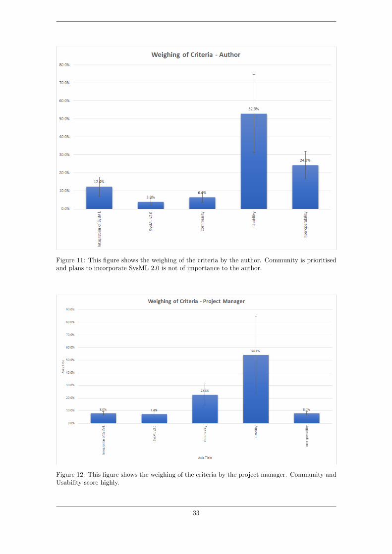
Figure 11: This figure shows the weighing of the criteria by the author. Community is prioritisedand plans to incorporate SysML 2.0 is not of importance to the author.
Figure 12: This figure shows the weighing of the criteria by the project manager. Community andUsability score highly.
33

Figure 13: This figure shows the weighing of the criteria by the team leader of On-board ProcessingAlgorithms. Community is highly valued, with usability as a second priority.
Figure 14: This figure shows the weighing of the criteria by the ADCS team leader. Usability ishighly valued, with interoperability as a close second.
34

Figure 15: This figure shows the weighing of the criteria by the Mechanics team leader. Usabilityscored highly, while SysML and community was not prioritised.
35

NTN
UN
orw
egia
n U
nive
rsity
of S
cien
ce a
nd T
echn
olog
yFa
culty
of E
ngin
eerin
gD
epar
tmen
t of M
echa
nica
l and
Indu
stria
l Eng
inee
ring
Runar Gården Rovik
Using Model Based SystemsEngineeringto Improve Design Decisions andCommunications in Student CubeSatProjects
Master’s thesis in Mechanical EngineeringSupervisor: Cecilia HaskinsCo-supervisor: Evelyn Honoré-LivermoreJuly 2021
Mas
ter’s
thes
is