Using a Shading Tool to Reform Window designing due to ...
6
Using a Shading Tool to Reform Window designing due to Solar Radiation Bahar Sultan Qurraie Department of Architecture Faculty of Engineering and Architecture, Gazi University Ankara, Turkey [email protected] Figen Beyhan Department of Architecture Faculty of Engineering and Architecture, Gazi University Ankara, Turkey [email protected] Abstract— Sun is the significant criterion that plays the most important role in architectural design. The sun's heat and radiation interact with the designed components of form and façade. These shading elements exhibit different expressions according to the structure orientation and the sun position. According to the climate of structure’s location, the expressions are being used to better respond to the environment in sustainable architecture. In order to get to this point, it is very important to calculate the shading geometry and solar energy during the day and to provide more suitable systems in glass and window designing. According to this, in order to arrive at more suitable shading systems by supporting MATLAB program, the software is written by taking the previous works as basis and closing some of their mistakes. According to the climate data, this program takes the plan drawings of window’s zone and some other information of window, the annual shading simulations are presented. Due to these simulations incident solar radiation of window, essential element of cooling load increasing in summer calculated. Furthermore window designing will be occurred by these simulations. So for the future works the user can import the glass or other datum of window or shading monument to design more efficiency. Index Terms— MATLAB program, shading, radiation, function, zone. I. INTRODUCTION Shading technique plays a critical role in improving energy efficiency. To examine the behavior of a shading technique, usual procedure is managing theoretical proves of solar heat gain coefficient (SHGC) or simulating of energy saving of building during definitive time [1]. In order to evaluate the performance of a shading device, the ability to compute the amount of shaded and unshaded area due to the shadow cast on a window by the sunray is required [2]. Jones employed the concept of a shading plane defined by the leading edge of the overhang and the bottom of the window to estimate the shaded area on a window. This method was also used for computing the amount of solar radiation on a vertical plane [3]. The other method is trigonometric approach which has been fully investigated with regards to the presence of awnings, over- hangs, side fins and parapets. Their geometries are characterized by rectangular shapes, which are parallel to the plane of the window and symmetric to its vertical axis [4]. In addition, SOMBRERO, a PC-program written in Turbo-Pascal, calculates the GSC (geometrical shading coefficient), the proportion of shaded area of an arbitrarily oriented surface surrounded by shading elements as a function of time and location [5]. Although TRNSHD is another PC-program developed with TRNSYS, for external shading and internal insulation simulations of structures [6]. Another software tool was performed by [2] which uses AutoCAD for graphically designing the geometry of shading system and MATLAB to prepare the algorithmic simulations. And the other program written in MATLAB developed by [7] which calculates the solar radiation and shadows on a rectangle surface. ShadingPlus is the other one to calculate solar heat gain coefficient (SHGC) is developed based on EnergyPlus (the computer simulation methodology) and uses as its core simulation engine [1]. All of these researches and simulation machines have details and advantages to reach the opinion, but all do not encompass all the field to draw a suitable window and shading form according to the plan and other criteria such as environmental elements. To achieve this issue, the graphical program has been written in MATLAB program language and user must insert location, time and other data with drawing the plan of the project. II. T CITY FUNCTION First of all climate is being identified and many cities of the world are already included. If the user does not found the desired city, the excel climate data needs to be added to energy plus site (https://energyplus.net/weather). The user transfers the program climate conditions by selecting the city. DOI: 10.24178/ijare.2018.4.1.01 International Journal of Advanced Research in Engineering (ISSN Online: 2412-4362) IJARE Vol 4(1) Mar 2018 This is an open access article under the CC BY-SA 4.0 license (https://creativecommons.org/licenses/by-sa/4.0/) IJARE 1
-
Upload
khangminh22 -
Category
Documents
-
view
6 -
download
0
Transcript of Using a Shading Tool to Reform Window designing due to ...

Using a Shading Tool to Reform Window designing due to Solar Radiation
Bahar Sultan Qurraie Department of Architecture
Faculty of Engineering and Architecture, Gazi University Ankara, Turkey
Figen Beyhan Department of Architecture
Faculty of Engineering and Architecture, Gazi University Ankara, Turkey
Abstract— Sun is the significant criterion that plays the most important role in architectural design. The sun's heat and radiation interact with the designed components of form and façade. These shading elements exhibit different expressions according to the structure orientation and the sun position. According to the climate of structure’s location, the expressions are being used to better respond to the environment in sustainable architecture.
In order to get to this point, it is very important to calculate the shading geometry and solar energy during the day and to provide more suitable systems in glass and window designing. According to this, in order to arrive at more suitable shading systems by supporting MATLAB program, the software is written by taking the previous works as basis and closing some of their mistakes. According to the climate data, this program takes the plan drawings of window’s zone and some other information of window, the annual shading simulations are presented. Due to these simulations incident solar radiation of window, essential element of cooling load increasing in summer calculated. Furthermore window designing will be occurred by these simulations. So for the future works the user can import the glass or other datum of window or shading monument to design more efficiency.
Index Terms— MATLAB program, shading, radiation, function, zone.
I. INTRODUCTION
Shading technique plays a critical role in improving energy efficiency. To examine the behavior of a shading technique, usual procedure is managing theoretical proves of solar heat gain coefficient (SHGC) or simulating of energy saving of building during definitive time [1]. In order to evaluate the performance of a shading device, the ability to compute the amount of shaded and unshaded area due to the shadow cast on a window by the sunray is required [2]. Jones employed the concept of a shading plane defined by the leading edge of the overhang and the bottom of the window to estimate the shaded area on a window. This method was also used for computing the amount of solar radiation on a vertical plane [3]. The other
method is trigonometric approach which has been fully investigated with regards to the presence of awnings, over- hangs, side fins and parapets. Their geometries are characterized by rectangular shapes, which are parallel to the plane of the window and symmetric to its vertical axis [4]. In addition, SOMBRERO, a PC-program written in Turbo-Pascal, calculates the GSC (geometrical shading coefficient), the proportion of shaded area of an arbitrarily oriented surface surrounded by shading elements as a function of time and location [5]. Although TRNSHD is another PC-program developed with TRNSYS, for external shading and internal insulation simulations of structures [6]. Another software tool was performed by [2] which uses AutoCAD for graphically designing the geometry of shading system and MATLAB to prepare the algorithmic simulations. And the other program written in MATLAB developed by [7] which calculates the solar radiation and shadows on a rectangle surface. ShadingPlus is the other one to calculate solar heat gain coefficient (SHGC) is developed based on EnergyPlus (the computer simulation methodology) and uses as its core simulation engine [1]. All of these researches and simulation machines have details and advantages to reach the opinion, but all do not encompass all the field to draw a suitable window and shading form according to the plan and other criteria such as environmental elements. To achieve this issue, the graphical program has been written in MATLAB program language and user must insert location, time and other data with drawing the plan of the project.
II. T CITY FUNCTION First of all climate is being identified and many cities of
the world are already included. If the user does not found the desired city, the excel climate data needs to be added to energy plus site (https://energyplus.net/weather). The user transfers the program climate conditions by selecting the city.
DOI: 10.24178/ijare.2018.4.1.01
International Journal of Advanced Research in Engineering (ISSN Online: 2412-4362)
IJARE Vol 4(1) Mar 2018
This is an open access article under the CC BY-SA 4.0 license (https://creativecommons.org/licenses/by-sa/4.0/)
IJARE
1

III. SOLAR FUNCTION
A. Solar Position
Fig. 1. Sun's zenith, altitude, and azimuth angles [8]
The solar position in relation to a point on the Earth’s surface can be determined by the solar azimuth angle φ and by the solar elevation angle . There are various methods to
calculate the value of these parameters with geo-location data, date and time [9-12].
The sun paths are different due to factors such as the: 1) Location (local latitude) 2) Rising and setting position (based on the time of the
year) 3) Duration of the day and night [13]
B. Declination angle The declination angle, the angle between the earth's
equatorial plane and the ecliptic plane, denoted by δ. If the Earth were not tilted on its axis of rotation, the declination would always be 0°. However, the Earth is tilted by 23.45° and the declination angle varies plus or minus this amount. Only at the spring and fall equinoxes is the declination angle equal to 0°. All the following equations developed from work by [8] which compliance with ASHRAE standards.
δ=23.45o sin [360/365(d−81)] Where d is the day of the year with Jan 1 as d = 1.
C. Local Standard Time Meridian (LSTM) The Local Standard Time Meridian (LSTM) is a
reference meridian used for a particular time zone and is similar to the Prime Meridian, which is used for Greenwich Mean Time. The (LSTM) is calculated according to the equation:
LSTM=15o.ΔTGMT [14]
Where ΔTGMT is the difference of the Local Time (LT) from Greenwich Mean Time (GMT) in hours.
D. Equation of Time (EoT) The equation of time (EoT) (in minutes) is an empirical
equation that corrects for the eccentricity of the Earth's orbit and the Earth's axial tilt.
EoT = 9.87 sin (2B) − 7.53 cos(B) − 1.5sin(B) [7]
Where B=3603/65(d−81) in degrees and d is the number of days since the start of the year.
E. Time Correction Factor (TC) The net Time Correction Factor (in minutes) accounts for
the variation of the Local Solar Time (LST) within a given time zone due to the longitude variations within the time zone and also incorporates the EoT above.
TC = 4 (Longitude−LSTM) + EoT [14]
The factor of 4 minutes comes from the fact that the Earth rotates 1° every 4 minutes.
F. Local Solar Time (LST) The Local Solar Time (LST) can be found by using the
previous two corrections to adjust the local time (LT).
LST=LT+TC60 [8]
G. Hour Angle (h) The Hour Angle converts the local solar time (LST) into
the number of degrees which the sun moves across the sky. By definition, the Hour Angle is 0° at solar noon. Since the Earth rotates 15° per hour, each hour away from solar noon corresponds to an angular motion of the sun in the sky of 15°. In the morning the hour angle is negative, in the afternoon the hour angle is positive.
h=15o(LST−12) [7]
H. Elevation angle (α) The elevation angle is the angular height of the sun in the
sky measured from the horizontal.
α = sin−1 [sin δ sin ϕ + cos δ cos ϕ cos h] [8] Where δ is the declination angle, ϕ is the local latitude
and h is the Hour angle.
I. Azimuth Angle (φ) The azimuth angle is the compass direction from which
the sunlight is coming. At solar noon, the sun is always directly south in the northern hemisphere and directly north in the southern hemisphere.
φ = cos−1[sin δ cos ϕ – cos δ cos ϕ cos h cos α] Where δ is the declination angle, ϕ is the local latitude
and HRA is the Hour angle Solar radiation data are often recorded in terms of local apparent time (LAT), also called true solar time (TST) [14].
DOI: 10.24178/ijare.2018.4.1.01
International Journal of Advanced Research in Engineering (ISSN Online: 2412-4362)
IJARE Vol 4(1) Mar 2018
This is an open access article under the CC BY-SA 4.0 license (https://creativecommons.org/licenses/by-sa/4.0/)
IJARE
2

IV. SHADING FUNCTION
Fig. 2. window surface Coordinate systems [15]
For locations which are at latitudes away from the equator, during the summer months, the sun will cast relatively short shadow while during the winter months, the sun will cast long shadows of objects. In the equatorial region, the sun’s path remains relatively unchanged hence the length of the shadows does not vary much throughout the year [13].
Whenever the direct radiation does not strike a surface there would be shadows. To compute the shadow of slabs or walls on the window we will benefit from previous works which calculated the geometry of shadow on global coordinate system xyz (the x-axis along the south direction, the y-axis along the east direction and the z-axis along the zenith direction).
The equation of a tilt plane through the origin is ax + by
+ cz = 0, where the tilt plane will be our case study window surfaced and in normal conditions the tilt degree is 90 º. Fig 2 seems window surface in coordinate systems.
All of these part’s equations and shading calculations are deducted from Cascone et al. [15] and evaluated by authors to code with MATLAB.
Where XY is window surface coordinate system and is the surface azimuth of window plane (angle between south and -Y) and is the window surface (wall) tilt angle (normally 90º). To set the solar vector due to zone and time “S” will be reached;
Where φ is solar azimuth angle and is solar elevation angle.
So when e.s will be negative the sun is in the back of
window surface so we will have full shadow, and when it will be positive we will have the shadow of obstacles [16]. To determine the shadow of obstacles, the corner points with P0(x0, y0, z0) will be considered and to find P’ (the shadow of P on window surface) we have these equation [15];
=
We need to turn it to the x y plane because it is difficult
to organize it in three dimensions. According to this, two matrixes are defined due to author;
To find in new xy coordinate system;
So the shadow of the corner points of obstacles will be reached. With connecting them we have the geometry of shadow on the window surface. The calculation of tree shadows and environment items is performed according to the Vegetation model of [15].
Fig 3 shows a screenshot of shadow function of MATLAB coding.
V. PLAN-DRAW FUNCTION The "Plan-Draw" function is defined to find the position
of the window relative to the building and the environment of the building. According to this function user must draw the zone plans one by one and ensure that the necessary data are entered. Fig 4 includes a screenshot of "Plan-Draw" function.
-Y
DOI: 10.24178/ijare.2018.4.1.01
International Journal of Advanced Research in Engineering (ISSN Online: 2412-4362)
IJARE Vol 4(1) Mar 2018
This is an open access article under the CC BY-SA 4.0 license (https://creativecommons.org/licenses/by-sa/4.0/)
IJARE
3
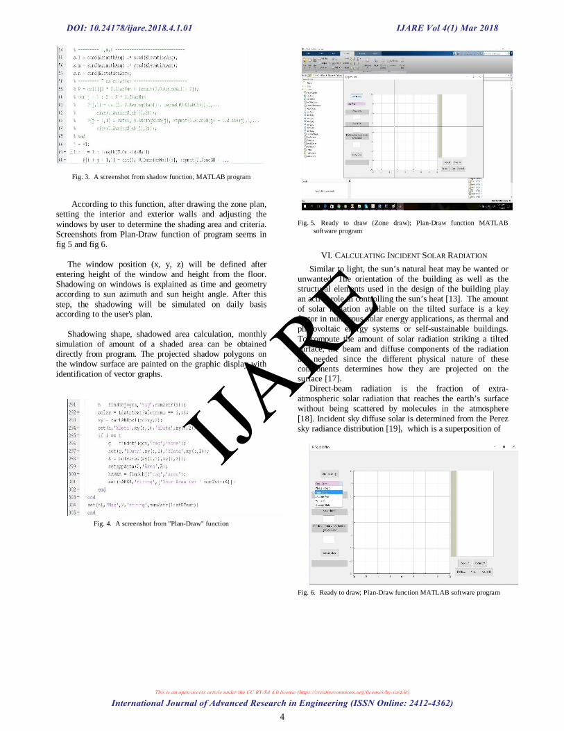
Fig. 3. A screenshot from shadow function, MATLAB program
According to this function, after drawing the zone plan,
setting the interior and exterior walls and adjusting the windows by user to determine the shading area and criteria. Screenshots from Plan-Draw function of program seems in fig 5 and fig 6.
The window position (x, y, z) will be defined after
entering height of the window and height from the floor. Shadowing on windows is explained as time and geometry according to sun azimuth and sun height angle. After this step, the shadowing will be simulated on daily basis according to the user's plan.
Shadowing shape, shadowed area calculation, monthly
simulation of amount of a shaded area can be obtained directly from program. The projected shadow polygons on the window surface are painted on the graphic display with identification of vector graphs.
Fig. 4. A screenshot from "Plan-Draw" function
Fig. 5. Ready to draw (Zone draw); Plan-Draw function MATLAB
software program
VI. CALCULATING INCIDENT SOLAR RADIATION Similar to light, the sun’s natural heat may be wanted or
unwanted. The orientation of the building as well as the structural elements used in the design of the building play an active role in controlling the sun’s heat [13]. The amount of solar radiation available on the tilted surface is a key factor in numerous solar energy applications, as thermal and photovoltaic energy systems or self-sustainable buildings. To compute the amount of solar radiation striking a tilted surface, the beam and diffuse components of the radiation are needed since the different physical nature of these components determines how they are projected on the surface [17].
Direct-beam radiation is the fraction of extra-atmospheric solar radiation that reaches the earth’s surface without being scattered by molecules in the atmosphere [18]. Incident sky diffuse solar is determined from the Perez sky radiance distribution [19], which is a superposition of
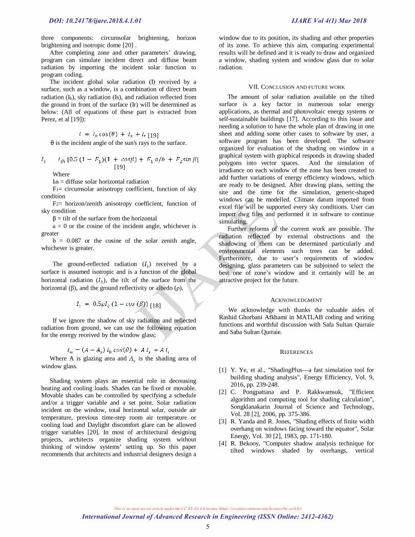
Fig. 6. Ready to draw; Plan-Draw function MATLAB software program
DOI: 10.24178/ijare.2018.4.1.01
International Journal of Advanced Research in Engineering (ISSN Online: 2412-4362)
IJARE Vol 4(1) Mar 2018
This is an open access article under the CC BY-SA 4.0 license (https://creativecommons.org/licenses/by-sa/4.0/)
IJARE
4
three components: circumsolar brightening, horizon brightening and isotropic dome [20] .
After completing zone and other parameters’ drawing, program can simulate incident direct and diffuse beam radiation by importing the incident solar function to program coding.
The incident global solar radiation (I) received by a surface, such as a window, is a combination of direct beam radiation (Ib), sky radiation (Is), and radiation reflected from the ground in front of the surface (Ir) will be determined as below: (All of equations of these part is extracted from Perez, et al [19]):
[19]
θ is the incident angle of the sun's rays to the surface.
[19] Where Idh = diffuse solar horizontal radiation F1= circumsolar anisotropy coefficient, function of sky
condition F2= horizon/zenith anisotropy coefficient, function of
sky condition β = tilt of the surface from the horizontal a = 0 or the cosine of the incident angle, whichever is
greater b = 0.087 or the cosine of the solar zenith angle,
whichever is greater. The ground-reflected radiation ( ) received by a
surface is assumed isotropic and is a function of the global horizontal radiation ( ), the tilt of the surface from the horizontal (β), and the ground reflectivity or albedo (ρ).
[18]
If we ignore the shadow of sky radiation and reflected
radiation from ground, we can use the following equation for the energy received by the window glass;
Where A is glazing area and is the shading area of window glass.
Shading system plays an essential role in decreasing
heating and cooling loads. Shades can be fixed or movable. Movable shades can be controlled by specifying a schedule and/or a trigger variable and a set point. Solar radiation incident on the window, total horizontal solar, outside air temperature, previous time-step room air temperature or cooling load and Daylight discomfort glare can be allowed trigger variables [20]. In most of architectural designing projects, architects organize shading system without thinking of window systems’ setting up. So this paper recommends that architects and industrial designers design a
window due to its position, its shading and other properties of its zone. To achieve this aim, comparing experimental results will be defined and it is ready to draw and organized a window, shading system and window glass due to solar radiation.
VII. CONCLUSION AND FUTURE WORK The amount of solar radiation available on the tilted
surface is a key factor in numerous solar energy applications, as thermal and photovoltaic energy systems or self-sustainable buildings [17]. According to this issue and needing a solution to have the whole plan of drawing in one sheet and adding some other cases to software by user, a software program has been developed. The software organized for evaluation of the shading on window in a graphical system with graphical responds in drawing shaded polygons into vector spaces. And the simulation of irradiance on each window of the zone has been created to add further variations of energy efficiency windows, which are ready to be designed. After drawing plans, setting the site and the time for the simulation, generic-shaped windows can be modelled. Climate datum imported from excel file will be supported every sky conditions. User can import dwg files and performed it in software to continue simulating.
Further reforms of the current work are possible. The radiation reflected by external obstructions and the shadowing of them can be determined particularly and environmental elements such trees can be added. Furthermore, due to user’s requirements of window designing, glass parameters can be subjoined to select the best one of zone’s window and it certainly will be an attractive project for the future.
ACKNOWLEDGMENT We acknowledge with thanks the valuable aides of
Rashid Ghorbani Afkhami in MATLAB coding and writing functions and worthful discussion with Safa Sultan Qurraie and Saba Sultan Qurraie.
REFERENCES [1] Y. Ye, et al., "ShadingPlus—a fast simulation tool for
building shading analysis", Energy Efficiency, Vol. 9, 2016, pp. 239-248.
[2] C. Pongpattana and P. Rakkwamsuk, "Efficient algorithm and computing tool for shading calculation", Songklanakarin Journal of Science and Technology, Vol. 28 [2], 2006, pp. 375-386.
[3] R. Yanda and R. Jones, "Shading effects of finite width overhang on windows facing toward the equator", Solar Energy, Vol. 30 [2], 1983, pp. 171-180.
[4] R. Bekooy, "Computer shadow analysis technique for tilted windows shaded by overhangs, vertical
DOI: 10.24178/ijare.2018.4.1.01
International Journal of Advanced Research in Engineering (ISSN Online: 2412-4362)
IJARE Vol 4(1) Mar 2018
This is an open access article under the CC BY-SA 4.0 license (https://creativecommons.org/licenses/by-sa/4.0/)
IJARE
5

projections, and side fins", ASHRAE Trans.;(United States), Vol. 89 [1A], 1983.
[5] A. Niewienda and F. Heidt, "SOMBRERO: A PC-tool to calculate shadows on arbitrarily oriented surfaces", Solar Energy, Vol. 58 [4-6], 1996, pp. 253-263.
[6] M. D. Hiller, TRNSHD-A Program for Shading and Insolation Calculations. 1996, University of Wisconsin-Madison.
[7] B. Keller and A. Costa, "A Matlab GUI for calculating the solar radiation and shading of surfaces on the earth", Computer Applications in Engineering Education, Vol. 19 [1], 2011, pp. 161-170.
[8] M. Iqbal, "Sun-Earth Astronomical Relationships," An Introduction to Solar Radiation, Vol. 1-28, 1983.
[9] J. J. Michalsky, "The astronomical almanac's algorithm for approximate solar position (1950–2050)", Solar energy, Vol. 40 [3], 1988, pp. 227-235.
[10] E. G. Melo, et al., "Using a shading matrix to estimate the shading factor and the irradiation in a three-dimensional model of a receiving surface in an urban environment", Solar Energy, Vol. 92, 2013, pp. 15-25.
[11] M. Blanco-Muriel, et al., "Computing the solar vector", Solar Energy, Vol. 70 [5], 2001, pp. 431-441.
[12] I. Reda and A. Andreas, "Solar position algorithm for solar radiation applications", Solar energy, Vol. 76 [5], 2004, pp. 577-589.
[13] L. You, L. Hao, and L. Adele, "Sun and Architecture", GEK 1506 Heavenly Mathematics.
[14] W. H. Wilson, "Solar ephemeris algorithm", SIO Ref, Vol. 80, 1980, pp. 13.
[15] Y. Cascone, V. Corrado, and V. Serra, "Calculation procedure of the shading factor under complex boundary conditions", Solar Energy, Vol. 85 [10], 2011, pp. 2524-2539.
[16] E. DOE, "6.0 input/output reference: The encyclopedic reference to EnergyPlus input and output", US Department of Energy, 2010.
[17] J. Ruiz-Arias, et al., "Proposal of a regressive model for the hourly diffuse solar radiation under all sky conditions", Energy Conversion and Management, Vol. 51 [5], 2010, pp. 881-893.
[18] K. B. Pierce, T. Lookingbill, and D. Urban, "A simple method for estimating potential relative radiation (PRR) for landscape-scale vegetation analysis", Landscape Ecology, Vol. 20 [2], 2005, pp. 137-147.
[19] R. Perez, et al., "Modeling daylight availability and irradiance components from direct and global irradiance", Solar energy, Vol. 44 [5], 1990, pp. 271-289.
[20] F. C. Winkelmann, "Modeling windows in EnergyPlus", Proceedings IBPSA Building Simulation, 2001.
DOI: 10.24178/ijare.2018.4.1.01
International Journal of Advanced Research in Engineering (ISSN Online: 2412-4362)
IJARE Vol 4(1) Mar 2018
This is an open access article under the CC BY-SA 4.0 license (https://creativecommons.org/licenses/by-sa/4.0/)
IJARE
6