USG BORAL FIRE-RATED SYSTEMS
24
USG BORAL FIRE-RATED SYSTEMS (UL Classified) ©2017 USG Boral Building Products Pte Ltd. All rights reserved. The trademarks USG BORAL and INNOVATION INSPIRED BY YOU are the trademarks of USG Boral Building Products Pte Ltd. The trademarks DUROCK, SHEETROCK, AND SECUROCK are the trademarks of U.S. Gypsum Company and used under license. TM_P(TC)_FS_1018_V1 USGBoral.com Plasterboard Ceilings Interior Finishes Metal Framing Substrates
-
Upload
khangminh22 -
Category
Documents
-
view
4 -
download
0
Transcript of USG BORAL FIRE-RATED SYSTEMS
USG BORALFIRE-RATED SYSTEMS(UL Classified)
©2017 USG Boral Building Products Pte Ltd. All rights reserved. The trademarks USG BORAL and INNOVATION INSPIRED BY YOU are the trademarks of USG Boral Building Products Pte Ltd. The trademarks DUROCK, SHEETROCK, AND SECUROCK are the trademarks of U.S. Gypsum Company and used under license.TM_P(TC)_FS_1018_V1
USGBoral.com Plasterboard Ceilings Interior Finishes Metal Framing Substrates
IntroductionContent
CONTENTS
Introduction 01
Building Code 02
Fire Engineering 03
UL Introduction 04
UL Listed Systems 05
UL Classified Systems 06
Floor-Ceiling 10
Fire Separation 11
Beams & Columns 12
Installation Details 13
Installation 14
Building Code Requirements 19

Introduction Introduction
01
Content
The Presidential Decree 1096 otherwise known as The National Building Code of the Philippines is the mandatory rules and regulations in building construction.
It is the policy of the State to safeguard life, health, property, and public welfare - consistent with the principles of sound environmental management. The National Building Code provides the framework and the minimum standards or regulations for all buildings and structures in order to control the building’s:
• Location • Construction • Site • Use • Design • Occupancy • Quality of material • Maintenance
The Code covers the following disciplines: architectural, civil/structural, electrical, mechanical, sanitary, plumbing, and electronics. This shall also apply to design, location, siting, construction, alteration, repair, conversion, use, occupancy, maintenance, moving, demolition of, and addition to public and private buildings and structures, except for traditional indigenous family dwellings, and those covered by Batas Pambansa Bilang 220 otherwise known as the “Economic and Socialized Housing Projects”.
THE NATIONAL BUILDING CODE OF THE PHILIPPINES
Exterior Track & BracketBuilding Code
DPWH
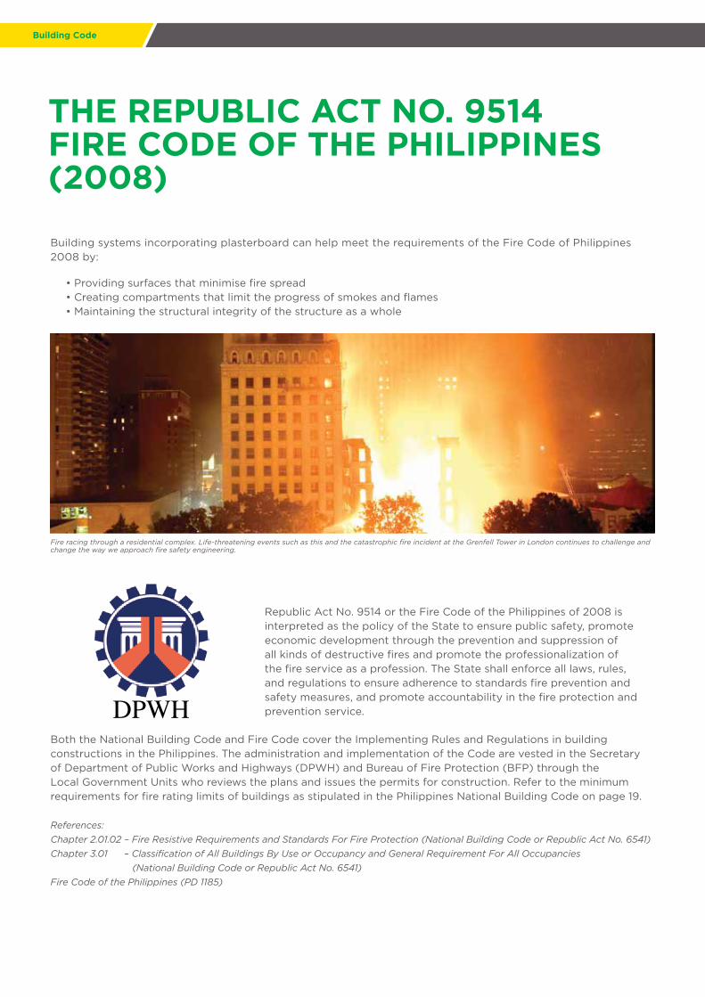
Building systems incorporating plasterboard can help meet the requirements of the Fire Code of Philippines 2008 by:
• Providing surfaces that minimise fire spread • Creating compartments that limit the progress of smokes and flames • Maintaining the structural integrity of the structure as a whole
Republic Act No. 9514 or the Fire Code of the Philippines of 2008 is interpreted as the policy of the State to ensure public safety, promote economic development through the prevention and suppression of all kinds of destructive fires and promote the professionalization of the fire service as a profession. The State shall enforce all laws, rules, and regulations to ensure adherence to standards fire prevention and safety measures, and promote accountability in the fire protection and prevention service.
Both the National Building Code and Fire Code cover the Implementing Rules and Regulations in building constructions in the Philippines. The administration and implementation of the Code are vested in the Secretary of Department of Public Works and Highways (DPWH) and Bureau of Fire Protection (BFP) through the Local Government Units who reviews the plans and issues the permits for construction. Refer to the minimum requirements for fire rating limits of buildings as stipulated in the Philippines National Building Code on page 19.
References:
Chapter 2.01.02 – Fire Resistive Requirements and Standards For Fire Protection (National Building Code or Republic Act No. 6541)
Chapter 3.01 – Classification of All Buildings By Use or Occupancy and General Requirement For All Occupancies
(National Building Code or Republic Act No. 6541)
Fire Code of the Philippines (PD 1185)
THE REPUBLIC ACT NO. 9514FIRE CODE OF THE PHILIPPINES (2008)
Fire racing through a residential complex. Life-threatening events such as this and the catastrophic fire incident at the Grenfell Tower in London continues to challenge and change the way we approach fire safety engineering.

Building Code Fire Engineering
03
Fire Engineering
UL certified fire-rated partition systems can be used in accordance with the performance-based principles of fire safety engineering. USG Boral’s fire-rated systems are specified and referenced across some of the most prestigious projects worldwide. They meet the objectives below which is in accordance with the Republic Act No. 9514 or the Fire Code of the Philippines 2008.
Objectives Means
To keep people safe Appropriate building design (compartments, smoke extraction, escape routes, ...)
To limit the risks of fire extensions and consequences
Classification or construction productsand systems
Fire Compartmentation
Introduction
The concept of fire resistance is the ability of a structure to maintain its structural capability and prevent the spread of flames or heat when exposed to fire conditions.
The gypsum that makes the core of USG Boral’s Type X Plasterboard portfolio is specially formulated to resist the dehydration by heat in the event of a fire.
USG BORAL TYPE X PLASTERBOARD
Fire compartmentation is a concept where the spread of fire within a building is restricted by partitioning walls or floors with fire resisting walls or ceilings. These partitions can also deter the spread of smoke which allows for a safe mode of escape during an emergency.
Fire Safety Functionality
Fire-rated partition for corridors as a mode of escape
Fire-rated ceiling in server rooms
Fire escape
USG Boral Rated Drywall/CeilingUSG Boral Securock® Fire-Rated Exterior Wall

UL Introduction
Underwriters Laboratories, UL is a global safety consulting and certification company (104 countries). It is one of several companies approved to perform safety testing by the U.S. Federal Agency Occupational Safety and Health Administration (OSHA). OSHA maintains a list of approved testing laboratories, which are known as Nationally Recognized Testing Laboratories.
How does UL Certified Fire-Rated System work?
1) All UL certified fire-rated products are tested under UL witnessed program2) Upon successfully passing the fire tests, the following taking place: • Minimum board weight is established • Formulation is also set for future production • The product is assigned a designation code • The product with specific designation code (as well as corresponding commercial name) will be listed in the approved fire-rated assemblies with key installation details (i.e. UL Designs) • The UL Designs will be added to the UL fire-rated system directory and can be accessed online publicly • The manufacturer will be issued an approved message that is to be printed on every single UL certified board to ensure only qualified products are installed in the job site • UL will also conduct regular plant inspection and review production record to ensure the compliance to its program
3) The following are the UL designation of USG Boral UL Certified products : • DCB- USG Durock® Cement Board • Type EX-1- 15.9mm (5/8”) Fire-Rated Plasterboard from Saraburi Plant • Type C- 15.9mm (5/8”) USG Boral Sheetrock® Firecode® Type C from Oman Plant • SCX- 15.9mm (5/8”) USG Boral Sheetrock® Firecode® X from Oman Plant • SGX- 15.9mm (5/8”) USG Boral Sheetrock® Glass-Mat Mold Tough® Firecode® X from Oman Plant • USGX- 15.9mm (5/8”) USG Boral Securock® Glass-Mat Sheathing Firecode® X from Oman Plant
UL CERTIFIED PRODUCTS INTRODUCTION
UL Introduction UL Listed Systems
05
USG BORAL’S UL CLASSIFIED FIRE-RATED PLASTERBOARD
The major concern when it comes to safeguarding lives against a catastrophic fire is the level of fire protection and the effectiveness of these protective measures.
Traditionally, designers follow a set of prescriptive Fire Code such as the Fire Code of the Philippines 2008 in applying the required fire protection for a building. Ethical design practices and the integrity of those designs are highly dependent on a robust testing system, coupled with a supply of fire-rated components that forms the fire-rated partition.
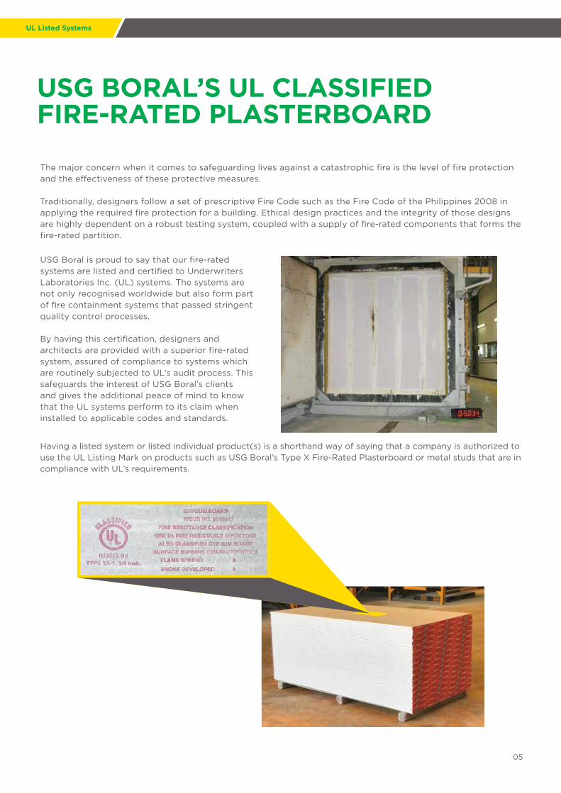
USG Boral is proud to say that our fire-rated systems are listed and certified to Underwriters Laboratories Inc. (UL) systems. The systems are not only recognised worldwide but also form part of fire containment systems that passed stringent quality control processes.
By having this certification, designers and architects are provided with a superior fire-rated system, assured of compliance to systems which are routinely subjected to UL’s audit process. This safeguards the interest of USG Boral’s clients and gives the additional peace of mind to know that the UL systems perform to its claim when installed to applicable codes and standards.
Having a listed system or listed individual product(s) is a shorthand way of saying that a company is authorized to use the UL Listing Mark on products such as USG Boral’s Type X Fire-Rated Plasterboard or metal studs that are in compliance with UL’s requirements.

UL Classified Systems
INTERIOR PARTITIONS WITH LIGHT GAUGE STUDS (0.45MM BMT (25 GAUGE))
90mm fiberglass insulation where applicable
Single layer 15.9mm (5/8”)EX-1, SCX, SGX, USGX
System Mass : 25kg/m2
Single layer 15.9mm (5/8”)EX-1, SCX, SGX, USGX
92mm stud x 0.45mm BMT@ 610mm spacing
(Maximum height 4600mm)
USG Boral 92mm x 0.45mm BMTmetal track
U465 60 mins
Fire Rating (mins)
UL System Number
Lining Side 1 Lining Side 2
Nom. Wall Width (mm) 124mm (4 7/8”)
RemarksStud Size (mm)
92mm (3 5/8’’)Min. 0.45mm (25 gauge)*
Insulation STC
60 U465 Single layer 15.9mm (5/8”) EX-1, SCX, SGX, USGX
Single layer 15.9mm (5/8”) EX-1, SCX, SGX, USGX Optional
STC 41 -no insulation Interiornon-bearing
wallSTC 47-90mm glass wool,
min. 14kg/m3
Notes:* Stud size is minimum unless otherwise stated in design. For more limiting height information, please contact your USG Boral office* 92mm stud x 0.45mm BMT @ 610mm spacing (Maximum height 4600mm)
UL Classified Systems
07
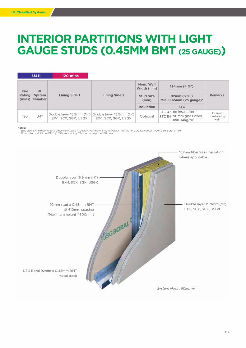
INTERIOR PARTITIONS WITH LIGHT GAUGE STUDS (0.45MM BMT (25 GAUGE))
Double layer 15.9mm (5/8”) EX-1, SCX, SGX, USGX
System Mass : 50kg/m2
Double layer 15.9mm (5/8”) EX-1, SCX, SGX, USGX
92mm stud x 0.45mm BMT@ 610mm spacing
(Maximum height 4600mm)
USG Boral 92mm x 0.45mm BMTmetal track
90mm fiberglass insulation where applicable
U411 120 mins
Fire Rating (mins)
UL System Number
Lining Side 1 Lining Side 2
Nom. Wall Width (mm) 124mm (4 7/8”)
RemarksStud Size (mm)
92mm (3 5/8’’)Min. 0.45mm (25 gauge)*
Insulation STC
120 U411 Double layer 15.9mm (5/8”) EX-1, SCX, SGX, USGX
Double layer 15.9mm (5/8”) EX-1, SCX, SGX, USGX Optional
STC 47-no insulation Interiornon-bearing
wallSTC 54-90mm glass wool,
min. 14kg/m3
Notes:* Stud size is minimum unless otherwise stated in design. For more limiting height information, please contact your USG Boral office* 92mm stud x 0.45mm BMT @ 610mm spacing (Maximum height 4600mm)

UL Classified Systems
INTERIOR PARTITIONS WITH LIGHT GAUGE STUDS (0.45MM BMT (25 GAUGE))
U420 60 - 120 mins
Fire Rating (mins)
ULSystem Number
Lining Side 1 Lining Side 2
Nom. Wall Width (mm) Double Wall
RemarksStud Size (mm)
41mm (1 5/8”)Min. 0.45mm BMT(25 gauge)
Insulation STC*
60 U420 Single layer 15.9mm (5/8”) EX-1, SCX, SGX, USGX
Single layer 15.9mm (5/8”) EX-1, SCX, SGX, USGX Optional
STC 46 -no insulationInterior
non-bearing wall
STC 57 -90mm glass wool, min. 14kg/m3, nom. wall width = 236mm
120 U420Double layer15.9mm (5/8”)
EX-1, SCX, SGX, USGX
Double layer 15.9mm (5/8”)
EX-1, SCX, SGX, USGX Optional
STC 51 -no insulationInterior
non-bearing wall
STC 62-90mm glass wool,min. 14kg/m3, nom. wall width = 268mm
Notes:* Stud size is minimum unless otherwise stated in design. For more limiting height information, please contact your USG Boral office* Twin stud 41mm Stud x 0.45mm BMT @610mm spacing (Maximum height 2900mm)
Single or double layer 15.9mm (5/8”) EX-1, SCX, SGX, USGX
System Mass : 25kg/m2 single layer board each side
50kg/m2 double layer board each side
Single or double layer 15.9mm (5/8”) EX-1, SCX, SGX, USGX
Twin stud 41mm stud x 0.45mm BMT @ 610mm spacing
(Maximum height 2900mm)
USG Boral 41mm x 0.45mm BMT metal track
90mm fiberglass insulation where applicable

UL Classified Systems
09
EXTERIOR PARTITIONS WITH HEAVY GAUGE STUDS (0.90MM BMT (20 GAUGE))
U425 45-120 mins
FireRating (mins)
ULSystem Number
Lining Side 1(Interior)
Lining Side 2(Exterior)
Nom. WallWidth (mm) Single Wall
RemarksStud Size (mm)
89mm (3 1/2”)Min. 0.90mm
BMT (20 gauge)Insulation STC*
45 U425 Single layer 15.9mm (5/8”) EX-1, SCX, SGX, USGX
Inside layer (Item 5)– 12.7mm (1/2”) or 15.9mm (5/8”)
Glass-Mat Sheathing;exterior layer (Item 5)
Durock® DCB
Required**(Any glass wool or mineral wool
with UL Marking)
STC 47
90mmglass wool,
min. 14kg/m3
Exterior bearing wall; design load 100%; fire from interior
ONLY.
60 U425 Double layer 12.7mm (1/2”) Type C STC 49
90 U425Double layer 15.9mm (5/8”)
EX-1, SCX, SGX, USGX STC 50
120 U425 3 layer 12.7mm (1/2”) Type C STC 51
Notes:* Stud size is minimum unless otherwise stated in design. For more limiting height information, please contact your USG Boral office* Max height with 92mm stud x 0.90mm BMT x 610mm spacing : 3000mm for wind pressure = 1.0kPa** Any glass wool or mineral wool with UL Marking
Insulation
Inside layer (Item 5)– 12.7mm (1/2”)or 15.9mm (5/8”) Glass-Mat Sheathing;exterior layer (Item 5) Durock® DCB
Exterior
Interior
3 layer 12.7mm (1/2”) Type C
Max. height with 92mm stud x 0.90mm BMT @ 610mm spacing: 4500mm
(Maximum height 3000mm for wind pressure = 1.0 kPa)
USG Boral 92mm x 0.84mm BMT metal track
Floor-Ceiling
FLOOR-CEILING SYSTEMS
G501 60 mins
FireRating(mins)
ULSystemNumber
Floor Ceiling Board
SteelJoist
Type 12J4Min. Size
RemarksFurringChannel
60.5mm (2 3/8”)(26 gauge) GI
Insulation STC**
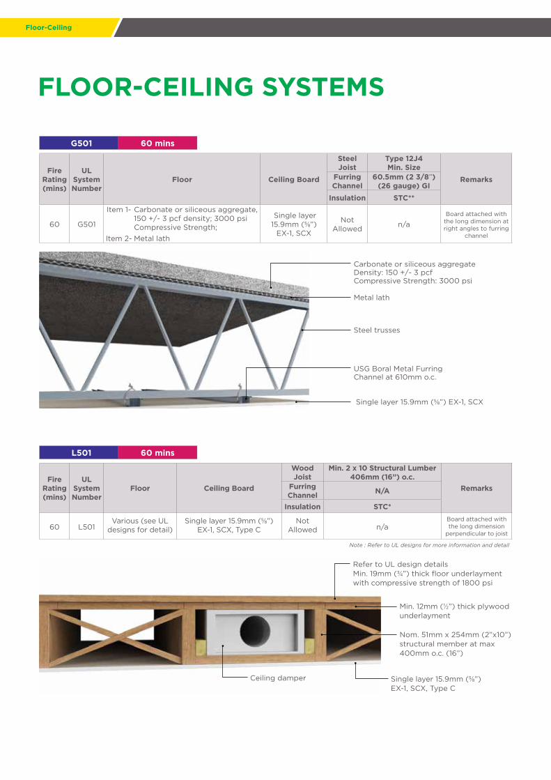
60 G501
Item 1- Carbonate or siliceous aggregate, 150 +/- 3 pcf density; 3000 psi Compressive Strength;
Single layer15.9mm (5/8”)
EX-1, SCX
NotAllowed n/a
Board attached with the long dimension at right angles to furring
channelItem 2- Metal lath
Carbonate or siliceous aggregateDensity: 150 +/- 3 pcf Compressive Strength: 3000 psi
USG Boral Metal Furring Channel at 610mm o.c.
Single layer 15.9mm (5/8”) EX-1, SCX
Metal lath
Steel trusses
Refer to UL design details Min. 19mm (3/4”) thick floor underlayment with compressive strength of 1800 psi
Single layer 15.9mm (5/8”)EX-1, SCX, Type C
Ceiling damper
Min. 12mm (1/2”) thick plywood underlayment
Nom. 51mm x 254mm (2”x10”) structural member at max 400mm o.c. (16”)
L501 60 mins
FireRating(mins)
ULSystemNumber
Floor Ceiling Board
WoodJoist
Min. 2 x 10 Structural Lumber 406mm (16”) o.c.
RemarksFurringChannel N/A
Insulation STC*
60 L501Various (see UL
designs for detail)Single layer 15.9mm (5/8”)
EX-1, SCX, Type CNot
Allowed n/aBoard attached with the long dimension
perpendicular to joist
Note : Refer to UL designs for more information and detail
11
Fire Separation
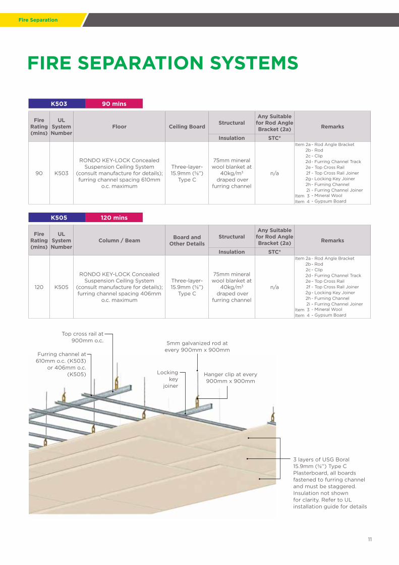
FIRE SEPARATION SYSTEMS
K503 90 mins
FireRating(mins)
ULSystemNumber
Floor Ceiling BoardStructural
Any Suitable for Rod Angle Bracket (2a) Remarks
Insulation STC*
90 K503
RONDO KEY-LOCK Concealed Suspension Ceiling System
(consult manufacture for details); furring channel spacing 610mm
o.c. maximum
Three-layer- 15.9mm (5/8”)
Type C
75mm mineral wool blanket at
40kg/m3
draped over furring channel
n/a
Item 2a - Rod Angle Bracket 2b- Rod2c - Clip2d- Furring Channel Track2e - Top Cross Rail2f - Top Cross Rail Joiner2g- Locking Key Joiner2h - Furning Channel2i - Furring Channel Joiner
Item 3 - Mineral WoolItem 4 - Gypsum Board
K505 120 mins
FireRating(mins)
ULSystemNumber
Column / Beam Board and Other Details
StructuralAny Suitable
for Rod Angle Bracket (2a) Remarks
Insulation STC*
120 K505
RONDO KEY-LOCK Concealed Suspension Ceiling System
(consult manufacture for details); furring channel spacing 406mm
o.c. maximum
Three-layer- 15.9mm (5/8”)
Type C
75mm mineral wool blanket at
40kg/m3
draped over furring channel
n/a
Item 2a - Rod Angle Bracket2b- Rod2c - Clip2d- Furring Channel Track2e - Top Cross Rail2f - Top Cross Rail Joiner2g- Locking Key Joiner2h - Furning Channel2i - Furring Channel Joiner
Item 3 - Mineral WoolItem 4 - Gypsum Board
Top cross rail at 900mm o.c.
Furring channel at 610mm o.c. (K503)
or 406mm o.c. (K505) Locking
key joiner
Hanger clip at every900mm x 900mm
3 layers of USG Boral 15.9mm (5/8’’) Type C Plasterboard, all boards fastened to furring channel and must be staggered. Insulation not shown for clarity. Refer to UL installation guide for details
5mm galvanized rod atevery 900mm x 900mm

Beams & Columns
BEAM AND COLUMN DESIGNS
N501 120 mins
FireRating(mins)
ULSystemNumber
Column / Beam Board and Other DetailsSteel
ColumnMin. Size
W 10 x 49 RemarksInsulation STC*
120
N501(see N502 and N505 for other
variations)
Min. size 203mm (W) x 610mm (L) (8" x 24") with outside dimensionof 200mm (7 7/8") x 165mm (6 1/2”)
with a flange thickness of 9.5mm (3/8") and web thickness
of 6.4mm (1/4") and cross section area of 46cm2 (7.06in2)
Item 1 -Concrete floor 149 pc
n/a n/a
1st layer fastened with 32mm (1 1/4") long
0.150" screw spaced 406mm (16") o.c.;
Item 2-Steel floor 38mm (1 1/2”) fluted type, welded to beam
Item 5-Brackets 0.56mm BMT (24 gauge) galvanized and 51mm (2”) legs
2nd layer with 44mm (1 3/4") long 0.15"
screw spaced 203mm (8") o.c.; screws are self-drilling and self-
tapping head made of case-hardened steel.
Item 6 -Corner angle 24 gauge GI 1 and 51mm (2”) legs fasterned to brackets
Item 7-Two-layer 15.9mm (5/8”) EX-1, SCX, Type C, Type C
X508* 180 mins
FireRating(mins)
ULSystemNumber
Column / Beam Board and Other DetailsSteel
ColumnMin. Size
W 10 x 49 RemarksInsulation STC*
180 X508
Min. size 254mm (W) x 254mm (L) (10" x 49") with outside dimension
of 254mm (10”) x 254mm (10”)with a flange thickness of
14.3mm (9/16”) and web thicknessof 7.9mm (5/16”) and cross section
area of 93cm2 (14.4in2)
Item 1-Three-layer 15.9mm (5/8”)EX-1, SCX, SGX, USGX, Type C
Notallowed n/a
Inner layer of 15.9mm (5/8”)
wallboard installed without horizontal joints. 25.4mm (1”) long self-drilling screws randomly
spaced as required for spport during installation of first layer of wall board
.
Item 2-28 gauge GI metal corner beads
Item 3-18 SWG annealed wire spaced 152mm (6”) from each end and at 533mm (1'9") interval
Item 4 -Gypsum plaster may be appliedItem 5 -Laminated with joint cement
2 x 15.9mm (5/8”) USG Boral Type C Plasterboard, all boards fastened to steel framing with case-hardened self tapping drywall screw
Brackets, 0.42mm BMT (24 gauge)
25mm x 51mm x 0.56mm BMT (24 gauge) corner angle
Concrete floor
Steel floor decking,32mm (1 1/4") fluted,
welded to beam
* Applicable for vertical or horizontal beam
0.345mm BMT(28 gauge)
Finished with USG BoralJoint Compounds
3 layers of USG Boral 15.9mm (5/8”) Type C Plasterboard
Beam Column
Note : Refer to UL design for more information and details

Installation Details
13
1-Layer Plasterboard Partition – U465Steel Stud- Cut 20mm (3/4") less than assembly height.Gypsum Board– Attached to studs and floor and ceiling track with 25mm (1") long Type S steel screw spaced 305mm (12") o.c. in the field and 203mm (8") o.c. along edges of board. Joints oriented vertically and staggered on the opposite side.
2-Layer Plasterboard Partition – U411Steel Stud– Cut approximately 20mm (3/4") less than assembly heightGypsum Board– Inner layer attached to stud vertically with 25mm (1") long Type S steel screw spaced 406mm (16") o.c. in the field and along the vertical edge; Outer layer attached to the stud over inner layer with 42mm (1 5/8") long Type S steel screw spaced 406mm (16") o.c. in the field and along the vertical edges and 305mm (12") o.c. to the floor and ceiling runners. Joints of screw-attached outer layer offset from inner layer joints. Joints of outer layer may be taped or untaped.
Top track
Bottom track
C-studs @ 610mm max o.c.
Acoustic insulation if required
Tape and set joints to external layers only
Vertical and horizontal joints to be staggered with adjacent and opposite boards
For the outer layer, boards are fastened at 406mm in field and 305mm on the edges of the plasterboard
Fasteners 10-16mm from edge of sheet
305mm
406mm
Fastened with 42mm long Type S steel screw at 305mm o.c. the top and bottom track for the outer layer
Stagger joints in layers. Inner layer fastened with 25mm
Type S screw spaced at 406mm in field and on edges
Double layer 15.9mm (5/8") EX-1, SCX, SGX, USGX
Top track
C-studs @ 610mm max o.c.
Acoustic insulation if required
Tape and set joints to external layers only
Vertical and horizontal joints to be staggered with adjacent and opposite boards
Fasteners spaced 305mm in field and at 203mm on the edges of the plasterboard
Fasteners 10-16mm from edge of sheet
Fastened with 25mm long Type S steel screw at 203mm o.c. at the top and bottom track
Single layer 15.9mm (5/8”) EX-1, SCX,SGX, USGX
Bottom track
203mm
305mm
INSTALLATION DETAILS
Installation
Vertically applied gypsum board shall have the edges parallel to framing members. Horizontally applied gypsum board shall have the edges at the right angles to the framing members. Intermediate vertical framing members are those between the vertical edges or ends of the board.
Unless otherwise stated in the detailed description of the individual system joints shall be staggered as follows:
a. Horizontal butt joints on opposite sides of a partition in single layer applications shall be staggered not less than 305mm (12").
b. Horizontal butt joints in adjacent layers on the same side of a partition in multilayer applications shall be staggered not less than 305mm (12").
c. Vertical joints on opposite sides of a partition in single layer applications shall not occur on the same stud.
When a fire-resistance-rated partition extends above the ceiling, the gypsum board joints occurring above the ceiling need not be taped and fasteners need not be covered when all of the following conditions are met.
a. The ceiling is part of a fire-resistance-rated floor ceiling or roof ceiling system;
b. All vertical joints occur over framing members;
c. Horizontal joints are either staggered 610mm (24") o.c. on opposite sides of the partition, or are covered with strips of gypsum board not less than 152mm (6") wide; or the partition is a two-layer system with joints staggered 406mm (16") or 610mm (24") o.c.; and
d. The partition is not part of a smoke or sound control system.
Where joint treatment is discontinued at or just above the ceiling line, the vertical joint shall be cross-taped at this location to reduce the possibility of joint cracking.
Metallic outlet boxes shall be permitted to be installed in wood and steel stud walls or partitions having gypsum board facings and classified as two hours or less. The surface area of individual boxes shall not exceed 103 square cm (16 square inch). The aggregate surface area of the boxes shall not exceed 645 square cm (100 square inch) in any 9.29 square meter (100 square feet). Boxes located on opposite sides of walls or partitions shall be in separate stud cavities and shall be separated by a minimum horizontal distance of 610mm (24"). Approved nonmetallic outlet boxes shall be permitted as allowed by local code. Installing outlet boxes in the sound control system may reduce the STC.
A vapor retarder shall be permitted to be added to any fire-resistance-rated system.
INSTALLATION DETAILS
JOINT STAGGERING
PARTITION– CEILING JUNCTION
VAPOR RETARDER
ELECTRICAL / UTILITY BOX

Installation
15
Unless otherwise specified in the detailed description, the generic steel studs and runners used in non-load-bearing walls and partitions in this Manual were fabricated from flat steel having a base metal thickness of not less than 0.45mm (0.0179") and have a return lip dimension of not less than 4.8mm (3/16")
Note: Consult the steel stud manufacturer for performance data and recommendations
before substituting proprietary steel studs that either are fabricated from steel having a
base metal thickness of less than 0.45mm (0.0179") have a return lip dimension less than
4.8mm (3/16").
Greater stud sizes (depths) shall be permitted to be used in metal or wood-stud systems. Metal studs of heavier gauge than those tested shall be permitted. The assigned rating of any load-bearing system shall also apply to the same system when used as a non-load-bearing system. Indicated stud spacings are maximums. Heavier gauge studs or closer stud spacing may reduce the STC. Greater stud depth may improve the STC.
Additional layers of Type X or regular gypsum panels shall be permitted to be added to any system. Additional layers of gypsum board may improve the STC.
When not specified as a component of a fire-resistance rated wall or partition system, cementitious backer units and/or wood structural panels shall be permitted to be added to one or both sides. Such panels shall be permitted to be applied either as a base layer directly to the framing (under the gypsum board), as a face layer (over the face layer of gypsum board), or between layers of gypsum board in multilayer systems. Where such panels are applied under the gypsum board or between layers of gypsum board the length of the fasteners specified for the attachment of the gypsum board applied over the panels shall be increased by not less than the thickness of the panels. Fastener spacing for the gypsum board and the number of layers of gypsum board shall be as specified in the system description.
When not specified as a component of a fire-tested wall or partition system, either faced or unfaced mineral fiber, glass fiber, or cellulose fiber insulation of a thickness not exceeding that of the cavity depth shall be permitted to be added within the stud cavity. Adding insulation may improve the STC.
Vertically applied gypsum board shall have the edges parallel to framing members. Horizontally applied gypsum board shall have the edges at right angles to the framing members. Intermediate vertical framing members are those between the vertical edges or ends of the board.
STEEL STUDS
MULTILAYERS
INSULATION
ORIENTATION OF GYPSUM PANELS
INSTALLATION DETAILS

Installation
Control joints shall be either manufactured devices designed for this purpose or field fabricated from suitable materials. Full height door frames shall be considered equivalent to a control joint. Control joints shall be installed where indicated on the plans. Control joints in the gypsum panel products shall be specified by the architect or designer where any of the following conditions exist.
1. A control joint shall be installed where a partition wall or ceiling traverses a construction joint (expansion, seismic, or building control element) in the base building structure.
2. Control joints shall be installed where a wall or partition runs in an uninterrupted straight plane exceeding 9m (30 linear feet).
3. Control joints in direct applied interior ceilings, and suspended ceilings without perimeter relief shall be installed so that linear dimensions between control joints do not exceed 9m (30 linear feet).
4. Control joints in suspended ceilings with perimeter relief shall be installed so that linear dimensions between control joints do not exceed 15m (50 linear feet).
5. Control joints in exterior ceilings and soffits shall be installed so that linear dimensions between control joints do not exceed 9m (30 linear feet).
6. A control joint or intermediate blocking shall be installed where ceiling framing members change direction.
7. Control joints shall be installed where specified by the architect or designer as a design accent or architectural feature.
INSTALLATION DETAILS
CONTROL JOINTS

Installation
17
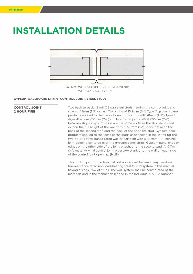
Fire Test: WHI-651-0318. 1, 3-15-90 & 3-20-90;WHI-647-3024, 9-20-91
GYPSUM WALLBOARD STRIPS, CONTROL JOINT, STEEL STUDS
Two back to back, 0.45mm base metal thickness (25 ga), steel studs framing the control joint and spaced 48mm (1 7/8") apart. Two strips of 15.9mm (5/8") Type X gypsum panel products applied to the back of one of the studs with 41mm (1 5/8") Type S drywall screws 610mm (24") o.c. Horizontal joints offset 610mm (24") between strips. Gypsum strips are the same width as the stud depth and extend the full height of the wall with a 15.9mm (5/8") space between the back of the second strip and the back of the opposite stud. Gypsum panel products applied to the faces of the studs as specified in the listing for the one-hour fire-resistance-rated wall or partition with a 12.7mm (1/2") control joint opening centered over the gypsum panel strips. Gypsum panel ends or edges on one side of the control joint attached to one stud and gypsum panel ends or edges on the other side of the control joint attached to the second stud. A 12.7mm (1/2") metal or vinyl control joint accessory stapled to the wall on each side of the control joint opening. (NLB)
This control joint protection method is intended for use in any one-hour fire-resistance-rated non-load-bearing steel C-stud system in this Manual having a single row of studs. The wall system shall be constructed of the materials and in the manner described in the individual GA File Number.
CONTROL JOINT1 HOUR FIRE
INSTALLATION DETAILS
Installation
INSTALLATION DETAILS
Fire Test: WHI-651-0318. 1, 3-15-90 & 3-20-90; WHI-647-3024, 9-20-91
GYPSUM WALLBOARD STRIPS, CONTROL JOINT, STEEL STUDS
Two back to back, 18 mil (25 ga.) steel studs framing the control joint and spaced 48mm (1 7/8") apart. Two strips of 15.9mm (5/8") Type X gypsum panel products applied to the back of one of the studs with 41mm (1 5/8") Type Sdrywall screws 610mm (24") o.c. Horizontal joints offset 610mm (24") between strips. Gypsum strips are the same width as the stud depth and extend the full height of the wall with a 15.9mm (5/8") space between the back of the second strip and the back of the opposite stud. Gypsum panel products applied to the faces of the studs as specified in the listing for the two-hour fire-resistance-rated wall or partition with a 12.7mm (1/2") control joint opening centered over the gypsum panel strips. Gypsum panel ends or edges on the other side of the joint attached to the second stud. A 12.7mm (1/2") metal or vinyl control joint accessory stapled to the wall on each side of the control joint opening. (NLB)
This control joint protection method is intended for use in any two-hour fire-resistance rated non load-bearing steel C-stud system in this manual having a single row of studs. The wall system shall be constructed of the materials and in the manner described in the individual GA File Number.
CONTROL JOINT2 HOUR FIRE

Building Code Requirements
19
UL Classified Fire-Rated Manual is intended to provide general information and should not be used as a substitute for professional advice. There are many variables that can influence construction projects which affect whether a particular construction technique is appropriate.
Before proceeding with any project we recommend you obtain professional advice to ascertain the appropriate construction techniques to suit the particular circumstances of your project having regard to the contents of this manual. We recommend you use qualified tradespersons to install this system. The technical information contained in this manual was correct at the time of printing (November 2018).
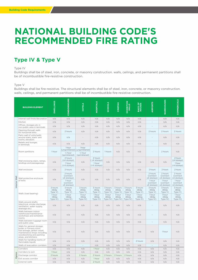
Type IV & Type VType IVBuildings shall be of steel, iron, concrete, or masonry construction. walls, ceilings, and permanent partitions shall be of incombustible fire-resistive construction.
Type VBuildings shall be fire-resistive. The structural elements shall be of steel, iron, concrete, or masonry construction. walls, ceilings, and permanent partitions shall be of incombustible fire-resistive construction.
BUILDING ELEMENT
DW
ELL
ING
S
CO
ND
OM
INIU
MS
HO
TELS
HO
SPIT
ALS
SCH
OO
LS
CIN
EM
AS
EX
HIB
ITIO
NH
ALL
S
BA
CK
OF
HO
USE
S
AIR
PO
RTS
WA
RE
HO
USE
S
CO
MM
ER
CIA
LS
Ext
erio
r W
all
Composite insulation system with external walls n/a n/a n/a n/a n/a n/a n/a n/a - n/a n/a
External wall (load bearing) 4 hours 4 hours 4 hours 4 hours 4 hours 4 hours 4 hours 4 hours 4 hours 4 hours 4 hoursExternal wall (non-load bearing) 4 hours 4 hours 4 hours 4 hours 4 hours 4 hours 4 hours 4 hours 4 hours 4 hours 4 hours
External walls decoration n/a n/a n/a n/a n/a n/a n/a n/a - n/a n/aExternal walls insulation-external thermal insulation systems
n/a n/a n/a n/a n/a n/a n/a n/a - n/a n/a
External walls insulation-internal thermal insulation systems
n/a n/a n/a n/a n/a n/a n/a n/a - n/a n/a
Fire barrier wall for additions or connected structures of different construction types
2 hours 2 hours 2 hours n/a 2 hours n/a n/a 2 hours 2 hours 2 hours 2 hours
Firewall 4 hours n/a n/a 4 hours 4 hours 4 hours 4 hours 4 hours n/a 4 hours 4 hoursGenerator rooms and compartments n/a n/a n/a n/a n/a n/a n/a 2 hours n/a n/a n/a
Wall enclosing stairs, ramps, landings & passageways
2 hours(≥4 storeys)
n/a
2 hours(≥4 storeys)
n/a n/a n/a n/a
2 hours(≥4 storeys)
2 hours(≥4 storeys)
2 hours(≥4 storeys)
n/a1 hour
(<4 storeys)1 hour
(<4 storeys)1 hour
(<4 storeys)1 hour
(<4 storeys)1 hour
(<4 storeys)
Walls (load bearing) n/a
3 hours (Bldg Type V)
n/a n/a n/a n/a n/a n/a n/a n/a n/a1 hour
(Bldg Type IV)
Inte
rio
r W
all
Columns n/a n/a n/a n/a n/a n/a n/a n/a - n/a n/a
Discharge corridor n/a 2 hours n/a n/a n/a n/a n/a n/a 2 hours 2 hours 2 hours
Evacuation refuge corridor n/a n/a 2 hours n/a n/a n/a n/a n/a - n/a n/a
Exit access corridor n/a 1 hour n/a n/a n/a n/a n/a n/a n/a n/a n/aFilm projection room, rewinding room n/a n/a n/a n/a n/a n/a 1 hour n/a n/a n/a n/a
Fire barrier wall for additions or connected structures of different construction types
n/a 20 mins n/a 20 mins n/a n/a n/a n/a n/a n/a n/a
Firewall n/a n/a 4 hours n/a n/a n/a n/a n/a 4 hours n/a n/aHazardaous area separation wall n/a n/a n/a n/a 1 hour n/a n/a n/a n/a n/a n/a
Highly toxic material storage n/a n/a n/a n/a n/a n/a n/a 1 hour n/a n/a n/a
Interior corridors n/a n/a n/a n/a 1/2 hour n/a n/a n/a n/a n/a n/a
NATIONAL BUILDING CODE'SRECOMMENDED FIRE RATING
Building Code Requirements
NATIONAL BUILDING CODE'SRECOMMENDED FIRE RATING
Type IV & Type VType IVBuildings shall be of steel, iron, concrete, or masonry construction. walls, ceilings, and permanent partitions shall be of incombustible fire-resistive construction.
Type VBuildings shall be fire-resistive. The structural elements shall be of steel, iron, concrete, or masonry construction. walls, ceilings, and permanent partitions shall be of incombustible fire-resistive construction.
BUILDING ELEMENT
DW
ELL
ING
S
CO
ND
OM
INIU
MS
HO
TELS
HO
SPIT
ALS
SCH
OO
LS
CIN
EM
AS
EX
HIB
ITIO
NH
ALL
S
BA
CK
OF
HO
USE
S
AIR
PO
RTS
WA
RE
HO
USE
S
CO
MM
ER
CIA
LS
Inte
rio
r W
all
Internal wall finish/decoration n/a n/a n/a n/a n/a n/a n/a n/a - n/a n/a
Kitchen n/a n/a n/a n/a n/a n/a n/a n/a - n/a n/aOffices, storages etc in non-public area in terminals n/a n/a n/a n/a n/a n/a n/a n/a - n/a n/a
Opening through wallsfor horizontal exits n/a 2 hours n/a n/a n/a n/a n/a n/a 2 hours 2 hours 2 hours
Party wall of units/wallsaround stairs, stairs' anti rooms, elevators
n/a n/a - n/a n/a n/a n/a n/a - n/a n/a
Retails and loungesin terminals n/a n/a n/a n/a n/a n/a n/a n/a - n/a n/a
Room partitions 1 hour
1 hour(unsprinklered)
1 hour(unsprinklered)
2 hours 1 hours n/a n/a n/a - 2 hours n/a1/2 hour
(sprinklered)1/2 hour
(sprinklered)
Wall enclosing stairs, ramps, landings and passageways n/a
2 hours (≥4 storeys)
n/a
2 hours ( ≥4 storeys)
n/a n/a n/a n/a n/a n/a
2 hours (≥4 storeys)
1 hour (<4 storeys)
1 hour (<4 storeys)
1 hour (<4 storeys)
Wall enclosure n/a 2 hours n/a n/a n/a n/a n/a n/a 2 hours 2 hours 2 hours
Wall protective enclosure of exits n/a
2 hours (connect ≥4 storeys)
n/a n/a n/a n/a n/a n/a
2 hours (connect ≥4 storeys)
2 hours (connect ≥4 storeys)
2 hours (connect ≥4 storeys)
1 hour (connect ≤3 storeys)
1 hour (connect ≤3 storeys)
1 hour (connect ≤3 storeys)
1 hour (connect ≤3 storeys)
Walls (load bearing)
3 hours(Bldg
Type V)
3 hours (Bldg
Type V)
3 hours (Bldg
Type V)
3 hours(Bldg
Type V)
3 hours (Bldg
Type V)
3 hours (Bldg
Type V)
3 hours(Bldg
Type V)
3 hours (Bldg
Type V)
3 hours (Bldg
Type V)
3 hours (Bldg
Type V)
3 hours (Bldg
Type V)1 hour (Bldg
Type IV)
1 hour (Bldg
Type IV)
1 hour (Bldg
Type IV)
1 hour (Bldg
Type IV)
1 hour (Bldg
Type IV)
1 hour (Bldg
Type IV)
1 hour (Bldg
Type IV)
1 hour (Bldg
Type IV)
1 hour (Bldg
Type IV)
1 hour (Bldg
Type IV)
1 hour (Bldg
Type IV)Walls around shafts (electrical, smoke discharge, ventilation, water supply, drainage etc)
n/a n/a n/a n/a n/a n/a n/a n/a - n/a n/a
Walls between indoor warehouse/maintenance workshops and exhibition rooms
n/a n/a n/a n/a n/a n/a n/a n/a - n/a n/a
Walls between luggage room and public area n/a n/a n/a n/a n/a n/a n/a n/a - n/a n/a
Walls for general storage, boiler or furnace room, fuel storage, janitor closet, maintenance shops including woodworking and painting areas, and kitchens
n/a n/a n/a n/a n/a n/a n/a n/a n/a 1 hour n/a
Walls for handling rooms of flammable liquids n/a n/a n/a n/a n/a n/a n/a 2 hours n/a n/a n/a
Walls of evacuation corridors n/a n/a - n/a n/a n/a n/a n/a - n/a n/a
Eg
ress
Corridors n/a n/a n/a 1 hour n/a n/a n/a n/a n/a n/a n/a
Corridors to exit 1 hour n/a n/a n/a n/a n/a n/a n/a n/a n/a n/a
Discharge corridor 2 hours n/a 2 hours 2 hours 2 hours 2 hours 2 hours n/a n/a n/a n/a
Exit access corridor n/a n/a n/a 1 hour n/a n/a n/a n/a n/a n/a n/a
External walls n/a n/a n/a 2 hours n/a n/a n/a n/a n/a n/a n/a

21
Building Code RequirementsBuilding Code Requirements
Type IV & Type VType IVBuildings shall be of steel, iron, concrete, or masonry construction. walls, ceilings, and permanent partitions shall be of incombustible fire-resistive construction.
Type VBuildings shall be fire-resistive. The structural elements shall be of steel, iron, concrete, or masonry construction. walls, ceilings, and permanent partitions shall be of incombustible fire-resistive construction.
BUILDING ELEMENT
DW
ELL
ING
S
CO
ND
OM
INIU
MS
HO
TELS
HO
SPIT
ALS
SCH
OO
LS
CIN
EM
AS
EX
HIB
ITIO
NH
ALL
S
BA
CK
OF
HO
USE
S
AIR
PO
RTS
WA
RE
HO
USE
S
CO
MM
ER
CIA
LS
Eg
ress
Fire barrier wall for additions or connected structures of different construction types
n/a n/a n/a n/a n/a n/a 2 hours n/a n/a n/a n/a
Opening through walls for horizontal exits 2 hours n/a 2 hours 2 hours 2 hours 2 hours 2 hours n/a n/a n/a n/a
Smoke partitions n/a n/a 1 hour n/a n/a n/a n/a n/a n/a n/a n/aStorage for medical and related compressed gas n/a n/a 2 hours n/a n/a n/a n/a n/a n/a n/a n/a
Storage room enclosure n/a n/a n/a n/a n/a n/a n/a n/a n/a n/a n/a
Wall enclosure 2 hours n/a 2 hours 2 hours 2 hours 2 hours 2 hours n/a n/a n/a n/a
Wall/protective enclosure of exits
2 hours (connect ≥4 storeys)
n/a
2 hours (connect ≥4 storeys)
2 hours (connect ≥4 storeys)
2 hours (connect ≥4 storeys)
2 hours (connect ≥4 storeys)
2 hours (connect ≥4 storeys)
n/a n/a n/a n/a1 hour
(connect ≤3 storeys)
1 hour (connect ≤3
storeys)
1 hour (connect ≤3
storeys)
1 hour (connect ≤3 storeys)
1 hour (connect ≤3 storeys)
1 hour (connect ≤3 storeys)
Walls enclosing stairs, ramps, landings and passageways n/a n/a
2 hours (≥4 storeys)
n/a
2 hours (≥4
storeys)
2 hours (≥4
storeys)
2 hours (≥4
storeys)n/a n/a n/a n/a
1 hour (<4 storeys)
1 hour (<4
storeys)
1 hour (<4
storeys)
1 hour (<4
storeys)
Cei
ling
Airport terminal n/a n/a n/a n/a n/a n/a n/a n/a - n/a n/aAtrium, gallery, open staircase, escalator n/a n/a n/a n/a n/a n/a n/a n/a - n/a n/a
Ceiling(including ceiling joist) n/a n/a n/a n/a n/a n/a n/a n/a - - n/a
Ceiling at corridors and exterior exit balconies 1 hour 1 hour 1 hour 1 hour 1 hour 1 hour 1 hour 1 hour 1 hour 1 hour 1 hour
Ceiling at exit passageways 1 hour 1 hour 1 hour 1 hour 1 hour 1 hour 1 hour 1 hour 1 hour 1 hour 1 hourCeiling at smoke proof enclosure 2 hours 2 hours 2 hours 2 hours 2 hours 2 hours 2 hours 2 hours 2 hours 2 hours 2 hours
Ceiling of kitchen n/a n/a n/a n/a n/a n/a n/a n/a - n/a n/aCeilings of entrance hall & corridor n/a n/a n/a n/a n/a n/a n/a n/a - n/a n/a
Ceilings of staircases without natural light/enclosed staircases/smoke proof staircases/anterooms
n/a n/a n/a n/a n/a n/a n/a n/a - n/a n/a
Film projection room, rewinding room n/a n/a n/a n/a n/a 1 hour n/a n/a n/a n/a n/a
Underground space n/a n/a n/a n/a n/a n/a n/a n/a - n/a n/a
*n/a = not applicable
References:
Chapter 2.01.02 - Fire Resistive Requirements and Standards For Fire Protection (National Building Code or Republic Act No. 6541)
Chapter 3.01 - Classification of All Buildings By Use or Occupancy and General Requirements For All Accupancies (National
Building Code or Republic Act No. 6541)
Fire Code of the Philippines (PD 1185)
NATIONAL BUILDING CODE'SRECOMMENDED FIRE RATING

AustraliaChinaIndiaIndonesiaMalaysiaMiddle EastNew ZealandThailandPhilippinesSingaporeSouth KoreaVietnam
3rd Floor 108 Central Building A,108 E. Rodriguez Jr. Avenue, Bagumbayan,Quezon City, Philippines 1110T: +63 2 911 6709 | +63 2 903 1200 | +63 2 236 5810F: +63 2 903 1201 | +63 2 857 2562 | +63 2 857 2251E: [email protected] | Skype call: usgboralph.outlook.com