Acoustic Diagnosis of Driving Belt Physical Condition in Enclosures
Upload
khangminh22Category
view
3download
0
The Passive Fire Protection HandbookThe UK’s comprehensive guide to passive ire protection
Chapter 6Fire Rated Ductwork and Service Enclosures
AUGUST 2017

Chapter 1: Introduction
Chapter 2: User guide
Chapter 3: Structural Steel
Chapter 4: Ceilings, Floors and Roofs
Chapter 5: Partitions and External Walls
Chapter 6: Fire Rated Ductwork and Service Enclosures ����������������������165Ventilation and Smoke Extraction Ducts ��������������������������������������� 166Cladding of Existing Sheet Metal Ducts ���������������������������������������������� 171Self-Supporting Ducts ���������������������������� 172Promat DURADUCT® LT ������������������������� 175DURADUCT® SMT Fireblast ������������������ 177DURADUCT® SR �������������������������������������� 179Cable Protection �������������������������������������� 180Cable Protection - External or Internal Fires ���������������������������������������� 184Service Enclosures ���������������������������������� 185Horizontal Service Enclosures, Suspended Services ������������������������������� 186Ventilation and Smoke Extraction Ducts ��������������������������������������� 187
Chapter 7: Penetration Seals
Chapter 8: Smoke Barriers and Doors
The Passive Fire Protection Handbook
Contents

CHAPTER 6: FIRE RATED DUCTWORK AND SERVICE ENCLOSURES
Fire Rated Ductwork and Service Enclosures
165TECHNICAL SERVICES T: 0800 1456033 E: [email protected]

The relative complexity of any ductwork system which is passing through different fire compartments and the relevance of the system’s function in ambient and fire conditions can make the selection of a suitable ductwork system difficult.
This section of the handbook aims to give guidance on the fire performance requirements of ductwork and offers a wide range of solutions for proprietary “off the shelf” fire rated ductwork, the protection of steel ductwork and for self-supporting systems using Promat PROMATECT®-L500.
For particularly onerous conditions e.g. where a high impact strength is required or for use in aggressive environments, Promat have developed a range of systems using Promat DURASTEEL®.
FIRE TESTING METHODSTo determine the fire resistance of ducts (without the aid of fire dampers) passing through or between compartments, the system should normally be tested or assessed in accordance with BS 476: Part 24: 1987. This standard has been written specifically for ventilation ducts, but guidance is also given in the standard on the performance requirements for ‘smoke outlet’ ducts and ‘kitchen extract’ ducts.
Tested duct systems are exposed to external fire (Duct A) and internal fire (Duct B). Fans create a standard pressure difference and air flow and the ducts fire performance is assessed in both the fan-on and the fan-off situations. When testing horizontal ducts, a run of at least 3m is located within the fire compartment and a further 2.5m outside the fire compartment.
BS 476: Part 24: 1987 expresses the fire resistance of ducts without the aid of dampers, in terms of stability, integrity and insulation. Stability failure occurs when the suspension or fixing devices can no longer retain a duct in its intended position or when sections of the duct collapse. This requirement does not apply to the length of the duct exposed to internal fire (Duct B) within the fire compartment.
Integrity failure occurs when cracks, holes or openings occur in the duct or at any penetrations through walls or floors, which flames or hot gases can pass. The effects on integrity of the movement and distortion of both restrained and unrestrained ducts are also included in the standard.
Insulation failure occurs when the temperature rise on the outer surface of the duct, outside the fire compartment, exceeds 140°C (mean) or 180°C (maximum). The guidance in the standard also states that ducts lined with combustible materials or coated internally with fats or greases e.g. kitchen extract, should also have this criterion for the inner surface of the duct within the fire compartment when the duct is exposed to external fire (Duct A).
For smoke extraction, the guidance in the standard states that the cross sectional area of a duct required to extract smoke in the event of a fire should not be reduced by more than 25%.
DESIGN CONSIDERATIONSThe following points are some of the factors which should be considered when determining the correct specification to ensure a ductwork system will provide the required fire performance. Further advice can be obtained from the Promat Technical Services Department.
1. Required Fire Exposure Ductwork systems which are located in more than one compartment should always be tested or assessed for their performance when exposed to the heating conditions of BS 476: Part 20: 1987. Reduced heating curves are generally only acceptable for certain components of the system e.g. the fan. The performance of a ductwork system will vary depending on whether or not a fire could have direct access to inside the duct through an unprotected opening. If in doubt, one should assume it can i.e. the Duct B scenario described previously under Fire Testing Methods.
2. Required Fire Performance It is normally required to satisfy all the relevant performance criteria of stability, integrity and insulation (and cross sectional area if a smoke extraction duct). However, the approval authority may accept a relaxation on occasions. For example, if no combustible materials or personnel could be in contact with the duct, the authority may accept a reduced insulation performance.
Chapter 6: Fire Rated Ductwork and Service Enclosures
Ventilation and Smoke Extraction Ducts
166
The Passive Fire Protection Handbook | 2017

SELECTION OF FIRE PROTECTION SYSTEMTraditionally all ductwork was fabricated from steel which normally had to be encased in a fire protection system when passing through a compartment wall or floor without the aid of a fire damper.
In recent years, self-supporting systems without a steel liner have been introduced to extract smoke in the event of a fire through natural ventilation, and now self-supporting systems e.g. Promat PROMATECT®-L500 and Promat DURASTEEL®, are available which can match the leakage and air flow performance of steel ducts in accordance with DW144 up to Class C.
To satisfy the wide range of requirements in the current market, Promat offers a number of products to protect steel ductwork and to fabricate self supporting duct systems.
The system selector on the next page should assist in determining the correct ductwork system to meet your needs and further guidance can be obtained from the Promat Technical Services Department.
3. Supporting Structure Any structural element that the ductwork system is supported from e.g. a beam, floor or wall, must have at least the same fire resistance as the duct system itself.
4. Hanger Support The hangers, supports and their fixings should be capable of bearing the load of the complete ductwork system including any applied insulation material or other services suspended from it. Chemical anchors are not generally suitable. It is generally not advisable to use unprotected supports if the stress exceeds the values given on page 172 and/or if hanger lengths exceed 2m. The hanger centres should not exceed the limits given in the following pages for the relevant system.
5. Steel Ductwork The steel duct must be constructed in accordance with the requirements of DW144 – Specification for sheet metal ductwork (published by the Heating and Ventilating Contractors’ Association), or equivalent specification.
6. Penetrations through Walls and Floors Care should be taken to ensure that movement of the duct in ambient or in fire conditions does not adversely affect the performance of the wall, partition or floor, or any penetration seal.
7. Movement Joints Movement joint details may be required for long lengths of duct, particularly where the duct spans across a movement joint in the floor or wall, or passes through floors or a roof that may deflect at different rates.
8. Air Flow and Leakage The design of some fire resisting duct systems may need modification to meet DW144 performance standards.
9. Ductwork Functions Most ductwork systems can fall into one or more of the following categories:• Ventilation and air conditioning• Natural smoke extract• Fan assisted smoke extract• Pressurisation of escape routes and fire fighting lobbies• Non-domestic kitchen extract.
In the event of a fire, the function of a system can often alter. For example, an air conditioning system could switch to become a fan assisted smoke extract duct. It is therefore essential that the performance requirements in both normal conditions and fire conditions are considered.
10. Other Requirements Acoustic performance, thermal insulation, water tolerance, strength and appearance can also be important considerations.
Chapter 6: Fire Rated Ductwork and Service Enclosures
Ventilation and Smoke Extraction Ducts
167TECHNICAL SERVICES T: 0800 1456033 E: [email protected]
Chapter 6: Fire Rated Ductwork and Service Enclosures
Ventilation and Smoke Extraction Ducts
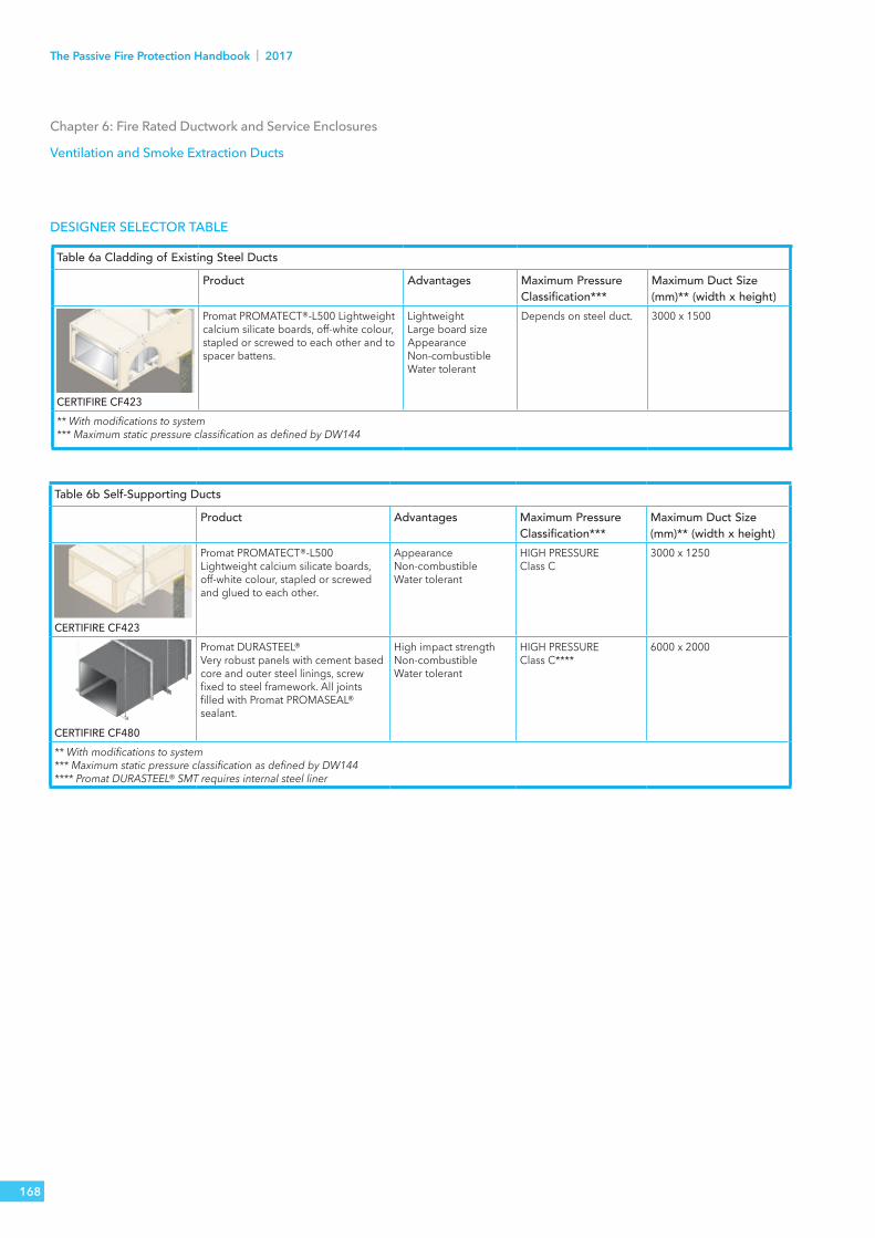
Table 6a Cladding of Existing Steel DuctsProduct Advantages Maximum Pressure
Classification***Maximum Duct Size (mm)** (width x height)
CERTIFIRE CF423
Promat PROMATECT®-L500 Lightweight calcium silicate boards, off-white colour, stapled or screwed to each other and to spacer battens.
LightweightLarge board sizeAppearanceNon-combustibleWater tolerant
Depends on steel duct. 3000 x 1500
** With modifications to system*** Maximum static pressure classification as defined by DW144
Table 6b Self-Supporting DuctsProduct Advantages Maximum Pressure
Classification***Maximum Duct Size (mm)** (width x height)
CERTIFIRE CF423
Promat PROMATECT®-L500Lightweight calcium silicate boards, off-white colour, stapled or screwed and glued to each other.
AppearanceNon-combustibleWater tolerant
HIGH PRESSURE Class C
3000 x 1250
CERTIFIRE CF480
Promat DURASTEEL®Very robust panels with cement based core and outer steel linings, screw fixed to steel framework. All joints filled with Promat PROMASEAL® sealant.
High impact strengthNon-combustibleWater tolerant
HIGH PRESSURE Class C****
6000 x 2000
** With modifications to system*** Maximum static pressure classification as defined by DW144 **** Promat DURASTEEL® SMT requires internal steel liner
DESIGNER SELECTOR TABLE
168
The Passive Fire Protection Handbook | 2017

Chapter 6: Fire Rated Ductwork and Service Enclosures
Ventilation and Smoke Extraction Ducts
Table 6c Cladding of Existing Steel DuctsProduct Stability
(mins)Integrity (mins)
Insulation (mins)
Thickness (mm)
Rock Wool Remarks
PromatPROMATECT®-L500**Certifire CF423
120 120 120 20 50mm x 100kg/m³ Insulation quoted for Duct Type B
240 240 240 50 75mm x 100kg/m³
** May only be used as kitchen extract ducts, where the internal wall temperature recommendation of the non-mandatory annex of BS 476: Part 24: 1987 has been relaxed by building control. For ducts exposed to external fire (Duct Type A) the insulation can be measured inside the duct, inside the fire compartment, or outside the duct in an adjacent compartment. All the above systems provide similar levels of insulation to that quoted, when the insulation is measured outside the duct in an adjacent compartment. For details of insulated ducts exposed to external fire where insulation is required inside the duct, inside the fire compartment, please consult the Promat Technical Services Department.
Table 6d Self-Supporting DuctsProduct Stability
(mins)Integrity (mins)
Insulation (mins)
Thickness (mm)
Rock Wool Remarks
PromatPROMATECT®-L500CERTIFIRE CF423
30 30 30 25 Not required Insulation quoted for Duct Type B. Exposed to external and internal fire.60 60 60 35 Not required
90 90 90 40 Not required
120 120 120 52 Not required
240 240 240 52 50mm x 100kg/m³
PromatDURADUCT® LT Certifire CF480
30 30 30 6 Not required Insulation quoted for Duct Type B.Exposed to external and internal fire.Natural ventilation/powered ventilation/ smoke extraction. Insulation applied when necessary.
60 60 60 6 50mm x 60kg/m³
120 120 120 6 80mm x 140kg/m³
180 180 180 6 100mm x 140kg/m³
240 240 240 6 120mm x 140kg/m³
60 60 60 6 50mm x 165kg/m³ Kitchen extract
120 120 120 6 90mm x 165kg/m³
PromatDURADUCT® SMTCertifire CF480
30 30 30 9.5 50mm x 60kg/m³ Insulation quoted for Duct Type B.Exposed to external and internal fire.Natural ventilation/powered ventilation/smoke extraction. Insulation applied when necessary.
60 60 60 9.5 50mm x 60kg/m³
120 120 120 9.5 80mm x 140kg/m³
180 180 180 9.5 100mm x 140kg/m³
240 240 240 9.5 120mm x 140kg/m³
60 60 60 6 50mm x 165kg/m³ Kitchen extract
120 120 120 6 90mm x 165kg/m³
169TECHNICAL SERVICES T: 0800 1456033 E: [email protected]

HANGERSEach hanger consists of two threaded rods and an angle or channel section. The hangers may be unprotected provided the rods are not more than 50mm from duct side walls and the stress in the hangers does not exceed the values given in the tables 6e and 6f. When hangers exceed 2000mm in length they should be clad with material of similar thickness to the duct to prevent excessive thermal expansion.
When hangers are suspended from protected steel beams it is advisable that the hanger rods should be protected for at least 300mm from the beams with the same level of protection as the structural beams.
Vertical duct runs normally require to be tied back to an adjoining masonry wall using threaded rods and angle or channel support section at maximum 3000mm centres.
GENERAL DESCRIPTIONFor any size of duct, the tensile stress in the steel hangers must not exceed the maximum permitted stress for each fire resistance period based on BS 5950: Part 8: 2003.
If these stress levels are exceeded then the size of the hanger rods must be increased, or the centres of the hangers reduced or the hangers protected. The penetration of the hanger fixings into any concrete soffit should be a minimum of 50mm for 120 minutes ratings or 65mm for 240 minutes ratings.
Chapter 6: Fire Rated Ductwork and Service Enclosures
Ventilation and Smoke Extraction Ducts
Table 6e Maximum Permitted Stress
Fire resistance period (minutes) Approximate Temperature ºC Maximum Permitted Stress
(N/mm²)
30 840 18
60 950 15
90 1000 10
120 1050 10
180 1100 6
240 1150 6
Table 6f Maximum Loads For Threaded Drop Rods
Nominal diameter
(mm)
Tensile stress area (BS 4190)
(mm²)
Load
60 minutes (15N/mm²)
120 minutes (10N/mm²)
240 minutes (6N/mm²)
(kN) (kg) (kN) (kg) (kN) (kg)
6 20.1 0.30 30.73 0.20 20.49 0.12 12.29
8 36.6 0.55 55.96 0.37 37.31 0.22 22.39
10 58.0 0.87 88.69 0.58 59.12 0.35 35.47
12 84.3 1.26 128.90 0.84 85.93 0.51 51.56
16 157.0 2.36 240.06 1.57 160.04 0.94 96.02
20 245.0 3.68 374.62 2.45 249.75 1.47 149.85
170
The Passive Fire Protection Handbook | 2017

Certifire Approval No CF 423PROMAT PROMATECT®-L500
TECHNICAL DATAUp to 240 minutes fire rating, stability, integrity and insulation in accordance with the criteria of BS 476: Part 24: 1987; internal or external fire.
1. Promat PROMATECT®-L500 boards, thickness in accordance with table on page 169.
2. Minimum 50mm x 50mm x 0.9mm steel channel collars (or deeper, if required to accommodate larger duct stiffeners, cross joints or thicker rock wool) are fitted around the duct at maximum 610mm centres. The channels are folded and fastened at the corners with minimum M4 steel rivets or self-tapping screws. The channels are filled with 100kg/m³ nominal density rock wool (if required). These channels are not fastened directly to the steel duct.
3. The Promat PROMATECT®-L500 boards are fixed to the channels with M4 self-tapping screws at maximum 200mm centres. The transverse joints are covered with 9mm x 100mm Promat SUPALUX® cover strips. Fixed with M4 self-tapping screws at nominal 200mm centres, a longitudinal board joint, other than at duct corners, must be backed by a steel channel, and covered with 9mm Promat SUPALUX® cover strips. Alternatively board corners may be fastened board to board using M4 screws of length twice the board thickness at maximum 200mm centres. The transverse joints are covered with 9mm Promat SUPALUX® cover strips.
4. Hanger diameter and supports sized to limit stress, in accordance with table on page 170. Maximum hanger spacing is 2400mm.
5. The boards at longitudal corner joints are fastened using steel angle, minimum 30mm x 30mm x 0.6mm, with M4 steel self-tapping screws at 200mm centres.
6. Steel duct in accordance with DW144.7. Promat PROMATECT®-L500 collar, minimum 20mm thick x 80mm wide
for 120 minutes, 50mm or 2 x 20mm thick x 80mm wide for 240 minutes.8. Rock wool tightly packed into aperture between surrounding structure
and the surface of the Promat PROMATECT®-L500 board.
Note: The above details are applicable for the construction of fire resistant encasements around steel ducts up to 1500mm wide, however, Promat PROMATECT®-L500 duct systems are approved for up to 3m wide. As an alternative fixing method, the angle at the corner and the channel at the butt joints can be replaced by Promat PROMATECT®-L500 strips 25mm x 25mm and 25mm x 50mm respectively. The installation time can usually be shortened by using steel staples at nominal 100mm centres instead of screws.
Chapter 6: Fire Rated Ductwork and Service Enclosures
Cladding of Existing Sheet Metal Ducts
13
4
6
5
2
Fig 6.30.1
Detail 4 Detail 5
1 2 8 3
5
6
Fig 6.30.3
1
2 3Fig 6.30.4 Fig 6.30.5
5 7
Fig 6.30.6
Detail 3
1
2364
4Fig 6.30.2
5
1
5
3 1
6
8
Detail 1 – Cross section through duct
Detail 3 – Corner detail
Detail 5
Detail 4 – Butt joint detail
171TECHNICAL SERVICES T: 0800 1456033 E: [email protected]

Certifire Approval No CF 423
Chapter 6: Fire Rated Ductwork and Service Enclosures
Self-Supporting Ducts
Table 6l Fire Inside (Duct B)Maximum duct pressure (Pa)
Fire resistance (minutes) Board thickness (mm)
Maximum internal dimensions of duct (mm)
StiffenersStability & Integrity
Insulation Method 1 Method 2
± 500 240 30 25 1200 x 1200± 500 240 30 25 2000 x 1250 1 row 1 row± 500 240 30 25 3000 x 1250 2 rows 2 rows± 500 240 60 35 1200 x 1200± 500 240 60 35 2000 x 1250 1 row 1 row± 500 240 60 35 3000 x 1250 2 rows 2 rows± 750 240 90 40 1200 x 1200± 750 240 90 40 2000 x 1250 1 row 1 row± 750 240 90 40 3000 x 1250 2 rows 2 rows± 750 240 120 52* 1200 x 1200± 750 240 120 52* 2000 x 1250 1 row 1 row± 750 240 120 52* 3000 x 1250 2 rows 2 rows+ 1000/- 2000 240 90 40 800 x 600+ 1000/- 2000 240 90 40 1440 x 700 1 row+ 1000/- 2000 240 90 40 1800 x 600 2 rows+ 1000/- 2000 240 120 52* 800 x 600+ 1000/- 2000 240 120 52* 1440 x 700 1 row+ 1000/- 2000 240 120 52* 1800 x 600 2 rows* To achieve 240 minutes insulation add 50mm rock wool 100 kg/m3 density.Note: For greater operating pressures and larger ducts please contact Promat Technical Services Department.
Table 6k Fire Outside (Duct A)Maximum duct pressure (Pa)
Fire resistance (minutes) Board thickness (mm)
Maximum internal dimensions of duct (mm)
Stiffeners
Stability & Integrity
Insulation Method 1 Method 2
± 500 240 120 25 1200 x 1200± 500 240 120 25 2000 x 1250 1 row 1 row± 500 240 120 25 3000 x 1250 2 rows 2 rows± 750 240 180 40 1200 x 1200± 750 240 180 40 2000 x 1250 1 row 1 row± 750 240 180 40 3000 x 1250 2 row 2 row± 750 240 240 52 2000 x 1250 1 row 1 row± 750 240 240 52 3000 x 1250 2 rows 2 rows+ 1000/- 2000 240 180 40 800 x 600+ 1000/- 2000 240 180 40 1440 x 700 1 row+ 1000/- 2000 240 180 40 1800 x 600 2 rows+ 1000/- 2000 240 240 52 1440 x 700 1 row+ 1000/- 2000 240 240 52 1800 x 600 2 rows
172
The Passive Fire Protection Handbook | 2017

Certifire Approval No CF 423
PROMAT PROMATECT®-L500The Promat PROMATECT®-L500 self-supporting system provides an economical and fire safe method of constructing natural and mechanical smoke extract and ventilation ductwork without a steel lining. Lengths of the Promat PROMATECT®-L500 system may be prefabricated reducing disruption to other trades on site.For selection of board thickness, it will not only depend on the required fire performance but also on the internal cross section of the duct and the operating pressure(s). With large ducts and medium to high operating pressures, internal stiffeners may be required.Tables 6k and 6l opposite give guidance on these requirements and further assistance is available from the Promat Technical Services Department.
TECHNICAL DATAUp to 240 minutes fire rating, stability, integrity and insulation in accordance with the criteria of BS 476: Part 24: 1987.1. Promat PROMATECT®-L500 board, thickness in accordance with Tables 6k and
6l (opposite). If guidance in Table 6k or 6l requires stiffeners to be used, please refer to details 4 and 5 on page 174.
2. Promat SUPALUX® strips, 100mm wide x 9mm thick.3. Promat VICUBOND® WR adhesive in all joints. (Promat PROMASEAL® Sealant
may be used on high pressure ducts to seal joints).4. Steel angle minimum 30mm x 30mm x 3mm thick, at maximum 1250mm
centres, sized according to duct size and weight and maximum permitted stress levels .
5. Threaded steel rod with hexagonal nuts, sized in accordance with table on page 170.
6. Steel wire staples or deep threaded screws as shown in table 6m below.7. Optional angle trim.
Table 6mBoard
thickness (mm)Screws at
200mm centresStaples at
100mm centres
9 25mm x No.6 28/10/1.0-
25 50mm x No.6 63/11/1.5
30 63mm x No.8 63/11/1.5
35 63mm x No.8 70/12/2
40 75mm x No.8 80/12/2
52 100mm x No.10 90/12.2/2.3
Chapter 6: Fire Rated Ductwork and Service Enclosures
Self-Supporting Ducts
Detail 1 – Duct supportThe duct must be supported at maximum 1250mm centres, located to coincide with joints, or to be within 50mm of the joint. For duct sections more than 1250mm in length, an additional hanger is required at themid-point of the section.
Detail 2 – Longitudinal section through insulated duct.
12
6 4
Fig 6.40.4
Detail 3 – Edge fixing, Alternative external angle trim
1
3 6 6
3
Fig 6.40.3
12
4
5
6
Fig 6.40.2
1
2
4
5
6
Fig 6.40.1
Detail 1 – Cross section through insulated duct
3
5
7
Detail 3
173TECHNICAL SERVICES T: 0800 1456033 E: [email protected]

Certifire Approval No CF 423PROMAT PROMATECT®-L500Maximum Duct Size and Operating PressuresThe basic duct design shown on page 173 is adequate for ducts with a maximum internal cross-section of 1200mm x 1200mm for operating pressures up to ± 500 Pa.
This limit can be increased to ± 750 Pa if the board thickness is 40mm or greater. For larger ducts and greater operating pressures, stiffeners are required using either of the methods shown in Details 4 and 5 (also see Tables 6k and 6l on pages 172).
For either method, the minimum stiffener thickness is 40mm.
Detail 4 – Stiffener: Method 1Stiffeners are constructed with strips of Promat PROMATECT®-L500, 250mm wide, fixed at maximum 600mm centres.
Detail 5 – Alternative Stiffener: Method 2The duct (1) is subdivided by a solid Promat PROMATECT®-L500 board, with holes cut within the wall of a size and quantity to ensure equal crossflow of air between the two halves.
Detail 6 – Masonry Wall PenetrationsThe duct (1) should pass through the wall opening without interruption. The penetration is sealed with rock wool of minimum density 60kg/m³ (3). A Promat PROMATECT®-L500 L-shape collar (2) fabricated from minimum 80mm x 80mm x 20mm thick, should be fixed to the duct only, on all four sides.
Insert approximately 30mm of rock wool (4) between the solid wall and cover angle. For penetrations through lightweight framed partitions, please consult the Promat Technical Services Department.
Detail 7 – Concrete Floor PenetrationsThe duct (1) should pass through the floor opening without interruption and the gap is sealed with Promat PROMASEAL® Compound (5). Secure Promat PROMATECT®-L500 L-shaped reinforcement collars (6) fabricated from minimum 80mm x 80mm x 20mm thick to the duct, to transfer the load of duct to the floor.
Note: Collars should be bonded with Promat Vicubond WR®.
Detail 4 – Stiffener: Method 1
Detail 5 – Stiffener: Method 2
Detail 6 – Masonry Wall Penetrations
Detail 7 – Concrete Floor Penetrations
2
1 3 4
1
5
1
6
Fig 6.40.5
Fig 6.40.6
Fig 6.40.7
Fig 6.40.8
Chapter 6: Fire Rated Ductwork and Service Enclosures
Self-Supporting Ducts
174
The Passive Fire Protection Handbook | 2017

Certifire Approval No CF 480PROMAT DURADUCT® LTConstructionPromat DURADUCT® LT consists of a galvanised steel inner duct overboarded with 6mm Promat DURASTEEL® and finishing trim angles. The system is installed using a proprietary flange. The total thickness of standard Promat DURADUCT® LT is nominally 7.5mm.
Typical ApplicationsPromat DURADUCT® LT is a fast track and economical Promat DURASTEEL® based fire resisting ductwork solution which combines the airflow and wipe down characteristics of standard galvanised steel ductwork with the armour plated comfort of ‘fit and forget’ Promat DURASTEEL®.
The Promat DURADUCT® LT system is manufactured by approved ductwork contractors and can be delivered to site with minimal site handling.
Promat DURADUCT® LT is tried and tested in ductwork solutions for natural ventilation ducting, mechanical ventilation ducting, natural smoke vents, mechanical smoke vents, fire rated pressurisation ductwork and kitchen extract ducting.
PerformanceUp to 240 minutes fire resistance in accordance with the integrity and insulation criteria of BS 476: Part 24:1987.
Trim angle Proprietary flange section
Fig 6.50.1
Chapter 6: Fire Rated Ductwork and Service Enclosures
Promat DURADUCT® LT
175TECHNICAL SERVICES T: 0800 1456033 E: [email protected]

Certifire Approval No CF 480
Table 6n Ductwork Insulation Matrix - Promat DURADUCT® LT Applications Powered ventilation/Natural ventilation/Smoke extraction/Kitchen extract
Notes All ductwork is tested/assessed to BS 476: Part 24: 1987 (ISO 6944-1985) Type A duct - External fire condition Type B duct - Internal fire condition
Natural Ventilation / Powered Ventilation / Smoke Extract
Minutes Stability IntegrityType A or B duct - 300ºC smoke temperature
Rock Wool Insulation
Type A duct - 1000ºC+ Type B duct - 1000ºC+
30 Yes Yes LT LT LT
60 Yes Yes LT LT + 30mm of 60 kg/m³ LT + 50mm of 60 kg/m³
120 Yes Yes LT LT + 50mm of 60 kg/m³ LT + 80mm of 140 kg/m³
180 Yes Yes LT LT + 50mm of 140 kg/m³ LT + 100mm of 140 kg/m³
240 Yes Yes LT LT + 90mm of 165 kg/m³ LT + 120mm of 140 kg/m³
Kitchen Extract
Where main fire risk is from in to out - Type B duct, internal fire condition, use the above table for powered ventilation/smoke extract Where main fire risk is from out to in - Type A duct, external fire condition at 1000ºC+. Use the table below.
Minutes Stability Integrity Rock Wool Insulation
Type A duct - 1000ºC+
60 Yes Yes LT + 50mm of 165 kg/m³
120 Yes Yes LT + 90mm of 165 kg/m³NOTE: It is normally required to satisfy all the relevant performance criteria of stability, integrity and insulation. However, if no combustible materials or personnel could be in contact with the duct the Approval Authority may accept a reduced insulation performance.
Chapter 6: Fire Rated Ductwork and Service Enclosures
Promat DURADUCT® LT
176
The Passive Fire Protection Handbook | 2017

Certifire Approval No CF 480CONSTRUCTIONThe SMT system is formed by fixing 9.5mm Promat DURASTEEL® sheets on to a welded, prefabricated steel skeletal framework, minimum 3mm thick. The sheets are fixed using self-drilling self-tapping screws, with Promat PROMASEAL® sealant applied before fixing to the frame. Flanged lengths of ductwork are bolted together trapping Promat PROMASEAL® sealant between the mating flanges. The SMT system can be constructed in 1, 2, 3 or 4 sided configurations.
TYPICAL APPLICATIONSPromat DURADUCT® SMT Fireblast has been tested to provide high levels of blast and fire protection making the system uniquely suitable for potentially explosive environments such as electrical transformer and switch gear rooms.
Promat DURADUCT® SMT is also tried and tested in ductwork solutions for smoke control, smoke exhaust, fresh air ventilation, kitchen extraction, fire protection of building services, pressurisation riser shafts, lift-shaft protection and protection of power cables and services.
PERFORMANCEUp to 240 minutes fire resistance in accordance with the integrity and insulation criteria of BS 476: Part 24:1987.
Fig 6.60.1
Chapter 6: Fire Rated Ductwork and Service Enclosures
DURADUCT® SMT Fireblast
177TECHNICAL SERVICES T: 0800 1456033 E: [email protected]

Promat DURADUCT® SMT may be constructed in 1, 2, 3 or 4 sided versions
Fig 6.60.2 Fig 6.60.3
Chapter 6: Fire Rated Ductwork and Service Enclosures
DURADUCT® SMT Fireblast
Table 6o Ductwork Insulation Matrix - Promat DURADUCT® SMT System Applications Powered ventilation/Natural ventilation/Smoke extraction/Kitchen extract
Notes All ductwork is tested/assessed to BS 476: Part 24: 1987 (ISO 6944-1985) Type A duct - External fire condition Type B duct - Internal fire condition
Natural Ventilation / Powered Ventilation / Smoke Extract
Minutes Stability IntegrityType A or B duct - 300ºC smoke temperature
Rock Wool Insulation
Type A duct - 1000ºC+ Type B duct - 1000ºC+
30 Yes Yes SMT SMT SMT
60 Yes Yes SMT SMT + 30mm of 60 kg/m³ SMT + 50mm of 60 kg/m³
120 Yes Yes SMT SMT + 50mm of 60 kg/m³ SMT + 80mm of 140 kg/m³
180 Yes Yes SMT SMT + 50mm of 140 kg/m³ SMT + 100mm of 140 kg/m³
240 Yes Yes SMT SMT + 90mm of 165 kg/m³ SMT + 120mm of 140 kg/m³
Kitchen Extract
Where main fire risk is from in to out - Type B duct, internal fire condition, use the above table Where main fire risk is from out to in - Type A duct, external fire condition at 1000ºC+. Use the table below.
Minutes Stability Integrity Rock Wool Insulation
Type A duct - 1000ºC+
60 Yes Yes SMT + 50mm of 165 kg/m³
120 Yes Yes SMT + 90mm of 165 kg/m³NOTE: It is normally required to satisfy all the relevant performance criteria of stability, integrity and insulation. However, if no combustible materials or personnel could be in contact with the duct the Approval Authority may accept a reduced insulation performance.
178
The Passive Fire Protection Handbook | 2017

Promat DURADUCT® SR Steel Run-Out Ducting (connected to a Promat DURASTEEL® smoke extract duct system)
Chapter 6: Fire Rated Ductwork and Service Enclosures
DURADUCT® SR
Table 6p Horizontal Rectangular Ducts
Fire resistancestability integrity insulation (mins)
Maximum duct width see note 1
(m)
Thickness of duct(mm)
Maximum duct section length
(m)
Type of cross joints, section type and size
(mm)
Maximum spacing of hangers and bearers
see note 3 (m)
120/120/- 0.75 1.2 1.5 Note 2 1.5
1
6
2
3
7
54
Fig 6.70.1
8
DURADUCT® SR 60 – 120 PROMAT DURADUCT® STEEL RUN-OUT DUCTINGA steel duct system tested to BS 476: Part 24: 1987 (ISO6944: 1985), built to enhanced DW144 standards, it provides 60 or 120 minutes stability/integrity. This ducting is for use together with the DURADUCT® SMT and DURADUCT® LT ranges for connection between the main smoke extract system and grilles where fire insulation performance is not required.
Additionally, the system may be used for smaller cross-section extract ducts that are located within protected shafts. These shafts provide the required fire compartmentation and the aesthetic finishes, such as those often used for toilet extract ducting.
TECHNICAL DATA1. Identification labels.2. Clamp.3. Duct support system.4. DURADUCT® steel run-out
duct system DURADUCT® SR.5. Grille.6. ‘Knock on flanges’.7. Shoe connection.8. Promat DURADUCT®
SMT or DURADUCT® LT.
PERFORMANCEThe DURADUCT® SR Range has been tested to: • BS 476: Part 24: 1987 and meets the fire stability
and integrity requirements for up to 120 minutes. • It maintains 75% cross-section and is suitable for smoke extract ducting.• Air Leakage Class A-C (DW144).
Note 1: The cross section of the DURADUCT® SR duct system is limited to 0.2m2 with no side greater than 0.75 metres wide. Ducts outside this range are manufactured from Promat DURASTEEL®. For full details please contact Promat Technical Services Department.
Note 2: Duct sections are constructed using Pittsburgh lock seams or RSA, with 40mm rivetted or spot welded flanges.
Note 3: The duct hangers consist of 12mm threaded steel drop rods and P1000T Unistrut channel bearers.
179TECHNICAL SERVICES T: 0800 1456033 E: [email protected]

CABLE PROTECTION In the event of a fire it may be vital to the safety of the building occupants that certain electrical systems and services remain functioning until all personnel have escaped. Such systems will therefore require protection from fire for a specified period of time and may include:• Electrically operated fire alarms• Emergency escape route lighting• Electrically operated extinguishing systems• Smoke extraction vent systems• Power supply for fire service elevators in high-rise
buildings• Water mains to sprinkler systems
In addition to protection from fire outside the duct, it is normally vital that any fire within the duct is contained e.g. if cable sheathing ignites due to an electrical overload.
A suitably designed duct will:• Prevent the propagation of fire from one building
compartment to another• Assist in maintaining escape routes• Ensure the continuing operation of other services within a
common service shaft• Reduce damage to localised areas• Contain smoke and toxic fumes from burning cables
The only fire resistance test standards for cable protection systems which simulate a real fire scenario are the German standards, DIN 4102, “Fire behaviour of building materials and building components”, Parts 11 and 12.Part 11 assesses the encasement system when exposed to a fully developed internal fire. The integrity of the encasement, and any penetrations through walls and floors, are measured, plus the temperature on the outer surface of the duct (140°C mean rise, 180°C maximum rise). The heating curve for DIN 4102: Part 11 is the same as that used in BS 476: Part 20: 1987 and the failure criteria for integrity and insulation are almost identical. The systems detailed are approved for use to provide a performance in accordance with BS 476: Part 20: 1987.DIN 4102: Part 12 assesses the encasement system when exposed to a fully developed external fire. In addition to the requirement to maintain the integrity of the encasement and any penetrations through walls or floors, the standard requires that:a) The cables continue to function for the duration of the
exposure period;b) The temperature on the cable jacket should not exceed 150°C.The tested encasement system protects a wide range of different cable types. Power is passed through the cables throughout the test.
As an added safety factor, the systems described in this section will ensure that the temperature on the cable jacket does not exceed 120°C.
NOTE: Fibre optic cables have a lower failure temperature and therefore the Promat Technical Services Department should be consulted to determine the required board thickness.
DESIGN CONSIDERATIONSThe following points are some of the factors which should be considered when determining the correct specification to ensure the cable duct system will provide the required fire performance. Further advice can be obtained from the Promat Technical Services Department.
1. Required Fire Exposure The specification of a cable duct system will depend on whether it is expected to resist external fire, internal fire, or both.
2. Required Fire Performance Generally, the most onerous requirement is to maintain the integrity of the circuit(s) when the system is exposed to external fire. If this is not needed, the performance requirements may be reduced by the approval authority to provide only stability, integrity and insulation of the duct system and/or the wall and floor penetrations. On occasions further relaxations may be approved e.g. a reduced insulation performance can sometimes be acceptable if no combustible materials or personnel will be in contact with the duct.
3. Supporting Structure The supporting hangers and their fixings should be capable of bearing the load of the complete cable system including any applied insulation material or other services suspended from it. Chemical anchors are not generally suitable. It is usually not advisable to use unprotected hangers if the stress exceeds 6N/mm² and/or if hanger lengths exceed 2000mm. The hanger centres should not exceed the distance limits given for the relevant system.
4. Penetrations through Walls and Floors Care should be taken to ensure that movement of the cable duct system in ambient or in fire conditions does not adversely affect the performance of the wall, partition or floor or any penetration seal.
5. Other Requirements Acoustic performance, thermal insulation, water tolerance, strength and appearance can also be important.
Selection of Board Type and ThicknessThe Promat systems based on Promat PROMATECT®-L500 or Promat DURASTEEL® would generally be preferred in very onerous conditions.
The board thickness will depend on the required fire performance, the internal dimensions of the duct, and whether or not the duct lid is fixed, as shown in the tables on the following page.
Chapter 6: Fire Rated Ductwork and Service Enclosures
Cable Protection
180
The Passive Fire Protection Handbook | 2017

Assessment No CC 211899 PUKL
Chapter 6: Fire Rated Ductwork and Service Enclosures
Cable Protection
EXTERNAL FIREThe board thicknesses given in Tables 6q and 6r will ensure that when the duct is exposed to a fully developed cellulosic external fire (BS 476: Part 20: 1987 curve), the cable jacket temperature rise will not exceed 120°C and the cables will remain functioning. If the cables are not required to maintain circuit integrity it may be possible to reduce the board thickness after consultation with the Promat Technical Services Department. Promat can also advise on specifications for larger duct sizes.
FIBRE OPTICSThese cables have a lower failure temperature and therefore the Promat Technical Services Department should be consulted to determine the required board thickness and construction details.
INTERNAL FIREThe board thicknesses given in Tables 6s and 6t will ensure that the stability, integrity and insulation of the duct will be maintained when exposed to a fully developed cellulosic internal fire (BS 476: Part 20: 1987 curve).
For ducts which do not require to satisfy the insulation criteria, and for larger ducts, please consult the Promat Technical Services Department.
Table 6q Internal Cross Section ≤ 110 x 100mm
Lid Type
Thickness of board for different fire resistance (minutes)
Board type30 60 90 120
Loose Fit 25mm 45mm 60mm 80mm Promat PROMATECT®-L500
Fixed 20mm 40mm 60mm 80mm Promat PROMATECT®-L500
Table 6r Internal Cross Section ≥ 110 x 100mm ≤ 520 x 250mm
Lid Type
Thickness of board for different fire resistance (minutes)
Board type30 60 90 120
Loose Fit 20mm 40mm 60mm 70mm Promat PROMATECT®-L500
Fixed 20mm 35mm 50mm 70mm Promat PROMATECT®-L500
Table 6s: For Stability, Integrity in Fire Compartment/Insulation in Adjacent Compartment
Thickness of board for different fire resistance (minutes)Board type
30 60 90 120
20mm 30mm 35mm 40mm Promat PROMATECT®-L500
Table 6t: For Stability, Integrity and Insulation in Fire Compartment
Thickness of board for different fire resistance (minutes)Board type
30 60 90 120
25mm 35mm 40mm 52mm Promat PROMATECT®-L500
181TECHNICAL SERVICES T: 0800 1456033 E: [email protected]
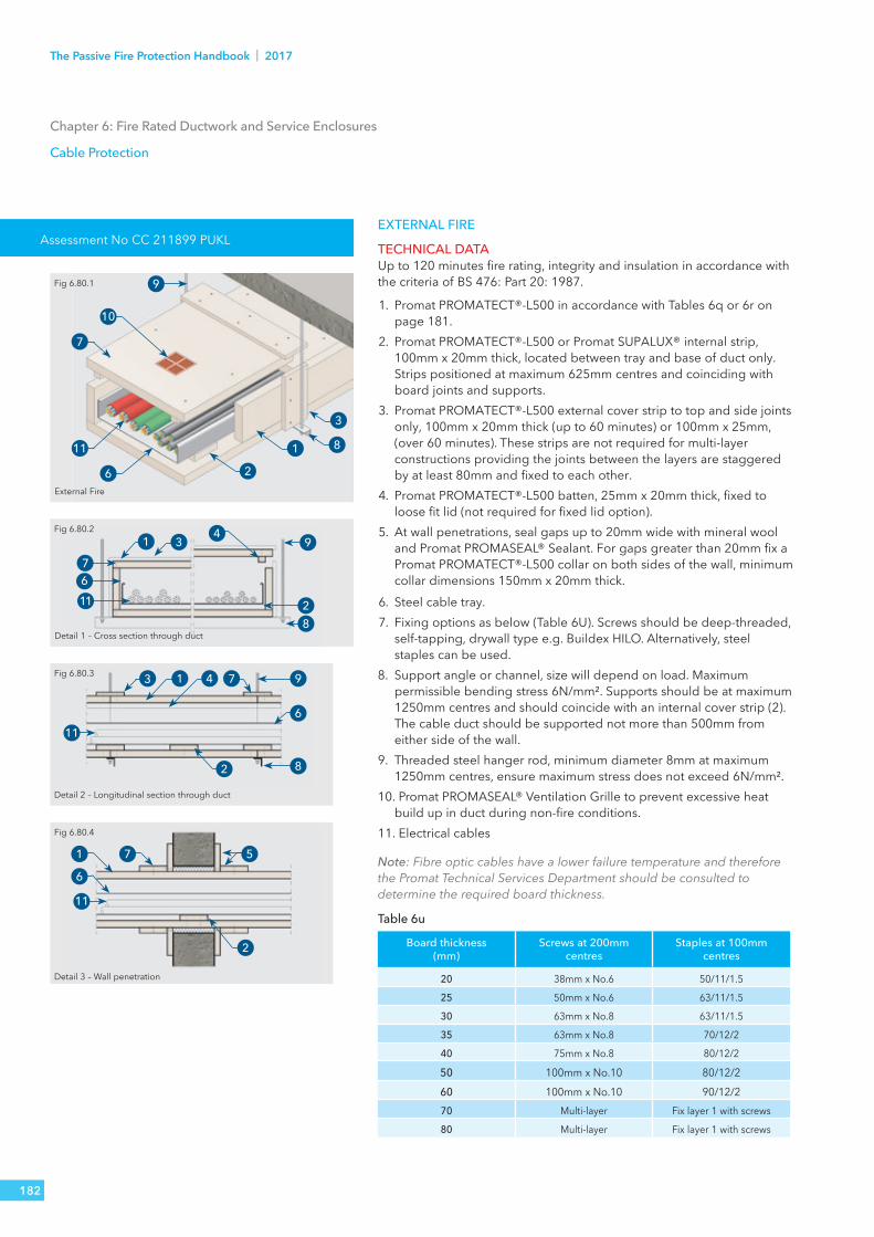
Assessment No CC 211899 PUKLEXTERNAL FIRE
TECHNICAL DATAUp to 120 minutes fire rating, integrity and insulation in accordance with the criteria of BS 476: Part 20: 1987.
1. Promat PROMATECT®-L500 in accordance with Tables 6q or 6r on page 181.
2. Promat PROMATECT®-L500 or Promat SUPALUX® internal strip, 100mm x 20mm thick, located between tray and base of duct only. Strips positioned at maximum 625mm centres and coinciding with board joints and supports.
3. Promat PROMATECT®-L500 external cover strip to top and side joints only, 100mm x 20mm thick (up to 60 minutes) or 100mm x 25mm, (over 60 minutes). These strips are not required for multi-layer constructions providing the joints between the layers are staggered by at least 80mm and fixed to each other.
4. Promat PROMATECT®-L500 batten, 25mm x 20mm thick, fixed to loose fit lid (not required for fixed lid option).
5. At wall penetrations, seal gaps up to 20mm wide with mineral wool and Promat PROMASEAL® Sealant. For gaps greater than 20mm fix a Promat PROMATECT®-L500 collar on both sides of the wall, minimum collar dimensions 150mm x 20mm thick.
6. Steel cable tray.7. Fixing options as below (Table 6U). Screws should be deep-threaded,
self-tapping, drywall type e.g. Buildex HILO. Alternatively, steel staples can be used.
8. Support angle or channel, size will depend on load. Maximumpermissible bending stress 6N/mm². Supports should be at maximum1250mm centres and should coincide with an internal cover strip (2). The cable duct should be supported not more than 500mm fromeither side of the wall.
9. Threaded steel hanger rod, minimum diameter 8mm at maximum1250mm centres, ensure maximum stress does not exceed 6N/mm².
10. Promat PROMASEAL® Ventilation Grille to prevent excessive heatbuild up in duct during non-fire conditions.
11. Electrical cables
Note: Fibre optic cables have a lower failure temperature and therefore the Promat Technical Services Department should be consulted to determine the required board thickness.
Table 6u
Board thickness (mm)
Screws at 200mm centres
Staples at 100mm centres
20 38mm x No.6 50/11/1.5
25 50mm x No.6 63/11/1.5
30 63mm x No.8 63/11/1.5
35 63mm x No.8 70/12/2
40 75mm x No.8 80/12/2
50 100mm x No.10 80/12/260 100mm x No.10 90/12/270 Multi-layer Fix layer 1 with screws
80 Multi-layer Fix layer 1 with screws
External Fire
Detail 1 – Cross section through duct
Detail 2 – Longitudinal section through duct
Detail 3 – Wall penetration
1
2
9
10
7
11
6
1 3
7611
1 4 73
2
11
1 7
11
5
6
2
Fig 6.80.1
Fig 6.80.2
Fig 6.80.3
Fig 6.80.4
3
8
9
28
9
6
8
Chapter 6: Fire Rated Ductwork and Service Enclosures
Cable Protection
4
182
The Passive Fire Protection Handbook | 2017

Chapter 6: Fire Rated Ductwork and Service Enclosures
Cable Protection
Internal Fire
Detail 1 – Cross section through duct
Detail 2 – Longitudinal section through duct
Detail 3 – Wall penetration
1
2
3
9
10
7
11 8
1 3 9
2
7
116
8
1 4 73 9
6
82
11
1 7 5
11
2
Fig 6.80.5
Fig 6.80.6
Fig 6.80.7
Fig 6.80.8
4
INTERNAL FIRE
TECHNICAL DATAUp to 120 minutes fire rating, integrity and insulation in accordance with the criteria of BS 476: Part 20: 1987.
1. Promat PROMATECT®-L500 in accordance with Tables 6s or 6t onpage 181.
2. Promat PROMATECT®-L500 or Promat SUPALUX® internal strip, 100mmx 20mm thick, located between tray and base of duct only. Stripspositioned at maximum 625mm centres and coinciding with board jointsand supports (8).
3. Promat SUPALUX® external cover strips, 100mm x 9mm thick, to top andside joints only. For ducts with an internal height greater than 300mmreplace the external strip with an internal Promat SUPALUX® strip, 100mmx 15mm thick. Fix side boards to ends of internal strip to strengthencasing, external strips not required for multi-layer construction providingthe joints between layers are staggered by at least 80mm and fixed toeach other.
4. Promat PROMATECT®-L500 or Promat SUPALUX® batten, 25mm x 20mmthick, fixed to loose fit lid (not required for fixed lid option).
5. At wall penetrations, seal gaps up to 20mm wide with mineral wool andPromat PROMASEAL® Sealant. For gaps greater than 20mm fix a PromatPROMATECT®-L500 or Promat SUPALUX® collar on both sides of the wall, minimum collar dimensions 150mm x 20mm thick.
6. Steel cable tray (not required for internal fire exposure unless the cableweight exceeds 25kg/m, then a cable tray should be used or the hangercentres should be reduced.
7. Fixing options as below. Screws should be deep-threaded, self-tapping, drywall type e.g. Buildex HILO. Alternatively, steel staples can be used.
8. Support angle or channel size will depend on the maximum permissiblebending stress 6N/mm². Supports should be at maximum 1250mmcentres and should coincide with an internal cover strip (2). The cableduct should be supported not more than 500mm from either side of thewall.
9. Threaded steel hanger rod, minimum diameter 8mm at maximum1250mm centres, ensure maximum stress does not exceed 6N/mm².
10. Promat PROMASEAL® Ventilation Grille to prevent excessive heat buildup in duct during non-fire conditions.
11. Electrical cables.
Table 6v
Boardthickness (mm)
Screws at200mm centres
Staples at100mm centres
9 25mm x No.6 28/10/1.215 30mm x No.6 32/10/1.220 38mm x No.6 50/11/1.525 50mm x No.6 63/11/1.530 63mm x No.8 63/11/1.535 63mm x No.8 70/12/240 75mm x No.8 80/12/250 100mm x No.10 80/12/260 100mm x No.10 90/12/270 Multi-layer Fix layer 1 with screws
183TECHNICAL SERVICES T: 0800 1456033 E: [email protected]

ACCESS HATCHES AND VENTILATION OPENINGSFor the installation and inspection of cables, a loose lid construction may be employed as described on pages 181 or 183 Alternatively, the lid can be fixed and inspection openings with hatches can be provided in the side walls of the duct as shown.
TECHNICAL DATAUp to 120 minutes fire rating, integrity and insulation in accordance with the criteria of BS 476: Part 20: 1987.
1. Promat PROMATECT®-L500 system encasing cable run.2. Promat PROMATECT®-L500 inspection hatch comprising:
a) Inner board stapled or secured to outer board. The inner board should be a close fit in the opening and should be the same thickness as the wall of the duct.
b) Outer board, at least 20mm thick, overlapping duct walls by at least 50mm.
3. Secure complete hatch to duct using threaded inserts e.g. Tecserts (Armstrong Fastening Systems) at maximum 200mm centres.
4. Electric cables.5. Wall of Promat PROMATECT®-L500 system.6. Promat PROMATECT®-L500, at least 50mm wide x 20mm thick, secured
to main panelusing fixings given in the tables on pages 182 or 184 7. Seal gaps for full depth of board thickness with Promat PROMASEAL®
Sealant. Ventilation for the cables can be provided by either Promat PROMASEAL® Ventilation Grille (8).
Detail 1 – Section through Promat PROMASEAL® Ventilation Grille• Standard Grille size is 93mm x 93mm overall. Can be combined as
multiples to create a larger free area• Open area per Grille = 0.0035m².• Grilles supplied in various thicknesses as follows:• 35mm (30 minutes), 2 x 35mm (60 minutes), 75mm (120 minutes) and
75 + 35mm (240 minutes).• Friction fit Grille (8) in aperture. Use Promat VICUBOND® WR adhesive
if loose fit.• Secure 50mm wide cover strips (10) if necessary to ensure Grille fully
surrounded by board.• The Grille is supported on the inside of the duct by a perforated steel
plate (supplied) (11) secured to the duct wall.
Construction of inspection opening
Multiple cable outlet exit from duct
Promat PROMASEAL® Ventilation Grille
Detail 1 – Section through Promat PROMASEAL® Ventilation Grille
1
2
3
5 6
4 7
8
9
8 10
11
Fig 6.90.1
Fig 6.90.2
Fig 6.90.3
Fig 6.90.4
Chapter 6: Fire Rated Ductwork and Service Enclosures
Cable Protection - External or Internal Fires
184
The Passive Fire Protection Handbook | 2017

SERVICE ENCLOSURESFor the provision of fire resisting constructions to general building services, 60 to 240 minutes fire rating (integrity with varying periods of insulation), in accordance with the performance criteria of BS 476: Part 20: 1987.No specific British Standard exists to cover fire protection to building services, therefore for the provision of fire resisting constructions to cable ducts and general building services, Promat constructions have been tested in accordance with the criteria of German DIN 4102, or British Standard BS 476: Part 20: 1987 and assessed to the criteria of BS 476: Part 24: 1987.These assessments include allowance for both internal and external fire. The integrity and, where pertinent, the insulation performance of the enclosure, and any penetrations through compartment walls and floors, are measured.Circuit integrity of electrical cables, or ability of the services to function, are not measured and do not constitute part of the failure criteria. Where circuit integrity of electrical cables is required, please refer to the cable protection section of this chapter.For the provision of a protection system which will ensure the ability of other services to function unimpaired in case of fire (e.g. fuel pipes, water mains), please contact the Promat Technical Services department.
VERTICAL AND HORIZONTAL SERVICE ENCLOSURES - FIXING TO ANGLES
TECHNICAL DATA (1, 2, 3 and 4 sided enclosures) Promat SUPALUX® and Promat PROMATECT®-L500 enclosuresUp to 240 minutes fire rating, integrity with various periods of insulation, in accordance with criteria of BS 476: Part 20: 1987 Internal or external fire.1. Promat SUPALUX® or Promat PROMATECT®-L500 boards,
thickness in accordance with table 6w below.2. Metal angle framing, consult Promat Technical Services
Department. Minimum 30mm x 30mm x 0.8mm angles up to 50mm x 50mm x 1.2mm. Steel channel may be required. Additional framing may be required according to span and impact requirements of construction.
3. M4 screws at 250mm centres, screw length to provide minimum 10mm penetration through angle. Two or three sided casings: fix steel angles to suitable fire resisting wall or soffit using M4 screws into non combustible plugs: screw length to provide minimum 30mm penetration into plugs.
4. Butt joints must have 75mm wide backing strip inside circumferential joints, if joint not backed by angle. Thickness of backing strip to be same as that required for board encasement.
Please contact Promat Technical Services for details of fixing for Promat service enclosures.
Chapter 6: Fire Rated Ductwork and Service Enclosures
Service Enclosures
Table 6w Vertical and Horizontal Service enclosures – 1, 2 and 3 sided enclosuresAngle fix method Product Fire Rating Stability/
Integrity/InsulationMaximum Size
Promat SUPALUX® 9mm thick 120/120/- 1000mm x 800mm (additional framing required for spans over 600mm)Assessment No. WF 169598
12mm thick 240/240/-
Promat PROMATECT®-L500 20mm thick 120/120/15 1200mm x 1200mm
25mm thick 120/120/30 1200mm x 1200mm
35mm thick 120/120/60 1200mm x 1200mm
40mm thick 120/120/90 1200mm x 1200mm
50mm thick 240/240/120 1200mm x 1200mm Assessment No. WF 169597
Promat DURASTEEL® 6mm thick 120/120/- 1500mm x 1500mm
9.5mm thick 240/240/- 1500mm x 1500mm Assessment No. WF 169601
185TECHNICAL SERVICES T: 0800 1456033 E: [email protected]

Installation Method 1
Installation Method 2
Fixing to steel angle Butt joint detail
14
5
32
6
14
5
32
6
1 1
2
66
55
Fig 6.100.1
Fig 6.100.2
Fig 6.100.3 Fig 6.100.4
Chapter 6: Fire Rated Ductwork and Service Enclosures
Horizontal Service Enclosures, Suspended Services
PROMAT SUPALUX® AND PROMAT PROMATECT®-L500 ENCLOSURES
TECHNICAL DATAUp to 240 minutes fire rating, integrity in accordance with the criteria of BS 476: Part 20: 1987; internal or external fire.
1. Fire protection boards, thickness in accordance with table 6x below.2. Steel channel collar, minimum 50mm x 25mm x 0.8mm thick, at board
joints or maximum 1220mm centres.3. General M & E services e.g. cable trunking, steel pipes, etc.4. Hanger diameter sized to limit stress not to exceed 10N/mm² (for
120 minutes) or 6N/mm² (for 240 minutes).5. M4 self-tapping screws at nominal 200mm centres.6. Steel angle, minimum 30mm x 30mm x 0.8mm thick, at corners.
Note: Solutions for the construction of systems with 1, 2 and 3-side used in combination with walls and ceilings are approved. Details on request.
For enclosures with a width exceeding 1220mm, the steel channel collar (2) shall be spaced at centres such to ensure a maximum unsupported area not exceeding 1.5m². The maximum approved width of the construction detail is 3000mm.
If the M & E service (3) being encased is a plastic pipe, external hangers and angles with stress 10N/mm² will be required to independently support the enclosure.
Table 6x Horizontal Service EnclosuresIntegrity and Insulation
Product Fire Rating Stability/Integrity/Insulation
Maximum Size
PromatSUPALUX®
9mm thick 120/120/- 1000mm x 800mmAssessment No. WF 169598
12mm thick 240/240/-
Promat PROMATECT®-L500
20mm thick 120/120/15 1200mm x 1200mm
25mm thick 120/120/30 1200mm x 1200mm
35mm thick 120/120/60 1200mm x 1200mm
40mm thick 120/120/90 1200mm x 1200mm
50mm thick 240/240/120 1200mm x 1200mm Assessment No. WF 169597
PromatDURASTEEL®
6mm thick 120/120/- 1500mm x 1500mm
9.5mm thick 240/240/- 1500mm x 1500mm Assessment No. WF 169601
186
The Passive Fire Protection Handbook | 2017

Assessment No WF 169601
6
1
2
5
4
73
Fig 6.120.1
Chapter 6: Fire Rated Ductwork and Service Enclosures
Ventilation and Smoke Extraction Ducts
PROMAT DURASTEEL®Promat DURASTEEL® enclosures provide protection against fire to cable ducts and general building services in accordance with the relevant criteria of BS 476: Parts 20: 1987 and 22: 1987.
Promat DURASTEEL® systems are suitable for providing protection to services even under extremely aggressive environments.
The Promat DURASTEEL® systems described below ensure the integrity of fire compartments.If the services are required to continue functioning in the event of fire, please consult the Promat Technical Services Department.
The maximum permissible dimensions for enclosures are up to 6000mm x 1500mm for up to 240 minutes fire resistance. For hanger sizes please consult Promat Technical Services Department.
TECHNICAL DATA1. Promat DURASTEEL® boards, thickness in accordance with table 6x on page 186.2. Steel flanges, fabricated by cutting and welding 50mm x 50mm x 3mm thick
angles, are bolted together with M8 nuts and bolts at nominal 250mm centres to form continuous sections.
3. Cable tray or services enclosure.4. Corner steel angle reinforcement, 50mm x 50mm x 3mm thick, these corner
angles do not require any mechanical fixing to the flanges (2).5. Support channels, sized according to duct weight, size and required fire
resistance.6. Steel hanger rods, sized according to duct weight, size and required fire
resistance.7. Cables or services.
187TECHNICAL SERVICES T: 0800 1456033 E: [email protected]

The Passive Fire Protection Handbook
GB ORDERLINEFor placing orders, delivery enquiries and local stockists etc.T: 0800 373 636F: 01275 379 037E: [email protected]
TECHNICAL SERVICESFor technical support and advice.T: 0800 145 6033E: [email protected]
RESOLUTIONSFor any problems with invoices or deliveries.T: 01275 379 031 or 0800 373 636E: [email protected]
Etex Building Performance LimitedMarsh Lane, Easton-in-Gordano, Bristol, BS20 0NE T: 0800 373 636 F: 01275 379 037
www.promat.co.uk
© 2017 Etex Building Performance Limited
AUGUST 2017
The Passive Fire Protection HandbookThe UK’s comprehensive guideto passive fire protection
AUGUST 2017
Copyright © 2022 FDOKUMEN