USER'S MANUAL_CENTRIFUGAL FAN_2020.cdr - Breeze Fan
28
We bring better air to life 2020 USER’S MANUAL FCS-FCD SERIES BCS-BCD SERIES Thank you for choosing centrifugal fan. Please read and save this user's manual for future reference. Read carefully before attempting to assemble, install, operate or maintain the product described. Protect yourself and others by observing all safety information. Failure to comply with instructions could result in personal injury and property damage. FCS Series BCS Series BCD Series FCD Series FORWARD | BACKWARD CURVE CENTRIFUGAL FAN
-
Upload
khangminh22 -
Category
Documents
-
view
1 -
download
0
Transcript of USER'S MANUAL_CENTRIFUGAL FAN_2020.cdr - Breeze Fan

We bring better air to life
2020
USER’S MANUAL
FCS-FCD SERIESBCS-BCD SERIES
Thank you for choosing centrifugal fan. Please read and save this
user's manual for future reference. Read carefully before attempting
to assemble, install, operate or maintain the product described.
Protect yourself and others by observing all safety information.
Failure to comply with instructions could result in personal injury
and property damage.
FCS Series
BCS Series BCD Series
FCD Series
FORWARD | BACKWARD CURVE
CENTRIFUGAL FAN

We bring better air to life
USER’S MANUALFCS-FCD | BCS-BCD SERIES
The fans of the FCS-FCD/BCS-BCD series for belt drive are produced in accordance with the latest technical standards and our
quality assurance programme which includes material and function tests ensures that the final product is of a high quality and
durability. Never the less these fans can be dangerous if they are not used and installed correctly, according to the instructions.
www.breeze.com.vn | [email protected]
1. GENERAL SAFETY INFORMATION
• Only approved, qualified personnel familiar with the assessment of hazards and risks associated with fans
and with the use of tools and test equipment required to service such fans, should install, operate and
maintain the product. Improper installation can result in electric shock, possible injury due to coming in contact
with moving parts, as well as other potential hazards.
• Before installing, operating and maintenance this fan please read this instructions carefully!
• If the installer or user is unable to understand the information in this manual or has any doubt that a safe and
reliable installation, operation and maintenance of the equipment can be assured, Breeze limited should be
contacted for advice.
• Warnings and safety information relevant to specific operations are contained at the start of the sections to
which they apply.
• When fans are retained in storage, access by unauthorised persons must be prevented with the use of
guards, barriers or secure premises such that fan impellers which may be rotating do not present a hazard.
• Follow all local electrical and safety codes, as well as the National Electrical Code, the National Fire
Protection Agency, where applicable.
• The rotation of the impeller is critical. It must be free to rotate without striking or rubbing any stationary
objects.
• Motor must be securely and adequately grounded.
• The fan' speed is changed, the motor current should be checked to make sure it is not exceeding the motor
nameplate amps.
• Do not allow the power cable to kink or come in contact with oil, grease, hot surfaces or chemicals. Replace
cord immediately if damaged.
• Verify that the power source is compatible with the equipment.
• Only operate the fan in its enclosed state or with properly assembled protective anti-intrusion fittings or with
protective screens.
• The fan must be operated only in accordance with the performance data and the approved medium passing
through.
• Never open access doors to a duct while the fan is running.
• Always disconnect power before working on or near a fan. Lock and tag the disconnect switch or breaker to
prevent accidental power up. Failure to disconnect power source can result in fire, shock or serious injury.
ATTENTION!
DANGER
CAUTION
• When servicing the fan, motor may be hot enough to cause pain or injury. Allow motor to cool before servicing.
• Precaution should be taken in explosive atmospheres.
2. PRODUCT OVERVIEW
The FCS/FCD and BCS/BCD series of centrifugal fans with forward/ backward s were developed with advanced impeller
technologies. They are designed to bear the BS and ISO standard for air performance, sound, and efficiency which are equivalent to
AMCA and DIN standard.
2.1 Construction.Breeze Centrifugal fans are designed and developed on the basis of advanced technology from United Kingdom. It has the features
of high efficiency, low noise, excellent performance, easy installation and so on. The belt drive allows for higher speeds of the impeller
and thus higher volumetric flows with a compact structure size. All fans are statically and dynamically balanced at the factory.

Important: when making a choice of a blowers consider the limit.
• Air volume
• Static pressure
• Output speed of the air
We bring better air to life
USER’S MANUALFCS-FCD | BCS-BCD SERIES
02
1. Scroll Housing
2. Outlet Flanges
3. Service Door
4. Adjustable Motor Plate
5. Fan Shaft
6. Bearing
7. Impeller
The centrifugal fans consists of the following main parts:
Centrifugal fans with standard motor are suitable for ventilation of
• Clean air
• Slightly dusty and greasy air
• Slightly aggressive gases and vapour
• Mediums up to an atmospheric density of 1.2 kg/m3
• Mediums with a temperature of -20°c up to +40°c
• Mediums up to a max. Humidity of 85%
• The ambient temperature of the motor must be between -20°c and +40°c
make sure and adhere to the specifications of the motor manufacturer.
2.2 Product Description
Material:
Casing: Size ranges are from 200mm to 1400mm diameter.
Ÿ Range sizes from 200mm to 1000mm are made of hot galvanized steel with EN 10142.
Ÿ For sizes 1120mm to 1400mm are made of mild steel with epoxy painting.
Impellers: All the s are designed highest peripheral speed and high efficiency. impeller
• The forward curve s of FCS/FCD are made of hot galvanized steel. impeller
• The backward curve s of BCS/BCD are made of mild steel, they are welded and epoxy painting.impeller
• All the s are statically and dynamically balanced to ISO 1940 with G2.5mm/s quality standard.impeller
Frame:
• The construction frame of R model is made of galvanized steel angle iron bars. The cutting and bending of the frame parts, as
well as the TOX connections, are formed with the use of tools to ensure the high accuracy and the rigidity of the frame.
• The heavy duty frames of E and C models are made with hot rolled steel and welded by angle steel and flat steel with epoxy
painting in order to ensure sufficient rigidity and strength.
Bearings:
• For construction of R model, the bearings are supplied with lubricated fittings. R model is used single row, deep groove, self-
aligning ball bearings. Sealed and lubricated for life, they are locked on the shaft with an eccentric ring clamp and supported,
inside electrically conductive rubber shock absorbers, on spider shaped holders bolted on the inlet to the closed side plate.
• For construction of E and C models, the bearings are supplied with redial bearing. E and C models are used sealed, single row,
self-aligning ball bearings, with eccentric clamp, mounted inside cast iron pillow blocks, with grease nipples, bolted to the side-
frames or pedestal.
8. Inlet Cone
9. Inlet Flanges
10. Weatherhood Components
11. Motor
12. Pulley
13. Belt
14. Cover Belt
www.breeze.com.vn | [email protected]
Fan type:
• FCS/FCD series: Forward curve centrifugal fan.
• BCS/BCD series: High efficiency, backward curve centrifugal fan.
Fan size:
• FCS series: 280mm - 1000mm
• FCD series: 200mm - 1000mm
• BCS series: 280mm - 1400mm
• BCD series: 200mm - 1250mm
These fans can cover the following performance range:
• FCS/FCD series: Air volume 90.000m3/h, static pressure up 1.500Pa.
• BCS/BCD series: Air volume 120.000m3/h, static pressure up 3.000Pa.
These fans have been designed for treating clean air within the temperature limits:o o• R model: -20 C - 85 C.o o• E model: -20 C - 85 C.o o• C model: -30 C - 185 C.
o (For special execution up to 400 C)
Ÿ Impeller diameter
Ÿ Absorbed power at the fan shaft
Ÿ Efficiency and noise levels.

Rotation Flanges o90 o180
RD
Right Hand
LG
Left Hand
Size Frame A B C D E Amax B C Amax B C
280 71-112 292 361 197 417 253 1130 400 516 1050 400 568
315 71-112 322 404 223 460 279 1200 435 568 1100 435 628
355 71-112 362 453 238 509 294 1280 465 628 1160 465 705
400
71-112 404 507 258 563 314 1360 495 701 1230 495 786
132 404 507 258 563 314 1380 495 701 1250 495 786
450
80-112 448 569 288 625 344 1420 550 776 1300 550 877
132 448 569 288 625 344 1470 550 776 1380 550 877
500
80-112 510 638 324 684 380 1530 590 850 1380 590 968
132 510 638 324 684 380 1550 590 850 1400 590 968
560
90-112 570 715 368 771 424 1620 635 956 1460 635 1093
132-160 570 715 368 771 424 1740 635 956 1560 635 1093
630
90-112 635 801 412 857 468 1780 685 1062 1560 685 1220
132-160 635 801 412 857 468 1880 685 1062 1650 685 1220
710
90-112 722 898 468 954 524 1920 740 1184 1680 740 1366
132-160 722 898 468 954 524 2000 740 1184 1770 740 1366
We bring better air to life
USER’S MANUALFCS-FCD | BCS-BCD SERIES
03
2.3 Dimension
60
A
C
B D
E
B
L
A
C
BA
C
L
B
L
A
C
B
L
A
C
Inlet Flange
Outlet Flange
FCS/BCS-R: Basic Model
* Dimensions shown are approximate only. The details please contact local sales office for more information.
All dimensions in mm.
www.breeze.com.vn | [email protected]

We bring better air to life
USER’S MANUALFCS-FCD | BCS-BCD SERIES
04
Rotation Flanges o90 o180
RD
Right Hand
LG
Left Hand
Size Frame A B C D E Amax B C Amax B C
280 80-112 292 361 197 417 253 1130 430 516 1050 430 568
315 80-112 322 404 223 460 279 1200 465 568 1100 465 628
355 80-112 362 453 238 509 294 1280 495 628 1160 495 705
400
90-112 404 507 258 563 314 1360 525 701 1230 525 786
132 404 507 258 563 314 1380 525 701 1250 525 786
450
90-112 448 569 288 625 344 1420 580 776 1300 580 877
132 448 569 288 625 344 1470 580 776 1320 580 877
500
90-112 510 638 324 684 380 1530 620 850 1380 620 968
132-160 510 638 324 684 380 1640 620 850 1480 620 968
560
100-112 570 715 368 771 424 1620 665 956 1460 665 1093
132-160 570 715 368 771 424 1740 665 956 1560 665 1093
630
100-112 635 801 412 857 468 1780 715 1062 1560 715 1220
132-160 635 801 412 857 468 1880 715 1062 1650 715 1220
710
100-132 722 898 468 954 524 1940 770 1184 700 770 1366
160-200 722 898 468 954 524 2100 770 1184 1870 770 1366
800 112-160 808 1007 520 1063 576 2150 825 1330 1850 825 1548
60
A
C
B D
E
Inlet Flange
Outlet Flange
FCS/BCS-E: Heavy Duty Model
B
L
A
C
BA
C
L
B
L
A
C
B
L
A
C
www.breeze.com.vn | [email protected]
* Dimensions shown are approximate only. The details please contact local sales office for more information.
All dimensions in mm.

We bring better air to life
USER’S MANUALFCS-FCD | BCS-BCD SERIES
05
Rotation Flanges o90 o180
RD
Right Hand
LG
Left Hand
Size Frame A B C D E Amax B C Amax B C
800 180-225 808 1007 520 1063 576 2320 825 1330 2020 825 1548
900
112-132 896 1130 580 1186 638 2280 905 1488 1950 905 1728
160-180 896 1130 580 1186 638 2420 905 1488 2080 905 1728
200-225 896 1130 580 1186 638 2520 905 1488 2180 905 1728
1000
132-180 996 1267 663 1323 719 2580 975 1621 2230 975 1890
200-250 996 1267 663 1323 719 2750 975 1621 2400 975 1890
1120
160-180 1018 1468 725 1526 825 2810 1200 1900 2410 1200 2050
200-225 1018 1468 725 1526 825 2960 1200 1900 2560 1200 2050
250-280 1018 1468 725 1526 825 3050 1200 1900 2650 1200 2050
1250
160-180 1310 1588 800 1688 900 3060 1300 2100 2610 1300 2400
200-225 1310 1588 800 1688 900 3210 1300 2100 2760 1300 2400
250-280 1310 1588 800 1688 900 3300 1300 2100 2850 1300 2400
1400
160-180 1450 1776 902 1876 1002 3310 1450 2300 2810 1450 2700
200-225 1450 1776 902 1876 1002 3460 1450 2300 2960 1450 2700
250-280 1450 1776 902 1876 1002 3550 1450 2300 3050 1450 2700
60
A
C
B D
E
Inlet Flange
Outlet Flange
FCS/BCS-E: Heavy Duty Model
B
L
A
C
BA
C
L
B
L
A
C
B
L
A
C
* Dimensions shown are approximate only. The details please contact local sales office for more information.
All dimensions in mm.
www.breeze.com.vn | [email protected]

We bring better air to life
USER’S MANUALFCS-FCD | BCS-BCD SERIES
06
60
A
C
B D
E
Inlet Flange
Outlet Flange
FCS/BCS-C: Overhang Model
Rotation Flanges o90 o180
RD
Right Hand
LG
Left Hand
Size Frame A B C D E Amax B C Amax B C
280 80-112 292 361 197 417 253 1130 675 516 1050 675 568
315 80-112 322 404 223 460 279 1200 700 568 1100 700 628
355 80-112 362 453 238 509 294 1280 775 628 1160 775 705
400
90-112 404 507 258 563 314 1360 800 701 1230 800 786
132 404 507 258 563 314 1380 800 701 1250 800 786
450
90-112 448 569 288 625 344 1420 894 776 1300 894 877
132 448 569 288 625 344 1470 894 776 1320 894 877
500
90-112 510 638 324 684 380 1530 930 850 1380 930 968
132-160 510 638 324 684 380 1640 930 850 1480 930 968
560
100-112 570 715 368 771 424 1620 1020 956 1460 1020 1093
132-160 570 715 368 771 424 1740 1020 956 1560 1020 1093
630
100-112 635 801 412 857 468 1780 1065 1062 1560 1065 1220
132-160 635 801 412 857 468 1880 1065 1062 1650 1065 1220
710
100-132 722 898 468 954 524 1940 1185 1184 1700 1185 1366
160-200 722 898 468 954 524 2100 1185 1184 1870 1185 1366
800 112-160 808 1007 520 1063 576 2150 1245 1330 1850 1245 1548
L
A
C
B B
C
A
L
A
C
L
BB
L
A
C
www.breeze.com.vn | [email protected]
* Dimensions shown are approximate only. The details please contact local sales office for more information.
All dimensions in mm.

We bring better air to life
USER’S MANUALFCS-FCD | BCS-BCD SERIES
07
Rotation Flanges o90 o180
RD
Right Hand
LG
Left Hand
Size Frame A B C D E Amax B C Amax B C
180-225 808 1007 520 1063 576 2320 1245 1330 2020 1245 1548
900
112-132 896 1130 580 1186 638 2280 1375 1488 1950 1375 1728
160-180 896 1130 580 1186 638 2420 1375 1488 2080 1375 1728
200-225 896 1130 580 1186 638 2520 1375 1488 2180 1375 1728
1000
132-180 996 1267 663 1323 719 2580 1450 1621 2230 1450 1890
200-250 996 1267 663 1323 719 2750 1450 1621 2400 1450 1890
1120
160-180 1018 1468 725 1526 825 2810 1600 1900 2410 1600 2050
200-225 1018 1468 725 1526 825 2960 1600 1900 2560 1600 2050
250-280 1018 1468 725 1526 825 3050 1600 1900 2650 1600 2050
1250
160-180 1310 1588 800 1688 900 3060 1750 2100 2610 1750 2400
200-225 1310 1588 800 1688 900 3210 1750 2100 2760 1750 2400
250-280 1310 1588 800 1688 900 3300 1750 2100 2850 1750 2400
1400
160-180 1450 1776 902 1876 1002 3310 1950 2300 2810 1950 2700
200-225 1450 1776 902 1876 1002 3460 1950 2300 2960 1950 2700
250-280 1450 1776 902 1876 1002 3550 1950 2300 3050 1950 2700
60
A
C
B D
E
Inlet Flange
Outlet Flange
FCS/BCS-C: Overhang Model
* Dimensions shown are approximate only. The details please contact local sales office for more information.
All dimensions in mm.
L
A
C
B B
C
A
L
A
C
L
BB
L
A
C
www.breeze.com.vn | [email protected]

We bring better air to life
USER’S MANUALFCS-FCD | BCS-BCD SERIES
08
3.1 Installation Guideliness
Rot
ation
Rot
ation
Rotation
Rotation
Once fan impeller diameters
INCORRECT
Ducted Inlet Installations:
Ducted Outlet Installations:
Inlet Duct Turns - Installation of a duct turn or elbow too close to the fan inlet reduces fan performance because air is loaded
unevenly into the fan . To achieve full fan performance, there should be at least one fan diameters between the turn impeller impeller
or elbow and the fan inlet.
Discharge Duct Turns- Duct turns located near the fan discharge should always be in the direction of the fan rotation. Fan
performance is reduced when duct turns are made immediately off the fan discharge. To achieve cataloged fan performance there
should be at least one equivalent duct diameters of straight ductwork between the fan discharge and any duct turns.
Length of Straight Duct
CORRECT
Turning
Vanes
CORRECT
INCORRECT
Inlet Spin - Inlet spin is a frequent cause of reduced fan performance. The change in fan performance is a function of the intensity of
spin and not easily defined. The best solution is proper duct design and airflow patterns. Turning vanes reduce the effects of inlet
spin.
CORRECT
Turning
Vanes
INCORRECT
01 fanimpellerdiameter
Single Fan Installation
Non-Ducted Installations:
Inlet Clearance - Installation of a fan with an open inlet too
close to a wall or bulkhead will cause reduced fan performance.
It is desirable to have a minimum of three-fourths of a impeller
diameter between the fan inlet and the wall.
Free Discharge - Free or abrupt discharge into a plenum
results in a reduction in fan performance. The effect of
discharge static regain is not realized.
3. INSTALLATION INSTRUCTION
• Move the fan to the desired location.
• Check and tighten fasteners throughout the unit and then fasten securely through mounting holes provided in the base angles.
• The unit must be set level (shimming may be necessary).
• Flexible duct connections and vibration isolators should be used where noise is a factor.
• The motor voltage and ampere rating must be checked for compatibility with the electrical supply prior to final electrical connection.
• Supply wiring to the fan must be properly fused, and conform to local and national electrical codes.
www.breeze.com.vn | [email protected]

We bring better air to life
USER’S MANUALFCS-FCD | BCS-BCD SERIES
09www.breeze.com.vn | [email protected]
3.2 Guideliness for Noise Control
Ÿ Ensure transitions close to attenuators are
gradual or better still, remote.
Ÿ Abrupt transitions immediately adjacent to an
attenuator will cause the attenuator pressure
to increase.
Volume Control Dampers:
Ÿ Allow for a settling duct between volume
control dampers and attenuators.
Ÿ Don't site volume control dampers or fittings
too close to attenuators as they can cause a
dramatic increase in attenuator pressure
drop.
Attenuators in relation to bends:
Ÿ Do ensure attenuator splitters are in the
plane of the bend as shown. Fit turning
vanes it R/W<1.0
Ÿ Don't use attenuator splitters as shown when
sited close to a bend as the pressure loss
across it will be greater than expected.
Transitions: Ensure symmetrical transitions
from the duct equipment to fan inlet.
CORRECT INCORRECT
Volume control damper
CORRECTVolume control damper
INCORRECT
CORRECT INCORRECT
Ÿ Place a concrete sleeve around the silencer
to increase the acoustic seal between rooms.
For less stringent requirements, pack around
the silencer with a resilient material to affect
a complete seal between the attenuator and
the opening.
Ÿ When trying to achieve very high attenuation
or very low noise levels (e.g. NR20) do not
use an inadequate seal between the silencer
and wall opening.
Isolated walls:
Ÿ Do fix the silencer to one wall only and place
a flexible or resilient seal on the isolated wall.
Ÿ Don't bridge the isolated wall to the non-
isolated wall with the silencer fixings.
Acoustic sealing of silencers to achievelow noise levels:
Flexible orresillient seat
Isolated wallIsolated wall
CORRECT
CORRECT
INCORRECT
INCORRECT

We bring better air to life
USER’S MANUALFCS-FCD | BCS-BCD SERIES
10www.breeze.com.vn | [email protected]
Louvres on silencer discharge:
oŸ Do ensure that the splitter orientation is at 90
to the louver orientation and place a spacer
between the silencer and discharge louver.
Ÿ Don't place a silencer immediately in front of a
louver.
CORRECT INCORRECT
Ÿ Do place a spacer between the louver and
the silencer and ensure that the splitter oorientation is at 90 to the louver orientation.
Ÿ Don't place a silencer immediately
downstream of a louver.
Fan positions relative to noise sensitive areas:
Ÿ Best: If fan cannot be relocated, wrap fan
and surrounding ductwork with a noise
barrier material (When wrapping fans pay
particular attention to ensuring there are no
holes at the joins). Allow sufficient overlap in
the wrap to ensure adequate coverage.
Remember that flexible connections will be
the weakest link.
Ÿ Do not place fans in ceiling spaces directly
above noise sensitive areas.
Flanking transmission:
Ÿ Installing the attenuator through or against
the wall minimises the chance of flanking
transmission via the duct system ensuring
the expected performance is achieved.
Ÿ If an attenuator is installed as shown, noise
from the fan can bypass the attenuator and
enter the conditioned space. This is known
as flanking transmission and will negatively
impact on the expected attenuator
performance.
Louvers on silencer inlet:
Better
Storeroom
Best
Better: Do place fans in ceiling spaces away from noise sensitive areas
Overlap wrap by100mm at all joins
Attenuator Attenuator
CORRECT INCORRECT
Ÿ Do use sweeping bends and take offs. Use
long chord turning vanes where possible.
Keep velocities low to reduce airflow
generated noise levels.
Ÿ Don't use sharp bends or take offs.
Changing direction of airflow:
Ÿ Do ensure velocities through supply and exhaust
grilled are low by increasing the grille size or
number of grilles. Size ductwork for constant static
pressure to each grille, thus eliminating or
minimissing the need for balancing damper
adjustment (which could / can generate excessive
noise).
Ÿ Don't allow high velocity air to pass through grilles.
When noise generated by grilles could cause a problem:
CORRECT INCORRECT
CORRECT INCORRECT
CORRECTINCORRECT
CORRECT INCORRECT
FlankingTransmission

We bring better air to life
USER’S MANUALFCS-FCD | BCS-BCD SERIES
11
HANGING TYPE
TOP VIEW
MOUNTING TYPE
Building Contruction
Spring Isolator
U-steelsupport
Stud
In case: Installation position B, i.e.
free inlet and ducted outlet
configuration.
Obstruction at fan inlet:
Allow a gap of at least one fan
diameter between fan inlet and
obstruction and fit a diffuser on the
discharge.
Inlet Duct
Outlet DuctAirflow
Flexible Connection
Building Construction
If inlet no connection ductL = Diameter
Adjust Boltto reach
Spring IsolatorBuilding Construction
Flexible Connection
Outlet Duct
Airflow
Belt Guard
Adjust Boltto reach Spring Isolator
Building Construction
Flexible Connection
Outlet Duct
Airflow
Belt Guard
www.breeze.com.vn | [email protected]
3.3 Installation Method

www.breeze.com.vn | [email protected] 12
We bring better air to life
USER’S MANUALFCS-FCD | BCS-BCD SERIES
Vibration Isolator Installation
Op
era
ting
/ free
he
igh
t
BUILDING CONTRUCTOR
EQUIPMENT OR HANG EQUIPMENT OR HANG EQUIPMENT OR HANG
1 2 3
EQUIPMENT OR HANG
4
EQUIPMENT OR HANG
5
EQUIPMENT FOOT ORMOUNTING BRA
TURN/ADJUSTBOLT TO REACH
1 2 3 4 5
HANGER ISOLATOR
MOUNTED ISOLATOR
Vibration Isolator Guideliness
• Choose proper isolator
• Adjust deflection based on the selected isolator.
• Maintain the operating / free height at the same level through step 2.
(The entire assembly must be levelled)
• Check all the deflection and operating/free height is properly maintained.
EQUIPMENT OR HANG
INCORRECT
EQUIPMENT OR HANG
CORRECTEQUIPMENT OR HANG
INCORRECT
BUILDING CONTRUCTOR
EQUIPMENT OR HANG
CORRECT
EQUIPMENT OR HANG
INCORRECT
Common Sources of Vibration1. Impeller Unbalance2. Drive Pulley Misalignment3. Incorrect Belt Tension4. Bearing Misalignment5. Mechanical Looseness6. Faulty Belts7. Drive Component Unbalance8. Poor Inlet/Outlet Conditions9. Foundation Stiffness
On start-up and during operation, the unit should operate smoothly with minimal
vibration. It is possible that a higher degree of vibration may be experienced. Excessive
vibration if left unchecked, can cause a multitude of problems, including structural and/or
component failure. The most common sources of vibration are listed.
3.4 Vibration
We bring better air to life
USER’S MANUALFCS-FCD | BCS-BCD SERIES
13
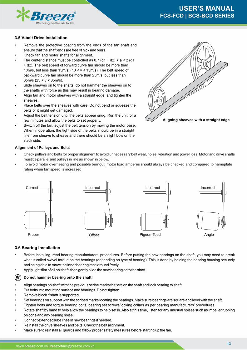
Aligning sheaves with a straight edge
Incorrect
Offset
Incorrect
Pigeon-Toed
Incorrect
Angle
Correct
Proper
3.6 Bearing Installation
Alignment of Pulleys and Belts
3.5 V-belt Drive Installation
• Remove the protective coating from the ends of the fan shaft and
ensure that the shaft ends are free of nick and burrs.
• Check fan and motor shafts for alignment.
• The center distance must be controlled as 0.7 (d1 + d2) < a < 2 (d1
+ d2). The belt speed of forward curve fan should be more than
10m/s, but less than 15m/s, (10 < v < 15m/s). The belt speed of
backward curve fan should be more than 25m/s, but less than
35m/s (25 < v < 35m/s).
• Slide sheaves on to the shafts, do not hammer the sheaves on to
the shafts with force as this may result in bearing damage.
• Align fan and motor sheaves with a straight edge, and tighten the
sheaves.
• Place belts over the sheaves with care. Do not bend or squeeze the
belts or it might get damaged.
• Adjust the belt tension until the belts appear snug. Run the unit for a
few minutes and allow the belts to set properly.
• Switch off the fan, adjust the belt tension by moving the motor base.
When in operation, the tight side of the belts should be in a straight
line from sheave to sheave and there should be a slight bow on the
slack side.
• Check pulleys and belts for proper alignment to avoid unnecessary belt wear, noise, vibration and power loss. Motor and drive shafts
must be parallel and pulleys in line as shown in below.
• To avoid motor overheating and possible burnout, motor load amperes should always be checked and compared to nameplate
rating when fan speed is increased.
• Before installing, read bearing manufacturers’ procedures. Before putting the new bearings on the shaft, you may need to break
what is called swivel torque on the bearings (depending on type of bearing). This is done by holding the bearing housing securely
and being able to move the inner bearing race around freely.
• Apply light film of oil on shaft, then gently slide the new bearing onto the shaft.
• Align bearings on shaft with the previous scribe marks that are on the shaft and lock bearing to shaft.
• Put bolts into mounting surface and bearings. Do not tighten.
• Remove block if shaft is supported.
• Set bearings on support with the scribed marks locating the bearings. Make sure bearings are square and level with the shaft.
• Tighten bolts and torque bearing bolts, bearing set screws/locking collars as per bearing manufacturers’ procedures.
• Rotate shaft by hand to help allow the bearings to help set in. Also at this time, listen for any unusual noises such as impeller rubbing
on cone and any bearing noise.
• Connect extended lube lines in new bearings if needed.
• Reinstall the drive sheaves and belts. Check the belt alignment.
• Make sure to reinstall all guards and follow proper safety measures before starting up the fan.
www.breeze.com.vn | [email protected]

We bring better air to life
USER’S MANUALFCS-FCD | BCS-BCD SERIES
14www.breeze.com.vn | [email protected]
14www.breeze.com.vn | [email protected]
3.7 Electric Installation
Electric Connection
• Before electrical connections are made, the supply voltage, phase and ampere capacity must be checked for compatibility with
the fan motor. In addition, the supply wiring must be properly fused and conform to local and national electrical codes. If the unit
is supplied with a safety disconnect switch, ensure proper wiring to the fan motor.
• Be sure the disconnect is switched to the “OFF” position before connecting supply wires. If no disconnect is supplied, ensure
the supply wire is not live before connection. Supply wires are then connected to the optional safety disconnect switch
(if supplied) or motor.
• The equipment connected ground for motor protection according to the instructions - Unless the guarantee isn't accepted.
• The most frequently encountered problems are motors that are wired to rotate the impeller in the wrong direction. This is
especially true with 3-phase installations where the motor will run in either direction, depending on how it has been wired. To
reverse rotation of a 3-phase motor, interchange any two of the three electrical leads. Single phase motors can be reversed by
changing internal connections as described on the motor label or wiring diagram.
• After connecting the wiring, install the terminal cover with screws.
Wiring diagram
W2 U2 V2
W1U1 V1
L1 L2
Voltage: 220V~240V/1P/50Hz - Delta Connection/Low Voltage
W2 U2 V2
W1V1U1
L11 L12 L13L21 L22 L23
Y - Star Connection / High VoltageVoltage: 380V~415V/3P/50Hz
W2 U2 V2
W1U1 V1
L1 L2 L3
Three-phase motors with cage rotor: Power >= 3.0kW
W2 U2 V2
W1U1 V1
L1 L2 L3
Voltage: 380V~415V/3P/50Hz
- Delta Connection / Low Voltage
Power <= 2.2kW
Single-speed Motors:
Three-phase motors with cage rotor: Power >= 3.0kW
Y - / Star-Delta Connection
Double-speed Motors with connection: 06 wires.
Two Separate Windings Connection: 6P/4P (960/1440 RPM) or 8P/6P (720/960 RPM).
U1 V1 W1
W2 U2 V2
L1 L2 L3
High speed | Y - Star ConnectionLow speed | Y - Star Connection
U1 V1 W1
W2 U2 V2
L1 L2 L3

We bring better air to life
USER’S MANUALFCS-FCD | BCS-BCD SERIES
15www.breeze.com.vn | [email protected]
High speed | Delta - Connection
L1 L2 L3
U1 V1 W1
W3 U3 V3
U4 V4 W4
W2 U2 V2
Low speed | Delta - Connection
Double-speed Motors with connection: 06 wires.
L1 L2 L3
U1 V1 W1
W3U3
V3
U4 V4 W4
W2 U2 V2
L1 L2 L3
U1 V1 W1
W3 U3 V3
U4 V4 W4
W2 U2 V2
Low speed | Y - Star Connection
U1 V1 W1
W2 U2 V2
L1 L2 L3
Dahlander Windings Connection: 4P/2P (1440/2880 RPM) or 8P/4P (720/1440 RPM)
High speed | 2Y - Star Connection
U1 V1 W1
W2 U2 V2
L1 L2 L3
Double-speed motors with connection: 12 wires
L1 L2 L3
U1 V1 W1
W3 U3 V3
U4V4
W4
W2 U2 V2
High speed | Y - Star ConnectionLow speed Y - Star Connection |
4.1. Visual Inspection of Equipment• The equipment type and arrangement should be verified as ordered at once when it arrives at the jobsite. When a discrepancy
is found, the local Breeze Sales Representative must be notified immediately so that corrective action may be investigated, also
verify electrical conformance to specifications. Unauthorized alterations and unauthorized backcharges will not be recognized by
Breeze Fan.
• After the unit has been assembled, installed and all utilities have been hooked up, the unit is now ready for operation.
4. OPERATION INSTRUCTION
• Switch on the fan for a short moment to check whether the direction of rotation is correct (See arrows at the fan casing).
• If incorrect, change the direction of rotation by changing the wiring. (Respect the instructions of power supply companies).
Check
Before starting the unit, check the following:
• Confirm that building supply voltage matches the voltage for which the unit is wired.
• Check all piping and wiring penetrations.
• Made by contractors for water tightness. All penetrations must be made watertight to prevent water damage to the unit and building.
• Rotate the fan manually to be sure that it is free to operate. Remove any dirt or debris that may have accumulated during impeller
installation.

We bring better air to life
USER’S MANUALFCS-FCD | BCS-BCD SERIES
16www.breeze.com.vn | [email protected]
4.2 Checks prior to initial start-upProceed with the fan's initial start-up in the following sequence:
• Check that the mechanical assembly has been carried out properly
• Remove foreign bodies located in the suction and outflow areas and in the fan space
• Check that the electrical installation has been completed in accordance with regulations
• Does the mains voltage match the motor voltage specified on the rating plate?
• Is the switchgear used suitable for the motor both with respect to the switching functions to be carried out and also to the
switching conditions and switched output of the motor?
• Is the motor protection system set correctly with regard to the motor's nominal current? The setting must be carried out in
accordance with the corresponding details contained on the motor output plate.
• Has the motor been connected correctly in accordance with the wiring diagram? The connection schematic supplied by the
motor suppliers applies for the connection of the motor. The special connection regulations are to be observed for explosion-
protected models.
• Fans with multi-speed motors should be checked on low speed during initial start-up.
• Check for unusual noise, vibration or overheating of bearings. Refer to the “Troubleshooting” section of this manual if a problem
develops.
Accident prevention:
• Protective anti-intrusion fittings, protective screens (see accessories) mounted, fan boxed in or assembled out of reach.
• If the fan is assembled for free-suction, the suction aperture must be covered by a protective screen. This is the only way that
the accident prevention regulation governing protection from contact can be deemed to have been met.
4.3 Starting up the fan for the first time.Only put the fan into operation after it has been assembled in accordance with the regulations:
• Put the fan into operation.
• Monitor its correct function (quiet running, vibration, imbalance, power consumption, controllability) Should the required output
(volume flow or pressure increase) not be achieved by the fan, e.g. through unforeseen changes in the installation system, the
rotor fins can be adjusted up to the maximum fin settings specified both on the rating plate and in the technical documentation.
The power consumption must be re-measured in order to avoid any possible motor overload. The thermal-protection system
may be activated if the motor power consumption is too high.
• Check the bearing temperature after a lengthy period of operation. Always keep suction openings clear. Check protective
screens or protective anti-intrusion fittings for dirt and clean if necessary.
Once the unit has been put into operation, a routine maintenance schedule should be set up to accomplish the following:
• Lubrication of bearings and motor.
• Impeller, casing, bolts and set screws on the entire fan should be checked for tightness.
• Any dirt accumulation on the impeller or in the casing should be removed to prevent unbalance and possible damage.
• Inspect fan impeller and casing looking for fatigue, corrosion or wear.
4.4 Checks after initial start-upCheck the mechanical connections after initial start-up, especially the joints at the fan.
Good
Check at regular intervals and re-balance as soon as possible
Alarm
Trip
Stop immediately
0 - 4.4
4.4 - 7.1
7.1 - 11.2
11.2 - 18
18.0
11.0
18.0
Vibration Velocity Table:
ACTION VIBRATION VELOCITYmm/s
Check at regular intervals
Clean and rebalance
• Check the fan bearing setscrews for tightness.
• Check alignment of sheaves and V-belts (See maintenance section).
• Inspect all fasteners to ensure that none have loosened during shipment.
• Check flex coupling for proper alignment and connect between motor shaft and fan shaft (direct drive).
• Check all guarding to ensure that it is securely attached and not interfering with rotating parts.
• Check all electrical connections for proper attachment.
• Check housing and ductwork, if accessible, for obstructions and foreign material that may damage the fan impeller.

We bring better air to life
USER’S MANUALFCS-FCD | BCS-BCD SERIES
17
Clean fan:
• Clean inlet cones.
• Clean impeller (if necessary dismount protection guards).
o Do not flood motor.
o Do not bend impeller, blades.
• Install protection guard.
5.2 Inspection of the belt drive Make sure to regularly inspect the belt drive during the initial operating hours. The drive belt will have to be inspected and
retightened, if necessary after an operating period of between 0.5 and 4 hours under full load and thereafter in intervals of about 24
operating hours.
• Unscrew the protective cover of the belt
• Inspect the drive belt as shown in "Belt Drive Installation" figure. if necessary, retighten the drive belt:
o Loosen the clamping screws on the side of the motor carriage
o Tighten the belt as required by adjusting the tension screws
o Tighten the clamping screws on the motor carriage
• Reinstall the protective cover of the belt.
www.breeze.com.vn | [email protected]
5. ROUTINE MAINTENANCE
• Regular maintenance is needed each year. The impeller blades require thorough cleaning once in 6 months.
• Before any maintenance work is undertaken:
o Stop fan in accordance to regulations and disconnect all poles from mains supply.
o Wait until impeller is stationary.
o Make sure that a restart is not possible.
• Use only original spare parts tested and approved by the manufacturer.
• The following safety notes must be observed when maintaining the machine.
• Replace the ball bearings of the motor whenever the grease utilization period has elapsed in accordance with the maintenance
instructions of the manufacturer.
• The technical maintenance includes periodic cleaning of the surfaces from accumulated dust and dirt.
• Use a soft dry brush or a vacuum cleaner to remove dust.
• Only use usual commercial cleaning material paying attention to the prescribed safety measures and do not use any abrasive
tools (surface protection will be destroyed).
5.1 Servicing maintenance.• The impeller and casing are subject to natural wear and tear through the action of dust, acidic and corrosive vapours, as well as
the gases which are mixed into the conveyed flow. The type and concentration of the dust, as well as the gases and vapours,
can lead to deposits, abrasion and corrosion at the impeller and casing.
• The materials can be attacked so much by this natural wear and tear that they can no longer stand up to the demands made of
them. Deposits on the rotor, which have never been evenly distributed, lead to an imbalanced state and thus to noisy running,
which in turn can result in damage to the motor bearing. Deposits in the casing lead to a narrowing of the available cross-
sectional area or to a roughening of the casing panels and can thus have an unfavourable effect on the fan's output data.
Should the checks, the regularity of which depend on the conveyed media and other operating conditions which differ in each
individual case, only reveal slight wear and tear, then the individual parts can be cleaned in good time or replaced if necessary.
Prior to all servicing work:
• Bring the fan to a halt in the prescribed manner and completely isolate the fan from the mains supply.
• Wait until the rotor has come to a halt.
• Ensure that the machine cannot be switched on again
• Clean the fan
• Clean the suction apertures
• Clean the rotor (if necessary dismantle the protective anti-intrusion fitting)
• Do not overload the motor
• Do not bend the rotor or vanes
• Assemble the protective anti-intrusion fitting.
• Control whether installation is correct:
o Impeller must rotate free
o Annular gap between impeller and wall plate/casing must be regular.
o Checking direction of rotation is correct.
General Check:
• Too much bearing play?
• Lubricant leaking from the bearings?
• Surface protective coating damaged?
• Attention: Conveyed medium too aggressive?
• Unusual noises during operation
• Fan output still sufficient for possibly extended or shortened ducting system?

We bring better air to life
USER’S MANUALFCS-FCD | BCS-BCD SERIES
18
-1
• Shaft bearings are the most critical moving part of a fan.
Therefore, special attention should be given to keeping the
bearings clean and well lubricated. Proper lubrication provides
for reduction in friction and wear, transmission and dissipation
of heat, extended bearing life and prevention of rust.
• In order for a lubricant to fulfill these tasks, the proper grease
applied at regular intervals is required. See the recommended
bearing lubrication schedule below.
• In addition to lubricating the bearings at specified intervals,
set screws in the bearing collars should be checked for
tightness. A bearing collar which has loosened will cause
premature failure of the fan shaft. Fasteners attaching the
bearings to the drive frame should also be checked.
• Fan equipped with spheriodical roller bearing assembly in the
plummer block housing has lubrication point when the life of
the grease is expectancy.
• The bearings must be greased at regular intervals in order to
attain the maximum permissible life of the bearing under more
severe operating conditions.
• The re-lubricating interval depends on the operating
temperature, relevant operating conditions speed and the type
of grease used should be set by the operator.
Recommended bearing lubrication scheduleRelubrication schedule in months
Standard grease
FanRPM
Bearing bore (inches)
1/2 -1 1 11 ⁄8 - 1 ⁄2 5 71 ⁄8 - 1 ⁄ 8 15 31 ⁄16 - 2 ⁄1672 ⁄16 - 3
5.4 Bearing Lubrication Schedule
www.breeze.com.vn | [email protected]
5.3 Motor maintenance • Motor maintenance is generally limited to cleaning and lubrication.
• Cleaning should be limited to exterior surfaces only.
• Removing dust and grease buildup on the motor casing assists proper motor cooling.
• Never wash-down motor with high pressure spray. Greasing of motors is only intended when fittings are provided. Many
fractional motors are permanently lubricated for life and require no further lubrication. Motors supplied with grease fittings
should be greased in accordance with the manufacturer's recommendations. When motor temperature does not exceed 104ºF
(40ºC), the grease should be replaced after 2000 hours of running time.
• Direct drive systems have extended grease lines to lubricate the motor without removal of any guarding.
Service intervals in operating hours forMotorFrame 2880 min 1440 min 960 and 720 min
56 20000 20000 20000
63 20000 20000 20000
71 20000 20000 20000
80 18000 20000 20000
90 16000 20000 20000
100 14000 20000 20000
112 14000 20000 20000
132 11000 20000 20000
160 20000 20000
180 20000 20000
200 18000 20000
225 18000 20000
Service intervals for motor bearings.
Motor standard.
Single speed:
2 Poles: 2880 rpm
4 Poles: 1440 rpm
6 Poles: 960 rpm
8 Poles: 720 rpm
Double speeds:
2/4 Poles: 2880/1440 rpm
4/8 Poles: 1440/720 rpm
4/6 Poles: 1440/960 rpm
6/8 Poles: 960/720 rpm
Motor bearing service intervals
• The roller bearings of the standard AC motors are basically equipped with a permanently sealed lubrication system consisting of
a high-quality, temperature-resistant, lithium-based roller bearing grease (melting point approximately 160°C). The amount of
lubricant supplied to the bearing by the motor manufacturer is sufficient for 10,000 to 20,000 operating hours.
• Unfavourable operating conditions, such as permanently lengthy operating periods, changes in bearing loads etc, require that
the motor bearings are monitored carefully. The service intervals or lubrication deadlines and amounts depend on the motor's
operating conditions, the rotary speed and size of bearing.
• As only the construction size and rotary speed of the motors are usually known, the service intervals specified in the adjacent
table should be applied. They refer to a coolant temperature of 40°C in the case of horizontal fitting (construction form B3). The
service intervals are to be put back by 1/3 in the case of vertical fitting.
-1 -1
To 25
500
750
1000
1250
1500
2000
2500
3000
3500
4000
5000
Mumberof Shots
12
12
12
2
12
12
12
12
12
12
12
12
12
12
9
7
6
5
3
2
2
1
0.5
0.25
12
11
8
6
5
4
3
2
1
0.5
0.25
x
12
10
7
5
4
3
2
1
0.5
0.25
x
x
12
8
6
4
3
2
1
0.5
0.25
x
x
x
4 8 10 168

Belt Section
Force require to deflect A belt 16mm per meter of span
Small Pulley/ Diameter (mm)
Newtonian (N)
Kilogram force (Kgf)
SPZ13-20 56-95 1.3-2.0
20-25 100-140 2.0-2.5
SPA25-35 80-132 2.5-3.6
35-45 140-200 3.6-4.6
SPB45-65 112-224 4.6-6.6
65-85 236-315 6.6-8.7
SPC85-150 224-335 8.7-11.7
115-150 375-560 11.7-15.3
A 10-15 80-140 1.1-1.5
B 20-30 125-200 2.0-3.1
We bring better air to life
USER’S MANUALFCS-FCD | BCS-BCD SERIES
19
• The following has to be noted: If the fan is equipped with re-
lubrication tubes (nipples located on the fan casing and not at
the fan bearing), then the quantity of grease for the first re-
greasing is calculated as follows (as the empty tubes need to be
fully filled):
o Regreasing quantity (1st time) = quantity shown on
label + 20ml per meter greasing-tube.
o Aternative – if the length of the greasing-tube is
unknown – please calculate: Regreasing quantity (1st
time) = quantity shown on label + 20ml * fan diameter
in m.
• After the first greasing interval you have to use the quantity
given on the label or on the documentation supplied.
• The re-lubrication intervals can be seen from the following curve
or can be provided separately.
• Bearing type:
o Deep-groove ball bearing single-row kf = 1.1
o Cylindrical roller bearing single row kf = 3.5
o dm = average bearing diameter [mm]
o dm = (d+D)/2
o n = speed (min-1)
• The pillow block housing has lubrication point suitable for
lubricating when the bearing operating temperature exceeding
its nominal of 70 degree or the bearing is used in very dusty or
damp or high contamination environment.
• Impellers require very little attention when exhausting clean air, however, air heavily laden with grease or dirt will tend to
accumulate on the impeller causing unbalance. impellers exhausting dirty or grease-laden air require frequent cleaning to
assure smooth and safe operation.
• All fasteners, including set screws in the bearing collars, should be checked for tightness each time maintenance checks are
performed.
• A proper maintenance program will help preserve the performance and reliability designed into the fan.
5.6 Impeller and Fastener Maintenance
5.5 Belt Drive Maintenance
Belt tension indicator applied to mid center distance.
mm deflection per1 meter of span
Belt Length
Center Distance
Cylindrical
roller bearing
Deep groove
ball bearing
Lu
brica
tion
inte
rva
lst f
[h
]
-1K n d [ min mּ m ]f m
0.2 0.3 0.5 0.7 1 1.5 2 3 5 7 10 15 203
100000
50000
30000
20000
10000
5000
30002000
1000
500
300200
*10
www.breeze.com.vn | [email protected]
• Before tensioning the belts installed on the pulleys, mark two
thin transverse lines on the back of a belt in the middle of the
group of belts, these marks shall be as far apart as possible
while remaining together on the straight part of the belt strand.
• Tighten the belts progressively after turning them for about
one minute, several times, after each adjustment, tighten the
pulleys so that the length between the two marks is increased
by the percentage given in the following table.
• This simplified belt tensioning method will facilitate the work
done by fitters for maintenance of trapezoidal belt
transmissions when important technical data are not available.
This avoids the need to calculate the optimum tension.
We bring better air to life
USER’S MANUALFCS-FCD | BCS-BCD SERIES
20www.breeze.com.vn | [email protected]
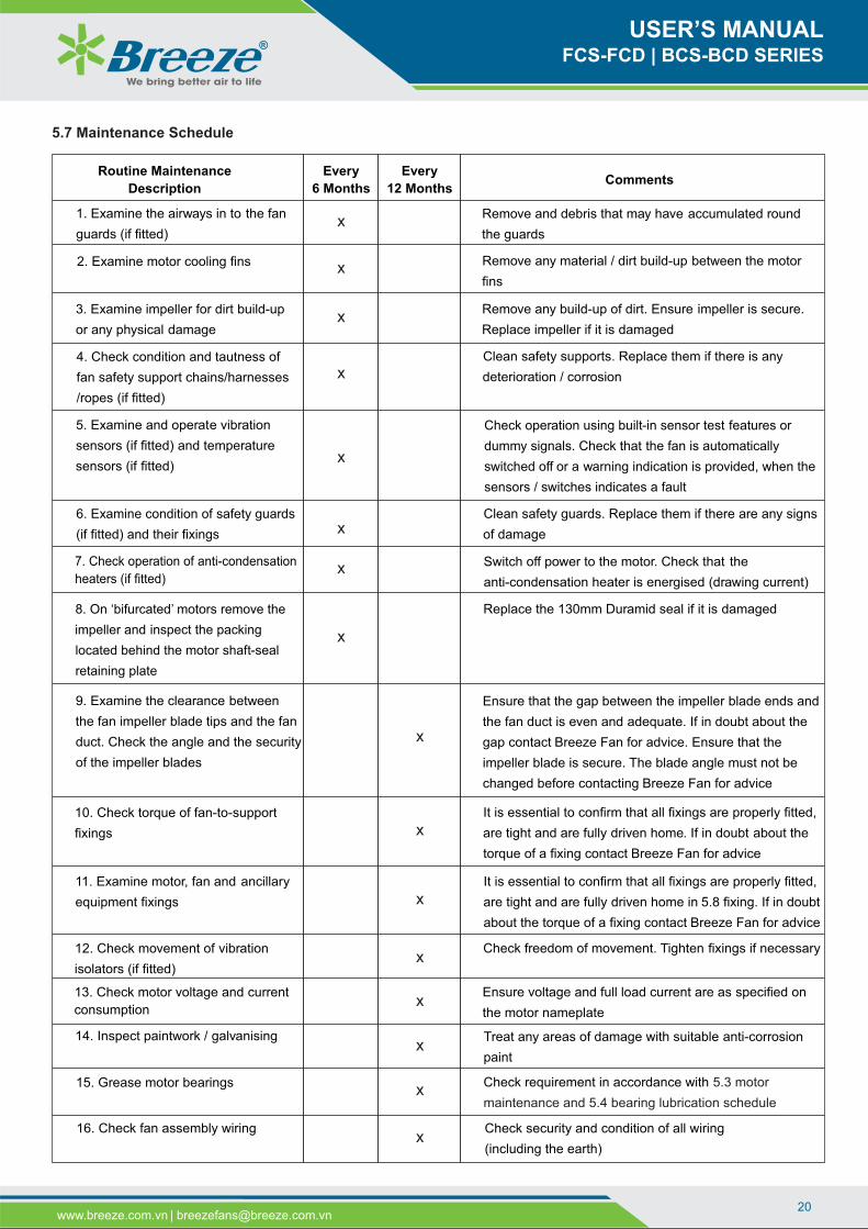
5.7 Maintenance Schedule
Routine Maintenance
Description
Every
6 Months
Every
12 MonthsComments
1. Examine the airways in to the fan
guards (if fitted)
Remove and debris that may have accumulated round
the guards
2. Examine motor cooling fins Remove any material / dirt build-up between the motor
fins
3. Examine impeller for dirt build-up
or any physical damage
Remove any build-up of dirt. Ensure impeller is secure.
Replace impeller if it is damaged
4. Check condition and tautness of
fan safety support chains/harnesses
/ropes (if fitted)
Clean safety supports. Replace them if there is any
deterioration / corrosion
5. Examine and operate vibration
sensors (if fitted) and temperature
sensors (if fitted)
Check operation using built-in sensor test features or
dummy signals. Check that the fan is automatically
switched off or a warning indication is provided, when the
sensors / switches indicates a fault
Clean safety guards. Replace them if there are any signs
of damage
7. Check operation of anti-condensation
heaters (if fitted)
Switch off power to the motor. Check that the
anti-condensation heater is energised (drawing current)
8. On ‘bifurcated’ motors remove the
impeller and inspect the packing
located behind the motor shaft-seal
retaining plate
Replace the 130mm Duramid seal if it is damaged
9. Examine the clearance between
the fan impeller blade tips and the fan
duct. Check the angle and the security
of the impeller blades
Ensure that the gap between the impeller blade ends and
the fan duct is even and adequate. If in doubt about the
gap contact Breeze Fan for advice. Ensure that the
impeller blade is secure. The blade angle must not be
changed before contacting Breeze Fan for advice
10. Check torque of fan-to-support
fixings
It is essential to confirm that all fixings are properly fitted,
are tight and are fully driven home. If in doubt about the
torque of a fixing contact Breeze Fan for advice
11. Examine motor, fan and ancillary
equipment fixings
It is essential to confirm that all fixings are properly fitted,
are tight and are fully driven home in 5.8 fixing. If in doubt
about the torque of a fixing contact Breeze Fan for advice
12. Check movement of vibration
isolators (if fitted)
Check freedom of movement. Tighten fixings if necessary
13. Check motor voltage and current
consumption
Ensure voltage and full load current are as specified on
the motor nameplate
14. Inspect paintwork / galvanising Treat any areas of damage with suitable anti-corrosion
paint
16. Check fan assembly wiring Check security and condition of all wiring
(including the earth)
x
6. Examine condition of safety guards
(if fitted) and their fixings
x
x
x
x
x
x
x
x
x
x
x
x
x
x
15. Grease motor bearings Check requirement in accordance with 5.3 motor
maintenance and 5.4 bearing lubrication schedulex

We bring better air to life
USER’S MANUALFCS-FCD | BCS-BCD SERIES
21www.breeze.com.vn | [email protected]
FIXING ARRANGEMENT OF TERMINAL BLOCK
Terminal screw locknut
Terminal screw washer
Customers supply lead eyelet (when fitted)
Connecting links (when fitted)
Motor lead eyelet
Fixing
Torque values
M4
M5
M6
M8
M10
1.5Nm - Brass
2.7Nm - Brass
5.5Nm - Brass
10.5Nm - Brass
55.5Nm - Steel
Terminal screw
Terminal block
Identification tag
Brass washer(Fitted with connecting links)
Terminal screw lockwasher
Important note:This drawing shows the correct assembly sequence of terminal parts.It is essential that no lockwashers or nuts are placed between the motor lead eyelet, connecting link or customers supply lead eyelet (when fitted).
Packing washers(Omit from assembly where stud
thread continues to terminal block surface)
Do not use copper wire links
It is essential to ensure that all fixings on the fan assembly are secure. When examining and checking the security of fixings during routine
maintenance, those fixings that have locking devices fitted or are painted over, need not be disturbed if they can be seen to be secure. Any
locking devices that are disturbed during maintenance must be discarded and replaced with new identical devices.
Thread forming screws must have locking compound applied when being reused. Those fixings that have no locking devices fitted and
are not painted over, should be checked at 95% of their original setting to ensure no unnecessary disturbance of the fixing. See picture
below for torque setting details. If in doubt about the torque of a particular fixing contact Breeze Fan for advice.
Torque settings for screws
Screw Fixing
Torque setting: +0% / -10% (Nm)
M4 M5 M6 M8 M10 M12 M14 M16 M18 M20 M22 M24
Steel 8.8
Stainless SteelA2, A4 Prop 70
Stainless SteelA2, A4 Prop 80
3.5 7.0 12 28 55 100 155 245 335 475 645 820
2 4 7 17 33 56 90 135 190 268 365 460
3 5.5 9.5 22 43 75 120 185 255 355 485 615
Torque settings for taper hubs
Bushes Taper Hubs
Torque
Type
Bore [mm]
Tightness [Nm]
1008 1108 1210 1310 1610 2012 2517
12,19,24 19,24,28 16,19,24,32 14,25,35 19,24,38,42 24,38,50 38,48,60
6 6 20 20 20 32 49
Base and Foot
Mount Torque
Settings
(Nm)
Motor Frame
Screw Fixing
Motor Base
D71 D80
Foot Mount
Shaft and
Fixings
D90 D100 D112 D132 D160/180 D200-315
M8 M10 M12 M12 M12 M16 M20 M24
15 15 35 55 55 135 240
50 85 85 85 180 350 450
450
Screw Fixing M6 M8 M10 M10 M12 M16 M20
Motor Frame D71/80 D90 D100 D112 D132 D160/180 D200-250
M24
D280-315
6 15 30 30 50 120 180 295Torque Value
-
TORQUE SETTINGS FOR FIXINGS
5.8 Fixing

6. REPAIR
22www.breeze.com.vn | [email protected]
We bring better air to life
USER’S MANUALFCS-FCD | BCS-BCD SERIES
Replacing the impeller:
• Remove the intake side protective grid and the tamper protection.
• Remove the protective cover of the belt in Fig 1.
• Loosen the tension of the belt drive in Fig 1.
• Remove the drive belt in Fig 2.
• On the side opposite of the drive, loosen the clamping screws of the ball bearings.
• Loosen the inlet cone mounting screws on the drive side.
• Remove the impeller together with the shaft from the drive side in Fig 3.
• Loosen the clamping screw for the setting collar on the opposite side of the drive
and remove the setting collar from the shaft.
• Pull the ball bearing off the shaft in Fig 5.
• Loosen the clamping screw for the setting collar on the impeller and remove the
setting collar.
• Pull off the impeller in Fig 6.
• Install the new impeller.
• Reverse the order for the installation.
• Install the intake side protective grid, the tamper protection and the protective
cover of the belt.
Before any repairs are undertaken please:
• Stop fan in accordance to regulations and disconnect all poles from mains supply.
• Wait until impeller is stationary.
• Make sure that a restart is not possible.
• Only use original spare parts manufactured and supplied by Breeze Fan.
Replacing the motor:
• Disconnect the wiring of the motor.
• Remove the protective cover of the belt in Fig 1.
• Loosen the clamping screws on the motor carriage in Fig 1.
• Release the tension of the belt drive in Fig 2.
• Remove the pulley from the motor shaft (for this, loosen the Allen screws on the
pulley and screw into the vacant holes. This will loosen the fit of the pulley on the
conical hub. Under no circumstances try to remove the pulley using a hammer or
similar tools) in Fig 3.
• Loosen the mounting screws at the motor flange (if necessary, steady the motor)
and remove the motor in Fig 4.
• Install the new motor.
• Install the pulley on the motor shaft (the pulleys must be aligned properly). Clamp
the conical hub by tightening the Allen screws
• Tighten the drive belt ( Maintenance)
• Install the protective cover of the belt
• Reconnect the wiring ( Installation)
Control whether installation is correct:
o The impeller must turn freely ( Installation)
o Control whether direction of rotation is correct.
( Installation)
o The gap between impeller and casing must be regular.
Fig 1
Fig 2
Fig 3
Fig 4
Fig 5Fig 6
We bring better air to life
USER’S MANUALFCS-FCD | BCS-BCD SERIES
23www.breeze.com.vn | [email protected]
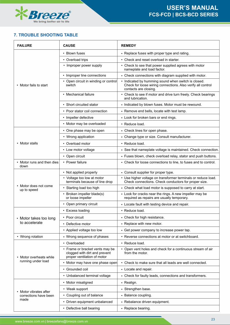
• Motor fails to start
• Blown fuses
Check and reset overload in starter.
• Improper power supply • Check to see that power supplied agrees with motor nameplate and load factor.
Check connections with diagram supplied with motor.
• Open circuit in winding or control switch
• Indicated by humming sound when switch is closed. Check for loose wiring connections. Also verify all control contacts are closing.
• Mechanical failure • Check to see if motor and drive turn freely. Check bearings and lubrication.
Indicated by blown fuses. Motor must be rewound.
Remove end bells, locate with test lamp.
• Impeller defective
• Motor may be overloaded
• Motor stalls
• One phase may be open
• Wrong application
• Overload motor
• Low motor voltage See that nameplate voltage is maintained. Check connection.
• Open circuit Fuses blown, check overload relay, stator and push buttons.
• Motor runs and then dies down
• Power failure Check for loose connections to line, to fuses and to control.
• Motor does not come up to speed
• Not applied properly
• Voltage too low at motor terminals because of line drop
Use higher voltage on transformer terminals or reduce load.Check connections. Check conductors for proper size.
• Starting load too high
• Broken impeller blade(s) or loose impeller
Look for cracks near the rings. A new impeller may berequired as repairs are usually temporary.
• Open primary circuit
• Motor takes too long to accelerate
• Excess loading
• Poor circuit
• Defective motor
• Applied voltage too low
• Wrong rotation
• Motor overheats while running under load
• Overloaded
• Frame or bracket vents may be clogged with dirt and prevent proper ventilation of motor
Open vent holes and check for a continuous stream of airfrom the motor.
• Motor may have one phase open Check to make sure that all leads are well connected.
• Grounded coil
• Unbalanced terminal voltage
FAILURE CAUSE REMEDY
Replace fuses with proper type and rating.
7. TROUBLE SHOOTING TABLE
• Overload trips
• Improper line connections
• Short circuited stator
• Poor stator coil connection
Look for broken bars or end rings.
Reduce load.
Check lines for open phase.
Change type or size. Consult manufacturer.
Reduce load.
Consult supplier for proper type.
Check what load motor is supposed to carry at start.
Locate fault with testing device and repair.
Reduce load.
Check for high resistance.
Replace with new motor.
Get power company to increase power tap.
Reverse connections at motor or at switchboard.Wrong sequence of phases
Reduce load.
Locate and repair.
Check for faulty leads, connections and transformers.
• Motor vibrates after corrections have been made
• Motor misaligned
• Weak support
• Coupling out of balance
• Driven equipment unbalanced Rebalance driven equipment.
• Defective ball bearing
Realign.
Strengthen base.
Balance coupling.
Replace bearing.
•
•
•
•
•
•
•
•
•
•
•
•
•
•
•
•
•
•
•
•
•
•
•
•
•
•
•
•
•
•
•
•
•
•

We bring better air to life
USER’S MANUALFCS-FCD | BCS-BCD SERIES
24www.breeze.com.vn | [email protected]
FAILURE CAUSE REMEDY
Motor vibrates aftercorrections have beenmade
Bearings not in line
Balancing weights shifted
Polyphase motor running singlephase
Check for open circuit.
Excessive end play
Unbalanced line currenton polyphase motorsduring normal operation
Unequal terminal volts
Single phase operation
Scraping noise
Fan rubbing air shield
Fan striking insulation
Loose on bedplate
Noise operationAirgap not uniform
Impeller unbalanced
Hot bearings general
Bent or sprung shaft
Excessive belt pull
Pulleys too far away
Pulley diameter too small
Misalignment
Hot ball bearings
Insufficient grease
Deterioration of greaseor lubricant contaminated
Remove old grease, wash bearings thoroughly in keroseneand replace with new grease.
Excess lubricant Reduce quantity of grease, bearing should not be morethan 1/2 filled.
Overloaded bearing
Broken ball or rough races
Line up properly.
Rebalance motor.
Adjust bearing or add washer.
Check leads and connections.
Check for open contacts.
Remove interference.
Clear fan.
Tighten holding bolts.
Check and correct bracket fits or bearing.
Rebalance.
Straighten or reshaft.
Decrease belt tension.
Move pulley closer to motor bearing.
Use larger pulleys.
Correct by realignment of drive.
Maintain proper quantity of grease in bearing.
Check alignment, side and end thrust.
Replace bearing, first clean casing thoroughly.
Restore the right lubrican t quantity. Check operation of the grease v alve
(when applicable).
Wrong lubricant quality Disassemble and clean the bearings. Relubricate using the correct l u bricant.
Not enough lubricant Top up with lubricant.
Not enough radial clearanc e in the bearings
Adjust the radial clearance.
Cooling disk not in place Install the cooling disk.
Temperature of the circulate d fluid too high
Check the working conditions. Adjust the gas temperature to i t s correct value.
Ambient temperature higher than 40°C
Reduce lubrication interva ls by half for each 15°C above 70°C measured on the bearing ring.
Bearing temperature tohigh
Whistling noise The bearings are worn Replace the bearings.
Knocking or rumbling inthe bearing
Presence of foreign bodies i n the bearing
Disassemble, clean an d check the bearings.
If necessary, change th e bearings and the lubricants. Replace the bearing s.
Deterioration of the bearing s during installation, marking of the raceways, oxidation or wear
Fan vibrations Blades are dirty Wear plate torn off
Clean th e impeller .Check the wear plates an d replace them if necessary.
Too much grease in bearings Adjust the lubricant quantity
• •
•
• •
•
•
•
•
•
•
•
•
•
•
•
•
• • • •
• •
• •
• •
• •
• •
• •
• •
• •
• •
• •
• •
• •
• •
• •
• •
• •
• •
• •
• •
• •
• •
•
• •
•
• •
• •
• •
• •
•
• •
• •
• •
• •
• •
•
Transmission belt not tight e n ough (slip)
Tighten the transmission be lt according to the manufacturer’s instructions.
Belt temperature too high • • •
Abnormal noise inbearings
• Insufficient or defectivelubrication
Check operation of lubrication devicesTop up with lubricant
• • •

We bring better air to life
USER’S MANUALFCS-FCD | BCS-BCD SERIES
25www.breeze.com.vn | [email protected]
Irregular wear or corrosion o f the impeller
Rebalance the impeller o r replace the rotor. • •
Impeller or shaft deformations due to overheating
Eliminate the causes of o v erheating. Replace the roto r. • •
•
Fan vibrations
Impeller not properly balanced Rebalance the impeller.
Couplings or transmissionsmisalig ned
Repeat the alignments in a c cordance with the particular instructions.
Driving machines are badly balanced or defective
Check the balance and o p eration of the driving machines. Recondition or replace when n e cessary.
The motor-fan unit is no t properly fixed or not firmly anchored
Retighten and check anchor b o lts in accordance with the instructions.
Bearings or bearing caps are n o t sufficiently tightened
Tighten assembly fasteners to t h e recommended torque.
The use of badly dimensioned anti-vibration pads (Resonance)
Replace the anti-vibration p a ds with correctly sized pads.
Speed too high Check the motor speed and t h e transmission ratio and correct the speed.
Pumping Change the flow setting until a n acceptable vibration amplitude is obtained.
Abnormal noise in the
fan
Presence of a foreign body Inspect the fan and remove t h e foreign body. Turn the rotor by hand .
Internal friction Check the clearance between t h e impeller and the intake and between the seal and the shaft crossing, turn the fan by hand.
External friction Check the position and t i g htness of the protective guards, turn the fan by hand.
Premature wear ofbearings
Excessive vibrations Check and correct the various c a uses of vibrations.
Incorrect lubrication Check and correct the l u brication.
Fan held stopped under e x citation by external vibrations
Eliminate vibrations by is o lating machines causing excitement and isolate the fan itself.
Fan held stopped without t a king precautions against corrosive agents
Take steps made necessary b y environmental and usage conditions: Intermitten t operation Provide protected stor age during stoppages
Keep warm during s t oppages, etc.
Impossible or verylong to start
Rotor blocked Check that the rotor turns by h a nd. Search for the cause of the b l ockage. Friction. Foreign bodies, et c.
Voltage at motor terminals too l o w Check the network voltage. Improve the electrical line, if l o sses are excessive.
Trips Check the settings of safety d e vices.
Insufficient motor power Replace the motor.
Improper starter Replace the starter.
Excessive power absorbed d u ring start up
Check that fan regulation d e vices are closed when starting.
Excessive powerabsorbed in service
Excessive speed Check motor speed and t r a nsmission ratios and correct if necessary.
Network less resistant tha n expected Use the regulation devices to a d just the flow to its design value.
Performances notobtained
Speed too low Check motor speed and t r ansmission ratio and correct if necessary. Adjust the belt tension .
Poor design of the intake and discharge network
Change the arrangement and s ize of the network.
Performances notobtained
Impeller installed backwards Invert the installation of the i m peller on the shaft.
Excessive clearances between theimpeller and the intake
Adjust the clearances to c o mply with the instructions.
FAILURE CAUSE REMEDY
•
• •
• •
• •
•
•
• • •
• • • •
•
•
•
•
•
•
• •
• •
• •
• •
• •
• •
• •
• •
• •
• •
• •
•
•
• •
• •
• •
• •
• •
• •
• •
• •
• •
Incorrect direction of rotation Changeover the motor d i rection of rotation. • •
• •
• •
•
•
We bring better air to life
USER’S MANUALFCS-FCD | BCS-BCD SERIES
26www.breeze.com.vn | [email protected]
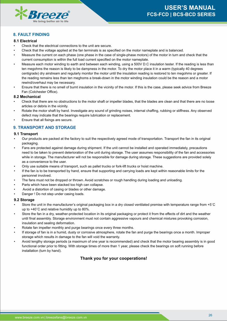
9.1 Transport• Our products are packed at the factory to suit the respectively agreed mode of transportation. Transport the fan in its original
packaging.
• Fans are protected against damage during shipment. If the unit cannot be installed and operated immediately, precautions
need to be taken to prevent deterioration of the unit during storage. The user assumes responsibility of the fan and accessories
while in storage. The manufacturer will not be responsible for damage during storage. These suggestions are provided solely
as a convenience to the user.
• Only use suitable means of transport, such as pallet trucks or fork-lift trucks or hoist machine.
• If the fan is to be transported by hand, ensure that supporting and carrying loads are kept within reasonable limits for the
personnel involved.
• The fans must not be dropped or thrown. Avoid scratches or rough handling during loading and unloading.
• Parts which have been stacked too high can collapse.
• Avoid a distortion of casing or blades or other damage.
• Danger ! Do not step under casing loads.
9. TRANSPORT AND STORAGE
9.2 Storage• Store the unit in the manufacturer’s original packaging box in a dry closed ventilated premise with temperature range from +5˚С
up to +40˚С and relative humidity up to 80%.
• Store the fan in a dry, weather-protected location in its original packaging or protect it from the effects of dirt and the weather
until final assembly. Storage environment must not contain aggressive vapours and chemical mixtures provoking corrosion,
insulation and sealing deformation.
• Rotate fan impeller monthly and purge bearings once every three months.
• If storage of fan is in a humid, dusty or corrosive atmosphere, rotate the fan and purge the bearings once a month. Improper
storage which results in damage to the fan will void the warranty.
• Avoid lengthy storage periods (a maximum of one year is recommended) and check that the motor bearing assembly is in good
functional order prior to fitting. With storage times of more than 1 year, please check the bearings on soft running before
installation (turn by hand).
8.1 Electrical• Check that the electrical connections to the unit are secure.
• Check that the voltage applied at the fan terminals is as specified on the motor nameplate and is balanced.
• Measure the current on each phase (one phase in the case of single-phase motors) of the motor in turn and check that the
current consumption is within the full load current specified on the motor nameplate.
• Measure each motor winding to earth and between each winding, using a 500V D.C insulation tester. If the reading is less than
ten megohms the reason is likely to be dampness in the motor. To dry the motor place it in a warm (typically 40 degrees
centigrade) dry airstream and regularly monitor the motor until the insulation reading is restored to ten megohms or greater. If
the reading remains less than ten meghoms a break-down in the motor winding insulation could be the reason and a motor
rewind/overhaul may be necessary.
• Ensure that there is no smell of burnt insulation in the vicinity of the motor. If this is the case, please seek advice from Breeze
Fan (Colchester Office).
8.2 Mechanical• Check that there are no obstructions to the motor shaft or impeller blades, that the blades are clean and that there are no loose
articles or debris in the vicinity.
• Rotate the motor shaft by hand. Investigate any sound of grinding noises, internal chaffing, rubbing or stiffness. Any observed
defect may indicate that the bearings require lubrication or replacement.
• Ensure that all fixings are secure.
8. FAULT FINDING
Thank you for your cooperations!

Applied standard:
BREEZE INDUSTRIAL VENTILATION JOINT STOCK COMPANY
Vietnam
Head Office:
215D8 Nguyen Van Huong Street, Thao Dien Ward,
District 2, Ho Chi Minh City, Vietnam.
Tel: +84 28 6651 8585 | Hotline: +84 931 920 368
Factory:
12 Road No. 570, Xom Moi Hamlet, Trung Lap Ha
Commune, Cu Chi District, Ho Chi Minh City, Vietnam.
Tel: +84 28 6659 9589
Ha Noi Office:
55, Alley No. 14, Vu Huu Street, Thanh Xuan Bac Ward,
Thanh Xuan District, Ha Noi City, Vietnam.
Tel: +84 24 6683 8797 | Hotline: +84 906 568 557.
Website: www.breeze.com.vn
Email: [email protected]
Singapore
Office:
No 15, Yishun Industrial Street
1, #03-29, WIN5 Singapore
S768091.
Tel: +65-6254-2648
Myanmar
Office:
No.13/B, Kan Yeik Thar
Street, Thingangyun
Township, Yangon, Myanmar.