User manual - TOX® PRESSOTECHNIK
126
User manual Process monitoring CEP400T TOX ® PRESSOTECHNIK Riedstrasse 4 D-88250 Weingarten www.tox-pressotechnik.com Edition: 02/19/2021, Version: 4 GmbH & Co. KG
-
Upload
khangminh22 -
Category
Documents
-
view
0 -
download
0
Transcript of User manual - TOX® PRESSOTECHNIK

User manual
Process monitoringCEP400T
TOX® PRESSOTECHNIKRiedstrasse 4D-88250 Weingarten
www.tox-pressotechnik.comEditi
on:
02/1
9/20
21, V
ersi
on: 4
GmbH & Co. KG

2 TOX_Manual_Process-monitoring-unit_CEP400T_en

Table of contents
TOX_Manual_Process-monitoring-unit_CEP400T_en 3
Table of contents
1 Important information
1.1 Legal note ................................................................................................... 7
1.2 Exclusion of liability ..................................................................................... 7
1.3 Validity of the document.............................................................................. 81.3.1 Content and target group ............................................................................ 81.3.2 Other applicable documents ....................................................................... 8
1.4 Gender note ................................................................................................ 8
1.5 Displays in the document ............................................................................ 91.5.1 Display of warnings ..................................................................................... 91.5.2 Display of general notes............................................................................ 101.5.3 Highlighting of texts and images ............................................................... 10
1.6 Contact and source of supply.................................................................... 11
2 Safety
2.1 Basic safety requirements......................................................................... 13
2.2 Organizational measures .......................................................................... 132.2.1 Safety requirements for the operating company ....................................... 132.2.2 Selection and qualifications of personnel.................................................. 14
2.3 Fundamental hazard potential................................................................... 152.3.1 Electrical hazards...................................................................................... 15
3 About this product
3.1 Warranty.................................................................................................... 17
3.2 Product Identification................................................................................. 183.2.1 Position and content of the type plate ....................................................... 18
3.3 Function description .................................................................................. 193.3.1 Process monitoring ................................................................................... 193.3.2 Force monitoring ....................................................................................... 193.3.3 Force measurement .................................................................................. 193.3.4 Test of the final position of the closed tool ................................................ 203.3.5 Networking via Ethernet (Option) .............................................................. 213.3.6 Log CEP 200 (optional)............................................................................. 21
Table of contents
4 TOX_Manual_Process-monitoring-unit_CEP400T_en
4 Technical data
4.1 Mechanical specifications ......................................................................... 23
4.2 Dimensions ............................................................................................... 244.2.1 Dimensions of installation housing............................................................ 244.2.2 Hole pattern of installation housing (rear view) ......................................... 254.2.3 Dimensions of wall/table housing.............................................................. 26
4.3 Power supply............................................................................................. 26
4.4 Hardware configuration ............................................................................. 27
4.5 Connections .............................................................................................. 284.5.1 Digital inputs.............................................................................................. 284.5.2 Connections .............................................................................................. 31
4.6 Environmental conditions .......................................................................... 38
4.7 Electromagnetic compatibility ................................................................... 38
4.8 Sensor Analog Standard Signals .............................................................. 39
4.9 Measuring sensor supply voltage.............................................................. 39
4.10 Screw sensor with standard signal output................................................. 39
4.11 DMS signals .............................................................................................. 404.11.1 Built-in version: pin assignment, analog standard signals ........................ 404.11.2 Pin assignment DMS force transducer...................................................... 414.11.3 Wall-mounted housing: pin assignment of force transducer .................... 42
4.12 Profibus interface ...................................................................................... 43
4.13 Fieldbus interface...................................................................................... 44
4.14 Pulse diagrams ......................................................................................... 464.14.1 Measuring mode ....................................................................................... 464.14.2 Measuring mode ....................................................................................... 474.14.3 Offset adjustment via PLC interface force transducer channel 1 + 2 ........ 50
5 Transport and storage
5.1 Temporary storages .................................................................................. 51
5.2 Dispatch for repair..................................................................................... 51
6 Commissioning
6.1 Preparing System...................................................................................... 53
6.2 Starting system ......................................................................................... 53
Table of contents
TOX_Manual_Process-monitoring-unit_CEP400T_en 5
7 Operation
7.1 Monitoring operation ................................................................................. 55
8 Software
8.1 Function of the Software ........................................................................... 57
8.2 Software interface ..................................................................................... 57
8.3 Control elements ....................................................................................... 588.3.1 Function buttons........................................................................................ 588.3.2 Checkboxes .............................................................................................. 588.3.3 Input field................................................................................................... 598.3.4 Dialog keyboard ........................................................................................ 598.3.5 Icons.......................................................................................................... 61
8.4 Main menus............................................................................................... 628.4.1 Select process / Enter process name ....................................................... 628.4.2 Configuration............................................................................................. 678.4.3 Lot size...................................................................................................... 798.4.4 Supplemnt ................................................................................................. 868.4.5 Valuation options....................................................................................... 968.4.6 Messages.................................................................................................. 98
9 Troubleshooting
9.1 Detecting faults ......................................................................................... 999.1.1 Acknowledging Messages......................................................................... 999.1.2 Analyzing NOK situations........................................................................ 1009.1.3 Error messages....................................................................................... 101
9.2 Battery buffer .......................................................................................... 104
10 Maintenance
10.1 Maintenance and repair .......................................................................... 105
10.2 Safety during maintenance ..................................................................... 105
10.3 Change flash card ................................................................................... 106
10.4 Battery change ........................................................................................ 107
Table of contents
6 TOX_Manual_Process-monitoring-unit_CEP400T_en
Maintenance table
11 Repairs
11.1 Repair work ............................................................................................. 111
12 Disassembly and Disposal
12.1 Safety requirements for disassembly ...................................................... 113
12.2 Disassembly............................................................................................ 113
12.3 Disposal .................................................................................................. 113
13 Appendices
13.1 Declaration of conformity ........................................................................ 115
13.2 UL certificate ........................................................................................... 118
Index
Important information
TOX_Manual_Process-monitoring-unit_CEP400T_en 7
1 Important information
1.1 Legal note
All rights reserved.Operating instructions, manuals, technical descriptions and software pub-lished by TOX® PRESSOTECHNIK GmbH & Co. KG ("TOX® PRES-SOTECHNIK") are copyright and must not be reproduced, distributed and/or otherwise processed or edited (e.g. by copying, microfilming, translation,transmission in any electronic medium or machine-readable form). Any use- including of extracts - contrary to this condition is prohibited without ap-proval in writing by TOX® PRESSOTECHNIK and may be subject to crimi-nal and civil legal sanctions.If this manual refers to goods and/or services of third parties, this is for ex-ample only or is a recommendation by TOX® PRESSOTECHNIK.TOX® PRESSOTECHNIK does not accept any liability or warranty/guaran-tee with reference to the selection, specifications and/or usability of thesegoods and services. The use and/or representation of trademarked brandsthat do not belong to TOX® PRESSOTECHNIK are for information only; allrights remain the property of the owner of the trademarked brand.Operating instructions, manuals, technical descriptions and software areoriginally compiled in German.
1.2 Exclusion of liability
TOX® PRESSOTECHNIK has checked the contents of this publication toensure that it conforms to the technical properties and specifications of theproducts or plant and the description of the software. However, discrepan-cies may still be present, so we cannot guarantee complete accuracy. Thesupplier documentation included with the system documentation is an ex-ception.However, the information in this publication is checked regularly and anyrequired corrections are included in subsequent editions. We are gratefulfor any corrections and suggestions for improvement. TOX® PRES-SOTECHNIK reserves the right to revise the technical specifications of theproducts or plant and/or the software or documentation without prior notice.
Important information
8 TOX_Manual_Process-monitoring-unit_CEP400T_en
1.3 Validity of the document
1.3.1 Content and target group
This manual contains information and instructions for the safe operationand safe maintenance or servicing of the product.� All information in this manual is up to date at the time of print.
TOX® PRESSOTECHNIK reserves the right to make technical changesthat improve the system or increase the standard of safety.
� The information is intended for the operating company as well as oper-ating and service personnel.
1.3.2 Other applicable documents
In addition to the available manual, further documents can be supplied.These documents must also be complied with. Other applicable documentscan be, for example:� additional operating manuals (e.g. of components or of a whole sys-
tem)� Supplier documentation� Instructions, such as software manual, etc.� Technical data sheet� Safety data sheets� Data sheets
1.4 Gender note
In order to enhance readability, references to persons that also relate to allsexes are normally only stated in the usual form in German or in the corre-sponding translated language in this manual, thus e.g. "operator" (singular)for male or female, or "operators" (plural) for male or female". This shouldin no way convey any gender discrimination or any violation of the principleof equality, however.
Important information
TOX_Manual_Process-monitoring-unit_CEP400T_en 9
1.5 Displays in the document
1.5.1 Display of warnings
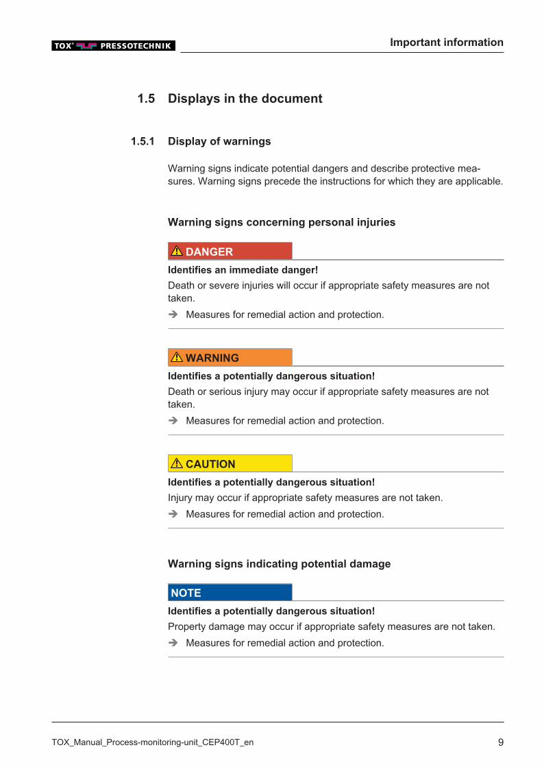
Warning signs indicate potential dangers and describe protective mea-sures. Warning signs precede the instructions for which they are applicable.
Warning signs concerning personal injuries
DANGER
Identifies an immediate danger!
Death or severe injuries will occur if appropriate safety measures are nottaken.è Measures for remedial action and protection.
WARNING
Identifies a potentially dangerous situation!
Death or serious injury may occur if appropriate safety measures are nottaken.è Measures for remedial action and protection.
CAUTION
Identifies a potentially dangerous situation!
Injury may occur if appropriate safety measures are not taken.è Measures for remedial action and protection.
Warning signs indicating potential damage
NOTE
Identifies a potentially dangerous situation!
Property damage may occur if appropriate safety measures are not taken.è Measures for remedial action and protection.
Important information
10 TOX_Manual_Process-monitoring-unit_CEP400T_en
1.5.2 Display of general notes
General notes show information on the product or the described actionsteps.
Identifies important information and tips for users.
1.5.3 Highlighting of texts and images
The highlighting of texts facilitates orientation in the document.
ü Identifies prerequisites that must be followed.
1. Action step 12. Action step 2: identifies an action step in an operating sequence that
must be followed to ensure trouble-free operation.w Identifies the result of an action.
u Identifies the result of a complete action.
è Identifies a single action step or several action steps that are not in anoperating sequence.
The highlighting of operating elements and software objects in texts facili-tates distinction and orientation.� <In square brackets> identifies operating elements, such as buttons,
levers and (valves) stopcocks.� ''with quotation marks'' identifies software display panels, such as win-
dows, messages, display panels and values.� In bold identifies software buttons, such as buttons, sliders, check-
boxes and menus.� In bold identifies input fields for entering text and/or numerical values.
Important information
TOX_Manual_Process-monitoring-unit_CEP400T_en 11
1.6 Contact and source of supply
Only use original spare parts or spare parts approved by TOX® PRES-SOTECHNIK.TOX® PRESSOTECHNIK GmbH & Co. KGRiedstraße 4D - 88250 WeingartenTel. +49 (0) 751/5007-333 E-Mail: [email protected] additional information and forms seewww.tox-pressotechnik.com

Important information
12 TOX_Manual_Process-monitoring-unit_CEP400T_en
Safety
TOX_Manual_Process-monitoring-unit_CEP400T_en 13
2 Safety
2.1 Basic safety requirements
The product is state of the art. However, operation of the product may in-volve danger to life and limb for the user or third parties or damage to theplant and other property.For this reason the following basic safety requirements will apply:� Read the operating manual and observe all safety requirements and
warnings.� Operate the product only as specified and only if it is in perfect techni-
cal condition.� Remedy any faults in the product or the plant immediately.
2.2 Organizational measures
2.2.1 Safety requirements for the operating company
The operating company is responsible for compliance with the followingsafety requirements:� The operating manual must always be kept available at the operation
site of the product. Ensure that the information is always complete andin legible form.
� In addition to the operating manual, the generally valid legal and otherbinding rules and regulations must be provided for the following contentand all personnel must be trained accordingly:– Work safety– Accident prevention– Working with hazardous substances– First aid– Environmental protection– Traffic safety– Hygiene
� The requirements and contents of the operating manual must be sup-plemented by existing national regulations (e.g. for prevention of acci-dents and for environmental protection).
� Instructions for special operating features (e.g. work organization, workprocesses, appointed personnel) and supervisory and reporting obliga-tions must be added to the operating manual.
Safety
14 TOX_Manual_Process-monitoring-unit_CEP400T_en
� Take action to ensure safe operation and make sure that the product ismaintained in a functional condition.
� Only allow authorized persons access to the product.� Ensure that all personnel work with awareness of safety and potential
dangers with reference to the information in the operating manual.� Provide personal protective equipment.� Maintain all safety and information on dangers regarding the product
complete and in legible condition and replace as required.� Do not make any changes, carry out attachments or conversions to the
product without the written approval of TOX® PRESSOTECHNIK. Ac-tion contrary to the above will not be covered by the warranty or the op-erating approval.
� Make sure that the annual safety inspections are carried out and docu-mented by an expert.
2.2.2 Selection and qualifications of personnel
The following safety requirements are applicable for the selection and quali-fications of personnel:� Only appoint persons to work on the plant who have read and under-
stood the operating manual, and in particular, the safety instructionsbefore starting work. This is particularly important for persons who onlywork on the plant occasionally, e.g. for maintenance work.
� Only allow persons appointed and authorized for this work access tothe plant.
� Only appoint reliable and trained or instructed personnel.� Only appoint persons to work in the danger zone of the plant who can
perceive and understand visual and acoustic indications of danger (e.g.visual and acoustic signals).
� Ensure that assembly and installation work and the initial commission-ing are performed exclusively by qualified personnel who have beentrained and authorized by TOX® PRESSOTECHNIK.
� Maintenance and repairs must be performed by qualified and trainedpersonnel only.
� Ensure that personnel who are being trained, instructed or are in an ap-prenticeship can only work on the plant under the supervision of an ex-perienced person.
� Have work on electrical equipment performed only by electricians ortrained persons under the direction and supervision of an electrician inaccordance with the electrotechnical regulations.

Safety
TOX_Manual_Process-monitoring-unit_CEP400T_en 15
2.3 Fundamental hazard potential
Fundamental hazard potentials exist. The specified examples draw atten-tion to known hazardous situations, but are not complete and do not in anyway provide safety and risk awareness action in all situations.
2.3.1 Electrical hazards
Attention should be paid to electrical hazards particularly inside the compo-nents in the area of all assemblies of the control system and motors of theinstallation.The following basically applies:� Have work on electrical equipment performed only by electricians or
trained persons under the direction and supervision of an electrician inaccordance with the electrotechnical regulations.
� Always keep the control box and/or terminal box closed.� Before commencing work on electrical equipment, switch off the main
switch of the system and secure it against being switched back on in-advertently.
� Pay attention to the dissipation of residual energy from the control sys-tem of the servomotors.
� Make sure that the components are disconnected from the power sup-ply when carrying out the work.

Safety
16 TOX_Manual_Process-monitoring-unit_CEP400T_en
About this product
TOX_Manual_Process-monitoring-unit_CEP400T_en 17
3 About this product
3.1 Warranty
Warranty and liability are based on the contractually specified conditions.Unless specified otherwise:The TOX® PRESSOTECHNIK GmbH & Co. KG excludes any warranty orliability claims in the event of defects or damage if these are attributable toone or more of the following causes:� Non-compliance with safety instructions, recommendations, instructions
and/or other specifications in the operating manual.� Non-compliance with the maintenance rules.� Unauthorized and improper commissioning and operation of the ma-
chine or components.� Improper use of the machine or components.� Unauthorized constructional modifications to the machine or compo-
nents or modifications to the software.� Use of non-genuine spare parts. Batteries, fuses and lamps are not
covered by the warranty.

About this product
18 TOX_Manual_Process-monitoring-unit_CEP400T_en
3.2 Product Identification
3.2.1 Position and content of the type plate
The type plate can be found on the back of the device.
Designation on the type plate Meaning
Type Product designationID No Material numberSN Serial number
Tab. 1 Type plate
Type code structure
Setup and function of process monitoring CEP 400T-02/-04/-08/-12 aresimilar to a large extent. The number of measurement channels differenti-ates the devices:
Type key Description
CEP 400T-02: Two separate measurement channels 'K1' and'K2'.
CEP 400T-04: Four separate measurement channels 'K1' to 'K4'.CEP 400T-08: Eight separate measurement channels 'K1' to 'K8'.CEP 400T-12: Twelve separate measurement channels 'K1' to
'K12'.
About this product
TOX_Manual_Process-monitoring-unit_CEP400T_en 19
3.3 Function description
3.3.1 Process monitoring
The process monitoring system compares the maximum force during aclinching process with the target values that are set in the device. Depend-ing on the result of the measurement, a good/bad message is issued bothon the internal display as well as the external interfaces provided.
3.3.2 Force monitoring
Measurement of force:� For tongs, the force is generally recorded via a screw sensor.� For presses, the force is recorded via a force sensor behind the die or
the punch (monitoring of the maximum value)
3.3.3 Force measurement
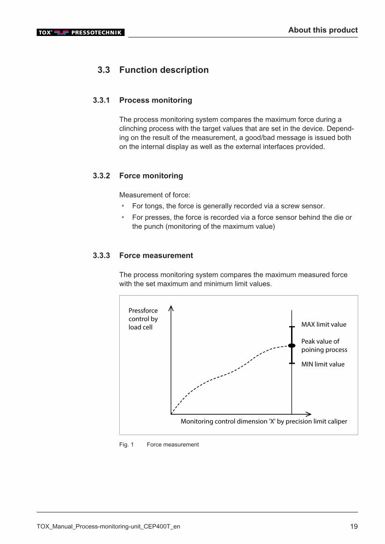
The process monitoring system compares the maximum measured forcewith the set maximum and minimum limit values.
MAX limit value
Peak value ofpoining process
MIN limit value
Monitoring control dimension 'X' by precision limit caliper
Pressforcecontrol byload cell
Fig. 1 Force measurement
About this product
20 TOX_Manual_Process-monitoring-unit_CEP400T_en
Changes in a process, e.g. clinching process, results in deviations in thepress force. If the measured force exceeds or drops below the fixed limitvalues, the process is stopped by the monitoring system. To ensure thatthe process stops at "natural" deviations of the press force, the limit valuesmust be chosen correctly and not to narrow.The function of monitoring equipment depends mainly on the setting of theevaluation parameter.
3.3.4 Test of the final position of the closed tool
Clinching
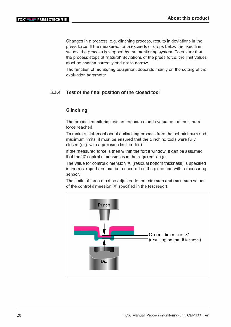
The process monitoring system measures and evaluates the maximumforce reached.To make a statement about a clinching process from the set minimum andmaximum limits, it must be ensured that the clinching tools were fullyclosed (e.g. with a precision limit button).If the measured force is then within the force window, it can be assumedthat the 'X' control dimension is in the required range.The value for control dimension 'X' (residual bottom thickness) is specifiedin the rest report and can be measured on the piece part with a measuringsensor.The limits of force must be adjusted to the minimum and maximum valuesof the control dimnesion 'X' specified in the test report.
Punch
Die
Control dimension 'X'(resulting bottom thickness)
About this product
TOX_Manual_Process-monitoring-unit_CEP400T_en 21
3.3.5 Networking via Ethernet (Option)
Transfer of measuring data to the PC – Ethernet
The PC used for data acquisition can communicate with several CEP 400Tdevices via the Ethernet interface. The IP address of the individual devicescan be configured (see Change the IP address, Page 90). The central PCcyclically monitors the status of all CEP 400 devices. On termination of ameasurement, the result will be read and logged by the PC.
TOX®softWare Module CEP 400
The TOX®softWare can image the following functions:� Display and filing of measuring values� Processing and filing of device configurations� Offline creation of device configurations
3.3.6 Log CEP 200 (optional)
The CEP 200 model can be replaced with a CEP 400T.To replace model CEP 200 with a CEP 400T, the CEP 200 interface mustbe activated. In this case the digital inputs and outputs according to theCEP 200 are occupied. For further information regarding handling, see theCEP 200 manual.

About this product
22 TOX_Manual_Process-monitoring-unit_CEP400T_en
Technical data
TOX_Manual_Process-monitoring-unit_CEP400T_en 23
4 Technical data
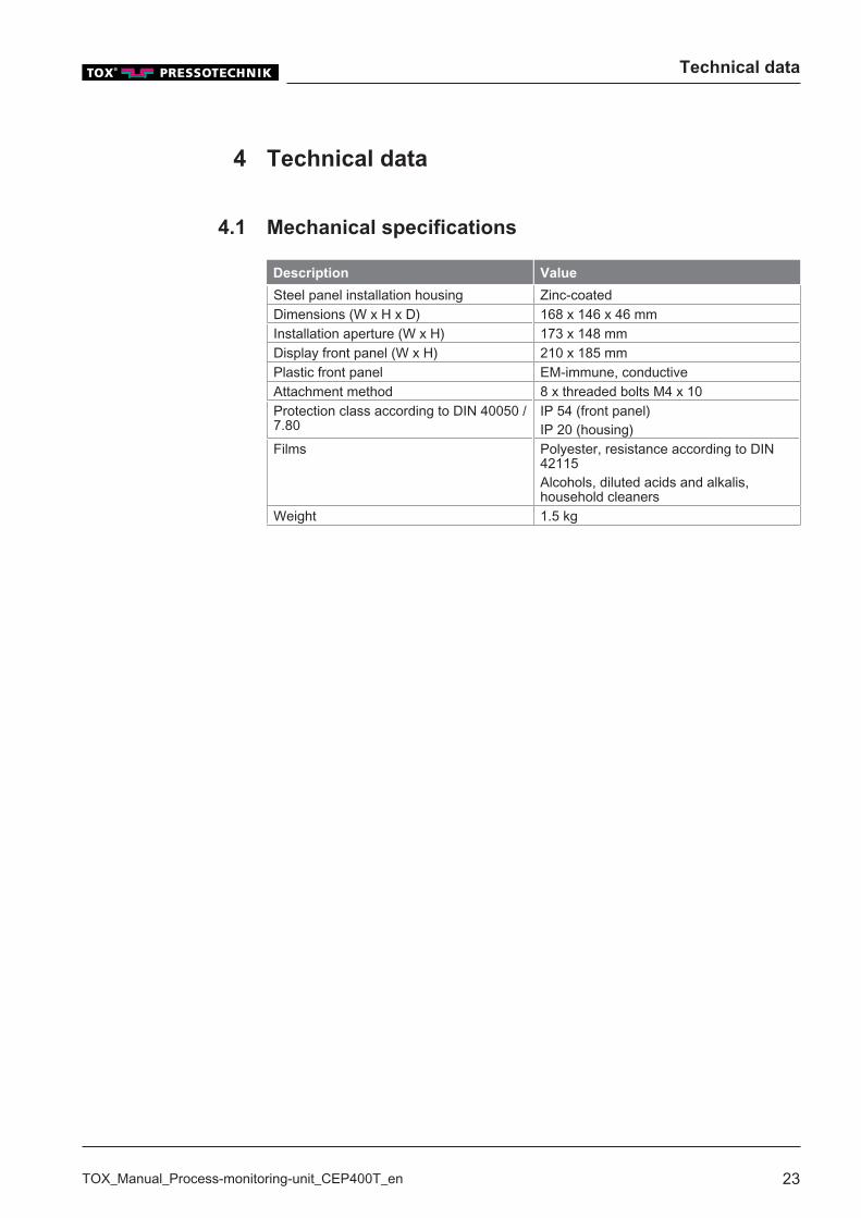
4.1 Mechanical specifications
Description Value
Steel panel installation housing Zinc-coatedDimensions (W x H x D) 168 x 146 x 46 mmInstallation aperture (W x H) 173 x 148 mmDisplay front panel (W x H) 210 x 185 mmPlastic front panel EM-immune, conductiveAttachment method 8 x threaded bolts M4 x 10Protection class according to DIN 40050 /7.80
IP 54 (front panel)IP 20 (housing)
Films Polyester, resistance according to DIN42115Alcohols, diluted acids and alkalis,household cleaners
Weight 1.5 kg
Technical data
24 TOX_Manual_Process-monitoring-unit_CEP400T_en
4.2 Dimensions
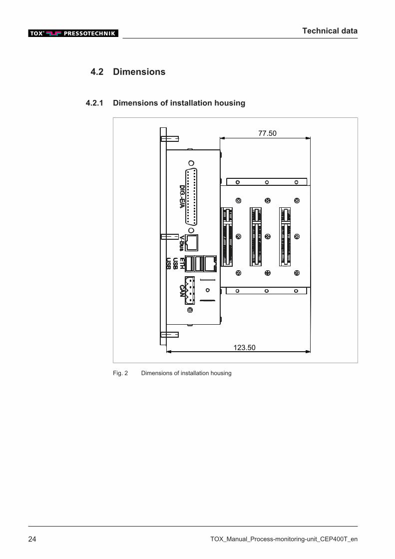
4.2.1 Dimensions of installation housing
77.50
123.50
Fig. 2 Dimensions of installation housing
Technical data
TOX_Manual_Process-monitoring-unit_CEP400T_en 25
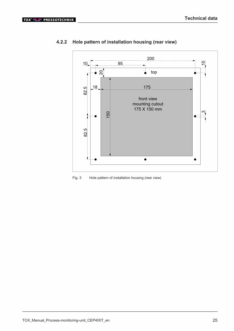
4.2.2 Hole pattern of installation housing (rear view)
82.5
82.5 18
20
10 95200
10
175
150 3
top
front viewmounting cutout175 X 150 mm
Fig. 3 Hole pattern of installation housing (rear view)
Technical data
26 TOX_Manual_Process-monitoring-unit_CEP400T_en
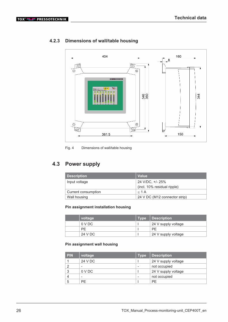
4.2.3 Dimensions of wall/table housing
Fig. 4 Dimensions of wall/table housing
4.3 Power supply
Description Value
Input voltage 24 V/DC, +/- 25%(incl. 10% residual ripple)
Current consumption ≤ 1 AWall housing 24 V DC (M12 connector strip)
Pin assignment installation housing
voltage Type Description
0 V DC I 24 V supply voltagePE I PE24 V DC I 24 V supply voltage
Pin assignment wall housing
PIN voltage Type Description
1 24 V DC I 24 V supply voltage2 - - not occupied3 0 V DC I 24 V supply voltage4 - - not occupied5 PE I PE
Technical data
TOX_Manual_Process-monitoring-unit_CEP400T_en 27
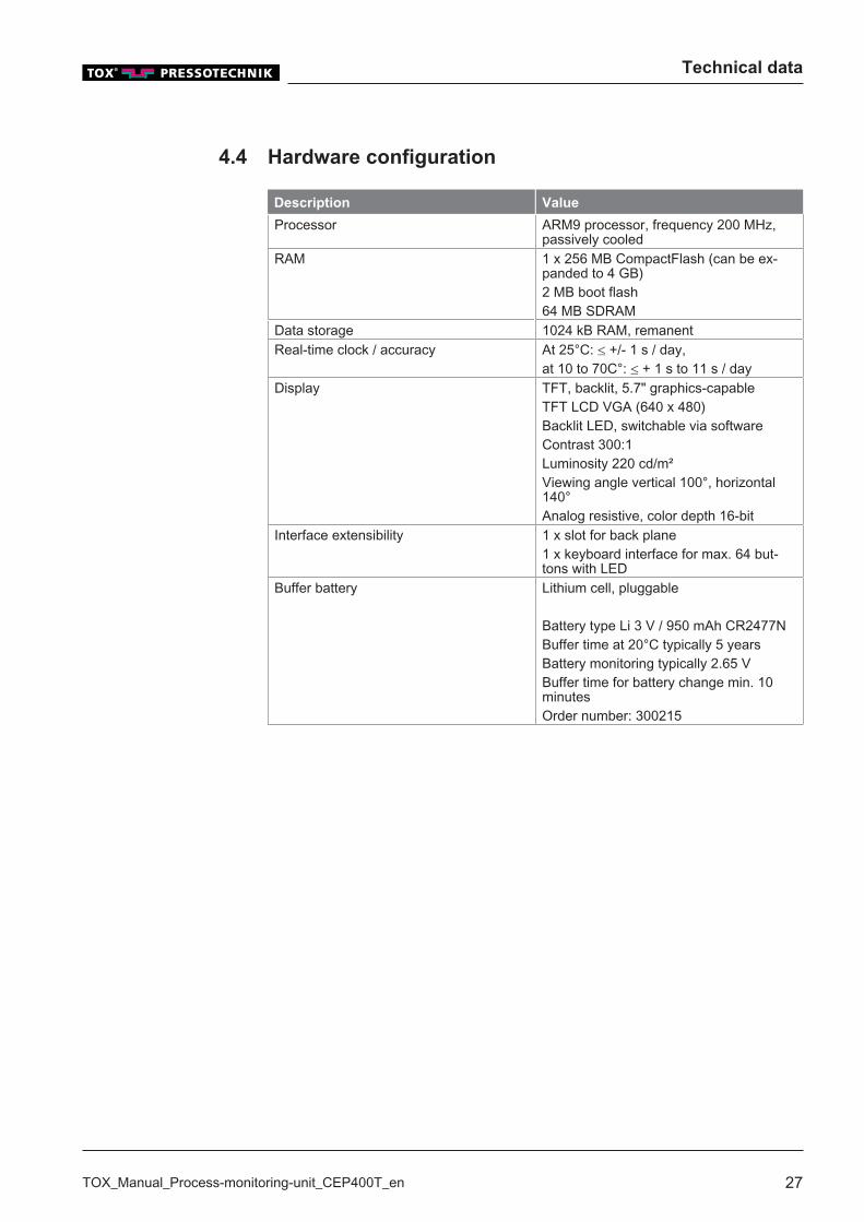
4.4 Hardware configuration
Description Value
Processor ARM9 processor, frequency 200 MHz,passively cooled
RAM 1 x 256 MB CompactFlash (can be ex-panded to 4 GB)2 MB boot flash64 MB SDRAM
Data storage 1024 kB RAM, remanentReal-time clock / accuracy At 25°C: ≤ +/- 1 s / day,
at 10 to 70C°: ≤ + 1 s to 11 s / dayDisplay TFT, backlit, 5.7" graphics-capable
TFT LCD VGA (640 x 480)Backlit LED, switchable via softwareContrast 300:1Luminosity 220 cd/m²Viewing angle vertical 100°, horizontal140°Analog resistive, color depth 16-bit
Interface extensibility 1 x slot for back plane1 x keyboard interface for max. 64 but-tons with LED
Buffer battery Lithium cell, pluggable
Battery type Li 3 V / 950 mAh CR2477NBuffer time at 20°C typically 5 yearsBattery monitoring typically 2.65 VBuffer time for battery change min. 10minutesOrder number: 300215
Technical data
28 TOX_Manual_Process-monitoring-unit_CEP400T_en
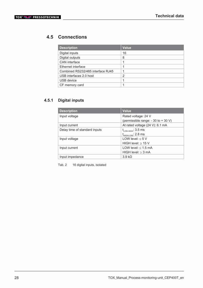
4.5 Connections
Description Value
Digital inputs 16Digital outputs 8CAN interface 1Ethernet interface 1Combined RS232/485 interface RJ45 1USB interfaces 2.0 host 2USB device 1CF memory card 1
4.5.1 Digital inputs
Description Value
Input voltage Rated voltage: 24 V(permissible range: - 30 to + 30 V)
Input current At rated voltage (24 V): 6.1 mADelay time of standard inputs tLOW-HIGH: 3.5 ms
tHIGH-LOW: 2.8 msInput voltage LOW level: ≤ 5 V
HIGH level: ≥ 15 VInput current LOW level: ≤ 1.5 mA
HIGH level: ≥ 3 mAInput impedance 3.9 kΩ
Tab. 2 16 digital inputs, isolated

Technical data
TOX_Manual_Process-monitoring-unit_CEP400T_en 29
Pin OK Standard CEP
400T
CEP 200 IO (Op-
tion, see Net-
working via Ether-
net (Option), Page
21)
1 I 0 Program bit 0 Measure2 I 1 Program bit 1 Reserve3 I 2 Program bit 2 Test plan selection
bit 14 I 3 Program bit 3 Test plan selection
bit 25 I 4 Program strobe Test plan selection
bit 26 I 5 Offset external Test plan selection
cycle7 I 6 Start measurement Error reset8 I 7 Start measurement
channel 2 (only 2-channel device)
19 0 V 0 V external Reserve20 I 8 HMI lock Reserve21 I 9 Error reset Reserve22 I 10 Program bit 4 Reserve23 I 11 Program bit 5 Reserve24 I 12 Reserve Reserve25 I 13 Reserve Reserve26 I 14 Reserve Reserve27 I 15 Reserve Reserve
Tab. 3 Built-in version: Digital inputs I0 – I15 (37-pin connector)
Technical data
30 TOX_Manual_Process-monitoring-unit_CEP400T_en
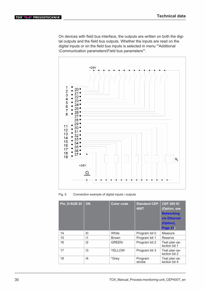
On devices with field bus interface, the outputs are written on both the digi-tal outputs and the field bus outputs. Whether the inputs are read on thedigital inputs or on the field bus inputs is selected in menu '''Additional\Communication parameters\Field bus parameters'''.
Fig. 5 Connection example of digital inputs / outputs
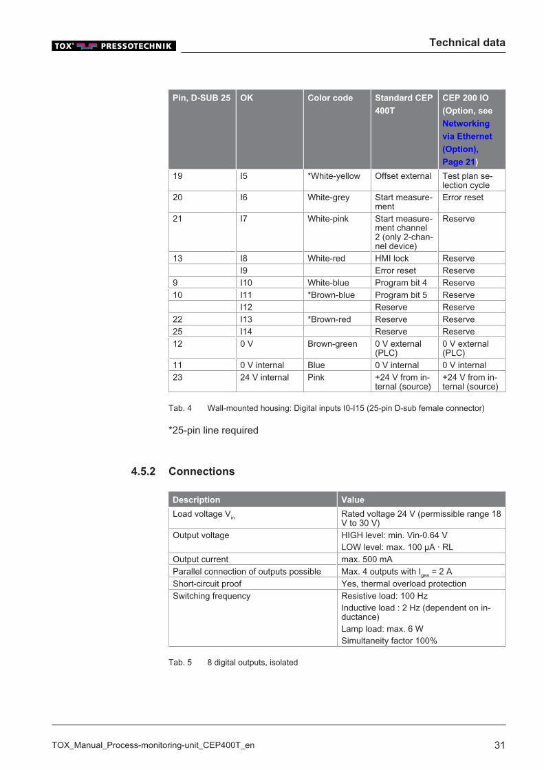
Pin, D-SUB 25 OK Color code Standard CEP
400T
CEP 200 IO
(Option, see
Networking
via Ethernet
(Option),
Page 21)
14 I0 White Program bit 0 Measure15 I1 Brown Program bit 1 Reserve16 I2 GREEN Program bit 2 Test plan se-
lection bit 117 I3 YELLOW Program bit 3 Test plan se-
lection bit 218 I4 *Grey Program
strobeTest plan se-lection bit 4
Technical data
TOX_Manual_Process-monitoring-unit_CEP400T_en 31
Pin, D-SUB 25 OK Color code Standard CEP
400T
CEP 200 IO
(Option, see
Networking
via Ethernet
(Option),
Page 21)
19 I5 *White-yellow Offset external Test plan se-lection cycle
20 I6 White-grey Start measure-ment
Error reset
21 I7 White-pink Start measure-ment channel2 (only 2-chan-nel device)
Reserve
13 I8 White-red HMI lock ReserveI9 Error reset Reserve
9 I10 White-blue Program bit 4 Reserve10 I11 *Brown-blue Program bit 5 Reserve
I12 Reserve Reserve22 I13 *Brown-red Reserve Reserve25 I14 Reserve Reserve12 0 V Brown-green 0 V external
(PLC)0 V external(PLC)
11 0 V internal Blue 0 V internal 0 V internal23 24 V internal Pink +24 V from in-
ternal (source)+24 V from in-ternal (source)
Tab. 4 Wall-mounted housing: Digital inputs I0-I15 (25-pin D-sub female connector)
*25-pin line required
4.5.2 Connections
Description Value
Load voltage Vin Rated voltage 24 V (permissible range 18V to 30 V)
Output voltage HIGH level: min. Vin-0.64 VLOW level: max. 100 µA · RL
Output current max. 500 mAParallel connection of outputs possible Max. 4 outputs with Iges = 2 AShort-circuit proof Yes, thermal overload protectionSwitching frequency Resistive load: 100 Hz
Inductive load : 2 Hz (dependent on in-ductance)Lamp load: max. 6 WSimultaneity factor 100%
Tab. 5 8 digital outputs, isolated
Technical data
32 TOX_Manual_Process-monitoring-unit_CEP400T_en
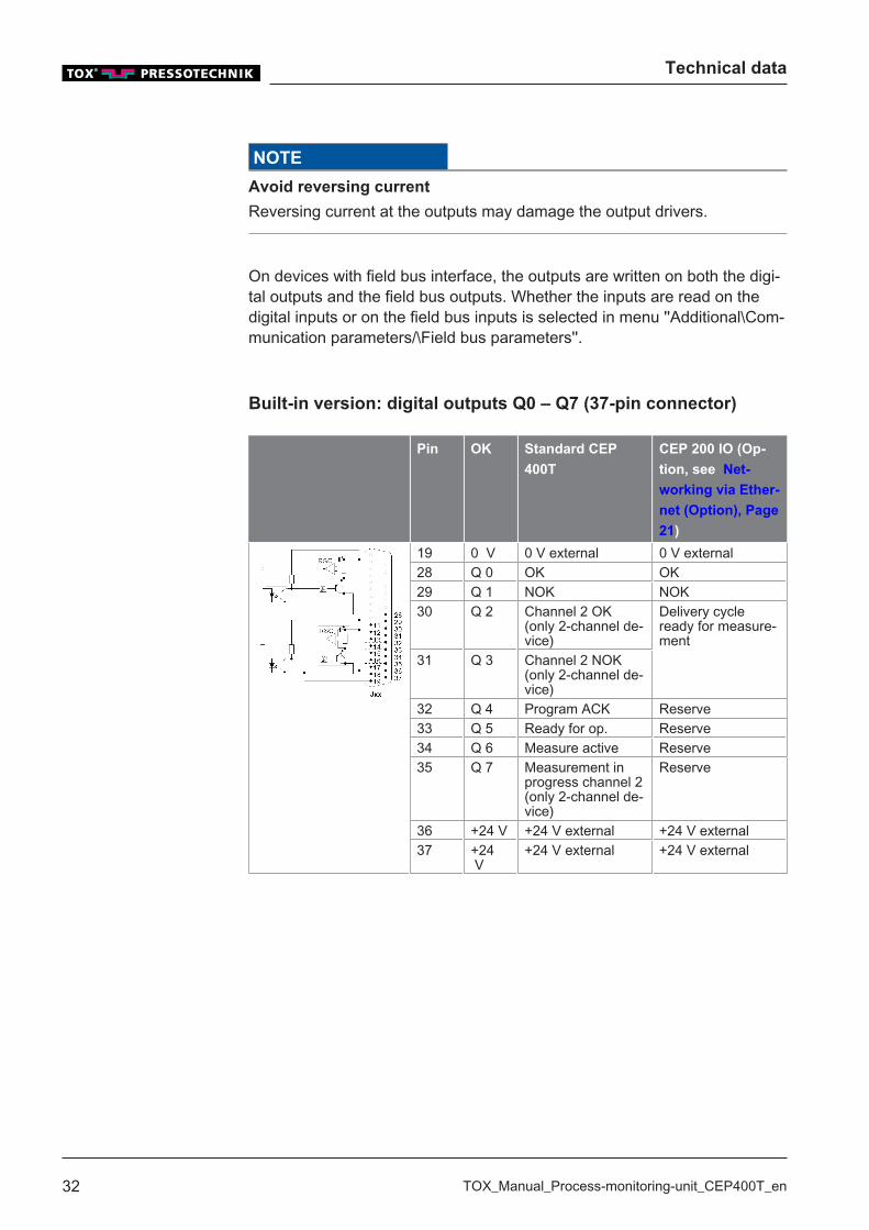
NOTE
Avoid reversing current
Reversing current at the outputs may damage the output drivers.
On devices with field bus interface, the outputs are written on both the digi-tal outputs and the field bus outputs. Whether the inputs are read on thedigital inputs or on the field bus inputs is selected in menu ''Additional\Com-munication parameters/\Field bus parameters''.
Built-in version: digital outputs Q0 – Q7 (37-pin connector)
Pin OK Standard CEP
400T
CEP 200 IO (Op-
tion, see Net-
working via Ether-
net (Option), Page
21)
19 0 V 0 V external 0 V external28 Q 0 OK OK29 Q 1 NOK NOK30 Q 2 Channel 2 OK
(only 2-channel de-vice)
Delivery cycleready for measure-ment
31 Q 3 Channel 2 NOK(only 2-channel de-vice)
32 Q 4 Program ACK Reserve33 Q 5 Ready for op. Reserve34 Q 6 Measure active Reserve35 Q 7 Measurement in
progress channel 2(only 2-channel de-vice)
Reserve
36 +24 V +24 V external +24 V external37 +24
V+24 V external +24 V external

Technical data
TOX_Manual_Process-monitoring-unit_CEP400T_en 33
Fig. 6 Connection example of digital inputs / outputs
Technical data
34 TOX_Manual_Process-monitoring-unit_CEP400T_en
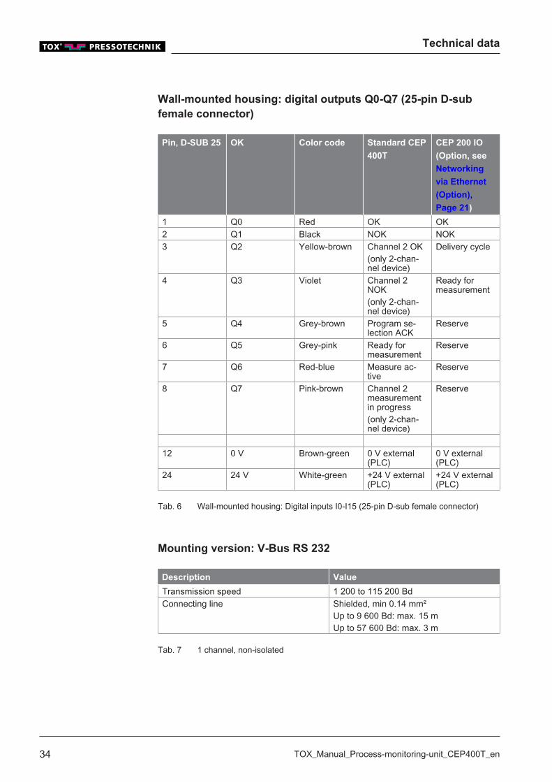
Wall-mounted housing: digital outputs Q0-Q7 (25-pin D-subfemale connector)
Pin, D-SUB 25 OK Color code Standard CEP
400T
CEP 200 IO
(Option, see
Networking
via Ethernet
(Option),
Page 21)
1 Q0 Red OK OK2 Q1 Black NOK NOK3 Q2 Yellow-brown Channel 2 OK
(only 2-chan-nel device)
Delivery cycle
4 Q3 Violet Channel 2NOK(only 2-chan-nel device)
Ready formeasurement
5 Q4 Grey-brown Program se-lection ACK
Reserve
6 Q5 Grey-pink Ready formeasurement
Reserve
7 Q6 Red-blue Measure ac-tive
Reserve
8 Q7 Pink-brown Channel 2measurementin progress(only 2-chan-nel device)
Reserve
12 0 V Brown-green 0 V external(PLC)
0 V external(PLC)
24 24 V White-green +24 V external(PLC)
+24 V external(PLC)
Tab. 6 Wall-mounted housing: Digital inputs I0-I15 (25-pin D-sub female connector)
Mounting version: V-Bus RS 232
Description Value
Transmission speed 1 200 to 115 200 BdConnecting line Shielded, min 0.14 mm²
Up to 9 600 Bd: max. 15 mUp to 57 600 Bd: max. 3 m
Tab. 7 1 channel, non-isolated
Technical data
TOX_Manual_Process-monitoring-unit_CEP400T_en 35
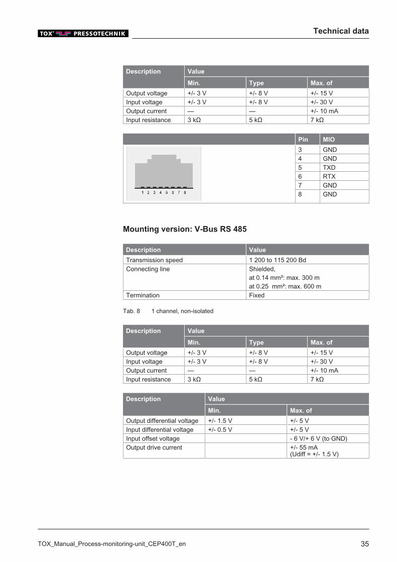
Description Value
Min. Type Max. of
Output voltage +/- 3 V +/- 8 V +/- 15 VInput voltage +/- 3 V +/- 8 V +/- 30 VOutput current — — +/- 10 mAInput resistance 3 kΩ 5 kΩ 7 kΩ
Pin MIO
3 GND4 GND5 TXD6 RTX7 GND8 GND
Mounting version: V-Bus RS 485
Description Value
Transmission speed 1 200 to 115 200 BdConnecting line Shielded,
at 0.14 mm²: max. 300 mat 0.25 mm²: max. 600 m
Termination Fixed
Tab. 8 1 channel, non-isolated
Description Value
Min. Type Max. of
Output voltage +/- 3 V +/- 8 V +/- 15 VInput voltage +/- 3 V +/- 8 V +/- 30 VOutput current — — +/- 10 mAInput resistance 3 kΩ 5 kΩ 7 kΩ
Description Value
Min. Max. of
Output differential voltage +/- 1.5 V +/- 5 VInput differential voltage +/- 0.5 V +/- 5 VInput offset voltage - 6 V/+ 6 V (to GND)Output drive current +/- 55 mA
(Udiff = +/- 1.5 V)
Technical data
36 TOX_Manual_Process-monitoring-unit_CEP400T_en
Pin MIO
1 RTX2 RTX3 GND4 GND7 GND8 GND
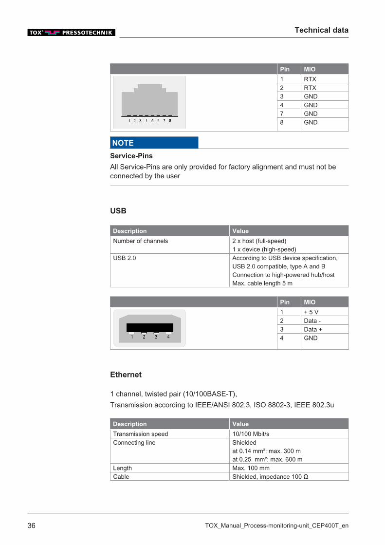
NOTE
Service-Pins
All Service-Pins are only provided for factory alignment and must not beconnected by the user
USB
Description Value
Number of channels 2 x host (full-speed)1 x device (high-speed)
USB 2.0 According to USB device specification,USB 2.0 compatible, type A and BConnection to high-powered hub/hostMax. cable length 5 m
Pin MIO
1 + 5 V2 Data -3 Data +4 GND
Ethernet
1 channel, twisted pair (10/100BASE-T),Transmission according to IEEE/ANSI 802.3, ISO 8802-3, IEEE 802.3u
Description Value
Transmission speed 10/100 Mbit/sConnecting line Shielded
at 0.14 mm²: max. 300 mat 0.25 mm²: max. 600 m
Length Max. 100 mmCable Shielded, impedance 100 Ω
Technical data
TOX_Manual_Process-monitoring-unit_CEP400T_en 37
Description Value
Connector RJ45 (modular connector)LED status indicator Yellow: active
Green: link
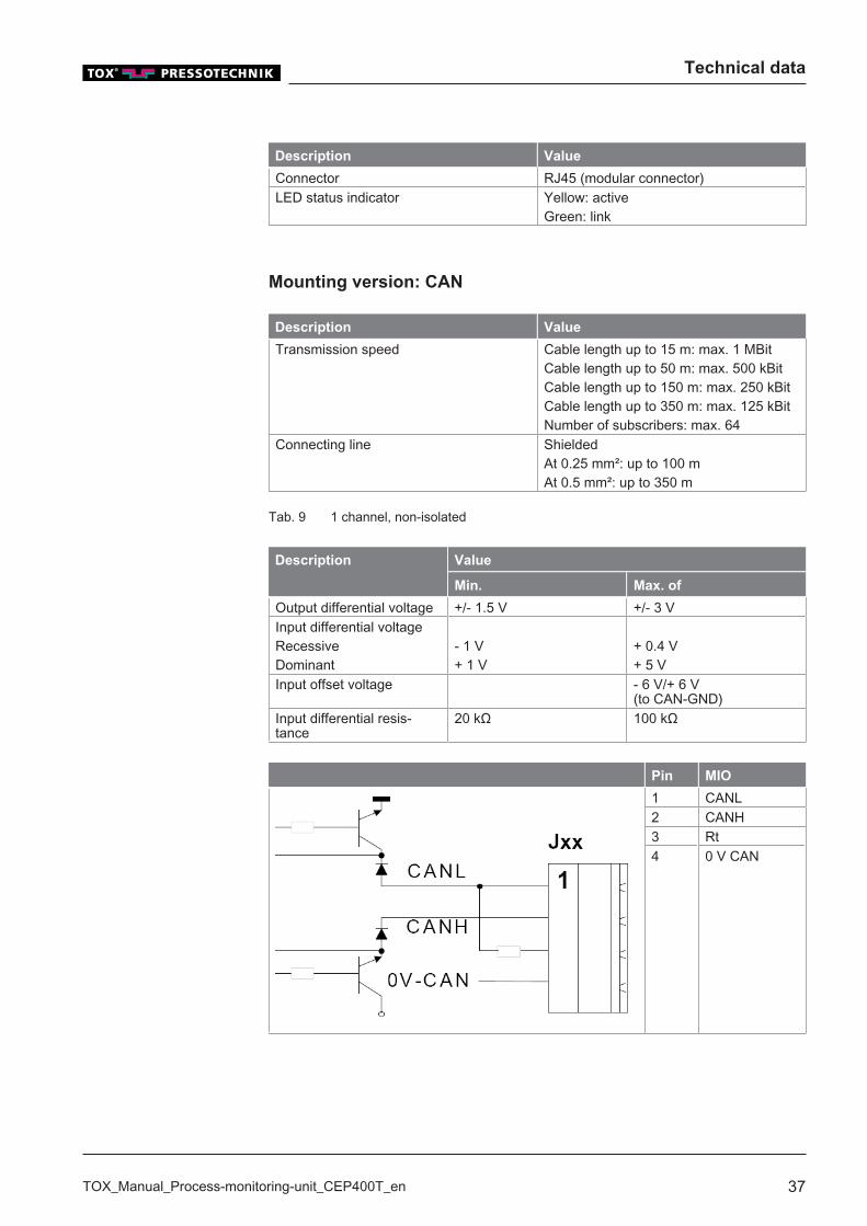
Mounting version: CAN
Description Value
Transmission speed Cable length up to 15 m: max. 1 MBitCable length up to 50 m: max. 500 kBitCable length up to 150 m: max. 250 kBitCable length up to 350 m: max. 125 kBitNumber of subscribers: max. 64
Connecting line ShieldedAt 0.25 mm²: up to 100 mAt 0.5 mm²: up to 350 m
Tab. 9 1 channel, non-isolated
Description Value
Min. Max. of
Output differential voltage +/- 1.5 V +/- 3 VInput differential voltageRecessiveDominant
- 1 V+ 1 V
+ 0.4 V+ 5 V
Input offset voltage - 6 V/+ 6 V (to CAN-GND)
Input differential resis-tance
20 kΩ 100 kΩ
Pin MIO
1 CANL2 CANH3 Rt4 0 V CAN

Technical data
38 TOX_Manual_Process-monitoring-unit_CEP400T_en
4.6 Environmental conditions
Description Value
Temperature Operation 0 to + 45 °CStorage - 25 to + 70 °C
Relative humidity without condensation(acc. to RH2)
5 to 90%
Vibrations according to IEC 68-2-6 15 to 57 Hz, amplitude 0.0375 mm, occa-sionally 0.075 mm57 to 150 Hz, acceleration. 0.5 g, occa-sionally 1.0 g
4.7 Electromagnetic compatibility
Description Value
Immunity according to EN 61000-6-2 / EN 61131-2Electrostatic discharge(EN 61000-4-2)
Contact: min. 8 kVClearance: min. 15 kV
Electromagnetic fields(EN 61000-4-3)
80 MHz - 1 GHz: 10 V/m 80% AM (1kHz)900 MHz ±5 MHz: 10 V/m 50% ED (200Hz)
Fast transients (EN 61000-4-4) Power supply lines: 2 kVProcess digital In-outputs: 1 kVProcess analog inputs outputs: 0.25 kVCommunication interfaces: 0.25 kV
Induced high frequency(EN 61000-4-6)
0.15 - 80 MHz 10 V 80% AM (1 kHz)
Surge voltage 1.2/50: min. 0.5 kV(measured at AC/DC converter input)
Emission interference according to EN 61000-6-4 / EN 61000-4-5RFI voltage EN 55011 150 kHz – 30 MHz (Group 1, Class A)RFI emissions EN 50011 30 MHz – 1 GHz (Group 1, Class A)
Tab. 10 Electromagnetic compatibility in line with EC directives
Technical data
TOX_Manual_Process-monitoring-unit_CEP400T_en 39
4.8 Sensor Analog Standard Signals
Here a force sensor is connected that sends out a 0-10 V signal. The inputis selected in menu ''Configuration''(see Chap. 8.4.2 Configuration, Page67).
Description Value
Nominal force or nominal distance Adjustable via the menuA/D converter 12 bit ≙ 4096 stepsNominal load of resolution 4096 steps, 1 step (bit) = nominal load /
4096Accuracy of measurement 1 %Max. sampling rate 2000 Hz (0.5 ms)
4.9 Measuring sensor supply voltage
Description Value
Auxiliary voltage +24 V ±5 %, max. 100 mAReference voltage 10 V ± 1% nominal signal: 0 – 10
24 V and 10 V are available for the power supply of the measuring sensor.They are to be wired according to the type of sensor.
4.10 Screw sensor with standard signal output
The input is selected in menu ''Configuration\Force sensor configura-tion''(see Configuring the force sensor, Page 69).
Description Value
Tare signal 0 V = Zero adjustment active, the forcesensor should be off-load here.>9 V = measuring mode, zero adjustmentstopped.
For sensors that can perform an internal offset (e.g. TOX®screw sensor) asignal is available that tells the sensor when the offset adjustment is to becarried out.The zero adjustment is activated with "Start measurement", and that is whyit should be ensured that the measurement is started before the press /clinching tongs are closed!
Technical data
40 TOX_Manual_Process-monitoring-unit_CEP400T_en
4.11 DMS signals
Force measuring via DMS force transducer. The input is selected in menu''Configuration\Force sensor configuration''(see Configuring the force sen-sor, Page 69).
Description Value
Nominal force adjustablesee Setting Nominal Force / Nominal Dis-tance Parameters.
Nominal stroke
A/D converter 16 bit ≙ 65536 stepsNominal load of resolution 65536 steps, 1 step (bit) = nominal load /
65536Gain error ±0.5 %Max. sampling rate 2000 Hz (0.5 ms)Bridge voltage 5 VCharacteristic value Adjustable
Adjustment value
The entry 'Nominal force' must match the nominal value of the force sensorused. See the data sheet of the force sensor.
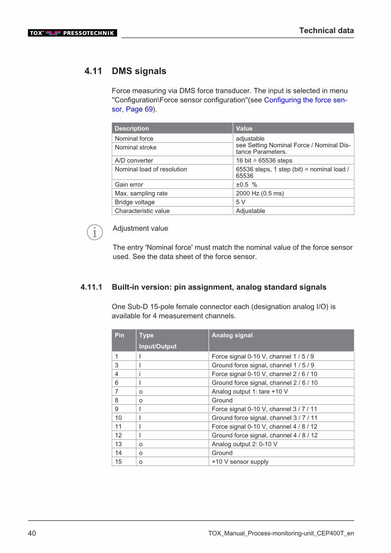
4.11.1 Built-in version: pin assignment, analog standard signals
One Sub-D 15-pole female connector each (designation analog I/O) isavailable for 4 measurement channels.
Pin Type
Input/Output
Analog signal
1 I Force signal 0-10 V, channel 1 / 5 / 93 I Ground force signal, channel 1 / 5 / 94 i Force signal 0-10 V, channel 2 / 6 / 106 I Ground force signal, channel 2 / 6 / 107 o Analog output 1: tare +10 V8 o Ground9 I Force signal 0-10 V, channel 3 / 7 / 1110 I Ground force signal, channel 3 / 7 / 1111 I Force signal 0-10 V, channel 4 / 8 / 1212 I Ground force signal, channel 4 / 8 / 1213 o Analog output 2: 0-10 V14 o Ground15 o +10 V sensor supply
Technical data
TOX_Manual_Process-monitoring-unit_CEP400T_en 41
Analog output 1 (pin 7)
Analog output 1 supplies +10 V during measuring mode (signal 'Startmeasurement' = 1).
The signal can be used to zero the measuring amplifier. Start measurement = 1: analog output 1 = >9 VStart measurement = 0: analog output 1: = +0 V
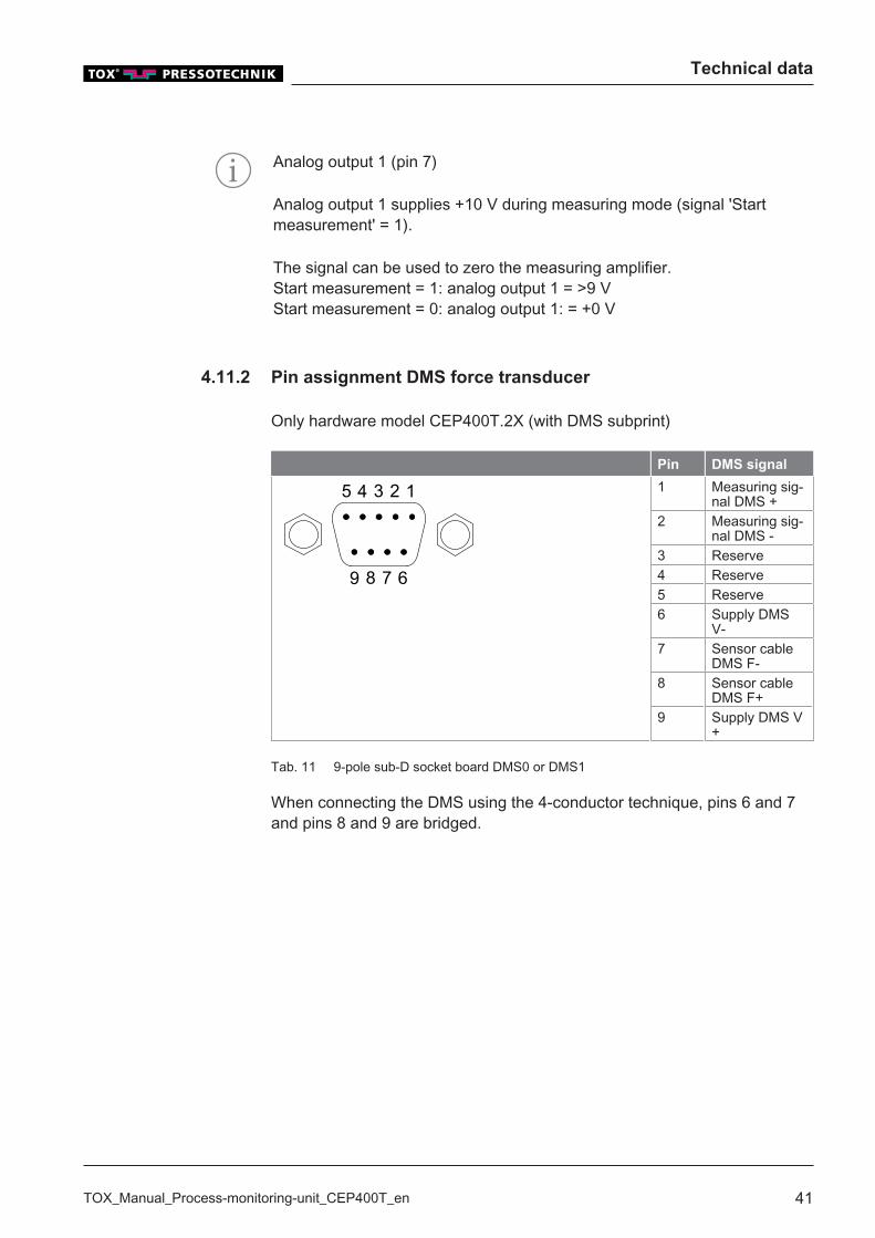
4.11.2 Pin assignment DMS force transducer
Only hardware model CEP400T.2X (with DMS subprint)
Pin DMS signal
12345
6789
1 Measuring sig-nal DMS +
2 Measuring sig-nal DMS -
3 Reserve4 Reserve5 Reserve6 Supply DMS
V-7 Sensor cable
DMS F-8 Sensor cable
DMS F+9 Supply DMS V
+
Tab. 11 9-pole sub-D socket board DMS0 or DMS1
When connecting the DMS using the 4-conductor technique, pins 6 and 7and pins 8 and 9 are bridged.

Technical data
42 TOX_Manual_Process-monitoring-unit_CEP400T_en
4.11.3 Wall-mounted housing: pin assignment of force transducer
A 17-pin plug is available for each of 4 channels.
Pin Signal name Type
Input/Out-
put
Notes
1 E+ K1 o Supply DMS V+, channel 1 / 5 / 92 E+ K3 o Supply DMS V+, channel 3 / 7 / 113 E-K1 o Supply DMS V-, channel 1 / 5 / 94 S+ K1 I Measuring signal DMS +, channel 1 / 5 /
95 E+ K2 o Supply DMS V+, channel 2 / 6 / 106 S- K1 I Measuring signal DMS -, channel 1 / 5 / 97 S+ K2 I Measuring signal DMS +, channel 2 / 6 /
108 E- K2 o Supply DMS V-, channel 2 / 6 / 109 E- K3 o Supply DMS V-, channel 3 / 7 / 1110 S- K2 I Measuring signal DMS -, channel 2 / 6 /
1011 S+ K3 I Measuring signal DMS +, channel 3 / 7 /
1112 S- K3 I Measuring signal DMS -, channel 3 / 7 /
1113 E+ K4 o Supply DMS V+, channel 4 / 8 / 1214 E- K4 o Supply DMS V-, channel 4 / 8 / 1215 S+ K4 I Measuring signal DMS +, channel 4 / 8 /
1216 Reserve17 S- K4 I Measuring signal DMS -, channel 4 / 8 /
12

Technical data
TOX_Manual_Process-monitoring-unit_CEP400T_en 43
4.12 Profibus interface
According to ISO/DIS 11898, isolated
Description Value
Transmission speed Cable length up to 100 m: max. 12000kBitCable length up to 200 m: max. 1500 kBitCable length up to 400 m: max. 500 kBitCable length up to 1000 m: max. 187.5kBitCable length up to 1200 m: max. 93.75kBitWire cross-section min. 0.34 mm²4Wire diameter 0.64 mm
Connecting line ShieldedAt 0.25 mm²: up to 100 mAt 0.5 mm²: up to 350 m
Input offset voltage - 7 V/+ 12 V (to GND)Output drive current -/- 55 mA (Udiff = +/- 1.5 V)Number of subscribers per segment Without repeater: max. 32
With repeater: max. 126 (every repeaterused reduces the max. number of sub-scribers)
Connecting line shielded, twisted surgeimpedance
135 to 165 Ω
Capacitance per unit length < 30 pf/mLoop resistance 110 Ω/kmRecommended cables Fixed installation UNITRONIC®-BUS L2/
FIP or UNITRONIC®-BUS L2/FIP 7-wireflexible installation UNITRONIC® BUS FDP L2/FIP
Node addresses 3 to 124
Description Value
Min. Max. of
Output differential voltage +/- 1.5 V +/- 5 VInput differential voltage +/- 0.2 V +/- 5 V
Pin Profibus
3 RXD/TXD-P4 CNTR-P (RTS)5 0 V6 + 5 V8 RXD/TXD-N
Technical data
44 TOX_Manual_Process-monitoring-unit_CEP400T_en
The output voltage from pin 6 for termination with a terminating resistor is +5 V.
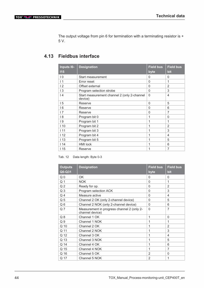
4.13 Fieldbus interface
Inputs I0-
I15
Designation Field bus
byte
Field bus
bit
I 0 Start measurement 0 0I 1 Error reset 0 1I 2 Offset external 0 2I 3 Program selection strobe 0 3I 4 Start measurement channel 2 (only 2-channel
device)0 4
I 5 Reserve 0 5I 6 Reserve 0 6I 7 Reserve 0 7I 8 Program bit 0 1 0I 9 Program bit 1 1 1I 10 Program bit 2 1 2I 11 Program bit 3 1 3I 12 Program bit 4 1 4I 13 Program bit 5 1 5I 14 HMI lock 1 6I 15 Reserve 1 7
Tab. 12 Data length: Byte 0-3
Outputs
Q0-Q31
Designation Field bus
byte
Field bus
bit
Q 0 OK 0 0Q 1 NOK 0 1Q 2 Ready for op. 0 2Q 3 Program selection ACK 0 3Q 4 Measure active 0 4Q 5 Channel 2 OK (only 2-channel device) 0 5Q 6 Channel 2 NOK (only 2-channel device) 0 6Q 7 Measurement in progress channel 2 (only 2-
channel device)0 7
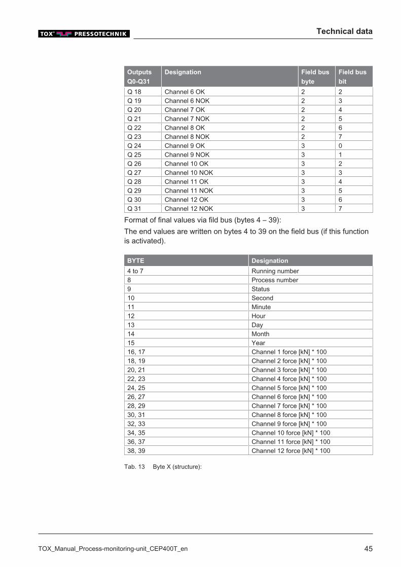
Q 8 Channel 1 OK 1 0Q 9 Channel 1 NOK 1 1Q 10 Channel 2 OK 1 2Q 11 Channel 2 NOK 1 3Q 12 Channel 3 OK 1 4Q 13 Channel 3 NOK 1 5Q 14 Channel 4 OK 1 6Q 15 Channel 4 NOK 1 7Q 16 Channel 5 OK 2 0Q 17 Channel 5 NOK 2 1
Technical data
TOX_Manual_Process-monitoring-unit_CEP400T_en 45
Outputs
Q0-Q31
Designation Field bus
byte
Field bus
bit
Q 18 Channel 6 OK 2 2Q 19 Channel 6 NOK 2 3Q 20 Channel 7 OK 2 4Q 21 Channel 7 NOK 2 5Q 22 Channel 8 OK 2 6Q 23 Channel 8 NOK 2 7Q 24 Channel 9 OK 3 0Q 25 Channel 9 NOK 3 1Q 26 Channel 10 OK 3 2Q 27 Channel 10 NOK 3 3Q 28 Channel 11 OK 3 4Q 29 Channel 11 NOK 3 5Q 30 Channel 12 OK 3 6Q 31 Channel 12 NOK 3 7
Format of final values via fild bus (bytes 4 – 39):The end values are written on bytes 4 to 39 on the field bus (if this functionis activated).
BYTE Designation
4 to 7 Running number8 Process number9 Status10 Second11 Minute12 Hour13 Day14 Month15 Year16, 17 Channel 1 force [kN] * 10018, 19 Channel 2 force [kN] * 10020, 21 Channel 3 force [kN] * 10022, 23 Channel 4 force [kN] * 10024, 25 Channel 5 force [kN] * 10026, 27 Channel 6 force [kN] * 10028, 29 Channel 7 force [kN] * 10030, 31 Channel 8 force [kN] * 10032, 33 Channel 9 force [kN] * 10034, 35 Channel 10 force [kN] * 10036, 37 Channel 11 force [kN] * 10038, 39 Channel 12 force [kN] * 100
Tab. 13 Byte X (structure):
Technical data
46 TOX_Manual_Process-monitoring-unit_CEP400T_en
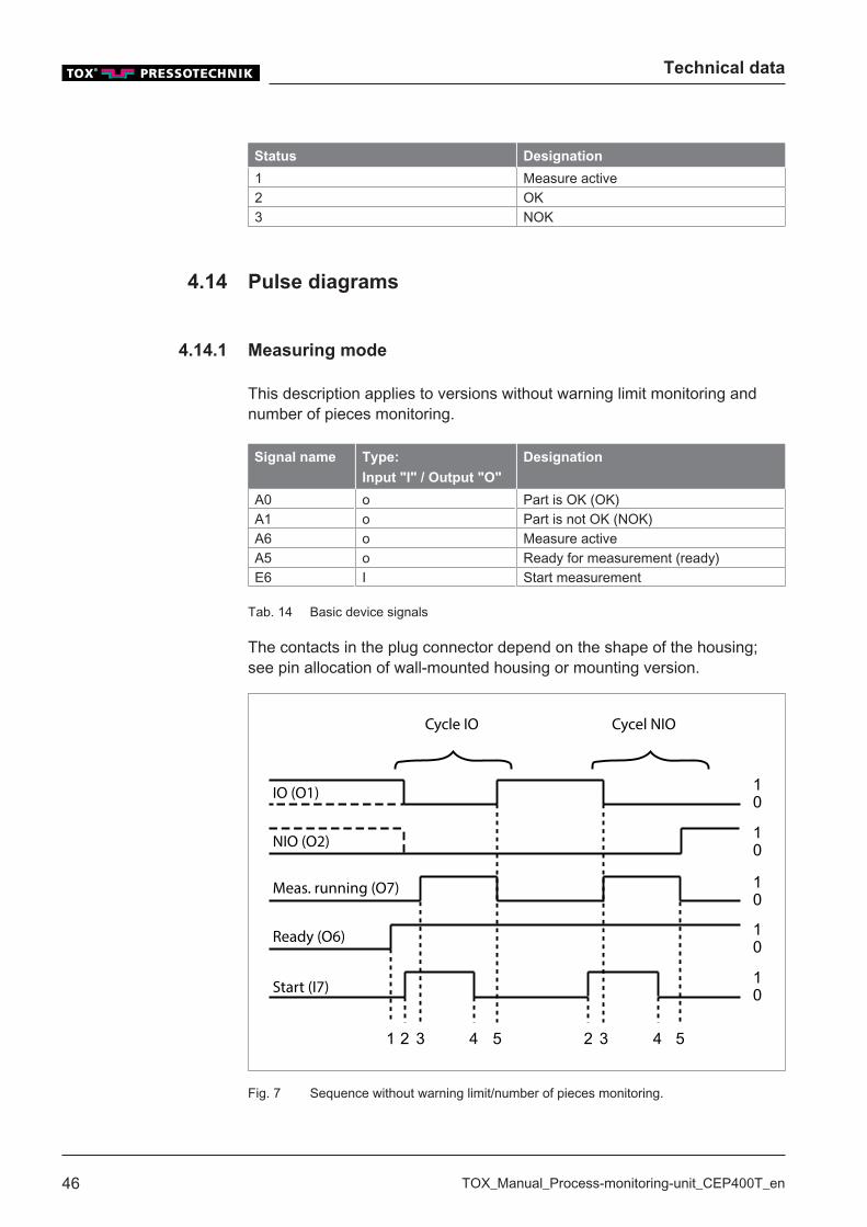
Status Designation
1 Measure active2 OK3 NOK
4.14 Pulse diagrams
4.14.1 Measuring mode
This description applies to versions without warning limit monitoring andnumber of pieces monitoring.
Signal name Type:
Input "I" / Output "O"
Designation
A0 o Part is OK (OK)A1 o Part is not OK (NOK)A6 o Measure activeA5 o Ready for measurement (ready)E6 I Start measurement
Tab. 14 Basic device signals
The contacts in the plug connector depend on the shape of the housing;see pin allocation of wall-mounted housing or mounting version.
10
10
10
10
10
1 2 3 4 5 2 3 4 5
Cycle IO Cycel NIO
IO (O1)
NIO (O2)
Meas. running (O7)
Ready (O6)
Start (I7)
Fig. 7 Sequence without warning limit/number of pieces monitoring.
Technical data
TOX_Manual_Process-monitoring-unit_CEP400T_en 47
1 After it has been switched on, the device signals that it is ready for measure-ment by setting the >Ready> signal.
2 When closing the press the signal <Start measurement> is set.3 The OK/NOK signal is reset. The <Measurement in progress> signal is set.4 When the conditions for triggering the return stroke have been met and the
minimum time has been reached (must be integrated in the overriding con-trol), the 'Start' signal is reset. The measurement is evaluated when the <S-tart> signal is reset.
5 The <OK> or <NOK> signal is set and the <Measurement in progress> sig-nal is reset. The OK or NOK signal remains set until the next start. When thefunction 'Number of pieces / Warning limit' is active, the OK signal that wasnot set must be used for the NOK evaluation. See the sequence at activewarning limit / number of pieces.
4.14.2 Measuring mode
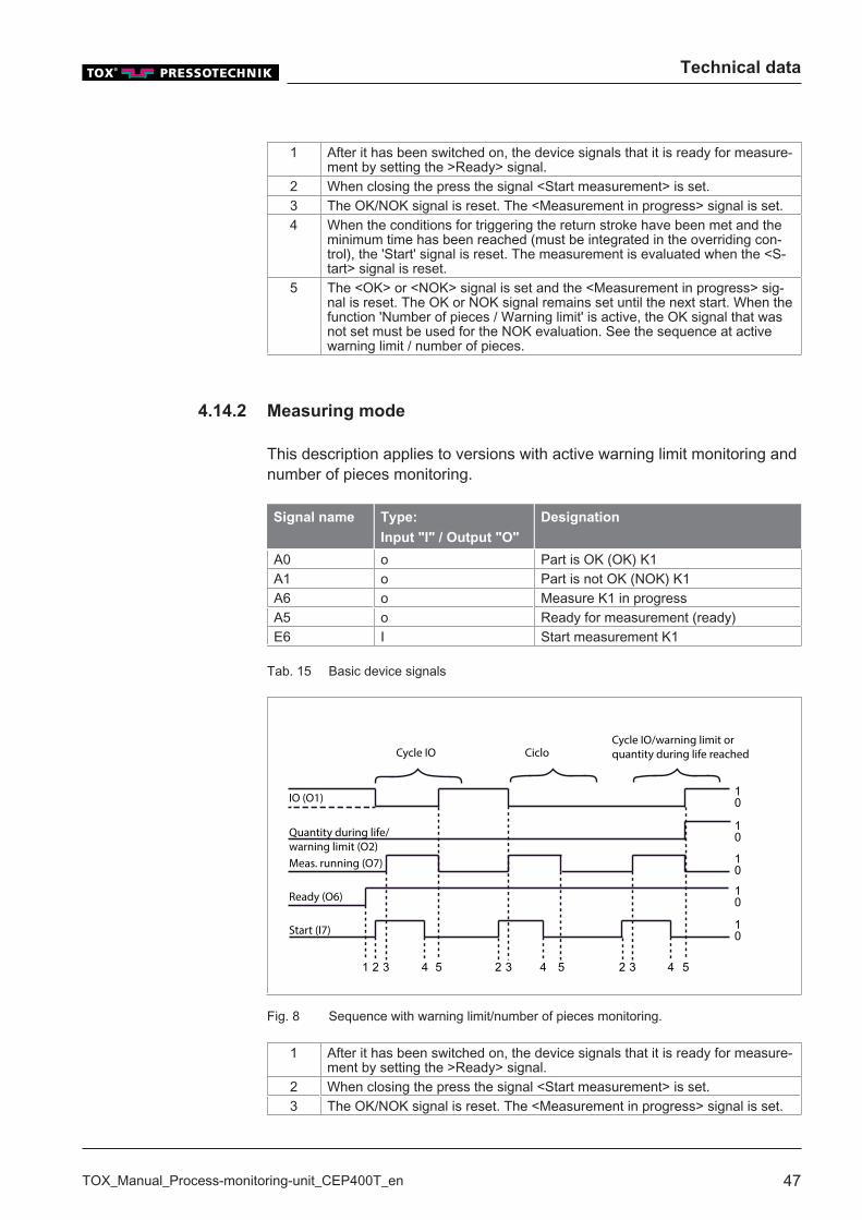
This description applies to versions with active warning limit monitoring andnumber of pieces monitoring.
Signal name Type:
Input "I" / Output "O"
Designation
A0 o Part is OK (OK) K1A1 o Part is not OK (NOK) K1A6 o Measure K1 in progressA5 o Ready for measurement (ready)E6 I Start measurement K1
Tab. 15 Basic device signals
1 2 3 4 5 2 3 4 5 2 3 4 5
10
10
10
10
10
Cycle IO CicloCycle IO/warning limit orquantity during life reached
IO (O1)
Quantity during life/warning limit (O2)Meas. running (O7)
Ready (O6)
Start (I7)
Fig. 8 Sequence with warning limit/number of pieces monitoring.
1 After it has been switched on, the device signals that it is ready for measure-ment by setting the >Ready> signal.
2 When closing the press the signal <Start measurement> is set.3 The OK/NOK signal is reset. The <Measurement in progress> signal is set.

Technical data
48 TOX_Manual_Process-monitoring-unit_CEP400T_en
4 When the conditions for triggering the return stroke have been met and theminimum time has been reached (must be integrated in the overriding con-trol), the 'Start' signal is reset. The measurement is evaluated when the <S-tart> signal is reset.
5 If the measurement lies within the programmed window, signal <OK> is set.If the measurement lies outside the programmed window, signal <OK> is notset. If the OK signal is missing it must be evaluated as NOK in the externalcontrol after a waiting period of at least 200 ms.If the warning limit or the number of pieces of a measurement channel hasbeen exceeded in the finished cycle, the output <Warning limit/Number ofpieces (NOK)> is also set. This signal can now be evaluated in the externalcontrol.
Plant control system: check the readiness of measurement
Before the command "Start measurement" it must be checked whether thCEP 400T is ready for measuring.
The process monitoring system might not be ready to measure due to amanual input or a fault. It is therefore always necessary prior to anautomatic sequence to check the 'Ready to measure' output of the systemcontroller before setting the 'Start' signal.
Signal name Type:
Input "I" / Output "O"
Designation
E0 I Program number bit 0E1 I Program number bit 1E2 I Program number bit 2E3 I Program number bit 3E10 I Program number bit 4E11 I Program number bit 5E4 I Program number cycleA4 o Program number acknowledgement
Tab. 16 Automatic program selection
The program number bits 0,1,2,3,4 and 5 are set binary as test plan num-ber from the system controller. With a rising edge of the timing signal fromthe system controller this information is read from the CEP 400T device

Technical data
TOX_Manual_Process-monitoring-unit_CEP400T_en 49
and evaluated. The reading in of the test plan selection bits is confirmed bysetting the acknowledgment signal. After the acknowledgment the systemcontroller resets the timing signal.
Selection of a test plan 0-63
10
10
10
10
10
10
1 2 3 4
BIT 0 (I1)
BIT 1 (I2)
BIT 2 (I3)
BIT 3 (I4)
Cycle (I5)
Acknowledgement(O5)
Fig. 9 Selection of a test plan 0-63
At (1) the test plan number 3 (bit 0 and 1 high) is set and selected by set-ting the 'Cycle' signal. At (2) the acknowledgment signal of the CEP deviceis set. The test plan selection cycle must remain set until the reading in ofthe new test plan number has been acknowledged. After the return of thetiming signal the acknowledgment signal is reset.
Bit Program no.
0 1 2 3 4 5
0 0 0 0 0 0 01 0 0 0 0 0 10 1 0 0 0 0 21 1 0 0 0 0 30 0 1 0 0 0 41 0 1 0 0 0 50 1 1 0 0 0 61 1 1 0 0 0 7 etc.
Tab. 17 Valence of the test plan selection bits: test plan no. 0-63 possible
Technical data
50 TOX_Manual_Process-monitoring-unit_CEP400T_en
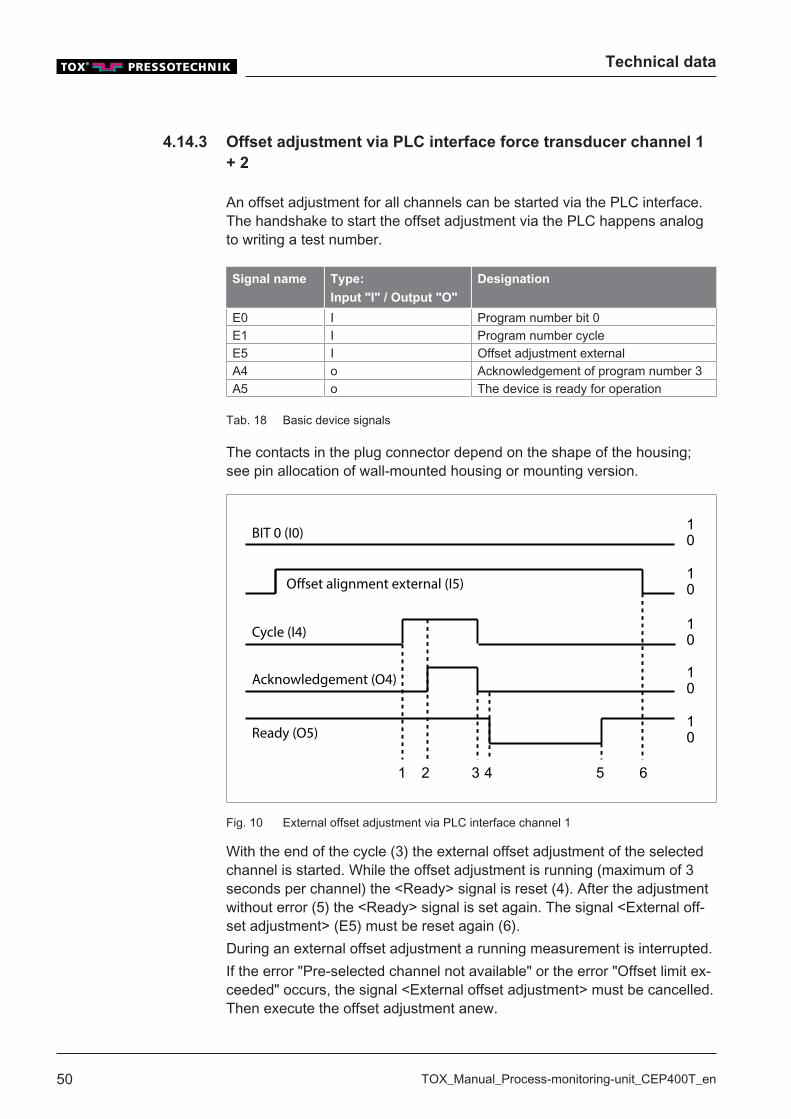
4.14.3 Offset adjustment via PLC interface force transducer channel 1+ 2
An offset adjustment for all channels can be started via the PLC interface.The handshake to start the offset adjustment via the PLC happens analogto writing a test number.
Signal name Type:
Input "I" / Output "O"
Designation
E0 I Program number bit 0E1 I Program number cycleE5 I Offset adjustment externalA4 o Acknowledgement of program number 3A5 o The device is ready for operation
Tab. 18 Basic device signals
The contacts in the plug connector depend on the shape of the housing;see pin allocation of wall-mounted housing or mounting version.
10
10
10
10
10
1 2 3 4 5 6
BIT 0 (I0)
Offset alignment external (I5)
Cycle (I4)
Acknowledgement (O4)
Ready (O5)
Fig. 10 External offset adjustment via PLC interface channel 1
With the end of the cycle (3) the external offset adjustment of the selectedchannel is started. While the offset adjustment is running (maximum of 3seconds per channel) the <Ready> signal is reset (4). After the adjustmentwithout error (5) the <Ready> signal is set again. The signal <External off-set adjustment> (E5) must be reset again (6).During an external offset adjustment a running measurement is interrupted.If the error "Pre-selected channel not available" or the error "Offset limit ex-ceeded" occurs, the signal <External offset adjustment> must be cancelled.Then execute the offset adjustment anew.

Transport and storage
TOX_Manual_Process-monitoring-unit_CEP400T_en 51
5 Transport and storage
5.1 Temporary storages
� Use original packaging.� Make sure that all electrical connections are covered to prevent dust
ingress.� Protect the display against sharp-edged objects e.g. due to cardboard
or hard foam.� Wrap the device, e.g. with a plastic bag.� Store the device only in closed, dry, dust-free and dirt-free rooms at
room temperature.� Add drying agent to the packaging.
5.2 Dispatch for repair
To dispatch the product for repair to TOX® PRESSOTECHNIK, please pro-ceed as follows:� Fill in the "Accompanying repair form". This we supply in the service
sector on our website or upon request via e-mail.� Send us the completed form via e-mail.� Then you will receive the shipping documents from us via e-mail.� Send us the product with the shipping documents and a copy of the
"Accompanying repair form".
For contact data see: Chap. 1.6 Contact and source of supply, Page 11orwww.tox-pressotechnik.com.

Transport and storage
52 TOX_Manual_Process-monitoring-unit_CEP400T_en
Commissioning
TOX_Manual_Process-monitoring-unit_CEP400T_en 53
6 Commissioning
6.1 Preparing System
1. Check installation and mounting.2. Connect required lines and devices, e.g. sensors and actuators.3. Connect supply voltage.4. Make sure that the correct supply voltage is connected.
6.2 Starting system
ü System is prepared.See Chap. 6.1 Preparing System, Page 53.
è Switch on the plant.
u The device starts the operating system and the application.u The device switches to the start screen.

Commissioning
54 TOX_Manual_Process-monitoring-unit_CEP400T_en
Operation
TOX_Manual_Process-monitoring-unit_CEP400T_en 55
7 Operation
7.1 Monitoring operation
No operating steps are necessary during ongoing operation.
The operating procedure must be monitored constantly in order to detectfaults in time.

Operation
56 TOX_Manual_Process-monitoring-unit_CEP400T_en
Software
TOX_Manual_Process-monitoring-unit_CEP400T_en 57
8 Software
8.1 Function of the Software
The software fulfils the following functions:� Clear representation of the operating parameters for operation monitor-
ing� Displaying of fault messages and warnings� Configuration of the operating parameters by setting individual operat-
ing parameters� Configuration of the interface by setting the software parameters
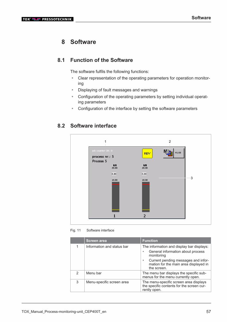
8.2 Software interface
1
3
2
Fig. 11 Software interface
Screen area Function
1 Information and status bar The information and display bar displays:� General information about process
monitoring� Current pending messages and infor-
mation for the main area displayed inthe screen.
2 Menu bar The menu bar displays the specific sub-menus for the menu currently open.
3 Menu-specific screen area The menu-specific screen area displaysthe specific contents for the screen cur-rently open.
Software
58 TOX_Manual_Process-monitoring-unit_CEP400T_en
8.3 Control elements
8.3.1 Function buttons
4321 65 7
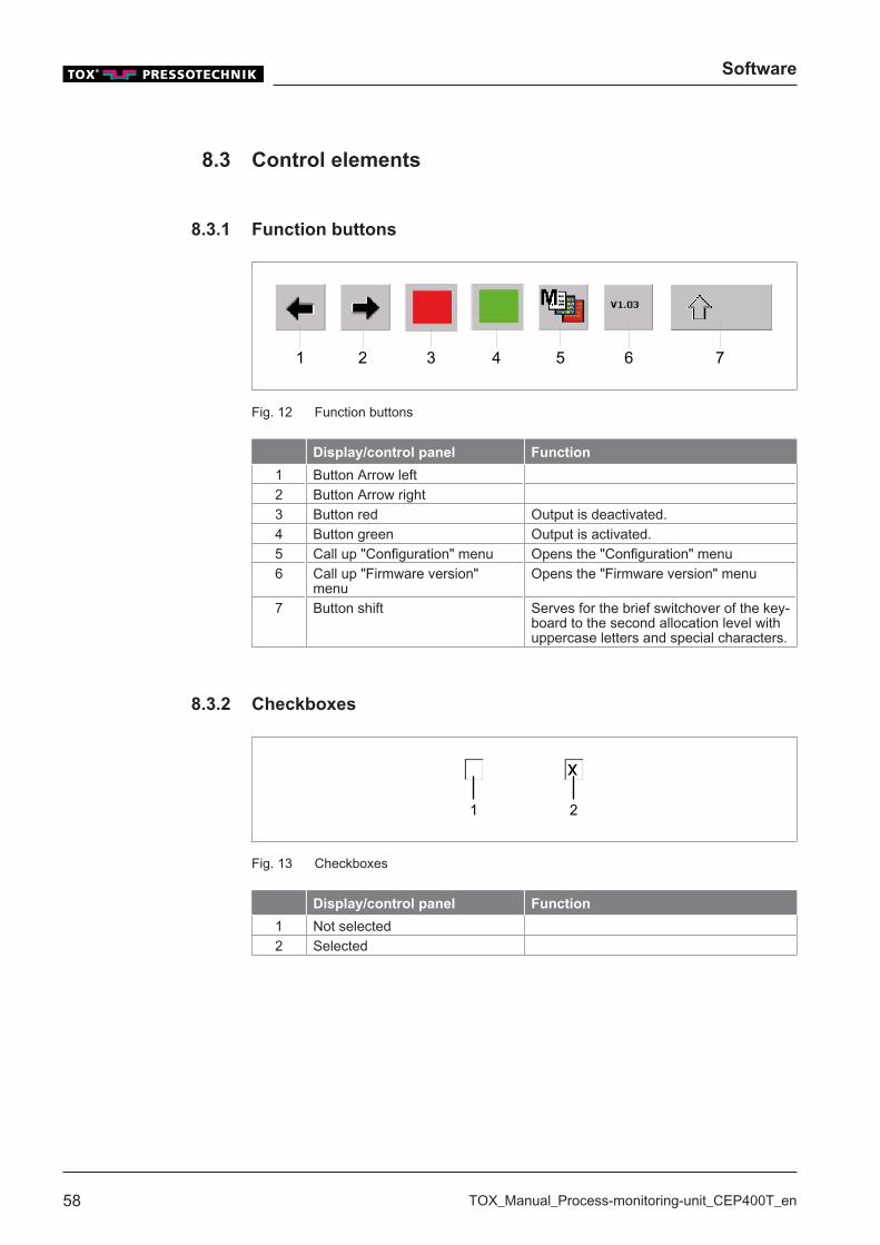
Fig. 12 Function buttons
Display/control panel Function
1 Button Arrow left2 Button Arrow right3 Button red Output is deactivated.4 Button green Output is activated.5 Call up "Configuration" menu Opens the "Configuration" menu6 Call up "Firmware version"
menuOpens the "Firmware version" menu
7 Button shift Serves for the brief switchover of the key-board to the second allocation level withuppercase letters and special characters.
8.3.2 Checkboxes
1 2
Fig. 13 Checkboxes
Display/control panel Function
1 Not selected2 Selected
Software
TOX_Manual_Process-monitoring-unit_CEP400T_en 59
8.3.3 Input field
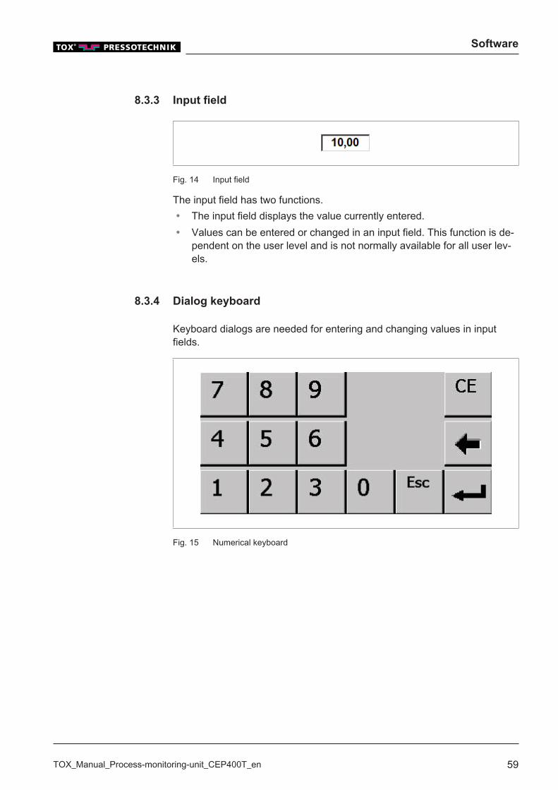
Fig. 14 Input field
The input field has two functions.� The input field displays the value currently entered.� Values can be entered or changed in an input field. This function is de-
pendent on the user level and is not normally available for all user lev-els.
8.3.4 Dialog keyboard
Keyboard dialogs are needed for entering and changing values in inputfields.
Fig. 15 Numerical keyboard

Software
60 TOX_Manual_Process-monitoring-unit_CEP400T_en
Fig. 16 Alphanumeric keyboard
It is possible to switch between three modes with the alphanumeric key-board:� Permanent uppercase� Permanent lowercase� Numbers and special characters
Activate permanent uppercase
è Keep pressing the Shift button until the keyboard displays uppercaseletters.w The keyboard displays uppercase letters.
Activating permanent lowercase
è Press Shift button until the keyboard displays lowercase letters.
u The keyboard displays lowercase letters.
Numbers and special characters
è Keep pressing the Shift button until the keyboard displays numbersand special characters.
u The keyboard displays numbers and special characters.
Software
TOX_Manual_Process-monitoring-unit_CEP400T_en 61
8.3.5 Icons
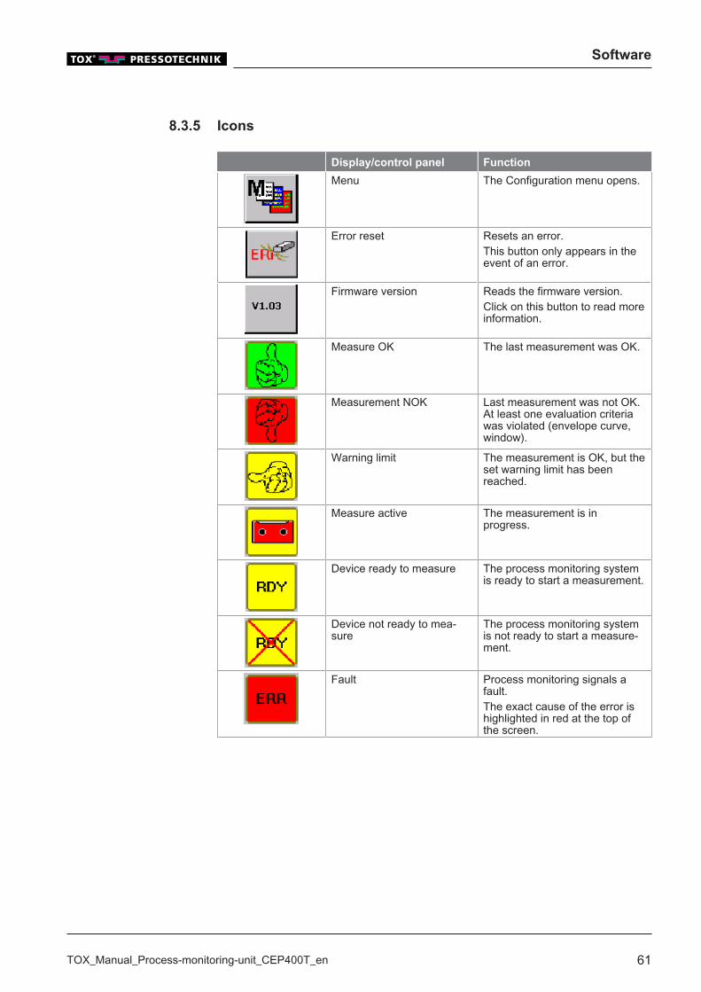
Display/control panel Function
Menu The Configuration menu opens.
Error reset Resets an error.This button only appears in theevent of an error.
Firmware version Reads the firmware version.Click on this button to read moreinformation.
Measure OK The last measurement was OK.
Measurement NOK Last measurement was not OK.At least one evaluation criteriawas violated (envelope curve,window).
Warning limit The measurement is OK, but theset warning limit has beenreached.
Measure active The measurement is inprogress.
Device ready to measure The process monitoring systemis ready to start a measurement.
Device not ready to mea-sure
The process monitoring systemis not ready to start a measure-ment.
Fault Process monitoring signals afault.The exact cause of the error ishighlighted in red at the top ofthe screen.
Software
62 TOX_Manual_Process-monitoring-unit_CEP400T_en
8.4 Main menus
8.4.1 Select process / Enter process name
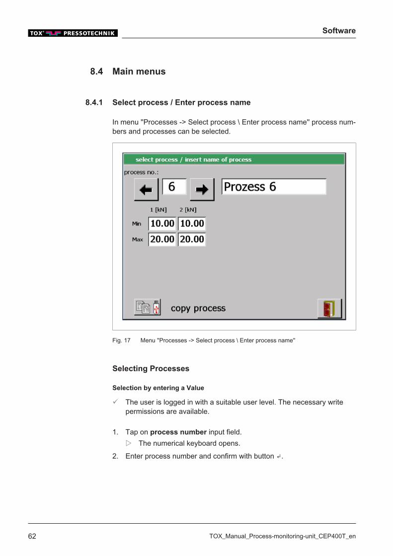
In menu ''Processes -> Select process \ Enter process name'' process num-bers and processes can be selected.
Fig. 17 Menu ''Processes -> Select process \ Enter process name''
Selecting Processes
Selection by entering a Value
ü The user is logged in with a suitable user level. The necessary writepermissions are available.
1. Tap on process number input field.w The numerical keyboard opens.
2. Enter process number and confirm with button ↲.
Software
TOX_Manual_Process-monitoring-unit_CEP400T_en 63
Selection by Function Buttons
ü The user is logged in with a suitable user level. The necessary writepermissions are available.
è Select process by tapping the or buttons.
Assigning Process Name
A name can be assigned for each process.
ü The user is logged in with a suitable user level. The necessary writepermissions are available.
1. Select process.2. Tap on process name input field.
w The alphanumeric keyboard opens.
3. Enter process name and confirm with the ↲ button.
Editing min/max limits
When setting up the process monitoring system, the parameters for themaximum and minimum limit values must be specified in order to evaluatethe measurement values correctly.Specifying limit values:
ü TOX®-Analysis assistance is available.
1. Clinching approx. 50 to 100 piece parts at simultaneous measurementof the press forces.
2. Checking the clinching points and piece parts (control dimension 'X',appearance of the clinching point, piece part test, etc.).
3. Analyzing the sequence of the press forces of every measuring point(according to MAX, MIN and average value).
Determining the limit values of the press force:
1. Maximum limit value = determined max. value + 500N2. Minimum limit value = determined min. value - 500N
Software
64 TOX_Manual_Process-monitoring-unit_CEP400T_en
ü The user is logged in with a suitable user level. The necessary writepermissions are available.
1. Tap the Minor Max input field under the channel whose value is to bechanged.w The numerical keyboard opens.
2. Enter the value and confirm with the ↲ button.
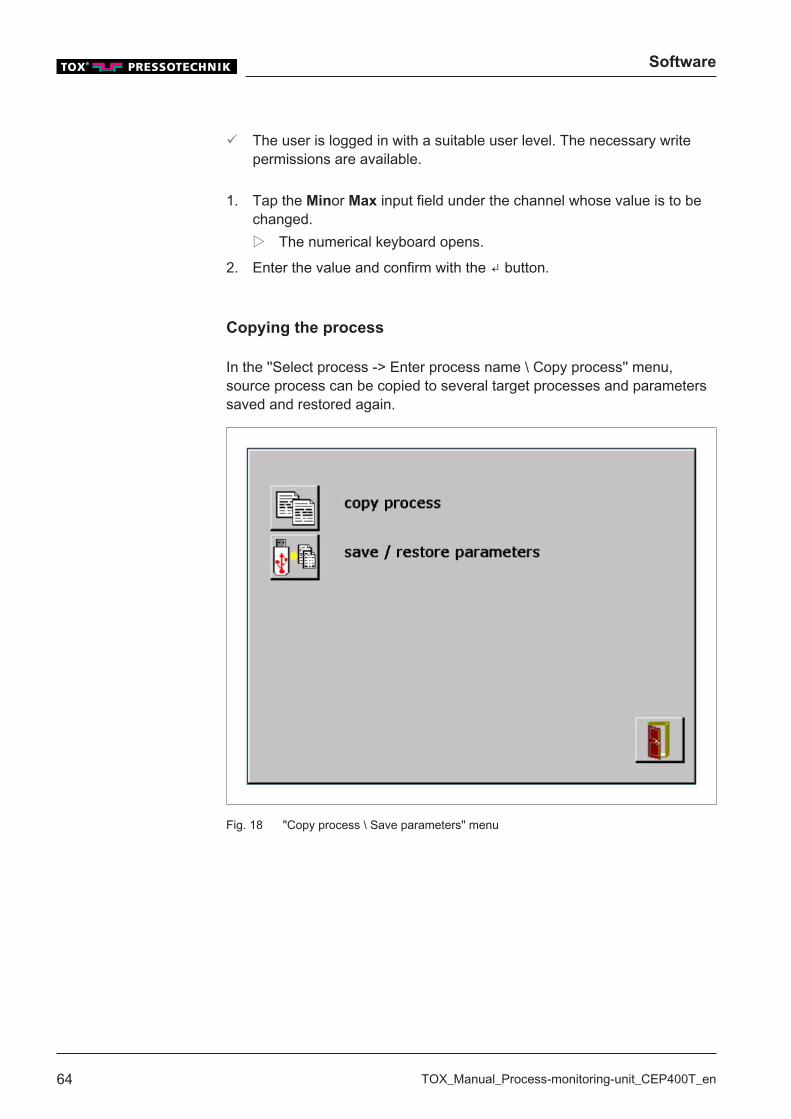
Copying the process
In the ''Select process -> Enter process name \ Copy process'' menu,source process can be copied to several target processes and parameterssaved and restored again.
Fig. 18 "Copy process \ Save parameters" menu

Software
TOX_Manual_Process-monitoring-unit_CEP400T_en 65
Copying the process
In the ''Select process -> Enter process name \ Copy proces \ Copyprocess'' menu the min/max limits can be copied from a source process toseveral target processes.
Fig. 19 Menu ''Copy process''
ü The user is logged in with a suitable user level. The necessary writepermissions are available.
ü The menu ''Select process -> Enter process name \ Copy process \Copy process'' is open.
1. Tap on the From process input field.w The numerical keyboard opens.
2. Enter the number of the first process to which the values are to becopied and confirm with the ↲ button.
3. Tap the Up to process input field.w The numerical keyboard opens.
4. Enter the number of the last process to which the values are to becopied and confirm with the↲ button.
5. NOTE! Data loss! The old process settings in the target process areoverwritten by copying.
Start copying process by tapping on the Accept button.
Software
66 TOX_Manual_Process-monitoring-unit_CEP400T_en
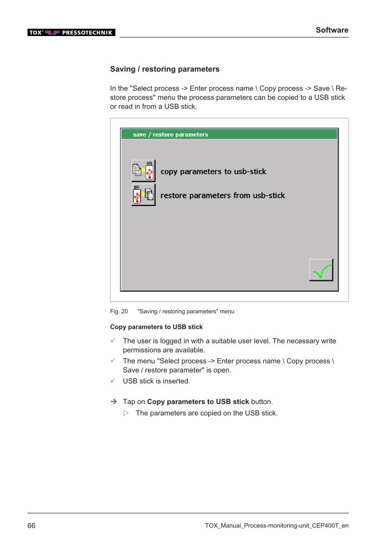
Saving / restoring parameters
In the ''Select process -> Enter process name \ Copy process -> Save \ Re-store process'' menu the process parameters can be copied to a USB stickor read in from a USB stick.
Fig. 20 "Saving / restoring parameters" menu
Copy parameters to USB stick
ü The user is logged in with a suitable user level. The necessary writepermissions are available.
ü The menu ''Select process -> Enter process name \ Copy process \Save / restore parameter'' is open.
ü USB stick is inserted.
è Tap on Copy parameters to USB stick button.w The parameters are copied on the USB stick.
Software
TOX_Manual_Process-monitoring-unit_CEP400T_en 67
Load parameters from USB stick
ü The user is logged in with a suitable user level. The necessary writepermissions are available.
ü USB stick is inserted.
è NOTE! Data loss! The old parameters in the target process are over-written by copying.
Tap theLoad the parameters from the USB stick button.w The parameters are read from the USB stick.
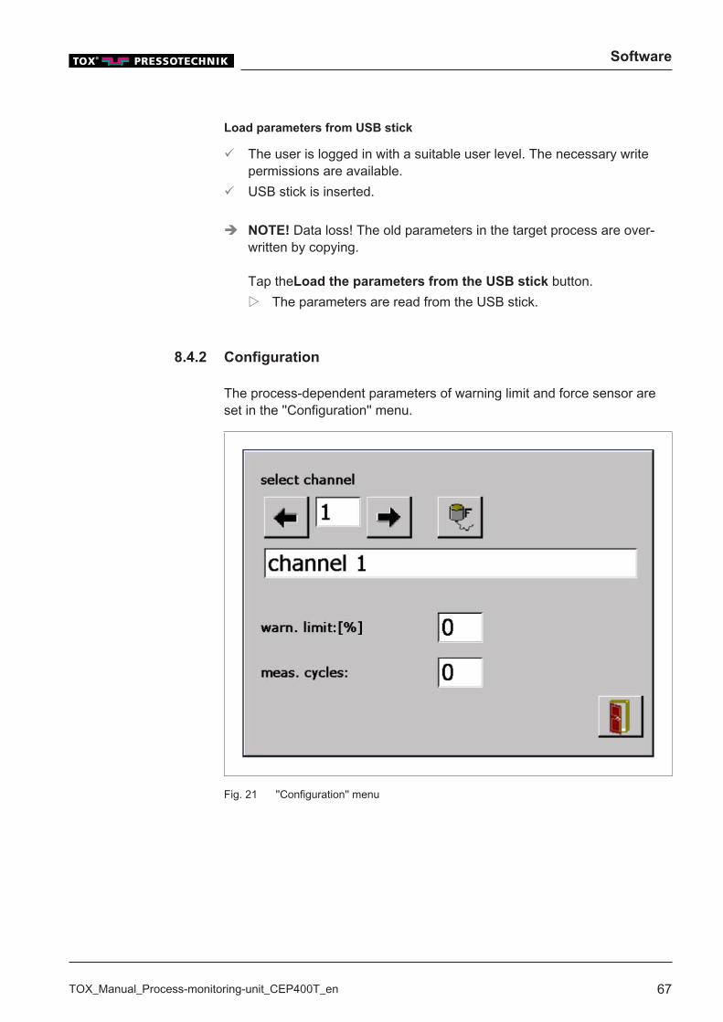
8.4.2 Configuration
The process-dependent parameters of warning limit and force sensor areset in the ''Configuration'' menu.
Fig. 21 ''Configuration'' menu
Software
68 TOX_Manual_Process-monitoring-unit_CEP400T_en
Naming the channel
ü The user is logged in with a suitable user level. The necessary writepermissions are available.
1. Tap on the Naming input field.w The alphanumeric keyboard opens.
2. Enter the channel (max. 40 characters) and confirm with ↲.
Setting warning limit and measuring cycles
With these settings the values are preset globally for all processes. Thesevalues must be monitored by the overriding control system.
Setting the warning limit
The value fixess the warning limit with regard to defined tolerance windowsthat are defined in the process.
ü The user is logged in with a suitable user level. The necessary writepermissions are available.
1. Tap on Warning limit: [%] input field.w The numerical keyboard opens.
2. Enter a value between 0 and 50 and confirm with ↲.
Deactivating the warning limit
ü The user is logged in with a suitable user level. The necessary writepermissions are available.
1. Tap on Warning limit: [%] input field.w The numerical keyboard opens.
2. Enter 0 and confirm with ↲.
Software
TOX_Manual_Process-monitoring-unit_CEP400T_en 69
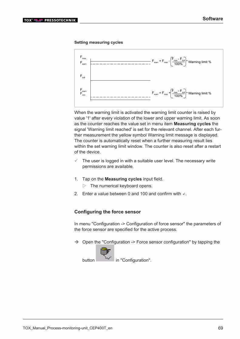
Setting measuring cycles
Fmax
Fsoll
FwarnFmin
FwarnFwarn = Fmax - 100%
Fmax - Fsoll *
Fwarn = Fmax + 100%
Fmax - Fsoll *
Warning limit %
Warning limit %
When the warning limit is activated the warning limit counter is raised byvalue '1' after every violation of the lower and upper warning limit. As soonas the counter reaches the value set in menu item Measuring cycles thesignal 'Warning limit reached' is set for the relevant channel. After each fur-ther measurement the yellow symbol Warning limit message is displayed.The counter is automatically reset when a further measuring result lieswithin the set warning limit window. The counter is also reset after a restartof the device.
ü The user is logged in with a suitable user level. The necessary writepermissions are available.
1. Tap on the Measuring cycles input field.w The numerical keyboard opens.
2. Enter a value between 0 and 100 and confirm with ↲.
Configuring the force sensor
In menu ''Configuration -> Configuration of force sensor'' the parameters ofthe force sensor are specified for the active process.
è Open the ''Configuration -> Force sensor configuration'' by tapping the
button in ''Configuration''.
Software
70 TOX_Manual_Process-monitoring-unit_CEP400T_en
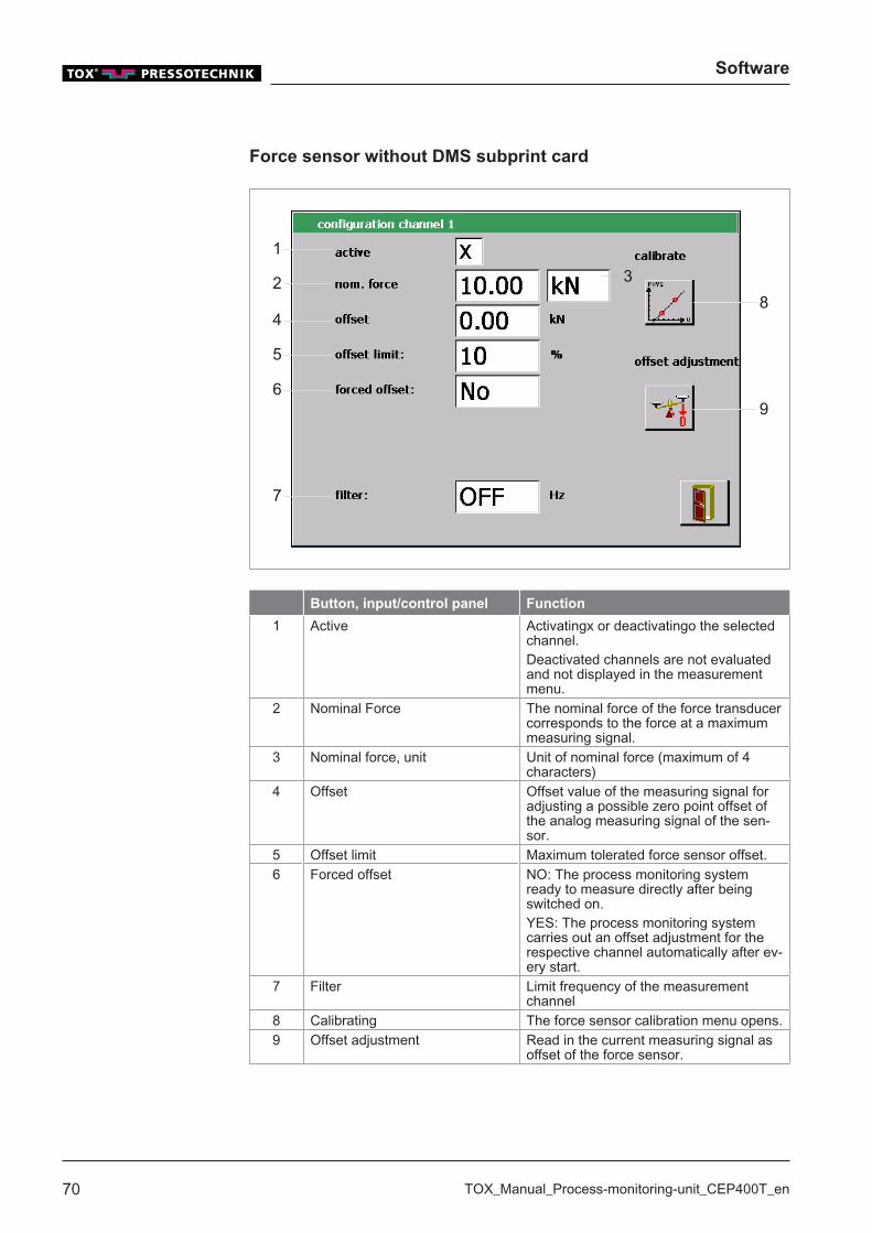
Force sensor without DMS subprint card
1
2
4
5
6
7
83
9
Button, input/control panel Function
1 Active Activatingx or deactivatingo the selectedchannel.Deactivated channels are not evaluatedand not displayed in the measurementmenu.
2 Nominal Force The nominal force of the force transducercorresponds to the force at a maximummeasuring signal.
3 Nominal force, unit Unit of nominal force (maximum of 4characters)
4 Offset Offset value of the measuring signal foradjusting a possible zero point offset ofthe analog measuring signal of the sen-sor.
5 Offset limit Maximum tolerated force sensor offset.6 Forced offset NO: The process monitoring system
ready to measure directly after beingswitched on.YES: The process monitoring systemcarries out an offset adjustment for therespective channel automatically after ev-ery start.
7 Filter Limit frequency of the measurementchannel
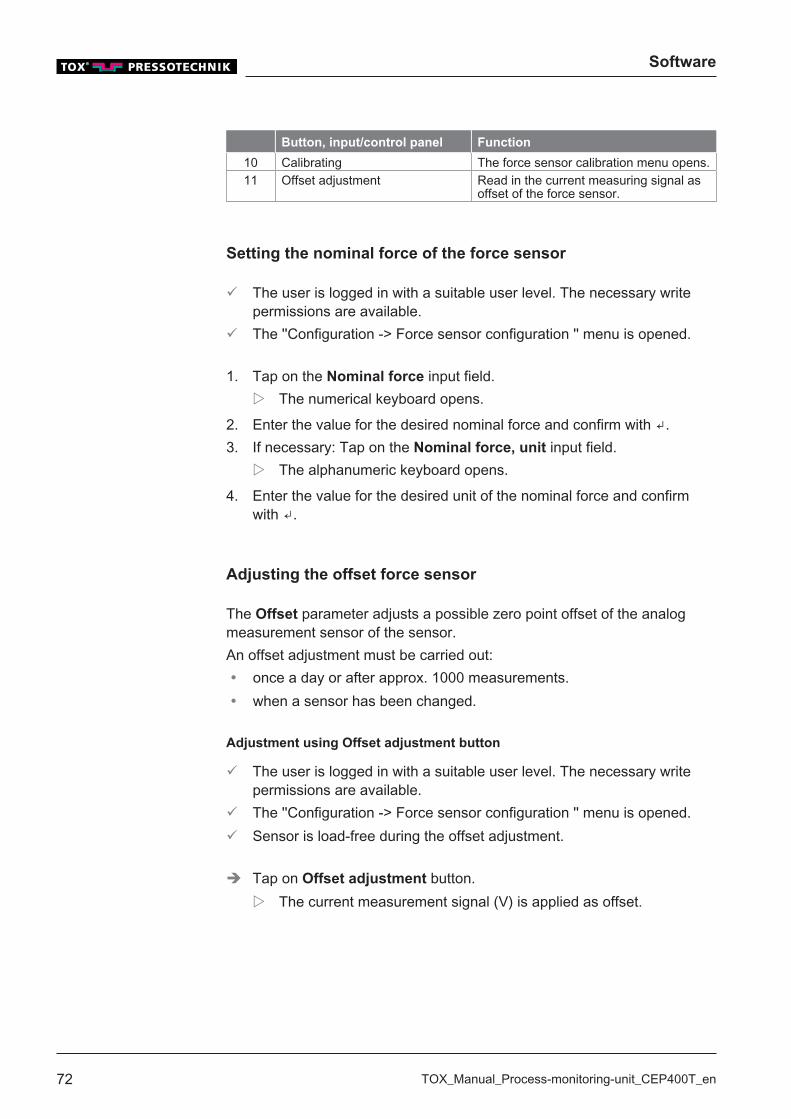
8 Calibrating The force sensor calibration menu opens.9 Offset adjustment Read in the current measuring signal as
offset of the force sensor.
Software
TOX_Manual_Process-monitoring-unit_CEP400T_en 71
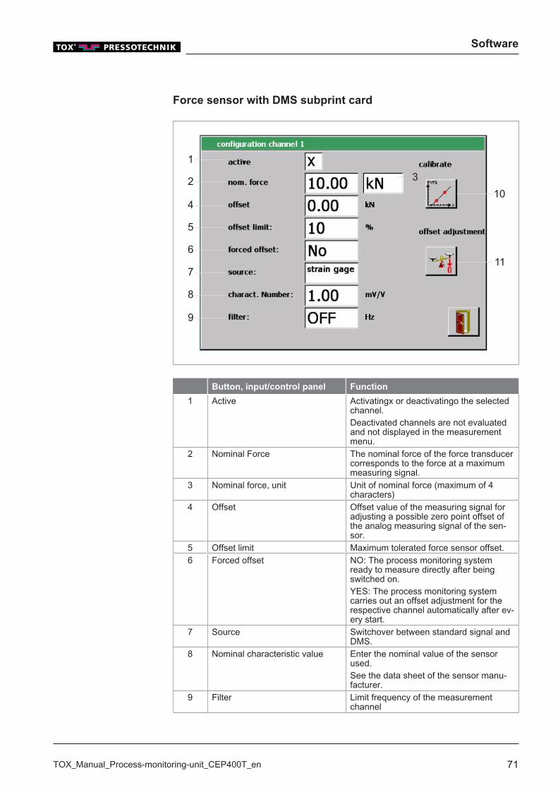
Force sensor with DMS subprint card
1
2
4
5
6
9
103
117
8
Button, input/control panel Function
1 Active Activatingx or deactivatingo the selectedchannel.Deactivated channels are not evaluatedand not displayed in the measurementmenu.
2 Nominal Force The nominal force of the force transducercorresponds to the force at a maximummeasuring signal.
3 Nominal force, unit Unit of nominal force (maximum of 4characters)
4 Offset Offset value of the measuring signal foradjusting a possible zero point offset ofthe analog measuring signal of the sen-sor.
5 Offset limit Maximum tolerated force sensor offset.6 Forced offset NO: The process monitoring system
ready to measure directly after beingswitched on.YES: The process monitoring systemcarries out an offset adjustment for therespective channel automatically after ev-ery start.
7 Source Switchover between standard signal andDMS.
8 Nominal characteristic value Enter the nominal value of the sensorused.See the data sheet of the sensor manu-facturer.
9 Filter Limit frequency of the measurementchannel
Software
72 TOX_Manual_Process-monitoring-unit_CEP400T_en
Button, input/control panel Function
10 Calibrating The force sensor calibration menu opens.11 Offset adjustment Read in the current measuring signal as
offset of the force sensor.
Setting the nominal force of the force sensor
ü The user is logged in with a suitable user level. The necessary writepermissions are available.
ü The ''Configuration -> Force sensor configuration '' menu is opened.
1. Tap on the Nominal force input field.w The numerical keyboard opens.
2. Enter the value for the desired nominal force and confirm with ↲.3. If necessary: Tap on the Nominal force, unit input field.
w The alphanumeric keyboard opens.
4. Enter the value for the desired unit of the nominal force and confirmwith ↲.
Adjusting the offset force sensor
The Offset parameter adjusts a possible zero point offset of the analogmeasurement sensor of the sensor.An offset adjustment must be carried out:� once a day or after approx. 1000 measurements.� when a sensor has been changed.
Adjustment using Offset adjustment button
ü The user is logged in with a suitable user level. The necessary writepermissions are available.
ü The ''Configuration -> Force sensor configuration '' menu is opened.ü Sensor is load-free during the offset adjustment.
è Tap on Offset adjustment button.w The current measurement signal (V) is applied as offset.
Software
TOX_Manual_Process-monitoring-unit_CEP400T_en 73
Adjustment via direct Value Input
ü The user is logged in with a suitable user level. The necessary writepermissions are available.
ü The ''Configuration -> Force sensor configuration '' menu is opened.ü Sensor is load-free during the offset adjustment.
1. Tap on Offset input field.w The numerical keyboard opens.
2. Enter the zero point value and confirm with ↲.
Offset limit force sensor
Offset limit of 10% means that the "Offset" value must only reach a maxi-mum of 10% of the nominal load. If the offset is higher, an error messageappears after the offset adjustment. This, for example, can prevent that anoffset is taught when the press is closed.
ü The user is logged in with a suitable user level. The necessary writepermissions are available.
ü The ''Configuration -> Force sensor configuration '' menu is opened.
è Tap on the Offset limit input field.w Each tap changes the value between 10 -> 20 -> 100.
Forced offset force sensor
If the forced offset is activated, an offset adjustment is carried out automati-cally after the process monitoring system is switched on.
ü The user is logged in with a suitable user level. The necessary writepermissions are available.
ü The ''Configuration -> Force sensor configuration '' menu is opened.
è Tap on the Forced offset input field.w Each tap changes the value from YES to NO and reverse.
Software
74 TOX_Manual_Process-monitoring-unit_CEP400T_en
Setting the force sensor filter
By setting a filter value the higher frequency deviations of the measuringsignal can be filtered out.
ü The user is logged in with a suitable user level. The necessary writepermissions are available.
ü The ''Configuration -> Force sensor configuration '' menu is opened.
è Tap on the Filter input field.w Each tap changes the value between OFF, 5, 10, 20, 50, 100, 200,
500, 1000.
Force sensor calibration
In menu ''Enter Configuration -> Configuration of force sensor\Nominalforce'' the measured electrical signal is converted to the correspondingphysical unit with the values of nominal force and offset. If the values fornominal force and offset are not known, they can be determined via the cal-ibration. For this a 2-point calibration is carried out. The first point here canbe the opened press with 0 kN force applied for example. The secondpoint, for example, can be the closed press when 2 kN force is applied. Theapplied forces must be known for carrying out the calibration, for example,which can be read on a reference sensor.
è Open the ''Enter Configuration -> Force sensor configuration\Nominal
force'' by tapping the button in ''Configuration\Configuration offorce sensor\''.
Software
TOX_Manual_Process-monitoring-unit_CEP400T_en 75
1
2
10
3
6
9
4 5
7 8
11 12
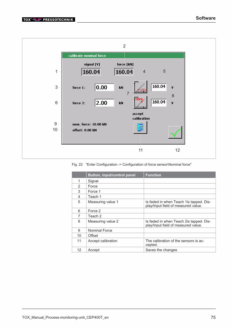
Fig. 22 ''Enter Configuration -> Configuration of force sensor\Nominal force''
Button, input/control panel Function
1 Signal2 Force3 Force 14 Teach 15 Measuring value 1 Is faded in when Teach 1is tapped. Dis-
play/Input field of measured value.6 Force 27 Teach 28 Measuring value 2 Is faded in when Teach 2is tapped. Dis-
play/Input field of measured value.9 Nominal Force
10 Offset11 Accept calibration The calibration of the sensors is ac-
cepted.12 Accept Saves the changes

Software
76 TOX_Manual_Process-monitoring-unit_CEP400T_en
ü The user is logged in with a suitable user level. The necessary writepermissions are available.
ü The ''Enter the Configuration -> Force sensor configuration\Nominalforce'' menu is opened.
1. Move to the first point, e.g. press opened.2. Determine the applied force (e.g. by a reference sensor attached tem-
porarily to the press) and simultaneously if possible tap the Teach 1button for reading the applied force.w The applied electrical signal is read in.
3. Tap on the Force 1 display/input field.w The numerical keyboard opens.
4. Enter the value of the measuring value of the electrical measuring sig-nal to be displayed and confirm with ↲.
5. Move to the second point, e.g. closing the press with a certain pressforce.
6. Determine the currently applied force and simultaneously if possible tapthe Teach 2 button for reading the applied force.w The current electrical measuring signal is accepted and displayed
in a new display/input field Measuring value 2 next to the Teach 2button.
7. Tap on the Force 2 display/input field.w The numerical keyboard opens.
8. Enter the value of the measuring value of the electrical measuring sig-nal to be displayed and confirm with ↲.
9. Save the changes with Accept calibration.
u When pressing the Accept calibration button the process monitoringsystem calculates the parameters of nominal force and offset from thethe two force values and the measured electrical signals. That con-cludes the calibration.
Software
TOX_Manual_Process-monitoring-unit_CEP400T_en 77
By tapping the text fields Measuring value 1 or Measuring value 2 thevalues of the measured electrical signals can also be changed beforetapping the Accept calibration button.
This should, however, only be made when the allocation of the electricalsignal for force is known.
Apply configuration
If a value or a setting has been changed in menu ''Configuration -> Configu-ration of force sensor'', a request dialog is displayed when exiting themenu.In this window the following options can be selected:� Only for this process:
The changes only apply to the current process and overwrite the previ-ous values/settings in the current process.
� Copy to all processesThe changes apply to all processes and overwrite the previous values/settings in all processes.
� Copy to the following processesThe changes are only accepted in the area that has been specified infields From process to process. The previous values/settings areoverwritten in the defined process area with the new values.
� Cancel entry:The changes are discarded and the window is closed.
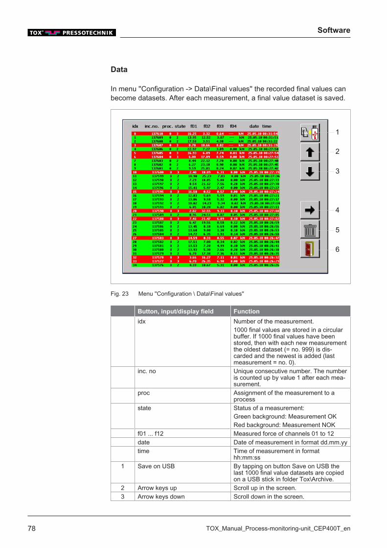
Software
78 TOX_Manual_Process-monitoring-unit_CEP400T_en
Data
In menu ''Configuration -> Data\Final values'' the recorded final values canbecome datasets. After each measurement, a final value dataset is saved.
4
2
6
5
3
1
Fig. 23 Menu ''Configuration \ Data\Final values''
Button, input/display field Function
idx Number of the measurement.1000 final values are stored in a circularbuffer. If 1000 final values have beenstored, then with each new measurementthe oldest dataset (= no. 999) is dis-carded and the newest is added (lastmeasurement = no. 0).
inc. no Unique consecutive number. The numberis counted up by value 1 after each mea-surement.
proc Assignment of the measurement to aprocess
state Status of a measurement:Green background: Measurement OKRed background: Measurement NOK
f01 ... f12 Measured force of channels 01 to 12date Date of measurement in format dd.mm.yytime Time of measurement in format
hh:mm:ss1 Save on USB By tapping on button Save on USB the
last 1000 final value datasets are copiedon a USB stick in folder Tox\Archive.
2 Arrow keys up Scroll up in the screen.3 Arrow keys down Scroll down in the screen.
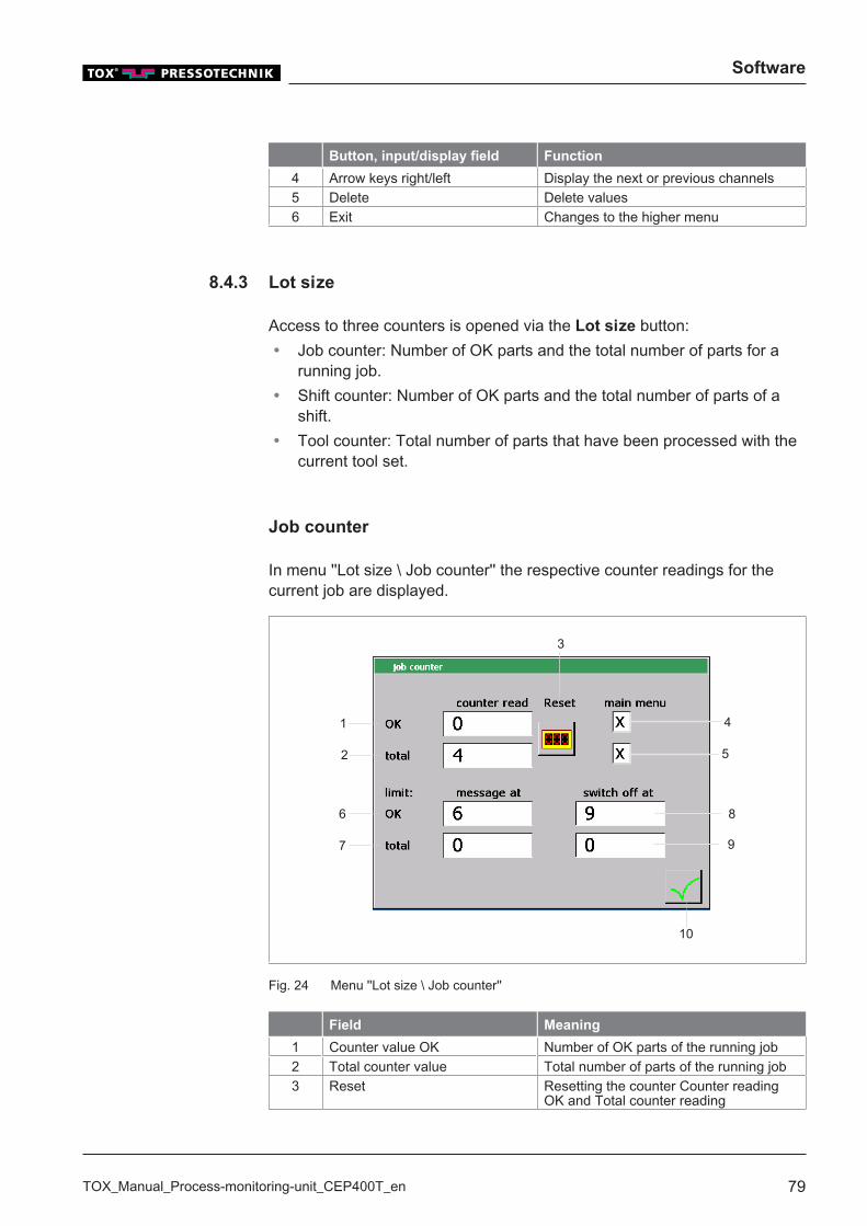
Software
TOX_Manual_Process-monitoring-unit_CEP400T_en 79
Button, input/display field Function
4 Arrow keys right/left Display the next or previous channels5 Delete Delete values6 Exit Changes to the higher menu
8.4.3 Lot size
Access to three counters is opened via the Lot size button:� Job counter: Number of OK parts and the total number of parts for a
running job.� Shift counter: Number of OK parts and the total number of parts of a
shift.� Tool counter: Total number of parts that have been processed with the
current tool set.
Job counter
In menu ''Lot size \ Job counter'' the respective counter readings for thecurrent job are displayed.
10
1
2
6
7
8
9
5
4
3
Fig. 24 Menu ''Lot size \ Job counter''
Field Meaning
1 Counter value OK Number of OK parts of the running job2 Total counter value Total number of parts of the running job3 Reset Resetting the counter Counter reading
OK and Total counter reading
Software
80 TOX_Manual_Process-monitoring-unit_CEP400T_en
Field Meaning
4 Main menu OK The counter reading is displayed in themain menu when the checkbox is acti-vated.
5 Main menu total The counter reading is displayed in themain menu when the checkbox is acti-vated.
6 Message at OK The number of the OK parts reached atwhich a stored yellow message is issuedon the display. Value 0 deactivates thefunction.
7 Message at total The number of the total parts reached atwhich a stored yellow message is issuedon the display. Value 0 deactivates thefunction.
8 Switch-off at OK The number of the OK parts reached atwhich the working process is ended anda stored red message is issued on thedisplay.
9 Switch-off at total The number of the total parts reached atwhich the working process is ended anda stored red message is issued on thedisplay.
10 Accept The settings are applied.The window will close.
Job counter - Switch-off at OK
A limit value can be entered in the input field Switch-off at OK. Once thecounter value reaches the value, the 'Ready' signal is switched off and anerror message is issued.Tapping on the Reset button resets the counter. After that, the next mea-surement can be continued.The value 0 deactivates the corresponding option. The system is not shutdown and no message is issued.
ü The user is logged in with a suitable user level. The necessary writepermissions are available.
ü Menu ''Lot size \ Job counter'' is open
1. Tap on the Switch-off at OK input field.w The numerical keyboard opens.
2. Enter the desired value and confirm with ↲.Value 0 deactivates the function.
Software
TOX_Manual_Process-monitoring-unit_CEP400T_en 81
Reset ''Switch-off at OK'' counter
1. When the limit value in input field ''Switch-off at OK''has been reached:2. Reset the counter by tapping on the Reset button.3. Start process again.
Job counter - Switch-off at total
A limit value can be entered in the input field Switch-off at total. As soonas the counter value reaches the value, a warning message is issued.The value 0 deactivates the corresponding option. The system is not shutdown and no message is issued.
ü The user is logged in with a suitable user level. The necessary writepermissions are available.
ü Menu ''Lot size \ Job counter'' is open
1. Tap on the Switch-off at total input field.w The numerical keyboard opens.
2. Enter the limit value and confirm with ↲.Value 0 deactivates the function.
Reset ''Switch-off at total'' counter
1. When the limit value in input field ''Switch-off at total'' has beenreached:
2. Reset the counter by tapping on the Reset button.3. Start process again.
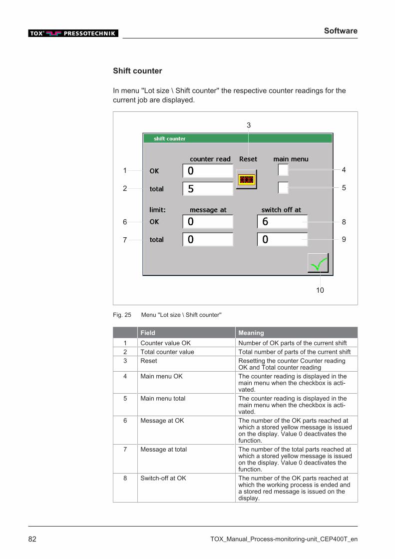
Software
82 TOX_Manual_Process-monitoring-unit_CEP400T_en
Shift counter
In menu ''Lot size \ Shift counter'' the respective counter readings for thecurrent job are displayed.
10
1
2
6
7
8
9
5
4
3
Fig. 25 Menu ''Lot size \ Shift counter''
Field Meaning
1 Counter value OK Number of OK parts of the current shift2 Total counter value Total number of parts of the current shift3 Reset Resetting the counter Counter reading
OK and Total counter reading4 Main menu OK The counter reading is displayed in the
main menu when the checkbox is acti-vated.
5 Main menu total The counter reading is displayed in themain menu when the checkbox is acti-vated.
6 Message at OK The number of the OK parts reached atwhich a stored yellow message is issuedon the display. Value 0 deactivates thefunction.
7 Message at total The number of the total parts reached atwhich a stored yellow message is issuedon the display. Value 0 deactivates thefunction.
8 Switch-off at OK The number of the OK parts reached atwhich the working process is ended anda stored red message is issued on thedisplay.

Software
TOX_Manual_Process-monitoring-unit_CEP400T_en 83
Field Meaning
9 Switch-off at total The number of the total parts reached atwhich the working process is ended anda stored red message is issued on thedisplay.
10 Accept The settings are applied.The window will close.
Shift counter - Switch-off at OK
A limit value can be entered in the input field Switch-off at OK. Once thecounter value reaches the value, the working process shuts down and acorresponding message is issued.Tapping on the Reset button resets the counter. After that, the next mea-surement can be continued.The value 0 deactivates the corresponding option. The system is not shutdown and no message is issued.
ü The user is logged in with a suitable user level. The necessary writepermissions are available.
ü Menu ''Lot size\Shift counter'' is open
1. Tap on the Switch-off at OK input field.w The numerical keyboard opens.
2. Enter the desired value and confirm with ↲.Value 0 deactivates the function.
Reset ''Switch-off at OK'' counter
1. When the limit value in input field ''Switch-off at OK''has been reached:2. Reset the counter by tapping on the Reset button.3. Start process again.
Shift counter - Switch-off at total
A limit value can be entered in the input field Switch-off at total. Once thecounter value reaches the value, the working process shuts down and acorresponding message is issued.The value 0 deactivates the corresponding option. The system is not shutdown and no message is issued.

Software
84 TOX_Manual_Process-monitoring-unit_CEP400T_en
ü The user is logged in with a suitable user level. The necessary writepermissions are available.
ü Menu ''Lot size\Shift counter'' is open
1. Tap on the Switch-off at total input field.w The numerical keyboard opens.
2. Enter the limit value and confirm with ↲.Value 0 deactivates the function.
Reset ''Switch-off at total'' counter
1. When the limit value in input field ''Switch-off at total'' has beenreached:
2. Reset the counter by tapping on the Reset button.3. Start process again.
Tool counter
In menu ''Lot size \ tool counter'' the respective counter readings for thecurrent job are displayed.
6
1
4 5
3
2
Fig. 26 Menu ''Lot size \ Tool counter''

Software
TOX_Manual_Process-monitoring-unit_CEP400T_en 85
Field Meaning
1 Total counter value Total number of parts (OK and NOK) thatwere produced with this tool.
2 Reset Reset of counter Total counter reading3 Main menu total The counter reading is displayed in the
main menu when the checkbox is acti-vated.
4 Message at total The number of the total parts reached atwhich a stored yellow message is issuedon the display. Value 0 deactivates thefunction.
5 Switch-off at total The number of the total parts reached atwhich the working process is ended anda stored red message is issued on thedisplay.
6 Accept The settings are applied.The window will close.
Tool counter - Switch-off at total
A limit value can be entered in the input field Switch-off at total. Once thecounter value reaches the value, the working process shuts down and acorresponding message is issued.The value 0 deactivates the corresponding option. The system is not shutdown and no message is issued.
ü The user is logged in with a suitable user level. The necessary writepermissions are available.
ü Menu ''Lot size\Tool counter'' is open
1. Tap on the Switch-off at total input field.w The numerical keyboard opens.
2. Enter the limit value and confirm with ↲.Value 0 deactivates the function.
Reset ''Switch-off at total'' counter
1. When the limit value in input field ''Switch-off at total'' has beenreached:
2. Reset the counter by tapping on the Reset button.3. Start process again.
Software
86 TOX_Manual_Process-monitoring-unit_CEP400T_en
8.4.4 Supplemnt
The access is opened via the Supplement button:� User administration: Administration of the access levels / the password� Language: Change language� Communication parameters: PC-interface (Field bus address)� Inputs/outputs: Actual state of digital inputs/outputs� Date/Time: Display of the current time / current date� Device name: Entry of the device name.
User administration
In the ''Supplement/User administration''the user can:� Log in with a specific user level.� Log out from the active user level.� Change the password
Log user in and out
The process monitoring system has an authorization management systemthat can limit or enable different operating options and configuration op-tions.
Authorization Description Password
Level 0 Machine operatorFunctions for observing the measurement dataand program selection are enabled.
No passwordrequired
Level 1 Installers and experienced machine operators:Changes of values within the program are en-abled.
TOX
Level 2 Authorized installer and system programmer:Also configuration data can be changed.
TOX2
Level 3 Plant construction and maintenance:Also extended additional configuration data canbe changed.
TOX3
Software
TOX_Manual_Process-monitoring-unit_CEP400T_en 87
Log in user
ü Menu ''Supplement\User administration'' is open.
1. Tap on the Login button.w The alphanumeric keyboard opens.
2. Enter the password of the authorization level and confirm with ↲.
u If the password was entered correctly, the selected authorization levelis active. - OR -If the password was entered incorrectly, a message will appear and thelogin procedure will be canceled.
u The actual authorization level is displayed at the top of the screen.
Log out user
ü Menu ''Supplement\User administration'' is open.ü The user is logged in with level 1 or higher.
è Tap on the Logout button.
u The authorization level changes to the next lower level.u The actual authorization level is displayed at the top of the screen.
Software
88 TOX_Manual_Process-monitoring-unit_CEP400T_en
Change password
The password can only be changed for the authorization level in which theuser is currently logged in. the user is logged in.
ü Menu ''Supplement\User administration'' is open
1. Tap the Change password button.w A dialog window opens with the request to enter the current pass-
word.
w The alphanumeric keyboard opens.
2. Enter the current password and confirm with ↲.w A dialog window opens with the request to enter the new password.
w The alphanumeric keyboard opens.
3. Enter the new password and confirm with ↲.w A dialog window opens with the request to enter the new password
again.
w The alphanumeric keyboard opens.
4. Enter the new password again and confirm it with ↲.
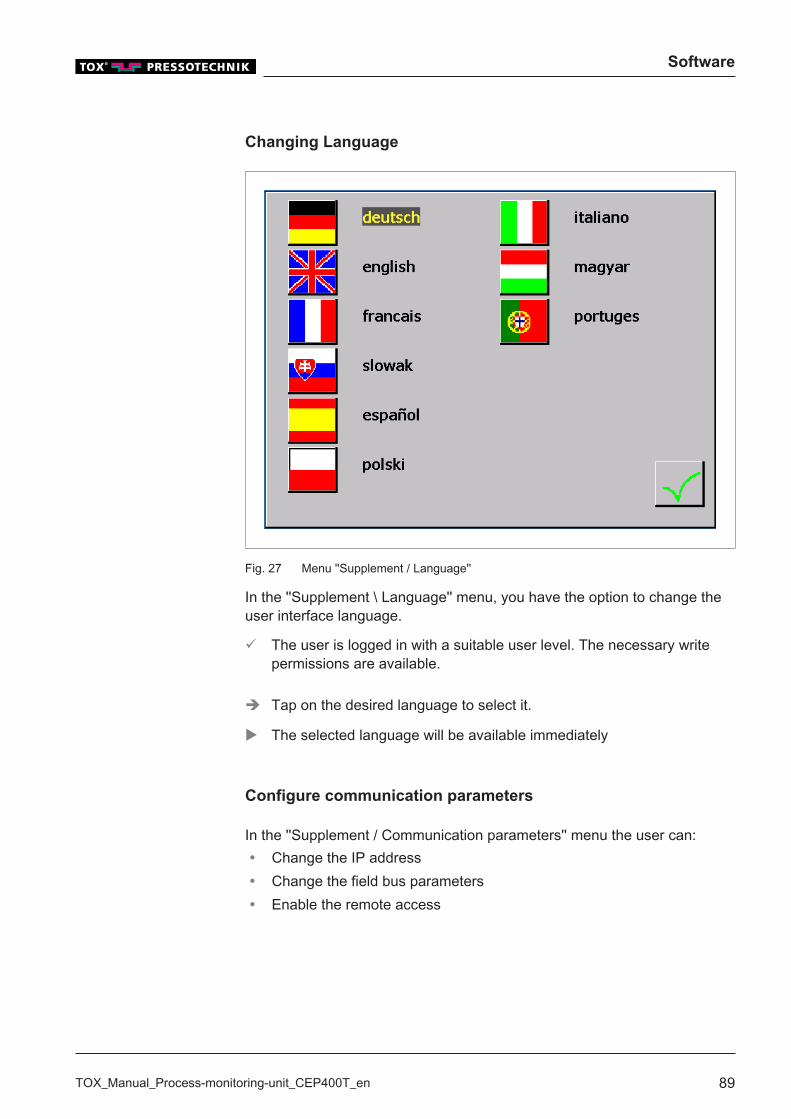
Software
TOX_Manual_Process-monitoring-unit_CEP400T_en 89
Changing Language
Fig. 27 Menu ''Supplement / Language''
In the ''Supplement \ Language'' menu, you have the option to change theuser interface language.
ü The user is logged in with a suitable user level. The necessary writepermissions are available.
è Tap on the desired language to select it.
u The selected language will be available immediately
Configure communication parameters
In the ''Supplement / Communication parameters'' menu the user can:� Change the IP address� Change the field bus parameters� Enable the remote access
Software
90 TOX_Manual_Process-monitoring-unit_CEP400T_en
Change the IP address
In menu ''Supplement \ Configuration parameter\IP address'' the EthernetIP address, the subnet mask and the default gateway can be changed.
Defining IP address via the DHCP protocol
ü The user is logged in with a suitable user level. The necessary writepermissions are available.
1. Tap on DHCP checkbox.2. Tap the Accept button.3. Restart the device.
Defining IP Address by entering a Value
ü The user is logged in with a suitable user level. The necessary writepermissions are available.
1. Tap on the first input field of the IP address group, enter the first threedigits of the IP address to be used and press the OK button to confirm.w The numerical keyboard opens.
2. Repeat the procedure for all input fields in the IP address group.3. Repeat point 2 and 3 to enter the Subnet mask and Default Gateway.4. Tap the Accept button.5. Restart the device.
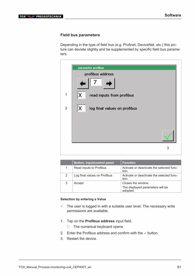
Software
TOX_Manual_Process-monitoring-unit_CEP400T_en 91
Field bus parameters
Depending in the type of field bus (e.g. Profinet, DeviceNet, etc.) this pic-ture can deviate slightly and be supplemented by specific field bus parame-ters.
3
1
2
Button, input/control panel Function
1 Read inputs to Profibus Activate or deactivate the selected func-tion.
2 Log final values on Profibus Activate or deactivate the selected func-tion.
3 Accept Closes the window.The displayed parameters will beadopted.
Selection by entering a Value
ü The user is logged in with a suitable user level. The necessary writepermissions are available.
1. Tap on the Profibus address input field.w The numerical keyboard opens.
2. Enter the Profibus address and confirm with the ↲ button.3. Restart the device.
Software
92 TOX_Manual_Process-monitoring-unit_CEP400T_en
Selection by Function Buttons
ü The user is logged in with a suitable user level. The necessary writepermissions are available.
1. Select the Profibus address by tapping the ⇒ or ⇐ buttons.2. Restart the device.
Enable the remote access
The remote access for TOX® PRESSOTECHNIK can be enabled in menu''Supplement \ Configuration parameters\Remote access''.
ü The user is logged in with a suitable user level. The necessary writepermissions are available.
ü Menu ''Supplement -> Configuration parameters\Remote access'' isopen.
è Tap on the Remote access button.w Remote access is enabled.
In-/Outputs
In the ''Supplement -> In-/Outputs'' menu the user can:� Check the current status of the internal digital inputs and outputs.� Check the current status of the field bus inputs and outputs.
Checking the internal In-/Outputs
In menu ''Supplement -> In-/Outputs I Internal I/O'' the current status of theinternal digital inputs and outputs can be checked.Status:� Active: The corresponding input or output is marked with a green
square.� Not active: The corresponding input or output is marked with a red
square.
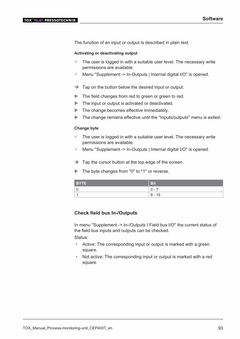
Software
TOX_Manual_Process-monitoring-unit_CEP400T_en 93
The function of an input or output is described in plain text.
Activating or deactivating output
ü The user is logged in with a suitable user level. The necessary writepermissions are available.
ü Menu ''Supplement -> In-Outputs | Internal digital I/O'' is opened.
è Tap on the button below the desired input or output.
u The field changes from red to green or green to red.u The input or output is activated or deactivated.u The change becomes effective immediately.u The change remains effective until the ''Inputs/outputs'' menu is exited.
Change byte
ü The user is logged in with a suitable user level. The necessary writepermissions are available.
ü Menu ''Supplement -> In-Outputs | Internal digital I/O'' is opened.
è Tap the cursor button at the top edge of the screen.
u The byte changes from ''0'' to ''1'' or reverse.
BYTE Bit
0 0 - 71 8 - 15
Check field bus In-/Outputs
In menu ''Supplement -> In-/Outputs I Field bus I/O'' the current status ofthe field bus inputs and outputs can be checked.Status:� Active: The corresponding input or output is marked with a green
square.� Not active: The corresponding input or output is marked with a red
square.
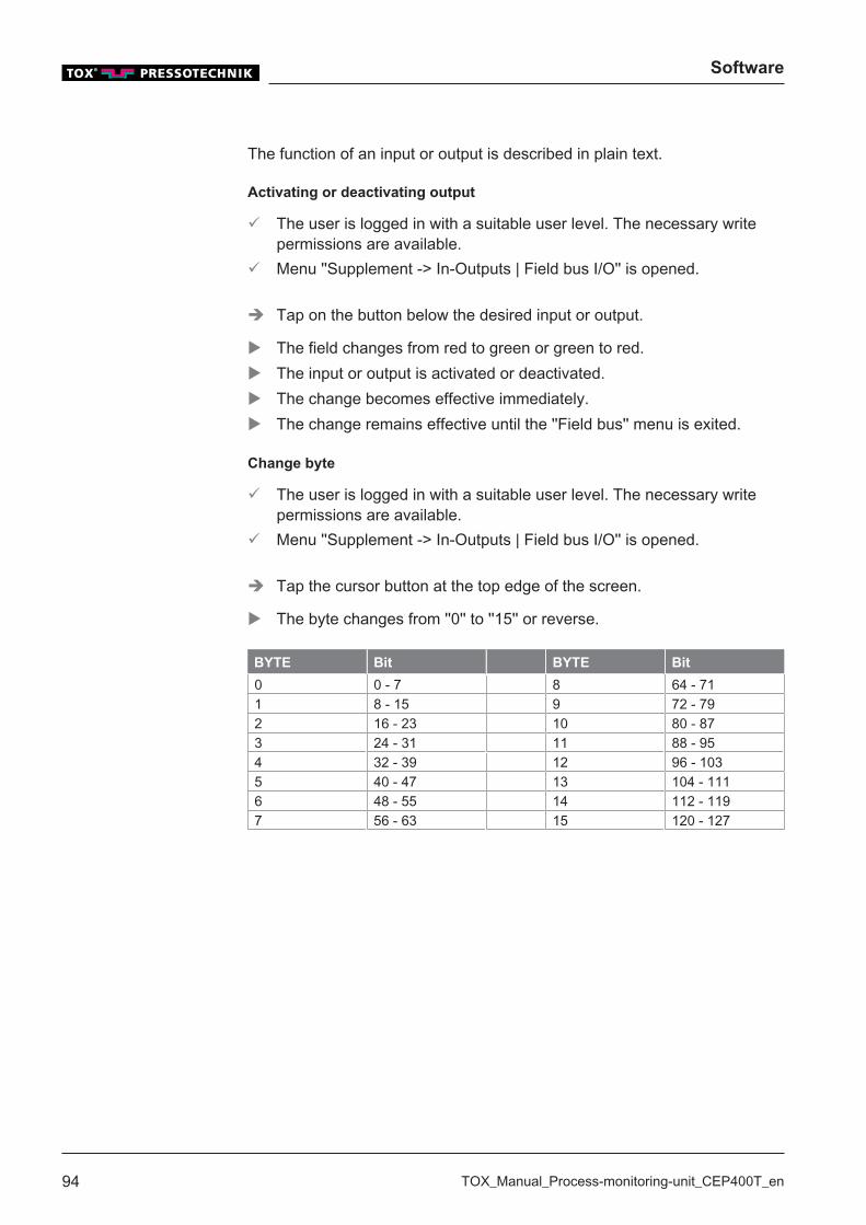
Software
94 TOX_Manual_Process-monitoring-unit_CEP400T_en
The function of an input or output is described in plain text.
Activating or deactivating output
ü The user is logged in with a suitable user level. The necessary writepermissions are available.
ü Menu ''Supplement -> In-Outputs | Field bus I/O'' is opened.
è Tap on the button below the desired input or output.
u The field changes from red to green or green to red.u The input or output is activated or deactivated.u The change becomes effective immediately.u The change remains effective until the ''Field bus'' menu is exited.
Change byte
ü The user is logged in with a suitable user level. The necessary writepermissions are available.
ü Menu ''Supplement -> In-Outputs | Field bus I/O'' is opened.
è Tap the cursor button at the top edge of the screen.
u The byte changes from ''0'' to ''15'' or reverse.
BYTE Bit BYTE Bit
0 0 - 7 8 64 - 711 8 - 15 9 72 - 792 16 - 23 10 80 - 873 24 - 31 11 88 - 954 32 - 39 12 96 - 1035 40 - 47 13 104 - 1116 48 - 55 14 112 - 1197 56 - 63 15 120 - 127
Software
TOX_Manual_Process-monitoring-unit_CEP400T_en 95
Setting Date/Time
In the ''Supplement -> Date/Time'' menu, the device time and device datecan be configured.
ü The user is logged in with a suitable user level. The necessary writepermissions are available.
ü The ''Supplement -> Date/Time'' menu is opened.
1. Tap on the Time or the Date input fields.w The numerical keyboard opens.
2. Enter the values in the corresponding fields and confirm with ↲.
Change device name
The device name is used, for example, to create a folder with the devicename on the data medium during the creation of a backup on a USB stick.This makes it clear in case of several process monitoring systems, onwhich device this backup was created.
ü The user is logged in with a suitable user level. The necessary writepermissions are available.
ü The ''Menu Supplement | Device name'' is opened.
1. Tap on Device name input field.w The alphanumeric keyboard opens.
2. Enter the device name and confirm with ↲.
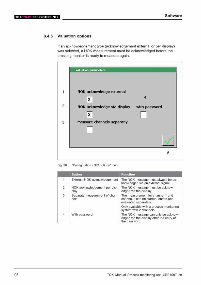
Software
96 TOX_Manual_Process-monitoring-unit_CEP400T_en
8.4.5 Valuation options
If an acknowledgement type (acknowledgement external or per display)was selected, a NOK measurement must be acknowledged before thepressing monitor is ready to measure again.
5
1
2
3
4
Fig. 28 ''Configuration \ NIO options'' menu
Button Function
1 External NOK acknowledgement The NOK message must always be ac-knowledged via an external signal.
2 NOK acknowledgement per dis-play
The NOK message must be acknowl-edged via the display.
3 Separate measurement of chan-nels
The measurement for channel 1 andchannel 2 can be started, ended andevaluated separately.Only available with a process monitoringsystem with 2 channels.
4 With password The NOK message can only be acknowl-edged via the display after the entry ofthe password.
Software
TOX_Manual_Process-monitoring-unit_CEP400T_en 97
Activate external NOK acknowledgement
ü The user is logged in with a suitable user level. The necessary writepermissions are available.
1. Tap on external NOK acknowledgement checkbox to activate exter-nal acknowledgement.
2. Tap on the Accept button to save the values.
Activating NOK acknowledgement per display
ü The user is logged in with a suitable user level. The necessary writepermissions are available.
1. Tap on NOK acknowledgement per display checkbox to activate theacknowledgement per display.
2. Tap on the checkbox With password to enter the password of autho-rization level 1, the one who can perform the acknowledgment.
3. Tap on the Accept button to save the values.
Separate measurement of channels
In case of a 2-channel device, the measurement for channel 1 and channel2 can each be started, ended and evaluated separately.
ü The user is logged in with a suitable user level. The necessary writepermissions are available.
ü The device is 2-channel capable.
1. Tap on external NOK acknowledgement checkbox to activate exter-nal acknowledgement.
2. Tap on the Measure channels separately button to display the statusof the measurement carried out last.
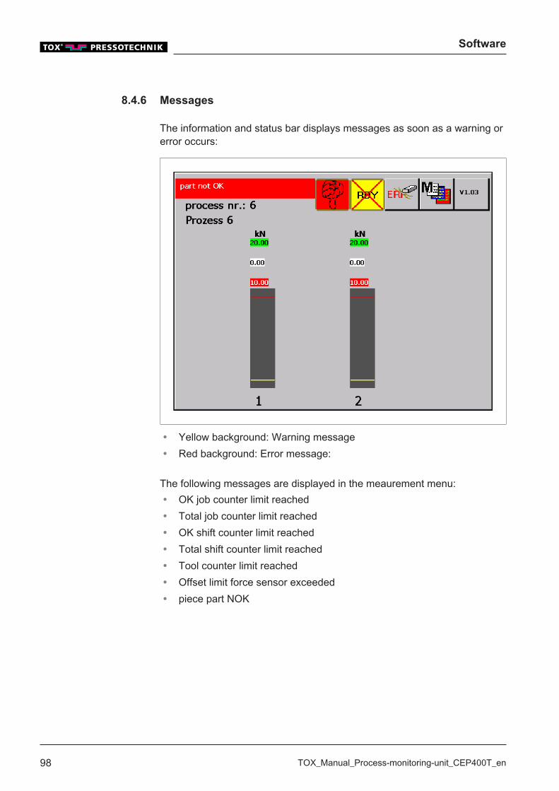
Software
98 TOX_Manual_Process-monitoring-unit_CEP400T_en
8.4.6 Messages
The information and status bar displays messages as soon as a warning orerror occurs:
� Yellow background: Warning message� Red background: Error message:
The following messages are displayed in the meaurement menu:� OK job counter limit reached� Total job counter limit reached� OK shift counter limit reached� Total shift counter limit reached� Tool counter limit reached� Offset limit force sensor exceeded� piece part NOK

Troubleshooting
TOX_Manual_Process-monitoring-unit_CEP400T_en 99
9 Troubleshooting
9.1 Detecting faults
Faults are displayed as alarms. Depending on the type of fault, the alarmsare displayed as errors or warnings.
Alarm
Type
Display Meaning
Warning Text with a yellow background in themeasurement menu of the device.
--
Fault Text with a red background in themeasurement menu of the device.
The next measurement is dis-abled and must be eliminatedand acknowledged.
9.1.1 Acknowledging Messages
After a fault, the button Error resetappears in the main screen.
è Tap on the Error reset button.
u The fault is reset.
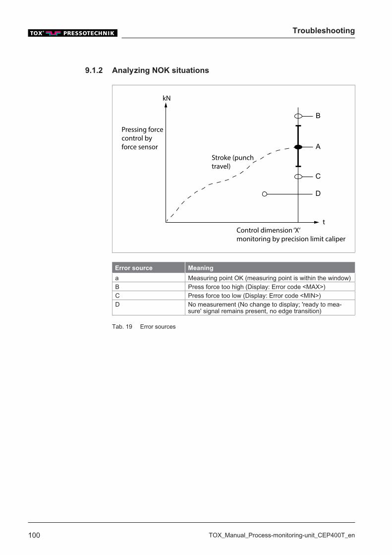
Troubleshooting
100 TOX_Manual_Process-monitoring-unit_CEP400T_en
9.1.2 Analyzing NOK situations
A
B
C
D
kN
t
Stroke (punchtravel)
Pressing forcecontrol byforce sensor
Control dimension ‘X‘monitoring by precision limit caliper
Error source Meaning
a Measuring point OK (measuring point is within the window)B Press force too high (Display: Error code <MAX>)C Press force too low (Display: Error code <MIN>)D No measurement (No change to display; 'ready to mea-
sure' signal remains present, no edge transition)
Tab. 19 Error sources
Troubleshooting
TOX_Manual_Process-monitoring-unit_CEP400T_en 101
9.1.3 Error messages
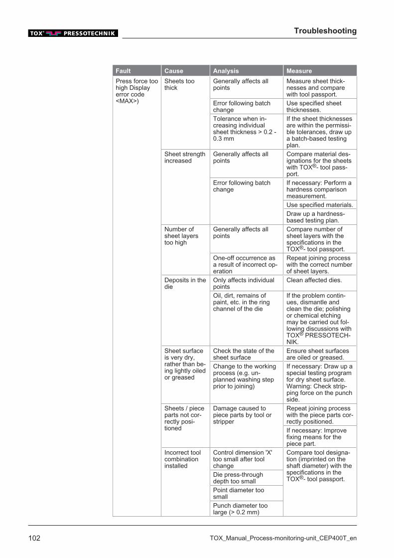
Troubleshooting
102 TOX_Manual_Process-monitoring-unit_CEP400T_en
Fault Cause Analysis Measure
Press force toohigh Displayerror code<MAX>)
Sheets toothick
Generally affects allpoints
Measure sheet thick-nesses and comparewith tool passport.
Error following batchchange
Use specified sheetthicknesses.
Tolerance when in-creasing individualsheet thickness > 0.2 -0.3 mm
If the sheet thicknessesare within the permissi-ble tolerances, draw upa batch-based testingplan.
Sheet strengthincreased
Generally affects allpoints
Compare material des-ignations for the sheetswith TOX®- tool pass-port.
Error following batchchange
If necessary: Perform ahardness comparisonmeasurement.Use specified materials.Draw up a hardness-based testing plan.
Number ofsheet layerstoo high
Generally affects allpoints
Compare number ofsheet layers with thespecifications in theTOX®- tool passport.
One-off occurrence asa result of incorrect op-eration
Repeat joining processwith the correct numberof sheet layers.
Deposits in thedie
Only affects individualpoints
Clean affected dies.
Oil, dirt, remains ofpaint, etc. in the ringchannel of the die
If the problem contin-ues, dismantle andclean the die; polishingor chemical etchingmay be carried out fol-lowing discussions withTOX® PRESSOTECH-NIK.
Sheet surfaceis very dry,rather than be-ing lightly oiledor greased
Check the state of thesheet surface
Ensure sheet surfacesare oiled or greased.
Change to the workingprocess (e.g. un-planned washing stepprior to joining)
If necessary: Draw up aspecial testing programfor dry sheet surface.Warning: Check strip-ping force on the punchside.
Sheets / pieceparts not cor-rectly posi-tioned
Damage caused topiece parts by tool orstripper
Repeat joining processwith the piece parts cor-rectly positioned.If necessary: Improvefixing means for thepiece part.
Incorrect toolcombinationinstalled
Control dimension 'X'too small after toolchange
Compare tool designa-tion (imprinted on theshaft diameter) with thespecifications in theTOX®- tool passport.
Die press-throughdepth too smallPoint diameter toosmallPunch diameter toolarge (> 0.2 mm)

Troubleshooting
TOX_Manual_Process-monitoring-unit_CEP400T_en 103
Fault Cause Analysis Measure
Press force toosmall Displayerror code<MIN>
Sheets too thin Generally affects allpoints
Measure sheet thick-nesses and comparewith TOX®- tool pass-port.
Error following batchchange
Use specified sheetthicknesses.
Tolerance when reduc-ing individual sheetthickness > 0.2 – 0.3mm
If the sheet thicknessesare within the permissi-ble tolerances, draw upa batch-based testingplan.
Sheet strengthreduced
Generally affects sev-eral points
Compare material des-ignations for the sheetswith TOX®- tool pass-port.
Error following batchchange
If necessary: Perform ahardness comparisonmeasurement.Use specified materials.Draw up a hardness-based testing plan.
Sheet partsmissing or onlyone sheetlayer present
Affects all points Repeat joining processwith the correct numberof sheet layers.
One-off occurrence asa result of incorrect op-eration
Sheet surfaceis oiled orgreased ratherthan beingvery dry
Check the state of thesheet surface
Carry out a washingstep prior to joining.
Change to the workingprocess (e.g. washingstep prior to joiningomitted)
If necessary: Draw up aspecial testing programfor greased / oiledsheet surface.
Broken punch Joining point hardlypresent or not at all
Replace faulty punch.
Broken die Joining point is nolonger round in shape
Replace faulty die.
Incorrect toolcombinationinstalled
Following tool change Compare tool designa-tion (imprinted on theshaft diameter) with thespecifications in theTOX®- tool passport.
Control dimension 'X'too largeDie press-throughdepth too largeCylindrical duct throughthe die too largePoint diameter too largePunch diameter toosmall (> 0.2 mm)
After switchingon or zero-point check,error code 'Off-set adjustment'appears (novalid zero-point value)
Broken cableat force trans-ducer
Following tool change Replace faulty forcetransducer.After removal of tool
unitThe force transducercan no longer be cali-brated
Measuring ele-ment in theforce trans-ducer is faulty
Zero point is unstableThe force transducercan no longer be cali-brated
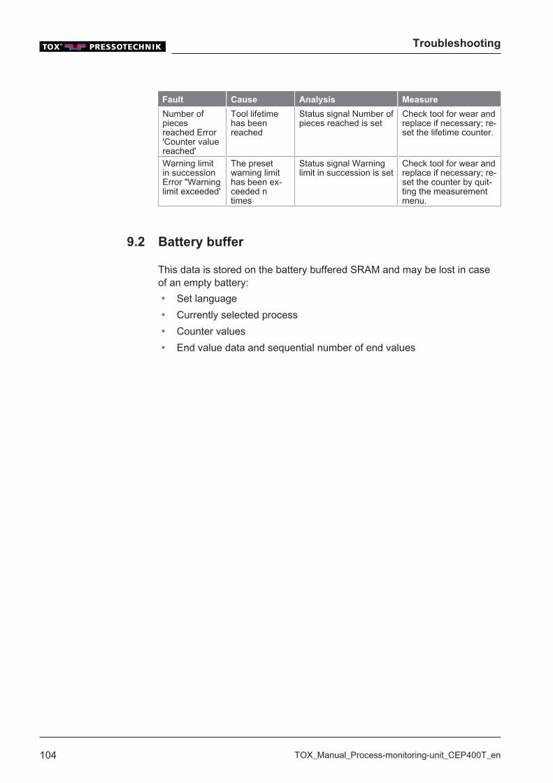
Troubleshooting
104 TOX_Manual_Process-monitoring-unit_CEP400T_en
Fault Cause Analysis Measure
Number ofpiecesreached Error'Counter valuereached'
Tool lifetimehas beenreached
Status signal Number ofpieces reached is set
Check tool for wear andreplace if necessary; re-set the lifetime counter.
Warning limitin successionError "Warninglimit exceeded'
The presetwarning limithas been ex-ceeded ntimes
Status signal Warninglimit in succession is set
Check tool for wear andreplace if necessary; re-set the counter by quit-ting the measurementmenu.
9.2 Battery buffer
This data is stored on the battery buffered SRAM and may be lost in caseof an empty battery:� Set language� Currently selected process� Counter values� End value data and sequential number of end values
Maintenance
TOX_Manual_Process-monitoring-unit_CEP400T_en 105
10 Maintenance
10.1 Maintenance and repair
The recommended time intervals for inspection work and maintenancework must be observed.The correct and proper repair of the TOX® PRESSOTECHNIK product canonly be assured by appropriately trained specialists. The operating com-pany or the personnel in charge of the repair must ensure that the repairpersonnel are properly trained in the repair of the product.The repairers themselves are always responsible for the work safety.
10.2 Safety during maintenance
The following applies:� Observe maintenance intervals if present and stipulated.� Maintenance intervals may vary from the stipulated maintenance inter-
vals.The maintenance intervals may have to be verified with the manufac-turer if necessary.
� Perform only maintenance work that is described in this manual.� Inform operating personnel before starting repair work.� Appoint a supervisor.
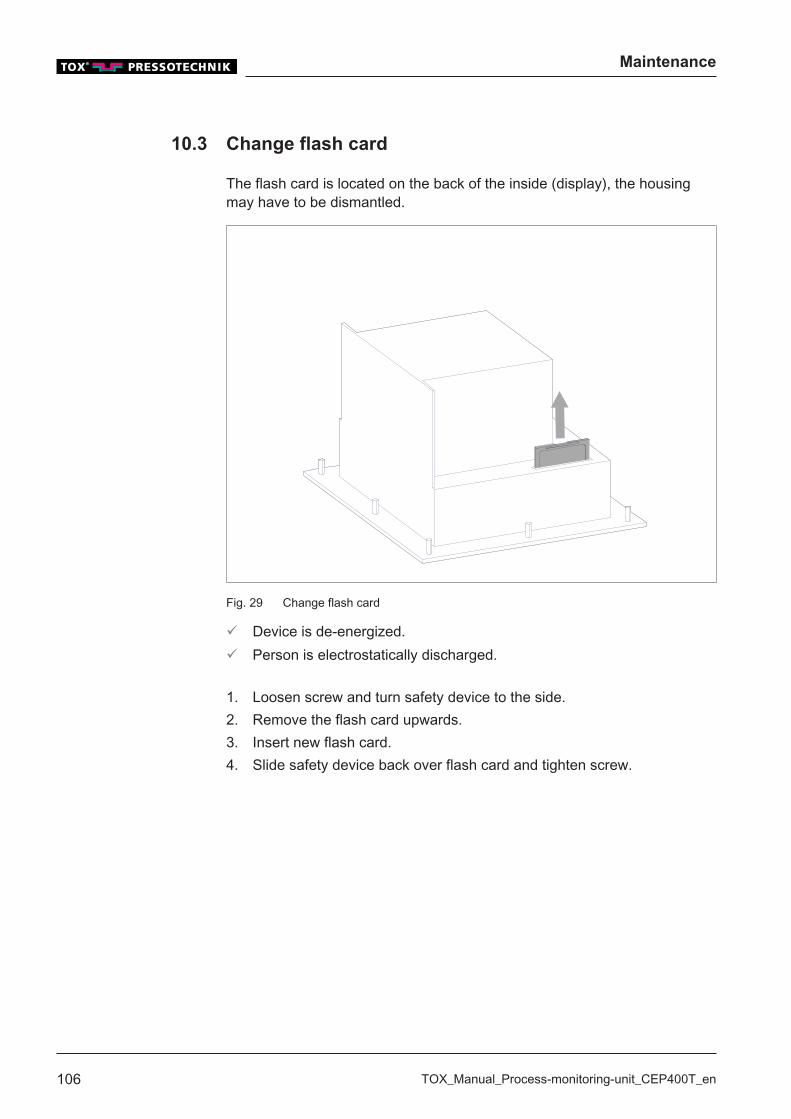
Maintenance
106 TOX_Manual_Process-monitoring-unit_CEP400T_en
10.3 Change flash card
The flash card is located on the back of the inside (display), the housingmay have to be dismantled.
Fig. 29 Change flash card
ü Device is de-energized.ü Person is electrostatically discharged.
1. Loosen screw and turn safety device to the side.2. Remove the flash card upwards.3. Insert new flash card.4. Slide safety device back over flash card and tighten screw.
Maintenance
TOX_Manual_Process-monitoring-unit_CEP400T_en 107
10.4 Battery change
TOX® PRESSOTECHNIK recommends a battery change after 2 years atthe latest.
ü Device is de-energized.ü Person is electrostatically discharged.ü Electrically non conductive tool for removing the battery.
1. Remove the cover of the lithium battery2. Pull the battery out with an insulated tool3. Install new lithium battery in the correct polarity.4. Install the cover.

Maintenance
108 TOX_Manual_Process-monitoring-unit_CEP400T_en
Maintenance table
TOX_Manual_Process-monitoring-unit_CEP400T_en 109
Maintenance table
The specified intervals are only approximate values. Depending on the areaof application, the actual values may differ from the guide values. The ac-tual intervals can be found in the system control.
Maintenance cycle Additional information
2 years 10.4 Battery change

Maintenance table
110 TOX_Manual_Process-monitoring-unit_CEP400T_en
Repairs
TOX_Manual_Process-monitoring-unit_CEP400T_en 111
11 Repairs
11.1 Repair work
No repair work is necessary.

Repairs
112 TOX_Manual_Process-monitoring-unit_CEP400T_en
Disassembly and Disposal
TOX_Manual_Process-monitoring-unit_CEP400T_en 113
12 Disassembly and Disposal
12.1 Safety requirements for disassembly
è Have the disassembly carried out by qualified personnel.
12.2 Disassembly
1. Shut down system or component.2. Disconnect system or component from the supply voltage.3. Remove all connected sensors, actuators or components.4. Disassemble system or component.
12.3 Disposal
When disposing of packaging, consumables and spare parts, including themachine and its accessories, the relevant national environmentalprotection regulations must be complied with.

Disassembly and Disposal
114 TOX_Manual_Process-monitoring-unit_CEP400T_en
Appendices
TOX_Manual_Process-monitoring-unit_CEP400T_en 115
13 Appendices
13.1 Declaration of conformity

Appendices
116 TOX_Manual_Process-monitoring-unit_CEP400T_en
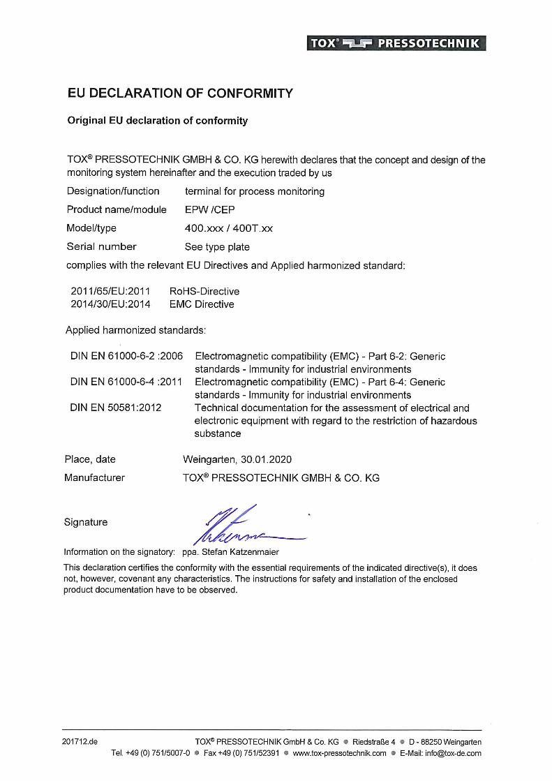
Appendices
118 TOX_Manual_Process-monitoring-unit_CEP400T_en
13.2 UL certificate
NOTICE OF COMPLETION
AND INITIAL PRODUCTION INSPECTION
Page 1
2019-08-30
TOX-PRESSOTECHNIK L L C MR. ERIC SEIFERTH 4250 Weaver Pkwy Warrenville, IL, 60555-3924 USA Our Reference: File E503298, Vol. D1 Project Number: 4788525144
Your Reference: Models EPW 400, Smart9 T070E, Smart9 T057, STE 341-xxx T070, STE346-0005, CEP 400T, Touch Screen PLC's
Project Scope: UL Listing to the following standard(s):
UL 61010-1, 3rd Edition, May 11, 2012, Revised April 29 2016, CAN/CSA-C22.2 No. 61010-1-12, 3rd Edition, Revision dated April 29 2016
Subject: Notice of Project Completion with Initial Production Inspection Dear MR. ERIC SEIFERTH: Congratulations! UL's investigation of your product(s) has been completed under the above Reference Numbers and the product was determined to comply with the applicable requirements. The Test Report and records in the Follow-Up Services Procedure covering the product are completed and are now being prepared (if you do not have a separate CB Report, you can to access the Test Report now). Please have the appropriate person in your company that is responsible for receiving/managing UL reports access an electronic copy of the Test Report and FUS Procedure through the CDA feature on MyHome@UL, or if you desire another method of receiving the report please contact one of the contacts below. If you are not familiar with our MyHome site or need to create a new account in order to access your reports, please click the link HERE. PLEASE NOTE: YOU ARE NOT AUTHORIZED TO SHIP ANY PRODUCTS BEARING ANY UL MARKS UNTIL THE INITIAL PRODUCTION INSPECTION HAS BEEN SUCCESSFULLY CONDUCTED BY THE UL FIELD REPRESENTATIVE. An Initial Production Inspection (IPI) is an inspection that must be conducted prior to the first shipment of products bearing the UL Mark. This is to ensure that products being manufactured are in accordance with UL LLC’s requirements including the Follow-Up Service Procedure. After the UL Representative has verified compliance of your product(s) at the manufacturing locations listed below, authorization will be granted for shipment of product(s) bearing the appropriate UL Marks as denoted in the Procedure (located in the FUS Documentation of the report). List of all manufacturing locations (please contact us if any are missing): Manufacturing Facility(ies):
TOX PRESSOTECHNIK GMBH & CO. KG Riedstraße 4 88250 Weingarten Germany Contact Name: Eric Seiferth Contact Phone No.: 1 630 447-4615 Contact Email: [email protected]
It is the responsibility of TOX-PRESSOTECHNIK L L C, the Applicant, to inform its manufacturers of that the IPI must be successfully completed before product may be shipped with the UL Mark. Instructions for the IPI will be sent to our inspection center nearest to each of your manufacturing locations. The contact information of the inspection center is provided above. Please contact the inspection center to schedule the IPI and ask any questions you may have regarding the IPI. Inspections at your production facility will be conducted under the supervision of:
Area Manager: ROB GEUIJEN IC Name: UL INSPECTION CENTER GERMANY, Address: UL INTERNATIONAL GERMANY GMBH
ADMIRAL-ROSENDAHL-STRASSE 9, NEU-ISENBURG, Germany, 63263
Contact Phone: 69-489810-0

Page 2
Email: Marks (as needed) may be obtained from: Information on the UL Marks, including our new Enhanced UL Certification Marks can be found on the UL website at https://markshub.ul.com Within Canada, there are federal and local statutes and regulations, such as the Consumer Packaging and Labeling Act, requiring the use of bilingual product markings on products intended for the Canadian market. It is the responsibility of the manufacturer (or distributor) to comply with this law. The UL Follow-Up Service Procedures will only include the English versions of the markings Any information and documentation provided to you involving UL Mark services are provided on behalf of UL LLC (UL) or any authorized licensee of UL. Feel free to contact me or any of our Customer Service representatives if you have any questions. UL is strongly committed to providing you with the finest customer experience possible. You may receive an email from [email protected] inviting you to please participate in a brief satisfaction survey. Please check your spam or junk folder to ensure receipt of the email. The subject line of the email is “Tell is about your recent experience with UL.” Please direct any questions about the survey to [email protected]. Thank you in advance for your participation. Very truly yours, Brett VanDoren 847-664-3931 Staff Engineer [email protected]

Index
TOX_Manual_Process-monitoring-unit_CEP400T_en 121
Index
Symbols
MenuSupplement............................................... 86
A
AdjustmentForce sensor............................................. 72
AnalyzingNOK situations........................................ 100
B
Basic safety requirements ............................. 13Battery change ............................................ 107Buttons
Function buttons ....................................... 58
C
CalibrationForce sensor............................................. 74
ChangeDevice name............................................. 95Password .................................................. 88
Change flash card ....................................... 106channel
Naming the ............................................... 68Checkboxes................................................... 58Commissioning.............................................. 53Communication parameters
Configure .................................................. 89configuration
Apply......................................................... 77Force sensor............................................. 69Naming the channel.................................. 68Nominal force of force sensor................... 72
ConfigureCommunication parameters...................... 89
Connections .................................................. 28Contact .......................................................... 11Control elements ........................................... 58Counter
Switch-off at OK.................................. 80, 83Switch-off at total .......................... 81, 83, 85
D
DateSet ............................................................ 95
Declaration of conformity............................. 115description
Function .................................................... 19Device name
Change ..................................................... 95Dialog
Keyboard .................................................. 59Digital inputs .................................................. 28Digital outputs.................. 31, 32, 34, 35, 36, 37Dimensions.................................................... 24
Hole pattern of installation housing........... 25Installation housing ................................... 24Wall/table housing .................................... 26
Disassembly ................................................ 113Safety...................................................... 113
DispatchRepair ....................................................... 51
Disposal....................................................... 113DMS signals .................................................. 40Document
additional .................................................... 8Validity ........................................................ 8
E
Electromagnetic compatibility ........................ 38Enable
Remote access ......................................... 92Environmental conditions .............................. 38Error message............................................. 101Ethernet
Networking................................................ 21Transfer of measuring data....................... 21
Exclusion of liability ......................................... 7
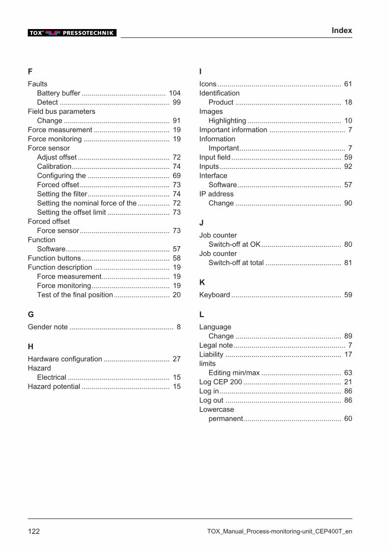
Index
122 TOX_Manual_Process-monitoring-unit_CEP400T_en
F
FaultsBattery buffer .......................................... 104Detect ....................................................... 99
Field bus parametersChange ..................................................... 91
Force measurement ...................................... 19Force monitoring ........................................... 19Force sensor
Adjust offset .............................................. 72Calibration................................................. 74Configuring the ......................................... 69Forced offset ............................................. 73Setting the filter ......................................... 74Setting the nominal force of the ................ 72Setting the offset limit ............................... 73
Forced offsetForce sensor............................................. 73
FunctionSoftware.................................................... 57
Function buttons............................................ 58Function description ...................................... 19
Force measurement.................................. 19Force monitoring....................................... 19Test of the final position............................ 20
G
Gender note .................................................... 8
H
Hardware configuration ................................. 27Hazard
Electrical ................................................... 15Hazard potential ............................................ 15
I
Icons.............................................................. 61Identification
Product ..................................................... 18Images
Highlighting ............................................... 10Important information ...................................... 7Information
Important..................................................... 7Input field ....................................................... 59Inputs............................................................. 92Interface
Software.................................................... 57IP address
Change ..................................................... 90
J
Job counterSwitch-off at OK........................................ 80
Job counter Switch-off at total ...................................... 81
K
Keyboard ....................................................... 59
L
LanguageChange ..................................................... 89
Legal note........................................................ 7Liability .......................................................... 17limits
Editing min/max ........................................ 63Log CEP 200 ................................................. 21Log in............................................................. 86Log out .......................................................... 86Lowercase
permanent................................................. 60
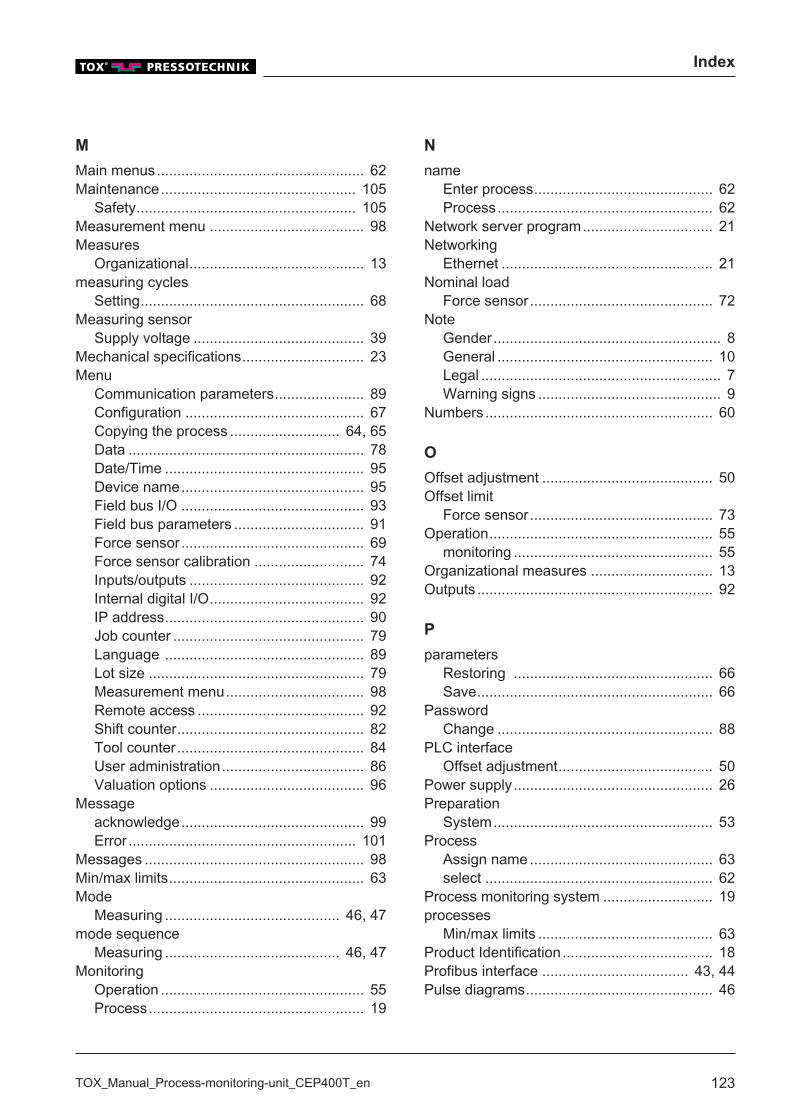
Index
TOX_Manual_Process-monitoring-unit_CEP400T_en 123
M
Main menus................................................... 62Maintenance................................................ 105
Safety...................................................... 105Measurement menu ...................................... 98Measures
Organizational........................................... 13measuring cycles
Setting....................................................... 68Measuring sensor
Supply voltage .......................................... 39Mechanical specifications.............................. 23Menu
Communication parameters...................... 89Configuration ............................................ 67Copying the process ........................... 64, 65Data .......................................................... 78Date/Time ................................................. 95Device name............................................. 95Field bus I/O ............................................. 93Field bus parameters ................................ 91Force sensor............................................. 69Force sensor calibration ........................... 74Inputs/outputs ........................................... 92Internal digital I/O...................................... 92IP address................................................. 90Job counter ............................................... 79Language ................................................. 89Lot size ..................................................... 79Measurement menu.................................. 98Remote access ......................................... 92Shift counter.............................................. 82Tool counter.............................................. 84User administration................................... 86Valuation options ...................................... 96
Messageacknowledge............................................. 99Error........................................................ 101
Messages ...................................................... 98Min/max limits................................................ 63Mode
Measuring ........................................... 46, 47mode sequence
Measuring ........................................... 46, 47Monitoring
Operation .................................................. 55Process..................................................... 19
N
nameEnter process............................................ 62Process..................................................... 62
Network server program................................ 21Networking
Ethernet .................................................... 21Nominal load
Force sensor............................................. 72Note
Gender........................................................ 8General ..................................................... 10Legal ........................................................... 7Warning signs ............................................. 9
Numbers........................................................ 60
O
Offset adjustment .......................................... 50Offset limit
Force sensor............................................. 73Operation....................................................... 55
monitoring ................................................. 55Organizational measures .............................. 13Outputs .......................................................... 92
P
parametersRestoring ................................................. 66Save.......................................................... 66
PasswordChange ..................................................... 88
PLC interfaceOffset adjustment...................................... 50
Power supply ................................................. 26Preparation
System...................................................... 53Process
Assign name ............................................. 63select ........................................................ 62
Process monitoring system ........................... 19processes
Min/max limits ........................................... 63Product Identification..................................... 18Profibus interface .................................... 43, 44Pulse diagrams.............................................. 46
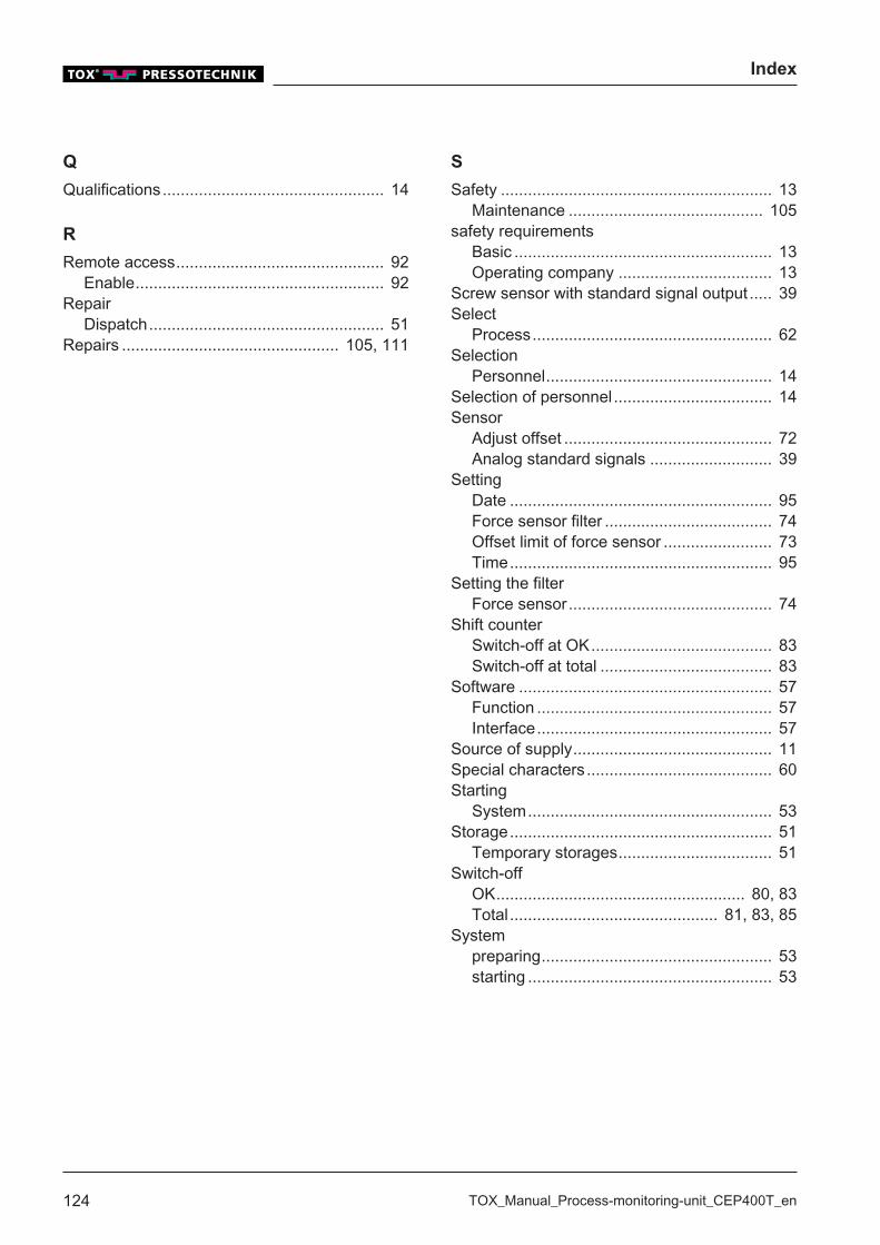
Index
124 TOX_Manual_Process-monitoring-unit_CEP400T_en
Q
Qualifications................................................. 14
R
Remote access.............................................. 92Enable....................................................... 92
RepairDispatch.................................................... 51
Repairs ................................................ 105, 111
S
Safety ............................................................ 13Maintenance ........................................... 105
safety requirementsBasic ......................................................... 13Operating company .................................. 13
Screw sensor with standard signal output ..... 39Select
Process..................................................... 62Selection
Personnel.................................................. 14Selection of personnel ................................... 14Sensor
Adjust offset .............................................. 72Analog standard signals ........................... 39
SettingDate .......................................................... 95Force sensor filter ..................................... 74Offset limit of force sensor ........................ 73Time.......................................................... 95
Setting the filterForce sensor............................................. 74
Shift counterSwitch-off at OK........................................ 83Switch-off at total ...................................... 83
Software ........................................................ 57Function .................................................... 57Interface.................................................... 57
Source of supply............................................ 11Special characters ......................................... 60Starting
System...................................................... 53Storage.......................................................... 51
Temporary storages.................................. 51Switch-off
OK....................................................... 80, 83Total .............................................. 81, 83, 85
Systempreparing................................................... 53starting ...................................................... 53
Index
TOX_Manual_Process-monitoring-unit_CEP400T_en 125
T
Target group.................................................... 8Technical data ............................................... 23
Connections.............................................. 28Digital inputs ............................................. 28Digital outputs ............. 31, 32, 34, 35, 36, 37Dimensions ................................... 24, 25, 26DMS signals.............................................. 40Electromagnetic compatibility ................... 38Environmental conditions.......................... 38Hardware configuration............................. 27Mechanical specifications ......................... 23Power supply ............................................ 26Profibus interface................................ 43, 44Pulse diagrams ......................................... 46Screw sensor with standard signal output 39Sensor ...................................................... 39
Test of the final position ................................ 20Clinching ................................................... 20
TextsHighlighting ............................................... 10
Timeset ............................................................. 95
Tool counter Switch-off at total ...................................... 85
Transfer of measuring data ........................... 21Transport ....................................................... 51Troubleshooting............................................. 99Type plate...................................................... 18
U
UL certificate ............................................... 118Uppercase
permanent................................................. 60User
Log in ........................................................ 86User administration ....................................... 86
Change password..................................... 88User.
Log out...................................................... 86
V
ValidityDocument ................................................... 8
Valuation options........................................... 96
W
warning limitSetting....................................................... 68
Warning signs.................................................. 9Warranty ........................................................ 17

Index
126 TOX_Manual_Process-monitoring-unit_CEP400T_en